Link Slab Details and Materials - Purdue e-Pubs
94
Ghadir Haikal, Julio A. Ramirez, Mohammad R. Jahanshahi, Sandra Villamizar, Osama Abdelaleim Link Slab Details and Materials JOINT TRANSPORTATION RESEARCH PROGRAM INDIANA DEPARTMENT OF TRANSPORTATION AND PURDUE UNIVERSITY SPR-4223 • Report Number: FHWA/IN/JTRP-2019/10 • DOI: 10.5703/1288284316920
-
Upload
khangminh22 -
Category
Documents
-
view
0 -
download
0
Transcript of Link Slab Details and Materials - Purdue e-Pubs
Ghadir Haikal, Julio A. Ramirez, Mohammad R. Jahanshahi,Sandra Villamizar, Osama Abdelaleim
Link Slab Details and Materials
JOINT TRANSPORTATIONRESEARCH PROGRAMINDIANA DEPARTMENT OF TRANSPORTATION AND PURDUE UNIVERSITY
SPR-4223 • Report Number: FHWA/IN/JTRP-2019/10 • DOI: 10.5703/1288284316920

RECOMMENDED CITATIONHaikal, G., Ramirez, J. A., Jahanshahi, M. R., Villamizar, S., & Abdelaleim, O. (2019). Link slab details and materials (Joint Transportation Research Program Publication No. FHWA/IN/JTRP-2019/10). West Lafayette, IN: Purdue University. https://doi.org/10.5703/1288284316920
AUTHORSGhadir Haikal, PhDAssistant Professor of Civil Engineering Lyles School of Civil EngineeringPurdue University
Julio A. Ramirez, PhDKettelhut Professor of Civil EngineeringLyles School of Civil EngineeringPurdue University
Mohammad R. Jahanshahi, PhDAssistant Professor of Civil Engineering Lyles School of Civil EngineeringPurdue University
Sandra Villamizar Osama AbdelaleimGraduate Research AssistantsLyles School of Civil EngineeringPurdue University
ACKNOWLEDGMENTSThe authors acknowledge the participation of the members of the Study Advisory Committee. Their support and as-sistance is appreciated.
JOINT TRANSPORTATION RESEARCH PROGRAMThe Joint Transportation Research Program serves as a vehicle for INDOT collaboration with higher education in-stitutions and industry in Indiana to facilitate innovation that results in continuous improvement in the planning, design, construction, operation, management and economic efficiency of the Indiana transportation infrastructure. https://engineering.purdue.edu/JTRP/index_html
Published reports of the Joint Transportation Research Program are available at http://docs.lib.purdue.edu/jtrp/.
NOTICEThe contents of this report reflect the views of the authors, who are responsible for the facts and the accuracy of the data presented herein. The contents do not necessarily reflect the official views and policies of the Indiana Depart-ment of Transportation or the Federal Highway Administration. The report does not constitute a standard, specifica-tion or regulation.

TECHNICAL REPORT DOCUMENTATION PAGE
1. Report No. FHWA/IN/JTRP-2019/10
2. Government Accession No. 3. Recipient’s Catalog No.
4. Title and Subtitle Link Slab Details and Materials
5. Report Date May 2019 6. Performing Organization Code
7. Author(s) Ghadir Haikal, Julio A. Ramirez, Mohammad R. Jahanshahi, Sandra Villamizar, and Osama Abdelaleim
8. Performing Organization Report No. FHWA/IN/JTRP-2019/10
9. Performing Organization Name and Address Joint Transportation Research Program Hall for Discovery and Learning Research (DLR), Suite 204 207 S. Martin Jischke Drive West Lafayette, IN 47907
10. Work Unit No.
11. Contract or Grant No. SPR-4223
12. Sponsoring Agency Name and Address Indiana Department of Transportation (SPR) State Office Building 100 North Senate Avenue Indianapolis, IN 46204
13. Type of Report and Period Covered Final Report 14. Sponsoring Agency Code
15. Supplementary Notes Conducted in cooperation with the U.S. Department of Transportation, Federal Highway Administration.
16. Abstract This report contains the findings of a synthesis study on the use of link slabs to eliminate intermediate joints in bridges of Indiana. The study was conducted under the sponsorship of the Joint Transportation Research Program. The motivation for the study was to investigate this promising technique to mitigate the damage associated with expansion joints that has long been recognized as a persistent and costly issue negatively impacting the bridge service life.
The report summarizes the background information and motivation for the study. It also provides a description of the report organization. The results of an extensive literature review of DOTs’ experience related to the use of this system and main research findings are presented as well as construction practice and examples of application. The results of the analysis of a bridge in Indiana where the link slab system has been implemented are presented. The bridge connecting the State Road 68 over the Interstate 64 was selected as a representative bridge based on the analysis of the inspection.
A parametric study on the effects of various parameters was conducted to evaluate the effect of support conditions and debonded length on the stress distribution and potential crack initiation in link slabs. Each variable was investigated separately to isolate its effect. Two bridge structures were investigated in this study. The first structure (Case 1) represents a bridge structure rehabilitated using link slabs. A second bridge structure (Case 2) with the same geometrical and material properties, but with a continuous and fully bonded deck, was also included in the parametric study for comparison purposes. This structure simulated new bridge construction.
17. Key Words bridge, concrete, fiber, performance, detailing, temperature effects, link slab, jointless bridges, bridge deck joints replacement, literature review, finite element
18. Distribution Statement No restrictions. This document is available through the National Technical Information Service, Springfield, VA 22161.
19. Security Classif. (of this report) Unclassified
20. Security Classif. (of this page) Unclassified
21. No. of Pages 94
22. Price
Form DOT F 1700.7 (8-72) Reproduction of completed page authorized

Executive Summary
This report contains the findings of a synthesis study on the use of link slabs to eliminateintermediate joints in bridges of Indiana. The study was conducted under the sponsorship ofthe Joint Transportation Research Program. The motivation for the study was to investigatethis promising technique to mitigate the damage associated with expansion joints that haslong been recognized as a persistent and costly issue negatively impacting the bridge servicelife.
The report consists of five chapters. The first chapter summarizes the background informa-tion and motivation for the study. It also provides a description of the report organization.In Chapter 2, the results of an extensive literature review of DOT experiences, including In-diana’s, with the use of this system, design and construction practices are summarized aswell. An extensive review of the research on these systems is also summarized in Chapter2. The results of the analysis of a bridge in Indiana where the link slab system has beenimplemented are summarized in Chapter 3. A comparative numerical study is conducted onthe bridge between the models representing the bridge before and after the link slab construc-tion under live and thermal loads. In Chapter 4, a parametric study is conducted to evaluatethe effect of support conditions and debonded length on the stress distribution and potentialcrack initiation in link slabs using a two-span bridge model. The goal of the parametric studyis to compare the performance of fully bonded link slabs, as implemented in Indiana, withthe more common debonded link slabs as recommended in the literature.
The main findings, conclusions and recommendations for implementation and further re-search from the study are given in Chapter 5. Major findings include limitations of currentdesign approaches, the effect of support conditions, and observed cracking issues, in partic-ular, in Indiana where the design detail used lacks a debonded zone. For improved perfor-mance, suggestions in the literature include the use of high tensile materials and improveddetails, such as the debonded slab with an additional transition zone between the link slaband the existing deck. However, these improvements would not eliminate cracking unlessthermal effects are addressed. Numerical analyses in Chapter 3 show that these loads aremajor contributors to high stresses in the deck leading to observed cracks in the field. Fur-ther investigation is needed to examine the appropriate method for considering temperatureeffects and support conditions in the design of link slabs.
Joint Transportation Research Program Report FHWA/IN/JTRP-2019/10


Contents
1. Introduction . . . . . . . . . . . . . . . . . . . . . . . . . . . . . . . . . . . . . . . . . . . 11.1 Background . . . . . . . . . . . . . . . . . . . . . . . . . . . . . . . . . . . . . . . . 11.2 Problem Statement . . . . . . . . . . . . . . . . . . . . . . . . . . . . . . . . . . . . 21.3 Objectives and Scope . . . . . . . . . . . . . . . . . . . . . . . . . . . . . . . . . . . 31.4 Information Collection . . . . . . . . . . . . . . . . . . . . . . . . . . . . . . . . . . 41.5 Report Organization . . . . . . . . . . . . . . . . . . . . . . . . . . . . . . . . . . . 4
2. Literature Review . . . . . . . . . . . . . . . . . . . . . . . . . . . . . . . . . . . . . . . . 72.1 DOT Experience . . . . . . . . . . . . . . . . . . . . . . . . . . . . . . . . . . . . . . 72.2 Previous Research on Link Slabs . . . . . . . . . . . . . . . . . . . . . . . . . . . . 8
2.2.1 North Carolina Department of Transportation (NCDOT) . . . . . . . . . . 82.2.2 Michigan Department of Transportation (MDOT) . . . . . . . . . . . . . . 152.2.3 Virginia Department of Transportation (VDOT) . . . . . . . . . . . . . . . 192.2.4 New York State Department of Transportation (NYSDOT) . . . . . . . . . 202.2.5 Hawaii Department of Transportation (HDOT) . . . . . . . . . . . . . . . . 212.2.6 Louisiana Department of Transportation (LaDOTD) . . . . . . . . . . . . . 232.2.7 Ministry of Transportation of Ontario (MTO) . . . . . . . . . . . . . . . . . 24
2.3 Design Specifications and State Construction Practices . . . . . . . . . . . . . . . 252.4 Assessment of Existing Indiana Link Slab Bridges . . . . . . . . . . . . . . . . . . 31
2.4.1 I-64 EB/WB over Captain Frank Road . . . . . . . . . . . . . . . . . . . . . 322.4.2 SR 64 over SR 37 . . . . . . . . . . . . . . . . . . . . . . . . . . . . . . . . . 332.4.3 Owensville Road over I-64 . . . . . . . . . . . . . . . . . . . . . . . . . . . . 342.4.4 SR-68 over I-64 . . . . . . . . . . . . . . . . . . . . . . . . . . . . . . . . . . 352.4.5 Hillcrest Road over US-50 . . . . . . . . . . . . . . . . . . . . . . . . . . . . 362.4.6 Summary of Inspection Reports . . . . . . . . . . . . . . . . . . . . . . . . 37
Joint Transportation Research Program Report FHWA/IN/JTRP-2019/10

2.5 Summary of the Literature and Practice Review . . . . . . . . . . . . . . . . . . . 39
3. Numerical Analysis of Indiana Bridge . . . . . . . . . . . . . . . . . . . . . . . . . . . 433.1 Bridge Model . . . . . . . . . . . . . . . . . . . . . . . . . . . . . . . . . . . . . . . 43
3.1.1 Geometry and Boundary Conditions . . . . . . . . . . . . . . . . . . . . . 433.1.2 Loading . . . . . . . . . . . . . . . . . . . . . . . . . . . . . . . . . . . . . . 46
3.2 Results . . . . . . . . . . . . . . . . . . . . . . . . . . . . . . . . . . . . . . . . . . . 483.3 Parametric Study . . . . . . . . . . . . . . . . . . . . . . . . . . . . . . . . . . . . . 50
3.3.1 Effect of Material . . . . . . . . . . . . . . . . . . . . . . . . . . . . . . . . . 513.3.2 Effect of Boundary Conditions . . . . . . . . . . . . . . . . . . . . . . . . . 52
4. Bridge Parameter Investigation . . . . . . . . . . . . . . . . . . . . . . . . . . . . . . . 554.1 Effect of Support Conditions . . . . . . . . . . . . . . . . . . . . . . . . . . . . . . 584.2 Effect of Debonded Length . . . . . . . . . . . . . . . . . . . . . . . . . . . . . . . 604.3 Conclusions of Parametric Study . . . . . . . . . . . . . . . . . . . . . . . . . . . . 64
5. Findings, Conclusions, and Proposed Recommendations for Implementation . . . . 655.1 Summary . . . . . . . . . . . . . . . . . . . . . . . . . . . . . . . . . . . . . . . . . . 655.2 Findings . . . . . . . . . . . . . . . . . . . . . . . . . . . . . . . . . . . . . . . . . . 65
5.2.1 Literature Review . . . . . . . . . . . . . . . . . . . . . . . . . . . . . . . . . 655.2.2 Analysis of Indiana Bridge . . . . . . . . . . . . . . . . . . . . . . . . . . . 705.2.3 Bridge Parameter Investigation . . . . . . . . . . . . . . . . . . . . . . . . . 71
5.3 Conclusions . . . . . . . . . . . . . . . . . . . . . . . . . . . . . . . . . . . . . . . . 725.3.1 Use by DOTs . . . . . . . . . . . . . . . . . . . . . . . . . . . . . . . . . . . 725.3.2 Design Practice . . . . . . . . . . . . . . . . . . . . . . . . . . . . . . . . . . 735.3.3 Research . . . . . . . . . . . . . . . . . . . . . . . . . . . . . . . . . . . . . . 73
5.4 Recommendations for Implementation . . . . . . . . . . . . . . . . . . . . . . . . . 745.5 Suggestions for Future Research . . . . . . . . . . . . . . . . . . . . . . . . . . . . 75
References . . . . . . . . . . . . . . . . . . . . . . . . . . . . . . . . . . . . . . . . . . . . . . 77
Joint Transportation Research Program Report FHWA/IN/JTRP-2019/10

List of Figures
1.1 Deck joint replacement approach with link slabs . . . . . . . . . . . . . . . . . . . 2
2.1 Debonded link slab configuration tested by Caner and Zia [1998] . . . . . . . . . 122.2 Link slab detail [Wing and Kowalsky, 2005] . . . . . . . . . . . . . . . . . . . . . . 142.3 ECC link slab configuration proposed by Li et al. [2003] . . . . . . . . . . . . . . 162.4 Link slab detail used in Michigan [Aktan et al., 2008] . . . . . . . . . . . . . . . . 182.5 UHPC link slab detail [Graybeal, 2014] . . . . . . . . . . . . . . . . . . . . . . . . 212.6 HPFRCC precast link slab tested by Reyes and Robertson [2011] . . . . . . . . . 222.7 GFRP link slab detail . . . . . . . . . . . . . . . . . . . . . . . . . . . . . . . . . . . 232.8 Full-scale beam testing setup as presented by Li and Saber [2009] . . . . . . . . . 232.9 Link slab details used in Canada [Lam et al., 2008] . . . . . . . . . . . . . . . . . 252.10 VDOT link slab detail [VDOT, 2018] . . . . . . . . . . . . . . . . . . . . . . . . . . 282.11 NYSDOT link slab detail [NYSDOT, 2018] . . . . . . . . . . . . . . . . . . . . . . 292.12 Location of the existing link slab bridges . . . . . . . . . . . . . . . . . . . . . . . 312.13 Link slab detail (I-64 over Captain Frank) . . . . . . . . . . . . . . . . . . . . . . . 332.14 Link slab detail (SR 64 over SR 37) . . . . . . . . . . . . . . . . . . . . . . . . . . . 342.15 Link slab detail (Owensville Road over I-64) . . . . . . . . . . . . . . . . . . . . . 352.16 Link slab detail (SR 68 over I-64) . . . . . . . . . . . . . . . . . . . . . . . . . . . . 362.17 Link slab detail (Hillcrest Road over US-50) . . . . . . . . . . . . . . . . . . . . . . 372.18 Cracking in Indiana link slab bridges as reported in inspection reports . . . . . . 38
3.1 Bridge elevation and cross-section as reported in drawings . . . . . . . . . . . . . 443.2 Plan view of the girders and diaphragms of the bridge model . . . . . . . . . . . 443.3 Boundary conditions for the concrete girders on the left and the steel girders on
the right . . . . . . . . . . . . . . . . . . . . . . . . . . . . . . . . . . . . . . . . . . 453.4 Applied (dashed) and AASHTO (solid) Gradient temperature diagrams for con-
crete and steel structures . . . . . . . . . . . . . . . . . . . . . . . . . . . . . . . . . 47
Joint Transportation Research Program Report FHWA/IN/JTRP-2019/10

3.5 Axial forces (kips) in the slab due to fully loaded structure under live load. Thetop figure is the bridge with expansion joint. The bottom figure is the bridgewith link slabs . . . . . . . . . . . . . . . . . . . . . . . . . . . . . . . . . . . . . . . 48
3.6 Axial forces (kips) in the slab due to uniform increase in temperature. The topfigure is the bridge with expansion joint. The bottom figure is the bridge withlink slabs . . . . . . . . . . . . . . . . . . . . . . . . . . . . . . . . . . . . . . . . . . 49
3.7 Axial forces (kips) in the slab due to uniform decrease in temperature. The topfigure is the bridge with expansion joint. The bottom figure is the bridge withlink slabs . . . . . . . . . . . . . . . . . . . . . . . . . . . . . . . . . . . . . . . . . . 49
3.8 Axial forces (kips) in the slab due to gradient temperature. The top figure is thebridge with expansion joint. The bottom figure is the bridge with link slabs . . . 50
3.9 Plan view of the girders and diaphragms of the bridge model where all girdersare made of concrete . . . . . . . . . . . . . . . . . . . . . . . . . . . . . . . . . . . 51
3.10 Axial forces (kips) in the slab due to uniform decrease in temperature. Thetop figure is the original bridge with link slab. The bottom figure is the bridgevariant (All concrete girders) with link slab . . . . . . . . . . . . . . . . . . . . . . 52
3.11 Axial forces (kips) in the slab due to fully loaded structure under live load. Thetop figure is the bridge with HHRHRHH support configuration. The middlefigure is the bridge with RRRHRRR support configuration. The bottom figureis the bridge with RRRHRRR support configuration and supports representingapproach slab . . . . . . . . . . . . . . . . . . . . . . . . . . . . . . . . . . . . . . . 53
3.12 Axial forces (kips) in the slab due to fully loaded structure under live load. Thetop figure is the bridge with HHRHRHH support configuration. The middlefigure is the bridge with RRRHRRR support configuration. The bottom figureis the bridge with RRRHRRR support configuration and supports representingapproach slab . . . . . . . . . . . . . . . . . . . . . . . . . . . . . . . . . . . . . . . 54
4.1 Bridge deck link slab (Case 1) . . . . . . . . . . . . . . . . . . . . . . . . . . . . . . 564.2 Continuous bridge deck (Case 2) . . . . . . . . . . . . . . . . . . . . . . . . . . . . 564.3 Tie constraint locations . . . . . . . . . . . . . . . . . . . . . . . . . . . . . . . . . . 574.4 Model assembly for live load . . . . . . . . . . . . . . . . . . . . . . . . . . . . . . 574.5 Effect of boundary conditions under live load . . . . . . . . . . . . . . . . . . . . 594.6 Effect of boundary conditions under uniform temperature load . . . . . . . . . . 594.7 Effect of debonding under live load for support conditions: RHHR; FFRH;
HHHH; and HRHH . . . . . . . . . . . . . . . . . . . . . . . . . . . . . . . . . . . 614.8 Effect of debonding under live load for support conditions: HRRH; HRRR; and
RRHR . . . . . . . . . . . . . . . . . . . . . . . . . . . . . . . . . . . . . . . . . . . . 624.9 Effect of debonding under uniform temperature load for support conditions:
RHHR; FFRH; HHHH; and HRHH . . . . . . . . . . . . . . . . . . . . . . . . . . . 63
Joint Transportation Research Program Report FHWA/IN/JTRP-2019/10

4.10 Effect of debonding under uniform temperature load for support conditions:HRRH; HRRR; and RRHR . . . . . . . . . . . . . . . . . . . . . . . . . . . . . . . . 64
5.1 ECC link slab configuration proposed by Li et al. [2003] . . . . . . . . . . . . . . 75
Joint Transportation Research Program Report FHWA/IN/JTRP-2019/10


List of Tables
1.1 Contacted state agencies . . . . . . . . . . . . . . . . . . . . . . . . . . . . . . . . . 4
2.1 Link slab applications . . . . . . . . . . . . . . . . . . . . . . . . . . . . . . . . . . 82.2 Summary of state practices . . . . . . . . . . . . . . . . . . . . . . . . . . . . . . . 302.3 Summary of geometric properties of Indiana link slab bridges . . . . . . . . . . . 322.4 Summary of inspection reports of Indiana link slab bridges . . . . . . . . . . . . 322.5 Literature summary . . . . . . . . . . . . . . . . . . . . . . . . . . . . . . . . . . . . 392.6 Mix proportions . . . . . . . . . . . . . . . . . . . . . . . . . . . . . . . . . . . . . . 412.7 Properties of GFRP reinforcement . . . . . . . . . . . . . . . . . . . . . . . . . . . 41
3.1 Mesh dimensions for concrete and steel structures . . . . . . . . . . . . . . . . . . 46
4.1 FEM material properties . . . . . . . . . . . . . . . . . . . . . . . . . . . . . . . . . 554.2 Surfaces for tie constraint definition . . . . . . . . . . . . . . . . . . . . . . . . . . 574.3 Maximum stresses at top of link slab due to live load . . . . . . . . . . . . . . . . 604.4 Maximum stresses at top of link slab due to uniform temperature load . . . . . 60
Joint Transportation Research Program Report FHWA/IN/JTRP-2019/10


Chapter 1
Introduction
1.1 Background
Conventional multispan bridges have expansion joints usually placed at the end of the spansover the piers and the abutments. The joints are designed to allow superstructure movementcaused by shrinkage, creep, and thermal effects. The damage associated with expansion jointshas long been recognized as a persistent and costly issue that can negatively impact the bridgeservice life [Alampalli and Yannotti, 1998; Au et al., 2013]. Bridge deck joints allow the en-trance of corrosive chemicals and debris causing premature deterioration of concrete bridgedecks, beam-ends, girder bearings, and supporting substructure [Kim et al., 2004].
The United States Federal Highway Administration (FHWA) and individual state depart-ments of transportation (DOTs) are actively promoting the implementation of jointless bridges,i.e., bridges without expansion joints, to address the durability problems and poor perfor-mance of deck joints. Jointless bridges have been used in many states. The elimination ofdeck joints results in additional forces that need to be considered in the design of the bridgesystems. Bridge deck joints can be replaced at the abutments by using an integral abutment,semi-integral abutment, or deck extension. At piers, joint elimination can be achieved by us-ing continuous-for-live-load bridge structures or by installing link slabs.
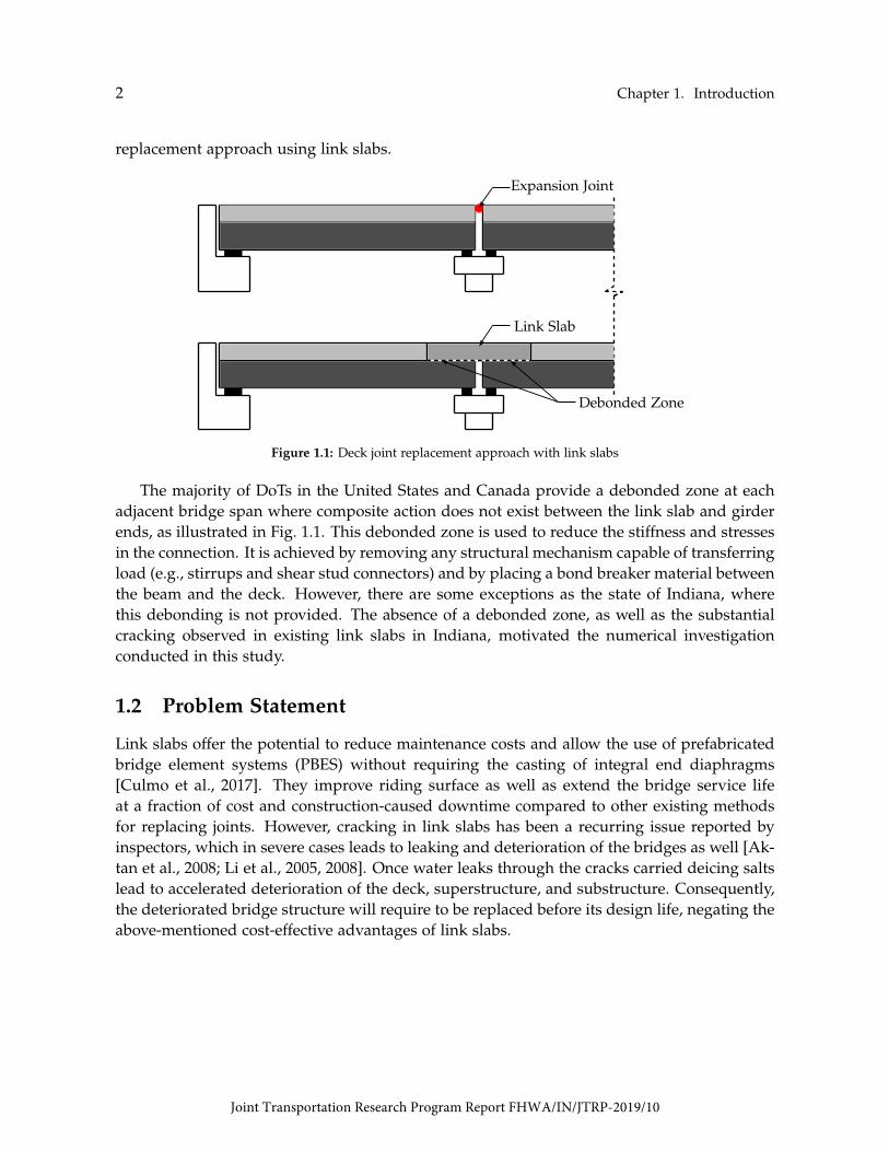
Link slabs are typically used by DOTs for replacing deck expansion joints over piers inshort and medium multispan bridges (i.e., span length from 30 ft to 100 ft). A link slab isthe portion of the deck over the joint that connects two adjacent deck spans, integrating thedeck as a fully continuous system while the girders remain simply-supported [Caner and Zia,1998]. Link Slabs can be implemented in concrete and steel beam bridge superstructure. Theprimary purpose of making the deck continuous is to avoid span separation and deteriorationdue to leaking [Caner et al., 2002; Sevgili and Caner, 2009]. Fig. 1.1 shows the deck joint
1
Joint Transportation Research Program Report FHWA/IN/JTRP-2019/10
2 Chapter 1. Introduction
replacement approach using link slabs.
Expansion Joint
Link Slab
Debonded Zone
Figure 1.1: Deck joint replacement approach with link slabs
The majority of DoTs in the United States and Canada provide a debonded zone at eachadjacent bridge span where composite action does not exist between the link slab and girderends, as illustrated in Fig. 1.1. This debonded zone is used to reduce the stiffness and stressesin the connection. It is achieved by removing any structural mechanism capable of transferringload (e.g., stirrups and shear stud connectors) and by placing a bond breaker material betweenthe beam and the deck. However, there are some exceptions as the state of Indiana, wherethis debonding is not provided. The absence of a debonded zone, as well as the substantialcracking observed in existing link slabs in Indiana, motivated the numerical investigationconducted in this study.
1.2 Problem Statement
Link slabs offer the potential to reduce maintenance costs and allow the use of prefabricatedbridge element systems (PBES) without requiring the casting of integral end diaphragms[Culmo et al., 2017]. They improve riding surface as well as extend the bridge service lifeat a fraction of cost and construction-caused downtime compared to other existing methodsfor replacing joints. However, cracking in link slabs has been a recurring issue reported byinspectors, which in severe cases leads to leaking and deterioration of the bridges as well [Ak-tan et al., 2008; Li et al., 2005, 2008]. Once water leaks through the cracks carried deicing saltslead to accelerated deterioration of the deck, superstructure, and substructure. Consequently,the deteriorated bridge structure will require to be replaced before its design life, negating theabove-mentioned cost-effective advantages of link slabs.
Joint Transportation Research Program Report FHWA/IN/JTRP-2019/10

1.3. Objectives and Scope 3
Different solutions have been proposed to address the cracking issue in link slabs. Someresearchers attribute the cracking to shrinkage and temperature gradients. As a result, severalstudies have been focusing on new material designs with improved tensile strength [Li et al.,2003; Ozyildirim et al., 2017; Hoomes et al., 2017]. Other researchers attribute the cracks to thetension force resulted from continuity moments, poor construction practices, and improperdetailing for the adequate accommodation of the bridge superstructure movement [Aktanet al., 2008; Li et al., 2003; Ulku et al., 2009; Okeil and El-Safty, 2005]. To this end, alternativedesign procedures and joint details have been developed.
1.3 Objectives and Scope
This research focuses on reviewing the current state-of-the-art and state-of-the-practice relatedto link slabs in bridge decks. Information is collected and reported about materials, designprovisions, construction procedures, system performance, and design details that have beenstudied for use or that are still being used in the United States and other countries. The goal isto provide a better understanding of the behavior of link-slab bridges and elucidate the mostpractical and efficient practices. The following tasks were identified to achieve the projectobjectives:
Task 1 — Review of relevant literature, findings of previous investigations, existing designmethods, domestic and foreign specifications, field implementations, and other sources thathelp to establish the state of knowledge on link slabs.
Task 2 — Summarize available information on the design and construction of link slabs inbridge decks.
Task 3 — Assess qualitatively the existing link-slabs bridges in the state of Indiana to iden-tify potential factors and conditions affecting the behavior of link slabs as well as detailingand materials used.
Task 4 — Examine current construction practices to obtain a comprehensive understand-ing of the existing retrofitting methods for bridges where link slabs are used to replace jointsand compared with evidence from performance wherever available as well as to ease of con-struction.
Task 5 — Identify critical parameters that affect the behavior of link slabs and researchareas of improvement.
Joint Transportation Research Program Report FHWA/IN/JTRP-2019/10
4 Chapter 1. Introduction
Task 6 — Perform preliminary finite element analysis to investigate the role played bydebonding and examine other potential parameters that influence the behavior of link slabsused in the state of Indiana. This task was added during project progress, motivated by ob-servations made during the bridge assessment (Task 3), where substantial deterioration wasnoted in existing link slabs.
Task 7 — Submit a final report that summarizes the entire research project and providessuggestions for future research needs.
1.4 Information Collection
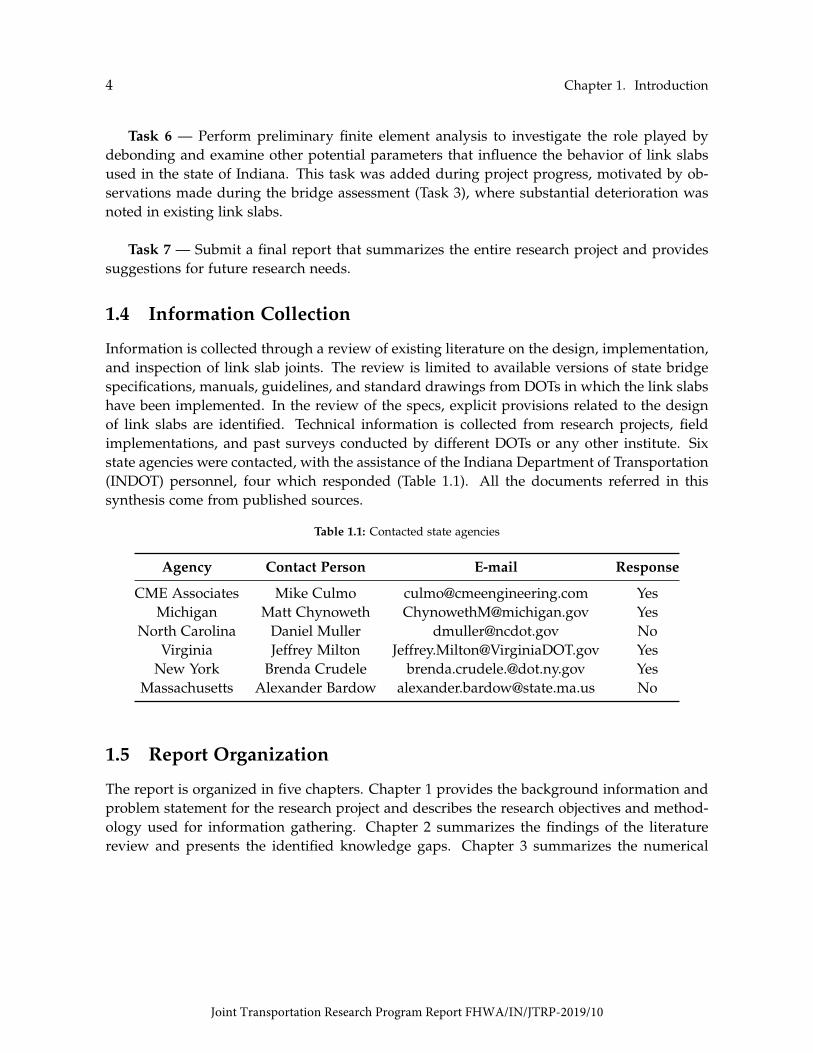
Information is collected through a review of existing literature on the design, implementation,and inspection of link slab joints. The review is limited to available versions of state bridgespecifications, manuals, guidelines, and standard drawings from DOTs in which the link slabshave been implemented. In the review of the specs, explicit provisions related to the designof link slabs are identified. Technical information is collected from research projects, fieldimplementations, and past surveys conducted by different DOTs or any other institute. Sixstate agencies were contacted, with the assistance of the Indiana Department of Transportation(INDOT) personnel, four which responded (Table 1.1). All the documents referred in thissynthesis come from published sources.
Table 1.1: Contacted state agencies
Agency Contact Person E-mail Response
CME Associates Mike Culmo [email protected] YesMichigan Matt Chynoweth [email protected] Yes
North Carolina Daniel Muller [email protected] NoVirginia Jeffrey Milton [email protected] Yes
New York Brenda Crudele [email protected] YesMassachusetts Alexander Bardow [email protected] No
1.5 Report Organization
The report is organized in five chapters. Chapter 1 provides the background information andproblem statement for the research project and describes the research objectives and method-ology used for information gathering. Chapter 2 summarizes the findings of the literaturereview and presents the identified knowledge gaps. Chapter 3 summarizes the numerical
Joint Transportation Research Program Report FHWA/IN/JTRP-2019/10

1.5. Report Organization 5
investigation performed on an existing bridge in Indiana. Chapter 4 shows the results of apreliminary parameter investigation conducted to evaluate the effect of support conditionsand debonded length on the behavior of link slabs. Chapter 5 presents the conclusions andprovides recommendations for further research.
Joint Transportation Research Program Report FHWA/IN/JTRP-2019/10

Chapter 2
Literature Review
This chapter summarizes the information gathered from a review of literature performedto establish the state of knowledge on link slabs. Specific areas of interest regarding linkslabs include (1) review of design and construction practices with potential to enhance theperformance, (2) lessons learned, (3) material specifications, and (4) factors that affect thebehavior.
2.1 DOT Experience
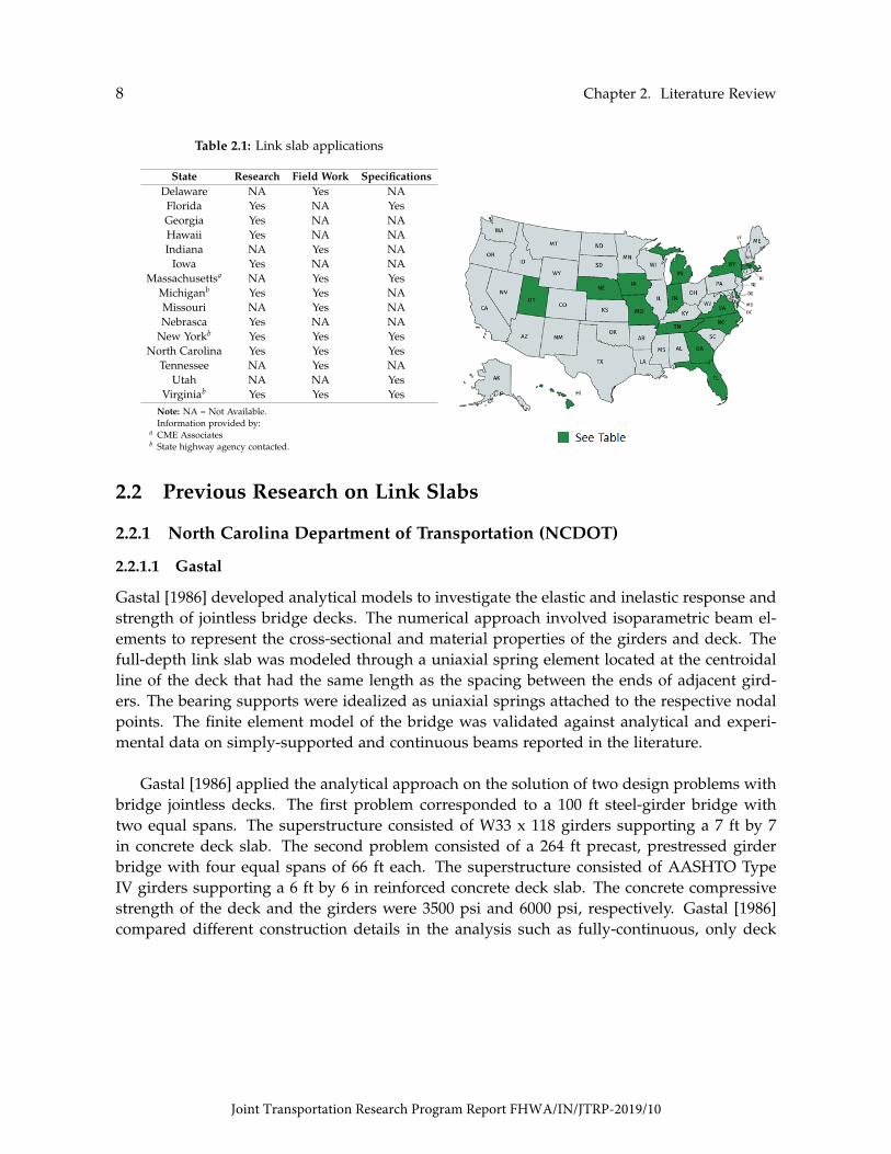
The review of available information from DOTs conducted in this project indicated that around30% of them in the United States had experience with the link slabs applications. The infor-mation is summarized in Table 2.1 in the categories of research, field work, and specifications.Approximately two-thirds of the reported agencies have performed research or implementedthe link-slab system in the field. Nearly one-third of them provided design provisions or of-ficial details. North Carolina, Michigan, Virginia, and New York were identified as key DOTsthat use link slabs. Many bridges have been retrofitted using link slabs in these states. Noticein Table 2.1 that some state highway agencies were contacted and provided information.
7
Joint Transportation Research Program Report FHWA/IN/JTRP-2019/10
8 Chapter 2. Literature Review
Table 2.1: Link slab applications
StateDelaware
ResearchNA
Field WorkYes
SpecificationsNA
Florida Yes NA YesGeorgiaHawaii
YesYes
NANA
NANA
Indiana NA Yes NAIowa Yes NA NA
Massachusettsa NA Yes YesMichiganb
MissouriYesNA
YesYes
NANA
Nebrasca Yes NA NANew Yorkb Yes Yes Yes
North Carolina Yes Yes YesTennessee NA Yes NA
Utah NA NA YesVirginiab Yes Yes Yes
Note: NA = Not Available.Information provided by:
a CME Associatesb State highway agency contacted.
2.2 Previous Research on Link Slabs
2.2.1 North Carolina Department of Transportation (NCDOT)
2.2.1.1 Gastal
Gastal [1986] developed analytical models to investigate the elastic and inelastic response andstrength of jointless bridge decks. The numerical approach involved isoparametric beam el-ements to represent the cross-sectional and material properties of the girders and deck. Thefull-depth link slab was modeled through a uniaxial spring element located at the centroidalline of the deck that had the same length as the spacing between the ends of adjacent gird-ers. The bearing supports were idealized as uniaxial springs attached to the respective nodalpoints. The finite element model of the bridge was validated against analytical and experi-mental data on simply-supported and continuous beams reported in the literature.
Gastal [1986] applied the analytical approach on the solution of two design problems withbridge jointless decks. The first problem corresponded to a 100 ft steel-girder bridge withtwo equal spans. The superstructure consisted of W33 x 118 girders supporting a 7 ft by 7in concrete deck slab. The second problem consisted of a 264 ft precast, prestressed girderbridge with four equal spans of 66 ft each. The superstructure consisted of AASHTO TypeIV girders supporting a 6 ft by 6 in reinforced concrete deck slab. The concrete compressivestrength of the deck and the girders were 3500 psi and 6000 psi, respectively. Gastal [1986]compared different construction details in the analysis such as fully-continuous, only deck
Joint Transportation Research Program Report FHWA/IN/JTRP-2019/10

2.2. Previous Research on Link Slabs 9
continuous, and non-continuous. Shored and unshored deck construction was also exam-ined. Several loadings were considered in the analysis including prestressing, dead loads,live loads, support displacements, temperature, and time-dependent effects. All the externalloads were applied using both load increment and displacement increment methods. Thesupport arrangements were varied by changing the position of the hinged (H), and roller (R)supports at each end of the girder. The five support configurations evaluated were: RHHR;HRRH; HRHR; HRRR; and RRRR. The effects of temperature were evaluated by consideringtwo temperature variation gradients under the action of the same service live load. A constanttemperature variation across the depth of the superstructure of 50 ◦F was assumed to modela seasonal temperature. A linearly decreasing gradient ranging from 50 ◦ to 0 ◦F was used fora daily variation of temperature.
Based on the study, it was concluded that the behavior of the jointless deck-continuousbeams was significantly influenced by the girder support conditions. The deck connection overthe intermediate support was, under any applied load, subjected to bending and axial force.Depending on the type and arrangement of the supporting conditions, tension or compressioncan occur at the deck connection, producing a different behavior of the whole structure foreach supporting situation. The support arrangements HRHR, HRRR, and RRRR behavedquite similarly to a non-continuous beam but with slightly smaller deflections and much lessductility. For these cases, the maximum capacity of the link slab was governed by the yieldof the reinforcing steel (assumed at a limiting strain of 1%). For the support arrangementHRRH, the deck behaved quite similarly to a non-continuous beam. A compressive force wasencountered at the deck connection which yields a much lower moment carrying capacityand ductility, allowing failure to occur by crushing of concrete at the bottom face of the deck.For the RHHR case, the deflections at the service load range became comparable to those of afully-continuous beam. Failure was obtained by extensive yielding of the reinforcing steel atthe connection, and its ultimate load capacity was well above that of a non-continuous beam.The researchers noted that temperature gradients and time effects on the concrete from creepand shrinkage did not show significant differences in deflections and cracking from thoseobserved by having fully-continuous and non-continuous beams. Their long-term strengthwas also unchanged. In addition, the authors recommended increasing the length of the deckconnections to achieve more flexibility, either by enlarging the gap space between girders orby providing some unbonded distance between deck and beams at each side of the support.
2.2.1.2 El-Safty
El-Safty [1994] updated the work accomplished by Gastal [1986] to account for partial debond-ing of the deck from the girder ends. The link slab was made longer than the space betweenthe two adjacent girders by breaking the composite action between the deck and the girder
Joint Transportation Research Program Report FHWA/IN/JTRP-2019/10

10 Chapter 2. Literature Review
for a certain distance. The length of this debonded zone varied from 1% to 8% of each ad-jacent span length. The link slab was modeled as a spring element with only axial stiffness.The length of the connection spring element was measured between its contact points withthe girders. The flexural stiffness of the deck was neglected at the connection element; Arotational restriction to the spring element was provided due to its offset position from thecentroid of the composite section. Both concrete deck and the girders were modeled usingisoparametric beam elements. The bearing supports were modeled with uniaxial spring ele-ments attached to the respective nodal points.
El-Safty [1994] considered two set of problems related to multi-span girders with jointlessbridge deck to validate the analytical model. The first problem was a steel superstructurebridge with two equal spans of 20 ft. The superstructure consisted of W12x26 girders sup-porting a 4 in thick and 2 ft wide concrete deck slab. The spacing at the joint was 4 in. Thesecond problem corresponded to the same four-span prestressed girder bridge analyzed byGastal [1986]. Four construction details were studied under this study: fully-continuous, non-continuous, only deck-continuous, and partially debonded continuous deck. The four bound-ary conditions considered were RRRR, RHRH, RHHR, and HRRH. Different loadings wereprestressing, dead loads, live loads, support displacements, temperature, and time-dependenteffects. Symmetrical and unsymmetrical loading conditions were examined for each supportarrangement. Thermal effects were analyzed considering a given temperature distributionover the composite cross-section. The temperature distribution was assumed to be stationaryin time and non-variable along the member length.
The study showed that boundary conditions and loading arrangement significantly affectthe responses of the deck with a partially debonded connection. For beams supported by twobearing pads, one at each side of a connection element, a compressive force was developedin the link slab. No improvement in the response and load carrying capacity of the beamswas observed due to debonding. Instead, there was a decrease in the ultimate load. Forbeams supported by hinges at each side of the connection, the behavior and stiffness of thedebonded beams were comparable to that of a fully continuous beam under service load. Forbeams with different support conditions at each side of the connection element, the increase oftheir ultimate load and the overload responses were more significant for debonded beams un-der unsymmetrical loading. It was concluded that if the ultimate load criterion governed thedesign, then the optimum debonded length should be taken as 4% of the span length. How-ever, if the deflection was the design criterion, the shorter debonded length corresponding to2% of span length should be used. It was also indicated that similar stiffness was observed forall debonded beams within the service load range, irrespective of the loading type and sup-port arrangement. The highest ultimate load was found for a debonding range of 2% to 6% ofthe span length, depending on the support conditions and loading. No significant difference
Joint Transportation Research Program Report FHWA/IN/JTRP-2019/10

2.2. Previous Research on Link Slabs 11
was observed in the responses of jointless decks with or without debond when subjected totemperature gradients. It is important to mention that the beams were supported by rollersand equally loaded.
2.2.1.3 Caner and Zia
Caner and Zia [1998] performed a series of tests on two jointless bridge decks to evaluatetheir behavior under static loading. The laboratory specimens consisted of a continuous re-inforced concrete deck supported by either steel beams or prestressed concrete girders. Thesteel bridge was constructed with two 20.5 ft long simple-span steel beams (W12x26) thatwere placed with a 2 in gap between their two adjacent ends. The deck width and thicknesswere 24 in and 4 in, respectively. The concrete girders had 8 in width and 12 in height. Linkslabs were detailed with a debonded zone equivalent to 5% of each adjacent bridge span toreduce stiffness and stresses (Fig. 2.1). This debonding was achieved by removing any struc-tural mechanism capable of transferring load (e.g., stirrups and shear stud connectors) and byplacing a bond breaker material between the beam and the deck. Link slabs were reinforcedwith three No. 6 epoxy coated bars.
Caner and Zia [1998] studied four different support configurations using pin and rollersupports to observe differences in behavior of the jointless decks (HRRH, RHRH, RRRR, andRHHR). The authors concluded that the link slab behavior was independent of the supportconditions since the measured reactions, strains, and deflections remained the same for allcases in the elastic range. The measured reactions and load-deflection curves of the girdersindicated that each individual span behaved as if it was simply-supported. They observedthat under service loading conditions (i.e., live load plus impact) the link slab cracked pri-marily due to bending. It was concluded that the main factors influencing the design of linkslabs were bending and cracking. Fine flexural cracks were observed at the center of the linkslabs. Caner and Zia [1998] justified this fact by arguing that issues associated with thesecracks are less problematic than those resulting from leaking expansion joints. The authorsrecommended to use epoxy coated reinforcing bars to minimize the potential for reinforce-ment corrosion as well as a shallow transverse saw cut at the center of the link slabs. Forhorizontally restrained bridges, it was recommended the use of two layers of reinforcementto provide better crack control.
Caner and Zia [1998] found that previous analytical approaches developed by Gastal [1986]and El-Safty [1994] failed in predicting the behavior of the jointless decks. The discrepancybetween test results and model predictions was attributed to the formulation of the link-slabelement that was represented only with axial stiffness. Based on the findings of the study, theresearchers provided methods for the analysis and design of link slabs. The analysis program
Joint Transportation Research Program Report FHWA/IN/JTRP-2019/10

12 Chapter 2. Literature Review
was used to determine stresses in the steel bars, and the surface crack widths at the mid-spanof the link slab. All the bridge elements, including the link slabs, were modeled throughconventional beam elements. The program was validated using the experimental results. Thesurface crack width was estimated by using the American Association of State Highway andTransportation Officials Specifications (AASHTO) code equation. The creep and shrinkagestrains were determined using the tables given in PCI Design Handbook [PCI, 1992]. In theanalysis, the moment of inertia of the cracked section was calculated and used for the centerportion of the link slab if the moment in the link slab exceeded the cracking moment. Also,the reinforcement design for the link slab was revised until the criteria were met if the crackwidth exceeded 0.013 in.
Existing Beam
0.05Ls1 0.05Ls2
Debonded ZoneGap
Ls1 Ls2
Existing Deck Link Slab Existing Deck
ExistingShear Studs
Figure 2.1: Debonded link slab configuration tested by Caner and Zia [1998]
Based on the laboratory study, Caner and Zia [1998] proposed the first formal design pro-cedure for link slabs. This methodology is currently the most often used by DOTs in theUnited States. The procedure idealizes the link slabs as pin connections. It assumes that linkslabs provide negligible continuity to the bridge system since they have lower stiffness com-pared to that of the girders. Therefore, the supporting bridge girders are considered to befully composite with the deck and simply-supported for both dead and live loads. Further,link slabs are detailed with a debonded zone equivalent to 5% of each adjacent bridge span,as shown in Fig. 2.1. Link slabs are designed to resist the bending moments imposed by beamend rotations due to live load. The moment in the link slab (Ma) is calculated through Eq. 2.1given by:
Ma =2Ec Ils
Llsθg (2.1)
where, Ec= elasticity modulus of the link-slab concrete; Ils= moment of inertia calculatedusing the gross section properties of the link slab; Lls= total length of the link slab; and θg=
Joint Transportation Research Program Report FHWA/IN/JTRP-2019/10

2.2. Previous Research on Link Slabs 13
maximum end rotations of the girders as simply-supported. The total length of the link slabLls is calculated as the sum of the debonded region at each adjacent span and the gap betweenthem (Fig. 2.1).
The design criteria are the stress in the reinforcement and the maximum crack width at thetension face of the link slab. The amount of reinforcement in the link slab is obtained usinga conservative reinforcing stress of 40% of the yield strength. The crack control criteria of theAASHTO specifications are applied to limit the crack width on the surface of the link slabs.
2.2.1.4 Wing and Kowalsky
Wing and Kowalsky [2005] conducted research to validate the design methodology and thelimit-states, and to evaluate the long-term performance of link-slab jointless bridges. Thisstudy was the first demonstration of a link slab installed in North Carolina (Fig. 2.2). Inthe field program, a rehabilitated bridge structure was monitored over one year. The bridgestructure initially had three interior expansion joints. After the bridge rehabilitation, onlythe center expansion joint was kept, and the other two were replaced with link slabs. Thedesign procedure developed by Caner and Zia [1998] was used for the design of the linkslabs with an established girder end rotation of 0.002 rad. The bridge was instrumented tomeasure temperature, strain, and deflections. After the bridge opened to traffic, the short-term monitoring for thermal and traffic loads was made. Live load tests were performed withfour different load levels positioned at two selected locations. The first location intended toproduce the maximum positive moment in one of the spans near to the link slab, whereas thesecond location, the maximum negative moment in the link slab. The applied loads were 31,48, 68, and 95 kips. The performance limit states of link slabs were defined by residual crackwidths and girder end rotations induced due to thermal or service loading. According to theauthors, the range of temperature variations throughout a typical day could be more than 59◦F while the annual temperature variations could exceed 113 ◦F. Based on the investigation,it was found that the assumption of simply supported spans for dead and live load wasacceptable although conservative. The thermal induced rotations were generally higher thanthose produced due to traffic loads. The crack size in the link slab exceeded the design criteria.The large crack (i.e., width of 0.063 in) was due to the saw cut which forced all the deformationinto one crack. A larger limit for crack width was suggested to be investigated for link slabshaving a saw cut. Several design charts were developed for different steel ratios based on thegeometry of the bridge. In addition to the experimental studies, an analytical model of theentire bridge was developed to predict its performance under specified loads. The model wasused to predict the girder end rotations during the live load test. The link slab was modeledas a pinned connection at the girder end bearings of the two adjacent girders.
Joint Transportation Research Program Report FHWA/IN/JTRP-2019/10

14 Chapter 2. Literature Review
Figure 2.2: Link slab detail [Wing and Kowalsky, 2005]
2.2.1.5 Okeil and El-Safty
Okeil and El-Safty [2005] introduced the effects of the support conditions on the link slabsystem. The authors developed a simplified method for the flexural analysis of bridges withjointless decks that involves an extension of the classic three-moment equation. Okeil andEl-Safty [2005] analyzed the link slabs as a partially continuous system since they prevent freerotation of the girders and the imposed rotations at their ends were not equal. As part of theinvestigation, several expressions for the tension force and the continuity moment at the linkslabs were derived for two support arrangements, RHHR and HRRH. These configurationswere selected because they corresponded to the upper and lower bounds of the behavior, re-spectively. In the derivation of the equations, it was assumed that link slabs only contributeaxial stiffness ignoring any flexural rigidity they may provide. The proposed equations werevalidated using experimental data from Caner and Zia [1998]. From the comparison, Okeiland El-Safty [2005] reported discrepancy between the deflection test results and the theoreti-cal results for the RHHR configuration. The authors explained that this difference was due tosupport movements that would prevent the development of large continuity moment [Okeiland El-Safty, 2005; El-Safty and Okeil, 2008]. A two-dimensional finite element model was
Joint Transportation Research Program Report FHWA/IN/JTRP-2019/10

2.2. Previous Research on Link Slabs 15
developed to check their hypothesis. The model consisted of a two-span bridge with a 7.5in thick concrete deck. Plane elements were used to model the web of the steel beams andthe reinforced concrete deck. Truss elements were used to model the flanges of the beamsand the link slab. Okeil and El-Safty [2005] evaluated four configurations including simply-supported, HRRH, RHHR, and fully continuous. They found that the results from the finiteelement model were in good agreement with those of the proposed method.
Okeil and El-Safty [2005] performed a parametric study on a two-span link slab bridge toevaluate the effects of parameters such as girder types, support conditions, steel reinforcementratios, and loading arrangements. The analytical results showed that the stiffness and tensionforce developed in the link slab were remarkably affected by the type of support configura-tion. Higher tensile forces in link slabs were observed when hinged supports were used. Adebonded length between 2% and 6% of the girder span, depending on the support and load-ing conditions, was found to be adequate to obtain the maximum load capacity in the linkslab. The increase of the steel reinforcement ratio in the link slab to an allowable limit (i.e.,6% and 3% with and without debonding, respectively) led the response of the bridge to beclose to a continuous system. The authors recommended to further investigate the influencesof skew, distribution of reactions and pier loads, and thermal and long-term effects.
2.2.1.6 Caner et al.
Caner et al. [2002] and Sevgili and Caner [2009] evaluated the seismic performance of bridgesretrofitted with link slabs through analytical models. Caner et al. [2002] investigated the seis-mic response of link slabs over precast, prestressed concrete girders and varied superstructuresupport arragements. Based on the analytical work, seismic design guidelines were provided.Sevgili and Caner [2009] studied the seismic performance of skewed bridges in terms of forcesand displacement when link slabs are used. The seismic response of various bridges with var-ied span lengths and skew angles was examined through elastic dynamic and nonlinear timehistory analyses. It was observed that link slabs can be implemented in bridges located inhigh seismic zones. A new reinforcement design for joint elimination at the abutments wasdeveloped.
2.2.2 Michigan Department of Transportation (MDOT)
2.2.2.1 Li et al.
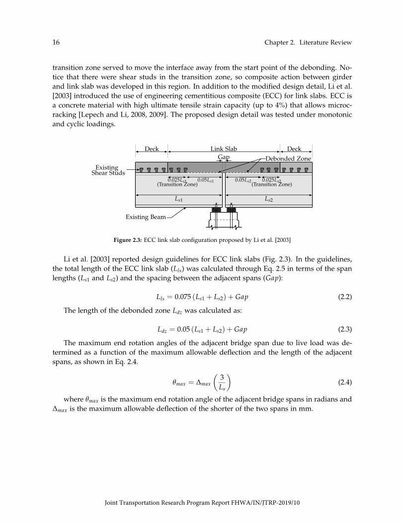
Li et al. [2003] proposed the detail show in Fig. 2.3 to address the interfacial cracking prob-lem of conventional link slabs, caused by high-stress concentrations at the interface betweenthe link slab and the existing concrete deck. As seen in Fig. 2.3, the proposed detail had atransition zone of 2.5% at each adjacent span in addition to the debonded zone of 5%. This
Joint Transportation Research Program Report FHWA/IN/JTRP-2019/10
16 Chapter 2. Literature Review
transition zone served to move the interface away from the start point of the debonding. No-tice that there were shear studs in the transition zone, so composite action between girderand link slab was developed in this region. In addition to the modified design detail, Li et al.[2003] introduced the use of engineering cementitious composite (ECC) for link slabs. ECC isa concrete material with high ultimate tensile strain capacity (up to 4%) that allows microc-racking [Lepech and Li, 2008, 2009]. The proposed design detail was tested under monotonicand cyclic loadings.
Existing Beam
0.05Ls1 0.05Ls20.025Ls1 0.025Ls2(Transition Zone) (Transition Zone)
Debonded ZoneGap
Ls1 Ls2
Deck Link Slab Deck
ExistingShear Studs
Figure 2.3: ECC link slab configuration proposed by Li et al. [2003]
Li et al. [2003] reported design guidelines for ECC link slabs (Fig. 2.3). In the guidelines,the total length of the ECC link slab (Lls) was calculated through Eq. 2.5 in terms of the spanlengths (Ls1 and Ls2) and the spacing between the adjacent spans (Gap):
Lls = 0.075 (Ls1 + Ls2) + Gap (2.2)
The length of the debonded zone Ldz was calculated as:
Ldz = 0.05 (Ls1 + Ls2) + Gap (2.3)
The maximum end rotation angles of the adjacent bridge span due to live load was de-termined as a function of the maximum allowable deflection and the length of the adjacentspans, as shown in Eq. 2.4.
θmax = ∆max3Ls
( )(2.4)
where θmax is the maximum end rotation angle of the adjacent bridge spans in radians and∆max is the maximum allowable deflection of the shorter of the two spans in mm.
Joint Transportation Research Program Report FHWA/IN/JTRP-2019/10

2.2. Previous Research on Link Slabs 17
2.2.2.2 Aktan et al.
Aktan et al. [2008] performed a field inspection of eight bridges in Michigan to determine theperformance of link slabs and other bridge components such as approach slabs, sleeper slabs,backwalls and bearings. All the inspected link slabs were designed based on the proceduredescribed by Caner and Zia [1998]. The design detail of the link slab is shown in Fig. 2.4Notice from the detail that the bottom layer of the reinforcement was discontinuous. Themain problems reported in the survey indicated the existence of full-depth transverse cracksof significant width at the centerline on the typical link slabs. The cracking was attributed topoor construction practices including insufficient placement of the longitudinal steel, lack ofa pour sequence, and untimely saw cut.
Aktan et al. [2008] performed a 3D finite element model analysis to investigate factorsaffecting jointless bridge deck cracking. The model represented an existing bridge, and it
Li et al. [2003] found that the stress in the reinforcement is not a suitable criterion to de-termine the required reinforcement ratio in the link slabs. The authors stated that the use ofan uncracked section for the calculation of the applied moment value in the link slabs leadsto an overestimation of the required amount of longitudinal reinforcement to satisfy the limitstress criterion. Therefore, the design method by Li et al. [2003] calculates the amount of steelreinforcement in the link slab based on the moment capacity of the section. A non-linear sec-tional analysis is used for the calculation of the moment capacity assuming that ECC materialremains perfectly elastic-plastic in service. Conservative working stress of 40% of the yieldstrength of the steel reinforcement was used for design.
In a later study, Li et al. [2005] performed the field demonstration of the improved designdetail shown in Fig. 2.3 in a bridge in Michigan. Cracking was observed three days afterplacement and before curing was completed. Several cracks developed within the link slab.The cracks were 0.005 in. to 0.014 in wide and spaced approximately 8 in. They tended tooriginate from the steel bars and propagate radially outward. The most severe cracking wasobserved around the rebar which protrude out of the link slab surface to be cast into the side-walk. The cracking was attributed to temperature gradients, shrinkage stresses, or too muchwater loss at early ages.
Li et al. [2008] concluded that causes of the early age cracking could be low water-to-cement ratio, low-retarder-to-cement ratio, use of gravity-based mixer, high curing tempera-ture, low curing relative humidity, wind effect, rebar as stress concentrator, and skew angle. Itwas recommended limiting the angle of skew angle to 25◦, nightime casting, and water curingfor at least 7 days.
Joint Transportation Research Program Report FHWA/IN/JTRP-2019/10

18 Chapter 2. Literature Review
Figure 2.4: Link slab detail used in Michigan [Aktan et al., 2008]
consisted of a single girder, two 834 in spans, and 9 in thick concrete deck. The compressivestrength for girder and deck was 5000 psi. Link slabs were modeled with the bottom reinforce-ment discontinued over the pier centerline. The design parameters investigated were supportconditions, debonded length, girder height, and adjacent span length ratios. Three differentsupport conditions were examined: HRRR, RHHR, and RRHR. Debonded length was variedas 0%, 2.5%, 5.0%, and 7.5% of the span length. The two standard PCI sections examined wereType III and Type VI. The effect of having unequal span lengths was investigated by increasingthe second span from 69.5 ft to 91 ft. The total length of the link slab was also increased from85 in to 98 in. The models were subjected to both live HL-93 and thermal loads for Zone 3, asspecified by AASHTO [2017]. Straight and 20◦ skew two-span multi girder full-width modelswere developed for investigating load demand on link slabs and addressing additional issuesfrom link slab torsion and twist that arise due to symmetric loading of single- and two-lanebridges.
Based on the analysis results, it was concluded that cracks on the link slabs were causedby thermal hydration and drying shrinkage stresses. It was observed that support conditionsgreatly influenced the behavior of link slabs. The link slabs were subjected to combined axialforce and moment with RHHR support configuration. The analysis also showed that dryingand thermal hydration shrinkage strains can generate cracks of which the width matched theexpected magnitude under a live load. The authors recommended to include the additionalmoment and axial force resulted from thermal gradient loads into the link slab design. Anew method for the analysis of link slabs was proposed that involved the use of an axial loadversus moment interaction diagram for those specific support configurations in which the link
Joint Transportation Research Program Report FHWA/IN/JTRP-2019/10
2.2. Previous Research on Link Slabs 19
slabs were subjected to combined flexural and axial loads. Full-bridge link slab assemblagemodels revealed that torsional moment increased in link slabs of skew bridges irrespective ofsupport conditions. The study recommended controlling cracking through the developmentof new cementitious materials. It was also suggested the use of continuous top and bottomreinforcements irrespective of support conditions as well as a saw cuts directly over the piercenterline and at each side of link slab to control cracking [Ulku et al., 2009].
2.2.2.3 Aktan and Attanayake
Aktan et al. [2008] proposed a design method based on the analysis of two-span bridge mod-els with zero skew angle and subjected to live and thermal loads. Aktan and Attanayake[2011] then modified the procedure to incorporate the effects of the angle of skew on thelink-slab moments. The investigation included finite element modeling of skew link slabssubjected to static truck-load and thermal gradients as well as field assessment of a skewedbridge. The influence of different bearing configurations on the link slab moment and forceresultants was also examined. Design recommendations were developed for the utilization oflink slabs in high skew bridges. The study determined that moment generated in a link slabunder temperature gradient loads remained constant irrespective of the span. It was observedthat the moment developed in a link slab under live load decreased with increased span. Theresearchers found the minimum reinforcement amount required by AASHTO specificationsto be adequate for skew link slabs at specific support configurations (i.e., HRRR or RRHR).Additional reinforcement at the bottom layer was suggested to resist large tensile stresses thatdevelop near the boundaries of the debonded region. It was also recommended a construc-tion joint at the limit of debonded and fully bonded zones. Bridge deflections and bearingtranslations were measured under static truck as well as thermal loads.
2.2.3 Virginia Department of Transportation (VDOT)
2.2.3.1 Ozyildirim et al.
Ozyildirim et al. [2017] evaluated the performance of different types of concrete materialsat eight rehabilitated joints using link slabs. Two of the link slabs were constructed usingrapid-set cement and latex modified concrete (LMC). The other six link slabs were built usinglow-permeability fiber reinforced concrete (FRC) with various class of fibers. The three typesof fibers used were polivynil alcohol, polypropylene, and steel. All concrete mixtures weredesigned to have a compressive strength of 3000 psi after 24 hours. Bridge surveys wereconducted to assess the performance of the materials, based on the observed cracking. Amaximum permissible crack with of 0.004 in. was established for resisting water penetration.The study reported low shrinkage and wider cracks using rapid-set cement with LMC. The
Joint Transportation Research Program Report FHWA/IN/JTRP-2019/10

20 Chapter 2. Literature Review
crack widths ranged from 0.004 in. to 0.016 in. All FRC mixtures showed high shrinkage andcracks widths less than 0.004 in. Further research was recommended to reduce shrinkage inthe FRC mixtures with polypropylene or steel fibers due to their satisfactory performance.
2.2.3.2 Hoomes et al.
Hoomes et al. [2017] evaluated the mechanical properties and performance of high-performancefiber reinforced concrete (HPFRC). The different HPFRC mixtures investigated were: ECC,hybrid fiber-reinforced concrete (HyFRC) with steel and synthetic fibers, HyFRC with onlysynthetic fibers, and UHPC with steel fibers. Different tests were carried out in the freshconcrete such as air content, density, slump cone, mini-slump flow, and inverted slump cone.Tests on hardened concrete tests were conducted to determine compressive, flexural, and bondstrengths. Shrinkage was also evaluated in different mixtures. According to the authors, ECCand UHPC mixes were self-consolidating and workable. HyFRC mixtures were workable butrequired consolidation. Fibers in ECC and HyFRC were well disbursed, but not for the UHPCsamples. It was observed that for the UHPC mix, the fibers settled at the bottom. All concretemixes, except UHPC, showed deflection hardening. This fact was attributed to the settlementof the fibers. The authors concluded that HyFRC with synthetic fibers provided the most eco-nomical solution for crack control and bond strength. A further field application using thismaterial was recommended.
2.2.4 New York State Department of Transportation (NYSDOT)
2.2.4.1 Royce
Royce [2016] presented several case studies in his paper on the utilization of ultra-high perfor-mance concrete (UHPC) in the State of New York. He provided the history of the developmentof the field-cast UHPC among precast elements along with the lessons learned in each of thesecase studies with little emphasis on the link slabs. He stated some of the most important fac-tors for the success of these joints. He mentioned that tight leak-free formworks were essentialduring the construction to ensure the strength of these joints. Moreover, careful storage of thepremix powder was needed to prevent moisture from creating silica balls of the powder re-sulting in inefficient mix. In addition, the application of heat for several hours in the curingof the joint would result in a desirable speed in strength gain. He noted that the utilization ofthe UHPC was advantageous in terms of the gained speed of construction.
The author dedicated a small section about the use of the UHPC in link slab constructionin New York. He claimed that UHPC was able to accommodate girder end rotations as theUHPC could develop ultimate tensile strains up to 0.0007. The NYSDOT link slabs designshave been effective as no visible cracks were reported on the link slabs constructed. However,
Joint Transportation Research Program Report FHWA/IN/JTRP-2019/10

2.2. Previous Research on Link Slabs 21
he stated that proper design was crucial as there were several factors affecting the perfor-mance of the link slab. He noted, also, that a faulty link slab design, might not only result incracks on the link slab but also structural deterioration of other bridge components.
Fig. 2.5 shows an example of a design detail implemented by NYSDOT. It corresponds toa partial-depth cast-in-place link slab. This connection detail was implemented to rehabilitatethe SR962G bridge over US Route 17 in Owego, New York. The bridge rehabilitation projectinvolved the use of precast concrete deck panels. The filler material used in the connectionwas UHPC [Graybeal, 2014].
Figure 2.5: UHPC link slab detail [Graybeal, 2014]
2.2.5 Hawaii Department of Transportation (HDOT)
2.2.5.1 Reyes and Robertson
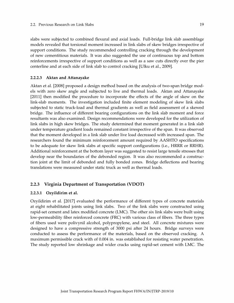
Reyes and Robertson [2011] introduced precast link slab details using high performance fiberreinforced cementitious composite (HPFRCC) reinforced with glass fiber reinforced polymer(GFRP). The proposed link slab was a thin slab of thickness less than the deck slab. Thestudy utilized full scale experimental test of three specimens of full scale expansion joints thatincluded part of the adjacent steel girders, as shown in Fig. 2.6. The girders in the test wereloaded statically for cycles of loads to simulate the traffic load and ensure the elastic responseof the detail. The first specimen tested was a cast-in-place link slab. Although this specimenshowed better continuity at the connection between the link slab and the deck compared to theother two specimens, it showed lower compressive strength capacity. The other two specimenswere pre-cracked precast link slabs connected to the deck slab via anchors/dowels. Theauthors argued that the precast slabs were advantageous as precracking was possible givingthe link slab more ductility and increasing the effectiveness of the slab in compression. A
Joint Transportation Research Program Report FHWA/IN/JTRP-2019/10
22 Chapter 2. Literature Review
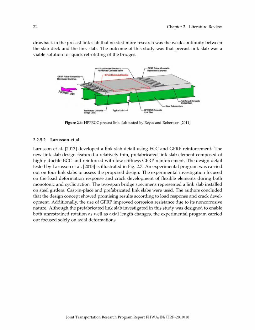
drawback in the precast link slab that needed more research was the weak continuity betweenthe slab deck and the link slab. The outcome of this study was that precast link slab was aviable solution for quick retrofitting of the bridges.
Figure 2.6: HPFRCC precast link slab tested by Reyes and Robertson [2011]
2.2.5.2 Larusson et al.
Larusson et al. [2013] developed a link slab detail using ECC and GFRP reinforcement. Thenew link slab design featured a relatively thin, prefabricated link slab element composed ofhighly ductile ECC and reinforced with low stiffness GFRP reinforcement. The design detailtested by Larusson et al. [2013] is illustrated in Fig. 2.7. An experimental program was carriedout on four link slabs to assess the proposed design. The experimental investigation focusedon the load deformation response and crack development of flexible elements during bothmonotonic and cyclic action. The two-span bridge specimens represented a link slab installedon steel girders. Cast-in-place and prefabricated link slabs were used. The authors concludedthat the design concept showed promising results according to load response and crack devel-opment. Additionally, the use of GFRP improved corrosion resistance due to its noncorrosivenature. Although the prefabricated link slab investigated in this study was designed to enableboth unrestrained rotation as well as axial length changes, the experimental program carriedout focused solely on axial deformations.
Joint Transportation Research Program Report FHWA/IN/JTRP-2019/10

2.2. Previous Research on Link Slabs 23
Existing Beam
1.64 f t. 1.64 f t.(Transition Zone) (Transition Zone)
1 in.
Ls1 Ls2
0.05Ls1 = 3.28 f t.(Debonded Zone)
3 in.ExistingShear Studs
Figure 2.7: GFRP link slab detail
2.2.6 Louisiana Department of Transportation (LaDOTD)
2.2.6.1 Li and Saber
Li and Saber [2009] investigated experimentally and numerically the use of corrosion resis-tant FRP grid reinforcement in developing durable ductile link slabs in jointless bridges. Theexperimental program presented by them included material testing to identify the variousmaterial properties such as modulus of elasticity, Poisson’s ratio, and coefficient of thermalexpansion, specimen testing via 3-point flexure test on FRP reinforced slabs to evaluate thecomposite behavior in bending, and full-scale beam testing to evaluate link slab performanceunder dead and live loads. The tested link slab detail was a debonded link slab with addedtwo FRP grid reinforcements 1 in apart of 1 in thickness slightly below the mid of the sectionas shown in Fig. 2.8.
Figure 2.8: Full-scale beam testing setup as presented by Li and Saber [2009]
Joint Transportation Research Program Report FHWA/IN/JTRP-2019/10

24 Chapter 2. Literature Review
The numerical analysis presented in the study is a finite element analysis on a three-span bridge under dead and live loads. The link slab modeled in the analysis was a FRPgrid reinforced debonded link slab. The study showed that although the lab-manufacturedFRP had higher ultimate strength, the commercial FRP exhibited more deflection, which wasfavorable for link slabs. The study, also, concluded from both analyses that the commercialFRP reinforced link slab significantly reduced the stresses in both the girders and the slabs asit provided high ductility to the slab. The proposed slab showed advantageous reduction inthe shrinkage and the thermal coefficients compared to the conventional reinforcement.
2.2.7 Ministry of Transportation of Ontario (MTO)
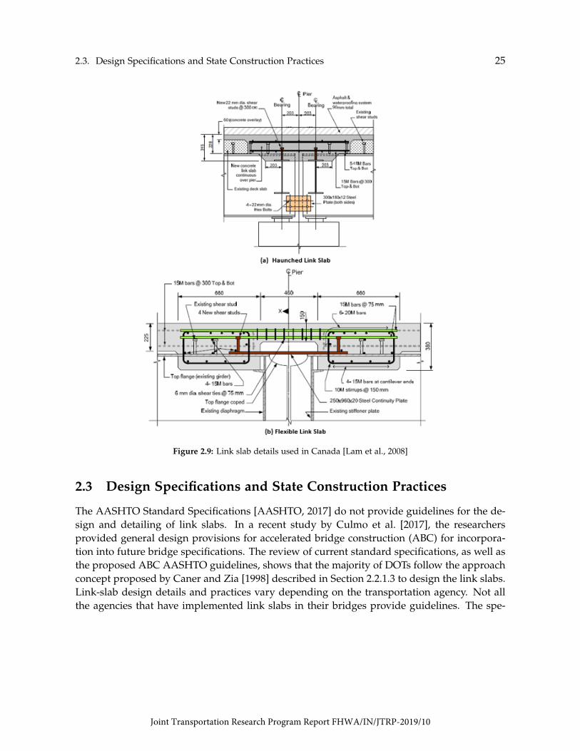
Ontario is one of the provinces of Canada that most implement link slabs in their bridges.Research conducted by Lam et al. [2008] and Lam [2011] documented different design detailsused by the Ministry of Transportation of Ontario (MTO). Lam [2011] reported three differ-ent link-slab configurations: haunched, flexible, and debonded. The haunched and flexibleconfigurations were used for deck rehabilitation during the early 1990s. Lam [2011] indicatedthat it has been discontinued the use of these details because of their high costs as well aslimitations in the girder end-rotations and girder depth. Both details are shown in Fig. 2.9and their full description can be found in Lam et al. [2008]; Lam [2011].
Au et al. [2013] introduced an adjustment factor for the link-slab moment equation (Eq. 2.1).According to the researchers, Eq. 2.1 did not account for the compatibility of displacement be-tween the link slabs and the supporting girders properly. Au et al. [2013] observed unrealisticdeformation patterns when three-dimensional analyses were conducted. The revised momentdemand by Au et al. [2013] is given by Eq. 2.5:
Ma =2Ec Ils
LlsθgαR (2.5)
The adjustment factor αR in Eq. 2.5 is given as a function of the distance between adjacentsimple supports at the pier location (Gap), as follows:
αR =4(
1 + 3GapLls
) (2.6)
Joint Transportation Research Program Report FHWA/IN/JTRP-2019/10
2.3. Design Specifications and State Construction Practices 25
Figure 2.9: Link slab details used in Canada [Lam et al., 2008]
2.3 Design Specifications and State Construction Practices
The AASHTO Standard Specifications [AASHTO, 2017] do not provide guidelines for the de-sign and detailing of link slabs. In a recent study by Culmo et al. [2017], the researchersprovided general design provisions for accelerated bridge construction (ABC) for incorpora-tion into future bridge specifications. The review of current standard specifications, as well asthe proposed ABC AASHTO guidelines, shows that the majority of DOTs follow the approachconcept proposed by Caner and Zia [1998] described in Section 2.2.1.3 to design the link slabs.Link-slab design details and practices vary depending on the transportation agency. Not allthe agencies that have implemented link slabs in their bridges provide guidelines. The spe-
Joint Transportation Research Program Report FHWA/IN/JTRP-2019/10
26 Chapter 2. Literature Review
cific standard provisions available for the design of link slabs, design details, and practicesin the states of North Carolina, Virginia, New York, Massachusetts, Florida, and Utah aresummarized below.
2.3.0.1 North Carolina
Section 8.2 of North Carolina Structures Management Unit Manual [NCDOT, 2018] recom-mends the use of link slabs for deck joint elimination on simple span superstructures. Section6.2.2.4 of the same design manual states that link slabs shall be used for replacing the ex-pansion joints over piers in bridges with span lengths not exceeding 75 ft. Both prestressedconcrete girders (AASHTO Type II and III) and steel beams are the type of cross sections re-quired by the specifications.
Current practice in North Carolina includes the use of full-depth link slabs with saw cutsat the center of the link slab. These saw cuts of 1.5 in deep are usually filled with a joint sealermaterial that is a low modulus silicone sealant. In addition, it is recommended the use ofClass AA Concrete (4500 psi), two layers of epoxy continuous steel longitudinal reinforcementwithin the link slab, and transverse construction joints located at the limits of the link slab(Fig. 2.2). No welding of forms of falsework to the top of girder are permitted in the link slabarea.
2.3.0.2 Virginia
Section 412.03 of the Virginia Standard Specifications [VDOT, 2016a] addresses the repairingprocess of bridge decks at piers using link slabs. It states, "Deck Slab Closure shall consist ofrepairing bridge decks for link slabs at piers and deck extensions at abutments in accordance with theplan details and the requirements herein. This work shall consist of removing and disposing of existingconcrete and any existing joint armor, removing and disposing of stud shear connectors within thelimits of the slab closure for steel beams/girders, removing and disposing of stirrup bars within thelimits of the slab closure for concrete beams/girders, repairing or replacing existing reinforcing steel asmay be required by the work described in this Section, preparing the contact surfaces, furnishing andplacing expanded polystyrene, and furnishing and placing new reinforcing steel and concrete in accor-dance with the details and requirements herein. Exposed undamaged existing reinforcing steel shall beabrasive blast cleaned and reused. The contractor shall develop a sequence of construction for deck slabclosures to be used in conjunction with other related work items (bearing modifications, etc.) whichshall be submitted to the Engineer for review prior to performing the work. The cost of preparing thesequence of construction shall be included in the price for deck slab closure."
The Virginia Manual for Bridge Element Inspection [VDOT, 2016b] states the different de-fects that shall be inspected in the link slabs, such as concrete delamination, spalls, patched
Joint Transportation Research Program Report FHWA/IN/JTRP-2019/10

2.3. Design Specifications and State Construction Practices 27
area, exposed rebar, efflorescence, rust staining, cracking, abrasion, leakage, and severe dam-age caused by impact. The manual establishes a link slab in good condition if none of theprevious defects are observed and if the cracks are less than 0.012 in in width or spacing morethan 36 in. No abrasion or wearing is permitted. Link slabs are defined as element 843 in themanual that defines joint closures constructed at piers. Slab extension is the element 844 thatdefines joint closures constructed at abutments.
Section 32.09 of the Manual of the Structure and Bridge Division [VDOT, 2018] addressesthe guidelines for bridge deck joint elimination. The manual states that link slabs should beused together with concrete overlays to provide additional protection over the cold joint be-tween the existing deck and the link slab or deck extension. The overlays should be placedafter the completion of the link slabs. For projects involving hydromilling, the placement ofthe link slabs before to hydromilling is recommended for convenience in handling the waterproduced during the process. The manual establishes a state goal of eliminating 2% of theexpansion joints in each District per fiscal year.
The VDOT bridge manual specifies the use of flexible link slabs on existing bridges inwhich the existing deck is not replaced or on new decks where the superstructure is notreplaced. It is also recommended, once the link slabs are installed, the structural designchecking of existing bridge elements as bearings, piers, and remaining joints. The bridgemanual states that jointless bridges with link slabs and spans less than 120 ft do not requireanalysis if meet the following requirements:
1. Compressive strength of concrete in link slab is equal or greater than 4000 psi.
2. Longitudinal reinforcing steel from existing concrete deck is spliced to reinforcement in link slabthrough lap splice or mechanical coupler; spacing not to exceed 12 in.
3. Transverse reinforcing steel is replaced and spliced, if necessary for staged construction.
4. Link slab length is 2 ft in either direction from the center-line.
5. Shear connectors are removed and a bond braking material is placed within the area of the linkslab
The Virginia standard detail for the link slabs is shown in Fig. 2.10. This detail is allowedto be used for a maximum bridge span length of 100 ft. In addition, it is required that both ofthe adjacent bearings supporting the beams at the joint allow horizontal movement. The useof elastomeric expansion bearings is encouraged as they help transfer longitudinal forces tothe substructure and minimize the redistribution of loads due to changing fixed/expansionbearing relationships. Concrete materials for the construction of link slabs must be LowShrinkage Class A4 Modified Concrete 4000 psi.
Joint Transportation Research Program Report FHWA/IN/JTRP-2019/10

28 Chapter 2. Literature Review
Figure 2.10: VDOT link slab detail [VDOT, 2018]
2.3.0.3 New York
The New York State Bridge Manual [NYSDOT, 2018] defines the link Slabs as:
"A concrete link slab is a relatively thin reinforced concrete slab or UHPC slab that typically con-nects simply supported deck spans. It is designed to flex due to girder deflections and transmit com-pressive and tensile forces through the deck in conjunction with appropriately designed bearings."
Article 19.7.1 of the New York state Bridge Manual addresses the general design consid-erations for joint elimination. For projects with full deck replacement, conventional link slab(CIP decks) or UHPC link slab (precast decks) is the priority for joint removal at intermediatesupports. For projects with deck retention, it is recommended only to use UHPC link-slabs.The UHPC link-slab detail is shown in Fig. 2.11. Section 5.2 of the manual addresses thejointless deck analysis and design. Article 5.2.3 specifically discusses jointless decks at piers.Article 12.2.8 says that the design and detailing of bearings for bridges with link slabs is com-plex and shall be accomplished together with the Office of Structures of the state.
The NYSDOT [2018] bridge manual requires a bond breaker along the top flange at theends of the girders near the pier to allow the slab to flex independently of the girder, reducingthe negative bending moment in the slab. A contraction joint shall be provided in any concrete
Joint Transportation Research Program Report FHWA/IN/JTRP-2019/10

2.3. Design Specifications and State Construction Practices 29
pour over the link slab location (barrier, sidewalk, curb, etc.). Link slabs are designed toflex with girder deflections as well as to transmit compressive and tensile loads between thespans. The design is influenced by, but not limited to, span arrangement, bearing type andarrangement, girder end rotation due to live load, bridge skew, and girder depth.
Figure 2.11: NYSDOT link slab detail [NYSDOT, 2018]
2.3.0.4 Massachusetts
Article 3.5.2.5 of the Massachusetts LRFD Bridge Manual [MassDOT, 2013] addresses the linkslab design provisions. A general procedure for the design of link slabs can be summarizedas follows:
1. Design adjacent spans as simply supported neglecting the proposed link slab.
2. Determine the length of the link slab using approximately 5% to 7% of each span length. Thelink slab requires debonding from the girder and thus no shear stud connectors shall be provided.
3. Determine the end rotations of the girders from the beam design under service (unfactored) liveloads. If the software used does not provide end rotations, the end rotations can be determinedusing the midspan deflections. The end rotation may be estimated as equal to 3.2∆LL/L.
4. Calculate the negative moment in the link slab due to service load rotations, Ma, using the grosssection properties of the link slab. Calculate cracking moment of link slab, Mcr [Article 5.7.3.6.2-2 AASHTO [2017]]. If Ma > Mcr, then cracks can be expected in the link slab and additionalreinforcement is required.
Joint Transportation Research Program Report FHWA/IN/JTRP-2019/10

30 Chapter 2. Literature Review
5. Design the reinforcement for the link slab to resist the applied moment using working stressmethods and check the control of cracking criteria per Article 5.7.3.4 AASHTO [2017]. Use γe,of 0.75 for Class 2 exposure condition. The tensile stress in the reinforcement, fss, shall not exceed0.4 fy.
2.3.0.5 Florida
Section 8.7 of Florida Structures Design and Detailing Manual [FDOT, 2018] addresses theprovisions for elimination of deck expansion joints. Article 8.7.2 states the provisions forcontinuous deck over simple span piers (i.e., link slabs). The debonded zone at each spanis determined as Ls/20, where Ls is the span length. Moment demand in the link slabs iscalculated following the design methodology proposed by Caner and Zia [1998] for bridgeswith span-length less than 100 ft. Detailed analysis is required for computing girder endrotations in longer bridges.
2.3.0.6 Utah
Article 21.5.2.5 of Utah Structures Design and Detailing Manual UDOT [2017] states the fol-lowing about the use of link slabs:
"Use link slabs to eliminate joints between simple spans where integral diaphragms are not feasible.A link slab is constructed by removing the joint and several feet of deck on each side of the joint, andreplacing the joint with a concrete slab that is not bonded to the girder. The treatment can eliminate theleaking joint and minimize repair costs and impacts."
Table 2.2 summarizes the above mentioned information regarding state practices.
Table 2.2: Summary of state practices
PracticeState
North Carolina Virginia New York Massachussets Florida UtahMax. span length 75 ft 100 ft NA NA 100 ft NA
Beam cross sectionAASHTO Type II and III
and steel girdersPC and steel girders NA NA NA NA
Max. skew angle NA NA 30 NA NA NA
Concrete type Class AA Concrete (4.5ksi)Low Shrinkage Class A4
UHPC (21 ksi) NAModified Concrete (4 ksi)
NA NA
Link slab configuration Full-depth Full-depth Partial-depth Full-depth Full-depth Full-depthDebonded length 5% of each span 2 ft of each span 2-3 ft of each span 5-7% of each span Ls/20 NA
Do not use two lines
Bearing types Elastomeric bearingsOne bearing must allow of fixed bearings
NAhorizontal movement Do not use with steel rocker
NA NA
or steel sliding bearingsDesign criteria Live load girder end rotations and AASHTO crack width criteria
Curing wet curing 7 daysNote: NA = Not Available.
Joint Transportation Research Program Report FHWA/IN/JTRP-2019/10
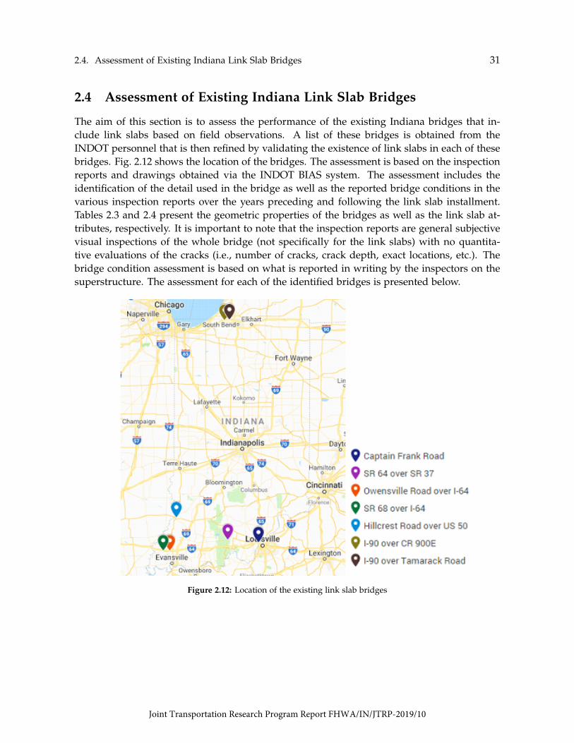
2.4. Assessment of Existing Indiana Link Slab Bridges 31
2.4 Assessment of Existing Indiana Link Slab Bridges
The aim of this section is to assess the performance of the existing Indiana bridges that in-clude link slabs based on field observations. A list of these bridges is obtained from theINDOT personnel that is then refined by validating the existence of link slabs in each of thesebridges. Fig. 2.12 shows the location of the bridges. The assessment is based on the inspectionreports and drawings obtained via the INDOT BIAS system. The assessment includes theidentification of the detail used in the bridge as well as the reported bridge conditions in thevarious inspection reports over the years preceding and following the link slab installment.Tables 2.3 and 2.4 present the geometric properties of the bridges as well as the link slab at-tributes, respectively. It is important to note that the inspection reports are general subjectivevisual inspections of the whole bridge (not specifically for the link slabs) with no quantita-tive evaluations of the cracks (i.e., number of cracks, crack depth, exact locations, etc.). Thebridge condition assessment is based on what is reported in writing by the inspectors on thesuperstructure. The assessment for each of the identified bridges is presented below.
Figure 2.12: Location of the existing link slab bridges
Joint Transportation Research Program Report FHWA/IN/JTRP-2019/10

32 Chapter 2. Literature Review
Table 2.3: Summary of geometric properties of Indiana link slab bridges
BridgeYearBuilt
GirderType
StructureType
Numberof Spans
Max. SpanLength [ft]
TotalLength [ft]
Captain Frank 1965 Prestressed Concrete Multi-beam 3 50 120SR64/SR37 1956 Concrete Multi-beam 5 41 181
Owensville 1966 Concrete/SteelContinuous
Steel/Multi-beam Concrete4 60 200
SR68/I64 1966 Concrete/SteelContinuous
Steel/Multi-beam Concrete4 68 223
Hillcrest/US50 1961 Concrete/SteelContinuous
Steel/Multi-beam Concrete5 80 277
I90/CR900 1956 Steel Multi-beam 3 34 117I90/Tamarack 1956 Steel Multi-beam 3 35 113
Table 2.4: Summary of inspection reports of Indiana link slab bridges
BridgeLink Slab
RehabilitationLink Slab
TypeInspection
DateCrack
LocationCaptain Frank 1992 Haunched 2000-2017 Girders at supports
SR64/SR37 2016 Haunched 2006-2016 Link slabOwensville 2015 Haunched 2008-2018 Typ. girder flexural
Increased underside deckSR68/I64 2015 Haunched 2007-2018 cracking and spalling adjacent
to upper flangeHillcrest/US50 2017 Debonded 2007-2017 No cracking reported
Heavy map cracking of deck,I90/CR900 2013 Not Identified 2007-2017 deck spalling, significant leakage
at link slabI90/Tamarack 2013 Not Identified 2007-2017 Link slab
2.4.1 I-64 EB/WB over Captain Frank Road
The rehabilitation plans for this bridge dates back to 1992. The plans show the removal ofall intermediate expansion joints and the installment of link slabs. A design detail of the linkslabs is shown in Fig. 2.13. It can be observed that the link slab is a haunch type detail withno debonding provided.
No inspection has been reported before the link slab construction. Nine inspection reportsbetween 2000 to 2017 are available for this bridge. According to these reports, the bridge isexhibiting cracks and showing deterioration in both the deck and the supporting girders. Itis clear that there is consistent deterioration near the abutments as more than 10 beams areexperiencing this type of deterioration. However, due to the lack of inspection reports before
Joint Transportation Research Program Report FHWA/IN/JTRP-2019/10

2.4. Assessment of Existing Indiana Link Slab Bridges 33
Figure 2.13: Link slab detail (I-64 over Captain Frank)
the link slab installment or even reports in the early years following the installment, it is dif-ficult to attribute the deterioration to the link slab installment.
The last visual inspection to this bridge was conducted on November 6, 2017. Both east-bound and westbound were inspected. It was reported fair condition for both the superstruc-ture and the wearing surface. Satisfactory condition with minor deterioration was reportedfor the deck and substructure. The inspector did not provide any specific information aboutthe condition of the link slab.
2.4.2 SR 64 over SR 37
According to the inspection report, the bridge rehabilitation was performed in 2016. All ex-pansion joints over intermediate piers were eliminated using link slabs. A design detail ofthe link slabs is shown in Fig. 2.14. It can be seen from the figure that a 1 in haunch wasused at the end of the girders. In addition, an overlay of latex modified concrete (LMC) wasprovided on top of the slab. A gap of 1 in between the girders was used in all bents exceptin those located between the middle spans. A debonded zone for this particular link slab wasnot provided.
A total of six inspection reports are evaluated between the years 2006 till 2016. Five in-spection reports have been reported before the link slab construction, while only one existsafter the link slab construction just few months later. According to these reports the bridgeexhibited slow deteriorations, mostly described as typical, over the years preceding the in-stallment of the link slab. However, just few months after the rehabilitation cracks, thoughminor, started to occur in both the deck and the girders especially around the link slabs.
Joint Transportation Research Program Report FHWA/IN/JTRP-2019/10
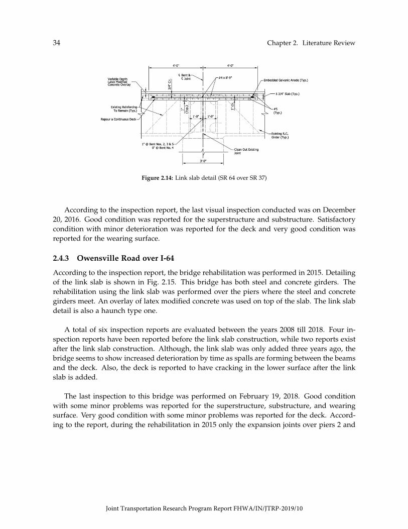
34 Chapter 2. Literature Review
Figure 2.14: Link slab detail (SR 64 over SR 37)
According to the inspection report, the last visual inspection conducted was on December20, 2016. Good condition was reported for the superstructure and substructure. Satisfactorycondition with minor deterioration was reported for the deck and very good condition wasreported for the wearing surface.
2.4.3 Owensville Road over I-64
According to the inspection report, the bridge rehabilitation was performed in 2015. Detailingof the link slab is shown in Fig. 2.15. This bridge has both steel and concrete girders. Therehabilitation using the link slab was performed over the piers where the steel and concretegirders meet. An overlay of latex modified concrete was used on top of the slab. The link slabdetail is also a haunch type one.
A total of six inspection reports are evaluated between the years 2008 till 2018. Four in-spection reports have been reported before the link slab construction, while two reports existafter the link slab construction. Although, the link slab was only added three years ago, thebridge seems to show increased deterioration by time as spalls are forming between the beamsand the deck. Also, the deck is reported to have cracking in the lower surface after the linkslab is added.
The last inspection to this bridge was performed on February 19, 2018. Good conditionwith some minor problems was reported for the superstructure, substructure, and wearingsurface. Very good condition with some minor problems was reported for the deck. Accord-ing to the report, during the rehabilitation in 2015 only the expansion joints over piers 2 and
Joint Transportation Research Program Report FHWA/IN/JTRP-2019/10

2.4. Assessment of Existing Indiana Link Slab Bridges 35
4 were replaced with link slab. No joint was ever present over pier 3.
Figure 2.15: Link slab detail (Owensville Road over I-64)
2.4.4 SR-68 over I-64
According to the inspection report, the bridge rehabilitation was performed in 2015. Detailingof the link slab is shown in Fig. 2.16. This bridge consists of two intermediate continuous steelspans and two outer concrete spans. The rehabilitation eliminated the expansion joint at theconnection between the steel and concrete spans using haunch type link slabs.
A total of seven inspection reports are evaluated between the years 2007 till 2018. Fiveinspection reports have been documented before the link slab construction, while two reportsexist after the link slab construction. According to the inspection reports, the bridge was ex-periencing increased joint leakage over the years, which is eliminated now after the link slabinstallment. Furthermore, the link slab seemed to have no effect on the concrete girders. On
Joint Transportation Research Program Report FHWA/IN/JTRP-2019/10
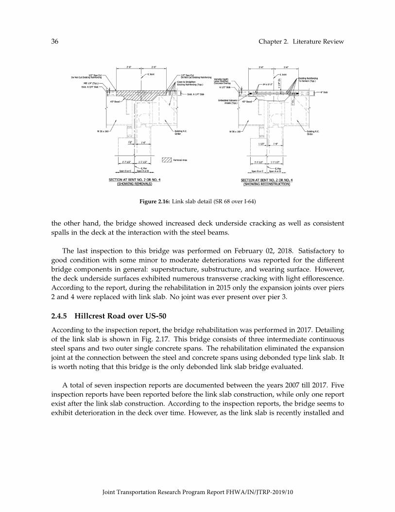
36 Chapter 2. Literature Review
Figure 2.16: Link slab detail (SR 68 over I-64)
the other hand, the bridge showed increased deck underside cracking as well as consistentspalls in the deck at the interaction with the steel beams.
The last inspection to this bridge was performed on February 02, 2018. Satisfactory togood condition with some minor to moderate deteriorations was reported for the differentbridge components in general: superstructure, substructure, and wearing surface. However,the deck underside surfaces exhibited numerous transverse cracking with light efflorescence.According to the report, during the rehabilitation in 2015 only the expansion joints over piers2 and 4 were replaced with link slab. No joint was ever present over pier 3.
2.4.5 Hillcrest Road over US-50
According to the inspection report, the bridge rehabilitation was performed in 2017. Detailingof the link slab is shown in Fig. 2.17. This bridge consists of three intermediate continuoussteel spans and two outer single concrete spans. The rehabilitation eliminated the expansionjoint at the connection between the steel and concrete spans using debonded type link slab. Itis worth noting that this bridge is the only debonded link slab bridge evaluated.
A total of seven inspection reports are documented between the years 2007 till 2017. Fiveinspection reports have been reported before the link slab construction, while only one reportexist after the link slab construction. According to the inspection reports, the bridge seems toexhibit deterioration in the deck over time. However, as the link slab is recently installed and
Joint Transportation Research Program Report FHWA/IN/JTRP-2019/10

2.4. Assessment of Existing Indiana Link Slab Bridges 37
Figure 2.17: Link slab detail (Hillcrest Road over US-50)
there are not enough inspection reports after the link slab installment, it is difficult to assessthe performance of the link slab.
The last inspection to this bridge was performed on November 01, 2018. Good conditionwas reported for both the superstructure and substructure, while satisfactory condition withminor deterioration is reported for the deck. The wearing surface is reported to be in excellentcondition as the rehabilitation included changing the wearing surface. According to the report,during the rehabilitation in 2017 only the expansion joints over piers 2 and 5 were replacedwith debonded link slab. No expansion joints were ever present over piers 3 and 4.
2.4.6 Summary of Inspection Reports
The detail for most of the link slabs identified in Indiana differ substantially than those inother states. The Indiana detail provides fully continuous deck that is achieved by havinga continuous reinforcement through the bridge deck and the link slab. The concrete in thebridge deck near the expansion joints is removed to only leave the reinforcement in the sec-tion. The objective, then, is to have the link slab reinforcement going through the deck andbeing connected to the old reinforcement. Finally, the concrete is poured in the link slab andthe bridge deck where the concrete was previously removed. The other important feature inthe widely used detail in the state of Indiana is that no debonding is provided between thegirders and the link slab. Consequently, the detail ensures the composite action between the
Joint Transportation Research Program Report FHWA/IN/JTRP-2019/10

38 Chapter 2. Literature Review
Figure 2.18: Cracking in Indiana link slab bridges as reported in inspection reports
girders and the deck through the fully bonded connection. It is important to note that onlyone bridge in the study is found to have a debonded link slab detail and that all link slabsstudied are composed of normal strength concrete.
Although the assessment of the Indiana link slab bridges is based on a small number ofbridges with no detailed scientific testing of these bridges, cracking of the bridges is observedin the inspection reports that can be attributed to the link slab construction. The crackingpatterns reported in the inspection reports vary across the bridges ranging from shear crackingat the supports to cracking in the link slab causing leakage as shown in Fig. 2.18. Therefore,it is essential to assess the link slabs performance further and obtain more scientific dataabout the bridge conditions after the link slabs construction. However, most of the bridgesreported transverse cracking in the bridge deck in the vicinity of the link slabs within thefirst year after the link slab construction. This observation is very dominant in the deck when
Joint Transportation Research Program Report FHWA/IN/JTRP-2019/10

2.5. Summary of the Literature and Practice Review 39
supported by steel girders. This observation is further investigated to identify its cause insubsequent chapters.
2.5 Summary of the Literature and Practice Review
Table 2.5 summarizes the literature presented in this synthesis. It can be seen from the tablethat link slabs are used mainly for rehabilitation purposes using steel bridge superstructure.Notice that the table specifies the type of link slab (i.e., haunched, flexible, and debonded)and the design detail used (i.e., details proposed by Caner and Zia [1998],Li et al. [2003], andLarusson et al. [2013]). Further, the research studies are classified into three major categories:experimental, analytical, and field work.
Table 2.5: Literature summary
Author Research ObjectiveType ofProject
GirderMaterial
ConnectionDetail
FEAnalysis
LaboratoryTesting
FieldTesting
Gastal [1986]El-Safty [1994]Caner and Zia [1998]Caner et al. [2002]Li et al. [2003]Li et al. [2005]Wing and Kowalsky [2005]Okeil and El-Safty [2005]Li et al. [2008]Lam et al. [2008]Sevgili and Caner [2009]Ulku et al. [2009]Li and Saber [2009]Aktan and Attanayake [2011]Reyes and Robertson [2011]Larusson et al. [2013]Au et al. [2013]
Ozyldirim et al. [2017]
Fu and Zhu [2017]
Zheng et al. [2018]
Hou et al. [2018]
Develop FE program for continuous deck analysisDetermine optimum LS debonded length
Investigate behavior of LSInvestigate LS seismic performanceInvestigate ECC application on LSInvestigate performance of ECC LS
Assess LS performancePropose method for LS flexural anlalysis
Investigate causes of ECC LS crackingDiscuss LS used by the MTO
Investigate of skew on LS seismic responseInvestigate LS behavior using FEInvestigate the use of FRP in LSInvestigate effect of skew on LS
Development LS with HPFRCC and GFRPDevelopment LS with HPFRCC and GFRP
Investigate LS long-term performanceInvestigate low-permeability FRCs with
different types of fibersInvestigate ECC mixtures for LS
Investigate behavior of LS with ECC andFRP reinforcement
Investigate LS fatigue performanceusing UHDCC
Rehabilitation/NewRehabilitationRehabilitationRehabilitationRehabilitationRehabilitationRehabilitationRehabilitationRehabilitationRehabilitationRehabilitationRehabilitationRehabilitationRehabilitationRehabiliationRehabilitationRehabilitation
Rehabilitation
Rehabilitation
Rehabilitation
Rehabilitation
Steel/ConcreteSteel/ConcreteSteel/Concrete
ConcreteSteelSteelSteelSteelSteelSteel
ConcreteConcrete
SteelConcrete
SteelSteelSteel
Steel
Steel
Steel
Steel
NAD-1D-1D-1D-2D-2D-1D-1D-2
H/F/D-1D-1D-1D-1D-1D-3D-3D-2
D-2
D-1
D-2
D-2
YesYesYesYesNoNoNoYesYesNoYesYesYesYesNoNoYes
No
Yes
No
No
NoNoYesNoYesNoNoNoNoNoNoNoYesNoYesYesYes
No
No
Yes
Yes
NoNoNoNoNoYesYesNoYesYesNoNoNoYesNoNoYes
Yes
No
No
No
Note: FE = Finite Element; NA = Not applicable; H = Haunched; F = Flexible; D = Debonded.1 = Caner and Zia [1998].2 = Li et al. [2003].3 = Larusson et al. [2013].
Based on information collected for this synthesis, there are three different link-slab config-urations: haunched, flexible, and debonded. The haunched and flexible configurations wereused in Canada for deck rehabilitation during the early 1990s. Lam et al. [2008] indicated thatit has been discontinued the use of these details because of their high costs as well as limita-tions in the girder end-rotations and girder depth. Presently, the debonded configuration isthe most often used by DOTs in the United States and Canada. Debonded link slabs can be
Joint Transportation Research Program Report FHWA/IN/JTRP-2019/10

40 Chapter 2. Literature Review
full depth or partial depth. The depth refers to that of the reinforced-concrete deck. There-fore, a full-depth link slab is one that extends to the bottom of the bridge deck. Debondedlink slabs can be either precast or cast-in-place concrete.
Typical design detail of a full-depth cast-in-place link slab is that proposed by Caner andZia [1998]. This link slab has a debonded zone equivalent to 5% of each adjacent bridge spanto reduce its stiffness and stresses, as illustrated in Fig. 2.1. A second full-depth cast-in-placelink slab configuration was proposed by Li et al. [2003] to address the interfacial crackingproblem observed in the Caner and Zia [1998] detail. This improved detail has a transitionzone of 2.5% at each adjacent span in addition to the debonded zone of 5% (Fig. 2.3). Thistransition zone serves to move the interface away from the start point of the debonding. Ex-ample of a partial-depth precast link slab was proposed and tested by Larusson et al. [2013].The configuration consist a 3 in thick link slab with a debonded zone of 6 ft and a transitionzone at each 1 ft, as illustrated in Fig. 2.7.
Several materials have been used in the construction of link slabs. Link slabs can beconstructed using conventional concrete. Example of acceptable field performance using tra-ditional concrete has been documented by Wing and Kowalsky [2005]. Recently, DOTs havefocused on developing advanced concretes that help both control cracking and minimize traf-fic disruptions. Virginia, Michigan, and New York are currently the pioneer agencies promot-ing the use of these materials for link slab applications. Advanced concrete materials usedwith link slabs include LMC, ECC, UHPC, and HyFRC [Fu and Zhu, 2017; Hou et al., 2018].An alternative to traditional epoxy-coated reinforcement is GFRP [Reyes and Robertson, 2011;Larusson et al., 2013; Li and Saber, 2009]. Mix proportions of different concrete mixtures aregiven in Table 2.6. Reported properties of the GFRP reinforcement are presented in Table 2.7.
Leakage has been recognized as the primary cause of deterioration in link slabs. The use oflow permeability and high durability concretes is highly recommended for the bridge systems[Ozyildirim et al., 2017]. The addition of fibers in the mixtures has been used to improve crackcontrol and reduce the steel reinforcement ratio required in a conventional link slab [Lepechand Li, 2009; Zheng et al., 2018]. Other essential performance requirements for link-slab ma-terial selection are low drying shrinkage, high bond, and high early strength [Li et al., 2003,2008].
The majority of link slabs in the United States are currently designed using the designmethodology proposed by Caner and Zia [1998]. This procedure was developed based on ap-proximate analysis methods and few tests conducted by the researchers [Gastal, F., and Zia, P.,1989; El-Safty, 1994; Caner and Zia, 1998]. Link slabs are designed to resist moments imposedby beam end rotations due to live load, and detailed with a debonded zone equivalent to 5%
Joint Transportation Research Program Report FHWA/IN/JTRP-2019/10

2.5. Summary of the Literature and Practice Review 41
of each adjacent bridge span to reduce stiffness and stresses. However, it has been reportedthat the design method is limited in accounting for the effect of axial forces on the link slabresulting from the girder end support conditions [Okeil and El-Safty, 2005; El-Safty and Okeil,2008; Aktan et al., 2008]. Also, temperature loads are not considered for the calculation of thebending moments at the link slabs [Aktan et al., 2008; Ulku et al., 2009]. The design criteriaadopted is the stress in the reinforcement that leads to overly conservative quantification ofthe amount of steel reinforcement [Lepech and Li, 2008, 2009].
Table 2.6: Mix proportions
Component [lb/yd3]
CementWaterFly AshSilica FumeSandCoarse AggregateGround QuartzLatexAccelerating AdmixtureHRWRPVA MicrofibersPVA MacrofibersPolypropylene MicrofibersSteel Fibers
LMC
658146
--
15291232
-206
------
ECC
983502
1180-
787---
29-
44---
UHPC
1200184
-390
1720-
355-
50.551.8
---
263
HyFRC
490315210
-11761454
----
7.311
17.9-
Note: LMC = Latex Modified Concrete; ECC = Engineering Cementi-tious Composite; UHPC = Ultra High Performance Concrete; HyFRC =Hybrid Fiber-Reinforced Concrete; PVA = Polyvinyl Alcohol; HRWR =High-Range Water-Reducing Admixture.
Table 2.7: Properties of GFRP reinforcement
Property GFRP
Ultimate Strain Capacity [%] 2.4-2.8Elastic Modulus [ksi] 46-48
Note: GFRP = Glass Fiber Reinforced Poly-mer.
Joint Transportation Research Program Report FHWA/IN/JTRP-2019/10

42 Chapter 2. Literature Review
Previous studies show that factors that directly affect the response of bridges with linkslabs are: support conditions, debonded length, temperature gradients, concrete type, girdertype, reinforcement ratio, interfacial bond strength, link-slab thickness, span-length ratio,girder height, and skew.
Joint Transportation Research Program Report FHWA/IN/JTRP-2019/10
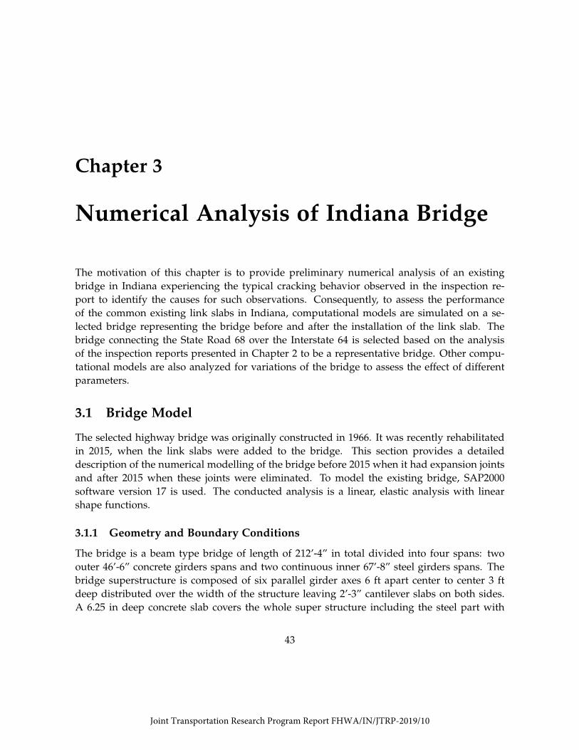
Chapter 3
Numerical Analysis of Indiana Bridge
The motivation of this chapter is to provide preliminary numerical analysis of an existingbridge in Indiana experiencing the typical cracking behavior observed in the inspection re-port to identify the causes for such observations. Consequently, to assess the performanceof the common existing link slabs in Indiana, computational models are simulated on a se-lected bridge representing the bridge before and after the installation of the link slab. Thebridge connecting the State Road 68 over the Interstate 64 is selected based on the analysisof the inspection reports presented in Chapter 2 to be a representative bridge. Other compu-tational models are also analyzed for variations of the bridge to assess the effect of differentparameters.
3.1 Bridge Model
The selected highway bridge was originally constructed in 1966. It was recently rehabilitatedin 2015, when the link slabs were added to the bridge. This section provides a detaileddescription of the numerical modelling of the bridge before 2015 when it had expansion jointsand after 2015 when these joints were eliminated. To model the existing bridge, SAP2000software version 17 is used. The conducted analysis is a linear, elastic analysis with linearshape functions.
3.1.1 Geometry and Boundary Conditions
The bridge is a beam type bridge of length of 212’-4” in total divided into four spans: twoouter 46’-6” concrete girders spans and two continuous inner 67’-8” steel girders spans. Thebridge superstructure is composed of six parallel girder axes 6 ft apart center to center 3 ftdeep distributed over the width of the structure leaving 2’-3” cantilever slabs on both sides.A 6.25 in deep concrete slab covers the whole super structure including the steel part with
43
Joint Transportation Research Program Report FHWA/IN/JTRP-2019/10

44 Chapter 3. Numerical Analysis of Indiana Bridge
Figure 3.1: Bridge elevation and cross-section as reported in drawings
a skew angle of 47◦. The bridge is supported on two abutments on the exterior, while theinterior supports are concrete piers of variable cross-sections.
Only the superstructure of the bridge is modelled since the aim of the models is to assessthe cracking observations in the superstructure. The substructure is represented by supportsin the models. In addition, as the temperature is expected to be a crucial factor in the as-sessment of the link slab performance, the depth of the girders needed to be represented.Therefore, the girders are modelled using area elements to allow the variation of stresses andstrains along the girders’ depth. In this case, the concrete girders are modelled using thickshell elements of 1’-4” thickness. On the other hand, the steel girders are modelled by thecombination of thick shell elements and frame elements. The shell elements represent theweb of the girder, while the frame elements represent the girder flanges. The same modellingprocedure applies for the steel and concrete diaphragms.
As per drawings, the concrete diaphragms are modelled only at the end of the concrete
Figure 3.2: Plan view of the girders and diaphragms of the bridge model
Joint Transportation Research Program Report FHWA/IN/JTRP-2019/10

3.1. Bridge Model 45
Figure 3.3: Boundary conditions for the concrete girders on the left and the steel girders on the right
spans parallel to the skewed angle. In contrast, intermediate steel diaphragms perpendicularto the longitudinal direction of the bridges are modelled in addition to end diaphragms inthe skewed direction. The steel diaphragms are half the depth of the main girders and arealigned such that the center line of the diaphragm meets the center line of the main girder.The concrete slab is also modelled as thick shell elements of 6.25 in thickness. The slab ismodelled continuous with the exception at the expansion joint locations in the model repre-senting the bridge before the link slab installment. The connection between the slab and thegirders is considered to transmit all straining actions and deformations in all models as thedrawings indicate the existence of shear connectors between the steel girders and the concreteslab. Similarly, the link slab is considered fixed to the rest of the slab as the drawings showthat the link slab is a haunched type detail where continuous reinforcement from the slabruns through the link slabs providing fixation.
According to the drawings, there is a shear key between the concrete diaphragms and thebridge substructure, which prevents the moment transfer between the diaphragms and thepier cap. Thus, the bottom of the concrete diaphragms is modelled as hinged. Although thesubstructure can theoretically have lateral deformations, the stiffness of the substructure isvery high that replacing it with a support restraining motion would not introduce consider-able error in the analysis. Unlike the diaphragms, the main concrete girders are fixed at thebottom ends as the drawings indicate that the substructure reinforcement goes through thegirders.
In contrast, the steel diaphragms only connect the main steel girders with no connection tothe substructure. Consequently, no restraints are needed on the steel diaphragms. Addition-
Joint Transportation Research Program Report FHWA/IN/JTRP-2019/10

46 Chapter 3. Numerical Analysis of Indiana Bridge
Concrete Structure Steel StructureSlab 0.92’ x 1.35’ Slab 1.13’ x 1.35’
Girder 0.75’ x 0.92’ Girder 0.75’ x 1.13’Exterior Diaphragm 0.75’ x 1.35’ Exterior Diaphragm 0.75’ x 1.35’
Link Slab 1.12’ x 1.35’ Exterior Diaphragm 0.75’ x 1.20’
Table 3.1: Mesh dimensions for concrete and steel structures
ally, the drawings show that the main steel girders are resting on bearings allowing horizontalmovements. However, modelling all the supports as rollers would result in instability of thestructure. To avoid that, the mid support is modelled as hinged, while the outer ones aremodelled as rollers, which would lead to the same deformation behavior expected from thedrawings.
Concrete girders and webs of the steel girders in the model are meshed to have fourelements in the depth. The other direction is meshed to have aspect ratio in the range of 0.5to 1, to avoid inappropriate elements that can cause numerical error. The resulting elementsizes are presented in Table 3.1.
3.1.2 Loading
Since the aim of these models is to compare the bridge performance before and after the linkslab construction, the different loading patterns are evaluated separately to assess the contri-bution of each loading case on the superstructure performance. Since the numerical analysispresented in this section is a linear elastic one, the effect of the combined loading is simplythe addition of the results from the different load cases.
Since the link slab is installed as a rehabilitation process for the existing bridge, the linkslab would not experience any dead load induced straining actions. Thus, the dead load isignored in the models as it does not contribute to any cracking in the link slabs. The live loadis assumed to be uniform load for the preliminary analysis. The uniform load is calculated bydistributing the load of the H20-44 truck over its area. Three cases of live load are consideredas follows:
1. The whole structure is loaded
2. Only the concrete structure is loaded
3. Only the steel structure is loaded
These live loads are selected such that the link slab would have either one of its adjacent spansis loaded or both are loaded simultaneously. All live loads are applied as distributed uniform
Joint Transportation Research Program Report FHWA/IN/JTRP-2019/10
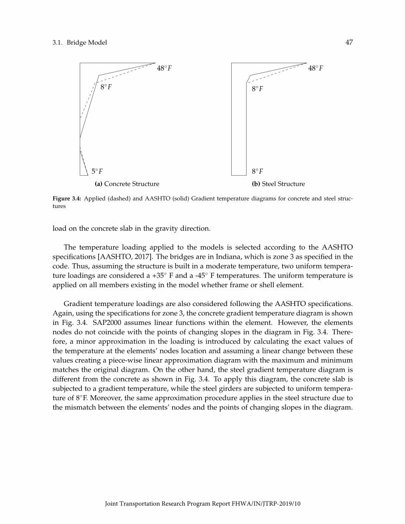
3.1. Bridge Model 47
load on the concrete slab in the gravity direction.
48◦F
5◦F
8◦F
(a) Concrete Structure
48◦F
8◦F
8◦F
(b) Steel Structure
Figure 3.4: Applied (dashed) and AASHTO (solid) Gradient temperature diagrams for concrete and steel struc-tures
The temperature loading applied to the models is selected according to the AASHTOspecifications [AASHTO, 2017]. The bridges are in Indiana, which is zone 3 as specified in thecode. Thus, assuming the structure is built in a moderate temperature, two uniform tempera-ture loadings are considered a +35◦ F and a -45◦ F temperatures. The uniform temperature isapplied on all members existing in the model whether frame or shell element.
Gradient temperature loadings are also considered following the AASHTO specifications.Again, using the specifications for zone 3, the concrete gradient temperature diagram is shownin Fig. 3.4. SAP2000 assumes linear functions within the element. However, the elementsnodes do not coincide with the points of changing slopes in the diagram in Fig. 3.4. There-fore, a minor approximation in the loading is introduced by calculating the exact values ofthe temperature at the elements’ nodes location and assuming a linear change between thesevalues creating a piece-wise linear approximation diagram with the maximum and minimummatches the original diagram. On the other hand, the steel gradient temperature diagram isdifferent from the concrete as shown in Fig. 3.4. To apply this diagram, the concrete slab issubjected to a gradient temperature, while the steel girders are subjected to uniform tempera-ture of 8◦F. Moreover, the same approximation procedure applies in the steel structure due tothe mismatch between the elements’ nodes and the points of changing slopes in the diagram.
Joint Transportation Research Program Report FHWA/IN/JTRP-2019/10
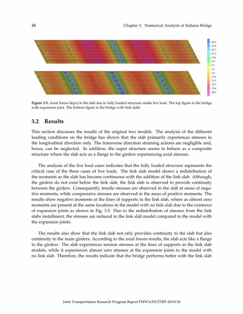
48 Chapter 3. Numerical Analysis of Indiana Bridge
+40.0
+33.8
+27.7
+21.5
+15.4
+9.2
+3.1
−3.1
−9.2
−15.4
−21.5
−27.7
−33.8
−40.0
Figure 3.5: Axial forces (kips) in the slab due to fully loaded structure under live load. The top figure is the bridgewith expansion joint. The bottom figure is the bridge with link slabs
3.2 Results
This section discusses the results of the original two models. The analysis of the differentloading conditions on the bridge has shown that the slab primarily experiences stresses inthe longitudinal direction only. The transverse direction straining actions are negligible and,hence, can be neglected. In addition, the super structure seems to behave as a compositestructure where the slab acts as a flange to the girders experiencing axial stresses.
The analysis of the live load cases indicates that the fully loaded structure represents thecritical case of the three cases of live loads. The link slab model shows a redistribution ofthe moments as the slab has become continuous with the addition of the link slab. Although,the girders do not exist below the link slab, the link slab is observed to provide continuitybetween the girders. Consequently, tensile stresses are observed in the slab at areas of nega-tive moments, while compressive stresses are observed in the areas of positive moments. Theresults show negative moments at the lines of supports in the link slab, where as almost zeromoments are present at the same locations in the model with no link slab due to the existenceof expansion joints as shown in Fig. 3.5. Due to the redistribution of stresses from the linkslabs installment, the stresses are reduced in the link slab model compared to the model withthe expansion joints.
The results also show that the link slab not only provides continuity to the slab but alsocontinuity to the main girders. According to the axial forces results, the slab acts like a flangeto the girders. The slab experiences tension stresses at the lines of supports in the link slabmodels, while it experiences almost zero stresses at the expansion joints in the model withno link slab. Therefore, the results indicate that the bridge performs better with the link slab
Joint Transportation Research Program Report FHWA/IN/JTRP-2019/10

3.2. Results 49
installed than the bridge with expansion joints under live load.
+10
+2−7
−15
−24
−32
−41−49−58−66−75−83
−92
−100
Figure 3.6: Axial forces (kips) in the slab due to uniform increase in temperature. The top figure is the bridge withexpansion joint. The bottom figure is the bridge with link slabs
+100
+92
+83
+75
+66
+58
+49
+41
+32
+24
+15
+7
−2
−10
Figure 3.7: Axial forces (kips) in the slab due to uniform decrease in temperature. The top figure is the bridgewith expansion joint. The bottom figure is the bridge with link slabs
Unlike the live load analysis, the uniform temperature analysis shows that the link slabbridge exhibit significantly higher axial stresses in the slab compared to the bridge with theexpansion joint in both uniform temperature cases as shown in Figs. 3.6 and 3.7. This resultis reasonable as the link slab prevents the bridge from deforming with temperature variationcausing stresses in the slab. The results show high tensile stresses in the case of the tempera-ture reduction which is way above the cracking limit (more than thrice) while almost the samemagnitude compressive stresses are observed in the temperature elevation case which can beeasily accommodated by the concrete strength.
Joint Transportation Research Program Report FHWA/IN/JTRP-2019/10

50 Chapter 3. Numerical Analysis of Indiana Bridge
+3.0
+0.8
−1.3
−3.5
−5.6
−7.8
−9.9
−12.1
−14.2
−16.4
−18.5
−20.7
−22.8
−25.0
Figure 3.8: Axial forces (kips) in the slab due to gradient temperature. The top figure is the bridge with expansionjoint. The bottom figure is the bridge with link slabs
It is important to note that the uniform temperature analysis assumes that the link slab isconstructed in a moderate temperature climate. In other words, if the link slab is constructedon elevated temperature days, the bridge would experience higher tensile stresses than pre-sented here, while constructing the bridge in winter would significantly reduce the tensilestresses on the expense of compressive stresses resulting from the elevated temperature case.
The final loading case considered for these models is the gradient temperature loadingcase. The results from this case of loading show similar behavior to the elevated uniform tem-perature. However, the overall values from the gradient case is much less than the uniformcase (almost quarter). Consequently, this load case is far from critical for the evaluation of thelink slab performance as the bridge in this case experience very low compressive stresses thatdo not contribute to the bridge cracking.
It can be concluded from the analysis of these two models is that the bridge cracking re-ported in the inspection reports is mainly due to the decrease of temperature between thesummer and the winter leading to the cracking observed in the first year after the link slabconstruction. The cracking observed coincides with the stress concentrations observed in themodel as the cracking is in the slab near the link slab locations.
3.3 Parametric Study
Several Models that are variations of the bridge are created to test the effect of differentparameters on the performance of the link slab in the bridge. Two sets of models are created
Joint Transportation Research Program Report FHWA/IN/JTRP-2019/10

3.3. Parametric Study 51
Figure 3.9: Plan view of the girders and diaphragms of the bridge model where all girders are made of concrete
for this section to test the effect of the boundary condition and the interaction between thesteel and concrete on the bridge performance. The first set of models is to evaluate the effectof having a concrete structure only compared to the mixed one. The second set of modelsaims to evaluate the effect of boundary conditions on the stress distribution in the bridge.
3.3.1 Effect of Material
An explanation to the results from the previous section that show the high effect of the uni-form temperature on the stresses in the slab is the difference between the expansion coeffi-cients of the concrete and steel. This difference causes a differential strain between the steeland concrete that can lead to high stress concentration at the connection interface. Conse-quently, a variant of the bridge is modelled by replacing the steel girders in the model withconcrete ones to check if these high stresses would be reduced. The new concrete girders areselected to match the concrete girders previously modelled. The boundary conditions andthe diaphragms are also selected to match those in the concrete part of the bridge. To doso, interior diaphragms are removed, while the external ones are replaced with concrete onesresting on hinge supports. Furthermore, the roller supports are replaced with fixed ones asshown in Fig. 3.10.
The results of this analysis show that there is no difference in the distribution of the stressesdue to live load. However, as expected, the distribution of stresses due to temperature loadingsignificantly changed from the original bridge. The magnitude of the maximum stresses dueto the uniform temperature in the bridge variant is less than the maximum of the originalbridge. In contrast, high stresses are observed over wider area in the slab in the variant modelcompared to the original bridge. Note that in both models the bridge is completely restrainedagainst any longitudinal expansion or deformation. The difference can be attributed to thedifference between the modulus of elasticity of concrete and steel.
Joint Transportation Research Program Report FHWA/IN/JTRP-2019/10
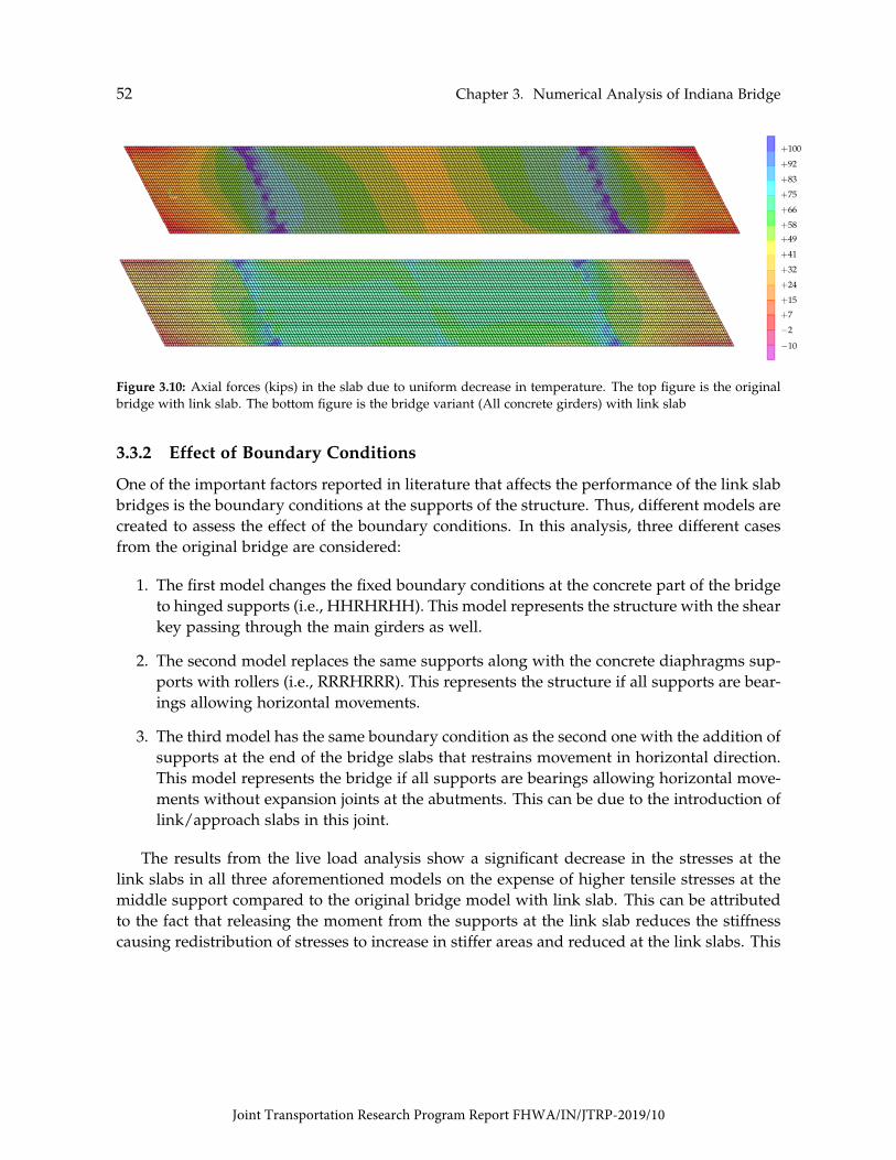
52 Chapter 3. Numerical Analysis of Indiana Bridge
+100
+92
+83
+75
+66
+58
+49
+41
+32
+24
+15
+7
−2
−10
Figure 3.10: Axial forces (kips) in the slab due to uniform decrease in temperature. The top figure is the originalbridge with link slab. The bottom figure is the bridge variant (All concrete girders) with link slab
3.3.2 Effect of Boundary Conditions
One of the important factors reported in literature that affects the performance of the link slabbridges is the boundary conditions at the supports of the structure. Thus, different models arecreated to assess the effect of the boundary conditions. In this analysis, three different casesfrom the original bridge are considered:
1. The first model changes the fixed boundary conditions at the concrete part of the bridgeto hinged supports (i.e., HHRHRHH). This model represents the structure with the shearkey passing through the main girders as well.
2. The second model replaces the same supports along with the concrete diaphragms sup-ports with rollers (i.e., RRRHRRR). This represents the structure if all supports are bear-ings allowing horizontal movements.
3. The third model has the same boundary condition as the second one with the addition ofsupports at the end of the bridge slabs that restrains movement in horizontal direction.This model represents the bridge if all supports are bearings allowing horizontal move-ments without expansion joints at the abutments. This can be due to the introduction oflink/approach slabs in this joint.
The results from the live load analysis show a significant decrease in the stresses at thelink slabs in all three aforementioned models on the expense of higher tensile stresses at themiddle support compared to the original bridge model with link slab. This can be attributedto the fact that releasing the moment from the supports at the link slab reduces the stiffnesscausing redistribution of stresses to increase in stiffer areas and reduced at the link slabs. This
Joint Transportation Research Program Report FHWA/IN/JTRP-2019/10

3.3. Parametric Study 53
Figure 3.11: Axial forces (kips) in the slab due to fully loaded structure under live load. The top figure is the bridgewith HHRHRHH support configuration. The middle figure is the bridge with RRRHRRR support configuration.The bottom figure is the bridge with RRRHRRR support configuration and supports representing approach slab
is, also, visible in the third variant model as more tensile stresses is observed at the new sup-ports added. The second model with all roller supports seem to have the highest compressivestresses (positive moments) in the slab in the steel spans.
Additionally, the live load results show that the stresses in the link slab is almost equiva-lent to the stresses in the slab around the expansion joint in the original bridge when it hadthe expansion joints. It can, then, be deduced that the installment of the link slabs providesstiffness equivalent to the stiffness induced by adding the moment restrains (fixation) at thesupports at the expansion joints. Although the values of the three variants seem to suggestthat all stresses are below the cracking limit, the results shown here are considered averagedas the slab is modelled using area elements showing uniform axial stresses. The stress valuesat the top and bottom fibers can increase compared to these values.
The uniform temperature results show wide variations in the stresses between the threevariants. The first variant, where the fixed supports are replaced with hinged supports showsalmost no difference in uniform temperature results from the original bridge with link slabsresults. On the other hand, the second variant shows almost no stresses due to temperature.This is reasonable as the support condition arrangement allows the structure to expand at the
Joint Transportation Research Program Report FHWA/IN/JTRP-2019/10

54 Chapter 3. Numerical Analysis of Indiana Bridge
Figure 3.12: Axial forces (kips) in the slab due to fully loaded structure under live load. The top figure is the bridgewith HHRHRHH support configuration. The middle figure is the bridge with RRRHRRR support configuration.The bottom figure is the bridge with RRRHRRR support configuration and supports representing approach slab
ends of the bridge causing no induced stresses all over the bridge. However, connecting theends of the bridge to the approach slab or abutments without allowing expansion producesstresses that are even higher than the original arrangement in general. The steel structureresults in these two models seem not to vary much, but the concrete part show significantchange in the stress distribution. The variant model, where the slab is connected to the ap-proach slab show significant increase in the tensile stresses in the concrete structure comparedto the original model since this connection prevents the expansion at the ends of the bridgeas shown in Fig. 3.12.
These results show that the stresses in the bridge due to both live load and temperatureare highly sensitive to the boundary condition configuration. The high stresses due to temper-ature can be completely removed if the structure is allowed to expand which in turn wouldgreatly reduce the demand on the link slab. This could then lead to reduction in the crackingobservations and increase the link slab performance.
Joint Transportation Research Program Report FHWA/IN/JTRP-2019/10

Chapter 4
Bridge Parameter Investigation
In order to evaluate the effect of factors on the behavior of link slabs identified from the lit-erature review, a preliminary investigation is conducted using a series of 3D finite elementmodels developed using the Abaqus/CAE software. This software is selected because of theadvantages offered to solve contact problems. The primary focus of the investigation is toevaluate the effect of support conditions and debonded length on the stress distribution andpotential crack initiation in link slabs. Each variable is investigated separately to isolate itseffect.
Two bridge structures are investigated in this study. The bridge structures are based onthe Michigan bridge studied by Aktan et al. [2008], but with a rectangular cross-section. Thefirst structure (Case 1) represents a bridge structure rehabilitated using link slabs. It consistsof a 1670 in bridge with two equal 834 in spans and zero skew, connected by a link slab. Thesuperstructure consists of a single line of concrete girders with an effective flange width of76 in. Deck thickness is 9 in. Fig. 4.1 shows the layout and the cross section of the bridgedeck link slab. A second bridge structure (Case 2) with the same geometrical and materialproperties, but with a continuous and fully bonded deck, is used for comparison purposes(Fig. 4.2). This structure simulates new bridge construction.
Table 4.1: FEM material properties
MaterialYoung’s Modulus
[ksi]Poisson’s
RatioThermal Coefficient
[in/in/F]Concrete 4031 0.2 6.0e-6
All components of bridge superstructure are modeled with same material using solid brickelements with linear elastic properties. Table 4.1 shows the material properties used in the
55
Joint Transportation Research Program Report FHWA/IN/JTRP-2019/10

56 Chapter 4. Bridge Parameter Investigation
Link Slab
Debonded Zone834 in. 834 in.
76 in.
9 in.
30 in.
20 in.
Beam
P = 96 kips P = 96 kips
Deck
Figure 4.1: Bridge deck link slab (Case 1)
834 in. 834 in.
2 in.
Beam
P = 96 kips P = 96 kips
Deck
Figure 4.2: Continuous bridge deck (Case 2)
models. None of the models incorporates the steel reinforcement. It is assumed that all parts,except for the girder ends at the joint location, are fully bonded. Therefore, tie constraints areused to model the full composite action between the concrete deck and girder as well as atthe interface between the concrete deck and link slab (Fig. 4.3). Table 4.2 presents the masterand slave surfaces used to define the constraints in the models. Contact properties are used tomodel the debonded zone at the link slab region. A mesh size of 2.5 in is used for all elements.
The supports are placed as a line of nodes at the bottom of each beam end and are mod-eled by constraining the appropriate degrees of freedom (Fig. 4.4). A fixed support (F) isrepresented as a node with all displacements and rotations restrained. A hinged support (H)is defined by constraining the displacements in all three directions. A roller support (R) ismodeled by constraining both vertical and transverse displacements.
Joint Transportation Research Program Report FHWA/IN/JTRP-2019/10

57
Table 4.2: Surfaces for tie constraint definition
Constraint Master Surface Slave Surface1 Top girders Bottom decks2 Deck sides Link slab sides
The models are subjected to the action of two different loadings: live load and uniformtemperature load. Live load is applied statically as a concentrated load at the middle of eachspan, as shown in Figs. 4.1 and 4.3. Each concentrated load equivalents to the resultant of adesign truck (H20-44) times an impact factor of 1.33. The two concentrated loads are appliedby using cylinders to distribute the load uniformly along the effective width, as illustratedin Fig. 4.3. These cylinders are idealized as rigid bodies to ensure deformations only on thebridge structure. The uniform temperature load considered is -50 ◦F (Zone 3 according to theAASHTO specifications [AASHTO, 2017]). This negative uniform temperature load is selectedbecause produces, for most cases, high tensile stresses on the link slab. The uniform tempera-ture is applied on all members existing in the model. The thermal coefficient of expansion forconcrete are given in Table 4.1. As the link slab is installed for bridge rehabilitation purposes,the dead load can be ignored in the models because it does not contribute to link slab cracking.
Figure 4.3: Tie constraint locations
Figure 4.4: Model assembly for live load
Joint Transportation Research Program Report FHWA/IN/JTRP-2019/10

58 Chapter 4. Bridge Parameter Investigation
4.1 Effect of Support Conditions
Seven different combinations of girder support restraints are considered in this study: FFRH,HHHH, HRHH, HRRH, HRRR, RHHR, and RRHR. These support arrangements are selectedbecause some of them represent the practice in Indiana and others are previously identifiedfrom the literature. Figs. 4.5 and 4.6 show the longitudinal normal stresses measured at the topof the link slab when the bridge structure is subjected to live load and uniform temperatureload, respectively. Notice that both figures show the stresses for only the link slab region. Forall support cases shown in these figures, the length of the full-depth link slab is kept constantas 43 in at each side from the axis of symmetry over the gap. This length is equal to 5%debonding. It can be seen from the figures that the behavior of link slabs is affected by thebridge boundary conditions. Fig. 4.5 shows that higher longitudinal normal stresses on thelink slab under live load are produced for those support arrangements with roller supportbelow of the link slabs (i.e., support cases RRHR, HRRH, FFRH, and HRHH). Fig. 4.6 showsthat, as the structure is more restrained at the outer supports, higher longitudinal normalstresses are observed due to uniform thermal load (i.e., support cases HRRH, FFRH, HRHH,and HHHH). Tables 4.3 and 4.4 show the comparison between the two bridge cases consideredin this study when the beam model is subjected to live and thermal loads, respectively. Theresults presented in Table 4.3 show that using a link slab with a debonded length of 5% ateach span decreases the stresses due to live load around 38% for all support cases whencomparing the results from those of a continuous and fully bonded deck (0% debonding).For the uniform temperature load case, the results of Table 4.4 show that the effect of 5%debonding was negligible for all support cases except one. For HHHH, no thermal releasewas available and the thermal gradient resulted in an increase of 26% compared with thecontinuous and fully bonded deck. Notice from the information presented that changingposition of H support does not produce any difference on the link slab response for both liveand thermal loads (i.e., stresses for support cases RRHR and HRRR are the same). Due tosymmetry in the model, stresses in the link slabs remained the same when having fixed (i.e.,FFRH) or pinned supports (i.e., HRHH) at the ends under the loadings cases considered.
Joint Transportation Research Program Report FHWA/IN/JTRP-2019/10

4.1. Effect of Support Conditions 59
Figure 4.5: Effect of boundary conditions under live load
Figure 4.6: Effect of boundary conditions under uniform temperature load
Joint Transportation Research Program Report FHWA/IN/JTRP-2019/10

60 Chapter 4. Bridge Parameter Investigation
Table 4.3: Maximum stresses at top of link slab due to live load
Support Max. Stress [ksi] DifferenceConditions Case 1
FFRH 2.90
Case 2
5.02
[%]
-42HHHH 1.21 2.09 -42HRHH 2.90 5.02 -42HRRH 3.52 5.82 -40HRRR 4.13 6.44 -36RHHR 1.64 2.37 -31RRHR 4.13
Note: F = Fixed.
6.44 -36
H = Hinged/Pinned.R = Roller.
Table 4.4: Maximum stresses at top of link slab due to uniform temperature load
SupportConditions
Max. Stress [ksi] Difference[%]Case 1 Case 2
FFRH 1.53 1.48 4HHHH 1.31 1.04 26HRHH 1.53 1.48 4HRRH 1.61 1.64 -2HRRR 0.00 0.00 0RHHR 0.00 0.00 0RRHR 0.00 0.00 0
Note: F = Fixed.H = Hinged/Pinned.R = Roller.
4.2 Effect of Debonded Length
The length of the debonded zone is varied to investigate its effect on the behavior of linkslabs. The following debonded lengths at each adjacent span are investigated: 9, 18, 26,36, 42, 51, and 61 in. These lengths expressed in terms of the span length correspond to thefollowing percentages: 1, 2, 3, 4, 5, 6, and 7. The beams are subjected to live and thermal loadsseparately. Figs. 4.7 and 4.8 illustrate the effect of of varying the debonded length when the
Joint Transportation Research Program Report FHWA/IN/JTRP-2019/10

4.2. Effect of Debonded Length 61
bridge is subjected to live load. Figs. 4.9 and 4.10 illustrate the effect of varying the debondedlength when the bridge is subjected to uniform temperature load. Notice that in all figuresthe results are presented for only the link slab region and for each support arrangement. Thelongitudinal normal stresses are measured at the top of the link slab. It can be seen fromthe results that increasing the debonded length, when the bridge is subjected to live load,results in reduced longitudinal normal stresses for all the boundary conditions considered.Bridges that allow thermal expansion experience no stresses in the link slab. For all boundaryconditions considered, stresses due to live load are approximately three times greater thanthose observed due to temperature loads.
Figure 4.7: Effect of debonding under live load for support conditions: RHHR; FFRH; HHHH; and HRHH
Joint Transportation Research Program Report FHWA/IN/JTRP-2019/10

62 Chapter 4. Bridge Parameter Investigation
Figure 4.8: Effect of debonding under live load for support conditions: HRRH; HRRR; and RRHR
Joint Transportation Research Program Report FHWA/IN/JTRP-2019/10

4.2. Effect of Debonded Length 63
Figure 4.9: Effect of debonding under uniform temperature load for support conditions: RHHR; FFRH; HHHH;and HRHH
Joint Transportation Research Program Report FHWA/IN/JTRP-2019/10
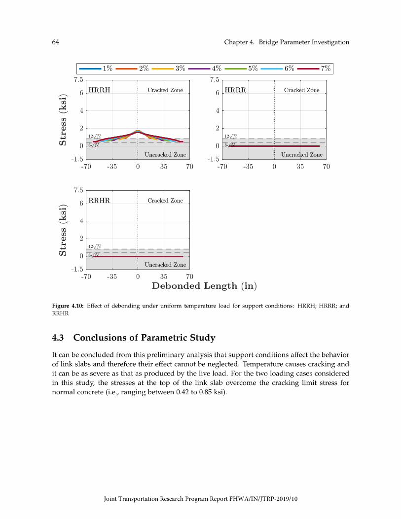
64 Chapter 4. Bridge Parameter Investigation
Figure 4.10: Effect of debonding under uniform temperature load for support conditions: HRRH; HRRR; andRRHR
4.3 Conclusions of Parametric Study
It can be concluded from this preliminary analysis that support conditions affect the behaviorof link slabs and therefore their effect cannot be neglected. Temperature causes cracking andit can be as severe as that as produced by the live load. For the two loading cases consideredin this study, the stresses at the top of the link slab overcome the cracking limit stress fornormal concrete (i.e., ranging between 0.42 to 0.85 ksi).
Joint Transportation Research Program Report FHWA/IN/JTRP-2019/10
Chapter 5
Findings, Conclusions, and Proposed Rec-ommendations for Implementation
5.1 Summary
The findings, conclusions, and proposed recommendations for implementations are presentedin this chapter for each of the three main tasks of the study of Literature Review (Chapter2); Analysis of Indiana Bridge (Chapter 3); and Bridge Parameter Investigation (Chapter 4).Suggestions for future research are also presented.
5.2 Findings
5.2.1 Literature Review
The literature review conducted in Chapter 2 on the state of practice about link slabs included:(1) State Departments of Transportation (DOT) experience; (2) previous research studies; (3)design specifications and construction practices; and (4) Indiana DOT implementation expe-rience. The salient findings are:
5.2.1.1 State Department of Transportation Experience
(a) Approximately 30% had experience with the use of link slabs, and approximately two-thirds of the reported agencies had performed research or implemented the link-slabsystem in the field.
(b) The reported cases of implementation of link slabs were mainly in the rehabilitation ofsteel girder bridge superstructure. In most cases, the link slabs were debonded from the
65
Joint Transportation Research Program Report FHWA/IN/JTRP-2019/10

66 Chapter 5. Findings, Conclusions, and Proposed Recommendations for Implementation
end girders.
(c) One-third of the agencies having reported experience with the system had design pro-visions or standard details. Several link slab joint details and materials have been de-veloped and used in the field. However, a standardized geometry and detailing has notbeen achieved across the DOTs. The details used in link slabs are described in Section5.2.1.2(b). North Carolina, Michigan, Virginia, and New York were identified as keyDOTs in the use of link slabs.
(d) The performance of link slabs implemented so far, varies among transportation agencies.For example, Michigan reported performance varying widely from very good to poor.Cracking was reported as the main issue of link slabs. The cracking was attributed topoor construction practices and improper detailing. There are other agencies such asVirginia, New York, and Massachusetts that have experienced good performance withlink slabs. No cracking issues were reported.
(e) Material used in the link slab is another aspect that varies among DOTs. North Carolinaand Massachusetts use conventional concrete, while other transportation agencies likeMichigan, Virginia, and New York prefer to use fiber reinforced concrete for link slabsapplications.
5.2.1.2 Previous Research
Previous research studies showed the focus to be on development more durable materialsfor use in link slabs. While few studies addressed improvements on design and detailingstandards. The salient findings from this portion of the literature review are:
(a) Material: four advanced concrete materials for link slabs have been reported: latexmodified concrete (LMC), fiber-reinforced engineering cementitious composite (ECC),ultra-high performance concrete (UHPC), and hybrid fiber-reinforced concrete (HyFRC).Common features between these materials are higher tensile strength and lower perme-ability. Research by Fu and Zhu [2017] identified ECC and UHPC mixtures as promisingcandidate options for use in link slabs. The compositions used are described in Section2.5. Hoomes et al. [2017] showed HyFRC with synthetic fibers provided the most eco-nomical solution for crack control and bond strength [See Section 2.2.3]. An alternativeto traditional epoxy-coated reinforcement is glass fiber reinforced polymer (GFPR) bars.
(b) Types: three different types of link slabs were identified in the literature: haunched,flexible, and debonded.
Joint Transportation Research Program Report FHWA/IN/JTRP-2019/10
5.2. Findings 67
i. The haunched and flexible configurations were used in Canada for deck rehabilita-tion. However, the use has been discontinued due to high costs as well as limita-tions in the girder end-rotations and girder depth [Lam, 2011].
ii. Currently, the debonded link slab detail is the most commonly used in the UnitedStates and Canada. It is described in detail Section 2.2. Four debonded configu-rations were reported: two full-depth cast-in-place, one partial-depth cast-in-place,and one partial-depth precast. The two full-depth link slabs as well as the onepartial-depth cast-in-place have been tested and implemented in the field. Thepartial-depth precast link slab has been tested but not used in the field.
iii. The first configuration of a full-depth cast-in-place link slab was proposed by Canerand Zia [1998]. The link slab had a debonded zone equivalent to 5% of each adjacentbridge span. The continuity for live load provided by the link slab is neglected. Afield inspection conducted by Aktan et al. [2008] on bridges in Michigan indicatedfull-depth transverse cracks of width between 0.01 to 0.02 in at the centerline on thelink slabs using this detail.
iv. The second full-depth cast-in-place link slab configuration was proposed by Li et al.[2003] to address the interfacial cracking problem with the link slab detailing pro-posed by Caner and Zia [1998]. The Caner and Zia [1998] detail caused by high-stress concentrations at the interface between the link slab and the existing concretedeck. The new detail had a transition zone of 2.5% at each adjacent span in additionto the debonded zone of 5%. This transition zone served to move the interface awayfrom the start point of the debonding. The new detail provides continuity for liveload. Testing of this design detail with ECC material and 2.5% debonding undercyclic loading (100,000 cycles) resulted in crack widths less than 0.002 in. while fora link slab using conventional concrete was 0.025 in. No cracks were observed at theinterface between the existing deck and the link slab. Li et al. [2005] implementedthe new detail in an actual structure in Michigan. The study concluded that ECClink slabs performed as designed. However, shrinkage cracking was reported afterthree days casting. Crack widths ranged between 0.005 in to 0.014 in. Li et al. [2008]investigated causes of the cracking and recommended limiting skew angle no morethan 25 degrees, night casting, and water curing for at least 7 days. The use ofstay-in-place forms, and the placement of sidewalk and barrier wall directly overthe link slabs was not recommended due to stress concentrations. A transverse sawcut was not also recommended.
v. Partial-depth cast-in-place link slab was used to rehabilitate the SR962G bridge overUS Route 17 in Owego, New York. The bridge rehabilitation project involved theuse of precast concrete deck panels. The filler material used in the connection wasUHPC.
Joint Transportation Research Program Report FHWA/IN/JTRP-2019/10

68 Chapter 5. Findings, Conclusions, and Proposed Recommendations for Implementation
vi. Partial-depth precast link slab details were proposed and tested by Reyes andRobertson [2011] and Larusson et al. [2013]. The details were constructed usingECC reinforced with GFPR bars and tested under tension and compression loads.
(c) Key Performance Factors:
i Temperature gradients: Research conducted by Aktan et al. [2008], using designdetail by Caner and Zia [1998], concluded that cracks in the link slabs are duemainly to hydration thermal loads and drying shrinkage. The authors recom-mended to consider thermal loads into the design of link slabs as well as developnew concrete materials that can tolerate these thermal loads. The authors also rec-ommended to use continuous top and bottom reinforcement and provide saw cutsat the ends of the link slab and directly over the pier centerline.
ii Support conditions: Caner and Zia [1998] concluded that support conditions donot affect the behavior of link slabs since the measured reactions, strains, and de-flections remained the same for all support cases in the elastic range. The measuredreactions and load-deflection curves of the girders indicated that each individualspan behaved as if it was simply-supported.Numerical analysis by Ulku et al. [2009] reported a moment value of 50 kip-ft underlive and temperature gradient load for support arrangements Hinge-Roller-Roller-Roller and Roller-Roller-Hinge-Roller. A reduced moment value of 19 kip-ft withincreased axial force was reported for Roller-Hinge-Hinge-Roller case.
iii Length of debonding: Numerical analysis performed by El-Safty and Okeil [2008]showed that a debonded length of 5% increases the load-carrying capacity of thebeam by about 11.6% when compared to that of an unbonded beam.Ulku et al. [2009] observed that link slab moment decreases with increasing thedebonded length but remains constant after a debonding of 5%. No changes in thenet axial force were observed when varying the debonded length since the axialstiffness of the link slab remained constant.
5.2.1.3 Design Specifications and Construction Practices
To date, there is no national survey of highway agencies that documents the state of practiceon link slabs. The review of the specifications and the proposed AASHTO guidelines foraccelerated bridge construction reveals that the majority of the states use:
(a) The design methodology proposed by Caner and Zia [1998] in North Carolina. Accord-ingly, the girder end rotation due to live load and the AASHTO crack limit are used asdesign criteria. It must be noted that none of the states consider thermal effects in thedesign of the link slab.
Joint Transportation Research Program Report FHWA/IN/JTRP-2019/10

5.2. Findings 69
(b) A debonded length of 5% to 7% at each span. No transition zone is specified by thestates.
(c) Full-depth link slabs. Only the state of New York indicates the use of a partial-depthconfiguration.
(d) Specify a 7-day wet curing period.
(e) Only three agencies, North Carolina, Virginia, and Florida specify maximum span length.The corresponding lengths are 75 ft, 100 ft, and 100 ft.
(f) Specified concrete materials by North Carolina, Virginia, and New York are Class AAConcrete, Low Shrinkage Class A4 Modified Concrete, and UHPC, respectively.
5.2.1.4 Indiana DOT Implementation Experience
The findings discussed in this section are based on the study of the inspection reports and thedrawings of the bridges analyzed in Indiana. Unfortunately, the inspection reports reviewedlack more numerical data to allow in-depth analysis of the behavior of the link slab bridges.These reports are based only on subjective visual inspections with no exact data of crackparameters like exact locations, width, and depth. The following findings are observed:
(a) Most link slab construction is recent with no enough inspection reports after the con-struction to observe the bridge performance in the long term. All analyzed link slabbridges were constructed in the years 2013 to 2017 with a maximum of two inspectionreports post link slab construction.
(b) All reviewed bridges in Indiana had the link slabs constructed as part of the rehabilita-tion.
(c) Link slabs mostly follow the haunched type detail, i.e., deeper than the deck (see Chapter2). In this detail, the link slab is fully bonded to the adjacent slabs as well as the girderswith no debonding.
(d) Six link slab bridges included approach slabs constructed alongside the construction oflink slabs during the rehabilitation of the bridges out of the seven reviewed. Approachslabs eliminate the possibility of the deck expansion over the abutments.
(e) All link slabs analyzed including one with debonded detail were constructed usingconventional normal strength Class C concrete.
(f) All analyzed bridges except the one with debonded link slab detail experienced dete-rioration and cracking after the link slab construction. Cracking patterns and locationsvary throughout the bridges.
Joint Transportation Research Program Report FHWA/IN/JTRP-2019/10
70 Chapter 5. Findings, Conclusions, and Proposed Recommendations for Implementation
(g) Although the inspection reports are recent, most analyzed Indiana bridges experiencedcracking within the first year of the link slab construction.
(h) In addition to the various cracking patterns, transverse cracking of the deck in the vicin-ity of the link slabs is common in most bridges after the link slab construction. Thetransverse cracking is more evident and stronger in decks supported by steel girders.
5.2.2 Analysis of Indiana Bridge
The bridge (#68-65-5213A) crossing the State Road 68 over the Interstate 64 was modelednumerically to evaluate the bridge performance after the construction of link slabs numericallyin Chapter 3. Two models were analyzed to represent the bridge superstructure prior tothe link slabs construction (i.e., including expansion joints) and compare with the bridgesuperstructure post link slab construction (i.e., jointless deck) subjected to both live loads andthermal loads. The link slab detail implemented in this bridge was the haunched type detail.The results indicated that the critical action of the superstructure was the longitudinal axialstress in the concrete deck. Therefore, only these stresses are presented in this section and,for simplicity, will be referred to as stresses. These findings of the numerical analysis aredescribed in reference to solicitation, type of superstructure, and bridge support conditions:
(a) Live load: the analysis showed that the presence of the link slab in replacement of thelongitudinal joints reduced compressive stresses at midspan of the deck as a result ofthe continuity provided by the link slab. On the other hand, the link slabs themselvesexperienced tensile stresses that can be maximized by fully loading the adjacent spans.
(b) Thermal loads: two types of thermal loadings were considered, gradient and uniform.Gradient temperature loading induced compressive stresses in the link slabs. The mag-nitude of the stresses was almost 50% of the magnitude of stresses induced due to liveloads. However, a uniform decrease in temperature induced tensile stresses in the linkslab, while a uniform increase in temperature induced compressive stresses. Prior toinstallation of the link slab, for purposes of comparison, the model was built with ex-pansion joints. It was shown that the maximum longitudinal stresses in the deck slabof the bridge with uniform temperature loading occurred at the bridge intermediatepier connecting the continuous steel spans. The model with the link slab and existingboundary conditions indicated that maximum stresses in the deck slab due to uniformtemperature loading occurred at the link slabs. The magnitude of these stresses wasaround 3.5 times the maximum on the deck at that location prior to installing the linkslab. However, the stresses due to uniform temperature loading over the intermediatepier connecting the two continuous steel spans were the same with both models.
Joint Transportation Research Program Report FHWA/IN/JTRP-2019/10

5.2. Findings 71
(c) Effect of bridge superstructure Type: to better understand the behavior of link slabs, anew model was developed by replacing the existing steel girders with concrete ones afterthe link slab is installed and referred to as concrete model. The model was selected totest if the observed thermal stresses in the model of the existing bridge can be attributedto the difference in expansion between the steel girders and concrete deck. Similar tothe original model, the controlling actions on the superstructure were the longitudinalaxial stresses in the deck. The magnitude of the maximum stresses due to uniformtemperature loading in the concrete model was twice the same stresses in the originalbridge prior to the link slab installment. Similar to the original bridge once the linkslab was in place, the distribution of the axial stresses in the deck was almost constantthroughout the intermediate two spans in the concrete model; and the maximum stressesin the concrete model due to uniform temperature loading were 1.6 times the maximumstresses prior to installation of the link slab. The stresses in the link slabs in either theoriginal model post link slab or the concrete bridge due to live loads were 1.4 times thecracking stress of the normal strength concrete, while the same stresses due to uniformdecrease in temperature were at least four times the cracking stress.
(d) Bridge support conditions: since the support conditions have been reported to influencethe link slab performance in bridges, three variations on the original model with linkslab construction were studied to compare the effect on the longitudinal stresses in thedeck. The stresses in the link slabs due to live loads decreased with less restraints atthe girders supports. The model simulating all roller supports had lower stresses inthe link slabs, while the existing bridge model which included fixed supports had thehighest stresses in the link slabs. Live load stresses at midspan of the intermediate steelspans increased when reducing the restraints; and, did not change significantly amongthe models with different boundary conditions at the continuous steel spans with theexception of the all-rollers model with a uniform decrease in temperature. Stresses dueto uniform decrease in temperature in the deck of the concrete spans in the approachslab model were twice as much as those stresses in the all-rollers model. Stresses due toany temperature loading case were almost zero in the all-rollers model.
5.2.3 Bridge Parameter Investigation
In Chapter 4, to further extend the analysis observations from the study in the Indiana bridgeconducted in Chapter 3, a series of 3D finite element models were developed to evaluate theeffect of support conditions and debonded length on the longitudinal stress distribution inthe deck and potential crack initiation in link slabs. Two bridge structures were investigated.The first structure (Case 1) represented a bridge structure rehabilitated using link slabs. Thesecond bridge structure (Case 2) had same geometrical and material properties as Case 1,but the concrete deck was continuous and fully bonded. The girder boundary conditions
Joint Transportation Research Program Report FHWA/IN/JTRP-2019/10
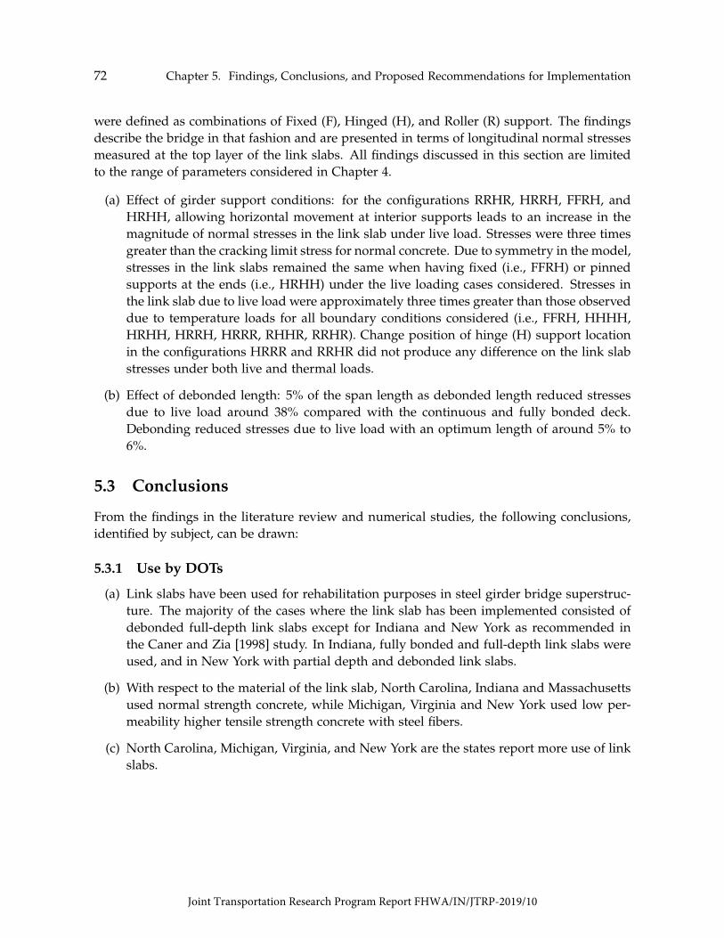
72 Chapter 5. Findings, Conclusions, and Proposed Recommendations for Implementation
were defined as combinations of Fixed (F), Hinged (H), and Roller (R) support. The findingsdescribe the bridge in that fashion and are presented in terms of longitudinal normal stressesmeasured at the top layer of the link slabs. All findings discussed in this section are limitedto the range of parameters considered in Chapter 4.
(a) Effect of girder support conditions: for the configurations RRHR, HRRH, FFRH, andHRHH, allowing horizontal movement at interior supports leads to an increase in themagnitude of normal stresses in the link slab under live load. Stresses were three timesgreater than the cracking limit stress for normal concrete. Due to symmetry in the model,stresses in the link slabs remained the same when having fixed (i.e., FFRH) or pinnedsupports at the ends (i.e., HRHH) under the live loading cases considered. Stresses inthe link slab due to live load were approximately three times greater than those observeddue to temperature loads for all boundary conditions considered (i.e., FFRH, HHHH,HRHH, HRRH, HRRR, RHHR, RRHR). Change position of hinge (H) support locationin the configurations HRRR and RRHR did not produce any difference on the link slabstresses under both live and thermal loads.
(b) Effect of debonded length: 5% of the span length as debonded length reduced stressesdue to live load around 38% compared with the continuous and fully bonded deck.Debonding reduced stresses due to live load with an optimum length of around 5% to6%.
5.3 Conclusions
From the findings in the literature review and numerical studies, the following conclusions,identified by subject, can be drawn:
5.3.1 Use by DOTs
(a) Link slabs have been used for rehabilitation purposes in steel girder bridge superstruc-ture. The majority of the cases where the link slab has been implemented consisted ofdebonded full-depth link slabs except for Indiana and New York as recommended inthe Caner and Zia [1998] study. In Indiana, fully bonded and full-depth link slabs wereused, and in New York with partial depth and debonded link slabs.
(b) With respect to the material of the link slab, North Carolina, Indiana and Massachusettsused normal strength concrete, while Michigan, Virginia and New York used low per-meability higher tensile strength concrete with steel fibers.
(c) North Carolina, Michigan, Virginia, and New York are the states report more use of linkslabs.
Joint Transportation Research Program Report FHWA/IN/JTRP-2019/10

5.3. Conclusions 73
(d) The presence of a transition zone into the existing deck beyond the debonded length ofthe link slab has been investigated and implemented by Michigan with mixed perfor-mance. In the laboratory showed good performance with respect to cracking while inthe field the implementation experienced cracking in the link slab.
(e) To date thermal loading is not considered in the design of link slabs.
5.3.2 Design Practice
Current design approach for link slabs includes simply supported girder end rotation [Canerand Zia, 1998] in conjunction with AASHTO crack width limitation [AASHTO, 2017]. Thethermal effects although mentioned in research studies, are not considered in practice by theDOTs responded in this study.
Additional conclusions from the findings from analytical and research studies indicatethat:
(a) The construction of the approach slabs alongside the link slabs construction restrainsthe bridge against thermal expansion causing high stresses due to thermal loads. Theeffect of uniform thermal loads on the bridge superstructure including the existing deckand the link slabs is highly dependent on the type of the superstructure girders whetherconcrete or steel girders and their support conditions. The identification of this effectcome from limited research studies.
(b) Debonding length of 5% is the optimum debonding length to induce the minimumlongitudinal tensile stresses in the link slabs due to live loads.
(c) Use of higher tensile strength and low permeability concrete materials are recommendedin the construction of link slabs.
(d) Effective strategies to minimize cracking reported in the literature are night-time casting,adequate curing, and the use of continuous top and bottom reinforcement.
5.3.3 Research
A few gaps have been identified during the current study where more research is recom-mended.
(a) The literature and analysis results show the influence of girder end support conditionson link slab stresses. A link slab over RHHR support configuration is subjected to bothaxial forces and flexure. However, this combined effect is not considered in the currentdesign methodology for link slabs.
Joint Transportation Research Program Report FHWA/IN/JTRP-2019/10

74 Chapter 5. Findings, Conclusions, and Proposed Recommendations for Implementation
(b) Research has focused on development more durable materials for use in link slabs.Few studies addressed improvements on design and detailing standards, and there is apaucity of data on the performance of precast concrete link slabs.
(c) The modified Caner and Zia proposed design detail was modified in a subsequent studyby adding a transition zone and ECC material. This detail was shown to have satisfactoryperformance in the laboratory under both cyclic and ultimate loads. No deteriorationwas observed at the interface between the existing deck and the link slab. However,in the field implementation early shrinkage and possibly temperature cracking was ob-served. Further evaluation of this detail in the lab and the field is recommended as themost promising form of construction for the link slabs.
(d) Promising materials recommended in the literature for use in link slabs, listed in orderof reported successful performance, are:
(i) ultra-high performance concrete (UHPC) and fiber-reinforced engineering cemen-titious composite (ECC).
(ii) hybrid fiber-reinforced concrete (HyFRC) is suggested as an economical solutioncompared to the UHPC and ECC mixtures. However, this material has not beenimplemented in the field.
5.4 Recommendations for Implementation
Based on the conclusions from the study, the following recommendations are presented forconsideration and possible implementation.
(a) It is recommended to use 5% debonding length and link slab detailing recommendedby Caner and Zia [1998], with the additional transition zone into the existing deck (Fig.5.1), to minimize the overall longitudinal tensile stresses in the link slabs. Laboratorystudies conducted by Li et al. [2003] showed that the introduction of the transition zoneeliminated cracking due to loads at the interface of the debonded link slab. It is rec-ommended to investigate improved reinforcement details and material specifications toaddress construction issues and enhance long-term performance.
(b) Since, in almost all cases studied, link slabs see high tensile stresses that are higher thanthe cracking limit of conventional normal-strength concrete, it is recommended to usehigh tensile materials for the link slabs. The literature addresses this issue extensivelyand provide better alternatives such as UHPC, ECC, and FRP. However, the use of thesematerials alone may not guarantee un-cracked link slabs without further considerationof thermal loading and the detailing of the link slab.
Joint Transportation Research Program Report FHWA/IN/JTRP-2019/10
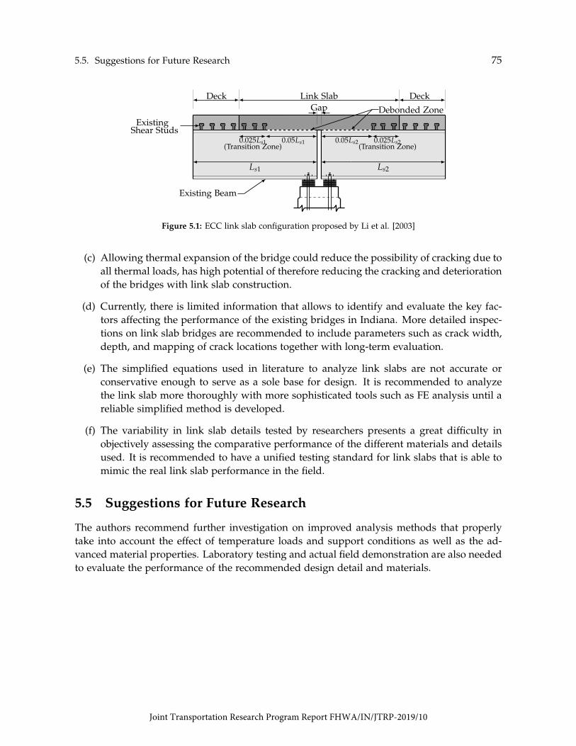
5.5. Suggestions for Future Research 75
Existing Beam
0.05Ls1 0.05Ls20.025Ls1 0.025Ls2(Transition Zone) (Transition Zone)
Debonded ZoneGap
Ls1 Ls2
Deck Link Slab Deck
ExistingShear Studs
Figure 5.1: ECC link slab configuration proposed by Li et al. [2003]
(c) Allowing thermal expansion of the bridge could reduce the possibility of cracking due toall thermal loads, has high potential of therefore reducing the cracking and deteriorationof the bridges with link slab construction.
(d) Currently, there is limited information that allows to identify and evaluate the key fac-tors affecting the performance of the existing bridges in Indiana. More detailed inspec-tions on link slab bridges are recommended to include parameters such as crack width,depth, and mapping of crack locations together with long-term evaluation.
(e) The simplified equations used in literature to analyze link slabs are not accurate orconservative enough to serve as a sole base for design. It is recommended to analyzethe link slab more thoroughly with more sophisticated tools such as FE analysis until areliable simplified method is developed.
(f) The variability in link slab details tested by researchers presents a great difficulty inobjectively assessing the comparative performance of the different materials and detailsused. It is recommended to have a unified testing standard for link slabs that is able tomimic the real link slab performance in the field.
5.5 Suggestions for Future Research
The authors recommend further investigation on improved analysis methods that properlytake into account the effect of temperature loads and support conditions as well as the ad-vanced material properties. Laboratory testing and actual field demonstration are also neededto evaluate the performance of the recommended design detail and materials.
Joint Transportation Research Program Report FHWA/IN/JTRP-2019/10

Joint Transportation Research Program Report FHWA/IN/JTRP-2019/10

References
AASHTO (2017). Bridge design specifications and commentary. In AASHTO LRFD. AmericanAssociation of State Highway and Transportation Officials, Washington, DC.
Aktan, H. and Attanayake, U. (2011). High skew link slab bridge system with deck sliding overbackwall or backwall sliding over abutments. Report. No. RC-1563, Michigan Departmentof Transportation, Lansing, MI.
Aktan, H., Attanayake, U., and Ulku, E. (2008). Combining link slab, deck sliding over back-wall, and revising bearings. Report. No. RC-1514, Michigan Department of Transportation,Kalamazoo, MI.
Alampalli, S. and Yannotti, A. (1998). In-Service Performance of Integral Bridges and JointlessDecks. Transportation Research Record: Journal of the Transportation Research Board, 1624(98-0540):1–7.
Au, A., Lam, C., Au, J., and Tharmabala, B. (2013). Eliminating Deck Joints Using DebondedLink Slabs : Research and Field Tests in Ontario. Journal of Bridge Engineering, 18(8):768–778.
Caner, A., Dogan, E., and Zia, P. (2002). Seismic Performance of Multisimple-Span BridgesRetrofitted with Link Slabs. Journal of Bridge Engineering, 7(2):85–93.
Caner, A. and Zia, P. (1998). Behavior and Design of Link Slabs for Jointless Bridge Decks.PCI Journal, 43(3):68–80.
Culmo, M. P., Marsh, L., and Stanton, J. (2017). Recommended aashto guide specifications forabc design and construction. Final Report for Project 12-102, National Cooperative HighwayResearch Program, Transportation Research Board, Washington, D.C.
El-Safty, A. (1994). Behavior of Jointless Bridge Decks. PhD thesis, North Carolina State Univer-sity, Raleigh, NC.
El-Safty, A. and Okeil, A. (2008). Extending the Service Life of Bridges using ContinuousDecks. PCI Journal, 53(6):96–111.
77
Joint Transportation Research Program Report FHWA/IN/JTRP-2019/10

78 References
FDOT (2018). Bridge maintenance course series—reference manual. In Bridge Division. FloridaDepartment of Transportation, Tallahassee, FL.
Fu, C. C. and Zhu, Y. F. (2017). A pilot application of link slab with selected material for mdtasteel bridges. Technical report, Maryland Transportation Authority, Baltimore, MD.
Gastal, F. (1986). Instantaneous and Time-Dependent Response and Strength of Jointless BridgeBeams. PhD thesis, North Carolina State University, Raleigh, NC.
Gastal, F., and Zia, P. (1989). Analysis of bridge beams with jointless decks. In InternationalAssociation for Bridge and Structural Engineering (IABSE), pages 555–560.
Graybeal, B. (2014). Design and construction of field-cast uhpc connections. Final Report. No.FHWA-HRT-14-084, Office of Infrastructure Research and Development, McLean, VA.
Hoomes, L., Ozyildirim, H. C., and Brown, M. (2017). Evaluation of high-performance fiber-reinforced concrete for bridge deck connections, closure pours, and joints. Final Report. No.FHWA-VTRC-17-R15, Virginia Transportation Research Council, Charlottesville, VA.
Hou, M., Hu, K., Yu, J., Dong, S., and Xu, S. (2018). Experimental Study on Ultra-High Duc-tility Cementitious Composites Applied to Link Slabs for Jointless Bridge Decks. CompositeStructures, 204(2018):167–177.
Kim, Y., Fischer, G., and Li, V. C. (2004). Performance of Bridge Deck Link Slabs Designedwith Ductile Engineered Cementitious Composite. ACI Structural Journal, 101(6):792–801.
Lam, C. (2011). Pulling the Teeth on Old Bridge Structures Eliminating Bridge ExpansionJoints with Concrete Link Slabs. Ontario’s Transportation Technology Transfer Digest Road Talk,1(Article 8):1–3.
Lam, C., Lai, D., Au, J., Lim, L., Young, W., and Tharmabala, B. (2008). Development ofConcrete Link Slabs to Eliminate Bridge Expansion Joints over Piers. Annual Conference ofthe Transportation Association of Canada, pages 1–20.
Larusson, L., Reyes, J., Lum, B., Fischer, G., and Robertson, I. N. (2013). Development offlexible link slabs using ductile fiber reinforced concrete. Final Report. No. UHM-CEE-13-04, Hawaii Department of Transportation, Honolulu, HI.
Lepech, M. D. and Li, V. C. (2008). Large-Scale Processing of Engineered Cementitious Com-posites. ACI Materials Journal, 105(4):358–366.
Lepech, M. D. and Li, V. C. (2009). Application of ECC for bridge deck link slabs. Materialsand Structures, 2009(42):1185–1195.
Joint Transportation Research Program Report FHWA/IN/JTRP-2019/10

References 79
Li, G. and Saber, A. (2009). Elimination of deck joints using a corrosion resistant frp ap-proach. Final Report. No. FHWA-LA-09-443, Louisiana Department of Transportation andDevelopment, Baton Rouge, LA.
Li, V., Fischer, G., Kim, Y., Lepech, M., Qian, S., Weimann, M., and Wang, S. (2003). Durablelink slabs for jointless bridge decks based on strain-hardening cementitious composites.Report. No. RC-1438, Michigan Department of Transportation, Lansing, MI.
Li, V., Lepech, M., and Li, M. (2005). Field demonstration of durable link slabs for jointlessbridge decks based on strain-hardening cementitious composites. Report. No. RC-1471,Michigan Department of Transportation, Lansing, MI.
Li, V., Yang, E., and Li, M. (2008). Field demonstration of durable link slabs for jointless bridgedecks based on strain-hardening cementitious composites-phase 3: Shrinkage control. Re-port. No. RC-1506, Michigan Department of Transportation, Lansing, MI.
MassDOT (2013). Lrfd bridge manual - part i. In Highway Division. Massachusetts Departmentof Transportation, Boston, MA.
NCDOT (2018). Structures management unit manual. In Contract Standards and DevelopmentUnit. North Carolina Department of Transportation, Raleigh, NC.
NYSDOT (2018). Bridge manual. In Engineering Division. New York State Department ofTransportation, Richmond, VA.
Okeil, A. and El-Safty, A. (2005). Partial Continuity in Bridge Girders with Jointless Decks.Practice Periodical on Structural Design and Construction, 10(4):229–238.
Ozyildirim, H. C., Khakimova, E., Nair, H., and Moruza, G. M. (2017). Fiber-ReinforcedConcrete in Closure Pours over Piers. ACI Materials Journal, 114(3):397–406.
PCI (1992). In PCI Design Handbook. Precast/Prestressed Concrete Institute, Chicago, IL.
Reyes, J. and Robertson, I. N. (2011). Precast link slab for jointless bridges decks. Final Report.No. UHM-CEE-11-09, Hawaii Department of Transportation, Honolulu, HI.
Royce (2016). Utilization of Ultra-High Performance Concrete (UHPC) in New York. In FirstInternational Interactive Symposium on UHPC, pages 1–9.
Sevgili, G. and Caner, A. (2009). Improved Seismic Response of Multisimple-Span SkewedBridges Retrofitted with Link Slabs. Journal of Bridge Engineering, 14(6):452–459.
UDOT (2017). Structures design and detailing manual. In Highway Division. Utah Departmentof Transportation, Salt Lake City, UT.
Joint Transportation Research Program Report FHWA/IN/JTRP-2019/10

80 References
Ulku, E., Attanayake, U., and Aktan, H. (2009). Jointless Bridge Deck with Link Slabs Designfor Durability. Transportation Research Record: Journal of the Transportation Research Board,1(2131):68–78.
VDOT (2016a). Vdot road and bridge specifications. In Structure and Bridge Division. VirginiaDepartment of Transportation, Richmond, VA.
VDOT (2016b). Vdot supplement to the aashto manual for bridge element inspection. InStructure and Bridge Division. Virginia Department of Transportation, Richmond, VA.
VDOT (2018). Manual of the structure and bridge division. In Part 2 Design Aids and TypicalDetails. Virginia Department of Transportation, Richmond, VA.
Wing, K. M. and Kowalsky, M. J. (2005). Behavior , Analysis , and Design of an InstrumentedLink Slab Bridge. Journal of Bridge Engineering, 10(3):331–344.
Zheng, Y., Zhang, L., and Xia, L. (2018). Investigation of the Behaviour of Flexible and DuctileECC Link Slab Reinforced with FRP. Construction and Building Materials, 166(2018):694–711.
Joint Transportation Research Program Report FHWA/IN/JTRP-2019/10

About the Joint Transportation Research Program (JTRP)On March 11, 1937, the Indiana Legislature passed an act which authorized the Indiana State Highway Commission to cooperate with and assist Purdue University in developing the best methods of improving and maintaining the highways of the state and the respective counties thereof. That collaborative effort was called the Joint Highway Research Project (JHRP). In 1997 the collaborative venture was renamed as the Joint Transportation Research Program (JTRP) to reflect the state and national efforts to integrate the management and operation of various transportation modes.
The first studies of JHRP were concerned with Test Road No. 1 — evaluation of the weathering characteristics of stabilized materials. After World War II, the JHRP program grew substantially and was regularly producing technical reports. Over 1,600 technical reports are now available, published as part of the JHRP and subsequently JTRP collaborative venture between Purdue University and what is now the Indiana Department of Transportation.
Free online access to all reports is provided through a unique collaboration between JTRP and Purdue Libraries. These are available at: http://docs.lib.purdue.edu/jtrp
Further information about JTRP and its current research program is available at:http://www.purdue.edu/jtrp
About This ReportAn open access version of this publication is available online. See the URL in the recommended citation below.
Haikal, G., Ramirez, J. A., Jahanshahi, M. R., Villamizar, S., & Abdelaleim, O. (2019). Link slab details and materials (Joint Transportation Research Program Publication No. FHWA/IN/JTRP-2019/10). West Lafayette, IN: Purdue University. https://doi.org/10.5703/1288284316920