
LICENSE AGREEMENT Static Control Components, Inc ...
61
LICENSE AGREEMENT Static Control Components, Inc. (Static Control) grants this limited license to the person, firm or corporation (hereinafter "User) downloading electronically or by printing this file to use Static Control’s copyrighted docu- ments in accordance with the terms of this agreement. If you agree with the terms of the license then you may download this information. If you do not agree with the terms of the license, then you are not authorized to use this information, and any use of it may be in violation of Static Control’s copyrights or trademarks. TRADEMARKS The Static Control material herein may make reference to its own trademarks, or trademarks of others. Static Control grants a limited license to the User to use Static Control’s trademarks in its internal documents and for its internal purposes on the following terms and conditions. Any use of Static Control’s trademark must be used in a context which makes it clear that the product reference is a Static Control Components, Inc. product, and not a product from any source. The materials provided to the User may include reference to trademarks of others. Any use of the User makes of these marks should reference the owner of those marks. Nothing in this agreement constitutes any authori- zation by Static Control to use any of these trademarks in any context. COPYRIGHTS Static Control grants a limited license to the User to use the attached copyrighted documents. The permitted use of these documents is limited to internal purposes and needs of the company. The company is prohibited from using these copyrighted documents, or any part of them, including graphic elements, in any materials that are used outside the physical business location of the User. The User is prohibited from using any materials in any documents whether printed or electronic, which are distributed to any third party. The use of these copy- righted documents, or parts of them, including graphic elements, from these documents in marketing material, either print, electronic or web is prohibited. The sale, transfer, copying of these documents or any parts of these documents to any other party is prohibited. Static Control Components, Inc. retains all rights to its copyrighted documents, and any use of these documents by User should reference Static Control’s copyrights, with the notice "copyright Static Control Components, Inc." Static Control reserves the right to cancel this license on 30-days written notice. All of the User’s material incor- porating Static Control’s copyrighted documents shall be destroyed upon receipt of its notice of termination. The User may not distribute, share, and otherwise convey the copyrighted documents to any other persons, cor- porations or individuals. The User, by use of these documents, acknowledges Static Control’s copyright in these materials. STATIC CONTROL DOES NOT GUARANTEE OR WARRANT DOWNLOADED INFORMATION The information User is downloading is published by Static Control in "as is" condition "with all faults". Static Control makes no representations or warranties of any kind concerning the quality, safety, or suitability of the downloadable materials, either express or implied, including without limitation any implied warranties of mer- chantability, fitness for a particular purpose, or non-infringement. Further, Static Control makes no representa- tions or warranties as to the truth, accuracy or completeness of any statements, information or materials con- cerning items available for download. In no event will Static Control be liable for any indirect, punitive, special, incidental, or consequential damages however they may arise even if Static Control has been previously advised of the possibility of such damages.
-
Upload
khangminh22 -
Category
Documents
-
view
2 -
download
0
Transcript of LICENSE AGREEMENT Static Control Components, Inc ...

LICENSE AGREEMENT
Static Control Components, Inc. (Static Control) grants this limited license to the person, firm or corporation(hereinafter "User) downloading electronically or by printing this file to use Static Control’s copyrighted docu-ments in accordance with the terms of this agreement. If you agree with the terms of the license then you maydownload this information. If you do not agree with the terms of the license, then you are not authorized to usethis information, and any use of it may be in violation of Static Control’s copyrights or trademarks.
TRADEMARKSThe Static Control material herein may make reference to its own trademarks, or trademarks of others. StaticControl grants a limited license to the User to use Static Control’s trademarks in its internal documents and forits internal purposes on the following terms and conditions. Any use of Static Control’s trademark must be usedin a context which makes it clear that the product reference is a Static Control Components, Inc. product, andnot a product from any source.
The materials provided to the User may include reference to trademarks of others. Any use of the User makesof these marks should reference the owner of those marks. Nothing in this agreement constitutes any authori-zation by Static Control to use any of these trademarks in any context.
COPYRIGHTSStatic Control grants a limited license to the User to use the attached copyrighted documents. The permitteduse of these documents is limited to internal purposes and needs of the company. The company is prohibitedfrom using these copyrighted documents, or any part of them, including graphic elements, in any materials thatare used outside the physical business location of the User. The User is prohibited from using any materials inany documents whether printed or electronic, which are distributed to any third party. The use of these copy-righted documents, or parts of them, including graphic elements, from these documents in marketing material,either print, electronic or web is prohibited. The sale, transfer, copying of these documents or any parts of thesedocuments to any other party is prohibited.
Static Control Components, Inc. retains all rights to its copyrighted documents, and any use of these documentsby User should reference Static Control’s copyrights, with the notice "copyright Static Control Components, Inc."
Static Control reserves the right to cancel this license on 30-days written notice. All of the User’s material incor-porating Static Control’s copyrighted documents shall be destroyed upon receipt of its notice of termination.
The User may not distribute, share, and otherwise convey the copyrighted documents to any other persons, cor-porations or individuals.
The User, by use of these documents, acknowledges Static Control’s copyright in these materials.
STATIC CONTROL DOES NOT GUARANTEE OR WARRANT DOWNLOADED INFORMATIONThe information User is downloading is published by Static Control in "as is" condition "with all faults". StaticControl makes no representations or warranties of any kind concerning the quality, safety, or suitability of thedownloadable materials, either express or implied, including without limitation any implied warranties of mer-chantability, fitness for a particular purpose, or non-infringement. Further, Static Control makes no representa-tions or warranties as to the truth, accuracy or completeness of any statements, information or materials con-cerning items available for download. In no event will Static Control be liable for any indirect, punitive, special,incidental, or consequential damages however they may arise even if Static Control has been previouslyadvised of the possibility of such damages.
Canon is a registered trademarks of Canon Computer Systems, Inc., Hewlett-Packard and LaserJet are registered trademarks of Hewlett-PackardCompany. QMS is a registered trademark of QMS Inc. Canon, Hewlett-Packard and QMS are not affiliated with Static Control Components, Inc., itsproducts, or this document. All trademarks and registered trademarks are the property of their respective owners.
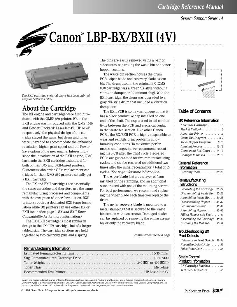
About the CartridgeThe BX engine and cartridge were first intro-duced with the QMS® 860 printer. When theBXII engine was introduced with the QMS 1660and Hewlett Packard® LaserJet® 4V, (HP or 4Vrespectively) the physical design of the car-tridge stayed the same, but drum and tonerwere upgraded to accommodate the enhancedresolution, higher print speed and the PowerSave option of the new engine. Interestingly,since the introduction of the BXII engine, QMShas made the BXII cartridge a standard forboth of their BX- and BXII-based printers.Customers who order OEM replacement car-tridges for their QMS 860 printers actually geta BXII cartridge.
The BX and BXII cartridges are essentiallythe same cartridge and therefore use the sameremanufacturing processes and componentswith the exception of toner formulation. BXIIprinters require a dedicated BXII toner formu-lation while BX printers can use either BX orBXII toner. (See page 3, BX and BXII TonerCompatibility for for more information.)
The BX/BXII cartridge is most similar indesign to the LX (IIP) cartridge, but of a largertabloid size. The cartridge sections are heldtogether by two cartridge pins and a spring.
The pins are easily removed using a pair ofsidecutters, separating the waste bin and tonerhopper sections.
The waste bin section houses the drum,PCR, wiper blade and recovery blade assem-bly. The drum used in the original BX (QMS860) cartridge was a green SX-style without avibration dampener (aluminum slug). With theBXII cartridge, the drum was upgraded to agray NX-style drum that included a vibrationdampener.
The BXII PCR is somewhat unique in that ithas a black conductive cap installed on oneend of the shaft. The cap is used to aid conduc-tivity between the PCR and electrical contactin the waste bin section. Like other CanonPCRs, the BX/BXII PCR is highly suspectible towear and exhibits print problems in lowhumidity conditions. To maximize perfor-mance and longevity, we recommend recoat-ing the PCR after the OEM cycle. RecoatedPCRs are guaranteed for five remanufacturingcycles, and can be recoated an additional twotimes after the initial recoating for a total of 15cycles. (See page 3 for more information)
The wiper blade features a layer of foaminstalled on the stamping, and an additionalwasher used with one of the mounting screws.For best performance, we recommend replac-ing the wiper blade each time you replace thedrum.
The mylar recovery blade is mounted to ametal stamping that is secured to the wastebin section with two screws. Damaged bladescan be replaced by removing the entire assem-bly or only the recovery blade.
System Support Series 14
Canon® LBP-BX/BXII (4V)
Cartridge Reference Manual
continued on the next page
Remanufacturing InformationEstimated Remanufacturing Time . . . . . . . . . . . . . . . . . . . . . . . . . . . . . . . . . . . . . . . . . . . . . . 15-30 mins.Sug. Remanufactured Cartridge Price . . . . . . . . . . . . . . . . . . . . . . . . . . . . . . . . . . . . . . . . . . . $109 -$139Toner Weight. . . . . . . . . . . . . . . . . . . . . . . . . . . . . . . . . . . . . . . . . . . . . . . . . . . . . . . . 340 (BX) or 400 (BXII)Toner Class . . . . . . . . . . . . . . . . . . . . . . . . . . . . . . . . . . . . . . . . . . . . . . . . . . . . . . . . . . . . . . . . . . . MicrofineRecommended Test Printer . . . . . . . . . . . . . . . . . . . . . . . . . . . . . . . . . . . . . . . . . . . . . . . HP LaserJet® 4V
The BXII cartridge pictured above has been paintedgray for better visibility.
© 1996, Static Control Components, Inc. All rights reserved worldwide.
Table of Contents
BX Reference InformationAbout the Cartridge . . . . . . . .1-3Market Outlook . . . . . . . . . . . . .3About the Printer . . . . . . . . . . . .4Waste Bin Diagram . . . . . . . .6-7Toner Hopper Diagram . . . .8-10Imaging Process . . . . . . . . .12-13Component Ref. Chart . . . .14-17Changes to the BX . . . . . . .18-19
General ReferenceInformation
Cleaning Tools . . . . . . . . . . .20-22
RemanufacturingInstructions
Separating the Cartridge . .23-24Disassembling Waste Bin .25-29Assembling Waste Bin . . . .30-33Disassembling Hopper . . . .34-37Sealing and Filling . . . . . . .38-42Assembling Hopper . . . . . . .43-46Filling Hopper w/o Seal . . . . . .47Assembling the Cartridge .48-49Installing the Pull Tab . . . .50-51
Troubleshooting BXPrint Defects
Reference to Print Defects .52-54Repetitive Defect Ruler . . . . . .55False Toner Low . . . . . . . . . . . .56
Static ControlProduct Information
BX Cartridge Supplies . . . . . . .57Technical Literature . . . . . . . . .58
Publication Price $39.95
About the BX CartridBX/BXII Reference Information
The drum shutter is a potential cause of damage to the d
The shutters extra length allows it to flex easily in the cent
a result, the shutter has a tendency to slap or rub against
drum with the cartridge is gripped in the shutter area or
shipping. A drum shutter felt is an essential aftermarke
nent in order to prevent scratches or nicks on the drum
The toner hopper section houses the mag roller, doc
and toner. The BX uses a black, coated mag roller. Th
tor of the black coating is one of the biggest issues w
the coating wears and smooths, it loses i
and properly deliver it to th
er the life of thor

About the BX Cartridge
© 1996, Static Control Components, Inc. All rights reserved worldwide.page 2 SSS.14
BX/BXII Reference Information
The drum shutter is a potential cause of damage to the drum.The shutter’s extra length allows it to flex easily in the center. Asa result, the shutter has a tendency to slap or rub against thedrum when the cartridge is gripped in the shutter area or dur-ing shipping. A drum shutter felt is an essential aftermarketcomponent in order to prevent scratches or nicks on the drum.
The toner hopper section houses the mag roller, doctor bladeand toner. The BX uses a black, coated mag roller. The wear fac-tor of the black coating is one of the biggest issues with this com-ponent. As the coating wears and smooths, it loses it’s ability touniformly charge toner and properly deliver it to the OPC. Theresult is lighter and lighter print over the life of the mag roller.
Once the coating is worn, neither stripping nor liquid treat-ments can restore the vital imaging properties of the mag roller.Our research has found that the only reliable method for attain-ing consistent mag roller performance is to completely resurfaceand recoat the sleeve. Static Control’s mag roller recoating pro-gram is projected to be available in the latter part of 1996.
The doctor blade uses plastic wipers installed at each end ofthe stamping that contact the mag roller sleeve. When replacingthe doctor blade, remove the wipers and install them on thereplacement blade. Doctor blade sealing foam, now availablefrom Static Control, is installed to the hopper body to preventleakage from underneath the doctor blade stamping.
Toner formulation is the key distinguishing factor between theBX and BXII cartridges. The BXII toner is formulated for thefaster speed (16 ppm), higher resolution and PowerSave™ fea-tures of the BXII engine and can be used in either BXII or BXcartridges. BX toner, however, is formulated exclusively for theBX application. The traditional BX cartridge uses 340 grams oftoner, while the BXII uses 400 grams.
The hopper is sealed using a gasket sealing assembly similarto the seal used in the LX (IIP) cartridge. Note that this seal isnot a “lay in” type of seal. The rear edge of the gasket isanchored in a groove at the rear of the seal channel. Sealing thehopper requires removal of the seal channel plug, toner low sen-sor bar and mag roller felts. The key to a secure seal and leak-age prevention is removing the OEM seal filament material. Allinstallation tools, cleaning tools and replacement items areincluded in the BX/BXII Gasket Sealing Assembly InstallationKit. An overview of the sealing process is included with theremanufacturing instructions in this manual on page 38.
BX and BXII Toner CompatibilityBX MicroGraphics 1 toner should be used exclusively with BX(QMS 860) applications. The BX MicroGraphics 1 toner is not for-mulated to meet the demands of the faster print speed, higher
Cartridge InformationQMS 860 (BX) QMS 1660E (BXII) HP LaserJet 4V/4MV (BXII)
OEM Part Number Canon EP-B Canon EP-BII C3900AOEM Published Yield1 7,500 pages 7,500 pages (4% coverage) 8,100 pagesPrice (Retail, as of June/July 1996) $199.00 $206.00 $206.001Yield is based on 5% page coverage, letter size pages unless noted otherwise.
Printer CompatibilityBXAccel-Writer 8100Acorn Graphtex 400Apple Laserwriter Select 350Birmy Graphics Powerimage 11/17, XL 11/17Brother HL-8PSJ/HP-PSJCalcomp CCL600/XF/ESCanon LBP-AX/BX
Daikin Industries Comtec 9700+ECRM ScriptprinterGenicom Corporation 9080Intergraph CorpJBCC Power Writer 5036JRL Systems Easycopy L SeriesJRL Systems LP-180Newgen Sys Turbo PS-440B/660B/1200B
OCE 6450/6451/6460QMS 860 Hammerhead Print SystemQMS 860/860 Plus Print SystemVarityper 5160Varityper PantherXante Accel-A-Writer 8100Xante Accel-A-Writer 8100 ENHXitron Clipper Cadet
BXIIBGL Tech Laserleader Mark 9416Calcomp CCL 600 ES/1200 ESCanon P-380Genicom 9160Hewlett-Packard LaserJet 4MV
Hewlett-Packard LaserJet 4VJRL Systems LP180-16 Model 1JRL Systems LP180-16 Model 2JRL Systems LP180-16 Model 3Newgen Systems DesignXpress 12Newgen Systems DesignXpress 6
Newgen Systems DesignXpress 8Prepress Solutions VT1200QMS 1660 Print SystemQMS 1660E Print SystemQMS 1660EX Print SystemXante Corporation Accel-A-Writer 8200

print resolution and power save features of the BXII-based print-ers. The print speed of the BXII printers is 16 ppm, double that ofthe BX, so there is less dwell time in the fuser section for meltingthe toner and bonding it to paper. The PowerSave™ feature of theBXII printers also requires a specific toner formulation thatworks with the wide range of temperature changes in the fusersection. Using BX toner in a BXII application generally results ina high degree of fuser offsetting and poor print quality. For bestresults, use BX MicroGraphics 1 toner exclusively with BX (QMS860) applications.
BXII MicroGraphics 1 toner can be used in either the BX orBXII application. When QMS introduced the BXII-based 1660printer, the BXII cartridge become the standard for both the 860and 1660 printers. An end user who orders a cartridge for the860 actually gets a BXII cartridge. Because the BXII holds 60more grams than the BX, the end user also gets a higher ratedpage yield.
We recommend building BX cartridges to BXII specificationsin order to take advantage of increased yield as well as completecartridge compatibility between BX and BXII printers.
BX UltraPrint DrumThe new BX UltraPrint™ drum used in combination with BX orBXII MicroGraphics toner offers a significant reduction in fuseroffsetting defects commonly associated with BXII printers. Thedrum was co-developed by our systems experts to obtainincreased yield while simultaneously minimizing the occurrenceof offsetting. The BX UltraPrint drum and MicroGraphics combi-nation achieves print quality and yield (8,000 pages at 5%) equalto that of the OEM.
Static Control’s BX/BXIIRemanufactured PCRLike most of the Canon-based Primary Charge Rollers, BXIIOEM PCRs are also recoatable through the Static Control PCRRecoating Program. After the initial recoating which is guaran-teed for 5 remanufacturing cycles, the BXII PCR can be recoatedan additional two times for a total of 15 remanufacturing cycles.
• Remove the black conductive Cap before recoatingPCRs from BX/BXII cartridges may have a black conductive capinstalled on one end of the PCR shaft. Before you send in yourBX/BXII PCRs for recoating, be sure to remove the black con-ductive cap from the PCR shaft and store it at your facility. Capsshould be reinstalled on the shaft of the recoated PCRs.
If caps are left installed on incoming PCRs, we will makeevery effort to return them with the recoated PCRs.
• Recoated BX/BXII PCRs are a mottled, tan or grayish color When you get recoated BX/BXII PCRs back, you will notice thatthe rollers appear mottled, tan or gray in color. During therecoating process the black outer layer of the PCR material isremoved and replaced with a clear coating. The tan or graycolor is the underlying resistive layer showing through the coat-ing.
• BX and BXII recoated PCRs are interchangeable There are no discernable differences between the PCRs in BX orBXII cartridge applications. Recoated BX/BXII PCRs can beused with either the BX or BXII applications.
For more information about Static Control’s PCR Recoating Program,contact your Sales Representative. Phone numbers are listed on the backpage of this manual.
© 1996, Static Control Components, Inc. All rights reserved worldwide. SSS.14 page 3
BX/BXII Reference Information
Market OutlookThe BX-based printer was a significant addition to the laserprinter market because it was the first tabloid-sized printerin the 7-10 ppm market segment offered at an affordableprice (about $3,500). The printer offered small to medium-sized businesses graphics capability and tabloid printing at600 dpi print resolution. Improvements in networkability,resolution, speed (16 ppm), and lower price points in thelater BXII-based printers have kept the printer competitivein the 16-20 ppm market segment. Without a doubt, pricingof under $2,000 (street price) for BX printers, in addition tothe expanded features, fuel the popularity of these printers.
BX/BXII printers are usually found in small graphics com-panies or graphics departments, newspaper companies,publishing, and departments that specialize in CAD applica-tions. Tabloid-sized page printing, full bleed and heavygraphics printing can increase page coverage which in turncan decrease yield rates.
Currently in North America, there are an estimated250,000 BX/BXII printer placements which consume approxi-mately 6-10 cartridges per year. As BXII printers remaincompetitive with other tabloid printers in similar marketsegments, placements are expected to increase. In the lastyear, industry trends have shown that BX/BXII cartridgeshave gained considerable share in the cartridge remanufac-turing mix of Canon-based cartridges. Although the share ofBX remanufactured cartridges is quite low compared tomature cartridge markets such as the SX, we expect years ofcontinued growth in the BX/BXII market share, as well asgrowth in total cartridge consumption.BX MicroGraphics I BXII MicroGraphics I
(BX340B) (BX2-400B)
BX (QMS 860) yes yes
BXII (HP4V) no yes
Compatibility Chart
CART
RIDG
E TY
PE
COMPATIBLE TONER FORMULATION

About the BX Printers
© 1996, Static Control Components, Inc. All rights reserved worldwide.page 4 SSS.14
BX/BXII Reference Information
Printer InformationQMS 860 (BX) QMS 1660E (BXII) HP LaserJet 4V/4MV (BXII)
Introduction List Price $3,906.00 $3,999.00 $2,449 (4V), $3,549 (4MV)First Ship Date July 1992 January 1995 September 1994Pages Per Minute (ppm) 8 ppm (letter) 16 ppm (letter) 16 ppm (let, legal, exec)
9 ppm (tabloid) 8 ppm (tabloid)Engine Duty Cycle 10,000 pages/month 35,000 pages/month 35,000 pages/monthProcessor 25 MHz Intel 80960CA 33 MHz IDT 3081E 33 MHz Intel 80960CFResolution (dpi) 600 (H) x 600 (V) 600 (H) x 600 (V) dpi (original) 600 (H) x 600 (V) dpi
1200 (H) x 600 (V) dpi (update REt resolution enhancementas of June 1995) 120 gray levels (PCL mode)
at 106 lpiToner Reduction Mode N/A yes (Conserve Toner mode) yes (Economode)EnergyStar Compliant no yes yes (PowerSave™ feature)Page Size letter, A4, A5, legal, exec., B4 letter, A4, A5, A6, legal, letter, A4, legal, exec., B4,
11x17” (tabloid), A3 exec., B4, B5, 11x17” (tab), A3 11x17” (tabloid), A3Target Market Graphic arts, presentation Workgroup printing, General office printing
graphics, desktop publishing, business graphics, (both printers); CAD, desktopword processing text processing publishing (4MV)
QMS 860QMS was one of the first companies to introduce a printer withthe Canon BX engine, and for several years after the release ofthe 860, QMS held a dominant share of the BX market. The QMS860 features 8 ppm print speed and 600 dpi print resolution.Most notable about the release of the 860 printer was that QMSset a new price point for tabloid printers. The 860 offered small-to medium-sized workgroups high-resolution tabloid printing atan affordable price, which made it one of the most popular BX-based printers. Versions of the 860 include the 860 HammerheadPrint System and the 860 Plus, all of which are based on thesame BX engine.
QMS 1660EThe QMS 1660E is an updated version (January 1995) of the 1660,which was one of the first BXII-based printers. The E version isstill based on the BXII engine and features 16 ppm print speed,1,200x600 dpi resolution and QMS’s fastest controller design. The1660E also features full bleed capability on 11x17 size paper.
The latest “E” version of the printer has built-in Ethernet capa-bility that QMS refers to as “CrownNet”. Although the HP ver-sion of the BXII sells for less than the 1660E, QMS believes thatthe CrownNet technology is a strong factor for securing sales.
In May 1995, QMS went even further to upgrade the 1660E byimproving print resolution from 600x600 to 1200(H) x 600(V) with
laser modulation. With adequate memory installed, the newdaughterboard allows the machine to operate at 1200x1200 dpi.
Hewlett Packard LaserJet 4V/4MVThe BXII-based LJ4V/4MV were the first of HP’s tabloid-sizelaser printers, but surprisingly HP was not the first company tooffer a printer based on the BXII engine: CalComp, NewGen,QMS and Xante introduced their versions of the printer severalmonths earlier.
HP’s version of the BXII is virtually indistinguishable fromother versions of the printer, not only in features, but also inappearance. At the time of its introduction, the 4V/MV featuredthe most powerful processor delivered by HP, a faster processorthan HP’s own 4Si. Like the QMS 1660E, the HP4V also offers fullbleed graphic technology for 11x17 size paper.
Reportedly, HP’s 4V/4MV printers were developed to bridge agap between the existing 12 ppm LJ4 plus and 17 ppm LJ4Siprinters. At the time the 4V/4MV were introduced, HP envi-sioned the need for tabloid-size printing to become more main-stream in the future. Which it has; current BXII printers arewidely used, not only for general office printing, but also for CADand graphics printing.

Notes
© 1996, Static Control Components, Inc. All rights reserved worldwide. SSS.14 page 5
BX/BXII Reference Information

Waste Bin Section - Terms and Definitions
© 1996, Static Control Components, Inc. All rights reserved worldwide.page 6 SSS.14
BX/BXII Reference Information
Spur Gear Drum ElectricalContact
OPC Drum
Wiper Blade
Recovery BladeAssemblyDrum
Contact Axle (Left end)
StampingStamping
SealingFoam
Blade
Blade
Primary ChargeRoller (PCR)PCR
Conductive Cap(BXII Models)
PCR Shaft
Washer
Helical Gear
Wiper BladeSealing Foam
PCRElectricalContact
PCR Saddle(only left end saddle
is conductive)Wiper BladeEnd Foam
RecoveryMagnet Strip
DrumShutter
WasteBin
Drum ShutterActuator Arm
Drum Axle(Right end)
Cartridge Pin(OEM-style)
CartridgePin (OEM-
style)
ExteriorSpring
A second wiper blade end foam is installed in reverse orientation at the oppositeend of the waste bin. Note that there is also another PCR saddle installed at theopposite end of the waste bin which is NOT CONDUCTIVE.

© 1996, Static Control Components, Inc. All rights reserved worldwide. SSS.14 page 7
BX/BXII Reference Information
Cartridge PinTwo pins installed at each end of the assembled cartridge holdthe waste bin and hopper sections together.
Drum Axle (Right)Installed at the right end of the waste bin section to hold thedrum in place.
Drum Contact Axle (Left)Installed at the left end of the waste bin section to hold the drumin place; a short metal rod installed in the axle assembly makescontact with the drum contact installed in the spur gear, provid-ing electrical contact between the drum and printer.
Drum Electrical ContactInstalled in the spur gear of the drum; makes contact with theshort metal rod installed in the drum contact axle and provideselectrical contact between the drum and printer.
Drum ShutterProtects the drum from light damage when the cartridge is outof the printer. When the cartridge is installed in the printer, theshutter opens so that the drum is exposed to the paper.
Drum Shutter Actuator ArmOpens the drum shutter when the cartridge is installed in theprinter.
Drum Shutter FeltShutter felt is an aftermarket component installed on the interi-or of the drum shutter. It protects the drum from potential dam-age caused by the opening and closing of the shutter. (Not shownin the illustration)
Exterior SpringInstalled on the exterior of the cartridge. Maintains pressurebetween the waste bin and hopper sections so the mag rollerbushings are properly seated on the drum, maintaining the cor-rect air gap between the drum and mag roller.
Organic Photo Conductor (OPC) DrumAn aluminum cylinder coated with light-sensitive organic photo-conductive material used to retain an image written to it by alaser beam. (Also called OPC, drum, photoreceptor)
OPC Drum Gears (Helical and Spur)The spur gear, on the left end of the waste bin section, housesthe drum electrical contact. The other larger gear is the helicalgear.
Primary Charge RollerUniformly charges the OPC drum. (Also called PCR, chargeroller, or roller)
PCR Conductive CapInstalled on the contact end of the PCR shaft; the cap aids con-ductivity to the PCR. (BXII Models Only).
PCR Electrical ContactMetal contact installed in the waste bin section of the cartridge;makes contact with conductive cap on shaft of installed PCR andprovides electrical contact between the printer and the PCR.
PCR SaddlesTwo saddles support the PCR at each end of the shaft. One sad-dle, located at the contact end of the cartridge (left end), is madeof conductive material. The other saddle is non-conductive. Thesprings at the base of the saddles maintain tension on the PCRso that it will make constant and uniform contact with the drum.
Recovery Blade AssemblyActs as a dam at the base of the waste bin, keeping the tonerfrom falling out of the waste bin onto the paper. On the BX car-tridge, the recovery blade is attached to a removable metalstamping. (Also called catcher blade or scavenger blade)
Recovery Magnet StripA magnet strip installed along the length of the waste bin sec-tion between the recovery blade assembly and waste bin body;used to catch toner that migrates past the recovery blade assem-bly.
Waste BinA receptacle that catches toner wiped from the drum. (Alsocalled waste hopper, dust bin)
Wiper BladeCleans the drum by wiping away toner that was not transferredto the paper. Constructed of a metal stamping (base) andpolyurethane blade. (Also called cleaning blade)
Wiper Blade End Foam Layer of foam that seals the area at the end of the polyurethanewiper blade; prevents leakage from the waste bin.
Wiper Blade Sealing FoamA strip of foam installed under the wiper blade along the lengthof the waste bin; the foam seals the area between the wiperblade and waste bin in order to prevent leakage from the wastebin.

Toner Hopper Section - Terms and Definitions
© 1996, Static Control Components, Inc. All rights reserved worldwide.page 8 SSS.14
BX/BXII Reference Information
Mag RollerSleeve Bushing
(Right)
Mag RollerSleeve Bushing
(Left)
Plastic Wiper(Left)
Plastic Wiper(Right)
Blade
Stamping
DoctorBlade
Mag RollerEnd Plate(Left End)
Mag RollerFelt
Mag RollerDrive Gear
Seal Channel
Plug
Seal Channel Plug
(Installed)
Doctor BladeSealing Foam
Gear HousingEnd Plate(Right End)
ElectricalContacts
MagneticDeveloper Roller
Mag RollerMagnet
Mag RollerElectrical Contactlocated at this end
of the roller
Mag RollerSleeve
Toner LowSensor Bar
Shown as removed
Pull Tab
Seal PullStrip
Seal AdhesiveRelease Liner
Mag Roller MagnetPositioner Bushing
Gasket SealingAssembly
SealChannel
SealChannelGroove
TonerReservoir
TonerPort
Toner FillOpening
Hopper Cap
Mag RollerStabilizer (Left)
TonerAgitator BarDrive Gear
A second mag roller felt is installed in reverse orientation at theopposite end of the hopper. Note that there is no seal channel plugat opposite end of the hopper.

© 1996, Static Control Components, Inc. All rights reserved worldwide. SSS.14 page 9
BX/BXII Reference Information
Development StationArea of the cartridge where toner is transferred from the tonerhopper to the latent image on the OPC drum using the magroller and doctor blade. (Not shown in illustration)
Doctor BladeUniformly meters the amount of toner on the mag roller. Thedoctor blade is constructed of a metal stamping (base) and aflexible blade. (Also called metering blade)
Doctor Blade Sealing FoamA strip of foam that seals the area between doctor blade stamp-ing and cartridge shell; prevents leakage from the toner hopper.
Electrical ContactsMetal contacts, located in the gear housing end plate, that pro-vide electrical contact between the printer and doctor blade,toner low sensor bar and mag roller.
Gasket Sealing AssemblyA rigid gasket base on which a seal is adhered. The gasket baseis installed in the seal channel with the long rear edge anchoredin a groove at the rear of the hopper seal channel.
Gear Housing End Plate (Right End)A removable housing that covers the toner agitator drive gear atthe right end of the hopper. This housing also provides a posi-tioner bushing that supports the magnet inside the mag rollersleeve and keeps the magnet stationary. The doctor blade, tonerlow bar and mag roller electrical contacts are housed in this endplate.
Hopper CapPlugs the fill opening of the hopper.
Magnetic Developer RollerA rotating coated aluminum sleeve around a stationary magnet.The mag roller attracts toner magnetically and applied AC/DCvoltage charges the toner and transfers it to the OPC. A doctorblade meters the toner before it is delivered to the OPC. (Alsocalled mag roller, developer roller)
Mag Roller Drive GearRotates the mag roller sleeve around the permanent magnet.
Mag Roller Electrical Contact Two prong contacts attached to the mag roller sleeve that con-tact the electrical contacts in the gear housing end plate; pro-vides electrical contact between the mag roller sleeve andprinter.
Mag Roller End Plate (Left End)Installed on the left side of the hopper section to cover the endof the mag roller.
Mag Roller FeltMaterial that lines the saddles where the mag roller rests in thehopper; also provides a seal at the ends of the mag roller.
Mag Roller Magnet Positioner BushingSupports the magnet inside the mag roller sleeve and keeps themagnet stationary; located in the gear housing end plate (rightend).
Mag Roller Sleeve Bushing (Right and Left)Placed on each end of the mag roller sleeve to establish a consis-tent air gap between the mag roller and drum when the car-tridge sections are assembled.
Mag Roller Stabilizer (Left End only)Prevents lateral movement of the mag roller. A stabilizer isplaced on the left end of the mag roller axle and secured inplace by screws and locating posts in the hopper section.
Plastic Wiper (Right and Left)Removable wipers installed on each end of the doctor bladestamping; wipes toner from the ends of the mag roller that rideon the mag roller felt; prevents toner from adhering to sleeve.Right and left plastic wipers are NOT interchangeable.
Pull TabAttached to the seal pull strip to enable the end user to removethe seal pull strip and release toner into the development sta-tion.
Seal ChannelThe area around the perimeter of the toner port where a seal isattached to the hopper body.
Seal Channel PlugA plastic plug installed at the left end of the hopper section toseal the end of the hopper where the seal pull strip exits thehopper; the plug also provides a positioner bushing for one endof the toner low sensor bar.
Seal Pull StripStrip of seal material pulled by the end user.
continued on next page

Toner Hopper Section - Terms and Definitions
© 1996, Static Control Components, Inc. All rights reserved worldwide.page 10 SSS.14
BX/BXII Reference Information
Seal Release LinerA clear strip that covers the pressure sensitive adhesive on thebottom side of the gasket sealing assembly; the extra length ofthe liner is provided so that the liner can be removed after theseal is fully positioned in the seal channel.
Toner Agitator BarA metal paddle bar that rotates inside the toner hopper to movethe toner toward the development station. (Not shown in theillustration)
Toner Agitator Bar Drive GearRotates the agitator bar in the hopper; located at the drive trainend of the hopper section (right end).
Toner Low Sensor BarActs as an antenna to detect low toner volume in the hopper.Once a signal from the antenna reaches a specified value, theprinter displays a toner low warning for the printer operator.
Toner PortAn opening, occupied by the seal, that runs along the length ofthe hopper. Once the seal is removed, toner travels through thisopening to the development station.
Toner ReservoirHolds the toner load needed for imaging.

Notes
© 1996, Static Control Components, Inc. All rights reserved worldwide. SSS.14 page 11
BX/BXII Reference Information

The Imaging Process
© 1996, Static Control Components, Inc. All rights reserved worldwide.page 12 SSS.14
BX/BXII Reference Information
Primary ChargeRoller (PCR)
OPC Drum
Recovery BladeAssembly
TransferRoller
Pape
r
Toner AgitatorBlade
Toner
Seal
Wiper Blade Grip Handle
DrumShutter
Upper FuserRoller
Lower PressureRoller
Waste Bin
TonerHopper
Doctor Blade
Toner LowSensor Bar
MagneticDeveloper Roller
Laser
The illustration below is a schematic view of the BX/BXII cartridgeimaging components from the left side of the cartridge. The cartridge isoriented as it would appear installed in the printer.

© 1996, Static Control Components, Inc. All rights reserved worldwide. SSS.14 page 13
The Seven Steps of Electrophotography
BX/BXII Reference Information
3 DevelopmentAt the development station, thelatent image on the drum ischanged into a visible tonerimage that will be transferredto the paper. The negativelycharged toner is attracted tothe latent images (exposedareas) on the drum where thecharge is more positive. The
toner is repelled from unexposed areas of the drum wherecharge has remained negative.
Toner is magnetically attracted to a 4-pole stationary magnetinside a rotating developer sleeve. The developer roller and thedoctor blade charge the toner. The doctor blade also meters theamount of toner present on the developer roller. An AC/DCvoltage gives the toner a negative charge bias and transfers thetoner to the OPC.
7 ErasureIn PCR-based systems such asthe BX/BXII, the PCR “erases”residual charges on the OPC byapplying a uniform surfacecharge to the OPC. Any varia-tions in charge on the OPC sur-face are made uniform as thePCR charges the OPC.
1 ChargingThe process begins with thecharging of the OPC by the pri-mary charge roller. A constantflow of current from the PCRproduces a blanket of negativecharge on the surface of therotating OPC drum.
2 Exposure The evenly charged OPC sur-face then passes under a laserbeam, which exposes the OPCone line at a time.
This focused beam scansacross the drum and emitslight only at locations to betoned later at the development
station. The energy from the laser activates the photoconduc-tor, and the surface charge is dissipated to ground forming thelatent image.
4 Transferring After development, the tonerimage on the surface of theOPC is brought in contact withthe paper moving at the samespeed. A transfer roller on theopposite side of the paperapplies a positive charge to thepaper, causing the negatively
charged toner to be attracted and transferred to the paper.
5 FusingThe paper, along with thetransferred toner image, thentravels to the fuser assembly.This assembly is composed of aheated upper roller and alower pressure roller. Duringfusing, the toner particles aremelted and fused to the paper.
6 CleaningSince a percentage of toner onthe photoreceptor is not trans-ferred, the OPC surface mustbe cleaned by a wiper blade.Any toner not transferred tothe paper is deposited in thewaste bin. A recovery bladeseals the area between the
drum and waste bin to prevent toner from spilling onto thepaper.
OPC
OPC
Toner
Upper FuserRoller
Lower Pressure
Roller
Negativecharge
PCR
PCR
TransferRoller
Pape
r
Fusedtoner
Pape
r
MagRollerToner
OPCDoctorBlade
OPC
OPC
OPC
PCR
Residualcharge
WiperBlade
Laser
LatentImage

BX Component Management Reference Chart
© 1996, Static Control Components, Inc. All rights reserved worldwide.page 14 SSS.14
BX/BXII Reference Information
COMPONENT CODE CLEAN LUBRICATE
Cartridge Pin LXPIN SubstituteComponent
NA NA
OPC Drum BXBGDRGR(with gears)UPBXDRGR(with gears)
Dry, filtered compressed air Pad coated area of drum with Kynar®; rotatedrum against wiper blade - min. 6 rotations
Drum Shutter Felt XP15DSFELTAftermarketComponent
Dry, filtered compressed air NA
SCCRemanufactured PCR
BXRMPCR 91-99% isopropyl alcohol and soft, lint-free cloth; DO NOT clean OEM PCRwith alcohol
DO NOT lubricate PCR shaft; lubricant notpresent in out-of-box OEM cartridge
PCR Cap - Conductive NA Lint-free cleaning cloth or lint-freeswab
DO NOT apply lubricant to the cap
PCR ContactSaddle
NA Lint-free swab dampened with 91-99%isopropyl alcohol
DO NOT lubricate either PCR saddle; lubricantnot present on out-of-box OEM cartridge
Wiper Blade BXBLADE Dry, filtered compressed air; direct airclose the surface of foam installed onthe stamping;DO NOT clean with alcohol
Dip edge of wiper blade in Kynar®; make sureblade edge is evenly covered
Wiper BladeSealing Foam
NA Dry, filtered compressed air; direct airclose to surface of foam
NA
Wiper BladeEnd Foam
NA Dry, filtered compressed air; direct airclose to surface of foam
NA
Recovery BladeAssembly
BXRBASM,BXRECBLADE orPRECB-BX
Dry, filtered compressed air NA
Recovery MagnetStrip
NA Dry, filtered compressed air NA
MagneticDeveloper Roller
Remanufacturedsleeve underdevelopment
Dry, filtered compressed air NA
Mag RollerElectrical Contacts
NA Clean contact prongs (end of magroller sleeve) and metal contact (onright end plate) with lint-free swabdampened with 91-99% isopropylalcohol
Apply a very small amount of conductivelubricant to the metal contact in the end plateSee page 21 for important informationregarding the use of conductive lubricant
Mag Roller Felt BXMRFELT Dry, filtered compressed air NA

EVALUATE REPLACE
OEM cartridge pins should be straight, unmarred and unmodified inlength
Replace OEM pins if bent, cut down or lost
Test print to check print density; check for deep concentric wearlines
Replace OEM drum after OEM cycle with SCC system-qualifieddrum; test print and replace as needed.
Install on interior of drum shutter to help protect drum fromdamage caused by opening and closing of shutter; felt shouldappear clean and fully secured to the cartridge
Replace if felt starts to peel, becomes dislodged or is missing
OEM PCR typically wears out after OEM cycle; SCC PCR guaranteedfor 5 cycles; note that the BX/BXII remanufactured PCR is amottled tan color
Replace OEM PCR after OEM cycle with SCC PCR; recoat SCCPCR after 5th and 10th remanufacturing cycles; one cycle PCRsare also available
Cap should be securely installed on the end of the PCR shaft Replace cap if damaged or missing
NA NA
Test print each cycle and check for vertical streaks Replace if wiper blade-related print defects detected; install newwiper blade each time a new drum is installed; test print eachcycle and replace as required
Foam should display smooth surface and be secured to thecartridge surface
Replace if foam is pitted, torn, dislodged or missing
Foam should display smooth surface and be secured to thecartridge surface
Replace if foam is pitted, torn, dislodged or missing
Blade should display a smooth surface and be completely securedto metal stamping
Replace blade if bent, kinked or damaged; replace entireassembly or blade only; installation tool required (Item Code:WXRBIKIT)
Magnet strip should be firmly secured to cartridge Replace if not secured to cartridge or if missing
Test print against baseline to check for light print defects; visuallyinspect for scratches, previously treated or sandblasted magrollers
Replacement mag roller sleeve under development
For optimum continuity make sure metal prongs are free of tonerand debris; make sure prongs and end plate contact make propercontact when the end plate is reinstalled
If the prongs do not make contact with metal contact in endplate, bend prongs to correct position
Felt should appear clean, intact and secured to mag roller saddle Replace if felt becomes excessively frayed, compacted withtoner, shiny in appearance or dislodged
© 1996, Static Control Components, Inc. All rights reserved worldwide. SSS.14 page 15
BX/BXII Reference Information

BX Component Management Reference Chart
© 1996, Static Control Components, Inc. All rights reserved worldwide.page 16 SSS.14
BX/BXII Reference Information
COMPONENT CODE CLEAN LUBRICATE
Doctor Blade BXDBLADE Dry, filtered compressed air; DO NOTclean with alcohol
NA
Doctor BladeSealing Foam
BXDBSFOAM Dry, filtered compressed air; direct airclose to surface of foam
NA
Gasket SealingAssembly
BXGSA NA NA
Toner BX/QMS: BX340BLJ4V/BXII: BX2-400B
Clean toner hopper with dry, filteredcompressed air
NA

© 1996, Static Control Components, Inc. All rights reserved worldwide. SSS.14 page 17
BX/BXII Reference Information
Test print to check print quality, background, or side-to-sidevariations in print quality
Replace OEM doctor blade with SCC replacement after OEMcycle; remove the plastic wipers from each end of the stampingand reinstall on the replacement blade; test print each cycle andreplace as required
Foam should display smooth surface and be secured to thecartridge surface
Replace if foam is pitted, torn, dislodged or missing
NA Remove OEM seal filament; install SCC BX Gasket SealingAssembly; installation tools required; see page 38 for details
Take care not to bend the toner low sensor bar when cleaning orfilling the hopper; otherwise false toner low warnings can be aresult; see pages 20-21 for details
NA
EVALUATE REPLACE

Changes to the BX/BXII Cartridge
© 1996, Static Control Components, Inc. All rights reserved worldwide.page 18 SSS.14
BX/BXII Reference Information
Variations in Left-end Mag RollerEnd Cap, Stabilizer, and Mag RollerDrive GearIf you have been observant all of the years the BX/BXII cartridgehas been in circulation, you may have noticed some subtlechanges in the mag roller end plate, stabilizer and mag rollerdrive gear. There are two variations of the end plate that coversthe left end of the mag roller. In comparing FIGs 1 and 2, youcan see a thin, raised ring around the axle hub. The ring mayfunction to help position the gear or prevent wear to the end capand gear.
The stabilizer has undergone at least three modifications thatwe have been able to document, as shown in FIGs 3 , 4 and 5.The stabilizer shown in FIG 3 is most commonly found in theOEM and remanufactured cartridges we use in the cartridgedevelopment lab and is used in combination with the mag rollerdrive gear shown in FIG 6. The stabilizer shown in FIG 5 isanother version, which is used with a different style gear thatdoes not incorporate a raised collar in the center of the gear.
When assembling BX/BXII cartridges, make sure that youhave the correct combination of gear and stabilizer; otherwise,the end plate will not fit properly over the end of the mag rollerand hopper. The stabilizers shown in FIG 3 and 4 should be usedwith the gear shown in FIG 6. The stabilizer shown in FIG 5should be used with the gear that does not incorporate a raisedcollar in the center of the gear (not shown in photo). The endplate may be used with either combination of stabilizer andgear.
FIG 3
FIG 1 FIG 2
FIG 4
FIG 5 FIG 6
Note that the stabilizer shownabove has raised collar.
Note the raised ring around theaxle hub.
The end plate shown above doesnot display a raised ring aroundthe axle hub.
Current style mag roller drivegear should be used in combina-tion with the stabilizer shown inFIGs 3 and 4.
The stabilizer shown above ismost commonly seen in current-production OEM cartridges.
A variation of the stabilizershown in FIG 4.

BX/BXII Reference Information
© 1996, Static Control Components, Inc. All rights reserved worldwide. SSS.14 page 19
Changes from BX to BXIIThe BX engine and cartridge were first introduced with theQMS 860 printer. When the BXII engine was introduced with theQMS 1660 and Hewlett Packard LJ4V, the physical design of thecartridge essentially stayed the same, with only a few upgradesto accommodate the enhanced resolution and higher printspeed of the BXII engine.
DrumThe original BX cartridge used a green SX-type technologydrum without a vibration dampener (aluminum slug). With theintroduction of the BXII, the drum was upgraded to a gray NX-type technology drum that included a vibration dampener.
PCRA conductive cap was added to one end of the PCR shaft in BXIIcartridges. When the PCR is installed in the cartridge, the end ofthe PCR with the cap is installed against the metal contact adja-cent to the conductive PCR saddle. The cap is used to aid con-ductivity between the PCR and metal contact that contacts withthe printer. The photos below show the difference between BXand BXII PCR configurations.
Pull TabThe photo below shows the change in pull tab design betweenBX and BXII cartridges. The earlier, BX pull tab is most similarto the tab used with the LX cartridge. The BXII pull tab featuresa loop grip area.
TonerToner formulation is the most significant difference between theBX and BXII cartridges. BXII toner is formulated for the fasterspeed, higher resolution and Power Save™ requirements of theBXII machine. The BXII cartridge offers higher page yield with atoner load of 400 grams, which is 60 grams more than the BXcartridge.
The BX PCR configuration doesnot include a conductive cap. Theshaft makes contact with themetal contact in the cartridge
The BXII PCR configurationincludes a conductive capinstalled on the contact end ofthe PCR shaft
PCR shaft only Conductive cap
The photo above shows the difference in pull tabs between BX and BXIIcartridges. The cartridge on the right is a BXII cartridge, the other twoare BX cartridges.
BX pull tabs BXII pull tab

Tools for Cleaning
© 1996, Static Control Components, Inc. All rights reserved worldwide.page 20 SSS.14
General Reference Information
The Fundamentals of CleaningThere are hundreds of cleaning products and treatments on themarket that promise to enhance yield, restore newness, andeven improve the durability of components. However, throughyears of research, our development labs have found that themost basic cleaning tools work the best: compressed air, tonervacuum, lint-free cleaning cloths, cotton swabs, isopropyl alco-hol, and Kynar®.
Our philosophy on cleaning is that the less you affect theproperties of components, the better. A cartridge is a complexsystem of interrelated components, and it is important to retainthe original balance of the system and imaging properties asmuch as possible. Adversely affecting even one component withtreatments or harsh cleaners can affect the entire imaging sys-tem. The key to effective cleaning is preventing damage andmaintaining a balanced system.
If you use gentle cleaning procedures and a system of compo-nents that work well together, you should not need to useextreme cleaning methods. Compressed air cleaning is recom-mended for all cartridge components because it does not chemi-cally or structurally affect components. Cleaning agents cancause buildup or leave residues that are harmful to components
and to the entire cartridge system. An example of this is usingsolvents to clean wiper blades. Certain chemicals can leave afilm on the blade that can be transferred to the drum as well asto the PCR.
As you read through this manual, you will notice that we cau-tion against cleaners, treatments, and overcoatings. Alcohol-based cleaners, for example, attack the surface of the drum, magroller, and PCR. It is the surface properties of components thatare critical to the imaging process. Once you affect the proper-ties of one component, the entire imaging system is affected.
Dry, Filtered Compressed AirCompressed air is the most efficient and effective cleaningmethod for all cartridge components. Cleaning with compressedair takes less time because you are able to cover more area witha sweep of the air nozzle than with a vacuum attachment. Andyou are able to direct air into narrow areas that cannot bereached with a vacuum. Fragile materials such as foam and feltcan be thoroughly cleaned with no damage to the material.
Just having compressed air is not enough. You should only usedry, well-filtered compressed air. Oil and water in the air linescan be transferred to components and can greatly increase the
Component Preferred Method Alternative Method Not RecommendedOPC Drum Compressed air Dry, lint-free cloth Coatings, treatments, toner cloths*, polishes,
alcohol, or any type of solvent
Primary Charge Roller (OEM) Lint-free cloth dampened Compressed air Wax, treatments, toner cloths, alcohol, or any type with water of solvent
SCC Remanufactured PCR Lint-free cloth dampened NA Do not use any cleaning method other than thewith isopropyl alcohol** preferred method prescribed
.Mag Roller Compressed air Dry, lint-free cloth Coatings, treatments, toner cloth,
alcohol, or any type of solvent
Wiper Blade Compressed air NA Creams, alcohol-based coatings, toner cloth,alcohol, or any type of solvent
Doctor Blade Compressed air NA Creams, alcohol-based coatings, toner cloth,alcohol, or any type of solvent
Electrical Contacts Cotton swab dampened NA NAwith isopropyl alcohol
Felt and Foam Material Compressed air Toner vacuum Alcohol or any type of solvent
Hopper Section Compressed air Toner vacuum Cleaners or solvents (excluding alcohol)Use extreme caution not to bend toner low bar
Waste Bin Section Compressed air Toner vacuum Cleaners or solvents
Cartridge Parts Compressed air Dry, lint-free cloth/swab Cleaners or solvents (excluding alcohol)(bushings, gears, etc.) with isopropyl alcohol
An Overview of Cleaning Recommendations
* Toner cloths are impregnated with a solution that will contaminate imaging components. Use toner cloths only to clean the exterior of an assembled cartridge.** For best results use 91-99% isopropyl alcohol. DO NOT USE DENATURED ALCOHOL.

© 1996, Static Control Components, Inc. All rights reserved worldwide. SSS.14 page 21
General Reference Information
Using ConductiveCartridge LubricantConductive cartridge lubricant isused in most cartridges to aid con-ductivity and reduce friction inareas where electrical contactsmeet. Equally important to the useof conductive cartridge lubricant is where it is applied and howmuch is used.
A general rule of thumb regarding application is “apply conduc-tive lubricant only where it is present on the OEM cartridge.” If lubri-cant is truly required, the OEM would be the first to recognize thisand would apply it accordingly. On the BX/BXII cartridge, conduc-tive lubricant is present on the mag roller contact only. Do not applylubricant to the PCR saddles.
Each time you remanufacture a cartridge, wipe off the old lubri-cant with a swab or cloth and apply fresh lubricant to the same area.If you replace components that are lubricated, be sure to apply freshlubricant to the same area on the replacement item.
“Sparingly” is an important word to remember when applyingconductive lubricant. We recommend a thin layer about the thick-ness of a sheet of notebook paper. Use the wooden end of a cottonswab to apply just enough lubricant to prevent any friction betweenthe moving components. (See photo above.) The lubricant should stayin place and work effectively for a full cycle.
Although the lubricant will aid conductivity, it will not increaseconductivity. Applying too much conductive lubricant in hopes ofincreasing the charge of the mag roller or drum will not result indarker print. In fact, large amounts of lubricant can spill into otherareas of the cartridge and adversely affect other components.
Conductive Cartridge Lubricant, 20 grams . . . . . . . . . . . . . . . . . . . . . . . . . . . . .(Item Code: CONCLUBE)
likelihood of print problems. An adequate dust control systemshould also accompany your compressed air set-up.
Use the proper nozzle attachments and safety equipmentwhen cleaning with compressed air. The Occupational Safety &Health Administration (OSHA) Standard, 29 CFR 1910.242 para-graphs a & b for general industry requires effective chip guard-ing and personal protective equipment (PPE) when using com-pressed air. When cleaning residual toner particles from car-tridges using a compressed air system, you must use air nozzlesmeeting OSHA requirements. Air nozzles that regulate air pres-sure to a maximum of 30 psi comply with this standard. Refer toSystem Support Series #7, Compressed Air Cleaning Systems,for more information.
Isopropyl AlcoholAlcohol is both good and bad for cleaning. Alcohol is not harm-ful to electrical contacts, the SCC PCR, or PCR saddles.However, alcohol is harmful to the polyurethane on wiper anddoctor blades as well as to the mag roller and drum. Alcoholshould not be used in any form to clean or treat these compo-nents. Be careful to avoid getting alcohol on foam and felt mate-rial because the alcohol will attack the adhesive backing andpossibly dislodge the material from the cartridge.
For best results, use only 91-99% isopropyl alcohol. Usingalcohol with a higher water content requires much more timefor evaporation and may leave the area damp. Anytime you usealcohol, make sure components and cartridge surfaces are com-pletely dry before you add toner or reassemble the cartridge.
Ninety-nine percent isopropyl alcohol is generally availablethrough distributors of chemical products, and 91% isopropylalcohol can be found at most major drug stores. If you have anyquestions, call Technical Support at the phone numbers listedon the back page of this guide.
Toner VacuumToner vacuums are a satisfactory alternative if you do not haveaccess to compressed air. Use brush attachments to clean car-tridge surfaces, and nozzles to clean narrow areas. Be careful toavoid touching coated surfaces on the drum and mag roller withthe vacuum attachments.
Vacuums can sometimes damage components. It is very easyto damage fragile sealing and recovery blades or to dislodgefelt/foam pieces when cleaning the cartridge. Additionally,exerting too much pressure on the nozzle while cleaning thehopper through the toner port can bend the toner low and agi-tator bars. Bending the toner low bar away from the mag rollercan contribute to premature toner low warning messageappearing.
Lint-Free Cloths and SwabsSoft, lint-free cloths and cotton lint-free swabs are excellent forcleaning imaging components. The material is soft and non-abrasive to most components. In order to avoid transferring oil,chemicals, or lint to components, use only dry, lint-free cleaningcloths. Never use a “toner cloth” to clean anything but the out-side of an assembled cartridge. These cloths are impregnatedwith mineral oil that can contaminate imaging components.
Cloths and swabs are also excellent applicators for alcohol orconductive grease. But remember not to reuse the cloth or swabfor cleaning.
Kynar®
Kynar® is most commonly used to lubricate the wiper blade.Dusting a new or just-cleaned wiper blade and drum withKynar® before installation will reduce the friction between thedrum and blade during the first few rotations of the drum.
Be sure to avoid getting Kynar® on the PCR. Kynar® buildup onthe PCR can cause imaging problems and print defects. Even asmall dot of Kynar® can block the transfer of charge to the OPCand can cause a repeating black dot defect.

Cleaning Tips & Techniques for Critical Imaging Components
© 1996, Static Control Components, Inc. All rights reserved worldwide.page 22 SSS.14
General Reference Information
Electrical ContactsEach time you remanufacture acartridge, make sure all of theelectrical contacts are free ofdebris and toner. Debris on con-tacts can interfere with the con-tinuity between critical car-tridge components.
Clean areas such as the magroller contacts, PCR contact,
and PCR saddles with isopropyl alcohol and a cotton swab (or alint-free cloth).
Primary Charge RollerUse a lint-free cloth dampenedwith water to clean the OEMPCR. Or if you are using anSCC remanufactured PCR, usea lint-free cleaning cloth damp-ened with isopropyl alcohol.Using cleaners, waxes, or treat-ments may produce a shiny,clean-looking roller, but thatdoes nothing to enhance the
performance of the PCR. These treatments can often damagethe roller as well as other components in the cartridge. Thedetermining factors of PCR performance are the constructionand design of the PCR. For more information about the technol-ogy of the PCR, refer to System Support Series #11 and #16.
OPC DrumsClean the drum with compressed air. Avoid touching the coatedsurface of the drum with your fingers, and be sure to keep thedrum in a light-protected areawhen you remove it from thecartridge.
Do not use cleaning solutionsor coating treatments on thedrum. Not only will they havean adverse effect on the drum,but they may also harm thewiper blade, PCR, or mag roller.
Mag RollerClean the mag roller with com-pressed air or a dry, lint-freecloth. Always handle the rollerby the axles or use clean latexgloves. Touching the coatedsurface of the mag roller with
your fingers can leave oil on the roller. The oil can remain onthe roller and cause print defects such as background orsmudge defects at the mag roller interval.
Do not be tempted to use any type of mag roller chemicalcleaner or coating. Our research has shown that liquid cleanersused on the mag roller cause a more measurable degradation ofprint quality when compared with that of an untreated roller.Coatings can contribute to over-bolded characters, poor pageyield, and backgrounding, and can increase the tendency oftoner additives to film the mag roller surface. The SCC cartridgesystems laboratory has observed no benefits in the performanceof treated mag rollers compared with an OEM mag rollercleaned exclusively with dry, filtered compressed air.
Wiper Blades and Doctor BladesClean wiper and doctor blades only with compressed air. Thesurface of the blade is cut to an accuracy of less than .001”. Anyabrasive action to the edge of the blade, such as rubbing with acloth, can degrade the edge of the blade and contribute to wiperblade-related defects.
Wiper blades perform best if left untreated by cleaners, pol-ishes, or coatings. Blade coatings do nothing for wiper bladedurability and can cause numerous problems: filming on boththe drum and charge roller, improper drum cleaning, and wiperblade flip-overs. Creams or treatments can cause a buildup on
the blade surface that cannotbe removed by using com-pressed air. Drum coatings canalso adversely affect the wiperblade.
Alcohol should also beincluded in the same categorywith creams, polishes, and coat-ings. Our testing has shown
that polyurethane blades will absorb alcohol and soften. Anyrubbing action on a softened blade can degrade the workingedge of the blade. Residual alcohol absorbed into the bladecould affect the drum. Our recommendation is to avoid alcoholfor cleaning wiper or doctor blades.
We recommend Kynar® for lubricating the wiper blade. Dipthe edge of blade in Kynar® and pad the drum. Reinstall thedrum and wiper blade; then rotate the drum into the wiperblade until the Kynar® is deposited into the waste bin.
DoctorBlade
WiperBlade

Separating the Cartridge
© 1996, Static Control Components, Inc. All rights reserved worldwide. SSS.14 page 23
Remanufacturing Instructions, Canon® LBP-BX/BXII (4V)
TOOLS YOU WILL NEED:• Needlenose pliers• Sidecutters
The cartridge shown in these instructions has been painted gray for bet-ter visibility. The actual color of the cartridge is black.
1. Remove the exterior spring using needlenose pliers. (FIG 1)The spring holds the toner hopper and waste bin sectionstogether.
Removeexteriorspring
Pull outcartridge
pin
Pull outcartridge
pin
2. Use a pair of side cutters to remove one pin from each endof the cartridge. (FIGs 2 & 3)The OEM pins can be replaced with Static Control’s LXEasy-pull metal cartridge pins (Item Code: LXPIN) if lost ordamaged.
FIG 1
FIG 2
FIG 3

© 1996, Static Control Components, Inc. All rights reserved worldwide.page 24 SSS.14
Remanufacturing Instructions, Canon® LBP-BX/BXII (4V)
Separating the Cartridge
3. Carefully separate the toner hopper and waste bin sections. As you separate the cartridge, hold the drum shutter opento avoid damage to the drum. (FIG 4)
Hold drumshutter open
TonerHopperSection
Waste Bin Section
FIG 4

Disassembling the Waste Bin Section
© 1996, Static Control Components, Inc. All rights reserved worldwide. SSS.14 page 25
Remanufacturing Instructions, Canon® LBP-BX/BXII (4V)
1. Remove the two white plastic drum axles from each end ofthe waste bin. NON-CONTACT AXLE: Remove the holding screw as shownin FIG 5.
CONTACT AXLE: Remove the holding screw as shown inFIG 7.
Use a flat-blade screwdriver to pry out the axle as shown inFIG 8.
Use needlenose pliers to grip the axle and pull it out of thewaste bin section. (FIG 6)
TOOLS YOU WILL NEED:• Needlenose pliers• Phillips Screwdriver• Flat-blade Screwdriver• Compressed air for cleaning (see page 20 for important
information regarding the use of compressed air)• 91-99% Isopropyl alcohol (see page 21 for important
information regarding the use of alcohol for cleaning)
Non-contactaxle
Contactaxle
FIG 5
FIG 6
FIG 7
FIG 8
Disassembling the Waste Bin Section
© 1996, Static Control Components, Inc. All rights reserved worldwide.page 26 SSS.14
Remanufacturing Instructions, Canon® LBP-BX/BXII (4V)
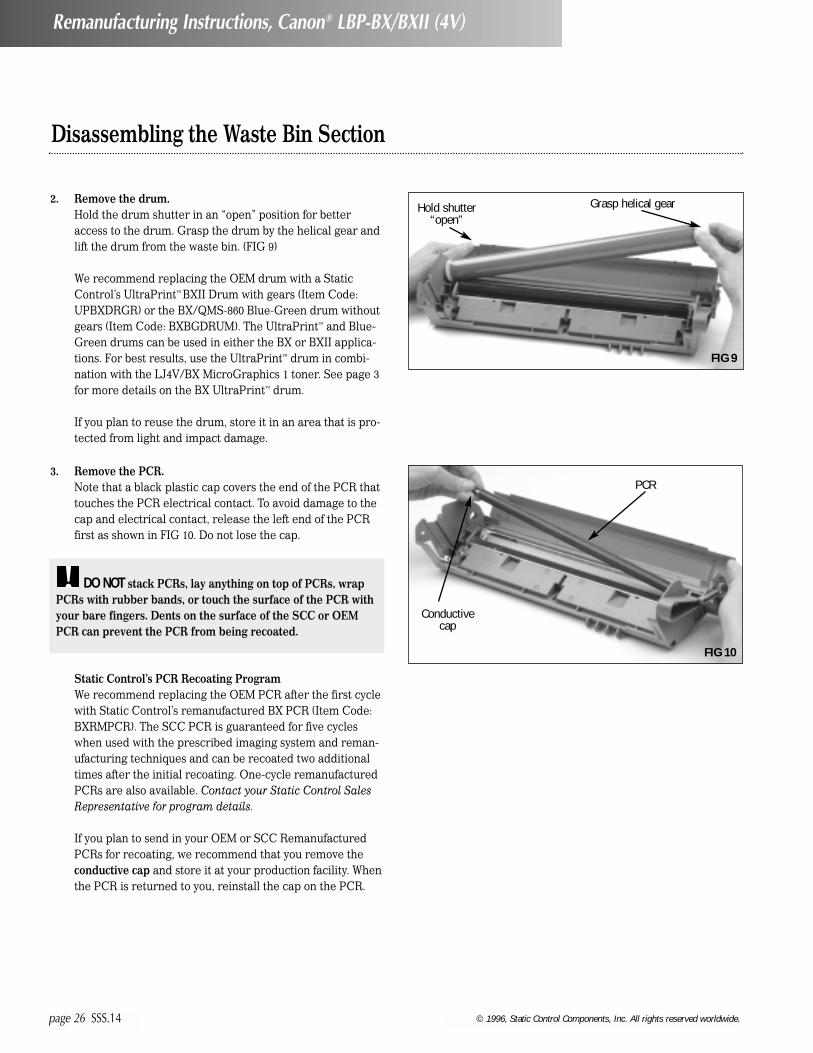
2. Remove the drum.Hold the drum shutter in an “open” position for betteraccess to the drum. Grasp the drum by the helical gear andlift the drum from the waste bin. (FIG 9)
We recommend replacing the OEM drum with a StaticControl’s UltraPrint™ BXII Drum with gears (Item Code:UPBXDRGR) or the BX/QMS-860 Blue-Green drum withoutgears (Item Code: BXBGDRUM). The UltraPrint™ and Blue-Green drums can be used in either the BX or BXII applica-tions. For best results, use the UltraPrint™ drum in combi-nation with the LJ4V/BX MicroGraphics 1 toner. See page 3for more details on the BX UltraPrint™ drum.
If you plan to reuse the drum, store it in an area that is pro-tected from light and impact damage.
Hold shutter“open”
Conductivecap
PCR
Grasp helical gear
3. Remove the PCR.Note that a black plastic cap covers the end of the PCR thattouches the PCR electrical contact. To avoid damage to thecap and electrical contact, release the left end of the PCRfirst as shown in FIG 10. Do not lose the cap.
Static Control’s PCR Recoating ProgramWe recommend replacing the OEM PCR after the first cyclewith Static Control’s remanufactured BX PCR (Item Code:BXRMPCR). The SCC PCR is guaranteed for five cycleswhen used with the prescribed imaging system and reman-ufacturing techniques and can be recoated two additionaltimes after the initial recoating. One-cycle remanufacturedPCRs are also available. Contact your Static Control SalesRepresentative for program details.
If you plan to send in your OEM or SCC RemanufacturedPCRs for recoating, we recommend that you remove theconductive cap and store it at your production facility. Whenthe PCR is returned to you, reinstall the cap on the PCR.
DO NOT stack PCRs, lay anything on top of PCRs, wrapPCRs with rubber bands, or touch the surface of the PCR withyour bare fingers. Dents on the surface of the SCC or OEMPCR can prevent the PCR from being recoated.
!
FIG 9
FIG 10

© 1996, Static Control Components, Inc. All rights reserved worldwide. SSS.14 page 27
Disassembling the Waste Bin Section
Remanufacturing Instructions, Canon® LBP-BX/BXII (4V)
Remove twoscrews
Washer locatedunder this screw
4. Remove the wiper blade. Remove two screws from the stamping area as shown inFIG 11; then carefully lift the blade from the waste bin asshown in FIG 12.
Note that the holding screw closest to the contact side ofthe waste bin uses an additional washer with the screw. Donot lose the washer.
FIG 11
FIG 12
Remove twoscrews from
stamping
Recovery bladeassembly
FIG 13
5. Remove the recovery blade. The mylar recovery blade is attached to a metal stampingand secured in the waste bin with two Phillips Screws. Theentire unit is referred to as the recovery blade assembly.
We recommend removing the recovery blade assembly toavoid damage to the mylar blade during cleaning. Removetwo screws from the stamping as shown in FIG 13.
A recovery magnet strip, located under the stamping of theassembly, prevents toner from migrating out of the wastebin. Do not remove this strip.

Disassembling the Waste Bin Section
© 1996, Static Control Components, Inc. All rights reserved worldwide.page 28 SSS.14
Remanufacturing Instructions, Canon® LBP-BX/BXII (4V)
6. Clean the waste bin.Empty the bulk of the waste toner and clean the waste binwith dry, filtered compressed air. (FIG 16) Direct com-pressed air on and around the wiper blade sealing foamand end foams to remove toner and debris from the foammaterial.
Wiper bladesealing foam
Wiper bladeend foams
(left and right)
To prevent breaking the locating posts that position thestamping, carefully pry up each end of the blade beforeremoving it. (FIGs 14 & 15)
Pry stampingfrom locating
post
Locatingpost
FIG 14
FIG 15
FIG 16

© 1996, Static Control Components, Inc. All rights reserved worldwide. SSS.14 page 29
Disassembling the Waste Bin Section
Remanufacturing Instructions, Canon® LBP-BX/BXII (4V)
9. Clean the PCR contact saddle (left end of waste bin).Clean any toner residue from the saddles and electricalcontact pad using a lint-free swab dampened with 91-99%isopropyl alcohol. (FIG 19)
8. Install a drum shutter felt. The drum is highly susceptible to damage by the drumshutter due to the extended length and flexibility of theshutter. (Item Code: XP15DSFELT)
Remove the adhesive backing from the shutter felt. Centerthe felt on the inside surface of the shutter as shown inFIG 18.
Complete instructions regarding drum shutter installationare included with the product, or refer to System SupportSeries #33.
7. Inspect the wiper blade sealing foam and endfoams. (FIG 17)The foam material should display a smooth surface void ofpits or tears in the material. Tears in the material can resultin a source of leakage from the waste bin.
PCR contactaxle
Wiper bladesealing foam
Drum Shutter Felt
Wiper bladeend foam
DO NOT apply conductive cartridge lubricant to eitherPCR saddle, shaft or to the conductive cap. Lubricant is notpresent on the OEM cartridge.
!
FIG 17
FIG 18
FIG 19

Assembling the Waste Bin Section
© 1996, Static Control Components, Inc. All rights reserved worldwide.page 30 SSS.14
Remanufacturing Instructions, Canon® LBP-BX/BXII (4V)
IMPORTANT Excessive torque applied to any of thescrews may damage the screw bosses.!
1. Clean and inspect the recovery blade.Clean the blade and stamping with dry, filtered compressedair. Be very careful not to damage the fragile blade. (FIG 20)
The recovery blade should display a smooth, flat surfacefree of kinks or waviness along the edge.
Replace blade (Item Code: BXRECBLADE) if damaged ordislodged or replace the entire assembly (Item Code: BXR-BASM). An installation tool is required for individual bladereplacement.
Complete instructions regarding recovery blade installationare included with the installation kit (Item Code: RBIKIT),or refer to System Support Series #19.
2. Install the recovery blade.Position the stamping over locating posts at each end of thewaste bin and secure the assembly with two Phillips Screws.(FIG 21)
3. Clean and inspect the wiper blade.Clean the wiper blade with dry, filtered compressed airONLY. Direct air close to foam on the stamping to removetoner and debris. (FIG 22)
For best results, replace the wiper blade each time youreplace the drum. (Item Code: BXBLADE)
Many wiper blade defects can be determined through testprinting before the cartridge is remanufactured. Check forhorizontal streaks or smudging (letter size page).
DO NOT use alcohol or any alcohol-based solvent to cleanthe polyurethane blade. !
Locating postsfor stamping
Foam strip on back ofwiper blade stamping
RecoveryBlade
TOOLS YOU WILL NEED:• Needlenose pliers• Phillips Screwdriver• Kynar® (Item Code: KPOW)• Long, shallow trough for dipping edge of wiper blade in
Kynar®
• Lint-free cloth (Item Code: LFCLOTH)• Lint-free or cotton swab (Item Code: LFSWAB or QTIP)• Compressed air for cleaning (see page 20 for important
information regarding the use of compressed air)• 91-99% Isopropyl alcohol (see page 21 for important
information regarding the use of alcohol for cleaning)
FIG 20
FIG 21
FIG 22

Assembling the Waste Bin Section
Dip edge ofblade in Kynar®
4. Dip the edge of the blade in Kynar® (Item Code: KPOW).Examine the length of the blade to ensure even coverage.Repeat the dipping process one more time. (FIG 23)
5. Install the wiper blade. Position the stamping over the locating posts in the wastebin, and secure the blade with two Phillips Screws. (FIG 24)
Note that the screw installed closest to the contact end ofthe waste bin uses a washer. Be sure to install the washerwith the screw. (FIG 24a)
Secure wiperblade with two
screws
Wipe PCR in onedirection ONLY
6. Clean and inspect the PCR.Gently wipe the PCR in one direction. Be careful not topinch or dent the surface of the PCR, as the material haspoor memory. (FIG 25)
• Clean the SCC PCR using a soft, lint-free cloth dampenedwith 91-99% ISOPROPYL ALCOHOL.
• Clean the OEM PCR using a soft, lint-free cloth dampenedwith WATER ONLY.
DO NOT lubricate the PCR shaft or conductive saddle.!
© 1996, Static Control Components, Inc. All rights reserved worldwide. SSS.14 page 31
Remanufacturing Instructions, Canon® LBP-BX/BXII (4V)
FIG 23
FIG 24FIG 24a
FIG 25

Assembling the Waste Bin Section
© 1996, Static Control Components, Inc. All rights reserved worldwide.page 32 SSS.14
Remanufacturing Instructions, Canon® LBP-BX/BXII (4V)
7. Install the PCR.Position the end of the PCR with the conductive cap on thecontact saddle (left end) as shown in FIG 26. Make sure thecap is seated against the metal contact as shown in themagnified view of FIG 26a to ensure proper electrical con-tact between the printer and PCR.
Conductivecap
Kynar®
Metal contact
8. Clean and inspect the drum. Clean the drum with dry, filtered compressed air. Inspectthe drum for deep concentric wear lines or cracks in thecoating. (FIG 27)
We recommend replacing the OEM drum with a StaticControl’s UltraPrint™ BXII Drum with gears (Item Code:UPBXDRGR) or the BX/QMS-860 Blue Green drum withoutgears (Item Code: BXBGDRUM). The UltraPrint™ and Blue-Green drums can be used in either the BX or BXII applica-tions. For best results, use the UltraPrint™ drum in combina-tion with the LJ4V/BX MicroGraphics 1 toner. See page 3for more details on the BX UltraPrint™ drum.
Complete instructions regarding gear installation areincluded with the drum, or contact Technical Support foradditional instructions. Phone numbers are listed on theback page of this manual.
DO NOT use cleaning agents or coatings on the drum. Becareful not to nick the surface of the drum with the air nozzle.!
9. Pad the coated area of the drum with Kynar®
(Item Code: KPOW). Be careful to avoid Kynar® on the gears. (FIG 28)
FIG 26
FIG 27
FIG 28
FIG 26a

Assembling the Waste Bin Section
© 1996, Static Control Components, Inc. All rights reserved worldwide. SSS.14 page 33
Remanufacturing Instructions, Canon® LBP-BX/BXII (4V)
10. Install the drum.Position the drum in the waste bin with the helical gear onthe right as shown in FIG 29.
11. Install both drum axles.Secure with holding screws. The contact axle is installed onthe left end of the waste bin as shown in FIG 30.
12. Rotate the drum at least 6 revolutions in the direction indi-cated by the arrows in FIG 32.Rotating the drum will help lubricate the wiper blade andprevent the potential of blade “flip overs”. Any Kynar®
wiped from the drum by the wiper blade will deposit in thewaste bin.
As you rotate the drum, wipe the Kynar® from the PCR witha lint-free cloth as shown in FIG 32 , or use dry, filteredcompressed air to blow off the Kynar®.
IMPORTANT Make sure there is no Kynar® present on thePCR, otherwise repeating voids in solid print areas at the PCRinterval may result.
!
Contactaxle
Non-contactaxle
13. Place the assembled waste bin section in a light-protectedarea until final reassembly.
Helicalgear
The non-contact axle is installed on the right end of thewaste bin as shown in FIG 31.
Wipe Kynar® from PCRwith lint-free cloth
Rotatedrum
FIG 32
FIG 31
FIG 30
FIG 29
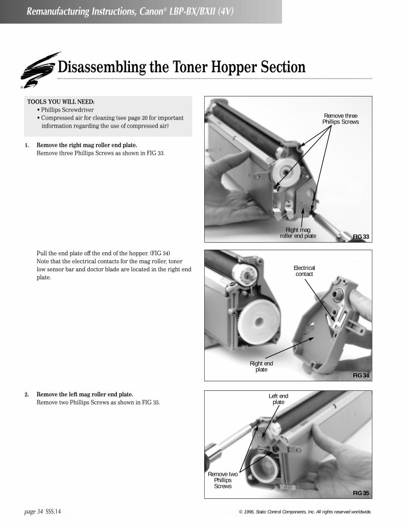
Disassembling the Toner Hopper Section
© 1996, Static Control Components, Inc. All rights reserved worldwide.page 34 SSS.14
Remanufacturing Instructions, Canon® LBP-BX/BXII (4V)
TOOLS YOU WILL NEED:• Phillips Screwdriver• Compressed air for cleaning (see page 20 for important
information regarding the use of compressed air)
1. Remove the right mag roller end plate.Remove three Phillips Screws as shown in FIG 33.
2. Remove the left mag roller end plate.Remove two Phillips Screws as shown in FIG 35.
Pull the end plate off the end of the hopper. (FIG 34)Note that the electrical contacts for the mag roller, tonerlow sensor bar and doctor blade are located in the right endplate.
Remove threePhillips Screws
Remove twoPhillipsScrews
Right endplate
Electricalcontact
Left endplate
Right magroller end plate FIG 33
FIG 34
FIG 35

Disassembling the Toner Hopper Section
© 1996, Static Control Components, Inc. All rights reserved worldwide. SSS.14 page 35
Remanufacturing Instructions, Canon® LBP-BX/BXII (4V)
3. Remove the mag roller drive gear. (FIG 37)
Pull the end cap off the end of the hopper as shown in FIG36. Note that the left end cap does not house electrical con-tacts.
Left endplate
Mag rollerdrive gear
4. Remove the mag roller stabilizer. (FIG 38)
Mag rollerstabilizer
FIG 36
FIG 37
FIG 38

Disassembling the Toner Hopper Section
© 1996, Static Control Components, Inc. All rights reserved worldwide.page 36 SSS.14
Remanufacturing Instructions, Canon® LBP-BX/BXII (4V)
5. Remove the mag roller.Grasp the axles at each end of the mag roller as shown inFIG 39 and carefully remove the roller from the hopper. Themag roller sleeve bushings installed on each end of the magroller can be left in place or removed. Be careful not to losethe bushings.
DO NOT touch the surface of the mag roller with yourfingers or scratch the surface. Store the mag roller on a softsurface, but DO NOT stack the rollers on top of each other.
!
6. Remove the doctor blade. Remove the two Phillips Screws that secure the bladestamping. (FIG 40)
Then, lift the blade from the hopper as shown in FIG 41. Becareful not to lose the plastic wipers on the doctor blade.You will reuse these if you install a replacement blade.
Two PhillipsScrews
Mag rollersleeve bushings
Plasticwipers
FIG 39
FIG 40
FIG 41

Disassembling the Toner Hopper Section
© 1996, Static Control Components, Inc. All rights reserved worldwide. SSS.14 page 37
Remanufacturing Instructions, Canon® LBP-BX/BXII (4V)
7. Clean the hopper with dry, filtered compressed air.Direct compressed air on and around the doctor blade seal-ing foam and mag roller felt components in order toremove as much toner and debris as possible. (FIG 42)
We don’t recommend using a toner vacuum to clean thehopper section due to potential damage to the toner lowsensor bar.
Before You Continue...If you plan to seal the hopper, proceed to page 38 for anoverview of the Static Control Gasket Sealing Assemblyinstallation instructions. The section is provided to showyou the basic steps of installation; however, you should notattempt to seal the hopper without thoroughly reading theinstructions included with the BX Gasket Sealing AssemblyKit (Item Code: BXGSAKIT) or refer to System SupportSeries #48.
If you plan to fill the hopper, but not install a seal, proceedto page 43 to reassemble the toner hopper section. Then fol-low the instructions on page 47 to fill the hopper.
FIG 42
Doctor bladesealing foam
Mag rollerfelts

Sealing and Filling the Toner Hopper - Overview
© 1996, Static Control Components, Inc. All rights reserved worldwide.page 38 SSS.14
Remanufacturing Instructions, Canon® LBP-BX/BXII (4V)
TOOLS YOU WILL NEED:• Needlenose pliers• BX Gasket Sealing Assembly Kit (Item Code: BXGSAKIT)
For a listing of the kit contents, see page 57 of this guide• Compressed air for cleaning (see page 20 for important
information regarding the use of compressed air)• 91-99% Isopropyl alcohol (see page 21 for important
information regarding the use of isopropyl alcohol)
IMPORTANT The instructions in this section are included to provide an OVERVIEW of BX Gasket Sealing Assembly installa-tion. Refer to the product instructions included with the BX Gasket Sealing Assembly Kit for more details. DO NOT ATTEMPT TOSEAL THE HOPPER WITHOUT THOROUGHLY READING THE INSTRUCTIONS.
!
1. Remove the right and left mag roller felts. In order to install a new seal or remove an old seal, the magroller felts, toner low sensor bar and seal channel plug mustbe removed. Use the curved scraper blade tool (included inthe seal kit) to lift up one end of the felt as shown in FIG 43.Then carefully peel the felt, along with the underlying adhe-sive, from the hopper.
Use curvedscraper tool tolift end of felt
Toner lowsensor bar
Seal channel
plug
2. Remove the toner low sensor bar.The toner low sensor bar is removed by grasping the bentend of the bar, then lifting the bar up and out of the hopper.(FIG 44)
3. Remove the seal channel plug.Use a pair of needlenose pliers to slide the plug to the leftand out of the seal channel.(FIG 45)
FIG 43
FIG 44
FIG 45

Sealing and Filling the Toner Hopper - Overview
© 1996, Static Control Components, Inc. All rights reserved worldwide. SSS.14 page 39
Remanufacturing Instructions, Canon® LBP-BX/BXII (4V)
4. Remove the OEM Seal material. (FIG 46)It is very important to remove as much of the OEM seal aspossible in order to ensure a secure seal with the new gas-ket seal. Large filaments of OEM material trapped under-neath a new seal can raise the new seal and allow tonerleakage from the hopper. (FIG 47)
For the BX application, 91-99% isopropyl alcohol is appliedto the seal to loosen the filament material. A curvedscraper blade tool, designed specifically for seal removal, isprovided in the kit.
5. Clean the hopper with dry, filtered compressed air. (FIG 48)A groove at the rear of the seal channel is used to anchorthe new seal in position in the hopper. Any residual alcoholin the groove can prevent the seal adhesive from securingto the hopper. Residual alcohol can also fall into the tonerreservoir and combine with toner.
6. Install the gasket sealing assembly. (FIG 49)Before the seal is initially positioned in the hopper, therelease liner on the seal is folded so that it accessible oncethe seal is properly positioned in the sealing channel. Thenthe backing can be removed without disturbing the positionof the seal.
The rear edge of the gasket seal is anchored in a groovethat runs along the rear of the hopper seal channel. Aninsertion tool is used to seat the edge of the seal in thegroove. When the edge of the seal is properly seated, theentire sealing assembly will lie flat in the sealing channel.
IMPORTANT If Static Control seal or other aftermarketseal is present in the channel, skip step 4 entirely. Refer to theBX Gasket Sealing Assembly installation instructions fordetails on how to remove these seals. (System Support Series #48).
!
IMPORTANT See page 21 for important informationregarding the use of isopropyl alcohol for this application.!
IMPORTANT The sealing surfaces, groove area, and hop-per must be COMPLETELY DRY before a new seal is installed.Allow adequate time for the alcohol to completely evaporate.
!
OEM Sealfilament
91-99% isopropyl alcohol
ReleaseLiner
Pull strip
Groove at rearof seal channel
Seal insertiontool
Curved scraperblade tool
Groove
FIG 46
FIG 47
FIG 48
FIG 49

Sealing and Filling the Toner Hopper - Overview
© 1996, Static Control Components, Inc. All rights reserved worldwide.page 40 SSS.14
Remanufacturing Instructions, Canon® LBP-BX/BXII (4V)
7. Remove the release liner from the seal.The photos in FIGs 50 & 51 illustrate how the backing isremoved while the seal is positioned in the hopper. Thebacking is removed and the seal is secured to the hopper insmall increments using the curved end of the installationtool or your finger as shown.
8. Secure the perimeter of the seal.The ends of the seal are particularly susceptible to tonerleakage if not secure. (FIG 52)
9. Fold the pull strip over the gasket sealing assembly.(FIG 53)
DO NOT press firmly on the center port area of the seal.!
Removerelease
liner
Seal pullstrip
Removerelease
liner
FIG 50
FIG 51
FIG 52
FIG 53

Sealing and Filling the Toner Hopper - Overview
© 1996, Static Control Components, Inc. All rights reserved worldwide. SSS.14 page 41
Remanufacturing Instructions, Canon® LBP-BX/BXII (4V)
10. Install the seal channel plug and toner low sensor bar. (FIG 54)Install the seal channel plug by sliding it into the sealchannel.
The bent end of the toner low sensor bar provides electricalcontact with a metal contact in the right mag roller endplate. Therefore, it is critical that the bar is properlysecured in the hopper. A drop of adhesive caulk is used tosecure the bar, as well as to seal the area around the tonerlow sensor bar and prevent toner leakage into the endplate. The adhesive caulk is included in the BX gasket sealkit.
11. Install replacement left and right mag roller felts. The mag roller felts used for the BX application are die-cutwith an extension as well as an angled end along one edgeof the felt. When the felts are installed, the extension andangle should face the interior of the hopper. A set of magroller felts are included with the BX Gasket SealingAssembly kit or available separately. (Item Code: BXMRFELT)
Drop of adhesive caulk
Seal channel
plug
Toner lowsensor bar
Extension
Angle
12. Inspect the doctor blade sealing foamWhen the BX seal is installed or replaced, the doctor bladesealing foam is easily damaged by direct contact with instal-lation tools and alcohol used to clean the seal channel. Thealcohol can deteriorate the adhesive that holds the foam tothe hopper and cause the foam to become dislodged.
Carefully inspect the foam and make sure that it is free ofpits or tears, and the entire length of the foam is secured tothe hopper. Replace as required. (Item Code: BXDBSFOAM)
To remove the foam, lift up one end of the foam with thecurved scraper blade tool, then peel the foam and adhesivebacking from the hopper. (FIG 56)
Complete instructions regarding doctor blade sealing foaminstallation are included with the product, or refer to SystemSupport Series #52.
Remove wornfoam
FIG 56
FIG 55
FIG 54

Sealing and Filling the Toner Hopper - Overview
© 1996, Static Control Components, Inc. All rights reserved worldwide.page 42 SSS.14
Remanufacturing Instructions, Canon® LBP-BX/BXII (4V)
13. Install replacement doctor blade sealing foam.Remove a small section of the backing. (FIG 57a) Starting atone end of the hopper, press the exposed section of thefoam to the mounting surface. (FIG 57)
Backing
Replacementfoam
Place the end ofthe foam here
15. Install the hopper cap. (FIG 59)
14. Fill the hopper with toner through the fill hole. (FIG 58)BX: Use BX/QMS-860 MicroGraphics 1 toner, 340 grams(Item Code: BX340B)BXII: Use LJ4V/BXII MicroGraphics 1 toner, 400 grams (Item Code: BX2-400B)
IMPORTANT Static Control’s BX toner is formulated forBX (QMS 860) applications ONLY. Static Control’s BXII tonercan be used in either BX or BXII applications. See page 3 formore details.
!
FIG 57
FIG 58
FIG 59
FIG 57a

Assembling the Toner Hopper Section
© 1996, Static Control Components, Inc. All rights reserved worldwide. SSS.14 page 43
Remanufacturing Instructions, Canon® LBP-BX/BXII (4V)
Secure the blade with Phillips Screws as shown in FIG 62a.
1. Clean the doctor blade with dry, filtered compressed air.(FIG 60)We recommend replacing the OEM doctor blade with theStatic Control doctor blade (Item Code: BXDBLADE) afterthe OEM cycle.
For subsequent remanufacturing cycles, test print the car-tridge prior to remanufacturing and inspect prints for doc-tor blade-related print defects. Replace the blade asrequired. See the component management chart on pages14-17 for more details.
Remove the plastic wipers from the old doctor blade andinstall on the replacement blade as shown in FIG 61. For anillustration of the orientation of the wipers on the doctorblade stamping, see page 8.
2. Install the doctor blade.Position the doctor blade stamping over the locating postsin the hopper section as shown in FIG 62.
TOOLS YOU WILL NEED:• Needlenose pliers• Phillips Screwdriver• Lint-free cloth (Item Code: LFCLOTH)• Lint-free or cotton swab (Item Code: LFSWAB or QTIP)• Conductive Cartridge Lubricant
(Item Code: CONCLUBE)
• Compressed air for cleaning (see page 20 for important information regarding the use of compressed air)
• 91-99% Isopropyl alcohol (see page 21 for importantinformation regarding the use of isopropyl alcohol.)
Locatingposts
Plasticwiper
FIG 60
FIG 61
FIG 62
FIG 62a

Assembling the Toner Hopper Section
© 1996, Static Control Components, Inc. All rights reserved worldwide.page 44 SSS.14
Remanufacturing Instructions, Canon® LBP-BX/BXII (4V)
3. Clean the mag roller with dry, filtered compressed air. (FIG 63)
A remanufactured mag roller sleeve is currently underdevelopment.
4. Clean the mag roller bushings. Use a lint-free cloth or a swab to clean toner and debrisfrom the bushings. (FIG 64)
Replace bushings if cracked or excessively worn.
5. Clean the mag roller contact.Use a cotton or lint-free swab to remove the grease frommetal contacts. (FIG 65)
6. Install mag roller bushings on each end of the mag roller.(FIG 66)
DO NOT scratch the coated area of the roller with the airnozzle or touch the mag roller with your fingers.!
7. Install the mag roller.Make sure the contact end of the roller is on the right endof hopper as shown in FIG 67.
Contact end ofmag roller on right
FIG 63
FIG 64
FIG 65 FIG 66
FIG 67
Mag rollersleeve bushing
Mag rollercontact

© 1996, Static Control Components, Inc. All rights reserved worldwide. SSS.14 page 45
Assembling the Toner Hopper Section
Remanufacturing Instructions, Canon® LBP-BX/BXII (4V)
8. Clean the mag roller electrical contact on the right endplate with a swab (Item Code: QTIP) or (Item Code:LFSWAB) dampened with 91-99% isopropyl alcohol. (FIG 68)For more information about cleaning with alcohol andwhere to find 91% or 99% isopropyl alcohol, turn to page 21.
9. Apply a THIN layer of conductive cartridge lubricant (ItemCode: CONCLUBE) on the electrical contact. (FIG 69)Use the wooden end of a swab as an applicator. For moreinformation regarding the application of cartridge lubri-cant, turn to page 22.
10. Install the right mag roller end plate. Note that the contact end of the mag roller axle is keyed asshown in FIG 70, and fits into a positioner bushing in theright end plate. As you position the end cap over the hop-per, grasp the axle at the opposite end of the mag rollerand rotate the magnet until the axle seats in the positionerbushing. (FIG 71)
Secure the end plate with 3 Phillips Screws.
Keyedaxle
Mag roller magnetpositioner bushing
Rotate magnetuntil it is seatedin the positionerbushing at the
other end
FIG 68
FIG 69
FIG 71
FIG 70

Assembling the Toner Hopper Section
© 1996, Static Control Components, Inc. All rights reserved worldwide.page 46 SSS.14
Remanufacturing Instructions, Canon® LBP-BX/BXII (4V)
11. Install the mag roller stabilizer and drive gear on the leftend of the hopper. Make sure each of these components is positioned correctlyas shown in FIGs 72, 73 & 74.
There are several variations of these three components.Refer to page 18 for details regarding proper assembly.
Stabilizer
Mag rollerdrive gear
Flange
Left magroller end cap
Position the mag roller drive gear so that the non-gearedflange faces toward the mag roller. (FIG 73)
12. Install the left mag roller end plate as shown in FIG 74. Secure the end plate with two Phillips Screws.
FIG 72
FIG 73
FIG 74

Filling the Toner Hopper Without a Seal
© 1996, Static Control Components, Inc. All rights reserved worldwide. SSS.14 page 47
Remanufacturing Instructions, Canon® LBP-BX/BXII (4V)
Before filling the hopper, make sure the toner hopper section iscompletely reassembled. With the mag roller securely installed,the hopper is adequately sealed for filling from toner bottles orfilling machines. However, note that filling machines may dis-pense toner with some force or pressure that can cause someleakage from around the mag roller.
1. Remove the hopper cap.
2. Shake the toner bottle to aerate the toner. BX: Use BX/QMS-860 MicroGraphics 1 toner, 340 grams(Item Code: BX340B) or LJ4V/BXII MicroGraphics 1 toner(Item Code: BX2-400B)BXII: Use LJ4V/BXII MicroGraphics 1 toner, 400 grams (Item Code: BX2-400B)
3. Using a funnel or a funnel attachment for the toner bottle,fill the hopper through the side fill hole. (FIG 76)
WARNING We do not recommend shipping the BX/BXIIcartridge without a seal. BX cartridges that are not sealed arehighly susceptible to leakage during shipping and handling.
!
IMPORTANT Be very careful not to touch the mag rolleras you fill the hopper. Oil from your fingers or hands cancause repeating print defects.
!
4. Install the hopper cap. (FIG 77)
Remove hopper cap
IMPORTANT Static Control’s BX toner is formulated forBX (QMS 860) applications ONLY. Static Control’s BXII tonercan be used in either BX or BXII applications. See page 3 formore details.
!
FIG 75
FIG 76
FIG 77

Assembling the Cartridge
© 1996, Static Control Components, Inc. All rights reserved worldwide.page 48 SSS.14
Remanufacturing Instructions, Canon® LBP-BX/BXII (4V)
1. Assemble the waste bin and toner hopper sections asshown in FIG 78.As you bring the sections together, hold the drum shutter ina slightly “open” position to avoid lodging the shutterbetween the two sections. If the shutter becomes lodged,the shutter will not open when installed in the printer,which will result in damage to both the printer and car-tridge.
2. Install the OEM cartridge pins at each end of the cartridge. If the OEM pins are damaged or missing, use LX cartridgepins (Item Code: LXPIN). (FIG 80)
Carefully squeeze the sections together to align the pinholes in each section. Then, push the pins in as far as theywill go. Note that the heads of the replacement LX pins willprotrude slightly from the base of the cartridge body evenwhen fully installed. This should not interfere with cartridgeor printer operations.
LX Pin
Once the sections are assembled, open the shutter to con-firm that it is not lodged. (FIG 79)
Hold shutter in “open” position
Openshutter
Mag rollerdrive gear
Drum helicalgear
TOOLS YOU WILL NEED:• Needlenose pliers• Phillips Screwdriver• LX Easy Pull Metal Cartridge Pins (2)
(Item Code: LXPIN)
FIG 78
FIG 79
FIG 80

Assembling the Cartridge
© 1996, Static Control Components, Inc. All rights reserved worldwide. SSS.14 page 49
Remanufacturing Instructions, Canon® LBP-BX/BXII (4V)
3. Install the exterior spring. (FIG 81)
4. Clean the exterior metal contacts.Use a cotton or lint-free swab dampened with 91-99% iso-propyl alcohol to clean. (FIG 82)
Exteriorspring
Hooks
FIG 81
FIG 82

Installing the Pull Tab
© 1996, Static Control Components, Inc. All rights reserved worldwide.page 50 SSS.14
Remanufacturing Instructions, Canon® LBP-BX/BXII (4V)
TOOLS YOU WILL NEED:• Scissors• BX Pull Tab (Item Code:BXOEMTAB)
Includes instructions; note that the Static Control BX Pull Tab is for use with the BX Gasket Sealing Assembly (Item Code: BXGSA)
Squared side of BXPull Tab toward the
spring on the hopper
Installed GasketSeal Pull Strip
Up throughthe BX Pull
Tab ring
Seal ExitShelf
Mark the seal pullstrip where it meets
the exit port plug andcut off the excess
Thread the seal pull stripbetween the seal exitshelf and the squared
edge of the BX Pull Tab
Slide BX PullTab into slot
Exit Port Plug
1. Install the pull tab into the pull tab slot on the hopper.After a BX Gasket Seal has been installed, slide the BX PullTab into the pull tab slot on the end of the hopper just abovethe toner fill hole as shown in FIG 83. Make sure thesquared side of the BX Pull Tab is toward the spring on thehopper.
2. Thread the seal pull strip through the pull tab.Thread the seal pull strip between the squared edge of theBX Pull Tab and the seal exit shelf, then loop the pull stripup through the BX Pull Tab ring as shown in FIG 84.
3. Mark the pull strip and trim.Loop the end of the seal pull strip back toward the sealchannel exit port plug. Mark the seal pull strip with a penwhere it meets the exit port plug. (FIG 85) Marking the sealpull strip ensures an accurate cut.
With scissors, cut the seal pull strip along the mark and dis-card the excess.
FIG 83
FIG 84
FIG 85

Installing the Pull Tab
© 1996, Static Control Components, Inc. All rights reserved worldwide. SSS.14 page 51
Remanufacturing Instructions, Canon® LBP-BX/BXII (4V)
4. Attach an adhesive strip.Remove an adhesive square from the sheet of adhesive.Place the adhesive square with the exposed, adhesive sidedown on the end of the seal pull strip. (FIG 86)
Press the adhesive square in place and carefully peel awaythe paper backing. (FIG 86)
5. Secure the seal pull strip loop.Fold the end of the seal pull strip back toward the sealchannel exit port plug and press the adhesive side downonto the seal pull strip exiting the seal port, thus creating aloop. (FIG 87) Press the seal pull strip firmly on the seal exitshelf to secure the loop.
With the adhesivesquare in place peel away the paper backing
Press firmly tosecure adhesive toboth sides of the
seal pull strip loop
DO NOT It is important to wrap the seal pull strip tautaround the tab ring; however, be careful not to pull hardenough to release or break the installed gasket seal.
!
FIG 86
FIG 87

Troubleshooting Print Defects
© 1996, Static Control Components, Inc. All rights reserved worldwide.page 52 SSS.14
Troubleshooting BX/BXII Print Defects
Establishing Baseline Performance Benchmarks
Test Print Print Characteristic TestMurphy’s Law Small Area Solid Black Density, Gray Scale Accuracy, Text Boldness, Character Blasting
Solid Black Large Area Solid Black Density, Horizontal Banding, Repetitive Defects
Gray Scale Gray Scale Accuracy, Overtoning, Horizontal Banding
Solid White Toner Leakage, Repetitive OPC, Mag Roller Defects
Barber Pole Text Boldness, Side to Side Uniformity, Character Blasting
We recommend that you perform a comprehensive series of testprints to establish the performance standards of your cartridgesutilizing Static Control’s BX/BXII Imaging System Components.Listed below is a series of Anacom Smart Box® test targets thatwe regularly use in system evaluation. This test series will
establish the normal print characteristics of the BX/BXII car-tridge for comparison with your subsequent remanufacturedcartridges. We further recommend that you retain this cartridgeas your standard to simplify future performance verification.
Anacom Smart Box® Test Print Series
Murphy’s Law Solid Black Gray Scale Solid White Barber Pole

© 1996, Static Control Components, Inc. All rights reserved worldwide. SSS.14 page 53
Troubleshooting BX/BXII Print Defects
1. Find the repeating defect. Defects may appear as horizontalbanding, dots, lines or hazing. Note that with BX/BXII car-tridges, the repetitive defect will appear vertically on a let-ter size page and horizontally on legal or tabloid size pages.(See the next page for details regarding orientation ofmedia as it exits the printer.)
2. Measure the distance between the defects. Interval mea-surements are provided in both inches and millimeters. Toget an accurate measurement, measure from the top or bot-tom of the first defect to the top or bottom of the next
defect. Make sure you are measuring like defects. It is pos-sible to have two sets of repetitive defects that overlap eachother on the page.
3. Find the interval number in the table below and the corre-sponding component. Some probable causes of the defectare listed to help with troubleshooting. This is not an exclu-sive list. Some repetitive defects may be the result of a com-bination of factors. If you having trouble locating a defect,call Technical Support at the telephone numbers listed onthe back of this manual.
How to Measure Repetitive Defects
Interval Component Probable Cause of Defect@ 3.75” (94 mm) OPC Drum OPC wear, OPC damage, OPC contactIntervals elliptical drum rotation, OPC light exposure degradation, PCR defect@ 1.70” (43 mm) Primary Charge Roller PCR wear, PCR Contamination, toner propertiesIntervals poor electrical contact, low RH% conditions, dry paper@ 2.48” (63 mm) Mag Roller Mag roller wear, mag roller electrical contact, mag roller cleaning damageIntervals mag roller bushing wear, doctor blade failure, toner properties,
mag roller contamination@ 3.46” (88 mm) Upper Fuser Roller Toner offsetting, fuser roller/pressure roller incompatibility,Intervals upper fuser roller/lower pressure roller wear/contamination@ 3.38” (83 mm) Lower Pressure Roller Toner/pressure roller incompatibility,Intervals pressure roller wear/contamination (defect will appear on backside of page)@ 2.40” (61 mm) Transfer Roller Repeating interval of light printIntervals
Repetitive Defect Troubleshooting Guide
Example of Repetitive Ghosting Defect on BX/BXII printer letter sizepaper; note that letter size paper exits printer in a landscape orientation
Ghost Images
Measure the distance between the top of thefirst defect and the top of the next defect.
Test Print
Test Print
Test Print
Example of Repetitive Ghosting Defect on BX/BXII printer tabloid sizepaper; note that tabloid size paper exits printer in a portrait orientation
GhostImages
PrintMeasure the distancebetween the top of thefirst defect and thetop of the next defect.
Test Printtest print
Test Printtest print
Test Printtest print

Troubleshooting BX/BXII Print Defects
© 1996, Static Control Components, Inc. All rights reserved worldwide.page 54 SSS.14
Page Orientation During the Printing Process
Tabloid 11”x 17”portrait orientation
Letter 8.5” x 11”landscape orientation
Legal 8.5” x 14”portrait orientation
HP LaserJet® 4V Printer
Movement ofpaper as it exitsthe printer
We recommend that you perform a comprehensive series of testprints to establish the performance standards of your cartridgesutilizing Static Control’s BX/BXII Imaging System Components.Listed below is a series of Anacom Smart Box® test targets thatwe regularly use in system evaluation. This test series will
establish the normal print characteristics of the BX/BXII car-tridge for comparison with your subsequent remanufacturedcartridges. We further recommend that you retain this cartridgeas your standard to simplify future performance verification.
Troubleshooting Print Defects continued
Print Defect Probable Cause of DefectBackground Inadequate drum charging/erasing, OPC wear, PCR wear, toner properties,
low RH% conditions, dry paperGhosting Inadequate drum charging/erasing, OPC wear, PCR wear,
PCR contamination, low RH% conditions, toner properties, dry paper, upper fuser roller (Toner Offsetting)
Light Print Mag roller, electrical contacts, OPC wear, PCR wear, toner properties, high RH% conditions, damp paper, doctor blade
Streaking/Lines Wiper blade (sharp-edged lines), Upper Fuser Roller, PCR contamination (vertical line), missing/damaged mag roller felts (page edge line)
Random Sprinkles Recovery blade, mag roller feltsSmudges OPC contamination, upper fuser roller, mag roller contaminationToner Offsetting Upper fuser roller, lower pressure roller, toner properties, PowerSave feature (BXII only)
Control Panel
Understanding the orientation of media as it travels through theimaging process of the printer can help in troubleshooting repet-itive print defects. The BX/BXII engine supports several mediasizes that exit the printer in both portrait and landscape orienta-tions. Letter-sized media, for example, follows the printer paper
path in a landscape orientation. Therefore, repetitive defects willappear horizontally if you are looking at the page in a landscapeorientation. If you are looking at a letter-sized page in the por-trait orientation, the defects will appear vertically. Legal- andtabloid-sized media exits the printer in portrait orientation.

Repetitive Defect Ruler
© 1996, Static Control Components, Inc. All rights reserved worldwide. SSS.14 page 55
Troubleshooting BX/BXII Print Defects
First occurrence of print defect
Magnetic Developer Roller 2.48 inches (63 mm)
Primary Charge Roller (PCR) 1.7 inches (43 mm)
Upper Delivery Roller 1.96 inches (50 mm)
Transfer Roller 2.4 inches (61 mm)
Fuser Pressure Roller 3.38 inches (83 mm)Upper Fuser Roller 3.46 inches (88 mm)
OPC Drum 3.75 inches (94 mm)
Registration Roller 1.96 inches (50 mm)

Preventing False Toner Low Warnings
© 1996, Static Control Components, Inc. All rights reserved worldwide.page 56 SSS.14
Troubleshooting BX/BXII Print Defects
Prevent Damage to the Toner LowSensor BarUse compressed air to clean the hopper instead of a toner vacu-um. Forcing a vacuum attachment or toner funnel into the hop-per through the toner port can inadvertently bend the toner lowbar away from the magroller. In the BX/BXII car-tridge the original distancebetween mag roller surfaceand toner low bar is .075".Increasing this distance byas little as .075” (a total dis-tance of .150”) can causepremature toner low warn-ings.
False toner low warnings should not occur in BX/BXII car-tridges, and therefore can be puzzling when they do happen. Afalse warning can be caused by a number of problems involvingthe printer, cartridge, toner or a combination of all three. Whilethe solution to toner low problems will vary from cartridge tocartridge, there are some preventative steps you can take.
Use the Correct TonerIf you are having an ongoing problem with false toner low warn-ings, try changing the brand of toner you are using. In most ofthe cases we have seen, toner is the cause of the false warnings.In our testing of BX toners and through calls on our TechSupport line, we have found that several aftermarket toners willcause a high incidence of false toner low warnings.
Static Control’s BX toners have been formulated and tested towork properly with the toner low sensing system. Based on test-ing and surveys of customers who use our toner exclusively, theoccurrence of false toner warnings is less than one percent.And, in these instances, factors unrelated to toner contributedto the false warnings.
How the Toner Low System WorksThe toner low bar reads the positive portion of the AC volt-age from the electromagnetic field around the mag roller.The toner provides a medium through which the AC voltagesignal travels to reach the toner low bar. As long as the toneris present between the mag roller and toner low bar, the barreceives the signal. As the toner level between the bar andmag roller begins to drop, the signal also drops. Once the sig-nal drops within a certain threshold, circuitry in the highvoltage power supply triggers a toner low message that issent to the printer interface board and is displayed on theprinter control panel LED. If the toner is not providing aproper medium through which the signal can travel, a tonerlow message can be triggered even when the cartridge is fullof toner.
Clean toner, grease and debrisfrom the contact prongs on themag roller sleeve. Use a cottonswab dampened with isopropylalcohol.
Each remanufacturing cycle,remove conductive grease fromthe metal contact in the gearhousing end plate. Apply a smallamount of conductive cartridgelubricant (Item Code: CON-CLUBE) to the contact.
Need Help? Call Technical SupportIf, after following these preventative measures, you still have problemswith false toner low warnings, contact Technical Support for additionaltroubleshooting advice.
Ensure Electrical ContactThoroughly clean all electrical contacts in the cartridge duringyour remanufacturing processes. Pay particular attention tocleaning the contact prongs on the end of the mag roller and itscorresponding contact plate in the gear housing end plate toensure optimum continuity. Then, apply a small amount of con-ductive lubricant to the metal contact. If the mag roller does notreceive the proper voltage from the power supply, it will in turnaffect the signal received by the toner low bar. For detailedinstructions regarding cleaning electrical contacts, refer to page45.

BX Cartridge Supplies, Kits and Imaging Systems
© 1996, Static Control Components, Inc. All rights reserved worldwide. SSS.14 page 57
Static Control Product Information
Imaging SystemsBXBGSYS-340B-G BX/QMS-860 Blue-Green OPC Drum/Gears,Toner,Wiper Blade
(BXBGDRUM, BX340B, BXBLADE)BX2BGSYS-400B-G BXII/LJ4V Blue-Green OPC Drum/Gears,Toner,Wiper Blade
(BXBGDRUM, BX2-400B, BXBLADE)UPBX2SYS UltraPrint™ BX/BXII OPC Drum/Gears,Toner,Wiper Blade
(UPBXDRGR, BX2-400B, BXBLADE)
Toners - Bottles, Bulk, Buoys & BagsBX340B BX/QMS-860 MicroGraphics 1, 340g BottleBX2-400B BXII/LJ4V MicroGraphics 1, 400g BottleAll Toners are Available in Bulk, Beacon Buoys, and 10/20 lb Per-Fill Bags - Call for Quotes
Toner KitsBXTSKIT BX/QMS-860 Toner/Seal Kit (BX340B, BXGSAPK)BX2TSKIT BXII/LJ4V Toner/Seal Kit (BX2-400B, BXGSAPK)
DrumsBXBGDRGR BX/QMS-860 Blue-Green OPC Drum/GearsUPBXDRGR UltraPrint™ BX/BXII OPC Drum/Gears
PCRsBXRMPCR BX/QMS-860 Remanufactured PCR (on exchange basis)1CBXRMPCR One Cycle BX/QMS-860 Reman PCR (on exchange basis)
Call for PCR Imaging System Package Pricing.We now have two programs available for our remanufactured PCRs. With our 15Cycle Program, PCRs can be recoated three times. Each recoating is good for up tofive cartridge cycles, for a total of 15 cartridge cycles.We also have a single cyclemulti-coating program, which involves recoating the PCR for one cartridge cycle,then recoating it again for another single cartridge cycle.As long as the PCR remainsundamaged, this process can be repeated indefinitely.Also, we buy recoatable PCRs.Call your Sales Representative for details.
Blades - Tools, Kits & SuppliesBXDBLADE BX/QMS-860 Doctor BladePRECB-BX BX/BXII PolyBlade™ Recovery BladeWXRBIKIT 5Si Recovery Blade Installation Kit (for BX)RBITOOL-PBT PolyBlade™ Recovery Blade Tool - TabloidBXRECBLADE BX/QMS-860 Recovery BladeBXRBASM BX/QMS-860 Recovery Blade AssemblyBXBLADE BX/QMS-860 Wiper BladeSEKTOOL Square Ended Knife Tool (with 3 knife blades)SE3PAK Square Ended Scraper Blades (3 per pack)
Bags5009521 Extra-Length Foil Bag (9.5” x 21”)5001121 Extra-Length Foil Bag (11” x 21”)6001121 Custom Printing Service, Foil Bag
Cartridge Parts, Tools & Supplies
FSTOOL Felt/Foam Scraper Tool (#1 handle, 3 blades)FSKNIFE Felt/Foam Scraper Tool Knife (3 blades for FSTOOL)BXDBSFOAM BX/QMS-860 Doctor Blade Sealing FoamBXMRFELT BX/QMS-860 Mag Roller Felt XP15DSFELT Fuji-Xerox XP15/20, BX Drum Shutter Felt
Packaging Supplies4VBOX 4V/BX Cartridge Box4VINSERT 4V/BX Cartridge Box InsertBPTAPE Brown Paper Tape (2” x 180’ 24 rolls/case)
Seals & Supplies - Gasket Sealing AssemblyBXGSA BX/QMS-860 Gasket Sealing AssemblyBXGSAKIT BX/QMS-860 Gasket Sealing Assembly KitBXGSAJIG BX/QMS-860 Gasket Sealing Assembly Hopper JigBXGSAPK BX/QMS-860 Gasket Sealing Assembly PackGSATOOL Gasket Sealing Assembly Installation ToolCSBTOOL Curved Scraper Blade ToolCSBKNIFE Curved Scraper Blade Knife (3 blades for CSBTOOL)BXOEMTAB BX/QMS-860 OEM-Type Seal Pull Tab

© 1996, Static Control Components, Inc. All rights reserved worldwide.page 58 SSS.14
74 5Si Mag Roller Felt75 5Si Mag Roller Sealing Blade76 5Si Doctor Blade Sealing Foam77 5Si Doctor Blade End Foam78 5Si Cartridge Clip
Remanufacturing & Reference Guide14 Canon LBP-BX/BXII (4V) Cartridge42 Canon LBP-EX (LJ4) Cartridge32 Canon-LBP-NX (IIISi/4Si) Cartridge2 Canon-LBP-PX (4L) Cartridge53 Canon LBP-WX (5Si) Cartridge60 Canon LBP-VX (5P) Cartridge1 Fuji-Xerox XP 5/10 (P1) Cartridge5 Fuji-Xerox XP15/20 Cartridge10 Xerox 5018 Dry Ink Cartridge
Technical Bulletins20 IIISi/4Si Technical Toner Analysis24 IIISi/4Si Sealing Channel Modifications25 CartridgeLube™ Saves Gears and Cartridges7 Compressed Air Cleaning Systems12 LJ4/EX Internal Hopper Damage15 LX Toner Starvation21 Microfine Toner Data Analysis Guide35 Photoreceptors11 IIISi/4Si Primary Charge Roller Replacement 22 System Development is the Key16 The Technology of PCRs23 What We Test and What it Means
User and Maintenance Manuals13 LJ4 Automated Cartridge Splitting System User’s Manual47 NX, SX, EX Cartridge Splitting System Maintenance Manual65 5Si Cartridge Splitting System User’s Manual
The System Support Series was exclusively developed by StaticControl’s scientific and engineering staff to deliver the informa-tion you need to build better cartridges and a more successfulbusiness. Technical Bulletins keep you informed of technical issues thataffect the way you remanufacture cartridges.Remanufacturing Instructions provide in-depth referenceinformation on the entirecartridge system.Fully illustrated ProductInstructions guide youstep-by-step through com-ponent replacement proce-dures.
Keep Up-to-Date with Static Control’s System Support Series Technical Literature
© April 1996, Static Control Components, Inc. All rights reserved worldwide.
System Support Series 42
Canon® LPB-EX (LJ4)
Canon is a registered trademark of Canon® USA and Canon Computer Systems®, Inc. It is used in this document for descriptive and informational purposes only.
Table of Contents
EX Reference Information
About the EX Cartridge . . . . .2-3
Remanufacturing Tools . . . . . . .3
Cartridge Age . . . . . . . . . .
. . . . .4
About the Printer . . . . . . . . . .
. .5
Waste Bin Exploded View . . .6-7
Hopper Exploded View . . . . . .8-9
Component Ref. Chart . . . .10-11
EX Sealing Technologies . .12-13
Changes in the EX . . . . . . . . . .
14
False Toner Low . . . . . . . . . .
. .15
Troubleshooting EX
Print Defects
Reference to Print Defects .16-18
Light Print . . . . . . . . . .
. . . . . . .19
Vertical Edge Light Print . . . . .20
Remanufacturing
Instructions
Waste Bin Section . . . . . . . .21-27
Hopper Section . . . . .28-29, 33-36
Splitting & Sealing . . . . . . .30-32
General Reference
Information
Imaging Process . . . . . . . . .3
7-38
PCR’s . . . . . . . . . .
. . . . . . . . .3
9-41
Mag Rollers . . . . . . . . . .
. . .42-45
OPC Drums . . . . . . . . . .
. . .46-48
Cleaning Tools . . . . . . . . . .
.49-51
Cartridge Environment . . .52-53
Static Control
Product Information
Leakage Prevention . . . . . .54-55
Product Information . . . . . .56-58
Technical Literature List . . . . .59
Laser printers featuring the EX engine
have been produced in higher num-
bers than any other printer in the
1990’s. Assuming HP continues ship-
ping the LaserJet® 4+/4M+ printer or
another enhanced version of the 4+
through the end of 1996, nearly 5 mil-
lion EX engine printers will have been
placed into the North American mar-
ket and over 7 million worldwide. This
places the EX printer on the same
level of importance as the SX engine
which dominated placements from
1987 to 1992. Even if the EX engine is
replaced by a successor by the end of
1996, remanufacturers can expect
their total number of remanufactured
EX cartridges to continue growing
through the year 2000. A similar phe-
nomenon has occurred with the SX
cartridge. When HP introduced the
LaserJet® 4 in October 1992, the SX
engined LaserJet® III was discontin-
ued. However, the volume of SX
remanufactured cartridges will not
peak until probably 1997, five years
later. This is due to the steadily
increasing market share of remanu-
factured cartridges throughout the life
of a given print engine.
This section is provided to give you an overview of the EX cartri
dge
before you begin with the remanufacturing instructions. Additio
nal,
detailed information on components and remanufacturing topics is pro-
vided following the step-by-step instructions.
The EX cartridge supports machines of three speeds: 8 and
ppm for the HP LaserJet 4® series and 16 ppm for the App
16/600 or ZX machine.
The OPC drum is about 8 times more sensitiv
e to la
than a typical SX or NX OPC, making a dedicated r
um essential for proper im
aging.
EX represented the first of a generation o
er characters than those of the SX
Consequently, less toner is
hat prints as 5% cov
7% on an EX
Depe
About the EX Cartridge
EX Reference Information
Publication Price $39.95
Cartridge Reference Manual, Static Control Components, Inc.
Remanufacturing Information
Estimated Time to Remanufacture . . . . . . . . . .
. . . . . . . . . .
. . . . . . . . . .
. . . . . . . . . .
. . . . .15-30 mins.
Sug. Remanufactured Cartridge Price . . . . . . . . . .
. . . . . . . . . .
. . . . . . . . . .
. . . . . . . . . .
. . . . . .$75-89
Toner Weight . . . . . . . . . .
. . . . . . . . . .
. . . . . . . . . .
. . . . . . . . . .
. . . . . . . . . .
. . . . . . . . . .
.340/380 grams
Toner Class . . . . . . . . . .
. . . . . . . . . .
. . . . . . . . . .
. . . . . . . . . .
. . . . . . . . . .
. . . . . . . . . .
. . . . . . .Microfine
Recommended Test Printer . . . . . . . . . .
. . . . . . . . . .
. . . . . . . . . .
. . . . . . . . . .
. . . . . . . . . .
.LaserJet 4+
Minimum Tools and Supplies Needed
• Phillips head screwdriver with magnetic tip
• Dry, filtered compressed air or toner vacuum
• Soft, lint-free cleaning cloth(Item# LFCCLOTH)
• Kynar® drum power
(Item# KPOW)
• Conductive Cartridge Lubricant™ (Item# CONCLUBE)
• Cleaning Swabs
(Item# QTIP)
• 91% - 99% isopropyl alcohol
IMPORTANT Read important information concerning the use of compressed air before
beginning the instructions. (See page 49-50)
!
Primary charge rollers have become the critical component in the cartridgeremanufacturing industry. Through research into the nature of IIISi/4Si print failuresover the last two years, our laboratories have examined virtually every PCR availabletoday. This technical report summarizes the characteristics of each type of roller wehave tested. This testing encompassed over 2,000,000 pages of test output in a batteryof IIISi and 4Si printers, a large portion of which was conducted in 5% relative humidityconditions in environmentally controlled test chambers. Currently, four general PCRcategories exist in the remanufacturing marketplace: Original OEM, Stripped OEM, Recoated OEM, and New Aftermarket.
Current RecommendationsThe results of our testing indicate that of the 10 types of rollers we have examined, theearly-style OEM blue-black PCR is clearly superior to every other roller tested. This PCRis our first recommendation if you have sufficient quantities available. Our secondrecommendation would be the current production gray OEM roller. However, thisrecommendation is made with several reservations: the roller is subject to rapid wear,and will not reliably perform in 5% relative humidity conditions. It’s wear can be severeenough to prevent the roller from being reused even a first cycle. This occurs due toboth customer usage conditions, and the variety of the gray roller in question–we haveidentified three to date that vary widely in durability and performance. We recommendcleaning OEM PCRs with only warm water and a soft, lint-free cloth. All other rollers wetested, stripped OEM, recoated OEM, and new aftermarket, exhibited deficiencies thatat some point in our testing lead to printing defects and/or OPC drum damage.
3 Layers Are Required For Proper Operation and Canon® Holds The PatentOne of the most important findings in our research is that a 3-layer roller is necessaryto address all the required performance characteristics for operation in all Canon® PCR-equipped cartridges. Our research verifies what Canon® states in their latest patent onthe 3-layer charge roller. In their U.S. Patent 5,235,386, Canon® describes in great detailthe deficiencies of rollers without the 3-layer construction: pinpoint dischargingdefects, uneven charge distribution, toner buildup (contamination), excessive frictioncoefficients, high wear rates, outgassing from the inner layers, and resistivity increasesin low humidities. Our research verifies that these defects do exist both with rollerswith less than 3 layers, and rollers with incorrectly engineered replacement 3rd layers(recoated rollers). Canon® OEM PCRs are constructed of three layers, each of a higherelectrical resistance from inner to outer layers: an inner conductive layer, a moreresistive middle layer, and a highly resistive outer layer. Based on our testing whichhas verified the information in the Canon®
patent, it is our conclusion that the only viableapproach to producing a replacement chargeroller is to replace the outer protective layer ongray OEM PCRs with a coating that equals orexceeds the properties of the OEM blue-blackPCR. Attempting to manufacture a new 3-layer roller could both potentially violateCanon’s® patent, and be prohibitively expensive.
What Is A Stripped OEM Roller and Why Will It FailA stripped OEM roller has had its outer resistive coating removed, transforming it intoa 2-layer roller. However, the presence of the highly resistive outer protective layer isabsolutely required for proper operation. A stripped roller can exhibit virtually everydeficiency described in Canon’s® patent and verified in our research. The most commonfailures that you will observe are, 1) excessive toner contamination on the PCR, 2) highPCR wear rates, 3) low relative humidity failures, and 4) high OPC wear rates. Each ofthese failures will cause backgrounding and ghosting print defects. Applying topicalliquid treatments to these stripped rollers will not improve their performance, orrestore the properties of the missing outer layer.
IIISi/4Si Primary Charge RollersThree Layer Design Is The Only Real Solution
System Support Series 11
Blue-Black OEM
Gray OEM
Stripped OEM–Type 1
Stripped OEM–Type 3
OEM PCR Cross Section
Outer Protective Layer, 5 µm
Inner Conductive Layer, 3 mm
Middle Resistive Layer, .2 mm
Center Steel Shaft Stripped OEM–Type 2
1. Using a pair of needle nose pliers, pinch together the
retaining clips on the agitator drive assembly and
push the drive assembly out of its casing.
Pinch clips together andpush drive assembly out of casing
Worn feltwasher
Casing
Agitator DriveAssembly
2. Remove the worn felt washer O-ring. Clean the agitator
drive assembly and around the casing with dry, clean
compressed air (or a dry, lint-free cloth).
3. Place a replacement felt washer on the shaft of the
drive assembly. Push felt washer over the retaining
clips.
4. Reinstall the drive assembly halfway into its casing.
RetainingClip
RetainingClip
5. Align the agitator bar in its receptacle on the drive
assembly as shown below. Use a hooked tool (such as
a paper clip) to lift the agitator bar to the correct
position.
Align agitator barin receptacle
Agitator Bar6. Use the insertion tool to push the drive assembly into
the casing until the retaining clips snap into place
inside the hopper. ❖
Insertion tool
Agitator DriveAssembly
Casing
System Support Series 28Product Instructions
Static Control Components, Inc.
Static Control Components (Europe) Ltd.
LJ4Felt Washer O-Ring
Replacement Kit
de.
Remanufacturing &
Reference Information
Technical Bulletins
Product Instructions3 IIISi/4Si Cutting Tool Kit36 IIISi PCRConnection™
6 4L/PC330 Perimeter Adhesive Seal Starter Kit41 4L Doctor Blade Repair Foam Installation Kit48 BX/BXII Gasket Sealing Assembly Installation Kit52 BX/BXII Doctor Blade Sealing Foam Replacement59 BX/BXII Seal Pull Tab33 Drum Shutter Felt Replacement (SX, 4L, BX, XP15/20)8 IBM Wiper Blade Tool 9 IBM Hopper Cover 26 LJ4 Mag Roller Felt Replacement Kit27 LJ4 Mag Roller Sealing Blade Installation Kit28 LJ4 Felt O-Ring Washer Installation Kit29 LJ4 Doctor Blade End Foam Installation Kit30 LJ4 Doctor Blade Sealing Foam31 LJ4 Screw Hole Repair Kit4 LX Hi-Flow™ Gasket Sealing Assembly Installation17 LX Wiper Blade Installation Kit38 Mag Roller Felt (PC330, 310, 320, 330, 530, 550, 770)39 Mag Roller Felt (LX/FX, BX/BXII)34 Mag Roller Felt (SX, IIISi/4Si)50 PC330 Doctor Blade Repair Foam18 Adhesive ProSeal™ Kit19 Recovery Blade Installation Kit51 SP101 Developer Sleeve Replacement40 XP5/10 Seal Gasket Sealing Assembly Installation Kit45 XP5/10 Doctor Blade End Foam46 XP5/10 Doctor Blade Sealing Foam43 XP15/20 Primary Corona Wire57 XP15/20 Adhesive ProSeal™ Kit44 XP15/20 Transfer Corona Wire61 5Si Drum Axle Tool Kit62 5Si Sealing Channel Rail Foam64 5Si Sealing Channel End Foam (Open/Closed)66 5Si Drum Axle Retaining Ring67 5Si Recovery Blade Installation Kit68 5Si Drum Shutter Felt69 5Si Felt O-Ring Washer Installation Kit70 5Si Drum Wiper Felt 71 5Si Wiper Blade Sealing Foam72 5Si Wiper Blade End Felt and End Foam73 5Si Recovery Magnet Assembly Installation
Product Instructions
BX
BX
BX
BX
BX
BX
BX
Static Control Product Information

Notes
© 1996, Static Control Components, Inc. All rights reserved worldwide. SSS.14 page 59
Canon® BX/BXII (4V)

Imaging System Technology You Can Count On!
All trademarks, registered trademarks, and brand names used in this document areproperty of their respective holders, and are not affiliated with Static ControlComponents, Inc., its products, or this document.
Static Control Components (Europe) LimitedUnit 32, Sutton’s Business Park • Sutton’s Park Avenue • Earley •Reading • Berkshire RG6 1AZ • United KingdomTel +44 (0) 118 935 1888 • Fax +44 (0) 118 935 1177
For More Information Contact:
Static Control Components, Inc., USAP. O. Box 152 • Sanford, NC 27331US/Can 800.488.2426 • Fax 800.488.2452Int’l 919.774.3808 • Int’l Fax 919.774.1287
US/Can 800.948.1072 • Int’l 919.774.3808 ––– TECHNICAL SUPPORT ––– UK 0800 834675 • Outside UK +44 (0) 118 935 1888
© 1996, Static Control Components, Inc. All rights reserved worldwide.
The development of cartridge imaging systems, such as the BX Imaging System, is the primary mission of our cartridge
systems laboratory and toner development laboratory. Through extensive testing and research, we develop the optimum
combination of matched components for each cartridge system. Our engineering and manufacturing expertise provides us
with total control in design, quality and development to produce products from the ground up. The result is a system of
components that seamlessly work together in each designed cartridge application.
This dedication and commitment results in guaranteed integrated cartridge systems that Static Control fully supports,
allowing you to quickly attack new market opportunities with complete confidence in the reliability and performance of your
cartridges.
SCC IMAGING DIVISION