Lec-01
45
The Department of Aeronautics & Astronautics Institute of Space Technology, Islamabad Computational Mechanics/BE-09/A & A 1 9/29/2013
Transcript of Lec-01

The Department of Aeronautics & Astronautics Institute of Space Technology, Islamabad
Computational Mechanics/BE-09/A & A 1 9/29/2013
The Department of Aeronautics & Astronautics Institute of Space Technology, Islamabad
Computational Mechanics (0-2) Seniors
Lecture-01
Faculty
Mr. Adnan Munir
Mr. Raees Fida Swati
The Department of Aeronautics & Astronautics Institute of Space Technology, Islamabad
Sequence of Presentation
o Theory of FEM
o Analytical Solution to a simplified Problem
o Introduction to Ansys 13.0
o Ansys Modules
o Overview of Ansys Parametic Design Language (APDL)
o Overview of GUI
o Preprocessing, Modeling & Post processing
o Cantilever beam Problem/Tutorial
Computational Mechanics/BE-09/A & A 3 9/29/2013
The Department of Aeronautics & Astronautics Institute of Space Technology, Islamabad
Scope of Problem
The purpose of this problem is to demonstrate how to solve the displacements and stresses of a homogeneous cantilever beam using ANSYS.
To develop an approach towards relatively complex problems & to understand the flow of steps in ANSYS 13.0
Computational Mechanics/BE-09/A & A 4 9/29/2013
The Department of Aeronautics & Astronautics Institute of Space Technology, Islamabad
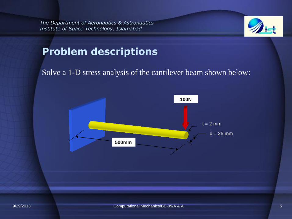
Problem descriptions
Solve a 1-D stress analysis of the cantilever beam shown below:
Computational Mechanics/BE-09/A & A 5
500mm
100N
d = 25 mm
t = 2 mm
9/29/2013
The Department of Aeronautics & Astronautics Institute of Space Technology, Islamabad
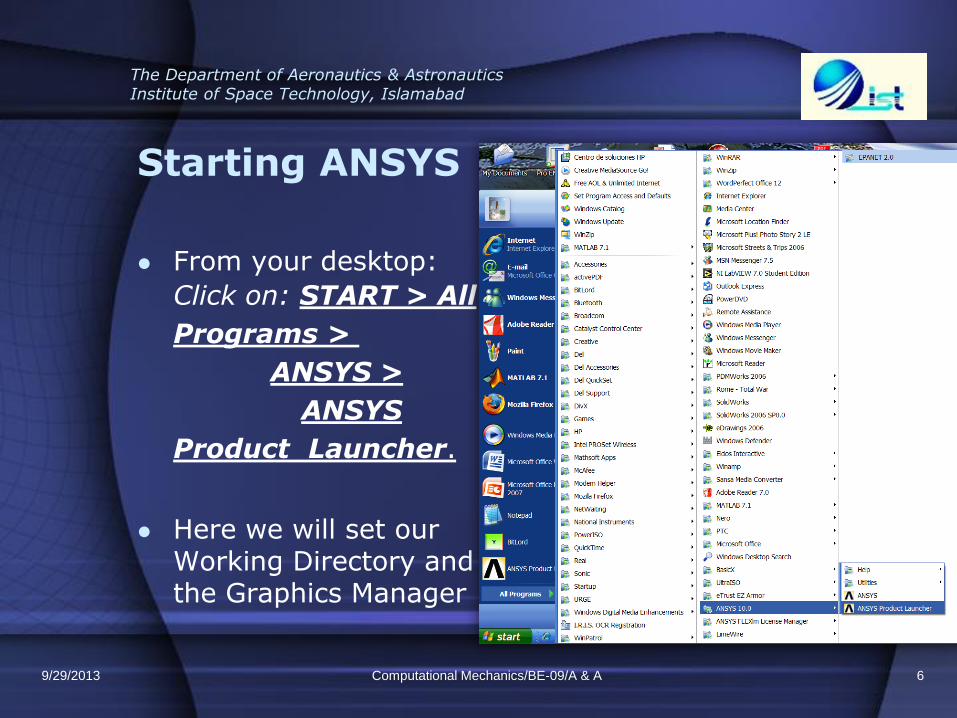
Starting ANSYS
From your desktop:
Click on: START > All
Programs >
ANSYS >
ANSYS
Product Launcher.
Here we will set our Working Directory and the Graphics Manager
Computational Mechanics/BE-09/A & A 6 9/29/2013
The Department of Aeronautics & Astronautics Institute of Space Technology, Islamabad
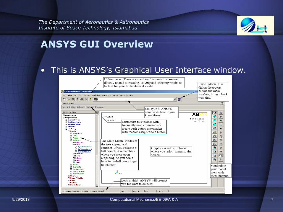
ANSYS GUI Overview
• This is ANSYS’s Graphical User Interface window.
Computational Mechanics/BE-09/A & A 7 9/29/2013
The Department of Aeronautics & Astronautics Institute of Space Technology, Islamabad
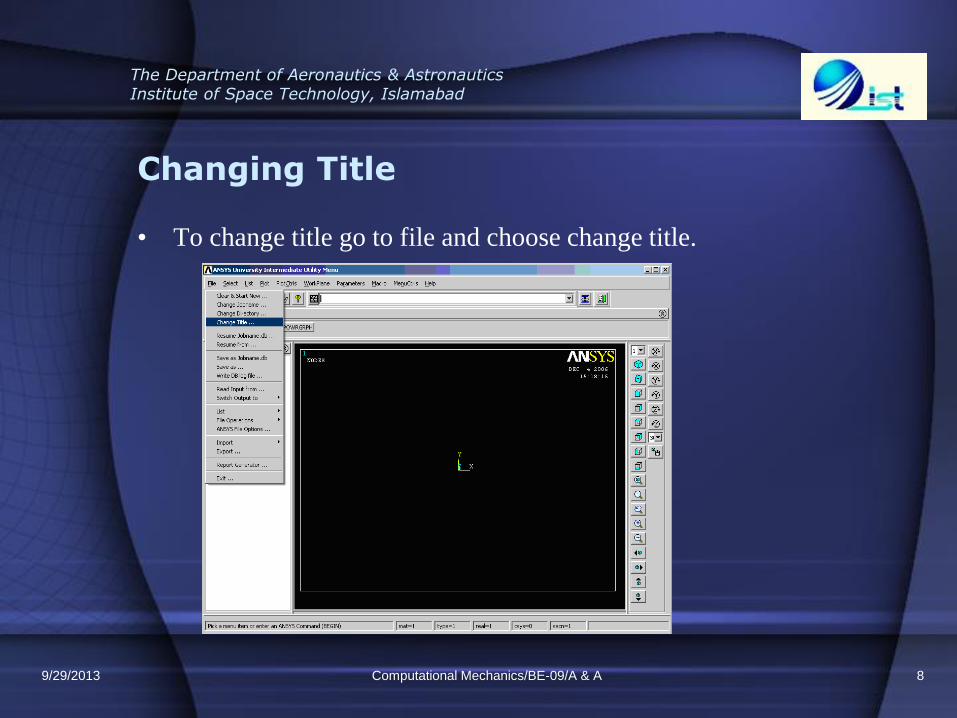
Changing Title
• To change title go to file and choose change title.
Computational Mechanics/BE-09/A & A 8 9/29/2013
The Department of Aeronautics & Astronautics Institute of Space Technology, Islamabad
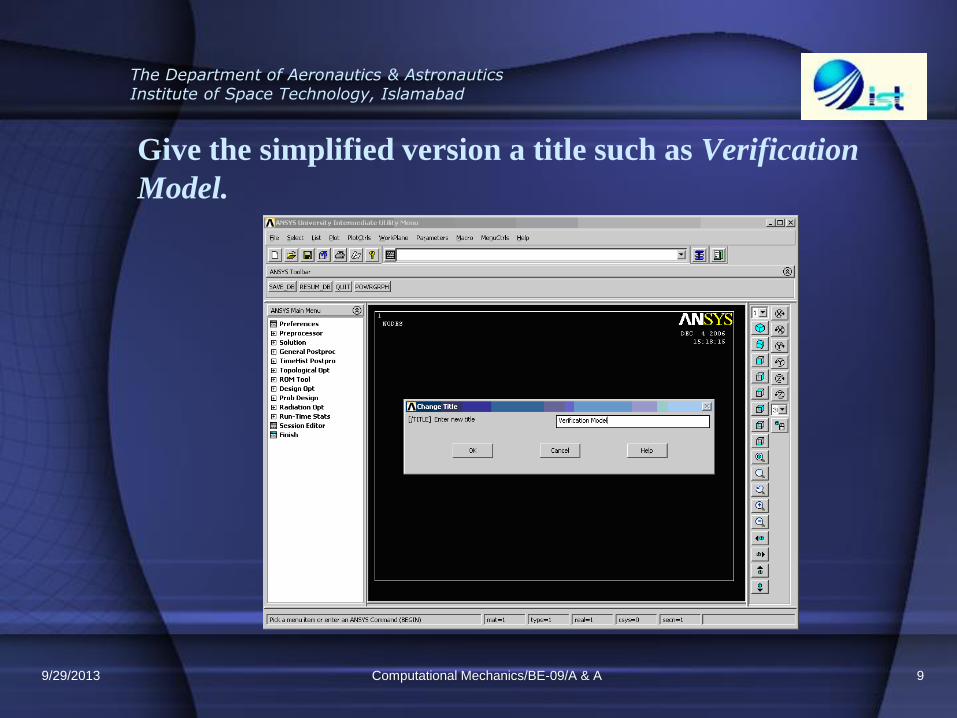
Give the simplified version a title such as Verification
Model.
Computational Mechanics/BE-09/A & A 9 9/29/2013
The Department of Aeronautics & Astronautics Institute of Space Technology, Islamabad
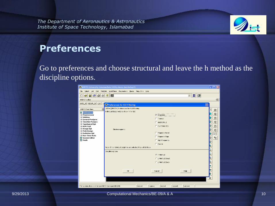
Preferences
Go to preferences and choose structural and leave the h method as the
discipline options.
Computational Mechanics/BE-09/A & A 10 9/29/2013

The Department of Aeronautics & Astronautics Institute of Space Technology, Islamabad
PREPROCESSING
Developing the startup requirements
Computational Mechanics/BE-09/A & A 11 9/29/2013
The Department of Aeronautics & Astronautics Institute of Space Technology, Islamabad
Element Type
It is important to define the element type for the beam. For this problem
we will use pipe elastic straight 16. PIPE16 is a uniaxial element with
tension-compression, torsion, and bending capabilities. The element has
six degrees of freedom at two nodes: translations in the nodal x, y, and z
directions and rotations about the nodal x, y, and z axes. This element is
based on the 3-D beam element (BEAM4), and includes simplifications
due to its symmetry and standard pipe geometry. To chose this element
type click: preprocessor
Computational Mechanics/BE-09/A & A 12 9/29/2013
The Department of Aeronautics & Astronautics Institute of Space Technology, Islamabad
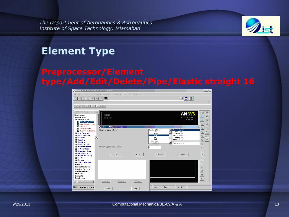
Element Type
Computational Mechanics/BE-09/A & A 13
Preprocessor/Element type/Add/Edit/Delete/Pipe/Elastic straight 16
9/29/2013
The Department of Aeronautics & Astronautics Institute of Space Technology, Islamabad
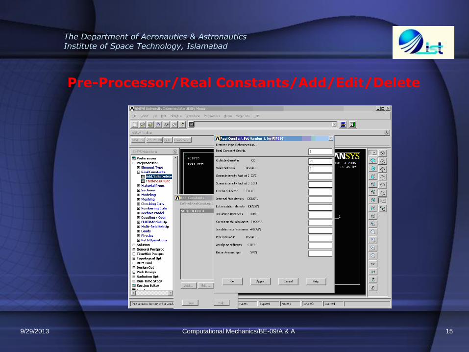
Real constants
• To define the geometric properties we select real constants. The real
constant are the dimensions that must remain constant during the
design. These constants are: diameters, thickness, among others.
• For the outside diameter write OD:25 mm and for the wall thickness
TKWALL:2 mm.
To chose the real constants click:
Processor/Real Constants/Add/Edit/Delete
Computational Mechanics/BE-09/A & A 14 9/29/2013
The Department of Aeronautics & Astronautics Institute of Space Technology, Islamabad
Pre-Processor/Real Constants/Add/Edit/Delete
Computational Mechanics/BE-09/A & A 15 9/29/2013
The Department of Aeronautics & Astronautics Institute of Space Technology, Islamabad
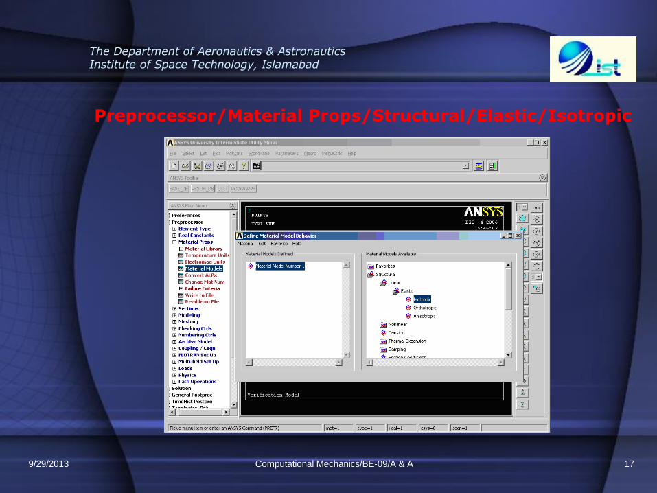
Material properties
• To define the element material properties we choose material models.
Our material will have a Modulus of Elasticity of 70,000 (MPa) and a
Poisson’s ratio of 0.33
• To add material properties click:
Preprocessor/Material Props/Structural/Elastic/Isotropic
Computational Mechanics/BE-09/A & A 16 9/29/2013
The Department of Aeronautics & Astronautics Institute of Space Technology, Islamabad
Preprocessor/Material Props/Structural/Elastic/Isotropic
Computational Mechanics/BE-09/A & A 17 9/29/2013
The Department of Aeronautics & Astronautics Institute of Space Technology, Islamabad
Geometry of the Cantilever Beam
• Now let us build the geometry in ANSYS. The strategy to create the
desired geometry is by first creating the key points where the loads
will be applied and then uniting these key points with lines.
• To create keypoints click:
Preprocessor/Modeling/Create/Keypoints/In Active Cs
Computational Mechanics/BE-09/A & A 18 9/29/2013
The Department of Aeronautics & Astronautics Institute of Space Technology, Islamabad
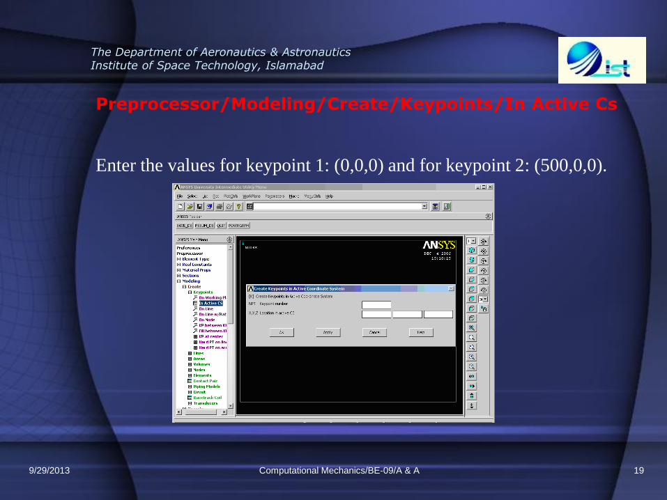
Preprocessor/Modeling/Create/Keypoints/In Active Cs
Enter the values for keypoint 1: (0,0,0) and for keypoint 2: (500,0,0).
Computational Mechanics/BE-09/A & A 19 9/29/2013
The Department of Aeronautics & Astronautics Institute of Space Technology, Islamabad
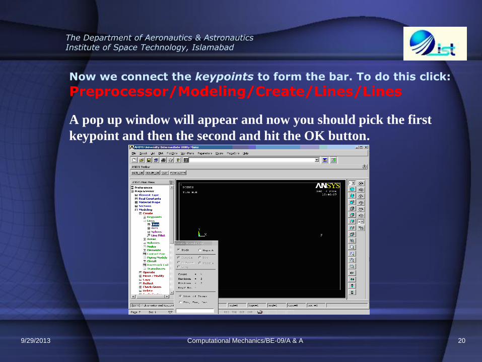
Now we connect the keypoints to form the bar. To do this click:
Preprocessor/Modeling/Create/Lines/Lines
A pop up window will appear and now you should pick the first
keypoint and then the second and hit the OK button.
Computational Mechanics/BE-09/A & A 20 9/29/2013

The Department of Aeronautics & Astronautics Institute of Space Technology, Islamabad
The line will look like this:
Computational Mechanics/BE-09/A & A 21 9/29/2013
The Department of Aeronautics & Astronautics Institute of Space Technology, Islamabad
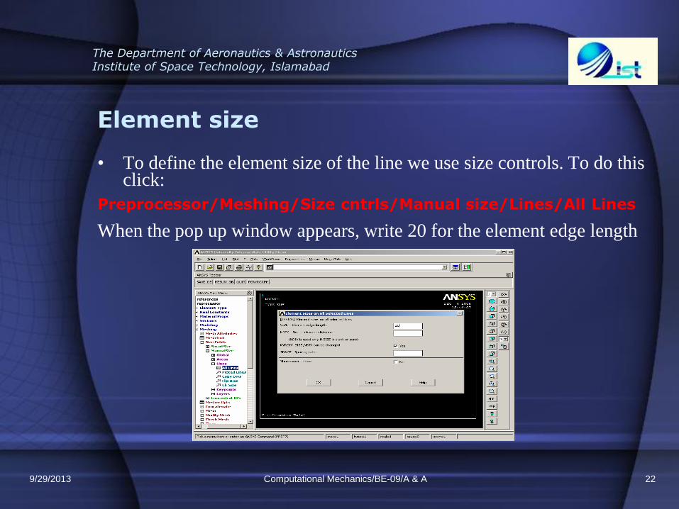
Element size
• To define the element size of the line we use size controls. To do this click:
Preprocessor/Meshing/Size cntrls/Manual size/Lines/All Lines
When the pop up window appears, write 20 for the element edge length
Computational Mechanics/BE-09/A & A 22 9/29/2013
The Department of Aeronautics & Astronautics Institute of Space Technology, Islamabad
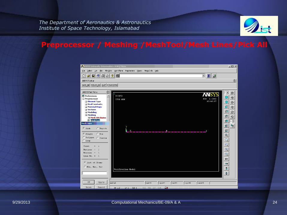
Meshing
To make the finite element analysis we must first divide the object into small elements, this is called meshing.
Now let us make the mesh using the mesh tool.
On the Main Menu window, select
Preprocessor \ Meshing \ MeshTool
Select mesh lines. After the pop up windows appears click the button that says pick all in that same pop up window. Then hit the OK button.
Computational Mechanics/BE-09/A & A 23 9/29/2013
The Department of Aeronautics & Astronautics Institute of Space Technology, Islamabad
Preprocessor / Meshing /MeshTool/Mesh Lines/Pick All
Computational Mechanics/BE-09/A & A 24 9/29/2013
The Department of Aeronautics & Astronautics Institute of Space Technology, Islamabad
Boundary conditions
For keypoint 1: constraint all DOF’s (displacement value = 0)
To apply the Boundary Conditions click:
Preprocessor/Loads/Define Loads/Apply/Structural/Displacement/On keypoints
When the pop up windows appears select the first keypoint and hit the ok button.
Computational Mechanics/BE-09/A & A 25 9/29/2013
The Department of Aeronautics & Astronautics Institute of Space Technology, Islamabad
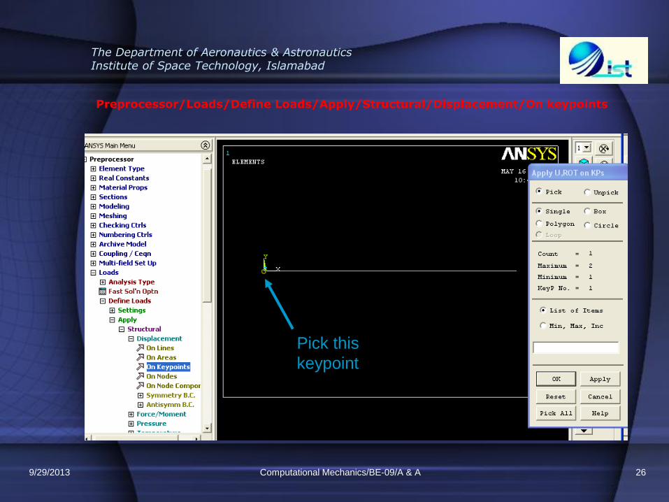
Preprocessor/Loads/Define Loads/Apply/Structural/Displacement/On keypoints
Computational Mechanics/BE-09/A & A 26
Pick this
keypoint
9/29/2013
The Department of Aeronautics & Astronautics Institute of Space Technology, Islamabad
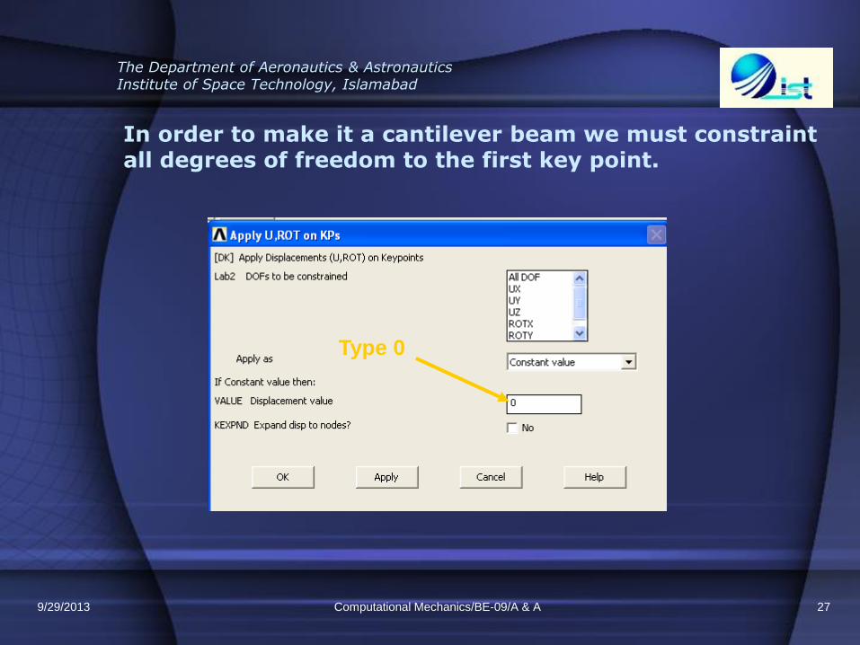
In order to make it a cantilever beam we must constraint all degrees of freedom to the first key point.
Computational Mechanics/BE-09/A & A 27
Type 0
9/29/2013
The Department of Aeronautics & Astronautics Institute of Space Technology, Islamabad
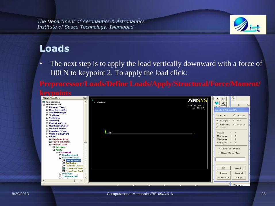
Loads
• The next step is to apply the load vertically downward with a force of
100 N to keypoint 2. To apply the load click:
Preprocessor/Loads/Define Loads/Apply/Structural/Force/Moment/
keypoints
Computational Mechanics/BE-09/A & A 28 9/29/2013

The Department of Aeronautics & Astronautics Institute of Space Technology, Islamabad
We must apply the load in the negative Y direction. That’s the reason we will enter a negative sign before the force value in the pop up window
Computational Mechanics/BE-09/A & A 29
Type -100
9/29/2013
The Department of Aeronautics & Astronautics Institute of Space Technology, Islamabad
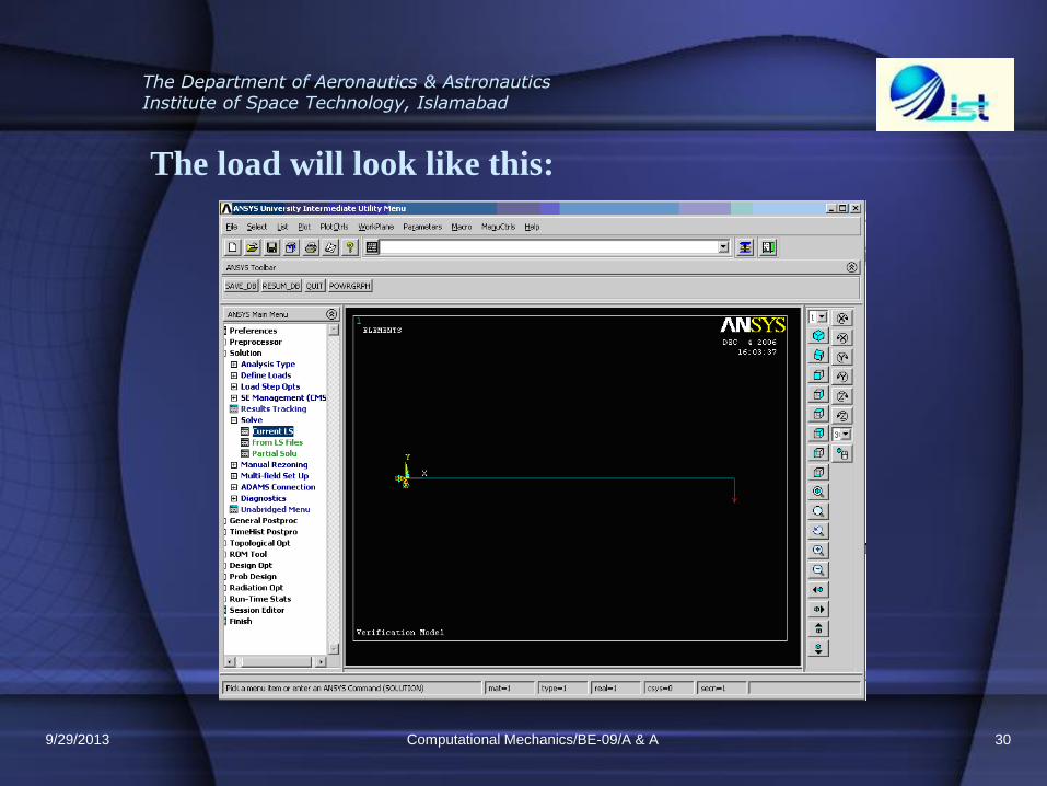
The load will look like this:
Computational Mechanics/BE-09/A & A 30 9/29/2013

The Department of Aeronautics & Astronautics Institute of Space Technology, Islamabad
SOLUTION
Computational Mechanics/BE-09/A & A 31 9/29/2013
The Department of Aeronautics & Astronautics Institute of Space Technology, Islamabad
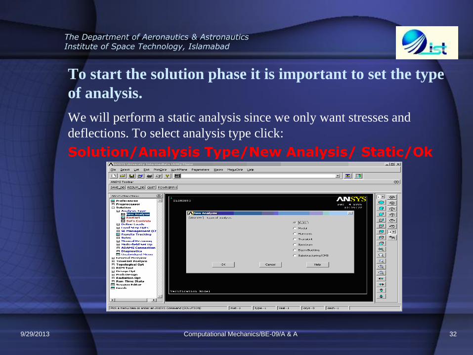
To start the solution phase it is important to set the type
of analysis.
We will perform a static analysis since we only want stresses and
deflections. To select analysis type click:
Solution/Analysis Type/New Analysis/ Static/Ok
Computational Mechanics/BE-09/A & A 32 9/29/2013
The Department of Aeronautics & Astronautics Institute of Space Technology, Islamabad
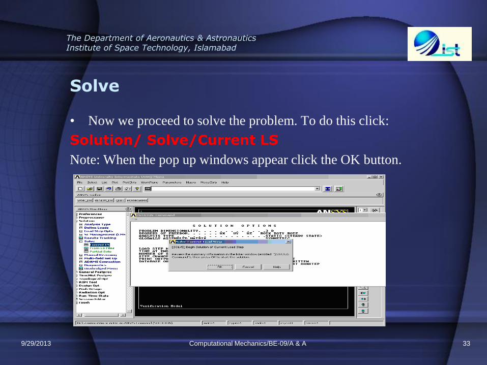
Solve
• Now we proceed to solve the problem. To do this click:
Solution/ Solve/Current LS
Note: When the pop up windows appear click the OK button.
Computational Mechanics/BE-09/A & A 33 9/29/2013
The Department of Aeronautics & Astronautics Institute of Space Technology, Islamabad
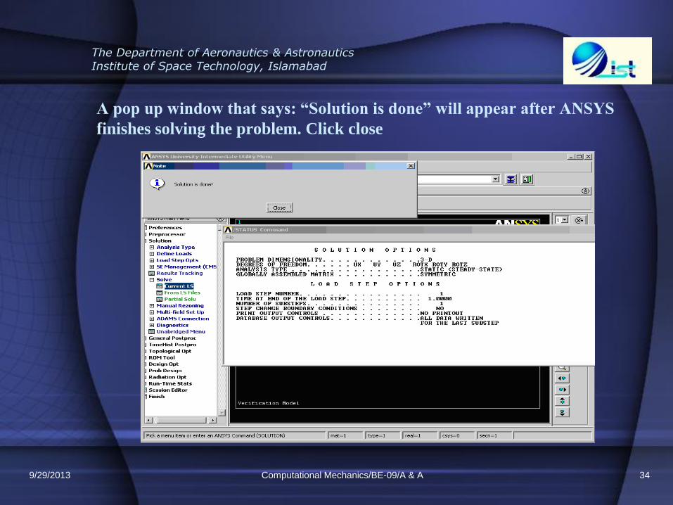
A pop up window that says: “Solution is done” will appear after ANSYS
finishes solving the problem. Click close
Computational Mechanics/BE-09/A & A 34 9/29/2013

The Department of Aeronautics & Astronautics Institute of Space Technology, Islamabad
POST PROCESSING
Computational Mechanics/BE-09/A & A 35 9/29/2013
The Department of Aeronautics & Astronautics Institute of Space Technology, Islamabad
FEM Solution & Plotting Results
• Now we already developed the geometry, Loads & Displacements and the meshing. We will start with the finite element analysis and obtain the displacements and stresses on the key points.
• After make the FEM solution we are able to plot the results, in this case the displacements and stresses.
Computational Mechanics/BE-09/A & A 36 9/29/2013
The Department of Aeronautics & Astronautics Institute of Space Technology, Islamabad
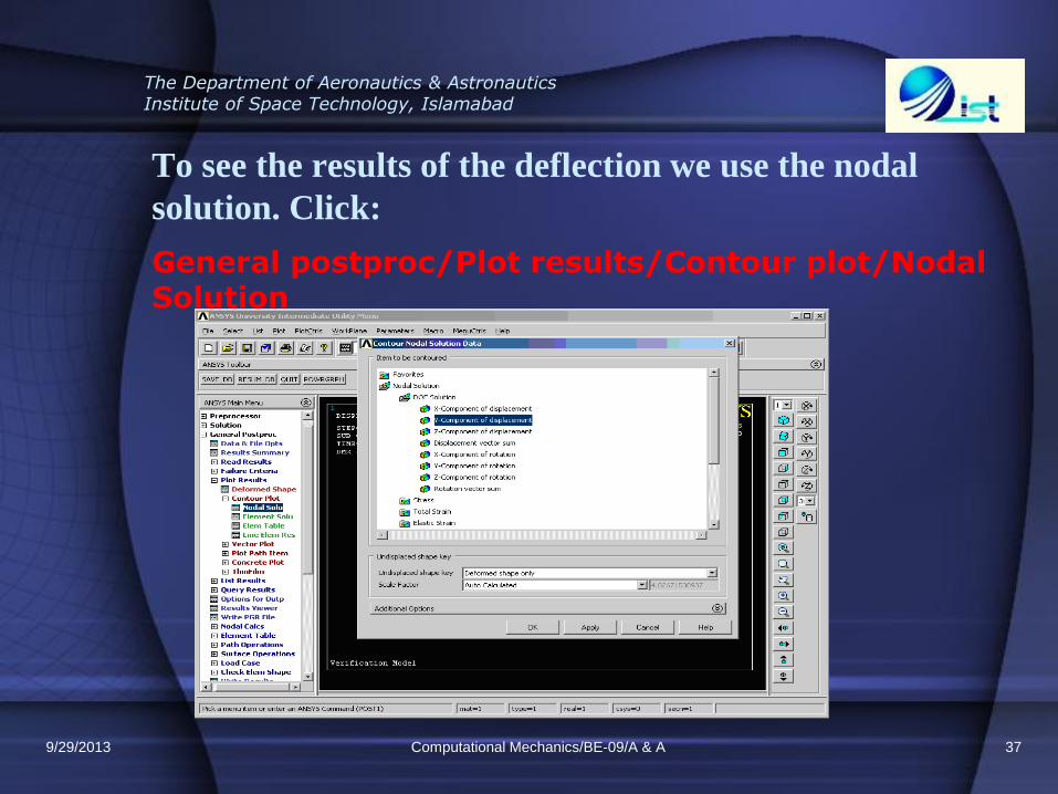
To see the results of the deflection we use the nodal
solution. Click:
General postproc/Plot results/Contour plot/Nodal Solution
Computational Mechanics/BE-09/A & A 37 9/29/2013
The Department of Aeronautics & Astronautics Institute of Space Technology, Islamabad
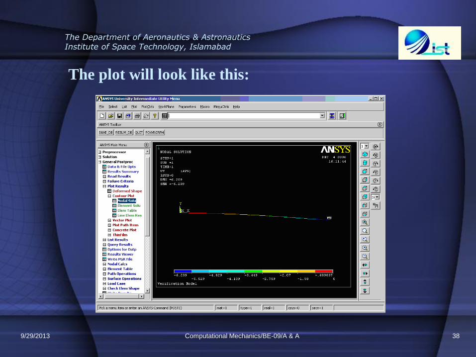
The plot will look like this:
Computational Mechanics/BE-09/A & A 38 9/29/2013
The Department of Aeronautics & Astronautics Institute of Space Technology, Islamabad
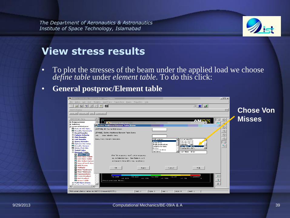
View stress results
• To plot the stresses of the beam under the applied load we choose define table under element table. To do this click:
• General postproc/Element table
Computational Mechanics/BE-09/A & A 39
Chose Von
Misses
9/29/2013
The Department of Aeronautics & Astronautics Institute of Space Technology, Islamabad
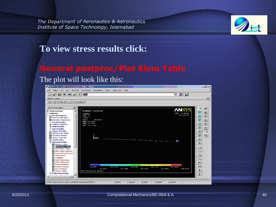
To view stress results click:
General postproc/Plot Elem Table
The plot will look like this:
Computational Mechanics/BE-09/A & A 40 9/29/2013
The Department of Aeronautics & Astronautics Institute of Space Technology, Islamabad
Practice Problem/assignment Simply supported beam - Surface Load Objective
This problem will familiarize you with the beam finite elements you are now learning in class. By comparing the ANSYS solution with simple beam theory, you will be able to understand the accuracy of your model.
9/29/2013 Computational Mechanics/BE-09/A & A 41

The Department of Aeronautics & Astronautics Institute of Space Technology, Islamabad
Simply supported beam - Surface Load
A schematic of a statically determinate beam with distributed load is shown below:
9/29/2013 Computational Mechanics/BE-09/A & A 42

The Department of Aeronautics & Astronautics Institute of Space Technology, Islamabad
Hints
Element type
using the ANSYS element Beam3, and it will be referred to as element type 1 in your model.
To find out more about this element, consult the online manual.
9/29/2013 Computational Mechanics/BE-09/A & A 43

The Department of Aeronautics & Astronautics Institute of Space Technology, Islamabad
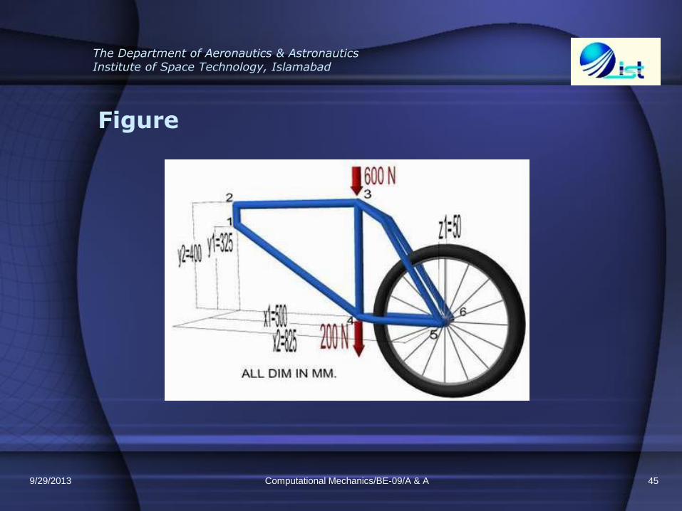
Practice Problem 3D Space Frame Example
Problem Description
The problem to be modeled in this example is a simple bicycle frame shown in the following figure. The frame is to be built of hollow aluminum tubing having an outside diameter of 25mm and a wall thickness of 2mm for the main part of the frame. For the rear forks, the tubing will be 12mm outside diameter and 1mm wall thickness.
9/29/2013 Computational Mechanics/BE-09/A & A 44
The Department of Aeronautics & Astronautics Institute of Space Technology, Islamabad
Figure
9/29/2013 Computational Mechanics/BE-09/A & A 45