
Landscape Irrigation Products - Rain Bird
208
The Intelligent Use of Water. ™ Landscape Irrigation Products 2021 Catalog
-
Upload
khangminh22 -
Category
Documents
-
view
1 -
download
0
Transcript of Landscape Irrigation Products - Rain Bird

The Intelligent Use of Water.™
Landscape Irrigation Products2021 Catalog
The Intelligent Use of Water™
At Rain Bird, we believe it is our responsibility to develop products and technologies that use water efficiently. Our commitment also extends to education, training and services for our industry and our communities.
Through innovative product development, Rain Bird is helping sustain healthier landscapes—and a healthier planet. A lush lawn or colorful garden can also be highly water-efficient. Every Rain Bird product is a testament to that truth.
From water-saving nozzles to sprays with pressure-regulating stems to leading-edge Smart Control Technology, Rain Bird products make the most of every drop, delivering superior results with less water. Keeping the world and your backyard beautiful. That’s The Intelligent Use of Water.™
The need to conserve water has never been greater. We want to do even more, and with your help, we can.
Preserving beauty while conserving water.
That's intelligent.
www.rainbird.com
3www.rainbird.com
IntroductionContents
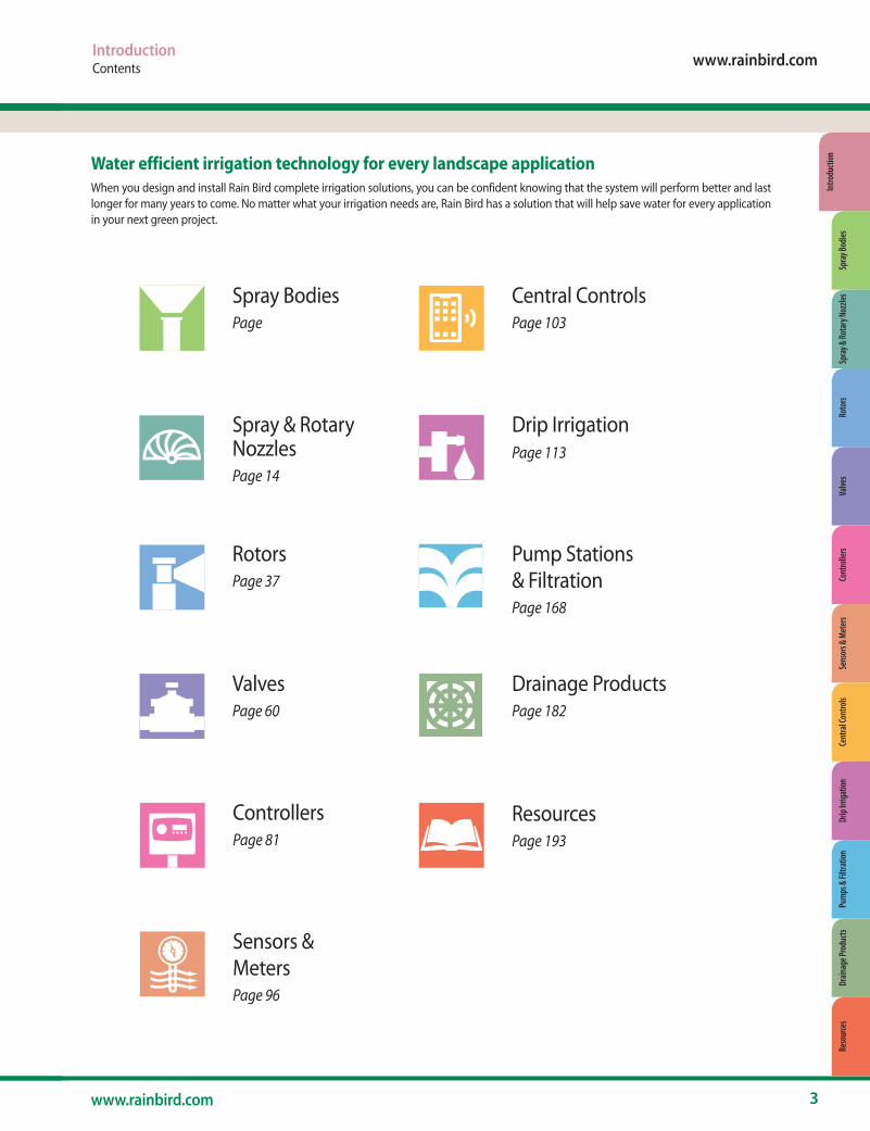
Water efficient irrigation technology for every landscape applicationWhen you design and install Rain Bird complete irrigation solutions, you can be confident knowing that the system will perform better and last longer for many years to come. No matter what your irrigation needs are, Rain Bird has a solution that will help save water for every application in your next green project.
Spray Bodies Page
RotorsPage 37
ValvesPage 60
ControllersPage 81
Sensors & MetersPage 96
Central ControlsPage 103
Drip IrrigationPage 113
Pump Stations & FiltrationPage 168
ResourcesPage 193
Drainage ProductsPage 182
Spray & Rotary Nozzles Page 14
Spra
y & Ro
tary
Noz
zles
Roto
rsVa
lves
Cont
rolle
rsSe
nsor
s & M
eter
sCe
ntra
l Con
trols
Drip
Irrig
atio
nPu
mps
& Fi
ltrat
ion
Drain
age P
rodu
cts
Reso
urce
sIn
trodu
ctio
nSp
ray B
odies

4 The Intelligent Use of Water.™
Together, we can make a differenceAt Rain Bird, we believe that saving water is a responsibility that we all share. Our industry can have a tremendous impact on water conservation by installing more efficient systems and teaching customers how to use them correctly. By working together, we can really make a difference.
Rain Bird’s 25 Ways offers practical, effective tips and advice drawn from the company’s 80-plus years of experience in the irrigation industry. Available at 25ways.rainbird.com, these resources can be used anywhere and by anyone who wants to improve their watering efficiency.
Water Saving Tips from Rain BirdVisit 25ways.rainbird.com for a complete list of water saving tips and techniques in each of the following categories.
25 WA25 WA
Improve Your Existing System
Use The Right Products
25 WA
25 WA
Water Only At The Right Times
Keep Your Water In Place
25 WA 25 WA
Don't Overwater
Update Your Landscape

Primary Applications
1802, 1804, 1806
1812 1800 PRS
1800 SAM
1800 SAM-PRS
1800 SAM-PRS-45
US-400 1300/ 1400
Bubblers
PA-80 PA-8S
PA-8S-NPPA-8S-PRS PA-8S-P45
RD-04, RD-06
RD-12 RD1800 SAM- PRS
RD1800 SAM- PRS-F
RD1800 SAM-
PRS-45-F
Turfgrass ● ● ● ● ● ● ● ● ● ●
Slopes ● ● ● ● ● ● ●
Ground Cover/Shrubs ● ● ● ● ● ● ● ● ● ● ● ● ● ●
High Pressure Systems ● ● ● ● ● ● ● ● ● ●
Low Pressure Systems ● ● ● ● ● ● ●
High Wind Areas ● ● ● ● ● ● ● ● ● ● ● ● ● ●
Non-Potable Water ● ● ● ● ● ●
Vandalism/Damage Prone ● ●
Dirty Water ● ● ● ● ●
Spray Bodies
5
Major Products
• The patented, built-in PRS regulator main-tains optimal operating pressure and restricts water loss by up to 70% if a nozzle is removed or damaged. It also ends water waste by eliminating misting and fogging caused by high pressure.
• Save water, stop low head drainage, and reduce water hammer by prevent-ing water from draining out of pipes after irrigation with 1800/RD1800 Series Sprays featuring Seal-A-Matic™ (SAM) check valves.
• Exclusive Flow Shield Technology available in the RD1800 Series pro-vides up to 90% reduction in water loss when a nozzle is removed, pre-venting potentially costly and unac-ceptable run-off.
Water Saving Tips
www.rainbird.com
Spra
y & Ro
tary
Noz
zles
Roto
rsVa
lves
Cont
rolle
rsSe
nsor
s & M
eter
sCe
ntra
l Con
trols
Drip
Irrig
atio
nPu
mps
& Fi
ltrat
ion
Drain
age P
rodu
cts
Reso
urce
sIn
trodu
ctio
nSp
ray B
odies
6 The Intelligent Use of Water.™
Spray Bodies
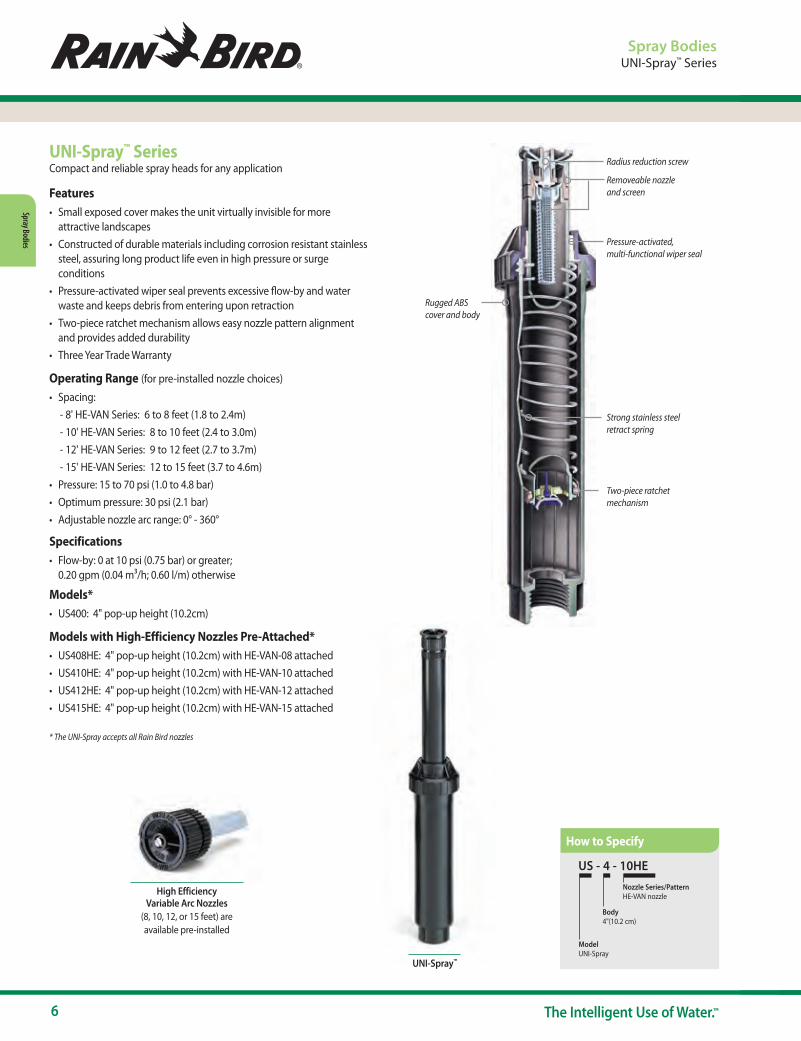
Radius reduction screw
Removeable nozzle and screen
Pressure-activated, multi-functional wiper seal
Strong stainless steel retract spring
Two-piece ratchet mechanism
Rugged ABS cover and body
Spray BodiesUNI-Spray™ Series
UNI-Spray™ SeriesCompact and reliable spray heads for any application
Features• Small exposed cover makes the unit virtually invisible for more
attractive landscapes• Constructed of durable materials including corrosion resistant stainless
steel, assuring long product life even in high pressure or surge conditions
• Pressure-activated wiper seal prevents excessive flow-by and water waste and keeps debris from entering upon retraction
• Two-piece ratchet mechanism allows easy nozzle pattern alignment and provides added durability
• Three Year Trade Warranty
Operating Range (for pre-installed nozzle choices)
• Spacing: - 8' HE-VAN Series: 6 to 8 feet (1.8 to 2.4m)- 10' HE-VAN Series: 8 to 10 feet (2.4 to 3.0m)- 12' HE-VAN Series: 9 to 12 feet (2.7 to 3.7m)- 15' HE-VAN Series: 12 to 15 feet (3.7 to 4.6m)
• Pressure: 15 to 70 psi (1.0 to 4.8 bar)• Optimum pressure: 30 psi (2.1 bar)• Adjustable nozzle arc range: 0° - 360°
Specifications• Flow-by: 0 at 10 psi (0.75 bar) or greater;
0.20 gpm (0.04 m3/h; 0.60 l/m) otherwise
Models*• US400: 4" pop-up height (10.2cm)
Models with High-Efficiency Nozzles Pre-Attached*• US408HE: 4" pop-up height (10.2cm) with HE-VAN-08 attached• US410HE: 4" pop-up height (10.2cm) with HE-VAN-10 attached• US412HE: 4" pop-up height (10.2cm) with HE-VAN-12 attached• US415HE: 4" pop-up height (10.2cm) with HE-VAN-15 attached
* The UNI-Spray accepts all Rain Bird nozzles
High Efficiency Variable Arc Nozzles
(8, 10, 12, or 15 feet) are available pre-installed
US - 4 - 10HE
Model UNI-Spray
Body4"(10.2 cm)
Nozzle Series/PatternHE-VAN nozzle
UNI-Spray™
How to Specify
www.rainbird.com/sprays
7www.rainbird.com
Spra
y Bod
ies
1800 Series
Spray Bodies1800® Series
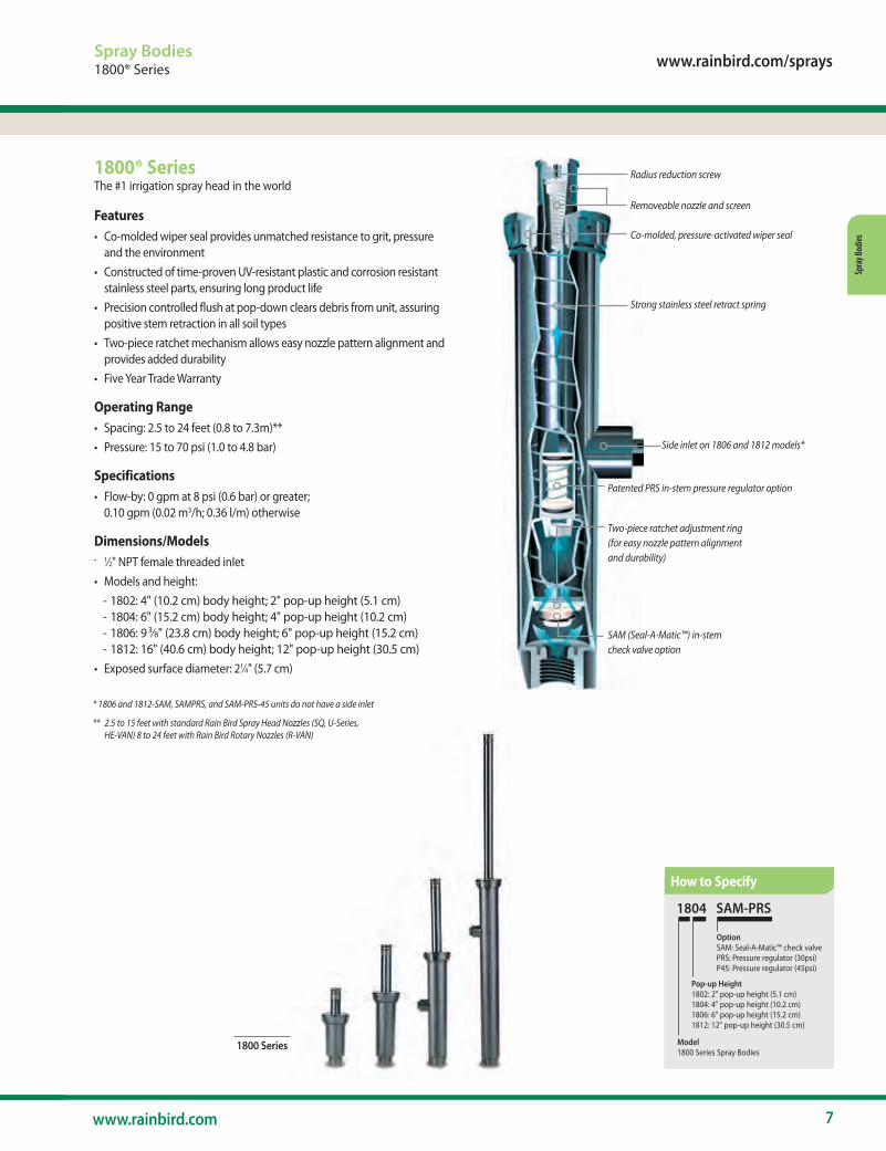
1800® SeriesThe #1 irrigation spray head in the world
Features• Co-molded wiper seal provides unmatched resistance to grit, pressure
and the environment• Constructed of time-proven UV-resistant plastic and corrosion resistant
stainless steel parts, ensuring long product life• Precision controlled flush at pop-down clears debris from unit, assuring
positive stem retraction in all soil types• Two-piece ratchet mechanism allows easy nozzle pattern alignment and
provides added durability• Five Year Trade Warranty
Operating Range• Spacing: 2.5 to 24 feet (0.8 to 7.3m)**• Pressure: 15 to 70 psi (1.0 to 4.8 bar)
Specifications• Flow-by: 0 gpm at 8 psi (0.6 bar) or greater;
0.10 gpm (0.02 m3/h; 0.36 l/m) otherwise
Dimensions/Models • 1⁄2" NPT female threaded inlet• Models and height:
- 1802: 4" (10.2 cm) body height; 2" pop-up height (5.1 cm)- 1804: 6" (15.2 cm) body height; 4" pop-up height (10.2 cm)- 1806: 93⁄8" (23.8 cm) body height; 6" pop-up height (15.2 cm)- 1812: 16" (40.6 cm) body height; 12" pop-up height (30.5 cm)
• Exposed surface diameter: 21⁄4" (5.7 cm)
1804 SAM-PRS
Pop-up Height 1802: 2" pop-up height (5.1 cm)1804: 4" pop-up height (10.2 cm)1806: 6" pop-up height (15.2 cm)1812: 12" pop-up height (30.5 cm)
Option SAM: Seal-A-Matic™ check valvePRS: Pressure regulator (30psi)P45: Pressure regulator (45psi)
Model 1800 Series Spray Bodies
Radius reduction screw
Removeable nozzle and screen
Co-molded, pressure-activated wiper seal
Strong stainless steel retract spring
Side inlet on 1806 and 1812 models*
Patented PRS in-stem pressure regulator option
Two-piece ratchet adjustment ring(for easy nozzle pattern alignment and durability)
SAM (Seal-A-Matic™) in-stem check valve option
* 1806 and 1812-SAM, SAMPRS, and SAM-PRS-45 units do not have a side inlet
** 2.5 to 15 feet with standard Rain Bird Spray Head Nozzles (SQ, U-Series, HE-VAN) 8 to 24 feet with Rain Bird Rotary Nozzles (R-VAN)
How to Specify
8 The Intelligent Use of Water.™
Spray Bodies
Spray Bodies1800® Series
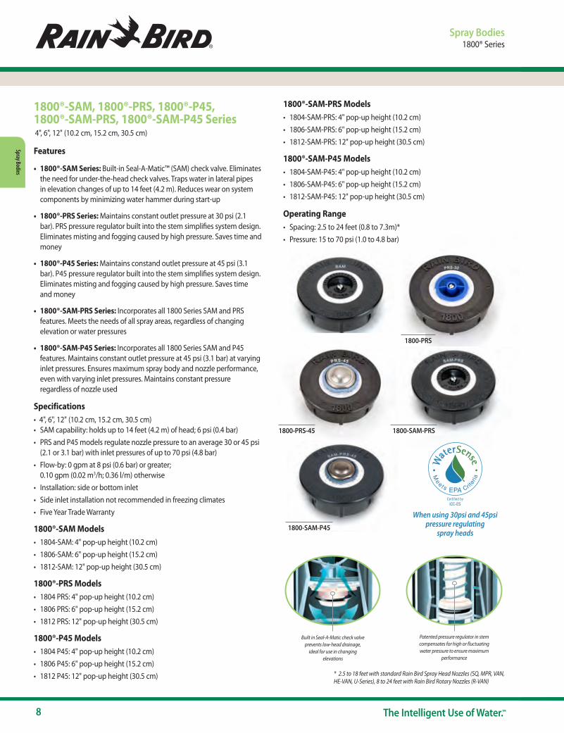
1800®-SAM, 1800®-PRS, 1800®-P45, 1800®-SAM-PRS, 1800®-SAM-P45 Series
Patented pressure regulator in stem compensates for high or fluctuating water pressure to ensure maximum
performance
Built in Seal-A-Matic check valve prevents low-head drainage,
ideal for use in changing elevations
1800-SAM
1800-PRS-45 1800-SAM-PRS
1800-SAM-P45
1800-PRS
1800®-SAM-PRS Models• 1804-SAM-PRS: 4" pop-up height (10.2 cm)• 1806-SAM-PRS: 6" pop-up height (15.2 cm)• 1812-SAM-PRS: 12" pop-up height (30.5 cm)
1800®-SAM-P45 Models• 1804-SAM-P45: 4" pop-up height (10.2 cm)• 1806-SAM-P45: 6" pop-up height (15.2 cm)• 1812-SAM-P45: 12" pop-up height (30.5 cm)
Operating Range• Spacing: 2.5 to 24 feet (0.8 to 7.3m)*• Pressure: 15 to 70 psi (1.0 to 4.8 bar)
* 2.5 to 18 feet with standard Rain Bird Spray Head Nozzles (SQ, MPR, VAN, HE-VAN, U-Series), 8 to 24 feet with Rain Bird Rotary Nozzles (R-VAN)
4", 6", 12" (10.2 cm, 15.2 cm, 30.5 cm)
Features
• 1800®-SAM Series: Built-in Seal-A-Matic™ (SAM) check valve. Eliminates the need for under-the-head check valves. Traps water in lateral pipes in elevation changes of up to 14 feet (4.2 m). Reduces wear on system components by minimizing water hammer during start-up
• 1800®-PRS Series: Maintains constant outlet pressure at 30 psi (2.1 bar). PRS pressure regulator built into the stem simplifies system design. Eliminates misting and fogging caused by high pressure. Saves time and money
• 1800®-P45 Series: Maintains constand outlet pressure at 45 psi (3.1 bar). P45 pressure regulator built into the stem simplifies system design. Eliminates misting and fogging caused by high pressure. Saves time and money
• 1800®-SAM-PRS Series: Incorporates all 1800 Series SAM and PRS features. Meets the needs of all spray areas, regardless of changing elevation or water pressures
• 1800®-SAM-P45 Series: Incorporates all 1800 Series SAM and P45 features. Maintains constant outlet pressure at 45 psi (3.1 bar) at varying inlet pressures. Ensures maximum spray body and nozzle performance, even with varying inlet pressures. Maintains constant pressure regardless of nozzle used
Specifications• 4", 6", 12" (10.2 cm, 15.2 cm, 30.5 cm) • SAM capability: holds up to 14 feet (4.2 m) of head; 6 psi (0.4 bar)• PRS and P45 models regulate nozzle pressure to an average 30 or 45 psi
(2.1 or 3.1 bar) with inlet pressures of up to 70 psi (4.8 bar)• Flow-by: 0 gpm at 8 psi (0.6 bar) or greater;
0.10 gpm (0.02 m3/h; 0.36 l/m) otherwise• Installation: side or bottom inlet• Side inlet installation not recommended in freezing climates• Five Year Trade Warranty
1800®-SAM Models• 1804-SAM: 4" pop-up height (10.2 cm)• 1806-SAM: 6" pop-up height (15.2 cm)• 1812-SAM: 12" pop-up height (30.5 cm)
1800®-PRS Models• 1804 PRS: 4" pop-up height (10.2 cm)• 1806 PRS: 6" pop-up height (15.2 cm)• 1812 PRS: 12" pop-up height (30.5 cm)
1800®-P45 Models• 1804 P45: 4" pop-up height (10.2 cm)• 1806 P45: 6" pop-up height (15.2 cm)• 1812 P45: 12" pop-up height (30.5 cm)
When using 30psi and 45psi pressure regulating
spray heads
www.rainbird.com/sprays
9www.rainbird.com
Spra
y Bod
ies
Spray BodiesRD1800™ Series
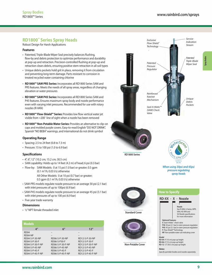
RD1800™ Series Spray HeadsRobust Design for Harsh Applications
Features• Patented, Triple-Blade Wiper Seal precisely balances flushing,
flow-by and debris protection to optimize performance and durability at pop-up and retraction. Precision-controlled flushing at pop-up and retraction clears debris, ensuring positive stem retraction in all soil types
• Unique debris pockets hold grit in place, removing it from circulation and preventing long-term damage. Parts resistant to corrosion in treated recycled water containing chlorine
• RD1800™ SAM PRS Series: Incorporates all RD1800 Series SAM and PRS features. Meets the needs of all spray areas, regardless of changing elevation or water pressures
• RD1800™ SAM P45 Series: Incorporates all RD1800 Series SAM and P45 features. Ensures maximum spray body and nozzle performance even with varying inlet pressures. Recommended for use with rotary nozzles (R-VAN)
• RD1800™ Flow-Shield™ Series: Provides low flow vertical water jet visible from +200’ line of sight when a nozzle has been removed
• RD1800™ Non-Potable Water Series: Provides an alternative to clip-on caps and molded purple covers. Easy-to-read English “DO NOT DRINK”, Spanish “NO BEBA” warnings, and international do not drink symbol
Operating Range• Spacing: 2.5 to 24 feet (0.8 to 7.3 m)• Pressure: 15 to 100 psi (1.0 to 6.9 bar)
Specifications• 4", 6", 12" (10.2 cm; 15.2 cm; 30.5 cm)• SAM capability: Holds up to 14 feet (4.2 m) of head; 6 psi (0.3 bar)• Flow-by: SAM Models: 0 at 15 psi (1.0 bar) or greater; 0.5 gpm
(0.1 m3/h; 0.03 l/s) otherwise All Other Models: 0 at 10 psi (0.7 bar) or greater;
0.5 gpm (0.1 m3/h; 0.03 l/s) otherwise• SAM-PRS models regulate nozzle pressure to an average 30 psi (2.1 bar)
with inlet pressures of up to 100psi (6.9 bar)• SAM-P45 models regulate nozzle pressure to an average 45 psi (3.1 bar)
with inlet pressures of up to 100 psi (6.9 bar)• Five-year trade warranty
Dimensions• ½” NPT female threaded inlet
RD-XX - X - Nozzle
Model RD-04: 4” (10 cm) pop-up heightRD-06: 6” (15 cm) pop-up heightRD-12: 12” (30.5 cm) pop-up height
Optional FeaturesS: Seal-A-Matic™ check valveP30: 30 psi (2.1 bar) in-stem pressure regulationP45: 45 psi (3.1 bar) in-stem pressure regulationF: Flow-Shield™ TechnologyNP: Non-potable water use indicating cover
NozzleSee R-VAN, U-Series, MPR, VAN, HE-VAN and SQ Nozzle specifications for more information
Notes: Specify sprinkler bodies and nozzles separately.
RD1800 Series
Service Indication Stream
Patented Triple-Blade Wiper Seal
Reinforced Ratchet Mechanism Unique
Debris Pockets
Patented Pressure Regulator
Exclusive Flow-Shield™
Technology .
Seal-A-Matic™ (SAM) Check Valve
Standard Cover
Non-Potable Cover
4” 6” 12" RD04 – –RD04-NP – –RD04-S-P-30-NP RD06-S-P-30-NP RD12-S-P-30-NPRD04-S-P-30-F RD06-S-P30-F RD12-S-P-30-FRD04-S-P-30-F-NP RD06-S-P-30-F-NP RD12-S-P-30-F-NPRD04-S-P-45-NP RD06-S-P-45-NP RD12-S-P-45-NPRD04-S-P-45-F RD06-S-P-45-F RD12-S-P-45-FRD04-S-P-45-F-NP RD06-S-P-45-F-NP RD12-S-P-45-F-NP
Models
How to Specify
When using 30psi and 45psi pressure regulating
spray heads

10 The Intelligent Use of Water.™
Spray Bodies
Spray BodiesSpray Accessories
1800®-EXTPlastic Extension
Features• UV-resistant thermo plastic
construction for long life• Fits all Rain Bird Spray Bodies
and Nozzles. Exception: Cannot be used with bubblers
Model• 1800-EXT
PA-80Plastic Adapter
Features• Adapts Rain Bird Spray Bodies
for use with any 1⁄2" (15/21) FPT bubbler or spray nozzle
• Rugged, UV-resistant thermoplastic construction
• Easy to install; no tools required
Dimensions• Height: 11⁄2" (3.8 cm); 0.8" (2.0
cm) above 1800 cap
Model• PA-80
PA-80
PAPlastic Shrub Adapter
Features• Adapts Rain Bird Nozzles for use
with 1⁄2" (15/21) NPT threaded risers
• Accepts protective, non-clogging 1800 Series filter screen (shipped with nozzle) and PCS Series screens
• Durable, non-corrosive plastic construction
• Non-Potable Plastic Shrub Adapter
Specifications• 1⁄2" (15/21) female inlet threads• Fine top threads accept all
Rain Bird nozzles
Model• PA-8S• PA-8S-NP
PA-8S PA-8S-NP
1800® NP CoverNon-Potable 1800 Spray Head CoverFeatures• Designed for excellent retention
on 1800 Series Spray Body covers
• Purple plastic cover for easy identification of non-potable water system
• Marked with “Do Not Drink!” warning in both English and Spanish
• Snaps onto all 1800® Series Spray Body covers
Model• 1800-NP
1800-NP1800-EXT
PA-8S-PRS & PA-8S-P4530 psi and 45 psi Pressure Regulating Shrub Adapters
Features• Adapts nozzles for use with 1⁄2" (15/21) NPT threaded risers• Patented PRS pressure regulator built into the stem. No parts to be
installed at the site. Saves time and money- Maintains constant pressure at 30 psi (2,1 bar) or 45 psi (3,1 bar)- Restricts water loss by up to 70% if nozzle is removed or damaged.
Saves water and money. Reduces liability. Recommended for vandal-prone areas
• Fits all Rain Bird plastic nozzles• Rugged thermoplastic construction resists UV rays
Operating Range• Pressure: 15 to 70 psi (1.0 to 4.8 bar)• Flow: 0.2 to 4.0 gpm (0.05 to 0.91 m3/h;
0.06 to 15.0 l/m)
Specifications• 1⁄2" female inlet threads• Fine top threads accept all Rain Bird nozzles• Height: 51⁄4" (13.3 cm)
Models• PA-8S-PRS• PA-8S-P45
1800 PCSPressure Compensating Screens
Features• Compensates* for pressure variations• Eliminates fogging and water waste caused by high pressures• Nozzles can be matched with screens to create short-throw, reduced-
radius patterns and/or flush-mounted bubblers• Color-coded for easy identification• Use with all 1800 Series plastic nozzles (MPR, VAN, U-Series, HE-VAN,
Strips and Bubblers)
Operating Range• Flow: 0.20 to 0.90 gpm (0.05 to 0.20 m3/h; 0.6 to 3.6 l/m)• Pressure: 15 to 70 psi (1.0 to 4.8 bar)
Models• PCS-020: 0.2 gpm (0.05 m3/h; 0.6 l/m) - Brown• PCS-025: 0.25 gpm (0.06 m3/h; 1.2 l/m) - Pink• PCS-030: 0.3 gpm (0.07 m3/h; 1.2 l/m) - Silver• PCS-040: 0.4 gpm (0.09 m3/h; 1.8 l/m) - Orange• PCS-060: 0.6 gpm (0.14 m3/h; 2.4 l/m) - Black
* With a pressure compensator, outlet pressure will be reduced, but will fluctuate as the inlet pressure changes. A pressure compensator cannot maintain outlet pressure at a constant rate. A pressure regulator establishes and maintains a constand outlet pressure of 30 psi (2.1 bar) or 45 psi (3.1 bar) as long as the inlet pressure at the spray head is greater than 30psi (2.1 bar) or 45 psi (3.1 bar)
1800 PCS ScreensPA-8S-PRS & PA-8S-P45
www.rainbird.com/sprays
11www.rainbird.com
Spra
y Bod
ies
Spray Bodies1800 PCS Screens
U-S
erie
sVA
N
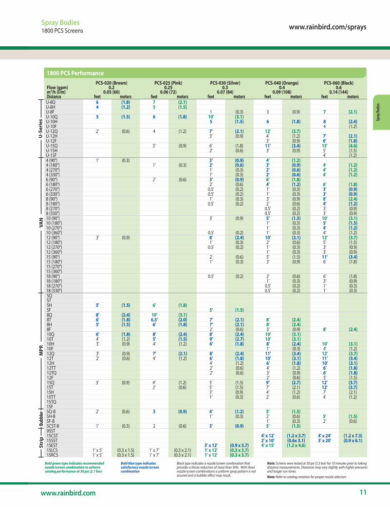
Black type indicates a nozzle/screen combination that provides a throw reduction of more than 50%. With these nozzle/screen combinations a uniform spray pattern is not assured and a bubbler effect may result.
Bold blue type indicates satisfactory nozzle/screen combination
Bold green type indicates recommended nozzle/screen combination to achieve catalog performance at 30 psi (2.1 bar)
Note: Screens were tested at 50 psi (3.5 bar) for 10 minutes prior to taking distance measure ments. Distances may vary slightly with higher pressures and longer run-timesNote: Refer to catalog notation for proper nozzle selection
Flow (gpm) m3/h (l/m)
PCS-020 (Brown)0.2
0.05 (60)
PCS-025 (Pink)0.25
0.06 (72)
PCS-030 (Silver)0.3
0.07 (84)
PCS-040 (Orange)0.4
0.09 (108)
PCS-060 (Black)0.6
0.14 (144) Distance feet meters feet meters feet meters feet meters feet metersU-8Q 6 (1.8) 7 (2.1)U-8H 4 (1.2) 5 (1.5)U-8F 1 (0.3) 3 (0.9) 7 (2.1)U-10Q 5 (1.5) 6 (1.8) 10' (3.1)U-10H 5 (1.5) 6 (1.8) 8 (2.4)U-10F 4 (1.2)U-12Q 2' (0.6) 4 (1.2) 7' (2.1) 12' (3.7)U-12H 3' (0.9) 4' (1.2) 7' (2.1)U-12F 3' (0.9) 6' (1.8)U-15Q 3' (0.9) 6' (1.8) 11' (3.4) 15' (4.6)U-15H 2' (0.6) 3' (0.9) 5' (1.5)U-15F 4' (1.2)4 (90°) 1' (0.3) 3' (0.9) 4' (1.2)4 (180°) 1' (0.3) 2' (0.6) 3' (0.9) 4' (1.2)4 (270°) 1' (0.3) 2' (0.6) 4' (1.2)4 (330°) 1' (0.3) 2' (0.6) 4' (1.2)6 (90°) 2' (0.6) 3' (0.9) 6' (1.8)6 (180°) 2' (0.6) 4' (1.2) 6' (1.8)6 (270°) 0.5' (0.2) 1' (0.3) 3' (0.9)6 (330°) 0.5' (0.2) 1' (0.3) 3' (0.9)8 (90°) 1' (0.3) 3' (0.9) 8' (2.4)8 (180°) 0.5' (0.2) 2' (0.6) 4' (1.2)8 (270°) 0.5' (0.2) 3' (0.9)8 (330°) 0.5' (0.2) 3' (0.9)10 (90°) 3' (0.9) 5' (1.5) 10' (3.1)10 (180°) 1' (0.3) 5' (1.5)10 (270°) 1' (0.3) 4' (1.2)10 (360°) 0.5' (0.2) 1' (0.3) 4' (1.2)12 (90°) 3' (0.9) 8' (2.4) 10' (3.1) 12' (3.7)12 (180°) 1' (0.3) 2' (0.6) 5' (1.5)12 (270°) 0.5' (0.2) 1' (0.3) 3' (0.9)12 (360°) 1' (0.3) 3' (0.9)15 (90°) 2' (0.6) 5' (1.5) 11' (3.4)15 (180°) 1' (0.3) 3' (0.9) 6' (1.8)15 (270°)15 (360°)18 (90°) 0.5' (0.2) 2' (0.6) 6' (1.8)18 (180°) 1' (0.3) 3' (0.9)18 (270°) 0.5' (0.2) 1' (0.3)18 (330°) 0.5' (0.2) 1' (0.3)5Q5T5H 5' (1.5) 6' (1.8)5F 5' (1.5)8Q 8' (2.4) 10' (3.1)8T 6' (1.8) 6.5' (2.0) 7' (2.1) 8' (2.4)8H 5' (1.5) 6' (1.8) 7' (2.1) 8' (2.4)8F 2' (0.6) 3' (0.9) 8' (2.4)10Q 6' (1.8) 8' (2.4) 8' (2.4) 10' (3.1)10T 4' (1.2) 5' (1.5) 9' (2.7) 10' (3.1)10H 3' (0.9) 4' (1.2) 6' (1.8) 8' (2.4) 10' (3.1)10F 1' (0.3) 4' (1.2)12Q 3' (0.9) 7' (2.1) 8' (2.4) 11' (3.4) 12' (3.7)12T 2' (0.6) 4' (1.2) 6' (1.8) 10' (3.1) 11' (3.4)12H 4' (1.2) 6' (1.8) 10' (3.1)12TT 2' (0.6) 4' (1.2) 6' (1.8)12TQ 2' (0.6) 3' (0.9) 6' (1.8)12F 2' (0.6) 5' (1.5)15Q 3' (0.9) 4' (1.2) 5' (1.5) 9' (2.7) 12' (3.7)15T 2' (0.6) 5' (1.5) 7' (2.1) 12' (3.7)15H 3' (0.9) 4' (1.2) 7' (2.1)15TT 1' (0.3) 2' (0.6) 4' (1.2)15TQ15F5Q-B 2' (0.6) 3 (0.9) 4' (1.2) 5' (1.5)5H-B 1' (0.3) 2' (0.6) 5' (1.5)5F-B 1' (0.3) 2' (0.6)5CST-B 1' (0.3) 2 (0.6) 3' (0.9) 5' (1.5)9SST15CST 4' x 12' (1.2 x 3.7) 4' x 24' (1.2 x 7.3)15SST 2' x 10' (0.6x 3.1) 3' x 20' (0.9 x 6.1)15EST 3' x 12' (0.9 x 3.7) 4' x 15' (1.2 x 4.6)15LCS 1' x 5' (0.3 x 1.5) 1' x 7' (0.3 x 2.1) 1' x 12' (0.3 x 3.7)15RCS 1' x 5' (0.3 x 1.5) 1' x 7' (0.3 x 2.1) 1' x 12' (0.3 x 3.7)
MPR
Bubb
lerSt
rip
1800 PCS Performance
12 The Intelligent Use of Water.™
Spray Bodies
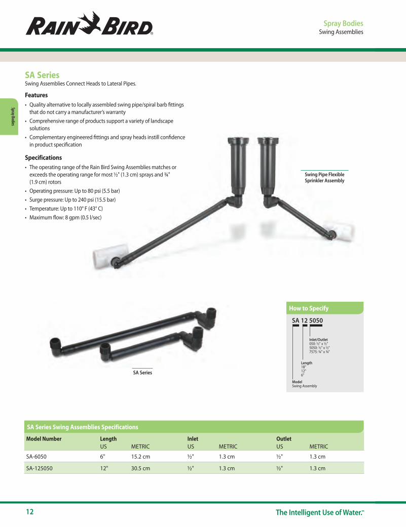
SA SeriesSwing Assemblies Connect Heads to Lateral Pipes.
Features• Quality alternative to locally assembled swing pipe/spiral barb fittings
that do not carry a manufacturer’s warranty• Comprehensive range of products support a variety of landscape
solutions• Complementary engineered fittings and spray heads instill confidence
in product specification
Specifications• The operating range of the Rain Bird Swing Assemblies matches or
exceeds the operating range for most ½" (1.3 cm) sprays and ¾" (1.9 cm) rotors
• Operating pressure: Up to 80 psi (5.5 bar)• Surge pressure: Up to 240 psi (15.5 bar)• Temperature: Up to 110° F (43° C)• Maximum flow: 8 gpm (0.5 l/sec)
SA Series
SA 12 5050
Model Swing Assembly
Length18"12"6"
Inlet/Outlet050: ½" x ½"5050: ½" x ½"7575: ¾" x ¾"
Spray BodiesSwing Assemblies
Model Number Length Inlet OutletUS METRIC US METRIC US METRIC
SA-6050 6" 15.2 cm ½" 1.3 cm ½" 1.3 cm
SA-125050 12" 30.5 cm ½" 1.3 cm ½" 1.3 cm
Swing Pipe Flexible Sprinkler Assembly
How to Specify
SA Series Swing Assemblies Specifications

www.rainbird.com/sprays
13www.rainbird.com
Spra
y Bod
ies
Spray BodiesSwing Pipe and Spiral Barb Fittings
SB Series Spiral Barb FittingsA Natural Product Complement to SPX Series Swing Pipe
Features and Benefits• Fittings are made of robust acetal material to make connecting swing
pipe fast and easy• Easy twist-in insertion – no glue or clamps needed for installation• Aggressive barb lip makes a secure connection that is less likely
to leak
• Broad range of shapes and sizes allow the contractor to choose the best fitting for the application
• Extended length and aggressive barb lip prevent blow outs, reducing likelihood of contractor call backs
Specifications• Operating pressure: Up to 80 psi (5.5 bar)• Temperature: Up to 110° F (43° C)
Models• SB-CPLG: ½" barb x ½" barb coupling • SBA-050: ½" M NPT x ½" barb adapter • SBE-075: ¾" M NPT x ½" barb elbow • SBE-050: ½" M NPT x ½" barb elbow • SB-TEE: ½" barb x ½" barb x ½" barb tee
SPX Series Swing PipeSwing Pipe with Spiral Barb Fittings Provides a Flexible Swing Assembly for Sprays and Rotors
Features and Benefits• SPX-FLEX100
- Superior flexibility allows pipe to be efficiently routed around hardscape, terraces, and uneven terrain to turn landscape design into reality
- Textured surface makes product easier to handle, contributing to labor efficiency, especially under wet conditions
- Resists kinking- Quick and easy installation lowers material and labor costs- Installs quickly leaving time for additional system installations and
incremental revenue opportunities
Specifications• Inside diameter: 0.49" (1.24 cm)• Operating pressure: Up to 80 psi (5.5 bar)• Temperature: Up to 110° F (43° C)
Models• SPX-FLEX-100: 100' (30 m) coil
SBE-050 SB-TEE
SB-CPLG SBA-050 SBE-075
SPX-FLEX100
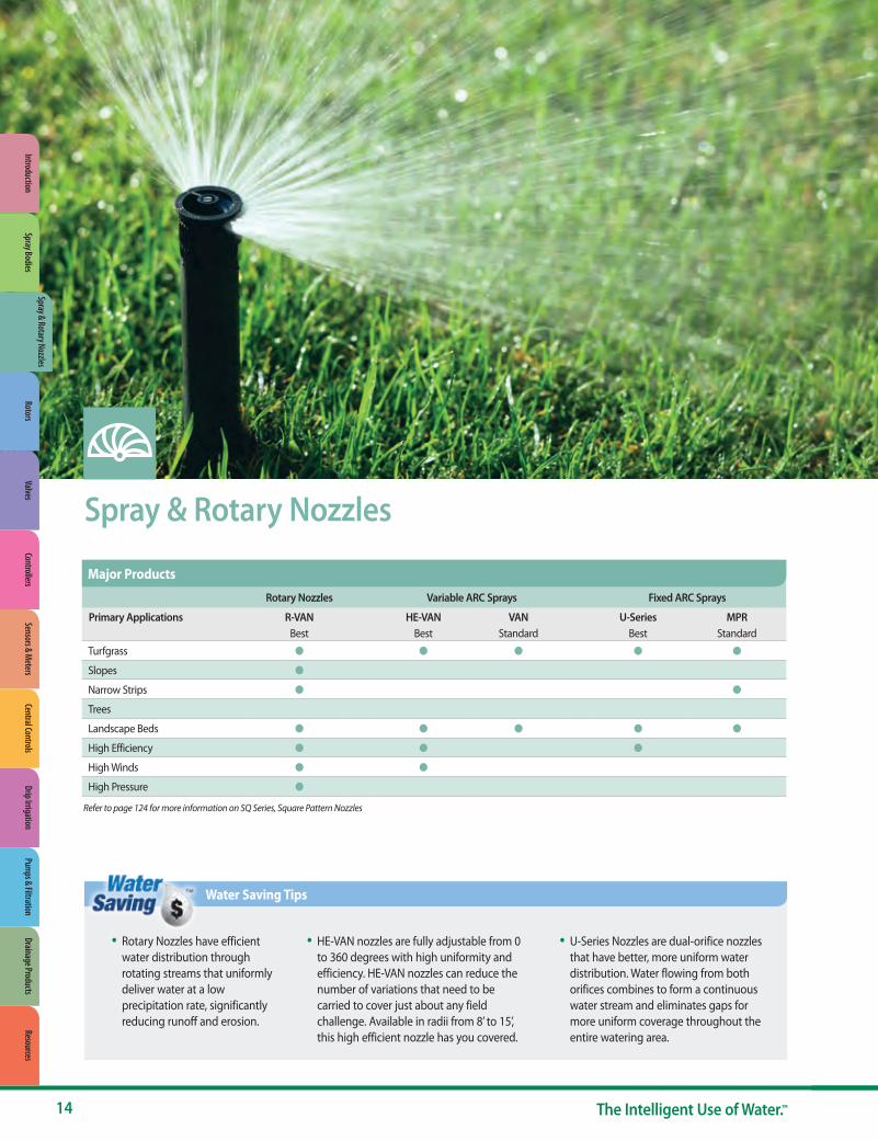
Spray & Rotary Nozzles
Rotary Nozzles Variable ARC Sprays Fixed ARC Sprays
Primary Applications R-VAN HE-VAN VAN U-Series MPRBest Best Standard Best Standard
Turfgrass ● ● ● ● ●
Slopes ●
Narrow Strips ● ●
Trees
Landscape Beds ● ● ● ● ●
High Efficiency ● ● ●
High Winds ● ●
High Pressure ●
Major Products
• Rotary Nozzles have efficient water distribution through rotating streams that uniformly deliver water at a low precipitation rate, significantly reducing runoff and erosion.
• HE-VAN nozzles are fully adjustable from 0 to 360 degrees with high uniformity and efficiency. HE-VAN nozzles can reduce the number of variations that need to be carried to cover just about any field challenge. Available in radii from 8’ to 15’, this high efficient nozzle has you covered.
• U-Series Nozzles are dual-orifice nozzles that have better, more uniform water distribution. Water flowing from both orifices combines to form a continuous water stream and eliminates gaps for more uniform coverage throughout the entire watering area.
Water Saving Tips
14 The Intelligent Use of Water.™
Refer to page 124 for more information on SQ Series, Square Pattern Nozzles
Spray & Rotary NozzlesRotors
ValvesControllers
Sensors & Meters
Central ControlsDrip Irrigation
Pumps & Filtration
Drainage ProductsResources
IntroductionSpray Bodies

www.rainbird.com/sprays
15www.rainbird.com
Spra
y & Ro
tary
Noz
zles
Spray and Rotary NozzlesOverview
What is a High-Efficiency Nozzle?Typical nozzles – Un-Even Watering
With typical nozzles, part of the lawn may not have enough water and other parts may be over-watered. A large portion of water may be lost to evaporation / misting, and over-spray.
High-efficiency nozzles – Even Watering
High-efficiency nozzles provide better coverage. Better coverage means shorter zone run-times while keeping grass healthy. Shorter run-times means you will save up to 25%+ water vs. typical nozzles. Rain Bird’s high-efficiency nozzles are also engineered to produce large water droplets to reduce wind drift.
Standard or Low Precipitation Rate?Low Precipitation Rate Nozzles
Low precipitation rate nozzles are best used in sloped or compacted soil areas to minimize run-off. The low watering rate makes run-times longer.
Standard Precipitation Rate Nozzles
Standard precipitation rate nozzles are best used for shorter distance irrigation, and when watering times may be limited due to city ordinances.
High-Efficiency Rotary Nozzles High-Efficiency Nozzles Standard Nozzles
Adjustable Arc (45° - 270°) Full Circle (360°) Adjustable Arc Fixed Arc Adjustable Arc Fixed Arc
R-VAN HE-VAN VANU-Series MPR
Low Precipitation Rate Standard Precipitation Rate
16 The Intelligent Use of Water.™
Spray & Rotary Nozzles
Rotary NozzlesR-VAN Nozzles
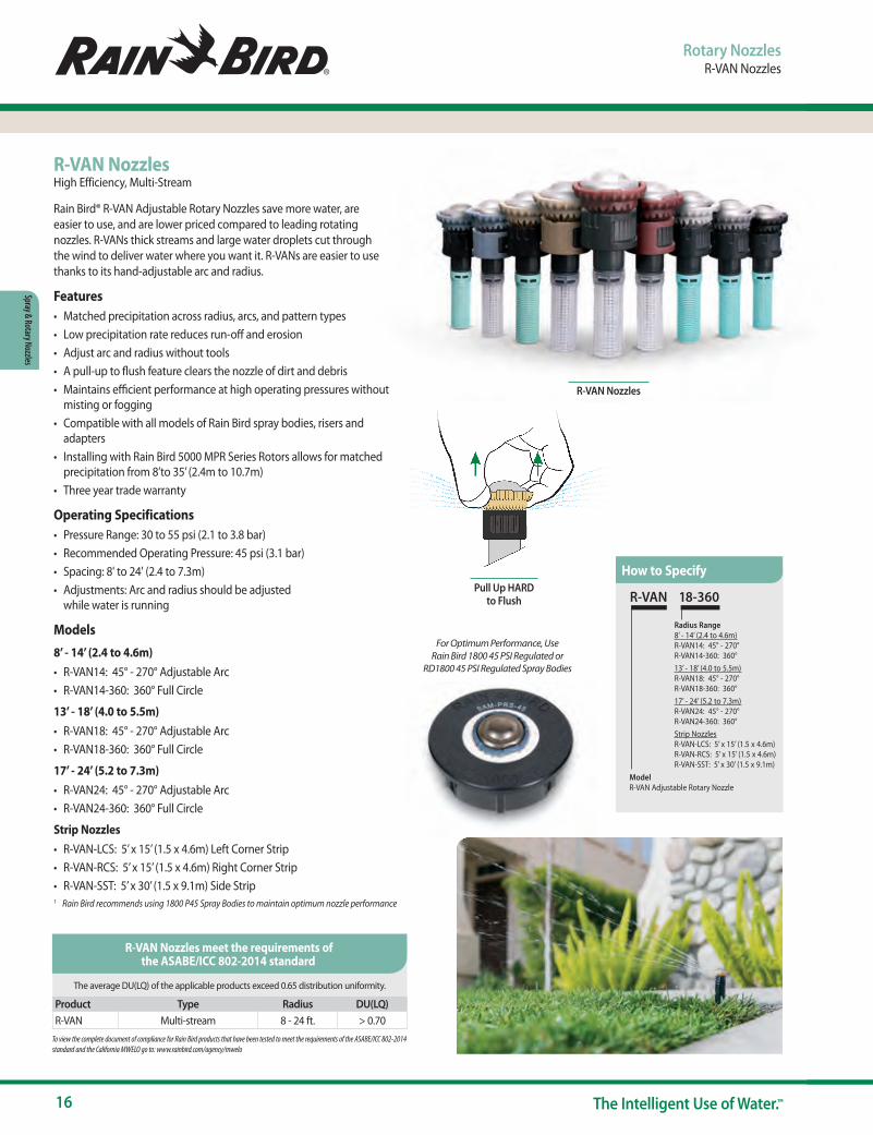
R-VAN NozzlesHigh Efficiency, Multi-Stream
Rain Bird® R-VAN Adjustable Rotary Nozzles save more water, are easier to use, and are lower priced compared to leading rotating nozzles. R-VANs thick streams and large water droplets cut through the wind to deliver water where you want it. R-VANs are easier to use thanks to its hand-adjustable arc and radius.
Features• Matched precipitation across radius, arcs, and pattern types • Low precipitation rate reduces run-off and erosion• Adjust arc and radius without tools • A pull-up to flush feature clears the nozzle of dirt and debris • Maintains efficient performance at high operating pressures without
misting or fogging • Compatible with all models of Rain Bird spray bodies, risers and
adapters • Installing with Rain Bird 5000 MPR Series Rotors allows for matched
precipitation from 8’to 35’ (2.4m to 10.7m) • Three year trade warranty
Operating Specifications• Pressure Range: 30 to 55 psi (2.1 to 3.8 bar) • Recommended Operating Pressure: 45 psi (3.1 bar) • Spacing: 8' to 24' (2.4 to 7.3m) • Adjustments: Arc and radius should be adjusted
while water is running
Models8’ - 14’ (2.4 to 4.6m)• R-VAN14: 45° - 270° Adjustable Arc• R-VAN14-360: 360° Full Circle
13’ - 18’ (4.0 to 5.5m)• R-VAN18: 45° - 270° Adjustable Arc• R-VAN18-360: 360° Full Circle
17’ - 24’ (5.2 to 7.3m)• R-VAN24: 45° - 270° Adjustable Arc• R-VAN24-360: 360° Full Circle
Strip Nozzles• R-VAN-LCS: 5’ x 15’ (1.5 x 4.6m) Left Corner Strip• R-VAN-RCS: 5’ x 15’ (1.5 x 4.6m) Right Corner Strip• R-VAN-SST: 5’ x 30’ (1.5 x 9.1m) Side Strip1 Rain Bird recommends using 1800 P45 Spray Bodies to maintain optimum nozzle performance
R-VAN 18-360
Model R-VAN Adjustable Rotary Nozzle
Radius Range8’ - 14’ (2.4 to 4.6m)R-VAN14: 45° - 270°R-VAN14-360: 360°13’ - 18’ (4.0 to 5.5m)R-VAN18: 45° - 270°R-VAN18-360: 360°17’ - 24’ (5.2 to 7.3m)R-VAN24: 45° - 270°R-VAN24-360: 360°Strip NozzlesR-VAN-LCS: 5’ x 15’ (1.5 x 4.6m) R-VAN-RCS: 5’ x 15’ (1.5 x 4.6m) R-VAN-SST: 5’ x 30’ (1.5 x 9.1m)
How to Specify
The average DU(LQ) of the applicable products exceed 0.65 distribution uniformity.
Product Type Radius DU(LQ) R-VAN Multi-stream 8 - 24 ft. > 0.70To view the complete document of compliance for Rain Bird products that have been tested to meet the requirements of the ASABE/ICC 802-2014 standard and the California MWELO go to: www.rainbird.com/agency/mwelo
R-VAN Nozzles meet the requirements of the ASABE/ICC 802-2014 standard
For Optimum Performance, Use Rain Bird 1800 45 PSI Regulated or
RD1800 45 PSI Regulated Spray Bodies
PRS
R-VAN Nozzles
Pull Up HARD to Flush
www.rainbird.com/sprays
17www.rainbird.com
Spra
y & Ro
tary
Noz
zles
Rotary NozzlesR-VAN Nozzles
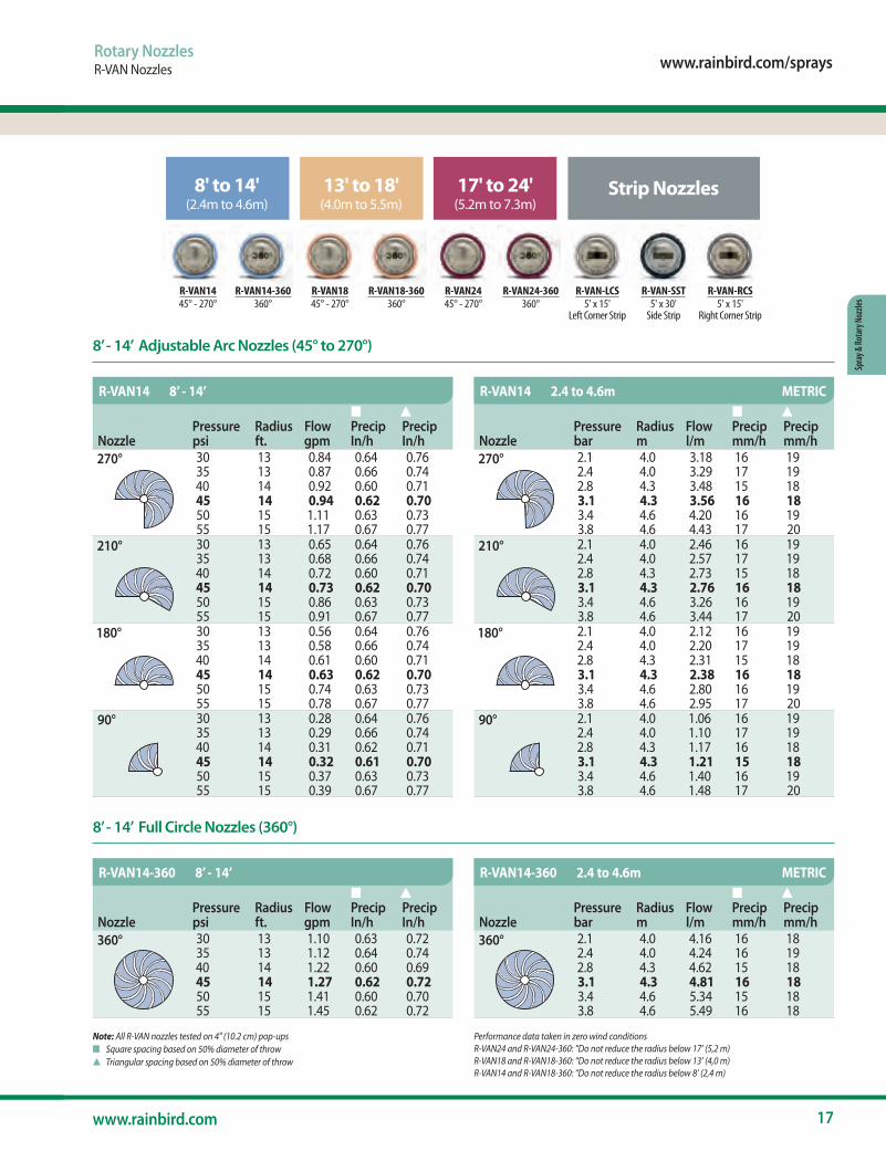
R-VAN14 R-VAN14-360 R-VAN18 R-VAN18-360 R-VAN24 R-VAN24-360 R-VAN-LCS R-VAN-SST R-VAN-RCS45° - 270° 360° 45° - 270° 360° 45° - 270° 360° 5' x 15'
Left Corner Strip5' x 30'
Side Strip5' x 15'
Right Corner Strip
8' to 14'(2.4m to 4.6m)
13' to 18'(4.0m to 5.5m)
17' to 24'(5.2m to 7.3m)
Strip Nozzles
Note: All R-VAN nozzles tested on 4" (10.2 cm) pop-upsn Square spacing based on 50% diameter of throws Triangular spacing based on 50% diameter of throw
Performance data taken in zero wind conditionsR-VAN24 and R-VAN24-360: “Do not reduce the radius below 17’ (5,2 m)R-VAN18 and R-VAN18-360: “Do not reduce the radius below 13’ (4,0 m)R-VAN14 and R-VAN18-360: “Do not reduce the radius below 8’ (2,4 m)
NozzlePressure psi
Radius ft.
Flow gpm
n Precip In/h
s Precip In/h
270° 30 13 0.84 0.64 0.7635 13 0.87 0.66 0.7440 14 0.92 0.60 0.7145 14 0.94 0.62 0.7050 15 1.11 0.63 0.7355 15 1.17 0.67 0.77
210° 30 13 0.65 0.64 0.7635 13 0.68 0.66 0.7440 14 0.72 0.60 0.7145 14 0.73 0.62 0.7050 15 0.86 0.63 0.7355 15 0.91 0.67 0.77
180° 30 13 0.56 0.64 0.7635 13 0.58 0.66 0.7440 14 0.61 0.60 0.7145 14 0.63 0.62 0.7050 15 0.74 0.63 0.7355 15 0.78 0.67 0.77
90° 30 13 0.28 0.64 0.7635 13 0.29 0.66 0.7440 14 0.31 0.62 0.7145 14 0.32 0.61 0.7050 15 0.37 0.63 0.7355 15 0.39 0.67 0.77
NozzlePressure psi
Radius ft.
Flow gpm
n Precip In/h
s Precip In/h
360° 30 13 1.10 0.63 0.7235 13 1.12 0.64 0.7440 14 1.22 0.60 0.6945 14 1.27 0.62 0.7250 15 1.41 0.60 0.7055 15 1.45 0.62 0.72
NozzlePressure bar
Radius m
Flow l/m
n Precip mm/h
s Precip mm/h
360° 2.1 4.0 4.16 16 182.4 4.0 4.24 16 192.8 4.3 4.62 15 183.1 4.3 4.81 16 183.4 4.6 5.34 15 183.8 4.6 5.49 16 18
R-VAN14 8’ - 14’
R-VAN14-360 8’ - 14’ R-VAN14-360 2.4 to 4.6m METRIC
NozzlePressure bar
Radius m
Flow l/m
n Precip mm/h
s Precip mm/h
270° 2.1 4.0 3.18 16 192.4 4.0 3.29 17 192.8 4.3 3.48 15 183.1 4.3 3.56 16 183.4 4.6 4.20 16 193.8 4.6 4.43 17 20
210° 2.1 4.0 2.46 16 192.4 4.0 2.57 17 192.8 4.3 2.73 15 183.1 4.3 2.76 16 183.4 4.6 3.26 16 193.8 4.6 3.44 17 20
180° 2.1 4.0 2.12 16 192.4 4.0 2.20 17 192.8 4.3 2.31 15 183.1 4.3 2.38 16 183.4 4.6 2.80 16 193.8 4.6 2.95 17 20
90° 2.1 4.0 1.06 16 192.4 4.0 1.10 17 192.8 4.3 1.17 16 183.1 4.3 1.21 15 183.4 4.6 1.40 16 193.8 4.6 1.48 17 20
R-VAN14 2.4 to 4.6m METRIC
8’ - 14’ Adjustable Arc Nozzles (45° to 270°)
8’ - 14’ Full Circle Nozzles (360°)
18 The Intelligent Use of Water.™
Spray & Rotary Nozzles
Rotary NozzlesR-VAN Nozzles
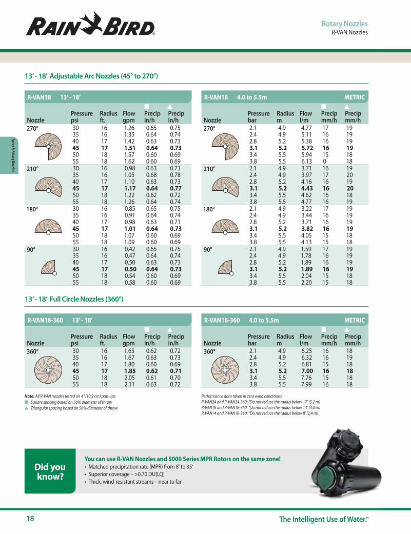
Note: All R-VAN nozzles tested on 4" (10.2 cm) pop-upsn Square spacing based on 50% diameter of throws Triangular spacing based on 50% diameter of throw
Performance data taken in zero wind conditions R-VAN24 and R-VAN24-360: “Do not reduce the radius below 17’ (5,2 m)R-VAN18 and R-VAN18-360: “Do not reduce the radius below 13’ (4,0 m)R-VAN14 and R-VAN18-360: “Do not reduce the radius below 8’ (2,4 m)
NozzlePressure psi
Radius ft.
Flow gpm
n Precip In/h
s Precip In/h
270° 30 16 1.26 0.65 0.7535 16 1.35 0.64 0.7440 17 1.42 0.63 0.7345 17 1.51 0.64 0.7350 18 1.57 0.60 0.6955 18 1.62 0.60 0.69
210° 30 16 0.98 0.63 0.7335 16 1.05 0.68 0.7840 17 1.10 0.63 0.7345 17 1.17 0.64 0.7750 18 1.22 0.62 0.7255 18 1.26 0.64 0.74
180° 30 16 0.85 0.65 0.7535 16 0.91 0.64 0.7440 17 0.98 0.63 0.7345 17 1.01 0.64 0.7350 18 1.07 0.60 0.6955 18 1.09 0.60 0.69
90° 30 16 0.42 0.65 0.7535 16 0.47 0.64 0.7440 17 0.50 0.63 0.7345 17 0.50 0.64 0.7350 18 0.54 0.60 0.6955 18 0.58 0.60 0.69
NozzlePressure psi
Radius ft.
Flow gpm
n Precip In/h
s Precip In/h
360° 30 16 1.65 0.62 0.7235 16 1.67 0.63 0.7340 17 1.80 0.60 0.6945 17 1.85 0.62 0.7150 18 2.05 0.61 0.7055 18 2.11 0.63 0.72
NozzlePressure bar
Radius m
Flow l/m
n Precip mm/h
s Precip mm/h
360° 2.1 4.9 6.25 16 182.4 4.9 6.32 16 192.8 5.2 6.81 15 183.1 5.2 7.00 16 183.4 5.5 7.76 15 183.8 5.5 7.99 16 18
R-VAN18 13’ - 18’
R-VAN18-360 13’ - 18’ R-VAN18-360 4.0 to 5.5m METRIC
NozzlePressure bar
Radius m
Flow l/m
n Precip mm/h
s Precip mm/h
270° 2.1 4.9 4.77 17 192.4 4.9 5.11 16 192.8 5.2 5.38 16 193.1 5.2 5.72 16 193.4 5.5 5.94 15 183.8 5.5 6.13 0 18
210° 2.1 4.9 3.71 16 192.4 4.9 3.97 17 202.8 5.2 4.16 16 193.1 5.2 4.43 16 203.4 5.5 4.62 16 183.8 5.5 4.77 16 19
180° 2.1 4.9 3.22 17 192.4 4.9 3.44 16 192.8 5.2 3.71 16 193.1 5.2 3.82 16 193.4 5.5 4.05 15 183.8 5.5 4.13 15 18
90° 2.1 4.9 1.59 17 192.4 4.9 1.78 16 192.8 5.2 1.89 16 193.1 5.2 1.89 16 193.4 5.5 2.04 15 183.8 5.5 2.20 15 18
R-VAN18 4.0 to 5.5m METRIC
13’ - 18’ Adjustable Arc Nozzles (45° to 270°)
13’ - 18’ Full Circle Nozzles (360°)
You can use R-VAN Nozzles and 5000 Series MPR Rotors on the same zone! • Matched precipitation rate (MPR) from 8' to 35‘• Superior coverage – >0.70 DU[LQ] • Thick, wind-resistant streams – near to far
Did you know?
www.rainbird.com/sprays
19www.rainbird.com
Spra
y & Ro
tary
Noz
zles
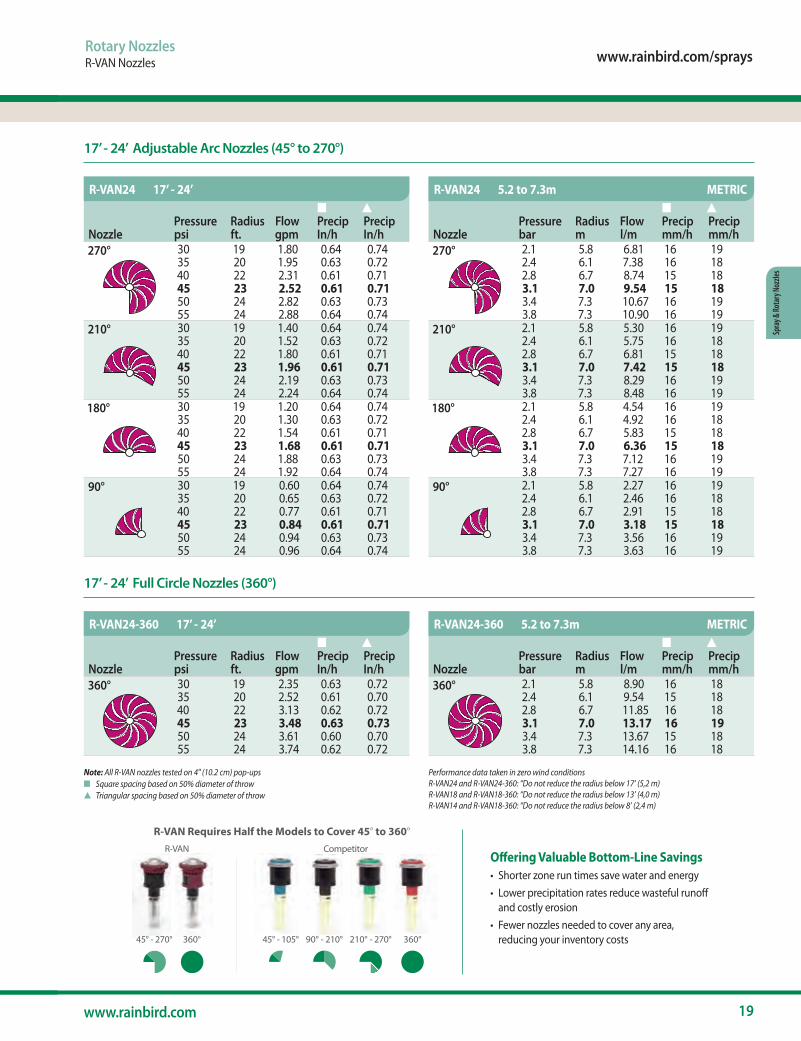
Rotary NozzlesR-VAN Nozzles
Note: All R-VAN nozzles tested on 4" (10.2 cm) pop-upsn Square spacing based on 50% diameter of throws Triangular spacing based on 50% diameter of throw
Performance data taken in zero wind conditions R-VAN24 and R-VAN24-360: “Do not reduce the radius below 17’ (5,2 m)R-VAN18 and R-VAN18-360: “Do not reduce the radius below 13’ (4,0 m)R-VAN14 and R-VAN18-360: “Do not reduce the radius below 8’ (2,4 m)
NozzlePressure psi
Radius ft.
Flow gpm
n Precip In/h
s Precip In/h
270° 30 19 1.80 0.64 0.7435 20 1.95 0.63 0.7240 22 2.31 0.61 0.7145 23 2.52 0.61 0.7150 24 2.82 0.63 0.7355 24 2.88 0.64 0.74
210° 30 19 1.40 0.64 0.7435 20 1.52 0.63 0.7240 22 1.80 0.61 0.7145 23 1.96 0.61 0.7150 24 2.19 0.63 0.7355 24 2.24 0.64 0.74
180° 30 19 1.20 0.64 0.7435 20 1.30 0.63 0.7240 22 1.54 0.61 0.7145 23 1.68 0.61 0.7150 24 1.88 0.63 0.7355 24 1.92 0.64 0.74
90° 30 19 0.60 0.64 0.7435 20 0.65 0.63 0.7240 22 0.77 0.61 0.7145 23 0.84 0.61 0.7150 24 0.94 0.63 0.7355 24 0.96 0.64 0.74
NozzlePressure psi
Radius ft.
Flow gpm
n Precip In/h
s Precip In/h
360° 30 19 2.35 0.63 0.7235 20 2.52 0.61 0.7040 22 3.13 0.62 0.7245 23 3.48 0.63 0.7350 24 3.61 0.60 0.7055 24 3.74 0.62 0.72
NozzlePressure bar
Radius m
Flow l/m
n Precip mm/h
s Precip mm/h
360° 2.1 5.8 8.90 16 182.4 6.1 9.54 15 182.8 6.7 11.85 16 183.1 7.0 13.17 16 193.4 7.3 13.67 15 183.8 7.3 14.16 16 18
R-VAN24 17’ - 24’
R-VAN24-360 17’ - 24’ R-VAN24-360 5.2 to 7.3m METRIC
NozzlePressure bar
Radius m
Flow l/m
n Precip mm/h
s Precip mm/h
270° 2.1 5.8 6.81 16 192.4 6.1 7.38 16 182.8 6.7 8.74 15 183.1 7.0 9.54 15 183.4 7.3 10.67 16 193.8 7.3 10.90 16 19
210° 2.1 5.8 5.30 16 192.4 6.1 5.75 16 182.8 6.7 6.81 15 183.1 7.0 7.42 15 183.4 7.3 8.29 16 193.8 7.3 8.48 16 19
180° 2.1 5.8 4.54 16 192.4 6.1 4.92 16 182.8 6.7 5.83 15 183.1 7.0 6.36 15 183.4 7.3 7.12 16 193.8 7.3 7.27 16 19
90° 2.1 5.8 2.27 16 192.4 6.1 2.46 16 182.8 6.7 2.91 15 183.1 7.0 3.18 15 183.4 7.3 3.56 16 193.8 7.3 3.63 16 19
R-VAN24 5.2 to 7.3m METRIC
17’ - 24’ Adjustable Arc Nozzles (45° to 270°)
17’ - 24’ Full Circle Nozzles (360°)
Offering Valuable Bottom-Line Savings• Shorter zone run times save water and energy• Lower precipitation rates reduce wasteful runoff
and costly erosion• Fewer nozzles needed to cover any area,
reducing your inventory costs
R-VAN Requires Half the Models to Cover 45° to 360°
45° - 105°45° - 270°
R-VAN Competitor
90° - 210°360° 210° - 270° 360°45° 270°° 360°°
ppp

20 The Intelligent Use of Water.™
Spray & Rotary Nozzles
Rotary NozzlesR-VAN Nozzles
Improving Watering Efficiencies Up to 30%• Gentle, rotating streams create uniform coverage at lower
precipitation rates• Multi-stream technology optimizes absorption for healthier lawns• Larger droplets and thicker streams cut through wind and keep
water in target zone
NozzlePressure psi
Size ft.
Flow gpm
— Precip In/h
s Precip In/h
Left Corner Strip
30 4’x14’ 0.18 0.62 0.6235 5’x15’ 0.22 0.56 0.5640 5’x15’ 0.23 0.59 0.5945 5’x15’ 0.24 0.62 0.6250 5’x15’ 0.25 0.64 0.6455 6’x16’ 0.28 0.56 0.56
NozzlePressure bar
Size m
Flow l/m
— Precip mm/h
s Precip mm/h
Left Corner Strip
2.1 1.2x4.3 0.68 16 162.4 1.5x4.6 0.83 14 142.8 1.5x4.6 0.87 15 153.1 1.5x4.6 0.91 16 163.4 1.5x4.6 0.95 16 163.8 1.8x4.9 1.06 14 14
NozzlePressure bar
Size m
Flow l/m
— Precip mm/h
s Precip mm/h
Side Strip
2.1 1.2x8.5 1.36 16 162.4 1.5x9.1 1.67 14 142.8 1.5x9.1 1.74 15 153.1 1.5x9.1 1.82 16 163.4 1.5x9.1 1.89 16 163.8 1.8x9.8 2.12 14 14
NozzlePressure bar
Size m
Flow l/m
— Precip mm/h
s Precip mm/h
Right Corner Strip
2.1 1.2x4.3 0.68 16 162.4 1.5x4.6 0.83 14 142.8 1.5x4.6 0.87 15 153.1 1.5x4.6 0.91 16 163.4 1.5x4.6 0.95 16 163.8 1.8x4.9 1.06 14 14
NozzlePressure psi
Size ft.
Flow gpm
— Precip In/h
s Precip In/h
Side Strip
30 4’x28’ 0.36 0.62 0.6235 5’x30’ 0.44 0.56 0.5640 5’x30’ 0.46 0.59 0.5945 5’x30’ 0.48 0.62 0.6250 5’x30’ 0.50 0.64 0.6455 6’x32’ 0.56 0.56 0.56
NozzlePressure psi
Size ft.
Flow gpm
— Precip In/h
s Precip In/h
Right Corner Strip
30 4’x14’ 0.18 0.62 0.6235 5’x15’ 0.22 0.56 0.5640 5’x15’ 0.23 0.59 0.5945 5’x15’ 0.24 0.62 0.6250 5’x15’ 0.25 0.64 0.6455 6’x16’ 0.28 0.56 0.56
R-VAN-LCS 5’ x 15’ R-VAN-LCS 1.5 x 4.6m METRIC
R-VAN-SST 1.5 x 9.1m METRIC
R-VAN-RCS 1.5 x 4.6m METRIC
R-VAN-SST 5’ x 30’
R-VAN-RCS 5’ x 15’
Note: All R-VAN nozzles tested on 4" (10.2 cm) pop-upsPerformance data taken in zero wind conditions
n Straight-line spacing based on 50% overlap of throw for LCS, SST, and RCSs Triangular spacing based on 50% overlap of throw for LCS, SST, and RCS
Strip Nozzles (Left Corner, Side, Right Corner) Easy Adjustments
Adjustable Arc NozzlesR-VAN14, R-VAN18, R-VAN24
RADIUS ADJUSTMENT
ARC ADJUSTMENT
Full Circle NozzlesR-VAN14-360, R-VAN18-360, RVAN24-360
RADIUS ADJUSTMENT
Strip NozzlesR-VAN-LCS, R-VAN-RCS, R-VAN-SST
SIZE ADJUSTMENT
www.rainbird.com/sprays
21www.rainbird.com
Spra
y & Ro
tary
Noz
zles
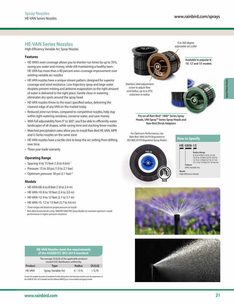
Spray NozzlesHE-VAN Series Nozzles
HE-VAN Series NozzlesHigh-Efficiency Variable Arc Spray Nozzles
Features• HE-VAN’s even coverage allows you to shorten run times by up to 35%,
saving you water and money, while still maintaining a healthy lawn. HE-VAN has more than a 40 percent even-coverage improvement over existing variable arc nozzles
• HE-VAN nozzles have a unique stream pattern, designed for superior coverage and wind resistance. Low-trajectory spray and large water droplets prevent misting and airborne evaporation so the right amount of water is delivered to the right place. Gentle close-in watering eliminates dry-spots around the spray head
• HE-VAN nozzles throw to the exact specified radius, delivering the cleanest edge of any VAN on the market today
• Reduced zone run times, compared to competitive nozzles, help stay within tight watering windows, conserve water, and save money
• With full adjustability from 0° to 360°, you’ll be able to efficiently water landscapes of all shapes, while saving time and stocking fewer nozzles
• Matched precipitation rates allow you to install Rain Bird HE-VAN, MPR and U-Series nozzles on the same zone
• HE-VAN nozzles have a tactile click to keep the arc setting from drifting over time
• Three year trade warranty
Operating Range• Spacing: 6 to 15 feet (1.8 to 4.6m) 1
• Pressure: 15 to 30 psi (1.0 to 2.1 bar)• Optimum pressure: 30 psi (2.1 bar) 2
Models• HE-VAN-08: 6 to 8 feet (1.8 to 2.4 m)• HE-VAN-10: 8 to 10 feet (2.4 to 3.0 m)• HE-VAN-12: 9 to 12 feet (2.7 to 3.7 m)• HE-VAN-15: 12 to 15 feet (3.7 to 4.6 m) 1 These ranges are based on proper pressure at nozzle 2 Rain Bird recommends using 1800/RD1800 PRS Spray Bodies to maintain optimum nozzle
performance in higher pressure situations
HE-VAN-15
Model High Efficiency Nozzle
FeatureVAN: Variable Arc
Radius Range8: 6 to 8 feet (1.8 to 2.4 m)10: 8 to 10 feet (2.4 to 3.0 m)12: 9 to 12 feet (2.7 to 3.7 m)15: 12 to 15 feet (3.7 to 4.6 m)
Available in popular 8', 10', 12' and 15' models
Stainless steel adjustment screw to adjust flow
and radius, up to a 25% reduction in radius
Fits on all Rain Bird® 1800® Series Spray Heads, UNI-Spray™ Series Spray Heads and
Rain Bird Shrub Adapters
To view the complete document of compliance for Rain Bird products that have been tested to meet the requirements of the ASABE/ICC 802-2014 standard and the California MWELO go to: www.rainbird.com/agency/mwelo
The average DU(LQ) of the applicable products exceed 0.65 distribution uniformity.
Product Type Radius DU(LQ)
HE-VAN Spray, Variable Arc 6 - 15 ft. > 0.70
HE-VAN Nozzles meet the requirements of the ASABE/ICC 802-2014 standard
How to SpecifyFor Optimum Performance, Use
Rain Bird 1800 30 PSI Regulated or RD1800 30 PSI Regulated Spray Bodies
PRS
0 to 360 degree adjustable arc collar
22 The Intelligent Use of Water.™
Spray & Rotary Nozzles
Spray NozzlesHE-VAN Series Nozzles
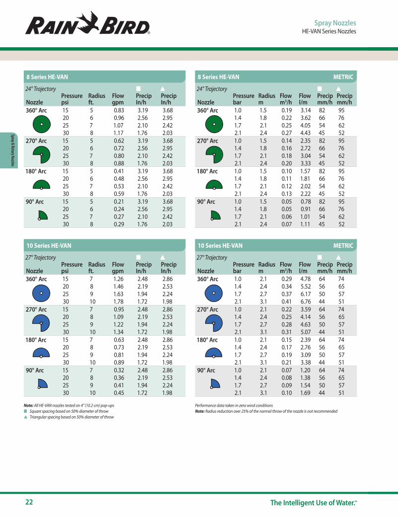
Note: All HE-VAN nozzles tested on 4" (10.2 cm) pop-upsn Square spacing based on 50% diameter of throws Triangular spacing based on 50% diameter of throw
Performance data taken in zero wind conditions Note: Radius reduction over 25% of the normal throw of the nozzle is not recommended
24° Trajectory n s
NozzlePressure psi
Radius ft.
Flow gpm
Precip In/h
Precip In/h
360° Arc 15 5 0.83 3.19 3.6820 6 0.96 2.56 2.9525 7 1.07 2.10 2.4230 8 1.17 1.76 2.03
270° Arc 15 5 0.62 3.19 3.6820 6 0.72 2.56 2.9525 7 0.80 2.10 2.4230 8 0.88 1.76 2.03
180° Arc 15 5 0.41 3.19 3.6820 6 0.48 2.56 2.9525 7 0.53 2.10 2.4230 8 0.59 1.76 2.03
90° Arc 15 5 0.21 3.19 3.6820 6 0.24 2.56 2.9525 7 0.27 2.10 2.4230 8 0.29 1.76 2.03
27° Trajectory n s
NozzlePressure psi
Radius ft.
Flow gpm
Precip In/h
Precip In/h
360° Arc 15 7 1.26 2.48 2.8620 8 1.46 2.19 2.5325 9 1.63 1.94 2.2430 10 1.78 1.72 1.98
270° Arc 15 7 0.95 2.48 2.8620 8 1.09 2.19 2.5325 9 1.22 1.94 2.2430 10 1.34 1.72 1.98
180° Arc 15 7 0.63 2.48 2.8620 8 0.73 2.19 2.5325 9 0.81 1.94 2.2430 10 0.89 1.72 1.98
90° Arc 15 7 0.32 2.48 2.8620 8 0.36 2.19 2.5325 9 0.41 1.94 2.2430 10 0.45 1.72 1.98
24° Trajectory n s
NozzlePressure bar
Radius m
Flow m3/h
Flow l/m
Precip mm/h
Precip mm/h
360° Arc 1.0 1.5 0.19 3.14 82 951.4 1.8 0.22 3.62 66 761.7 2.1 0.25 4.05 54 622.1 2.4 0.27 4.43 45 52
270° Arc 1.0 1.5 0.14 2.35 82 951.4 1.8 0.16 2.72 66 761.7 2.1 0.18 3.04 54 622.1 2.4 0.20 3.33 45 52
180° Arc 1.0 1.5 0.10 1.57 82 951.4 1.8 0.11 1.81 66 761.7 2.1 0.12 2.02 54 622.1 2.4 0.13 2.22 45 52
90° Arc 1.0 1.5 0.05 0.78 82 951.4 1.8 0.05 0.91 66 761.7 2.1 0.06 1.01 54 622.1 2.4 0.07 1.11 45 52
27° Trajectory n s
NozzlePressure bar
Radius m
Flow m3/h
Flow l/m
Precip mm/h
Precip mm/h
360° Arc 1.0 2.1 0.29 4.78 64 741.4 2.4 0.34 5.52 56 651.7 2.7 0.37 6.17 50 572.1 3.1 0.41 6.76 44 51
270° Arc 1.0 2.1 0.22 3.59 64 741.4 2.4 0.25 4.14 56 651.7 2.7 0.28 4.63 50 572.1 3.1 0.31 5.07 44 51
180° Arc 1.0 2.1 0.15 2.39 64 741.4 2.4 0.17 2.76 56 651.7 2.7 0.19 3.09 50 572.1 3.1 0.21 3.38 44 51
90° Arc 1.0 2.1 0.07 1.20 64 741.4 2.4 0.08 1.38 56 651.7 2.7 0.09 1.54 50 572.1 3.1 0.10 1.69 44 51
8 Series HE-VAN
10 Series HE-VAN
8 Series HE-VAN METRIC
10 Series HE-VAN METRIC
www.rainbird.com/sprays
23www.rainbird.com
Spra
y & Ro
tary
Noz
zles
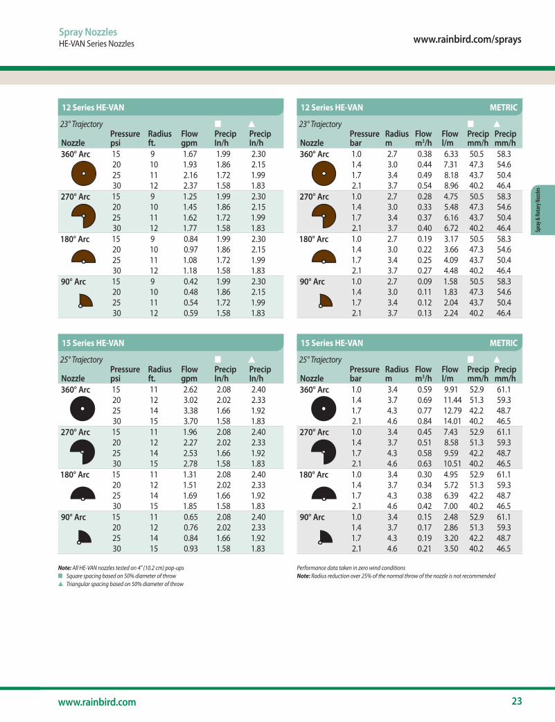
Spray NozzlesHE-VAN Series Nozzles
Note: All HE-VAN nozzles tested on 4" (10.2 cm) pop-upsn Square spacing based on 50% diameter of throws Triangular spacing based on 50% diameter of throw
Performance data taken in zero wind conditions Note: Radius reduction over 25% of the normal throw of the nozzle is not recommended
23° Trajectory n s
NozzlePressure psi
Radius ft.
Flow gpm
Precip In/h
Precip In/h
360° Arc 15 9 1.67 1.99 2.3020 10 1.93 1.86 2.1525 11 2.16 1.72 1.9930 12 2.37 1.58 1.83
270° Arc 15 9 1.25 1.99 2.3020 10 1.45 1.86 2.1525 11 1.62 1.72 1.9930 12 1.77 1.58 1.83
180° Arc 15 9 0.84 1.99 2.3020 10 0.97 1.86 2.1525 11 1.08 1.72 1.9930 12 1.18 1.58 1.83
90° Arc 15 9 0.42 1.99 2.3020 10 0.48 1.86 2.1525 11 0.54 1.72 1.9930 12 0.59 1.58 1.83
25° Trajectory n s
NozzlePressure psi
Radius ft.
Flow gpm
Precip In/h
Precip In/h
360° Arc 15 11 2.62 2.08 2.4020 12 3.02 2.02 2.3325 14 3.38 1.66 1.9230 15 3.70 1.58 1.83
270° Arc 15 11 1.96 2.08 2.4020 12 2.27 2.02 2.3325 14 2.53 1.66 1.9230 15 2.78 1.58 1.83
180° Arc 15 11 1.31 2.08 2.4020 12 1.51 2.02 2.3325 14 1.69 1.66 1.9230 15 1.85 1.58 1.83
90° Arc 15 11 0.65 2.08 2.4020 12 0.76 2.02 2.3325 14 0.84 1.66 1.9230 15 0.93 1.58 1.83
23° Trajectory n s
NozzlePressure bar
Radius m
Flow m3/h
Flow l/m
Precip mm/h
Precip mm/h
360° Arc 1.0 2.7 0.38 6.33 50.5 58.31.4 3.0 0.44 7.31 47.3 54.61.7 3.4 0.49 8.18 43.7 50.42.1 3.7 0.54 8.96 40.2 46.4
270° Arc 1.0 2.7 0.28 4.75 50.5 58.31.4 3.0 0.33 5.48 47.3 54.61.7 3.4 0.37 6.16 43.7 50.42.1 3.7 0.40 6.72 40.2 46.4
180° Arc 1.0 2.7 0.19 3.17 50.5 58.31.4 3.0 0.22 3.66 47.3 54.61.7 3.4 0.25 4.09 43.7 50.42.1 3.7 0.27 4.48 40.2 46.4
90° Arc 1.0 2.7 0.09 1.58 50.5 58.31.4 3.0 0.11 1.83 47.3 54.61.7 3.4 0.12 2.04 43.7 50.42.1 3.7 0.13 2.24 40.2 46.4
25° Trajectory n s
NozzlePressure bar
Radius m
Flow m3/h
Flow l/m
Precip mm/h
Precip mm/h
360° Arc 1.0 3.4 0.59 9.91 52.9 61.11.4 3.7 0.69 11.44 51.3 59.31.7 4.3 0.77 12.79 42.2 48.72.1 4.6 0.84 14.01 40.2 46.5
270° Arc 1.0 3.4 0.45 7.43 52.9 61.11.4 3.7 0.51 8.58 51.3 59.31.7 4.3 0.58 9.59 42.2 48.72.1 4.6 0.63 10.51 40.2 46.5
180° Arc 1.0 3.4 0.30 4.95 52.9 61.11.4 3.7 0.34 5.72 51.3 59.31.7 4.3 0.38 6.39 42.2 48.72.1 4.6 0.42 7.00 40.2 46.5
90° Arc 1.0 3.4 0.15 2.48 52.9 61.11.4 3.7 0.17 2.86 51.3 59.31.7 4.3 0.19 3.20 42.2 48.72.1 4.6 0.21 3.50 40.2 46.5
12 Series HE-VAN
15 Series HE-VAN
12 Series HE-VAN METRIC
15 Series HE-VAN METRIC
24 The Intelligent Use of Water.™
Spray & Rotary Nozzles
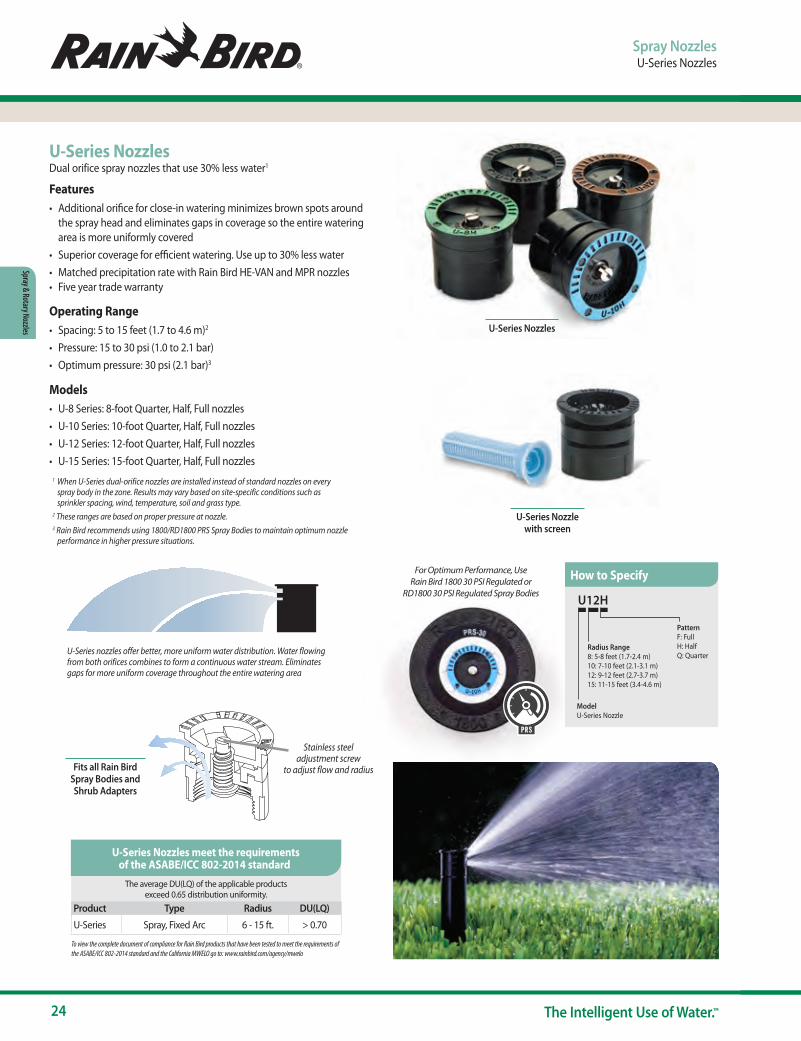
U-Series NozzlesDual orifice spray nozzles that use 30% less water1
Features• Additional orifice for close-in watering minimizes brown spots around
the spray head and eliminates gaps in coverage so the entire watering area is more uniformly covered
• Superior coverage for efficient watering. Use up to 30% less water • Matched precipitation rate with Rain Bird HE-VAN and MPR nozzles• Five year trade warranty
Operating Range• Spacing: 5 to 15 feet (1.7 to 4.6 m)2
• Pressure: 15 to 30 psi (1.0 to 2.1 bar)• Optimum pressure: 30 psi (2.1 bar)3
Models• U-8 Series: 8-foot Quarter, Half, Full nozzles• U-10 Series: 10-foot Quarter, Half, Full nozzles• U-12 Series: 12-foot Quarter, Half, Full nozzles• U-15 Series: 15-foot Quarter, Half, Full nozzles
1 When U-Series dual-orifice nozzles are installed instead of standard nozzles on every spray body in the zone. Results may vary based on site-specific conditions such as sprinkler spacing, wind, temperature, soil and grass type.
2 These ranges are based on proper pressure at nozzle. 3 Rain Bird recommends using 1800/RD1800 PRS Spray Bodies to maintain optimum nozzle
performance in higher pressure situations.
Spray NozzlesU-Series Nozzles
Fits all Rain Bird Spray Bodies and Shrub Adapters
Stainless steel adjustment screw
to adjust flow and radius
To view the complete document of compliance for Rain Bird products that have been tested to meet the requirements of the ASABE/ICC 802-2014 standard and the California MWELO go to: www.rainbird.com/agency/mwelo
The average DU(LQ) of the applicable products exceed 0.65 distribution uniformity.
Product Type Radius DU(LQ)
U-Series Spray, Fixed Arc 6 - 15 ft. > 0.70
U-Series Nozzles meet the requirements of the ASABE/ICC 802-2014 standard
U12H
PatternF: FullH: HalfQ: Quarter
Radius Range8: 5-8 feet (1.7-2.4 m)10: 7-10 feet (2.1-3.1 m)12: 9-12 feet (2.7-3.7 m)15: 11-15 feet (3.4-4.6 m)
ModelU-Series Nozzle
How to Specify
U-Series Nozzle with screen
U-Series nozzles offer better, more uniform water distribution. Water flowing from both orifices combines to form a continuous water stream. Eliminates gaps for more uniform coverage throughout the entire watering area
U-Series Nozzles
For Optimum Performance, Use Rain Bird 1800 30 PSI Regulated or
RD1800 30 PSI Regulated Spray Bodies
PRS

www.rainbird.com/sprays
25www.rainbird.com
Spra
y & Ro
tary
Noz
zles
Spray NozzlesU-Series Nozzles
12° Trajectory n s
NozzlePressure psi
Radius ft.
Flow gpm
Precip In/h
Precip In/h
U-10F 15 7 1.16 2.07 2.3920 8 1.34 2.01 2.3225 9 1.50 1.62 1.8730 10 1.64 1.58 1.83
U-10H 15 7 0.58 2.07 2.3920 8 0.67 2.01 2.3225 9 0.75 1.62 1.8730 10 0.82 1.58 1.83
U-10Q 15 7 0.29 2.07 2.3920 8 0.33 2.01 2.3225 9 0.37 1.62 1.8730 10 0.41 1.58 1.83
12° Trajectory n s
NozzlePressure bar
Radius m
Flow m3/h
Flow l/m
Precip mm/h
Precip mm/h
U-10F 1.0 2.1 0.26 4.4 52 601.5 2.6 0.30 5.3 47 552.0 3.0 0.34 6.1 41 482.1 3.1 0.37 6.2 40 46
U-10H 1.0 2.1 0.13 2.2 52 601.5 2.6 0.15 2.6 47 552.0 3.0 0.17 3.1 41 482.1 3.1 0.19 3.1 40 46
U-10Q 1.0 2.1 0.07 1.1 52 601.5 2.6 0.08 1.3 47 552.0 3.0 0.08 1.5 41 482.1 3.1 0.09 1.6 40 46
U10 Series U10 Series METRIC
Note: All U-Series nozzles tested on 4" (10.2 cm) pop-upsn Square spacing based on 50% diameter of throws Triangular spacing based on 50% diameter of throw
Performance data taken in zero wind conditionsRadius refers to recommended product spacing. Actual radii along arc may vary
10° Trajectory n s
NozzlePressure psi
Radius ft.
Flow gpm
Precip In/h
Precip In/h
U-8F 15 5 0.74 2.85 3.2920 6 0.86 2.30 2.6625 7 0.96 1.89 2.1830 8 1.05 1.58 1.83
U8H 15 5 0.37 2.85 3.2920 6 0.42 2.25 2.5925 7 0.47 1.85 2.1330 8 0.52 1.58 1.83
U8Q 15 5 0.18 2.77 3.2020 6 0.21 2.25 2.5925 7 0.24 1.89 2.1830 8 0.26 1.58 1.83
10° Trajectory n s
NozzlePressure bar
Radius m
Flow m3/h
Flow l/m
Precip mm/h
Precip mm/h
U-8F 1.0 1.7 0.16 2.8 72 841.5 2.1 0.20 3.4 58 682.0 2.4 0.23 3.9 48 552.1 2.4 0.24 4.0 40 46
U-8H 1.0 1.7 0.08 1.4 72 841.5 2.1 0.10 1.7 57 662.0 2.4 0.12 1.9 47 542.1 2.4 0.12 2.0 40 46
U-8Q 1.0 1.7 0.04 0.7 70 811.5 2.1 0.05 0.8 57 662.0 2.4 0.06 1.0 48 552.1 2.4 0.06 1.0 40 46
U8 Series U8 Series METRIC
26 The Intelligent Use of Water.™
Spray & Rotary Nozzles
Note: All U-Series nozzles tested on 4" (10.2 cm) pop-upsn Square spacing based on 50% diameter of throws Triangular spacing based on 50% diameter of throw
Performance data taken in zero wind conditionsRadius refers to recommended product spacing. Actual radii along arc may vary
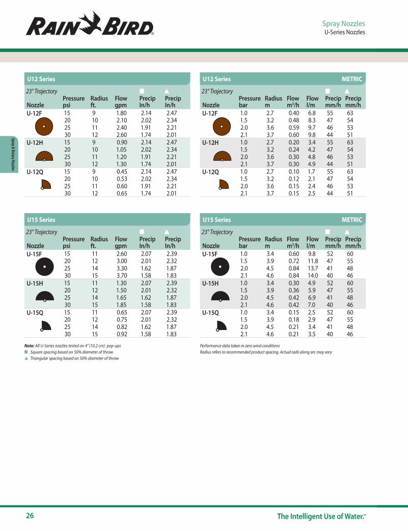
23° Trajectory n s
NozzlePressure psi
Radius ft.
Flow gpm
Precip In/h
Precip In/h
U-12F 15 9 1.80 2.14 2.4720 10 2.10 2.02 2.3425 11 2.40 1.91 2.2130 12 2.60 1.74 2.01
U-12H 15 9 0.90 2.14 2.4720 10 1.05 2.02 2.3425 11 1.20 1.91 2.2130 12 1.30 1.74 2.01
U-12Q 15 9 0.45 2.14 2.4720 10 0.53 2.02 2.3425 11 0.60 1.91 2.2130 12 0.65 1.74 2.01
23° Trajectory n s
NozzlePressure bar
Radius m
Flow m3/h
Flow l/m
Precip mm/h
Precip mm/h
U-12F 1.0 2.7 0.40 6.8 55 631.5 3.2 0.48 8.3 47 542.0 3.6 0.59 9.7 46 532.1 3.7 0.60 9.8 44 51
U-12H 1.0 2.7 0.20 3.4 55 631.5 3.2 0.24 4.2 47 542.0 3.6 0.30 4.8 46 532.1 3.7 0.30 4.9 44 51
U-12Q 1.0 2.7 0.10 1.7 55 631.5 3.2 0.12 2.1 47 542.0 3.6 0.15 2.4 46 532.1 3.7 0.15 2.5 44 51
U12 Series U12 Series METRIC
23° Trajectory n s
NozzlePressure psi
Radius ft.
Flow gpm
Precip In/h
Precip In/h
U-15F 15 11 2.60 2.07 2.3920 12 3.00 2.01 2.3225 14 3.30 1.62 1.8730 15 3.70 1.58 1.83
U-15H 15 11 1.30 2.07 2.3920 12 1.50 2.01 2.3225 14 1.65 1.62 1.8730 15 1.85 1.58 1.83
U-15Q 15 11 0.65 2.07 2.3920 12 0.75 2.01 2.3225 14 0.82 1.62 1.8730 15 0.92 1.58 1.83
23° Trajectory n s
NozzlePressure bar
Radius m
Flow m3/h
Flow l/m
Precip mm/h
Precip mm/h
U-15F 1.0 3.4 0.60 9.8 52 601.5 3.9 0.72 11.8 47 552.0 4.5 0.84 13.7 41 482.1 4.6 0.84 14.0 40 46
U-15H 1.0 3.4 0.30 4.9 52 601.5 3.9 0.36 5.9 47 552.0 4.5 0.42 6.9 41 482.1 4.6 0.42 7.0 40 46
U-15Q 1.0 3.4 0.15 2.5 52 601.5 3.9 0.18 2.9 47 552.0 4.5 0.21 3.4 41 482.1 4.6 0.21 3.5 40 46
U15 Series U15 Series METRIC
Spray NozzlesU-Series Nozzles
www.rainbird.com/sprays
27www.rainbird.com
Spra
y & Ro
tary
Noz
zles
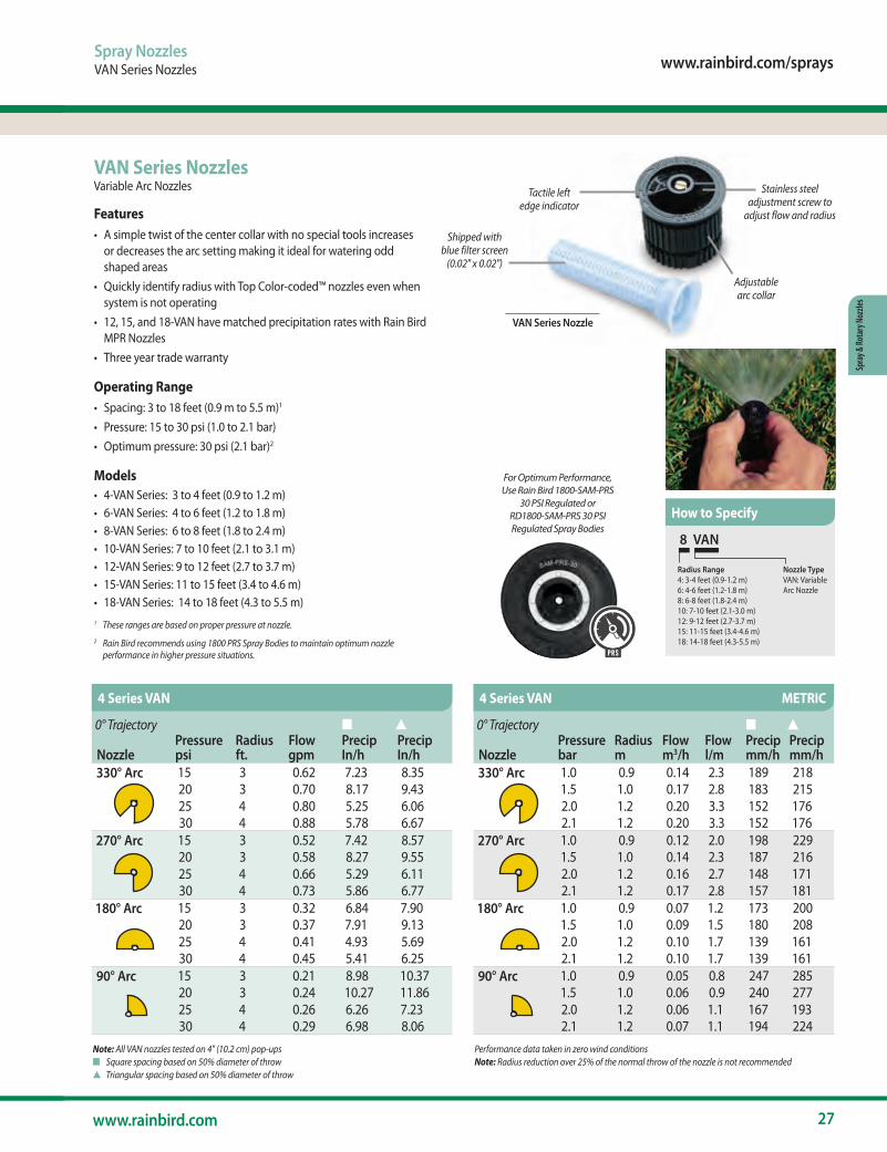
VAN Series NozzlesVariable Arc Nozzles
Features• A simple twist of the center collar with no special tools increases
or decreases the arc setting making it ideal for watering odd shaped areas
• Quickly identify radius with Top Color-coded™ nozzles even when system is not operating
• 12, 15, and 18-VAN have matched precipitation rates with Rain Bird MPR Nozzles
• Three year trade warranty
Operating Range• Spacing: 3 to 18 feet (0.9 m to 5.5 m)1
• Pressure: 15 to 30 psi (1.0 to 2.1 bar)• Optimum pressure: 30 psi (2.1 bar)2
Models• 4-VAN Series: 3 to 4 feet (0.9 to 1.2 m)• 6-VAN Series: 4 to 6 feet (1.2 to 1.8 m)• 8-VAN Series: 6 to 8 feet (1.8 to 2.4 m)• 10-VAN Series: 7 to 10 feet (2.1 to 3.1 m)• 12-VAN Series: 9 to 12 feet (2.7 to 3.7 m)• 15-VAN Series: 11 to 15 feet (3.4 to 4.6 m)• 18-VAN Series: 14 to 18 feet (4.3 to 5.5 m)1 These ranges are based on proper pressure at nozzle.2 Rain Bird recommends using 1800 PRS Spray Bodies to maintain optimum nozzle
performance in higher pressure situations.
Spray NozzlesVAN Series Nozzles
8 VAN
Nozzle TypeVAN: Variable Arc Nozzle
Radius Range4: 3-4 feet (0.9-1.2 m)6: 4-6 feet (1.2-1.8 m)8: 6-8 feet (1.8-2.4 m)10: 7-10 feet (2.1-3.0 m)12: 9-12 feet (2.7-3.7 m)15: 11-15 feet (3.4-4.6 m)18: 14-18 feet (4.3-5.5 m)
Note: All VAN nozzles tested on 4" (10.2 cm) pop-upsn Square spacing based on 50% diameter of throws Triangular spacing based on 50% diameter of throw
Performance data taken in zero wind conditions Note: Radius reduction over 25% of the normal throw of the nozzle is not recommended
How to Specify
0° Trajectory n s
NozzlePressure psi
Radius ft.
Flow gpm
Precip In/h
Precip In/h
330° Arc 15 3 0.62 7.23 8.3520 3 0.70 8.17 9.4325 4 0.80 5.25 6.0630 4 0.88 5.78 6.67
270° Arc 15 3 0.52 7.42 8.5720 3 0.58 8.27 9.5525 4 0.66 5.29 6.1130 4 0.73 5.86 6.77
180° Arc 15 3 0.32 6.84 7.9020 3 0.37 7.91 9.1325 4 0.41 4.93 5.6930 4 0.45 5.41 6.25
90° Arc 15 3 0.21 8.98 10.3720 3 0.24 10.27 11.8625 4 0.26 6.26 7.2330 4 0.29 6.98 8.06
0° Trajectory n s
NozzlePressure bar
Radius m
Flow m3/h
Flow l/m
Precip mm/h
Precip mm/h
330° Arc 1.0 0.9 0.14 2.3 189 2181.5 1.0 0.17 2.8 183 2152.0 1.2 0.20 3.3 152 1762.1 1.2 0.20 3.3 152 176
270° Arc 1.0 0.9 0.12 2.0 198 2291.5 1.0 0.14 2.3 187 2162.0 1.2 0.16 2.7 148 1712.1 1.2 0.17 2.8 157 181
180° Arc 1.0 0.9 0.07 1.2 173 2001.5 1.0 0.09 1.5 180 2082.0 1.2 0.10 1.7 139 1612.1 1.2 0.10 1.7 139 161
90° Arc 1.0 0.9 0.05 0.8 247 2851.5 1.0 0.06 0.9 240 2772.0 1.2 0.06 1.1 167 1932.1 1.2 0.07 1.1 194 224
4 Series VAN 4 Series VAN METRIC
For Optimum Performance, Use Rain Bird 1800-SAM-PRS
30 PSI Regulated or RD1800-SAM-PRS 30 PSI Regulated Spray Bodies
PR S
VAN Series Nozzle
Shipped with blue filter screen
(0.02" x 0.02")
Tactile left edge indicator
Stainless steel adjustment screw to
adjust flow and radius
Adjustable arc collar
28 The Intelligent Use of Water.™
Spray & Rotary Nozzles
Note: All VAN nozzles tested on 4" (10.2 cm) pop-upsn Square spacing based on 50% diameter of throws Triangular spacing based on 50% diameter of throw
Performance data taken in zero wind conditions Note: Radius reduction over 25% of the normal throw of the nozzle is not recommended
You can use HE-VAN nozzles to have better coverage and save water vs. VAN nozzles.• Stronger streams and larger water droplets for increased wind resistance.• Superior close-in watering and edges provide better coverage.• Shortened run times saves up to 35% in water
Did you know?
0° Trajectory n s
NozzlePressure psi
Radius ft.
Flow gpm
Precip In/h
Precip In/h
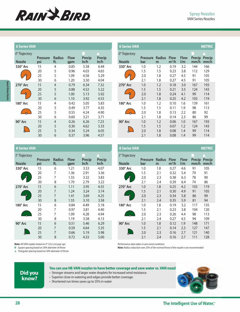
330° Arc 15 4 0.85 5.58 6.4420 5 0.96 4.03 4.6525 5 1.09 4.58 5.2930 6 1.20 3.50 4.04
270° Arc 15 4 0.79 6.34 7.3220 5 0.88 4.52 5.2225 5 1.00 5.13 5.9230 6 1.10 3.92 4.53
180° Arc 15 4 0.42 5.05 5.8320 5 0.49 3.77 4.3525 5 0.55 4.24 4.9030 6 0.60 3.21 3.71
90° Arc 15 4 0.26 6.26 7.2320 5 0.30 4.62 5.3325 5 0.34 5.24 6.0530 6 0.37 3.96 4.57
5° Trajectory n s
NozzlePressure psi
Radius ft.
Flow gpm
Precip In/h
Precip In/h
330° Arc 15 6 1.21 3.53 4.0720 7 1.36 2.91 3.3625 7 1.55 3.32 3.8330 8 1.70 2.79 3.22
270° Arc 15 6 1.11 3.95 4.5520 7 1.24 3.24 3.7425 7 1.41 3.69 4.2530 8 1.55 3.10 3.58
180° Arc 15 6 0.84 4.49 5.1820 7 0.97 3.81 4.4025 7 1.09 4.28 4.9430 8 1.19 3.58 4.13
90° Arc 15 6 0.51 5.46 6.2920 7 0.59 4.64 5.3525 7 0.66 5.19 5.9830 8 0.72 4.33 5.00
0° Trajectory n s
NozzlePressure bar
Radius m
Flow m3/h
Flow l/m
Precip mm/h
Precip mm/h
330° Arc 1.0 1.2 0.19 3.2 144 1661.5 1.5 0.23 3.8 112 1292.0 1.8 0.27 4.5 91 1052.1 1.8 0.27 4.5 91 105
270° Arc 1.0 1.2 0.18 3.0 167 1931.5 1.5 0.21 3.5 124 1432.0 1.8 0.24 4.1 99 1142.1 1.8 0.25 4.2 103 119
180° Arc 1.0 1.2 0.10 1.6 139 1611.5 1.5 0.11 1.9 98 1132.0 1.8 0.13 2.2 80 922.1 1.8 0.14 2.3 86 99
90° Arc 1.0 1.2 0.06 1.0 167 1931.5 1.5 0.07 1.2 124 1432.0 1.8 0.08 1.4 99 1142.1 1.8 0.08 1.4 99 114
5° Trajectory n s
NozzlePressure bar
Radius m
Flow m3/h
Flow l/m
Precip mm/h
Precip mm/h
330° Arc 1.0 1.8 0.27 4.6 91 1051.5 2.1 0.32 5.4 79 912.0 2.3 0.38 6.3 78 902.1 2.4 0.39 6.4 74 86
270° Arc 1.0 1.8 0.25 4.2 103 1191.5 2.1 0.30 4.9 91 1052.0 2.3 0.34 5.8 86 992.1 2.4 0.35 5.9 81 94
180° Arc 1.0 1.8 0.19 3.2 117 1351.5 2.1 0.23 3.8 104 1202.0 2.3 0.26 4.4 98 1132.1 2.4 0.27 4.5 94 109
90° Arc 1.0 1.8 0.12 1.9 148 1711.5 2.1 0.14 2.3 127 1472.0 2.3 0.16 2.7 121 1402.1 2.4 0.16 2.7 111 128
6 Series VAN
8 Series VAN
6 Series VAN METRIC
8 Series VAN METRIC
Spray NozzlesVAN Series Nozzles

www.rainbird.com/sprays
29www.rainbird.com
Spra
y & Ro
tary
Noz
zles
Spray NozzlesVAN Series Nozzles
Note: All VAN nozzles tested on 4" (10.2 cm) pop-upsn Square spacing based on 50% diameter of throws Triangular spacing based on 50% diameter of throw
Performance data taken in zero wind conditions Note: Radius reduction over 25% of the normal throw of the nozzle is not recommended
You can use HE-VAN nozzles to have better coverage and save water vs. VAN nozzles.• Stronger streams and larger water droplets for increased wind resistance.• Superior close-in watering and edges provide better coverage.• Shortened run times saves up to 35% in water
Did you know?
10° Trajectory n s
NozzlePressure psi
Radius ft.
Flow gpm
Precip In/h
Precip In/h
360° Arc 15 7 1.93 3.80 4.3920 8 2.32 3.50 4.0425 9 2.52 3.00 3.4630 10 2.60 2.50 2.89
270° Arc 15 7 1.45 3.80 4.3920 8 1.75 3.50 4.0425 9 1.89 3.00 3.4630 10 2.10 2.70 3.12
180° Arc 15 7 0.97 3.80 4.3920 8 1.20 3.50 4.0425 9 1.26 3.00 3.4630 10 1.45 2.80 3.23
90° Arc 15 7 0.48 3.80 4.3920 8 0.58 3.50 4.0425 9 0.63 3.00 3.4630 10 0.75 2.90 3.35
15° Trajectory n s
NozzlePressure psi
Radius ft.
Flow gpm
Precip In/h
Precip In/h
360° Arc 15 9 1.56 1.86 2.1420 10 1.86 1.79 2.0625 11 2.12 1.68 1.9530 12 2.36 1.58 1.82
270° Arc 15 9 1.17 1.86 2.1420 10 1.39 1.79 2.0625 11 1.59 1.68 1.9430 12 1.77 1.58 1.82
180° Arc 15 9 0.78 1.86 2.1420 10 0.93 1.79 2.0625 11 1.06 1.68 1.9530 12 1.18 1.58 1.82
90° Arc 15 9 0.39 1.86 2.1420 10 0.46 1.79 2.0625 11 0.53 1.68 1.9530 12 0.59 1.58 1.82
10° Trajectory n s
NozzlePressure bar
Radius m
Flow m3/h
Flow l/m
Precip mm/h
Precip mm/h
360° Arc 1.0 2.1 0.44 7.3 96 1111.5 2.4 0.53 9.0 89 1032.0 2.7 0.57 9.8 76 882.1 3.1 0.59 9.8 63 73
270° Arc 1.0 2.1 0.33 5.5 96 1111.5 2.4 0.4 6.8 89 1032.0 2.7 0.43 7.8 76 882.1 3.1 0.48 7.9 68 79
180° Arc 1.0 2.1 0.22 3.7 96 1111.5 2.4 0.27 4.6 89 1032.0 2.7 0.29 5.3 76 882.1 3.1 0.33 5.5 71 82
90° Arc 1.0 2.1 0.11 1.8 96 1111.5 2.4 0.13 2.3 89 1032.0 2.7 0.14 2.7 76 882.1 3.1 0.17 2.8 73 85
15° Trajectory n s
NozzlePressure bar
Radius m
Flow m3/h
Flow l/m
Precip mm/h
Precip mm/h
360° Arc 1.0 2.7 0.35 5.80 48 551.5 3.2 0.44 7.37 43 502.0 3.6 0.52 8.75 41 472.1 3.7 0.54 9.02 40 46
270° Arc 1.0 2.7 0.26 4.35 48 551.5 3.2 0.33 5.53 43 502.0 3.6 0.39 6.56 41 472.1 3.7 0.41 6.76 40 46
180° Arc 1.0 2.7 0.17 2.90 48 551.5 3.2 0.22 3.69 43 502.0 3.6 0.26 4.37 41 472.1 3.7 0.27 4.51 40 46
90° Arc 1.0 2.7 0.09 1.45 48 551.5 3.2 0.11 1.84 43 502.0 3.6 0.13 2.19 41 472.1 3.7 0.14 2.25 40 46
10 Series VAN
12 Series VAN
10 Series VAN METRIC
12 Series VAN METRIC

30 The Intelligent Use of Water.™
Spray & Rotary Nozzles
Spray NozzlesVAN Series Nozzles
Note: All VAN nozzles tested on 4" (10.2 cm) pop-upsn Square spacing based on 50% diameter of throws Triangular spacing based on 50% diameter of throw
Performance data taken in zero wind conditions Note: Radius reduction over 25% of the normal throw of the nozzle is not recommended
You can use HE-VAN nozzles to have better coverage and save water vs. VAN nozzles.• Stronger streams and larger water droplets for increased wind resistance.• Superior close-in watering and edges provide better coverage.• Shortened run times saves up to 35% in water
Did you know?
23° Trajectory n s
NozzlePressure psi
Radius ft.
Flow gpm
Precip In/h
Precip In/h
360° Arc 15 11 2.60 2.07 2.3920 12 3.00 2.01 2.3225 14 3.30 1.62 1.8730 15 3.70 1.58 1.83
270° Arc 15 11 1.95 2.07 2.3920 12 2.25 2.01 2.3225 14 2.48 1.62 1.8730 15 2.78 1.58 1.83
180° Arc 15 11 1.30 2.07 2.3920 12 1.50 2.01 2.3225 14 1.65 1.62 1.8730 15 1.85 1.58 1.83
90° Arc 15 11 0.65 2.07 2.3920 12 0.75 2.01 2.3225 14 0.82 1.62 1.8730 15 0.92 1.58 1.83
26° Trajectory n s
NozzlePressure psi
Radius ft.
Flow gpm
Precip In/h
Precip In/h
360° Arc 15 14 4.21 2.07 2.3920 15 4.70 2.01 2.3225 17 4.86 1.62 1.8730 18 5.32 1.58 1.83
270° Arc 15 14 3.16 2.07 2.3920 15 3.52 2.01 2.3225 17 3.65 1.62 1.8730 18 3.99 1.58 1.83
180° Arc 15 14 2.11 2.07 2.3920 15 2.35 2.01 2.3225 17 2.43 1.62 1.8730 18 2.66 1.58 1.83
90° Arc 15 14 1.05 2.07 2.3920 15 1.17 2.01 2.3225 17 1.22 1.62 1.8730 18 1.33 1.58 1.83
23° Trajectory n s
NozzlePressure bar
Radius m
Flow m3/h
Flow l/m
Precip mm/h
Precip mm/h
360° Arc 1.0 3.4 0.60 9.8 52 601.5 3.9 0.72 11.8 47 552.0 4.5 0.84 13.7 41 482.1 4.6 0.84 14.0 40 46
270° Arc 1.0 3.4 0.45 7.4 52 601.5 3.9 0.54 8.8 47 552.0 4.5 0.63 10.3 41 482.1 4.6 0.63 10.5 40 46
180° Arc 1.0 3.4 0.30 4.9 52 601.5 3.9 0.36 5.9 47 552.0 4.5 0.42 6.9 41 482.1 4.6 0.42 7.0 40 46
90° Arc 1.0 3.4 0.15 2.5 52 601.5 3.9 0.18 2.9 47 552.0 4.5 0.21 3.4 41 482.1 4.6 0.21 3.5 40 46
26° Trajectory n s
NozzlePressure bar
Radius m
Flow m3/h
Flow l/m
Precip mm/h
Precip mm/h
360° Arc 1.0 4.3 0.96 15.9 52 601.5 4.8 1.07 18.0 47 552.0 5.4 1.20 19.8 41 482.1 5.5 1.21 20.1 40 46
270° Arc 1.0 4.3 0.72 12.0 52 601.5 4.8 0.80 13.5 47 552.0 5.4 0.90 14.8 41 482.1 5.5 0.91 15.1 40 46
180° Arc 1.0 4.3 0.48 8.0 52 601.5 4.8 0.54 9.0 47 552.0 5.4 0.60 9.9 41 482.1 5.5 0.61 10.1 40 46
90° Arc 1.0 4.3 0.24 4.0 52 601.5 4.8 0.27 4.5 47 552.0 5.4 0.30 5.0 41 482.1 5.5 0.30 5.0 40 46
15 Series VAN
18 Series VAN
15 Series VAN METRIC
18 Series VAN METRIC
www.rainbird.com/sprays
31www.rainbird.com
Spra
y & Ro
tary
Noz
zles
Rain Bird® MPR Nozzles, The Industry Standard
Spray NozzlesMPR Nozzles
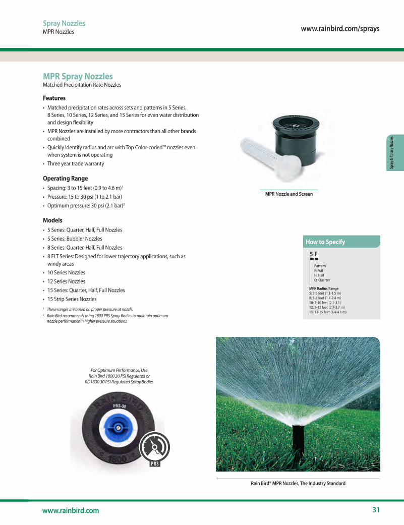
MPR Spray NozzlesMatched Precipitation Rate Nozzles
Features• Matched precipitation rates across sets and patterns in 5 Series,
8 Series, 10 Series, 12 Series, and 15 Series for even water distribution and design flexibility
• MPR Nozzles are installed by more contractors than all other brands combined
• Quickly identify radius and arc with Top Color-coded™ nozzles even when system is not operating
• Three year trade warranty
Operating Range• Spacing: 3 to 15 feet (0.9 to 4.6 m)1
• Pressure: 15 to 30 psi (1 to 2.1 bar)• Optimum pressure: 30 psi (2.1 bar)2
Models• 5 Series: Quarter, Half, Full Nozzles • 5 Series: Bubbler Nozzles• 8 Series: Quarter, Half, Full Nozzles • 8 FLT Series: Designed for lower trajectory applications, such as
windy areas • 10 Series Nozzles• 12 Series Nozzles• 15 Series: Quarter, Half, Full Nozzles• 15 Strip Series Nozzles1 These ranges are based on proper pressure at nozzle.2 Rain Bird recommends using 1800 PRS Spray Bodies to maintain optimum
nozzle performance in higher pressure situations.
5 F
PatternF: FullH: HalfQ: Quarter
MPR Radius Range5: 3-5 feet (1.1-1.5 m)8: 5-8 feet (1.7-2.4 m)10: 7-10 feet (2.1-3.1)12: 9-12 feet (2.7-3.7 m)15: 11-15 feet (3.4-4.6 m)
How to Specify
For Optimum Performance, Use Rain Bird 1800 30 PSI Regulated or
RD1800 30 PSI Regulated Spray Bodies
PRS
MPR Nozzle and Screen
32 The Intelligent Use of Water.™
Spray & Rotary Nozzles
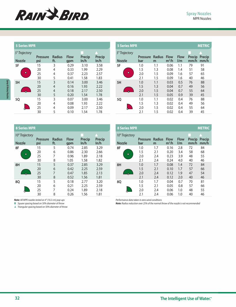
Note: All MPR nozzles tested on 4" (10.2 cm) pop-upsn Square spacing based on 50% diameter of throws Triangular spacing based on 50% diameter of throw
Performance data taken in zero wind conditions Note: Radius reduction over 25% of the normal throw of the nozzle is not recommended
Spray NozzlesMPR Nozzles
10° Trajectory n s
NozzlePressure psi
Radius ft.
Flow gpm
Precip In/h
Precip In/h
8F 15 5 0.74 2.85 3.2920 6 0.86 2.30 2.6625 7 0.96 1.89 2.1830 8 1.05 1.58 1.82
8H 15 5 0.37 2.85 3.2920 6 0.42 2.25 2.5925 7 0.47 1.85 2.1330 8 0.52 1.56 1.81
8Q 15 5 0.18 2.77 3.2020 6 0.21 2.25 2.5925 7 0.24 1.89 2.1830 8 0.26 1.56 1.81
10° Trajectory n s
NozzlePressure bar
Radius m
Flow m3/h
Flow l/m
Precip mm/h
Precip mm/h
8F 1.0 1.7 0.16 2.8 72 841.5 2.1 0.20 3.4 58 682.0 2.4 0.23 3.9 48 552.1 2.4 0.24 4.0 40 46
8H 1.0 1.7 0.08 1.4 72 841.5 2.1 0.10 1.7 57 662.0 2.4 0.12 1.9 47 542.1 2.4 0.12 2.0 40 46
8Q 1.0 1.7 0.04 0.7 70 811.5 2.1 0.05 0.8 57 662.0 2.4 0.06 1.0 48 552.1 2.4 0.06 1.0 40 46
8 Series MPR 8 Series MPR METRIC
5° Trajectory n s
NozzlePressure psi
Radius ft.
Flow gpm
Precip In/h
Precip In/h
5F 15 3 0.29 3.10 3.5820 4 0.33 1.99 2.2925 4 0.37 2.23 2.5730 5 0.41 1.58 1.83
5H 15 3 0.14 3.00 3.4620 4 0.16 1.93 2.2225 4 0.18 2.17 2.5030 5 0.20 1.54 1.78
5Q 15 3 0.07 3.00 3.4620 4 0.08 1.93 2.2225 4 0.09 2.17 2.5030 5 0.10 1.54 1.78
5° Trajectory n s
NozzlePressure bar
Radius m
Flow m3/h
Flow l/m
Precip mm/h
Precip mm/h
5F 1.0 1.1 0.06 1.1 79 911.5 1.3 0.08 1.4 51 582.0 1.5 0.09 1.6 57 652.1 1.5 0.09 1.6 40 46
5H 1.0 1.1 0.03 0.5 76 881.5 1.3 0.04 0.7 49 562.0 1.5 0.04 0.7 55 642.1 1.5 0.05 0.9 39 45
5Q 1.0 1.1 0.02 0.4 76 881.5 1.3 0.02 0.4 49 562.0 1.5 0.02 0.4 55 642.1 1.5 0.02 0.4 39 45
5 Series MPR 5 Series MPR METRIC

www.rainbird.com/sprays
33www.rainbird.com
Spra
y & Ro
tary
Noz
zles
Spray NozzlesMPR Nozzles
Note: All MPR nozzles tested on 4" (10.2 cm) pop-upsn Square spacing based on 50% diameter of throws Triangular spacing based on 50% diameter of throw
Performance data taken in zero wind conditions Note: Radius reduction over 25% of the normal throw of the nozzle is not recommended
15° Trajectory n s
NozzlePressure psi
Radius ft.
Flow gpm
Precip In/h
Precip In/h
10F 15 7 1.16 2.28 2.6320 8 1.30 1.96 2.2625 9 1.44 1.71 1.9830 10 1.58 1.52 1.75
10H 15 7 0.58 2.28 2.6320 8 0.65 1.96 2.2625 9 0.72 1.71 1.9830 10 0.79 1.52 1.75
10Q 15 7 0.29 2.28 2.6320 8 0.33 1.96 2.2625 9 0.36 1.71 1.9830 10 0.39 1.52 1.75
15° Trajectory n s
NozzlePressure bar
Radius m
Flow m3/h
Flow l/m
Precip mm/h
Precip mm/h
10F 1.0 2.1 0.26 4.2 58 671.5 2.4 0.29 4.8 50 582.0 3.0 0.35 6.0 39 452.1 3.1 0.36 6.0 37 43
10H 1.0 2.1 0.13 2.4 58 671.5 2.4 0.14 2.4 50 582.0 3.0 0.18 3.0 39 452.1 3.1 0.18 3.0 37 43
10Q 1.0 2.1 0.06 1.2 58 671.5 2.4 0.07 1.2 50 582.0 3.0 0.09 1.2 39 452.1 3.1 0.09 1.2 37 43
10 Series MPR 10 Series MPR METRIC
30° Trajectory n s
NozzlePressure psi
Radius ft.
Flow gpm
Precip In/h
Precip In/h
12F 15 9 1.80 2.14 2.4720 10 2.10 2.02 2.3425 11 2.40 1.91 2.2130 12 2.60 1.74 2.01
12H 15 9 0.90 2.14 2.4720 10 1.05 2.02 2.3425 11 1.20 1.91 2.2130 12 1.30 1.74 2.01
12Q 15 9 0.45 2.14 2.4720 10 0.53 2.02 2.3425 11 0.60 1.91 2.2130 12 0.65 1.74 2.01
30° Trajectory n s
NozzlePressure bar
Radius m
Flow m3/h
Flow l/m
Precip mm/h
Precip mm/h
12F 1.0 2.7 0.40 6.8 55 631.5 3.2 0.48 8.3 47 542.0 3.6 0.59 9.7 46 532.1 3.7 0.60 9.8 44 51
12H 1.0 2.7 0.20 3.4 55 631.5 3.2 0.24 4.2 47 542.0 3.6 0.30 4.9 46 532.1 3.7 0.30 4.9 44 51
12Q 1.0 2.7 0.10 1.7 55 631.5 3.2 0.12 2.1 47 542.0 3.6 0.15 2.4 46 532.1 3.7 0.15 2.5 44 51
12 Series MPR 12 Series MPR METRIC

34 The Intelligent Use of Water.™
Spray & Rotary Nozzles
Spray NozzlesMPR Nozzles
Note: All MPR nozzles tested on 4" (10.2 cm) pop-upsn Square spacing based on 50% diameter of throws Triangular spacing based on 50% diameter of throw
Performance data taken in zero wind conditions Note: Radius reduction over 25% of the normal throw of the nozzle is not recommended
Note: Indicates adjusted radius at psi shown
Note: Flow at adjusted radius of 5 feet (1.5 m)
30° Trajectory n s
NozzlePressure psi
Radius ft.
Flow gpm
Precip In/h
Precip In/h
15F 15 11 2.60 2.07 2.3920 12 3.00 2.01 2.3225 14 3.30 1.62 1.8730 15 3.70 1.58 1.83
15H 15 11 1.30 2.07 2.3920 12 1.50 2.01 2.3225 14 1.65 1.62 1.8730 15 1.85 1.58 1.83
15Q 15 11 0.65 2.07 2.3920 12 0.75 2.01 2.3225 14 0.82 1.62 1.8730 15 0.92 1.58 1.83
30° Trajectory n s
NozzlePressure bar
Radius m
Flow m3/h
Flow l/m
Precip mm/h
Precip mm/h
15F 1.0 3.4 0.60 9.8 52 601.5 3.9 0.72 11.8 47 552.0 4.5 0.84 13.7 41 482.1 4.6 0.84 14.0 40 46
15H 1.0 3.4 0.30 4.9 52 601.5 3.9 0.36 5.9 47 552.0 4.5 0.42 6.8 41 482.1 4.6 0.42 7.0 40 46
15Q 1.0 3.4 0.15 2.5 52 601.5 3.9 0.18 2.9 47 552.0 4.5 0.21 3.4 41 482.1 4.6 0.21 3.5 40 46
15 Series MPR 15 Series MPR METRIC
0° Trajectory
NozzlePressure psi
Radius ft.
Flow gpm
5F-B 15 5 1.5020 5 1.5025 5 1.5030 5 1.50
5H-B 15 5 1.0020 5 1.0025 5 1.0030 5 1.00
5Q-B 15 5 0.5020 5 0.5025 5 0.5030 5 0.50
5CST-B 15 5 0.5020 5 0.5025 5 0.5030 5 0.50
0° Trajectory
NozzlePressure bar
Radius m
Flow m3/h
Flow l/m
5F-B 1.0 1.5 0.35 5.71.5 1.5 0.35 5.72.0 1.5 0.35 5.72.1 1.5 0.35 5.7
5H-B 1.0 1.5 0.23 3.81.5 1.5 0.23 3.82.0 1.5 0.23 3.82.1 1.5 0.23 3.8
5Q-B 1.0 1.5 0.12 1.91.5 1.5 0.12 1.92.0 1.5 0.12 1.92.1 1.5 0.12 1.9
5CST-B 1.0 1.5 0.12 1.91.5 1.5 0.12 1.92.0 1.5 0.12 1.92.1 1.5 0.12 1.9
5 Series MPR Stream Bubbler Nozzles 5 Series MPR Stream Bubbler Nozzles METRIC
www.rainbird.com/sprays
35www.rainbird.com
Spra
y & Ro
tary
Noz
zles
Spray NozzlesMPR Nozzles
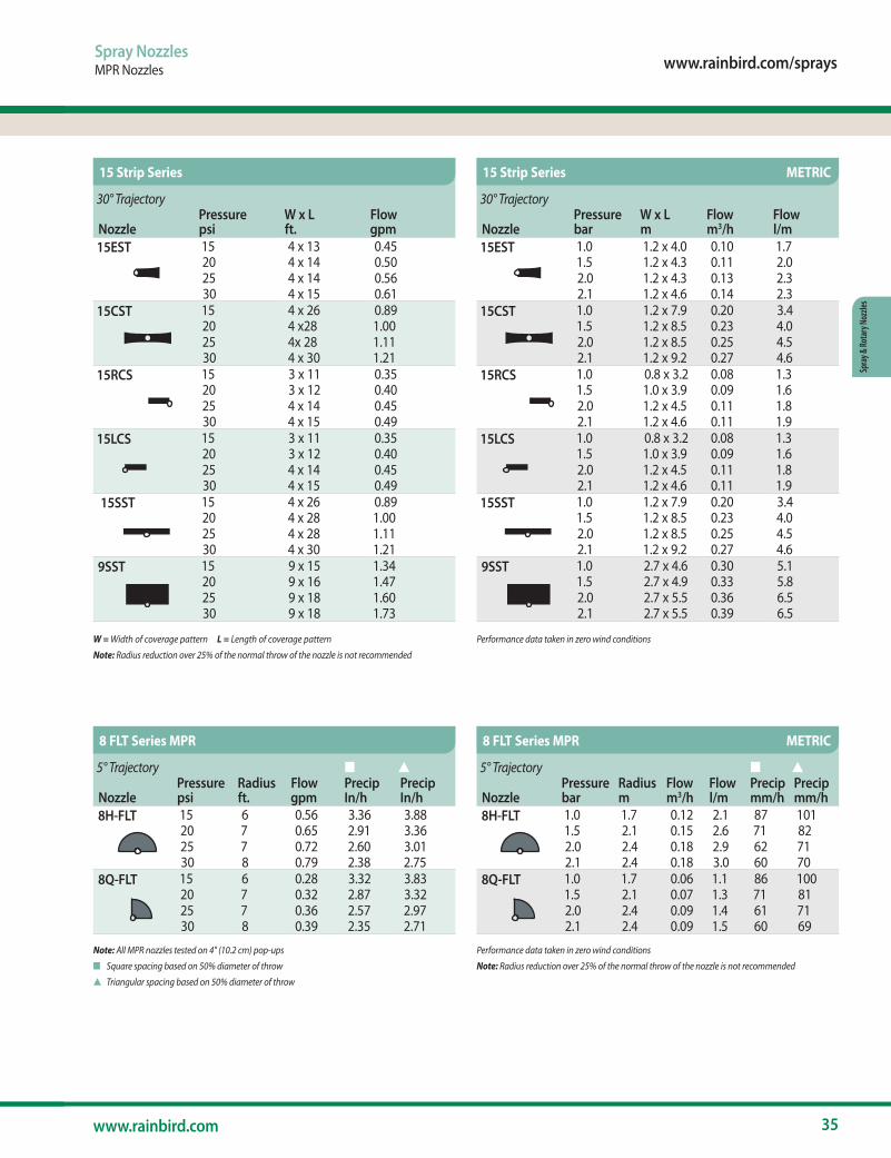
W = Width of coverage pattern L = Length of coverage pattern
Note: Radius reduction over 25% of the normal throw of the nozzle is not recommended
Performance data taken in zero wind conditions
Note: All MPR nozzles tested on 4" (10.2 cm) pop-ups
n Square spacing based on 50% diameter of throw
s Triangular spacing based on 50% diameter of throw
Performance data taken in zero wind conditions
Note: Radius reduction over 25% of the normal throw of the nozzle is not recommended
5° Trajectory n s
NozzlePressure psi
Radius ft.
Flow gpm
Precip In/h
Precip In/h
8H-FLT 15 6 0.56 3.36 3.8820 7 0.65 2.91 3.3625 7 0.72 2.60 3.0130 8 0.79 2.38 2.75
8Q-FLT 15 6 0.28 3.32 3.8320 7 0.32 2.87 3.3225 7 0.36 2.57 2.9730 8 0.39 2.35 2.71
5° Trajectory n s
NozzlePressure bar
Radius m
Flow m3/h
Flow l/m
Precip mm/h
Precip mm/h
8H-FLT 1.0 1.7 0.12 2.1 87 1011.5 2.1 0.15 2.6 71 822.0 2.4 0.18 2.9 62 712.1 2.4 0.18 3.0 60 70
8Q-FLT 1.0 1.7 0.06 1.1 86 1001.5 2.1 0.07 1.3 71 812.0 2.4 0.09 1.4 61 712.1 2.4 0.09 1.5 60 69
8 FLT Series MPR 8 FLT Series MPR METRIC
30° Trajectory
NozzlePressure psi
W x L ft.
Flow gpm
15EST 15 4 x 13 0.4520 4 x 14 0.5025 4 x 14 0.5630 4 x 15 0.61
15CST 15 4 x 26 0.8920 4 x28 1.0025 4x 28 1.1130 4 x 30 1.21
15RCS 15 3 x 11 0.3520 3 x 12 0.4025 4 x 14 0.4530 4 x 15 0.49
15LCS 15 3 x 11 0.3520 3 x 12 0.4025 4 x 14 0.4530 4 x 15 0.49
15SST 15 4 x 26 0.8920 4 x 28 1.0025 4 x 28 1.1130 4 x 30 1.21
9SST 15 9 x 15 1.3420 9 x 16 1.4725 9 x 18 1.6030 9 x 18 1.73
30° Trajectory
NozzlePressure bar
W x L m
Flow m3/h
Flow l/m
15EST 1.0 1.2 x 4.0 0.10 1.71.5 1.2 x 4.3 0.11 2.02.0 1.2 x 4.3 0.13 2.32.1 1.2 x 4.6 0.14 2.3
15CST 1.0 1.2 x 7.9 0.20 3.41.5 1.2 x 8.5 0.23 4.02.0 1.2 x 8.5 0.25 4.52.1 1.2 x 9.2 0.27 4.6
15RCS 1.0 0.8 x 3.2 0.08 1.31.5 1.0 x 3.9 0.09 1.62.0 1.2 x 4.5 0.11 1.82.1 1.2 x 4.6 0.11 1.9
15LCS 1.0 0.8 x 3.2 0.08 1.31.5 1.0 x 3.9 0.09 1.62.0 1.2 x 4.5 0.11 1.82.1 1.2 x 4.6 0.11 1.9
15SST 1.0 1.2 x 7.9 0.20 3.41.5 1.2 x 8.5 0.23 4.02.0 1.2 x 8.5 0.25 4.52.1 1.2 x 9.2 0.27 4.6
9SST 1.0 2.7 x 4.6 0.30 5.11.5 2.7 x 4.9 0.33 5.82.0 2.7 x 5.5 0.36 6.52.1 2.7 x 5.5 0.39 6.5
15 Strip Series 15 Strip Series METRIC
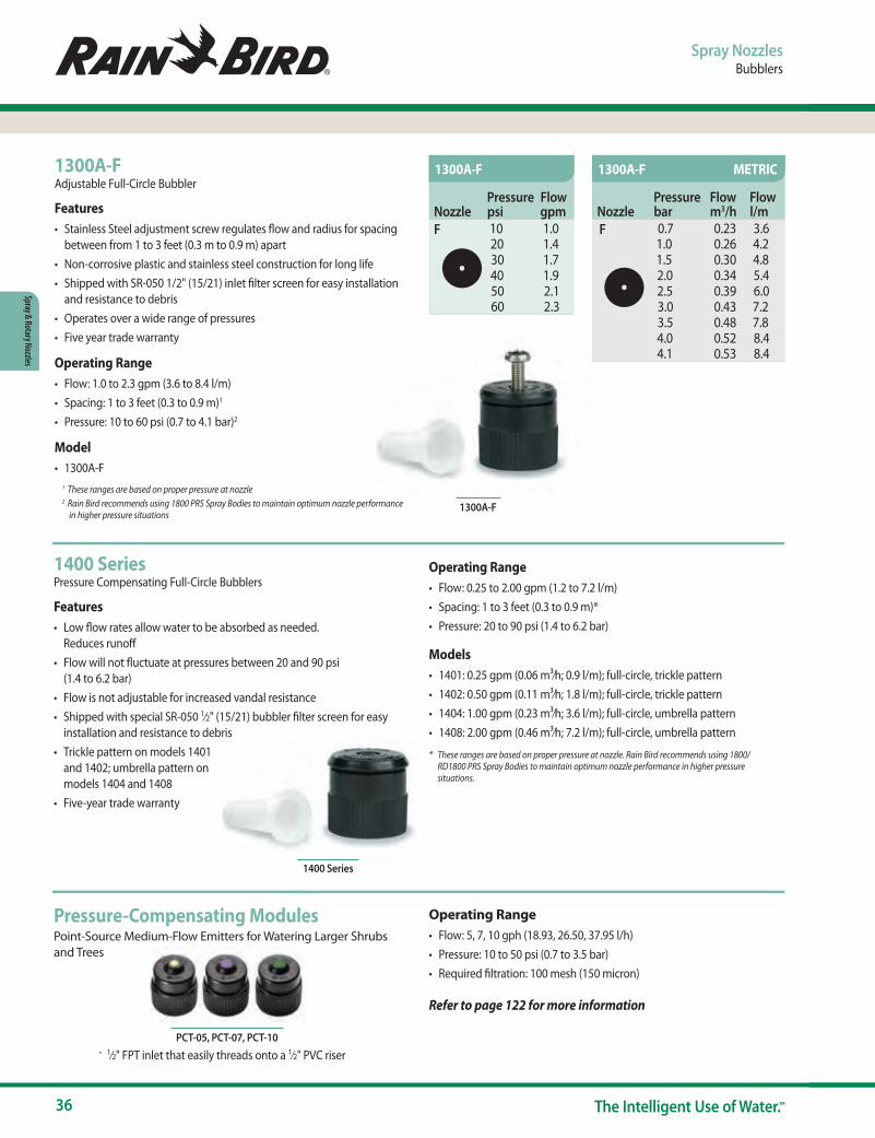
36 The Intelligent Use of Water.™
Spray & Rotary Nozzles
Spray NozzlesBubblers
1300A-FAdjustable Full-Circle Bubbler
Features• Stainless Steel adjustment screw regulates flow and radius for spacing
between from 1 to 3 feet (0.3 m to 0.9 m) apart • Non-corrosive plastic and stainless steel construction for long life• Shipped with SR-050 1/2" (15/21) inlet filter screen for easy installation
and resistance to debris • Operates over a wide range of pressures• Five year trade warranty
Operating Range• Flow: 1.0 to 2.3 gpm (3.6 to 8.4 l/m) • Spacing: 1 to 3 feet (0.3 to 0.9 m)1
• Pressure: 10 to 60 psi (0.7 to 4.1 bar)2
Model• 1300A-F
1 These ranges are based on proper pressure at nozzle 2 Rain Bird recommends using 1800 PRS Spray Bodies to maintain optimum nozzle performance
in higher pressure situations
1400 SeriesPressure Compensating Full-Circle Bubblers
Features• Low flow rates allow water to be absorbed as needed.
Reduces runoff• Flow will not fluctuate at pressures between 20 and 90 psi
(1.4 to 6.2 bar)• Flow is not adjustable for increased vandal resistance• Shipped with special SR-050 1⁄2" (15/21) bubbler filter screen for easy
installation and resistance to debris• Trickle pattern on models 1401
and 1402; umbrella pattern on models 1404 and 1408
• Five-year trade warranty
1300A-F
1400 Series
Operating Range• Flow: 0.25 to 2.00 gpm (1.2 to 7.2 l/m)• Spacing: 1 to 3 feet (0.3 to 0.9 m)*• Pressure: 20 to 90 psi (1.4 to 6.2 bar)
Models• 1401: 0.25 gpm (0.06 m3⁄h; 0.9 l/m); full-circle, trickle pattern• 1402: 0.50 gpm (0.11 m3⁄h; 1.8 l/m); full-circle, trickle pattern• 1404: 1.00 gpm (0.23 m3⁄h; 3.6 l/m); full-circle, umbrella pattern• 1408: 2.00 gpm (0.46 m3⁄h; 7.2 l/m); full-circle, umbrella pattern
* These ranges are based on proper pressure at nozzle. Rain Bird recommends using 1800/RD1800 PRS Spray Bodies to maintain optimum nozzle performance in higher pressure situations.
Pressure-Compensating ModulesPoint-Source Medium-Flow Emitters for Watering Larger Shrubs and Trees
Operating Range• Flow: 5, 7, 10 gph (18.93, 26.50, 37.95 l/h)• Pressure: 10 to 50 psi (0.7 to 3.5 bar)• Required filtration: 100 mesh (150 micron)
Refer to page 122 for more information
PCT-05, PCT-07, PCT-10• 1⁄2" FPT inlet that easily threads onto a 1⁄2" PVC riser
NozzlePressure psi
Flow gpm
F 10 1.020 1.430 1.740 1.950 2.160 2.3
NozzlePressure bar
Flow m3/h
Flow l/m
F 0.7 0.23 3.61.0 0.26 4.21.5 0.30 4.82.0 0.34 5.42.5 0.39 6.03.0 0.43 7.23.5 0.48 7.84.0 0.52 8.44.1 0.53 8.4
1300A-F 1300A-F METRIC
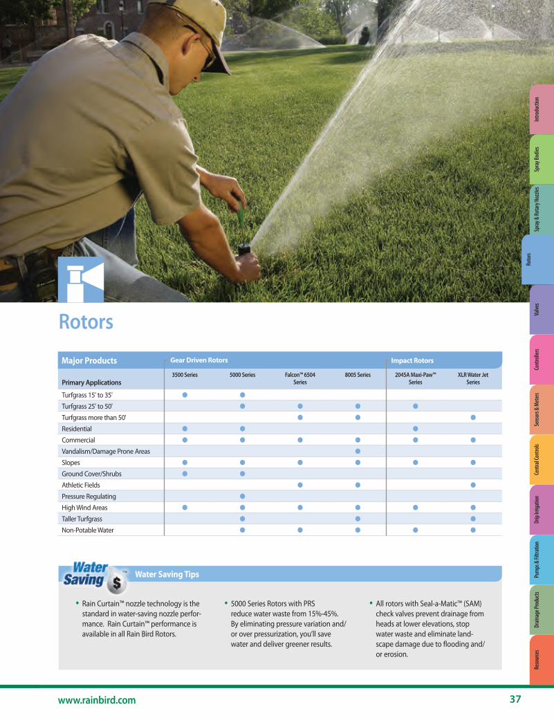
www.rainbird.com/rotors
37www.rainbird.com
Roto
rs
Primary Applications3500 Series 5000 Series Falcon™ 6504
Series8005 Series 2045A Maxi-Paw™
SeriesXLR Water Jet
Series
Turfgrass 15' to 35' ● ●
Turfgrass 25' to 50' ● ● ● ●
Turfgrass more than 50' ● ● ●
Residential ● ● ●
Commercial ● ● ● ● ● ●
Vandalism/Damage Prone Areas ●
Slopes ● ● ● ● ● ●
Ground Cover/Shrubs ● ●
Athletic Fields ● ● ●
Pressure Regulating ●
High Wind Areas ● ● ● ● ● ●
Taller Turfgrass ● ● ●
Non-Potable Water ● ● ● ● ●
Rotors
• Rain Curtain™ nozzle technology is the standard in water-saving nozzle perfor-mance. Rain Curtain™ performance is available in all Rain Bird Rotors.
• 5000 Series Rotors with PRS reduce water waste from 15%-45%. By eliminating pressure variation and/or over pressurization, you’ll save water and deliver greener results.
• All rotors with Seal-a-Matic™ (SAM) check valves prevent drainage from heads at lower elevations, stop water waste and eliminate land-scape damage due to flooding and/or erosion.
Water Saving Tips
Major Products Gear Driven Rotors Impact Rotors
Spra
y & Ro
tary
Noz
zles
Roto
rsVa
lves
Cont
rolle
rsSe
nsor
s & M
eter
sCe
ntra
l Con
trols
Drip
Irrig
atio
nPu
mps
& Fi
ltrat
ion
Drain
age P
rodu
cts
Reso
urce
sIn
trodu
ctio
nSp
ray B
odies

38 The Intelligent Use of Water.™
Rotors
3504-PC
3500 - S - PC - SAM
3504 - PC - SAM
Model 3500 Series 4" pop-up
Shrub Models
4" Models
ModelShrub
RotationPC: Reversing Part Circle
OptionsSAM
Rotors3500 Series
3500 SeriesCompact Residential Rotor. Big on Value and Convenience
Features• Rain Curtain™ nozzles deliver even distribution over the entire radius
including large wind resistant droplets and gentle close-in watering resulting in greener turf using less water
• Oversized wiper seal prevents leaks and protects internals from debris• Arc adjustment through the top of the rotor requiring only a flat-blade
screwdriver• 3 year trade warranty
Options• SAM Seal-A-Matic™ check valve holds up to 7 ft (2.1 m) of elevation
change
Operating Specifications• Precipitation rate: 0.37 to 0.83 inches per hour (9 to 21 mm/h)• Radius: 15 to 35 feet (4.6 to 10.7 m)• Radius may be reduced up to 25% with radius reduction screw• Pressure: 25 to 55 psi (1.7 to 3.8 bar)• Flow rate: 0.54 to 4.6 gpm (2.0 to 17.4 l/m)• 1⁄2" NPT female bottom threaded inlet• Reversing full- and part-circle adjustment 40° - 360°• Nozzle trajectory of 25°
Models• 3504-PC: 4" part/reverse full circle• 3504-PC-SAM: 4" part/reverse full circle with SAM• 3500-S-PC-SAM: 4" part/reverse full circle shrub model with SAM
Superior Distribution Uniformity
The 3500 Series Rotors with Rain Curtain™ Technology are engineered to deliver a uniform spray pattern, giving you a
consistently green lawn throughout.
0.37 to 0.83 in/hr (9 to 21 mm/h)
25 to 55 psi (1.7 to 3.8 bar)
0.54 to 4.6 gpm (2.0 to 17.4 l/m) (0.12 to 1.04 m3/h)
4" (10.2 cm)
Shrub: 7" (17.8 cm) 4": 6 5/8" (16.8 cm)
½” NPT
How to Specify
The average DU(LQ) of the applicable products exceed 0.65 distribution uniformity.
Product Type Radius DU(LQ) 3500 Rotors 15 - 35 ft. > 0.75To view the complete document of compliance for Rain Bird products that have been tested to meet the requirements of the ASABE/ICC 802-2014 standard and the California MWELO go to: www.rainbird.com/agency/california/MWELO.htm
3500 Series Rotors meet the requirements of the ASABE/ICC 802-2014 standard
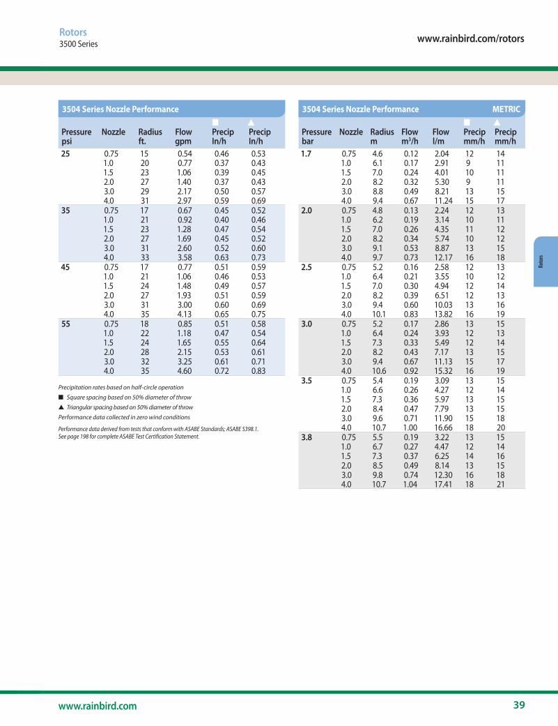
www.rainbird.com/rotors
39www.rainbird.com
Roto
rs
Pressurepsi
Nozzle Radius ft.
Flow gpm
n Precip In/h
s Precip In/h
25 0.75 15 0.54 0.46 0.531.0 20 0.77 0.37 0.431.5 23 1.06 0.39 0.452.0 27 1.40 0.37 0.433.0 29 2.17 0.50 0.574.0 31 2.97 0.59 0.69
35 0.75 17 0.67 0.45 0.521.0 21 0.92 0.40 0.461.5 23 1.28 0.47 0.542.0 27 1.69 0.45 0.523.0 31 2.60 0.52 0.604.0 33 3.58 0.63 0.73
45 0.75 17 0.77 0.51 0.591.0 21 1.06 0.46 0.531.5 24 1.48 0.49 0.572.0 27 1.93 0.51 0.593.0 31 3.00 0.60 0.694.0 35 4.13 0.65 0.75
55 0.75 18 0.85 0.51 0.581.0 22 1.18 0.47 0.541.5 24 1.65 0.55 0.642.0 28 2.15 0.53 0.613.0 32 3.25 0.61 0.714.0 35 4.60 0.72 0.83
Pressurebar
Nozzle Radius m
Flow m3/h
Flow l/m
n Precip mm/h
s Precip mm/h
1.7 0.75 4.6 0.12 2.04 12 141.0 6.1 0.17 2.91 9 111.5 7.0 0.24 4.01 10 112.0 8.2 0.32 5.30 9 113.0 8.8 0.49 8.21 13 154.0 9.4 0.67 11.24 15 17
2.0 0.75 4.8 0.13 2.24 12 131.0 6.2 0.19 3.14 10 111.5 7.0 0.26 4.35 11 122.0 8.2 0.34 5.74 10 123.0 9.1 0.53 8.87 13 154.0 9.7 0.73 12.17 16 18
2.5 0.75 5.2 0.16 2.58 12 131.0 6.4 0.21 3.55 10 121.5 7.0 0.30 4.94 12 142.0 8.2 0.39 6.51 12 133.0 9.4 0.60 10.03 13 164.0 10.1 0.83 13.82 16 19
3.0 0.75 5.2 0.17 2.86 13 151.0 6.4 0.24 3.93 12 131.5 7.3 0.33 5.49 12 142.0 8.2 0.43 7.17 13 153.0 9.4 0.67 11.13 15 174.0 10.6 0.92 15.32 16 19
3.5 0.75 5.4 0.19 3.09 13 151.0 6.6 0.26 4.27 12 141.5 7.3 0.36 5.97 13 152.0 8.4 0.47 7.79 13 153.0 9.6 0.71 11.90 15 184.0 10.7 1.00 16.66 18 20
3.8 0.75 5.5 0.19 3.22 13 151.0 6.7 0.27 4.47 12 141.5 7.3 0.37 6.25 14 162.0 8.5 0.49 8.14 13 153.0 9.8 0.74 12.30 16 184.0 10.7 1.04 17.41 18 21
Rotors3500 Series
Precipitation rates based on half-circle operation
n Square spacing based on 50% diameter of throw
s Triangular spacing based on 50% diameter of throw
Performance data collected in zero wind conditions
Performance data derived from tests that conform with ASABE Standards; ASABE S398.1. See page 198 for complete ASABE Test Certification Statement.
3504 Series Nozzle Performance 3504 Series Nozzle Performance METRIC
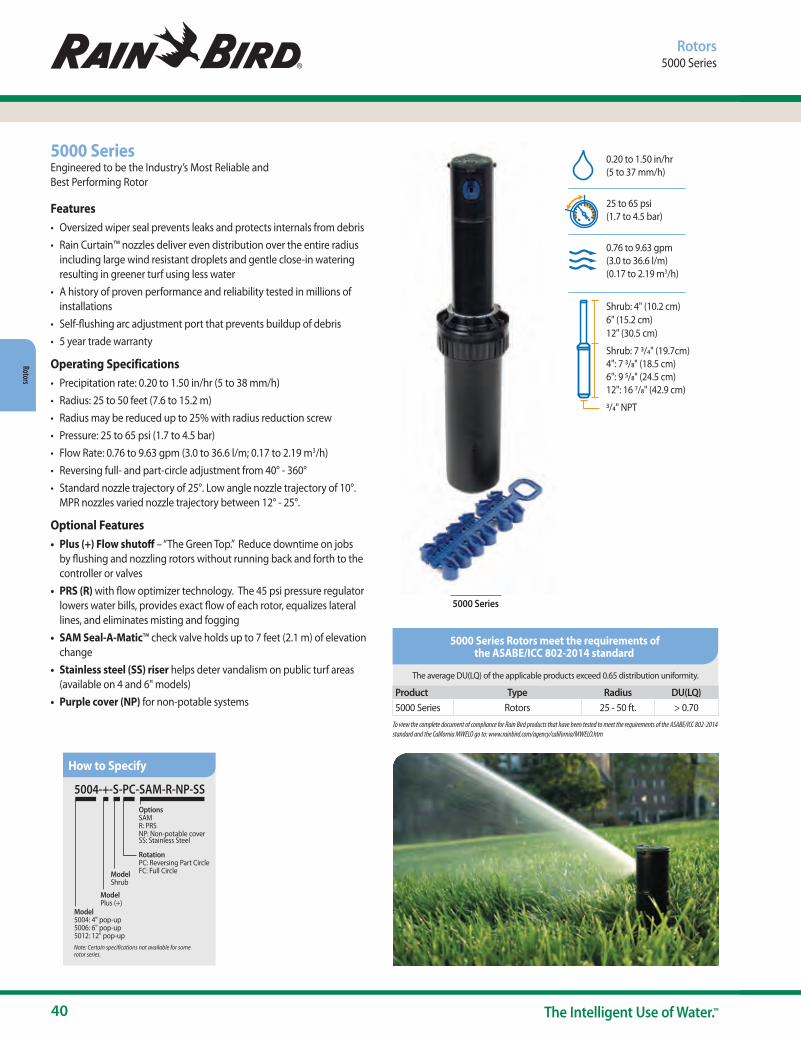
40 The Intelligent Use of Water.™
Rotors
Rotors5000 Series
5000 SeriesEngineered to be the Industry’s Most Reliable and Best Performing Rotor
Features• Oversized wiper seal prevents leaks and protects internals from debris• Rain Curtain™ nozzles deliver even distribution over the entire radius
including large wind resistant droplets and gentle close-in watering resulting in greener turf using less water
• A history of proven performance and reliability tested in millions of installations
• Self-flushing arc adjustment port that prevents buildup of debris• 5 year trade warranty
Operating Specifications• Precipitation rate: 0.20 to 1.50 in/hr (5 to 38 mm/h)• Radius: 25 to 50 feet (7.6 to 15.2 m) • Radius may be reduced up to 25% with radius reduction screw• Pressure: 25 to 65 psi (1.7 to 4.5 bar)• Flow Rate: 0.76 to 9.63 gpm (3.0 to 36.6 l/m; 0.17 to 2.19 m3/h)• Reversing full- and part-circle adjustment from 40° - 360°• Standard nozzle trajectory of 25°. Low angle nozzle trajectory of 10°.
MPR nozzles varied nozzle trajectory between 12° - 25°.
Optional Features• Plus (+) Flow shutoff – “The Green Top.” Reduce downtime on jobs
by flushing and nozzling rotors without running back and forth to the controller or valves
• PRS (R) with flow optimizer technology. The 45 psi pressure regulator lowers water bills, provides exact flow of each rotor, equalizes lateral lines, and eliminates misting and fogging
• SAM Seal-A-Matic™ check valve holds up to 7 feet (2.1 m) of elevation change
• Stainless steel (SS) riser helps deter vandalism on public turf areas (available on 4 and 6" models)
• Purple cover (NP) for non-potable systems
5000 Series
0.20 to 1.50 in/hr (5 to 37 mm/h)
25 to 65 psi (1.7 to 4.5 bar)
0.76 to 9.63 gpm (3.0 to 36.6 l/m) (0.17 to 2.19 m3/h)
Shrub: 4" (10.2 cm) 6" (15.2 cm) 12" (30.5 cm)
Shrub: 7 3/4" (19.7cm) 4": 7 3/8" (18.5 cm) 6": 9 5/8" (24.5 cm) 12": 16 7/8" (42.9 cm)
3/4" NPT
5004-+-S-PC-SAM-R-NP-SS
Model 5004: 4" pop-up 5006: 6" pop-up5012: 12" pop-up
ModelPlus (+)
ModelShrub
RotationPC: Reversing Part CircleFC: Full Circle
OptionsSAM R: PRSNP: Non-potable coverSS: Stainless Steel
Note: Certain specifications not available for somerotor series.
How to Specify
The average DU(LQ) of the applicable products exceed 0.65 distribution uniformity.
Product Type Radius DU(LQ) 5000 Series Rotors 25 - 50 ft. > 0.70To view the complete document of compliance for Rain Bird products that have been tested to meet the requirements of the ASABE/ICC 802-2014 standard and the California MWELO go to: www.rainbird.com/agency/california/MWELO.htm
5000 Series Rotors meet the requirements of the ASABE/ICC 802-2014 standard
www.rainbird.com/rotors
41www.rainbird.com
Roto
rs
Rotors5000 Series
S Shrub Model + Flow Shut-off
PC Part Circle & Reversing Full Circle FC Non-Reversing Full Circle
SAM Check valve R Pressure Regulation
5000 Series (cont.)ModelsPart-circle units (PC) are adjustable from 40° –360°. Full-circle units (FC) are 360 degrees only.• 5000SPCSAM: 5000S Shrub Part Circle SAM • 5000+SPCSAM: 5000S Shrub Plus Part Circle SAM • 5000+SPCSAMNP: 5000S Shrub Plus Part Circle SAM Non Potable • 5000+SPCSAMR: 5000S Shrub Plus PRS Part Circle SAM• 5000+SPCSAMRN: 5000S Shrub Plus PRS Part Circle SAM Non Potable• 5004PC: 5004 Part Circle • 5004PC20: 5004 Part Circle w/2.0 Nozzle • 5004PC30: 5004 Part Circle w/3.0 Nozzle • 5004PCSAM: 5004 Part Circle SAM • 5004PCSAM20: 5004 Part Circle SAM w/2.0 Nozzle • 5004PCNP: 5004 Part Circle Non Potable • 5004PCR: 5004 Part Circle PRS • 5004+PC: 5004 Plus Part Circle • 5004+PC20: 5004 Plus Part Circle w/2.0 Nozzle • 5004+PC30: 5004 Plus Part Circle w/3.0 Nozzle • 5004+PCSAM: 5004 Plus Part Circle SAM • 5004+PCR 5004: Plus Part Circle PRS • 5004+PCSAMR: 5004 Plus Part Circle SAM PRS • 5004+PCSAMR20: 5004 Plus Part Circle SAM PRS w/2.0 Nozzle • 5004+PCSAMR30: 5004 Plus Part Circle SAM PRS w/3.0 Nozzle • 5004+PCSAMRNP: 5004 Plus Part Circle SAM PRS Non Potable • 5004+PCSAMRSS: 5004 Plus Part Circle SAM PRS Stainless Steel • 5004+PCSAMRNS: 5004 Plus Part Circle SAM PRS Stainless Steel
Non Potable • 5004FC 5004: Full Circle • 5004+FC 5004: Plus Full Circle • 5004+FCSAM: 5004 Plus Full Circle SAM • 5004+FCSAMR: 5004 Plus Full Circle SAM PRS
• 5004+FCSAMRSS: 5004 Plus Full Circle Stainless Steel SAM PRS • 5006PC: 5006 Part Circle • 5006PC30: 5006 Part Circle w/ 3.0 Nozzle • 5006+PC: 5006 Plus Part Circle • 5006+PCSAM: 5006 Plus Part Circle SAM • 5006+PCSAMNP: 5006 Plus Part Circle SAM Non Potable • 5006+PCSAMR: 5006 Plus Part Circle SAM PRS • 5006+PCSAMRNP: 5006 Plus Part Circle SAM PRS Non Potable • 5006+PCSAMRSS: 5006 Plus Part Circle SAM PRS Stainless Steel • 5006+PCSAMRNS: 5006 Plus Part Circle SAM PRS Stainless Steel
Non Potable • 5012+PCSAMR: 5012 Plus Part Circle SAM PRS • 5012+PCSAMRNP: 5012 Plus Part Circle SAM PRS Non Potable
SS Stainless Steel NP Non-Potable Cover
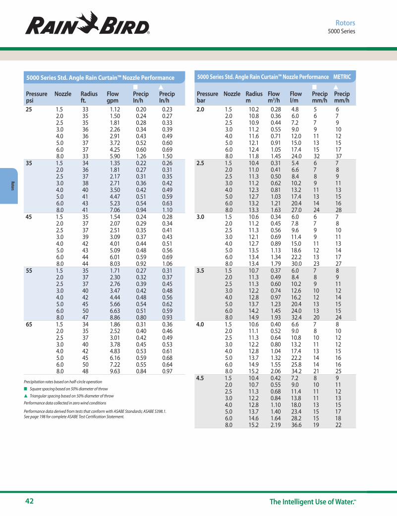
42 The Intelligent Use of Water.™
Rotors
Rotors5000 Series
Precipitation rates based on half-circle operation
n Square spacing based on 50% diameter of throw
s Triangular spacing based on 50% diameter of throw
Performance data collected in zero wind conditions
Performance data derived from tests that conform with ASABE Standards; ASABE S398.1. See page 198 for complete ASABE Test Certification Statement.
Pressurepsi
Nozzle Radius ft.
Flow gpm
n Precip In/h
s Precip In/h
25 1.5 33 1.12 0.20 0.23 2.0 35 1.50 0.24 0.27 2.5 35 1.81 0.28 0.33 3.0 36 2.26 0.34 0.39 4.0 36 2.91 0.43 0.49 5.0 37 3.72 0.52 0.60 6.0 37 4.25 0.60 0.69 8.0 33 5.90 1.26 1.50
35 1.5 34 1.35 0.22 0.26 2.0 36 1.81 0.27 0.31 2.5 37 2.17 0.31 0.35 3.0 38 2.71 0.36 0.42 4.0 40 3.50 0.42 0.49 5.0 41 4.47 0.51 0.59 6.0 43 5.23 0.54 0.63 8.0 41 7.06 0.94 1.10
45 1.5 35 1.54 0.24 0.28 2.0 37 2.07 0.29 0.34 2.5 37 2.51 0.35 0.41 3.0 39 3.09 0.37 0.43 4.0 42 4.01 0.44 0.51 5.0 43 5.09 0.48 0.56 6.0 44 6.01 0.59 0.69 8.0 44 8.03 0.92 1.06
55 1.5 35 1.71 0.27 0.31 2.0 37 2.30 0.32 0.37 2.5 37 2.76 0.39 0.45 3.0 40 3.47 0.42 0.48 4.0 42 4.44 0.48 0.56 5.0 45 5.66 0.54 0.62 6.0 50 6.63 0.51 0.59 8.0 47 8.86 0.80 0.93
65 1.5 34 1.86 0.31 0.36 2.0 35 2.52 0.40 0.46 2.5 37 3.01 0.42 0.49 3.0 40 3.78 0.45 0.53 4.0 42 4.83 0.53 0.61 5.0 45 6.16 0.59 0.68 6.0 50 7.22 0.55 0.64 8.0 48 9.63 0.84 0.97
5000 Series Std. Angle Rain Curtain™ Nozzle Performance
Pressurebar
Nozzle Radius m
Flow m3/h
Flow l/m
n Precip mm/h
s Precip mm/h
2.0 1.5 10.2 0.28 4.8 5 62.0 10.8 0.36 6.0 6 72.5 10.9 0.44 7.2 7 93.0 11.2 0.55 9.0 9 104.0 11.6 0.71 12.0 11 125.0 12.1 0.91 15.0 13 156.0 12.4 1.05 17.4 15 178.0 11.8 1.45 24.0 32 37
2.5 1.5 10.4 0.31 5.4 6 72.0 11.0 0.41 6.6 7 82.5 11.3 0.50 8.4 8 93.0 11.2 0.62 10.2 9 114.0 12.3 0.81 13.2 11 135.0 12.7 1.03 17.4 13 156.0 13.2 1.21 20.4 14 168.0 13.3 1.63 27.0 24 28
3.0 1.5 10.6 0.34 6.0 6 72.0 11.2 0.45 7.8 7 82.5 11.3 0.56 9.6 9 103.0 12.1 0.69 11.4 9 114.0 12.7 0.89 15.0 11 135.0 13.5 1.13 18.6 12 146.0 13.4 1.34 22.2 13 178.0 13.4 1.79 30.0 23 27
3.5 1.5 10.7 0.37 6.0 7 82.0 11.3 0.49 8.4 8 92.5 11.3 0.60 10.2 9 113.0 12.2 0.74 12.6 10 124.0 12.8 0.97 16.2 12 145.0 13.7 1.23 20.4 13 156.0 14.2 1.45 24.0 13 158.0 14.9 1.93 32.4 20 24
4.0 1.5 10.6 0.40 6.6 7 82.0 11.1 0.52 9.0 8 102.5 11.3 0.64 10.8 10 123.0 12.2 0.80 13.2 11 124.0 12.8 1.04 17.4 13 155.0 13.7 1.32 22.2 14 166.0 14.9 1.55 25.8 14 168.0 15.2 2.06 34.2 21 25
4.5 1.5 10.4 0.42 7.2 8 92.0 10.7 0.55 9.0 10 112.5 11.3 0.68 11.4 11 123.0 12.2 0.84 13.8 11 134.0 12.8 1.10 18.0 13 155.0 13.7 1.40 23.4 15 176.0 14.6 1.64 28.2 15 188.0 15.2 2.19 36.6 19 22
5000 Series Std. Angle Rain Curtain™ Nozzle Performance METRIC
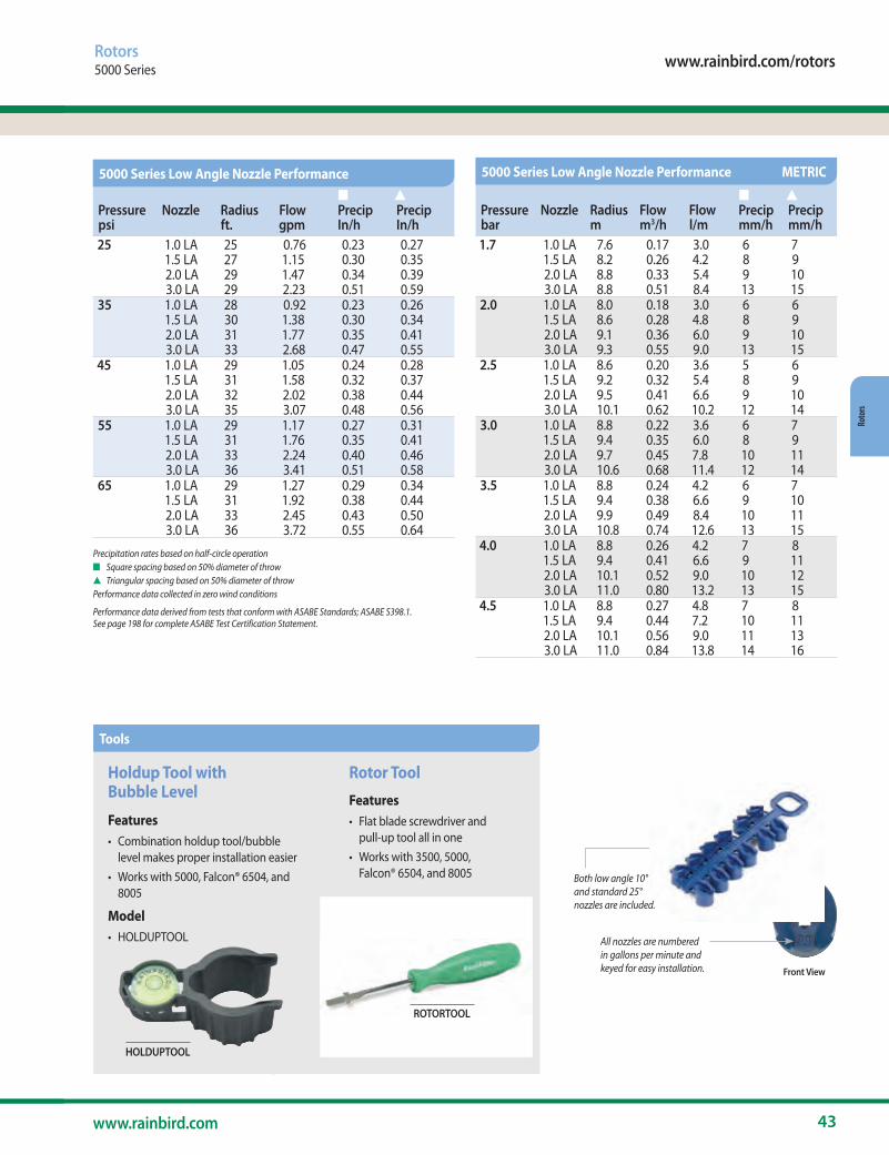
www.rainbird.com/rotors
43www.rainbird.com
Roto
rs
Rotors5000 Series
Precipitation rates based on half-circle operationn Square spacing based on 50% diameter of throws Triangular spacing based on 50% diameter of throwPerformance data collected in zero wind conditions
Performance data derived from tests that conform with ASABE Standards; ASABE S398.1. See page 198 for complete ASABE Test Certification Statement.
All nozzles are numberedin gallons per minute andkeyed for easy installation. Front View
Both low angle 10° and standard 25° nozzles are included.
Tools
Holdup Tool with Bubble Level
Features• Combination holdup tool/bubble
level makes proper installation easier• Works with 5000, Falcon® 6504, and
8005
Model• HOLDUPTOOL
HOLDUPTOOL
Rotor ToolFeatures• Flat blade screwdriver and
pull-up tool all in one• Works with 3500, 5000,
Falcon® 6504, and 8005
Model• ROTORTOOL
ROTORTOOL
Pressurepsi
Nozzle Radius ft.
Flow gpm
n Precip In/h
s Precip In/h
25 1.0 LA 25 0.76 0.23 0.27 1.5 LA 27 1.15 0.30 0.35 2.0 LA 29 1.47 0.34 0.39 3.0 LA 29 2.23 0.51 0.59
35 1.0 LA 28 0.92 0.23 0.26 1.5 LA 30 1.38 0.30 0.34 2.0 LA 31 1.77 0.35 0.41 3.0 LA 33 2.68 0.47 0.55
45 1.0 LA 29 1.05 0.24 0.28 1.5 LA 31 1.58 0.32 0.37 2.0 LA 32 2.02 0.38 0.44 3.0 LA 35 3.07 0.48 0.56
55 1.0 LA 29 1.17 0.27 0.31 1.5 LA 31 1.76 0.35 0.41 2.0 LA 33 2.24 0.40 0.46 3.0 LA 36 3.41 0.51 0.58
65 1.0 LA 29 1.27 0.29 0.34 1.5 LA 31 1.92 0.38 0.44 2.0 LA 33 2.45 0.43 0.50 3.0 LA 36 3.72 0.55 0.64
5000 Series Low Angle Nozzle Performance
Pressurebar
Nozzle Radius m
Flow m3/h
Flow l/m
n Precip mm/h
s Precip mm/h
1.7 1.0 LA 7.6 0.17 3.0 6 71.5 LA 8.2 0.26 4.2 8 92.0 LA 8.8 0.33 5.4 9 103.0 LA 8.8 0.51 8.4 13 15
2.0 1.0 LA 8.0 0.18 3.0 6 61.5 LA 8.6 0.28 4.8 8 92.0 LA 9.1 0.36 6.0 9 103.0 LA 9.3 0.55 9.0 13 15
2.5 1.0 LA 8.6 0.20 3.6 5 61.5 LA 9.2 0.32 5.4 8 92.0 LA 9.5 0.41 6.6 9 103.0 LA 10.1 0.62 10.2 12 14
3.0 1.0 LA 8.8 0.22 3.6 6 71.5 LA 9.4 0.35 6.0 8 92.0 LA 9.7 0.45 7.8 10 113.0 LA 10.6 0.68 11.4 12 14
3.5 1.0 LA 8.8 0.24 4.2 6 71.5 LA 9.4 0.38 6.6 9 102.0 LA 9.9 0.49 8.4 10 113.0 LA 10.8 0.74 12.6 13 15
4.0 1.0 LA 8.8 0.26 4.2 7 81.5 LA 9.4 0.41 6.6 9 112.0 LA 10.1 0.52 9.0 10 123.0 LA 11.0 0.80 13.2 13 15
4.5 1.0 LA 8.8 0.27 4.8 7 81.5 LA 9.4 0.44 7.2 10 112.0 LA 10.1 0.56 9.0 11 133.0 LA 11.0 0.84 13.8 14 16
5000 Series Low Angle Nozzle Performance METRIC

44 The Intelligent Use of Water.™
Rotors
Precipitation rates based on half-circle operation
n Square spacing based on 50% diameter of throw
s Triangular spacing based on 50% diameter of throw
Performance data collected in zero wind conditions
Performance data derived from tests that conform with ASABE Standards; ASABE S398.1. See page 198 for complete ASABE Test Certification Statement.
Rotors5000 Series
Pressurepsi
Nozzle Radius ft.
Flow gpm
n Precip In/h
s Precip In/h
25 1.5 33 1.12 0.2 0.232.0 35 1.5 0.24 0.272.5 35 1.81 0.28 0.333.0 36 2.26 0.34 0.394.0 36 2.91 0.43 0.495.0 37 3.72 0.52 0.666.0 37 4.25 0.60 0.698.0 33 5.9 1.26 1.5
35 1.5 34 1.35 0.22 0.262.0 36 1.81 0.27 0.312.5 37 2.17 0.31 0.353.0 38 2.71 0.36 0.414.0 40 3.5 0.42 0.495.0 41 4.47 0.51 0.596.0 43 5.23 0.54 0.638.0 41 7.06 0.94 1.1
45 1.5 35 1.54 0.24 0.282.0 37 2.07 0.29 0.342.5 37 2.51 0.35 0.413.0 39 3.09 0.37 0.434.0 42 4.01 0.44 0.515.0 43 5.09 0.48 0.566.0 44 6.01 0.55 0.638.0 44 8.03 0.92 1.06
55 – 75 1.5 35 1.59 0.25 0.292.0 37 2.14 0.3 0.352.5 37 2.6 0.37 0.423.0 39 3.2 0.39 0.444.0 42 4.15 0.45 0.525.0 43 5.27 0.5 0.586.0 44 6.22 0.57 0.658.0 44 8.31 0.72 0.84
5000 PRS Std. Angle Rain Curtain™ Nozzle Performance
Pressurebar
Nozzle Radius m
Flow m3/h
Flow l/m
n Precip mm/h
s Precip mm/h
1.7 1.5 10.1 0.25 4.2 5 62.0 10.7 0.34 5.4 6 72.5 10.7 0.41 6.6 7 83.0 11.0 0.51 8.4 8 104.0 11.3 0.66 10.8 10 125.0 11.9 0.84 13.8 12 146.0 11.9 0.97 16.2 14 168.0 11.0 1.34 22.2 22 26
2.0 1.5 10.2 0.28 4.8 5 62.0 10.8 0.36 6.0 6 72.5 10.9 0.44 7.2 7 93.0 11.2 0.55 9.0 9 104.0 11.6 0.71 12.0 11 12.65.0 12.1 0.91 15.0 13 156.0 12.4 1.05 17.4 15 178.0 11.8 1.45 24.0 32 37
2.5 1.5 10.4 0.31 5.4 6 72.0 11.0 0.41 6.6 7 82.5 11.3 0.50 8.4 8 93.0 11.2 0.62 10.2 9 114.0 12.3 0.81 13.2 11 135.0 12.7 1.03 17.4 13 156.0 13.2 1.21 20.4 14 168.0 13.3 1.63 27.0 24 18
3.0 1.5 10.6 0.34 6.0 6 72.0 11.2 0.45 7.8 7 82.5 11.3 0.56 9.6 9 103.0 12.1 0.69 11.4 9 114.0 12.7 0.89 16.8 11 135.0 13.5 1.13 18.6 12 146.0 13.9 1.34 22.2 14 168.0 14.1 1.79 30.0 23 27
3.5 – 5.2 1.5 10.6 0.35 6.0 6 72.0 11.2 0.47 7.8 8 92.5 11.3 0.58 10.2 9 113.0 12.1 0.71 12.0 10 114.0 12.7 0.92 15.6 12 135.0 13.5 1.17 19.2 13 156.0 13.9 1.39 22.8 14 178.0 14.1 1.85 31.2 18 21
5000 PRS Std. Angle Rain Curtain™ Nozzle Performance METRIC

www.rainbird.com/rotors
45www.rainbird.com
Roto
rs
Rotors5000 Series
Precipitation rates based on half-circle operation
n Square spacing based on 50% diameter of throw
s Triangular spacing based on 50% diameter of throw
Performance data collected in zero wind conditions
Performance data derived from tests that conform with ASABE Standards; ASABE S398.1. See page 198 for complete ASABE Test Certification Statement.
Flow
Rat
e (g
pm)
15 20 25 30 35 40 45 50 55 60 65 70 75
12.0
11.0
10.0
9.0
8.0
7.0
6.0
5.0
4.0
3.0
2.0
1.0
0.0
Inlet Pressure (psi)
8.0 RC - with PRS
5.0 RC - with PRS
2.0 RC - with PRS
8.0 RC - no PRS
5.0 RC - no PRS
3.0 RC - no PRS
2.0 RC - no PRS
3.0 RC - with PRS
Flow 45 50 55 60 65 70 75 80GPM
6 0 0.33 0.66 0.96 1.25 1.54 1.81 2.06 8 0 0.43 0.85 1.24 1.62 1.98 2.33 2.67
10 0 0.55 1.07 1.57 2.05 2.52 2.96 3.39 12 0 0.66 1.27 1.86 2.43 2.97 3.50 4.01 14 0 0.77 1.49 2.18 2.84 3.48 4.10 4.70 16 0 0.87 1.69 2.48 3.24 3.97 4.67 5.35 18 0 0.98 1.90 2.79 3.64 4.46 5.25 6.01 20 0 1.10 2.12 3.10 4.05 4.96 5.83 6.68 22 0 1.21 2.33 3.42 4.46 5.47 6.44 7.37 24 0 1.30 2.54 3.72 4.85 5.94 7.00 8.01 26 0 1.41 2.76 4.04 5.27 6.45 7.60 8.70 28 0 1.53 2.96 4.34 5.66 6.93 8.16 9.35 30 0 1.63 3.17 4.65 6.07 7.43 8.74 10.02
Tota
l Zon
e Fl
ow in
GPM
Total gallons of water saved per minute of run timeEx: At 70 psi a zone with 20 gpm of flow would save
4.96 gallons a minute with 5000 PRS
Pressurepsi
Nozzle Radius ft.
Flow gpm
n Precip In/h
s Precip In/h
25 1.0 LA 25 0.76 0.22 0.261.5 LA 27 1.15 0.3 0.352.0 LA 29 1.47 0.34 0.393.0 LA 29 2.23 0.51 0.59
35 1.0 LA 28 0.92 0.21 0.251.5 LA 30 1.38 0.3 0.342.0 LA 31 1.77 0.35 0.413.0 LA 33 2.68 0.47 0.55
45 1.0 LA 29 1.05 0.23 0.261.5 LA 31 1.58 0.32 0.372.0 LA 32 2.02 0.38 0.443.0 LA 35 3.07 0.48 0.56
55 – 75 1.0 LA 29 1.09 0.25 0.291.5 LA 31 1.64 0.33 0.382.0 LA 32 2.09 0.39 0.453.0 LA 35 3.18 0.5 0.58
5000 PRS Low Angle Nozzle Performance
Pressurebar
Nozzle Radius m
Flow m3/h
Flow l/m
n Precip mm/h
s Precip mm/h
1.7 1.0 LA 7.6 0.17 3.0 6 71.5 LA 8.2 0.26 4.2 8 92.0 LA 8.8 0.33 5.4 9 103.0 LA 8.8 0.51 8.4 13 15
2.0 1.0 LA 8.0 0.18 3.0 6 61.5 LA 8.6 0.28 4.8 8 92.0 LA 9.1 0.36 6.0 9 103.0 LA 9.3 0.55 9.0 13 15
2.5 1.0 LA 8.6 0.20 3.6 5 61.5 LA 9.2 0.32 5.4 8 92.0 LA 9.5 0.41 6.6 9 103.0 LA 10.1 0.62 10.2 12 14
3.0 1.0 LA 8.8 0.22 3.6 6 71.5 LA 9.4 0.35 6.0 8 92.0 LA 9.7 0.45 7.8 10 113.0 LA 10.6 0.68 11.4 12 14
3.5 – 5.2 1.0 LA 8.8 0.23 3.6 6 71.5 LA 9.4 0.36 6.0 8 102.0 LA 9.7 0.47 7.8 10 123.0 LA 10.6 0.70 12.0 13 15
5000 PRS Low Angle Nozzle Performance METRIC
Flow Rate vs. Inlet Pressure – Rain Curtain™ Nozzles How much water can you save each minute using Rain Bird® 5000 PRS Rotors with Flow Optimizer Technology?
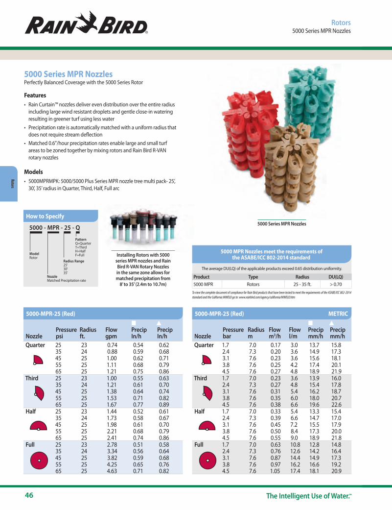
46 The Intelligent Use of Water.™
Rotors
Installing Rotors with 5000 series MPR nozzles and Rain Bird R-VAN Rotary Nozzles in the same zone allows for matched precipitation from
8’ to 35’ (2.4m to 10.7m)
5000 - MPR - 25 - Q
Model Rotor
Radius Range25'30'35'
PatternQ=QuarterT=ThirdH=HalfF=Full
NozzleMatched Precipitation rate
5000 Series MPR NozzlesPerfectly Balanced Coverage with the 5000 Series Rotor
Features• Rain Curtain™ nozzles deliver even distribution over the entire radius
including large wind resistant droplets and gentle close-in watering resulting in greener turf using less water
• Precipitation rate is automatically matched with a uniform radius that does not require stream deflection
• Matched 0.6”/hour precipitation rates enable large and small turf areas to be zoned together by mixing rotors and Rain Bird R-VAN rotary nozzles
Models• 5000MPRMPK: 5000/5000 Plus Series MPR nozzle tree multi pack- 25’,
30’, 35’ radius in Quarter, Third, Half, Full arc
5000 Series MPR Nozzles
Rotors5000 Series MPR Nozzles
How to Specify
NozzlePressurepsi
Radius ft.
Flow gpm
n Precip In/h
s Precip In/h
Quarter 25 23 0.74 0.54 0.6235 24 0.88 0.59 0.6845 25 1.00 0.62 0.7155 25 1.11 0.68 0.7965 25 1.21 0.75 0.86
Third 25 23 1.00 0.55 0.6335 24 1.21 0.61 0.7045 25 1.38 0.64 0.7455 25 1.53 0.71 0.8265 25 1.67 0.77 0.89
Half 25 23 1.44 0.52 0.6135 24 1.73 0.58 0.6745 25 1.98 0.61 0.7055 25 2.21 0.68 0.7965 25 2.41 0.74 0.86
Full 25 23 2.78 0.51 0.5835 24 3.34 0.56 0.6445 25 3.82 0.59 0.6855 25 4.25 0.65 0.7665 25 4.63 0.71 0.82
NozzlePressurebar
Radius m
Flow m3/h
Flow l/m
n Precip mm/h
s Precip mm/h
Quarter 1.7 7.0 0.17 3.0 13.7 15.82.4 7.3 0.20 3.6 14.9 17.33.1 7.6 0.23 3.6 15.6 18.13.8 7.6 0.25 4.2 17.4 20.14.5 7.6 0.27 4.8 18.9 21.9
Third 1.7 7.0 0.23 3.6 13.9 16.02.4 7.3 0.27 4.8 15.4 17.83.1 7.6 0.31 5.4 16.2 18.73.8 7.6 0.35 6.0 18.0 20.74.5 7.6 0.38 6.6 19.6 22.6
Half 1.7 7.0 0.33 5.4 13.3 15.42.4 7.3 0.39 6.6 14.7 17.03.1 7.6 0.45 7.2 15.5 17.93.8 7.6 0.50 8.4 17.3 20.04.5 7.6 0.55 9.0 18.9 21.8
Full 1.7 7.0 0.63 10.8 12.8 14.82.4 7.3 0.76 12.6 14.2 16.43.1 7.6 0.87 14.4 14.9 17.33.8 7.6 0.97 16.2 16.6 19.24.5 7.6 1.05 17.4 18.1 20.9
5000-MPR-25 (Red) 5000-MPR-25 (Red) METRIC
The average DU(LQ) of the applicable products exceed 0.65 distribution uniformity.
Product Type Radius DU(LQ) 5000 MPR Rotors 25 - 35 ft. > 0.70To view the complete document of compliance for Rain Bird products that have been tested to meet the requirements of the ASABE/ICC 802-2014 standard and the California MWELO go to: www.rainbird.com/agency/california/MWELO.htm
5000 MPR Nozzles meet the requirements of the ASABE/ICC 802-2014 standard
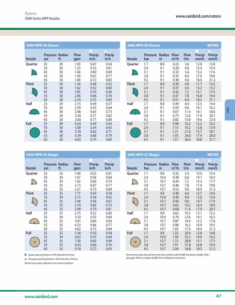
www.rainbird.com/rotors
47www.rainbird.com
Roto
rs
n Square spacing based on 50% diameter of throw
s Triangular spacing based on 50% diameter of throw
Performance data collected in zero wind conditions
Performance data derived from tests that conform with ASABE Standards; ASABE S398.1. See page 186 for complete ASABE Test Certification Statement.
Rotors5000 Series MPR Nozzles
NozzlePressurepsi
Radius ft.
Flow gpm
n Precip In/h
s Precip In/h
Quarter 25 29 1.03 0.47 0.5435 30 1.23 0.53 0.6145 30 1.40 0.60 0.6955 30 1.56 0.67 0.7765 30 1.69 0.72 0.83
Third 25 29 1.34 0.46 0.5335 30 1.62 0.52 0.6045 30 1.85 0.59 0.6955 30 2.06 0.66 0.7665 30 2.24 0.72 0.83
Half 25 29 2.15 0.49 0.5735 30 2.59 0.55 0.6445 30 2.96 0.63 0.7355 30 3.30 0.71 0.8265 30 3.60 0.77 0.89
Full 25 29 4.24 0.49 0.5635 30 5.08 0.54 0.6345 30 5.78 0.62 0.7155 30 6.39 0.68 0.7965 30 6.92 0.74 0.85
NozzlePressurepsi
Radius ft.
Flow gpm
n Precip In/h
s Precip In/h
Quarter 25 32 1.40 0.53 0.6135 34 1.67 0.56 0.6445 35 1.92 0.60 0.7055 35 2.13 0.67 0.7765 35 2.31 0.73 0.84
Third 25 32 1.77 0.50 0.5835 34 2.15 0.54 0.6245 35 2.46 0.58 0.6755 35 2.74 0.65 0.7565 35 2.99 0.70 0.81
Half 25 32 2.75 0.52 0.6035 34 3.33 0.55 0.6445 35 3.81 0.60 0.6955 35 4.23 0.66 0.7765 35 4.62 0.73 0.84
Full 25 32 5.36 0.50 0.5835 34 6.62 0.55 0.6445 35 7.58 0.60 0.6955 35 8.43 0.66 0.7665 35 9.18 0.72 0.83
NozzlePressurebar
Radius m
Flow m3/h
Flow l/m
n Precip mm/h
s Precip mm/h
Quarter 1.7 8.8 0.23 3.6 12.0 13.82.4 9.1 0.28 4.8 13.4 15.43.1 9.1 0.32 5.4 15.2 17.63.8 9.1 0.35 6.0 17.0 19.64.5 9.1 0.38 6.6 18.4 21.2
Third 1.7 8.8 0.30 4.8 11.7 13.52.4 9.1 0.37 6.0 13.2 15.23.1 9.1 0.42 7.2 15.1 17.43.8 9.1 0.47 7.8 16.8 19.44.5 9.1 0.51 8.4 18.3 21.1
Half 1.7 8.8 0.49 8.4 12.5 14.42.4 9.1 0.59 9.6 14.1 16.23.1 9.1 0.67 11.4 16.1 18.63.8 9.1 0.75 12.6 17.9 20.74.5 9.1 0.82 13.8 19.6 22.6
Full 1.7 8.8 0.96 16.2 12.3 14.22.4 9.1 1.15 19.2 13.8 15.93.1 9.1 1.31 21.6 15.7 18.13.8 9.1 1.45 24.0 17.4 20.04.5 9.1 1.57 26.4 18.8 21.7
NozzlePressurebar
Radius m
Flow m3/h
Flow l/m
n Precip mm/h
s Precip mm/h
Quarter 1.7 9.8 0.32 5.4 13.4 15.42.4 10.4 0.38 6.6 14.1 16.33.1 10.7 0.44 7.2 15.3 17.73.8 10.7 0.48 7.8 17.0 19.64.5 10.7 0.52 9.0 18.4 21.3
Third 1.7 9.8 0.40 6.6 12.7 14.62.4 10.4 0.49 8.4 13.6 15.83.1 10.7 0.56 9.6 14.7 17.03.8 10.7 0.62 10.2 16.4 18.94.5 10.7 0.68 11.4 17.9 20.7
Half 1.7 9.8 0.62 10.2 13.1 15.22.4 10.4 0.76 12.6 14.1 16.33.1 10.7 0.87 14.4 15.2 17.63.8 10.7 0.96 16.2 16.9 19.54.5 10.7 1.05 17.4 18.4 21.3
Full 1.7 9.8 1.22 20.4 12.8 14.82.4 10.4 1.50 25.2 14.0 16.23.1 10.7 1.72 28.8 15.1 17.53.8 10.7 1.91 31.8 16.8 19.44.5 10.7 2.09 34.8 18.3 21.2
5000-MPR-30 (Green)
5000-MPR-35 (Beige)
5000-MPR-30 (Green) METRIC
5000-MPR-35 (Beige) METRIC
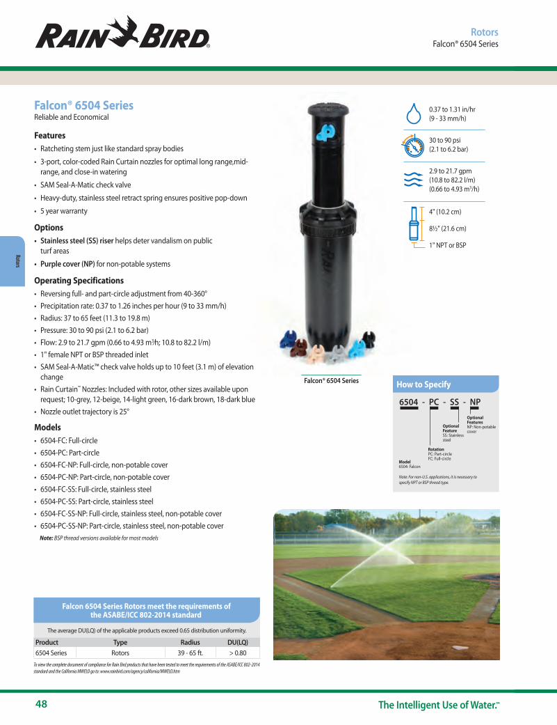
48 The Intelligent Use of Water.™
Rotors
Falcon® 6504 Series
Falcon® 6504 SeriesReliable and Economical
Features• Ratcheting stem just like standard spray bodies
• 3-port, color-coded Rain Curtain nozzles for optimal long range,mid-range, and close-in watering
• SAM Seal-A-Matic check valve
• Heavy-duty, stainless steel retract spring ensures positive pop-down
• 5 year warranty
Options• Stainless steel (SS) riser helps deter vandalism on public
turf areas
• Purple cover (NP) for non-potable systems
Operating Specifications• Reversing full- and part-circle adjustment from 40-360° • Precipitation rate: 0.37 to 1.26 inches per hour (9 to 33 mm/h)• Radius: 37 to 65 feet (11.3 to 19.8 m)• Pressure: 30 to 90 psi (2.1 to 6.2 bar)• Flow: 2.9 to 21.7 gpm (0.66 to 4.93 m3⁄h; 10.8 to 82.2 l/m)• 1" female NPT or BSP threaded inlet• SAM Seal-A-Matic™ check valve holds up to 10 feet (3.1 m) of elevation
change• Rain Curtain™ Nozzles: Included with rotor, other sizes available upon
request; 10-grey, 12-beige, 14-light green, 16-dark brown, 18-dark blue• Nozzle outlet trajectory is 25°
Models• 6504-FC: Full-circle • 6504-PC: Part-circle• 6504-FC-NP: Full-circle, non-potable cover• 6504-PC-NP: Part-circle, non-potable cover• 6504-FC-SS: Full-circle, stainless steel • 6504-PC-SS: Part-circle, stainless steel • 6504-FC-SS-NP: Full-circle, stainless steel, non-potable cover • 6504-PC-SS-NP: Part-circle, stainless steel, non-potable cover Note: BSP thread versions available for most models
RotorsFalcon® 6504 Series
0.37 to 1.31 in/hr (9 - 33 mm/h)
30 to 90 psi (2.1 to 6.2 bar)
2.9 to 21.7 gpm (10.8 to 82.2 l/m) (0.66 to 4.93 m3/h)
4" (10.2 cm)
8½" (21.6 cm)
1" NPT or BSP
6504 - PC - SS - NP
Model6504: Falcon
Note: For non-U.S. applications, it is necessary to specify NPT or BSP thread type.
RotationPC: Part-circleFC: Full-circle
Optional Feature SS: Stainless steel
Optional Features NP: Non-potable cover
How to Specify
The average DU(LQ) of the applicable products exceed 0.65 distribution uniformity.
Product Type Radius DU(LQ) 6504 Series Rotors 39 - 65 ft. > 0.80To view the complete document of compliance for Rain Bird products that have been tested to meet the requirements of the ASABE/ICC 802-2014 standard and the California MWELO go to: www.rainbird.com/agency/california/MWELO.htm
Falcon 6504 Series Rotors meet the requirements of the ASABE/ICC 802-2014 standard
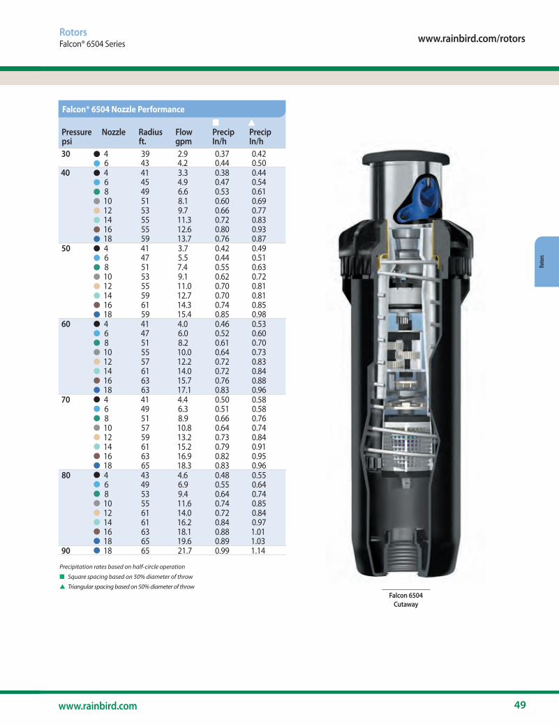
www.rainbird.com/rotors
49www.rainbird.com
Roto
rs
RotorsFalcon® 6504 Series
Precipitation rates based on half-circle operation
n Square spacing based on 50% diameter of throw
s Triangular spacing based on 50% diameter of throw
Pressurepsi
Nozzle Radius ft.
Flow gpm
n Precip In/h
s Precip In/h
30 4 39 2.9 0.37 0.426 43 4.2 0.44 0.50
40 4 41 3.3 0.38 0.446 45 4.9 0.47 0.548 49 6.6 0.53 0.6110 51 8.1 0.60 0.6912 53 9.7 0.66 0.7714 55 11.3 0.72 0.8316 55 12.6 0.80 0.9318 59 13.7 0.76 0.87
50 4 41 3.7 0.42 0.496 47 5.5 0.44 0.518 51 7.4 0.55 0.6310 53 9.1 0.62 0.7212 55 11.0 0.70 0.8114 59 12.7 0.70 0.8116 61 14.3 0.74 0.8518 59 15.4 0.85 0.98
60 4 41 4.0 0.46 0.536 47 6.0 0.52 0.608 51 8.2 0.61 0.7010 55 10.0 0.64 0.7312 57 12.2 0.72 0.8314 61 14.0 0.72 0.8416 63 15.7 0.76 0.8818 63 17.1 0.83 0.96
70 4 41 4.4 0.50 0.586 49 6.3 0.51 0.588 51 8.9 0.66 0.7610 57 10.8 0.64 0.7412 59 13.2 0.73 0.8414 61 15.2 0.79 0.9116 63 16.9 0.82 0.9518 65 18.3 0.83 0.96
80 4 43 4.6 0.48 0.556 49 6.9 0.55 0.648 53 9.4 0.64 0.7410 55 11.6 0.74 0.8512 61 14.0 0.72 0.8414 61 16.2 0.84 0.9716 63 18.1 0.88 1.0118 65 19.6 0.89 1.03
90 18 65 21.7 0.99 1.14
Falcon® 6504 Nozzle Performance
•••••••••••••••••••••••••••••••••••••••••••Falcon 6504
Cutaway

50 The Intelligent Use of Water.™
Rotors
RotorsFalcon® 6504 Series
Precipitation rates based on half-circle operation
n Square spacing based on 50% diameter of throw
s Triangular spacing based on 50% diameter of throw
Performance data collected in zero wind conditions
Performance data derived from tests that conform with ASABE Standards; ASABE S398.1. See page 198 for complete ASABE Test Certification Statement.
Pressurebar
Nozzle Radius m
Flow m3/h
Flow l/m
n Precip mm/h
s Precip mm/h
2.1 4 11.9 0.66 10.98 9 116 13.1 0.95 15.90 11 13
2.5 4 12.3 0.72 11.92 10 116 13.5 1.05 17.56 12 138 14.9 1.50 25.20 13 1610 15.5 1.84 30.60 15 1812 16.2 2.20 36.60 17 1914 16.8 2.57 42.60 18 2116 16.8 2.86 47.40 20 2418 18.0 3.11 51.60 19 22
3.0 4 12.5 0.78 13.02 10 126 14.1 1.16 19.34 12 138 15.1 1.56 26.04 14 1610 15.8 1.92 31.99 15 1812 16.4 2.31 38.44 17 2014 17.2 2.68 44.63 18 2116 17.4 3.00 49.95 20 2318 18.0 3.25 54.11 20 23
3.5 4 12.5 0.85 14.09 11 136 14.9 1.26 20.96 11 138 15.5 1.69 28.24 14 1610 16.2 2.08 34.70 16 1812 16.8 2.52 41.98 18 2114 18.0 2.91 48.45 18 2116 18.6 3.27 54.53 19 2218 18.1 3.53 58.78 22 25
4.0 4 12.5 0.89 14.91 11 136 14.4 1.34 22.33 13 158 15.5 1.83 30.44 15 1710 16.6 2.23 37.17 16 1912 17.3 2.72 45.28 18 2114 18.5 3.12 52.01 18 2116 19.1 3.50 58.37 19 2218 19.0 3.81 63.45 21 24
Falcon® 6504 Nozzle Performance METRIC
Pressurebar
Nozzle Radius m
Flow m3/h
Flow l/m
n Precip mm/h
s Precip mm/h
4.5 4 12.5 0.96 15.94 12 146 14.6 1.40 23.33 13 158 15.5 1.95 32.43 16 1910 17.1 2.37 39.44 16 1912 17.7 2.89 48.17 18 2114 18.6 3.32 55.38 19 2216 19.2 3.71 61.82 20 2318 19.5 4.03 67.12 21 24
5.0 4 12.7 1.01 16.84 13 156 14.9 1.47 24.50 13 158 15.7 2.05 34.16 17 1910 17.2 2.50 41.64 17 1912 18.1 3.04 50.72 19 2114 18.6 3.51 58.49 20 2316 19.2 3.91 65.11 21 2418 19.8 4.23 70.51 22 25
5.5 4 13.1 1.04 17.39 12 146 14.9 1.56 25.79 14 168 16.1 2.13 35.54 16 1910 16.8 2.63 43.84 19 2212 18.6 3.18 52.92 18 2114 18.6 3.67 61.23 21 2516 19.2 4.10 68.40 22 2618 19.8 4.44 74.07 23 26
6.0 18 19.8 4.79 79.77 24 286.2 18 19.8 4.93 82.13 25 29
••••••••••••••••••••••••••••••••••
••••••••••••••••••••••••••
Falcon® 6504 Rain Curtain™ Nozzles
Low Flow Kit - B81610
Standard Flow Kit - B81620
4
10 1412
16 18
8
6
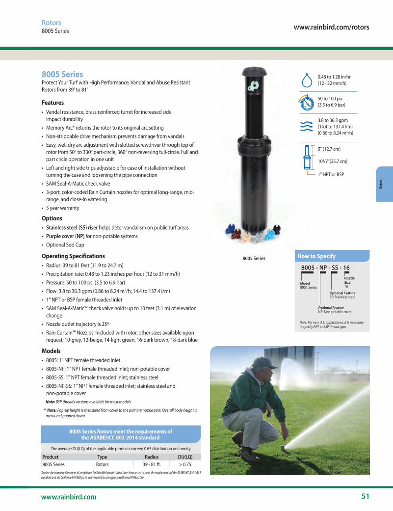
www.rainbird.com/rotors
51www.rainbird.com
Roto
rs
8005 Series
8005 SeriesProtect Your Turf with High Performance, Vandal and Abuse Resistant Rotors from 39' to 81'
Features• Vandal resistance, brass reinforced turret for increased side
impact durability• Memory Arc® returns the rotor to its original arc setting • Non-strippable drive mechanism prevents damage from vandals• Easy, wet, dry arc adjustment with slotted screwdriver through top of
rotor from 50° to 330° part-circle, 360° non-reversing full-circle. Full and part circle operation in one unit
• Left and right side trips adjustable for ease of installation without turning the case and loosening the pipe connection
• SAM Seal-A-Matic check valve• 3-port, color-coded Rain Curtain nozzles for optimal long-range, mid-
range, and close-in watering• 5 year warranty
Options• Stainless steel (SS) riser helps deter vandalism on public turf areas• Purple cover (NP) for non-potable systems• Optional Sod Cup
Operating Specifications • Radius: 39 to 81 feet (11.9 to 24.7 m)• Precipitation rate: 0.48 to 1.23 inches per hour (12 to 31 mm/h)• Pressure: 50 to 100 psi (3.5 to 6.9 bar)• Flow: 3.8 to 36.3 gpm (0.86 to 8.24 m3/h; 14.4 to 137.4 l/m)• 1" NPT or BSP female threaded inlet• SAM Seal-A-Matic™ check valve holds up to 10 feet (3.1 m) of elevation
change• Nozzle outlet trajectory is 25º• Rain Curtain™ Nozzles: Included with rotor, other sizes available upon
request; 10-grey, 12-beige, 14-light green, 16-dark brown, 18-dark blue
Models• 8005: 1" NPT female threaded inlet• 8005-NP: 1" NPT female threaded inlet; non-potable cover• 8005-SS: 1" NPT female threaded inlet; stainless steel• 8005-NP-SS: 1" NPT female threaded inlet; stainless steel and
non-potable cover Note: BSP threads versions available for most models
** Note: Pop-up height is measured from cover to the primary nozzle port. Overall body height is measured popped down
Rotors8005 Series
0.48 to 1.28 in/hr (12 - 32 mm/h)
50 to 100 psi (3.5 to 6.9 bar)
3.8 to 36.3 gpm (14.4 to 137.4 l/m) (0.86 to 8.24 m3/h)
5" (12.7 cm)
101/8" (25.7 cm)
1" NPT or BSP
8005 - NP - SS - 16
Model8005 Series
Optional Feature NP: Non-potable cover
Optional Feature SS: Stainless steel
Nozzle Size16
Note: For non-U.S. applications, it is necessary to specify NPT or BSP thread type.
How to Specify
The average DU(LQ) of the applicable products exceed 0.65 distribution uniformity.
Product Type Radius DU(LQ) 8005 Series Rotors 39 - 81 ft. > 0.75To view the complete document of compliance for Rain Bird products that have been tested to meet the requirements of the ASABE/ICC 802-2014 standard and the California MWELO go to: www.rainbird.com/agency/california/MWELO.htm
8005 Series Rotors meet the requirements of the ASABE/ICC 802-2014 standard

52 The Intelligent Use of Water.™
Rotors
Rotors8005 Series
Precipitation rates based on half-circle operation
n Square spacing based on 50% diameter of throw
s Triangular spacing based on 50% diameter of throw
Performance data collected in zero wind conditions
Performance data derived from tests that conform with ASABE Standards; ASABE S398.1. See page 186 for complete ASABE Test Certification Statement.
Sod Cup for 8005
Pressurepsi
Nozzle Radius ft.
Flow gpm
n Precip In/h
s Precip In/h
50 04 39 3.8 0.48 0.5606 45 5.6 0.53 0.6208 49 6.6 0.53 0.6110 53 9.3 0.64 0.7412 57 11.1 0.66 0.7614 59 12.6 0.70 0.8116 61 14.3 0.74 0.8518 63 16.1 0.78 0.9020 65 18.6 0.85 0.9822 65 20.7 0.94 1.0924 63 22.3 1.08 1.2526 65 24.3 1.11 1.28
60 04 39 3.8 0.48 0.5606 45 6.1 0.58 0.6708 49 8.4 0.67 0.7810 53 10.1 0.69 0.8012 59 12.0 0.66 0.7714 61 14.3 0.74 0.8516 65 15.9 0.72 0.8418 65 17.8 0.81 0.9420 67 20.1 0.86 1.0022 71 23.2 0.89 1.0224 69 24.7 1.00 1.1526 73 26.7 0.96 1.11
70 04 39 4.7 0.60 0.6906 45 6.7 0.64 0.7408 49 9.0 0.72 0.8310 55 11.1 0.71 0.8212 59 13.2 0.73 0.8414 63 15.3 0.74 0.8616 67 17.2 0.74 0.8518 67 19.3 0.83 0.9620 71 22.0 0.84 0.9722 73 25.2 0.91 1.0524 75 27.0 0.92 1.0726 75 29.4 1.01 1.16
80 04 39 5.0 0.63 0.7306 45 7.1 0.68 0.7808 49 9.8 0.79 0.9110 55 11.8 0.75 0.8712 61 14.2 0.73 0.8514 63 16.4 0.80 0.9216 67 18.6 0.80 0.9218 69 20.9 0.85 0.9820 71 23.9 0.91 1.0522 75 27.3 0.93 1.0824 77 29.2 0.95 1.1026 79 31.5 0.97 1.12
8005 Nozzle Performance
Pressurepsi
Nozzle Radius ft.
Flow gpm
n Precip In/h
s Precip In/h
90 12 61 14.7 0.76 0.8814 65 17.9 0.82 0.9416 69 20.0 0.81 0.9318 71 22.2 0.85 0.9820 73 25.3 0.91 1.0622 75 29.1 1.00 1.1524 79 31.0 0.96 1.1026 79 33.7 1.04 1.20
100 20 75 26.8 0.85 0.9722 77 30.7 1.00 1.1524 79 32.8 1.01 1.1726 81 36.3 1.07 1.23
••••••••••• ••••••••••• ••••••••••• •••••••••••
••••••• •••
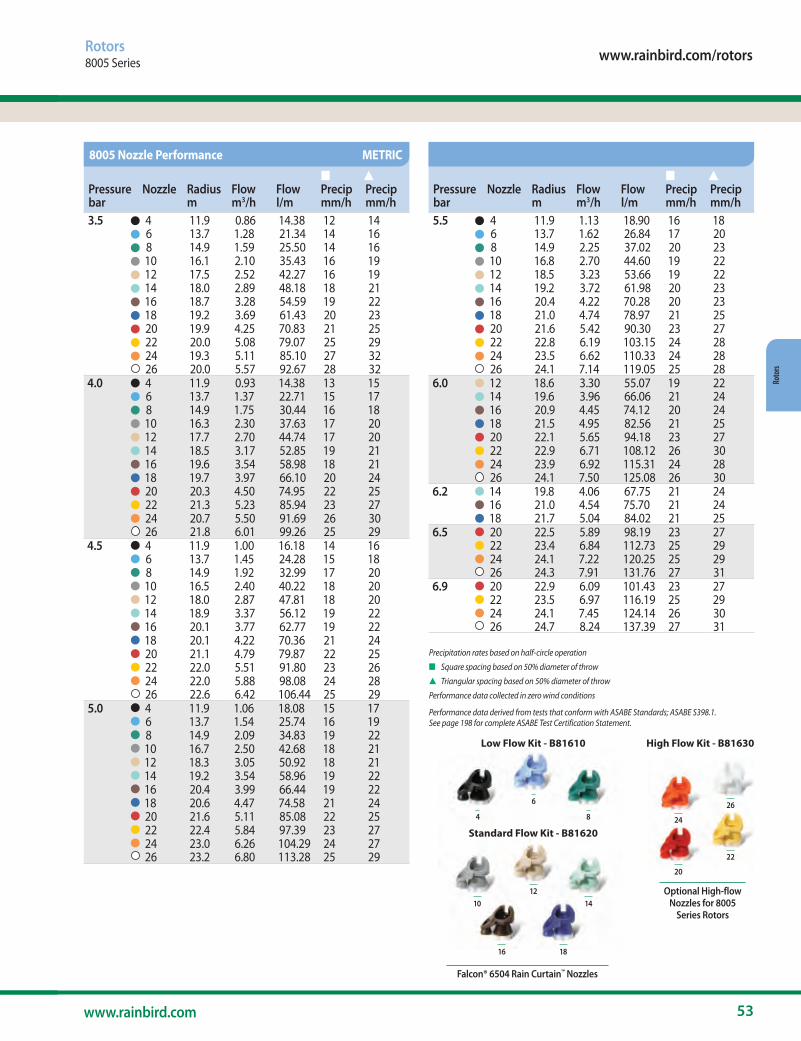
www.rainbird.com/rotors
53www.rainbird.com
Roto
rs
Rotors8005 Series
Precipitation rates based on half-circle operation
n Square spacing based on 50% diameter of throw
s Triangular spacing based on 50% diameter of throw
Performance data collected in zero wind conditions
Performance data derived from tests that conform with ASABE Standards; ASABE S398.1. See page 198 for complete ASABE Test Certification Statement.
Pressurebar
Nozzle Radius m
Flow m3/h
Flow l/m
n Precip mm/h
s Precip mm/h
3.5 4 11.9 0.86 14.38 12 146 13.7 1.28 21.34 14 168 14.9 1.59 25.50 14 1610 16.1 2.10 35.43 16 1912 17.5 2.52 42.27 16 1914 18.0 2.89 48.18 18 2116 18.7 3.28 54.59 19 2218 19.2 3.69 61.43 20 2320 19.9 4.25 70.83 21 2522 20.0 5.08 79.07 25 2924 19.3 5.11 85.10 27 3226 20.0 5.57 92.67 28 32
4.0 4 11.9 0.93 14.38 13 156 13.7 1.37 22.71 15 178 14.9 1.75 30.44 16 1810 16.3 2.30 37.63 17 2012 17.7 2.70 44.74 17 2014 18.5 3.17 52.85 19 2116 19.6 3.54 58.98 18 2118 19.7 3.97 66.10 20 2420 20.3 4.50 74.95 22 2522 21.3 5.23 85.94 23 2724 20.7 5.50 91.69 26 3026 21.8 6.01 99.26 25 29
4.5 4 11.9 1.00 16.18 14 166 13.7 1.45 24.28 15 188 14.9 1.92 32.99 17 2010 16.5 2.40 40.22 18 2012 18.0 2.87 47.81 18 2014 18.9 3.37 56.12 19 2216 20.1 3.77 62.77 19 2218 20.1 4.22 70.36 21 2420 21.1 4.79 79.87 22 2522 22.0 5.51 91.80 23 2624 22.0 5.88 98.08 24 2826 22.6 6.42 106.44 25 29
5.0 4 11.9 1.06 18.08 15 176 13.7 1.54 25.74 16 198 14.9 2.09 34.83 19 2210 16.7 2.50 42.68 18 2112 18.3 3.05 50.92 18 2114 19.2 3.54 58.96 19 2216 20.4 3.99 66.44 19 2218 20.6 4.47 74.58 21 2420 21.6 5.11 85.08 22 2522 22.4 5.84 97.39 23 2724 23.0 6.26 104.29 24 2726 23.2 6.80 113.28 25 29
8005 Nozzle Performance METRIC
Pressurebar
Nozzle Radius m
Flow m3/h
Flow l/m
n Precip mm/h
s Precip mm/h
5.5 4 11.9 1.13 18.90 16 186 13.7 1.62 26.84 17 208 14.9 2.25 37.02 20 2310 16.8 2.70 44.60 19 2212 18.5 3.23 53.66 19 2214 19.2 3.72 61.98 20 2316 20.4 4.22 70.28 20 2318 21.0 4.74 78.97 21 2520 21.6 5.42 90.30 23 2722 22.8 6.19 103.15 24 2824 23.5 6.62 110.33 24 2826 24.1 7.14 119.05 25 28
6.0 12 18.6 3.30 55.07 19 2214 19.6 3.96 66.06 21 2416 20.9 4.45 74.12 20 2418 21.5 4.95 82.56 21 2520 22.1 5.65 94.18 23 2722 22.9 6.71 108.12 26 3024 23.9 6.92 115.31 24 2826 24.1 7.50 125.08 26 30
6.2 14 19.8 4.06 67.75 21 2416 21.0 4.54 75.70 21 2418 21.7 5.04 84.02 21 25
6.5 20 22.5 5.89 98.19 23 2722 23.4 6.84 112.73 25 2924 24.1 7.22 120.25 25 2926 24.3 7.91 131.76 27 31
6.9 20 22.9 6.09 101.43 23 2722 23.5 6.97 116.19 25 2924 24.1 7.45 124.14 26 3026 24.7 8.24 137.39 27 31
••••••••••• ••••••••••• ••••••••••• •••••••••••
••••••••••• ••••••• •••••• •••
Falcon® 6504 Rain Curtain™ Nozzles
Low Flow Kit - B81610
Standard Flow Kit - B81620
4
10 1412
16 18
8
6
Optional High-flow Nozzles for 8005
Series Rotors
High Flow Kit - B81630
20
22
24
26
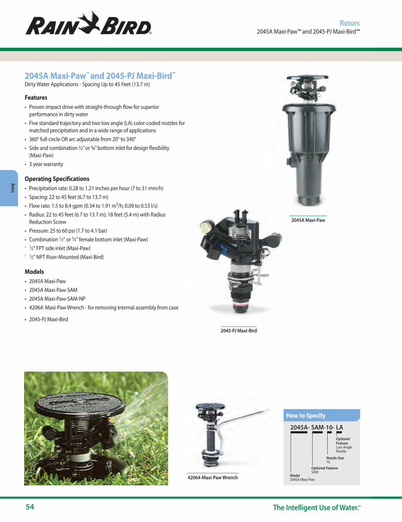
54 The Intelligent Use of Water.™
Rotors
2045-PJ Maxi-Bird
Rotors2045A Maxi-Paw™ and 2045-PJ Maxi-Bird™
2045A Maxi-Paw™ and 2045-PJ Maxi-Bird™
Dirty Water Applications - Spacing Up to 45 Feet (13.7 m)
Features• Proven impact drive with straight-through flow for superior
performance in dirty water• Five standard trajectory and two low angle (LA) color-coded nozzles for
matched precipitation and in a wide range of applications• 360° full-circle OR arc adjustable from 20° to 340°• Side and combination ½” or ¾” bottom inlet for design flexibility
(Maxi-Paw)• 3 year warranty
Operating Specifications• Precipitation rate: 0.28 to 1.21 inches per hour (7 to 31 mm/h)• Spacing: 22 to 45 feet (6.7 to 13.7 m)• Flow rate: 1.5 to 8.4 gpm (0.34 to 1.91 m3/h; 0.09 to 0.53 l/s)• Radius: 22 to 45 feet (6.7 to 13.7 m); 18 feet (5.4 m) with Radius
Reduction Screw• Pressure: 25 to 60 psi (1.7 to 4.1 bar)• Combination 1⁄2" or 3⁄4" female bottom inlet (Maxi-Paw)• 1⁄2" FPT side inlet (Maxi-Paw)• 1⁄2" NPT Riser-Mounted (Maxi-Bird)
Models• 2045A Maxi-Paw• 2045A Maxi-Paw-SAM• 2045A Maxi-Paw-SAM-NP• 42064: Maxi-Paw Wrench - for removing internal assembly from case
• 2045-PJ Maxi-Bird
2045A Maxi-Paw
2045A- SAM-10- LA
OptionalFeatureLow AngleNozzle
Nozzle Size10
Optional FeatureSAM
Model 2045A Maxi-Paw 42064-Maxi-Paw Wrench
How to Specify
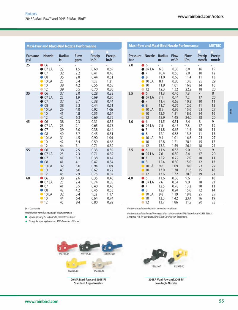
www.rainbird.com/rotors
55www.rainbird.com
Roto
rs
Rotors2045A Maxi-Paw™ and 2045-PJ Maxi-Bird™
LA = Low Angle
Precipitation rates based on half-circle operation
n Square spacing based on 50% diameter of throw
s Triangular spacing based on 50% diameter of throw
Performance data collected in zero wind conditions
Performance data derived from tests that conform with ASABE Standards; ASABE S398.1. See page 198 for complete ASABE Test Certification Statement.
2045A Maxi-Paw and 2045-PJ Standard Angle Nozzles
2045A Maxi-Paw and 2045-PJ Low Angle Nozzles
206592-06 206592-08
206592-10
115902-07 115902-10
206592-07
206592-12
Pressurepsi
Nozzle Radius ft.
Flow gpm
n Precip In/h
s Precip In/h
25 06 - - - -07 LA 22 1.5 0.60 0.6907 32 2.2 0.41 0.4808 35 2.8 0.44 0.5110 LA 25 3.4 1.05 1.2110 38 4.2 0.56 0.6512 39 5.5 0.70 0.80
35 06 37 2.0 0.28 0.3207 LA 23 1.9 0.69 0.8007 37 2.7 0.38 0.4408 38 3.3 0.44 0.5110 LA 29 4.0 0.92 1.0610 41 4.8 0.55 0.6412 42 6.3 0.69 0.79
45 06 38 2.3 0.31 0.3507 LA 25 2.1 0.65 0.7507 39 3.0 0.38 0.4408 40 3.7 0.45 0.5110 LA 31 4.5 0.90 1.0410 42 5.4 0.59 0.6812 44 7.1 0.71 0.82
55 06 38 2.5 0.33 0.3907 LA 25 2.3 0.71 0.8207 41 3.3 0.38 0.4408 41 4.1 0.47 0.5410 LA 32 5.0 0.94 1.0910 43 6.0 0.62 0.7212 45 7.9 0.75 0.87
60 06 38 2.6 0.35 0.4007 LA 25 2.4 0.74 0.8507 41 3.5 0.40 0.4608 42 4.2 0.46 0.5310 LA 32 5.4 1.02 1.1710 44 6.4 0.64 0.7412 45 8.4 0.80 0.92
Maxi-Paw and Maxi-Bird Nozzle Performance
Pressurebar
Nozzle Radius m
Flow m3/h
Flow l/m
n Precip mm/h
s Precip mm/h
2.0 6 - - - - -07 LA 6.8 0.38 6.0 16 197 10.4 0.55 9.0 10 128 11.0 0.68 11.4 11 1310 LA 8.1 0.83 13.8 25 2910 11.9 1.01 16.8 14 1612 12.3 1.32 22.2 18 20
2.5 6 11.3 0.46 7.8 7 807 LA 7.1 0.44 7.2 17 207 11.4 0.62 10.2 10 118 11.7 0.76 12.6 11 1310 LA 8.9 0.92 15.6 23 2710 12.5 1.11 18.6 14 1612 12.9 1.45 24.0 18 20
3.0 6 11.5 0.51 8.4 8 907 LA 7.5 0.47 7.8 17 197 11.8 0.67 11.4 10 118 12.1 0.83 13.8 11 1310 LA 9.4 1.01 16.8 23 2710 12.8 1.21 20.4 15 1712 13.3 1.59 26.4 18 21
3.5 6 11.6 0.55 9.0 8 907 LA 7.6 0.50 8.4 17 207 12.2 0.72 12.0 10 118 12.4 0.89 15.0 12 1310 LA 9.6 1.09 18.0 23 2710 13.0 1.30 21.6 15 1812 13.6 1.72 28.8 19 21
4.0 6 11.6 0.58 9.6 9 1007 LA 7.6 0.54 9.0 18 217 12.5 0.78 13.2 10 118 12.7 0.94 15.6 12 1410 LA 9.8 1.19 19.8 25 2910 13.3 1.42 23.4 16 1912 13.7 1.86 31.2 20 23
Maxi-Paw and Maxi-Bird Nozzle Performance METRIC
•••••••••••••••••••••••••••••••••••
•••••••••••••••••••••••••••••••••••
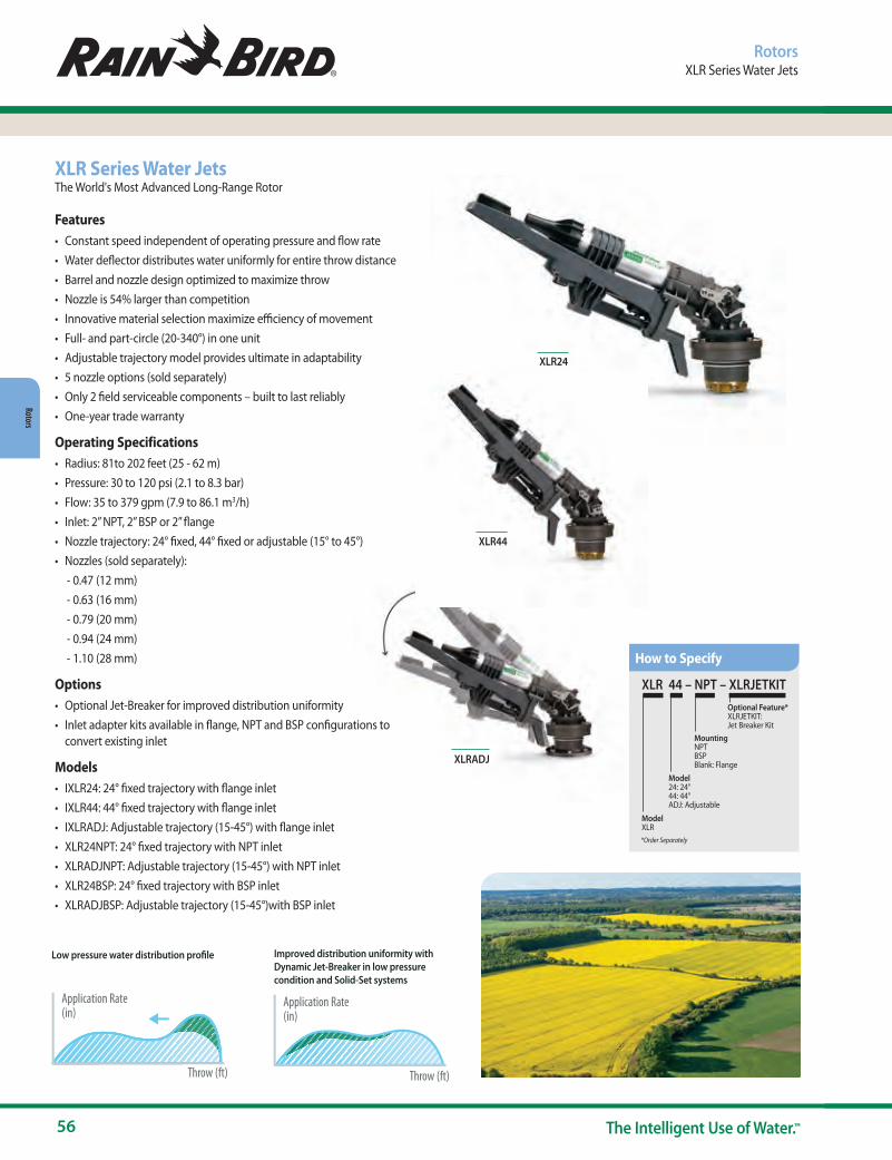
56 The Intelligent Use of Water.™
Rotors
XLRADJ
XLR Series Water JetsThe World's Most Advanced Long-Range Rotor
Features• Constant speed independent of operating pressure and flow rate• Water deflector distributes water uniformly for entire throw distance• Barrel and nozzle design optimized to maximize throw• Nozzle is 54% larger than competition• Innovative material selection maximize efficiency of movement• Full- and part-circle (20-340°) in one unit• Adjustable trajectory model provides ultimate in adaptability • 5 nozzle options (sold separately)• Only 2 field serviceable components – built to last reliably• One-year trade warranty
Operating Specifications• Radius: 81to 202 feet (25 - 62 m)• Pressure: 30 to 120 psi (2.1 to 8.3 bar)• Flow: 35 to 379 gpm (7.9 to 86.1 m3/h)• Inlet: 2” NPT, 2” BSP or 2” flange• Nozzle trajectory: 24° fixed, 44° fixed or adjustable (15° to 45°)• Nozzles (sold separately):
- 0.47 (12 mm)- 0.63 (16 mm)- 0.79 (20 mm)- 0.94 (24 mm)- 1.10 (28 mm)
Options• Optional Jet-Breaker for improved distribution uniformity• Inlet adapter kits available in flange, NPT and BSP configurations to
convert existing inlet
Models• IXLR24: 24° fixed trajectory with flange inlet• IXLR44: 44° fixed trajectory with flange inlet• IXLRADJ: Adjustable trajectory (15-45°) with flange inlet• XLR24NPT: 24° fixed trajectory with NPT inlet• XLRADJNPT: Adjustable trajectory (15-45°) with NPT inlet• XLR24BSP: 24° fixed trajectory with BSP inlet• XLRADJBSP: Adjustable trajectory (15-45°)with BSP inlet
RotorsXLR Series Water Jets
XLR24
XLR 44 – NPT – XLRJETKIT
Model XLR
Model24: 24°44: 44°ADJ: Adjustable
MountingNPTBSPBlank: Flange
Optional Feature*XLRJETKIT: Jet Breaker Kit
*Order Separately
How to Specify
XLR44
Application Rate(in)
Throw (ft)
Low pressure water distribution profile
Application Rate(in)
Throw (ft)
Improved distribution uniformity with Dynamic Jet-Breaker in low pressure condition and Solid-Set systems
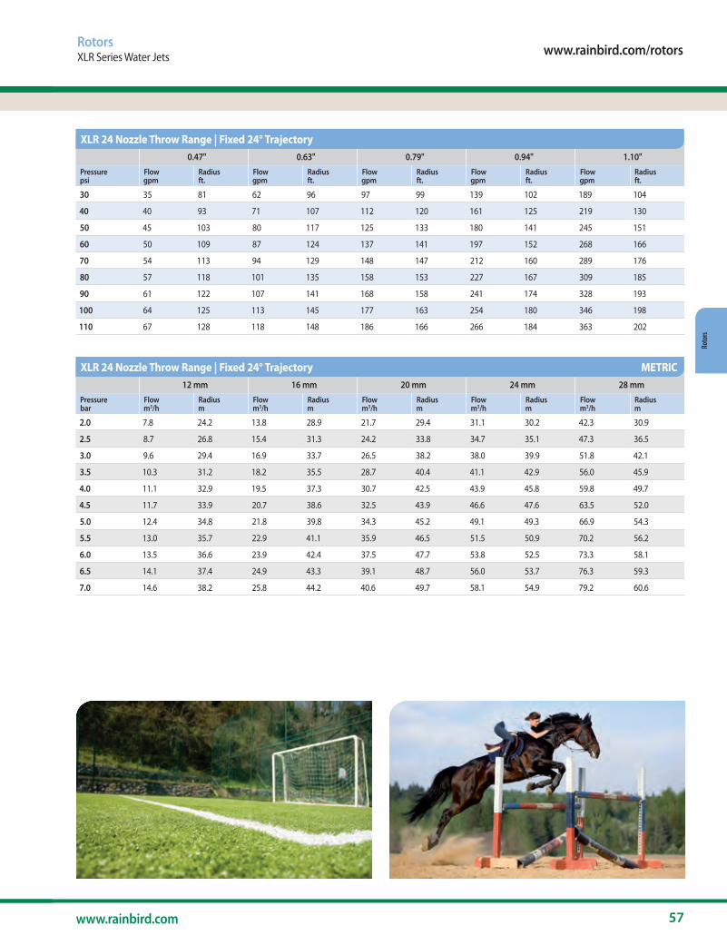
www.rainbird.com/rotors
57www.rainbird.com
Roto
rs
RotorsXLR Series Water Jets
0.47" 0.63" 0.79" 0.94" 1.10"Pressure psi
Flow gpm
Radiusft.
Flow gpm
Radiusft.
Flow gpm
Radiusft.
Flow gpm
Radiusft.
Flow gpm
Radiusft.
30 35 81 62 96 97 99 139 102 189 104
40 40 93 71 107 112 120 161 125 219 130
50 45 103 80 117 125 133 180 141 245 151
60 50 109 87 124 137 141 197 152 268 166
70 54 113 94 129 148 147 212 160 289 176
80 57 118 101 135 158 153 227 167 309 185
90 61 122 107 141 168 158 241 174 328 193
100 64 125 113 145 177 163 254 180 346 198
110 67 128 118 148 186 166 266 184 363 202
XLR 24 Nozzle Throw Range | Fixed 24° Trajectory
12 mm 16 mm 20 mm 24 mm 28 mmPressure bar
Flow m3/h
Radiusm
Flow m3/h
Radiusm
Flow m3/h
Radiusm
Flow m3/h
Radiusm
Flow m3/h
Radiusm
2.0 7.8 24.2 13.8 28.9 21.7 29.4 31.1 30.2 42.3 30.9
2.5 8.7 26.8 15.4 31.3 24.2 33.8 34.7 35.1 47.3 36.5
3.0 9.6 29.4 16.9 33.7 26.5 38.2 38.0 39.9 51.8 42.1
3.5 10.3 31.2 18.2 35.5 28.7 40.4 41.1 42.9 56.0 45.9
4.0 11.1 32.9 19.5 37.3 30.7 42.5 43.9 45.8 59.8 49.7
4.5 11.7 33.9 20.7 38.6 32.5 43.9 46.6 47.6 63.5 52.0
5.0 12.4 34.8 21.8 39.8 34.3 45.2 49.1 49.3 66.9 54.3
5.5 13.0 35.7 22.9 41.1 35.9 46.5 51.5 50.9 70.2 56.2
6.0 13.5 36.6 23.9 42.4 37.5 47.7 53.8 52.5 73.3 58.1
6.5 14.1 37.4 24.9 43.3 39.1 48.7 56.0 53.7 76.3 59.3
7.0 14.6 38.2 25.8 44.2 40.6 49.7 58.1 54.9 79.2 60.6
XLR 24 Nozzle Throw Range | Fixed 24° Trajectory METRIC

58 The Intelligent Use of Water.™
Rotors
RotorsXLR Series Water Jets
The performance data were obtained under ideal testing conditions and may be adversely affected by wind and other factors. Pressure refers to pressure at nozzle.A lowered trajectory angle improves the irrigation efficiency in windy conditions. For every 3° drop of the trajectory angle the throw is reduced by aprrox. 3 to 4%Radius = radius of throw in feet. Nozzle at 5 feet above ground level. Height = maximum stream height in meters above nozzle.
• For every 3° drop of the trajectory angle, the throw is reduced by approximately 3 to 4%. • Use the XLR 24 Nozzle Throw Range Table for your pressure and nozzle diameter.
0.47" 0.63" 0.79" 0.94" 1.10"
Pressure psi
Flow gpm
Radiusft.
Height ft.
Flow gpm
Radiusft.
Height ft.
Flow gpm
Radiusft.
Height ft.
Flow gpm
Radiusft.
Height ft.
Flow gpm
Radiusft.
Height ft.
40 40 82 37 71 98 38 112 113 39 161 121 40 219 128 41
50 45 91 43 80 108 45 125 125 47 180 135 48 245 144 50
60 50 97 48 87 116 51 137 135 54 197 146 56 268 157 58
70 54 102 51 94 122 55 148 142 59 212 154 62 289 165 66
80 57 107 54 101 127 59 158 148 64 227 160 68 309 172 72
90 61 110 56 107 132 62 168 153 68 241 165 72 328 177 77
100 64 113 58 113 135 65 177 157 71 254 169 76 346 182 82
110 67 115 60 118 137 66 186 160 73 266 172 79 363 185 85
120 70 116 61 124 139 68 194 161 75 278 175 81 379 188 87
XLR 44 Nozzle Throw Range / Fixed 44° Trajectory
12 mm 16 mm 20 mm 24 mm 28 mm
Pressure bar
Flow m3/h
Radiusm
Height m
Flow m3/h
Radiusm
Height m
Flow m3/h
Radiusm
Height m
Flow m3/h
Radiusm
Height m
Flow m3/h
Radiusm
Height m
3.0 9.6 26.1 11.9 16.9 31.0 12.3 26.5 35.9 12.7 38.0 38.5 13.1 51.8 41.0 13.4
3.5 10.3 27.7 13.1 18.2 33.0 13.7 28.7 38.2 14.4 41.1 41.1 14.9 56.0 44.0 15.3
4.0 11.1 29.3 14.3 19.5 34.9 15.1 30.7 40.6 16.0 43.9 43.8 16.6 59.8 47.1 17.3
4.5 11.7 30.4 15.1 20.7 36.3 16.1 32.5 42.2 17.2 46.6 45.6 18.1 63.5 49.0 18.9
5.0 12.4 31.5 15.9 21.8 37.7 17.1 34.3 43.9 18.4 49.1 47.4 19.5 66.9 51.0 20.5
5.5 13.0 32.4 16.4 22.9 38.7 17.9 35.9 45.1 19.4 51.5 48.7 20.6 70.2 52.3 21.8
6.0 13.5 33.3 17.0 23.9 39.8 18.7 37.5 46.3 20.3 53.8 50.0 21.7 73.3 53.6 23.0
6.5 14.1 33.9 17.4 24.9 40.5 19.2 39.1 47.1 21.0 56.0 50.9 22.5 76.3 54.6 24.1
7.0 14.6 34.5 17.9 25.8 41.2 19.8 40.6 48.0 21.7 58.1 51.8 23.4 79.2 55.6 25.1
7.5 15.1 34.8 18.1 26.7 41.7 20.2 42.0 48.5 22.2 60.1 52.4 24.0 82.0 56.3 25.8
8.0 15.6 35.2 18.4 27.6 42.1 20.6 43.4 49.0 22.7 62.1 53.0 24.6 84.6 57.0 26.4
XLR 44 Nozzle Throw Range / Fixed 44° Trajectory METRIC
XLR ADJ Nozzle Throw Range | Adjustable Trajectory
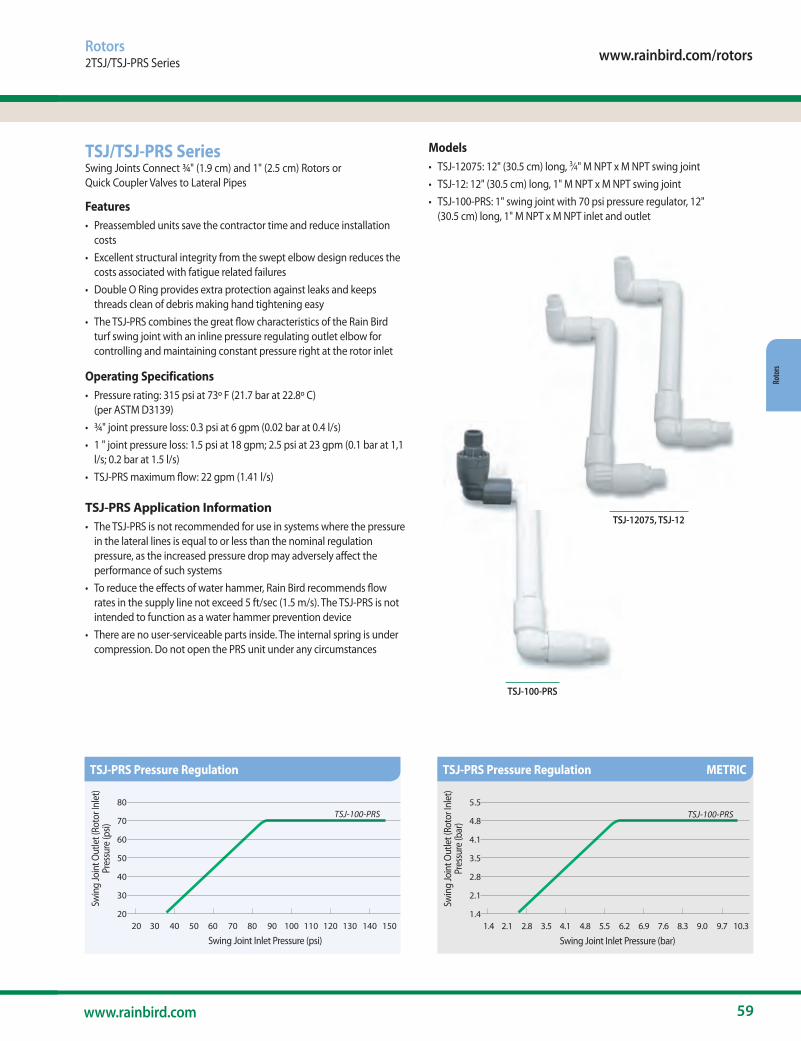
www.rainbird.com/rotors
59www.rainbird.com
Roto
rs
TSJ-100-PRS
TSJ-12075, TSJ-12
Rotors2TSJ/TSJ-PRS Series
TSJ/TSJ-PRS SeriesSwing Joints Connect ¾" (1.9 cm) and 1" (2.5 cm) Rotors or Quick Coupler Valves to Lateral Pipes
Features• Preassembled units save the contractor time and reduce installation
costs• Excellent structural integrity from the swept elbow design reduces the
costs associated with fatigue related failures• Double O Ring provides extra protection against leaks and keeps
threads clean of debris making hand tightening easy• The TSJ-PRS combines the great flow characteristics of the Rain Bird
turf swing joint with an inline pressure regulating outlet elbow for controlling and maintaining constant pressure right at the rotor inlet
Operating Specifications• Pressure rating: 315 psi at 73º F (21.7 bar at 22.8º C)
(per ASTM D3139)• ¾" joint pressure loss: 0.3 psi at 6 gpm (0.02 bar at 0.4 l/s)• 1 " joint pressure loss: 1.5 psi at 18 gpm; 2.5 psi at 23 gpm (0.1 bar at 1,1
l/s; 0.2 bar at 1.5 l/s)• TSJ-PRS maximum flow: 22 gpm (1.41 l/s)
TSJ-PRS Application Information• The TSJ-PRS is not recommended for use in systems where the pressure
in the lateral lines is equal to or less than the nominal regulation pressure, as the increased pressure drop may adversely affect the performance of such systems
• To reduce the effects of water hammer, Rain Bird recommends flow rates in the supply line not exceed 5 ft/sec (1.5 m/s). The TSJ-PRS is not intended to function as a water hammer prevention device
• There are no user-serviceable parts inside. The internal spring is under compression. Do not open the PRS unit under any circumstances
Swin
g Jo
int O
utle
t (Ro
tor I
nlet
)Pr
essu
re (p
si)
TSJ-100-PRS
Swing Joint Inlet Pressure (psi)
80
70
60
50
40
30
20 20 30 40 50 60 70 80 90 100 110 120 130 140 150
Swin
g Jo
int O
utle
t (Ro
tor I
nlet
)Pr
essu
re (b
ar)
TSJ-100-PRS
5.5
4.8
4.1
3.5
2.8
2.1
1.4 1.4 2.1 2.8 3.5 4.1 4.8 5.5 6.2 6.9 7.6 8.3 9.0 9.7 10.3
Swing Joint Inlet Pressure (bar)
Models• TSJ-12075: 12" (30.5 cm) long, 3⁄4" M NPT x M NPT swing joint• TSJ-12: 12" (30.5 cm) long, 1" M NPT x M NPT swing joint• TSJ-100-PRS: 1" swing joint with 70 psi pressure regulator, 12"
(30.5 cm) long, 1" M NPT x M NPT inlet and outlet
TSJ-PRS Pressure Regulation TSJ-PRS Pressure Regulation METRIC
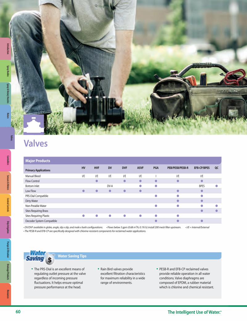
• DV/DVF available in globe, angle, slip x slip, and male x barb configurations. • Flows below 3 gpm (0.68 m3/h; 0.19 l/s) install 200 mesh filter upstream. • I/E = Internal/External • The PESB-R and EFB-CP are specifically designed with chlorine-resistant components for reclaimed water applications.
Valves
• The PRS-Dial is an excellent means of regulating outlet pressure at the valve regardless of incoming pressure fluctuations. It helps ensure optimal pressure performance at the head.
• Rain Bird valves provide excellent filtration characteristics for maximum reliability in a wide range of environments.
• PESB-R and EFB-CP reclaimed valves provide reliable operation in all water conditions. Valve diaphragms are composed of EPDM, a rubber material which is chlorine and chemical resistant.
Water Saving Tips
HV HVF DV DVF ASVF PGA PEB/PESB/PESB-R EFB-CP/BPES QCPrimary Applications
Manual Bleed I/E I/E I/E I/E I/E I I/E I/E
Flow Control l l l l l lBottom Inlet DV-A l l BPES lLow Flow l l l l l l lPRS-Dial Compatible l l lDirty Water l lNon-Potable Water l l l lSites Requiring Brass l lSites Requiring Plastic l l l l l l lDecoder System Compatible l l l
Major Products
60 The Intelligent Use of Water.™
Spray & Rotary NozzlesRotors
ValvesControllers
Sensors & Meters
Central ControlsDrip Irrigation
Pumps & Filtration
Drainage ProductsResources
IntroductionSpray Bodies
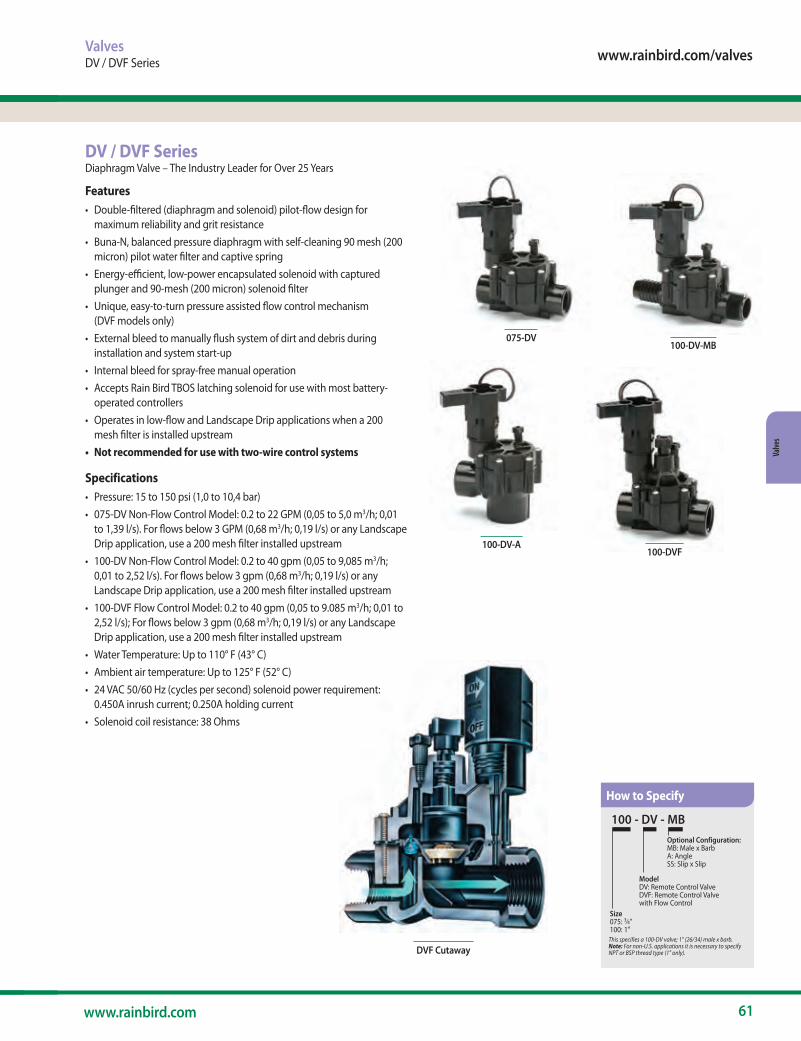
www.rainbird.com/valves
61www.rainbird.com
Valve
s
DVF Cutaway
100-DVF
100-DV-MB
DV / DVF SeriesDiaphragm Valve – The Industry Leader for Over 25 Years
Features• Double-filtered (diaphragm and solenoid) pilot-flow design for
maximum reliability and grit resistance• Buna-N, balanced pressure diaphragm with self-cleaning 90 mesh (200
micron) pilot water filter and captive spring• Energy-efficient, low-power encapsulated solenoid with captured
plunger and 90-mesh (200 micron) solenoid filter• Unique, easy-to-turn pressure assisted flow control mechanism
(DVF models only)• External bleed to manually flush system of dirt and debris during
installation and system start-up• Internal bleed for spray-free manual operation • Accepts Rain Bird TBOS latching solenoid for use with most battery-
operated controllers • Operates in low-flow and Landscape Drip applications when a 200
mesh filter is installed upstream• Not recommended for use with two-wire control systems
Specifications• Pressure: 15 to 150 psi (1,0 to 10,4 bar) • 075-DV Non-Flow Control Model: 0.2 to 22 GPM (0,05 to 5,0 m3/h; 0,01
to 1,39 l/s). For flows below 3 GPM (0,68 m3/h; 0,19 l/s) or any Landscape Drip application, use a 200 mesh filter installed upstream
• 100-DV Non-Flow Control Model: 0.2 to 40 gpm (0,05 to 9,085 m3/h; 0,01 to 2,52 l/s). For flows below 3 gpm (0,68 m3/h; 0,19 l/s) or any Landscape Drip application, use a 200 mesh filter installed upstream
• 100-DVF Flow Control Model: 0.2 to 40 gpm (0,05 to 9.085 m3/h; 0,01 to 2,52 l/s); For flows below 3 gpm (0,68 m3/h; 0,19 l/s) or any Landscape Drip application, use a 200 mesh filter installed upstream
• Water Temperature: Up to 110° F (43° C) • Ambient air temperature: Up to 125° F (52° C) • 24 VAC 50/60 Hz (cycles per second) solenoid power requirement:
0.450A inrush current; 0.250A holding current • Solenoid coil resistance: 38 Ohms
ValvesDV / DVF Series
100 - DV - MB
This specifies a 100-DV valve; 1" (26/34) male x barb. Note: For non-U.S. applications it is necessary to specify NPT or BSP thread type (1" only).
ModelDV: Remote Control ValveDVF: Remote Control Valve with Flow Control
Size 075: 3⁄4" 100: 1"
Optional Configuration:MB: Male x BarbA: AngleSS: Slip x Slip
100-DV-A
075-DV
How to Specify

62 The Intelligent Use of Water.™
Valves
Note: DV/DVF Male x barb not recommended for
flows exceeding 30 gpm (6.81 m3/h, 113.56 l/m)
DimensionsDV Valves• Height: 41⁄2" (11.4 cm) • Height (Angle): 51⁄2" (14 cm)• Length: 43⁄8" (11.1 cm) • Length (Angle): 33⁄4" (9.5 cm)• Length (MB): 53⁄4" (14.6 cm)• Width: 31⁄3" (8.4 cm)
DVF Valves• Height: 53⁄5" (14.2 cm)• Length: 43⁄8" (11.1 cm)• Length (MB): 53⁄4" (14.6 cm)• Width: 31⁄3" (8.4 cm)
Models• 075-DV: 3⁄4" NPT• 100-DV: 1" NPT female x female*• 100-DV-SS: 1" slip x slip• 100-DV-A: 1" NPT female x female• 100-DV-MB: 1" male x barb• 100-DVF: 1" NPT female x female*• 100-DVF-SS: 1" slip x slip• 100-DVF-MB: 1" male x barb * Available with BSP threads
Recommendations
1. Rain Bird recommends flow rates that result in discharge velocities in the supply line not to exceed 7.5 ft/sec (2.3 m/s) in order to reduce the effects of water hammer.
2. Rain Bird residential valves cannot be used with PRS pressure regulating modules.
3. Not recommended for use with two-wire systems.
DV / DVF Series (cont.)
ValvesDV / DVF Series
Flow gpm
075-DV 3⁄4" psi
100-DV/100-DVF 1" psi
1 3.2 3.33 3.9 3.65 4.2 3.810 5.0 3.820 7.7 5.130 - 6.440 - 8.6
DV and DVF Valve Pressure Loss (psi)
Flow gpm
075-DV 3⁄4" psi
100-DV/100-DVF 1" psi
1 2.8 2.53 3.0 2.95 3.2 3.010 3.9 3.120 4.3 4.330 5.4 7.440 8.2 12.7
100-DV Angle, MxB Valve Pressure Loss (psi)
Flow m3/h l/m
075-DV 3⁄4" bar
100-DV/100-DVF 1" bar
0.23 4 0.22 0.230.60 10 0.26 0.241.20 20 0.29 0.263.60 60 0.45 0.324.50 75 0.53 0.356.00 100 - 0.419.00 150 - 0.59
DV and DVF Valve Pressure Loss (bar) METRIC
Flow m3/h l/m
075-DV 3⁄4" bar
100-DV/100-DVF 1" bar
0.23 4 0.19 0.170.60 10 0.20 0.191.20 20 0.22 0.213.60 60 0.28 0.264.50 75 0.30 0.306.00 100 0.35 0.449.00 150 0.56 0.86
100-DV Angle, MxB Valve Pressure Loss (bar) METRIC
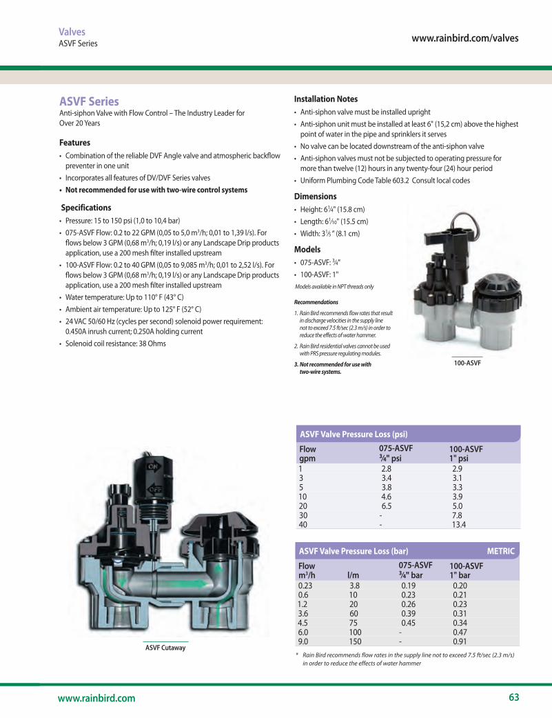
www.rainbird.com/valves
63www.rainbird.com
Valve
s
ValvesASVF Series
ASVF Cutaway
100-ASVF
* Rain Bird recommends flow rates in the supply line not to exceed 7.5 ft/sec (2.3 m/s) in order to reduce the effects of water hammer
ASVF SeriesAnti-siphon Valve with Flow Control – The Industry Leader for Over 20 Years
Features• Combination of the reliable DVF Angle valve and atmospheric backflow
preventer in one unit• Incorporates all features of DV/DVF Series valves• Not recommended for use with two-wire control systems
Specifications• Pressure: 15 to 150 psi (1,0 to 10,4 bar) • 075-ASVF Flow: 0.2 to 22 GPM (0,05 to 5,0 m3/h; 0,01 to 1,39 l/s). For
flows below 3 GPM (0,68 m3/h; 0,19 l/s) or any Landscape Drip products application, use a 200 mesh filter installed upstream
• 100-ASVF Flow: 0.2 to 40 GPM (0,05 to 9,085 m3/h; 0,01 to 2,52 l/s). For flows below 3 GPM (0,68 m3/h; 0,19 l/s) or any Landscape Drip products application, use a 200 mesh filter installed upstream
• Water temperature: Up to 110° F (43° C) • Ambient air temperature: Up to 125° F (52° C) • 24 VAC 50/60 Hz (cycles per second) solenoid power requirement:
0.450A inrush current; 0.250A holding current • Solenoid coil resistance: 38 Ohms
Installation Notes• Anti-siphon valve must be installed upright• Anti-siphon unit must be installed at least 6" (15,2 cm) above the highest
point of water in the pipe and sprinklers it serves • No valve can be located downstream of the anti-siphon valve • Anti-siphon valves must not be subjected to operating pressure for
more than twelve (12) hours in any twenty-four (24) hour period • Uniform Plumbing Code Table 603.2 Consult local codes
Dimensions• Height: 61⁄4" (15.8 cm)• Length: 61⁄10" (15.5 cm)• Width: 31⁄5 “ (8.1 cm)
Models• 075-ASVF: 3⁄4"• 100-ASVF: 1" Models available in NPT threads only
Recommendations
1. Rain Bird recommends flow rates that result in discharge velocities in the supply line not to exceed 7.5 ft/sec (2.3 m/s) in order to reduce the effects of water hammer.
2. Rain Bird residential valves cannot be used with PRS pressure regulating modules.
3. Not recommended for use with two-wire systems.
Flow gpm
075-ASVF 3⁄4" psi
100-ASVF 1" psi
1 2.8 2.93 3.4 3.15 3.8 3.310 4.6 3.920 6.5 5.030 - 7.840 - 13.4
ASVF Valve Pressure Loss (psi)
Flow m3/h l/m
075-ASVF 3⁄4" bar
100-ASVF 1" bar
0.23 3.8 0.19 0.200.6 10 0.23 0.211.2 20 0.26 0.233.6 60 0.39 0.314.5 75 0.45 0.346.0 100 - 0.479.0 150 - 0.91
ASVF Valve Pressure Loss (bar) METRIC
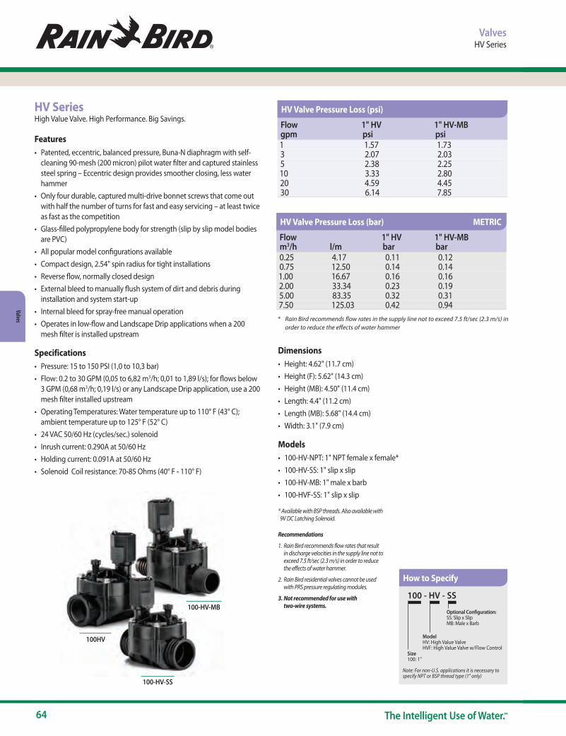
64 The Intelligent Use of Water.™
Valves
HV SeriesHigh Value Valve. High Performance. Big Savings.
Features• Patented, eccentric, balanced pressure, Buna-N diaphragm with self-
cleaning 90-mesh (200 micron) pilot water filter and captured stainless steel spring – Eccentric design provides smoother closing, less water hammer
• Only four durable, captured multi-drive bonnet screws that come out with half the number of turns for fast and easy servicing – at least twice as fast as the competition
• Glass-filled polypropylene body for strength (slip by slip model bodies are PVC)
• All popular model configurations available• Compact design, 2.54" spin radius for tight installations• Reverse flow, normally closed design • External bleed to manually flush system of dirt and debris during
installation and system start-up • Internal bleed for spray-free manual operation • Operates in low-flow and Landscape Drip applications when a 200
mesh filter is installed upstream
Specifications• Pressure: 15 to 150 PSI (1,0 to 10,3 bar) • Flow: 0.2 to 30 GPM (0,05 to 6,82 m3/h; 0,01 to 1,89 l/s); for flows below
3 GPM (0,68 m3/h; 0,19 l/s) or any Landscape Drip application, use a 200 mesh filter installed upstream
• Operating Temperatures: Water temperature up to 110° F (43° C); ambient temperature up to 125° F (52° C)
• 24 VAC 50/60 Hz (cycles/sec.) solenoid • Inrush current: 0.290A at 50/60 Hz • Holding current: 0.091A at 50/60 Hz • Solenoid Coil resistance: 70-85 Ohms (40° F - 110° F)
Dimensions• Height: 4.62" (11.7 cm)• Height (F): 5.62" (14.3 cm)• Height (MB): 4.50" (11.4 cm)• Length: 4.4" (11.2 cm)• Length (MB): 5.68" (14.4 cm)• Width: 3.1" (7.9 cm)
Models• 100-HV-NPT: 1" NPT female x female*• 100-HV-SS: 1" slip x slip• 100-HV-MB: 1" male x barb• 100-HVF-SS: 1" slip x slip
* Available with BSP threads. Also available with 9V DC Latching Solenoid.
Recommendations
1. Rain Bird recommends flow rates that result in discharge velocities in the supply line not to exceed 7.5 ft/sec (2.3 m/s) in order to reduce the effects of water hammer.
2. Rain Bird residential valves cannot be used with PRS pressure regulating modules.
3. Not recommended for use with two-wire systems.
ValvesHV Series
100 - HV - SS
Note: For non-U.S. applications it is necessary to specify NPT or BSP thread type (1" only)
ModelHV: High Value Valve HVF: High Value Valve w/Flow Control
Size 100: 1"
Optional Configuration:SS: Slip x SlipMB: Male x Barb
100HV
100-HV-MB
100-HV-SS
* Rain Bird recommends flow rates in the supply line not to exceed 7.5 ft/sec (2.3 m/s) in order to reduce the effects of water hammer
How to Specify
Flow gpm
1" HV psi
1" HV-MB psi
1 1.57 1.73 3 2.07 2.03 5 2.38 2.25 10 3.33 2.80 20 4.59 4.45 30 6.14 7.85
HV Valve Pressure Loss (psi)
Flow m3/h l/m
1" HV bar
1" HV-MB bar
0.25 4.17 0.11 0.120.75 12.50 0.14 0.141.00 16.67 0.16 0.162.00 33.34 0.23 0.195.00 83.35 0.32 0.317.50 125.03 0.42 0.94
HV Valve Pressure Loss (bar) METRIC
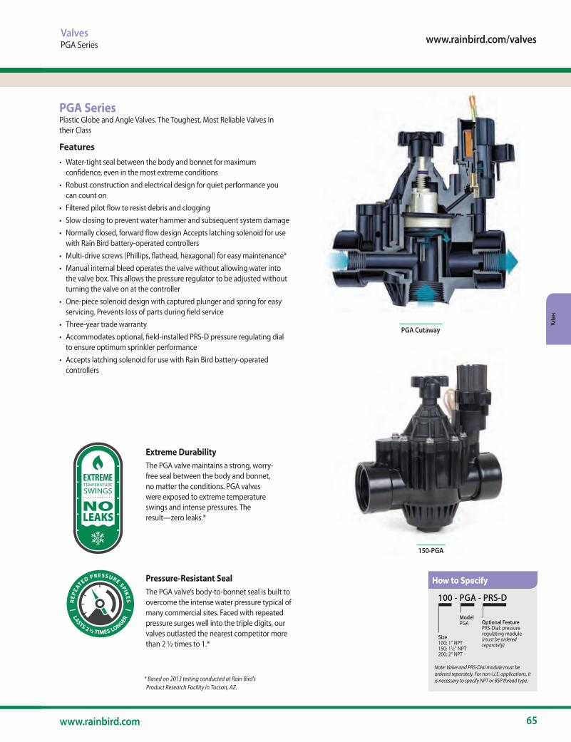
www.rainbird.com/valves
65www.rainbird.com
Valve
s
PGA SeriesPlastic Globe and Angle Valves. The Toughest, Most Reliable Valves In their Class
Features
• Water-tight seal between the body and bonnet for maximum confidence, even in the most extreme conditions
• Robust construction and electrical design for quiet performance you can count on
• Filtered pilot flow to resist debris and clogging• Slow closing to prevent water hammer and subsequent system damage• Normally closed, forward flow design Accepts latching solenoid for use
with Rain Bird battery-operated controllers• Multi-drive screws (Phillips, flathead, hexagonal) for easy maintenance* • Manual internal bleed operates the valve without allowing water into
the valve box. This allows the pressure regulator to be adjusted without turning the valve on at the controller
• One-piece solenoid design with captured plunger and spring for easy servicing. Prevents loss of parts during field service
• Three-year trade warranty • Accommodates optional, field-installed PRS-D pressure regulating dial
to ensure optimum sprinkler performance • Accepts latching solenoid for use with Rain Bird battery-operated
controllers
PGA Cutaway
150-PGA
ValvesPGA Series
* Based on 2013 testing conducted at Rain Bird's Product Research Facility in Tucson, AZ.
S
EXTREMETEMPERATURE
SWINGS
NOLEAKS
|
R
EPEA
TED PRESSURE SPIKES | LASTS 2 ½ TIMES LONGER
S
EXTREMETEMPERATURE
SWINGS
NOLEAKS
|
R
EPEA
TED PRESSURE SPIKES | LASTS 2 ½ TIMES LONGER
Extreme DurabilityThe PGA valve maintains a strong, worry-free seal between the body and bonnet, no matter the conditions. PGA valves were exposed to extreme temperature swings and intense pressures. The result—zero leaks.*
Pressure-Resistant SealThe PGA valve’s body-to-bonnet seal is built to overcome the intense water pressure typical of many commercial sites. Faced with repeated pressure surges well into the triple digits, our valves outlasted the nearest competitor more than 2 ½ times to 1.*
100 - PGA - PRS-D
Size 100: 1" NPT150: 11⁄2" NPT200: 2" NPT
ModelPGA Optional Feature
PRS-Dial: pressureregulating module(must be ordered separately)
Note: Valve and PRS-Dial module must be ordered separately. For non-U.S. applications, it is necessary to specify NPT or BSP thread type.
How to Specify

66 The Intelligent Use of Water.™
Valves
ValvesPGA Series
Options• Accommodates optional, field installed PRS-D pressure regulating
module to ensure optimum sprinkler performance. Regulates up to 100 psi (6.9 bar)
• Accepts latching solenoid for use with Rain Bird battery-operated controllers up to 150 psi (10,35 bar)
• Compatible with ESP-LXD decoders
Specifications• Pressure: 15 to 150 psi (1.04 to 10.4 bar)• Flow without PRS-D option: 2 to150 gpm (0.45 to 34.05 m3/h;
7.8 to 568 l/m)• Flow with PRS-D option: 5 to 150 gpm (1.14 to 34.05 m3/h;
19.2 to 568 l/m)• Water temperature: Up to 110° F (43° C)• Ambient temperature: Up to 125° F (52° C)• 24VAC 50/60Hz (cycles/sec) solenoid power requirement • Inrush current: 0.41A (9.9VA) at 50/60Hz• Holding current: 0.14A (3.43VA) at 50/60Hz• Solenoid coil resistance: 30-39 Ohms, nominal
DimensionsModel Height Length Width• 100-PGA 7 1⁄4" (18.4 cm) 5 1⁄2" (14.0 cm) 3 1⁄4" (8.3 cm)• 150-PGA 8" (20.3 cm) 6 3⁄4" (17.2 cm) 3 1⁄2" (8.9 cm)• 200-PGA 10" (25.4 cm) 7 3⁄4" (19.7 cm) 5" (12.7 cm)Note: PRS-Dial adds 2" (5.1 cm) to valve height
Models• 100-PGA: 1" NPT• 150-PGA: 1 1⁄2" NPT• 200-PGA: 2" NPT BSP threads available; specify when ordering
Recommendations
1. Rain Bird recommends flow rates in the supply line not to exceed 7.5 ft/sec (2.29 m/s) in order to reduce the effects of water hammer
2. For flows below 5 gpm (1.14 m3⁄h; 19.2 l/m), Rain Bird recommends use of upstream filtration to prevent debris from collecting below the diaphragm
3. For flows below 10 gpm (2.27 m3⁄h; 37.8 l/m) Rain Bird recommends the flow control stem be turned down two full turns from the fully open position
PGA Series (cont.)
Flow gpm
100-PGA Globe1"
100- PGAAngle1"
150- PGAGlobe1½"
150-PGAAngle1½"
200- PGA Globe 2"
200- PGA Angle 2"
2 5.1 4.3 - - - -5 5.5 5.0 - - - -10 5.9 5.5 - - - -20 6.0 5.6 - - - -30 6.4 5.5 1.9 1.3 - -40 7.0 7.5 3.2 2.0 1.2 1.050 - - 4.8 3.0 1.5 0.975 - - 11.1 6.5 3.0 1.7100 - - 19.2 11.7 5.5 3.0125 - - - - 8.6 4.8150 - - - - 12.0 6.5
PGA Series Valve Pressure Loss (psi)
Flow m3/h
Flow l/m
100-PGA Globe2.5cm
100- PGAAngle2.5cm
150- PGAGlobe3.8cm
150-PGAAngle3.8cm
200- PGA Globe 5.1cm
200- PGA Angle 5.1cm
0.5 7.6 0.35 0.30 - - - -1.2 20 0.38 0.35 - - - -3 50 0.41 0.38 - - - -6 100 0.43 0.38 0.10 0.07 - -9 150 0.48 0.51 0.22 0.14 0.08 0.0712 200 - - 0.38 0.23 0.12 0.0715 250 - - 0.61 0.36 0.17 0.1018 300 - - 0.86 0.51 0.24 0.1321 350 - - 1.16 0.70 0.33 0.1824 400 - - - - 0.43 0.2327 450 - - - - 0.54 0.3030 500 - - - - 0.66 0.3634 568 - - - - 0.83 0.45
PGA Series Valve Pressure Loss (bar)
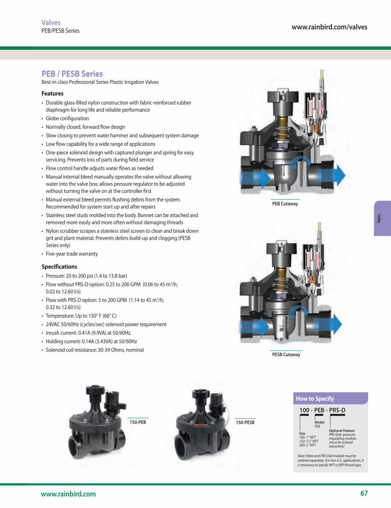
www.rainbird.com/valves
67www.rainbird.com
Valve
s
ValvesPEB/PESB Series
PEB / PESB SeriesBest-in-class Professional Series Plastic Irrigation Valves
Features• Durable glass-filled nylon construction with fabric-reinforced rubber
diaphragm for long life and reliable performance• Globe configuration • Normally closed, forward flow design • Slow closing to prevent water hammer and subsequent system damage • Low flow capability for a wide range of applications • One-piece solenoid design with captured plunger and spring for easy
servicing. Prevents loss of parts during field service • Flow control handle adjusts water flows as needed • Manual internal bleed manually operates the valve without allowing
water into the valve box; allows pressure regulator to be adjusted without turning the valve on at the controller first
• Manual external bleed permits flushing debris from the system. Recommended for system start up and after repairs
• Stainless steel studs molded into the body. Bonnet can be attached and removed more easily and more often without damaging threads
• Nylon scrubber scrapes a stainless steel screen to clean and break down grit and plant material. Prevents debris build-up and clogging (PESB Series only)
• Five-year trade warranty
Specifications• Pressure: 20 to 200 psi (1.4 to 13.8 bar) • Flow without PRS-D option: 0.25 to 200 GPM (0.06 to 45 m3/h;
0.02 to 12.60 l/s) • Flow with PRS-D option: 5 to 200 GPM (1.14 to 45 m3/h;
0.32 to 12.60 l/s) • Temperature: Up to 150° F (66° C) • 24VAC 50/60Hz (cycles/sec) solenoid power requirement • Inrush current: 0.41A (9.9VA) at 50/60Hz• Holding current: 0.14A (3.43VA) at 50/60Hz• Solenoid coil resistance: 30-39 Ohms, nominal
PEB Cutaway
PESB Cutaway
150-PEB 150-PESB
100 - PEB - PRS-D
Size 100: 1" NPT150: 11⁄2" NPT200: 2" NPT
ModelPEB
Optional FeaturePRS-Dial: pressureregulating module(must be ordered separately)
Note: Valve and PRS-Dial module must be ordered separately. For non-U.S. applications, it is necessary to specify NPT or BSP thread type.
How to Specify

68 The Intelligent Use of Water.™
Valves
Notes1. Loss values are with flow control fully open
2. PRS-Dial recommended for use in shaded area only
Options• Accommodates optional, field installed PRS-D pressure regulating
module to ensure optimum sprinkler performance. Regulates up to 100 psi (6.9 bar)
• Accepts latching solenoid for use with Rain Bird battery-operated controllers up to 150 psi (10,35 bar)
• Compatible with ESP-LXD decoders• Optional purple flow control handle for non-potable water applications
PEB-NP-HAN1 (1"); PEB-NP-HAN2 (1 1/2" and 2")
Dimensions Model Height Length Width• 100-PEB and 100-PESB: 61⁄2" (16.5 cm) 4" (10.2 cm) 4" (10.2 cm)• 150-PEB and 150-PESB: 8" (20.3 cm) 6" (15.2 cm) 6" (15.2 cm)• 200-PEB and 200-PESB: 8" (20.3 cm) 6" (15.2 cm) 6" (15.2 cm) Note: The PRS-Dial option adds 2" (5.1 cm) to valve height
Models• 100-PEB and 100-PESB: 1" NPT• 150-PEB and 150-PESB: 11⁄2" NPT• 200-PEB and 200-PESB: 2" NPT BSP threads available; specify when ordering
Recommendations
1. Rain Bird recommends flow rates in the supply line not to exceed 7.5 ft/sec (2.29 m/s) in order to reduce the effects of water hammer
2. For flows below 5 gpm (1.14 m3⁄h; 19.2 l/m), Rain Bird recommends use of upstream filtration to prevent debris from collecting below the diaphragm
3. For flows below 10 gpm (2.27 m3⁄h; 37.8 l/m) Rain Bird recommends the flow control stem be turned down two full turns from the fully open position
4. For PRS-Dial applications, Rain Bird recommends the installation of a pressure-regulating master valve or inline pressure regulator when the inlet pressure exceeds 100 psi (6.9 bar)
PEB / PESB Series (cont.)
ValvesPEB/PESB Series
Flow gpm
100-PEB 1"
150-PEB 1½"
200-PEB 2"
0.25 0.8 - -0.5 1.0 - -1 1.3 - -5 1.7 - -10 1.8 - -20 2.9 3.9 -30 5.6 3.6 -40 10.0 3.5 -50 15.6 3.6 4.875 - 5.4 4.5100 - 9.6 5.2125 - 14.6 8.2150 - 21.2 11.8175 - - 15.5200 - - 19.5
PEB and PESB Series Valve Pressure Loss (psi)
Flow m3/h
Flow l/m
100-PEB 2.5cm
150-PEB 3.8cm
200-PEB 5.1cm
0.06 1 0.06 - -0.3 5 0.09 - -0.6 10 0.10 - -1.2 20 0.12 - -3 50 0.15 - -6 100 0.32 0.26 -9 150 0.68 0.24 -12 200 - 0.26 0.3315 250 - 0.33 0.3218 300 - 0.42 0.3221 350 - 0.57 0.3424 400 - 0.74 0.4127 450 - 0.92 0.5130 500 - 1.14 0.6433 550 - 1.38 0.7736 600 - - 0.9039 650 - - 1.0442 700 - - 1.1845 757 - - 1.34
PEB and PESB Series Valve Pressure Loss (bar) METRIC
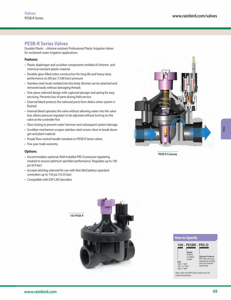
www.rainbird.com/valves
69www.rainbird.com
Valve
s
PESB-R Cutaway
ValvesPESB-R Series
PESB-R Series ValvesDurable Plastic – chlorine resistant Professional Plastic Irrigation Valves for reclaimed water irrigation applications
Features• Plastic diaphragm and scrubber components molded of chlorine- and
chemical-resistant plastic material• Durable glass-filled nylon construction for long life and heavy-duty
performance at 200 psi (13.80 bars) pressure • Stainless steel studs molded into the body. Bonnet can be attached and
removed easily without damaging threads • One-piece solenoid design with captured plunger and spring for easy
servicing. Prevents loss of parts during field service • External bleed protects the solenoid ports from debris when system is
flushed • Internal bleed operates the valve without allowing water into the valve
box; allows pressure regulator to be adjusted without turning on the valve at the controller first
• Slow closing to prevent water hammer and subsequent system damage • Scrubber mechanism scrapes stainless steel screen clean to break down
grit and plant material • Purple flow control handle standard on PESB-R Series valves • Five-year trade warranty
Options• Accommodates optional, field installed PRS-D pressure regulating
module to ensure optimum sprinkler performance. Regulates up to 100 psi (6.9 bar)
• Accepts latching solenoid for use with Rain Bird battery-operated controllers up to 150 psi (10.35 bar)
• Compatible with ESP-LXD decoders
100 - PESBR - PRS-D
Size 100: 1" NPT150: 11⁄2" NPT200: 2" NPT
ModelPESB-R:scrubbermodel
Optional FeaturePRS-Dial: pressureregulating module(must be ordered separately)
Note: Valve and PRS-Dial module must be ordered separately.
150-PESB-R
How to Specify

70 The Intelligent Use of Water.™
Valves
ValvesPESB-R Series
Notes1. Loss values are with flow control fully open
2. PRS-Dial recommended for use in shaded area only
Specifications• Pressure: 20 to 200 psi (1.38 to 13.80 bar)• Flow: 0.25 to 200 gpm (0.06 to 45.40 m3⁄h; 0.02 to 12.60 l/s)• Flow with PRS-Dial: 5 to 200 gpm (1.14 to 45.40 m3⁄h; 0.32 to 12.60 l/s)• Temperature: Up to 150° F (66° C)• 24VAC 50/60Hz (cycles/sec) solenoid power requirement • Inrush current: 0.41A (9.9VA) at 50/60Hz• Holding current: 0.14A (3.43VA) at 50/60Hz• Solenoid coil resistance: 30-39 Ohms, nominal
Dimensions Model Height Length Width• 100-PESB-R 61⁄2" (16.5 cm) 4" (10.2 cm) 4" (10.2 cm)• 150-PESB-R 8" (20.3 cm) 6" (15.2 cm) 6" (15.2 cm)• 200-PESB-R 8" (20.3 cm) 6" (15.2 cm) 6" (15.2 cm)Note: The PRS-Dial option adds 2" (5.1 cm) to valve height
Models• 100-PESB-R: 1" NPT• 150-PESB-R: 1½" NPT• 200-PESB-R: 2" NPTBSP threads available, specify when ordering
Recommendations
1. Rain Bird recommends flow rates in the supply line not to exceed 7.5 ft/sec (2.29 m/s) in order to reduce the effects of water hammer
2. For flows below 5 gpm (1.14 m3⁄h; 19.21 l/m), Rain Bird recommends use of upstream filtration to prevent debris from collecting below the diaphragm
3. For flows below 10 gpm (2.27 m3⁄h; 37.8 l/m) Rain Bird recommends the flow control stem be turned down two full turns from the fully open position
PESB-R Series (cont.)Flow gpm
100-PESB-R 1"
150-PESB-R 1½"
200-PESB-R 2"
0.25 1.6 - -0.5 3.0 - -1 1.8 - -5 2.9 - -10 2.9 - -20 2.6 3.5 -30 5.8 3.1 -40 10.2 2.3 -50 16.0 2.1 3.775 - 4.3 3.3100 - 7.5 4.7125 - 11.9 8.6150 - 17.0 12.6175 - - 14.8200 - - 18.9
PESB-R Series Valve Pressure Loss (psi)
Flow m3/h
Flow l/m
100-PESB-R 2.5cm
150-PESB-R 3.8cm
200-PESB-R 5.1cm
0.06 1 0.11 - -0.3 5 0.13 - -0.6 10 0.15 - -1.2 20 0.20 - -3 50 0.19 - -6 100 0.32 0.22 -9 150 0.69 0.16 -12 200 - 0.16 0.2515 250 - 0.24 0.2418 300 - 0.33 0.2521 350 - 0.45 0.3024 400 - 0.59 0.3827 450 - 0.75 0.5330 500 - 0.91 0.6733 550 - 1.10 0.8236 600 - - 0.9239 650 - - 1.0042 700 - - 1.1345 757 - - 1.30
PESB-R Series Valve Pressure Loss (bar) METRIC
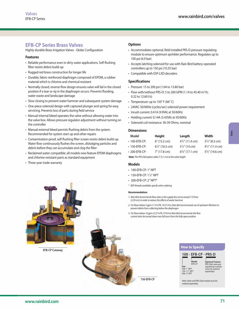
www.rainbird.com/valves
71www.rainbird.com
Valve
s
Options• Accommodates optional, field installed PRS-D pressure regulating
module to ensure optimum sprinkler performance. Regulates up to 100 psi (6.9 bar)
• Accepts latching solenoid for use with Rain Bird battery-operated controllers up to 150 psi (10.35 bar)
• Compatible with ESP-LXD decoders
Specifications• Pressure: 15 to 200 psi (1.04 to 13.80 bar) • Flow with/without PRS-D: 5 to 200 GPM (1.14 to 45.40 m3/h;
0.32 to 12.60 l/s) • Temperature: up to 150° F (66° C) • 24VAC 50/60Hz (cycles/sec) solenoid power requirement • Inrush current: 0.41A (9.9VA) at 50/60Hz• Holding current: 0.14A (3.43VA) at 50/60Hz• Solenoid coil resistance: 30-39 Ohms, nominal
Dimensions Model Height Length Width• 100-EFB-CP: 6" (15.2 cm) 41⁄2" (11.4 cm) 31⁄4" (8.3 cm)• 150-EFB-CP: 61⁄2" (16.5 cm) 51⁄2" (14 cm) 41⁄2" (11.4 cm)• 200-EFB-CP: 7" (17.8 cm) 63⁄4" (17.1 cm) 53⁄4" (14.6 cm) Note: The PRS-Dial option adds 2" (5.1 cm) to the valve height
Models• 100-EFB-CP: 1" NPT• 150-EFB-CP: 11⁄2" NPT• 200-EFB-CP: 2" NPT** BSP threads available; specify when ordering
Recommendations
1. Rain Bird recommends flow rates in the supply line not to exceed 7.5 ft/sec (2.29 m/s) in order to reduce the effects of water hammer
2. For flows below 5 gpm (1.14 m3⁄h; 19.21 l/m), Rain Bird recommends use of upstream filtration to prevent debris from collecting below the diaphragm
3. For flows below 10 gpm (2.27 m3⁄h; 37.8 l/m) Rain Bird recommends the flow control stem be turned down two full turns from the fully open position
ValvesEFB-CP Series
EFB-CP Series Brass ValvesHighly durable Brass Irrigation Valves - Globe Configuration
Features• Reliable performance even in dirty water applications. Self-flushing
filter resists debris build-up• Rugged red brass construction for longer life• Durable, fabric-reinforced diaphragm composed of EPDM, a rubber
material which is chlorine and chemical resistant• Normally closed, reverse flow design ensures valve will fail in the closed
position if a tear or rip in the diaphragm occurs. Prevents flooding, water waste and landscape damage
• Slow closing to prevent water hammer and subsequent system damage • One-piece solenoid design with captured plunger and spring for easy
servicing. Prevents loss of parts during field service • Manual internal bleed operates the valve without allowing water into
the valve box. Allows pressure regulator adjustment without turning on the controller
• Manual external bleed permits flushing debris from the system. Recommended for system start up and other repairs
• Contamination-proof, self-flushing filter screen resists debris build-up. Water flow continuously flushes the screen, dislodging particles and debris before they can accumulate and clog the filter
• Reclaimed water compatible: all models now feature EPDM diaphragms and chlorine-resistant parts as standard equipment
• Three-year trade warranty
EFB-CP Cutaway100 - EFB-CP - PRS-D
Size100: 1" NPT 150: 11⁄2" NPT 200: 2" NPT
ModelEFB-CP
Optional FeaturePRS-Dial: pressureregulating module(must be ordered separately)
Note: Valve and PRS-Dial module must be ordered separately.
150-EFB-CP
How to Specify
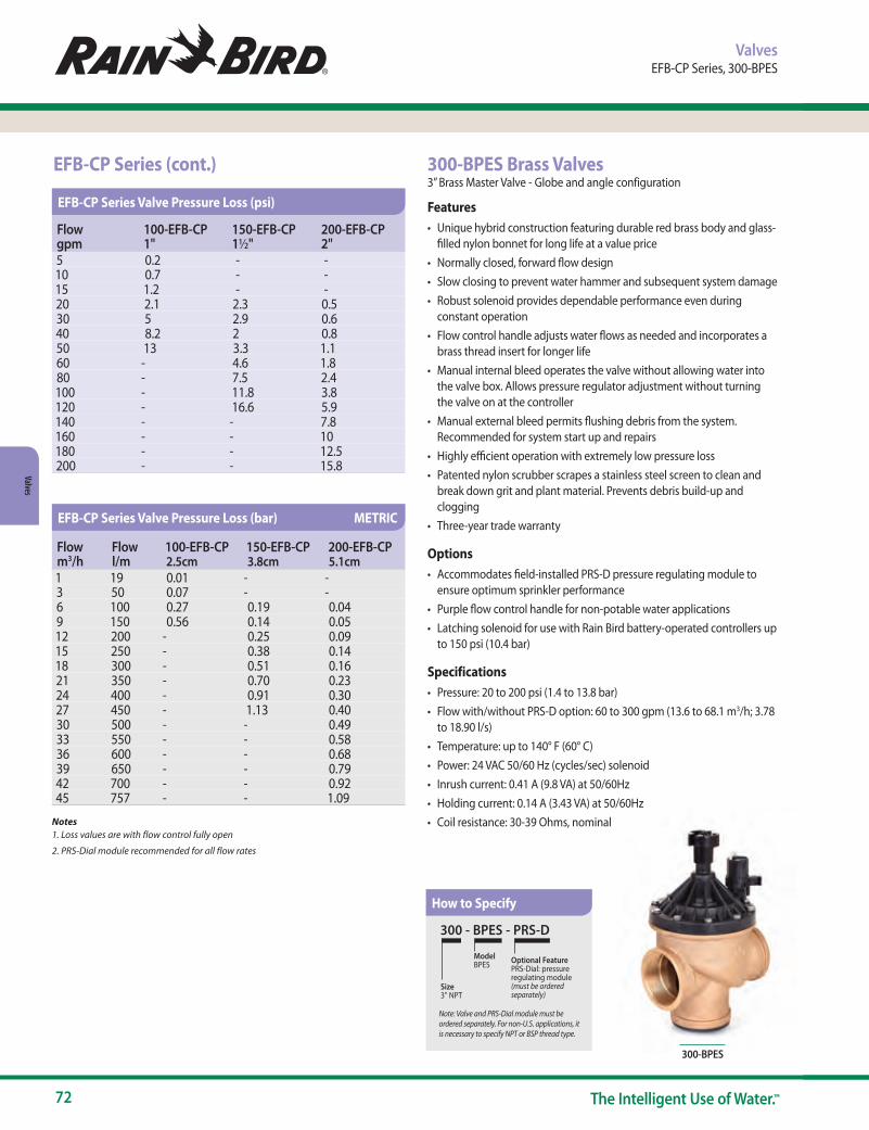
72 The Intelligent Use of Water.™
Valves
ValvesEFB-CP Series, 300-BPES
Notes1. Loss values are with flow control fully open
2. PRS-Dial module recommended for all flow rates
300-BPES
300-BPES Brass Valves3” Brass Master Valve - Globe and angle configuration Features• Unique hybrid construction featuring durable red brass body and glass-
filled nylon bonnet for long life at a value price• Normally closed, forward flow design • Slow closing to prevent water hammer and subsequent system damage • Robust solenoid provides dependable performance even during
constant operation • Flow control handle adjusts water flows as needed and incorporates a
brass thread insert for longer life • Manual internal bleed operates the valve without allowing water into
the valve box. Allows pressure regulator adjustment without turning the valve on at the controller
• Manual external bleed permits flushing debris from the system. Recommended for system start up and repairs
• Highly efficient operation with extremely low pressure loss • Patented nylon scrubber scrapes a stainless steel screen to clean and
break down grit and plant material. Prevents debris build-up and clogging
• Three-year trade warranty
Options• Accommodates field-installed PRS-D pressure regulating module to
ensure optimum sprinkler performance • Purple flow control handle for non-potable water applications • Latching solenoid for use with Rain Bird battery-operated controllers up
to 150 psi (10.4 bar)
Specifications • Pressure: 20 to 200 psi (1.4 to 13.8 bar) • Flow with/without PRS-D option: 60 to 300 gpm (13.6 to 68.1 m3/h; 3.78
to 18.90 l/s) • Temperature: up to 140° F (60° C) • Power: 24 VAC 50/60 Hz (cycles/sec) solenoid • Inrush current: 0.41 A (9.8 VA) at 50/60Hz • Holding current: 0.14 A (3.43 VA) at 50/60Hz • Coil resistance: 30-39 Ohms, nominal
300 - BPES - PRS-D
Size3" NPT
ModelBPES Optional Feature
PRS-Dial: pressureregulating module(must be ordered separately)
Note: Valve and PRS-Dial module must be ordered separately. For non-U.S. applications, it is necessary to specify NPT or BSP thread type.
EFB-CP Series (cont.)
How to Specify
Flow gpm
100-EFB-CP 1"
150-EFB-CP 1½"
200-EFB-CP 2"
5 0.2 - -10 0.7 - -15 1.2 - -20 2.1 2.3 0.530 5 2.9 0.640 8.2 2 0.850 13 3.3 1.160 - 4.6 1.880 - 7.5 2.4100 - 11.8 3.8120 - 16.6 5.9140 - - 7.8160 - - 10180 - - 12.5200 - - 15.8
EFB-CP Series Valve Pressure Loss (psi)
Flow m3/h
Flow l/m
100-EFB-CP 2.5cm
150-EFB-CP 3.8cm
200-EFB-CP 5.1cm
1 19 0.01 - -3 50 0.07 - -6 100 0.27 0.19 0.049 150 0.56 0.14 0.0512 200 - 0.25 0.0915 250 - 0.38 0.1418 300 - 0.51 0.1621 350 - 0.70 0.2324 400 - 0.91 0.3027 450 - 1.13 0.4030 500 - - 0.4933 550 - - 0.5836 600 - - 0.6839 650 - - 0.7942 700 - - 0.9245 757 - - 1.09
EFB-CP Series Valve Pressure Loss (bar) METRIC

www.rainbird.com/valves
73www.rainbird.com
Valve
s
Valves300-BPES, DB Series Wire Connectors
WC Series Wire ConnectorConnections Made Easy
Features and Benefits• Install Faster – the WC Series Wire Connectoris quick to install and
provides reliable moisture sealing for controller and valve electrical connections you can count on
• Simplify Inventory – This is the only wire connector you’ll need! It is ideal for use on two wire decoder control systems
• Avoid Call Backs – Locating and repairing a corroded wire splice costs your business time and money. Avoid unnecessary service call backs
• Use for standard controllers, valve boxes and soil moisture sensors • Wire combinations ranging from 22ga to 8ga • Use on connections from 24 VAC to 600 VAC • UL 486D certified for direct burial • The Strain Relief ensures wires are secure and won’t pull apart • Waterproof silicone sealant protects against corrosion • UV-resistant material ensures product performance does not degrade
even after long periods of exposure to sunlight
Models• WC20: Direct Bury Silicone Tube, Red Yellow Wire Nut, Bag of 20
WC20
BPES Cutaway
DimensionsModel Height Length Width• 300 135⁄8" (34.61 cm) 8" (20.32 cm) 7" (17.78 cm)
Models• 300-BPES: 3" NPT BSP threads available; specify when ordering
Recommendations
1. Rain Bird recommends flow rates in the supply line not to exceed 7.5 ft/sec (2.29 m/s) in order to reduce the effects of water hammer.
2. For flows below 5 gpm (1.14 m3⁄h; 19.2 l/m), Rain Bird recommends use of upstream filtration to prevent debris from collecting below the diaphragm.
3. For flows below 10 gpm (2.27 m3⁄h; 37.8 l/m) Rain Bird recommends the flow control stem be turned down two full turns from the fully open position.
Notes1. Loss values are with flow control fully open2. PRS-Dial module recommended for all flow rates
Flow gpm Globe Angle60 6.6 6.880 5.1 5.9100 3.2 3.5120 1.8 1.8140 1.8 2.1160 2.0 2.1180 2.2 2.0200 2.7 2.5250 4.0 3.4300 4.9 4.5
BPES 3" Valve Pressure Loss (psi)
WC202-3 #10 2#182-5 #12 1 #8 w/2 #182-5 #14 3 #10 w/1 #184-6 #16 3 #12 w/3 #18
3 #14 w/2 #18
Wire Combinations (for solid and stranded wire)
Flow m3/h l/s Globe Angle13.6 227 0.46 0.4724 400 0.19 0.2136 600 0.14 0.1448 800 0.21 0.1960 1000 0.29 0.2668 1136 0.34 0.31
BPES 3" Valve Pressure Loss (bar) METRIC
The combinations listed are only a sample of the most common wire combinations.
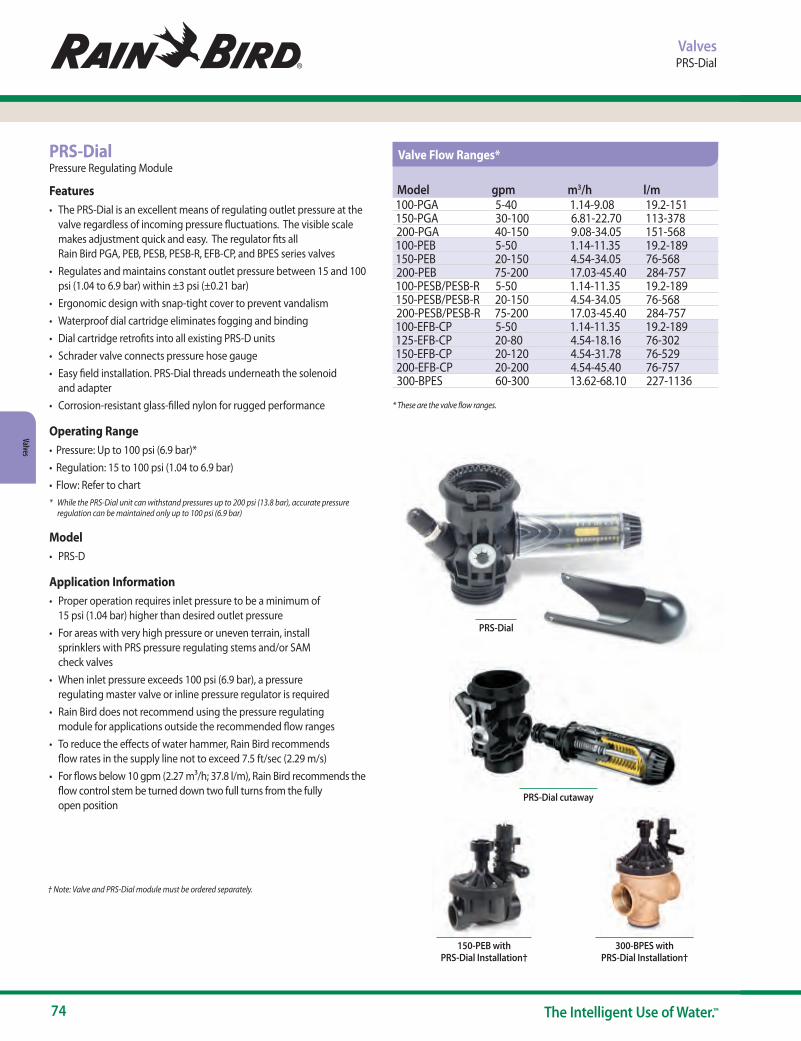
74 The Intelligent Use of Water.™
Valves
PRS-Dial
* These are the valve flow ranges.
ValvesPRS-Dial
PRS-DialPressure Regulating Module
Features• The PRS-Dial is an excellent means of regulating outlet pressure at the
valve regardless of incoming pressure fluctuations. The visible scale makes adjustment quick and easy. The regulator fits all Rain Bird PGA, PEB, PESB, PESB-R, EFB-CP, and BPES series valves
• Regulates and maintains constant outlet pressure between 15 and 100 psi (1.04 to 6.9 bar) within ±3 psi (±0.21 bar)
• Ergonomic design with snap-tight cover to prevent vandalism• Waterproof dial cartridge eliminates fogging and binding• Dial cartridge retrofits into all existing PRS-D units• Schrader valve connects pressure hose gauge• Easy field installation. PRS-Dial threads underneath the solenoid
and adapter• Corrosion-resistant glass-filled nylon for rugged performance
Operating Range• Pressure: Up to 100 psi (6.9 bar)*• Regulation: 15 to 100 psi (1.04 to 6.9 bar)• Flow: Refer to chart* While the PRS-Dial unit can withstand pressures up to 200 psi (13.8 bar), accurate pressure
regulation can be maintained only up to 100 psi (6.9 bar)
Model• PRS-D
Application Information• Proper operation requires inlet pressure to be a minimum of
15 psi (1.04 bar) higher than desired outlet pressure• For areas with very high pressure or uneven terrain, install
sprinklers with PRS pressure regulating stems and/or SAM check valves
• When inlet pressure exceeds 100 psi (6.9 bar), a pressure regulating master valve or inline pressure regulator is required
• Rain Bird does not recommend using the pressure regulating module for applications outside the recommended flow ranges
• To reduce the effects of water hammer, Rain Bird recommends flow rates in the supply line not to exceed 7.5 ft/sec (2.29 m/s)
• For flows below 10 gpm (2.27 m3/h; 37.8 l/m), Rain Bird recommends the flow control stem be turned down two full turns from the fully open position
PRS-Dial cutaway
150-PEB with PRS-Dial Installation†
† Note: Valve and PRS-Dial module must be ordered separately.
300-BPES with PRS-Dial Installation†
Model gpm m3/h l/m100-PGA 5-40 1.14-9.08 19.2-151150-PGA 30-100 6.81-22.70 113-378200-PGA 40-150 9.08-34.05 151-568100-PEB 5-50 1.14-11.35 19.2-189150-PEB 20-150 4.54-34.05 76-568200-PEB 75-200 17.03-45.40 284-757100-PESB/PESB-R 5-50 1.14-11.35 19.2-189150-PESB/PESB-R 20-150 4.54-34.05 76-568200-PESB/PESB-R 75-200 17.03-45.40 284-757100-EFB-CP 5-50 1.14-11.35 19.2-189125-EFB-CP 20-80 4.54-18.16 76-302150-EFB-CP 20-120 4.54-31.78 76-529200-EFB-CP 20-200 4.54-45.40 76-757300-BPES 60-300 13.62-68.10 227-1136
Valve Flow Ranges*
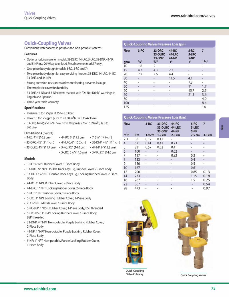
www.rainbird.com/valves
75www.rainbird.com
Valve
s
Quick-Coupling ValvesConvenient water access in potable and non-potable systems
Features• Optional locking cover on models 33-DLRC, 44-LRC, 5-LRC, 33-DNP, 44-NP,
and 5-NP (use 2049 key to unlock). Metal cover on model 7 only • One-piece body design (models 3-RC, 5-RC and 7) • Two-piece body design for easy servicing (models 33-DRC, 44-LRC, 44-RC,
33-DNP, and 44-NP) • Strong corrosion-resistant stainless steel spring prevents leakage • Thermoplastic cover for durability • 33-DNP, 44-NP, and 5-NP covers marked with "Do Not Drink!" warnings in
English and Spanish• Three-year trade warranty
Specifications• Pressure: 5 to 125 psi (0.35 to 8.63 bar)• Flow: 10 to 125 gpm (2.27 to 28.38 m3⁄h; 37.8 to 473 l/m)• 33-DNP, 44-NP, and 5-NP flow: 10 to 70 gpm (2.27 to 15.89 m3⁄h; 37.8 to
265 l/m)
Dimensions (height)• 3-RC: 41⁄4" (10.8 cm)• 33-DRC: 43⁄8" (11.1 cm)• 33-DLRC: 45⁄8" (11.7 cm)
• 44-RC: 6" (15.2 cm)• 44-LRC: 6" (15.2 cm)• 5-RC: 51⁄2" (14.0 cm)• 5-LRC: 51⁄2" (14.0 cm)
• 7: 53⁄4" (14.6 cm)• 33-DNP: 43⁄8" (11.1 cm)• 44-NP: 6" (15.2 cm)• 5-NP: 51⁄2" (14.0 cm)
Models• 3-RC: ¾" NPT Rubber Cover, 1-Piece Body• 33-DRC: ¾" NPT Double Track Key Lug, Rubber Cover, 2-Piece Body• 33-DLRC: ¾" NPT Double Track Key Lug, Locking Rubber Cover, 2-Piece
Body • 44-RC: 1" NPT Rubber Cover, 2-Piece Body• 44-LRC: 1" NPT Locking Rubber Cover, 2-Piece Body• 5-RC: 1" NPT Rubber Cover, 1-Piece Body• 5-LRC: 1" NPT Locking Rubber Cover, 1-Piece Body• 7: 1½" NPT Metal Cover, 1-Piece Body• 5-RC-BSP: 1" BSP Rubber Cover, 1-Piece Body, BSP threaded• 5-LRC-BSP: 1" BSP Locking Rubber Cover, 1-Piece Body,
BSP threaded• 33-DNP: ¾" NPT Non-potable, Purple Locking Rubber Cover,
2-Piece Body• 44-NP: 1" NPT Non-potable, Purple Locking Rubber Cover,
2-Piece Body• 5-NP: 1" NPT Non-potable, Purple Locking Rubber Cover,
1-Piece Body
Flow 3-RC 33-DRC 44-RC 5-RC 733-DLRC 44-LRC 5-LRC33-DNP 44-NP 5-NP
gpm 3⁄4" 3⁄4" 1" 1" 11⁄2" 10 1.8 2 - - -15 4.7 4.3 2.2 - -20 7.2 7.6 4.4 - -30 - - 11.5 4.1 -40 - - - 7.3 -50 - - - 11 1.760 - - - 15.7 2.570 - - - 21.5 3.680 - - - - 4.9100 - - - - 8.4125 - - - - 14
Flow 3-RC 33-DRC 44-RC 5-RC 733-DLRC 44-LRC 5-LRC33-DNP 44-NP 5-NP
m3⁄h l/m 1.9 cm 1.9 cm 2.5 cm 2.5 cm 3.8 cm2.3 38 0.12 0.12 - - -4 67 0.41 0.42 0.23 - -5 83 0.57 0.62 0.4 - -6 100 - - 0.62 - -7 117 - - 0.83 0.3 -8 133 - - - 0.4 -9 150 - - - 0.5 -10 167 - - - 0.61 -12 200 - - - 0.85 0.1314 233 - - - 1.15 0.1816 267 - - - 1.5 0.2522 367 - - - - 0.5428 473 - - - - 0.97
Quick-Coupling Valve Cutaway Quick Coupling Valves
ValvesQuick-Coupling Valves
Quick-Coupling Valves Pressure Loss (psi)
Quick-Coupling Valves Pressure Loss (bar)
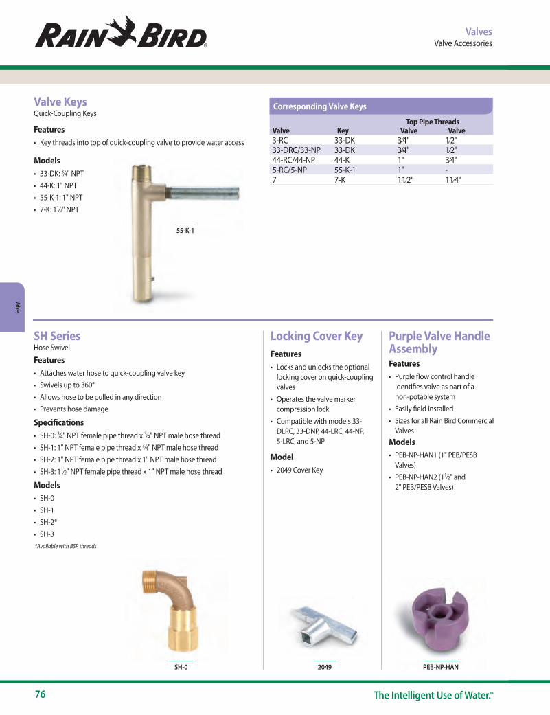
76 The Intelligent Use of Water.™
Valves
Top Pipe ThreadsValve Key Valve Valve3-RC 33-DK 3⁄4" 1⁄2"33-DRC/33-NP 33-DK 3⁄4" 1⁄2"44-RC/44-NP 44-K 1" 3⁄4"5-RC/5-NP 55-K-1 1" -7 7-K 11⁄2" 11⁄4"
ValvesValve Accessories
Valve KeysQuick-Coupling Keys
Features• Key threads into top of quick-coupling valve to provide water access
Models• 33-DK: 3⁄4" NPT • 44-K: 1" NPT • 55-K-1: 1" NPT • 7-K: 11⁄2" NPT
SH SeriesHose Swivel
Features• Attaches water hose to quick-coupling valve key• Swivels up to 360°• Allows hose to be pulled in any direction• Prevents hose damage
Specifications• SH-0: 3⁄4" NPT female pipe thread x 3⁄4" NPT male hose thread• SH-1: 1" NPT female pipe thread x 3⁄4" NPT male hose thread• SH-2: 1" NPT female pipe thread x 1" NPT male hose thread• SH-3: 11⁄2" NPT female pipe thread x 1" NPT male hose thread
Models• SH-0• SH-1• SH-2*• SH-3 *Available with BSP threads
SH-0
Locking Cover KeyFeatures• Locks and unlocks the optional
locking cover on quick-coupling valves
• Operates the valve marker compression lock
• Compatible with models 33-DLRC, 33-DNP, 44-LRC, 44-NP, 5-LRC, and 5-NP
Model• 2049 Cover Key
2049
Purple Valve Handle AssemblyFeatures• Purple flow control handle
identifies valve as part of a non-potable system
• Easily field installed• Sizes for all Rain Bird Commercial
ValvesModels• PEB-NP-HAN1 (1" PEB/PESB
Valves)• PEB-NP-HAN2 (11⁄2" and
2" PEB/PESB Valves)
PEB-NP-HAN
55-K-1
Corresponding Valve Keys

www.rainbird.com/valves
77www.rainbird.com
Valve
s
ValvesCommercial Valve Wire Sizing – 50Hz
24 VAC Solenoid Valves Wire Sizing – 50Hz Commercial Valve Wire Sizing ProcedureStep 1Determine actual distance, along wire run, from controller out to the first valve on a circuit and between each succeeding valve on a multiple valve circuit. Example: (Two watt solenoid, 26.5 volt transformer, 50Hz, at 150 psi water pressure at valves.)
Step 2Calculate the equivalent circuit length for each valve circuit on the controller. (See chart to left)
Step 3Selecting Common Wire Size: Using the longest equivalent length calculated above, go to the appropriate valve chart and select a common wire and a control wire that are as close to the same size as possible (the common wire size should always be equal to or one size larger than the control wire size.) In the example above, the circuit for station #3 has the longest equivalent length, 7000 feet. In the chart (for this example use the chart for 150 psi water pressure at the valve and a 26.5 volt transformer) select a wire size combination of size 14 and 12 wire. Select common wire as size 12 wire. Since one common wire shall be used for all valves on the controller, you have now established the common wire size for that controller as size 12 wire.
Step 4 Sizing Circuit Control Wires: Reading only from the row for the common wire size selected in Step 3 (size 12), proceed to select each control wire size from the chart using the calculated equivalent length for each circuit.
EXAMPLE:Station #1: Equiv. Length = 1 valve x 2000 ft. = 2000 ft. select size 18 control wire
Station #2: Equiv. Length = (1 valve x 1000 ft.) + (2 valves x 2000 ft.) = 5000 ft. select size 16 control wire
Station #3: Equiv. Length = (1 valve x 500 ft.) + (2 valves x 1000 ft.) + (3 valves x 1500 ft.) = 7000 ft. select size 14 control wire
80 psi (5.5 bar) Water Pressure at Valve Common Control Wire Size Wire Size 18 16 14 12 10 8 6 4 18 3700 16 4600 6000 14 5400 7400 9600 12 6000 8600 11800 15200 10 6500 9600 13700 18700 24200 8 6900 10400 15400 21800 29700 38500 6 7100 10900 16600 24300 34600 47100 60600 4 7300 11300 17500 26300 38800 55100 74600 97000
100 psi (6.9 bar) Water Pressure at Valve
Common Control Wire Size Wire Size 18 16 14 12 10 8 6 4 18 3200 16 4000 5200 14 4700 6400 8300 12 5200 7400 10200 13200 10 5600 8300 11900 16200 20900 8 5900 9000 13300 18900 25700 33300 6 6100 9500 14300 21100 29900 40700 52400 4 6300 9800 15100 22800 33500 47700 64600 83900
125 psi (8.6 bar) Water Pressure at Valve
Common Control Wire Size Wire Size 18 16 14 12 10 8 6 4
18 2900 16 3500 4600 14 4100 5700 7400 12 4600 6600 9000 11700 10 5000 7400 10500 14400 18600 8 5300 8000 11800 16800 22800 29600 6 5400 8400 12700 18700 26600 36200 46600 4 5600 8700 13400 20200 29800 42300 57300 74600
150 psi (10.4 bar) Water Pressure at Valve
Common Control Wire Size Wire Size 18 16 14 12 10 8 6 4
18 2600 16 3200 4100 14 3700 5000 6600 12 4100 5900 8100 10400 10 4500 6600 9400 12800 16600 8 4700 7100 10500 15000 20400 26400 6 4900 7500 11400 16700 23800 32300 41600 4 5000 7800 12000 18100 26600 37800 51300 66600
200 psi (13.8 bar) Water Pressure at Valve
Common Control Wire Size Wire Size 18 16 14 12 10 8 6 4
18 2400 16 2900 3800 14 3400 4700 6100 12 3800 5500 7500 9700 10 4100 6100 8800 11900 15500 8 4400 6600 9800 13900 19000 24600 6 4500 7000 10600 15500 22100 30100 38700 4 4600 7200 11100 16800 24800 35200 47700 62000
••••••••
••••••••
••••••••
••••••••
••••••••
9.8 VA Valves (EZ) with 26.5 Volt Transformers - Equivalent Feet of Circuit
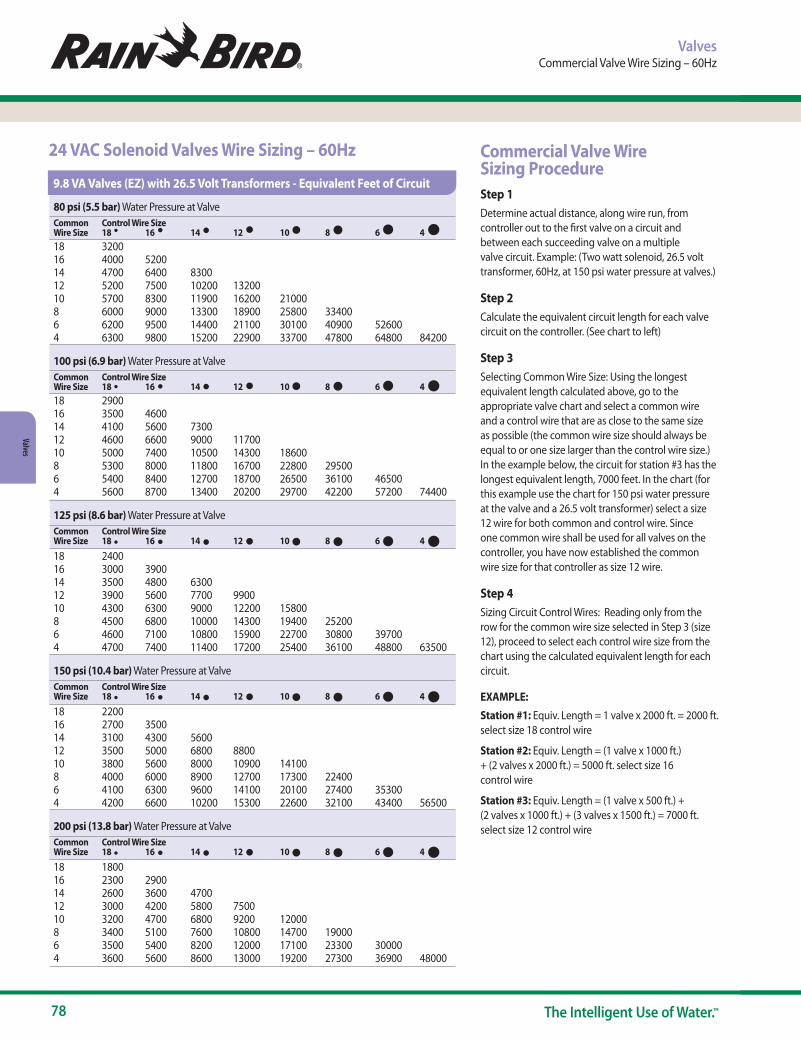
78 The Intelligent Use of Water.™
Valves
24 VAC Solenoid Valves Wire Sizing – 60Hz Commercial Valve Wire Sizing ProcedureStep 1Determine actual distance, along wire run, from controller out to the first valve on a circuit and between each succeeding valve on a multiple valve circuit. Example: (Two watt solenoid, 26.5 volt transformer, 60Hz, at 150 psi water pressure at valves.)
Step 2Calculate the equivalent circuit length for each valve circuit on the controller. (See chart to left)
Step 3Selecting Common Wire Size: Using the longest equivalent length calculated above, go to the appropriate valve chart and select a common wire and a control wire that are as close to the same size as possible (the common wire size should always be equal to or one size larger than the control wire size.) In the example below, the circuit for station #3 has the longest equivalent length, 7000 feet. In the chart (for this example use the chart for 150 psi water pressure at the valve and a 26.5 volt transformer) select a size 12 wire for both common and control wire. Since one common wire shall be used for all valves on the controller, you have now established the common wire size for that controller as size 12 wire.
Step 4 Sizing Circuit Control Wires: Reading only from the row for the common wire size selected in Step 3 (size 12), proceed to select each control wire size from the chart using the calculated equivalent length for each circuit.
EXAMPLE:Station #1: Equiv. Length = 1 valve x 2000 ft. = 2000 ft. select size 18 control wire
Station #2: Equiv. Length = (1 valve x 1000 ft.) + (2 valves x 2000 ft.) = 5000 ft. select size 16 control wire
Station #3: Equiv. Length = (1 valve x 500 ft.) + (2 valves x 1000 ft.) + (3 valves x 1500 ft.) = 7000 ft. select size 12 control wire
ValvesCommercial Valve Wire Sizing – 60Hz
80 psi (5.5 bar) Water Pressure at Valve Common Control Wire Size Wire Size 18 16 14 12 10 8 6 4 18 3200 16 4000 5200 14 4700 6400 8300 12 5200 7500 10200 13200 10 5700 8300 11900 16200 21000 8 6000 9000 13300 18900 25800 33400 6 6200 9500 14400 21100 30100 40900 52600 4 6300 9800 15200 22900 33700 47800 64800 84200
100 psi (6.9 bar) Water Pressure at Valve
Common Control Wire Size Wire Size 18 16 14 12 10 8 6 4 18 2900 16 3500 4600 14 4100 5600 7300 12 4600 6600 9000 11700 10 5000 7400 10500 14300 18600 8 5300 8000 11800 16700 22800 29500 6 5400 8400 12700 18700 26500 36100 46500 4 5600 8700 13400 20200 29700 42200 57200 74400
125 psi (8.6 bar) Water Pressure at Valve
Common Control Wire Size Wire Size 18 16 14 12 10 8 6 4
18 2400 16 3000 3900 14 3500 4800 6300 12 3900 5600 7700 9900 10 4300 6300 9000 12200 15800 8 4500 6800 10000 14300 19400 25200 6 4600 7100 10800 15900 22700 30800 39700 4 4700 7400 11400 17200 25400 36100 48800 63500
150 psi (10.4 bar) Water Pressure at Valve
Common Control Wire Size Wire Size 18 16 14 12 10 8 6 4
18 2200 16 2700 3500 14 3100 4300 5600 12 3500 5000 6800 8800 10 3800 5600 8000 10900 14100 8 4000 6000 8900 12700 17300 22400 6 4100 6300 9600 14100 20100 27400 35300 4 4200 6600 10200 15300 22600 32100 43400 56500
200 psi (13.8 bar) Water Pressure at Valve
Common Control Wire Size Wire Size 18 16 14 12 10 8 6 4
18 1800 16 2300 2900 14 2600 3600 4700 12 3000 4200 5800 7500 10 3200 4700 6800 9200 12000 8 3400 5100 7600 10800 14700 19000 6 3500 5400 8200 12000 17100 23300 30000 4 3600 5600 8600 13000 19200 27300 36900 48000
••••••••
••••••••
••••••••
••••••••
••••••••
9.8 VA Valves (EZ) with 26.5 Volt Transformers - Equivalent Feet of Circuit
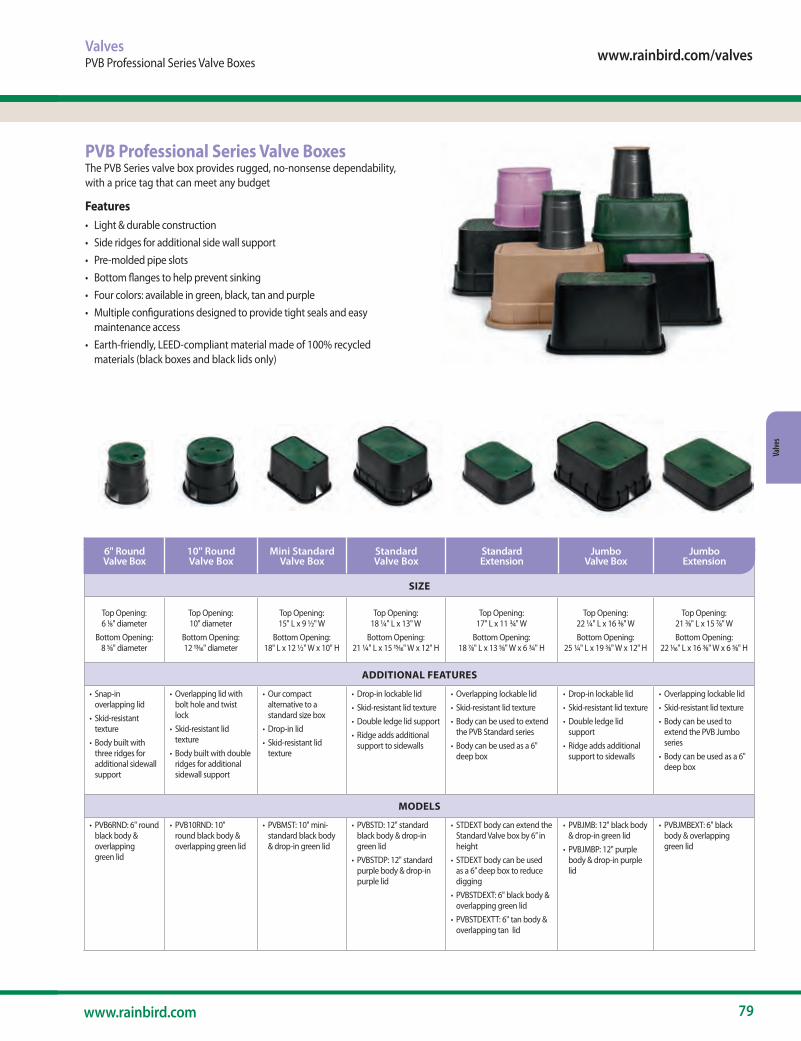
www.rainbird.com/valves
79www.rainbird.com
Valve
s
ValvesPVB Professional Series Valve Boxes
PVB Professional Series Valve BoxesThe PVB Series valve box provides rugged, no-nonsense dependability, with a price tag that can meet any budget
Features• Light & durable construction• Side ridges for additional side wall support• Pre-molded pipe slots• Bottom flanges to help prevent sinking• Four colors: available in green, black, tan and purple• Multiple configurations designed to provide tight seals and easy
maintenance access• Earth-friendly, LEED-compliant material made of 100% recycled
materials (black boxes and black lids only)
SIZE
Top Opening: 6 1⁄8" diameter
Bottom Opening: 8 5⁄8" diameter
Top Opening: 10" diameter
Bottom Opening: 12 13⁄16" diameter
Top Opening: 15" L x 9 ½" W
Bottom Opening: 18" L x 12 ½" W x 10" H
Top Opening: 18 ¼" L x 13" W
Bottom Opening: 21 ¼" L x 15 15⁄16" W x 12" H
Top Opening: 17" L x 11 ¾" W
Bottom Opening: 18 7⁄8" L x 13 5⁄8" W x 6 ¾" H
Top Opening: 22 ¼" L x 16 3⁄8" WBottom Opening:
25 ¼" L x 19 3⁄8" W x 12" H
Top Opening: 21 3⁄8" L x 15 7⁄8" WBottom Opening:
22 1⁄16" L x 16 3⁄8" W x 6 5⁄8" H
ADDITIONAL FEATURES
• Snap-in overlapping lid
• Skid-resistant texture
• Body built with three ridges for additional sidewall support
• Overlapping lid with bolt hole and twist lock
• Skid-resistant lid texture
• Body built with double ridges for additional sidewall support
• Our compact alternative to a standard size box
• Drop-in lid• Skid-resistant lid
texture
• Drop-in lockable lid• Skid-resistant lid texture• Double ledge lid support• Ridge adds additional
support to sidewalls
• Overlapping lockable lid• Skid-resistant lid texture• Body can be used to extend
the PVB Standard series• Body can be used as a 6"
deep box
• Drop-in lockable lid• Skid-resistant lid texture• Double ledge lid
support• Ridge adds additional
support to sidewalls
• Overlapping lockable lid• Skid-resistant lid texture• Body can be used to
extend the PVB Jumbo series
• Body can be used as a 6" deep box
MODELS
• PVB6RND: 6" round black body & overlapping green lid
• PVB10RND: 10" round black body & overlapping green lid
• PVBMST: 10" mini-standard black body & drop-in green lid
• PVBSTD: 12" standard black body & drop-in green lid
• PVBSTDP: 12" standard purple body & drop-in purple lid
• STDEXT body can extend the Standard Valve box by 6” in height
• STDEXT body can be used as a 6” deep box to reduce digging
• PVBSTDEXT: 6" black body & overlapping green lid
• PVBSTDEXTT: 6" tan body & overlapping tan lid
• PVBJMB: 12" black body & drop-in green lid
• PVBJMBP: 12" purple body & drop-in purple lid
• PVBJMBEXT: 6" black body & overlapping green lid
6" Round Valve Box
10" Round Valve Box
Mini Standard Valve Box
Standard Valve Box
Standard Extension
Jumbo Valve Box
Jumbo Extension
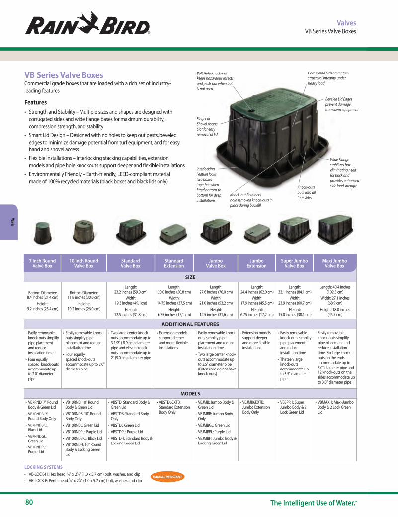
80 The Intelligent Use of Water.™
Valves
Finger or Shovel Access Slot for easy removal of lid
Bolt Hole Knock-outkeeps hazardous insects and pests out when bolt is not used
Interlocking Feature locks two boxes together when fitted bottom-to-bottom for deep installations
Beveled Lid Edgesprevent damage from lawn equipment
Knock-out Retainershold removed knock-outs in place during backfill
Knock-outs built into all four sides
Corrugated Sides maintain structural integrity under heavy load
Wide Flange stabilizes box eliminating need for brick and provides enhanced side load strength
VB Series Valve BoxesCommercial grade boxes that are loaded with a rich set of industry-leading features
Features• Strength and Stability – Multiple sizes and shapes are designed with
corrugated sides and wide flange bases for maximum durability, compression strength, and stability
• Smart Lid Design – Designed with no holes to keep out pests, beveled edges to minimize damage potential from turf equipment, and for easy hand and shovel access
• Flexible Installations – Interlocking stacking capabilities, extension models and pipe hole knockouts support deeper and flexible installations
• Environmentally Friendly – Earth-friendly, LEED-compliant material made of 100% recycled materials (black boxes and black lids only)
LOCKING SYSTEMS• VB-LOCK-H: Hex head 3⁄8" x 21⁄4" (1.0 x 5.7 cm) bolt, washer, and clip• VB-LOCK-P: Penta head 3⁄8" x 21⁄4" (1.0 x 5.7 cm) bolt, washer, and clip
ValvesVB Series Valve Boxes
VANDAL RESISTANT
SIZE
Bottom Diameter: 8.4 inches (21,4 cm)
Height: 9.2 inches (23,4 cm)
Bottom Diameter: 11.8 inches (30,0 cm)
Height: 10.2 inches (26,0 cm)
Length: 23.2 inches (59,0 cm)
Width: 19.3 inches (49,1cm)
Height: 12.5 inches (31,8 cm)
Length: 20.0 inches (50,8 cm)
Width: 14.75 inches (37,5 cm)
Height: 6.75 inches (17,1 cm)
Length: 27.6 inches (70,0 cm)
Width: 21.0 inches (53,2 cm)
Height: 12.5 inches (31,6 cm)
Length: 24.4 inches (62,0 cm)
Width: 17.9 inches (45,5 cm)
Height: 6.75 inches (17,2 cm)
Length: 33.1 inches (84,1 cm)
Width: 23.9 inches (60,7 cm)
Height: 15.0 inches (38,1 cm)
Length: 40.4 inches (102,5 cm)
Width: 27.1 inches (68,9 cm)
Height: 18.0 inches (45,7 cm)
ADDITIONAL FEATURES
• Easily removable knock-outs simplify pipe placement and reduce installation time
• Four equally spaced knock-outs accommodate up to 2.0" diameter pipe
• Easily removable knock-outs simplify pipe placement and reduce installation time
• Four equally spaced knock-outs accommodate up to 2.0" diameter pipe
• Two large center knock-outs accommodate up to 3 1/2" ( 8.9 cm) diameter pipe and eleven knock-outs accommodate up to 2" (5.0 cm) diameter pipe
• Extension models support deeper and more flexible installations
• Easily removable knock-outs simplify pipe placement and reduce installation time
• Two large center knock-outs accommodate up to 3.5" diameter pipe. (Extensions do not have knock-outs)
• Extension models support deeper and more flexible installations
• Easily removable knock-outs simplify pipe placement and reduce installation time
• Thirteen large knock-outs accommodate up to 3.5" diameter pipe
• Easily removable knock-outs simplify pipe placement and reduce installation time. Six large knock-outs on the ends accommodate up to 5.0" diameter pipe and 12 knock-outs on the sides accommodate up to 3.0" diameter pipe
MODELS
• VB7RND: 7" Round Body & Green Lid
• VB7RNDB: 7" Round Body Only
• VB7RNDBKL: Black Lid
• VB7RNDGL: Green Lid
• VB7RNDPL: Purple Lid
• VB10RND: 10" Round Body & Green Lid
• VB10RNDB: 10" Round Body Only
• VB10RNDL: Green Lid• VB10RNDPL: Purple Lid• VB10RNDBKL: Black Lid• VB10RNDH: 10" Round
Body & Locking Green Lid
• VBSTD: Standard Body & Green Lid
• VBSTDB: Standard Body Only
• VBSTDL Green Lid• VBSTDPL: Purple Lid• VBSTDH: Standard Body &
Locking Green Lid
• VBSTD6EXTB: Standard Extension Body Only
• VBJMB: Jumbo Body & Green Lid
• VBJMBB: Jumbo Body Only
• VBJMBGL: Green Lid• VBJMBPL: Purple Lid • VBJMBH: Jumbo Body &
Locking Green Lid
• VBJMB6EXTB: Jumbo Extension Body Only
• VBSPRH: Super Jumbo Body & 2 Lock Green Lid
• VBMAXH: Maxi-Jumbo Body & 2 Lock Green Lid
7 Inch Round Valve Box
10 Inch Round Valve Box
Standard Valve Box
Standard Extension
Jumbo Valve Box
Jumbo Extension
Super Jumbo Valve Box
Maxi Jumbo Valve Box
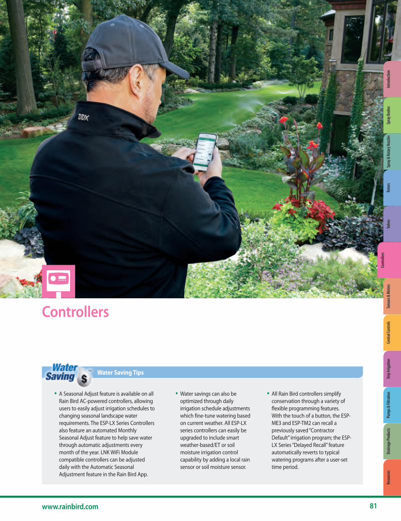
Controllers
• A Seasonal Adjust feature is available on all Rain Bird AC-powered controllers, allowing users to easily adjust irrigation schedules to changing seasonal landscape water requirements. The ESP-LX Series Controllers also feature an automated Monthly Seasonal Adjust feature to help save water through automatic adjustments every month of the year. LNK WiFi Module compatible controllers can be adjusted daily with the Automatic Seasonal Adjustment feature in the Rain Bird App.
• Water savings can also be optimized through daily irrigation schedule adjustments which fine-tune watering based on current weather. All ESP-LX series controllers can easily be upgraded to include smart weather-based/ET or soil moisture irrigation control capability by adding a local rain sensor or soil moisture sensor.
• All Rain Bird controllers simplify conservation through a variety of flexible programming features. With the touch of a button, the ESP-ME3 and ESP-TM2 can recall a previously saved “Contractor Default” irrigation program; the ESP-LX Series “Delayed Recall” feature automatically reverts to typical watering programs after a user-set time period.
Water Saving Tips
81www.rainbird.com
Spra
y & Ro
tary
Noz
zles
Roto
rsVa
lves
Cont
rolle
rsSe
nsor
s & M
eter
sCe
ntra
l Con
trols
Drip
Irrig
atio
nPu
mps
& Fi
ltrat
ion
Drain
age P
rodu
cts
Reso
urce
sIn
trodu
ctio
nSp
ray B
odies
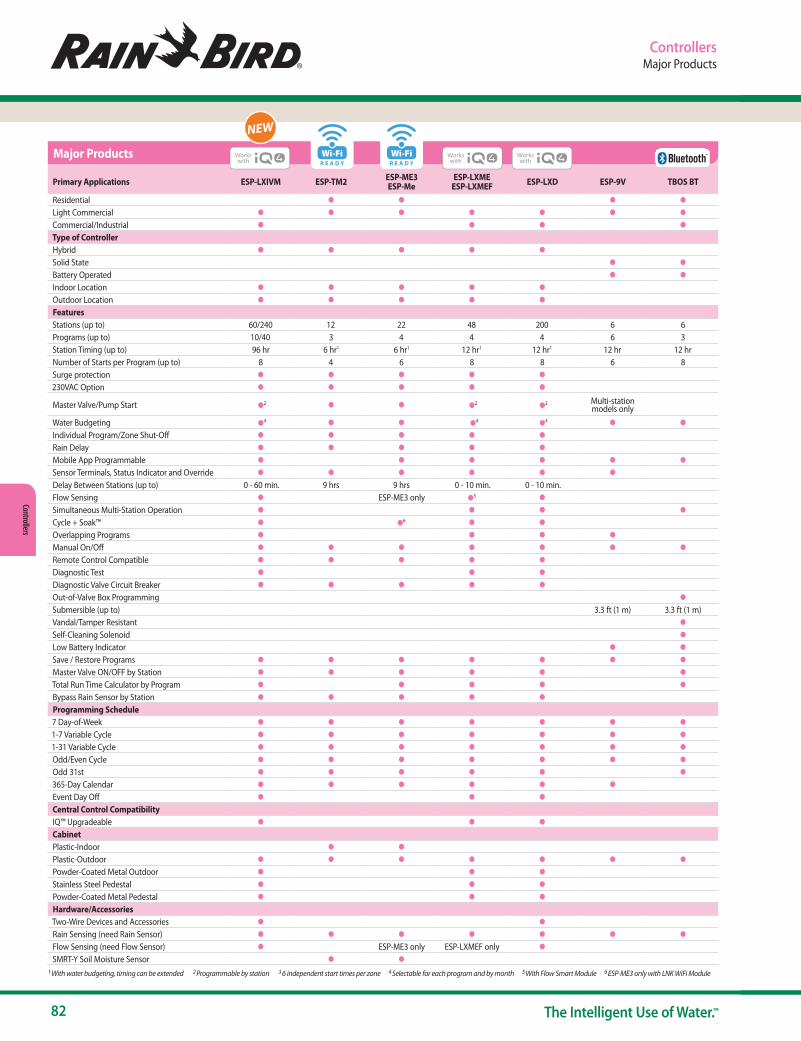
82 The Intelligent Use of Water.™
Controllers
Primary Applications ESP-LXIVM ESP-TM2 ESP-ME3 ESP-Me
ESP-LXME ESP-LXMEF ESP-LXD ESP-9V TBOS BT
Residential ● ● ● ●
Light Commercial ● ● ● ● ● ● ●
Commercial/Industrial ● ● ● ●
Type of ControllerHybrid ● ● ● ● ●
Solid State ● ●
Battery Operated ● ●
Indoor Location ● ● ● ● ●
Outdoor Location ● ● ● ● ●
FeaturesStations (up to) 60/240 12 22 48 200 6 6Programs (up to) 10/40 3 4 4 4 6 3Station Timing (up to) 96 hr 6 hr1 6 hr1 12 hr1 12 hr1 12 hr 12 hrNumber of Starts per Program (up to) 8 4 6 8 8 6 8Surge protection ● ● ● ● ●
230VAC Option ● ● ● ● ●
Master Valve/Pump Start ●2 ● ● ●2 ●2 Multi-station models only
Water Budgeting ●4 ● ● ●4 ●4 ● ●
Individual Program/Zone Shut-Off ● ● ● ● ●
Rain Delay ● ● ● ● ●
Mobile App Programmable ● ● ● ● ● ●
Sensor Terminals, Status Indicator and Override ● ● ● ● ● ●
Delay Between Stations (up to) 0 - 60 min. 9 hrs 9 hrs 0 - 10 min. 0 - 10 min.Flow Sensing ● ESP-ME3 only ●5 ●
Simultaneous Multi-Station Operation ● ● ● ●
Cycle + Soak™ ● ●6 ● ●
Overlapping Programs ● ● ● ●
Manual On/Off ● ● ● ● ● ● ●
Remote Control Compatible ● ● ● ● ●
Diagnostic Test ● ● ●
Diagnostic Valve Circuit Breaker ● ● ● ● ●
Out-of-Valve Box Programming ●
Submersible (up to) 3.3 ft (1 m) 3.3 ft (1 m)Vandal/Tamper Resistant ●
Self-Cleaning Solenoid ●
Low Battery Indicator ● ●
Save / Restore Programs ● ● ● ● ● ● ●
Master Valve ON/OFF by Station ● ● ● ● ● ●
Total Run Time Calculator by Program ● ● ● ● ●
Bypass Rain Sensor by Station ● ● ● ● ●
Programming Schedule7 Day-of-Week ● ● ● ● ● ● ●
1-7 Variable Cycle ● ● ● ● ● ● ●
1-31 Variable Cycle ● ● ● ● ● ● ●
Odd/Even Cycle ● ● ● ● ● ● ●
Odd 31st ● ● ● ● ● ●
365-Day Calendar ● ● ● ● ● ●
Event Day Off ● ● ●
Central Control CompatibilityIQ™ Upgradeable ● ● ●
CabinetPlastic-Indoor ● ●
Plastic-Outdoor ● ● ● ● ● ● ●
Powder-Coated Metal Outdoor ● ● ●
Stainless Steel Pedestal ● ● ●
Powder-Coated Metal Pedestal ● ● ●
Hardware/AccessoriesTwo-Wire Devices and Accessories ● ●
Rain Sensing (need Rain Sensor) ● ● ● ● ● ● ●
Flow Sensing (need Flow Sensor) ● ESP-ME3 only ESP-LXMEF only ●
SMRT-Y Soil Moisture Sensor ● ●
Major Products
ControllersMajor Products
1 With water budgeting, timing can be extended 2 Programmable by station 3 6 independent start times per zone 4 Selectable for each program and by month 5 With Flow Smart Module 6 ESP-ME3 only with LNK WiFi Module
Wi-FiR E A D Y
Wi-FiR E A D Y
NEW

www.rainbird.com/controllers
83www.rainbird.com
Cont
rolle
rs
NEW
ControllersESP-LXIVM and LXIVM Pro 2-Wire Controllers
ESP-LXIVM and LXIVM Pro 2-Wire Controllers60/240 Station Capable Two-Wire Commercial Controller
Controller Features• 60-station capability standard expandable to 240 stations with LXIVM
Pro Panel• Four available sensor inputs (one wired plus up to three on 2-Wire path)
with override switch. Eight (Seven plus 1) for LX-IVM Pro• Five flow sensors supported (LX-IVM), Ten for LX-IVM Pro• Supported Field devices: IVM-SOL, IVM-OUT and IVM Smart Valves• Supports IVM-SEN sensor devices (flow sensing and weather sensor
support) and IVM-SD surge devices (one per 500 feet of two-wire path or every 15 devices required)
• Central Control capable with Rain Bird IQ Communications Cartridges and software (see pg. 106)
• Six user-selectable languages• 10 independent programs (LX-IVM) or 40 Programs (LX-IVM Pro)• Removable front panel is programmable under battery power• Compatible with Rain Bird Landscape Irrigation and Maintenance and
Third Party Remotes• Plastic, locking, UV resistant, wall-mount case, Optional Metal and
Stainless Steel Case & Pedestal
Operating Specifications• Station timing: 0 min to 96 hrs • Program level and global Monthly Seasonal Adjust; 0% to 300% (96 hrs
maximum station run time) • 8 start times per program• Program Day Cycles include Custom days of the week, Odd, Odd no 31st,
Even, and Cyclical dates • Manual station, program, test program
Diagnostic Features • Alarm light with external case lens • 2-Wire diagnostics to simplify and expedite troubleshooting• Four isolated wire paths prevent full system failure under a single short • 2-Wire Mapping: Maps the devices to corresponding wire paths in the
controller to help quickly find and resolve issues• Trending 12-month electrical history reports and proactive action • Self-Healing: Automatically detect “fixes” to wire path and splice issues
and re-start irrigation without reliance on manual intervention• Two- Way Communication: with Intelligent Valve Modules (IVM)
communication happens both ways enabling key features • Self-Shutoff : Once loss of power is detected, automatically shutoff
valve to avoid leaks
Certifications• cULus, CE, IPX4. For current certifications visit:
www.rainbird.com/esplxivm
ESP-LXIVM Controller
Allows users to control/monitor 1 to 1000s of controllers from their
computer or mobile device

84 The Intelligent Use of Water.™
Controllers
ControllersESP-LXIVM and LXIVM Pro 2-Wire Controllers
ESP-LXIVM and LXIVM Pro 2-Wire Controllers(cont.)Water Management Features • Learn Flow utility and flow usage totalizer help optimize water usage • FloWatch™ protection for high and low fl ow conditions set by the user
FloManager™ manages hydraulic demand, make full use of available water to turn on as many stations as possible without exceeding water supply and reducing the total time to complete irrigation cycles.
• SimulStations™ allows stations to operate at the same time; up to 8 with LX-IVM and 16 with LXIVM Pro
• Cycle+Soak™ by station • Rain Delay up to 30 days • 365-Day Calendar Day Off (up to 5 days) • Station Delay by program • Normally Open or Normally Closed Master Valves programmable by
station; up to 5 with LX-IVM and 10 with LX-IVM Pro • Optional Weather Sensors are programmable by station to prevent or
pause watering; up to 4 with LX-IVM and 8 with LX-IVM Pro • Seasonal Adjust by Program or by Month
Environmental • Operating Temperature
- Operating temperature range: 14ºF to 149ºF (-10ºC to 65ºC) • Operating Humidity
- Operating humidity range: 95% max at 40ºF to 120ºF (4ºC to 49ºC) in a non-condensing environment
• Storage Temperature - Storage temperature range: -40ºF to 150ºF (-40ºC to 66ºC)
• Upgrade Options - IQ-NCC Network Communication Cartridge - LXIVM Pro Panels (for regular 60 station controllers)
Electrical Specifications• Power Supply Voltage: 120 VAC ± 10%, 60Hz • Power back-up: Lithium coin-cell battery maintains time and date while
nonvolatile memory maintains the schedule• Simultaneous operation of up to eight (IVM) or sixteen (IVM Pro) Stations
plus any corresponding master valves
Dimensions (W x H x D)• 14.32” x 12.69” x 5.50” (36.4 x 32.2 x 14.0 cm)
Model• ESPLXIVM: Domestic Version 120VC• ESPLXIVMP: Domestic Version (Pro) 120V
Accessories• IVM Field Devices* (see next page)• Painted Metal and Stainless Steel Pedestal/Enclosure Options
available (see pg. 95)• IQ-NCC: Network Communication Cartridge for ESP-LX Series
Controllers (see pg. 106)• See page 98 for information on Rain Bird FS-Series Flow Sensors• Pump Start Relays (PSR110-IVM or PSR220-IVM)
* IVM Field devices include peel-off barcode address labels
For more information call the ESP-LX Hotline: 1-866-544-1406
LXMMSSPED Shown with ESP-LXIVM in LXMMSS Stainless Steel Cabinet

www.rainbird.com/controllers
85www.rainbird.com
Cont
rolle
rs
IVM-SOL
IVM-OUT
IVM-SEN
IVM-SD
ControllersESP-LXIVM and LXIVM Pro 2-Wire Controllers
Field Devices ESP-LXIVM 2-Wire Field Devices Field Devices are installed along the 2-Wire path to interface with valves and other hardware.
IVM-SOL • Interfaces with LX-IVM to control station valves and master valves • Interfaces with PEB, PESB, PGA, EFB-BP and BESP Valves • Available pre-installed in a SmartValve configuration with PEB and
PGA Valves• Rain Bird WC20 connectors (included) to be used for all splices• Current Draw: 0.67mA• Model: LXIVMSOL
IVM-OUT • Interfaces with LX-IVM to manage 3rd party valves and external gear
such as pump stations • Rain Bird WC20 connectors (included) to be used for all splices• Current Draw: 0.67mA • Model: LXIVMOUT
IVM-SEN• Interfaces with LX-IVM to control weather sensors or flow sensors • Rain Bird WC20 connectors (included) to be used for all splices• Current Draw: 6mA • Model: LXIVMSEN
IVM-SD (Surge Protection)• IVM-SD provides surge protection on the 2-Wire path • One every 500ft or 15 field devices • Rain Bird WC20 connectors to be used for all splices• Model: LXIVMSD
Feature LX-IVM LX-IVM Pro
Max Programs 10 40
Stations 60 240
Max Simulstations 8 16 (plus active MV's)
Master Valves 5 10
Flow sensors 5 10
Weather sensors 4 8 (including 1 Local)
Watering windows 1 per program
Max run time 96 hrs
Start Times/program 8
Interstation delay Up to 1 hour per program
LCD 2.5”x5” at 127x256 pixels. Monochrome with backlight
Front Panel Buttons- All Buttons are back-lit - 5 Programming Button - Dedicated Language, Info and Back Buttons
Transformer size 1.9 amp (50 VA)
IVM current draw 720 uA (Standby)
Sensor current draw 8.4mA (Standby)
Max wire run1.65 miles (2.66Km) 14 AWG in Star configuration 6.61 miles (10.63Km) Looped
No. 2-Wire paths and terminal pairs 4
Cabinet Plastic
FloWatch (flow sensing)YES - Available Options: Diagnose & Eliminate, Shut Down & Alarm, Alarm Only
FloManager (flow optimization) Yes
Flow Rate 0 to 9999.9 gallons/min. (0.1 gallons/min. resolution)
Supported Flow SensorsFS050P, FS075P, FS100P, FS150P, FS200P, FS300P, FS400P, FS100B, FS150B,FS200B, FS350B, FS350SS, Custom
Surge 20 kV int. - 1 IVM-SD every 500 ft. (or 15 field devices)
Valve type DC Latching
Diagnostics Short FindingAutomatically Detect and Turn Off Wire Path Ability to turn on constant current source for field trouble shooting
Diagnostics Electrical History- Daily Values (Last 30 Days) - Monthly Averages (Last 12 Mos.) - Values recorded 11:59 PM daily
Diagnostics – Field Device Response List Responding and List Not Responding
Diagnostics Controller OutputTracks Current Draw from 2-Wire Path 0.67 mA per IVM-SOL/IVM-OUT 6 mA per IVM-SEN
Diagnostics Watering Test Test All Stations 1 to 10 Mins. (per station)
Central Control Capable Yes
Key Specifications
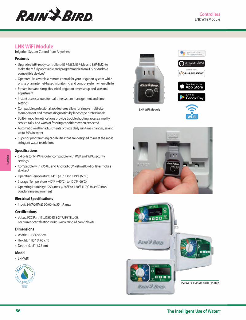
86 The Intelligent Use of Water.™
Controllers
LNK WiFi ModuleIrrigation System Control from Anywhere
Features• Upgrades WiFi-ready controllers (ESP-ME3, ESP-Me and ESP-TM2) to
make them fully accessible and programmable from iOS or Android compatible devices*
• Operates like a wireless remote control for your irrigation system while onsite or an internet-based monitoring and control system when offsite
• Streamlines and simplifies initial irrigation timer setup and seasonal adjustment
• Instant access allows for real-time system management and timer settings
• Compatible professional app features allow for simple multi-site management and remote diagnostics by landscape professionals
• Built-in mobile notifications provide troubleshooting access, simplify service calls, and warn of freezing conditions when expected
• Automatic weather adjustments provide daily run time changes, saving up to 50% in water
• Superior programming capabilities that are designed to meet the most stringent water restrictions
Specifications• 2.4 GHz (only) WiFi router compatible with WEP and WPA security
settings• Compatible with iOS 8.0 and Android 6 (Marshmallow) or later mobile
devices*• Operating Temperature: 14° F (-10° C) to 149°F (65°C)• Storage Temperature: -40°F (-40°C) to 150°F (66°C)• Operating Humidity: 95% max @ 50°F to 120°F (10°C to 49°C) non-
condensing environment
Electrical Specifications• Input: 24VAC(RMS) 50/60Hz; 55mA max
Certifications• cULus, FCC Part 15c, ISED RSS-247, IFETEL, CE.
For current certifications visit: www.rainbird.com/lnkwifi
Dimensions• Width: 1.13” (2.87 cm)• Height: 1.83” (4.65 cm)• Depth: 0.48” (1.22 cm)
Model• LNKWIFI
LNK WiFi Module
ControllersLNK WiFi Module
ESP-ME3, ESP-Me and ESP-TM2
Wi-Fi

www.rainbird.com/controllers
87www.rainbird.com
Cont
rolle
rs
ControllersESP-TM2 Series Controller
ESP-TM2 Series ControllerSimple, Flexible, and Reliable for Residential Applications
Features• Upgradeable for WiFi-based remote monitoring and control via iOS and
Android mobile devices (with LNK WiFi Module sold separately).• Internet-based weather information can be used to make daily
adjustments to the irrigation schedule, saving up to 30% in water (with LNK WiFi Module sold separately).
• 4, 6, 8, and 12 station models to meet small or large residential irrigation needs
• Set Permanent Days Off per program to ensure watering never occurs on days when maintenance crews are on site (for Odd/Even/ Cyclic schedules)
• Easy to install indoors or outdoors with pre-installed power cord• Quick programming in just 3 steps for ease of setup• 3 available programs with up to 4 start times for each program to meet
the needs of varied landscapes• One-touch manual watering capability for ease of use• Large back-lit LCD display for improved visibility in low-light and direct
sun conditions• Contractor Default™ allows you to easily save and restore your custom
schedule• Delay Watering up to 14 days and automatically resume watering after
the set delay has elapsed• Bypass Rain Sensor for any station gives you the ability to customize
which stations react to a rain sensor• Seasonal Adjust by program allows you to easily reduce or increase
watering by program
Specifications• Operating Temperature: Up to 149°F (65°C)• Storage Temperature: -40°F (-40°C) to 150°F (66°C)• Operating Humidity: 95% max @ 50°F to 120°F (10°C to 49°C) non-
condensing environment
Electrical Specifications• Input required: 120VAC (±10%) @ 60Hz• Output: 1A at 24VAC• Master Valve/Pump Start Relay• External battery back-up not required. Nonvolatile memory
permanently saves the current programming and a 10 year life lithium battery maintains the controllers time and date during power outages
Certifications• cULus, FCC Part 15b, CAN ICES-3(B)/NMB-3(B), NOM-001-SCFI-1993, CE.
For current certifications visit: www.rainbird.com/esptm2
Dimensions• Width: 7.92 in. (20.1 cm)• Height: 7.86 in. (20.0 cm)• Depth: 3.51 in. (9.0 cm)
Models• TM2-4-120V: 4-station 120VAC• TM2-6-120V: 6-station 120VAC• TM2-8-120V: 8-station 120VAC• TM2-12-120V: 12-station 120VAC
Accessories• LNKWIFI: LNK WiFi Module for remote control and notification via iOS or
Android device• WR2 Series Wireless Rain + Freeze Sensors• RSD Series Rain Sensors
ESP-TM2Look for the WaterSense labeled LNK WiFi Module and a Rain Bird Rain Sensor to improve the water efficiency capabilities of this controller
Works withLNK WiFi

88 The Intelligent Use of Water.™
Controllers
ControllersESP-Me Series Controllers
ESP-ME3 and ESP-Me Series ControllersThe industry’s most flexible irrigation controller solution. Supports up to 22 stations
Features• Upgradeable for WiFi-based remote monitoring and control via iOS and
Android mobile devices (with LNK WiFi Module sold separately).• Internet-based weather information can be used to make daily
adjustments to the irrigation schedule, saving up to 30% in water (with LNK WiFi Module sold separately).
• Large LCD display with easy to navigate user interface• Master valve/pump start circuit• Non-Volatile (100 year) storage memory• Remotely Programmable under 9V battery power (not included)• Program based scheduling allows 4 individual programs with 6
independent start times per program for 24 total start times• Watering schedule options: By days of week, ODD calendar days, EVEN
calendar days, or Cyclic (every 1 – 30 days) Advanced Features• Advanced diagnostics and short detection with LED alert• Contractor Default™ Program Save/Restore saved program(s)• Rain Sensor bypass by Station• Delay Watering up to 14 days (applies only to stations not set to ignore
Rain Sensor)• Manual Watering option by program or station• Seasonal Adjust applied to all programs or individual program• Adjustable delay between valves (default set to 0)• Master Valve on/off by station
ESP-ME3 Specific Features• Built-in flow-sensing capabilities• Easy to install indoors or outdoors with pre-installed power cord• Back-lit LCD display for improved visibility in low-light and direct
sun conditions
Operating Specifications• Station timing: 1 minute to 6 hours• Seasonal Adjust: 5% to 200%• Max operating temperature: 149°F (65°C)
Electrical Specifications• Input Required: 120VAC ± 10%, 60Hz
(International models: 230/240VAC ± 10%, 50/60Hz)
• Master Valve/Pump Start Relay
• Operating Voltage: 24VAC 50/60Hz
• Max Coil Inrush: 11VA
• Max Coil Holding: 5VA - Idle/Off power draw 0.06 amps at 120VAC
• Power back-up not required. Nonvolatile memory permanently saves the current programming and a 10 year life lithium battery maintains the controllers time and date during power outages.
Certifications• cULus, FCC Part 15b, CAN ICES-3(B)/NMB-3(B). For current certifications
visit: www.rainbird.com/espme, www.rainbird.com/me3
Dimensions• Width: 10.7" (27.2 cm)
• Height: 7.7" (19.5 cm)
• Depth: 4.4" (11.2 cm)
North America Models (120VAC)• Controller Base Models
- ESP4MEI: 4 station indoor model - ESP4ME3: 4 station indoor / outdoor model
• Modules - ESPSM3: 3 station module - ESPSM6: 6 station module (compatible with ESP-ME3 and ESP-ME
series controllers only)
Accessories• LNKWIFI: LNK WiFi Module for remote control and notification via iOS or
Android device• WR2: Wireless Rain + Freeze Sensors• RSD Series Rain Sensors• MJ100B Flow Sensor and other wired flow sensors*
* ESP-ME3 only
ESP-ME3 and ESP-Me Series Controller and Modules
Look for the WaterSense labeled LNK WiFi Module and a Rain Bird Rain Sensor to improve the water efficiency capabilities of this controller
Works withLNK WiFi
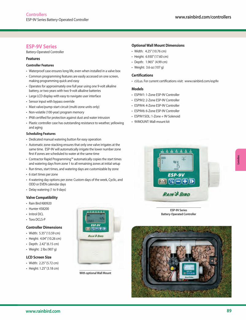
www.rainbird.com/controllers
89www.rainbird.com
Cont
rolle
rs
ControllersESP-9V Series Battery-Operated Controller
ESP-9V SeriesBattery-Operated Controller
Features
Controller Features• Waterproof case ensures long life, even when installed in a valve box• Common programming features are easily accessed on one screen,
making programming quick and easy• Operates for approximately one full year using one 9-volt alkaline
battery, or two years with two 9-volt alkaline batteries• Large LCD display with easy to navigate user interface• Sensor input with bypass override• Mast valve/pump-start circuit (multi-zone units only)• Non-volatile (100-year) program memory• IP68 certified for protection against dust and water intrusion• Plastic controller case has outstanding resistance to weather, yellowing
and aging
Scheduling Features• Dedicated manual watering button for easy operation• Automatic zone-stacking ensures that only one valve irrigates at the
same time. ESP-9V will automatically irrigate the lower number zone first if zones are scheduled to water at the same time
• Contractor Rapid Programming™ automatically copies the start times and watering days from zone 1 to all remaining zones at initial setup
• Run times, start times, and watering days are customizable by zone• 6 start times per zone• 4 watering day options per zone: Custom days of the week, Cyclic, and
ODD or EVEN calendar days• Delay watering (1 to 9 days)
Valve Compatibility• Rain Bird K80920• Hunter 458200• Irritrol DCL• Toro DCLS-P
Controller Dimensions• Width: 5.35” (13.59 cm)• Height: 4.04” (10.26 cm)• Depth: 2.42” (6.15 cm)• Weight: 2 lbs (907 g)
LCD Screen Size• Width: 2.25” (5.72 cm)• Height: 1.25” (3.18 cm)
Optional Wall Mount Dimensions• Width: 4.25” (10.76 cm)• Height: 6.930” (17.60 cm)• Depth: 1.965” (4.99 cm)• Weight: 3.6 oz (107 g)
Certifications• cULus. For current certifications visit: www.rainbird.com/esp9v
Models• ESP9V1: 1-Zone ESP-9V Controller• ESP9V2: 2-Zone ESP-9V Controller• ESP9V4: 4-Zone ESP-9V Controller• ESP9V6: 6-Zone ESP-9V Controller• ESP9V1SOL: 1-Zone + 9V Solenoid• 9VMOUNT: Wall-mount kit
With optional Wall Mount
ESP-9V Series Battery-Operated Controller

90 The Intelligent Use of Water.™
Controllers
ControllersTBOS-BT Bluetooth Battery-Operated Controller
TBOS-BTBluetooth Battery-Operated Controller.Install anywhere. Program from a Smartphone.
Features
Rain Bird Mobile App Features for TBOS BT• Create, review and transmit irrigation programs• Capability to set zones or programs to manually irrigate• Basic programming includes 3 independent programs A,B and C, each
with 8 start times per day• Stations can be assigned to several programs with different watering
run times• Run time is from 1 minute to 12 hours in 1-minute increments• Five watering day cycle modes (Custom, even, odd, odd-31, cyclical)
selectable by program for maximum flexibility and watering• Program and global Monthly Seasonal Adjust; 0% to 300% (1%
increments)• Delay watering from 1 to 14 days• Built-in ID with naming capability. The control module and stations can
be individually named.• Optional passcode• Permanently turn the controller off to prevent irrigation• Battery indicator reports the status of the control module's battery• Capability to clear the control module’s irrigation program
Controller Features• Operates for approximately one full year using one 9-volt alkaline
battery• Completely potted to obtain IP68 conformity• Independent station operation allows sequential start times (with
stacking in case of overlap) restriction compliance• Master valve output on TBOS BT1, 2, 4, & 6 Control Modules• No loss of irrigation program after a battery replacement
Valve Compatibility• Rain Bird TBOS Potted Latching Solenoid (K80920)
- DV, DVF, ASVF, PGA, PEB, PESB, EFB-CP, and BPES series• Hunter 458200• Irritrol DCL• Toro DCLS-P
Certifications• cULus , FCC Part 15b , ISED RSS-247 Issue 2.0 , CE , IP68, ICASA, CITC,
ACMA, SUBTEL, SRRC, MIC, IFETEL, CRA, TRA. For current certifications visit: www.rainbird.com/tbosbt
TBOS-BT System Components
Rain Bird Mobile App Features for TBOS BT• Available for Android and IOS devices
Models• TBOS-BT1 (1 Station)• TBOS-BT2 (2 Station)• TBOS-BT4 (4 Station)• TBOS-BT6 (6 Station)
Accessories• K80920 TBOSPSOL: TBOS Potted Latching Solenoid• RSDBEX: RSD Series Rain Sensors• Adapter for Non-Rain Bird plastic valves
- K80510 TBOSADAPP• Adapter for Non-Rain Bird brass valves
- K80610 TBOSADAPB
TBOS-BT Bluetooth Battery-Operated
Controller and Mobile App
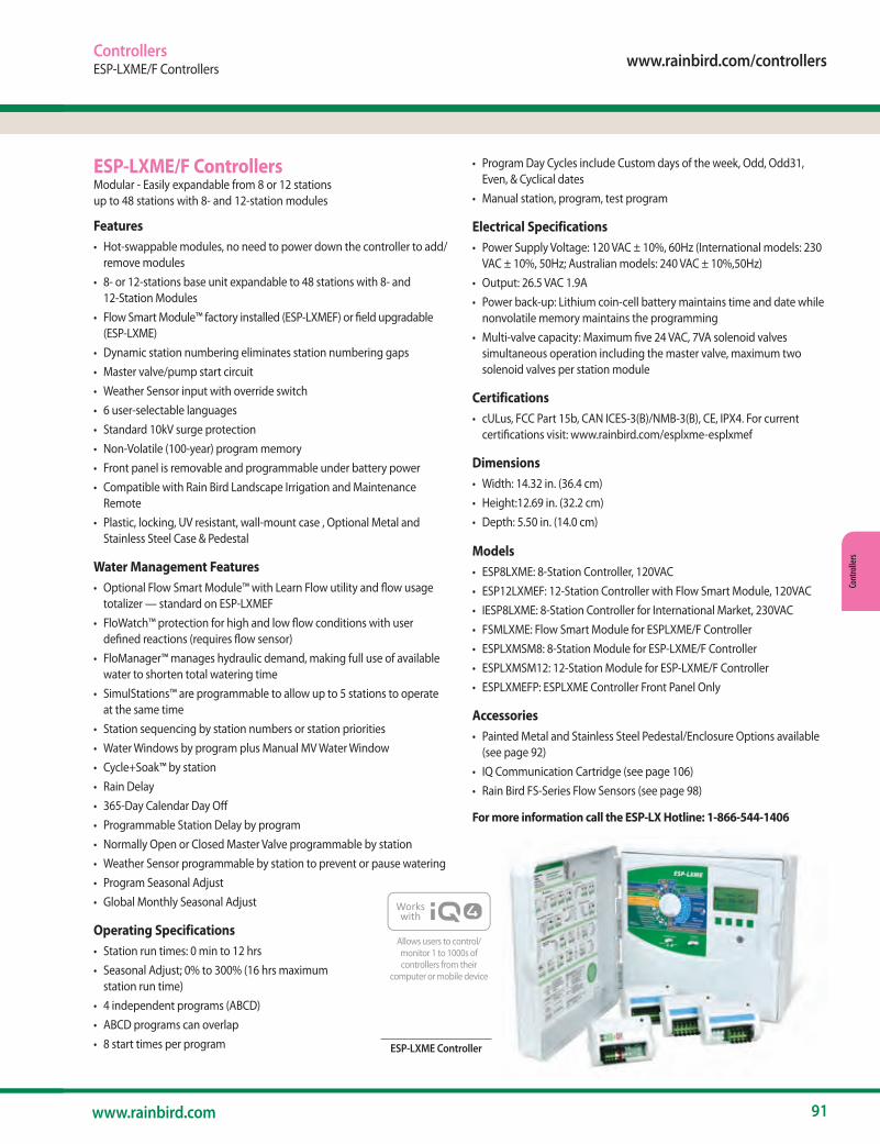
www.rainbird.com/controllers
91www.rainbird.com
Cont
rolle
rs
ControllersESP-LXME/F Controllers
ESP-LXME/F ControllersModular - Easily expandable from 8 or 12 stations up to 48 stations with 8- and 12-station modules
Features• Hot-swappable modules, no need to power down the controller to add/
remove modules • 8- or 12-stations base unit expandable to 48 stations with 8- and
12-Station Modules • Flow Smart Module™ factory installed (ESP-LXMEF) or field upgradable
(ESP-LXME)• Dynamic station numbering eliminates station numbering gaps • Master valve/pump start circuit • Weather Sensor input with override switch • 6 user-selectable languages • Standard 10kV surge protection • Non-Volatile (100-year) program memory • Front panel is removable and programmable under battery power• Compatible with Rain Bird Landscape Irrigation and Maintenance
Remote• Plastic, locking, UV resistant, wall-mount case , Optional Metal and
Stainless Steel Case & Pedestal
Water Management Features• Optional Flow Smart Module™ with Learn Flow utility and flow usage
totalizer — standard on ESP-LXMEF• FloWatch™ protection for high and low flow conditions with user
defined reactions (requires flow sensor)• FloManager™ manages hydraulic demand, making full use of available
water to shorten total watering time• SimulStations™ are programmable to allow up to 5 stations to operate
at the same time• Station sequencing by station numbers or station priorities• Water Windows by program plus Manual MV Water Window• Cycle+Soak™ by station• Rain Delay• 365-Day Calendar Day Off• Programmable Station Delay by program• Normally Open or Closed Master Valve programmable by station• Weather Sensor programmable by station to prevent or pause watering• Program Seasonal Adjust• Global Monthly Seasonal Adjust
Operating Specifications• Station run times: 0 min to 12 hrs• Seasonal Adjust; 0% to 300% (16 hrs maximum
station run time)• 4 independent programs (ABCD)• ABCD programs can overlap• 8 start times per program
• Program Day Cycles include Custom days of the week, Odd, Odd31, Even, & Cyclical dates
• Manual station, program, test program
Electrical Specifications• Power Supply Voltage: 120 VAC ± 10%, 60Hz (International models: 230
VAC ± 10%, 50Hz; Australian models: 240 VAC ± 10%,50Hz)• Output: 26.5 VAC 1.9A• Power back-up: Lithium coin-cell battery maintains time and date while
nonvolatile memory maintains the programming• Multi-valve capacity: Maximum five 24 VAC, 7VA solenoid valves
simultaneous operation including the master valve, maximum two solenoid valves per station module
Certifications• cULus, FCC Part 15b, CAN ICES-3(B)/NMB-3(B), CE, IPX4. For current
certifications visit: www.rainbird.com/esplxme-esplxmef
Dimensions• Width: 14.32 in. (36.4 cm)• Height:12.69 in. (32.2 cm)• Depth: 5.50 in. (14.0 cm)
Models• ESP8LXME: 8-Station Controller, 120VAC • ESP12LXMEF: 12-Station Controller with Flow Smart Module, 120VAC • IESP8LXME: 8-Station Controller for International Market, 230VAC • FSMLXME: Flow Smart Module for ESPLXME/F Controller • ESPLXMSM8: 8-Station Module for ESP-LXME/F Controller • ESPLXMSM12: 12-Station Module for ESP-LXME/F Controller • ESPLXMEFP: ESPLXME Controller Front Panel Only
Accessories• Painted Metal and Stainless Steel Pedestal/Enclosure Options available
(see page 92)• IQ Communication Cartridge (see page 106)• Rain Bird FS-Series Flow Sensors (see page 98)
For more information call the ESP-LX Hotline: 1-866-544-1406
ESP-LXME Controller
Allows users to control/monitor 1 to 1000s of controllers from their
computer or mobile device
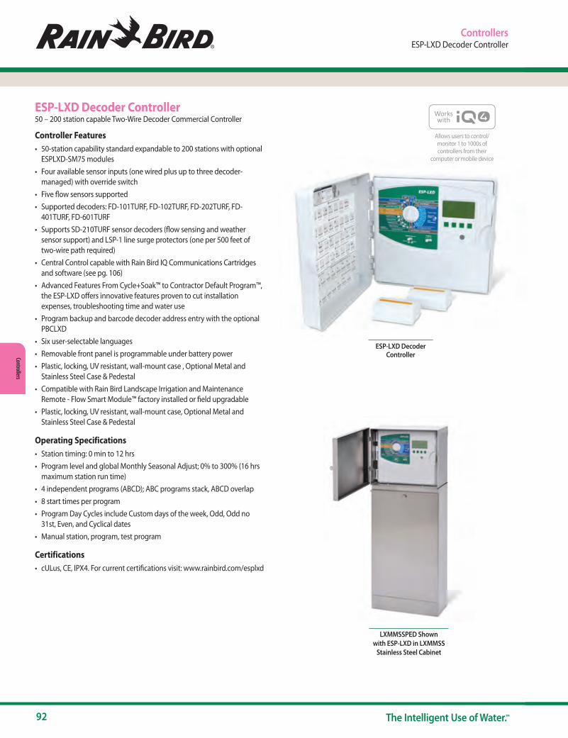
92 The Intelligent Use of Water.™
Controllers
ESP-LXD Decoder Controller50 – 200 station capable Two-Wire Decoder Commercial Controller
Controller Features• 50-station capability standard expandable to 200 stations with optional
ESPLXD-SM75 modules• Four available sensor inputs (one wired plus up to three decoder-
managed) with override switch• Five flow sensors supported• Supported decoders: FD-101TURF, FD-102TURF, FD-202TURF, FD-
401TURF, FD-601TURF• Supports SD-210TURF sensor decoders (flow sensing and weather
sensor support) and LSP-1 line surge protectors (one per 500 feet of two-wire path required)
• Central Control capable with Rain Bird IQ Communications Cartridges and software (see pg. 106)
• Advanced Features From Cycle+Soak™ to Contractor Default Program™, the ESP-LXD offers innovative features proven to cut installation expenses, troubleshooting time and water use
• Program backup and barcode decoder address entry with the optional PBCLXD
• Six user-selectable languages• Removable front panel is programmable under battery power• Plastic, locking, UV resistant, wall-mount case , Optional Metal and
Stainless Steel Case & Pedestal • Compatible with Rain Bird Landscape Irrigation and Maintenance
Remote - Flow Smart Module™ factory installed or field upgradable• Plastic, locking, UV resistant, wall-mount case, Optional Metal and
Stainless Steel Case & Pedestal
Operating Specifications• Station timing: 0 min to 12 hrs • Program level and global Monthly Seasonal Adjust; 0% to 300% (16 hrs
maximum station run time) • 4 independent programs (ABCD); ABC programs stack, ABCD overlap • 8 start times per program • Program Day Cycles include Custom days of the week, Odd, Odd no
31st, Even, and Cyclical dates • Manual station, program, test program
Certifications• cULus, CE, IPX4. For current certifications visit: www.rainbird.com/esplxd
ControllersESP-LXD Decoder Controller
ESP-LXD Decoder Controller
LXMMSSPED Shown with ESP-LXD in LXMMSS
Stainless Steel Cabinet
Allows users to control/monitor 1 to 1000s of controllers from their
computer or mobile device
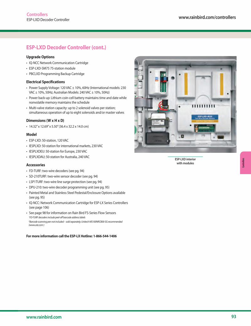
www.rainbird.com/controllers
93www.rainbird.com
Cont
rolle
rs
Upgrade Options• IQ-NCC Network Communication Cartridge • ESP-LXD-SM75 75-station module • PBCLXD Programming Backup Cartridge
Electrical Specifications• Power Supply Voltage: 120 VAC ± 10%, 60Hz (International models: 230
VAC ± 10%, 50Hz; Australian Models: 240 VAC ± 10%, 50Hz) • Power back-up: Lithium coin-cell battery maintains time and date while
nonvolatile memory maintains the schedule • Multi-valve station capacity: up to 2 solenoid valves per station;
simultaneous operation of up to eight solenoids and/or master valves
Dimensions (W x H x D)• 14.32” x 12.69” x 5.50” (36.4 x 32.2 x 14.0 cm)
Model• ESP-LXD: 50-station, 120 VAC• IESPLXD: 50-station for international markets, 230 VAC• IESPLXDEU: 50-station for Europe, 230 VAC• IESPLXDAU; 50-station for Australia, 240 VAC
Accessories• FD-TURF: two-wire decoders (see pg. 94)• SD-210TURF: two-wire sensor decoder (see pg. 94)• LSP1TURF: two-wire line surge protection (see pg. 94)• DPU-210: two-wire decoder programming unit (see pg. 95)• Painted Metal and Stainless Steel Pedestal/Enclosure Options available
(see pg. 95)• IQ-NCC: Network Communication Cartridge for ESP-LX Series Controllers
(see page 106)• See page 98 for information on Rain Bird FS-Series Flow Sensors 1FD-TURF decoders include peel-off barcode address labels 2Barcode scanning pen not included – sold separately; Unitech MS100NRCB00-SG recommended
(www.ute.com )
For more information call the ESP-LX Hotline: 1-866-544-1406
ESP-LXD Decoder Controller (cont.)
ControllersESP-LXD Decoder Controller
ESP-LXD interior with modules
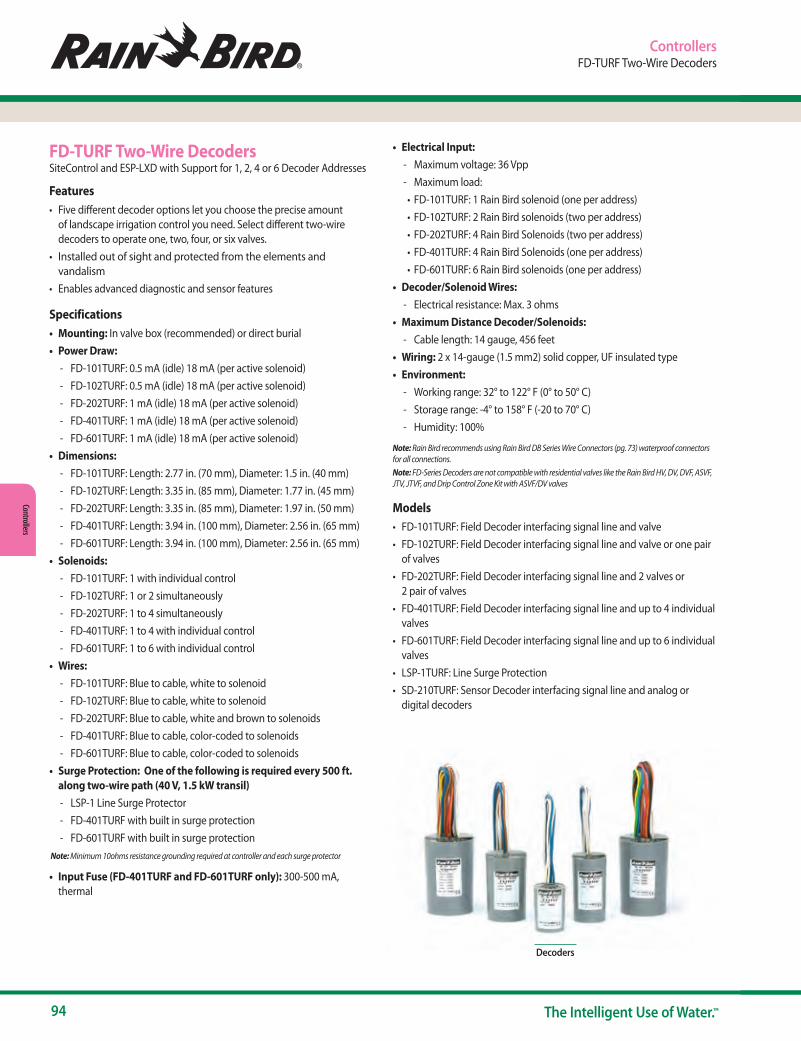
94 The Intelligent Use of Water.™
Controllers
ControllersFD-TURF Two-Wire Decoders
FD-TURF Two-Wire DecodersSiteControl and ESP-LXD with Support for 1, 2, 4 or 6 Decoder Addresses
Features• Five different decoder options let you choose the precise amount
of landscape irrigation control you need. Select different two-wire decoders to operate one, two, four, or six valves.
• Installed out of sight and protected from the elements and vandalism
• Enables advanced diagnostic and sensor features
Specifications• Mounting: In valve box (recommended) or direct burial• Power Draw:
- FD-101TURF: 0.5 mA (idle) 18 mA (per active solenoid) - FD-102TURF: 0.5 mA (idle) 18 mA (per active solenoid) - FD-202TURF: 1 mA (idle) 18 mA (per active solenoid) - FD-401TURF: 1 mA (idle) 18 mA (per active solenoid) - FD-601TURF: 1 mA (idle) 18 mA (per active solenoid)
• Dimensions: - FD-101TURF: Length: 2.77 in. (70 mm), Diameter: 1.5 in. (40 mm) - FD-102TURF: Length: 3.35 in. (85 mm), Diameter: 1.77 in. (45 mm) - FD-202TURF: Length: 3.35 in. (85 mm), Diameter: 1.97 in. (50 mm) - FD-401TURF: Length: 3.94 in. (100 mm), Diameter: 2.56 in. (65 mm) - FD-601TURF: Length: 3.94 in. (100 mm), Diameter: 2.56 in. (65 mm)
• Solenoids: - FD-101TURF: 1 with individual control - FD-102TURF: 1 or 2 simultaneously - FD-202TURF: 1 to 4 simultaneously - FD-401TURF: 1 to 4 with individual control - FD-601TURF: 1 to 6 with individual control
• Wires: - FD-101TURF: Blue to cable, white to solenoid - FD-102TURF: Blue to cable, white to solenoid - FD-202TURF: Blue to cable, white and brown to solenoids - FD-401TURF: Blue to cable, color-coded to solenoids - FD-601TURF: Blue to cable, color-coded to solenoids
• Surge Protection: One of the following is required every 500 ft. along two-wire path (40 V, 1.5 kW transil)
- LSP-1 Line Surge Protector - FD-401TURF with built in surge protection - FD-601TURF with built in surge protection
Note: Minimum 10ohms resistance grounding required at controller and each surge protector
• Input Fuse (FD-401TURF and FD-601TURF only): 300-500 mA, thermal
Decoders
• Electrical Input: - Maximum voltage: 36 Vpp - Maximum load: • FD-101TURF: 1 Rain Bird solenoid (one per address)• FD-102TURF: 2 Rain Bird solenoids (two per address)• FD-202TURF: 4 Rain Bird Solenoids (two per address)• FD-401TURF: 4 Rain Bird Solenoids (one per address)• FD-601TURF: 6 Rain Bird solenoids (one per address)
• Decoder/Solenoid Wires: - Electrical resistance: Max. 3 ohms
• Maximum Distance Decoder/Solenoids: - Cable length: 14 gauge, 456 feet
• Wiring: 2 x 14-gauge (1.5 mm2) solid copper, UF insulated type• Environment:
- Working range: 32° to 122° F (0° to 50° C) - Storage range: -4° to 158° F (-20 to 70° C) - Humidity: 100%
Note: Rain Bird recommends using Rain Bird DB Series Wire Connectors (pg. 73) waterproof connectors for all connections.Note: FD-Series Decoders are not compatible with residential valves like the Rain Bird HV, DV, DVF, ASVF, JTV, JTVF, and Drip Control Zone Kit with ASVF/DV valves
Models• FD-101TURF: Field Decoder interfacing signal line and valve• FD-102TURF: Field Decoder interfacing signal line and valve or one pair
of valves• FD-202TURF: Field Decoder interfacing signal line and 2 valves or
2 pair of valves• FD-401TURF: Field Decoder interfacing signal line and up to 4 individual
valves• FD-601TURF: Field Decoder interfacing signal line and up to 6 individual
valves• LSP-1TURF: Line Surge Protection• SD-210TURF: Sensor Decoder interfacing signal line and analog or
digital decoders

www.rainbird.com/controllers
95www.rainbird.com
Cont
rolle
rs
Controller PedestalsPedestals for ESP-LX Series, ESP-MC, ESP-SAT, ESP-SITE, and CCU Features• Includes all necessary moun ting bolts, nuts, and washers
Specifications• Material: Powder-coated steel and stainless steel• Field wiring connection: In controller
Dimensions Model Height Width Depth• LXMM 127⁄8" (32.7 cm) 14½" (36.8 cm) 7¾" (19.7 cm)• LXMMPED 28" (71.1 cm) 14¼" (36.2 cm) 7¼" (18.4 cm) • LXMMSS 127⁄8" (32.7 cm) 14½" (36.8 cm) 7¾" (19.7 cm)• LXMMSSPED 28" (71.1 cm) 14¼" (36.2 cm) 7¼" (18.4 cm)
Model• LXMM: Metal Cabinet for
ESP-LX Series Controllers*• LXMMPED: Metal Pedestal for
ESP-LX Series Controllers*• LXMMSS: Stainless Steel Metal
Wall Mount Enclosure for ESP-LX Series Controllers
• LXMMSSPED: Stainless Steel Metal Pedestal for ESP-LX Series Controllers
* Note: Metal cabinets and pedestals are not standard on ESP-LX Series controllers and must be purchased separately. LXMMPED requires LXMM, and LXMMSSPED requires LXMSS.
LXMMSSPED Shown with ESP-LXIVM in LXMMSS Stainless Steel Cabinet
PBCLXD Cartridge
PBCLXD Programming Backup Cartridge for ESP-LXDProvides program backup and restore and barcode scanning capability for the ESP-LXD controller (not compatible with ESP-LXME or ESP-LX Basic)
Upgrade Kit Features• Provides 8 full backups, including all programs, flow information
and decoder addresses – allows you to easily archive 8 different controllers – restoring all information typically takes two minutes or less
• Snaps into the back of the ESP-LXD front panel; installs without tools; no additional enclosures or external wiring required
• Kit includes cable for interface to barcode scanning pen (pen not included) – allows you to quickly scan decoder addresses into the ESP-LXD controller during installation to save you time
Model• PBCLXD (works with all versions of the ESP-LXD controller)
ControllersPBC-LXD, Controller Pedestals DPU-210 Decoder Programming Unit
DPU-210
DPU-210 Decoder Programming UnitFor ESP-LXD, MDC/MDC2 and SiteControl FD-Turf Two-Wire Decoders
• Decoder Programming Unit tests and verifies operation of the ESP-LXD, MDC/MDC2, or SiteControl FD Series Field Decoders. Also allows for re-programming decoder addresses for maximum site set-up flexibility
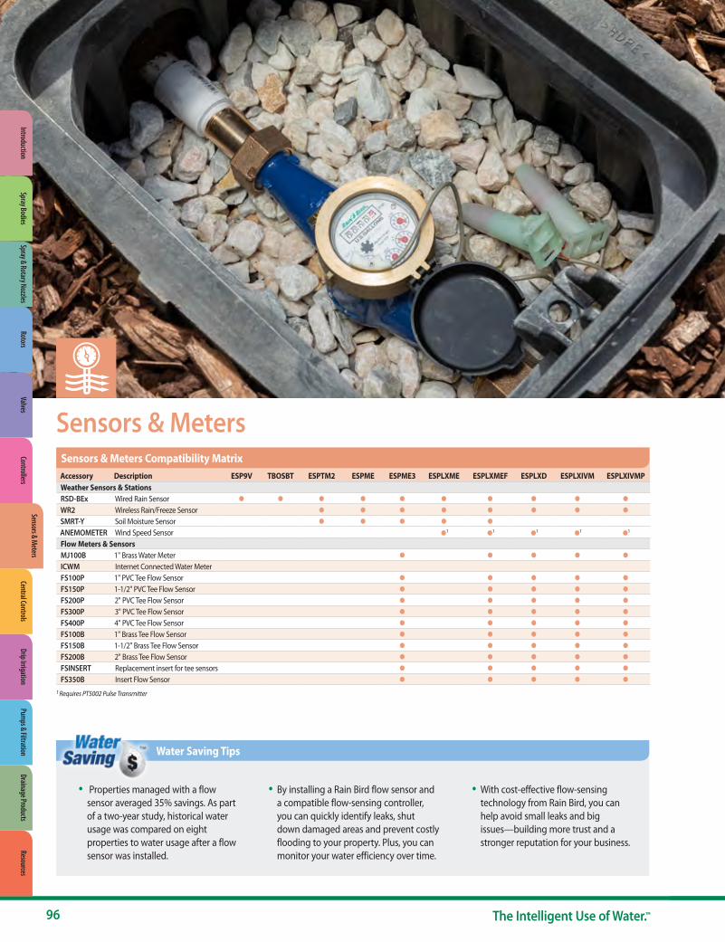
96 The Intelligent Use of Water.™
Sensors & Meters
• Properties managed with a flow sensor averaged 35% savings. As part of a two-year study, historical water usage was compared on eight properties to water usage after a flow sensor was installed.
• By installing a Rain Bird flow sensor and a compatible flow-sensing controller, you can quickly identify leaks, shut down damaged areas and prevent costly flooding to your property. Plus, you can monitor your water efficiency over time.
• With cost-effective flow-sensing technology from Rain Bird, you can help avoid small leaks and big issues—building more trust and a stronger reputation for your business.
Water Saving Tips
Accessory Description ESP9V TBOSBT ESPTM2 ESPME ESPME3 ESPLXME ESPLXMEF ESPLXD ESPLXIVM ESPLXIVMPWeather Sensors & StationsRSD-BEx Wired Rain Sensor ● ● ● ● ● ● ● ● ● ●
WR2 Wireless Rain/Freeze Sensor ● ● ● ● ● ● ● ●
SMRT-Y Soil Moisture Sensor ● ● ● ● ●
ANEMOMETER Wind Speed Sensor ●1 ●1 ●1 ●1 ●1
Flow Meters & SensorsMJ100B 1" Brass Water Meter ● ● ● ● ●
ICWM Internet Connected Water MeterFS100P 1" PVC Tee Flow Sensor ● ● ● ● ●
FS150P 1-1/2" PVC Tee Flow Sensor ● ● ● ● ●
FS200P 2" PVC Tee Flow Sensor ● ● ● ● ●
FS300P 3" PVC Tee Flow Sensor ● ● ● ● ●
FS400P 4" PVC Tee Flow Sensor ● ● ● ● ●
FS100B 1" Brass Tee Flow Sensor ● ● ● ● ●
FS150B 1-1/2" Brass Tee Flow Sensor ● ● ● ● ●
FS200B 2" Brass Tee Flow Sensor ● ● ● ● ●
FSINSERT Replacement insert for tee sensors ● ● ● ● ●
FS350B Insert Flow Sensor ● ● ● ● ●
Sensors & Meters Compatibility Matrix
1 Requires PT5002 Pulse Transmitter
Sensors & Meters
Spray & Rotary NozzlesRotors
ValvesControllers
Sensors & Meters
Central ControlsDrip Irrigation
Pumps & Filtration
Drainage ProductsResources
IntroductionSpray Bodies
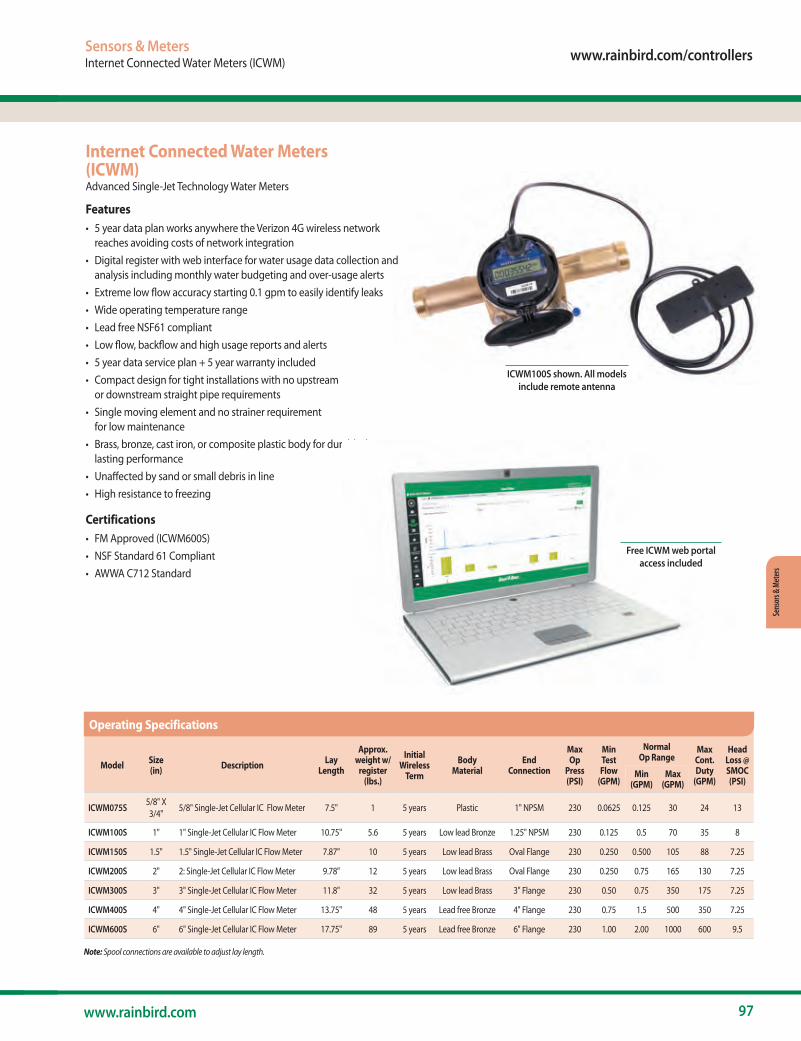
www.rainbird.com/controllers
97www.rainbird.com
Sens
ors &
Met
ers
Sensors & MetersInternet Connected Water Meters (ICWM)
Internet Connected Water Meters (ICWM)Advanced Single-Jet Technology Water Meters
Features• 5 year data plan works anywhere the Verizon 4G wireless network
reaches avoiding costs of network integration• Digital register with web interface for water usage data collection and
analysis including monthly water budgeting and over-usage alerts• Extreme low flow accuracy starting 0.1 gpm to easily identify leaks• Wide operating temperature range• Lead free NSF61 compliant• Low flow, backflow and high usage reports and alerts• 5 year data service plan + 5 year warranty included• Compact design for tight installations with no upstream
or downstream straight pipe requirements• Single moving element and no strainer requirement
for low maintenance• Brass, bronze, cast iron, or composite plastic body for durable, long-
lasting performance• Unaffected by sand or small debris in line• High resistance to freezing
Certifications• FM Approved (ICWM600S)• NSF Standard 61 Compliant • AWWA C712 Standard
Model Size (in) Description Lay
Length
Approx. weight w/
register (lbs.)
Initial Wireless
Term
Body Material
End Connection
Max Op
Press (PSI)
Min Test Flow
(GPM)
Normal Op Range
Max Cont. Duty
(GPM)
Head Loss @ SMOC (PSI)
Min (GPM)
Max (GPM)
ICWM075S 5/8" X 3/4" 5/8" Single-Jet Cellular IC Flow Meter 7.5" 1 5 years Plastic 1" NPSM 230 0.0625 0.125 30 24 13
ICWM100S 1" 1" Single-Jet Cellular IC Flow Meter 10.75" 5.6 5 years Low lead Bronze 1.25" NPSM 230 0.125 0.5 70 35 8
ICWM150S 1.5" 1.5" Single-Jet Cellular IC Flow Meter 7.87" 10 5 years Low lead Brass Oval Flange 230 0.250 0.500 105 88 7.25
ICWM200S 2" 2: Single-Jet Cellular IC Flow Meter 9.78" 12 5 years Low lead Brass Oval Flange 230 0.250 0.75 165 130 7.25
ICWM300S 3" 3" Single-Jet Cellular IC Flow Meter 11.8" 32 5 years Low lead Brass 3" Flange 230 0.50 0.75 350 175 7.25
ICWM400S 4" 4" Single-Jet Cellular IC Flow Meter 13.75" 48 5 years Lead free Bronze 4" Flange 230 0.75 1.5 500 350 7.25
ICWM600S 6" 6" Single-Jet Cellular IC Flow Meter 17.75" 89 5 years Lead free Bronze 6" Flange 230 1.00 2.00 1000 600 9.5
Note: Spool connections are available to adjust lay length.
Operating Specifications
ICWM100S shown. All models include remote antenna
Free ICWM web portal access included
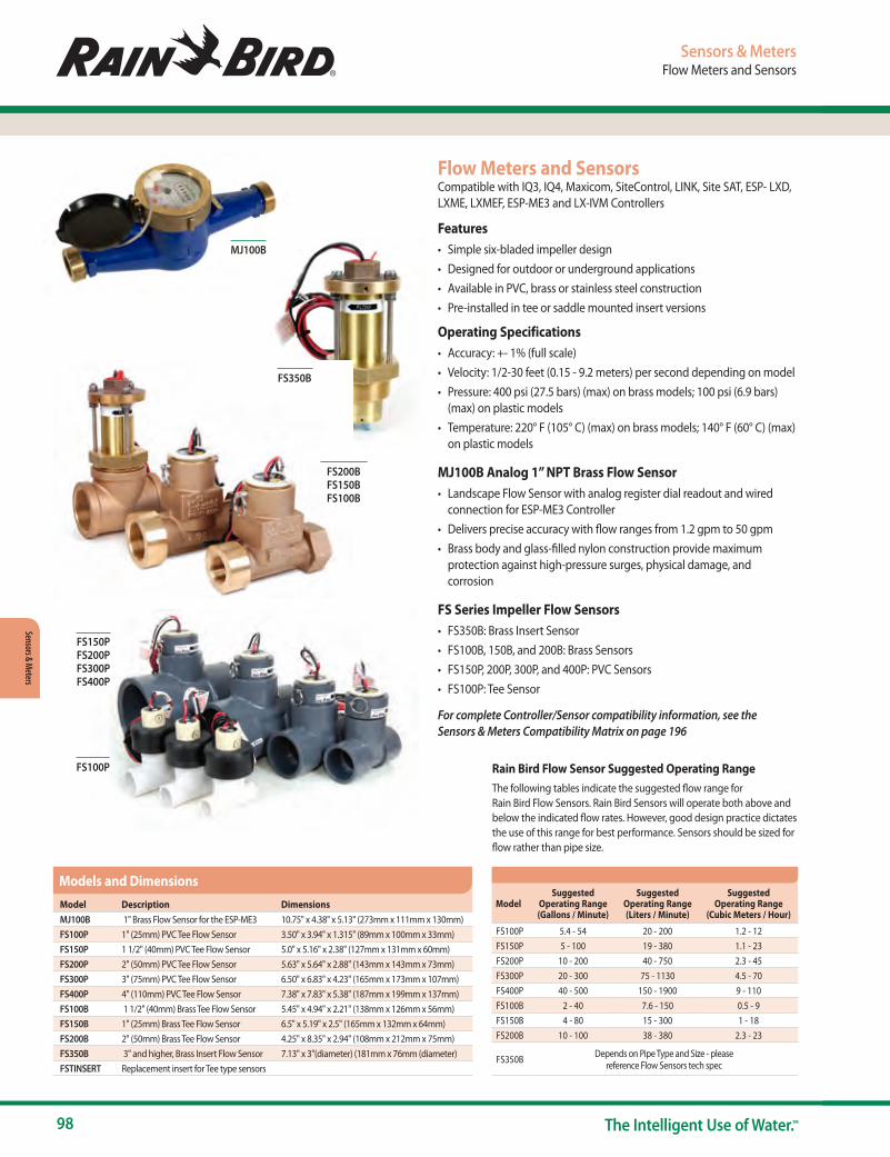
98 The Intelligent Use of Water.™
Sensors & Meters
Sensors & MetersFlow Meters and Sensors
Flow Meters and SensorsCompatible with IQ3, IQ4, Maxicom, SiteControl, LINK, Site SAT, ESP- LXD, LXME, LXMEF, ESP-ME3 and LX-IVM Controllers
Features• Simple six-bladed impeller design• Designed for outdoor or underground applications• Available in PVC, brass or stainless steel construction• Pre-installed in tee or saddle mounted insert versions
Operating Specifications• Accuracy: +- 1% (full scale)• Velocity: 1/2-30 feet (0.15 - 9.2 meters) per second depending on model• Pressure: 400 psi (27.5 bars) (max) on brass models; 100 psi (6.9 bars)
(max) on plastic models• Temperature: 220° F (105° C) (max) on brass models; 140° F (60° C) (max)
on plastic models
MJ100B Analog 1” NPT Brass Flow Sensor• Landscape Flow Sensor with analog register dial readout and wired
connection for ESP-ME3 Controller• Delivers precise accuracy with flow ranges from 1.2 gpm to 50 gpm• Brass body and glass-filled nylon construction provide maximum
protection against high-pressure surges, physical damage, and corrosion
FS Series Impeller Flow Sensors• FS350B: Brass Insert Sensor• FS100B, 150B, and 200B: Brass Sensors• FS150P, 200P, 300P, and 400P: PVC Sensors• FS100P: Tee Sensor
For complete Controller/Sensor compatibility information, see the Sensors & Meters Compatibility Matrix on page 196
MJ100B
FS350B
FS200B FS150B FS100B
FS150P FS200P FS300P FS400P
FS100P
ModelSuggested
Operating Range(Gallons / Minute)
Suggested Operating Range (Liters / Minute)
Suggested Operating Range
(Cubic Meters / Hour)
FS100P 5.4 - 54 20 - 200 1.2 - 12FS150P 5 - 100 19 - 380 1.1 - 23FS200P 10 - 200 40 - 750 2.3 - 45FS300P 20 - 300 75 - 1130 4.5 - 70FS400P 40 - 500 150 - 1900 9 - 110FS100B 2 - 40 7.6 - 150 0.5 - 9FS150B 4 - 80 15 - 300 1 - 18FS200B 10 - 100 38 - 380 2.3 - 23
FS350B Depends on Pipe Type and Size - please reference Flow Sensors tech spec
Model Description DimensionsMJ100B 1" Brass Flow Sensor for the ESP-ME3 10.75" x 4.38" x 5.13" (273mm x 111mm x 130mm)FS100P 1" (25mm) PVC Tee Flow Sensor 3.50" x 3.94" x 1.315" (89mm x 100mm x 33mm)FS150P 1 1/2" (40mm) PVC Tee Flow Sensor 5.0" x 5.16" x 2.38" (127mm x 131mm x 60mm)FS200P 2" (50mm) PVC Tee Flow Sensor 5.63" x 5.64" x 2.88" (143mm x 143mm x 73mm)FS300P 3" (75mm) PVC Tee Flow Sensor 6.50" x 6.83" x 4.23" (165mm x 173mm x 107mm)FS400P 4" (110mm) PVC Tee Flow Sensor 7.38" x 7.83" x 5.38" (187mm x 199mm x 137mm)FS100B 1 1/2" (40mm) Brass Tee Flow Sensor 5.45" x 4.94" x 2.21" (138mm x 126mm x 56mm)FS150B 1" (25mm) Brass Tee Flow Sensor 6.5" x 5.19" x 2.5" (165mm x 132mm x 64mm)FS200B 2" (50mm) Brass Tee Flow Sensor 4.25" x 8.35" x 2.94" (108mm x 212mm x 75mm)FS350B 3" and higher, Brass Insert Flow Sensor 7.13" x 3"(diameter) (181mm x 76mm (diameter)FSTINSERT Replacement insert for Tee type sensors
Models and Dimensions
Rain Bird Flow Sensor Suggested Operating RangeThe following tables indicate the suggested flow range for Rain Bird Flow Sensors. Rain Bird Sensors will operate both above and below the indicated flow rates. However, good design practice dictates the use of this range for best performance. Sensors should be sized for flow rather than pipe size.

www.rainbird.com/controllers
99www.rainbird.com
Sens
ors &
Met
ers
Flow Monitors / Pulse TransmittersThe PT322 Pulse Transmitter converts a flow sensor’s data output and transmits it through the two-wire path to the Site Controller or to the MaxiLink communication board. Designed for use with Maxicom, SiteControl, Link, and SiteSat systems, the PT322 is easily configurable through your computer, providing real-time flow or wind speed data.
The PT5002 Flow Monitor/Transmitter is a state of the art instrument, translating flow sensor data or anemometer wind speed data to display instantaneous and total flow/speed in multiple formats, and transmit data to Maxicom and SiteControl Satellite Controller Systems. It also features two high flow cutoff outputs, closing valves and saving water if a pipe or rotor malfunctions, or a high wind speed alert is set. Replacing the PT3002, the new model features a large backlit display and an improved user interface with easy to program functionality.
FeaturesPT5002 Flow Monitor/Transmitter• Large, easy to read backlit display• Simple menu driven soft-key programming• Pre-programmed Rain Bird flow sensor k-factor and offset selection• Flow Sensor or Wind Sensor input• Instantaneous Flow Rate• Resettable Total Flow• Hi Flow / High Wind Master Valve Shutoff• Pulse Decoder output to various controllers and central controls• Available in two versions:
- PT5002 Panel Mount Kit I/O terminal connectors, mounting hardware, and 24v power supply included
- PT5002NEMA Wall Mount Kit Weatherproof NEMA enclosure, I/O terminal connectors, mounting hardware, and 24v power supply included
PT322 Pulse Transmitter• Reliable Solid State design• Compact, easy to mount• Secure snap fit connectors• Two diagnostic Status LEDs• Programmable from Laptop or ComputerOperating Specifications • Input required: -12-30 VDC/VAC on PT322-12-24 VAC/VDC on PT5002• Output: Pulse output• Operating Temp: -4° F-158° F (-20° C to 70° C)
Sensors & MetersFlow Monitors / Pulse Transmitters
Product Description ESP9V TBOSBT ESPTM2 ESPME ESPME3 ESPLXME ESPLXMEF ESPLXD ESPLXIVM ESPLXIVMPPT322 Pulse Transmitter FlowPT5002 Flow Monitor/Pulse Transmitter FlowPT322 Flow Monitor/Pulse Transmitter Wind ● ● ● ● ●
IQ withMaxicom
withMaxicom CCU
withSiteControl TWI
withSiteControl
with ESPLXME ESPLXMEF ESPLXD ESPLXIVM ESPLXIVMP ESPSITE ESPSAT2 ESPSATL ESPSAT2 ESPSATL LDI
PT322 Pulse Transmitter Flow/Wind ● ●* ● ●* ● ●
PT5002 Flow Monitor/Pulse Transmitter Flow/Wind ● ●* ● ●* ● ●
Compatibility Matrix
* Requires DECPULLR Decoder for Flow Sensor Input
PT322
FSSURGEKIT
PT5002 Wall Mount with NEMA enclosure
Configuration• For ESP-LXD Decoder Systems, the Flow Sensor is installed with a
Two-Wire Decoder Sensor Decoder (SD210TURF)• For ESP-LXMEF Systems, the Flow Sensor is attached to the
FSM-LXME Flow Smart Module• For ESP-ME3 Controllers, the Flow Sensor is attached to flow sensor
terminals in the controller• For (Hard Wire) Two-Wire Satellite Systems (Maxicom2® and
SiteControl), the Flow Sensor is installed with a Pulse Transmitter and a Rain Bird Pulse Decoder (DECPULLR)
• For Link Radio Satellite Systems (Maxicom2 and SiteControl), the Flow Sensor is installed with a Pulse Transmitter (no pulse decoder required)
• For ESP-SITE Satellite Systems (Maxicom2), the Flow Sensor is installed with a Pulse Transmitter (no decoder required)
• For SiteControl Decoder Systems, the Flow Sensor is installed with a Two-Wire Decoder Sensor Decoder (SD210TURF)
• Surge protection (FSSURGEKIT) is recommended for Maxicom & SiteControl systems – One at the Pulse Transmitter, and if more than 50’ of wire run, one at the Flow Sensor. FSSURGEKIT is not compatible with ESP-LXMEF and ESP-LXD Controllers
PT5002 Panel Mount Flow Monitor
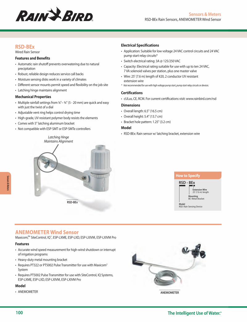
100 The Intelligent Use of Water.™
Sensors & Meters
RSD-BEx
Latching Hinge Maintains Alignment
Sensors & MetersRSD-BEx Rain Sensors, ANEMOMETER Wind Sensor
RSD-BExWired Rain Sensor
Features and Benefits• Automatic rain shutoff prevents overwatering due to natural
precipitation• Robust, reliable design reduces service call backs• Moisture sensing disks work in a variety of climates• Different sensor mounts permit speed and flexibility on the job site• Latching hinge maintains alignment
Mechanical Properties• Multiple rainfall settings from 1⁄8"– ¾" (5 - 20 mm) are quick and easy
with just the twist of a dial• Adjustable vent ring helps control drying time• High-grade, UV resistant polymer body resists the elements• Comes with 5" latching aluminum bracket• Not compatible with ESP-SMT or ESP-SMTe controllers
RSD - BEx
Model RSD: Rain Sensing Device
MountingBE: Metal Bracket
Extension Wire25' (7.6 m) length
How to Specify
ANEMOMETER
ANEMOMETER Wind SensorMaxicom,2® SiteControl, IQ™, ESP-LXME, ESP-LXD, ESP-LXIVM, ESP-LXIVM Pro
Features• Accurate wind speed measurement for high-wind shutdown or interrupt
of irrigation programs• Heavy-duty metal mounting bracket• Requires PT322 or PT5002 Pulse Transmitter for use with Maxicom2
System• Requires PT5002 Pulse Transmitter for use with SiteControl, IQ Systems,
ESP-LXME, ESP-LXD, ESP-LXIVM, ESP-LXIVM Pro
Model• ANEMOMETER
Electrical Specifications• Application: Suitable for low voltage 24 VAC control circuits and 24 VAC
pump start relay circuits*• Switch electrical rating: 3A @ 125/250 VAC• Capacity: Electrical rating suitable for use with up to ten 24 VAC,
7 VA solenoid valves per station, plus one master valve• Wire: 25' (7.6 m) length of #20, 2 conductor UV resistant
extension wire* Not recommended for use with high voltage pump start, pump start relay circuits or devices.
Certifications• cULus, CE, RCM. For current certifications visit: www.rainbird.com/rsd
Dimensions• Overall length: 6.5" (16.5 cm)• Overall height: 5.4" (13.7 cm)• Bracket hole pattern: 1.25" (3.2 cm)
Model• RSD-BEx: Rain sensor w/ latching bracket, extension wire

www.rainbird.com/controllers
101www.rainbird.com
Sens
ors &
Met
ers
Models• North America (916 MHz)
- WR2-RFC: Rain + Freeze Combo - WR2-48: Rain + Freeze Combo with 48-hour hold
• International (868 MHz) - WR2-RFC-868: Rain + Freeze Combo
Sensors & MetersWR2 Series Wireless Rain + Freeze Sensors
WR2 Series Wireless Rain + Freeze SensorsSuperior responsiveness to rainfall and cold temperatures, save up to 35% on water usage
Features & Benefits• Enhanced antenna array provides superior signal reliability that
overcomes most line-of-sight obstructions• Sensor signal strength indicator enables one person set up, reducing
installation time• Convenient adjustment and monitoring of rain or freeze settings at the
controller interface• Simple battery replacement without the need to disassemble the
sensor• Highly intuitive icon-driven controller interface simplifies programming• Easy to install, self-leveling sensor bracket mounts to flat surfaces or rain
gutters• Antennas concealed within the units for greater visual appeal and
product robustness• "Quick Shut Off" interrupts active irrigation cycle during a rain event
Electrical Specifications• Application: suitable for use with 24 VAC controllers (with or without
pump start / master valve)• Electrical rating suitable for use with up to six 24VAC 7VA solenoids plus
an additional master valve or pump start that does not exceed 53VA• Controller Interface Wire: 30” (76 cm) length of #22 gauge (0.64 mm) UV
resistant extension wire• FCC approved spread spectrum 2 way radio transceivers with FCC Class
B approvals• Signal transmission distance of 700’ (213.4 m) Line of Sight• Battery life: four or more years under normal operating conditions• 6 KV surge / lighting protection
Certifications• cULus, FCC Part 15c, ISED RSS-210, CE.
For current certifications visit: www.rainbird.com/wr2
Mechanical Properties• Adjustable rainfall settings from 1/8” – 1/2” (3 – 13 mm)• Adjustable low temperature settings from 33°F – 41°F (0.5° – 5°C)• Three irrigation modes to select: Programmed, Suspend Irrigation for 72
hours, Override sensor for 72 hours
Note: The WR2-48 model replaces the Suspend Irrigation for 72 Hours mode with 48-Hour Irrigation Hold Active mode.
• "Quick Shut Off” suspends active irrigation cycle within approximately two minutes
• High-grade, UV resistant polymer units resist harmful environmental effects
Program in seconds Determine best sensor location
Install sensor easily using mounting bracket
Step 1 Step 2 Step 3
Robust internal antennas for superior aesthetics
Rugged self-leveling bracket maintains rain sensor orientation
WR2 Series Wireless Rain/Freeze Sensors
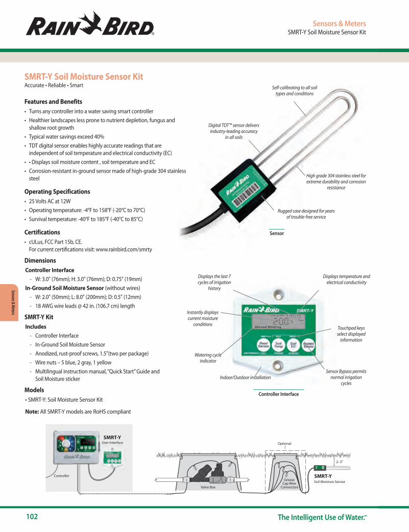
102 The Intelligent Use of Water.™
Sensors & Meters
SMRT-Y Soil Moisture Sensor KitAccurate • Reliable • Smart
Features and Benefits• Turns any controller into a water saving smart controller• Healthier landscapes less prone to nutrient depletion, fungus and
shallow root growth• Typical water savings exceed 40%• TDT digital sensor enables highly accurate readings that are
independent of soil temperature and electrical conductivity (EC)• • Displays soil moisture content , soil temperature and EC• Corrosion-resistant in-ground sensor made of high-grade 304 stainless
steel
Operating Specifications• 25 Volts AC at 12W • Operating temperature: -4°F to 158°F (-20°C to 70°C)• Survival temperature: -40°F to 185°F (-40°C to 85°C)
Certifications• cULus, FCC Part 15b, CE.
For current certifications visit: www.rainbird.com/smrty
DimensionsController Interface
- W: 3.0" (76mm); H: 3.0" (76mm); D: 0.75" (19mm)In-Ground Soil Moisture Sensor (without wires)
- W: 2.0" (50mm); L: 8.0" (200mm); D: 0.5" (12mm) - 18 AWG wire leads @ 42 in. (106.7 cm) length
SMRT-Y KitIncludes
- Controller Interface - In-Ground Soil Moisture Sensor - Anodized, rust-proof screws, 1.5"(two per package) - Wire nuts – 5 blue, 2 gray, 1 yellow - Multilingual instruction manual, “Quick Start” Guide and
Soil Moisture sticker
Models• SMRT-Y: Soil Moisture Sensor Kit
Note: All SMRT-Y models are RoHS compliant
Sensors & MetersSMRT-Y Soil Moisture Sensor Kit
Displays the last 7 cycles of irrigation
history
Instantly displays current moisture
conditions
Watering cycle indicator
Indoor/Outdoor installationSensor Bypass permits
normal irrigation cycles
Touchpad keys select displayed
information
Displays temperature and electrical conductivity
Digital TDT™ sensor delivers industry-leading accuracy
in all soils
High grade 304 stainless steel for extreme durability and corrosion
resistance
Rugged case designed for years of trouble-free service
Self-calibrating to all soil types and conditions
Sensor
Controller Interface
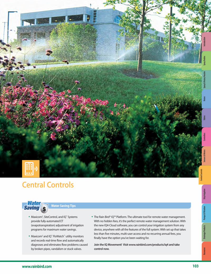
103www.rainbird.com
Cent
ral C
ontro
ls
103
Central Controls
• Maxicom2, SiteControl, and IQ™ Systems provide fully-automated ET (evapotranspiration) adjustment of irrigation programs for maximum water savings.
• The Rain Bird® IQ™ Platform. The ultimate tool for remote water management. With no hidden fees, it’s the perfect remote water management solution. With the new IQ4-Cloud software, you can control your irrigation system from any device, anywhere with all the features of the full system. With set up that takes less than five minutes, multi-user access and no recurring annual fees, you finally have the option you’ve been waiting for.• Maxicom2 and IQ™ FloWatch™ utility monitors
and records real-time flow and automatically diagnoses and eliminates flow problems caused by broken pipes, vandalism or stuck valves.
Water Saving Tips
www.rainbird.com
Join the IQ Movement! Visit www.rainbird.com/products/iq4 and take control now.
Spra
y & Ro
tary
Noz
zles
Roto
rsVa
lves
Cont
rolle
rsSe
nsor
s & M
eter
sCe
ntra
l Con
trols
Drip
Irrig
atio
nPu
mps
& Fi
ltrat
ion
Drain
age P
rodu
cts
Reso
urce
sIn
trodu
ctio
nSp
ray B
odies

104 The Intelligent Use of Water.™
Central Controls
Central ControlsMajor Products
System Name IQ4 - Cloud SiteControl Maxicom ®
System Type Modular multi-site central control system
Modular single site central control system
Multi-satellite central control system
Traditionally wired or two-wire decoder Works with both Works with both Traditionally wired
Typical applications
Multi-site management with modular features. Ideal solution for
water managers, schools, parks, corporate campuses and
transportation departments
Single site management with modular features. Ideal for large
resorts, cemeteries, shopping centers, theme parks and sports stadiums
Multi-site commercial or industrial irrigation applications. Ideal for municipalities, school districts,
homeowner associations and park and recreation departments
Number of sites/system 1000+ 1 200+Local and/or remote site control Local and remote Local Local and remote
Maximum number of simultaneous stations per site/system
5 per ESP-LXME 8 per ESP-LXIVM 8 per ESP-LXD 16 per ESP-LXIVM Pro 3,584 per site 112 per CCU
Number of ET (weather) sources 100 4 16
Program adjustments by ET Yes Yes Yes
Program adjustments by percentage Yes Yes YesProgramming by volume/gallons No No Yes
Number of programs 4 per ESP-LXME 10 per ESP-LXIVM 4 per ESP-LXD 40 per ESP-LXIVM Pro 100 total per system 999 per CCU
Flow management capabilities Yes Yes YesFlow monitoring/recording capabilities Yes Yes YesHigh-flow shutdown Mainline and laterals Mainline only Mainline and lateralsLow- or zero-flow shutdown Mainline and laterals No Mainline and lateralsAlarms/warnings Yes Yes YesSensor input and manual bypass Yes Yes Yes
Number of weather sensor inputs 1 per ESP-LXME 4 per ESP-LXIVM 4 per ESP-LXD 8 per ESP-LXIVM Pro
Up to 200 sensor inputs per system Up to 56 per CCU
Number of flow sensor inputs 1 per ESP-LXME 5 per ESP-LXIVM 5 per ESP-LXD 10 per ESP-LXIVM Pro
Up to 200 sensor inputs per system
Up to 6 (two wire) or 20 (Link) per CCU
Software/password log-on protection Yes N/A YesRemote control capabilities Yes Yes, Freedom System Yes, Freedom SystemCycle+Soak™ Yes Yes YesWater window by program/schedule Yes Yes YesComputer included with software No Yes YesComputer programming Yes Yes Yes24/7 system monitoring Yes, by the controller Yes, by the computer Yes, by the CCU
24/7 communication & feedback No Yes, computer to satellites and decoders CCU to satellite
Remote site telephone, cellular, radio, Ethernet, Wi-Fi communication All No All
Automatic remote site communication Yes No Yes
Satellite controllers or decoders ESP-LXME ESP-LXIVM ESP-LXD ESP-LXIVM Pro
ESP-SAT Satellites or FD-Series Decoders ESP-SAT or ESP-SITE Satellites
Modular station capacity ESP-LXME: 8-48 ESP-LXD: 50-200 No NoNumber of site/system interfaces N/A – No interfaces required 8 >200Number of satellites/system 16,000+ 896 >5,600Number of satellites/site interface Up to 150 satellites per IQNet Up to 112 per TWI Up to 28 per CCU
Number of satellite stations/siteESP-LXME: Up to 7,200 per IQNetESP-LXD: Upto 30,000 per IQNet
ESP-LXIVM: Up to 9,000 per IQNetESP-LXIVM Pro: Up to 36,000 per IQNet
Up to 21,504 per system Up to 672 per CCU
Number of decoder addresses per site Up to 30,000 per IQNet Up to 4,000 N/AInteractive map interface No Yes NoGPS, CAD, SHP, BMP Import N/A Yes BMP, PDF, JPEGValve control: stations or decoders Both Both Satellite stations onlyEstimated/actual water use report Yes Yes YesEvent recording (station operation) Yes Yes YesProjected operation (dry/run) capability Yes Yes YesSupported by Global Services Plan Yes Yes YesCan also manage lighting and security systems Yes Yes Yes
Major Products

Cent
ral C
ontro
ls
www.rainbird.com/professionals/products/central-control-water-mgmt
105www.rainbird.com
IQ4 Central Control SoftwareModular Multi-Site Central Control
The IQ Platform offers state-of-the-art command and control features in an easy to learn and use interface. IQ provides advanced water management features saving money and time.
ApplicationsAll IQ versions provide remote programming, management, and monitoring of ESP-LX Series Controllers from the computer in your office. IQ is the perfect irrigation control solution for parks departments, school districts, property managers, landscape maintenance contractors, and water managers. IQ can manage small single-controller sites as well as large multi-controller sites and supports both ESP-LX Series traditionally-wired and 2-wire controllers. IQ-Cloud is a cloud based service allowing users to login and control their irrigation system from any internet connected device including desktop computers, tablet computers and mobile smartphones. IQ-Cloud is ideal for organizations with multiple irrigation system administrators and/or users that require mobility. IQ-Cloud features the ability to use mobile devices providing quick access to all IQ4 features in an interface designed for touchscreen devices found in smartphones or tablets. Users are not restricted to an initial capacity and can add satellites at will. Internet access is required.
IQ Platform Software Features• Compatible with ESP-LXME, ESP-LXIVM and ESP-LXMEF traditionally-
wired and ESP-LXD two-wire decoder controllers • Programming in seconds, minutes, and hours • ET station run time adjustments by site • Detailed logs and reports • Automated satellite Synchronize & Retrieve Logs • Satellite Two-Way Programming (changes made at the satellite can be
viewed and accepted in the IQ4 software) • Auto-Synchronization of data from IQ to Satellite • Software uses Irrigation Association terminology and formulas • IQ Global Weather Internet Service which provides local weather data
including rain fall • Retrieves minute-by-minute flow logs from flow sensor equipped ESP-
LXMEF, ESP-LXIVM and ESP-LXD Satellite Controllers • Flow Logs vs. Projected Flow Graphical Report (identifies which
programs & stations where running at any point in time) • User selectable languages include English, Spanish, French, German,
Italian and Portuguese
Visit www.rainbird.com/products/iq4 to learn more about the features included in the IQ4 Platform.
Central ControlsIQ4-Cloud Software
Additional 5-Satellite Capacity Upgrade (IQ-Desktop/ Enterprise)• IQ Software satellite controller capacity can be upgraded in 5-satellite
increments• Additional capacity is added through a purchased software activation
Keycode
Recommended Computer Requirements for IQ-Desktop• Windows 10, Windows 8, Windows 7 Service Pack 1 • Intel I5-540M or equivalent processor • 8 GB RAM (minimum) • 10 GB available disk space • 1024 x 768 pixel screen resolution • Internet Access • Chrome (recommended), Edge, or Firefox browser• Network Connection (for Ethernet, WiFi, Cellular)• Serial Port or USB to Serial Adapter (for Direct Connect and External
Modem communication)
IQ4 SOFTWARE
IQ4-Cloud: IQ4 cloud-based software compatible with all Rain Bird ESP-LX controllers with NCC communications cartridges
How to Specify

106 The Intelligent Use of Water.™
Central Controls
Central ControlsIQ NCC Network Communication Cartridge
IQ NCC Network Communication CartridgeUpgrades any ESP-LX Series Controller to an IQ Central Control Satellite Controller
Features• IQ is the perfect irrigation control solution for parks departments,
school districts, property managers, landscape maintenance contrac-tors and water managers. IQ can manage small single-controller sites as well as large multi-controller sites. IQ NCC cartridges are compatible with the ESP-LXME Controller with 1 to 48-station capacity, ESP-LXD Decoder Controller with 1 to 200-station capacity, ESP-LXIVM Controller with 1 to 60-station capacity and ESP-LXIVM Pro with 1 to 240 station capacity
• IQ NCC cartridges are initially configured through a setup wizard provided in the ESP-LX Series Controller IQ Settings dial position. Com-munication setting parameters are configured through the IQ software or the NCC Configurator Software designed for netbook/laptop use on the job site
Direct Satellites• Single controller sites would use an IQ NCC cartridge configured
as a Direct satellite. A Direct satellite has an IQ central computer communication connection but no network connections to other satellites in the system
Server & Client Satellites• Multi-controller sites would use one IQ NCC cartridge configured
as a Server satellite and the other NCC cartridges configured as Client satellites. The Server satellite has an IQ central computer communication connection and shares this communication connection with the Client satellites though high-speed data cable or radios. The communication connection between Server and Client satellites is called the IQNet™
• Satellites on a common IQNet can share weather sensors and master valves
• Server and Client satellites using high-speed data cable for IQNet communication require installation of an IQ CM Communication Module. Server and Client satellites using radio communication for IQNet communication require installation of an IQSSRADIO radio. Each cartridge kit includes cables to connect the NCC cartridge to connection module and/or radio
IQ NCC 4G Cellular Cartridge• Includes embedded 4G Cellular Data Modem with antenna connector • Includes internal antenna for plastic controller enclosures (optional 4G
external antenna available for metal case controller enclosures) • Requires 4G Cellular data service plan purchased from Rain Bird with
cellular service included • Used for Direct or Server Satellite applications requiring wireless Cellular
communication with the IQ central computer • Available with 1st year of communication service included. • 4G Cartridge with included communication service not offered in all
areas
IQ NCC-EN Ethernet Cartridge• Includes embedded Ethernet Network Modem with RJ-45 port• Includes RJ-45e patch cable (requires LAN network static IP address)
IQ NCC-RS RS232 Cartridge• Includes RS-232 Port for IQ Direct Cable or External Modem
communication connection to the IQ central computer, and external modem cable (IQ Direct Cable provided with IQ Software Package)
• Used for Direct or Server Satellite applications requiring direct cable connection or external modem (radio or other 3rd-party device) communication with the IQ central computer, and for Client Satellite applications requiring IQNet high-speed data cable or radio communication with the Server Satellite
IQ FSCM-LXME Flow Smart Connection Module• Provides IQNet high-speed data cable connections for ESP-LXME
Controller• Includes Flow Smart Module and Base Module functions• Replaces standard ESP-LXME Base Module
IQ CM-LXD Connection Module• Provides IQNet high-speed data cable connections for ESP-LXD
Controller• Installs in ESP-LXD 0 (zero) module slot
IQ SS-Radio Radio Modem• Provides IQNet wireless radio communication between Server and
Client satellite controllers• Can also be used with the IQ NCC-RS RS232 Cartridge for IQ central
computer to Direct or Server satellite radio communication• Includes power supply and external antenna (programming software
and cable provided separately)
LX Series Cartridge Panel with IQ-NCC-RS Cartridge Installed

www.rainbird.com/centralcontrols
107www.rainbird.com
Cent
ral C
ontro
ls
Central ControlsSiteControl
SiteControlA Full-Featured Central Control System for Single Site Applications
Features• Advanced Graphical Tracking- Maps generated by GPS technology
or AutoCAD recreate your site. Interactive mapping and on-screen graphics show your complete site with location of individual valves and sprinklers allows you to measure and calculate areas from your map
• Smart Weather™ is sesigned to take complete advantage of Rain Bird’s most advanced line of weather stations, tracks ET and rainfall via a weather station and reacts to current weather conditions based on user-defined options. Advanced warning system accepts user-defined sensor thresholds. System operator is immediately alerted if thresholds are exceeded
• RainWatch™ uses tipping bucket rain can(s) to detect and suspend irrigation while measuring rainfall. When rain stops, irrigation resumes with run times reduced according to measured rain
• Minimum ET- allows setting minimum ET threshold values for irrigation to take place. Promotes deep watering for optimum turf conditions
• Automatic ET automatically adjust run times in relation to fluctuations in Evapotranspiration (ET) values
• Remote System Control allows you to take control of your system and operate SiteControl from anywhere on your site using the Rain Bird FREEDOM System. Phone (landline or cellular) or radio communication options
• Hybrid System operates Satellite Controllers and/or Two-Wire Decoders • SiteControl Plus operates four Large Decoder Interfaces (LDI), each
capable of operating up to 1,000 solenoids with Hybrid system, can further expand capabilities by combining Two-Wire Decoder and/or Satellite Controller options up to four total interface devices
Superior Monitoring and Scheduling• Flo-Graph™ allows visibility of real-time graphics with individual station
information presented in colorful charts • Flo-Manager™ balances system demands and maximum capacities with
efficiency helping to lower water demand, reduce system wear and tear and save energy
• Cycle + Soak™. Better control the application of water on slopes and in areas with poor drainage
• QuickIRR™ Quick and easy method to build irrigation schedules and programs based on your parameters
SiteControl
Other Features• Up to 200 points of connection• Up to 200 pulse sensors• Water usage logs• Station run-time logs• Posted and dry run logs• ET spreadsheet• 1 year Global Service Plan included
Models• SCON: Desktop PC with SiteControl software, includes 1 year Global
Support Plan (GSP)
Software Module Options• Smart Weather• Rain Bird Messenger
(for Smart Weather)• Automatic ET• Hybrid Module• Smart Sensor• Map Utilities• Freedom
• 8 Additional Locations• Additional Wire-Path (2nd)• Additional Wire-Path (3rd)• Additional Wire-Path (4th)• SiteControl Plus• Smart Pump• MI (Mobile Interface)
Global Service Plan (GSP) • Visit rainbird.com/gsp/index.htm for more information.

108 The Intelligent Use of Water.™
Central Controls
Central ControlsSiteControl Hardware
SiteControl HardwareTWI Satellite Interface• Allows real-time, two-way communication between SiteControl Central
Controller and field satellites• Allows use of advanced in-field capabilities of ESP-SAT twowire or LINK
versions• Modular capacity can grow with the site
Two-Wire Decoder Interface• Allows real-time, two-way communication between SiteControl Central
Controller and decoders• Connects the powerful capabilities of SiteControl with the ease of
installation and security of a two-wire decoder system• System can be set up and expanded according to project needs
ESP-SAT Satellite Controller• 40 Stations Satellite Controller• Field Satellite Controller for Maxicom2 or SiteControl Central Control
systems• The power of an advanced water-management tool, in an easy-to-use
package• All the features and stand-alone capabilities of the Rain Bird ESP-MC
Controller line
Spread Spectrum Radio• Frequency hopping to avoid interference • Reduced cost of ownership, no FCC license required • No FCC restrictions on antenna height (User should check local laws) • Radios can be set up as repeater to achieve great distances and
overcome obstacles
Ethernet Devices• Use Ethernet networks to:
• - Communicate from Central Control Computer to CCUs, SiteSats, TWIs and weather stations
• - Communicate from CCU and TWIs to ESP-Sats
WS-PRO Weather Stations• Scientific accuracy sensors located three meters above the ground for
added vandal-resistance• Powerful, internal micro-logger for climatic data collection, logging and
analysis, constant communication with weather sensors, and storage of 30 days of data
• Rugged yet lightweight metal construction;
Sensor-Pulse Decoders• Complete feedback system• Extends central control system versatility• Color-coded wire leads for ease of installation• Programmable address codes for individual operation
RAINGAUGE Rain Sensor• Accurate rain counter switch counts rainfall in 1/100th inch increments• Heavy-duty metal construction• Mounting bracket• Debris screen
ANEMOMETER Wind Sensor• Accurate wind speed measurement for high-wind shutdown or
interrupt of irrigation programs• Heavy-duty metal mounting bracket• Requires PT322 or PT5002 Pulse Transmitter/Monitor for use with
Maxicom2® System
Maxi Interface Boards• Upgrades an ESP-MC Controller (wall mount or pedestal) to an
ESP-SAT Satellite Controller• No additional enclosures or external wiring required• Installs on stand-offs on controller output board
MSP-1 Surge Protection• Protects central control components from electrical surges on a
two-wire communication path• Can be installed in satellite or CCU pedestal or in valve box
in conjunction with MGP-1 (Maxicom2® Grounding Plate)
MGP-1 Surge Grounding Plate• Provides a mounting location for MSP-1 or other grounding wires
directly to a grounding rod or pipe• Installed on grounding rod or pipe
ESP-MIB-TW DEC-SEN-LR DEC-PUL-LRESP-SAT Satellite ControllerTWI Interface
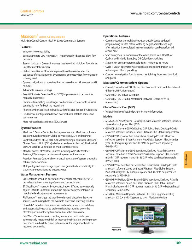
www.rainbird.com/centralcontrols
109www.rainbird.com
Cent
ral C
ontro
ls
Central ControlsMaxicom2®
Operational Features• Communication Control Engine automatically sends updated
programming to sites before watering begins and retrieves logs after irrigation is completed; manual operation can be performed at any time
• Start day cycles: Custom (day of the week), Odd/Even, Odd31, or Cyclical and include Event Day Off Calendar scheduling
• Station run-times programmable from 1 minute to 16 hours• Cycle + Soak™ optimizes water application to soil infiltration rate,
reducing runoff and puddling • Control non-irrigation functions such as lighting, fountains, door locks
and gates
Maxicom2 Communications Options • Central Controller to CCU: Phone, direct connect, radio, cellular, network
(Ethernet, Wi-Fi, fiber-optics)• CCU to ESP-SAT2: Two-wire path• CCU to ESP-SATL: Radio, MasterLink, network (Ethernet, Wi-Fi,
fiber-optics)
Global Service Plan (GSP) • Visit rainbird.com/gsp/index.htm for more information.
Models • MC2GOLD1: New System - Desktop PC with Maxicom software, includes
1 year Global Support Plan (GSP)• GSPMCPL3: Current GSP Or Expired GSP Subscribers, Desktop PC with
Maxicom software, includes 3 Years Platinum Plus Global Support Plan• GSPMXPPCIA: Current GSP Subscribers, Desktop PC with Maxicom
software, based on 3 Year Platinum Plus Global Support Plan, includes year 1 GSP, requires year 2 and 3 GSP to be purchased separately (M95543A2)
• GSPMXPPCIM: Current GSP Subscribers, Desktop PC with Maxicom software, based on 3 Years Platinum Plus Global Support Plan, includes month 1 GSP, requires month 2 - 36 GSP to be purchased separately (M95544M2)
• GSPMXPPNIA: New GSP or Expired GSP Subscribers, Desktop PC with Maxicom software, based on 3 Years Platinum Plus Global Support Plan, includes year 1 GSP, requires year 2 and 3 GSP to be purchased separately (M95541A2)
• GSPMXPPNIM: New GSP or Expired GSP Subscribers, Desktop PC with Maxicom software, based on 3 Years Platinum Plus Global Support Plan, includes month 1 GSP, requires month 2 - 36 GSP to be purchased separately (M95542M2)
• MC2UPG: Maxicom Upgrade Software - CD Only, upgrade existing Maxicom 1.X, 2.X and 3.X system to latest Maxicom Version
Maxicom® version 4.5 now availableMulti-Site Central Control Ideal for Large Commercial Systems
Features• Windows 10 compatibility• Seek & Eliminate Low Flow (SELF) – Automatically diagnose a low flow
problem• Station Lockout – Quarantine zones that have had high/low flow alarms
until the user takes action• Station Priorities for Flow Manager – allows the user to alter the
sequence of irrigation zones by assigning priorities when flow manager is being used
• Queued irrigation max run time limit increased from 99 minutes to 999 minutes
• Adjustable rain can settings• Seek & Eliminate Excessive Flow (SEEF) improvement to account for
manual adjustments• Database trim setting is no longer fixed and is user-selectable so users
can decide how far back the records go• Phone number/address field works with URL’s and longer IP Addresses• Field Device Configuration Report now includes satellite names and
sensor names • More robust database format (SQL Server)
System Features• Maxicom2® Central Controller Package comes with Maxicom2 software,
pre-configured computer, Global Service Plan (GSP), and training • Control hundreds of ESP-SITE-SAT Satellites (single controller sites) and
Cluster Control Units (CCUs) which can each control up to 28 individual ESP-SAT Satellite Controllers on multi-controller sites
• Monitor dozens of Weather Sources including WSPRO2 Weather Stations, ET Managers, or rain counting sensors (Raingauge)
• Freedom Remote Control allows manual operation of system through a cellular phone or radio
• Multiple log and water usage reports are generated automatically to track system operation and water savings
Water Management Features• Cross satellite schedule operation; 999 separate schedules per CCU
provides precision watering of areas and microclimates• ET Checkbook™ manages Evapotranspiration (ET) and automatically
adjusts Satellite Controller station run-time or day cycle intervals to match the landscapes water requirements
• FloManager™ manages the total flow demand placed on the water source(s), optimizing both the available water and watering window
• FloWatch™ monitors flow sensors at each water source, records flow, and automatically reacts to problem flows by shutting down the effected portion of the system (individual valve or mainline)
• RainWatch™ monitors rain counting sensors, records rainfall, and automatically reacts to rainfall by interrupting irrigation, waiting to see how much rain has fallen, and determines if the irrigation should be resumed or cancelled
Maxicom

110 The Intelligent Use of Water.™
Central Controls
Central ControlsMaxicom2® Hardware
Maxicom2® HardwareCluster Control Unit CCU Interface• Runs real-time operations of a site consisting of up to 28 satellites• Adapts station sequence to changing conditions for
maximum efficiency• Instantly responds to unexpected conditions and sensor inputs
ESP-SAT Satellite Controller• 40 Stations Satellite Controller• Field Satellite Controller for Maxicom2 or SiteControl Central Control
systems• The power of an advanced water-management tool, in an easy-to-use
package• All the features and stand-alone capabilities of the Rain Bird ESP-MC
Controller line
ESP-SITE-SAT Satellite Controller• 40 Stations Satellite Controller• Combines power of a Cluster Control Unit (CCU) with capabilities of a
single ESP-Satellite controller for small Maxicom2 sites• Advanced water-management tool, in an easy-to-use package• All the features and stand-alone capabilities of the Rain Bird ESP-MC
Controller line
Spread Spectrum Radio• Frequency hopping to avoid interference • Reduced cost of ownership, no FCC license required • No FCC restrictions on antenna height (User should check local laws) • Radios can be set up as repeater to achieve great distances and
overcome obstacles
Ethernet Devices• Use Ethernet networks to:
• - Communicate from Central Control Computer to CCUs, SiteSats, TWIs and weather stations
• - Communicate from CCU and TWIs to ESP-Sats
WS-PRO Weather Stations• Scientific accuracy sensors located three meters above the ground for
added vandal-resistance• Powerful, internal micro-logger for climatic data collection, logging and
analysis, constant communication with weather sensors, and storage of 30 days of data
• Rugged yet lightweight metal construction
Sensor-Pulse Decoders• Complete feedback system• Extends central control system versatility• Color-coded wire leads for ease of installation• Programmable address codes for individual operation
RAINGAUGE Rain Sensor• Accurate rain counter switch counts rainfall in 1/100th inch increments• Heavy-duty metal construction• Mounting bracket• Debris screen
ANEMOMETER Wind Sensor• Accurate wind speed measurement for high-wind shutdown or
interrupt of irrigation programs• Heavy-duty metal mounting bracket• Requires PT322 or PT5002 Pulse Transmitter/Monitor for use with
Maxicom2 System
Maxi Interface Boards• Upgrades an ESP-MC Controller (wall mount or pedestal) to an
ESP-SAT or ESP-SITE Satellite Controller• No additional enclosures or external wiring required• Installs on stand-offs on controller output board
MSP-1 Surge Protection• Protects central control components from electrical surges on a
two-wire communication path• Can be installed in satellite or CCU pedestal or in valve box
in conjunction with MGP-1 (Maxicom2® Grounding Plate)
MGP-1 Surge Grounding Plate• Provides a mounting location for MSP-1 or other grounding wires
directly to a grounding rod or pipe• Installed on grounding rod or pipe
RAINGAUGEMGP-1CCU-28-W ESP-40SAT-2W Satellite MSP-1
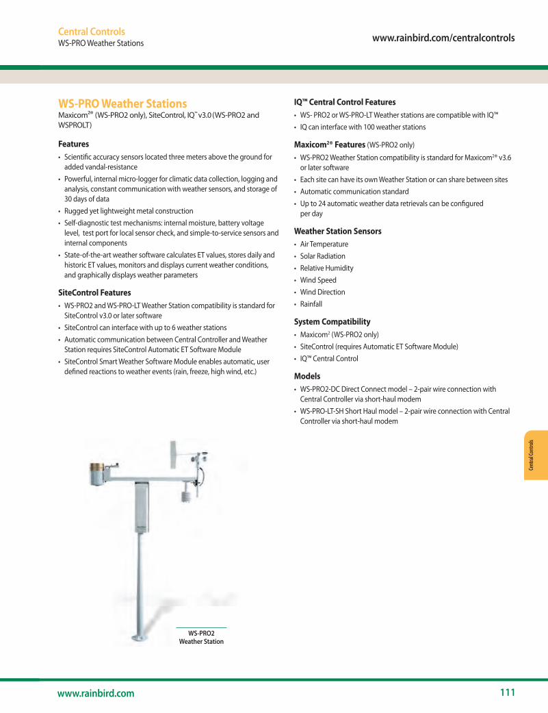
www.rainbird.com/centralcontrols
111www.rainbird.com
Cent
ral C
ontro
ls
Central ControlsWS-PRO Weather Stations
IQ™ Central Control Features• WS- PRO2 or WS-PRO-LT Weather stations are compatible with IQ™ • IQ can interface with 100 weather stations
Maxicom2® Features (WS-PRO2 only)
• WS-PRO2 Weather Station compatibility is standard for Maxicom2® v3.6 or later software
• Each site can have its own Weather Station or can share between sites• Automatic communication standard• Up to 24 automatic weather data retrievals can be configured
per day
Weather Station Sensors• Air Temperature• Solar Radiation• Relative Humidity• Wind Speed• Wind Direction• Rainfall
System Compatibility• Maxicom2 (WS-PRO2 only)• SiteControl (requires Automatic ET Software Module)• IQ™ Central Control
Models• WS-PRO2-DC Direct Connect model – 2-pair wire connection with
Central Controller via short-haul modem• WS-PRO-LT-SH Short Haul model – 2-pair wire connection with Central
Controller via short-haul modem
WS-PRO Weather StationsMaxicom2® (WS-PRO2 only), SiteControl, IQ™ v3.0 (WS-PRO2 and WSPROLT)
Features• Scientific accuracy sensors located three meters above the ground for
added vandal-resistance• Powerful, internal micro-logger for climatic data collection, logging and
analysis, constant communication with weather sensors, and storage of 30 days of data
• Rugged yet lightweight metal construction • Self-diagnostic test mechanisms: internal moisture, battery voltage
level, test port for local sensor check, and simple-to-service sensors and internal components
• State-of-the-art weather software calculates ET values, stores daily and historic ET values, monitors and displays current weather conditions, and graphically displays weather parameters
SiteControl Features• WS-PRO2 and WS-PRO-LT Weather Station compatibility is standard for
SiteControl v3.0 or later software• SiteControl can interface with up to 6 weather stations• Automatic communication between Central Controller and Weather
Station requires SiteControl Automatic ET Software Module• SiteControl Smart Weather Software Module enables automatic, user
defined reactions to weather events (rain, freeze, high wind, etc.)
WS-PRO2 Weather Station

112 The Intelligent Use of Water.™
Central Controls
Central ControlsSpread Spectrum Radio, ANEMOMETER Wind Sensor
Spread Spectrum RadioMaxicom2®, SiteControl or IQ™
Features• Frequency hopping to avoid interference • Reduced cost of ownership, no FCC license required • No FCC restrictions on antenna height (User should check local laws) • Radios can be set up as repeater to achieve great distances and
overcome obstacles
Installation Requirements• Site Survey required prior to ordering and must be submitted
with order• RADTN9MIB mounts directly onto ESP-SAT MIB; RADTN9TWI
connects with ribbon cable• Antenna and antenna cable required (sold separately by Rain Bird
Production and Service Center)
Models• Radios – For IQ Primary & Secondary Communication and For
Maxicom and Site Control Primary Communication - IQSSRADIO: 900 MHz Spread Spectrum radio – Allows
communication between Central Computer and IQ Direct or IQ Server Satellite, and between IQ Server Satellite and IQ Client Satellites. Also can be used for communication between Maxicom Central Computer and CCU or Site Satellite, between Site Control Central Computer and TWI / SDI or LDI, and between a Central Computer and weather station
• Radios – For Maxicom and Site Control Secondary Communication - RADTN9MIB: license free wireless radio (902-928 MHz) between
CCU and satellites - RB-SS-TN9B: Plastic Case Radio – License free radio to
communicate to IQ Satellites

Primary Applications Single outlet emitter
Multi-outlet emitter
Bubbler emitter Spray Inline emitter
(Dripline) RWS
Thick bushes ● ● ● ●
Single bush ●
Small trees ● ● ● ●
Large trees ● ● ● ●
Ground cover ● ● ●
Annuals ● ● ●
Mixed vegetation ● ● ●
Potted plants ● ● ● ●
Hedges ● ●
Vegetation on slopes ● ●
Drip Irrigation
Major Products
• Drip products deliver water directly to the root zone. Use dripline for dense plantings where it’s cost effective to distribute low-volume water evenly. Use a system of precise emitter devices for sparse plantings where it’s cost effective to separately irrigate each plant.
• Use drip to eliminate overspray, and you’ll eliminate waste. Eliminate unsightly spray stains on buildings and fences. Eliminate soil erosion, water runoff, and potential litigation. Walkways, roads, and vehicles stay dry.
• Ask your tax advisor about capital depreciation when calculating your return-on-investment for a drip retrofit. Save water, and save money at the same time.
Water Saving Tips
113www.rainbird.com
Spra
y & Ro
tary
Noz
zles
Roto
rsVa
lves
Cont
rolle
rsSe
nsor
s & M
eter
sCe
ntra
l Con
trols
Drip
Irrig
atio
nPu
mps
& Fi
ltrat
ion
Drain
age P
rodu
cts
Reso
urce
sIn
trodu
ctio
nSp
ray B
odies
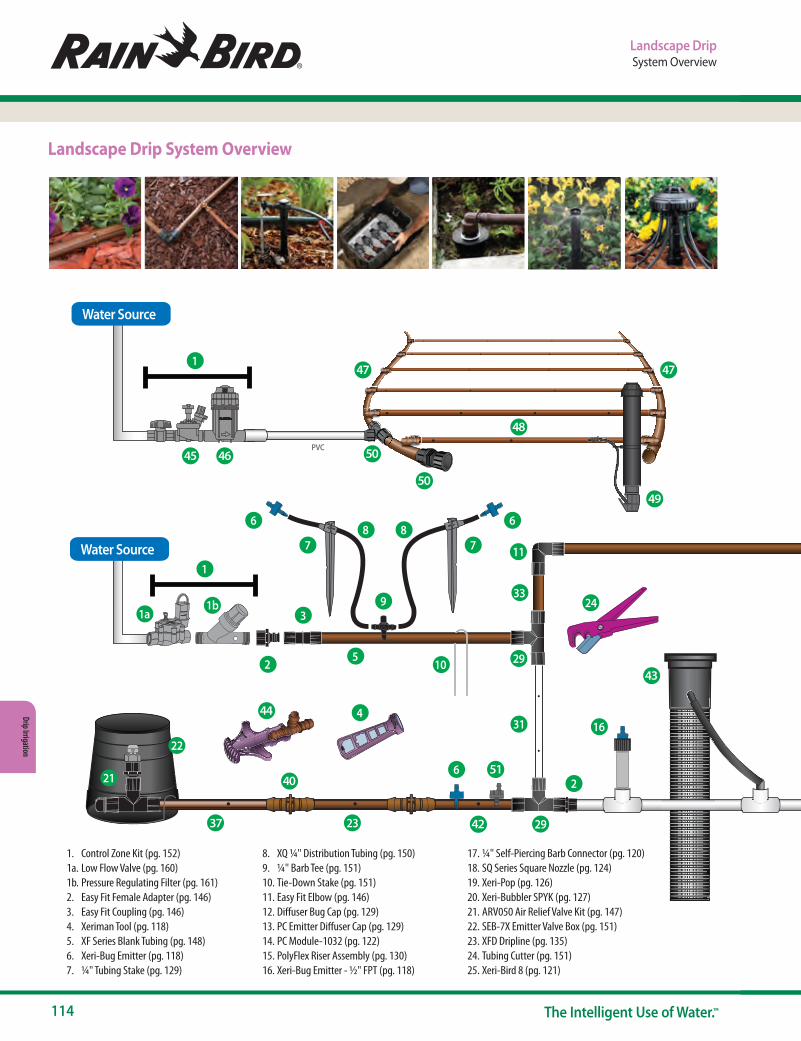
114 The Intelligent Use of Water.™
Drip Irrigation
45 46
47
48
49
47
37
40
43
44
41
42
5152
41
23
50
50
Landscape DripSystem Overview
1. Control Zone Kit (pg. 152)1a. Low Flow Valve (pg. 160)1b. Pressure Regulating Filter (pg. 161)2. Easy Fit Female Adapter (pg. 146)3. Easy Fit Coupling (pg. 146)4. Xeriman Tool (pg. 118)5. XF Series Blank Tubing (pg. 148)6. Xeri-Bug Emitter (pg. 118)7. ¼" Tubing Stake (pg. 129)
8. XQ ¼" Distribution Tubing (pg. 150)9. ¼" Barb Tee (pg. 151)10. Tie-Down Stake (pg. 151)11. Easy Fit Elbow (pg. 146)12. Diffuser Bug Cap (pg. 129)13. PC Emitter Diffuser Cap (pg. 129)14. PC Module-1032 (pg. 122)15. PolyFlex Riser Assembly (pg. 130)16. Xeri-Bug Emitter - ½" FPT (pg. 118)
17. ¼" Self-Piercing Barb Connector (pg. 120)18. SQ Series Square Nozzle (pg. 124)19. Xeri-Pop (pg. 126)20. Xeri-Bubbler SPYK (pg. 127)21. ARV050 Air Relief Valve Kit (pg. 147)22. SEB-7X Emitter Valve Box (pg. 151)23. XFD Dripline (pg. 135)24. Tubing Cutter (pg. 151)25. Xeri-Bird 8 (pg. 121)
Landscape Drip System Overview
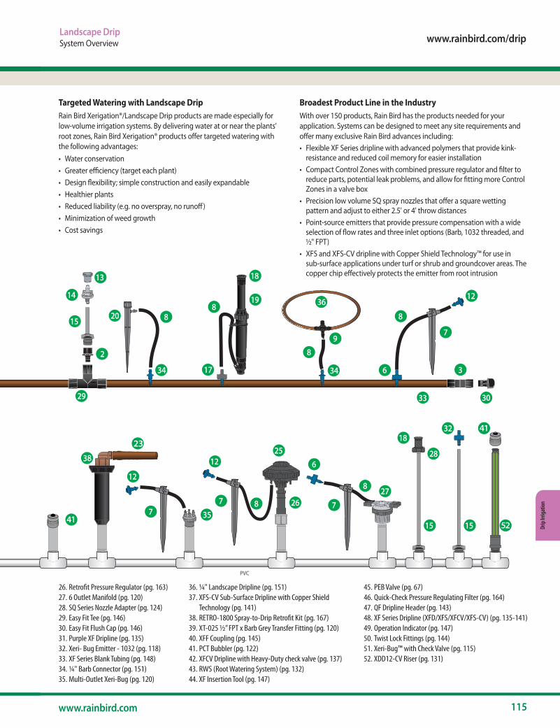
www.rainbird.com/drip
115www.rainbird.com
Drip
Irrig
atio
n
Landscape DripSystem Overview
26. Retrofit Pressure Regulator (pg. 163)27. 6 Outlet Manifold (pg. 120)28. SQ Series Nozzle Adapter (pg. 124)29. Easy Fit Tee (pg. 146)30. Easy Fit Flush Cap (pg. 146)31. Purple XF Dripline (pg. 135)32. Xeri- Bug Emitter - 1032 (pg. 118)33. XF Series Blank Tubing (pg. 148)34. ¼" Barb Connector (pg. 151)35. Multi-Outlet Xeri-Bug (pg. 120)
36. ¼" Landscape Dripline (pg. 151)37. XFS-CV Sub-Surface Dripline with Copper Shield
Technology (pg. 141)38. RETRO-1800 Spray-to-Drip Retrofit Kit (pg. 167)39. XT-025 ½” FPT x Barb Grey Transfer Fitting (pg. 120)40. XFF Coupling (pg. 145)41. PCT Bubbler (pg. 122)42. XFCV Dripline with Heavy-Duty check valve (pg. 137)43. RWS (Root Watering System) (pg. 132)44. XF Insertion Tool (pg. 147)
45. PEB Valve (pg. 67)46. Quick-Check Pressure Regulating Filter (pg. 164)47. QF Dripline Header (pg. 143)48. XF Series Dripline (XFD/XFS/XFCV/XFS-CV) (pg. 135-141)49. Operation Indicator (pg. 147)50. Twist Lock Fittings (pg. 144)51. Xeri-Bug™ with Check Valve (pg. 115)52. XDD12-CV Riser (pg. 131)
Broadest Product Line in the IndustryWith over 150 products, Rain Bird has the products needed for your application. Systems can be designed to meet any site requirements and offer many exclusive Rain Bird advances including:• Flexible XF Series dripline with advanced polymers that provide kink-
resistance and reduced coil memory for easier installation• Compact Control Zones with combined pressure regulator and filter to
reduce parts, potential leak problems, and allow for fitting more Control Zones in a valve box
• Precision low volume SQ spray nozzles that offer a square wetting pattern and adjust to either 2.5' or 4' throw distances
• Point-source emitters that provide pressure compensation with a wide selection of flow rates and three inlet options (Barb, 1032 threaded, and ½" FPT)
• XFS and XFS-CV dripline with Copper Shield Technology™ for use in sub-surface applications under turf or shrub and groundcover areas. The copper chip effectively protects the emitter from root intrusion
Targeted Watering with Landscape DripRain Bird Xerigation®/Landscape Drip products are made especially for low-volume irrigation systems. By delivering water at or near the plants’ root zones, Rain Bird Xerigation® products offer targeted watering with the following advantages:• Water conservation• Greater efficiency (target each plant)• Design flexibility; simple construction and easily expandable• Healthier plants• Reduced liability (e.g. no overspray, no runoff)• Minimization of weed growth• Cost savings
45 46
47
48
49
47
37
40
43
44
41
42
5152
41
23
50
50
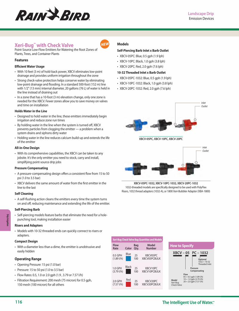
116 The Intelligent Use of Water.™
Drip Irrigation
Landscape DripEmission Devices
Xeri-Bug™ with Check ValvePoint-Source Low-Flow Emitters for Watering the Root Zones of Plants, Trees, and Container Plants
Features
Efficient Water Usage• With 10 feet (3 m) of hold-back power, XBCV eliminates low-point
drainage and provides uniform irrigation throughout the zone• Strong check-valve protection helps conserve water by eliminating
low-point drainage and flooding. In a standard 500-foot (152 m) line with 1/2" (13 mm) internal diameter, 20 gallons (76 L) of water is held in the line instead of draining out
• In a zone that has a 10-foot (3 m) elevation change, only one zone is needed for the XBCV. Fewer zones allow you to save money on valves and time on installation
Holds Water in the Line• Designed to hold water in the line, these emitters immediately begin
irrigation and reduce zone run times• By holding water in the line when the system is turned off, XBCV
prevents particles from clogging the emitter — a problem when a system drains and siphons dirty water
• Holding water in the line reduces calcium build-up and extends the life of the emitter
All-in-One Design• With its comprehensive capabilities, the XBCV can be taken to any
jobsite. It’s the only emitter you need to stock, carry and install, simplifying point-source drip jobs
Pressure Compensating• A pressure-compensating design offers a consistent flow from 15 to 50
psi (1.0 to 3.5 bar)• XBCV delivers the same amount of water from the first emitter in the
line to the last
Self Cleaning• A self-flushing action cleans the emitters every time the system turns
on and off, reducing maintenance and extending the life of the emitter.
Self-Piercing Barb• Self-piercing models feature barbs that eliminate the need for a hole-
punching tool, making installation easier
Risers and Adapters• Models with 10-32 threaded ends can quickly connect to risers or
adapters.
Compact Design• With a diameter less than a dime, the emitter is unobtrusive and
easily hidden
Operating Range• Opening Pressure: 15 psi (1.0 bar)• Pressure: 15 to 50 psi (1.0 to 3.5 bar)• Flow Rates: 0.5, 1.0 or 2.0 gph (1.9 , 3.79 or 7.57 l/h)• Filtration Requirement: 200 mesh (75 micron) for 0.5 gph,
150 mesh (100 micron) for all others
InletOutlet
InletOutlet
XBCV-05PC-1032, XBCV-10PC-1032, XBCV-20PC-10321032-threaded models are specifically designed to be used with PolyFlex
Risers, 1032 thread adapters (1032-A), or 1800 Xeri-Bubbler Adapter (XBA-1800)
XBCV-05PC, XBCV-10PC, XBCV-20PC
XBCV – 05 PC – 1032
Model Xeri-BugCheck Valve
Optional1032 = 10-32Threaded Inlet
Flow05 = 0.5 gph (1.89 l/h)10 = 1.0 gph (3.79 l/h)20 = 2.0 gph (7.57 l/h)
Pressure Compensating
How to SpecifyFlow Rate Color
Bag Qty.
Model Number
0.5 GPH (1.89 l/h)
Blue 25 100
XBCV05PC XBCV05PCBULK
1.0 GPH (3.79 l/h)
Black 25 100
XBCV10PC XBCV10PCBULK
2.0 GPH (7.57 l/h)
Red 25 100
XBCV20PC XBCV20PCBULK
Xeri-Bug Check Valve Bag Quantities and Models
Models
Self-Piercing Barb Inlet x Barb Outlet• XBCV-05PC: Blue, 0.5 gph (1.9 lph)• XBCV-10PC: Black, 1.0 gph (3.8 lph)• XBCV-20PC: Red, 2.0 gph (7.6 lph)
10-32 Threaded Inlet x Barb Outlet• XBCV-05PC-1032: Blue, 0.5 gph (1.9 lph)• XBCV-10PC-1032: Black, 1.0 gph (3.8 lph)• XBCV-20PC-1032: Red, 2.0 gph (7.6 lph)
NEW
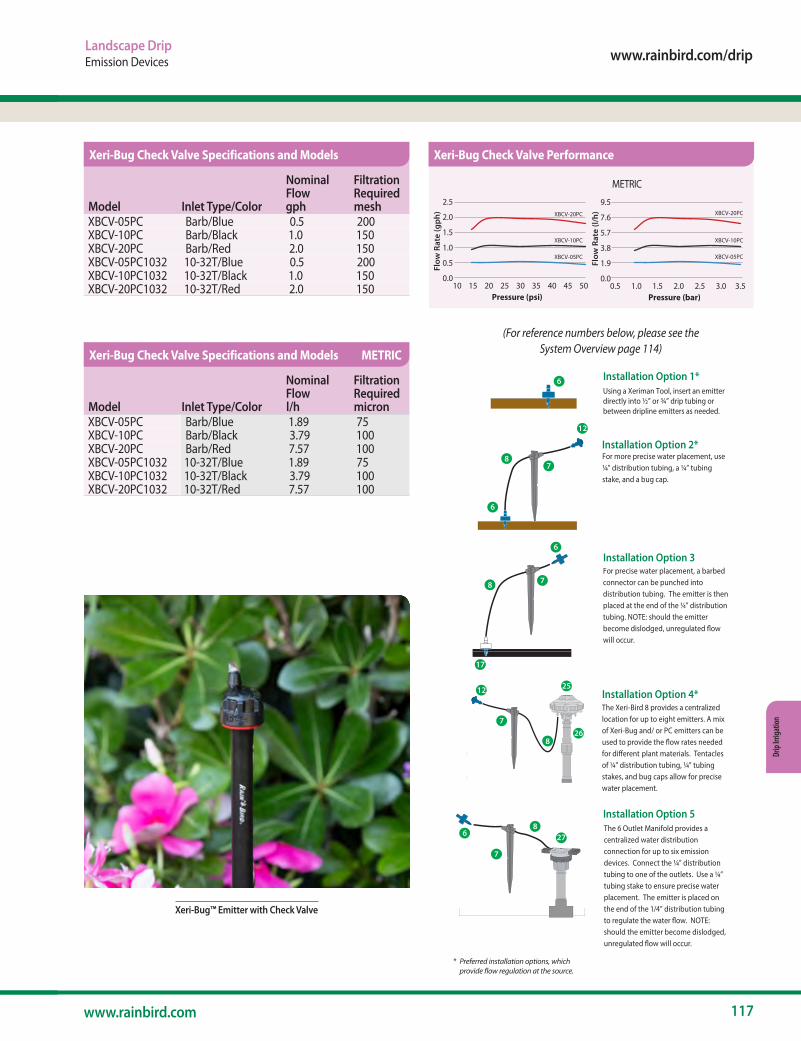
www.rainbird.com/drip
117www.rainbird.com
Drip
Irrig
atio
n
Landscape DripEmission Devices
Xeri-Bug™ Emitter with Check Valve
Installation Option 3
Using a Xeriman Tool, insert an emitterdirectly into ½” or ¾” drip tubing or between dripline emitters as needed.
For more precise water placement, use ¼” distribution tubing, a ¼” tubing stake, and a bug cap.
6
For precise water placement, a barbed connector can be punched into distribution tubing. The emitter is then placed at the end of the ¼” distribution tubing. NOTE: should the emitter become dislodged, unregulated �owwill occur.
The Xeri-Bird 8 provides a centralized location for up to eight emitters. A mix of Xeri-Bug and/ or PC emitters can be used to provide the �ow rates needed for di�erent plant materials. Tentacles of ¼” distribution tubing, ¼” tubing stakes, and bug caps allow for precise water placement.
5
6
78
9
The 6 Outlet Manifold provides a centralized water distribution connection for up to six emission devices. Connect the ¼” distribution tubing to one of the outlets. Use a ¼” tubing stake to ensure precise water placement. The emitter is placed on the end of the 1/4” distribution tubing to regulate the water �ow. NOTE: should the emitter become dislodged, unregulated �ow will occur.
8
27
7
6
Installation Option 1*
Installation Option 5
Installation Option 2*
Installation Option 4*
7
8
25
26
12
35
8
8
8
25
12
12
26
6
6
7
7
7
7
827
17
6
6
(For reference numbers below, please see the System Overview page 114)
* Preferred installation options, which provide flow regulation at the source.
Model Inlet Type/Color
Nominal Flow gph
Filtration Required mesh
XBCV-05PC Barb/Blue 0.5 200XBCV-10PC Barb/Black 1.0 150XBCV-20PC Barb/Red 2.0 150XBCV-05PC1032 10-32T/Blue 0.5 200XBCV-10PC1032 10-32T/Black 1.0 150XBCV-20PC1032 10-32T/Red 2.0 150
Xeri-Bug Check Valve Specifications and Models
Model Inlet Type/Color
Nominal Flow l/h
Filtration Required micron
XBCV-05PC Barb/Blue 1.89 75XBCV-10PC Barb/Black 3.79 100XBCV-20PC Barb/Red 7.57 100XBCV-05PC1032 10-32T/Blue 1.89 75XBCV-10PC1032 10-32T/Black 3.79 100XBCV-20PC1032 10-32T/Red 7.57 100
Xeri-Bug Check Valve Specifications and Models METRIC
Xeri-Bug Check Valve Performance
METRIC
Flow
Rat
e (g
ph)
Flow
Rat
e (l/
h)
2.5 2.0
1.5
1.0
0.5
0.0 10 15 20 25 30 35 40 45 50
Pressure (psi)
9.5 7.6
5.7
3.8
1.9
0.00.5 1.0 1.5 2.0 2.5 3.0 3.5
Pressure (bar)
XBCV-05PC
XBCV-10PC
XBCV-20PC
XBCV-05PC
XBCV-10PC
XBCV-20PC
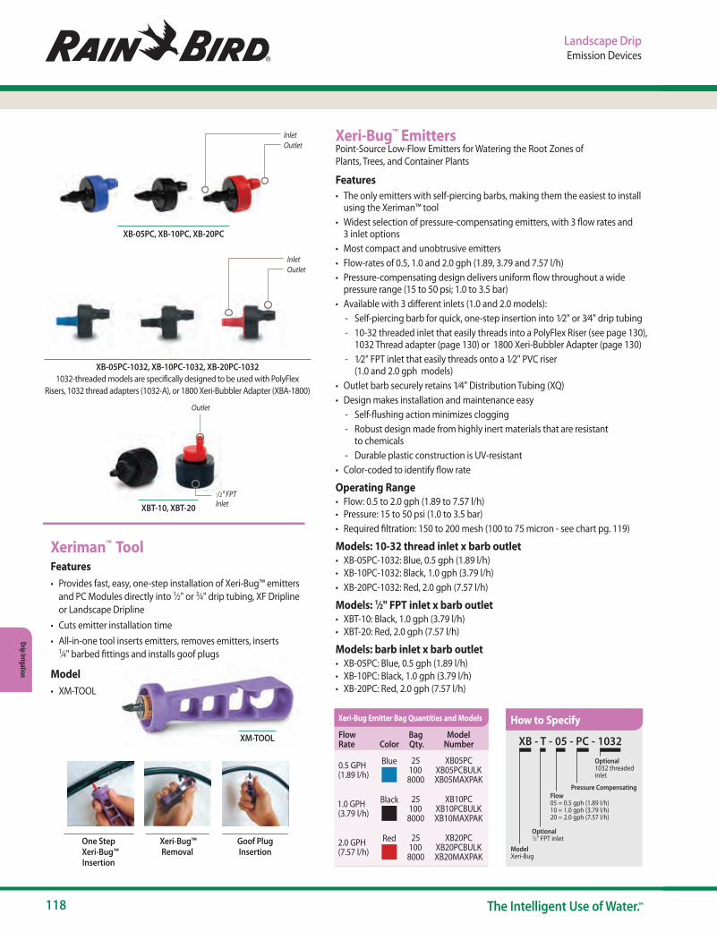
118 The Intelligent Use of Water.™
Drip Irrigation
Landscape DripEmission Devices
Xeri-Bug™ EmittersPoint-Source Low-Flow Emitters for Watering the Root Zones of Plants, Trees, and Container Plants
Features• The only emitters with self-piercing barbs, making them the easiest to install
using the Xeriman™ tool• Widest selection of pressure-compensating emitters, with 3 flow rates and
3 inlet options• Most compact and unobtrusive emitters• Flow-rates of 0.5, 1.0 and 2.0 gph (1.89, 3.79 and 7.57 l/h)• Pressure-compensating design delivers uniform flow throughout a wide
pressure range (15 to 50 psi; 1.0 to 3.5 bar)• Available with 3 different inlets (1.0 and 2.0 models):
- Self-piercing barb for quick, one-step insertion into 1⁄2" or 3⁄4" drip tubing - 10-32 threaded inlet that easily threads into a PolyFlex Riser (see page 130),
1032 Thread adapter (page 130) or 1800 Xeri-Bubbler Adapter (page 130) - 1⁄2" FPT inlet that easily threads onto a 1⁄2" PVC riser
(1.0 and 2.0 gph models)• Outlet barb securely retains 1⁄4" Distribution Tubing (XQ)• Design makes installation and maintenance easy
- Self-flushing action minimizes clogging - Robust design made from highly inert materials that are resistant
to chemicals - Durable plastic construction is UV-resistant
• Color-coded to identify flow rate
Operating Range• Flow: 0.5 to 2.0 gph (1.89 to 7.57 l/h)• Pressure: 15 to 50 psi (1.0 to 3.5 bar)• Required filtration: 150 to 200 mesh (100 to 75 micron - see chart pg. 119)
Models: 10-32 thread inlet x barb outlet• XB-05PC-1032: Blue, 0.5 gph (1.89 l/h)• XB-10PC-1032: Black, 1.0 gph (3.79 l/h)• XB-20PC-1032: Red, 2.0 gph (7.57 l/h)
Models: 1⁄2" FPT inlet x barb outlet• XBT-10: Black, 1.0 gph (3.79 l/h)• XBT-20: Red, 2.0 gph (7.57 l/h)
Models: barb inlet x barb outlet• XB-05PC: Blue, 0.5 gph (1.89 l/h)• XB-10PC: Black, 1.0 gph (3.79 l/h)• XB-20PC: Red, 2.0 gph (7.57 l/h)
InletOutlet
InletOutlet
XB-05PC-1032, XB-10PC-1032, XB-20PC-10321032-threaded models are specifically designed to be used with PolyFlex
Risers, 1032 thread adapters (1032-A), or 1800 Xeri-Bubbler Adapter (XBA-1800)
XB-05PC, XB-10PC, XB-20PC
Outlet
1/2" FPT InletXBT-10, XBT-20
XB - T - 05 - PC - 1032
Model Xeri-Bug
Optional1⁄2" FPT inlet
Optional1032 threaded inlet
Flow05 = 0.5 gph (1.89 l/h)10 = 1.0 gph (3.79 l/h)20 = 2.0 gph (7.57 l/h)
Pressure Compensating
XM-TOOL
Xeriman™ ToolFeatures• Provides fast, easy, one-step installation of Xeri-Bug™ emitters
and PC Modules directly into 1⁄2" or 3⁄4" drip tubing, XF Dripline or Landscape Dripline
• Cuts emitter installation time• All-in-one tool inserts emitters, removes emitters, inserts
1⁄4" barbed fittings and installs goof plugs
Model• XM-TOOL
One Step Xeri-Bug™
Insertion
Xeri-Bug™ Removal
Goof Plug Insertion
How to SpecifyFlow Rate Color
Bag Qty.
Model Number
0.5 GPH (1.89 l/h)
Blue 25 100 8000
XB05PC XB05PCBULK XB05MAXPAK
1.0 GPH (3.79 l/h)
Black 25 100 8000
XB10PC XB10PCBULK XB10MAXPAK
2.0 GPH (7.57 l/h)
Red 25 100 8000
XB20PC XB20PCBULK XB20MAXPAK
Xeri-Bug Emitter Bag Quantities and Models
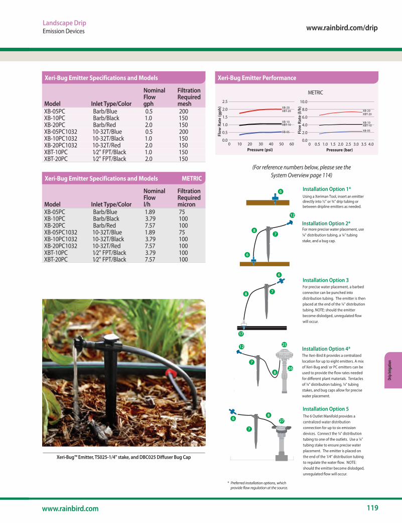
www.rainbird.com/drip
119www.rainbird.com
Drip
Irrig
atio
n
Landscape DripEmission Devices
Xeri-Bug™ Emitter, TS025-1/4" stake, and DBC025 Diffuser Bug Cap
METRIC
Flow
Rat
e (g
ph)
Flow
Rat
e (l/
h)
2.5 2.0
1.5
1.0
0.5
0.0 0 10 20 30 40 50 60
Pressure (psi)
10.0 8.0
6.0
4.0
2.0
0.0 0 0.5 1.0 1.5 2.0 2.5 3.0 3.5 4.0
Pressure (bar)
XB-20 XBT-20
XB-10 XBT-10
XB-05
XB-20 XBT-20
XB-10 XBT-10
XB-05
Installation Option 3
Using a Xeriman Tool, insert an emitterdirectly into ½” or ¾” drip tubing or between dripline emitters as needed.
For more precise water placement, use ¼” distribution tubing, a ¼” tubing stake, and a bug cap.
6
For precise water placement, a barbed connector can be punched into distribution tubing. The emitter is then placed at the end of the ¼” distribution tubing. NOTE: should the emitter become dislodged, unregulated �owwill occur.
The Xeri-Bird 8 provides a centralized location for up to eight emitters. A mix of Xeri-Bug and/ or PC emitters can be used to provide the �ow rates needed for di�erent plant materials. Tentacles of ¼” distribution tubing, ¼” tubing stakes, and bug caps allow for precise water placement.
5
6
78
9
The 6 Outlet Manifold provides a centralized water distribution connection for up to six emission devices. Connect the ¼” distribution tubing to one of the outlets. Use a ¼” tubing stake to ensure precise water placement. The emitter is placed on the end of the 1/4” distribution tubing to regulate the water �ow. NOTE: should the emitter become dislodged, unregulated �ow will occur.
8
27
7
6
Installation Option 1*
Installation Option 5
Installation Option 2*
Installation Option 4*
7
8
25
26
12
35
8
8
8
25
12
12
26
6
6
7
7
7
7
827
17
6
6
(For reference numbers below, please see the System Overview page 114)
* Preferred installation options, which provide flow regulation at the source.
Model Inlet Type/Color
Nominal Flow gph
Filtration Required mesh
XB-05PC Barb/Blue 0.5 200XB-10PC Barb/Black 1.0 150XB-20PC Barb/Red 2.0 150XB-05PC1032 10-32T/Blue 0.5 200XB-10PC1032 10-32T/Black 1.0 150XB-20PC1032 10-32T/Red 2.0 150XBT-10PC 1⁄2" FPT/Black 1.0 150XBT-20PC 1⁄2" FPT/Black 2.0 150
Xeri-Bug Emitter Specifications and Models
Model Inlet Type/Color
Nominal Flow l/h
Filtration Required micron
XB-05PC Barb/Blue 1.89 75XB-10PC Barb/Black 3.79 100XB-20PC Barb/Red 7.57 100XB-05PC1032 10-32T/Blue 1.89 75XB-10PC1032 10-32T/Black 3.79 100XB-20PC1032 10-32T/Red 7.57 100XBT-10PC 1⁄2" FPT/Black 3.79 100XBT-20PC 1⁄2" FPT/Black 7.57 100
Xeri-Bug Emitter Specifications and Models METRIC
Xeri-Bug Emitter Performance
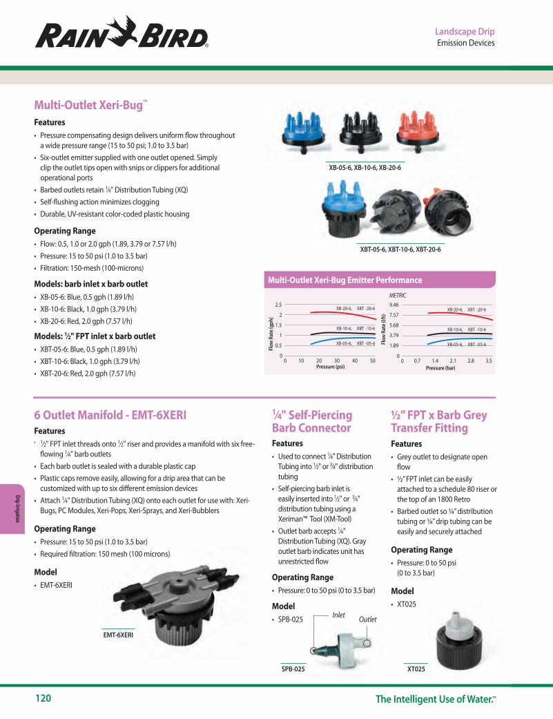
120 The Intelligent Use of Water.™
Drip Irrigation
Landscape DripEmission Devices
Multi-Outlet Xeri-Bug™
Features• Pressure compensating design delivers uniform flow throughout
a wide pressure range (15 to 50 psi; 1.0 to 3.5 bar)• Six-outlet emitter supplied with one outlet opened. Simply
clip the outlet tips open with snips or clippers for additional operational ports
• Barbed outlets retain 1⁄4" Distribution Tubing (XQ)• Self-flushing action minimizes clogging• Durable, UV-resistant color-coded plastic housing
Operating Range• Flow: 0.5, 1.0 or 2.0 gph (1.89, 3.79 or 7.57 l/h)• Pressure: 15 to 50 psi (1.0 to 3.5 bar)• Filtration: 150-mesh (100-microns)
Models: barb inlet x barb outlet• XB-05-6: Blue, 0.5 gph (1.89 l/h)• XB-10-6: Black, 1.0 gph (3.79 l/h)• XB-20-6: Red, 2.0 gph (7.57 l/h)
Models: 1⁄2" FPT inlet x barb outlet• XBT-05-6: Blue, 0.5 gph (1.89 l/h)• XBT-10-6: Black, 1.0 gph (3.79 l/h)• XBT-20-6: Red, 2.0 gph (7.57 l/h)
METRIC
2.5
2
1.5
1
0.5
5040302010
9.46
7.57
5.68
3.79
1.89
3.52.82.11.40.7
00
00
XB-20-6,
Flow
Rat
e (gp
h)Fl
ow R
ate (
l/h)
Pressure (bar)
Pressure (psi)
XBT -20-6
XB-10-6, XBT -10-6
XB-05-6, XBT -05-6
XB-20-6, XBT -20-6
XB-10-6, XBT -10-6
XB-05-6, XBT -05-6
2.5
2
1.5
1
0.5
5040302010
9.46
7.57
5.68
3.79
1.89
3.52.82.11.40.7
00
00
XB-20-6,
Flow
Rat
e (gp
h)Fl
ow R
ate (
l/h)
Pressure (bar)
Pressure (psi)
XBT -20-6
XB-10-6, XBT -10-6
XB-05-6, XBT -05-6
XB-20-6, XBT -20-6
XB-10-6, XBT -10-6
XB-05-6, XBT -05-6
XB-05-6, XB-10-6, XB-20-6
XBT-05-6, XBT-10-6, XBT-20-6
6 Outlet Manifold - EMT-6XERI Features• 1⁄2" FPT inlet threads onto 1⁄2" riser and provides a manifold with six free-
flowing 1⁄4" barb outlets• Each barb outlet is sealed with a durable plastic cap• Plastic caps remove easily, allowing for a drip area that can be
customized with up to six different emission devices• Attach 1⁄4" Distribution Tubing (XQ) onto each outlet for use with: Xeri-
Bugs, PC Modules, Xeri-Pops, Xeri-Sprays, and Xeri-Bubblers
Operating Range• Pressure: 15 to 50 psi (1.0 to 3.5 bar)• Required filtration: 150 mesh (100 microns)
Model• EMT-6XERI
½” FPT x Barb Grey Transfer Fitting Features• Grey outlet to designate open
flow• ½” FPT inlet can be easily
attached to a schedule 80 riser or the top of an 1800 Retro
• Barbed outlet so ¼” distribution tubing or ¼” drip tubing can be easily and securely attached
Operating Range• Pressure: 0 to 50 psi
(0 to 3.5 bar)
Model• XT025
EMT-6XERI
OutletInlet
SPB-025 XT025
1⁄4" Self-Piercing Barb ConnectorFeatures• Used to connect 1⁄4" Distribution
Tubing into 1⁄2" or 3⁄4" distribution tubing
• Self-piercing barb inlet is easily inserted into 1⁄2" or 3⁄4" distribution tubing using a Xeriman™ Tool (XM-Tool)
• Outlet barb accepts 1⁄4" Distribution Tubing (XQ). Gray outlet barb indi cates unit has unrestricted flow
Operating Range• Pressure: 0 to 50 psi (0 to 3.5 bar)
Model• SPB-025
Multi-Outlet Xeri-Bug Emitter Performance
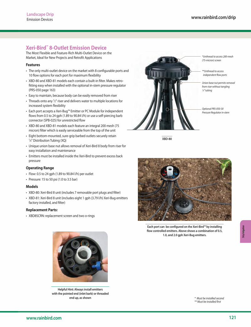
www.rainbird.com/drip
121www.rainbird.com
Drip
Irrig
atio
n
Landscape DripEmission Devices
*Unthread to access 200-mesh (75-micron) screen
**Unthread to access independent flow ports
Union base nut permits removal from riser without tangling 1⁄4" tubing
Optional PRS-050-30 Pressure Regulator in-stem
XBD-80
Xeri-Bird™ 8-Outlet Emission DeviceThe Most Flexible and Feature-Rich Multi-Outlet Device on the Market, Ideal for New Projects and Retrofit Applications
Features• The only multi-outlet device on the market with 8 configurable ports and
10 flow options for each port for maximum flexibility• XBD-80 and XBD-81 models each contain a built-in filter. Makes retro-
fitting easy when installed with the optional in-stem pressure regulator (PRS-050 page 163)
• Easy to maintain, because body can be easily removed from riser• Threads onto any 1⁄2" riser and delivers water to multiple locations for
increased system flexibility• Each port accepts a Xeri-Bug™ Emitter or PC Module for independent
flows from 0.5 to 24 gph (1.89 to 90.84 l/h) or use a self-piercing barb connector (SPB-025) for unrestricted flow
• XBD-80 and XBD-81 models each feature an integral 200 mesh (75 micron) filter which is easily serviceable from the top of the unit
• Eight bottom-mounted, sure-grip barbed outlets securely retain 1⁄4" Distribution Tubing (XQ)
• Unique union base nut allows removal of Xeri-Bird 8 body from riser for easy installation and maintenance
• Emitters must be installed inside the Xeri-Bird to prevent excess back pressure
Operating Range• Flow: 0.5 to 24 gph (1.89 to 90.84 l/h) per outlet• Pressure: 15 to 50 psi (1.0 to 3.5 bar)
Models• XBD-80: Xeri-Bird 8 unit (includes 7 removable port plugs and filter)• XBD-81: Xeri-Bird 8 unit (includes eight 1 gph (3.79 l/h) Xeri-Bug emitters
factory installed, and filter)
Replacement Parts:• XBD8SCRN: replacement screen and two o-rings
Each port can be configured on the Xeri-Bird™ by installing flow controlled emitters. Above shows a combination of 0.5,
1.0, and 2.0 gph Xeri-Bug emitters.
Helpful Hint: Always install emitters with the pointed end (inlet barb) or threaded
end up, as shown * Must be installed second** Must be installed first
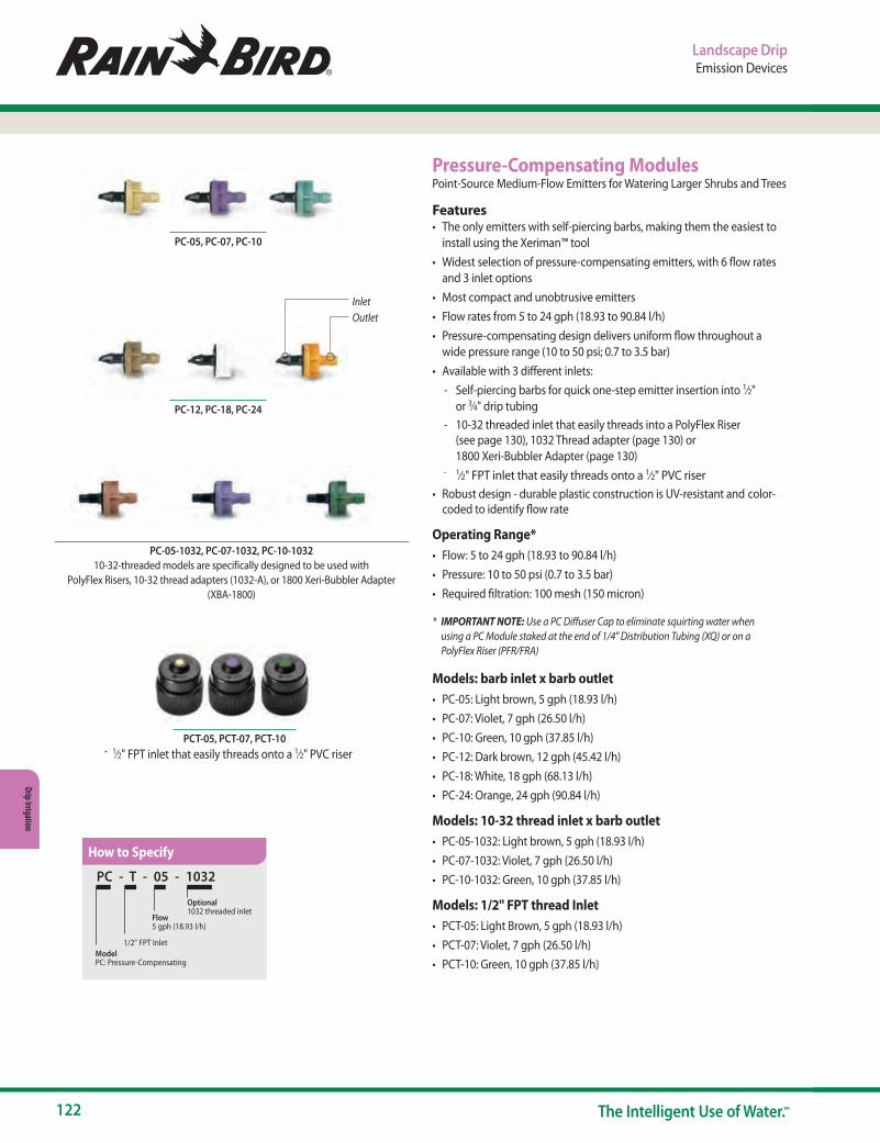
122 The Intelligent Use of Water.™
Drip Irrigation
Landscape DripEmission Devices
Pressure-Compensating ModulesPoint-Source Medium-Flow Emitters for Watering Larger Shrubs and Trees
Features• The only emitters with self-piercing barbs, making them the easiest to
install using the Xeriman™ tool• Widest selection of pressure-compensating emitters, with 6 flow rates
and 3 inlet options• Most compact and unobtrusive emitters• Flow rates from 5 to 24 gph (18.93 to 90.84 l/h)• Pressure-compensating design delivers uniform flow throughout a
wide pressure range (10 to 50 psi; 0.7 to 3.5 bar)• Available with 3 different inlets:
- Self-piercing barbs for quick one-step emitter insertion into 1⁄2" or 3⁄4" drip tubing
- 10-32 threaded inlet that easily threads into a PolyFlex Riser (see page 130), 1032 Thread adapter (page 130) or 1800 Xeri-Bubbler Adapter (page 130)
- 1⁄2" FPT inlet that easily threads onto a 1⁄2" PVC riser• Robust design - durable plastic construction is UV-resistant and color-
coded to identify flow rate
Operating Range*• Flow: 5 to 24 gph (18.93 to 90.84 l/h)• Pressure: 10 to 50 psi (0.7 to 3.5 bar)• Required filtration: 100 mesh (150 micron)
* IMPORTANT NOTE: Use a PC Diffuser Cap to eliminate squirting water when using a PC Module staked at the end of 1/4" Distribution Tubing (XQ) or on a PolyFlex Riser (PFR/FRA)
Models: barb inlet x barb outlet• PC-05: Light brown, 5 gph (18.93 l/h)• PC-07: Violet, 7 gph (26.50 l/h)• PC-10: Green, 10 gph (37.85 l/h)• PC-12: Dark brown, 12 gph (45.42 l/h)• PC-18: White, 18 gph (68.13 l/h)• PC-24: Orange, 24 gph (90.84 l/h)
Models: 10-32 thread inlet x barb outlet• PC-05-1032: Light brown, 5 gph (18.93 l/h)• PC-07-1032: Violet, 7 gph (26.50 l/h)• PC-10-1032: Green, 10 gph (37.85 l/h)
Models: 1/2" FPT thread Inlet• PCT-05: Light Brown, 5 gph (18.93 l/h)• PCT-07: Violet, 7 gph (26.50 l/h)• PCT-10: Green, 10 gph (37.85 l/h)
InletOutlet
PC-05, PC-07, PC-10
PC-12, PC-18, PC-24
PC-05-1032, PC-07-1032, PC-10-103210-32-threaded models are specifically designed to be used with
PolyFlex Risers, 10-32 thread adapters (1032-A), or 1800 Xeri-Bubbler Adapter (XBA-1800)
PC - T - 05 - 1032
Model PC: Pressure-Compensating
Optional1032 threaded inlet
Flow5 gph (18.93 l/h)
1/2" FPT Inlet
PCT-05, PCT-07, PCT-10• 1⁄2" FPT inlet that easily threads onto a 1⁄2" PVC riser
How to Specify

www.rainbird.com/drip
123www.rainbird.com
Drip
Irrig
atio
n
Landscape DripEmission Devices
PC Module (PC-10-1032) with PC Diffuser Cap (PC-DIFFUSER) on PolyFlex Riser (PFR-
PFA) (PolyFlex Risers available in 12" and 24" models - p. 130)
PC-DIFFUSER PC-DIFF-PPL
PC Diffuser Caps are designed to fit onto outlet of pressure-compensating drip modules
Models: (see page 129 for complete information)• PC-DIFFUSER: Black• PC-DIFF-PPL: Purple, to designate non-potable water
PC Diffuser Caps
Pressure-Compensating Modules
METRIC
Flow
Rat
e (l/
h)
Pressure (psi)
Flow
Rat
e (g
ph)
Pressure (bar)0 1.0 2.0 2.5 3.5 4.0
0 10 20 30 40 50 60
PC-24
PC-18PC-12
PC-10 & PCT-10
PC-07 & PCT-07
PC-05 & PCT-05
PC-24
PC-18PC-12
2824201612
840
106917661453015
0
PC-10 & PCT-10
PC-07 & PCT-07
PC-05 & PCT-05
Flow
Rat
e (l/
h)
Pressure (psi)
Flow
Rat
e (g
ph)
Pressure (bar)0 1.0 2.0 2.5 3.5 4.0
0 10 20 30 40 50 60
PC-24
PC-18PC-12
PC-10 & PCT-10
PC-07 & PCT-07
PC-05 & PCT-05
PC-24
PC-18PC-12
2824201612
840
106917661453015
0
PC-10 & PCT-10
PC-07 & PCT-07
PC-05 & PCT-05
ModelInlet Type/ Outlet/Color
Nominal Flow gph
Filtration Required mesh
PC-05 Barb / light brown 5 100PC-07 Barb / violet 7 100PC-10 Barb / green 10 100PC-12 Barb / dark brown 12 100PC-18 Barb / white 18 100PC-24 Barb / orange 24 100PC-05-1032 10-32T / light brown 5 100PC-07-1032 10-32T / violet 7 100PC-10-1032 10-32T / green 10 100PCT-05 NPT / light brown 5 100PCT-07 NPT / violet 7 100PCT-10 NPT / green 10 100
ModelInlet Type/ Outlet/Color
Nominal Flow l/h
Filtration Required micron
PC-05 Barb / light brown 18.93 150PC-07 Barb / violet 26.50 150PC-10 Barb / green 37.85 150PC-12 Barb / dark brown 45.42 150PC-18 Barb / white 68.13 150PC-24 Barb / orange 90.84 150PC-05-1032 10-32T / light brown 18.93 150PC-07-1032 10-32T / violet 26.50 150PC-10-1032 10-32T / green 37.85 150PCT-05 NPT / light brown 18.93 150PCT-07 NPT / violet 26.50 150PCT-10 NPT / green 37.85 150
Pressure-Compensating Module Models
Pressure-Compensating Modules & Bubblers Performance
Pressure-Compensating Module Models METRIC
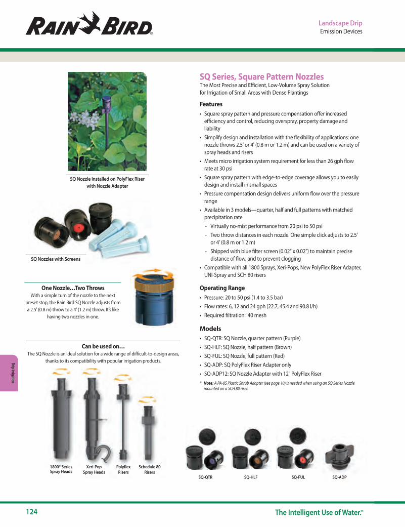
124 The Intelligent Use of Water.™
Drip Irrigation
Landscape DripEmission Devices
Can be used on…
The SQ Nozzle is an ideal solution for a wide range of difficult-to-design areas, thanks to its compatibility with popular irrigation products.
1800® Series Spray Heads
Xeri-PopSpray Heads
PolyflexRisers
Schedule 80Risers
SQ Series, Square Pattern NozzlesThe Most Precise and Efficient, Low-Volume Spray Solution for Irrigation of Small Areas with Dense Plantings
Features• Square spray pattern and pressure compensation offer increased
efficiency and control, reducing overspray, property damage and liability
• Simplify design and installation with the flexibility of applications: one nozzle throws 2.5' or 4' (0.8 m or 1.2 m) and can be used on a variety of spray heads and risers
• Meets micro irrigation system requirement for less than 26 gph flow rate at 30 psi
• Square spray pattern with edge-to-edge coverage allows you to easily design and install in small spaces
• Pressure compensation design delivers uniform flow over the pressure range
• Available in 3 models—quarter, half and full patterns with matched precipitation rate
- Virtually no-mist performance from 20 psi to 50 psi - Two throw distances in each nozzle. One simple click adjusts to 2.5'
or 4' (0.8 m or 1.2 m) - Shipped with blue filter screen (0.02" x 0.02") to maintain precise
distance of flow, and to prevent clogging• Compatible with all 1800 Sprays, Xeri-Pops, New PolyFlex Riser Adapter,
UNI-Spray and SCH 80 risers
Operating Range• Pressure: 20 to 50 psi (1.4 to 3.5 bar)• Flow rates: 6, 12 and 24 gph (22.7, 45.4 and 90.8 l/h)• Required filtration: 40 mesh
Models• SQ-QTR: SQ Nozzle, quarter pattern (Purple)• SQ-HLF: SQ Nozzle, half pattern (Brown)• SQ-FUL: SQ Nozzle, full pattern (Red)• SQ-ADP: SQ PolyFlex Riser Adapter only• SQ-ADP12: SQ Nozzle Adapter with 12" PolyFlex Riser* Note: A PA-8S Plastic Shrub Adapter (see page 10) is needed when using an SQ Series Nozzle
mounted on a SCH 80 riser.
SQ Nozzles with Screens
SQ Nozzle Installed on PolyFlex Riser with Nozzle Adapter
One Nozzle…Two Throws
With a simple turn of the nozzle to the next preset stop, the Rain Bird SQ Nozzle adjusts from a 2.5' (0.8 m) throw to a 4' (1.2 m) throw. It’s like
having two nozzles in one.
SQ-QTR SQ-HLF SQ-FUL SQ-ADP

www.rainbird.com/drip
125www.rainbird.com
Drip
Irrig
atio
n
Landscape DripEmission Devices
Performance data taken in zero wind conditions
4'2.5'
2.5'
4'
4' 5'2.5'
8'
8'
5'
5'
8'
2.5 feet throw @ 6" height above grade
NozzlePressure psi
Throw Radius ft.
Flow gph
Flow gpm
Precip.Rate w/no overlap in/h
Q 20 2.5 6.0 0.10 1.6430 2.5 7.0 0.12 1.9040 3.0 7.2 0.12 1.3250 3.0 7.2 0.12 1.32
H 20 2.5 10.2 0.17 1.3130 2.5 10.7 0.18 1.5740 3.0 10.7 0.18 1.2250 3.0 10.7 0.18 1.22
F 20 2.5 20.0 0.33 1.2830 2.5 24.2 0.40 1.5540 3.0 27.3 0.46 1.2250 3.0 27.3 0.46 1.22
4 feet throw @ 6" height above grade
NozzlePressure psi
Throw Radius ft.
Flow gph
Flow gpm
Precip.Rate w/no overlap in/h
Q 20 4.0 6.0 0.10 0.6430 4.0 7.2 0.12 0.7440 4.5 7.2 0.12 0.5950 4.5 7.2 0.12 0.59
H 20 4.0 10.2 0.17 0.5130 4.0 10.7 0.18 0.6140 4.5 10.7 0.18 0.5450 4.5 10.7 0.18 0.54
F 20 4.0 20.0 0.33 0.5030 4.0 24.2 0.40 0.6140 4.5 27.3 0.46 0.5450 4.5 27.3 0.46 0.54
0.8 m throw @ 0.15 m height above grade
NozzlePressure bar
Throw Radius m
Flow lph
Flow lpm
Precip.Rate w/no overlap mm/h
Q 1.4 0.8 23 0.38 422.1 0.8 27 0.44 482.8 0.9 27 0.45 343.4 0.9 27 0.45 34
H 1.4 0.8 39 0.65 332.1 0.8 41 0.68 402.8 0.9 41 0.68 313.4 0.9 41 0.68 31
F 1.4 0.8 76 1.27 332.1 0.8 92 1.53 392.8 0.9 103 1.72 313.4 0.9 103 1.72 31
1.2 m throw @ 0.15 m height above grade
NozzlePressure bar
Throw Radius m
Flow lph
Flow lpm
Precip.Rate w/no overlap mm/h
Q 1.4 1.2 23 0.38 162.1 1.2 27 0.44 192.8 1.4 27 0.45 153.4 1.4 27 0.45 15
H 1.4 1.2 39 0.65 132.1 1.2 41 0.68 162.8 1.4 41 0.68 143.4 1.4 41 0.68 14
F 1.4 1.2 76 1.27 132.1 1.2 92 1.53 152.8 1.4 103 1.72 143.4 1.4 103 1.72 14
SQ Nozzle Performance
SQ Nozzle Performance
SQ Nozzles
SQ Nozzle Performance METRIC
SQ Nozzle Performance METRIC
SQ Performance Charts
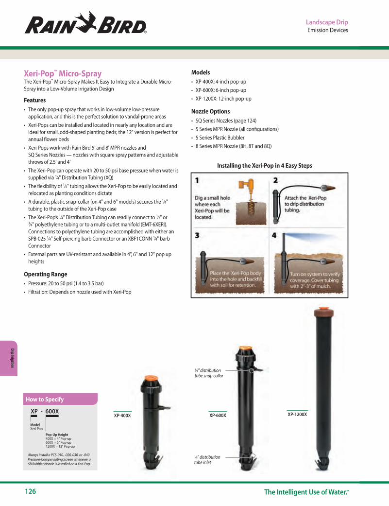
126 The Intelligent Use of Water.™
Drip Irrigation
Landscape DripEmission Devices
Xeri-Pop™ Micro-SprayThe Xeri-Pop™ Micro-Spray Makes It Easy to Integrate a Durable Micro-Spray into a Low-Volume Irrigation Design
Features• The only pop-up spray that works in low-volume low-pressure
application, and this is the perfect solution to vandal-prone areas• Xeri-Pops can be installed and located in nearly any location and are
ideal for small, odd-shaped planting beds; the 12" version is perfect for annual flower beds
• Xeri-Pops work with Rain Bird 5' and 8' MPR nozzles and SQ Series Nozzles — nozzles with square spray patterns and adjustable throws of 2.5' and 4'
• The Xeri-Pop can operate with 20 to 50 psi base pressure when water is supplied via 1⁄4" Distribution Tubing (XQ)
• The flexibility of 1⁄4" tubing allows the Xeri-Pop to be easily located and relocated as planting conditions dictate
• A durable, plastic snap-collar (on 4" and 6" models) secures the 1⁄4" tubing to the outside of the Xeri-Pop case
• The Xeri-Pop’s 1⁄4" Distribution Tubing can readily connect to 1⁄2" or 3⁄4" polyethylene tubing or to a multi-outlet manifold (EMT-6XERI). Connections to polyethylene tubing are accomplished with either an SPB-025 1⁄4" Self-piercing barb Connector or an XBF1CONN 1⁄4" barb Connector
• External parts are UV-resistant and available in 4", 6" and 12" pop up heights
Operating Range• Pressure: 20 to 50 psi (1.4 to 3.5 bar)• Filtration: Depends on nozzle used with Xeri-Pop
Models• XP-400X: 4-inch pop-up• XP-600X: 6-inch pop-up• XP-1200X: 12-inch pop-up
Nozzle Options• SQ Series Nozzles (page 124)• 5 Series MPR Nozzle (all configurations)• 5 Series Plastic Bubbler• 8 Series MPR Nozzle (8H, 8T and 8Q)
XP-1200X
1⁄4" distribution tube inlet
1⁄4" distribution tube snap collar
XP-600XXP - 600X
Model Xeri-Pop
Pop-Up Height400X = 4" Pop-up600X = 6" Pop-up1200X = 12" Pop-up
Always install a PCS-010, -020, 030, or -040 Pressure-Compensating Screen whenever a 5B Bubbler Nozzle is installed on a Xeri-Pop.
XP-400X
Installing the Xeri-Pop in 4 Easy Steps
How to Specify
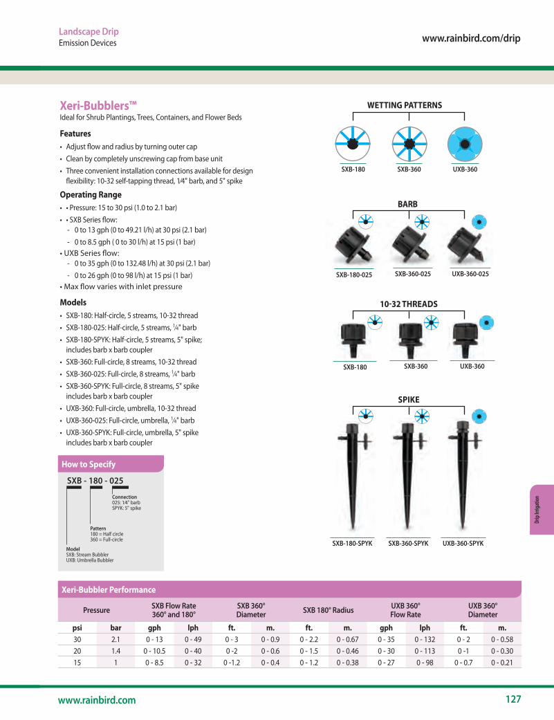
www.rainbird.com/drip
127www.rainbird.com
Drip
Irrig
atio
n
Landscape DripEmission Devices
Xeri-Bubblers™Ideal for Shrub Plantings, Trees, Containers, and Flower Beds
Features• Adjust flow and radius by turning outer cap• Clean by completely unscrewing cap from base unit• Three convenient installation connections available for design
flexibility: 10-32 self-tapping thread, 1⁄4" barb, and 5" spike
Operating Range• • Pressure: 15 to 30 psi (1.0 to 2.1 bar)• • SXB Series flow:
- 0 to 13 gph (0 to 49.21 l/h) at 30 psi (2.1 bar) - 0 to 8.5 gph ( 0 to 30 l/h) at 15 psi (1 bar)
• UXB Series flow: - 0 to 35 gph (0 to 132.48 l/h) at 30 psi (2.1 bar) - 0 to 26 gph (0 to 98 l/h) at 15 psi (1 bar)
• Max flow varies with inlet pressure
Models• SXB-180: Half-circle, 5 streams, 10-32 thread• SXB-180-025: Half-circle, 5 streams, 1⁄4" barb • SXB-180-SPYK: Half-circle, 5 streams, 5" spike;
includes barb x barb coupler• SXB-360: Full-circle, 8 streams, 10-32 thread• SXB-360-025: Full-circle, 8 streams, 1⁄4" barb • SXB-360-SPYK: Full-circle, 8 streams, 5" spike
includes barb x barb coupler • UXB-360: Full-circle, umbrella, 10-32 thread• UXB-360-025: Full-circle, umbrella, 1⁄4" barb• UXB-360-SPYK: Full-circle, umbrella, 5" spike
includes barb x barb coupler
SXB-180-025
SXB-180
SXB-180-SPYK
SXB - 180 - 025
Model SXB: Stream BubblerUXB: Umbrella Bubbler
Connection025: 1⁄4" barbSPYK: 5" spike
Pattern180 = Half circle360 = Full-circle
UXB-360SXB-180 SXB-360
SXB-360-025 UXB-360-025
BARB
WETTING PATTERNS
10-32 THREADS
SXB-360 UXB-360
SPIKE
SXB-360-SPYK UXB-360-SPYK
Pressure SXB Flow Rate360° and 180°
SXB 360° Diameter SXB 180° Radius UXB 360°
Flow RateUXB 360° Diameter
psi bar gph lph ft. m. ft. m. gph lph ft. m.30 2.1 0 - 13 0 - 49 0 - 3 0 - 0.9 0 - 2.2 0 - 0.67 0 - 35 0 - 132 0 - 2 0 - 0.5820 1.4 0 - 10.5 0 - 40 0 -2 0 - 0.6 0 - 1.5 0 - 0.46 0 - 30 0 - 113 0 -1 0 - 0.3015 1 0 - 8.5 0 - 32 0 -1.2 0 - 0.4 0 - 1.2 0 - 0.38 0 - 27 0 - 98 0 - 0.7 0 - 0.21
How to Specify
Xeri-Bubbler Performance
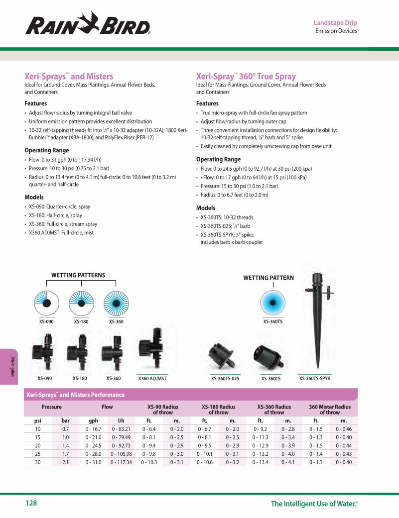
128 The Intelligent Use of Water.™
Drip Irrigation
Landscape DripEmission Devices
Xeri-Spray™ 360° True SprayIdeal for Mass Plantings, Ground Cover, Annual Flower Beds and Containers
Features• True micro-spray with full-circle fan spray pattern• Adjust flow/radius by turning outer cap• Three convenient installation connections for design flexibility:
10-32 self-tapping thread, 1⁄4" barb and 5" spike• Easily cleaned by completely unscrewing cap from base unit
Operating Range• Flow: 0 to 24.5 gph (0 to 92.7 l/h) at 30 psi (200 kpa)• • Flow: 0 to 17 gph (0 to 64 l/h) at 15 psi (100 kPa)• Pressure: 15 to 30 psi (1.0 to 2.1 bar)• Radius: 0 to 6.7 feet (0 to 2.0 m)
Models• XS-360TS: 10-32 threads• XS-360TS-025: 1⁄4" barb • XS-360TS-SPYK: 5" spike;
includes barb x barb coupler
XS-360TSXS-360TS-025 XS-360TS-SPYKXS-090 XS-180 XS-360
Xeri-Sprays™ and MistersIdeal for Ground Cover, Mass Plantings, Annual Flower Beds, and Containers
Features• Adjust flow/radius by turning integral ball valve• Uniform emission pattern provides excellent distribution• 10-32 self-tapping threads fit into 1⁄2" x 10-32 adapter (10-32A); 1800 Xeri-
Bubbler™ adapter (XBA-1800); and PolyFlex Riser (PFR-12)
Operating Range• Flow: 0 to 31 gph (0 to 117.34 l/h)• Pressure: 10 to 30 psi (0.75 to 2.1 bar)• Radius: 0 to 13.4 feet (0 to 4.1 m) full-circle; 0 to 10.6 feet (0 to 3.2 m)
quarter- and half-circle
Models• XS-090: Quarter-circle, spray• XS-180: Half-circle, spray• XS-360: Full-circle, stream spray• X360 ADJMST: Full-circle, mist
XS-360TSXS-090 XS-180 XS-360
X360 ADJMST
WETTING PATTERNS WETTING PATTERN
Pressure Flow XS-90 Radiusof throw
XS-180 Radiusof throw
XS-360 Radiusof throw
360 Mister Radiusof throw
psi bar gph l/h ft. m. ft. m. ft. m. ft. m.10 0.7 0 - 16.7 0 - 63.21 0 - 6.4 0 - 2.0 0 - 6.7 0 - 2.0 0 - 9.2 0 - 2.8 0 - 1.5 0 - 0.4615 1.0 0 - 21.0 0 - 79.49 0 - 8.1 0 - 2.5 0 - 8.1 0 - 2.5 0 - 11.3 0 - 3.4 0 - 1.3 0 - 0.4020 1.4 0 - 24.5 0 - 92.73 0 - 9.4 0 - 2.9 0 - 9.5 0 - 2.9 0 - 12.9 0 - 3.9 0 - 1.5 0 - 0.4425 1.7 0 - 28.0 0 - 105.98 0 - 9.8 0 - 3.0 0 - 10.1 0 - 3.1 0 - 13.2 0 - 4.0 0 - 1.4 0 - 0.4330 2.1 0 - 31.0 0 - 117.34 0 - 10.3 0 - 3.1 0 - 10.6 0 - 3.2 0 - 13.4 0 - 4.1 0 - 1.3 0 - 0.40
Xeri-Sprays™ and Misters Performance

www.rainbird.com/drip
129www.rainbird.com
Drip
Irrig
atio
n
Landscape DripEmission Devices and Distribution Components
1⁄4" Tubing Stake with CapFeatures• Locking cap holds
tubing in place• Used for holding 1⁄4" Distribution
Tubing (XQ) in place at the plant root zone
• Accepts 1⁄4" Distribution Tubing from 0.19 O.D. to 0.256 O.D.
• Bug cap included• Constructed of UV-resistant
plastic material
Model• TS-025WCAP
PC Diffuser CapFeatures• Cap snaps securely onto the PC Module and XB emitter outlet to create
bubbler effect and prevent wash out• Designed for quick and easy installation• Made of UV-resistant polyethylene material
Models• PC-DIFFUSER: Black• PC-DIFF-PPL: Purple to designate non-potable water
Universal 1⁄4" Tubing StakeFeatures• Holds 1⁄4" Distribution Tubing
and emitter or Diffuser Bug Cap firmly in place at the root zone of the plant
• Designed to securely hold Rain Bird and other manufacturers’ 1⁄4" Distribution Tubing — 0.16" to 0.18" I.D. and 0.22" to 0.25" O.D.
• Rigid stake featuring a flat enlarged head designed to withstand hammering into tough soil
Note: If emitter is installed at inlet to distribution tubing, use a Diffuser Bug Cap (DBC-025) at outlet of tubing to prevent bugs from clogging tubing and to help hold tubing in place
Model• TS-025
Suggested Applications
Diffuser Bug CapFeatures• Prevents bugs and other debris from clogging 1⁄4" Distribution Tubing• Barbed inlet fits into 1⁄4" Distribution Tubing (XQ)• Flanged shield diffuses water to minimize soil erosion at
emission point
Operating Range• Pressure: 0 to 50 psi (0 to 3.5 bar)
Models• DBC-025: Black
Outlet
Inlet
TS-025WCAP
DBC-025
PC-DIFFUSER
A. 1⁄4" tubing, 1⁄4" stake, PC Module, Diffuser Bug Cap. Used for runs greater than 5 feet from main line
PC-DIFF-PPL
B. 1⁄4" tubing, 1⁄4" stake, Diffuser Bug Cap. Used for runs up to 5 feet from main line
(Drip emitter not shown – installed directly into lateral line)
TS-025

130 The Intelligent Use of Water.™
Drip Irrigation
Landscape DripDistribution Components
12" PolyFlex RiserFeatures• 12" riser that is used with any 10-
32 threaded emission device to deliver water directly to a plant. These include Xeri-Bugs, PC Modules, Xeri-Bubblers and Xeri-Sprays
• Extremely rugged and reliable – constructed of thick-walled, high-density polyethylene
• Can be used with a riser-stake (RS-025T)
Operating Range• Pressure: 15 to 50 psi
(1.0 to 3.5 bar)
Model• PFR-12
10-32 Thread AdapterFeatures• Inlet: 1⁄2" FPT that screws onto
any 1⁄2" MPT riser• Outlet: 10-32 threads that
accept Xeri-Bugs, PC Modules, Xeri-Bubblers and Xeri-Sprays with 10-32 threads
• Constructed of UV-resistant plastic material
Operating Range• Pressure: 15 to 50 psi
(1.0 to 3.5 bar)
Model• 10-32A
Riser Stake- ThreadedFeatures• Rugged 5" (12.7 cm) stake for use
with PolyFlex Risers• Constructed of UV-resistant
plastic material• Barbed side inlet accepts 1⁄4"
Distribution Tubing (XQ)• 10-32 threaded outlet
permits easy threading of 12" (30.5 cm) PolyFlex Riser (PFR-12)
Operating Range• Pressure: 15 to 50 psi
(1.0 to 3.5 bar)
Model• RS-025T
PolyFlex Riser and Adapter AssembliesFeatures• 12" or 24" riser that is pre-assembled with a 1⁄2" male threaded base that
simplifies installation• Use with any 10-32 threaded emission device to deliver water directly to a
plant. These include Xeri-Bugs, PC Modules, Xeri-Bubblers and Xeri-Sprays• Newly-designed adapter with larger tabs makes installation
quicker and easier; can be used on PVC laterals, or with any 1⁄2" female threaded adapter
• Adapter made of heavy-duty Marlex®, which requires no Teflon® tape, saving time during installation
• Extremely rugged and reliable PolyFlex Riser constructed of thick-walled, high-density polyethylene
Operating Range• Pressure: 15 to 50 psi (1.0 to 3.5 bar)
Models• PFR-FRA: 12" (30.5 cm) PolyFlex Riser and adapter• PFR-FRA24: 24" (61.0 cm) PolyFlex Riser and adapter
PFR-FRA
PolyFlex Riser and Stake AssemblyFeatures• 12" riser that is pre-assembled
with a 7" (17.8 cm) stake• Use with any 10-32 threaded
emission device to deliver water directly to a plant. These include Xeri-Bugs, PC Modules, Xeri-Bubblers and Xeri-Sprays
• Saves time and money when installing a low-volume irrigation system
• Extremely rugged and reliable PolyFlex Riser constructed of thick-walled, high-density polyethylene
Operating Range• Pressure: 15 to 50 psi
(1.0 to 3.5 bar)
Model• PFR-RS: 12" (30.5 cm)
PolyFlex Riser and 7" (17.8 cm) stake
1800 Xeri-Bubbler AdapterFeatures• Inlet: 1⁄2" female threads that
screw onto a Rain Bird 1800 series or UNI-Spray or shrub adapter
• Outlet: 10-32 threads that accept any emission device with 10-32 threads including Xeri-Bugs, PC Modules, Xeri-Bubblers and Xeri-Sprays
• Sits at grade when installed on a spray head for a robust installation
Operating Range• Pressure: 15 to 50 psi
(1.0 to 3.5 bar)
Model• XBA-1800
PFR-12
10-32A
RS-025T
PFR-RS
XBA-1800
Use with SQ-ADP (SQ PolyFlex riser adapter, p. 124)
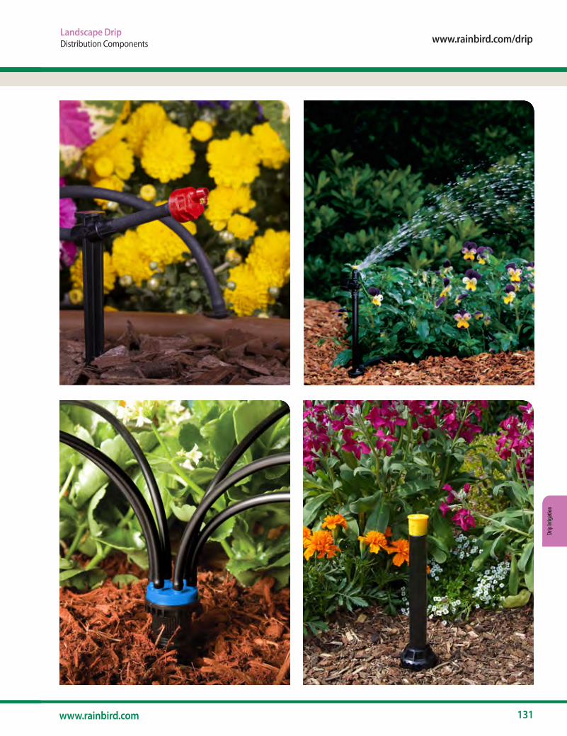
www.rainbird.com/drip
131www.rainbird.com
Drip
Irrig
atio
n
Landscape DripDistribution Components
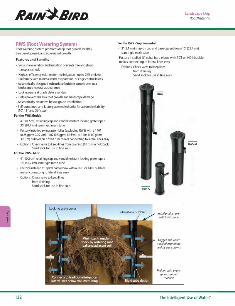
132 The Intelligent Use of Water.™
Drip Irrigation
Subsurface bubblerLocking grate cover
Connects to traditional irrigation lateral lines or low-volume tubing
Minimizes transplant shock by watering root ball and adjacent soil
Rigid tube design
Install product even with finish grade
Oxygen and water circulation promote
healthy plant growth
Position units evenly spaced around
root ball
RWS (Root Watering System)Root Watering System promotes deep root growth, healthy tree development, and accelerated growth
Features and Benefits• Subsurface aeration and irrigation prevents tree and shrub
transplant shock• Highest efficiency solution for tree irrigation - up to 95% emission
uniformity with minimal wind, evaporation, or edge control losses• Aesthetically designed subsurface bubbler contributes to a
landscape’s natural appearance• Locking grate at grade deters vandals• Helps prevent shallow root growth and hardscape damage• Aesthetically attractive below grade installation• Self-contained and factory assembled units for assured reliability
(10", 18" and 36" sizes)For the RWS Model:
- 4" (10.2 cm) retaining cap and vandal resistant locking grate tops a 36" (91.4 cm) semi-rigid mesh tube
- Factory installed swing assemblies (excluding RWS) with a 1401 (0.25 gpm; 0.95 l/m), 1402 (0.5 gpm; 1.9 l/m), or 1404 (1.00 gpm; 3.8 l/m) bubbler on a fixed riser makes connecting to lateral lines easy
- Options: Check valve to keep lines from draining (10 ft. min holdback) Sand sock for use in fine soils
For the RWS - Mini: - 4" (10.2 cm) retaining cap and vandal resistant locking grate tops a
18" (45.7 cm) semi-rigid mesh tube - Factory installed ½" spiral barb elbow with a 1401 or 1402 bubbler
makes connecting to lateral lines easy - Options: Check valve to keep lines
from draining Sand sock for use in fine soils
For the RWS - Supplemental: - 2" (5.1 cm) snap-on cap and base cap enclose a 10" (25.4 cm)
semi-rigid mesh tube- Factory installed ½" spiral barb elbow with PCT or 1401 bubbler
makes connecting to lateral lines easy - Options: Check valve to keep lines
from draining Sand sock for use in fine soils
RWS
RWS-S
RWS-M
Landscape DripRoot Watering
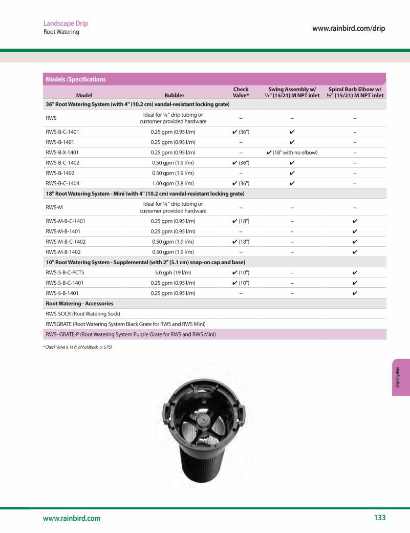
www.rainbird.com/drip
133www.rainbird.com
Drip
Irrig
atio
n
Model BubblerCheck Valve*
Swing Assembly w/ ½" (15/21) M NPT inlet
Spiral Barb Elbow w/ ½" (15/21) M NPT inlet
36" Root Watering System (with 4" (10.2 cm) vandal-resistant locking grate)
RWS Ideal for ¼ “ drip tubing or customer provided hardware – – –
RWS-B-C-1401 0.25 gpm (0.95 l/m) ✔ (36") ✔ –
RWS-B-1401 0.25 gpm (0.95 l/m) – ✔ –
RWS-B-X-1401 0.25 gpm (0.95 l/m) – ✔ (18" with no elbow) –
RWS-B-C-1402 0.50 gpm (1.9 l/m) ✔ (36") ✔ –
RWS-B-1402 0.50 gpm (1.9 l/m) – ✔ –
RWS-B-C-1404 1.00 gpm (3.8 l/m) ✔ (36") ✔ –
18" Root Watering System - Mini (with 4" (10.2 cm) vandal-resistant locking grate)
RWS-M Ideal for ¼ “ drip tubing or customer provided hardware – – –
RWS-M-B-C-1401 0.25 gpm (0.95 l/m) ✔ (18") – ✔
RWS-M-B-1401 0.25 gpm (0.95 l/m) – – ✔
RWS-M-B-C-1402 0.50 gpm (1.9 l/m) ✔ (18") – ✔
RWS-M-B-1402 0.50 gpm (1.9 l/m) – – ✔
10" Root Watering System - Supplemental (with 2" (5.1 cm) snap-on cap and base)
RWS-S-B-C-PCT5 5.0 gph (19 l/m) ✔ (10") – ✔
RWS-S-B-C-1401 0.25 gpm (0.95 l/m) ✔ (10") – ✔
RWS-S-B-1401 0.25 gpm (0.95 l/m) – – ✔
Root Watering - Accessories
RWS-SOCK (Root Watering Sock)
RWSGRATE (Root Watering System Black Grate for RWS and RWS Mini)
RWS- GRATE-P (Root Watering System Purple Grate for RWS and RWS Mini)
Models /Specifications
* Check Valve is 14 ft. of holdback, or 6 PSI
Landscape DripRoot Watering
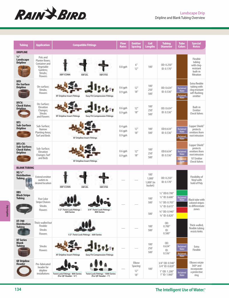
134 The Intelligent Use of Water.™
Drip Irrigation
Landscape DripDripline and Blank Tubing Overview
DRIPLINE¼" Landscape Dripline
Pots and Planter Boxes; Container and
Vegetable Gardens; Shrubs; Flowers
0.8 gph 6"
12"100'
OD: 0.250" ID: 0.170"
Flexible tubing
with clog-resistant built-in
filtration
XFD On-Surface Dripline On-surface;
Shrubs; Flowers
0.6 gph 0.9 gph
12" 18"
100'250'500'
OD: 0.634" ID: 0.536"
Extra flexible tubing with
clog resistant self-flushing
emitter
Reclaimed Water
Reclaimed Water
XFCV; Check Valve; Dripline
On-Surface; Elevation Changes;
Shrubs and Flowers
0.6 gph 0.9 gph
12" 18"
100'250'500'
OD: 0.634" ID: 0.536"
Built-in Emitter
Check Valves
XFS Sub-Surface Dripline
Sub-Surface; Narrow
Planting Areas; Turf and Beds
0.4 gph0.6 gph 0.9 gph
12" 18"
100'500'
OD:0.634"ID: 0.536"
Copper Shield™ protects
emitters from root intrusion
Reclaimed Water
Reclaimed Water
XFS-CV; Sub-Surface; Check Valve; Dripline
Sub-Surface; Elevation
Changes; Turf and Beds
0.6 gph 0.9 gph
12" 18"
100'250'500'
OD:0.634"ID: 0.536"
Copper Shield™ protects
emitters from root intrusion
10' Emitter Check Valves
Reclaimed Water
Reclaimed Water
BLANK TUBING
XQ ¼" Distribution Tubing Extend emitter
outlets to desired location
— —
100'1,000'
1,000' (in bucket)
OD: 0.250" ID: 0.170"
Flexibility of Vinyl with
hold of Poly
XBS Black Stripe Tubing Five Color
Stripe ChoicesShrubsFlowers
— —
100'500'
500'
½" OD:0.700"½" ID: 0.600"
½" OD: 0.705"½" ID: 0.615"
¾" OD: 0.940"¾" ID: 0.820"
Black tube with colored stripes to differentiate
zones
Reclaimed Water
XT-700 Distribution Tubing
Thick-walled but FlexibleShrubsFlowers
— —100'500'
OD: 0.700"
ID: 0.580"
Thick-walled, flexible tubing
resists kinks
XF Series Blank Tubing Shrubs
Flowers— —
100'250'500'
OD: 0.634"
ID: 0.536"
Extra Flexible
Reclaimed Water
Reclaimed Water
QF Dripline Header Pre-fabricated
header for dripline
installations
—
Elbow Spacing:
12" 18"
100'
3/4" OD: 0.940" 3/4" ID: 0.820"
1" OD: 1.200" 1" ID: 1.060"
Elbows rotate 360º and
incorporate a protective
ringReclaimed
Water
XBF2EL XBF3TEEXBF1CONN
1/2": Twist Lock Fittings – 600 Series
3/4": Twist Lock Fittings – 800 Series
XF Dripline Insert Fittings Easy Fit Compression Fittings
XF Dripline Insert Fittings Easy Fit Compression Fittings
XF Dripline Insert Fittings
XF Dripline Insert Fittings
Twist Lock Fittings - 800 Series (For QF Header - ¾")
Twist Lock Fittings - 1000 Series (For QF Header - 1")
XBF2EL XBF3TEEXBF1CONN
1/2": Twist Lock Fittings – 600 Series
XF Dripline Insert Fittings Easy Fit Compression Fittings
Tubing Application Compatible Fittings Flow Rates
Emitter Spacing
Coil Lengths
Tubing Diameter
Tube Colors
Special Notes
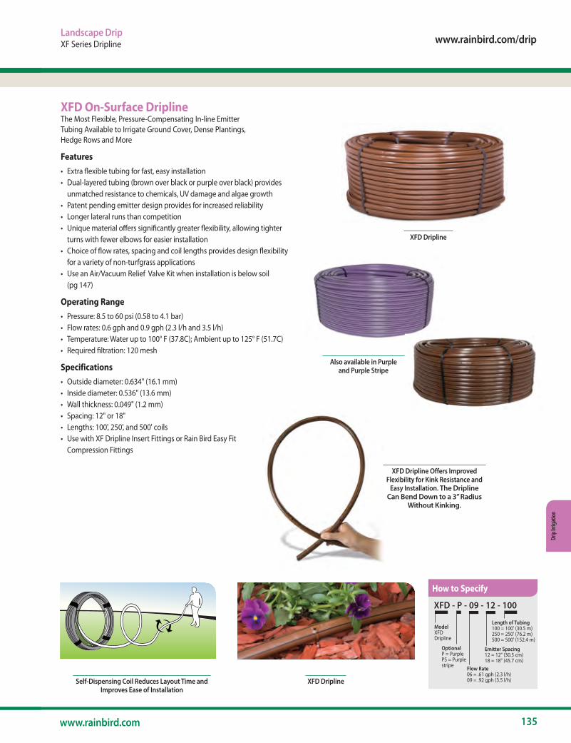
www.rainbird.com/drip
135www.rainbird.com
Drip
Irrig
atio
n
Landscape DripXF Series Dripline
XFD - P - 09 - 12 - 100
Model XFDDripline
OptionalP = PurplePS = Purple stripe Flow Rate
06 = .61 gph (2.3 l/h)09 = .92 gph (3.5 l/h)
Emitter Spacing 12 = 12" (30.5 cm)18 = 18" (45.7 cm)
Length of Tubing100 = 100' (30.5 m)250 = 250' (76.2 m)500 = 500' (152.4 m)
Self-dispensing Dripline
XFD DriplineSelf-Dispensing Coil Reduces Layout Time and Improves Ease of Installation
XFD On-Surface DriplineThe Most Flexible, Pressure-Compensating In-line Emitter Tubing Available to Irrigate Ground Cover, Dense Plantings, Hedge Rows and More
Features• Extra flexible tubing for fast, easy installation• Dual-layered tubing (brown over black or purple over black) provides
unmatched resistance to chemicals, UV damage and algae growth• Patent pending emitter design provides for increased reliability• Longer lateral runs than competition• Unique material offers significantly greater flexibility, allowing tighter
turns with fewer elbows for easier installation• Choice of flow rates, spacing and coil lengths provides design flexibility
for a variety of non-turfgrass applications• Use an Air/Vacuum Relief Valve Kit when installation is below soil
(pg 147)
Operating Range• Pressure: 8.5 to 60 psi (0.58 to 4.1 bar)• Flow rates: 0.6 gph and 0.9 gph (2.3 l/h and 3.5 l/h)• Temperature: Water up to 100° F (37.8C); Ambient up to 125° F (51.7C)• Required filtration: 120 mesh
Specifications• Outside diameter: 0.634" (16.1 mm)• Inside diameter: 0.536" (13.6 mm)• Wall thickness: 0.049" (1.2 mm)• Spacing: 12" or 18" • Lengths: 100', 250', and 500' coils • Use with XF Dripline Insert Fittings or Rain Bird Easy Fit
Compression Fittings
XFD Dripline Offers Improved Flexibility for Kink Resistance and
Easy Installation. The Dripline Can Bend Down to a 3” Radius
Without Kinking.
How to Specify
XFD Dripline
Also available in Purple and Purple Stripe
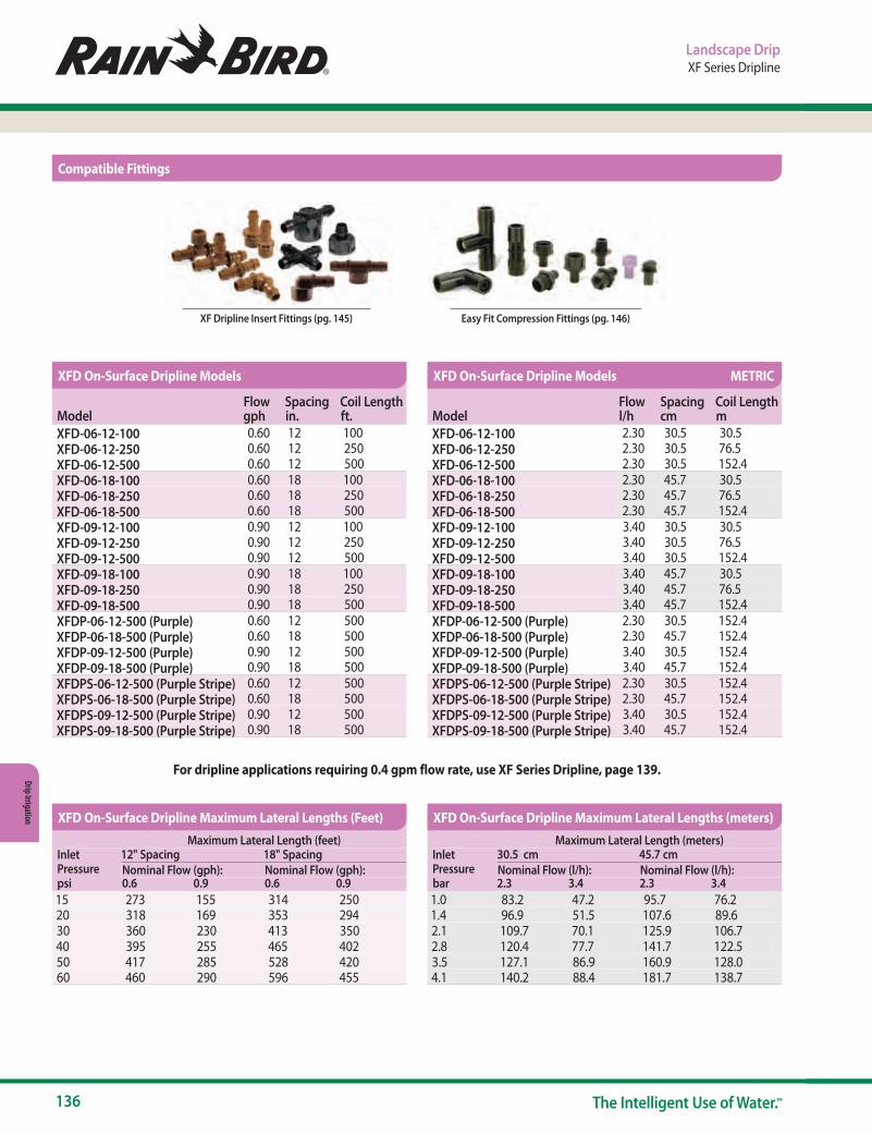
136 The Intelligent Use of Water.™
Drip Irrigation
Landscape DripXF Series Dripline
For dripline applications requiring 0.4 gpm flow rate, use XF Series Dripline, page 139.
XF Dripline Insert Fittings (pg. 145) Easy Fit Compression Fittings (pg. 146)
ModelFlow gph
Spacing in.
Coil Length ft.
XFD-06-12-100 0.60 12 100XFD-06-12-250 0.60 12 250XFD-06-12-500 0.60 12 500XFD-06-18-100 0.60 18 100XFD-06-18-250 0.60 18 250XFD-06-18-500 0.60 18 500XFD-09-12-100 0.90 12 100XFD-09-12-250 0.90 12 250XFD-09-12-500 0.90 12 500XFD-09-18-100 0.90 18 100XFD-09-18-250 0.90 18 250XFD-09-18-500 0.90 18 500XFDP-06-12-500 (Purple) 0.60 12 500XFDP-06-18-500 (Purple) 0.60 18 500XFDP-09-12-500 (Purple) 0.90 12 500XFDP-09-18-500 (Purple) 0.90 18 500XFDPS-06-12-500 (Purple Stripe) 0.60 12 500XFDPS-06-18-500 (Purple Stripe) 0.60 18 500XFDPS-09-12-500 (Purple Stripe) 0.90 12 500XFDPS-09-18-500 (Purple Stripe) 0.90 18 500
ModelFlow l/h
Spacing cm
Coil Length m
XFD-06-12-100 2.30 30.5 30.5XFD-06-12-250 2.30 30.5 76.5XFD-06-12-500 2.30 30.5 152.4XFD-06-18-100 2.30 45.7 30.5XFD-06-18-250 2.30 45.7 76.5XFD-06-18-500 2.30 45.7 152.4XFD-09-12-100 3.40 30.5 30.5XFD-09-12-250 3.40 30.5 76.5XFD-09-12-500 3.40 30.5 152.4XFD-09-18-100 3.40 45.7 30.5XFD-09-18-250 3.40 45.7 76.5XFD-09-18-500 3.40 45.7 152.4XFDP-06-12-500 (Purple) 2.30 30.5 152.4XFDP-06-18-500 (Purple) 2.30 45.7 152.4XFDP-09-12-500 (Purple) 3.40 30.5 152.4XFDP-09-18-500 (Purple) 3.40 45.7 152.4XFDPS-06-12-500 (Purple Stripe) 2.30 30.5 152.4XFDPS-06-18-500 (Purple Stripe) 2.30 45.7 152.4XFDPS-09-12-500 (Purple Stripe) 3.40 30.5 152.4XFDPS-09-18-500 (Purple Stripe) 3.40 45.7 152.4
Maximum Lateral Length (feet)Inlet Pressure psi
12" Spacing 18" SpacingNominal Flow (gph): Nominal Flow (gph):0.6 0.9 0.6 0.9
15 273 155 314 25020 318 169 353 29430 360 230 413 35040 395 255 465 40250 417 285 528 42060 460 290 596 455
Maximum Lateral Length (meters)Inlet Pressure bar
30.5 cm 45.7 cmNominal Flow (l/h): Nominal Flow (l/h):2.3 3.4 2.3 3.4
1.0 83.2 47.2 95.7 76.21.4 96.9 51.5 107.6 89.62.1 109.7 70.1 125.9 106.72.8 120.4 77.7 141.7 122.53.5 127.1 86.9 160.9 128.04.1 140.2 88.4 181.7 138.7
XFD On-Surface Dripline Models
XFD On-Surface Dripline Maximum Lateral Lengths (Feet) XFD On-Surface Dripline Maximum Lateral Lengths (meters)
XFD On-Surface Dripline Models METRIC
Compatible Fittings

www.rainbird.com/drip
137www.rainbird.com
Drip
Irrig
atio
n
Landscape DripXF Series Dripline
XFCV Dripline with Check ValveRain Bird® XFCV Dripline with a heavy-duty 3.5 psi check valve for on-surface applications adds a valuable member to the Rain Bird XF Series of Dripline. The XFCV is the most effective dripline in the industry and is ideal for areas where no other dripline will work. When used in applications where elevation changes exist, the patent-pending check valve keeps the dripline charged, holding 8 feet of hold back. Rain Bird's XFCV offers better uniformity and helps to prevent over-watering at the low-point in the zone, avoiding puddling and water draining from the dripline.
It accepts Rain Bird Easy Fit Compression Fittings, XF Dripline Barbed Insert Fittings and other 17 mm barbed insert fittings.
Features
Simple• Rain Bird’s patent-pending 3.5 psi check valve technology keeps
the dripline charged with water at all times, increasing uniformity of watering, and conserves water by eliminating the need to recharge the line at the beginning of each watering cycle
• Through the use of a proprietary tubing material, the XFCV Dripline with heavy-duty check valve is the most flexible dripline tubing in the industry, making it the easiest dripline to design with and install
• Rain Bird’s low-profile emitter design reduces in-line pressure loss, allowing longer lateral runs, simplifying design and reducing installation time
• Variety of emitter flow rates, emitter spacing and coil lengths provide design flexibility for on-surface areas with or without elevation changes
Made with Recycled Content• All Rain Bird XF Dripline (XFD, XFS, XFCV, XFS-CV) qualify for LEED credit
4.2 because they contain at least 20% Polyethylene post consumer recycled material by cost. These come in an assortment of coil sizes, flow rates and emitter spacing
Reliable• The pressure-compensating emitter design provides a consistent flow
over the entire lateral length ensuring higher uniformity for increased reliability in the pressure range of 20 to 60 psi
Durable• Dual-layered tubing (brown over black) provides unmatched resistance
to chemicals, algae growth and UV damage
Grit Tolerant• Rain Bird’s proprietary emitter design resists clogging by use of an extra
wide flow path combined with a self-flushing action
With XFCV's built-in 3.5 check valve, all lines are keptcharged and up to 8 feet of water is held back
XFCV Dripline for Elevated Applications
With XFCV's built-in 3.5 check valve, all lines are keptcharged and up to 8 feet of water is held back
XFCV - 06 - 12 - 100
Model XFCV DriplinewithHeavy-DutyCheck Valve
Flow Rate06 = .61 gph (2.3 l/h)09 = .92 gph (3.5 l/h)
Emitter Spacing 12 = 12" (30.5 cm)18 = 18" (45.7 cm)
Length of Tubing100 = 100' (30.5 m)250 = 250' (76.2 m) 500 = 500' (152.4 m)
How to Specify
For reclaimed water, use XFS-CV

138 The Intelligent Use of Water.™
Drip Irrigation
Maximum Lateral Length (meters)Inlet Pressure bar
30.5 cm 45.7 cmNominal Flow (l/h): Nominal Flow (l/h):2.3 3.4 2.3 3.4
1.4 59 41 77 662.1 88 63 123 1032.8 107 76 152 1273.5 121 86 175 1454.1 133 94 194 161
Maximum Lateral Length (feet)Inlet Pressure psi
12" Spacing 18" SpacingNominal Flow (gph): Nominal Flow (gph):0.6 0.9 0.6 0.9
20 192 136 254 21530 289 205 402 33740 350 248 498 41650 397 281 573 47760 436 309 637 529
Landscape DripXF Series Dripline
Operating Range• Opening Pressure: 14.5 psi• Pressure: 20 to 60 psi (1.38 to 4.14 bar)• Flow rates: 0.6 and 0.9 gph (2.3 l/hr and 3.5 l/hr)• Temperature:
- Water: Up to 100°F (37.8° C) - Ambient: Up to 125°F (51.7° C)
• Required Filtration: 120 mesh
Specifications• Dimensions:
- OD: 0.634" (16mm) - ID: 0.536" (13.6mm);
• Thickness: 0.049" (1.2mm)• 12" & 18" (30.5 cm, 45.7 cm) spacing• Available in 100', 250', and 500' (30.5 m, 76.2 m, and 152.4 m) coils• Coil Color: Brown• Use with XF Dripline Insert Fittings or Rain Bird Easy Fit
Compression Fittings
Easy Fit Compression Fittings (pg. 146)XF Dripline Insert Fittings (pg. 145)
ModelFlow gph
Spacing in.
Coil Length ft.
XFCV-06-12-100 0.60 12 100XFCV-06-12-250 0.60 12 250XFCV-06-12-500 0.60 12 500XFCV-06-18-100 0.60 18 100XFCV-06-18-250 0.60 18 250XFCV-06-18-500 0.60 18 500XFCV-09-12-100 0.90 12 100XFCV-09-12-250 0.90 12 250XFCV-09-12-500 0.90 12 500XFCV-09-18-100 0.90 18 100XFCV-09-18-250 0.90 18 250XFCV-09-18-500 0.90 18 500
ModelFlow gph
Spacing in.
Coil Length ft.
XFCV-06-12-100 2.30 30.5 30.5XFCV-06-12-250 2.30 30.5 76.2XFCV-06-12-500 2.30 30.5 152.4XFCV-06-18-100 2.30 30.5 30.5XFCV-06-18-250 2.30 30.5 76.2XFCV-06-18-500 2.30 30.5 152.4XFCV-09-12-100 2.30 30.5 30.5XFCV-09-12-250 2.30 30.5 76.2XFCV-09-12-500 2.30 30.5 152.4XFCV-09-18-100 2.30 30.5 30.5XFCV-09-18-250 2.30 30.5 76.2XFCV-09-18-500 2.30 30.5 152.4
XFCV Dripline Models XFCV Dripline Models METRIC
XFCV Dripline Maximum Lateral Lengths (Feet) XFCV Dripline Maximum Lateral Lengths (Meters) METRIC
Compatible Fittings

www.rainbird.com/drip
139www.rainbird.com
Drip
Irrig
atio
n
XFS Sub-Surface Dripline
XFS Dripline offers increased flexibility for easy installation
XFS - P - 09 - 12 - 100
Model XFS Sub-SurfaceDripline
OptionalP = PurplePS = Purple stripe
Flow Rate04 = .42 gph (1.6 l/h)06 = .61 gph (2.3 l/h)09 = .92 gph (3.5 l/h)
Emitter Spacing 12 = 12" (30.5 cm)18 = 18" (45.7 cm)
Length of Tubing100 = 100' (30.5 m)500 = 500' (152.4 m)
XFS Sub-Surface Dripline with Copper Shield™ Technology
Irrigation Association
Show Winner
XFS Sub-Surface Dripline with Copper Shield™ TechnologySub-Surface Drip Irrigation (SDI) perfect for small, narrow and tight planting areas, switchbacks, as well as all turf landscapesRain Bird® XFS Sub-Surface Copper-Colored Dripline with Copper Shield™ Technology is the latest innovation in the Rain Bird Landscape Drip Family. Rain Bird’s patent-pending Copper Shield Technology protects the emitter from root intrusion, creating a long-lasting, low maintenance sub-surface drip irrigation system for use under turf grass or shrub and groundcover areas.A proprietary tubing material makes the XFS Sub-Surface Dripline with Copper Shield the most flexible tubing in the industry, and the easiest sub-surface dripline to design with and install.
Features
Simple• Rain Bird’s low-profile emitter design reduces in-line pressure loss, allowing
longer lateral runs, simplifying design and reducing installation time• Variety of emitter flow rates, emitter spacing and coil lengths provide
design flexibility for either sub-surface turf or sub-surface shrub and groundcover applications
Reliable• XFS Sub-Surface Dripline emitters are protected from root intrusion by Rain
Bird’s patent-pending Copper Shield™ Technology resulting in a system that does not require maintenance or replacement of chemicals to prevent root intrusion
• The pressure-compensating emitter design provides a consistent flow over the entire lateral length ensuring higher uniformity for increased reliability in the pressure range of 8.5 to 60 psi
Durable• Dual-layered tubing (copper over black) provides unmatched resistance
to chemicals, algae growth and UV damage• Grit Tolerant: Rain Bird’s proprietary emitter design resists clogging by
use of an extra-wide flow path combined with a self-flushing action
Operating Range• Pressure: 8.5 to 60 psi (0.58 to 4.14 bar)• Flow rates: 0.4 gph, 0.6, and 0.9 gph (1.6 l/h, 2.3 l/hr and 3.5 l/hr)• Temperature:
- Water: Up to 100°F (37.8° C) - Ambient: Up to 125°F (51.7° C)
• Required Filtration: 120 mesh
Specifications• Dimensions: OD: 0.634" (16mm); ID: 0.536" (13.6mm);
Thickness: 0.049" (1.2mm)• 12" and 18" (30.5 cm and 45.7 cm) spacing• Available in 100' and 500' (30.5 m and 152.4 m) coils• Coil Color: Copper• Use with XF Dripline Insert Fittings
Landscape DripXF Series Dripline
How to Specify
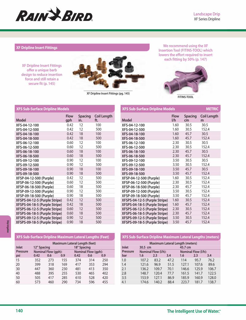
140 The Intelligent Use of Water.™
Drip Irrigation
Landscape DripXF Series Dripline
XF Dripline Insert Fittings (pg. 145) FITINS-TOOL
We recommend using the XF Insertion Tool (FITINS-TOOL) which lowers the effort required to insert
each fitting by 50% (p. 147)
XF Dripline Insert Fittings offer a unique barb
design to reduce insertion force and still retain a
secure fit (p. 145)
ModelFlow gph
Spacing in.
Coil Length ft.
XFS-04-12-100 0.42 12 100XFS-04-12-500 0.42 12 500XFS-04-18-100 0.42 18 100XFS-04-18-500 0.42 18 500XFS-06-12-100 0.60 12 100XFS-06-12-500 0.60 12 500XFS-06-18-100 0.60 18 100XFS-06-18-500 0.60 18 500XFS-09-12-100 0.90 12 100XFS-09-12-500 0.90 12 500XFS-09-18-100 0.90 18 100XFS-09-18-500 0.90 18 500XFSP-04-12-500 (Purple) 0.42 12 500XFSP-06-12-500 (Purple) 0.60 12 500XFSP-06-18-500 (Purple) 0.60 18 500XFSP-09-12-500 (Purple) 0.90 12 500XFSP-09-18-500 (Purple) 0.90 18 500XFSPS-04-12-5 (Purple Stripe) 0.42 12 500XFSPS-04-18-5 (Purple Stripe) 0.42 18 500XFSPS-06-12-5 (Purple Stripe) 0.60 12 500XFSPS-06-18-5 (Purple Stripe) 0.60 18 500XFSPS-09-12-5 (Purple Stripe) 0.90 12 500XFSPS-09-18-5 (Purple Stripe) 0.90 18 500
ModelFlow l/h
Spacing cm
Coil Length m
XFS-04-12-100 1.60 30.5 30.5XFS-04-12-500 1.60 30.5 152.4XFS-04-18-100 1.60 45.7 30.5XFS-04-18-500 1.60 45.7 152.4XFS-06-12-100 2.30 30.5 30.5XFS-06-12-500 2.30 30.5 152.4XFS-06-18-100 2.30 45.7 30.5XFS-06-18-500 2.30 45.7 152.4XFS-09-12-100 3.50 30.5 30.5XFS-09-12-500 3.50 30.5 152.4XFS-09-18-100 3.50 45.7 30.5XFS-09-18-500 3.50 45.7 152.4XFSP-04-12-500 (Purple) 1.60 30.5 152.4XFSP-06-12-500 (Purple) 2.30 30.5 152.4XFSP-06-18-500 (Purple) 2.30 45.7 152.4XFSP-09-12-500 (Purple) 3.50 30.5 152.4XFSP-09-18-500 (Purple) 3.50 45.7 152.4XFSPS-04-12-5 (Purple Stripe) 1.60 30.5 152.4XFSPS-04-18-5 (Purple Stripe) 1.60 45.7 152.4XFSPS-06-12-5 (Purple Stripe) 2.30 30.5 152.4XFSPS-06-18-5 (Purple Stripe) 2.30 45.7 152.4XFSPS-09-12-5 (Purple Stripe) 3.50 30.5 152.4XFSPS-09-18-5 (Purple Stripe) 3.50 45.7 152.4
Maximum Lateral Length (feet)Inlet Pressure psi
12" Spacing 18" SpacingNominal Flow (gph): Nominal Flow (gph):0.42 0.6 0.9 0.42 0.6 0.9
15 352 273 155 374 314 25020 399 318 169 417 353 29430 447 360 230 481 413 35040 488 395 255 530 465 40250 505 417 285 610 528 42060 573 460 290 734 596 455
Maximum Lateral Length (meters)Inlet Pressure bar
30.5 cm 45.7 cmNominal Flow (l/h): Nominal Flow (l/h):1.6 2.3 3.4 1.6 2.3 3.4
1.0 107.2 83.2 47.2 114 95.7 76.21.4 121.6 96.9 51.5 127.1 107.6 89.62.1 136.2 109.7 70.1 146.6 125.9 106.72.8 148.7 120.4 77.7 161.5 141.7 122.53.5 153.9 127.1 86.9 185.9 160.9 128.04.1 174.6 140.2 88.4 223.7 181.7 138.7
XFS Sub-Surface Dripline Models
XFS Sub-Surface Dripline Maximum Lateral Lengths (Feet) XFS Sub-Surface Dripline Maximum Lateral Lengths (meters)
XFS Sub-Surface Dripline Models METRIC
XF Dripline Insert Fittings
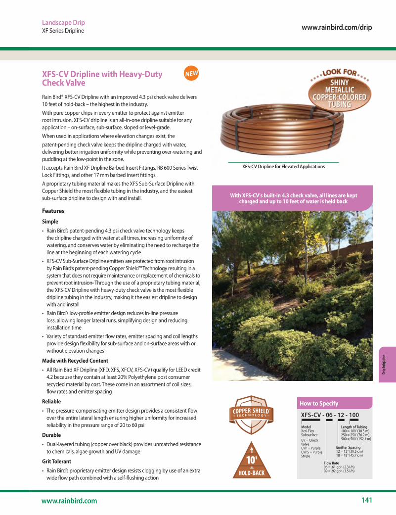
www.rainbird.com/drip
141www.rainbird.com
Drip
Irrig
atio
n
Landscape DripXF Series Dripline
XFS-CV Dripline with Heavy-Duty Check ValveRain Bird® XFS-CV Dripline with an improved 4.3 psi check valve delivers 10 feet of hold-back – the highest in the industry. With pure copper chips in every emitter to protect against emitter root intrusion, XFS-CV dripline is an all-in-one dripline suitable for any application – on-surface, sub-surface, sloped or level-grade.When used in applications where elevation changes exist, thepatent-pending check valve keeps the dripline charged with water, delivering better irrigation uniformity while preventing over-watering and puddling at the low-point in the zone. It accepts Rain Bird XF Dripline Barbed Insert Fittings, RB 600 Series Twist Lock Fittings, and other 17 mm barbed insert fittings.A proprietary tubing material makes the XFS Sub-Surface Dripline with Copper Shield the most flexible tubing in the industry, and the easiest sub-surface dripline to design with and install.
Features
Simple• Rain Bird’s patent-pending 4.3 psi check valve technology keeps
the dripline charged with water at all times, increasing uniformity of watering, and conserves water by eliminating the need to recharge the line at the beginning of each watering cycle
• XFS-CV Sub-Surface Dripline emitters are protected from root intrusion by Rain Bird’s patent-pending Copper Shield™ Technology resulting in a system that does not require maintenance or replacement of chemicals to prevent root intrusion• Through the use of a proprietary tubing material, the XFS-CV Dripline with heavy-duty check valve is the most flexible dripline tubing in the industry, making it the easiest dripline to design with and install
• Rain Bird’s low-profile emitter design reduces in-line pressure loss, allowing longer lateral runs, simplifying design and reducing installation time
• Variety of standard emitter flow rates, emitter spacing and coil lengths provide design flexibility for sub-surface and on-surface areas with or without elevation changes
Made with Recycled Content• All Rain Bird XF Dripline (XFD, XFS, XFCV, XFS-CV) qualify for LEED credit
4.2 because they contain at least 20% Polyethylene post consumer recycled material by cost. These come in an assortment of coil sizes, flow rates and emitter spacing
Reliable• The pressure-compensating emitter design provides a consistent flow
over the entire lateral length ensuring higher uniformity for increased reliability in the pressure range of 20 to 60 psi
Durable• Dual-layered tubing (copper over black) provides unmatched resistance
to chemicals, algae growth and UV damage
Grit Tolerant• Rain Bird’s proprietary emitter design resists clogging by use of an extra
wide flow path combined with a self-flushing action
XFS-CV Dripline for Elevated Applications
NEW
10'
With XFS-CV's built-in 4.3 check valve, all lines are keptcharged and up to 10 feet of water is held back
XFS-CV - 06 - 12 - 100
Model Xeri-FlexSubsurfaceCV = Check ValveCVP = PurpleCVPS = PurpleStripe
Flow Rate06 = .61 gph (2.3 l/h)09 = .92 gph (3.5 l/h)
Emitter Spacing 12 = 12" (30.5 cm)18 = 18" (45.7 cm)
Length of Tubing100 = 100' (30.5 m)250 = 250' (76.2 m)500 = 500' (152.4 m)
How to Specify
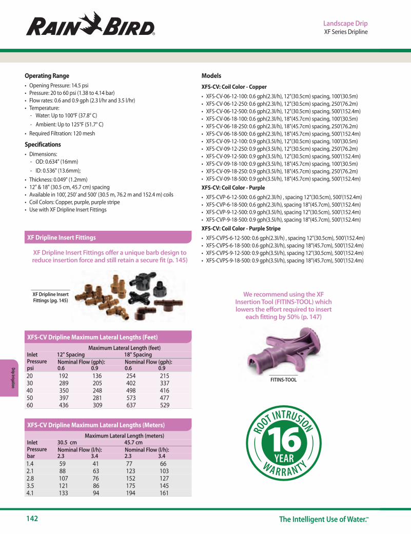
142 The Intelligent Use of Water.™
Drip Irrigation
Landscape DripXF Series Dripline
Operating Range• Opening Pressure: 14.5 psi• Pressure: 20 to 60 psi (1.38 to 4.14 bar)• Flow rates: 0.6 and 0.9 gph (2.3 l/hr and 3.5 l/hr)• Temperature:
- Water: Up to 100°F (37.8° C) - Ambient: Up to 125°F (51.7° C)
• Required Filtration: 120 mesh
Specifications• Dimensions:
- OD: 0.634" (16mm) - ID: 0.536" (13.6mm);
• Thickness: 0.049" (1.2mm)• 12" & 18" (30.5 cm, 45.7 cm) spacing• Available in 100', 250' and 500' (30.5 m, 76.2 m and 152.4 m) coils• Coil Colors: Copper, purple, purple stripe• Use with XF Dripline Insert Fittings
Models
XFS-CV: Coil Color - Copper• XFS-CV-06-12-100: 0.6 gph(2.3I/h), 12"(30.5cm) spacing, 100'(30.5m)• XFS-CV-06-12-250: 0.6 gph(2.3I/h), 12"(30.5cm) spacing, 250'(76.2m)• XFS-CV-06-12-500: 0.6 gph(2.3I/h), 12"(30.5cm) spacing, 500'(152.4m)• XFS-CV-06-18-100: 0.6 gph(2.3I/h), 18"(45.7cm) spacing, 100'(30.5m)• XFS-CV-06-18-250: 0.6 gph(2.3I/h), 18"(45.7cm) spacing, 250'(76.2m)• XFS-CV-06-18-500: 0.6 gph(2.3I/h), 18"(45.7cm) spacing, 500'(152.4m)• XFS-CV-09-12-100: 0.9 gph(3.5I/h), 12"(30.5cm) spacing, 100'(30.5m)• XFS-CV-09-12-250: 0.9 gph(3.5I/h), 12"(30.5cm) spacing, 250'(76.2m)• XFS-CV-09-12-500: 0.9 gph(3.5I/h), 12"(30.5cm) spacing, 500'(152.4m)• XFS-CV-09-18-100: 0.9 gph(3.5I/h), 18"(45.7cm) spacing, 100'(30.5m)• XFS-CV-09-18-250: 0.9 gph(3.5I/h), 18"(45.7cm) spacing, 250'(76.2m)• XFS-CV-09-18-500: 0.9 gph(3.5I/h), 18"(45.7cm) spacing, 500'(152.4m)XFS-CV: Coil Color - Purple• XFS-CVP-6-12-500: 0.6 gph(2.3I/h) , spacing 12"(30.5cm), 500'(152.4m)• XFS-CVP-6-18-500: 0.6 gph(2.3I/h), spacing 18"(45.7cm), 500'(152.4m)• XFS-CVP-9-12-500: 0.9 gph(3.5I/h), spacing 12"(30.5cm), 500'(152.4m)• XFS-CVP-9-18-500: 0.9 gph(3.5I/h), spacing 18"(45.7cm), 500'(152.4m)XFS-CV: Coil Color - Purple Stripe• XFS-CVPS-6-12-500: 0.6 gph(2.3I/h) , spacing 12"(30.5cm), 500'(152.4m)• XFS-CVPS-6-18-500: 0.6 gph(2.3I/h), spacing 18"(45.7cm), 500'(152.4m)• XFS-CVPS-9-12-500: 0.9 gph(3.5I/h), spacing 12"(30.5cm), 500'(152.4m)• XFS-CVPS-9-18-500: 0.9 gph(3.5I/h), spacing 18"(45.7cm), 500'(152.4m)
FITINS-TOOL
We recommend using the XF Insertion Tool (FITINS-TOOL) which lowers the effort required to insert
each fitting by 50% (p. 147)
XF Dripline Insert Fittings offer a unique barb design to reduce insertion force and still retain a secure fit (p. 145)
XF Dripline Insert Fittings
Maximum Lateral Length (meters)Inlet Pressure bar
30.5 cm 45.7 cmNominal Flow (l/h): Nominal Flow (l/h):2.3 3.4 2.3 3.4
1.4 59 41 77 662.1 88 63 123 1032.8 107 76 152 1273.5 121 86 175 1454.1 133 94 194 161
Maximum Lateral Length (feet)Inlet Pressure psi
12" Spacing 18" SpacingNominal Flow (gph): Nominal Flow (gph):0.6 0.9 0.6 0.9
20 192 136 254 21530 289 205 402 33740 350 248 498 41650 397 281 573 47760 436 309 637 529
XFS-CV Dripline Maximum Lateral Lengths (Feet)
XFS-CV Dripline Maximum Lateral Lengths (Meters)
XF Dripline Insert Fittings (pg. 145)
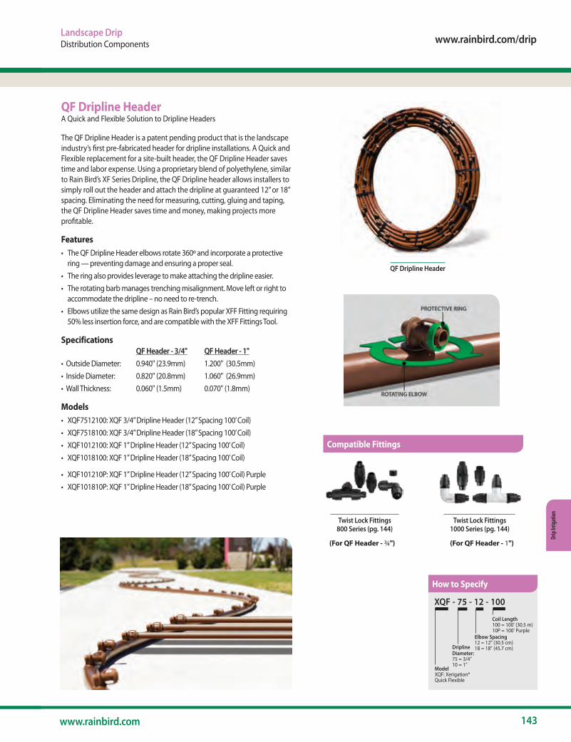
www.rainbird.com/drip
143www.rainbird.com
Drip
Irrig
atio
n
QF Dripline HeaderA Quick and Flexible Solution to Dripline Headers
The QF Dripline Header is a patent pending product that is the landscape industry’s first pre-fabricated header for dripline installations. A Quick and Flexible replacement for a site-built header, the QF Dripline Header saves time and labor expense. Using a proprietary blend of polyethylene, similar to Rain Bird’s XF Series Dripline, the QF Dripline header allows installers to simply roll out the header and attach the dripline at guaranteed 12” or 18” spacing. Eliminating the need for measuring, cutting, gluing and taping, the QF Dripline Header saves time and money, making projects more profitable.
Features• The QF Dripline Header elbows rotate 360º and incorporate a protective
ring — preventing damage and ensuring a proper seal.• The ring also provides leverage to make attaching the dripline easier.• The rotating barb manages trenching misalignment. Move left or right to
accommodate the dripline – no need to re-trench.• Elbows utilize the same design as Rain Bird’s popular XFF Fitting requiring
50% less insertion force, and are compatible with the XFF Fittings Tool.
Specifications QF Header - 3/4" QF Header - 1"• Outside Diameter: 0.940" (23.9mm) 1.200" (30.5mm)• Inside Diameter: 0.820" (20.8mm) 1.060" (26.9mm)• Wall Thickness: 0.060" (1.5mm) 0.070" (1.8mm)
Models• XQF7512100: XQF 3/4” Dripline Header (12” Spacing 100’ Coil)• XQF7518100: XQF 3/4” Dripline Header (18” Spacing 100’ Coil)• XQF1012100: XQF 1” Dripline Header (12” Spacing 100’ Coil)• XQF1018100: XQF 1” Dripline Header (18” Spacing 100’ Coil)
• XQF101210P: XQF 1” Dripline Header (12” Spacing 100’ Coil) Purple• XQF101810P: XQF 1” Dripline Header (18” Spacing 100’ Coil) Purple
QF Dripline Header
XQF - 75 - 12 - 100
Model XQF: Xerigation® Quick Flexible
DriplineDiameter:75 = 3/4”10 = 1”
Elbow Spacing 12 = 12" (30.5 cm)18 = 18" (45.7 cm)
Coil Length100 = 100' (30.5 m)10P = 100' Purple
Twist Lock Fittings800 Series (pg. 144)
Twist Lock Fittings1000 Series (pg. 144)
(For QF Header - ¾") (For QF Header - 1")
How to Specify
Landscape DripDistribution Components
Compatible Fittings
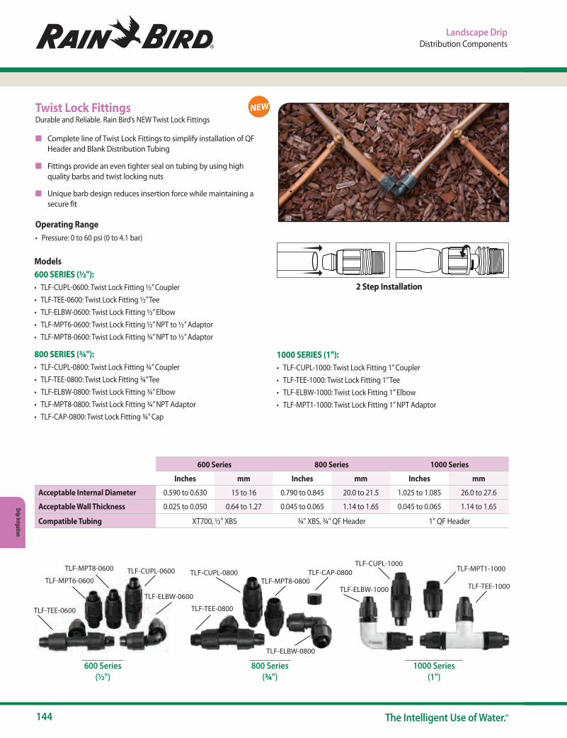
144 The Intelligent Use of Water.™
Drip Irrigation
Landscape DripDistribution Components
NEWTwist Lock FittingsDurable and Reliable. Rain Bird’s NEW Twist Lock Fittings
n Complete line of Twist Lock Fittings to simplify installation of QF Header and Blank Distribution Tubing
n Fittings provide an even tighter seal on tubing by using high quality barbs and twist locking nuts
n Unique barb design reduces insertion force while maintaining a secure fit
Operating Range• Pressure: 0 to 60 psi (0 to 4.1 bar)
600 Series(½")
800 Series(¾")
1000 Series(1")
Models600 SERIES (½"):• TLF-CUPL-0600: Twist Lock Fitting ½” Coupler• TLF-TEE-0600: Twist Lock Fitting ½” Tee • TLF-ELBW-0600: Twist Lock Fitting ½” Elbow• TLF-MPT6-0600: Twist Lock Fitting ½” NPT to ½” Adaptor• TLF-MPT8-0600: Twist Lock Fitting ¾” NPT to ½” Adaptor
800 SERIES (¾"):• TLF-CUPL-0800: Twist Lock Fitting ¾” Coupler• TLF-TEE-0800: Twist Lock Fitting ¾” Tee • TLF-ELBW-0800: Twist Lock Fitting ¾” Elbow• TLF-MPT8-0800: Twist Lock Fitting ¾” NPT Adaptor• TLF-CAP-0800: Twist Lock Fitting ¾” Cap
TLF-CUPL-1000
TLF-TEE-1000
TLF-MPT1-1000
TLF-TEE-0800
TLF-CUPL-0800TLF-MPT6-0600
TLF-TEE-0600
TLF-MPT8-0600 TLF-CUPL-0600
TLF-ELBW-0600
TLF-MPT8-0800TLF-CAP-0800
TLF-ELBW-0800
TLF-ELBW-1000
600 Series 800 Series 1000 Series
Inches mm Inches mm Inches mm
Acceptable Internal Diameter 0.590 to 0.630 15 to 16 0.790 to 0.845 20.0 to 21.5 1.025 to 1.085 26.0 to 27.6
Acceptable Wall Thickness 0.025 to 0.050 0.64 to 1.27 0.045 to 0.065 1.14 to 1.65 0.045 to 0.065 1.14 to 1.65
Compatible Tubing XT700, ½" XBS ¾" XBS, ¾" QF Header 1" QF Header
2 Step Installation
1000 SERIES (1"):• TLF-CUPL-1000: Twist Lock Fitting 1” Coupler• TLF-TEE-1000: Twist Lock Fitting 1” Tee • TLF-ELBW-1000: Twist Lock Fitting 1” Elbow• TLF-MPT1-1000: Twist Lock Fitting 1” NPT Adaptor
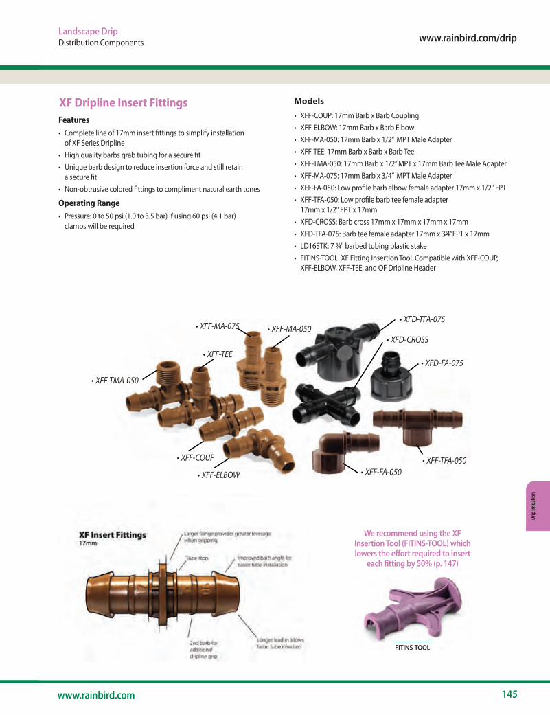
www.rainbird.com/drip
145www.rainbird.com
Drip
Irrig
atio
n
• XFF-TMA-050
• XFF-COUP
• XFF-ELBOW
• XFF-MA-050
• XFF-FA-050• XFF-TFA-050
• XFD-TFA-075
• XFD-FA-075
• XFD-CROSS• XFF-MA-075
• XFF-TEE
Landscape DripDistribution Components
Models
• XFF-COUP: 17mm Barb x Barb Coupling• XFF-ELBOW: 17mm Barb x Barb Elbow• XFF-MA-050: 17mm Barb x 1/2” MPT Male Adapter• XFF-TEE: 17mm Barb x Barb x Barb Tee• XFF-TMA-050: 17mm Barb x 1/2” MPT x 17mm Barb Tee Male Adapter• XFF-MA-075: 17mm Barb x 3/4” MPT Male Adapter• XFF-FA-050: Low profile barb elbow female adapter 17mm x 1/2" FPT• XFF-TFA-050: Low profile barb tee female adapter
17mm x 1/2" FPT x 17mm• XFD-CROSS: Barb cross 17mm x 17mm x 17mm x 17mm• XFD-TFA-075: Barb tee female adapter 17mm x 3⁄4”FPT x 17mm• LD16STK: 7 ¾" barbed tubing plastic stake• FITINS-TOOL: XF Fitting Insertion Tool. Compatible with XFF-COUP,
XFF-ELBOW, XFF-TEE, and QF Dripline Header
Features• Complete line of 17mm insert fittings to simplify installation
of XF Series Dripline• High quality barbs grab tubing for a secure fit• Unique barb design to reduce insertion force and still retain
a secure fit• Non-obtrusive colored fittings to compliment natural earth tones
Operating Range• Pressure: 0 to 50 psi (1.0 to 3.5 bar) if using 60 psi (4.1 bar)
clamps will be required
XF Dripline Insert Fittings
FITINS-TOOL
We recommend using the XF Insertion Tool (FITINS-TOOL) which lowers the effort required to insert
each fitting by 50% (p. 147)
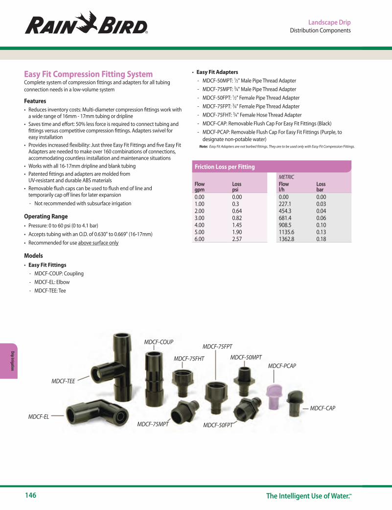
146 The Intelligent Use of Water.™
Drip Irrigation
MDCF-COUP
MDCF-CAP
MDCF-PCAP
MDCF-TEE
MDCF-EL
MDCF-75FHT MDCF-50MPT
MDCF-75FPT
MDCF-75MPT MDCF-50FPT
Easy Fit Compression Fitting SystemComplete system of compression fittings and adapters for all tubing connection needs in a low-volume system
Features• Reduces inventory costs: Multi-diameter compression fittings work with
a wide range of 16mm - 17mm tubing or dripline• Saves time and effort: 50% less force is required to connect tubing and
fittings versus competitive compression fittings. Adapters swivel for easy installation
• Provides increased flexibility: Just three Easy Fit Fittings and five Easy Fit Adapters are needed to make over 160 combinations of connections, accommodating countless installation and maintenance situations
• Works with all 16-17mm dripline and blank tubing• Patented fittings and adapters are molded from
UV-resistant and durable ABS materials• Removable flush caps can be used to flush end of line and
temporarily cap off lines for later expansion - Not recommended with subsurface irrigation
Operating Range• Pressure: 0 to 60 psi (0 to 4.1 bar)• Accepts tubing with an O.D. of 0.630" to 0.669" (16-17mm)• Recommended for use above surface only
Models• Easy Fit Fittings
- MDCF-COUP: Coupling - MDCF-EL: Elbow - MDCF-TEE: Tee
Landscape DripDistribution Components
• Easy Fit Adapters - MDCF-50MPT: 1⁄2" Male Pipe Thread Adapter - MDCF-75MPT: 3⁄4" Male Pipe Thread Adapter - MDCF-50FPT: 1⁄2" Female Pipe Thread Adapter - MDCF-75FPT: 3⁄4" Female Pipe Thread Adapter - MDCF-75FHT: 3⁄4" Female Hose Thread Adapter - MDCF-CAP: Removable Flush Cap For Easy Fit Fittings (Black) - MDCF-PCAP: Removable Flush Cap For Easy Fit Fittings (Purple, to
designate non-potable water) Note: Easy Fit Adapters are not barbed fittings. They are to be used only with Easy Fit Compression Fittings.
Flow gpm
Loss psi
0.00 0.001.00 0.32.00 0.643.00 0.824.00 1.455.00 1.906.00 2.57
METRICFlow l/h
Loss bar
0.00 0.00227.1 0.03454.3 0.04681.4 0.06908.5 0.101135.6 0.131362.8 0.18
Friction Loss per Fitting

www.rainbird.com/drip
147www.rainbird.com
Drip
Irrig
atio
n
OPERIND
ARV050
XF Insertion ToolThe XF Insertion Tool reduces the effort required to insert the fittings into the tube by 50%.
Features• 50% Less effort required to
install fittings than without a tool
• Firmly locks fittings into place while inserting Dripline
• Tool helps widen the dripline opening to make the fitting insertion easier
• Solid grip and comfortable fit in hand
Model• FITINS-TOOL
Air/Vacuum Relief Valve KitFeatures• Use with Rain Bird XF-Series
or Landscape Dripline inline emitter tubing when installation is below soil*
• Made of quality rust-proof materials
• Fits inside an SEB 7XB emitter box
*Rain Bird recommends XFS dripline with Copper Shield™ for subsurface installations, including installations under turf grass.
Model• ARV050: ½" Air Relief Valve
Install Air/Vacuum Relief Valves correctly by: Locate at the highest point(s) of the dripline zone. Install the valve in an exhaust header or a line that runs perpendicular to the lateral rows to ensure all rows of the dripline can take advantage of the air/vacuum relief valve
Drip System Operation IndicatorFeatures• Stem rises 6" for clear visibility• When stem is extended, drip
system is charged to a minimum of 15 psi
• Operational Indicator Kit includes three different indication caps: potable, non-potable, or an adjustable 4-VAN spray nozzle
• Includes 16" of ¼" distribution tubing with connection fitting pre-installed
Model• OPERIND
1/2" ARVEmitter Spacing 0.6 GPH 0.9 GPH
12" 639' 424'18" 958' 636'24" 1278' 848'
ARV CapacityTotal Flow (GPM) 6.5Total Flow (GPH) 390
1/2" ARVEmitter Spacing 2.3 l/h 3.4 l/h
0.30 m 195 1290.46 m 292 1940.61 m 390 258
ARV CapacityTotal Flow (l/m) 24.6Total Flow (l/h) 1476
Landscape DripDistribution Components
XFF-COUP
The XF Insertion Tool works with the following XF Fittings:
XFF-ELBOW XFF-TEE
The XF Insertion Tool securely locks fittings into place to make inserting dripline easier.
The tool also has a sloped valley to allow room for the dripline when inserting a fitting onto the second side.
FITINS-TOOL
Maximum Length of Dripline Useable with the ARV
Maximum Length of Dripline Useable with the ARV METRIC
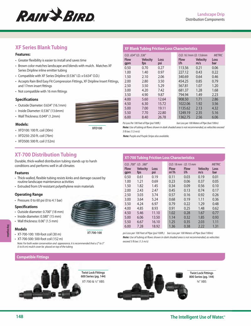
148 The Intelligent Use of Water.™
Drip Irrigation
Landscape DripDistribution Components
Compatible Fittings
XT-700 Distribution TubingDurable, thick-walled distribution tubing stands up to harsh conditions and performs well in all climates
Features• Thick-walled, flexible tubing resists kinks and damage caused by
routine landscape maintenance activities• Extruded from UV-resistant polyethylene resin materials
Operating Range• Pressure: 0 to 60 psi (0 to 4.1 bar)
Specifications• Outside diameter: 0.700" (18 mm) • Inside diameter: 0.580" (15 mm)• Wall thickness: 0.06" (1.5 mm)
Models• XT-700-100: 100-foot coil (30 m)• XT-700-500: 500-foot coil (152 m) Note: For both water conservation and appearance, it is recommended that a 2" to 3"
(5 to 8 cm) mulch cover be placed on top of the tubing
psi Loss per 100 Feet of Pipe (psi/100ft.) bar Loss per 100 Meters of Pipe (bar/100m)Note: Use of tubing at flows shown in dark shaded area is not recommended, as velocities exceed 5 ft/sec (1.5 m/s)
XT-700-100
XF Series Blank TubingFeatures:• Greater flexibility is easier to install and saves time• Brown color matches landscape and blends with mulch. Matches XF
Series Dripline inline emitter tubing• Compatible with XF Series Dripline (0.536" I.D. x 0.634" O.D.)• Accepts Rain Bird Easy Fit Compression Fittings, XF Dripline Insert Fittings,
and 17mm insert fittings• Not compatible with 16 mm fittings
Specifications• Outside Diameter: 0.634" (16.1mm)• Inside Diameter: 0.536" (13.6mm)• Wall Thickness: 0.049" (1.2mm)
Models:• XFD100: 100 ft. coil (30m)• XFD250: 250 ft. coil (76m) • XFD500: 500 ft. coil (152m)
Psi Loss Per 100 Feet of Pipe (psi/100ft.) bar Loss per 100 Meters of Pipe (bar/100m) Note: Use of tubing at flows shown in dark shaded area is not recommended, as velocities exceed
5 ft/sec (1.5 m/s)
XFD100
Twist Lock Fittings600 Series (pg. 144)
Twist Lock Fittings800 Series (pg. 144)
XT-700 & ½" XBS ¾" XBS
O.D. .634" I.D. .536"Flow gpm
Velocity fps
Loss psi
0.50 0.70 0.271.00 1.40 0.971.50 2.10 2.062.00 2.80 3.502.50 3.50 5.293.00 4.20 7.423.50 4.90 9.874.00 5.60 12.644.50 6.30 15.725.00 7.00 19.115.50 7.70 22.806.00 8.40 26.78
O.D. .700" I.D. .580" Flow gpm
Velocity fps
Loss psi
0.50 0.61 0.191.00 1.21 0.691.50 1.82 1.452.00 2.43 2.472.50 3.03 3.743.00 3.64 5.243.50 4.24 6.974.00 4.85 8.934.50 5.46 11.105.00 6.06 13.505.50 6.67 16.106.00 7.28 18.92
O.D. 16.1mm I.D. 13.6mm METRICFlow l/h
Velocity m/s
Loss bar
113.56 0.21 0.06227.12 0.43 0.22340.69 0.64 0.46454.25 0.85 0.79567.81 1.07 1.20681.37 1.28 1.68794.94 1.49 2.23908.50 1.71 2.861022.06 1.92 3.561135.62 2.13 4.321249.19 2.35 5.161362.75 2.56 6.06
O.D. 18 mm I.D. 15 mm METRICFlow m3/h
Flow l/h
Velocity m/s
Loss bar
0.11 0.03 0.19 0.010.23 0.06 0.37 0.050.34 0.09 0.56 0.100.45 0.13 0.74 0.170.57 0.16 0.92 0.260.68 0.19 1.11 0.360.79 0.22 1.29 0.480.91 0.25 1.48 0.621.02 0.28 1.67 0.771.14 0.32 1.85 0.931.25 0.35 2.03 1.111.36 0.38 2.22 1.31
XF Blank Tubing Friction Loss Characteristics
XT-700 Tubing Friction Loss Characteristics
Compatible Fittings
Note: Purple and Purple Stripe also available.
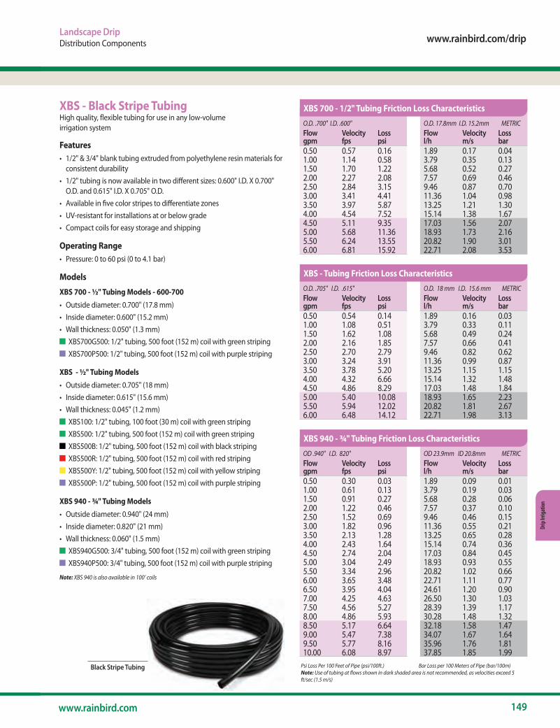
www.rainbird.com/drip
149www.rainbird.com
Drip
Irrig
atio
n
O.D. .700" I.D. .600"Flow gpm
Velocity fps
Loss psi
0.50 0.57 0.161.00 1.14 0.581.50 1.70 1.222.00 2.27 2.082.50 2.84 3.153.00 3.41 4.413.50 3.97 5.874.00 4.54 7.524.50 5.11 9.355.00 5.68 11.365.50 6.24 13.556.00 6.81 15.92
O.D. .705" I.D. .615"Flow gpm
Velocity fps
Loss psi
0.50 0.54 0.141.00 1.08 0.511.50 1.62 1.082.00 2.16 1.852.50 2.70 2.793.00 3.24 3.913.50 3.78 5.204.00 4.32 6.664.50 4.86 8.295.00 5.40 10.085.50 5.94 12.026.00 6.48 14.12
OD .940" I.D. 820"Flow gpm
Velocity fps
Loss psi
0.50 0.30 0.031.00 0.61 0.131.50 0.91 0.272.00 1.22 0.462.50 1.52 0.693.00 1.82 0.963.50 2.13 1.284.00 2.43 1.644.50 2.74 2.045.00 3.04 2.495.50 3.34 2.966.00 3.65 3.486.50 3.95 4.047.00 4.25 4.637.50 4.56 5.278.00 4.86 5.938.50 5.17 6.649.00 5.47 7.389.50 5.77 8.1610.00 6.08 8.97
O.D. 17.8mm I.D. 15.2mm METRICFlow l/h
Velocity m/s
Loss bar
1.89 0.17 0.043.79 0.35 0.135.68 0.52 0.277.57 0.69 0.469.46 0.87 0.7011.36 1.04 0.9813.25 1.21 1.3015.14 1.38 1.6717.03 1.56 2.0718.93 1.73 2.1620.82 1.90 3.0122.71 2.08 3.53
O.D. 18 mm I.D. 15.6 mm METRICFlow l/h
Velocity m/s
Loss bar
1.89 0.16 0.033.79 0.33 0.115.68 0.49 0.247.57 0.66 0.419.46 0.82 0.6211.36 0.99 0.8713.25 1.15 1.1515.14 1.32 1.4817.03 1.48 1.8418.93 1.65 2.2320.82 1.81 2.6722.71 1.98 3.13
OD 23.9mm ID 20.8mm METRICFlow l/h
Velocity m/s
Loss bar
1.89 0.09 0.013.79 0.19 0.035.68 0.28 0.067.57 0.37 0.109.46 0.46 0.1511.36 0.55 0.2113.25 0.65 0.2815.14 0.74 0.3617.03 0.84 0.4518.93 0.93 0.5520.82 1.02 0.6622.71 1.11 0.7724.61 1.20 0.9026.50 1.30 1.0328.39 1.39 1.1730.28 1.48 1.3232.18 1.58 1.4734.07 1.67 1.6435.96 1.76 1.8137.85 1.85 1.99
XBS 700 - 1/2" Tubing Friction Loss Characteristics
XBS - Tubing Friction Loss Characteristics
XBS 940 - ¾" Tubing Friction Loss Characteristics
Landscape DripDistribution Components
XBS - Black Stripe TubingHigh quality, flexible tubing for use in any low-volume irrigation system
Features• 1/2" & 3/4" blank tubing extruded from polyethylene resin materials for
consistent durability• 1/2" tubing is now available in two different sizes: 0.600" I.D. X 0.700"
O.D. and 0.615" I.D. X 0.705" O.D.• Available in five color stripes to differentiate zones• UV-resistant for installations at or below grade• Compact coils for easy storage and shipping
Operating Range• Pressure: 0 to 60 psi (0 to 4.1 bar)
Models
XBS 700 - ½" Tubing Models - 600-700• Outside diameter: 0.700" (17.8 mm)• Inside diameter: 0.600" (15.2 mm)• Wall thickness: 0.050" (1.3 mm)
XBS700G500: 1/2" tubing, 500 foot (152 m) coil with green striping XBS700P500: 1/2" tubing, 500 foot (152 m) coil with purple striping
XBS - ½" Tubing Models• Outside diameter: 0.705" (18 mm)• Inside diameter: 0.615" (15.6 mm)• Wall thickness: 0.045" (1.2 mm)
XBS100: 1/2" tubing, 100 foot (30 m) coil with green striping XBS500: 1/2" tubing, 500 foot (152 m) coil with green striping XBS500B: 1/2" tubing, 500 foot (152 m) coil with black striping XBS500R: 1/2" tubing, 500 foot (152 m) coil with red striping XBS500Y: 1/2" tubing, 500 foot (152 m) coil with yellow striping XBS500P: 1/2" tubing, 500 foot (152 m) coil with purple striping
XBS 940 - ¾" Tubing Models• Outside diameter: 0.940" (24 mm)• Inside diameter: 0.820" (21 mm)• Wall thickness: 0.060" (1.5 mm)
XBS940G500: 3/4" tubing, 500 foot (152 m) coil with green striping XBS940P500: 3/4" tubing, 500 foot (152 m) coil with purple striping
Note: XBS 940 is also available in 100’ coils
Psi Loss Per 100 Feet of Pipe (psi/100ft.) Bar Loss per 100 Meters of Pipe (bar/100m) Note: Use of tubing at flows shown in dark shaded area is not recommended, as velocities exceed 5
ft/sec (1.5 m/s)
Black Stripe Tubing

150 The Intelligent Use of Water.™
Drip Irrigation
Landscape DripDistribution Components
Flow at 30 psi Spacing Coil LengthModel gph l/h in. cm ft. m
LDQ0806100 0.8 3.0 6 15.25 100 30.50LDQ0812100 0.8 3.0 12 30.5 100 30.5
1⁄4" Landscape DriplineRain Bird 1⁄4" Dripline is a perfect choice for small-sized areas such as planter boxes, container gardens, loops around trees, vegetable gardens and shrubs
Features• Simple to use, as the flexible tubing makes watering pots and
container gardens easy - Clog resistance through built-in filtration and two outlet holes, 180
degrees apart• Brown tubing complements Rain Bird XF Dripline• Works with Rain Bird 1⁄4" barbed Fittings
Operating Range• 10 to 40 psi (0.7 to 2.7 bar)• Flow rate at 30 psi (2.0 bar): 0.8gph (3.0 l/h)• Required filtration: 200 mesh (75 micron)
Specifications• Outside diameter: 0.250" (6 mm)• Inside diameter: 0.170" (4 mm)• Wall thickness: 0.040" (1 mm)• Spacing: 6" or 12" (15.25 cm and 30.5 cm)• Length: 100' (30.5 m) coils
Models• LDQ0806100 • LDQ0812100
XQ ¼" Distribution TubingThe strongest and most flexible ¼" Distribution Tubing available to extend emitter outlets to desirable discharge locations
Features• Unique blend of polymers that give it the flexibility of vinyl with hold
of poly• New textured finish improves handling• Self extracting coiling feature makes it easy to use, store and
eliminates waste• Fits over barbed outlet ports and all Xerigation® emission devices and
¼" transfer fittings• Extruded from UV-resistant polyethylene resin materials
Specifications• Outside Diameter: 0.25" (6.3 mm)• Inside Diameter: 0.17" (4.3 mm)
Operating Range• Pressure: 0 to 60 psi (0 to 4.1 bar)
Models• XQ-100: 100-foot (30m) coil ¼" distribution tubing• XQ-1000: 1000-foot (305m) coil ¼" distribution tubing• XQ-1000-B: 1000-foot (305m) coil ¼" distribution tubing in a bucket
Psi Loss Per 100 Feet of tubing; C=150 Bar Loss per 100 Meters of tubingNote: Use of tubing at flows shown in dark shaded area is not recommended, as velocities exceed 5 ft/sec (1.5 m/s)
XQ-1000-B ¼" TubingXQ-100 and XQ-1000 ¼" Tubing
LDQ-08-06-100
• Wall Thickness: .04" (1.0 mm)• Lengths: 100' and 1000' coils
O.D. .25" I.D. .17" Flow gpm
Velocity fps
Loss psi
1 0.27 0.163 0.80 1.245 1.33 3.207 1.86 5.979 2.39 9.5011 2.92 13.7913 3.45 18.7515 3.98 24.4317 4.52 30.8018 4.78 34.2319 5.05 37.8320 5.31 41.6025 6.64 62.8630 7.97 88.08
O.D. 6.3mm I.D. 4.3mm METRICFlow m3/h
Flow l/h
Velocity m/s
Loss bar
0.00 3.79 0.08 0.010.01 11.6 0.24 0.090.02 18.92 0.41 0.220.03 26.50 0.57 0.410.03 34.07 0.73 0.660.04 41.64 0.89 0.950.05 49.21 1.05 1.290.06 56.78 1.21 1.690.06 64.35 1.38 2.130.07 68.13 1.46 2.360.07 71.92 1.54 2.610.08 75.70 1.62 2.870.09 94.63 2.03 4.340.11 113.55 2.43 6.08
XQ ¼" Distribution Tubing Friction Loss Characteristics
Flow Characteristics
METRIC 4.0 3.5 3.0 2.5 2.0 1.5 1.0 0.5 0.0 0 0.5 1.0 1.5 2.0 2.5 3.0
Pressure (bar)
1.2 1.0
0.8
0.6
0.4
0.2 0.0 0 10 15 20 25 30 35 40
Pressure (psi)
Flow
Rat
e (l/
h)
Flow
Rat
e (g
ph)
1⁄4" Landscape Dripline Performance
Emitter Spacing
Maximum Length of Run
Flow per Ft. @ 15 psi
6" 19 feet 1 gph/ft.12" 33 feet 0.5 gph/ft.
Maximum Length of Run (Feet)
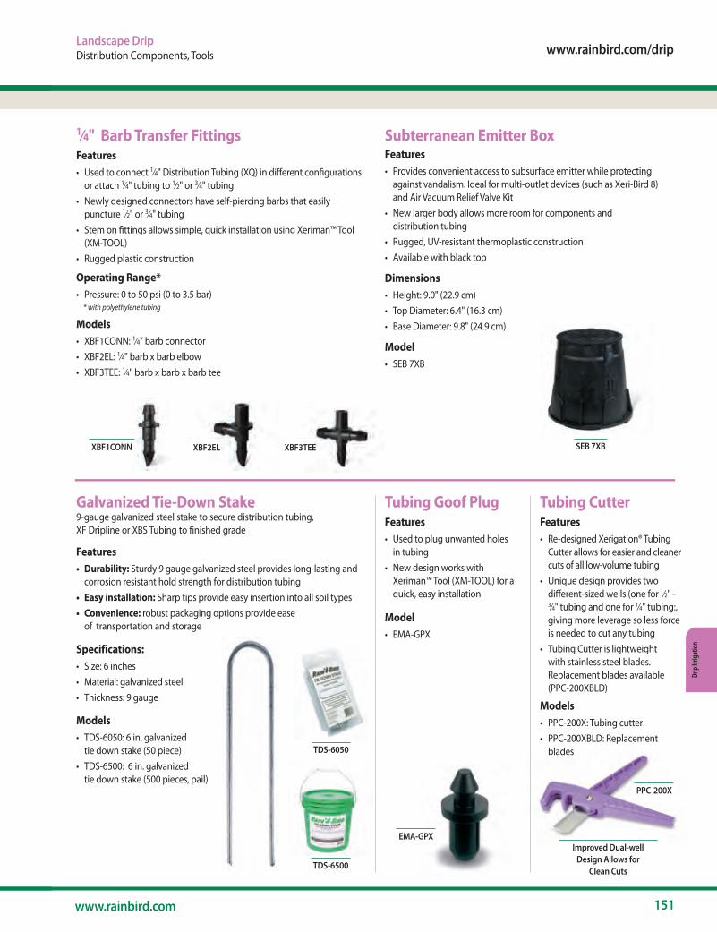
www.rainbird.com/drip
151www.rainbird.com
Drip
Irrig
atio
n
TDS-6500
Landscape DripDistribution Components, Tools
1⁄4" Barb Transfer FittingsFeatures• Used to connect 1⁄4" Distribution Tubing (XQ) in different configurations
or attach 1⁄4" tubing to 1⁄2" or 3⁄4" tubing• Newly designed connectors have self-piercing barbs that easily
puncture 1⁄2" or 3⁄4" tubing• Stem on fittings allows simple, quick installation using Xeriman™ Tool
(XM-TOOL)• Rugged plastic construction
Operating Range*• Pressure: 0 to 50 psi (0 to 3.5 bar) * with polyethylene tubing
Models• XBF1CONN: 1⁄4" barb connector• XBF2EL: 1⁄4" barb x barb elbow• XBF3TEE: 1⁄4" barb x barb x barb tee
XBF2EL XBF3TEEXBF1CONN
Subterranean Emitter BoxFeatures• Provides convenient access to subsurface emitter while protecting
against vandalism. Ideal for multi-outlet devices (such as Xeri-Bird 8) and Air Vacuum Relief Valve Kit
• New larger body allows more room for components and distribution tubing
• Rugged, UV-resistant thermoplastic construction• Available with black top
Dimensions• Height: 9.0" (22.9 cm)• Top Diameter: 6.4" (16.3 cm)• Base Diameter: 9.8" (24.9 cm)
Model• SEB 7XB
Tubing Goof PlugFeatures• Used to plug unwanted holes
in tubing• New design works with
Xeriman™ Tool (XM-TOOL) for a quick, easy installation
Model• EMA-GPX
PPC-200X
Improved Dual-well Design Allows for
Clean Cuts
Tubing CutterFeatures• Re-designed Xerigation® Tubing
Cutter allows for easier and cleaner cuts of all low-volume tubing
• Unique design provides two different-sized wells (one for 1⁄2" - 3⁄4" tubing and one for 1⁄4" tubing:, giving more leverage so less force is needed to cut any tubing
• Tubing Cutter is lightweight with stainless steel blades. Replacement blades available (PPC-200XBLD)
Models• PPC-200X: Tubing cutter• PPC-200XBLD: Replacement
blades
EMA-GPX
SEB 7XB
Galvanized Tie-Down Stake9-gauge galvanized steel stake to secure distribution tubing, XF Dripline or XBS Tubing to finished grade
Features• Durability: Sturdy 9 gauge galvanized steel provides long-lasting and
corrosion resistant hold strength for distribution tubing• Easy installation: Sharp tips provide easy insertion into all soil types• Convenience: robust packaging options provide ease
of transportation and storage
Specifications:• Size: 6 inches• Material: galvanized steel• Thickness: 9 gauge
Models• TDS-6050: 6 in. galvanized
tie down stake (50 piece)• TDS-6500: 6 in. galvanized
tie down stake (500 pieces, pail)
TDS-6050
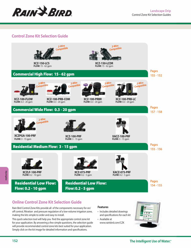
152 The Intelligent Use of Water.™
Drip Irrigation
Control Zone Kit Selection Guide
Online Control Zone Kit Selection GuideRain Bird Control Zone Kits provide all of the components necessary for on/off control, filtration and pressure regulation of a low-volume irrigation zone, making the kits simple to order and easy to install.This quick selection tool will help you find the appropriate control zone kit for your application. By answering a few simple questions, the selection guide will provide recommended control zone kits best suited for your application. Simply click on the kit image for detailed information and specifications.
Features• Includes detailed drawings
and specifications for each kit• Available at
www.rainbird.com/CZK
Pages 155 - 152
Pages 157 - 158
Pages 155 - 156
Commercial Wide Flow: 0.3 - 20 gpm
XCZ-100-PRB-COMFLOW: 0.3 - 20 gpm
XCZ-100-FLOWFLOW: 0.3 - 20 gpm
XCZ-100-PRB-LCFLOW: 0.3 - 20 gpm
XCZ-100-PRBRFLOW: 0.3 - 20 gpm
Pages154 - 155
Flow: 0.2 - 10 gpm
XCZ-075-PRFFLOW: 0.2 - 5 gpm
XCZLF-100-PRFFLOW: 0.2 - 10 gpm
XACZ-075-PRFFLOW: 0.2 - 5 gpm
Flow: 0.2 - 5 gpm
Residential Medium Flow: 3 - 15 gpm
Residential Low Flow: Residential Low Flow:
XCZPGA-100-PRFFLOW: 3 - 15 gpm
XCZ-100-PRFFLOW: 3 - 15 gpm
XACZ-100-PRFFLOW: 3 - 15 gpm
Commercial High Flow: 15 - 62 gpm
XCZ-150-LCSFLOW: 15 - 62 gpm
XCZ-150-LCDRFLOW: 15 - 62 gpm
2-Wire Compatible2-Wire
Compatible2-Wire Compatible2-Wire
Compatible
2-Wire Compatible
2-Wire Compatible2-Wire
Compatible
Landscape DripControl Zone Kit Selection Guides
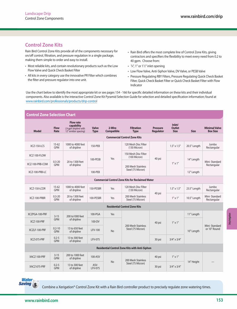
www.rainbird.com/drip
153www.rainbird.com
Drip
Irrig
atio
n
Landscape DripControl Zone Components
Use the chart below to identify the most appropriate kit or see pages 154 - 166 for specific detailed information on these kits and their individual components. Also available is the interactive Control Zone Kit Pyramid Selection Guide for selection and detailed specification information; found at www.rainbird.com/professionals/products/drip-control
Combine a Xerigation® Control Zone Kit with a Rain Bird controller product to precisely regulate zone watering times.
Control Zone KitsRain Bird Control Zone Kits provide all of the components necessary for on/off control, filtration, and pressure regulation in a single package, making them simple to order and easy to install.
• Most reliable kits, and contain revolutionary products such as the Low Flow Valve and Quick Check Basket Filter
• All kits in every category use the innovative PR Filter which combines the filter and pressure regulator into one unit.
• Rain Bird offers the most complete line of Control Zone Kits, giving contractors and specifiers the flexibility to meet every need from 0.2 to 40 gpm. Choose from:
• 3⁄4", 1" or 11⁄2" inlet opening• Low Flow Valve, Anti-Siphon Valve, DV Valve, or PESB Valve• Pressure Regulating RBY Filters, Pressure Regulating Quick Check Basket
Filter, Quick Check Basket Filter or Quick Check Basket Filter with Flow Indicator
ModelFlow Rate
Flow rate capability
(.9 gph dripline with 12" emitter spacing)
Valve Type
2-Wire Compatible
Filtration
TypePressure
Regulator
Inlet/ Outlet
Size SizeMinimal Valve
Box Size
Commercial Control Zone Kits
XCZ-150-LCS 15-62 GPM
1000 to 4000 feet of dripline 150-PEB
Yes
120 Mesh Disc Filter (130 Micron)
40 psi
1.5" x 1.5" 20.5" Length Jumbo Rectangular
XCZ-100-FLOW
0.3-20 GPM
20 to 1300 feet of dripline
100-PESB
150 Mesh Disc Filter (100 Micron)
1" x 1"14" Length
Mini- Standard RectangularXCZ-100-PRB-COM
200 Mesh Stainless Steel (75 Micron)
XCZ-100-PRB-LC 100-PEB 12" Length
Commercial Control Zone Kits for Reclaimed Water
XCZ-150-LCDR 15-62 GPM
1000 to 4000 feet of dripline 150-PESBR Yes 120 Mesh Disc Filter
(130 Micron)40 psi
1.5" x 1.5" 23.5" Length Jumbo Rectangular
XCZ-100-PRBR 0.3-20 GPM
20 to 1300 feet of dripline 100-PESBR Yes 200 Mesh Stainless
Steel (75 Micron) 1" x 1" 10.5" Length Mini- Standard Rectangular
Residential Control Zone Kits
XCZPGA-100-PRF3-15 GPM
200 to1000 feet of dripline
100-PGA Yes
200 Mesh Stainless Steel (75 Micron)
40 psi 1" x 1"
11" Length
Mini- Standard or 10" Round
XCZ-100-PRF 100-DV
No 10" LengthXCZLF-100-PRF 0.2-10 GPM
13 to 650 feet of dripline LFV-100
XCZ-075-PRF 0.2-5 GPM
13 to 300 feet of dripline LFV-075 30 psi 3/4" x 3/4"
Residential Control Zone Kits with Anti-Siphon
XACZ-100-PRF 3-15 GPM
200 to 1000 feet of dripline 100-ASV
No 200 Mesh Stainless Steel (75 Micron)
40 psi 1" x 1"
14" Height —
XACZ-075-PRF 0.2-5 GPM
13 to 300 feet of dripline
ASV-LFV-075 30 psi 3/4" x 3/4"
Control Zone Selection Chart
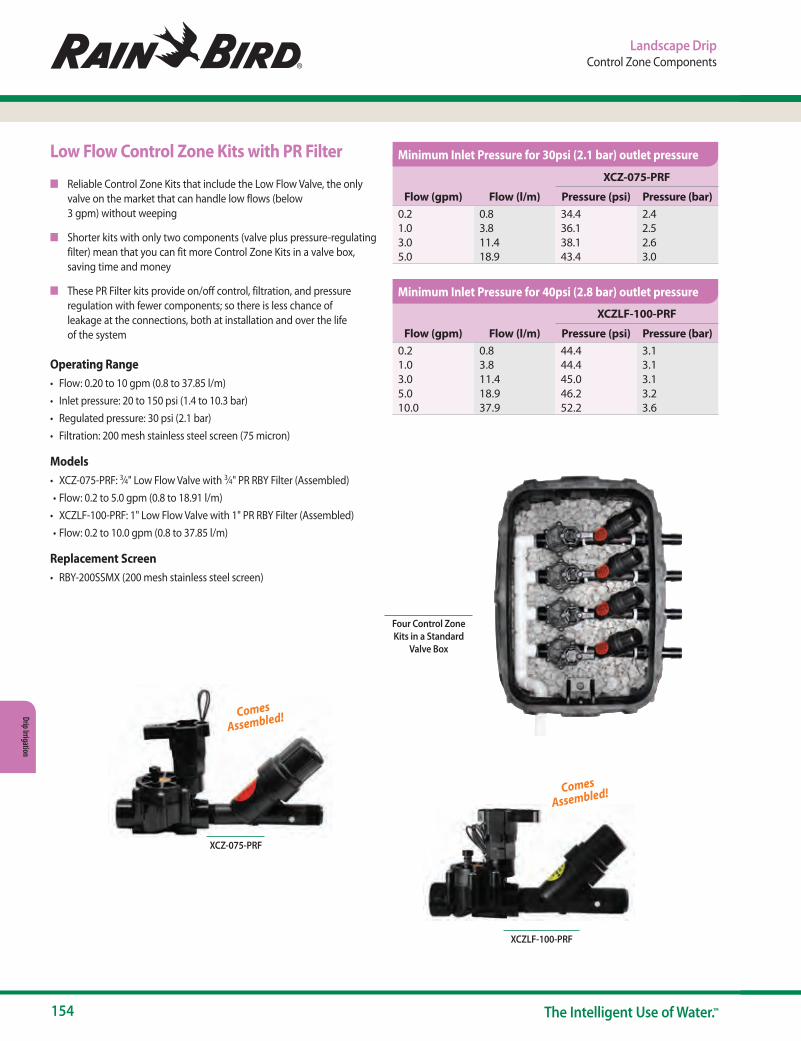
154 The Intelligent Use of Water.™
Drip Irrigation
Landscape DripControl Zone Components
Four Control Zone Kits in a Standard
Valve Box
Low Flow Control Zone Kits with PR Filter
n Reliable Control Zone Kits that include the Low Flow Valve, the only valve on the market that can handle low flows (below 3 gpm) without weeping
n Shorter kits with only two components (valve plus pressure-regulating filter) mean that you can fit more Control Zone Kits in a valve box, saving time and money
n These PR Filter kits provide on/off control, filtration, and pressure regulation with fewer components; so there is less chance of leakage at the connections, both at installation and over the life of the system
Operating Range• Flow: 0.20 to 10 gpm (0.8 to 37.85 l/m)• Inlet pressure: 20 to 150 psi (1.4 to 10.3 bar)• Regulated pressure: 30 psi (2.1 bar)• Filtration: 200 mesh stainless steel screen (75 micron)
Models• XCZ-075-PRF: 3⁄4" Low Flow Valve with 3⁄4" PR RBY Filter (Assembled)• Flow: 0.2 to 5.0 gpm (0.8 to 18.91 l/m)
• XCZLF-100-PRF: 1" Low Flow Valve with 1" PR RBY Filter (Assembled)• Flow: 0.2 to 10.0 gpm (0.8 to 37.85 l/m)
Replacement Screen• RBY-200SSMX (200 mesh stainless steel screen)
Comes
Assembled!
XCZ-075-PRF
Flow (gpm) Flow (l/m)
XCZ-075-PRF
Pressure (psi) Pressure (bar)0.2 0.8 34.4 2.41.0 3.8 36.1 2.53.0 11.4 38.1 2.65.0 18.9 43.4 3.0
Flow (gpm) Flow (l/m)
XCZLF-100-PRF
Pressure (psi) Pressure (bar)0.2 0.8 44.4 3.11.0 3.8 44.4 3.13.0 11.4 45.0 3.15.0 18.9 46.2 3.210.0 37.9 52.2 3.6
XCZLF-100-PRF
Comes
Assembled!
Minimum Inlet Pressure for 30psi (2.1 bar) outlet pressure
Minimum Inlet Pressure for 40psi (2.8 bar) outlet pressure
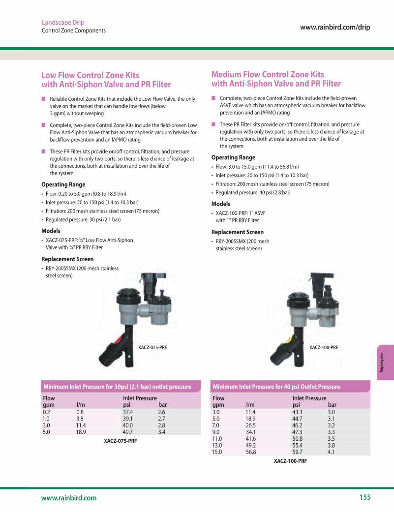
www.rainbird.com/drip
155www.rainbird.com
Drip
Irrig
atio
n
Landscape DripControl Zone Components
Low Flow Control Zone Kits with Anti-Siphon Valve and PR Filtern Reliable Control Zone Kits that include the Low Flow Valve, the only
valve on the market that can handle low flows (below 3 gpm) without weeping
n Complete, two-piece Control Zone Kits include the field-proven Low Flow Anti-Siphon Valve that has an atmospheric vacuum breaker for backflow prevention and an IAPMO rating
n These PR Filter kits provide on/off control, filtration, and pressure regulation with only two parts; so there is less chance of leakage at the connections, both at installation and over the life of the system
Operating Range• Flow: 0.20 to 5.0 gpm (0.8 to 18.9 l/m)• Inlet pressure: 20 to 150 psi (1.4 to 10.3 bar)• Filtration: 200 mesh stainless steel screen (75 micron)• Regulated pressure: 30 psi (2.1 bar)
Models• XACZ-075-PRF: 3⁄4" Low Flow Anti-Siphon
Valve with 3⁄4" PR RBY Filter
Replacement Screen• RBY-200SSMX (200 mesh stainless
steel screen)
XACZ-075-PRF
Medium Flow Control Zone Kits with Anti-Siphon Valve and PR Filtern Complete, two-piece Control Zone Kits include the field-proven
ASVF valve which has an atmospheric vacuum breaker for backflow prevention and an IAPMO rating
n These PR Filter kits provide on/off control, filtration, and pressure regulation with only two parts; so there is less chance of leakage at the connections, both at installation and over the life of the system
Operating Range• Flow: 3.0 to 15.0 gpm (11.4 to 56.8 l/m)• Inlet pressure: 20 to 150 psi (1.4 to 10.3 bar)• Filtration: 200 mesh stainless steel screen (75 micron)• Regulated pressure: 40 psi (2.8 bar)
Models• XACZ-100-PRF: 1" ASVF
with 1" PR RBY Filter
Replacement Screen• RBY-200SSMX (200 mesh
stainless steel screen)
XACZ-100-PRF
XACZ-075-PRF
XACZ-100-PRF
Flow Inlet Pressuregpm l/m psi bar0.2 0.8 37.4 2.61.0 3.8 39.1 2.73.0 11.4 40.0 2.85.0 18.9 49.7 3.4
Flow Inlet Pressuregpm l/m psi bar3.0 11.4 43.3 3.05.0 18.9 44.7 3.17.0 26.5 46.2 3.29.0 34.1 47.3 3.311.0 41.6 50.8 3.513.0 49.2 55.4 3.815.0 56.8 59.7 4.1
Minimum Inlet Pressure for 30psi (2.1 bar) outlet pressure Minimum Inlet Pressure for 40 psi Outlet Pressure
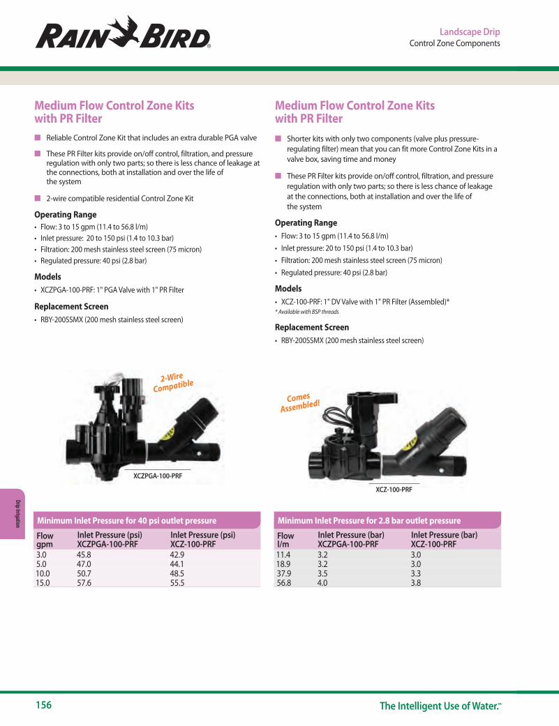
156 The Intelligent Use of Water.™
Drip Irrigation
Landscape DripControl Zone Components
Medium Flow Control Zone Kits with PR Filtern Reliable Control Zone Kit that includes an extra durable PGA valve
n These PR Filter kits provide on/off control, filtration, and pressure regulation with only two parts; so there is less chance of leakage at the connections, both at installation and over the life of the system
n 2-wire compatible residential Control Zone Kit
Operating Range• Flow: 3 to 15 gpm (11.4 to 56.8 l/m)• Inlet pressure: 20 to 150 psi (1.4 to 10.3 bar)• Filtration: 200 mesh stainless steel screen (75 micron)• Regulated pressure: 40 psi (2.8 bar)
Models• XCZPGA-100-PRF: 1" PGA Valve with 1" PR Filter
Replacement Screen• RBY-200SSMX (200 mesh stainless steel screen)
Medium Flow Control Zone Kits with PR Filtern Shorter kits with only two components (valve plus pressure-
regulating filter) mean that you can fit more Control Zone Kits in a valve box, saving time and money
n These PR Filter kits provide on/off control, filtration, and pressure regulation with only two parts; so there is less chance of leakage at the connections, both at installation and over the life of the system
Operating Range• Flow: 3 to 15 gpm (11.4 to 56.8 l/m)• Inlet pressure: 20 to 150 psi (1.4 to 10.3 bar)• Filtration: 200 mesh stainless steel screen (75 micron)• Regulated pressure: 40 psi (2.8 bar)
Models• XCZ-100-PRF: 1" DV Valve with 1" PR Filter (Assembled)** Available with BSP threads
Replacement Screen• RBY-200SSMX (200 mesh stainless steel screen)
XCZ-100-PRF
XCZPGA-100-PRF
Comes
Assembled!
2-Wire
Compatible
Flow gpm
Inlet Pressure (psi) XCZPGA-100-PRF
Inlet Pressure (psi) XCZ-100-PRF
3.0 45.8 42.95.0 47.0 44.110.0 50.7 48.515.0 57.6 55.5
Flow l/m
Inlet Pressure (bar) XCZPGA-100-PRF
Inlet Pressure (bar) XCZ-100-PRF
11.4 3.2 3.018.9 3.2 3.037.9 3.5 3.356.8 4.0 3.8
Minimum Inlet Pressure for 40 psi outlet pressure Minimum Inlet Pressure for 2.8 bar outlet pressure

www.rainbird.com/drip
157www.rainbird.com
Drip
Irrig
atio
n
Landscape DripControl Zone Components
XCZ-100-PRB-LC
Wide Flow Commercial Control Zone Kit with Pressure Regulating, Basket Filtern Industry wide flow range between 0.3 and 20 gpm (1.13 to 75.71 l/m)
leading enables single SKU purchase for large projects
n Updated with the reliable, flexible and proven PEB valve with the rugged pressure regulating basket filter
n This PR Filter kit provides on/off control, filtration, and pressure regulation with only two parts; so there is less chance of leakage at the connections, both at installation and over the life of the system
n The “No Spill” feature of the basket filter ensures dirt does not fall back into the filter during cleanup operation. The threaded filter top with 0-ring makes it easy to remove and clean that stainless steel filter screen
Operating Range• Flow: 0.3 to 20 gpm (1.13 to 75.71 l/m)*• Inlet Pressure: 15 to 150 psi (1,0 to 10,3 bar)• Regulating Pressure: 40 psi (2,7 bar)• Filtration: 200 mesh (75 micron) stainless steel• Temperature: Up to 150 degree F (66 degree C)
Model• XCZ-100-PRB-LC: 1” PEB Valve with 1” Pressure Regulating (40 psi),
Basket Filter
Replacement Filter Screens• QKCHK-100M: 100 mesh stainless steel screen, red• QKCHK-200M: 200 mesh stainless steel screen, white
Replacement Cap• BFCAP (Complete cap with body o-ring)
*For flows below 5gpm Rain Bird recommends use of upstream filtration to prevent debris from collecting below the diaphragm
2-Wire
Compatible
Flow Rate Inlet Pressuregpm l/m psi bar0.3 1.14 41.0 2.821.0 3.78 41.5 2.865.0 18.9 43.0 2.910.0 37.9 48.0 3.315.0 56.8 56.0 3.820.0 75.7 65.0 4.5
Minimum Inlet Pressure for 40 psi (2.8 bar) Outlet Pressure

158 The Intelligent Use of Water.™
Drip Irrigation
Landscape DripControl Zone Components
XCZ-100-PRB-COM
Wide Flow Commercial Control Zone Kit with Scrubber Valve & Pressure Regulating, Basket Filtern Complete kit is the simplest, smallest and most reliable Control
Zone Kit for commercial applications between 0.3 and 20 gpm (1.13 and 76 l/m)
n Includes the reliable, proven PESB Valve which provides patented scrubbing action, making this kit ideal for commercial dirty water applications
n Includes the Pressure Regulating, Quick-Check Basket Filter that has a clear indicator which goes from green to red, telling you when to clean the filter. This reduces maintenance and takes the guesswork out of cleaning the filter. In addition, the threaded top makes it easy to remove and clean the stainless steel screen
n Basket Filter and Pressure Regulator have been combined for one smaller Pressure Regulating, Quick-Check Basket filter that is 24% smaller than the previous unit
n Flow Indicating Basket Filter kit provides flow measurement, filtration (stainless steel, 150 mesh) and 40 psi integrated pressure regulation all in an all-in-one compact kit that protects your irrigation system
Operating Range• Flow: 0.3 to 20.0 gpm (1.13 to 75.7 l/m)*• Inlet Pressure: 15 to 150 psi (1,0 to 10,3 bar)• Regulating Pressure: 40 psi (2,7 bar)• Filtration: 200 mesh (75 micron) stainless steel• Temperature: Up to 150º F (66º C)
Model• XCZ-100-FLOW: 1" Ball Valve with 1" PESB valve and 1" Pressure
Regulating (40 psi) Quick Check Basket Filter with Flow Indication • XCZ-100-PRB-COM: 1" Ball Valve with 1" PESB Valve and 1" Pressure
Regulating (40 psi), Quick-Check Basket Filter• XCZ-100-PRBR: 1" PESBR Valve and 1" Pressure Regulating (40psi)
Basket Filter
Replacement Screens
Replacement Screens for XCZ-100PRBR & XCZ-PRB-COM• QKCHK100M (100 mesh/150 micron stainless steel screen)• QKCHK200M (200 mesh/75 micron stainless steel screen)
Replacement Screens for XCZ-100-FLOW• FLOW120M (120 mesh/125 micron stainless steel screen)• FLOW150M (150 mesh/100 micron stainless steel screen)• FLOW200M (200 mesh/75 micron stainless steel screen)
Replacement Cap• QKCHKCAP (Complete cap with body o-ring)
* For flows below 5gpm Rain Bird recommends use of upstream filtration to prevent debris from collecting below the diaphragm
XCZ-100-PRBR
2-Wire
Compatible
2-Wire
Compatible
2-Wire
Compatible
Flow gpm
Inlet Pressure (psi)XCZ-100-PRB-COM
Inlet Pressure (psi) XCZ-100-PRBR
0.3 41.0 41.01.0 41.5 41.53.0 42.0 42.05.0 44.0 45.010.0 47.3 49.015.0 53.0 57.020.0 62.5 62.5
Flow l/m
Inlet Pressure (bar)XCZ-100-PRB-COM
Inlet Pressure (bar) XCZ-100-PRBR
1.136 2.82 2.823.78 2.86 2.8611.4 2.9 2.918.9 3.0 3.137.9 3.3 3.456.8 3.6 3.975.7 4.3 4.3
Minimum Inlet Pressure for 40 psi outlet pressure
Minimum Inlet Pressure for 2.8 bar Outlet Pressure
XCZ-100-PRB-COM
NEW

www.rainbird.com/drip
159www.rainbird.com
Drip
Irrig
atio
n
Landscape DripControl Zone Components
1.5" Inline Commercial Control Zone KitRun Up to 62 gpm for Large Zones
n High Flow Range: Allows for larger drip zone coverage with one control zone kit, saving labor cost, material cost and installation hassle.
n Low Friction Loss: Allows usage in zones with lower head pressure.
n Fully Assembled: Saves installation labor cost by ensuring all key components are included and that the direction of flow in individual components is assembled properly.
n Inline Configuration: Fewer connection points, which fits two kits instead of just one in a jumbo valve box. Also provides more access for maintenance and components.
Operating Range• Flow Range: 15 to 62 gpm (56.8 l/min to 234.69 l/min) • Inlet Pressure: 15 to 115 psi (1.03 to 7.9 bar) • Regulated Pressure: 40 psi (2.8 bar) • Filtration: 120 mesh (130 micron) • Water Temperature: 33° F up to 110° F (0.5° C to 43° C) • Ambient Temperature: 33° F up to 125° F (0.5° C to 52° C)
Specifications
Dimensions• XCZ-150-LCS: 20 3/4" L x 5 3/4" W x 9½" H• XCZ-150-LCDR: 23½" L x 5 3/4" W x 9½" H
Filtration• XCZ-150-LCS: 1½" (3.81 cm) Stainless Steel Screen Filter, 120 Mesh
(130 Micron); Surface Area: 42 in2 (270 cm2)• XCZ-150-LCDR: 1½" (3.81 cm) Disc Filter, 120 Mesh (130 Micron);
Surface Area: 48 in2 (310 cm2)
Valve Type• XCZ-150-LCS: 1.5" PEB• XCZ-150-LCDR: 1.5" PESB-R
• Power: 24 VAC 50/60 Hz (cycles/sec) solenoid • Inrush Current: 0.41A (9.84 VA) at 50/60Hz • Holding Current: 0.14A (3.43VA) at 50/60Hz • Coil Resistance: 30-39 Ohms • Two-wire compatible with ESP-LXD Decoders
Models • XCZ-150-LCS • XCZ-150-LCDR
Replacement Filters
Disc• LGFC120MD
Screen• LGFC120MS
XCZ-150-LCS
XCZ-150-LCDR
2-Wire
Compatible
2-Wire
Compatible
Flow Rate (gpm) XCZ-150-LCS XCZ-150-LCDR15 1.9 2.320 2.4 3.425 4.1 4.930 5.3 5.340 7.4 8.050 13.6 14.460 20.7 20.7
Pressure Loss Characteristics
Flow Rate (l/h) XCZ-150-LCS XCZ-150-LCDR56.8 0.13 0.1675.7 0.17 0.2394.7 0.28 0.34113.6 0.37 0.37151.4 0.51 0.55189.3 0.94 0.99227.1 1.43 1.43
Pressure Loss Characteristics
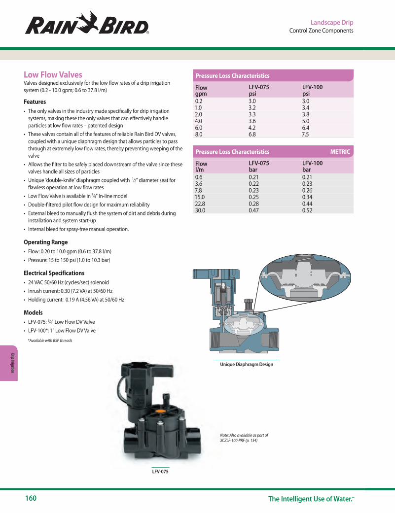
160 The Intelligent Use of Water.™
Drip Irrigation
Landscape DripControl Zone Components
LFV-075
Unique Diaphragm Design
Low Flow ValvesValves designed exclusively for the low flow rates of a drip irrigation system (0.2 - 10.0 gpm; 0.6 to 37.8 l/m)
Features• The only valves in the industry made specifically for drip irrigation
systems, making these the only valves that can effectively handle particles at low flow rates – patented design
• These valves contain all of the features of reliable Rain Bird DV valves, coupled with a unique diaphragm design that allows particles to pass through at extremely low flow rates, thereby preventing weeping of the valve
• Allows the filter to be safely placed downstream of the valve since these valves handle all sizes of particles
• Unique “double-knife” diaphragm coupled with 1⁄2" diameter seat for flawless operation at low flow rates
• Low Flow Valve is available in 3⁄4" In-line model• Double-filtered pilot flow design for maximum reliability• External bleed to manually flush the system of dirt and debris during
installation and system start-up• Internal bleed for spray-free manual operation.
Operating Range• Flow: 0.20 to 10.0 gpm (0.6 to 37.8 l/m)• Pressure: 15 to 150 psi (1.0 to 10.3 bar)
Electrical Specifications• 24 VAC 50/60 Hz (cycles/sec) solenoid• Inrush current: 0.30 (7.2 VA) at 50/60 Hz• Holding current: 0.19 A (4.56 VA) at 50/60 Hz
Models• LFV-075: 3⁄4" Low Flow DV Valve• LFV-100*: 1" Low Flow DV Valve
*Available with BSP threads
Note: Also available as part of XCZLF-100-PRF (p. 154)
Flow gpm
LFV-075 psi
LFV-100 psi
0.2 3.0 3.01.0 3.2 3.42.0 3.3 3.84.0 3.6 5.06.0 4.2 6.48.0 6.8 7.5
Flow l/m
LFV-075 bar
LFV-100 bar
0.6 0.21 0.213.6 0.22 0.237.8 0.23 0.2615.0 0.25 0.3422.8 0.28 0.4430.0 0.47 0.52
Pressure Loss Characteristics
Pressure Loss Characteristics METRIC

www.rainbird.com/drip
161www.rainbird.com
Drip
Irrig
atio
n
Landscape DripControl Zone Components
Inline RBY FilterStatic filter helps prevent plugging in a drip irrigation system
Features• A simple and reliable filter for low-volume irrigation systems• Simple to clean, as cap has a sealing O-ring and unthreads to provide
access to the stainless steel filter element• Strong and reliable due to its robust design and glass-filled
polypropylene construction• Male x Male threaded connections for direct connection to valves and
pressure regulators• Replacement stainless steel elements are available in 200 mesh
(75 micron)
Operating Range• Flow:
- 3⁄4" units: 0.20 to 12.0 gpm (0.8 to 45.4 l/m) - 1" units: 0.20 to 18.0 gpm (0.8 to 68.1 l/m)
• Pressure: 20 to 150 psi (1.4 to 10.3 bar)• Filtration: 200 mesh (75 micron)
Models• RBY075MPTX: 3⁄4" Inline RBY Filter with 200 Mesh Screen• RBY100MPTX: 1" Inline RBY Filter with 200 Mesh Screen*
Replacement screen:• RBY-200SSMX (200 mesh stainless steel screen)
Note: Filter must be installed downstream of a control valve and not under constant pressure.
RBY075MPTX
Note: Pressure loss for 200 mesh filter screen
Pressure-Regulating Filter (RBY)Unique, compact unit that works with all valves to create a simple, efficient control zone. Combines filtration and pressure regulation in one piece for protection of downstream components in a low-volume irrigation system
Features• Reduces the number of components in a control zone, making it
smaller and easier to install. More control zones can fit in one valve box!
• Combination unit comes with 200 mesh (75 micron) stainless steel reduces the number of connections, making installation easier and faster
• Static RBY filter regulates pressure to a nominal 30 or 40 psi (2.0 or 2.8 bar) - PR RBY Filter Cap has sealing O-ring and unthreads to provide access to the filter element for easy cleaning
• 30 or 40 psi pressure regulator is integrated into the filter body• Robust body and cap are made of glass-filled polypropylene and
provide 150 psi (10.3 bar) pressure rating
Operating Range• Flow - 3⁄4" units: 0.20 to 5.0 gpm (0.8 to 18.9 l/m)
- 1" units: 3.0 to 15.0 gpm (11.4 to 56.8 l/m)• Inlet pressure: 20 to 150 psi (1.4 to 10.3 bar)• Regulated pressure: - 3⁄4" units: 30 psi (2.1 bar)
- 1" units: 40 psi (2.8 bar)
Models• PRF-075-RBY: 3⁄4" PR RBY Filter• PRF-100-RBY: 1" PR RBY Filter
Replacement Screen• RBY-200SSMX (200 mesh stainless steel screen) Note: When installing with emission points more than 5 ft. above the pressure regulating filter, a
check valve should be installed after the regulator. Note: Filter must be installed downstream of a control valve and not under constant pressure.
PRF-075-RBY and PRF-100-RBY
Note: Pressure loss for 200 mesh filter screen
Components of Control Zone
Kits Found on pg. 154-166
Stainless Steel
Screen
Flow Rate RBY075MPTX RBY100MPTXgpm l/m psi bar psi bar1.00 0.8 0.1 0.00 0.1 0.003.00 3.8 0.4 0.01 0.3 0.015.0 11.4 1.1 0.03 0.5 0.027.0 18.9 1.6 0.08 0.8 0.039.0 26.5 2.7 0.11 1.4 0.0612.0 34.1 4.5 0.19 2.2 0.1014.0 45.4 — 0.31 3.0 0.1516.0 53.0 — — 3.8 0.2118.0 60.6 — — 4.7 0.26
68.1 — — — 0.32
Flow Rate PRF-075-RBY PRF-100-RBYgpm l/m psi bar psi bar0.2 0.8 3.0 0.21 N/A N/A1.0 3.8 4.0 0.28 N/A N/A3.0 11.4 6.1 0.42 0.8 0.065.0 18.9 10.0 0.69 2.0 0.148.0 30.3 N/A N/A 3.8 0.2610.0 37.9 N/A N/A 5.2 0.3615.0 56.8 N/A N/A 12.0 0.83
Pressure Loss Characteristics
Pressure Loss Characteristics

162 The Intelligent Use of Water.™
Drip Irrigation
Landscape DripControl Zone Components
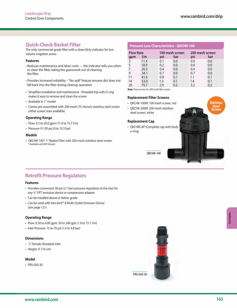
www.rainbird.com/drip
163www.rainbird.com
Drip
Irrig
atio
n
Landscape DripControl Zone Components
Quick-Check Basket FilterThe only commercial-grade filter with a clean/dirty indicator for low-volume irrigation zones
Features• Reduces maintenance and labor costs — the indicator tells you when to clean the filter, taking the guesswork out of cleaning the filter
• Provides increased reliability – “No-spill” feature ensures dirt does not fall back into the filter during cleanup operation
• Simplifies installation and maintenance - threaded top with O-ring makes it easy to remove and clean the screen
• Available in 1" model• Comes pre-assembled with 200 mesh (75 micron) stainless steel screen
(other screen sizes available)
Operating Range• Flow: 0.3 to 20.0 gpm (11.4 to 75.7 l/m)• Pressure: 0-150 psi (0 to 10.3 bar)
Models• QKCHK-100*: 1" Basket Filter with 200 mesh stainless steel screen * Available with BSP threads
QKCHK-100
Note: Pressure loss for 200 mesh filter screen
Retrofit Pressure RegulatorsFeatures• Provides convenient 30 psi (2.1 bar) pressure regulation at the riser for
any ½" FPT emission device or compression adapter• Can be installed above or below grade• Can be used with Xeri-bird™ 8 Multi-Outlet Emission Device
(see page 121)
Operating Range• Flow: 0.50 to 4.00 gpm; 30 to 240 gph (1.9 to 15.1 l/m)• Inlet Pressure: 15 to 70 psi (1.0 to 4.8 bar)
Dimensions• 1⁄2" female-threaded inlet• Height: 4" (10 cm)
Model• PRS-050-30
PRS-050-30
Replacement Filter Screens• QKCHK-100M: 100 mesh screen, red• QKCHK-200M: 200 mesh stainless
steel screen, white
Replacement Cap• QKCHKCAP (Complete cap with body
o-ring)
Stainless Steel
Screen
Flow Rate 100 mesh screen 200 mesh screengpm l/m psi bar psi bar3 11.4 0.1 0.0 0.0 0.05 18.9 0.2 0.0 0.0 0.07 26.5 0.4 0.0 0.4 0.09 34.1 0.7 0.0 0.7 0.011 41.6 0.9 0.1 1.1 0.114 53.0 1.3 0.1 1.6 0.120 75.7 2.9 0.2 3.2 0.2
Pressure Loss Characteristics - QKCHK-100
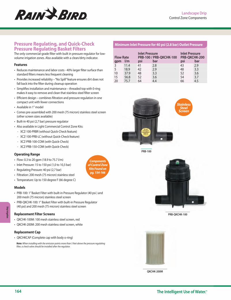
164 The Intelligent Use of Water.™
Drip Irrigation
Pressure Regulating, and Quick-Check Pressure Regulating Basket FiltersThe only commercial-grade filter with built in pressure regulator for low-volume irrigation zones. Also available with a clean/dirty indicator.
Features• Reduces maintenance and labor costs - 40% larger filter surface than
standard filters means less frequent cleaning• Provides increased reliability – “No Spill” feature ensures dirt does not
fall back into the filter during cleanup operation• Simplifies installation and maintenance – threaded top with 0-ring
makes it easy to remove and clean that stainless steel filter screen• Efficient design – combines filtration and pressure regulation in one
compact unit with fewer connections• Available in 1" model• Comes pre-assembled with 200 mesh (75 micron) stainless steel screen
(other screen sizes available)• Built-in 40 psi (2,7 bar) pressure regulator• Also available in Light Commercial Control Zone Kits:
- XCZ-100-PRBR (without Quick-Check feature) - XCZ-100-PRB-LC (without Quick-Check feature) - XCZ-PRB-100-COM (with Quick-Check) - XCZ-PRB-150-COM (with Quick-Check)
Operating Range• Flow: 0.3 to 20 gpm (18.9 to 75.7 l/m)• Inlet Pressure: 15 to 150 psi (1,0 to 10,3 bar)• Regulating Pressure: 40 psi (2,7 bar)• Filtration: 200 mesh (75 micron) stainless steel• Temperature: Up to 150 degree F (66 degree C)
Models• PRB-100: 1” Basket Filter with built-in Pressure Regulator (40 psi ) and
200 mesh (75 micron) stainless steel screen• PRB-QKCHK-100: 1" Basket Filter with built-in Pressure Regulator
(40 psi) and 200 mesh (75 micron) stainless steel screen
Replacement Filter Screens• QKCHK-100M: 100 mesh stainless steel screen, red• QKCHK-200M: 200 mesh stainless steel screen, white
Replacement Cap• QKCHKCAP (Complete cap with body o-ring)
Note: When installing with the emission points more than 5 feet above the pressure regulating filter, a check valve should be installed after the regulator.
PRB-100
Components of Control Zone
Kits Found on pg. 154-166
Stainless Steel
Screen
PRB-QKCHK-100
QKCHK-200M
Landscape DripControl Zone Components
Flow RateInlet Pressure PRB-100 / PRB-QKCHK-100
Inlet Pressure PRB-QKCHK-200
gpm l/m psi bar psi bar3 11.4 41 2.8 43 2.95 18.9 42 2.9 48 3.310 37.9 48 3.3 52 3.615 56.8 52 3.6 54 3.720 75.7 64 4.4 66 4.5
Minimum Inlet Pressure for 40 psi (2.8 bar) Outlet Pressure

www.rainbird.com/drip
165www.rainbird.com
Drip
Irrig
atio
n
Landscape DripControl Zone Components
1" & 1½ " High Flow Inline Pressure RegulatorsHigh flow Pressure Regulator family that delivers pre-set regulation for a wide flow range (0.5 -70 gpm) providing a solution for most irrigation applications.
Features
Flexibility• Its high flow range (0.5 gpm to 70 gpm) capacity allows usage in a wide
range of applications, making it ideal for drip or spray applications. It can be installed above or below grade.
- 1” Pressure Regulators flow range: 0.5-35 gpm (1.9 to 132.5 l/min) - 1 ½” Pressure Regulator flow range: 15-70 gpm ( 56.8 to 265.0 l/min)
Reliable Performance: • Pre-set outlet pressure regulation at either 40 psi (2.8 bar) or 50 psi (3.4
bar) provides worry-free protection for your irrigation installations.
Durability:• Tested to meet Rain Bird’s high-quality standards. High Strength ABS
construction and stainless steel springs provide the durability to withstand any job.
Operating Range• Pressure Regulation:
- PSI-H40X-100: 40 psi (2.8 bar) - PSI-H50X-100: 50 psi (3.4 bar) - PSI-H40X-150: 40 psi (2.8 bar) - PSI-M30X-075: 30 psi (2.1 bar)
• Flow Range: - PSI-H40X-100 & PSI-H50X-100: 0.5 gpm (1.9 l/min) to 35 gpm
(132.5 l/min) - PSI-H40X-150: 15 gpm (56.8 l/min) to 70 gpm (265.0 l/min) - PSI-M30X-075: 2.0 to 10.0 gpm; 120 to 600 gph (7.8 to 37.9 l/m)
• Inlet pressure: 15 to150 psi (10.3 bar)• Inlet Pressure (PSI-M30X-075): 10 to 150 psi (0.7 to 10.3 bar)
Specifications• PSI-H40X-100 & PSI-H50X-100 : 1” Female NPT X 1” Female NPT• PSI-H40X-150: 1 ½” Female NPT X 1 ½” Female NPT• PSI-M30X-075: 3⁄4" NPT female-threaded inlet and outlet
Dimensions:• PSI-H40X-100 & PSI-H50X-100: 5.8” (14.7 cm) in Length x 2.7” (6.8 cm)
in Width• PSI-H40X-150: 6.3” (16.0 cm) in Length x 3.3” (8.4 cm) in Width
Models• PSI-H40X-100: 1" 40 psi inline Pressure Regulator• PSI-H50X-100: 1" 50 psi inline Pressure Regulator• PSI- H40X-150: 1½" 40 psi inline Pressure Regulator• PSI-M30X-075: 3⁄4" 30 psi (2.1 bar) regulator for medium flow
PSI – H XX X – 100
Model Pressure Regulator
Flow Range CapacityH = High Flow (up to 70 gpm; 265 l/m)M = Medium Flow (up to 10 gpm; 37.9 l/m)
Pre-Set Pressure Regulation 40 = 40 psi (2.8 bar)50 = 50 psi (3.5 bar)
Inlet/Outlet Size075 = ¾ in (1.9 cm)100 = 1 in (2.5 cm)150 = 1½ in (3.8 cm)
How to Specify
1" & 1½ " High Flow Inline Pressure Regulators
NEW
PSI-M30X-075
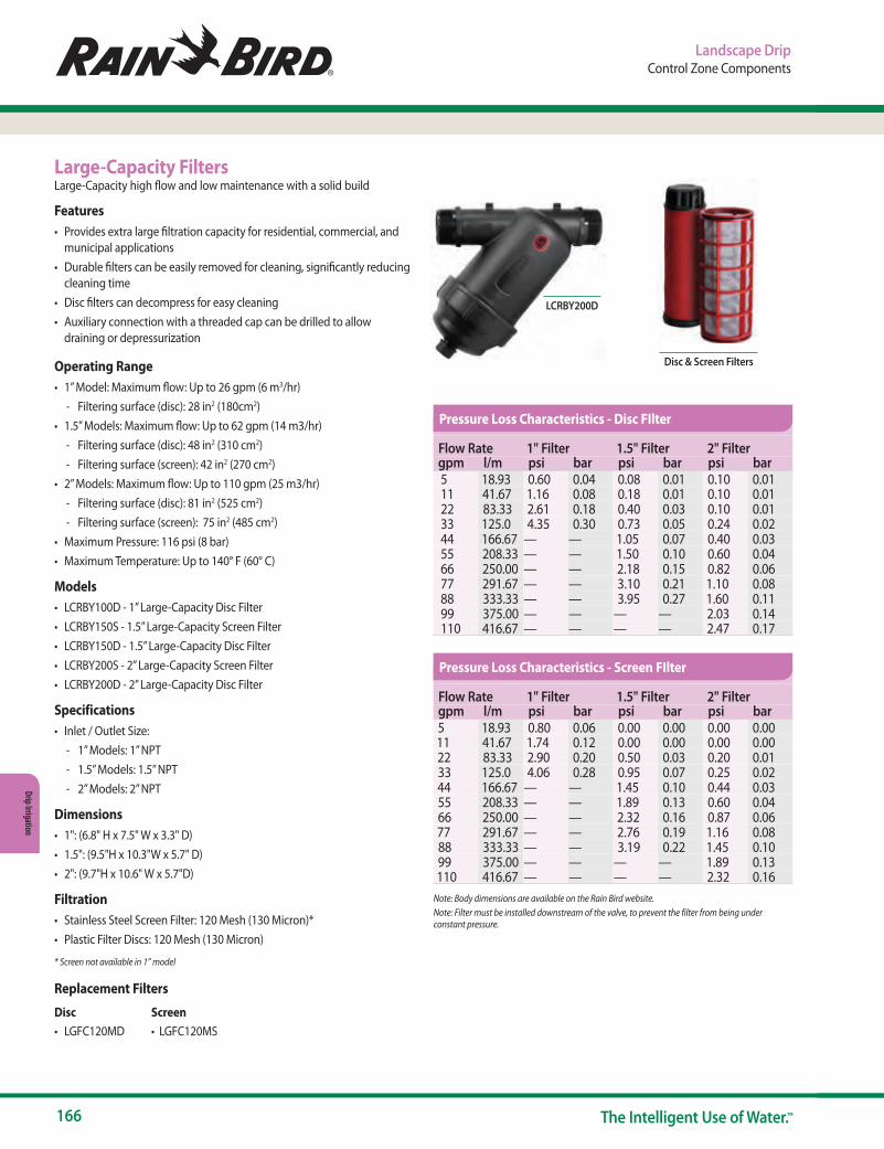
166 The Intelligent Use of Water.™
Drip Irrigation
Landscape DripControl Zone Components
Large-Capacity FiltersLarge-Capacity high flow and low maintenance with a solid build
Features• Provides extra large filtration capacity for residential, commercial, and
municipal applications• Durable filters can be easily removed for cleaning, significantly reducing
cleaning time• Disc filters can decompress for easy cleaning • Auxiliary connection with a threaded cap can be drilled to allow
draining or depressurization
Operating Range• 1” Model: Maximum flow: Up to 26 gpm (6 m3/hr)
- Filtering surface (disc): 28 in2 (180cm2)• 1.5” Models: Maximum flow: Up to 62 gpm (14 m3/hr)
- Filtering surface (disc): 48 in2 (310 cm2) - Filtering surface (screen): 42 in2 (270 cm2)
• 2” Models: Maximum flow: Up to 110 gpm (25 m3/hr) - Filtering surface (disc): 81 in2 (525 cm2) - Filtering surface (screen): 75 in2 (485 cm2)
• Maximum Pressure: 116 psi (8 bar)• Maximum Temperature: Up to 140° F (60° C)
Models• LCRBY100D - 1” Large-Capacity Disc Filter• LCRBY150S - 1.5” Large-Capacity Screen Filter• LCRBY150D - 1.5” Large-Capacity Disc Filter• LCRBY200S - 2” Large-Capacity Screen Filter• LCRBY200D - 2” Large-Capacity Disc Filter
Specifications• Inlet / Outlet Size:
- 1” Models: 1” NPT - 1.5” Models: 1.5” NPT - 2” Models: 2” NPT
Dimensions• 1": (6.8" H x 7.5" W x 3.3" D)• 1.5": (9.5"H x 10.3"W x 5.7" D)• 2": (9.7"H x 10.6" W x 5.7"D)
Filtration• Stainless Steel Screen Filter: 120 Mesh (130 Micron)* • Plastic Filter Discs: 120 Mesh (130 Micron)
* Screen not available in 1” model
Replacement Filters
Disc Screen• LGFC120MD • LGFC120MS
LCRBY200D
Disc & Screen Filters
Note: Body dimensions are available on the Rain Bird website.Note: Filter must be installed downstream of the valve, to prevent the filter from being under constant pressure.
Flow Rate 1" Filter 1.5" Filter 2" Filtergpm l/m psi bar psi bar psi bar 5 18.93 0.60 0.04 0.08 0.01 0.10 0.01 11 41.67 1.16 0.08 0.18 0.01 0.10 0.01 22 83.33 2.61 0.18 0.40 0.03 0.10 0.01 33 125.0 4.35 0.30 0.73 0.05 0.24 0.02 44 166.67 — — 1.05 0.07 0.40 0.03 55 208.33 — — 1.50 0.10 0.60 0.04 66 250.00 — — 2.18 0.15 0.82 0.06 77 291.67 — — 3.10 0.21 1.10 0.08 88 333.33 — — 3.95 0.27 1.60 0.11 99 375.00 — — — — 2.03 0.14 110 416.67 — — — — 2.47 0.17
Flow Rate 1" Filter 1.5" Filter 2" Filtergpm l/m psi bar psi bar psi bar5 18.93 0.80 0.06 0.00 0.00 0.00 0.0011 41.67 1.74 0.12 0.00 0.00 0.00 0.0022 83.33 2.90 0.20 0.50 0.03 0.20 0.0133 125.0 4.06 0.28 0.95 0.07 0.25 0.0244 166.67 — — 1.45 0.10 0.44 0.0355 208.33 — — 1.89 0.13 0.60 0.0466 250.00 — — 2.32 0.16 0.87 0.0677 291.67 — — 2.76 0.19 1.16 0.0888 333.33 — — 3.19 0.22 1.45 0.1099 375.00 — — — — 1.89 0.13110 416.67 — — — — 2.32 0.16
Pressure Loss Characteristics - Disc FIlter
Pressure Loss Characteristics - Screen FIlter
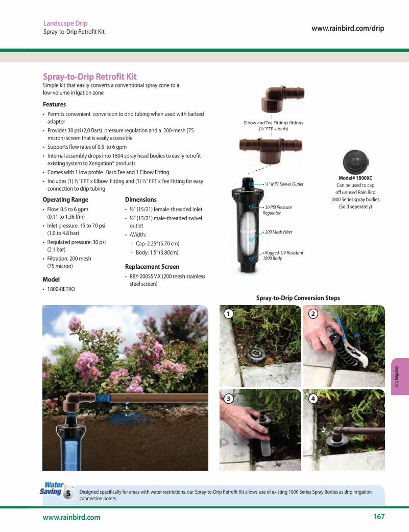
www.rainbird.com/drip
167www.rainbird.com
Drip
Irrig
atio
n
Designed specifically for areas with water restrictions, our Spray-to-Drip Retrofit Kit allows use of existing 1800 Series Spray Bodies as drip irrigation connection points.
Landscape DripSpray-to-Drip Retrofit Kit
Elbow and Tee Fittings fittings (½” FTP x barb)
• ½” MPT Swivel Outlet
• 30 PSI Pressure Regulator
• 200 Mesh Filter
• Rugged, UV Resistant 1800 Body
Features• Permits convenient conversion to drip tubing when used with barbed
adapter• Provides 30 psi (2,0 Bars) pressure regulation and a 200-mesh (75
micron) screen that is easily accessible• Supports flow rates of 0.5 to 6 gpm• Internal assembly drops into 1804 spray head bodies to easily retrofit
existing system to Xerigation® products• Comes with 1 low profile Barb Tee and 1 Elbow Fitting• Includes (1) ½” FPT x Elbow Fitting and (1) ½” FPT x Tee Fitting for easy
connection to drip tubing
Model# 1800XCCan be used to cap
off unused Rain Bird1800 Series spray bodies.
(Sold seperately)
Spray-to-Drip Conversion Steps
1
3
2
4
Spray-to-Drip Retrofit KitSimple kit that easily converts a conventional spray zone to a low-volume irrigation zone
Operating Range• Flow: 0.5 to 6 gpm
(0.11 to 1.36 l/m)• Inlet pressure: 15 to 70 psi
(1.0 to 4.8 bar)• Regulated pressure: 30 psi
(2.1 bar)• Filtration: 200 mesh
(75 micron)
Model• 1800-RETRO
Dimensions• ½" (15/21) female-threaded inlet• ½" (15/21) male-threaded swivel
outlet• •Width:
- Cap: 2.25” (5.70 cm) - Body: 1.5” (3.80cm)
Replacement Screen• RBY-200SSMX (200 mesh stainless
steel screen)
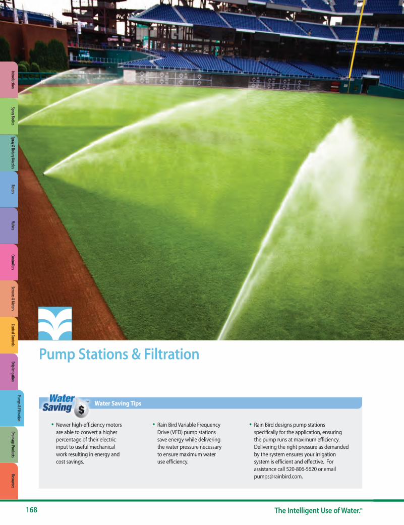
Pump Stations & Filtration
• Newer high-efficiency motors are able to convert a higher percentage of their electric input to useful mechanical work resulting in energy and cost savings.
• Rain Bird Variable Frequency Drive (VFD) pump stations save energy while delivering the water pressure necessary to ensure maximum water use efficiency.
• Rain Bird designs pump stations specifically for the application, ensuring the pump runs at maximum efficiency. Delivering the right pressure as demanded by the system ensures your irrigation system is efficient and effective. For assistance call 520-806-5620 or email [email protected].
Water Saving Tips
168 The Intelligent Use of Water.™
Spray & Rotary NozzlesRotors
ValvesControllers
Sensors & Meters
Central ControlsDrip Irrigation
Pumps & Filtration
Drainage ProductsResources
IntroductionSpray Bodies
Feet PSI 30 35 40 45 50 55 60 65 70 75 80 85 90 95 100 105 110 115 120 125 130 135 140 150 160 170 180 190 200 210 PSI Feet270 110 110 270259 105 105 259247 100 100 247
236 95 95 236224 90 90 224213 85 85 213201 80 80 201189 75 75 189178 70 70 178166 65 65 166155 60 60 155143 55 55 143132 50 50 132120 45 45 120109 40 40 10997 35 35 9785 30 30 8574 25 25 7462 20 20 6251 15 15 5139 10 10 39
Feet PSI 30 35 40 45 50 55 60 65 70 75 80 85 90 95 100 105 110 115 120 125 130 135 140 150 160 170 180 190 200 210 PSI Feet
CLP05BAC
CLP10KAC
CLP07GAC
CLP05DAC
CLP03AAC
CLP05EAC
CLP03CAC
Flow
Flow
CLP10NAC
CLP07JAC
CLP10LACCLP05FAC
CLP07HAC
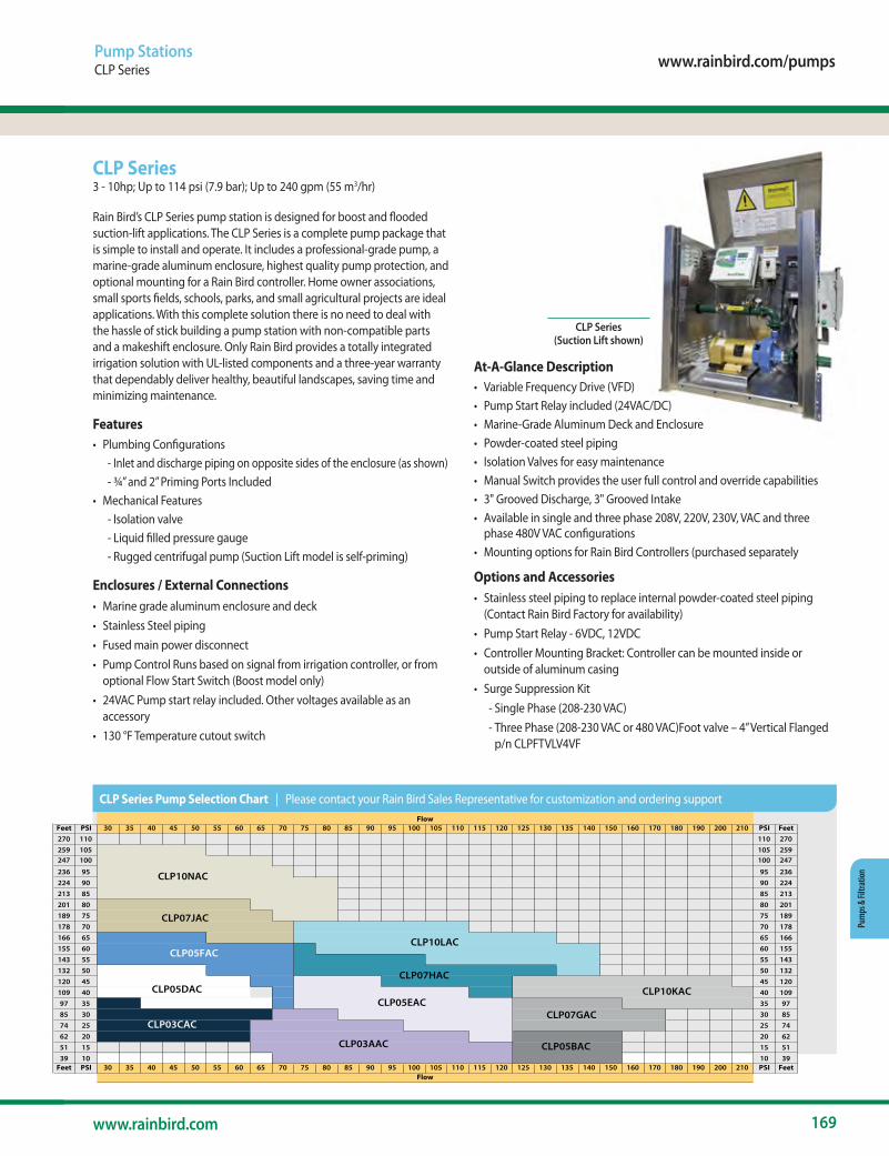
www.rainbird.com/pumps
169www.rainbird.com
Pum
ps &
Filtr
atio
n
Pump StationsCLP Series
CLP Series 3 - 10hp; Up to 114 psi (7.9 bar); Up to 240 gpm (55 m3/hr)
Rain Bird’s CLP Series pump station is designed for boost and flooded suction-lift applications. The CLP Series is a complete pump package that is simple to install and operate. It includes a professional-grade pump, a marine-grade aluminum enclosure, highest quality pump protection, and optional mounting for a Rain Bird controller. Home owner associations, small sports fields, schools, parks, and small agricultural projects are ideal applications. With this complete solution there is no need to deal with the hassle of stick building a pump station with non-compatible parts and a makeshift enclosure. Only Rain Bird provides a totally integrated irrigation solution with UL-listed components and a three-year warranty that dependably deliver healthy, beautiful landscapes, saving time and minimizing maintenance.
Features• Plumbing Configurations
- Inlet and discharge piping on opposite sides of the enclosure (as shown) - ¾” and 2” Priming Ports Included
• Mechanical Features - Isolation valve - Liquid filled pressure gauge - Rugged centrifugal pump (Suction Lift model is self-priming)
Enclosures / External Connections• Marine grade aluminum enclosure and deck• Stainless Steel piping• Fused main power disconnect• Pump Control Runs based on signal from irrigation controller, or from
optional Flow Start Switch (Boost model only) • 24VAC Pump start relay included. Other voltages available as an
accessory• 130 °F Temperature cutout switch
At-A-Glance Description• Variable Frequency Drive (VFD)• Pump Start Relay included (24VAC/DC)• Marine-Grade Aluminum Deck and Enclosure• Powder-coated steel piping• Isolation Valves for easy maintenance• Manual Switch provides the user full control and override capabilities• 3" Grooved Discharge, 3" Grooved Intake• Available in single and three phase 208V, 220V, 230V, VAC and three
phase 480V VAC configurations• Mounting options for Rain Bird Controllers (purchased separately
Options and Accessories• Stainless steel piping to replace internal powder-coated steel piping
(Contact Rain Bird Factory for availability)• Pump Start Relay - 6VDC, 12VDC• Controller Mounting Bracket: Controller can be mounted inside or
outside of aluminum casing• Surge Suppression Kit
- Single Phase (208-230 VAC) - Three Phase (208-230 VAC or 480 VAC)Foot valve – 4” Vertical Flanged p/n CLPFTVLV4VF
CLP Series (Suction Lift shown)
Feet PSI 30 35 40 45 50 55 60 65 70 75 80 85 90 95 100 105 110 115 120 125 130 135 140 150 160 170 180 190 200 210 PSI Feet270 110 110 270259 105 105 259247 100 100 247
236 95 95 236224 90 90 224213 85 85 213201 80 80 201189 75 75 189178 70 70 178166 65 65 166155 60 60 155143 55 55 143132 50 50 132120 45 45 120109 40 40 10997 35 35 9785 30 30 8574 25 25 7462 20 20 6251 15 15 5139 10 10 39
Feet PSI 30 35 40 45 50 55 60 65 70 75 80 85 90 95 100 105 110 115 120 125 130 135 140 150 160 170 180 190 200 210 PSI Feet
CLP05BAC
CLP10KAC
CLP07GAC
CLP05DAC
CLP03AAC
CLP05EAC
CLP03CAC
Flow
Flow
CLP10NAC
CLP07JAC
CLP10LACCLP05FAC
CLP07HAC
CLP Series Pump Selection Chart | Please contact your Rain Bird Sales Representative for customization and ordering support

170 The Intelligent Use of Water.™
Pumps & Filtration
Pump StationsACLP Series
Rain Bird® ACLP Series3 - 20hp; Up to 110 psi (7.6 bar); Up to 360 gpm (82 m3/hr)
Rain Bird’s ACLP series pump stations are UL listed packaged pump stations designed for boost, suction lift or flooded suction applications. The ACLP station features a marine-grade aluminum enclosure, professional-grade centrifugal pump, and powder coated carbon steel piping for efficient performance and maximum corrosion resistance. The ACLP stations feature variable speed controls to smoothly, efficiently, and reliably produce constant pressure at varying flow rates within a large envelope of operation. See individual pump performance curves for details.
At-A-Glance Description• Variable Frequency Drive (VFD)• Pump Start Relay included Flow Switch included• Bladder Tank included• Marine-Grade Aluminum Enclosure with powder coated steel deck and
exhaust fan• Isolation Valves for easy maintenance and priming• Auto-Off-Manual Switch provides the user full control and override
capabilities• Available in single and three phase 208V, 220V, 230V, VAC and three
phase 480V VAC configurations• Multiple options for boost, flooded suction, and suction lift applications
(see options list)• External Fault / Alarm and Run lights
Features• Plumbing Configurations
- Inlet and discharge piping on opposite sides of the enclosure (as shown) - ½” priming port
• Mechanical Features - Discharge and intake isolation valves - Liquid filled pressure gauges on intake and discharge piping - Rugged centrifugal pump
Optional Accessories• Surge Suppression Kit
- Single phase (208V,220V, or 230V AC) - Three phase (208V, 220V, 230V or 480V AC)
• Stainless steel piping to replace internal powder coated carbon steel piping
• Environmental package, includes space heater and enclosure insulation• Passive intake strainer and foot valve assembly for suction lift
applications• Self-cleaning inlet strainer and foot valve assembly for improved
suction lift performance• Automatic backflushing suction scanning process flow filter
ACLP Series
Feet PSI 30 35 40 45 50 55 60 65 70 75 80 85 90 95 100 105 110 115 120 125 130 135 140 150 160 170 180 190 200 210 220 230 240 250 260 270 280 290 300 PSI Feet316 130 130 316305 125 125 305293 120 120 293282 115 115 282270 110 110 270259 105 105 259247 100 100 247236 95 95 236224 90 90 224213 85 85 213201 80 80 201
189 75 75 189178 70 70 178166 65 65 166
155 60 60 155143 55 55 143132 50 50 132120 45 45 120109 40 40 10997 35 35 9785 30 30 8574 25 25 7462 20 20 6251 15 15 5139 10 10 39
Feet PSI 30 35 40 45 50 55 60 65 70 75 80 85 90 95 100 105 110 115 120 125 130 135 140 150 160 170 180 190 200 210 220 230 240 250 260 270 280 290 300 PSI Feet
ACLP20TACACLP05FAC
ACLP03CAC
ACLP05DAC
ACLP05EAC
ACLP10LAC
ACLP05BAC
ACLP07GAC
ACLP10KAC
ACLP15OAC
ACLP15RAC
ACLP15PAC
ACLP20WAC
ACLP20UAC
Flow
Flow
ACLP10NAC
ACLP07JAC
ACLP03AAC
ACLP07HAC
ACLP20VAC
ACLP Series Pump Selection Chart | Please contact your Rain Bird Sales Representative for customization and ordering support

www.rainbird.com/pumps
171www.rainbird.com
Pum
ps &
Filtr
atio
n
Pump StationsLow Profile Pump Stations – LP Series
Low Profile Pump Stations – LP Series Rain Bird’s LP Series Horizontal End Suction and Vertical multistage pump stations are designed for small to midsize boost, flooded suction and suction lift applications such as city parks and buildings, sports fields, commercial buildings, small home owner’s associations and large residential sites. Its low profile design, durable centrifugal or vertical multistage pump configuration, and choice of options make it an ideal choice for Turf irrigation applications.
Standard Features• Cost effective – Standardized VFD driven pump system in enclosure
delivers high performance with minimum investment • Low Profile – Compact aluminum enclosure with powder coated skid
and piping• Energy efficient – Variable Frequency Drive (VFD) maintains constant
pressure at varying flow demand• Reliability – Simple, standard design, easy installation and maintenance• Mechanical Features
- Inlet Butterfly Isolation Valve - Discharge Butterfly Isolation Valve - Silent Check Valve
• Enclosures / External Connections - Marine Grade Aluminum Enclosure - Polyester Powder-Coated Steel Deck and Piping - Thermostat and Fan on Mechanical Enclosure
• Pump Control - Pump Start Relay - VFD - Variable Frequency Drive for Control of Pressure
• Display - Monochrome Touch Screen Display
Optional Features and AccessoriesVisit: www.rainbird.com/professionals/products/pumps-pump-stations
Models• Horizontal End Suction - LP Series
- 5 to 10 HP; Up to 100 psi (6.9 bar); Up to 200 gpm (12.6 lps, 45.4 m3/h)• Vertical Multistage - LP Series
- 1 to 7.5 HP; Up to 120 psi (8.3 bar); Up to 0 gpm (5.7 lps, 20.4 m3/h)
(1) Refer to pump performance curves, provided upon request from [email protected]
Horizontal End Suction - LP Series Shown 5 to 10 HP; Up to 100 psi (6.9 bar);
Up to 200 gpm (12.6 lps, 45.4 m3/h)
Motor Size 1 HP 1.5 HP 2 HP 5 HP 7.5 HP
Pump Type Vertical Multistage
Power Requirement480/60/3 V/HZ/PH
208-230/60/3 V/HZ/PH208-230/60/1 V/HZ/PH
Inlet Pressure Requirement Suction Lift or Boost ApplicationsOutlet Pressure Up to 120 psi (8.3 bar) (1)
Outlet Flow Up to 90 gpm (5.7 lps, 20.4 m3/h) (1)
Concrete Slab Dimensions (min) 65" x 49" (165 cm x 125 cm)Platform Skid Dimensions (min) 53” x 39 3/4” (135 cm x 101 cm)
Inlet / Discharge Size 2" flange fitting standard - 3" and 4" adapters availableCabinet Height (from slab) 35" (89 cm) or 47" (107 cm)
Motor Size 5 HP 7.5 HP 10 HP
Pump Type Horizontal End Suction
Power Requirement
480/60/3 V/HZ/PH
208-230/60/3 V/HZ/PH
208-230/60/1 V/HZ/PH
Inlet Pressure Requirement Suction Lift or Boost Applications
Outlet Pressure Up to 100 psi (6.9 bar) (1)
Outlet Flow Up to 200 gpm (12.6 lps, 45.4 m3/h) (1)
Concrete Slab Dimensions (min) 65" x 49" (165 cm x 125 cm)
Platform Skid Dimensions (min) 53" x 39.75" (135 cm x 101 cm)
Inlet / Discharge Size 2" Flange Fitting (adapter) 3" Flange Fitting 4" Flange Fitting
(adapter)
Cabinet Height (from slab) 35" (89 cm)
LP Series – Horizontal End Suction - 1 Pump – Aluminum Enclosure
LP Series – Vertical Multistage – 1 Pump – Aluminum Enclosure

172 The Intelligent Use of Water.™
Pumps & Filtration
Pump StationsLow to Medium Flow Pump Stations – D-Series
Low to Medium Flow Pump Stations – D-Series Rain Bird’s single pump, Vertical Multi-Stage and Horizontal End Suction stations in powder-coated green enclosures are designed for small to midsize boost, flooded suction and suction lift applications such as city parks and buildings, sports fields, commercial buildings, small home owner’s associations and large residential sites. Its small footprint, durable centrifugal or multistage pump configuration, and choice of options make it an ideal choice for Turf irrigation applications.
Standard Features• Reliability – Integrated Plug-n-Pump provide single source responsibility
for the entire pumping system insuring trouble-free installation and operation
• Energy efficient – Variable Frequency Drive (VFD) maintains constant pressure at varying flow demand
• Inlet and discharge isolation valves for easier mechanical serviceability• Easy Start-up – All stations are water-tested at the factory prior to
shipment.• Mechanical Features
- Inlet Butterfly Isolation Valve - Discharge Butterfly Isolation Valve - Silent Check Valve
• Pressure / Flow - Stainless Steel Pressure Transducer - Flow Switch
• Enclosures / External Connections - Polyester Powder Coated Steel Enclosure - Polyester Powder-Coated Steel Deck and Piping - Re-Prime Piping (Suction Lift only) - Thermostat and Fan on Mechanical Enclosure
• Pump Control - Pump Start Relay - VFD - Variable Frequency Drive for Control of Pressure
• Display - Monochrome Touch Screen Display - Optional Color Touch Screen Display with Remote Communication Capability
Optional Features and AccessoriesVisit: www.rainbird.com/professionals/products/pumps-pump-stations
Models• Horizontal End Suction - 1 Pump - D Series
- 5 to 20 HP; Up to 130 psi (9.0 bar); Up to 180 gpm (11.4 lps, 40.9 m3/h)• Vertical Multistage – 1 Pump – D Series
- 3 to 15 HP; Up to 120 psi (8.3 bar); Up to 200 gpm (12.6 lps, 45.4 m3/h)
Motor Size 3 HP 5 HP 7 ½ HP 10 HP 15 HPPump Type Vertical Multi-Stage
Power Requirement480/60/3 V/HZ/PH
208-230/60/3 V/HZ/PH208-230/60/1 V/HZ/PH
Inlet Pressure Requirement Suction Lift or Boost ApplicationsOutlet Pressure Up to 120 psi (8.3 bar) (1)
Outlet Flow Up to 180 gpm (11.4 lps, 40.9 m3/h) (1)
Concrete Slab Dimensions (min) 90" x 48" (229 cm x 122 cm)Platform Skid Dimensions (min) 78" x 36" (198 cm x 91 cm)
Inlet / Discharge Size 4" Standard - 2", 3", and 6" adapters availableCabinet Height (from slab) 52" (132 cm) or 64" (163 cm)
(1) Refer to pump performance curves, provided upon request from [email protected]
Horizontal End Suction - 1 Pump - D Series shown 5 to 20 HP; Up to 130 psi (9.0 bar);
Up to 350 gpm (22.1 lps, 79.5 m3/h)
Motor Size 5 HP 7 ½ HP 10 HP 15 HP 20 HP
Pump Type Horizontal End Suction
Power Requirement480/60/3 V/HZ/PH
208-230/60/3 V/HZ/PH
230/60/1 V/HZ/PH 208/60/1 V/HZ/PH
Inlet Pressure Requirement Suction Lift (up to 3 ft. lift), or Boost Applications
Outlet Pressure Up to 130 psi (9.0 bar) (1)
Outlet Flow Up to 350 gpm (22.1 lps, 79.5 m3/h) (1)
Concrete Slab Dimensions (min) 90" x 48" (229 cm x 122 cm)
Platform Skid Dimensions (min) 78" x 36" (198 cm x 91 cm)Inlet / Discharge Size 4" standard - 2", 3" and 6" adapters are external accessories
Cabinet Height (from slab) 52" (132 cm) or 64" (163 cm)
D-Series – Vertical Multistage – 1 Pump – Green Enclosure
D-Series – Horizontal End Suction – 1 Pump – Green Enclosure
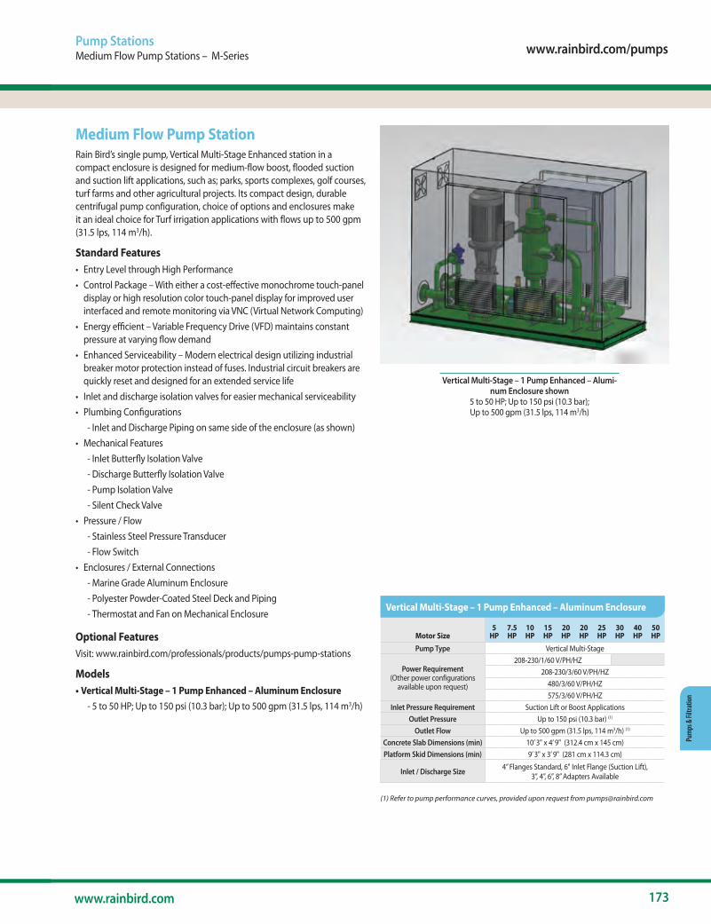
www.rainbird.com/pumps
173www.rainbird.com
Pum
ps &
Filtr
atio
n
Pump StationsMedium Flow Pump Stations – M-Series
Medium Flow Pump StationRain Bird’s single pump, Vertical Multi-Stage Enhanced station in a compact enclosure is designed for medium-flow boost, flooded suction and suction lift applications, such as; parks, sports complexes, golf courses, turf farms and other agricultural projects. Its compact design, durable centrifugal pump configuration, choice of options and enclosures make it an ideal choice for Turf irrigation applications with flows up to 500 gpm (31.5 lps, 114 m3/h).
Standard Features• Entry Level through High Performance• Control Package – With either a cost-effective monochrome touch-panel
display or high resolution color touch-panel display for improved user interfaced and remote monitoring via VNC (Virtual Network Computing)
• Energy efficient – Variable Frequency Drive (VFD) maintains constant pressure at varying flow demand
• Enhanced Serviceability – Modern electrical design utilizing industrial breaker motor protection instead of fuses. Industrial circuit breakers are quickly reset and designed for an extended service life
• Inlet and discharge isolation valves for easier mechanical serviceability• Plumbing Configurations
- Inlet and Discharge Piping on same side of the enclosure (as shown)• Mechanical Features
- Inlet Butterfly Isolation Valve - Discharge Butterfly Isolation Valve - Pump Isolation Valve - Silent Check Valve
• Pressure / Flow - Stainless Steel Pressure Transducer - Flow Switch
• Enclosures / External Connections - Marine Grade Aluminum Enclosure - Polyester Powder-Coated Steel Deck and Piping - Thermostat and Fan on Mechanical Enclosure
Optional FeaturesVisit: www.rainbird.com/professionals/products/pumps-pump-stations
Models• Vertical Multi-Stage – 1 Pump Enhanced – Aluminum Enclosure
- 5 to 50 HP; Up to 150 psi (10.3 bar); Up to 500 gpm (31.5 lps, 114 m3/h)
(1) Refer to pump performance curves, provided upon request from [email protected]
Vertical Multi-Stage – 1 Pump Enhanced – Alumi-num Enclosure shown
5 to 50 HP; Up to 150 psi (10.3 bar); Up to 500 gpm (31.5 lps, 114 m3/h)
Motor Size5
HP7.5 HP
10 HP
15 HP
20 HP
20 HP
25 HP
30 HP
40 HP
50 HP
Pump Type Vertical Multi-Stage
Power Requirement (Other power configurations
available upon request)
208-230/1/60 V/PH/HZ208-230/3/60 V/PH/HZ
480/3/60 V/PH/HZ575/3/60 V/PH/HZ
Inlet Pressure Requirement Suction Lift or Boost ApplicationsOutlet Pressure Up to 150 psi (10.3 bar) (1)
Outlet Flow Up to 500 gpm (31.5 lps, 114 m3/h) (1)
Concrete Slab Dimensions (min) 10’ 3" x 4’ 9" (312.4 cm x 145 cm)Platform Skid Dimensions (min) 9’ 3" x 3’ 9" (281 cm x 114.3 cm)
Inlet / Discharge Size 4” Flanges Standard, 6" Inlet Flange (Suction Lift), 3”, 4”, 6”, 8” Adapters Available
Vertical Multi-Stage – 1 Pump Enhanced – Aluminum Enclosure
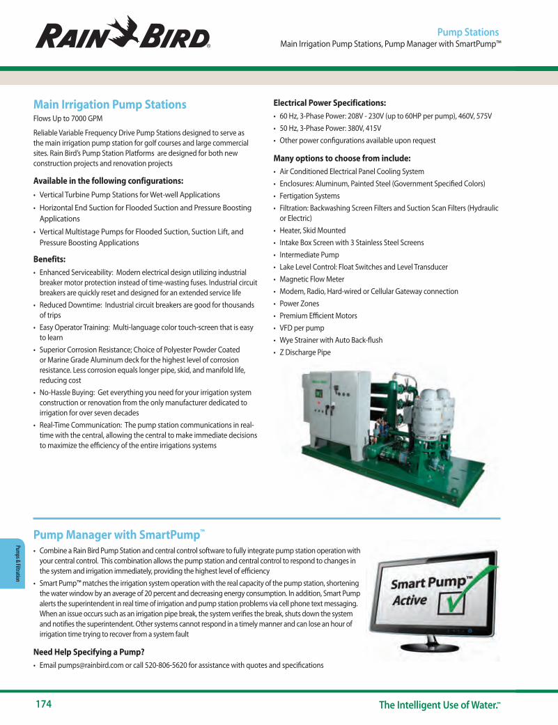
174 The Intelligent Use of Water.™
Pumps & Filtration
Main Irrigation Pump StationsFlows Up to 7000 GPM
Reliable Variable Frequency Drive Pump Stations designed to serve as the main irrigation pump station for golf courses and large commercial sites. Rain Bird’s Pump Station Platforms are designed for both new construction projects and renovation projects
Available in the following configurations:• Vertical Turbine Pump Stations for Wet-well Applications
• Horizontal End Suction for Flooded Suction and Pressure Boosting Applications
• Vertical Multistage Pumps for Flooded Suction, Suction Lift, and Pressure Boosting Applications
Benefits:• Enhanced Serviceability: Modern electrical design utilizing industrial
breaker motor protection instead of time-wasting fuses. Industrial circuit breakers are quickly reset and designed for an extended service life
• Reduced Downtime: Industrial circuit breakers are good for thousands of trips
• Easy Operator Training: Multi-language color touch-screen that is easy to learn
• Superior Corrosion Resistance; Choice of Polyester Powder Coated or Marine Grade Aluminum deck for the highest level of corrosion resistance. Less corrosion equals longer pipe, skid, and manifold life, reducing cost
• No-Hassle Buying: Get everything you need for your irrigation system construction or renovation from the only manufacturer dedicated to irrigation for over seven decades
• Real-Time Communication: The pump station communications in real-time with the central, allowing the central to make immediate decisions to maximize the efficiency of the entire irrigations systems
Electrical Power Specifications: • 60 Hz, 3-Phase Power: 208V - 230V (up to 60HP per pump), 460V, 575V• 50 Hz, 3-Phase Power: 380V, 415V• Other power configurations available upon request
Many options to choose from include:• Air Conditioned Electrical Panel Cooling System• Enclosures: Aluminum, Painted Steel (Government Specified Colors)• Fertigation Systems• Filtration: Backwashing Screen Filters and Suction Scan Filters (Hydraulic
or Electric)• Heater, Skid Mounted• Intake Box Screen with 3 Stainless Steel Screens• Intermediate Pump• Lake Level Control: Float Switches and Level Transducer• Magnetic Flow Meter• Modem, Radio, Hard-wired or Cellular Gateway connection• Power Zones• Premium Efficient Motors• VFD per pump• Wye Strainer with Auto Back-flush• Z Discharge Pipe
Pump StationsMain Irrigation Pump Stations, Pump Manager with SmartPump™
Pump Manager with SmartPump™
• Combine a Rain Bird Pump Station and central control software to fully integrate pump station operation with your central control. This combination allows the pump station and central control to respond to changes in the system and irrigation immediately, providing the highest level of efficiency
• Smart Pump™ matches the irrigation system operation with the real capacity of the pump station, shortening the water window by an average of 20 percent and decreasing energy consumption. In addition, Smart Pump alerts the superintendent in real time of irrigation and pump station problems via cell phone text messaging. When an issue occurs such as an irrigation pipe break, the system verifies the break, shuts down the system and notifies the superintendent. Other systems cannot respond in a timely manner and can lose an hour of irrigation time trying to recover from a system fault
Need Help Specifying a Pump?• Email [email protected] or call 520-806-5620 for assistance with quotes and specifications

www.rainbird.com/pumps
175www.rainbird.com
Pum
ps &
Filtr
atio
n
Pump StationsPump Start Relays
Pump Start RelaysFor Optimum Pump Performance and Protection
Rain Bird Pump Start Relays (PSRs) provide worry free performance for your irrigation system and are compatible with Rain Bird and other reliable irrigation controllers.
Dual Voltage Pump Start Relay Features• Works with a lawn controller's start/stop command to facilitate the
electrical path from the breaker box to the pump motor• Provides "pilot duty" operation for all types of electrically driven pump
equipment with available coil voltages of 24, 110 and 220 VAC• 40 AMP certified relay• Quick connect terminals with wire nuts• Grounding provision• Compatible with 24 VAC timed lawn controllers• Compatible with 110 or 220 VAC 3/4 HP thru 5 HP* single phase pumps• Grey "baked-on" powder coating, for long life in difficult environments• UL Listed as "Enclosed Industrial Control Panels" and backed by a one-
year warranty• Housed in compact NEMA3R weather-tight enclosures• Not recommended for use with 2-wire controller/decoder systems
Model• PSR110220
2-Wire Pump Start Relay Features• Works with a lawn controller's start/stop command to facilitate the
electrical path from the breaker box to the pump motor• Provides "pilot duty" operation for all types of electrically driven pump
equipment with available coil voltages of 24, 110 or 220 VAC• 40 AMP certified relay• Quick connect terminals with wire nuts• Grounding provision• Compatible with 24 VAC timed lawn controllers• Compatible with 110 or 220 VAC 3/4 HP thru 5 HP* single phase pumps• Grey "baked-on" powder coating, for long life in difficult environments• UL Listed as "Enclosed Industrial Control Panels" and backed by a one-
year warranty• Housed in compact NEMA3R weather-tight enclosures• Includes an additional ice cube relay for 2-wire controller/decoder
systems
Models• PSR110IC or PSR220IC
* when thermal protection is present
PSR110220
PSR110IC or
PSR220IC
Model Line Voltage Coil Voltage hp
PSR110IC 110 24 3/4 through 2*
PSR220IC 220 24 3/4 through 5*
PSR110220 110 or 220 24 3/4 through 5*
* National electrical code (nec) states all motors will be thermally protected from excessive “amperage draw.” Most motors under 2 hp are supplied with thermal protection from the motor manufacturer. For motors over 2 hp, code-compliant PSRB pump protection is recommended.
NOTE: Circuit breakers are never classified as motor protection
NOTE: Check with your local health department for regulations and requirements for backflow prevention.
Pump Start Relays Specifications
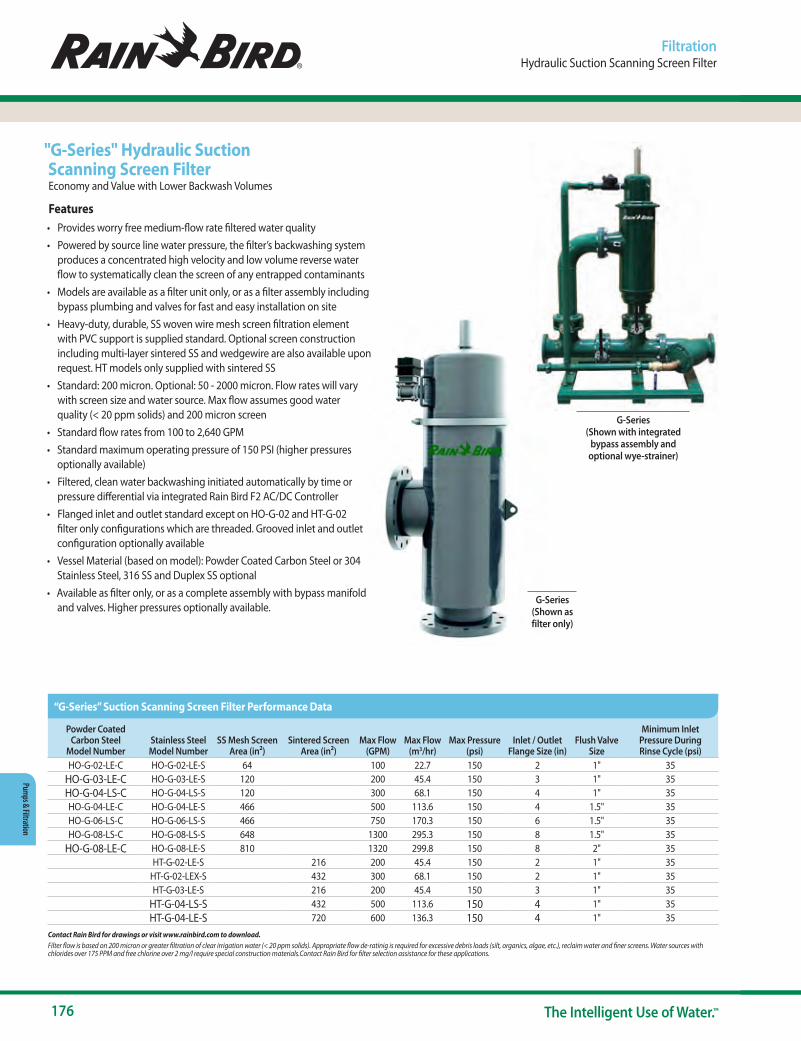
176 The Intelligent Use of Water.™
Pumps & Filtration
Powder Coated Carbon Steel
Model NumberStainless SteelModel Number
SS Mesh Screen Area (in²)
Sintered Screen Area (in²)
Max Flow (GPM)
Max Flow (m3/hr)
Max Pressure (psi)
Inlet / Outlet Flange Size (in)
Flush Valve Size
Minimum Inlet Pressure During Rinse Cycle (psi)
HO-G-02-LE-C HO-G-02-LE-S 64 100 22.7 150 2 1" 35HO-G-03-LE-C HO-G-03-LE-S 120 200 45.4 150 3 1" 35HO-G-04-LS-C HO-G-04-LS-S 120 300 68.1 150 4 1" 35HO-G-04-LE-C HO-G-04-LE-S 466 500 113.6 150 4 1.5" 35HO-G-06-LS-C HO-G-06-LS-S 466 750 170.3 150 6 1.5" 35HO-G-08-LS-C HO-G-08-LS-S 648 1300 295.3 150 8 1.5" 35
HO-G-08-LE-C HO-G-08-LE-S 810 1320 299.8 150 8 2" 35HT-G-02-LE-S 216 200 45.4 150 2 1" 35
HT-G-02-LEX-S 432 300 68.1 150 2 1" 35HT-G-03-LE-S 216 200 45.4 150 3 1" 35
HT-G-04-LS-S 432 500 113.6 150 4 1" 35HT-G-04-LE-S 720 600 136.3 150 4 1" 35
FiltrationHydraulic Suction Scanning Screen Filter
"G-Series" Hydraulic Suction Scanning Screen FilterEconomy and Value with Lower Backwash Volumes
Features• Provides worry free medium-flow rate filtered water quality• Powered by source line water pressure, the filter’s backwashing system
produces a concentrated high velocity and low volume reverse water flow to systematically clean the screen of any entrapped contaminants
• Models are available as a filter unit only, or as a filter assembly including bypass plumbing and valves for fast and easy installation on site
• Heavy-duty, durable, SS woven wire mesh screen filtration element with PVC support is supplied standard. Optional screen construction including multi-layer sintered SS and wedgewire are also available upon request. HT models only supplied with sintered SS
• Standard: 200 micron. Optional: 50 - 2000 micron. Flow rates will vary with screen size and water source. Max flow assumes good water quality (< 20 ppm solids) and 200 micron screen
• Standard flow rates from 100 to 2,640 GPM• Standard maximum operating pressure of 150 PSI (higher pressures
optionally available)• Filtered, clean water backwashing initiated automatically by time or
pressure differential via integrated Rain Bird F2 AC/DC Controller• Flanged inlet and outlet standard except on HO-G-02 and HT-G-02
filter only configurations which are threaded. Grooved inlet and outlet configuration optionally available
• Vessel Material (based on model): Powder Coated Carbon Steel or 304 Stainless Steel, 316 SS and Duplex SS optional
• Available as filter only, or as a complete assembly with bypass manifold and valves. Higher pressures optionally available.
G-Series (Shown with integrated
bypass assembly and optional wye-strainer)
G-Series (Shown as filter only)
“G-Series” Suction Scanning Screen Filter Performance Data
Contact Rain Bird for drawings or visit www.rainbird.com to download.Filter flow is based on 200 micron or greater filtration of clear irrigation water (< 20 ppm solids). Appropriate flow de-ratinig is required for excessive debris loads (silt, organics, algae, etc.), reclaim water and finer screens. Water sources with chlorides over 175 PPM and free chlorine over 2 mg/l require special construction materials.Contact Rain Bird for filter selection assistance for these applications.
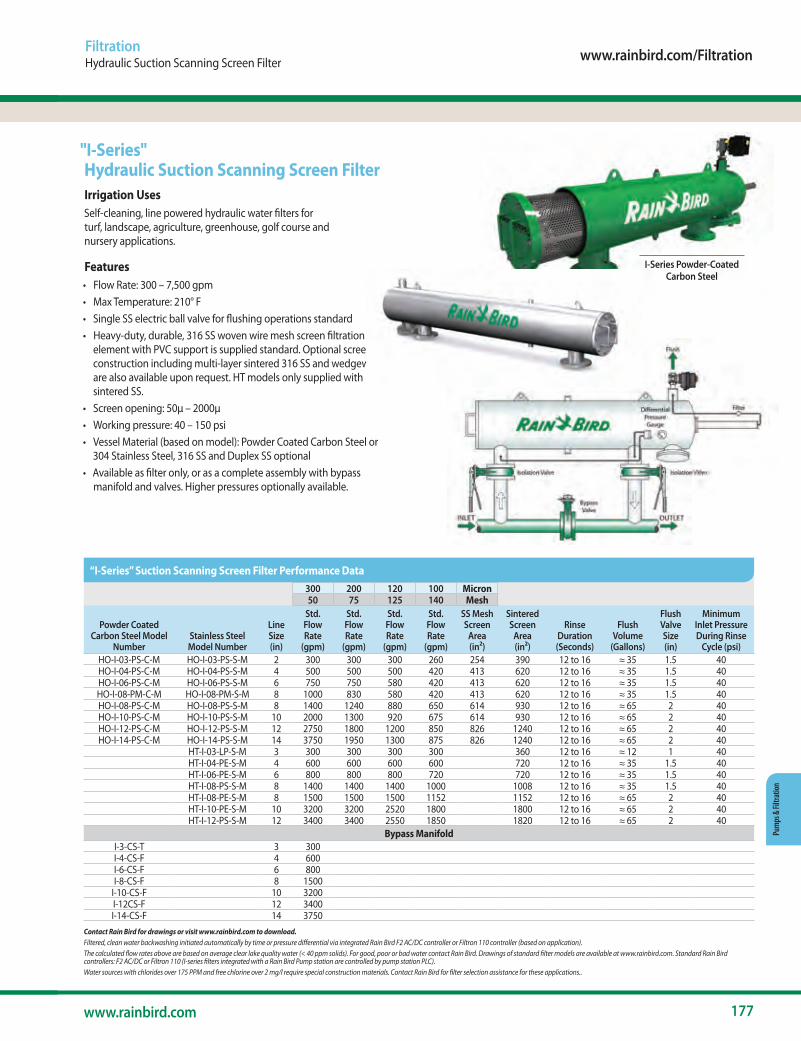
www.rainbird.com/Filtration
177www.rainbird.com
Pum
ps &
Filtr
atio
n
300 200 120 100 Micron50 75 125 140 Mesh
Powder Coated Carbon Steel Model
NumberStainless SteelModel Number
LineSize(in)
Std.FlowRate
(gpm)
Std.FlowRate
(gpm)
Std.FlowRate
(gpm)
Std.FlowRate
(gpm)
SS MeshScreen
Area(in²)
SinteredScreen
Area(in²)
RinseDuration(Seconds)
FlushVolume
(Gallons)
FlushValveSize(in)
MinimumInlet PressureDuring Rinse
Cycle (psi)HO-I-03-PS-C-M HO-I-03-PS-S-M 2 300 300 300 260 254 390 12 to 16 ≈ 35 1.5 40HO-I-04-PS-C-M HO-I-04-PS-S-M 4 500 500 500 420 413 620 12 to 16 ≈ 35 1.5 40HO-I-06-PS-C-M HO-I-06-PS-S-M 6 750 750 580 420 413 620 12 to 16 ≈ 35 1.5 40HO-I-08-PM-C-M HO-I-08-PM-S-M 8 1000 830 580 420 413 620 12 to 16 ≈ 35 1.5 40HO-I-08-PS-C-M HO-I-08-PS-S-M 8 1400 1240 880 650 614 930 12 to 16 ≈ 65 2 40HO-I-10-PS-C-M HO-I-10-PS-S-M 10 2000 1300 920 675 614 930 12 to 16 ≈ 65 2 40HO-I-12-PS-C-M HO-I-12-PS-S-M 12 2750 1800 1200 850 826 1240 12 to 16 ≈ 65 2 40HO-I-14-PS-C-M HO-I-14-PS-S-M 14 3750 1950 1300 875 826 1240 12 to 16 ≈ 65 2 40
HT-I-03-LP-S-M 3 300 300 300 300 360 12 to 16 ≈ 12 1 40HT-I-04-PE-S-M 4 600 600 600 600 720 12 to 16 ≈ 35 1.5 40HT-I-06-PE-S-M 6 800 800 800 720 720 12 to 16 ≈ 35 1.5 40HT-I-08-PS-S-M 8 1400 1400 1400 1000 1008 12 to 16 ≈ 35 1.5 40HT-I-08-PE-S-M 8 1500 1500 1500 1152 1152 12 to 16 ≈ 65 2 40HT-I-10-PE-S-M 10 3200 3200 2520 1800 1800 12 to 16 ≈ 65 2 40HT-I-12-PS-S-M 12 3400 3400 2550 1850 1820 12 to 16 ≈ 65 2 40
Bypass ManifoldI-3-CS-T 3 300I-4-CS-F 4 600I-6-CS-F 6 800I-8-CS-F 8 1500
I-10-CS-F 10 3200I-12CS-F 12 3400I-14-CS-F 14 3750
FiltrationHydraulic Suction Scanning Screen Filter
"I-Series" Hydraulic Suction Scanning Screen FilterIrrigation UsesSelf-cleaning, line powered hydraulic water filters for turf, landscape, agriculture, greenhouse, golf course and nursery applications.
Features• Flow Rate: 300 – 7,500 gpm• Max Temperature: 210° F• Single SS electric ball valve for flushing operations standard• Heavy-duty, durable, 316 SS woven wire mesh screen filtration
element with PVC support is supplied standard. Optional screen construction including multi-layer sintered 316 SS and wedgewire are also available upon request. HT models only supplied with sintered SS.
• Screen opening: 50μ – 2000μ• Working pressure: 40 – 150 psi• Vessel Material (based on model): Powder Coated Carbon Steel or
304 Stainless Steel, 316 SS and Duplex SS optional• Available as filter only, or as a complete assembly with bypass
manifold and valves. Higher pressures optionally available.
I-Series Powder-Coated Carbon Steel
I-Series Stainless Steel
“I-Series” Suction Scanning Screen Filter Performance Data
Contact Rain Bird for drawings or visit www.rainbird.com to download.Filtered, clean water backwashing initiated automatically by time or pressure differential via integrated Rain Bird F2 AC/DC controller or Filtron 110 controller (based on application). The calculated flow rates above are based on average clear lake quality water (< 40 ppm solids). For good, poor or bad water contact Rain Bird. Drawings of standard filter models are available at www.rainbird.com. Standard Rain Bird controllers: F2 AC/DC or Filtron 110 (I-series filters integrated with a Rain Bird Pump station are controlled by pump station PLC).Water sources with chlorides over 175 PPM and free chlorine over 2 mg/l require special construction materials. Contact Rain Bird for filter selection assistance for these applications..
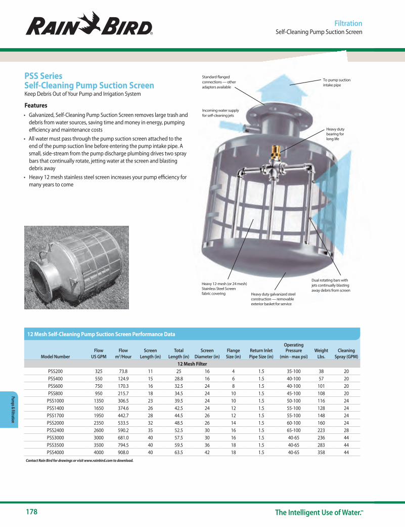
178 The Intelligent Use of Water.™
Pumps & Filtration
Dual rotating bars withjets continually blastingaway debris from screen
Heavy 12-mesh (or 24 mesh) Stainless Steel Screen fabric covering
Heavy duty galvanized steelconstruction — removableexterior basket for service
Incoming water supplyfor self-cleaning jets
Standard flanged connections — otheradapters available
To pump suctionintake pipe
Heavy duty bearing for long life
Model Number
FlowUS GPM
Flowm3/Hour
ScreenLength (in)
TotalLength (in)
Screen Diameter (in)
Flange Size (in)
Return InletPipe Size (in)
Operating Pressure
(min - max psi)Weight
Lbs.Cleaning
Spray (GPM)12 Mesh Filter
PSS200 325 73.8 11 25 16 4 1.5 35-100 38 20PSS400 550 124.9 15 28.8 16 6 1.5 40-100 57 20PSS600 750 170.3 16 32.5 24 8 1.5 40-100 101 20PSS800 950 215.7 18 34.5 24 10 1.5 45-100 108 20
PSS1000 1350 306.5 23 39.5 24 10 1.5 50-100 116 24PSS1400 1650 374.6 26 42.5 24 12 1.5 55-100 128 24PSS1700 1950 442.7 28 44.5 26 12 1.5 55-100 148 24PSS2000 2350 533.5 32 48.5 26 14 1.5 60-100 160 24PSS2400 2600 590.2 35 52.5 30 16 1.5 65-100 223 28PSS3000 3000 681.0 40 57.5 30 16 1.5 40-65 236 44PSS3500 3500 794.5 40 59.5 36 18 1.5 40-65 283 44PSS4000 4000 908.0 40 63.5 42 18 1.5 40-65 358 44
Contact Rain Bird for drawings or visit www.rainbird.com to download.
PSS Series Self-Cleaning Pump Suction ScreenKeep Debris Out of Your Pump and Irrigation System
Features• Galvanized, Self-Cleaning Pump Suction Screen removes large trash and
debris from water sources, saving time and money in energy, pumping efficiency and maintenance costs
• All water must pass through the pump suction screen attached to the end of the pump suction line before entering the pump intake pipe. A small, side-stream from the pump discharge plumbing drives two spray bars that continually rotate, jetting water at the screen and blasting debris away
• Heavy 12 mesh stainless steel screen increases your pump efficiency for many years to come
FiltrationSelf-Cleaning Pump Suction Screen
12 Mesh Self-Cleaning Pump Suction Screen Performance Data
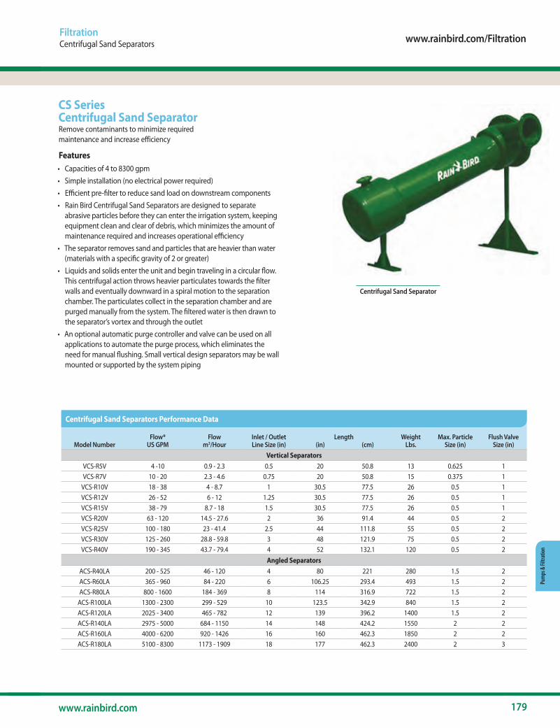
www.rainbird.com/Filtration
179www.rainbird.com
Pum
ps &
Filtr
atio
n
Model NumberFlow*
US GPMFlow
m3/HourInlet / Outlet Line Size (in)
Length (in) (cm)
Weight Lbs.
Max. Particle Size (in)
Flush Valve Size (in)
Vertical SeparatorsVCS-R5V 4 -10 0.9 - 2.3 0.5 20 50.8 13 0.625 1VCS-R7V 10 - 20 2.3 - 4.6 0.75 20 50.8 15 0.375 1
VCS-R10V 18 - 38 4 - 8.7 1 30.5 77.5 26 0.5 1VCS-R12V 26 - 52 6 - 12 1.25 30.5 77.5 26 0.5 1VCS-R15V 38 - 79 8.7 - 18 1.5 30.5 77.5 26 0.5 1VCS-R20V 63 - 120 14.5 - 27.6 2 36 91.4 44 0.5 2VCS-R25V 100 - 180 23 - 41.4 2.5 44 111.8 55 0.5 2VCS-R30V 125 - 260 28.8 - 59.8 3 48 121.9 75 0.5 2VCS-R40V 190 - 345 43.7 - 79.4 4 52 132.1 120 0.5 2
Angled SeparatorsACS-R40LA 200 - 525 46 - 120 4 80 221 280 1.5 2ACS-R60LA 365 - 960 84 - 220 6 106.25 293.4 493 1.5 2ACS-R80LA 800 - 1600 184 - 369 8 114 316.9 722 1.5 2
ACS-R100LA 1300 - 2300 299 - 529 10 123.5 342.9 840 1.5 2ACS-R120LA 2025 - 3400 465 - 782 12 139 396.2 1400 1.5 2ACS-R140LA 2975 - 5000 684 - 1150 14 148 424.2 1550 2 2ACS-R160LA 4000 - 6200 920 - 1426 16 160 462.3 1850 2 2ACS-R180LA 5100 - 8300 1173 - 1909 18 177 462.3 2400 2 3
CS SeriesCentrifugal Sand SeparatorRemove contaminants to minimize required maintenance and increase efficiency
Features• Capacities of 4 to 8300 gpm• Simple installation (no electrical power required)• Efficient pre-filter to reduce sand load on downstream components• Rain Bird Centrifugal Sand Separators are designed to separate
abrasive particles before they can enter the irrigation system, keeping equipment clean and clear of debris, which minimizes the amount of maintenance required and increases operational efficiency
• The separator removes sand and particles that are heavier than water (materials with a specific gravity of 2 or greater)
• Liquids and solids enter the unit and begin traveling in a circular flow. This centrifugal action throws heavier particulates towards the filter walls and eventually downward in a spiral motion to the separation chamber. The particulates collect in the separation chamber and are purged manually from the system. The filtered water is then drawn to the separator’s vortex and through the outlet
• An optional automatic purge controller and valve can be used on all applications to automate the purge process, which eliminates the need for manual flushing. Small vertical design separators may be wall mounted or supported by the system piping
FiltrationCentrifugal Sand Separators
Centrifugal Sand Separator
Centrifugal Sand Separators Performance Data
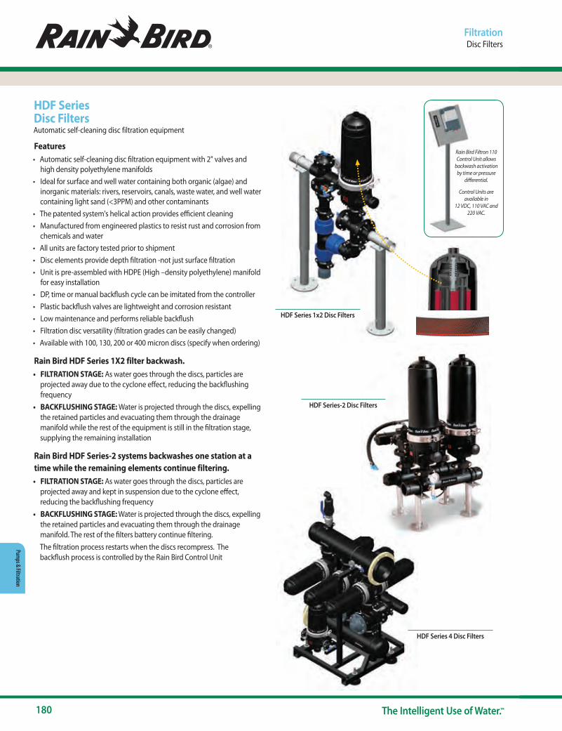
180 The Intelligent Use of Water.™
Pumps & Filtration
HDF Series Disc FiltersAutomatic self-cleaning disc filtration equipment
Features• Automatic self-cleaning disc filtration equipment with 2" valves and
high density polyethylene manifolds• Ideal for surface and well water containing both organic (algae) and
inorganic materials: rivers, reservoirs, canals, waste water, and well water containing light sand (<3PPM) and other contaminants
• The patented system's helical action provides efficient cleaning• Manufactured from engineered plastics to resist rust and corrosion from
chemicals and water• All units are factory tested prior to shipment• Disc elements provide depth filtration -not just surface filtration• Unit is pre-assembled with HDPE (High –density polyethylene) manifold
for easy installation• DP, time or manual backflush cycle can be imitated from the controller• Plastic backflush valves are lightweight and corrosion resistant• Low maintenance and performs reliable backflush• Filtration disc versatility (filtration grades can be easily changed)• Available with 100, 130, 200 or 400 micron discs (specify when ordering)
Rain Bird HDF Series 1X2 filter backwash.• FILTRATION STAGE: As water goes through the discs, particles are
projected away due to the cyclone effect, reducing the backflushing frequency
• BACKFLUSHING STAGE: Water is projected through the discs, expelling the retained particles and evacuating them through the drainage manifold while the rest of the equipment is still in the filtration stage, supplying the remaining installation
Rain Bird HDF Series-2 systems backwashes one station at a time while the remaining elements continue filtering.• FILTRATION STAGE: As water goes through the discs, particles are
projected away and kept in suspension due to the cyclone effect, reducing the backflushing frequency
• BACKFLUSHING STAGE: Water is projected through the discs, expelling the retained particles and evacuating them through the drainage manifold. The rest of the filters battery continue filtering.
The filtration process restarts when the discs recompress. The backflush process is controlled by the Rain Bird Control Unit
FiltrationDisc Filters
Rain Bird Filtron 110 Control Unit allows
backwash activation by time or pressure
differential.
Control Units are available in
12 VDC, 110 VAC and 220 VAC.
HDF Series 1x2 Disc Filters
HDF Series-2 Disc Filters
HDF Series 4 Disc Filters

www.rainbird.com/Filtration
181www.rainbird.com
Pum
ps &
Filtr
atio
n
FiltrationHDF Series Disc Filters Rain Bird Filtration Controller
Specifications
HDF Series 1x2 Disc Filters• Suited for areas with or without electricity.• Ideal where manual cleaning is troublesome.• Compact design fits in tight spaces.• Control Unit functions on pressure differential or time.• Automatic self-cleaning 2” filter for low flow ranges.• Maximum Flow: 106 gpm (24 m3/h)• Maximum filtering surface (231 in²/1492 cm²).• Maximum pressure: 145 psi (10 bar)• Maximum temperature: 140° F (60° C)• Standard 100 micron : Optional 130, 200 or 400 micron.
HDF Series 2 Disc Filters• Suitable for surface and well waters containing both organic (algae) and
inorganic materials. - Rivers, reservoirs, canals and waste water
• Well water containing light sand (<3 PPM) and other contaminants.• Maximum flow: 848 gpm (192 m3/h) - 106 gpm (24 m3/h) per filter
element. Max flow is based on 200 micron discs and good water quality source (< 20 ppm solids). Flow is de-rated based on water source and filtration level. Consult Rain Bird for sizing information
• Maximum filtering surface: (231 in²/1492 cm²)• Maximum pressure: 145 psi (10 bar)• Maximum temperature: 140° F (60° C)• Standard: 100 micron. Optional: 20, 50, 130, 200 or 400 micron.
Control UnitsRain Bird Filtron 11 O with integrated pressure differential switch allows backwash activation by time or pressure differential. Controllers are available in 12 VDC, 11 O VAC and 220 VAC.
Model NumberNumber of Filters Manifold
Filtering Surface (in) (cm)
1X2/2G 1-2"Inlet: 2" PVC
Outlet: 2" NPTDrainage: 2: NPT
231 1492
Model NumberNumber of Filters Manifold
Filtering Surface (in) (cm)
2X2/3G 2 3”- GROOVED 463 2,984
3X2/4G 3 4”- GROOVED 694 4,476
4X2/6G 4 6”- GROOVED 925 5,968
5X2/6G 5 6”- GROOVED 1,156 7,460
6X2/6G 6 6”- GROOVED 1,388 8,952
7X2/6G 7 6”- GROOVED 1,619 10,444
8X2/8G 8 8”- GROOVED 1,850 11,936
INPUT115 - 230VAC
12 - 15VDC230VAC (optional)
OUTPUT24VAC, 12VDC
FEATURESUp to Two (2) stations plus master valve
Input voltage 115, 230 VAC (optional) 12VDCOutput selectable to operate 24VAC, 12VDC solenoids
Pressure differential (PD) gauge includedFixed PD delay
Resettable backwash countResettable alarm
Plastic outdoor boxPeriodic, manual, or pressure differential (PD) actuation
Accurate timingSimple programming
Drainage manifolds included.Consult factory for other configurations.Rain Bird reserves the right to change the characteristics of these products without prior notice.
HDF Series 4 Disc Filtration systems for flows over 848 GPM (192 m3/h) quoted upon request.
Rain Bird Filtration Controller
HDF Series 1x2 Disc Filters Specifications
HDF Series 2 Disc Filters Specifications
F2 AC/DC-P Specifications

182 The Intelligent Use of Water.™
Drainage Products
Drainage
• Installing a well-designed drainage system will result in the collection and capture of rain, runoff water and standing water from the site.
• The collected water can then be directed to an on-site storage tank, treated (if required) and pumped on an “as needed” basis to feed a Rain Bird water efficient irrigation system.
• Drainage systems can reduce damage to structures by directing water away from the foundation of the structure to a more desirable area on the site.
• A Rain Bird Drainage Pop-Up Valve (DPUV) can be installed at the lowest point of the piping network to allow for the collected water to slowly percolate into the soil and recharge the ground water supply.
• A properly installed drainage system can eliminate issues on the site caused by rushing or standing water which can result in soil erosion, plant disease and structural damage.
• Remember, water always runs downhill. Make sure that there is at least a 2% elevation difference between the high-end and the low-end of the drainage system.
Water Saving Tips
Spray & Rotary NozzlesRotors
ValvesControllers
Sensors & Meters
Central ControlsDrip Irrigation
Pumps & Filtration
Drainage ProductsResources
IntroductionSpray Bodies
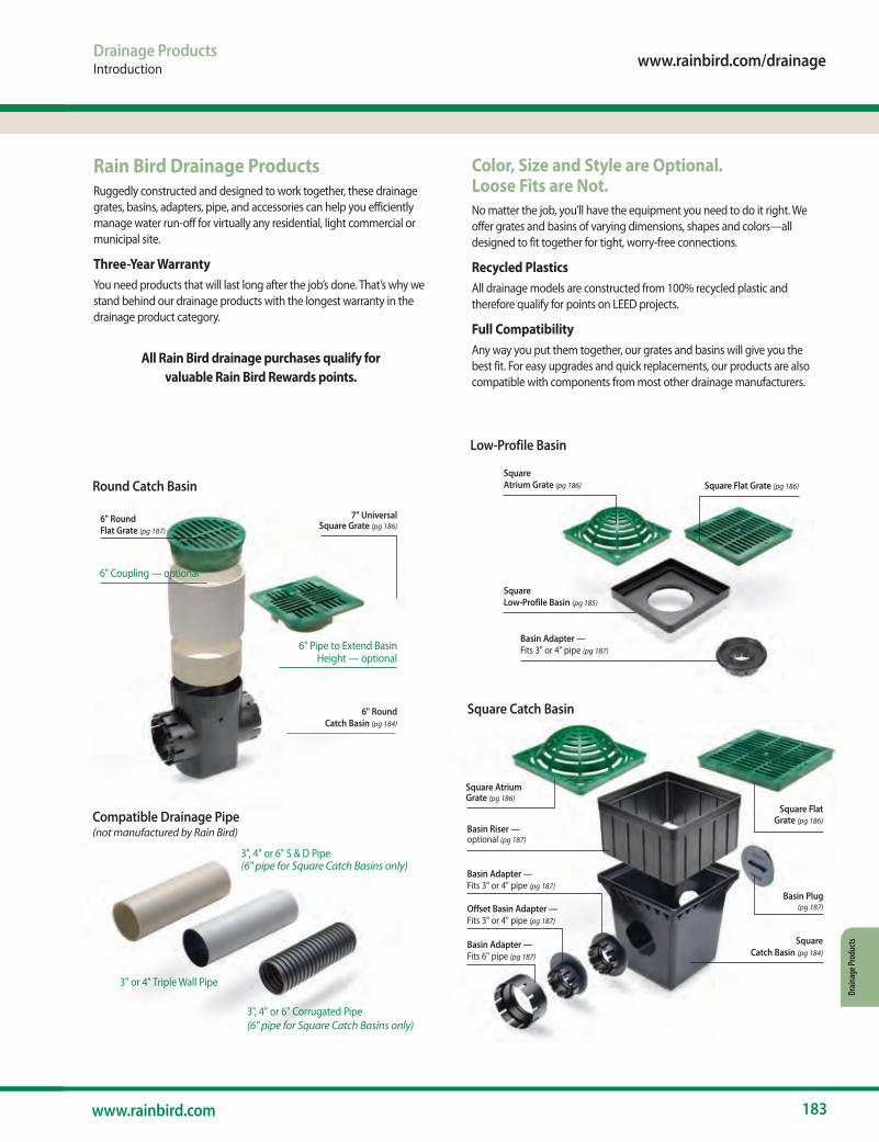
www.rainbird.com/drainage
183www.rainbird.com
Drain
age P
rodu
cts
Compatible Drainage Pipe (not manufactured by Rain Bird)
3", 4" or 6" Corrugated Pipe(6" pipe for Square Catch Basins only)
3" or 4" Triple Wall Pipe
3", 4" or 6" S & D Pipe(6" pipe for Square Catch Basins only)
Drainage ProductsIntroduction
Low-Profile Basin
Basin Adapter — Fits 3" or 4" pipe (pg 187)
Square Atrium Grate (pg 186)
Square Low-Profile Basin (pg 185)
Square Flat Grate (pg 186)
Square Catch Basin
Basin Riser — optional (pg 187)
Square Flat Grate (pg 186)
Basin Adapter — Fits 3" or 4" pipe (pg 187)
Basin Plug (pg 187)
Square Catch Basin (pg 184)
Offset Basin Adapter — Fits 3" or 4" pipe (pg 187)
Basin Adapter — Fits 6" pipe (pg 187)
Square Atrium Grate (pg 186)
7" Universal Square Grate (pg 186)
6" Round Catch Basin (pg 184)
6" Coupling — optional
6" Round Flat Grate (pg 187)
6" Pipe to Extend Basin Height — optional
Round Catch Basin
Rain Bird Drainage ProductsRuggedly constructed and designed to work together, these drainage grates, basins, adapters, pipe, and accessories can help you efficiently manage water run-off for virtually any residential, light commercial or municipal site.
Three-Year WarrantyYou need products that will last long after the job’s done. That’s why we stand behind our drainage products with the longest warranty in the drainage product category.
All Rain Bird drainage purchases qualify for valuable Rain Bird Rewards points.
Color, Size and Style are Optional. Loose Fits are Not.No matter the job, you’ll have the equipment you need to do it right. We offer grates and basins of varying dimensions, shapes and colors—all designed to fit together for tight, worry-free connections.
Recycled PlasticsAll drainage models are constructed from 100% recycled plastic and therefore qualify for points on LEED projects.
Full CompatibilityAny way you put them together, our grates and basins will give you the best fit. For easy upgrades and quick replacements, our products are also compatible with components from most other drainage manufacturers.
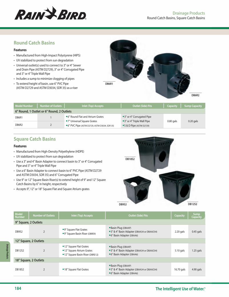
184 The Intelligent Use of Water.™
Drainage Products
DB6R2
DB6R1
DB9S2 DB12S2
DB18S2
Drainage ProductsRound Catch Basins, Square Catch Basins
Round Catch BasinsFeatures• Manufactured from High-Impact Polystyrene (HIPS)• UV stabilized to protect from sun degradation• Universal outlet(s) used to connect to 3" or 4" Sewer
and Drain Pipe (ASTM D2729), 3" or 4" Corrugated Pipe and 3" or 4" Triple Wall Pipe
• Includes a sump to minimize clogging of pipes• To extend height of basin, use 6" PVC Pipe
(ASTM D2729 and ASTM D3034, SDR 35) as a riser
6" Round, 1 Outlet or 6" Round, 2 Outlets
DB6R1 1 • 6" Round Flat and Atrium Grates• 7" Universal Square Grates• 6" PVC Pipe (ASTM D2729, ASTM D3034, SDR 35)
• 3" or 4" Corrugated Pipe• 3" or 4" Triple Wall Pipe• S & D Pipe (ASTM D2729)
0.80 gals 0.20 galsDB6R2 2
Model Number Number of Outlets Inlet (Top) Accepts Outlet (Side) Fits Capacity Sump Capacity
Square Catch BasinsFeatures• Manufactured from High-Density Polyethylene (HDPE)• UV stabilized to protect from sun degradation• Use a 3" and 4" Basin Adapter to connect basin to 3" or 4" Corrugated
Pipe and 3" or 4" Triple Wall Pipe• Use a 6" Basin Adapter to connect basin to 6" PVC Pipe (ASTM D2729
and ASTM D3034, SDR 35) and 6" Corrugated Pipe• Use 9" or 12" Square Basin Riser(s) to extend height of 9" and 12" Square
Catch Basins by 6" in height, respectively• Accepts 9", 12" or 18" Square Flat and Square Atrium grates
9" Square, 2 Outlets
DB9S2 2• 9" Square Flat Grates• 9" Square Basin Riser (DBRE9)
• Basin Plug (DBAAP)• 3" & 4" Basin Adapter (DBAA34 or DBAAO34)• 6" Basin Adapter (DBAA6)
2.20 gals 0.45 gals
12" Square, 2 Outlets
DB12S2 2• 12" Square Flat Grates• 12" Square Atrium Grates• 12" Square Basin Riser (DBRE12)
• Basin Plug (DBAAP)• 3" & 4" Basin Adapter (DBAA34 or DBAAO34)• 6" Basin Adapter (DBAA6)
5.10 gals 1.25 gals
18" Square, 2 Outlets
DB18S2 2 • 18" Square Flat Grates• Basin Plug (DBAAP)• 3" & 4" Basin Adapter (DBAA34 or DBAAO34)• 6" Basin Adapter (DBAA6)
16.70 gals 4.90 gals
Model Number Number of Outlets Inlet (Top) Accepts Outlet (Side) Fits Capacity Sump
Capacity
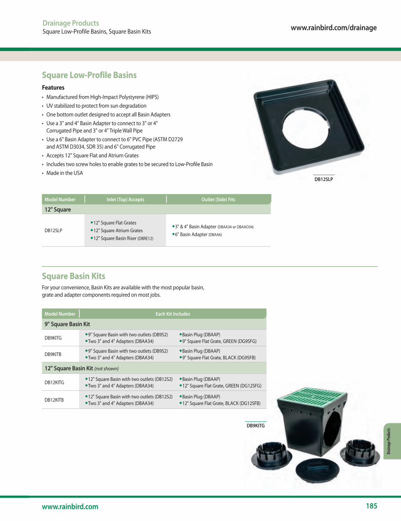
www.rainbird.com/drainage
185www.rainbird.com
Drain
age P
rodu
cts
Drainage ProductsSquare Low-Profile Basins, Square Basin Kits
Square Low-Profile BasinsFeatures• Manufactured from High-Impact Polystyrene (HIPS)• UV stabilized to protect from sun degradation• One bottom outlet designed to accept all Basin Adapters• Use a 3" and 4" Basin Adapter to connect to 3" or 4"
Corrugated Pipe and 3" or 4" Triple Wall Pipe• Use a 6" Basin Adapter to connect to 6" PVC Pipe (ASTM D2729
and ASTM D3034, SDR 35) and 6" Corrugated Pipe• Accepts 12" Square Flat and Atrium Grates• Includes two screw holes to enable grates to be secured to Low-Profile Basin• Made in the USA
Square Basin KitsFor your convenience, Basin Kits are available with the most popular basin, grate and adapter components required on most jobs.
12" Square
DB12SLP• 12" Square Flat Grates• 12" Square Atrium Grates• 12" Square Basin Riser (DBRE12)
• 3" & 4" Basin Adapter (DBAA34 or DBAAO34)
• 6" Basin Adapter (DBAA6)
9" Square Basin Kit
DB9KITG• 9" Square Basin with two outlets (DB9S2)• Two 3" and 4" Adapters (DBAA34)
• Basin Plug (DBAAP)• 9" Square Flat Grate, GREEN (DG9SFG)
DB9KITB• 9" Square Basin with two outlets (DB9S2)• Two 3" and 4" Adapters (DBAA34)
• Basin Plug (DBAAP)• 9" Square Flat Grate, BLACK (DG9SFB)
12" Square Basin Kit (not shown)
DB12KITG• 12" Square Basin with two outlets (DB12S2)• Two 3" and 4" Adapters (DBAA34)
• Basin Plug (DBAAP)• 12" Square Flat Grate, GREEN (DG12SFG)
DB12KITB• 12" Square Basin with two outlets (DB12S2)• Two 3" and 4" Adapters (DBAA34)
• Basin Plug (DBAAP)• 12" Square Flat Grate, BLACK (DG12SFB)
DB12SLP
DB9KITG
Model Number Inlet (Top) Accepts Outlet (Side) Fits
Model Number Each Kit Includes
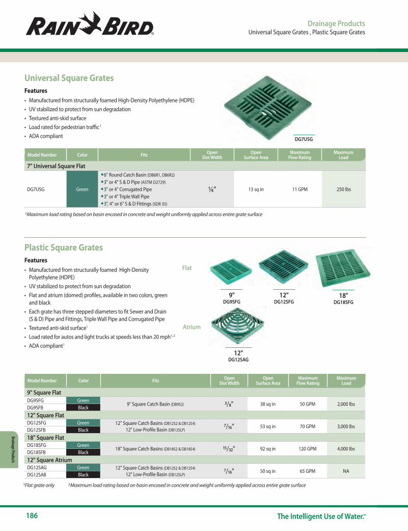
186 The Intelligent Use of Water.™
Drainage Products
Drainage ProductsUniversal Square Grates , Plastic Square Grates
Plastic Square GratesFeatures• Manufactured from structurally foamed High-Density
Polyethylene (HDPE) • UV stabilized to protect from sun degradation• Flat and atrium (domed) profiles, available in two colors, green
and black • Each grate has three stepped diameters to fit Sewer and Drain
(S & D) Pipe and Fittings, Triple Wall Pipe and Corrugated Pipe• Textured anti-skid surface1 • Load rated for autos and light trucks at speeds less than 20 mph1, 2 • ADA compliant1
Flat
Atrium
9" DG9SFG
12" DG12SFG
12" DG12SAG
18" DG18SFG
9" Square FlatDG9SFG Green
9" Square Catch Basin (DB9S2) 3/8" 38 sq in 50 GPM 2,000 lbsDG9SFB Black12" Square FlatDG12SFG Green 12" Square Catch Basins (DB12S2 & DB12S4)
12" Low-Profile Basin (DB12SLP) 7/16" 53 sq in 70 GPM 3,000 lbsDG12SFB Black18" Square FlatDG18SFG Green
18" Square Catch Basins (DB18S2 & DB18S4) 15/32" 92 sq in 120 GPM 4,000 lbsDG18SFB Black12" Square AtriumDG12SAG Green 12" Square Catch Basins (DB12S2 & DB12S4)
12" Low-Profile Basin (DB12SLP) 7/16" 50 sq in 65 GPM NADG12SAB Black
1 Flat grate only 2 Maximum load rating based on basin encased in concrete and weight uniformly applied across entire grate surface
Model Number Color Fits Open Slot Width
Open Surface Area
Maximum Flow Rating
Maximum Load
Universal Square GratesFeatures• Manufactured from structurally foamed High-Density Polyethylene (HDPE)• UV stabilized to protect from sun degradation• Textured anti-skid surface• Load rated for pedestrian traffic 1
• ADA compliant
7" Universal Square Flat
DG7USG Green
• 6" Round Catch Basin (DB6R1, DB6R2)
• 3" or 4" S & D Pipe (ASTM D2729)
• 3" or 4" Corrugated Pipe• 3" or 4" Triple Wall Pipe• 3", 4" or 6" S & D Fittings (SDR 35)
¼" 13 sq in 11 GPM 250 lbs
DG7USG
1 Maximum load rating based on basin encased in concrete and weight uniformly applied across entire grate surface
Model Number Color Fits Open Slot Width
Open Surface Area
Maximum Flow Rating
Maximum Load
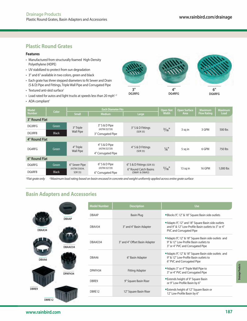
www.rainbird.com/drainage
187www.rainbird.com
Drain
age P
rodu
cts
Drainage ProductsPlastic Round Grates, Basin Adapters and Accessories
Plastic Round GratesFeatures• Manufactured from structurally foamed High-Density
Polyethylene (HDPE) • UV stabilized to protect from sun degradation• 3" and 6" available in two colors, green and black • Each grate has three stepped diameters to fit Sewer and Drain
(S & D) Pipe and Fittings, Triple Wall Pipe and Corrugated Pipe• Textured anti-skid surface1 • Load rated for autos and light trucks at speeds less than 20 mph1, 2 • ADA compliant1
3" DG3RFG
4" DG4RFG
3" Round Flat
DG3RFG Green 3" Triple Wall Pipe
3" S & D Pipe (ASTM D2729)
3" Corrugated Pipe
3" S & D Fittings (SDR 35) 3/16" 3 sq in 3 GPM 500 lbs
DG3RFB Black
4" Round Flat
DG4RFG Green 4" Triple Wall Pipe
4" S & D Pipe (ASTM D2729)
4" Corrugated Pipe
4" S & D Fittings (SDR 35) ¼" 5 sq in 6 GPM 750 lbs
6" Round Flat
DG6RFG Green 6" Sewer Pipe (ASTM D3034,
SDR 35)
6" S & D Pipe (ASTM D2729)
6" Corrugated Pipe
6" S & D Fittings (SDR 35)
6" Round Catch Basins (DB6R1 & DB6R2)
5/16" 13 sq in 16 GPM 1,000 lbsDG6RFB Black
1 Flat grate only 2 Maximum load rating based on basin encased in concrete and weight uniformly applied across entire grate surface
6" DG6RFG
Model Number Color
Each Diameter Fits Open Slot Width
Open Surface Area
Maximum Flow Rating
Maximum LoadSmall Medium Large
DBAAP
DBAA34
DBAAO34
DBAA6
DPAFH34
DBRE12
Basin Adapters and Accessories
DBAAP Basin Plug • Blocks 9", 12" & 18" Square Basin side outlets
DBAA34 3" and 4" Basin Adapter• Adapts 9", 12" and 18" Square Basin side outlets
and 9" & 12" Low-Profile Basin outlets to 3" or 4" PVC and Corrugated Pipe
DBAAO34 3" and 4" Offset Basin Adapter• Adapts 9", 12" & 18" Square Basin side outlets and
9" & 12" Low-Profile Basin outlets to 3" or 4" PVC and Corrugated Pipe
DBAA6 6" Basin Adapter• Adapts 9", 12" & 18" Square Basin side outlets and
9" & 12" Low-Profile Basin outlets to 6" PVC and Corrugated Pipe
DPAFH34 Fitting Adapter • Adapts 3" or 4" Triple Wall Pipe to 3" or 4" PVC and Corrugated Pipe
DBRE9 9" Square Basin Riser • Extends height of 9" Square Basin or 9" Low-Profile Basin by 6"
DBRE12 12" Square Basin Riser • Extends height of 12" Square Basin or 12" Low-Profile Basin by 6"
Model Number Description Use
DBRE9
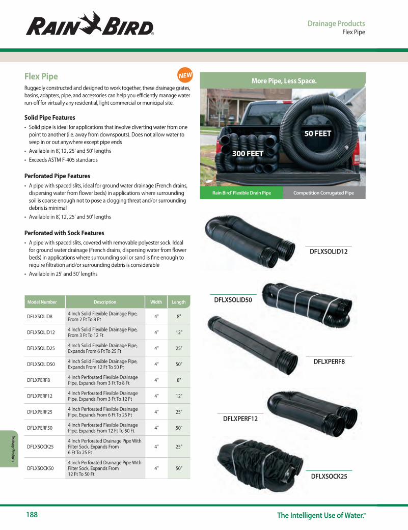
188 The Intelligent Use of Water.™
Drainage Products
Drainage ProductsFlex Pipe
Flex PipeRuggedly constructed and designed to work together, these drainage grates, basins, adapters, pipe, and accessories can help you efficiently manage water run-off for virtually any residential, light commercial or municipal site.
Solid Pipe Features• Solid pipe is ideal for applications that involve diverting water from one
point to another (i.e. away from downspouts). Does not allow water to seep in or out anywhere except pipe ends
• Available in 8’, 12', 25' and 50’ lengths• Exceeds ASTM F-405 standards
Perforated Pipe Features• A pipe with spaced slits, ideal for ground water drainage (French drains,
dispersing water from flower beds) in applications where surrounding soil is coarse enough not to pose a clogging threat and/or surrounding debris is minimal
• Available in 8’, 12', 25' and 50’ lengths
Perforated with Sock Features• A pipe with spaced slits, covered with removable polyester sock. Ideal
for ground water drainage (French drains, dispersing water from flower beds) in applications where surrounding soil or sand is fine enough to require filtration and/or surrounding debris is considerable
• Available in 25' and 50' lengths
DFLXSOLID8 4 Inch Solid Flexible Drainage Pipe, From 2 Ft To 8 Ft 4" 8"
DFLXSOLID12 4 Inch Solid Flexible Drainage Pipe, From 3 Ft To 12 Ft 4" 12"
DFLXSOLID25 4 Inch Solid Flexible Drainage Pipe, Expands From 6 Ft To 25 Ft 4" 25"
DFLXSOLID50 4 Inch Solid Flexible Drainage Pipe, Expands From 12 Ft To 50 Ft 4" 50"
DFLXPERF8 4 Inch Perforated Flexible Drainage Pipe, Expands From 3 Ft To 8 Ft 4" 8"
DFLXPERF12 4 Inch Perforated Flexible Drainage Pipe, Expands From 3 Ft To 12 Ft 4" 12"
DFLXPERF25 4 Inch Perforated Flexible Drainage Pipe, Expands From 6 Ft To 25 Ft 4" 25"
DFLXPERF50 4 Inch Perforated Flexible Drainage Pipe, Expands From 12 Ft To 50 Ft 4" 50"
DFLXSOCK254 Inch Perforated Drainage Pipe With Filter Sock, Expands From 6 Ft To 25 Ft
4" 25"
DFLXSOCK504 Inch Perforated Drainage Pipe With Filter Sock, Expands From 12 Ft To 50 Ft
4" 50"
Model Number Description Width Length
NEW
DFLXSOLID12
DFLXPERF8
DFLXSOLID50
DFLXPERF12
DFLXSOCK25
300 FEET
50 FEET
Rain Bird® Flexible Drain Pipe Competition Corrugated Pipe
® Registered trademark of Rain Bird Corporation © 2019 Rain Bird Corporation 8/19 D41606
More Pipe, Less Space.
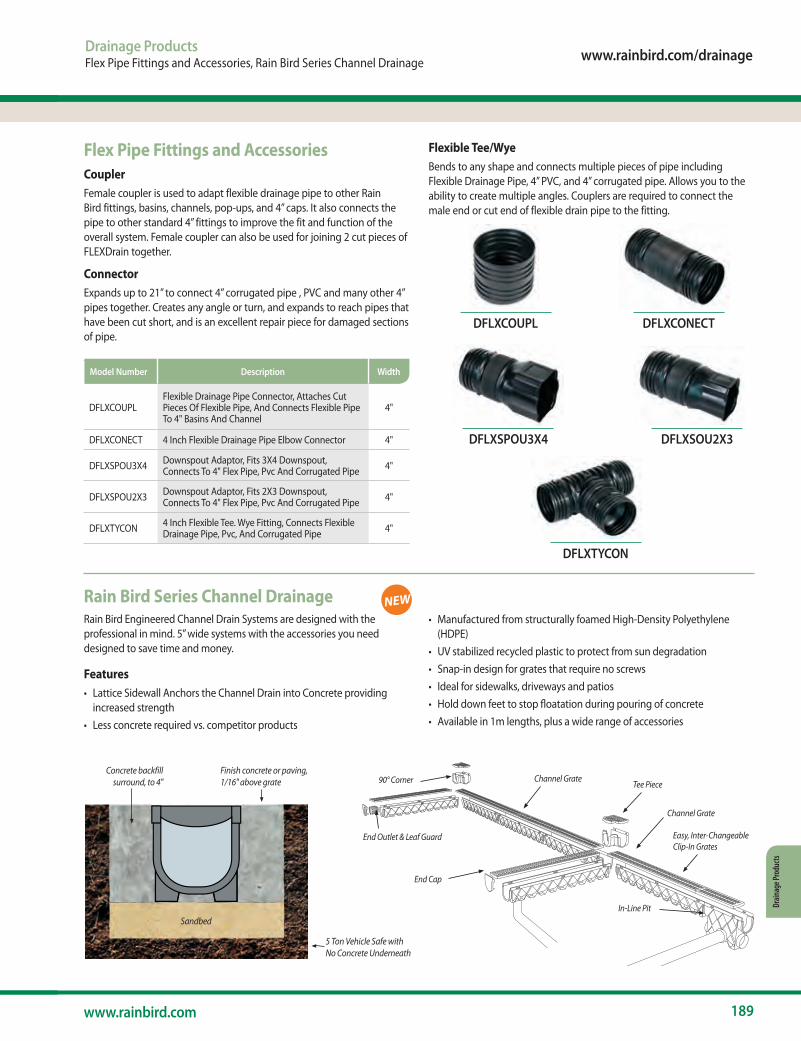
www.rainbird.com/drainage
189www.rainbird.com
Drain
age P
rodu
cts
Drainage ProductsFlex Pipe Fittings and Accessories, Rain Bird Series Channel Drainage
Rain Bird Series Channel DrainageRain Bird Engineered Channel Drain Systems are designed with the professional in mind. 5” wide systems with the accessories you need designed to save time and money.
Features• Lattice Sidewall Anchors the Channel Drain into Concrete providing
increased strength • Less concrete required vs. competitor products
NEW
End Outlet & Leaf Guard
90° Corner Channel GrateTee Piece
Channel Grate
End Cap
In-Line Pit
Easy, Inter-Changeable Clip-In Grates
5 Ton Vehicle Safe with No Concrete Underneath
Concrete backfill surround, to 4"
Finish concrete or paving, 1/16" above grate
Sandbed
• Manufactured from structurally foamed High-Density Polyethylene (HDPE)
• UV stabilized recycled plastic to protect from sun degradation • Snap-in design for grates that require no screws• Ideal for sidewalks, driveways and patios• Hold down feet to stop floatation during pouring of concrete• Available in 1m lengths, plus a wide range of accessories
Flex Pipe Fittings and AccessoriesCouplerFemale coupler is used to adapt flexible drainage pipe to other Rain Bird fittings, basins, channels, pop-ups, and 4” caps. It also connects the pipe to other standard 4” fittings to improve the fit and function of the overall system. Female coupler can also be used for joining 2 cut pieces of FLEXDrain together.
ConnectorExpands up to 21” to connect 4” corrugated pipe , PVC and many other 4” pipes together. Creates any angle or turn, and expands to reach pipes that have been cut short, and is an excellent repair piece for damaged sections of pipe.
DFLXCOUPLFlexible Drainage Pipe Connector, Attaches Cut Pieces Of Flexible Pipe, And Connects Flexible Pipe To 4" Basins And Channel
4"
DFLXCONECT 4 Inch Flexible Drainage Pipe Elbow Connector 4"
DFLXSPOU3X4 Downspout Adaptor, Fits 3X4 Downspout, Connects To 4" Flex Pipe, Pvc And Corrugated Pipe 4"
DFLXSPOU2X3 Downspout Adaptor, Fits 2X3 Downspout, Connects To 4" Flex Pipe, Pvc And Corrugated Pipe 4"
DFLXTYCON 4 Inch Flexible Tee. Wye Fitting, Connects Flexible Drainage Pipe, Pvc, And Corrugated Pipe 4"
Model Number Description Width
Flexible Tee/WyeBends to any shape and connects multiple pieces of pipe including Flexible Drainage Pipe, 4” PVC, and 4” corrugated pipe. Allows you to the ability to create multiple angles. Couplers are required to connect the male end or cut end of flexible drain pipe to the fitting.
DFLXCONECT
DFLXSPOU3X4
DFLXTYCON
DFLXCOUPL
DFLXSOU2X3
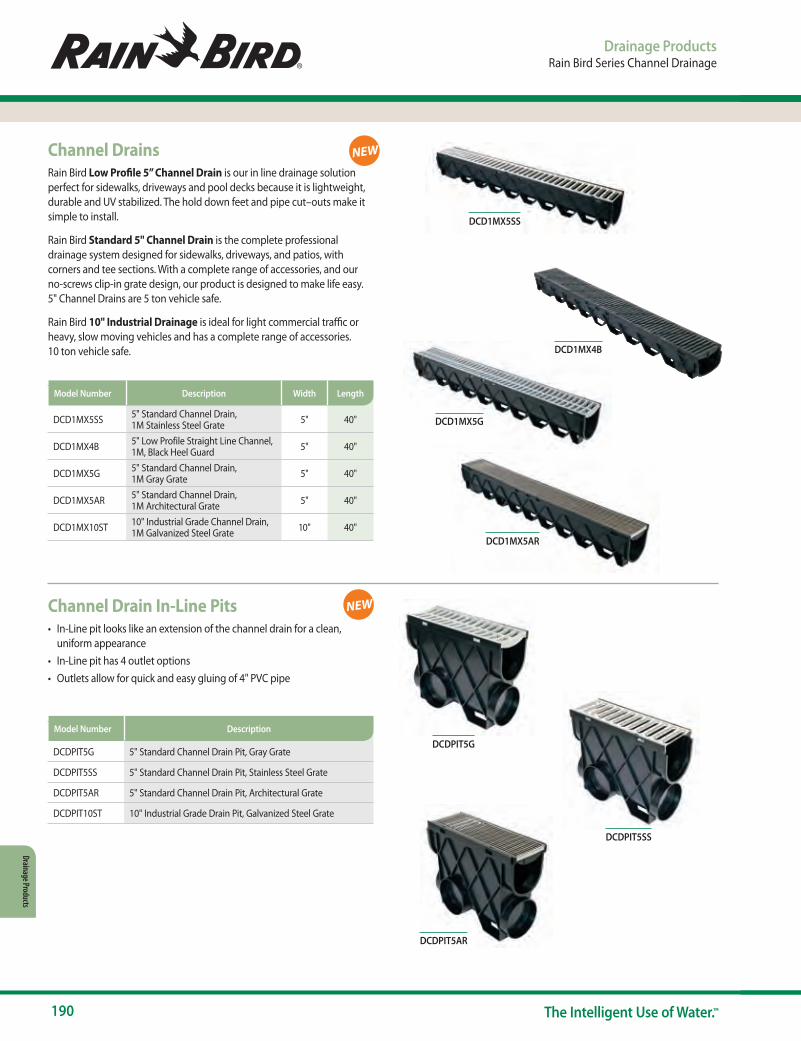
190 The Intelligent Use of Water.™
Drainage Products
Drainage ProductsRain Bird Series Channel Drainage
Channel DrainsRain Bird Low Profile 5” Channel Drain is our in line drainage solution perfect for sidewalks, driveways and pool decks because it is lightweight, durable and UV stabilized. The hold down feet and pipe cut–outs make it simple to install.
Rain Bird Standard 5" Channel Drain is the complete professional drainage system designed for sidewalks, driveways, and patios, with corners and tee sections. With a complete range of accessories, and our no-screws clip-in grate design, our product is designed to make life easy. 5" Channel Drains are 5 ton vehicle safe.
Rain Bird 10" Industrial Drainage is ideal for light commercial traffic or heavy, slow moving vehicles and has a complete range of accessories. 10 ton vehicle safe.
Channel Drain In-Line Pits• In-Line pit looks like an extension of the channel drain for a clean,
uniform appearance• In-Line pit has 4 outlet options• Outlets allow for quick and easy gluing of 4" PVC pipe
DCDPIT5G 5" Standard Channel Drain Pit, Gray Grate
DCDPIT5SS 5" Standard Channel Drain Pit, Stainless Steel Grate
DCDPIT5AR 5" Standard Channel Drain Pit, Architectural Grate
DCDPIT10ST 10" Industrial Grade Drain Pit, Galvanized Steel Grate
Model Number Description
DCD1MX5SS 5" Standard Channel Drain, 1M Stainless Steel Grate 5" 40"
DCD1MX4B 5" Low Profile Straight Line Channel, 1M, Black Heel Guard 5" 40"
DCD1MX5G 5" Standard Channel Drain, 1M Gray Grate 5" 40"
DCD1MX5AR 5" Standard Channel Drain, 1M Architectural Grate 5" 40"
DCD1MX10ST 10" Industrial Grade Channel Drain, 1M Galvanized Steel Grate 10" 40"
Model Number Description Width Length
NEW
NEW
DCD1MX5SS
DCDPIT5G
DCDPIT5AR
DCDPIT5SS
DCD1MX4B
DCD1MX5G
DCD1MX5AR
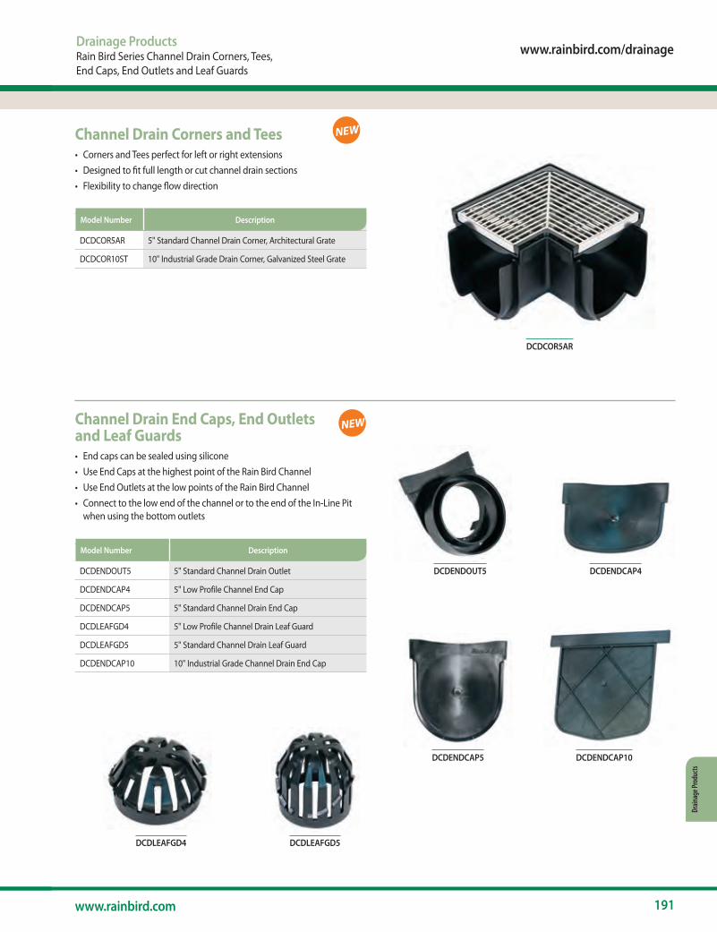
www.rainbird.com/drainage
191www.rainbird.com
Drain
age P
rodu
cts
Channel Drain Corners and Tees• Corners and Tees perfect for left or right extensions• Designed to fit full length or cut channel drain sections• Flexibility to change flow direction
Channel Drain End Caps, End Outlets and Leaf Guards• End caps can be sealed using silicone• Use End Caps at the highest point of the Rain Bird Channel• Use End Outlets at the low points of the Rain Bird Channel• Connect to the low end of the channel or to the end of the In-Line Pit
when using the bottom outlets
DCDENDOUT5 5" Standard Channel Drain Outlet
DCDENDCAP4 5" Low Profile Channel End Cap
DCDENDCAP5 5" Standard Channel Drain End Cap
DCDLEAFGD4 5" Low Profile Channel Drain Leaf Guard
DCDLEAFGD5 5" Standard Channel Drain Leaf Guard
DCDENDCAP10 10" Industrial Grade Channel Drain End Cap
Model Number Description
DCDCOR5AR 5" Standard Channel Drain Corner, Architectural Grate
DCDCOR10ST 10" Industrial Grade Drain Corner, Galvanized Steel Grate
Model Number Description
DCDCOR5AR
DCDENDCAP10
Drainage ProductsRain Bird Series Channel Drain Corners, Tees, End Caps, End Outlets and Leaf Guards
NEW
NEW
DCDENDOUT5
DCDENDCAP5
DCDENDCAP4
DCDLEAFGD5DCDLEAFGD4

192 The Intelligent Use of Water.™
Drainage Products
Drainage ProductsDrainage Pop-Up Valves, Accessories
Drainage Pop-Up ValvesFeatures• Available in four configurations• Pop-up valve body manufactured from structurally foamed High-Density Polyethylene (HDPE)• Elbow (where applicable) manufactured from PVC• Adapter (where applicable) manufactured from High Impact Polystyrene (HIPS)• UV stabilized to protect from sun degradation• Spring-loaded cover rises ½" to discharge excess water in system• Spring automatically retracts cover to closed position after excess water is discharged• Can be used in both vertical and horizontal position• Stainless steel spring to prevent rusting• PVC elbows (where applicable) include a ¼" drain hole to eliminate standing water• Made in the USA
Accessories
DPUV3E
DPUV4EHUB
SOAKWELL
DSOAKSOCK
DPUV3E Green Drainage Pop-Up Valve with 3" PVC Elbow• 3" S & D Pipe (ASTM D2729)
• 3" Triple Wall Pipe
DPUV4EHUB Green Drainage Pop-Up Valve with 4" PVC Elbow and Adapter (DPAFHA34)
• 3" or 4" Corrugated Pipe• 3" or 4" Triple Wall Pipe• 3" or 4" S & D Pipe (ASTM D2729)
Model Number Color Description Connects To
Soakwell• High strength reinforced polymer• Collects and reuses unwanted storm water runoff• Drainage slots provide maximum water flow to surrounding soil• 3 Piece design makes for easier installation and transport• Strong but lightweight lid replaces concrete lid for easier installation
DSOAKWELL 26.75” Diameter x 31.75” H Soakwell Base 6.61
DSOAKLID 26.75” Diameter Soakwell Lid 3.09
DSOAKSOCK Soakwell Sock 0.22
Model Number Description Color
DSOAKLID

www.rainbird.com
193www.rainbird.com
Reso
urce
s
Programs and Marketing Resources Contacts/Information
Design and Specification Resources www.rainbird.com/documents/professionals
Distributor Portal Website www.rainbird.com/turfdistributor
Public and Non-Profit Agencies Portal www.rainbird.com/agency
Facebook www.facebook.com/RainBirdCorp
Intelligent Use of Water™ www.rainbird.com/corporate/intelligent-use-water
LEED Library www.rainbird.com/LEED
Rain Bird Logo www.rainbird.com/corporate/rain-bird-logo
Product Catalog www.rainbird.com/catalog
Product Literature and Tech Specs www.rainbird.com/documents/professionals
Rain Bird Agency Rewards (non-profits and government agencies) www.rainbird.com/agency • E-mail: [email protected]
Rain Bird Rewards www.rainbird.com/Rewards • E-mail: [email protected]
Rain Bird Training Services www.rainbirdservices.com
Rain Bird Replacement Parts www.rainbird.com/parts
Twitter www.twitter.com/rainbirdcorp
Water Efficiency Calculators www.rainbird.com/professionals/calculators
Site Reports www.rainbird.com/sitereports
YouTube www.youtube.com/rainbirdcorp
Resources
Rain Bird Online Resources and Contacts List
Spra
y & Ro
tary
Noz
zles
Roto
rsVa
lves
Cont
rolle
rsSe
nsor
s & M
eter
sCe
ntra
l Con
trols
Drip
Irrig
atio
nPu
mps
& Fi
ltrat
ion
Drain
age P
rodu
cts
Reso
urce
sIn
trodu
ctio
nSp
ray B
odies

194 The Intelligent Use of Water.™
Resources
ResourcesRain Bird Training Services
Rain Bird Training ServicesDedicated to the Development of Irrigation Professionals
To learn more, visit: www.rainbirdservices.com
Factory Trained
Your Name Here
WAT E R E F FI C IE NC Y E X PE RT
Rain Bird Live and Online
Rain Bird Live Streaming Rain Bird Brings the classroom to you• Short pre-scheduled classes that cover relevant
irrigation topics• Make the most of your time and let Rain Bird bring
training to you• Live pre-scheduled training taught by professional
irrigation trainers• Not another sales webinar, we provide interactive virtual
classroom training
Rain Bird Online Training
Rain Bird Basics Online • For people with little to no irrigation experience• Non-manufacturer specific training, not just Rain Bird • The basics of irrigation adjustments, repairs and operation
Rain Bird Technical Online • In-depth technical irrigation training anytime, anywhere • Best practices for installing, operating, and maintaining
irrigation systems• Pass the Factory Trained exam and you will earn a Factory
Trained designation and certificate
Rain Bird Classroom Training
Rain Bird AcademyGeneral Irrigation Skills Training• Top quality training on many manufacturers’ products • Prepare for Irrigation Association (IA) exams• The Rain Bird Academy Boot Camp delivers the basics of
irrigation in one week - Boot Camp classes are part of the IA Select Program
Rain Bird Factory TrainedComprehensive Training on Rain Bird Products • Training is exclusive to Rain Bird Products• Be an expert on installing, managing and maintaining
Rain Bird irrigation systems• Get the designation that proves to your customers that
you are the best choice to do the job

www.rainbird.com
195www.rainbird.com
Reso
urce
s
Rain Bird RewardsSupporting Your Business Success and Growth
You’re working hard to build a successful business and Rain Bird Rewards is here to reward you. We have the benefits and tools you can use to attract new customers, train your employees and reduce costs. Reinvesting in your company and its future success has never been so easy.
Join today — and get the benefits you need to take your business to the next level.
Help Your Business SucceedTools to grow your business.• Use Rain Bird marketing materials to align your business with the
industry leader
Rewards you deserve.• Points can be redeemed to reward your hard work and help you build a
successful business
Training discounts.• Receive 20% off professional-level training from Rain Bird Training
Services
Reward for Your Hard WorkLet Rain Bird reward your growing business
now and in the future.
Customer Service At Rain Bird, we believe that when you purchase our products, you should also receive the support you need to ensure that they perform as designed. Like our products, Rain Bird customer service is designed to exceed expectations. When you call with questions about orders or new products, you get the support you need from the top water management professionals in the industry, backed by our vast global network of distributor-partners.
Worry-Free WarrantiesOur comprehensive product warranties make it even easier to choose Rain Bird and relax. Most Rain Bird Landscape Irrigation products are warranted to the trade for a period of either three or five years from the date of original purchase. A Rain Bird warranty is hassle-free support that enables maximum peak performance by irrigation system professionals. For you, it’s the added peace of mind of knowing Rain Bird is there when you need it.
Rain Bird’s Professional Customer Satisfaction PolicyRain Bird will repair or replace at no charge any Rain Bird professional product that fails in normal use within the warranty period stated below. You must return it to the dealer or distributor where you bought it. Product failures due to acts of God including without limitation, lightning and flooding, are not covered by this warranty. This commitment to repair or replace is our sole and total warranty.
ResourcesRain Bird Rewards, Customer Service and Warranties
For more information, see your Rain Bird Distributor. To find the nearest authorized distributor in your area, visit www.rainbird.com or call 1-800-RAINBIRD
* XF Series Dripline - 7 Years on Environmental Stress Cracking (ESCR)
Implied Warranties of Merchantability and Fitness, if Applicable, are Limited to One Year from the Date of Sale.
We will not, under any circumstances be liable for incidental or consequential damages, no matter how they occur.
I. Landscape Irrigation and Drainage Products1800 Series Pop-Up Spray Heads, U-Series Nozzles, PA-8S and PA-8S-PRS Shrub Adapters, 1300 and 1400 Bubblers, 5000 Series Rotors, 5500 Series Rotors, 8005 Series Rotors, Falcon® 6504 Series Rotors, PEB/PESB/PESB-R Plastic Valves, DV/DVF and ASVF Plastic Valves, VB Series Valve Boxes, Internet Connected Water Meters (ICWM), and XF Series Dripline* – 5 years
C2 Power Unit – 2 years
Pump Start Relays – 1 year for controls/electronics, 2 years for enclosure
All other Landscape Irrigation and Drainage products – 3 years
II. Golf Products, Agricultural Products, and Pump StationsFor complete information and details please visit: http://www.rainbird.com/corporate/CustomerSatisfactionPolicy.htm
III. All Other Products - 1 year
R E W A R D SRain Bird®
P R O F E S S I O N A L
Enroll today at ww2.rainbird.com/rewards/enrollment.htm
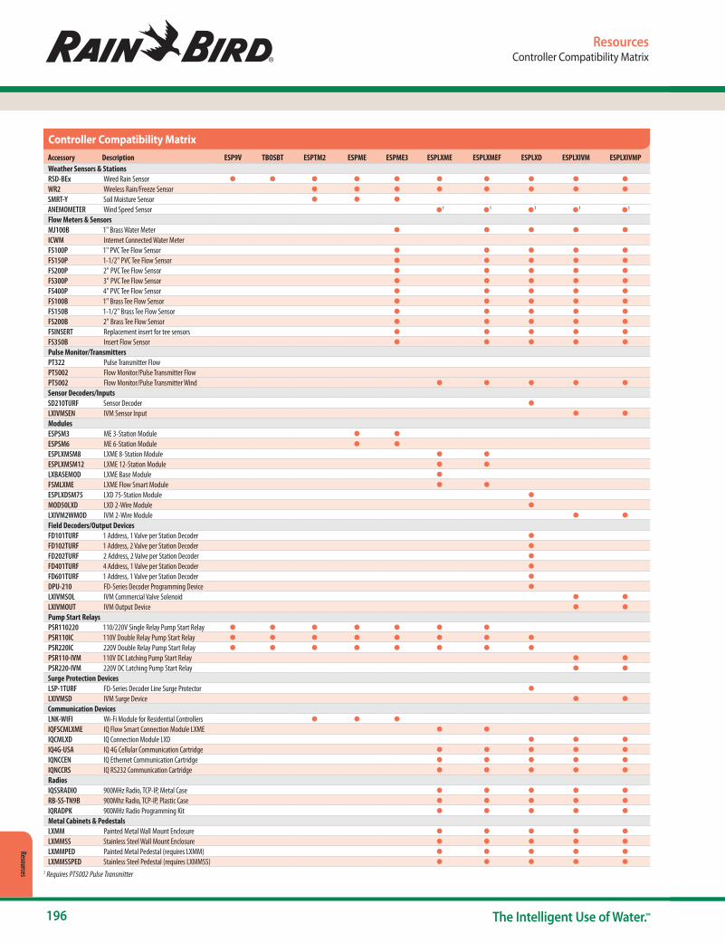
196 The Intelligent Use of Water.™
Resources
ResourcesController Compatibility Matrix
Accessory Description ESP9V TBOSBT ESPTM2 ESPME ESPME3 ESPLXME ESPLXMEF ESPLXD ESPLXIVM ESPLXIVMPWeather Sensors & StationsRSD-BEx Wired Rain Sensor ● ● ● ● ● ● ● ● ● ●
WR2 Wireless Rain/Freeze Sensor ● ● ● ● ● ● ● ●
SMRT-Y Soil Moisture Sensor ● ● ●
ANEMOMETER Wind Speed Sensor ●1 ●1 ●1 ●1 ●1
Flow Meters & SensorsMJ100B 1" Brass Water Meter ● ● ● ● ●
ICWM Internet Connected Water MeterFS100P 1" PVC Tee Flow Sensor ● ● ● ● ●
FS150P 1-1/2" PVC Tee Flow Sensor ● ● ● ● ●
FS200P 2" PVC Tee Flow Sensor ● ● ● ● ●
FS300P 3" PVC Tee Flow Sensor ● ● ● ● ●
FS400P 4" PVC Tee Flow Sensor ● ● ● ● ●
FS100B 1" Brass Tee Flow Sensor ● ● ● ● ●
FS150B 1-1/2" Brass Tee Flow Sensor ● ● ● ● ●
FS200B 2" Brass Tee Flow Sensor ● ● ● ● ●
FSINSERT Replacement insert for tee sensors ● ● ● ● ●
FS350B Insert Flow Sensor ● ● ● ● ●
Pulse Monitor/TransmittersPT322 Pulse Transmitter FlowPT5002 Flow Monitor/Pulse Transmitter FlowPT5002 Flow Monitor/Pulse Transmitter Wind ● ● ● ● ●
Sensor Decoders/InputsSD210TURF Sensor Decoder ●
LXIVMSEN IVM Sensor Input ● ●
ModulesESPSM3 ME 3-Station Module ● ●
ESPSM6 ME 6-Station Module ● ●
ESPLXMSM8 LXME 8-Station Module ● ●
ESPLXMSM12 LXME 12-Station Module ● ●
LXBASEMOD LXME Base Module ●
FSMLXME LXME Flow Smart Module ● ●
ESPLXDSM75 LXD 75-Station Module ●
MOD50LXD LXD 2-Wire Module ●
LXIVM2WMOD IVM 2-Wire Module ● ●
Field Decoders/Output DevicesFD101TURF 1 Address, 1 Valve per Station Decoder ●
FD102TURF 1 Address, 2 Valve per Station Decoder ●
FD202TURF 2 Address, 2 Valve per Station Decoder ●
FD401TURF 4 Address, 1 Valve per Station Decoder ●
FD601TURF 1 Address, 1 Valve per Station Decoder ●
DPU-210 FD-Series Decoder Programming Device ●
LXIVMSOL IVM Commercial Valve Solenoid ● ●
LXIVMOUT IVM Output Device ● ●
Pump Start RelaysPSR110220 110/220V Single Relay Pump Start Relay ● ● ● ● ● ● ●
PSR110IC 110V Double Relay Pump Start Relay ● ● ● ● ● ● ● ●
PSR220IC 220V Double Relay Pump Start Relay ● ● ● ● ● ● ● ●
PSR110-IVM 110V DC Latching Pump Start Relay ● ●
PSR220-IVM 220V DC Latching Pump Start Relay ● ●
Surge Protection DevicesLSP-1TURF FD-Series Decoder Line Surge Protector ●
LXIVMSD IVM Surge Device ● ●
Communication DevicesLNK-WIFI Wi-Fi Module for Residential Controllers ● ● ●
IQFSCMLXME IQ Flow Smart Connection Module LXME ● ●
IQCMLXD IQ Connection Module LXD ● ● ●
IQ4G-USA IQ 4G Cellular Communication Cartridge ● ● ● ● ●
IQNCCEN IQ Ethernet Communication Cartridge ● ● ● ● ●
IQNCCRS IQ RS232 Communication Cartridge ● ● ● ● ●
RadiosIQSSRADIO 900MHz Radio, TCP-IP, Metal Case ● ● ● ● ●
RB-SS-TN9B 900Mhz Radio, TCP-IP, Plastic Case ● ● ● ● ●
IQRADPK 900MHz Radio Programming Kit ● ● ● ● ●
Metal Cabinets & PedestalsLXMM Painted Metal Wall Mount Enclosure ● ● ● ● ●
LXMMSS Stainless Steel Wall Mount Enclosure ● ● ● ● ●
LXMMPED Painted Metal Pedestal (requires LXMM) ● ● ● ● ●
LXMMSSPED Stainless Steel Pedestal (requires LXMMSS) ● ● ● ● ●
Controller Compatibility Matrix
1 Requires PT5002 Pulse Transmitter

www.rainbird.com
197www.rainbird.com
Reso
urce
s
ResourcesCentral Control Compatibility Matrix
IQ with
Maxicom with
Maxicom CCU with
SiteControl TWI with
SiteControl with
ESPLXME ESPLXMEF ESPLXD ESPLXIVM ESPLXIVMP ESPSITE ESPSAT2 ESPSATL ESPSAT2 ESPSATL LDIWeather Sensors & StationsRSD-BEx Wired Rain Sensor ● ● ● ● ● ● ● ● ● ● ●WR2 Wireless Rain/Freeze Sensor ● ● ● ● ● ● ● ● ● ●RAINGAUGE Tipping Rain Gauge Sensor ● ● ● ● ● ●ANEMOMETER Wind Speed Sensor ●1 ●1 ●1 ●1 ●1 ●2 ●2 ●2 ●2 ●2
WSPRO2DC Weather Station (requires modem) ● ● ● ● ● ● ● ● ● ● ●Flow Meters & SensorsMJ100B 1" Brass Water Meter ● ● ● ● ●2 ●2 ●2 ●2 ●2 ●ICWM Internet Connected Water MeterFS100P 1" PVC Tee Flow Sensor ● ● ● ● ●2 ●2 ●2 ●2 ●2 ●FS150P 1-1/2" PVC Tee Flow Sensor ● ● ● ● ●2 ●2 ●2 ●2 ●2 ●FS200P 2" PVC Tee Flow Sensor ● ● ● ● ●2 ●2 ●2 ●2 ●2 ●FS300P 3" PVC Tee Flow Sensor ● ● ● ● ●2 ●2 ●2 ●2 ●2 ●FS400P 4" PVC Tee Flow Sensor ● ● ● ● ●2 ●2 ●2 ●2 ●2 ●FS100B 1" Brass Tee Flow Sensor ● ● ● ● ●2 ●2 ●2 ●2 ●2 ●FS150B 1-1/2" Brass Tee Flow Sensor ● ● ● ● ●2 ●2 ●2 ●2 ●2 ●FS200B 2" Brass Tee Flow Sensor ● ● ● ● ●2 ●2 ●2 ●2 ●2 ●FSINSERT Replacement insert for tee sensors ● ● ● ● ●2 ●2 ●2 ●2 ●2 ●FS350B Insert Flow Sensor ● ● ● ● ●2 ●2 ●2 ●2 ●2 ●Pulse Monitor/TransmittersPT322 Pulse Transmitter ● ●3 ● ●3 ● ●PT5002 Flow Monitor/Pulse Transmitter ● ● ● ● ● ●3 ● ●3 ● ●Sensor Decoders/InputsSD210TURF Sensor Decoder ● ●LXIVMSEN IVM Sensor Input ● ●DECPULLR Pulse Decoder ● ●DECSENLR Sensor Decoder ● ●ModulesESPSM3 ME 3-Station ModuleESPSM6 ME 6-Station ModuleESPLXMSM8 LXME 8-Station Module ● ●ESPLXMSM12 LXME 12-Station Module ● ●LXBASEMOD LXME Base Module ●FSMLXME LXME Flow Smart Module ● ●ESPLXDSM75 LXD 75-Station Module ●MOD50LXD LXD 2-Wire Module ●LXIVM2WMOD IVM 2-Wire Module ● ●Field Decoders/Output DevicesFD101TURF 1 Address, 1 Valve per Station Decoder ● ●FD102TURF 1 Address, 2 Valve per Station Decoder ● ●FD202TURF 2 Address, 2 Valve per Station Decoder ● ●FD401TURF 4 Address, 1 Valve per Station Decoder ● ●FD601TURF 1 Address, 1 Valve per Station Decoder ● ●DPU-210 FD-Series Decoder Programming Device ● ●LXIVMSOL IVM Commercial Valve Solenoid ● ●LXIVMOUT IVM Output Device ● ●Pump Start RelaysPSR110220 110/220V Single Relay Pump Start Relay ● ● ● ● ● ● ● ●PSR110IC 110V Double Relay Pump Start Relay ● ● ● ● ● ● ● ● ●PSR220IC 220V Double Relay Pump Start Relay ● ● ● ● ● ● ● ● ● PSR110-IVM 110V DC Latching Pump Start Relay ● ● PSR220-IVM 220V DC Latching Pump Start Relay ● ●Surge Protection DevicesFSSURGEKIT FS-Series Flow Sensor Surge Protector ● ● ● ● ●LSP-1TURF FD-Series Decoder Line Surge Protector ● ●LXIVMSD IVM Surge Device ● ●Communication DevicesLNK-WIFI Wi-Fi Module for Residential ControllersPBC-LXD ESPLXD Programming Backup Cartridge ●IQFSCMLXME IQ Flow Smart Connection Module LXME ● ●IQCMLXD IQ Connection Module LXD ● ● ●IQ4G-USA IQ 4G Cellular Communication Cartridge ● ● ● ● ●IQNCCEN IQ Ethernet Communication Cartridge ● ● ● ● ●IQNCCRS IQ RS232 Communication Cartridge ● ● ● ● ●RBDS-MPX Maxi Link Communication Multiplexer ● ●RBDS-PME Maxi Primary Ethernet Modem ● ● ● ● ● ●RBDS-SEMET Maxi Link Secondary Ethernet Modem ● ●ESPMIBTW Maxi Two-Wire Satellite Interface Board ● ●ESPMIBLINK Maxi Link Satellite Interface Board ● ●ESPMIBSITE Maxi Site Satellite Interface Board ●RadiosIQSSRADIO 900MHz Radio, TCP-IP, Metal Case ● ● ● ● ●RB-SS-TN9B 900Mhz Radio, TCP-IP, Plastic Case ● ● ● ● ● ● ●RADTN9M1B 900Mhz Radio, TCP-IP, Plastic Case ● ●IQRADPK 900MHz Radio Programming Kit ● ● ● ● ● ● ●Auxillary Terminal StripsESPSATOB24 Maxi 1-24 Station Terminal Strip ● ● ● ● ●ESPSATOB40 Maxi 25-40 Station Terminal Strip ● ● ● ● ●Metal Cabinets & PedestalsLXMM Painted Metal Wall Mount Enclosure ● ● ● ● ●LXMMSS Stainless Steel Wall Mount Enclosure ● ● ● ● ●LXMMPED Painted Metal Pedestal (requires LXMM) ● ● ● ● ●LXMMSSPED Stainless Steel Pedestal (requires LXMMSS) ● ● ● ● ●
Central Control Compatibility Matrix
1 Requires PT5002 Pulse Transmitter 2 Requires PT322 or PT5002 Pulse Transmitter 3 Requires DEC-Series Decoder for Sensor Input
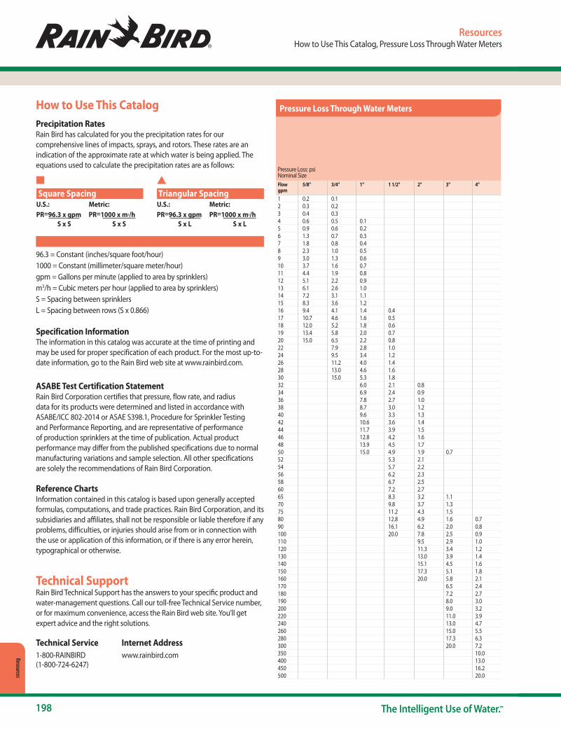
198 The Intelligent Use of Water.™
Resources
Pressure
Loss
Reference
Charts
ResourcesHow to Use This Catalog, Pressure Loss Through Water Meters
Technical SupportRain Bird Technical Support has the answers to your specific product and water-management questions. Call our toll-free Technical Service number, or for maximum convenience, access the Rain Bird web site. You’ll get expert advice and the right solutions.
Technical Service Internet Address 1-800-RAINBIRD www.rainbird.com(1-800-724-6247)
Specification InformationThe information in this catalog was accurate at the time of printing and may be used for proper specification of each product. For the most up-to-date information, go to the Rain Bird web site at www.rainbird.com.
ASABE Test Certification StatementRain Bird Corporation certifies that pressure, flow rate, and radius data for its products were determined and listed in accordance with ASABE/ICC 802-2014 or ASAE S398.1, Procedure for Sprinkler Testing and Performance Reporting, and are representative of performance of production sprinklers at the time of publication. Actual product performance may differ from the published specifications due to normal manufacturing variations and sample selection. All other specifications are solely the recommendations of Rain Bird Corporation.
Reference ChartsInformation contained in this catalog is based upon generally accepted formulas, computations, and trade practices. Rain Bird Corporation, and its subsidiaries and affiliates, shall not be responsible or liable therefore if any problems, difficulties, or injuries should arise from or in connection with the use or application of this information, or if there is any error herein, typographical or otherwise.
Precipitation RatesRain Bird has calculated for you the precipitation rates for our comprehensive lines of impacts, sprays, and rotors. These rates are an indication of the approximate rate at which water is being applied. The equations used to calculate the precipitation rates are as follows:
96.3 = Constant (inches/square foot/hour)1000 = Constant (millimeter/square meter/hour)gpm = Gallons per minute (applied to area by sprinklers)m3/h = Cubic meters per hour (applied to area by sprinklers)S = Spacing between sprinklersL = Spacing between rows (S x 0.866)
Square Spacing U.S.: Metric:PR=96.3 x gpm PR=1000 x m3/h S x S S x S
Triangular Spacing U.S.: Metric:PR=96.3 x gpm PR=1000 x m3/h S x L S x L
n s
How to Use This Catalog
Pressure Loss: psiNominal Size
Flow 5/8" 3/4" 1" 1 1/2" 2" 3" 4" gpm 1 0.2 0.12 0.3 0.23 0.4 0.34 0.6 0.5 0.15 0.9 0.6 0.2 6 1.3 0.7 0.37 1.8 0.8 0.48 2.3 1.0 0.59 3.0 1.3 0.610 3.7 1.6 0.711 4.4 1.9 0.812 5.1 2.2 0.913 6.1 2.6 1.014 7.2 3.1 1.115 8.3 3.6 1.216 9.4 4.1 1.4 0.417 10.7 4.6 1.6 0.518 12.0 5.2 1.8 0.619 13.4 5.8 2.0 0.720 15.0 6.5 2.2 0.822 7.9 2.8 1.024 9.5 3.4 1.226 11.2 4.0 1.428 13.0 4.6 1.630 15.0 5.3 1.832 6.0 2.1 0.834 6.9 2.4 0.936 7.8 2.7 1.038 8.7 3.0 1.240 9.6 3.3 1.342 10.6 3.6 1.444 11.7 3.9 1.546 12.8 4.2 1.648 13.9 4.5 1.750 15.0 4.9 1.9 0.752 5.3 2.154 5.7 2.256 6.2 2.358 6.7 2.560 7.2 2.765 8.3 3.2 1.170 9.8 3.7 1.3 75 11.2 4.3 1.580 12.8 4.9 1.6 0.790 16.1 6.2 2.0 0.8100 20.0 7.8 2.5 0.9110 9.5 2.9 1.0120 11.3 3.4 1.2130 13.0 3.9 1.4140 15.1 4.5 1.6150 17.3 5.1 1.8160 20.0 5.8 2.1170 6.5 2.4180 7.2 2.7190 8.0 3.0200 9.0 3.2220 11.0 3.9240 13.0 4.7260 15.0 5.5280 17.3 6.3300 20.0 7.2350 10.0400 13.0450 16.2500 20.0
Pressure Loss Through Water Meters
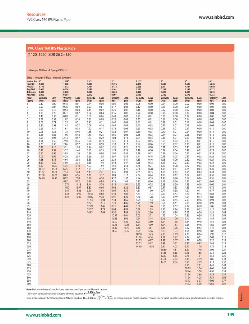
www.rainbird.com
199www.rainbird.com
Reso
urce
s
ResourcesPVC Class 160 IPS Plastic Pipe
PVC Class 160 IPS Plastic Pipe
(1120, 1220) SDR 26 C=150
Note: Dark shaded area of chart indicates velocities over 5' per second. Use with caution
The velocity values were derived using the following equation V = 0.408 × Qgpm
d2
Table are based upon the following Hazen-Williams equation: Hf = 0.2083 × 100 1.852 ×
Q1.852
C D4.8655 for change in psi per foot of elevation. Pressure loss for uphill elevation and pressure gain for downhill elevation changes.
psi Loss per 100 Feet of Pipe (psi/100 ft.)
Sizes 1" through 6" Flow 1 through 600 gpmNominal Size 1" 1 1/4" 1 1/2" 2" 2 1/2" 3" 4" 6" Pipe OD 1.315 1.660 1.900 2.375 2.875 3.500 4.500 6.625 Avg. ID 1.175 1.512 1.734 2.173 2.635 3.21 4.134 6.084 Avg. Wall 0.070 0.074 0.083 0.101 0.120 0.145 0.183 0.271 Tolerance 0.020 0.020 0.020 0.020 0.020 0.020 0.020 0.031 Min. Wall 0.060 0.064 0.073 0.091 0.110 0.135 0.173 0.255 Flow Velocity Loss Velocity Loss Velocity Loss Velocity Loss Velocity Loss Velocity Loss Velocity Loss Velocity Loss (gpm) (ft/s) (psi) (ft/s) (psi) (ft/s) (psi) (ft/s) (psi) (ft/s) (psi) (ft/s) (psi) (ft/s) (psi) (ft/s) (psi) 1 0.30 0.02 0.18 0.01 0.14 0.00 0.09 0.00 0.06 0.00 0.04 0.00 0.02 0.00 0.01 0.002 0.59 0.07 0.36 0.02 0.27 0.01 0.17 0.00 0.12 0.00 0.08 0.00 0.05 0.00 0.02 0.003 0.89 0.15 0.54 0.04 0.41 0.02 0.26 0.01 0.18 0.00 0.12 0.00 0.07 0.00 0.03 0.004 1.18 0.25 0.71 0.07 0.54 0.04 0.35 0.01 0.24 0.00 0.16 0.00 0.10 0.00 0.04 0.005 1.48 0.38 0.89 0.11 0.68 0.06 0.43 0.02 0.29 0.01 0.20 0.00 0.12 0.00 0.06 0.006 1.77 0.54 1.07 0.16 0.81 0.08 0.52 0.03 0.35 0.01 0.24 0.00 0.14 0.00 0.07 0.007 2.07 0.71 1.25 0.21 0.95 0.11 0.60 0.04 0.41 0.01 0.28 0.01 0.17 0.00 0.08 0.008 2.36 0.91 1.43 0.27 1.09 0.14 0.69 0.05 0.47 0.02 0.32 0.01 0.19 0.00 0.09 0.009 2.66 1.14 1.61 0.33 1.22 0.17 0.78 0.06 0.53 0.02 0.36 0.01 0.21 0.00 0.10 0.0010 2.96 1.38 1.78 0.40 1.36 0.21 0.86 0.07 0.59 0.03 0.40 0.01 0.24 0.00 0.11 0.0011 3.25 1.65 1.96 0.48 1.49 0.25 0.95 0.08 0.65 0.03 0.44 0.01 0.26 0.00 0.12 0.0012 3.55 1.94 2.14 0.57 1.63 0.29 1.04 0.10 0.71 0.04 0.48 0.01 0.29 0.00 0.13 0.0014 4.14 2.58 2.50 0.76 1.90 0.39 1.21 0.13 0.82 0.05 0.55 0.02 0.33 0.01 0.15 0.0016 4.73 3.30 2.86 0.97 2.17 0.50 1.38 0.17 0.94 0.06 0.63 0.02 0.38 0.01 0.18 0.0018 5.32 4.10 3.21 1.20 2.44 0.62 1.56 0.21 1.06 0.08 0.71 0.03 0.43 0.01 0.20 0.0020 5.91 4.99 3.57 1.46 2.71 0.75 1.73 0.25 1.18 0.10 0.79 0.04 0.48 0.01 0.22 0.0022 6.50 5.95 3.93 1.74 2.99 0.90 1.90 0.30 1.29 0.12 0.87 0.04 0.53 0.01 0.24 0.0024 7.09 6.99 4.28 2.05 3.26 1.05 2.07 0.35 1.41 0.14 0.95 0.05 0.57 0.02 0.26 0.0026 7.68 8.11 4.64 2.38 3.53 1.22 2.25 0.41 1.53 0.16 1.03 0.06 0.62 0.02 0.29 0.0028 8.27 9.30 5.00 2.73 3.80 1.40 2.42 0.47 1.65 0.18 1.11 0.07 0.67 0.02 0.31 0.0030 8.87 10.57 5.35 3.10 4.07 1.59 2.59 0.53 1.76 0.21 1.19 0.08 0.72 0.02 0.33 0.0035 10.34 14.06 6.25 4.12 4.75 2.12 3.02 0.71 2.06 0.28 1.39 0.11 0.84 0.03 0.39 0.0040 11.82 18.00 7.14 5.28 5.43 2.71 3.46 0.90 2.35 0.35 1.58 0.14 0.95 0.04 0.44 0.0145 13.30 22.39 8.03 6.56 6.11 3.37 3.89 1.12 2.64 0.44 1.78 0.17 1.07 0.05 0.50 0.0150 14.78 27.21 8.92 7.98 6.78 4.10 4.32 1.37 2.94 0.53 1.98 0.20 1.19 0.06 0.55 0.0155 9.82 9.52 7.46 4.89 4.75 1.63 3.23 0.64 2.18 0.24 1.31 0.07 0.61 0.0160 10.71 11.18 8.14 5.74 5.18 1.91 3.53 0.75 2.38 0.29 1.43 0.08 0.66 0.0165 11.60 12.97 8.82 6.66 5.62 2.22 3.82 0.87 2.57 0.33 1.55 0.10 0.72 0.0170 12.49 14.88 9.50 7.64 6.05 2.55 4.11 1.00 2.77 0.38 1.67 0.11 0.77 0.0275 13.38 16.90 10.18 8.68 6.48 2.89 4.41 1.13 2.97 0.43 1.79 0.13 0.83 0.0280 14.28 19.05 10.86 9.78 6.91 3.26 4.70 1.28 3.17 0.49 1.91 0.14 0.88 0.0285 11.53 10.94 7.34 3.65 4.99 1.43 3.37 0.55 2.03 0.16 0.94 0.0290 12.21 12.16 7.78 4.06 5.29 1.59 3.56 0.61 2.15 0.18 0.99 0.0395 12.89 13.45 8.21 4.48 5.58 1.76 3.76 0.67 2.27 0.20 1.05 0.03100 13.57 14.79 8.64 4.93 5.88 1.93 3.96 0.74 2.39 0.22 1.10 0.03110 14.93 17.64 9.50 5.88 6.46 2.30 4.36 0.88 2.63 0.26 1.21 0.04120 10.37 6.91 7.05 2.71 4.75 1.04 2.86 0.30 1.32 0.05130 11.23 8.02 7.64 3.14 5.15 1.20 3.10 0.35 1.43 0.05140 12.10 9.20 8.23 3.60 5.54 1.38 3.34 0.40 1.54 0.06150 12.96 10.45 8.81 4.09 5.94 1.57 3.58 0.46 1.65 0.07160 13.82 11.77 9.40 4.61 6.34 1.76 3.82 0.52 1.76 0.08170 14.69 13.17 9.99 5.16 6.73 1.97 4.06 0.58 1.87 0.09180 10.58 5.73 7.13 2.19 4.30 0.64 1.98 0.10190 11.16 6.34 7.52 2.42 4.54 0.71 2.09 0.11200 11.75 6.97 7.92 2.67 4.77 0.78 2.20 0.12225 13.22 8.67 8.91 3.32 5.37 0.97 2.48 0.15250 14.69 10.53 9.90 4.03 5.97 1.18 2.76 0.18275 10.89 4.81 6.57 1.40 3.03 0.21300 11.88 5.65 7.16 1.65 3.31 0.25325 12.87 6.55 7.76 1.91 3.58 0.29350 13.86 7.52 8.36 2.19 3.86 0.33375 14.85 8.54 8.95 2.49 4.13 0.38400 9.55 2.81 4.41 0.43425 10.15 3.14 4.68 0.48450 10.74 3.50 4.96 0.53475 11.34 3.86 5.24 0.59500 11.94 4.25 5.51 0.65550 13.13 5.07 6.06 0.77600 14.32 5.96 6.61 0.91
PVC Class 160 IPS Plastic Pipe
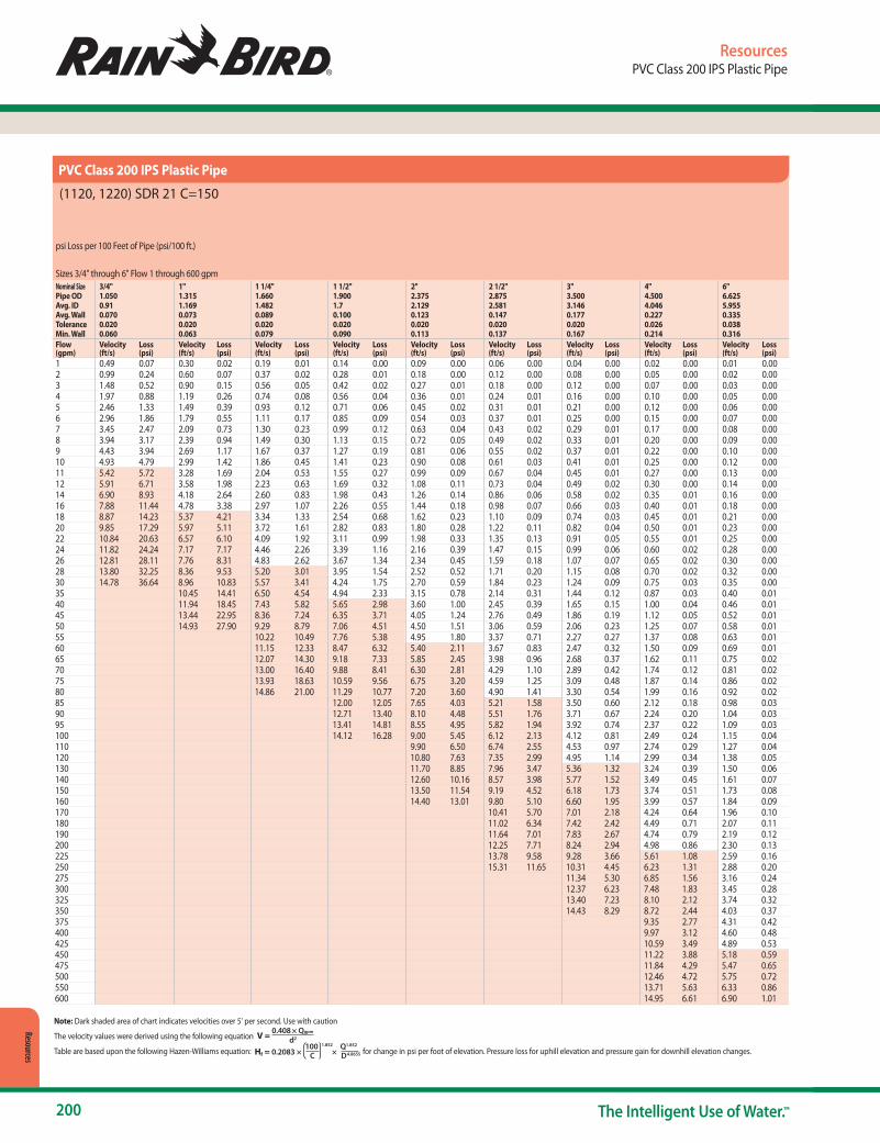
200 The Intelligent Use of Water.™
Resources
ResourcesPVC Class 200 IPS Plastic Pipe
PVC Class 200 IPS Plastic Pipe
(1120, 1220) SDR 21 C=150
psi Loss per 100 Feet of Pipe (psi/100 ft.)
Sizes 3/4" through 6" Flow 1 through 600 gpmNominal Size 3/4" 1" 1 1/4" 1 1/2" 2" 2 1/2" 3" 4" 6" Pipe OD 1.050 1.315 1.660 1.900 2.375 2.875 3.500 4.500 6.625 Avg. ID 0.91 1.169 1.482 1.7 2.129 2.581 3.146 4.046 5.955 Avg. Wall 0.070 0.073 0.089 0.100 0.123 0.147 0.177 0.227 0.335 Tolerance 0.020 0.020 0.020 0.020 0.020 0.020 0.020 0.026 0.038 Min. Wall 0.060 0.063 0.079 0.090 0.113 0.137 0.167 0.214 0.316 Flow Velocity Loss Velocity Loss Velocity Loss Velocity Loss Velocity Loss Velocity Loss Velocity Loss Velocity Loss Velocity Loss(gpm) (ft/s) (psi) (ft/s) (psi) (ft/s) (psi) (ft/s) (psi) (ft/s) (psi) (ft/s) (psi) (ft/s) (psi) (ft/s) (psi) (ft/s) (psi)1 0.49 0.07 0.30 0.02 0.19 0.01 0.14 0.00 0.09 0.00 0.06 0.00 0.04 0.00 0.02 0.00 0.01 0.002 0.99 0.24 0.60 0.07 0.37 0.02 0.28 0.01 0.18 0.00 0.12 0.00 0.08 0.00 0.05 0.00 0.02 0.003 1.48 0.52 0.90 0.15 0.56 0.05 0.42 0.02 0.27 0.01 0.18 0.00 0.12 0.00 0.07 0.00 0.03 0.004 1.97 0.88 1.19 0.26 0.74 0.08 0.56 0.04 0.36 0.01 0.24 0.01 0.16 0.00 0.10 0.00 0.05 0.005 2.46 1.33 1.49 0.39 0.93 0.12 0.71 0.06 0.45 0.02 0.31 0.01 0.21 0.00 0.12 0.00 0.06 0.006 2.96 1.86 1.79 0.55 1.11 0.17 0.85 0.09 0.54 0.03 0.37 0.01 0.25 0.00 0.15 0.00 0.07 0.007 3.45 2.47 2.09 0.73 1.30 0.23 0.99 0.12 0.63 0.04 0.43 0.02 0.29 0.01 0.17 0.00 0.08 0.008 3.94 3.17 2.39 0.94 1.49 0.30 1.13 0.15 0.72 0.05 0.49 0.02 0.33 0.01 0.20 0.00 0.09 0.009 4.43 3.94 2.69 1.17 1.67 0.37 1.27 0.19 0.81 0.06 0.55 0.02 0.37 0.01 0.22 0.00 0.10 0.0010 4.93 4.79 2.99 1.42 1.86 0.45 1.41 0.23 0.90 0.08 0.61 0.03 0.41 0.01 0.25 0.00 0.12 0.0011 5.42 5.72 3.28 1.69 2.04 0.53 1.55 0.27 0.99 0.09 0.67 0.04 0.45 0.01 0.27 0.00 0.13 0.0012 5.91 6.71 3.58 1.98 2.23 0.63 1.69 0.32 1.08 0.11 0.73 0.04 0.49 0.02 0.30 0.00 0.14 0.0014 6.90 8.93 4.18 2.64 2.60 0.83 1.98 0.43 1.26 0.14 0.86 0.06 0.58 0.02 0.35 0.01 0.16 0.0016 7.88 11.44 4.78 3.38 2.97 1.07 2.26 0.55 1.44 0.18 0.98 0.07 0.66 0.03 0.40 0.01 0.18 0.0018 8.87 14.23 5.37 4.21 3.34 1.33 2.54 0.68 1.62 0.23 1.10 0.09 0.74 0.03 0.45 0.01 0.21 0.0020 9.85 17.29 5.97 5.11 3.72 1.61 2.82 0.83 1.80 0.28 1.22 0.11 0.82 0.04 0.50 0.01 0.23 0.0022 10.84 20.63 6.57 6.10 4.09 1.92 3.11 0.99 1.98 0.33 1.35 0.13 0.91 0.05 0.55 0.01 0.25 0.0024 11.82 24.24 7.17 7.17 4.46 2.26 3.39 1.16 2.16 0.39 1.47 0.15 0.99 0.06 0.60 0.02 0.28 0.0026 12.81 28.11 7.76 8.31 4.83 2.62 3.67 1.34 2.34 0.45 1.59 0.18 1.07 0.07 0.65 0.02 0.30 0.0028 13.80 32.25 8.36 9.53 5.20 3.01 3.95 1.54 2.52 0.52 1.71 0.20 1.15 0.08 0.70 0.02 0.32 0.0030 14.78 36.64 8.96 10.83 5.57 3.41 4.24 1.75 2.70 0.59 1.84 0.23 1.24 0.09 0.75 0.03 0.35 0.0035 10.45 14.41 6.50 4.54 4.94 2.33 3.15 0.78 2.14 0.31 1.44 0.12 0.87 0.03 0.40 0.0140 11.94 18.45 7.43 5.82 5.65 2.98 3.60 1.00 2.45 0.39 1.65 0.15 1.00 0.04 0.46 0.0145 13.44 22.95 8.36 7.24 6.35 3.71 4.05 1.24 2.76 0.49 1.86 0.19 1.12 0.05 0.52 0.0150 14.93 27.90 9.29 8.79 7.06 4.51 4.50 1.51 3.06 0.59 2.06 0.23 1.25 0.07 0.58 0.0155 10.22 10.49 7.76 5.38 4.95 1.80 3.37 0.71 2.27 0.27 1.37 0.08 0.63 0.0160 11.15 12.33 8.47 6.32 5.40 2.11 3.67 0.83 2.47 0.32 1.50 0.09 0.69 0.0165 12.07 14.30 9.18 7.33 5.85 2.45 3.98 0.96 2.68 0.37 1.62 0.11 0.75 0.0270 13.00 16.40 9.88 8.41 6.30 2.81 4.29 1.10 2.89 0.42 1.74 0.12 0.81 0.0275 13.93 18.63 10.59 9.56 6.75 3.20 4.59 1.25 3.09 0.48 1.87 0.14 0.86 0.0280 14.86 21.00 11.29 10.77 7.20 3.60 4.90 1.41 3.30 0.54 1.99 0.16 0.92 0.0285 12.00 12.05 7.65 4.03 5.21 1.58 3.50 0.60 2.12 0.18 0.98 0.0390 12.71 13.40 8.10 4.48 5.51 1.76 3.71 0.67 2.24 0.20 1.04 0.0395 13.41 14.81 8.55 4.95 5.82 1.94 3.92 0.74 2.37 0.22 1.09 0.03100 14.12 16.28 9.00 5.45 6.12 2.13 4.12 0.81 2.49 0.24 1.15 0.04110 9.90 6.50 6.74 2.55 4.53 0.97 2.74 0.29 1.27 0.04120 10.80 7.63 7.35 2.99 4.95 1.14 2.99 0.34 1.38 0.05130 11.70 8.85 7.96 3.47 5.36 1.32 3.24 0.39 1.50 0.06140 12.60 10.16 8.57 3.98 5.77 1.52 3.49 0.45 1.61 0.07150 13.50 11.54 9.19 4.52 6.18 1.73 3.74 0.51 1.73 0.08160 14.40 13.01 9.80 5.10 6.60 1.95 3.99 0.57 1.84 0.09170 10.41 5.70 7.01 2.18 4.24 0.64 1.96 0.10180 11.02 6.34 7.42 2.42 4.49 0.71 2.07 0.11190 11.64 7.01 7.83 2.67 4.74 0.79 2.19 0.12200 12.25 7.71 8.24 2.94 4.98 0.86 2.30 0.13225 13.78 9.58 9.28 3.66 5.61 1.08 2.59 0.16250 15.31 11.65 10.31 4.45 6.23 1.31 2.88 0.20275 11.34 5.30 6.85 1.56 3.16 0.24300 12.37 6.23 7.48 1.83 3.45 0.28325 13.40 7.23 8.10 2.12 3.74 0.32350 14.43 8.29 8.72 2.44 4.03 0.37375 9.35 2.77 4.31 0.42400 9.97 3.12 4.60 0.48425 10.59 3.49 4.89 0.53450 11.22 3.88 5.18 0.59475 11.84 4.29 5.47 0.65500 12.46 4.72 5.75 0.72550 13.71 5.63 6.33 0.86600 14.95 6.61 6.90 1.01
Note: Dark shaded area of chart indicates velocities over 5' per second. Use with caution
The velocity values were derived using the following equation V = 0.408 × Qgpm
d2
Table are based upon the following Hazen-Williams equation: Hf = 0.2083 × 100 1.852 ×
Q1.852
C D4.8655 for change in psi per foot of elevation. Pressure loss for uphill elevation and pressure gain for downhill elevation changes.
PVC Class 200 IPS Plastic Pipe

www.rainbird.com
201www.rainbird.com
Reso
urce
s
ResourcesPVC Class 315 IPS Plastic Pipe
PVC Class 315 IPS Plastic Pipe
(1120, 1220) SDR 13.5 C=150
psi Loss per 100 Feet of Pipe (psi/100 ft.)
Sizes 1/2" through 6" Flow 1 through 600 gpmNominal Size 1/2" 3/4" 1" 1 1/4" 1 1/2" 2" 2 1/2" 3" 4" 6" Pipe OD 0.840 1.050 1.315 1.660 1.900 2.375 2.875 3.500 4.500 6.625 Avg. ID 0.6960 0.8740 1.1010 1.3940 1.5980 2.0030 2.4230 2.9510 3.7940 5.5840 Avg. Wall 0.072 0.088 0.107 0.133 0.151 0.186 0.226 0.275 0.353 0.521 Tolerance 0.020 0.020 0.020 0.020 0.020 0.020 0.026 0.031 0.040 0.059 Min. Wall 0.062 0.078 0.097 0.123 0.141 0.176 0.213 0.259 0.333 0.491 Flow Velocity Loss Velocity Loss Velocity Loss Velocity Loss Velocity Loss Velocity Loss Velocity Loss Velocity Loss Velocity Loss Velocity Loss(gpm) (ft/s) (psi) (ft/s) (psi) (ft/s) (psi) (ft/s) (psi) (ft/s) (psi) (ft/s) (psi) (ft/s) (psi) (ft/s) (psi) (ft/s) (psi) (ft/s) (psi)1 0.84 0.25 0.53 0.08 0.34 0.03 0.21 0.01 0.16 0.00 0.10 0.00 0.07 0.00 0.05 0.00 0.03 0.00 0.01 0.002 1.68 0.90 1.07 0.30 0.67 0.10 0.42 0.03 0.32 0.02 0.20 0.01 0.14 0.00 0.09 0.00 0.06 0.00 0.03 0.003 2.53 1.90 1.60 0.63 1.01 0.20 0.63 0.06 0.48 0.03 0.31 0.01 0.21 0.00 0.14 0.00 0.09 0.00 0.04 0.004 3.37 3.24 2.14 1.07 1.35 0.35 0.84 0.11 0.64 0.06 0.41 0.02 0.28 0.01 0.19 0.00 0.11 0.00 0.05 0.005 4.21 4.89 2.67 1.61 1.68 0.53 1.05 0.17 0.80 0.09 0.51 0.03 0.35 0.01 0.23 0.00 0.14 0.00 0.07 0.006 5.05 6.86 3.20 2.26 2.02 0.74 1.26 0.23 0.96 0.12 0.61 0.04 0.42 0.02 0.28 0.01 0.17 0.00 0.08 0.007 5.90 9.12 3.74 3.01 2.36 0.98 1.47 0.31 1.12 0.16 0.71 0.05 0.49 0.02 0.33 0.01 0.20 0.00 0.09 0.008 6.74 11.68 4.27 3.86 2.69 1.25 1.68 0.40 1.28 0.20 0.81 0.07 0.56 0.03 0.37 0.01 0.23 0.00 0.10 0.009 7.58 14.53 4.81 4.80 3.03 1.56 1.89 0.49 1.44 0.25 0.92 0.08 0.63 0.03 0.42 0.01 0.26 0.00 0.12 0.0010 8.42 17.66 5.34 5.83 3.37 1.90 2.10 0.60 1.60 0.31 1.02 0.10 0.69 0.04 0.47 0.02 0.28 0.00 0.13 0.0011 9.26 21.07 5.88 6.96 3.70 2.26 2.31 0.72 1.76 0.37 1.12 0.12 0.76 0.05 0.52 0.02 0.31 0.01 0.14 0.0012 10.11 24.75 6.41 8.17 4.04 2.66 2.52 0.84 1.92 0.43 1.22 0.14 0.83 0.06 0.56 0.02 0.34 0.01 0.16 0.0014 11.79 32.93 7.48 10.87 4.71 3.53 2.94 1.12 2.24 0.58 1.42 0.19 0.97 0.08 0.66 0.03 0.40 0.01 0.18 0.0016 13.48 42.16 8.55 13.92 5.39 4.53 3.36 1.44 2.56 0.74 1.63 0.25 1.11 0.10 0.75 0.04 0.45 0.01 0.21 0.0018 15.16 52.44 9.61 17.32 6.06 5.63 3.78 1.79 2.88 0.92 1.83 0.31 1.25 0.12 0.84 0.05 0.51 0.01 0.24 0.0020 10.68 21.05 6.73 6.84 4.20 2.17 3.20 1.12 2.03 0.37 1.39 0.15 0.94 0.06 0.57 0.02 0.26 0.0022 11.75 25.11 7.40 8.16 4.62 2.59 3.52 1.33 2.24 0.44 1.53 0.18 1.03 0.07 0.62 0.02 0.29 0.0024 12.82 29.50 8.08 9.59 5.04 3.04 3.83 1.57 2.44 0.52 1.67 0.21 1.12 0.08 0.68 0.02 0.31 0.0026 13.89 34.21 8.75 11.12 5.46 3.53 4.15 1.82 2.64 0.60 1.81 0.24 1.22 0.09 0.74 0.03 0.34 0.0028 14.96 39.25 9.42 12.76 5.88 4.05 4.47 2.08 2.85 0.69 1.95 0.27 1.31 0.11 0.79 0.03 0.37 0.0030 16.02 44.60 10.10 14.50 6.30 4.60 4.79 2.37 3.05 0.79 2.08 0.31 1.41 0.12 0.85 0.04 0.39 0.0135 11.78 19.29 7.35 6.12 5.59 3.15 3.56 1.05 2.43 0.42 1.64 0.16 0.99 0.05 0.46 0.0140 13.46 24.70 8.40 7.84 6.39 4.03 4.07 1.34 2.78 0.53 1.87 0.20 1.13 0.06 0.52 0.0145 15.15 30.72 9.45 9.75 7.19 5.01 4.58 1.67 3.13 0.66 2.11 0.25 1.28 0.07 0.59 0.0150 16.83 37.34 10.50 11.85 7.99 6.09 5.08 2.03 3.47 0.80 2.34 0.31 1.42 0.09 0.65 0.0155 11.55 14.13 8.79 7.27 5.59 2.42 3.82 0.96 2.58 0.37 1.56 0.11 0.72 0.0260 12.60 16.60 9.59 8.54 6.10 2.85 4.17 1.13 2.81 0.43 1.70 0.13 0.79 0.0265 13.65 19.26 10.39 9.91 6.61 3.30 4.52 1.31 3.05 0.50 1.84 0.15 0.85 0.0270 14.70 22.09 11.18 11.37 7.12 3.79 4.86 1.50 3.28 0.57 1.98 0.17 0.92 0.0375 15.75 25.10 11.98 12.91 7.63 4.30 5.21 1.70 3.51 0.65 2.13 0.19 0.98 0.0380 16.80 28.29 12.78 14.55 8.14 4.85 5.56 1.92 3.75 0.74 2.27 0.22 1.05 0.0385 13.58 16.28 8.64 5.42 5.91 2.15 3.98 0.82 2.41 0.24 1.11 0.0490 14.38 18.10 9.15 6.03 6.25 2.39 4.22 0.92 2.55 0.27 1.18 0.0495 15.18 20.01 9.66 6.67 6.60 2.64 4.45 1.01 2.69 0.30 1.24 0.05100 15.98 22.00 10.17 7.33 6.95 2.90 4.69 1.11 2.83 0.33 1.31 0.05110 11.19 8.74 7.64 3.46 5.15 1.33 3.12 0.39 1.44 0.06120 12.20 10.27 8.34 4.07 5.62 1.56 3.40 0.46 1.57 0.07130 13.22 11.92 9.03 4.72 6.09 1.81 3.68 0.53 1.70 0.08140 14.24 13.67 9.73 5.41 6.56 2.07 3.97 0.61 1.83 0.09150 15.25 15.53 10.42 6.15 7.03 2.36 4.25 0.69 1.96 0.11160 16.27 17.50 11.12 6.93 7.50 2.66 4.54 0.78 2.09 0.12170 11.81 7.76 7.96 2.97 4.82 0.87 2.22 0.13180 12.51 8.62 8.43 3.30 5.10 0.97 2.36 0.15190 13.20 9.53 8.90 3.65 5.39 1.08 2.49 0.16200 13.90 10.48 9.37 4.02 5.67 1.18 2.62 0.18225 15.64 13.03 10.54 4.99 6.38 1.47 2.94 0.22250 17.37 15.84 11.71 6.07 7.09 1.79 3.27 0.27275 12.88 7.24 7.79 2.13 3.60 0.33300 14.06 8.51 8.50 2.50 3.93 0.38325 15.23 9.87 9.21 2.91 4.25 0.44350 16.40 11.32 9.92 3.33 4.58 0.51375 17.57 12.86 10.63 3.79 4.91 0.58400 11.34 4.27 5.23 0.65425 12.05 4.77 5.56 0.73450 12.75 5.31 5.89 0.81475 13.46 5.87 6.22 0.89500 14.17 6.45 6.54 0.98550 15.59 7.70 7.20 1.17600 17.01 9.04 7.85 1.38
Note: Dark shaded area of chart indicates velocities over 5' per second. Use with caution
The velocity values were derived using the following equation V = 0.408 × Qgpm
d2
Table are based upon the following Hazen-Williams equation: Hf = 0.2083 × 100 1.852 ×
Q1.852
C D4.8655 for change in psi per foot of elevation. Pressure loss for uphill elevation and pressure gain for downhill elevation changes.
PVC Class 315 IPS Plastic Pipe

202 The Intelligent Use of Water.™
Resources
ResourcesPVC Schedule 40 IPS Plastic Pipe
PVC Schedule 40 IPS Plastic Pipe
(1120, 1220) C=150
psi Loss per 100 Feet of Pipe (psi/100 ft.)
Sizes 1/2" through 6" Flow 1 through 600 gpmNominal Size 1/2" 3/4" 1" 1 1/4" 1 1/2" 2" 2 1/2" 3" 4" 6" Pipe OD 0.840 1.050 1.315 1.660 1.900 2.375 2.875 3.500 4.500 6.625 Avg. ID 0.602 0.804 1.029 1.36 1.59 2.047 2.445 3.042 3.998 6.031 Avg. Wall 0.119 0.123 0.143 0.150 0.155 0.164 0.215 0.229 0.251 0.297 Tolerance 0.020 0.020 0.020 0.020 0.020 0.020 0.024 0.026 0.028 0.034 Min. Wall 0.109 0.113 0.133 0.140 0.145 0.154 0.203 0.216 0.237 0.280 Flow Velocity Loss Velocity Loss Velocity Loss Velocity Loss Velocity Loss Velocity Loss Velocity Loss Velocity Loss Velocity Loss Velocity Loss(gpm) (ft/s) (psi) (ft/s) (psi) (ft/s) (psi) (ft/s) (psi) (ft/s) (psi) (ft/s) (psi) (ft/s) (psi) (ft/s) (psi) (ft/s) (psi) (ft/s) (psi)1 1.13 0.50 0.63 0.12 0.39 0.04 0.22 0.01 0.16 0.00 0.10 0.00 0.07 0.00 0.04 0.00 0.03 0.00 0.01 0.002 2.25 1.82 1.26 0.44 0.77 0.13 0.44 0.03 0.32 0.02 0.19 0.00 0.14 0.00 0.09 0.00 0.05 0.00 0.02 0.003 3.38 3.85 1.89 0.94 1.16 0.28 0.66 0.07 0.48 0.03 0.29 0.01 0.20 0.00 0.13 0.00 0.08 0.00 0.03 0.004 4.50 6.55 2.52 1.60 1.54 0.48 0.88 0.12 0.65 0.06 0.39 0.02 0.27 0.01 0.18 0.00 0.10 0.00 0.04 0.005 5.63 9.91 3.16 2.42 1.93 0.73 1.10 0.19 0.81 0.09 0.49 0.03 0.34 0.01 0.22 0.00 0.13 0.00 0.06 0.006 6.75 13.89 3.79 3.40 2.31 1.02 1.32 0.26 0.97 0.12 0.58 0.04 0.41 0.02 0.26 0.01 0.15 0.00 0.07 0.007 7.88 18.48 4.42 4.52 2.70 1.36 1.54 0.35 1.13 0.16 0.68 0.05 0.48 0.02 0.31 0.01 0.18 0.00 0.08 0.008 9.01 23.66 5.05 5.79 3.08 1.74 1.76 0.45 1.29 0.21 0.78 0.06 0.55 0.03 0.35 0.01 0.20 0.00 0.09 0.009 10.13 29.43 5.68 7.20 3.47 2.17 1.99 0.56 1.45 0.26 0.88 0.08 0.61 0.03 0.40 0.01 0.23 0.00 0.10 0.0010 11.26 35.77 6.31 8.75 3.85 2.63 2.21 0.68 1.61 0.32 0.97 0.09 0.68 0.04 0.44 0.01 0.26 0.00 0.11 0.0011 12.38 42.68 6.94 10.44 4.24 3.14 2.43 0.81 1.78 0.38 1.07 0.11 0.75 0.05 0.48 0.02 0.28 0.00 0.12 0.0012 13.51 50.14 7.57 12.27 4.62 3.69 2.65 0.95 1.94 0.44 1.17 0.13 0.82 0.05 0.53 0.02 0.31 0.01 0.13 0.0014 15.76 66.71 8.84 16.32 5.39 4.91 3.09 1.26 2.26 0.59 1.36 0.17 0.96 0.07 0.62 0.03 0.36 0.01 0.16 0.0016 18.01 85.42 10.10 20.90 6.17 6.29 3.53 1.62 2.58 0.76 1.56 0.22 1.09 0.09 0.71 0.03 0.41 0.01 0.18 0.0018 20.26 106.24 11.36 25.99 6.94 7.82 3.97 2.01 2.90 0.94 1.75 0.28 1.23 0.12 0.79 0.04 0.46 0.01 0.20 0.0020 12.62 31.59 7.71 9.51 4.41 2.45 3.23 1.14 1.95 0.33 1.36 0.14 0.88 0.05 0.51 0.01 0.22 0.0022 13.89 37.69 8.48 11.35 4.85 2.92 3.55 1.37 2.14 0.40 1.50 0.17 0.97 0.06 0.56 0.02 0.25 0.0024 15.15 44.28 9.25 13.33 5.29 3.43 3.87 1.60 2.34 0.47 1.64 0.20 1.06 0.07 0.61 0.02 0.27 0.0026 16.41 51.36 10.02 15.46 5.74 3.98 4.20 1.86 2.53 0.54 1.77 0.23 1.15 0.08 0.66 0.02 0.29 0.0028 17.67 58.91 10.79 17.73 6.18 4.56 4.52 2.13 2.73 0.62 1.91 0.26 1.23 0.09 0.71 0.02 0.31 0.0030 18.94 66.94 11.56 20.15 6.62 5.19 4.84 2.42 2.92 0.71 2.05 0.30 1.32 0.10 0.77 0.03 0.34 0.0035 13.49 26.81 7.72 6.90 5.65 3.23 3.41 0.94 2.39 0.40 1.54 0.14 0.89 0.04 0.39 0.0040 15.41 34.33 8.82 8.84 6.46 4.13 3.89 1.21 2.73 0.51 1.76 0.18 1.02 0.05 0.45 0.0145 17.34 42.70 9.93 10.99 7.26 5.14 4.38 1.50 3.07 0.63 1.98 0.22 1.15 0.06 0.50 0.0150 19.27 51.90 11.03 13.36 8.07 6.25 4.87 1.83 3.41 0.77 2.20 0.27 1.28 0.07 0.56 0.0155 12.13 15.94 8.88 7.45 5.36 2.18 3.75 0.92 2.42 0.32 1.40 0.08 0.62 0.0160 13.24 18.72 9.68 8.75 5.84 2.56 4.09 1.08 2.65 0.37 1.53 0.10 0.67 0.0165 14.34 21.72 10.49 10.15 6.33 2.97 4.44 1.25 2.87 0.43 1.66 0.11 0.73 0.0270 15.44 24.91 11.30 11.65 6.82 3.41 4.78 1.43 3.09 0.50 1.79 0.13 0.79 0.0275 16.54 28.31 12.10 13.23 7.30 3.87 5.12 1.63 3.31 0.56 1.91 0.15 0.84 0.0280 17.65 31.90 12.91 14.91 7.79 4.36 5.46 1.84 3.53 0.63 2.04 0.17 0.90 0.0285 18.75 35.69 13.72 16.69 8.28 4.88 5.80 2.06 3.75 0.71 2.17 0.19 0.95 0.0390 19.85 39.67 14.52 18.55 8.76 5.43 6.14 2.29 3.97 0.79 2.30 0.21 1.01 0.0395 15.33 20.50 9.25 6.00 6.48 2.53 4.19 0.87 2.42 0.23 1.07 0.03100 16.14 22.55 9.74 6.59 6.82 2.78 4.41 0.96 2.55 0.25 1.12 0.03110 17.75 26.90 10.71 7.87 7.51 3.31 4.85 1.14 2.81 0.30 1.23 0.04120 19.37 31.60 11.68 9.24 8.19 3.89 5.29 1.34 3.06 0.36 1.35 0.05130 12.66 10.72 8.87 4.52 5.73 1.56 3.32 0.41 1.46 0.06140 13.63 12.30 9.55 5.18 6.17 1.79 3.57 0.47 1.57 0.06150 14.61 13.97 10.24 5.89 6.61 2.03 3.83 0.54 1.68 0.07160 15.58 15.75 10.92 6.63 7.05 2.29 4.08 0.61 1.79 0.08170 16.55 17.62 11.60 7.42 7.50 2.56 4.34 0.68 1.91 0.09180 17.53 19.58 12.28 8.25 7.94 2.85 4.59 0.75 2.02 0.10190 18.50 21.65 12.97 9.12 8.38 3.15 4.85 0.83 2.13 0.11200 19.47 23.80 13.65 10.03 8.82 3.46 5.11 0.92 2.24 0.12225 15.36 12.47 9.92 4.31 5.74 1.14 2.52 0.15250 17.06 15.16 11.02 5.24 6.38 1.39 2.80 0.19275 18.77 18.09 12.12 6.25 7.02 1.65 3.08 0.22300 13.23 7.34 7.66 1.94 3.37 0.26325 14.33 8.51 8.30 2.25 3.65 0.30350 15.43 9.76 8.93 2.58 3.93 0.35375 16.53 11.09 9.57 2.93 4.21 0.40400 17.64 12.50 10.21 3.31 4.49 0.45425 18.74 13.99 10.85 3.70 4.77 0.50450 19.84 15.55 11.49 4.11 5.05 0.56475 12.12 4.55 5.33 0.62500 12.76 5.00 5.61 0.68550 14.04 5.97 6.17 0.81600 15.32 7.01 6.73 0.95
Note: Dark shaded area of chart indicates velocities over 5' per second. Use with caution
The velocity values were derived using the following equation V = 0.408 × Qgpm
d2
Table are based upon the following Hazen-Williams equation: Hf = 0.2083 × 100 1.852 ×
Q1.852
C D4.8655 for change in psi per foot of elevation. Pressure loss for uphill elevation and pressure gain for downhill elevation changes.
PVC Schedule 40 IPS Plastic Pipe

www.rainbird.com
203www.rainbird.com
Reso
urce
s
ResourcesPVC Schedule 80 IPS Plastic Pipe
PVC Schedule 80 IPS Plastic Pipe
(1120, 1220) C=150
psi Loss per 100 Feet of Pipe (psi/100 ft.)
Sizes 1/2" through 6" Flow 1 through 600 gpmNominal Size 1/2" 3/4" 1" 1 1/4" 1 1/2" 2" 2 1/2" 3" 4" 6" Pipe OD 0.840 1.050 1.315 1.660 1.900 2.375 2.875 3.500 4.500 6.625 Avg. ID 0.526 0.722 0.935 1.254 1.476 1.913 2.289 2.864 3.786 5.709 Avg. Wall 0.157 0.164 0.190 0.203 0.212 0.231 0.293 0.318 0.357 0.458 Tolerance 0.020 0.020 0.022 0.024 0.024 0.026 0.034 0.036 0.040 0.052 Min. Wall 0.147 0.154 0.179 0.191 0.200 0.218 0.276 0.300 0.337 0.432 Flow Velocity Loss Velocity Loss Velocity Loss Velocity Loss Velocity Loss Velocity Loss Velocity Loss Velocity Loss Velocity Loss Velocity Loss(gpm) (ft/s) (psi) (ft/s) (psi) (ft/s) (psi) (ft/s) (psi) (ft/s) (psi) (ft/s) (psi) (ft/s) (psi) (ft/s) (psi) (ft/s) (psi) (ft/s) (psi) 1 1.47 0.97 0.78 0.21 0.47 0.06 0.26 0.01 0.19 0.01 0.11 0.00 0.08 0.00 0.05 0.00 0.03 0.00 0.01 0.002 2.95 3.50 1.57 0.75 0.93 0.21 0.52 0.05 0.37 0.02 0.22 0.01 0.16 0.00 0.10 0.00 0.06 0.00 0.03 0.003 4.42 7.42 2.35 1.59 1.40 0.45 0.78 0.11 0.56 0.05 0.33 0.01 0.23 0.01 0.15 0.00 0.09 0.00 0.04 0.004 5.90 12.64 3.13 2.71 1.87 0.77 1.04 0.18 0.75 0.08 0.45 0.02 0.31 0.01 0.20 0.00 0.11 0.00 0.05 0.005 7.37 19.11 3.91 4.09 2.33 1.16 1.30 0.28 0.94 0.13 0.56 0.04 0.39 0.01 0.25 0.01 0.14 0.00 0.06 0.006 8.85 26.78 4.70 5.74 2.80 1.63 1.56 0.39 1.12 0.18 0.67 0.05 0.47 0.02 0.30 0.01 0.17 0.00 0.08 0.007 10.32 35.63 5.48 7.63 3.27 2.17 1.82 0.52 1.31 0.24 0.78 0.07 0.55 0.03 0.35 0.01 0.20 0.00 0.09 0.008 11.80 45.63 6.26 9.77 3.73 2.78 2.08 0.67 1.50 0.30 0.89 0.09 0.62 0.04 0.40 0.01 0.23 0.00 0.10 0.009 13.27 56.75 7.04 12.15 4.20 3.45 2.34 0.83 1.69 0.37 1.00 0.11 0.70 0.04 0.45 0.01 0.26 0.00 0.11 0.0010 14.75 68.98 7.83 14.77 4.67 4.20 2.59 1.01 1.87 0.46 1.11 0.13 0.78 0.05 0.50 0.02 0.28 0.00 0.13 0.0011 8.61 17.62 5.13 5.01 2.85 1.20 2.06 0.54 1.23 0.15 0.86 0.06 0.55 0.02 0.31 0.01 0.14 0.0012 9.39 20.70 5.60 5.88 3.11 1.41 2.25 0.64 1.34 0.18 0.93 0.08 0.60 0.03 0.34 0.01 0.15 0.0014 10.96 27.55 6.53 7.83 3.63 1.88 2.62 0.85 1.56 0.24 1.09 0.10 0.70 0.03 0.40 0.01 0.18 0.0016 12.52 35.27 7.47 10.03 4.15 2.40 3.00 1.09 1.78 0.31 1.25 0.13 0.80 0.04 0.46 0.01 0.20 0.0018 14.09 43.87 8.40 12.47 4.67 2.99 3.37 1.35 2.01 0.38 1.40 0.16 0.90 0.05 0.51 0.01 0.23 0.0020 15.65 53.32 9.33 15.16 5.19 3.63 3.75 1.64 2.23 0.47 1.56 0.19 0.99 0.07 0.57 0.02 0.25 0.0022 10.27 18.08 5.71 4.33 4.12 1.96 2.45 0.56 1.71 0.23 1.09 0.08 0.63 0.02 0.28 0.0024 11.20 21.24 6.23 5.09 4.49 2.30 2.68 0.65 1.87 0.27 1.19 0.09 0.68 0.02 0.30 0.0026 12.13 24.64 6.75 5.91 4.87 2.67 2.90 0.76 2.02 0.32 1.29 0.11 0.74 0.03 0.33 0.0028 13.07 28.26 7.26 6.77 5.24 3.06 3.12 0.87 2.18 0.36 1.39 0.12 0.80 0.03 0.35 0.0030 14.00 32.12 7.78 7.70 5.62 3.48 3.34 0.99 2.34 0.41 1.49 0.14 0.85 0.04 0.38 0.0035 16.33 42.73 9.08 10.24 6.55 4.63 3.90 1.31 2.73 0.55 1.74 0.18 1.00 0.05 0.44 0.0140 10.38 13.11 7.49 5.93 4.46 1.68 3.11 0.70 1.99 0.24 1.14 0.06 0.50 0.0145 11.68 16.31 8.43 7.38 5.02 2.09 3.50 0.87 2.24 0.29 1.28 0.08 0.56 0.0150 12.97 19.83 9.36 8.97 5.57 2.54 3.89 1.06 2.49 0.36 1.42 0.09 0.63 0.0155 14.27 23.65 10.30 10.70 6.13 3.03 4.28 1.27 2.74 0.43 1.57 0.11 0.69 0.0160 15.57 27.79 11.24 12.57 6.69 3.56 4.67 1.49 2.98 0.50 1.71 0.13 0.75 0.0265 12.17 14.58 7.25 4.13 5.06 1.72 3.23 0.58 1.85 0.15 0.81 0.0270 13.11 16.73 7.80 4.74 5.45 1.98 3.48 0.66 1.99 0.17 0.88 0.0275 14.05 19.01 8.36 5.38 5.84 2.25 3.73 0.76 2.13 0.19 0.94 0.0380 14.98 21.42 8.92 6.06 6.23 2.53 3.98 0.85 2.28 0.22 1.00 0.0385 15.92 23.96 9.48 6.78 6.62 2.83 4.23 0.95 2.42 0.24 1.06 0.0390 10.03 7.54 7.01 3.15 4.48 1.06 2.56 0.27 1.13 0.0495 10.59 8.34 7.40 3.48 4.73 1.17 2.70 0.30 1.19 0.04100 11.15 9.17 7.79 3.83 4.97 1.29 2.85 0.33 1.25 0.04110 12.26 10.94 8.57 4.57 5.47 1.53 3.13 0.39 1.38 0.05120 13.38 12.85 9.34 5.37 5.97 1.80 3.42 0.46 1.50 0.06130 14.49 14.90 10.12 6.22 6.47 2.09 3.70 0.54 1.63 0.07140 15.61 17.09 10.90 7.14 6.96 2.40 3.98 0.62 1.75 0.08150 11.68 8.11 7.46 2.73 4.27 0.70 1.88 0.10160 12.46 9.14 7.96 3.07 4.55 0.79 2.00 0.11170 13.24 10.23 8.46 3.44 4.84 0.88 2.13 0.12180 14.02 11.37 8.95 3.82 5.12 0.98 2.25 0.13190 14.80 12.57 9.45 4.22 5.41 1.09 2.38 0.15200 15.57 13.82 9.95 4.64 5.69 1.19 2.50 0.16225 11.19 5.78 6.40 1.49 2.82 0.20250 12.44 7.02 7.12 1.81 3.13 0.24275 13.68 8.38 7.83 2.15 3.44 0.29300 14.92 9.84 8.54 2.53 3.76 0.34325 16.17 11.41 9.25 2.94 4.07 0.40350 9.96 3.37 4.38 0.46375 10.67 3.83 4.69 0.52400 11.39 4.31 5.01 0.58425 12.10 4.82 5.32 0.65450 12.81 5.36 5.63 0.73475 13.52 5.93 5.95 0.80500 14.23 6.52 6.26 0.88550 6.88 1.05600 7.51 1.24
Note: Dark shaded area of chart indicates velocities over 5' per second. Use with caution
The velocity values were derived using the following equation V = 0.408 × Qgpm
d2
Table are based upon the following Hazen-Williams equation: Hf = 0.2083 × 100 1.852 ×
Q1.852
C D4.8655 for change in psi per foot of elevation. Pressure loss for uphill elevation and pressure gain for downhill elevation changes.
PVC Schedule 80 IPS Plastic Pipe

204 The Intelligent Use of Water.™
Resources
ResourcesPolyethylene (PE) SDR Pressure Rated Tube
Polyethylene (PE) SDR Pressure Rated Tube
(2306, 3206, 3306) SDR 7, 9, 11.5, 15 C=140
psi Loss per 100 Feet of Pipe (psi/100 ft.)
Sizes 1/2" through 4" Flow 1 through 600 gpmNominal Size 1/2" 3/4" 1" 1 1/4" 1 1/2" 2" 2 1/2" 3" 4" Avg. I.D. 0.622 0.824 1.049 1.380 1.610 2.067 2.469 3.068 4.026 Flow Velocity Loss Velocity Loss Velocity Loss Velocity Loss Velocity Loss Velocity Loss Velocity Loss Velocity Loss Velocity Loss(gpm) (ft/s) (psi) (ft/s) (psi) (ft/s) (psi) (ft/s) (psi) (ft/s) (psi) (ft/s) (psi) (ft/s) (psi) (ft/s) (psi) (ft/s) (psi)1 1.05 0.49 0.60 0.12 0.37 0.04 0.21 0.01 0.16 0.00 0.10 0.00 0.07 0.00 0.04 0.00 0.03 0.002 2.11 1.76 1.20 0.45 0.74 0.14 0.43 0.04 0.31 0.02 0.19 0.01 0.13 0.00 0.09 0.00 0.05 0.003 3.16 3.73 1.80 0.95 1.11 0.29 0.64 0.08 0.47 0.04 0.29 0.01 0.20 0.00 0.13 0.00 0.08 0.004 4.22 6.35 2.40 1.62 1.48 0.50 0.86 0.13 0.63 0.06 0.38 0.02 0.27 0.01 0.17 0.00 0.10 0.005 5.27 9.60 3.00 2.44 1.85 0.76 1.07 0.20 0.79 0.09 0.48 0.03 0.33 0.01 0.22 0.00 0.13 0.006 6.33 13.46 3.61 3.43 2.22 1.06 1.29 0.28 0.94 0.13 0.57 0.04 0.40 0.02 0.26 0.01 0.15 0.007 7.38 17.91 4.21 4.56 2.60 1.41 1.50 0.37 1.10 0.18 0.67 0.05 0.47 0.02 0.30 0.01 0.18 0.008 8.44 22.93 4.81 5.84 2.97 1.80 1.71 0.47 1.26 0.22 0.76 0.07 0.54 0.03 0.35 0.01 0.20 0.009 9.49 28.52 5.41 7.26 3.34 2.24 1.93 0.59 1.42 0.28 0.86 0.08 0.60 0.03 0.39 0.01 0.23 0.0010 10.55 34.67 6.01 8.82 3.71 2.73 2.14 0.72 1.57 0.34 0.95 0.10 0.67 0.04 0.43 0.01 0.25 0.0011 6.61 10.53 4.08 3.25 2.36 0.86 1.73 0.40 1.05 0.12 0.74 0.05 0.48 0.02 0.28 0.0012 7.21 12.37 4.45 3.82 2.57 1.01 1.89 0.48 1.15 0.14 0.80 0.06 0.52 0.02 0.30 0.0114 8.41 16.45 5.19 5.08 3.00 1.34 2.20 0.63 1.34 0.19 0.94 0.08 0.61 0.03 0.35 0.0116 9.61 21.07 5.93 6.51 3.43 1.71 2.52 0.81 1.53 0.24 1.07 0.10 0.69 0.04 0.40 0.0118 10.82 26.21 6.67 8.10 3.86 2.13 2.83 1.01 1.72 0.30 1.20 0.13 0.78 0.04 0.45 0.0120 12.02 31.85 7.42 9.84 4.28 2.59 3.15 1.22 1.91 0.36 1.34 0.15 0.87 0.05 0.50 0.0122 8.16 11.74 4.71 3.09 3.46 1.46 2.10 0.43 1.47 0.18 0.95 0.06 0.55 0.0224 8.90 13.79 5.14 3.63 3.78 1.72 2.29 0.51 1.61 0.21 1.04 0.07 0.60 0.0226 9.64 16.00 5.57 4.21 4.09 1.99 2.48 0.59 1.74 0.25 1.13 0.09 0.65 0.0228 10.38 18.35 6.00 4.83 4.41 2.28 2.67 0.68 1.87 0.28 1.21 0.10 0.70 0.0330 11.12 20.85 6.43 5.49 4.72 2.59 2.86 0.77 2.01 0.32 1.30 0.11 0.76 0.0335 12.98 27.74 7.50 7.30 5.51 3.45 3.34 1.02 2.34 0.43 1.52 0.15 0.88 0.0440 8.57 9.35 6.30 4.42 3.82 1.31 2.68 0.55 1.73 0.19 1.01 0.0545 9.64 11.63 7.08 5.49 4.30 1.63 3.01 0.69 1.95 0.24 1.13 0.0650 10.71 14.14 7.87 6.68 4.77 1.98 3.35 0.83 2.17 0.29 1.26 0.0855 11.78 16.87 8.66 7.97 5.25 2.36 3.68 0.99 2.38 0.35 1.38 0.0960 12.85 19.82 9.44 9.36 5.73 2.77 4.02 1.17 2.60 0.41 1.51 0.1165 10.23 10.86 6.21 3.22 4.35 1.36 2.82 0.47 1.64 0.1370 11.02 12.45 6.68 3.69 4.69 1.55 3.03 0.54 1.76 0.1475 11.81 14.15 7.16 4.19 5.02 1.77 3.25 0.61 1.89 0.1680 12.59 15.95 7.64 4.73 5.35 1.99 3.47 0.69 2.01 0.1885 13.38 17.84 8.12 5.29 5.69 2.23 3.68 0.77 2.14 0.2190 8.59 5.88 6.02 2.48 3.90 0.86 2.27 0.2395 9.07 6.50 6.36 2.74 4.12 0.95 2.39 0.25100 9.55 7.15 6.69 3.01 4.33 1.05 2.52 0.28110 10.50 8.53 7.36 3.59 4.77 1.25 2.77 0.33120 11.46 10.02 8.03 4.22 5.20 1.47 3.02 0.39130 12.41 11.62 8.70 4.89 5.63 1.70 3.27 0.45140 13.37 13.33 9.37 5.61 6.07 1.95 3.52 0.52150 10.04 6.38 6.50 2.22 3.78 0.59160 10.71 7.19 6.94 2.50 4.03 0.67170 11.38 8.04 7.37 2.79 4.28 0.74180 12.05 8.94 7.80 3.11 4.53 0.83190 12.72 9.88 8.24 3.43 4.78 0.92200 13.39 10.87 8.67 3.78 5.03 1.01225 9.75 4.70 5.66 1.25250 10.84 5.71 6.29 1.52275 11.92 6.81 6.92 1.81300 13.00 8.00 7.55 2.13325 14.09 9.28 8.18 2.47350 8.81 2.84375 9.44 3.22400 10.07 3.63425 10.70 4.06450 11.33 4.52475 11.96 4.99500 12.59 5.49550 13.84 6.55600 15.10 7.70
Note: Dark shaded area of chart indicates velocities over 5' per second. Use with caution
The velocity values were derived using the following equation V = 0.408 × Qgpm
d2
Table are based upon the following Hazen-Williams equation: Hf = 0.2083 × 100 1.852 ×
Q1.852
C D4.8655 for change in psi per foot of elevation. Pressure loss for uphill elevation and pressure gain for downhill elevation changes.
Polyethylene (PE) SDR Pressure Rated Tube
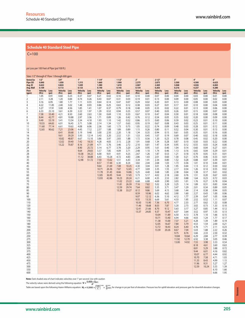
www.rainbird.com
205www.rainbird.com
Reso
urce
s
ResourcesSchedule 40 Standard Steel Pipe
Schedule 40 Standard Steel Pipe
C=100
psi Loss per 100 Feet of Pipe (psi/100 ft.)
Sizes 1/2" through 6" Flow 1 through 600 gpmNominal Size 1/2" 3/4" 1" 1 1/4" 1 1/2" 2" 2 1/2" 3" 4" 6" Pipe OD 0.840 1.050 1.315 1.660 1.900 2.375 2.875 3.500 4.500 6.625Avg. ID 0.622 0.824 1.049 1.380 1.610 2.067 2.469 3.068 4.026 6.065Avg. Wall 0.109 0.113 0.133 0.140 0.145 0.154 0.203 0.216 0.237 0.280 Flow Velocity Loss Velocity Loss Velocity Loss Velocity Loss Velocity Loss Velocity Loss Velocity Loss Velocity Loss Velocity Loss Velocity Loss(gpm) (ft/s) (psi) (ft/s) (psi) (ft/s) (psi) (ft/s) (psi) (ft/s) (psi) (ft/s) (psi) (ft/s) (psi) (ft/s) (psi) (ft/s) (psi) (ft/s) (psi)1 1.05 0.91 0.60 0.23 0.37 0.07 0.21 0.02 0.16 0.01 0.10 0.00 0.07 0.00 0.04 0.00 0.03 0.00 0.01 0.002 2.11 3.28 1.20 0.84 0.74 0.26 0.43 0.07 0.31 0.03 0.19 0.01 0.13 0.00 0.09 0.00 0.05 0.00 0.02 0.003 3.16 6.95 1.80 1.77 1.11 0.55 0.64 0.14 0.47 0.07 0.29 0.02 0.20 0.01 0.13 0.00 0.08 0.00 0.03 0.004 4.22 11.85 2.40 3.02 1.48 0.93 0.86 0.25 0.63 0.12 0.38 0.03 0.27 0.01 0.17 0.01 0.10 0.00 0.04 0.005 5.27 17.91 3.00 4.56 1.85 1.41 1.07 0.37 0.79 0.18 0.48 0.05 0.33 0.02 0.22 0.01 0.13 0.00 0.06 0.006 6.33 25.10 3.61 6.39 2.22 1.97 1.29 0.52 0.94 0.25 0.57 0.07 0.40 0.03 0.26 0.01 0.15 0.00 0.07 0.007 7.38 33.40 4.21 8.50 2.60 2.63 1.50 0.69 1.10 0.33 0.67 0.10 0.47 0.04 0.30 0.01 0.18 0.00 0.08 0.008 8.44 42.77 4.81 10.88 2.97 3.36 1.71 0.89 1.26 0.42 0.76 0.12 0.54 0.05 0.35 0.02 0.20 0.00 0.09 0.009 9.49 53.19 5.41 13.54 3.34 4.18 1.93 1.10 1.42 0.52 0.86 0.15 0.60 0.06 0.39 0.02 0.23 0.01 0.10 0.0010 10.55 64.65 6.01 16.45 3.71 5.08 2.14 1.34 1.57 0.63 0.95 0.19 0.67 0.08 0.43 0.03 0.25 0.01 0.11 0.0011 11.60 77.14 6.61 19.63 4.08 6.06 2.36 1.60 1.73 0.75 1.05 0.22 0.74 0.09 0.48 0.03 0.28 0.01 0.12 0.0012 12.65 90.62 7.21 23.06 4.45 7.12 2.57 1.88 1.89 0.89 1.15 0.26 0.80 0.11 0.52 0.04 0.30 0.01 0.13 0.0014 8.41 30.68 5.19 9.48 3.00 2.50 2.20 1.18 1.34 0.35 0.94 0.15 0.61 0.05 0.35 0.01 0.16 0.0016 9.61 39.29 5.93 12.14 3.43 3.20 2.52 1.51 1.53 0.45 1.07 0.19 0.69 0.07 0.40 0.02 0.18 0.0018 10.82 48.87 6.67 15.10 3.86 3.97 2.83 1.88 1.72 0.56 1.20 0.23 0.78 0.08 0.45 0.02 0.20 0.0020 12.02 59.40 7.42 18.35 4.28 4.83 3.15 2.28 1.91 0.68 1.34 0.28 0.87 0.10 0.50 0.03 0.22 0.0022 13.22 70.87 8.16 21.89 4.71 5.76 3.46 2.72 2.10 0.81 1.47 0.34 0.95 0.12 0.55 0.03 0.24 0.0024 8.90 25.72 5.14 6.77 3.78 3.20 2.29 0.95 1.61 0.40 1.04 0.14 0.60 0.04 0.27 0.0126 9.64 29.83 5.57 7.85 4.09 3.71 2.48 1.10 1.74 0.46 1.13 0.16 0.65 0.04 0.29 0.0128 10.38 34.22 6.00 9.01 4.41 4.25 2.67 1.26 1.87 0.53 1.21 0.18 0.70 0.05 0.31 0.0130 11.12 38.88 6.43 10.24 4.72 4.83 2.86 1.43 2.01 0.60 1.30 0.21 0.76 0.06 0.33 0.0135 12.98 51.72 7.50 13.62 5.51 6.43 3.34 1.91 2.34 0.80 1.52 0.28 0.88 0.07 0.39 0.0140 8.57 17.44 6.30 8.24 3.82 2.44 2.68 1.03 1.73 0.36 1.01 0.10 0.44 0.0145 9.64 21.69 7.08 10.25 4.30 3.04 3.01 1.28 1.95 0.44 1.13 0.12 0.50 0.0250 10.71 26.36 7.87 12.45 4.77 3.69 3.35 1.55 2.17 0.54 1.26 0.14 0.55 0.0255 11.78 31.45 8.66 14.86 5.25 4.40 3.68 1.85 2.38 0.64 1.38 0.17 0.61 0.0260 12.85 36.95 9.44 17.45 5.73 5.17 4.02 2.18 2.60 0.76 1.51 0.20 0.67 0.0365 13.93 42.86 10.23 20.24 6.21 6.00 4.35 2.53 2.82 0.88 1.64 0.23 0.72 0.0370 11.02 23.22 6.68 6.88 4.69 2.90 3.03 1.01 1.76 0.27 0.78 0.0475 11.81 26.39 7.16 7.82 5.02 3.29 3.25 1.14 1.89 0.31 0.83 0.0480 12.59 29.74 7.64 8.82 5.35 3.71 3.47 1.29 2.01 0.34 0.89 0.0585 13.38 33.27 8.12 9.86 5.69 4.15 3.68 1.44 2.14 0.38 0.94 0.0590 8.59 10.96 6.02 4.62 3.90 1.60 2.27 0.43 1.00 0.0695 9.07 12.12 6.36 5.10 4.12 1.77 2.39 0.47 1.05 0.06100 9.55 13.33 6.69 5.61 4.33 1.95 2.52 0.52 1.11 0.07110 10.50 15.90 7.36 6.70 4.77 2.33 2.77 0.62 1.22 0.08120 11.46 18.68 8.03 7.87 5.20 2.73 3.02 0.73 1.33 0.10130 12.41 21.66 8.70 9.12 5.63 3.17 3.27 0.85 1.44 0.12140 13.37 24.85 9.37 10.47 6.07 3.64 3.52 0.97 1.55 0.13150 10.04 11.89 6.50 4.13 3.78 1.10 1.66 0.15160 10.71 13.40 6.94 4.66 4.03 1.24 1.77 0.17170 11.38 15.00 7.37 5.21 4.28 1.39 1.89 0.19180 12.05 16.67 7.80 5.79 4.53 1.54 2.00 0.21190 12.72 18.43 8.24 6.40 4.78 1.71 2.11 0.23200 13.39 20.26 8.67 7.04 5.03 1.88 2.22 0.26225 9.75 8.76 5.66 2.33 2.50 0.32250 10.84 10.64 6.29 2.84 2.77 0.39275 11.92 12.70 6.92 3.38 3.05 0.46300 13.00 14.92 7.55 3.98 3.33 0.54325 8.18 4.61 3.60 0.63350 8.81 5.29 3.88 0.72375 9.44 6.01 4.16 0.82400 10.07 6.77 4.44 0.92425 10.70 7.58 4.71 1.03450 11.33 8.43 4.99 1.15475 11.96 9.31 5.27 1.27500 12.59 10.24 5.55 1.39550 6.10 1.66600 6.66 1.95
Note: Dark shaded area of chart indicates velocities over 7' per second. Use with caution
The velocity values were derived using the following equation V = 0.408 × Qgpm
d2
Table are based upon the following Hazen-Williams equation: Hf = 0.2083 × 100 1.852 ×
Q1.852
C D4.8655 for change in psi per foot of elevation. Pressure loss for uphill elevation and pressure gain for downhill elevation changes.
Schedule 40 Standard Steel Pipe
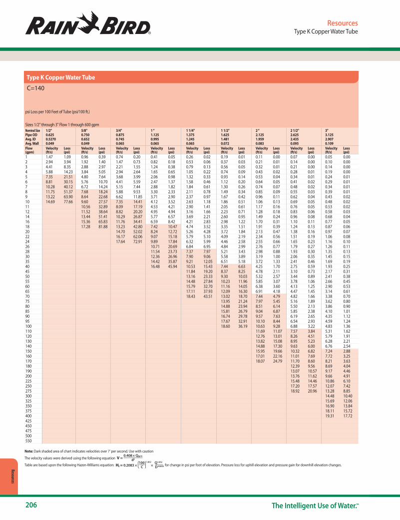
206 The Intelligent Use of Water.™
Resources
ResourcesType K Copper Water Tube
Type K Copper Water Tube
C=140
psi Loss per 100 Feet of Tube (psi/100 ft.)
Sizes 1/2" through 3" Flow 1 through 600 gpmNominal Size 1/2" 5/8" 3/4" 1 “ 1 1/4" 1 1/2" 2 “ 2 1/2" 3" Pipe OD 0.625 0.750 0.875 1.125 1.375 1.625 2.125 2.625 3.125 Avg. ID 0.5270 0.652 0.745 0.995 1.245 1.481 1.959 2.435 2.907 Avg. Wall 0.049 0.049 0.065 0.065 0.065 0.072 0.083 0.095 0.109 Flow Velocity Loss Velocity Loss Velocity Loss Velocity Loss Velocity Loss Velocity Loss Velocity Loss Velocity Loss Velocity Loss(gpm) (ft/s) (psi) (ft/s) (psi) (ft/s) (psi) (ft/s) (psi) (ft/s) (psi) (ft/s) (psi) (ft/s) (psi) (ft/s) (psi) (ft/s) (psi)1 1.47 1.09 0.96 0.39 0.74 0.20 0.41 0.05 0.26 0.02 0.19 0.01 0.11 0.00 0.07 0.00 0.05 0.002 2.94 3.94 1.92 1.40 1.47 0.73 0.82 0.18 0.53 0.06 0.37 0.03 0.21 0.01 0.14 0.00 0.10 0.003 4.41 8.35 2.88 2.97 2.21 1.55 1.24 0.38 0.79 0.13 0.56 0.05 0.32 0.01 0.21 0.00 0.14 0.004 5.88 14.23 3.84 5.05 2.94 2.64 1.65 0.65 1.05 0.22 0.74 0.09 0.43 0.02 0.28 0.01 0.19 0.005 7.35 21.51 4.80 7.64 3.68 3.99 2.06 0.98 1.32 0.33 0.93 0.14 0.53 0.04 0.34 0.01 0.24 0.016 8.81 30.15 5.76 10.70 4.41 5.59 2.47 1.37 1.58 0.46 1.12 0.20 0.64 0.05 0.41 0.02 0.29 0.017 10.28 40.12 6.72 14.24 5.15 7.44 2.88 1.82 1.84 0.61 1.30 0.26 0.74 0.07 0.48 0.02 0.34 0.018 11.75 51.37 7.68 18.24 5.88 9.53 3.30 2.33 2.11 0.78 1.49 0.34 0.85 0.09 0.55 0.03 0.39 0.019 13.22 63.90 8.64 22.68 6.62 11.85 3.71 2.90 2.37 0.97 1.67 0.42 0.96 0.11 0.62 0.04 0.43 0.0210 14.69 77.66 9.60 27.57 7.35 14.41 4.12 3.52 2.63 1.18 1.86 0.51 1.06 0.13 0.69 0.05 0.48 0.0211 10.56 32.89 8.09 17.19 4.53 4.21 2.90 1.41 2.05 0.61 1.17 0.16 0.76 0.05 0.53 0.0212 11.52 38.64 8.82 20.20 4.95 4.94 3.16 1.66 2.23 0.71 1.28 0.18 0.83 0.06 0.58 0.0314 13.44 51.41 10.29 26.87 5.77 6.57 3.69 2.21 2.60 0.95 1.49 0.24 0.96 0.08 0.68 0.0416 15.36 65.83 11.76 34.41 6.59 8.42 4.21 2.83 2.98 1.22 1.70 0.31 1.10 0.11 0.77 0.0518 17.28 81.88 13.23 42.80 7.42 10.47 4.74 3.52 3.35 1.51 1.91 0.39 1.24 0.13 0.87 0.0620 14.70 52.02 8.24 12.72 5.26 4.28 3.72 1.84 2.13 0.47 1.38 0.16 0.97 0.0722 16.17 62.06 9.07 15.18 5.79 5.10 4.09 2.19 2.34 0.56 1.51 0.19 1.06 0.0824 17.64 72.91 9.89 17.84 6.32 5.99 4.46 2.58 2.55 0.66 1.65 0.23 1.16 0.1026 10.71 20.69 6.84 6.95 4.84 2.99 2.76 0.77 1.79 0.27 1.26 0.1128 11.54 23.73 7.37 7.97 5.21 3.43 2.98 0.88 1.93 0.30 1.35 0.1330 12.36 26.96 7.90 9.06 5.58 3.89 3.19 1.00 2.06 0.35 1.45 0.1535 14.42 35.87 9.21 12.05 6.51 5.18 3.72 1.33 2.41 0.46 1.69 0.1940 16.48 45.94 10.53 15.43 7.44 6.63 4.25 1.70 2.75 0.59 1.93 0.2545 11.84 19.20 8.37 8.25 4.78 2.11 3.10 0.73 2.17 0.3150 13.16 23.33 9.30 10.03 5.32 2.57 3.44 0.89 2.41 0.3855 14.48 27.84 10.23 11.96 5.85 3.07 3.78 1.06 2.66 0.4560 15.79 32.70 11.16 14.05 6.38 3.60 4.13 1.25 2.90 0.5365 17.11 37.93 12.09 16.30 6.91 4.18 4.47 1.45 3.14 0.6170 18.43 43.51 13.02 18.70 7.44 4.79 4.82 1.66 3.38 0.7075 13.95 21.24 7.97 5.45 5.16 1.89 3.62 0.8080 14.88 23.94 8.51 6.14 5.50 2.13 3.86 0.9085 15.81 26.79 9.04 6.87 5.85 2.38 4.10 1.0190 16.74 29.78 9.57 7.63 6.19 2.65 4.35 1.1295 17.67 32.91 10.10 8.44 6.54 2.93 4.59 1.24100 18.60 36.19 10.63 9.28 6.88 3.22 4.83 1.36110 11.69 11.07 7.57 3.84 5.31 1.62120 12.76 13.01 8.26 4.51 5.79 1.91130 13.82 15.08 8.95 5.23 6.28 2.21140 14.88 17.30 9.63 6.00 6.76 2.54150 15.95 19.66 10.32 6.82 7.24 2.88160 17.01 22.16 11.01 7.69 7.72 3.25170 18.07 24.79 11.70 8.60 8.21 3.63180 12.39 9.56 8.69 4.04190 13.07 10.57 9.17 4.46200 13.76 11.62 9.66 4.91225 15.48 14.46 10.86 6.10250 17.20 17.57 12.07 7.42275 18.92 20.96 13.28 8.85300 14.48 10.40325 15.69 12.06350 16.90 13.84375 18.11 15.72400 19.31 17.72425 450 475 500 550
Note: Dark shaded area of chart indicates velocities over 7' per second. Use with caution
The velocity values were derived using the following equation V = 0.408 × Qgpm
d2
Table are based upon the following Hazen-Williams equation: Hf = 0.2083 × 100 1.852 ×
Q1.852
C D4.8655 for change in psi per foot of elevation. Pressure loss for uphill elevation and pressure gain for downhill elevation changes.
Type K Copper Water Tube

www.rainbird.com
207www.rainbird.com
Index¼" Barb Transfer Fittings . . . . . . . . . . . . . . . . . . . . . . . . . . . . . .151¼" Landscape Dripline . . . . . . . . . . . . . . . . . . . . . . . . . . . . . . . 150¼" Self-Piercing Barb Connector. . . . . . . . . . . . . . . . . . . . . . 120¼" Tubing Stake with Cap . . . . . . . . . . . . . . . . . . . . . . . . . . . . 1291" & 1½ " High Flow Inline Pressure Regulators . . . . . . . .1651.5" Inline Commercial Control Zone Kit . . . . . . . . . . . . . . 1596 Outlet Manifold - EMT-6Xeri . . . . . . . . . . . . . . . . . . . . . . . . 12010-32 Thread Adapter . . . . . . . . . . . . . . . . . . . . . . . . . . . . . . . . 13012" PolyFlex Riser. . . . . . . . . . . . . . . . . . . . . . . . . . . . . . . . . . . . . 13024 VAC Solenoid Valves Wire Sizing – 50Hz . . . . . . . . . . . . .7724 VAC Solenoid Valves Wire Sizing – 60Hz . . . . . . . . . . . . .78300-BPES Brass Valves . . . . . . . . . . . . . . . . . . . . . . . . . . . . . . . . . .721300A-F . . . . . . . . . . . . . . . . . . . . . . . . . . . . . . . . . . . . . . . . . . . . . . . .361400 Series . . . . . . . . . . . . . . . . . . . . . . . . . . . . . . . . . . . . . . . . . . . . .361800®-EXT . . . . . . . . . . . . . . . . . . . . . . . . . . . . . . . . . . . . . . . . . . . . . .101800® NP Cover . . . . . . . . . . . . . . . . . . . . . . . . . . . . . . . . . . . . . . . .101800®-SAM, 1800®-PRS, 1800®-P45,
1800®-SAM-PRS, 1800®-SAM-P45 Series. . . . . . . . . . . . . . . . 81800® Series . . . . . . . . . . . . . . . . . . . . . . . . . . . . . . . . . . . . . . . . . . . . . 71800 PCS . . . . . . . . . . . . . . . . . . . . . . . . . . . . . . . . . . . . . . . . . . . . . . .101800 Xeri-Bubbler Adapter . . . . . . . . . . . . . . . . . . . . . . . . . . . 1302045A Maxi-Paw™ and 2045-PJ Maxi-Bird™. . . . . . . . . . . . .543500 Series. . . . . . . . . . . . . . . . . . . . . . . . . . . . . . . . . . . . . . . . . . . . .385000 Series. . . . . . . . . . . . . . . . . . . . . . . . . . . . . . . . . . . . . . . . . . . . .405000 Series MPR Nozzles . . . . . . . . . . . . . . . . . . . . . . . . . . . . . . .468005 Series. . . . . . . . . . . . . . . . . . . . . . . . . . . . . . . . . . . . . . . . . . . . . 51½” FPT x Barb Grey Transfer Fitting . . . . . . . . . . . . . . . . . . . 120Air/Vacuum Relief Valve Kit. . . . . . . . . . . . . . . . . . . . . . . . . . . .147Anemometer Wind Sensor . . . . . . . . . . . . . . . . . . . . . . . . . . . 100ASVF Series. . . . . . . . . . . . . . . . . . . . . . . . . . . . . . . . . . . . . . . . . . . . .63Basin Adapters and Accessories . . . . . . . . . . . . . . . . . . . . . . .187Centrifugal Sand Separator . . . . . . . . . . . . . . . . . . . . . . . . . . 179Channel Drain Corners and Tees . . . . . . . . . . . . . . . . . . . . . .191Channel Drain End Caps, End Outlets
and Leaf Guards . . . . . . . . . . . . . . . . . . . . . . . . . . . . . . . . . . . . .191Channel Drain In-Line Pits. . . . . . . . . . . . . . . . . . . . . . . . . . . . 190Channel Drains. . . . . . . . . . . . . . . . . . . . . . . . . . . . . . . . . . . . . . . 190CLP Series . . . . . . . . . . . . . . . . . . . . . . . . . . . . . . . . . . . . . . . . . . . 169Commercial Valve Wire Sizing Procedure . . . . . . . . . . . 77, 78Controller Pedestals . . . . . . . . . . . . . . . . . . . . . . . . . . . . . . . . . . . .95Control Zone Kits . . . . . . . . . . . . . . . . . . . . . . . . . . . . . . . . . . . . 153Control Zone Kit Selection Guide. . . . . . . . . . . . . . . . . . . . . 152CS Series . . . . . . . . . . . . . . . . . . . . . . . . . . . . . . . . . . . . . . . . . . . . . 179Customer Service . . . . . . . . . . . . . . . . . . . . . . . . . . . . . . . . . . . . .195Diffuser Bug Cap . . . . . . . . . . . . . . . . . . . . . . . . . . . . . . . . . . . . . 129Disc Filters . . . . . . . . . . . . . . . . . . . . . . . . . . . . . . . . . . . . . . . . . . . 180DPU-210 Decoder Programming Unit . . . . . . . . . . . . . . . . . .95Drainage Pop-Up Valves . . . . . . . . . . . . . . . . . . . . . . . . . . . . . 192Drip System Operation Indicator . . . . . . . . . . . . . . . . . . . . . .147DV / DVF Series . . . . . . . . . . . . . . . . . . . . . . . . . . . . . . . . . . . . . . . . 61Easy Fit Compression Fitting System . . . . . . . . . . . . . . . . . 146EFB-CP Series Brass Valves. . . . . . . . . . . . . . . . . . . . . . . . . . . . . . 71ESP-9V Series. . . . . . . . . . . . . . . . . . . . . . . . . . . . . . . . . . . . . . . . . . .89ESP-LXD Decoder Controller . . . . . . . . . . . . . . . . . . . . . . . . . . .92ESP-LXIVM and LXIVM Pro 2-Wire Controllers . . . . . . . . . .83ESP-LXME/F Controllers . . . . . . . . . . . . . . . . . . . . . . . . . . . . . . . . 91ESP-ME3 and ESP-Me Series Controllers . . . . . . . . . . . . . . . .88ESP-TM2 Series Controller . . . . . . . . . . . . . . . . . . . . . . . . . . . . . .87Falcon® 6504 Series . . . . . . . . . . . . . . . . . . . . . . . . . . . . . . . . . . . .48FD-TURF Two-Wire Decoders. . . . . . . . . . . . . . . . . . . . . . . . . . .94Flex Pipe . . . . . . . . . . . . . . . . . . . . . . . . . . . . . . . . . . . . . . . . . . . . . 188Flex Pipe Fittings and Accessories . . . . . . . . . . . . . . . . . . . . 189Flow-Indicating Basket Filter . . . . . . . . . . . . . . . . . . . . . . . . . 162Flow Meters and Sensors. . . . . . . . . . . . . . . . . . . . . . . . . . . . . . .98Flow Monitors / Pulse Transmitters . . . . . . . . . . . . . . . . . . . . .99
Galvanized Tie-Down Stake . . . . . . . . . . . . . . . . . . . . . . . . . . .151"G-Series" Hydraulic Suction Scanning Screen Filter . . . 176
HDF Series . . . . . . . . . . . . . . . . . . . . . . . . . . . . . . . . . . . . . . . . . . . 180HE-VAN Series Nozzles . . . . . . . . . . . . . . . . . . . . . . . . . . . . . . . . . 21Holdup Tool with Bubble Level. . . . . . . . . . . . . . . . . . . . . . . . .43How to Use This Catalog . . . . . . . . . . . . . . . . . . . . . . . . . . . . . 198HV Series. . . . . . . . . . . . . . . . . . . . . . . . . . . . . . . . . . . . . . . . . . . . . . .64Inline RBY Filter . . . . . . . . . . . . . . . . . . . . . . . . . . . . . . . . . . . . . . .161Internet Connected Water Meters (ICWM). . . . . . . . . . . . . .97IQ4 Central Control Software. . . . . . . . . . . . . . . . . . . . . . . . . .105IQ NCC Network Communication Cartridge . . . . . . . . . . 106
"I-Series" Hydraulic Suction Scanning Screen Filter . . . . .177Landscape Drip System Overview. . . . . . . . . . . . . . . . . . . . 114Large-Capacity Filters . . . . . . . . . . . . . . . . . . . . . . . . . . . . . . . . 166LNK WiFi Module. . . . . . . . . . . . . . . . . . . . . . . . . . . . . . . . . . . . . . .86Locking Cover Key . . . . . . . . . . . . . . . . . . . . . . . . . . . . . . . . . . . . .76Low Flow Control Zone Kits with Anti-Siphon Valve
and PR Filter . . . . . . . . . . . . . . . . . . . . . . . . . . . . . . . . . . . . . . . . .155Low Flow Control Zone Kits with PR Filter . . . . . . . . . . . . 154Low Flow Valves. . . . . . . . . . . . . . . . . . . . . . . . . . . . . . . . . . . . . . 160Low Profile Pump Stations – LP Series . . . . . . . . . . . . . . . .171Low to Medium Flow Pump Stations – D-Series . . . . 172Main Irrigation Pump Stations . . . . . . . . . . . . . . . . . . . . . . . 174Maxicom® version 4.5 . . . . . . . . . . . . . . . . . . . . . . . . . . . . . . . . 109Maxicom2® Hardware . . . . . . . . . . . . . . . . . . . . . . . . . . . . . . . . 110Medium Flow Control Zone Kits with Anti-Siphon
Valve and PR Filter . . . . . . . . . . . . . . . . . . . . . . . . . . . . . . . . . . .155Medium Flow Control Zone Kits with PR Filter. . . . . . . . 156Medium Flow Control Zone Kits with PR Filter. . . . . . . . 156Medium Flow Pump Station . . . . . . . . . . . . . . . . . . . . . . . . . 173MPR Spray Nozzles . . . . . . . . . . . . . . . . . . . . . . . . . . . . . . . . . . . . . 31Multi-Outlet Xeri-Bug™. . . . . . . . . . . . . . . . . . . . . . . . . . . . . . . 120Online Control Zone Kit Selection Guide . . . . . . . . . . . . . 152PA. . . . . . . . . . . . . . . . . . . . . . . . . . . . . . . . . . . . . . . . . . . . . . . . . . . . . .10PA-8S-PRS & PA-8S-P45. . . . . . . . . . . . . . . . . . . . . . . . . . . . . . . . .10PA-80 . . . . . . . . . . . . . . . . . . . . . . . . . . . . . . . . . . . . . . . . . . . . . . . . . .10PBCLXD Programming Backup Cartridge for ESP-LXD. .95PC Diffuser Caps . . . . . . . . . . . . . . . . . . . . . . . . . . . . . . . . .123, 129PEB / PESB Series. . . . . . . . . . . . . . . . . . . . . . . . . . . . . . . . . . . . . . .67PESB-R Series Valves. . . . . . . . . . . . . . . . . . . . . . . . . . . . . . . . . . . .69PGA Series . . . . . . . . . . . . . . . . . . . . . . . . . . . . . . . . . . . . . . . . . . . . .65Plastic Round Grates . . . . . . . . . . . . . . . . . . . . . . . . . . . . . . . . . .187Plastic Square Grates. . . . . . . . . . . . . . . . . . . . . . . . . . . . . . . . . 186PolyFlex Riser and Adapter Assemblies. . . . . . . . . . . . . . . 130PolyFlex Riser and Stake Assembly . . . . . . . . . . . . . . . . . . . 130Pressure-Compensating Modules . . . . . . . . . . . . . . . . . 36, 122Pressure Regulating, and Quick-Check Pressure
Regulating Basket Filters. . . . . . . . . . . . . . . . . . . . . . . . . . . . 164Pressure-Regulating Filter (RBY). . . . . . . . . . . . . . . . . . . . . . .161PRS-Dial. . . . . . . . . . . . . . . . . . . . . . . . . . . . . . . . . . . . . . . . . . . . . . . .74PSS Series Self-Cleaning Pump Suction Screen. . . . . . . 178Pump Manager with SmartPump™. . . . . . . . . . . . . . . . . . . 174Pump Start Relays. . . . . . . . . . . . . . . . . . . . . . . . . . . . . . . . . . . . .175Purple Valve Handle Assembly . . . . . . . . . . . . . . . . . . . . . . . . .76PVB Professional Series Valve Boxes . . . . . . . . . . . . . . . . . . . .79QF Dripline Header. . . . . . . . . . . . . . . . . . . . . . . . . . . . . . . . . . . 143Quick-Check Basket Filter . . . . . . . . . . . . . . . . . . . . . . . . . . . . 163Quick-Coupling Valves . . . . . . . . . . . . . . . . . . . . . . . . . . . . . . . . .75Rain Bird® ACLP Series . . . . . . . . . . . . . . . . . . . . . . . . . . . . . . . 170Rain Bird Drainage Products . . . . . . . . . . . . . . . . . . . . . . . . . 183Rain Bird Filtration Controller. . . . . . . . . . . . . . . . . . . . . . . . . .181Rain Bird Rewards. . . . . . . . . . . . . . . . . . . . . . . . . . . . . . . . . . . . .195Rain Bird Series Channel Drainage . . . . . . . . . . . . . . . . . . . 189Rain Bird Training Services . . . . . . . . . . . . . . . . . . . . . . . . . . . 194RD1800™ Series Spray Heads. . . . . . . . . . . . . . . . . . . . . . . . . . . . 9
Retrofit Pressure Regulators . . . . . . . . . . . . . . . . . . . . . . . . . . 163Riser Stake-Threaded. . . . . . . . . . . . . . . . . . . . . . . . . . . . . . . . . 130Rotor Tool . . . . . . . . . . . . . . . . . . . . . . . . . . . . . . . . . . . . . . . . . . . . . .43Round Catch Basins . . . . . . . . . . . . . . . . . . . . . . . . . . . . . . . . . . 184RSD-BEx. . . . . . . . . . . . . . . . . . . . . . . . . . . . . . . . . . . . . . . . . . . . . . 100R-VAN Nozzles . . . . . . . . . . . . . . . . . . . . . . . . . . . . . . . . . . . . . . . . .16RWS (Root Watering System). . . . . . . . . . . . . . . . . . . . . . . . . 132SA Series . . . . . . . . . . . . . . . . . . . . . . . . . . . . . . . . . . . . . . . . . . . . . . .12SB Series Spiral Barb Fittings . . . . . . . . . . . . . . . . . . . . . . . . . . .13SH Series . . . . . . . . . . . . . . . . . . . . . . . . . . . . . . . . . . . . . . . . . . . . . . .76SiteControl . . . . . . . . . . . . . . . . . . . . . . . . . . . . . . . . . . . . . . . . . . . .107SiteControl Hardware . . . . . . . . . . . . . . . . . . . . . . . . . . . . . . . . 108SMRT-Y Soil Moisture Sensor Kit. . . . . . . . . . . . . . . . . . . . . . 102Spray-to-Drip Retrofit Kit . . . . . . . . . . . . . . . . . . . . . . . . . . . . . .167Spread Spectrum Radio . . . . . . . . . . . . . . . . . . . . . . . . . . . . . . 112SPX Series Swing Pipe. . . . . . . . . . . . . . . . . . . . . . . . . . . . . . . . . .13SQ Series, Square Pattern Nozzles . . . . . . . . . . . . . . . . . . . . 124Square Basin Kits . . . . . . . . . . . . . . . . . . . . . . . . . . . . . . . . . . . . . .185Square Catch Basins. . . . . . . . . . . . . . . . . . . . . . . . . . . . . . . . . . 184Square Low-Profile Basins . . . . . . . . . . . . . . . . . . . . . . . . . . . . .185Subterranean Emitter Box. . . . . . . . . . . . . . . . . . . . . . . . . . . . .151Suggested Applications . . . . . . . . . . . . . . . . . . . . . . . . . . . . . . 129TBOS-BT. . . . . . . . . . . . . . . . . . . . . . . . . . . . . . . . . . . . . . . . . . . . . . . .90Technical Support . . . . . . . . . . . . . . . . . . . . . . . . . . . . . . . . . . . . 198TSJ/TSJ-PRS Series. . . . . . . . . . . . . . . . . . . . . . . . . . . . . . . . . . . . . .59Tubing Cutter . . . . . . . . . . . . . . . . . . . . . . . . . . . . . . . . . . . . . . . . .151Tubing Goof Plug . . . . . . . . . . . . . . . . . . . . . . . . . . . . . . . . . . . . .151Twist Lock Fittings. . . . . . . . . . . . . . . . . . . . . . . . . . . . . . . . . . . . 144UNI-Spray™ Series. . . . . . . . . . . . . . . . . . . . . . . . . . . . . . . . . . . . . . . 6Universal ¼" Tubing Stake. . . . . . . . . . . . . . . . . . . . . . . . . . . . 129Universal Square Grates . . . . . . . . . . . . . . . . . . . . . . . . . . . . . . 186U-Series Nozzles . . . . . . . . . . . . . . . . . . . . . . . . . . . . . . . . . . . . . . .24Valve Keys. . . . . . . . . . . . . . . . . . . . . . . . . . . . . . . . . . . . . . . . . . . . . .76VAN Series Nozzles . . . . . . . . . . . . . . . . . . . . . . . . . . . . . . . . . . . . .27VB Series Valve Boxes. . . . . . . . . . . . . . . . . . . . . . . . . . . . . . . . . . .80WC Series Wire Connector. . . . . . . . . . . . . . . . . . . . . . . . . . . . . .73Wide Flow Commercial Control Zone Kit with Pressure
Regulating, Basket Filter . . . . . . . . . . . . . . . . . . . . . . . . . . . . .157Wide Flow Commercial Control Zone Kit with Scrubber
Valve & Pressure Regulating, Basket Filter. . . . . . . . . . . 158Worry-Free Warranties . . . . . . . . . . . . . . . . . . . . . . . . . . . . . . . .195WR2 Series Wireless Rain + Freeze Sensors . . . . . . . . . . . .101WS-PRO Weather Stations. . . . . . . . . . . . . . . . . . . . . . . . . . . . .111XBS - Black Stripe Tubing. . . . . . . . . . . . . . . . . . . . . . . . . . . . . 149XD Risers . . . . . . . . . . . . . . . . . . . . . . . . . . . . . . . . . . . . . . . . . . . . . .131Xeri-Bird™ 8-Outlet Emission Device . . . . . . . . . . . . . . . . . .121Xeri-Bubblers™ . . . . . . . . . . . . . . . . . . . . . . . . . . . . . . . . . . . . . . . .127Xeri-Bug™ Emitters . . . . . . . . . . . . . . . . . . . . . . . . . . . . . . . . . . . 118Xeri-Bug™ with Check Valve . . . . . . . . . . . . . . . . . . . . . . . . . . 116Xeriman™ Tool. . . . . . . . . . . . . . . . . . . . . . . . . . . . . . . . . . . . . . . 118Xeri-Pop™ Micro-Spray . . . . . . . . . . . . . . . . . . . . . . . . . . . . . . . 126Xeri-Sprays™ and Misters. . . . . . . . . . . . . . . . . . . . . . . . . . . . . 128Xeri-Spray™ 360° True Spray. . . . . . . . . . . . . . . . . . . . . . . . . . 128XFCV Dripline with Check Valve . . . . . . . . . . . . . . . . . . . . . . .137XFD On-Surface Dripline . . . . . . . . . . . . . . . . . . . . . . . . . . . . . .135XF Dripline Insert Fittings . . . . . . . . . . . . . . . . . . . . . . . . . . . . .145XF Insertion Tool . . . . . . . . . . . . . . . . . . . . . . . . . . . . . . . . . . . . . .147XFS-CV Dripline with Heavy-Duty Check Valve . . . . . . . .141XF Series Blank Tubing . . . . . . . . . . . . . . . . . . . . . . . . . . . . . . . 148XFS Sub-Surface Dripline with Copper Shield™
Technology . . . . . . . . . . . . . . . . . . . . . . . . . . . . . . . . . . . . . . . . . 139XLR Series Water Jets. . . . . . . . . . . . . . . . . . . . . . . . . . . . . . . . . . .56XQ ¼" Distribution Tubing . . . . . . . . . . . . . . . . . . . . . . . . . . . 150XT-700 Distribution Tubing. . . . . . . . . . . . . . . . . . . . . . . . . . . 148
ResourcesIndex
Reso
urce
s

D37200T 11/15/2020
Rain Bird Corporation6991 E. Southpoint RoadTucson, AZ 85756Phone: (520) 741-6100Fax: (520) 741-6522
Rain Bird Technical Services(800) RAINBIRD (1-800-724-6247) (U.S. and Canada)
Rain Bird Corporation970 West Sierra Madre AvenueAzusa, CA 91702Phone: (626) 812-3400Fax: (626) 812-3411
www.rainbird.com
Rain Bird International, Inc.1000 West Sierra MadreAzusa, CA 91702Phone: (626) 963-9311Fax: (626) 852-7343
At Rain Bird, we believe it is our responsibility to develop products and technologies that use water e�ciently. Our commitment also extends to education, training and services for our industry and our communities.
The need to conserve water has never been greater. We want to do even more, and with your help, we can. Visit www.rainbird.com for more information about The Intelligent Use of Water.™
The Intelligent Use of Water.™LEADERSHIP • EDUCATION • PARTNERSHIPS • PRODUCTS
Printed on recycled paper.® Registered Trademark of Rain Bird Corporation© 2020 Rain Bird Corporation 11/20