
Lake Manchester Road Kholo WPS WB033 MCC Electrical ...
69
, , risbane Water - La {e Manchester Rd ERectricali Mantua r firnt-4'f - Lake Manchester Road Kholo WPS WB033 MCC Electrical Manual Q-Pulse Id TMS678 Active 29/01/2014 Page 1 of 69
-
Upload
khangminh22 -
Category
Documents
-
view
0 -
download
0
Transcript of Lake Manchester Road Kholo WPS WB033 MCC Electrical ...

, ,
risbane Water - L
a {e Manchester R
d E
Rectricali M
antua
r
firnt-4'f
-
Lake Manchester Road Kholo WPS WB033 MCC Electrical Manual
Q-Pulse Id TMS678 Active 29/01/2014 Page 1 of 69

COMMON LOGIC Pty Ltd Electrical Manual Specialist Electrical Contractors
Subject: Lake Manchester Road MCC Sheet: 1
Of: 10
Section 1
Page Revision No: 1 Date: 26/04/02 Manual Issue No: 1 Date: 26/04/02
1.0 GENERAL DESCRIPTION OF OPERATION 2
2.0 GENERAL DESCRIPTION OF SYSTEM (COMPONENTS) 3
2.1 MAIN SWITCH. 3 2.2 SURGE DIVERTERS. 3 2.3 CIRCUIT BREAKERS. 3 2.4 VARIABLE SPEED DRIVES. 3 2.5 FLOWMETER 3 2.6 CIRCUIT BREAKERS. 3 2.7 PUMP SELECTOR SWITCHES. 3 2.8 POTENTIOMETER 3 2.9 SURGE FILTER 4 2.10 POWER SUPPLY 4 2.11 CONVERTER 4 2.12 TELEMETRY SYSTEM 4 2.13 METERING 4 2.14 INDICATING 4
3.0 DRAWINGS 5
4.0 PART LIST 6
5.0 VARIABLE SPEED DRIVE 7
6.0 TELEMETRY SYSTEM 8
7.0 TEST SHEETS & FINAL COMMISSIONING 9
8.0 TECHNICAL INFORMATION 10
Authorised By: Grant Kerr
Jg56mc02.doc
Lake Manchester Road Kholo WPS WB033 MCC Electrical Manual
Q-Pulse Id TMS678 Active 29/01/2014 Page 2 of 69

COMMON LOGIC Pty Ltd Electrical Manual Specialist Electrical Contractors
Subject: Lake Manchester Road MCC Sheet: 2 Of: 10
Section 1
Page Revision No: 1 Date: 26/04/02 Manual Issue No: 1 Date: 26/04/02
1.0 GENERAL DESCRIPTION OF OPERATION
The switchboard has a main switch that isolates the entire switchboard. Each motor starter has its own three phases moulded case circuit breaker. The two pumps are controlled via their Variable Speed Drives. In order to operate the pumps all of the above mentioned circuit breakers have to be switched on. The switchboard has extraction fans that remove heat from the pumps compartment and from the telemetry compartment.
Each pump is controlled in an identical fashion; each will run manually or automatically when the fire switch is in CONTROL position. When the fire switch is in FIRE position, the fire pump will run.
Manual Mode:
When the fire switch is in CONTROL position and a pump selector switch is in the MANUAL position, the VSD inputs 12 and 32 are made. Thus, commanding the VSD to run at a preset fixed constant speed selected via the potentiometer connected to the VSD, when the Start PB is pressed.
Auto mode:
When the fire switch is in CONTROL position and a pump selector switch is in AUTO position, the PLC will initiate a run signal via a AC relay (TC1, TC2) this in turn initiates the Run/Stop Relay for each available starter. The pump will run at a reference speed, determined by the PLC. The PLC controls the pumps in relation with other PLC parameters and in the case of the booster pump, with the flowmeter connected to a flow sensor located in the pipe.
( Fire mode:
When the fire switch is in FIRE position, the fire pump will automatically start to run. In the case of the fire pump is not available, the booster pump will start to run.
Pump Stop:
The pumps will stop for one or more the following reasons:
1. - E/Stop. - If the E/stop is pressed, the corresponding VFD will stop itself from running.
2. - Fault signal. - If a VFD fault occurs, the PLC will remove the start signal to the VFD and the VFD will stop itself from running. Thus the VFD will not be available to run.
3. - Fire switch in OFF position. - If the fire switch is turned to OFF position, the run relay will not energised and the VFD will not be able to run.
Authorised By: Grant Kerr
Jg56mc02.doc
Lake Manchester Road Kholo WPS WB033 MCC Electrical Manual
Q-Pulse Id TMS678 Active 29/01/2014 Page 3 of 69

COMMON LOGIC Pty Ltd Electrical Manual Specialist Electrical Contractors
Subject: Lake Manchester Road MCC Sheet: 3 Of: 10
Section 1
Page Revision No: 1 Date: 26/04/02 Manual Issue No: 1 Date: 26/04/02
2.0 GENERAL DESCRIPTION OF SYSTEM (COMPONENTS)
The pump station consists of a set of a 5.5kW booster pump and an 18.5kW fire pump. Each pump is started via a Variable Speed Drive.
2.1 MAIN SWITCH.
Terasaki XS125CJ63 3 poles 63 Amps. Main Switch has been installed for isolating the entire switchboard.
2.2 SURGE DIVERTERS.
Critec SA70kA surge diverters have been installed for protecting against lightning transients and surges in each phase.
2.3 CIRCUIT BREAKERS.
Sprecher&Schun DINT6 3 pole 20 and 50 Amps. Circuit breakers have been installed for protecting booster and fire pump drives, respectively. Thermal and magnetic overload protection is provided by the circuit breakers. Circuit breakers must be manually re-set after tripping.
2.4 VARIABLE SPEED DRIVES.
Danfoss VLT6011 Variable Speed Drive has been installed in each pump drive for controlling the pump. In the AC Distribution cubicle escutcheon door, there is a keypad for operating the VF drive. For further information, see Section 5.
2.5 FLOWMETER
ABB Magmaster Flowmeter Transmitter has been installed for monitoring the existing flow in the pipe, through an ABB Magmaster Flow Sensor. It is protected by a
DINT6102 C 1 pole 2 Amps. circuit breaker.
2.6 CIRCUIT BREAKERS.
Sprecher&Schun DINT6 1 pole 2, 6 and 10 Amp circuit breaker have been installed for protecting the control circuits, the door lights, the fans and the telemetry system. Thermal and magnetic overload protection is provided by the circuit breakers. The circuit breakers must be manually re-set after tripping.
2.7 PUMP SELECTOR SWITCHES.
A Kraus&Naimer CA-10-A223 600 FT2 Pump Selector Switch has been installed for selecting the operation mode of each pump. A Kraus&Naimer CA-10-A362 600 FT2 Fire Control Switch has been installed for selecting the operation mode of the system.
2.8 POTENTIOMETER
Authorised By: Grant Kerr
Jg56mc02.doc
Lake Manchester Road Kholo WPS WB033 MCC Electrical Manual
Q-Pulse Id TMS678 Active 29/01/2014 Page 4 of 69

COMMON LOGIC Pty Ltd Electrical Manual Specialist Electrical Contractors
Subject: Lake Manchester Road MCC Sheet: 4 Of: 10
Section 1
Page Revision No: 1 Date: 26/04/02 Manual Issue No: 1 Date: 26/04/02
RS Components TC162-805 2W 0-1 I<S2 linear Potentiometers have been installed for selecting the constant speed that each VFD will run in manual mode.
2.9 SURGE FILTER
Critec SF-1100-DIN 10 Amp. Surge filter has been installed for protecting the telemetry system against surges. It is protected by a DINT6110 C 1 pole 10 Amps. circuit breaker.
2.10 POWER SUPPLY
Powerbox P50E-15 240/13.8VDC power supply has been installed for supplying 13.8V DC to the telemetry unit PDS500.
2.11 CONVERTER
Powerbox C500-CONV 12/24VDC Converter has been installed for supplying 24V DC to the inputs and outputs modules and to the pressure gauges.
2.12 TELEMETRY SYSTEM
A Hunter Watertech Telemetry System has been installed for controlling and monitoring the pumps, flowmeter and pressure gauges. For further information, refer to Section 6.
2.13 METERING
IME RQ48.0 240V Hours run meter have been installed in the door for monitoring the running hours of each pump.
2.14 INDICATING
Sprecher&Schun D5P indication lights have been installed for indicating the status of the pumps and the attention alarm.
Authorised By: Grant Kerr
Jg56mc02.doc
Lake Manchester Road Kholo WPS WB033 MCC Electrical Manual
Q-Pulse Id TMS678 Active 29/01/2014 Page 5 of 69

COMMON LOGIC Pty Ltd Electrical Manual Specialist Electrical Contractors
Subject: Lake Manchester Road MCC Sheet: 5 Of: 10
Section 1
Page Revision No: 1 Date: 26/04/02 Manual Issue No: 1 Date: 26/04/02
3.0 DRAWINGS
Authorised By: Grant Kerr
g mc . oc
Lake Manchester Road Kholo WPS WB033 MCC Electrical Manual
Q-Pulse Id TMS678 Active 29/01/2014 Page 6 of 69
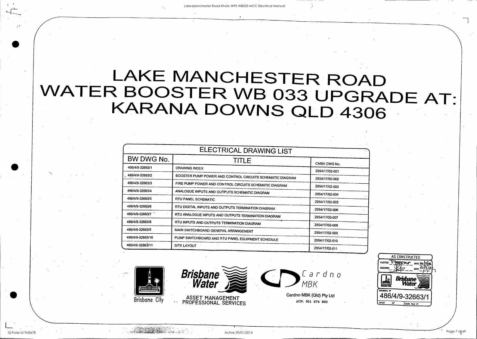
LAKE MANCHESTER ROAD WATER BOOSTER WB 033 UPGRADE AT: KARANA DOWNS QLD 4306 .
ELECTRICAL DRAWING LIST TITLE CMBK DWG No.
BW DWG No. 486/4/9-32663/1 DRAWING INDEX
2954/17/02-001 . 486/4/9-32663/2 BOOSTER PUMP POWER AND CONTROL CIRCUITS SCHEMATIC DIAGRAM 2954/17/02-002
486/4/9-32663/3 FIRE PUMP POWER AND CONTROL CIRCUITS SCHEMATIC DIAGRAM 2954/17/02-003 486/4/9-32663/4 ANALOGUE INPUTS AND OUTPUTS SCHEMATIC DIAGRAM 2954/17/02-004 486/4/9-32663/5 RTU PANEL SCHEMATIC
2954/17/02-005 486/4/9-32663/6 RTU DIGITAL INPUTS AND OUTPUTS TERMINATION DIAGRAM 2954/17/02-006 _
486/4/9-32663/7 RTU ANALOGUE INPUTS AND OUTPUTS TERMINATION DIAGRAM 2954/17/02-007 _
486/4/9-32663/8 RTU INPUTS AND OUTPUTS TERMINATION DIAGRAM .
2954/17/02-008 _
486/4/9-32663/9 MAIN SWITCHBOARD GENERAL ARRANGEMENT 2954/17/02-009
486/4/9-32663/10 PUMP SWITCHBOARD AND RTU PANEL EQUIPMENT SCHEDULE 2954/17/02-010
86/4/9-32663/11 SITE LAYOUT 2954/17/02-011
Brisbane City
Brisbane Water dag
ASSET MANAGEMENT PROFESSIONAL SERVICES
Cardno MBK
Cardno MBK (Qld) Pty Ltd ACN: 051 074 992
AS CONSTRUCTED
DATE
DATE /1) CVP
Water pRzA1786 /419-32663/1 SHEET OF 'MD FlIE
-
Lake Manchester Road Kholo WPS WB033 MCC Electrical Manual
Q-Pulse Id TMS678 Active 29/01/2014 Page 7 of 69

A
a
2 3 5 7 9 I 10 11
12 13 14 15 I6
C
D
E
F
13
H
INCOMERS FROM ENERGEX POLE No. 280577 SERVICE LINE TYPE 4625 ALUMINIUM (100 AMP CAPACITY)
FAULT LEVEL 10kA for 1 second ENRWB I I I 1
2
3
5
6
8
9
10
11
12
13
14
15
16
17
18
19
20
21
22
23
25
ENERGEX 'Ar kWh DIRECT CONNECTED METERING TARIFF 22
I I I 80A MCCB DEFEATABLE DOOR I/L
26
27
28
29
30
31
32
33
34
3S El
36
37
38
39
42
43
45
. 46
48
6A ./*
CRITEC SA7OKA SURGE DIVERTORS
111 10A H1
Ni
240V AC
RTU PANEL SUPPLY (REFER DWG. 486/4/9- 32663/5
30
6A PHASE FAILURE PHASE FAILURE RELAY IPFI
C.8.
r
N5 PLC & RTU DIGITAL INPUTS IN LINES 12 8. 43
11
20A BOOSTER C.B.
6A 13 1
SWITCHBOARD EMERGENCY STOP
RR1-1 116
FRUN -1
TRRI-1
EM STOP
--------01 FUN-2 %S2
117
115
120
119
V.F. DRIVE RUNNING TO CONTROL CIRCUIT TO LINE No. 20
V.F. DRIVE WARNING ALARM TO CONTROL CIRCUIT TO LINE No. 28
49 V.F. DRIVE READY CONT NUED ON DWG. TO CONTROL CIRCUIT
SO No. 486/4/9-32663/3 TO LINE No. 21
16
16
.18
A
.VF
POWER-BOX N
240V AC - 24VDC 5P.,- POWER SUPPLY -VE
19
THERMOSTAT ON PUMP 31 n TS
01 02 OPENS ON OVERTEMP SOLENOID VALVE TS;112
0 0 03 04
SVR
TEMPERATURE CONTROL RELAY 15
MOTOR COOLING WATER SOLENOID VALVE
SOLENOID VALVE RELAY 8
VFD7 -1 17 HRM I - HOURS RUN METER
7A VFOIR-I 7B 18 FLVFC11_. VFD RUNNING RELAY
1 READY 2 19 19, 6, 41 BOOSTER PUMP AVAILABLE 110 START 4, 39 0 /6\ u_
U. O ,_,
0113 ErRi VFW RUN RELAY -0I
1S2
FPA-3
8A VFD1W-1
114a (Ref 468/4/9-32663/3 line 101
112
25
23, 36
0 11411FRUN - FIRE RUN RELAY 37, 42
DANFOSS VFO1 UNIT
(TYPE VII 6008 SW. BD. FIELD
91 LI U 96 >- ft- 1
oi II 9212 V 97 111 0- rt.- 11
W 98
f>. -Li- II
II C7
I
93 L3
94 PE PE 95 In
RUN/ 8 STOP
5011
16 RESET 53
1PR.
117R-
12 COMMON 55
27 STOP STOP 32 SELECT
5011 SET UP 2
29 FIRE SPEED 541.
RELAY 07 VFO1R-1
42 18
7A
76
16
112 8A
RELAY 08 45 VFD1W-1
16 8B
19
READY .60
55
1SC
Owl
1W2
A11/2
ta-
ta- 0
PLC ANALOG INPUTS
101 A11/1- Ai-1-1 0
r MANUAL SPEED CONTROL 1K POTENTIOMETER
RS PART No. TC102805 TC581969 TC581931
A
FR1 BOOSTER PUMP FAULT RELAY 16. 45
BOOSTER PUMP (5.5kW. 11A)
1x3C..E.2.5sq.mm Cu. SCREENED CABLE
7°2 A11/2*
A11/2-
A01/1.
1610 3 A11/2- AI-1-2
104
PLC ANALOG OUTPUT
A01/1-
A01/1
1018 A01/1- AO -1 -1
119
BOOSTER PUMP MOTOR THERMISTOR
VF DRIVE MOTOR CURRENT
4-20mA RTU INPUT
VF DRIVE RUNNING SPEED
4 20mA RTU INPUT
VF DRIVE SPEED REFERENCE
4-20mA RTU OUTPUT
L
2 3 A 4 5
K6
PLC DIGITAL INPUTS
KS J6
---111/ 3
RTU 24V DC
(REFER DWG. 486/4/9-32663/51
011/0. BPA-1 011/0-
BOOSTER PUMP AVAILABLE 2 1
DI-1-0 COM -
11 0 34
24V DC INPUT SIGNALS
DI1/1. VFDI-2 Dm_ 5
R- DI1/2. SV1 D11/2- 7
BOOSTER PUMP VFD1 ON (PUMP RUNNINGI
4 2 01-1-1
-1.7)- <, SOLENOID VALVE OPEN 6 3
DI-1-2 011/7, RESET win_ BOOSTER PUMP ------111) ....r°-----0----C,------\)--. RESET (VFD1 FAULTI 17
16 8
011/15.
33
PF-1 0 011/5. R L
010 I o 13 152
15
011/6. FR1-1 0
01-1-7
011/15- 0---0 SITE MAINS ON
32 16
011/5-
01-1-15
BOOSTER PUMP
0-11 REMOTE MODE SELECTED
01-1-5
011/6- BOOSTER PUMP VFD1 FAULT
14 7 DI-1-6
."--41,--M-117-0----(29 28 g
FT-1
FLOWMETER FAULT
S 27
011/12. RESET 011/12-
24V DC OUTPUT MODULE 1
\)-- ATTENTION ALARM RESET " " D1-1-12
RTU 24VDC 69 (REFER OWG. 486/4/9-32663/S1
PLC DIGITAL OUTPUTS
17
167 COMM
CONTINUED ON OWG. 486/4/9-32663/3
RTU 24V AC SUPPLY (REFER DWG. 486/4/9-32663/81
BPA-2 DIN1
VF01-3 DIN2
PF-2 iD
11
0 148
DIN3
0 149
. FR1-2
COMM
DIN4
0 150
0 151
CONTINUED ON DWG. 486/4/9-32663/3
4A CI 0 142
LPRO TLC-02- )1 RTU MODULE BOOSTER PUMP AV
Li
BOOSTER PUMP START/STOP 24
BOOSTER PUMP STATUS
BOOSTER PUMP VFD I FAULT RESET 38
ATTENTION INDICATOR
O BOOS ' 'UMP VFD (PUMP RUNNINGI
0-' (<9 4, eisc
BLE
-I SITE MM
BOOSTER PUMP ' VF01 FAULT
24V
1
2
3
S
6
7
8
9
10
LEGEND
SWBD INTERFACE TERMINALS ( SWITCHBOARD I
SWBO VFD TERMINALS ( SWITCHBOARD I
RTU PANEL FUSE TERMINAL I 100 mA UNLESS NOTED I
-0- RTU PANEL LINK TERMINAL ( RTU PANEL )
-0- FIELD TERMINAL
EXTERNAL WIRING
RTU DIGITAL INPUT
11 N.> RTU DIGITAL OUTPUT
12
13
TS
16
17
18
19
20
21
22
23
24
25
26
27
28
29
30
31
32
33
35
36.
37
38
39
40
41
42
43
44
47
48
50
1. \I
II.,
RTU ANALOG INPUT 4 20mA
RTU ANALOG OUTPUT 4 20mA
NOTES:. 1. INCOMING AND PUMP CIRCUIT BREAKERS SHALL
BE LINE SIDE SHROUDED.
AS CONSTRUCTED
A
a
D
E
h1-4
PLoTtED*PttUNTICwh, ()ATE 500102.
CHECKED DATE
E 04962 AS BUILT WAS CARON° CRG 2954 17 02-062 OPM DATE AMENDMENT
MANAGER OF BUSINESS DATE ASSET SERVICES
MANAGER OF DATE OPERATIONS
MANAGER PROFESSIONAL DATE. SERVICES -ENGINEEFUNG
SUPERVISING . - FLP.E.O. NO. DATE CMIIK RJ. 45192 03/2032 ENGINEER '
CADD FILE
JOB FILE SURVEY NO
SURVEYED FIELD BOOK
DESIGN CUM 17.1161
DESIGN CHECK 20.11.01
DRAM PBX 21.11.01
DRAFTING CHECK CMBK 24.11.01 @Wow Oty
Brisbane Water j.sme'''''`i
WATER BOOSTER UPGRADES - LAKE MANCHESTER ROAD WATER BOOSTER WS 033
TraTER PUMP POWER AND CONTROL CIRCUIT
SCHEMATIC DIAGRAM
SCALE A.H. DATUM
OF DRAWING
486/4/9-32663/2 SHEETS
AMEND.
E 10 11 12 13 14
15 16 .
G
Lake Manchester Road Kholo WPS WB033 MCC Electrical Manual
Q-Pulse Id TMS678 Active 29/01/2014 Page 8 of 69

1 I
2 3 4 6 7 9 I 10
11 12 13 15 16
1
2
3
4
5
6
7
8
9
10
11
12
13
14
15
16
17
18
19
20
21
22
23
CONTINUED ON DWG. No. 486/4/9-32663/2
EN R WB
24
25
26
27
28 E2
29
30
31
32
33
34
35
36
3'1
38
39
40
42
43
45
46
48
49
50
N2
N3
N6
I TWIN IDERNATATI
6A 2
0-K 10A
1 1111TTIL VAR1A161 FAN
' COKIR41E9
BI
N2
N3
6A p, .
30mA RCD
P4A
P413
:== N4 DOOR SWITCHES
N6
VFD CUBICLE FAN
RTU CUBICLE FAN
VFD CUBICLE FAN
10A SINGLE GPO MOUNTED ON HINGED ESCUTCHEON OF THE SWITCHBOARD
8 WATT FLUORESCENT IN INCOMER CUBICLE
8 WATT FLUORESCENT IN VF DRIVES CUBICLE
8 WATT FLUORESCENT IN RTU CUBICLE
r
21
50A FIFE PUMP C.B
K Lo
6A 23
E2
26 VFD2-1 27
7A VFD2R -1 78 0
28
I READY 2
SWITCHBOARD EMERGENCY STOP
29
O cc 210 START *--0 0
( R
209 TC2-1 1211 -O S21
BA VfD2W-1 86 ..o DANFOSS
VFD2 UNIT (TYPE= VLT 6027
RFI
L1 --10 91 L1
L2 -S 92 L2
L3 93 L3
L-
U 96
V 97 N-
W 98
94 PE PE 95
e RR2-1 216 RUN/
'" STOP FRUN2-1
TRR2-1 217
215
16 RESET
212
0
HRM4 HOURS RUN METER
FD2 VFO RUNNING RELAY 6,43
DELI FIRE PUMP AVAILABLE 4, 41 Oro 486/4/9-32663/2 line 29
a I.
LL u_ z O
213ORR2 I I 0 VFD RUN RELAY 18, 31
2S
FRUN2 2140
FIRE RUN RELAY 32,38
FR2
SW. BD. FIELD
SO.
53111
55 111
12 COMMON .24V EN STOP 220 EMERGENCY -ill.° R i 527 STOP i i 0_41218 32 SELECT
SET UP 2 252
FRUN2-2 219
Vf. DRIVE RUNNING TO CONTROL CIRCUIT TO UNE No. 8
V.F. DRIVE WARNING ALARM TO CONTROL CIRCUIT TO LINE No. 18
V.F. DRIVE READY TO CONTROL CIRCUIT TO LINE No. 10
26
2PR.
2PR-
2SC
29 FIRE SPEED
50.
1-
2W1
FIRE PUMP FAULT RELAY 16,45
FIRE PUMP (18.5kW, 34.1A)
1x3C..E.10sq.mm Cu. SCREENED CABLE
MANUAL SPEED CONTROL 1K POTENTIOMETER
RS PART No. TC102805 TC581969 TC581931
RELAY 07 5411 VFO2R-1
7A 1 42s. 28 A11/3.
13
I . 7
2W2
RELAY 08 26 VFO2W-1
5 ----111R-oz-i 1s A11/4.
212 111 / 39 IF A114- ...C.
26 88 READY -..
29
. 60
55 OE
A01/2 A01/2..ik___ 2
A01/2- 120
0 A01/2- AO-1-2 . i
105
106 0
107
0 108
0
PLC ANALOG INPUTS A11/3..1
A11/3- AI-1-3
A11/ 4..
A11/4- AI-1-4
PLC ANALOG OUTPUT
FIRE PUMP MOTOR THERMISTOR
VF DRIVE .
MOTOR CURRENT 4-20mA RTU INPUT
VF DRIVE RUNNING SPEED
4 20mA RTU INPUT
VF DRIVE SPEED REFERENCE
4-20mA RTU OUTPUT
K6
PLC DIGITAL INPUTS
CONTINUED FROM OWG, 486/4/9-32663/2
24V DC INPUT MODULE 1
DI2/0. FPA-1 012/0-
36 1
17 A 0_ FIRE PUMP AVAILABLE
0I-2-0 COM -
012/1. VFD2-2 012/1- 39
38 2 \)-
R L
* 0 2S2
FR2-1
24V DC OUTPUT MODULE 1
01 -2 -1
FIRE PUMP VFD2 ON (PUMP RUNNING)
0 ,(e.' NJ' FIRE MODE SELECTED
42 * DI-2-3
i --(/ CONTROL MODE SELECTED 0
DI-2-10
FIRE PUMP
0-4 RESET (VFD2 FAULT)
01-2-7 57--/ 8(
FIRE PUMP 012/5- 0 C' REMOTE MODE SELECTED
46 6 01-2-5
FIRE PUMP 012/6- 0 (z VFD2 FAULT 48 7 DI -2 -6
PLC DIGITAL OUTPUTS CONTINUED FROM DWG. 486/4/9-32663/2
1
A .comm
24VAC CONTINUED FROM DWG. 486/4/9-32663/2
FPA-2 DINS
VFD2-3 DING ./3
FR2-2
0 152
DINT
0 153
O 154
24V
FIRE PUMP START/STOP 14
FIRE PUMP STATUS
VFD2 FAULT RESET 33
RO TLC -02-01 RTU MODULE
O FIRE PUMP AV BLE
UMP ON (PUMP RUNNING)
FIRE PUMP VFD FAULT
1
2
3
4
6
1
13
9
10
11
12
13
15
NOTES: 16
1. INCOMING AND PUMP CIRCUIT BREAKERS SHALL BE LINE SIDE SHROUDED.
LEGEND
56/80 INTERFACE TERMINALS ( SWITCHBOARD I
-M- SWBD VFD TERMINALS ( SWITCHBOARO I
-0-- RTU PANEL FUSE TERMINAL I 100 mA UNLESS NOTED
RTU PANEL LINK TERMINAL ( RTU PANEL
-0- FIELD TERMINAL
EXTERNAL WIRING
RTU DIGITAL INPUT
.> RTU DIGITAL OUTPUT
I
I
RTU ANALOG INPUT 4 20mA
RTU ANALOG OUTPUT 4-20mA
17
18
19
20
21
22
23
24
25
26
27
28
29
30
31
32
33
34
35
36
37
38
39
40
43
AS CONSTRUCTED
PLOTTED 1:3 1,101Tralr CHEERED
A
B
C
N-0
DATE 1(41101 DATE
E 10.09.02 AS BUILT. WAS CM NO DRG 2954 17 02.003 DPM 4V4 DATE AMENDMENT MKS, MANAGER OF BUSINESS ASSET SERVICES
DATE
MANAGF_Ft OF OPERATIONS
DATE
MANAGER PROFESSIONAL SERVICES - ENGINEERING
DATE
SUPERVISING ENGINEER CMBK RJ. 05192 03/2002
R.P.E.O. NO. DATE
CADD FILE
JOB FILE SURVEY NO.
SURVEYED FIELD BOOK
DESIGN OINK 17.11.01
DESIGN DECK 20.11.01
DRAWN CORK 21.11.01
DRAFTING CHECK 24.11.01 lkisbane Cty
Water Brisbane
WAR BOOSTER UPGRADES - 46 LAKE MANCHESTER ROAD 47 WATER BOOSTER WB 033 48
POWER AND CONTROL CIRCUIT 49 SCHEMATIC DIAGRAM 50
SCALE A.H. DATUM
OF SHEETS DRAWING W
486/4/9-32663/3 AMEND.
E 2 I 3 I 4 I 5
10 I 12 13 14 15 18
Lake Manchester Road Kholo WPS WB033 MCC Electrical Manual
Q-Pulse Id TMS678 Active 29/01/2014 Page 9 of 69

\I
\II
6
C
E
F
0
H
11 12 I 13 14
15 16
TO VFDI TERMINALS REFER - DWG. No. 486/4/9-32663/2
TO VF02 TERMINALS REFER - DWG. No. 486/4/9-32663/3
4-20mA
4-20MA
4 -20mA
All /3- 1060
4-20mA
ROSEMOUNT 2088 PRESSURE TRANSMITTER
( SUCTION
MOUNTED (W ) - IN PUMP PIT
(Bk) 11
RTU ANALOG INPUTS MODULE 1
A11/1- 1020
A11/1. 101
tf
AI1/2- 1040
A11/2. 103
A11/3. 105
o A11/4- 108
A11/4. 107
17
\I
A11/5- 110
A11/5. 109
L100mA FUSES
RTU 24V DC REFER DWG. 486/4/9-32663/5
16 111
+ I-
I J7 1110 17
NYLON TUBE TO TAPPING POINT IN PIPE
4-20mA
BOOSTER PUMP MOTOR CURRENT
VFD1 BOOSTER PUMP RUNNING SPEED
FIRE PUMP MOTOR CURRENT .
FIRE PUMP VFD RUNNING SPEED
\J SPARE
A11/6.
T 1120
ROSEMOUNT 2088 - RTU 24V DC DELIVERY PRESSURE REFER DWG. 486/4/9-32663/5
TRANSMITTER +
I MOUNTED 117 17 (WI J6 113 1 .17
NYLON TUBE TO TAPPING
IN PUMP PIT +
A A11/7. If (Bk) 4 4-20mA
114 REFLUX IN DELIVERY ZONE 1 POINT IN DELIVERY SIDE OF
F ELPRO TLC-02-01 1
L COMM L] AIN2 1A COMM I AIN2 _116
ABB-MAG FLOWMETER 240V AC REFER DWG. J oA No. 486/4/9-32663/5 L. NIA oN
PROPRIETARY CABLE - TO FLOWMETER HEAD
VFD1 SPEED CONTROL. TERMINALS REFER DWG. No. 486/4/9-32663/2
VFD2 SPEED CONTROL TERMINALS REFER DWG. No. 486/4/9-32663/3
ft 11 4-20mA
11 A11/8.
J PUMPS SUCTION PRESSURE
PUMPS DELIVERY PRESSURE
PUMPS DELIVERY FLOW
RTU ANALOG OUTPUTS MODULE 1
100mA FUSES -1
I A01/1. * \I' BOOSTER PUMP
4-20mA 118 VFD SPEED CONTROL
1190 A01/1-
A0112
4-20mA 120
1210 A01/2-
12 A01/3.
12S-/-A01/3-
1240 A01/4.
A01/4- 1250"
L IFIRE PUMP VFD SPEED CONTROL
II, AI SPARE
IL Al SPARE
LEGEND
R.T.U. FUSE TERMINAL
O R.T.U. DISCONNECT TERMINAL
0 SWITCHBOARD TERMINAL
SWITCHBOARD VFD TERMINAL
C. \
IL
RTU DIGITAL INPUT
RTU DIGITAL OUTPUT
RTU ANALOG INPUT
RTU ANALOG OUTPUT
NOTES: 1. RTU FUSE TERMINALS ARE FITTED WITH 100mA
FUSE-LINKS UNLESS OTHERWISE SHOWN.
AS CONSTRUCTED
PLOTTED DATE I eb LQ CHECKED DATE
10.0902 AS BUILT. WAS CARON° ORG 2954 17 02431 DPM DATE AMENDMENT
MANAGER OF BUSINESS ASSET SERVICES
DATE
MANAGER OF OPERATIONS
DATE
MANAGER PROFESSIONAL DATE SERVICES - ENGINEERING
SUPERVISING ENGINEER
FL P.E.O. NO. DATE CMBK KJ. 35192 022002
CADD FILE
JOB FILE SURVEY NO SURVEYED FIELD BOOK / DESIGN CMBK 17.11.01
'54.
DESIGN CHECK OW 20.11.01
DRAM CUBIC 21.111 -0
DRAFTING CHECK CUBK 24.11.01 itbb" C17
Brisbane Water j;..A-ZgEr`me....,:-..an
WATER BOOSTER UPGRADES - LAKE MANCHESTER ROAD WATER BOOSTER WB 033
ANALOGUE INPUTS AND OUTPUTS SCHEMATIC DIAGRAM
SCALE
DRAWING W
A.H. DATUM
N' OF SHEETS
486/4/9-32663/4 AMEND.
10 11 I 12 1 13 13 16
Lake Manchester Road Kholo WPS WB033 MCC Electrical Manual
Q-Pulse Id TMS678 Active 29/01/2014 Page 10 of 69
12 13 14 15
CUTE( SUM
PROTECTION
HI
Ni
EARTH BAR
r-C
2A
NIA
POWER SUPPLY
40Y
6A
110 NIA
COIQUTER
GPO
NIA
((PRO ETU GPO
24AX
BATTERIES 2 X 6.5 Ah
- -It- sAtfP
95
80
SEE FRE PIMP SMTCHOURD SOOMATE CUORAM
REFER OWE 686/1/9-32663/3
0E SI
ROVi trelgEEI
a; g Egggggm iex
ex ex
girif.1417... 7111
° ^ r!. E
OL CC
000 -16
440 0
.\3
VA
1111-0
ELPRO RTUJ
NOTES:
I. TERMINAL NUMBERS SHOWN EITHER IMMEDIATELY BELOW, RIGHT OR LEFT OF THE TERMINAL
. 2. ALL FUSED TERMINALS TO BE FITTED MTH IONA FUSE-LINKS UNLESS NOTED OTHERWISE.
LEGEND:
RELAY OR
CONTACTOR COIL
R.T.U. RISE TERMINAL (NOTE 21
O R.T.U. LINK TERMINAL
SAMP 87
68
E
2.10T -V00.2:
El es ° V V V m SPARES
1.4,(}o61111&1611111 see see oeo see see coo° lel lellIlleeeeeeeeeeeeeeee VI 2 19 IS 11 12 23 21. 6 25 26 21 28
w 29 30 31 32 8 NO NC c
DO 9
NO NC C
00 10
NO NC C
DO 11
NO NC C
D012
NO NC C
00 13
NO NC C
DO 14
NO NC C
DO 5 NO NC C
00 16
+ - Al 1
4 - A18
+ - Al 9
+ - A110
+ - AI 11
+ - M 12
24V OV + - AO 3
24V OV + - AO 4
ETHERNET INPUTS OUTPUTS
C000000000000000) (00000000) 11 18 19 20 21 22 23 24 25 26 21 28 29 30 31 32 9 10 11 12 13 14 15 16
IrDA
o PDS COMPACT
( DC 4-
IN
( DC OUT I e
( PORT 0
( PORT
DIAGNOSTICS
eNET SERIES RTU INPUTS OUTPUTS
1
( PORT 2
CO 000000000000000) (0. 0000000)
1 2 3 4 5 6 1 a 9 10 11 12 13 U. 5 16 1 2 3 4 S 6 7 8 R. T. 0 0
( RADIO RF RUN
0
( LANDLINE
1 2 3 4 5 6 7 8 fi 9 10 11 12 w
13 14 5 16 8 C NC NO
DO 1
C NC NO
DO 2
C NC NO
00 3
C NC NO
DO 4
C NC NO
DOS
C NC NO
DO 6
NC NO
DO 7
NC NO
DO 8
- +
All - +
Al 2
- +
Al 3
- +
All - +
A15
- +
Al 6
AO 1
- + 01/14V
AO 2
- + OV 24V gam; cirri am; ram 0 ' . I-& '® 0 ri71CLIILI7CZI is § A
"b-o-o-o"dleo
a 0 z
t
S" ooi
/15 11! t111 II g
5- PIE 1 111N111 gggIllgi
REFER DWG. 486 /U9- 32663/2 SCHEMATIC DIAGRAM
SI
18
Ea #40,,H1
/204
0
80
SEE ANALOGUE VO SCHEMATIC DIAGRAM
REFER DWG. 486/ 4/9-32663/ 4
1
18
Is
Ex-
2 AYP
19 12
93
C{M
092
5AHP 91
12 -
CONVERTER
VDC
111
AMP 0 89 90
12 MASTER() PSTN "WOOMERA" MODEM
TELSTRA PSTN LINE 32012593
AS CONSTRUCTED -4
PLOTTED Pmotroi-c CHECKED
DATE tqlin, DATE
E Kam AS BUILT DATE AMENDMENT INMALS,
MANAGER OF BUSINESS ASSET SERVICES
DATE
MANAGER OF OPERATIONS
DATE
MANAGER PROFESSIONAL. SERVICES- ENGINEERING
SUPERVISING R.P.E.C1. NO. DATE ENGINEER CMBK RJ. 05192 0372032
DATE
CADD FILE
JOB FILE
SURVEYED
4313 4_11-32653_544.vE0w9
SURVEY NO.
FIELD BOOK
'DESIGN CMBI( A
17.11,01 'S,
DESIGN CHECK BW 20.11.01
DRAWN CMESK 21.11.01
sORAFTHO CHECK CMBK 24.11.01 004...4 CRY,
BrialreerAs WATER BOOSTER UPGRADES - LAKE MANCHESTER ROAD WATER BOOSTER WB 033
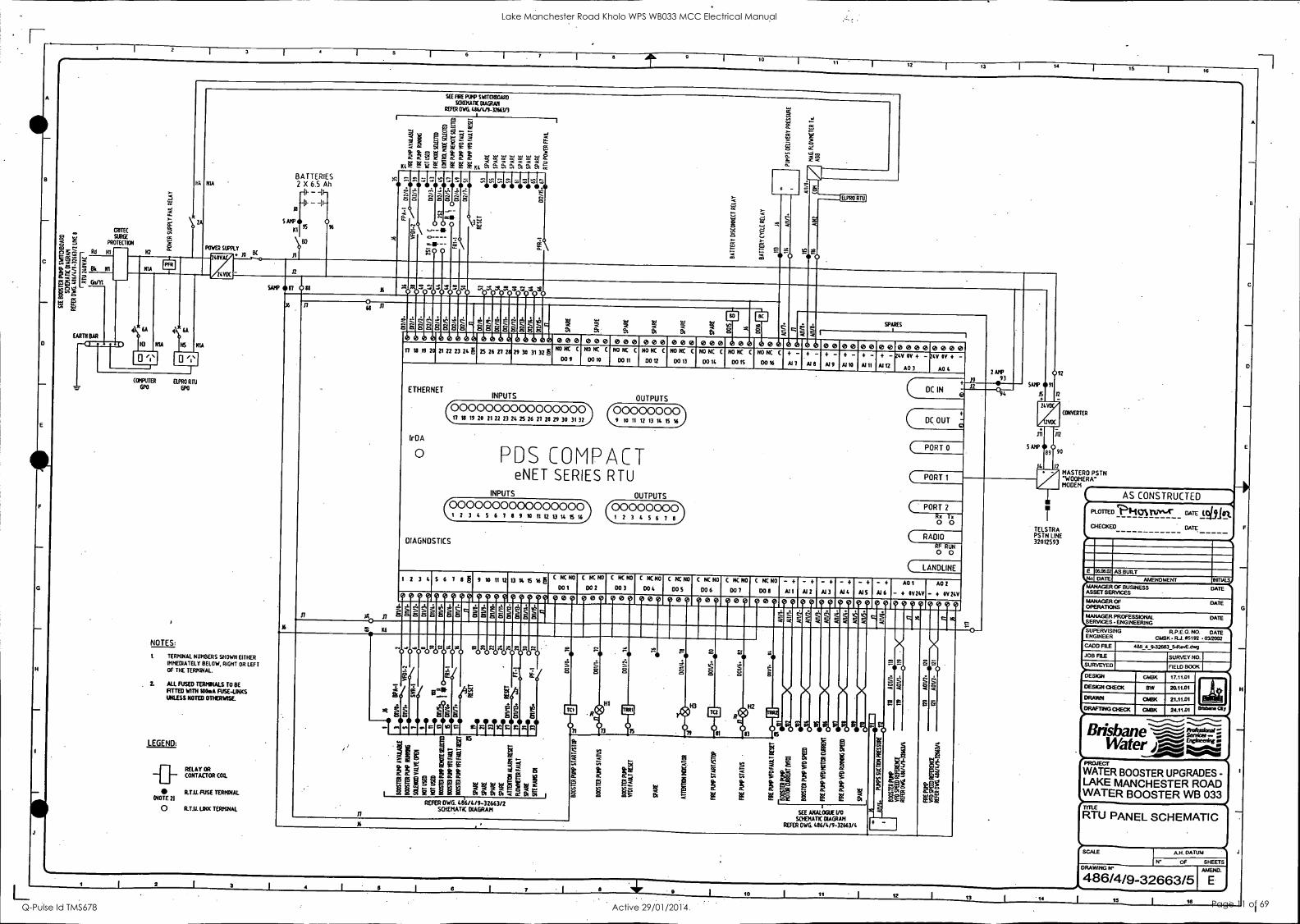
RTU PANEL SCHEMATIC
SCALE
DRAWING PC
DATUM
SHEETS OF
486/4/9-32663/5 AMEND.
E 2 4 6 a I 7 0 10 11 12 13 11 I 16 I 18
Lake Manchester Road Kholo WPS WB033 MCC Electrical Manual
Q-Pulse Id TMS678 Active 29/01/2014 Page 11 of 69

2 T 3 I I I 6
BOOSTER AND FIRE PUMPS CUBICLE
BOOSTER PUMP DIGITAL INPUTS
II A /(1WI DI1/0. (125::
(zwi 011/1, VFD1- 2 011/1- (28k) ----3
(3W) 0I1/2 SVR-1 011/2- (381,1_, . -----43
)6W) 011/7. RESET 011/7- (68k)
--1-° )9W1 011/1S. PF-1 011/15- (98k)
-----c) R L ' )4W) 011 /5.0 ili : o 011/5- (48k)
)SW) DI1/6. FR1-1 011/6- (58k) .-----°
13%.11!)11/11J14 011/13- (88k)
37W) 011/12. RESET 011/12- (78k) -r°
011/0- (18k)
FIRE PUMP DIGITAL INPUTS
)10W) 012/0. FPA-1 (108k) -----°
piWi 012/1. VF02-2
012/0-
012/1- (118k) ...-----°
)12W) D12/3.041F ° 012/3- (128k)
)15W) DI2/4.0 i 40 SI
012/4- (15Bk)
)13w1 012/7.,. RESET 012/1- (138k)
12/5- (148k) )16W) 01215.0 ; 1:1
)1SW) DI2/6. FR2-1 012/6- (158k)
BOOSTER PUMP AVAILABLE
BOOSTER PUMP VFW ON (PUMP RUNNING)
SOLENOID VALVE OPEN
BOOSTER PUMP RESET (VFD1 FAULT)
SITE MAINS ON
BOOSTER PUMP REMOTE MODE SELECTED
BOOSTER PUMP VFD1 FAULT
FLOWMETER FAULT
ATTENTION ALARM RESET
FIRE PUMP AVAILABLE
FIRE PUMP VF02 ON (PUMP RUNNING)
FIRE MODE SELECTED
CONTROL MODE SELECTED
FIRE PUMP RESET (VF02 FAULT)
FIRE MP PU REMOTE MODE SELECTED
FIRE PUMP VF02 FAULT
1
1
1
I
I
a 10 t1 T 12 13 I 14 15
16
TERMINALS
011/0-
I
24V DC REFER OWG. No.
HUNTER WATERTECH
RTU LOCATED
R.T.U.
AT RTU
CUBICLE
PANEL
BOOSTER PUMP AVAILABLE
BOOSTER PUMP RUNNING
SOLENOID VALVE OPEN
NOT USED
NOT USED
BOOSTER PUMP REMOTE NODE SELECTED
BOOSTER PUMP VFO FAULT
BOOSTER PUMP VSD FAULT RESET
SPARE
SPARE
SPARE
SPARE
ATTENTION ALARM RESET
FLOWMETER FAULT
SPARE
SITE MAINS ON
FIRE PUMP AVAILABLE
FIRE PUMP RUNNING
NOT USED
FIRE PUMP FIRE MODE SELECTED
FIRE PUMP NORMAL MODE SELECTED
FIRE PUMP REMOTE MODE SELECTED
FIRE PUMP VFD FAULT
FIRE PUMP VSD FAULT RESET
SPARE
SPARE
SPARE
SPARE
SPARE
SPARE
SPARE
SPARE
486/4/9-32663/5 16
1_,..Bk 011/0- (COM)
Lw 011/0.
DI1/1- 2
DNA- 4
5
011/2- 3
41. 001111;
L 011/2.
ON/3- 4
USED
4-r-Bk 011/5-
8
1311/4- 5
{NOT 10
-4 011/5-
6 U Lw DIVS.
_._Bk 011/6- 13
ON/6- DIGITAL
7 INPUTS 14 Lw 011/6.
DI1/7- 1-16
8 6 k D11/7-
16
Lw 011/7. -4 011/8-
9
SPARES
011/12 -
18
19 -EE1- 011/9-
10 20
011/10- 11
21
22
011/11- 12
23
24
011/12- 13
25
26 LW 011/12.
DI1/13- DI1/13- 14
27 --EE1- 28
Lw DI1/13.
D11/14- 15
29
SPARE{ 9 Bk 011/1S-
30
011/1S- 16
31
32
-EB-
(REFER DWG. No. 486/4/9- 32663/5)
DC-
24V DC.
-Ew DI1/15. 33
17 17 34
16 K4
012/0-
(COM)
35 (COM) 17
10,_Bk 012/0 - 36
LW D12/0. 37 -Ea-
012/1- 18 11.-Bk 012/1- 38
AS CONSTRUCTED Lw DI2/1.
012/2- 19
39
PLOTTED pp-tcrsiv,4- oarEttilliat OiECKED DATE
NOT USED -[ 12_[Bk D12/3-
40
012/3- 20
41
'42 .
DI2/4- 21
w -1E3-
012/5- 22 46 W /5.
012/6- DIGITAL INPUTS
E 060102 AS BUILT 012/6- 0 DATE AMENDMENT WRNS
19,_Bk Lw D12/6..
48
012/1-
23 17-32
24 MANAGER OF BUSINESS DATE ASSET SERVICES
49 1312/7-
50 MANAGER OF DATE OPERATIONS
(REFER DWG. Na. 24V DC- 486/4/9-32663/S)
L-w 012/7.
012/8-
A 25
51 -(E3-
SPARES -
.17
52 -1E3- MANAGER PROFESSIONAL DATE SERVICES ENGINEERING
012/9- 26 S3
SUPERVISING RP.E.O. NO. DATE ENGINEER CMBK R.J. 05192 032002
012/10- SS
GADD RIB 434 4_9-32663 6-RwEAN/3 56
012/11-
27 JOB FILE SURVEY NO
SURVEYED FIELD BOOK 58
012/12-
28
29 DESIGN CMBK 17.11.01
59
60 DESIGN CHECK 13W 20.11AI
61 DRAWN CASK 21.11101 62 012/13-
012/14-
30' DRAFTING CHECK CASK 24.11101 914b4ne aty 63
Brisbane Water .'-'E***41`ri
64
012/5-
31 65 66
3'1
32
(COM)
67
WATER BOOSTER UPGRADES - LAKE MANCHESTER ROAD WATER BOOSTER WB 033
RTU DIGITAL INPUTS AND OUTPUTS TERMINATION DIAGRAM
A.H. DATUM
OF SHEETS DRAWING Br
486/4/9-32663/6 AMEND.
E 1 2 2 I 4 I 7 I a
14 15 I 16
Lake Manchester Road Kholo WPS WB033 MCC Electrical Manual
Q-Pulse Id TMS678 Active 29/01/2014 Page 12 of 69

2 3 4 5 6 I 7 a 9 10
11 1 12 13 14 15
I t6
BOOSTER PUMP DIGITAL OUTPUTS
17W) 001/0. nTC1 001/0- (1713k)
)18W1 001/1. (0111 001/1- (188k) R
)19W) 001/2. 11TRR1 D01/2- (198k)
ROW) 001/4. ?H3 001/4- 12013k)
FIRE PUMP DIGITAL OUTPUTS
)21W1 001/5. fiTC2 001/5- (215k)
)22W) 001/6* gh..H2 D01/6- 1228k)
)23W) 001/7. 0TRR2 001/7- (235k)
BOOSTER PUMP START/STOP
BOOSTER PUMP STATUS
VFD1 FAULT RESET
ATTENTION INDICATOR
FIRE PUMP START/STOP
FIRE PUMP STATUS
VFD2 FAULT RESET
24V DC.
BOOSTER PUMP V.F. DRIVE 1
REFER DRAWING: - 486/4/9- 32663/2
r r V.F. DRIVE L MOTOR CURRENT
V.F. DRIVE L RUNNING SPEED
IC V.F. DRIVE L SPEED CONTROL
FIRE PUMP V.F. DRIVE 2 REFER DRAWING: - 486/4/9- 32663/3
FLMOTOR CURRENT r V.F. DRIVE
r V.F. ORIVE L RUNNING SPEED
V.F. DRIVE SPEED CONTROL
- -
; BOOSTER AND FIRE I PUMPS CUBICLE
A11/1.
A11/1-
A11/2. A11/2- A01/1. A01/1-
A11/3- A11/4. All /4-
A01 /2. A01/2-
Bk1 1 W
Bk
_ - 15 W
-
ABB MAGMASTER SENSOR
amgCEMMIO
Ost Slot S1G2
0S2
COI CO2
430
FLOWMETER VENDOR'S TRANSMITTER
.5
4 CABLE
I A .01.111/ 02m ee 10M
(APPROXI
051 L
quath , S 1 S1221 HE
0S2
111 ®
1.1.1.11 CIFEer CD COM 01111.I.MW CO2 K. CO2
IC-
H6
- - -- - - - - HUNTER WATERTECH R.T.U. CUBICLE
RTU TERMINALS LOCATED AT RTU PANEL
K6
001/0.
16
W D01/0 LBk 001/0-
,_10 W D01/1. TBk 001/1-
_19 w 001/2 TB', D01/2-
SPARE
_20 (IT / -[Bk 001/4-
21 w 001/5. tBk 001/5-
_22 rEsk 001/6-
1 w 001/7. 6k 001/7-
CIDNI 4=MI DI1/13
24 VOLT DC (REFER DWG. No. 486/4/9-32663/51
12 VOLT DC (REFER DWG. No. 486/4/9-32663/51
AB LO
B MAGMASTER FWMETER SENSOR:
ROSEMOUNT 2088 PRESSURE TRANSMITTER .16 WI-K 101 > (SUCTION) 4-20mA t AI1/6. Bk-1
-r- MOUNTED IN PUMP PIT 4 PAIR OEKERON
15m (APPROX.) ROSEMOUNT 2088
PRESSURE TRANSMITTER 4-20mA. (DELIVERY)
MOUNTED IN PUMP PIT
.16
A11/7. W 2- BkT
A11/8.
32
111
J12
69
70
71
72
73
-.-1224V 0C-.-- 001/1.
74 001/2. 75
76 -4EO- TI 78
2
3 DIGITAL
OUTPUTS
001/4.._ 4
1-8
001/3.
79
80 D01/5.
81
82
83
81.
S
.-- 6
001/6. 7 --
001/1. 85
86 MELO
-1E3- 88
89 -IIE3-
BATTERY K1
90
___, 13
1- 12V/24V CONVERTER
1-- RADIO
15
12 1- 24/12 CONVERTER
19
n } PDS500
18
J2 }BATTERY SUPPLY
1- SPARES
A11/1.
J2
J4
91 -E3- 92
93
94
DISCONNECT RELAY
240V AC
POWER SUPPLY REF DWG:- 486/4/9-32663/5
FLOWMETER FAULT SIGNAL TO R T U REF DWG:- 486/4/9-32663/2
COMA AIN2
-r-1 TO TERMINALS 109 AND 110 ON
DWG:- 486/4/9-32663/8
-[SPARES
95 -1E3- 96
97 -1E3- 98
99 -1a3- 100
1w A11/1.
w 1111/2.
T.Bk A11/2- w A11/3.
T_Bk A11/3- W A11/4.
TBk A11/4-
1-,-W 143,k A11/6.
2 -43k A11/7.
W A11/8.
Bk 24V DC ri
SPARE -[
101
8
DIGITAL OUTPUTS
9-16 NOT USED
02
103 -1E3- 104
105 -/M1-
WI
108 -1E3- 109 -4E1-
AM/1- AU/2. AM/2- A11/3. AM/3- A11/4. AM/4- A11/5.
010 AM/5-
111 -4E1- 112
113
114
15
116
J6 24V DC.I A11/6.
.16 21.V DC., A11/7. A11/8. A11/8-
w A01/1 Ilk A01/1
w A01/2 Tak A01/2
SPARES-{
UNUSED - TERMINALS
115 A01/1.
BOOSTER PUMP START/STOP-
BOOSTER PUMP STATUS
BOOSTER PUMP VFD1 FAULT RESET
SPARE
ATTENTION INDICATOR
FIRE PUMP START/STOP
FIRE PUMP STATUS
FIRE PUMP VFD FAULT RESET
A
1
2
3
ANALOG 4 INPUTS
1-12 5
6
7
8
CHANNELS 9-12
NOT USED
REFER DWG. No. 486/4/9-32663/5 -FOR TERMINATION DETAILS
119
120
121
A01/1- A01/2. A01/2-
) A01/3.
123 A01/3-
121. -E3- A0114.
125 A01/1.-
126
227
128
129
130
et 132
133
134,
135
136
138
139 SHIELD
11.0 SHIELD SHIELD
2 ANALOG OUTPUTS
3 1-4
4
BOOSTER PUMP MOTOR CURRENT
BOOSTER PUMP VF01 RUNNING SPEED
FIRE PUMP VFD MOTOR CURRENT
FIRE PUMP VFD RUNNING SPEED
SPARE
PUMPS SUCTION PRESSURE
PUMPS DELIVERY PRESSURE
PUMPS DELIVERY FLOW
BOOSTER PUMP VF01 SPEED CONTROL
FIRE PUMP VFD2 SPEED CONTROL
SPARE
SPARE
AS CONSTRUCTED
PLATTED POW% T5-1'1/41- DATE l Oil LOL
CHECKED DATE
E 0708.02 AS BUILT DATE AMENDMENT INMALS
MANAGER OF BUSINESS DATE ASSET SERVICES
MANAGER OF DATE OPERATIONS
MANAGER PROFESSIONAL DATE SERVICES 'ENGINEERING
SUPERVISING FLP.E.CL NO. DATE ENGINEER CMBK -RJ. 95192 032002 GADD FILE 486_4 9-32663/7RevE.dwp
JOB FILE SURVEY NO.
SURVEYED FIELD BOOK
DESIGN CMBK 17.11.01
DESIGN CHECK SW 20.1191
DRAWN CMFIK 21.11.01 FA DRAPING CHECK 0413K 24.11.01
Wotan. Clty
Brisbane Water
WATER BOOSTER UPGRADES - LAKE MANCHESTER ROAD WATER BOOSTER WB 033
RTU ANALOGUE INPUTS AND OUTPUT TERMINATION DIAGRAM
SCALE Ail DATUM
OF SHEETS DRAWING IV
486/4/9-32663/7 AMEND.
E 2 3 4 5 10 11 12 13 14
I 1S 16
D
Lake Manchester Road Kholo WPS WB033 MCC Electrical Manual
Q-Pulse Id TMS678 Active 29/01/2014 Page 13 of 69

P - BOOST- ER AND F- IRE PUMPS CUBICLE
BOOSTER PUMP DIGITAL INPUTS
BPA-2
VF01-3
PF-2
FRI-2
DINI (11314 BOOSTER PUMP AVAILABLE
DIN2 (2W)
DIN3 (2Bk)
DIN4 (3W)
FIRE PUMP DIGITAL INPUTS
FPA-1
VFD2-2
VFD2W-1
(IWI COMM
DINS 1313k1
DIN6 (4W/
DINT (48k)
BOOSTER PUMP VFD 1 ON (PUMP RUNNING)
SITE MAINS ON
BOOSTER PUMP VFD 1 FAULT
FIRE PUMP AVAILABLE
FIRE PUMP VFD 2 ON (PUMP RUNNING)
FIRE PUMP VFD 2 FAULT
/6\ -ErMETERS43- REFER 486/4%-2663/7
ELPRO TLC-02-01 RTU MODULE
RTU TERMINALS LOCATED AT RTU PANEL
141
142 SPARE -143
(LOOP POWEREDI-c -144 A N2
145 COMM
.
(1W) COMM
(IBM (214)
128k)
(3W)
(3Bk) (4W1
(4Bk)
DINI
DIN2
DIN3
DIN4
DINS
DIN6
DIN?
SPARES -
146
147
148
149
AIN2
COMM
DINt
DIN2
150
151
152
153
154
DIN3
DIN4
DINS
DIN6
DIN7
155
156
157
1513
159
160
161
162
163
164
DIN8
DIN9
DIN10
DIN11
DIN12
'DOT' 10072 100T3 10074
3
6
9
10
11
12
13
14
15
16
17
18
19
20
NOTES:
THE ELPRO TLC-02-01 RTU MODULE WILL BE JJSED AS AN INTERFACE MODULE TO TRANSMIT MONITORING SIGNALS OF THE PUMP STATION TO THE BRISBANE WATER CENTRAL CONTROL ROOM FOR THE SHORT TERM UNTIL THE PROPER RTU INFRASTRUCTURE IS IN PLACE.
AS CONSTRUCTED
PLOTTED PHONT47.4A-
CHECKED
DATE (0
DATE
C 10.0202 AS BUILT WAS CARDNO ORO 2954_17 crloas DPM DATE AMENDMENT MMALS
MANAGER OF BUSINESS ASSET SERVICES
DATE
MANAGER OF OPERATIONS
DATE
MANAGER PROFESSIONAL SERVICES - ENGINEERING
DATE
SUPERVISING R.P.E.O. NO. DATE ENGINEER GLIBK - R.J. 85192 0312002
CADO FILE
JOB FILE SURVEY NO..
VURVEYED FIELD BOOK 1.
DESIGN CASK 17.11.01
DESIGN CHECK
DRAWN
8W 20.11.01
DISK 21.11.01
DRAFTING CHECK ChM 24.11.01
F
Brisbane - Water ift-ri0
WATER BOOSTER UPGRADES - LAKE MANCHESTER ROAD WATER BOOSTER WB 033
RTU INPUTS AND OUTPUTS TERMINATION DIAGRAM
SCALE
DRAWING N
A.H. DATUM
OF SHEETS
486/4/9-32663/8 AMEND
C 2 3 4 6 7 1 9 11 1 12 14 15 I 18
Lake Manchester Road Kholo WPS WB033 MCC Electrical Manual
Q-Pulse Id TMS678 Active 29/01/2014 Page 14 of 69
2 3 4 6 B 10
12 I 13 14 15 i 16
75
SIDE DOOR COVERS - OFF-REMOTE-FIRE SELECTOR SWITCH
FILTER IN DO OF SWITCHBOARD
40
1810
630 550
IE;) 550
t25
41--AERUL 640 PPE FOR RTU ANTENNA GALVANISED WATER SUPPORT OVERALL
WITH 040 GALVANISED CAP X.,... HOWE 400010
FOLD DOWN L
DOOR`
UUFLuoR041 sw
I
T'STA
. .. . t - 690w400r6ale ENERGEX .4r 30
PETER
DOOR SWITCH
TRAY 510:35
TLE-C BOOSTER PUMP
VFO TYPE
VLF WI
ARE PUMP TYPE
ALT 6021
DOUBLE HMO BAKELITE WAGE%
PETER PANEL POS COMPACT
. PREY RTU
A MIR
22
s
ELPRO KU HOULE
LONA noes SD STARLESS Si
EITTEP
1N0
. .
i Liu I TWORO au 'ilsi SWITCH
[ rMSEVPGM PI E4 1.0 Mao PVC DUCT
EA.
V .., ',I -
00ABOno PVC DUCT
. r CON
1001 O's M constx.
III GE150..211 TVs
R010E01 rx
s L-
I
I
i
;4. I I -. i .3B500.3gim 910 PROTELIKII ETU
BAI mu' N. SEALED
VENT1U
75 x 40mm V CHANNEL PLINTH. GALVANISED, BOLT ON OUTDO WITH G L L-. L-
FRONT VIEW
TOP
2-01
EEL V BOLTS
REMOTE-OFF-FRE SELECTOR SWITCH SI BERM PANEL
Y IS MOUNTED DI
SECTION. WITH A
TION CPEINIG TO THE OF RE BOARD, FIT
WOE TO STOP VERMIN
65.65s5ao ANGLE 160on LONG WELDED TO PLINTH. GALVANISED AFTER FABINCATION, AERIAL SUPPORT BOLTED USING N12 STAINLESS STEEL BOLTS. NUTS. A WASHERS
LOG BOOK POCKET 1IONOSWK200
FA/URETER N DO OF SWITOSOARD
AR MY 1..."
PLINTH IS Wm SMALLER -1 ALL ROUND A BEAD OF SLIM
IS APPLIED BEFORE SOLING TOGETHER
200400:60. ITAKEUTE GLANDPLATES OVER 160x3610 °POCKS IN BASE
DRAWING POCKET
0011.260Wa200 DOOR LAYOUT
1:10 I AERIAL REMOVED FOR CLARITY 1
L---PROVOE 1112 CLEARANCE
HOLES IN PURER
VI 1 4 RTU BATTERY
. IN SEALED
ir I
1 I
Iry ;I ir AAP .............. -sel.
200//2000ale IMICEUTE GLANDPLATES OVER 16406000 OPEN GS IN BASE
450
200
VARIABLE SPEED DRIVE
LEFT END VIEW 1:10
MAN SWITCH
PUMP CB
SINGLE GPO
141,4 POOR
OZYPOO
AJI
VWT non 6(1110
0
IK
T
M. :EM= AMC MA% O taig 0 0
DAMAO eAFAIAT
TIT 15 0 'Or
OROME PLATED PIRTLE HINGES
--OEN NB. WATER PPE WELDED TO foe DOCK MD STEEL PLATE GALVANSED AFTER FABRICATION
114111)101
0
w
SECTION 1:10
SECTION 1:10
e- DOUCilt TURN 1000-1342 LOCKS
ESCUTCHEON LAYOUT too
Goo NEOPRENE GASKET
WEATHERPROOF
DOOR SEAL DETAIL to
RETAINER
1
200
SECTION too
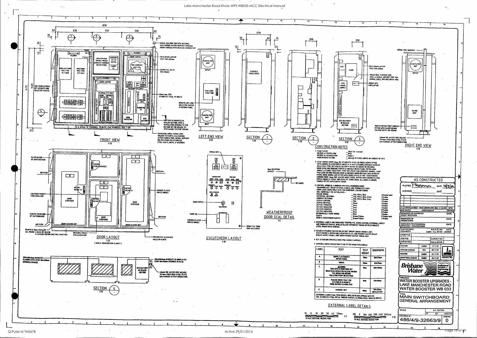
CONSTRUCTION NOTES
AERIAL PPE SUPPORT
F01.0 ()OWN LAPTOP TRAY SE013S0an
Name HOLE THROUCH SIDE WALL t AERIAL SIPPORT PPE FOR AERIAL CABLE. PROVIDE DRAW WIRE
SINGLE GPO FOR LAPTOP
VENTS FOR BATTERY CUBICLE FITTED WITH GAUZE BENNO TO STOP ENTRY OF VERNN
Done BE WATER PPE WELDED TO Lass DIM MOLD STEEL PLATE GMVANSED DEER FABRICATOR.
RIGHT END VIEW 1:10
1 FAULT LEVEL 25kA for I second DEGREE of PROTECTOR PS5 DEGREE of SEGREGATION -FORNI MAN BUSBAR RATING INA p 7S C RISE ABOVE AN AMBIENT OF 30C
2 CASE FORMED FROM Mow 306 STARLESS STEEL 213 FINSM DOORS FITTED WITH CHROME PLATED PINTLE HINGES t 3-WAY LATOING LOCKABLE HANDLES SELECT= TYPE 1101-PSCUL SECURITY KEYED AS SHOWN OK DRAWING. BOOR OVER FRE BRIGADE SWITCH & VERGE% METER PANEL FITTED WITH SINGLE LATCHNG SELECTROC TYPE 1107-P5C01 PAD-LOCKABLE HANDLE, 1200' PAD-LOOT ON ARE BRIGADE DOOR 1 DERGEX SUPPLED PAD-LOCK ON METER PANEL 003N DOORS ARE FITTED WITH 003R STAYS AT 105. ESCUTCHEONS FORKED FROM Wu 2ND SEALED SHEET STEEL. FITTED WITH CHROME PLATED POTTLE HNGES L VIKA' 1000-1142 VI TURN LOCKS. ALL DOORS & MNGED PANELS FITTED WITH EARTH STRAP.
3 CONTROL WRING IS A MONIUM V90 REX. ITUM3EREO LISDIG GRAPHOPI.AST* TRASP SYSTEM. CABLES ARE TERNIMATE0 05540 CROP LUGS COMPATIBLE WITH TIE EQUPTIDIT, COLOUR COOING
WILL GENERALLY BE AS FOLLOWS- PHASE WIRING Wlite, Doe POTENTIAL METERING CURRENT METERING 240Vac CONTROL DOOR NEUTRAL ITV ELV POSITIVE 210/ ELV NEGATIVE 21.V RTU POSITIVE 2EV RTU NEGATIVE INTRNSICAU.Y SAFE WIRING EARTH DOOR & ESCUTCHEON EARTHS
_Red. White, Bloc Black _Red, Wlite, Blue. Grey _Red _Black _Grey _Grey _Qv _Grey _Blue _Green/Yellow _Green/Ye/1ov
INTERNAL LABELS ARE ENGRAVED TRAFFOLYTE, SCREW AFRXED. EXTERNAL LABELS ARE ENGRAVED BRASS. WILED BLACK AFFIXED BY PEAKS OF N3 STARLESS STEEL ROUNO HEAD SCREWS.
5 BOARS IS POWDER COATED OSLUX POST GREEN 1 366181 MOE I. OUT. ESCUTCHEONS t REMOVABLE GEARTRAYS etc ARE POWDER COATED OULUX BRIGHT ROTE 1 321661. ARE DOOR POWDER COATED 'SIGNAL RED'
6 BCC STANJARO SPECFKATION I PSE-S010411 APPLIES.
7 ANTENNA SURGE PROTECTOR TO BE FITTED NSW RTU CUBKLE
LABEL TEXT TEXT
HEIGHT
DIMENSIONS
A SUPPLY AUTHORNY METER PANEL
Wm 300X2001
B W0033 Dm C .VABIRIG
ISIS SITE IS MONITORED BY 1EWSTEAD OPERATOR PLEASE INFORM
THE OPERATOR BEFORE ISOLATING PUMP OR STATION
25IMIGIM.
o PLEASE 01E0 THAT THE STATION ISM REMOTE
MOE BEFORE LEAVING SITE
Sr 210:600.
E DANGER 4.15V Now 300112000 IONLED RED
EXTERNAL LABELS Um TRIOS BRASS, NrI.LED BUSK AFFIXED WITH N3 306 STARLESS STEEL PETAL DREAD SCREWS. ALTERNATEVELY HUED BRASS.
EXTERNAL LABEL DETAILS
10 0 10 20 30 40 50mm BEGSSEM+1 1:1 SCALE BEFORE REDUCTION
100 0 100 200 300 400 SOOmm GE5251 1:10 SCALE BEFORE REOUCTION
AS CONSTRUCTED
PLOTTED ...ti:aTIONILP%. DATE '°1' I CHECKED DATE
D
0
1003172
DATE
AS DELT -WAS CARDNO DRG 2951 1702-009 AMENDMENT
DPM
MANAGER OF BUSINESS DATE ASSET SERVICES
MANAGER OF DATE OPERATIONS
MANAGER PROFESSIONAL DATE SERVICES- ENGINEERING
SUPERVISING RP.E.O. NO. DATE ENGINEER GASH - Rd. 05192 - 03/2002
CADET FILE
.109 FILE SURVEY NO.
SURVEYED FIELD BOOK
DESIGN CASK 17.11.01
DESIGN CHECK BW 20.11.01
DRAWN GASH 21.11.01
DRAFTING CHECK OAK 24.11.01 Brio/0m My
Brisbane -..
Watery '"; WATER BOOSTER UPGRADES - LAKE MANCHESTER ROAD WATER BOOSTER WB 033
MAIN SWITCHBOARD GENERAL ARRANGEMENT
SCALE A.H. DATUM
OF SHEETS DRAWING N
486/4/9-32663/9 AMEND.
2 4 7- 9 10 12 13 14 15 I 16
Lake Manchester Road Kholo WPS WB033 MCC Electrical Manual
Q-Pulse Id TMS678 Active 29/01/2014 Page 15 of 69

2 3 6 7 9 10
12 13 14 15
16
SWITCHBOARD: SELECT ALL EQUIPMENT FROM THE FOLLOWING LIST: ITEM No QTY DESCRIPTION MANUFACTURER CATALOGUE No
01 1 MAIN CIRCUIT BREAKER TERASAKI DIN-TIOH3800 02 1 ROTARY OPERATOR c/w DOOR I/L TERASAKI
03 3 SURGE DIVERTORS CRITEC SA 10KA
04 1 DISTRIBUTION CB 12 WAY CHASSIS TERASAKI SAFE-TRCB6-1630 05 1 SWBD GPO C/BREAKER TERASAKI
06 1 SWBD GPO CLIPSAL 15 238
07 1 SWBD LIGHTS C/BREAKER TERASAKI DIN-T6-106C 08 2 SWBD FLOURO LIGHTS THORN , BB108
09 2 SWBD FLOURO DOOR SWITCHES CAMSCO SM202 10 1 SWBD VENTILATION FANS CONTROLLER RITTAL SK3120.000 11 1 PHASE FAILURE RLY C/BREAKER TERASAKI DIN-T63200
12 1 PHASE FAILURE RELAY CROMPTON 252PSGW
13 1 HOURS RUN METER NATIONAL TH639
14 4 240VAC 2A 2PCO RELAY IZUMI RH213-U-240VAC
15 1 STOP LATCHED PUSH BUTTON SWITCH SPRECHER & SCHUH DN3-30-01
16 1 3POLE 2POSN ROTARY SWITCH AUTO/MAN. KRAUS & NAIMER - 17 1 START MOMENTRY PUSH BUTTON SWITCH SPRECHER & SCHUH DT3P-G.-10M
18 1 2POLE 3POSN ROTARY SWITCH FIRE/OFF/REMOTE KRAUS & NAIMER -
19 1 DC SUPPLY C/BREAKER TERASAKI -
20 1 POWER SUPPLY 240AC/24VDC 5A POWERBOX - 21 24VDC 2A 2PCO RELAY KLIPPON - 22 2 PUMP C/BREAKER TERASAKI - 23 2 VARIABLE SPEED DRIVE DANFOSS VLT6027 & VLT6008 24 2 SPEED CONTROL POTENTIOMETER RS TC102805 TC58I969 TC581931
25 TERMINALS KLIPPON (OR PHOENIX EQUIV.)
26 3 END STOP KLIPPON (OR PHOENIX EQUIV.) EW35 (038356) . 27 3 END PLATE KLIPPON (OR PHOENIX EQUIV.) AP (011796)
28 50 FEED THROUGH TERMINAL KLIPPON (OR PHOENIX EQUIV.) SAK4/35 (044366) 29 3 RESET PUSH BUTTON SPRECHER & SCHUH OT3P-MB-10M
30 1 SWBD FAN SUPPLY C/BREAKER TERASAKI OW-T6-106C
31 2 VFD's CONTROL SUPPLY C/BREAKER TERASAKI DW-T6-106C 32 3 SWITCHBOARD VFD FAN RITTAL SK3323.100
33
34
35
36
37
38
39
40
41
42
43
44
RTU PANEL
ITEM No QTY DESCRIPTION 1._
MANUFACTURER CATALOGUE No . 01 1 MAIN CIRCUIT BREAKER TERASAKI DIN-T6140C
02 1 SURGE REDUCTION FILTER CRITEC SRF-1100C-SF 03 2 COMPUTER & RTU OUTLET C/BREAKER TERASAKI DIN-T6-102C 04 2 COMPUTER OUTLET & RTU OUTLET CLIPSAL 15 238
05 1 POWER FAILURE RELAY NHP DWRS-440V 06 * 1 RTU 13.8VDC POWER SUPPLY POWERBOX P50E-15 07 * 2 6.5Ah BATTERY APOLLO PDSBAT -12V
08 * I
1 12V/24V DC CONVERTER POWERBOX C500-CONV 09 * 1 PLC HUNTER WATERTECH PDS COMPACT eNET RTU 10 1 ALARM RESET PUSH BUTTON TERASAKI DTPB691
11 1 BATTERY DISCONNECT RELAY KLIPPON RS30 111016.2)
11.1 1 BATTERY CONNECT RELAY KLIPPON RS30 (11016.21
12 1 SITE ATTENTION ALARM INDICATOR TERASAKI DTPUDTLOR/OTLP24 13 ** 1 INLET PRESSURE TRANSDUCER ROSEMOUNT 2088G2A22A15184
14 * 1 RADIO (FUTURE) TRIO TC-900DR
15 * 1 RADIO COAX SURGE PROTECTOR (FUTURE) POLYPHASER CORPORATION IS-50NX-C2
16 * 1 ANTENNA (FUTURE) - R.F. INDUSTRIES Y6815-82
16.1 1 ANTENNA MAST STORK ELECTRICAL 6 METRES HIGH
16.2 * 1 COAX CABLE (INTERNAL) R.F. INDUSTRIES RG58
16.3 * 1 COAX CABLE (EXTERNAL) R.F. INDUSTRIES RG213
16.4 * 1 COAX PLUG R.F. INDUSTRIES SMA 16.5 1 COAX PLUG R.F. INDUSTRIES N88 (MALE) 16.6 * 2 COAX CABLE PLUG R.F. INDUSTRIES N07 (MALE) 16.7 * 1 U CLAMP R.F. INDUSTRIES UNV 17 1 BATTERY ENCLOSURE FIBOX FO 175/1250 18 TERMINALS
18.1 164 FUSE/LINK TERMINAL KLIPPON (OR PHOENIX EQUIV.) KDKS 1/35 (9503311 18.2 4 END PLATE KLIPPON (OR PHOENIX EQUIV.) AP (950333) 18.3 6 100mA FUSE CARTRIDGE KLIPPON (OR PHOENIX EQUIV.) FUSE (043030) 18.4 3 1A FUSE CARTRIDGE KLIPPON (OR PHOENIX EQUIV.) FUSE (043070) 18.5 3 5A FUSE CARTRIDGE KLIPPON (OR PHOENIX EQUIV.) FUSE (043130) 18.6 7 END STOP KLIPPON (OR PHOENIX EQUIV.) EW35 (038356) 18.7 2 EARTH TERMINAL KLIPPON (OR PHOENIX EQUIV.) EK4/35 (066116)
18.8 3 FEED THROUGH TERMINAL KLIPPON (OR PHOENIX EQUIV.) SAKE /35 (0380561 18.9 2 END PLATE KLIPPON (OR PHOENIX EQUIV.) AP 10117961
18.10 2 FEED THROUGH. TERMINAL KLIPPON (OR PHOENIX EQUIV.) SAK4/35 (044366) 19 1 EARTH LINK KLIPPON (OR PHOENIX EQUIV.) BP165C12
20 1 PRESSUREGAUGE ENCLOSURE BEM ENCLOSURES PJ302215 « PJ3022/M 21 1 BATTERY VENT HIMEL VM-25 22 1 PRESS. GAUGE ENCLOSURE VENT HIMEL VM-25 23 * 1 MAGNETIC FLOWMETER TRANSMITTER ABB - MAGMASTER
24 1 FLOWMETER POWER CB TERASAKI DIN-T10106C
25 * 1 RTU & RADIO MODULE ELPRO TLC-02-01
NOTES:
ITEMS MARKED WITH * ARE FREE ISSUED ITEMS.
AS CONSTRUCTED
B
',Lump P rinrv-v- DATE to_19 tn. CHECKED DATE
E 609.02 AS BUILT WAS CARDNO ERG 2954 17 02.010 DPM DATE AMENDMENT
MANAGER OF BUSINESS DATE ASSET SERVICES
MANAGER OF DATE OPERATIONS
MANAGER PROFESSIONAL DATE SERVICES - ENGINEERING
SUPERVISING R.P.E.O. NO. DATE ENGINEER CM8K RJ. 85192 032502 CADD FILE
JOB FILE
SURVEYED
SURVEY NO.
FIELD BOOK
DESIGN CMBK 17.11.01
DESIGN CHECK SW 20.11.131
DRAWN GAM( 21.11.01
DRAFTING CHECK CMBK 24.11.01
_ Brldwrie Oty
Brisbane Water )04::"*--
WATER BOOSTER UPGRADES - LAKE MANCHESTER ROAD WATER BOOSTER WB 033
PUMP SWITCHBOARD AND RTU PANEL EQUIPMENT SCHEDULE
SCALE
DRAWING N.
A.H. DATUM
OF SHEETS
486/4/9-32663/10 AMEND.
E 2 3 4 8
10 11 12 I 13 14 I 15 18
Lake Manchester Road Kholo WPS WB033 MCC Electrical Manual
Q-Pulse Id TMS678 Active 29/01/2014 Page 16 of 69

2 3 4 6 7 9 10 11
12 93 14 15 16
PROPERTY BOUNDARY
N
DIA. TRUNK MAIN
CENTRELINE
TOP OF BATTER
BOTTOM OF BATTER
E
EXISTING FLOWMETER
STONE PITCH OUTLET ON*BATTER
INSTALL 3x8Omm CONDUITS BETWEEN SWITCHBOARD AND PUMP PIT.
EXISTING WATER BOOSTER
PUMPS PITS WB 033
300
600
INSTALL 1x8Omm CONDUIT BETWEEN POLE AND SWITCHBOARD
INSTALL NEW SWITCHBOARD ON NEW CONCRETE SLAB (EXACT LOCATION TO BE
N SITE) - 150mm DIA. TRUNK MAIN
PROPERTY BOUNDARY
.441111- _ - _ _ _ _ _
FROG FLAP TO END OF 100 DIA. PIPE.
LAKE MANCHESTER ROAD
EXISTING PROPERTY POLE
TOP OF BATTER
BOTTOM OF BATTER
CENTRELINE _ - - -
PLAN.
/B\ NOTES:
1. SLAB IS/WILL BE
- 150mm IN DEPTH
- 100rnm OUTSIDE FOOTPRINT OF SWITCHBOARD. - 800mm OUTSIDE FRONT OF SWITCHBOARD. - e.g cs.
500 0 500 1000 1500 2000 2500mm ISS/m1..±±1 150 SCALE BEFORE REDUCTION
MCC
SLAB
100
AS CONSTRUCTED
CHECKED DATE
C 0.09.02 AS BUILT - WAS CARDNO ORG 2951 11_02-011 0 DATE
MANAGER OF BUSINESS DATE ASSET SERVICES
MANAGER OF DATE OPERATIONS
MANAGER PROFESSIONAL DATE SERVICES - ENGINEERING
SUPERVISING RP.E.O. NO. DATE ENGINEER CMBK RJ. 05182 - 032002 CADD FILE
JOB FIE SURVEYED
DESIGN
DESIGN CHECK
DRAWN
DRAFTING CHECK
Brisbane Water Jo-.
PROJECT
BOOSTER UPGRADES - LAKE MANCHESTER ROAD WATER BOOSTER WB 033 TrtIE
SITE LAYOUT
SCALE
DRAWING N'
486/4/9-32663/11 2
12 13 14 15 J 10
Lake Manchester Road Kholo WPS WB033 MCC Electrical Manual
Q-Pulse Id TMS678 Active 29/01/2014 Page 17 of 69

0
0
0 E
-0 0
lE
U
a.) CV O a--
0 E 0
0 Cr
CUBICLE
SUNSHADE
CONSTRUCTION
(IF IN DOUBT, ASK.)
- 1.6mm 304 Stainless Steel with Anticorrosion Pad. - External - Du lux Mist Green 36648. - Internal - Du lux Mist Green 36648. - Escutcheons - Du lux Bright White 32166 Powder Coat. - IP55 degree of protection. - Bottom Cable Entry.
- To be 200mm over the front, 100mm over the sides and back. 1.6mm 316 Stainless Steel. U Support System. To be welded to panel, screw shade to support.
- Fix shade to U Supports with 6mm Tapped Stainless Steel nuts and bolts - To be fixed with vandal-resistant nuts.
EQUIPMENT
PANEL - 2mm thick Mild Sheet Steel. - Du lux Bright White 32166 Powder Coated. - Secure with 316 stainless steel nuts and studs. Minimun 6 studs for heavy duty panels.
DOOR LOCKING
DOORS
- EXTERNAL - Selectrux semi flush type 1107SSCUI swing handles, keyed Lockwood RC496 'C'. except for Metering Panel - Keyed Pad-Lockable and for Fire Door S200 Pad-lock.
- ESCUTCHEON - Chrome acorn nuts and studs and EMKA 1000 U42 turn locks.
Lift off type , seal to be 6.0mm neoprene gasket, held by a retainer to the inside of the door.
External Doors to be 1.6mm 304 Stainless Steel.
Escutcheons to be 2mm Zinc Annealed Mild Sheet Steel.
Stiffeners on all doors lexcept for Metering Panel.
- Fit Door Stays in doors. To be opened 105 degrees.
- Minimum 3 chrome plated Hinges for Doors over 1200mm.
Earthing - M6 Studs to be provided on all doors and hinged panels.
GLANDPLATES - 6.0mm bakelite.
316 stainless steel screws.
25x6mm Neoprene Gaskets. Earth studs.
PLINTH - 3 x M12 Clearance holes in Plinth to be provided for bolting to floor Plinth to be galvanised Channel (75mm)
- 10mm of silicon before bolting on to board. Fixed with 316 stainless steel bolts
CUBICLE
EOPRENE DUST SEAL
EXTERNAL DOOR (TYPICAL)
WEATHERPROOF DETAIL
MULLION FOLD TO SUIT SHEET METAL THICKNESS
AND IP RATING
DOOR SEALING DETAILS
FWN COMMON LOGIC PTY. LTD.
P0. BOX 2008 Mansfield QLD. 4122 Tele: 07 3849 7449
LWN 16/04/02 D AS BUILT SWN
22/03/02 MC ISSUED FOR CONSTRUCTION(NSHOF) FTN
22/02/02 MB ISSUED FOR CONSTRUCTION LTN
15/02/02 MA ISSUED FOR APPROVAL STN
DATE 16/04/0:',
DRAWN BRAT
SCALE NTS,:
APPROVED
BRISBANE WATER - LAKE MANCHESTER PUMP STATION
GENERAL ARRANGEMENT
JG5 6DNO0 A3 sheet 1/1 ISSUE D
Lake Manchester Road Kholo WPS WB033 MCC Electrical Manual
Q-Pulse Id TMS678 Active 29/01/2014 Page 18 of 69

0
O
_o
O. a)
O E
-0
a)
- o C O
a) 7D
C O
O
C O E E O U
(1) 0. O 0_
a)
V)
0 a)
a) _C
C
O E
Wit 0'
O -0
7
LEFT HAND SIDE VIEW
(SUNSHADES OFF)
1475
450
50
90
75
E
(IF IN DOUBT, ASK.)
1860
670 600 590
1, TO
TOP IVEW (SUNSHADES OFF)
L_
_
[
-
UNMMEMB l'agosenma.1 F......,..val
I. W9033 .1
Ill
I. W9M I
17IMIM
r---) I I
I I
LI-___
'-
-t
1_ -1
0 0 0
FRONT VIEW RIGHT HAND SIDE VIEW
16/04/02 D AS BUILT 22/03/02 MC ISSUED FOR CONSTRUCTION (WSHOP) 22/02/02 MB ISSUED FOR CONSTRUCTION
15/02/02 MA ISSUED FOR APPROVAL
FWN LWN SWN FTN LTN STN
COMMON LOGIC PTY. LTD.
P0. BOX 2008 Mansfield QLD. 4122 Tele: 07 3849 7449
DATE 16/04/6_
DRAWN BRM
SCALE 10_1)
APPROVED i
BRISBANE WATER - LAKE MANCHESTER PUMP STATION
GENERAL ARRANGEMENT
JG56DNO1 A3 sheet 1/1 ISSUE D
Lake Manchester Road Kholo WPS WB033 MCC Electrical Manual
Q-Pulse Id TMS678 Active 29/01/2014 Page 19 of 69

-o
O U
0
-o 0 E a)
C
-0 C 0
C
-CD
0 0
O C 0
CN CO C".1
(NI CD
C_D
0_
O
0 E E O
0 >.
N O 2 0 a)
N
C 0 a)
_c
0 E O
0 -o
(IF IN DOUBT, ASK.)
BOOSTER
PUMP PUMP
VFD
VLT6008
FIRE
PUMP
VFD
VLT6027
4:: 11;nal
4:4=0:4:4:4 In:41
0 E
0 Di 101j Fp] 0 rpli Direr LJ
--,--I: -6 6 "-4-g 6 -aallI.
.-_
0001
PDS
COMPACT o 0
11111111111111111111111111111111111111111111111111111111111111111
I
BAI ILKIES
BOX
O
FRONT VIEW (DOORS REMOVED)
16/04/02 22/03/02
D AS BUILT
FWN LWN
SWN
22/02/02 15/02/02
MC MB
ISSUED FOR CONSTRUCTION(NSHOP) FTN ISSUED FOR CONSTRUCTION
MA ISSUED FOR APPROVAL
LTN STN
COMMON LOGIC PTY. LTD.
P0. BOX 2008 Mansfield OLD. 4122 Tele: 07 3849 7449
DATE 16/04/02
DRAWN BRK
SCALE 1/10 APPROVED
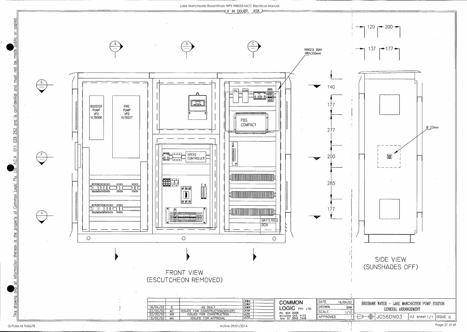
BRISBANE WATER - LAKE MANCHESTER PUMP STATION
GENERAL ARRANGEMENT
JG56DNO2 A3 sheet 1/1 ISSUE D
Lake Manchester Road Kholo WPS WB033 MCC Electrical Manual
Q-Pulse Id TMS678 Active 29/01/2014 Page 20 of 69
-0 a)
0 U
O
_O
0. 0 0
c
.=
a)
C O U
-0
0 C-N1
Co CN
0-) CNI C2!
a_
a) 0. 0 0 CD
_C
C 0 0
0 -0
(IF IN DOUBT, ASK.)
E
BOOSTER
PUMP
VFD
VLT6008
L
FIRE
PUMP VFD
VLT6027
P
L
: 1 0-0- L= SPEED CONTROLLER 1,U e 1=-
410km6 RIM]
EN
LAALO
6 8
0
.1000000001010.0. -MT nmAir-L-Inr, L.(
olttoompopoo..
---, po
PDS
COMPACT 0 0
0
I
BAI 'ERIE.
BOX
S
O O O
FRONT VIEW (ESCUTCHEON REMOVED)
HINGED TRAY 480x350mm
--`4," 140
277
200
285
177
it
!
120 200
137
I
I I
I
e I
I 1
T
T
SIDE VIEW (SUNSHADES OFF)
0 23mm
16/04/02 22/03/02 22/02/02 15/02/02
MC MB
AS BUILT
ISSUED FOR CONSTRUCTION(WSHOP) ISSUED FOR CONSTRUCTION ----
FWN LAW SWN FTN
MA ISSUED FOR APPROVAL
LTN STN
COMMON LOGIC PTY. LTD.
P0. BOX 2008 Mansfield OLD. 4122 Tele: 07 3849 7449
DATE 16/04/02
DRAWN BRM .
SCALE 1/1Q t
APPROVED r
BRISBANE WATER - LAKE MANCHESTER PUMP STATION
GENERAL ARRANGEMENT
JG5 6DNO3 A3 sheet 1/1 ISSUE D
Lake Manchester Road Kholo WPS WB033 MCC Electrical Manual
Q-Pulse Id TMS678 Active 29/01/2014 Page 21 of 69

0 U
0
_O
(1)
0 E
-0
c
-0 0
0 U
0_
0
0 E E 0
a) a. 0 a.
0 CL)
0 0 E 0
Cr
0 0 01
I-
35
100
540
135
100
365
C-CHANNEL 50x5Omm
60 40
I I
LOOM SUPPORT 225x20x15mm -
FIRE
PUMP
VFD
VLT6027
00" 50mm
SECTION
SIDE VIEW
WELDED L-ANGLE 450x40x4Omm
535
275
100
30
170
1 0 225
30
IF IN DOUBT, ASK.)
LOOM SUPPORT
DUCT SUPPORT 380x40x15mm
LOOM SUPPORT
SECTION
SIDE VIEW
T
35
375
140
360
95 2
80 0
/
,--
II 1
LOOM SUPPORT
PS
m o I I
RTU
ELPRO RADIO
il
I
SECTION
SIDE VIEW
WELDED L-ANGLE 390x40x4Omm
140
177
150
490
177
137 90
I I
LOOM SUPPORT
0 10mm° GEAR TRAY
220x500mm
C )
SECTION
SIDE VIEW
(WITHOUT GT)
FWN COMMON LOGIC PTY. LTD.
P0. BOX 2008 Mansfield OLD. 4122 Tele: 07 3849 7449
LWN 16/04/02 D AS BUILT SWN
22/03/02 MC ISSUED FOR CONSTRUCTION(WSHOP) ISSUED FOR CONSTRUCTION
FTN LTN 22/02/02 MB
15/02/02 MA ISSUED FOR APPROVAL STN
DATE 16/04/02
DRAWN BRM'
SCALE 1/10
APPROVED
BRISBANE WATER - LAKE MANCHESTER PUMP STATION
GENERAL ARRANGEMENT
JG5 6DNO4 A3 sheet 1/1 ISSUE D
Lake Manchester Road Kholo WPS WB033 MCC Electrical Manual
Q-Pulse Id TMS678 Active 29/01/2014 Page 22 of 69
a. 0 0
C5
- 0 0
c -o
O
C.-)
Cl_
0 _J
C O E E 0
0)
Cr C
0
0
- 15151
155
rr 550--.15dir-390-i 115 fOr.-; /
r 375
L 53
L 120
90
45
200
100
r--
TOP VIEW
(SUNSHADES OFF)
1501-- CUTOUT 50NIONNI
SECTION
TOP VIEW
135 145
GLANDPLATE 4004200mm CUTOUT 360,116Dmm
GLANDPLATE 4004200mm CUTOUT 360x160mm
26GLANDPLATE 04300mm CUTOUT
II
SECTION
TOP VIEW
1 320
(IF IN DOUBT, ASK,)
1350.
175
270
580
EDOSTER PUUP
WD VI.T13008
FOIE
MVP ND
05.15027
kirt.=!r=ift
PUMPS GT
155
A r
FWN LWN
16/04/02 AS BUILT SWN
22/03/02 MC ISSUED FOR CONSTRUCTION(WSHOP) FTN
22/02/02 MB ISSUED FOR CONSTRUCTION LTN
15/02/02 MA ISSUED FOR APPROVAL STN
PUMPS GT
750
L 120
30= 85
90
F-- 150
170
550
1
--- SPEED CONTROLLER
run
U.T41
AC DISTRIBUTION GT
170
50T
-15530 1 1°°1651651
130 r 1
Cl 8, El 1 E2 F 0 0
,?:1 181 ,8 j_:.< 1
OHO
CI
L . M . N P
0 0 0
0
I I
_JW5cLol 83 U5J50L PUMPS GT
1350
PDS
COMPACT
11111111111111111111111111111111111111111111111111111111111111111
11111111111111,11111111111111111111111111111111111111111111111111
illS111111111111111111111111111111111111111111111111111
TELEMETRY GT
CUTOUT DETAILS
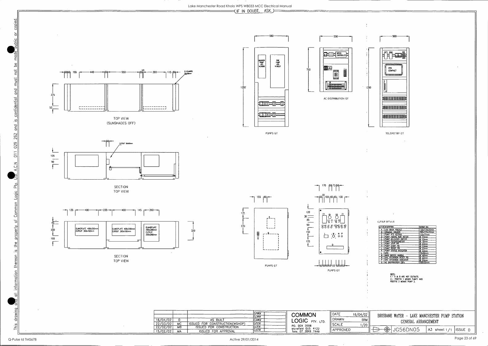
_ETTER DESCRIPTION CUTOUT ON.
A LOG BOOK POCKET I 35,11 70x2Ornm 8 DRAWING HOLDER 2604270x2Ornm C PUMP VFD KEYPAD 13347Imm
E PUMP SELECTOR SWITCH 13 73mm F PUMP POTENTIOMETER 0 10mm G PUMP STOP PB 0 23mm H PUMP START PB 0 73mm J PUMP RESET PB 0 23mm K PUMP STATUS INDICATOR 0 23mm L GPO 70x50mm 14 MAIN SWITCH HANDLE 0 40mm N SITE ATTENTION RESET P8 0 23mm P SITE ATTENTION INDICATOR 0 23mm El AC DISTRIBUTION CB's 288450mm
; 1.- A & B ARE NOT CUTOUTS.
2.- POSTF1X 1 MEANS PUIAP1 AND
POSTF1X 2 MEANS PUMP 2.
COMMON LOGIC PTY. LTD.
P0. BOX 2008 Mansfield QLD. 4122 Tele: 07 3849 7449
DATE 16/04/02
DRAWN BRM
SCALE 1/20
APPROVED
BRISBANE WATER - LAKE MANCHESTER PUMP STATION
GENERAL ARRANGEMENT
JG56DNO5 A3 sheet1/1 ISSUE D
Lake Manchester Road Kholo WPS WB033 MCC Electrical Manual
Q-Pulse Id TMS678 Active 29/01/2014 Page 23 of 69
-III (- CABLE COLOURS CHECKED 0 A
POWER 240VAC - PHASE COLOUR , NEUTRAL BLACK
CONTROL 240VAC - ACTIVE WHITE , NEUTRAL BLACK
24VDC - POSITIVE ORANGE , NEGATIVE VIOLET
TELEMETRY - GREY
EARTH CABLES - GREEN/YELLOW
L---11444 CABLE MARKERS CHECKED 0 A BRADY SLEEVING TO BE USED
EACH CABLE IS TO BE NUMBERED AT EACH END
EVERY CABLE IS TO HAVE A NUMBER TO MATCH THE DRAWING
NUMBERS IN SLEEVES TO READ LEFT TO RIGHT OR TOP TO BOTTOM
I NCT 1
DUCTING CHECKED 0 A GREY SLOTTED DUCT COMPLETE WITH LID
MAX 50% FULL
ID START C
LABELLING CHECKED 0 A ALL PANEL EQUIPMENT TO BE LABELLED USING ENGRAVED TRAFFOLITE
ALL DOOR EQUIPMENT TO BE LABELLED USING W/B/W TRAFFOLITE LABEL FIXED WITH STAINLESS STEEL SCREWS
Ea= TERMINALS CHECKED 0 A ALL TERMINALS TO BE NUMBERED TO MATCH DRAWINGS
MAX ONE WIRE PER TERMINAL ENTRY
ALLOW SPARE SPACE FOR TERMINALS
TWO EARTH TERMINALS PER ROW OF TERMINALS, EARTH BAR NEAR TERMINALS
FUSED - KLIPPON W SERIES
GENERAL THROUGH TERMINALS - KLIPPON W SERIES
TEST/DISCONNECT - KLIPPON W SERIES
CABLES CHECKED 0 A POWER CABLE TO BE V75 AND CONTROL CABLE TO BE CLASS V9OHT
LIGHTING CABLES TO BE A MIN 1.5mm INTERNAL AND EXTERNAL
CONTROL CABLES TO BE A MIN 1.0mm INTERNAL (1.5mm EXTERNAL)
POWER CABLES TO BE A MIN 2.5mm INTERNAL AND EXTERNAL
RTU CABLES TO BE A MIN 0.75mm INTERNAL AND EXTERNAL
TELEMETRY - DEKORON
ALL CABLES ARE TO BE LUGGED
ALL CABLES TO HINGED PANEL TO BE SLEEVED
COMPONENT LABELLING
MINE NUMBER COMPONENT DESCRIPTION-........
024/1 ----NUMBER OF CONTACT
(IF IN DOUBT, ASIA
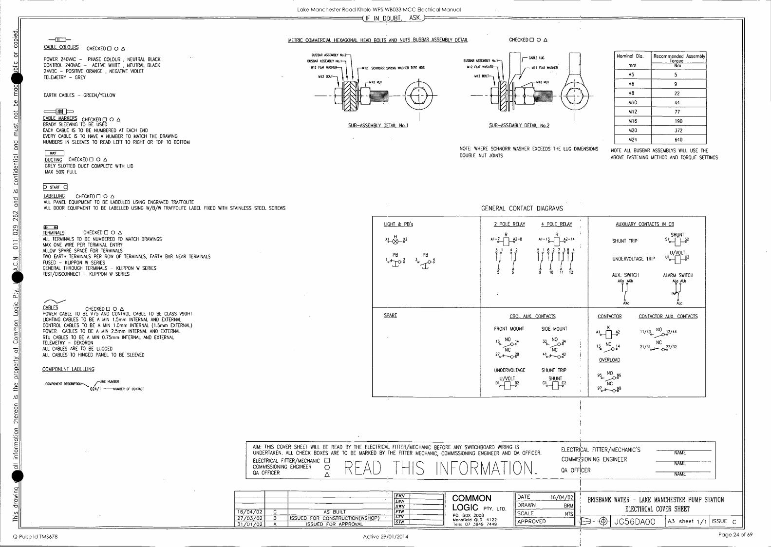
METRIC COMMERCIAL HEXAGONAL HEAD BOLTS AND NUTS BUSBAR ASSEMBLY DETAIL
BUSBAR ASSEMBLY No.2-
BUSBAR ASSEMBLY No.
4112 FLAT WASHER-11)
U12 BOLT
12 SCHNORR SPRLNG WASHER TYPE HOS
F1112 NUT
I ilimmom
Am
SUB-ASSEMBLY DETAIL No.1
BUSBAR ASSEMBLY No.
U12 FLAT WASH
1112 BOLT
CHECKED 0 A
n CABLE LUG
U12 FLAT WASHER.
NUT
Mr I lit INNEN
111A1111
SUB-ASSEMBLY DETAIL No.2
NOTE: WHERE SCHNORR WASHER EXCEEDS THE LUG DIMENSIONS
DOUBLE NUT JOINTS
GENERAL CONTACT DIAGRAMS
Nominal Dia.
mm
Recommended Assembly Toraue
Nm
M5 5
M6 9
M8 22
M1O 44
M12 77
M16 190
M20 372
M24 640
NOTE ALL BUSBAR ASSEMBLYS WILL USE THE
ABOVE FASTENING METHOD AND TORQUE SETTINGS
LIGHT & PB's
PB tio
2 POLE RELAY 4 POLE RELAY AUXILIARY CONTACTS IN CB
H N__(8) _g2
PB
3 ,Th-
R R Al-.7_02..2-8 Al -13
3 1 4 2 5 e1 6 2 7 38 4
III III If 111 1; It 1 1 5 6 9 10 11 12
SHUNT
SHUNT TRIP S1 S2
UNDERVOLTAGE TRIP laU/VOLT uto__g2
AUX. SWITCH ALARM SWITCH
Au rb ALa ALb
Ir 1 AXc ALc
SPARE CBOL AUX. CONTACTS CONTACTOR CONTACTOR AUX. CONTACTS
FRONT MOUNT SIDE MOUNT
NO NO 1.3 1.1 n 34 0_ 0 .....-A0-0
NC NC
20 3--o-P 41 _42
UNDERVOLTAGE SHUNT TRIP
U /VOLT SHUNT DI -22 Cl --0 C2
--
K NO Aio_ag2 11/4302/44
NO NC 13. 14 21/31._+___0_32/32 T.,--0'
OVERLOAD
9 5 0-
NO 6 _,AID-0
NC 9708
AIM: THIS COVER SHEET WILL BE READ BY THE ELECTRICAL FITTER/MECHANIC BEFORE ANY SWITCHBOARD WIRING IS
UNDERTAKEN. ALL CHECK BOXES ARE TO BE MARKED BY THE F TTER MECHANIC, COMMISSIONING ENGINEER AND QA OFFICER.
ELECTRICAL FITTER/MECHANIC
COMMISSIONING ENGINEER 0 R-AD QA OFFICER A S \FORVATO\ ELECTRI
i
CAL FITTER/MECHANIC'S
COMMISSIONING ENGINEER
QA OFFICER
NAME
NAME
NAME
16/04/02 27/03/02 31/01/02
B
AS BUILT ISSUED FOR CONSTRUCTION(WSHOP)
ISSUED FOR APPROVAL
FWN LWN SWN FTN LTN STN
COMMON LOGIC PTY. LTD.
P0. BOX 2008 Mansfield OLD. 4122 Tele: 07 3849 7449
DATE 16/04/02 DRAWN BRM
SCALE NTS
APPROVED
BRISBANE WATER - LAKE MANCHESTER PUMP STATION
ELECTIRCAL COVER SHEET
NI /.% 1 JG56DA00 A3 sheet 1/1 ISSUE C
Lake Manchester Road Kholo WPS WB033 MCC Electrical Manual
Q-Pulse Id TMS678 Active 29/01/2014 Page 24 of 69

COMMON LOGIC Pty Ltd Electrical Manual Specialist Electrical Contractors
Subject: Lake Manchester Road MCC Sheet: 6 Section Of: 10 1
Page Revision No: 1 Date: 26/04/02 Manual Issue No: 1 Date: 26/04/02
4.0 PART LIST
Authorised By: Grant Kerr
__ MC .
.
Lake Manchester Road Kholo WPS WB033 MCC Electrical Manual
Q-Pulse Id TMS678 Active 29/01/2014 Page 25 of 69

PART LIST
Supplier Part Num _ ' Description .«
ABK Electrical Wholesale Pty Ltd CLI15WE GPO SINGLE 10A SWPLUG ROCKER WHITE
ABK Electrical Wholesale Pty Ltd CLI238 STD MTG BOX 3/4 END ENTRY
ABK Electrical Wholesale Pty Ltd THOBB108 1X8WATT BIKINI
AP Controls Pty Ltd S150-24 240/110V24V/6.5A DC POWER SUPPLY
Australian Solenoid Company Pty Ltd CA10 A220-600FT2 STANDBYDUTY SWITCH PLATE "PUMP 2 DUTY"
Australian Solenoid Company Pty Ltd CA10 A223600FT2 SWITCH ENGRAVED "AUTO-MANUAL", PLATE "FIRE PUMP"
Australian Solenoid Company Pty Ltd CA10 A223600FT2
SWITCH ENGRAVED "AUTO-MANUAL", PLATE "BOOSTER PUMP"
Australian Solenoid Company Pty Ltd CA10 A362600FT2
3POS SWITCH ENGRAVED 'FIRE OFF - CONTROL, PLATE "FIRE MODE"
B&R Enclosures Pty Ltd BS08 8MMX914X1218 BAKERLITE INSULATING PANEL
B&R Enclosures Pty Ltd PJ3022/M MOUNTING PANEL
B&R Enclosures Pty Ltd PJ302215 300X220X150MM PRESSURE GAUGE ENC
Crompton Instruments 252-PSGW 415V NOMINAL VOLTAGE SENSING RELAY
CT Sheetmetal Pty Ltd LAKE MANCHESTER ROAD PUMP STATION
Danfoss (Australia) Pty Ltd 175Z0850 DOOR MOUNTING KIT FOR KEYPAD/DISPLAY
Danfoss (Australia) Pty Ltd 175Z7027 VARIABLE SPEED DRIVE 6008 COMPACT
Danfoss (Australia) Pty Ltd 175Z7031 VARIABLE SPEED DRIVE 6027 MODEL
Danfoss (Australia) Pty Ltd 175Z7803 RELAY OPTION CARD
Dore Electrics 165E12 12 HOLE EARTH BAR
Dore Electrics 165N12 12 HOLE NEUTRAL BAR
Dore Electrics SM202 LEVER LIMIT SWITCH
NHP Electrical Engineering 56.32 0070 24V DC RELAY 2 CONTACTS
NHP Electrical Engineering 96.72 2P 12AMP RELAY BASE FOR 56.32 RLY
NHP Electrical Engineering BA9S- l3130V -2.4W LAMP BA9S LONG LIFE 130C 2.4W
NHP Electrical Engineering D5PF33LX10 GREEN PUSH BUTTON 1 NO CONTACT
NHP Electrical Engineering D5PF63LX10 BLUE PUSHBUTTON 1NO CONTACT
NHP Electrical Engineering D5PMTS443LX01 EMERG STOP BUTTON 40MM 1N/C NHP Electrical Engineering D5PP43DLO RED PILOT LIGHT ROUND MAX 130V
NHP Electrical Engineering D5PP53DLO YELLOW PILOT LIGHT ROUND MAX 130V
NHP Electrical Engineering DINT6102C DINT 6KA 1P 2A CB
NHP Electrical Engineering DINT6106C DINT 6KA 1P 6A CB
NHP Electrical Engineering DINT6110C DINT 6KA 1P 10A CB
NHP Electrical Engineering DINT6306C DINT 6KA 3P 6A CB
NHP Electrical Engineering DINT6320C DINT 6KA 3P 20A CB
NHP Electrical Engineering DINT6350C DINT 6KA 3P 50A CB
NHP Electrical Engineering DRCB 1030 MCR/RCD 1P 10A 30MA 10KA
NHP Electrical Engineering DWR2 415VAC RELAY PHASE FAILURE
NHP Electrical Engineering EUL60V230VAC MONITORING RELAY VOLTAGE
NHP Electrical Engineering ICL153 3PHASE BUSBAR COMB 120A 15P
NHP Electrical Engineering M0175/125G 175X175X125 ENC. GREY COVER
NHP Electrical Engineering M0200/150G 250X175X150MM ENCLOSURE GREY COVER
NHP Electrical Engineering NES63 63AMP CLIP IN FUSES
NHP Electrical Engineering NV63FW BS88 FUSE HOLDER 63A CLIP IN F/W
NHP Electrical Engineering RQ480.240VAC 48MM 240VAC HOUR RUN METER 50HZ
NHP Electrical Engineering XFHA22 HANDLE KIT STD
Rittal Pty Ltd SK3120.000 SPEED CONTROL MOUNTING KIT
Rittal Pty Ltd SK3323.100 SK FAN 230VAC 105.120M3/K
Rittal Pty Ltd SK3323.200 SK OUTLET FILTER FOR SK3323
RS Components 384.0154 0.1A FUSE 10/PK
RS Components TC162-805 21MM 2W CERNET 0.1K LINEAR POT
1 Jg56pm03.xls 26/04/02
Lake Manchester Road Kholo WPS WB033 MCC Electrical Manual
Q-Pulse Id TMS678 Active 29/01/2014 Page 26 of 69
PART LIST
Supplier Part-Num -Description ---_.
SCA Distributors Pty Ltd SA7OKA CRITEC SURGE DIVERTER
SCA Distributors Pty Ltd SF1100DIN SURGE FILTER 10A
Weidmuller 101100 WSI6 FUSE TERMINAL
Weidmuller 101110 WTR2.5 DISCONNECT TERMINAL
Weidmuller 102020 WDU6 TERMINAL
Weidmuller 1101621001 24V DC RELAY
2 Jg56pm03.xls 26/04/02
Lake Manchester Road Kholo WPS WB033 MCC Electrical Manual
Q-Pulse Id TMS678 Active 29/01/2014 Page 27 of 69

COMMON LOGIC Pty Ltd Electrical Manual Specialist Electrical Contractors
Subject: Lake Manchester Road MCC Sheet: 7
Of: 10
Section 1
Page Revision No: 1 Date: 26/04/02 Manual Issue No: 1 Date: 26/04/02
5.0 VARIABLE SPEED DRIVE
Authorised By: Grant Kerr
Jg56mc02.doc
Lake Manchester Road Kholo WPS WB033 MCC Electrical Manual
Q-Pulse Id TMS678 Active 29/01/2014 Page 28 of 69

COMMON LOGIC Pty Ltd Electrical Manual Specialist Electrical Contractors
Subject: Lake Manchester Road MCC Sheet: 8 Of: 10
Section 1
Page Revision No: 1 Date: 26/04/02 Manual Issue No: 1 Date: 26/04/02
6.0 TELEMETRY SYSTEM
Authorised By: Grant Kerr
Jg56mc02.doc
Lake Manchester Road Kholo WPS WB033 MCC Electrical Manual
Q-Pulse Id TMS678 Active 29/01/2014 Page 29 of 69

COMMON LOGIC Pty Ltd Electrical Manual Specialist Electrical Contractors
Subject: Lake Manchester Road MCC Sheet: g Of: 10
Section 1
Page Revision No: 1 Date: 26/04/02 Manual Issue No: 1 Date: 26/04/02
7.0 TEST SHEETS & FINAL COMMISSIONING
Authorised By: Grant Kerr
gbcimcUL.aoc
Lake Manchester Road Kholo WPS WB033 MCC Electrical Manual
Q-Pulse Id TMS678 Active 29/01/2014 Page 30 of 69

COMMON LOGIC Pty Ltd Specialist Electrical Contractors Factory Acceptance Tests Subject: FAT for Lake Manchester MCC Sheet: 1 Section
Of: 7
I I
Page Revision No: 0 Date: 11/04/02 Manual Issue No: 0 Date: 11/04/02
1.0 FACTORY ACCEPTANCE TEST 2
1.1 INTRODUCTION 2 1.2 PRODUCTION UNIT INFORMATION 2 1.3 SAFETY PRECAUTIONS 2
2.0 ELECTRICAL EARTHING SYSTEM 3 2.1 ELECTRICAL CONTINUITY AND RESISTANCE OF EARTHING SYSTEM 3 2.2 CONTINUITY TEST SHEET
3 3.0 INSULATION RESISTANCE TEST
3 3.1 INSULATION RESISTANCE TEST
3 3.2 Low VOLTAGE SWITCHBOARDS INSULATION TEST 3 4.0 GENERAL WIRING AND VISUAL INSPECTION 4
4.1 GENERAL WIRING AND VISUAL INSPECTION 4 4.2 SWITCHGEAR VISUAL CHECKLIST 4 4.3 TERMINAL VISUAL CHECKLIST 5 4.4 RELAY VISUAL CHECKLIST 5
5.0 CONTINUITY TEST 5
5.1 CONTINUITY TEST 5
6.0 COMPONENT OPERATIONAL TEST 6 6.1 COMPONENT OPERATION TEST 6 6.2 AC CONTROL SYSTEMS
6 6.3 DC CONTROL SYSTEMS 6 6.4 MOTOR PROTECTION AND OPERATION 7 6.5 MISCELLANEOUS OPERATIONAL TESTS 7
7.0 SWITCHBOARD FUNCTIONAL TEST 7 7.1 SWITCHBOARD FUNCTIONAL TESTS
7
Test Carried out by Signed... Date...
Test witnessed by . Signed... Date...
Authorised By:
JG56QT01 11 April, 2002
Lake Manchester Road Kholo WPS WB033 MCC Electrical Manual
Q-Pulse Id TMS678 Active 29/01/2014 Page 31 of 69

COMMON LOGIC Pty Ltd -
Specialist Electrical Contractors Factory Acceptance Tests Subject: FAT for Lake Manchester MCC - I Sheet: 2
Of: 7
Section 1
Page Revision No: 0 Date: 11/04/02 Manual Issue. No: 0 Date: 11/04/02
1.0 FACTORY ACCEPTANCE TEST
1.1 Introduction Complete EVERY box below, if items are not applicable indicate by a N/A in the check box, any comments can be completed at the end of the checklist. Aim: This Commissioning list is to be completed by the person/s who are undertaking the commissioning and testing of the switchboard in question. The commissioning list is designed to check the fundamental wiring of the switchboard. Scope: This Commissioning list is designed to test the operation of the MSB and Controls only. Building wiring is subject to test by building services qualified personnel.
Legend of Symbols Check Box, ® Setting to be recorded, -+ Action to take
1.2 Production Unit Information Job Number -,156, Job Description t_Le, Vattc Lo_do-Nr Pak_ 654. Name Signature Date Testing Officer 'e,T..,;r i2iy-14,;rr_ 15/0Y /02- Witness
1.3 Safety precautions Outlined below are some common safety procedures and First Aid Instruction .
SAFETY FIRST I) Never test live boards alone. Always inform others of your actions and intentions. 2) Isolate mains REMOVE TEST PLUG and locate close to testing area under your control. 3) Isolate the switchboard main switch and all circuitbreakers and fuses to completely remove all possibility of
switching a live conductor when not deliberately required. 4) Tag all Distribution as DO NOT OPERATE removing only after tested and safe. 5) Insure NO LIVE WIRES are exposed at any time and a CLEAR TESTING AREA and escape route at all times. 6) PROTECTIVE CLOTHING and eyewear should be warn at all times.
Test Carried out by Signed... Date...
Test witnessed by . Signed... Date...
Authorised By:
JG56QT01 11 April, 2002
Lake Manchester Road Kholo WPS WB033 MCC Electrical Manual
Q-Pulse Id TMS678 Active 29/01/2014 Page 32 of 69

COMMON LOGIC Pty Ltd Specialist Electrical Contractors Factory Acceptance Tests
FAT for Lake Manchester MCC
I
Sheet: Of: 7
3 Section ISubject:
Page Revision No: 0 Date: 11/04/02 Manual Issue No: 0 Date: 11/04/02
2.0 ELECTRICAL EARTHING SYSTEM
2.4 Electrical continuity and resistance of earthing system Maximum resistance of the Earthing system within the switchboard is 0.5 ohms (AS/NZS
3000:2000) 0 Test resistance of the Earthing system 0 .0 ohms
2.2 Continuity Test Sheet ITEM DETAIL COMPARTMENT DESIGNATION AND / TEST RESULT
1 All Earth's wired and continuous /I 2 All metal work earthed where required V; 3 Isolate Individual Earth Systems and check
continuity. V 4 Test resistance of Earthing system to
compartment Answer in Ohms f
V
3.0
3.1
Insulation
- -> -+
3.2
MEGGAR
INSULATION RESISTANCE TEST
Insulation Resistance Test resistance of whole or part of an installation must be a minimum of 1 Meg/ohm
/NZS 3000:2000) Insulation test conducted on all internal circuits (Refer test over page) Insulation test conducted on all busbar (Refer test over page) All Selector Switches, Isolators and CB's are in the off position Surge Diverter Disconnected Remove MEN LINK before insulation test All electronic equipment susceptible to high voltage damage to be isolated.
Low Voltage Switchboards Insulation Test VOLTAGE (30-1/ VOLTS
INSTRUMENT DETAILS fic32 1 sccfs,0 ACROSS RESULT (MOHM) COMMENTS Join Red, White & Blue Phases and Neutral, Test to Earth 20(70,--Q Red Phase to White , Blue & N )* 200 DeCL White Phase to Red, Blue and N 2' n_Q_ Blue Phase to Red, White & N , DO 1-0-, N to Red, White & Blue > /2_000.<2,
Test Carried out by Signed... Date... .
Test witnessed by Signed... Date...
Authorised By:
JG56QT01 11 April, 2002
Lake Manchester Road Kholo WPS WB033 MCC Electrical Manual
Q-Pulse Id TMS678 Active 29/01/2014 Page 33 of 69

COMMON LOGIC Pty Ltd Specialist Electrical Contractors Factory Acceptance Tests
FAT for Lake Manchester MCC Sheet: Of: 7 I
ISubject: Section
Page Revision No: 0 Date: 11/04/02 Manual Issue No: 0 Date: 11/04/02
4.0 GENERAL WIRING AND VISUAL INSPECTION
4.1 General Wiring and Visual Inspection Electrical Construction Coversheet DWG No.arca,WO Completed and correct.
4.2 Switchgear Visual Checklist -3 Carry out visual and mechanical checks to Switchgear
ITEM
NO:
DETAIL . COMPARTMENT DESIGNATION
2/2 1 Main Switch totally isolates SWBD V 2
Cables tight and correct phase rotation.
3 Main Switch Correct Rating/Label
4 Main Switch fuse in place marked correctly
5 Surge diverter in place, earth neutral wired correctly
7 ITEM
NO:
DETAIL COMPARTMENT NUMBER
AIL 2/2 3 /i. 1 .
All CB correct size designation correct all connections tight.
V xr 2
All CB switches mechanically operate correctly
/ V 3
All incoming terminal numbers as per drawings \/ / 4 All wires numbered as per drawings
(random inspection) / 5
Cable colours and size correct to cover sheet and specification
I / i
6 Wire numbering method correct to cover sheet and specification i
7 Cables loomed and bushed correctly to all compartments as per cover sheet and specification
1 / / IJ
Test Carried out by Signed... Date...
Test witnessed by Signed... Date...
Authorised By:
JG56QT01 11 April, 2002
Lake Manchester Road Kholo WPS WB033 MCC Electrical Manual
Q-Pulse Id TMS678 Active 29/01/2014 Page 34 of 69

COMMON LOGIC Pty Ltd Specialist Electrical Contractors Factory Acceptance Tests
FAT for Lake Manchester MCC Sheet: 5
Of: 7 1
ISubject: Section
Page Revision No: 0 Date: 11/04/02 Manual Issue No: 0 Date: 11/04/02
4.3 Terminal Visual Checklist -+ Carry out visual and mechanical checks on Terminals ITEM
NO: DETAIL OMPARTMENT DESIGNATION
V- 211 31 1 All Terminals tight ( Randomly check )
2 All Voltage types separated by segregation plate (Check All) \/ V
3 Correct current ratings for cable as per DWG. (Check all) I
4 Secure by End Clamps (Check All) j J V 5 Labelled correctly as per drawings and
contra contract specification j i
1 /
6 Easily accessible. J , ,/ t 7 Field connection Terminals are correct
type as per contract specification
, J 8 High Voltage Terminal Shrouded WA NA
4.4 Relay Visual Checklist -4 Carry out visual and mechanical checks on Relays ITEM NO:
DETAIL COMPARTMENT DESIGNATION 43/i 1 All AC RELAYS have correct relay base
types (Octal, etc) Ni kV,A
2 All DC RELAYS types have correct Relay Base types (Flat pin)
3 Relays labelled correctly as per Drns 77z 4 All relay coils correct voltage rating as
per drawings 240, 24, AC, DC 5 Does relay require Diode correct voltage
(240VAC, 24VDC) Check polarity of wiring
tqA OA 6 Are all terminals tight 1/ X/
5.0 CONTINUITY TEST
5.1 Continuity Test \LI Wiring of circuits and connections are correct to constructed wiring schematics.
Random Continuity Test using Buzzer. Visual Check of all wiring.
-4 Open all Circuit breakers and remove all fuse links -4 Test each cubicle in turn with corresponding drawings -4 Continue to carry out visual and drawing checks (ie wire numbers, etc)
Test Carried out by Signed... Date...
Test witnessed by . Signed... Date...
Authorised By:
JG56QT01 11 April, 2002
Lake Manchester Road Kholo WPS WB033 MCC Electrical Manual
Q-Pulse Id TMS678 Active 29/01/2014 Page 35 of 69

COMMON LOGIC Pty Ltd Specialist Electrical Contractors Factory Acceptance Tests
Subject: FAT for Lake Manchester MCC Sheet: 6 Of: 7
I Section 1
Page Revision No: 0 Date: 11/04/02 Manual Issue No: 0 Date: 11/04/02
-4 Bridge control points to check operation if possible.
ITEM
NO:
- Drawing Number/ Section COMPARTMENT DESIGNATION
1
2
3 _
4 5.
6
7
6.0
6.1
6.2
-->
--4
AFTER
COMPONENT OPERATIONAL TEST
Component Operation Test Correct Operation and Voltages All set points and parameters set to test values if required.
AC Control Systems Open all circuit breakers and remove all fuse links Test each cubicle individually, replacing fuses and closing circuit breakers in turn.
VOLTAGE APPLIED -- Apply mains supply ---> Carry out voltage and operational checks (ie switch operation etc) -+ Bridge control points to check operation
ITEM NO:
DETAIL COMPARTMENT DESIGNATION .21., 3/i
1 Mains Incoming Voltage Measured OK 2 All CB's are turned off and isolate Crts 7 3 Phase Fail operates correctly V 1411k 4 Phase Fail Hysteresis time setting _sec OP NA
6.3 DC control Systems --> Carry out operational and voltage checks
ITEM DETAIL COMPARTMENT DESIGNATION NO: 3/1
1 Check supply Voltage to Supply Transformer/Battery Charger
2 All DC Fuses in place and correct size 3 Check operation of Voltmeter OA
Test Carried out by Signed... Date...
, Test witnessed by . Signed... Date...
.4.1,, Authorised By
11 April, 2002
Lake Manchester Road Kholo WPS WB033 MCC Electrical Manual
Q-Pulse Id TMS678 Active 29/01/2014 Page 36 of 69

COMMON LOGIC Pty Ltd Specialist Electrical Contractors Factory Acceptance Tests
Subject: FAT for Lake Manchester MCC Sheet: 7
Of: 7
I 1 Section
Page Revision No: 0 Date: 11/04/02 Manual Issue No: 0 Date: 11/04/02
4 I Check operation of Ammeter 10411111111 6.4 Motor protection and Operation -4 Carry out voltage, settings and Operational Checks
ITEM NO
DETAIL MOTOR. DESIGNATION iti EP FP
1 Confirm operation of Motor Overloads 7 2 Confirm and label Overload Settings 3 Confirm Voltage supply to all Motors (415, 240) i, A 4 Confirm operation of Auxiliary Contacts V / 1 5 Confirm operation of Heater Contacts V "
6 Confirm operation of Contacts (manual start, auto start) V
7 Complete motor Installation Test Sheet
6.5 Miscellaneous Operational Tests -4 Carry out Voltage and Operational Checks of Miscellaneous Circuits
ITEM NO
DETAIL ITEMS COMPARTMENT DESIGNATION TESTED ft.
A._ 4tes ?zooccrefe FIA1P -I- I Vt-o F t ke PunP i--
7.0 SWITCHBOARD FUNCTIONAL TEST
7.1 Switchboard Functional Tests 2f Correct sequential operation of all components.
Test Carried out by Signed... Date...
Test witnessed by . Signed... Date...
Authorised By:
JG56QT01 11 April, 2002
Lake Manchester Road Kholo WPS WB033 MCC Electrical Manual
Q-Pulse Id TMS678 Active 29/01/2014 Page 37 of 69
COMMON LOGIC Pty Ltd Specialist Electrical Contractors Site Acceptance Tests
Subject: SAT for Lake Manchester MCC Sheet: i
Of: 4
Section
Page Revision No: 0 Date: 17/04/02 Manual Issue No: 0 Date: 17/04/02
1.0 SITE ACCEPTANCE TEST 2
1.1 INTRODUCTION 2 1.2 PRODUCTION UNIT INFORMATION 2 1.3 SAFETY PRECAUTIONS 2
2.0 MOTOR OPERATION 3
2.1 LOCAL OPERATION 3 2.2 REMOTE OPERATION 3 2.3 FIRE OPERATION 3
3.0 COMPONENT OPERATIONAL TEST 4
3.1 COMPONENT OPERATION TEST 4 3.2 MISCELLANEOUS OPERATIONAL TESTS 4
4.0 SWITCHBOARD FUNCTIONAL TEST 4
4.1 SWITCHBOARD FUNCTIONAL TESTS 4 4.2 CRITICAL ALARMS 4
Test Carried out by Signed... Date... ._ .
Test witnessed by Signed... Date...
Authorised By:
17 April, 2002
Lake Manchester Road Kholo WPS WB033 MCC Electrical Manual
Q-Pulse Id TMS678 Active 29/01/2014 Page 38 of 69

COMMON LOGIC Pty Ltd Specialist Electrical Contractors Site Acceptance Tests
Subject: SAT for Lake Manchester MCC 1 Sheet: 2
Of: 4
Section 1
Page Revision No: 0 Date: 17/04/02 Manual Issue No: 0 Date: 17/04/02
1.0 SITE ACCEPTANCE TEST
1.1 Introduction Complete EVERY box below, if items are not applicable indicate by a N/A in the check box, any comments can be completed at the end of the checklist. Aim: This Commissioning list is to be completed by the person/s who are undertaking the commissioning and testing of the switchboard in question. The commissioning list is designed to check the fundamental operation of the switchboard. Scope: This Commissioning list is designed to test the operation of the MSB and Controls only. Building wiring is subject to test by building services qualified personnel.
Legend of Symbols 0 Check Box, ® Setting to be recorded, -+ Action to take
1.2 Production Unit Information Job Number Job Description
Name Signature Date
Testing Officer Z--1.Al.c. CDGc:KY)0 (--- /-:j?'?',-----r./..---- - - - - / 471/0 Q - Witness
1.3 Safety precautions Outlined below are some common safety procedures and First Aid Instruction .
SAFETY FIRST 1) Never test live boards alone. Always inform others of your actions and intentions. 2) Isolate mains REMOVE TEST PLUG and locate close to testing area under your control. 3) Isolate the switchboard main switch and all circuitbreakers and fuses to completely remove all possibility of
switching a live conductor when not deliberately required. 4) Tag all Distribution as DO NOT OPERATE removing only after tested and safe. 5) Insure NO LIVE WIRES are exposed at any time and a CLEAR TESTING AREA and escape route at all times. 6) PROTECTIVE CLOTHING and eyewear should be warn at all times.
Test Carried out by 2-c-t ke C' cocy)esor'Signedie....2.--01z-r/c26 2 Test witnessed by . Signed... Date...
Authorised By:
JGS6QT02 17 April, 2002
Lake Manchester Road Kholo WPS WB033 MCC Electrical Manual
Q-Pulse Id TMS678 Active 29/01/2014 Page 39 of 69

COMMON LOGIC Pty Ltd Specialist Electrical Contractors Site Acceptance Tests
SAT for Lake Manchester MCC Sheet: 3
Of: 4 1
ISubject: Section
Page Revision No: 0 Date: 17/04/02 Manual Issue No: 0 Date: 17/04/02
2.0 MOTOR OPERATION
2.1 Local Operation
ITEM
NO: DETAIL MOTOR DESIGNATION
1 Correct manual start in all motors
/ 2 Correct manual stop in all
motors / 3 Correct lights operation
(running/overload) 4 Correct rotation in all motors 5 Correct overload settings in
all motors as per dwgs /
6 Correct current measure in all motors
7
8
2.2 Remote Operation
.
ITEM
NO: DETAIL COMPARTMENT DESIGNATION
1 Correct automatic start in all motors
2 Correct automatic stop in all motors
3 Correct rotation in all motors 7 4 Correct sequence of
operation 5
6
2.3 Fire Operation
ITEM
NO: DETAIL COMPARTMENT DESIGNATION
1 Correct fire start in all motors 4 2 Correct stop in all motors ki,- 3 Correct rotation in all motors 4 Correct sequence of
operation
Test Carried out by i4-ike C(C-c"Ev'C' r- Signed. 1)ate... a2/11-4:72
Test witnessed by Signed... Date...
Authorised By:
17 April, 2002
Lake Manchester Road Kholo WPS WB033 MCC Electrical Manual
Q-Pulse Id TMS678 Active 29/01/2014 Page 40 of 69
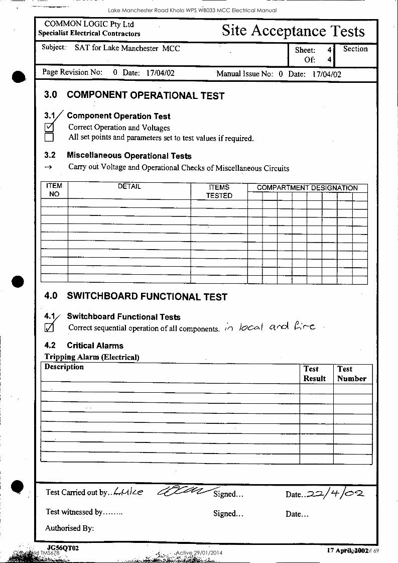
COMMON LOGIC Pty Ltd Specialist Electrical Contractors Site Acceptance Tests Subject: SAT for Lake Manchester MCC
.
Sheet: 4
Of: 4 1 Section 1
Page Revision No: 0 Date: 17/04/02 Manual Issue No: 0 Date: 17/04/02
3.0
3.1
3.2 --
COMPONENT OPERATIONAL TEST
Component Operation Test Correct Operation and Voltages All set points and parameters set to test values if required.
Miscellaneous Operational Tests Carry out Voltage and Operational Checks of Miscellaneous Circuits
ITEM NO
DETAIL ITEMS TESTED
COMPARTMENT DESIGNATION _
4.0 SWITCHBOARD FUNCTIONAL TEST
y Switchboard Functional Tests Correct sequential operation of all components. in locct I cl not e-,r-C.,
4.2 Critical Alarms Tripping Alarm (Electrical) Description Test
Result Test Number
Test Carried out by.. L44) ---."Z-----Signed... Date..22 /I-fic)2 Test witnessed by . Signed... Date...
Authorised By:
,
17 April, 2002
Lake Manchester Road Kholo WPS WB033 MCC Electrical Manual
Q-Pulse Id TMS678 Active 29/01/2014 Page 41 of 69

COMMON LOGIC Pty Ltd Electrical Manual Specialist Electrical Contractors
Subject: Lake Manchester Road MCC Sheet: 10 Of: 10
Section 1
Page Revision No: 1 Date: 26/04/02 Manual Issue No: 1 Date: 26/04/02
8.0 TECHNICAL INFORMATION
Authorised By: Grant Kerr
Jg56mc02.doc
Lake Manchester Road Kholo WPS WB033 MCC Electrical Manual
Q-Pulse Id TMS678 Active 29/01/2014 Page 42 of 69
Rittal
SK
Filter !Lifter
Fan-and-filter units Ventilateur a filtre Ventilator Filterflakt Ventilatore-filtro Ventilador con filtro
SK 3322.m SK 3325.m SK 3323.m SK 3326.m SK 3324.xxx
Montageanleitung
Assembly instructions
Notice de montage Montage-instructie
Montageanvisning Istruzioni di montaggio Instrucciones de montaje
la a a E9i
Umschalten auf Perfektion[RITTFILI
Lake Manchester Road Kholo WPS WB033 MCC Electrical Manual
Q-Pulse Id TMS678 Active 29/01/2014 Page 43 of 69

Best.- Nr. Filterkifter SK
3322.100 3322.107 3322.600
3322.115 3322.117 3322.615
3322.024 3322. 3322.027
. 3322.048 3322 3322 047
'
3323.100 3323.107 3323.600
3323.115 3323.117 3323.615
3323.024 3323 027
'
3323.048 3323.047
Bemessungsbetriebs- spannung Volt/Hz 230/50/60115/50 /60 24 (DC) 48 (DC) 230/50/60115/50 /60 24 (DC) 48 (DC)
Luftleistung freiblasend 55/66 m3/h 105/120 m3 /h
selbstanlaufender Spaltpolmotor
Gleichstrom- motor
selbstanlaufender Spaltpolmotor
Gleichstrom - motor
Bemessungsstrom 0,12 N 0,11 A
0,24 N 0,23 A 0,15 A 0,09 A
0,12 N 0,11 A
0,24 N 0,23 A 0,15 A 0,09 A
Leistung 19 W/18 W 3,5 W 4,4 W 19 W/18 W 3,5 W_ 4,3 W
Ersatzfiltermatte 3322.700 3171.100
Feinfiltermatte 3181.100
Filterbifter- Dichtrahmen 3322.900 3191.100
Strahlwasserhaube 3322.800 3323.800
Gerauschpegel 46/49 dB (A) 46/49 dB (A)
.- Nr. Best: SK Filter
3324.100 3324.107 3324.600
3324.115 ' 3324117 ' 3324.615
3324.024 3324
' 027
3324 048 ' 3324 ' 047
3325.100 * 3325107 ' 3325.600
3325.115 ' 3325117 ' 3325.615
3325 024 ' 3325
' 027
3325.048 3325
' 047
3326.100 '
. 3326 107 3326.600
3326.115 3326.117 3326.615
Bemessungsbetriebs- spannung Volt/Hz 230/50/60 115/50/60 24 (DC) 48 (DC) 230/50/60115/50 /60 24 (DC) 48 (DC) 230/50/60 115/50/60
Luftleistung freiblasend 180/160 m,/h 230/265 m3/h 500/560 m3/h
Axialventilator selbstanlaufender Spaltpolmotor
Gleichstrom- motor
selbstanlaufender Spaltpolmotor
Gleichstrom- motor Kondensatormotor
Bemessungsstrom 0,19 Ai 0,20 A 0,38 Ai 0,40 A
0 30 A '
0,34 A 0,28 N 0,24 A 0,53 N 0,49 A
0 58 A '
0,31 A 0,29 N 0,35 A
0,58 Al 0,70 A
Leistung 30 W/35 W 7,2 W 14 W 41 W/38 W 14 W 15 W 64 W/80 W
Gerauschpegel 52/48 dB (A) 54/56 dB (A) 59/61 dB (A)
Ersatzfiltermatte 3172.100 3173.100
Feinfiltermatte 3182.100 3183.100
FilterKifter- Dichtrahmen 3192.100 3193.100
Strahlwasserhaube 3324.800 3326.800
Temperaturbereich - 10 °C bis + 55 °C
Schutzart nach EN 60529/10.91
IP 43 Standard; IP 54 bei Verwendung von Filtermatten und Filterlufter -Dichtrahmen IP X5 bei Verwendung von Filtermatten und Strahlwasserhauben
2. Montage Montagefolge 1 -4 und Einbaulage beachten! Luftrichtungsanderung durch Drehen des Ventilators mOglich. Voll kompatibel zu den Ausschnitten und Bohrungen der alten" Generation. Schnellmontage-System far Filterlafter und Austrittsfilter. Einfach einrasten und fertig.
3. Elektrischer AnschluB Die AnschluBspannung und -frequenz massen den Nenn- werten des Typenschildes entsprechen. Die einschlagigen Vorschriften der Ortlichen EVU sind zu beachten. Elektrischer AnschluB und evil. Reparatur darfen nur von autorisiertem Fachpersonal durchgefahrt werden. Nur Originalersatzteile verwenden!
4. Filterwechsel und Reinigung Das Wechselintervall der Filtermatte ist je nach Staubanfall und Betriebszeit individuell festzulegen. Achtung! Filterwechsel rechtzeitig durchfahren. Eine ver- schmutzte Filtermatte fahrt zur Temperaturerhohung im Schaltschrank! Die Filtermatte kann durch Auswaschen oder Ausblasen gereinigt werden.
5. Lieferumfang 1 Filtertafter, anschlufffertig, 1 Bohrschablone.
6. Garantie Auf dieses Gerat gewahren wir, bei fachgerechter Anwendung, 1 Jahr Garantie auf Material und Herstellfehler vom Tage der Lieferung an.
7. Entsorgung Die verwendeten Kunststoffteile sind wiederverwertbar.
8. Zubehor 8.1 Ersatz-, Feinfiltermatten und Dichtrahmen 8.2 Strahlwasserhaube- 8,3 Temperaturregler SK 3110.000 8.4 Temperaturanzeige mit Schaltkontakt SK 3114.000
(nur far 230 V AC Lafter) 8.5 Drehzahlregler SK 3120.000 (nur far 230 V AC Lifter).
9. Farbe RAL 7032 100 / 115 / 048 / 024 RAL 7035 107 / 117 / 047 / 027
2
Lake Manchester Road Kholo WPS WB033 MCC Electrical Manual
Q-Pulse Id TMS678 Active 29/01/2014 Page 44 of 69

Model No. fan-and-filter units SK
3322.100 3322.107 3322.600
3322.115 3322.117 3322.615
3322.024 3322.027
3322.048 3322.047
3323115 3323.100 .
3323.107 3323.600
3323 . 3323.117 3323.615
3323.024 3323.027
3323.048 3323.047
Rated voltage Volt/Hz 230/50/60115/50 /60 24 (DC) 48 (DC) 230/50/60115/50 /60 24 (DC) 48 (DC)
Air throughput unimpeded airflow 55/66 m3/h 105/120 m3/h
Axial fan self-starting shaded pole motor DC motor self-starting
shaded pole motor DC motor
Rated current 0.12 N 0.11 A
0.24 N 0.23 A 0.15 A 0.09 A
0.12 N 0.11 A
N 0.24 0.23 A 0.15 A 0.09 A
Nominal output 19 W /18 W 3.5 W 4.4 W 19 W/18 W 3.5 W 4.3 W
Spare filter mat 3322.700 3171.100 Fine filter mat 3181.100 Sealing frame for fan-and-filter units 3322.900 .3191.100
Hose-proof hood 3322.800 3323.800 Noise level 46/49 dB (A) 46/49 dB (A)
Model No. fan-and-filter units SK
3324.100 3324.107 3324.600
3324.115 3324.117 3324.615
3324.024 3324.027.
3324.048 3324.047
3325.100 3325.107 3325.600
3325.115 3325.117 3325.615
3325.024 3325.027
3325.048 3325.047
3326.100 3326.107 3326.600
3326.115 3326.117 3326.615
Rated voltage Volt/Hz 230/50/60 115/50/60 24 (DC) 48 (DC) 230/50/60 115/50/60 24 (DC) 48 (DC) 230/50/60 115/50/60
Air throughput unimpeded airflow 180/160 m3/h 230/265 m3/h 500/560 m3/h
Axial fan self-starting shaded pole motor DC motor self-starting
shaded pole motor DC motor capacitor motor
Rated current 0.19 N 0.20 A
0.38 A/ 0.40 A
0'30 A 0.34 A 00.-2248 AN 00..4593 AA/
0'58 A 0.31 A 0.29 A/ 0.-35 A
0.58 N 0.70 A
Nominal output 30 W/35 W 7.2 W 14 W 41 W/38 W 14 W 15 W 64 W/80 W
Noise level 52/48 dB (A) 54/56 dB (A) 59/61 dB (A)
Spare filter mats 3172.100 3173.100 Fine filter mat 3182.100 3183.100 Sealing frame for fan-and-filter units 3192.100 3193.100
Hose-proof hood 3324.800 3326.800 Temperature range - 10 °C to + 55 °C
Protection category to EN 60 529/10.91
IP 43 standard; IP 54 by using of filter mat and sealing frame for fan-and-filter units IP X5 by using of filter mat and hose-proof hood
2. Assembly Observe sequence of assembly 1 - 4, and Mounting position! Airflow direction can be changed by reversing the fitting of fan. Fully compatible with the cutouts and holes of the "old" units. Quick-assembly system for fan-and-filter units and outlet filter. Simply snap into place, and that's it.
. Electrical connection Supply voltage and frequency must correspond to the rated values stated on the nameplate. The relevant requirements of the local electricity board must be observed. Electrical connection and repair must be carried out by authorised specialist personnel only. Use original spares only.
4. Filter replacement and cleaning The frequency of filter replacements should be determined individually, depending on dust accumulation and operating period. Note: Filter replacement must be carried out in good time. A soiled filter mat will cause the temperature to rise inside the enclosure! The filter mat can be regenerated by washing or blowing out.
5. Supply includes 1 fan-and-filter unit, ready for connection, 1 drilling template.
6. Guarantee We will guarantee this unit, if used correctly, for 1 year in respect of materials and manufacturing faults, from the date of its supply.
7. Waste disposal The plastic material used in the components can be recycled.
8. Accessories 8.1 Spare filter mats, fine filter mats and sealing frame 8.2 Hose-proof hood 8.3 Thermostat SK 3110.000 8.4 Temperature indicator with switch contact SK 3114.000
(only for 230 V AC fan) 8.5 Speed control SK 3120.000 (only for 230 V AC fan).
9. Colour RAL 7032 100 / 115 / 048 / .024 RAL 7035 107 / 117 / 047 / 027
3
Lake Manchester Road Kholo WPS WB033 MCC Electrical Manual
Q-Pulse Id TMS678 Active 29/01/2014 Page 45 of 69

N° de ref. Ventilateur a filtre SK
3322.100 3322.107 3322.600
3322.115 3322.117 3322.615
3322.024 3322.027
3322.048 3322.047
3323.100 3323.107 3323 3323.600
3323.115 3323.117 3323.615
3323.024 3323.027
3323.048 3323.047
III
Tension nominate Volt/Hz 230/50/60115/50 /60 24 (DC) 48 (DC) 230/50/60115/50 /60 24 (DC) 48 (DC)
Debit d'air en south. libre 55/66 m3/h 105/120 m3 /h
Ventilateur axial moteur a bague de
dephasage autodemarrant
mo eur a courant continu
moteur a bague de dephasage
autodemarrant
mo eur a courant continu
Intensite nominate 0,12N 0,11 A
0,24 N 0,23 A 0,15 A 0,09 A 0,12 N
0,11 A 0,24 N 0,23 A 0,15 A 0,09 A
Puissance nominale 19 W/18 W 3,5 W 4,4 W 19 W/18 W 3,5 W 4,3 W
Cart.f iltrante de rechange 3322.700 3171.100
Cartouche filtrante fine - 3181.100
Cadre d'etancheite pour ventilateur a filtre 3322.900 3191.100
Capot de protection contre les jets d'eau 3322.800 3323.800
Niveau sonore 46/49 dB (A) 46/49 dB (A)
N° de ref. Ventilateur a filtre SK
3324.100 3324.107 3324.600
3324.115 3324.117 3324.615
3324.024 3324.027
3324.048 3324.047
3325.100 3325.107 3325.600
3325.115 3325.117 3325.615
3325.024 3325.027
3325.048 3325.047
3326.100 3326.107 3326.600
3326.115 3326.117 3326.615
Tension nominate Volt/Hz 230/50/60 115/50/60 24 (DC) 48 (DC) 230/50/60 115/50/60 24 (DC) 48 (DC) 230/50/60 115/50/60
Debit d'air en souffl. libre 180/160 m3/h 230/265 m3/h 500/560 m3 /h
Ventilateur axial moteur a bague de
dephasage autodemarrant
mo eur a courant continu
moteur a bague de dephasage
autodemarrant
mo eur a courant continu
a condensateur moteur
Intensite nominate 0,19 N 0,20 A
0,38 N 0,40 A 0,30 A 0,34 A 0,28 N
0,24 A 0,53 N 0,49 A 0,58 A 0,31 A
0,29 N 0,35 A
0,58 N 0,70 A
Puissance nominate 30 W/35 W 7,2 W 14 W 41 W/38 W 14 W 15 W 64 W/80 W
Niveau sonore 52/48 dB (A) 54/56 dB (A) 59/61 dB (A)
Cart.filtrante de rechange 3172.100 3173.100
Cartouche filtrante fine 3182.100 3183.100
Cadre d'etancheite pour ventilateur a filtre 3192.100 3193.100
Capot de protection contre les jets d'eau 3324.800 3326.800
Plage de temperature - 10 °C a + 55 °C
Degre de protection selon EN 60 529/10.91
IP 43 standard; IP 54 en utilisant une cartouche filtrante et un cadre d'etancheite pour ventilateur a filtre IP X5 en utilisant une cartouche filtrante at un capot de protection contre les jets d'eau
2. Montage Respecter I'ordre des sequences de montage 1 -4 et la position de montage! II est possible de changer la direction du courant d'air en tournant le ventilateur. Les ventilateurs a filtre sont entierement compatibles avec les decoupes at les pergages des appareils de l'ancienne generation. Systeme de montage rapide pour les ventilateurs a filtre et pour les f titres de sortie. II suffit de les encliqueter et c'est tout.
3. Raccordement electrique La tension et la frequence de raccordement doivent corres- pondre aux valeurs nominates inscrites sur la plaque signaletique. Respecter les prescriptions an vigueur de I'EVU ou de l'EDF. Le raccordement electrique at les eventuelles reparations ne doivent etre executes que par du personnel qualifie compe- tent. N'utiliser que des pieces de rechange originates!
4. Changement des filtres et nettoyage Lintervalle souhaitable pour le changement des cartouches filtrantes depend de la quantite de poussiere presente dans fair at de la duree de tonctionnement. II doff done etre defini de fawn individuelle. Attention! Le changement du filtre doit etre fait en temps voutu: une cartouche filtrante encrassee provoque une ele- vation de la temperature dans !'armoire electrique! II est possible de regenerer la cartouche filtrante en la !avant ou en la passant a Fair comprime.
5. Composition de la livraison 1 ventilateur a filtre'pret au raccordement, 1 gabarit de percage.
6. Garantie Pour rappareil utilise correctement, nous assurons sur le materiau at as vices de fabrication une garantie d'un an a compter du jour de la livraison.
7. Retraitement Toutes les pieces an matiere plastique utilisees dans ces appareils sont recyclables.
8. Accessoires 8.1 Cartouches filtrantes de rechange, cartouches filtrantes
fine at le cadre d'etancheite 8.2 Capot de protection contre les jets d'eau 8.3 Regulateur de temperature SK 3110.000 8.4 Indicateur de temperature avec contact inverseur
SK 3114.000 (seulement pour ventilateur 230 V AC) 8.5 Contrele de vitesse de rotation SK 3120.000
(seulement pour ventilateur 230 V AC).
9. Coloris RAL 7032; 100 / .115 / .048 / .024 RAL 7035; 107 / .117 / .047 / .027
4
Lake Manchester Road Kholo WPS WB033 MCC Electrical Manual
Q-Pulse Id TMS678 Active 29/01/2014 Page 46 of 69

Nederlands Bestelnr. Ventilator SK
3322.100 3322.107 3322.600
3322.115 3322.117 3322.615
3322.024 3322.027
3322.048 3322.047
3323.100 3323.107 3323.600
3323.115 3323.117 3323.615
3323.024 3323.027
3323.048 3323.047
Aansluitspanning Volt/Hz
230/50/60115/50 /60 24 (DC) 48 (DC) 230/50/60115/50 /60 24 (DC) 48 (DC)
Luchtverplaatsing vrijblazend 55/66 m3 /h 105/120 m3/h
Axiaalventilator zelfaanlopende kortsluitankermotor
gelijkstroom- motor
zelfaanlopende kortsluitankermotor
gelijkstroom- motor
Nominale bedrijfsstroom
0,12 A/ 0,11 A
0,24 N 0,23 A 0,15 A 0,09 A 0,12 N
0,11 A 0,24 A/ 0,23 A 0,15 A 0,09 A
Nominal opgenomen vermogen 19 W/18 W 3,5 W 4,4 W 19 W/18 W 3,5 W 4,3 W
Filtermat 3322.700 3171.100 Fijnfiltermat 3181.100 Ventilator-afdichting 3322.900 3191.100 Afdekkap v. ventilato- ren i. v. m. spyicwater 3322.800 3323.800
Geluidsnivo 46/49 dB (A) 46/49 dB (A)
Bestelnr. Ventilator SK
3324.100 3324.107 3324.600
3324.115 3324.117 3324.615
3324.024 3324.027
3324.048 3324.047
3325.100 3325.107 3325.600
3325.115 3325.117 3325.615
3325.024 3325.027
3325.048 3325.047
3326.100 3326.107 3326.600
3326.115 3326.117 3326.615
Aansluitspanning Volt/Hz 230/50/60115/50 /60 24 (DC) 48 (DC) 230/50/60115/50 /60 24 (DC) 48 (DC) 230/50/60115/50 /60
Luchtverplaatsing vrijblazend 180/160 m3 /h 230/265 m3 /h 500/560 m3 /h
Axiaalventilator zelfaanlopende kortsluitankermotor
gelijks room- motor
zelfaanlopende kortsluitankermotor
gelijks room- motor kondensatormotor
Nominate bedrijfsstroom
0,19 N 0,20 A
0,38 A/ 0,40 A 30 A 0,,34 0 A 0,28 A/
0,24 A 0,53 A/ 0,49 A 58 A 0,,31 0 A 0,29 N
0,35 A 0,58 A/ 0,70 A
Nominal opgenomen vermogen 30 W/35 W 7,2 W 14 W 41 W/38 W 14 W 15 W 64 W/80 W
Geluidsnivo 52/48 dB (A) 54/56 dB (A) 59/61 dB (A)
Filtermat 3172.100 3173.100 Fijnfiltermat 3182.100 3183.100 Ventilator-afdichting 3192.100 3193.100 Afdekkap v. ventilato ren L v. m. spyicwater 3324.800 3326.800
Temperatuurbereik - 10 °C tot + 55 °C
Beschermklasse volg. EN 60529/10.91
IP 43 standaard; IP 54 bij toepassing van een filtermat en ventilator-afdichting IP X5 bij toepassing van een filtermat en afdekkap voor ventilatoren i. v. m. spyicwater
2. Montage Let op de montagevolgorde 1 -4 en de inbouwstand! Door het omkeren van de ventilator kan de luchtstroomrichting omgedraaid worden. Boorpatroon en sparingen zijn gelijk aan die van de vergelijk- bare
ro e konventionele Rittal ventilatoren.
nelmontagesysteem voor ventilator en ventilatierooster, simpel inklikken.
3. Elektrische aansluiting De aansluitspanning en netfrekwentie moeten overeenkomen met de nominate waarden vermeld op het typeplaatje. De plaatselijke voorschriften opvolgen. Het elektrisch aansluiten on eventueel repareren alleen door geautoriseerd vakpersoneel uit laten voeren. Aileen originele onderdelen gebruiken!
4. Filtermaten verwisselen en schoonmaken De regelmaat waarmee filtermatten vervangen of schoonge- maakt moeten worden is afhankelijk van de vervuiling en de inschakelduur en moot per situatie vastgelegd worden. Let op! Filtermat op tijd vervangen of schoonmaken. Een ver- vuilde filtermat kan ertoe !olden dat de temperatuur in de schakelkast to hoog wordt. De filtermat kan door uitwassen of doorblazen schoongemaakt worden.
5. Levering 1 ventilator, aansluitgereed, 1 sjabloon.
6. Garantie Op dit apparaat wordt een garantie van 1 jaar gegeven. De garantie gelds vanaf de dag van levering en voorzover het apparaat vakkundig is gebruikt.
7. Recycling De toegepaste kunststof materialen zijn recyclebaar.
8. Toebehoren 8.1 Filtermatten, fijnfiltermatten on afdichting 8.2 Afdekkap voor ventilatoren i. v. m. spyicwater 8.3 Thermostaat SK 3110.000 8.4 Temperatuurindicator met schakelcontact SK 3114.000
(alleen bij ventilator 230 V AC) 8.5 Toerentalregeling SK 3120.000
(alleen bij ventilator 230 V AC).
9. Kleur RAL 7032 100 / 115 / 048 / 024 RAL 7035 107 / 117 / 047 / 027
Lake Manchester Road Kholo WPS WB033 MCC Electrical Manual
Q-Pulse Id TMS678 Active 29/01/2014 Page 47 of 69

Best nr Filterflakt SK
3322.100 3322.107 3322.600
3322.115 3322.117 3322.615
3322.024 3322.027
3322.048 3322.047
3323.100 3323.107 3323.600
3323.115' 3323.117 3323.615
3323.024 3323.027
3323.048 3323.047
Markspanning Volt/Hz 230/50/60115/50 /60 24 (DC) 48 (DC) 230/50/60115/50 /60 24 (DC) 48 (DC)
Lufteffekt friblasande 55/66 m3/h 105/120 m3/h
Axialflakt sjalvstartande spaltmotor
likstrOms- motor
sjalvstartande spaltmotor
likstrOms- motor
sjalvstartande spaltmotor
Markstrom 0,12 N 0,11 A
0,24 N 0,23A 0,15 A 0,09 A
0,12 N 0,11 A
0,24 N 0,23A 0,15 A 0,09 A
Markeffekt 19 W/18 W 3,5 W 4,4 W 19 W/18 W 3,5 W 4,3 W
Filtermatta 3322.700 3171.100 Finfiltermatta 3181.100 Tatningsram for filterflakt 3322.900 3191.100
Stralvattenhuya 3322.800 3323.800 Ljudniva 46/49 dB (A) 46/49 dB (A)
Best nr Filterf lakt SK
3324.100 3324.107 3324.600
3324.115 3324.117 3324.615
3324.024 3324.027
3324.048 3324.047
3325.100 3325.107 3325.600
3325.115 3325.117 3325.615
3325.024 3325.027
3325.048 3325.047
3326.100 3326.107 3326.600
3326.115 3326.117 3326.615
Markspanning Volt/Hz 230/50/60115/50 /60 24 (DC) 48 (DC) 230/50/60115/50 /60 24 (DC) 48 (DC) 230/50/60115/50 /60
Lufteffekt friblasande 180/160 m3 /h 230/265 m3/h 500/560 m3/h
Axialflakt sjalvstartande spaltmotor likstrOmsmotor sjalvstartande
spaltmotor likstremsmotor kondensatormotor
Markstram 0,19 N 0,20 A
0,38 N 0,40 A 0,30 A 0,34 A
0,28 N 0,24 A
0,53 N 0,49 A
0,58 A 0,31 A 0,29 N 0,35 A
0,58 A/ 0,70 A
Markeffekt 30 W/35 W 7,2 W 14 W 41 W/38 W 14 W 15 W 64 W/80 W Ljudniva 52/48 dB (A) 54/56 dB (A) 59/61 dB (A) Filtermatta 3172.100 3173.100 Finfiltermatta 3182.100 3183.100 Tatningsram for filterflakt 3192.100 3193.100
Stralvattenhuya 3324.800 3326.800 Temperaturomrade - 10 °C till + 55 °C Kapslingsklass enligt EN 60 529/10.91
IP 43 standard; IP 54 vid anvandande av filtermatta och tatningsram for filterflakt IP X5 vid anvandande av filtermatta och stralvattenhuva
2. Montering Beakta monteringsfOljden 1 -4 och inbyggnadslage! Lultriktningsandring ar majlig genom vridning av flakten. Fullt kompartibel till den "aldre" generationen utstansningar och borrningar. Snabbmontagesystem for filterflakt och utblasningsfilter. Enkelt infallning i rasterspar och klar.
3. Elektrisk anslutning Anslutningsspanning och -frekvens maste motsvara typskyltens markvarden. De tillampliga lokala fOreskrifterna maste beaktas. Elektrisk anslutning och eventuall reparation far bara genom- f6ras av behOriga fackman. Anvand endast originalreservdelar!
4. Byte av filter och rengbring Bytesintervall f6r filter far faststallas individuellt beroende pa dammangd och driftstid. Observera! UtfOr filterbyte i ratt tid. Ett nersmutsat filter leder till temperaturhOjning i apparatskapet. Filter kan rengares genom tvattning eller urblasning.
5. Leveransinnehall 1 filterflakt, anslutningsklar, 1 haltagningsfilte.
6. Garanti PA denna apparat beviljar vi, vid fackmassig anvandning, 1 are garanti pa material och tillverkningsfel fran leverans- dagen.
7. Avfallshantering De anvanda plastdetaljerna kan Ateranvandas.
8. Tillbehor 8.1 Filtermatta, finfiltermatta och tatningsram 8.2 Stralvattenhuva 8.3 Termostat SK 3110.000 8.4 Temperaturdisplay med brytkontakt SK 3114.000
(endast pa flakt 230 V AC) 8.5 Varvtalsreglering SK 3120.000 (endast pa flakt 230 V AC).
9. Fargton RAL 7032' 100 / .115 / .048 / .024 RAL 7035' 107 / .117 / .047 / .027
Lake Manchester Road Kholo WPS WB033 MCC Electrical Manual
Q-Pulse Id TMS678 Active 29/01/2014 Page 48 of 69

Italiano Nr. d'ord. Ventilatori-filtro SK
3322.100 3322.107 3322.600
3322.115 3322.117 3322.615
3322.024 3322.027
3322.048 3322.047
3323.100 3323.107 3323.600
3323.115 3323.117 3323.615
3323.024 3323.027
3323.048 3323.047
Tensione nominale Volt/Hz 230/50/60 115/50/60 24 (DC) 48 (DC) 230/50/60115/50 /60 24 (DC) 48 (DC)
Portata d'aria in aspirazione libera 55/66 m3/h 105/120 m3/h
Ventilatore assiale motore autoawiante a poll schermati
mo ore c. c.
motore autoawiante a poll schermati
mo ore c. c.
Corrente nominale 0,12 N 0,11 A
0,24 N 023 A
0,15 A 0,09 A 0,12 N 0,11A
0,24 N 0,23A 0,15 A 0,09 A
Potenza nominale 19 W/18 W 3,5 W 4,4 W 19 W/18 W 3,5 W 4,3 W
Feltro di ricambio 3322.700 3171.100
Feltro a maglie fini , 3181.100 Guarnizione di tenuta per ventilatori-filtro 3322.900 3191.100
Cuffia di protezione 3322.800 3323.800 Livello di rumore 46/49 dB (A) 46/49 dB (A)
Nr. d'ord. Ventilatori-filtro SK
3324.100 3324.107 3324.600
3324.115 ' 3324.117
3324.615
3324.024 3324 027
'
3324.048 3324 047
'
3325.100 3325.107 3325.600
3325.115 ' 3325.117
3325.615
3325.024 3325 027
3325.048 3325 047 '
3326 100 ' 3326.107
3326.600
3326.115 3326.117 3326.615
Tensione nominale Volt/Hz
230/50/60115/50 /60 24 (DC) 48 (DC) 230/50/60115/50 /60 24 (DC) 48 (DC) 230/50/60115/50 /60
Portata d'aria in aspirazione libera 180/160 m3/h 230/265 m3/h 500/560 m3/h
Ventilatore assiale motore autoawiante a poli schermati
mo ore c. c.
motore autoawiante a poll schermati
mo ore c. c.
motore con condensatore
Corrente nominale 0,19 N 0,20 A
0,38 N 0.40 A
0'30 A 0,34 A 0,28 N 0,24 A
0,53 A/ 0,49 A
0'58 A 0,31 A 0,29 N 0,35 A
0,58 N 0,70 A
Potenza nominale 30 W/35 W 7,2 W 14 W 41 W/38 W 14 W 15 W 64 W/80 W
Livello di rumore 52/48 dB (A) 54/56 dB (A) 59/61 dB (A)
Feltri di ricambio 3172.100 3173.100 Feltro a maglie fini 3182.100 3183.100 Guarnizione di tenuta per ventilatori-filtro 3192.100 3193.100
Cuffia di protezione 3324.800 3326.800 Campo di temperatura - 10 °C fino a + 55 °C
Grado di protezione secondo EN 60 529/10.91
IP 43 standard; IP 54 utilizzando un filtro a maglie e guarnizione di tenuta per ventilatori-filtro IP X5 utilizzando un filtro a maglie e cuffia di protezione
2. Montaggio Attenersi alle successioni esposte dai punti 1 -4 e rispettare la posizione di montaggio! La modifica del flusso d'aria 6 possibile ructando H ventilatore. La feritoia ed i Pori di fissaggio per questo ventilatore sono com-
patibifi col ventilatore della precedente .generazione Per il
ventilatore ed it filtro d'uscita 6 stato adottato H sistema di mon- taggio rapido. Semplicemente appendere ed innestare.
3. Allacciamento elettrico La tensione di ahmentazione e la frequenza devono corrispon- dere ai valori nominali riportati nella targhetta. Eseguire l'allac- ciamento net rispetto delle prescrizioni a norme locali. L'allacciamento elettrico ed eventuati riparazioni vanno eseguiti soltanto da personale qualificato. Per riparazioni impiegare soltanto parti di ricambio originah!
4. Sostituzione del feltro e pulizia II periodo di tempo fra due sostituzioni del feltro 6 funzione della quantit6 di polvere e tempo di funzionamento, va percio stabihto di volta in volta per i singoli impianti. Attenzione: Eseguire la sostituzione del feltro per tempo. Un feltro sporco comporta un'aumento della temperatura interna dell'armadio! II feltro si pu6 rigenerare lavandolo o con getto d'aria.
5. La fornitura comprende: 1 ventilatore-filtro, pronto per I'allacciamento, 1 dima di foratura.
6. Garanzia Dal giorno della fornitura consideriamo per questo apparec- chio 1 anno di garanzia, per difetti di materiale, di costruzione e per impiego corretto.
7. Recupero Le parti in ptastica impiegate sono rivatorizzabili.
8. Accessori 8.1 Feltri di ricambio, feltri a maglie fini a guarnizione di
tenuta 8.2 Cuffia di protezione 8.3 Termostato SK 3110.000 8.4 Indicators di temperature con contatto in scambio
SK 3114.000 (solo per ventilatore 230 V c. a.) 8.5 Regolazione del numero dei girl SK 3120.000
(solo per it ventilatore 230 V c. a.).
9. Colore RAL 7032* 100 / .115 / .048 / .024 RAL 7035* 107 / .117 / .047 / .027
7
Lake Manchester Road Kholo WPS WB033 MCC Electrical Manual
Q-Pulse Id TMS678 Active 29/01/2014 Page 49 of 69

Referencia Ventilador con filtro SK
3322.100 3322.107 3322.600
3322.115 3322.117 3322.615
3322.024 3322.027
3322.048 3322.047
3323.100 3323.107 3323.600
3323.115 3323.117 3323.615
3323.024 3323.027
3323.048 3323.047
Tension nominal Volt/Hz 230/50/60115/50 /60 24 (DC) 48 (DC) 230/50/60115/50 /60 24 (DC) 48 (DC)
Potencia de soplado libre 55/66 m3/h 105/120 m3/h
Ventilador axial motor de autoarranque
motor de corriente continua
motor de autoarranque
motor de autoarranque
Corriente nominal 0,12 A/ 0,11 A
0,24 A/ 0,23 A
0,15 A 0,09 A 0,12 N 0,11 A
N 0,24 0,23 A
0,15 A 0,09 A
Potencia nominal 19 W/18 W 3,5 W 4,4 W 19 W/18 W 3,5 W 4,3 W
Estera filtrante de repuesto 3322.700 3171.100
Estera filtrante fina 3181.100 Juntas p. ventilador 3322.900 3191.100 Cub. contra agua a presion 3322.800 3323.800
Nivel de ruidos 46/49 dB (A) 46/49 dB (A)
Referencia Ventilador con filtro SK
3324.100 3324.107 3324.600
3324.115 3324.117 3324.615
3324.024 3324.027
3324.048 3324.047
3325.100 3325.107 3325.600
3325.115 3325.117 3325.615
3325.024 3325.027
3325.048 3325.047
3326.100 3326.107 3326.600
3326.115 3326.117 3326.615
Tensi6n nominal Volt/Hz
230 /50/60115/50/60 24 (DC) 48 (DC) 230/50/60115/50 /60 24 (DC) 48 (DC) 230/50/60115/50 /60
Potencia de soplado libre 180/160 m3/Y1 230/265 m3/h 500/560 m3/h
Ventilador axial motor de autoarranque
motor de corriente continua
motor de autoarranque
motor de corriente continua
arranque por condensador
Corriente nominal 0,19 A/ 0,20 A
0,38 A/ 0,40 A
0,30 A 0,34 A 0,28 A/ 0,24 A
0,53 Al 0,49 A 0,58 A 0,31 A
0,29 A/ 0,35 A
0,58 A/ 0,70 A
Potencia nominal 30 W/35 W 7,2 W 14 W 41 W/38 W 14 W 15 W 64 W/80 W
Nivel de ruidos 52/48 dB (A) 54/56 dB (A) 59/61 dB (A)
Estera filtrante de repuesto 3172.100 3173.100
Estera filtrante fina 3182.100 3183.100 Juntas p. ventilador 3192.100 3193.100 Cub. contra agua a presion 3324.800 3326.800
Gama de temperatura - 10 °C a + 55 °C
Grado de protecciOn segiin EN 60 529/10.91
IP 43 estandar; IP 54 utilizando una estera filtrante y juntas para ventilador IP X5 utilizando una estera filtrante y cubierta contra agua a presiOn
2. Montaje jRespeten el orden de montaje 1 -4 y la posiciOn de montaje! Posibilidad de cambiar la direcci6n del sire girando el venti- lador. Totalmente compatible con las escotaduras y taladros de as generaciones .anteriores Sistema de montaje rapid() para el ventilador con filtro y el filtro de salida. Tan solo hay que acoplarlo.
3. Conezion electrica La tension y frecuencia de conexian debe corresponder al valor nominal de la placa de caracteristicas. La conexian electrica y reparaciones solo deben ser reafiza- das por personal autorizado. iLltifice Onicamente piezas de recambio originales!
4. Cambio del filtro y limpieza El periodo de tiempo, que debe transcurrir entre los cambios de la estera filtrante, debe ser determinado individualmente dependiendo del grado de exposici6n al polvo y el tiempo de servicio. jAtencion! Realice el cambio de filtros a tiempo. Una estera filtrante sucia provoca el aumento de la temperatura interior del armario. La estera filtrante puede lavarse o limpiarse por soplado.
5. Unidad de envase: 1 ventilador con filtro, listo pars la conexiOn, 1 esquema de perforaciones.
6. Garantia Para este aparato ofrecemos, con una utilizacian adecuada, una garantla de material y defectos de fabricaci6n de 1 ano a partir del dia de su suministro.
7. Reciclado Las piezas plasticas utilizadas pueden ser recicladas.
8. Accesorios 8.1 Esteras filtrantes de repuesto, esteras filtrantes fina
y marco de estanqueidad 8.2 Cubierta contra agua a presi6n 8.3 Termostato SK 3110.000 8.4 Indicador de temperatura con contacto libre de potencial
SK 3114.000 (solo pars ventilador de 230 V c. a.) 8.5 RegulaciOn de velocidad SK 3120.000 (solo pars
ventilador de 230 V c. a.).
9. Color RAL 7032- 100 / .115 / .048 / .024 RAL 7035- 107 / .117 .047 / .027
8
Lake Manchester Road Kholo WPS WB033 MCC Electrical Manual
Q-Pulse Id TMS678 Active 29/01/2014 Page 50 of 69

Notizen/Notes
9
Lake Manchester Road Kholo WPS WB033 MCC Electrical Manual
Q-Pulse Id TMS678 Active 29/01/2014 Page 51 of 69
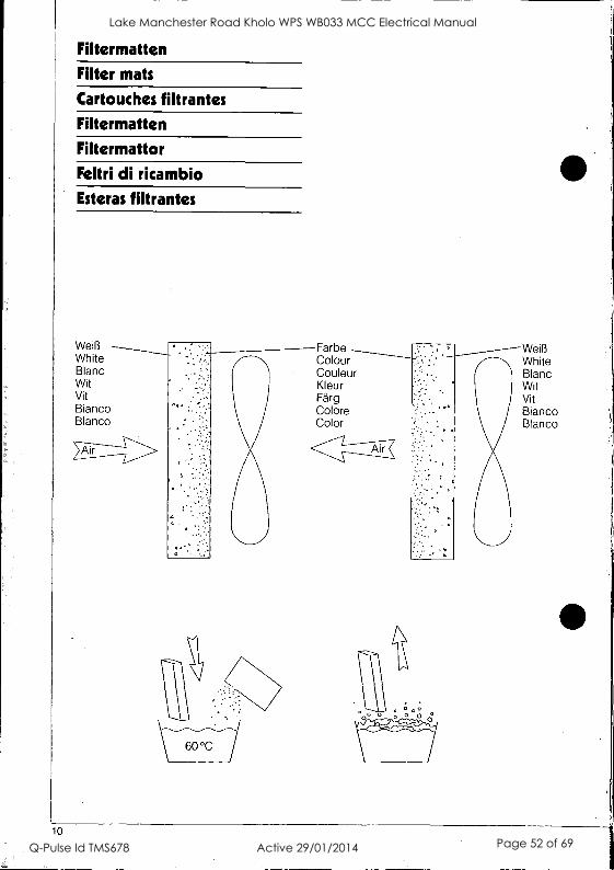
Filtermatten
Filter mats
Cartouches filtrantes
Filtermatten
Filtermattor
Feltri di ricambio Esteras filtrantes
Weifi White Blanc Wit Vit Bianco Blanco
10
Farbe Colour Couleur Kleur Farg Co lore Color
White Blanc Wit Vit Bianco Blanco
Lake Manchester Road Kholo WPS WB033 MCC Electrical Manual
Q-Pulse Id TMS678 Active 29/01/2014 Page 52 of 69
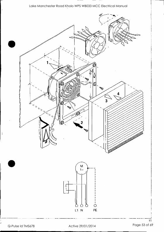
11
Lake Manchester Road Kholo WPS WB033 MCC Electrical Manual
Q-Pulse Id TMS678 Active 29/01/2014 Page 53 of 69

Schaltschrank-Systeme Enclosure systems Systemes d'armoires electriques Schakelkastsystemen Agparatskapssystem Sistemi di armadi per quadri di comando Sistemas de armarios
Elektronik-Aufbau-Systeme EL
Electronic systems EL
Systemes de montage electroniques EL Elektronica-opbouwsystemen EL
Elektroniksystem EL
Sistemi di allestimento EL per I'elettronica industriale Sistemas de soporte electrOnicos EL
-jf../5-4 EL
Schaltschrank-Klimatisierung SK Enclosure air-conditioning SK
Climatisation d'armoires electriques SK SchakelkastklimaatbeheersinqSK Apparatskapsklimatiserinq SK
Apparecchi SK per la climatizzazione di quadri di com. Climatizacien de armarios SK
j.:19.7_2/9.NOT, SK
Stromverteilunqs-Komponenten SV Power distribution components SV Composants de distribution de courant SV Stroomverdelinoscomponenten SV
StrOmfordelningskomponenter SV Componenti SV per la distribuzione di corrente elettrica Componentes de distribuciOn de corriente SV 7it-531Z 6EZ-,./.5-t. sv
Datenebertraqunqs-Komponenten DK Data communication components DK Composants de distribution de donnees informat. DK Data-overdrachtscomoonenten DK DatativerfOringskomponenter DK Armadi e contenitori DK per trasmissione dart e telefonia Componentes de la transmisiOn de datos 5-*-93fli-M5v9,3/T-z, DK
Outdoor-Gehause CS
Outdoor enclosures CS Armoires outdoor CS
Outdoor -behuizingen CS
Utomhusskap CS Armadi modulari CS per applicazioni da esterno Cajas para la intemperie CS 7r7 F7I:../90-,3/1-,-'-:,),T-L, CS
Rittal-Werk Rudolf Loh GmbH & Co. KG Postfach 1662 D-35726 Herborn Telefon (02772) 505-0 Telefax (02772) 505 -2319 eMail: [email protected] Internet: http://www.rittal.de
235 944 A - 1/mschalten auf Perfektionl,PITTF19ts;
Lake Manchester Road Kholo WPS WB033 MCC Electrical Manual
Q-Pulse Id TMS678 Active 29/01/2014 Page 54 of 69

SIN31A111111SNI
uoultuag
ao!no saps pool JnoA peluoo aseeld sluewapnbeJ uopoepoid uo aouws!sse Jod
onpard s!yl 6uppuey wort saw!; pe le ue le; eq isnw suopneowd (Gs]) 06.1e1108113.3P3S 0.110813
'Nd ANZ palm eq Isnw a6ins 'efiewep luauet.wed Isu!ebe ionpoid ayi peloid of e
-eouarepalu! lo °mos e.'eq pinoo JO 'we ley; sionpoid pue selquo ep!s6uole spew 6uRnoi ppm/ z
uopouni aouewnisp e6ipsneo aoue epapp. leoploale 1su!e68 paloid veto seinsopue 0013 'suopoun; leopuo 6uRuloped we min 'sprewruisu! 0111040810 ampsues peisu! of eo!loiJd pooh s! u 9.N
apew eq-pnw "313 arm; aup 'sJewosqe aluJel se tons 'slueuodwoo uo!ssaJddns da 6U11111 J01 uo!sytwd 'pasn eq ;cm ueo spew ;means weym swenoid 6u!sneo spiel; du Jo lug/ No eqi u! spew Indu! leu6p moi pue indmo mans .;
6a spiewuopnue lepisnpu! u! 3'B Jo; eopoard Jo epoo pooh e oo pepwsu! uaym settpoei!O na ay; lo swewapnbw uogeonniao ay; leew of pau6!sep ueeq sett e6ue., ionpoid s!yi
slueLueJlnbeu uoneneisui (ova) AmIquedwoo o11eu6ewonoeia
pedal Jape pelameow eq Ism pun NI ieqei ep!s ey; uo puno; Jeqwnuiapow pn; ayi elonb eseeld Apnbue Aue ypm emellene s! luewd!nbe Aownooe y6p4 pepnbar ayi p peidwepe eq -Aluo pinoys s!yl 'trey; 'pedal Jape Aes 'AJesseoeu peweep eq uoparqpeo pinoys legi luepodw! s! lI !nopo ieu!6!Jo ey; pasn esoyi se 0311E-18101 pue 6upei 'adAl ewes ey; Jo eq Isnw wueuodwoo lueweouldar uay; paldwaue eq pedw wogs (z e6ed uo spelap) 'ammo eovues sluewruisui uoidwalo ;sweat'.
of JO fume; ayi of pet.impai s! pun ay; ley; pepuewwooe s! p fuesseoeu 6u!eq pedal e Jo Juana Alemiun alp ul -uo!sonoo pue sseuiy6p Jo; suopoeuuoo IIe loeyo pue Isnp
;o suogeinwnooe OA011.18.1 eldwexe Joj uawd!nbe lo ssep s!y; Jo; spiepues iewiou 01. papedsu! eq pinoys pun eta
eoueuelu!ew
peweouoo iwitroo ay; Jo ueds etp lo okor. Apeo!dAl s! spew uopexpleo ay' Jo J0118 wnw!xew ayi uawd!nbe eiwnooe sseooe eney iou seop Japeisu! ay; p appi6 e se pepvtoid ale sianuoo punwe slum uopeiqueo ayi
(siepow Jetno lie) dn Bugles
e6epon paieJ x ge*; = peopeno snonupuo0 puelsypm e6epoA
Aelep wnw!xew °/001 sa6UeJ e6epon IIe JOd
Aelea e6wIon
pale) xepu! sselo %g t of pwagmeo ale 1-1 5110A
09£ °nogg se6epoA e6epon pee xepu! ssep Tot 01 pelexpleo ale 1=1 spon-on moiaq pue Jo se6e110A
sppod ;es eoueiequn % ; -:smopo; se pelexpleo
fume; ale Aey; pue swewapnbei 6upeledo ;ins o; vas eq ueo yo!ym sempow uopeiqpeo om; °my sionpard eseui
(DSd-ZSZ 'ASd-ZSZ) .s10ilu03
'8
'Z
6umas
u!pm Jaw Aue ww; elejedes Owl eq pinoys spew indpio pue indu! 'dn )10!d
Clid-CSZ 1141d-ZSZ
SJOSUOS annonpu! poo opeu6ew ypm Apo esn Jo; peu6!sep s! lonpoid s!yi
peeds 6u!su uo sesPeue-ap Aele8 eo peeds 6u!su uo sasPeue Aele13 z*o 1
peeds 6u!sp uo ses!6Jeue Aeleu or4 Apeweiu! S impwiel
o; papeuuoo s! 8 leuRwei peeds o; uopiodwd leu6p vU11./0 e OAP 9; pue g; sieu!wiei- -Apewelu! S ieup.wei o; pepauuoo s! 8 impwlei serpen pelemeo ey; o; las we spite' du; eq sainsue ow yo!ym luewepnbei spp Jo; pasn s! luw; lonpard eq; uo lod ;snipe JOIOW ayi ndlno vw9L'O = peeds 6upJuru IewJOu Jo; pelsn[pe kopei we spun
-pas!6Jeue eq ploys situp Oarip Ile peeds 61.puuni leurJou le pue ems pes!6Jeue ue u! OJe sAelar Indlno clod ei6u!s alp ley; seleo!pu! s,031 pa, perequinip au eu6p dui e eien!u! !pm pun ow 'spwp °say) epmno 6u!now indu! ay; Jo
wane ayi ul spupi °mews uRipm paropuow we sindu! dui (Elid-C9Z) Atileld 6U1SUOS peadS
spupi uRipm s! Aiddns ayo 1841 swop:1u! 031 pal peieupnip uv Amer Jenoe6ueyo clod alqnop e e!A Ieu6!s dui e empu! ll!M pun ey; 'spw!! asay; erpsino 6u!now indu! ey; 11.18A8 ay; ill swim emelles uppm pepapuow OJe sir-du! dui
(DSd-ZSZ dSd-ZSZ) Aele8 eoueleg aseyd
per ayi no pue dn pun ayl 6uRpi pue dip asealw umop 6upene! Aq pene!yoe eq Aew 6111110111S0d0J JO le/towel:1 pexp Aiwp; s! pun ey; moe49 eoeld ow! peNopo dpo eseepei alp 6u!fuleo e6pe wopoq
ayi pue ipi a6pa auo JOAO pamooy s! moeq ayi uo Inoino a6pe dot ay) 'pa, ma e uo Jopeloid a lunow o
-sad(; zgz iunow papddns a ueo Joldepe lepeds e 'pax!; meJOS eq Aew Aey; AienpewelIV
'LLZ917 NICI wwge e uo 6upunow Jo; pau6!sep we sioloward ayi wnw!up.0 u ol ;del eq ploys suopampit pue uopeJedo ayi pane jou ilim suopisod J9140 Inq eowins leopen e uo aq Apeauou !pm 6upunovi srpsieo saw6ap 09 010 e6uei ayi ep!sIno eq 10u 11!^^ pue ape's Aneuosew s! einiwedwal waylwe ey; weym pue 346puns papp
iou 'uop!sod Aip e 13911elau! aq pinoys Jolowoid ayi uolleneisui
-sir-moo uopueme;u! lenuew pun 'peyoew s!
ammedwel 6upeledo iewiou Jape su!ewar uop!puoo dui ay; ley; os '6u!pasei lenuew Jo; Appel NI set; vsloid-zgz Iepovl
sin000 uoquefuelu! lenuew piun 'payoew s! sainwiedwal letwou le pasl6Jeue s! )(vial uuele 81419414MS peu6Isap s! pun 941
spw!! 6UOIJOM iewiou uppm s! wnieJedwal Joisp.wayl ey; ueym seleopu! 031 ueeJ6 peleu!wnip uv -Aelai Janoe6ueyo clod eppop e le!A leu6p e alep!u! ipm pun ay; 'spw!1 amp °wino 6u!now indw lo wane ayi uI spwp eiqunes upp!M paropuow we sindu!
(11Nd-ZSZ V IfillNd-ZsZ) Aeleu diJi Joismieta uononpoilui
VIINd-zsz dsd-zsz
SHd-C9Z 1101d-Z9Z
11,11d-ZSZ
0Sd-ZSZ 1Allold-ZSZ
139JaA03 siepow 11111/
suogonipui uogelleisui Aelail alBuy amid '6u!suas paads `dpi Jolsiwia14.1.
L661 1Pdy uo!l!P3 HSINclOSZMI
Lake Manchester Road Kholo WPS WB033 MCC Electrical Manual
Q-Pulse Id TMS678 Active 29/01/2014 Page 55 of 69
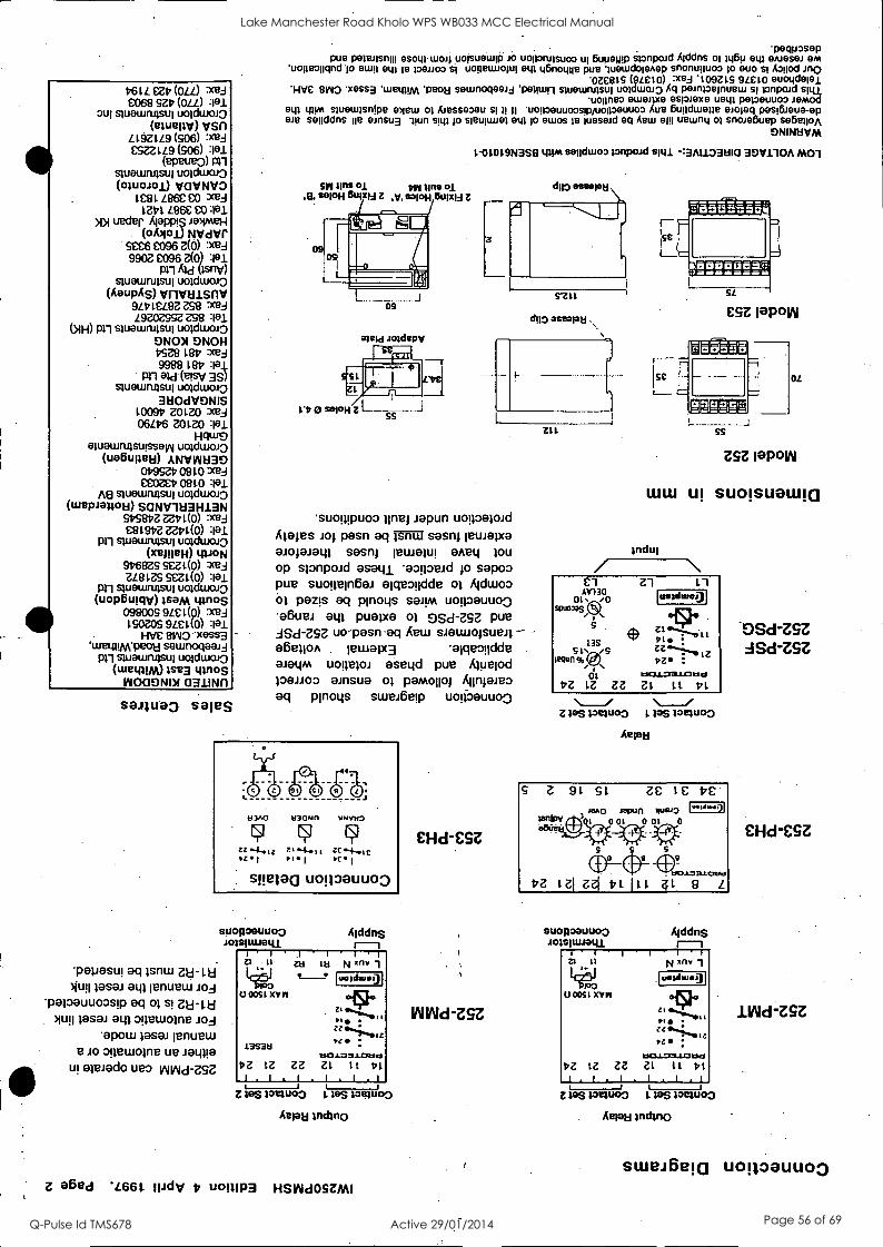
461L Mt, (OLL) :xed £068 SZV(OLL)
3U1 quewn.ristm uoldwoi3 (eluellV) vSfl
Ll9Z (SO6) :xed CSZZ L L9 (506)
(ePeue0) an quewrulsw uoldwoJo (morel) VOVNV3
I£81 L86£ £0 xed 1241 L86C CO :lel
>1>1 ueder APPPI$ .10)ImeH (oloioi) NVdYf
SCC6 £096 Z(0) :xed 9902 £096 z(.:)
Prl Ald IsnV) spiewruisui uoichuaio
(AaupAS) vnvaisnv 9L41ELEIZ ZS8 xed L9ZOZSSZ ZS8 :101
(NH) Pll swewrutsw uoldwolo ONON ONOH 4SZe 180 :red 9988 LEO :lel
Prl Old (eleV 3S) swewrwsui uoldwoiO
31:10dVDNIS 100917 ZOLZO 2ceJ 06L46 ?AM :P1
Hdw9 eptewn4supsen uoldwoi3
(uaBuRBEI) ANV1111130 019SZ4 0910 :red CCOZC170810 :Iel
A8 sluewrupw uoldwOJO (wepieuou) SCINV11:13H13N
S1751317Z ZZ4L(0) :xed C819172 ZZ4L(0) :lel
pn quewrwsui uoldwcuo (xeineH) toioN
946EOS SIZ1(0) :xed zaLzs stzl.(0) :101
pn quewrwsui uoldwato (uop6umv) Isom tildeS
098009 9L£ 1(o) xed 190ZOS 9LC L(0) :101
HVC 81n/O "xess3 'wewmA'peou sawnoqeeij
pn swewrwsui uoldwoi3 (wet/HAA)Ise3 titeoS
WOCIONDI aaliNn
seiiueo sales
peciposep pue peleJisnm esowtuoq .uolsuetupi JO uoporuisuoo w &Jump wonpad Aiddns 1461, OAJOSOJ eM
uopeopqnd 'to etup ew POMO uogetwopq etp q6noque pue wewdotenep snonunuoo to euo si Awlod *OZE819 (gLe10) :xeJ tO9Z IS 9LE tO euotidelei
'WC 'xessa 'wetipm 'peotti sewnoqeeJj 'pelpun stuewrwsw uot wwo Aq peinpeinuew tonpoJd situ 'wpm eweme esiwexe uew peweuuoo Jemod
etp uptei swetutsnIpe www of fuesseoeu uopoeuuoospuopoeuuoo Atte 6updwepe mpg pesi6Jeue-ep we senddns pie einsu3 .pun spp lo sietnunen ew to ewos le lueseid eq Aew 0111 uewnq of snweEtuepseiNlim 6elvleA
ski sins 01 DW lIns of ,g, SOIOH BUIXIU Z .V. 021011 OUIXIA
09
Kew Joidepv
1-01019N3S8 trIVA sepdwoo loopoid sill -:3ALL33HI0 3DV110A MOl
S'Zil
duo aseepu
suon!puoo Jepun uogoalcud Males JOI pasn aq r-S7W sasni !maw° 0.100Jato SeS0/ 'maw! GAEL/ 10u
op slonpoJd emu aopowd sapoo pue suogein6at apeo!idde of Mum of pezis eq wogs swim uonoauuo0 aBuei eqi pueixa 01 0Sd-ZSZ pue dSd-ZSZ uo-pasn-eq Aew siauuolsuen afielion letualx3 'ameNdde 0.101/AA uopepa, aseqd pue Aluelod 1001103 01nSUO 01 pamoliol Alinjamo eq pinoys swei6e!p uogoauuo0
'pepeSu! eq Isnw Z1:1-1.8
)1L/II leSal ato lenuew Jod papauuoosp eq of s! Zu-nd
Mull 19983 a(41 opwolne Jo3 wow IGS01 penuew
e JO 9gewome ue ialaa u! ;Naiad° ueo void-nz
stionoeuuo9 JOISTALYalli
Aiddrts
Z1 II
PoO U 0051 XVII
13S-3t1
.1
1.14 N xny
uendaue)
45}e
OZ LZ ZZ Zt LI DI 1.II.I.I.1 E 10$ 13v3v03 I. In toctucto
Aelau
Z 06ed *L661 IlidV b e0111P3 HSVUOSZMI
EHd-CSZ
ININd-ZSZ
Ztt
Ise et
ss
ZSZ laPoIN
LULU Ul SUOISUatilla
Indui
Cl 130
Z1 AV
Cll. /0 SPulnas
13S
12qtin % (80
01 17Z LZ ZZ
L
uanituo.9
Z lag Pewoo 1 las imuo3 Aelau
suopoeuuoo JOISIULtatli
AiddnS r-1 1 " 1 I 1 1 1
A 11
100 0051 XVII
N xn. 1
[ridlueg
-1,i
1110.1...7a.LOUNd
OZ LZ ZZ ZL 11 171 1.1.1.. I .i.t Z leS toque:* I. los toete03
Aefew Indin0
DSd-ZSZ ASd-ZSZ
£Hd-ESZ
1Wd-ZSZ
s wei6 e uoRoauu o3
Lake Manchester Road Kholo WPS WB033 MCC Electrical Manual
Q-Pulse Id TMS678 Active 29/01/2014 Page 56 of 69

Novaris Technologies Pty Ltd Customer Support Manager PO Box 2010 Kingston TASMANIA AUSTRALIA 7050
affix stamp here
5 Year i Warranty
Novaris TeChnologies Pty Ltd Kingston, Tasmania AUSTRALIA
Lake Manchester Road Kholo WPS WB033 MCC Electrical Manual
Q-Pulse Id TMS678 Active 29/01/2014 Page 57 of 69

5 YEAR LIMITED WARRANTY This is limi 5 years and is given by Novaris Technologies Pty Ltd (Novaris ) to the original purchaser ofWcts made Ix Novaris ("the products). The warranty certificate must be completed by the distributor and the purchaser in order to claim under thiswarranty. 1. What Novaris will do - If the product fails under normal use and service because of a manufacturing defect in materials or workmanship within 5 years from the date of purchase Novaris will at its option, either repair or replace the product with an equivalent product. The repaired or replacement product will be warranted under the terms of this warranty for the remainder of the warranty period forthe product 1,
originally supplied. 2. How to obtain warranty service -To obtain warranty service you must return the product to Novaris. The product must be accompanied; by the warranty certificate duly completed along with your sales receipt or invoice. Freight and insurance is your responsibility. 3. What is not covered -This warranty does not cover any failure of equipment not supplied by Novaris or any consumables* attached to or forming part of the product nor does it cover any failure of or damage to the product due to: (a) it being connected to equipment or accessories not authorised by Novaris. (b) improper handling, misuse, neglect, accident, improper installation or non compliance with the directions for use; (c) any alteration or modification which in the opinion of Novaris will affect the ability to service the product, or (d) repair by anyone other than an authorised Novaris service agent No guarantee is given concerning the operation of surge or transient protection products since atmospheric lightning dischargesare an unpredictable process subject to the laws of nature and independent of human control. The products do not provide total protection. Component parts of some products may be sacrificial when exposed to the effects of lightning and also voltage surges and transints. Novaris does not guarrantee repair or replacement services will be available after expiration of the 5 year warrant, period. 4. Rights under the Trade Practices Act - It is acknowledged by Novaris that, under applicable State and Commonwealth Law certain I
conditions may be implied and rights and remedies conferred on the purchaser in relation to the product which cannot be excluded, restricted or modified by agreement (non excludable rights). Novaris disclaims all express or implied conditions and warranties in relation to the product other than the express terms of this warranty and any excludable rights. Novaris' responsibility to the Purchaser is, where permitted limited to the undertakings stated in section I of this warranty and subject to the above, in no event is Novaris liable (where before or after discharge of the contract for supply ofthe product or otherwise) for any loss or damage suffered by the Purchaser as the user caused or contributed to by negligence of Novaris, itsservants or agents, nor is Novaris liable for special, incidental, indirect or consequential loss or damage suffered by the Purchaser including but not I;
limited to economic loss, loss of profit or revenue or reputation or costs arising from the loss of use of the product.
*consumables include indicator lamps and illumination sources, items made wholly or partly of glass or ceramic material, electical elements,transformer windings, electric motors, reconditioned parts and batteries.
CUSTOMER WARRANTY REGISTRATION CARD IVsend a copy of this registration and prof o of purchase with any warranty claim.
Name Title (i.e.Mr, Mrs, Ms)
Position
Company
Street Address
City State
Telephone Facsimile
Distributor Details
Purchased From
Details of Products under Warranty
Catalogue Number Serial Number
Your Industry Please complete the industry application information to receiv
Postcode
Date
Computing
Airports
Broadcasting
Government
Communications
Electrical Contractor
Railway Signalling
Power Authority
Other (please specify)
e kw product information from Novaris Technologies
Process Control Defence
Intelligent Buildings Telephone
Oil & Gas Transport
Government Consultant
I
Lake Manchester Road Kholo WPS WB033 MCC Electrical Manual
Q-Pulse Id TMS678 Active 29/01/2014 Page 58 of 69

Technical Information Sheet SF105/10/20DIN
S.URGE:NOTERSMOW,CURWWDIR:RA77---
Product Description
Novaris Technologies power line surge filters are designed for the effective protection against induced transient overvoltages caused by lightning and other events on AC and DC power supply circuits.
Versions are available for voltage ratings up to 240V AC and are housed in a rugged metal enclosure with DIN43880 compliant dimensions.
Operation
Multistage transient protection is utilised in every unit. Metal oAide varistors, as the first-stage, absorb the majority of the energy. These components are continuously monitored for integrity and indicated by a green LED on the top of the case. A red LED indicates power ON.
The first stage is followed by a low pass LC filter which further attenuates the let through voltage. The filter also attenuates low level noise and harmonics.
The third stage comprises metal oxide varistors. These provide a final clamping circuit and protect against impulses generated by the loads connected. This is particularly important when multiple loads are connected. Do not exceed total filter ratings.
All filters with a /A suffix have the LED indicators as described above. Filters with suffix /AR have an inbuilt alarm relay which provides a clean changeover contact. This may be used to externally monitor the status of the filter or used as a power fail indicator. The relay is normally energised when power is applied.
When installing DC equipment follow the polarity indications on the filter label. Incorrectly connected DC loads connected to AC filters will cause incorrect operation of LEDs even though filter will still effectively operate.
Specifications
Description No phases: Voltage drop: Efficiency: Earth leakage: Protection modes: Protection stages: Filter configuration:
Multistage power surge filter 1
<2V at full load 99% <0.75mA Transverse and common mode MOV / low pass filter / MOV LC, transverse and common modes.
Surge withstand: ANSI C62.41 cat, A, B, opt. C AS1768-1991 cat. A, B, opt. C
Surge rating: 16KA per line for 8/20us pulse 40KA per line for cat. C units
Let through voltage: 600V for 6kV/3kA 8/20us pulse Frequency response:3dB point 800Hz Indicator: MOV integrity - green LED
Power ON - red LED Clean contact C/O 4kV isolation Alarm relay:
Dimensions: 5A /A versions: 10A & 20A /A versions:
Mounting:
Terminal capacity: Location:
116Hx 54 Wx 800 116H x 120W x 80D
DIN 46 277 rail also screw mount available 4sqmm Final subcircuits to AS1768 location categories A and B:
Optional category C
it o. Vmaz ?:SF405b I /%1.40V/A "
05D1100VJA , 7;:l
-;!SF105DINIK:.' 250V
.;'-SFtilOP 11+30y/A \i/
SE:liplilll/k;:.`'"- ' Ff1061144
FMODIO0V/
8k1,;10D,IN46/4.-.
p.SF1200IN/A. .:;;BF120D IN:40/
indicates,LEVZlisplaflorifNeitioti /A indicates., 4displayand.*externat 'alarm for
versions. ew-
_
Novaris Technologies Pty Ltd 72 Browns Road, Kingston, TAS. 7050 AUSTRALIA Copyright ©1998 Novaris Technologies Pty Ltd E-mail: [email protected]
ABN 33 065 427 232 TEL: 03 6229 7233 FAX: 03 6229 9245 International FAX: +613 6229 9245
Lake Manchester Road Kholo WPS WB033 MCC Electrical Manual
Q-Pulse Id TMS678 Active 29/01/2014 Page 59 of 69
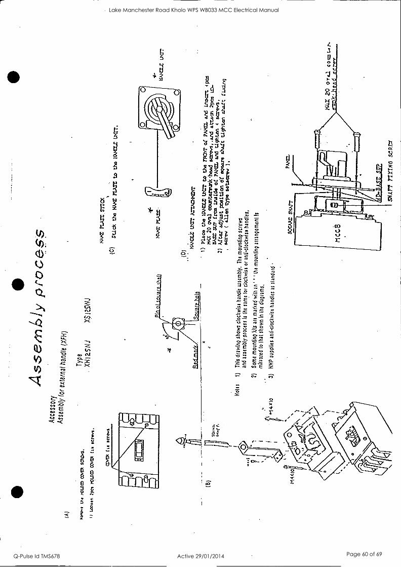
(A)
tht
PO
LLE
D
CO
VE
R S
CA
NS
.
it Lamm 2
pci POLLED COM (
tx serws.
Ass
emL
ly p
roce
ss
Acc
esso
ry
Ass
embl
y fo
r ex
tern
al h
andl
e (X
FH
)
Typ
e X
Hia
SN
J X
SIZ
9NJ
8AME PLATE,STTCX
(0)
solo
* th
o tW
.CE
P
LAT
E to
tho
1 C
VC
ILZ
Lt
.= .
-14
104.
0 M
A=
1
(0)
. ,
wax
tzar
Am
ax=
1)
Pla
no t
he UNHOLE LI= t
o tho TT
of PA EL and Ins= 4
pc*
Ka 2
0 ov
al ccuntarrunk*head acrovs,.ard attain 2pco
BASE SUP Zr as inside of PA
and cicriun
4 screw.
2) After adjust poditlen of
ekoe
are
shalt tIschton shaft fixing
=rev
( ailed typo Ws:rev )
.
Hol
es
1)
Thi
s dr
awin
g sh
ows
cloc
kwis
e ha
ndle
use
mbl
y.
The
mou
ntin
g sc
rew
s an
d as
sem
bly
proc
ess
Is
the
sam
e fo
r cl
ockw
ise
or a
nilo
ckw
ise
hand
les.
2)
Som
e m
ount
ino
kits
are
mar
ked
with
an'
" th
e m
ount
ind
arra
ngem
ent I
s m
irror
ed t
o th
at s
how
n in
the
O
isot
ams,
3)
NH
P s
uppl
ies
anti-
cloc
kwis
e ha
ndle
s as
st
anda
rd
Lake Manchester Road Kholo WPS WB033 MCC Electrical Manual
Q-Pulse Id TMS678 Active 29/01/2014 Page 60 of 69

Installation
Cable Preparation Details RG 58 Style Cable
BNC-113
.111111101111::::::::3
sa2 C)
15-
FME - 101
N-99
N-88
15-
I1 C)
TNC-26
1
MPL-604/5
14r
UHF-44
TIN CENTRE CONDUCTOR
MB 10 / MB 12
Important Note: Take care not to cut into the braid or centre conductor
wires when trimming cables
32
at fr0 RF Industries Pty Ltd
ACN 001 695 512
\ Doc Ret:INS-36334-2
NSW: Unit B, 3 Lenton Place, North Rocks 2151 Ph: (02) 9630 0655 Fax: (02)9630 0844 VIC: Unit 20/257 Colchester Rd, Kilsyth 3137 Ph: (03) 9761 6244 Fax: (03) 9761 6288 OLD: 16 Kyabra Street, Newstead 4006 Ph: (07)3252 7600 Fax: (07)3252 5505 WA: 26 Collingwood Street, Osborne Park 6017 Ph: (08)9244 4858 Fax: (08)9446 4263
02000 RF Industries Pty Ltd
Lake Manchester Road Kholo WPS WB033 MCC Electrical Manual
Q-Pulse Id TMS678 Active 29/01/2014 Page 61 of 69

APPENDIX A: HOW TO ASSEMBLE ANTENNA CONNECTORS The following instructions apply to all three connectors:
1. Place clamp nut and plain gasket over cable. 2. Trim outer sheath from cable to dimension shown. 3. Fold back braid and insert ferrule to trap braid between outer sheath and ferrule. 4. Trim off surplus braid. 5. Trim dielectric to dimension shown, and check that exposed centre conductor length is as
specified. 6. Tin centre conductor. 7. Slide rear insulator over dielectric to butt against ferrule. 8. Mount contact (male for plugs, female for jacks) over centre conductor with shoulder
pressed against rear insulator. 9. Hold cable and contact firmly together, and solder. 10. Slide plain gasket and clamp nut up to ferrule, trapping braid. 11. Fit front insulator over contact to butt against rear insulator. 12. Press sub-assembly into body as far as possible and engage clamp nut. 13. Holding body and cable rigid, tighten clamp nut to compress plain gasket and retain cable.
RG213 To BNC
Clamp Nut Plain Gasket
RG213 To N-Type
1- 0.5
-1L 6.0
RG213
Clamp Nut Plain Gasket
1- 6.0
p
Ferrule Rear Hale Front Insulator Contact Insulator
B
l
Male Contact
1
Plug Body
Ferrule Rear Female Front Insulator Contact Insulator
Ping Body
jack Body
RTU INSTALLATION Version 1.3, 24/02/2000 17
Lake Manchester Road Kholo WPS WB033 MCC Electrical Manual
Q-Pulse Id TMS678 Active 29/01/2014 Page 62 of 69

RG58 To N-Type
RG58
f Clamp Nut Plain Gasket
13J
O.4
L 6.0
Ferrule
Hale Coutact
Rear Female Front Insulator Contact Insulator
Plug Body
Jack Body
18 Version 1.3, 24/02/2000 RTU INSTALLATION
Lake Manchester Road Kholo WPS WB033 MCC Electrical Manual
Q-Pulse Id TMS678 Active 29/01/2014 Page 63 of 69

C101 GB
CONNECTING DIAGRAMS C-, CA-, CR- SWITCHES KRA US & NAIMER (130 Technical Data according.to UL and CSA Specifications
CA4 CA10 CA11 CA20 BA20 CA25 C26 C32 C42 C80 0125 CA4-1 CA I OB CA11B CA20B CA25B C43
CR10 CR11 -
C315 C316
M500 M510 M51OB
Rated Voltage Ampere Rating
V A.C. A
277 300 600 600 600 300 600 600 600 600 600 10 20') 20') 30 30 30 35 50 65 100 150
600 240
600 10
Ondard motor load: 3phase - 3pole 110V - 120V L-Rating 220V - 240V
440V - 480V 550V - 600V
1phase - 2pole 110V - 120V 220V - 240V
277V 440V - 480V 550V - 600V
Pilot Duty Heavy
HP HP HP HP HP '
HP HP HP HP
0,75 1.5 1,5 3 3 15
7,5 10 15 1 3 3 7,5
5 5 7,5 7,5 10 . 10 15 20 25
5 10 10 20 25 25 30 40 - - 5 10 10 - 25 30 30 40 50
0,3 0,5 0,5 1,5 1,5 2 2 3 3 5 7,5
0,75 1 1 3 3 5 5 7,5 7,5 10 15 0,75 2 2 3 3 5 5 7,5 7,5 10 15
2 5 5 10 15 15 20 25 - - 2 5 5 - 15 20 . 20 25 30 A300 A300 A600 A600 A600 A300 MOO -
30 75 70 60 15
40 40 50 50 MOO
-
-
-
-
-
-
-
A600
Type of wire Temperature rating of wire Torque value for field wiring terminals
For short circuit protection according UL refer to note
-
°C lb-in. Nm -
use copper wire only / utitisez conducteurs en cuivre 60/75 60/75 60/75 75 60/75 60/75 60 75 75 A B 5 7 7 12 12 12 - 50 50 0,6 0,8 0,8 1,3 1,3 1,3 - - - 5,6 5,6
C C C C C - I - - C C
75
-
D
60/75
:
-
1 CSA: max. 16A .
A: 60°C for max. 80A, 75°C for max. 100A I
B: 60°C for max. 125A, 75°C for max. 150A C: These devices are suitable for use on circuits capable of delivering not more than 5kA rms symmetrical amperes, 600V ac max. when protected by Class RK1 fuses.
Ces dispositives sont adaptes aux utilisations sur des circuits susceptibles de delivrer au plus 5kA alternatifs efficaces, 600V c.a. maxi.: avec protection par fusibles type RK1. D: These devices are suitable for use on circuits capable of delivering not more than 10kA rms symmetrical amperes. 600V ac maximum. i
Ces dispositives sont adapts aux utilisations sur des circuits susceptibles de delivrer au plus 10kA alternatifs efficaces, 600V c.a. maxi. Note according to UL: Listed terminal lug's type RF717 manufactured by Thomas & Betts have to be used for field wiring of type C80 andIC125 with single screw terminals.
Nominal Voltage 1V 6V 12V 24V 48V 110V 220V 300V Nominal Voltage 1V 6V 12V 24V 48V 110V 220V 300V
CAD11 I A A.C. A D.C.
6
4
3 2,5
2 1,5
1
0,8 0,8 0,3
0,4 0,2
0,2 0,1
0,13 0,06
CAD12 I A A.C. A D.C.
- 6 - 4
6 3
5
2,2 5
1,2 .
3 0,6
2 0,3
1,3 0,2
Warning note: After installation of the switches the spacings between the terminals must be sufficient to fulfill the requirement of the applicable standards
ON/OFF Switches: A100 1pole A290 1pole A101 2pole A291 2pole A102 3pole A292 3pole A103 Opole A324 Opole A200 1pole A325 5pole A201 2pole A326 6pole A202 3pole A341 5pole A203 4pole A342 6pole A208 3pole A343 7pole
Double-throw Switches: .369 5pole
5 3 7 9 13 11 15 17 19
1\b i\ 1 l\ b 1.\? 1 1\ 1
2 4 10 12 18
A344 8pole A345 9pole A346 10pole A347 11pole A348 12pole A386 3pole A591 2pole A592 3pole A593 4pole
1 3 5 7 9 11 13 15 17 19 21 23
1 1 1 1 1 1 1 1 1 1 1 1
2 4 6 8 10 12 14 16 18 20 22 24
A204 1pole A205 2pole A206 3pole
A293 Opole A327 4pole A207 Opole
1 3 5 7 1 3 5 7 1 3 5 7
1 1 1 1 1111 1.1.1J \ \f \f \f \f \f 2 4 6 8 2 4 6 8 2 4 6 8
A370 6pole A371 7pole A376 12pole
1 5 3 7 9 13 11 15 17 21 19 23 25 27 1 5 3 7 9 13 11 15 17 21 19 23 25 29 27 31 33 37 35 39 41 45 43 47
1\t1 1\t/ 1\ b 1\l by 1\,!. vyyly l\ra bf b by by y b\f 1
2 4 10 12 18 20 26 2 4 10 12 18 20 26 28 34 36 42 44
A37410pole A3751Ipole A372 8pole A373 9pole A570 6pote
1 5 3 . 7 9 13 11 15 17 21 19 23 25 29 27 31 33 37 35 39 41 43 1 5 3 7 9 13 11 15 17 21 19 23 25 29 27 31 33 35 1 3 5 7 9 11 13 15 17 19 21 23
i.\( 1 by. b.b If by y by 1\ tb 4fb 1\ tb by L \rb by by L\ fl, by by by 1\ fl 1\ tb 1.1 1\fb Ivk 1 it 1 fb b.? 1
2 4 10 12 18 20 26 28 34 36 42 2 4 10 12 18 20 26 28 34 2 6 10 14 18 22
A575 !pole A585 !pole A720 !pole A120 1 pole A220 !pole A520 !pole A530 !pole A210 1pole A510 !pole A576 2pole A586 2pole A721 2pole A121 2pole A221 2pole A521 2pole A531 2pole A211 2pole A511 2pole A577 3pole A587 3pole A722 3pole A122 3pole A222 3pole A522 3pole A532 3pole A212 3pole A512 3pole A578 Opole A588 4pole A723 Opole A123 Opole A223 4pole A523 Opole A533 4pole A213 Opole A513 4pole A361 5pole
1 3 5 7 9 11 13 15 1 3 5 7 9 11 13 15 3 1 7 5 11 9 15 13 5 1 7 3 13 9 15 11 19 17
1\f Y. 1 1\1 1\ i,1 1\fl 1\?'1 i
1
I d
1
1 d
1
4 1
/
1 b/ 11/ 11/ /
1/-1// 1
2 4 6 8 10 12 14 16 2 6 10 14 2 6 10 14 2 4 10 12 18
A218 !pole A299 3pole A295 1pole A297 3pole A362 6pole A363 7pole A364 8pole A219 2pole A294 4pole A296 2pole
5 1 7 3 13 9 15 11 21 17 23 19 27 25 5 1 7 3 13 9 15 11 21 17 23 19 29 25 31 27 1 3 5 7 9 11 13 15 1 3 5 7 9 11
1
1
1 1
1
1 i 1
1 1
1
1 1
1
1 1
1
1 1
1
1 1
1
4 1
/ b 1
/
1 1
/
1 1
/ 1 1
/
1 b b b
1
1 1
11
b
1
1 1
11
i T
1 1..1 i.\,..1 d\r .1
2 4 10 12 18 20 26 2 4 10 12 18 20 26 28 2 6 10 14 2 6 10
A565 !pole A710 !pole A566 2pole A711 2pole A567 3pole A712 3pole A714 1pole A214 1pole A320 1pole A568 4pole A713 4pole A795 !pole A715 2pole A215 2pole A216 3pole A321 2pole A322 3pole 3 1 7 511 11 915 15 13 1 3 1 35 7 1 3 5 7 9 11 3 1 7 5 11 9
1
1b
I
Li 1 1
lb 1
¢b
L 1 1 1 I
I,
1
<I 1.1.11.11 I,
1
11.11111 1 lb 1 Al l
4 2 8 6 12 10 16 14 2 4 2 4 6 8 2 6 10
General Application Switches: A310 1pole A330 1pole L1
I
AB i B
3 4111 N 0
AI
A315 L1
3pole 1
R S T
9 13
i L2
3
2 8 14 -
A312 2pole A331 2pole
0
A314 3pole
1 3 A332 3pole 1 5 9 3 7 11
A311 Ipole Ll R L1 R
A i 3 Bi 1. S L T f i i N
T L3 IT 0
A 'i B
5 7
1 5
, 2 6 10 A B o 2 6 4
5
i
7 17 3 11 15 A339 2pole
1_1
IC':
I 7
2 6 8
A 1Bi
3
2 6 10
A313 2pole L1 R
L3
2 6 10
441
3 7
BiCi 9 1
Switches may only be mounted, connected and set into operation by qualified persons according to the accepted rules of technology. Do neither lubricate nor treat contacts.
Lake Manchester Road Kholo WPS WB033 MCC Electrical Manual
Q-Pulse Id TMS678 Active 29/01/2014 Page 64 of 69

Multi-step Switches without "OFF": A230 1pole A250 2pole
3 5 3 7 11 5 O 0 0 0 0 0
10-42 10 -?2 90-? 6
A270 3pole
5 9 7 11 15 17 o o o o o o
10-0, 2 3 0-?4 130-114
A489 6pole
3 7 11 5 15 19 23 17 27 31 35 29 o 0 0 0 0 0 0 0 0 0 0 0
10-y 2 9o-?6 13 0-? 14 210-018 25 0-?26 33o-? 30
A476 Opole A484 5pole
3 7 11 5 15 19 23 17 27 29 o o o o o 0 0 0 0 0
101)2 90-?6 13 0--? 14 210-1 18 250-?26
A231 1pole A251 2pole A271 3pole A477 Opole A485 5pole A490 6pole
5 7 ' 13 15 21 23 29 31 37 39 45 47 o o o o o o o o o o o o
10 --g203 9 0-?1.0011 170-019 250-7260 27 33 o-?3,40 35 41 o?420 43
A232 1pole A272 3pole A233 1pole A252 2pole A478 4pole A253 2pole A273 3pole
5 9 17 11 25 29 37 31 5 9 17 21 5 9 19 23 29 33 O 0 0 0 0 0 0 0 0 0 0 0 0 0 0 0 0 0
10-12 03 13 0-?,2015 21 0-?220 23 33 0--?320 35 10-? 2 ° 3 130 ---014:15 10_.12013 150-?4o3 2526027 0 0 0 0 0 0 0 0 0 0 0 0 0 0 7 19 27 39 11 7 23 19 21 17 11 7 35 31
A234 1pole A254 2pole A274 3pole
9 25 37 5 o 13 21 0 15 33 0 41
O 0 0 0 0 0 10 2 03 17 0-?16019 29 °-?30° 31
o ° 7 0 023 0 035 11 27 39
A235 1pole A255 2pole A275 3pole
1
50 9 o 013 210
25 029 370
40 045
10 --7203 170-N019 330340.35 15° 07 310 023 470 039
11 27 43
A236 1pole A237 1pole 13 13 9 , 17 91317 17
500-0015 50° - 0019 10-120? 1°-?2°3
o, 011
00 ' 11
A239 1pole A238 1pole A639 1pole
90 13 0 017 50 0 21
10-?2 0 3 07
190105011
13 9 , 17 50 00 21
1°2 °3 230 e 7
1 1-5
11
A730 1pole A750 2pole A731 1pole A751 2pole 5 7 5 7 13 15 \ 3 11
o / o \ / o \ / o o \ \ / o / o \ / 10-12 --?4 - -16 9 0-1 10 --112 - -? 8 10 2- --? 6- ----0,8- --?4o3 9 o-?10 - ---?14 - ---016 - -112011
Multi-step Switches with "OFF": A240 1pole A280 3pole A486 5pole A241 1pole A260 2pole A480 4pole A491 6pole A261 2pole ' A281 3pole
1 3 5 7 9 11 13 15 17 19 21 23 5 7 5 7 17 10 0 03 90 0 011 10 0 9 30 0 011 130 0 015 0 0 0 0 0 0 0 0 0 0 0 0
-? 2 -1s -? 10 -? 14 -118 -? 22 . -12 -'?8 -12 --14 X14
A242 1pole A282 3pole A481 Opole A487 5pole A262 2pole A482 Opole
7 5 19 17 5 7 17 19 29 1 3 9 11 13 15 21 0 23 1 0 9 3 0 11 130 0 021 150 0 23 2500027 0 027 5 3 7 13 11 15 21 19 23 29 27 31 o o o o o o o o o o o o 100 00 90000 1700 00 250 25o000 -?2 -? 12 -?14 -124 -12 -14 -?14 .-?16 -126 -12 -710 --118 -?26
A243 1pole A244 1pole A263 2pole A283 3pole A264 2pole A284 3pole A245 1pole A265 2pole
5 9 3 17 11 15 25 29 23 5 9 3 17 21 15 9 13 15
100 0 0011 5 9 7 21 25 23
1 000 7 13 o 0 o 19 21 000 27 10 000 o
7 130000 019 252903°302731 10000 011
170000 027 o o o o o o o o -7 2011 -714023 -726035 -72 -112 -?22 -9 2007 -oo 2 o15 -940113
1 3 I 3 I 019
A246 1pole
5 9 11 1000 0013
-g2 o15 03
07
Coding Switches: A540 A541
1 1 3 1 5
2 4 6
0
1 X 2
3 X 4 X 5 X 6
7 X X
A542
A247 1pole
5 9 13 1 0 00015 o -72o17
0 3 11 0
7
1 1 3 1 5
2 4 6
X X 1
2 X 3 X
A543
A249 1pole A248 1pole A649 1pole
5 9 13 1 0 00017 17 o -r? 2:19
150ji°73
1 1 3 1 5 1 7
2 4 6 8
0
1 X 2
3 X 4 X 5
6 X 7
1 1 3 5 1 7 9 111
2 4 6 8 10 12
0 X X 1 X 2 * X 3 X * X 4 X X 5 X
)<<
6 X 7 X
4 X 5
6
7 X X 8 X 9 X
10
11 X ))( X
A545
5 9 13
.1 00 00017 o 21
1900 0, 003 15 fi 7
1 I 3 I 5.1 7 I 9 1.11113 115_,
2 4 6 8 10 12 14 16
0 x x x l x 2 X 3 X X 4 X 5 X 6 X x
X 8 X X X 9 X
10 X 11 x X X
A550
1. 3 1 5 1 7
o oo
2 4 6 8
0 1 X 2
3 X )<< 4 X 5 X 6
7
8
X
9 X
A551
0
1
2
3
4
5
6
7
1 1 3 1 5 1 7 0000 2 4 6 8
X X
IME3
X
X
8 X 9
X
A552
1 1 a 1 5 1 7 1 9 111 113 115
2 4 6 8 10 12 14 16
0 X 1 X 2 X 3 X 4 X 5 X 6
))
X 7 X 8 X 9 X
0
Lake Manchester Road Kholo WPS WB033 MCC Electrical Manual
Q-Pulse Id TMS678 Active 29/01/2014 Page 65 of 69

M001 GB
MOUNTING INSTRUCTION SWITCH SIZE SO KRAUS & NAIMER
MOUNTING OF ESCUTCHEON PLATE:
Mountings: EA, EA-V, ECA, EDA, EFA, EFA-V, EGA, ERA. KD1A, KN1A, KN2A, VEA, VEA-V, VE1A
Removal: Press the sprongs
Mounting: Snap on by pressing
MOUNTINGS:
Mountings: E, E-V, E22, E22-V,EC, ED, ED22, EF, EF-V, EG, EGF, ER, ERF, KD1, KN1, KN2, VE, VE-V, VE1, VE22, VE22-V, VF, VF-V, VF22, VF22V
Removal: By means of a screw driver
Mounting: Snap on by pressing
E, EA, E-V, EA-V, EF, EFA, EF-V, EFA-V, EG, EGA, EGF, KD1, KD1A, KN1, KN1A, KN2, KN2A (BA20: Mounting E see E22)
Mounting EFA: D10A, D11A, D12A- switches: max. 2mm
EC, ECA, ED, EDA, ED22 Mounting onto control panel as shown for mounting E (max. control panel thickness mounting EDA: 2mm). Mounting of protective cover:
EC, ECA, ED, EDA: Slip on the protective cover from the rear. ED22: Slip on the protective cover from the rear and
fix it by means of a cable wraper (1) (see picture).
Protection of the protective cover. EC, ECA, ED,EDA IP30 ED22: IP42 1
EL, ES., FL, FS.
Only at mounting FL. and FS.
Only a mounting ES. and FS. with angular escutcheon plate.
Mounting of escutcheon plate: Removal:
By means of a screw driver: Mounting:
Snap on by pressing Snap on switch by pressing.
/7)
Snap on escutcheon plate or ring by pressing.
MOUNTING OF HANDLE: Removal:
Loosen the screw, pull off handle
Mounting: Loosen the screw and push it into the handle, slip the handle onto the shaft, fasten the screw
FT2.., FT3.., FT4.., FH3, FH3-V
only FH3, FH3-V
Adaptor ring for 30mm mounting
VE, VEA, VE-V, VEA-V (BA20: Mounting VE see VE22)
VE11 VE1A
Above details are subject to change without notice.
Switches may only be mounted, connected and set into operation by qualified persons according to the accepted rules of technology. Do neither lubricate nor treat contacts.
Lake Manchester Road Kholo WPS WB033 MCC Electrical Manual
Q-Pulse Id TMS678 Active 29/01/2014 Page 66 of 69

MOUNTINGS:
Height adjustment: 1. Loosen the clip by a proper auxiliary tool
and pull-off the front-unit. 2. Adjust the height: Snap-on the clip-part
onto the latch of the escutcheon plate. 3. Attach front-unit and click it on.
MOUNTING DIMENSIONS mm:
PANEL MOUNTING:
Single hole mounting:
0
Mounting EL. ES1 ES2-ES5 FH3.. FL. FS1 FS2-FS5 FT1... FT2... FT3... FT4...
Protection' IP40 IP40 IP40 IP65 IP652 IP652 IP652 IP65 IP65 IP65 IP65 Drilling plan N L M L N L M L L UN UN
1, Control panel sided 2, For D10 -D12 and D10P-D12P Protection IP42
Two and four hole mounting:
Mounting E,EA EA -_Vv E22 E 22 -V EE& ETA ED22 EF EF-V EFA EFA-V NA EGF ER, ERA ERF KD1 KD1A
KN1 KN1A
KN2 KN2A
Protection' IP40 IP40 IP65 IP65 IP40 IP65 IP65 IP65 IP65 IP65 IP65 IP40 IP65 IP40 IP65 IP40 IP40 IP40 DillingplanA A B2 C3 A A B2 A A A A A A A R AR A A A G 8-15 8-15 11-15 11-15 8-156 196 11-15 15-19 15-19 18-22 18-22 10-15 19-22 8-15 15-19 10-15 10-15 8-15 F 36 36 30 30 366 368 30 36 36 36 36 48 48 _ 36 _ 366 36 366 48 48 36
1, Control panel sided 2, For CG-switches drilling plan C
3, For CG-switches drilling plan B
BASE MOUNTING:
4, For CA20, CA25, CH10-CHR16: 10-15mm
5, For CA20, CA25, CH1O-CHR16: 22mm
6, For CA20, CA25, CH10-CHR16: 48mm
MOUntin n VE, VE-V
VEA, VEA-V VE1
VE1A VE22, VE22V VE4 VF, VF-V VF22, VF22V
Protection' IP40 IP40 IP40 IP40 IP65 . IP65 Drilling plan A R A C S R A R C S
G 8-15 8-15 8-15 11-13 11-13 F 36 362 36 30 362 36 362 30
1. Control panel sided 2, For CA25, CH and CHR: 48mm
Drilling plan control panel:
C:
5
+0,2 3,2 0
L:
N
22,3 0 +e4
GK CAST ALUMINIUM ENCLOSURE: Protection: IP65
A B C D E
80 75 52 63 4,8
Hole dimensions of the base mounting plate:
S:
Lake Manchester Road Kholo WPS WB033 MCC Electrical Manual
Q-Pulse Id TMS678 Active 29/01/2014 Page 67 of 69
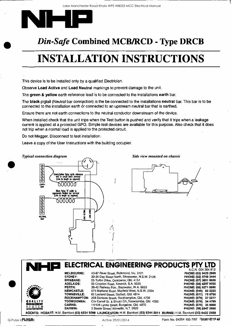
Din-Safe Combined MCB/RCD - Type DRCB
INSTALLATION INSTRUCTIONS
This device is to be installed only by a qualified Electrician.
Observe Load Active and Load Neutral markings to prevent damage to the unit.
The green & yellow earth reference lead is to be connected to the installations earth bar.
The black pigtail (Neutral bar connpction) is the be connected to the installations neutral bar. This bar is to be connected to the installation earth dr connected to an upstream neutral bar that is earthed.
Ensure there are not earth connections to the neutral conductor downstream of the device.
When installed check that the unit trips when the Test button is pushed and verify that it trips when a leakage current is applied at a protected GPO. Simple test devices are available for this purpose. Also check that it does not trip when a normal load is applied to the protected circuit.
Do not Megger. Disconnect to test installation.
Leave a copy of the User Instructions with the building occupier.
Typical connection diagram
0 0 0 0 0 0
EARTH
BAR
0 0 0 0 0 0
CT" Tobeircreger rel'eren" (trim to length os required)
qvgigcircikoteftirutrlotl bcOarbit
to
ttrim to length os required)
NEUTRAL
BAR
Side view mounted on chassis
ELECTRICAL ENGINEERING PRODUCTS PTY LTD A.C.N. 004 304 812
MELBOURNE: 43-67 River Street, Richmond, Vic. 3121 PHONE: (03) 9429 2999 SYDNEY: 30-34 Day Street North, Silverwater, N.S.W. 2128 PHONE: (02) 9748 3444 BRISBANE: 25 Turbo Drive, Coorparoo, ad. 4151 PHONE: (07) 3891 6008 ADELAIDE: 50 Croydon Road, Keswick, S.A. 5035 PHONE: (08) 8297 9055 PERTH: 38-42 Railway Pde., Bayswater, W.A. 6053 PHONE: (08) 9271 8666 NEWCASTLE: 575 Maitland Road, Mayfield West, N.S.W. 2304 PHONE: (049) 60 2220 TOWNSVILLE: 62 Leyland Street, Garbutt, Old. 4814 PHONE: (077) 79 0700 ROCKHAMPTON: 208 Denison Street, Rockhampton, Old. 4700 PHONE: (079) 27 2277
QUALITY TOOWOOMBA: Cnr Carroll St. & Struan Crt.,Toowoomba, Old. 4350 PHONE: (076) 34 4799
S
MANAGEMENT YSTEM CAIRNS:
DARWIN: 14/128 Lyons Street, Bungalow, Old. 4870 3 Steele StreetWinnellie, N.T. 0820
PHONE: (070) 35 PHONE: (08) 8947
6888 2666 MUM XATII MIMEO
AGENTS: HOBART: N.M. Bamford (03) 6234 9299 LAUNCESTON: N.M. Bamford (03) 6344 8811 BURNIE: N.M. Bamford (03) 6432 2588
FLYER Form No. 04204 155 7/97 07/97-DTP-M
Lake Manchester Road Kholo WPS WB033 MCC Electrical Manual
Q-Pulse Id TMS678 Active 29/01/2014 Page 68 of 69

Din-Safe Combined MCWRCD - Type DRCB
USER INSTRUCTIONS
Important Information This device will trip and isolate the active circuit when current from active to earth is detected. Protection is
therefore provided against faults to earth through the body, but not against faults from active to neutral that pass
through the body.
At all times electricity can be dangerous and this device is not to be regarded as a substitute for basic electrical safety precautions.
Always unplug any electrical equipment to achieve isolation before any inspection or repair of that equipment is
attempted.
Tripping of this device indicates a leakage current to earth, an overcurrent or a short circuit between active and
neutral. The cause of tripping should be determined and removed before resetting this device. If the problem
cannot be found and the device trips repeatedly, please seek advice from an electrical contractor or contact your
nearest NHP office.
This device should be tested at regular intervals. Pressing the test button simulates a leakage current to earth and
the device should trip immediately the button is pushed. It is recommended that a test is performed each month to
ensure the safety offered by this device is maintained. If the device fails to trip when tested the device is fault or
there is a problem with the installation. Please contact an electrical contractor to have the problem rectified or seek
advice from your nearest NHP office.
Operating Notes
f }
LT 00705
Neutral (Load)
Active (Load)
Test Button
ON POSITION
OFF POSITION
Active (Line)
The Din-Safe combined MCB/RCD is designed to provide protection of the fixed wiring and to also trip when a person receives a shock. In the case of electrical shock the time taken for the unit to turn off the power is considered short enough by authorities to prevent serious injury.
Some electrical products have been found to trip earth leakage devices even when they appear to be operating normally. Products with water heating elements sometimes exhibit this problem. The cause of tripping is that there are internal leakage currents in the product and repair or replacement is required. The earth leakage device is not at fault.
The operating toggle has two positions ON & OFF.
The trip free mechanism ensure the contacts open with the toggle locked or sealed in the "ON" position.
Lake Manchester Road Kholo WPS WB033 MCC Electrical Manual
Q-Pulse Id TMS678 Active 29/01/2014 Page 69 of 69