
L E V I T O N - Steven Engineering
548
L-101 The Industry’s Premier Line of Wiring Devices Including Power Delivery and Data Connection Devices for Construction & Maintenance THE FUTURE IS ON Courtesy of Steven Engineering, Inc. ● 230 Ryan Way, South San Francisco, CA 94080-6370 ● General Inquiries: (800) 670-4183 ● www.stevenengineering.com
-
Upload
khangminh22 -
Category
Documents
-
view
1 -
download
0
Transcript of L E V I T O N - Steven Engineering

L-101
The Industry’s Premier Lineof Wiring DevicesIncluding Power Delivery and Data Connection Devices for Construction & Maintenance
LEVITON
Leviton Manufacturing Co., Inc. 59-25 Little Neck Parkway, Little Neck, NY 11362-2591Telephone: 1-800-323-8920 • FAX: 1-800-832-9538Tech Line (8:30AM–7:30PM E.S.T. Monday–Friday): 1-800-824-3005
Leviton Manufacturing of Canada, Ltd.165 Hymus Boulevard, Pointe Claire, Quebec H9R 1E9Telephone: 1-800-469-7890 • FAX: 1-800-563-1853
Leviton S. de R.L. de C.V.Lago Tana 43, Mexico DF, Mexico CP 11290 Tel. (+52) 55-5082-1040 • www.leviton.com.mx
©2007 Leviton Manufacturing Co., Inc. All rights reserved C-740/K7
THE FUTURE IS ONTHE FUTURE IS ON
®
Courtesy of Steven Engineering, Inc. ● 230 Ryan Way, South San Francisco, CA 94080-6370 ● General Inquiries: (800) 670-4183 ● www.stevenengineering.com

Inside Front Cover Inside Back Cover
Courtesy of Steven Engineering, Inc. ● 230 Ryan Way, South San Francisco, CA 94080-6370 ● General Inquiries: (800) 670-4183 ● www.stevenengineering.com

Courtesy of Steven Engineering, Inc. ● 230 Ryan Way, South San Francisco, CA 94080-6370 ● General Inquiries: (800) 670-4183 ● www.stevenengineering.com

Occupancy Sensor LightIng ControlsOverview . . . . . . . . . . . . . . . . . . . . . . . . . . . . . . . . . . . . .D2Decora Wall Switch Infrared Occupancy Sensors . . .D3-D6Decora Dual-Relay Wall Switch Infrared Occupancy Sensors . . . . . . . . . . . . . . . . . . . . .D4Decora Wall Switch Multi-Tech Occupancy Sensor . . . . .D4Manual-ON Wall Switch Occupancy Sensor . . . . . . . . . .D6Self-Contained Fixture Mount Occupancy Sensor . . . . . .D7Power Base Adaptor . . . . . . . . . . . . . . . . . . . . . . . . . . . .D8Self-Contained Infrared Ceiling Mount Occupancy Sensor . . . . . . . . . . . . . . . . . . . . . . . . . . . . .D9Multi-Tech Ceiling Mount Occupancy Sensor . . . . . . . .D10Ultrasonic Ceiling Mount Occupancy Sensor . . . . . . . .D11Infrared Ceiling Mount Occupancy Sensor . . . . . . . . . .D12Multi-Tech Wall Mount Occupancy Sensor . . . . . . . . . .D13Infrared Wide-View Wall Mount Occupancy Sensor . . .D14Infrared High-Bay Wall Mount Occupancy Sensor . . . .D14
Infrared Long-Range Wall Mount Occupancy Sensor . .D14Power Packs for Occupancy Sensors . . . . . . . . . . . . . .D15Infrared Outdoor Motion Sensors . . . . . . . . . . . . . . . . .D16Centura SystemCentura® Fluorescent EnergyManagement System . . . . . . . . . . . . . . . . . . . . . .D17, D18Timed Lighting ControlsDecora Plus Electronic Timer Switches . . . . . . . . . . . . .D19Decora Programmable Electronic Timer Switches . . . . .D20Variable Countdown Timer Switch . . . . . . . . . . . . . . . . .D20Z-MAX Relay Lighting Control Systems . . . . . . . . .D21-D27Z-MAX Relay Cabinets . . . . . . . . . . . . . . . . . . . . .D22, D23RRP-Remote 4-Relay Panel . . . . . . . . . . . . . . . . . . . . .D24EZ-MAX Relay Cabinets . . . . . . . . . . . . . . . . . . . . . . . .D25Z-MAX Digital and Low Voltage Switch Stations . . . . . . .D26miniZ™ Intelligent Daylight Management System . . . . .D27
SECTIONDEnergy
Management Products
Architectural Lighting Control SystemsDimensions® D3200 . . . . . . . . . . . . . . . . . . . . . . . . .C2-C4Dimensions® D4000 . . . . . . . . . . . . . . . . . . . . . . . .C5, C6Power Extenders . . . . . . . . . . . . . . . . . . . . . . . . . . . . . . .C7a-2000 Modular Dimming Cabinets . . . . . . . . . . . . .C8, C9Architectural SpecificationOverview . . . . . . . . . . . . . . . . . . . . . . . . . . . . . . . . . . . .C10Monet® Controls . . . . . . . . . . . . . . . . . . . . . . . . . .C11, C12Monet® Multi-Gang Wallplates . . . . . . . . . . . . . . . . . . .C13Renoir® Preset Slide Controls . . . . . . . . . . . . . . . .C14, C15Van Gogh® Rotary Dimmers . . . . . . . . . . . . . . . . . . . . .C16Ganging and Derating Lighting Controls . . . . . . . . . . . . .C17Designer ControlsOverview . . . . . . . . . . . . . . . . . . . . . . . . . . . . . . . . . . . .C18Vizia™ Digital Controls . . . . . . . . . . . . . . . . . . . . . . . . .C19Vizia™ Remotes . . . . . . . . . . . . . . . . . . . . . . . . . . . . . .C20Vizia-RF™ Scene Capable Dimmers . . . . . . . . . . . . . .C21Vizia-RF™ Remotes . . . . . . . . . . . . . . . . . . . . . . . . . . .C22Mural® Digital Controls . . . . . . . . . . . . . . . . . . . . . . . . .C23
Mural® Scene Controls . . . . . . . . . . . . . . . . . . . . .C24, C25Touch Lighting ControlsOverview . . . . . . . . . . . . . . . . . . . . . . . . . . . . . . . . . . . .C26True Touch™ Digital Touch Dimmer . . . . . . . . . . . . . . .C27ToggleTouch™ Digital Dimmer . . . . . . . . . . . . . . . . . . .C28Traditional ControlsOverview . . . . . . . . . . . . . . . . . . . . . . . . . . . . . . . . . . . .C29IllumaTech™ Preset Slide Controls . . . . . . . . . . . . . . . .C30IllumaTech™ Rotary Controls . . . . . . . . . . . . . . . . . .C31SureSlide™ Slide Controls . . . . . . . . . . . . . . . . . . . .C32Trimatron™ Deluxe Rotary Controls . . . . . . . . . . . . .C33Incandescent Lighting ControlsToggle Dimmers . . . . . . . . . . . . . . . . . . . . . . . . . . . .C34Decora 911 Flasher Switch . . . . . . . . . . . . . . . . . . .C344-Level Step Dimmer . . . . . . . . . . . . . . . . . . . . . . . .C35Feed-Through Lamp-Cord Dimmers . . . . . . . . . . . .C35Tabletop Dimmer . . . . . . . . . . . . . . . . . . . . . . . . . . .C35Full-Range Dimmer Socket . . . . . . . . . . . . . . . . . . .C35
TABLE OF CONTENTS with Quick Reference Index
ii
Acenti® CollectionOverview . . . . . . . . . . . . . . . . . . . . . . . . . . . . . . . . . . . . .A2Acenti Lighting ControlsDimmers and Fan Speed Control . . . . . . . . . . . . . . . . . .A3Acenti Switches15A and 20A Switches . . . . . . . . . . . . . . . . . . . . . . . . . .A4Electronic Timer Switch . . . . . . . . . . . . . . . . . . . . . . . . .A4Manual-ON Occupancy Sensor . . . . . . . . . . . . . . . . . . .A4
Acenti ReceptaclesTriplex and Duplex . . . . . . . . . . . . . . . . . . . . . . . . . . . . .A5Sixplex and Duplex Surge Protective Receptacles . . . . . .A5Acenti Wallplates and QuickPort® ConnectorsWallplates . . . . . . . . . . . . . . . . . . . . . . . . . . . . . . . . . . . .A6QuickPort Snap-In Connectors . . . . . . . . . . . . . . . . . . . .A7QuickPort Wallplate Inserts . . . . . . . . . . . . . . . . . . . . . . .A7
SECTIONAAcenti Collection
SECTIONCLighting and Fan
Speed Controls
ABOUT LEVITON—vi–ix; HOW TO USE THIS CATALOG—x, A8, C36, D28, G18, H8, J36, K18, T6, U6CATALOG NUMBER ALPHANUMERIC INDEX (last section)—Index pages 1–16
Decora® Plus Screwless Snap-On . . . . . . . . . . . .E2, E4, E5Decora® . . . . . . . . . . . . . . . . . . . . . . . . . . . . . . .E3, E4, E5Wallplate Overview . . . . . . . . . . . . . . . . . . . . . . . . . . . . .E6Toggle . . . . . . . . . . . . . . . . . . . . . . . . . . . . . . . . . . . .E7–E9Duplex Receptacle . . . . . . . . . . . . . . . . . . . . . . . .E10, E11Single Receptacle . . . . . . . . . . . . . . . . . . . . . . . . . . . . .E12Telephone or Cable Outlet, Box Mount . . . . . . . . .E13, E14Telephone or Cable Outlet, Strap Mount . . . . . . . .E14, E15Blank, Box Mount . . . . . . . . . . . . . . . . . . . . . . . . .E16, E17Blank, Strap Mount . . . . . . . . . . . . . . . . . . . . . . . .E17, E18Power Outlet Receptacles . . . . . . . . . . . . . . . . . . .E19, E20Two-Gang with Centered Opening . . . . . . . . . . . . . . . . .E21Louvre Plates . . . . . . . . . . . . . . . . . . . . . . . . . . . . . . . .E22Combination Wallplates
Toggle and Single Receptacle . . . . . . . . . . . . . . . . .E23Toggle and Duplex Receptacle . . . . . . . . . . . . .E23, E24
Toggle and Decora/GFCI . . . . . . . . . . . . . . . . . . . . .E25Toggle and Blank . . . . . . . . . . . . . . . . . . . . . . . . . . .E26Standard Combinations–2-Gang . . . . . . . . . . .E26–E28Standard Combinations–3-Gang/4-Gang . . . . . . . . .E28
Sectional for Multi-Gang Installations . . . . . . . . . . . . . .E29Hot Stamped and Engraved . . . . . . . . . . . . . . . . .E29, E30Voice/Data/CATV . . . . . . . . . . . . . . . . . . . . . . . . . . . . . .E31Weather Resistant Covers
Raintight While-In-Use . . . . . . . . . . . . . . . . . . . . . .E32Industrial Grade . . . . . . . . . . . . . . . . . . . . . . . . . . . .E33Die-cast Zinc . . . . . . . . . . . . . . . . . . . . . . . . . . . . . .E34Thermoplastic . . . . . . . . . . . . . . . . . . . . . . . . . . . . .E35
Stainless Steel Lockout . . . . . . . . . . . . . . . . . . . . .E34, E35Accessories . . . . . . . . . . . . . . . . . . . . . . . . . . . . . . . . .E36Custom Wallplates . . . . . . . . . . . . . . . . . . . . . . . .E37–E40
SECTIONEWallplates
General Overview . . . . . . . . . . . . . . . . . . . . . . . . . . . . . .B2Decora Switch Overview . . . . . . . . . . . . . . . . . . . . . . . . .B3Commercial Grade SwitchesDecora Plus AC Quiet Rocker Switches . . . . . . . . . . . . .B4Decora Plus Momentary and Maintained Switches . . . . .B5Decora Plus Illuminated and Pilot Light Switches . . . . . .B6Residential Grade SwitchesDecora AC Quiet Rocker Switches . . . . . . . . . . . . . .B7, B8Illuminated, Pilot Light . . . . . . . . . . . . . . . . . . . . . . . . . .B8Decora 911 Emergency Flasher . . . . . . . . . . . . . . . . . . .B8Industrial and Commercial Grade ReceptaclesDecora Receptacles Overview . . . . . . . . . . . . . . . . . . . . .B9Decora Plus Receptacles . . . . . . . . . . . . . . . . . . .B10, B11Residential Grade ReceptaclesDecora Quickwire and Side Wired . . . . . . . . . . . . . . . .B12Hospital and Industrial Grade Surge Protective ReceptaclesDecora Back and Side Wired . . . . . . . . . . . . . . . . . . . .B13SmartLockPRO® GFCI Receptacles
SmartLockPRO® Overview . . . . . . . . . . . . . . . . . . .B14
GFCI Receptacles . . . . . . . . . . . . . . . . . . . . . . . . . .B15Combination Switch/GFCI Outlet . . . . . . . . . . . . . . .B15Blank Face . . . . . . . . . . . . . . . . . . . . . . . . . . . . . . .B15
Commercial Grade DevicesDecora Combination Devices . . . . . . . . . . . . . . . .B16, B17Decora Voice/Data/Video Devices . . . . . . . . . . . . . . . . .B18Decora Plus Canadian 347V AC Quiet Rocker Switches . . . . . . . . . . . . . . . . . . . . . . . . .B19Canadian 347V Midway Nylon Wallplates . . . . . . . . . . .B19WallplatesDecora Plus Screwless Snap-On . . . . . . . . . . . . . . . . . .B20Decora Thermoset, Thermoplastic and Metal . . . .B21–B23Adapters . . . . . . . . . . . . . . . . . . . . . . . . . . . . . . . . . . . .B24Replacement Screws . . . . . . . . . . . . . . . . . . . . . . . . . .B24Decora-Style Recessed ReceptaclesOverview . . . . . . . . . . . . . . . . . . . . . . . . . . . . . . . . . . . .B25Recessed Entertainment Box . . . . . . . . . . . . . . . . . . . .B26Duplex Recessed Receptacles . . . . . . . . . . . . . . . . . . .B26
SECTIONBDecora Devices
Courtesy of Steven Engineering, Inc. ● 230 Ryan Way, South San Francisco, CA 94080-6370 ● General Inquiries: (800) 670-4183 ● www.stevenengineering.com

Overview . . . . . . . . . . . . . . . . . . . . . . . . . . . . . . . . . . . . .G2Hospital Grade
Back and Side Wired with Wire Leads . . . . . . . . . . . . . . . . . . . . . . . . . . . . . . . .G3Isolated Ground . . . . . . . . . . . . . . . . . . . . . . . . . . . . .G3Four-In-One . . . . . . . . . . . . . . . . . . . . . . . . . . . . . . . .G5
Industrial GradeBack and Side Wired with Wire Leads . . . . . . . . . . . .G4Side Wired . . . . . . . . . . . . . . . . . . . . . . . . . . . . . . . . .G4Isolated Ground . . . . . . . . . . . . . . . . . . . . . . . . . . . . .G4Dual Voltage . . . . . . . . . . . . . . . . . . . . . . . . . . . . . . .G4Clock Hanger . . . . . . . . . . . . . . . . . . . . . . . . . . . . . .G4Four-In-One . . . . . . . . . . . . . . . . . . . . . . . . . . . . . . . .G5
Power Devices . . . . . . . . . . . . . . . . . . . . . . . . . . . .G6–G11Commercial GradeOverview . . . . . . . . . . . . . . . . . . . . . . . . . . . . . . . . . . . .G12
Back and Side Wired . . . . . . . . . . . . . . . . . . . .G13, G15Dual Voltage . . . . . . . . . . . . . . . . . . . . . . . . . . . . . .G13Side Wired . . . . . . . . . . . . . . . . . . . . . . . . . . . .G14, G15Brass Floorbox Assembly . . . . . . . . . . . . . . . . . . . .G14QuickPort® Snap-In Jacks with Brass Floorplate . . .G15
Residential GradeQuickwire Push-In . . . . . . . . . . . . . . . . . . . . . . . . . .G16Quickwire Push-In and Side Wired . . . . . . . . . . . . .G16Side Wired . . . . . . . . . . . . . . . . . . . . . . . . . . . .G16, G17CO/ALR . . . . . . . . . . . . . . . . . . . . . . . . . . . . . . . . . .G16Clock Hanger . . . . . . . . . . . . . . . . . . . . . . . . . . . . .G17Snap-In Devices . . . . . . . . . . . . . . . . . . . . . . . . . . .G17
Industrial Grade SwitchesOverview . . . . . . . . . . . . . . . . . . . . . . . . . . . . . . . . . . . . .F2Back and Side Wired . . . . . . . . . . . . . . . . . . . . . . . . . . .F3
Toggle . . . . . . . . . . . . . . . . . . . . . . . . . . . . . . . . . . . .F3Locking . . . . . . . . . . . . . . . . . . . . . . . . . . . . . . . . . . .F3Wire Lead Toggle . . . . . . . . . . . . . . . . . . . . . . . . . . . .F3Canadian 347V AC . . . . . . . . . . . . . . . . . . . . . . . . . .F3Pilot Light . . . . . . . . . . . . . . . . . . . . . . . . . . . . . . . . . .F4Lighted Handle . . . . . . . . . . . . . . . . . . . . . . . . . . . . .F4Maintained Contact . . . . . . . . . . . . . . . . . . . . . . . . . .F5Momentary Contact . . . . . . . . . . . . . . . . . . . . . . . . . .F5
Side Wired . . . . . . . . . . . . . . . . . . . . . . . . . . . . . . . . . . .F6Toggle . . . . . . . . . . . . . . . . . . . . . . . . . . . . . . . . . . . .F6Locking . . . . . . . . . . . . . . . . . . . . . . . . . . . . . . . . . . .F6
AC Manual Motor and Welder Starting . . . . . . . . . . . . . .F7Safety Disconnect Switches . . . . . . . . . . . . . . . . . . . .F8, F9
Key Lock Power . . . . . . . . . . . . . . . . . . . . . . . . . . . . . .F10Commercial Grade SwitchesOverview . . . . . . . . . . . . . . . . . . . . . . . . . . . . . . . . . . . .F11Back and Side Wired . . . . . . . . . . . . . . . . . . . . . . . . . .F12
Toggle . . . . . . . . . . . . . . . . . . . . . . . . . . . . . . . . . . .F12Side Wired . . . . . . . . . . . . . . . . . . . . . . . . . . . . . . . . . .F12
Toggle . . . . . . . . . . . . . . . . . . . . . . . . . . . . . . . . . . .F12Hospital Call . . . . . . . . . . . . . . . . . . . . . . . . . . . . . . .F12Canadian 120/277V AC . . . . . . . . . . . . . . . . . . . . . .F12Lighted Toggle . . . . . . . . . . . . . . . . . . . . . . . . . . . . .F13Canadian 347V AC . . . . . . . . . . . . . . . . . . . . . . . . .F13Framed Toggle . . . . . . . . . . . . . . . . . . . . . . . . . . . . .F13
Residential Grade SwitchesQuickwire and Sidewire . . . . . . . . . . . . . . . . . . . . . . . . .F14
Illuminated Toggle . . . . . . . . . . . . . . . . . . . . . . . . . .F14CO/ALR . . . . . . . . . . . . . . . . . . . . . . . . . . . . . . . . . .F14
GFCI Personnel Protection DevicesSmartLockPro® GFCI Devices . . . . . . . . . . . . . . . . .H2–H4
Overview . . . . . . . . . . . . . . . . . . . . . . . . . . . . . . .H2–H3Hospital Grade Receptacles . . . . . . . . . . . . . . . . . . .H4Commercial Grade Receptacles . . . . . . . . . . . . . . . .H4Switch-Rated Blank Face . . . . . . . . . . . . . . . . . . . . .H4Combination Switch/GFCI Outlet . . . . . . . . . . . . . . . .H4
High-Current . . . . . . . . . . . . . . . . . . . . . . . . . . . . . . . . .H5Right-Angle GFCI Plug . . . . . . . . . . . . . . . . . . . . . . . . . .H5
Shallow Wallbox Extender for GFCI . . . . . . . . . . . . . . . . .H5GFCI Cordsets and Extension Cords . . . . . . . . . . . . . . . .H6GFCI Accessories . . . . . . . . . . . . . . . . . . . . . . . . . . . . . .H7Flush Cover Wallplates . . . . . . . . . . . . . . . . . . . . . . . . . .H7Raintight While-In-Use Covers . . . . . . . . . . . . . . . . . . . .H7Temporary Portable Power Distribution Center/GFCI (The Box) . . . . . . . . . . . . . . . .H7Power Cords for The Box . . . . . . . . . . . . . . . . . . . . . . . .H7
SECTIONHGFCI Personnel
Protection Devices
Overview . . . . . . . . . . . . . . . . . . . . . . . . . . . . . . . . . . . . .K2Controllers—Green Line
Toscana™ Deluxe Programmer . . . . . . . . . . . . . . . . .K3Wall Switch Controllers with 2-Way Communication . . . . . . . . . . . . . . . . . . . .K4, K5Wall Switch Controllers with Scene Capability . . . . . .K5RF Products . . . . . . . . . . . . . . . . . . . . . . . . . . . . . . .K6
Controllers—Red LineBasic Programmer . . . . . . . . . . . . . . . . . . . . . . . . . .K7Table Top Controller . . . . . . . . . . . . . . . . . . . . . . . . . .K7Dry Contact Controllers . . . . . . . . . . . . . . . . . . . . . . .K7
Receivers—Green LineWall Switches with 2-WayCommunication . . . . . . . . . . . . . . . . . . . . . . . . . . . . .K8Wall Switches with Scene Capability . . . . . . . . . .K8, K9Plug-In Modules with Scene Capability . . . . . . . . . .K10
Receivers—Red LineWall Switches . . . . . . . . . . . . . . . . . . . . . . . . . . . . .K11Remote Switches . . . . . . . . . . . . . . . . . . . . . . . . . . .K12Double-Pole 20A Wall Switch . . . . . . . . . . . . . . . . .K12Receptacles . . . . . . . . . . . . . . . . . . . . . . . . . . . . . .K13Universal Low-Voltage Module . . . . . . . . . . . . . . . . .K14Fixture Modules . . . . . . . . . . . . . . . . . . . . . . . . . . .K14
DHC Network Integrity ProductsPanel-Mounted Surge Protective Devices . . . . . . . . . . . . . . . . . . . . . . . . . .K15System Amplifier/Coupler/Repeater . . . . . . . . . . . . .K16Couplers and Attenuators . . . . . . . . . . . . . . . . . . . .K16Filters . . . . . . . . . . . . . . . . . . . . . . . . . . . . . . . . . . .K17Signal Strength Indicator . . . . . . . . . . . . . . . . . . . . .K17
SECTIONFAC Switches
iii
Commercial Grade AC Combination Devices15A Devices . . . . . . . . . . . . . . . . . . . . . . . . . . . . . . . . . .I2
15A Switch/Receptacle . . . . . . . . . . . . . . . . . . . . . . .I215A Switches . . . . . . . . . . . . . . . . . . . . . . . . . . . . . . .I215A S.P. Switch/Neon Pilot Light . . . . . . . . . . . . . . . .I2
20A Devices . . . . . . . . . . . . . . . . . . . . . . . . . . . . . . . . . .I220A S.P. Switches . . . . . . . . . . . . . . . . . . . . . . . . . . .I220A S.P. Switch/Receptacle . . . . . . . . . . . . . . . . . . . .I220A S.P. Switch/Neon Pilot Light . . . . . . . . . . . . . . . .I2
Decora® Combination Devices . . . . . . . . . . . . . . . . . . . . .I3Decora® Multi Switches . . . . . . . . . . . . . . . . . . . . . . . . . .I4SmartLockPRO ® GFCI/Switch . . . . . . . . . . . . . . . . . . . . .I4
SECTIONICombination
Devices
Structured Media™ ComponentsOverview . . . . . . . . . . . . . . . . . . . . . . . . . . . . . . . . . . . . .J2Enclosures . . . . . . . . . . . . . . . . . . . . . . . . . . . . . . . . .J3–J5Media Versatile™ Panel . . . . . . . . . . . . . . . . . . . . . . . . .J5Enclosure for Multiple Dwelling Units (MDUs) . . . . . . . . .J6Cabling Panels . . . . . . . . . . . . . . . . . . . . . . . . . . . . .J7–J10Stand-Alone Modules and Boards . . . . . . . . . . . . .J10, J11Mounting Brackets . . . . . . . . . . . . . . . . . . . . . . . . .J11, J12Power and Surge Protective . . . . . . . . . . . . . . . . . .J13, J14Networking and Internet Sharing . . . . . . . . . . . . . . . . . .J15Video Distribution . . . . . . . . . . . . . . . . . . . . . . . . . .J16–J18Home Video Monitoring System . . . . . . . . . . . . . . .J19–J21Residential Intercom System . . . . . . . . . . . . . . . . . . . . .J22Home Entertainment ComponentsLeviton/JBL Products and SystemsIndoor Speakers . . . . . . . . . . . . . . . . . . . . . . . . . . . . . .J23
Outdoor Speakers . . . . . . . . . . . . . . . . . . . . . . . . . . . . .J24Home Theater Speakers . . . . . . . . . . . . . . . . . . . . .J24-J25Harman/Kardon Entertainment Center Components and Accessories . . . . . . . . . . . . . . . . . . . .J26Leviton Architectural Edition™ Products Multi-Room Audio Amplifiers and Keypad System Accessories . . . . . . . . . . . . . . . . . . . . .J27Audio Volume Controls . . . . . . . . . . . . . . . . . . . . . .J28-J30Audio Distribution Products . . . . . . . . . . . . . . . . . .J31-J32SpecGrade Sound™ ProductsIndoor Speakers . . . . . . . . . . . . . . . . . . . . . . . . . . . . . .J33Outdoor Speakers . . . . . . . . . . . . . . . . . . . . . . . . . . . . .J33Other Home Entertainment ProductsDecora Media System . . . . . . . . . . . . . . . . . . . . . . . . . .J34Multi-Room IR Repeater System . . . . . . . . . . . . . . . . . .J35Decora Recessed Receptacles . . . . . . . . . . . . . . . . . . .J35
SECTIONJStructured Media
Components
SECTIONKDHC Powerline
Carrier Components
SECTIONGStraight Blade
Receptacles
TABLE OF CONTENTS with Quick Reference Index
Courtesy of Steven Engineering, Inc. ● 230 Ryan Way, South San Francisco, CA 94080-6370 ● General Inquiries: (800) 670-4183 ● www.stevenengineering.com

Industrial Specification Grade Locking DevicesOverview . . . . . . . . . . . . . . . . . . . . . . . . . . . . . . . . .N2–N415 Amp Devices . . . . . . . . . . . . . . . . . . . . . . . . . . . .N5, N620 Amp Devices . . . . . . . . . . . . . . . . . . . . . . . . . . .N7–N1130 Amp Devices . . . . . . . . . . . . . . . . . . . . . . . . .N12–N16Wetguard® Devices
15 Amp . . . . . . . . . . . . . . . . . . . . . . . . . . . . . . . . . .N1720 Amp . . . . . . . . . . . . . . . . . . . . . . . . . . . . .N17, N1830 Amp . . . . . . . . . . . . . . . . . . . . . . . . . . . . . . . . . .N19
Corrosion Resistant Devices15 Amp . . . . . . . . . . . . . . . . . . . . . . . . . . . . . . . . . .N2020 Amp . . . . . . . . . . . . . . . . . . . . . . . . . . . . . . . . . .N2130 Amp . . . . . . . . . . . . . . . . . . . . . . . . . . . . . . . . . .N2250 Amp . . . . . . . . . . . . . . . . . . . . . . . . . . . . . . . . . .N23
Non-NEMA Devices15 Amp . . . . . . . . . . . . . . . . . . . . . . . . . . . . . . . . . .N2420 Amp . . . . . . . . . . . . . . . . . . . . . . . . . . . . . . . . . .N2430 Amp . . . . . . . . . . . . . . . . . . . . . . . . . . . . . . . . . .N2550 Amp . . . . . . . . . . . . . . . . . . . . . . . . . . . . . . . . . .N2550 Amp "California Style" . . . . . . . . . . . . . . . . . . . .N26
Weather Resistant Boots . . . . . . . . . . . . . . . . . . . . . . .N27Power Interrupting Devices . . . . . . . . . . . . . . . . . . . . .N28Midget Straight Blade and Locking Devices . . . . . . . . .N29Combination Locking and Straight Blade Devices . . . . .N30Integrated Inlets and Outlets with Weather Resistant Covers . . . . . . . . . . . . . . . . . . . . . . .N30
SECTIONNLocking and
Corrosion Resistant Devices
Industrial Grade Plugs & ConnectorsOverview . . . . . . . . . . . . . . . . . . . . . . . . . . . . . . . . . . . .M215A 125V & 250V
Hospital Grade . . . . . . . . . . . . . . . . . . . . . . . . . . . . .M3Industrial Grade . . . . . . . . . . . . . . . . . . . . . . . . . . . .M3Flanged Inlets and Outlets . . . . . . . . . . . . . . . . . . . .M3Wetguard® . . . . . . . . . . . . . . . . . . . . . . . . . . . . . . . .M5Dustguard® . . . . . . . . . . . . . . . . . . . . . . . . . . . . . . .M5Python™ . . . . . . . . . . . . . . . . . . . . . . . . . . . . . . . . .M6Integrated Inlets and Outlets withWeather-Resistant Covers . . . . . . . . . . . . . . . . . . . . .M7
20A 125V & 250VHospital Grade . . . . . . . . . . . . . . . . . . . . . . . . . . . . .M4Industrial Grade . . . . . . . . . . . . . . . . . . . . . . . . . . . .M4Flanged Inlets and Outlets . . . . . . . . . . . . . . . . . . . .M4Wetguard® . . . . . . . . . . . . . . . . . . . . . . . . . . . . . . . .M5Dustguard® . . . . . . . . . . . . . . . . . . . . . . . . . . . . . . .M5
Python™ . . . . . . . . . . . . . . . . . . . . . . . . . . . . . . . . .M6Integrated Inlets and Outlets with Weather-Resistant Covers . . . . . . . . . . . . . . . . .M7
Weather-Resistant Boots . . . . . . . . . . . . . . . . . . . . . . . .M420 AMP Power Plugs . . . . . . . . . . . . . . . . . . . . . . . . . . .M830 AMP Nylon Angle Plugs . . . . . . . . . . . . . . . . . . . . . .M850 AMP Nylon Angle Plugs . . . . . . . . . . . . . . . . . . . . . .M960 AMP Nylon Angle Plugs . . . . . . . . . . . . . . . . . . . . .M10Commercial Grade Plugs & ConnectorsOverview . . . . . . . . . . . . . . . . . . . . . . . . . . . . . . . . . . .M1115A 125V & 250V . . . . . . . . . . . . . . . . . . . . . . . . . . . .M1220A 125V & 250V . . . . . . . . . . . . . . . . . . . . . . . . . . . .M1330 Amp and 50 Amp Dual Power Attachment Plugs . .M14Residential Grade Plugs & ConnectorsParallel, Polarized and Non-Polarized . . . . . . . . . . . . .M15Grounding . . . . . . . . . . . . . . . . . . . . . . . . . . . . . . . . . .M16
Cam Connectors and Stage Pin Devices for Commercial andIndustrial ApplicationsStage Pin Devices—Overview, and Benefits . . . . . . . . . .P220, 60 and 100 AMP Stage Pin Devices . . . . . . . . . . . . .P3Cam Connectors—Overview, and Benefits . . . . . . . .P4, P5Ampacity Chart . . . . . . . . . . . . . . . . . . . . . . . . . . . . . . . .P6Up to 140 AMP
15 Series–Taper Nose . . . . . . . . . . . . . . . . . . . . . . . .P7Up to 300 AMP
16 Series–Taper Nose . . . . . . . . . . . . . . . . . . . . . . . .P818 Series–Ball Nose . . . . . . . . . . . . . . . . . . . . . . . .P11
Up to 400 AMP16 Series–Taper Nose . . . . . . . . . . . . . . . . . . . .P9, P1018 Series–Ball Nose . . . . . . . . . . . . . . . . . . . .P12–P13
Up to 690 AMP17 Series–Taper Nose . . . . . . . . . . . . . . . . . . . . . . .P1419 Series–Ball Nose . . . . . . . . . . . . . . . . . . . . . . . .P1522 Series–Latching Ball Nose . . . . . . . . . . . . . . . . .P1623 Series–Latching Taper Nose . . . . . . . . . . . . . . . .P17
Product Accessories . . . . . . . . . . . . . . . . . . . . . . . . . . .P18Stage Pin Dimensional Drawings . . . . . . . . . . . . . .P19–20Cam Connector Dimensional Drawings . . . . . . . . . .P21–26
North American Watertight Pin & Sleeve DevicesOverview . . . . . . . . . . . . . . . . . . . . . . . . . . . . . . . . .O2, O320 & 30 Amp Devices . . . . . . . . . . . . . . . . . . . . . . . . . .O460 & 100 Amp Devices . . . . . . . . . . . . . . . . . . . . . . . . .O5Dimensions . . . . . . . . . . . . . . . . . . . . . . . . . . . . . . .O6, O7Specifications . . . . . . . . . . . . . . . . . . . . . . . . . . . . .O8, O9PowerSwitch® by LevitonNorth American Watertight Mechanical InterlocksOverview . . . . . . . . . . . . . . . . . . . . . . . . . . . . . . .O10, O1120 & 30 Amp Devices . . . . . . . . . . . . . . . . . . . . . . . . .O1260 & 100 Amp Devices . . . . . . . . . . . . . . . . . . . . . . . .O13Dimensions . . . . . . . . . . . . . . . . . . . . . . . . . . . . . . . . .O14Specifications . . . . . . . . . . . . . . . . . . . . . . . . . . . . . . . .O15International-Rated Pin & Sleeve Devices16, 32, 63 & 125 Amp Devices . . . . . . . . . . . . . . . . . .O16Specifications . . . . . . . . . . . . . . . . . . . . . . . . . . . . . . . .O17Dimensions . . . . . . . . . . . . . . . . . . . . . . . . . . . . .O18–O20
Pin & Sleeve ProductsBack Boxes . . . . . . . . . . . . . . . . . . . . . . . . . . . . . . . . .O21Accessories . . . . . . . . . . . . . . . . . . . . . . . . . . . . . . . . .O22Making the Right ConnectionColor Code and Clock Position . . . . . . . . . . . . . . . . . . .O23Leviton Catalog Numbering System . . . . . . . . . . . . . . .O23PowerSwitch® by LevitonWatertight Safety Disconnect SwitchesOverview . . . . . . . . . . . . . . . . . . . . . . . . . . . . . . . . . . .O2430, 60 & 100 Amp Devices . . . . . . . . . . . . . . . . . . . . .O25Specifications . . . . . . . . . . . . . . . . . . . . . . . . . . . . . . . .O26Dimensions . . . . . . . . . . . . . . . . . . . . . . . . . . . . .O27, O28Accessories . . . . . . . . . . . . . . . . . . . . . . . . . . . . . . . . .O28
Quick Reference Guide . . . . . . . . . . . . . . . . . . . . . . . . . .L2ConnectorsQuickPort® . . . . . . . . . . . . . . . . . . . . . . . . . . . . . . . .L3–L5Fiber Optic . . . . . . . . . . . . . . . . . . . . . . . . . . . . . . . .L6, L7Wallplates and HousingsQuickPort . . . . . . . . . . . . . . . . . . . . . . . . . . . . . . . .L8–L16Acenti® . . . . . . . . . . . . . . . . . . . . . . . . . . . . . . . . . . . .L17Standard Telephone/Video Jacks . . . . . . . . . . . . .L18–L22Workstation Accessories . . . . . . . . . . . . . . . . . . . . . . .L23Copper ComponentsPatch Panels . . . . . . . . . . . . . . . . . . . . . . . . . . . .L24–L30Industrial Connectivity . . . . . . . . . . . . . . . . . . . . . . . . .L31Patch Cords . . . . . . . . . . . . . . . . . . . . . . . . . . . . . . . . .L32110-Style . . . . . . . . . . . . . . . . . . . . . . . . . . . . . . .L33–L3866-Block . . . . . . . . . . . . . . . . . . . . . . . . . . . . . . .L39–L40Fiber ComponentsEnclosures . . . . . . . . . . . . . . . . . . . . . . . . . . . . . .L41–L45Fiber Optic Cable Assemblies . . . . . . . . . . . . . . . . . . . .L46
Accessories . . . . . . . . . . . . . . . . . . . . . . . . . . . . .L47–L49EnclosuresTelecommunications . . . . . . . . . . . . . . . . . . . . . .L50, L51Wireless Access Point . . . . . . . . . . . . . . . . . . . . . . . . .L52Cable Management and Rack AccessoriesVersi-Duct® . . . . . . . . . . . . . . . . . . . . . . . . . . . . . . . . .L53Rack and Frame . . . . . . . . . . . . . . . . . . . . . . . . .L54–L57Hook and Loop . . . . . . . . . . . . . . . . . . . . . . . . . . . . . .L58Labeling Products . . . . . . . . . . . . . . . . . . . . . . . . .L59, L60Tools and AccessoriesPunchdown/Termination . . . . . . . . . . . . . . . . . . . . . . .L61Fiber L62–L64 Tone Test . . . . . . . . . . . . . . . . . . . . . .L65Crimping/Stripping . . . . . . . . . . . . . . . . . . . . . . . . . . . .L65Craftsperson’s Handset . . . . . . . . . . . . . . . . . . . . . . . .L66Modular Plug Breakout Adapter . . . . . . . . . . . . . . . . . .L66
iv
SECTIONLMultimedia Structured
Cabling Systems
SECTIONOPin &
Sleeve Devices
SECTIONPSingle Pole Cam-TypeConnectors and Stage
Pin Devices
SECTIONMStraight Blade
Plugs and Connectors
TABLE OF CONTENTS with Quick Reference Index®
Courtesy of Steven Engineering, Inc. ● 230 Ryan Way, South San Francisco, CA 94080-6370 ● General Inquiries: (800) 670-4183 ● www.stevenengineering.com

Overview . . . . . . . . . . . . . . . . . . . . . . . . . . . . . . . . . . . .S2Incandescent LampholdersOutlet Box, Keyless and Pull Chain . . . . . . . . . . . . . .S3, S4Metal Shell and Interiors . . . . . . . . . . . . . . . . . . . . . . . . .S5Phenolic Cap and Shell . . . . . . . . . . . . . . . . . . . . . . . . .S5Multi-Lampholder Clusters . . . . . . . . . . . . . . . . . . . . . . .S6Porcelain Par Connectors . . . . . . . . . . . . . . . . . . . . . . . .S6Bayonet Socket–Single Contact . . . . . . . . . . . . . . . . . . .S6Porcelain Mogul Base . . . . . . . . . . . . . . . . . . . . . . . . . .S7Socket Extensions . . . . . . . . . . . . . . . . . . . . . . . . . . . . .S8Appliance Heating Receptacle . . . . . . . . . . . . . . . . . . . .S8Porcelain and Phenolic . . . . . . . . . . . . . . . . . . . . . . . . .S8Porcelain Snap-In . . . . . . . . . . . . . . . . . . . . . . . . . . . . . .S9Porcelain Keyless–Commercial Units . . . . . . . . . . . . . . .S9Porcelain Keyless Fixture Single Circuit-Medium Base . .S9Porcelain Keyless Medium Base–Side Angle Mounted .S10Phenolic Keyless Fixture–Medium Base . . . . . . . . . . . .S10
Lampholders for Recessed Single Contact Lamps . . . .S10Lampholders for Metal Halide and Quartz Halogen Lamps . . . . . . . . . . . . . . . . . . . . .S10Candle Sockets . . . . . . . . . . . . . . . . . . . . . . . . . .S10–S12Fluorescent LampholdersCompact Fluorescent Ceiling Lampholder . . . . . . . . . . .S4Linear Fluorescent . . . . . . . . . . . . . . . . . . . . . . .S13–S17
Medium Bi-Pin . . . . . . . . . . . . . . . . . . . . . . . .S13–S15High Output . . . . . . . . . . . . . . . . . . . . . . . . . .S13, S14Slimline . . . . . . . . . . . . . . . . . . . . . . . . . . . . . .S13, S14Miniature . . . . . . . . . . . . . . . . . . . . . . . . . . . . . . . .S16T-8 to T-5 Adapter . . . . . . . . . . . . . . . . . . . . . . . . . .S16
4-Pin Long Twin Tube with 2G11 Base . . . . . . . . . . . . .S17Lamp Support Clips for Long Twin Tube . . . . . . . . . . . .S18Compact Fluorescent Lampholders (CFL’s) . . . . .S19–S22For a complete listing of OEM products, see the OEM-100 Catalog.
Industrial Surge Protective DevicesOverview . . . . . . . . . . . . . . . . . . . . . . . . . . . . . . . . . . . . .R2Four-Outlet Plug-Ins . . . . . . . . . . . . . . . . . . . . . . . . . . . .R3
5100 Series . . . . . . . . . . . . . . . . . . . . . . . . . . . . . . . .R3Surge Strips . . . . . . . . . . . . . . . . . . . . . . . . . . . . . . . . . .R4Surge Protection Modules . . . . . . . . . . . . . . . . . . . . . . . .R5Surge Protection Panels . . . . . . . . . . . . . . . . . . . . . .R6, R7
74000 Series . . . . . . . . . . . . . . . . . . . . . . . . . . . . . . .R657000 Series . . . . . . . . . . . . . . . . . . . . . . . . . . . . . . .R752000 Series . . . . . . . . . . . . . . . . . . . . . . . . . . . . . . .R847000 and 52000-7M3 Series . . . . . . . . . . . . . . . . .R942000 and 32000 Series . . . . . . . . . . . . . . . . . . . . .R10
Low Voltage Communications SPD’s3400 and 3800 Series . . . . . . . . . . . . . . . . . . . . . .R11Surge Counter: 51000 SMC . . . . . . . . . . . . . . . . . .R11
Equipment Cabinet SPD’s . . . . . . . . . . . . . . . . . . . . . . .R123800 Series . . . . . . . . . . . . . . . . . . . . . . . . . . . . . . .R12
Surge Protection Receptacles . . . . . . . . . . . . . . . . . . . .R13Decora Series Four-In-One Series . . . . . . . . . . . . . .R14
Commercial Surge Protection DevicesS1000 and S2000 Series Surge Strips . . . . . . . . . . . . .R154950 Series Surge Strips . . . . . . . . . . . . . . . . . . . . . . .R155500 and 5505 Series PDU’s with Surge Protection . . .R16Rack-mounted Power Distribution Devices4505 Series 19" Rack Mount PDUs . . . . . . . . . . . . . . .R17P1000 Series PDUs . . . . . . . . . . . . . . . . . . . . . . . . . . .R17Metered Series PDUs . . . . . . . . . . . . . . . . . . . . . . . . . .R18Switched Series PDUs . . . . . . . . . . . . . . . . . . . . . . . . .R19Residential Surge Protection DevicesMeter Socket Surge Adapter . . . . . . . . . . . . . . . . . . . . .R20Secondary Surge Arrestors . . . . . . . . . . . . . . . . . . . . . .R20General Purpose Plug-Ins . . . . . . . . . . . . . . . . . . . . . . .R2151000 Series Surge Protection Panels . . . . . . . . . . . . .R213950 Series Module Bracket . . . . . . . . . . . . . . . . . . . .R225950 Series Surge Modules . . . . . . . . . . . . . . . . . . . . .R22Uninterruptible Power SuppliesSine and Online Series UPS Systems . . . . . . . . . . . . . .R23Pro, Slim and Strip Series UPS Systems . . . . . . . .R23, R24
v
SECTIONRSurge Protective
Devices
SECTIONSLampholders
SECTIONVTechnical
Information
Abbreviations . . . . . . . . . . . . . . . . . . . . . . . . . . . . . . . . .V2National Electrical Code Requirements . . . . . . . . . . . . . .V3Associations, Organizations and Standards . . . . . . . .V4, V5Certification Agencies and Markings . . . . . . . . . . . . . . . .V5UL, CSA and NEMA Standards Pertaining to Leviton . . .V6High-Abuse, UL Listed Hospital Grade Wiring Devices . .V7Glossary of Electrical Wiring Device Terms . . . . . . .V8–V10Switches . . . . . . . . . . . . . . . . . . . . . . . . . . . . . . . . . . . .V11Dimmers . . . . . . . . . . . . . . . . . . . . . . . . . . . . . . . . . . .V11Receptacles . . . . . . . . . . . . . . . . . . . . . . . . . . . . .V11, V12Ground Fault Circuit Interrupters (GFCI’s) . . . . . . . . . . .V12Enclosure Classifications . . . . . . . . . . . . . . . . . . .V13–V15
Materials Used in Wiring Devices . . . . . . . . . . . . .V15, V16ANSI Architectural Symbols . . . . . . . . . . . . . . . . . . . . .V17NEMA Straight Blade Configurations . . . . . . . . . . . . . .V18NEMA Locking Configurations . . . . . . . . . . . . . . . . . . .V18Horsepower Ratings for NEMA Configurations . . . . . . .V20Circuit Wiring Diagrams . . . . . . . . . . . . . . . . . . . .V21–V23Switch Wiring Diagrams . . . . . . . . . . . . . . . . . . . . . . . .V24Diameter Ranges of Jacketed Cord . . . . . . . . . . . . . . . .V25Wallplate Dimensions . . . . . . . . . . . . . . . . . . . . . . . . . .V26Telephone Wiring Devices — Codes and Standards . . .V27Wire Color Codes & Jack Pin Designations . . . . . . . . . .V28
Appliance SwitchesSingle Pole Pull Chain . . . . . . . . . . . . . . . . . . . . . . . . . .T2Single Pole Rotary . . . . . . . . . . . . . . . . . . . . . . . . . . . . .T2Two Circuit Rotary . . . . . . . . . . . . . . . . . . . . . . . . . . . . .T3Single Pole Pushbutton . . . . . . . . . . . . . . . . . . . . . . . . .T3Door Jamb Switch . . . . . . . . . . . . . . . . . . . . . . . . . . . . .T3Fluorescent Starter Pushbutton . . . . . . . . . . . . . . . . . . .T4Single Pole Toggle . . . . . . . . . . . . . . . . . . . . . . . . . . . . .T4Feed-Through Cord Switch . . . . . . . . . . . . . . . . . . . . . . .T5Miniature Feed-Through Cord Switch . . . . . . . . . . . . . . .T5
SECTIONTAppliance Switches
SECTIONQWire Mesh
Safety Grips
Wire Mesh Safety GripsOverview . . . . . . . . . . . . . . . . . . . . . . . . . . . . . . . . . . . . .Q2Technical Reference . . . . . . . . . . . . . . . . . . . . . . . . . . . .Q3Selecting Pulling and Support Grips . . . . . . . . . . . . .Q4–Q6Pulling Grips . . . . . . . . . . . . . . . . . . . . . . . . . . . . . .Q7–Q14Strain-Relief Grips . . . . . . . . . . . . . . . . . . . . . . . .Q15–Q18Support Grips . . . . . . . . . . . . . . . . . . . . . . . . . . . .Q19–Q26
Residential Grade Electrical Accessories and Decorative DevicesTaps and Adapters . . . . . . . . . . . . . . . . . . . . . . . . . . . . .U2Night Lights . . . . . . . . . . . . . . . . . . . . . . . . . . . . . . . . . .U3Guide Lights . . . . . . . . . . . . . . . . . . . . . . . . . . . . . . . . . .U4Fluorescent Utility Lights . . . . . . . . . . . . . . . . . . . . . . . .U4Child Protection Devices . . . . . . . . . . . . . . . . . . . . . . . . .U4Accessories . . . . . . . . . . . . . . . . . . . . . . . . . . . . . . . . . .U4Wallplates . . . . . . . . . . . . . . . . . . . . . . . . . . . . . . . . . . . .U5
SECTIONUElectrical
Accessories& Decorative
Devices
TABLE OF CONTENTS with Quick Reference Index
Courtesy of Steven Engineering, Inc. ● 230 Ryan Way, South San Francisco, CA 94080-6370 ● General Inquiries: (800) 670-4183 ● www.stevenengineering.com

1906
1910
1929
1932
1939
1961
1953
1973
1965
1975
1986
2007
2005
2003
1979
Courtesy of Steven Engineering, Inc. ● 230 Ryan Way, South San Francisco, CA 94080-6370 ● General Inquiries: (800) 670-4183 ● www.stevenengineering.com

The Leviton
Manufacturing
Company
offers our
customers
the most
comprehensive
selection of wiring devices
for virtually every conceiv-
able residential, commercial,
industrial and OEM wiring
application. From our simple
roots at the dawn of the
electrical age, our product
offering has branched out
to include more than 25,000
wiring devices, systems and
components which meet
the needs of today’s rapidly
changing global market-
place. And while times have
changed, the core principles
upon which the Leviton family
business was formed remain
the same. Quality, innovation
and a rich heritage of unparal-
leled customer service and
support are hallmarks of the
Leviton name.
From Modest Beginnings to Industry Leader
Like many large companies today,
Leviton didn’t start out that way.
Our founding father Isidor Leviton
opened up a small tinsmithing
operation in Manhattan in 1906,
after emigrating from Russia. The
small startup company produced
mantle tips for the gas lighting
industry. As electricity quickly grew
to become the dominant infrastruc-
ture for powering the lights and
the appliances
of the day,
the business
retooled to
produce a single
electrical product
— the pull-chain
lampholder. Envisioning the wide-
spread use of electricity in homes,
businesses and factories at the
turn of the century, the Leviton
Company continued to anticipate
marketplace needs. As times
changed, so did we, and over ten
decades, from simple beginnings,
we evolved to become an industry
leader with operations throughout
North America and around the globe.
Leading the Way through a Rich Family Heritage
Today, standing on the horizon of
our second century in business,
we’re committed to remaining
that rarity in the contemporary
American business landscape —
a third generation family-owned
company dedicated to our core
vision, philosophy and family
culture. From the early days of
Isidor Leviton, to the global
expansion engineered by the
“big-picture” thinking of our late
CEO and Chairman, Harold Leviton,
to our latest branding and
strategic programs under his
successor Don Hendler, Leviton’s
legacy and family tradition live on.
Now in our second century, we
continue to lead the industry
with the most
complete
selection of
products,
programs
and services.
Rooted in a Rich Tradition of Excellence
Harold Leviton
Isidor Leviton
Don Hendler
Courtesy of Steven Engineering, Inc. ● 230 Ryan Way, South San Francisco, CA 94080-6370 ● General Inquiries: (800) 670-4183 ● www.stevenengineering.com

Your Future Is On with Leviton
There’s a good reason Leviton is
the number one choice of builders,
architects, electrical contractors,
specifying engineers and other
electrical professionals we serve.
We’ve set the highest levels of
quality and efficiency as our bench-
marks. Our products are backed by
superior technical service, quality
assurance, engineering, research
and development, testing and the
highest manufacturing standards.
This combination of expertise and
personal commitment has earned us
a worldwide reputation for quality,
precision and reliability.
Pioneering Advances
Leviton engineers, designers and
researchers apply leading-edge
technology in the design of our
products. Equipped with the latest
CAD/CAM tools, direct model-
making capability and industry-
leading R & D and testing facilities,
our design staff is able to quickly
develop products for every indus-
trial and commercial grade wiring
device application, as well as the
latest offerings in lighting controls,
lighting and energy management
systems, structured media compo-
nents, home automation and a host
of other emerging new areas.
Advanced Technologies
Through vertical integration of
our manufacturing capabilities,
we fabricate all parts for the
devices we produce. This assures
unmatched quality, not only in
finished products, but also in
components and sub-assemblies.
Industrial robotics and automated
assembly improve our manufac-
turing process dramatically, so
that we are able to measure
production times in minutes, and
often in seconds. And, our ability to
make quick product changeovers
enables us to operate at the
cutting edge of responsiveness.
Setting the Standard for Service
The true mark of leadership
is customer satisfaction.
A centralized customer service
department lets us service your
needs with quick turnaround and
maximum efficiency.
Strategically located warehouses
throughout North America,
equipped with state-of-the-art
material handling technologies
are interlinked by a computerized
network that provides outstanding
turnaround and order fill for our
customers. Our electronic data
interchange (EDI) and vendor
managed inventory (VMI) satisfy
a broad array of customer needs.
No matter what markets you serve...
Courtesy of Steven Engineering, Inc. ● 230 Ryan Way, South San Francisco, CA 94080-6370 ● General Inquiries: (800) 670-4183 ● www.stevenengineering.com

World-Class Quality
Leviton’s state-of-the-art manufac-
turing processes facilitate zero-
defect factory output as well as
lower production costs. Our quality
assurance team has instituted an
innovative inspection program that
applies statistical process controls
to improve product quality.
Component parts are checked at
every step to ensure that finished
devices are perfect. In addition,
we use UL as a registrar to secure
ISO registration for our manufac-
turing plants, warehouses and
office facilities.
All Leviton manufacturing facilities
are ISO 9001 Certified. We are also
committed to Six Sigma quality
standards as an integral part of our
operations. This leads to measur-
able quality enhancements in all
phases of manufacturing, with the
goal of achieving a performance
standard of 99.9997%, or 3.4
defects per 1 million opportunities.
Powerful Marketing Maximizes Opportunity
Leviton goes to market in the Retail,
Distribution and OEM channels.
Each has a dedicated Marketing
Division applying its depth of
expertise to identify opportunities
for creating strong sales volume,
increased share of market and
sustained profitable growth for
our customers. In addition, Leviton
offers comprehensive marketing
and merchandising support that
includes advertising, collateral
materials, sales aids, incentive
programs, award-winning merchan-
dising systems, promotions and
in-depth training.
Leading the IndustryLeviton has led the industry atthe forefront of progress andinnovation for over a century. We sustain this legacy with acontinuing commitment to
pioneering new technologies,implementing enlightened businesspolicies and providing outstandingresponsiveness. The net result is that no matter what marketsyou serve, it’s our pledge to serve you well.
Our Most Comprehensive Catalog to DateThe L-101 Catalog reflects
our commitment to support
traditional as well as emerging
new markets. We expanded this
catalog with an extensive line
of rugged, high-performance
Industrial Grade devices to satisfy
the exacting needs of industrial
and institutional users. Also
included is a larger offering of
devices for commercial and
residential applications, including
the latest structured wiring and
multimedia solutions. Our most
comprehensive catalog to date,
the L-101 represents our
dedicated commitment to serving
your complete electrical wiring
device needs.
...Leviton will serve you well.Courtesy of Steven Engineering, Inc. ● 230 Ryan Way, South San Francisco, CA 94080-6370 ● General Inquiries: (800) 670-4183 ● www.stevenengineering.com

10U10
The L-101 Leviton Wiring Device Catalog is designed to help you find the device you’re seeking in the quickest and easiest way possible. Most product sections are divided into three distinct categories in the following sequence—Industrial Grade, CommercialGrade and Residential Grade—and grouped according to amperage and voltage, lowest to highest. For example, if you need toorder 15 Amp, 125 Volt Industrial Grade straight-blade duplex receptacles, begin your search with the main Table of Contents at thefront of the book. Here you’ll see that all straight blade receptacles are listed in Section G. Turn to Section G for a more detailed Tableof Contents on the first page. Each section page contains product descriptions, ratings and catalog numbers. There are also helpfulhighlights including Specifications and Features, Testing and Code Compliance, Color listing, Material Characteristics anddimensioned color product photos. Any product page in the L-101 Catalog can be clearly copied or faxed to customers andprospects for use as a specificr sheet or as part of a presentation.
The Quick Reference Guide follows the main Table of Contents to help you pinpoint and locate specific products. TechnicalSection V provides general product and test data, industry standards, NEMA configuration charts, a glossary of wiring deviceterms, ANSI architectural symbols and other related information. Specific catalog numbers are listed in the exhaustive index atthe back of the catalog.
RATING
Choose GRADE, if appropriate
DIMENSIONED PHOTOGRAPH
WIRING/CERTIFICATIONS
CATALOG NUMBER
DESCRIPTION
Check for NEMA CONFIGURATION
WALLPLATE REFERENCE, if appropriate
SPECIFICATIONS & FEATURES
TESTING AND CODE COMPLIANCE
COLOR LISTING
MATERIAL CHARACTERISTICSL
K
J
I
H
G
F
E
D
C
B
A
I
D
E
H
B
J
G
K
F
L
C
A
TABLE OF CONTENTS with Quick Reference Index
Courtesy of Steven Engineering, Inc. ● 230 Ryan Way, South San Francisco, CA 94080-6370 ● General Inquiries: (800) 670-4183 ● www.stevenengineering.com

Acenti C
ollection IndexSECTIONA
Acenti CollectionPremium Grade
INDEXAcenti® CollectionOverview . . . . . . . . . . . . . . . . . . . . . . . . . . . . . . . .A2Acenti Lighting ControlsDimmers and Fan Speed Control . . . . . . . . . . . . . .A3Acenti Switches15A and 20A Switches . . . . . . . . . . . . . . . . . . . . . .A4Electronic Timer Switch . . . . . . . . . . . . . . . . . . . . .A4Manual-ON Occupancy Sensor . . . . . . . . . . . . . . .A4Acenti ReceptaclesTriplex and Duplex . . . . . . . . . . . . . . . . . . . . . . . . .A5Sixplex and Duplex Surge Protective Receptacles . .A5Acenti Wallplates and QuickPort® ConnectorsWallplates . . . . . . . . . . . . . . . . . . . . . . . . . . . . . . .A6QuickPort Snap-In Connectors . . . . . . . . . . . . . . . .A7QuickPort Wallplate Inserts . . . . . . . . . . . . . . . . . .A7
Courtesy of Steven Engineering, Inc. ● 230 Ryan Way, South San Francisco, CA 94080-6370 ● General Inquiries: (800) 670-4183 ● www.stevenengineering.com

To learn more about Leviton’s outstanding offering of devices visit our Website at: www.leviton.com
Ace
nti Col
lect
ion
A2
ACENTI®COLLECTION FEATURES
Premium Grade Lighting Controls and Devices
ACENTI BY LEVITON…DOWN TO THE LAST DETAIL
Acenti Lighting ControlsLighting and fan speed controls feature a patent-pending return to neutral push pad, multi-location control witheither matching or coordinating remotes, soothing blue LEDs and Acenti’s unique surface alignment system.
THE ACENTI COLLECTION OFFERS A FULL PORTFOLIO OF TECHNICALLY AND AESTHETICALLY SUPERIOR DEVICES FOR RESIDENTIAL APPLICATIONS. Acenti lighting controls and switches respond alike; their push pads remain permanently graded. No line breaks or irregular shadow patterns detract from their pleasing, symmetrical appearance. The Collection includes theindustry’s first triplex receptacle, duplex and sixplex surge protective receptacles, GFCIs, screwless snap-onwallplates, and QuickPort® multimedia inserts and snap-in connectors.
Clear housing for visual confirmation of termination
Multifunction clips forfastening to wallplate Microcontroller with
onboard non-volatilememory
LED brightnessdisplay
Dim/bright bar
Return-to-neutralpush pad
Locator LEDHigh-grade triac for superior reliability
Built-in radio/TVinterference filter
Back- and side-wiring screw terminals
SwitchesReturn-to-neutral push pad withblue LED locator. 15A electronic(single-pole or multi-location) and20A electromechanical models(120 & 277V in SP, 3W, 4W).ACS15-1LW shown
Triplex & Duplex ReceptaclesExclusive space-saving TriplexReceptacle in NEMA 5-15Rand 5-20R configurations.Duplex models also available.AC315-W shown
WallplatesScrewless snap-on design providessmooth, clean look exclusively forall Acenti devices. Brushed stain-less steel versions available.ACWP1-W shown
GFCI, Sixplex & Duplex SurgeProtective ReceptaclesGFCIs feature lockout action for added safety. Exclusive Sixplex SurgeReceptacle saves space and helpsprotect sensitive electronic equipment.ACSR6-W shown
Air-gap switcheases service
ACI06-1LWFeatures and Benefits� Efficient construction with consistent form factor, excellent
ergonomic traits and precision feel� Innovative contoured geometry* offers an exclusive
aesthetic design� Clean multi-gang installation with no dividers between devices� Devices and wallplates molded from engineering-grade
polymer with subtle matte finish and flawless color match
� Screwless wallplates snap onto device’s TOX®-fastened multifunction clips
� Brushed and polished metal finish wallplates available tocoordinate with premium grade appliances
� Meet all applicable UL, CSA, NOM and FCC requirements� Backed by a Five-Year Limited Warranty* U. S. and Foreign Patents Pending.TOX® is a registered trademark of TOX PRESSOTECHNIK, LLC.
Robust MOV for superiorsurge protection
Courtesy of Steven Engineering, Inc. ● 230 Ryan Way, South San Francisco, CA 94080-6370 ● General Inquiries: (800) 670-4183 ● www.stevenengineering.com

Acenti C
ollection
A3For answers to technical questions, call Leviton’s Techline at 1-800-824-3005
ACENTI®LIGHTING CONTROLS • 400–1000 WATTS • 120V AC 60Hz
Premium Grade Lighting Controls
SPECIFICATIONS AND FEATURES
• Universal design provides crisp actuation withminimal travel
• Push pad always returns to neutral positionregardless of load status
• Minimum brightness can be adjusted to comfortable level
• Dim-lock feature allows lights to turn on to auser-configured level every time
• Soothing blue LED Locator for easy location inthe dark
• Subtle blue LED brightness level display• Digital circuitry provides eye-pleasing
soft-ON/fade-OFF and extended lamp life; fade rates are selectable
• Protected memory and voltage compensationmaintain light levels after power outages
• Single-pole (one-location) and 3-way (multi-location) switching with Acenti Remote Units
• Built-in radio/TV interference filter• Terminal screws (back- and side-wire) on select
models ease installation• Multifunction self-grounding clip snaps onto
wallplate and ensures proper device alignment• Screwless, snap-on wallplates in matching
and coordinating colors
TESTING AND CODE COMPLIANCE
• UL Listed (File #E-31373)• CSA Certified (File #LR-3413)
• NOM Certified (#057)• Meets FCC Part 15• Backed by a Limited Five-Year Warranty
*COLOR
For color selection, add suffix to catalog number asfollows: Alabaster (-W), Quartz (-Q), Natural (-A),Sand (-S), Driftwood (-D), Cocoa (-C), Slate (-G),Onyx (-E).
MATERIAL CHARACTERISTICS
Environmental: Flammability UL-94, V2 RatingOperating Temperature: 32°F to 130°F
Acenti Lighting ControlsAll Acenti lighting controls provide single-pole (one location) and 3-way (multi-location) control when usedwith Remote unit.
Acenti Controls with LED Locator and Brightness Display 120V AC 60Hz Only URDESCRIPTION CAT. NO. RATING COLOR*Acenti Incandescent Dimmer ACI06-1L 600W W, Q, A, S, D, C, G, EAcenti Magnetic Low-Voltage Dimmer ACM06-1L 600VA (450W) W, Q, A, S, D, C, G, E Acenti Incandescent/ ACM10-1L 1000W/ W, Q, A, S, D, C, G, E Magnetic Low-Voltage Dimmer 1000VA (800W)Acenti Electronic Low-Voltage Dimmer; ACE04-1L 400W W, Q, A, S, D, C, G, E Neutral requiredAcenti Electronic Low-Voltage Dimmer; ACE06-1L 600W W, Q, A, S, D, C, G, ENeutral requiredAcenti Advance Mark 10™ Powerline or ACX10-1L 1000VA W, Q, A, S, D, C, G, E Tu-Wire™ Fluorescent Dimmer; Neutral requiredAcenti Hi-lume® or Eco-10™ (Eco-Series) ACH08-1L 8 Amps W, Q, A, S, D, C, G, E Fluorescent Dimmer; Neutral requiredAcenti Quiet Fan Speed Control ACF01-1L 1.5 Amps W, Q, A, S, D, C, G, E (LED Display denotes speed); Neutral required Matching Remote Unit to 120V Dimmers/Fan AC00R-1L No load rating W, Q, A, S, D, C, G, E Speed Control for 3-Way or up to 5 locations; Neutral requiredCoordinating Remote Unit to 120V Dimmers/Fan AC00R-10 No load rating W, Q, A, S, D, C, G, E Speed Control for 3-Way or up to 10 locations,no LED; Neutral required†
† Except when used with incandescent or magnetic low-voltage dimmers.
Use Leviton Power Extenders to extendthe load capacity of box-mounted dimmers. Leviton Power Extenders areavailable for incandescent, magneticlow-voltage, electronic low-voltage,Advance Mark 10™ Powerline fluores-cent dimming ballasts or equivalents,and 0–10 VDC dimmable fluorescentballasts such as Advance Mark 7™,OSRAM Sylvania Quicktronic Helios orequivalent ballasts.See Section C for more information.
3.28
(83
.3)
4.79
(12
1.7)
2.71
(68
.8)
1.75 (44.5) 1.40(35.6)
3.28
(83
.3)
4.79
(12
1.7)
2.71
(68
.8)
1.75 (44.5) 1.37(34.8)
ACI06-1LW
ACE06-1LW
CAUTION ON RETROFITS: When retrofitting Mark 10™ Powerline dimming ballasts into fixtures that originally had InstantStart ballasts, the sockets MUST be replaced with Rapid Start sockets to allow proper dimmer operation and prevent dam-age to the dimming ballast. Refer to the instructions provided with the ballast and the Leviton dimmer.
Acenti Colors
Alabaster (-W) Quartz (-Q) Natural (-A) Sand (-S) Driftwood (-D) Cocoa (-C) Slate (-G) Onyx (-E)Note: Wallplates are also available in Brushed Stainless Steel, Polished Chrome and 24K Gold finishes. Custom premium colors available.
Maximum Load per Acenti DeviceCAT. NO. SINGLE 2-GANG MORE THAN 2-GANGACE04-1L 400W 350W 250W ACE06-1L 600W 500W 400W ACF01-1L 1.5A 1.5A 1.5A ACH08-1L 8A 8A 8A ACI06-1L 600W 600W 500W ACM06-1L 600VA (450W) 600VA (450W) 500VA (375W) ACM10-1L 1000W/ 800W/ 650W/
1000VA (800W) 800VA (640W) 650VA (520W)ACX10-1L 1000VA 800VA 650VA
Courtesy of Steven Engineering, Inc. ● 230 Ryan Way, South San Francisco, CA 94080-6370 ● General Inquiries: (800) 670-4183 ● www.stevenengineering.com

Ace
nti Col
lect
ion
A4
ACENTI®SWITCHES AND ADAPTIVE DEVICES • 120 AND 277V AC
Premium Grade Switches and Adaptive Devices
To learn more about Leviton’s outstanding offering of devices visit our Website at: www.leviton.com
SPECIFICATIONS AND FEATURES
Acenti Switches• Universal design provides crisp actuation with minimal
travel• Push pad always returns to neutral position regardless of
load status• Soothing blue Locator LED for easy location in the dark• ACS15-1L provides single-pole (one-location) and multi-
location switching with Acenti Remote Units• Terminal screws (back- and side-wire) ease installation• Multifunction self-grounding clip snaps onto wallplate
and ensures proper device alignment• Screwless, snap-on wallplates in matching and
coordinating colorsAcenti Electronic Timer Switch• Four preset buttons plus OFF for timed control of
lights and appliances• LEDs indicate time elapsed and last LED flashes
two-minutes-until-OFF warningAcenti Occupancy Sensor• Manual-ON/Automatic OFF operation in accordance
with California Title 24 2005 requirements• ACP15 provides true 3-way control when used with
ACP0R Remote – ideal for L-shaped room or any largerooms
• ACP15 can be used with Acenti Switch Remotes fortrue 3-way control where a single sensor provides
complete room coverage – ideal for rooms with morethan one entrance
• ACP0R Remote can be used with any Acenti dimmer for true 3-way control with combined occupancy sensor/dimmer functionality – ideal for Jack and Jill bathrooms
TESTING AND CODE COMPLIANCE
Switches: • UL Listed (File #E-7458) • CSA Certified (File #LR-152105)• Meets NEMA WD-1 & WD-6 requirementsTimer: • UL Listed (File #E-66800) • CSA Certified (File #LR-68679)Occupancy Sensor: • UL Listed (File #E-118904)• CSA Certified (File #LR-152105)• Conforms to California Title 24 Energy code and FCC
regulationsAll Devices: • NOM Certified (#057)• Backed by a Limited Five-Year Warranty
*COLOR
For color selection, add suffix to catalog number as follows:Alabaster (-W), Quartz (-Q), Natural (-A), Sand (-S),Driftwood (-D), Cocoa (-C), Slate (-G), Onyx (-E).
MATERIAL CHARACTERISTICS
Environmental: Flammability UL-94, V2 RatingOperating Temperature: 32°F to 130°F
Acenti SwitchesAcenti Switches 120V AC URDESCRIPTION CAT. NO. RATING COLOR*Acenti 15-Amp Non-Dimming Electronic Switch ACS15-1L 15 Amp W, Q, A, S, D, C, G, E for Single-Pole, 3-Way or More Applications, with LED Locator; Neutral requiredMatching Remote Unit to ACS15-1L Switch for 3-Way AC0SR-1L No load W, Q, A, S, D, C, G, E or up to 5 locations, with LED Locator; Neutral required ratingCoordinating Remote Unit to ACS15-1L Switch for AC0SR-10 No load W, Q, A, S, D, C, G, E 3-Way or up to 10 locations, no LED; Neutral required ratingAcenti 20-Amp Non-Dimming Electromechanical Switch AC201-1L 20 Amp W, Q, A, S, D, C, G, E for Single-Pole and Motor Loads, with LED LocatorAcenti 20-Amp Non-Dimming Electromechanical AC203-1L 20 Amp W, Q, A, S, D, C, G, ESwitch for 3-Way Applications, with LED LocatorAcenti 20-Amp Non-Dimming Electromechanical AC204-1L 20 Amp W, Q, A, S, D, C, G, ESwitch for 4-Way Applications, with LED Locator
Acenti Switches 277V AC URDESCRIPTION CAT. NO. RATING COLOR*Acenti 20-Amp Non-Dimming Electromechanical AC201-7L 20 Amp W, Q, A, S, D, C, G, ESwitch for Single-Pole Applications, with LED LocatorAcenti 20-Amp Non-Dimming Electromechanical AC203-7L 20 Amp W, Q, A, S, D, C, G, ESwitch for 3-Way Applications, with LED LocatorAcenti 20-Amp Non-Dimming Electromechanical AC204-7L 20 Amp W, Q, A, S, D, C, G, ESwitch for 4-Way Applications, with LED Locator
Acenti Adapted DevicesAcenti Electronic Timer Switch 120V AC 60Hz Only URDESCRIPTION CAT. NO. INTERVAL COLOR*Acenti Timer Switch with Four Preset ACT60-L 10-20- W, AButtons and OFF, LED Locator; Neutral required. 30-60 3-Wire, Single-Pole, 1000W Incandescent, Minutes20A Inductive, 1 HP @ 120V
Acenti Manual-ON Occupancy Sensor 120V AC 60Hz Only URDESCRIPTION CAT. NO. RATING COLOR*Manual-ON Occupancy Sensor, CEC Title 24 Compliant, ACP15-CB Incandescent: W, A, ESingle-Pole, 3-Way or more when used with ACP0R 1800VA, Remote or Acenti Switch Remotes AC0SR-1L and Fluorescent: AC0SR-10; Neutral required. With LED locator, 1800W at 120V AC.180° field of view, 900 sq. ft. coverage. Motor: 1⁄2 HP @ 120V ACManual-ON Occupancy Sensor Remote Unit, 3-Way or ACP0R-CB No load rating W, A, Emore when used with ACP15 Occupancy Sensor or any Acenti Dimmer; Neutral required. With LED locator, 180° field of view, 900 sq. ft. coverage.
3.28
(83
.3)
4.79
(12
1.7)
2.71
(68
.8)
1.75 (44.5) 1.40(35.6)
2.38
(83
.3)
4.79
(12
1.7)
2.71
(68
.8)
1.75 (44.5) 1.40(35.6)
ACS15-1LW
AC201-1LW
3.28
(83
.3)
4.79
(12
1.7)
2.60
(66
.1)
1.75 (44.5) 1.35(34.3)
ACP15-CBW
Courtesy of Steven Engineering, Inc. ● 230 Ryan Way, South San Francisco, CA 94080-6370 ● General Inquiries: (800) 670-4183 ● www.stevenengineering.com

3.28
(83
.3)
4.79
(12
1.7)
2.77
(70
.4)
3.61 (91.7)
3.35 (85.0)
1.81 (46.0) 1.26(31.9)
ACSR6-W
Acenti ReceptaclesAcenti Triplex and Duplex Receptacles 125V URDESCRIPTION CAT. NO./COLOR* CAT. NO./COLOR*
15A/125V 20A/125V
Acenti Triplex Receptacle AC315 AC320W, Q, A, S, D, C, G, E W, Q, A, S, D, C, G, E
Acenti Duplex Receptacle AC215 AC220W, Q, A, S, D, C, G, E W, Q, A, S, D, C, G, E
Acenti GFCI, Sixplex and Duplex Surge Protective Receptacles 125V URDESCRIPTION CAT. NO./COLOR* CAT. NO./COLOR*
15A/125V 20A/125V
Acenti GFCI Receptacle, ACGF1 ACGF220A/125V Feed-Through W, Q, A, S, D, C, G, E W, Q, A, S, D, C, G, E Acenti Sixplex Surge Protective ACSR6 —Receptacle, 2-Gang with 6" Leads, W, Q, A, S, D, C, G, EIndicator Light and Audible AlarmAcenti Duplex Surge Protective ACSSR —Receptacle with Indicator Light W, Q, A, S, D, C, G, E and Audible Alarm A
centi Collection
A5For answers to technical questions, call Leviton’s Techline at 1-800-824-3005
ACENTI®RECEPTACLES • 15 AMP 125V • 20 AMP 125V
Premium Grade Receptacles
SPECIFICATIONS AND FEATURES
All Triplex and Duplex Receptacles• Fit into a standard size wallbox• Exclusive space-saving Triplex Receptacle accommodates
3 NEMA grounding plugs• Neat multi-gang installation with no dividers between
devices• Terminal screws (back and side wire) available for
easier installation• Multifunction self-grounding clip snaps onto wallplate
and ensures proper device alignment• Subtle, matte finish complements fine décors• Molded from engineering-grade polymer for uniformity
and flawless color match• Screwless, snap-on wallplates in matching and
coordinating colorsGFCI Receptacles• Patented bridge contact provides individual set of
contacts for GFCI receptacle face and downstream receptacles
• Patented, advanced technology “dead-face” safety feature: no power to receptacle face if improperly wired(line-load reversal)
• Lockout feature for added safety• Matching TEST and RESET buttons
Surge Protective Receptacles• Exclusive space-saving Sixplex Surge Protective
Receptacle provides six outlets• Protect sensitive electronic equipment against
transient voltage surges• UL 1449 clamping level: 400V• Audible alarm for protection status• Soothing blue LED Monitor/Indicator
TESTING AND CODE COMPLIANCE
• UL Listed (Triplex/Duplex/Surge: File #E-13399, GFCI: File #E-48380)
• CSA Certified (Triplex/Duplex: File #LR-152105, GFCI: File #LR-57811, Surge: File #MC152105/LR-406)
• NOM Certified (#057)• Meets NEMA WD-1 & WD-6 requirements• Backed by a Limited Five-Year Warranty
*COLOR
For color selection, add suffix to catalog number as follows:Alabaster (-W), Quartz (-Q), Natural (-A), Sand (-S),Driftwood (-D), Cocoa (-C), Slate (-G), Onyx (-E).
MATERIAL CHARACTERISTICS
Environmental: Flammability UL-94, V2 RatingOperating Temperature: 32°F to 130°F
5-20RG
W5-15RG
W
3.28
(83
.3)
4.79
(12
1.7)
2.77
(70
.4)
1.80 (45.7) 1.26 (31.9)AC315-W
5-15RG
W 5-20RG
W
3.28
(83
.3)
4.79
(21
2.7)
2.70
(16
8.6)
1.80 (45.7) 1.24(31.5)
ACGF1-W
3.28
(83
.3)
4.79
(12
1.7)
2.77
(70
.4)
1.80 (45.7) 0.86(21.9)AC215-W
Courtesy of Steven Engineering, Inc. ● 230 Ryan Way, South San Francisco, CA 94080-6370 ● General Inquiries: (800) 670-4183 ● www.stevenengineering.com

Ace
nti Col
lect
ion
A6
ACENTI®WALLPLATES
Premium Grade Wallplates
To learn more about Leviton’s outstanding offering of devices visit our Website at: www.leviton.com
Acenti Screwless Snap-On WallplatesDESCRIPTION COLOR* ENGINEERING BRUSHED POLISHED 24K GOLD
GRADE STAINLESS CHROME CAT. NO.** POLYMER STEEL CAT. NO.**CAT. NO. CAT. NO.**
1-Gang W, Q, A, S, ACWP1 ACWM1-STS ACWM1-PCH ACWM1-24K1 Acenti D, C, G, E
2-Gang W, Q, A, S, ACWP2 ACWM2-STS ACWM2-PCH ACWM2-24K2 Acenti D, C, G, E
3-Gang W, Q, A, S, ACWP3 ACWM3-STS ACWM3-PCH ACWM3-24K3 Acenti D, C, G, E
4-Gang W, Q, A, S, ACWP4 ACWM4-STS ACWM4-PCH ACWM4-24K4 Acenti D, C, G, E
5-Gang 5 Acenti W, Q, A, S, ACWP5 ACWM5-STS ACWM5-PCH ACWM5-24KD, C, G, E
6-Gang 6 Acenti W, Q, A, S, ACWP6 ACWM6-STS ACWM6-PCH ACWM6-24KD, C, G, E
Blank Wallplate Insert W, Q, A, S, ACW14 — — —D, C, G, E
4.92
(12
4.9)
0.30 (7.6)
3.28 (83.4)
ACWPI-W
SPECIFICATIONS AND FEATURES
• Exclusively for all Acenti devices• Screwless snap-on design provides smooth, clean look • Subtle, matte finish complements fine décor• Available in engineering-grade polymer, brushed stainless
steel, polished chrome and 24k Gold metal finishes• Unique, screwless metal finish wallplates
coordinate with premium-grade appliances• Single-opening design of multi-gang wallplates means
device frames rest side by side, without extra webbingbetween them to disrupt clean appearance
• Alignment plate with positioning pins ensures alignment of device and wallplate
• Snaps easily and directly onto device’s multifunction,Tox®†-fastened clips, which also provides self-groundingof device and metal wallplate (when used with a properlygrounded metal wallbox)
• Custom premium colors and QuickPort® jack inserts available
TESTING AND CODE COMPLIANCE
• UL Listed and CSA Certified• NOM Certified (#057)• Meet NEMA Standards WD-1, WD-6 (plastic); Meet
NEMA and ANSI standards (metal) • Backed by a Limited Five-Year Warranty
*COLOR
For color selection, add suffix to catalog number as follows: Alabaster (-W), Quartz (-Q), Natural (-A), Sand (-S), Driftwood (-D), Cocoa (-C), Slate (-G), Onyx (-E).**STS denotes Stainless Steel, PCH denotes PolishedChrome and 24K denotes 24k Gold finishes.
†TOX® is a registered trademark of TOX PRESSOTECHNIK, LLC.
ACWM1-PCH
ACWM1-24K
ACWM1-STS
Courtesy of Steven Engineering, Inc. ● 230 Ryan Way, South San Francisco, CA 94080-6370 ● General Inquiries: (800) 670-4183 ● www.stevenengineering.com

Acenti C
ollection
A7For answers to technical questions, call Leviton’s Techline at 1-800-824-3005
ACENTI® QUICKPORT® MULTIMEDIA CONNECTORS AND INSERTS
Premium Grade Multimedia Connectors and Inserts
Acenti® QuickPort Snap-In Connectors and Wallplate InsertsAcenti QuickPort® Snap-In ConnectorsDESCRIPTION CAT. NO.Cat 5e Jack AC108-R*5RCA Jack w/Red Stripe AC830-B*RRCA Jack w/Black Stripe AC830-B*ERCA Jack w/Yellow Stripe AC830-B*YRCA 110 Termination, Orange Barrel AC735-RO*RCA 110 Termination, Red Barrel AC735-RR*RCA 110 Termination, White Barrel AC735-RW*RCA 110 Termination, Yellow Barrel AC735-RY*Banana Jack w/Red Stripe AC837-B*RBanana Jack w/Black Stripe AC837-B*EBinding Post w/Red Stripe AC833-B*RBinding Post w/Black Stripe AC833-B*EBNC Adapter, Nickel-Plated AC084-B*FBNC Adapter, Gold-Plated AC832-0B*F-Type Adapter, Nickel-Plated AC084-F*FF-Type Adapter, Gold-Plated AC831-0B*Blank Insert AC084-B*BS-Video Module, 110 Termination AC734-SV*
Acenti QuickPort® Multimedia Wallplate InsertsDESCRIPTION CAT. NO. COLOR*2-Port QuickPort Insert AC642 W, Q, A, S, D, C, G, E3-Port QuickPort Insert AC643 W, Q, A, S, D, C, G, E4-Port QuickPort Insert AC644 W, Q, A, S, D, C, G, E6-Port QuickPort Insert AC646 W, Q, A, S, D, C, G, E
1.80 (45.7)
4.80
(12
1.9)
AC644-W
SPECIFICATIONS AND FEATURES
• Complements complete line of premium grade Acentidevices
• Provides voice, data, audio and video• Compatible with the complete collection of Acenti
screwless, snap-on wallplates
TESTING AND CODE COMPLIANCE
QuickPort Wallplate Inserts• UL Listed and CSA Certified• Meets NEMA Standards WD-1, WD-6 QuickPort Snap-In Connectors and Wallplate Inserts• Backed by a Limited Five-Year Warranty
*COLOR
When ordering Acenti QuickPort Snap-In Connectors,insert color description where (*) is indicated. Alabaster(W), Quartz (Q), Natural (A), Sand (S), Driftwood (D),Cocoa (C), Slate (G) and Onyx (E). When ordering Acenti QuickPort Wallplate Inserts, addsuffix to catalog number as follows: Alabaster (-W),Quartz (-Q), Natural (-A), Sand (-S), Driftwood (-D),Cocoa (-C), Slate (-G) and Onyx (E).
Alabaster (-W) Quartz (-Q) Natural (-A) Sand (-S) Driftwood (-D) Cocoa (-C) Slate (-G) Onyx (-E)
Courtesy of Steven Engineering, Inc. ● 230 Ryan Way, South San Francisco, CA 94080-6370 ● General Inquiries: (800) 670-4183 ● www.stevenengineering.com

HOW TO USE THIS CATALOG
A8
The L-101 Leviton Wiring Device Catalog is designed to help you find the device you’re seeking in the quickest and easiest way possible. Most product sections are divided into three distinct categories in the following sequence—Industrial Grade, CommercialGrade and Residential Grade—and grouped according to amperage and voltage, lowest to highest. For example, if you need toorder 15 Amp, 125 Volt Industrial Grade straight-blade duplex receptacles, begin your search with the main Table of Contents at thefront of the book. Here you’ll see that all straight blade receptacles are listed in Section G. Turn to Section G for a more detailed Tableof Contents on the first page. Each section page contains product descriptions, ratings and catalog numbers. There are also helpfulhighlights including Specifications and Features, Testing and Code Compliance, Color listing, Material Characteristics and dimen-sioned color product photos. Any product page in the L-101 Catalog can be clearly copied or faxed to customers and prospects foruse as a specifier sheet or as part of a presentation.
The Quick Reference Guide follows the main Table of Contents to help you pinpoint and locate specific products. TechnicalSection V provides general product and test data, industry standards, NEMA configuration charts, a glossary of wiring deviceterms, ANSI architectural symbols and other related information. Specific catalog numbers are listed in the exhaustive index atthe back of the catalog.
RATING
Choose GRADE, if appropriate
DIMENSIONED PHOTOGRAPH
WIRING/CERTIFICATIONS
CATALOG NUMBER
DESCRIPTION
Check for NEMA CONFIGURATION
WALLPLATE REFERENCE, if appropriate
SPECIFICATIONS & FEATURES
TESTING AND CODE COMPLIANCE
COLOR LISTING
MATERIAL CHARACTERISTICSL
K
J
I
H
G
F
E
D
C
B
A
I
D
E
H
B
J
G
K
F
L
C
A
Courtesy of Steven Engineering, Inc. ● 230 Ryan Way, South San Francisco, CA 94080-6370 ● General Inquiries: (800) 670-4183 ● www.stevenengineering.com

Decora D
evices IndexSECTIONB
Decora® DevicesGeneral Overview . . . . . . . . . . . . . . . . . . . . . . . . . .B2Decora Switch Overview . . . . . . . . . . . . . . . . . . . . .B3Commercial Grade SwitchesDecora Plus AC Quiet Rocker Switches . . . . . . . .B4Decora Plus Momentary and Maintained Switches . . . . . . . . . . . . . . . . . . . . . .B5Decora Plus Illuminated and Pilot Light Switches . . . . . . . . . . . . . . . . . . . . . . .B6Residential Grade SwitchesDecora AC Quiet Rocker Switches . . . . . . . . .B7, B8Illuminated, Pilot Light . . . . . . . . . . . . . . . . . . . .B8Decora 911 Emergency Flasher . . . . . . . . . . . . .B8Industrial and Commercial Grade ReceptaclesDecora Receptacles Overview . . . . . . . . . . . . . . .B9Decora Plus Receptacles . . . . . . . . . . . . .B10, B11Residential Grade ReceptaclesDecora Quickwire and Side Wired . . . . . . . . . . .B12Hospital and Industrial Grade Surge Protective ReceptaclesDecora Back and Side Wired . . . . . . . . . . . . . .B13SmartLockPRO® GFCI ReceptaclesSmartLockPRO® Overview . . . . . . . . . . . . . . . .B14
GFCI Receptacles . . . . . . . . . . . . . . . . . . . . .B15Combination Switch/GFCI Outlet . . . . . . . . . .B15Blank Face . . . . . . . . . . . . . . . . . . . . . . . . . .B15
Commercial Grade DevicesDecora Combination Devices . . . . . . . . . .B16, B17Decora Voice/Data/Video Devices . . . . . . . . . . .B18Decora Plus Canadian 347V AC Quiet Rocker Switches . . . . . . . . . . . . . . . . . . .B19Canadian 347V Midway Nylon Wallplates . . . . .B19WallplatesDecora Plus Screwless Snap-On . . . . . . . . . . . .B20Decora Thermoset, Thermoplastic and Metal . . . . . . . . . . . . . . . . . . . . . . . . .B21–B23Adapters . . . . . . . . . . . . . . . . . . . . . . . . . . . . .B24Replacement Screws . . . . . . . . . . . . . . . . . . . .B24Decora-Style Recessed ReceptaclesOverview . . . . . . . . . . . . . . . . . . . . . . . . . . . . . .B25Recessed Entertainment Box . . . . . . . . . . . . . .B26Duplex Recessed Receptacles . . . . . . . . . . . . .B26
Courtesy of Steven Engineering, Inc. ● 230 Ryan Way, South San Francisco, CA 94080-6370 ● General Inquiries: (800) 670-4183 ● www.stevenengineering.com

DECORA® DEVICE FEATURES
Commercial Grade Wiring devices
Dec
ora
Dev
ices
B2
LEVITON’S DECORA DESIGNER LINE OF WIRING DEVICES ADDS CONTEMPORARY STYLING TO ANY RESIDENTIAL OR COMMERCIAL APPLICATION.
Decora Devices are built to the highest performance standards to provide a long, trouble-free service life. TheDecora Devices line represents a broad selection of switches, receptacles, surge suppressor receptacles,SmartLock® GFCI receptacles, combination devices, wall jacks and wallplates.
IvoryAlmond
Gray Red Ebony (Black)
Light Almond White
AluminumStainless Steel
Polished Brass
Brushed Brass
Mahogany Brown
DECORA COLORSDecora devices are offered in a widerange of colors and finishes, whichincludes Almond, Light Almond,White, Ivory, Gray, Red, Ebony(Black) and Mahogany Brown. Aselection of metal Decora wallplatescomes in Brushed Brass, PolishedBrass, satin-finish Stainless Steel andAluminum.
Features and Benefits� Decora Devices are engineered for beauty, versatility and durability� All Decora Plus Commercial Grade devices feature heavy-duty construction� All Decora devices meet or exceed applicable UL, CSA and NOM
testing standards� Backed by a Limited 10-Year Warranty
Decora SwitchesA complete range of single pole, doublepole, 3 and 4-way switches in both residential and commercial grades.5691-2E, 5621-2W shown
Decora Illuminated SwitchesPilot Light, Illuminated Rocker, Maintainedand Momentary Contact versions. 5631-2I, 5628-2A shown
Decora ReceptaclesA broad selection of amperages andNEMA configurations in Industrial,Commercial and Residential grades withan array of colors from which to choose.16352-GY shown
Decora Hospital Grade ReceptaclesLeviton’s selection includes IsolatedGround, Tamper Resistant, SurgeProtected, GFCI and PowerIndication versions.16262-IGR shown
Decora Communications Wiring DevicesPre-configured and field-configurable jacksaccommodate Decora wallplates, comple-menting other Decora wiring devices, andfit in standard NEMA wallboxes.41658-W shown
Decora Combo DevicesCompact design fits dual or triple switch,switch/receptacle, or switch/GFCI recep-tacle into standard wallboxes.7299-I shown
To learn more about Leviton’s outstanding offering of devices visit our Website at: www.leviton.comCourtesy of Steven Engineering, Inc. ● 230 Ryan Way, South San Francisco, CA 94080-6370 ● General Inquiries: (800) 670-4183 ● www.stevenengineering.com

Decora D
evices
B3For answers to technical questions, call Leviton’s Techline at 1-800-824-3005
DECORA® PLUS DEVICE FEATURES
Commercial Grade Switches
5691-2
Decora Plus SwitchesA complete range of ruggedCommercial Specification Grade single pole, double pole, 3 and 4-wayswitches.5691-2E, 5621-2W shown
Pilot Light SwitchesRocker lens is illuminated whenload is ON. 5628-2A shown
Illuminated SwitchesRocker lens is illuminated whenload is OFF. 5631-2I shown
Momentary Contact SwitchesCombines Decora styling andrugged construction for momentarycontact closure (single-pole, double-throw, center OFF switching).5657-2A shown
Residential Grade SwitchesEngineered for smooth, quiet operationand a long trouble-free service in fineresidential interiors.5601-2I shown
Maintained Contact SwitchesRugged Decora styling for maintainedcontact closure (single-pole, double-throw, center OFF switching).5685-2E shown
Features and Benefits� Engineered for fine tolerances and top
performance� Decora Plus Switches feature impact
resistant thermoplastic construction forlong service life
� All Decora devices meet or exceed appli-cable UL, CSA and NOM testing standards
Decora Plus Switchesfeature back and sidewiring terminals andaccept both strandedand solid conductorsSelf-grounding clip
Decora Plus Switches havepatented concave rockers thatpresent a low profile
Triple combination-headmounting screws(straight slot, Phillipsand Robertson head)
One-piece wrap-aroundheavy gauge steel strapincorporates lockingtabs for extra strength
DECORA PLUS SWITCHES ENHANCE EVERY INTERIOR
Leviton’s Decora line of designer-style switches are available in a complete range of single pole, double pole, 3 and 4-way switches in both residential and commercial grades. They come in a cascade of contemporaryshades and add an air of distinction and value to contemporary commercial and residential design schemes.
Courtesy of Steven Engineering, Inc. ● 230 Ryan Way, South San Francisco, CA 94080-6370 ● General Inquiries: (800) 670-4183 ● www.stevenengineering.com

2.75
(69
.8)
3.28
(83
.3)
4.06
(10
3.2)
1.30 (33.0)
1.16 (29.4)
5691-2GY
1.30 (33.0)
1.16 (29.4)
2.75
(69
.8)
3.28
(83
.3)
4.06
(10
3.2)
5693-2A
Dec
ora
Dev
ices
B4
DECORA® PLUS SWITCHES 15 and 20 AMP 120/277V
Commercial Grade Switches
SPECIFICATIONS AND FEATURES
Back and Side Wired• Full rated current capacity with tungsten, fluores-
cent or resistive loads. Motor capacity is 80% ofswitch rating
• Back and side-wiring terminals accept both solidand stranded wire to ease installation
• New architecturally-styled smooth-action concave rocker
• Heavy-duty impact-resistant thermoplastic construc-tion for long service life in commercial applications
• Two ground connection options: a green groundingscrew and a self-grounding clip
• For Canadian 347V Decora Plus Switches, see page B19TESTING AND CODE COMPLIANCE
TESTING AND CODE COMPLIANCE
• UL Listed (File #E-7458)• CSA Certified (File #LR-3413)• NOM Certified (#057)• Compliance with the latest Federal Specification
WS-896• Backed by a Limited 10-Year Warranty
*COLOR
Colors available as listed. For other color selections, add suffix to catalog numbers as follows: Ivory (-I), White (-W), Almond (-A), Light Almond (-T), Gray (-GY), Black (-E), Red (-R).Imprinted Decora SwitchesCustom orders available in Ivory (-I), White (-W).
HORSEPOWER
15A 20A__ __1⁄2 @120V 1 @ 120V2 @ 240V 2 @ 240V
MATERIAL CHARACTERISTICS
Environmental: Flammability UL-94, V2 RatingOperating Temperature: -40°C to 120°C
Decora Plus AC Quiet Rocker SwitchesBack and Side Wired 120/277V AC URDESCRIPTION 15 AMP 20 AMP ROCKER & FRAME COLOR*
Basic Cat. No. Denotes Mahogany
Single-Pole 5691-2 5621-2† I, W, A, T, GY, EThree-way 5693-2 5623-2† I, W, A, T, GY, EFour-way — 5624-2 I, W, A, T, GY
†Available in Red (-R)
WallplatesTHERMOPLASTIC POLYCARBONATE SCREWLESS SNAP-ON 302 STAINLESS STEEL
For complete Decora wallplate selection, see pages B20–B24.80401-NT 80409-NT 80301-SGY 80309-SGY 84401-40 84409-40
To learn more about Leviton’s outstanding offering of devices visit our Website at: www.leviton.comCourtesy of Steven Engineering, Inc. ● 230 Ryan Way, South San Francisco, CA 94080-6370 ● General Inquiries: (800) 670-4183 ● www.stevenengineering.com

2.75
(69
.8)
3.28
(83
.3)
4.06
(10
3.2)
1.30 (33.0)
1.16 (29.4)
5657-2W
1.30 (33.0)
1.16(24.9)
3.28
(83
.3)
4.03
(10
3.2)
2.75
(69
.8)
5686-2I
Decora D
evices
B5For answers to technical questions, call Leviton’s Techline at 1-800-824-3005
DECORA® PLUS SWITCHES 15 AMP 120/277V
Commercial Grade Switches
SPECIFICATIONS AND FEATURES
• Full rated current capacity with tungsten, fluorescent or resistive loads. Motor capacity is80% of switch rating
• Wrap-around heavy-gauge strap with locking tabsfor added strength
• Back and side-wiring terminals accept both solidand stranded wire to ease installation
TESTING AND CODE COMPLIANCE
• UL Listed (File #E-7458)• CSA Certified (File #LR-3413)• NOM Certified (#057)• Meets requirements of latest Federal Specification
WS-896• Backed by a Limited 10-Year Warranty
*COLOR
Colors available as listed. For other color selections,add suffix to catalog numbers as follows: Ivory (-I), White (-W), Almond (-A), Light Almond (-T), Gray (-GY), Black (-E).
HORSEPOWER
15A__1⁄2 @120V2 @ 240V
MATERIAL CHARACTERISTICS
Environmental: Flammability UL-94, V2 RatingOperating Temperature: -40°C to 120°C
Decora Plus Momentary and Maintained SwitchesBack and Side Wired Momentary Contact 15 AMP 120/277V AC URDESCRIPTION CAT. NO. COLOR*
Basic Cat. No. Denotes Mahogany
Single-Pole, Double Throw, Center OFF 5657-2 I, W, A, T, GY, E
Back and Side Wired Maintained Contact 15 AMP 120/277V AC URDESCRIPTION CAT. NO. COLOR*
Basic Cat. No. Denotes Mahogany
Single-Pole, Double-Throw, Center OFF 5685-2 I, W, A, T, GY, EDouble-Pole, Double-Throw, Center OFF 5686-2 I, W, A, T (No Mahogany)
WallplatesTHERMOSET THERMOPLASTIC POLISHED BRASS
For complete Decora wallplate selection, see pages B20–B24.
80401-W 80601-WMidway Size
80401-NW 80409-NW 81401-PB 81409-PB
Courtesy of Steven Engineering, Inc. ● 230 Ryan Way, South San Francisco, CA 94080-6370 ● General Inquiries: (800) 670-4183 ● www.stevenengineering.com
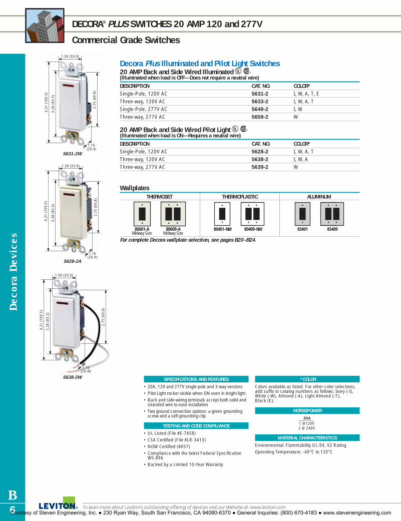
Dec
ora
Dev
ices
B6
DECORA® PLUS SWITCHES 20 AMP 120 and 277V
Commercial Grade Switches
SPECIFICATIONS AND FEATURES
• 20A, 120 and 277V single-pole and 3-way versions• Pilot Light rocker visible when ON even in bright light• Back and side-wiring terminals accept both solid and
stranded wire to ease installation• Two ground connection options: a green grounding
screw and a self-grounding clip
TESTING AND CODE COMPLIANCE
• UL Listed (File #E-7458)• CSA Certified (File #LR-3413)• NOM Certified (#057)• Compliance with the latest Federal Specification
WS-896• Backed by a Limited 10-Year Warranty
*COLOR
Colors available as listed. For other color selections,add suffix to catalog numbers as follows: Ivory (-I),White (-W), Almond (-A), Light Almond (-T), Black (E).
HORSEPOWER
20A__1 @120V2 @ 240V
MATERIAL CHARACTERISTICS
Environmental: Flammability UL-94, V2 RatingOperating Temperature: -40°C to 120°C
Decora Plus Illuminated and Pilot Light Switches20 AMP Back and Side Wired Illuminated UR(Illuminated when load is OFF—Does not require a neutral wire)
DESCRIPTION CAT. NO. COLOR*Single-Pole, 120V AC 5631-2 I, W, A, T, EThree-way, 120V AC 5633-2 I, W, A, TSingle-Pole, 277V AC 5649-2 I, WThree-way, 277V AC 5659-2 W
20 AMP Back and Side Wired Pilot Light UR(Illuminated when load is ON—Requires a neutral wire)
DESCRIPTION CAT. NO. COLOR*Single-Pole, 120V AC 5628-2 I, W, A, TThree-way, 120V AC 5638-2 I, W, AThree-way, 277V AC 5639-2 W
2.75
(69
.8)
3.28
(83
.3)
4.31
(10
9.5)
1.30 (33.0)
1.16(29.4)
5631-2W
1.16(29.4)
2.75
(69
.8)
3.28
(83
.3)
4,31
(10
9.5)
1.30 (33.0)
5628-2A
1.30 (33.0)
1.16(29.40
2.75
(69
.8)
3.28
(83
.3)
4.31
(10
9.5)
5638-2W
WallplatesTHERMOSET THERMOPLASTIC ALUMINUM
For complete Decora wallplate selection, see pages B20–B24.
80601-AMidway Size
80609-AMidway Size
80401-NW 80409-NW 83401 83409
To learn more about Leviton’s outstanding offering of devices visit our Website at: www.leviton.comCourtesy of Steven Engineering, Inc. ● 230 Ryan Way, South San Francisco, CA 94080-6370 ● General Inquiries: (800) 670-4183 ● www.stevenengineering.com

2.80
(71
.1)
3.28
(83
.3)
4.20
(10
6.7)
1.30 (33.0)
0.99(25.2)5601-2I
2.80
(71
.1)
3.28
(83
.3)
4.20
(10
6.7)
1.30 (33.0)
0.99 (25.2)5603-2E
1.30 (33.0)
0.99(25.20
2.80
(71
.1)
3.28
(83
.3)
4.20
(10
6.7)
5603-2GY
Decora D
evices
B7For answers to technical questions, call Leviton’s Techline at 1-800-824-3005
DECORA® SWITCHES 15 AMP 120/277V
Residential Grade Switches
SPECIFICATIONS AND FEATURES
• Switch frame shields against dust and fits inwallplate to prevent rocker binding
• Side Wire and Quickwire (No.12 or No.14 copperor copper-clad wire) push-in terminal wiringoptions
• Sturdy construction for long service life• Full rated current capacity with tungsten, fluores-
cent or resistive loads. Motor capacity is 80% ofswitch rating
• Conform to all NEMA standard specifications
TESTING AND CODE COMPLIANCE
• UL Listed (File #E-7458)• CSA Certified (File #LR-3413)• NOM Certified (#057)• Backed by a Limited Two-Year Warranty
*COLOR
Rocker/Frame colors available as listed.
HORSEPOWER
15A__1⁄2 @120V2 @ 240V
MATERIAL CHARACTERISTICS
Environmental: Flammability UL-94, V2 RatingOperating Temperature: -40°C to 120°C
Decora AC Quiet Rocker Switches15 AMP Quickwire Push-In and Side Wired 120/277V AC URDESCRIPTION CAT. NO. ROCKER/FRAME COLOR*Single-Pole 5601 Mahogany
5601-I Ivory5601-W White 5601-2 Mahogany5601-2I Ivory5601-2W White5601-2A Almond5601-2T Light Almond5601-2E Ebony5601-2GY Gray5601-S2I† Ivory5601-S2W† White5601-S2A† Almond
Double-Pole 5602-2 Mahogany5602-2I Ivory5602-2W White 5602-2GY Gray5602-2A Almond5602-2T Light Almond5602-2E Ebony
Three-Way 5603 Mahogany5603-I Ivory5603-W White 5603-2 Mahogany5603-2I Ivory5603-2W White5603-2A Almond5603-2T Light Almond5603-2E Ebony5603-2GY Gray5603-S2I† Ivory5603-S2W† White5603-S2A† Almond
Four-Way 5604-2 Mahogany5604-2I Ivory5604-2W White 5604-2A Almond5604-2T Light Almond5604-2E Ebony5604-2GY Gray
Note: To order Decora rocker switches with grounding screw add suffix -2 (e.g. 5601-2I)† Self-grounding when installed in a properly grounded metal wallbox.
WallplatesTHERMOSET POLYCARBONATE SCREWLESS SNAP-ON 302 STAINLESS STEEL
For complete Decora wallplate selection, see pages B20–B24.80401-GY 80409-GY 80301-SI 80309-SI 84401-40 84409-40
Courtesy of Steven Engineering, Inc. ● 230 Ryan Way, South San Francisco, CA 94080-6370 ● General Inquiries: (800) 670-4183 ● www.stevenengineering.com

Dec
ora
Dev
ices
B8
DECORA® SWITCHES15 AMP 120 and 120/277V
Residential Grade Switches
*COLOR
For color choice add suffix as follows: Ivory (-I), White (-W), Almond (-A), Light Almond (-T).
HORSEPOWER
15A__1⁄2 @120V2 @ 240V
MATERIAL CHARACTERISTICS
Environmental: Flammability UL-94, V2 RatingOperating Temperature: -40°C to 120°C
SPECIFICATIONS AND FEATURES
• Illuminated Switch rocker illuminated when load is OFF
• Pilot Light switch rocker visible when ON even inbright light
• Switch border shields against dust and fits inwallplate to prevent rocker binding
• Side-wiring terminals accept both solid andstranded wire to ease installation
• Full rated current capacity with tungsten, fluores-cent or resistive loads. Motor capacity is 80% ofswitch rating
• Conform to all NEMA standard specificationsImprinted Decora Switches• Stock Decora switches available with choice of
three imprints on rocker: FAN, DISPOSAL, OIL BURNER
911 Switch• 911 Switch provides standard ON/OFF control plus
a special illuminated FLASH function will flash con-trolled lighting ON and OFF at one-second intervals
• Replaces standard single-pole switch–flash functionalerts neighbors and helps emergency personnellocate a house quickly
TESTING AND CODE COMPLIANCE
• UL Listed (File #E-7458)• CSA Certified (File #LR-3413)• NOM Certified (#057)• Backed by a Limited Two-Year Warranty
SPECIFICATIONS AND FEATURES
Decora AC Quiet Rocker SwitchesQuickwire® and Side Wired Illuminated 15 AMP 120/277V AC UR(Illuminated when load is OFF–Does not require a neutral wire)
DESCRIPTION CAT. NO. COLOR*Single-Pole 5611-I Ivory
5611-W White5611-2A Almond5611-2T Light Almond
Three-Way 5613-I Ivory5613-W White5613-2A Almond5613-2T Light Almond
Four-Way 5614-2I Ivory5614-2W White5614-2A Almond5614-2T Light Almond
Note: To order Decora rocker switches with grounding screw add suffix -2 (e.g. – 5611-2I)
Quickwire and Side Wired Pilot Light 15 AMP 120V AC UR(Illuminated when load is ON–Requires a neutral wire)
DESCRIPTION CAT. NO. COLOR*Single-Pole 5618-2 I, W, A, T
Quickwire and Side Wired Imprinted 15 AMP 120/277V AC URDESCRIPTION STOCK MESSAGES AVAILABLE CAT. NO. COLOR*Single-Pole, Stock FAN, DISPOSAL, 5601-Z2 I, Wor Custom Imprinted OIL BURNER
Quickwire and Side Wired Molded 15 AMP 120/277V AC URDESCRIPTION CAT. NO. COLOR*Single-Pole ON/OFF 5601-X2 I, W, A, T, EMolded in Rocker
911 Flasher Switch500 WATTS 120V URDESCRIPTION CAT. NO. COLOR*3-Position Emergency Flasher Rocker Switch 911 I, W, A
3.28
(83
.3)
4.06
(10
3.2)
2.80
(71
.1)
0.99(25.2)
1.30 (33.0)
5611-2A
1.30 (33.3)
0.99(25.2)
2.80
(71
.1)
3.28
(83
.3)
4.20
(10
6.7)
5601-Z2W
1.30 (33.0)
1.59(40.5)
3.28
(83
.3)
4.13
(10
4.9)
2.66
(67
.6)
2.38 (60.5)
911-W
WallplatesTHERMOSET ALUMINUM
For complete Decora wallplate selection, see pages B20–B24.
80401-W 80409-W 83401 8340980601-IMidway Size
80609-IMidway Size
To learn more about Leviton’s outstanding offering of devices visit our Website at: www.leviton.comCourtesy of Steven Engineering, Inc. ● 230 Ryan Way, South San Francisco, CA 94080-6370 ● General Inquiries: (800) 670-4183 ● www.stevenengineering.com

Decora D
evices
B9For answers to technical questions, call Leviton’s Techline at 1-800-824-3005
DECORA® RECEPTACLE FEATURES
Industrial Grade Receptacles
Features and Benefits� Engineered for fine appearance and top
performance in demanding commercial and institutional applications using a durable,thermoplastic face and impact-resistant construction
� Shallow design for maximum wiring room in wallbox
� Back Wire and Side Wire terminal wiringoptions for ease of installation
� Heavy-gauge zinc-plated steel locked-in wrap-around strap
� Triple-wipe brass contacts for long service life� Exclusive V-shaped, serrated back wiring
clamps for superior contact and conductivity� Available in an array of colors to coordinate
with any interior� Backed by a Limited 10-Year Warranty
Triple-wipe brass contacts for long service life
Back and side wiringholes accept No. 12or No. 14 copper orcopper-clad wire
Labor-saving self-grounding clip
Heavy-gauge zinc-plated steel locked-inwrap-around strap
Combination triple-drive Brass #10-32screws (Standard,Phillips, Robertson)for fast installation.
Hospital Grade Tamper Resistant ReceptaclesThese Hospital Grade receptacles incor-porate a unique shutter mechanism thatopens easily for insertion of 2 or 3-prongplugs, but prevents the insertion of smallobjects into either slot.16262-SGI shown
Surge Supressor ReceptaclesDecora-style single and duplex surge-protective receptacles, including versionswith audible alarm, LED indicator light and Isolated Ground.8280-IGB shown
Dual Voltage ReceptaclesMaintain the consistent look of Decorastyle receptacles throughout commer-cial settings even when the need arisesfor Dual Voltage 15A 125 and 15A 250Vduplex receptacles.16292-I shown
Hospital Grade Power Indication™ ReceptaclesPower Indication meets UL 498Hospital Grade identification require-ments and provides visual confirma-tion that the device is energized.16362-PLR shown
Residential Grade ReceptaclesReceptacles engineered for elegantappearance, speedy installation and along trouble-free service life for fine residential applications.5325-I shown
SmartLockPRO® GFCI ReceptaclesSmartLockPRO GFCI meets or exceeds UL 2006 requirements and features apatented lockout action that blocksRESET if GFCI protection has beencompromised. 7599-W shown
16252-W
THE BEAUTY, DURABILITY AND VERSATILITY OFDECORA RECEPTACLES
Leviton’s Decora line of designer-style receptaclesare available in Industrial Grade (includingHospital Grade), Commercial Grade andResidential Grade, with a number of wiringoptions and features. They come in a variety ofcontemporary shades and add contemporarystyle to fine interiors everywhere.
Courtesy of Steven Engineering, Inc. ● 230 Ryan Way, South San Francisco, CA 94080-6370 ● General Inquiries: (800) 670-4183 ● www.stevenengineering.com

2.78
(70
.6)
3.28
(83
.3)
4.06
(10
3.2)
1.31 (33.3)
0.88(22.4)
16262-HGI
1.31 (33.3)
0.88(22.4)
3.28
(83
.3)
4.06
(10
3.2)
2.78
(70
.6)
16262-PLR
2.78
(70
.6)
3.28
(83
.3)
4.06
(10
3.2)
1.31 (33.3)
0.88(22.4)
16262-SGW
1.31 (33.3)
0.88(22.4)
3.28
(83
.3)
4.06
(10
3.2)
2.78
(70
.6)
16262-W
Dec
ora
Dev
ices
B10
DECORA® PLUS RECEPTACLES 15 and 20 AMP 125V • 20 AMP 250V
Industrial Grade Receptacles
SPECIFICATIONS AND FEATURES
• Durable thermoplastic face in an array of contem-porary colors
• Receptacles have a locked-in mounting strap witha self-grounding clip riveted to the strap (ExceptIsolated Ground devices)
• Hospital Grade Tamper-resistant receptaclesinclude a unique shutter mechanism that openseasily for the insertion of 2 or 3-prong plugs whilepreventing entry by other small objects into eitheroutlet slot
• Hospital Grade Isolated Ground receptacles (identi-fied by an orange face or triangle on the face) pro-tect sensitive electronic equipment and eliminateelectromagnetic interference by providing a sepa-rate path to ground
• Power Indication meets UL 498 Hospital Gradeidentification requirements and provides visualconfirmation that the device is energized.
• Back and side wiring terminals permit fast installa-tion of up to No. 10 solid or stranded conductors
• Triple-wipe copper alloy contacts ensure maximumconductivity
TESTING AND CODE COMPLIANCE
• UL Listed (File #E-13399)• CSA Certified (File #LR-406)• NOM Certified (#057)• Backed by a Limited 10-Year Warranty
*COLOR
Basic Cat. Nos. denote Mahogany device (unless indi-cated) and Orange for Isolated Ground (-IG) Devices.Isolated Ground Receptacle is distinguished by anorange triangle on its face. For other color selections,add suffix to the catalog number as follows: Ivory (-I),White (-W), Almond (-A), Light Almond (-T),Mahogany (for IG devices only, add -B), Red (-R),Gray (-G or -GY) and Black (-E).
MATERIAL CHARACTERISTICS
Environmental: Flammability UL-94, V2 RatingOperating Temperature: -40°C to 60°C MaximumContinuous
Decora Plus ReceptaclesBack and Side Wired NEMA 5-15R & 5-20R UR(Basic Cat. No. denotes Mahogany device except where noted)
DESCRIPTION CAT. NO./COLOR* CAT. NO./COLOR*15A-125V 20A-125V
Hospital Grade, Duplex 16262-HG 16362-HGI, W, G, R (No Mahogany) I, W, A, G, R (No Mahogany)
Hospital Grade, 16262-SG —Tamper Resistant Duplex I, W, A, RHospital Grade, 16262-IG (Basic Cat. No. Orange) 16362-IG (Basic Cat. No. Orange)Isolated Ground Duplex B, I, W, G, R, E B, I, W, G, R(Not Self-Grounding)Hospital Grade, 16262-PL 16362-PL Power Indication Duplex I, W, R (No Mahogany) I, W, R (No Mahogany)Industrial Grade, Duplex 16262 16362
I, W, GY, E I, W, A, T, GY, E
Back and Side Wired NEMA 6-20R URDESCRIPTION CAT. NO./COLOR*
20A-250V
Hospital Grade, Duplex 16462-HGI, W (No Mahogany)
Wallplates for Isolated Ground Devices Engraved with “Isolated Ground” URDESCRIPTION CAT. NO. COLOR*Decora Receptacle Wallplate 80401-IG Orange only
5-15RG
W 5-20RG
W
6-20RG
WallplatesTHERMOPLASTIC POLYCARBONATE SCREWLESS SNAP-ON 302 STAINLESS STEEL
For complete Decora wallplate selection, see pages B20–B24.
80401-NI PJ26-IMidway Size
80409-NR80409-NI 84401-40 84409-4080301-SW 80309-SW
To learn more about Leviton’s outstanding offering of devices visit our Website at: www.leviton.comCourtesy of Steven Engineering, Inc. ● 230 Ryan Way, South San Francisco, CA 94080-6370 ● General Inquiries: (800) 670-4183 ● www.stevenengineering.com

3.28
(83
.3)
4.06
(10
3.2)
2.78
(70
.6)
1.31 (33.3)
0.84(21.4)
16342-GY
1.31 (33.3)
0.84(24.1)
2.78
(70
.6)
3.28
(83
.3)
4.06
(10
3.2)
16352-A
1.31 (33.3)
0.82(20.8)
3.28
(83
.3)
4.06
(10
3.2)
2.36
(60
.0)
16251
Decora Plus ReceptaclesBack and Side Wired, Self-Grounding† NEMA 5-15R, 6-15R, 5-20R & 6-20R UR(Basic Cat. No. denotes Mahogany device*)
DESCRIPTION CAT. NO./COLOR CAT. NO./COLOR CAT. NO./COLOR CAT. NO./COLOR15A/125V 15A/250V 20A/125V 20A/250V
Duplex 16252 16662 16352 16462I, W, A, T, GY, E I, W I, W, A, T, GY, E I, W
(No Mahogany) (No Mahogany)Single 16251 16651 16351 16451
I, W I, W I, W I, W (No Mahogany) (No Mahogany)
Tamper Resistant Duplex DR15S-G — — —I, W, A (No Mahogany)
†Self-grounding when installed in a properly grounded metal wallbox
Side Wired, Self-Grounding† NEMA 5-15R, 6-15R, 5-20R & 6-20R UR(Basic Cat. No. denotes Mahogany device*)
DESCRIPTION CAT. NO./COLOR CAT. NO./COLOR CAT. NO./COLOR CAT. NO./COLOR15A/125V 15A/250V 20A/125V 20A/250V
Duplex 16242 — 16342 —I, W, E I, W, GY, E
Single 16241 16641 16341 16441I, W I, W I, W, A, T, GY, E I, W, A, T(No Mahogany) (No Mahogany) (No Mahogany)
†Self-grounding when installed in a properly grounded metal wallbox
Back and Side Wired, Self-Grounding†125V/250V Dual Voltage NEMA 5-15R & 6-15R UDESCRIPTION CAT. NO. COLOR*Duplex, Dual Voltage 16292 I, W
†Self-grounding when installed in a properly grounded metal wallbox
Decora D
evices
B11For answers to technical questions, call Leviton’s Techline at 1-800-824-3005
DECORA® PLUS RECEPTACLES 15 AMP 125 and 250V • 20 AMP 125 and 250V
Commercial Grade Receptacles
SPECIFICATIONS AND FEATURES
• Back Wire and Side Wire terminal options• Heavy-gauge zinc-plated steel locked-in wrap-
around strap• Terminal screws accept up to No. 10 copper or
copper-clad wire, solid or stranded• Back wire terminals accept up to No. 10 copper
or copper-clad wire, solid or stranded• Labor-saving self-grounding clip• Heavy-duty triple-wipe brass contacts for long
service life• Impact-resistant thermoplastic construction
TESTING AND CODE COMPLIANCE
• UL Listed (File #E-13399)• CSA Certified (File #LR-406)• NOM Certified (#057)• Backed by a Limited 10-Year Warranty
*COLOR
Basic Cat. No. denotes Mahogany device (unlessindicated). For other color selections, add suffix tothe catalog number as follows: Ivory (-I), White (-W),Almond (-A), Light Almond (-T), Gray (-GY) andBlack (-E).
MATERIAL CHARACTERISTICS
Environmental: Flammability UL-94, V2 RatingOperating Temperature: -40°C to 60°C MaximumContinuous
5-15RG
W 6-15RG
5-20RG
W 6-20RG
5-15RG
W 6-15RG
5-20RG
W 6-20RG
WallplatesTHERMOSET POLYCARBONATE SCREWLESS SNAP-ON THERMOPLASTIC
For complete Decora wallplate selection, see pages B20–B24.
80401 SJ26-SAMidway Size
80609-AMidway Size
80409-NGY80401-NGYSJ262-SAMidway Size
Courtesy of Steven Engineering, Inc. ● 230 Ryan Way, South San Francisco, CA 94080-6370 ● General Inquiries: (800) 670-4183 ● www.stevenengineering.com

1.30 (33.0)
0.70(17.8)
2.77
(70
.5)
3.28
(83
.3)
4.06
(10
3.2)
5325-A
3.28
(83
.30
4.06
(10
3.2)
2.77
(70
.5)
1.30 (33.0)
0.70(17.8)
5325-SW
3.28
(83
.30
4.06
(10
3.2)
2.77
(70
.5)
1.30 (33.0)
0.70(17.8)5328-W
Dec
ora
Dev
ices
B12
DECORA® RECEPTACLES 15 AMP 125V
Residential Grade Receptacles
SPECIFICATIONS AND FEATURES
• Side Wire and Quickwire™ holes accept No. 14 AWG copper wire for Cat. No. 5325
• Heavy-gauge zinc-plated steel mounting strap• Heavy duty double-wipe brass contacts for long
service life
TESTING AND CODE COMPLIANCE
• UL Listed (File #E-13399)• CSA Certified (File #LR-406)• NOM Certified (#057)• Backed by a Limited One-Year Warranty
*COLOR
Basic Cat. No. denotes Mahogany (Brown) deviceunless indicated. For other color selections, add suffix to the catalog number as follows: Ivory (-I),White (-W), Almond (-A), Light Almond (-T), Gray (-GY), and Black (-E).
MATERIAL CHARACTERISTICS
Environmental: Flammability UL-94, V2 RatingOperating Temperature: -40°C to 60° C MaximumContinuous
Decora AC ReceptaclesSide Wire and Quickwire NEMA 5-15R URDESCRIPTION CAT. NO. COLOR*
Basic Cat. No. Denotes Mahogany
Duplex 5325 I, W, A, T, GY, EDuplex, Self-Grounding Clip 5325-S† I, W, A, T (No Mahogany)Duplex, 8-Hole Quickwire 5328 I, W, A (No Mahogany)
†Self-grounding when installed in a properly grounded metal wallbox
5-15RG
W
WallplatesTHERMOSET THERMOPLASTIC POLISHED BRASS 302 STAINLESS STEEL
For complete Decora wallplate selection, see pages B20–B24.80401-A 80411-E80409-E 81401-PB80401-NT 80409-NT 84401-40 84409-40
To learn more about Leviton’s outstanding offering of devices visit our Website at: www.leviton.comCourtesy of Steven Engineering, Inc. ● 230 Ryan Way, South San Francisco, CA 94080-6370 ● General Inquiries: (800) 670-4183 ● www.stevenengineering.com

Decora D
evices
B13For answers to technical questions, call Leviton’s Techline at 1-800-824-3005
DECORA® RECEPTACLES 15 AMP 125V • 20 AMP 125V
Industrial Grade Receptacles
Decora Surge Protective ReceptaclesBack and Side Wired NEMA 5-15R & 5-20R UR(Basic Cat. No. denotes Mahogany device except where noted)
DESCRIPTION CAT. NO./COLOR* CAT. NO./COLOR*15A-125V 20A-125V
Hospital Grade, Surge Duplex with 8280 8380Indicator Light and Audible Alarm I, W, A, T, R, B I, W, GY, R, BHospital Grade, Surge Single with — 8381Indicator Light and Audible Alarm I (No Mahogany)Hospital Grade, Isolated Ground, 8280-IG 8380-IGSurge Duplex with Indicator Light I, W, A, G, B, O I, W, G, B, Oand Audible Alarm (No Mahogany) (No Mahogany)Hospital Grade, Isolated Ground, 8281-IG 8381-IGSurge Single with Indicator Light I, O I, W, Band Audible Alarm (No Mahogany) (No Mahogany)Industrial Grade, Surge Duplex with 7280 7380Indicator Light and Audible Alarm I, W, A, GY, B I, W, GY, BIndustrial Grade, Surge Duplex 5280 5380with Indicator Light I, W, A, T, GY, B I, W, GY, BIndustrial Grade, Isolated Ground, 5280-IG 5380-IGSurge Duplex with Indicator Light I, W, A, G, B, O I, W, G, B, O
5-15RG
W 5-20RG
W
For more information regarding Surge Protective Devices, refer to Section R.
SPECIFICATIONS AND FEATURES
• Decora-styled TVSS receptacles protect sensitiveelectronic equipment against transient voltagesurges
• UL 1449 Suppressed Voltage Ratings: 400V for all3 modes (line-neutral, line-ground, neutral ground)
• Hospital Grade versions (indicated by green dot onreceptacle face) are suitable for high-abuse healthcare, industrial and commercial applications
• Isolated Ground versions (indicated by orange coloror orange triangle on receptacle face) provide apure ground path for use with isolated groundingsystems
• Monitor/Indicator LED is ON continuously when protection is active and OFF when protection circuitis deactivated due to excessive transients
• All Hospital Grade devices and Cat. Nos. 7280 and7380 Industrial devices also provide an audibletone alert that sounds if protection is lost
• Maximum Continuos Operating Voltage: 150V• Maximum single-pulse transient current (8 x 20µs
Amps peak) 24,000A (L-N), 12,000A (L-G), 12,000 (N-G)
• Rated single pulse transient energy (10 x 1000µs,impulse) 320 Joules
• RFI and EMI noise filtration (-35db, @5KHz-5MHz)
TESTING AND CODE COMPLIANCE
• UL Listed (File #E-13399)• CSA Certified (File #LR-406)• NOM Certified (#057)• UL Standard 1449-2nd ED• Backed by a Limited 10-Year Warranty
*COLOR
Basic Cat. Nos. denote Mahogany device, unlessindicated. Isolated Ground Receptacle is distin-guished by an orange triangle on its face. For othercolor selections, add suffix to the catalog number as follows: Ivory (-I), White (-W), Almond (-A), Light Almond (-T), Red (-R), Gray (-G or -GY), Blue (-B) and Orange (-O).
MATERIAL CHARACTERISTICS
Environmental: Flammability UL-94, V2 RatingOperating Temperature: -40°C to 120°C
1.30 (33.0)
1.22(31.0)
3.28
(83
.3)
4.06
(10
3.2)
2.70
(68
.6)
8380-B
1.22 (31.0)
3.28
(83
.3)
4.06
(10
3.2)
2.70
(68
.6)
1.30 (33.0)
7280-A
2.70
(68
.6)
3.28
(83
.3)
4.21
(10
6.9)
1.22(31.00
1.30 (33.0)
5280-W
WallplatesTHERMOSET POLYCARBONATE SCREWLESS SNAP-ON BRASS 302 STAINLESS STEEL
For complete Decora wallplate selection, see pages B20–B24.
80401-NB PJ26-BUMidway Size
SJ262-SAMidway Size
80309-SA 81401 81409 84401-40 84409-40
Courtesy of Steven Engineering, Inc. ● 230 Ryan Way, South San Francisco, CA 94080-6370 ● General Inquiries: (800) 670-4183 ● www.stevenengineering.com

Dec
ora
Dev
ices
B14
DECORA® SMARTLOCKPRO ® GFCI PERSONNEL PROTECTION DEVICE FEATURES
Commercial Grade Decora Devices
TESTING AND CODE COMPLIANCE
• UL Standard 943 Class A (GFCI) and 498(Receptacles)
• UL Listed (File # 48380)• CSA Certified (File #LR-57811)• NOM Certified (#057)• Backed by a Limited Two-Year Warranty
*COLOR
Basic Cat. Nos. denote Brown color unless indicated.For other color selections, add suffix to catalog num-ber as follows: Ivory (-I), White (-W), Almond (-A),Light Almond (-T), Gray (-G or GY), Red (-R), Black (-E).
MATERIAL CHARACTERISTICS
Flammability: Rated V2Operating Temperature: -30°F (-35°C) to 151°F (66°C)
SPECIFICATIONS AND FEATURES
• Meets or exceeds UL 2006 Requirements• TEST and RESET functions work together so that a
tripped GFCI cannot be reset if GFCI circuit nolonger provides ground fault protection
• RESET button is blocked if GFCI protection hasbeen compromised, reducing the possibility ofend-users incorrectly assuming that a reset GFCI is providing ground fault protection when it actuallyis not
• Line-load diagnostic feature prevents GFCI frombeing reset and stops power from being fed tothe GFCI receptacle face or through to down-stream devices. This alerts installer to a line-loadreversal. Indicator light will be ON to indicateline-load reversal.
• The SmartLockPRO® GFCI with lockout action isdesigned and patented by Leviton
• Trip threshold meets or exceeds UL requirementsfor tripping time
• Impact-resistant thermoplastic cover and body • Silver-alloy contacts • Compatible with all Decora devices: available in
selected Decora colorsCombination Switch/SmartLockPRO® GFCI Outlet• Ideal for kitchens, bathrooms, modular kitchen
units, bathroom cabinet fixtures, lamp cabinet fixtures and applications where combinationdevices are used.
Ideal for a Wide Range of GFCI Applications� Residential – Kitchens, bathrooms, garages, basements and
other wet locations� Outdoors – Outdoor receptacles by pools, cabanas, patios,
decks and lanais� Hospital and Healthcare Facilities – Scrub rooms, lavatories kitchenettes and
other potentially wet locations� Educational Facilities – Classrooms, restrooms, laboratories, dormitories and kitchens� Airports – Bathrooms, general use areas and maintenance areas� Restaurants, Lodging and Retail Malls – Bathrooms, general use areas and
maintenance areas� Commercial Offices – Bathrooms, basement areas, hallways and kitchens� Public Areas – Near wet and damp locations
� Patented professional grade lockout action as end-of-life indication� Prevents power from being connected to face and feed-through terminals
when miswired (line-load reversal)� Improved immunity to electrical noise to reduce false tripping� Advanced electronics provide superior surge immunity� Trip threshold meets or exceeds UL requirements for tripping time
THE SMARTLOCKPRO® PROTECTION ADVANTAGEWhile other GFCI manufacturers may have taken the alternate route in the 2006 UL Standard by providing an indicator light for end-of-life indication, allowing reset and continued use of a GFCI with unprotected power to the GFCI face and downstream receptacles, the SmartLockPRO’s reset button will not engage if protection has been compromised. TheSmartLockPRO’s unique patented professional grade end-of-life lockout action, reduces the possibility of end-users incorrectly assuming that a reset GFCI outlet is providing ground fault protection when it actually is not.
SmartLockPRO® GFCI with Professional GradeLockout ActionMeets or exceeds Underwriters Laboratories (UL) 2006UL943 GFCI Safety Standards
To learn more about Leviton’s outstanding offering of devices visit our Website at: www.leviton.comCourtesy of Steven Engineering, Inc. ● 230 Ryan Way, South San Francisco, CA 94080-6370 ● General Inquiries: (800) 670-4183 ● www.stevenengineering.com

WallplatesTHERMOSET POLYCARBONATE SCREWLESS SNAP-ON POLISHED BRASS 302 STAINLESS STEEL
For complete Decora wallplate selection, see pages B20–B24.
Decora D
evices
B15For answers to technical questions, call Leviton’s Techline at 1-800-824-3005
SMARTLOCKPRO® GFCI RECEPTACLES 15 AMP 125V • 20 AMP 125V
Commercial and Hospital Grade GFCI Personnel Protection Devices
Hospital Grade SmartLockPRO® GFCI ReceptaclesBack and Side Wired 15 AMP 125V at Receptacle, 20 AMP Feed-Through URDESCRIPTION CAT. NO. COLOR* NEMA CONFIG.
Basic Cat. No. Denotes Brown
Duplex with LED Indicator Light, 7599-HG I, W, A, T, G, Rbuttons match face colorDuplex with LED Indicator Light, buttons 7599-DIN Black Onlymatch face color. DIN-Rail mounting with terminal wiring block. UL Recognized Component
Back and Side Wired 20 AMP 125V at Receptacle and Feed-Through URDESCRIPTION CAT. NO. COLOR* NEMA CONFIG.
Basic Cat. No. Denotes Brown
Duplex with LED Indicator Light, 7899-HG I, W, A, T, G, Rbuttons match face color
Commercial Grade SmartLockPRO® GFCI ReceptaclesBack and Side Wired 15 AMP 125V at Receptacle, 20 AMP Feed-Through URDESCRIPTION CAT. NO. COLOR* NEMA CONFIG.
Basic Cat. No. Denotes Brown
Duplex with Indicator Light, 7599 I, W, A, T, GY, R, Ebuttons match face colorDuplex with LED Indicator Light, 7599-L I, W (No Brown)Black & Red buttons. With 6" leads
Back and Side Wired 20 AMP 125V at Receptacle and Feed-Through URDESCRIPTION CAT. NO. COLOR* NEMA CONFIG.
Basic Cat. No. Denotes Brown
Duplex with LED Indicator Light, 7899 I, W, A, T, GY, Ebuttons match face colorDuplex with LED Indicator Light, 7899-L I, W (No Brown)Black & Red buttons. With 6" leads
Combination Switch/SmartLockPRO® GFCI Outlet15 AMP @ 125V Side Wired AC Switch Rating, 15 AMP 125V at Receptacle, 20 AMP Feed-Through URDESCRIPTION CAT. NO. COLOR* NEMA CONFIG.Single-Pole Switch and SmartLock 7299 I, W, AGFCI-Protected Outlet, buttons match face color
Blank Face SmartLockPRO® GFCIBack and Side Wired 20 AMP 125V Feed-Through URDESCRIPTION CAT. NO. COLOR*Blank Face, No Indicator Light, 8590 I, W, A, T, Ebuttons match face color
5-15RG
W
5-15RG
W
5-15RG
W
5-20RG
W
5-20RG
W
80301-SW 80309-SW 81401-PB 81409-PB 84401-40 84409-4080401-NT 80409-NT
3.28
(83
.3)
4.21
(10
6.9)
2.70
(68
.6)
1.13 (28.6)
1.70 (43.2)
7599-I
3.28
(83
.3)
4.21
(10
6.9)
2.70
(68
.6)
1.13 (28.6)
1.70 (43.2)
7599-HGI
Courtesy of Steven Engineering, Inc. ● 230 Ryan Way, South San Francisco, CA 94080-6370 ● General Inquiries: (800) 670-4183 ● www.stevenengineering.com

Dec
ora
Dev
ices
B16
DECORA® COMBINATION DEVICES 15 and 20 AMP • 120 and 120/277V
Commercial Grade Combination Devices
Decora Combination Devices15 AMP URDESCRIPTION RATING CAT. NO. COLOR*Single-Pole Switch/Receptacle Switch: 15A–120V AC 5625 I, W, A, T, GY, E
Receptacle: 15A-125VSingle-Pole Switch/Pilot Light Switch: 15A–120V AC 5626 I, W, A
Pilot: 1/25W–125V ACTwo Single-Pole Switches 15A-120/277V AC 5634 I, W, A, T, GY, E3-Way Switch/Single-Pole Switch 15A-120/277V AC 5641 I, W, A, T, ETwo 3-Way Switches 15A-120/277V AC 5643 I, W, A, T3-Way Switch/Receptacle Switch: 15A–120V AC 5645 I, W, A, E
Receptacle: 15A–125V3-Way Switch/Pilot Light Switch: 15A–120V AC 5646 I, W, A
Pilot: 1/25W–125V
20 AMP URDESCRIPTION RATING CAT. NO. COLOR*Two Single-Pole Switches 20A-120/277V AC 5627 I, W, A, TSingle-Pole Switch/Receptacle Switch: 20A-120V AC 5636 I, W, A
Receptacle: 20A-125VSingle-Pole Switch/Pilot Light Switch: 20A-120V AC 5637 I, W, A
Pilot: 1/25W-125V ACTwo 3-Way Switches 20A-120/277V AC 5640 I, W, A, T
SPECIFICATIONS AND FEATURES
• Elegant Decora styling provides multiple control ina single-gang wallbox
• All devices have grounding screw• Fit standard wall boxes
TESTING AND CODE COMPLIANCE
• UL Listed (File #E-7458)• CSA Certified (File #LR-3413)• NOM Certified (#057)• Backed by a Limited Two-Year Warranty
*COLOR
Colors available as listed. For other color selections,add suffix to catalog numbers as follows: Ivory (-I),White (-W), Almond (-A), Light Almond (-T), Gray (-GY) and Black (-E).
HORSEPOWER
15A 20A__ __1⁄2 @120V 1 @ 120V2 @ 240V 2 @ 240V
MATERIAL CHARACTERISTICS
Environmental: Flammability UL-94, V2 RatingOperating Temperature: -40°C to 120°C
1.31 (33.4)
1.06(26.9)
3.28
(83
.3)
4.20
(10
6.7)
2.77
(70
.4)
5625-T
1.31 (33.4)
1.06(26.9)
3.28
(83
.3)
4.20
(10
6.7)
2.77
(70
.4)
5634-T
WallplatesTHERMOSET THERMOPLASTIC POLYCARBONATE SCREWLESS SNAP-ON 302 STAINLESS STEEL
For complete Decora wallplate selection, see pages B20–B24.80401-W 80409-W 80309-SI 80311-SI80409-NI 84411-40
To learn more about Leviton’s outstanding offering of devices visit our Website at: www.leviton.comCourtesy of Steven Engineering, Inc. ● 230 Ryan Way, South San Francisco, CA 94080-6370 ● General Inquiries: (800) 670-4183 ● www.stevenengineering.com

Decora D
evices
B17For answers to technical questions, call Leviton’s Techline at 1-800-824-3005
DECORA® COMBINATION DEVICES 15 AMP 120V • 15 AMP 125V
Commercial Grade Combination Devices
Decora Combination SwitchesIndividual Switches: 15 AMP 120V/Device Total: 20 AMP-120V† URDESCRIPTION CAT. NO. COLOR*Dual Rocker Switches 1754 I, W, A, TDual Rocker Switches 1754-2 Wwith Ground ScrewIlluminated Dual Rocker Switches 1754-IL I, W, Alight is ON when top rocker is offThree Rocker Switches 1755 I, W, A, TThree Rocker Switches 1755-2 I, Wwith Ground ScrewThree Rocker Switches 1759 I, W(Double Pole ON-OFF-ON Top Switch;Two Single-Pole Switches)
†WARNING: Although each individual rocker switch is rated up to 15A 120V, the total combined load for both duplex or allthree triplex switches MUST NOT EXCEED 20 AMPS.
Decora Combination Switch/SmartLockPRO® GFCI OutletReceptacle: 15 AMP 125V/Feed-through: 20 AMP 125V DESCRIPTION CAT. NO. COLOR*Single-Pole Switch and 7299 I, W, ASmartLockPRO GFCI-Protected Outletwith Indicator Light
SPECIFICATIONS AND FEATURES
• Multi-switch combination devices save space andadd convenience
• Common shunted internally to all switches• Elegant Decora styling permits ganging with other
Decora devices• Switch/SmartLockPRO ® GFCI Receptacle replaces
standard switch/outlet combination devices incommercial or residential installations
• Space-saving SmartLockPRO ® GFCI protection innew or retrofit construction
• Switch/SmartLockPRO ® GFCI Receptacle permitsmultiple wiring options that allow six different applications
SmartLockPRO ® GFCI• Meets or exceeds UL 2006 Code Requirements for
line-load reversal indication during installation andend-of-life indication
• Exclusive, patented lockout-action: RESET buttonis blocked if GFCI protection has been compro-mised, eliminating the risk of end-users incorrectlyassuming that a reset GFCI is providing groundfault protection when it actually is not
ND CODE COMPLIANCE
TESTING AND CODE COMPLIANCE
Decora Switches • UL Listed (File #7458)• CSA (File #LR-3413) • NOM Certified (#057)• Backed by a Limited Two-Year WarrantySwitch/SmartLockPRO ® GFCI Receptacle• UL Listed (File #48380)• Listed UL Standard 943, Class A • CSA Certified (File #LR-57811) • NOM Certified (#057)• Backed by a Limited Two-Year Warranty
*COLOR
Colors available as listed. For other color selections,add suffix to catalog numbers as follows: Ivory (-I), White (-W), Almond (-A), Light Almond (-T).
MATERIAL CHARACTERISTICS
Environmental: Flammability UL-94, V2 RatingOperating Temperature: -40°C to 120°C
WallplatesTHERMOSET POLYCARBONATE SCREWLESS SNAP-ON BRASS
For complete Decora wallplate selection, see pages B20–B24.80401-I 80409-I 80301-SW 80311-SW80309-SW 81401
7299-I
1.11(28.2)
3.28
(83
.3)
4.06
(10
3.2)
2.80
(71
.2)
1755-W
1.31 (33.4)
1.70 (43.9)
1.19(30.1)
3.28
(83
.3)
4.21
(10
6.9)
2.74
(69
.5)
Courtesy of Steven Engineering, Inc. ● 230 Ryan Way, South San Francisco, CA 94080-6370 ● General Inquiries: (800) 670-4183 ● www.stevenengineering.com

3.28
(83
.3)
4.06
(10
3.2)
2.62
(66
.6)
1.30 (33.0)
0.44(11.1)
40649-A
1.30 (33.0)
3.28
(83
.3)
4.06
(10
3.2)
2.62
(66
.6)
40681
3.28
4.06
(10
3.2)
2.62
(66
.6)
1.30 (33.0)
40682-GY
Dec
ora
Dev
ices
B18
DECORA® VOICE, DATA and VIDEO DEVICES
Commercial Grade Wall Jacks
Wall JacksType 625 Single Telephone Wall Jacks URDESCRIPTION CAT. NO. COLOR*
Basic Cat. No. Denotes Mahogany
4-Conductor 40649 I, W, A, GY, E6-Conductor 40638 I, W, A, T, GY, E8-Conductor 40680 I, W
F Connector Wall Jacks* URDESCRIPTION CAT. NO. COLOR*
Basic Cat. No. Denotes Mahogany
Single F Connector 40681 I, W, A, T, GYDuplex F Connector 40682 I, W, A, T, GYSingle F Connector 80381 I, W, A, T, GY(includes Snap-On Decora Plus Wallplate)
*Standard bulkhead F connector for CATV or other video applications. These jacks are not rated UL94V-O.
Decora® Plus Voice/Data Jacks with QuickPort® Snap-in Modules URDESCRIPTION CAT. NO. COLOR*Empty, 2-Port Platform, No Jacks 41642 I,W, A, T, GY, B Platform with Two 6-Conductor Jacks 41666 I, WPlatform with Two 8-Conductor Jacks 41688 I, W, TPlatform with One 6-Conductor Jack 41658 I, Wand One F ConductorPlatform with One 6-Conductor Jack 41668 I, Wand One 8-Conductor Jack
For QuickPort® Snap-in Modules, see section “S”
SPECIFICATIONS AND FEATURES
• All wall jacks are compatible with Decora Plussnap-on wallplates and Decora standard wallplates
• All wall jacks can be used with single or multiple-gang wall boxes
• Modular Jacks have 50 micro-inches hard gold-plated phosphor bronze spring wire contacts.
• Jacks can be used for 75-OHM cable connectionsfor televisions, VCR’s and receivers
• Decora Plus Duplex Jack uses snap-in moduleswith quick-connect insulation displacement terminals for 22 or 24 AWG wire
TESTING AND CODE COMPLIANCE
• UL Listed (File #109712) in accordance with NECArticle 800-51(-I)
• CSA Certified (File #80287 for all cat. nos. except80381, which is File #LR-20064)
• NOM Certified (#057)
• Decora F-Connector Wall Jacks meet specs. for UL 1863
• Meet FCC Part 68 requirements• All Decora Plus Voice/Data Jack Snap-in QuickPort
modules meet TIA-568A electrical, mechanicaland transmission requirements
• Wall Jacks’ housings of high-impact, self-extinguishing plastic, rated UL 94 V-O
• Backed by a Limited Two-Year Warranty
*COLOR
Basic Cat. No. denotes Mahogany device (unlessindicated). For other color selections, add suffix tocatalog numbers as follows: Ivory (-I), White (-W),Almond (-A), Light Almond (-T), Gray (-GY), Black (-E),Brown (-B).
MATERIAL CHARACTERISTICS
Environmental Flammability: Meet specs for UL1863
WallplatesTHERMOSET THERMOPLASTIC POLYCARBONATE SCREWLESS SNAP-ON
For complete Decora wallplate selection, see pages B20–B24.
80401-A 80301-S80601-AMidway Size
80409-NGYPJ26-GYMidway Size
SJ262-SMidway Size
To learn more about Leviton’s outstanding offering of devices visit our Website at: www.leviton.comCourtesy of Steven Engineering, Inc. ● 230 Ryan Way, South San Francisco, CA 94080-6370 ● General Inquiries: (800) 670-4183 ● www.stevenengineering.com

Decora D
evices
B19For answers to technical questions, call Leviton’s Techline at 1-800-824-3005
DECORA® PLUS CANADIAN 15 and 20 AMP 347V
Commercial Grade Switches
SPECIFICATIONS AND FEATURES
• New architecturally-styled smooth-action concave rocker
• Heavy-duty impact-resistant thermoplastic construction for long service life in commercial applications
• Full rated current capacity with tungsten, fluores-cent or resistive loads. Motor capacity is 80% ofswitch rating
• Wrap-around heavy-gauge strap with locking tabsfor added strength
• Back and side-wiring terminals accept both solidand stranded wire to ease installation
• Green grounding screw• Canadian 347V Decora wallplates available in a
number of colors• Note: Decora Plus Canadian 347V switches fit only
those wallplates designated for 347V AC devices• Note: Canadian 347V Decora wallplates fit
“Commander Type” boxes
TESTING AND CODE COMPLIANCE
Switches• UL Listed (File #E-7458)• CSA Certified (File #LR-3413)Wallplates• UL Listed (File #E-13397)• CSA (File #LR-16347)• NOM Certified (#057) • Fully compliant with NEMA Standards WD-1• Backed by a Limited 10-Year Warranty
*COLOR
For color selection, add suffix to catalog number asfollows: Ivory (-I), White (-W), Almond (-A), Gray (-G),Black (-E) and Red (-R).
MATERIAL CHARACTERISTICS
Environmental: Flammability UL-94, V2 RatingOperating Temperature: -40°C to 120°C
Canadian 347V AC Quiet Rocker SwitchesBack and Side Wired 15 AMP 347V AC URDESCRIPTION CAT. NO. COLOR*Single-Pole Rocker Switch 5691-C I, W, A, G, E3-Way Rocker Switch 5693-C I, W, A, E4-Way Rocker Switch 5694-C W
Back and Side Wired 20 AMP 347V AC URDESCRIPTION CAT. NO. COLOR*Single-Pole Rocker Switch 5621-C I, W, G3-Way Rocker Switch 5623-C W, G4-Way Rocker Switch 5624-C W
Midway Nylon WallplatesFor Canadian 347V Decora Devices DESCRIPTION CAT. NO. COLOR*1-Gang 1-Decora 80401-CN I, W, A, G, E
2-Gang 2-Decora 80409-CN I, W, A, G, E
3-Gang 3-Decora 80411-CN I, W, G, E
4-Gang 4-Decora 80412-CN I, W, G
3.53
(89
.7)
4.31
(10
9.5)
2.75
(69
.8)
1.30 (33.0)
1.16 (29.4)
5691-CI
1.30 (33.0)
1.16(29.4)
3.53
(89
.7)
4.31
(1.
09.5
)
2.75
(69
.8)
5621-CW
Courtesy of Steven Engineering, Inc. ● 230 Ryan Way, South San Francisco, CA 94080-6370 ● General Inquiries: (800) 670-4183 ● www.stevenengineering.com

Decora Plus Screwless Snap-On WallplatesDESCRIPTION COLOR STANDARD MIDWAY1-Gang 1-Decora Ivory 80301-SI SJ26-SI
Ebony/Black 80301-SE SJ26-SEGray 80301-SGY SJ26-SGYWhite 80301-SW SJ26-SWMahogany/Brown 80301-S SJ26-SAlmond 80301-SA SJ26-SALight Almond 80301-ST SJ26-ST
2-Gang 2-Decora Ivory 80309-SI SJ262-SIEbony/Black 80309-SE SJ262-SEGray 80309-SGY SJ262-SGYWhite 80309-SW SJ262-SWMahogany/Brown 80309-S SJ262-SAlmond 80309-SA SJ262-SALight Almond 80309-ST SJ262-ST
3-Gang 3-Decora Ivory 80311-SI SJ263-SIEbony/Black 80311-SE SJ263-SEWhite 80311-SW SJ263-SWAlmond 80311-SA SJ263-SALight Almond 80311-ST SJ263-ST
4-Gang 4-Decora Ivory 80312-SI SJ264-SIWhite 80312-SW SJ264-SWAlmond 80312-SA SJ264-SALight Almond 80312-ST SJ264-ST
5-Gang 5-Decora Ivory 80321-SI SJ265-SIWhite 80321-SW SJ265-SWAlmond 80321-SA SJ265-SALight Almond 80321-ST SJ265-ST
6-Gang 6-Decora Ivory 80326-SI SJ266-SIWhite 80326-SW SJ266-SWAlmond 80326-SA SJ266-SALight Almond 80326-ST SJ266-ST
Decora Plus Screwless Snap-On Wallplates� Sleek, smooth contemporary architectural styling enhances
fine décor� Exclusive new design eliminates subplate screws� “Hook and Snap” subplate and wallplate mounting provides
easy, time saving installation� Decora-compatible two-piece kit allows easy retrofit to any
Decora installation� Tough, unbreakable polycarbonate construction� Now available in standard and midway sizes that can be
mounted onto larger-volume wallboxes and/or used to hidewall irregularities.
Dec
ora
Wal
lpla
tes
B20
DECORA® PLUS SCREWLESS SNAP-ON WALLPLATES
Commercial Grade Wallplates
TESTING AND CODE COMPLIANCE
• UL Listed (File #E-13397)• Meets NEMA Standards WD-1, WD-6• CSA Certified (File #LR-16347)• NOM Certified (File #057)• Backed by a Limited Ten-Year Warranty
MATERIAL CHARACTERISTICS
Environmental: Flammability UL-94, V2 RatingOperating Temperature: -40°C to 120°C
Midway SizeSingle-Gang Screwless Snap-On Wallplate
SJ26-SMidway wallplates can be mounted onto larger-volume outlet boxes and/or used to hide wallirregularities. Midway wallplates are a full0.375" higher and wider than standard sizewallplates.NOTE: Add 1.81" (46.0mm) for each additional gang.
4.61
(11
7.1)
2.75 (69.9) 0.26
(6.5)
3.13 (79.4) 0.26
(6.5)
4.99
(12
6.7)
Standard SizeSingle-Gang Screwless Snap-On Wallplate
80301-S
80301-SWStandard Size
SJ26-SWMidway Size
To learn more about Leviton’s outstanding offering of devices visit our Website at: www.leviton.comCourtesy of Steven Engineering, Inc. ● 230 Ryan Way, South San Francisco, CA 94080-6370 ● General Inquiries: (800) 670-4183 ● www.stevenengineering.com

Decora W
allplates
B21For answers to technical questions, call Leviton’s Techline at 1-800-824-3005
DECORA® WALLPLATES
Residential and Commercial Grade Decora Wallplates
TESTING AND CODE COMPLIANCE
• Thermoplastic and Thermoset: UL Listed (File#E-13397)
• Metal: UL Listed (File #E-16347)• Meets NEMA Standards WD-1, WD-6• CSA Certified (File #LR-16347)• NOM Certified (File #057)
MATERIAL CHARACTERISTICS
Environmental: Flammability UL-94, V2 RatingOperating Temperature: -40°C to 120°C
All Decora Wallplates� Accent any wall covering with a wide selection of colors and finishes� Smooth face and rounded edges resist dust accumulation� Individual plastic wrapping to protect wallplate’s surface� Color-matched metal mounting screws supplied
Residential Grade Thermoset Wallplates� Photoelectrically color-matched to Leviton Decora devices� Designed for high dielectric strength and arc resistance� Meet or surpass UL 514 testing requirements� Resistant to fading, discoloration, grease, oils, organic solvents and
moisture scratches� Backed by a Limited Two-Year Warranty
Commercial Grade Thermoplastic Wallplates� Molded thermoplastic for maximum resistance to impact, abrasion,
fading and discoloration� Resistant to mechanical stress associated with high abuse applications� Backed by a Limited Ten-Year Warranty
Commercial Grade Metal Wallplates� Rounded edges to prevent injury and wall damage� Deluxe stainless steel is non-magnetic Type 302, .032" thick� Standard magnetic stainless steel Type 430, .032" thick, also available� Brass is 70/30 alloy 260, .040" thick� Aluminum is 3004 alloy, .040" thick � Backed by a Limited Ten-Year Warranty
0.25 (6.4)
Nylon and Plastic
0.19(4.8)Metal
3.81
(96
.8)
4.50
(11
4.3)
2.75 (69.9)
0.25 (6.4)
Nylon and Plastic
y
3.13 (79.4)
3.81
(96
.8)
4.88
(12
3.8
Standard Size Single-Gang
Midway Size Single-GangMidway wallplates can be mounted onto larger-volumeoutlet boxes and/or used to hide wall irregularities.Midway wallplates are a full 0.375" higher and widerthan standard size wallplates.
Oversized Single-GangOversized wallplates are used to conceal greater wallirregularities than those hidden by Midway wallplates.Oversized wallplates are a full 0.75" higher and widerthan standard size wallplates.NOTE: Add 1.81" (46.0mm) for each additional gang.
0.25 (6.4)
Nylon and Plastic
3.81
(96
.8)
5.25
(13
3.4)
3.50 (88.9)
Courtesy of Steven Engineering, Inc. ● 230 Ryan Way, South San Francisco, CA 94080-6370 ● General Inquiries: (800) 670-4183 ● www.stevenengineering.com

Dec
ora
Wal
lpla
tes
B22
DECORA® WALLPLATES
Residential and Commercial Grade Decora Wallplates
Screwless Snap-OnThermoset Thermoplastic Polycarbonate Assorted Metals
DESCRIPTION1-Gang 1-DecoraCOLOR STANDARD MIDWAY OVERSIZE STANDARD MIDWAY STANDARD MIDWAY MATERIAL STANDARD OVERSIZE
P26 SPJ26 PO26 N26 PJ26Ivory 80401-I 80601-I 86601 80401-NI PJ26-I 80301-SI SJ26-SI Chrome * —Black 80401-E — — 80401-NE PJ26-E 80301-SE SJ26-SE Aluminum A26 —
83401Gray 80401-GY — — 80401-NGY PJ26-GY 80301-SGY SJ26-SGY Brass B26 —
81401White 80401-W 80601-W 88601 80401-NW PJ26-W 80301-SW SJ26-SW Polished 81401-PB —
BrassBrown 80401 80601 — 80401-N PJ26 80301-S SJ26-S 430 S/S * *Almond 80401-A 80601-A 82601 80401-NA PJ26-A 80301-SA SJ26-SA 302 S/S SN26-N SO26
84401-40 SO26Light Almond 80401-T 80601-T — 80401-NT PJ26-T 80301-ST SJ26-STRed — — — 80401-NR PJ26-R — —Blue — — — 80401-NB PJ26-BU — —
DESCRIPTION2-Gang 2-DecoraCOLOR STANDARD MIDWAY OVERSIZE STANDARD MIDWAY STANDARD MIDWAY MATERIAL STANDARD OVERSIZE
P262 SPJ262 PO262 N262 PJ262Ivory 80409-I 80609-I 86602 80409-NI PJ262-I 80309-SI SJ262-SI Chrome * —Black 80409-E — — 80409-NE PJ262-E 80309-SE SJ262-SE Aluminum A262 —
83409Gray 80409-GY — — 80409-NGY PJ262-GY 80309-SGY SJ262-SGY Brass B262 —
81409White 80409-W 80609-W 88602 80409-NW PJ262-W 80309-SW SJ262-SW Polished 81409-PB —
BrassBrown 80409 80609 — 80409-N — 80309-S SJ262-S 430 S/S * *Almond 80409-A 80609-A 82602 80409-NA PJ262-A 80309-SA SJ262-SA 302 S/S S262-N SO262
84409-40 SO262Light Almond 80409-T 80609-T — 80409-NT PJ262-T 80309-ST SJ262-STRed — — — 80409-NR — — —Blue — — — 80409-NB — — —
DESCRIPTION3-Gang 3-DecoraCOLOR STANDARD MIDWAY OVERSIZE STANDARD MIDWAY STANDARD MIDWAY MATERIAL STANDARD OVERSIZE
P263 SPJ263 N263 PJ263Ivory 80411-I 80611-I — 80411-NI PJ263-I 80311-SI SJ263-SI Chrome * —Black 80411-E — — 80611-E — 80311-SE SJ263-SE Aluminum A263 —
83411Gray 80411-GY — — 80411-NGY PJ263-GY — — Brass B263 —
81411White 80411-W 80611-W — 80411-NW PJ263-W 80311-SW SJ263-SW Polished 81411-PB —
BrassBrown 80411 80611 — 80411-N — — — 430 S/S * *Almond 80411-A 80611-A — 80411-NA PJ263-A 80311-SA SJ263-SA 302 S/S S263-N SO263
84411-40 SO263Light Almond 80411-T 80611-T — 80411-NT PJ263-T 80311-ST SJ263-ST
*Consult your Leviton representative for ordering details: allow 3–4 weeks for delivery.For Decora Combination Wallplates, see Section E.
NOTE: Where applicable, Industry Number indicated in BOLD FACE. For some wallplates, Industry Number and Leviton Catalog Number are identical.
To learn more about Leviton’s outstanding offering of devices visit our Website at: www.leviton.comCourtesy of Steven Engineering, Inc. ● 230 Ryan Way, South San Francisco, CA 94080-6370 ● General Inquiries: (800) 670-4183 ● www.stevenengineering.com

Decora W
allplates
B23For answers to technical questions, call Leviton’s Techline at 1-800-824-3005
Screwless Snap-OnThermoset Thermoplastic Polycarbonate Assorted Metals
DESCRIPTION4-Gang 4-DecoraCOLOR STANDARD MIDWAY OVERSIZE STANDARD MIDWAY STANDARD MIDWAY MATERIAL STANDARD OVERSIZE
P264 SPJ264 N264 PJ264Ivory 80412-I 80612-I — 80412-NI PJ264-I 80312-SI SJ264-SI Chrome * —Black 80412-E — — — — 80312-SE SJ264-SE Brass B264 —
81412Gray 80412-GY — — — PJ264-GY — — 430 S/S * —White 80412-W 80612-W — 80412-NW PJ264-W 80312-SW SJ264-SW 302 S/S S264-N —
84412-40Brown 80412 80612 — 80412-N — 80312 —Almond 80412-A 80612-A — 80412-NA PJ264-A 80312-SA SJ264-SALight Almond 80412-T 80612-T — 80412-NT PJ264-T 80312-ST SJ264-ST
DESCRIPTION5-Gang 5-DecoraCOLOR STANDARD MIDWAY OVERSIZE STANDARD MIDWAY STANDARD MIDWAY MATERIAL STANDARD OVERSIZE
P265 N265Ivory 80423-I — — — — 80321-SI SJ265-SI Brass B265 —
81423Black 80423-E — — — — — — 430 S/S * —Gray 80423-GY — — — — — — 302 S/S S265 —
84423-40White 80423-W — — — — 80321-SW SJ265-SWBrown 80423 — — — — — —Almond 80423-A — — — — 80321-SA SJ265-SALight Almond 80423-T — — 80423-NT — 80321-ST SJ265-ST
DESCRIPTION6-Gang 6-DecoraCOLOR STANDARD MIDWAY OVERSIZE STANDARD MIDWAY STANDARD MIDWAY MATERIAL STANDARD OVERSIZE
P266 N266Ivory 80436-I — — — — 80326-SI SJ266-SI Brass B266 —
*Black 80436-E — — — — — — 430 S/S — —Gray 80436-GY — — — — — — 302 S/S S266-N —
84436-40White 80436-W — — — — 80326-SW SJ266-SWBrown 80436 — — — — — —Almond 80436-A — — 80436-NA — 80326-SA SJ266-SALight Almond 80436-T — — — — 80326-ST SJ266-ST
DESCRIPTION7-Gang 7-DecoraCOLOR STANDARD MIDWAY OVERSIZE STANDARD MIDWAY STANDARD MIDWAY MATERIAL STANDARD OVERSIZE
S607Ivory 80407-I† — — — — — — Brass B607 —
*White 80407-W† — — — — — — 430 S/S * —
302 S/S S607-N —*
DESCRIPTION8-Gang 8-DecoraCOLOR STANDARD MIDWAY OVERSIZE STANDARD MIDWAY STANDARD MIDWAY MATERIAL STANDARD OVERSIZE
S609Ivory — — — — — — — Brass B609 —
*White 80408-W† — — — — — — 430 S/S * —
302 S/S S609-N —*
*Consult your Leviton representative for ordering details: allow 3–4 weeks for delivery. †Painted metal
DECORA® WALLPLATES
Residential and Commercial Grade Decora Wallplates
NOTE: Where applicable, Industry Number indicated in BOLD FACE. For some wallplates, Industry Number and Leviton Catalog Number are identical.
Courtesy of Steven Engineering, Inc. ● 230 Ryan Way, South San Francisco, CA 94080-6370 ● General Inquiries: (800) 670-4183 ● www.stevenengineering.com

6197-W
Dec
ora
Wal
lpla
te A
cces
sori
es
B24
Standard Size Plastic Adapters DESCRIPTION CAT. NO. COLOR*
Basic Cat. No. Denotes Mahogany
80400 I, W, A, T, GY, E
Dimmer Shaft (.406" hole)
80414 I, W, A, T, GY, E
Blank (no hole)
40681-I I, W, A, T, GY, E
CATV Jack
6197 I, WWallbox Adapter Extends shallow wallbox to fit GFCI/Decora devices
Decora® Plus Standard Size Plastic AdaptersDESCRIPTION CAT. NO. COLOR*
80381 I, W, A, T, GY, E
CATV Jack
80314 I, W, A, T, GY, E
Blank (no hole)
TESTING AND CODE COMPLIANCE
• Backed by a Limited Two-Year Warranty
*COLOR
Colors available as listed. For other color selections,add suffix to catalog numbers as follows: Ivory (-I), White (-W), Almond (-A), Light Almond (-T), Gray (-GY), Black (-E).
MATERIAL CHARACTERISTICS
Environmental: Flammability UL-94, V2 RatingOperating Temperature: -40°C to 120°C
DECORA REPLACEMENT SCREWS
80400-I
80414-W
DECORA® WALLPLATE ACCESSORIES
Residential Grade
DESCRIPTION CAT. NO.Almond 82400100 per boxStainless Steel 84400100 per boxBrown 85400100 per box
DESCRIPTION CAT. NO.Ivory 86400100 per boxGray 87400100 per boxWhite 88400100 per box
Wallplate Replacement Screws (5⁄16"–6x32 threads)
To learn more about Leviton’s outstanding offering of devices visit our Website at: www.leviton.comCourtesy of Steven Engineering, Inc. ● 230 Ryan Way, South San Francisco, CA 94080-6370 ● General Inquiries: (800) 670-4183 ● www.stevenengineering.com

Decora D
evices
B25For answers to technical questions, call Leviton’s Techline at 1-800-824-3005
DECORA®-STYLE RECESSED DEVICES
Residential Grade Recessed Devices
Features and Benefits� Recessed Entertainment Box (REB) centralizes
points for AC power, audio, video, home theater,data and phone connections
� Recessed two-gang duplex receptacle withopenings for 6 QuickPort® Connectors installsinvisibly behind wall units and wall-mounted flat-panel TVs
� Two-gang duplex receptacle is fully compatiblewith Leviton’s QuickPort snap-in modules,including component video and S-Video signalconnectors (not included)
� Recessed One-Gang Duplex Receptacle sup-plies AC power for two components (flat panelTVs and video receiver)
� Meet all applicable UL and CSA requirements� Backed by a Limited Two-Year Warranty
GET A FLAWLESS FLUSH-MOUNTED INSTALLATION WITH LEVITON’S LINE OF RECESSED DEVICES
For an almost invisible installation behind wall-mounted TVs, entertainment centers, monitors and more, connect with Leviton Recessed Devices. The Recessed Entertainment Box (REB) centralizesAC power and low-voltage connection points foraudio, video, data and phones. For smaller applica-tions, choose the Two-Gang Recessed DuplexReceptacle with openings for 6 installer-selectedQuickPort ® connectors or the One-Gang RecessedDuplex Receptacle.
The Recessed Entertainment BoxCentralizes home theater electronicsin a single location. Ideal for new construction and retrofit applications.(QuickPort® connectors not included)47617-REB shown
Recessed Duplex Receptaclewith Connector Openings Flush mounts to install invisiblybehind wall units and flat panelTVs. Provides openings for 6 installer-selected QuickPortconnectors.690-W shown
AC PowerConnectors
Telephone/Fax/ModemConnectors
Video ServiceConnectors
(Satellite TV/CATV)
Support All HomeTheater Connectors
Recessed One-GangDuplex ReceptacleSupplies AC power for two components andprovides sleek installationfor signature artworkand flat panel TVs. 689-W shown
Courtesy of Steven Engineering, Inc. ● 230 Ryan Way, South San Francisco, CA 94080-6370 ● General Inquiries: (800) 670-4183 ● www.stevenengineering.com

9.46 (240.3)
6.9 (175.3)
3.9(99.1)
6.2
(157
.5)
7.9
(200
.7)
Dec
ora
Dev
ices
B26
DECORA®-STYLE RECESSED DEVICES
Residential Grade Recessed Devices
Recessed Entertainment BoxDESCRIPTION CAT. NO. COLOR*REB Box with Low-Profile Frame 47617-REB WhiteHigh-Profile Cover 47617-HPC WhiteLow-Profile Frame 47617-LPF WhiteReplacement Snap-In Plates (2/Bag) 47617-PLT WhiteREB Box with High-Profile Cover 47617-RBH White
Decora Recessed Receptacles Duplex Recessed Receptacles 15A-125V AC, 2-Pole, 3-Wire, NEMA 5-15R URDESCRIPTION CAT. NO. COLOR* NEMA CONFIG.Two-Gang Duplex Receptacle with Openings for 6 QuickPort Connectors (4 blank inserts included)† 690 I, W, T, EOne-Gang Duplex Receptacle 689 I, W, T, E
† QuickPort Connectors not included.
Single Recessed Receptacles Side-Wired 15A-125V AC, 2-Pole, 3-Wire, NEMA 5-15R URDESCRIPTION CAT. NO. COLOR* NEMA CONFIG.One-Gang Single Receptacle with 688 I, WClock Hanger HookOne-Gang Single Receptacle with 5261-CH StainlessClock Hanger Hook Steel
Side-Wired 20A-125V AC, 2-Pole, 3-Wire, NEMA 5-20R URDESCRIPTION CAT. NO. COLOR* NEMA CONFIG.One-Gang Single Receptacle with 5361-CH StainlessClock Hanger Hook Steel
SPECIFICATIONS AND FEATURES
Recessed Entertainment Box• Manages home theater, satellite TV, Internet,
whole-house audio/video and home-networkingelectronics from a single location
• Ideal for new construction (stud-mounted) andretrofit (wall-mounted) applications
• Low-profile frame provides neat, clean recessedinstallation
• Optional high-profile cover includes sliding plasticfront panel and channels all wires through the bottom of the REB
• Any combination of line and low-voltage productscan be configured in the three device opening
• Paintable white ABS molded plastic for structuralintegrity
Recessed Two-Gang Duplex Receptacle with QuickPort Openings• Provides 2 15A/125V AC NEMA 5-15R power out-
lets and openings for 6 installer-selected QuickPortconnectors or blank inserts (4 inserts included)
• Fully compatible with Leviton’s QuickPort Snap-Inmodules, including component video and S-videosignal connectors (not included)
• Includes plastic electrical box designed for use innew and retrofit construction and a barrier to sepa-rate line and low-voltage conductors
• Wallplate built into device
Recessed One-Gang Duplex Receptacle• Installs invisibly behind wall units, signature
artwork and wall-mounted flat-panel TVs• Supplies AC power for two components (flat panel
TVs and video receiver)• Fits most common electrical boxes available
(electrical box not included)Recessed One-Gang Single Receptacles• Includes clock-hanger hook• Flush mount with square recess
TESTING AND CODE COMPLIANCE
Recessed Receptacles• cULus Listed• NOM Certified (#057)All Recessed Devices• Backed by a Limited Two-Year Warranty
*COLOR
For color selection, add suffix to catalog number asfollows: Ivory (-I), White (-W), Light Almond (-T) andBlack (-E).
MATERIAL CHARACTERISTICS
Environmental: Flammability UL-94, V2 RatingOperating Temperature: -40˚ to 120˚C
47617-RBH
4.78 (121.4)3.23 (82.0)
3.38(85.9)
2.65
(67
.3)
4.71
(11
9.6)
690-W
2.95 (74.9)1.5 (38.1)
.95
2.65
(67
.3)
4.71
(11
9.6)
689-W
3.28
(83
.3)
4.50
(11
4.3)
2.75 (69.9)1.58
(40.1)688-W
5-15RG
W
5-15RG
W
5-20RG
W
To learn more about Leviton’s outstanding offering of devices visit our Website at: www.leviton.comCourtesy of Steven Engineering, Inc. ● 230 Ryan Way, South San Francisco, CA 94080-6370 ● General Inquiries: (800) 670-4183 ● www.stevenengineering.com

LIGHTING CONTROLS
Commercial Grade Lighting Controls
Lighting and Fan Speed C
ontrols Index
INDEXArchitectural Lighting Control SystemsDimensions® D3200...........................................C2-C4Dimensions® D4000..........................................C5, C6Power Extenders......................................................C7a-2000 Modular Dimming Cabinets ...................C8, C9Architectural SpecificationOverview................................................................C10Monet® Controls ............................................C11, C12Monet® Multi-Gang Wallplates ...............................C13Renoir® Preset Slide Controls.........................C14, C15Van Gogh® Rotary Dimmers...................................C16Ganging and Derating Lighting Controls ...................C17Designer ControlsOverview................................................................C18Vizia™ Digital Controls ............................................C19Vizia™ Remotes .....................................................C20Vizia-RF™ Scene Capable Dimmers.......................C21Vizia-RF™ Remotes................................................C22Mural® Digital Controls...........................................C23Mural® Scene Controls ..................................C24, C25Touch Lighting ControlsOverview................................................................C26True Touch™ Digital Touch Dimmer .......................C27ToggleTouch™ Digital Dimmer................................C28Traditional ControlsOverview................................................................C29IllumaTech™ Preset Slide Controls .........................C30IllumaTech™ Rotary Controls..................................C31SureSlide™ Slide Controls ......................................C32Trimatron™ Deluxe Rotary Controls ........................C33Incandescent Lighting ControlsToggle Dimmers.....................................................C34Decora 911 Flasher Switch ....................................C344-Level Step Dimmer .............................................C35Feed-Through Lamp-Cord Dimmers ......................C35Tabletop Dimmer ...................................................C35Full-Range Dimmer Socket....................................C35
SECTIONCLighting and FanSpeed Controls
Courtesy of Steven Engineering, Inc. ● 230 Ryan Way, South San Francisco, CA 94080-6370 ● General Inquiries: (800) 670-4183 ● www.stevenengineering.com

Triac with generous1000W zone capacity
LCD with intuitive, menu-driven Wizard interfaceguides setup and operation
Zone information buttonsdisplay zone name andbrightness level
Individual zonedim/bright control
Built-in IR receiver foruse with hand-heldremote control
Interchangeable covers
Dimensions Architectural Lighting Control SystemsEach Dimensions® System combines ease of operation with a wide range of entry stations andaccessories to provide a powerful and flexible control solution. The bright LCD readout displays functionsand scene information in plain English, and guides you step-by-step through setup and operation. Theyenable the optimal mix of lighting to be selected—to evoke the right mood—without the guesswork.
Arc
hite
ctur
al L
ight
ing
Con
trol
Sys
tem
s
C2
DIMENSIONS® ARCHITECTURAL LIGHTING CONTROL SYSTEM FEATURES
Commercial Grade Lighting Controls
To learn more about Leviton’s outstanding offering of devices visit our Website at: www.leviton.com
Features and Benefits� Astronomical clock for event scheduling� Programmable scene and zone names,
fade rates and much more� Join/separate functionality (D3208
and D4200)� Optional setup software and handheld remote control� Meets ASHRAE Standard 90.1 requirements� Backed by a Limited Two-Year WarrantyNOTE: The Dimensions product line also includes the highly advancedD8000 system. Consult your Leviton representative for more information.
D3200 Multizone Controller/DimmerAdvanced, multipoint scene control and dimming with4 to 6 dimming loads and 8 scene buttons. D3208 features join/separate for partitioning and the additionof two auxiliary zones via network power extenders.D3206-ILS shown
D3200 Scene ControllerFour-scene Decora® wallcontroller with Off switch.Ideal for secondaryentranceways and residential applications. NE505 shown
D3200 Infrared Remote ControlHandheld remotecontrol for use withany IR-receivingD3200 controller.NE210 shown
D4000 Series Multizone Controller32-zone digital lighting controller and entry station used with dimming cabinets, relay cabinetsremote receivers, and accessory stations.D4200-00W shown
DIMENSIONS D3200 SYSTEM DIMENSIONS D4000 SYSTEM
D3200 LCnet SmartJack (with Software)PC/laptop-to-network jack thatenables D3200 Data Managersoftware.NE100-00C shown D4000 Series Remote Station
Decora-style wall controllers in15 versions, each with uniquerange of D4000 functionality.D42P8-00W shown
WHETHER IT’S ADVANCED ARCHITECTURAL LIGHTING CONTROL SYSTEMS THAT CAN BE CUSTOM-MANUFACTURED FORANY SITE-SPECIFIC REQUIREMENT OR INNOVATIVE BOX-MOUNTED CONTROLS FOR INCANDESCENT, LOW-VOLTAGE ANDFLUORESCENT LIGHTING, LEVITON HAS THE PRODUCTS YOU CAN DEPEND ON. Our designer preset systems and distributed programmable computer-controlled systems are ideal for large-scale, multi-use environments. Leviton’s innovative line of box-mounted controls includes digital multi-location devices that providemaximum performance in architectural, commercial and residential settings.
One-touch scenerecall buttons
Courtesy of Steven Engineering, Inc. ● 230 Ryan Way, South San Francisco, CA 94080-6370 ● General Inquiries: (800) 670-4183 ● www.stevenengineering.com

Architectural Lighting C
ontrol System
s
C3For answers to technical questions, call Leviton’s Techline at 1-800-824-3005
DIMENSIONS® ARCHITECTURAL LIGHTING CONTROL SYSTEMS
Commercial Grade Lighting Controls
C3
Dimensions D3200 Architectural Lighting Control SystemThe Dimensions D3200 is a component-based lighting system flexible enough for a wide rangeof commercial and high-end residential lighting applications. The essential component is theMultizone Controller/Dimmer, a self-contained programmable dimmer and scene controller thatwill control up to eight zones of lighting. The unit will also function as a control unit for otherdevices attached to the Leviton Control Network (LCnet). By adding wall mounted scene controllers, a hand-held remote and a SmartJack for PC-based programming, the D3200 offers a comprehensive lighting control solution that can be expanded at any time.
Dimensions D3200 Multizone Controller/DimmersDESCRIPTION CAT. NO. LOAD RATING COLOR*D3204 Multizone Controller/ Dimmer—Self-contained dimmer D3204-1LW 120V AC 60Hz: Wwith learning IR receiver. Controls up to 4 local zones and a 1920W/VA total output, maximum of 248 remote zones. Features 8 scene buttons 1000W/VA max. per zone, and 32-scene capability. LCD with wizard menus. Supplies 1200W/VA max. per side. 24VDC @ 150mA power to hardwired control devices. For use with Incandescent, Tungsten,
Magnetic Low Voltage Transformer, Advance Mark 10™ Powerline Electronic Fluorescent Dimming Ballast, Neon, Cold Cathode and non-dimming loads. Electronic Low Voltage and 0-10V DC Fluorescent Hi-Lume and Eco-10 controlled with optional power extenders.
Dimensions D3206 Multizone Controller/Dimmer— D3206-1LW Same as D3204-1LW WSelf-contained dimmer with learning IR receiver. Controls up to 6 local zones and a maximum of 186 remote zones. Features 8 scene buttons and 32-scene capability. LCD with wizard menus. Supplies 24VDC @ 150mA power to hardwired control devices.
Dimensions D3208 Multizone Controller/Dimmer— D3208-1LW Same as D3204-1LW WAll features of the D3206 plus: Combine/separate functionality for 8 partitioned spaces in up to 256 configurations. Up to 64 scheduled scene changes. Easy access to 2 auxiliary loads from front panel. Controls 62 additional remote zones (248 max).
D3204 Multizone Controller/Dimmer—same as D3204-IL D3204-2LW 230V AC 50–60Hz: Wexcept rated for 230V loads. 2400W/VA total output,
800W/VA max. per zone. For use with Incandescent, Tungsten, Magnetic Low Voltage Transformer, Advance Mark 10™ PowerlineElectronic Fluorescent Dimming Ballast, Neon, Cold Cathode and non-dimming loads.
D3206 Multizone Controller/Dimmer—same as D3206-1L D3206-2LW Same as D3204-2LW Wexcept rated for 230V loads.
Dimensions D320x Color Change Kits D32CK — II, WW, AA, GG, EE, SW
8.80 (223.5)
4.73
(12
0.1)
2.63
(66
.8)
2.84
(72
.1)
2.26 (57.4)
2.65 (67.3)
D3208
*COLOR/CONTROLLERS
Available with White Frame/White Cover(-1LW) or (-2LW). For other colors, orderCat. No. D32CK Color Change Kit andadd suffix as follows: Ivory Frame/IvoryCover (-II), White Frame/White Cover (-WW), Almond Frame/Almond Cover (-AA), Gray Frame/Gray Cover (-GG),Black Frame/Black Cover (-EE), WhiteFrame/Smoke Cover (-SW).
Courtesy of Steven Engineering, Inc. ● 230 Ryan Way, South San Francisco, CA 94080-6370 ● General Inquiries: (800) 670-4183 ● www.stevenengineering.com

Arc
hite
ctur
al L
ight
ing
Con
trol
Sys
tem
s
C4
DIMENSIONS® ARCHITECTURAL LIGHTING CONTROL SYSTEM FEATURES
Commercial Grade Lighting Controls
To learn more about Leviton’s outstanding offering of devices visit our Website at: www.leviton.com
1.75 (44.5)
4.71
(11
9.6)
2.69
(68
.3)
1.10(27.9)
3.28
(83
.3)
0.84(2.1)
6.79
(17
2.8)
2.00 (50.8)
Dimensions D3200 Architectural Lighting Control SystemDimensions D3200 System ComponentsDESCRIPTION CAT. NO. LOAD RATING COLOR*Scene Controller—Decora-style 5-button wall NE505 Input Voltage: 24VDC White with controller with 4 scene recall buttons Input Current: 24mA Ivory Colorplus OFF. Features learning IR receiver. option*
NE505 Color Change Kit with Customizable Labels DCK05-0C — I, W, A, (wallplates sold separately) G, E
Decora Partition Controller–with 5 buttons NE515 Input Voltage: 24VDC White (4 walls and Reset). For use in D3208 system. Input Current: 24mA with
Ivory Color option*
Infrared Remote Control—Handheld remote NE210 No load rating— Blackfor use with any IR-receiving D3200 Controller. for use with any Provides 8 scene selections, group DIM/BRIGHT, IR-receiving D3200 Max and OFF buttons. Controller
Terminator Block—For use with LCnets not terminated NE600 No load rating Whitewith D3200s and with total wire length greater than 10 ft.
SmartJack—Decora-style jack enables D3200 Setup NE100-00C No load rating White with Software to be run from PC or laptop. Includes PC Ivory Colorcable and Software CD. Essential for any LCnet option*system where PC interface is desired.†
Power Extenders—Extend the power handling See page C7 Models available for See page C7capacity of any D3206/D3208 dimming zone or for complete incandescent, magnetic-activates auxilary zones. listing low voltage, electronic low-
voltage, Advance Mark 7™
0–10V or equivalent and 0–10VDC dimmable electronic fluorescent ballasts. See page C8 for ratings.
†Software can be downloaded from www.leviton.com/D3200
NE505
NE210
Dimensions D3200SPECIFICATIONS AND FEATURES
D3204 and D3206• 41 internally-driven dimming loads (D3206); 4 for
D3204• Controls up to 186 remote zones via Leviton
Control Network (LCnet) bus (D3206); D3204 controls up to 248
• 6 (D3206) and 4 (D3204) Scene buttons and 32-scene capability
• 2-line, 32-character LCD with Wizards for easy setup• LED Light-level indicators• Group raise/lower buttons for changing all zone light
levels at same time• Learning IR Receiver• Powers LCnet controllers and Leviton SmartJack• Mounts in 4-gang box with 4-gang device cover• UL Listed, CSA Certified• California Title 24 compliant and meets ASHRAE
Standard 90.1 requirements • Backed by a Limited Two-Year WarrantyD3208 Additional Features• Up to 64 scheduled scene changes based on time
of day or astronomical clock• Combine/Separate functionality for 8 partitions in up
to 256 different configurations• Controls up to 248 remote zones• Easy front panel access to 2 auxiliary LCnet dimming
zones or switching loads
DAPPLICATIONS
• Home Theaters• Great Rooms• Ballrooms• Conference Rooms• Restaurants• Executive Offices• Surgical Suites• Houses of Worship• Light Commercial Applications
D3200 System Components*COLOR/COMPONENTS
Cat Nos. NE505, NE515 and NE100 come in Whitewith matching wallplate. Include snap-on Ivory ColorChange Kit. (Ivory wallplate sold separately). WithDCK05-0C Color Change Kits add to suffix as follows:Ivory (I), White (W), Almond (A), Gray (G), andBlack (E).
TESTING AND CODE COMPLIANCE
• UL Listed, CSA Certified, FCC Part 15 (where applicable)
• Backed by a Limited Two-Year Warranty
Courtesy of Steven Engineering, Inc. ● 230 Ryan Way, South San Francisco, CA 94080-6370 ● General Inquiries: (800) 670-4183 ● www.stevenengineering.com

Architectural Lighting C
ontrol System
s
C5
DIMENSIONS® ARCHITECTURAL LIGHTING CONTROL SYSTEMS
Commercial Grade Lighting Controls
SPECIFICATIONS AND FEATURES
• Up to 32 zones/channels of control• Up to 6 Internal Network Dimmers• Scene memory 16 + 2• Fade times for each scene• Room partition control• Remote dimmer configuration• Includes Lockout and Sequencer• Complete multi-event scheduler• Integrated astronomical time clock• Dimmer Rating for Incandescent, Advance Mark
10®*, Lutron Tu-Wire®* and Magnetic Low Voltageload types: - 120V: Max 1,000W per Dimmer; Max 1,920W per
unit (continuous); Max 1,200W per side- 230V: Max 800W per Dimmer; Max 2,420W per
unit (continuous); Max 1,200W per sideD4104/D4106 Stand-Alone Systems• Compatible with Entry and Room Combine Stations• Used when integration with other product or rooms
is not required.• 4 or 6 channels and dimmersD4200 Network Controller• Full network compatibility• 32 control channels• Used to control other dimmers or relays on the
Luma-Net network
D4206 Network Controller w/Dimmers• Full network and device compatibility• 32 control channels• Used to control other dimmers or relays on the
Luma-Net network• 6 internal dimmersD4006 Remote Dimmer• Full network compatibility• Controllable by any network controller• Start channel and Network ID (address) set from
front panel• Full configuration from any connected D4200
or D4206• 6 internal dimmersEntrance Stations• Connect to controller via Luma-Net network• Used to remotely control scenes and zones on a
master stationCommand Stations• Connect to controller via Luma-Net network• Used to execute commands on a master stationRoom Combine Stations• Connect to controller via Luma-Net network• Requires 1 Master station in each room, addressed
10 for room 1, 20 for room 2, etc.• Other room-combine options available, contact your
local sales agent for more information
APPLICATIONS
• Ballrooms• Cafeterias• Auditoriums• Lecture Halls• Conference Rooms• Hotel Suites• Restaurants• Museums• Houses of Worship
D4200
D42P8-00W
Dimensions D4000 Series Architectural Lighting Control SystemThe Dimensions D4000 Series offers a wide range of entry stations and accessories for a powerful and flexible lighting control solution. Easy to install, configure and operate, D4000Series products are scalable for every application from stand-alone systems to a complete network environment.
Product Compatibility ChartPRODUCTS BEING CONTROLLED
D4000 D4200 D4200 iSeries e Z-MAX ClosureSeries Entrance Partition a-2000 Network /D4104/ Input/ Controllers Stations Stations MDS Panels NPC D4106 D4200 D4206 D4006 Output AVD4104/ Yes Yes — — — — — — — — —D4106D4200 Yes Yes Yes Yes Yes — Yes Yes Yes Yes YesD4206 Yes Yes Yes Yes Yes — Yes Yes Yes Yes YesD8000 — — Yes Yes Yes — — Yes Yes Yes Yes
* Mark 10 ® is a registered trademark of Advance Transformer Company.Lutron Tu-Wire® is a registered trademark of Lutron Electronics Co., Inc.
For answers to technical questions, call Leviton’s Techline at 1-800-824-3005Courtesy of Steven Engineering, Inc. ● 230 Ryan Way, South San Francisco, CA 94080-6370 ● General Inquiries: (800) 670-4183 ● www.stevenengineering.com

6.79
(17
2.9)
2.00 (50.8)
0.84(2.1)
Arc
hite
ctur
al L
ight
ing
Con
trol
Sys
tem
s
C6
DIMENSIONS® ARCHITECTURAL LIGHTING CONTROL SYSTEMS
Commercial Grade Lighting Controls
To learn more about Leviton’s outstanding offering of devices visit our Website at: www.leviton.com
4.71
(11
9.6)
2.69
(68
.3)
1.75 (44.5) 1.20(30.6)
3.28
(83
.3)
1.95 (49.5)2.42 (61.2)
2.25
(57
.2)
2.69
(68
.3)
Dimensions D4000 Series Architectural Lighting ControlsDimensions D4000 Series Lighting ControllerDESCRIPTION CAT. NO.120V, 4 Channels/Dimmers, Stand-Alone System D4104-1LW230V, 4 Channels/Dimmers, Stand-Alone System D4104-2LW120V, 6 Channels/Dimmers, Stand-Alone System D4106-1LW230V, 6 Channels/Dimmers, Stand-Alone System D4106-2LWNetwork Controller D4200-00W120V, 6 Channels/Dimmers, Network Controller w/Dimmers D4206-1LW230V, 6 Channels/Dimmers, Network Controller w/Dimmers D4206-2LW120V, 6 Channels/Dimmers, Remote Dimmer D4006-1LW230V, 6 Channels/Dimmers, Remote Dimmer D4006-2LW
Dimensions D4000 Series Wall-Mounted Remote StationsOne-button Start/Stop Sequencer D42SQ-00WOne-button Start/Stop Event Timer D42ET-00WOne-button Join/Separate Link D42LI-NKWOne-button Lock/Unlock D42LO-CKWTwo-button: Preset Scene 1 and OFF, built-in IR receiver D42P1-00WTwo-button: Master Raise and Lower, built-in IR receiver D42RL-00WTwo-button: Preset Scene Max and OFF, built-in IR receiver D42MO-00WThree-button: Preset Scene 1, Max and OFF, built-in IR receiver D42P1-M0WFour-button: Max, OFF, Master Raise and Lower, built-in IR receiver D42MO-RLWFive-button: Preset Scenes 1–4 and OFF, built-in IR receiver D42P4-00WFive-button: Preset Scene 1, Max, OFF, Master Raise and Lower, built-in IR receiver D42P1-RLWEight-button: Preset Scenes 1–4, Max, OFF, Raise and Lower, built-in IR receiver D42P4-RLWEight-button: Preset Scenes 9–16 D42P9-16WTen-button: Preset Scenes 1–8, Max and OFF, built-in IR receiver D42P8-00WTen-button: Preset Scenes 9–16, Raise and Lower, built-in receiver D42P9-RLW
Dimensions D4000 Series Room-Combine StationsOne-button: Combines 2 rooms with 1 partition D42CS-01WThree-button: Combines 3 rooms with 3 partitions D42CS-3AWFour-button: Combines 4 rooms with 4 partitions D42CS-04WTwo-button: Combines 3 rooms with 2 partitions D42CS-02WThree-button: Combines 4 rooms with 3 partitions D42CS-03W
Dimensions D4000 Series IR Handheld Controls†Four Preset Scenes D42IR-04LEight Preset Scenes D42IR-08LSixteen Preset Scenes D42IR-16L
†Remote IR Ceiling-Mount Receivers available in single-gang and 2-gang models. Consult your Leviton representative formore information.
See page C5 For Dimensions D4000 Series Specifications and Features
2.69
(68
.3)
4.71
(11
9.6)
1.75 (44.5) 1.20(30.6)
3.28
(83
.3)
D42P8-00W
D42CS-03W
D42IR-16L
Courtesy of Steven Engineering, Inc. ● 230 Ryan Way, South San Francisco, CA 94080-6370 ● General Inquiries: (800) 670-4183 ● www.stevenengineering.com

Architectural Lighting C
ontrol System
s
C7For answers to technical questions, call Leviton’s Techline at 1-800-824-3005
POWER EXTENDERS for ARCHITECTURAL LIGHTING CONTROL SYSTEMS
Commercial Grade Lighting Controls
4.00 (101.6)3.62 (91.9)
4.30
(10
9.2)
4.72
(11
9.9)
4.50 (114.3) 2.06(52.3)
Standard Power ExtendersPower Extenders—PE100, PE200, PE300, PE400DESCRIPTION CAT. NO. RATINGExtends dimming zone capacity to full 1920W/VA @ 120V PE100-10W Input Voltage: 120V 50/60Hzfor incandescent, magnetic low-voltage, halogen or Load Rating: 1920W/VAneon/cold cathode lighting. Aluminum heat sink with Load Output Power: phase independent snap-on white cover of control device
Dimmer Input: 120V 50/60Hz
Extends dimming zone capacity to full 1920VA @ 120V PE200-10W Input Voltage: 120V 50/60Hzfor Mark 10™ Powerline, Hi-Lume®, or equivalent Load Rating: 1920VA dimmable fluorescent ballast. Aluminum heat sink with Load Output Power: phase independent snap-on white cover of control device
Dimmer Input: 120V 50/60Hz
Extends dimming zone capacity to full 3000VA @ 277V PE200-70W Input Voltage: 277V 50/60Hzfor Mark 10™ Powerline, Hi-Lume®, or equivalent Load Rating: 3000VA dimmable fluorescent ballast. Aluminum heat sink with Load Output Power: phase independent snap-on white cover of control device
Dimmer Input: 120V 50/60Hz
Extends dimming zone capacity to full control PE300-D0W Input Voltage: 120V AC to of a 20A circuit with 0–10 V DC Mark 7® 0–10V, 277V AC, 60HzLutron 0–10V, OSRAM Sylvania Quicktronic® Helios™ Load Rating: 20A–2400VA @ 120V AC, or equivalent ballast. Metallic silver color. 5500VA @ 277V AC
Power Consumption: 6W @ 120V AC, 18W @ 277V ACOutput Ballast Control: 0–10V DCDimmer Input: 120V 60Hz
Extends dimming zone capacity to full control of a PE400-10W Input Voltage: 120V AC 50/60Hz1000W/VA @ 120V AC for electronic low voltage or Load Rating: 1000W/VA incandescent lighting. Aluminum heat sink with Load Output Power: phase independent snap-on white cover of control device
Dimmer Input: 120V 60Hz
Mark 10™ and Mark 7™ are trademarks of Advance Transformer Company.Hi-Lume® is a registered trademark of Lutron Electronics Co., Inc.
Auxillary-Zone Network Power Extenders (for D3200 Systems only)DESCRIPTION CAT. NO. RATINGEnables 2 auxiliary zones on a D3200 Controller/Dimmer PEAUX-12W Input Voltage: 120V AC 50/60Hzfor full control over incandescent, magnetic low-voltage, Load Rating: 1920W/VA total, or neon/cold cathode lighting. Aluminum heat sink with or 1000W/VA max. per zonesnap-on white cover Load Output Power: phase independent
of control deviceDimmer Input: D3200
Enables 1 auxiliary zone on a D3200 Controller/Dimmer PEAUX-AUW Input Voltage: 230V AC 50/60Hz for full control over incandescent, magnetic low-voltage, Load Rating: 2400 W/VA total or neon/cold cathode lighting Aluminum heat sink with Load Output Power: phase independent snap-on white cover of control device
Dimmer Input: D3200
Enables 1 auxiliary zone on a D3200 Controller/Dimmer PEAU7-M1W Input Voltage: 120-230V 50-60Hz for full control over Mark 7™ 0-10V, OSRAM Output Ballast Control: 0-10V DC Sylvania Quicktronic Helios, Lutron 0-10V, or equivalent Load Rating: 20A-120V & 10A-230V ballasts. Aluminum heat sink with snap-on white cover Load Output Power: phase independent
of control deviceDimmer Input: D3200
Power Extender CompatibilityStandard Power Extenders work with any Dimensions Multizone Controller/Dimmer and all ArchitecturalSystems. Refer to the chart below for compatibility with Leviton Box-Mounted Dimmers.
POWER EXTENDER BOX-MOUNTING DIMMER COMPATIBILITYPE100-10W Must use 120V 600W Incandescent version of Acenti, IllumaTech, Mural,
True Touch, ToggleTouch, Sure Slide and Home Controls. (or 600VA version of Acenti). For Monet, use 120V 600VA Magnetic Low-Voltage version (requires Neutral wire). For dimmers that include a Neutral wire, the dimmer Neutral wire must be connected.
PE200-10W Must use 120V 600VA Mark 10 version Acenti, of Monet, IllumaTech, andPE200-70W Mural. For dimmers that include a Neutral wire, the dimmer Neutral wire
must be connected. For Hi-Lume ballasts, use incandescent dimmers. PE200-70W is compatible with all 600VA-220V box-mounted dimmers.
PE300-D0W Must use 120V 600W Incandescent version of Acenti, llumaTech, Mural, True Touch, ToggleTouch, Sure Slide and Home Controls. For Monet, use 120V 600VA Magnetic Low-Voltage version (requires Neutral wire). For dimmers that include a Neutral wire, the dimmer Neutral wire must be connected.
PE400-D0W Must use 120V 600W Incandescent version of Acenti, llumaTech, Mural, True Touch, Trimatron and Sure Slide Home Controls. For Monet, use 120V 600VA Magnetic Low-Voltage version (requires Neutral wire). For dimmers that include a Neutral wire, the dimmer Neutral wire must be connected.
SPECIFICATIONS AND FEATURES
Standard Power Extenders• Emulates characteristics of dimmer it
is connected to in terms of dimmingrange and resolution
• Low-end trim available for settingminimum brightness level (PE100,PE200, PE300)
• PE100, PE200 and PE400 can besurface or flush mounted using 1900Box and 2-gang raised cover
• PE300 mounts in 4" square box
APPLICATIONS
Standard Power Extenders• Works with any D3200 Multizone
Controller/Dimmer to extend loadcapacity of any zone
• Extends load capacity of box-mounteddimmers (see compatibility chart)
• Works with all families of LevitonArchitectural Systems
Network Power Extenders• Enables a D3200 Multizone
Controller/Dimmer to accommodateextra loads
• Works with any D3200 MultizoneController/Dimmer to extend loadcapacity of any zone
TESTING AND CODE COMPLIANCE
• UL Listed (except PEAUX-AUW), CSACertified and NOM Certified
• Backed by a Limited Two-YearWarranty
PE100/200/400/AUX/AU7
PE300-DOW
Courtesy of Steven Engineering, Inc. ● 230 Ryan Way, South San Francisco, CA 94080-6370 ● General Inquiries: (800) 670-4183 ● www.stevenengineering.com

Arc
hite
ctur
al L
ight
ing
Con
trol
Sys
tem
s
C8
ARCHITECTURAL DIMMING CABINETS
Commercial Grade Lighting Controls
To learn more about Leviton’s outstanding offering of devices visit our Website at: www.leviton.com
a-2000® Modular Dimming CabinetsThe a-2000® is a compact, high-performance dimming cabinet that combines theatrical grade performance with the ability to control a wide variety of architectural load types. Its modular designenables rapid servicing of both dimming modules and control electronics. The a-2000 digitalmodule cabinets are easy to install and work with virtually all types of lighting, including 120 and 277VAC dimming fluorescent lamps. This state-of-the-art cabinet integrates seamlessly with preset or manual controls, building automation, daylight harvesting and time clock systems. Thea-2000 is a highly versatile dimming platform supporting a broad array of control requirements.
24-Channel a-2000
a-2000-24Reliable fan-cooled design
Built-in DMX512 input for simpleintegration of theatrical control LCD Screen for easy,
menu-driven setup
Slide-in dimmer modules for tool-free service
Contractor friendly wireways with generous knuckle room
Front-mounted bypass switchesfor dimmer override
SPECIFICATIONS AND FEATURES
• Fully programmable from front panel• Plug-in dimmer modules for easy maintenance• Communication inputs: DMX512, Luma-Net III,
RS485, full bright, emergency, and +0-10VDCanalog
• Capacity of up to 48 dimmer circuits• Each dimmer channel rated to 20A continuous
(20A modules only)• All load types supported• Rugged dual-SCR dimmer circuitry for superior
dimming performance and reliability over triacdimmers
• Individual bypass per-dimmer provides work-lightfunction
• Restoration feature restores the last lighting lookin the event of power failures
• Lifetime non-volatile memory• Super-quiet, redundant ball-bearing fan design
for added reliability• Contractor-friendly design for easy installation
with a large wiring space• Compact 30-3/8 inch cabinet width holds up to
24 dimmer CCTS and fits between two studwidths
• Surface or recessed mounting• Top, bottom or side feed
APPLICATIONS
• Office spaces• Daylight harvesting• Cafeterias• Ballrooms• Auditoriums• Houses of worship• Lecture halls• Conference rooms• Restaurants• Multi-purpose rooms• Office spaces• Spaces requiring a single dimming source for a
broad range of loads
For complete ordering information on Leviton a-2000 Dimming Cabinets consult your Leviton representative.
Courtesy of Steven Engineering, Inc. ● 230 Ryan Way, South San Francisco, CA 94080-6370 ● General Inquiries: (800) 670-4183 ● www.stevenengineering.com

Architectural Lighting C
ontrol System
s
C9For answers to technical questions, call Leviton’s Techline at 1-800-824-3005
ARCHITECTURAL DIMMING CABINETS
Commercial Grade Lighting Controls
a-2000® Dimmer ModulesThe a-2000 uses a modular dimmer, allowing for ease of replacement and custom tailoring of module type to each project’s specific needs. Leviton’s a-2000 dimmer modules employproven dual SCR dimming technology, inherited from Leviton’s line of theatrical equipment.
SUPPORTED LOAD TYPE UNIVERSAL 240V STANDARDIncandescent x x xTungsten x x xNeon x x xCold-Cathode x x xMagnetic Low Voltage x x xElectronic Low Voltage* x x xFluorescent Dimming Ballasts x x x
0–10V Fluorescent Ballast Example†: x x xAdvance Mark 7®
2-Wire Fluorescent Ballast Example†: x – xAdvance Mark 10®
3-Wire Fluorescent Ballast Examples†: x** – –Lutron Hi-lume® & Eco-10™* Electronic Low Voltage transformers are supported upon the manufacturer’s approval for use with forward phase dimmers. When the use of Electronic Low Voltage is required that does not meet this requirement, Leviton’s PE400 powerextender may be used. Contact your local Leviton LMS representative for more information.** Supports all standard load types as well as 2 circuits of Hi-lume and other 3-wire fluorescent dimming ballasts.
† Mark 7 ® and 10 ® are registered trademarks of Advance Transformer Company.Eco-10™ is a trademark and Hi-lume® is a registered trademark of Lutron Electronics Co., Inc
a-2000-24 with Relay Cabinet
SPECIFICATIONS AND FEATURES
• 20A continuous duty rating (120V modules only)• Voltage regulation: compensates for incoming line
voltage variations• 97% efficiency• 350¨µS rise time standard• Ratings are for continuous use at 100% loadUniversal Modules:• Bypass switch has two modes: Normal and Bypass.
When the switch is set to Bypass (red LED illumi-nated), the SCRs and relays are forced to turn onindependent of the control module
• 277V Universal modules may be used in 120V cabinets.
• 120V Universal modules may be used only in 120Vcabinets.
240V Modules:• Built-in bypass switches (240V): Bypasses control
electronics permitting the cabinet to be used forwork lights during construction.
Standard Modules:• Built-in bypass switches (120V) or shunts (277V):
Bypasses control electronics, permitting the cabinetto be used for work lights during construction.
Courtesy of Steven Engineering, Inc. ● 230 Ryan Way, South San Francisco, CA 94080-6370 ● General Inquiries: (800) 670-4183 ● www.stevenengineering.com

Arc
hite
ctur
al S
peci
fica
tion
s Li
ghti
ng C
ontr
ols
C10 To learn more about Leviton’s outstanding offering of devices visit our Website at: www.leviton.com
ARCHITECTURAL SPECIFICATIONS LIGHTING CONTROLS FEATURES
Commercial Grade Lighting Controls
Air-gap switcheases service
Highly reliable triac
Built-in radio/TVinterference filter
Architectural Specification Lighting ControlsInspired by the great painters, Leviton’s Monet®, Renoir® and Van Gogh® dimmers and fan speedcontrols accent today’s most beautiful interiors. Leviton’s premier line of architectural lightingcontrols can accommodate high wattage loads and mate with screwless narrow- and wide-finwallplates—for the ultimate flexibility in design.
Internal surge-protective MOV Extruded aluminum heat sink Locator LED illuminates foreasy location in dark
Full range slider forsmooth, precise dimming
Copper heat spreader
Features and Benefits� Full-range dimming for both single-pole and multi-
location control� Accommodates high-power loads� Low profile, designer styling; mates with narrow- and
wide-fin screwless wallplates
� Wide range of colors available through convenient color change kits
� UL and CSA Listed� Backed by a Limited Five-Year Warranty
ARCHITECTURAL SPECIFICATION DIMMING AND FAN SPEED CONTROLS
Monet® Slide Dimmer Low-profile architecturalcontrols with advancedfeatures. With narrow orwide fin. Matte finish.Custom-engravedwallplates available.MNI06-1LW shown
Renoir® Slide Dimmer Rugged, full-range presetslide dimmer for high-power loads. With narrowor wide fin81000-W shown
Van Gogh® Rotary Dimmer Architectural yet classicfull-range rotary dimmer forhigh-power incandescentloads. Rugged design. 60800-W shown
Monet® MNI06-1LW
Courtesy of Steven Engineering, Inc. ● 230 Ryan Way, South San Francisco, CA 94080-6370 ● General Inquiries: (800) 670-4183 ● www.stevenengineering.com

4.25 (108.0)
4.72
(11
9.9)
MNI15-1LW
Architectural S
pecification Lighting C
ontrols
C11For answers to technical questions, call Leviton’s Techline at 1-800-824-3005
MONET® LIGHTING CONTROLS • 600–1200 WATTS • 120–277V AC 60Hz
Commercial Grade Lighting Controls
MNI06-1LW
Monet Architectural Specification Grade Preset Controls 120V and 277V AC 60HzLow-profile Architectural Decora Digital Preset Slide Dimmers with LED locator light. MostMonet dimmers provide single-pole (1 location) and 3-way (multi-location) control withSwitching Remote.
Incandescent 120V AC URDESCRIPTION CAT. NO. RATING COLOR CHANGE KITMonet Dimmer (narrow fin) MNI06-1LW 600W I, W, A, G, E, BMonet Dimmer (narrow fin) MNI10-1LW 1000W I, W, A, G, E, BMonet Dimmer (wide fin) MNI15-1LW 1500W I, W, A, G, E, BMonet Incandescent Dimmer, Single-Pole, MNI06-10W 600W I, W, A, G, EUnlighted (narrow fin)Monet Incandescent Dimmer, Single-Pole, MNI10-10W 1000W I, W, A, G, EUnlighted (narrow fin)
Low-Voltage 120V ACURDESCRIPTION CAT. NO. RATING COLOR CHANGE KITMonet Dimmer (narrow fin) Electronic MNE04-1LW 400VA (320W) I, W, A, G, E, BMonet Dimmer (narrow fin) Magnetic MNM06-1LW 600VA (450W) I, W, A, G, E, BMonet Dimmer (narrow fin) Magnetic MNM10-1LW 1000VA (800W) I, W, A, G, E, BMonet Dimmer (wide fin) Magnetic MNM15-1LW 1500VA (1200W) I, W, A, G, E, B
Mark 10™ Fluorescent Ballast 120 and 277V ACURFor Advance Mark 10™ Powerline fluorescent dimming ballasts.
DESCRIPTION CAT. NO. RATING COLOR CHANGE KITMonet Mark 10 Fluorescent Dimmer (narrow fin) MNX10-1LW 1000VA 120V AC I, W, A, G, E, BMonet Mark 10 Fluorescent Dimmer (wide fin) MNX15-1LW 1500VA 120V AC I, W, A, G, E, BMonet Mark 10 277V Fluorescent Dimmer MNX20-7LW 2000VA 277V AC I, W, A, G, E, B(narrow fin)Monet Mark 10 277V Fluorescent Dimmer MNX30-7LW 3000VA 277V AC I, W, A, G, E, B(wide fin)
Fan Speed Controls 120V AC URDESCRIPTION CAT. NO. RATING COLOR CHANGE KITMonet Fan Speed Control (narrow fin) MNF07-1LW 7.5A 120V AC I, W, A, G, E, BMonet Fan Speed Control (wide fin) MNF10-1LW 10A 120V AC I, W, A, G, E, B
Monet Accessory ProductsDESCRIPTION CAT. NO. RATING COLOR CHANGE KITMonet Remote Non-Dimming Switching MN00R-D0W No load rating, I, W, G, E, AUnit for 3-Way Applications use with (Unlighted) 120V & 277V
Monet dimmers only
Color Change Kits for MN00R-D0W Monet MNK0R-00 — I, W, G, E, A3-Way Switching UnitColor Change Kit for Narrow Fin Monet MNKIT-SL — I, W, A, G, E, BLighted ControlsColor Change Kit for Wide Fin Monet MNKIT-1L — I, W, A, G, E, BLighted ControlsColor Change Kit for Monet Unlighted Dimmers MNKIT-S0 — I, W, A, G, EMonet Adapter Plate: Allows any Decora MN0LA-000 — Metal strap-mount device to be ganged with (large) Heat Sinkeither small or large-size Monet controls. MN0SA-000In multi-gang installations, must use on ends (small)
Note: Mark 10® is a trademark of the Advance Transformer Company. NOTE: Multi-gang wallplates are available for combining narrow and wide dimmers, with or without fins removed. Refer to page C13.
2.64
(67
.1)
2.75 (69.9)1.57 (39.9)
0.24(6.10
4.72
(11
9.9)
CAUTION ON RETROFITS: Whenretrofitting Mark 10® Powerline dim-ming ballasts into fixtures that origi-nally had Instant Start ballasts, thesockets MUST be replaced with RapidStart sockets to allow proper dimmeroperation and prevent damage to thedimming ballast. Refer to the instruc-tions provided with the ballast and theLeviton dimmer.
Monet Architectural Fin WidthNarrow: 2.75" (69.9 mm)Wide: 4.25" (108.0 mm)
4.72
(11
9.9)
2.64
(67
.1)
2.75 (69.9)
0.24(6.1)
3.28
(83
.3)
1.57(39.9)MN00R-D0W
Note: Sharing a neutral wire may cause flickering. Connect all dimmers to the same phase or run a separate neutral toeach phase. Consult Leviton Techline if problems persist.Digital Lighting and Fan Speed Controls are polarity sensitive devices. Always follow the wiring instructions included with each device. They can be used in conventional 3-way and 4-way wiring circuits only when the Control is properlyconnected to the load as indicated by the device’s wiring instructions.
See page C12 for Monet Specifications and Features
Courtesy of Steven Engineering, Inc. ● 230 Ryan Way, South San Francisco, CA 94080-6370 ● General Inquiries: (800) 670-4183 ● www.stevenengineering.com

Arc
hite
ctur
al S
peci
fica
tion
s Li
ghti
ng C
ontr
ols
C12
MONET® LIGHTING CONTROLS • 20 AMP 120 and 120/277V
Commercial Grade Lighting Controls
To learn more about Leviton’s outstanding offering of devices visit our Website at: www.leviton.com
Monet Architectural Specification Grade Controls Monet Switches URDESCRIPTION CAT. NO. RATING COLOR*Monet Single-Pole Rocker Switch with Screw MNS20-1L 20A 120V AC I, W, A, G, ETerminals, Lighted (narrow fin)Monet 3-Way Rocker Switch with Screw MNS20-D3 20A 120/277V AC I, W, A, G, ETerminals, Unlighted (narrow fin)Monet 4-Way Rocker Switch with Screw MNS20-D4 20A 120/277V AC I, W, A, G, ETerminals, Unlighted (narrow fin)
SPECIFICATIONS AND FEATURES
• Premier Architectural Specification Grade dimmercombines high load capability, esthetic appearance,digital circuitry and Scene Lighting capabilities
• Provides single-pole and 3-way switching withMonet Non-Dimming Remote Unit
• Low-profile architectural fins, even on wide-fin models, for a flush fit appearance
• Smooth slide-dimming operation. Push slider forON/OFF preset
• Digital circuit provides Soft-ON/Fade-OFF for eye-pleasing effect and prolonged bulb life
• Specially designed to minimize shadows with non-reflective, easy-to-clean matte finish. Ideal for museums, art galleries, showrooms
• Soft, green locator LED discretely positioned on slider
• Square Law Dimming ensures linear slide controlacross entire dim and bright output range
• Hidden air-gap switch; slider moves into hidden key-way to access air-gap switch for servicing needs.When air gap switch is open, red line appears at top
• Small and large size adapter plates fit all LevitonDecora straps to make them compatible with Monet wallplates
• Screwless, designer Monet wallplates with matte finish included. Multi-gang wallplates also availablefor combining narrow and wide dimmers, with orwithout fins removed (see page C13)
• Customized wallplate engravings available—Seeyour Leviton representative for more information
• Built-in radio/TV interference filter• Protected memory during temporary power failures• Internal MOV for surge protection
TESTING AND CODE COMPLIANCE
• UL Listed (File #E-31373)• CSA Certified (File #LR-3413)• Backed by a Limited Two-Year Warranty*
*COLOR
Cat. No. denotes White device. For other colors,order Color Change Kits and add suffix as follows:Ivory (-I), White (-W), Gray (-G), Black (-E), Brown (-B) and Almond (-A). Monet Rocker Switches listedabove do not use Color Change Kits–Add suffix tobasic Cat. No. for color selection.
MATERIAL CHARACTERISTICS
Environmental: Flammability UL-94, V2 RatingOperating Temperature: 32°F to 130°F
MNS20-1LW
2.75 (69.9)
.40 (10.2)
1.04 (26.4)
3.28
(83
.3)
4.72
(11
9.8)
2.60
(66
.0)
MNS20 shown
Courtesy of Steven Engineering, Inc. ● 230 Ryan Way, South San Francisco, CA 94080-6370 ● General Inquiries: (800) 670-4183 ● www.stevenengineering.com

1.32 (33.5 mm)
3.12 (79.2 mm)
6.00 (152.4 mm) 0.161 (4.1 mm)
2.64
(67
.1 m
m)
4.85
(12
3.2
mm
)
MNW20-00
Architectural S
pecification Lighting C
ontrols
C13For answers to technical questions, call Leviton’s Techline at 1-800-824-3005
MONET® WALLPLATE SPECIFICATIONS
Commercial Grade Lighting Controls
Monet Multi-Gang Wallplates
MONET MULTI-GANG WALLPLATE CATALOG NUMBER SYSTEM
Example: MNW31-00WAdd letter to indicate color:-I (Ivory), -W (White), -A (Almond), -G (Gray) and -E (Black)
00 = No fins removedFB = Fins broken off
Number of large-fin devices
Number of small-fin devices
Monet Wallplate
TABLE 1 — FOR INSTALLATIONS WITH NO FINS BROKEN OFFWallplate Cat. No. Number of Narrow Wallbox
Fin/Wide Fin Controls RequirementsMNW10-00 1 Narrow 1-Gang
MNW20-00 2 Narrow 3-Gang
MNW30-00 3 Narrow 5-Gang
MNW40-00 4 Narrow 6-Gang
MNW50-00 5 Narrow 9-Gang
MNW60-00 6 Narrow 10-Gang
MNW01-00 1 Wide 1-Gang
MNW02-00 2 Wide 4-Gang
MNW03-00 3 Wide 7-Gang
MNW04-00 4 Wide 9-Gang
MNW11-00 1 Narrow/1 Wide 4-Gang
MNW21-00 2 Narrow/1 Wide 5-Gang
MNW31-00 3 Narrow/1 Wide 7-Gang
MNW41-00 4 Narrow/1 Wide 8-Gang
MNW51-00 5 Narrow/1 Wide 10-Gang
MNW12-00 1 Narrow/2 Wide 6-Gang
MNW22-00 2 Narrow/2 Wide 8-Gang
MNW32-00 3 Narrow/2 Wide 9-Gang
MNW13-00 1 Narrow/3 Wide 9-Gang
MNW23-00 2 Narrow/3 Wide 10-Gang
Maximum Load per Monet Dimmer Multi-Gang with Fins Broken Off Cat. No. Single 2-Gang More Than
2-Gang MNE04 400VA (320W) 300VA (240W) 250VA (200W)
MNF07 7.5A 6A 5.3A
MNF10 10A 8A 7A
MNI06 600W 500W 400W
MNI10 1000W 800W 700W
MNI15 1500W 1250W 1000W
MNM06 600VA (450W) 500VA (375W) 400VA (300W)
MNM10 1000VA (800W) 800VA (640W) 700VA (560W)
MNM15 1500VA (1200W) 1250VA (1000W) 1000VA (800W)
MNX10 1000VA (980W) 800VA (784W) 700VA (686W)
MNX15 1500VA (1470W) 1250VA (1225W) 1000VA (980W)
MNX20-7 2000VA (1960W) 1600VA (1568W) 1400VA (1372W)
MNX30-7 3000VA (2940W) 2500VA (2450W) 2000VA (1960W)
TABLE 2 — FOR INSTALLATIONS WITH FINS BROKEN OFFWallplate Cat. No. Number of Narrow Wallbox
Fin/Wide Fin Controls RequirementsMNW20-FB 2 Narrow 2-Gang
MNW30-FB 3 Narrow 3-Gang
MNW40-FB 4 Narrow 4-Gang
MNW50-FB 5 Narrow 5-Gang
MNW60-FB 6 Narrow 6-Gang
MNW70-FB 7 Narrow 7-Gang
MNW80-FB 8 Narrow 8-Gang
MNW90-FB 9 Narrow 9-Gang
MNW02-FB 2 Wide 3-Gang
MNW03-FB 3 Wide 5-Gang
MNW04-FB 4 Wide 7-Gang
MNW05-FB 5 Wide 9-Gang
MNW11-FB 1 Narrow/1 Wide 3-Gang
MNW21-FB 2 Narrow/1 Wide 4-Gang
MNW31-FB 3 Narrow/1 Wide 5-Gang
MNW41-FB 4 Narrow/1 Wide 6-Gang
MNW51-FB 5 Narrow/1 Wide 7-Gang
MNW61-FB 6 Narrow/1 Wide 8-Gang
MNW71-FB 7 Narrow/1 Wide 9-Gang
MNW81-FB 8 Narrow/1 Wide 10-Gang
MNW12-FB 1 Narrow/2 Wide 5-Gang
MNW22-FB 2 Narrow/2 Wide 6-Gang
MNW32-FB 3 Narrow/2 Wide 7-Gang
MNW42-FB 4 Narrow/2 Wide 8-Gang
MNW52-FB 5 Narrow/2 Wide 9-Gang
MNW62-FB 6 Narrow/2 Wide 10-Gang
MNW13-FB 1 Narrow/3 Wide 7-Gang
MNW23-FB 2 Narrow/3 Wide 8-Gang
MNW33-FB 3 Narrow/3 Wide 9-Gang
MNW43-FB 4 Narrow/3 Wide 10-Gang
MNW14-FB 1 Narrow/4 Wide 9-Gang
MNW24-FB 2 Narrow/4 Wide 10-Gang
Note: For more information on Fin Removal, refer to the instruction sheet providedwith each Monet device.
Monet multi-gang wallplates are available for every permissible combi-nation of small fin and large fin dimmers. Tables 1 and 2 can be usedto determine if a specific combination of devices is possible. Whensmall and large fin devices are combined, all the large fin devicesmust be placed to one side and all the small fin devices must beplaced to the other side. In an installation where all the fins are brokenoff, do not remove the fins from the dimmers at each of the extremeends of the installation.
Courtesy of Steven Engineering, Inc. ● 230 Ryan Way, South San Francisco, CA 94080-6370 ● General Inquiries: (800) 670-4183 ● www.stevenengineering.com

Arc
hite
ctur
al S
peci
fica
tion
s Li
ghti
ng C
ontr
ols
C14
RENOIR® LIGHTING CONTROLS • 800–2000 WATTS • 120 and 277V AC 60Hz
Commercial Grade Lighting Controls
To learn more about Leviton’s outstanding offering of devices visit our Website at: www.leviton.com
Renoir Architectural Specification Preset Slide DimmersRenoir Incandescent 120V AC 60Hz Only URDESCRIPTION CAT. NO. RATING COLOR*Renoir Single-Pole (narrow fin) 80800 800W I, W, GY, BRenoir 3-Way (narrow fin) 80800-3 800W I, W, GY, BRenoir Single-Pole (narrow fin) 81000 1000W I, W, A, GY, BRenoir Single-Pole, Illuminated (narrow fin) 81000-L 1000W I, WRenoir 3-Way (narrow fin) 81000-3 1000W I, W, A, GY, BRenoir 3-Way, Illuminated (narrow fin) 81000-L3 1000W I, WRenoir Single-Pole (wide fin) 81500 1500W I, W, A, GY, BRenoir 3-Way (wide fin) 81500-3 1500W I, W, A, GY, BRenoir Single-Pole (wide fin) 82000 2000W I, W, A, GY, BRenoir Single-Pole, Illuminated (wide fin) 82000-L 2000W I, WRenoir 3-Way (wide fin) 82000-3 2000W I, W, A, GYRenoir 3-Way, Illuminated (wide fin) 82000-L3 2000W I, W
Renoir Magnetic Low-Voltage 120V AC 60Hz Only URDESCRIPTION CAT. NO. RATING COLOR*Renoir Single Pole (narrow fin) 71111 1000VA (800W) I, W, GY, BRenoir 3-Way (narrow fin) 71113 1000VA (800W) I, W, BRenoir Single Pole (wide fin) 71511 1500VA (1200W) I, WRenoir 3-Way (wide fin) 71513 1500VA (1200W) I
Renoir Fluorescent Dimming Ballasts 120V and 277V AC 60Hz Only URDESCRIPTION CAT. NO. RATING COLOR*Renoir Fluorescent Dimmer, 26666-31 1200VA (900W) 120V AC WhiteSingle-Pole and 3-Way (wide-fin) Advance Mark 10™ Powerline
fluorescent dimming ballastRenoir Fluorescent Dimmer, 26666-37 1200VA (900W) 277V AC WhiteSingle-Pole and 3-Way (wide-fin) Advance Mark 10™ Powerline
fluorescent dimming ballastNote: For complete information on installation, ganging and derating of High Wattage Dimmers, consult Leviton's LightingControls Product Selection Guide or the Dimmer Instruction Sheet provided with the device. When ganging these units, no derating is necessary except on those units which have had both sets of snap-off, finsremoved. These shall be derated as follows:
4.50
(11
4.3)
2.57
(65
.3)
0.75(19.1)
2.75 (69.9)1.05
(26.6)
81000-W
4.50 (114.3)
4.50
(11
4.3)
82000-W
Maximum Load per Renoir Dimmer Multi-Gang with Fins Broken Off Cat. No. Single 2-Gang More Than
2-Gang 26666-31 1200VA 1100VA 1050VA
26666-37 1200VA 1200VA 1200VA
71111/3 1000VA (800W) 800VA (800W) 700VA (640W)
71511/3 1500VA (1200W) 1300VA (1200W) 1100VA (1040W)
80800 800W 700W 600W
81000 1000W 800W 700W
81500 1500W 1300W 1000W
82000 2000W 1800W 1500W
SPECIFICATIONS AND FEATURES
• ON/OFF rocker switch turns lights ON at last selectedbrightness level
• Smooth-action, linear slide control for easy, preciseoperation
• Available in single-pole (one location) and 3-way(multi-location) versions. 3-way dimmer is used withstandard 3-way ON/OFF switch
• Decora-styling coordinates with Leviton’s extensiveline of Decora devices
• Decora-style screwless snap-on wallplates present anattractive appearance in any application
• Slim, compact housing easily fits in standard wallboxes
• Fins are easily removed for multi-gang applications• Large radio/TV interference filter• Illuminated versions available
TESTING AND CODE COMPLIANCE
• UL Listed (File #E-31373)• CSA Certified (File #LR-3413)• Backed by a Limited Five-Year Warranty
*COLOR
Add suffix to catalog numbers as follows for color selection: Ivory (-I) White (-W), Almond (A), Gray (-GY),Brown (-B)
MATERIAL CHARACTERISTICS
Environmental: Flammability UL-94, V2 RatingOperating Temperature: 32°F to 130°F
Renoir Architectural Fin WidthNarrow: 2.75" (69.9 mm)Wide: 4.50" (108.0 mm)
CAUTION ON RETROFITS: Whenretrofitting Mark 10® Powerlinedimming ballasts into fixtures thatoriginally had Instant Start ballasts,the sockets MUST be replaced withRapid Start sockets to allow properdimmer operation and prevent damage to the dimming ballast. Refer to the instructions providedwith the ballast and the Leviton dimmer.
NOTE: For fin removal and switchbox requirements for ganging Leviton Renoir dimmers, refer to page C17.
Note: Sharing a neutral wire may cause flickering. Connect all dimmers to the same phase or run a separate neutral toeach phase. Consult Leviton Techline if problems persist.
Courtesy of Steven Engineering, Inc. ● 230 Ryan Way, South San Francisco, CA 94080-6370 ● General Inquiries: (800) 670-4183 ● www.stevenengineering.com

Architectural S
pecification Lighting C
ontrols
C15For answers to technical questions, call Leviton’s Techline at 1-800-824-3005
RENOIR® FAN SPEED CONTROLS • 7.5–15 AMP 120V AC 60HZ
Commercial Grade Lighting Controls
SPECIFICATIONS AND FEATURES
• Smooth-action, linear slide control for easy, preciseoperationr
• Manual low-end trim adjustment feature on fanspeed controls allows precise adjustment of low-end fan settings when installing device
• Decora-styling coordinates with Leviton’s extensiveline of Decora devices
• Decora-style screwless snap-on wallplate present an attractive appearance in any application
• Slim, compact housing easily fits in standard wallboxes
• Fins are easily removed for multi-gang applications
TESTING AND CODE COMPLIANCE
• UL Listed (File # E-31373) • CSA Certified (File #LR-3413)• Backed by a Limited Five-Year Warranty
*COLOR
Add suffix to catalog numbers as follows for colorselection: Ivory (-I) White (-W).
MATERIAL CHARACTERISTICS
Environmental: Flammability UL-94, V2 RatingOperating Temperature: 32°F to 130°F
Renoir Architectural Specification Preset Slide Fan Speed ControlsRenoir Fan Speed Controls 120V AC 60Hz Only URDESCRIPTION CAT. NO. RATING COLOR*Renoir Single-Pole (narrow-fin) 80827 7.5 Amps I, WRenoir Single-Pole (wide-fin) 81127 10 Amps I, WRenoir Single-Pole (wide-fin) 81527 15 Amps I, WNOTE: For fin removal and switchbox requirements for ganging Leviton Renoir fan speed controls, refer to page C17.
Note: Sharing a neutral wire may cause flickering. Connect all dimmers to the same phase or run a separate neutral to eachphase. Consult Leviton Techline if problems persist.
Renoir Architectural Fin WidthNarrow: 2.88" (73.2 mm)Wide: 4.69" (119.1 mm)
4.50
(11
4.3)
2.57
(65
.3)
0.75(19.1)
2.75 (69.9)1.05
(26.6)
80827-W
Courtesy of Steven Engineering, Inc. ● 230 Ryan Way, South San Francisco, CA 94080-6370 ● General Inquiries: (800) 670-4183 ● www.stevenengineering.com

Arc
hite
ctur
al S
peci
fica
tion
s Li
ghti
ng C
ontr
ols
C16
VAN GOGH® LIGHTING CONTROLS • 800–2000 WATTS • 120V AC 60Hz
Commercial Grade Lighting Controls
To learn more about Leviton’s outstanding offering of devices visit our Website at: www.leviton.com
Van Gogh Architectural Specification Rotary DimmersVan Gogh Incandescent 120V AC 60Hz Only URDESCRIPTION CAT. NO. RATING COLOR*Van Gogh Single-Pole Rotary (narrow fin) 60800 800W I, WVan Gogh 3-Way Push ON/Push OFF (narrow fin) 60800-3 800W I, WVan Gogh Single-Pole Rotary (narrow fin) 61000 1000W I, WVan Gogh 3-Way Push ON/Push OFF (narrow fin) 61000-3 1000W I, WVan Gogh Single-Pole Rotary (wide fin) 61500 1500W I, WVan Gogh Single-Pole Rotary (wide fin) 62000 2000W I, W
Note: Sharing a neutral wire may cause flickering. Connect all dimmers to the same phase or run a separate neutral toeach phase. Consult Leviton Techline if problems persist.When ganging these units, no derating is necessary except on those units which have had both sets of snap-off, finsremoved. These shall be derated as follows:
Maximum Load per Van Gogh Dimmer Multi-Gang with Fins Broken OffCat. No. Single 2-Gang More Than
2-Gang 60800 800W 700W 600W
61000 1000W 800W 700W
61500 1500W 1300W 1100W
62000 2000W 1800W 1500W
Color Change Kits for 60800, 61000 Dimmer Units DESCRIPTION CAT. NO.Brown Cover and Matching Knob w/Gold Insert 60001Ivory Cover and Matching Knob w/Gold Insert 60001-IWhite Cover and Matching Knob w/ Silver Insert 60001-W
Color Change Kits for 61500, 62000 Dimmer Units DESCRIPTION CAT. NO.Brown Cover and Matching Knob w/Gold Insert 60002Ivory Cover and Matching Knob w/Gold Insert 60002-IWhite Cover and Matching Knob w/ Silver Insert 60002-W
Van Gogh™ Architectural Rotary Fan Speed Control 120V AC 60Hz OnlyDESCRIPTION CAT. NO. RATING COLOR*Van Gogh Single-Pole (wide fin) 61027 10 Amps I, W
Note: When more than one ceiling fan is controlled, make sure the blades are rotating on all fans.
NOTE: For fin removal and switchbox requirements for ganging Leviton Van Gogh dimmers, refer to page C17.
Van Gogh Architectural Fin WidthNarrow: 2.75" (69.9 mm)Wide: 4.56" (115.8 mm)
SPECIFICATIONS AND FEATURES
• Classic rotary architectural-style dimmer is a popularchoice in many installations
• Available in Rotary ON/OFF (single pole only) andPush-ON/Push-OFF (3-way).
• 3-way version is used with a standard 3-way ON/OFF switch
• Snap-on cover conceals heat fins• Color-matched dimmer control knob with gold insert
for an attractive appearance in any installation• Snap-off fins permit easy ganging with other devices• Slim, compact housing easily fits in standard wall box• Large radio/TV interference filter
TESTING AND CODE COMPLIANCE
• UL Listed (File #E-31373, 62000 File #E-66800) • CSA Certified (File #LR-3413)• Backed by a Limited Five-Year Warranty
*COLOR
Add suffix to catalog number as follows for colors:Ivory cover with Gold insert (-I), White cover withSilver insert (-W).
MATERIAL CHARACTERISTICS
Environmental: Flammability UL-94, V2 RatingOperating Temperature: 32°F to 130°F
4.50
(11
4.3)
2.69
(68
.3)
2.75 (69.9)
0.75(19.1)
1.32(33.5)
4.50
(11
4.3)
4.56 (115.8)
61000-W
62000-W
Courtesy of Steven Engineering, Inc. ● 230 Ryan Way, South San Francisco, CA 94080-6370 ● General Inquiries: (800) 670-4183 ● www.stevenengineering.com

Lighting Controls
C17For answers to technical questions, call Leviton’s Techline at 1-800-824-3005
GANGING AND DERATING LIGHTING CONTROLS
Commercial Grade Lighting Controls
Maximum Load Per Dimmer for Multi-Ganging All Strap-Mounted Dimmers
Ganging and Derating Box-Mounted Lighting ControlsGanging is an installation practice where two or more lighting controlsare mounted side-by-side using the required number of connectedwallboxes. Ganging may require the removal of part of the fins onArchitectural Dimmers or part of the mounting strap on strap-mounteddevices. In Architectural Dimmers, the metallic fins help dissipate heatfrom within the device. Strap mounted dimmers use the mountingstrap for the same purpose. Therefore, removing a portion of the fins orstrap for ganging purposes will require derating the dimmers to preventthem from overheating.
Ganging and Derating Leviton Lighting ControlsWhen ganging Mural, True Touch, ToggleTouch and IllumaTech controls, the side sections of the mounting strap must be removed.Use pliers to carefully bend side sections back and forth until theybreak off. The side sections of the strap dissipate heat, so removingthem requires derating the dimmer’s capacity. See Chart 1.Note that Leviton SureSlide and Trimatron lighting controls can beganged without removing any sections of their mounting straps.However, SureSlide and Trimatron controls must also be derated when they’re ganged.
GangingSwitch boxes required for ganging Leviton architectural controls when no fins are removed:
Ganging and Leviton Renoir® and Van Gogh® Architectural Lighting ControlsWhen fins are broken off on wide and narrow controls for ganging purposes, the number of switch boxes required can be quickly determined byreferring to the two charts below.
Switch boxes requiredfor ganging Leviton architectural controlswhen all inside fins are removed:
*Narrow controls must have fins broken off to be ganged.
Number of Narrow Controls
0 0 1 2 3 4 5 6
0 0 1 2 3 4 5 6
1 1 3 4 5 6 7 8
2 3 5 6 7 8 9 10
3 5 7 8 9 10 11 12
4 7 9 10 11 12 13 14
5 9 11 12 13 14 15 16
6 11 13 14 15 16 17 18
Num
ber o
f Wid
e Co
ntro
ls
Number of Narrow Controls*
0 0 1 2 3 4
0 • • • • •
1 1 3 5 7 8
2 4 6 7 9 11
3 7 9 10 11 13
4 9 11 12 14 16Num
ber o
f Wid
e Co
ntro
ls
Chart 1Dimmer Single 2-Gang More ThanRating 2-Gang 500W 500W 400W 300W600W 600W 500W 400W1000W 1000W 800W 700W400VA 400VA 350VA 250VA600VA* 600VA 500VA 400VA1000VA 1000VA 800VA 700VA
*Except IPX06-7, which requires no derating
Maximum Bulb Wattage for Magnetic Low-Voltage LightingThe capacity of a magnetic low-voltage dimmer is its VA rating. If awattage rating is also listed (as in this book), it is merely an estimate ofthe lamp wattage that can be placed on a UL-approved magnetic low-voltage transformer without exceeding the dimmer's VA rating. (Thisis, in turn, based on an estimate of transformer efficiency.)
Chart 2Power To Transformer Lamp LoadTransformer Efficiency1000VA X 80% = 800W600VA X 75% = 450W
Courtesy of Steven Engineering, Inc. ● 230 Ryan Way, South San Francisco, CA 94080-6370 ● General Inquiries: (800) 670-4183 ● www.stevenengineering.com

Ligh
ting
Con
trol
s
C18
DESIGNER CONTROL FEATURES
Commercial Grade Controls
To learn more about Leviton’s outstanding offering of devices visit our Website at: www.leviton.com
Designer Lighting ControlsBrilliant inside and out — the Vizia® collection includes dimmers, fan speed controls and radio frequency(RF) products integrated into a stylish form factor. With Vizia RF, homeowners can automate lighting aswell as select appliances and electronics. The Mural ® line encompasses scene-capable enhancementproducts. These designer-style devices provide full-range dimming in a sleek, Decora body that willenhance any décor.
Features and Benefits� Easy to operate for people of all ages and abilities� Digital circuitry provides eye-pleasing soft-ON/fade-OFF
that extends lamp life� Compatible with Decora® screwless and Decora standard
designer wallplates
� Wide range of colors available through convenient colorchange kits
� UL and CSA Listed� Backed by a Limited Five-Year Warranty
LEVITON DESIGNER DIMMERS FOR FULL-RANGE DIMMING
Vizia Controls Vizia digital dimmer withLED brightness level indi-cators, intuitive Dim/Brightbar and return-to-neutralpushpad. Color-changekits available.VZI06-1L shown
Vizia Remote ControlsEnables multi-locationdimming or fan controlwhen used in conjunctionwith Vizia Dimmer/FanSpeed Controls. VZ00R-1L shown
Mural 7-Scene ControllerDecora style controller sends commands for up to 7 distinct scenes to individualMural Scene-CapableControllers.MN00C-1LW shown
Dim/bright bar
Return-to-neutral push pad
LED brightnessdisplay
Back & side-wiringscrew terminals Air gap switch
eases service
LED indicator
High-grade triac for superior reliability
Robust MOV forsuperior surgeprotection
Built-in radio/TVinterference filter
Back & side-wiringscrew terminals
Microcontroller with onboard non-volatile memory
VZI06-IL
Courtesy of Steven Engineering, Inc. ● 230 Ryan Way, South San Francisco, CA 94080-6370 ● General Inquiries: (800) 670-4183 ● www.stevenengineering.com

Lighting Controls
C19For answers to technical questions, call Leviton’s Techline at 1-800-824-3005
VIZIA™ CONTROLS • 600–1000 WATTS • 120 AND 277V AC 60Hz
Commercial Grade Controls
4.13
(10
4.9)
1.75 (44.5)1.40
(35.6)
2.71
(68
.8)
3.28
(83
.3)
VZI06-1LX
SPECIFICATIONS AND FEATURES
• Streamlined Decora styling complements anyinterior, adds a “family look” when ganged withany Decora device
• Push pad always returns to neutral regardless ofload status
• Digital circuitry provides Soft-ON/Fade-OFF lighting and prolonged lamp life or an option viasimple programming for classic ON/OFF
• Green LED locator light illuminates when lightsare OFF
• Air-gap switch completely disconnects power tounit for bulb changing or removal from service
• Provides single pole (one-location) or multi-loca-tion full range dimming when used with ViziaDimmer Remotes (see P. C20 for Vizia Remotes)
• Vizia Six-Pack: Three color choices along with single pole or 3-way control provide 6 differentoptions in each box, eliminating the need to stocka large variety of devices
• Color Change Kits are available in a wide range ofcolors, making it easy and economical to changedecorating schemes
• Power failure recovery assures retention of light-ing levels during long-term power interruptions
• Built-in radio/TV interference filter• Quiet 1.5Amp Fan Speed Controls are perfect for
libraries, study rooms and any areas where ceilingfan noise could become distracting
• Fits in standard wallbox – units may be ganged• LED display alongside push pad indicates
selected brightness /fan speed level • Dim/Bright Bar allows user to set brightness level
when lights are ON or OFF• Minimum brightness level can be easily pro-
grammed from 1 to 50% of full brightness• Dim Lock level feature determines preset light
level regardless of last setting• Selectable Fade Rate is easily programmable for
desired Fade ON/OFF • Press and hold push pad to turn lights on to full
bright from any preset light level• To use the Delayed OFF feature while lights are
ON (10 seconds to OFF), press and hold thepush pad
• Compatible with Decora PLUS screwlesswallplates and Decora wallplates
TESTING AND CODE COMPLIANCE
• UL Listed (File #E-31373)• CSA Certified (File #M/C 152105)• Backed by a Limited Five-Year warranty
MATERIAL CHARACTERISTICS
Environmental: Flammability UL-94, V2 RatingOperating Temperature: 32°F to 130°F
*COLOR
Vizia Controls come packaged with three colors.Controls with suffix (-X) include White, Ivory andAlmond. Controls with suffix (-Z) include White,Ivory and Light Almond. Color Change Kitsavailable in the following colors: Ivory (I), White (-W), Almond (-A), Light Almond (-T), Gray (-G),Black (-E), Red (-R) and Brown (-B).
Use Leviton Power Extenders to extendthe load capacity of box-mounted dim-mers. Leviton Power Extenders areavailable for incandescent, magneticlow-voltage, electronic low-voltage,Advance Mark 10® Powerline fluores-cent dimming ballasts or equivalents,and 0–10 VDC dimmable fluorescentballasts such as Advance Mark 7®
0-10V, OSRAM Sylvania QuicktronicHelios or equivalent ballasts.
Note: Sharing a neutral wire may cause flickering. Connect all dimmers to the same phase or run a separate neutral to each phase. Consult Leviton Techline if problems persist.Digital Lighting and Fan Speed Controls are polarity sensitive devices. Always follow the wiring instructions included with each device.
CAUTION ON RETROFITS: When retrofitting Mark 10® Powerline dimming ballasts into fixtures that originally had Instant Start ballasts, the sockets MUST bereplaced with Rapid Start sockets to allow proper dimmer operation and prevent damage to the dimming ballast. Refer to the instructions provided with the ballastand the Leviton dimmer.
Vizia Digital ControlsAll Vizia Preset Dimmers and Fan Speed Controls provide single-pole (one location) or 3-way (multi-location) control when used with a Vizia remote unit.
Vizia Digital Controls with LED Locator and Brightness DisplaySingle-Pole, 3-Way or more applications URDESCRIPTION CAT. NO. RATING COLOR*
X=I+W+AZ=I+W+T
Vizia Incandescent Dimmer† VZI06-1L 600W 120V AC 60Hz X, Z, WVizia Magnetic Low Voltage Dimmer† VZM06-1L 600VA (450W) X, Z
120V AC 60HzVizia Incandescent/Magnetic Low Voltage VZM10-1L 1000W Incandescent, X, ZDimmer† 1000VA Magnetic Low
Voltage 120V AC 60HzVizia Electronic Low Voltage Dimmer; neutral required† VZE04-1L 400W 120V AC 60Hz X, ZVizia Electronic Low Voltage Dimmer; neutral required† VZE06-1L 600W 120V AC 60Hz X, ZVizia Fluorescent Dimmer for Advance Mark 10® VZX10-1L 1000VA 120V AC 60Hz X, ZPowerline or Tu-Wire® Ballasts; neutral requiredVizia Fluorescent Dimmer for Advance Mark 10® VZX12-7L 1200VA X, ZPowerline Ballasts; neutral required 277V AC 60HzVizia Fluorescent Dimmer for Hi-Lume® or Eco-10® VZH08-1L 8A 120V AC 60Hz X, Z(Eco Series) Ballasts; neutral requiredVizia Fluorescent Dimmer for Hi-Lume® or Eco-10® VZH06-7L 6A 277V AC 60Hz X, Z(Eco Series) Ballasts; neutral requiredVizia Quiet Fan Speed Control; neutral required VZF01-1L 1.5A 120V AC 60Hz X, ZVizia Switch with LED Locator; neutral required VZS15-1L 15A 120V AC 60Hz X, ZVizia Matching Dimmer/Fan Speed VZKIT-MD — I, W, A, T, Color Change Kit G, E, R, BVizia Coordinating Dimmer/Fan Speed VZKIT-CD — I, W, A, T, Color Change Kit; no LED G, E, R, BVizia Matching Switch VZKIT-MS — I, W, A, T, Color Change Kit with LED Locator G, E, R, BVizia Coordinating Switch VZKIT-CS — I, W, A, T, Color Change Kit, no LED G, E, R, B
† Contractor Packs are available in White (-W), Almond (-A) or Light Almond (-T), packaged 10 pieces/box. To order, add suffix –ML to catalog number followed by color designation. Ex.: VZI06-ML*
Eco-10® (Eco-Series) Tu-Wire® and Hi-Lume® are trademarks of Lutron Electronics Co., Inc.See Page C7 for more information on Leviton Power Extenders
Courtesy of Steven Engineering, Inc. ● 230 Ryan Way, South San Francisco, CA 94080-6370 ● General Inquiries: (800) 670-4183 ● www.stevenengineering.com

Ligh
ting
Con
trol
s
C20
VIZIA™ CONTROLS • 120 AND 277V AC 60Hz
Commercial Grade Controls
To learn more about Leviton’s outstanding offering of devices visit our Website at: www.leviton.com
SPECIFICATIONS AND FEATURES
• Can be used with all Vizia Dimmers, Switches andFan Speed controls
• Streamlined Decora styling complements any interior, adds a “family look” when ganged with any Decora device
• Push pad returns to neutral regardless of load status• Green LED locator light illuminates when lights are
OFF (matching remotes only)• Provides multi-location full range control when used
with Vizia Dimmers/Fan Speed Controls • Three color options in each box eliminates the need
to stock a large variety of devices• Color Change Kits are available in a wide range of
colors, making it easy and economical to changedecorating schemes
• Fits in standard wallbox – units may be ganged• Matching Remotes have LEDs and
provide control from up to 5 different locations (neutral wire required)
• Coordinating Remotes provide control from up to 10 different locations
TESTING AND CODE COMPLIANCE
• UL Listed (File #E-31373)• CSA Certified (File #M/C 152105)• Backed by a Limited Five-Year Warranty
MATERIAL CHARACTERISTICS
Environmental: Flammability UL-94, V2 RatingOperating Temperature: 32°F to 130°F
*COLOR
Vizia Remotes come packaged with three colors.Controls with suffix (-X) include White, Ivory andAlmond. Controls with suffix (-Z) include White, Ivoryand Light Almond. Color Change Kits available in thefollowing colors: Ivory (I), White (-W), Almond (-A),Light Almond (-T), Gray (-G), Black (-E), Red (-R)and Brown (-B). Use Leviton Power Extenders to extend
the load capacity of box-mounted dim-mers. Leviton Power Extenders areavailable for incandescent, magneticlow-voltage, electronic low-voltage,Advance Mark 10® Powerline fluores-cent dimming ballasts or equivalents,and 0–10 VDC dimmable fluorescentballasts such as Advance Mark 7®
0–10V, OSRAM Sylvania QuicktronicHelios or equivalent ballasts.
4.13
(10
4.9)
1.75 (44.5)1.40
(35.6)
2.71
(68
.8)
3.28
(83
.3)
VZ00R-10X
Note: Sharing a neutral wire may cause flickering. Connect all dimmers to the same phase or run a separate neutral toeach phase. Consult Leviton Techline if problems persist.Digital Lighting and Fan Speed Controls are polarity sensitive devices. Always follow the wiring instructions included with each device.
4.13
(10
4.9)
1.75 (44.5)1.40
(35.6)
2.71
(68
.8)
3.28
(83
.3)
VZ00R-1LX
Vizia Remotes Vizia Remotes — No Load RatingFor Use with Vizia Dimmers, Switches and Fan Speed Controls URDESCRIPTION CAT. NO. RATING COLOR*
X=I+W+AZ=I+W+T
Vizia Matching Remote Unit to 120V Dimmers/Fan Speed VZ00R-1L 120V AC 60Hz X, Z, WControl for 3-way or up to 5 locations, with LED Locator and Brightness/Fan Speed Display; neutral required†Vizia Matching Remote Unit to 277V Dimmers for 3-way or VZ00R-7L 277V AC 60Hz X, Zup to 5 locations, with LED Locator and Brightness Display; neutral requiredVizia Coordinating Remote Unit to 120V Dimmers/Fan Speed VZ00R-10 120V AC 60Hz X, ZControl for 3-way or up to 10 locations, no LED; neutral required when used with a device that requires a neutral wire†Vizia Matching Switch Remote Unit to 120V Dimmers/ VZ0SR-1L 120V AC 60Hz X, ZFan Speed Control and VZS15-1L Switch for 3-way or up to 5 locations, with LED Locator; neutral requiredVizia Coordinating Switch Remote Unit to 120V Dimmers/ VZ0SR-10 120V AC 60Hz X, ZFan Speed Control and VZS15-1L Switch for 3-way or up to 10 locations, no LED; neutral required when used with adevice that requires a neutral wireVizia Matching Dimmer/Fan Speed Remote Color Change Kit VZKIT-MD — I, W, A, T, with LED Locator and Brightness Display G, E, R, BVizia Coordinating Dimmer/Fan Speed Remote VZKIT-CD — I, W, A, T, Color Change Kit, no LED G, E, R, BVizia Matching Switch Remote Color Change Kit with VZKIT-MS — I, W, A, T, LED Locator G, E, R, BVizia Coordinating Switch Remote Color Change Kit, no LED VZKIT-CS — I, W, A, T,
G, E, R, B
† Contractor Packs are available in White (-W), Almond (-A) or Light Almond (-T), packaged 10 pieces/box. To order, addsuffix –ML to catalog number followed by color designation. Ex.: VZ00R-ML*
Courtesy of Steven Engineering, Inc. ● 230 Ryan Way, South San Francisco, CA 94080-6370 ● General Inquiries: (800) 670-4183 ● www.stevenengineering.com

Lighting Controls
C21For answers to technical questions, call Leviton’s Techline at 1-800-824-3005
VIZIA RF™ CONTROLS • 600-1000W • 120V AC 60HZ
Residential Grade Home Control System
SPECIFICATIONS AND FEATURES
Vizia RF Scene Capable Dimmers• Scene capable, wireless control via RF
(Z-Wave® technology)• Digital circuitry provides soft ON/fade OFF light
switching and smooth full-range changes inbrightness level for extended bulb life
• Push pad always returns to neutral positionregardless of load status
• Compatible with Decora Plus screwless wallplatesand Decora wallplates
• Complements Vizia Lighting Controls (see pageC19 for more information)
• Color change kits are available to allow fast colorchangeover and simplify stocking inventory
• Vizia Six-Pack: Three color choices along with single pole or 3-way control provide 6 differentoptions in each box, eliminating the need to stocka large variety of devices
• Easy adjustments for minimum brightness level,Dim-Lock and selectable fade rates
• Lights turn ON at the last selected brightness levelor at user-programmable Dim-Lock setting
• Manual and remote ON/OFF/DIM/BRIGHT control of connected Dimmer
• ON/OFF/DIM/BRIGHT scene and zone controlcapability
• Responds to Vizia RF Controllers as well asselected Z-Wave certified controllers from othermanufacturers
• Works with the Vizia RF 1-Zone Controller/Matching Dimmer Remote (RZCZ1-1L) for RF virtual 3-way control without the need for traditional 3-way wiring or for a dedicated traveler wire
• Works with Vizia™ (non-RF) CoordinatingRemotes (VZ00R-10) for hardwired 3-way or upto 10-location control
• Enhanced 2-way communication• Easy to clean, high gloss finish complements a
wide range of décors• DIM/BRIGHT bar allows user to select brightness
level when lights are ON or OFF— green LED displays brightness level
• Power-failure memory allows light levels to returnto the same levels set prior to power interruption
• RFI filtering for radio, audio and video equipment• UL required air gap switch disconnects power
from load locally. It is concealed during normaloperation and is accessible without removing the wallplate
Vizia RF Scene Capable Plug-in Appliance Module(RZP15)• Provides 15A-120VAC NEMA 5-15R grounding
receptacle for use with a wide variety of lampsand appliances
• Provides Manual ON/OFF switching of plug-inload and remote scene and zone control compatibility
• Enhanced 2-way communicationVizia RF Scene Capable Plug-in Lamp DimmingModule (RZP03)• Provides NEMA polarized 1-15R 2-blade
receptacle for use with incandescent lamps• Load Sensing feature allows lamp to be turned
ON manually using the lamp’s switch or the integrated ON/OFF button
• Provides manual and remote ON/OFF/DIM/BRIGHT control of plug-in lamps
• Enhanced 2-way communication• Provides ON/OFF/DIM/BRIGHT scene and zone
control capability
TESTING AND CODE COMPLIANCE
• UL Listed (File #E-66800)• CSA Certified (File #152105)• NOM Certified (#057)• Complies with FCC Part 15, Class B• Z-Wave Certified• Backed by a Limited Five-Year Warranty
*COLOR
Vizia-RF Lighting Controls come packaged withthree colors. Controls with suffix (-X) include White,Ivory and Almond. Color Change Kits available inthe following colors: Ivory (-I), White (-W), Almond (-A), Light Almond (-T), Gray (-G), Black (-E), Red(-R) and Brown (-B).
MATERIAL CHARACTERISTICS
Environmental: Flammability UL-94, V2 RatingOperating Temperature: 32°F to 130°F
Vizia RF Scene Capable DimmersAll Vizia RF dimmers provide single-pole (one-location) and 3-way (multi-location) control when used witha Vizia coordinating (no LED) remote unit.
DESCRIPTION CAT. NO. RATING COLOR*X=I+W+A
Vizia RF Incandescent Scene Capable Dimmer RZI06-1L 600W Xwith LED Locator and Brightness DisplayVizia RF Incandescent Scene Capable Dimmer RZI10-1L 1000W Xwith LED Locator and Brightness DisplayVizia RF Magnetic Low-Voltage Scene Capable RZM10-1L 1000VA XDimmer with LED Locator and Brightness DisplayVizia RF ON/OFF Scene Capable Switch RZS15-1L 15A Xwith LED Locator
Vizia RF Matching Dimmer Color Change Kit VZKIT-MD I, W, A, T,G, E, R, B
Vizia RF Matching Switch Color Change Kit with VZKIT-MS I, W, A, T,LED Locator and Brightness Display G, E, R, BSee Page C20 for Vizia Non-RF remotes. See Page C22 for Vizia RF remotes.
Vizia RF Plug-In ModulesDESCRIPTION CAT. NO. RATING COLOR*Vizia RF Scene Capable Plug-In RZP03-1L 300W WhiteLamp Dimming ModuleVizia RF Scene Capable Plug-In Appliance Module RZP15-1L 15A White
Vizia RF Plug-In Serial Interface Module RZC0P-1L — WhiteASCII to Z-Wave Interface
4.13
(10
4.9)
1.75 (44.5)1.40
(35.6)
2.71
(68
.8)
3.28
(83
.3)
RZI06-1LX
4.13
(10
4.9)
1.75 (44.5)1.37
(34.8)
2.71
(68
.8)
3.28
(83
.3)
RZM10-1LX
1800W Resistive1800W Incandescent1800VA Fluorescent1800VA Inductive1/2 HP Motor (9.8A)
1800W Resistive1800W Incandescent1800VA Fluorescent1800VA Inductive1/2 HP motor loads @ 120V AC, 60Hz
Courtesy of Steven Engineering, Inc. ● 230 Ryan Way, South San Francisco, CA 94080-6370 ● General Inquiries: (800) 670-4183 ● www.stevenengineering.com

Ligh
ting
Con
trol
s
C22
VIZIA RF™ HOME CONTROLS • 120V AC 60HZ
Residential Grade Controls
Vizia RF™ Remotes for Use with Vizia RF Scene-Capable Dimmers and SwitchesVizia RF™ Remotes URDESCRIPTION CAT. NO. RATING COLOR*
X=I+W+AZ=I+W+T
Vizia RF 1-Button Zone Dimming Controller RZCZ1-1L No load rating – X120V AC 60Hz
Vizia RF 4-Button Zone Controller RZCZ4-1L No load rating – X120V AC 60Hz
Vizia RF 1-Button Scene Controller RZCS1-1L No load rating – X120V AC 60Hz
Vizia RF 4-Button Scene Controller RZCS4-1L No load rating – X120V AC 60Hz
Vizia RF Handheld Remote Controller RZCPG-0SG 2 AA batteries SilverProgrammer/Timer (Internal Astronomical Clock) (Included)Vizia RF Handheld Remote Controller RZCPG-BSG 2 AA batteries SilverProgrammer (Basic) (Included)Vizia RF IR Handheld Remote Controller RZMR1-0SG 2 AA batteries Silver
(Included)4-Button Scene Controller Color Change Kit VZKIT-S4 — I, W, Awith LED Locator4-Button Zone Controller Color Change Kit VZKIT-Z4 — I, W, Awith LED LocatorMatching Dimmer Color Change Kit with VZKIT-MD — I, W, ALED Locator and Brightness Display for RZCZ1Matching Switch Color Change Kit with VZKIT-MS — I, W, ALED Locator for RZCS1Coordinating Dimmer Remote for up to VZ00R-10 No load rating – X, Z10 location applications; neutral required 120V AC 60Hz
4.13
(10
4.9)
1.75 (44.5)1.40
(35.6)
2.71
(68
.8)
3.28
(83
.3)
RZCS1-1LX
4.13
(10
4.9)
1.75 (44.5)1.40
(35.6)
2.71
(68
.8)
3.28
(83
.3)
RZCS4-1LX
RZCPG-0SG
SPECIFICATIONS AND FEATURES
Vizia RF Controllers• Compatible with Decora Plus screwless wallplates
and Decora wallplates• Enhanced 2-way communication• Popular Vizia-style push pad on 1-button controllers
blend seamlessly with other devices in the Vizia collection
Vizia RF 1-Button Scene Controller (RZCS1-1L)• Provides remote ON/OFF control of one scene• Virtual 3-way and multi-location remote ON/OFF
control of selected Vizia RF switches without theneed for traditional 3-way wiring or a dedicated traveler wire
• Controller fits in standard wall box and utilizeshousehold 120VAC 60Hz wiring (when neutral wireis present) for easy “no-new-wires” installation
• Green LED illuminates to indicate controlled scene.When acting as a matching remote, LED will illumi-nate when the load is OFF
Vizia RF 1-Button Zone Dimming Controller (RZCZ1-1L)• Provides remote ON/OFF/DIM/BRIGHT control of
one Vizia RF Dimmer• Virtual 3-way remote dimming control of selected
Vizia RF dimmers without the need for traditional 3-way wiring or a dedicated traveler wire
• Controller fits in standard wall box and utilizes existing 120VAC 60Hz wiring to replace a regularswitch (when neutral wire is present) for easy “no-new-wires” installation
• Green LED locator illuminates to indicate controlledzone or load is OFF
Vizia RF 4-Button Scene (RZCS4-1L) or Zone (RZCZ4-1L) Controllers• Provides remote ON/OFF/DIM/BRIGHT control of
four scenes (RZCS4-1L) or zones/areas (RZCZ4-1L)of selected Vizia RF devices
• Integrated infrared (IR) port• Controller fits in standard wall box and utilizes
existing 120VAC 60Hz wiring to replace a regularswitch (when neutral wire is present) for easy “no-new-wires” installation
• Green LED illuminates when the assigned scene(RZCS4-1L) or zone/area (RZCZ4-1L) is ACTIVE
Vizia RF Handheld RemotesRZCPG• Primary device for creating and programming a Vizia
RF system• Provides user level control of up to 128 devices• Can operate as a secondary remote control• Provides remote control (ON/OFF/DIM/BRIGHT/
SCENE/ZONE) of all devices in the Vizia RF networkRZMR1• Works with Vizia RF IR compatible controllers• Controls four scenes and four zones
TESTING AND CODE COMPLIANCE
• UL Listed (File #-E-66800)• CSA Certified (File #152105)• NOM Certified (#057)• Complies with FCC Part 15, Class B • Z-Wave Certified • Backed by a Limited Five-Year WarrantyHandheld Remotes• Complies with FCC Part 15, Class B • Z-Wave Certified
*COLOR
Vizia-RF Home Controls come packaged with threecolors. Controls with suffix (-X) include White, Ivoryand Almond. Controls with suffix (-Z) include White,Ivory and Light Almond. Color Change Kits available inthe following colors: Ivory (I), White (-W), Almond (-A).
MATERIAL CHARACTERISTICS
Environmental: Flammability UL-94, V2 RatingOperating Temperature: 32°F to 131°F
To learn more about Leviton’s outstanding offering of devices visit our Website at: www.leviton.comCourtesy of Steven Engineering, Inc. ● 230 Ryan Way, South San Francisco, CA 94080-6370 ● General Inquiries: (800) 670-4183 ● www.stevenengineering.com

Lighting Controls
C23
MURAL® LIGHTING CONTROLS • 600–1000 WATTS • 120V AC 60Hz
Commercial Grade Controls
Mural Digital ControlsAll Mural controls provide single-pole (one location) or 3-way (multi-location) control when used with Multi-Remote unit.
Mural Digital Controls 120V AC 60Hz Only URDESCRIPTION CAT. NO. RATING COLOR*Mural Incandescent Dimmer with LED Locator MDI06-1L 600W I, W, Aand Brightness Display (G, E, B with Kit)Mural Incandescent Dimmer with LED Locator MDI10-1L 1000W I, W, Aand Brightness Display (G, E, B with Kit)Mural Magnetic Low-Voltage Dimmer with MDM06-1L 600VA (450W) I, W, ALED Locator and Brightness Display (G, E, B with Kit)Mural Magnetic Low-Voltage Dimmer with MDM10-1L 1000VA (800W) I, W, ALED Locator and Brightness Display (G, E, B with Kit)Mural Electronic Low-Voltage Dimmer with MDE03-1L 350VA (280W) WLED Locator and Brightness Display (I, A, G, E, B with Kit)Mural Quiet Fan Speed Control with LED Locator MDF01-1L 1.5A I, W, Aand Brightness Display; neutral required (G, E, B with Kit)Coordinating Remote Unit to Dimmers/ MS00R-10 No load rating I, W, AFan Speed Controls for 3-way or up to (G, E with Kit)10 locations, no LEDCoordinating Remote Unit to Electronic MSE0R-10 No load rating WLow-Voltage Dimmer for 3-way or up to (I, A, G, E with Kit)10 locations, no LED; neutral required
Color Change Kits for Mural ControlsDESCRIPTION CAT. NO. COLOR*Mural Dimmer Color Change Kit DRKDD-1L I, W, A, G, E, Bwith LED Locator and Brightness Display Remote Color Change Kit, DRK0R-00 I, W, A, G, E, Bno LED Locator or Display
Digital Lighting and Fan Speed Controls are polarity sensitive devices. Always follow the wiring instructions included with each device.
SPECIFICATIONS AND FEATURES
• Provides single-pole (one-location) or multi-location fullrange dimming when used with MS00R remote unit
• Streamlined popular Decora styling enhances any interior and adds a family look when ganged with otherDecora devices
• Smooth ON/OFF and DIM/BRIGHT Decora rockeraction provides ease of operation for people of all agesand abilities
• Digital circuitry provides Soft-ON/Fade-OFF switchingfor an eye-pleasing effect and extended lamp life
• Compatible with DecoraPLUS screwless and Decora wallplates
• Locator LED illuminated when lights are OFF• Color change kits available in a wide range of choices,
making it easy and economical to change decoratingschemes
• Color change kits simplify inventory for distributors andcontractors who can offer a complete range of colorswithout stocking a different device for each one
• Protected memory and voltage compensation maintainlight levels after short-term power outages and duringminor power fluctuations
• Coordinates with Leviton’s DHC line of products• Green LED display alongside rocker indicates selected
brightness level on MD models • Built-in radio/TV interference filter • Air gap switch completely disconnects power to unit for
bulb changing or removal from service
TESTING AND CODE COMPLIANCE
• UL Listed (File #E-31373)• CSA Certified (File #LR-3413)• Backed by a Limited Five-Year Warranty
*COLOR
To order colors, add suffix to basic catalog number.Colors in parentheses must be ordered as ColorChange Kits. Color suffixes are: Ivory (-I), White (-W),Almond (-A), Gray (-G), Black (-E) and Brown (-B).
MATERIAL CHARACTERISTICS
Environmental: Flammability UL-94, V2 RatingOperating Temperature: 32°F to 130°F
Use Leviton Power Extenders to extendthe load capacity of box-mounted dim-mers. Leviton Power Extenders areavailable for incandescent, magneticlow-voltage, electronic low-voltage,Advance Mark 10® Powerline fluores-cent dimming ballasts or equivalents,and 0–10 VDC dimmable fluorescentballasts such as Advance Mark 7®
0–10V, OSRAM Sylvania QuicktronicHelios or equivalent ballasts.
4.13
(10
4.9)
2.67
(67
.8)
2.38 (60.5) 1.32(33.6)
3.28
(83
.3)
MDI06-1LW
See Page C7 for more information on Leviton Power Extenders
For answers to technical questions, call Leviton’s Techline at 1-800-824-3005Courtesy of Steven Engineering, Inc. ● 230 Ryan Way, South San Francisco, CA 94080-6370 ● General Inquiries: (800) 670-4183 ● www.stevenengineering.com
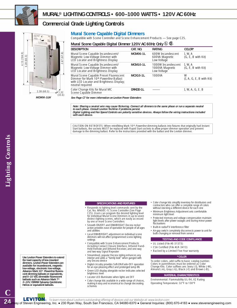
Ligh
ting
Con
trol
s
C24
MURAL® LIGHTING CONTROLS • 600–1000 WATTS • 120V AC 60Hz
Commercial Grade Lighting Controls
To learn more about Leviton’s outstanding offering of devices visit our Website at: www.leviton.com
SPECIFICATIONS AND FEATURES
• Responds to lighting level commands sent by theCat. No. MN00C-1L Scene Controller (See PageC25). Users can program the desired lighting level for individual Mural Scene Dimmers in up to sevendistinct lighting scenes, which are easily accessedby one or more Scene Controllers
• Smooth ON/OFF and DIM/BRIGHT Decora rockeraction provides ease of operation for people of all agesand abilities
• Local DIM/BRIGHT adjustment on individual scenedimmers will not affect programmed scene lighting settings
• Compatible with Scene Enhancement Productsincluding Contact Closure Interface, Infrared Hand-Held Remote and Infrared Receiver, and one-way and two-way Signal Repeater
• Streamlined, popular Decora styling enhances any interior and adds a “family look” when ganged with any Decora device
• Digital circuitry provides Soft-ON/Fade-OFF operationfor an eye-pleasing effect and prolonged lamp life
• Green LED display alongside rocker indicates selectedbrightness level
• Locator LED illuminates when lights are OFF• Color change kits available in a wide range of choices,
making it easy and economical to change decoratingschemes
• Color change kits simplify inventory for distributors andcontractors who can offer a complete range of colorswithout stocking a different device for each one
• Minimum Brightness Adjustment sets comfortable minimum light level
• Protected memory and voltage compensation maintainlight levels after power outages and during minor powerfluctuations
• Built-in radio/TV interference filter• Air-gap switch completely disconnects power to unit for
bulb changing or removal from service
TESTING AND CODE COMPLIANCE
• UL Listed (File #E-31373)• CSA Certified (File #LR-3413)• Backed by a Limited Five-Year warranty
*COLOR
To order colors, add suffix to basic catalog number.Colors in parentheses must be ordered as ColorChange Kits. Color suffixes are: Ivory (-I), White (-W),Almond (-A), Gray (-G), Black (-E) and Brown (-B).
MATERIAL CHARACTERISTICS
Environmental: Flammability UL-94, V2 RatingOperating Temperature: 32°F to 130°F
Mural Scene Capable Digital DimmersCompatible with Scene Controller and Scene Enhancement Products — See page C25.
Mural Scene Capable Digital Dimmer 120V AC 60Hz Only URDESCRIPTION CAT. NO. RATING COLOR*Mural Scene Capable Incandescent/ MCM06-1L 600W Incandescent I, W, AMagnetic Low-Voltage Dimmer with 600VA Magnetic (G, E, B with Kit)LED Locator and Brightness Display Low VoltageMural Scene Capable Incandescent/ MCM10-1L 1000W Incandescent I, W, AMagnetic Low-Voltage Dimmer with 1000VA Magnetic (G, E, B with Kit)LED Locator and Brightness Display Low VoltageMural Scene Capable Preset Fluorescent MCX10-1L 1000VA WDimmer for Mark 10® Powerline Ballast (I, A, G, E, B with Kit)with LED Locator and Brightness Display;neutral requiredColor Change Kits for Mural MC DRKDD-1L — I, W, A, G, E. BScene Capable Dimmer
See Page C7 for more information on Leviton Power Extenders
Note: Sharing a neutral wire may cause flickering. Connect all dimmers to the same phase or run a separate neutral to each phase. Consult Leviton Techline if problems persist.Digital Lighting and Fan Speed Controls are polarity sensitive devices. Always follow the wiring instructions included with each device.
CAUTION ON RETROFITS: When retrofitting Mark 10® Powerline dimming ballasts into fixtures that originally had InstantStart ballasts, the sockets MUST be replaced with Rapid Start sockets to allow proper dimmer operation and prevent damage to the dimming ballast. Refer to the instructions provided with the ballast and the Leviton dimmer.
Use Leviton Power Extenders to extendthe load capacity of box-mounted dimmers. Leviton Power Extenders areavailable for incandescent, magneticlow-voltage, electronic low-voltage,Advance Mark 10® Powerline fluores-cent dimming ballasts or equivalents,and 0–10 VDC dimmable fluorescentballasts such as Advance Mark 7®
0–10V, OSRAM Sylvania QuicktronicHelios or equivalent ballasts.
4.13
(10
4.9)
2.67
(67
.8)
2.38 (60.5) 1.32(33.6)
3.28
(83
.3)
MCM06-1LW
Courtesy of Steven Engineering, Inc. ● 230 Ryan Way, South San Francisco, CA 94080-6370 ● General Inquiries: (800) 670-4183 ● www.stevenengineering.com

Lighting Controls
C25For answers to technical questions, call Leviton’s Techline at 1-800-824-3005
MURAL® SCENE CONTROLS • NO LOAD RATING
Commercial Grade Lighting Controls
Mural Scene Controller and AccessoriesScene Controller for Mural Scene Capable Lighting Controls URDESCRIPTION CAT. NO. RATING COLOR*Mural Scene Controller: MN00C-1L No load rating, White, for 7 Lighting-Scene Buttons plus use with 120V other colors OFF and Group DIM/BRIGHT Buttons Mural Scene use Color
Dimmers only Change KitsColor Change Kits with Text for Mural DCKS7-00 — I, W, A, G, E MN00C-1L Scene ControllerColor Change Kit with Customizable Labels DCKS7-0C — I, W, A, G, E for Mural Scene Controller
Scene Enhancement Products—Compatible with Mural Scene Capable Lighting Controls URDESCRIPTION CAT. NO. RATING COLOR*Signal Repeater—Must be used if 17100-1WY, No load rating —controlling lighting on more 17100-2WY 120V ACthan one circuit. One-Way and Two-Way versions availableContact Closure Interface—Allows control 177BI No load rating (Non-color item) of Mural Scene Capable devices from 120V AChome theater and building control systems via momentary contact inputsInfrared Receiver available with 177IR-IWA No load rating Supplied with Wall Mount and Ceiling Fan Bezels 120V AC Ivory, White and
Almond bezelsHand-Held Infrared Remote Control: 177RC No load rating Ewith 4 Scene Buttons plus OFF 120V AC
Note: A Repeater must be used on any installation that uses more than one circuit.
SPECIFICATIONS AND FEATURES
Scene Controller• Sends commands for up to seven distinct scenes to
individual Mural Scene Capable Dimmers• Multiple Scene Controllers can be used for multi-
point access to scenes.• Provides OFF button and two arrow-shaped buttons
for group Dim and Bright control• Local DIM/BRIGHT adjustment on individual scene
dimmers will not affect programmed scene settings • Green LED display for each scene button indicates
selected scene• Fast, easy scene programming: Press scene button
on MN00C, adjust individual level on Mural SceneCapable dimmer, press program button on dimmer
• Controls up to 20 scene dimmers per circuit• Streamlined, popular Decora styling enhances any
interior and adds a “family look” when ganged withany Decora device
• Use Decora Plus or any standard Decora wallplate• Color change kits are available in a wide range of
colors making it easy and economical to changedecorating schemes
• Internal MOV for surge protection
• Customized lettering for each scene button avail-able (maximum of 8 characters and spaces) — seeyour Leviton representative for ordering information
Scene Enhancement Products • Two-Way Repeater provides scene control commu-
nication link between branch circuits. One-WayRepeater allows the creation of separate scene control zones
TESTING AND CODE COMPLIANCE
• UL Listed (File #E-31373 – Cat. Nos. MN00C and177IR; File #E-66800 – Cat. Nos. 17100-1WY and17100-2WY; File #E-600800 – Cat. No. 177BI )
• CSA Certified (File #LR-3413)• Backed by a Limited Five-Year Warranty
*COLOR
Basic Cat. No. denotes White device. For other colors, order Color Change Kits and add suffix as follows: Ivory (-I), White (-W), Almond (-A), Gray (-G)and Black (-E) .
MATERIAL CHARACTERISTICS
Environmental: Flammability UL-94, V2 RatingOperating Temperature: 32°F to 130°F
4.71
(11
9.7)
2.69
(68
.2)
1.75 (44.5) 1.30(33.1)
3.28
(83
.3)
MN00C-1LW
Courtesy of Steven Engineering, Inc. ● 230 Ryan Way, South San Francisco, CA 94080-6370 ● General Inquiries: (800) 670-4183 ● www.stevenengineering.com

Ligh
ting
Con
trol
s
C26
TOUCH LIGHTING CONTROL FEATURES
Commercial Grade Lighting Controls
To learn more about Leviton’s outstanding offering of devices visit our Website at: www.leviton.com
Highly reliable triac
Built-in radio/TVinterference filter
Touch Lighting ControlsThe Leviton Touch series includes two full-range dimming lines that use digital touch pad technology toenable dimming and switching with a touch of a finger: True Touch™ and ToggleTouch™.
Microcontroller with onboardnon-volatile memory
Touch pad forbrightening
Smooth-action toggle arm
Copper heat spreader
Features and Benefits� Preset dimmers incorporate touchpad technology� Digital circuitry provides eye-pleasing Soft-ON/
Fade-OFF that extends lamp life (most models)� Single- and multi-location control available
� Wide range of colors coordinates with any décor� UL and CSA Listed� Backed by a Limited Five-Year Warranty
LEVITON TOUCH DIMMERS FOR FULL-RANGE DIMMING
True Touch™ Dimmer Decora-style digital touchdimmer. Provides fingertipfull-range single-pole andmulti-location dimming.Color change kits available.TTI10-1LX shown
ToggleTouch™ Dimmer Unique design featurestoggle-style ON/OFFswitch with bright anddim digital touch padsalongside toggle and LED locator light.TGI10-1LW shown
Locator LED for easylocation in dark
Touch pad for dimming
ToggleTouch™TGI10-1LW
Courtesy of Steven Engineering, Inc. ● 230 Ryan Way, South San Francisco, CA 94080-6370 ● General Inquiries: (800) 670-4183 ● www.stevenengineering.com

Lighting Controls
C27For answers to technical questions, call Leviton’s Techline at 1-800-824-3005
TRUE TOUCH™ LIGHTING CONTROLS • 600–1000 WATTS • 120V AC 60Hz
Commercial Grade Lighting Controls
True Touch Digital DimmersAll True Touch dimmers provide single-pole (one location) or 3-way (multi-location) control when used with TrueTouch Remote.
True Touch Digital Dimmer 120V AC 60Hz URDESCRIPTION CAT. NO. RATING COLOR*
X=I+W+AZ=I+W+T
True Touch Incandescent Dimmer TTI06-1L 600W X, Z, GS with LED Locator
True Touch Incandescent Dimmer TTI10-1L 1000W X, Z, GSwith LED Locator
True Touch Magnetic Low-Voltage Dimmer TTM10-1L 1000VA (800W) X, Z, GSwith LED Locator
Coordinating Remote Unit to True Touch Dimmers TT00R-1 No load rating X, Z, GSfor 3-way or up to 10 locations, no LED
True Touch Dimmer Color Change Kit TTKIT — I, W, A, T, GY, E, WS,GI, BG
True Touch Remote Dimmer Color Change Kit TTKTR — I, W, A, T, GY, E, WS,GI, BG
See Page C7 for more information on Leviton Power Extenders
Digital Lighting and Fan Speed Controls are polarity sensitive devices. Always follow the wiring instructions included with each device. They can be used in conventional 3-way and 4-way wiring circuits only when the Control is properlyconnected to the load as indicated by the device’s wiring instructions.
Use Leviton Power Extenders to extendthe load capacity of box-mounted dim-mers. Leviton Power Extenders areavailable for incandescent, magneticlow-voltage, electronic low-voltage,Advance Mark 10® Powerline fluores-cent dimming ballasts or equivalents,and 0–10 VDC dimmable fluorescentballasts such as Advance Mark 7®
0–10V, OSRAM Sylvania QuicktronicHelios or equivalent ballasts.
SPECIFICATIONS AND FEATURES
• Provides fingertip ease of use and precise adjustment of lighting levels. Simple one-touch for ON at preset level, or again for OFF. Touch and hold for BRIGHT/DIM lighting control
• Provides single-pole (one-location) and multi-location full range dimming when used with TT00Rremote dimmer
• Attractive Decora styling blends with any interior• Digital circuitry provides Soft-ON/Fade-OFF
switching for an eye-pleasing effect and extendedlamp life
• Compatible with DecoraPLUS screwless and Decora wallplates
• Locator LED is illuminated when lights are OFF (no LED on Remote Unit)
• Color change kits offered in a wide range of colors,making it easy and economical to change decoratingschemes
• Protected memory maintains light levels after short-term power outages and during minor powerfluctuations
• Built-in radio/TV interference filter • Air gap switch completely disconnects power to unit
for bulb changing or removal from service
TESTING AND CODE COMPLIANCE
• UL Listed (File #E-31373• CSA Certified (File #LR-3413)• Backed by a Limited Five-Year Warranty
*COLOR
TTI06, TTI10 and TTM10 products come packagedwith three colors. Products with suffix (-X) includeWhite, Ivory and Almond; products with suffix (-Z)include White, Ivory and Light Almond; products withsuffix (-GS) include White, Gold and Silver. Colorchange kits available in the following colors: White (-W), Ivory (-I), Almond (-A), Light Almond (-T), Gray (-G), Black (-E), White Frame/Silver Touch (-WS), Ivory Frame/Gold Touch (-GI) and Brown Frame/Gold Touch (-BG).
MATERIAL CHARACTERISTICS
Environmental: Flammability UL-94, V2 RatingOperating Temperature: 32°F to 130°F
4.13
(10
4.9)
2.67
(67
.8)
2.38 (60.5) 1.38(35.1)
3.28
(83
.3)
TTI10-1LX
Courtesy of Steven Engineering, Inc. ● 230 Ryan Way, South San Francisco, CA 94080-6370 ● General Inquiries: (800) 670-4183 ● www.stevenengineering.com

Ligh
ting
Con
trol
s
C28
TOGGLETOUCH™ LIGHTING CONTROLS • 600–1000 WATTS • 120V AC 60Hz
Commercial Grade Lighting Controls
To learn more about Leviton’s outstanding offering of devices visit our Website at: www.leviton.com
ToggleTouch Digital DimmersAll ToggleTouch Preset Dimmers provide single-pole (one-location) or 3-way (multi-location) control whenused with a 3-way switch, except where noted.
ToggleTouch Digital Touch Dimmer with LED Locator 120V AC 60Hz URDESCRIPTION CAT. NO. RATING COLOR*ToggleTouch Incandescent Dimmer TGI06-1L 600W W, I, A, T, BToggleTouch Incandescent Dimmer TGI10-1L 1000W W, I, A, T, GToggleTouch Magnetic Low-Voltage Dimmer TGM10-1L 1000VA (800W) W, I, A, T, G
Note: Leviton does not recommend using the ToggleTouch Dimmer with metal wallplates.See Page C7 for more information on Leviton Power Extenders
Digital Lighting and Fan Speed Controls are polarity sensitive devices. Always follow the wiring instructions included with each device. They can be used in conventional 3-way and 4-way wiring circuits only when the Control is properlyconnected to the load as indicated by the device’s wiring instructions.
SPECIFICATIONS AND FEATURES
• Provides a unique combination of toggle-styleON/OFF switching and digital touch pad technology
• Designed for smooth ON/OFF toggle action and fingertip touch dimming control that’s easy to operate
• Provides single-pole (one-location) and 3-way(multi-location) control when used with a 3-way switch
• Touch pads match color of toggle switch• Fits and gangs perfectly with Leviton standard
toggle wallplates and all Leviton toggle switches• Provides preset dimming with Soft-ON feature
(does not provide Fade-OFF)• Locator LED is illuminated when lights are OFF• Protected memory during temporary power failures
ensures that ToggleTouch will retain last settingbefore power interruption
• Built-in radio/TV interference filter
TESTING AND CODE COMPLIANCE
• UL Listed (File #E-31373) • CSA Certified (File #LR-3413)• Backed by a Limited Five-Year Warranty
*COLOR
To order colors, add suffix to catalog number as follows: Ivory (-I), White (-W), Almond (-A), LightAlmond (-T), Gray (-G) and Brown (-B).
MATERIAL CHARACTERISTICS
Environmental: Flammability UL-94, V2 RatingOperating Temperature: 32°F to 130°F
Use Leviton Power Extenders to extendthe load capacity of box-mounted dimmers. Leviton Power Extenders areavailable for incandescent, magneticlow-voltage, electronic low-voltage,Advance Mark 10® Powerline fluores-cent dimming ballasts or equivalents,and 0–10 VDC dimmable fluorescentballasts such as Advance Mark 7®
0–10V, OSRAM Sylvania QuicktronicHelios or equivalent ballasts.
4.13
(10
4.9)
2.70
(68
.6)
1.75 (44.5) 1.44(36.6)
3.28
(83
.3)
TGI06-1LW
Courtesy of Steven Engineering, Inc. ● 230 Ryan Way, South San Francisco, CA 94080-6370 ● General Inquiries: (800) 670-4183 ● www.stevenengineering.com

Lighting Controls
C29For answers to technical questions, call Leviton’s Techline at 1-800-824-3005
TRADITIONAL CONTROL FEATURES
Commercial and Residential Grade Controls
Highly reliable triac
Traditional ControlsLeviton offers a full line of slide, rotary and toggle dimmers and fan speed controls ideally suited totraditional interiors. The line includes IllumaTech™, SureSlide™, and Trimatron® brand devices as well as a number of specialty lighting devices. Leviton traditional controls are offered in a variety of colors.
Capturedslide knobremainson device
Features and Benefits� Features slide, rotary and toggle style dimmers � Most with full-range dimming and built-in radio/TV
interference filter � Single- and multi-location control available
� UL and CSA Listed� Backed by a Limited Five-Year Warranty
TRADITIONAL STYLE SLIDE AND ROTARY LIGHTING CONTROLS
Locator LEDilluminates foreasy locationin dark
Built-in radio/TVinterference filter
Smooth-action slidepotentiometer
Single-pole and 3-way mechanism
SureSlide™ Slide ControlsSmooth-action slide controlfor easy, precise operation.Slim design ideal for multi-gang installations. Presetand slide-to-off versions.6633-PLW shown
Trimatron® Rotary ControlsUltra-compact, full-rangerotary dimmers.6681-W shown
Specialty Lighting ControlsSpecialty dimmers, socketsand switches. Emergencyswitch flashes lights on andoff. Lamp-cord and 4-stepdimmers also available.911-W shown
IPI10-1LZ
IllumaTech™ Slide and Rotary DimmersDecora-style dimmer with full-range slide or rotarydimming for single- or multi-location dimming control. Color change kits available.IPI06-1LZ and RPI06-ILZ shown
Courtesy of Steven Engineering, Inc. ● 230 Ryan Way, South San Francisco, CA 94080-6370 ● General Inquiries: (800) 670-4183 ● www.stevenengineering.com

Ligh
ting
Con
trol
s
C30
ILLUMATECH™ CONTROLS • 600–1000 WATTS • 120 and 277V AC 60Hz
Commercial Grade Controls
To learn more about Leviton’s outstanding offering of devices visit our Website at: www.leviton.com
IllumaTech Preset Slide ControlsAll IllumaTech Preset Dimmers provide single-pole (one-location) or 3-way (multi-location) control whenused with a 3-way switch.
IllumaTech Slide Contols—Single Pole and 3-Way URDESCRIPTION CAT. NO. RATING COLOR*
X=I+W+AZ=I+W+T
IllumaTech Incandescent Dimmer IPI06-1L 600W X, Z with LED Locator 120V AC 60HzIllumaTech Incandescent Dimmer IPI10-1L 1000W X, Z with LED Locator 120V AC 60HzIllumaTech Electronic Low-Voltage Dimmer IPE04-1L 400VA (320W) X, Z with LED Locator; neutral required 120V AC 60Hz IllumaTech Magnetic Low-Voltage Dimmer IPM06-1L 600VA (450W) X, Z with LED Locator 120V AC 60Hz IllumaTech Magnetic Low-Voltage Dimmer IPM10-1L 1000VA (800W) X, Z with LED Locator 120V AC 60Hz IllumaTech Fluorescent Dimmer for Advance Mark 7® IP710-DL 1200VA @ X, Z 0-10V Ballast with LED Locator; neutral required 120V AC 60Hz,
1500VA @ 277V AC 60Hz
IllumaTech Fluorescent Dimmer for Advance Mark 10® IPX06-10 600VA X, Z Powerline Ballasts, no LED; neutral required 120V AC 60Hz IllumaTech Fluorescent Dimmer for Advance Mark 10® IPX10-10 1000VA X, Z Powerline Ballasts, no LED; neutral required 120V AC 60Hz IllumaTech Fluorescent Dimmer for Advance Mark 10® IPX06-70 600VA X, Z Powerline Ballasts, no LED; neutral required 277V AC 60HzIllumaTech Fluorescent Dimmer for Advance Mark 10® IPX12-70 1200VA X, Z Powerline Ballasts, no LED; neutral required 277V AC 60HzIllumaTech Quiet Fan Speed Control IPF01-1L 1.5 Amps X, Z with LED Locator; neutral required 120V AC 60Hz IllumaTech Fully variable Fan Speed Control IPF05-1L 5 Amps X, Z with LED Locator; neutral required 120V AC 60HzIllumaTech Color Change Kit IPKIT-00 — I, W, A, T, with LED Locator G, E, R, BIllumaTech Color Change Kit, no LED IPKIT-0N — I, W, A, T
G, E, R, BIllumaTech Color Change Kit IPQFK-00 — I, W, A, T, for Fan Speed Control G, E, R, BSee Page C7 for more information on Leviton Power Extenders
4.15
(10
5.4)
2.68
(68
.1)
1.75 (44.5)
2.12 (53.8)
1.41(35.8)
3.28
(83
.3)
IPI10-1LZ
Note: Sharing a neutral wire may cause flickering. Connect all dimmers to the same phase or run a separate neutral toeach phase. Consult Leviton Techline if problems persist.
CAUTION ON RETROFITS: When retrofitting Mark 10® Powerline dimming ballasts into fixtures that originally had InstantStart ballasts, the sockets MUST be replaced with Rapid Start sockets to allow proper dimmer operation and prevent dam-age to the dimming ballast. Refer to the instructions provided with the ballast and the Leviton dimmer.
Use Leviton Power Extenders to extendthe load capacity of box-mounted dim-mers. Leviton Power Extenders areavailable for incandescent, magneticlow-voltage, electronic low-voltage,Advance Mark 10® Powerline fluores-cent dimming ballasts or equivalents,and 0–10 VDC dimmable fluorescentballasts such as Advance Mark 7®
0–10V, OSRAM Sylvania QuicktronicHelios or equivalent ballasts.
SPECIFICATIONS AND FEATURES
• Fluid slide movement allows fine adjustment of lightlevel with minimum effort
• Captured, wrap-around slide bar stays in place andcannot fall off during use
• Easy-to-use pushbutton switch with convenientlypositioned locator LED. Makes the pushbutton easier to find in the dark
• Provide single-pole (one-location) and multi-locationlighting control when used with a 3-way switch
• IllumaTech Six-Pack: Three color choices, along withsingle- or multi-location control provide six differentoptions in each box, eliminating the need to stock alarge variety of devices
• Attractive Decora styling blends with any interior• Compatible with Decora screwless and Decora
standard designer wallplates• Power failure recovery ensures retention of last
setting before power interruption• Built-in radio/TV interference filter• Quiet 1.5 Amp Fan Speed Controls are ideal for
libraries, study rooms and any area where ceilingfan noise could become distracting. Full range 5-amp fan speed controls also available
• Color change kits feature a self-aligning mechanismthat automatically connects it to internal slider
• Snap-On Color Change Kits allow color changes onany device, eliminating the need to stock a separatedevice for every available color
TESTING AND CODE COMPLIANCE
• UL Listed (File #E-31373) • CSA Certified (File #LR-3413)• Backed by a Limited Five-Year Warranty
*COLOR
IllumaTech Preset Controls come packaged withthree colors. Controls with suffix (-X) include Ivory,White and Almond; controls with suffix (-Z) includeIvory, White and Light Almond. Color Change Kitsavailable in the following colors: Ivory (-I), White (-W),Almond (-A), Light Almond (-T), Gray (-G), Black (-E),Brown (-B) and Red (-R).
MATERIAL CHARACTERISTICS
Environmental: Flammability UL-94, V2 RatingOperating Temperature: 32°F to 130°F
Courtesy of Steven Engineering, Inc. ● 230 Ryan Way, South San Francisco, CA 94080-6370 ● General Inquiries: (800) 670-4183 ● www.stevenengineering.com

Lighting Controls
C31For answers to technical questions, call Leviton’s Techline at 1-800-824-3005
ILLUMATECH™ CONTROLS • 600 WATTS • 120V AC 60Hz
Residential Grade Controls
Use Leviton Power Extenders to extendthe load capacity of box-mounted dim-mers. Leviton Power Extenders areavailable for incandescent, magneticlow-voltage, electronic low-voltage,Advance Mark 10® Powerline fluores-cent dimming ballasts or equivalents,and 0–10 VDC dimmable fluorescentballasts such as Advance Mark 7®
0–10V, OSRAM Sylvania QuicktronicHelios or equivalent ballasts.
SPECIFICATIONS AND FEATURES
• Combines traditional rotary dial with contemporaryDecora styling
• Dimmers provide single-pole (one-location) and 3-way (multi-location) control when used with a 3-way switch
• IllumaTech Six-Pack: Three color choices, alongwith single- or 3-way control provide six differentoptions in each box, eliminating the need to stock a large variety of devices
• Dimmers available in illuminated and non-illuminated versions
• Quiet 1.5 Amp Fan Speed Controls are perfect forlibraries, study rooms and any area where ceilingfan noise could become distracting
• Dual fan speed control and dimmer is ideal for ceiling fans with built-in light fixtures
• Attractive Decora styling coordinates perfectly withLeviton’s complete line of Decora wiring devices
• Compatible with Decora Plus screwless and Decorastandard designer wallplates
• Built-in radio/TV interference filter• Slim, compact housing fits easily into a standard
wallbox and is suitable for multi-gang installations
TESTING AND CODE COMPLIANCE
• UL Listed (File #E-31373) • CSA Certified (File #LR-3413)• Backed by a Limited Five-Year Warranty
*COLOR
IllumaTech Rotary Controls come packaged withthree colors. Controls with suffix (-X) include White,Ivory and Almond; controls with suffix (-Z) includeIvory, White and Light Almond.
MATERIAL CHARACTERISTICS
Environmental: Flammability UL-94, V2 RatingOperating Temperature: 32°F to 130°F
IllumaTech Rotary ControlsAll IllumaTech Rotary Controls combine the ease of a traditional rotary dial with the contemporary look ofLeviton Decora®.
IllumaTech Rotary Controls 120V AC 60Hz URDESCRIPTION CAT. NO. RATING COLOR*
X=I+W+AZ=I+W+T
IllumaTech Rotary Incandescent Dimmer, RPI06-1L 600W X, Z Single-Pole or 3-way, with LED Locator IllumaTech Rotary Incandescent Dimmer, RPI06-10 600W X, Z Single-Pole or 3-way, no LED IllumaTech Rotary Quiet Fan Speed Control, RTF01-1L 1.5A X, Z Single-Pole, no LED IllumaTech Rotary Quiet Fan Speed Control RTD01-10 1.5A X, Zand Dimmer, Single-Pole, no LED Fan Control/
300W Dimmer
See Page C7 for more information on Leviton Power Extenders
4.12
(10
4.6)
2.67
(67
.8)
1.73 (44.0) 1.30(33.1)
3.28
(83
.30)
RTD01-10X
4.12
(10
4.6)
2.23
(56
.6)
1.73 (44.0) 1.30(33.1)
3.28
(83
.3)
RPI06-1LX
Courtesy of Steven Engineering, Inc. ● 230 Ryan Way, South San Francisco, CA 94080-6370 ● General Inquiries: (800) 670-4183 ● www.stevenengineering.com

Ligh
ting
Con
trol
s
C32
SURESLIDE™ CONTROLS • 600 WATTS • 120V AC 60Hz
Residential Grade Controls
To learn more about Leviton’s outstanding offering of devices visit our Website at: www.leviton.com
Use Leviton Power Extenders to extendthe load capacity of box-mounted dim-mers. Leviton Power Extenders areavailable for incandescent, magneticlow-voltage, electronic low-voltage,Advance Mark 10® Powerline fluores-cent dimming ballasts or equivalents,and 0–10 VDC dimmable fluorescentballasts such as Advance Mark 7®
0–10V, OSRAM Sylvania QuicktronicHelios or equivalent ballasts.
SPECIFICATIONS AND FEATURES
• All SureSlide devices have a permanently mountedsmooth-action integrated linear slide control for easy,precise operation
• SureSlide features a slim, compact housing that fitseasily into a standard wallbox and is suitable for multi-gang installations
• Preset versions provide single-pole (one-location) and3-way (multi-location) lighting control when used witha 3-way switch
• Illuminated versions feature optional-use Locator LED• SureSlide’s attractive Decora styling coordinates
perfectly with Leviton’s complete line of Decora wiring devices
• Compatible with Decora screwless and Decora standard designer wallplates
• Built-in radio/TV interference filter• Quiet 1.5 Amp Fan Speed Controls are ideal for
libraries, study rooms and any area where ceiling fannoise could become distracting. Full range 5-amp fanspeed controls also available
• SureSlide Cat. No. 6668 is specially designed towork with the Philips Dimmable Marathon™
TESTING AND CODE COMPLIANCE
• UL Listed (File #E-31373) • CSA Certified (File #LR-3413)• Limited Five-Year Warranty
*COLOR
To order colors, add suffix to catalog number as follows: Ivory (-I), White (-W), Almond (-A), LightAlmond (-T), Gray (-GY) and Black (-E). Basic Cat. No.denotes Brown where Brown is available.
MATERIAL CHARACTERISTICS
Environmental: Flammability UL-94, V2 RatingOperating Temperature: 32°F to 130°F
SureSlide™ Full Range Slide Controls 120V AC 60Hz OnlyIncandescent URDESCRIPTION CAT. NO. RATING COLOR*SureSlide Single-Pole Slide-To-Off Dimmer, with 6631-L 600W I, W, A, Toptional use LEDSureSlide Single-Pole or 3-Way Dimmer 6633-PL 600W I, W, A, Twith Preset On/Off Switch, with optional use LEDSureSlide Incandescent or Magnetic Low-Voltage 6628 300W or 300VA I, W, A Dual Slide-To-Off Dimmer—two Single-Pole Loads per circuit;
600W/600VA Total
Low Voltage URDESCRIPTION CAT. NO. RATING COLOR*SureSlide Magnetic Low-Voltage Dimmer, Single-Pole or 6613-PL 600VA (450W) I, W, A, T 3-Way with Preset On/OFF Switch, with optional use LEDSureSlide Electronic Low-Voltage Dimmer, Single-Pole or 6615-P 300W W, T3-Way with Preset On/OFF Switch
Advance Mark 10® Powerline /Philips Marathon™UR
DESCRIPTION CAT. NO. RATING COLOR*SureSlide Dimmer for Mark 10 PowerLine/ 6668 Mark 10 I, WPhillips Marathon Ballasts, Single-Pole 500W-120V,
Philips Dimmable Marathon– 350W-120V
Full-Range Fan Speed Control URDESCRIPTION CAT. NO. RATING COLOR*SureSlide Single-Pole 6627-1 5A I, W
SureSlide Single-Pole or 3-Way with Preset ON/OFF 6637-P 5A I, W, A
Quiet Step Fan Speed Controls URDESCRIPTION CAT. NO. RATING COLOR*
SureSlide Single-Pole or 3-way Quiet Step with 6629-3 1.5A I, W, A, GYPreset ON/OFFSureSlide Dual Quiet Fan Speed Control and Dimmer 6630 1.5A Fan Control/ I, W, A, T, GY
300W Dimmer
See Page C7 for more information on Leviton Power Extenders
CAUTION ON RETROFITS: When retrofitting Mark 10™ Powerline dimming ballasts into fixtures that originally had InstantStart ballasts, the sockets MUST be replaced with Rapid Start sockets to allow proper dimmer operation and prevent damage to the dimming ballast. Refer to the instructions provided with the ballast and the Leviton dimmer.
4.13
(10
4.9)
2.70
(68
.6)
1.73 (43.9) 1.34(34.0)
3.28
(83
.3)
4.13
(10
4.9)
2.70
(68
.6)
1.73 (43.9) 1.34(34.0)
3.28
(83
.3)
6631-LW
6633-PLW
(Also available in Brown)
(Brown notavailable)
Courtesy of Steven Engineering, Inc. ● 230 Ryan Way, South San Francisco, CA 94080-6370 ● General Inquiries: (800) 670-4183 ● www.stevenengineering.com

3.28
(83
.3)
4.12
(10
4.6)
2.69
(68
.4)
1.73 (44.0) 1.38(35.1)6639-W
3.28
(83
.3)
4.12
(10
4.6)
2.23
(56
.6)
1.73 (44.0) 1.30(33.1)
6681-W
3.28
(83
.3)
4.00
(10
1.6)
2.16
(54
.9)
1.59 (40.4) 0.92(23.4)6602-W
Lighting Controls
C33
TRIMATRON™ CONTROLS • 600 WATTS
Residential Grade Controls
Trimatron™ Deluxe Full Range Rotary ControlsTrimatron Incandescent Rotary Dimmers 600 Watts URDESCRIPTION CAT. NO. RATING COLOR*Trimatron Incandescent Dimmer, push-ON/ 6681 600W-120V AC I, W, Apush-OFF, Single-PoleTrimatron Incandescent Dimmer, push-ON/ 6683 600W-120V AC I, W, Apush-OFF 3-WayTrimatron Incandescent Dimmer, Single-Pole 6602 600W-120V AC I, WTrimatron Incandescent Dimmer Single-Pole 6602-220 600W-220V W(Not UL Listed or CSA Certified) 50Hz Decora Plastic Adapter for Rotary Dimmers — 80400 — I, W, A, Eplastic, standard size; fits over .406" dimmer shaft (Basic Cat. No.
denotes Brown)Dimmer Knobs with metal insert 26115 — I, W, A, T, E(packed 25 per box) (Basic Cat. No.
denotes Brown)
Note: All dimmers have a ground wire.
Trimatron Fan Speed Controls 120V AC 60Hz Only URDESCRIPTION CAT. NO. RATING COLOR*Trimatron Full-Range Fan Speed Control 6616-X 5A-120V AC I, WTrimatron Quiet Fan Speed Control 6639 1.5A-120V AC I, W
See Page C7 for more information on Leviton Power Extenders
Use Leviton Power Extenders to extend the load capacity of box-mounted dimmers. Leviton Power Extenders are availablefor incandescent, magnetic low-voltage, electronic low-voltage, Advance Mark 10® Powerline fluorescent dimming ballasts or equivalents, and 0–10 VDC dimmable fluorescent ballasts such as Advance Mark 7® 0–10V, OSRAM SylvaniaQuicktronic Helios or equivalent ballasts.
SPECIFICATIONS AND FEATURES
• Leviton Trimatron lighting controls are traditionalrotary-style dimmers featuring an ultra-compactdesign that fits in even the tightest single-gangwallboxes and is suitable for multi-gang installations
• Built-in radio/TV interference filter• Quiet 1.5 Amp Trimatron Fan Speed Controls are
ideal for libraries, study rooms and any area whereceiling fan noise could become distracting. Fullrange 5-Amp fan speed controls also available
• Wire leads provided for fast, easy assembly and wiring
TESTING AND CODE COMPLIANCE
• UL Listed (File #E-31373) • CSA Certified (File #LR-3413)• Backed by a Limited Five-Year Warranty
*COLOR
Add suffix to catalog numbers as follows to selectcolors: Ivory (-I), White (-W), Almond (-A), LightAlmond (-T) and Black (-E). Cat. Nos. 80400 and26115 also available in Brown (no suffix).
MATERIAL CHARACTERISTICS
Environmental: Flammability UL-94, V2 RatingOperating Temperature: 32°F to 130°F
3.28
(83
.3)
4.12
(10
4.6)
2.23
(56
.6)
1.73 (44.0) 1.38(35.1)6616-XW
For answers to technical questions, call Leviton’s Techline at 1-800-824-3005Courtesy of Steven Engineering, Inc. ● 230 Ryan Way, South San Francisco, CA 94080-6370 ● General Inquiries: (800) 670-4183 ● www.stevenengineering.com

Ligh
ting
Con
trol
s
C34
INCANDESCENT LIGHTING CONTROLS • 500–600 WATTS • 120V AC 60Hz
Residential Grade Lighting Controls
To learn more about Leviton’s outstanding offering of devices visit our Website at: www.leviton.com
Incandescent Lighting ControlsToggle Dimmers 600 Watts 120V AC 60Hz Only URDESCRIPTION CAT. NO. RATING COLOR*
(Basic Cat. No. Denotes Brown)
Incandescent Dimmer, Single-Pole 6641 600W-120V AC I, W,Incandescent Dimmer for Single-Pole or 3-Way 6643 600W-120V AC I, W Incandescent Dimmer, Single-Pole, Illuminated 6691 600W-120V AC Clear Incandescent Dimmer, Single-Pole or 3-way, Illuminated 6693 600W-120V AC Clear
Decora® 911 Flasher 500 Watts 120V AC 60Hz Only URDESCRIPTION CAT. NO. RATING COLOR*Decora 3-Position Emergency Flasher Rocker Switch, 911 500W-120V AC I, W, AIncandescent only
SPECIFICATIONS AND FEATURES
Toggle Dimmers• Easy-to-install shallow design replaces standard
switch in single wallbox• Built-in radio/TV interference filter • Positive ON/OFF action with smooth, full-range
brightness control911 Switch• 911 replaces standard single-pole switch and
alerts neighbors and helps emergency personnellocate a house quickly
• 911 Switch has standard ON/OFF operation plus aspecial illuminated “FLASH” position that causescontrolled lighting to flash ON and OFF at one second intervals
TESTING AND CODE COMPLIANCE
• UL Listed (File #E-31373)• CSA Certified (File #LR-3413)• Backed by a Limited Five-Year Warranty
*COLOR
Basic Cat. No. denotes Brown where indicated. Addsuffix to catalog number as follows for other colors:Ivory (-I), White (-W), and Almond (-A).
MATERIAL CHARACTERISTICS
Environmental: Flammability UL-94, V2 RatingOperating Temperature: 32°F to 130°F
3.28
(83
.3)
3.99
(10
1.4)
1.75 (44.5) 1.90(48.3)
6641-W
3.28
(83
.3)
4.14
(10
5.0)
2.65
(67
.3)
2.39 (60.7)1.43
(36.4)911-W
Courtesy of Steven Engineering, Inc. ● 230 Ryan Way, South San Francisco, CA 94080-6370 ● General Inquiries: (800) 670-4183 ● www.stevenengineering.com

Lighting Controls
C35For answers to technical questions, call Leviton’s Techline at 1-800-824-3005
INCANDESCENT LIGHTING CONTROLS • 150–500 WATTS • 120V AC 60Hz
Residential Grade Lighting Controls
Specialty Dimmers and SocketsIncandescent Dimmers 120V AC 60Hz Only URDESCRIPTION CAT. NO. RATING COLOR*Decora 4-Level Step Dimmer 6161 500W W, I, AIncandescent onlyHI-LO Feed-through Lamp-Cord Dimmer 1420 200W W
(Basic Cat. No. Denotes Brown)
Full-Range Feed-through Lamp-Cord Dimmer 6250-3 200W I (Individually boxed) (Basic Cat. No. (not UL Listed or CSA Certified) Denotes Brown)Tabletop Dimmer for plug-in lamps TBI03 300W W, E
Dimmer Socket 120V AC 60Hz Only URDESCRIPTION CAT. NO. RATING COLOR*Full-Range Compact Dimmer Socket 6151 150W (Non-color item) (1/8 I.P.S Thread and Set Screw)
SPECIFICATIONS AND FEATURES
Four-Level Step Dimmer• Eliminates guesswork — user selects one of four
preset lighting levels (25%, 50%, 75%, 100%)• Easily installs in place of single-pole switch• LED indicates selected level of brightness• Sleek designer styling; can be ganged with other
Decora devices
Lamp Cord and Socket Dimmers• Compact Dimmer Socket interchangeable with
standard lampholder for dimmer conversion (eliminates need for expensive 3-way bulbs)
• Full-Range Feed-Through Lamp Cord Dimmer provides full-range dimming with positive ON/OFFaction in a completely insulated plastic housing
TESTING AND CODE COMPLIANCE
• UL Listed (File #E-3810) – 6151; (File #E-7458) –1420; (File #E-7442) – 6250-3
• CSA Certified (File #LR-1863) – 6151; (File #LR-3413) – 1420
• Backed by a Limited Five-Year Warranty
*COLOR
Basic Cat. No. denotes Brown where indicated. Addsuffix to catalog number as follows for other colors:Ivory (-I), White (-W).
MATERIAL CHARACTERISTICS
Environmental: Flammability UL-94, V2 RatingOperating Temperature: 32°F to 130°F
3.28
(83
.3)
4.13
(10
5.0)
2.65
(67
.3)
1.73 (43.4) 1.53(38.9)
1.25 (31.7)
1.50 (38.1)
2.66
(67
.5)
6161-W
6151
Courtesy of Steven Engineering, Inc. ● 230 Ryan Way, South San Francisco, CA 94080-6370 ● General Inquiries: (800) 670-4183 ● www.stevenengineering.com

C36
HOW TO USE THIS CATALOG
The L-101 Leviton Wiring Device Catalog is designed to help you find the device you’re seeking in the quickest and easiest way possible. Most product sections are divided into three distinct categories in the following sequence—Industrial Grade, CommercialGrade and Residential Grade—and grouped according to amperage and voltage, lowest to highest. For example, if you need toorder 15 Amp, 125 Volt Industrial Grade straight-blade duplex receptacles, begin your search with the main Table of Contents at thefront of the book. Here you’ll see that all straight blade receptacles are listed in Section G. Turn to Section G for a more detailed Tableof Contents on the first page. Each section page contains product descriptions, ratings and catalog numbers. There are also helpfulhighlights including Specifications and Features, Testing and Code Compliance, Color listing, Material Characteristics and dimen-sioned color product photos. Any product page in the L-101 Catalog can be clearly copied or faxed to customers and prospects foruse as a specifier sheet or as part of a presentation.
The Quick Reference Guide follows the main Table of Contents to help you pinpoint and locate specific products. TechnicalSection V provides general product and test data, industry standards, NEMA configuration charts, a glossary of wiring deviceterms, ANSI architectural symbols and other related information. Specific catalog numbers are listed in the exhaustive index atthe back of the catalog.
RATING
Choose GRADE, if appropriate
DIMENSIONED PHOTOGRAPH
WIRING/CERTIFICATIONS
CATALOG NUMBER
DESCRIPTION
Check for NEMA CONFIGURATION
WALLPLATE REFERENCE, if appropriate
SPECIFICATIONS & FEATURES
TESTING AND CODE COMPLIANCE
COLOR LISTING
MATERIAL CHARACTERISTICSL
K
J
I
H
G
F
E
D
C
B
A
I
D
E
H
B
J
G
K
F
L
C
A
Courtesy of Steven Engineering, Inc. ● 230 Ryan Way, South San Francisco, CA 94080-6370 ● General Inquiries: (800) 670-4183 ● www.stevenengineering.com

Energy M
anagement P
roducts IndexSECTIOND
Energy ManagementProductsINDEXOccupancy Sensor LightIng ControlsOverview . . . . . . . . . . . . . . . . . . . . . . . . . . . . . . . . . . .D2Decora Wall Switch Infrared Occupancy Sensors . .D3-D6Decora Dual-Relay Wall Switch Infrared Occupancy Sensors . . . . . . . . . . . . . . . . . . . . . . . . . . .D4Decora Wall Switch Multi-Tech Occupancy Sensor . . .D4Manual-ON Wall Switch Occupancy Sensor . . . . . . . .D6Self-Contained Fixture Mount Occupancy Sensor . . . .D7Power Base Adaptor . . . . . . . . . . . . . . . . . . . . . . . . . .D8Self-Contained Infrared Ceiling Mount Occupancy Sensor . . . . . . . . . . . . . . . . . . . . . . . . . . .D9Multi-Tech Ceiling Mount Occupancy Sensor . . . . . .D10Ultrasonic Ceiling Mount Occupancy Sensor . . . . . . .D11Infrared Ceiling Mount Occupancy Sensor . . . . . . . .D12Multi-Tech Wall Mount Occupancy Sensor . . . . . . . .D13Infrared Wide-View Wall Mount Occupancy Sensor . .D14Infrared High-Bay Wall Mount Occupancy Sensor . . .D14Infrared Long-Range Wall Mount Occupancy Sensor . .D14Power Packs for Occupancy Sensors . . . . . . . . . . . .D15Infrared Outdoor Motion Sensors . . . . . . . . . . . . . . . .D16Centura SystemCentura® Fluorescent EnergyManagement System . . . . . . . . . . . . . . . . . . . .D17, D18Timed Lighting ControlsDecoraPlus Electronic Timer Switches . . . . . . . . . . . .D19Decora Programmable Electronic Timer Switches . . .D20Variable Countdown Timer Switch . . . . . . . . . . . . . . .D20Z-MAX Relay Lighting Control Systems . . . . . . . .D21-D27Z-MAX Relay Cabinets . . . . . . . . . . . . . . . . . . . .D22, D23RRP-Remote 4-Relay Panel . . . . . . . . . . . . . . . . . . .D24EZ-MAX Relay Cabinets . . . . . . . . . . . . . . . . . . . . . . .D25Z-MAX Digital and Low Voltage Switch Stations . . . . .D26miniZ™ Intelligent Daylight Management System . . .D27
Courtesy of Steven Engineering, Inc. ● 230 Ryan Way, South San Francisco, CA 94080-6370 ● General Inquiries: (800) 670-4183 ● www.stevenengineering.com

Ene
rgy
Man
agem
ent
Pro
duct
s
D2
OCCUPANCY SENSOR LIGHTING CONTROL FEATURES
Commercial and Residential Grade Energy Management Products
To learn more about Leviton’s outstanding offering of devices visit our Website at: www.leviton.com
Occupancy Sensor Lighting ControlsLeviton offers a variety of space-monitoring Occupancy Sensor Lighting Controls for virtually any room, facility, homeor office. Wall or ceiling mount, with passive infrared, ultrasonic or multi-technology sensing; end-users will benefitfrom the energy savings, convenience and security provided by Leviton Occupancy Sensors.
LEVITON OFFERS A RANGE OF PRODUCTS THAT REDUCE ENERGY COSTS WHILE INCREASING COMFORT AND SECURITY. The modular Centura® Fluorescent Energy Management system offers "daylight harvesting" in commercial buildingsthrough the use of photo sensors, occupancy sensors, dimmers and a PC-based lighting control interface. OccupancySensors provide convenient, hands-free lights-ON/lights-OFF switching either independently or as part of the Centurasystem. Leviton's residential and commercial grade Electronic Timers reduce energy bills and can provide a "lived-inlook" for added home security. Z-MAX™ timed relay lighting control panels combine time clock and switching contactorfunctions with innovative technology for advanced scheduling of lighting and other loads in commercial, educationaland outdoor areas.
Ground clip toensure solidconnection
Wall-Switch Occupancy Sensor Push button formanual ON/OFF
Fresnel lens foroptimal field of view
Adjustable blindersblock peripheral signals
PIR sensors detectIR signal
Photocell detects light toenable energy-savingambient light override
Time, rangeand lightadjustments
Features and Benefits� Adjustable delayed-OFF and/or self-
adjusting delayed-OFF interval compen-sates for occupancy patterns—preventing unnecessary ON/OFF switching
� Many with self-adjusting settings that con-tinuously analyze and adjust for optimumperformance
� Advanced passive infrared (PIR) technologyfor monitoring obstruction-free areas
� Advanced ultrasonic sensing technology forhighly accurate small-motion monitoring
� For use with incandescent or fluorescentlighting
� Backed by a Limited Five-Year Warranty
OCCUPANCY SENSOR LIGHTING CONTROLS FOR COMMERCIAL AND RESIDENTIAL APPLICATIONS
Decora® Wall-SwitchInfrared OccupancySensorFeatures automatic“walk-through” sensingand self-adjustingdelayed-OFF. Dual relayversions available.ODS15-IDW shown
Wall-Mount Occupancy SensorAvailable with multi-technology sensing or IRwide-view, high-bay andlong-range versions. Fits in corner.OSW12-M0W shown
Infrared Outdoor Motion SensorAdjustable delayed-OFF plus sensitivity toreduce false triggers.For commercial and residential applications.PS200 shown
Self-Contained Infrared Ceiling-Mount Occupancy Sensor Features built-in relayand 360º coverage. For small spaces. ODC0S-I1W shown
Multi-tech Ceiling-MountOccupancy Sensor IR and ultrasonic combine for accuratemonitoring while mini-mizing false triggers. For larger, open areas.Self adjusting.OSC20-M0W shown
Ultrasonic Ceiling-MountOccupancy Sensor Highly accurate small-motion detection. Self-adjusting sensitivity and time off.OSC05-U0W shown
LED indicator flashes whensensor detects motion
Courtesy of Steven Engineering, Inc. ● 230 Ryan Way, South San Francisco, CA 94080-6370 ● General Inquiries: (800) 670-4183 ● www.stevenengineering.com

Energy M
anagement P
roducts
D3For answers to technical questions, call Leviton’s Techline at 1-800-824-3005
DECORA® OCCUPANCY SENSOR LIGHTING CONTROLS • WALL SWITCH
Commercial and Residential Grade Energy Management Products
SPECIFICATIONS AND FEATURES
All ODS Wall Switch Sensors• Ambient light override prevents these devices from
switching lights ON when there is ample natural sunlight• Push-button manual override is used to turn lights ON
at any time, regardless of the override setting• 180° field of view, 2100 sq. ft. of coverage• One unit can be used for 120V or 277VAC 60Hz incan-
descent, low voltage and fluorescent lighting with eithermagnetic or electronic ballasts, and motor loads
• Fits in standard wallbox; gangable• Elegant Decora styling; uses Decora wallplateODS15-ID PIR Occupancy Sensor• For use in small offices, conference rooms, classrooms,
stockrooms, lounges, restrooms, warehouses and com-mercial areas
• Exclusive automatic “Walk-Through” sensing increasesenergy savings by shutting lights within 21⁄2 minutesafter momentary occupancy
• Delayed-OFF time interval (5, 10 and 20 minutes) compensates for real-time occupancy patterns, prevent-ing unnecessary ON/OFF switching—with 30-secondtest mode
ODS10-ID PIR Occupancy Sensor• For use in enclosed offices, storage rooms, copier
rooms and closets• Delayed-OFF time settings: 10, 20 and 30 minutes with
30-second test modeAll Night Light Wall Switch Sensors• For use in conference rooms, classrooms, small
offices, lounges, hotel/hospital/office restrooms• 180˚ field of view, 1200 sq. ft. of coverage• Night light with dim featureOSSNL-ID PIR Occupancy Sensor• Manual delayed-OFF time settings: 30 seconds,
30 minutes, 1 hour, 2 hours OSS10-ID PIR Occupancy Sensor• Manual delayed-OFF time settings: 30 seconds to
30 minutes
• Manual ON/Auto OFF operation for CEC Title 24Compliance
TESTING AND CODE COMPLIANCE
• UL Listed (File #E-118904)• CSA Certified (File #LR-91148M)• NOM Certified (#057)• Conforms to California Title 24 Energy Code• Backed by a Limited Five-Year Warranty
*COLOR
Colors available as listed, add suffix to catalog number as follows: Ivory (-I), White (-W), Almond (-A), Light Almond (-T), Gray (-G).
MATERIAL CHARACTERISTICS
Operating Temperature: 0°C to 50°CStorage Temperature: -10°C to 85°CRelative Humidity: 20% to 90% non-condensing
Wall Switch Occupancy Sensor Lighting ControlsDecora Wall Switch Infrared Occupancy Sensor (Incandescent or Fluorescent) URDESCRIPTION CAT. NO. RATING COLOR*Decora Wall Switch ODS10-ID Incandescent: 800W @ 120V, I, W, A, T, GPIR Occupancy Sensor, Fluorescent: 1200VA @ 120V, 180˚ field of view, 2100 sq. ft 2700VA @ 277V.
For 60 Hz AC only.Motor: 1/4 HP @ 120V
Decora Wall Switch ODS15-ID Incandescent: 1800W @ 120V. I, W, A, T, GPIR Occupancy Sensor Fluorescent: 1800VA @ 120V,with Self-Adaptive Technology, 4000VA @ 277V.180˚ field of view, 2100 sq. ft Motor: 1/4 HP @ 120V Decora Wall Switch PIR OSSNL-ID Incandescent: 800W @ 120V I, W, A, T, GOccupancy Sensor with LED Fluorescent: 1200VA @ 120VNight Light, 180˚ field of view, 2700VA @ 277V1200 sq. ft (neutral required) Motor: 1/8HP @ 120VCEC Title 24 Compliant Decora OSS10-ID Incandescent: 800W @ 120V I, W, A, T, GWall Switch PIR Manual-ON Fluorescent: 1200VA @ 120V Sensor with LED Night Light, 2700VA @ 277V 180˚ field of view, 1200 sq. ft (neutral required) Motor: 1/8HP @ 120V
3.28
(83
.3)
4.06
(10
3.2)
2.60
(66
.1)
1.75 (44.4) 1.35(34.3)
ODS15-IDW
4.11(104.4)
2.66(67.5)
1.75(44.5)
1.35(33.6)
OSSNL-IDW/OSS10-IDW
ODSXX-ID/OSSXX-ID Field of View (in feet)
TOP VIEW
SIDE VIEW
15 400
0
15
15
30
30
40
40
4
Minor Motion, IR
Major Motion, IR
5
0
Courtesy of Steven Engineering, Inc. ● 230 Ryan Way, South San Francisco, CA 94080-6370 ● General Inquiries: (800) 670-4183 ● www.stevenengineering.com

Ene
rgy
Man
agem
ent
Pro
duct
s
D4
DECORA® OCCUPANCY SENSOR LIGHTING CONTROLS • WALL SWITCH
Commercial Grade Energy Management Products
To learn more about Leviton’s outstanding offering of devices visit our Website at: www.leviton.com
4.11(104.4)
2.66(67.5)
1.75(44.5)
1.35(33.6)
ODS0D-IDW/ODS0D-TDW
4.11(104.4)
2.66(67.5)
1.75(44.5)
1.35(33.6)
OSSMT-MDMulti-Tech Sensor
Wall Switch Occupancy Sensor Lighting ControlsDual-Relay Decora Wall Switch Infrared Occupancy Sensor URDESCRIPTION CAT. NO. PHOTOCELL RATING COLOR*
CONTROL OPTIONS PER RELAY
Dual-Relay Decora ODS0D-ID Default Setting: Primary Relay: I, W, A, T, GWall Switch PIR Conference Room Mode Fluorescent: 1200VA @ 120V,Occupancy Sensor (Both Primary and Secondary 2700VA @ 277V.with Self-Adaptive Relays respond to Incandescent: 800W @ 120V.Technology, Ambient Light Override.) Secondary Relay: 180˚ field of view, Alternate Setting: Fluorescent: 800VA @ 120V,2100 sq. feet Classroom Mode 1200VA @ 277V.
(Primary Relay only Incandescent: 800W @ 120V responds to Ambient Light Override.)
Dual-Relay Decora ODS0D-TD Primary Relay provides Primary Relay: I, W, A, T, GWall Switch PIR Automatic ON switching Fluorescent: 1200VA @120V, Occupancy Sensor and responds to Ambient 2700VA @ 277V. with Self-Adaptive Light Override. Secondary Incandescent: 800W @ 120V. Technology. Secondary Relay provides Manual-ON Secondary Relay: relay provides Manual- switching only Fluorescent: 800VA @ 120V, ON only for CEC Title 24 1200VA @ 277V. compliance, 180˚ field Incandescent: 800W @ 120Vof view, 2100 sq. ft
Decora Wall Switch Multi-Tech (PIR & US) Occupancy Sensors URDESCRIPTION CAT. NO. RATING COLOR*Decora Wall Switch Multi-Tech OSSMT-MD Incandescent/Tungsten: I, W, A, T, GOccupancy Sensor with 800W @ 120VSelf-Adaptive Technology, Fluorescent: 1200VA @ 120V,180˚ field of view, 1200 sq. ft 2700VA @ 277V
Motor: 1/4HP @ 120V
ODS0D-ID, -TD Field of View (in feet)
TOP VIEW
SIDE VIEW
15 400
0
15
15
30
30
40
40
4
Minor Motion, IR
Major Motion, IR
5
0
SPECIFICATIONS AND FEATURES
Dual-Relay PIR Occupancy Sensors• Ideal for classrooms, multimedia and conference
rooms, day care centers, office, and lounges• Exclusive automatic “Walk-Through” sensing• Provides automatic switching for 2 separate banks of
fluorescent, incandescent, or low-voltage lighting from asingle unit
• Delayed-OFF time interval (5, 10 and 20 minutes) compensates for real-time occupancy patterns, prevent-ing unnecessary ON/OFF switching—with 30-secondtest mode
• ODS0D-TD provides Manual-ON/Auto-OFF operationfor CEC Title 24 compliance
OSSMT-MD Multi-Tech Occupancy Sensor• Ideal in offices, conference rooms, storage areas,
restrooms, classrooms and lounges
• Combines passive infrared and ultrasonic technolo-gies to provide maximum sensitivity with immunity tofalse triggering
• Ambient light override prevents lights from turningON when there is ample natural light
• Exclusive automatic “Walk-Through” sensing• Manual delayed-OFF time settings (30 seconds to
30 minutes)• Manual-ON/Auto-OFF setting for CEC Title 24
compliance
TESTING AND CODE COMPLIANCE
• UL Listed (File #E-118904)• Cat. No. ODS0D-ID is CUL/US Certified• CSA Certified (File #LR-91148M)• NOM Certified (#057)• Conforms to California Title 24 Energy Code• Backed by a Limited Five-Year Warranty
*COLOR
Colors available as listed, add suffix to catalog number as follows: Ivory (-I), White (-W), Almond (-A), Light Almond (-T), Gray (-G).
MATERIAL CHARACTERISTICS
Operating Temperature: 0°C to 50°CStorage Temperature: -10°C to 85°CRelative Humidity: 20% to 90% non-condensing
20 ft (6.1 m)minor motion
30 ft (9.1 m)
20 ft (6.1 m)minor motion
40 ft(12.2 m)
OSSMT-MD Field of View (in feet)
Courtesy of Steven Engineering, Inc. ● 230 Ryan Way, South San Francisco, CA 94080-6370 ● General Inquiries: (800) 670-4183 ● www.stevenengineering.com

Energy M
anagement P
roducts
D5For answers to technical questions, call Leviton’s Techline at 1-800-824-3005
DECORA® OCCUPANCY SENSOR LIGHTING CONTROLS • WALL SWITCH
Residential Grade Energy Management Products
Wall Switch Occupancy Sensor Lighting ControlsDecora Wall Switch Infrared Occupancy Sensor URDESCRIPTION CAT. NO. RATING COLOR*Decora Wall Switch PIR Occupancy Sensor, PR180-1L Incandescent: 500W, I, W, A Single-Pole & 3-Way, 180° field of view, Rapid Start Magnetic 400 sq. ft Fluorescent only:
400VA @ 120V AC, Decora Wall Switch PIR Occupancy Sensor, PR150-1L Incandescent: 500W, I, W, A Single-Pole, 150° field of view, 350 sq. ft Rapid Start Magnetic
Fluorescent only: 400VA @ 120V AC,
SPECIFICATIONS AND FEATURES
• PR180 with 180° field of view, 400 sq. ft. of coverage: For use in large rooms, home offices, and a variety of light commercial and residentialapplications
• PR150 with 150° field of view, 350 sq. ft. of coverage: For use in residential applications
• Ambient light override prevents these devices fromswitching lights ON when there is ample natural sunlight
• Manual override for use as a standard ON/OFFswitch
• Adjustable delayed-OFF time interval (15 seconds to15 minutes)
• Fits in standard wallbox; gangable• Elegant Decora styling; uses Decora wallplate
TESTING AND CODE COMPLIANCE• UL Listed (File #E-118904)• CSA Certified (File #LR-91148M)• Backed by a Limited Two-Year Warranty
*COLOR
Colors available as listed, add suffix to catalog numberas follows: Ivory (-I), White (-W), Almond (-A).
MATERIAL CHARACTERISTICS
Operating Temperature: 0°C to 50°CStorage Temperature: -10°C to 85°CRelative Humidity: 20% to 90% non-condensing
TOP VIEW
SIDE VIEW
10
10
45
0
0200
TOP VIEW
SIDE VIEW
10
10
45
0
0200
PR150-1L Field of View (in feet) PR180-1L Field of View (in feet)
3.28
(83
.3)
4.06
(10
3.2)
2.60
(66
.1)
1.75 (44.4) 1.35(34.3)
PR180-ILW
Courtesy of Steven Engineering, Inc. ● 230 Ryan Way, South San Francisco, CA 94080-6370 ● General Inquiries: (800) 670-4183 ● www.stevenengineering.com

Ene
rgy
Man
agem
ent
Pro
duct
s
D6
DECORA® OCCUPANCY SENSOR LIGHTING CONTROLS • WALL SWITCH
Residential Grade Energy Management Products
To learn more about Leviton’s outstanding offering of devices visit our Website at: www.leviton.com
Manual-ON Wall Switch Occupancy Sensor Lighting ControlsDecora Manual-ON Wall Switch Infrared Occupancy Sensor URDESCRIPTION CAT. NO. RATING COLOR*Decora Manual-ON Wall Switch PIR IPP15-1L Incandescent: 1800W, I, W, A, T, E Occupancy Sensor, CEC Title 24 Fluorescent: 1800VA Compliant, Single-Pole, 3-Way or more at 120V AC, when used with IPP0R Sensor Remote or Motor: 1/2 HP @ 120V AC Vizia Switch Remote, 180˚ field of view, 900 sq. ft (neutral required)Decora Manual-ON Occupancy IPP0R-1L 120V AC–No load rating, I, W, A, TSensor Remote, 180˚ field of For use with IPP15 Sensor view, 900 sq. ft (neutral required) or Vizia DimmersVizia™ Matching Switch VZ0SR-1L 120V AC–No load rating X (I, W & A),Remote, lighted (neutral required) Z (I, W & T)Vizia™ Coordinating Switch VZ0SR-10 120V AC–No load rating X (I, W & A),Remote, unlighted (neutral required) Z (I, W & T)
4.06(103.2)
1.75(44.4)
1.35(34.3)
2.60(66.1)
IPP15-ILW
SPECIFICATIONS AND FEATURES
• Manual-ON/Automatic OFF operation in accordancewith California Title 24 2005 requirements
• 180˚ field-of-view provides approximately 900 sq. ft. ofcoverage suitable for bathrooms, basements, garages,utility rooms, and a variety of other residential areas
• Low-profile design eliminates an obtrusive “scanning-device” look
• Elegant Decora styling complements any interior andcoordinates with Leviton’s popular line of Decorawiring devices and Vizia lighting controls
• IPP15 provides a true 3-Way feature when used withthe IPP0R Manual-ON Occupancy Sensor Remote orthe VZ0SR Vizia Switch Remote
• Convenient push-button provides Manual ON/OFFlight switching at any time
• Segmented Fresnel lens provides optimum sensitivityand performance
• Horizontal field of view may be adjusted between180˚ and 32˚ of arc by using integral blinders locatedon either side of the lens
• Four optional manual adjustments for delayed-OFFtime settings maximize energy savings: 30 seconds(for walk test), 5 minutes, 15 minutes and 30 minutes
• LED indicator light flashes when sensor detectsmotion to verify detection is active
• Fits in standard wallbox• Requires a neutral (white) wire connection
TESTING AND CODE COMPLIANCE
• UL Listed (File #E-118904)• CSA Certified (File #LR-152105)
• Conforms to California Title 24 Energy Code andFCC regulations
• Backed by a Limited Five-Year Warranty
*COLOR
Colors available as listed, add suffix to catalog number as follows: Ivory (-I), White (-W), Almond (-A), Light Almond (-T) and Black (-E). Vizia SwitchRemotes come packaged with three colors. Controlswith suffix (-X) include White, Ivory and Almond.Controls with suffix (-Z) include White, Ivory andLight Almond.
MATERIAL CHARACTERISTICS
Operating Temperature: 0°C to 50°CStorage Temperature: -10°C to 85°CRelative Humidity: 20% to 90% non-condensing
TOP VIEW
SIDE VIEW
15 300
0
15
15
30
30
45
0
IPP15-IL Field of View (in feet)
Courtesy of Steven Engineering, Inc. ● 230 Ryan Way, South San Francisco, CA 94080-6370 ● General Inquiries: (800) 670-4183 ● www.stevenengineering.com

Energy M
anagement P
roducts
D7For answers to technical questions, call Leviton’s Techline at 1-800-824-3005
OCCUPANCY SENSOR LIGHTING CONTROLS • FIXTURE MOUNT
Commercial Grade Energy Management Products
Self-Contained Infrared Fixture-Mount Occupancy SensorDESCRIPTION CAT. NO. RATING MOUNTING HEIGHT COLORSelf-Contained Fixture-Mount OSFHU-ITW Fluorescent: 800VA 360˚ lens: WhiteHigh Bay Occupancy Sensor @ 120V, 40 ft with 60 ft dia.with 360˚ open area lens and 1200VA @ 277V, 30 ft with 50 ft dia.60 x 20 ft. aisle pattern lens 1500VA @ 347V 20 ft with 50 ft dia.
Motor: 1/4HP @ Aisle lens: 120V 40 ft with 60 ft (length)
x 20 ft (width)Offset Adapter Accessory OSF0A-00W –– –– Whitefor High Bay Fixture-Mount Occupancy Sensor
3.50(88.9)
3.50(88.9)
Aisle Lens
1.25(31.8)
OSFHU-ITW
SPECIFICATIONS AND FEATURES
• Ideal in commercial facilities with high ceilings,including warehouses, manufacturing and others
• Mounts directly to industrial-style fluorescent luminaires or electrical junction box
• Provided with an open area 360˚ lens installed in the sensor and an interchangeable 60 x 20 ft. aisle-pattern lens
• Self-contained PIR sensor and relay turn individualfixtures ON/OFF based on occupancy
• Accommodates high-bay 20-40 ft. mounting heights• Relay uses zero-crossing circuitry for enhanced relia-
bility and long-life operation
• Delayed-OFF time adjustment from 30 seconds to 20 minutes
• Two-piece accessory offset adapter (Cat. No. OSFOA-00W) that snaps into a 1⁄2" knockout on the end of anindustrial fixture is also available
• Adapter allows positioning of the sensor below the fixture body to improve field of view for deep body fixtures
TESTING AND CODE COMPLIANCE
• UL and cUL Listed• California Title 24 Compliant• FCC Compliant• Backed by a Limited Five-Year Warranty
OSFHU-ITW Aisle Field of View (in feet)
OSFHU-ITW 360° Field of View (in feet)
360˚ Lens
OSF0A
Courtesy of Steven Engineering, Inc. ● 230 Ryan Way, South San Francisco, CA 94080-6370 ● General Inquiries: (800) 670-4183 ● www.stevenengineering.com

Ene
rgy
Man
agem
ent
Pro
duct
s
D8
OCCUPANCY SENSOR LIGHTING CONTROLS • POWER BASE ADAPTOR
Commercial Grade Energy Management Products
To learn more about Leviton’s outstanding offering of devices visit our Website at: www.leviton.com
SPECIFICATIONS AND FEATURES
• Ideal for use in lavatories, remodels, hard ceilingspaces, energy conservation retrofits and anyinstallation with limited access for low-voltagewiring
• Patent-pending design converts Leviton low-voltageceiling sensors to line voltage
• Ideal for both existing buildings with limited accessto low-voltage wiring and new construction withline-voltage circuiting only
• Mounts easily in a standard 2.125" deep x 4" octa-gon or 2.125" deep x 4" square electrical box witha 2-gang mud ring; flying leads provide fast linevoltage connections
• Two-piece terminal block provides fast, easy low-voltage connections to the sensor
• Relay uses zero-crossing circuitry for enhancedreliability and long-life operation
TESTING AND CODE COMPLIANCE
• UL and cUL Listed• NOM Certified• California Title 24 Compliant• Backed by a Limited Five-Year Warranty
Self-Contained Power Base AdaptorPower Base Adaptor Converts any Leviton low voltage ceiling or wall-mount occupancy sensor to a self-contained, line voltageunit with 15A, 120/277V load capacity
Power Base Adaptor UDESCRIPTION CAT. NO. POWER RATING COLOR
INPUT/OUTPUTPower Base Adaptor OPB15-0DW Power Input: 15A Incandescent, White
120/277VAC Electronic orControl Output: Magnetic24VDC, 40mA Fluorescent Ballast
Ø4.50(114.3)
1.75(44.5)
OPB15-ODW
Hot (Black)120/277V
Neutral (White)
OPB15 Power Base
Any Leviton Low-VoltageCeiling Sensor
Load (Blue)
Load
OPB15-0DW Power Base Adaptor Wiring Diagram
Courtesy of Steven Engineering, Inc. ● 230 Ryan Way, South San Francisco, CA 94080-6370 ● General Inquiries: (800) 670-4183 ● www.stevenengineering.com

Energy M
anagement P
roducts
D9For answers to technical questions, call Leviton’s Techline at 1-800-824-3005
OCCUPANCY SENSOR LIGHTING CONTROLS • CEILING MOUNT
Commercial Grade Energy Management Products
Ceiling-Mount Occupancy Sensor Lighting ControlsPIR Occupancy Sensor with built-in relay—Separate Power Pack not required
Self-Contained Infrared Ceiling-Mount Occupancy Sensor URDESCRIPTION CAT. NO. RATING COVERAGE COLORSelf-Contained Ceiling-Mount ODC0S-I1W Incandescent: 360°, 530 sq. ft WhiteInfrared Occupancy Sensor 1000W @ 120V. and Switching Relay Fluorescent:
1000VA @ 120V. 1 HP @ 120VFor 60Hz AC only
Self-Contained Ceiling-Mount ODC0S-I2W Incandescent: 360°, 530 sq. ft WhiteInfrared Occupancy Sensor 1000W @ 220V. and Switching Relay Fluorescent:
500VA @ 220V. For 50Hz AC only
Self-Contained Ceiling-Mount ODC0S-I7W Fluorescent: 360°, 530 sq. ft WhiteInfrared Occupancy Sensor 2700VA @ 277V. and Switching Relay For 60Hz AC onlyProtective Cage ODCCG — — White
0
13
13
TOP VIEW
SIDE VIEW8
003713 3 7 13
ODC0S-I Field of View (in feet)
Ø4.
30 (
109.
2)
2.15(54.6)
ODC0S-I1W
SPECIFICATIONS AND FEATURES
• Ideal for use in storage areas, small bathrooms,copy rooms and a variety of small spaces withoutwall switches
• Full 360° view of a 530 sq. ft. area when surfacemounted on standard, 8-foot ceiling
• Sensor and switching relay combined in a singleself-contained unit—No control unit required
• Ambient light override option prevents lights fromturning ON when there is ample natural light
• Adjustable Delayed-OFF time settings from 20 seconds (for test mode) to 15 minutes
• Small, unobtrusive self-contained unit: 4.3" (109.2 mm) diameter
TESTING & CODE COMPLIANCE• UL Listed and CSA Certified• California Title 24 compliant and meets ASHRAE
Standard 90.1 requirements• Backed by a Limited Five-Year Warranty
Courtesy of Steven Engineering, Inc. ● 230 Ryan Way, South San Francisco, CA 94080-6370 ● General Inquiries: (800) 670-4183 ● www.stevenengineering.com

Ene
rgy
Man
agem
ent
Pro
duct
s
D10
OCCUPANCY SENSOR LIGHTING CONTROLS • CEILING MOUNT
Commercial Grade Energy Management Products
To learn more about Leviton’s outstanding offering of devices visit our Website at: www.leviton.com
Ceiling-Mount Occupancy Sensor Lighting ControlsMulti-Technology Ceiling-Mount Occupancy Sensor UR (For use with Leviton Power Pack)*Advanced motion sensors combine infrared and ultrasonic technology for highly accurate monitoring with-out false triggering. All-digital self-adjusting technology provides “Install and Forget” solution for automaticlighting control.
DESCRIPTION CAT. NO. COVERAGE OPERATING COLORFREQUENCY
Multi-Tech Ceiling-Mount OSC05-M0W 180°, 500 sq. ft 40kHz WhiteOccupancy SensorMulti-Tech Ceiling-Mount OSC10-M0W 360°, 1000 sq. ft 40kHz WhiteOccupancy Sensor Multi-Tech Ceiling-Mount OSC20-M0W 360°, 2000 sq. ft 32kHz WhiteOccupancy Sensor Protective Cage for Ceiling-Mount ODCCG-000 — — WhiteOccupancy Sensors
*Low-voltage wiring is used to connect Leviton Occupancy Sensors to Cat. No. OSP20 Power Pack or a Centura CN100Power Pack (purchased separately). See page D15 for information on OSP20.
SPECIFICATIONS AND FEATURES
• Ideal for office areas with cubicles, general work space, classrooms, cafeteriasand public areas in commercial facilities
• Ultrasonic sensing for maximum sensitivity combined with Passive Infrared (PIR)sensing to prevent false triggering from air conditioning and corridor activity
• Self-adjusting settings continuously analyze and adjust for optimum performance• Ambient light override prevents lights from turning ON when there is ample
natural light • Manual Delayed-OFF time settings of 30 seconds to 30 minutes• Self-Adjusting Delayed-OFF time interval settings for 30 seconds to 30 minutes
— Compensates for real-time occupancy patterns, preventing unnecessaryON/OFF switching
• Non-volatile memory preserves all automatic and manual settings duringpower outages
• Choice of coverage patterns to suit a variety of applications• Small, unobtrusive size blends in with any décor• Fast, simple installation using 4 color-coded low-voltage wires and a single
mounting post• Compatible with Wiremold® surface raceways for mounting to hard ceilings
TESTING AND CODE COMPLIANCE• CUL/US, FCC and NOM Certified• California Title 24 compliant and meets ASHRAE Standard 90.1 requirements• Backed by a Limited Five-Year Warranty
0
20
11.5
11.5
8.5
8.5
20 TOP VIEW
SIDE VIEW
0 20 231711 155.6 93
8
0
OSC05-M0W Field of View (in feet)
0
20
11.5
11.5
8.5
8.5
20
SIDE VIEW
TOP VIEW
2323 1717
8
0
111115 1520 2099 33 0 5.65.6
OSC10-M0W Field of View
0
20
8
16
16
11.5
11.5
20
SIDE VIEW
TOP VIEW
03 35.5 5.59 911 1115 1520 2032 3222.5 22.5
OSC20-M0W Field of View
Minor Motion, Ultrasonic
Major Motion, Ultrasonic
Major Motion, IR
OSC05-M0W
Ø4.
20 (
106.
7)
1.55(39.4)
OSC20-M0W
1.55(39.4)
Ø4.
20 (
106.
7)
Courtesy of Steven Engineering, Inc. ● 230 Ryan Way, South San Francisco, CA 94080-6370 ● General Inquiries: (800) 670-4183 ● www.stevenengineering.com

Energy M
anagement P
roducts
D11For answers to technical questions, call Leviton’s Techline at 1-800-824-3005
OCCUPANCY SENSOR LIGHTING CONTROLS • CEILING MOUNT
Commercial Grade Energy Management Products
Ceiling-Mount Occupancy Sensor Lighting ControlsUltrasonic Ceiling-Mount Occupancy Sensor UR (For use with Leviton Power Pack)*Advanced Ultrasonic sensing technology for highly accurate monitoring with excellent immunity to air currents and other interference. All-digital self-adjusting technology provides “Install and Forget” solutionfor automatic lighting control.
DESCRIPTION CAT. NO. COVERAGE OPERATING COLORFREQUENCY
Ultrasonic Ceiling-Mount OSC05-U0W 180°, 500 sq. ft 40kHz WhiteOccupancy SensorUltrasonic Ceiling-Mount OSC10-U0W 360°, 1000 sq. ft 40kHz WhiteOccupancy Sensor Ultrasonic Ceiling-Mount OSC20-U0W 360°, 2000 sq. ft 32kHz WhiteOccupancy Sensor Protective Cage for Ceiling-Mount ODCCG-000 — — WhiteOccupancy Sensors
*Low-voltage wiring is used to connect Leviton Occupancy Sensors to Cat. No. OSP20 Power Pack or a Centura CN100Power Pack (purchased separately). See page D15 for information on OSP20.
SPECIFICATIONS AND FEATURES
• Ideal for restrooms, office areas with cubicles, gen-eral work space, warehouse and storage facilities,cafeterias and public areas in commercial facilities
• Ultrasonic sensing for maximum range and sensitivity combined with high immunity to falsetriggering from air currents and other interference
• Self-adjusting settings continuously analyze andadjust for optimum performance
• Ambient light override prevents lights from turningON when there is ample natural light
• Manual Delayed-OFF time settings of 30 seconds to30 minutes
• Self-Adjusting Delayed-OFF time interval settings for30 seconds to 30 minutes — Compensates for real-time occupancy patterns, preventing unnecessaryON/OFF switching
• Non-volatile memory preserves all automatic andmanual settings during power outages
• Choice of coverage patterns to suit a variety ofapplications
• Small, unobtrusive size blends in with any décor• Fast, simple installation using 4 color-coded low-
voltage wires and a single mounting post
TESTING AND CODE COMPLIANCE• CUL/US Certified• Meets ASHRAE Standard 90.1 requirements• Backed by a Limited Five-Year Warranty
0
11.5
11.5
8.5
8.5
231705 10 20
OSC05-U0W Field of View (in feet)
0
16
16
11.5
11.5
032 3222.5 22.5
OSC20-U0W Field of View
0
11.5
11.5
8.5
8.5
2323 17170
OSC10-U0W Field of View
Minor Motion, Ultrasonic
Major Motion, Ultrasonic
Ø4.
20 (
106.
7)
1.34 (34.0)
OSC05-U0W
Courtesy of Steven Engineering, Inc. ● 230 Ryan Way, South San Francisco, CA 94080-6370 ● General Inquiries: (800) 670-4183 ● www.stevenengineering.com

Ene
rgy
Man
agem
ent
Pro
duct
s
D12
OCCUPANCY SENSOR LIGHTING CONTROLS • CEILING MOUNT
Commercial Grade Energy Management Products
To learn more about Leviton’s outstanding offering of devices visit our Website at: www.leviton.com
Ceiling-Mount Occupancy Sensor Lighting ControlsInfrared Ceiling-Mount Occupancy Sensor UR (For use with Leviton Power Pack)*Advanced Passive Infrared technology for highly accurate monitoring in a variety of commercial applica-tions. All-digital self-adjusting technology provides “Install and Forget” solution for automatic lighting control.
DESCRIPTION CAT. NO. COVERAGE COLORInfrared Ceiling-Mount Occupancy Sensor OSC04-I0W 360°, 450 sq. ft WhiteInfrared Ceiling-Mount Occupancy Sensor OSC15-I0W 360°, 1500 sq. ft Whitewith Ambient Light Override and Secondary RelayProtective Cage for Ceiling-Mount ODCCG-000 — WhiteOccupancy Sensors
*Low-voltage wiring is used to connect Leviton Occupancy Sensors to Cat. No. OSP20 Power Pack or a Centura CN100Power Pack (purchased separately). See page D15 for information on OSP20.
Ø4.
20 (
106.
7)
1.55(39.4)
OSC04-I0W
0
12
5
5
12
0
SIDE VIEW
TOP VIEW
77 1212 5 95 339
8
0
0
20
10
10
20
SIDE VIEW
TOP VIEW
201515 11 119 95.65.6 3320
8
0
OSC04-I0W Field of View (in feet) OSC15-I0W Field of View
Major Motion, IR
Minor Motion, IR
SPECIFICATIONS AND FEATURES
• Ideal for use in small offices, closets, open offices,and other areas in commercial facilities with unobstructed view of the sensor
• Self-adjusting settings continuously analyze andadjust for optimum performance
• Ambient light override prevents lights from turningON when there is ample natural light
• Manual Delayed-OFF time settings of 30 seconds to30 minutes
• Self-Adjusting Delayed-OFF time interval settings for30 seconds to 30 minutes — Compensates for real-time occupancy patterns, preventing unnecessaryON/OFF switching
• Non-volatile memory preserves all automatic andmanual settings during power outages
• Small, unobtrusive size blends in with any décor• Fast, simple installation using 4 color-coded
low-voltage wires and a single mounting post
TESTING AND CODE COMPLIANCE• Meets ASHRAE Standard 90.1 requirements• Backed by a Limited Five-Year Warranty
Courtesy of Steven Engineering, Inc. ● 230 Ryan Way, South San Francisco, CA 94080-6370 ● General Inquiries: (800) 670-4183 ● www.stevenengineering.com

Energy M
anagement P
roducts
D13For answers to technical questions, call Leviton’s Techline at 1-800-824-3005
OCCUPANCY SENSOR LIGHTING CONTROLS • WALL MOUNT
Commercial Grade Energy Management Products
Wall-Mount Occupancy Sensor Lighting ControlsMulti-Technology Wall-Mount Occupancy Sensor UR(For use with Leviton Power Pack or Power Base Adaptor)*Advanced motion sensors combine infrared and ultrasonic technology for highly accurate monitoring without false triggering. All-digital self-adjusting technology provides “Install and Forget” solution for automatic lighting control.
DESCRIPTION CAT. NO. COVERAGE OPERATING COLORFREQUENCY
Multi-Tech Wall-Mount OSW12-M0W 115°, 1200 sq. ft 32kHz WhiteOccupancy Sensor
*Low-voltage wiring is used to connect Leviton Occupancy Sensors to Cat. No. OSP20 Power Pack, OPB15 Power BaseAdaptor or a Centura CN100 Power Pack (purchased separately). See page D15 for information on OSP20 and page D8for information on OPB15.
Note: Canopy and neck allow the Wall-Mount Occupancy Sensor to be installed on the ceiling as well.
5.50
(13
9.7)
4.67(118.6)
Ø4.23 (107.4)
58
31
1611.5
31
58
8 SIDE VIEW
TOP VIEW
( )
680 3 8 1523 32
310
0
11.516
OSW12-M0WWall Mount
5.50
(13
9.7)
6.37
(16
1.8)
Ø4.23 (107.4)
OSW12-M0WCeiling Mount
OSW12-M0W Field of View (in feet)
Minor Motion, Ultrasonic
Major Motion, Ultrasonic
Major Motion, IR
Minor Motion, IR
SPECIFICATIONS AND FEATURES
• Ideal for conference rooms, stairwells, high-ceilingrooms, open areas, storage rooms and classrooms.Also ideal for corner mounting in a variety of applications.
• Ultrasonic sensing for maximum sensitivity combined with Passive Infrared (PIR) sensing to prevent false triggering from air conditioning and corridor activity
• Adjustable swivel neck rotates 85° vertically and60° horizontally— Can be used for ceiling or wallmounting
• Self-adjusting settings continuously analyze andadjust for optimum performance
• Ambient light override prevents lights from turningON when there is ample natural light
• Manual Delayed-OFF time settings of 30 seconds to30 minutes
• Self-Adjusting Delayed-OFF time interval settings for30 seconds to 30 minutes — Compensates for real-time occupancy patterns, preventing unnecessaryON/OFF switching
• Non-volatile memory preserves all automatic andmanual settings during power outages
• Fast, simple installation using 3 color-coded low-voltage wires and a single mounting post
TESTING AND CODE COMPLIANCE• Meets ASHRAE Standard 90.1 requirements• Backed by a Limited Five-Year Warranty• California Title 24 Compliant
Courtesy of Steven Engineering, Inc. ● 230 Ryan Way, South San Francisco, CA 94080-6370 ● General Inquiries: (800) 670-4183 ● www.stevenengineering.com

Ene
rgy
Man
agem
ent
Pro
duct
s
D14
OCCUPANCY SENSOR LIGHTING CONTROLS • WALL MOUNT
Commercial Grade Energy Management Products
To learn more about Leviton’s outstanding offering of devices visit our Website at: www.leviton.com
Wall-Mount Occupancy Sensor Lighting ControlsInfrared Wide View, High-Bay and Long-Range Wall-Mount Occupancy Sensor UR(For use with Leviton Power Pack or Power Base Adaptor)*Advanced Passive Infrared technology for highly accurate monitoring in a variety of commercial applications.All-digital self-adjusting technology provides “Install and Forget” solution for automatic lighting control.
DESCRIPTION CAT. NO. COVERAGE COLORInfrared Wide-View Wall-Mount OSWWV-I0W 115°, 2500 sq. ft White Occupancy Sensor Infrared High-Bay Wall-Mount OSWHB-I0W 55 ft., 7 ft. wide White Occupancy Sensor @ 30 ft. highInfrared Long-Range Wall-Mount OSWLR-I0W 100 ft., 110º WhiteOccupancy Sensor @ 10 ft. high
*Low-voltage wiring is used to connect Leviton Occupancy Sensors to Cat. No. OSP20 Power Pack, OPB15 Power BaseAdaptor or a Centura CN100 Power Pack (purchased separately). See page D15 for information on OSP20 and page D8for information on OPB15.
Note: Canopy and neck allow the Wall-Mount Occupancy Sensor to be installed on the ceiling as well.
SPECIFICATIONS AND FEATURES
• OSWWV-I: Ideal for conferencerooms, stairwells, high-ceiling rooms,large open areas, parking garages,storage rooms and rooms with pen-dant fixtures. Also ideal for cornermounting in a variety of applications.
• OSWHB-I and OSWLR-I: Ideal formonitoring long, narrow spaces suchas warehouse aisles, hallways, stair-ways, any narrow room, closets andstorage areas. Also ideal for cornermounting in a variety of applications.
• Self-adjusting settings continuouslyanalyze and adjust for optimum performance
• Ambient light override prevents lightsfrom turning ON when there is amplenatural light
• Adjustable swivel neck rotates 85°vertically and 60° horizontally—Canbe used for ceiling or wall mounting
• Manual Delayed-OFF time settings of30 seconds to 30 minutes
• Self-Adjusting Delayed-OFF time inter-val settings for 30 seconds to 30 min-utes — Compensates for real-timeoccupancy patterns, preventingunnecessary ON/OFF switching
• Non-volatile memory preserves allautomatic and manual settings dur-ing power outages
• Fast, simple installation using 3 color-coded low-voltage wires and a singlemounting post
TESTING AND CODE COMPLIANCE• Meets ASHRAE Standard 90.1
requirements• Backed by a Limited Five-Year
Warranty• California Title 24 Compliant
29
29
58
58
8
03 8 15 31 68
SIDE VIEW
TOP VIEW
0
0
OSWWV Field of View (in feet)
0
30
3.5
3.5
52253 130
0
0
16.6
16.6
SIDE VIEW
TOP VIEW
14 42 71 100
10
0
OSWHB Field of View
OSWLR Field of View
Major Motion, IR
Minor Motion, IR
5.50
(13
9.7)
4.67(118.6)
Ø4.
23 (
107.
4)
OSWHB-I0W
Courtesy of Steven Engineering, Inc. ● 230 Ryan Way, South San Francisco, CA 94080-6370 ● General Inquiries: (800) 670-4183 ● www.stevenengineering.com

Energy M
anagement P
roducts
D15For answers to technical questions, call Leviton’s Techline at 1-800-824-3005
OCCUPANCY SENSOR POWER PACKS
Commercial Grade Energy Management Products
Occupancy Sensor Power Packs Power packs provide power for occupancy sensors as well as load switching circuitry. A Leviton Power Pack isrequired with any low voltage occupancy sensor. Add-A-Relay units can be used to expand control capability.
Power Packs and Accessories UR (For use with Leviton Occupancy Sensors on pages D10–D14)
DESCRIPTION CAT. NO. POWER RELAY RATING CONTROL POWER SUPPLYINPUT INPUT OUTPUT
Power Pack OSP20-0D0 120/220/ 20A fluorescent/ 5mA, 150mA,277VAC, incandescent @ 120V, 24VDC 24VDC60Hz 20A fluor. @ 277V;
1HP @120V,2HP @ 240V
Power Pack with OSP20-RD0 120/220/ 20A fluorescent/ 5mA, 150mA,HVAC relay 277VAC, incandescent @ 120V, 24VDC 24VDC
60Hz 20A fluor. @ 277V; 1HP @ 120V, 2HP @ 240V; HVAC: 0.5A @ 125VAC,1A @ 30VDC
Power Pack with OSP15-R30 347VAC, 15A fluorescent @ 347V; 5mA, 120mA,HVAC relay 60Hz 1HP @ 120V, 2HP @ 240V; 24VDC 24VDC
HVAC: 0.5A @ 125VAC, 1A @ 30VDC
Add-A-Relay Unit OSA20-R00 — 15A incandescent @120V, 5mA, —with HVAC relay 20A fluorescent @120V, 24VDC
20A fluor. @ 277V, 15A fluor. @ 347V; HVAC: 0.5A @ 125VAC,1A @ 30VDC
Low-Voltage Nipple OSPNA-000 — — — —Adapter with 1/2" Lock Nut for Power Pack and Add-A-Relay units
Power Pack Capacity FormulaLeviton power packs can be used to provide power to one or more occupancy sensors. Since currentconsumptions of occupancy sensors may vary, the best way to ensure you order the correct number ofpower packs and Add-A-Relays is by using this formula:
+ + < 150mA per power pack
SENSOR CURRENT CONSUMPTIONOSC04-I, OSC15-I, OSWHB-I, OSWLR-I, OSWWV-I 20mAOSC05-M, OSC05-U, OSW12-M 30mAOSC20-M, OSC20-U 32mAOSC10-M, OSC10-U 40mAOSA20-R00 Add-A-Relay 50mA
3.66 (93.0)
2.35
(56
.7)
1.38(35.1)
OSP20-RD0
SPECIFICATIONS AND FEATURES
Power Pack• For use with all OS Series occupancy sensors• Power supply for OS Series occupancy sensors • Switches incandescent, magnetic and electronic
fluorescent, magnetic and electronic low voltage,and motor loads
• Compact size and light weight allows easy mount-ing through knockout in junction box (from eitherinside or outside the box) with a simple twist-on nut
Add-A-Relay• Expands power pack load capacity by functioning
as a supplementary relay• Provides ability to switch loads in different voltage
systems
• Compatible with electronic ballasts• Same compact size and mounting features as
Power Pack Nipple Adapter• Simplifies the connection of occupancy sensor to
the low-voltage side of a power pack mountedinside a fluorescent ballast cavity
• 1/2" conduit lock nut included
TESTING AND CODE COMPLIANCE• cULus, FCC and NOM Certified• Meets ASHRAE Standard 90.1 requirements• Backed by a Limited Five-Year Warranty
Number of Model A sensors
XSensor A current
consumption rating
Number of Model B sensors
XSensor B current
consumption rating…
Number of Add-A-Relays
X50mA
Courtesy of Steven Engineering, Inc. ● 230 Ryan Way, South San Francisco, CA 94080-6370 ● General Inquiries: (800) 670-4183 ● www.stevenengineering.com

Ene
rgy
Man
agem
ent
Pro
duct
s
D16
OCCUPANCY SENSOR LIGHTING CONTROLS • OUTDOOR
Commercial and Residential Grade Energy Management Products
To learn more about Leviton’s outstanding offering of devices visit our Website at: www.leviton.com
Outdoor Motion SensorsPassive Infrared (PIR) outdoor motion sensors provide outstanding value in security lighting, convenience,safety and energy savings for a wide range of commercial and residential applications.
COMMERCIAL GRADEProfessional Series Infrared Outdoor Occupancy Sensor URDESCRIPTION CAT. NO. RATING COVERAGE COLORProfessional Series Outdoor PS200-10 Incandescent: 1000W @ 120V. 200° WhitePIR Motion Sensor For 60Hz AC onlyProfessional Series Outdoor PS200-1F Incandescent: 1000W @ 120V. WhitePIR Motion Sensor with For 60Hz AC only 200°Dual FloodlightsProfessional Series Outdoor PS110-10 Incandescent: 1000W @ 120V. 110° WhitePIR Motion Sensor For 60Hz AC onlyProfessional Series Outdoor PS110-1F Incandescent: 1000W @ 120V. 110° WhitePIR Motion Sensor with For 60Hz AC only Dual Floodlights
RESIDENTIAL GRADEResidential Series Infrared Outdoor Occupancy Sensor URDESCRIPTION CAT. NO. RATING COVERAGE COLORResidential Series Outdoor RS110-10 Incandescent: 500W @ 120V. 110° WhitePIR Motion Sensor For 60Hz AC onlyResidential Series Outdoor RS110-1F Incandescent: 500W @ 120V. 110° WhitePIR Motion Sensor with For 60Hz AC only. Dual Floodlights
SPECIFICATIONS AND FEATURES
Professional Series• Ideal for a wide range of commercial/industrial
settings including parking areas, storage facilities,warehouses, loading docks, marina, garages,walkways, campus grounds, meat lockers, walk-in refrigerators/freezers and outbuildings
• Adjustable Delayed-OFF time settings from 20 seconds (for test mode) to 15 minutes
• Adjustable sensitivity and immunity to RFI signalsreduces false triggers
• Ambient light override prevents lights from turningON when there is ample natural light
• Provides Automatic, Test and Continuous Modes—Test mode simulates automatic operation with shortdelayed-OFF time for ease of making adjustments.Continuous mode enables manual override for
constant “lights ON” operation (when used with standard ON/OFF switch)
• Surge suppression minimizes likelihood of damagedue to electrical surges
• Temperature compensation feature ensures uniformperformance in extreme hot or cold weather and during temperature fluctuations
• Sensor neck adjustment allows accurate area moni-toring: 110° vertical, 180° horizontal, 110° rotational
Residential Series• Ideal for a wide range of residential settings including
backyards, garages, entranceways, porches, swim-ming pool areas, doorways and private docks
• Sensor neck adjustment allows accurate area moni-toring: 110° vertical, 180° horizontal, 110° rotational
• Adjustable Delayed-OFF time settings from 20 seconds (for test mode) to 15 minutes
• Adjustable sensitivity reduces false triggers• Provides Automatic, Test and Continuous Modes—
Test mode simulates automatic operation with shortDelayed-OFF time for ease of making adjustments.Continuous mode enables manual override for constant “lights ON” operation (when used withstandard ON/OFF switch)
TESTING AND CODE COMPLIANCE
• UL Listed• CSA Certified
MATERIAL CHARACTERISTICS
• Meets ASHRAE Standard 90.1 requirements• Backed by a Limited Five-Year Warranty
50
50
0
10
0
500
SIDE VIEW
TOP VIEW
50
50
0
10
0
500
SIDE VIEW
TOP VIEW
PS110/RS110 Field of View (in feet) PS200 Field of View
4.50
(11
4.3)
2.43
(63
.0)
9.16(232.7)
5.36(136.1)
PS200
Courtesy of Steven Engineering, Inc. ● 230 Ryan Way, South San Francisco, CA 94080-6370 ● General Inquiries: (800) 670-4183 ● www.stevenengineering.com

Energy M
anagement P
roducts
D17For answers to technical questions, call Leviton’s Techline at 1-800-824-3005
FLUORESCENT ENERGY MANAGEMENT SYSTEMS
Commercial Grade Energy Management Products
System Wiring Diagram
CN221DIMMING
CONTROLLER
CN200DIMMING
CONTROLLERw/IR RECEIVER
CN220SWITCHING
CONTROLLER
ODC0PPHOTOCELL
ODxxxOCCUPANCY SENSOR
O-10V DC Ballast
Alternate Ballast Connection
HVAC COMM. - GreenHVAC NC - Brown
HVAC NO - Brown/White
RETURN - GrayDIM - Violet
PHOTOCELL - OrangeCAN_L - Blue/WhiteCAN_H - Blue
HVACSystem
OCCUPANCY - Blue
DC GROUND - Green POWER (+24V) - Green/White
CN100 DIMMING POWER PACK
Hot (Black)
Blue
Black
Green Ground
Black
Gray
3 2 14
Violet
White Violet
Blue Bundle
Red Bundle
Gray
White
BlueNeutral (White)
Line 120/277VAC
Line Voltage Low-Voltage
ON
MAX
BRIGHT
DIM
OFF
NE100 SMARTJACK
Centura® Fluorescent EnergyManagement SystemCentura combines the technology of “daylightharvesting” with a host of innovative energy-efficient modular lighting controls, includingdimmers, timers, occupancy sensors andphoto-sensors that dim or turn off fluorescentlighting when a space is not being used.Centura incorporates the ability to interfacewith Leviton occupancy sensors to provideeven greater energy savings. When single ormultiple occupancy sensors are installed,programmed interior lighting is automaticallyturned OFF when the room is vacant andback ON to the programmed level whenoccupancy is detected. The use of movementsensors means energy savings up to a proven 50%.
Leviton Occupancy Sensors Compatible with Centura SystemDESCRIPTION CAT. NO. COVERAGE PAGE NO.Multi-tech Ceiling Sensor OSC05-M0W 180º, 500 sq. ft. D10Multi-tech Ceiling Sensor OSC10-M0W 360º, 1000 sq. ft. D10Multi-tech Ceiling Sensor OSC20-M0W 360º, 2000 sq. ft. D10Ultrasonic Ceiling Sensor OSC05-U0W 180º, 500 sq. ft. D11Ultrasonic Ceiling Sensor OSC10-U0W 360º, 1000 sq. ft. D11Ultrasonic Ceiling Sensor OSC20-U0W 360º, 2000 sq. ft. D11PIR Ceiling Sensor OSC04-I0W 360º, 450 sq. ft. D12PIR Ceiling Sensor OSC15-I0W 360°, 1500 sq. ft. D12 Multi-tech Wall Sensor OSW12-M0W 115º, 1200 sq. ft. D13PIR Wide-View Sensor OSWWV-I0W 115º, 2500 sq. ft. D14PIR Long Range Sensor OSWLR-I0W 100 ft. @ 10 ft. high D14PIR High-Bay Sensor OSWHB-I0W 55 ft., 7 ft. wide @ 30 ft. high D14
Note: The Leviton Occupancy Sensors listed can be powered by the Centura Dimming Power Pack—Use of a separateOccupancy Sensor Power Pack is not required.
For more information on Commercial Fluorescent Energy Management Systems, visit Leviton’s website at www.leviton.com
Courtesy of Steven Engineering, Inc. ● 230 Ryan Way, South San Francisco, CA 94080-6370 ● General Inquiries: (800) 670-4183 ● www.stevenengineering.com

Ene
rgy
Man
agem
ent
Pro
duct
s
D18
FLUORESCENT ENERGY MANAGEMENT SYSTEMS
Commercial Grade Energy Management Products
To learn more about Leviton’s outstanding offering of devices visit our Website at: www.leviton.com
Centura® Fluorescent Energy Management SystemLeviton’s Centura, a modular lighting control system for dimming fluorescent ballasts (Advance Mark 7™,OSRAM Sylvania Quicktronic® Helios™ and Energy Savings SuperDim™), brings increased energy savings tocommercial spaces. Using a technique known as “daylight harvesting,” Centura factors in the available daylightfor the precise control of fluorescent light levels to achieve optimum comfort and energy efficiency.
Centura Fluorescent Energy Management System DESCRIPTION CAT. NO. RATING COLORCentura Dimming Power Pack—ON/OFF and CN100-0D0 2400VA @ 120V AC 60Hz, 5500VA GrayDIM/BRIGHT control of 0-10VDC dimming @ 277V AC 60Hz. For use with Metallic fluorescent ballasts. Responds to Wall Controller, Advance Mark 7™ 0-10VDC, Occupancy Sensor and Photocell input and OSRAM Sylvania Quicktronic®
provides +24 VDC power supply for these Helios™, Energy Savings devices. Programmed via Wall Controller SuperDim™ and comparable or via Leviton Personal Dimmer software ballasts onlyfrom a PC. Secondary relay sends control signals to HVAC system. LEDs indicate operation modeCentura Dimming Controller with Infrared CN200-00C No load rating, for use with WhiteReceiver—Decora-style 5-button unit for Centura Dimming Power Pack only (Ivory ON/OFF, DIM/BRIGHT and MAX override. color Built-in IR receiver for use with Centura change NE200-00E Hand-Held Remote. kit Programs energy management functions included)Centura Hand-Held Remote Controller Infrared— NE200-00E No load rating, for use with BlackRemote provides convenient ON/OFF, Centura CN200 Controller onlyDIM/BRIGHT control presets and programming.Designed for use with Centura CN200Centura Switching Controller— CN220-00C No load rating WhiteDecora-style rocker for ON/OFF switching (Ivory
colorchange kitincluded)
Centura Dimming Controller—Decora-style CN221-00C No load rating, for use with Whiterocker for ON/OFF switching with built-in Centura Dimming (Ivoryarrow-shaped rocker for DIM/BRIGHT control. Power Pack only colorLED display indicates selected brightness change level. Programs energy management functions— kit back of wallplate provides instruction label that included)lines up with LEDs to facilitate programming Centura Photocell—Detects available light ODC0P No load rating, for use with Whitelevels for “Daylight Harvesting.” Allows Centura Centura Dimming system to maintain a programmed light level by Power Pack only.constantly adjusting fluorescent light output to 0–70 foot candlescompensate for changes in available daylightCentura LCnet SmartJack—Includes a cable NE100-00C No load rating, for use with Whitefor connecting the SmartJack to a PC and a Centura Power Pack (Ivory mini-CD containing server, administrator and coloruser software. For the latest software upgrades, change check Leviton’s website at leviton.com/centura kits
included)
For more information on Commercial Fluorescent Energy Management Systems, visit Leviton’s website at www.leviton.com
4.30
(10
9.2)
4.00 (101.6)3.62
(91.9)
CN100
4.71
(11
9.6)
2.69
(68
.3)
1.76 (44.7) 1.10(27.9)
3.28
(83
.3)
CN200
4.11
(10
4.4)
2.66
(67
.5)
1.75 (44.5) 1.32(33.6)
3.28
(83
.3)
CN221
2.51
(63
.8)
0.99(25.1)
ODC0P
SPECIFICATIONS AND FEATURES
• Ideal for commercial spaces and individual offices• Reduces eyestrain and fatigue from glare, increasing
comfort and productivity • All functions conveniently accessed through
Controllers or via Leviton Personal Dimmer softwarefrom a PC
• Dimming Power Pack provides low-voltage powersupply for Controllers, Photocell and OccupancySensors
• Photocell provides energy savings through DaylightHarvesting technology
• Use with Leviton Occupancy Sensors for increasedenergy savings: Lights turn ON automatically to programmed levels when personnel enter area; OFFautomatically when area becomes vacant
• Modular system design expands energy savingoptions with an interface for building emergencysystems, load shedding programs and time clock systems
• Dimming Power Pack mounts in standard 4" squareback box. Dimming and Switching Controllersmount in standard single-gang switch box
TESTING AND CODE COMPLIANCE• Agency approvals for all Centura components are
UL, CSA, NOM, FCC, and California Title 24 (whereapplicable) except for the hand-held remote controller
• Meets ASHRAE Standard 90.1 requirements• Backed by a Limited Two-Year Warranty (except
photocell: Backed by a Limited Five-Year Warranty)
Courtesy of Steven Engineering, Inc. ● 230 Ryan Way, South San Francisco, CA 94080-6370 ● General Inquiries: (800) 670-4183 ● www.stevenengineering.com

Energy M
anagement P
roducts
D19For answers to technical questions, call Leviton’s Techline at 1-800-824-3005
DECORA® PLUS ELECTRONIC TIMER SWITCHES • 600–1000 WATTS
Commercial and Residential Grade Energy Management Products
Decora Plus Electronic Timer SwitchesLeviton Timers add contemporary styling to any commercial or residential application. Built to the highestperformance standards, Decora Electronic Timers provide long-lasting trouble-free service life.Four Preset buttons plus an OFF button permit timed control of lights and appliances. Decora Plus Timersare ideal for heat lamps, foyer and outdoor lights, hot tubs, spas, attic and exhaust fans. LEDs indicateelapsed time and flash “Two Minutes Until OFF” warning.
COMMERCIAL GRADEElectronic Timer Switches 120V AC 60Hz URDESCRIPTION CAT. NO. INTERVAL COLOR*Four Preset Buttons and OFF 6215M 2-5-10-15 Minutes I, W, A, T3-Wire, Single-Pole (Neutral Required) 6230M 5-10-15-30 Minutes I, W, A, T1000W Incandescent, 20A Inductive 6260M 10-20-30-60 Minutes I, W, A, T1 HP @ 120V. Compatible with 6212H 2-4-8-12 Hourselectronic ballasts I, W, A
RESIDENTIAL GRADEElectronic Timer Switches 120V AC 60Hz URDESCRIPTION CAT. NO. INTERVAL COLOR*Four Preset Buttons and OFF 6515M 2-5-10-15 Minutes I, W, A2-Wire, Single-Pole, 120V 6560M 10-20-30-60 Minutes I, W, A500W Incandescent Only 6512H 2-4-8-12 Hours I, W, A
For more information regardingmatching wallplates, colors, materials, single and multi-gang,refer to Wallplates, section E.
2.67
(67
.8)
2.38 (60.5)1.53
(38.9)
3.28
(83
.3)
4.13
(10
4.9)
6215M-W
SPECIFICATIONS AND FEATURES
• Electronic Timer Switch has four preset buttonsplus OFF for timed control of lights and appliances
• Electronic Timer Switch LEDs indicate time elapsed and last LED flashes two minutes until OFF warning
• All install easily in single gang wallbox in place of standard switch
• Electronic keypad control • Matching Decora wallplate included
TESTING AND CODE COMPLIANCE• UL Listed (File #E-66800)• CSA Certified (File #LR-68679)• NOM Certified (#057)• Meets ASHRAE Standard 90.1 requirements• NOM Certified (#057)• Backed by a Limited Two-Year Warranty
*COLOR
Colors available as listed. For color selections, addsuffix to catalog numbers as follows: Ivory (-I), White(-W), Almond (-A), Light Almond (-T).
MATERIAL CHARACTERISTICS
Environmental: Flammability UL-94, V2 RatingOperating Temperature: 32°F to 130°F
Courtesy of Steven Engineering, Inc. ● 230 Ryan Way, South San Francisco, CA 94080-6370 ● General Inquiries: (800) 670-4183 ● www.stevenengineering.com

Ene
rgy
Man
agem
ent
Pro
duct
s
D20
DECORA® ELECTRONIC TIMER SWITCHES
Commercial and Residential Grade Energy Management Products
To learn more about Leviton’s outstanding offering of devices visit our Website at: www.leviton.com
Decora Programmable Electronic Timer SwitchesCOMMERCIAL GRADE24-Hour Programmable Electronic Timer Switch 120V AC 60Hz URDESCRIPTION CAT. NO. INTERVAL COLOR*24-Hour LCD Programmable 6124H 24-Hour ON/OFF scheduling I, W, A, T Timer Switch–1200W Incandescent, in 30 minute intervals1200VA Inductive @ 120V AC 60Hz Motor: 1 HP @ 120V AC 60Hz UL, 3⁄4 HP @ 120V AC 60Hz CSA Neutral Connection Required Compatible with electronic ballasts
RESIDENTIAL GRADE14-Hour Programmable Electronic Timer Switch 120V AC 60Hz URDESCRIPTION CAT. NO. INTERVAL COLOR14-Hour Segment Programmable 6651 14-Hour ON/OFF scheduling I, W, ATimer Switch–40W min, 500W max. @ in hourly intervals120V AC 60Hz, Incandescent only
Variable Countdown Timer Switch 120V AC 60Hz URDESCRIPTION CAT. NO. INTERVAL COLORDecora Style Rotary-Dial 6652 1 minute to 18 hours I, W, A Variable Countdown Timer Switch–600W Incandescent, 20A Inductive Motor: 1 HP @ 120V AC 60HzNeutral Connection Required
SPECIFICATIONS AND FEATURES
24-Hour Programmable Timer• Ideal for a wide variety of commercial and residential
applications including outdoor lighting, pools, motors,sprinklers, exhaust and attic fans, bathroom heatlamps, hot tubs and spas, whole-house exhaustfan scheduling, office lights, janitor closets, landscape and security lighting
• Permits separate ON or OFF scheduling for half-hour periods of the day; ON/OFF manual controlavailable by using button below display panel
• Decora styling enhances any interior (NOTE:6124H cannot be used with Decora Plus ScrewlessSnap-On Wallplates)
14-Hour Programmable Timer• Ideal for residential incandescent lighting control
including indoor, outdoor and seasonal lighting• “Set-it-and-forget convenience” provides automatic
daily control with manual override• Automates daily switching program (up to 14
hours) by responding to DIP switch ON or OFFposition for each hour; repeats until function switchis moved to Manual or OFF mode
Countdown Timer Switch• For residential and light commercial applications
including indoor and outdoor lighting, office lightsand ceiling paddle fans
• Simple rotary-dial time selection of settings from 1 minute to 18 hours: ON/OFF manual controlavailable
• An illuminated LED indicates load is ON. BlinkingLED accompanied by annunciator sound indicatesend of time cycle
TESTING AND CODE COMPLIANCE
• UL Listed (File #E-66800)• CSA Certified (File #LR-68679)• Backed by a Limited Two-Year warranty
*COLOR
Colors available as listed. For color selections, add suffix to catalog numbers as follows: Ivory (-I),White (-W), and Almond (-A).
MATERIAL CHARACTERISTICS
Environmental: Flammability UL-94, V2 RatingOperating Temperature: 32°F to 130°F
3.28
(83
.3)
4.13
(10
4.9)
2.67
(67
.8)
2.38 (60.5)1.53
(38.9)
3.28
(83
.3)
4.13
(10
4.9)
1.73 (43.9)
2.73
(69
.2)
1.43(36.3)
6124H-W
6651-W
Courtesy of Steven Engineering, Inc. ● 230 Ryan Way, South San Francisco, CA 94080-6370 ● General Inquiries: (800) 670-4183 ● www.stevenengineering.com

Energy M
anagement P
roducts
D21For answers to technical questions, call Leviton’s Techline at 1-800-824-3005
TIMED LIGHTING CONTROL PANELS
Commercial Grade Energy Management Products
Z-MAX Relay Overview
Lighting Control Relay SystemsThe Leviton Z-MAX™ line of timed lighting controls and relays provides advanced scheduling of lighting and other loads inapplications where a time clock is typically used in conjunction with switching contactors. All Z-MAX models feature easy-to-use menu-driven programming and configuration, a programmable time clock and output relays in a compact cabinet,and several optional accessories for remote control. Z-MAX relay panels are ideal for cafeterias, auditoriums, offices, park-ing facilities, gymnasiums, pools, educational facilities, and landscape and security lighting. A number of wall stations, flushtrim kits and other accessories are available.
• In four versions: 8-relay non-networked and 8-relay, 24-relay, 48-relay networked
• Single-circuit relay cards simplify maintenance and expansion
• Integrated astronomical time clock
• Individually replaceable relays rated for all light sources as well as motors
• Single-pole and two-pole relays fit in the same location
• Normal or emergency panel capability
• Compatible with occupancy sensors, photocells, digital and low-voltage wall stations and more
Available Color
Blue
NEMA Type-1 enclosurewith removable door
Keypad with LCD andoversized buttons easesprogramming
Multi-voltage powersupply (120V-347V)
Revolutionary Z-Maxrelay circuit providesunmatched durability
Contractor-friendlyoversized lugs accept#8-16 AWG wire
Modular connectors forwiring outside cabinet
Keyed lock
Courtesy of Steven Engineering, Inc. ● 230 Ryan Way, South San Francisco, CA 94080-6370 ● General Inquiries: (800) 670-4183 ● www.stevenengineering.com

13 (330.2)
13 (
330.
2)
4.34(110.6)
R08BD
Ene
rgy
Man
agem
ent
Pro
duct
s
D22
TIMED LIGHTING CONTROL PANELS
Commercial Grade Energy Management & Dimming Products
To learn more about Leviton’s outstanding offering of devices visit our Website at: www.leviton.com
Z-MAXTM Relay CabinetsZ-MAX Relay Cabinets provide complex scheduling of lighting and other loads in commercialand residential applications where a time clock would typically be used in conjunction withswitching contactors. Z-MAX relay cabinets are ideal for cafeterias, auditoriums, offices, park-ing facilities, gymnasiums, pools, educational facilities, and landscape and security lighting.Unique to Z-MAX is the standard relay card’s proprietary circuitry that eliminates arc showerpitting at the contacts for extended relay life. The stand-alone cabinets presented here arebest suited to advanced scheduling of a single area (networked 8-relay cabinets are alsoavailable). The Z-MAX line features a wide range of accessories, including digital and low-voltage switch stations.
8-Relay Stand-Alone Z-MAX Cabinets URWith 8 switch inputs and 20A output relays
DESCRIPTION CAT. NO. INPUT POWER COLORStandard 8-Relay Cabinet (no relays) R08BD-000 120, 277, 347V Blue 8-Relay Cabinet with 4 Standard Relays R08BD-104 120, 277, 347V Blue 8-Relay Cabinet with 8 Standard Relays R08BD-108 120, 277, 347V Blue 8-Relay Cabinet with 4 2-Pole Relays R08BD-204 120, 277, 347V Blue 8-Relay Cabinet with 8 2-Pole Relays R08BD-208 120, 277, 347V Blue 8-Relay Cabinet with 4 347V Relays R08BD-C04 120, 277, 347V Blue 8-Relay Cabinet with 8 347V Relays R08BD-C08 120, 277, 347V Blue
For network versions replace B in middle of catalog number with N for network. 24-relay and 48-relay cabinets with 12 switch inputs (in master and slave versions) are also available.For digital and low-voltage switch stations, see page D26.
Z-MAX Relay Cards URFor incandescent, electronic fluorescent, magnetic fluorescent, electronic low voltage, neon cold cathode,high intensity discharge and motor loads
DESCRIPTION CAT. NO. INPUT POWERStandard 20A Single-Pole Relay Card* RELAY-STD 120-277V 2-Pole 20A Relay Card RELAY-2PL 240/480V 347V Single-Pole 20A Relay Card RELAY-347 120-347V Normally Closed Relay Card RELAY-NCL 120-347V
*NOTE: Relay cabinets ship with RELAY-STD modules unless otherwise specified.
For the complete line of Z-MAX components, visit Leviton’s website at www.leviton.com.
SPECIFICATIONS AND FEATURES
• Easy-to-program keypad control module with LCDscreen and straightforward menus—in plain English(not code)
• Internal time clock with astronomical clock, daylightsavings time, and holiday scheduling features
• Generous wiring space and easy-to-wire terminals• Switch inputs with override capability for each relay• Hinged, removable door with keyed lock• Works with analog controllers, low voltage switches,
discrete and analog photocells, and occupancy sensors
• Accessories include: Z-MAX Switch Stations, tele-phone and modem interface modules, additional
switch input board, Ethernet module, photocell,flush trim kits, voltage barriers, and PC-based programming software
• Enclosure Dimensions: 13.00 (330.2) x 13.00(330.2) x 4.34 (110.6)
TESTING AND CODE COMPLIANCE
• UL Listed (for individual load types) and CULListed under both Industrial Control Equipmentand Energy Management Equipment
• California Title 24 compliant and meets ASHRAEStandard 90.1 requirements
• NOM certified• Limited Two-Year Warranty on cabinets
Courtesy of Steven Engineering, Inc. ● 230 Ryan Way, South San Francisco, CA 94080-6370 ● General Inquiries: (800) 670-4183 ● www.stevenengineering.com

Energy M
anagement P
roducts
D23For answers to technical questions, call Leviton’s Techline at 1-800-824-3005
TIMED LIGHTING CONTROL PANELS
Commercial Grade Energy Management & Dimming Products
Z-MAX Relay Product ListingZ-MAX Relay Cabinets with Integrated Electrical DistributionZ-MAX Relay Panels with an integrated electrical distribution systemoffer the convenience of a single feed with the flexibility of our popularZ-MAX relay system. Each includes all the award winning features ofthe Z-MAX product line, integrated with a standard system of electricaldistribution and over current protection. These integrated systemsuse commonly available Cutler Hammer breakers.
SPECIFICATIONS AND FEATURES
• Single or Three Phase configurations• 120V, 277V or 347V systems• Main lugs or main breaker• Custom load center configuration• Field replaceable standard breakers• All standard Z-MAX operational features• Uses Cutler-Hammer CH, GHQ and GBH frame
snap-in breakers, locked in place by the enclosure• Ships as one complete pre-wired assembly
• Up to 100,000A AIC, short Circuit Current Rating,available on all panelboards (Consult factory fordetails)
• 277/480V panelboards, main lugs, 65k AIC @120/208V, 14k AIC @ 277/480V standard
• 277/480V panelboard, main breaker, 35k AIC standard
• 120/208V or 120/240V panelboards, main lugs, 10k AIC standard
• 120/208V or 120/240V panelboards, main breaker,25k AIC standard depending on main breaker
• 347/600V panelboards, main lugs, 10k AIC standard
• 347/600V panelboards, main breaker, 19k AICstandard
TESTING AND CODE COMPLIANCE
• UL and cUL Listed
120V Systems Stock ConfigurationsCAT. NO. VOLTS PHASE POWER FEED NO. OF CIRCUIT BREAKERS NO. OF Z-MAX RELAY MODULES
(20A SINGLE POLE) (STANDARD SINGLE POLE)RB423-L11 120/208 3Ø Main Lug 42 42RB423-B11 120/208 3Ø 225A Main Breaker 42 42RB421-L11 120/240 1Ø Main Lug 42 42RB421-B11 120/240 1Ø 225A Main Breaker 42 42RB243-L11 120/208 3Ø Main Lug 24 24RB243-L11 120/208 3Ø 225A Main Breaker 24 24RB241-L11 120/240 1Ø Main Lug 24 24RB241-B11 120/240 1Ø 225A Main Breaker 24 24
277V Systems Stock ConfigurationsCAT. NO. VOLTS PHASE POWER FEED NO. OF CIRCUIT BREAKERS NO. OF Z-MAX RELAY MODULES
(20A SINGLE POLE) (STANDARD SINGLE POLE)RB423-L21 277/480 3Ø Main Lug 42 42RB423-B21 277/480 3Ø 200A Main Breaker 42 42RB243-L21 277/480 3Ø Main Lug 24 24RB243-B21 277/480 3Ø 200A Main Breaker 24 24
Custom configurations are available upon request. Contact your local Leviton LMS representative for additional information or visit www.leviton.com/LMS.
Z-MAX Relay Cabinets withIntegrated Electrical Distribution
Courtesy of Steven Engineering, Inc. ● 230 Ryan Way, South San Francisco, CA 94080-6370 ● General Inquiries: (800) 670-4183 ● www.stevenengineering.com
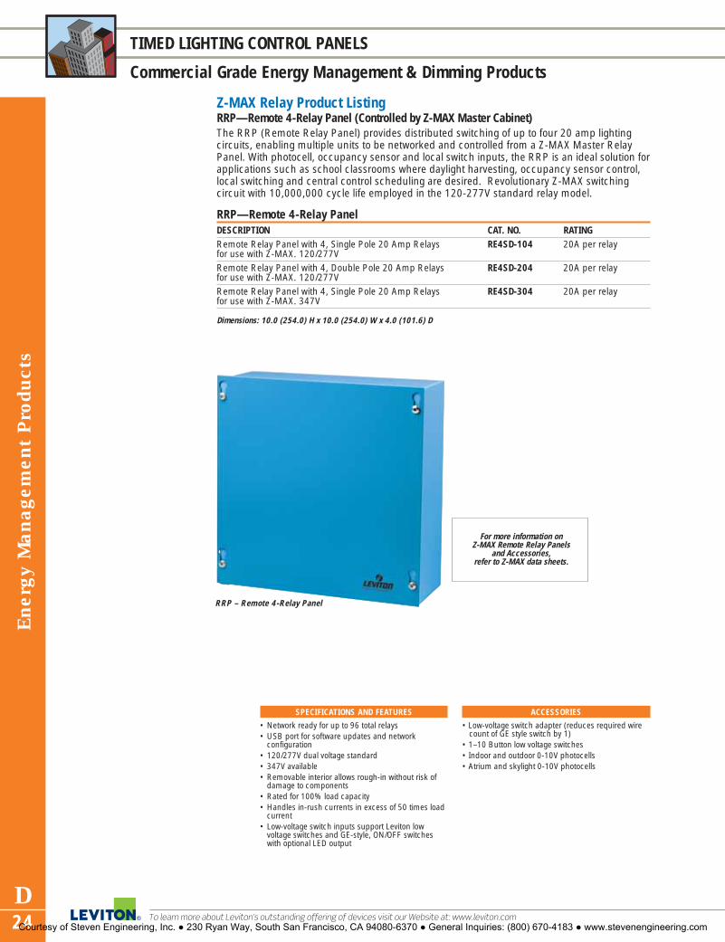
To learn more about Leviton’s outstanding offering of devices visit our Website at: www.leviton.com
Ene
rgy
Man
agem
ent
Pro
duct
s
D24
TIMED LIGHTING CONTROL PANELS
Commercial Grade Energy Management & Dimming Products
Z-MAX Relay Product ListingRRP—Remote 4-Relay Panel (Controlled by Z-MAX Master Cabinet)The RRP (Remote Relay Panel) provides distributed switching of up to four 20 amp lighting circuits, enabling multiple units to be networked and controlled from a Z-MAX Master RelayPanel. With photocell, occupancy sensor and local switch inputs, the RRP is an ideal solution forapplications such as school classrooms where daylight harvesting, occupancy sensor control,local switching and central control scheduling are desired. Revolutionary Z-MAX switching circuit with 10,000,000 cycle life employed in the 120-277V standard relay model.
RRP—Remote 4-Relay PanelDESCRIPTION CAT. NO. RATINGRemote Relay Panel with 4, Single Pole 20 Amp Relays RE4SD-104 20A per relayfor use with Z-MAX. 120/277VRemote Relay Panel with 4, Double Pole 20 Amp Relays RE4SD-204 20A per relayfor use with Z-MAX. 120/277V Remote Relay Panel with 4, Single Pole 20 Amp Relays RE4SD-304 20A per relayfor use with Z-MAX. 347V
SPECIFICATIONS AND FEATURES
• Network ready for up to 96 total relays• USB port for software updates and network
configuration• 120/277V dual voltage standard• 347V available• Removable interior allows rough-in without risk of
damage to components• Rated for 100% load capacity• Handles in-rush currents in excess of 50 times load
current• Low-voltage switch inputs support Leviton low
voltage switches and GE-style, ON/OFF switcheswith optional LED output
ACCESSORIES
• Low-voltage switch adapter (reduces required wirecount of GE style switch by 1)
• 1–10 Button low voltage switches• Indoor and outdoor 0-10V photocells• Atrium and skylight 0-10V photocells
RRP – Remote 4-Relay Panel
For more information on Z-MAX Remote Relay Panels
and Accessories, refer to Z-MAX data sheets.
Dimensions: 10.0 (254.0) H x 10.0 (254.0) W x 4.0 (101.6) D
Courtesy of Steven Engineering, Inc. ● 230 Ryan Way, South San Francisco, CA 94080-6370 ● General Inquiries: (800) 670-4183 ● www.stevenengineering.com

Energy M
anagement P
roducts
D25For answers to technical questions, call Leviton’s Techline at 1-800-824-3005
TIMED LIGHTING CONTROL PANELS
Commercial Grade Energy Management & Dimming Products
EZ-MAX Relay Product ListingEZ-MAX Relay CabinetsEZ-MAX relay lighting control panels combine the power and performance of the larger Z-MAX relay cabinets in a cost-effective four-circuit packagethat’s housed in a compact 10" X 10" standard electrical enclosure. It is theideal contractor friendly, quick-to-install solution for smaller, stand-aloneapplications that do not require the field configuration or advanced networking features of the larger Z-MAX cabinets. It serves as a smartreplacement for time clock/contactor installations for any application requiring reliable and cost-effective automatic lighting control.
EZ-MAX Relay CabinetsDESCRIPTION CAT. NO. RATINGEZ-MAX with 4 120-277V relays RE4BD-104 20A per relayEZ-MAX with 4 208-480V 2-pole relays RE4BD-204 20A per relayEZ-MAX with 4 120-347V relays RE4BD-C04 20A per relay
Dimensions: 10.0 (254.0) H x 10.0 (254.0) W x 4.0 (101.6) D
See pages D10-D15 for information on compatible Leviton Occupancy Sensors.
For digital and low-voltage switch stations, see page D26.
EZ-MAX Relay Cabinet
SPECIFICATIONS AND FEATURES
Relay Cabinets• 120-277V standard relay model features revolution-
ary, patent-pending Z-MAX switching circuit with anunprecedented 10,000,000 cycle life
• 347V available• Low-voltage inputs allow connection of photocells,
occupancy sensors and low-voltage switches for acomprehensive, easy-to-install energy managementsolution
• Refer to pages D21-D22 for Z-MAX general featuresAccessories• Modem module for touch tone control or remote
configuration
• Low-voltage switch adapter (reduces required wirecount of GE style switch by 1)
• 1–4 Button low voltage switches• Indoor and outdoor 0-10V photocells• Atrium and skylight 0-10V photocells
TESTING AND CODE COMPLIANCE
• ASHRAE 90.1 compliant• CEC Title 24 compliant• Limited Ten-Year Warranty
For more information on EZ-MAX Relay Cabinets,
refer to EZ-MAX data sheets.
Courtesy of Steven Engineering, Inc. ● 230 Ryan Way, South San Francisco, CA 94080-6370 ● General Inquiries: (800) 670-4183 ● www.stevenengineering.com

LVS-08W
ZMDSW-03W
Ene
rgy
Man
agem
ent
Pro
duct
s
D26
TIMED LIGHTING CONTROL PANELS
Commercial and Residential Grade Energy Management Products
To learn more about Leviton’s outstanding offering of devices visit our Website at: www.leviton.com
Z-MAX Relay Product ListingZ-MAX Digital and Low Voltage Switch StationsThe Z-MAX system can incorporate either digital or low-voltage stations. Although they lookidentical, there are a few differences in how they operate. Both contain buttons that are programmable to a variety of functions and custom labels are available.
Z-MAX Switch StationsDESCRIPTION DIGITAL SWITCH LOW-VOLTAGE SWITCH COLOR
CAT. NO.* CAT. NO.**On/Off switch ZMDSW-01W LVS-01W WhiteZones 1 and 2 ZMDSW-02W LVS-02W WhiteZones 1 to 3 ZMDSW-03W LVS-03W WhiteZones 1 to 4 ZMDSW-04W LVS-04W WhiteZones 1 to 5 ZMDSW-05W LVS-05W WhiteZones 1 to 6 ZMDSW-06W LVS-06W WhiteZones 1 to 8 ZMDSW-08W LVS-08W WhiteZones 1 to 10 ZMDSW-10W LVS-10W White
Note: Wallplate sold separately*Support network and master Z-MAX versions only**Support EZ-MAX and Z-MAX stand-alone and slave versions only
miniZ™ Low-Voltage Switch StationsDESCRIPTION CAT. NO. COLOR5-Button dimming controller with On/Off, for use with miniZ only. LV200-00W WhiteOn/Off switch controller for use with miniZ, Z-MAX and EZ-MAX LV240-00W White
Dimensions: 4.71 (119.7) H x 1.76 (44.7) W x 1.26 (32.0) D for Switch Stations
SPECIFICATIONS AND FEATURES
Common Features• Available in 8 configurations• Programmable functions include: on, off, and group
and scene select• Compatible with standard and midway size Decora®
wallplates• Custom labeling available; contact a factory
representativeDigital Station• Wired via Luma-Net® to compatible products
including D4200, D8000, a-2000, i Series e, i SeriesQuad, and Z-MAX Relay Cabinets
• Networks with up to 127 devices• Compatible with handheld IR remote control
Low-Voltage Station• Compatible with EZ-MAX and Z-MAX Relay
Cabinets, MDS cabinets, a-2000 cabinets (with analog card), network protocol converter, andother low-voltage devices
• Cat. No. LV240 for use with miniZ IntelligentDaylight Management System, Z-MAX and EZ-MAX
• Cat. No. LV200 for use with miniZ IntelligentDaylight Management System only
WARRANTY
• Limited Two-Year Warranty
Courtesy of Steven Engineering, Inc. ● 230 Ryan Way, South San Francisco, CA 94080-6370 ● General Inquiries: (800) 670-4183 ● www.stevenengineering.com

Energy M
anagement P
roducts
D27For answers to technical questions, call Leviton’s Techline at 1-800-824-3005
TIMED LIGHTING CONTROL PANELS
Commercial Grade Energy Management & Dimming Products
miniZ™ Product ListingminiZ™ Intelligent Daylight Management SystemminiZ combines occupancy sensing, daylight harvesting and flexible lighting control functionsinto a single, easily installed package. miniZ features several methods of ladderless commis-sioning, including the AutoCal™ feature, the world’s first 100% self-configuring daylight har-vesting system. Installation requires little more than any other power-pack type product. Theperformance features and capabilities of the miniZ product provide a package that surpassesall others in the industry at a price anyone can afford.
miniZ™ Intelligent Daylight Management System20A output relays (120/277V); 15A output relays (347V); Fluorescent, non-dimmed and 1-10V dimmed(0,2 or 3 zones); 120mA/24V output for operation of occupancy sensors, etc.
CAT. NO. 20A POWER 0-10V DIMMING CONTROL INPUT NETWORKCIRCUITS CIRCUITS VOLTAGE FUNCTIONALITY
MZB00-102 2 0 120/277VAC NoMZD20-102 2 2 120/277VAC NoMZD30-101 1 3 120/277VAC NoMZN20-102* 2 2 120/277VAC YesMZN30-101* 1 3 120/277VAC YesMZB00-C02 2 0 220/347VAC NoMZD20-C02 2 2 220/347VAC NoMZD30-C01 1 3 220/347VAC NoMZN20-C02* 2 2 220/347VAC YesMZN30-C01* 1 3 220/347VAC Yes*Consult with factory for availability.
Dual Room miniZ™ Intelligent Daylight Management SystemThe dual room miniZ offers the same performance features as the miniZ, but instead of working in oneroom using one photocell to control three zones, it provides dual room/ one zone per room daylight harvest-ing control using a separate photocell and occupancy sensor for each room.
CAT. NO. 20A POWER 0-10V DIMMING CONTROL INPUT NETWORKCIRCUITS CIRCUITS VOLTAGE FUNCTIONALITY
MZB02-102 2 0 120/277VAC No
MZD22-102 2 2 120/277VAC No
MZN22-102* 2 2 120/277VAC Yes
MZB02-C02 2 0 220/347VAC No
MZD22-C02 2 2 220/347VAC No
MZN22-C02* 2 2 220/347VAC Yes
*Consult with factory for availability.
6.65(168.9)
2.1(53.3)
6.65(168.9)
miniZ/ Dual Room miniZ
SPECIFICATIONS AND FEATURES
• Automatic Correction setting for Light Loss Factor(LLF) recognizes and corrects for lumen mainte-nance issues
• Cost-effective energy code compliance• Ladderless Commissioning™ provides install-and-
forget convenience• Automatic closed-loop, multi-zone daylight control• Convenient occupancy sensor and photocell
integration• Simplified daylight harvesting with 3% to 100%
dimming capabilities (0-10V fluorescent dimmingballasts required)
• Autocal™ (patent pending) automatic photocell calibration
• Accepts external time clock inputs
• Simplified integration with emergency and buildingautomation systems
• Automatic Daylight Harvest Mode provides optimum lighting output for additional energy savings potential
• Daylight switching full range 0-10V dimming andnetwork models available
• Cost effective energy code compliance• Accepts external time clock inputs• Closed loop or open loop daylight control• Isolated contacts for HVAC relay• miniZ works in one room using one photocell and
occupancy sensor to control three zones• Dual Room miniZ controls one zone per room
using a separate photocell and occupancy sensorfor each room
NETWORK FEATURES
• Luma-CAN® Network support• Network digital switch support• Z-MAX master/slave network participation• Remote shared network inputs• Scalable system expansion
TESTING AND CODE COMPLIANCE
• UL and cUL Listed• CEC Title-24 Listed• Limited Two-Year Warranty
Courtesy of Steven Engineering, Inc. ● 230 Ryan Way, South San Francisco, CA 94080-6370 ● General Inquiries: (800) 670-4183 ● www.stevenengineering.com
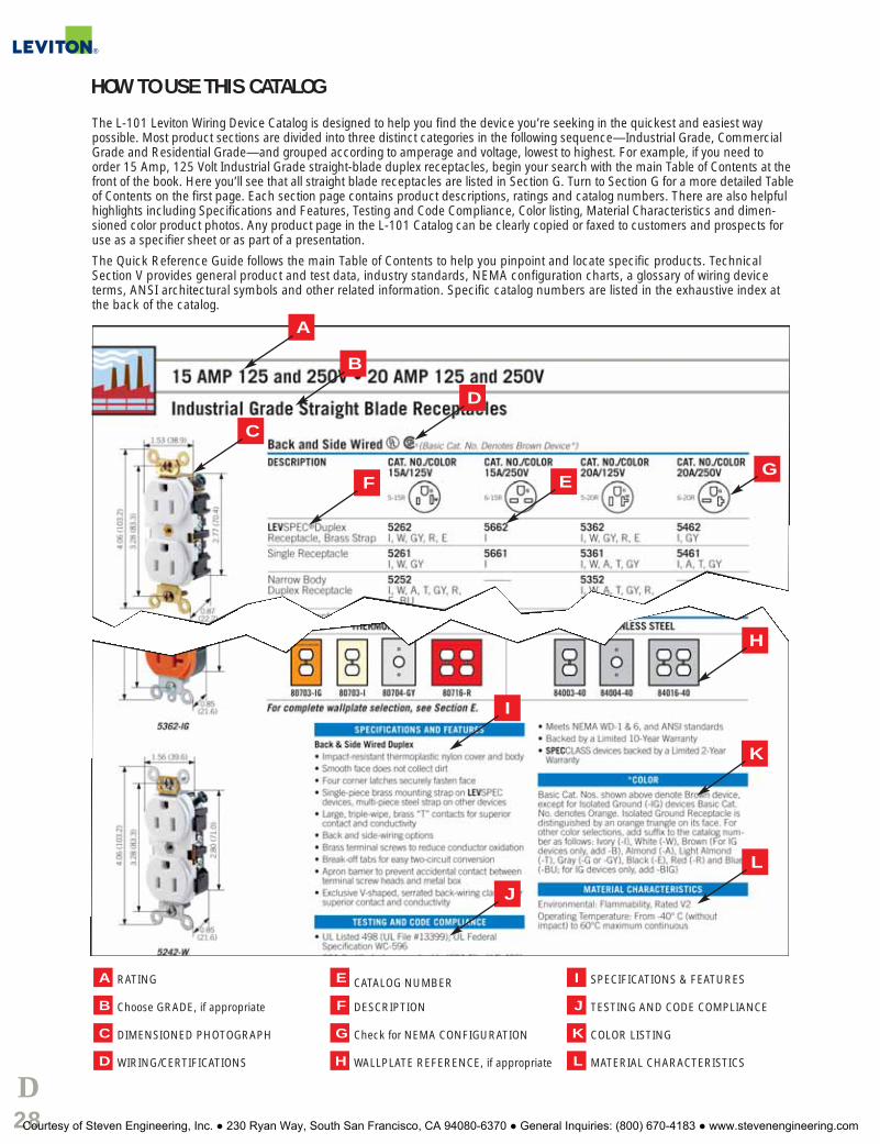
D28
HOW TO USE THIS CATALOG
The L-101 Leviton Wiring Device Catalog is designed to help you find the device you’re seeking in the quickest and easiest way possible. Most product sections are divided into three distinct categories in the following sequence—Industrial Grade, CommercialGrade and Residential Grade—and grouped according to amperage and voltage, lowest to highest. For example, if you need toorder 15 Amp, 125 Volt Industrial Grade straight-blade duplex receptacles, begin your search with the main Table of Contents at thefront of the book. Here you’ll see that all straight blade receptacles are listed in Section G. Turn to Section G for a more detailed Tableof Contents on the first page. Each section page contains product descriptions, ratings and catalog numbers. There are also helpfulhighlights including Specifications and Features, Testing and Code Compliance, Color listing, Material Characteristics and dimen-sioned color product photos. Any product page in the L-101 Catalog can be clearly copied or faxed to customers and prospects foruse as a specifier sheet or as part of a presentation.
The Quick Reference Guide follows the main Table of Contents to help you pinpoint and locate specific products. TechnicalSection V provides general product and test data, industry standards, NEMA configuration charts, a glossary of wiring deviceterms, ANSI architectural symbols and other related information. Specific catalog numbers are listed in the exhaustive index atthe back of the catalog.
RATING
Choose GRADE, if appropriate
DIMENSIONED PHOTOGRAPH
WIRING/CERTIFICATIONS
CATALOG NUMBER
DESCRIPTION
Check for NEMA CONFIGURATION
WALLPLATE REFERENCE, if appropriate
SPECIFICATIONS & FEATURES
TESTING AND CODE COMPLIANCE
COLOR LISTING
MATERIAL CHARACTERISTICSL
K
J
I
H
G
F
E
D
C
B
A
I
D
E
H
B
J
G
K
F
L
C
A
Courtesy of Steven Engineering, Inc. ● 230 Ryan Way, South San Francisco, CA 94080-6370 ● General Inquiries: (800) 670-4183 ● www.stevenengineering.com

Wallplates Index
SECTIONEWallplatesINDEXDecora® Plus Screwless Snap-On . . . . . . . .E2, E4, E5Decora® . . . . . . . . . . . . . . . . . . . . . . . . . . .E3, E4, E5Wallplate Overview . . . . . . . . . . . . . . . . . . . . . . . . .E6Toggle . . . . . . . . . . . . . . . . . . . . . . . . . . . . . . .E7–E9Duplex Receptacle . . . . . . . . . . . . . . . . . . . .E10, E11Single Receptacle . . . . . . . . . . . . . . . . . . . . . . . .E12Telephone or Cable Outlet, Box Mount . . . . .E13, E14Telephone or Cable Outlet, Strap Mount . . . .E14, E15Blank, Box Mount . . . . . . . . . . . . . . . . . . . .E16, E17Blank, Strap Mount . . . . . . . . . . . . . . . . . . .E17, E18Power Outlet Receptacles . . . . . . . . . . . . . . .E19, E20Two-Gang with Centered Opening . . . . . . . . . . . . .E21Louvre Plates . . . . . . . . . . . . . . . . . . . . . . . . . . . .E22Combination Wallplates
Toggle and Single Receptacle . . . . . . . . . . . . . .E23Toggle and Duplex Receptacle . . . . . . . . .E23, E24Toggle and Decora/GFCI . . . . . . . . . . . . . . . . . .E25Toggle and Blank . . . . . . . . . . . . . . . . . . . . . . .E26Standard Combinations–2-Gang . . . . . . . .E26–E28Standard Combinations–3-Gang/4-Gang . . . . . .E28
Sectional for Multi-Gang Installations . . . . . . . . . .E29Hot Stamped and Engraved . . . . . . . . . . . . .E29, E30Voice/Data/CATV . . . . . . . . . . . . . . . . . . . . . . . . .E31Weather Resistant Covers
Raintight While-In-Use . . . . . . . . . . . . . . . . . . .E32Industrial Grade . . . . . . . . . . . . . . . . . . . . . . . .E33Die-cast Zinc . . . . . . . . . . . . . . . . . . . . . . . . . .E34Thermoplastic . . . . . . . . . . . . . . . . . . . . . . . . .E35
Stainless Steel Lockout . . . . . . . . . . . . . . . . .E34, E35Accessories . . . . . . . . . . . . . . . . . . . . . . . . . . . . .E36Custom Wallplates . . . . . . . . . . . . . . . . . . . .E37–E40
Courtesy of Steven Engineering, Inc. ● 230 Ryan Way, South San Francisco, CA 94080-6370 ● General Inquiries: (800) 670-4183 ● www.stevenengineering.com

Wal
lpla
tes
E2
DECORA® PLUS SCREWLESS SNAP-ON WALLPLATES
Residential and Commercial Grade Wallplates
To learn more about Leviton’s outstanding offering of devices visit our Website at: www.leviton.com
Decora Plus Screwless Snap-On WallplatesDESCRIPTION COLOR STANDARD MIDWAY1-Gang 1-Decora Ivory 80301-SI SJ26-SI
Ebony/Black 80301-SE SJ26-SEGray 80301-SGY SJ26-SGYWhite 80301-SW SJ26-SWMahogany/Brown 80301-S SJ26-SAlmond 80301-SA SJ26-SALight Almond 80301-ST SJ26-ST
2-Gang 2-Decora Ivory 80309-SI SJ262-SIEbony/Black 80309-SE SJ262-SEGray 80309-SGY SJ262-SGYWhite 80309-SW SJ262-SWMahogany/Brown 80309-S SJ262-SAlmond 80309-SA SJ262-SALight Almond 80309-ST SJ262-ST
3-Gang 3-Decora Ivory 80311-SI SJ263-SIEbony/Black 80311-SE SJ263-SEWhite 80311-SW SJ263-SWAlmond 80311-SA SJ263-SALight Almond 80311-ST SJ263-ST
4-Gang 4-Decora Ivory 80312-SI SJ264-SIWhite 80312-SW SJ264-SWAlmond 80312-SA SJ264-SALight Almond 80312-ST SJ264-ST
5-Gang 5-Decora Ivory 80321-SI SJ265-SIWhite 80321-SW SJ265-SWAlmond 80321-SA SJ265-SALight Almond 80321-ST SJ265-ST
6-Gang 6-Decora Ivory 80326-SI SJ266-SIWhite 80326-SW SJ266-SWAlmond 80326-SA SJ266-SALight Almond 80326-ST SJ266-ST
Decora Plus Screwless Snap-On Wallplates� Sleek, smooth contemporary architectural styling enhances
fine décor� Exclusive new design eliminates subplate screws� “Hook and Snap” subplate and wallplate mounting provides
easy, time saving installation� Decora-compatible two-piece kit allows easy retrofit to any
Decora installation� Tough, unbreakable polycarbonate construction� Now available in standard and midway sizes that can be
mounted onto larger-volume wallboxes and/or used to hidewall irregularities.
TESTING AND CODE COMPLIANCE
• UL Listed (File #E-13397)• Meets NEMA Standards WD-1, WD-6• CSA Certified (File #LR-16347)• NOM Certified (File #057)• Backed by a Limited Ten-Year Warranty
MATERIAL CHARACTERISTICS
Environmental: Flammability UL-94, V2 RatingOperating Temperature: -40°C to 120°C
Midway SizeSingle-Gang Screwless Snap-On Wallplate
SJ26-SMidway wallplates can be mounted onto larger-volume outlet boxes and/or used to hide wallirregularities. Midway wallplates are a full0.375" higher and wider than standard sizewallplates.NOTE: Add 1.81" (46.0mm) for each additional gang.
4.61
(11
7.1)
2.75 (69.9) 0.26
(6.5)
3.13 (79.4) 0.26
(6.5)
4.99
(12
6.7)
Standard SizeSingle-Gang Screwless Snap-On Wallplate
80301-S
80301-SWStandard Size
SJ26-SWMidway Size
Courtesy of Steven Engineering, Inc. ● 230 Ryan Way, South San Francisco, CA 94080-6370 ● General Inquiries: (800) 670-4183 ● www.stevenengineering.com

Wallplates
E3For answers to technical questions, call Leviton’s Techline at 1-800-824-3005
DECORA® WALLPLATES
Residential and Commercial Grade Decora Wallplates
TESTING AND CODE COMPLIANCE
• Thermoplastic and Thermoset: UL Listed (File#E-13397)
• Metal: UL Listed (File #E-16347)• Meets NEMA Standards WD-1, WD-6• CSA Certified (File #LR-16347)• NOM Certified (File #057)
MATERIAL CHARACTERISTICS
Environmental: Flammability UL-94, V2 RatingOperating Temperature: -40°C to 120°C
All Decora Wallplates� Accent any wall covering with a wide selection of colors and finishes� Smooth face and rounded edges resist dust accumulation� Individual plastic wrapping to protect wallplate’s surface� Color-matched metal mounting screws supplied
Residential Grade Thermoset Wallplates� Photoelectrically color-matched to Leviton Decora devices� Designed for high dielectric strength and arc resistance� Meet or surpass UL 514 testing requirements� Resistant to fading, discoloration, grease, oils, organic solvents and
moisture scratches� Backed by a Limited Two-Year Warranty
Commercial Grade Thermoplastic Wallplates� Molded thermoplastic for maximum resistance to impact, abrasion,
fading and discoloration� Resistant to mechanical stress associated with high abuse applications� Backed by a Limited Ten-Year Warranty
Commercial Grade Metal Wallplates� Rounded edges to prevent injury and wall damage� Deluxe stainless steel is non-magnetic Type 302, .032" thick� Standard magnetic stainless steel Type 430, .032" thick, also available� Brass is 70/30 alloy 260, .040" thick� Aluminum is 3004 alloy, .040" thick � Backed by a Limited Ten-Year Warranty
0.25 (6.4)
Nylon and Plastic
0.19(4.8)Metal
3.81
(96
.8)
4.50
(11
4.3)
2.75 (69.9)
0.25 (6.4)
Nylon and Plastic
y
3.13 (79.4)
3.81
(96
.8)
4.88
(12
3.8
Standard Size Single-Gang
Midway Size Single-GangMidway wallplates can be mounted onto larger-volumeoutlet boxes and/or used to hide wall irregularities.Midway wallplates are a full 0.375" higher and widerthan standard size wallplates.
Oversized Single-GangOversized wallplates are used to conceal greater wallirregularities than those hidden by Midway wallplates.Oversized wallplates are a full 0.75" higher and widerthan standard size wallplates.NOTE: Add 1.81" (46.0mm) for each additional gang.
0.25 (6.4)
Nylon and Plastic
3.81
(96
.8)
5.25
(13
3.4)
3.50 (88.9)
Courtesy of Steven Engineering, Inc. ● 230 Ryan Way, South San Francisco, CA 94080-6370 ● General Inquiries: (800) 670-4183 ● www.stevenengineering.com

Dec
ora
Wal
lpla
tes
E4
WALLPLATES
Residential and Commercial Grade Decora Wallplates
To learn more about Leviton’s outstanding offering of devices visit our Website at: www.leviton.com
DecoraScrewless Snap-On
Thermoset Thermoplastic Polycarbonate Assorted Metals
DESCRIPTION1-Gang 1-DecoraCOLOR STANDARD MIDWAY OVERSIZE STANDARD MIDWAY STANDARD MIDWAY MATERIAL STANDARD OVERSIZE
P26 SPJ26 PO26 N26 PJ26Ivory 80401-I 80601-I 86601 80401-NI PJ26-I 80301-SI SJ26-SI Chrome * —Black 80401-E — — 80401-NE PJ26-E 80301-SE SJ26-SE Aluminum A26 —
83401Gray 80401-GY — — 80401-NGY PJ26-GY 80301-SGY SJ26-SGY Brass B26 —
81401White 80401-W 80601-W 88601 80401-NW PJ26-W 80301-SW SJ26-SW Polished 81401-PB —
BrassBrown 80401 80601 — 80401-N PJ26 80301-S SJ26-S 430 S/S * *Almond 80401-A 80601-A 82601 80401-NA PJ26-A 80301-SA SJ26-SA 302 S/S SN26-N SO26
84401-40 SO26Light Almond 80401-T 80601-T — 80401-NT PJ26-T 80301-ST SJ26-STRed — — — 80401-NR — — —Blue — — — 80401-NB PJ26-BU — —
DESCRIPTION2-Gang 2-DecoraCOLOR STANDARD MIDWAY OVERSIZE STANDARD MIDWAY STANDARD MIDWAY MATERIAL STANDARD OVERSIZE
P262 SPJ262 PO262 N262 PJ262Ivory 80409-I 80609-I 86602 80409-NI PJ262-I 80309-SI SJ262-SI Chrome * —Black 80409-E — — 80409-NE PJ262-E 80309-SE SJ262-SE Aluminum A262 —
83409Gray 80409-GY — — 80409-NGY PJ262-GY 80309-SGY SJ262-SGY Brass B262 —
81409White 80409-W 80609-W 88602 80409-NW PJ262-W 80309-SW SJ262-SW Polished 81409-PB —
BrassBrown 80409 80609 — 80409-N PJ262 80309-S SJ262-S 430 S/S * *Almond 80409-A 80609-A 82602 80409-NA PJ262-A 80309-SA SJ262-SA 302 S/S S262-N SO262
84409-40 SO262Light Almond 80409-T 80609-T — 80409-NT PJ262-T 80309-ST SJ262-STRed — — — 80409-NR — — —Blue — — — 80409-NB — — —
DESCRIPTION3-Gang 3-DecoraCOLOR STANDARD MIDWAY OVERSIZE STANDARD MIDWAY STANDARD MIDWAY MATERIAL STANDARD OVERSIZE
P263 SPJ263 N263 PJ263Ivory 80411-I 80611-I — 80411-NI PJ263-I 80311-SI SJ263-SI Chrome * —Black 80411-E — — — — 80311-SE SJ263-SE Aluminum A263 —
83411Gray 80411-GY — — 80411-NGY PJ263-GY — — Brass B263 —
81411White 80411-W 80611-W — 80411-NW PJ263-W 80311-SW SJ263-SW Polished 81411-PB —
BrassBrown 80411 80611 — 80411-N — — — 430 S/S * *Almond 80411-A 80611-A — 80411-NA PJ263-A 80311-SA SJ263-SA 302 S/S S263-N SO263
84411-40 SO263Light Almond 80411-T 80611-T — 80411-NT PJ263-T 80311-ST SJ263-ST
*Consult your Leviton representative for ordering details: allow 3–4 weeks for delivery.
NOTE: Where applicable, Industry Number indicated in BOLD FACE. For some wallplates, Industry Number and Leviton Catalog Number are identical.
Courtesy of Steven Engineering, Inc. ● 230 Ryan Way, South San Francisco, CA 94080-6370 ● General Inquiries: (800) 670-4183 ● www.stevenengineering.com

DecoraScrewless Snap-On
Thermoset Thermoplastic Polycarbonate Assorted Metals
DESCRIPTION4-Gang 4-DecoraCOLOR STANDARD MIDWAY OVERSIZE STANDARD MIDWAY STANDARD MIDWAY MATERIAL STANDARD OVERSIZE
P264 SPJ264 N264 PJ264Ivory 80412-I 80612-I — 80412-NI PJ264-I 80312-SI SJ264-SI Chrome * —Black 80412-E — — — — 80312-SE SJ264-SE Brass B264 —
81412Gray 80412-GY — — — PJ264-GY — — 430 S/S * —White 80412-W 80612-W — 80412-NW PJ264-W 80312-SW SJ264-SW 302 S/S S264-N —
84412-40Brown 80412 — — 80412-N — — —Almond 80412-A 80612-A — 80412-NA PJ264-A 80312-SA SJ264-SALight Almond 80412-T 80612-T — 80412-NT PJ264-T 80312-ST SJ264-ST
DESCRIPTION5-Gang 5-DecoraCOLOR STANDARD MIDWAY OVERSIZE STANDARD MIDWAY STANDARD MIDWAY MATERIAL STANDARD OVERSIZE
P265 N265Ivory 80423-I — — — — 80321-SI SJ265-SI Brass B265 —
81423Black 80423-E — — — — — — 430 S/S * —Gray 80423-GY — — — — — — 302 S/S S265 —
84423-40White 80423-W — — — — 80321-SW SJ265-SWBrown 80423 — — — — — —Almond 80423-A — — — — 80321-SA SJ265-SALight Almond 80423-T — — 80423-NT — 80321-ST SJ265-ST
DESCRIPTION6-Gang 6-DecoraCOLOR STANDARD MIDWAY OVERSIZE STANDARD MIDWAY STANDARD MIDWAY MATERIAL STANDARD OVERSIZE
P266 N266Ivory 80436-I — — — — 80326-SI SJ266-SI Brass B266 —
*Black 80436-E — — — — — — 430 S/S — —Gray 80436-GY — — — — — — 302 S/S S266-N —
84436-40White 80436-W — — — — 80326-SW SJ266-SWBrown 80436 — — — — — —Almond 80436-A — — 80436-NA — 80326-SA SJ266-SALight Almond 80436-T — — — — 80326-ST SJ266-ST
DESCRIPTION7-Gang 7-DecoraCOLOR STANDARD MIDWAY OVERSIZE STANDARD MIDWAY STANDARD MIDWAY MATERIAL STANDARD OVERSIZE
S607Ivory 80407-I† — — — — — — Brass B607 —
*White 80407-W† — — — — — — 430 S/S * —
302 S/S S607-N —*
DESCRIPTION8-Gang 8-DecoraCOLOR STANDARD MIDWAY OVERSIZE STANDARD MIDWAY STANDARD MIDWAY MATERIAL STANDARD OVERSIZE
S609Ivory 80408-I† — — — — — — Brass B609 —
*White 80408-W† — — — — — — 430 S/S * —
302 S/S S609-N —*
*Consult your Leviton representative for ordering details: allow 3–4 weeks for delivery. †Painted metal
Decora W
allplates
E5For answers to technical questions, call Leviton’s Techline at 1-800-824-3005
WALLPLATES
Residential and Commercial Grade Decora Wallplates
Courtesy of Steven Engineering, Inc. ● 230 Ryan Way, South San Francisco, CA 94080-6370 ● General Inquiries: (800) 670-4183 ● www.stevenengineering.com

Wal
lpla
tes
E6
LARGER SIZE WALLPLATES
Residential and Commercial Grade Wallplates
To learn more about Leviton’s outstanding offering of devices visit our Website at: www.leviton.com
TESTING AND CODE COMPLIANCE
• UL Listed• Meets NEMA Standards WD-1, WD-6• CSA Certified
MATERIAL CHARACTERISTICS
Environmental: Flammability UL-94, V2 RatingOperating Temperature: -40°C to 120°C
Features and Benefits of All Leviton Wallplates� Easy to Clean, smooth finish� Noncombustible� Individual plastic wrapping to protect wallplate surface� Color-matched metal mounting screws supplied in an envelope to protect
plate from scratches� UL Listed and CSA Certified� Conform to NEMA and ANSI Standards
Residential Grade Thermoset (Plastic) Wallplates� Photoelectrically color-matched to Leviton Decora devices� Designed for high dielectric strength and arc resistance� Meet or surpass UL 514 testing requirements� Resistant to fading, discoloration, grease, oils, organic solvents and moisture
scratches� Backed by a Limited Two-Year Warranty
Commercial Grade Thermoplastic (Nylon) Wallplates� Molded thermoplastic for maximum resistance to impact, abrasion, fading
and discoloration� Resistant to mechanical stress associated with high abuse applications� Backed by a Limited Ten-Year Warranty
Commercial Grade Metal Wallplates� Rounded edges to prevent injury and wall damage� Deluxe stainless steel is non-magnetic Type 302, .032" thick� Standard magnetic stainless steel Type 430, .032" thick, also available� Brass is 70/30 alloy 260, .040" thick� Aluminum is 3004 alloy, .040" thick � Backed by a Limited Ten-Year Warranty
2.38
(60
.3)
4.50
(11
4.3)
2.75 (69.8) 0.25(6.4)
Nylon andPlastic
0.19(4.8)Metal
2.38
(60
.3)
4.88
(12
3.8)
3.13 (79.4) 0.25(6.4)
Nylon andPlastic
2.38
(60
.3)
5.25
(13
3.4)
3.50 (88.9) 0.25(6.4)
Nylon andPlastic
0.19(4.8)Metal
Standard Size Single-Gang
Midway Size Single-GangMidway wallplates can be mounted onto larger-volumeoutlet boxes and/or used to hide wall irregularities.Midway wallplates are a full 0.375" higher and widerthan standard size wallplates.
Oversized Single-GangOversized wallplates are used to conceal greater wallirregularities than those hidden by Midway wallplates.Oversized wallplates are a full 0.75" higher and widerthan standard size wallplates.NOTE: Add 1.81" (46.0mm) for each additional gang.
A COMPLETE SELECTION OF WALLPLATES FOR INDUSTRIAL, COMMERCIALAND RESIDENTIAL APPLICATIONS
Courtesy of Steven Engineering, Inc. ● 230 Ryan Way, South San Francisco, CA 94080-6370 ● General Inquiries: (800) 670-4183 ● www.stevenengineering.com

ToggleThermoset (Plastic) Thermoplastic (Nylon) Assorted Metals
DESCRIPTION1-Gang 1-ToggleCOLOR STANDARD MIDWAY OVERSIZE STANDARD MIDWAY MATERIAL STANDARD OVERSIZE
P1 SPJ1 PO1 N1 PJ1Ivory 86001 80501-I 86101 80701-I PJ1-I Chrome C1 —
1901Black — — — 80701-E PJ1-E Aluminum A1 —
83001Gray 87001 — — 80701-GY PJ1-GY Brass B1 —
81001Red — — — 80701-R — Polished Brass 81001-PB —White 88001 80501-W 88101 80701-W PJ1-W 430 S/S S1 SO1
84001 84101Brown 85001 80501 85101 80701 PJ1 302 S/S S1-N SO1-N
84001-40 84101-40Almond 82001 80501-A — 80701-A PJ1-ALight Almond 78001 80501-T — 80701-T PJ1-T
DESCRIPTION2-Gang 2-TogglesCOLOR STANDARD MIDWAY OVERSIZE STANDARD MIDWAY MATERIAL STANDARD OVERSIZE
P2 SPJ2 PO2 N2 PJ2Ivory 86009 80509-I 86109 80709-I PJ2-I Chrome 1909 —Black — —- —- 80709-E PJ2-E Aluminum A2 —
83009Gray 87009 — —- 80709-GY PJ2-GY Brass B2 —
81009Red — — — 80709-R — Polished Brass 81009-PB —White 88009 80509-W 88109 80709-W PJ2-W 430 S/S S2 —
84009Brown 85009 80509 85109 80709 — 302 S/S S2-N SO2-N
84009-40 84109-40Almond 82009 80509-A — 80709-A PJ2-A
Light Almond 78009 80509-T — 80709-T PJ2-T
DESCRIPTION3-Gang 3-TogglesCOLOR STANDARD MIDWAY OVERSIZE STANDARD MIDWAY MATERIAL STANDARD OVERSIZE
P3 SPJ3 PO3 N3 PJ3Ivory 86011 80511-I 86111 80711-I PJ3-I Chrome * —Black — — — 80711-E PJ3-E Aluminum A3 —
83011Gray 87011 — — 80711-GY — Brass B3 —
81011Red — — — 80711-R — Polished Brass 81011-PBWhite 88011 80511-W 88111 80711-W PJ3-W 430 S/S S3 —
84011Brown 85011 80511 — 80711 PJ3 302 S/S S3-N SO3-N
84011-40 84111-40Almond 82011 80511-A — 80711-A PJ3-ALight Almond 78011 80511-T — 80711-T PJ3-T
*Consult your Leviton representative for ordering details: allow 3–4 weeks for delivery.
Wallplates
E7For answers to technical questions, call Leviton’s Techline at 1-800-824-3005
WALLPLATES
Residential and Commercial Grade Wallplates
NOTE: Where applicable, Industry Number indicated in BOLD FACE. For some wallplates, Industry Number and Leviton Catalog Number are identical.
Courtesy of Steven Engineering, Inc. ● 230 Ryan Way, South San Francisco, CA 94080-6370 ● General Inquiries: (800) 670-4183 ● www.stevenengineering.com

ToggleThermoset (Plastic) Thermoplastic (Nylon) Assorted Metals
DESCRIPTION4-Gang 4-TogglesCOLOR STANDARD MIDWAY OVERSIZE STANDARD MIDWAY MATERIAL STANDARD OVERSIZE
P4 SPJ4 N4 PJ4Ivory 86012 80512-I — 80712-I PJ4-I Chrome * —
Black — — — 80712-E — Aluminum A4 —83012
Gray 87012 — — — — Brass B4 —81012
Polished Brass 81012-PB —White 88012 80512-W — 80712-W PJ4-W 430 S/S S4 *
84012Brown 85012 80512 — — — 302 S/S S4-N SO4-N
84012-40 84112-40Almond 82012 80512-A — 80712-A PJ4-ALight Almond 78012 80512-T — 80712-T PJ4-T
DESCRIPTION5-Gang 5-TogglesCOLOR STANDARD MIDWAY OVERSIZE STANDARD MIDWAY MATERIAL STANDARD OVERSIZE
P5 N5Ivory 86023 — — 80723-I — Chrome * —White 88023 — — 80723-W — Aluminum A5 —
*Brown 85023 — — — — Brass B5 —
81023Almond 82023 — — — — Polished Brass 81023-PB —Light Almond 78023 — — — — 430 S/S S5 —
*302 S/S S5-N —
84023-40
DESCRIPTION6-Gang 6-TogglesCOLOR STANDARD MIDWAY OVERSIZE STANDARD MIDWAY MATERIAL STANDARD OVERSIZE
P6 N6Ivory 86036 — — 80736-I — Chrome * —White 88036 — — 80736-W — Aluminum A6 —
*Brown 85036 — — — — Brass B6 —
81036Almond 82036 — — — — 430 S/S S6 —
*Light Almond 78036 — — — — 302 S/S S6-N —
84036-40
*Consult your Leviton representative for ordering details: allow 3–4 weeks for delivery.
Wal
lpla
tes
E8
WALLPLATES
Residential and Commercial Grade Wallplates
To learn more about Leviton’s outstanding offering of devices visit our Website at: www.leviton.com
NOTE: Where applicable, Industry Number indicated in BOLD FACE. For some wallplates, Industry Number and Leviton Catalog Number are identical.
Courtesy of Steven Engineering, Inc. ● 230 Ryan Way, South San Francisco, CA 94080-6370 ● General Inquiries: (800) 670-4183 ● www.stevenengineering.com

ToggleThermoset (Plastic) Thermoplastic (Nylon) Assorted Metals
DESCRIPTION7-Gang 7-TogglesCOLOR STANDARD MIDWAY OVERSIZE STANDARD MIDWAY MATERIAL STANDARD OVERSIZE
S601Ivory S601-I† — — — — Chrome * —White S601-W† — — — — Brass B601 —
*430 S/S * —302 S/S S601-N —
84070-40†Painted metal wallplate.
DESCRIPTION8-Gang 8-TogglesCOLOR STANDARD MIDWAY OVERSIZE STANDARD MIDWAY MATERIAL STANDARD OVERSIZE
S602 N6Ivory S602-I† — — — — Chrome * —White S602-W† — — — — Brass B602 —
*430 S/S * —302 S/S S602-N —
84048-40†Painted metal wallplate.
DESCRIPTION9-Gang 9-TogglesCOLOR STANDARD MIDWAY OVERSIZE STANDARD MIDWAY MATERIAL STANDARD OVERSIZE
S603Ivory S603-I† — — — — Chrome * —White S603-W† — — — — Brass B603 —
*430 S/S * —302 S/S S603-N —
84049-40†Painted metal wallplate.
DESCRIPTION10-Gang 10-TogglesCOLOR STANDARD MIDWAY OVERSIZE STANDARD MIDWAY MATERIAL STANDARD OVERSIZE
S604Ivory S604-I† — — — — Chrome * —White S604-W† — — — — Brass B604 —
*302 S/S S604-N —
84050-40†Painted metal wallplate.*Consult your Leviton representative for ordering details: allow 3–4 weeks for delivery.
Wallplates
E9For answers to technical questions, call Leviton’s Techline at 1-800-824-3005
WALLPLATES
Residential and Commercial Grade Wallplates
NOTE: Where applicable, Industry Number indicated in BOLD FACE. For some wallplates, Industry Number and Leviton Catalog Number are identical.
Courtesy of Steven Engineering, Inc. ● 230 Ryan Way, South San Francisco, CA 94080-6370 ● General Inquiries: (800) 670-4183 ● www.stevenengineering.com

ReceptacleThermoset (Plastic) Thermoplastic (Nylon) Assorted Metals
DESCRIPTION1-Gang 1-DuplexCOLOR STANDARD MIDWAY OVERSIZE STANDARD MIDWAY MATERIAL STANDARD OVERSIZE
P8 SPJ8 N8 PJ8Ivory 86003 80503-I 86103 80703-I PJ8-I Chrome C8 —
1903Black — — — 80703-E PJ8-E Aluminum A8 —
83003Gray 87003 — — 80703-GY PJ8-GY Brass B8 —
81003Red — — — 80703-R PJ8-R Polished Brass 81003-PB —White 88003 80503-W 88103 80703-W PJ8-W 430 S/S S8 SO8
84003 84103Brown 85003 80503 85103 80703 PJ8 302 S/S S8-N SO8-N
84003-40 84103-40Blue — — — 80703-BU PJ8-BUAlmond 82003 80503-A — 80703-A PJ8-ALight Almond 78003 80503-T — 80703-T PJ8-T
DESCRIPTION2-Gang 2-DuplexCOLOR STANDARD MIDWAY OVERSIZE STANDARD MIDWAY MATERIAL STANDARD OVERSIZE
P82 SPJ82 N82 PJ82Ivory 86016 80516-I 86116 80716-I PJ82-I Chrome C82 —
*Black — — — 80716-E PJ82-E Aluminum A82 —
83016Gray 87016 — — 80716-GY PJ82-GY Brass B82 —
81016Red — — — 80716-R PJ82-R Polished Brass * —White 88016 80516-W 88116 80716-W PJ82-W 430 S/S S82 SO82
84016 84116Brown 85016 80516 85116 80716 PJ82 302 S/S S82-N SO82-N
84016-40 84116-40Orange — — — 80716-ORG —Blue — — — 80716-BU —Almond 82016 80516-A — 80716-A PJ82-ALight Almond 78016 80516-T — 80716-T PJ82-T
DESCRIPTION3-Gang 3-DuplexCOLOR STANDARD MIDWAY OVERSIZE STANDARD MIDWAY MATERIAL STANDARD OVERSIZE
P83Ivory 86030 — — 80730-I — Chrome * —
Aluminum * —
Gray — — — 80730-GY — Brass * —
Red — — — 80730-R — 430 S/S S83 —*
White 88030 — — 80730-W — 302 S/S S83-N SO83-N84030-40 84130-40
Brown 85030 — — — —Light Almond — — — 78030 —
*Consult your Leviton representative for ordering details: allow 3–4 weeks for delivery.
Wal
lpla
tes
E10
WALLPLATES
Residential and Commercial Grade Wallplates
To learn more about Leviton’s outstanding offering of devices visit our Website at: www.leviton.com
NOTE: Where applicable, Industry Number indicated in BOLD FACE. For some wallplates, Industry Number and Leviton Catalog Number are identical.
Courtesy of Steven Engineering, Inc. ● 230 Ryan Way, South San Francisco, CA 94080-6370 ● General Inquiries: (800) 670-4183 ● www.stevenengineering.com

Wallplates
E11For answers to technical questions, call Leviton’s Techline at 1-800-824-3005
WALLPLATES
Residential and Commercial Grade Wallplates
Duplex ReceptacleThermoset (Plastic) Thermoplastic (Nylon) Assorted Metals
DESCRIPTION4-Gang 4-DuplexCOLOR STANDARD MIDWAY OVERSIZE STANDARD MIDWAY MATERIAL STANDARD OVERSIZE
P84Ivory 86041 — — — — Chrome * —White 88041 — — — — Aluminum * —Brown 85041 — — — — Brass * —
430 S/S S84 *84041
302 S/S S84-N **
DESCRIPTION5-Gang 5-DuplexCOLOR STANDARD MIDWAY OVERSIZE STANDARD MIDWAY MATERIAL STANDARD OVERSIZE
Chrome * —Brass B85 —
*302 S/S S85-N —
84055-40
DESCRIPTION6-Gang 6-DuplexCOLOR STANDARD MIDWAY OVERSIZE STANDARD MIDWAY MATERIAL STANDARD OVERSIZE
Chrome * —Brass B86 —
*302 S/S S86-N —
84056-40
DESCRIPTION7-Gang 7-DuplexCOLOR STANDARD MIDWAY OVERSIZE STANDARD MIDWAY MATERIAL STANDARD OVERSIZE
Chrome * —Brass B608 —
*430 S/S S608 —
*302 S/S * —
DESCRIPTION8-Gang 8-DuplexCOLOR STANDARD MIDWAY OVERSIZE STANDARD MIDWAY MATERIAL STANDARD OVERSIZE
Chrome * —Brass B6082 —
*430 S/S S6082 —
*302 S/S * —
*Consult your Leviton representative for ordering details: allow 3–4 weeks for delivery.
NOTE: Where applicable, Industry Number indicated in BOLD FACE. For some wallplates, Industry Number and Leviton Catalog Number are identical.
Courtesy of Steven Engineering, Inc. ● 230 Ryan Way, South San Francisco, CA 94080-6370 ● General Inquiries: (800) 670-4183 ● www.stevenengineering.com

Wal
lpla
tes
E12
WALLPLATES
Residential and Commercial Grade Wallplates
To learn more about Leviton’s outstanding offering of devices visit our Website at: www.leviton.com
Single Receptacle—15 Amp and 20 Amp Straight Blade and 15 Amp LockingThermoset (Plastic) Thermoplastic (Nylon) Assorted Metals
DESCRIPTION1-Gang 1-Single 1.406" dia. HoleCOLOR STANDARD MIDWAY OVERSIZE STANDARD MIDWAY MATERIAL STANDARD OVERSIZE
P7 SPJ7 N7 PJ7Ivory 86004 80504-I — 80704-I PJ7-I Chrome * —Black — — — 80704-E — Aluminum A7 —
83004Gray — — — 80704-GY — Brass B7 —
81004Red — — — 80704-R PJ7-R 430 S/S S7 *
*White 88004 80504-W — 80704-W PJ7-W 302 S/S S7-N SO7-N
84004-40 84104-40Brown 85004 80504 — 80704 —Orange — — — 80704-ORG —Almond 82004 80504-A — 80704-A PJ7-ALight Almond 78004 80504-T — 80704-T PJ7-T
DESCRIPTION2-Gang 2-Singles 1.406" dia. HolesCOLOR STANDARD MIDWAY OVERSIZE STANDARD MIDWAY MATERIAL STANDARD OVERSIZE
P72 SPJ82 N82 PJ82Ivory 86052 — — — — Chrome * —White 88052 — — — — Aluminum * —Brown 85052 — — — — Brass * —
430 S/S S72 —*
302 S/S S72-N —84052-40
DESCRIPTION3-Gang 3-Singles 1.406" dia. HolesCOLOR STANDARD MIDWAY OVERSIZE STANDARD MIDWAY MATERIAL STANDARD OVERSIZE
Brass * —430 S/S S73 —
*302 S/S S73-N —
S73-N
DESCRIPTION4-Gang 4-Singles 1.406" dia. HolesCOLOR STANDARD MIDWAY OVERSIZE STANDARD MIDWAY MATERIAL STANDARD OVERSIZE
Brass * —430 S/S S74 —
*302 S/S S74-N —
DESCRIPTION5-Gang 5-Singles 1.406" dia. HolesCOLOR STANDARD MIDWAY OVERSIZE STANDARD MIDWAY MATERIAL STANDARD OVERSIZE
Brass * —430 S/S S75 —
*302 S/S S75-N —
DESCRIPTION6-Gang 6-Singles 1.406" dia. HolesCOLOR STANDARD MIDWAY OVERSIZE STANDARD MIDWAY MATERIAL STANDARD OVERSIZE
Brass * —430 S/S S76 —
*302 S/S S76-N —
*Consult your Leviton representative for ordering details: allow 3–4 weeks for delivery.
NOTE: Where applicable, Industry Number indicated in BOLD FACE. For some wallplates, Industry Number and Leviton Catalog Number are identical.
Courtesy of Steven Engineering, Inc. ● 230 Ryan Way, South San Francisco, CA 94080-6370 ● General Inquiries: (800) 670-4183 ● www.stevenengineering.com

Telephone or Cable Outlet Wallplates—Box MountedThermoset (Plastic) Thermoplastic (Nylon) Assorted Metals
DESCRIPTION1-Gang Phone/Cable .312" dia. Hole, Box MountCOLOR STANDARD MIDWAY OVERSIZE STANDARD MIDWAY MATERIAL STANDARD OVERSIZE
SPJ738Ivory — 80513-I — — — Aluminum A738 —
83013White — 80513-W — — — Brass B738 —
81013Almond — 80513-A — — — Polished Brass 81013-PB —Light Almond — 80513-T — — — 430 S/S S738 —
84013302 S/S S7-N —
84013-40
DESCRIPTION1-Gang Phone/Cable .406" dia. Hole, Box MountCOLOR STANDARD MIDWAY OVERSIZE STANDARD MIDWAY MATERIAL STANDARD OVERSIZE
P11 PJ11Ivory 86013 — — — PJ11-I Aluminum * —Black — — — — PJ11-E Brass * —Gray — — — — PJ11-GY 430 S/S * —White 88013 — — — PJ11-W 302 S/S S11-N *
84061-40Almond 82013 — — — PJ11-ALight Almond 78013 — — — PJ11-T
DESCRIPTION1-Gang Phone/Cable .625" dia. Hole, Box MountCOLOR STANDARD MIDWAY OVERSIZE STANDARD MIDWAY MATERIAL STANDARD OVERSIZE
P737Ivory 86017 — — — — Aluminum A737 —
*White 88017 — — — — Brass B737 —
81017430 S/S S737 —
*302 S/S S737-N —
84017-40
DESCRIPTION2-Gang Phone/Cable .406" dia. Hole, Box MountCOLOR STANDARD MIDWAY OVERSIZE STANDARD MIDWAY MATERIAL STANDARD OVERSIZE
P21Ivory 86062 — — — — Brass * —White 88062 — — — — 430 S/S * —
302 S/S S21-N —84062-40
DESCRIPTION3-Gang Phone/Cable .406" dia. Hole, Box MountCOLOR STANDARD MIDWAY OVERSIZE STANDARD MIDWAY MATERIAL STANDARD OVERSIZE
Brass * —430 S/S * —302 S/S S31-N —
*Consult your Leviton representative for ordering details: allow 3–4 weeks for delivery.
Wallplates
E13For answers to technical questions, call Leviton’s Techline at 1-800-824-3005
WALLPLATES
Residential and Commercial Grade Wallplates
NOTE: Where applicable, Industry Number indicated in BOLD FACE. For some wallplates, Industry Number and Leviton Catalog Number are identical.
Courtesy of Steven Engineering, Inc. ● 230 Ryan Way, South San Francisco, CA 94080-6370 ● General Inquiries: (800) 670-4183 ● www.stevenengineering.com

Wal
lpla
tes
E14
WALLPLATES
Residential and Commercial Grade Wallplates
To learn more about Leviton’s outstanding offering of devices visit our Website at: www.leviton.com
Telephone or Cable Outlet Wallplates—Box MountedThermoset (Plastic) Thermoplastic (Nylon) Assorted Metals
DESCRIPTION4-Gang Phone/Cable .406" dia. Hole, Box MountCOLOR STANDARD MIDWAY OVERSIZE STANDARD MIDWAY MATERIAL STANDARD OVERSIZE
Brass * —430 S/S * —302 S/S S41-N —
*
DESCRIPTION5-Gang Phone/Cable .406" dia. Hole, Box MountCOLOR STANDARD MIDWAY OVERSIZE STANDARD MIDWAY MATERIAL STANDARD OVERSIZE
Brass * —430 S/S * —302 S/S S51-N —
*
DESCRIPTION6-Gang Phone/Cable .406" dia. Hole, Box MountCOLOR STANDARD MIDWAY OVERSIZE STANDARD MIDWAY MATERIAL STANDARD OVERSIZE
Brass * —430 S/S * —302 S/S S61-N —
*
Telephone or Cable Outlet Wallplates—Strap MountedThermoset (Plastic) Thermoplastic (Nylon) Assorted Metals
DESCRIPTION1-Gang Phone/Cable .406" dia. Hole, Strap MountWith knockout to enlarge hole to .625"COLOR STANDARD MIDWAY OVERSIZE STANDARD MIDWAY MATERIAL STANDARD OVERSIZE
P12Ivory 86018 — — — — Aluminum * —White 88018 — — — — Brass * —Brown 85018 — — — — 430 S/S S12 —
*302 S/S S12-N —
84018-40
DESCRIPTION1-Gang Phone/Cable .406" dia. Hole, Strap MountCOLOR STANDARD MIDWAY OVERSIZE STANDARD MIDWAY MATERIAL STANDARD OVERSIZE
PO12 N12Ivory — — 86113 80718-I — Brass * —Black — — — 80718-E — 430 S/S * —Gray — — — 80718-GY — 302 S/S *White — — 88113 80718-W —Brown — — — 80718 —
DESCRIPTION1-Gang Phone/Cable .625" dia. Hole, Strap MountCOLOR STANDARD MIDWAY OVERSIZE STANDARD MIDWAY MATERIAL STANDARD OVERSIZE
P730White 88037 — — — — Brass * —
430 S/S * S0730*
302 S/S S730-N S0730-N84037-40 84137-40
*Consult your Leviton representative for ordering details: allow 3–4 weeks for delivery.
NOTE: Where applicable, Industry Number indicated in BOLD FACE. For some wallplates, Industry Number and Leviton Catalog Number are identical.
Courtesy of Steven Engineering, Inc. ● 230 Ryan Way, South San Francisco, CA 94080-6370 ● General Inquiries: (800) 670-4183 ● www.stevenengineering.com

Wallplates
E15For answers to technical questions, call Leviton’s Techline at 1-800-824-3005
WALLPLATES
Residential and Commercial Grade Wallplates
Telephone or Cable Outlet Wallplates—Strap MountedThermoset (Plastic) Thermoplastic (Nylon) Assorted Metals
DESCRIPTION2-Gang Phone/Cable .406" dia. Hole, Strap MountCOLOR STANDARD MIDWAY OVERSIZE STANDARD MIDWAY MATERIAL STANDARD OVERSIZE
P22Ivory P22-I† — — — — Brass — —
430 S/S * —302 S/S S22-N
*†Painted metal wallplate.
DESCRIPTION3-Gang Phone/Cable .406" dia. Hole, Strap MountCOLOR STANDARD MIDWAY OVERSIZE STANDARD MIDWAY MATERIAL STANDARD OVERSIZE
P32Brass — —430 S/S * —302 S/S S32-N
*†Painted metal wallplate.
DESCRIPTION4-Gang Phone/Cable .406" dia. Hole, Strap MountCOLOR STANDARD MIDWAY OVERSIZE STANDARD MIDWAY MATERIAL STANDARD OVERSIZE
Brass * —430 S/S * —302 S/S S42-N —
*†Painted metal wallplate.
DESCRIPTION5-Gang Phone/Cable .406" dia. Hole, Strap MountCOLOR STANDARD MIDWAY OVERSIZE STANDARD MIDWAY MATERIAL STANDARD OVERSIZE
Brass * —430 S/S * —302 S/S S52-N —
*†Painted metal wallplate.
DESCRIPTION6-Gang Phone/Cable .406" dia. Hole, Strap MountCOLOR STANDARD MIDWAY OVERSIZE STANDARD MIDWAY MATERIAL STANDARD OVERSIZE
Brass * —430 S/S * —302 S/S S62-N —
*†Painted metal wallplate.*Consult your Leviton representative for ordering details: allow 3–4 weeks for delivery.
NOTE: Where applicable, Industry Number indicated in BOLD FACE. For some wallplates, Industry Number and Leviton Catalog Number are identical.
Courtesy of Steven Engineering, Inc. ● 230 Ryan Way, South San Francisco, CA 94080-6370 ● General Inquiries: (800) 670-4183 ● www.stevenengineering.com

WALLPLATES
Residential and Commercial Grade Wallplates
Blank Wallplates—Box MountedThermoset (Plastic) Thermoplastic (Nylon) Assorted Metals
DESCRIPTION1-Gang 1-Blank, Box MountedCOLOR STANDARD MIDWAY OVERSIZE STANDARD MIDWAY MATERIAL STANDARD OVERSIZE
P13 SPJ13 PO13 N13 PJ13Ivory 86014 80514-I 86114 80714-I PJ13-I Chrome * —Black — — — 80714-E PJ13-E Aluminum A13 —
83014Gray 87014 — — 80714-GY PJ13-GY Brass B13 —
81014Red — — — 80714-R PJ13-R 430 S/S S13 SO13
84014 84114White 88014 80514-W 88114 80714-W PJ13-W 302 S/S S13-N SO13-N
84014-40 84114-40Brown 85014 80514 85114 80714 PJ13Almond 82014 80514-A — 80714-A PJ13-ALight Almond 78014 80514-T — 80714-T PJ13-T
DESCRIPTION2-Gang 2-Blanks, Box MountedCOLOR STANDARD MIDWAY OVERSIZE STANDARD MIDWAY MATERIAL STANDARD OVERSIZE
P23 SPJ23 N24Ivory 86025 80525-I — 80725-I PJ23-I Aluminum 83025 —Black — — — 80725-E — Brass B23 —
81025Gray 87025 — — 80725-GY PJ23-GY Polished Brass 81025-PB —White 88025 80525-W — 80725-W PJ23-W 430 S/S S23
84025Brown 85025 80525 — 80725 — 302 S/S S23-N SO23-N
84025-40 84125-40Almond 82025 80525-A — 80725-A PJ23-ALight Almond 78025 80525-T — 80725-T PJ23-T
DESCRIPTION3-Gang 3-Blanks, Box MountedCOLOR STANDARD MIDWAY OVERSIZE STANDARD MIDWAY MATERIAL STANDARD OVERSIZE
P33Ivory 86033 80533-I — 80735-I — Aluminum * —Black — — — 80735-E — Brass * —Gray — — — 80735-GY — 430 S/S * —White 88033 80533-W — 80735-W — 302 S/S S33-N SO33-N
84033-40 84133-40Brown 85033 — — — —Almond — — — 80735-A —
DESCRIPTION4-Gang 4-Blanks, Box MountedCOLOR STANDARD MIDWAY OVERSIZE STANDARD MIDWAY MATERIAL STANDARD OVERSIZE
P43Ivory 86064 — — — — Aluminum * —White 88064 — — — — Brass * —Brown 85064 — — — — 430 S/S S43 *
84064302 S/S S43-N *
84064-40
DESCRIPTION5-Gang 5-Blanks, Box MountedCOLOR STANDARD MIDWAY OVERSIZE STANDARD MIDWAY MATERIAL STANDARD OVERSIZE
Brass * —302 S/S S53-N —
84065-40*Consult your Leviton representative for ordering details: allow 3–4 weeks for delivery.
Wal
lpla
tes
E16 To learn more about Leviton’s outstanding offering of devices visit our Website at: www.leviton.com
NOTE: Where applicable, Industry Number indicated in BOLD FACE. For some wallplates, Industry Number and Leviton Catalog Number are identical.
Courtesy of Steven Engineering, Inc. ● 230 Ryan Way, South San Francisco, CA 94080-6370 ● General Inquiries: (800) 670-4183 ● www.stevenengineering.com

Wallplates
E17For answers to technical questions, call Leviton’s Techline at 1-800-824-3005
WALLPLATES
Residential and Commercial Grade Wallplates
Blank Wallplates—Box MountedThermoset (Plastic) Thermoplastic (Nylon) Assorted Metals
DESCRIPTION6-Gang 6-Blanks, Box MountedCOLOR STANDARD MIDWAY OVERSIZE STANDARD MIDWAY MATERIAL STANDARD OVERSIZE
Brass * —302 S/S S63-N —
84066-40
DESCRIPTION7-Gang 7-Blanks, Box MountedCOLOR STANDARD MIDWAY OVERSIZE STANDARD MIDWAY MATERIAL STANDARD OVERSIZE
Brass * —302 S/S S6013-N —
84067-40
DESCRIPTION8-Gang 8-Blanks, Box MountedCOLOR STANDARD MIDWAY OVERSIZE STANDARD MIDWAY MATERIAL STANDARD OVERSIZE
Brass * —302 S/S S6023-N —
84068-40
Blank Wallplates—Strap MountedThermoset (Plastic) Thermoplastic (Nylon) Assorted Metals
DESCRIPTION1-Gang 1-Blank, Strap MountedCOLOR STANDARD MIDWAY OVERSIZE STANDARD MIDWAY MATERIAL STANDARD OVERSIZE
P12Ivory 86019 — — 80719-I — Aluminum * —Black — — — 80719-E — Brass * —Gray — — — 80719-GY — 430 S/S S14 *
84019Red — — — 80719-R — 302 S/S S14-N SO14-N
84019-40 84119-40
White 88019 — — 80719-W —
Brown 85019 — — 80719 —
DESCRIPTION2-Gang 2-Blank, Strap MountedCOLOR STANDARD MIDWAY OVERSIZE STANDARD MIDWAY MATERIAL STANDARD OVERSIZE
P24Ivory 86034 — — 80734-I — 430 S/S * —Black — — — 80734-E — 302 S/S S24-N SO24-N
84034-40 84134-40Red — — — 80734-R —White 88034 — — 80734-W —
DESCRIPTION3-Gang 3-Blank, Strap MountedCOLOR STANDARD MIDWAY OVERSIZE STANDARD MIDWAY MATERIAL STANDARD OVERSIZE
P34Ivory 86035 — — — — Brass * —White 88035 — — — — 430 S/S * *
302 S/S S34-N —84035-40
*Consult your Leviton representative for ordering details: allow 3–4 weeks for delivery.
NOTE: Where applicable, Industry Number indicated in BOLD FACE. For some wallplates, Industry Number and Leviton Catalog Number are identical.
Courtesy of Steven Engineering, Inc. ● 230 Ryan Way, South San Francisco, CA 94080-6370 ● General Inquiries: (800) 670-4183 ● www.stevenengineering.com

Wal
lpla
tes
E18
WALLPLATES
Residential and Commercial Grade Wallplates
To learn more about Leviton’s outstanding offering of devices visit our Website at: www.leviton.com
Blank Wallplates—Strap MountedThermoset Thermoplastic Assorted Metals
DESCRIPTION4-Gang 4-Blank, Strap MountedCOLOR STANDARD MIDWAY OVERSIZE STANDARD MIDWAY MATERIAL STANDARD OVERSIZE
P44Ivory 86057 — — — — Brass * —White 88057 — — — — 430 S/S * *
302 S/S S44-N —84057-40
DESCRIPTION5-Gang 5-Blank, Strap MountedCOLOR STANDARD MIDWAY OVERSIZE STANDARD MIDWAY MATERIAL STANDARD OVERSIZE
Brass * —430 S/S *302 S/S S54-N —
S54-N
DESCRIPTION6-Gang 6-Blank, Strap MountedCOLOR STANDARD MIDWAY OVERSIZE STANDARD MIDWAY MATERIAL STANDARD OVERSIZE
Brass * —430 S/S * —302 S/S S64-N —
*
DESCRIPTION7-Gang 7-Blank, Strap MountedCOLOR STANDARD MIDWAY OVERSIZE STANDARD MIDWAY MATERIAL STANDARD OVERSIZE
Brass * —430 S/S * —302 S/S S6014-N —
*
DESCRIPTION8-Gang 8-Blank, Strap MountedCOLOR STANDARD MIDWAY OVERSIZE STANDARD MIDWAY MATERIAL STANDARD OVERSIZE
Brass * —430 S/S * —302 S/S S6024-N —
*
*Consult your Leviton representative for ordering details: allow 3–4 weeks for delivery.
NOTE: Where applicable, Industry Number indicated in BOLD FACE. For some wallplates, Industry Number and Leviton Catalog Number are identical.
Courtesy of Steven Engineering, Inc. ● 230 Ryan Way, South San Francisco, CA 94080-6370 ● General Inquiries: (800) 670-4183 ● www.stevenengineering.com
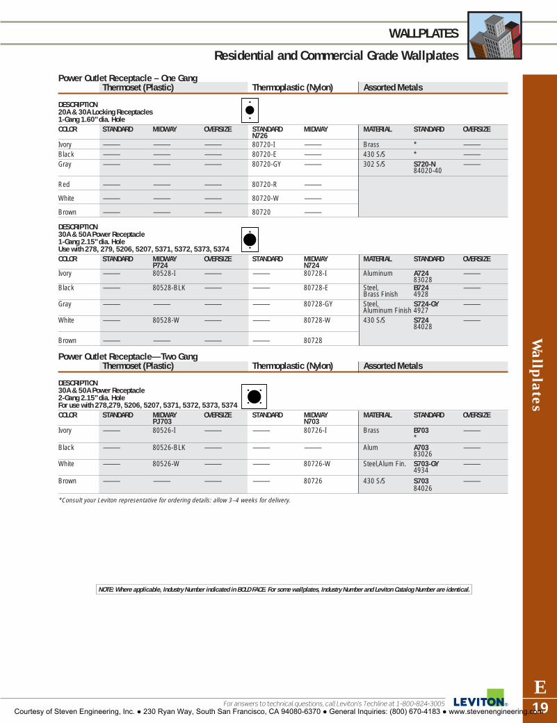
Wallplates
E19For answers to technical questions, call Leviton’s Techline at 1-800-824-3005
WALLPLATES
Residential and Commercial Grade Wallplates
Power Outlet Receptacle – One GangThermoset (Plastic) Thermoplastic (Nylon) Assorted Metals
DESCRIPTION20A & 30A Locking Receptacles 1-Gang 1.60" dia. HoleCOLOR STANDARD MIDWAY OVERSIZE STANDARD MIDWAY MATERIAL STANDARD OVERSIZE
N726Ivory — — — 80720-I — Brass * —Black — — — 80720-E — 430 S/S * —Gray — — — 80720-GY — 302 S/S S720-N —
84020-40
Red — — — 80720-R —
White — — — 80720-W —
Brown — — — 80720 —
DESCRIPTION30A & 50A Power Receptacle1-Gang 2.15" dia. Hole Use with 278, 279, 5206, 5207, 5371, 5372, 5373, 5374 COLOR STANDARD MIDWAY OVERSIZE STANDARD MIDWAY MATERIAL STANDARD OVERSIZE
P724 N724Ivory — 80528-I — — 80728-I Aluminum A724 —
83028Black — 80528-BLK — — 80728-E Steel, B724 —
Brass Finish 4928Gray — — — — 80728-GY Steel, S724-GY —
Aluminum Finish 4927White — 80528-W — — 80728-W 430 S/S S724 —
84028
Brown — — — — 80728
Power Outlet Receptacle—Two GangThermoset (Plastic) Thermoplastic (Nylon) Assorted Metals
DESCRIPTION30A & 50A Power Receptacle2-Gang 2.15" dia. HoleFor use with 278,279, 5206, 5207, 5371, 5372, 5373, 5374COLOR STANDARD MIDWAY OVERSIZE STANDARD MIDWAY MATERIAL STANDARD OVERSIZE
PJ 703 N703Ivory — 80526-I — — 80726-I Brass B703 —
*Black — 80526-BLK — — — Alum A703 —
83026White — 80526-W — — 80726-W Steel,Alum Fin. S703-GY —
4934Brown — — — — 80726 430 S/S S703 —
84026
*Consult your Leviton representative for ordering details: allow 3–4 weeks for delivery.
NOTE: Where applicable, Industry Number indicated in BOLD FACE. For some wallplates, Industry Number and Leviton Catalog Number are identical.
Courtesy of Steven Engineering, Inc. ● 230 Ryan Way, South San Francisco, CA 94080-6370 ● General Inquiries: (800) 670-4183 ● www.stevenengineering.com

Wal
lpla
tes
E20
WALLPLATES
Residential and Commercial Grade Wallplates
To learn more about Leviton’s outstanding offering of devices visit our Website at: www.leviton.com
Power Outlet Receptacle – Two GangThermoset (Plastic) Thermoplastic (Nylon) Assorted Metals
DESCRIPTION2-Gang 2.15" dia. Hole OffsetCOLOR STANDARD MIDWAY OVERSIZE STANDARD MIDWAY MATERIAL STANDARD OVERSIZE
430 S/S S705 —84022
DESCRIPTION30A & 50A Power Receptacle2-Gang 2.465" dia. Hole COLOR STANDARD MIDWAY OVERSIZE STANDARD MIDWAY MATERIAL STANDARD OVERSIZEIvory — 80530-I — — — Steel, Alum Fin S701-GY —
S701-GYBlack — 80530-BLK — — — 430 S/S S701 —
*White — 80530-W — — — 302 S/S S701-40 —
Almond — 80530-A — — —
Light — 80530-T — — —Almond
*Consult your Leviton representative for ordering details: allow 3–4 weeks for delivery.
NOTE: Where applicable, Industry Number indicated in BOLD FACE. For some wallplates, Industry Number and Leviton Catalog Number are identical.
Courtesy of Steven Engineering, Inc. ● 230 Ryan Way, South San Francisco, CA 94080-6370 ● General Inquiries: (800) 670-4183 ● www.stevenengineering.com

Wallplates
E21For answers to technical questions, call Leviton’s Techline at 1-800-824-3005
WALLPLATES
Residential and Commercial Grade Wallplates
Two Gang with Centered OpeningThermoset (Plastic) Thermoplastic (Nylon) Assorted Metals
DESCRIPTION2-Gang 1-ToggleCOLOR STANDARD MIDWAY OVERSIZE STANDARD MIDWAY MATERIAL STANDARD OVERSIZE
Brass 81040 —430 S/S — —302 S/S S740-N —
84040-40
DESCRIPTION2-Gang 1-Phone/Cable.406" Hole, Box MountCOLOR STANDARD MIDWAY OVERSIZE STANDARD MIDWAY MATERIAL STANDARD OVERSIZE
Brass * —430 S/S * —302 S/S * —
DESCRIPTION2-Gang 1-Phone/Cable .406" Hole, Strap MountCOLOR STANDARD MIDWAY OVERSIZE STANDARD MIDWAY MATERIAL STANDARD OVERSIZE
Brass * —430 S/S * —302 S/S * —
DESCRIPTION2-Gang BlankBox MountCOLOR STANDARD MIDWAY OVERSIZE STANDARD MIDWAY MATERIAL STANDARD OVERSIZE
Brass * —430 S/S * —302 S/S * —
DESCRIPTION2-Gang BlankStrap MountCOLOR STANDARD MIDWAY OVERSIZE STANDARD MIDWAY MATERIAL STANDARD OVERSIZE
Brass — —430 S/S — —302 S/S * —
DESCRIPTION2-Gang 1-DecoraCOLOR STANDARD MIDWAY OVERSIZE STANDARD MIDWAY MATERIAL STANDARD OVERSIZE
Brass — —430 S/S * —302 S/S S746-N —
S746-N
DESCRIPTION2-Gang 1 Single Outlet 1.406" dia. HoleCOLOR STANDARD MIDWAY OVERSIZE STANDARD MIDWAY MATERIAL STANDARD OVERSIZE
Brass — —430 S/S * —302 S/S S747-N —
84092-40
DESCRIPTION2-Gang 1-DuplexCOLOR STANDARD MIDWAY OVERSIZE STANDARD MIDWAY MATERIAL STANDARD OVERSIZE
302 S/S S748-N —84039-40
*Consult your Leviton representative for ordering details: allow 3–4 weeks for delivery.
NOTE: Where applicable, Industry Number indicated in BOLD FACE. For some wallplates, Industry Number and Leviton Catalog Number are identical.
Courtesy of Steven Engineering, Inc. ● 230 Ryan Way, South San Francisco, CA 94080-6370 ● General Inquiries: (800) 670-4183 ● www.stevenengineering.com

Wal
lpla
tes
E22
WALLPLATES
Residential and Commercial Grade Wallplates
To learn more about Leviton’s outstanding offering of devices visit our Website at: www.leviton.com
Louvre PlatesThermoset (Plastic) Thermoplastic (Nylon) Assorted Metals
DESCRIPTION1-Gang Center 1-Louvre PlateHorizontal Box MountCOLOR STANDARD MIDWAY OVERSIZE STANDARD MIDWAY MATERIAL STANDARD OVERSIZE
P760Ivory 86079† — — — — Brass B760 —
81079White 88079† — — — — 430 S/S * —
302 S/S S760-N —84079-40
DESCRIPTION1-Gang 1-Louvre PlateStrap MountCOLOR STANDARD MIDWAY OVERSIZE STANDARD MIDWAY MATERIAL STANDARD OVERSIZE
P771Ivory 86080† — — — — Brass B771 —
81080White 88080† — — — — 430 S/S * —Almond 82080† — — — — 302 S/S S771-N —
84080-40
DESCRIPTION2-Gang 2-Louvre PlateStrap MountCOLOR STANDARD MIDWAY OVERSIZE STANDARD MIDWAY MATERIAL STANDARD OVERSIZE
Brass * —430 S/S * —302 S/S S772-N —
84081-40
DESCRIPTION3-Gang 3-Louvre PlateStrap MountCOLOR STANDARD MIDWAY OVERSIZE STANDARD MIDWAY MATERIAL STANDARD OVERSIZE
Brass * —430 S/S * —302 S/S * —
†Painted metal wallplate.*Consult your Leviton representative for ordering details: allow 3–4 weeks for delivery.
NOTE: Where applicable, Industry Number indicated in BOLD FACE. For some wallplates, Industry Number and Leviton Catalog Number are identical.
Courtesy of Steven Engineering, Inc. ● 230 Ryan Way, South San Francisco, CA 94080-6370 ● General Inquiries: (800) 670-4183 ● www.stevenengineering.com

Wallplates
E23For answers to technical questions, call Leviton’s Techline at 1-800-824-3005
WALLPLATES
Residential and Commercial Grade Wallplates
NOTE: Where applicable, Industry Number indicated in BOLD FACE. For some wallplates, Industry Number and Leviton Catalog Number are identical.
Combination WallplatesToggle Switch and Single Receptacle
Thermoset (Plastic) Thermoplastic (Nylon) Assorted Metals
DESCRIPTION2-Gang 1-Toggle 1-Single 1.406" dia. HoleCOLOR STANDARD MIDWAY OVERSIZE STANDARD MIDWAY MATERIAL STANDARD OVERSIZE
P17Ivory 86007 — — — — Aluminum * —White 88007 — — — — Brass * —
430 S/S S17 —84007
302 S/S S17-N —84007-40
DESCRIPTION3-Gang 2-Toggles 1-Single 1.406" dia. HoleCOLOR STANDARD MIDWAY OVERSIZE STANDARD MIDWAY MATERIAL STANDARD OVERSIZE
Aluminum * —Brass * —430 S/S * —302 S/S S27-N —
84088-40
DESCRIPTION4-Gang 3-Toggles 1-Single 1.406" dia. HoleCOLOR STANDARD MIDWAY OVERSIZE STANDARD MIDWAY MATERIAL STANDARD OVERSIZE
Aluminum * —Brass * —430 S/S * —302 S/S S37-N —
84042-40
Combination WallplatesToggle Switch and Duplex Receptacle
Thermoset (Plastic) Thermoplastic (Nylon) Assorted Metals
DESCRIPTION2-Gang 1-Toggle 1-DuplexCOLOR STANDARD MIDWAY OVERSIZE STANDARD MIDWAY MATERIAL STANDARD OVERSIZE
P18 SPJ18 PO18 N18Ivory 86005 80505-I 86105 80705-I PJ18-I Aluminum A18 —
83005Black — — — 80705-E PJ18-E Brass B18 —
81005Gray 87005 — — 80705-GY — 430 S/S S18 *
84005Red — — — 80705-R — 302 S/S S18-N SO18-N
84005-40 84105-40White 88005 80505-W 88105 80705-W PJ18-WBrown 85005 80505 — 80705 -----Almond 82005 80505-A — 80705-A PJ18-ALight 78005 80505-T — 80705-T PJ18-TAlmond
*Consult your Leviton representative for ordering details: allow 3–4 weeks for delivery.
Courtesy of Steven Engineering, Inc. ● 230 Ryan Way, South San Francisco, CA 94080-6370 ● General Inquiries: (800) 670-4183 ● www.stevenengineering.com
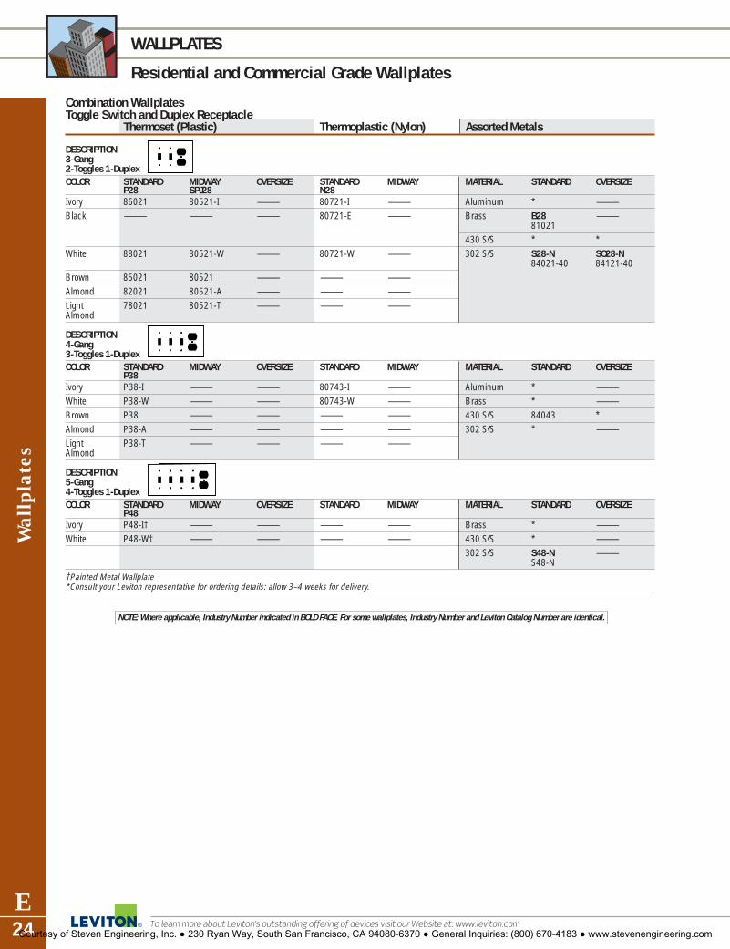
Wal
lpla
tes
E24
WALLPLATES
Residential and Commercial Grade Wallplates
To learn more about Leviton’s outstanding offering of devices visit our Website at: www.leviton.com
Combination WallplatesToggle Switch and Duplex Receptacle
Thermoset (Plastic) Thermoplastic (Nylon) Assorted Metals
DESCRIPTION3-Gang 2-Toggles 1-DuplexCOLOR STANDARD MIDWAY OVERSIZE STANDARD MIDWAY MATERIAL STANDARD OVERSIZE
P28 SPJ28 N28Ivory 86021 80521-I — 80721-I — Aluminum * —Black — — — 80721-E — Brass B28 —
81021430 S/S * *
White 88021 80521-W — 80721-W — 302 S/S S28-N SO28-N84021-40 84121-40
Brown 85021 80521 — — —Almond 82021 80521-A — — —Light 78021 80521-T — — —Almond
DESCRIPTION4-Gang 3-Toggles 1-DuplexCOLOR STANDARD MIDWAY OVERSIZE STANDARD MIDWAY MATERIAL STANDARD OVERSIZE
P38Ivory P38-I — — 80743-I — Aluminum * —White P38-W — — 80743-W — Brass * —Brown P38 — — — — 430 S/S 84043 *Almond P38-A — — — — 302 S/S * —Light P38-T — — — —Almond
DESCRIPTION5-Gang 4-Toggles 1-DuplexCOLOR STANDARD MIDWAY OVERSIZE STANDARD MIDWAY MATERIAL STANDARD OVERSIZE
P48Ivory P48-I† — — — — Brass * —White P48-W† — — — — 430 S/S * —
302 S/S S48-N —S48-N
†Painted Metal Wallplate*Consult your Leviton representative for ordering details: allow 3–4 weeks for delivery.
NOTE: Where applicable, Industry Number indicated in BOLD FACE. For some wallplates, Industry Number and Leviton Catalog Number are identical.
Courtesy of Steven Engineering, Inc. ● 230 Ryan Way, South San Francisco, CA 94080-6370 ● General Inquiries: (800) 670-4183 ● www.stevenengineering.com

Wallplates
E25For answers to technical questions, call Leviton’s Techline at 1-800-824-3005
WALLPLATES
Residential and Commercial Grade Wallplates
Combination WallplatesToggle Switch and Decora/GFCI
Thermoset (Plastic) Thermoplastic (Nylon) Assorted Metals
DESCRIPTION2-Gang 1-Toggle 1-Decora/GFCICOLOR STANDARD MIDWAY OVERSIZE STANDARD MIDWAY MATERIAL STANDARD OVERSIZE
P126 SPJ126 PO126 PJ126Ivory 80405-I 80605-I 86605 80707-I PJ126-I Brass * —Black 80405-E — — 80707-E — 430 S/S S126 —
S126Gray 80405-GY — — 80707-GY — 302 S/S * —Red — — — 80707-R —White 80405-W 80605-W 88605 80707-W PJ126-WBrown 80405 80605 — 80707 PJ126Almond 80405-A 80605-A 82605 80707-A PJ126-ALight 80405-T 80605-T — 80707-T PJ126-TAlmond
DESCRIPTION3-Gang 2-Toggles 1-Decora/GFCICOLOR STANDARD MIDWAY OVERSIZE STANDARD MIDWAY MATERIAL STANDARD OVERSIZE
P226 SPJ226 SPJ226Ivory 80421-I — — 80745-I PJ226-I Brass * —Black 80421-E — — — — 430 S/S * —White 80421-W — — 80745-W PJ226-W 302 S/S S226-N —
84421-40Brown 80421 — — — PJ226Almond 80421-A — — 80745-A PJ226-ALight 80421-T — — — PJ226-TAlmond
DESCRIPTION3-Gang 2-Decora/GFCI 1 - ToggleCOLOR STANDARD MIDWAY OVERSIZE STANDARD MIDWAY MATERIAL STANDARD OVERSIZE
P1262Ivory 80431-I — — 80731-I — Brass * —Black — — — 80731-E — 430 S/S * —Gray 80431-GY — — 80731-GY — 302 S/S * —White 80431-W — — 80731-W —Brown 80431 — — — —Almond 80431-A — — — —Light 80431-T — — — —Almond
DESCRIPTION4-Gang 2-Toggles 2-Decora/GFCI COLOR STANDARD MIDWAY OVERSIZE STANDARD MIDWAY MATERIAL STANDARD OVERSIZE
P326Ivory P326-I — — 80732-I — Brass * —White P326-W — — 80732-W — 430 S/S * —Brown P326 — — — — 302 S/S * —Almond P326-A — — — —Light P326-T — — — —Almond
DESCRIPTION4-Gang 3-Toggles 1-Decora/GFCI COLOR STANDARD MIDWAY OVERSIZE STANDARD MIDWAY MATERIAL STANDARD OVERSIZE
P2262 SPJ826Ivory P2262-I† — — Brass * —White P2262-W† — — — — 430 S/S * —
302 S/S * —
DESCRIPTION5-Gang 4-Toggles 1-Decora/GFCI COLOR STANDARD MIDWAY OVERSIZE STANDARD MIDWAY MATERIAL STANDARD OVERSIZE
SPJ826Brass * —430 S/S * —302 S/S S426-N
S426-N —†Painted metal wallplate.*Consult your Leviton representative for ordering details: allow 3–4 weeks for delivery.
Courtesy of Steven Engineering, Inc. ● 230 Ryan Way, South San Francisco, CA 94080-6370 ● General Inquiries: (800) 670-4183 ● www.stevenengineering.com
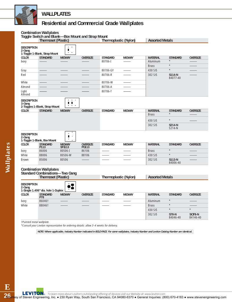
Wal
lpla
tes
E26
WALLPLATES
Residential and Commercial Grade Wallplates
To learn more about Leviton’s outstanding offering of devices visit our Website at: www.leviton.com
Combination WallplatesToggle Switch and Blank—Box Mount and Strap Mount
Thermoset (Plastic) Thermoplastic (Nylon) Assorted Metals
DESCRIPTION2-Gang 1-Toggle 1-Blank, Strap MountCOLOR STANDARD MIDWAY OVERSIZE STANDARD MIDWAY MATERIAL STANDARD OVERSIZEIvory — — — 80706-I — Aluminum * —
Brass * —Gray — — — 80706-GY — 430 S/S * —Red — — — 80706-R — 302 S/S S114-N —
84077-40White — — — 80706-W —Almond — — — 80706-A —Light — — — 80706-T —Almond
DESCRIPTION3-Gang 2-Toggles 1-Blank, Strap MountCOLOR STANDARD MIDWAY OVERSIZE STANDARD MIDWAY MATERIAL STANDARD OVERSIZE
Brass * —
430 S/S * —302 S/S S214-N
S214-N
DESCRIPTION2-Gang 1-Toggle 1-Blank, Box MountCOLOR STANDARD MIDWAY OVERSIZE STANDARD MIDWAY MATERIAL STANDARD OVERSIZE
P113 SPJ113 PO113Ivory 86006 80506-I 86106 — — Brass * —White 88006 80506-W 88106 — — 430 S/S * —Brown 85006 80506 — — — 302 S/S S113-N —
84006-40
Combination WallplatesStandard Combinations—Two Gang
Thermoset (Plastic) Thermoplastic (Nylon) Assorted Metals
DESCRIPTION2-Gang 1-Single 1.406" dia. hole 1-DuplexCOLOR STANDARD MIDWAY OVERSIZE STANDARD MIDWAY MATERIAL STANDARD OVERSIZE
P78Ivory 86046† — — — — Aluminum * —White 88046† — — — — Brass * —
430 S/S * *302 S/S S78-N SO78-N
84046-40 84146-40†Painted metal wallplate.*Consult your Leviton representative for ordering details: allow 3–4 weeks for delivery.
NOTE: Where applicable, Industry Number indicated in BOLD FACE. For some wallplates, Industry Number and Leviton Catalog Number are identical.
Courtesy of Steven Engineering, Inc. ● 230 Ryan Way, South San Francisco, CA 94080-6370 ● General Inquiries: (800) 670-4183 ● www.stevenengineering.com
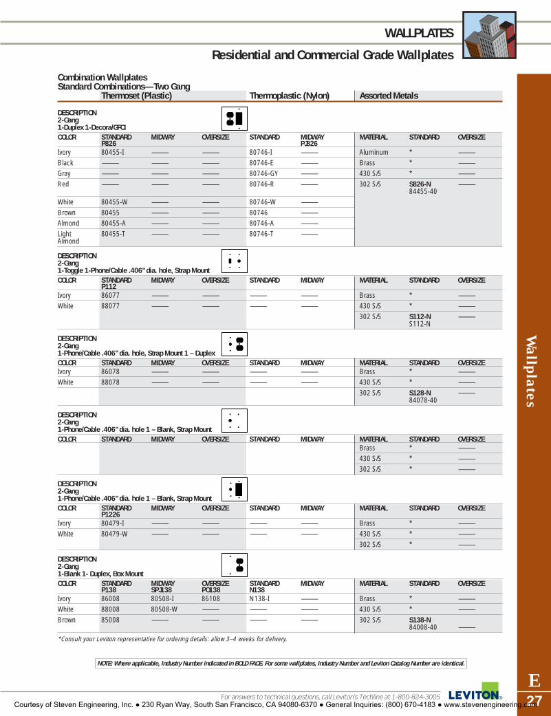
Wallplates
E27For answers to technical questions, call Leviton’s Techline at 1-800-824-3005
WALLPLATES
Residential and Commercial Grade Wallplates
Combination WallplatesStandard Combinations—Two Gang
Thermoset (Plastic) Thermoplastic (Nylon) Assorted Metals
DESCRIPTION2-Gang 1-Duplex 1-Decora/GFCICOLOR STANDARD MIDWAY OVERSIZE STANDARD MIDWAY MATERIAL STANDARD OVERSIZE
P826 PJ826Ivory 80455-I — — 80746-I — Aluminum * —Black — — — 80746-E — Brass * —Gray — — — 80746-GY — 430 S/S * —Red — — — 80746-R — 302 S/S S826-N —
84455-40White 80455-W — — 80746-W —Brown 80455 — — 80746 —Almond 80455-A — — 80746-A —Light 80455-T — — 80746-T —Almond
DESCRIPTION2-Gang 1-Toggle 1-Phone/Cable .406" dia. hole, Strap MountCOLOR STANDARD MIDWAY OVERSIZE STANDARD MIDWAY MATERIAL STANDARD OVERSIZE
P112Ivory 86077 — — — — Brass * —White 88077 — — — — 430 S/S * —
302 S/S S112-N —S112-N
DESCRIPTION2-Gang 1-Phone/Cable .406" dia. hole, Strap Mount 1 – DuplexCOLOR STANDARD MIDWAY OVERSIZE STANDARD MIDWAY MATERIAL STANDARD OVERSIZEIvory 86078 — — — — Brass * —White 88078 — — — — 430 S/S * —
302 S/S S128-N —84078-40
DESCRIPTION2-Gang 1-Phone/Cable .406" dia. hole 1 – Blank, Strap MountCOLOR STANDARD MIDWAY OVERSIZE STANDARD MIDWAY MATERIAL STANDARD OVERSIZE
Brass * —430 S/S * —302 S/S * —
DESCRIPTION2-Gang 1-Phone/Cable .406" dia. hole 1 – Blank, Strap MountCOLOR STANDARD MIDWAY OVERSIZE STANDARD MIDWAY MATERIAL STANDARD OVERSIZE
P1226Ivory 80479-I — — — — Brass * —White 80479-W — — — — 430 S/S * —
302 S/S * —
DESCRIPTION2-Gang 1-Blank 1- Duplex, Box Mount COLOR STANDARD MIDWAY OVERSIZE STANDARD MIDWAY MATERIAL STANDARD OVERSIZE
P138 SPJ138 PO138 N138Ivory 86008 80508-I 86108 N138-I — Brass * —White 88008 80508-W — — — 430 S/S * —Brown 85008 — — — — 302 S/S S138-N
84008-40 —
*Consult your Leviton representative for ordering details: allow 3–4 weeks for delivery.
NOTE: Where applicable, Industry Number indicated in BOLD FACE. For some wallplates, Industry Number and Leviton Catalog Number are identical.
Courtesy of Steven Engineering, Inc. ● 230 Ryan Way, South San Francisco, CA 94080-6370 ● General Inquiries: (800) 670-4183 ● www.stevenengineering.com

Wal
lpla
tes
E28
WALLPLATES
Residential and Commercial Grade Wallplates
To learn more about Leviton’s outstanding offering of devices visit our Website at: www.leviton.com
Combination WallplatesStandard Combinations—Two Gang
Thermoset (Plastic) Thermoplastic (Nylon) Assorted Metals
DESCRIPTION2-Gang 1-Blank 1- Duplex, Strap MountCOLOR STANDARD MIDWAY OVERSIZE STANDARD MIDWAY MATERIAL STANDARD OVERSIZE
P148 PJ826Ivory 86087† — — — — Brass * —White 88087† — — — — 430 S/S * —
302 S/S S148-N —84087-40
DESCRIPTION2-Gang 1-Blank 1-Single 1.406" dia. hole, Strap MountCOLOR STANDARD MIDWAY OVERSIZE STANDARD MIDWAY MATERIAL STANDARD OVERSIZE
P147-IIvory 86085† — — — — Aluminum * —White 88085† — — — — Brass * —
430 S/S * —302 S/S S147-N —
84085-40
DESCRIPTION2-Gang 1-Blank 1-Decora/GFCI, Strap MountCOLOR STANDARD MIDWAY OVERSIZE STANDARD MIDWAY MATERIAL STANDARD OVERSIZE
P1426 SPJ1326Ivory P1426-I† 80608-I — 80708-I — Brass * —Black — — — 80708-E — 430 S/S * *Gray — — — 80708-GY — 302 S/S S1426-N *
S1426-NWhite P1426-W† 80608-W — 80708-W —Brown — 80608 — 80708 —Almond — 80608-A — 80708-A —Light — 80608-T — 80708-T —Almond
STANDARD COMBINATIONS—THREE GANGDESCRIPTION3-Gang 1-Toggle 2-DuplexCOLOR STANDARD MIDWAY OVERSIZE STANDARD MIDWAY MATERIAL STANDARD OVERSIZE
P182Ivory 86047 — — 80747-I — Brass * —White 88047 — — 80747-W — 430 S/S * *Brown 85047 — — — — 302 S/S S182-N SO182-N
84047-40 84147-40
STANDARD COMBINATIONS—FOUR GANGDESCRIPTION4-Gang 2-Toggle 2-DuplexCOLOR STANDARD MIDWAY OVERSIZE STANDARD MIDWAY MATERIAL STANDARD OVERSIZE
P1226Aluminum * —Brass B282 —
81045430 S/S * —302 S/S S282-N —
84045-40†Painted metal wallplate.*Consult your Leviton representative for ordering details: allow 3–4 weeks for delivery.
NOTE: Where applicable, Industry Number indicated in BOLD FACE. For some wallplates, Industry Number and Leviton Catalog Number are identical.
Courtesy of Steven Engineering, Inc. ● 230 Ryan Way, South San Francisco, CA 94080-6370 ● General Inquiries: (800) 670-4183 ● www.stevenengineering.com

Engraved W
allplates
E29For answers to technical questions, call Leviton’s Techline at 1-800-824-3005
ENGRAVED WALLPLATES
Residential and Commercial Grade Wallplates
Sectional Wallplates for Multi-Gang Installations†Thermoplastic Construction
DESCRIPTION COLOR CENTER PANELS END PANELSCAT. NO. CAT. NO.
Duplex Receptacle White PSC 8-W PSE 8-WIvory PSC 8-I PSE 8-I
Toggle Switch White PSC 1-W PSE 1-WIvory PSC 1-I PSE 1-I
Single Receptacle, White PSC 7-W PSE 7-W 1.406" dia. hole Ivory PSC 7-I PSE 7-IBlank, Strap-Mount White PSC 14 PSE 14-W
Ivory PSC14-I PSE 14-IDecora White PSC 26-W PSE 26-W
Ivory PSC 26-I PSE 26-I
†Outer dimensions of wallplates created from two or more sectional panels will be the same as standard multi-gang plates.
Center End
Duplex Receptacle
Horizontal Split Plate for Terminated Cable
DESCRIPTIONHorizontal Split Plate for Terminated Cable1-Gang .625” dia. Hole w/Grommet .406" inner dia.COLOR CAT. NO. IND. NO. METAL CAT. NO. IND. NO.Ivory N751-I N751-I BRASS * —White N751-W N751-W 430 S/S * —
302 S/S S751-N S751-N
Hot Stamped And Engraved PlatesThermoset (Plastic) Thermoplastic (Nylon) Assorted Metals (Engraved)
DESCRIPTION1-Gang 1-DuplexStamped And Engraved “EMERGENCY”COLOR STANDARD MIDWAY OVERSIZE STANDARD MIDWAY MATERIAL STANDARD OVERSIZERed — — — 80703-RE PJ8-RE 302 S/S 84003-E40 —
2-Gang 2-DuplexStamped And Engraved “EMERGENCY”COLOR STANDARD MIDWAY OVERSIZE STANDARD MIDWAY MATERIAL STANDARD OVERSIZERed — — — 80716-RE PJ82-RE 302 S/S 84016-E40
1-Gang 1-DuplexStamped And Engraved “ISOLATED GROUND”COLOR STANDARD MIDWAY OVERSIZE STANDARD MIDWAY MATERIAL STANDARD OVERSIZEOrange — — — 80703-IG PJ8-IG 302 S/S 84003-IG —White — — — 80703-IGW —
2-Gang 2-DuplexStamped And Engraved “ISOLATED GROUND”COLOR STANDARD MIDWAY OVERSIZE STANDARD MIDWAY MATERIAL STANDARD OVERSIZEOrange — — — 80716-IG — 302 S/S * —
1-Gang 1-Single, 1.406" Dia. Hole Stamped And Engraved “ISOLATED GROUND”COLOR STANDARD MIDWAY OVERSIZE STANDARD MIDWAY MATERIAL STANDARD OVERSIZEOrange — — 80704-IG — 302 S/S * —
*Consult The End Of This Wallplate Section For Ordering Details: Allow 3-4 Weeks For Delivery.
EMERGENCY
ISOLATEDGROUND
EMERGENCY
ISOLATEDGROUND
ISOLATED
GROUND
Courtesy of Steven Engineering, Inc. ● 230 Ryan Way, South San Francisco, CA 94080-6370 ● General Inquiries: (800) 670-4183 ● www.stevenengineering.com
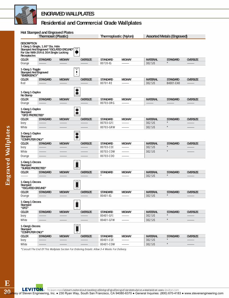
To learn more about Leviton’s outstanding offering of devices visit our Website at: www.leviton.com
GFCI
PROTECTED
To learn more about Leviton’s outstanding offering of devices visit our Website at: www.leviton.com
Eng
rave
d W
allp
late
s
E30
ENGRAVED WALLPLATES
Residential and Commercial Grade Wallplates
Hot Stamped and Engraved PlatesThermoset (Plastic) Thermoplastic (Nylon) Assorted Metals (Engraved)
DESCRIPTION1-Gang 1-Single, 1.60" Dia. Hole Stamped And Engraved “ISOLATED GROUND”For Use With 20A & 30A Single Locking Receptacles COLOR STANDARD MIDWAY OVERSIZE STANDARD MIDWAY MATERIAL STANDARD OVERSIZEOrange — — — 80720-IG — 302 S/S * —
1-Gang 1-Toggle Stamped And Engraved “EMERGENCY”COLOR STANDARD MIDWAY OVERSIZE STANDARD MIDWAY MATERIAL STANDARD OVERSIZERed — — — 80701-RE — 302 S/S 84001-E40 —
1-Gang 1-DuplexNo StampCOLOR STANDARD MIDWAY OVERSIZE STANDARD MIDWAY MATERIAL STANDARD OVERSIZEOrange — — — 80703-ORG — — — —
1-Gang 1-DuplexStamped“GFCI PROTECTED”COLOR STANDARD MIDWAY OVERSIZE STANDARD MIDWAY MATERIAL STANDARD OVERSIZEIvory — — — 80703-GFI — 302 S/S * —White — — — 80703-GRW — 302 S/S * —
1-Gang 1-DuplexStamped “COMPUTER ONLY”COLOR STANDARD MIDWAY OVERSIZE STANDARD MIDWAY MATERIAL STANDARD OVERSIZEIvory — — — 80703-COI — 302 S/S * —White — — — 80703-COW — 302 S/S * —Orange — — — 80703-COO —
1-Gang 1-Decora Stamped “SURGE PROTECTED”COLOR STANDARD MIDWAY OVERSIZE STANDARD MIDWAY MATERIAL STANDARD OVERSIZE— — — — * — 302 S/S * —
1-Gang 1-Decora Stamped“ISOLATED GROUND”COLOR STANDARD MIDWAY OVERSIZE STANDARD MIDWAY MATERIAL STANDARD OVERSIZEOrange — — — 80401-IG — 302 S/S * —
1-Gang 1-Decora Stamped “GFCI”COLOR STANDARD MIDWAY OVERSIZE STANDARD MIDWAY MATERIAL STANDARD OVERSIZEIvory — — — 80401-GFI — 302 S/S * —White — — — 80401-GFW — 302 S/S * —
1-Gang1-Decora Stamped “COMPUTER ONLY”COLOR STANDARD MIDWAY OVERSIZE STANDARD MIDWAY MATERIAL STANDARD OVERSIZEIvory — — — 80401-COI — 302 S/S * —White — — — 80401-COW — 302 S/S * —
*Consult The End Of This Wallplate Section For Ordering Details: Allow 3-4 Weeks For Delivery.
GFCI
PROTECTED
COMPUTER
ONLY
SURGE
PROTECTED
ISOLATED
GROUND
GFCI
COMPUTER
ONLY
ISOLATEDGROUND
EMERGENCY
Courtesy of Steven Engineering, Inc. ● 230 Ryan Way, South San Francisco, CA 94080-6370 ● General Inquiries: (800) 670-4183 ● www.stevenengineering.com

Voice/Data/CAT
V W
allplates
E31For answers to technical questions, call Leviton’s Techline at 1-800-824-3005
WALLPLATES
Commercial Grade
Standard SizeVoice/Data/Catv Wallplates*DESCRIPTION COLOR (NYLON) METAL CAT. NO.1-Gang Ivory — 80781-IType “F” Connector White — 80781-W
Almond — 80781-ALight Almond — 80781-T
1-Gang Ivory — 80782-IDuplex White — 80782-WType “F” Connector Almond — 80782-A
Light Almond — 80782-T1-Gang* — 302 S/S 84441-40Db9 Data Connector — 302 S/S 84442-40Db15 Data Connector
1-Gang* — 302 S/S 84444-40Bnc/Tnc “D” Connector
Voice/Data/CATV WallplatesThese sturdy, high-impact wallplates for the 46000 series voice/data devices are available for single-gang applications with standard or Decora-compatible styling.
For more information regarding Voice/Data/CATV Wallplates, refer to Section L.
Courtesy of Steven Engineering, Inc. ● 230 Ryan Way, South San Francisco, CA 94080-6370 ● General Inquiries: (800) 670-4183 ● www.stevenengineering.com

To learn more about Leviton’s outstanding offering of devices visit our Website at: www.leviton.com
Wea
ther
-Res
ista
nt C
over
s
E32
WEATHER-RESISTANT COVERS
Commercial Grade
Features and BenefitsPlastic� Impact resistant thermoplastic
construction� Pre-installed gasket for easy,
reliable installation� Tongue and groove plate-to-cover
construction� Offset device opening (horizontal
only) for easier cord exit� Thermoplastic inserts prevent insect
and debris accumulation
Plastic and Metal� Self-closing� Vertical and horizontal mounting� Die cast aluminum or impact-
resistant thermoplastic covers and bases
� Weather-resistant gaskets� Stainless steel springs� Gray or clear finish
SPECIFICATIONS & FEATURES
• Mounting Screws and rubber gasket included forfast, easy installation onto surface-mounted out-door-type boxes or flush-mounted wall boxes
• Easy-grip self-closing covers with durable, noncor-rosive stainless steel screws
• acked by a Limited Two-Year Warranty
TESTING AND CODE COMPLIANCE
• Full compliance with UL, CSA and NEC Section410-57 requirements for damp and wet locations with cover closed
• Raintight while-in-use covers are NEMA 3R ratedfor use with unattended plugs engaged in “live”receptacles in wet or damp locations
*COLOR
Basic Cat. No. denotes Brown. For other color selections, add suffix to catalog numbers as follows:White (-W), Light Almond (-T), Gray (-GY).
5.05 (128.3)Ø 0.25 (6.4)
padlock opening
5.46
(13
8.7)
2.88 (73.2)
Ø 0.63 (16.0)cord opening
3.75 (95.6)
6.59
(16
7.4
mm
)
3.30 (83.8)
Ø 0.25 (16.0)cord opening
HORIZONTAL MOUNT, STANDARD5997
VERTICAL MOUNT, EXTRA DEEP5976-D
Raintight While-In-Use CoversDESCRIPTION MOUNTING CAT. NO.Telescoping While-In-Use Smoked Cover Vertical T5979-WWith Colored Base And Matching Duplex, Vertical T5979-TDecora And Single Receptacle Wallplates Vertical T5979-GY
Vertical T5979Duplex Receptacle, Gray, Standard Vertical 5976-GYDuplex Receptacle, Gray, Extra Deep Vertical 5976-DGYDuplex Receptacle, Clear, Standard Vertical 5976-CLDuplex Receptacle, Clear, Extra Deep Vertical 5976-DCLDecora/GFCI, Clear, Standard Vertical 5977-CLDecora/GFCI, Clear, Extra Deep Vertical 5977-DCLSingle Receptacle, Gray, Standard Vertical 5978-GYSingle Receptacle, Clear, Standard Vertical 5978-CLSingle Receptacle, Gray, Extra Deep Vertical 5978-DGYSingle Receptacle, Clear, Extra Deep Vertical 5978-DCLDuplex Receptacle, Gray, Standard Horizontal 5996-GYDuplex Receptacle, Gray, Extra Deep Horizontal 5996-DGYDuplex Receptacle, Clear, Standard Horizontal 5996-CLDecora/GFCI, Gray, Standard Horizontal 5997-GYDecora/GFCI, Gray, Extra Deep Horizontal 5997-DGYDecora/GFCI, Clear, Standard Horizontal 5997-CLDecora/GFCI, Clear, Extra Deep Horizontal 5997-DCLSingle Receptacle, Gray, Standard Horizontal 5998-GYSingle Receptacle, Gray, Extra Deep Horizontal 5998-DGYSingle Receptacle, Clear, Standard Horizontal 5998-CL
Courtesy of Steven Engineering, Inc. ● 230 Ryan Way, South San Francisco, CA 94080-6370 ● General Inquiries: (800) 670-4183 ● www.stevenengineering.com

Weather-R
esistant Covers
E33For answers to technical questions, call Leviton’s Techline at 1-800-824-3005
WEATHER-RESISTANT COVERS
Industrial Grade
Industrial Weather-Resistant CoversDESCRIPTION COLOR CAT. NO.For use with 15-amp locking, GRAY WP115-amp and 20-amp straight-blade flanged inlets and outletsFor use with 20-amp and 30-amp GRAY WP23-, 4-, and 5-wire locking flanged inlets and outlets; 30-amp and 50-amp 3-wire power receptaclesFor use with 20-amp and 30-amp YELLOW 7420-CRand FS/FD boxes single locking receptacles
TESTING AND CODE COMPLIANCE
• UL Listed (File # E-13397)• CSA Certified (File # LR-16347)• NOM Certified (# 057)• IP 54 Suitability rating (protected against
dust and splashing water)• NEMA Type 3R enclosure rating• Backed by a Limited 10-Year Warranty
MATERIAL CHARACTERISTICS
Environmental: VO Flammability Rating per UL 94Operating Temperature: -40°C to 75°C
Features and Benefits� Glass-filled thermoplastic cover and
plate for outstanding impact resistanceand durability
� UL 94-VO Flammability Rating� Superior IP 54 Suitability rating protects
against dust particles and splashingwater
� NEMA Type 3R enclosure rating ensuresprotection against rain, sleet and damage from external ice formation
� Dual gaskets, one under plate and one under lid, for weather-resistant fit
� Stainless steel hinge-pin, spring andmounting screws for excellent corrosionresistance
� Triple-combination screws acceptPhillips, straight-blade or Robertson-head screwdrivers
� Oversized cover tab for easier openingwith gloved hands
� Mounts to panel or FS/FD boxes� UL Listed and CSA certified for wet
locations with cover closed
CL
CL
L
B
BCL
CL
4.76 (120.9) GASKET
4.56 (115.8)
2.8
4 (
72
.1)
Ø3
.57
(9
0.7
)
3.25 (82.6) (2PL)
1.88
(47
.8)(2
PL)
3.0
4 (
77
.2)
GA
SK
ET
(4) 6-32 TRIPLE HEADMOUNTING SCREW
CLCL
CL
1.1
6
(29
.5)
4.65 (118.1)
SECTION A–A
COVER GASKET
COVER
PLATE
BOTTOM PLATEGASKET
PLATE GASKET
CL C
A A
CL
CL
CL CL
A
B
B
4.56 (115.8)
3.25 (82.6)
2.8
4 (
72
.1)
4.76 (120.9) GASKET
1.8
8 (
47
.8)
(4) 6-32 TRIPLE HEADMOUNTING SCREW
CLCL
1.06
(2
6.9)
SECTION A–A
COVER GASKET
COVER
PLATEBOTTOM PLATEGASKET
PLATE GASKET
CL
3.0
4 (
77
.2)
GA
SK
ET
Ø3
.26
(8
2.8
)A
WATER RESISTANT COVERWP2
WATER RESISTANT COVERWP1 and 7420-CR
Courtesy of Steven Engineering, Inc. ● 230 Ryan Way, South San Francisco, CA 94080-6370 ● General Inquiries: (800) 670-4183 ● www.stevenengineering.com

To learn more about Leviton’s outstanding offering of devices visit our Website at: www.leviton.com
Wea
ther
-Res
ista
nt C
over
s
E34
WEATHER-RESISTANT COVERS
Industrial Grade
Die-Cast Zinc Weather-Resistant CoversDESCRIPTION MOUNTING CAT. NO.Duplex Receptacle Vertical 49261-GANG
Single Receptacle Horizontal 4925-21-GANG Self-Closing Lid1.406 Dia. Hole
Duplex Receptacle or Horizontal 4970Combination Device1-GANGTwo IndependentSelf-Closing Lids★
Decora/GFCI Horizontal 49901-GANG Self-Closing Lid
Decora/GFCI Vertical 49921-GANG Self-Closing Lid★
Decora/GFCI Horizontal 6196-FS1-GANG Self-Closing Lidfor mounting on FS type boxDecora/GFCI Vertical 6196-VFS1-GANG Self-Closing Lidfor mounting on FS type box
Weatherproof Horizontal 1432Wallplate & Switch or15A 120V AC Vertical
NEMA 1 Steel Enclosure Vertical N13NCwithout Switch
DESCRIPTION COLOR CAT. NO.Lockout Wallplate S/S 84001-LOK(lock sold separately)
All devices are UL Listed . Also CSA Certified except where indicated by★
Courtesy of Steven Engineering, Inc. ● 230 Ryan Way, South San Francisco, CA 94080-6370 ● General Inquiries: (800) 670-4183 ● www.stevenengineering.com

Weather-R
esistant Covers
E35For answers to technical questions, call Leviton’s Techline at 1-800-824-3005
WEATHER-RESISTANT COVERS
Commercial Grade
Thermoplastic Weather-Resistant CoversDESCRIPTION MOUNTING CAT. NO.Duplex Receptacle Horizontal 4976-GYor Combination Device 4976-W1-GANGTwo IndependentSelf-Closing LidsDuplex Receptacle Horizontal 4976-FSor Combination Device1-GANG for mountingon FS type boxTwo Independent LidsDuplex Receptacle or Vertical 4978-GYCombination Device 4978-W1-GANG Self-Closing Lid
Single Receptacle Vertical 4979-GY1-GANG Self-Closing Lid1.406" Dia. Hole
Single 20A or 30A Locking Vertical 4980-GYReceptacle 1-GANG Self-Closing Lid1.60" Dia. Hole
Decora/GFCI Horizontal 4996-GY1-GANG 4996-WSelf-Closing Lid
Decora/GFCI Vertical 4998-GY1-GANG 4998-WSelf-Closing Lid
Oversized Duplex Horizontal 4986-GY1-GANG Two Independant Self-Closing Lids
Blank Box Mounted Wallplates with GasketDESCRIPTION MOUNTING CAT. NO.1-GANG N/A 83014-EXTAluminum, Box Mount
2-GANG N/A 83025-EXTAluminum, Box Mount
Type 302 Stainless Steel Wallplate—Box MountDESCRIPTION COLOR CAT. NO.Type 302 Stainless Steel S/S 84071-40Wallplate w/Tamper-Resistant Screws and Spanner Tool
All devices are UL Listed and CSA Certified.
Courtesy of Steven Engineering, Inc. ● 230 Ryan Way, South San Francisco, CA 94080-6370 ● General Inquiries: (800) 670-4183 ● www.stevenengineering.com

To learn more about Leviton’s outstanding offering of devices visit our Website at: www.leviton.com
Wal
lpla
te A
cces
sori
es
E36
WALLPLATE ACCESSORIES
Commercial Grade
Wallplate Screws
DESCRIPTION COLOR CAT. NO.
Oval Head Milled Slot Ivory 86400-PRT5/16" long – 6-32 thread 100 per box Gray 87400-PRT
White 88400-PRTBrown 85400-PRTAlmond 82400-PRTS/S 84400-PRT
Oval Head Milled Slot Ivory 86000-PRT1/2" long—6-32 thread 100 per box Black 83000-PRT
Gray 87000-PRTWhite 88000-PRTBrown 85000-PRTS/S 84000-PRT
Oval Head Milled Slot Ivory 86500-PRT7/8" long—6-32 thread 50 per box Red 89500-PRT
White 88500-PRTBrown 85500-PRTS/S 84500-PRT
Pilot Light Jewels
DESCRIPTION COLOR CAT. NO.
Round Green 405 GRFits single receptacle hole Red 405 R1.375–1.406" dia.
Rectangular Green 406 GRFits toggle switch hole Red 406 R.406 x .942"
Lampholder Assembly 2152for use with jewels orlouvre plates—use withstandard 2.5" box and 4 watt bulb(bulb included)
Mounting Screws
DESCRIPTION COLOR CAT. NO.
Phillips/Standard S/S 844407/8" long—6-32 thread 50 per bag
Decora Plus Standard Size Plastic Adapters
DESCRIPTION COLOR CAT. NO.
CATV Jack Ivory 80381-IBlack 80381-EGray 80381-GYWhite 80381-WAlmond 80381-ALight Almond 80381-T
Blank Ivory 80314-INo Hole Black 80314-E
Gray 80314-GYWhite 80314-WAlmond 80314-ALight Almond 80314-T
All devices are UL Listed and CSA Certified.
Tamper-Resistant Spanner Head Screws
DESCRIPTION COLOR CAT. NO.
Spanner Head S/S 84000-T1/2" long—6-32 thread, 100 per box
Screwdriver Black 84000-TSDfor Spanner head orTamper-Resistant screws
Plastic Wallplate Adapters
DESCRIPTION COLOR CAT. NO.
These adapters permit the use of rotary dimmers in multi-gang Decora installations or fill blank holes in multi-device Decora or togglewallplates.
Dimmer Shaft Ivory 80400-I.406" dia. Hole Black 80400-E
Gray 80400-GYBrown 80400White 80400-WAlmond 80400-ALight 80400-TAlmond
Blank Decora Ivory 80414-INo Hole Black 80414-E
Gray 80414-GYBrown 80414White 80414-WAlmond 80414-ALight 80414-TAlmond
Blank Toggle Ivory 80700-INo Hole Gray 80700-GY
Brown 80700White 80700-WAlmond 80700-ALight 80700-TAlmond
Wallbox Adapter Ivory 6197-IExtends shallow wallbox Brown 6197to fit GFCI/Decora devices White 6197-W
Snap in Grommet Black 403-Ereduces 1.406" to 1.00"for use with singlereceptacle wallplates
Thermoplastic 404Yoke/Mounting Strap w/screwsCustom wallplate configurations11, 23, 27 and 31 are supplied with strap kits. See page G42
Special Wallplates
The Order Form and instructions requesting custom wallplate configurations are found on the following pages. Custom wallplates are available in a variety of metals and can be requested from Levitonthrough special order, beginning on the next page.
All devices are UL Listed and CSA Certified.
Courtesy of Steven Engineering, Inc. ● 230 Ryan Way, South San Francisco, CA 94080-6370 ● General Inquiries: (800) 670-4183 ● www.stevenengineering.com

Wallplates
E37For answers to technical questions, call Leviton’s Techline at 1-800-824-3005
WALLPLATES
How to Order Custom Wallplates
General Information
Custom wallplates, up to twelve gangs in size, made of brass, stainless steel, painted steel, aluminum or chrome, can be specialordered from Leviton. Any combination of the configurations shown can be specified to meet your needs. In addition, standard andcustom metal wallplates can be engraved, and standard nylon wallplates can be hot stamped, with the message of your choice.Follow the steps below to fill out the Custom Wallplate Order Form completely and accurately. The finished order form mustinclude:
1. The wallplate catalog number2. The type of wallplate material desired (from the Material Code Chart)3. The quantity of wallplates desired4. The wallplate configurations in proper order (from the Configuration Code Chart)5. The wallplate color, selected from the Wallplate Color Code Chart6. Engraved or hot stamped message, if desired, with message location and letter size7. Engraved or hot stamped message filler color, selected from the Fill-In Color Chart
Photocopy the blank Custom Wallplate Order Form at the back of this section and refer to the completed sample Custom Wallplate Order Form shown when filling out your order. Your Leviton representative can provide you with additional forms if needed. The sample order grid below shows the custom wallplate pictured at right:
Sample Grid
CAT. NO. MATERIAL CODE QTY.
COLOR CODE ENGRAVED HOT STAMPED LETTER SIZE
FILLER CODE PRICE
EMERGENCY
(1) (2) (3) (4) (5) (6) (7) (8) (9) (10) (11) (12)
90004 S3 1
01 01
EMERGENCY
03 01
XR
✔ 3/8"
Courtesy of Steven Engineering, Inc. ● 230 Ryan Way, South San Francisco, CA 94080-6370 ● General Inquiries: (800) 670-4183 ● www.stevenengineering.com
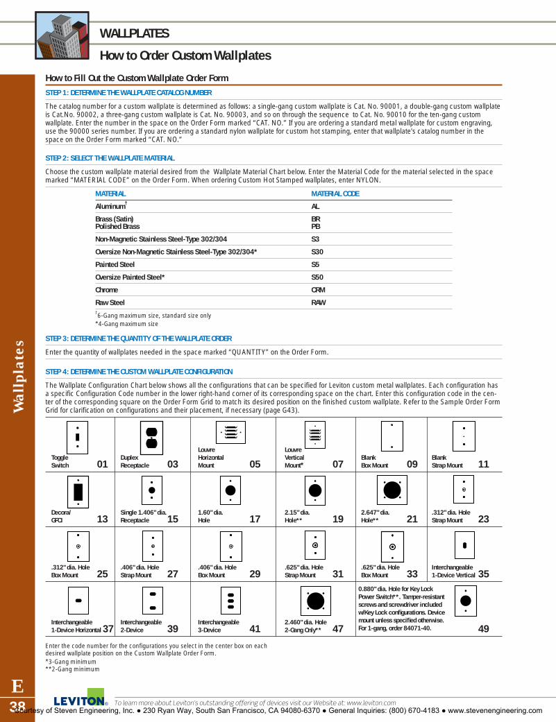
To learn more about Leviton’s outstanding offering of devices visit our Website at: www.leviton.com
Wal
lpla
tes
E38
WALLPLATES
How to Order Custom Wallplates
How to Fill Out the Custom Wallplate Order Form
STEP 1: DETERMINE THE WALLPLATE CATALOG NUMBER
The catalog number for a custom wallplate is determined as follows: a single-gang custom wallplate is Cat. No. 90001, a double-gang custom wallplateis Cat.No. 90002, a three-gang custom wallplate is Cat. No. 90003, and so on through the sequence to Cat. No. 90010 for the ten-gang customwallplate. Enter the number in the space on the Order Form marked “CAT. NO.” If you are ordering a standard metal wallplate for custom engraving,use the 90000 series number. If you are ordering a standard nylon wallplate for custom hot stamping, enter that wallplate's catalog number in thespace on the Order Form marked “CAT. NO.”
STEP 2: SELECT THE WALLPLATE MATERIAL
Choose the custom wallplate material desired from the Wallplate Material Chart below. Enter the Material Code for the material selected in the spacemarked “MATERIAL CODE” on the Order Form. When ordering Custom Hot Stamped wallplates, enter NYLON.
MATERIAL MATERIAL CODE
Aluminum† AL
Brass (Satin) BRPolished Brass PB
Non-Magnetic Stainless Steel-Type 302/304 S3
Oversize Non-Magnetic Stainless Steel-Type 302/304* S30
Painted Steel S5
Oversize Painted Steel* S50
Chrome CRM
Raw Steel RAW†6-Gang maximum size, standard size only*4-Gang maximum size
STEP 3: DETERMINE THE QUANTITY OF THE WALLPLATE ORDER
Enter the quantity of wallplates needed in the space marked “QUANTITY” on the Order Form.
STEP 4: DETERMINE THE CUSTOM WALLPLATE CONFIGURATION
The Wallplate Configuration Chart below shows all the configurations that can be specified for Leviton custom metal wallplates. Each configuration hasa specific Configuration Code number in the lower right-hand corner of its corresponding space on the chart. Enter this configuration code in the cen-ter of the corresponding square on the Order Form Grid to match its desired position on the finished custom wallplate. Refer to the Sample Order FormGrid for clarification on configurations and their placement, if necessary (page G43).
Louvre LouvreToggle Duplex Horizontal Vertical Blank BlankSwitch 01 Receptacle 03 Mount 05 Mount* 07 Box Mount 09 Strap Mount 11
Decora/ Single 1.406" dia. 1.60" dia. 2.15" dia. 2.647" dia. .312" dia. HoleGFCI 13 Receptacle 15 Hole 17 Hole** 19 Hole** 21 Strap Mount 23
.312" dia. Hole .406" dia. Hole .406" dia. Hole .625" dia. Hole .625" dia. Hole Interchangeable Box Mount 25 Strap Mount 27 Box Mount 29 Strap Mount 31 Box Mount 33 1-Device Vertical 35
Interchangeable Interchangeable Interchangeable 2.460" dia. Hole1-Device Horizontal 37 2-Device 39 3-Device 41 2-Gang Only** 47 49
Enter the code number for the configurations you select in the center box on eachdesired wallplate position on the Custom Wallplate Order Form.*3-Gang minimum**2-Gang minimum
0.880" dia. Hole for Key Lock Power Switch**. Tamper-resistantscrews and screwdriver included w/Key Lock configurations. Devicemount unless specified otherwise. For 1-gang, order 84071-40.
Courtesy of Steven Engineering, Inc. ● 230 Ryan Way, South San Francisco, CA 94080-6370 ● General Inquiries: (800) 670-4183 ● www.stevenengineering.com

Wallplates
E39For answers to technical questions, call Leviton’s Techline at 1-800-824-3005
WALLPLATES
How to Order Custom Wallplates
How to Fill Out the Custom Wallplate Order Form (continued)
STEP 5: SELECT THE WALLPLATE COLOR
For painted metal, select one of the following colors and enter its color code in the space marked “COLOR CODE” on the order form:
COLOR WALLPLATE COLOR CODE
AAllmmoonndd PPAA
BBllaacckk PPEE
BBrroowwnn PPBB
GGrraayy PPGG
IIvvoorryy PPII
OOrraannggee PPOO
RReedd PPRR
WWhhiittee PPWW
STEP 6: ENTER ENGRAVING INFORMATION
NOTE: WE CAN ENGRAVE NYLON AND PAINTED AND UNPAINTED METAL WALLPLATES. After completing steps 1-5: 66AA)) Type or clearly print the message(s) (i.e., TURN OFF) as you wish it to appear on the lines provided in the appropriate Grid box(es). 66BB)) Select the size of the letters you desire for the wallplate message from the dimensions shown below and enter that size in the space marked “LETTER SIZE” on the Order Form. 66CC)) Select the fill-in color for the message letter from the chart below and enter the code for the color chosen in the space marked“FILLER CODE.”
FILLER COLOR CODES for Engraved Wallplates LETTER SIZE GAUGE for Engraved Wallplates
COLOR CODE
BBllaacckk XXEE1/8" 3/16" 1/4" 5/16" 3/8"
WWhhiittee XXWW
RReedd XXRR E E E E ENNoo FFiilllleerr XXXX
STEP 7: ENTER HOT STAMPING INFORMATION
77AA)) Select the message(s) desired from the Message Library below. Enter the message on the lines provided in the appropriate Grid box(es) wherethey should appear. The message will be stamped in 3/16"-high text.
HOT STAMPING MESSAGE LIBRARY FOR CUSTOM NYLON WALLPLATES
11.. SSHHOOWWEERR 77.. HHEEAATT 1133.. OONN 1199.. IISSOOLLAATTEEDD 2255.. EEQQUUIIPP22.. VVAANNIITTYY 88.. DDAATTAA 1144.. PPRROOTTEECCTTEEDD 2200.. GGRROOUUNNDD 2266.. FFLLUUOORREESSCCEENNTT33.. VVOOIICCEE 99.. CCOOMMPPUUTTEERR 1155.. OOFFFF 2211.. CCOONNDDIITTIIOONNEEDD 2277.. OOIILL44.. OONNLLYY 1100.. GGFFCCII 1166.. OOIILL BBUURRNNEERR 2222.. CCOONNDDIITTIIOONNEEDD PPOOWWEERR 2288.. PPOOWWEERR55.. IISSOOLLAATTEEDD GGRROOUUNNDD 1111.. SSUURRGGEE 1177.. PPCC 2233.. CCRRIITTIICCAALL 2299.. UUPPSS66.. EEMMEERRGGEENNCCYY 1122.. FFAANN 1188.. DDEEDDIICCAATTEEDD 2244.. EELLEECC..
77BB)) Select the fill-in color for the message letter from the chart below and enter the code for the color chosen in the space marked “FILLER CODE.”
COLOR CODE
BBllaacckk XXEE
WWhhiittee XXWW
RReedd XXRR
NNoo FFiilllleerr XXXX
To order nylon wallplates with custom hot stamped message, contact your Leviton salesman or customer service representative.
88)) NOTE: Sequential engraving is available. Consult factory for ordering instructions.
Courtesy of Steven Engineering, Inc. ● 230 Ryan Way, South San Francisco, CA 94080-6370 ● General Inquiries: (800) 670-4183 ● www.stevenengineering.com

To learn more about Leviton’s outstanding offering of devices visit our Website at: www.leviton.com
Wal
lpla
tes
E40
WALLPLATES
How to Order Custom Wallplates
Custom Wallplate Order Form
BILL TO: SHIP TO:
CAT. NO. MATERIAL CODE QTY.
COLOR CODE ENGRAVED HOT STAMPED LETTER SIZE
FILLER CODE PRICE
ENGRAVING INFORMATION (Please print per corresponding gang number.)
(1) (7)
(2) (8)
(3) (9)
(4) (10)
(5) (11)
(6) (12)
(1) (2) (3) (4) (5) (6) (7) (8) (9) (10) (11) (12)
DESCRIPTION(Use this space to add additional information that may be helpful.)
TERMS
• Please take care to complete your order carefully. Customwallplates cannot be returned
• Custom orders are shipped in three to four weeks
• All engraving shall be centered within its corresponding gangunless specifically instructed to span across multiple gangs
• All engravings on toggle configurations shall appear above themounting screw holes unless specifically instructed otherwise
• All engravings on GFCI/Decora configurations shall appear belowthe mounting screw hole unless specifically instructed otherwise
Courtesy of Steven Engineering, Inc. ● 230 Ryan Way, South San Francisco, CA 94080-6370 ● General Inquiries: (800) 670-4183 ● www.stevenengineering.com

AC S
witches Index
INDEXIndustrial Grade SwitchesOverview . . . . . . . . . . . . . . . . . . . . . . . . . . . . . . .F2Back and Side Wired . . . . . . . . . . . . . . . . . . . . . .F3
Toggle . . . . . . . . . . . . . . . . . . . . . . . . . . . . . . .F3Locking . . . . . . . . . . . . . . . . . . . . . . . . . . . . . .F3Wire Lead Toggle . . . . . . . . . . . . . . . . . . . . . . .F3Canadian 347V AC . . . . . . . . . . . . . . . . . . . . .F3Pilot Light . . . . . . . . . . . . . . . . . . . . . . . . . . . .F4Lighted Handle . . . . . . . . . . . . . . . . . . . . . . . .F4Maintained Contact . . . . . . . . . . . . . . . . . . . . .F5Momentary Contact . . . . . . . . . . . . . . . . . . . . .F5
Side Wired . . . . . . . . . . . . . . . . . . . . . . . . . . . . .F6Toggle . . . . . . . . . . . . . . . . . . . . . . . . . . . . . . .F6Locking . . . . . . . . . . . . . . . . . . . . . . . . . . . . . .F6
AC Manual Motor and Welder Starting . . . . . . . . .F7Safety Disconnect Switches . . . . . . . . . . . . . .F8, F9Key Lock Power . . . . . . . . . . . . . . . . . . . . . . . .F10Commercial Grade SwitchesOverview . . . . . . . . . . . . . . . . . . . . . . . . . . . . . .F11Back and Side Wired . . . . . . . . . . . . . . . . . . . . .F12
Toggle . . . . . . . . . . . . . . . . . . . . . . . . . . . . . .F12Side Wired . . . . . . . . . . . . . . . . . . . . . . . . . . . .F12
Toggle . . . . . . . . . . . . . . . . . . . . . . . . . . . . . .F12Hospital Call . . . . . . . . . . . . . . . . . . . . . . . . .F12Canadian 120/277V AC . . . . . . . . . . . . . . . . .F12Lighted Toggle . . . . . . . . . . . . . . . . . . . . . . . .F13Canadian 347V AC . . . . . . . . . . . . . . . . . . . .F13Framed Toggle . . . . . . . . . . . . . . . . . . . . . . .F13
Residential Grade SwitchesQuickwire and Sidewire . . . . . . . . . . . . . . . . . . .F14
Illuminated Toggle . . . . . . . . . . . . . . . . . . . . .F14CO/ALR . . . . . . . . . . . . . . . . . . . . . . . . . . . . .F14
SECTIONFAC Switches
Courtesy of Steven Engineering, Inc. ● 230 Ryan Way, South San Francisco, CA 94080-6370 ● General Inquiries: (800) 670-4183 ● www.stevenengineering.com

AC SWITCH FEATURES
Industrial Grade AC Switches
To learn more about Leviton’s outstanding offering of devices visit our Website at: www.leviton.com
AC S
wit
ches
F2
LEVITON OFFERS A FULL LINE OF 15, 20 AND 30 AMP AC SWITCHES, AVAILABLE IN INDUSTRIAL, COMMERCIAL ANDRESIDENTIAL GRADE, WITH A WIDE VARIETY OF COLORS, WIRING OPTIONS AND OTHER FEATURES.Leviton’s AC switches are for control of resistive and inductive loads and motors. A full selection of ratings is avail-able in Industrial Grade, Commercial Grade and Residential Grade.
The following pages provide a comprehensive overview of the complete Leviton AC Quiet Switch product line.Ordering information will help you select the switches best suited to meet your application requirements.
Leviton’s Industrial Grade AC switches for heavy-duty applications represent top-of-the-linequality and peak performance. Leviton uses the finest materials available and the highestproduction standards to produce industrial switches of unmatched versatility and reliability.
Break-off plaster ears foruse as shims
1221-2I
� Top-of-the-line industrial-grade quality forpeak performance and rugged, long-lastingservice
� All screws are triple-drive and acceptStandard, Phillips and Robertson screwdrivers
� External clamp-type wiring terminals pro-vides secure connection of solid or strandedwire for back or side wiring
� Back or side-wired grounding terminal offerswiring flexibility
� Sturdy, long-lasting thermoplastic togglesprovide smooth switching action and long life
� UL 20 Listed; meets latest FederalSpecifications WS-896, CSA SpecificationC22.2.2 No. 11 Certified; NOM Certified;complies with NEMA and ANSI requirements
� Backed by a Limited 10-Year Warranty
Features and Benefits– Industrial Grade Switches
Back and Side WiredExternal clamp-type terminals formaximum wiring versatility.1203-2I shown
LockingDesigned to prevent tampering andunauthorized switching.1121-2L shown
Maintained and Momentary ContactPositive switching action with center-off position.1285 shown
Heavy-gauge copper alloy, one-piece con-tact and toggle cam arm provides smooth,firm toggle action for “fast-make” and“slow-break” operation
Large silver cadmium-oxide contactsfor long life, prevent sticking, weldingand excessive pitting
Color-coded covers: 15 Amp-blue;20 Amp-red; 30 Amp-green
External clamp-type terminalprovides secure connection forback and side wiring
Thermoplastic toggle has high-impactstrength and withstands elevatedoperating temperatures
Back or side-wiredgrounding terminal forquick installation
Shallow 3/4" deep body formore wall box room
Large head, triple-drive,brass combination screwsfor speedy wiring and installation
Fully enclosed switch mechanismin rugged thermoplastic housingfor strength, tracking and arc resistance
Pilot LightToggle is illuminated when load ison for visual confirmation.1201-PLC shown
Heavy gauge, anti-corrosivemounting strap withgrounding screw and self-grounding clip
Courtesy of Steven Engineering, Inc. ● 230 Ryan Way, South San Francisco, CA 94080-6370 ● General Inquiries: (800) 670-4183 ● www.stevenengineering.com

AC S
witches
F3For answers to technical questions, call Leviton’s Techline at 1-800-824-3005
15, 20 and 30 AMP 120/277V • 15 and 30 AMP CANADIAN 347V
Industrial Grade AC Quiet Switches
SPECIFICATIONS AND FEATURES
• Top-of-the-line industrial quality• Heavy gauge copper alloy one-piece arm for top
performance• Large silver cadmium-oxide contacts for long life,
prevent sticking, welding and excessive pitting• Color-coded covers: 15 Amp-blue;20 Amp-red;
30 Amp-green• Fully enclosed switch mechanism in rugged hous-
ing for strength, tracking and arc resistance• Brass combination-head terminal screws on
LEVSPEC devices, steel combination head terminalscrews on other devices
• Self-grounding clip on LEVSPEC devices (self-grounding when used with a grounded metal wallbox)
• Wire lead switches for fast and easy installation
TESTING AND CODE COMPLIANCE
• Meets all NEMA WD 1 & 6, and ANSI requirements• Meets Federal Specification WS-896• UL Listed (File #E-7458)• CSA Certified (File #152105)• NOM Certified (#057)• Backed by a Limited 10-Year Warranty• SPECCLASS devices backed by a Limited 2-Year
Warranty
*COLOR
Basic Cat. Nos. shown above denote Brown color. Other color available as listed, add suffix to catalognumber as follows: Ivory (-I), White (-W), Gray (-GY or -G), Red (-R), Black/Ebony (-E), Almond (-A) andLight Almond (-T). For locking switch colors, use the following suffixes: Ivory (-2IL), White (-2WL), Gray (-2GL), Red (-2RL).
** CANADIAN COLOR
For color selection, add suffix to catalog number asfollows: Ivory (-I), White (-W), Brown (-B), Red (-R),and Gray (-G).
HORSEPOWER
15A 20A 30A__ __ __1⁄2 @120V 1 @ 120V 2 @ 120V2 @ 240V 2 @ 240V 2 @ 240V
MATERIAL CHARACTERISTICS
Environmental: Flammability, Rated V2Operating Temperature: -40°C to 65°C.
Back and Side Wired 120/277V AC Quiet Switches URDESCRIPTION 15 AMP 20 AMP 30 AMP COLOR*LEVSPEC® Basic Cat. No. Denotes Brown
Single-Pole Toggle 1201-2 1221-2 3031-2 15A: I, W, GY, R 20A: I, W, A, T, GY, R, E30A: I, W
Single-Pole Locking† 1201-2L 1221-2L 3031-2L 15A: I; 20A: I, W, G, RDouble-Pole Toggle 1202-2 1222-2 3032-2 15A: I, W, GY
20A: I, W, GY, R, E30A: I, W, E, R
Double-Pole Locking† 1202-2L 1222-2L 3032-2L 20A: I3-Way Toggle 1203-2 1223-2 3033-2 15A: I, W, GY, R
20A: I, W, GY, R, E, A, T 30A: I, W
3-Way Locking† 1203-2L 1223-2L 3033-2L 15A: I; 20A: I, W, G4-Way Toggle 1204-2 1224-2 — 15A: I, W, GY
20A: I, W, GY, R, E, T4-Way Locking† 1204-2L 1224-2L — 20A: I, G, WSPECCLASS® General Duty SwitchesSingle Pole Toggle — 1221-S — 20A: I, W, R, GYDouble Pole Toggle — 1222-S — 20A: I, W, GY3-Way Toggle — 1223-S — 20A: I, W, R, GY4-Way Toggle — 1224-S — 20A: I, W, GY†Key for Locking Switch: Cat. No. 55500-PRT.
Wire Lead 120/277V AC Quiet Switches URDESCRIPTION 15 AMP 20 AMP COLORSPECCLASS® General Duty SwitchesSingle-Pole Toggle 1241 1243 15A & 20A: I, W3-Way Toggle 1242 1244 15A & 20A: I, W
Back and Side Wired Canadian 347V AC Quiet Switches RDESCRIPTION 15 AMP 20 AMP COLOR**
See Canadian Color
Single-Pole Toggle 18201 18221 15A & 20A: I, W, B, R, GDouble-Pole Toggle 18202 18222 15A: I only
20A: I, B3-Way Toggle 18203 18223 15A & 20A: I, W, B, R, G4-Way Toggle 18204 18224 15A: I, B, R, G
20A: I, B
2.12
(53
.9)
3.28
(83
.3)
4.06
(10
3.2)
1.31 (33.3)
1.03 (25.1)
0.95(24.3)
1201-2IL
KEY †
1.31 (33.3)
1.03(26.1)
2.12
(53
.9)
3.28
(83
.3)
4.06
(10
3.2)
1221-2I
1.31 (33.3)
1.03(26.1)
3.28
(83
.3)
4.06
(10
3.2)
2.1
(53.
9)
3303-2W
WallplatesTHERMOPLASTIC 302 STAINLESS STEEL
For complete wallplate selection, see Section E.
EMERGENCY
84001-40 84001-E40 84009-40 84011-4080701-I 80709-E 80711-W
NOTE: Cat. Nos. 1201, 1221, 18201, 18221, 1203, 1223, 18203 and 18223 feature externalclamp-type wiring termination for back and side wiring
Courtesy of Steven Engineering, Inc. ● 230 Ryan Way, South San Francisco, CA 94080-6370 ● General Inquiries: (800) 670-4183 ● www.stevenengineering.com

2.12
(53
.9)
3.28
(83
.3)
4.06
(10
3,2)
1.31 (33.3)
1.03 (26.1)
1201-PLC
1.31 (33.3)
1.03 (26.1)
2.12
(53
.9)
3.28
(83
.3)
4.06
(10
3.2)
1201-LHI
1.31 (33.3)
1.03(26.1)
2.12
(53
.9)
3.28
(83
.3)
4.06
(10
3.2)
1222-PLR
2.12
(53
.9)
3.28
(83
.3)
4.06
(10
3.2)
1.31 (33.3)
1.03(26.1)
1223-LHW
AC S
wit
ches
F4
15, 20 and 30 AMP 120V and 20 AMP 277V
Industrial Grade AC Switches
To learn more about Leviton’s outstanding offering of devices visit our Website at: www.leviton.com
Pilot Light and Lighted HandleBack and Side Wired Pilot Light URDESCRIPTION* 15 AMP 20 AMP 30 AMP 20 AMP
120V 120V 120V 277VSingle-Pole 1201-PL 1221-PL 3031-PL� 1221-7P�
Double-Pole 1202-PL+ 1222-PL 3032-PL� 1222-7P+3-Way 1203-PL 1223-PL — 1223-7P+
Note: Pilot light switches require a neutral wire; lighted handle switches do not require a neutral wire.*Available toggles for these devices: Clear (-PLC), Red (-PLR), Green (-PLG).+Available in red toggle only.�Available in clear or red toggle only.
Back and Side Wired Lighted Handle URDESCRIPTION† 15 AMP 20 AMP 30 AMP 20 AMP
120V 120V 120V 277VSingle-Pole 1201-LH 1221-LH 3031-LH* 1221-7L3-Way 1203-LH 1223-LH — 1223-7L
Note: Pilot light switches require a neutral wire; lighted handle switches do not require a neutral wire.†Available toggles for these devices: Clear (-LHC), Ivory (-LHI), White (-LHW).*Available in ivory toggle only.
SPECIFICATIONS AND FEATURES
• Pilot light and lighted handle switches provide topperformance in punishing industrial applications
• Lighted handle illuminated when load is OFF. Pilotlight toggle illuminated when load is ON.
• 120 and 277V versions in single pole and 3-way • Fully enclosed switch mechanism in rugged
housing for strength, track and arc resistance• Self-grounding clip (self-grounding when used with
a grounded metal wallbox)
TESTING AND CODE COMPLIANCE
• Meets all NEMA WD 1 & 6, and ANSI requirements• Meets Federal Specification WS-896• UL Listed (File #E-7458)• CSA Certified (File #152105)• NOM Certified (#057)• Backed by a Limited 10-Year Warranty
HORSEPOWER
15A 20A 30A__ __ __1⁄2 @120V 1 @ 120V 2 @ 120V
MATERIAL CHARACTERISTICS
Environmental: Flammability, Rated V2Operating Temperature: -40°C to 65°C.
WallplatesTHERMOPLASTIC 302 STAINLESS STEEL
For complete wallplate selection, see Section E.
EMERGENCY
84001-40 84001-E40 84009-40 84011-4080701-I 80709-I 80711-W
Courtesy of Steven Engineering, Inc. ● 230 Ryan Way, South San Francisco, CA 94080-6370 ● General Inquiries: (800) 670-4183 ● www.stevenengineering.com

3.28
(83
.3)
4.06
(10
3.2)
2.75
(69
.8)
1.37 (34.9)
1.26(32.0)
0.95(24.3)
1281-L
2.75
(69
.8)
3.28
(83
.3)
4.06
(10
3.2)
1.37 (34.9)
1.26(32.0)
1285
1.37 (34.9)
1.26(32.0)
2.75
(69
.8)
3.28
(83
.30)
4.06
(10
3.2)
1256
1.37 (34.9)
1.26(32.0)
0.95(24.3)
2.75
(69
.8)
3.28
(83
.3)
4.06
(10
3.2)
1257-L
AC S
witches
F5For answers to technical questions, call Leviton’s Techline at 1-800-824-3005
15, 20 and 30 AMP 120/277V
Industrial Grade AC Switches
SPECIFICATIONS AND FEATURES
• Single-Pole and Double-Pole versions, toggle or locking
• Positive switching action with center-off position• Large silver cadmium-oxide contacts for long life,
prevent sticking, welding and excessive pitting• Clamp-type terminals accept up to #10 CU wire• Full rated current capacity on fluorescent, tungsten
and resistive loads; motor load capacity up to 80%switch current rating
TESTING AND CODE COMPLIANCE
• Meets all NEMA WD 1 & 6, and ANSI requirements• UL Listed (File #E-7458)• CUL (File #E-63969)• NOM Certified (#057)• Backed by a Limited 10-Year Warranty
*COLOR
Basic Cat. Nos. shown above denote Brown colorexcept for Locking Devices (Black). Other colorsavailable as listed, add suffix to catalog number asfollows: Ivory (-I), White (W-) and Gray (-GY).
HORSEPOWER
15A 20A 30A__ __ __1⁄2 @120V 1 @ 120V 2 @ 120V2 @ 240V 2 @ 240V 2 @ 240V
MATERIAL CHARACTERISTICS
Environmental: Flammability, Rated V2Operating Temperature: -40°C to 65°C.
Maintained and Momentary ContactBack and Side Wired Maintained Contact 120/277V AC URDESCRIPTION 15 AMP 20 AMP 30 AMP COLOR*
Basic Cat. No. Denotes Brown
Single-Pole, 1281 1285 1287 15A: I, WDouble Throw, 20A: I, W, GYCenter Off 30A: ISingle-Pole, 1281-L 1285-L 1287-L 15, 20 & 30A: Black onlyDouble Throw,Center Off, Locking† Double-Pole, 1282 1286 1288 15A: I, WDouble Throw, 20A: I, WCenter Off 30A: I, WDouble-Pole, — — 1288-L 30A: Black onlyDouble Throw,Center Off, Locking†
†Key for Locking Switch: Cat. No. 55500-PRT
Back and Side Wired Momentary Contact 120/277V AC URDESCRIPTION 15 AMP 20 AMP 30 AMP COLOR*
Basic Cat. No. Denotes Brown
Single-Pole, 1256 1257 1260� 15: I, W, GYDouble-Throw, 20A: I, W, GYCenter Off 30A: Brown onlySingle-Pole, — 1257-L� — 20A: Black onlyDouble-Throw, Center Off, Locking† Double-Pole, — — 1262� 30A: Brown onlyDouble-Throw, Center Off
†Key for Locking Switch: Cat. No. 55500-PRT.CSA Certified except where indicated by �
WallplatesTHERMOPLASTIC 302 STAINLESS STEEL
For complete wallplate selection, see Section E.
EMERGENCY
84001-40 84001-E40 84009-40 84011-4080701-I 80709-E 80711-W
Courtesy of Steven Engineering, Inc. ● 230 Ryan Way, South San Francisco, CA 94080-6370 ● General Inquiries: (800) 670-4183 ● www.stevenengineering.com

AC S
wit
ches
F6
15 and 20 AMP 120/277V
Industrial Grade AC Quiet Switches
To learn more about Leviton’s outstanding offering of devices visit our Website at: www.leviton.com
SPECIFICATIONS AND FEATURES
• Rugged construction for trouble-free service inindustrial environments
• Heavy-gauge copper alloy one-piece arm forsmooth, quiet, firm toggle action
• Large silver cadmium-oxide contacts for long life,prevent sticking, welding and excessive pitting
• Large head, deep-slotted terminal screws for fast,easy wiring; accept up to #10 copper and copper-clad wire
• Self-grounding clip (self-grounding when used witha metal wallbox)
TESTING AND CODE COMPLIANCE
• Meets all NEMA WD 1 & 6, and ANSI requirements• UL Listed (File #E-7458) to meet the latest Federal
Specification, WS-896• CSA Certified (File #152105)• NOM Certified (#057)• Backed by a Limited 10-Year Warranty
*COLOR
Basic Cat. Nos. shown above denote Brown color.Other colors available as listed, add suffix to catalognumber as follows: Ivory (-I), White (-W), Gray (-GY),Red (-R), Black/Ebony (-E).
HORSEPOWER
15A 20A__ __1⁄2 @120V 1 @ 120V2 @ 240V 2 @ 240V
MATERIAL CHARACTERISTICS
Environmental: Flammability, Rated V2Operating Temperature: -40°C to 65°C.
Side Wired 120/277V AC Quiet Switches URDESCRIPTION 15 AMP 20 AMP COLOR*
Basic Cat. No. Denotes Brown
Single-Pole Toggle 1101-2 1121-2 15A: I, W, GY 20A: I, W, GY, R
Single-Pole Locking† 1101-2L 1121-2L 15A & 20A: Brown OnlyDouble-Pole Toggle 1102-2 1122-2 15A: I
20A: I, W, GYDouble-Pole Locking 1102-2L 1122-2L 15A & 20A: Brown Only3-Way Toggle 1103-2 1123-2 15A: I, W, GY
20A: I, W, GY, R3-Way Locking† 1103-2L 1123-2L 15A & 20A: Brown Only4-Way Toggle 1104-2 1124-2 15A: Ivory only
20A: I, W, GY, R4-Way Locking† 1104-2L 1124-2L 15A & 20A: Brown Only
†Key for Locking Switch: Cat. No. 55500-PRT.
1.31 (33.3)
0.92(23.4)
3.28
(83
.3)
4.06
(10
3.2)
2.19
(55
.6)
1101-2GY
1.31 (33.3)
0.92(23.4)
2.19
(55
.6)
3.28
(83
.3)
4.06
(10
3.2)
0.95 (24.1)
1121-2L
1.31 (33.3)
0.92(23.4)
2.19
(55
.6)
3.28
(83
.3)
4.06
(10
3.2)
1123-2W
WallplatesTHERMOPLASTIC 302 STAINLESS STEEL
For complete wallplate selection, see Section E.
EMERGENCY
84001-40 84001-E40 84009-40 84011-4080701 80709-I 80711-W
Courtesy of Steven Engineering, Inc. ● 230 Ryan Way, South San Francisco, CA 94080-6370 ● General Inquiries: (800) 670-4183 ● www.stevenengineering.com

AC S
witches
F7For answers to technical questions, call Leviton’s Techline at 1-800-824-3005
30, 40 and 60 AMP 600V
Industrial Grade AC Manual Motor and Welder Starting Switches
TESTING AND CODE COMPLIANCE
• MS devices: UL & CUL Listed (File #E-63969)• WS devices: UL Recognized Component
(File #E-63969)• MS & WS devices comply with UL 508• Backed by a Limited Ten-Year Warranty
MATERIAL CHARACTERISTICS
UL94 VO Flammability RatingOperating Temperature: -40°C to 65°C
SPECIFICATIONS AND FEATURES
MS Switches• All molded parts are thermoplastic to resist
impacts, chemicals, temperature, tracking and arcing• Positive-contact design enhances fast-make/
slow-break • Silver-alloy contacts for maximum conductivity and
service life• Back and side wire terminals accept up to #10 AWG
solid copper wire. For stranded #8 AWG wire, removeterminal clamp and use ring terminal
• Oversized #10 triple-combination terminal screws arevibration resistant
• Insulating barrier between terminals provide isolationfrom each phase
• Nickel-plated brass mounting yoke for superior corrosion resistance
• Large toggle provides positive actuation, even withgloved hand
WS Switches• Capable of accommodating bus bar termination in
multi-gang applications• Hole for mounting hardware supports panel mounting
with self-threading fasteners or pop rivets• Terminal screws accept up to # 10 AWG solid copper
wire. For stranded # 8 AWG wire, remove terminalclamp and use ring terminal
• Fast-threading, corrosion-resistant brass triple-combination screws for fast, easy installation
Back and Side Wired AC Manual Motor Starting Switches 30 AMP 600V AC URDESCRIPTION MAX. HP IN TYPE 1 IN TYPE 3R SWITCH
RATING ENCL. ENCL. ONLYDouble-pole, single-throw AC 2HP 120V AC N1302 N3302 MS302manual motor starting switch, 5HP 240V ACwithout overload protection. 10HP 480V AC N1302-TColor: Black 15HP 600V ACSame as above – Short Toggle — — MS302-SThree-pole, single-throw AC 3HP 120V AC N1303 N3303 MS303manual motor starting switch, 7.5HP 240V ACwithout overload protection. 15HP 480V AC N1303-TColor: Black 20HP 600V ACSame as above – Short Toggle — — MS303-S
Back and Side Wired AC Manual Motor Starting Switches 40 AMP 600V AC URDESCRIPTION MAX HP RATING CAT. NO.Double-pole, single-throw AC manual 2HP 120V AC MS402motor starting switch, without overload 5HP 240V ACprotection. 10HP 480V ACColor: Black 15HP 600V ACThree-pole, single-throw AC manual 3HP 120V AC MS403motor starting switch, without overload 7.5HP 240V ACprotection. 15HP 480V ACColor: Black 20HP 600V AC
Back or Front Wired AC Manual Motor Starting Switches 60 AMP 600V AC URDESCRIPTION MAX. HP IN NEMA SWITCH
RATING 3R ENCL. ONLYDouble-pole, single-throw AC manual 10HP 240V AC N3602 MS602-BWmotor starting switch, without overload 15HP 480V ACprotection. Back Wired. Color: Black 20HP 600V ACSame as above except Front Wired — MS602-FWThree-pole, single-throw AC manual 10HP 240V AC N3603 MS603-BWmotor starting switch, without overload 25HP 480V ACprotection. Back Wired. Color: Black 30HP 600V ACSame as above except Front Wired — MS603-FW
Side Wired AC Manual Welder Starting Switches 40 AMP 600V AC URDESCRIPTION MAX. HP RATING CAT. NO.Double-pole, single-throw AC manual 5HP 250V AC WS402welder starting switch. Color: Black
3.11 (78.7) 2.40(61.0)
5.60
(14
2.2)
2.97 (75.4)
N1303
3.28
(83.
3)
3.75
(95.
3)
0.90 (22.9)
1.51 (38.3)
2.03 (51.6)
MS302-S
2.19
(55
.6)
3.28
(83
.3)
4.06
(10
3.2)
1.20 (35.0)
1.14(29.0)
WS402
Enclosures and WallplatesTYPE 1 STEEL TYPE 3R 302 STAINLESS STEEL LOCKOUT TYPE 1 ENCLOSURES TYPE 3R ENCLOSUREENCLOSURE ENCLOSURE WALLPLATE w/TAMPER-RESISTANT w/THERMOPLASTIC WITHOUT SWITCH
WITHOUT SWITCH WITHOUT SWITCH SCREWS and SPANNER TOOL COVER and For 40 or 60A For 30A MS Switches For 30A MS Switches w/30A 2-P (N1302-T) or MS Switches
30A 3-P (N1303-T) Switch2 Knockouts 2 Bottom 2 Bottom 1/2"and 3/4" Knockouts KnockoutsTop and #1 Allows: both allow:Bottom 1/2", 3/4", 1/2", 3/4",
1", 11/4" 1", 11/4"#2 Allows:1/2", 3/4"
Note: For Type 3R Enclosure lockout, padlock with 5/16" or equivalent shackle recommended (min. 1/4" Dia.).For complete wallplate selection, see Section E.
N13NC N33NC 84001-LOK (Lock purchased separately) N1303-T
(w/30A Switch)N13NC-T (Cover Only) N36NC
Courtesy of Steven Engineering, Inc. ● 230 Ryan Way, South San Francisco, CA 94080-6370 ● General Inquiries: (800) 670-4183 ● www.stevenengineering.com

To learn more about Leviton’s outstanding offering of devices visit our Website at: www.leviton.com
Wat
erti
ght
Saf
ety
Dis
conn
ect
Sw
itch
es
F8
SAFETY DISCONNECT SWITCH FEATURES
Industrial Grade Watertight Safety Disconnect SwitchesUL 98 & UL 508 Listed, CUL per CSA Specification, C22.2 No. 14 Certified
2 YEAR LIMITED
Liquid-tight conduit fitting can beinstalled for top or bottom feed
One fitting supplied:• 30 Amp – 1"• 60 Amp – 11/4"• 100 Amp – 11/2"
Red “pistol grip” handle provides visual confirmationof switch’s status
Impact UV and chemical-resistantValox enclosure rated to UL and IECwatertight standards
• Type 3R, 4X & 12K• IP67
Circuit identification pad formeans of identifying specificequipment loads
Integrated lockout handle meetsOSHA safety regulations
Stainless steel screws arecaptive and will not fall outwhen cover is opened
Brass threaded inserts will notstrip, provide higher torque,and form tighter seal betweenback box and cover
Pre-wired grounding plates (top and bottom of enclosure)connect to metal conduitgrounding system
Rugged hinge mechanism pivots180º for easy access during installation and maintenance
Disconnect switch with integrated fuse holder offersproven performance in a compact package• Fused cartridges accept “Class J” fuses (not included)• 1 Factory installed Auxiliary Contact (Normally Open
– 10 Amp)• Additional Auxiliary Contact Available (Normally Closed
– 10 Amp)• Easily accessible neutral and ground terminal blocks
DS60-FAX
DS60-FAX
Fused Models Accept “Class J” Time-Delay Fuses
by Leviton
Generous wiring space fortop to bottom wiring
STANDARDS & CERTIFICATIONSSafety Disconnect Switches
UL 98 Fused UL 508 CSA C22.2 NOM CE IEC(Including 100A Non-Fused - DS) Non-Fused No. 14 947-3
E63969 � � �* �
Watertight Safety DisconnectSwitches Include —30 Amp Fused, 60 & 100 Amp(Fused & Non-Fused)
Meets 2002 NEC® Requirements 430.102 (A) and 430.102 (B)
Handle with padlock installed
Cover Screws: 11/8" deep slotted. LG stainless steel.Mounting Screws: 10-24 x 1/2" deep slotted. LG stainless steel.
* Not available on DS30-AX
Courtesy of Steven Engineering, Inc. ● 230 Ryan Way, South San Francisco, CA 94080-6370 ● General Inquiries: (800) 670-4183 ● www.stevenengineering.com

Watertight S
afety Disconnect S
witches
F9For answers to technical questions, call Leviton’s Techline at 1-800-824-3005
TECHNICAL INFORMATION
Industrial Grade Watertight Safety Disconnect Switches
INTERUPTED RATINGS — RMS SYMMETTRICAL AMPERES
AMPS MAXVOLTAGE
CATALOG NO. NON-FUSED CATALOG NO. FUSED30 600V AC DS30-AX DS30-FAX60 600V AC DS60-AX DS60-FAX100 600V AC DS100-AX —
2 YEAR LIMITED
MAX. HP RATINGS PER UL508NON-FUSED SAFETY DISCONNECT SWITCHES
DS30-AX DS60-AX DS100-AX
ELECTRICALDevice Current Duration
Applied
30 A 60 A 2 min60 A 120 A 4 min100 A 200 A 6 min
Certified forcurrent
Current interrupting at Interrupting full-rated
current and voltage
6000 operations at rated
Endurance current and voltage (Power factor 0.75 – 0.80)
1000 V plus Dielectric twice rated
voltage for 1 minute
MECHANICAL
Mold Stress Relief 70°C for 7 hours
Remains in place Knockout Test with 20 lb
push
Crush 100 lb
1.2 lb steel ballImpact dropped
from 5 ft
Same as Cold Impact above, after
conditioningto -35°C
110% ofStrength of specified Insulating tighteningBase and Support torque on
terminal screws
18 lb pull onPullout internal wires
ENVIRONMENTAL
V2 or better per UL 94 or CSA
Flammability 22.2 No 0.6; V-0 for watertight enclosure
Rain (3R) Water spray @ per UL 50 5 psi from
all sides for 1 hr
Hosedown (4X) Water spray @
per UL 50 65 gal/min for 5 minutesCement Dust
Dust (12K) Circulated @per UL 50 1000 ft/minute for
5 minutes
Gasket Aging 70°C for 168 hoursExposed plastic
UV Resistance materials are UV stabilized
Operating -40°C to +60°CTemperature (-40°F to +140°F)
DS30-AX(Non-Fused)
DS60-FAX(Fused)
DS100-AX(Non-Fused)
Engineered to UL & IECWatertight Standards
by Leviton
Ground PathIntegrity
Ordering Information for Watertight Safety Disconnect Switches
MAX. HP RATINGS PER UL508FUSED SAFETY DISCONNECT SWITCHES
DS30-FAX DS60-FAX
NR = Not Rated
VOLTS
120V AC 2 NR208V AC 7.5 15240V AC 3 NR480V AC 15 NR600V AC 20 NR3Ø Y 120/208V AC 7.5 153Ø 240V AC 7.5 153Ø 480V AC 15 303Ø 600V AC 20 50
VOLTS
120V AC 1 2 5208V AC 5 20 25240V AC 2.5 10 15480V AC 5 20 25600V AC NA 20 203Ø Y 120/208V AC 5 20 253Ø 240V AC 5 20 303Ø 480V AC 15 40 503Ø 600V AC 15 40 50
Meets 2002 NEC®
Requirements 430.102 (A) and
430.102 (B)
Non-Fused are suitable for use on circuits capable of deliver-ing not more than (see chart below for catalog no. and value) RMS symmetrical amperes.
Fused, when protected by Class J fuses, 600V AC maximum,are suitable for use on circuits capable of delivering not morethan (see chart below for catalog no. and value) RMS symmetrical amperes.
Courtesy of Steven Engineering, Inc. ● 230 Ryan Way, South San Francisco, CA 94080-6370 ● General Inquiries: (800) 670-4183 ● www.stevenengineering.com

AC S
wit
ches
F10
20 AMP 120/277V
Industrial Grade AC Key Lock Power Switches
To learn more about Leviton’s outstanding offering of devices visit our Website at: www.leviton.com
SPECIFICATIONS AND FEATURES
• Key-operated locking mechanism for maximumtamper-proof operation in schools, institutions,public housing, trailer parks, loading docks, freightyards and other areas
• Chrome lock dome with 2 keys provided per switch• Back and side wire terminals accept up to
#14 – #10 AWG copper or copper clad wire• Large, combination head terminal screws with
external clamps• 4-Way switch has internal, back-wire clamps• Triple-combination mounting screws for fast, easy
installation • Heavy-gauge rust-resistant mounting strap with
steel grounding screw and self-grounding clip (selfgrounding when used in a properly grounded metalwallbox)
• Key removable in ON or OFF positions
TESTING AND CODE COMPLIANCE
• Meets NEMA WD-1, WD-6 & ANSI requirements• Meets Federal Specifications WS-896• UL Listed (File #E-7458)• CSA Certified (File #152105)• NOM Certified (#057)• Backed by a Limited Ten-Year Warranty
HORSEPOWER
20A__1 @ 120V2 @ 240V
. 16 Amp Max.
MATERIAL CHARACTERISTICS
Environmental: Flammability, Rated V2Operating Temperature: -40°C to 65°C.
Back and Side Wired Key Lock Power Switches 20 AMP 120/277V AC URDESCRIPTION CAT. NO.Single-Pole Key Lock Power Switch, 2 keys provided 1221-2KLDouble-Pole Key Lock Power Switch, 2 keys provided 1222-2KL3-Way Key Lock Power Switch, 2 keys provided 1223-2KL4-Way Key Lock Power Switch, 2 keys provided 1224-2KLReplacement Keys, 2 per pack 2KL
Key Lock Power Switches are not recommended for use on Master or Emergency Power Systems.
2.19
(55
.6)
3.28
(83
.3)
4.06
(10
3.2)
1.68(42.7)
1.19(30.2)
1221-2KLw/TWO KEYS
Wallplates and Wallboxes302 STAINLESS STEEL FD or DEEP WALLBOX ADAPTER EXTENDS SHALLOW
COMES WITH TAMPER-RESISTANT RECOMMENDED MINIMUM INTERNAL WALLBOX, USE WITH STAINLESSSCREWS and SPANNER TOOL DEPTH 23/4" SINGLE COVER/GANG WALLPLATE–CAT. NO. 84071-40
2-GANG STAINLESS STEEL 3-GANG STAINLESS STEEL WALLPLATE WALLPLATE
For complete wallplate selection, see Section E.
84701-40
COLORBrownIvoryWhite
CAT. NO.61976197-I6197-W
84072-40 84073-40
Courtesy of Steven Engineering, Inc. ● 230 Ryan Way, South San Francisco, CA 94080-6370 ● General Inquiries: (800) 670-4183 ● www.stevenengineering.com

AC S
witches
F11For answers to technical questions, call Leviton’s Techline at 1-800-824-3005
AC QUIET SWITCH FEATURES
Commercial Grade AC Quiet Switches
Back and Side WiredExternal clamp-type terminals formaximum wiring versatility.CSB1-20 shown
Framed ToggleFor neater finished appearance.54501-2I shown
Lighted ToggleLights up,when power is off, easyto locate in darkened rooms.5501-LHI shown
Hospital Call SwitchTurns on when toggle is pulleddown with cord (included).5501-8 shown
Side WiredSturdy, rugged, cost effective.CS120-2W shown
LEVITON OFFERS A LARGE SELECTION OF 15 AND 20 AMP COMMERCIAL SWITCHES,AVAILABLE IN A WIDE VARIETY OF COLORS, WIRING OPTIONS AND OTHER FEATURES.
Leviton’s Commercial Grade switches are designed to offer outstanding reliability and top performance in commercial settings. Ideal applications include municipal facilities,government buildings, malls, department stores, hospital and health care facilities, officebuildings, schools, colleges, universities, houses of worship and cultural institutions.
Features and Benefits� Listed UL Federal Specification, WS-896� Heavy-duty pre-plated steel mounting strap
for maximum strength� All screws are brass combination-head for
fast installation with Standard, Phillips andRobertson head screwdrivers
� External clamp-type wiring terminals providessecure connection of solid or stranded wirefor back or side wiring (CSB1 and CSB3)
� Backed by a Limited 10-Year Warranty
CSB1-15I
Large, brass triple-drivecombination screws forfast wiring and installation
Heavy-duty pre-platedsteel mounting strap
External clamp-type terminalprovides secure connectionfor back and side wiring
Large switch contacts formaximum conductivity
Courtesy of Steven Engineering, Inc. ● 230 Ryan Way, South San Francisco, CA 94080-6370 ● General Inquiries: (800) 670-4183 ● www.stevenengineering.com

AC S
wit
ches
F12
15 and 20 AMP 120/277V • 15 and 20 AMP CANADIAN 120/277V
Commercial Grade AC Quiet Switches
To learn more about Leviton’s outstanding offering of devices visit our Website at: www.leviton.com
SPECIFICATIONS AND FEATURES
• Large head triple-drive combination screws (Standard,Phillips and Robertson) for fast wiring
• Heavy-gauge, rust-resistant steel mounting strap• Accepts #14–#12 AWG copper or copper-clad wire• Convenient break-off plaster ears for best alignment• Large switch contacts for maximum conductivity
TESTING AND CODE COMPLIANCE
• UL Listed to meet the latest Federal Specification, WS-896 (File #E-748)
• Meets all NEMA WD 1 & 6, and ANSI requirements• CSA Certified (File #LR-3413)• NOM Certified (#057)• Backed by a Limited 10-Year Warranty
*COLOR
Basic Cat. Nos. shown above denote Brown color. Other col-ors available as listed, add suffix to catalog number as fol-lows: Ivory (-I), White (-W), Almond (-A), Light Almond (T),Gray (-GY), Black (-E).
** CANADIAN COLOR
For color selection, add suffix to catalog number as follows:Ivory (-I), White (-W), Brown (-B), and Gray (-G).
HORSEPOWER
15A 20A__ __1⁄2 @120V 1 @ 120V2 @ 240V 2 @ 240V
MATERIAL CHARACTERISTICS
Environmental: Flammability, Rated V2Operating Temperature: -40°C to 65°C.
Back and Side Wired 120/277V AC Quiet Switches URDESCRIPTION 15 AMP 20 AMP COLOR*
Basic Cat. No. Denotes Brown
Single-Pole Toggle CSB1-15 CSB1-20 15A & 20A: I, W, A, T, GDouble-Pole Toggle CSB2-15 CSB2-20 15A: I, W, A, T
20A: I, W, A, T, G3-Way Toggle CSB3-15 CSB3-20 15A: I, W, A, T
20A: I, W, A, T, G4-Way Toggle CSB4-15 CSB4-20 15A: I, W, A
20A: I, W, A, G
Side Wired 120/277V AC Quiet Switches URDESCRIPTION 15 AMP 20 AMP COLOR*
Basic Cat. No. Denotes Brown
Single-Pole Toggle CS115-2 CS120-2 15A & 20A: I, W, A, T, GY, ESingle-Pole Hospital Call Switch† 5501-8 — 15A: IDouble-Pole Toggle CS215-2 CS220-2 15A: I, W, GY
20A: I, W, A, T, GY, EDouble-Pole Hospital Call Switch† 5502-8 — 15A: Ivory Only3-Way Toggle CS315-2 CS320-2 15A: I, W, A, T, GY
20A: I, W, A, T, GY, E4-Way Toggle CS415-2 CS420-2 15A: I, W, A, T, GY
20A: I, W, A, T, GY, ESingle-Pole, Framed Toggle 54501-2 54521-2 15A & 20A: I, W, GYDouble-Pole, Framed Toggle 54502-2 54522-2 15A: I, W
20A: I, W3-Way, Framed Toggle 54503-2 54523-2 15A & 20A: I, W, GY4-Way, Framed Toggle 54504-2 54524-2 15A: I, W, A, T, GY
20A: I, W, GY†Hospital Call Switch turns on when toggle is pulled down with cord (3-ft braided cord included)
Side Wired Canadian 120/277V AC Quiet Switches RNote: Cat. No. 54501-2 series is identified in Canada by the following catalog numbers:
DESCRIPTION 15 AMP 20 AMP COLOR**See Canadian Color
Single-Pole, Framed Toggle 1101-C 54521-2 15A: I, W, B, G, E20A: I, W, B, G
Double-Pole, Framed Toggle 1102-C 54522-2 15A & 20A: I, W, B, G3-Way, Framed Toggle 1103-C 54523-2 15A: I, W, B, E
20A: I, W, B, G4-Way, Framed Toggle 1104-C 54524-2 15A: I, W, B, E
20A: I, W, B, G
1.31 (33.3)
86(21.8)
2.12
(53
.9)
3.28
(83
.3)
4.06
(10
3.2)
CSB1-20
1.31 (33.3)
86(21.8)
2.12
(53
.9)
3.28
(83
.3)
4.06
(10
3.2)
CSB3-20G
1.31 (33.3)
0.92(23.3)
3.28
(83
.3)
4.06
(10
3.2)
2.12
(53
.9)
CS120-2W
3.28
(83
.3)
4.06
(10
3.2)
2.12
(53
.9)
1.31 (33.3)
0.92(23.4)54501
NOTE: Cat. Nos. CSB1 and CSB3 feature external clamp-type wiring termination for back and side wiring
WallplatesTHERMOPLASTIC 302 STAINLESS STEEL
For complete wallplate selection, see Section E.
EMERGENCY
84001-40 84001-E40 84009-40 84011-4080701-I 80709 80711-W
Courtesy of Steven Engineering, Inc. ● 230 Ryan Way, South San Francisco, CA 94080-6370 ● General Inquiries: (800) 670-4183 ● www.stevenengineering.com

AC S
witches
F13For answers to technical questions, call Leviton’s Techline at 1-800-824-3005
15 AMP 120V • 15 AMP CANADIAN 347V
Commercial Grade AC Quiet Switches
SPECIFICATIONS AND FEATURES
• Quiet, reliable mechanical action• Large head triple-drive combination screws
(Standard, Phillips and Robertson) for fast wiringinstallation
• Accepts #14–#12 AWG copper or copper-clad wire• Large switch contacts for maximum conductivity
TESTING AND CODE COMPLIANCE
• UL listed to meet the latest Federal Specification,WS-896 (File #E-748)
• Meets all NEMA WD 1 & 6, and ANSI requirements• CSA Certified (File #LR-3413)• NOM Certified (#057)• Backed by a Limited 10-Year Warranty
*COLOR
Basic Cat. Nos. shown above denote Brown colorexcept for Lighted Toggle Switches. Other colorsavailable as listed, add suffix to catalog number asfollows: Ivory (-I), White (-W). ** CANADIAN COLOR
** CANADIAN COLOR
For color selection, add suffix to catalog number asfollows: Ivory (-I), White (-W), Brown (-B), and Gray (-G)
HORSEPOWER
15A__1⁄2 @120V
MATERIAL CHARACTERISTICS
Environmental: Flammability, Rated V2Operating Temperature: -40°C to 65°C.
Side Wired Lighted Toggle 15 AMP 120V AC Only URDESCRIPTION CAT. NO. COLOR*Single-Pole Lighted Toggle 5501-LH 15A: I, W3-Way Lighted Toggle 5503-LH 15A: I, W
Side Wired Canadian 15 AMP 347V AC URDESCRIPTION CAT. NO. COLOR**
See Canadian Color
Single-Pole, Framed Toggle 18201-C 15A: I, W, B, GDouble-Pole, Framed Toggle 18202-C 15A: I, W3-Way, Framed Toggle 18203-C 15A: I, W, B, G4-Way, Framed Toggle 18204-C 15A: I, W, G
1.31 (33.3)
0.92(23.3)
2.12
(53
.9)
3.28
(83
.3)
4.06
(10
3.2)
5501-LHI
2.12
(53
.9)
3.28
(83
.3)
4.06
(10
3.2)
1.31 (33.3)
1.03(26.1)
5503-LHW
WallplatesTHERMOPLASTIC 302 STAINLESS STEEL
For complete wallplate selection, see Section E.
EMERGENCY
84001-40 84001-E40 84009-40 84011-4080701-I 80709-I 80711-W
Courtesy of Steven Engineering, Inc. ● 230 Ryan Way, South San Francisco, CA 94080-6370 ● General Inquiries: (800) 670-4183 ● www.stevenengineering.com

AC S
wit
ches
F14
15 AMP 120V
Residential Grade AC Quiet Switches
To learn more about Leviton’s outstanding offering of devices visit our Website at: www.leviton.com
SPECIFICATIONS AND FEATURES
• Faster installation with combination of side wiringand Quickwire push-in wiring
• Quickwire accepts conductors up to #12 AWG; #14 AWG in Canada
• Side wire accepts conductors up to #12 AWG• Large head triple-drive combination screws
(Standard, Phillips, Robertson) for fast wiringinstallation
• Impact-resistant, durable thermoplastic toggle and frame
TESTING AND CODE COMPLIANCE
• UL Listed (File # E-7458)• CSA Certified (File #LR-3413)• NOM Certified (#057)• Backed by a Limited Two-Year Warranty
*COLOR
Basic Cat. Nos. shown above denote Brown color.Other colors available as listed, add suffix to catalognumber as follows: Ivory (-I), White (-W), Almond (-A), light Almond (T), Black/Ebony (-E), Clear (-C),Grey (-GY)
HORSEPOWER
15A__1⁄2 @120V
MATERIAL CHARACTERISTICS
Environmental: Flammability, Rated V2Operating Temperature: -40°C to 65°C.
Quickwire and Side Wired Framed Toggle 15 AMP 120V AC Quiet Switches URDESCRIPTION CAT. NO. COLOR*
Basic Cat. No. Denotes Brown
Single-Pole 1451 I, W3-Way 1453 I, W, A, TSingle-Pole with grounding screw 1451-2 I, W, A, T, E3-Way with grounding screw 1453-2 I, W, A, T, E4-Way with grounding screw 54504-2 I, W, A, GY, TSingle-Pole, less ears with grounding screw 1451-4 I, W3-Way, less ears with grounding screw 1453-4 I, W
Note: Available in Convenience Packs.
Quickwire and Side Wired Illuminated Toggle 15 AMP 120V AC URDESCRIPTION CAT. NO. COLOR (Toggle & Frame)*Single-Pole (Amber Illumination) 1461-LH C 3-Way (Amber Illumination) 1463-LH C Single-Pole (Green Illumination) 1461-GH I, W, A, T, E 3-Way (Green Illumination) 1461-GH I, W, A, T, E
Note: Illuminated switches do not require a neutral wire.
CO/ALR Side Wired Framed Toggle15 AMP 120V AC URDESCRIPTION CAT. NO. COLOR*
Basic Cat. No. Denotes Brown
Single-Pole with grounding screw 2651-2 I, W
3-Way with grounding screw 2653-2 I, W
Note: CO/ALR devices are for connection to 12 or 10 AWG aluminum conductors.
• Aluminum• Copperclad• Copper
For use with
CSACERTIFIED
CO/ALR
3.28
(83
.3)
4.20
(10
6.7)
2.13
(53
.9)
1.31 (33.3)
1.01(25.7)
1451
1.31 (33.3)
1.05(26.6)
3.28
(83
.3)
4.20
(10
6.7)
2.09
(53
.2)
1453
3.28
(83
.3)
4.20
(10
6.7)
2.09
(53
.2)
1.31 (33.3)
1.05(26.6)
1461-LHC
1.31 (33.3)
1.01(26.7)
3.28
(83
.3)
4.20
(10
6.6)
2.13
(60
.3)
2651-2
WallplatesTHERMOPLASTIC 302 STAINLESS STEEL
For complete wallplate selection, see Section E.
EMERGENCY
84001-40 84001-E40 84009-40 84011-4080701-I 80709 80711-W
Courtesy of Steven Engineering, Inc. ● 230 Ryan Way, South San Francisco, CA 94080-6370 ● General Inquiries: (800) 670-4183 ● www.stevenengineering.com
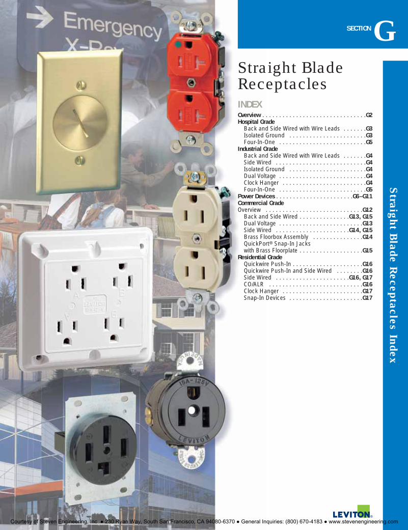
Straight B
lade Receptacles Index
INDEXOverview . . . . . . . . . . . . . . . . . . . . . . . . . . . . . . .G2Hospital Grade
Back and Side Wired with Wire Leads . . . . . . .G3Isolated Ground . . . . . . . . . . . . . . . . . . . . . . .G3Four-In-One . . . . . . . . . . . . . . . . . . . . . . . . . .G5
Industrial GradeBack and Side Wired with Wire Leads . . . . . . .G4Side Wired . . . . . . . . . . . . . . . . . . . . . . . . . . .G4Isolated Ground . . . . . . . . . . . . . . . . . . . . . . .G4Dual Voltage . . . . . . . . . . . . . . . . . . . . . . . . . .G4Clock Hanger . . . . . . . . . . . . . . . . . . . . . . . . .G4Four-In-One . . . . . . . . . . . . . . . . . . . . . . . . . .G5
Power Devices . . . . . . . . . . . . . . . . . . . . . . .G6–G11Commercial GradeOverview . . . . . . . . . . . . . . . . . . . . . . . . . . . . .G12
Back and Side Wired . . . . . . . . . . . . . . .G13, G15Dual Voltage . . . . . . . . . . . . . . . . . . . . . . . . .G13Side Wired . . . . . . . . . . . . . . . . . . . . . .G14, G15Brass Floorbox Assembly . . . . . . . . . . . . . . .G14QuickPort® Snap-In Jacks with Brass Floorplate . . . . . . . . . . . . . . . . . . .G15
Residential GradeQuickwire Push-In . . . . . . . . . . . . . . . . . . . . .G16Quickwire Push-In and Side Wired . . . . . . . .G16Side Wired . . . . . . . . . . . . . . . . . . . . . .G16, G17CO/ALR . . . . . . . . . . . . . . . . . . . . . . . . . . . .G16Clock Hanger . . . . . . . . . . . . . . . . . . . . . . . .G17Snap-In Devices . . . . . . . . . . . . . . . . . . . . . .G17
SECTIONGStraight BladeReceptacles
Courtesy of Steven Engineering, Inc. ● 230 Ryan Way, South San Francisco, CA 94080-6370 ● General Inquiries: (800) 670-4183 ● www.stevenengineering.com

STRAIGHT BLADE RECEPTACLE FEATURES
Industrial Grade Straight Blade Receptacles
To learn more about Leviton’s outstanding offering of devices visit our Website at: www.leviton.com
Str
aigh
t Bla
de R
ecep
tacl
es
G2
LEVITON’S INDUSTRIAL GRADE STRAIGHT BLADE RECEPTACLES ARE BUILT TO THE MOST DEMANDING STANDARDSFOR PERFORMANCE AND RELIABILITY. THEY’RE DESIGNED TO WITHSTAND THE HIGHEST ABUSE AND RESIST IMPACT,CRACKING AND HARSH CHEMICALS.
All Leviton Hospital Grade Receptacles undergo the most stringent UL testing to assure continuous,safe operation in any application requiring high-abuse tolerance, including health care facilities,manufacturing plants and schools.
Thick-walled impact-resistantthermoplastic nylon cover andbody withstands abuse
Apron barrier to prevent accidental contact of terminalscrew heads with metal box
Exclusive V-shaped, serratedback-wiring clamps for superiorcontact and conductivity
Face and body locked together withexclusive four-corner latch construction,remains securely fastened
Nickel-plated brass bushing foradditional assembly security
Exclusive nickel-plated brass,staked on, self-grounding clipwill never fall off
Nickel-plated brass, one piecemounting strap with integralground contact, for superiorground path
Large, triple-wipe, nickel platedbrass “T” contacts for superiorcontact and conductivity
Exclusive triple combination#10-32 nickel-plated brass terminal screws, straight slot,Phillips #2, Robertson #1, forexcellent torque
Back and side-wiring options
8300-PLR shown
Features and Benefits� UL 498 for Hospital Grade (UL File
#E-13399); UL Federal Specification WC-596 Listing
� CSA Certified where applicable (CSA File #LR-406)
� NOM Certified� Meets NEMA WD-1 and 6 and ANSI
standards� All industrial back and side wired receptacles
have #10-32 triple combination head terminalscrews; straight, Phillips and Robertson.
� Back and side wiring options accept #14–#10AWG stranded or solid wire
� Power Indication™ circuit board integrates100,000 hour LED and components in a compact fail-safe assembly
� Apron barrier to prevent accidental contactbetween terminal screw heads and metal box
� Exclusive V-shaped, serrated back-wiringclamps for superior contact and conductivity
� Backed by a Limited 10-Year Warranty� Hospital Grade Receptacles also available with
Decora® designer-styling (See Decora® Plusdevices, Section B)
Power Indication™ meets UL498Hospital Grade identification require-ments and offers visual confirmationthat the device is energized
Smooth face, easy to clean and soil resistant
Back and side-wire groundingterminal for quick groundinstallation
Four-In-OneHardwire device converts a duplexreceptacle installation into fourreceptacles without multiple instal-lation labor and material costs.5490-BU shown
Hospital Grade, Isolated GroundProvides a pure ground path to abuilding’s isolated ground system.8200-IG shown
Hospital Grade, Tamper ResistantApproved for emergency circuitsand pediatric/psychiatric careareas.8300-SGW shown
Industrial Grade Back & Side WiredFeatures interlocking thermoplasticbody and cover with one-piecebrass strap.5262-W shown
TM
Courtesy of Steven Engineering, Inc. ● 230 Ryan Way, South San Francisco, CA 94080-6370 ● General Inquiries: (800) 670-4183 ● www.stevenengineering.com

WallplatesTHERMOPLASTIC 302 STAINLESS STEEL
For complete wallplate selection, see Section E.
Hospital GradeBack and Side Wired/Wire Lead UR(Basic Cat. No. Denotes Brown Device*)
DESCRIPTION CAT. NO./COLOR CAT. NO./COLOR CAT. NO./COLOR CAT. NO./COLOR15A/125V 15A/250V 20A/125V 20A/250V
Duplex Receptacle 8200 8600 8300 8400I, W, GY, R I I, W, A, T, GY, R, E I
Single Receptacle 8210 — 8310 —I, W, R I, W, GY, R
Slim Design 8200-H — 8300-H —Receptacle I, W, GY, R I, W, GY, RDuplex Receptacle, 8200-SG — 8300-SG —Tamper-Resistant I, W, G, R I, W, A, T, G, RIlluminated 8200-HL — 8300-HL —Duplex Receptacle I, W, G, R, (No Brown) I, W, R (No Brown)Power Indication™ 8200-PL — 8300-PL —Duplex Receptacle I, W, R, (No Brown) I, W, R (No Brown)Duplex Receptacle, 8200-L — 8300-L —w/6" Wire Leads I, W, GY, R I, W, A, GY, R, ENote:Single, Slim Design, Illuminated, Power Indication and Tamper-Resistant Receptacles meet specifications for UL HospitalGrade listing but have a different construction and design from standard Hospital Grade Duplex Receptacles listed above.There are dimensional differences between 8200-SG and 8300-SG devices. 8200-SG contains a nickel-plated steel yokewith riveted ground contacts. 8300-SG contains a one-piece, nickel-plated brass yoke.
Isolated Ground Receptacles UR(Basic Cat. No. Denotes Orange Device*)
DESCRIPTION CAT. NO./COLOR CAT. NO./COLOR CAT. NO./COLOR CAT. NO./COLOR15A/125V 15A/250V 20A/125V 20A/250V
Duplex Receptacle 8200-IG — 8300-IG —B, I, W, G, R B, I, W, G, R
Duplex Receptacle 8200-LIG — 8300-LIG —w/6" Ground Lead Orange Only Orange OnlySingle Receptacle 8210-IG — 8310-IG —w/6" Ground Lead Orange Only Orange Only
6-20RG
5-20RG
W6-15RG
5-15RG
W
Straight B
lade Receptacles
G3For answers to technical questions, call Leviton’s Techline at 1-800-824-3005
15 AMP 125 and 250V • 20 AMP 125 and 250V
Industrial Grade Straight Blade Receptacles
SPECIFICATIONS AND FEATURES
Duplex Receptacles• Impact-resistant thermoplastic nylon cover and body• Smooth face does not collect dirt• Four corner latches securely fasten face• Large, triple-wipe, brass “T” contacts for superior
contact and conductivity• High-performance brass #10-32 terminal screws to
reduce conductor oxidation • Back and side-wire ground termination brass
strap version• Back and side-wiring options • Break-off tabs for easy two-circuit conversion• Apron barrier to prevent accidental contact between
terminal screw heads and metal box • Exclusive V-shaped, serrated back-wiring clamps for
superior contact• Power Indication™ provides permanent "green dot"
lens with 100,000 hour LED status indicator• Wire lead receptacles for fast and easy installationNote: Cat. Nos. 8200-HL and 8300-HL construction featuresdiffer from those listed above.
TESTING AND CODE COMPLIANCE
• UL Listed 498 for Hospital Grade (UL File#13399); UL Federal Specification WC-596
• CSA Certified (CSA File #152105)• NOM Certified (#057)• Meets NEMA WD-1 & 6, and ANSI standards• Backed by a Limited 10-Year Warranty
*COLOR
Basic Cat. Nos. shown above denote Brown for HospitalGrade and Orange for Isolated Ground (-IG) Devices.Isolated Ground Receptacle is distinguished by anorange triangle on its face. For other color selections,add suffix to the catalog number as follows: Ivory (-I),White (-W), Almond (-A), Brown (for IG devices only,add -B), Red (-R), Gray (-G or -GY) and Black (-E).
MATERIAL CHARACTERISTICS
Environmental: Flammability, Rated V2Operating Temperature: From -40° C (withoutimpact) to 60°C maximum continuous
See Page G4 for Leviton’s full line of Four-In-One Receptacles.See Section R for Leviton’s full line of Surge Protective Devices.
4.06
(10
3.2)
3.28
(83
.3)
0.87 (22.2)
2.77
(70
.4)
1.53 (38.9)
8200-PLR
4.06
(10
3.2)
3.28
(83
.3)
2.78
(70
.6)
0.88(22.3)
1.53 (38.9)
8300-E
4.06
(10
3.2)
3.28
(83
.3)
2.77
(70
.4)
1.56 (39.5)
0.87(22.2)
8200-SGW
1.56 (39.5)
0.87(22.2)
4.06
(10
3.2)
3.28
(83
.3)
2.77
(70
.4)
8200-IG
ISOLATED GROUND ISOLATED GROUND
80703-IG 80704-IG 80703-I 80704-GY 80716-R 84003-40 84004-40 84016-40
Courtesy of Steven Engineering, Inc. ● 230 Ryan Way, South San Francisco, CA 94080-6370 ● General Inquiries: (800) 670-4183 ● www.stevenengineering.com

Str
aigh
t Bla
de R
ecep
tacl
es
G4 To learn more about Leviton’s outstanding offering of devices visit our Website at: www.leviton.com
15 AMP 125 and 250V • 20 AMP 125 and 250V
Industrial Grade Straight Blade Receptacles
SPECIFICATIONS AND FEATURES
Back & Side Wired Duplex• Impact-resistant thermoplastic nylon cover and body• Smooth face does not collect dirt• Four corner latches securely fasten face• Single-piece brass mounting strap on LEVSPEC devices,
multi-piece steel strap on other devices• Large, triple-wipe, brass “T” contacts for superior contact
and conductivity• Back and side-wiring options• Brass terminal screws to reduce conductor oxidation• Break-off tabs for easy two-circuit conversion• Apron barrier to prevent accidental contact between
terminal screw heads and metal box • Exclusive V-shaped, serrated back-wiring clamps for
superior contact and conductivity• Wire lead receptacles for fast and easy installation
TESTING AND CODE COMPLIANCE
• UL Listed 498 (UL File #13399); UL FederalSpecification WC-596
• CSA Certified where applicable (CSA File #LR-406)• NOM Certified (#057)• Meets NEMA WD-1 & 6, and ANSI standards• Backed by a Limited 10-Year Warranty• SPECCLASS devices backed by a Limited 2-Year Warranty
*COLOR
Basic Cat. Nos. shown above denote Brown device, exceptfor Isolated Ground (-IG) devices Basic Cat. No. denotesOrange. Isolated Ground Receptacle is distinguished by anorange triangle on its face. For other color selections, add suffix to the catalog number as follows: Ivory (-I), White (-W),Brown (For IG devices only, add -B), Almond (-A), LightAlmond (-T), Gray (-G or -GY), Black (-E), Red (-R) and Blue(-BU; for IG devices only, add -BIG)
MATERIAL CHARACTERISTICS
Environmental: Flammability, Rated V2Operating Temperature: From -40° C (without impact) to60°C maximum continuous
Back and Side Wired/Wire Lead UR(Basic Cat. No. Denotes Brown Device*)
DESCRIPTION CAT. NO./COLOR CAT. NO./COLOR CAT. NO./COLOR CAT. NO./COLOR15A/125V 15A/250V 20A/125V 20A/250V
LEVSPEC®Duplex 5262 5662 5362 5462Receptacle, Brass Strap I, W, GY, R, E I I, W, GY, R, E I, GYSingle Receptacle 5261 5661 5361 5461
I, W, GY I I, W, A, T, GY, E I, A, T, GYNarrow Body 5252 — 5352 —Duplex Receptacle I, W, A, T, GY, R, I, W, A, T, GY, R,
E, BU E, BUSingle Receptacle, 5261-CH — 5361-CH —Clockhanger Stainless Steel Stainless SteelSPECCLASS® General Duty 5262-S — 5362-S —Duplex Receptacle I, W, A, T, GY, R, I, W, A, T, GY, R,
E, BU E, BU
SPECCLASS® General Duty 5262-L — 5362-L —Duplex Receptacle I, W, A, GY, R, E I, W, A, GY, R, Ew/6" Wire Leads
Note: Single Receptacles meet Federal Specifications WC-596 but have a different construction and design than DuplexReceptacles listed above.
Back and Side Wired — Isolated Ground Receptacles (-IG) UR(Basic Cat. No. Denotes Orange Device*)
DESCRIPTION CAT. NO./COLOR CAT. NO./COLOR CAT. NO./COLOR CAT. NO./COLOR15A/125V 15A/250V 20A/125V 20A/250V
Slim Design 5262-IG 5662-IG 5362-IG 5462-IGDuplex Receptacle B, I, W, G, R, BIG B, I, W, A, T, G, R, BIG
Side Wired UR(Basic Cat. No. Denotes Brown Device*)
DESCRIPTION CAT. NO./COLOR CAT. NO./COLOR CAT. NO./COLOR CAT. NO./COLOR15A/125V 15A/250V 20A/125V 20A/250V
Duplex Receptacle 5242 — 5342 —I, W, GY, R I, W, GY, R
Single Receptacle 5251 5651 5351 —I I, W I
Back and Side Wired Dual Voltage UR(Basic Cat. No. Denotes Brown Device*)
DESCRIPTION RATING CAT. NO. COLORDuplex Receptacle 15A 125V/15A 250V 5292 I
5-15RG
W 6-15RG
5-20RG
W 6-20RG
1.53 (38.9)
0.87(22.2)
4.06
(10
3.2)
3.28
(83
.3)
2.77
(70
.4)
5262-W
0.85(21.6)
4.06
(10
3.2)
3.28
(83
.3)
2.76
(70
.2)
1.33 (33.7)
5362-SW
1.33 (33.7)
0.85(21.6)
4.01
03.2
)
3.28
(83
.3)
2.76
(70
.2)
5362-IG
1.56 (39.6)
0.85(21.6)
4.06
(10
3.2)
3.28
(83
.3)
2.80
(71
.0)
5242-W
WallplatesTHERMOPLASTIC 302 STAINLESS STEEL
For complete wallplate selection, see Section E.
ISOLATED GROUND
80703-IG 80703-I 80704-GY 80716-R 84003-40 84004-40 84016-40
Courtesy of Steven Engineering, Inc. ● 230 Ryan Way, South San Francisco, CA 94080-6370 ● General Inquiries: (800) 670-4183 ● www.stevenengineering.com

Straight B
lade Receptacles
G5For answers to technical questions, call Leviton’s Techline at 1-800-824-3005
15 AMP 125V • 20 AMP 125V
Industrial Grade Straight Blade Receptacles
SPECIFICATIONS AND FEATURES
• Terminal wiring screws fit inside a standard single-gang wallbox; adapter plate not required (optional)
• Heavy-impact nylon cover and base for strengthand resistance to chemicals and corrosives
• Smooth face; easy to clean surface• Easy-to-read voltage and amperage rating molded
onto face• Heavy-duty, T-type triple-wipe bronze contacts for
maximum performance• Ground holes configured up or down to be outside
the device, accommodating up to 4 Fed Spec sizestraight or angle plugs
• No. 8 terminal screws accept up to No. 12 solid orstranded copper wire
• Termination anchor holes for easy conductor wiring• Deep cut mill-slotted screws resist slippage• Exclusive shield-wall design protects ground con-
nection from contact with live circuit conductors• “A” and “B” molded on face and back for easy
identification of receptacle pairs for split-circuitconversion. (Note: Split circuit not available onsurge models).
• Convenient built-in strip-gauge
TESTING AND CODE COMPLIANCE
• UL Listed 498 for Hospital Grade (UL File #13399);UL Federal Specification WC-596; Ul Listed AdapterPlates (File #E-13397)
• CSA Certified where applicable (CSA File #152105);CSA Certified Adapter Plates (File #LR-16347)
• NOM Certified (#057)• Complies with NEMA WD-1 & 6, and ANSI standards• Backed by a Limited 10-Year Warranty
*COLOR
Basic Cat. Nos. denote Brown device, except forIsolated Ground (-IG) devices-Basic Cat. No. denotesOrange. Isolated Ground receptacle distinguished byorange triangle on its face. For other color selections,add suffix to the catalog number as follows: Ivory (-I),White (-W), Red (-R), Gray (-G or -GY), Black (-E),Orange (For adapter plates and portable boxes only, -OR), Blue (-BU, -BLU, -B) and Yellow (-Y).
MATERIAL CHARACTERISTICS
Environmental: Flammability, Rated V2Operating Temperature: From -40° C (withoutimpact) to 60°C maximum continuous
Four-In-One 2-Pole 3-Wire Grounding UR(Basic Cat. No. denotes Brown device, except Isolated Ground devices—Basic Cat. No. denotes Orange device)
DESCRIPTION CAT. NO./COLOR* CAT. NO./COLOR*15A-125V 20A-125V
Industrial Grade 1254 21254I, W, GY, R, E I, W, GY, R, E, Y
Hospital Grade 1254-H 21254-HI, W, R I, W, GY, R
Hospital Grade, Isolated Ground 1254-IG 21254-IGI, W
Industrial Grade, Surge Protective 5480 5490I, W, GY, R, BU (No Brown) I, W, GY, BU (No Brown)
Industrial Grade, Surge Protective/ 5480-IG 5490-IGIsolated Ground Orange only Orange, I, BHospital Grade, Surge Protective/ 8480-IG 8490-IGIsolated Ground I, W, B I, BHospital Grade, Surge Protective 8480 8490
I, W, R (No Brown) I, W, R (No Brown)
For surge protective performance data, see page R14.
Four-In-One Adapter Plates URCAT. NO. COLOR*
Basic Cat. No. denotes Brown
3254 I, W, GY, R, E, OR, BLU
Four-In-One Portable Boxes URCAT. NO. COLOR*4254 I, GY, E, OR, Y (No Brown)
Portable boxes are not UL Listed. UL Listing does not apply when Four-in-One Receptacles are used with portable boxesfor extension cord applications.
5-15RG
W 5-20RG
W
4.50 (114.3) SQ.
38.38 (85.9)
3.38
(85
.9)
1.15(29.2)
5490-BU
4.50 (114.3) SQ.
38.38 (85.9)
3.38
(85
.9)
1.15(29.2)
1254-GY
4.50 (114.3) SQ.
38.38 (85.9)3.
38 (
85.9
)
1.15(29.2)
8490-R
4.50 (114.3) SQ.
3.38 (85.9)
3.28
(83
.3)
0.90(22.9)4254-Y
Four-In-One Receptacle Wallbox MountingMOUNTS DIRECTLY MOUNTS WITH ADAPTER PLATE
4" Square 2-Gang 411/16" Square4" OctagonalSingle-Gang
Courtesy of Steven Engineering, Inc. ● 230 Ryan Way, South San Francisco, CA 94080-6370 ● General Inquiries: (800) 670-4183 ● www.stevenengineering.com

Str
aigh
t Bla
de R
ecep
tacl
es
G6
20 AMP 120/208V • 30 AMP 125V
Industrial Grade Straight Blade Receptacles
To learn more about Leviton’s outstanding offering of devices visit our Website at: www.leviton.com
SPECIFICATIONS AND FEATURES
• Heavy-gauge, double-wipe copper alloy contacts • Easy-to-wire terminals accept up to No. 4 AWG
conductors• Terminals marked for easy identification and
fast wiring• All mounting hardware included• Flush-mount devices fit single or two-gang outlet
boxes
TESTING AND CODE COMPLIANCE
• UL Listed for copper or aluminumconductors–except Cat. Nos. 7250, 7313, 830-T(File #E-13399); Angle Plugs (File #E-13393)
• UL Test 498• CSA Certified for copper or aluminum conductors
(File #152105); Receptacle for RecreationalVehicles (File #2781); CSA Test 42
• NOM Certified (#057)• Meets NEMA and ANSI standards• Backed by a Limited 10-Year Warranty
MATERIAL CHARACTERISTICS
Environmental: Flammability, Rated V2Operating Temperature: From -40° C (withoutimpact) to 60°C maximum continuous
Power Devices20 AMP 120/208V 3ØY 4-Pole 4-Wire Non-Grounding UDESCRIPTION CAT. NO. WALLPLATE INFORMATIONFlush Mount Receptacle 7250-FR Fits any standard single gang receptacle plate with
1.41" diameter center hole. See Section E for more information
Matching Plug 7251-C
30 AMP 125V 2-Pole 3-Wire Grounding URDESCRIPTION CAT. NO. WALLPLATE INFORMATIONFlush Mount Receptacle 5371 Fits all wallplates with 2.15" diameter center hole.
See Section E for more information
Flush Mount Receptacle 5371-IG As aboveIsolated GroundMatching Angle Plug 9530-P
30 AMP 125V 2-Pole 3-Wire Grounding URDESCRIPTION CAT. NO.Flush Mount Receptacle 7313for Recreational Vehicles
Matching Angle Plug 830-T
18-20RW
XZ
Y
18-20PW
ZX
Y
TT-30R W
G
5-30RG
W
5-30PG
W
TT-30PANSI STD.C73.13
G
W
3.28
(83
.3)
2.38
(60
.3)
3.70
(94
.0)
1.16(29.5)
1.81 (46.0)
2.25 (57.1)
Ø2.
10 (
53.5
)
2.50
(63
.5)
7313
3.28
(83
.3)
2.38
(60
.3)
3.70
(94
.0)
1.77(45.0)
1.81 (46.0)
2.25 (57.1)
Ø2.
11 (
53.6
)
2.50
(63
.5)
5371
WallplatesTHERMOPLASTIC 430 STAINLESS STEEL ALUMINUM WEATHER-RESISTANT COVER
2.15" Dia. Opening 2.15" Dia. Opening 1.41" Dia. Opening 2.15" Dia. Opening IP64 Ratedfor use with 7250
For complete wallplate selection, see Section E.80728-E 80726-I 84028 84004 83028 WP284026
Courtesy of Steven Engineering, Inc. ● 230 Ryan Way, South San Francisco, CA 94080-6370 ● General Inquiries: (800) 670-4183 ● www.stevenengineering.com

Straight B
lade Receptacles
G7For answers to technical questions, call Leviton’s Techline at 1-800-824-3005
30 AMP 125/250V • 30 AMP 250V • 30 AMP 277V
Industrial Grade Straight Blade Receptacles
SPECIFICATIONS AND FEATURES
• Made of durable thermoplastic• Heavy-gauge, double-wipe copper alloy contacts • Easy-to-wire terminals accept up to No. 4 AWG
conductors• Terminals marked for easy identification and
fast wiring• All mounting hardware included• Flush-mount devices fit single or two-gang
outlet boxes • Surface-mount devices are COMMERCIAL GRADE
and have concentric knockouts for 3⁄4" and 1" conduit and adjustable cord clamp for back andbottom entrance of cable
TESTING AND CODE COMPLIANCE
• UL Listed for copper or aluminum conductors (File #E-13399); Angle Plugs (File #E-13393, File #E-3810)
• UL Test 498• CSA Certified for copper or aluminum conductors
(File #152105); CSA Test 42• NOM Certified (#057)• Meets NEMA and ANSI standards• Backed by a Limited 10-Year Warranty
MATERIAL CHARACTERISTICS
Environmental: Flammability, Rated V2Operating Temperature: From -40° C (withoutimpact) to 75°C maximum continuous
Power Devices30 AMP 250V 2-Pole 3-Wire Grounding URDESCRIPTION CAT. NO. WALLPLATE INFORMATIONFlush Mount Receptacle 5372 Fits all wallplates with 2.15" diameter center hole.
See Section E for more information.
Flush Mount Receptacle 5372-IG As aboveIsolated GroundSurface Mount Receptacle 5376Matching Angle Plug 9630-P
30 AMP 277V 2-Pole 3-Wire Grounding URDESCRIPTION CAT. NO. WALLPLATE INFORMATIONFlush Mount Receptacle 9730-A Fits all wallplates with 2.15" diameter center hole.
See Section E for more information.
30 AMP 125/250V 3-Pole 3-Wire Non-Grounding URDESCRIPTION CAT. NO. WALLPLATE INFORMATIONFlush Mount Receptacle 5207 Fits all wallplates with 2.15" diameter center hole.
See Section E for more information.
Surface Mount Receptacle 5054Matching Angle Plug 9332-P
6-30RG
6-30PG
7-30RG
W
10-30RW
Y X
10-30PW
YX
2.25 (57.1)
1.81 (46.0)
1.77(45.0)
3.70
(94
.1)
3.28
(83
.3)
Ø2.
11 (
53.6
)
2.38
(60
.3)
2.50
(63
.5)
5372
3.28
(83
.3)
2.38
(60
.3)
3.70
(94
.0)
1.77(45.0)
1.81 (46.0)
2.25 (57.1)
؈2
.11
(53.
6)
2.57
(63
.5)
9730-A
4.82
(12
2.5)
2.04(51.9)2.68 (68.1)
5054
4.82
(12
2.5)
2.04(51.9)2.68 (68.1)
5376
WallplatesTHERMOPLASTIC 430 STAINLESS STEEL ALUMINUM WEATHER-RESISTANT COVER
2.15" Dia. Opening 2.15" Dia. Opening 2.15" Dia. Opening IP64 Rated
For complete wallplate selection, see Section E.80728-E 80726-I 84028 83028 WP284026
Courtesy of Steven Engineering, Inc. ● 230 Ryan Way, South San Francisco, CA 94080-6370 ● General Inquiries: (800) 670-4183 ● www.stevenengineering.com

Str
aigh
t Bla
de R
ecep
tacl
es
G8
30 AMP 125/250V • 30 AMP 250V 3Ø • 30 AMP 120/208V 3ØY
Industrial Grade Straight Blade Receptacles
To learn more about Leviton’s outstanding offering of devices visit our Website at: www.leviton.com
Power Devices30 AMP 125/250V 3-Pole 4-Wire Grounding URDESCRIPTION CAT. NO. WALLPLATE INFORMATIONFlush Mount Receptacle 278 Fits all wallplates with 2.15" diameter center hole,
(shown on page G9). See Section E for more information.
Panel Mount Receptacle 278-PM Same dimensions as Cat. No. 279-PM (except for NEMA config.) shown on page G10.
Surface Mount Receptacles 55054Matching Angle Plug 9432-P
30 AMP 250V 3Ø 3-Pole 4-Wire Grounding URDESCRIPTION CAT. NO. WALLPLATE INFORMATIONFlush Mount Receptacle 8430 Fits 2-gang wallplates w/2.465" diameter center hole.
See Section E for more information.
Matching Angle Plug 8432-P
30 AMP 120/208V 3ØY 4-Pole 4-Wire Non-Grounding URDESCRIPTION CAT. NO. WALLPLATE INFORMATIONFlush Mount Receptacle 8330 Fits 2-gang wallplates w/2.465" diameter center hole.
See Section E for more information.
Matching Angle Plug 8332-P
18-30R X
Y
Z
W
18-30RW
ZX
Y
15-30R
GZ X
Y
15-30PG
ZX
Y
G
14-30RG
X
W
Y
14-30RG
X
W
Y
SPECIFICATIONS AND FEATURES
• Made of durable thermoplastic• Heavy-gauge, double-wipe copper alloy contacts • Easy-to-wire terminals accept up to No. 4 AWG
conductors• Terminal marked for easy identification and
fast wiring• All mounting hardware included• Flush-mount devices fit single or two-gang
outlet boxes • Surface mount devices are COMMERCIAL GRADE
and have concentric knockouts for 3⁄4" and 1" conduit and adjustable cord clamp and back andbottom entrance of cable
TESTING AND CODE COMPLIANCE
• UL Listed for copper or aluminum conductors (File #E-13399); Angle Plugs (File #E-13393, File #E-3810)
• UL Test 498• CSA Certified for copper or aluminum conductors
(File #152105); CSA Test 42• NOM Certified (#057)• Meets NEMA and ANSI standards• Backed by a Limited 10-Year Warranty
MATERIAL CHARACTERISTICS
Environmental: Flammability, Rated V2Operating Temperature: From -40° C (withoutimpact) to 75°C maximum continuous
3.28
(83
.3)
2.38
(60
.3)
3.75
(95
.3)
1.80(45.7)
Ø2.
10 (
53.3
)
1.81 (46.0)
2.50 (63.5)
2.50
(63
.5)
278
3.28
(83
.3)
3.75
(95
.3)
1.68(42.7)
Ø2.
44 (
61.9
)
2.75 (69.8)
1.81 (46.0)
2.38
(60
.3)
8430
3.28
(83
.3)
3.75
(95
.3)
1.68(42.7)
Ø2.
44 (
61.9
)
2.75 (69.8)
1.81 (46.0)
2.38
(60
.3)
8330
4.82
(12
2.5)
2.04(51.9)2.68 (68.1)
55054
Wallplates302 STAINLESS STEEL 430 STAINLESS STEEL STEEL-ALUMINUM FINISH
2.465" Dia. Opening 2.465" Dia. Opening 2.465" Dia. Opening
For Cat. No. 278, see recommended wallplates (with 2.15" Dia. Opening) on page G9For complete wallplate selection, see Section E.
S701-40 S701 S701-GY
Courtesy of Steven Engineering, Inc. ● 230 Ryan Way, South San Francisco, CA 94080-6370 ● General Inquiries: (800) 670-4183 ● www.stevenengineering.com

Straight B
lade Receptacles
G9For answers to technical questions, call Leviton’s Techline at 1-800-824-3005
50 AMP 125, 250 and 277V
Industrial Grade Straight Blade Receptacles
SPECIFICATIONS AND FEATURES
• Made of durable thermoplastic• Heavy-gauge, double-wipe copper alloy contacts • Easy-to-wire terminals accept up to No. 4 AWG
conductors• Terminal marked for easy identification and
fast wiring• All mounting hardware included• Flush-mount devices fit single or two-gang
outlet boxes • Surface-mount devices are COMMERCIAL GRADE
and have concentric knockouts for 3⁄4" and 1" conduit and adjustable cord clamp and back andbottom entrance of cable
TESTING AND CODE COMPLIANCE
• UL Listed for copper or aluminum conductors (File #E-13399); Angle Plugs (File #E-13393, File #E-3810)
• UL Test 498• CSA Certified for copper or aluminum conductors
(File #152105); CSA Test 42• NOM Certified (#057)• Meets NEMA and ANSI standards• Backed by a Limited 10-Year Warranty
MATERIAL CHARACTERISTICS
Environmental: Flammability, Rated V2Operating Temperature: From -40° C (withoutimpact) to 75°C maximum continuous
Power Devices50 AMP 125V 2-Pole 3-Wire Grounding URDESCRIPTION CAT. NO. WALLPLATE INFORMATIONFlush Mount Receptacle 5373 Fits all wallplates with 2.15" diameter center hole.
See Section E for more information.
Matching Angle Plug 9550-P
50 AMP 250V 2-Pole 3-Wire Grounding URDESCRIPTION CAT. NO. WALLPLATE INFORMATIONFlush Mount Receptacle 5374 Fits all wallplates with 2.15" diameter center hole.
See Section E for more information.
Flush Mount Receptacle 5374-IG As aboveIsolated GroundSurface Mount Receptacle 5378Matching Angle Plug 9650-P
50 AMP 277V 2-Pole 3-Wire Grounding URDESCRIPTION CAT. NO. WALLPLATE INFORMATIONFlush Mount Receptacle 9750-A Fits all wallplates with 2.15" diameter center hole.
See Section E for more information.
Matching Angle Plug 9750-P
5-50RG
W
5-50PG
W
6-50RG
6-50PG
7-50RG
W
7-50PG
W
3.28
(83
.3)
2.38
(60
.3)
3.70
(94
.1)
1.77(45.0)
Ø2.
11 (
53.6
)
1.81 (46.0)
2.25 (57.1)
2.50
(63
.5)
5373
3.28
(83
.3)
3.70
(94
.1)
1.68(42.7)
Ø2.
44 (
61.9
)
2.25 (57.1)
1.81 (46.0)
2.38
(60
.3)
2.50
(63
.5)
9750-A
3.28
(83
.3)
2.38
(60
.3)
3.70
(94
.1)
1.77(45.0)
Ø2.
11 (
53.6
)
1.81 (46.0)
2.25 (57.1)
2.50
(63
.5)
5374-IG
4.82
(12
2.5)
2.04(51.9)2.68 (68.1)
5378
WallplatesTHERMOPLASTIC 430 STAINLESS STEEL ALUMINUM WEATHER-RESISTANT COVER
2.15" Dia. Opening 2.15" Dia. Opening 2.15" Dia. Opening IP64 Rated
For complete wallplate selection, see Section E.80728-E 80726-I 84028 83028 WP284026
Courtesy of Steven Engineering, Inc. ● 230 Ryan Way, South San Francisco, CA 94080-6370 ● General Inquiries: (800) 670-4183 ● www.stevenengineering.com

Str
aigh
t Bla
de R
ecep
tacl
es
G10
50 AMP 125/250 and 250V 3Ø
Industrial Grade Straight Blade Receptacles
To learn more about Leviton’s outstanding offering of devices visit our Website at: www.leviton.com
Power Devices50 AMP 125/250V 3-Pole 3-Wire Non-Grounding URDESCRIPTION CAT. NO. WALLPLATE INFORMATIONFlush Mount Receptacle 5206 Fits all wallplates with 2.15" diameter center hole.
See Section E for more information.|
Surface Mount Receptacle 5050Matching Angle Plug 9450-P
50 AMP 125/250V 3-Pole 4-Wire Grounding URDESCRIPTION CAT. NO. WALLPLATE INFORMATIONFlush Mount Receptacle 279 Same dimensions as Cat. No. 278 (except for NEMA
config.) shown on page G8. Fits all wallplates with .215" diameter hole. See Section E for more information.
Panel Mount Receptacle 279-PM Same dimensions (except for NEMA config.) and recommended panel cutout as Cat. No. 278-PM listed on page G8.
Surface Mount Receptacle 55050Matching Angle Plug 9452-P
50 AMP 250V 3Ø 3-Pole 4-Wire Grounding URDESCRIPTION CAT. NO. WALLPLATE INFORMATIONFlush Mount Receptacle 8450 Fits wallplates with 2.465" diameter center hole.
See Section E for more information.
Flush Mount Receptacle 8450-IG As aboveIsolated GroundMatching Angle Plug 8452-P
15-50RG
Z X
Y
15-50PG
ZX
Y
14-50RG
Y X
W
14-50PG
YX
W
10-50RW
Y X
10-50PW
YX
SPECIFICATIONS AND FEATURES
• Made of durable thermoplastic• Heavy-gauge, double-wipe copper alloy contacts • Easy-to-wire terminals accept up to No. 4 AWG
conductors• Terminal marked for easy identification and
fast wiring• All mounting hardware included• Flush-mount devices fit single or two-gang
outlet boxes • Surface-mount devices are COMMERCIAL GRADE
and have concentric knockouts for 3⁄4" and 1" conduit and adjustable cord clamp and back andbottom entrance of cable
TESTING AND CODE COMPLIANCE
• UL Listed for copper or aluminum conductors (File #E-13399); Angle Plugs (File #E-13393, File #E-3810)
• UL Test 498• CSA Certified for copper or aluminum conductors
(File #152105); CSA Test 42• NOM Certified (#057)• Meets NEMA and ANSI standards• Backed by a Limited 10-Year Warranty
MATERIAL CHARACTERISTICS
Environmental: Flammability, Rated V2Operating Temperature: From -40° C (withoutimpact) to 75°C maximum continuous
Ø2.
44 (
61.8
)
2.22(56.4)
Ø0.18 (4.5) HOLE THRU (4 PLCS)
279-PM
4.82
(12
2.5)
2.04(51.9)2.68 (68.1)
55050
3.28
(83
.3)
3.75
(95
.3)
1.64(41.6)
Ø2.
44 (
61.9
)
2.75 (69.8)
1.81 (46.0)
2.38
(60
.3)
8450
3.28
(83
.3)
2.38
(60
.3)
3.70
(94
.1)
1.77(45.0)
Ø2.
11 (
53.6
)
1.81 (46.0)2.25 (57.1)
2.50
(63
.5)
5206
Wallplates430 STAINLESS STEEL 302 STAINLESS STEEL WEATHER-RESISTANT COVER
2.15" Dia. Opening–For use with 279 & 5206 2.465" Dia. Opening–For use with 8450-A IP64 Rated
For complete wallplate selection, see Section E.S701-40
1.41 (35.7)
1.41
(35
.7)
1.13
(2
8.8)
0.84
(2
1.3)
2.20 (55.8)
DIA. 0.200 (5.08)HOLE THRU(4 PLCS)
279-PM Recommended Panel Cutout
WP284028 84026
Courtesy of Steven Engineering, Inc. ● 230 Ryan Way, South San Francisco, CA 94080-6370 ● General Inquiries: (800) 670-4183 ● www.stevenengineering.com

Straight B
lade Receptacles
G11For answers to technical questions, call Leviton’s Techline at 1-800-824-3005
50 AMP 120/208V 3ØY • 60 AMP 125/250, 250 3Ø and 120/208V 3ØY
Industrial Grade Straight Blade Receptacles
SPECIFICATIONS AND FEATURES
• Made of durable thermoplastic• Heavy-gauge, double-wipe copper alloy contacts • Easy-to-wire terminals accept up to No. 4 AWG
conductors• Terminal marked for easy identification and
fast wiring• All mounting hardware included• Flush-mount devices fit single or two-gang
outlet boxes
TESTING AND CODE COMPLIANCE
• UL Listed for copper or aluminum conductors (File #E-13399); Angle Plugs (File #E-13393, File #E-3810)
• UL Test 498• CSA Certified for copper or aluminum conductors
(File #152105); CSA Test 42• NOM Certified (#057)• Meets NEMA and ANSI standards• Backed by a Limited 10-Year Warranty
MATERIAL CHARACTERISTICS
Environmental: Flammability, Rated V2Operating Temperature: From -40° C (withoutimpact) to 75°C maximum continuous
Power Devices50 AMP 120/208V 3ØY 4-Pole 4-Wire Non-Grounding UDESCRIPTION CAT. NO. WALLPLATE INFORMATIONFlush Mount Receptacle 8350 Fits wallplates with 2.465” diameter center hole.
Matching Angle Plug 8352-P
60 AMP 125/250V 3-Pole 4-Wire Grounding URDESCRIPTION CAT. NO. WALLPLATE INFORMATIONFlush Mount Receptacle 9460 Fits wallplates with 2.465" diameter hole.
Flush Mount Receptacle 9460-IG As aboveIsolated GroundMatching Angle Plug 9462-P
60 AMP 250V 3Ø 3-Pole 4-Wire Grounding URDESCRIPTION CAT. NO. WALLPLATE INFORMATIONFlush Mount Receptacle 8460 Fits wallplates with 2.465" diameter hole.
Matching Angle Plug 8462-P
60 AMP 120/208V 3ØY 4-Pole 4-Wire Non-Grounding UDESCRIPTION CAT. NO. WALLPLATE INFORMATIONFlush Mount Receptacle 8360 Fits wallplates with 2.465" diameter hole.
Matching Angle Plug 8362-P
18-50RW
Z X
Y
18-50PW
ZX
Y
14-60RG
Y X
W
14-60PG
YX
W
15-60RG
Z X
Y
15-60PG
ZX
Y
18-60RW
Z X
Y
18-60PW
X Z
Y
3.28
(83
.3)
3.75
(95
.3)
1.68(42.7)
Ø2.
44 (
61.9
)
2.75 (69.8)
1.81 (46.0)
2.38
(60
.3)
3.28
(83
.3)
3.75
(95
.3)
1.68(42.7)
Ø2.
44 (
61.9
)
2.75 (69.8)
1.81 (46.0)
2.38
(60
.3)
9460
3.28
(83
.3)
3.75
(95
.3)
1.68(42.7)
Ø2.
44 (
61.9
)
2.75 (69.8)
1.81 (46.0)
2.38
(60
.3)
8360
8350
Wallplates302 STAINLESS STEEL 430 STAINLESS STEEL STEEL-ALUMINUM FINISH
2.465" Dia. Opening 2.465" Dia. Opening 2.465" Dia. Opening
For complete wallplate selection, see Section E.S701-40 S701 S701-GY
Courtesy of Steven Engineering, Inc. ● 230 Ryan Way, South San Francisco, CA 94080-6370 ● General Inquiries: (800) 670-4183 ● www.stevenengineering.com

Back-wiring clamps accept upto No. 10 solid or strandedcopper wire
Exclusive V-shaped, serratedback-wiring clamps for supe-rior contact and conductivity
BR20 shown
Str
aigh
t Bla
de R
ecep
tacl
es
G12
STRAIGHT BLADE RECEPTACLE FEATURES
Commercial Grade Straight Blade Receptacles
To learn more about Leviton’s outstanding offering of devices visit our Website at: www.leviton.com
LEVITON OFFERS A LARGE SELECTION OF 15 AND 20 AMP COMMERCIAL GRADE RECEPTACLES, AVAILABLE IN A WIDE VARIETY OF COLORS, WIRING OPTIONS AND OTHER FEATURES.
Features and Benefits� Cost-efficient alternative to industrial
receptacles� Manufactured to withstand the demands of
commercial and institutional applications� Power contacts available in triple and double
wipe for maximum conductivity and plugretention
� Shallow design for maximum wiring room in box
� UL Listed 498 (UL File #E-13399)
� CSA Certified where applicable (CSA File #LR-406)
� NOM Certified (#057)� Meets NEMA WD-1 & 6, and ANSI standards� Backed by a Limited 10-Year Warranty� All commercial side-wired receptacles have
#8-32 triple combination head terminalscrews
� All commercial back and side-wired recepta-cles have #10-32 triple combination head terminal screws
Zinc die-cast bushing for additional assembly security
Self-grounding clip stakedon, will never fall off
Base and face made of highimpact thermoplastic
Convenient washer-typebreak-off plaster ears forbest flush alignment
Face locked into base
External clamp type, back wiring
Easily accessible break-off tabswhen split feed wiring isrequired; allows easy two-circuit conversion
Heavy duty wraparound mounting strap locked into body
Exclusive brass #10-32 triplecombination combinesPhillips, Robertson, Slottedscrew heads for fast installa-tion; backed out and staked,accept No. 10 copper orcopper-clad wire
Leviton’s Commercial Receptacles are manufactured to withstand the demands ofcommercial and institutional applications. These commercial receptacles providelong-lasting service life and are a cost-saving alternative to the industrial devices.
Back & Side WiredConstructed of high impactresistant thermoplastic, powercontacts are triple wipe for goodconductivity.BR15-W shown
Dual VoltageSmooth face, self-grounding clip,easily accessible break-off tabs forsplit-circuit wiring.5844 shown
Side WiredAvailable with back and side-wired options, it can operate ateither 125 or 250V volts.CR15-W shown
Brass Floor Box AssemblyComplete with brass plate, receptacle, brass screw-in cap and O-ring.5249-FBA shown
Courtesy of Steven Engineering, Inc. ● 230 Ryan Way, South San Francisco, CA 94080-6370 ● General Inquiries: (800) 670-4183 ● www.stevenengineering.com

Straight B
lade Receptacles
G13For answers to technical questions, call Leviton’s Techline at 1-800-824-3005
15 AMP 125 and 250V • 20 AMP 125 and 250V
Commercial Grade Straight Blade Receptacles
Back and Side Wired 15 AMP 125V & 250V 20 AMP 125V & 250V Grounding UR(Basic Cat. No. Denotes Brown Device*)
DESCRIPTION CAT. NO./COLOR CAT. NO./COLOR CAT. NO./COLOR CAT. NO./COLOR15A/125V 15A/250V 20A/125V 20A/250V
Duplex BR15 BR20 5824Receptacle I, W, GY, E, A, T I, W, GY, E, A, T ISingle 5088 5089 5891 5823Receptacle I, A I (No Brown) W I
Dual Voltage Back and Side Wired 20 AMP 125V & 20 AMP 250V Grounding U(Basic Cat. No. Denotes Brown Device*)
DESCRIPTION CAT. NO. CAT. NO. COLOR*20A/125V 20A/250V Basic Cat. No. Denotes Brown
Duplex Receptacle, 5844 5844 IDual Voltage
Dual Voltage Side Wired 15 AMP 125V & 15 AMP 250V Grounding URDESCRIPTION CAT. NO. CAT. NO. COLOR*
15A/125V 15A/250V Basic Cat. No. Denotes Brown
Duplex, Grounding, 5031 5031 I, WDual Voltage (Triple Wipe)
Dual Voltage Side Wired 20 AMP 125V & 20 AMP 250V Grounding URDESCRIPTION CAT. NO. CAT. NO. COLOR*
20A/125V 20A/250V Basic Cat. No. Denotes Brown
Duplex Receptacle, 5842 5842 IDual Voltage (Triple Wipe)
SPECIFICATIONS AND FEATURES
• Large-head, triple-drive terminal screws, backedout and staked, accept No. 10 copper or copper-clad wire
• Back-wiring clamps accept up to No. 10 copper orcopper-clad wire
• All power contacts are triple wipe for maximumconductivity and plug retention
• Heavy-gauge, rust-resistant steel mounting strap• Shallow design for maximum wiring room in box• Convenient washer-type break-off plaster ears for
best flush alignment• Captive mounting screws for fast installation• Break-off tabs on duplex receptacles for easy two-
circuit conversion
TESTING AND CODE COMPLIANCE
• UL Listed 498 • CSA Certified where applicable (File #LR-406)• NOM Certified (#057)• Meets or exceeds NEMA WD-1, & 6, and ANSI
standards• Backed by a Limited 10-Year Warranty
*COLOR
Basic Cat. Nos. shown above denote Brown color.For other color selections, add the suffix to catalognumber as follows: Ivory (-I), White (-W), Black (-E),Almond (-A), Light Almond (-T), Gray (-GY).
MATERIAL CHARACTERISTICS
Environmental: Flammability, Rated V2Operating Temperature: From -40° C (withoutimpact) to 60°C maximum continuous
1.33 (33.7)
4.06
(10
3.2)
3.28
(83
.3)
2.77
(70
.4)
0.87(22.2)
BR15-W
1.53 (39.0)
4.06
(10
3.2)
2.38
(83
.3)
1.48
"
1.07(27.2)
5031-W
4.06
(10
3.2)
3.28
(83
.3)
1.33 (33.7)
2.36
(60
.0)
0.82(2.08)
5088-I
4.06
(10
3.2)
3.28
(83
.3)
2.78
(70
.6)
1.09(27.7)
1.55 (39.5)
5844
5-15RG
W 6-15RG
5-20RG
W 6-20RG
5-15RG
W 6-15RG
5-20RG
W 6-20RG
5-20RG
W 6-20RG
WallplatesTHERMOPLASTIC 302 STAINLESS STEEL
For complete wallplate selection, see Section E.80703-I 80704-W 80716-I 84003-40 84004-40 84016-40
Courtesy of Steven Engineering, Inc. ● 230 Ryan Way, South San Francisco, CA 94080-6370 ● General Inquiries: (800) 670-4183 ● www.stevenengineering.com

Str
aigh
t Bla
de R
ecep
tacl
es
G14
15 AMP 125 and 250V • 20 AMP 125 and 250V
Commercial Grade Straight Blade Receptacles
To learn more about Leviton’s outstanding offering of devices visit our Website at: www.leviton.com
Side Wired 15 AMP 125 and 250V 20 AMP 125 and 250V UR(Basic Cat. No. Denotes Brown Device*)
DESCRIPTION CAT. NO./COLOR CAT. NO./COLOR CAT. NO./COLOR CAT. NO./COLOR15A/125V 15A/250V 20A/125V 20A/250V
Duplex CR15 5028* CR20 5822*Receptacle I, W, A, T, GY, E I I, W, A, T, GY, E I, WDuplex Receptacle, CR15 — CR20 —Smooth Face I, W, GY I, W, GYDuplex Receptacle, 5042 — — —on 4" Cover� Zinc plated steelSingle Receptacle 5015 5029 5801 5821
I, W, A, T I I, W, A, T I, W, A, TSingle Receptacle 5059 — — —on 4" Cover Zinc plated steelDuplex Receptacle 5040 — 5340 —with Pigtail Leads� I, W (No Brown) I, W, GY, ASingle Receptacle, 5258-SS 5658-SS — 5458-SSShort Strap, 8-32 E Only E Only E OnlyTapped MountingHoles on 13⁄4" CentersTamper Resistant CR15S-G — — —Duplex Receptacle I, W, T (No Brown)Single Display Receptacle 5250 — — —w/Solid Brass Plate. BrassSingle Brass Floorbox 5249-FBA — 5349-FBA —Assembly. Brass BrassDuplex Brass Floorbox 25249-FBA — 25349-FBA —Assembly Brass BrassDuplex Nickel-Plated 25249-SBAFloorbox AssemblyFloorbox Replacement Screw Cap with O-Ring—Single, Brass–5249-CAP; Duplex, Brass–25249-CAP
CSA Certified except where indicated by �
5-15RG
W 6-15RG
6 1 R
5-20RG
W 6-20RG
SPECIFICATIONS AND FEATURES
Side Wired Duplex Receptacles• Large-head terminal screws, backed out and
staked, accept No. 10 copper or copper-clad wire• All power contacts are triple wipe for maximum
conductivity and plug retention — except CR series• Heavy-gauge, rust-resistant steel mounting strap• Shallow design for maximum wiring room in box• Convenient washer-type break-off plaster ears for
best flush alignment • Captive mounting screws for fast installation where
applicableBrass Floorbox Assembly• Complies with NEC 370-27(b)• All-in-one, ready-to-wire unit provides quick, easy
installation• Plate gasket and O-ring combine to seal out mois-
ture and contaminants • Thick brass plate and screw cap resist abuse and
prevent contaminant from entering device• Durable nylon receptacle face and body resist
breakage• Brass screw cap threaded to fit flush to plate• Green grounding screw
TESTING AND CODE COMPLIANCE
• UL Listed 498 (File #E-13399)• CSA Certified where applicable (File #LR-406)• NOM Certified (#057)• Meets or exceeds NEMA WD-1, and -6, and ANSI
standards• Backed by a Limited 10-Year Warranty
*COLOR
Basic Cat. Nos. shown above denote Brown colordevice. For other color selections, add suffix to thecatalog number as follows: Ivory (-I), White (-W),Almond (-A), Light Almond (-T), Gray (-GY) and Black (-E).
MATERIAL CHARACTERISTICS
Environmental: Flammability, Rated V2Operating Temperature: From -40° C (withoutimpact) to 60°C maximum continuous
4.06
(10
3.2)
3.28
(83
.3)
2.80
(71
.0)
1.53 (39.0)
1.07(27.1)CR15-W
1.07(27.1)
1.53 (39.0)
2.80
(71
.0)
3.28
(83
.3)
4.06
(10
3.2)
CR20-GY
2.38
(60
.3)
4.50
(11
4.3)
2.75 (69.9)
3.89(96.7)
5249-FBA
3.28
(83
.3)
4.06
(10
3.2)
1.54 (39.0)
2.80
(71
.0)
0.85(21.6)CR15S-GI
WallplatesTHERMOPLASTIC 302 STAINLESS STEEL
For complete wallplate selection, see Section E.84003-40 84004-40 84016-4080703-I 80704-W 80716-I
Courtesy of Steven Engineering, Inc. ● 230 Ryan Way, South San Francisco, CA 94080-6370 ● General Inquiries: (800) 670-4183 ● www.stevenengineering.com

Straight B
lade Receptacles
G15For answers to technical questions, call Leviton’s Techline at 1-800-824-3005
15 AMP 277V • 20 AMP 125/250V
Commercial Grade QuickPort® Jacks w/Brass Floorplate • Straight Blade Receptacles
SPECIFICATIONS AND FEATURES
Receptacles• Terminal screws, backed out and staked, accept
No. 10 copper or copper-clad wire• Power contacts are double wipe for maximum con-
ductivity and plug retention• Heavy gauge, rust-resistant steel mounting strap• Shallow design for maximum wiring room in box• Convenient washer-type break-off plaster ears for
best flush alignment• Captive mounting screws for fast installation
TESTING AND CODE COMPLIANCE
• UL Listed 498 • CSA Certified where applicable (File #LR-406)• NOM Certified (#057)• Meets or exceeds NEMA WD-1 and -6, and ANSI
standards• Backed by a Limited 10-Year Warranty*COLOR
*COLOR
Basic Cat. Nos. shown above denote Brown color.For other color selections, add the suffix to catalognumber as follows: Ivory (-I).
MATERIAL CHARACTERISTICS
Environmental: Flammability, Rated V2Operating Temperature: From -40° C (withoutimpact) to 60°C maximum continuous
QuickPort® Snap-In Jacks and Modules with Brass Floorplate URDESCRIPTION CAT. NO. COLOR*Floor Jack Housing with Brass Plate and 6-Conductor Jack 41650-6 BrassFloor Jack Housing with Brass Plate and Coaxial F-Connector 41650-F BrassDuplex Floor Jack Housing with Brass Plate and 41652-6 BrassTwo 6-Conductor JacksDuplex Floor Jack Housing with Brass Plate, 6-Conductor 41652-6F BrassJack and Coaxial F-ConnectorDuplex Floor Jack Housing only; 41652-000 Brass1 Blank Filler Provided
Back and Side Wired 15 AMP 277V AC Grounding URDESCRIPTION CAT. NO. COLOR*
Basic Cat. No. Denotes Brown
Duplex Receptacle (Double Wipe) 5585 Brown Only
Side Wired 20 AMP 125/250V Non-Grounding UDESCRIPTION CAT. NO. COLOR*
Basic Cat. No. Denotes Brown
Single Receptacle (Double Wipe) 5032 I(9151-N matching plug on page M4)
7-15RG
W
10-20RW
Y
X
1.44 (36.5)4.
06 (
103.
2)
3.28
(83
.3)
2.76
(70
.2)
0.97(24 7)
5585
4.50
(11
4.3)
2.75 (69.9)
1.66(42.2)
41650-F
4.50
(11
4.3)
2.75 (69.9)
1.28(32.5)
41652-6F
Courtesy of Steven Engineering, Inc. ● 230 Ryan Way, South San Francisco, CA 94080-6370 ● General Inquiries: (800) 670-4183 ● www.stevenengineering.com

Str
aigh
t Bla
de R
ecep
tacl
es
G16
15 AMP 125V • 15 AMP 125V CO/ALR
Residential Grade Straight Blade Receptacles
To learn more about Leviton’s outstanding offering of devices visit our Website at: www.leviton.com
SPECIFICATIONS AND FEATURES
• Terminal screws accept up to No. 12 copper orcopper-clad wire
• Quickwire push-in terminals accept No. 14 solidcopper wire only
• Double-wipe power contacts for maximum conduc-tivity and plug retention
• Thermoplastic construction• Heavy-gauge, rust-resistant steel mounting strap• Shallow design for maximum wiring room• Break-off plaster ears for best flush alignment• Captive mounting screws• Break-off tabs allow easy two-circuit conversion
TESTING AND CODE COMPLIANCE
• UL Listed 498• CSA Certified where applicable (File #LR-406)• NOM Certified (#057)• Meets or exceeds NEMA standards• Backed by a Limited Two Year Warranty• CO/ALR UL Listed 1561
*COLOR
Basic Cat. Nos. shown above denote Brown color. For other color selections, add the suffix to catalognumber as follows: Ivory (-I), White (-W), Almond (-A),Light Almond (-T).
MATERIAL CHARACTERISTICS
Environmental: Flammability, Rated V2Operating Temperature: From -40° C (withoutimpact) to 60°C maximum continuous
8-Hole Quickwire Push-In 15 AMP 125V Grounding URDESCRIPTION CAT. NO. COLOR*
Basic Cat. No. Denotes Brown
Duplex Receptacle, 5248-CP I, WCONTRACTOR PACK (10 BULK)
Duplex Receptacle, Less Plaster Ears (200 BULK) 5248-4 I, W
Quickwire Push-In and Side Wired 15 AMP 125V Grounding URDESCRIPTION CAT. NO. COLOR*
Basic Cat. No. Denotes Brown
Duplex Receptacle, All Screws Backed Out, 5320-CP I, W, A, TCONTRACTOR PACK (10 BULK)
Duplex Receptacle, Self-Grounding 5320-S I, W, A, TDuplex Receptacle, Less Plaster Ears�, 5320-4 I, WAll Screws Backed Out
Side Wired 15 AMP 125V Grounding UDESCRIPTION CAT. NO. COLOR*
Basic Cat. No. Denotes Brown
Duplex Receptacle, on 4" Cover 1228 Brown Only
CONTRACTOR PACK is a box of 10 bulk-packed devices (no individual packaging) for speedy on-the-job installation.
Side Wired CO/ALR 15 AMP 125V Grounding URDESCRIPTION CAT. NO. COLOR*
No Brown
Duplex Receptacle, 12650 I, WUL Listed for direct connection to No. 12 or No. 10 aluminum conductors
CSA Certified except where indicated by �
5-15RG
W
5-15RG
W
5-15RG
W
5-15RG
W • Aluminum• Copperclad• Copper
For use with
CSACERTIFIED
CO/ALR
4.06
(10
3.2)
3.28
(83
.3)
2.78
(70
.6)
1.55 (39.3)
0.76(19.3)
5248-WCP
3.28
(83
.3)
4.06
(10
3.2)
2.77
(70
.5)
1.33 (33.7)
0.74(18.9)
5320-WCP
1.33 (33.7)
3.28
(83
.3)
4.06
(10
3.2)
2.77
(70
.9)
0.74(18.9)
12650-W
WallplatesTHERMOSET THERMOPLASTIC 302 STAINLESS STEEL
For complete wallplate selection, see Section E.85003 86016 80703-I 80716-I 84003-40 84016-40
Courtesy of Steven Engineering, Inc. ● 230 Ryan Way, South San Francisco, CA 94080-6370 ● General Inquiries: (800) 670-4183 ● www.stevenengineering.com

Straight B
lade Receptacles
G17For answers to technical questions, call Leviton’s Techline at 1-800-824-3005
15 AMP 125V
Residential Grade Straight Blade Receptacles
SPECIFICATIONS AND FEATURES
223-I & 5000• Terminal screws accept up to No. 12 copper or
copper-clad wire for side wiring• Double-wipe power contacts for maximum conduc-
tivity and plug retention• Heavy-gauge, rust-resistant steel mounting strap• Shallow design for maximum wiring room• Break-off plaster ears for best flush alignment• Captive mounting screws• Break-off tabs allow easy two-circuit conversionSnap-In Devices• All 1306 product come with dual exiting
capabilities• Snap-in devices with other mounting clips and ter-
minations available upon request
TESTING AND CODE COMPLIANCE
• UL Listed 498• CSA Certified where applicable (File #LR-406)• NOM Certified (#057)• Meets or exceeds NEMA standards• Backed by a Limited Two-Year Warranty
*COLOR
Basic Cat. Nos. shown above denote Brown color.For other color selections, add the suffix to catalognumber as follows: Ivory (-I), White (-W), Black (-E).
MATERIAL CHARACTERISTICS
Environmental: Flammability, Rated V2Operating Temperature: From -40° C (withoutimpact) to 60°C maximum continuousSnap-In DevicesEnvironmental: Flammability, Rated V2Operating Temperature: From -40° C (withoutimpact) to 65°C maximum continuous
Side Wired 15 AMP/125V Non-Grounding URDESCRIPTION CAT. NO. COLOR*
Basic Cat. No. Denotes Brown
Duplex Receptacle,� Plaster Ears 223 I, W
Duplex Receptacle� T-SLOT, Not UL Listed; 5000 Ifor replacement use only (No Brown)
Snap-In Devices 15 AMP/125V URDESCRIPTION CAT. NO. PANEL PANEL COLOR*
THICKNESS OPENING No Brown
(inches) (inches)2-Wire Polarized Outlet. 1306 .028 –.060 .97 x .52 E, WLeads No. 14 AWG, 105°C Plastic, 6" Long, Stripped 1⁄2"
2-Wire Polarized Outlet. 306 .015 –.093 .97 x .52 E, WBack Strap Mounting, Leads No. 14 AWG, 105°C Plastic, 6" Long, Stripped 1⁄2"
3-Wire Grounding Outlet. 1374 .031 –.080* .95 x .95 E, WLeads No. 14 AWG, 105°C Plastic,6" Long, Stripped 1⁄2". Grounding Wire No. 16 AWG
3-Wire Grounding Power Plug. 1373 .031 –.080 .95 x .95 ELeads No. 14 AWG, 105°CPlastic, 6" Long, Stripped 1⁄2".Grounding Wire No. 16 AWG
*Other panel thicknesses available.
Side Wired Clock Hanger 15 AMP/125V Grounding URDESCRIPTION CAT. NO. COLOR*
No Brown
Flush Mount with Square Recess 688 I, W
CSA Certified except where indicated by �
1-15R W
1-15R W
1-15R W
5-15RG
W
5-15RG
W
5-15PG
W
1.33 (33.7)
4.06
(10
3.2)
3.28
(83
.3)
2.77
(70
.5)
0.66(16.6)
223-I
3.28
(83
.3)
4.50
(11
4.3)
2.75 (69.9)1.58
(40.1)688-W
0.52
(13.
2)
0.78(19.8)
1.16 (29.5)
1306-W
1.06(27.0)
0.77(19.5)
1.06
(27.
0)
1374-E
Courtesy of Steven Engineering, Inc. ● 230 Ryan Way, South San Francisco, CA 94080-6370 ● General Inquiries: (800) 670-4183 ● www.stevenengineering.com

G18
HOW TO USE THIS CATALOG
The L-101 Leviton Wiring Device Catalog is designed to help you find the device you’re seeking in the quickest and easiest way possible. Most product sections are divided into three distinct categories in the following sequence—Industrial Grade, CommercialGrade and Residential Grade—and grouped according to amperage and voltage, lowest to highest. For example, if you need toorder 15 Amp, 125 Volt Industrial Grade straight-blade duplex receptacles, begin your search with the main Table of Contents at thefront of the book. Here you’ll see that all straight blade receptacles are listed in Section G. Turn to Section G for a more detailed Tableof Contents on the first page. Each section page contains product descriptions, ratings and catalog numbers. There are also helpfulhighlights including Specifications and Features, Testing and Code Compliance, Color listing, Material Characteristics and dimen-sioned color product photos. Any product page in the L-101 Catalog can be clearly copied or faxed to customers and prospects foruse as a specifier sheet or as part of a presentation.
The Quick Reference Guide follows the main Table of Contents to help you pinpoint and locate specific products. TechnicalSection V provides general product and test data, industry standards, NEMA configuration charts, a glossary of wiring deviceterms, ANSI architectural symbols and other related information. Specific catalog numbers are listed in the exhaustive index atthe back of the catalog.
RATING
Choose GRADE, if appropriate
DIMENSIONED PHOTOGRAPH
WIRING/CERTIFICATIONS
CATALOG NUMBER
DESCRIPTION
Check for NEMA CONFIGURATION
WALLPLATE REFERENCE, if appropriate
SPECIFICATIONS & FEATURES
TESTING AND CODE COMPLIANCE
COLOR LISTING
MATERIAL CHARACTERISTICSL
K
J
I
H
G
F
E
D
C
B
A
I
D
E
H
B
J
G
K
F
L
C
A
Courtesy of Steven Engineering, Inc. ● 230 Ryan Way, South San Francisco, CA 94080-6370 ● General Inquiries: (800) 670-4183 ● www.stevenengineering.com

GFC
I Personnel P
rotection Devices Index
SECTIONHGFCI Personnel Protection DevicesINDEXGFCI Personnel Protection DevicesSmartLockPro® GFCI Devices . . . . . . . . . . . . .H2–H4
Overview . . . . . . . . . . . . . . . . . . . . . . . . . . .H2–H3Hospital Grade Receptacles . . . . . . . . . . . . . . . .H4Commercial Grade Receptacles . . . . . . . . . . . . .H4Switch-Rated Blank Face . . . . . . . . . . . . . . . . . .H4Combination Switch/GFCI Outlet . . . . . . . . . . . .H4
High-Current . . . . . . . . . . . . . . . . . . . . . . . . . . . . .H5Right-Angle GFCI Plug . . . . . . . . . . . . . . . . . . . . . .H5Shallow Wallbox Extender for GFCI . . . . . . . . . . . . .H5GFCI Cordsets and Extension Cords . . . . . . . . . . . .H6GFCI Accessories . . . . . . . . . . . . . . . . . . . . . . . . .H7Flush Cover Wallplates . . . . . . . . . . . . . . . . . . . . . .H7Raintight While-In-Use Covers . . . . . . . . . . . . . . . .H7Temporary Portable Power Distribution Center/GFCI(The Box) . . . . . . . . . . . . . . . . . . . . . . . . . . . . . . .H7Power Cords for The Box . . . . . . . . . . . . . . . . . . . .H7
Courtesy of Steven Engineering, Inc. ● 230 Ryan Way, South San Francisco, CA 94080-6370 ● General Inquiries: (800) 670-4183 ● www.stevenengineering.com

SMARTLOCKPRO® GFCI PERSONNEL PROTECTION DEVICE FEATURES
Commercial Grade GFCI Personnel Protection Devices
To learn more about Leviton’s outstanding offering of devices visit our Website at: www.leviton.com
GFC
I Per
sonn
el P
rote
ctio
n Dev
ices
H2
LEVITON IS THE LEADING DESIGNER AND MANUFACTURER OF GROUND FAULT CIRCUIT INTERRUPTERS (GFCIs) IN THEELECTRICAL INDUSTRY. FOR MORE THAN A QUARTER OF A CENTURY, LEVITON HAS DEVELOPED — AND CONTINUES TODEVELOP — GFCI RECEPTACLES AND OTHER PRODUCTS TO HELP REDUCE THE HAZARD OF SERIOUS ELECTRICAL SHOCK.
The National Electric Code requires GFCI protection in specific locations within residential, commercial andindustrial installations. New and revised GFCI applications appear with each new edition of the code. Levitonoffers the largest and most diverse line of high quality, reliable devices to meet the demand for ground fault protection. Following is a complete listing of Leviton’s GFCI product line.
Ideal for a Wide Range of GFCI Applications� Residential – Kitchens, bathrooms, garages, basements and other
wet locations� Outdoors – Outdoor receptacles by pools, cabanas, patios, decks
and lanais� Hospital and Healthcare Facilities – Scrub rooms, lavatories
kitchenettes and other potentially wet locations� Airports – Bathrooms, general use areas and maintenance areas� Educational Facilities – Classrooms, restrooms, laboratories, dormitories and kitchens� Restaurants, Lodging and Retail Malls – Bathrooms, general use areas and maintenance areas� Commercial offices – Bathrooms, basement areas, hallways and kitchens� Public Areas – Near wet and damp locations
TESTING AND CODE COMPLIANCE
• UL Standard 943 Class A (GFCI) and 498(Receptacles)
• UL Listed (File # 48380)• CSA (#LR-57811)• NOM Certified (#057)• Backed by a Limited Two-Year Warranty
COLOR
Basic Cat. Nos. denote Brown color unless indicated.For other color selections, add suffix to catalog numberas follows: Ivory (-I), White (-W), Almond (-A), LightAlmond (-T), Gray (-G or GY), Red (-R), Black (-E).
MATERIAL CHARACTERISTICS
Flammability: Rated V2Operating Temperature: -30°F (-35°C) to 151°F (66°C)
SPECIFICATIONS AND FEATURES
• Meets or exceeds UL 2006 Requirements• TEST and RESET functions work together so that a
tripped GFCI cannot be reset if GFCI circuit nolonger provides ground fault protection
• RESET button is blocked if GFCI protection hasbeen compromised, providing a true “dead-face”design that ensures no power at GFCI receptacleface or downstream-fed receptacles
• Line-load diagnostic feature prevents GFCI frombeing reset and stops power from being fed to theGFCI receptacle face or through to downstreamdevices. This alerts installer to a line-load reversal.Indicator light will be ON to indicate line/load reversal.
• The SmartLockPRO GFCI with lockout action isdesigned and patented by Leviton
• Trip threshold meets or exceeds UL requirementsfor tripping time
• Impact-resistant thermoplastic cover and body • Silver-alloy contacts • Compatible with all Decora devices: available in
selected Decora colorsCombination Switch/SmartLockPRO® GFCI Outlet• Ideal for kitchens, bathrooms, modular kitchen
units, bathroom cabinet fixtures, lamp cabinet fixtures and applications where combinationdevices are used.
� Patented professional grade lockout action as end-of-life indication� Prevents power from being connected to face and feed-through terminals when
miswired (Line-load reversal)� Improved immunity to electrical noise to reduce false tripping� Advanced electronics provide superior surge immunity� Trip threshold meets or exceeds UL requirements for tripping time
THE SMARTLOCKPRO® PROTECTION ADVANTAGEWhile other GFCI manufacturers may have taken the alternate route in the 2006 ULStandard by providing an indicator light for end-of-life indication, allowing reset and continued use of a GFCI with unprotected power to the GFCI face and downstream receptacles, the SmartLockPRO’s reset button will not engage if protection has been compromised. The SmartLockPRO’s unique patented professional grade end-of-life lock-out action, reduces the possibility of end-users incorrectly assuming that a reset GFCI outlet is providing ground fault protection when it actually is not
SmartLockPRO® GFCI with Professional Grade Lockout ActionMeets or exceeds Underwriters Laboratories (UL) 2006UL943 GFCI Safety Standards
Courtesy of Steven Engineering, Inc. ● 230 Ryan Way, South San Francisco, CA 94080-6370 ● General Inquiries: (800) 670-4183 ● www.stevenengineering.com

GFC
I Personnel P
rotection Devices
H3For answers to technical questions, call Leviton’s Techline at 1-800-824-3005
SMARTLOCKPRO®GFCI PERSONNEL PROTECTION DEVICE FEATURES
Commercial Grade GFCI Personnel Protection Devices
UL Standard 943 Class A (GFCI) & 498 (Receptacles)CSA Certified (File #057)Meets July 28, 2006 UL Requirements
Triple drive combinationterminal screws.
“Surge hardened” electronicsoffer superior resistance tosurges and overvoltages.
Dual function LED offers indication of line/load reversal & power availability.
Heavy duty double wipe for15 Amp contacts and triplewipe for 20 Amp contacts
Patented lockout feature prevents “RESET” if GFCI isnot functioning properly ormiswired due to reversal ofline and load leads.
Thick-walled, impact-resistantthermoplastic nylon cover andbody withstands abuse
Silver alloy contacts for reliablemake/break switching.
Eight back-wire holes(two per terminal) andback-wire ground.
Provisions for back- or side-wiring.
7599-W
Leviton SmartLockPRO® icon ensures improved GFCI
product design.
Lockout action blocks the “RESET”button if GFCI protection has been
compromised.
Dual function LED offers indication of line/load reversal &
power availability.
Courtesy of Steven Engineering, Inc. ● 230 Ryan Way, South San Francisco, CA 94080-6370 ● General Inquiries: (800) 670-4183 ● www.stevenengineering.com
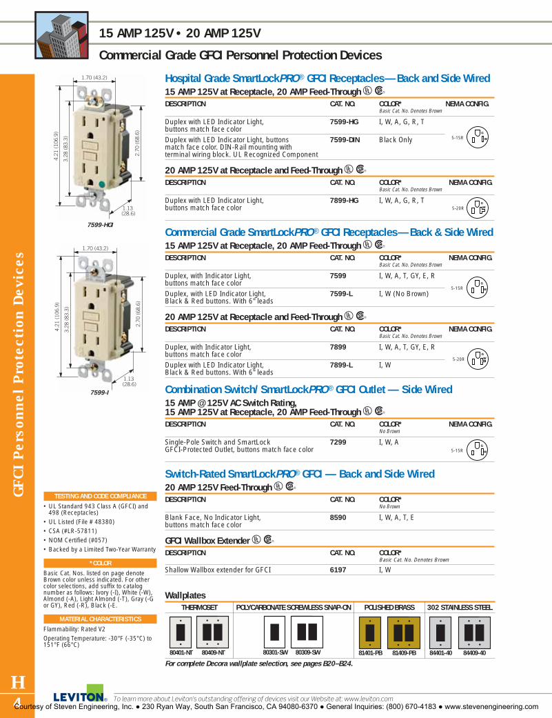
GFC
I Per
sonn
el P
rote
ctio
n Dev
ices
H4
15 AMP 125V • 20 AMP 125V
Commercial Grade GFCI Personnel Protection Devices
To learn more about Leviton’s outstanding offering of devices visit our Website at: www.leviton.com
Hospital Grade SmartLockPRO ® GFCI Receptacles—Back and Side Wired15 AMP 125V at Receptacle, 20 AMP Feed-Through URDESCRIPTION CAT. NO. COLOR* NEMA CONFIG.
Basic Cat. No. Denotes Brown
Duplex with LED Indicator Light, 7599-HG I, W, A, G, R, Tbuttons match face colorDuplex with LED Indicator Light, buttons 7599-DIN Black Onlymatch face color. DIN-Rail mounting with terminal wiring block. UL Recognized Component
20 AMP 125V at Receptacle and Feed-Through URDESCRIPTION CAT. NO. COLOR* NEMA CONFIG.
Basic Cat. No. Denotes Brown
Duplex with LED Indicator Light, 7899-HG I, W, A, G, R, Tbuttons match face color
Commercial Grade SmartLockPRO ® GFCI Receptacles—Back & Side Wired15 AMP 125V at Receptacle, 20 AMP Feed-Through URDESCRIPTION CAT. NO. COLOR* NEMA CONFIG.
Basic Cat. No. Denotes Brown
Duplex, with Indicator Light, 7599 I, W, A, T, GY, E, Rbuttons match face colorDuplex, with LED Indicator Light, 7599-L I, W (No Brown)Black & Red buttons. With 6" leads
20 AMP 125V at Receptacle and Feed-Through URDESCRIPTION CAT. NO. COLOR* NEMA CONFIG.
Basic Cat. No. Denotes Brown
Duplex, with Indicator Light, 7899 I, W, A, T, GY, E, Rbuttons match face colorDuplex with LED Indicator Light, 7899-L I, WBlack & Red buttons. With 6" leads
Combination Switch/ SmartLockPRO ® GFCI Outlet — Side Wired15 AMP @ 125V AC Switch Rating, 15 AMP 125V at Receptacle, 20 AMP Feed-Through URDESCRIPTION CAT. NO. COLOR* NEMA CONFIG.
No Brown
Single-Pole Switch and SmartLock 7299 I, W, AGFCI-Protected Outlet, buttons match face color
Switch-Rated SmartLockPRO® GFCI — Back and Side Wired20 AMP 125V Feed-Through URDESCRIPTION CAT. NO. COLOR*
No Brown
Blank Face, No Indicator Light, 8590 I, W, A, T, Ebuttons match face color
GFCI Wallbox Extender URDESCRIPTION CAT. NO. COLOR*
Basic Cat. No. Denotes Brown
Shallow Wallbox extender for GFCI 6197 I, W
5-15RG
W
5-15RG
W
5-15RG
W
5-20RG
W
5-20RG
W
WallplatesTHERMOSET POLYCARBONATE SCREWLESS SNAP-ON POLISHED BRASS 302 STAINLESS STEEL
For complete Decora wallplate selection, see pages B20–B24.
80301-SW 80309-SW 81401-PB 81409-PB 84401-40 84409-4080401-NT 80409-NT
3.28
(83
.3)
4.21
(10
6.9)
2.70
(68
.6)
1.13 (28.6)
1.70 (43.2)
7599-I
3.28
(83
.3)
4.21
(10
6.9)
2.70
(68
.6)
1.13 (28.6)
1.70 (43.2)
7599-HGI
TESTING AND CODE COMPLIANCE
• UL Standard 943 Class A (GFCI) and498 (Receptacles)
• UL Listed (File # 48380)• CSA (#LR-57811)• NOM Certified (#057)• Backed by a Limited Two-Year Warranty
*COLOR
Basic Cat. Nos. listed on page denoteBrown color unless indicated. For othercolor selections, add suffix to catalognumber as follows: Ivory (-I), White (-W),Almond (-A), Light Almond (-T), Gray (-Gor GY), Red (-R), Black (-E.
MATERIAL CHARACTERISTICS
Flammability: Rated V2Operating Temperature: -30°F (-35°C) to151°F (66°C)
Courtesy of Steven Engineering, Inc. ● 230 Ryan Way, South San Francisco, CA 94080-6370 ● General Inquiries: (800) 670-4183 ● www.stevenengineering.com

GFC
I Personnel P
rotection Devices
H5For answers to technical questions, call Leviton’s Techline at 1-800-824-3005
15 AMP 125V • 20 AMP 125V
Commercial Grade GFCI Personnel Protection Devices
SPECIFICATIONS AND FEATURES
High Current GFCI • Adds ground fault protection to heavy equipment
powered through 3-and 4-wire circuits groundedwith neutral
• Meets or exceeds UL 2003 Code Requirements forincreased surge immunity, corrosion resistance,resistance to false tripping and diagnostic indica-tion for line-load wiring reversal
• Exclusive, patented lockout-action: RESET buttonis blocked if GFCI protection has been compro-mised, eliminating the risk of end-users incorrectlyassuming that a reset GFCI is providing groundfault protection when it actually is not
• Test and Reset buttons confirm proper operation• Ideal for use with spas, heater packs, high
pressure washers, industrial mixers and otherequipment
Right Angle GFCI Plug• UL 943 Class A GFCI operation with open-neutral
protection• May be pre-wired to cable of any specified length• Power indicator light goes off if GFCI trips or unit
is unplugged
TESTING AND CODE COMPLIANCE
Right Angle GFCI Plug• UL Standard 943 Class A (GFCI) and 498
(receptacles)• UL Recognized Component (File #48380)• CSA Certified (LR-57811)• Backed by a Limited One-Year Warranty
*COLOR
Basic Cat. Nos. shown above denote color as indi-cated. For other color selections, add the suffix to catalog number as follows: Ivory (-I), White (-W),Black (-E).
MATERIAL CHARACTERISTICS
Flammability: Rated V2Operating Temperature: -30°F (-35°C) to 151°F(66°C)
High Current SmartLock® GFCI — Back and Side Wired URDESCRIPTION CAT. NO. COLOR*
No Brown
High Current GFCI Contact rating at GFCI: 20A 125V, 8895 I, W, Eload capability with 125V control relay: 80A @ 240V max.Note: The 8895 is wired in conjunction with a switching contactor or relay supplied by the customer. Each 8895 and contactor combination MUST be reviewed and approved by UL. Consult Leviton, Little Neck, for a list of combinationsapproved to date.
Right Angle GFCI Plug URDESCRIPTION CAT. NO. COLOR NEMA CONFIG.
Rated 15A-125V, Automatic Reset 16592† Black
Rated 15A-125V, Automatic Reset 16593† Black
Rated 20A-125V, Automatic Reset 16893† Black
† Wiring module accepts No. 18 (.300") thru No. 12 (.432") cord sizes
Waterproof Cover for Right Angle GFCI PlugsDESCRIPTION CAT. NO. COLOR NEMA CONFIG.
Waterproof Cover for Right Angle 86593 ClearGFCI Plugs with ground pin up orientation
Heavy Duty Right Angle GFCI Plug URDESCRIPTION CAT. NO. COLOR NEMA CONFIG.
Rated 15A-125V, Automatic Reset 6593†† Black
Rated 15A-125V, Manual Reset 6594†† Yellow
Rated 20A-125V, Manual Reset 6893†† Black
Rated 20A-125V, Automatic Reset 6894†† Yellow
†† Wiring module accepts No. 18 (.300") thru No. 12 (.607") cord sizes
5-15PG
W
5-15PG
W
5-20PG
W
5-20PG
W
1.13(28.6)
2.58(65.5)
3.28
(83
.3)
4.21
(10
6.9)
2.70
(68
.6)
8895-W
2.40(61.0)
1.60(41.0)
4.75
(12
1.0)
5.12
(13
0.0)
6594
1.57(39.9)
1.64(41.7)
3.72
(94
.5)
3.93
(99
.8)
16593
1-15P
Courtesy of Steven Engineering, Inc. ● 230 Ryan Way, South San Francisco, CA 94080-6370 ● General Inquiries: (800) 670-4183 ● www.stevenengineering.com

GFC
I Per
sonn
el P
rote
ctio
n Dev
ices
H6
15 and 20 AMP 125V • 15 and 20 AMP 240V
Commercial Grade GFCI Personnel Protection Devices
To learn more about Leviton’s outstanding offering of devices visit our Website at: www.leviton.com
SPECIFICATIONS AND FEATURES
• UL 943 Class A GFCI operation with open-neutralprotection
• Automatic Reset Cord Sets (black body) will auto-matically reset ON when power is restored after apower interruption
• Manual Reset Cord Sets (yellow body) will not auto-matically reset ON when power is restored after apower interruption–Reset button must be pushed in
• Trip threshold meets or exceeds UL requirementsfor tripping time
• Impact-resistant thermoplastic cover and body• Silver alloy contacts• Water-resistant enclosure is sealed by ultrasonic
welding• Power indicator light goes off if GFCI trips or unit is
unplugged
TESTING AND CODE COMPLIANCE
• UL Standard 943 Class A (GFCI) • UL Listed (File #48380)• Backed by a Limited One-Year Warranty
MATERIAL CHARACTERISTICS
Flammability: Rated V2Operating Temperature: -30°F (-35°C) to 151°F (66°C)
Automatic Reset GFCI Cord Sets and Extension Cord — Black Body URDESCRIPTION CAT. NO. LENGTH NEMA CONFIG.15A-125V GFCI Cord Set 66591-2C 2 feet15A-125V GFCI Cord Set 66591-6C 6 feet15A-125V GFCI Cord Set 66591-25C 25 feet15A-125V GFCI Cord Set, 66591-WL 20 feetwith Fluorescent Light15A-125V GFCI Cord Set, Triple Outlet 66593-3 3 feet15A-125V Locking GFCI Cord Set 66597-3 3 feet
20A-125V GFCI Cord Set 66891-3 3 feet
20A-125V Locking GFCI Cord Set 66897-3 3 feet
15A-125V GFCI Extension Cord* 26591-37C 37 feet No Connector
15A-125V GFCI Cord Set 66591-2C 2 feet
15A-240V GFCI Extension Cord* 26592-E 35 feet No Connector
20A-240V GFCI Extension Cord* 36592-E 35 feet No Connector
Manual Reset GFCI Cord Sets — High Visibility Yellow Body URDESCRIPTION CAT. NO. LENGTH NEMA CONFIG.15A-125V 69591-3 3 feet15A-125V 69591-25 25 feetTriple-tap, 15A-125V 69593-3 3 feet20A-125V 69891-3 3 feet
15A-125V, w/Wetguard® 69591-W3 3 feetPlugs and Connectors15A-125V, w/Wetguard® 69591-W25 25 feetPlugs and Connectors20A-125V, w/Wetguard® 69891-W3 3 feetPlugs and Connectors�
*UL recognized componentCSA Certified except where indicated by �
5-15RG
W5-15PG
W
5-15RG
W5-15PG
W
5-15RG
W5-15PG
W
5-15RG
W5-15PG
W
5-15PG
W
L5-15RL5-15P
GW5-20R5-20P
G
W
6-15PG
6-20PG
GW5-20R5-20P
G
W
GW5-20R5-20P
G
W
L5-20RL5-20P
2.50 (63.5)
6.70
(17
0.2)
66591-2C
2.50 (63.5)
6.70
(17
0.2)
69591-W3
Courtesy of Steven Engineering, Inc. ● 230 Ryan Way, South San Francisco, CA 94080-6370 ● General Inquiries: (800) 670-4183 ● www.stevenengineering.com

GFC
I Personnel P
rotection Devices
H7For answers to technical questions, call Leviton’s Techline at 1-800-824-3005
GFCI ACCESSORIES
Commercial Grade GFCI Personnel Protection Devices
SPECIFICATIONS AND FEATURES
The Box• For temporary use in industrial & commercial
maintenance & repair stations (construction, entertainment, amusement sites, trade shows, convention halls) where portable power is needed
• Weatherproof covers prevent nuisance tripping;prevent moisture from entering contacts
• Clear port hole panel for circuit breaker viewing• Reinforced metal housing & legs withstand abusePower Cords• Flexible, abrasion-resistant construction for
reliable performance to -31°F
TESTING AND CODE COMPLIANCE
• Raintight covers satisfy NEC Article 410-57(b)requirements
• Raintight covers are rated NEMA 3RThe Box• Meets OSHA Regulation 20, Part 1926, Subpart K
for open-neutral GFCI & circuit overload protection• UL Listed for outdoor use• Backed by a Limited One-Year WarrantyPower Cords• UL Listed (File #E-48380)
Single Gang Flush Cover Wallplates — Gray Finish URMOUNTING POSITION & DESCRIPTION CAT. NO. FITS TYPE OF BOXVertical — Die-Cast Zinc 6196-V StandardHorizontal — Die-Cast Zinc 6196 StandardVertical — Die-Cast Zinc 6196-VFS FS (Four Screws)Horizontal — Die-Cast Zinc 6196-FS FS (Four Screws)Horizontal — Die-Cast Zinc 4990 StandardVertical — Die-Cast Zinc 4992 StandardHorizontal — Plastic 4996 StandardVertical — Plastic 4998 Standard
Raintight While-In-Use Covers URDESCRIPTION CAT. NO. COLORGFCI, Vertical Mount 5977-GY GrayGFCI, Vertical Mount w/Extra Deep Cover 5977-DGY GrayGFCI, Vertical Mount 5977-CL ClearGFCI, Vertical Mount w/Extra Deep Cover 5977-DCL ClearGFCI, Horizontal Mount 5997-GY GrayGFCI, Horizontal Mount w/Extra Deep Cover 5997-DGY GrayGFCI, Horizontal Mount 5997-CL ClearGFCI, Horizontal Mount w/Extra Deep Cover 5997-DCL Clear
Temporary Portable Power Distribution Center/GFCI (The Box) URDESCRIPTION CAT. NO. INLET OUTLET NEMA CONFIG.
Non-NEMA Non-NEMACalifornia Style California Style
Power Distribution Box. PB101-SGF 50A, 50A, GFCI-Protected Receptacles: 125/250V 125/250V(6) 20A/125V Locking, GFCI Protected(1) 30A/250V Locking, GFCI ProtectedPower Distribution Box PB101-000 50A 50AGFCI Protected Receptacles: 125/250V 125/250V(6) 20A/125V Locking, GFCI Protected(1) 30A/250V Locking, Non-GFCI ProtectedPower Distribution Box, PB103-SGF 50A, 50A, GFCI-Protected Receptacles: 125/250V 125/250V(6) 20A/125V Straight Blade, GFCI Protected (1) 30A/250V Locking, GFCI ProtectedPower Distribution Box PB103-000 50A 50AGFCI Protected Receptacles: 125/250V 125/250V(6) 20A/125V Straight Blade, GFCI Protected(1) 30A/250V Locking, Non-GFCI Protected
Power Cords UDESCRIPTION CAT. NO. NON-NEMA CONFIG.50 ft. Temporary Power Cord KRS-A9519w/Weather-Resistant 50A, 125/250 Plug & Connector100 ft. Temporary Power Cord KUS-A9519w/Weather-Resistant 50A, 125/250 Plug & Connector
1:L 6-30R
G
X
Y
6: L5-20R
1: L6-30R
G
X
Y
6: 5-20R
GW
3.30 (83.8)
6.59
(16
7.4)
3.75(95.6)
5977-CL
22.00 (559.0)
12.0
(30
5.0)
16.0(406.0)
12.0(305.0)
PB101-SGF
KRS-A9519
X
Y
W
EQ GR
NON-NEMA
EQ GRX
Y
W
Courtesy of Steven Engineering, Inc. ● 230 Ryan Way, South San Francisco, CA 94080-6370 ● General Inquiries: (800) 670-4183 ● www.stevenengineering.com

H8
HOW TO USE THIS CATALOG
The L-101 Leviton Wiring Device Catalog is designed to help you find the device you’re seeking in the quickest and easiest way possible. Most product sections are divided into three distinct categories in the following sequence—Industrial Grade, CommercialGrade and Residential Grade—and grouped according to amperage and voltage, lowest to highest. For example, if you need toorder 15 Amp, 125 Volt Industrial Grade straight-blade duplex receptacles, begin your search with the main Table of Contents at thefront of the book. Here you’ll see that all straight blade receptacles are listed in Section G. Turn to Section G for a more detailed Tableof Contents on the first page. Each section page contains product descriptions, ratings and catalog numbers. There are also helpfulhighlights including Specifications and Features, Testing and Code Compliance, Color listing, Material Characteristics and dimen-sioned color product photos. Any product page in the L-101 Catalog can be clearly copied or faxed to customers and prospects foruse as a specifier sheet or as part of a presentation.
The Quick Reference Guide follows the main Table of Contents to help you pinpoint and locate specific products. TechnicalSection V provides general product and test data, industry standards, NEMA configuration charts, a glossary of wiring deviceterms, ANSI architectural symbols and other related information. Specific catalog numbers are listed in the exhaustive index atthe back of the catalog.
RATING
Choose GRADE, if appropriate
DIMENSIONED PHOTOGRAPH
WIRING/CERTIFICATIONS
CATALOG NUMBER
DESCRIPTION
Check for NEMA CONFIGURATION
WALLPLATE REFERENCE, if appropriate
SPECIFICATIONS & FEATURES
TESTING AND CODE COMPLIANCE
COLOR LISTING
MATERIAL CHARACTERISTICSL
K
J
I
H
G
F
E
D
C
B
A
I
D
E
H
B
J
G
K
F
L
C
A
Courtesy of Steven Engineering, Inc. ● 230 Ryan Way, South San Francisco, CA 94080-6370 ● General Inquiries: (800) 670-4183 ● www.stevenengineering.com
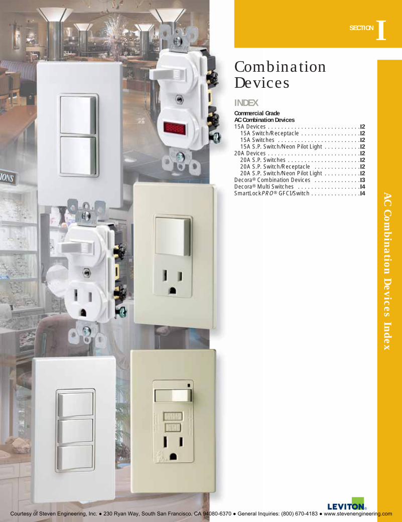
AC C
ombination D
evices IndexSECTIONI
Combination DevicesINDEXCommercial GradeAC Combination Devices15A Devices . . . . . . . . . . . . . . . . . . . . . . . . . . . .I2
15A Switch/Receptacle . . . . . . . . . . . . . . . . . .I215A Switches . . . . . . . . . . . . . . . . . . . . . . . . .I215A S.P. Switch/Neon Pilot Light . . . . . . . . . . .I2
20A Devices . . . . . . . . . . . . . . . . . . . . . . . . . . . .I220A S.P. Switches . . . . . . . . . . . . . . . . . . . . . .I220A S.P. Switch/Receptacle . . . . . . . . . . . . . .I220A S.P. Switch/Neon Pilot Light . . . . . . . . . . .I2
Decora® Combination Devices . . . . . . . . . . . . . .I3Decora® Multi Switches . . . . . . . . . . . . . . . . . . .I4SmartLockPRO® GFCI/Switch . . . . . . . . . . . . . . .I4
Courtesy of Steven Engineering, Inc. ● 230 Ryan Way, South San Francisco, CA 94080-6370 ● General Inquiries: (800) 670-4183 ● www.stevenengineering.com

15 and 20 AMP 120V and 120/277V
Commercial Grade AC Combination Devices
To learn more about Leviton’s outstanding offering of devices visit our Website at: www.leviton.com
AC C
ombi
nati
on D
evic
es
I2
LEVITON OFFERS THE MOST COMPREHENSIVE LINE OF DURABLE COMBINATION DEVICES ON THE MARKET TODAY.
Combination devices permit installation of two devices in a space normally occupied by only one, resulting inreduced installation time and increased convenience.
The following pages provide a detailed listing of the complete line of Leviton combination devices.
SPECIFICATIONS AND FEATURES
• AC quiet switches have silver-cadmium oxide con-tacts and receptacles have double-wipe contactsfor maximum conductivity
• All devices have grounding screw, except wherenoted
• Side wired with terminal screws that accept up to#12 copper or copper-clad wire
• Fit standard wallboxes• Break-off tabs on devices with AC quiet switches
permit conversion to separate feeds
TESTING AND CODE COMPLIANCE
• UL Listed (File #7458)• CSA (File #LR-3413) • NOM Certified (#057)• Backed by a Limited Two-Year Warranty
*COLOR
Basic Cat. Nos. shown above denote Brown color. Forother color selections, add suffix to the catalog num-ber as follows: Ivory (-I), White (-W), Almond (-A),Light Almond (-T), Black (-E).
HORSEPOWER
15A 20A__ __1⁄2 @120V 1 @ 120V2 @ 240V 2 @ 240V
MATERIAL CHARACTERISTICS
Environmental: Flammability UL-94, V2 RatingOperating Temperature: -40°C to 120°C
Combination Devices†
15 AMP URDESCRIPTION RATING CAT. NO. COLOR*
Basic Cat. No. Denotes Brown
Two Single-Pole Switches 15A–120/277V AC 5224 I, W(Non-Grounding)Two Single-Pole Switches 15A–120/277V AC 5224-2 I, W, A, T
Single-Pole Switch/Receptacle Switch: 15A–120V AC 5225 I, W, A, TReceptacle: 15A-125V
Single-Pole Switch/Pilot Light Switch: 15A–120V AC 5226 I, W, A, TPilot Light: 1/25W–125V AC
3-Way Switch/ Single-Pole Switch 15A–120/277V AC 5241 I, W, A, T
Two 3-Way Switches 15A–120/277V AC 5243 I, W, A, T
3-Way Switch/Receptacle Switch: 15A–120V AC 5245 I, WReceptacle: 15A–125V
3-Way Switch/Pilot Light Switch: 15A-120V AC 5246 I, WPilot light: 1/25W-125V AC
20 AMP URDESCRIPTION RATING CAT. NO. COLOR*
Basic Cat. No. Denotes Brown
Two Single-Pole Switches 20A–120/277V AC 5334 I, WSingle-Pole Switch/Receptacle Switch: 20A–120V AC 5335 I, W, E
Receptacle: 20A–125VSingle-Pole Switch/Pilot Light Switch: 20A–120V AC 5336 I
Pilot Light: 1/25W–125V AC† All devices are grounded except where noted.
4.20
(10
6.7)
3.28
(83
.3)
1.06 (27.0)
2.77
(70
.4)
1.62 (41.1)
5225-W
4.20
(10
6.7)
3.28
(83
.3)
1.06 (27.0)
2.77
(70
.4)
1.62 (41.1)
5224-2W
4.20
(10
6.7)
3.28
(83
.3)
1.06 (27.0)
2.77
(70
.4)
1.62 (41.1)
5226-W
WallplatesTHERMOSET THERMOPLASTIC 302 STAINLESS STEEL
For complete wallplate selection, see Section E.88003 80703-W 84003-40
Courtesy of Steven Engineering, Inc. ● 230 Ryan Way, South San Francisco, CA 94080-6370 ● General Inquiries: (800) 670-4183 ● www.stevenengineering.com

AC C
ombination D
evices
I3For answers to technical questions, call Leviton’s Techline at 1-800-824-3005
15 and 20 AMP 120V and 120/277V
Commercial Grade AC Combination Devices
SPECIFICATIONS AND FEATURES
• Elegant Decora styling provides multiple control ina single-gang wallbox
• All devices have grounding screw• Fit standard wall boxes
TESTING AND CODE COMPLIANCE
• UL Listed (File #E-7458)• CSA Certified (File #LR-3413)• NOM Certified (#057)• Backed by a Limited Two-Year Warranty
*COLOR
Colors available as listed. For other color selections,add suffix to catalog numbers as follows: Ivory (-I),White (-W), Almond (-A), Light Almond (-T), Gray (-GY) and Black (-E).
HORSEPOWER
15A 20A__ __1⁄2 @120V 1 @ 120V2 @ 240V 2 @ 240V
MATERIAL CHARACTERISTICS
Environmental: Flammability UL-94, V2 RatingOperating Temperature: -40°C to 120°C
Decora® Combination Devices15 AMP URDESCRIPTION RATING CAT. NO. COLOR*Two Single-Pole Switches 15A-120/277V AC 5634 I, W, A, T, GY, ESingle-Pole Switch/Receptacle Switch: 15A–120V AC 5625 I, W, A, T, GY, E
Receptacle: 15A-125VSingle-Pole Switch/Pilot Light Switch: 15A–120V AC 5626 I, W, A
Pilot: 1/25W–125V AC3-Way Switch/Single-Pole Switch 15A-120/277V AC 5641 I, W, A, T, ETwo 3-Way Switches 15A-120/277V AC 5643 I, W, A, T3-Way Switch/Receptacle Switch: 15A–120V AC 5645 I, W, A, E
Receptacle: 15A–125V3-Way Switch/Pilot Light Switch: 15A–120V AC 5646 I, W, A
Pilot: 1/25W–125V AC
20 AMP URDESCRIPTION RATING CAT. NO. COLOR*Two Single-Pole Switches 20A-120/277V AC 5627 I, W, A, TSingle-Pole Switch/Receptacle Switch: 20A-120V AC 5636 I, W, A
Receptacle: 20A-125VSingle-Pole Switch/Pilot Light Switch: 20A-120V AC 5637 I, W, A
Pilot: 1/25W-125V ACTwo 3-Way Switches 20A-120/277V AC 5640 I, W, A, T
1.31 (33.4)
0.93(23.6)
3.28
(83
.3)
4.20
(10
6.7)
2.83
(71
.9)
5625-T
1.31 (33.4)
1.06(26.9)
3.28
(83
.3)
4.20
(10
6.7)
2.77
(70
.4)
5634-W
WallplatesTHERMOSET THERMOPLASTIC POLYCARBONATE SCREWLESS SNAP-ON 302 STAINLESS STEEL
For complete Decora wallplate selection, see pages B20–B24.80401-I 80401-NW 80301-ST 80301-SW 84401-40
Courtesy of Steven Engineering, Inc. ● 230 Ryan Way, South San Francisco, CA 94080-6370 ● General Inquiries: (800) 670-4183 ● www.stevenengineering.com
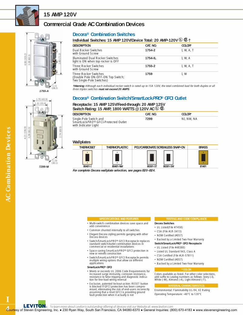
AC C
ombi
nati
on D
evic
es
I4
15 AMP 120V
Commercial Grade AC Combination Devices
To learn more about Leviton’s outstanding offering of devices visit our Website at: www.leviton.com
Decora® Combination SwitchesIndividual Switches: 15 AMP 120V/Device Total: 20 AMP-120V UR†DESCRIPTION CAT. NO. COLOR*Dual Rocker Switches 1754-2 I, W, A, Twith Ground ScrewIlluminated Dual Rocker Switches 1754-IL I, W, Alight is ON when top rocker is OFFThree Rocker Switches 1755-2 I, W, A, Twith Ground ScrewThree Rocker Switches 1759 I, W(Double Pole ON-OFF-ON Top Switch;Two Single-Pole Switches)
†Warning: Although each individual rocker switch is rated up to 15A 120V, the total combined load for both duplex or allthree triplex switches must not exceed 20 AMPS.
Decora® Combination Switch/SmartLockPRO® GFCI OutletReceptacle: 15 AMP 125V/Feed-through: 20 AMP 125V Switch Rating: 15 AMP, 1800 WATTS @ 120V AC URDESCRIPTION CAT. NO. COLOR*Single-Pole Switch and 7299 NI, NW, NASmartLockPRO ® GFCI-Protected Outletwith Indicator Light
SPECIFICATIONS AND FEATURES
• Multi-switch combination devices save space andadd convenience
• Common shunted internally to all switches• Elegant Decora styling permits ganging with other
Decora devices• Switch/SmartLockPRO® GFCI Receptacle replaces
standard switch/outlet combination devices incommercial or residential installations
• Space-saving SmartLockPRO® GFCI protection innew or retrofit construction
• Switch/SmartLockPRO® GFCI Receptacle permits multiple wiring options that allow six different applications
SmartLockPRO® GFCI• Meets or exceeds UL 2006 Code Requirements for
increased surge immunity, corrosion resistance,resistance to false tripping and diagnostic indica-tion for line-load wiring reversal
• Exclusive, patented lockout-action: RESET buttonis blocked if GFCI protection has been compro-mised, eliminating the risk of end-users incorrectlyassuming that a reset GFCI is providing groundfault protection when it actually is not
TESTING AND CODE COMPLIANCE
Decora Switches • UL Listed(File #7458)• CSA (File #LR-3413) • NOM Certified (#057)• Backed by a Limited Two-Year WarrantySwitch/SmartLockPRO® GFCI Receptacle• UL Listed (File #48380)• Listed UL Standard 943, Class A • CSA Certified (File #LR-57811) • NOM Certified (#057)• Backed by a Limited Two-Year Warranty
*COLOR
Colors available as listed. For other color selections,add suffix to catalog numbers as follows: Ivory (-I), White (-W), Almond (-A), Light Almond (-T).
MATERIAL CHARACTERISTICS
Environmental: Flammability UL-94, V2 RatingOperating Temperature: -40°C to 120°C
7299-NI
1.11(28.2)
3.28
(83
.3)
4.06
(10
3.2)
2.80
(71
.2)
1755-A
1.31 (33.4)
1.70 (43.9)
1.19(30.1)
3.28
(83
.3)
4.21
(10
6.9)
2.74
(69
.5)
WallplatesTHERMOSET THERMOPLASTIC POLYCARBONATE SCREWLESS SNAP-ON BRASS
For complete Decora wallplate selection, see pages B20–B24.80401-I 80401-NW 80301-ST 80301-SW 81401
Courtesy of Steven Engineering, Inc. ● 230 Ryan Way, South San Francisco, CA 94080-6370 ● General Inquiries: (800) 670-4183 ● www.stevenengineering.com

Structured M
edia Com
ponents IndexSECTIONJ
Structured MediaComponentsLeviton Integrated Networks™
INDEXStructured Media™ ComponentsOverview . . . . . . . . . . . . . . . . . . . . . . . . . . . . . . . . .J2Enclosures . . . . . . . . . . . . . . . . . . . . . . . . . . . .J3–J5Media Versatile™ Panel . . . . . . . . . . . . . . . . . . . . . .J5Enclosure for Multiple Dwelling Units (MDUs) . . . .J6Cabling Panels . . . . . . . . . . . . . . . . . . . . . . . .J7–J10Stand-Alone Modules and Boards . . . . . . . . .J10, J11Mounting Brackets . . . . . . . . . . . . . . . . . . . .J11, J12Power and Surge Protective . . . . . . . . . . . . .J13, J14Networking and Internet Sharing . . . . . . . . . . . . .J15Video Distribution . . . . . . . . . . . . . . . . . . . . .J16–J18Home Video Monitoring System . . . . . . . . . .J19–J21Residential Intercom System . . . . . . . . . . . . . . . .J22
Home Entertainment Components
Leviton/JBL Products and SystemsIndoor Speakers . . . . . . . . . . . . . . . . . . . . . . . . . .J23Outdoor Speakers . . . . . . . . . . . . . . . . . . . . . . . . .J24Home Theater Speakers . . . . . . . . . . . . . . . .J24-J25Harman/Kardon Entertainment Center Components and Accessories . . . . . . . . . . . . . . .J26Leviton Architectural Edition™ Products Multi-Room Audio Amplifiers and Keypad System Accessories . . . . . . . . . . . . . . . . .J27Audio Volume Controls . . . . . . . . . . . . . . . . . .J28-J30Audio Distribution Products . . . . . . . . . . . . . .J31-J32SpecGrade Sound™ ProductsIndoor Speakers . . . . . . . . . . . . . . . . . . . . . . . . . .J33Outdoor Speakers . . . . . . . . . . . . . . . . . . . . . . . . .J33Other Home Entertainment ProductsDecora Media System . . . . . . . . . . . . . . . . . . . . . .J34Multi-Room IR Repeater System . . . . . . . . . . . . .J35Decora Recessed Receptacles . . . . . . . . . . . . . . .J35
Courtesy of Steven Engineering, Inc. ● 230 Ryan Way, South San Francisco, CA 94080-6370 ● General Inquiries: (800) 670-4183 ● www.stevenengineering.com
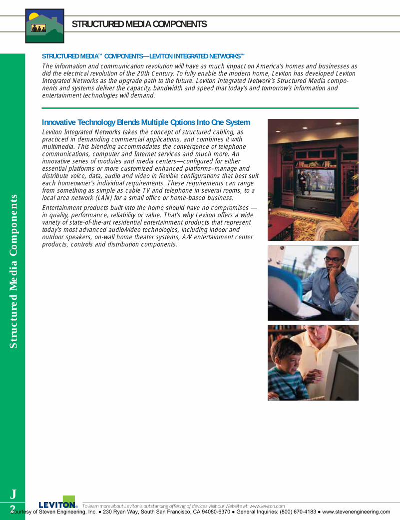
STRUCTURED MEDIA COMPONENTS
To learn more about Leviton’s outstanding offering of devices visit our Website at: www.leviton.com
Str
uctu
red
Med
ia C
ompo
nent
s
J2
STRUCTURED MEDIA™ COMPONENTS—LEVITON INTEGRATED NETWORKS™
The information and communication revolution will have as much impact on America’s homes and businesses asdid the electrical revolution of the 20th Century. To fully enable the modern home, Leviton has developed LevitonIntegrated Networks as the upgrade path to the future. Leviton Integrated Network’s Structured Media compo-nents and systems deliver the capacity, bandwidth and speed that today’s and tomorrow’s information and entertainment technologies will demand.
Innovative Technology Blends Multiple Options Into One SystemLeviton Integrated Networks takes the concept of structured cabling, aspracticed in demanding commercial applications, and combines it withmultimedia. This blending accommodates the convergence of telephonecommunications, computer and Internet services and much more. Aninnovative series of modules and media centers—configured for eitheressential platforms or more customized enhanced platforms–manage anddistribute voice, data, audio and video in flexible configurations that best suiteach homeowner's individual requirements. These requirements can rangefrom something as simple as cable TV and telephone in several rooms, to alocal area network (LAN) for a small office or home-based business.
Entertainment products built into the home should have no compromises —in quality, performance, reliability or value. That’s why Leviton offers a widevariety of state-of-the-art residential entertainment products that representtoday’s most advanced audio/video technologies, including indoor andoutdoor speakers, on-wall home theater systems, A/V entertainment centerproducts, controls and distribution components.
Courtesy of Steven Engineering, Inc. ● 230 Ryan Way, South San Francisco, CA 94080-6370 ● General Inquiries: (800) 670-4183 ● www.stevenengineering.com

Structured M
edia Com
ponents
J3
STRUCTURED MEDIA™ CENTERS
SPECIFICATIONS AND FEATURES
• Accommodates up to two full-width Pre-ConfiguredStructured Cabling Panels–delivering audio/ video,voice and data to any room of the home or office.
• Positive “stops” on housing sidewalls prevent the enclosure from falling through studs duringinstallation.
• One piece white steel unit holds full and half-widthexpansion modules.
• Can be surface-mounted or recessed.Ideal for newinstallations or retrofits.
• Mounting guides on the cover align screw-holesand reduce the chances of dropping during attachment.
• Powder-coated white cover features a 3⁄4" overlapto hide irregular drywall cuts.
• Combine two or more enclosures for larger installa-tions or future expansion.
• Multiple knock-outs on top and bottom includingtwo new 2" knockouts on top, facilitate cable entry and routing.
• Cut-out in base of enclosure for mounting singlegang J-Box kit
• Six 3" square self-healing foam grommets accom-modate cable bundles
Series 140 Structured Media EnclosureThis 14" professional-grade whole-house media enclosure creates one distribution point in the home for alllow voltage cables. It will accommodate two Pre-Configured Structured Cabling Panels. The sturdy designand functionality facilitate installation, reducing job-site labor costs, and making it ideal for essential homenetworking.
SPECIFICATIONSDimensions:Enclosure: 14.38"H x 14.38"W x 3.60"DCover: 16.10"H x 16.10"WMaterials: White, powder-coated enclosure (20 gauge steel), cover (18 gauge steel)Standards Compliance: ACA and cULus Listed. UL Listed for fire and burglary
Series 140 Structured Media Enclosures and CoversDESCRIPTION CAT. NO.Series140 Enclosure and Flush-Mount Cover, empty 47605-140Series140 Enclosure only 47605-14ESeries 140 Flush Mount Cover 47605-14CSeries 140 Hinged Cover–Economy 47605-14DSeries 140 Hinged Cover–Premium 47605-14PSeries140 Enclosure only (6 per pack) 47605-14GSeries 140 Flush Mount Cover (6 per pack) 47605-14B
47605-140 Panel Enclosure with Cover Series 140 Panel Premium Hinged Cover
For answers to technical questions, call Leviton’s Techline at 1-800-824-3005Courtesy of Steven Engineering, Inc. ● 230 Ryan Way, South San Francisco, CA 94080-6370 ● General Inquiries: (800) 670-4183 ● www.stevenengineering.com
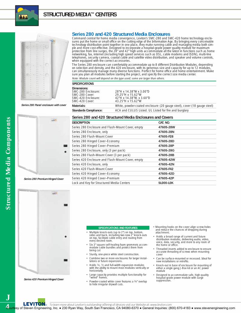
Str
uctu
red
Med
ia C
ompo
nent
s
J4
STRUCTURED MEDIA™ CENTERS
To learn more about Leviton’s outstanding offering of devices visit our Website at: www.leviton.com
SPECIFICATIONS AND FEATURES
• Multiple knock-outs (up to 2") on top, bottom,sides and back, including two new 2" knock-outson top, facilitate cable entry and routing fromevery desired room.
• Six 3" square self-healing foam grommets accom-modate cable bundles and protect them frombeing cut
• Sturdy, one-piece white steel construction.• Combine two or more enclosures for larger instal-
lations or future expansions.• Holds 1⁄4, 1⁄2 and full-width expansion modules
with the ability to mount most modules vertically orhorizontally.
• Large capacity provides multiple functionality for“wired” homes.
• Powder-coated white cover features a 3⁄4" overlapto hide irregular drywall cuts.
• Mounting hooks on the cover align screw-holes and reduce the chances of dropping during attachment.
• Holds a broad range of current and future distribution modules, delivering audio, video,voice, data, security, and more to any room of the home or office.
• Threaded inserts added to enclosure to ensureaccurate threading of screws when mountingcover
• Can be surface-mounted or recessed. Ideal fornew installations or retrofits.
• Knock-out in base of enclosure for mounting ofeither a single gang J-Box kit or an AC power module
• Designed to accommodate safe, high-quality hospital-grade power module with surge suppression.
Series 280 and 420 Structured Media EnclosuresCommand central for home media convergence, Leviton’s SMC-280 and SMC-420 home technology enclo-sures put the home or small office on the cutting edge of the Information Age. By bringing every conceivabletechnology distribution point together in one place, they make running cable and managing media both sim-ple and more cost-effective. Designed to incorporate a hospital-grade power quality module for maximum protection from line surges, the 28" and 42" high units accommodate all the latest in functions such as homenetworking, fax, internet (including high speed services such as DSL, cable modems and ISDN), multi-linetelephones, security camera, coaxial cable and satellite video distribution, and speaker and volume controls,when equipped with the correct accessories.The Series 280 enclosure can comfortably accommodate up to 8 different Distribution Modules, dependingon selection and density, and the 420 enclosure, with its generous size and capacity for up to 12 modules,can simultaneously manage many diverse functions. Perfect for home office and home entertainment. Makesure you plan all modules before starting the project, and specify the correct size media center.Note: Module count will depend on the type used; some are larger than others.
SPECIFICATIONSDimensions:SMC-280 Enclosure: 28"H x 14.38"W x 3.00"DSMC-280 Cover: 29.25"H x 15.62"WSMC-420 Enclosure: 42"H x 14.38"W. x 3.60"DSMC-420 Cover: 43.25"H x 15.62"WMaterials: White, powder-coated enclosure (20 gauge steel), cover (18 gauge steel)Standards Compliance: ACA and CULUS Listed. UL Listed for fire and burglary
Series 280 and 420 Structured Media Enclosures and CoversDESCRIPTION CAT. NO.Series 280 Enclosure and Flush-Mount Cover, empty 47605-28WSeries 280 Enclosure, only 47605-28NSeries 280 Flush-Mount Cover 47605-F28Series 280 Hinged Cover–Economy 47605-28DSeries 280 Hinged Cover–Premium 47605-28PSeries 280 Enclosure, only (3 per pack) 47605-28GSeries 280 Flush-Mount Cover (3 per pack) 47605-28BSeries 420 Enclosure and Flush-Mount Cover, empty 47605-42WSeries 420 Enclosure, only 47605-42NSeries 420 Flush-Mount Cover 47605-F42Series 420 Hinged Cover–Economy 47605-42DSeries 420 Hinged Cover–Premium 47605-42PLock and Key for Structured Media Centers 5L000-L0K
Series 280 Premium Hinged Cover
Series 420 Premium Hinged Cover
Series 280 Panel enclosure with cover
Courtesy of Steven Engineering, Inc. ● 230 Ryan Way, South San Francisco, CA 94080-6370 ● General Inquiries: (800) 670-4183 ● www.stevenengineering.com

Structured M
edia Com
ponents
J5For answers to technical questions, call Leviton’s Techline at 1-800-824-3005
STRUCTURED MEDIA™ CENTERS
SPECIFICATIONS AND FEATURES
Extender Brackets• Made of sturdy white powder-coated 18-gauge
sheet metal• Louvers in the Extender Brackets enhance venti-
lation for added protection against heat build-upfrom installed modules
• Two-Year Product Warranty
Extender Brackets for Leviton Series 280 and 420 Structured Media Centers The Extender Brackets provide an additional 2" of depth and enhanced ventilation with Leviton’s Series280 and 420 Structured Media Centers (SMCs). The Extender Brackets, which are attached between theenclosure and the cover, form a frame assembled from four 2"–deep sheet metal rails with louvers on eachside. The greater depth allows for better cable management and for larger modules, such as audio ampli-fiers, to be mounted within the Structured Media Centers.
Series 280 and 420 Structured Media EnclosuresDESCRIPTION CAT. NO.Extender Bracket 2" depth extension package for 47612-28BSeries 280 Structured Media CentersExtender Bracket 2" depth extension package for 47612-42BSeries 420 Structured Media Centers
SPECIFICATIONS AND FEATURES
• Eight 1" or 1.5" conduit fittings on top and bottomfacillitate cable entry and routing
• Wall-mount or recess. Ideal for new installationsor retrofits
• Securable door provides maximum protectionfrom dust and abuse
• Plywood backing allows open architecture forcustomizing layout and can accommodate a widevariety of Structured Media Distribution Modules.
Media Versatile Panel—For Custom Retrofits and RemodelingIdeal for custom retrofits and remodeling applications, the Media Versatile™ Panelwith 3⁄8" plywood backing allows an open architecture for consolidating low voltageelectronics and distribution components for phone, fax/modem, data, home networking,audio, video and home control. The 24" high cold-rolled steel panel with securabledoor will accommodate a wide variety of Structured Media Distribution Modules bysimply removing the Push-Lock Pins and attaching directly to the plywood backing.The sturdy construction is built to industrial-grade standards, and the panel can besurface mounted or recessed in the wall. (Optional mounting brackets may be usedfor non-standard stud spacing). Ideal for custom retrofits and remodeling applications.Available in black powder coat finish. UL Listed.
SPECIFICATIONSDimensions: 24"H x 14"W x 6"DMaterials: Powder-coated 18 gauge steel with 3⁄8"
plywood backingStandards Compliance: UL Listed.
Media Versatile PanelDESCRIPTION CAT. NO.Media Versatile Panel 47602-24EMounting Brackets—(set of 4) 47602-BKE
Courtesy of Steven Engineering, Inc. ● 230 Ryan Way, South San Francisco, CA 94080-6370 ● General Inquiries: (800) 670-4183 ● www.stevenengineering.com

Str
uctu
red
Med
ia C
ompo
nent
s
J6
STRUCTURED MEDIA™ CENTERS
To learn more about Leviton’s outstanding offering of devices visit our Website at: www.leviton.com
Compact Structured Media Enclosure—For Multi-Dwelling Units (MDU’s)Leviton’s new Compact Structured Media Enclosure for Multi-Dwelling Units offers a compact, cost-effectivedistribution point for basic telephone and video to owners/managers of multi-unit buildings. The unit accom-modates a variety of telephone/video distribution configurations by hosting up to three Telephone ExpansionBoards and one Passive Video Splitter.
SPECIFICATIONSDimensions: (Enclosure) 8.03"(204.0) H x 14.40"(365.6) W x 3.71"(94.2) D
(Cover) 9.01"(228.9) H x 15.39"(390.8) LMaterials: ABS molded plasticStandards Compliance: UL94 VO flame-retardant fire rating
Compact Structured Media Enclosure for MDU’sDESCRIPTION CAT. NO.Compact Structured Media Enclosure 47605-MDUand Cover, emptyMDU Kit (Compact Structured Media 47604-F6Enclosure & Cover plus 1x6 Telephone Expansion Board)MDU Kit (Compact Structured Media 47604-F6SEnclosure & Cover plus 1x6 Telephone Expansion Board and 6-Way Splitter)
SPECIFICATIONS AND FEATURES
• Unique modular design has fewer parts and ismade exclusively from ABS molded plastic to pro-vide customers with cost savings in installation time
• Flexibility to accommodate a variety oftelephone/video distribution configurations
• Snap-on cover requires no tools or fasteners• Molded-in brackets provide quick snap-in conven-
ience for Telephone Expansion Boards• Angled video splitter shelf for easy installation• Hosts up to three Telephone Expansion Boards and
one Passive Video Splitter• Available empty with cover or in two kitted ver-
sions with a 1x6 Telephone Expansion Board orwith a 1x6 Telephone Expansion Board and a 6-Way Splitter
Courtesy of Steven Engineering, Inc. ● 230 Ryan Way, South San Francisco, CA 94080-6370 ● General Inquiries: (800) 670-4183 ● www.stevenengineering.com

Structured M
edia Com
ponents
J7For answers to technical questions, call Leviton’s Techline at 1-800-824-3005
STRUCTURED MEDIA™ PANELS/MODULES
COMPONENTS APPLICATION FEATURES AVAILABLE AS
1x9 BridgedTelephoneBoard
Basic telephonedistribution
Category 5eVoice & DataBoard
Basic homenetworking
Category 6Voice & DataBoard
Basic homenetworking
TelephonePatchingBoard
Expanded 4-linetelephonedistribution
TelephoneSecurityBoard
Route simpletelephone withsecurity interface
DSL FilterBoard
Filters DSLsignal fromtelephone line
1
2
3
4
5
6
7
1 2
ON
3 4
FROM DEMARCATION
OFF
SECURITY
EXPANSION PORT
1
2
3
4
5
6
7
8
9
101 2 3 4
1 2 3 4
LEVITONCategory 5e
JACK 6 6 5
LEVITONCategory 6
JACK 6 6 5
LINE
IN OUTFILTERED
Pre-Configured Structured Cabling PanelsRoute telephone, data and video services throughout your home or office with one simple panel. Leviton’s Pre-configured Structured CablingPanels combine some of our most popular voice, data and RF modules to create an economical one-stop home and office media distributionpoint. See the following pages for available configurations. Some modules are available in expansion styles to fill unused panel slots (see thispage). Choose the pre-configured combination that best meets your needs, and enhance with expansion boards or stand-alone brackets.
Panel Components and Expansion BoardsPre-configured Panels are assembled at the factory and will contain one or more of the following distribution modules.
• Bridge up to 4 telephone lines to 9 locations
• Connect up to 9 separate telephones per line
• Printed circuit board module
• 4-pair 110-type IDC punchdowns
• Part of a Pre-configured Panel
• Stand-alone module with bracket
• Expansion board without bracket
• Patch phone or data connections to 6 locations
• Combine with a TLDM, key system, or net-work hubs for additional applications
• Printed circuit board module
• 4-pair 110-type IDC punchdowns and 6 CAT 5e RJ-45 ports
• Part of a Pre-configured Panel
• Stand-alone module with bracket
• Expansion board without bracket
• Patch phone or data connections to 6 locations
• Combine with a TLDM, key system, or net-work hubs for additional applications
• Printed circuit board module
• 4-pair 110-type IDC punchdowns and 6 CAT 6 RJ-45 ports
• Part of a Pre-configured Panel
• Stand-alone module with bracket
• Expansion board without bracket
TELEPHONE
MODEM
• Filters DSL signal from phone line before distribution throughout a home or office.
• Eliminates need for individual filters at eachwallplate.
• Use with any phone distribution module.• Printed circuit board module with RJ-45 jack
and 110 punchdowns
• Stand-alone module with bracket
• Expansion board without bracket
• Bridge up to 4 telephone lines to 7 locations
• Printed circuit board module
• One incoming 4-pair 110-type IDC punchdownand 7 outgoing RJ-45 jack connections
• Combine with a Category 5e Board to route telephone to remote locations
• Part of a Pre-configured Panel
• Expansion board without bracket
• Bridge up to 4 telephone lines to 6 locations
• Connect up to 6 separate telephones per line
• Connect to security system
• Printed circuit board module
• 4-pair 110-type IDC punchdowns
• Stand-alone module with bracket
TELEPHONE
FAX MODEM
DATA TELEPHONE
FAX MODEM
DATA TELEPHONE
FAX MODEM
TELEPHONE
FAX MODEM
TELEPHONE
FAX MODEM
Courtesy of Steven Engineering, Inc. ● 230 Ryan Way, South San Francisco, CA 94080-6370 ● General Inquiries: (800) 670-4183 ● www.stevenengineering.com

Str
uctu
red
Med
ia C
ompo
nent
s
J8
STRUCTURED MEDIA™ PANELS/MODULES
To learn more about Leviton’s outstanding offering of devices visit our Website at: www.leviton.com
Pre-configured Structured Cabling Panels—Full WidthLeviton has a Pre-Configured Structured Cabling Panel to fit any application. See opposite for explanationsof individual boards. Use the Panels as they are, expand with easy snap-in Expansion Boards, or combinewith other Panels or Stand-alone Modules to create a Structured Media solution tailored to your specificneeds. Ideal for all installations, from basic to high-end. The new non-conductive synthetic bracket fea-tures a rugged construction and a “shelf-style” design with enhanced cable management and easier instal-lation. Boards quickly snap on and off for easy adds/moves/changes.
DESCRIPTION CAT. NO. CONSISTS OFBasic Telephone and 47606-BTV • (1) 1x9 Bridged Telephone Board Video Panel (BTV) • (1) 6-way 2GHz Video Splitter
• Bridge up to 4 telephone lines to 9 locations• Route video to 6 locations
Basic Home Networking 47606-BNP • (1) Telephone Patching Board Plus Panel (BNP) • (1) Category 5e Voice & Data Module
• (1) 6-way 2GHz Video Splitter• 6 4-line telephone connections • Route video to 6 locations• Patch data or telephone service to 6 remote locations• Comes with 6 8-inch 8p8c Flat Patch Cords
Advanced Home Telephone 47606-AHT • (1) Telephone Line Distribution Module& Video Panel (AHT) • (1) Category 5e Voice & Data Board
• (1) 6-way 2GHz Video Splitter • 19 multi-line telephone connections (in various
combinations of 2 or 4 lines) • Route video to 6 locations • Patch data or telephone service to 6 remote locations• Comes with 6 8-inch 8p8c Flat Patch Cords
Full-width panel dimensions: 6.25"H x 13.06"W x 2.50"DFor detailed features and dimensions, please consult individual specification sheets at www.leviton.com
47606-BTV
47606-BNP
47606-AHT
COMPONENTS APPLICATION FEATURES AVAILABLE AS
TelephoneLineDistributionBoard (TLDM)
Enhancedtelephonedistribution
4x12 TelephoneDistributionBoard
VideoSplitters
Basic videodistribution
CS-204PV/DS5-2150MHz SPLITTER
IN
SECURITY
FROM DEMARCATION
TE
ST
1,2,
3,4
1,2,
3,4
1,2,
3,4
1,2,
3,4
1,2,
3,4
1,2,
3,4
1,2,
3,4
1,2,
3,4
1,4
1,4
4,1
3,4
3,4
2,4
2,3
2,1
2,1
1,3
1,3
AD
O1234
1,2,
3,4
1,2,
3,4
1,2,
3,4
1,2,
3,4
1,2,
3,4
1,2,
3,4
1,2,
3,4
1,2,
3,4
1,2,
3,4
1,2,
3,4
1,2,
3,4
1,2,
3,4
1,2,
3,4
1,2,
3,4
1,2,
3,4
1,2,
3,4
1,2,
3,4
1,2,
3,4
Panel Components and Expansion Boards (continued)
Pre-configured Panels are assembled at the factory and will contain one or more of the following distribution modules.
• 19 multi-line telephone connections in combi-nations of 2 or 4 lines
• Bridge “Line 1” service to 12 locations and 4-line service to 8 locations
• Connect to CAT 5e Voice & Data Board(s) oradditional panels for more connections and easier adds/moves/changes
• Independent RJ-45 jack and punchdown security interface to accommodate alarm systems
• Part of a Pre-configured Panel ONLY
• Expansion board with bracket
• Fits easily into any Leviton Structured Mediaenclosure, or can be used as a stand-aloneunit.
• Distribute up to 4 telephone lines through 12 telephone connections
• Links with other distribution boards, modules,or panels to expand the system
• 12 modular RJ-45 jack outputs.• 4-pair 110 type IDC inputs.
• Part of a Pre-configured Panel ONLY
VIDEO
TELEPHONE
FAX MODEM
TELEPHONE
FAX MODEM
• Cable TV or off-air antenna signals
• 4-way or 6-way RF Splitter
• Die-cast housing
• Available in 1GHz and 2GHz models
• Part of a Pre-configured Panel
• Stand-alone module with bracket
Courtesy of Steven Engineering, Inc. ● 230 Ryan Way, South San Francisco, CA 94080-6370 ● General Inquiries: (800) 670-4183 ● www.stevenengineering.com

Structured M
edia Com
ponents
J9For answers to technical questions, call Leviton’s Techline at 1-800-824-3005
STRUCTURED MEDIA™ PANELS
DESCRIPTION CAT. NO. CONSISTS OFAdvanced Home Office Panel 47606-ASO • (1) Telephone Line Distribution Module
• (2) Category 5e Voice & Data Boards• (1) 6-Way 2GHz Video Splitter• (1) 19 multi-line telephone connections (in various
combinations of 2 or 4 lines)• Route video to 6 locations• Patch data or telephone service to 6 remote locations• Comes with (6) 8-inch 8p8c Flat Patch Cords
12-Port Structured Media 47603-12P • (1) Telephone Line Distribution ModulePanel (12P) • (2) Category 5e Voice & Data Boards
• 19 multi-line telephone connections (in variouscombinations of 2 or 4 lines)
• Patch data or telephone service to 12 remote locations
• Comes with 12 8-inch 8p8c Flat Patch Cords
18-Port Structured Media 47603-18P • (1) Telephone Line Panel (18P)Distribution Module• (3) Category 5e Voice & Data Boards • 19 multi-line telephone connections (in various
combinations of 2 or 4 lines) • Patch data or telephone service to 18
remote locations • Comes with 18 8-inch 8p8c Flat Patch Cords
24-Port Structured Media 47603-24P • (1) Telephone Line Distribution ModulePanel (24P) • (4) Category 5e Voice & Data Boards
• 19 multi-line telephone connections (in various combinations of 2 or 4 lines)
• Patch data or telephone service to 24 remote locations
• Comes with 24 8-inch 8p8c Flat Patch Cords4 x 12 Telephone 47603-12M • (1) 4 x 12 Telephone Dist. BoardDistribution Panel • Handles up to 4 telephone lines through
12 connections4 x 12 Telephone 47603-412 • (1) 4 x 12 Telephone Dist. BoardDistribution Panel • (1) 8-way 2GHz Video Splitterw/ Splitter • Handles up to 4 telephone lines through
12 connections• Features output for up to 8 video connections
4 x 18 Telephone 47603-18M • (1) 4 x 18 Telephone Dist. BoardDistribution Panel • Handles up to 4 telephone lines through
18 connections4 x 18 Telephone 47603-8C1 • (1) 4 x 18 Telephone Dist. BoardDistribution Panel • (1) Category 5e Voice & Data Module w/CAT 5e Board • Handles up to 4 telephone lines through
18 connections• Provides voice and data service to 6 remote locations
via CAT 5e voice and data boards
Full-width panel dimensions: 6.25"H x 13.06"W x 2.50"DFor detailed features and dimensions, please consult individual specification sheets at www.leviton.com
47606-ASO
47603-12P
47603-18P
47603-24P
47603-12M
47603-18M
47603-8CI
Courtesy of Steven Engineering, Inc. ● 230 Ryan Way, South San Francisco, CA 94080-6370 ● General Inquiries: (800) 670-4183 ● www.stevenengineering.com

Stand-Alone Modules and Expansion BoardsStand-Alone ModulesDESCRIPTION–MODULE with BRACKET CAT. NO.A–1x9 Bridged Telephone Module 47689-00BB–Category 5e Voice and Data Module 47605-C5BC–Telephone Security Module 47609-TSVD–DSL Filter Module 47616-DSB
Category 6 Voice and Data Module 47616-C6B
A B C D
Str
uctu
red
Med
ia C
ompo
nent
s
J10
STRUCTURED MEDIA™ PANELS and BOARDS
To learn more about Leviton’s outstanding offering of devices visit our Website at: www.leviton.com
Pre-Configured Structured Cabling Panels—Compact SeriesLeviton’s simple solution for basic telephone and video distribution. These compact panels, with their space-sav-ing profile provide simple bridged telephone to 9 locations and 1GHz video to four or six \locations, respectively. Compact Series Panels are ideal for MDUs and apartments, installations with space constraints and/or installa-tions where budget is the driving concern.
DESCRIPTION CAT. NO. CONSISTS OFTelephone & 4-Way Video 47603-1G4 • (1) 1x9 Bridged Telephone Board
• (1) 4-way 1GHz Video Splitter• Bridge up to 4 telephone lines to 9 locations• Route video to 4 locations
Telephone & 6-Way Video 47603-1G6 • (1) 1x9 Bridged Telephone Board• (1) 6-way 1GHz Video Splitter• Bridge up to 4 telephone lines to 9 locations• Route video to 6 locations
Telephone Security 47603-TSV • (1) Telephone Security Board & 6-Way Video • (1) 6-way 1GHz Video Splitter
• Bridge up to 4 telephone lines to 6 locations• RJ-45 Port for Security Interface• Route video to 6 locations
Telephone & 8-Way Video 47603-1G8 • (1) 1x9 Bridged Telephone Board • (1) 8-way 1GHz Video Splitter• Bridge up to 4 telephone lines to 9 locations• Route video to 8 locations
Compact panel dimensions: 6.5"H x 6.5"WFor detailed features and dimensions, please consult individual specification sheets at www.levitonvoicedata.com
47603-1G4
47603-1G6
47603-TSV
47603-1G8
Expansion BoardsDESCRIPTION CAT. NO.E–1x9 4-Line Bridged Telephone Board 47603-110F–1 x 6 4-Line Bridged Telephone Expansion Board 47609-F6G–1 x 4 6-Line Bridged telephone Expansion Board 47609-S4H–1 x 10 6-Line Bridged Telephone Security Expansion Board 47609-S10I–1x5 4-Line Bridged Phone w/Data Pass Through Expansion Board 47609-D5PJ–1x4 4-Line Bridged Phone and 4-Port CAT 5e Expansion Board 47609-4DPK–1x4 Bridged Phone Board 47609-004L–Category 5e Voice and Data Expansion Board 47603-C5
Category 6 Voice and Data Expansion Board 47611-C6
LE F G H I J K
Courtesy of Steven Engineering, Inc. ● 230 Ryan Way, South San Francisco, CA 94080-6370 ● General Inquiries: (800) 670-4183 ● www.stevenengineering.com

Structured M
edia Com
ponents
J11For answers to technical questions, call Leviton’s Techline at 1-800-824-3005
STRUCTURED MEDIA COMPONENTS
E
C
H GF
Plastic Mounting Brackets for Leviton Structured Media CentersThe Single Plastic Bracket accepts mounting of any single Leviton phone, data, security or DSL Filter Boardwithin the Structured Media Center to enhance an existing system, for use as a stand-alone solution forvoice (with or without security), data and DSL filtering services. The Expansion Plastic Bracket is a full-width bracket that can be populated with up to five Leviton phone, data, security or DSL Filter ExpansionBoards to meet custom application needs. The Data Plastic Bracket can be used to mount switches,routers, and modems within Leviton’s Structured Media Centers. This unit offers a universal design thataccommodates installation of a variety of manufacturers’ products.
DESCRIPTION CAT. NO.A–Single Plastic Bracket for mounting a single Leviton phone, data, security or DSL 47612-SBK
Filter Expansion Board in a Leviton Series 140, 280 or 420 Structured Media CenterB–Expansion Plastic Bracket for mounting up to five Leviton phone, data, security or DSL 47612-EBK
Filter Expansion Boards in a Leviton Series 140, 280 or 420 Structured Media CenterC–Half Plastic Bracket for mounting up to 3 Leviton Phone, Data, Security or DSL Filter
Expansion Boards in Series 140, 280 or 420 SMC 47612-HBKD–Data Plastic Bracket for mounting switches, routers, and modems within a Leviton 47612-DBK
Series 140, 280 or 420 Structured Media Center
Multimedia Adapter Bracket and Mounting PlatesCreate a custom audio/video, copper or fiber mini-panel in your Structured Media Center with the Multi-MediaAdapter Bracket. The bracket supports your choice of two 6-pack mounting plates, and snaps easily into anyof Leviton’s Structured Media Centers with push-pins. Pre-loaded mounting plates are available for BNC andF-connectors, or create a custom configuration with unloaded 6-pack QuickPort® plates. QuickPort platesaccept any combination of the following QuickPort adapters or connectors: BNC, F-Connector, ST, FC, SC andMT-RJ Fiber Optics, Banana Jacks, Speaker Binding Posts, RCA, S-Video, Voice Grade, and Category 5, 5e or 6. Bracket mounts vertically or horizontally.
DESCRIPTION CAT. NO.E–Multimedia Bracket 47612-MMAF–BNC Mounting plate, 6-pack, loaded 5F100-BNCG–F-Connector Mounting plate, 6-pack, loaded 5F100-6VFH–QuickPort Mounting plate, 6-pack, unloaded 5F100-6QP
AccessoriesDESCRIPTION CAT. NO.8-Conductor Flat Telephone Patch Cord, 8" long ((1 each) 42400-8FG
SPECIFICATIONS AND FEATURES
All Plastic Brackets• Made of sturdy white ABS plastic• Come with push-lock pins• Snap-in installation in any Leviton series 140, 280
or 420 Structured Media Center• Allow for cable management via routing
under bracket
BA
Expansion BoardsDESCRIPTION CAT. NO.M–Telephone Patching Expansion Board 47609-EMPN–DSL Filter Board 47616-DSFO–Telephone Line Distribution Module and 19 Multi-Line 47603-TDM
Connections (in various combinations of 2 or 4 lines) BoardP–4x12 Telephone Distribution Board 47603-12BQ–4x18 Telephone Distribution Board 47603-18B
M N O P Q
D
Courtesy of Steven Engineering, Inc. ● 230 Ryan Way, South San Francisco, CA 94080-6370 ● General Inquiries: (800) 670-4183 ● www.stevenengineering.com

A
B
C
Str
uctu
red
Med
ia C
ompo
nent
s
J12
STRUCTURED MEDIA™ BRACKETS
To learn more about Leviton’s outstanding offering of devices visit our Website at: www.leviton.com
SPECIFICATIONS AND FEATURES
All Brackets • Made of white powder-coated 18 gauge sheet metal• Come with push-lock pins Universal Security Brackets• Allow an unlimited number of upgrades (limited
only by the enclosure’s size) to be added to anexisting security system terminated within anyLeviton Structured Media Center
• Sold in pairs with self-tapping screws and spacersto easily connect the largest number of securityalarm manufacturers’ panels
Universal Shelf Bracket• Allows security batteries and other products to be
mounted inside any Leviton Structured Media Center• Vertical and horizontal slots on bracket to
accommodate Velcro strips, ensuring vertical and horizontal stability
Combo Bracket• Allows Leviton products to be installed in most
non-Leviton structured wiring enclosures
Universal Security & Shelf Brackets for Leviton Structured Media CentersThe Universal Security Brackets allow for consolidation and integration of security products into any ofLeviton’s Series 140, 280 or 420 Structured Media Center enclosures. The 6" and 12" Universal SecurityBrackets accommodate the widest variety of security alarm panels. These 1"–wide brackets are sold inpairs with self-tapping screws and insulating spacers for easy attachment to the panels. The UniversalShelf Bracket provides space for security batteries of various sizes as well as other products to be mountedwithin Leviton’s Series 140, 280 or 420 Structured Media Centers. The bracket comes with four 8" longVelcro® strips to strap down products to the shelf, ensuring both vertical and horizontal stability.
Universal Security & Shelf Brackets for Leviton 140, 280 or 420 Structured Media CentersDESCRIPTION CAT. NO.A–6" Universal Security Bracket. Comes a set of two 6"–long, 1"–wide brackets with 47612-6SB
self-tapping screws and spacers for mounting within Leviton’s Series 140, 280 or 420 Structured Media Centers
B–12" Universal Security Bracket. Comes a set of two12"–long, 1"–wide brackets with 47612-1SBself-tapping screws and spacers for mounting within Leviton’s Series 140, 280 or 420 Structured Media Centers
C–Universal Shelf Bracket. Comes with four 8"–long Velcro strips to strap down security 47612-UBKbatteries of various sizes as well as other products to be mounted within Leviton’s Series 140, 280 or 420 Structured Media Centers
D–Half-Width Universal Security Plate. Comes with a 6" long plate with four adhesive 47612-HSBclips for mounting with Leviton’s Series 140, 280 or 420 Structured Media Centers
E–Full-Width Universal Security Plate. Comes with a 12" long plate with four adhesive 47612-FSBclips for mounting with Leviton’s Series 140, 280 or 420 Structured Media Centers
F–Combo Bracket is designed to accommodate Leviton products to be installed in most 47612-CBKstructured wiring enclosures on the market
D
F
E
Courtesy of Steven Engineering, Inc. ● 230 Ryan Way, South San Francisco, CA 94080-6370 ● General Inquiries: (800) 670-4183 ● www.stevenengineering.com
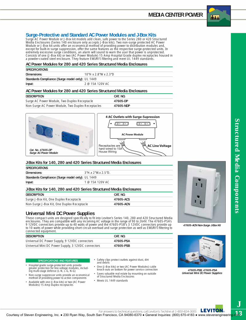
Structured M
edia Com
ponents
J13For answers to technical questions, call Leviton’s Techline at 1-800-824-3005
MEDIA CENTER POWER
SPECIFICATIONS AND FEATURES
• Hospital grade surge-protected units providegreater protection for line-voltage modules, includ-ing multi-stage defense (L-N, L-G, N-G)
• Non-surge suppressor units provide an economicalmethod of providing power to active components
• Available with one (J-Box kits) or two (AC PowerModules) 15 Amp duplex receptacles
• Safety clips protect outlets against dust, dirt and debris
• One (J-Box kits) or two (AC Power Modules) cableknock-outs on bottom for power service connection
• Saves valuable real estate by mounting on outsideof Structured Media Enclosures
• Meets UL 1449 standards
Surge-Protective and Standard AC Power Modules and J-Box KitsSurge AC Power Module or J-Box kit models add clean, safe power to the Series 280 or 420 StructuredMedia Enclosures (Series 140 enclosure only accepts J-Box kits). Two non-surge protected AC PowerModule or J-Box kit units offer an economical method of providing power to distribution modules and,except for built-in surge suppression, offer the same features as the respective surge-protected units. Inextremely excessive surge conditions, an alarm will sound to warn the user that power is unprotected.Consists of one (J-Box kit) or two (AC Power Module) 15 Amp Hospital Grade duplex receptacles housed ina powder-coated steel enclosure. They feature EMI/RFI filtering and meet UL 1449 standards.
AC Power Modules for 280 and 420 Series Structured Media EnclosuresSPECIFICATIONSDimensions: 10"H x 2.8"W x 2.3"DStandards Compliance (Surge model only): UL 1449Input: 2 @ 15A 120V AC
AC Power Modules for 280 and 420 Series Structured Media EnclosuresDESCRIPTION CAT. NO.Surge AC Power Module, Two Duplex Receptacle 47605-DPNon-Surge AC Power Module, Two Duplex Receptacles 47605-NDP
Cat. No. 47605-DP Surge AC Power Module
47605-ACN Non-Surge J-Box Kit
J-Box Kits for 140, 280 and 420 Series Structured Media EnclosuresSPECIFICATIONSDimensions: 3"H.x 2"W.x 2.5"D.Standards Compliance (Surge model only): UL 1449Input: 1 @ 15A 120V AC
J-Box Kits for 140, 280 and 420 Series Structured Media EnclosuresDESCRIPTION CAT. NO.Surge J-Box Kit, One Duplex Receptacle 47605-ACSNon-Surge J-Box Kit, One Duplex Receptacle 47605-ACN
Universal Mini DC Power SuppliesThese compact units are designed specifically to fit into Leviton’s Series 140, 280 and 420 Structured Mediaenclosures. They are compatible with any incoming AC voltage in the range of 90 to 264V. The 47605-PSA’s9 12VDC connectors provide up to 40 watts of power and the 47605-PSB’s 3 12VDC connectors provide upto 10 watts of power while providing short circuit overload and surge protection as well as EMI/RFI filtering toconnected equipment.
DESCRIPTION CAT. NO.Universal DC Power Supply, 9 12VDC connectors 47605-PSAUniversal Mini DC Power Supply, 3 12VDC connectors 47605-PSB
47605-PSB, 47605-PSAUniversal Mini DC Power Supplies
Courtesy of Steven Engineering, Inc. ● 230 Ryan Way, South San Francisco, CA 94080-6370 ● General Inquiries: (800) 670-4183 ● www.stevenengineering.com

Str
uctu
red
Med
ia C
ompo
nent
s
J14
MEDIA CENTER POWER
To learn more about Leviton’s outstanding offering of devices visit our Website at: www.leviton.com
DC Power Distribution ModuleThe DC Power Distribution Module is a unique solution to the need for high quality electrical power for theseparate DC-powered components in the Structured Media Enclosure. This module reduces clutter andopens-up space in the Structured Media Enclosure by eliminating the need for multiple DC transformers.Powered by a single DC power supply, the Power Distribution module provides fully-regulated 12 VDCpower for up to 6 devices.
SPECIFICATIONSInput: 110V ACOutput: Provides 13V DC power for up to 6 devices 1500mACompliance (Surge model only): UL 1449Dimensions: 6.58"H x 2.5"W x 1.5"DWire Gauge: Up to 12 gauge
DC Power Distribution ModuleDESCRIPTION CAT. NO.DC Power Distribution Module 48212-0DC
Snap-In Surge Protection Modules
SPECIFICATIONS AND FEATURES
• Interchangeable modules accommo-date changing surge protectionneeds
• All modules easily snap in to the Cat. No. 3950 Surge Module Bracket
• User-friendly design—no wiringrequired
• Telephone/Fax/Modem Module actsas a splitter, allowing the connectionof two devices
SPECIFICATIONS AND FEATURES
• Contains six removable double screwterminal jacks.
• Each jack utilizes slot-drive screws.• Shipped with 6 wires containing
18 gauge connectors and 2.1 mmpower plugs.
• Fully regulated (12 volt DC regulatedoutput).
Snap-In Modules for Structured Media Enclosure Surge Module BracketLeviton’s snap-in surge protective modules provide customized surge protection for all low-voltage commu-nication and data lines in the Structured Media Enclosure. All Series 5950 modules can snap-in to the Cat.No. 3950-BKT Surge Module Bracket. The bracket, allows you to add and change modules to fit specificprotection needs. Choose from a selection of protection modules for Digital Satellite Systems, Ethernet sys-tems, Cable TV, Telephone/Fax/Modem and DSL/ADSL equipment. All devices attached to the modules arecovered under the Leviton $50,000 Connected Equipment Warranty.
DESCRIPTION CAT. NO.Satellite System/Cable TV Protection Module—4 Standard F-connectors. 3-Amp fuse for Beige—5951-SAover-current. Max. line voltage: 75V DC. Breakdown Voltage Range: 70.4-110 Volts/Sec Gray—5951-SAT
Ice—5951-SACEthernet Protection Module (10 Base-T Applications)—Two RJ45 connectors to protect Beige—5952-ETtwo pair of transmit/receive lines. 10-Amp automatic Resettable PTC fuses. Gray—5952-ETHMax. operating voltage: 16.6V DC. Breakdown Voltage Range: 2.62-19.2 Volts/SecCable TV System Protection Module—Two Standard F-type connectors. 3-Amp fuse for Beige—5953-PCover-current. Max. line voltage: 75V DC. Breakdown Voltage Range: 70.4-110 Volts/Sec Gray—5953-PCG
Ice—5953-PCCTelephone/Fax/Modem Protection Module–Three RJ11, 4-wire/2-pair connectors. Beige—5954-AT43-Position splitter allows for connection to a common line. 3-Amp fuse for over-current Gray—5954-PT4protection. Max. operating voltage: 150V rms (including ring voltage). Breakdown Voltage Ice—5954-CT4Range: 162-331 Volts/SecDSL/ADSL Subscriber Equipment Protection Module–Three RJ11, 4-wire/2pair Beige—5955-DTconnectors. 3-Amp fuse for over-current protection. Max. operating voltage: 150V rms Gray—5955-DTG(including ring voltage). Breakdown Voltage Range: 162-331 Volts/SecCat. 5 Ethernet Module Beige—5957-OCSTwo RJ45 Connectors with Ground Pin for Ethernet - Cat. 5 Grey—5957-C5GTwo Line Telephone Module Beige—5958-AT4One Input, One Output RJ11 Connector for 4-Wire POTS Grey—5958-PT4Four Line Telephone Module Beige—5959-BT8One Input, One Outpupt RJ45 Connector for 8-Wire POTS Grey—5959-GT8Surge Module Bracket 3950-BKT
TESTING AND CODE COMPLIANCE
CAT. NO. MCOV (VDC) CLAMPING TESTED TO MEET STANDARDSVOLTAGE (VDC)
5951 60 388 UL 452 ANSI/IEEE5952 16.6 23 UL497B C-62.365953 60 388 UL4525954 288 715 UL497A CSA5955 205 210 UL497A (#LR-94773)5957 16.6 23 UL497B5958 288 715 UL497A5959 288 715 UL497A
3950-BKT
Courtesy of Steven Engineering, Inc. ● 230 Ryan Way, South San Francisco, CA 94080-6370 ● General Inquiries: (800) 670-4183 ● www.stevenengineering.com

Structured M
edia Com
ponents
J15For answers to technical questions, call Leviton’s Techline at 1-800-824-3005
NETWORKING and INTERNET SHARING
47611-8PT
47611-5PT
SPECIFICATIONS AND FEATURES
• Connects up to 4 devices directly (up to 253 com-puters via a series of cascaded devices) to theInternet using a single shared high-speed DSL,cable modem, or Satellite connection
• Allows fast Internet access at up to 100 Mbps• Permits creation of a private high-speed home area
network HAN) or local area network (LAN) in smalloffice/home office (SOHO) environments for allconnected computers with its fast, integral10/100Mbps auto-sensing Ethernet ports
• High performance suitable for demanding homeoffice and telecommuting applications, includingsharing of high-speed and high-capacity devicessuch as storage devices and back-up systems.
• Network Address Translation technology (NAT)creates a firewall that securely cloaks the privatenetwork from outside access
• Pass-through IPSEC and ISAKMP protocols allowattached LAN users to implement secure VirtualPrivate Network (VPN) communication applica-tions on their PC’s.
• Built-in DHCP server for easy setup and allocationof IP addresses on the LAN.
• Connections are made by running cable fromdesired locations to a Category 5e Voice and DataModule (either a stand-alone module page J10, orone of the units in the Pre-Configured StructuredCabling Panels page J9). From there, Category 5or 5e patch cord can be used to connect theGateway to the Category 5e Module.
• Network protocols: TCP/IP, DHCP, DNS, NAT,TFTP, HTTP, PPOE. Not PPOA
• Auto detect uplink: Use any port to cascade addi-tional switches, hubs or routers
Structured Media™ Modules—Internet Connection Sharingand Multi-Location Networking10/100 Internet Gateway Cable/DSL Broadband Router* Leviton’s 10/100Mbps Internet Gateway (a.k.a router) allows multiple users to securelyshare a single, protected high-speed Internet connection.
10/100 base-t switches*At 10/100Mbps speeds, these units are excellent choices for networking PC’s to meet awide range of residential needs such as sharing files, printers and other peripherals. *Networked PC’s and peripherals require compatible networking cards or adapters and associated software.
10/100 Base-T Switches and 10/100 Base-T Internet Gateway Router SPECIFICATIONS 10/100BASE-T 5-PORT 10/100 BASE-T INTERNET
(OR 8-PORT) SWITCHES GATEWAY ROUTERData Transfer Rate 10/100 MbpsConnectors 5 (or 8) ports, 1 AC Power 4 LAN ports, 1 WAN port,
Adapter Jack 1 Uplink port, 1 AC Power Adapter JackCabling Requirements Standard Cat 5/5e UTPLED Indicators One Power Indicator, 5 (or 8) One Power Indicator, one Diagnostic
Link/Activity and 5 (or 8) 100Mbps Indicator, five Link/Activity, five FDX/Col and five 10/100Mbps
Power Supply 12VDC, 1000mADimensions 5.85" x 3.2" x 1.03" 5.54" x3.92" x 1.05"Standards Compliance IEEE 802.3 10 Base-T Ethernet
IEEE 802.3u 100 Base-TX Fast Ethernet, and FCC Class B
10/100 Base-T Switches and 10/100 Base-T Internet Gateway RouterDESCRIPTION CAT. NO.10/100 Base-T 5-Port Ethernet Switch, with Power Adapter 47611-5PT10/100 Base-T 8-Port Ethernet Switch, with Power Adapter 47611-8PT10/100 Base-T Internet Gateway Router, with Power Adapter 47611-GT4
Cable Distribution—Modem Outside the Structured Media Center
Cat No. 47611-GT410/100Mbps InternetGateway Router
Courtesy of Steven Engineering, Inc. ● 230 Ryan Way, South San Francisco, CA 94080-6370 ● General Inquiries: (800) 670-4183 ● www.stevenengineering.com

Str
uctu
red
Med
ia C
ompo
nent
s
J16
VIDEO DISTRIBUTION
To learn more about Leviton’s outstanding offering of devices visit our Website at: www.leviton.com
CATV 1GHz Video Distribution ModulesCable service providers are converting to digital systems. These new systems will squeeze hundreds of chan-nels plus Internet service onto the coax line. Leviton’s high-performance CATV modules can support thesenew systems while limiting noise and other artifacts. Modules can distribute standard inputs such as CATVand antennas, and modulated inputs such as VCR’s, DVD’s and security camera/CCTV on coaxial cablethroughout the house. Signals can be precisely controlled through the modules’ built-in amplifier/ attenuator(-5 to +15db) to compensate for variations in incoming signal strength for the clearest possible reception*. Incorporates state-of-the-art bi-directional signal paths to support cable modem or cable box communicationsthroughout a home or office. Choose from one or three-input models; both come with 8 outputs. One andthree-input models come in both nickel-plated and gold-plated connector versions. Dimensions: 3.50"H x 6.50"W x 3.20"D, Connector: F-Type, Impedance: 75 Ohm, Power Input: 12 VDC,500 mA (1x8 & 3x8).*Not for use in-line between Ï satellite dish (LNB) and DBS satellite TV receiver.
1x8 CATV Distribution Modules (1GHz)Parameter Bandwidth Forward Path Return Path
Band - - 52-1000Mhz 5-42Mhz
Gain (Loss) - - 4dB (-0.5dB)
Flatness - - ±0.75dB ±1.5dB
Return Loss – Input - - 22.0dB 21.0dB
Return Loss – Output - - 22.0dB 21.0dB
Port Isolation – Output - - 25.0dB 27.0dB
Group Delay (span 3.58Mhz) 54-60Mhz 15ns - -
61-1000Mhz 7ns - -
Group Delay (span 1Mhz) 5-42 MHz - - 17ns
10-40 MHz - - 10ns
Power to RF Input Isolation 5-1000 MHz 100dB (min)
RFI Isolation 5-1000 MHz -110dBc
Noise Figure 5-1000 MHz 3.5dB
CSO -65dBc
Distortions* CTB -74dBc
Xmod -75dBc
* Input level at +10dBmV flat 77 channels & 200Mhz noise for QAM test from 550 to 790MhzOperating Temperature: -40ºC to +60 ºC
3x8 CATV Distribution Modules (1GHz)Parameter Bandwidth Forward Path Return Path
Band - - 52-1000Mhz 5-42Mhz
Gain (Loss) - - 3.5dB (-11.0dB)
Flatness - - ±1.0dB ±1.5dB
Return Loss – Input - - 22.0dB 21.0dB
Return Loss – Output - - 20.0dB 21.0dB
Port Isolation – Output - - 25.0dB 25.0dB
Group Delay (span 3.58Mhz) 54-60Mhz 15ns - -
61-1000Mhz 7ns - -
Group Delay (span 1Mhz) 5-42 MHz - - 17ns
10-40 MHz - - 10ns
Power to RF Input Isolation 5-1000 MHz 100dB (min)
RFI Isolation 5-1000 MHz -110dBc
Noise Figure 5-1000 MHz 6.5dB
CSO -65dBc
Distortions* CTB -74dBc
Xmod -75dBc
* Input level at +10dBmV flat 77 channels & 200Mhz noise for QAM test from 550 to 790MhzOperating Temperature: -40ºC to +60 ºC
CATV Distribution ModulesDESCRIPTION CAT. NO.1x8 CATV Module, 1 GHz, Nickel-plated Connectors 47693-ESM1x8 CATV Module, 1 GHz, Gold-plated Connectors 47693-GSM3x8 CATV Module, 1 GHz, Nickel-plated Connectors 47693-3BY3x8 CATV Module, 1 GHz, Gold-plated Connectors 47693-G3Y
47693-ESM
47693-GSM
47693-3BY
47693-G3Y
Courtesy of Steven Engineering, Inc. ● 230 Ryan Way, South San Francisco, CA 94080-6370 ● General Inquiries: (800) 670-4183 ● www.stevenengineering.com

Structured M
edia Com
ponents
J17For answers to technical questions, call Leviton’s Techline at 1-800-824-3005
VIDEO DISTRIBUTION
Video AmplifierRun cable TV and other video service signals, such as antenna or other modulated input through this VideoAmplifier Module and boost video signal strength up to 25 dB. Features a variable attenuator for signalamplification level setting, and an FM trap to eliminate unwanted FM interference.
SPECIFICATIONSDimensions: 6.58"H x 3.67"W x 4.4"DFrequency Range MHz: 50-1000Gain Control Range dB: 10-25dBFM Trap dB: 25Impedance: 75 OhmConnector Type: F-typePower Source: 12 VDC 500 mA
Video AmplifierDESCRIPTION CAT. NO.Video Amplifier Module 48210-VA
SPECIFICATIONS AND FEATURES
• Run cable TV or other video signalsthrough the Video Amplifier beforesplitting and distributing throughoutthe home or office.
• Boost signal strength by up to 25 dB.
48210-VA
Courtesy of Steven Engineering, Inc. ● 230 Ryan Way, South San Francisco, CA 94080-6370 ● General Inquiries: (800) 670-4183 ● www.stevenengineering.com

Str
uctu
red
Med
ia C
ompo
nent
s
J18
VIDEO DISTRIBUTION
To learn more about Leviton’s outstanding offering of devices visit our Website at: www.leviton.com
1 GHz Modules
1 GHz Video Splitters
SPECIFICATIONS AND FEATURES
• Splits video signals. Outputs for up to4, 6 or 8 televisions.
• Provide digital cable, cable TV andother video services, via coaxialcable, to any room in the house.
• Die-cast housing and printed circuitboard.
• Use with the Video Amplifier forincreased signal strength.
• Units for SMC 140, 280, 420 comewith mounting bracket.
• Gold-flashed contacts on 2 GHz unitsprovide lowest conductive resistance.
SPECIFICATIONS AND FEATURES
• Distributes digital satellite signals to up to 4 TVs (47691-3MS) or 8 TVs(47691-5MS).
• Combines signals from digital satellite withoff-air antenna onto single coax cable.
• DSS 75 Ohm and 2.0 GHz Combiner/Diplexer with DC Blocking, Cat. No.40856-DSS, is available to separateantenna and cable signals.
47691-3MS
47691-5MS
Passive ComponentsUse 4-, 6- and 8-way Passive Video Splitters to split digital cable, quality cable TV and off-air antenna signalsto 4, 6, or 8 televisions throughout the home or office. They feature die-cast housing and printed circuitboard construction. Use with the Video Amplifier for increased signal strength.
1x4, 1x6, 1x8 Passive Video SplittersITEM CAT NO. DIMENSION RANGE1x4 47690-4C 2.14"H x 6.58"W x 1.40"D 1 GHz
47690-004 1.65"H x 3.34"W x 1.14"D 1 GHz47690-4C2 2.14"H x 6.58"W x 1.40"D 2 GHz47690-G4 1.65"H x 3.34"W x 1.14"D 2 GHz
1x6 47690-6C 3.00"H x 6.58"W x 1.40"D 1 GHz47690-006 2.64"H x 3.34"W x 1.14"D 1 GHz47690-6C2 3.00"H x 6.58"W x 1.40"D 2 GHz47690-G6 2.64"H x 3.34"W x 1.14"D 2 GHz
1x8 47690-8C 3.00"H x 6.58"W x 1.40"D 1 GHz47690-008 2.64"H x 3.34"W x 1.14"D 1 GHz47690-8C2 3.00"H x 6.58"W x 1.40"D 2 GHz47690-G8 2.64"H x 3.34"W x 1.14"D 2 GHz
1x4, 1x6, 1x8 Passive Video Splitters1x4 Passive Video Splitter Module for SMC 140, 280, 420 (1 GHz) 47690-4C1x4 Passive Video Splitter For Compact Structured Media Enclosure 47690-0041x6 Passive Video Splitter Module for SMC 140, 280, 420 (1 GHz) 47690-6C1x6 Passive Video Splitter For Compact Structured Media Enclosure 47690-0061x8 Passive Video Splitter Module for SMC 140, 280, 420 (1 GHz) 47690-8C1x8 Passive Video Splitter For Compact Structured Media Enclosure 47690-0081x4 Passive Video Splitter Module for SMC 140, 280, 420 (2 GHz) 47690-4C21x4 Passive Video Splitter For Compact Structured Media Enclosure (2GHz) 47690-G41x6 Passive Video Splitter Module for SMC 140, 280, 420 (2 GHz) 47690-6C21x6 Passive Video Splitter For Compact Structured Media Enclosure (2GHz) 47690-G61x8 Passive Video Splitter Module for SMC 140, 280, 420 (2 GHz) 47690-8C21x8 Passive Video Splitter For Compact Structured Media Enclosure (2GHz) 47690-G8
Satellite Distribution Components3x4 Multi-Switch—Passive module combines signals from dual incoming LNB digital satellite systems withoff-air antenna signals on a single coaxial cable, enabling distribution to up to 4 TV's. Module incorporatesa separate input for TV antenna signals (best used in combination with a video amplifier).5x8 Multi-Switch—Active module combines signals from two dual incoming LNB digital satellite systemswith an off-air antenna or cable signals on a single coaxial cable, enabling distribution to up to 8 TV's.Works with HDTV or standard receivers and with integrated multi-switches at the satellite dish; also workswith DirecTV® systems. Equipped with built-in low noise amplifier and 24VDC power supply.
SPECIFICATIONS CAT. NO. 47691-3MS3x4 Multi-SwitchDimensions: 4.77"H x 6.58"W x 2.37"DFrequency: Terrestrial: 40-860 MHz
Satellite: 950-2150 MHzReceiver Output: 40-2150 MHz
Connectors: F-type, 75 Ohms LNB Input Selection: LNBA: 13/14VDC
LNBB: 17/18VDCInsertion Loss Terrestrial: -7dB(typical): Satellite: -3dBReturn Loss Terrestrial: -10dB(typical): Satellite: -10dBIsolation (typical): Output to Opposite Input -22dBDC Power Passing: 500ma (max.)
SPECIFICATIONS CAT. NO. 47691-5MS5x8 Multi-SwitchDimensions: 7.14"H x 13.25"W x 2.33"DFrequency: Terrestrial: 54-806 MHz
Satellite: 950-2150 MHzReceiver Output: 54-2150 MHz
Connectors: F-type, 75 Ohms LNB Input Selection: 13/18VDC or 22kHz toneInsertion Loss Terrestrial: -2dB(typical): Satellite: -5dBRejection: Satellite-Terrestrial: 30dB
Terrestrial-Satellite: 20dBReceiver-Receiver: 30dB
Switching Isolation: Terrestrial: N/ASatellite: 30dB
Noise Figure: Terrestrial: 5dBSatellite: 4.8dB
Max. Current to LNBs: 500mADC Power: 24VDC, 600mA
DESCRIPTION CAT. NO.3x4 Multi-Switch 47691-3MS5x8 Multi-Switch 47691-5MS
Courtesy of Steven Engineering, Inc. ● 230 Ryan Way, South San Francisco, CA 94080-6370 ● General Inquiries: (800) 670-4183 ● www.stevenengineering.com

Structured M
edia Com
ponents
J19For answers to technical questions, call Leviton’s Techline at 1-800-824-3005
HOME VIDEO MONITORING SYSTEM
Leviton Video Monitoring SystemLeviton’s easy-to-install, high-resolution color video cameras only require one CAT 5e cable for video andpower connections, both of which are supplied by a Camera Hub in the SMC. The Camera Hub installs in asingle Leviton bracket space in the SMC and the cameras mount with only two screws on a low voltage ring(Indoor Camera) or outdoor electrical box (Outdoor Camera). Standard 110 IDC terminations and 8P8Cjacks make the UTP cable connections quick, simple and reliable. Indoor Camera fits in a Decora stylewallplate and comes with clear and tinted lens covers. The Outdoor Camera provides 0 Lux operation with IRillumination.
The Leviton IP/Quad Module enables users to view a full-screen single Indoor or Outdoor camera view ormultiple cameras, up to four at once in the same “quad” view, on one or more TV sets in the home, or viathe Internet from any location using an Internet browser on a PC. Mount s directly in SMC with integralmounting bracket.
Video Monitoring System ComponentsDESCRIPTION CAT. NO.Indoor Color Camera VSIND-0SCOutdoor Color Camera VSOUT-00WCamera Hub VSHUB-000IP/Quad Module VSQIP-000
VSIND-0SC
VSOUT-00W
VSHUB-000
VSQIP-000
Orange
Orange/WhiteBlue
Brown
Blue/White
GreenGreen/White
Brown/White
SPECIFICATIONS AND FEATURES
Camera Hub• Powers camera engines over UTP connection up to
100 metersIndoor Camera• Includes balun for clear video over UTP cable• Includes 15VDC input power terminals for separate
power cable where UTP run exceeds 100 meterlimit
• Internal strap allows viewing angle adjustment• Fits standard Decora plate with snap-in clear or
smoked insertsOutdoor camera• Auto-on infrared LEDs for B&W video images in
zero Lux conditions • Includes balun for clear video over UTP cable
• Includes 15VDC input power terminals for separatepower cable where UTP run exceeds 100 meterlimit
• Mounts via special single-gang wallplate.• Ball-joint strut allows 360º rotation and +/- 90º tilt
viewing angle adjustmentIP/Quad Module• Mounts directly to the SMC with integral mounting
bracket• Enables user to view Indoor and Outdoor Cameras
on one or more TV sets in the home or via theInternet from any location using an Internetbrowser on a PC
• Easy browser setup and control of all cameras,including camera name, sensitivity, brightness,contrast, saturation, hue, and single or multiplecamera display mode
Courtesy of Steven Engineering, Inc. ● 230 Ryan Way, South San Francisco, CA 94080-6370 ● General Inquiries: (800) 670-4183 ● www.stevenengineering.com

Str
uctu
red
Med
ia C
ompo
nent
s
J20
HOME VIDEO MONITORING SYSTEM
To learn more about Leviton’s outstanding offering of devices visit our Website at: www.leviton.com
Media Center ModulatorThe Media Center Modulator takes the signal from a video device such as a security camera (or multiplecameras using the Video Sequencer) and modulates the signal to one unused cable TV channel, whichcan then be combined with the CATV signal to multiple locations anywhere in the home, effectively provid-ing a whole-house security channel. Select the broadcast channel to be programmed via dip-switch button programming. The modulator pro-vides 0, 10, 20 or 30 dBmV RF output. Note: Modulator broadcasts mono audio only. In a Structured Media System, when used with Structured Media VideoDistribution modules, the Modulator must be used with a Leviton Notch Filter (PN 47690-NFA) to clear the target cablechannel and avoid interference.
SPECIFICATIONSDimensions: 3.2"H x 2.25"W x 1"DInputs: RCA video, RCA audio inputsOutputs: 1 F-connector for RF signalOperational channels: 14-69 UHF; 70-94, 100-125 CATV Bandwidth: 50MHZ-860MHZPower: 12V DC 400mA
Media Center ModulatorDESCRIPTION CAT. NO.Media Center Modulator 48213-VMA
Video SequencerThe Structured Media Video Sequencer, which automatically switches between video cameras, is a securityproduct engineered for long-term home use. With the Video Sequencer, up to four Decora Cameras* maybe monitored sequentially. The Sequencer allows a variable time-interval setting from 1–30 seconds oneach camera to allow thorough surveillance of any perimeter or interior. The Video Sequencer has fourcomposite RCA audio/video inputs and two sets of RCA outputs to connect with a monitor or modulator. Itsnaps into a 280 or 420 Structured Media Center.
SPECIFICATIONSDimensions: 7.4"H x 4.75"W x 2"DPower: 12 VDC @ 300mA Inputs: Four RCA video; Eight RCA left/right audio Outputs: 2 RCA video and 4 RCA left/right audioTime interval: 1-30 seconds, variable/adjustableSignal to Noise Ratio: <1.2dBBandwidth: 5MHz
Video SequencerDESCRIPTION CAT. NO.Video Sequencer 48213-CVS
*Not for use with Indoor/Outdoor B&W Camera with built-in modulator (Cat. No. 48213-BMC).
SPECIFICATIONS AND FEATURES
• RCA video and audio inputs.• F-Connector output: 14-69 UHF;
70-94, 100-125 CATV.• DC power supply.
SPECIFICATIONS AND FEATURES
• Inputs for up to four video camerasand audio sources.• Automatic switching between
cameras.• 1–30 second variable time setting
between cameras.• RCA composite audio/video inputs
and outputs.
48213-VMA
48213-CVS
Courtesy of Steven Engineering, Inc. ● 230 Ryan Way, South San Francisco, CA 94080-6370 ● General Inquiries: (800) 670-4183 ● www.stevenengineering.com

Structured M
edia Com
ponents
J21For answers to technical questions, call Leviton’s Techline at 1-800-824-3005
HOME VIDEO MONITORING SYSTEM
Indoor/Outdoor B&W Camera with Built-in ModulatorThe Indoor/Outdoor B&W Camera allows monitoring of front doors, back yards, and anywhere an extra eye is desirable. It is designed to withstand temperature and environmental extremes when mounted in asuitable location.* The camera uses a single wire for power and video making installation easy. Output iscontrolled by a dip-switch inside the camera housing. Permits 360° horizontal adjustment and 180°vertical adjustment.*Recommended mounting is in a sheltered location such as under an eave or overhang and away from direct exposure torain and snow.
Not for use with video sequencer
SPECIFICATIONSDimensions: Base 5.5" x 4.5"Power: 12 VDC, 300mAOutput Connection: F-Connector, 75 OhmCamera Lens: 3.6 mmResolution: 350+ linesMinimum Illumination: 0.7 luxOutput Level: 27 dBmVOutput Frequency: UHF 14-69, CATV 70-94, 100-125Cable Type: RG 59, RG6 or better
Indoor/Outdoor B&W Camera with Built-in Modulator DESCRIPTION CAT. NO.Indoor/Outdoor B&W Camera with Built-in Modulator 48213-BMC
RF Notch FilterThe RF Notch Filter is an essential element of Home Security Monitoring and Multi-Room Video. It blocksincoming cable TV channels 75–80, allowing the Media Center Modulator or Component Modulator tobroadcast an in-house “security” or “entertainment” channel over the coaxial cable system without inter-ference. The Notch Filter simply couples to the coaxial cable TV input on either a splitter or an active videodistribution device. Once installed, it filters out six cable channels to make room for any home security orentertainment video application. It also blocks outgoing signals, such as cameras, from being broadcastoutside the home.
SPECIFICATIONSDimensions/Weight: 3"L x .9"W – 2lbsType: Passive RF filterBandwidth: CATV channels 75-80Input: Female F-connector Output: Male F-connector
RF Notch FilterDESCRIPTION CAT. NO.RF Notch Filter 47690-NFA
48213-BMC
47690-NFA
Courtesy of Steven Engineering, Inc. ● 230 Ryan Way, South San Francisco, CA 94080-6370 ● General Inquiries: (800) 670-4183 ● www.stevenengineering.com

Str
uctu
red
Med
ia C
ompo
nent
s
J22
RESIDENTIAL INTERCOM SYSTEM
To learn more about Leviton’s outstanding offering of devices visit our Website at: www.leviton.com
RESIDENTIAL INTERCOM SYSTEMLeviton brings the home intercom into the 21st century with the introduction of its new Residential Intercomsystem for Structured Media™ installations. Available as a series of easy-to-install components, theResidential Intercom system is designed to incorporate easily into the category 5-based modular structuredwiring systems that have become a standard feature of today’s high-tech homes.
DESCRIPTION CAT. NO.A-Intercom Kit (includes Main Controller Board, 1 Interface Board on a bracket with 1 Outdoor station 47000-MKBB-Main Controller Board 47000-00MC-Outdoor Station (Brushed nickel finish) 47000-0D1D-Indoor Station (White) 47000-0W1E-Indoor Station (Black) 47000-0E1F-Door Strike Module 47000-STRG-Interface Board with 4 additional ports 47000-PRT H-Door Chime Module 47000-CHM
SPECIFICATIONS AND FEATURES
• Main controller board installs easily in SMC• System integrates with other services in SMC
(phone system, door strike, lighting controls, doorbell, dry contact security devices and Indoor andOutdoor Stations
• Supports up to 12 wall station locations in fourzones
• Onboard firmware for music-on-hold• Answering machine function for message and mes-
sage taking for intercom activations• Allows call-on-hold for hang-up at one location and
pick-up at another• Allows whole-house paging, including phone-to-
phone paging• CCTV capability integrated in Interface Board
A
C, D, E
F, G, H
47000-MKB includes Main Controller Boardand Bracket with one Outdoor Station andInterface Board. No additional products arerequired for communication over the tele-phone. Simply run a single Cat5e cable fromthe SMC to each additional wall station, ifdesired.
To second StationInterface Board orauxiliary module if used.
Dry contact input.Do not apply voltage here.
From Test port on TLDM
Call button
Courtesy of Steven Engineering, Inc. ● 230 Ryan Way, South San Francisco, CA 94080-6370 ● General Inquiries: (800) 670-4183 ● www.stevenengineering.com

Structured M
edia Com
ponents
J23
LEVITON/JBL PRODUCTS AND SYSTEMS
Leviton Architectural Edition™ powered by JBL Products and SystemsWhen music and film professionals who create and record sound for a living have to“get it right,” they insist on JBL. Because they know JBL systems will faithfully deliver allthe clarity, accuracy and impact of the original performance. When it comes to enter-taining at home, why settle for less than the recording industry’s best? Especially whenLeviton makes it easy to build premium JBL sound right into the home and enjoy music,movies and more with the same legendary quality heard in concerts, clubs, recordingstudios, and from behind the screens of the best theaters in the world. The Leviton Architectural Edition powered by JBL program transforms a living roominto a cinema, a deck into an outdoor concert, a kitchen into an elegant bistro, a din-ing room into a dance hall. Even a master bath turns into a luxurious private retreat.Most important, Leviton/JBL systems are the product of precision engineering,advanced audio technology, painstaking craftsmanship and the latest advances inmaterials— the same technologies, features and performance that make JBL the firstchoice of professionals. And they are offered through a select network of qualityhomebuilders and trained installation professionals working with Leviton, the leader inresidential connectivity and home networking systems.
Leviton Architectural Edition™ powered by JBL Indoor In-Wall and In-Ceiling SpeakersLeviton/JBL multi-room In-Wall and In-Ceiling Speakers can deliver a professional listening experience in thehome because they incorporate the same features and technologies found in JBL’s renowned family of pro-fessional studio monitors, including an Elliptical Oblate Spheroidal™ (EOS) Waveguide for improved high-frequency dispersion throughout a listening area, Titanium-laminate drivers to ensure musical accuracy andclarity, and HeatScape™ magnetic structures for impact and bass realism.
6.5-Inch (170mm) Two-Way In-Wall LoudspeakerAcoustically transparent paintable baffles and grilles. 1” (25mm) Titanium laminate dome tweeter and 6.5”(170mm) Titanium-laminate woofer, Frequency Response (-10dB): 38 Hz-20 kHz, Sensitivity (2.83V/1m):88 dB, Power Handling: 80 Watts, Impedance: Nominal 8 Ohms, Dimensions: 11” (279mm) H x 8.5”(226mm) W x 3.87” (98mm) D. Weight: 5 lb/2.3 kg per speaker. Sold in pairs.
DESCRIPTION CAT NO.6.5-Inch Two-Way In-Wall Loudspeaker AEI65
8-Inch (200mm) Two-Way In-Wall LoudspeakerAcoustically transparent paintable baffles and grilles. 1” (25mm) Titanium laminate dome tweeter and 8”(200mm) Titanium-laminate woofer, Frequency Response (-10dB): 30 Hz-20 kHz, Sensitivity (2.83V/1m):89 dB, Power Handling: 100 Watts, Impedance: Nominal 8 Ohms, Dimensions: 13.12” (333mm) H x10.12” (257mm) W x 4” (102mm) D. Weight: 7.8 lb/3.5kg per speaker. Sold in pairs.
DESCRIPTION CAT NO.8-Inch Two-Way In-Wall Loudspeaker AEI80
6.5-Inch (170mm) Two-Way In-Ceiling LoudspeakerAcoustically transparent paintable baffles and grilles. 1” (25mm) Titanium laminate dome tweeter and 6.5”(170mm) Titanium-laminate woofer, Frequency Response (-10dB): 40 Hz-20 kHz, Sensitivity (2.83V/1m):88dB, Power Handling: 80 Watts, Impedance: Nominal 8 Ohms, Dimensions: 9.18” (233mm) Diameter x4.25” (108mm) Depth. Weight: 4.5 lb/2.0 kg per speaker. Sold in pairs.
DESCRIPTION CAT NO.6.5-Inch Two-Way In-Ceiling Loudspeaker AEC65
8-Inch (200mm) Two-Way In-Ceiling LoudspeakerAcoustically transparent paintable baffles and grilles. 1” (25mm) Titanium laminate dome tweeter and 8”(200mm) Titanium-laminate woofer, Frequency Response (-10dB): 32 Hz-20 kHz, Sensitivity (2.83V/1m): 89dB, Power Handling: 100 Watts, Impedance: Nominal 8 Ohms, Dimensions: 10.87” (275mm) Diameter x4.25” (108mm) Depth. Weight: 5.3 lb/2.5 kg per speaker. Sold in pairs.
DESCRIPTION CAT NO.8-Inch Two-Way In-Ceiling Loudspeaker AEC80
6.5-Inch (170mm) Two-Channel/Single Location Two-Way In-Ceiling LoudspeakerAcoustically transparent paintable baffles and grilles. Reproduces two channels of stereo from one loca-tion. Dual .75” (19mm) Titanium laminate dome tweeters and 6.5” (170mm) Dual voice-coil Titanium-lam-inate woofer, Frequency Response (-10dB): 40 Hz-20 kHz, Sensitivity (2.83V/1m): 88 dB with bothchannels driven, Power Handling: 100 Watts total, Impedance: Nominal 8 Ohms, Dimensions: 9.8”(233mm) Diameter x 4.25” (108mm) Depth. Weight: 4 lb/1.8kg per speaker. Sold individually.
DESCRIPTION CAT NO.6.5-Inch Two-Channel/Single Location Two-Way In-Ceiling Loudspeaker AEM65
AEI65
AEI80
AEC65
AEC80
AEM65
Note: See page J24 for In-Wall and In-Ceiling Preconstruction Kits
For answers to technical questions, call Leviton’s Techline at 1-800-824-3005Courtesy of Steven Engineering, Inc. ● 230 Ryan Way, South San Francisco, CA 94080-6370 ● General Inquiries: (800) 670-4183 ● www.stevenengineering.com

Str
uctu
red
Med
ia C
ompo
nent
s
J24
LEVITON/JBL PRODUCTS AND SYSTEMS
Pre-Construction Kits for Leviton/JBL In-Wall and In-Ceiling SpeakersDESCRIPTION CAT NO.Pre-Construction Kit - 6.5" In-Ceiling Speakers PCC55-KITPre-Construction Kit - 8" In-Ceiling Speakers AEPC8-KITPre-Construction Kit - 6.5" In-Wall Speakers AEPI6-KITPre-Construction Kit - 8" In-Wall Speakers AEPI8-KITIn-Wall Shelf Pre-Construction (for use with AAEI55) AEPIS-KIT
Leviton Architectural Edition™ powered by JBL Outdoor/All-Weather SpeakersAs the brand delivering sound in more concert venues than any other (including all three Woodstock festi-vals) JBL is extremely qualified to bring premium sound outdoors. These outdoor speakers are engineeredto withstand long-term exposure to the elements right down to their weatherized grilles and input connec-tors. They are also ideal for indoor pools, atriums and other large open spaces where enclosure speakerswith large-area coverage are desired.
Outdoor/All-Weather Two-Way LoudspeakerProfessional-grade injection-molded weather-resistant ported base-reflex enclosure with metal-mesh grille,.75” (19mm) Titanium laminate dome tweeter and 4” (100mm) WeatherPlas™ (polymer-coated cellulosefiber cone) woofer with rubber surround, high-temperature/oversized Kapton® voice coil and HeatScape™motor structure, Frequency Response (-3dB): 75 Hz-20 kHz, Sensitivity (2.83V/1m): 86 dB, PowerHandling: 100 Watts, Impedance: Nominal 8 Ohms, Dimensions: 9.5” (241mm) H x 6.25” (159mm) W x4.75” (121mm) D. Weight: 4.5 lb/2.1 kg per speaker. Sold in pairs.
DESCRIPTION CAT NO.Outdoor/All-Weather Two-Way Loudspeaker AEN24
Outdoor/All-Weather Three-Way Loudspeaker“Extreme performance” three-way professional-grade sealed enclosure speaker with all-metal, gold-platedbinding posts for outdoor applications and for music and home theater installations (as a satellite with asubwoofer system). 1” (25mm) Pure Titanium laminate dome tweeter, 4” (100mm) WeatherPlas™shielded midrange with Linear Field Proximity (LFP) bezel and 6” (150mm) WeatherPlas™ (polymer-coated cellulose fiber cone) woofer with rubber surround, high-temperature/oversized Kapton® voice coil,Frequency Response (-3dB): 60 Hz-20 kHz, Sensitivity (2.83V/1m): 90 dB, Power Handling: 150 Watts,Impedance: Nominal 8 Ohms, Dimensions: 10.25” (260mm) H x 14.62” (371mm) W x 5” (127mm) D.Weight: 11 lb/5 kg per speaker. Sold in pairs
DESCRIPTION CAT NO.Outdoor/All-Weather Three-Way Loudspeaker AES36** See Leviton.com for current Leviton part number.
Leviton Architectural Edition™ powered by JBL Home Theater Speaker ComponentsJBL systems measure-up to higher standards than “home” theater, because more JBL speakers are foundin film recording studios and behind the screens of the worlds best movie theaters than any other brand.This select group of installed and enclosed speakers for residential home-theater applications can bring cinema realism to any living room.
Two-Way In-Wall Center Channel SpeakerCan be used in front-speaker home theater applications either singly with Leviton/JBL In-Wall left and rightspeakers or in a matched set of three left/right/center speaker in ultra-premium installations.Acoustically-transparent paintable baffle and grille. 1” (25mm) Pure Titanium dome tweeter and two 5” (125mm)Polymer-coated aluminum woofers, Frequency Response (-10dB): 40 Hz-20 kHz, Sensitivity (2.83V/1m):88 dB, Power Handling: 120 Watts, Impedance: Nominal 8 Ohms, Dimensions: 7.5” (191mm) H x 15.37”(391mm) W x 3.87” (98mm) D. Weight: 5.7 lb/2.5 kg per speaker. Sold individually
DESCRIPTION CAT NO.Two-Way In-Wall Center Channel Speaker AEI55
Dual 5-Inch (125mm) Two-Way Shelf-Mount Center Channel LoudspeakerEnclosed free-standing, shelf-mounted center-channel speaker to accompany in-wall installed left and rightspeakers like the Leviton/JBL AEI65, AEI80 and AEI55. .75” (19mm) Titanium laminate dome shieldedtweeter and two 5” (130mm) PolyPlas™ shielded woofers, Frequency response (-3dB): 75 Hz-20 kHz,Sensitivity (2.83V/1m): 90 dB, Power Handling: 75 Watts, Impedance: Nominal 8 Ohms, Dimensions: 6.5”(165mm) H x 20.25” (514mm) W x 9.62” (244mm) D. Weight: 9.6 lb/4.4 kg per speaker. Sold individually..
DESCRIPTION CAT NO.Dual 5-Inch (130mm) Two-Way Shelf-Mount Center Channel Loudspeaker AECCS
AEN24
AES36
AEI55
AECCS
AESUB
To learn more about Leviton’s outstanding offering of devices visit our Website at: www.leviton.comCourtesy of Steven Engineering, Inc. ● 230 Ryan Way, South San Francisco, CA 94080-6370 ● General Inquiries: (800) 670-4183 ● www.stevenengineering.com

Structured M
edia Com
ponents
J25
LEVITON/JBL PRODUCTS AND SYSTEMS
Powered 12-Inch SubwooferFreestanding front firing, powered (amplified) subwoofer to reinforce in-wall and in-ceiling installed systems inhome theater viewing. High-efficiency, high current switched amplifier. Variable low-pass crossover and out-put level (volume) control. 12” (300mm) PolyPlas™ woofer with heat-resistant voice coil, front-firing enclo-sure, Amplifier output (RMS): 300 Watts, Dynamic power (peak): 600 Watts, Frequency response (+/-3dB):25 Hz low-pass crossover setting (variable), Dimensions: 19.75” (502mm) H x 14.37” (365mm) W x 18”(457mm) D. Weight: 39.5 lb/18 kg. Sold individually.
DESCRIPTION CAT NO.Powered 12” Subwoofer AESUB
Leviton Architectural Edition™ powered by JBL On-Wall Home Cinema Speaker SystemAn ideal solution for home theater locations where an in-wall/in-ceiling installed home theater speaker solution is impractical but full performance is desired (such as in room corner installations). This is a 5-channel surround-sound package that is expandable to 6.1 or 7.1 surround-sound operation with the addition of optional matched AESS5 Expansion Satellite Speaker(s). Includes 5 mounting brackets and subwoofer input RCA cable. Available in White or black finish
Home Cinema Speaker SystemSpeaker Complement: Five 2-way magnetically shielded satellite speakers with high-output 2.5” (63.5mm) woofer and precision .5” (12.7mm) tweeter, and one 8” (200mm) 100 watt powered subwoofer with LFE input, adjustable level control, and built-in crossover network for use with speaker-level outputs. Enclosure: Bass-reflex with FreeFlow™ flared port, Recommended power range: 10-100 Watts, Subwoofer Frequency Response (+/- 3dB): 150 Hz-20kHz, Satellite Speaker Sensitivity (2.83V/1m): 86dB, Satellite Impedance: Nominal 8 Ohms, Dimensions (Subwoofer): 16.25” (413mm) H x 11” (279mm) W x 13.75” (349mm) D, Dimensions (Satellite Speaker): 5” (127mm) H x 3.5” (88mm) W x 3.5” (88mm) D Subwoofer weight: 28 lb/12.7 kg.
Expansion Satellite SpeakerOne 2-way magnetically shielded satellite speaker with high-output 2.5” (63.5mm) woofer and precision.5” (12.7mm) tweeter. Recommended power range: 10-100 Watts, Frequency Response (+/- 3dB): 150Hz-20kHz, Speaker Sensitivity (2.83V/1m): 86dB, Impedance: Nominal 8 Ohms, Dimensions (SatelliteSpeaker): 5” (127mm) H x 3.5” (88mm) W x 3.5” (88mm) D Weight: 1.8lb/0.8kg per speaker.
DESCRIPTION CAT NO.5-Channel Surround-Sound Home Cinema Speaker System AEH50-BLwith 100 Watt Powered subwoofer and 5 Satellite Speakers - Black5-Channel Surround-Sound Home Cinema Speaker System AEH50-WHwith 100 Watt Powered subwoofer and 5 Satellite Speakers - WhiteOptional AEH50 System matched satellite Speaker for 6.1 and AESS5-BL7.1 surround-sound operation – BlackOptional AEH50 System matched satellite Speaker for 6.1 and AESS5-WH7.1 surround-sound operation – White
Rough-In Kit/Adapter Wallplate for JBL Satellite SpeakerDecorative Satellite Speaker Adapter Wallplate. Dimensions: 4.5” (114mm) H x 2.75” (70mm) W x .25”(6mm) D Weight : 1 oz./0.3 kg
DESCRIPTION CAT NO.Rough-In Kit/Adapter Wallplate for JBL Satellite Speaker - White AEPHK-WHRough-In Kit/Adapter Wallplate for JBL Satellite Speaker - Black AEPHK-BL
For answers to technical questions, call Leviton’s Techline at 1-800-824-3005Courtesy of Steven Engineering, Inc. ● 230 Ryan Way, South San Francisco, CA 94080-6370 ● General Inquiries: (800) 670-4183 ● www.stevenengineering.com

Str
uctu
red
Med
ia C
ompo
nent
s
J26
LEVITON/JBL PRODUCTS AND SYSTEMS
Audio/Video Entertainment Center Components and Accessories fromHarman/Kardon™There is no better way to assure the highest performance and value from a state-of-the-art Leviton/JBLthan to power it with matched Harman/Kardon Entertainment Center. The Harman/Kardon componentsavailable as part of the Leviton/JBL program represent a summary of today’s most advanced analog anddigital audio and video technologies—and ensure full compatibility with the home entertainment formatsand platforms of the future.
Harman/Kardon Audio/Video ReceiversHarman/Kardon 7.1-channel digital audio/video receivers offer a wealth of listening and viewing options,including high-current amplifier design for accurate tracking of musical and audio/video source informa-tion, the latest HDMI audio/video input and switching, auto speaker calibration for surround sound perfec-tion, multi-room audio, XM Satellite Radio and I-Pod capability, and much more, all in a elegant package.
DESCRIPTION CAT NO.7.1 Channel Surround Sound A/V Receiver, w/HDMI™ Switching and A-BUS® HKAVR-XXX*7.1 Channel Surround Sound A/V Receiver, w/HDMI™ Switching HKAVR-XXX*
High-Performance Single-Disc DVD PlayerAdvanced video performance requires a maximum resolution source, because the best TV screen is onlyas good as what’s fed into it. The Harman/Kardon progressive-scan DVD Player is equal to the task, withHDMI output, DCDi by Faroudja video processing, and up-scaling to 1080i high-definition playback.
DESCRIPTION CAT NO.High-Performance Single-Disc DVD Player with HDMI Output and 1080i Upscaling HKDVD-038*
High-Definition 5-Disc CD Carousel ChangerThe Harman/Kardon Changer compliments your multi-room audio system by delivering hours of musicwith a wide range of programming options to customize the mix – and advanced digital signal processorsand digital output capability to ensure that every musical note is delivered free from distortion.
DESCRIPTION CAT NO.High-Definition 5-Disc CD Carousel Changer HKCDC-000*
The Bridge™ iPod Docking Station The Bridge docking station allows your favorite iPod tracks and playlists to be controlled and heard throughan entire home entertainment system when used with a compatible Harman/Kardon A/V Receiver.
DESCRIPTION CAT NO.The Bridge™ iPod Docking Station HKPOD-000*
Infrared Remote SensorThe low-profile IR remote sensor can be placed conveniently to control audio and video components witha compatible receiver’s remote control even when they are in a cabinet or entertainment center. AllHarman/Kardon AV products can be connected together so that one IR Sensor can operate them all.
DESCRIPTION CAT NO.IR Remote Sensor HKRMS-000*
Harman/Kardon™ A-BUS® SystemMulti-room music is easy with these amplified volume controls and distribution hub. The hub simply plugs-into the back of an A-BUS Ready® Harman/Kardon (or other brand) A/V Receiver, and sends a selectedsound source to up to four rooms/zones where the amplified volume controls take over. The system is idealfor background and casual indoor audio entertaining applications.
Amplified In-Wall A-BUS Volume Control A Decora up/down amplified rocker-style volume control for dedicated speakers in a single room/zone foruse with any A-BUS Ready Harman/Kardon A/V Receiver. Also accepts control commands to A/V receiveror other compatible components via a built-in IR sensor.
DESCRIPTION CAT NO.Amplified In-Wall A-BUS® Volume Control HKABV-000*
A-BUS® Hub 4-Zone System ExpansionWhen used with the A-BUS interface on compatible HKAVR A/V Receivers, it allows the A/V Receiver to operateup to four rooms/zones of distributed audio (with HKABV Volume Controls and connected speakers).
DESCRIPTION CAT NO.A-BUS® Hub 4-Zone System Expansion HKABH-000*
HKAVR-XXX
HKDVD-038
HKCDC-000
HKPOD-000
HKABV-000
* See Leviton.com to confirm current Leviton part number. Check with your Leviton salesperson for product availability.
To learn more about Leviton’s outstanding offering of devices visit our Website at: www.leviton.comCourtesy of Steven Engineering, Inc. ● 230 Ryan Way, South San Francisco, CA 94080-6370 ● General Inquiries: (800) 670-4183 ● www.stevenengineering.com
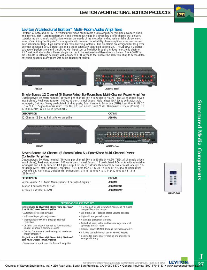
AE6MA AE6MA–back
Structured M
edia Com
ponents
J27
LEVITON ARCHITECTURAL EDITION PRODUCTS
Leviton Architectural Edition™ Multi-Room Audio AmplifiersLeviton’s AE6MA and AE6MC Architectural Edition Multi-Room Audio Amplifiers combine advanced audioengineering, high-current performance and tremendous value in a single low-profile chassis that deliverssuperior multi-channel amplification to meet the needs of the most demanding residential multi-zone sys-tems. Combining “audiophile” sound quality with commercial reliability, these amplifiers area no-compro-mise solution for large, high-output multi-room listening systems. The amplifiers are designed for long-termuse with advanced circuit protection and a thermostatically-controlled cooling fan. The AE6MA is a perfectbalance of performance and simplicity, with input source flexibility through a unique “electronic channellink” feature that enables different single sources to be assigned to different rooms/zones. The AE6MC isthe ultimate in listening flexibility, with advanced LCD keypads that enable the selection of up to seven differ-ent audio sources in any room with full independent control.
Single-Source 12 Channel (6 Stereo Pairs) Six-Room/Zone Multi-Channel Power AmplifierOutput power: 50 Watts nominal (40 watts per channel 20Hz to 20kHz @ <0.2% THD, all channels driveninto 8 ohms); Peak output power: 100 watts per channel; Inputs: Gold-plated RCA jacks with adjustableinput gain; Outputs: 5-way gold-plated binding posts; Total Harmonic Distortion (THD): Less than 0.1% 20Hz to 20 kHz; Signal-to-noise ratio: Over 105 dB; Fan noise: Quiet 28 dB; Dimensions: 3.5 in (89mm) H x17 in (432mm) W x 11.5 in (292mm) D
DESCRIPTION CAT NO.12 Channel (6 Stereo Pairs) Power Amplifier AE6MA
Seven-Source 12 Channel (6 Stereo Pairs) Six-Room/Zone Multi-Channel PowerController/AmplifierOutput power: 50 Watts nominal (40 watts per channel 20Hz to 20kHz @ <0.2% THD, all channels driveninto 8 ohms); Peak output power: 100 watts per channel; Inputs: 14 gold-plated RCA jacks with adjustableinput gain and a fully buffered RCA jack output for each; Outputs: Removable screw terminal, accepts 12-20 gauge wire; Total Harmonic Distortion (THD): Less than 0.1% 20 Hz to 20 kHz; Signal-to-noise ratio:Over 105 dB; Fan noise: Quiet 26 dB; Dimensions: 3.5 in (89mm) H x 17 in (432mm) W x 11.5 in(292mm) D
DESCRIPTION CAT NO.Seven-Source, Six-Room Multi-Channel Controller-Amplifier AE6MCKeypad Controller for AE6MC AE6MC-PADRemote Control for AE6MC AE6MC-RMT
SPECIFICATIONS AND FEATURES
Single-Source 12 Channel (6 Stereo Pairs) Six-Room/Zone Multi-Channel Power Amplifier• Automatic protection circuitry• Individual input gain adjustment• External power ON/OFF through external
controllers • Channel Link allows channels to have individual
sources or share a common source• Cooling fan prevents overheating and maximizes
energy efficiencySingle-Source 12 Channel (6 Stereo Pairs) Six-Room/Zone Multi-Channel Power Amplifier• Seven source input selection for each amplifier
• RS-232 port for use with whole-house and PC-basedcompatible control systems
• Six internal 80+ position stereo volume controls • High efficiency/small space. • Automatic protection circuitry • Individual bass, treble and balance adjustment of
speakers in each room• External power ON/OFF through external controllers• All-zone control through use of AE6MC keypad • Cooling fan prevents overheating and maximizes
energy efficiency
AE6MC AE6MC–back
AE6MC-PAD
For answers to technical questions, call Leviton’s Techline at 1-800-824-3005Courtesy of Steven Engineering, Inc. ● 230 Ryan Way, South San Francisco, CA 94080-6370 ● General Inquiries: (800) 670-4183 ● www.stevenengineering.com

Str
uctu
red
Med
ia C
ompo
nent
s
J28
LEVITON ARCHITECTURAL EDITION PRODUCTS
Composer Series Volume ControlsLeviton’s Composer Series controls are built to a single quality standard, which meanssystem designers can specify them for any distributed sound application with totalconfidence. (Leviton’s Strauss and Chopin Digital Volume controls use the same heat-dissipation technology used on the space shuttle and resistive switching to achieveruler-flat frequency response.) On the Brahms rotary controls, tapped auto-trans-former design provides a stable interface between high-current amplification andspeakers of virtually any type while resisting contamination from dust and dirt. All audio power ratings are UL referenced. All volume controls feature screw connec-tors for long-term connection integrity.
Decora® Strauss™ Transformer-Free™ and Impedance Matching Transformer-Free™ Volume ControlsIn multi-room distributed audio systems, the source of undesirable speaker coloration (usually perceivedas a “muffled” sound) is often the volume control itself, because the audio transformers (AKA: autoform-ers) used in conventional controls can actually filter the bass and treble frequencies. The Decora StraussTransformer-Free Volume Controls use audio-grade Cermetile resistors to change volume levels while leav-ing the audio signal unaffected, resulting in ruler-flat frequency response across the entire audible fre-quency range. Moreover, Decora Strauss Transformer-Free Volume Controls eliminate the problem of“saturation” associated with conventional volume controls and can handle tremendous amounts of musicpower. Available in standard and impedance-matched versions.
SPECIFICATIONSSpeaker Impedance: 2-16 Ohms (nominal 8 Ohms)Power Handling: 200W peak/100W RMSFrequency Response: 20Hz-20KkHz +/- 1dBDimensions: 4.06"(103.1) H x 1.32"(33.5) W x 2.5"(63.5) DMounting: Standard single-gang design with a mounting depth of 2.5" Wire Gauge: Detachable cable connectors are compatible with all standard
speaker wire sizes (14-18 gauge)Color: White (Optional color change kits available
Decora Strauss Transformer-Free Volume ControlDESCRIPTION CAT NO.–WHITEDecora Strauss Transformer-Free Impedance-Matched Volume Control SGVSM-00WDecora Strauss Transformer-Free Volume Control SGVST-00WColor change kit converts to Ivory and Almond SGVCK-IAColor change kit converts to Ebony SGVCK-00EColor change kit converts to Light Almond SGVCK-0LA
An entertainment system is like a chain – it can only be as strong as its weakest link. The Leviton ArchitecturalEdition series of products was developed to make sure that every link in the system—volume controls, distributionand connection components, even multi-room amplifiers—have no weak points and are as “state-of-the-art” inperformance as the systems’ speakers. The Leviton Architectural Edition is a complete solution for entertainmentsystem designers and installers. Leviton’s award-winning System Matching module and Strauss™ Transformer-Free volume controls use advanced aerospace technology to deliver ruler-flat frequency response to every zone of a multi-room audio system. The Architectural Edition multi-room audio amplifiers combineadvanced audio engineering, high-current performance and tremendous value in a single low-profile chassis thatdelivers superior multi-channel amplification to meet the needs of the most demanding residential multi-zone sys-tems. The advanced circuit engineering inside Leviton’s home theater and multi-room wallplates means thataudiophile-grade connectivity can be easy and quick to install.
SPECIFICATIONS AND FEATURES
• Decora slide control with precision12-position switch (including fully-OFF position)
• Transformer-Free™ volume controlsdeliver rich, full sound at any volume level in any room
• Aerospace-grade Cermetile resistorsreplace conventional autoformers tomaintain audio signal purity
• Detachable cable connector is com-patible with all standard speaker wire (14-18 gauge)
SGVST-00W
To learn more about Leviton’s outstanding offering of devices visit our Website at: www.leviton.comCourtesy of Steven Engineering, Inc. ● 230 Ryan Way, South San Francisco, CA 94080-6370 ● General Inquiries: (800) 670-4183 ● www.stevenengineering.com

Structured M
edia Com
ponents
J29
LEVITON ARCHITECTURAL EDITION PRODUCTS
Decora Digital™ Chopin™ Volume ControlFill a room with high-quality audio at the touch of a button, replacing traditional transformers and rotary con-trols with this advanced interface module and one-touch Decora Chopin Rocker-Switch Wall Unit. AttractiveDecora styling and transformer-less design delivers simplicity and superior sound-quality, and enables“three-way” volume control operation in larger rooms/zones. The Volume Control mounts in a standard wallbox or low-voltage mounting bracket and connects via Category 5 cable to the Interface Module.
SPECIFICATIONSPeak RMS Power Rating: 200 Watts per channelContinuous Power Rating: 100 Watts RMS per channelFrequency Response, all rated power levels, DC-50,000 Hz+/-0.1 dB:Speaker Impedance: 4-16 Ohms nominalSpeaker/Amplifier Connection: Removable, snap-in audio monoblock w/screw terminalsPower: 12 Volts DC, 200 mA
Decora Digital Volume Control SystemsDESCRIPTION CAT. NO.
Decora Digital Volume Control Kit 48211-WVK(Includes Interface Module and Wall Unit with Power Supply)Decora Digital Volume Control Wall Unit 48211-WVC
Decora Digital Chopin Volume Control• Connects to Interface Module with a single RJ-45
connection. No direct speaker/amplifier connectionsrequired at the controller.
• Microprocessor-controlled relays for silent switching.• Provides impedance matching with speakers from
4–16 Ohms.• Terminates all amplifier and speaker connections
using high-quality audio connection block. • Digital, transformer-free design uses aerospace-
quality cermatile resistors for proper heat dissipation
and superior performance.• Each audio zone requires one Digital Volume Control
module.• Each Digital Volume Control module can support up
to three volume control units.• Each Digital Volume Control module can control up
to 4 pairs of speakers.• Tap mute feature activated when center of rocker
panel is pressed.
SPECIFICATIONS AND FEATURES
48211-WVC
48211-WVK
Brahms Autoformer Volume ControlsOn the Brahms series of rotary controls, tapped auto-transformer design provides a stable interface betweenhigh-current amplification and speakers of virtually any type while resisting contamination from dust and dirt.
Brahms™ Stereo Volume Controls—75 Watt AudioTThe 75 Watt Brahms series (25 Watts RMS) of volume controls is designed for low to moderate power instal-lations in the home. The units accommodate 4, 8 or 16 Ohm speakers and amplifiers up to 75 Watts. All con-trols are impedance matching.Attenuation: -34 dB in 12 steps. Attenuator Type: Tapped auto transformer. Power Rating: UL Listed @ 75Watts audio, 25 Watts RMS continuous. Frequency Response: 35 Hz–20 kHz. Screw type connections, 12position rotary switch.
Decora® Brahms™ Stereo Volume Controls—75 Watt AudioControl stereo volume from convenient wall-mounted location.
DESCRIPTION CAT NO.–WHITEDecora Brahms Stereo Volume Control, 40841-0DW75 Watt, 25 Watt RMS with insert, knob and plate. Boxed unit pack, rack pack carton 40841-0DW
+ - + -
For answers to technical questions, call Leviton’s Techline at 1-800-824-3005Courtesy of Steven Engineering, Inc. ● 230 Ryan Way, South San Francisco, CA 94080-6370 ● General Inquiries: (800) 670-4183 ● www.stevenengineering.com
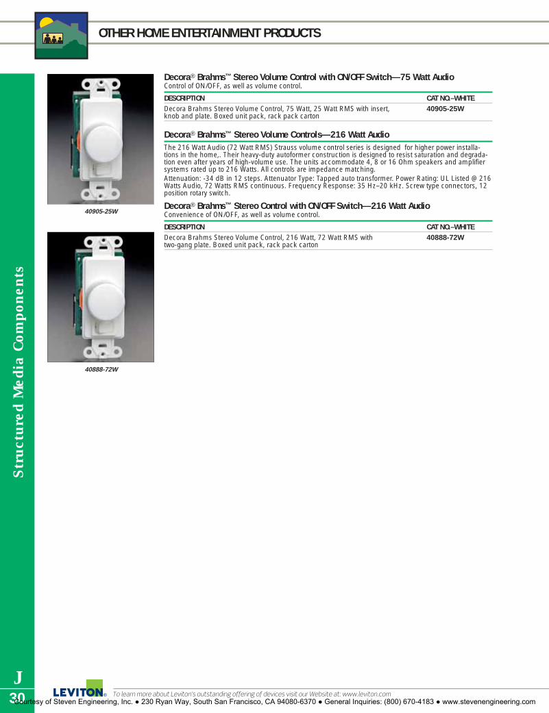
Str
uctu
red
Med
ia C
ompo
nent
s
J30
OTHER HOME ENTERTAINMENT PRODUCTS
Decora® Brahms™ Stereo Volume Control with ON/OFF Switch—75 Watt AudioControl of ON/OFF, as well as volume control.
DESCRIPTION CAT NO.–WHITEDecora Brahms Stereo Volume Control, 75 Watt, 25 Watt RMS with insert, 40905-25Wknob and plate. Boxed unit pack, rack pack carton
Decora® Brahms™ Stereo Volume Controls—216 Watt AudioThe 216 Watt Audio (72 Watt RMS) Strauss volume control series is designed for higher power installa-tions in the home,. Their heavy-duty autoformer construction is designed to resist saturation and degrada-tion even after years of high-volume use. The units accommodate 4, 8 or 16 Ohm speakers and amplifiersystems rated up to 216 Watts. All controls are impedance matching.Attenuation: -34 dB in 12 steps. Attenuator Type: Tapped auto transformer. Power Rating: UL Listed @ 216Watts Audio, 72 Watts RMS continuous. Frequency Response: 35 Hz–20 kHz. Screw type connectors, 12position rotary switch.
Decora® Brahms™ Stereo Control with ON/OFF Switch—216 Watt AudioConvenience of ON/OFF, as well as volume control.
DESCRIPTION CAT NO.–WHITEDecora Brahms Stereo Volume Control, 216 Watt, 72 Watt RMS with 40888-72Wtwo-gang plate. Boxed unit pack, rack pack carton
40888-72W
40905-25W
To learn more about Leviton’s outstanding offering of devices visit our Website at: www.leviton.comCourtesy of Steven Engineering, Inc. ● 230 Ryan Way, South San Francisco, CA 94080-6370 ● General Inquiries: (800) 670-4183 ● www.stevenengineering.com

Structured M
edia Com
ponents
J31
LEVITON ARCHITECTURAL EDITION PRODUCTS
Leviton Architectural EditionSystem Matching Module with AutoSurge™ TechnologyThe System Matching Module is used to match the impedance of all speakers and volume controls auto-matically at a central wiring point It allows connecting up to six rooms of speakers to a stereo amplifier,and is a cost-effective way to design a passive, impedance-matched multi-room music system.
SPECIFICATIONSDimensions: 2.57"(68.6) H x 6.38"(161.9) W x 5.38"(136.5) DMounting Location: Mounts in Leviton Structured Media™ CentersPower Handling: 150W RMS per channel/225W peakFrequency Response: 10Hz-40kHz, +/- .5dBWire Gauge: Detachable cable connectors are compatible with all standard
speaker wire sizes (18-14 AWG)
System Matching ModuleDESCRIPTION CAT NO.–WHITESystem Matching Module with AutoSurge Technology SGAMP-000
1x6 Passive Audio ModuleEasy, centralized audio system distribution module connects up to six pairs of speakers from an entertain-ment center or amplifier. Note: To ensure a correct impedance match with an amplifier, only use the pas-sive audio module with impedance-matched volume controls.
SPECIFICATIONSDimensions: 6.58"H x 2.89"W x 1.42"DWire Gauge: 18–14 AWGRequirements: Product should be used with impedance-matched
volume controls
1x6 Passive Audio ModuleDESCRIPTION CAT. NO.1x6 Passive Audio Module 48211-06A
SGAMP-000
NOTE: Do not use the System Matching Module with impedance-matched volume controls.
System Matching Module• Connects up to six rooms/zones• Convenient single-point connection for all speakers• Combine with Decora® Strauss™ Transformer-Free-
Volume™ Controls or equivalent to control up to six locations of speakers from one amplifier or receiver*
• User-removable connectors facilitate installation• Transformer-Free impedance-matching design
ensures linear frequency response, signal integrityand high power handling capacity
1x6 Passive Audio Module• Supports up to six pairs of speakers.• Parallel connection scheme insures the best
sound quality.• User-removable connectors facilitate installation.• Connects with standard fire-rated speaker wire.
SPECIFICATIONS AND FEATURES
48211-06A
For answers to technical questions, call Leviton’s Techline at 1-800-824-3005Courtesy of Steven Engineering, Inc. ● 230 Ryan Way, South San Francisco, CA 94080-6370 ● General Inquiries: (800) 670-4183 ● www.stevenengineering.com

Str
uctu
red
Med
ia C
ompo
nent
s
J32
LEVITON ARCHITECTURAL EDITION PRODUCTS
Home Theater and Multi-Room Integrated WallplatesBoth integrated wallplates combine the convenience of a ready-made plate with pre-configured wiring termi-nations with the performance and connection quality of “audiophile-grade” connectors. These plates arecomplete and ready-to-use, and make a “custom quality” statement in any installed entertainment system.
Home Theater Interface WallplateConnector Type (Front of module): 14 audiophile-grade, gold-plated black and red spring clips, 2 RCAconnectors, 2 QuickPort openings; Connector Type (Back of module): 8-pin and 6-pin in-line pluggablescrew terminals; Wallplate: High quality impact-resistant white plastic, standard 3-gang with matchingpainted screws; Mounting Depth: 2.5” (64mm); Wiring: 14-16 gauge speaker wire
DESCRIPTION CAT NO.Home Theater Interface Wallplate AEHTK-000
Multi-Room Stereo Speaker WallplateConnector Type (Front of module): 4 audiophile-grade, gold-plated black and red spring clips, 2 QuickPortopenings; Connector Type (Back of module): Two 2-pin in-line pluggable screw terminals; Wallplate: Highquality impact-resistant white plastic, standard single-gang with matching painted screws; MountingDepth: 2.5” (64mm); Wiring: 14-16 gauge speaker wire
DESCRIPTION CAT NO.Multi-Room Stereo Speaker Wallplate AEMRK-000
Specialized Audio/Video WallplatesThese high-value plates are quick to install and intuitive to use when connecting a multi-room entertainmentsystem.
Single Spring Clip WallplateEquipped with spade terminals. Mounted on break resistant polymer wallplate.
DESCRIPTION CAT NO.–WHITE CAT NO.–IVORYSingle Spring Clip Wallplate. 40951-1PW 40951-1PICarded unit pack, rack pack carton
Double Spring Clip WallplateEquipped with spade terminals. Mounted on break resistant polymer wallplate.
DESCRIPTION CAT NO.–WHITE CAT NO.–IVORYDouble Spring Clip Wallplate. 40952-2PW 40952-2PICarded unit pack, rack pack carton
40951-1PW
40952-2PWSPECIFICATIONS AND FEATURES
Home Theater Interface Wallplate• Accommodates from 5.1 to 7.1 channel surround–
sound systems• For use with low voltage rings and standard low
voltage junction boxes• Features RCA connectors for connecting subwoofers• Two extra openings for additional QuickPort
connectors
Multi-Room Stereo Speaker Wallplate• Integrated wallplate for connecting left and right
audio speakers (+/- connections)• For use with low voltage rings and standard low
voltage junction boxes• Two extra openings for additional QuickPort
connectors
AEHTK-000
AEMRK-000
To learn more about Leviton’s outstanding offering of devices visit our Website at: www.leviton.comCourtesy of Steven Engineering, Inc. ● 230 Ryan Way, South San Francisco, CA 94080-6370 ● General Inquiries: (800) 670-4183 ● www.stevenengineering.com

Structured M
edia Com
ponents
J33
SPEC GRADE SOUND™ PRODUCTS
Spec Grade Sound™ Indoor and Outdoor SpeakersLeviton’s award-winning* Spec-Grade Sound™ indoor and outdoor speaker line takes installed home audioto a new level in both technical innovation and value. Leviton’s Spec-Grade Sound™ indoor and outdoorspeakers can be used with Leviton’s innovative, exclusive Decora® Strauss™ Transformer-Free™ VolumeControls and Leviton’s System Matching Module and other audio distribution products to form complete sys-tems. All of Leviton Spec Grade Sound™ indoor speakers incorporate exceptionally strong, light and rigidAeroNylon tweeters and Kevlar®-composite woofers for exceptional clarity, detail and impact. They comewith built-in AutoSurge protection to help protect the speakers from possible damage due to overdriving. Theoutdoor/utility speaker is constructed of weather resistant materials inside and out. *Electronic House Magazine “Product of the Year”Kevlar is a registered trademark of E.I. du Pont de Nemours and company
6.5-inch Two-Way In-Ceiling Loudspeaker*Paintable grill and frame. 6.5-inch Composite Kevlar cone low-frequency transducer, .5-inch AeroNylondome high-frequency transducer, 2-way balanced precision crossover network with AutoSurge circuit protection, Frequency Response: 50-20kHz +/- 3dB, Sensitivity: 87.0 dB SPL @ 1Watt/1 Meter, PowerHandling: 120W peak/60W RMS, Impedance: Nominal 8 Ohms/Minimum 6 Ohms, Dimensions: Diameter:9.03 in (229.4mm); Depth: 4.06 in (103.1mm)
DESCRIPTION CAT NO.–WHITE ONLY6.5-inch Two-Way In-Ceiling Loudspeaker SGC65-00W
6.5-inch Two-Way In-Wall Loudspeaker*Paintable grill and frame. 6.5-inch Composite Kevlar cone low-frequency transducer, .5-inch AeroNylondome high-frequency transducer, 2-way balanced precision crossover network with AutoSurge‘ circuit protection, Frequency Response: 50-20kHz +/- 3dB, Sensitivity: 88.0 dB SPL @ 1Watt/1 Meter, PowerHandling: 120W peak/60W RMS, Impedance: Nominal 8 Ohms/Minimum 6 Ohms, Dimensions: 12.31 in(312.8mm) H x 9.02 in (229mm) W x 4.06 in (103mm) D
DESCRIPTION CAT NO.–WHITE ONLY6.5-inch Two-Way In-Wall Loudspeaker SGI65-00W
8-inch Two-Way In-Wall Loudspeaker*Paintable grill and frame. 8-inch Composite Kevlar cone low-frequency transducer, 1-inch AeroNylon domehigh-frequency transducer with phase/time alignment guide, 2-way balanced precision crossover networkwith AutoSurge‘ circuit protection, Frequency Response: 44-20kHz +/- 3dB, Sensitivity: 86.5 dB SPL @1Watt/1 Meter, Power Handling: 160W peak/80W RMS, Impedance: Nominal 8 Ohms/Minimum 6 Ohms,Dimensions: 14.25 in (362mm) H x 10.24 in (260mm) W x 4.06 in (103mm) D
DESCRIPTION CAT NO.–WHITE ONLY8-Inch Two-Way In-Wall Loudspeaker SGI80-00W*Require separate back box for use in fire rated applications
Outdoor/Utility Two-Way Loudspeaker5.25-inch Silicate-fiber cone low-frequency transducer with butyl surround, .5-inch Polydome high-frequencytransducer, 2-way balanced precision crossover network with AutoSurge circuit protection, Element-resistantpolypropylene enclosure, gold-plated binding posts, and aluminum mounting, Frequency Response: 50-20kHz +/- 3dB, Sensitivity: 87 dB SPL @ 1Watt/1 Meter, Power Handling: 120W peak/60W RMS, Impedance:Nominal 8 Ohms/Minimum 6 Ohms, Dimension: 8.75 in (222.3mm) H x 6.33 in (161mm) W x 5.5 in(140mm) D (without bracket)
DESCRIPTION CAT NO.–WHITE ONLYOutdoor/Utility Two-Way Loudspeaker SGO99-00W
Spec Grade Sound Pre-Construction BracketsThe Spec Grade Sound Speaker rough in brackets are designed to save time during the rough-in and trim-out phases. The built-in wire management loops ensure that the wire is securely placed and easily locatedduring speaker installation.
DESCRIPTION CAT NO.–WHITE ONLYPre-Construction kit for 6.5" In-Ceiling Speaker PCC55-KITPre-Construction kit for 6.5" In-Wall Speaker PCI65-KITPre-Construction kit for 8" In-Wall Speaker PCI80-KIT
Spec Grade Sound Speaker GrillsDESCRIPTION CAT NO.–WHITE ONLYSpeaker Grill for Speaker SGC65 SGC65-GRLSpeaker Grill for Speaker SGI65 SGI65-GRLSpeaker Grill for Speaker SGI80 SGI80-GRL
SGC65-00W
SGI65-00W
SGO99-00W
SGI80-00W
For answers to technical questions, call Leviton’s Techline at 1-800-824-3005Courtesy of Steven Engineering, Inc. ● 230 Ryan Way, South San Francisco, CA 94080-6370 ● General Inquiries: (800) 670-4183 ● www.stevenengineering.com

Str
uctu
red
Med
ia C
ompo
nent
s
J34
OTHER HOME ENTERTAINMENT PRODUCTS
SPECIFICATIONS SEND UNIT RECEIVE UNIT MEDIA HUBDimensions: 4.1"H x 1.4"W x 2.0"D 4.1"H x 1.4"W x 2.0"D 6.5"H x 3.4"W x 1.75"DVideo Bandwidth: 50 M Hz @ -3 dB 50 M Hz @ -3 dB 50 M Hz @ -3 dBVideo THD: 75 dBc -75 dBc -75 dBcVideo Input: — 0.5V to 2V composite 0.5V to 2V compositeVideo Output: 0.5V to 2V composite — —Slew Rate: 800/Vus 800/Vus 800/VusAudio Input Impedance: — 20k Ohms, max 3Vp-p 20k Ohms, max 3Vp-pAudio Output Impedance: 51 Ohms, max 2Vp-p — —Audio Freq. Response: 5 Hz-100k Hz, ±3 dB 5 Hz-100k Hz, ±3 dB 5 Hz-100k Hz, ±3 dBAudio THD: 0.002% 20 Hz-20k Hz 0.004% 20 Hz-20k Hz 0.002% 20 Hz-20k HzAudio S/N Ratio: 100 dB typical, 80 dB 100 dB typical, 80 dB 100 dB typical, 80 dB
min 20 Hz-20k Hz min 20 Hz-20k Hz min 20 Hz-20k HzInput Noise: 4.5nV/( Hz), 1/2 6nV/( Hz), 1/2 4.5nV/( Hz), 1/2
typical @ 1k Hz typical @ 1k Hz typical @ 1k HzInput and Outputs: 3 RCA input jacks 3 RCA output jacks 3 RCA input jacks
1 set RJ-45 in/out jacks 1 set RJ-45 in/out jacks 1 RJ-45 input jack1 110 punchdown out 1 110 punchdown out 6 RJ-45 output jacks1 DC power input 1 DC power input 1 DC power input
Power: 12VDC 12VDC 15VDC
Decora Media SystemDESCRIPTION CAT. NO.Decora Media System Media Hub with Power Supply 48210-MCHDecora Media System Send and Receive Unit Pair with Power Supply 48210-SRUDecora Media System Send Unit with Power Supply 48210-MSUDecora Media System Receive Unit 48210-MRU
Decora Media™ SystemSend analog audio and video signals through up to 1,000 feet (300meters) of Category-5 cable with no discernible distortion. The DecoraMedia System is ideal for connecting source components back to amulti-room audio amplifier located elsewhere in a system. DMS iscomprised of: a Send Unit for transmitting audio/video signals, aReceive Unit for receiving signals and a Media Hub. The DMS canoperate several ways: in a “hub” configuration with one Send unitsending a single audio/video signal to up to six Receiver units, andpoint-to-point where Send and Receive units are linked directlytogether to replace expensive specialized cables or baluns with simpleCategory-5 cabling..Send and receive units run on 12VDC, hub runs on 15VDC and canbe powered independently or through the Media Hub.
SPECIFICATIONS AND FEATURES
• Cascade hub units to distribute audio/video signals to over 20 locations.
• Send and Receive units are equipped with RJ-45jacks and 110 punchdown blocks for maximumflexibility in installation.
• Composite RCA inputs for connectivity directlyfrom A/V source.
• Send and Receive units fit standard wallboxes andDecora wallplates.
• Advanced circuitry with automatic equalizationstreams analog stereo audio and video signals overlong distances with less distortion.
• Stereo audio input/output handles Dolby®
ProLogic™ surround signals.• RJ-45 input for Send unit.
To learn more about Leviton’s outstanding offering of devices visit our Website at: www.leviton.comCourtesy of Steven Engineering, Inc. ● 230 Ryan Way, South San Francisco, CA 94080-6370 ● General Inquiries: (800) 670-4183 ● www.stevenengineering.com

Structured M
edia Com
ponents
J35
OTHER HOME ENTERTAINMENT PRODUCTS
Multi-Room Infrared (IR) Repeater SystemThe IR Repeater System consists of three pieces: an IR Target, IR Emitter and a distribution block for distrib-uting control signals to multiple emitters. The IR Target takes the signal from a remote control for an audio/video component and converts it to a low-voltage electrical signal, sending it back to a component to be con-trolled by the IR emitter. The flush-mount IR Target easily installs in a ceiling or wall, and connects withCategory 5 cable to the IR Emitter. Multiple IR Emitters connect to controlled A/V components through the dis-tribution block in the Structured Media Enclosure. Distribution block (Cat. No. 47689-B) available separately.Dimensions: 2"L x 1"W,Power: 12V DC @200mA, Target Output: 4 signal leads, Target Input: 2 power leads(DC + and -), Emitter Output: Infrared to control source component, Emitter Input: 2 signal leads, PowerSupply (included): 12V DC @5mA
IR Repeater SystemDESCRIPTION CAT. NO.A–Target 47621-CMSB–Emitter 47621-MIEC–1x9 Bridged Telephone Module for IR Repeater, 47603-110
w/o bracket. Indiv. boxed unit pack, rack pack carton.
Recessed Entertainment BoxDESCRIPTION CAT. NO. COLOR*REB Box with Low-Profile Frame 47617-REB WhiteHigh-Profile Cover 47617-HPC WhiteLow-Profile Frame 47617-LPF WhiteReplacement Snap-In Plates (2/Bag) 47617-PLT WhiteREB Box with High-Profile Cover 47617-RBH White
Decora Recessed Receptacles Duplex Recessed Receptacles 15A-125V AC, 2-Pole, 3-Wire, NEMA 5-15R URDESCRIPTION CAT. NO. COLOR* NEMA CONFIG.Two-Gang Duplex Receptacle with Openings for 6 QuickPort Connectors (4 blank inserts included)† 690 I, W, T, EOne-Gang Duplex Receptacle 689 I, W, T, E
Single Recessed Receptacles Side-Wired 15A-125V AC, 2-Pole, 3-Wire, NEMA 5-15R URDESCRIPTION CAT. NO. COLOR* NEMA CONFIG.One-Gang Single Receptacle with 688 I, WClock Hanger HookOne-Gang Single Receptacle with 5261-CH StainlessClock Hanger Hook Steel
Side-Wired 20A-125V AC, 2-Pole, 3-Wire, NEMA 5-20R URDESCRIPTION CAT. NO. COLOR* NEMA CONFIG.One-Gang Single Receptacle with 5361-CH StainlessClock Hanger Hook Steel
† QuickPort Connectors not included.
B
A
C
5-15RG
W
5-15RG
W
5-20RG
W
9.46 (240.3)
6.9 (175.3)
3.9(99.1)
6.2
(157
.5)
7.9
(200
.7)
4.78 (121.4)3.23 (82.0)
3.38(85.9)
2.65
(67
.3)
4.71
(11
9.6)
2.95 (74.9)1.5 (38.1)
.95
2.65
(67
.3)
4.71
(11
9.6)
3.28
(83
.3)
4.50
(11
4.3)
2.75 (69.9)1.58
(40.1)
SPECIFICATIONS AND FEATURES
Recessed Entertainment Box• Provides single location for line and low-voltage
connections• Stud- and wall-mountable• Neat, clean recessed installation• Optional high-profile cover includes sliding plastic
front panel and channels all wires through the bottom of the REB
• Paintable white ABS plastic Recessed Two-Gang Duplex Receptacle with QuickPort Openings• Provides 2 15A/125V AC NEMA 5-15R power out-
lets and openings for any 6 installer-selectedQuickPort connectors or blank inserts (4 insertsincluded)
• Includes plastic electrical box and a barrier to separate line and low-voltage conductors
• Wallplate built into deviceRecessed One-Gang Duplex Receptacle• Installs invisibly behind wall units, signature
artwork and wall-mounted flat-panel TVs• Supplies AC power for two components
• Fits most common electrical boxes available (electrical box not included)
Recessed One-Gang SingleReceptacles• Includes clock-hanger hook• Flush mount with square recess
TESTING AND CODE COMPLIANCE
Recessed Receptacles• cULus Listed• NOM Certified (#057)All Recessed Devices• Backed by a Limited Two-Year Warranty
*COLOR
For color selection, add suffix to catalog number asfollows: Ivory (-I), White (-W), Light Almond (-T) andBlack (-E).
MATERIAL CHARACTERISTICS
Environmental: Flammability UL-94, V2 RatingOperating Temperature: -40˚ to 120˚C
For answers to technical questions, call Leviton’s Techline at 1-800-824-3005Courtesy of Steven Engineering, Inc. ● 230 Ryan Way, South San Francisco, CA 94080-6370 ● General Inquiries: (800) 670-4183 ● www.stevenengineering.com

J36
HOW TO USE THIS CATALOG
The L-101 Leviton Wiring Device Catalog is designed to help you find the device you’re seeking in the quickest and easiest way possible. Most product sections are divided into three distinct categories in the following sequence—Industrial Grade, CommercialGrade and Residential Grade—and grouped according to amperage and voltage, lowest to highest. For example, if you need toorder 15 Amp, 125 Volt Industrial Grade straight-blade duplex receptacles, begin your search with the main Table of Contents at thefront of the book. Here you’ll see that all straight blade receptacles are listed in Section G. Turn to Section G for a more detailed Tableof Contents on the first page. Each section page contains product descriptions, ratings and catalog numbers. There are also helpfulhighlights including Specifications and Features, Testing and Code Compliance, Color listing, Material Characteristics and dimen-sioned color product photos. Any product page in the L-101 Catalog can be clearly copied or faxed to customers and prospects foruse as a specifier sheet or as part of a presentation.
The Quick Reference Guide follows the main Table of Contents to help you pinpoint and locate specific products. TechnicalSection V provides general product and test data, industry standards, NEMA configuration charts, a glossary of wiring deviceterms, ANSI architectural symbols and other related information. Specific catalog numbers are listed in the exhaustive index atthe back of the catalog.
RATING
Choose GRADE, if appropriate
DIMENSIONED PHOTOGRAPH
WIRING/CERTIFICATIONS
CATALOG NUMBER
DESCRIPTION
Check for NEMA CONFIGURATION
WALLPLATE REFERENCE, if appropriate
SPECIFICATIONS & FEATURES
TESTING AND CODE COMPLIANCE
COLOR LISTING
MATERIAL CHARACTERISTICSL
K
J
I
H
G
F
E
D
C
B
A
I
D
E
H
B
J
G
K
F
L
C
A
Courtesy of Steven Engineering, Inc. ● 230 Ryan Way, South San Francisco, CA 94080-6370 ● General Inquiries: (800) 670-4183 ● www.stevenengineering.com

DECORA®HOME CONTROLS (DHC)
Residential Grade Controllers—Green Line
Decora H
ome C
ontrols Com
ponents Index
INDEXOverview...............................................................K2Controllers—Green Line
Toscana™ Deluxe Programmer ..........................K3Wall Switch Controllers with 2-Way Communication...........................................K4, K5Wall Switch Controllers with Scene Capability.....K5RF Products......................................................K6
Controllers—Red LineBasic Programmer ............................................K7Table Top Controller...........................................K7Dry Contact Controllers......................................K7
Receivers—Green LineWall Switches with 2-Way Communication .........K8Wall Switches with Scene Capability.............K8, K9Plug-In Modules with Scene Capability ............K10
Receivers—Red LineWall Switches ..................................................K11Remote Switches.............................................K12Double-Pole 20A Wall Switch...........................K12Receptacles ....................................................K13Universal Low-Voltage Module .........................K14Fixture Modules ..............................................K14
DHC Network Integrity ProductsPanel-Mounted Surge Protective Devices.........K15System Amplifier/Coupler/Repeater .................K16Couplers and Attenuators ................................K16Filters..............................................................K17Signal Strength Indicator .................................K17
SECTIONKDHC Powerline Carrier Components
Courtesy of Steven Engineering, Inc. ● 230 Ryan Way, South San Francisco, CA 94080-6370 ● General Inquiries: (800) 670-4183 ● www.stevenengineering.com

Hom
e Aut
omat
ion
Pro
duct
s
K2
DHC POWERLINE CARRIER COMPONENTS FEATURES
Residential Grade Controllers
To learn more about Leviton’s outstanding offering of devices visit our Website at: www.leviton.com
LEVITON’S DECORA HOME CONTROLS (DHC) RESIDENTIAL POWERLINE CARRIER COMPONENTS PROVIDE HOMEOWNERSWITH EVERYTHING NEEDED FOR PROGRAMMED AND MANUAL CONTROL OF LIGHTING AND APPLIANCES USING THEIRHOME’S EXISTING AC WIRING.Our current listing of DHC components features new programmers, controllers and receivers with Scene LightingCapability for coordinated, whole-house lighting control. This includes models offering two-way communication,which enables controllers in remote locations to show the On/Off status of individual lighting loads. Many new DHCcomponents feature Intellisense™, a Leviton exclusive technology. Intellisense reduces noise sensitivity withoutreducing command signal sensitivity, resulting in the most reliable performance of any powerline carrier homeautomation system available today.
DHC CONTROLLERS, RECEIVERS AND NETWORK INTEGRITY PRODUCTS
DHC ControllersDHC Controllers sendcontrol signals to user-specified DHC addressthroughout the network.Offering includes wall-mounted programmable,plug-in, tabletop, wirelesshand-held, wall switch/dimmer and sensor units,plus models with 2-waycommunication.HXC7S-1TW shown
DHC ReceiversDHC Receivers can be setto any of 256 DHC addresscodes for remote/ manualcontrol of incandescent,inductive, fluorescent, orlow-voltage loads. They areavailable as receptacle,plug-in, fixture and multi-location wall switches anddimmer switches.HXM10-1TW shown
Network Integrity ProductsLeviton highly recommendsinstalling these products inevery DHC application. TheSystem Coupler/Repeaterensures DHC signal integritythroughout the house.Panel-mount surge devicesprotect DHC componentsfrom transient voltagesurges.51120-1 shown
Features and Benefits� A network of controllers and DHC switch, dimmer, fixture and receptacle receivers that communicate via
unique coded switching signals over a home’s AC wiring to automate control of lights and appliances� DHC components replace switches and outlets, which simplifies installation compared with other
automation systems that require dedicated proprietary wiring backbones.� An effective way to contribute to energy conservation and extend bulb and appliance life� Offers significant security benefits to today’s homeowner, including programmed automatic and manual
home security features
Toscana ProgrammerHCCPG-1TW
Panic Button ControllerHXC1A-1TW
ReceptacleReceiver6227
Seven-SceneDimming ControllerHXC7S-1TW
Key Chain RemoteController HCCKR
Plug-in TransceiverHCPRF
Switch Receivers 6291,6293, 6381, HXM10-1TW,HXM06-1TW, HCS10-1SW
Burglar Alarm Interface6330
System Amplifier/RepeaterHCA02-10E
Courtesy of Steven Engineering, Inc. ● 230 Ryan Way, South San Francisco, CA 94080-6370 ● General Inquiries: (800) 670-4183 ● www.stevenengineering.com
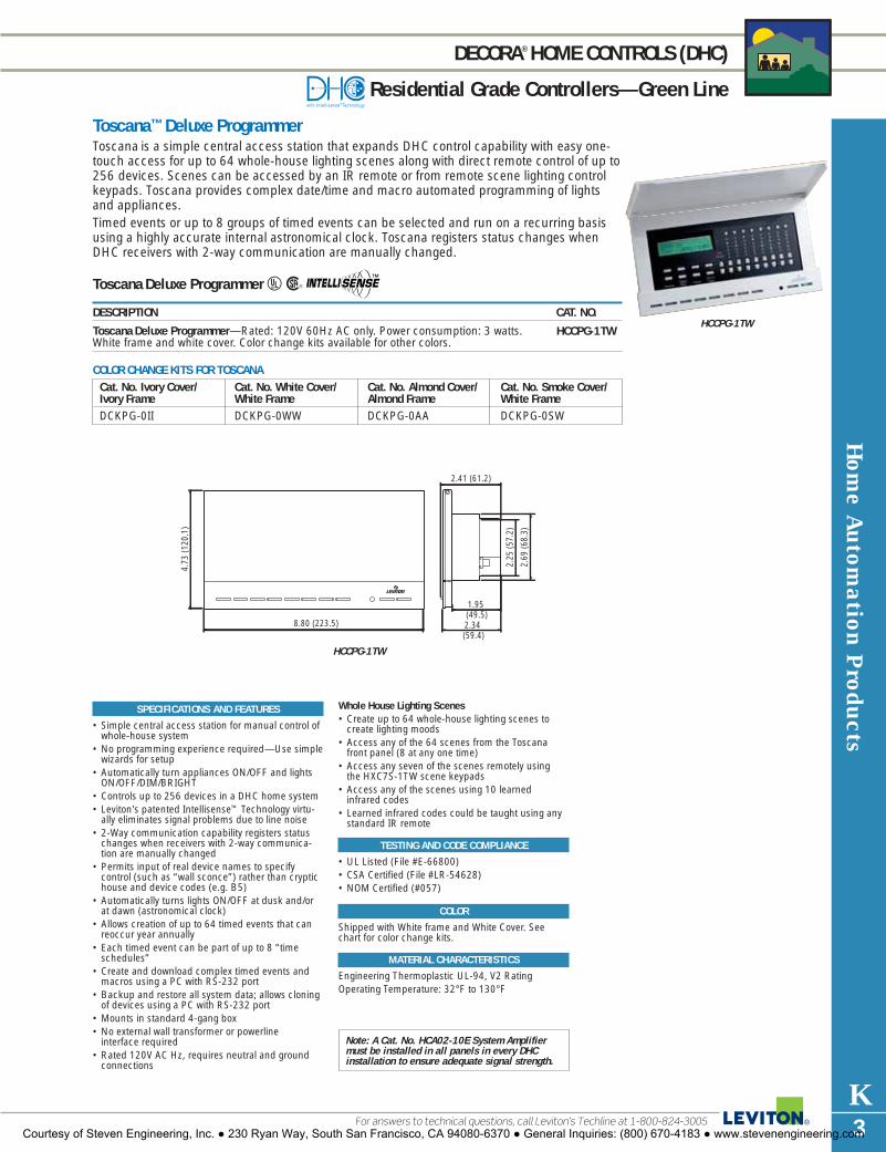
Toscana™ Deluxe ProgrammerToscana is a simple central access station that expands DHC control capability with easy one-touch access for up to 64 whole-house lighting scenes along with direct remote control of up to256 devices. Scenes can be accessed by an IR remote or from remote scene lighting controlkeypads. Toscana provides complex date/time and macro automated programming of lightsand appliances. Timed events or up to 8 groups of timed events can be selected and run on a recurring basisusing a highly accurate internal astronomical clock. Toscana registers status changes whenDHC receivers with 2-way communication are manually changed.
Toscana Deluxe Programmer UR
DESCRIPTION CAT. NO.
Toscana Deluxe Programmer—Rated: 120V 60Hz AC only. Power consumption: 3 watts.White frame and white cover. Color change kits available for other colors.
Hom
e Autom
ation Products
K3For answers to technical questions, call Leviton’s Techline at 1-800-824-3005
DECORA®HOME CONTROLS (DHC)
Residential Grade Controllers—Green Line
HCCPG-1TW
SPECIFICATIONS AND FEATURES
• Simple central access station for manual control ofwhole-house system
• No programming experience required—Use simplewizards for setup
• Automatically turn appliances ON/OFF and lightsON/OFF/DIM/BRIGHT
• Controls up to 256 devices in a DHC home system• Leviton's patented Intellisense™ Technology virtu-
ally eliminates signal problems due to line noise• 2-Way communication capability registers status
changes when receivers with 2-way communica-tion are manually changed
• Permits input of real device names to specify control (such as “wall sconce”) rather than cryptichouse and device codes (e.g. B5)
• Automatically turns lights ON/OFF at dusk and/orat dawn (astronomical clock)
• Allows creation of up to 64 timed events that canreoccur year annually
• Each timed event can be part of up to 8 “timeschedules”
• Create and download complex timed events andmacros using a PC with RS-232 port
• Backup and restore all system data; allows cloningof devices using a PC with RS-232 port
• Mounts in standard 4-gang box• No external wall transformer or powerline
interface required• Rated 120V AC Hz, requires neutral and ground
connections
Whole House Lighting Scenes• Create up to 64 whole-house lighting scenes to
create lighting moods• Access any of the 64 scenes from the Toscana
front panel (8 at any one time)• Access any seven of the scenes remotely using
the HXC7S-1TW scene keypads• Access any of the scenes using 10 learned
infrared codes• Learned infrared codes could be taught using any
standard IR remote
TESTING AND CODE COMPLIANCE
• UL Listed (File #E-66800)• CSA Certified (File #LR-54628)• NOM Certified (#057)
COLOR
Shipped with White frame and White Cover. Seechart for color change kits.
MATERIAL CHARACTERISTICS
Engineering Thermoplastic UL-94, V2 RatingOperating Temperature: 32°F to 130°F
Note: A Cat. No. HCA02-10E System Amplifiermust be installed in all panels in every DHCinstallation to ensure adequate signal strength.
Cat. No. Ivory Cover/ Cat. No. White Cover/ Cat. No. Almond Cover/ Cat. No. Smoke Cover/Ivory Frame White Frame Almond Frame White Frame DCKPG-0II DCKPG-0WW DCKPG-0AA DCKPG-0SW
COLOR CHANGE KITS FOR TOSCANA
4.73
(120
.1)
8.80 (223.5)
2.41 (61.2)
2.69
(68.
3)
2.25
(57.
2)
1.95 (49.5)2.34 (59.4)
HCCPG-1TW
HCCPG-1TW
Courtesy of Steven Engineering, Inc. ● 230 Ryan Way, South San Francisco, CA 94080-6370 ● General Inquiries: (800) 670-4183 ● www.stevenengineering.com
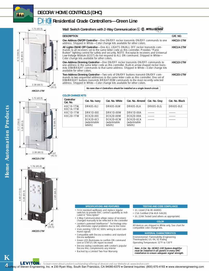
Hom
e Aut
omat
ion
Pro
duct
s
K4
DECORA®HOME CONTROLS (DHC)
Residential Grade Controllers—Green Line
To learn more about Leviton’s outstanding offering of devices visit our Website at: www.leviton.com
Wall Switch Controllers with 2-Way Communication UR
DESCRIPTION CAT. NO.
One Address ON/OFF Controller—One ON/OFF rocker transmits ON/OFF commands to oneaddress. Shipped in White—Color change kits available for other colors.All Lights ON/All OFF Controller—One ALL LIGHTS ON/ALL OFF rocker transmits com-mands to all receivers set to the same letter code as this controller. Provides “PanicButton” lighting control for safety and security. NOTE: Receptacle receivers and UniversalLow-Voltage Module (6337) do not respond to ALL ON command. Shipped in White—Color change kits available for other colors.One-Address Dimming Controller—One ON/OFF rocker transmits ON/OFF commands toone address in the same letter code as this controller. Built-in arrow-shaped rocker trans-mits DIM/BRIGHT commands to that same address. Shipped in White—Color change kitsavailable for other colors.Two-Address Dimming Controller—Two sets of ON/OFF buttons transmit ON/OFF com-mands to two sequential addresses in the same letter code as this controller. One set ofDIM/BRIGHT buttons transmits BRIGHT/DIM commands to the most recently selectedaddress. Shipped in White—Color change kits available for other colors.
SPECIFICATIONS AND FEATURES
• Fit in standard wallboxes and replace regularswitches to provide DHC control capability as indi-cated in “Description”
• 2-Way Communication allows status of receiverschanged manually to be reflected in the controller
• Leviton's patented Intellisense™ Technology virtu-ally eliminates signal problems due to line noise
• Uses existing 120V AC 60Hz wiring to send com-mand signals
• Compatible with Decora screwless and standardDecora wallplates
• Green LED illuminates to confirm ON commandsent or STATUS ON report received
• Decora styling coordinates with Leviton’s popularDecora line; complements any interior
• Backed by a Limited Two-Year Warranty
TESTING AND CODE COMPLIANCE
• UL Listed (File #E-66800)• CSA Certified (File #LR-54628)• UL 224A Tested (and others as appropriate)
COLOR
All devices are shipped in White only. See chart forcompatible color change kits.
MATERIAL CHARACTERISTICS
Environmental: Flammability (EngineeringThermoplastic) UL-94, V2 RatingOperating Temperature: 32°F to 130°F
Controller Cat. No. Ivory Cat. No. White Cat. No. Almond Cat. No. Gray Cat. No. BlackCat. No.HXC10-1TW, DRK0S-0LI DRK0S-0LW DRK0S-0LA DRK0S-0LG DRK0S-0LEHXC1A-1TWHXC1D-1TW DRK1D-00I DRK1D-00W DRK1D-00A — —HXC2D-1TW DCK2D-00I DCK2D-00W DCK2D-00A — —
DCK2D-0CI DCK2D-0CW DCK2D-0CA — —(w/printable (w/printable (w/printable labels) labels) labels)
COLOR CHANGE KITS
3.28
(83
.3)
4.13
(10
4.9)
2.38 (60.5) 1.39(35.3)
2.66
(67
.6)
1.73 (43.9)
HXC10-1TW
3.28
(83
.3)
4.11
(10
4.4)
2.38 (60.3) 1.67 (42.5)
2.70
(66
.7)
1.73 (43.9)
HXC1D-1TW
1.76 (45.0)
1.40(35.5)
2.69
(68
.2)
3.28
(83
.3)
4.40
(11
2.0)
HXC2D-1TW
Note: A Cat. No. HCA02-10E System Amplifiermust be installed in all panels in every DHCinstallation to ensure adequate signal strength.
HXC10-1TW
HXC1A-1TW
HXC1D-1TW
HXC2D-1TW
No more than 4 Controllers should be installed on a single branch circuit.
Courtesy of Steven Engineering, Inc. ● 230 Ryan Way, South San Francisco, CA 94080-6370 ● General Inquiries: (800) 670-4183 ● www.stevenengineering.com

Hom
e Autom
ation Products
K5For answers to technical questions, call Leviton’s Techline at 1-800-824-3005
DECORA®HOME CONTROLS (DHC)
Residential Grade Controllers—Green Line
SPECIFICATIONS AND FEATURES
• Fit in standard wallboxes and replace regularswitches to provide DHC control capability as indicated in “Description”
• 2-Way Communication allows status of receiverschanged manually to be reflected in the controller
• Leviton’s patented Intellisense™ Technology virtuallyeliminates signal problems due to line noise
• Uses existing 120V AC 60Hz wiring to send command signals
• Compatible with Decora Plus screwless and standard Decora wallplates
• Green LED illuminates to confirm ON commandsent or STATUS ON report received
• Decora styling coordinates with Leviton's popularDecora line; complements any interior
• Backed by a Limited Two-Year Warranty
TESTING AND CODE COMPLIANCE
• UL Listed (File #E-66800)• CSA Certified (File #LR-54628)• UL 224A Tested (and others as appropriate)
COLOR
All devices are shipped in White only. See chart forcompatible color change kits.
MATERIAL CHARACTERISTICS
Engineering Thermoplastic UL-94, V2 RatingOperating Temperature: 32°F to 130°F
Wall Switch Controllers with 2-Way Communication UR
DESCRIPTION CAT. NO.
Three-Address Dimming Controller—Three sets of ON/OFF buttons transmit ON/OFF commands to three sequential addresses in the same letter code group as this controller.One set of DIM/BRIGHT buttons transmits DIM/BRIGHT commands to the most recentlyselected address. Shipped in White—Color change kits available for other colors.Four-Address Dimming Controller—Four sets of ON/OFF buttons transmit ON/OFF commands to four sequential addresses in the same letter code group as this controller.One set of DIM/BRIGHT buttons transmits DIM/BRIGHT commands to the most recentlyselected. Shipped in White—Color change kits available for other colors.Three-Address Dimming, ALL LIGHTS ON/ALL OFF Controller—Three sets of ON/OFF buttons transmit ON/OFF commands to three sequential addresses in the same letter codegroup as this controller. One set of DIM/BRIGHT buttons transmits DIM/BRIGHT com-mands to the most recently selected address. One set of ALL LIGHTS ON/ALL OFF buttonstransmits commands to all receivers set to the same letter code as this transmitter.Receptacle receivers and Universal Low-Voltage Module (6337) will not respond to ALL ONcommand. Shipped in White—Color change kits available for other colors.Seven-Scene Dimming Controller—Each of seven SCENE buttons transmits ON commandsat preset levels to 12 sequential addresses in the same letter code as this controller. (Note:12-address sequence continues at address 1 if address 16 is reached before all sequentialaddresses are completed). May be used with all Leviton scene-capable receivers. One set ofSCENE DIM/SCENE BRIGHT buttons transmits SCENE DIM/BRIGHT commands to mostrecently selected scene. One OFF button transmits OFF command to most recently selectedscene. Green LEDs illuminate to indicate ON command sent or SCENE ON commanddetected. Shipped in White—Color change kits available for other colors.The HCCS7-1TW utilizes extended code format. This command structure is compatible with Cat. No. HCA02-10E DHC System Amplifier/Coupler /Repeater but is not compatible with the older version of the System Amplifier Cat. No. 6201.
No more than 4 Controllers should be installed on a single branch circuit.
Controller Cat. No. Ivory Cat. No. White Cat. No. Almond Cat. No. Gray Cat. No. BlackCat. No.HXC3D-1TW DCK3D-00I DCK3D-00W DCK3D-00A — —
DCK3D-0CI DCK3D-0CW DCK3D-0CA — —(w/printable (w/printable (w/printable labels) labels) labels)
HXC4A-1TW DCK4A-00I DCK4A-00W DCK4A-00A — —DCK4A-0CI DCK4A-0CW DCK4A-0CA —(w/printable (w/printable (w/printable labels) labels) labels)
HXC4D-1TW DCK4D-00I DCK4D-00W DCK4D-00A — —DCK4D-0CI DCK4D-0CW DCK4D-0CA — —(w/printable (w/printable (w/printable labels) labels) labels)
HXC7S-1TW DCKS7-00I DCKS7-00W DCKS7-00A DCKS7-00G DCKS7-00EDCKS7-0CI DCKS7-0CW DCKS7-0CA DCKS7-0CG DCKS7-0CE(w/printable (w/printable (w/printable (w/printable (w/printable labels) labels) labels) labels) labels)
COLOR CHANGE KITS
1.76 (45.0)
1.40(35.5)
2.69
(68
.2)
3.28
(83
.3)
4.40
(11
2.0)
HXC3D-1TW
1.76 (45.0)
1.40(35.5)
2.69
(68
.2)
3.28
(83
.3)
4.40
(11
2.0)
HXC4A-1TW
1.76 (45.0)
1.40(35.5)
2.69
(68
.2)
3.28
(83
.3)
4.40
(11
2.0)
HXC7S-1TW
Note: A Cat. No. HCA02-10E System Amplifiermust be installed in all panels in every DHCinstallation to ensure adequate signal strength.
HXC3D-1TW
HXC4D-1TW
HXC4A-1TW
HXC7S-1TW
Courtesy of Steven Engineering, Inc. ● 230 Ryan Way, South San Francisco, CA 94080-6370 ● General Inquiries: (800) 670-4183 ● www.stevenengineering.com

Hom
e Aut
omat
ion
Pro
duct
s
K6
DECORA®HOME CONTROLS (DHC)
Residential Grade Controllers—Green Line
To learn more about Leviton’s outstanding offering of devices visit our Website at: www.leviton.com
RF ComponentsDESCRIPTION CAT. NO.
Universal Remote Control—Hand-held wireless remote control sends RF (radio frequency)command signals to DHC Plug-In Transceiver Cat. No. HCPRF for up to 256 DHCaddresses. With an operating range of up to 50 ft. through wall and ceilings, it sendsON/OFF, DIM/BRIGHT and ALL ON/ALL OFF commands for lighting and ON/OFF com-mands for appliances. The Universal Remote will also control audio and video equipment,including TV’s, VCR’s, cable boxes, satellite receivers, DVD and CD players and more.Functions as an all-in-one controller for lighting and audio/video systems, making it idealfor home theaters. Universal design also makes it suitable for the elderly and physicallychallenged. Dual built-in timers can shut off TV and/or DHC devices up to ninety minutesafter setting. Uses 2 AAA batteries. Must be used with HCPRF Transceiver. Color: Black. Plug-In Transceiver—Accepts Radio Frequency DHC commands from the UniversalRemote Cat. No. HCCUR for ON/OFF, DIM/BRIGHT and ALL ON/ALL OFF, as well asON/OFF commands from the Key Chain Remote Cat. No. HCCKR. The Plug-In Transceiverworks with all DHC receivers by re-transmitting commands signals onto the home’s existingelectrical wiring. Plugs into any standard receptacle and provides a built-in outlet forON/OFF switching of incandescent lamps rated 300W max. @ 120V AC. The lamp can becontrolled remotely or locally via the programming button on the face of the Transceiver,which can also be used to change the unit's DHC address. Features Intellisense™Technology to ensure optimum system performance. 2-Way communication permits localstatus of attached lamp to show on all 2-Way capable DHC controllers. Multiple HCPRFTransceivers can be used to increase coverage in large homes. Unit will re-transmit com-mands for up 256 DHC addresses. Color: White. Key Chain Remote Controller—Designed to fit on a key chain and send RF (radio fre-quency) command signals to DHC Plug-In Transceiver Cat. No. HCPRF. With an operatingrange of up to 50 ft. through wall and ceilings, it sends ON/OFF commands for any 2sequential DHC addresses (addresses are user programmable). Ideal for control of homelighting from a vehicle when entering garage or driveway. Uses long-life 3V CR2032 lithiumbattery (included). Must be used with HCPRF Transceiver. Color: Black.
SPECIFICATIONS AND FEATURES
• Leviton's Universal Remote Control works withDHC-controlled lighting and appliances as well asaudio/video system components
• Ultra-compact Key Chain Remote adds to homesecurity by allowing users to turn ON lighting asthey approach entranceway, garage or driveway
• Plug-In Transceiver features Intellisense™
Technology for optimum reliability, 2-way signalingcapability, and easy one-button programming.Must be used with Universal Remote and KeyChain Remote.
• Backed by a Limited Two-Year Warranty
TESTING AND CODE COMPLIANCE
• UL Listed (File #E-66800)• CSA Certified (File #LR-69519)• NOM Certified (#057)• UL 224A Tested (and others as appropriate)
COLOR
Colors available as listed.
MATERIAL CHARACTERISTICS
Environmental: Flammability (EngineeringThermoplastic) UL-94, V2 RatingOperating Temperature: 32°F to 130°F
Note: Cat. No. HCCUR is CSA Certified only.Cat. No. HCPRF-1TW is UL Listed, CSA Certifiedand NOM Certified. UL and CSA not required forCat. No. HCCKR-E
HCCUR
HCPRF-1TW
HCCKR-E
HCCUR
HCCKR-E
Courtesy of Steven Engineering, Inc. ● 230 Ryan Way, South San Francisco, CA 94080-6370 ● General Inquiries: (800) 670-4183 ● www.stevenengineering.com

3.28
(83
.3)
4.06
(10
3.1)
2.75
(69
.9)
1.75 (44.5)
1.44(36.6)
Hom
e Autom
ation Products
K7For answers to technical questions, call Leviton’s Techline at 1-800-824-3005
DECORA®HOME CONTROLS (DHC)
Residential Grade Controllers—Red Line
SPECIFICATIONS AND FEATURES
• Programmer adds user-devised scheduling to DHCautomated control of lights and appliances forgreater convenience, energy savings and security
• Programmer and Controllers send DHC switchingcommands over existing 60Hz 120V AC housewiring.
• Dry Contact Transmitters link signaling from photocells, infrared sensors, security systems,motion sensors, and other dry contact transmittersto DHC controlled devices
• Backed by a Limited Two-Year Warranty
TESTING AND CODE COMPLIANCE
• UL Listed (File #E-66800)• CSA Certified (File #LR-54628)• NOM Certified (#057)
COLOR
Colors available as indicated. Cat. No. 6312 availablein Ivory (-I), White (-W) and Almond (-A).
MATERIAL CHARACTERISTICS
Engineering Thermoplastic UL-94, V2 RatingOperating Temperature: 32°F to 130°F
Note: A Cat. No. HCA02-10E System Amplifier mustbe installed in all panels in every DHC installationto ensure adequate signal strength.
Programmer/Controller Products URDESCRIPTION CAT. NO.
Basic Wall Mounted Programmer—A powerful home automation controller that is easy toinstall and use. Compact, low-profile unit fits in single-gang wallbox. Accepts up to fouraddresses; maximum two ON and two OFF commands per address. SECURITY mode ran-domly selects ON and OFF times to make an empty home appear occupied. ALL LIGHTSON switch acts as a panic-button lighting system, switching on all DHC switch modules withone touch. DIM/BRIGHTEN command can automatically adjust lighting levels of all fixturescontrolled by DHC dimming receivers. LED readout shows time and program status; batteryback-up protects clock setting and program status for ten hours during power interruption.Available in Ivory, White, and Almond.Table Top Controller�—Provides manual remote control for all 256 DHC addresses. Commandfunctions include ON/OFF, ALL LIGHTS ON/ALL OFF and DIM/BRIGHTEN. The 6320 plugsinto any 120 volt AC receptacle to transmit command signals over existing AC wiring.Dry Contact Controllers�—Allow monitoring of up to four dry contact closures. No. 6315Maintained Contact Transmitter sends ON or OFF command signals in response to contactopening or closure. No. 6316 Momentary Contact Transmitter sends ON or OFF commandsignals in response to contact closure, and no command signal upon contact openings.These units can be used with photocells, infrared sensors, security system, motion sensors,and any other dry-contact-based sensors. Installs in a single-gang wallbox. Color: Ivory.Power to control side: 125V 60Hz AC Only.
LV LEAD COLOR TRANSMITS TOBlue A1*Orange A2*Yellow A3*Brown A4*
*Or any four sequential address codes within the same Letter Code group as the Transmitter.
CSA Certified except where indicated by�
6312
6320
63156316
4.52
(11
4.9)
5.51 (140.0)
0.95(24.1)
5.87 (148.1)4.45
(113.0)
1.64(41.7)
6312
6320
6315
No more than 4 Controllers should be installed on a single branch circuit.
Courtesy of Steven Engineering, Inc. ● 230 Ryan Way, South San Francisco, CA 94080-6370 ● General Inquiries: (800) 670-4183 ● www.stevenengineering.com

Hom
e Aut
omat
ion
Pro
duct
s
K8
DECORA®HOME CONTROLS (DHC)
Residential Grade Receivers—Green Line
To learn more about Leviton’s outstanding offering of devices visit our Website at: www.leviton.com
Scene-Capable Wall Dimmers and Switches URThe new DHC Scene-Capable Receivers provide one-button programming for scene and address captur-ing. All feature Leviton’s exclusive Intellisense® to ensure top performance and reliability even when noiseis present on the AC powerline.Dimming Wall Switch Receivers provide manual and remote ON/OFF switching and full-range dimming forincandescent and magnetic low-voltage lighting loads. The new HXS08-1TW Electronic Switch Receiver(non-dimming) provides manual and remote ON/OFF switching for incandescent, magnetic low-voltage,fluorescent and compact fluorescent lighting. All Switch Receivers come with a locator LED. Dimmingmodels feature an LED brightness level display and a preset feature that turns lights ON at the last selectedbrightness level. Double Tap feature immediately adjusts light to full brightness without affecting the lastselected brightness level. All -T Receivers allow 2-way status tracking with the DHC Toscana™ DeluxeProgrammer and new 2-way capable controllers when receivers are changed locally.Typical applications include home theaters, dining rooms, chandeliers, living rooms with multiple high-hats, entranceways, and a wide range of mood lighting applications.
DESCRIPTION CAT. NO. RATING @ 120V 60Hz COLOR
600 Watt Scene-Capable Dimming Wall Switch HCM06-1DW Incandescent 600W, White Receiver with One-Button Programming (450W) Magnetic (Ivory kit and LED brightness display. 3-Way capable when Low-Voltage Lighting included)used with MS00R-10 Multi-Remote 600VA 1000 Watt Scene-Capable Dimming Wall Switch HCM10-1DW 1000W Incandescent, White Receiver with One-Button Programming 1000VA (750W) Magnetic (Ivory kit and LED brightness display. 3-Way capable when Low-Voltage Lighting included)used with MS00R-10 Multi-Remote600 Watt Scene-Capable Dimming Wall Switch HXM06-1TW 600W Incandescent, White Receiver with One-Button Programming, 600VA (450W) Magnetic (Ivory kit 2-Way Communication and LED brightness Low-Voltage Lighting included)display. Neutral connection required1000 Watt Scene-Capable Dimming Wall Switch HXM10-1TW 1000W, 120V AC 60Hz White Receiver with One-Button Programming, Incandescent, (Ivory kit 2-Way Communication and LED brightness 1000VA (750W) Magnetic included)display. Neutral connection required Low-Voltage Lighting8 Amp Scene-Capable Electronic Switch Receiver HXS08-1TW 8 Amp, 1000W Incandescent, White (non-dimming) with One-Button Programming 1000VA (750W) (Ivory kitand 2-Way Communication. Neutral connection Fluorescent & Magnetic included)required Low-Voltage Lighting
Special Note: As with any dimmer, derating for multiple gang installations is required for Wall Switch Receivers.
SPECIFICATIONS AND FEATURES
• New One Button Programming• Provide Scene Control capability when used with
DHC Scene Controller HXCS7-1TW and HCCPG-1TWToscana Programmer. Also backward compatible with16400/16450-S and 16400/16450-SD SceneControllers
• HCM06/10-1DW provides 3-way and multi-locationcapability when used with MS00R-10 Multi-Remote
• Soft On/Fade Off brightness levels extend bulb life• Fits in standard wall boxes• Leviton’s patented Intellisense™ Technology virtually
eliminates signal problems due to line noise• Protected memory during minor power fluctuations• LED brightness display alongside rocker• Packed with Ivory and White snap-on rocker/frame
kit; optional snap-on rocker/frame color change kitssold separately. See color change kit chart
• Decora-styled to coordinate with Leviton’s Decora lineof wiring devices
• Backed by a Limited Two-Year Warranty
TESTING AND CODE COMPLIANCE
• UL Listed to File No. E31373• CSA Certified to File No. LR3413• NOM Certified #057
COLOR
Colors available as indicated. See chart for Rockerand Frame Kits (must be purchased separately)
MATERIAL CHARACTERISTICS
Engineering Thermoplastic UL-94, V2 RatingOperating Temperature: 32°F to 130°FNote: A Cat. No. HCA02-10E System Amplifier must
be installed in all panels in every DHC installationto ensure adequate signal strength.
Use Leviton Power Extenders to extend the load capacity of DHC Dimming Wall Switch Receivers.
Receiver Cat. No. Ivory Cat. No. White Cat. No. Almond Cat. No. Gray Cat. No. BlackCat. No.HCM06/10-1DW DRKDD-1LI DRKDD-1LW DRKDD-1LA DRKDD-1LG DRKDD-1LEHXM06/10-1TW DRKDD-1LI DRKDD-1LW DRKDD-1LA DRKDD-1LG DRKDD-1LEHXS08-1TW DRK0D-1LI DRK0D-1LW DRK0D-1LA DRK0D-1LG DRK0D-1LE
COLOR CHANGE KITS FOR WALL DIMMERS AND SWITCHES
3.28
(83
.3)
4.13
(10
4.9)
2.38 (60.5) 1.39(35.3)
2.66
(67
.6)
1.73 (43.9)
HXM06-1TW
3.28
(83
.3)
4.13
(10
4.9)
2.38 (60.5) 1.39(35.3)
2.66
(67
.6)
1.73 (43.9)
HXS08-1TW
3.28
(83
.3)
4.13
(10
4.9)
2.38 (60.5) 1.39(35.3)
2.66
(67
.6)
1.73 (43.9)
HCM06-1DW
Courtesy of Steven Engineering, Inc. ● 230 Ryan Way, South San Francisco, CA 94080-6370 ● General Inquiries: (800) 670-4183 ● www.stevenengineering.com

Hom
e Autom
ation Products
K9For answers to technical questions, call Leviton’s Techline at 1-800-824-3005
DECORA®HOME CONTROLS (DHC)
Residential Grade Receivers—Green Line
Scene-Capable Wall Dimmers URDimming Wall Switch Receivers provide manual and remote ON/OFF switching and full range dimming forincandescent and magnetic low-voltage loads. Receivers are scene-capable when used with Leviton’sToscana Programmer HCCPG-1TW and Seven-Scene Controller HXC7S. Receivers will respond to ON,OFF, DIM, BRIGHT, ALL LIGHTS ON/ALL OFF AND SCENE commands. Receivers also provide single-poleand 3-way (multi-location) ON/OFF switching and full range dimming when used with MS00R-10 Multi-Remote. Preset feature turns lights ON at last selected brightness level. Soft ON/Fade OFF feature provideseye-pleasing effect and extended bulb life. Cat. No. HCS10-1SW is a non-dimming ON/OFF Receiver. Allreceivers feature Intellisense™ Technology to ensure top performance and reliability even when noise ispresent on the AC powerline.Packed with Ivory and White Rocker and Frame Kits. Kits for other colors must be purchased separately.
DESCRIPTION CAT. NO. RATING COLOR
600 Watt Scene-Capable Dimming Switch— HCM06-1SW 600W Incandescent, White Single-pole and 3-way (multi-location) when used 600VA (450W) (Ivory kit with MS00R Multi-Remote. Neutral not required Magnetic Low-Voltage included)for incandescent loads. 120V AC 60Hz1000 Watt Scene-Capable Dimming Switch— HCM10-1SW 1000W Incandescent, White Single-pole and 3-way (multi-location) when used 1000VA (750W) (Ivory kit with MS00R Multi-Remote. Neutral not required for Magnetic Low-Voltage included)incandescent loads. 120V AC 60Hz10 Amp Scene-Capable Switch (Non-Dimming)— HCS10-1SW 1200W Incandescent, White Single-pole and 3-way (multi-location) when used 1200VA Fluorescent and (Ivory kit with MS00R Multi-Remote. Neutral required. Magnetic Low-Voltage Lighting included)Requires Cat. No. 6287 when used with electronic 10A-120V AC 60Hzloads such as compact fluorescent lamps.
SPECIFICATIONS AND FEATURES
• Provide Scene Control capability when used with DHC Scene Controller HXCS7-1TW and HCCPG-1TWToscana Programmer. Also backward compatible with16400/16450-S and 16400/16450-SD SceneControllers
• Provides 3-way and multi-location capability whenused with MS00R-10 Multi-Remote
• Soft On/Fade Off brightness levels allowing extendedbulb life
• Fits in standard wall boxes• Leviton’s patented Intellisense™ Technology virtually
eliminates signal problems due to line noise• Protected memory during minor power fluctuations• Packed with Ivory and White snap-on rocker/frame
kit; optional snap-on rocker/frame color change kitssold separately. See color change kit chart
• Decora-styled to coordinate with Leviton’s Decora lineof wiring devices
• Backed by a Limited Two-Year Warranty
TESTING AND CODE COMPLIANCE
• UL Listed to File No. E31373• CSA Certified to File No. LR3413• NOM Certified #057
COLOR
Colors available as indicated. See chart for Rockerand Frame Kits (must be purchased separately)
MATERIAL CHARACTERISTICS
Engineering Thermoplastic UL-94, V2 RatingOperating Temperature: 32°F to 130°F
Cat. No. Ivory Cat. No. White Cat. No. Almond Cat. No. Gray Cat. No. Black
DRK0D-1LI DRK0D-1LW DRK0D-1LA DRK0D-1LG DRK0D-1LE
ROCKER AND FRAME KITS FOR HCM10-1SW AND HCM06-1SW
Cat. No. Ivory Cat. No. White Cat. No. Almond Cat. No. Gray Cat. No. Black
DRK0S-0LI DRK0S-0LW DRK0S-0LA DRK0S-0LG DRK0S-0LE
ROCKER AND FRAME KITS FOR HCS10-1SW
3.28
(83
.3)
4.13
(10
4.9)
2.38 (60.5) 1.39(35.3)
2.66
(67
.6)
1.73 (43.9)
HCM06-1SW
3.28
(83
.3)
4.13
(10
4.9)
2.38 (60.5) 1.39(35.3)
2.66
(67
.6)
1.73 (43.9)
HCS10-1SW
Courtesy of Steven Engineering, Inc. ● 230 Ryan Way, South San Francisco, CA 94080-6370 ● General Inquiries: (800) 670-4183 ● www.stevenengineering.com

Hom
e Aut
omat
ion
Pro
duct
s
K10
DECORA®HOME CONTROLS (DHC)
Residential Grade Receivers—Green Line
To learn more about Leviton’s outstanding offering of devices visit our Website at: www.leviton.com
Scene-Capable Plug-In Receiver Modules UR
DESCRIPTION CAT. NO.
Scene-Capable Plug-In Appliance Module with One-Button Programming and 2-WayCommunication—Provides 1-button programming through address capturing. No wiringnecessary; plugs into any 15A-125V grounding receptacle and provides NEMA 5-15Rgrounding receptacle for lights and appliances. Provides manual and remote ON/OFFswitching for a variety of fee-standing lights and appliances. Provides scene capability(ON/OFF switching) when used with the HXCS7-1TW Seven-Scene Controller and theHCCPG-1TW Toscana Deluxe Programmer. Responds to ON, OFF, ALL LIGHTS ON/ALLOFF and SCENE COMMANDS. Push button allows manual ON/OFF control. Provides status tracking to notify 2-way capable controllers of manual status changes. FeaturesIntellisense™ Technology for the utmost in reliability even when noise exists on the AC powerline. With LED locator light. Color: White.Rated: 120V AC 60 Hz, 1800W Incandescent, 1800VA Fluorescent, 15A Resistive, 1/2 HP Motor loads @ 120V ACScene-Capable Plug-In Lamp Module with One-Button Programming—Provides 1-button pro-gramming through address capturing. Provides remote ON/OFF switching, manual ONswitching, and remote full-range dimming for plug-in incandescent lamps. No wiring nec-essary; plugs into 15 Amp AC outlet. Allows local control of any lamp plugged into it.Available in White (-W) only. Provides Scene Control capability when used with DHC SceneController HXCS7-1TW and HCCPG-1TW DHC Toscana Deluxe Programmer. Also back-ward compatible with 16400/16450-S and 16400/16450-SD DHC Scene Controllers.Equipped with Leviton’s Intellisense® advanced circuitry for the utmost in reliability, evenwhere electrical “noise” exists on the power line. Responds to ON, OFF, DIM, BRIGHT, ALLLIGHTS ON/ALL OFF and SCENE LIGHTING commands. Rated: 120V 60Hz, 300W Incandescent
HXP15-1TW
HCP03-10W
SPECIFICATIONS AND FEATURES
• Plug-in design requires no wiring• HXP15-1TW provides manual and remote ON/OFF
switching of plug-in lamps and appliances• HCP03-10W provides manual and remote ON/OFF
switching and full-range dimming for plug-in incandescent lamps
• One-button programming through address capturing• Scene-capable when used with when used with the
HXCS7-1TW Seven-Scene Controller and theHCCPG-1TW Toscana Deluxe Programmer.
• Protected memory maintains status of plug-in loadsand address programming during minor power fluctuations
• HXP15-1TW provides status tracking to notify 2-waycapable controllers of manual status changes
• Leviton's patented Intellisense™ Technology virtuallyeliminates signal problems due to line noise
• Backed by a Limited Two-Year Warranty
TESTING AND CODE COMPLIANCE
• UL Listed (File #E-66800) • CSA Certified (File #LR-54628)• NOM Certified (#057)
MATERIAL CHARACTERISTICS
Engineering Thermoplastic UL-94, V2 RatingOperating Temperature: 32°F to 130°F
1.56(39.5)2.13
(53.9)
2.39 (60.6)
2.97
(75
.3)
HXP15-1TW
1.15(29.2)2.12
(54.0)
1.95 (49.7)
2.97
(75
.3)
HCP03-10W
Courtesy of Steven Engineering, Inc. ● 230 Ryan Way, South San Francisco, CA 94080-6370 ● General Inquiries: (800) 670-4183 ● www.stevenengineering.com

Cat. No. Ivory
6091-I
ROCKER AND FRAME KITS FOR 6291 AND 6293 SWITCH
Hom
e Autom
ation Products
K11For answers to technical questions, call Leviton’s Techline at 1-800-824-3005
DECORA®HOME CONTROLS (DHC)
Residential Grade Receivers—Red Line
SPECIFICATIONS AND FEATURES
• Fit in standard wallboxes and replace regularswitches to provide manual and remote ON/OFFswitching of lighting and appliances. 6381-WI dimming switch rated for incandescent lighting only
• Leviton’s patented Intellisense™ Technology virtuallyeliminates signal problems due to line noise
• Use existing 60Hz 120V AC house wiring to addmulti-location switching without resorting to compli-cated and costly conventional wiring means
• Decora styled to coordinate with Leviton’s Decoraline of wiring devices
• Backed by a Limited Two-Year Warranty
TESTING AND CODE COMPLIANCE
• UL Listed (File #E-66800)• CSA Certified (File #LR-54628)
MATERIAL CHARACTERISTICS
Engineering Thermoplastic UL-94, V2 RatingOperating Temperature: 32°F to 130°F
Wall Switch Receivers UR
DESCRIPTION CAT. NO.
Single-Pole (One Location) Switch—Equipped with Intellisense (gated automatic gain control)and provides manual and remote ON/OFF control. Can be set to any of 256 DHC addresscodes to switch incandescent, inductive or resistive loads where dimming is not required.Responds to ON, OFF, ALL LIGHTS ON/ALL OFF commands. Wires easily into standard wallbox using terminal screws. Neutral Connection Required. Pilot light is ON when switch is ON.Code wheels are located beneath rocker plate. Packed with Ivory and White Rocker andFrame. Kits for other colors must be purchased separately (See Chart). Requires Cat. No.6287 when used with electronic loads such as compact fluorescent lamps.Rated: 15A 120V AC 60Hz Incandescent, Inductive or Resistive3-Way (Multi-Location) Switch—Equipped with Intellisense (gated automatic gain control).Provides manual and remote ON/OFF control in multi-station switching circuits when usedin conjunction with one or more Cat. No. 6294 Remote Switches. The 6293 can be set toany of 256 DHC address codes to switch incandescent, inductive or resistive loads wheredimming is not required. Responds to ON, OFF, ALL LIGHTS ON/ALL OFF commands.Wires easily into standard wall box using terminal screws. Neutral Connection Required.Pilot light is ON when switch is ON. Code wheels are located beneath rocker plate. Forproper operation, the total length of traveler wire between Multi-Location Switch andRemote should not exceed 90 feet. Packed with Ivory and White Rocker and Frame. Kits for other colors must be purchased separately (See Chart).Rated: 15A 120V AC 60Hz Incandescent, Inductive or Resistive
6291-WI
6293-WI
Cat. No. Ivory Cat. No. White
6081-I 6081-W
ROCKER AND FRAME KITS FOR 6383 SWITCH
3.28
(83
.3)
4.06
(10
3.1)
2.70
(68
.6)
1.42 (38.6)
1.53(38.9)
6293-WI
Courtesy of Steven Engineering, Inc. ● 230 Ryan Way, South San Francisco, CA 94080-6370 ● General Inquiries: (800) 670-4183 ● www.stevenengineering.com

Hom
e Aut
omat
ion
Pro
duct
s
K12
DECORA®HOME CONTROLS (DHC)
Residential Grade Receivers—Red Line
To learn more about Leviton’s outstanding offering of devices visit our Website at: www.leviton.com
Wall Switch Remotes and Receivers URDESCRIPTION CAT. NO.
3-Way and 4-Way (Multi-Location) Remote Switch—For use with DHC Cat. Nos. 6383 and6293 Multi-Location Switches as a remote switch. The 6294 provides 3-Way, 4-Way andhigher-level control in conjunction with these units. It cannot be used for any other purpose inthe DHC network. The unit wires easily into standard wall box using terminal screws. Forproper operation, the total length of traveler wire between Multi-Location Switch and Remoteshould not exceed 90 feet. Available in Ivory (-I), White (-W) and Almond (-A). Specifycolor(s) when ordering, as snap-on cover and frame kits cannot be used with the 6294.No Load Rating—For use with 6293 and 6383 units onlyDouble Pole Wall Switch—Equipped with Intellisense (gated automatic gain control). Provideslocal and remote ON/OFF control. Responds to ON/OFF and ALL OFF commands from con-trollers. Can be set to any of the 256 DHC address codes. Intended for control of pool pumps,air conditioning units, spa heaters and pumps, and other large residential loads. Wire easilyinto any standard wall box by means of six-inch leads. Available in Ivory only.Rated: 20A 2 HP 250V AC 60Hz
6294
6371-I
SPECIFICATIONS AND FEATURES
• Remote Units add multi-location capability to dimmer and switch receivers
• Fit in standard wallboxes to replace regularswitches
• Leviton's patented Intellisense™ Technology virtually eliminates signal problems due to linenoise (Cat. No. 6371-I)
• 6371-I Heavy-duty appliance switch available forautomated control of heavy-duty loads such as airconditioning and pool pumps
• Decora styled to coordinate with Leviton’s Decoraline of wiring devices
• Backed by a Limited Two-Year Warranty
TESTING AND CODE COMPLIANCE
• UL Listed (File #E-66800)• CSA Certified (File # LR-54628)
COLOR
Colors available as indicated.
HORSEPOWER
Cat. No 6371-I: 2 HP @ 250V 20A
MATERIAL CHARACTERISTICS
Engineering Thermoplastic UL-94, V2 RatingOperating Temperature: 32°F to 130°FMATERIAL
CHARACTERISTICS
Cat. No. Ivory Cat. No. White Cat. No. Almond Cat. No. Gray Cat. No. Black
DRK0R-00I DRK0R-00W DRK0R-00A DRK0R-00G DRK0R-00E
ROCKER AND FRAME KITS FOR MS00R-10 REMOTE SWITCH
3.28
(83
.3)
4.09
(10
3.9)
2.75
(69
.9)
1.70 (43.2)
1.40(35.6)
6371-I
Courtesy of Steven Engineering, Inc. ● 230 Ryan Way, South San Francisco, CA 94080-6370 ● General Inquiries: (800) 670-4183 ● www.stevenengineering.com

Hom
e Autom
ation Products
K13For answers to technical questions, call Leviton’s Techline at 1-800-824-3005
DECORA®HOME CONTROLS (DHC)
Residential Grade Receivers—Red Line
SPECIFICATIONS AND FEATURES
• Available in commonly used NEMA configurations• Fit in standard wallboxes and replace standard
receptacles• Leviton's patented Intellisense™ Technology virtu-
ally eliminates signal problems due to line noise • Decora styled to coordinate with Leviton’s Decora
line of wiring devices• Backed by a Limited Two-Year Warranty
TESTING AND CODE COMPLIANCE
• UL Listed (File #E-66800)• CSA Certified (File # LR-54628)• NOM Certified (#057)
COLOR
Colors available as indicated in Ivory (-I), White (-W)and Almond (-A).
MATERIAL CHARACTERISTICS
Engineering Thermoplastic UL-94, V2 RatingOperating Temperature: 32°F to 130°FMATERIAL
CHARACTERISTICS
RECEPTACLE Receivers UR
DESCRIPTION CAT. NO.
Split Duplex Wall Receptacle—Equipped with Intellisense (gated automatic gain control).Top outlet provides remote ON/OFF load control in response to controller command sig-nals. Bottom outlet is continuously live. Local control of any light or appliance plugged intothe controlled outlet can be achieved by switching the load ON/OFF switch once or twice.Will not respond to ALL LIGHTS ON command. Fits standard wall boxes and supplied withleads for easy installation.Rated: 15A 120V 60Hz AC only. NEMA 5-15R . Duplex Wall Receptacle—Equipped with Intellisense (gated automatic gaincontrol). Same as 6227, but with both top and bottom outlets providingON/OFF control in response to controller command signals. Feed-through loadlead allows control of receptacles downstream. Will not respond to ALL LIGHTSON command. No local control available. Rated: 15A 120V 60Hz AC only. NEMA 5-15RSingle Wall Receptacle�—Equipped with Intellisense (gated automatic gaincontrol). Provides ON/OFF control. No local control available. Wires easily intostandard wallbox using supplied six-inch leads. Will not respond to ALLLIGHTS ON command.Rated: 20A 120V 60Hz AC only. NEMA 5-20R Single Wall Receptacle�—Equipped with Intellisense (gated automatic gaincontrol). Provides ON/OFF control. No local control available. Wires easily intostandard wallbox using supplied six-inch leads. Will not respond to ALLLIGHTS ON command.Rated: 20A 250V 60Hz AC only. NEMA 6-20R
CSA Certified except where indicated by�
6227-I6227-W6227-A
6280-W
6296-I6296-W
6298-W
NEMA 5-15RG
W
NEMA 5-15RG
W
NEMA 5-20RG
W
NEMA 6-20RG
3.28
(83
.3)
4.09
(10
3.9)
2.75
(69
.9)
1.70 (43.2)
1.40(35.6)
6227-I
3.28
(83
.3)
4.09
(10
3.9)
2.75
(69
.9)
1.70 (43.2)
1.40(35.6)
6280-W
3.28
(83
.3)
4.09
(10
3.9)
2.75
(69
.9)
1.70 (43.2)
1.40(35.6)
6296-W
3.28
(83
.3)
4.09
(10
3.9) 2.
75 (
69.9
)
1.70 (43.2)
1.40(35.6)
6298-I
Courtesy of Steven Engineering, Inc. ● 230 Ryan Way, South San Francisco, CA 94080-6370 ● General Inquiries: (800) 670-4183 ● www.stevenengineering.com

Hom
e Aut
omat
ion
Pro
duct
s
K14
DECORA®HOME CONTROLS (DHC)
Residential Grade Receivers—Red Line
To learn more about Leviton’s outstanding offering of devices visit our Website at: www.leviton.com
Receiver Modules URDESCRIPTION CAT. NO.
Universal Low Voltage Module—Almost any device operated at low voltages can now beautomated using the 6337. This receiver interfaces between the low voltage device and the120V AC wiring network. It receives an ON or OFF command from DHC Transmitters andcan operate sprinkler systems, designated lighting, skylight closures, heating systems,garage door openers and other lighting and motor loads. Simply connect LV wiring to thescrew terminal on the module and plug it into any 120V wall outlet.In addition to switching contacts, the 6337 has a built-in alarm that can be set to soundwhenever the switch contacts are closed. The 6337 can be set to operate the relay only,the alarm only, or both the relay and the alarm.The 6337 can also be set for momentary operation so that the relay and/or the alarm willbe turned on for approximately two seconds in response to any ON command. Does notrespond to ALL LIGHTS ON or DIM/BRIGHT commands.Rated: 120V 60Hz AC only. Contacts: 5A 12V DC,
100VA 30V DC InductiveFixture Relay Module—Can be mounted at either an incandescent or fluorescent fixture bymeans of adhesive strips. Responds to ON/OFF and ALL LIGHTS ON/ALL OFF commandsfrom controllers. Equipped with leads for easy installation.Rated: 15A 120V 60Hz AC only, incandescent, inductive, or resistive.Dimming Fixture Module—Can be mounted at an incandescent fixture by means of adhesive strips. Responds to ON/OFF, DIM/BRIGHTEN and ALL LIGHTS ON/ALL OFFcommands from controllers. Equipped with leads for easy installation.Rated: 300W incandescent 120V 60Hz AC only.
See Lighting Controls Section C for more information on Leviton Power Extenders.
6337
6375
6376
SPECIFICATIONS AND FEATURES
• Universal Low Voltage Module can automatedevices operated at low voltages such as sprin-klers, skylights, and heating/AC systems
• Fixture modules provide direct control for fixtureswhere only remote control is necessary
• Backed by a Limited Two-Year Warranty
TESTING AND CODE COMPLIANCE
• UL Listed (File #E-66800)• CSA Certified (File #LR-54628)• NOM Certified (#057)
MATERIAL CHARACTERISTICS
Engineering Thermoplastic UL-94, V2 RatingOperating Temperature: 32°F to 130°FMATERIAL
CHARACTERISTICS
Use Leviton Power Extenders to extend the load capacity of DHC Dimming Wall Switch Receivers.
3.57
(90
.7)
2.20 (55.9)
1.55 (39.5)
6337
2.10 (93.3)
1.30(33.0)
2.95
(74
.9)
6375
Courtesy of Steven Engineering, Inc. ● 230 Ryan Way, South San Francisco, CA 94080-6370 ● General Inquiries: (800) 670-4183 ● www.stevenengineering.com

Hom
e Autom
ation Products
K15For answers to technical questions, call Leviton’s Techline at 1-800-824-3005
DECORA®HOME CONTROLS (DHC)
Residential Grade Network Integrity Products
SPECIFICATIONS AND FEATURES
• Real-time diagnostic visual indicator shows powerand suppression status for each \protected phase
• Cat. No. 51110-PTC Multimedia Panel protectsAC, phone/fax/modem, and CATV/Satellite linesfrom transient voltage surges
• Cat. No. 52120-M2H features user-replaceablesurge modules
• Backed by a Limited 10-Year Warranty
TESTING AND CODE COMPLIANCE
• Listed to UL 1449 (2nd edition) Standards• UL Listed (File #E-146315)• CSA Certified (File #LR94773)
MATERIAL CHARACTERISTICS
Engineering Thermoplastic UL-94, V2 RatingOperating Temperature: -10°C to 60°CMATERIAL
CHARACTERISTICS
Note: A Panel Mount Surge Protective Device should be installed at the service panel in every DHC installation.
51110-PTC
51120-1
DHC Network Integrity Products URPanel Mounted Surge Protective Devices (SPD)—Provides homes with protection from high-energy transientvoltage surges that can damage sensitive electronic circuits in computers, audio and video components andelectronic appliances. DHC components incorporate micro circuitry and Leviton highly recommends protect-ing the DHC network from powerline surges. Leviton Panel Mount devices feature unique hybrid suppressioncircuitry for outstanding surge protection. The following devices are compatible with all DHC components.
DESCRIPTION CAT. NO. MAX. SURGE CURRENT UL 1449 (8 X 20µs wave) L-N RATING L-N
120/240V AC, Single-Phase—Standard J-box metal 51120-1 50kA 500Venclosure with pre-punched standard knockouts.120/208V AC, 3-Phase WYE—Standard J-box metal 51120-3 50kA 500Venclosure with pre-punched standard knockouts.120/240V AC, Single-Phase—NEMA 3R enclosure 51120-3R 50kA 800Vsuitable for outdoor use120/240V AC, Single-Phase—Features sine wave 52120-M2H 100kA 400Vtracking, redundant protection and replaceable/surge modules. NEMA 12 enclosure with hinged cover.120/240V AC, Single-Phase Multimedia Panel— 51110-PTC AC: 48kA AC: 400VProvides surge protection for AC powerline, 2-pairs Tel: 1.9kA @ 3.8kV Tel: 220Vof phone/fax/modem connections, and dual CATV: 2kA CATV: 25VCATV/Satellite feeds using F connectors. Painted steel NEMA 1 enclosure with four perforated 7/8" knockouts.
Multimedia Panel Surge Protective DeviceCat. No. 51110-PTC
3.50 (88.9)
Top View
4.75 (120.7)
2.2
(56.
4)
8.13
(20
6.5)
5.50
(13
9.7)
6.50
(16
5.1)
PANEL MOUNTED SURGE PROTECTIVE DEVICE Cat. No.51120-1,-3
6.00 (152.4)
6.00
REF
. (15
2.4)
7.00
(17
7.8)
6.00
(15
2.4)
7.00 (177.8)
4.06 (103.1
Courtesy of Steven Engineering, Inc. ● 230 Ryan Way, South San Francisco, CA 94080-6370 ● General Inquiries: (800) 670-4183 ● www.stevenengineering.com

Hom
e Aut
omat
ion
Pro
duct
s
K16
DECORA®HOME CONTROLS (DHC)
Residential Grade Network Integrity Products
To learn more about Leviton’s outstanding offering of devices visit our Website at: www.leviton.com
DHC Network Integrity Products URDESCRIPTION CAT. NO.
System Amplifier/Coupler/Repeater with Built-in Test Signal Generator—Performs a variety offunctions to ensure outstanding DHC system performance and reliability. Couples transmit-ter (programmer and controller) signals generated on the 120V leg where the transmitterdraws power onto the other leg in a 120/240V single-phase 3-wire residential wiring sys-tem. The HCA02-10E also amplifies and repeats command signals to maintain proper sig-nal strength through the DHC system. Green pilot light indicates unit has power. Lamp willindicate when signal is being transmitted. Features Intellisense™ Technology to helpensure top performance even when noise is present on the AC powerline. The error lampindicates the Intellisense feature is activated. The unit provides convenient test signaltransmission for easy signal strength verification at individual DHC module locations usingLeviton’s Cat. No. 6386 Signal Strength Indicator.The HCA02-10E should be installed at the main panel on its own dedicated 15A breaker inaccordance with NEC requirements. The HCA02-10E cannot be used in a 3-phase system.
Signal Bridge/Passive System Coupler—Couples the DHC command signal onto the 120Vlegs of the power system to ensure sufficient command signal strength throughout theDHC network. (NOTE: 6299 should NOT be installed in the same panel as HCA02-10E).Rated: 120/240V 60Hz AC only.Signal Attenuator, 2-Phase—Attenuates “(knocks down”) external noise and signal levelsentering the DHC network. The 6285 can be used to block interference from appliances,electronic ballasts and home electronics to ensure top performance from DHC network.Also used to block signal leakage (attenuation) caused by capacitive filters and electronicpower supplies.Rated: 2-Phase 120/240V & 120/208V 60Hz AC only.Multi-Phase Blocking Coupler—The 6284 is installed between the incoming electrical serviceand the service panel in apartment buildings, condominiums, attached-unit dwellings andhomes sharing the same side of the electrical transformer. Keeps extraneous electronic noiseand signals from entering or leaving the DHC network.Rated: 120V, 120/240V & 120/208V 60Hz AC—Max. 200 Amp panel.
Note: A Cat. No. HCA02-10E System Amplifier must be installed in all panels in every DHC installationto ensure adequate signal strength.
6299
6285
6284
HCA02-10E
4.77
(12
1.2)
3.08 (78.1)
1.64 (41.7)
HCA02-10E
1.38(35.2)
4.12
(10
4.7)
2.69
(68
.4)
1.73 (43.9)
6299
SPECIFICATIONS AND FEATURES
• Cat. No. HCA02-10E System Amplifier/Coupler/Repeater must be installed in all DHCinstallations to ensure adequate signal strength.
• Cat. Nos. 6284 and 6285 are used to stop extrane-ous noise and signals from degrading DHC networkoperation
• Backed by a Limited Two-Year Warranty
TESTING AND CODE COMPLIANCE
• UL Listed (File #E-66800)• CSA Certified (File #LR3413)• UL 244A Tested (and others where applicable)
MATERIAL CHARACTERISTICS
Engineering Thermoplasti UL-94, V2 RatingOperating Temperature: 32°F to 130°FMATERIAL
CHARACTERISTICS
Courtesy of Steven Engineering, Inc. ● 230 Ryan Way, South San Francisco, CA 94080-6370 ● General Inquiries: (800) 670-4183 ● www.stevenengineering.com
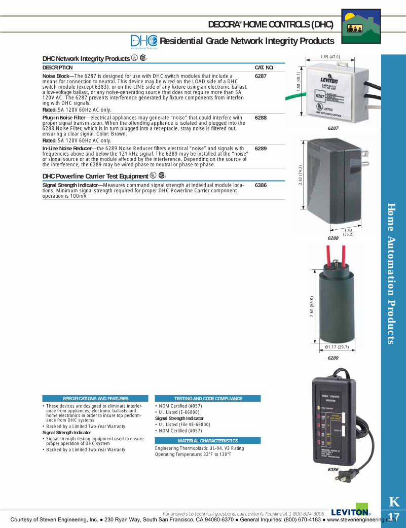
Hom
e Autom
ation Products
K17For answers to technical questions, call Leviton’s Techline at 1-800-824-3005
DECORA®HOME CONTROLS (DHC)
Residential Grade Network Integrity Products
DHC Network Integrity Products URDESCRIPTION CAT. NO.
Noise Block—The 6287 is designed for use with DHC switch modules that include ameans for connection to neutral. This device may be wired on the LOAD side of a DHCswitch module (except 6383), or on the LINE side of any fixture using an electronic ballast,a low-voltage ballast, or any noise-generating source that does not require more than 5A120V AC. The 6287 prevents interference generated by fixture components from interfer-ing with DHC signals.Rated: 5A 120V 60Hz AC only.Plug-in Noise Filter—electrical appliances may generate “noise” that could interfere withproper signal transmission. When the offending appliance is isolated and plugged into the6288 Noise Filter, which is in turn plugged into a receptacle, stray noise is filtered out,ensuring a clear signal. Color: Brown.Rated: 5A 120V 60Hz AC only.In-Line Noise Reducer—the 6289 Noise Reducer filters electrical “noise” and signals withfrequencies above and below the 121 kHz signal. The 6289 may be installed at the “noise”or signal source or at the module affected by the interference. Depending on the source ofthe interference, the 6289 may be wired phase to neutral or phase to phase.
DHC Powerline Carrier Test Equipment URSignal Strength Indicator—Measures command signal strength at individual module loca-tions. Minimum signal strength required for proper DHC Powerline Carrier componentoperation is 100mV.
6288
6289
6386
6287
SPECIFICATIONS AND FEATURES
• These devices are designed to eliminate interfer-ence from appliances, electronic ballasts andhome electronics in order to insure top perform-ance from DHC systems
• Backed by a Limited Two-Year WarrantySignal Strength Indicator• Signal strength testing equipment used to ensure
proper operation of DHC system• Backed by a Limited Two-Year Warranty
TESTING AND CODE COMPLIANCE
• NOM Certified (#057)• UL Listed (E-66800)Signal Strength Indicator• UL Listed (File #E-66800)• NOM Certified (#057)
MATERIAL CHARACTERISTICS
Engineering Thermoplastic UL-94, V2 RatingOperating Temperature: 32°F to 130°FMATERIAL
CHARACTERISTICS
1.85 (47.0)
1.58
(40
.1)
6287
1.43(36.2)
2.92
(74
.2)
6288
2.60
(66
.0)
Ø1.17 (29.7)
6289
6386
Courtesy of Steven Engineering, Inc. ● 230 Ryan Way, South San Francisco, CA 94080-6370 ● General Inquiries: (800) 670-4183 ● www.stevenengineering.com

K18
HOW TO USE THIS CATALOG
The L-101 Leviton Wiring Device Catalog is designed to help you find the device you’re seeking in the quickest and easiest way possible. Most product sections are divided into three distinct categories in the following sequence—Industrial Grade, CommercialGrade and Residential Grade—and grouped according to amperage and voltage, lowest to highest. For example, if you need toorder 15 Amp, 125 Volt Industrial Grade straight-blade duplex receptacles, begin your search with the main Table of Contents at thefront of the book. Here you’ll see that all straight blade receptacles are listed in Section G. Turn to Section G for a more detailed Tableof Contents on the first page. Each section page contains product descriptions, ratings and catalog numbers. There are also helpfulhighlights including Specifications and Features, Testing and Code Compliance, Color listing, Material Characteristics and dimen-sioned color product photos. Any product page in the L-101 Catalog can be clearly copied or faxed to customers and prospects foruse as a specifier sheet or as part of a presentation.
The Quick Reference Guide follows the main Table of Contents to help you pinpoint and locate specific products. TechnicalSection V provides general product and test data, industry standards, NEMA configuration charts, a glossary of wiring deviceterms, ANSI architectural symbols and other related information. Specific catalog numbers are listed in the exhaustive index atthe back of the catalog.
RATING
Choose GRADE, if appropriate
DIMENSIONED PHOTOGRAPH
WIRING/CERTIFICATIONS
CATALOG NUMBER
DESCRIPTION
Check for NEMA CONFIGURATION
WALLPLATE REFERENCE, if appropriate
SPECIFICATIONS & FEATURES
TESTING AND CODE COMPLIANCE
COLOR LISTING
MATERIAL CHARACTERISTICSL
K
J
I
H
G
F
E
D
C
B
A
I
D
E
H
B
J
G
K
F
L
C
A
Courtesy of Steven Engineering, Inc. ● 230 Ryan Way, South San Francisco, CA 94080-6370 ● General Inquiries: (800) 670-4183 ● www.stevenengineering.com

Multim
edia Structured C
abling System
s IndexSECTIONL
Structured CablingSystemsINDEXQuick Reference Guide . . . . . . . . . . . . . . . . . . . .L2ConnectorsQuickPort® . . . . . . . . . . . . . . . . . . . . . . . . . .L3–L5Fiber Optic . . . . . . . . . . . . . . . . . . . . . . . . . .L6, L7Wallplates and HousingsQuickPort . . . . . . . . . . . . . . . . . . . . . . . . . .L8–L16Acenti® . . . . . . . . . . . . . . . . . . . . . . . . . . . . . .L17Standard Telephone/Video Jacks . . . . . . . .L18–L22Workstation Accessories . . . . . . . . . . . . . . . . . .L23Copper ComponentsPatch Panels . . . . . . . . . . . . . . . . . . . . . .L24–L30Industrial Connectivity . . . . . . . . . . . . . . . . . . .L31Patch Cords . . . . . . . . . . . . . . . . . . . . . . . . . . .L32110-Style . . . . . . . . . . . . . . . . . . . . . . . . .L33–L3866-Block . . . . . . . . . . . . . . . . . . . . . . . . .L39–L40Fiber ComponentsEnclosures . . . . . . . . . . . . . . . . . . . . . . . .L41–L45Fiber Optic Cable Assemblies . . . . . . . . . . . . . .L46Accessories . . . . . . . . . . . . . . . . . . . . . . .L47–L49EnclosuresTelecommunications . . . . . . . . . . . . . . . .L50, L51Wireless Access Point . . . . . . . . . . . . . . . . . . .L52Cable Management and Rack AccessoriesVersi-Duct® . . . . . . . . . . . . . . . . . . . . . . . . . . .L53Rack and Frame . . . . . . . . . . . . . . . . . . .L54–L57Hook and Loop . . . . . . . . . . . . . . . . . . . . . . . .L58Labeling Products . . . . . . . . . . . . . . . . . . .L59, L60Tools and AccessoriesPunchdown/Termination . . . . . . . . . . . . . . . . .L61Fiber . . . . . . . . . . . . . . . . . . . . . . . . . . . .L62–L64Tone Test . . . . . . . . . . . . . . . . . . . . . . . . . . . . .L65Crimping/Stripping . . . . . . . . . . . . . . . . . . . . . .L65Craftsperson’s Handset . . . . . . . . . . . . . . . . . .L66Modular Plug Breakout Adapter . . . . . . . . . . . .L66
Courtesy of Steven Engineering, Inc. ● 230 Ryan Way, South San Francisco, CA 94080-6370 ● General Inquiries: (800) 670-4183 ● www.stevenengineering.com

eXtreme® 10GOur Category 6A solution enables advanced technologies, includingnew 10G and IP-based services. eXtreme 10G connectors featurepatent-pending Cone of Silence and patented Retention ForceTechnology® (RFT) for unparalleled signal integrity.
eXtreme® 6+Leviton’s Category 6 solution with patented Retention ForceTechnology. Includes connectors, patch cords and a variety of patchpanels. Exceeds TIA specifications for channel, permanent link andcomponent-rated Category 6 systems.
GigaMax® 5eLeviton’s Category 5e channel and component rated solution.Includes connectors, patch cords and a variety of universal and pre-configured panels. Exceeds TIA specifications for channel-andcomponent-rated Category 5e systems.
Category 5Leviton’s Category 5 solution for fast reliable voice and dataapplications from frame to workstation. Includes connectors, patchcords and universal panels. Exceeds TIA specifications for channeland category-rated Category 5 systems.
Opt-X®
Opt-X is Leviton’s full solution Fiber Optic System incorporating awide range of fiber optic components, including adapters, mountingplates, connectors, enclosures, cable assemblies, tools,consumables and workstation products with features and options tomeet all types of customer and application needs.
FastCAM™Leviton’s FastCAM fiber connectors are pre-terminated and factorypolished to provide precision termination of single-mode ormultimode fiber.
Thread-Lock®
Award-winning Thread-Lock mechanical connectors are part ofLeviton’s full line of connectors. Ideal for quick installations, thereusable connectors make field-installation simple and cost-effective.
Fast-CureReliable, cost-effective fiber optic connectors with quick, adhesivetermination featuring precision pre-radiused zirconia ferrules, high retention strength , and patented non-optical disconnect spacer design.
Versa-Cleave®
The Versa-Cleave tool is your award-winning solution for cleavingfiber perfectly every time.
Versi-Duct®Leviton's versatile horizontal and vertical slotted duct system for fiberand copper cable organization and management. A high-qualitysystem with a variety of solution-based accessories.
LabelWare™
A TIA/EIA-606-A compliant tool to label and help identify yourcabling infrastructure.
110 ChannelMax®
110 channel duct allows extra space for routing cables by increasingthe vertical channel depth to 3 or 5 inches.
Retention Force Technology®
Patented features included in eXtreme 6+ and Gigamax 5e+products, which provide enhanced connection integrity and promoteconsistent performance over the life of the system. Increased wireretention reduces tine contact failure. Improved gas-tight connectionprevents corrosion.
QuickPort®Leviton’s extensive line of snap-in modules allows complete field-configurability for the installer. Leviton QuickPort housings, such aswallplates, MOS housings and modular furniture faceplates, can beconfigured with a custom combination of QuickPort modules whicheasily snap in or out of ports.
Decora®
The original Decora QuickPort module wallplate is designed to matchDecora electrical devices manufactured by Leviton.
Lifetime Performance WarrantyLeviton Voice & Data Division offers a Lifetime Performance Warrantywhen approved components are installed by a Leviton CertifiedInstaller through the Certified Cabling System (CCS) program.
TIA GuidelinesThe TIA, or Telecommunications Industries Association, is theindustry regulatory body which defines industry standards, such asthe following:
TIA/EIA-568-B: Commercial Building TelecommunicationsCabling Standard
TIA/EIA-569-B: Commercial Building Standards forTelecommunications Pathways & Spaces
TIA/EIA-570-B: Residential and Light Commercial WiringStandard
TIA/EIA-606-A: Administration Standard for theTelecommunications Infrastructure ofCommercial Buildings
TIA/EIA-607: Telecommunications Bonding and GroundingStandard
Styles, Features, etc.These color bars are found throughout this catalog to indicateadditional information about a given product. They point out uniquefeatures and configurations, or other technical notes to help you inunderstanding, choosing or using Leviton products.
STRUCTURED CABLING DEVICE FEATURES
To learn more about Leviton’s outstanding offering of devices visit our Website at: www.leviton.com
Mul
tim
edia
Str
uctu
red
Cab
ling
Dev
ice
Feat
ures
L2
Quick Reference GuideThe following terms are used throughout this section to help users quickly identify special product features.
STYLES
FEATURES
TESTING AND CODE COMPLIANCE
*COLOR
MATERIAL CHARACTERISTICS
Courtesy of Steven Engineering, Inc. ● 230 Ryan Way, South San Francisco, CA 94080-6370 ● General Inquiries: (800) 670-4183 ● www.stevenengineering.com

Connectors
L3
QUICKPORT® COPPER CONNECTORS
A
C
E J L
G HI B F
D
QuickPort Connectors for UTP and STP Copper CableA–I Leviton offers a variety of copper connectors from advanced CAT 6A (10G) to CAT 3 solu-
tions. CAT 6A eXtreme® 10G, our highest performing connector featuring the Cone ofSilence and Retention Force Technology®, (RFT), resists alien crosstalk (AXT) and offersunparalleled signal integrity. eXtreme 6+ and component rated GigaMAx 5e+ connectorsalso feature patented RFT for long term performance. Shielded connectors in CAT 5e and CAT 6 ratings feature a robust, die-cast housing, provideprotection from electromagnetic interference, andoffer increased data security. Category 5 andCategory 3 connectors offer an economical solutionfor a variety of applications.All connectors feature standard QuickPort compati-bility and universal color coded wiring labels andexceed industry performance standards. Availablein 14 colors.
Use a Leviton Field-Termination Coaster toquickly and easily punchdown wires on any LevitonCategory or MultimediaConnector. For more information, call Sales Support at 1-800-922-6229.
Ivory(I) White(W) Gray(G)
Black(E) Orange(O) Blue(L)
Crimson Yellow(Y) Green(V)Red(C)
Purple(P) Almond(A) Lt Almond(T)
Brown(B) Dk Red(R)
*COLOR/CONNECTORS
For color selection, add suffix to catalognumber as follows: Ivory (I), White (W),Gray (G), Black (E), Orange (O), Blue (L),Crimson Red (C), Yellow (Y), Green (V),Purple (P), Almond (A), Light Almond (T),Brown (B), Dark Red (R).
MATERIAL CHARACTERISTICS
• All module bodies are fire-retardant plastic rated UL 94V-0
• Jack spring contacts are the highestquality phosphor bronze, plated with 50 microinches of gold over 100microinches of nickel for lowest contactresistance, maximum life
TESTING AND CODE COMPLIANCE
• All category-rated connectors complywith TIA-568-A requirements
• UL Listed• Fully compliant with NEC Article 800• Meet FCC Part 68
Color ChoicesK
Quickport Snap-In ConnectorseXtreme® 10G Snap-In Connectors cULus ƒ
DESCRIPTION CAT. NO.[A] eXtreme 10G channel-rated connector 6110G-R*6
Cone of Silence™ replacement pack (bag of 13) 61C05-B13
eXtreme® 6+ Connectors cULus ƒ
DESCRIPTION CAT. NO.[B] 8-conductor eXtreme 6+ component-rated connector 61110-R*6[C] 8-conductor eXtreme 6+ component-rated connectors 61110-B*6
QuickPack™ (25 per pack)[D] eXtreme 6+ shielded channel-rated connector 6S180-SH6
GigaMax® 5e Connectors cULus
DESCRIPTION CAT. NO.[E] 8-conductor GigaMax 5e+ component-rated connector 5G110-R*5[F] 8-conductor GigaMax 5e+ component-rated connectors 5G110-B*5
QuickPack™ (25 per pack)[G] 8-conductor GigaMax 5e channel-rated connector 5G108-R*5[H] 8-conductor GigaMax 5e channel-rated connectors 5G108-B*5
QuickPack™ (25 per pack)[I] GigaMax 5e shielded channel-rated connector 5S180-SH5
Category 5 Connectors URDESCRIPTION CAT. NO.[J] 8-conductor Category 5 connector 41108-R*5
Category 3 Connectors UR3DESCRIPTION CAT. NO.[K] 8-conductor connector 41108-R*3
Voice Grade Connectors URDESCRIPTION CAT. NO.[L] 6-conductor USOC connector 41106-R*6
8-conductor USOC connector 41108-R*8
N11173
N11173
N11173
N11173
Note: Protect your Category 5e and 6 connectors from damage and debris withLeviton’s field installable Shutters andIcons. See Labeling Products Page L60.
For answers to technical questions, call Leviton’s Techline at 1-800-722-2082Courtesy of Steven Engineering, Inc. ● 230 Ryan Way, South San Francisco, CA 94080-6370 ● General Inquiries: (800) 670-4183 ● www.stevenengineering.com

Con
nect
ors
L4
QUICKPORT® for AUDIO/VIDEO
To learn more about Leviton’s outstanding offering of devices visit our Website at: www.leviton.com
QuickPort Adapters & Connectors for Audio/VideoMix & match QuickPort Snap-In Audio/Video Adapters and Connectors to create a customizedmultimedia center. Make connections with standard industry tools. For CompressionConnectors, use Leviton’s Master Compression Tool.A BNC QuickPort Adapter: Gold-plated female-to-female connector with twist-on front and
rear connections using BNC plugs. Applications: high-end video, home theater, CCTV,LAN. Cable: shielded video & data cable.
B F-Type QuickPort Adapter: Nickel or gold-plated female-to-female connector with screw-onfront and rear connections. Applications: TV, VCR, DVD, satellite, home theater. Cable: coaxial cable terminated with “F” plugs.
C S-Video QuickPort Connector: Flush-mount S-Video connector on the front with 110puchdowns on the rear. Applications: audio/video, conference rooms, classrooms,computers, projectors. Cable: UTP Category 5, 5e or 6 cable.
D QuickPort Blank Inserts: Cover up unused QuickPort housing openings. Order inpackages of 10.
E RCA QuickPort Adapters: Black, yellow or red striped color-coded module for front and rear connections using RCA plugs. Applications: audio/video, home theatre. Cable: shielded audio/video cable with terminated RCA plugs.
F RCA-110 QuickPort Connector: Standard RCA connector on the front with 110punchdowns on the rear. Applications: audio/video, VCR, DVD, computers and gamingconsoles. Cable: UTP Category 5, 5e or 6 cable.
G, H F-Type and RCA QuickPort Compression Connectors: Time saving solution for robustterminations right at the wall plate. Applications: HDTV, cameras, component video,CATV and satellite signal delivery. Cable: RG6 Quad.
I, J RCA and F-Type Compression Connectors: Female style connectors feature radial crimp forincreased audio/video signal integrity. Applications: HDTV, cameras, component video,CATV and satellite signal delivery. Cable: RG6 Quad.
All modules meet or exceed industry standards. All QuickPort connectors and modules areUL certified, fully compliant with NEC® Article 800, and meet FCC Part 68. For product specifications and recommendations, please visit our web resource atwww.leviton.com/.
Quickport ModulesAudio/Video Adapters U ƒDESCRIPTION CAT. NO. CAT. NO. CAT. NO. CAT. NO. CAT. NO.
IVORY WHITE ALMOND BLACK GRAY[A] BNC Adapter, nickel-plated† 41084-BIF 41084-BWF 41084-BAF 41084-BEF 41084-BGF
BNC Adapter, gold-plated 40832-0BI 40832-0BW 40832-0BA — —[B] F-type Adapter, nickel-plated† 41084-FIF 41084-FWF 41084-FAF 41084-FEF 41084-FGF
F-type Adapter, gold-plated 40831-0BI 40831-0BW 40831-0BA — —[C] S-Video Connector, 40734-SVI 40734-SVW 40734-SVA 40734-SVE 40734-SVG
110 termination†[D] Blank Insert (pack of 10)† 41084-BIB 41084-BWB 41084-BAB 41084-BEB 41084-BGB[E] RCA Jack, gold-plated 40830-BIE 40830-BWE 40830-BAE — —
w/black stripe† RCA Jack, gold-plated 40830-BIR 40830-BWR 40830-BAR — —w/red stripe†RCA Jack, gold-plated 40830-BIY 40830-BWY 40830-BAY — —w/yellow stripe†RCA Jack, gold-plated 40830-BIV 40830-BWV — — —w/green stripe†RCA Jack, gold-plated 40830-BIL 40830-BWL — — —w/blue stripe†
[F] RCA-110 Connector† 40735-R*I 40735-R*W 40735-R*A 40735-R*E 40735-R*GPart numbers shown are for individual polybag packages in standard cartons. Some carded and contractor packs alsoavailable. Call customer service at 1-800-722-2082.† Note: Also available in Light Almond (*T*)
Compression Connectors and AdaptersDESCRIPTION CAT. NO. CAT. NO.
F-STYLE RCA[G-H] QuickPort Compression 40782-CPF 40782-R*W
Connectors[I-J] Compression Connectors 40985-CPF 40985-CRU
Note: See Tools & Accessories Page L59 for Master Compression Tool.
B
D
E
G H
F
C
I–J
A
*COLOR/CONNECTORS
For color selection, add suffix to catalognumber as follows: [F] RCA-110Connector Inner Barrel Color—Orange(O), Red (R), White (W), Yellow (Y). [G–H] Insert Color—Red (R), Black (E),Yellow (Y), Blue (L), Green (V).
MATERIAL CHARACTERISTICS
• All module bodies are fire-retardantplastic rated UL 94V-0
Courtesy of Steven Engineering, Inc. ● 230 Ryan Way, South San Francisco, CA 94080-6370 ● General Inquiries: (800) 670-4183 ● www.stevenengineering.com

QUICKPORT® SNAP-IN ADAPTERS and CONNECTORS for AUDIO
MATERIAL CHARACTERISTICS
• All module bodies are fire-retardantplastic rated UL 94V-0
D
C
FE
ML
ON
HG
J
K
I
QuickPort Snap-In Adapters & Connectors for AudioA, B Banana Jack Adapters: One black striped or one red striped color-coded module per unit
pack. Screw-on rear-side connections. Front-side connections use standard banana plugs.Applications: speaker connections. Cable: speaker wire terminated with banana plugs.
C, D Binding Post Adapters: One black striped or one red striped color-coded module per unitpack. Screw-on rear-side connections. Optional front-side connections—either screw-onor push-in—for banana plugs, speaker tip, spade tip, or bare wire. Applications: audiospeaker connections. Cable: speaker wire.
All modules meet or exceed industry standards. All QuickPort connectors and modules areUL certified, fully compliant with NEC® Article 800, and meet FCC Part 68.
QuickPort Snap-In ModulesAudio Adapters U ƒDESCRIPTION CAT. NO. CAT. NO. CAT. NO. CAT. NO.
IVORY WHITE ALMOND LIGHT ALMOND[A] Banana Jack Adapter, 40837-BIE 40837-BWE 40837-BAE 40837-BTE
gold-plated w/black stripe[B] Banana Jack Adapter, 40837-BIR 40837-BWR 40837-BAR 40837-BTR
gold-plated w/red stripe[C] Binding Post Adapter 40833-BIE 40833-BWE 40833-BAE 40833-BTE
gold-plated w/black stripe[D] Binding Post Adapter 40833-BIR 40833-BWR 40833-BAR 40833-BTR
gold-plated w/red stripe
Part numbers shown are for individual polybag packages in standard cartons. Some carded and contractor packs alsoavailable. Call customer service at 1-800-722-2082.
Push-On, Twist-On & Crimp-On F ConnectorsE, F Push-On F-Connectors: Quick, cost-effective 75 Ohm coaxial cable terminations, require
no crimping tools. Quick and Universal versions accommodate RG-59, RG-6, and RG-6Quad coax diameters.
G–K 1-Piece and 2-Piece Crimp-On F-Connectors: Terminates 75 Ohm coaxial cable with acrimp-on male F-Connector. 2-piece version with separate crimp ring, or one-pieceversion with crimp ring attached. Both RG-59 and RG-6 versions available.Crimping tool required.
L, M Twist-On F-Connectors: Twist-on male F-Connector for 75 Ohm coaxial cable. Nocrimping required. RG-59 and RG-6 versions.
Push-On, Crimp-On and Twist-On ConnectorsDESCRIPTION CAT. NO.[E] Universal F-Connector (bag of 100 with installation tool) 40985-HPC[F] Quick F-Connector (bag of 20 with installation tool) 40985-HPM[G] One-piece Crimp-on for RG-6 quad shield (bag of 100) 40985-0Q6[H] One-piece Crimp-on for RG-59 (bag of 100) 40985-1P9[I] One-piece Crimp-on for RG-6 (bag of 100) 40985-1P6[J] Two-piece Crimp-on for RG-59 (bag of 100) 40985-2P9[K] Two-piece Crimp-on for RG-6 (bag of 100) 40985-2P6[L] Twist-On Connector for RG-59 (bag of 100) 40985-TW9[M] Twist-On Connector for RG-6 (bag of 100) 40985-TW6
Note: See Tools & Accessories Section Page L63 for Crimping Tool.
HDMI and DVI ConnectorsDESCRIPTION CAT. NO. CAT. NO.
WHITE IVORY
3.5mm Stereo Connector 40839-SWS 40839-SIS[N] HDMI Feed Through-Decora Style 41647-00W 41647-00I[O] DVI Feed Through 41648-00W 41648-00I
Connectors
L5
B
A
For answers to technical questions, call Leviton’s Techline at 1-800-722-2082Courtesy of Steven Engineering, Inc. ● 230 Ryan Way, South San Francisco, CA 94080-6370 ● General Inquiries: (800) 670-4183 ● www.stevenengineering.com

L
M
Con
nect
ors
L6 To learn more about Leviton’s outstanding offering of devices visit our Website at: www.leviton.com
FIBER OPTIC CONNECTORS
FastCAM™ Factory Polished Fiber ConnectorsPre-terminated and factory polished to provide precision termination of single-mode andmultimode fiber. Available in LC, ST and SC styles to fit 250µm and 900µm cables withstandard single-mode and standard multimode or laser-optimized multimode fiber options
FastCAM Fiber Connectors DESCRIPTION CAT. NO.[A] FastCAM ST Multimode 62.5µm Connector 49991-MST[B] FastCAM ST Multimode 50µm Connector 49991-5ST[C] FastCAM ST Single-mode Connector 49991-SST
FastCAM Laser Optimized ST Multimode Connector 49991-LST[D] FastCAM SC Multimode 62.5µm Connector 49991-MSC[E] FastCAM SC Multimode 50µm Connector 49991-5SC[F] FastCAM SC Single-mode Connector 49991-SSC
FastCAM Laser Optimized SC Multimode Connector 49991-LSC[G] FastCAM LC Multimode 62.5µm Connector 49991-MLC[H] FastCAM LC Multimode 50µm Connector 49991-5LC[I] FastCAM LC Single-mode Connector 49991-SLC[J] FastCAM Laser Optimized LC Multimode Connector 49991-LLC
Thread-Lock® Reusable Fiber Connectors, Multimode And Single-modeK-M Award-winning Thread-Lock Connectors, available in SC, FC and ST® styles, are
reusable, field-terminable fiber optic connectors with a simple, craft-friendly installation.Available in 62.5/125 and 50/125 multimode or single-mode versions. Each box of 50connectors includes one tightening tool.
Thread-Lock Fiber ConnectorsDESCRIPTION CAT. NO. CAT. NO.
SINGLEMODE MULTIMODE[K] SC Thread-Lock Connector 49884-SSC (blue) 49884-MSC (beige)[L] FC Thread-Lock Connector 49883-SFC 49883-MFC[M] ST Thread-Lock Connector 49882-SST 49882-MST
Thread-Lock AccessoriesDESCRIPTION CAT. NO.[N] SC Duplex Clip for Thread-Lock Connector, 49884-DPC
black (bag of 25)[O] Silicon Build-up Sleeve Kit, includes one of 49885-SBS
each type (bag of 10)Nylon Retention Sleeve (bag of 10) 49855-SLV
MT-RJ Fiber Connectors, MultimodeP, Q Leviton MT-RJ Workstation connectors offer innovative push-button fiber termination, and
plug directly into our MOS adapters (see page L14). Frame-Station connectors use a camtechnology to lock the fiber into a terminated position for use in frame or, with adapters, inthe workstation. Both feature a pre-polished ribbon fiber ferrule that eliminates polishing.
MT-RJ Fiber ConnectorsDESCRIPTION CAT. NO.[P] High-Density MT-RJ Frame-Station Connector, 49888-6SF
multimode, 62.5 µmHigh-Density MT-RJ Frame-Station Connector, 49888-5SFmultimode, 50.0 µm
[Q] High-Density MT-RJ Workstation Connector, 49888-6SWmultimode, 62.5 µmHigh-Density MT-RJ Workstation Connector, 49888-5SWmultimode, 50.0 µm
P
N
O
Q
Note: For a complete listing of Fiber Optic Tools, see the Tools section, Pages L62–L64.
A B C
D E
G H
F
K
I J
Courtesy of Steven Engineering, Inc. ● 230 Ryan Way, South San Francisco, CA 94080-6370 ● General Inquiries: (800) 670-4183 ● www.stevenengineering.com

DC
Connectors
L7For answers to technical questions, call Leviton’s Techline at 1-800-722-2082
FIBER OPTIC ADAPTERS and CONNECTORS
Fast Cure Adhesive ConnectorsA-D Leviton Fast-Cure adhesive connectors, available in ST, SC, FC, and LC styles, are
reliable, cost-effective fiber optic connectors with quick, adhesive termination. Featureprecision pre-radiused zirconia ferrules, high cable retention crimp, and patented non-optical disconnect spacer design. Available in multimode or singlemode versions.
Adhesive ConnectorsDESCRIPTION CAT. NO. CAT. NO.
SINGLE-MODE MULTIMODE[A] ST Fast Cure Connector 49990-SST 49990-MST[B] SC Fast Cure Connector 49990-SSC 49990-MSC[C] FC Fast Cure Connector 49990-SFC 49990-MFC[D] LC Fast Cure Connector with 3mm boot 49990-SL2 49990-ML2
LC Fast Cure Connector with .9mm boot 49990-SDL 49990-MDL
Fast Cure AccessoriesDESCRIPTION CAT. NO. CAT. NO.
SINGLE-MODE MULTIMODE[E] SC Duplex Clip for Fast Cure Connector, 49886-DSC
black (bag of 25)[F] LC Duplex Clip for Fast Cure Connector, 49886-DLS
blue (bag of 25)[G] LC Duplex Clip for Fast Cure Connector, 49886-DLM
beige (bag of 25)
QuickPort® Snap-In Fiber AdaptersH–L Leviton offers QuickPort adapters to bring Thread-Lock and Fast-Cure fiber to any
QuickPort wallplate or housing. FC, SC, ST, LC and MT-RJ adapters, in various colors.
Fiber AdaptersDESCRIPTION CAT. NO.[H] QuickPort MT-RJ Adapter, for Frame-Station Connector 49889-QF*[I] QuickPort ST Fiber Optic Adapter, SM/MM, 41084-S*F
Phos. Bronze Sleeve†QuickPort ST Fiber Optic Adapter, SM/MM, 41084-S*ZZirconia Sleeve
[J] QuickPort Simplex FC Fiber Optic Adapter, SM/MM, 41084-F*PPhos. Bronze SleeveQuickPort Simplex FC Fiber Optic Adapter, SM/MM, 41084-F*ZZirconia Sleeve
[K] QuickPort Multimode Simplex SC Adapter Module, 41085-M*CPhos BronzeQuickPort Singlemode Simplex SC Adapter Module, 41085-S*CZirconia Ceramic
[L] QuickPort Duplex LC Adapter, SM/MM, 41085-ML*Phos. Bronze SleeveQuickPort Duplex LC Adapter, SM/MM, 41085-SL*Zirconia Ceramic Sleeve
[H] Use with MOS 1 Port Adapter 41291-1M* Page L15† Note: Cat. No. 41084 also available in Light Almond (-STF)
*COLOR/FIBER ADAPTERS
[H–M] For color selection, add suffix to catalog number as follows: Ivory (I), White (W), Gray (G), Black (E).
A B
Leviton’s Fiber Optic Consumables Kitsprovide the products you need toquickly and efficiently polish, cleanand terminate all our fiber connectors.See Page L63.
Leviton QuickPort fiber adapters fit intoany Leviton QuickPort wallplate orhousing, providing a high-density fiber-to-the-workstation solution, see pagesL8–L17 for workstation options.
EG
F
H
L
KJ
I
Courtesy of Steven Engineering, Inc. ● 230 Ryan Way, South San Francisco, CA 94080-6370 ● General Inquiries: (800) 670-4183 ● www.stevenengineering.com

QuickPort Wallplates with standard-sized openings designed toaccommodate QuickPort connectors or adapters.
Flush MountWallplates designed to fit smoothly against a wall,with a minimum profile.
Decora®
Wallplates with standard-sized openings designed toaccommodate Decora Inserts.
Decora InsertStandard, Decora-sized inserts designed to adapt high and low voltage applications to a single wallplate profile.
Single-gangThe standard wallplate width of 2.75" W x 4.53" H.
Dual-GangThe standard double wallplate width of 4.625" W x 4.53" H.
Wall JackA wallplate preconfigured with some kind ofconnector or adapter.
MidsizeA wider (3.12" W x 4.87" H) single-gang wallplatedesigned to disguise flaws in drywall or provide adesigner silhouette.
Type 106 (Duplex)The Standard NEMA-style form, with two openings,which is most common among electrical outlets.
Type 105 (Single)The Standard NEMA-style form with one opening—less common than the Type 106.
Type 104 (Duplex)A NEMA-style of surface-mount box, with two outletsor openings, common for use with telephone jackson walls or along baseboards.
Type 103 (Single)Identical to the type 104 box, but featuring only one outlet.
Acenti™ InsertQuickPort inserts designed to snap into Acentiwallplates.
Acenti WallplateSleek, low-profile plates available in 1–6 gang stylesaccept a variety of QuickPort and other inserts forvoice, data, electro-mechanical, lighting control,GFCI and more.
Wal
lpla
tes
and
Hou
sing
s
L8
QUICKPORT® FLUSH MOUNT WALLPLATES and INSERTS
To learn more about Leviton’s outstanding offering of devices visit our Website at: www.leviton.com
QuickPort Flush Mount Wallplates and InsertsLeviton offers one of the largest selections of field-configurable, flush mount wallplates and inserts available ontoday’s market. They provide the adaptability and performance required in a voice/data wiring interface in a sleeklow-profile wallplate. Choose from a full range of materials and styles, including: nylon, urea and stainless steel; standard and midsize;single- and dual-gang; and Decora® designer styling. All Leviton flush mount devices fit standard NEMA openingsfor easy installation on new or existing wallboxes.
Styles
Courtesy of Steven Engineering, Inc. ● 230 Ryan Way, South San Francisco, CA 94080-6370 ● General Inquiries: (800) 670-4183 ● www.stevenengineering.com

Wallplates and H
ousings
L9
QUICKPORT® DECORA® MULTIMEDIA INSERTS
QuickPort Decora Multimedia InsertsCombine voice, data, audio and video in one compact, attractive Decora wallplate. QuickPortDecora Wallplate Inserts offer designer style to match Leviton Decora electrical switches andoutlets, with the capacity and flexibility to support high-tech communications for boardrooms orworkstations. QuickPort snap-in modules fit neatly into a single gang Decora wallplate and canbe combined with Decora electrical devices (with a barrier box) in a multi-gang wallplate. Simplysnap in the QuickPort connectors of your choice to customize multimedia options. Compatiblewith all standard Decora wallplates and Decora Plus snap-on wallplates with hidden mountingscrews and standard NEMA openings. UL Listed and CSA Certified.
QuickPort Decora Multimedia InsertsDESCRIPTION CAT. NO. CAT. NO. CAT. NO. CAT. NO. CAT. NO. CAT. NO.
IVORY WHITE GRAY BLACK ALMOND BROWN2-Port Insert† 41642-00I 41642-00W 41642-0GY 41642-00E 41642-00A 41642-00B3-Port Insert† 41643-00I 41643-00W 41643-0GY 41643-00E 41643-00A 41643-00B4-Port Insert† 41644-00I 41644-00W 41644-0GY 41644-00E 41644-00A 41644-00B6-Port Insert† 41646-00I 41646-00W 41646-0GY 41646-00E 41646-00A 41646-00BBlank Insert† 80414-00I 80414-00W 80414-0GY 80414-00E 80414-00A
QuickPort 2-Port Insert/Connector KitsDESCRIPTION CAT. NO. CAT. NO.
IVORY WHITE2-Port Insert w/two 6-conductor connectors 41666-00I 41666-00W 2-Port Insert w/two 8-conductor connectors† 41688-00I 41688-00W
Decora Plus Voice/Data Connectors with QuickPort Snap-In ModulesDESCRIPTION CAT. NO. CAT. NO.
IVORY WHITEInsert with one 6-conductor jack and one F-connector 41658-00I 41658-00WInsert with one 6-conductor jack and one 8-conductor jack 41668-00I 41668-00W
Note: Order QuickPort Snap-In Modules on pages L3–L7. Configured versions also meet FCC Part 68. † Note: Also available in Light Almond (00T)
Decora WallplatesDESCRIPTION CAT. NO. CAT. NO. CAT. NO.
UREA NYLON DECORA PLUS SNAP-ONSingle-Gang Decora Wallplate 80401-00* 80401-0N* 80301-0S*Dual-Gang Decora Wallplate 80409-00* 80409-0N* 80309-0S*Three-Gang Decora Wallplate 80411-00* 80411-0N* 80311-0S*Four-Gang Decora Wallplate 80412-00* 80412-0N* 80312-0S*
Note: Additional Decora Wallplate ordering information can be found on page L9.
For Decora-style F-connector andTelephone Wall Jack Inserts, see page L19.
*COLOR/WALLPLATES
For color selection, add suffix to catalognumber as follows:1- and 2-Gang–Ivory (I), White (W), Gray (G), Black (E),Almond (A), Light Almond (T) and Brown(no additional suffix indicates Brown). 3-Gang–Ivory (I), White (W), Black (E),Almond (A) and Light Almond (T). 4-Gang–Ivory (I), White (W), Almond (A)and Light Almond (T).
For answers to technical questions, call Leviton’s Techline at 1-800-722-2082Courtesy of Steven Engineering, Inc. ● 230 Ryan Way, South San Francisco, CA 94080-6370 ● General Inquiries: (800) 670-4183 ● www.stevenengineering.com

Wal
lpla
tes
and
Hou
sing
s
L10
QUICKPORT® SINGLE- and DUAL-GANG WALLPLATES
To learn more about Leviton’s outstanding offering of devices visit our Website at: www.leviton.com
A
B
C
Leviton’s LabelWare® System isTIA/EIA-606-A compliant and designedto help you label all our copper andfiber products. User-friendly softwaremakes it quick, easy, and completelyconfigurable or use pre-printed labels.See pages L59-L60.
QuickPort Single- and Dual-Gang WallplatesQUICKPORT SINGLE-GANG MULTI-PORT WALLPLATES WITH OR WITHOUT DESIGNATION WINDOWSA, B Single-gang flush mount wallplates offer field-configurable flexibility in an attractive
single-piece housing. Fully compatible with all QuickPort Snap-in Modules includingconnectors or blank fillers. Options for port identification include LabelWare® wallplateand housing labels, typed or handwritten labels for designation windows, or the use ofdifferent color QuickPort modules. All windows are field-label compatible, and cover thewallplate security screw. UL Listed, CSA Certified, NEC Article 800 compliant.
QuickPort Single-Gang InsertsDESCRIPTION CAT. NO. CAT. NO. CAT. NO. CAT. NO. CAT. NO. CAT. NO.
IVORY WHITE GRAY BLACK ALMOND BROWN6-Port Wallplate* 41080-6IP 41080-6WP 41080-6GP 41080-6EP 41080-6AP 41080-6BP4-Port Wallplate* 41080-4IP 41080-4WP 41080-4GP 41080-4EP 41080-4AP 41080-4BP3-Port Wallplate* 41080-3IP 41080-3WP 41080-3GP 41080-3EP 41080-3AP 41080-3BP2-Port Wallplate* 41080-2IP 41080-2WP 41080-2GP 41080-2EP 41080-2AP 41080-2BP1-Port Wallplate* 41080-1IP 41080-1WP 41080-1GP 41080-1EP 41080-1AP 41080-1BP
† Note: Cat. No. 41080 also available in Light Almond (41080-*TP)
QuickPort Single-Gang Wallplates with Designation ID WindowsDESCRIPTION NO. OF CAT. NO. CAT. NO. CAT. NO. CAT. NO.
WINDOWS IVORY WHITE GRAY BLACK6-Port Wallplate 2 42080-6IS 42080-6WS 42080-6GS 42080-6ES4-Port Wallplate 2 42080-4IS 42080-4WS 42080-4GS 42080-4ES3-Port Wallplate 2 42080-3IS 42080-3WS 42080-3GS 42080-3ES2-Port Wallplate 2 42080-2IS 42080-2WS 42080-2GS 42080-2ES1-Port Wallplate 1 42080-1IS 42080-1WS 42080-1GS 42080-1ES
Note: Housings are sold empty. Snap-in Connectors must be ordered separately. (See pages L3–L7.)
QUICKPORT DUAL-GANG MULTI-PORT WALLPLATES WITH DESIGNATION WINDOWSC Dual-gang flush mount wallplates with designation windows are designed in a single-piece
housing and a wide choice of port counts for maximum density. Field configure with anycombination of QuickPort Snap-in Modules. Use different color QuickPort modules for portidentification, or type or hand-write labels for designation windows. All windows are field-label compatible, and cover the wallplate security screw. QuickPort wallplates are ULListed, CSA Certified, and listed in compliance with NEC Article 800.
QuickPort Dual-Gang Wallplates with Designation ID WindowsDESCRIPTION NO. OF CAT. NO. CAT. NO. CAT. NO. CAT. NO.
WINDOWS IVORY WHITE GRAY BLACK12-Port Wallplate 4 42080-12I 42080-12W 42080-12G 42080-12E8-Port Wallplate 4 42080-8IP 42080-8WP 42080-8GP 42080-8EP6-Port Wallplate 4 42080-6IP 42080-6WP 42080-6GP 42080-6EP4-Port Wallplate 4 42080-4IP 42080-4WP 42080-4GP 42080-4EP3-Port Wallplate 2 42080-3IP 42080-3WP 42080-3GP 42080-3EP2-Port Wallplate 2 42080-2IP 42080-2WP 42080-2GP 42080-2EP1-Port Wallplate 2 42080-1IP 42080-1WP 42080-1GP 42080-1EPNote: Housings are sold empty. Snap-in Connectors must be ordered separately. (See pages L3–L7.)
QUICKPORT MIDWAY WALLPLATESD Midway wallplates provide QuickPort modularity with .375" more coverage than standard
wallplates. Expanded silhouette provides designer look and easily hides irregular drywall cutsor flaws around outlets. The 4.875" x 3.125" plate is .375" wider and taller, and matchesLeviton’s Midway Wallplates for electrical devices and lighting controls, .25" depth ensures aclean fit with various devices. Crafted from durable, smooth-finish nylon, wallplates fit asingle-gang electrical box. UL listed and CSA certified.
QuickPort Midway Single-Gang Wallplates, NylonDESCRIPTION CAT. NO. CAT. NO. CAT. NO. CAT. NO. CAT. NO.
IVORY WHITE ALMOND BROWN LT ALMOND6-Port Midway QuickPort Wallplate 41091-6IN 41091-6WN 41091-6AN 41091-6BN 41091-6TN4-Port Midway QuickPort Wallplate 41091-4IN 41091-4WN 41091-4AN 41091-4BN 41091-4TN3-Port Midway QuickPort Wallplate 41091-3IN 41091-3WN 41091-3AN 41091-3BN 41091-3TN2-Port Midway QuickPort Wallplate 41091-2IN 41091-2WN 41091-2AN 41091-2BN 41091-2TN1-Port Midway QuickPort Wallplate 41091-1IN 41091-1WN 41091-1AN 41091-1BN 41091-1TN
Courtesy of Steven Engineering, Inc. ● 230 Ryan Way, South San Francisco, CA 94080-6370 ● General Inquiries: (800) 670-4183 ● www.stevenengineering.com

Wallplates and H
ousings
L11For answers to technical questions, call Leviton’s Techline at 1-800-722-2082
QUICKPORT® STAINLESS STEEL WALLPLATES/WALLPLATE INSERTS
QuickPort Stainless Steel WallplatesQUICKPORT STAINLESS STEEL SINGLE-GANG AND DUAL-GANG WALLPLATESA, B Leviton's single-gang and dual-gang QuickPort Stainless Steel Wallplates provide elegant
designer styling, and accept any QuickPort connector or adapter. Ideal in environmentsthat demand durable, easy-to-clean solution. Use different color QuickPort modules or theLabelWare System for port identification. Fit standard NEMA electrical boxes. cULus Listed,meet FCC Part 68, and are listed in compliance with TIA/EIA-568-B.
QuickPort Stainless Steel WallplatesDESCRIPTION CAT. NO. CAT. NO. CAT. NO. CAT. NO. CAT. NO. CAT. NO. CAT. NO.
1-PORT 2-PORT 3-PORT 4-PORT 6-PORT 8-PORT 12-PORTSingle-Gang 43080-1S1 43080-1S2 43080-1S3 43080-1S4 43080-1S6 — —Dual-Gang — 43080-2S2 — 43080-2S4 43080-2S6 43080-2S8 43080-S12
Note: Housings are sold empty. Snap-in Connectors must be ordered separately. (See pages L3–L7.)
QUICKPORT STAINLESS STEEL WALLPHONE WALLPLATESC Bring Stainless Steel elegance to your wallphone. Easily mount any standard wallphone on
this sturdy, standard-sized wallplate with durable rivets. Single port accepts any LevitonQuickPort Connector. Recessed design fits cleanly with slide-rail mechanisms.
QuickPort Stainless Steel Wallphone WallplatesDESCRIPTION CAT. NO.Stainless Steel Wallphone Wallplate, recessed 4108W-1SPStainless Steel Wallphone Wallplate 4108W-0SP
Note: Leviton also offers Voice-Grade Wall Phone Jacks. (See pages L3–L7.)
QuickPort Wallplate InsertsQUICKPORT DUPLEX/QUAD 106 INSERTSD, E The QuickPort Duplex and Quad 106 Units are ideal for applications where two or four
individual modular ports are desired, within the standard ‘106/NEMA-style’ outline thatprevails among electrical outlets. Accepts all QuickPort Snap-in Modules and fitsstandard NEMA wallboxes and most floor boxes and monuments. A recess above eachmodule port on the Duplex 106 Unit accommodates Leviton Designation Labels (pageL60) or hand-written port ID. Uses standard duplex wallplates (sold separately, seeSection E). UL & CSA listed and NEC Article 800 compliant.
QuickPort Duplex 106 Insert URDESCRIPTION CAT. NO. CAT. NO. CAT. NO. CAT. NO. CAT. NO.
LT. ALMOND IVORY WHITE GRAY BLACKQuickPort Duplex 106 Insert only 41087-2TP 41087-2IP 41087-2WP 41087-2GP 41087-2EPQuickPort Quad 106 Insert only 41087-QTP 41087-QIP 41087-QWP 41087-QGP 41087-QEP
Note: Inserts are sold empty. Snap-in Connectors must be ordered separately. (See pages L3–L7.)
QUICKPORT FLOOR JACK INSERTSF Rugged and fully field-configurable, this device provides point-of-use connectivity for a
broad range of applications where convenience or building requirements dictate the use ofa floor-mounted communications outlet. Each floorplate is made of .06" thick solid brass tohold up under heavy furniture or foot traffic. When not in use, a flush-fitting brass screwcap keeps internal components free from dirt and dust.The two individual ports are configured easily with any combination of QuickPort. QuickPortfloor jacks will fit standard metal boxes 3" x 2", 3" x 21⁄8" and larger.
QuickPort Duplex Floor Jack Insert with Brass Plate and Screw CapDESCRIPTION CAT. NO.Insert with one F-connector, one blank module, and brass plate w/cap 41650-00FInsert with one 6-conductor connector, one blank module, and brass plate w/cap 41650-006Insert with one blank module and brass plate w/cap 41652-000Insert with two 6-conductor jacks and brass plate w/cap 41652-006Insert with one 6-conductor connector, one F-connector, and brass plate w/cap 41652-06F
F
E
A
C
NOTE: Wallplate included with eachQuickPort Floor Jack Insert.
B
D
Courtesy of Steven Engineering, Inc. ● 230 Ryan Way, South San Francisco, CA 94080-6370 ● General Inquiries: (800) 670-4183 ● www.stevenengineering.com

Wal
lpla
tes
and
Hou
sing
s
L12
QUICKPORT® MODULAR FURNITURE FACEPLATES
To learn more about Leviton’s outstanding offering of devices visit our Website at: www.leviton.com
Steelcase Series
Herman Miller® series (shown with49910-SE4 and Herman Miller's"Reducer" G1189A)
Haworth® Panels
*COLOR/FACEPLATES
For color selection, add suffix to catalognumber as follows: Ivory (I), White (W),Gray (G), Black (E).
MATERIAL CHARACTERISTICS
High-impact, fire-retardant, plasticrated UL 94V-0.
Standard Modular Furniture Faceplates with ID WindowsDESCRIPTION CAT. NO. HERMAN STEELCASE HAWORTH® HON OTHERS
MILLER®
2-Port 49910-S*2 � � � � �
4-Port (w/1 blank) 49910-S*4 � � � � �
4-Port Extended-depth† 49910-E*4 � � � � �(w/1 blank)Note: Standard modular furniture faceplates above fit openings of approximately 1.38" x 2.63".†4-port extended plate provides 1/2" added depth (3/4" total) for installation into shallow raceway channels, e.g., some pow-ered channels.� Compatible when used with Herman Miller G1189A Reducer available from Herman Miller dealers.
Herman Miller Modular Furniture FaceplatesDESCRIPTION CAT. NO. HERMAN STEELCASE HAWORTH® HON OTHERS
MILLER®
2-Port HM Faceplate† 49910-H*2 � — — — —4-Port HM Faceplate 49910-H*4 � — — — —(with 1 Blank)Note: Herman Miller faceplates above fit openings of approximately 1.88" x 2.98".†Fits most Herman Miller furniture. To ensure compatibility with specific models call Applications Engineering.
QuickPort furniture faceplates come in manystyles to fit all major modularfurniture brands.
QuickPort Modular Furniture FaceplatesBring a simple snap-in installation, attractive streamlined appearance and easy identifi-cation to your modular furniture environments. QuickPort Modular Furniture Faceplatesaccept all QuickPort Snap-In Modules—supporting virtually any application—and snapeasily and snugly into standard modular furniture. Features faceplate windows withclear plastic covers that allow easy insertion of ID labels. Labor-saving QuickPort jackdesign and tool-less plate installation simplifies installations, adds, moves and changes,and allows access to the connectors without removing the furniture channel cover.Available in 2- and 4-port versions, and in four colors: ivory, white, gray and black.cULus Listed and A-Tick Certified.
Courtesy of Steven Engineering, Inc. ● 230 Ryan Way, South San Francisco, CA 94080-6370 ● General Inquiries: (800) 670-4183 ● www.stevenengineering.com

Wallplates and H
ousings
L13For answers to technical questions, call Leviton’s Techline at 1-800-722-2082
QUICKPORT® MULTIMEDIA OUTLET SYSTEM (MOS)
QuickPort Multimedia Outlet System (MOS)The innovative QuickPort Multimedia Outlet System is designed to provide the highest level of application and instal-lation flexibility for fiber optic and twisted-pair connectivity. It consists of a surface mount box and single- and dual-gang wallplates, which accept a variety of copper, fiber, and A/V QuickPort snap-in modules The MOS line is distinguished from other QuickPort housings by several features: front-load installation capability sothat changes can be made without dismantling the entire device; duplex modules and fiber coupling types for SC, ST,MT-RJ and other applications; the addition of S-video and RCA adapters for high-definition audio/video; and designelements for enhanced routing, storage and bend radius protection of fiber and copper cabling. See individual prod-uct descriptions for more features.For product specifications and recommendations, please visit our web resource at www.leviton.com.
Features and BenefitsA Multiple connector termination stations provide stabilized
punchdown support.B Leviton’s exclusive dual rings store the fiber loop and
provide multiple straight paths to each port.C Single latch cover with security option restricts access
if desired. D Multi-directional mounting and raceway access allow
complete installation flexibility.E Front-loading inserts simplify configuration, while strong
latches keep them in place during use.F Fiber storage/spacer ring fits between wallbox/mud ring
and MOS dual-gang plate for fiber loop storage and management.
G 45˚ angled jack insert optimizes bend radius complianceof cable exiting QuickPort® snap-in connectors.
H Load up to 12 devices in a dual-gang wallplate.
A�
B�
C�D�
D�
E�
G� H�
F�
Courtesy of Steven Engineering, Inc. ● 230 Ryan Way, South San Francisco, CA 94080-6370 ● General Inquiries: (800) 670-4183 ● www.stevenengineering.com

QuickPort Multimedia Outlet System (MOS)MOS Surface Mount Boxes and Wallplates
6-Port Surface Mount Box 41296-MMo
Single-Gang Wallplate 41290-SMo
Dual-Gang Wallplate 41290-DMo
Fiber Storage/Spacer Ring 41290-DR*
MOS Inserts for Surface Mount Boxes and Wallplates2-Port QuickPort Adapter, flush, (1 unit high) 41291-2Qo
1-Port QuickPort Adapter, flush, (1 unit high) 41291-1Mo
1 S-video Insert Module, (1 unit high) 41291-1Vo
1 RCA Insert Module, 2-port, screw terminal (1 unit high) 41291-1Ro
(red and white stripe)1 RCA Insert Module, 3-port, female-to-female adapters (1 unit high) 41292-3Ro
(yellow and white stripe)1 HD-15 Insert Module, female-to-female (1 unit high) 41293-HDo
1 HD-15 Screw Terminal 41295-HD•
1 Duplex ST® Adapter, (1 unit high) (phos. bronze sleeve) 41291-2T*1 Duplex ST® Adapter, (1 unit high) (zirconia ceramic sleeve) 41291-ZT*1 Duplex FC Adapter (1 unit high) (phos. bronze sleeve) 41291-PF*1 Duplex FC Adapter (1 unit high) (zirconia ceramic sleeve) 41291-ZF*1 Duplex SC Adapter (1 unit high) (phos. bronze sleeve) 41291-PC*1 Duplex SC Adapter (1 unit high) (zirconia ceramic sleeve) 41291-2C*Blank Module (1 unit high) 41291-1B*Blank Module HD-15 Insert Module 41291-DBo
1 RCA Component (Y, W, R) 110 41292-AV•
1 RCA Component (R, G, B) 110 41292-DV•
1 Decora Converter Strap 41649-00•
MOS Inserts for use with MOS Wallplates2-Port QuickPort Adapter, 45˚ exit (1.5 units high) 41294-2Qo
Blank Module (0.5 unit high) 41295-5Bo
Blank Module (1.5 units high) 41294-2Bo
Blank Module (2 units high) 41292-2Bo
1 Duplex ST® Adapter 45˚ exit, SM/MM (1.5 units high) (phos. bronze sleeve) 41294-2T*1 Duplex ST® Adapter 45˚ exit, SM/MM (1.5 units high) (zirconia ceramic sleeve) 41294-ZT*1 Duplex FC Adapter 45˚ exit, SM/MM (1.5 units high) (phos. bronze sleeve) 41294-PF*1 Duplex FC Adapter 45˚ exit, SM/MM (1.5 units high) (zirconia ceramic sleeve) 41294-ZF*1 Duplex SC® Adapter 45˚ exit, SM/MM (1.5 units high) (phos. bronze sleeve) 41294-PC*1 Duplex SC® Adapter 45˚ exit, SM/MM (1.5 units high) (zirconia ceramic sleeve) 41294-2C*1 Duplex ST® Adapter 45˚ exit, SM/MM (2 units high) (phos. bronze sleeve) 41292-2T*1 Duplex ST® Adapter 45˚ exit, SM/MM (2 units high) (zirconia ceramic sleeve) 41292-ZT*1 Duplex FC Adapter 45˚ exit, SM/MM (2 units high) (phos. bronze sleeve) 41292-PF*1 Duplex FC Adapter 45˚ exit, SM/MM (2 units high) (zirconia ceramic sleeve) 41292-ZF*2 Duplex SC® Adapter 45˚ exit, SM/MM (2 units high) (phos. bronze sleeve) 41292-PC*2 Duplex SC® Adapter 45˚ exit, SM/MM (2 units high) (zirconia ceramic sleeve) 41292-2C*2 Duplex ST® Adapter 45˚ exit, SM/MM (3 units high) (phos. bronze sleeve) 41293-4T*2 Duplex ST® Adapter 45˚ exit, SM/MM (3 units high) (zirconia ceramic sleeve) 41293-ZT*
2 Duplex FC Adapter 45˚ exit, SM/MM (3 units high) (phos. bronze sleeve) 41293-PF*2 Duplex FC Adapter 45˚ exit, SM/MM (3 units high) (zirconia ceramic sleeve) 41293-ZF*
2 Duplex SC® Adapter 45˚ exit, SM/MM (3 units high) (phos. bronze sleeve) 41293-PC*2 Duplex SC® Adapter 45˚ exit, SM/MM (3 units high) (zirconia ceramic sleeve) 41293-4C*
Wal
lpla
tes
and
Hou
sing
s
L14
QUICKPORT® MULTIMEDIA OUTLET SYSTEM (MOS)
To learn more about Leviton’s outstanding offering of devices visit our Website at: www.leviton.com
StylesConfigurations for MOS Wallplates
One–1 Unit HighOne–1 Units High
One–3 Units High
One– 1/2 Unit HighOne–1 Unit High
One–1-1/2 Units High
Two–1-1/2 Units High
Three–1 Unit High
COLOR/INSERTS and WALLPLATES
For color selection, add suffix to catalognumber as follows: * Ivory (I), White (W), Gray (G), Black (e)° Light Almond (T), Ivory (I), White (W),
Gray (G), Black (E)• Ivory (I), White (W)
MATERIAL CHARACTERISTICS
High-impact, fire-retardant, plastic ratedUL 94V-0.
Courtesy of Steven Engineering, Inc. ● 230 Ryan Way, South San Francisco, CA 94080-6370 ● General Inquiries: (800) 670-4183 ● www.stevenengineering.com

QuickPort Surface Mount HousingsLeviton’s surface mount housings offer fast, economical installation and field configuration for applications where itmay not be practical to add a wallbox, such as modular furniture environments or retrofit situations. As with allQuickPort field-configurable products, you configure the housing to your specific needs using Snap-In Modules—easily rearranged if applications change. These housings can be adapted for mounting on all types of surfaces,including walls and furniture with tape or screws (both included) modular furniture with a modular furniture bracket(page L23) or to metal surfaces with magnets (page L23). Note: Identify all your connections with Leviton LabelWare System wallplate and housing labels (See page L60.)
In-port connector termination stations provide stability duringpunchdown.
Designation window accepts hand-written indications, field-printed labelingsystems, Leviton LabelWare™ or pre-printed port ID labels (see page L59).
For large installations, silkscreen thecover with words, numbers, icons orcompany logos. Call ApplicationsEngineering for advice on artworkand minimum quantity requirements.
4-, 6- and 12-port housing featureraceway knockouts on all non-portedsides which are compatible withmajor raceway brands.
Port identification areas residenext to numbered ports.
4-, 6- and 12-port surface-mount housings are compatiblewith Leviton’s modular furnituremounting brackets and magnets(see page L24).
Wallplates and H
ousings
L15For answers to technical questions, call Leviton’s Techline at 1-800-722-2082
QUICKPORT® SURFACE MOUNT HOUSINGS
Courtesy of Steven Engineering, Inc. ● 230 Ryan Way, South San Francisco, CA 94080-6370 ● General Inquiries: (800) 670-4183 ● www.stevenengineering.com

Wal
lpla
tes
and
Hou
sing
s
L16
QUICKPORT® SURFACE MOUNT HOUSINGS
To learn more about Leviton’s outstanding offering of devices visit our Website at: www.leviton.com
*COLOR/INSERTS and WALLPLATES
For color selection, add suffix to catalognumber as follows: Ivory (I), White (W),Gray (G), Black (E).
MATERIAL CHARACTERISTICS
High-impact, fire-retardant, plastic ratedUL 94V-0.
AB
C D E
QuickPort 1-, 2-, 4-, 6-, and12-Port Surface Mount HousingsA–E Leviton has a surface mount housing to suit your need. 1-, 2-, 4-, 6- and 12-Port
housings are easily field configured with QuickPort Connectors (sold separately, pagesL3–L7). The 2-port version comes with a blank filler to cover and protect one unusedopening. The 4- and 6-port housings are sized to completely cover a single-gang NEMAwallbox opening, while the 12-port fits over a single- or dual-gang NEMA box opening.Housings contain knockouts to accommodate raceway and cable entry, with built-in strain relief to assure undisturbed connections, and easy cover latches allow easyadds, moves and changes.All housings can be mounted with screws or adhesive mounting tape (both provided), orwith magnets or modular furniture brackets (sold separately on page L24). Identify portsand stations by using ample space next to each port or the designation window. All housings are UL Listed and compliant with NEC Article 800.
QuickPort Surface Mount HousingsDESCRIPTION CAT. NO.[A] 1-Port Surface Mount Housing 41089-1*P[B] 2-Port Surface Mount Housing (includes 1 blank module) 41089-2*P[C] 4-Port Surface Mount Housing 41089-4*P[D] 6-Port Surface Mount Housing 41089-6*P[E] 12-Port Surface Mount Housing 41089-12*
Note: Connectors must be ordered separately. (See pages L3–L7)Leviton also offers Pre-configured Voice-Grade Surface Mount Jacks. (See page L23)
Courtesy of Steven Engineering, Inc. ● 230 Ryan Way, South San Francisco, CA 94080-6370 ● General Inquiries: (800) 670-4183 ● www.stevenengineering.com

A B C D
E F
Wallplates and H
ousings
L17For answers to technical questions, call Leviton’s Techline at 1-800-722-2082
ACENTI™ WALLPLATES
Acenti Wallplates, QuickPort® Inserts and ConnectorsLeviton’s new Acenti wallplates are sleek and smooth and come in 7 soft neutral colors to perfectlycomplement any home or office environment. The soft radius design with low-profile cornersadds personality with clean simple lines. Available in 1-, 2-, 3-, 4-, 5- and 6-gang styles.Choose from a wide variety of inserts for voice, data, electro-mechanical, lighting control, GFCI,and more. QuickPort inserts give all your voice, data, audio/visual and even fiber connections asleek new look. See all the options at Leviton.com/acenti or call Leviton Customer Service at1(800) 323-8920.
Acenti QuickPort Multimedia InsertsDESCRIPTION CAT. NO.[A] 2-Port Acenti QuickPort Insert AC642[B] 3-Port Acenti QuickPort Insert AC643[C] 4-Port Acenti QuickPort Insert AC644[D] 6-Port Acenti QuickPort Insert AC646
Acenti WallplatesDESCRIPTION CAT. NO.[E] Single-Gang Acenti Wallplate ACWP1[F] Dual-Gang Acenti Wallplate ACWP2
Three-Gang Acenti Wallplate ACWP3Four-Gang Acenti Wallplate ACWP4Five-Gang Acenti Wallplate ACWP5Six-Gang Acenti Wallplate ACWP6
Note: Order QuickPort Snap-In Connectors on page L3–L7. Configured versions also meet FCC Part 68
Acenti® QuickPort® Snap-In ConnectorsDESCRIPTION CAT. NO.
GigaMax® Cat 5e Channel-Rated Connector AC108-R*5[G] BNC Adapter, Nickel-Plated AC084-B*F
BNC Adapter, Gold-Plated AC832-0B*F-Type Adapter, Nickel-Plated AC084-F*F
[H] F-Type Adapter, Gold-Plated AC831-0B*[I] S-Video Module, 110 Termination AC734-SV*[J] Blank Insert (Pack of 10) AC084-B*B
RCA Jack, Gold-Plated w/Red Stripe AC830-B*R[K] RCA Jack, Gold-Plated w/Black Stripe AC830-B*E
RCA Jack, Gold-Plated w/Yellow Stripe AC830-B*Y[L] Banana Jack, Gold-Plated w/Red Stripe AC837-B*R
Banana Jack, Gold-Plated w/Black Stripe AC837-B*EBinding Post Adapter, Gold-Plated w/Red Stripe AC833-B*R
[M] Binding Post Adapter, Gold-Plated w/Black Stripe AC833-B*ERCA 110 Termination Connector, Orange Inner Barrel AC735-RO*RCA 110 Termination Connector, Red Inner Barrel AC735-RR*RCA 110 Termination Connector, White Inner Barrel AC735-RW*RCA 110 Termination Connector, Yellow Inner Barrel AC735-RY*
*COLOR/ACENTI
For color selection, add suffix to catalognumber as follows: Neutral Colors–Alabaster (ALA), Onyx (ONX) and Slate(SLT). Off-White Colors–Quartz (QTZ),Sand (SND), Driftwood (DFT) andNatural (NTL).
G
H
J
I
K
L
M
Courtesy of Steven Engineering, Inc. ● 230 Ryan Way, South San Francisco, CA 94080-6370 ● General Inquiries: (800) 670-4183 ● www.stevenengineering.com
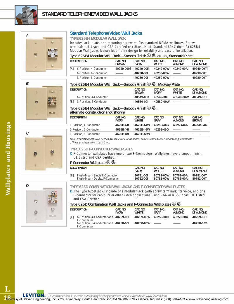
Wal
lpla
tes
and
Hou
sing
s
L18
STANDARD TELEPHONE/VIDEO WALL JACKS
To learn more about Leviton’s outstanding offering of devices visit our Website at: www.leviton.com
Standard Telephone/Video Wall JacksTYPE 625B4 MODULAR WALL JACKIncludes jack, plate, and mounting hardware. Fits standard NEMA wallboxes. Screwterminals. UL Listed and CSA Certified or cULus Listed. Standard 6P4C (item A) 625B4Modular Wall Jacks feature lead-frame design for reliability and ease of installation.
Type 625B4 Modular Wall Jack—Smooth Finish UR cULus, Standard PlateDESCRIPTION CAT. NO. CAT. NO. CAT. NO. CAT. NO. CAT. NO.
BROWN IVORY WHITE ALMOND LT ALMOND[A] 6-Position, 4-Conductor 40249-000† 40249-00I† 40249-00W† 40249-00A† 40249-00T†
6-Position, 6-Conductor — 40238-00I 40238-00W — 40238-00T8-Position, 8-Conductor — 40280-00I 40280-00W — 40280-00T
Type 625B4 Modular Wall Jack—Smooth Finish UR, Midway PlateDESCRIPTION CAT. NO. CAT. NO. CAT. NO. CAT. NO.
BROWN IVORY WHITE LT ALMOND6-Position, 4-Conductor 40549-000 40549-00I 40549-00W 40549-00T
[B] 8-Position, 8-Conductor 40580-00I 40580-00W —
Type 625B4 Modular Wall Jack—Smooth Finish UR,alternate construction (not shown)DESCRIPTION CAT. NO. CAT. NO. CAT. NO. CAT. NO. CAT. NO.
IVORY WHITE GRAY ALMOND BROWN6-Position, 4-Conductor 4625B-44I 4625B-44W 4625B-44G 4625B-44A 4625B-0446-Position, 6-Conductor 4625B-46I 4625B-46W 4625B-46G — —8-Position, 8-Conductor 4625B-48I 4625B-48W — — —
Note: Robertson/Slot Drive screws available for 4625B series, call customer service for ordering information.†These products are cULus Listed.
TYPE 625D F-CONNECTOR WALLPLATESC F-Connector wallplates have one or two F-Connectors. Wallplates have a smooth finish.
UL Listed and CSA certified.
F-Connector Wallplate URDESCRIPTION CAT. NO. CAT. NO. CAT. NO. CAT. NO.
IVORY WHITE ALMOND LT ALMOND[B] Flush-Mount Single F-Connector 80781-00I 80781-00W 80781-00A 80781-00T
Flush-Mount Duplex F-Connector 80782-00I 80782-00W 80782-00A 80782-00T
TYPE 625D COMBINATION WALL JACKS AND F-CONNECTOR WALLPLATESD The Type 625D jacks include one modular jack (with screw terminals) for voice, and one
F-connector for cable TV or other video applications using RG6 or RG59 coax. UL Listedand CSA Certified.
Type 625D Combination Wall Jacks and F-Connector Wallplates URDESCRIPTION CAT. NO. CAT. NO. CAT. NO. CAT. NO. CAT. NO.
IVORY WHITE GRAY ALMOND LT ALMOND[C] 6-Position, 4-Conductor and 40259-00I 40259-00W 40259-00G 40259-00A 40259-00T
F-Connector6-Position, 6-Conductor and 40258-00I 40258-00W — — 40258-00TF-Connector
A
B
C
D
Courtesy of Steven Engineering, Inc. ● 230 Ryan Way, South San Francisco, CA 94080-6370 ● General Inquiries: (800) 670-4183 ● www.stevenengineering.com

Wallplates and H
ousings
L19For answers to technical questions, call Leviton’s Techline at 1-800-722-2082
TELEPHONE INSERT WALL JACKS
Decora® Telephone Wall Jack InsertsDECORA MODULAR SINGLE OR DUPLEX WALL JACK INSERTSA These single or duplex flush-mount voice-grade connectors fit in Leviton’s popular
Decora line of devices. Screw terminals. Includes matching Decora wallplate.
Decora Modular Wall Jack URDESCRIPTION CAT. NO. CAT. NO. CAT. NO.
IVORY WHITE LT ALMOND Decora Single Modular Wall Jack, 6-position 4-conductor 40949-0ID 40949-0WD 40949-OTDDecora Duplex Modular Wall Jack, 6-position 4-conductor 40944-0ID 40944-0WD 40944-0TD
TYPE 625 DECORA MODULAR WALL JACKSB Single flush mount jack for use with Decora or Decora Plus wallplates. Mount in standard
or multi-gang electrical box. Screw terminals. UL Listed and CSA Certified.
Type 625 Decora Modular Wall Jack URDESCRIPTION CAT. NO. CAT. NO. CAT. NO. CAT. NO. CAT. NO. CAT. NO.
IVORY WHITE GRAY BLACK ALMOND BROWN6-position 4-conductor 40649-00I 40649-00W 40649-0GY 40649-00E 40649-00A 40649-0006-position 6-conductor† 40638-00I 40638-00W 40638-0GY 40638-00E 40638-00A 40638-0008-position 8-conductor 40680-00I 40680-00W 40680-0GY — — —
† Note: Cat. No. 40680 also available in Light Almond (40680-00T)
DECORA TV/PHONE COMBINATION JACKC Combination jack with 4-Conductor modular jack for UTP telephone connections and
F-Connector for video (coaxial cable) connections. Includes matching Decora wallplate.
Decora TV/Phone Combination Jack URDESCRIPTION CAT. NO. CAT. NO. CAT. NO.
IVORY WHITE LT ALMONDDecora TV/Phone Combination Jack, 6-position 4-conductor 40959-0ID 40959-0WD 40959-0TD
Midway Telephone and Telephone/F-Connector Wall JacksMIDWAY WALL JACKSD, E Midway wall jacks provide a larger silhouette for a more designer look, and to easily hide
irregular drywall cuts. Choose a voice grade connector for UTP cable or an F-connector(filled or empty) for coaxial cable. Crafted from durable, UV-resistant nylon.
QuickPort® Midway Wallplates URDESCRIPTION CAT. NO.[D] Midway Video Wallplate with F-Connector† 40539-0M*[E] Midway Video Wallplate without F-Connector (hexagonal opening only) 40539-HM*
Midway Phone Wallplate with 6P4C Voice Grade Connector 40539-PM*Midway Wallplate with 6P4C Voice Grade Connector & F-Connector 40539-CM*
TYPE 625B MIDWAY DUPLEX WALL JACKSThese smooth finish midway units include 2 jacks, wallplate and mounting hardware. Wire to provide the same dial tone on both jacks or separate lines. Screw terminals. UL Listed &CSA Certified.
Type 625B Duplex Wall Jack URDESCRIPTION CAT. NO. CAT. NO.
IVORY WHITEType 625B Duplex Wall Jack, 6-position 4-conductor, Midway Plate† 40544-00I 40544-00WType 625B Duplex Wall Jack, 6-position 6-conductor, Midway Plate 40566-00I —Type 625B Duplex Wall Jack, 8-position 8-conductor, Midway Plate† 40588-00I 40588-00W
Note: Part Numbers 40544 and 40588 are also available in Light Almond (40544-00T and 40588-00T)
*COLOR/MIDWAY WALLPLATES
For color selection, add suffix to catalognumber as follows: Ivory (I), White (W),Almond (A), Brown (B), Light Almond (T)
A
B
C
D
Courtesy of Steven Engineering, Inc. ● 230 Ryan Way, South San Francisco, CA 94080-6370 ● General Inquiries: (800) 670-4183 ● www.stevenengineering.com

Wal
lpla
tes
and
Hou
sing
s
L20
TELEPHONE WALL PHONE JACKS
To learn more about Leviton’s outstanding offering of devices visit our Website at: www.leviton.com
Telephone Wall Phone JacksTYPE 630A QUICK-CONNECT WALL PHONE JACK WITH PLASTIC WALL PLATEA Features quick-connect terminals, screw-on wallplate, metal bracket, mounting lugs, and
installation tool. Removable lugs and color-matched plastic inserts (included) permitconversion from wall phone jack to flush mount jack. UL Listed and CSA Certified.
Type 630A Quick-Connect Jack with Plastic Wallplate URDESCRIPTION CAT. NO. CAT. NO. CAT. NO. CAT. NO. CAT. NO.
IVORY WHITE GRAY ALMOND LT ALMOND6-Position, 4-Conductor 40253-00I 40253-00W 40253-0GY 40253-00A 40253-00T6-Position, 6-Conductor 40263-00I 40263-00W — — 40263-00T
TYPE 630A QUICK-CONNECT WALL PHONE JACK WITH STAINLESS STEEL WALLPLATEB Includes 4-or 6-conductor jack with screw terminals, stainless steel screw-on wallplate.
mounting screws and installation tool.
Type 630A Quick-Connect Jack with Stainless Steel Wallplate URDESCRIPTION CAT. NO.6-Position, 4-Conductor w/ QuickPort terminations 40223-00S6-Position, 6-Conductor w/ screw terminations 40226-00S
WALL PHONE JACKC Single phone jack for standard wall phone. Four color-coded screw-down connections.
Wall Phone Jack URDESCRIPTION CAT. NO. CAT. NO. CAT. NO. CAT. NO.
IVORY WHITE ALMOND LT ALMONDWall Phone Jack 40914-00I 40914-00W 40914-00A 40914-00T
TYPE 625B3 DUPLEX WALL JACKD These smooth finish units include 2 jacks, wallplate and mounting hardware. Wire to provide
the same dialtone on both jacks or separate lines. Screw terminals. UL Listed & CSA Certified.
Type 625B3 Duplex Wall Jack URDESCRIPTION CAT. NO. IVORY CAT. NO. WHITEType 6255B3 Duplex Wall Jack, 6-position 4-conductor, Standard Plate* 40244-00I 40244-00WType 6255B3 Duplex Wall Jack, 6-position 6-conductor, Standard Plate† 40266-00I 40266-00W* NOTE: Part Number 40244 is also available in Almond (40244-00A), Light Almond (40244-00T) and Brown
(40244-000) versions.† NOTE: Part Number 40266 is also available in Light Almond (40266-00T)
TYPE 630A SCREW TERMINAL WALL JACK WITH PLASTIC WALLPLATEE Features 4-conductor jack, screw terminals, screw-on wallplate and removable mounting
lugs can be converted to a flush-mount jack by replacing lugs with color-keyed plasticinserts (included). UL Listed and CSA Certified.
Type 630A Screw Terminal Wall Jack with Plastic Wallplate URDESCRIPTION CAT. NO. IVORY CAT. NO. WHITE CAT. NO. LT ALMOND6-position, 4-conductor 40257-00I 40257-00W 40257-00T
TYPE 630A SCREW TERMINAL WALL JACK WITH SNAP-ON PLASTIC WALLPLATEF Includes snap-on wallplate, mounting screws, and factory installed legs. UL Listed and
CSA Certified.
Type 630A Screw Terminal Wall Jack with Snap-On Plastic Wallplate URDESCRIPTION CAT. NO. CAT. NO. CAT. NO. CAT. NO.
IVORY WHITE ALMOND LT ALMOND6-position, 4-conductor 40214-00I 40214-00W 40214-00A 40214-00T6-position, 6-conductor 40216-00I 40216-00W — 40216-00T
A
B
C
D
E
F
Courtesy of Steven Engineering, Inc. ● 230 Ryan Way, South San Francisco, CA 94080-6370 ● General Inquiries: (800) 670-4183 ● www.stevenengineering.com

Wallplates and H
ousings
L21For answers to technical questions, call Leviton’s Techline at 1-800-722-2082
TELEPHONE WALL JACK INSERTS
Telephone Wall Jack InsertsTYPE 106 DUPLEX FLUSH MOUNT MODULAR JACK WITH 110-TYPE TERMINATIONA The Type 106 duplex jack accommodates two voice and/or data terminals in the same
jack location, using standard duplex electrical wallplates. Jack choices include 4-, 6-, and8-conductor modular jacks for voice or data, with 8-conductor keyed versions typically usedfor data. Mounts easily in standard electrical boxes, most floor monuments, raceways, andmany cellular or raised floor boxes without adapters. May be ganged for multiple-portapplications. Installation is fast and easy with 110-type insulation displacement connectorsfor 22-26 AWG inside wiring. UL Listed, CSA Certified, and meets FCC Part 68 requirements.
Type 106 Flush Mount Modular Jack URDESCRIPTION PORT CAT. NO. CAT. NO. CAT. NO.
DESIGNATIONS IVORY WHITE GRAYTwo 4-Conductor USOC Jacks† Line 1 Line 2 41364-IDI 41364-IDW 41364-IDGTwo 6-Conductor USOC Jacks Line 1 Line 2 41366-IDI 41366-IDW 41366-IDGOne 6-Conductor USOC Jack and Voice Data 41365-IDI 41365-IDW —one 8-conductor T568B CAT 3 jackTwo 8-Conductor USOC Jacks Line 1 Line 2 41368-IDI — —Two 8-Conductor T568B CAT 3 Jacks Line 1 Line 2 41367-IDI 41367-IDW —Two 8-Conductor T568B Jacks 3 Voice Data 41361-IDI — —One 8-Conductor T568B Jack, and Voice Data 41360-IDI — —one 8-conductor keyed T568B jack 3
† Note: Part Numbers 41364 and 41361 are also available in Light Almond (41364-00T and 41361-00T)Note: Wallplate ordering information can be found on pages L8–L12.
TYPE 105 FLUSH MOUNT MODULAR JACK WITH 110-TYPE TERMINATIONB The 105 single-port flush mount jack fits a standard single opening (1.406" diameter)
electrical wallplate. It is available in 4-, 6-, or 8-conductor configurations for voice and data,with the 8-conductor keyed version typically used for data. Mounts easily in standardsingle-, double-, or multi-gang electrical boxes, most floor monuments, and many cellularor raised floor boxes. Installs quickly using industry standard 110-type insulationdisplacement connectors for 22-26 AWG inside wiring. UL Listed, CSA Certified, and meetsFCC Part 68 requirements.
Type 105 Flush Mount Modular Jack URDESCRIPTION CAT. NO. CAT. NO. CAT. NO.
IVORY WHITE LT ALMONDOne 6-Position, 4-Conductor Jack 41054-IDD — 41054-TDDOne 8-Position, 8-Conductor Jack, T568B 3 41058-IDA 41058-WDA —
Note: Wallplate ordering information can be found on pages L8–L11.
TYPE 625B ROUND MODULAR JACK WALLPLATE INSERTC A 4-conductor jack with Type 43A mounting bracket attached. Mounts in any standard
electrical box. Slotted holes facilitate alignment. Can be used indoors or outdoors with corresponding Leviton wallplate. For use with 4-conductor modular line cord. Screw terminals. UL Listed & CSA Certified.
Type 625B Round Modular Jack Wallplate Insert and Wallplate URDESCRIPTION CAT. NO. CAT. NO.
IVORY LT ALMONDType 625B Round Modular Jack 40201-00I 40201-00TRound Modular Jack Wallplate 80704-00I 80704-00T
MATERIAL CHARACTERISTICS
Flush Mount Modular Jacks• Housing: High-impact, fire-retardant
plastic rated UL 94V0. • Spring wire contacts: Phosphor
bronze, plated with 50 microincheshard gold over 100 microinchesnickel.
• Wire leads: PVC-insulated, tinnedsolid copper.
• Mounting screws: CombinationPhillips/straight blade head.
A
B
C
Courtesy of Steven Engineering, Inc. ● 230 Ryan Way, South San Francisco, CA 94080-6370 ● General Inquiries: (800) 670-4183 ● www.stevenengineering.com

Wal
lpla
tes
and
Hou
sing
s
L22
SURFACE MOUNT TELEPHONE JACKS
To learn more about Leviton’s outstanding offering of devices visit our Website at: www.leviton.com
Surface Mount Telephone JacksTYPE 103 SURFACE MOUNT MODULAR JACK WITH 110-TYPE TERMINATIONA The 103 single-port surface mount jack is available in 4-, 6-, or 8-conductor configurations
for voice and data. Mounts using screws or doublesided tape (both included), or optionalmagnets (see page L24). UL Listed and CSA Certified.
Type 103 Single-Port Surface Mount Modular Jack URDESCRIPTION CAT. NO. CAT. NO. CAT. NO.
IVORY WHITE LT ALMOND6-Position, 4-conductor Jack 41034-IDA — 41034-TDA6-Position, 6-conductor Jack 41036-IDA — 41036-TDA8-Position, 8-conductor USOC Jack 41038-IDA — 41038-TDA8-Position, 8-conductor T568B Category 3 compliant Jack 41038-IDB 41038-WDB 41038-TDB
TYPE 104 DUPLEX SURFACE MOUNT MODULAR JACK WITH 110-TYPE TERMINATIONB The 104 Duplex Surface Mount Jack accommodates two voice and/or data ports. Available
in 4-, 6-, or 8-conductor configurations for voice and data. Mounts easily using screws ordoublesided tape (both included), or optional magnets (see page L23). UL Listed and CSA Certified.
Type 104 Duplex Surface Mount Modular Jack URDESCRIPTION PORT CAT. NO. CAT. NO.
DESIGNATIONS IVORY LT ALMONDTwo 4-Conductor Jacks Line 1 Line 2 41044-IDA 41044-TDATwo 6-Conductor Jacks Line 1 Line 2 41046-IDA 41046-TDAOne 6-Conductor Jack and one 8-conductor Voice Data 41086-IDB —T568B Category 3 compliant jack Two 8-Conductor USOC Jacks Line 1 Line 2 41048-IDA —Two 8-Conductor Line 1 Line 2 41048-IDB 41048-TDBT568B Category 3 compliant JacksTwo 8-Conductor Data Data 41088-IDB —T568B Category 3 compliant Jacks, one keyed and one non-keyed
TYPE 625A2 SURFACE MOUNT JACKC The compact design of this “biscuit block” jack offers improved appearance and space
savings for surface-mount applications, and includes many features to facilitate installation.Unit comes with your choice of modular jacks prewired to combo-head screw terminals.High-reliability features include retainer comb to assure proper contact between jack andplug. Self-tapping screws and adhesive pad are included. UL Listed and CSA Certified.
Type 625A2 Surface Mount Jack URDESCRIPTION CAT. NO. CAT. NO. CAT. NO. CAT. NO.
IVORY WHITE GRAY LT ALMOND6-Position 4-Conductor 4625A-24I 4625A-24W — 4625A-24T6-Position 6-Conductor 4625A-26I 4625A-26W — 4625A-26T8-Position 8-Conductor 40278-00I 40278-00W 40278-00G 40278-00T8-Position 8-Conductor (with shorting bar, RJ31X) 40278-SBI — — 40278-SBT8-Position 4-Conductor (with shorting bar, RJ31X) 40274-SBI — — —
MATERIAL CHARACTERISTICS
103 Jacks• Housings: High-impact, fire-retardant
plastic rated UL 94V0. • Spring wire contacts: Phosphor
bronze, plated with 50 microinchesgold over 100 microinches nickel.
• 110 clips: Solder-plated phosphorbronze.
MATERIAL CHARACTERISTICS
104 Jacks• Housings: High-impact, fire-retardant
plastic rated UL 94V0. • Spring wire contacts: Phosphor
bronze, plated with 50 microinchesgold over 100 microinches nickel.
• 110 clips: Solderplated phosphorbronze.
A
B
C
Courtesy of Steven Engineering, Inc. ● 230 Ryan Way, South San Francisco, CA 94080-6370 ● General Inquiries: (800) 670-4183 ● www.stevenengineering.com

Wallplates and H
ousings
L23For answers to technical questions, call Leviton’s Techline at 1-800-722-2082
WORKSTATION ACCESSORIES
Workstation AccessoriesSINGLE- AND DUAL-GANG SURFACE MOUNT BACKBOXESThese two-piece Surface Mount Backboxes snap snugly together to adapt Leviton flush mountproducts for surface mounting. Available in two sizes with knockouts on all sides for cable entry.Mounting options include screws and double-sided tape (installer-supplied); modular furniturebrackets (F, G, H below) or magnet mounting (E below).
Single- and Dual-Gang Surface Mount BackboxesDESCRIPTION CAT. NO. CAT. NO. CAT. NO. CAT. NO.
IVORY WHITE GRAY BLACK[A] Single-Gang 1.89" deep 42777-1IA 42777-1WA 42777-1GA 42777-1EA[B] Single-Gang 1.45" deep 42777-1IB 42777-1WB 42777-1GB 42777-1EB[C] Dual-Gang 1.89" deep 42777-2IA 42777-2WA 42777-2GA 42777-2EA[D] Dual-Gang 1.45" deep 42777-2IB 42777-2WB 42777-2GB 42777-2EB
MAGNETSMount surface mount products on desks and other metal surfaces.
MagnetsDESCRIPTION CAT. NO.[E] Magnets (4 per pack) 41030-SMJUse 1 Magnet for 2-port Surface Mount Housing. Use 2 Magnets for 4-, 6-, and 12-port Surface MountHousings, Single & Dual-Gang Surface Mount Backboxes, 103 & 104 type Modular Jacks.
MODULAR FURNITURE BRACKETSUse to install Leviton surface mount outlets (or flush mount devices with backbox) in manytypes of modular offices. Can also be used with Leviton backboxes and surface mount 4-, 6-and 12-port housings. Cold-rolled steel units snap securely into modular partitions. A cutoutallows rear cable entry for a clean, uncluttered look and tangle-free installation. Available inblack.
Modular Furniture BracketsDESCRIPTION CAT. NO.[F] For Steelcase 9000®, Haworth®, Knoll Morrison®, 49222-BLK
Allsteel®, Teknion® and Westinghouse®
[G] For Herman Miller Ethospace® and Steelcase Avenir® 49222-ESP[H] For Herman Miller Action Office® 49222-HAO
A B
C D
F G H
E
Courtesy of Steven Engineering, Inc. ● 230 Ryan Way, South San Francisco, CA 94080-6370 ● General Inquiries: (800) 670-4183 ● www.stevenengineering.com

Wal
lpla
tes
and
Hou
sing
s
L24
PATCH PANELS
To learn more about Leviton’s outstanding offering of devices visit our Website at: www.leviton.com
Category 6A (10G) Performance SystemLeviton’s eXtreme® 10G System, featuring Cone of Silence™ and Retention ForceTechnology®, supports backwards compatibility for 1G and 10/100 Ethernet, as well asadvanced new 10G Base-T applications. Patent pending Cone of Silence blocks alien crosstalk(AXT) between neighboring connectors. Retention Force Technology ensures error-freeperformance over the life of the system by reinforcing tine contacts even when 4- or 6-pinplugs have been used.
EXTREME 10G QUICKPORT® PATCH PANELSPreloaded with black eXtreme 10G connectors, panels offer universal T568A/B wiringcompatibility, 110-style IDC termination field, and labeling surfaces. Available in standard andangled styles.
CAT 6A Performance QuickPort® Patch PanelsDESCRIPTION CAT. NO.24-Port QuickPort Patch Panel preloaded with eXtreme® 10G Connectors, 1RU 6910G-U2448-Port QuickPort Patch Panel preloaded with eXtreme 10G Connectors, 2RU 6910G-U4848-Port High-Density QuickPort Patch Panel kitted with 48 eXtreme 10G connectors and 6910G-D48cable management bar, 1RU
24-Port [1.75" H x 19.0" W]
48-Port [3.5" H x 19.0" W]
Recessed Angled 48-Port [3.5" H x 19.0" W x 4.8" D]
SPECIFICATIONS AND FEATURES
• Guaranteed to exceed the current TIA CAT 6A specifications for all AXT, NEXT, FEXT, PSNEXT,PSELFEXT, PSACR Insertion Loss and Return Loss,with tested transmission performance
• Exceeds TIA 568 B.2-10 channel performance wheninstalled with Leviton approved 10G cable
• ETL verified to comply with and guaranteed to meetIEEE 802.3an 10GBASE-T and TIA Cat 6A standards
• Proprietary technology allows the channel to surpassproposed “6 around 1” Alien Crosstalk (AXT) testrequirements
Courtesy of Steven Engineering, Inc. ● 230 Ryan Way, South San Francisco, CA 94080-6370 ● General Inquiries: (800) 670-4183 ● www.stevenengineering.com

Connectors
L25For answers to technical questions, call Leviton’s Techline at 1-800-722-2082
PATCH PANELS
eXtreme® 6+ Universal Patch PanelsCraft-friendly eXtreme 6+ Universal Patch Panels exceed published Category 6 standards and feature patented Retention Force Technology™ for robust long-term performance andmechanical integrity. These 12-, 24-, 48- and 96-port panels (and 12-port patch block) come pre-configured withcraft-friendly 110-style punchdowns on the rear and six-port RJ-45 front modules. Reardesignation labels are reversible, with color-coded diagrams for T568A, T568B and 25-pairwiring configurations. Patch panels feature advanced cable management and accommodate top, bottom or sidecable entry.All eXtreme 6+ panels mount in standard 19" equipment racks, are cULus Listed and A-tickcompliant.
eXtreme 6+ Universal Patch Panels UDESCRIPTION CAT. NO. CAT. NO. CAT. NO. CAT. NO. CAT. NO. CAT. NO.
12-PORT 12-PORT 24-PORT 48-PORT CENTRAL LABEL 96-PORTPATCH BLOCK* PANEL PANEL PANEL 48-PORT PANEL PANEL
High-density, 69586-U89 69586-U12 69586-U24 69586-U48 69586-C48 69586-U96Pre-Configured Patch Panel with wire management barDimensions: 10.0"H x 2.30"W 1.75"H x 19.0"W 1.75"H x 19.0"W 3.5"H x 19.0"W 3.5"H x 19.0"W 7"H x 19.0"W
*12-Port Patch Block does not include wire management bar.
eXtreme 6+ QuickPort® Patch PanelsQuickPort Category 6 Patch Panels are provided in a kit with black eXtreme 6+ connectors andare available in 24- and 48-port versions. IRU 48-port panel provides extra density in minimalspace. Connector rear-termination field ensures easy accessibility and accommodates T568A orT568B wiring configurations. cULus listed.
QuickPort Category 6 Patch Panels URDESCRIPTION DIMENSIONS CAT. NO.24-Port, IRU Patch Panel with eXtreme 6+ Connectors 1.75"H x 19"W 69270-U2448-Port, 2RU Patch Panel with eXtreme 6+ Connectors 3.5"H x 19"W 69270-U4848-port, IRU QuickPort High Density Patch Panel with 69270-D48eXtreme 6+ Connectors with cable mgmt bar
N11173
STYLES
FEATURES
Universal printed circuit-board mod-ules— with 110 connections and reartermination field for easy-field config-urability— can be used for T568A,T568B or 25-pair wiring schemes.
• Patch panel labeling kit features colored slide-in front port identifica-tion labels.
• Reversible rear label slides easily intoredesigned slot and shows color-coded diagrams for T568A, T568Band 25-pair wiring.
12-Port Panel
24-Port Panel
48-Port Panel
96-Port Panel
48-Port Panelwith Centralized Labels
MATERIAL CHARACTERISTICS
• Panels and blocks are 16 gauge steel,black painted finish with white write-onareas silkscreened beside the connec-tors. Printed circuit boards and plasticcomponents are fire-retardant materi-als rated UL 94V-O.
12-Port Patch Block
Courtesy of Steven Engineering, Inc. ● 230 Ryan Way, South San Francisco, CA 94080-6370 ● General Inquiries: (800) 670-4183 ● www.stevenengineering.com

Cop
per
Com
pone
nts
L26
PATCH PANELS and BLOCKS
To learn more about Leviton’s outstanding offering of devices visit our Website at: www.leviton.com
GigaMax® 5e and Category 5 Universal Patch Panels and Patch BlocksGigaMax 5e and Category 5 Universal Patch Panels and Patch Blocks come in a variety of portdensities. Both the blocks and panels come pre-configured with 110-punchdowns on the backand either Category 5 or GigaMax 5e six-port modules on the front. Both versions can be usedfor T568A or T568B wiring configurations. The panels, available with 12 to 96 pre-configuredports, mount in standard 19" equipment racks and accommodate top, bottom or side cableentry. For smaller, wall-mount installations, the 12-port patch blocks are an ideal low-profilesolution. GigaMax 5e panels are rated for both component and channel-level performance.All panels and blocks are cULus Listed and meet all requirements of the latest published TIAguidelines.
Universal GigaMax 5e Patch Panels UDESCRIPTION CAT. NO. CAT. NO. CAT. NO. CAT. NO. CAT. NO.
12-PORT 24-PORT 48-PORT CENTRAL LABEL 96-PORT48-PORT
T568B/T568A 5G596-U12 5G596-U24 5G596-U48 5G596-C48 5G596-U96Dimensions: 1.75"H x 19.0"W 1.75"H x19.0"W 3.5"H x 19.0"W 3.5"H x 19.0"W 7.0" H x 19.0" W
Universal Category 5 Patch Panels UDESCRIPTION CAT. NO. CAT. NO. CAT. NO. CAT. NO.
12-PORT 24-PORT 48-PORT 96-PORTT568B/T568A 59596-U12 59596-U24 59596-U48 59596-U96Dimensions: 1.75"H x 19.0"W 1.75"H x 19.0" W 3.5"H x 19.0"W 7.0"H x 19.0"W
Universal Category 5 and GigaMax 5e Patch Blocks (including Mounting Brackets)
DESCRIPTION CAT. NO. CAT. NO.12-PORT CATEGORY 5 12-PORT GigaMax 5e
T568B/T568A 59596-U89 5G596-U89Dimensions: 10.0"H x 2.30"W 10.0"H x 2.30"W
GigaMax 5e QuickPort® Patch PanelsQuickPort Category 5e Patch Panels are provided in a kit with with black GigaMax 5e+ connectorsand are available in 24- and 48-port versions. Connector rear-termination field ensures easy acces-sibility and accommodates T568A or T568B wiring configurations. UL listed.
QuickPort Category 5e Patch Panels URDESCRIPTION DIMENSIONS CAT. NO.24-Port, IRU Patch Panel with GigaMax 5e+ Connectors 1.75"H x 19"W 5G270-U2448-Port, 2RU Patch Panel with GigaMax 5e+ Connectors 3.5"H x 19"W 5G270-U4848-port, 1RU Patch Panel with GigaMax 5e+ Connectors, 5G270-D48cable mgmt bar
Note: Use Leviton’s LabelWare™ System to quickly label your QuickPort panels. See Page L57.
N11173
N11173
MATERIAL CHARACTERISTICS
• Panels and blocks are 16 gauge steel,black painted finish with white write-on areas silkscreened beside the con-nectors. Printed circuit boards andplastic components are fire-retardantmaterials rated UL 94V-O.
N11173
LISTEDCOMM. CIR C UIT
A C CE S SORY40S8
UL®C US
STYLES
FEATURES
• Connector spring wire contacts arehighest quality phosphor bronze,plated with 50 microinches gold over100 microinches of nickel.
• Universal printed circuit-boardmodules with 110 IDC punchdownscan be used for T568A, T568B and25-pair wiring configurations.
12-Port
24-Port
48-Port
96-Port
48-Portwith Centralized Labels
UNIVERSAL T568A& T568B
Courtesy of Steven Engineering, Inc. ● 230 Ryan Way, South San Francisco, CA 94080-6370 ● General Inquiries: (800) 670-4183 ● www.stevenengineering.com

Copper C
omponents
L27For answers to technical questions, call Leviton’s Techline at 1-800-722-2082
ANGLED PATCH PANELS
extreme® 6+, GigaMax™ 5e and QuickPort® Angled Patch PanelsSimplify cable management, ease patch cord access, and increase rack density with AngledPatch Panels from Leviton. Panels are available in eXtreme 6+ or GigaMax 5e Universal/110-style Angled versions. Field-configurable QuickPort versions accommodate any style of QuickPort connector, and are availableempty, or as kits with either Gigamax 5e+ or extreme 6+ QuickPort connectors.All Universal panels feature 110-style punchdowns and reversible rear designation labels withcolor-coded wiring diagrams for T568A, T568B and 25-pair configurations. An array of accessories, including Horizontal Ring, 1RU and 2RU Angled Blank Panel Inserts,Transitional Cover and Angled Cable Management Bar improves rack management. All panels mount in standard 19" equipment racks and accommodate side cable entry. Allpanels are cULus Listed and meet or exceed all requirements of applicable Category ratings.
Angled Universal/110 Patch Panels UDESCRIPTION DIMENSIONS CAT. NO.eXtreme 6+ Angled Patch Panel, 48-Port, 2RU 3.5" x 19.0" x 4.8" 69587-U48GigaMax 5e Angled Patch Panel, 48-Port, 2RU 3.5" x 19.0" x 4.8" 5G597-U48
Angled QuickPort Panels UDESCRIPTION DIMENSIONS CAT. NO.eXtreme 6+ Angled Pre-configured Patch Panel, 48-Port 3.5" x 19.0" x 4.8" 69271-U48GigaMax 5e Angled Pre-configured Patch Panel, 48-Port 3.5" x 19.0" x 4.8" 5G271-U48High Density Angled Patch Panel, 72-Port, 2RU, 49256-D72w/cable mgmt bar, sold emptyQuickPort Angled Patch Panel, 1RU, sold empty 49256-H24QuickPort Angled Patch Panel, 48-Port, sold empty 3.5" x 19.0" x 4.8" 49256-H48
Note: See Section L3–L5 for QuickPort connector options.
Angled Panel AccessoriesDESCRIPTION CAT. NO.[A] Angled Cable Management Bar, rear (4 Hook and Loop fasteners included) 49006-AMB[B] Vertical Transition Ring (Horizontal Cable Ring), 2/box 49262-HR1[C] Front Blank Angled Panel, 2RU 49254-BA2[D] Front Blank Angled Panel, 1RU 49254-BA1[E] Transitional Cover 49254-BC1
Angled Horizontal Patch Cord Organizer, 1RU 49254-LPMAngled Horizontal Patch Cord Organizer, 2RU 49254-BCM
N11173
N11173
A
B
D
E
C
Courtesy of Steven Engineering, Inc. ● 230 Ryan Way, South San Francisco, CA 94080-6370 ● General Inquiries: (800) 670-4183 ● www.stevenengineering.com

Cop
per
Com
pone
nts
L28
MULTIMEDIA PATCH PANELS AND PATCH BLOCKS
To learn more about Leviton’s outstanding offering of devices visit our Website at: www.leviton.com
QuickPort® Multimedia Patch Panels and Patch BlocksCreate a Category 5, 5e, 6 or multimedia panel instantly by matching Leviton Performance connectors with versatile QuickPort patch panels and patch blocks. Field-configure with anyQuickPort Snap-in Modules for voice, data, audio and video, including: Category 5, GigaMax®
5e, and eXtreme® 6+ (sold separately), to configure the panel to your exact needs. Configure patch blocks with up to 12 QuickPort modules. Patch panels range in port densityfrom 24 to 48 ports. 24- and 32-port panels incorporate Leviton’s exclusive ‘Quick TerminationStation’, and a cable management tray. The high-density panels include a wire managementbar. An 89D mounting bracket is sold separately for patch blocks.
QuickPort Multimedia Patch Panels with Cable Tray URDESCRIPTION DIMENSIONS CAT. NO.[A] 24-Port Patch Panel with Cable Tray (3.5"H x 19"W) 49255-Q24
(Order 1 Port identification kit) 49257-QID[B] 32-Port Patch Panel with Cable Tray (3.5"H x 19"W) 49255-Q32
(Order 2 Port identification kits) 49257-QID
QuickPort High Density Multimedia Patch Panels with Wire Management Bar URDESCRIPTION DIMENSIONS CAT. NO.[C] High Density 24-Port Patch Panel (1.75"H x 19"W) 49255-H24
w/Wire Management Bar (Order 1-Port identification kit) 49257-QHD
[D] High Density 48-Port Patch Panel (3.5"H x 19"W) 49255-H48w/Wire Management Bar.(Order 2-Port identification kits) 49257-QHD
QuickPort High Multimedia Patch Blocks URDESCRIPTION DIMENSIONS CAT. NO.QuickPort 12-Port Patch Block, (10"H x 2.375" W) 49255-Q89(mounting bracket sold separately) QuickPort Patch Block mounting bracket, 40089-00Dshown above (89D)QuickPort 12-Port Multimedia Patch Block, (extra deep) (10"H x 2.375"W) 47689-0QP(mounting bracket included)
Note: The above QuickPort Multimedia Patch Panels and Blocks are sold empty. See pages L3–L7 for our full line ofQuickPort Connectors.Note: Use Leviton’s LabelWare™ System to quickly label your QuickPort panels. See Page L59.
STYLES
A 24-Port
B 32-Port
D 48-Port High Density
C 24-Port High Density
FEATURES
• Cable-tie down slots accommodateHook and Loop Cable Managementtie-wraps and plastic cable ties.Built-in cable management organizescable and helps maintain optimumbend radii.
• Exclusive Quick Termination Stationscan be used to temporarily holdconnectors for more convenienttermination and cable dressing on24- and 32-port standard QuickPortpanels.
• QuickPort panels accept all LevitonQuickPort snap-in connectors,modules and blanks. Use withCategory 6, 5e or 5 connectors foroutstanding performance.
• Rugged dual-wall reinforcedconstruction provides secure, flushmount module retention.
Courtesy of Steven Engineering, Inc. ● 230 Ryan Way, South San Francisco, CA 94080-6370 ● General Inquiries: (800) 670-4183 ● www.stevenengineering.com

Copper C
omponents
L29For answers to technical questions, call Leviton’s Techline at 1-800-722-2082
HIGH DENSITY AND ZERO-U PATCH PANELS
High Density Patch PanelsLeviton’s high density 1RU 48-port and 2RU 72-port style patch panels provide the extradensity you need along with robust performance. The 1RU 48-port patch panels featureindustry-first, die-cast aluminum construction for high-strength and low weight and include aheavy-duty cable management bar to support the terminated cables. They are sold empty orkitted with 48 category-rated QuickPort connectors. The 72-port super-high density panelsare sold empty in flat, angled and recessed-angle configurations.
High Density Patch PanelsDESCRIPTION CAT. NO.
High-Density 48-Port Patch Panel w/ CAT 6A connectors, cable management bar 6910G-D48High-Density 48-Port Patch Panel w/CAT 6 connectors, cable management bar 69270-D48High-Density 48-Port Patch Panel w/CAT 5e connectors, cable management bar 5G270-D48
[A] High-Density 48-Port Patch Panel, empty, w/cable management bar 49255-D48High-Density Cable Management Bar, sold separately 49005-DMB
[B] High-Density 72-Port Patch Panel 49255-D72High-Density 72-Port Angled Patch Panel 49256-D72High-Density 72-Port Recessed Angled Patch Panel 4W256-D72
VertiGO™ Zero-U Patch PanelsLeviton’s new VertiGO Zero-U Patch Panels with Opt-X® and QuickPort Adapter Platecompatibility (sold separately) provide the ideal solution for copper and fiber connectivity inlimited space without taking up any horizontal rack space.
VertiGO Zero-U PanelsDESCRIPTION CAT. NO.[C] QuickPort 12-Port Zero-U Patch Panels, panel only 49280-QP0
QuickPort 12-Port Zero-U Patch Panel, panel w/ 3" wire channel 49280-QP3QuickPort 12-Port Zero-U Patch Panel, panel w/ 6" wire channel 49280-QP6
[D] Opt-X Adapter Plate Zero-U Patch Panel, panel only 49280-AP0Opt-X Adapter Plate Zero-U Patch Panel, panel w/ 3" wire channel 49280-AP3Opt-X Adapter Plate Zero-U Patch Panel, panel w/ 6" wire channel 49280-AP6
QuickPort & Opt-X Adapter PlatesDESCRIPTION CAT. NO.[E] Opt-X Adapter Plate, 6-Pack QuickPort, sold empty 5F100-QP6[F] Opt-X Adapter Plate, Blank 5F100-BLK[G] Opt-X Adapter Plate, 6-Pack Duplex LC MM, (12-fiber) beige, phos. bronze sleeve 5F100-12P[H] Opt-X Adapter Plate, 6-Pack Duplex LC MM, (12-fiber) aqua, 5F100-12A
zirconia ceramic sleeve
Shielded Patch PanelShielded patch panel provides both EMI protection and data security. Panel accepts Leviton’sQuickPort Shutter Kit for labeling options and includes grounding wire and nickel-plating forimproved grounding, cable management bar and cable ties
QuickPort Shielded Patch PanelDESCRIPTION CAT. NO.[I] QuickPort Shielded Patch Panel, 24-Port, 1RU 4S255-S24
A
B
C
FE
D
G H
VERTIGO FEATURES
• Ideal for data center cabinets and other high-density network spaces.
• Mounts on the back rail of cabinets utilizing industry standard RU fastener spacing.
• Can be installed on the right or left of the cabinet.• Can share mounting hardware with servers or other
existing equipment.
I
Courtesy of Steven Engineering, Inc. ● 230 Ryan Way, South San Francisco, CA 94080-6370 ● General Inquiries: (800) 670-4183 ● www.stevenengineering.com

Cop
per
Com
pone
nts
L30
HIGH DENSITY AND ZERO-U PATCH PANELS
To learn more about Leviton’s outstanding offering of devices visit our Website at: www.leviton.com
Voice Grade Patch PanelsLeviton's Voice Grade Patch Panels are the perfect solution for bringing voice to your cablerack. Pre-configured in 24- and 48-Port densities, and designed specifically for voice gradeapplications, these low-cost panels are available in pre-connectorized and 110-IDC versions. A unique rear label is provided for the 110-IDC style patch panels that delineates 1-pair, 2-pairand 4-pair termination, in addition to showing 25-pair color coded termination.
Voice Grade Patch Panels, 110-Style UDESCRIPTION CAT. NO. CAT. NO.
24-PORT 48-PORTVoice 8P4C Jacks, 110 termination 49013-P24 49013-P48Dimensions: 1.75"H x 19.0"W 3.5"H x 19.0"W
Cable Management Bar 49005-CMB 49005-CMB
Voice Grade Patch Panels, Pre-Connected UDESCRIPTION CAT. NO. CAT. NO.
24-PORT 48-PORTVoice 8P2C Jacks, 25-pair connector 49012-J24 49012-J48Voice 8P4C Jacks, 25-pair connector 49014-J24 49014-J48Voice 8P8C Jacks, 25-pair connector 49018-J24 49018-J48Dimensions: 1.75"H x 19.0"W 3.5"H x 19.0"W
Cable Management Bar 49005-CMB 49005-CMB
Note: 49004 comes without label holders, and is available only in black painted finish with white write-on areas next tothe connectors.
N11173
N11173
STYLES
FEATURES
Cable management bar availableseparately to facilitate dressing andorganization of cable.
• Printed circuit-board modules with110 IDC-style punchdowns orindustry standard RJ21X connectortermination.
• Connector spring wire contacts arehighest quality phosphor bronze,plated with 50 microinches gold over100 microinches of nickel.
24-Port
48-Port
Courtesy of Steven Engineering, Inc. ● 230 Ryan Way, South San Francisco, CA 94080-6370 ● General Inquiries: (800) 670-4183 ● www.stevenengineering.com

Copper C
omponents
L31For answers to technical questions, call Leviton’s Techline at 1-800-722-2082
INDUSTRIAL CONNECTIVITY
DuraPort™ Industrial ConnectivityMoisture, dust, corrosion, acids, detergents, oils, and vibration – each presents a seriousthreat to network connectivity, especially with repeated exposure. Defeat these threats withpatent pending DuraPort Industrial Connectivity products, Leviton’s IP67-rated line ofconnector housings, patch cords, and wallplates.
DuraPort™ Industrial Connector HousingsDESCRIPTION CAT. NO.[A] CAT 6 Industrial Connector Housing w/Connector Cap D6706-00E" CAT 5e+ Industrial Connector Housing w/Connector Cap D675E-00E" Connector Cap D6701-00E
DuraPort™ Industrial Stainless Steel WallplatesDESCRIPTION CAT. NO.[B] Industrial Wallplate, S/S, 1-Port, Single-Gang D6710-1S1" Industrial Wallplate, S/S, 2-Port, Single-Gang D6710-1S2" Industrial Wallplate, S/S, 2-Port, Dual-Gang D6710-2S2" Industrial Wallplate, S/S, 4-Port, Dual-Gang D6710-2S4
DuraPort™ Industrial Patch Cords, CAT 6DESCRIPTION CAT. NO.[C] Industrial Plug-to-Industrial Plug, 3-ft D6720-03E" Industrial Plug-to-Industrial Plug, 5-ft D6720-05E" Industrial Plug-to-Industrial Plug, 7-ft D6720-07E" Industrial Plug-to-Industrial Plug, 10-ft D6720-10E" Industrial Plug-to-Industrial Plug, 15-ft D6720-15E" Industrial Plug-to-Industrial Plug, 20-ft D6720-20E
[D] Industrial Plug-to-RJ45 Plug, 3-ft D6721-03E" Industrial Plug-to-RJ45 Plug, 5-ft D6721-05E" Industrial Plug-to-RJ45 Plug, 7-ft D6721-07E" Industrial Plug-to-RJ45 Plug, 10-ft D6721-10E" Industrial Plug-to-RJ45 Plug, 15-ft D6721-15E" Industrial Plug-to-RJ45 Plug, 20-ft D6721-20E
Duraport™ Industrial Outlet KitsDESCRIPTION CAT. NO.[E] Industrial Outlet Kit, S/S, 1-Port, Single-Gang D670K-1S1
Industrial Outlet Kit, S/S, 2-Port, Single-Gang D670K-1S2Industrial Outlet Kit, S/S, 2-Port, Dual-Gang D670K-2S2Industrial Outlet Kit, S/S, 4-Port, Dual-Gang D670K-2S4
A Connector Housings
B Stainless Steel Wallplates
C Plug-to-Industrial Plug
D Industrial Plug-to-RJ45
E Outlet Kits
SPECIFICATIONS AND FEATURES
DuraPort™ Industrial Connector Housings• Made of Polybutylene Terephthalate (PBT) for
strength and chemical resistance.DuraPort™ Industrial Wallplates• Molded gasket with embedded sealing feature for
wallplate mounting holes, ensures a watertight fit.DuraPort™ Industrial Patch Cords• Sheathed in Thermoplastic Elastomer to resist heat,
abrasion, and tearing.DuraPort™ Industrial Outlet Kits• Pre-assembled stainless steel wallplate with an
appropriate number of connector housings andconnector caps.
Courtesy of Steven Engineering, Inc. ● 230 Ryan Way, South San Francisco, CA 94080-6370 ● General Inquiries: (800) 670-4183 ● www.stevenengineering.com
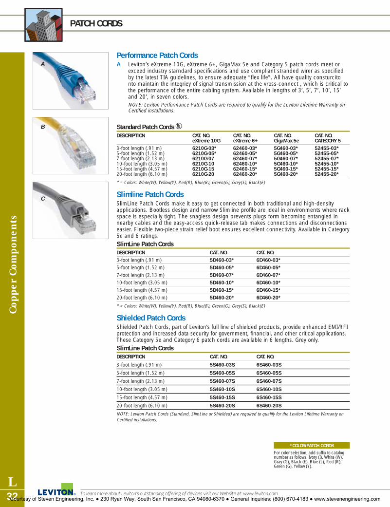
Cop
per
Com
pone
nts
L32
PATCH CORDS
To learn more about Leviton’s outstanding offering of devices visit our Website at: www.leviton.com
*COLOR/PATCH CORDS
For color selection, add suffix to catalognumber as follows: Ivory (I), White (W),Gray (G), Black (E), Blue (L), Red (R),Green (G), Yellow (Y).
Performance Patch CordsA Leviton’s eXtreme 10G, eXtreme 6+, GigaMax 5e and Category 5 patch cords meet or
exceed industry starndard specifications and use compliant stranded wirer as specifiedby the latest TIA guidelines, to ensure adequate “flex life”. All have quality consturcitonto maintain the integriey of signal transmission at the vross-connect , which is critical tothe performance of the entire cabling system. Available in lengths of 3’, 5’, 7’, 10’, 15’and 20’, in seven colors.NOTE: Leviton Performance Patch Cords are required to qualify for the Leviton Lifetime Warranty onCertified installations.
Standard Patch Cords UDESCRIPTION CAT. NO. CAT. NO. CAT. NO. CAT. NO.
eXtreme 10G eXtreme 6+ GigaMax 5e CATEGORY 53-foot length (.91 m) 6210G-03* 62460-03* 5G460-03* 52455-03*5-foot length (1.52 m) 6210G-05* 62460-05* 5G460-05* 52455-05*7-foot length (2.13 m) 6210G-07 62460-07* 5G460-07* 52455-07*10-foot length (3.05 m) 6210G-10 62460-10* 5G460-10* 52455-10*15-foot length (4.57 m) 6210G-15 62460-15* 5G460-15* 52455-15*20-foot length (6.10 m) 6210G-20 62460-20* 5G460-20* 52455-20*
* = Colors: White(W), Yellow(Y), Red(R), Blue(B), Green(G), Grey(S), Black(E)
Slimline Patch CordsSlimLine Patch Cords make it easy to get connected in both traditional and high-densityapplications. Bootless design and narrow Slimline profile are ideal in environments where rackspace is especially tight. The snagless design prevents plugs form becoming entangled innearby cables and the easy-access quick-release tab makes connections and disconnectionseasier. Flexible two-piece strain relief boot ensures excellent connectivity. Available in Category5e and 6 ratings.SlimLine Patch CordsDESCRIPTION CAT. NO. CAT. NO.3-foot length (.91 m) 5D460-03* 6D460-03*5-foot length (1.52 m) 5D460-05* 6D460-05*7-foot length (2.13 m) 5D460-07* 6D460-07*10-foot length (3.05 m) 5D460-10* 6D460-10*15-foot length (4.57 m) 5D460-15* 6D460-15*20-foot length (6.10 m) 5D460-20* 6D460-20*
* = Colors: White(W), Yellow(Y), Red(R), Blue(B), Green(G), Grey(S), Black(E)
Shielded Patch CordsShielded Patch Cords, part of Leviton’s full line of shielded products, provide enhanced EMI/RFIprotection and increased data security for government, financial, and other critical applications.These Category 5e and Category 6 patch cords are available in 6 lengths. Grey only. SlimLine Patch CordsDESCRIPTION CAT. NO. CAT. NO.
3-foot length (.91 m) 5S460-03S 6S460-03S
5-foot length (1.52 m) 5S460-05S 6S460-05S
7-foot length (2.13 m) 5S460-07S 6S460-07S
10-foot length (3.05 m) 5S460-10S 6S460-10S
15-foot length (4.57 m) 5S460-15S 6S460-15S
20-foot length (6.10 m) 5S460-20S 6S460-20S
NOTE: Leviton Patch Cords (Standard, SlimLine or Shielded) are required to qualify for the Leviton Lifetime Warranty onCertified installations.
A
B
C
Courtesy of Steven Engineering, Inc. ● 230 Ryan Way, South San Francisco, CA 94080-6370 ● General Inquiries: (800) 670-4183 ● www.stevenengineering.com

EXTREME® 6+ 110-STYLE WIRING PRODUCTSCopper C
omponents
L33For answers to technical questions, call Leviton’s Techline at 1-800-722-2082
A
B
D
C
eXtreme 6+ 110-Style Wiring ProductsLeviton’s 110-Style Wiring Products are perfect for quick and easy cross connects in a minimumof space. Achieve top performance and network integrity at consolidation points, even atCategory 6 levels. Building a cross-connect system for voice and data is effortless.eXtreme 6+ 110-Style Wiring Blocks are available in 96- and 288-Pair units, with or withoutlegs for wall mount applications. We also offer 96-, 192- and 288-pair rack-mount units. All kitsinclude C-4 clips.A full selection of patch cords is available for easy connection to network equipment. All unitsmeet or exceed Category 6 transmission requirements.
eXtreme 6+ Cat 6 110-Style Wiring Block – Kitted VersionsDESCRIPTION CAT. NO.[A] eXtreme 6+ 110-Style Wiring Block, Wall-Mount w/o legs, CAT 6, 96-Pair 41NB6-1F4[B] eXtreme 6+ 110-Style Wiring Block, Wall-Mount w/legs, CAT 6, 96-Pair 41AB6-1F4[C] eXtreme 6+ 110-Style Wiring Block, Wall-Mount w/legs, CAT 6, 288-Pair 41AB6-3F4[D] eXtreme 6+ 110-Style Wiring Block, Rack-Mount, CAT 6, 96-Pair 41DR6-1F4
eXtreme 6+ 110-Style Wiring Block, Rack-Mount, CAT 6, 192-Pair 41DR6-2F4eXtreme 6+ 110-Style Wiring Block, Rack-Mount, CAT 6, 288-Pair 41DR6-3F4
Note: Category 5e and 6 110 wiring block legs are non-removable.Note: Identify all of your 110 products with LabelWare™ 110 wiring product labels. See page L59.Note: All kits include C-4 clips.
N11173
MATERIAL CHARACTERISTICS
• C-4 connector clips (sold separately or included in kitted versions) are fire-retardant UL 94V-0 plastic with solder-plated IDC’s.
Courtesy of Steven Engineering, Inc. ● 230 Ryan Way, South San Francisco, CA 94080-6370 ● General Inquiries: (800) 670-4183 ● www.stevenengineering.com

Cop
per
Com
pone
nts
L34
EXTREME® 6+ 110-STYLE PATCH CORDS and CONNECTOR CLIPS
To learn more about Leviton’s outstanding offering of devices visit our Website at: www.leviton.com
eXtreme 6+ 110-Style Patch CordsA, B Make your network connections with eXtreme 6+ 110-style Patch Cords, a quick solution for
110 to 110 and 110 to RJ45 applications (in both T568A and T568B wiring configurations).Cords are gray with gray boots and are offered in 1', 2', 3', 5', 7' and 10' lengths. All cordsmeet or exceed all Category 6 transmission requirements.
eXtreme 6+ Cat 6 110-Style Patch Cords DESCRIPTION CAT. NO. CAT. NO. CAT. NO. CAT. NO. CAT. NO. CAT. NO.
1-FOOT 2-FOOT 3-FOOT 5-FOOT 7-FOOT 10-FOOT[A] CAT 6 110 to 62240-01S 62240-02S 62240-03S 62240-05S 62240-07S 62240-10S
110-Style Patch Cord, 4 pair
[B] CAT 6 110 to 6234A-01S 6234A-02S 6234A-03S 6234A-05S 6234A-07S 6234A-10ST568A Patch Cord, 4 pairCAT 6 110 to 6234B-01S 6234B-02S 6234B-03S 6234B-05S 6234B-07S 6234B-10ST568B Patch Cord, 4 pair
eXtreme 6+ 110-Style Connector ClipsC Choose these connector clips for a high-quality, gas-tight connection to ensure signal
integrity in your Category 6 applications. Clips withstand 200 re-terminations and are madeof fire-retardant plastic rated UL 94V-0 with solder-plated IDCs.
eXtreme 6+ Cat 6 110-Style C-4 Clip DESCRIPTION CAT. NO.[C] eXtreme 6+ C-4 Clip, CAT 6 (bag of 10) 69104-IDC
N11173
N11173
C
A
B
Courtesy of Steven Engineering, Inc. ● 230 Ryan Way, South San Francisco, CA 94080-6370 ● General Inquiries: (800) 670-4183 ● www.stevenengineering.com
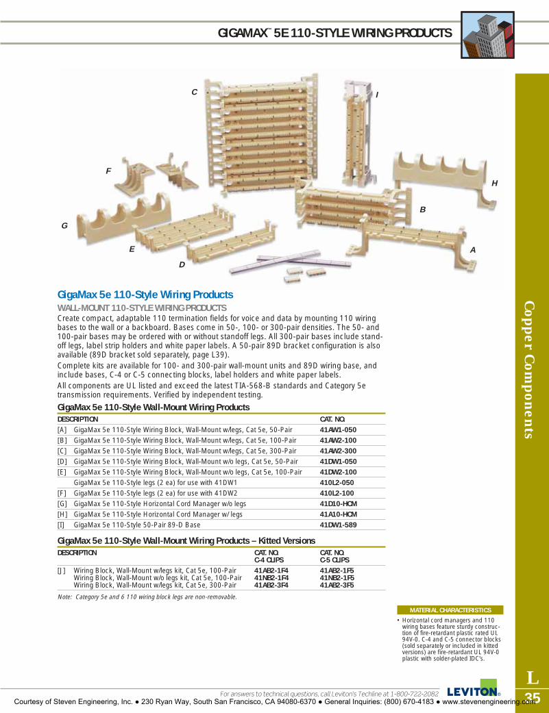
C
B
H
I
D
E
G
F
A
Copper C
omponents
L35For answers to technical questions, call Leviton’s Techline at 1-800-722-2082
GIGAMAX™ 5E 110-STYLE WIRING PRODUCTS
GigaMax 5e 110-Style Wiring ProductsWALL-MOUNT 110-STYLE WIRING PRODUCTSCreate compact, adaptable 110 termination fields for voice and data by mounting 110 wiringbases to the wall or a backboard. Bases come in 50-, 100- or 300-pair densities. The 50- and100-pair bases may be ordered with or without standoff legs. All 300-pair bases include stand-off legs, label strip holders and white paper labels. A 50-pair 89D bracket configuration is alsoavailable (89D bracket sold separately, page L39). Complete kits are available for 100- and 300-pair wall-mount units and 89D wiring base, andinclude bases, C-4 or C-5 connecting blocks, label holders and white paper labels.All components are UL listed and exceed the latest TIA-568-B standards and Category 5etransmission requirements. Verified by independent testing.
GigaMax 5e 110-Style Wall-Mount Wiring ProductsDESCRIPTION CAT. NO.[A] GigaMax 5e 110-Style Wiring Block, Wall-Mount w/legs, Cat 5e, 50-Pair 41AW1-050[B] GigaMax 5e 110-Style Wiring Block, Wall-Mount w/legs, Cat 5e, 100-Pair 41AW2-100[C] GigaMax 5e 110-Style Wiring Block, Wall-Mount w/legs, Cat 5e, 300-Pair 41AW2-300[D] GigaMax 5e 110-Style Wiring Block, Wall-Mount w/o legs, Cat 5e, 50-Pair 41DW1-050[E] GigaMax 5e 110-Style Wiring Block, Wall-Mount w/o legs, Cat 5e, 100-Pair 41DW2-100
GigaMax 5e 110-Style legs (2 ea) for use with 41DW1 410L2-050[F] GigaMax 5e 110-Style legs (2 ea) for use with 41DW2 410L2-100[G] GigaMax 5e 110-Style Horizontal Cord Manager w/o legs 41D10-HCM[H] GigaMax 5e 110-Style Horizontal Cord Manager w/ legs 41A10-HCM[I] GigaMax 5e 110-Style 50-Pair 89-D Base 41DW1-589
GigaMax 5e 110-Style Wall-Mount Wiring Products – Kitted VersionsDESCRIPTION CAT. NO. CAT. NO.
C-4 CLIPS C-5 CLIPS[J] Wiring Block, Wall-Mount w/legs kit, Cat 5e, 100-Pair 41AB2-1F4 41AB2-1F5
Wiring Block, Wall-Mount w/o legs kit, Cat 5e, 100-Pair 41NB2-1F4 41NB2-1F5Wiring Block, Wall-Mount w/legs kit, Cat 5e, 300-Pair 41AB2-3F4 41AB2-3F5
Note: Category 5e and 6 110 wiring block legs are non-removable.
MATERIAL CHARACTERISTICS
• Horizontal cord managers and 110wiring bases feature sturdy construc-tion of fire-retardant plastic rated UL94V-0. C-4 and C-5 connector blocks(sold separately or included in kittedversions) are fire-retardant UL 94V-0 plastic with solder-plated IDC’s.
Courtesy of Steven Engineering, Inc. ● 230 Ryan Way, South San Francisco, CA 94080-6370 ● General Inquiries: (800) 670-4183 ● www.stevenengineering.com

C
D
B
A
Cop
per
Com
pone
nts
L36
RACK-MOUNT 110-STYLE WIRING PRODUCTS
To learn more about Leviton’s outstanding offering of devices visit our Website at: www.leviton.com
Rack-Mount 110-Style Wiring ProductsRack-Mount 110 Wiring Products attach to standard 19" wide racks to create compact,adaptable 110 termination fields for voice and data. Panels come in 100-, 200- or 300-pairdensities and terminate 22-26 AWG solid copper wire. Cord management is provided byhorizontal cord managers (sold separately).Kits for 100-, 200- and 300-pair rack-mount panels include the panel, C-4 and C-5 connectingblocks, label strip holders and white paper labels.Horizontal cord managers and 110 wiring bases feature sturdy single-piece construction of fire-retardant plastic rated UL 94V-0. Wiring bases are attached to 19" wide steel rack-mount panels, painted black. Screws are included for mounting the panels onto 19" racks. C-4 and C-5connector blocks are fire-retardant UL 94V-0 plastic with solder-plated IDC’s.All components are UL Listed, and exceed Category 5e transmission requirements. Verified byindependent testing.
GigaMax® 5e 110-Style Rack-Mount Wiring Blocks UDESCRIPTION CAT. NO.[A] GigaMax 5e 110-Style Wiring Block, Rack-Mount, Cat 5e, 100 Pair 41DR2-100[B] GigaMax 5e 110-Style Wiring Block, Rack-Mount, Cat 5e, 200 Pair 41DR2-200[C] GigaMax 5e 110-Style Wiring Block, Rack-Mount, Cat 5e, 300 Pair 41DR2-300[D] Rack-Mount Horizontal Cord Manager 41D1R-HCM
(for part numbers listed above and below).
GigaMax 5e 110-Style Rack-Mount Wiring Products – Kitted VersionsDESCRIPTION CAT. NO. CAT. NO.
C-4 CLIPS C-5 CLIPSGigaMax 5e 110-Style Wiring Block, Rack-Mount kit, 41DBR-1F4 41DBR-1F5Cat 5e, 100-Pair
[E] GigaMax 5e 110-Style Wiring Block, Rack-Mount kit, 41DBR-2F4 41DBR-2F5Cat 5e, 200-PairGigaMax 5e 110-Style Wiring Block, Rack-Mount kit, 41DBR-3F4 41DBR-3F5Cat 5e, 300-Pair
Note: Leviton’s Label Holders and Strips are ideal for identification of all your key 110 connections. See page L60.
Courtesy of Steven Engineering, Inc. ● 230 Ryan Way, South San Francisco, CA 94080-6370 ● General Inquiries: (800) 670-4183 ● www.stevenengineering.com

A
DB
C
Copper C
omponents
L37For answers to technical questions, call Leviton’s Techline at 1-800-722-2082
GIGAMAX® 5e 110-STYLE PATCH CORDS and CONNECTOR CLIPS
GigaMax 5e 110-Style Patch CordsA–D Make quick connections with GigaMax 110-Style Patch Cords. Available in 110 to 110
for cross connects and 110 to RJ45 (in both T568A and T568B wiring configurations) toconnect to a panel or nearby workstation. The cords are offered in 1', 2', 3', 5', and 10'lengths, in gray with gray boots.
GigaMax 5e 110-Style Patch Cords A-Tick
DESCRIPTION CAT. NO. CAT. NO. CAT. NO. CAT. NO. CAT. NO. CAT. NO.1-FOOT 2-FOOT 3-FOOT 5-FOOT 7-FOOT 10-FOOT
[A] 110 to 110 5G210-01S 5G210-02S 5G210-03S 5G210-05S 5G210-07S 5G210-10SPatch Cord, 1 pair
[B] 110 to 110 5G220-01S 5G220-02S 5G220-03S 5G220-05S 5G220-07S 5G220-10SPatch Cord, 2 pair
[C] CAT 5e, 5G240-01S 5G240-02S 5G240-03S 5G240-05S 5G240-07S 5G240-10S110 to110 Patch Cord, 4 pair
[D] CAT 5e, 5G34A-01S 5G34A-02S 5G34A-03S 5G34A-05S 5G34A-07S 5G34A-10S110 to 568A Patch Cord, 4 pairCAT 5e, 5G34B-01S 5G34B-02S 5G34B-03S 5G34B-05S 5G34B-07S 5G34B-10S110 to 568B Patch Cord, 4 pair
GigaMax 5e 110-Style Connector ClipsE These high-quality connector clips securely seat the wires on 110 wiring bases, providing a
gas-tight IDC connection that maintains signal integrity for high performance applications.Available in three Category 5/5e pair-count sizes: C-3, C-4 and C-5. These clips withstand 200reterminations, and are made of fire-retardant plastic rated UL 94V-0 with solder-platedinsulation displacement connectors.
GigaMax 5e 110-Style Connector Clip UDESCRIPTION CAT. NO.GigaMax 5e 110-Style C-3 Connector Clips (bag of 10) 49103-IDCGigaMax 5e 110-Style C-4 Connector Clips (bag of 10) 49104-IDCGigaMax 5e 110-Style C-4 Connector Clips (bag of 50) 49104-I50GigaMax 5e 110-Style C-5 Connector Clips (bag of 10) 49105-IDC
N11173
E
Courtesy of Steven Engineering, Inc. ● 230 Ryan Way, South San Francisco, CA 94080-6370 ● General Inquiries: (800) 670-4183 ● www.stevenengineering.com

Cop
per
Com
pone
nts
L38
110-STYLE WALL-MOUNT FRAMES
To learn more about Leviton’s outstanding offering of devices visit our Website at: www.leviton.com
110-Style Wall-Mount FramesA–D For 110 wall-mount applications, mounting frames provide additional options for cord/cable
management, access, and density via a rear cable channel, side slots, horizontal cordmanagers and a bottom cable tray. Components are offered individually or in kits (seeordering information below for description of included parts).Begin with the basic mounting frames and vertical cord managers. Each has a 300-paircapacity—room for three 100-pair wiring bases, with 100-pair horizontal cord managers inbetween. The capacity for each mounting frame or vertical manager may be increased to 600or 900 pairs with the addition of up to two 300-pair extension units.Frames, trays and vertical cord managers are composed of sturdy steel, painted black; wiringbases, connector blocks and horizontal cord managers are fire-retardant plastic rated UL94V-0. Kits include screws for attaching wiring bases and cord managers to the mountingframe. All components are UL Listed and exceed Category 5e transmission requirements.Verified by independent testing.
Wall-Mounting Frame 110-Style Wiring ProductsDESCRIPTION CAT. NO.[A] 300-pair Basic Mounting-Frame Unit (sheet metal frame and 41MB2-SMF
bottom cable tray only).[B] 300-pair Extension Mounting-Frame Unit (sheet metal frame only). 41MB2-SMEBasic Mounting Frame Kit with three 100-pair bases; mounting frame; 41MB2-3FTcable tray; C-4 connector blocks; three horizontal cord managers; label strip holders and white label strips.Extension Mounting Frame Kit with three 100-pair bases; mounting frame; 41MB2-EXTC-4 connector blocks; three horizontal cord managers; label strip holders and white label strips.[C] 300-pair Vertical Cord Manager, Basic unit; includes bottom cable tray. 41880-300[D] 300-pair Vertical Cord Manager, Extension unit. 41880-EXT
Rack-Mount Horizontal Cord Manager (Not Shown) 41D1R-HCM
110-Style ChannelMax™ SystemE–H Manage your cable with the 110 ChannelMax System, perfect to maximize control in
minimum space. Cable channel provides extra room in the rear, cable trough allows aclean connection at the CP/frame, and vertical spool manager helps to dress cross-connect cables.
110-Style Channel SystemDESCRIPTION CAT. NO.[E] 3" Deep Vertical Cable Channel 41CMS-300[F] 5" Deep Vertical Cable Channel 41CMS-500[G] Horizontal Cable Management Trough 41CMS-HCM[H] Vertical Spool Manager Mounting Bracket 41CMS-VSM
B
C
A
D
EF
GH
Courtesy of Steven Engineering, Inc. ● 230 Ryan Way, South San Francisco, CA 94080-6370 ● General Inquiries: (800) 670-4183 ● www.stevenengineering.com

Copper C
omponents
L39For answers to technical questions, call Leviton’s Techline at 1-800-722-2082
66-CONNECTING PRODUCTS
A
C
E
D
B
66-Clip Connecting BlocksA variety of M Blocks, including 25-pair and split 50-pair styles, provide versatile cross connectpoints in equipment and telecommunications rooms. Install individually or in pairs.Constructed of high-impact, fire-retardant UL 94V-0 plastic with phosphor bronze quick-con-nect insulation displacement 66-clips. Install individually or in pairs in a cross-connect systemusing jumper wires or bridging clips.
66-Clip Connecting Blocks UDESCRIPTION CAT. NO.[A] M Block: 25-pair (66M1-25) 10"H x 35/16"W x 13/16"D 40066-M25
Split M Block: 50-pair (66M1-50) 10"H x 35/16"W x 13/16"D 40066-M50M Block with female connector (66M1-50W) 10"H x 35/16"W x 13/16"D 40066-0MW
[B] M Block with female and male connectors (66M1-50W2) 40066-MW210"H x 35/16"W x 13/16"D
[C] Connectorized Demarc Block (66M1-50R) 10"H x 313/32"W x 23/4"D 40066-0MRfemale amphenol
66-Clip Connecting Block AccessoriesAccessories include Covers for M Blocks and Demarc Blocks, M-Block Brackets forJack/Connector Mounting, Wire Distribution Spools, Modular Adapters and Bridging Clips.
Bridging ClipsDESCRIPTION CAT. NO.[D] Bridging Clips (SA-1), bag of 50 40067-0BC
Hinged Covers and Snap-On CoversDESCRIPTION CAT. NO.
Snap-on Cover for M blocks (66MC-4) 9-15/16" H x 2-5/16" W x 5/16" D 40050-MCVHinged Cover for Demarc blocks: orange (66MC4LH-O) 40050-MH010" H x 2-7/16" W x 3/4" DHinged Cover for M blocks: grey (66MC4LH-G) 10" H x 2-7/16" W x 3/4" D 40050-MHG
Bracket for M Blocks and Connector MountingDESCRIPTION CAT. NO.[E] M-block Bracket for connector mounting (89-D/QuickPort Blocks) 40089-00D
10" H x 3-13/32" W x 1-1/2" D
Note: Numbers in parentheses refer to industry product designation.
Courtesy of Steven Engineering, Inc. ● 230 Ryan Way, South San Francisco, CA 94080-6370 ● General Inquiries: (800) 670-4183 ● www.stevenengineering.com

Cop
per
Com
pone
nts
L40
66-CONNECTING BLOCK ACCESSORIES
To learn more about Leviton’s outstanding offering of devices visit our Website at: www.leviton.com
66-Clip Connecting Block Accessories (continued)
Modular AdaptersDESCRIPTION CAT. NO.[F] Position Modular Adapter (Tap™-2) - Converts two 66-clip contacts 40072-0T2
into a 6P2C modular jack 4-Position Modular Adapter (Tap™-4) - Converts four contacts 40072-0T4into a 6P4C modular jack6-Position Modular Adapter (Tap™-6) - Converts six contacts 40072-0T6into a 6P6C modular jack8-Position Modular Adapter, T568B wiring (Tap™-008) - 40072-0T8Converts eight contacts 8P8C non-keyed modular jack
Wire Distribution SpoolsDESCRIPTION CAT. NO.[G] Wire Distribution Spool (20-A) 1-3/4" Dia. x 3" H 40054-0DS[H] Wire Distribution Spool with screw (20-B) 1-3/4" Dia. x 3" H 40054-DSS
Note: Number in parentheses refers to industry product designation.
Surface-Mount Mini Patch PanelsFor applications with space limitations or simple breakout patching, the Mini Patch Panel withmodular connectors can be mounted almost anywhere. Combine two or more panels in-lineand use patch cords to make and change connections.
Surface-Mount Mini Patch Panels URDESCRIPTION CAT. NO.[I] 25 6-position 2-conductor (RJ11) FCC Spec Jacks connected to a 41600-00I
circuit board with one male 25-pair connector in surface-mount housing. Wired in standard T-R sequence (26-1, 27-2, 28-3, etc).
[J] 25 6-position 4-conductor (RJ14) FCC Spec Jacks wired into two male 41610-00I25-pair connectors in standard T-R sequence.
[K] 25 6-position 2-conductor (RJ11) FCC Spec Jacks connected to a circuit 41620-00Iboard with two bridged 25-pair connectors (one male and one female) in standard T-R sequence for series connection.Mounting Magnets (20 Per Package) 49200-00M
G
IJ
H
F
K
Courtesy of Steven Engineering, Inc. ● 230 Ryan Way, South San Francisco, CA 94080-6370 ● General Inquiries: (800) 670-4183 ● www.stevenengineering.com

Front and rear tilt-up lids thatprovide unobstructed access toadapters and mounting plates.
0-24 ST connector bulkhead
0-12 ST connector bulkhead
0-24 SC connector bulkhead
Three six pack plate bulkhead
High-density adapter enclosure houses upto 24 ST® or 12 duplex SC adapters.Another version accepts three six-fibermounting plates; configure with ST, FC, SC,LC and MT-RJ or add a QuickPort plate tocreate a multimedia enclosure.
Mounting brackets arereversible for mid- or flush-mounting in 19" racks.
Slide rail option allows easyinstallation and re-entryregardless of equipment orenclosures above.
SEE FIBER DENSITYCHART, PAGE L48
Fiber Com
ponents
L41For answers to technical questions, call Leviton’s Techline at 1-800-722-2082
OPT-X® 1000 1RU FIBER OPTIC ENCLOSURES
Opt-X 1000 Low-Profile Rack-Mount Enclosures (1RU) 1.75"H x 19.0"W x 12.0"DU
DESCRIPTION CAT. NO. CAT. NO.W/O RAILS W/RAILS
24 Fiber w/6 ST adapters 5R030-0AB 5P030-0AB24 Fiber w/3 duplex SC adapters 5R030-0HB 5P030-0HB72 Fiber, empty (accepts 3 adapter plates, sold sep.) 5R130-00N 5P130-00N24 Fiber, loaded w/12 ST adapters 5R230-0AB 5P230-0AB24 Fiber, loaded w/6 duplex SC adapters 5R230-0HB 5P230-0HB24 Fiber, unloaded, punched for ST adapters 5R330-0AA 5P330-0AA24 Fiber, unloaded, punched for duplex SC adapters 5R330-0HA 5P330-0HA24 Fiber loaded w/24 ST adapters 5R330-0AB 5P330-0AB24 Fiber loaded w/12 duplex SC adapters 5R330-0HB 5P330-0HB
Add-On Slide Rail KitDESCRIPTION CAT. NO.Slide Rail Kit for IRU enclosures only 5S100-SLM
Replacement DoorDESCRIPTION CAT. NO.24 Fiber Rack-Mount Metal 1RU Replacement Door 5D000-1RM
LOADED = The enclosure’s bulkhead contains the specified couplings. UNLOADED = The enclosure includes a bulkhead which has openings for, but does not include, the specified couplings.EMPTY = No bulkhead coupling plates are included.Note: For mounting plates and accessories, see pages L47-49.Note: Custom lengths and configurations on pigtails available; call customer service for more information: 1-800-722-2082
Opt-X 1000 Low-Profile Rack-Mountshown in open view.
Courtesy of Steven Engineering, Inc. ● 230 Ryan Way, South San Francisco, CA 94080-6370 ● General Inquiries: (800) 670-4183 ● www.stevenengineering.com

Fibe
r Com
pone
nts
L42
OPT-X® 1000 2RU FIBER OPTIC ENCLOSURES
To learn more about Leviton’s outstanding offering of devices visit our Website at: www.leviton.com
Opt-X 1000 Fiber Optic Enclosures (2RU) 3.5"H x 19.0"W x 12.0"DU
DESCRIPTION CAT. NO.2RU Enclosure with Metal Door (no lock) 5R430-00N2RU Enclosure with Metal Door and one Lock/key 5R440-00N2RU Enclosure with Poly Door (No Lock) 5R460-00N
Replacement DoorsDESCRIPTION CAT. NO.2RU Replacement Metal Door 5D000-2RM2RU Replacement Poly Door 5D000-2RP
AccessoriesDESCRIPTION CAT. NO.12 Splice Tray 5T000-00T3M Fibrlock™ Splice Holder 5T000-3MTAT&T Rotary Splice Holder 5T000-ATTLock and Key 5L000-LOKSlide mounts (kit) 5S100-SLMFiber rings, 2 per pack, 2.5" diameter 5R100-OFR
PLEASE NOTE: All STOCK configurations of this rack-mount enclosure are sold ‘empty,’ or without any mounting platesinstalled. Capacity is dependent upon configuration of mounting plates as shown in note. Rack-mount enclosures DOinclude grounding/strain relief, grommets, labels, and the appropriate number of cable management rings. Note: For mounting plates and accessories. See pages L47-L49.Note: Custom lengths and configurations on pigtails available; call customer service for more information: 1-800-722-2082
SEE FIBER DENSITYCHART, PAGE L48
Wall mount or rack mount formaximum flexibility. Mid- or flush-mount the 2RU in any space on astandard 19" or 23" rack, or use theuniversal mounting brackets to flushmount on a wall.
Metal or smokedpolycarbonate doors.Metal doors are availablewith or without a lock.
Horizontal entry ports in thefront and back and verticalentry ports in the rear offeregress/ ingress for distributionof patch cables.
Room for up to 6 MountingPlates, housing a wide varietyof SC, FC, ST, LC and MT-RJadapters. See Fiber DensityChart on page L47.
Front and rear tilt-up lids thatprovide unobstructed access toadapters and mounting plates.
Courtesy of Steven Engineering, Inc. ● 230 Ryan Way, South San Francisco, CA 94080-6370 ● General Inquiries: (800) 670-4183 ● www.stevenengineering.com

Fiber Com
ponents
L43For answers to technical questions, call Leviton’s Techline at 1-800-722-2082
OPT-X® 1000 3RU and 6RU FIBER OPTIC ENCLOSURES
Opt-X 1000 Rack-Mount Enclosures, 3 Rack Units High (3RU) 5.25"H x 19.0"W x 12.0"DU
DESCRIPTION CAT. NO.3RU, Empty with metal door, no lock 5R730-00N3RU, Empty with metal door and one lock/key 5R740-00N3RU, Empty with smoked polycarbonate door, no lock 5R760-00N
Opt-X 1000 Rack-Mount Enclosures, 6 Rack Units High (6RU) 10.25"H x 19.0"W x 12.0"DU
DESCRIPTION CAT. NO.6RU, Empty with metal door, no lock 5R930-00N6RU, Empty with metal door and one lock/key 5R940-00N6RU, Empty with smoked polycarbonate door, no lock 5R960-00N
Add-On Slide Rail KitDESCRIPTION CAT. NO.Slide rail kit for 3RU or 6RU fiber Rack-Mount enclosures only 5S100-SLM
Replacement DoorsDESCRIPTION CAT. NO.3RU Rack-Mount replacement metal door 5D000-3RM3RU Rack-Mount replacement smoked poly door 5D000-3RP
Add-On Lock and KeyDESCRIPTION CAT. NO.Add security to an existing door for this enclosure—simply removethe black plastic plug on the door front, and replace with lock mechanism.Lock and Key 5L000-LOK
PLEASE NOTE: All STOCK configurations of this rack-mount enclosure are sold ‘empty,’ or without any mounting platesinstalled. Capacity is dependent upon configuration of mounting plates as shown in note. Rack-mount enclosures DOinclude grounding/strain relief, grommets, labels, 8 or 16 blank plastic mounting plates, and the appropriate number ofcable management rings.Note: For mounting plates and accessories. See pages L47-49.
Tilt-up rear door providesunobstructed access to thefiber loop.
Reversible mounting brackets allowmounting on 19" or 23" industry standardequipment frames; move forward for flushmount positioning in NEMA enclosures.
Front and rear doorsdrop down flat to actas a workshelf, orcan be removedcompletely. Availablein metal or smokedpolycarbonate.
FEATURES
• Includes 8 (3RU) or 16 (6RU) plasticblank mounting plates to inexpensivelyfill up any unused locations.
• Houses up to 12 (3RU) or 24 (6RU)mounting plates for assorted fiber ormultimedia applications. See charton page L48.
SEE FIBER DENSITYCHART, PAGE L48
Courtesy of Steven Engineering, Inc. ● 230 Ryan Way, South San Francisco, CA 94080-6370 ● General Inquiries: (800) 670-4183 ● www.stevenengineering.com

Fibe
r Com
pone
nts
L44
OPT-X® 1000 WALL-MOUNT FIBER OPTIC ENCLOSURES
To learn more about Leviton’s outstanding offering of devices visit our Website at: www.leviton.com
Opt-X 1000 Small Wall-Mount Enclosures 8.0"H x 13.0"W x 3.5"DU
DESCRIPTION CAT. NO.Small, Empty with solid metal door, no lock, holds no splice trays 5W110-00NSmall, Empty with split metal door and one lock/key, holds no splice trays 5W120-00NSmall, Empty with solid metal door and lock/key, holds no splice trays 5W170-00N
Opt-X 1000 Medium Wall-Mount Enclosures 14.0"H x 12.0"W x 5.25"DU
DESCRIPTION CAT. NO.Medium, Empty with solid metal door, no lock, holds 6 splice trays 5W310-00NMedium, Empty with split metal door and one lock/key, holds 6 splice trays 5W320-00NMedium, Empty with solid metal door and one lock/key, holds 6 splice trays 5W370-00N
Opt-X 1000 Large Wall-Mount Enclosures 17.0"H x 15.0"W x 5.25"DU
DESCRIPTION CAT. NO.Large, Empty with solid metal door, no lock, holds 6 splice trays 5W710-00NLarge, Empty with split metal door and one lock/key, holds 6 splice trays 5W720-00NLarge, Empty with solid metal door and lock/key, holds 6 splice trays 5W770-00N
Add-On Lock and KeyDESCRIPTION CAT. NO.Add security to an existing metal enclosure door. Simply remove the black plastic plug on the door front, and replace with lock mechanism.Lock and Key 5L000-LOK
PLEASE NOTE: All STOCK configurations of this wall-mount enclosure are sold ‘empty,’ or without any mounting platesinstalled. Capacity is dependent upon configuration of mounting plates shown on page L48. The wall-mount enclosures DOinclude grounding/strain relief, grommets, labels, and the appropriate number of cable management rings. Large Wall-Mount Enclosure includes 8 blank plastic mounting plates.Note: For mounting plates and accessories. See page L48.
Unique cable management ringis adjustable and stackable tosimplify fiber loop installation,bend radius compliance, andfuture maintenance/additions.Stores 3 meters of 900 micronfiber per adapter.
Sidewall cutout gives completelyunobstructed access to themounting plates when door isopen (covered when door isclosed).
Houses 2 (small), 4 (medium) or12 mounting plates for assortedfiber or multimedia applications.See chart on page L47.
Doors are L-shaped for max-imum access to couplingsthrough the open sidewall.Door options:• Split with single lock • Split with two locks
(custom option)• Solid with single lock• Solid without lock
SEE FIBER DENSITYCHART, PAGE L48
Courtesy of Steven Engineering, Inc. ● 230 Ryan Way, South San Francisco, CA 94080-6370 ● General Inquiries: (800) 670-4183 ● www.stevenengineering.com

Fiber Com
ponents
L45For answers to technical questions, call Leviton’s Techline at 1-800-722-2082
OPT-X® 500 and OPT-X® 250 FIBER OPTIC ENCLOSURES
Opt-X 500 Fiber Enclosures, 3 Rack Units High (3RU) 5.25"H x 19.0"W x 12.0"DU
DESCRIPTION CAT. NO.[A] 1RU, empty with metal cover, no lock 5R1UA-A03[B] 2RU, empty with metal cover, no lock 5R2UA-A06[C] 3RU, empty with metal cover, no lock 5R3UA-A12
Opt-X 250 Fiber Panel 1.75"H x 19.0"W x 7.7"DU
DESCRIPTION CAT. NO.1RU, empty with no metal cover, no lock 5R1UE-A03
C
A
B
1RU with cover
2RU with cover
3RU with cover
SEE FIBER DENSITYCHART, PAGE L48
Opt-X 500 1RU, 2RU and 3RU Fiber Optic Enclosures
Opt-X 250 1RU Fiber Optic Panel
SPECIFICATIONS AND FEATURES
Opt-X 500 Fiber Enclosure• One-piece removable cover protects and conceals
patch cords and allows for complete accessibilityto the back of the enclosure.
• Mounting brackets allow for installation on anyrack space.
• Stores 3 meters of 900 micron tight buffered fiberper adapter.
• Multiple bend radius and cable managementfeatures including 2 cable tie down features in front, and 4 in back,protect and organize cables.
Opt-X 250 Fiber Panel• Perfect for small to medium installations with
excellent flexibility at a competitive price.• Utilizes minimum rack space while providing
space for up to three (3) adapter plates or splicetrays (more splice trays if no obstructions).
• Two fiber management rings easily attach to lowprofile mounting clips for customized positioning.Includes multiple bend radius and cablemanagement features.
• Open back allows easy access and managementin all directions.
• Mounting brackets allow panel to be installed onany rack space.
Courtesy of Steven Engineering, Inc. ● 230 Ryan Way, South San Francisco, CA 94080-6370 ● General Inquiries: (800) 670-4183 ● www.stevenengineering.com

Fibe
r Com
pone
nts
L46
FIBER OPTIC CABLE ASSEMBLIES
To learn more about Leviton’s outstanding offering of devices visit our Website at: www.leviton.com
Examples: 50DSC-M05 = 50 micron Duplex SC-SC multimode connector – 5 meters
Configure Your Catalog NumberFiber Optic Cable Assemblies, OFNR Rated — Configure your Catalog Number by following the key below
AA B CC–D EE(Catalog Number)
Standard & CodePigtailMT-RJ-to-MT-RJ MJST-to-ST STSC-to-SC SCFC-to-FC FCLC-to-LC LC
Hybrid CodeSC-to-ST CTSC-to-FC CFSC-to-MT-RJ CMST-to-MT-RJ TMST-to-FC TFSC-to-LC CLST-to-LC TLFC-to-LC FLLC-to-MT-RJ ML
Step 1 Step 2 Step 3 Step 4 Step 5 CORE STYLE/POLISH TYPE (AA) CABLE TYPE (B) CONNECTOR COMBINATIONS (CC) MODE (D) CABLE LENGTH (EE)
Fiber Optic Cable AssembliesLeviton offers an extensive line of high quality fiber optic cable assemblies,including laser optimized versions as well as pigtails for frame and work-station. Strenuously tested for return and insertion loss, and held to strictinternal quality standards, these cable assemblies are developed to exceedTIA 568-B.3 standards.Choose from standard & hybrid combinations of connectors, in single-modeand multimode, for cable assemblies and pigtails in ST, SC, FC, LC andMT-RJ styles. Laser optimized assemblies are available in a 50µm corestyle with a variety of connection configurations including combinations ofMT-RJ, ST, SC and LC connectors and provide 10-gig performance forhigher bandwidth requirements at greater distances.We also provide custom lengths and configurations manufactured to yourexact specifications—simply call customer service for more information.PLEASE NOTE: CUSTOM LENGTHS MAY REQUIRE A WAITING PERIOD.All cables are OFNR* rated and meet all applicable TIA/EIA and industrystandards.*OFNP-rated cables are available as a special order. See below.
Cable Type CodeSimplex SDuplex DPigtail PNote: MT-RJ is alwaysduplex. Simplex andduplex cannot becombined.
Multimode Core Code50µm size 5062.5µm size 6250µm laser optimized 5L
Singlemode CoreUPC polish UP(ultra physical contact)APC polish AP(angle physical contact)
Mode Type CodeSingle-mode SMultimode MNote: This will dependon selected CoreSize/Polish as indicatedin Step 1.
Length/m Length/ft Code1 meter 3.3' 012 meters 6.6' 023 meters 9.8' 035 meters 16.4' 0510 meters 32.8' 10Note: Custom lengths available upon request. Call Customer Serviceat 1(800) 722-2082 for more information.
Single-mode
Laser Optimized
Multimode Pigtail
Courtesy of Steven Engineering, Inc. ● 230 Ryan Way, South San Francisco, CA 94080-6370 ● General Inquiries: (800) 670-4183 ● www.stevenengineering.com

Fiber Com
ponents
L47For answers to technical questions, call Leviton’s Techline at 1-800-722-2082
FIBER OPTIC ACCESSORIES
OPT-X® Fiber Adapter Plates*DESCRIPTION CAT. NO.[A] 6-Pack ST MM, (6-fiber) phos. bronze sleeve 5F100-1ST
6-Pack ST SM, (6-fiber) zirconia ceramic sleeve 5F100-6ZT[B] 8-Pack ST MM, (8-fiber) phos. bronze sleeve 5F100-8ST
8-Pack ST SM, (8-fiber) zirconia ceramic sleeve 5F100-8ZT6-Pack FC MM, (6-fiber) phos. bronze sleeve 5F100-6PF6-Pack FC SM, (6-fiber) zirconia ceramic sleeve 5F100-6ZF8-Pack FC MM, (8-fiber) phos. bronze sleeve 5F100-8PF8-Pack FC SM, (8-fiber) zirconia ceramic sleeve 5F100-8ZF
[C] 3-Pack Duplex SC MM, (6-fiber) beige, phos. bronze sleeve 5F100-3BC[D] 3-Pack Duplex SC SM, (6-fiber) blue, phos. bronze sleeve 5F100-3SC[E] 3-Pack Duplex SC SM, (6-fiber) green, zirconia ceramic sleeve 5F100-3CA
3-Pack Duplex SC SM, (6-fiber) blue, zirconia ceramic sleeve 5F100-3ZC3-Pack Duplex SC MM Laser Optimized, (6-fiber) aqua, zirconia ceramic sleeve 5F100-3AC
[F] 6-Pack Duplex SC MM, (12-fiber) beige, phos. bronze sleeve 5F100-6BC[G] 6-Pack Duplex SC SM, (12-fiber) blue, phos. bronze sleeve 5F100-CSC[H] 6-Pack Duplex SC MM laser optimized, (12-fiber) aqua, zirconia ceramic sleeve 5F100-6AC
6-Pack Duplex SC SM, (12-fiber) blue, zirconia ceramic sleeve 5F100-6ZC6-Pack Duplex SC SM, (12-fiber) green, zirconia ceramic sleeve 5F100-6CA
[I] 6-Pack MT-RJ MM, (12-fiber) beige, dual polarity 5F100-6MC[J] 12-Pack MT-RJ MM, (24-fiber) beige, dual polarity 5F100-12M[K] 6-Pack Duplex LC MM, (12-fiber) beige, phos. bronze sleeve 5F100-12P[L] 6-Pack Duplex LC SM, (12-fiber) blue, zirconia ceramic sleeve 5F100-12Z
6-Pack Duplex LC SM, (12-fiber) green, zirconia ceramic sleeve 5F100-12V[M] 6-Pack Duplex LC MM laser optimized, (12-fiber) aqua, zirconia ceramic sleeve 5F100-12A[N] 6-Pack Quad LC MM, (24-fiber) beige, phos. bronze sleeve 5F100-24P[O] 6-Pack Quad LC SM, (24-fiber) blue, zirconia ceramic sleeve 5F100-24Z[P] 6-Pack Quad LC MM, (24-fiber) laser optimized aqua, zirconia ceramic sleeve 5F100-24A[Q] Blank, metal 5F100-BLK
Blank, plastic 5F100-BPP
*NOTE: Not for use with LightSpace™ Enclosures.
3-pack, 6-pack, 8-pack, 12-pack =capacity of up to 3, 6, 8 or 12 connec-tors, respectively.
A
B
C
D
E
F
G
H
I
J
O
Q
P
K
L
M
N
Courtesy of Steven Engineering, Inc. ● 230 Ryan Way, South San Francisco, CA 94080-6370 ● General Inquiries: (800) 670-4183 ● www.stevenengineering.com

Fibe
r Com
pone
nts
L48
FIBER OPTIC ACCESSORIES
To learn more about Leviton’s outstanding offering of devices visit our Website at: www.leviton.com
Fiber Density ChartStyles
RACK MOUNT DENSITYLow Profile 1RUHolds 1 Bulkhead w/or w/o 3 Mounting Plates
6-pack ST = up to 18 Fibers 8-pack ST = up to 24 Fibers6-pack FC = up to 18 Fibers 8-pack FC = up to 24 Fibers3-pack Duplex SC = up to 18 Fibers6-pack Duplex SC = up to 24 Fibers6-pack MT-RJ = up to 36 Fibers12-pack MT-RJ = up to 72 Fibers
2RU Holds up to 6 Mounting Plates
6-pack ST = up to 36 Fibers8-pack ST = up to 48 Fibers6-pack FC = up to 36 Fibers8-pack FC = up to 48 Fibers3-pack Duplex SC = up to 36 Fibers6-pack Duplex SC = up to 72 Fibers6-pack MT-RJ = up to 72 Fibers12-pack MT-RJ = up to 144 Fibers
3RU Holds up to 12 Mounting Plates
6-pack ST = up to 72 Fibers8-pack ST = up to 96 Fibers6-pack FC = up to 72 Fibers8-pack FC = up to 96 Fibers3-pack Duplex SC = up to 72 Fibers6-pack Duplex SC = up to 144 Fibers6-pack MT-RJ = up to 144 Fibers12-pack MT-RJ = up to 288 Fibers
6RU Holds up to 24 Mounting Plates
6-pack ST = up to 144 Fibers8-pack ST = up to 192 Fibers6-pack FC = up to 144 Fibers8-pack FC = up to 192 Fibers3-pack Duplex SC = up to 144 Fibers6-pack Duplex SC = up to 288 Fibers6-pack MT-RJ = up to 288 Fibers12-pack MT-RJ = up to 576 Fibers
WALL MOUNT DENSITYSmall Holds up to 2 Mounting Plates
6-pack ST = up to 12 Fibers8-pack ST = up to 16 Fibers6-pack FC = up to 12 Fibers8-pack FC = up to 16 Fibers3-pack Duplex SC = up to 12 Fibers6-pack Duplex SC = up to 24 Fibers6-pack MT-RJ = up to 24 Fibers12-pack MT-RJ = up to 48 Fibers
Medium Holds up to 4 Mounting Plates
6-pack ST = up to 24 Fibers8-pack ST = up to 32 Fibers6-pack FC = up to 24 Fibers8-pack FC = up to 32 Fibers3-pack Duplex SC = up to 24 Fibers6-pack Duplex SC = up to 48 Fibers6-pack MT-RJ = up to 48 Fibers12-pack MT-RJ = up to 96 Fibers
Large Holds up to 12 Mounting Plates
6-pack ST = up to 72 Fibers8-pack ST = up to 96 Fibers6-pack FC = up to 72 Fibers8-pack FC = up to 96 Fibers3-pack Duplex SC = up to 72 Fibers6-pack Duplex SC = up to 144 Fibers6-pack MT-RJ = up to 144 Fibers12-pack MT-RJ = up to 288 Fibers
Courtesy of Steven Engineering, Inc. ● 230 Ryan Way, South San Francisco, CA 94080-6370 ● General Inquiries: (800) 670-4183 ● www.stevenengineering.com

Fiber Com
ponents
L49For answers to technical questions, call Leviton’s Techline at 1-800-722-2082
FIBER OPTIC ACCESSORIES
Fiber AdaptersDESCRIPTION CAT. NO.[A] ST® Adapter MM w/Phosphor Bronze Sleeve 49882-SAD[B] ST Adapter SM w/Zirconia Sleeve 49882-ZAD[C] FC Adapter SM w/Phosphor Bronze Sleeve 49883-SAD[D] FC Adapter MM w/Zirconia Sleeve 49883-MAD[E] SC Duplex Adapter SM (blue) w/Zirconia Sleeve 49884-SAD
SC Duplex Adapter SM (blue) w/Phosphor Bronze Sleeve 49884-MAD[F] SC Duplex Adapter MM (beige) w/Phosphor Bronze Sleeve 49884-BAD[G] SC Duplex Adapter MM aqua, zirconia ceramic sleeve 49884-AAD[H] SC Simplex Adapter SM blue, zirconia ceramic sleeve 49884-SAS[I] SC Simplex Adapter MM beige, phos. Bronze sleeve 49884-MAS[J] SC Simplex Adapter SM APC green, zirconia ceramic sleeve 49884-VAS[K] MT-RJ Adapter MM (beige) 49889-MAD[L] Quad LC Adapter MM (aqua) 5F100-QLA[M] Quad LC Adapter MM (beige) 5F100-QLC[N] Quad LC Adapter SM (blue) 5F100-QLZ[O] Duplex LC Adapter MM (beige) 5F100-DLC[P] Duplex LC Adapter SM (blue) 5F100-DLZ[Q] LC Duplex Adapter MM aqua, zirconia ceramic sleeve 5F100-DLA
LC Simplex Adapter MM green, zirconia ceramic sleeve 5F100-DLV
FIBER OPTIC FAN-OUT KITR Protect your bare fiber and prepare loose-tube cable for direct termination to connectors with
these simple 6- or 12-strand kits. Available in 24" or 36" lengths. Kits separate 250 µm fibersand route them into color-coded 900 µm buffer tubes. No proprietary tools required. Can beused with any manufacturers loose-tube cabling, and any industry standard connectors.
Fiber Optic Fan-Out KitDESCRIPTION CAT. NO.[R] 24" Fiber Optic Fan-Out Kit, 6-fiber 49887-06S
24" Fiber Optic Fan-Out Kit, 12-fiber 49887-12S36" Fiber Optic Fan-Out Kit, 6-fiber 49887-06L36" Fiber Optic Fan-Out Kit, 12-fiber 49887-12L
FIBER OPTIC FAN-OUT CONSUMABLES KITS Leviton's Fan-Out Consumables Kit contains everything to properly terminate at least 10
Fiber Optic Fan-Out Kits, including lint-free wipes, alcohol pads, d'Gel™ packets, sealant,and talc powder
Fiber Optic Fan-Out Consumables KitDESCRIPTION CAT. NO.[S] Fan-Out Consumables Kit 49800-FAN
SPLICE TRAY KITSSplice Tray KitsDESCRIPTION CAT. NO.
12-splice Splice Tray Kit 5T000-00T(Comes standard with Fusion/Heatshrink splice holders)
EXTRA CABLE MANAGEMENT RINGSExtra Cable Management RingsDESCRIPTION CAT. NO.
Additional Fiber Cable Management Rings (package of 2)— 5R100-0FRCan be stacked on top of existing rings for additional cable storage or management.
S
A-D
R
K-Q
E-J
Courtesy of Steven Engineering, Inc. ● 230 Ryan Way, South San Francisco, CA 94080-6370 ● General Inquiries: (800) 670-4183 ● www.stevenengineering.com
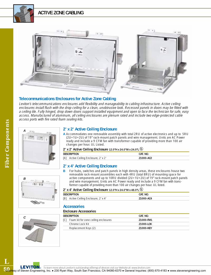
Fibe
r Com
pone
nts
L50
ACTIVE ZONE CABLING
To learn more about Leviton’s outstanding offering of devices visit our Website at: www.leviton.com
2' x 2' Active Ceiling EnclosureA Accommodates one removable assembly with total 2RU of active electronics and up to 5RU
(2U+1U+2U) of 19" rack-mount patch panels and wire management. Units are AC Powerready and include a 9 CFM fan with transformer capable of providing more than 100 airchanges per hour. UL Listed.
2' x 2' Active Ceiling Enclosure 12.0"H x 24.0"W x 24.0"LU
DESCRIPTION CAT. NO.[A] Active Ceiling Enclosure, 2' x 2' Z1000-AC2
2' x 4' Active Ceiling EnclosureB For hubs, switches and patch panels in high density areas, these enclosures house two
removable rack-mount assemblies each with 4RU (total 8RU) of mounting space foractive components and up to 10RU divided (2U+1U+2U) of 19" rack-mount patch panelsand wire management. Units are AC Power ready and include a 9 CFM fan with trans-former capable of providing more than 100 air changes per hour. UL listed.
2' x 4' Active Ceiling Enclosure 12.0"H x 24.0"W x 48.0"LU
DESCRIPTION CAT. NO.[B] Active Ceiling Enclosure, 2' x 4' Z1000-AC4
AccessoriesEnclosure AccessoriesDESCRIPTION CAT. NO.[C] Foam kit for zone ceiling enclosures Z1000-FM1
Chrome Lock Kit Z1000-LOKReplacement Keys (2) Z1000-KEY
Telecommunications Enclosures for Active Zone CablingLeviton’s telecommunications enclosures add flexibility and manageability to cabling infrastructure. Active ceilingenclosures install flush with the drop ceiling for a clean, unobtrusive look. Recessed panels in doors may be fitted witha ceiling tile. Fully hinged, drop down doors support installed equipment and open to face the technician for safe, easyaccess. Manufactured of aluminum, all ceiling enclosures are plenum rated and include two edge-protected cableaccess ports with fire rated foam sealing kits.
A
B
C
Courtesy of Steven Engineering, Inc. ● 230 Ryan Way, South San Francisco, CA 94080-6370 ● General Inquiries: (800) 670-4183 ● www.stevenengineering.com

Enclosureas
L51For answers to technical questions, call Leviton’s Techline at 1-800-722-2082
PASSIVE ZONE CABLING
Telecommunications Enclosures for Passive Zone CablingThese easy-to-install enclosures provide flexible consolidation point placement in the floor or ceiling. Manufacturedof aluminum, enclosures are plenum rated and include fire-rated foam sealing kits.
A2' x 2' Passive Ceiling EnclosureA For consolidation points within the ceiling, these enclosures accommodate up to 5RU
(2U+1U+2U) of 19" rack-mount patch panels and or wire management. Enclosures installflush with the drop ceiling and recessed panels in doors may be fitted with a ceiling tile for aclean, unobtrusive look. Fully hinged, drop down doors support installed equipment andopen to face the technician for safe, easy access. UL listed.
2' x 2' Passive Ceiling Enclosure UDESCRIPTION CAT. NO.[A] Passive Ceiling Enclosure, 2' x 2' Z1000-PC2
2' x 2' Passive Raised Floor EnclosureFor consolidation points in air handling spaces under 8" deep raised floors, this enclosure holdstwo 4RU (8U total) racks to accommodate any combination of standard 19" rack-mountablepatch panels or wire management. Rotating patch panel mounting locations provide easyaccess to rear of patch panels for easy terminations. UL listed.
2' x 2' Passive Raised Floor Enclosure UDESCRIPTION CAT. NO.Passive Raised Floor Enclosure, 8" depth Z1000-PF2
Courtesy of Steven Engineering, Inc. ● 230 Ryan Way, South San Francisco, CA 94080-6370 ● General Inquiries: (800) 670-4183 ● www.stevenengineering.com

Enc
losu
res
L52
WIRELESS ACCESS POINT ENCLOSURES
To learn more about Leviton’s outstanding offering of devices visit our Website at: www.leviton.com
Wireless Access Point EnclosuresWIRELESS ACCESS POINT CEILING ENCLOSURES, 10" AND 5"A-B Mount these enclosures into standard 2' x 2' ceiling tiles for a clean look and easy
access. Each unit is designed to house a variety of wireless access points. Single edge-protected access port includes a fire-rated foam sealing kit, making it suitable for airhandling spaces. Doors are fully hinged and lockable. The enclosure is painted white toblend with ceiling tiles. Multiple door faceplates, including a blank one, are soldseparately to accommodate a variety of wireless equipment. UL listed.
WIRELESS ACCESS POINT CEILING ENCLOSURE, 4" DEEPC This ceiling mount enclosure accommodates one wireless access point or bridge. The
removable door mounted bracket supports equipment up to 101/2" wide by 51/2" deep by17/8" high. Fully hinged door is is lockable for security and is stamped with two obroundholes centered 5" apart allowing antennas to extend below the drop ceiling. UL listed.
Wireless Access Point Ceiling Enclosures UDESCRIPTION CAT. NO.[A] Wireless Access Point Ceiling Enclosure, 10" Depth, w/o Faceplate W1000-WCE[B] Wireless Access Point Ceiling Enclosure, 5” Depth, w/o Faceplate W1000-WC5[C] Wireless Access Point Ceiling Enclosure, 4" Depth W1000-WC0
FaceplatesWireless Access Point Ceiling Enclosure FaceplatesDESCRIPTION CAT. NO.
Blank Faceplate (Fits 10" Wireless Access Point Enclosure) W1000-F01Faceplate for Cisco Aironet™ 350 (Fits 5" and 10" Wireless Access Point Enclosure) W1000-F02Faceplate for Cisco Aironet 1100 (Fits 5" and 10" Wireless Access Point Enclosure) W1000-F03Faceplate for Cisco Aironet 1200 (Fits 5" and 10" Wireless Access Point Enclosure) W1000-F04
[D] Faceplate for Leviton AP200 Wireless Access Point w/mounting bracket W1000-WC5
WIRELESS ACCESS POINT WALL-MOUNT ENCLOSUREE Constructed of rugged steel with a lock assembly these enclosures are perfect for areas
where there is limited floor or ceiling space and a need for security. Inside spaceaccommodates a Cisco® Aironet® 350 or equivalent equipment sized 9" wide by 61/2"high by 23/4" deep. UL listed.
Wireless Access Point Wall-Mount Enclosure UDESCRIPTION CAT. NO.[E] Wireless Access Point Wall-Mount Enclosure W1000-WW0
C
D
A
B
E
Courtesy of Steven Engineering, Inc. ● 230 Ryan Way, South San Francisco, CA 94080-6370 ● General Inquiries: (800) 670-4183 ● www.stevenengineering.com

Cable M
anagement
L53For answers to technical questions, call Leviton’s Techline at 1-800-722-2082
VERSI-DUCT® CABLE MANAGEMENT SYSTEM
A
B
C
E FG
H
D
Versi-DuctSlotted Duct Cable Management SystemLeviton’s unique Versi-Duct Slotted Duct System provides a versatile simple solution for fiberand copper cable organization and management. The horizontal duct is available in both onerack (1RU-1.75") or two-rack (2RU-3.5") unit sizes to accommodate both small and largecable systems. Vertical slotted ducts comes in a 35" half or 80" full rack height version. Boththe horizontal and vertical slotted ducts come in Front Only or Front & Back configurationswith cable-concealing covers and an assortment of accessories. Versi-Duct is the ideal systemfor efficient, adaptable rack and frame cable management.
Versi-Duct Slotted Duct Cable Management SystemsDESCRIPTION CAT. NO.[A] Vertical Front & Rear Duct, 80" high 4980L-VFR[B] Vertical Front-only Duct, 80" high 4980L-VFO[C] Vertical Front & Rear Duct, 35" high 4935L-VFR[D] Vertical Front-only Duct, 35" high 4935L-VFO[E] Horizontal Front & Rear Duct, 2RU 492RU-HFR[F] Horizontal Front & Rear Duct, 1RU 491RU-HFR[G] Horizontal Front-only Duct, 2RU 492RU-HFO[H] Horizontal Front-only Duct, 1RU 491RU-HFO[I] Vertical Channel Divider 49265-DV1[J] Slack Loop Storage Organizer, extended (2") 49265-SL2[K] Bend-radius Compliant Funnel, rear only 49265-FN4[L] Duct Cover Hinge, 4 per package 49265-HNG[M] Extended Cover, Front-only 2RU 49265-EX3[N] Extended Cover, Front-only 1RU 49265-EX1[O] Slack Loop Storage Organizer 49265-SL1[P] Cable Retainer 49265-WR1[Q] Mounting Bracket, 2 per package 49265-BRK
FEATURES
Versi-Duct
• Versatile accessories solve a varietyof cable management challenges
• Suitable for copper and fiber applications
• Slack loop control feature
• Helps maintain proper cable bend radii
• Offered in Front & Back and FrontOnly versions (for both vertical andhorizontal ducts)
• Horizontal Duct offered in 1RU(1.75") and 2RU (3.50") sizes
• Horizontal Duct offered in 35" and80" lengths
• Cable concealing covers with optional hinges
IM
N
K J
P
O
QL
Courtesy of Steven Engineering, Inc. ● 230 Ryan Way, South San Francisco, CA 94080-6370 ● General Inquiries: (800) 670-4183 ● www.stevenengineering.com

E
D
A
B
C
F
G
G
Horizontal Cable ManagementCreate a first class cabling infrastructure and reduce network administration time using Leviton'sHorizontal Cable Management System. Options include cable management bars, patch cordorganizers, slack organizers, and the patent-pending Front Hinge Bracket.
Cable Management BarsDESCRIPTION HEIGHT RINGS CAT NO.
[A] Rear Cable Manager for Active Equipment 2RU 41188-SM2
[B] Extended Cable Management Bar 49005-EMB
[C] Cable Management Bar 49005-CMB
[D] High Density Cable Management Bar 49005-DMB
Horizontal Patch Cord OrganizersDESCRIPTION HEIGHT RINGS CAT NO.
[E] Horizontal Patch Cord Organizer 2RU 2" 49253-2CM
Horizontal Patch Cord Organizer 2RU 4" 49253-BCM
Horizontal Patch Cord Organizer 1RU 4" 49253-LPM
[F] Horizontal Patch Cord Organizer 4RU 5" 49253-4CM
Horizontal Patch Cord Organizer 4RU 7" 49253-6CM
Horizontal Patch Cord Organizer (Angled) 1RU 2" 4W254-LPM
Horizontal Patch Cord Organizer (Angled) 2RU 2" 4W254-BCM
Horizontal Patch Cord Organizer (w/ metal cover) 1RU 4" 4925C-LPM
[G] Horizontal Patch Cord Organizer (w/ metal cover) 2RU 4" 4925C-BCM
Horizontal Patch Cord Organizer (w/ metal cover) 4RU 5" 4925C-4CM
Horizontal Patch Cord Organizer (w/ metal cover) 4RU 7" 4925C-6CM
Front Hinge BracketDESCRIPTION HEIGHT RINGS CAT NO.
[H] Front Hinge Bracket 3RU 49400-FHB
Cab
le M
anag
emen
t
L54
RACK AND FRAME CABLE MANAGEMENT
To learn more about Leviton’s outstanding offering of devices visit our Website at: www.leviton.comCourtesy of Steven Engineering, Inc. ● 230 Ryan Way, South San Francisco, CA 94080-6370 ● General Inquiries: (800) 670-4183 ● www.stevenengineering.com

Cable M
anagement
L55For answers to technical questions, call Leviton’s Techline at 1-800-722-2082
RACK AND FRAME CABLE MANAGEMENT
Rack Cable Management and AccessoriesCORD ORGANIZERSTwo-Position Cord Organizer combines horizontal and vertical distribution rings with individualrouting clips for patch cord organization between patch panels. One-Position Cord Organizer is1RU with vertical distribution rings and individual routing clips.
Cord OrganizersDESCRIPTION CAT. NO.[A] Two-Position Organizer Panel (19" wide, 2RU) 49252-PO2[B] One-Position Organizer Panel (19" wide, 1RU) 49252-PO1
COMBO FRONT/REAR MANAGEMENTManage front and rear cables/cords in a 2RU standard rack space. Oversized front rings meetlarger-capacity requirements for patch cords. Rear management maintains bend radius ofcables routed from vertical channels. Retention rings and fixed anchor points for ‘loose-fit’ ortie-wrapped bundles.
Combo Front/Rear ManagementDESCRIPTION CAT. NO.[C] Combo Front/Rear Manager (19" wide, 2RU) 49252-PCM
RECLOSEABLE CABLE BARSManage cable vertically and horizontally on relay racks and cabinets. 19" metal-clad horizontalbar with attached loops (Hook and Loop-Style) screws into rack to manage cables horizontally.
Recloseable Cable BarsDESCRIPTION CAT. NO. 3RU[D] Metal Clad Horizontal Bar (for 19" Racks, 1RU) 41150-019
THE WRAP BARMounts to the rear of standard TIA/EIA racks to support cable bundles and help maintain bendradius near cable terminations. Fixed anchor points for ‘loose-fit’ tie wrapped cables.
The Wrap BarDESCRIPTION CAT. NO.[E] Tie Wrap Bar (19" wide, 1.0" high, 1.5" deep) 49258-TWB
SPACEMAKER CABLE MANAGERMounts to front or rear of standard TIA/EIA racks to support cable bundles and help maintain bendradius. Allows retrofit of current configurations without the need to move existing patch panels.Using existing panel screws, simply loosen screws, slide in SpaceMaker, and re-tighten screws.
Spacemaker Cable ManagerDESCRIPTION CAT. NO.[F] SpaceMaker Cable Manager (19" wide, 1RU, 2RU, 3RU) 41188-SM1
VERTICAL MANAGEMENT COMPONENTSFlexible front and rear vertical management. "Open-ring" system can be changed as needed fortotal customization and on-site adaptability. An optional tie bracket and divider panel can be addedto provide cord and cable separation between racks.
Vertical Management ComponentsDESCRIPTION CAT. NO.[G] 3" Vertical Manager Ring (4-pair cable capacity: 180 rear, 250 front) 49260-MR3[H] 6" Vertical Manager Ring (4-pair cable capacity: 360 rear, 500 front) 49260-MR6[I] Tie Bracket to secure vertical manager ring to adjacent rack 49261-BKT
E
F
A
C
D
G
B
I
H
Courtesy of Steven Engineering, Inc. ● 230 Ryan Way, South San Francisco, CA 94080-6370 ● General Inquiries: (800) 670-4183 ● www.stevenengineering.com

Cab
le M
anag
emen
t
L56
RACK AND FRAME CABLE MANAGEMENT
To learn more about Leviton’s outstanding offering of devices visit our Website at: www.leviton.com
G
D
E
C
A
B
Angled Panel Cable ManagementAngled panels and accessories provide improved access to 110 punch down fields and allowthe option to increase rack density. Angled Cable Management Accessories, suitable forCategory 5e, 6, or 10G Angled Patch Panels, provide enhanced cable management and organi-zation via the Angled Cable Management Bar, Vertical Transition Rings, 1RU and 2RU AngledBlank Panel Inserts, and Transitional Covers. Recessed Angled and Angled styles available.
RECLOSABLE TIE-WRAPSA Hook & Loop tie-wrap that easily reopens for moves, adds and changes, this general purpose Hook & Loop strap is available in 5", 8" and 12" lengths 1/2" wide.
Recessed Angled Panel Cable Management AccessoriesDESCRIPTION CAT. NO.
[A] Recessed Angled Horizontal Patch Cord Organizer, 1RU 4W254-LPM
Recessed Angled Horizontal Patch Cord Organizer, 2RU 4W254-BCM
1RU Recessed Angled Blank Panel Inserts 4W254-BA1
[B] 2RU Recessed Angled Blank Panel Inserts 4W254-BA2
[C] Recessed Angled Cable Management Bar, rear 4W006-AMB(4 hook and loop fasteners included)
[D] Recessed Angled Transitional Cover 4W254-BC1
Vertical Transition Rings (Horizontal Cable Ring), 2/box 49262-HR1
Angled Panel Cable Management AccessoriesDESCRIPTION CAT. NO.
Angled Horizontal Patch Cord Organizer, 1RU 49254-LPMAngled Horizontal Patch Cord Organizer, 2RU 49254-BCM
[E] 1RU Angled Blank Panel Inserts 49254-BA1[F] 2RU Angled Blank Panel Inserts 49254-BA2[G] Angled Cable Management Bar, rear (4 hook and loop fasteners included) 49006-AMB[H] Angled Transitional Cover 49254-BC1
Vertical Transition Ring (Horizontal Cable Ring), 2/box 49262-HR1
F
H
Courtesy of Steven Engineering, Inc. ● 230 Ryan Way, South San Francisco, CA 94080-6370 ● General Inquiries: (800) 670-4183 ● www.stevenengineering.com

Cable M
anagement
L57For answers to technical questions, call Leviton’s Techline at 1-800-722-2082
RACK AND FRAME CABLE MANAGEMENT
Rack Cable Management and AccessoriesRACK AND PANEL ACCESSORIESThe Hinged Wall-Mount Bracket is designed for use in installations where space is constrainedor racks are not used. Available in 2RU, 3RU, and 4RU sizes.Blank Panels provide a seamless look until additional rack space is needed for future expansion.
Rack and Panel AccessoriesDESCRIPTION CAT. NO.[A] Hinged Wall-Mount Bracket, 2RU 49251-W62
Hinged Wall-Mount Bracket, 3RU 49251-W63Hinged Wall-Mount Bracket, 4RU 49251-W64
[B] Front Blank Panel, Standard, 4RU 49254-BP4[C] Front Blank Panel, Standard, 2RU 49254-BP2[D] Front Blank Panel, Standard, 1RU 49254-BP1
110 CHANNELMAX® SYSTEMRoute and manage cables and cross connect wires in 110-style installations with the 110ChannelMax System. 3" and 5" Cable Channels, provide two to three times the space of typical110 blocks with legs, and the non-proprietary design works with all standard 110 blocks.Vertical Spool Managers and Horizontal Cable Management Troughs organize and supportcables while allowing easy access for re-configuration. Vertical Spool Manager works with WireDistribution Spools, PN 40054-DSS, sold separately.
110 ChannelMax® SystemDESCRIPTION CAT. NO.[E] Horizontal Cable Management Trough 41CMS-HCM[F] Vertical Spool Manager Mounting Bracket 41CMS-VSM[G] 5" Deep Vertical Cable Channel 41CMS-500[H] 3" Deep Vertical Cable Channel 41CMS-300
Wire Management Spools 40054-DSS
A
B-D
E-H
Courtesy of Steven Engineering, Inc. ● 230 Ryan Way, South San Francisco, CA 94080-6370 ● General Inquiries: (800) 670-4183 ● www.stevenengineering.com
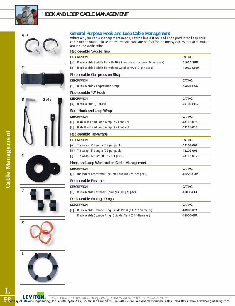
Cab
le M
anag
emen
t
L58
HOOK AND LOOP CABLE MANAGEMENT
To learn more about Leviton’s outstanding offering of devices visit our Website at: www.leviton.com
L
J
E
K
C
D G, H, I
A, B General Purpose Hook and Loop Cable ManagementWhatever your cable management needs, Leviton has a Hook and Loop product to keep yourcable under wraps. These innovative solutions are perfect for the messy cables that accumulatearound the workstation.
Recloseable Saddle TiesDESCRIPTION CAT NO.
[A] Recloseable Saddle Tie with 10/32 metal rack screw (10 per pack) 41020-SPR
[B] Recloseable Saddle Tie with #8 wood screw (10 per pack) 41010-SPW
Recloseable Compression StrapDESCRIPTION CAT NO.
[C] Recloseable Compression Strap 45224-RCS
Recloseable “J” HookDESCRIPTION CAT NO.
[D] Recloseable “J” Hook 46700-SLG
Bulk Hook and Loop WrapDESCRIPTION CAT NO.
[E] Bulk Hook and Loop Wrap, 75 Foot Roll 43115-075
[F] Bulk Hook and Loop Wrap, 15 Foot Roll 43115-015
Recloseable Tie-WrapsDESCRIPTION CAT NO.
[G] Tie Wrap, 5" Length (25 per pack) 43105-005
[H] Tie Wrap, 8" Length (25 per pack) 43108-008
[I] Tie Wrap, 12" Length (25 per pack) 43112-012
Hook and Loop Workstation Cable ManagementDESCRIPTION CAT NO.
[J] Individual Loops with Peel-off Adhesive (25 per pack) 41225-SAP
Recloseable FastenerDESCRIPTION CAT NO.
[K] Recloseable Fasteners (orange) (10 per pack) 41030-OFT
Recloseable Storage RingsDESCRIPTION CAT NO.
[L] Recloseable Storage Ring, Inside Plant (11.75" diameter) 48900-IFR
Recloseable Storage Ring, Outside Plant (24" diameter) 48900-0FR
Courtesy of Steven Engineering, Inc. ● 230 Ryan Way, South San Francisco, CA 94080-6370 ● General Inquiries: (800) 670-4183 ● www.stevenengineering.com

Labeling Products
L59For answers to technical questions, call Leviton’s Techline at 1-800-722-2082
LABELWARE™ SYSTEMS
LableWareLabelWare is the perfect tool to create TIA/EIA-606-A compliant labels for cabling infrastructurecomponents. Laser print surface on pre-cut, perforated 8.5" x 11" sheets provides simple appli-cation with permanent legibility. User-friendly software includes label templates designed specif-ically for Leviton patch panels, patch cords, 110 wiring products and wallplates. The contextsensitive Help Module includes step-by-step instructions to easily create and customize complexlabel builds in minutes. The Build Editor allows integration of fonts and symbols from your wordprocessing software. Download LabelWare software at www.levitonvoicedata.com/labelware.
Cable and Wallplate Product LabelsDESCRIPTION CAT. NO.[A] Cable Wrap-around Labels (8mm), 48 self-adhesive labels per sheet 59260-00W[B] Wallplate & Housing Labels, 10 sheets, 80 card-stock labels per sheet (white) 59259-C0W[C] Port Labels, 10 sheets, 324 self-adhesive labels per sheet (clear) 59259-ACL
Patch Panel and 110 Wiring Product LabelsDESCRIPTION CAT. NO. CAT. NO. CAT. NO. CAT. NO. CAT. NO.
WHITE PUR/YEL BLU/GRY RED/ORG GRE/BRN[D] 110 Wiring Product Labels, 59258-00W 59258-0PY 59258-0LG 59258-0RO 59258-0VB
10 sheets, 16 labels/sheet[E] Patch Panel and Block Labels 59256-00W 59256-0PY 59256-0LG 59256-0RO 59256-0VB
10 sheets, 40 labels/sheet[F] QuickPort Patch Panel 59257-00W 59257-0PY 59257-0LG 59257-0RO 59257-0VB
and Block Labels, 10 sheets, 40 labels/sheet
TIA/EIA-606-A Color Code ChartTERMINATION TYPE TYPICAL APPLICATION COLORDemarcation Point Central office connection OrangeNetwork Connections User side of central office connection GreenCommon Equipment Connections to PBX, mainframe, LAN, multiplexer Purple1st Level Backbone Terminations of building backbone cable MCs to ICs White2nd Level Backbone Terminations of building backbone cable ICs to HCs GrayHorizontal Cabling Terminations of horizontal cable in TEs BlueCampus Backbone Termination of backbone cable between buildings BrownAuxiliary Circuits Alarms, security, or energy management Yellow Key Circuits Connections to key telephone systems Red
Orange Green Purple White Gray Blue Brown Yellow Red
C
A
B
D
Courtesy of Steven Engineering, Inc. ● 230 Ryan Way, South San Francisco, CA 94080-6370 ● General Inquiries: (800) 670-4183 ● www.stevenengineering.com

Labe
ling
Pro
duct
s
L60
LABELING ACCESSORIES
To learn more about Leviton’s outstanding offering of devices visit our Website at: www.leviton.com
QuickPort® Shutters and IconsLeviton’s field-installable QuickPort Shutters protect connectors from dust and debris with aunique, one-piece hinged door. Suitable for commercial and residential applications.Shutters feature labels and recessed windows and fit on Leviton Category 6, 5e, 5, and 3and 8-Position Voice Grade connectors, when used in a QuickPort wallplate or housing.Optional label kits are available. NOTE: SHUTTERS DO NOT WORK WITH CONNECTORINTERFACE BEZELS.
QuickPort Shutters and IconsDESCRIPTION CAT. NO.[A] QuickPort Shutter Kit w/Leviton logo and miscellaneous icons 51084-ICN
Accessory Kit w/pre-printed icons on white paper 51084-XLB[B] Color Label Kit w/pre-printed icons on colored paper* 51084-CLB
Patch Panel and Port AccessoriesPatch Panel Port Identification KitsDESCRIPTION CAT. NO.[C] QuickPort 32-port ID kit (for 24- and 32-port panels) 49257-QID[C] QuickPort High Density ID kit (for 24- and 48-port high density panels) 49257-QHD
PRE-PRINTED PORT DESIGNATION LABELS[D] Identify ports on any QuickPort Housings with these attractive and versatile jack designation
labels. Printed on clear self-adhesive backing. Commercial or residential labels available.
Port Designation LabelsDESCRIPTION CAT. NO. CAT. NO.
BLACK INK WHITE INKCommercial Labels—10 sheets per kit, 94 labels per sheet 41080-LEB 41080-LWBResidential Labels—10 sheets per kit, 94 labels per sheet 40740-0BE —
110 Product Labeling Holders and StripsE Identify all your 110 ports quickly and easily with these label holders and slide-in label strips.
The clear plastic holders attach to all types of 110 wiring bases including wall, rack and wall-mounting frame styles. Labeling strips are lined for 2-, 3-, 4- or 5-pair spacing and availablein white for Cat 6 110 Wiring Products. Cat 5e labeling strips are available in your choice ofnine colors.
110 Product Labeling Holders and StripsDESCRIPTION CAT. NO.[E] Clear Label Holders (bag of 6) 41100-HLD[E] CAT 6 Label Strips lined for 4-pair spacing (bag of 6) 41LBL-60W
(available in white only)[E] CAT 5e Label Strips lined for 2-, 3-, 4- or 5-pair spacing (bag of 6) 41LBL-00*
(available in one of 9 colors)
C
41080-LEB Shown
D
E
B
A
*COLOR/LABELS
QuickPort Shutter KitFor color selection, add suffix to catalognumber as follows: Gray (G), Orange (O),Blue (L), Yellow (Y), Green (V), Purple (P),Brown (B), Red (R).110 Product LabelsFor color selection, add suffix to catalognumber as follows: White (W), Gray (G),Orange (O), Blue (L), Yellow (Y), Green (V),Purple (P), Brown (B), Red (R).
Courtesy of Steven Engineering, Inc. ● 230 Ryan Way, South San Francisco, CA 94080-6370 ● General Inquiries: (800) 670-4183 ● www.stevenengineering.com

Tools and A
ccessories
L61For answers to technical questions, call Leviton’s Techline at 1-800-722-2082
TOOLS and ACCESSORIES
A
B
C
D
E
H
F
110 Punchdown ToolWIRE PUNCHDOWN/TERMINATION TOOLA A versatile punchdown/termination tool with changeable blades (sold separately) that
enables installers to make reliable connections on a variety of wire termination blocks.Terminate/punch down wire with one simple push on the handle. An adjustable impactsetting allows you to terminate wire with less effort than other impact tools. Handle canbe fitted with several interchangeable custom blades to cover many termination types:110 IDC, 66 IDC, Krone, BIX (Northern Telecom BIX system), and an awl (woodscrewstarter punch). A spare blade can be kept in a storage chamber in the handle.
B–E These special application blades are for use with the Wire Punchdown Tool for terminating22, 24 or 26 gauge wire. Krone and BIX blades feature scissor-action trim
D814 Wire Puchdown/Termination Tool and D814 Tool BladesDESCRIPTION CAT. NO.[A] Wire Punchdown/Termination Tool (Blade Sold Separately) 49553-814[B] 110 IDC Blade 49553-110[C] 66-IDC Blade 49553-066[D] BIX® Blade 49553-BIX[E] Krone® Blade 49553-KRN
AWL (Woodscrew starter punch) 49553-AWL
MULTI-PAIR TERMINATION TOOLF The Multi-pair Termination Tool is designed for use with Leviton’s Category 6 110-style
wiring products. The high-impact, spring-loaded handle, makes it easy to terminatemultiple pairs with just one punch. Use “Blade In” and “Blade Out” options for daisy chainor full termination. Category 5e and 6 heads are available separately. Handle works withboth Category 5e and 6 heads.
Multi-Pair Termination Tools and AccessoriesDESCRIPTION CAT. NO.[F] Mass Termination Multi-Pair Tool Handle with CAT 6, 4-Pair Head 49553-TTH
Mass Termination Replacement Head, CAT 6, 4-Pair 49553-64HMass Termination Replacement Head, CAT 5e, 5-Pair 49553-55H
MASTER COMPRESSION TOOLG The Multi-pair Termination Tool is designed for use with Leviton’s Category 6 110-style
wiring products. The high-impact, spring-loaded handle, makes it easy to terminatemultiple pairs with just one punch. Use “Blade In” and “Blade Out” options for daisy chainor full termination. Category 5e and 6 heads are available separately. Handle works withboth Category 5e and 6 heads.
Master CompressionToolDESCRIPTION CAT. NO.[G] Master Compression Tool 40989-CPT
Compression Connectors are sold on page L4.
Courtesy of Steven Engineering, Inc. ● 230 Ryan Way, South San Francisco, CA 94080-6370 ● General Inquiries: (800) 670-4183 ● www.stevenengineering.com

Too
ls a
nd A
cces
sori
es
L62
FIBER OPTIC TOOLS
To learn more about Leviton’s outstanding offering of devices visit our Website at: www.leviton.com
Opt-X Fiber Tool KitsOPT-X LIGHT TOOL KITA All the essential tools for quick field-termination of fiber optic connectors. Includes 100X
inspection scope, scribe, polishing fixture, polishing pad, 900µm buffer remover tool, jacketstripper, Thread-Lock® tightening tool, and scissors.
OPT-X PRO TOOL KITB Use with any SC, ST, or FC Thread-Lock connectors. Includes Thread-Lock Versa-Cleave®
Tool, 200X inspection scope, Thread-Lock tightening tool, one 250Ìm and one 900Ìmbuffer remover, polishing pad, safety glasses, scissors, jacket stripper, polishing fixture, andmusic wire.
OPT-X FAST-CURE TOOL KITC Use with single-mode or multimode Fast-Cure adhesive connectors - SC, ST, FC, or LC.
Includes 200X inspection scope, one 250Ìm and one 900Ìm buffer remover, polishing pad,standard 2.5mm and LC 1.25mm polishing fixtures, LC scope adapter, fiber crimp tool,safety glasses, scissors, jacket stripper, music wire and lapping film. Adhesive/AcceleratorKit sold separately on page K5.
OPT-X MT-RJ ACCESSORY KITAdds MT-RJ capability to existing tool kits.
Fiber Optic Tool KitsDESCRIPTION CAT. NO.[A] Opt-X Light Tool Kit 49800-MTK[B] Opt-X Pro Tool Kit (includes Versa-Cleave) 49800-UTP[C] Opt-X Fast-Cure Tool Kit 49800-FTK
Opt-X MT-RJ Accessory Kit 49800-SLA
C
B
A
Courtesy of Steven Engineering, Inc. ● 230 Ryan Way, South San Francisco, CA 94080-6370 ● General Inquiries: (800) 670-4183 ● www.stevenengineering.com

Tools and A
ccessories
L63For answers to technical questions, call Leviton’s Techline at 1-800-722-2082
FIBER OPTIC TOOLS and CONSUMABLES
J
AFiber Optic Tools and Consumables Sold Individually Individual ComponentsDESCRIPTION CAT. NO.
Universal Tools[A] 250 µm Buffer Remover 49886-BR2[B] 900 µm Buffer Remover 49886-BR9[C] Jacket Stripper 49886-STP[D] Aramid Strand Scissors 49886-SIS
Marking Pen 49886-SMPSafety Glasses 49886-GLSSapphire Scribe 49886-SCR2.5mm Polishing Puck 49886-PUC3" x 6" Polishing Pad 49886-PADOpt-X® Tool Kit Carrying Case 49886-CSETightening Tools
[E] ST/SC Combination Tightening Tool 49886-CTT[F] FC Tightening Tool 49883-FCT
FastCAM Installation Kits[G] Multi/Single-Mode Installation Kit 49800-SMK[H] Multimode Installation Kit 49800-MMK
MT-RJ Specific ToolsStrip Length Gauge 49886-SLGFrame-Station Connector Assembly Tool 49886-FITWorkstation Connector Lead-in Crimp Tool 49886-SLCVersa-Cleave® Adapter for MT-RJ Workstation Connectors 49886-VWAVersa-Cleave Adapter for MT-RJ Frame-Station Connectors 49886-VFAOpt-X 20/20 Lenses 49886-OTTMT-RJ Tool Kit Carrying Case 49886-CSTMT-RJ Accessory Kit Carrying Case 49886-CSAFast-Cure Specific Tools
[G] Fiber Optic Crimp Tool with .128, .151, .178 hex die 49886-FCTLC Scope Adapter 49886-LCS1.25mm (LC) Polishing Puck 49886-LCPFast-Cure Tool Kit Carrying Case 49886-FCCConsumablesMusic Wire 49886-WRELint Free Dry Wipes 100/pack 49886-DWPAlcohol Pads 100/pack 49886-APD12 µm Aluminum Oxide Lapping Film, 100/pack 49886-12F3 µm Aluminum Oxide Lapping Film, 100/pack 49886-03F0.3 µm Aluminum Oxide Lapping Film, 100/pack 49886-X3FReplacement Needles 25/pack 49886-FCNReplacement Syringes 25/pack 49886-SYR
CONSUMABLES KITSH-J Leviton’s Consumables Kits contain everything you need to clean and polish connectors,
such as polyester wipes, alcohol pads, music wire, and 12-, 3- and 0.3 µm lapping film.Fast-Cure kit adds needles and syringes, plus adhesive and accelerator. Adhesive/Accelerator kit is also sold separately. Fan-Out Consumables Kits are also available.
Consumables KitsDESCRIPTION CAT. NO.[H] Universal Consumables Kit 49800-CON[I] Fast-Cure Consumables Kit 49800-FAC[J] Adhesive/Accelerator Kit 49800-680
Fan-Out Consumables Kit (shown on page L51) 49800-FAN
B
C
D
EF
I
K
L
G
H
Courtesy of Steven Engineering, Inc. ● 230 Ryan Way, South San Francisco, CA 94080-6370 ● General Inquiries: (800) 670-4183 ● www.stevenengineering.com

Too
ls a
nd A
cces
sori
es
L64
FIBER OPTIC TOOLS and CONSUMABLES
To learn more about Leviton’s outstanding offering of devices visit our Website at: www.leviton.com
E
F
Fiber Optic ToolsTHREAD-LOCK® VERSA-CLEAVE® TOOLA–C Diamond blade cleaves fiber perfectly every time, eliminating the need for a craft-sensitive
scribe procedure. The ergonomic stop-watch design fits comfortably in the hand, workswith any style or brand of mechanical 2.5mm ferrule connector, and cleaves with a simplepush of the button. The integrated debris cup catches and retains fiber debris for safedisposal. Versa-Cleave can be ordered separately, or as part of the Opt-X® Pro Tool Kit
Thread-Lock Versa-CleaveDESCRIPTION CAT. NO.[A] Versa-Cleave Tool 49886-TVC[B] Versa-Cleave Adapter for MT-RJ Workstation Connector 49886-VWA[C] Versa-Cleave Adapter for MT-RJ Frame-Station Connector 49886-VFA
SAFETY PADD Provides a flexible, shatterproof, non-slip surface perfect for terminating all Leviton Fiber
Optic Connectors.
Safety PadDESCRIPTION CAT. NO.[D] Safety Pad 49886-SPD
INSPECTION SCOPESE, F Leviton’s 100x and 200x Inspection Scopes allow techs to view multimode and
singlemode end-face polishes safely, and reduce the chances of over-polishing (a side-effect of many coaxial inspection scopes). 200x Scope features oblique viewingtechnology, ergonomic grip, 200X magnification and full laser eye protection throughwavelengths of 850-1550 nanometer. Both scopes feature rugged construction thatstands up to jobsite abuse.
Inspection ScopesDESCRIPTION CAT. NO.[E] 100x Inspection Scope 49886-SCP[F] 200x Inspection Scope 49886-FSP
A, B, C
D
Courtesy of Steven Engineering, Inc. ● 230 Ryan Way, South San Francisco, CA 94080-6370 ● General Inquiries: (800) 670-4183 ● www.stevenengineering.com

Tools and A
ccessories
L65For answers to technical questions, call Leviton’s Techline at 1-800-722-2082
TOOLS and ACCESSORIES
Tone Test SetA Use the Leviton Tone Test Set in low voltage wire applications to test for continuity, check for
shorts or opens, and provide talk battery for a communication line on a vacant pair. Connecttoner across a wire pair and set to transmit either a continuous 1000 Hz or alternating500/1000 Hz tone. Use with the Speaker Probe (below) to trace pairs and locate brokenpairs/cables in walls.Also identifies Tip and Ring polarity, and line condition for CLEAR LINE with dial tone,BUSY LINE and RINGING LINE. Features “O” ring seals on the case, test leads for waterresistance, support leash, tri-color, and nylon-braided tinsel wire test leads. Telco-standard,6A-type alligator clips with piercing pins securely grip 66-clips, screw heads, screw bodies,and wire-wrapped or threaded terminals. A 6-position, 2-conductor plug lead is alsoprovided for connection to modular jacks.
Inductive Speaker ProbeB The streamlined inductive speaker probe detects audible frequency tones quickly for accu-
rate tracing and identification of wires, cables, and metallic circuits. Use with the tone test set(above) to trace and isolate pairs in virtually any type of wire application, without damage tothe insulation. Identifies single wires or individual pairs in multiple-pair cables at terminals orclosures; identifies station wiring or cables to specific equipment in closets or on distributionframes; and identifies the ends of drop wires. Probe can also be used to locate prewiring, oropens in wires, after wall covering is installed. Features both needlepoint and duckbill tips anda non-locking slide switch.
Tone Test Set, Inductive Speaker Probe — Individual Items and CombinationsDESCRIPTION CAT. NO.[A] Tone Test Set (includes 9 volt battery) 49560-TTS[B] Inductive Speaker Probe only (includes 9 volt battery; 49561-SSP
one duckbill tip; and one needlepoint tip)[C] Leather Belt Holster for Tone Test Set 49560-LCC[D] Leather Belt Holster for inductive speaker probe 49561-LCC
Spare duckbill and needlepoint tip set 49561-TIPKit containing tone test set with belt holster, and inductive 49562-TSKspeaker probe with belt holsterKit containing 5 tone test sets with belt holsters, and 5 inductive 49562-KITspeaker probes with belt holsters
Crimping Tool for Coaxial ConnectorsE For use in crimping coaxial connectors onto RG-59 or RG-6 cables. Rugged metal construction
with cushioned handles. Carded package for display in merchandising racks.
Crimping Tool for Coaxial ConnectorsDESCRIPTION CAT. NO.[E] Crimping Tool for Coaxial Connectors 40988-000
UTP Stripping ToolF Use this versatile tool to strip unshielded twisted pair (UTP) cable. Carded package for display
in merchandising racks.
UTP Stripping ToolDESCRIPTION CAT. NO.[F] Stripping Tool 49660-00C
A
B
C
Optional leather belt holsters.
F
E
D
Courtesy of Steven Engineering, Inc. ● 230 Ryan Way, South San Francisco, CA 94080-6370 ● General Inquiries: (800) 670-4183 ● www.stevenengineering.com

Too
ls a
nd A
cces
sori
es
L66
TOOLS and ACCESSORIES
To learn more about Leviton’s outstanding offering of devices visit our Website at: www.leviton.com
Craftsperson’s HandsetA This handset is used by installers, repair technicians, and other authorized personnel for
basic line testing and essential on-site temporary communications. Line-powered to provideeither DTMF (Touch Tone) or dial pulse output. Features all standard ‘buttset’ line tests,including polarity check, line monitoring, and signaling.
Craftsperson’s HandsetDESCRIPTION CAT. NO.[A] Craftsperson’s Handset 49575-CTS
Termination Tool (66-BT)B This ‘pocket friendly’ tool quickly punches down 20 through 26 gauge unstripped wire in
devices using 66-clip terminals. It adjusts to accommodate variation in wire size and bladesharpness. Replaceable blades reverse to let you terminate and cut wire in a single stroke, orterminate without.
Replacement Stem for Termination Tool (66-BT02)C The replaceable stem for the termination tool blade.
Replacement Blade for Termination Tool (66-BT01)D This blade reverses so wires can be terminated and cut, or terminated without cutting. It also
adjusts to accommodate variation in wire size or blade sharpness.
Termination Tool, Replacement Stem and Replacement BladeDESCRIPTION CAT. NO.[B] Termination Tool (66-BT) 46666-0BT[C] Replacement Stem for Termination Tool (66-BT02) 46666-BTS[D] Replacement Blade for termination Tool (66-BT01) 46666-BTB
Note: Numbers in parentheses refer to industry product designation.
Modular Plug Breakout AdapterE For testing any 6- or 8-position modular jack with the Tone Test Set or Craftsperson’s Handset.
Includes contacts to connect, via alligator clip leads, to any test apparatus or Lineman’s TestSet. Can be used in series with any cable with a 6- or 8-conductor modular plug.
Modular Plug Breakout AdapterDESCRIPTION CAT. NO.[E] Modular Plug Breakout Adapter 40070-MDP
A
B
E
C
D
Courtesy of Steven Engineering, Inc. ● 230 Ryan Way, South San Francisco, CA 94080-6370 ● General Inquiries: (800) 670-4183 ● www.stevenengineering.com

Straight B
lade Plugs and C
onnectors IndexSECTIONM
Straight BladePlugs and ConnectorsINDEXIndustrial Grade Plugs & ConnectorsOverview . . . . . . . . . . . . . . . . . . . . . . . . . . . . . . . .M215A 125V & 250V
Hospital Grade . . . . . . . . . . . . . . . . . . . . . . . . . .M3Industrial Grade . . . . . . . . . . . . . . . . . . . . . . . . .M3Flanged Inlets and Outlets . . . . . . . . . . . . . . . . .M3Wetguard® . . . . . . . . . . . . . . . . . . . . . . . . . . . . .M5Dustguard® . . . . . . . . . . . . . . . . . . . . . . . . . . . .M5Python™ . . . . . . . . . . . . . . . . . . . . . . . . . . . . . . .M6Integrated Inlets and Outlets withWeather-Resistant Covers . . . . . . . . . . . . . . . . . .M7
20A 125V & 250VHospital Grade . . . . . . . . . . . . . . . . . . . . . . . . . .M4Industrial Grade . . . . . . . . . . . . . . . . . . . . . . . . .M4Flanged Inlets and Outlets . . . . . . . . . . . . . . . . .M4Wetguard® . . . . . . . . . . . . . . . . . . . . . . . . . . . . .M5Dustguard® . . . . . . . . . . . . . . . . . . . . . . . . . . . .M5Python™ . . . . . . . . . . . . . . . . . . . . . . . . . . . . . . .M6Integrated Inlets and Outlets with Weather-Resistant Covers . . . . . . . . . . . . . . . . . .M7
Weather-Resistant Boots . . . . . . . . . . . . . . . . . . . .M420 AMP Power Plugs . . . . . . . . . . . . . . . . . . . . . . .M830 AMP Nylon Angle Plugs . . . . . . . . . . . . . . . . . .M850 AMP Nylon Angle Plugs . . . . . . . . . . . . . . . . . .M960 AMP Nylon Angle Plugs . . . . . . . . . . . . . . . . .M10Commercial Grade Plugs & ConnectorsOverview . . . . . . . . . . . . . . . . . . . . . . . . . . . . . . .M1115A 125V & 250V . . . . . . . . . . . . . . . . . . . . . . . .M1220A 125V & 250V . . . . . . . . . . . . . . . . . . . . . . . .M1330 Amp and 50 Amp Dual Power Attachment Plugs . . . . . . . . . . . . . . . . . . . . . . . . .M14Residential Grade Plugs & ConnectorsParallel, Polarized and Non-Polarized . . . . . . . . . .M15Grounding . . . . . . . . . . . . . . . . . . . . . . . . . . . . . .M16
Courtesy of Steven Engineering, Inc. ● 230 Ryan Way, South San Francisco, CA 94080-6370 ● General Inquiries: (800) 670-4183 ● www.stevenengineering.com

STRAIGHT BLADE PLUG AND CONNECTOR FEATURES
Industrial Grade Straight Blade Plugs and Connectors
To learn more about Leviton’s outstanding offering of devices visit our Website at: www.leviton.com
Str
aigh
t Bla
de P
lugs
and
Con
nect
ors
M2
A COMPLETE LINE OF PLUGS AND CONNECTORS THAT STANDS UP TO THE HARSHEST ENVIRONMENTSThe Leviton line of straight blade plugs and connectors includes: Black & White™ Industrial Grade devices thatresist impact, corrosion and chemicals; Hospital Grade devices that meet the highest standards for dependable,long-term performance; Wetguard® for water and moisture resistance; Dustguard® to resist dust and dirt;Python™, with an innovative interlocking design; rugged nylon flanged inlets and outlets; and integrated inletsand outlets with weather resistant covers.
Leviton's 15 and 20 Amp nylon plugs and connectors offer superior performance andlong-lasting reliability features; from ergonomic design details to rugged constructionthat resists impact, punishing application environments, chemicals and corrosives.
Features and Benefits� UL 498 Listed; meets latest Federal
Specifications WC-598; CSA SpecificationC22.2 No. 42 Certified
� Cord clamp with removable strain relief insertaccepts cables rated from 10-3 ST to 18-3SVT (.245"–.700")
� One-piece, rivetless triple-wipe brass connector contacts offer enlarged contact surface area
� Husk is constructed of ST801 Super ToughNylon for superior impact resistance in ruggedenvironments
� Beveled back edges prevent body from catching on corners and rough surfaces
� Ergonomic, fluted body design with radial gripping edge is ideal for gripping and pulling
Python™
Hinged design provides speedy,simple wiring and installation,delivers top performance, standsup to rough-duty applications.5456-VY shown
Flanged Inlets and OutletsFit flush on equipment mountingpanels and require only 2 mountingscrews for easy panel assembly.5278-C shown
Angle Plugs and ConnectorsFor hospital and industry usewhere power cords must lay closeto walls and floors; 8 plug positions.8215-CAT shown
Hospital GradeSuperior design, heavy-duty, impact-resistant, all nylon construction forlong-lasting performance and relia-bility in the demanding healthcareenvironment. 8215-C shown
Wetguard®
Specifically developed for wet ordamp locations. EPTR thermo-plastic rubber body and ruggeddesign resist water, alkalies,grease, oils and solvents.14W48 shown
Individual deep-funnelled chamferedwire wells. Clearhousing allowsinspection of wiretermination and provides molded-inwire strip gage
Wire clamps move in individualchamber — provide positive crimplock without cutting wire strand
Captive, color-coded brass #8terminal screws
Three "U" type fast-threading, tripledrive, steel screws secure wiring moduleto body
Dead front solid containmentbarrier prevents accidentalcontact with internal parts
NEMA configuration anddevice rating are molded onfront of device to assist withidentification
Wiring module keyed to body for easy assembly and a tight fit
Positive contact plate bundlesstranded wire maximizing surface contact resulting in improved termination
External cord grip utilizes deep triple drive steelscrews that are backed out and positioned insideshrouded pockets. External clamps accepts wiremesh grips. Catalog and NEMA numbers printedon cord clamp
#8-32 triple drive brass terminal screws
5266-C
Courtesy of Steven Engineering, Inc. ● 230 Ryan Way, South San Francisco, CA 94080-6370 ● General Inquiries: (800) 670-4183 ● www.stevenengineering.com

1.41 (35.8)
2.09
(53
.1)
Ø1.53 (38.9) 1.30(33.0)
Ø1.39 (35.3)
Ø1.53 (38.9)
1.98
(50
.4)
Ø1.39 (35.3)
Ø1.53 (38.9)
2.76
(70
.1)
NEMA 5-15P G
W
NEMA 5-15R G
W
Straight B
lade Plugs and C
onnectors
M3For answers to technical questions, call Leviton’s Techline at 1-800-824-3005
15 AMP 125 and 250V
Industrial Grade Straight Blade Plugs and Connectors
SPECIFICATIONS AND FEATURES
Hospital Grade• Unmatched quality and performance confirmed by
rigorous UL 498 testing• Clearly identified by green dot Industrial Grade• Rugged construction resists impact, sunlight,
chemicals and rough use• All contacts are solid one-piece brass for better
conductivity• Triple-wipe, heavy-duty power contacts set in deep
pockets to resist damage • Captive, color-coded brass #8 terminal screws• Unique cord clamp accepts wide range of cord
sizes (.245"–.700"), providing secure grip withoutdamaging cord jacket: SVT 18-3 to SO 14-3 withstrain relief insert, up to ST 10-3 when strain reliefinsert is removed.
• Power Indication™ devices equipped with greenneon bulb rated at 30,000 hours (24/7) for 3.5years
TESTING AND CODE COMPLIANCE
• Meet NEMA WD 1 & 6, ANSI requirements• UL Listed & meets UL Fed. Spec. requirements:
Industrial Plugs & Connectors (File #13393);Hospital Grade (UL 498, File #E-13393)
• CSA Certified (File #LR-406)• NOM Certified (#057)• Backed by a Limited 10-Year Warranty
MATERIAL CHARACTERISTICS
Environmental: Flammability, Rated V2Operating Temperature: -40°C to 65°C
Hospital Grade —15 AMP 125V 2-Pole, 3-Wire Grounding URDESCRIPTION CAT. NO. PLUG CAT. NO. CONNECTOR
Hospital Grade, Black & White Body 8215-C 8219-CHospital Grade, Transparent Body 8215-CT 8219-CTHospital Grade, Power Indication™ Transparent 8215-PLC 8219-PLCHospital Grade Angle, Transparent Body 8215-CAT —
Industrial Grade —15 AMP 125V 2-Pole, 3-Wire Grounding URBlack & White Nylon Body 5266-C 5269-CHigh-Visibility Yellow Nylon Body 5266-CY 5269-CYAll-Black Nylon for Stage and Studio 5266-CB 5269-CBAll-Black Nylon, Power Indication™ 5266-PLB 5269-PLBOrange & White Body 5266-CO 5269-COGray Nylon Body 5266-CG 5269-CGBlack & White Nylon Body, Power Indication™ 5266-PLC 5269-PLCAngle, Black & White Nylon Body 5266-CA 5269-CABlack 2-Piece Nylon Shell 5266-N 5269-NFlanged Inlet, White Nylon Body 5278-C —Flanged Outlet, White Nylon Body — 5279-C
Industrial Grade —15 AMP 250V 2-Pole, 3-Wire Grounding URDESCRIPTION CAT. NO. PLUG CAT. NO. CONNECTOR
Black & White Nylon Body 5666-C 5669-CHigh-Visibility Yellow Nylon Body 5666-CY 5669-CYAngle, Black & White Nylon Body 5666-CA —Flanged Inlet, White Nylon Body 15678-C —Flanged Outlet, White Nylon Body — 15679-C
NEMA 6-15P G NEMA 6-15R G
8215-CAT
5266-C
5269-C
1.78
(45
.0)
Ø1.69 (43.0)
2.11 (54.0)
Ø2.50 (63.0)
5278-C
For Weather Resistant Plug and Connector Boots, see page M4.
Courtesy of Steven Engineering, Inc. ● 230 Ryan Way, South San Francisco, CA 94080-6370 ● General Inquiries: (800) 670-4183 ● www.stevenengineering.com

Str
aigh
t Bla
de P
lugs
and
Con
nect
ors
M4
20 AMP 125 and 250V
Industrial Grade Straight Blade Plugs and Connectors
To learn more about Leviton’s outstanding offering of devices visit our Website at: www.leviton.com
SPECIFICATIONS AND FEATURES
Hospital Grade• Unmatched quality and performance confirmed by
rigorous UL 498 testing• Clearly identified by green dot Industrial Grade• Rugged construction resists impact, sunlight,
chemicals and rough use• All connector contacts are solid one-piece brass for
superior conductivity• Triple-wipe, heavy-duty power contacts set in deep
pockets to resist damage • Captive, color-coded brass #8 terminal screws• Unique cord clamp accepts wide range of cord
sizes (.245"–.700"), providing secure grip withoutdamaging cord jacket: SVT 18-3 to SO 14-3 withstrain relief insert, up to ST 10-3 when strain reliefinsert is removed.
• Power Indication™ devices equipped with greenneon bulb rated at 30,000 hours (24/7) for 3.5years
TESTING AND CODE COMPLIANCE
• Meet NEMA WD 1 & 6, ANSI requirements• UL Listed & meets Fed. Spec. requirements:
Industrial Plugs & Connectors (File #13393);Hospital Grade (UL 498, File #E-13393)
• CSA Certified (File #LR-406)• NOM Certified (#057)• Backed by a Limited 10-Year Warranty
MATERIAL CHARACTERISTICS
Environmental: Flammability, Rated V2Operating Temperature: -40°C to 65°C
Hospital Grade — 20 AMP 125V 2-Pole, 3-Wire Grounding URDESCRIPTION CAT. NO. PLUG CAT. NO. CONNECTOR
Hospital Grade, Black & White Body 8315-C 8319-CHospital Grade, Transparent Body 8315-CT 8319-CTHospital Grade, Power Indication™ Transparent 8315-PLC 8319-PLCHospital Grade Angle, Transparent Body 8315-CAT —
Industrial Grade — 20 AMP 125V 2-Pole, 3-Wire Grounding URBlack & White Nylon Body 5366-C 5369-CBlack & White Nylon Body, Power Indication™ 5366-PLC 5369-PLCAll-Black Nylon, Power Indication™ 5366-PLB 5369-PLBHigh-Visibility Yellow Nylon Body 5366-CY 5369-CYGray Nylon Body 5366-CG 5369-CGAngle, Black & White Nylon Body 5366-CA 5369-CAFlanged Inlet, White Nylon Body 15378-C —Flanged Outlet, White Nylon Body — 15379-C
Hospital Grade — 20 AMP 250V 2-Pole, 3-Wire Grounding URDESCRIPTION CAT. NO. PLUG CAT. NO. CONNECTOR
Hospital Grade Angle, Transparent Body 8415-CAT —
Industrial Grade — 20 AMP 250V 2-Pole, 3-Wire Grounding URBlack & White Nylon Body 5466-C 5469-CHigh-Visibility Yellow Nylon Body 5466-CY 5469-CYFlanged Inlet, White Nylon Body 5478-C —Flanged Outlet, White Nylon Body — 5479-C
Weather-Resistant Boots UROur outstanding Industrial Grade boots feature a triple-seal design to protect straight blade and locking plugs andconnectors against the harmful effects of dirt and moisture in harsh environments. Boots are available in black orhigh-visibility yellow. The fluted surface and grip-ring design provide a non-slip grip even in wet conditions.
DESCRIPTION CAT. NO.Weather-Resistant Straight Blade Plug Boot, Black Rubber. 6017For 15A & 20A Straight Blade Industrial Nylon PlugsWeather-Resistant Straight Blade Plug Boot, High Visibility Yellow Rubber. 6017-YFor 15A & 20A Straight Blade Industrial Nylon PlugsWeather-Resistant Straight Blade Connector Boot, Black Rubber. 6018For 15A & 20A Straight Blade Industrial Nylon ConnectorsWeather-Resistant Straight Blade Connector Boot, High Visibility 6018-YYellow Rubber. For 15A & 20A Straight Blade Industrial Nylon Connectors
NEMA 6-20PG NEMA
6-20R
G CSA config.
in Canada
G
NEMA 5-20PG
W
NEMA 5-20R
GW
CSA config.
in Canada
G
W
1.98
(50
.4)
Ø1.39 (35.3)
Ø1.53 (38.9)
Ø1.53 (38.9)
2.09
(53
.1)
1.41 (35.8)
1.30(33.0)
1.41 (35.8)
2.09
(53
.1)
Ø1.53 (38.9) 1.30(33.0)
8315-PLC
5366-CA
8415-CAT
Ø2.00 (50.8)
2.73
(69
.4)
6017-Y
Courtesy of Steven Engineering, Inc. ● 230 Ryan Way, South San Francisco, CA 94080-6370 ● General Inquiries: (800) 670-4183 ● www.stevenengineering.com

Straight B
lade Plugs and C
onnectors
M5For answers to technical questions, call Leviton’s Techline at 1-800-824-3005
15 AMP 125 and 250V • 20 AMP 125 and 250V
Industrial Grade Straight Blade Plugs and Connectors
NEMA 5-15PG
W NEMA 5-15RG
W
NEMA 5-15PG
W NEMA 5-15RG
W
NEMA 6-15PG
NEMA 6-15RG
NEMA 7-15RG
W
NEMA 5-15PG
W NEMA 5-15RG
W
NEMA 6-15PG
NEMA 6-15RG
NEMA 5-20PG
W
NEMA 6-20PG
TESTING AND CODE COMPLIANCE
• Meet NEMA WD 1 & 6, ANSI requirements• UL Listed & meets Fed. Spec. requirements:
Wetguard (File #13393), Dustguard (File #E-13393)• CSA Certified (File #LR-406)• NOM Certified (#057)• Backed by a Limited 10-Year Warranty
MATERIAL CHARACTERISTICS
Environmental: Flammability, Rated V2Operating Temperature: -40°C to 65°C
SPECIFICATIONS AND FEATURES
Wetguard• IEC IP66 and IP 67 Rated, in accordance with IEC
529 as evaluated by UL and CSA• NEMA Type 3, 3S, 4, 4X, 6 and 6P Ratings in
accordance with UL 50 and CSA 94• Outstanding resistance to wet and damp environ-
ments, extreme temperature variations, acids, alka-lis, grease, oils and solvents
• Effective “tongue and groove” construction sealsout water, moisture, dirt when plugs are mated withconnectors
• Innovative strain-relief grips cables securely, keepsout water and moisture
• Cord clamp range: 18/3–10/3S0 (.375"–.655")
• Non-magnetic stainless steel fast-threading assemblyscrews won’t interfere with sensitive equipment
• Connector “hood” closure cap seals device when not in use
Dustguard• IEC/IP44 Rated• Developed to withstand dusty and dirty environ-
ments, cracking and fading, temperature extremes• Rugged wiring modules have high performance
1-piece brass triple-wipe contacts, solid brass plug blades
• Self centering cord clamp accepts wide range ofconductors, 18-3 SVT–12-3SO (.240"–.655")
Ø1.50 (38.1)
2.71
(68
.8)
Ø1.28 (32.5)
14W47
15W47
4.20
(10
6.7)
Ø2.30 (58.3)
Ø1.28 (32.5)
NEMA 5-20PG
W
Wetguard® Devices Engineered to IP66 & IP67 Watertight StandardsWetguard Straight Blade Plugs and Connectors URDESCRIPTION CAT. NO. PLUG CAT. NO. CONNECTORRubber Yellow, 15A-125V 2-Pole, 3-Wire 14W47 15W47
Black Rubber, 15A-125V 2-Pole, 3-Wire 14W47-B 15W47-B
Yellow Rubber , 15A-250V 2-Pole, 3-Wire 14W49 15W49
Yellow Rubber, 15A-277V 2-Pole, 3-Wire 14W34 15W34
Yellow Rubber , 20A-125V 2-Pole, 3-Wire 14W33 15W33
Yellow Rubber , 20A-250V 2-Pole, 3-Wire 14W48 15W48
Repacement Closure Cap URDESCRIPTION CAT. NO.Replacement Female Closure Cap for use with 50W5015A & 20A 2-pole, 3-wire devices
Dustguard® Devices Engineered to IP44 Splashproof and Dust-Tight Standards
Dustguard Straight Blade Plugs and Connectors URDESCRIPTION CAT. NO. PLUG CAT. NO. CONNECTORHigh-Visibility Yellow, 15A-125V 2-Pole, 3-Wire 1447 1547
High-Visibility Yellow, 15A-250V 2-Pole, 3-Wire 1449 1549
High-Visibility Yellow, 20A-125V 2-Pole, 3-Wire 1433 1533
High-Visibility Yellow, 20A-250V 2-Pole, 3-Wire 1448 1548
NEMA 5-20RG
W
NEMA 6-20PG
NEMA 6-20RG
NEMA 7-15PG
W
NEMA 5-20RG
W
NEMA 6-20RG
For 15 and 20 Amp corrosion resistant straight blade devices, see pages N20–N21.
Courtesy of Steven Engineering, Inc. ● 230 Ryan Way, South San Francisco, CA 94080-6370 ● General Inquiries: (800) 670-4183 ● www.stevenengineering.com

Str
aigh
t Bla
de P
lugs
and
Con
nect
ors
M6
15 AMP 125 and 250V • 20 AMP 125 and 250V
Industrial Grade Straight Blade Plugs and Connectors
To learn more about Leviton’s outstanding offering of devices visit our Website at: www.leviton.com
Python™ Plugs and Connectors Feature a Hinged Design for Fast, Easy Installation and Assembly
Hospital Grade —15 AMP 125V 2-Pole, 3-Wire Grounding URDESCRIPTION CAT. NO. PLUG CAT. NO. CONNECTOR
White Nylon Body 8256-V 8259-V
Industrial Grade —15 AMP 125V 2-Pole, 3-Wire Grounding URBlack Nylon Body 5256-VB 5259-VBHigh-Visibility Yellow Nylon Body 5256-VY 5259-VYGray Nylon Body 5256-VG 5259-VGAngle, High-Visibility Yellow Nylon Body 5256-VA —
Hospital Grade —15 AMP 250V 2-Pole, 3-Wire Grounding URDESCRIPTION CAT. NO. PLUG CAT. NO. CONNECTOR
White Nylon Body 8656-V 8659-V
Industrial Grade —15 AMP 250V 2-Pole, 3-Wire Grounding URHigh-Visibility Yellow Nylon Body 15656-VY 15659-VYAngle, High-Visibility Yellow Nylon Body 15656-VA —
Hospital Grade — 20 AMP 125V 2-Pole, 3-Wire Grounding URDESCRIPTION CAT. NO. PLUG CAT. NO. CONNECTOR
White Nylon Body 8356-V 8359-V
Industrial Grade — 20 AMP 125V 2-Pole, 3-Wire Grounding URBlack Nylon Body 5356-VB 5359-VBHigh-Visibility Yellow Nylon Body 5356-VY 5359-VYAngle, High-Visibility Yellow Nylon Body 5356-VA —
Hospital Grade — 20 AMP 250V 2-Pole, 3-Wire Grounding URDESCRIPTION CAT. NO. PLUG CAT. NO. CONNECTOR
White Nylon Body 8456-V 8459-V
Industrial Grade — 20 AMP 250V 2-Pole, 3-Wire Grounding URHigh-Visibility Yellow Nylon Body 5456-VY 5459-VYAngle, High-Visibility Yellow Nylon Body 5456-VA —
NEMA 5-20PG
W
NEMA 5-20R
GW
CSA config.
in Canada
G
W
NEMA 6-20PG NEMA
6-20R
G CSA config.
in Canada
G
NEMA 5-15P G
W
NEMA 5-15R G
W
NEMA 6-15P G NEMA 6-15R G
SPECIFICATIONS AND FEATURES
Python• Tough high-impact body• Hinged design delivers fast, easy installation
and assembly• Triple-drive screws for easy wiring — Standard,
Philips, Robertson• Wide Cord Clamp Range, 18-3 SVT–10-3 ST,
(.245"–.700")
TESTING AND CODE COMPLIANCE
• Meet NEMA WD 1 & 6, ANSI requirements• UL Listed & meets Fed. Spec. requirements:
Industrial Plugs & Connectors (File #13393);Hospital Grade (UL 498, File #E-13393)
• CSA Certified (File #LR-406)• NOM Certified (#057)• Backed by a Limited 10-Year Warranty
MATERIAL CHARACTERISTICS
Environmental: Flammability, Rated V2Operating Temperature: -40°C to 65°C
1.10(27.9)
1.81
(46
.0)
1.37 (34.9)
1.41 (35.7)
1.21(30.7)
5256-VA
1.81
(46
.0)
1.40 (35.7)
1.22(31.0)
5456-VY
1.22
(31
.0)
1.40 (36.7)2.50
(63.5)
5459-VY
Courtesy of Steven Engineering, Inc. ● 230 Ryan Way, South San Francisco, CA 94080-6370 ● General Inquiries: (800) 670-4183 ● www.stevenengineering.com

Straight B
lade Plugs and C
onnectors
M7For answers to technical questions, call Leviton’s Techline at 1-800-824-3005
15 AMP 125 and 250V • 20 AMP 125 and 250V
Industrial Grade Straight Blade Plugs and Connectors
SPECIFICATIONS AND FEATURES
• Glass-filled thermoplastic cover and plate provideoutstanding impact resistance and durability
• UL 94 VO Flammability Rating • IP 64 Suitability rating protects against dust parti-
cles and splashing water• NEMA Type-3R enclosure Rating ensures protec-
tion against rain, sleet and damage from externalice formations
• Available with standard wire wells or with slots thataccept fork terminals
• Dual gaskets, one under plate and one under lid,for weather-resistant fit
• Stainless steel external hardware resists corrosiveeffects of moisture
• Large thumb-tab makes it easy to open cover withgloved hand
• Mounts to panels or FS/FD boxes• UL Listed and CSA Certified for wet locations with
cover closed
TESTING AND CODE COMPLIANCE
• UL Listed (File #-13397)• CSA Certified (File #LR-16347• NOM Certified (#057)• IP 64 Suitability Rating (protected against dust and
splashing water)• NEMA Type-3R Enclosure Rating when properly
installed (protected against rain, sleet and damagefrom external ice formations)
• Backed by a Limited 2-Year Warranty
MATERIAL CHARACTERISTICS
Environmental: VO Flammability Rating per UL 94Operating Temperature: -40°C to 75°C
Integrated Power Inlets and Outlets with Weather-Resistant Covers� Engineered to IP 64 and NEMA 3R Protection Ratings
� Suitable for Industrial Indoor and Outdoor Use
Integrated Power Inlets and Outlets with Weather-Resistant Covers URGray, Glass-Filled Thermoplastic Cover and White, Nylon Device
DESCRIPTION CAT. NO. FLANGED INLET CAT. NO. FLANGED OUTLETStandard Wire Wells, 5278-CWP 5279-CWP15A-125V 2-Pole, 3-Wire
Slots for Fork Terminals, 5278-FWP 5279-FWP15A-125V 2-Pole, 3-Wire
Standard Wire Wells, 15678-CWP 15679-CWP15A-250V 2-Pole, 3-Wire
Standard Wire Wells, 15378-CWP 15379-CWP20A-125V 2-Pole, 3-Wire
Standard Wire Wells, 5478-CWP 5479-CWP20A-250V 2-Pole, 3-Wire
Note: For locking configurations, please see Section N.
NEMA 5-15P G
W
NEMA 5-15R G
W
NEMA 5-15P G
W
NEMA 5-15R G
W
NEMA 6-15P G NEMA 6-15R G
NEMA 5-20PG
W
NEMA 5-20R
GW
CSA config.
in Canada
G
W
NEMA 6-20PG NEMA
6-20R
G CSA config.
in Canada
G
1.88 (46.6)
2.84 (72.2)
1.49 (37.8)
4.56
(11
5.9)
3.25
(82
.6)
5278-CWP
5278-CWP Shown Open
5279-CWP Shown Open
Courtesy of Steven Engineering, Inc. ● 230 Ryan Way, South San Francisco, CA 94080-6370 ● General Inquiries: (800) 670-4183 ● www.stevenengineering.com

Str
aigh
t Bla
de P
lugs
and
Con
nect
ors
M8
20 AMP 125/250 and 120/208V • 30 AMP 125, 250, 277 125/250 and 120/208V
Industrial Grade Straight Blade Plugs and Connectors
To learn more about Leviton’s outstanding offering of devices visit our Website at: www.leviton.com
20 AMP Power Plugs20 AMP 125/250V Straight Blade Plugs 3-Pole 3-Wire Non-Grounding URDESCRIPTION CAT. NO. MATCHING RECEPTACLE NEMA CONFIG.Straight Plug 9151-N 5032
5032-I
20 AMP 120/208V 4-Pole, 4-Wire, 3ØY Non-Grounding UStraight Plug 7251-C 7250-FR
30 AMP Nylon Angle Plugs30 AMP 125V 2-Pole 3-Wire Grounding URDESCRIPTION CAT. NO. MATCHING RECEPTACLE NEMA CONFIG.Angle Plug 9530-P 5371
5371-IG
30 AMP 250V 2-Pole 3-Wire Grounding URAngle Plug 9630-P 5372
5372-IG
30 AMP 277V 2-Pole 3-Wire Grounding URAngle Plug 9730-A
30 AMP 125/250V 3-Pole 3-Wire Non-Grounding URAngle Plug 9332-P 5207
30 AMP 125/250V 3-Pole 4-Wire Grounding URAngle Plug 9432-P 278
30 AMP 250V 3-Pole 4-Wire 3-Phase Grounding URAngle Plug 8432-P 8430
30 AMP 120/208V 4-Pole 4-Wire 3ØY Non-Grounding URAngle Plug 8332-P 8330
5-30P
G
W
6-30P
G
7-30PG
W
10-30PW
YX
14-30P
GYX
W
15-30P
GZX
Y
G
18-30P
W
ZX
Y
10-20PW
Y
X
18-20P
W
ZX
Y
SPECIFICATIONS AND FEATURES
• Rugged cord clamp for secure cable grip accom-modates cord diameters from .625" to 1.375" anddoes not tear conductor jacket
• Made of tough, heavy-duty nylon for long service life• Devices feature heavy-sectioned dead-front
right-angle• Pressure-clamp terminal design• Terminals accept up to #4AWG stranded
conductors• Four-way positioning front module• Solid brass blades for maximum conductivity
TESTING AND CODE COMPLIANCE
• UL Listed (File #13393)• UL Test 498 (CSA 42)• CSA Certified (File #LR-406)• NOM Certified (#057)• Backed by a Limited Two-Year Warranty
MATERIAL CHARACTERISTICS
Environmental: Flammability, Rated V2Operating Temperature: -40°C to 65°C
For more information regarding matching receptacles, refer to Receptacles, Section G.
4.37
(11
1.1)
2.76 (70.2)
2.52 (64.0) Sq. Face
1.89(47.9)
9530-P
4.37
(11
1.1)
2.76 (70.2)
2.52 (64.0) Face
1.89(47.9)
9432-P
Courtesy of Steven Engineering, Inc. ● 230 Ryan Way, South San Francisco, CA 94080-6370 ● General Inquiries: (800) 670-4183 ● www.stevenengineering.com

4.37
(11
1.1)
2.76 (70.2)
2.52 (64.0) Sq. Face
1.89(47.9)
9650-P
4.37
(11
1.1)
2.76 (70.2)
2.52 (64.0) Face
1.89(47.9)
9450-P
4.37
(11
1.1)
2.76 (70.2)
2.52 (64.0) Face
1.89(47.9)
8452-P
Straight B
lade Plugs and C
onnectors
M9For answers to technical questions, call Leviton’s Techline at 1-800-824-3005
50 AMP 125, 250, 277 125/250 and 120/208V
Industrial Grade Straight Blade Plugs and Connectors
SPECIFICATIONS AND FEATURES
• Rugged cord clamp for secure cable grip accom-modates cord diameters from .625" to 1.375" anddoes not tear conductor jacket
• Made of tough, heavy-duty nylon for long service life• Devices feature heavy-sectioned dead-front
right-angle• Pressure-clamp terminal design• Terminals accept up to #4AWG stranded
conductors• Four-way positioning front module• Solid brass blades for maximum conductivity
TESTING AND CODE COMPLIANCE
• UL Listed (File #13393)• UL Test 498 (CSA 42)• CSA Certified (File #LR-406)• NOM Certified (#057)• Backed by a Limited Two-Year Warranty
MATERIAL CHARACTERISTICS
Environmental: Flammability, Rated V2Operating Temperature: -40°C to 65°C
50 AMP Nylon Angle Plugs50 AMP 125V 2-Pole 3-Wire Grounding URDESCRIPTION CAT. NO. MATCHING RECEPTACLE NEMA CONFIG.Angle Plug 9550-P 5373
50 AMP 250V 2-Pole 3-Wire Grounding URAngle Plug 9650-P 5374
5374-IG
50 AMP 277V 2-Pole 3-Wire Grounding URAngle Plug 9750-P 9750-A
50 AMP 125/250V 3-Pole 3-Wire Non-Grounding URAngle Plug 9450-P 5206
50 AMP 125/250V 3-Pole 4-Wire Grounding URAngle Plug 9452-P 279
50 AMP 250V 3-Pole 4-Wire 3-Phase Grounding URAngle Plug 8452-P 8450
8450-IG
50 AMP 120/208V 4-Pole 4-Wire 3ØY Non-Grounding UAngle Plug 8352-P 8350
5-50P
G
W
6-50PG
7-50PG
W
10-50PW
YX
14-50P
G
X
W
Y
15-50P
GZX
Y
18-50P
W ZX
Y
For more information regarding matching receptacles, refer to Receptacles, Section G.
Courtesy of Steven Engineering, Inc. ● 230 Ryan Way, South San Francisco, CA 94080-6370 ● General Inquiries: (800) 670-4183 ● www.stevenengineering.com
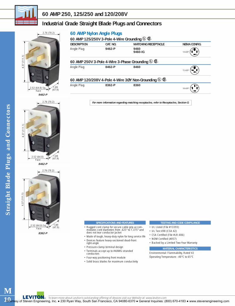
Str
aigh
t Bla
de P
lugs
and
Con
nect
ors
M10
60 AMP 250, 125/250 and 120/208V
Industrial Grade Straight Blade Plugs and Connectors
To learn more about Leviton’s outstanding offering of devices visit our Website at: www.leviton.com
SPECIFICATIONS AND FEATURES
• Rugged cord clamp for secure cable grip accom-modates cord diameters from .625" to 1.375" anddoes not tear conductor jacket
• Made of tough, heavy-duty nylon for long service life• Devices feature heavy-sectioned dead-front
right-angle• Pressure-clamp terminal design• Terminals accept up to #4AWG stranded
conductors• Four-way positioning front module• Solid brass blades for maximum conductivity
TESTING AND CODE COMPLIANCE
• UL Listed (File #13393)• UL Test 498 (CSA 42)• CSA Certified (File #LR-406)• NOM Certified (#057)• Backed by a Limited Two-Year Warranty
MATERIAL CHARACTERISTICS
Environmental: Flammability, Rated V2Operating Temperature: -40°C to 65°C
For more information regarding matching receptacles, refer to Receptacles, Section G.
60 AMP Nylon Angle Plugs60 AMP 125/250V 3-Pole 4-Wire Grounding URDESCRIPTION CAT. NO. MATCHING RECEPTACLE NEMA CONFIG.Angle Plug 9462-P 9460
9460-IG
60 AMP 250V 3-Pole 4-Wire 3-Phase Grounding URAngle Plug 8462-P 8460
60 AMP 120/208V 4-Pole 4-Wire 3ØY Non-Grounding URAngle Plug 8362-P 8360
14-60P
GYX
W
15-60P
GZX
Y
18-60P
WX Z
Y
4.37
(11
1.1)
2.76 (70.2)
2.52 (64.0) Sq. Face
1.89(47.9)
9462-P
4.37
(11
1.1)
2.76 (70.2)
2.52 (64.0) Face
1.89(47.9)
8462-P
4.37
(11
1.1)
2.76 (70.2)
2.52 (64.0) Sq. Face
1.89(47.9)
8362-P
Courtesy of Steven Engineering, Inc. ● 230 Ryan Way, South San Francisco, CA 94080-6370 ● General Inquiries: (800) 670-4183 ● www.stevenengineering.com

Built-in cord grip adjustsautomatically for usewith No. 18-2 throughNo. 12-3 cords
NEMA Configuration and ratingmolded into front module for easyidentification
Husk and module keyed for easyalignment during wiring
Triple-drive head screws —3⁄16" (4.76mm.) Standard,Philips, Robertson S
traight Blade P
lugs and Connectors
M11For answers to technical questions, call Leviton’s Techline at 1-800-824-3005
STRAIGHT BLADE PLUG AND CONNECTOR FEATURES
Commercial Grade Straight Blade Plugs and Connectors
LEVITON OFFERS A LARGE SELECTION OF 15, 20, 30 AND 50 AMP COMMERCIAL GRADESTRAIGHT BLADE PLUGS AND CONNECTORS, AVAILABLE IN A WIDE VARIETY OF FEATURES.
Leviton’s Commercial Grade Straight Blade Plugs and Connectors are rugged performers.They are moisture, chemical and abuse- resistant. And they’re ideal for indoor and out-door use.
PVC Grounding PlugResists moisture and chemicals;suited for outdoor cords. 515PV shown
PVC Angle Grounding PlugSpeed-thread assembly screwstighten with just a few quick turns;impact-resistant.515AN shown
Armored Grounding PlugIdeal for shops, garages andrough-duty work with hard floors.520PA shown
PVC Grounding ConnectorUnique dimpled body design pro-vides secure grip; resists abuse.515CV shown
Armored Grounding ConnectorTwo-piece strain-relief clamp cen-ter cord for neat installation; able totake hard punishment.615CA shown
Dual Power Vinyl Angle PlugThermoplastic body for long life;interchangeable blade configurations.930 shown
Motor Base InletContains heavy gauge brassblades and thermoplastic housing.5239 shown
Rubber Grounding ConnectorProvides protection against roughuse, dirt, moisture and tempera-ture extremes.515CR shown
� EPTR rubber-backed plugs and connectors stand up to rough use, protect against dirt andmoisture
� Deep-slotted, backed-out terminal screws draw backwire clamps securely over strippedleads for maximum conductivity
Courtesy of Steven Engineering, Inc. ● 230 Ryan Way, South San Francisco, CA 94080-6370 ● General Inquiries: (800) 670-4183 ● www.stevenengineering.com

2.61
(66
.3)
Ø1.38 (35.1)
Ø1.54 (39.1)
515CV
Str
aigh
t Bla
de P
lugs
and
Con
nect
ors
M12
15 AMP 125 and 250V
Commercial Grade Straight Blade Plugs and Connectors
To learn more about Leviton’s outstanding offering of devices visit our Website at: www.leviton.com
TESTING AND CODE COMPLIANCE
• Meet NEMA requirements• UL Listed (File #E-13393)• CSA Certified (File #LR-406)• NOM Certified (#057)• Backed by a Limited 10-Year Warranty
MATERIAL CHARACTERISTICS
Environmental: Flammability, Rated V2 per UL 94Operating Temperature: -40°C to 65°C.
SPECIFICATIONS AND FEATURES
• Triple-drive head screws — Standard, Philips,Robertson
• NEMA configuration number & rating molded onface of device for easy identification
• Rubber body is dirt and moisture resistant• Deep-slotted, backed out terminal screws draw
backwire clamps securely for maximum conductivity
• Husk & module keyed for easy alignment during wiring
• Built-in cord grip adjusts automatically for use withNo. 18-3 through No. 12-3 cords (.245"–.655")
• Motor Base Inlet accepts No. 10 max. copper orcopper clad wire
PVC Plugs & Connectors• Rugged PVC body resists moisture and chemicals;
suited for outdoor cords
• Unique dimpled body design provides a secure grip• Speed-thread assembly screws tighten with just a
few quick turnsArmored Plugs & Connectors• Ideal for shops, garages and rough-duty work with
hard floors• Two piece strain-relief clamp center cord for neat
installationRubber-Back Plugs & Connectors• Designed to stand up to rough use• No internal metal parts exposed• Elastomeric husk provides added protection against
dirt and moisture entry into the back wire port• Designed to operate in the widest possible tempera-
ture range
1.41 (35.8)
2.09
(53
.1)
Ø1.53 (38.9) 1.30(33.0)
515AN
2.11
(54
.0)
1.78(45.0)
5239
15 AMP Plugs, Angle Plugs, Armored Plugs and Connectors15 AMP 125V 2-Pole 3-Wire Grounding URDESCRIPTION CAT. NO. COLOR NEMA CONFIG.PVC Grounding Plug 515PV YellowArmored Grounding Plug 515PA Yellow/Steel ArmorRubber Grounding Plug 515PR BlackPVC Angle Grounding Plug 515AN WhitePVC Grounding Connector 515CV YellowArmored Grounding Connector 515CA Yellow/Steel ArmorRubber Grounding Connector 515CR BlackMotor Base Inlet 5239 Black
15 AMP 250V 2-Pole 3-Wire Grounding URDESCRIPTION CAT. NO. COLOR NEMA CONFIG.PVC Grounding Plug 615PV YellowArmored Grounding Plug 615PA Yellow/Steel ArmorArmored Grounding Connector 615CA Yellow/Steel ArmorMotor Base Inlet 5240 Black
5-15PG
W 5-15RG
W
6-15P 6-15RG G
Courtesy of Steven Engineering, Inc. ● 230 Ryan Way, South San Francisco, CA 94080-6370 ● General Inquiries: (800) 670-4183 ● www.stevenengineering.com

2.56
(65
.0)
Ø1.55 (39.2)
Ø1.38 (35.1)
2.02
(51
.3)
520CA
Ø1.54 (39.4)
Ø1.38 (35.1)
1.94
(49
.4)
620PV
Straight B
lade Plugs and C
onnectors
M13For answers to technical questions, call Leviton’s Techline at 1-800-824-3005
20 AMP 125 and 250V
Commercial Grade Straight Blade Plugs and Connectors
TESTING AND CODE COMPLIANCE
• Meet NEMA requirements• UL Listed (File #E-13393)• CSA Certified (File #LR-406)• NOM Certified (#057)• Backed by a Limited 10-Year Warranty
MATERIAL CHARACTERISTICS
Environmental: Flammability, Rated V2 per UL 94Operating Temperature: -40°C to 65°C.
SPECIFICATIONS AND FEATURES
• Triple-drive head screws — Standard, Philips, Robertson• NEMA configuration number & rating molded on device
for easy identification• Dirt and moisture resistant• Deep-slotted, backed out terminal screws draw backwire
clamps securely for maximum conductivity• Husk & module keyed for easy alignment during wiring• Built-in cord grip adjusts automatically for use with No. 18-
3 through No. 12-3 cords (.245"–.655")
PVC Plugs & Connectors• Rugged PVC body resists moisture and chemicals;
suited for outdoor cords• Unique dimpled body design provides a secure grip• Speed-thread assembly screws tighten with just a
few quick turnsArmored Plugs & Connectors• Ideal for shops, garages and rough-duty work with
hard floors• Two piece strain-relief clamp center cord for neat
installation
20 AMP Plugs, Angle Plugs, Armored Plugs and Connectors20 AMP 125V 2-Pole 3-Wire Grounding URDESCRIPTION CAT. NO. COLOR NEMA CONFIG.PVC Grounding Plug 520PV YellowArmored Grounding Plug 520PA Yellow/Steel ArmorPVC Grounding Connector 520CV Yellow Armored Grounding Connector 520CA Yellow/Steel Armor
20 AMP 250V 2-Pole 3-Wire Grounding URDESCRIPTION CAT. NO. COLOR NEMA CONFIG.PVC Grounding Plug 620PV YellowArmored Grounding Plug 620PA Yellow/Steel ArmorPVC Grounding Connector 620CV YellowArmored Grounding Connector 620CA Yellow/Steel ArmorRubber Back Grounding Plug 620PR Black
5-20PG
W
5-20R
6-20PG
6-20RG
GW
620PR
1.94
(49
.4)
Ø1.38 (35.1)
Ø1.54 (39.1)
Courtesy of Steven Engineering, Inc. ● 230 Ryan Way, South San Francisco, CA 94080-6370 ● General Inquiries: (800) 670-4183 ● www.stevenengineering.com

2.56 (65.1)
3.49
(88
.6)
1.44(36.5)
930
2.56 (65.1)
3.49
(88
.6)
1.44(36.5)
931
Str
aigh
t Bla
de P
lugs
and
Con
nect
ors
M14
30 AMP—125V/50 AMP 125V, 250V/50 AMP 250V, 125/250V/50 AMP 125/250V, 125V
Commercial Grade Straight Blade Plugs and Connectors
To learn more about Leviton’s outstanding offering of devices visit our Website at: www.leviton.com
SPECIFICATIONS AND FEATURES
• Tough thermoplastic shell for long life• Shell and bottom are hinged in front for ease of
assembly• Solid brass blades with color-coded terminals
simplify wiring• Each dual combination plug supplied with 30A
blades and flat 50A blade• Dead front right angle construction• Interchangeable blades eliminate need for stocking
different devices• Built-in rejection feature prevents closure if blades
are incorrectly positioned• Versatile cord clamp suitable for use with Nos. 14,
12, 10, 8 and 6 AWG round cord and Nos. 10/3SRDT, 8/2-10/1 SRDT and 6/2-8/1 flat wire
• Wiring stripping gauge molded into plug cover
TESTING AND CODE COMPLIANCE
• Meet NEMA requirements• UL Listed (File #13393)• CSA Certified (File #LR-406)• NOM Certified (File #057)• Backed by a Limited 10-Year Warranty
MATERIAL CHARACTERISTICS
Environmental: Flammability, Rated V2 per UL 94Operating Temperature: -40°C to 65°C
30 AMP/50 AMP Dual Power Attachment Plugs30 AMP 125V/50 AMP 125V Grounding URDESCRIPTION CAT. NO. COLOR NEMA CONFIG.Dual-Power Vinyl Angle Plug, 930 BlackInterchangeable BladesCord Dia. Range .630"–1.050"
30 AMP 250V/50 AMP 250V Grounding URDESCRIPTION CAT. NO. COLOR NEMA CONFIG.Dual-Power Vinyl Angle Plug, 931 BlackInterchangeable BladesCord Dia. Range .630"–1.050"
30 AMP 125/250V/50 AMP 125/250V Non-Grounding URDESCRIPTION CAT. NO. COLOR NEMA CONFIG.Dual-Power Vinyl Angle Plug, 287-T BlackInterchangeable BladesCord Dia. Range .687"–1.050"
30 AMP 125/250V/50 AMP 125/250V Grounding URDESCRIPTION CAT. NO. COLOR NEMA CONFIG.Dual-Power Vinyl Angle Plug, 275-T BlackInterchangeable BladesCord Dia. Range .750"–1.125"
30 AMP 125V 2-Pole 3-Wire Grounding URDESCRIPTION CAT. NO. COLOR NEMA CONFIG.Travel Trailer Vinyl Angle Plug, 830-T Blackfor use with 7313 ReceptacleCord Dia. Range .687"–.875"
5-30PG
W5-50P
G
W
6-30PG
6-50PG
10-30PW
YX
10-50PW
YX
14-30PG
X
W
Y 14-50PG
X
W
Y
ANSI Std. C73.13TT-30P
G
W
Courtesy of Steven Engineering, Inc. ● 230 Ryan Way, South San Francisco, CA 94080-6370 ● General Inquiries: (800) 670-4183 ● www.stevenengineering.com

2.25 (57.25)
1.00 (25.4)
0.811(20.6)
321-PW
1.38 (35.1)
0.81 (20.6)
1.63
(41
.4)
101
1.06
(27
.0)
0.75(18.9)
0.98 (25.0)
123-Pl
2.29
(58
.2)
0.81(20.6)
1.38 (35.1)
102-W
Straight B
lade Plugs and C
onnectors
M15For answers to technical questions, call Leviton’s Techline at 1-800-824-3005
10 AMP 125V • 15 AMP 125V
Residential Grade Straight Blade Plugs and Connectors
SPECIFICATIONS AND FEATURES
• Brass plug blades and connector contacts for max-imum conductivity
• Armored devices have heavily plated steel shieldsand cord clamps
• Vinyl devices resist chipping, cracking, oils, greaseand acids
• Rubber devices resist cold, abrasion, grease, oils,acids and impact
• Plastic devices resist grease, oils and acids
TESTING AND CODE COMPLIANCE
• Meet NEMA requirements (1-15P)• UL Listed (File #E-13393)• CSA Certified• NOM Certified (#057)• Backed by a Limited Two-Year Warranty
MATERIAL CHARACTERISTICS
Environmental: Flammability, Rated V2 per UL 94Operating Temperature: -40°C to 65°C
10 AMP and 15 AMP Parallel Plugs and ConnectorsEasy Wire Plugs URDESCRIPTION CAT. NO. COLOR CORD DIA. WIRE GAUGE (stranded) NEMA
(inches) Amperage (Watts) CONFIG.Non-Polarized 321 Brown
#16/2 HPN, 15A (1875 Watts)321-W White
#18/2 HPN, 10A (1250 Watts)#18/2 SPT-1, 10A (1250 Watts)#18/2 SPT-2, 10A (1250 Watts)
Polarized 321-P* Brown321-PW* White
Non-Polarized 123 Brown123-I Ivory
#18/2 SPT-1, 10A (1250 Watts)123-W White#20/2 XT, 3A (375 Watts)Polarized 123-P* Brown
123-PI* Ivory123-PW* White
*Packed 500 Bulk
15 AMP 125V 2-Pole, 2-Wire URDESCRIPTION CAT. NO. COLOR CORD DIA. WIRE GAUGE NEMA
(inches) (stranded) CONFIG.Polarized Light Duty 101 Brown No. 20, 18,Clamptite Plug 101-W White Up to .250 16 Flat or
101-E Black RoundedNote: Consult factory for availability of non-polarized version
Polarized Light Duty 102 Brown No. 20, 18,Clamptite Connector 102-W White Up to .250 16 Flat or
102-E Black RoundedNon-Polarized Heavy-Duty 115PV YellowPVC PlugNon-Polarized Heavy-Duty 115PR BlackTPE Rubber PlugNon-Polarized Short 48643 BrownFlat Vinyl Plug� 48643-W White .375 max. 18–14
48643-E BlackPolarized Angle 638 BlackVinyl Plug� 638-B Brown .343 max. 16 max.
638-W WhiteNon-Polarized Round 48646 BlackVinyl Handle Plug, .437 max. 18–14w/Cord Clamp�
Non-Polarized 612† BlackVinyl Connector, .437 max. 14 max.w/Cord Clamp�
Non-Polarized Round 48642 BlackVinyl Handle Plug, .375 max. 18–14w/Spring Blades�
†Not UL Listed. For replacement use only.CSA Certified except where indicated by �
1-15PNon-Polarized
1-15PPolarized W
1-15PNon-Polarized
1-15PPolarized W
1-15PPolarized
1-15RPolarized
W
W
.245–.655"AWG 18-2 to 12-2 cable.
Courtesy of Steven Engineering, Inc. ● 230 Ryan Way, South San Francisco, CA 94080-6370 ● General Inquiries: (800) 670-4183 ● www.stevenengineering.com

Str
aigh
t Bla
de P
lugs
and
Con
nect
ors
M16
15 AMP 125V
Residential Grade Straight Blade Plugs and Connectors
To learn more about Leviton’s outstanding offering of devices visit our Website at: www.leviton.com
SPECIFICATIONS AND FEATURES
• Double wipe brass contacts for maximum conductiv-ity and blade retention
TESTING AND CODE COMPLIANCE
• Meet NEMA requirements• UL Listed (File #E-13393)• CSA Certified (File #LR-406)• NOM Certified (#057)• Backed by a Limited Two-Year Warranty
MATERIAL CHARACTERISTICS
Environmental: Flammability, Rated V2 per UL 94Operating Temperature: -40°C to 65°C
15 AMP Plugs and Connectors15 AMP 125V 2-Pole, 3-Wire Grounding URDESCRIPTION CAT. NO. COLOR CORD DIA. WIRE GAUGE NEMA
(inches) (stranded) CONFIG.Vinyl Handle Plug, 48648 Black .437 max. 18–14w/Cord Clamp�
Vinyl Connector, 617 Black .437 max. 16 max.w/ Steel Cord ClampRubber Plug 113 Black .396-.562 18–14w/Vinyl Inner AssemblyRubber Connector 114 Black .396-.562 18–14mates w/No. 113 aboveWeatherproof Inlet 4937 No. 10 max.on Flush Mount Wallplate copper or with Aluminum Cover copper clad
CSA Certified except where indicated by �
5-15PG
W
5-15RG
W
1.64
(41
.7)
Ø1.53 (38.9)
Ø1.50 (38.1)
113
2.27
(57
.5)
Ø1.53 (38.9)
Ø1.50 (38.1)
114
4937
Courtesy of Steven Engineering, Inc. ● 230 Ryan Way, South San Francisco, CA 94080-6370 ● General Inquiries: (800) 670-4183 ● www.stevenengineering.com

Locking and Corrosion R
esistant Devices Index
INDEXIndustrial Specification Grade Locking DevicesOverview . . . . . . . . . . . . . . . . . . . . . . . . . . .N2–N415 Amp Devices . . . . . . . . . . . . . . . . . . . . . .N5, N620 Amp Devices . . . . . . . . . . . . . . . . . . . . .N7–N1130 Amp Devices . . . . . . . . . . . . . . . . . . . .N12–N16Wetguard® Devices
15 Amp . . . . . . . . . . . . . . . . . . . . . . . . . . . .N1720 Amp . . . . . . . . . . . . . . . . . . . . . . . .N17, N1830 Amp . . . . . . . . . . . . . . . . . . . . . . . . . . . .N19
Corrosion Resistant Devices15 Amp . . . . . . . . . . . . . . . . . . . . . . . . . . . .N2020 Amp . . . . . . . . . . . . . . . . . . . . . . . . . . . .N2130 Amp . . . . . . . . . . . . . . . . . . . . . . . . . . . .N2250 Amp . . . . . . . . . . . . . . . . . . . . . . . . . . . .N23
Non-NEMA Devices15 Amp . . . . . . . . . . . . . . . . . . . . . . . . . . . .N2420 Amp . . . . . . . . . . . . . . . . . . . . . . . . . . . .N24 30 Amp . . . . . . . . . . . . . . . . . . . . . . . . . . . .N2550 Amp . . . . . . . . . . . . . . . . . . . . . . . . . . . .N2550 Amp "California Style" . . . . . . . . . . . . . . .N26
Weather Resistant Boots . . . . . . . . . . . . . . . . . .N27Power Interrupting Devices . . . . . . . . . . . . . . . .N28Midget Straight Blade and Locking Devices . . . .N29Combination Locking and Straight Blade Devices . . . . . . . . . . . . . . . . . . .N30Integrated Inlets and Outlets with Weather Resistant Covers . . . . . . . . . . . . . . . . .N30
SECTIONNLocking andCorrosionResistant Devices
Courtesy of Steven Engineering, Inc. ● 230 Ryan Way, South San Francisco, CA 94080-6370 ● General Inquiries: (800) 670-4183 ● www.stevenengineering.com

To learn more about Leviton’s outstanding offering of devices visit our Website at: www.leviton.com
LOCKING DEVICE FEATURES
Industrial Grade Locking Devices
Lock
ing
Dev
ices
N2
LOCKING DEVICES FOR THE ENTIRE SPECTRUM OF INDUSTRIAL APPLICATIONSLeviton’s Industrial Grade Locking Devices are built to provide unparalleled quality and superior performance in themost severe industrial settings. The Locking Devices line represents a broad selection of plugs and connectors,locking receptacles, flanged inlets and outlets, California-style devices, midget locking devices, power interruptingdevices, and non-NEMA devices. Leviton combines the best materials available with superior production standardsto produce a broad selection of Locking Devices of unmatched flexibility and dependability.
• UL 498 Listed • Federal Specification
WC-596 Listed• CSA Specification C22.2
No. 42 Certified
Transparent wiring chambers provide a means of visual inspectionof conductors and terminals
Cleat on contacts cutsoxidation when plugblades enter contactsurfaces
One-piece, rivetless, .035" thick brasscontacts offer enlarged contact surfaceareas, improved conductivity, lowresistance, low heat and long life
Combination #10-32 deepslotted/ Phillips brass screwseasily torque to 10-14 in.-lbs.
Ergonomically designed flutedbody with radial gripping ridgecreates an ideal surface forgripping, turning and pulling
Cable gage identifies maximumcord size allowed with strainrelief insert
External cord clamp utilizes deep triple drive steel screws that are backed out and positioned inside shrouded pockets.External clamp accepts wire mesh grips
Internal wiring chambers isolate individualconductors to prevent flashover, arcing,
and stray strands of wire
Color-coded terminal screws
Deep slotted/ Phillips/Robertson steel screwssecure wiring module (12-14 in.-lbs) to body
NEMA configuration, agency certifica-tions and device rating are molded onfront of device to assist with identification
Solid brass blades are fitted andheld tightly and securely in place
Wiring module keyed to bodyfor easy assembly
Positive crimp contact plate bundles stranded wire maximizingwire/clamp surface contact
Terminal identification letters on back coverensure quick and accurate termination
Super Tough Nylon resistsdamage from severe impact,abrasion and chemical attack
Molded-in strip gage providescorrect measurement for properstrip length of conductor
L I F E T I M E
Color-coded terminal screws
Dead front construction preventsaccidental contact with internal parts
Speed drive screws forfaster assembly
Shrouded pockets in cord clampprevents slippage of screwdriverblade when tightening clamp screws.
Wire clamps move within individualchambers to provide positive clamplock without cutting wire strands.
Captive terminal screws eliminatenuisance dropping and searching formissing screws.
Deep-funnelled, large wire wellsguide conductors into terminationposition.
Courtesy of Steven Engineering, Inc. ● 230 Ryan Way, South San Francisco, CA 94080-6370 ● General Inquiries: (800) 670-4183 ● www.stevenengineering.com

LOCKING DEVICE FEATURES
Industrial Grade Locking Devices
Locking Devices
N3
LOCKING FLUSH RECEPTACLESEngineered for maximum performance with aUL 94 V-O Flammability Rating.
Flanged Inlets and OutletsBuilt to endure hard use withrugged nylon flanges thatassure a smooth, flush fit andoutstanding resistance tocracking and breaking. 2316 shown
Weather-Resistant BootsFeature triple seal action toprotect locking plugs andconnectors from the harmfuleffects of dirt and moisture inharsh operations.6034 shown
Specifically developed for wetor damp locations. EPTR ther-moplastic rubber body andrugged design resists water,acids, alkalies, grease, oilsand solvents.24W47 shown
Extra thick .050" nickel-platedbrass mounting strap
Stamped-in agencycertifications
Amperage & voltage rating
NEMA line number
Color-codedvoltage rating
Manufacturer
Triple-combomounting screws
Seam betweenfront cover andback cover is farfrom contact arcing
One-piece ,040" thick brass, high-coppercontent contacts with nickel-plated
clamp type terminals
Contacts deeplyseated in thickwalled faced
Oversized #10 brassPhillips/Robertson/Straight Slot drive terminal screw
Mechanically-securedall-brass ground path
Stability ribs
Molded-in terminalidentification letters
Multi-terminationdesign
Accepts #8º#14solid or strandedconductors
Midget Locking DevicesML1, ML2 and ML3 Lockingdevices covering the entirespectrum of industrial applica-tions where restrained spaceconsiderations are a factor.ML1-C shown
2710 shown
125V 250V 277V AC
125/250V 3ø250V 3ø480V
Color-Coded Voltage Ratings
Uni-body face
L I F E T I M E
For answers to technical questions, call Leviton’s Techline at 1-800-824-3005Courtesy of Steven Engineering, Inc. ● 230 Ryan Way, South San Francisco, CA 94080-6370 ● General Inquiries: (800) 670-4183 ● www.stevenengineering.com
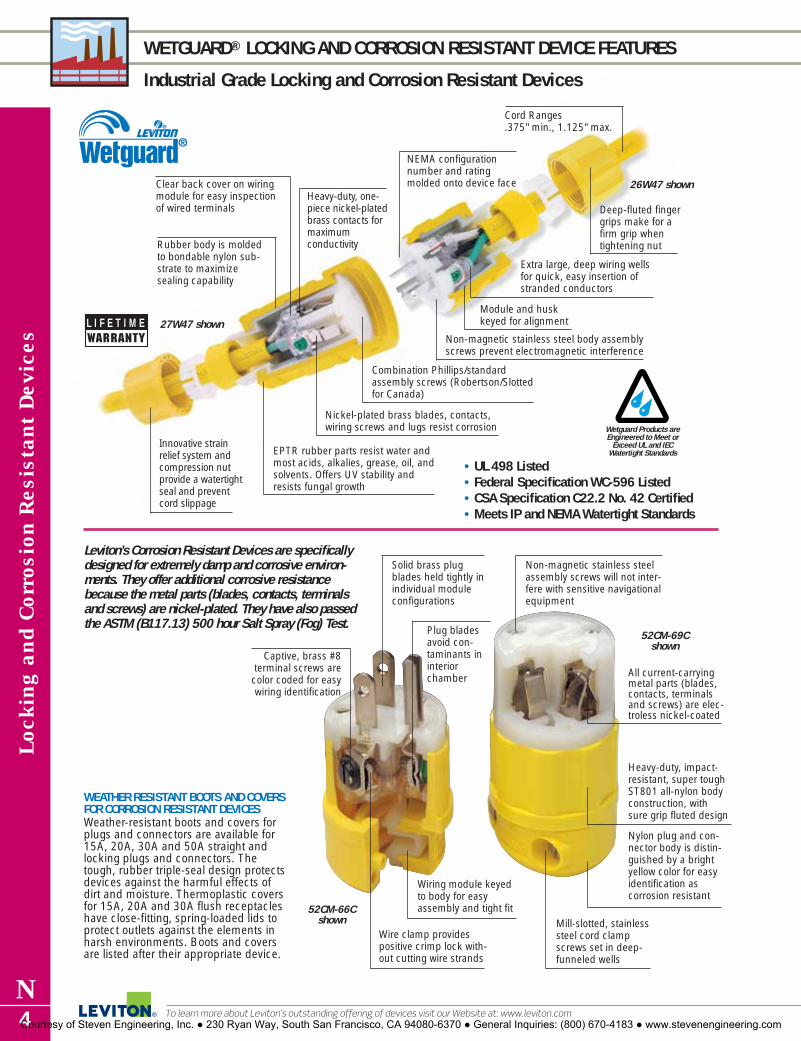
Nickel-plated brass blades, contacts,wiring screws and lugs resist corrosion
Clear back cover on wiringmodule for easy inspectionof wired terminals
Innovative strainrelief system andcompression nutprovide a watertightseal and preventcord slippage
EPTR rubber parts resist water andmost acids, alkalies, grease, oil, andsolvents. Offers UV stability andresists fungal growth
Combination Phillips/standardassembly screws (Robertson/Slottedfor Canada)
NEMA configurationnumber and ratingmolded onto device face
Module and husk keyed for alignment
Deep-fluted fingergrips make for afirm grip whentightening nut
Extra large, deep wiring wellsfor quick, easy insertion ofstranded conductors
Non-magnetic stainless steel body assemblyscrews prevent electromagnetic interference
Rubber body is moldedto bondable nylon sub-strate to maximize sealing capability
Cord Ranges .375" min., 1.125" max.
Heavy-duty, one-piece nickel-platedbrass contacts formaximum conductivity
Lock
ing
and
Cor
rosi
on R
esis
tant
Dev
ices
N4
WETGUARD® LOCKING AND CORROSION RESISTANT DEVICE FEATURES
Industrial Grade Locking and Corrosion Resistant Devices
To learn more about Leviton’s outstanding offering of devices visit our Website at: www.leviton.com
Leviton’s Corrosion Resistant Devices are specificallydesigned for extremely damp and corrosive environ-ments. They offer additional corrosive resistancebecause the metal parts (blades, contacts, terminalsand screws) are nickel-plated. They have also passedthe ASTM (B117.13) 500 hour Salt Spray (Fog) Test.
WEATHER RESISTANT BOOTS AND COVERSFOR CORROSION RESISTANT DEVICESWeather-resistant boots and covers forplugs and connectors are available for15A, 20A, 30A and 50A straight andlocking plugs and connectors. Thetough, rubber triple-seal design protectsdevices against the harmful effects ofdirt and moisture. Thermoplastic coversfor 15A, 20A and 30A flush receptacleshave close-fitting, spring-loaded lids toprotect outlets against the elements inharsh environments. Boots and coversare listed after their appropriate device.
All current-carryingmetal parts (blades,contacts, terminalsand screws) are elec-troless nickel-coated
52CM-69Cshown
52CM-66Cshown
26W47 shown
Wetguard Products areEngineered to Meet or
Exceed UL and IECWatertight Standards
27W47 shown
Heavy-duty, impact-resistant, super toughST801 all-nylon bodyconstruction, with sure grip fluted design
Nylon plug and con-nector body is distin-guished by a brightyellow color for easyidentification as corrosion resistant
Mill-slotted, stainlesssteel cord clampscrews set in deep-funneled wells
Non-magnetic stainless steelassembly screws will not inter-fere with sensitive navigationalequipment
Solid brass plugblades held tightly inindividual moduleconfigurations
Plug bladesavoid con-taminants ininteriorchamber
Captive, brass #8terminal screws arecolor coded for easywiring identification
Wiring module keyedto body for easyassembly and tight fit
Wire clamp providespositive crimp lock with-out cutting wire strands
L I F E T I M E
• UL 498 Listed • Federal Specification WC-596 Listed• CSA Specification C22.2 No. 42 Certified• Meets IP and NEMA Watertight Standards
Courtesy of Steven Engineering, Inc. ● 230 Ryan Way, South San Francisco, CA 94080-6370 ● General Inquiries: (800) 670-4183 ● www.stevenengineering.com

Ø 1
.39
(35.
3)
Ø 1
.53
(38.
9)
1.98 (50.4)
4720-C
2.76 (70.0)
Ø 1
.39
(35.
3)
Ø 1
.53
(38.
9)
4729-C
Locking Devices
N5For answers to technical questions, call Leviton’s Techline at 1-800-824-3005
15 AMP 125V
Industrial Grade Locking Devices
15 AMP 125V 2-Pole 3-Wire Grounding URDESCRIPTION CAT. NO. NEMA CONFIG.Dustguard™ Locking Plug, Yellow EPTR Body 2447Dustguard™ Locking Connector, Yellow EPTR Body 2547Duplex Flush Receptacle, Self Grounding, Back and Side Wired 4700Duplex Flush Receptacle w/2 Hot Feeds and 1 Neutral Return, 4702-IIRSelf Grounding, Back and Side WiredDuplex Flush Receptacle w/Split Feed — 2 Hot Feeds and 4703-IIR2 Neutral Returns, Self Grounding, Back and Side WiredDuplex Flush Receptacle, Isolated Ground, Back and Side Wired 4700-IGSingle Flush Receptacle 4710Single Flush Receptacle, w/Short Strap 4710-SSSingle Flush Receptacle, Isolated Ground 4710-IGLocking Flanged Outlet 4715-CLocking Flanged Inlet 4716-CLocking Plug, Black & White Nylon Body 4720-CPower Indication™ Locking Plug, Black & White Nylon Body 4720-PLCAngle Locking Plug, Black & White Nylon Body 4720-CALocking Plug, All Black Nylon for Stage and Studio 4720-CBLocking Plug, Yellow Nylon Body 4720-CYLocking Connector, Black & White Nylon Body 4729-CPower Indication™ Locking Connector, Black Nylon Body 4729-PLCLocking Connector, All Black Nylon for Stage and Studio 4729-CBLocking Connector, Yellow Nylon Body 4729-CY
Weather-Resistant Boots for 15A Locking Plugs and Connectors are listed on page N27
TESTING AND CODE COMPLIANCE
• All receptacles, plugs, connectors, inlets and outletsare designed to meet NEMA WD-6, and ANSI C-73,and to meet/exceed UL 498 standards
• UL Fed. Spec. Listed WC-596 – Plugs, Connectorsand Flanged Inlets (File #E-13393), Receptaclesand Flanged Outlets (File #E-13399)
• CSA Certified (File #LR-406)• NOM Certified (#057)• Backed by a Lifetime Warranty
MATERIAL CHARACTERISTICS
Environmental: Flammability Rated V2 per UL94Operating Temperature: -40°C to 60°C
SPECIFICATIONS AND FEATURES
Locking Flush Receptacles• Rugged nylon body and cover for outstanding resist-
ance to impact and harsh chemicals• Double-wipe phosphor-bronze power contactsLocking Plugs and Connectors• Super tough Nylon body resists damage from severe
impact, abrasion and chemicals• Ergonomic, fluted body design with radial grip ridge is
ideal for gripping, turning and pulling• Cord clamp does not have to be disassembled from
body for wiring—accepts all wire mesh strain reliefs• One-piece, rivetless .035" thick brass connector
contacts and solid brass plug blades provide maximumconductivity and long service life
• Power Indication™ 15A Locking Plugs & Connectorsequipped with green neon bulb rated at 30,000 hours(24/7) for 3.5 years
Flanged Inlets and Outlets• Rugged nylon flange fits flush and won’t crack in high-
abuse applications• Individual deep-funneled chamfered wire wells guide
each wire into rectangular chambers• Wire clamps provide positive crimp lock without cutting
wire strandsDustguard Plugs and Connectors• IEC IP44 Rated• Developed to withstand dusty and dirty environments,
cracking and fading, temperature extremes• Rugged wiring modules have high performance single-
piece brass triple-wipe contacts, solid brass plug blades
L5-15R
W
G
L5-15P
W
G
Cord Clamp Range—Black & White Plugs and Connectors: .240"–.700" #18–#10 AWG Dustguard Plugs andConnectors: .240"–.655" #18–#12 AWG
1.78
(43
.5)
Ø 2.50 (63.5)
Ø 1.69 (42.8)
4716-C
Ø 1.53 (38.9)
1.47 (35.7)
1.30(33.0)
2.09
(53
.2)
4720-CA
Wallplates and Covers302 STAINLESS STEEL 302 STAINLESS STEEL WEATHER-RESISTANT FLIP LID COVERSINGLE RECEPTACLE DUPLEX RECEPTACLE FOR INLETS AND OUTLETS
1.41" Dia. Opening IP64 Rated—Includes Gasket and Screws
For complete wallplate selection, see Section E.84004-40 WP184003-40
Courtesy of Steven Engineering, Inc. ● 230 Ryan Way, South San Francisco, CA 94080-6370 ● General Inquiries: (800) 670-4183 ● www.stevenengineering.com

2.76 (70.0)
Ø 1
.39
(35.
3)
Ø 1
.53
(38.
9)
4579-CY
Ø 1
.39
(35.
3)
Ø 1
.53
(38.
9)
1.98 (50.4)
4570-CY
Lock
ing
Dev
ices
N6
15 AMP 250V, 277V and 3Ø 250V
Industrial Grade Locking Devices
To learn more about Leviton’s outstanding offering of devices visit our Website at: www.leviton.com
15 AMP 250V 2-Pole 3-Wire Grounding URDESCRIPTION CAT. NO. NEMA CONFIG.Duplex Flush Receptacle, Self Grounding, Back and Side Wired 4550Duplex Flush Receptacle, Isolated Ground, Back and Side Wired 4550-IGSingle Flush Receptacle 4560Single Flush Receptacle, Isolated Ground 4560-IGLocking Plug, Black & White Nylon Body 4570-CPower Indication™ Locking Plug, Black & White Nylon Body 4570-PLCAngle Locking Plug, Black & White Nylon Body 4570-CALocking Plug, Yellow Nylon Body 4570-CYLocking Connector, Black & White Nylon Body 4579-CPower Indication™ Locking Connector, Black & White Nylon Body 4579-PLCLocking Connector, Yellow Nylon Body 4579-CYLocking Flanged Outlet 4585-CLocking Flanged Inlet 4586-C
15 AMP 277V 2-Pole 3-Wire Grounding URDESCRIPTION CAT. NO. NEMA CONFIG.Duplex Flush Receptacle, Self Grounding, Back and Side Wired 4750Duplex Flush Receptacle, Isolated Ground, Back and Side Wired 4570-IGSingle Flush Receptacle 4760Single Flush Receptacle, Isolated Ground 4760-IGLocking Plug, Black & White Nylon Body 4770-CPower Indication™ Locking Plug, Black & White Nylon Body 4770-PLCAngle Locking Plug, Black & White Nylon Body 4770-CALocking Plug, Yellow Nylon Body 4770-CYLocking Connector, Black & White Nylon Body 4779-CLocking Connector, Yellow Nylon Body 4779-CYPower Indication™ Locking Connector, Black & White Nylon Body 4779-PLCLocking Flanged Outlet 4785-CLocking Flanged Inlet 4786-C
15 AMP 3Ø 250V 3-Pole 3-Wire Non-Grounding UDESCRIPTION CAT. NO. NEMA CONFIG.Single Flush Receptacle 4870Locking Plug, Black & White Nylon Body 4880-CLocking Connector, Black & White Nylon Body 4889-C
Weather-Resistant Boots for 15A Locking Plugs and Connectors are listed on page N27
TESTING AND CODE COMPLIANCE
• All receptacles, plugs, connectors, inlets and outletsare designed to meet NEMA WD-6, and ANSI C-73,and to meet/exceed UL 498 standards
• UL Fed Spec. Listed WC-596 – Plugs, Connectorsand Flanged Inlets (File #E-13393), Receptaclesand Flanged Outlets (File #E-13399)
• CSA Certified (File #LR-406)• NOM Certified (#057)• Backed by a Lifetime Warranty
MATERIAL CHARACTERISTICS
Environmental: Flammability Rated V2 per UL94Operating Temperature: -40°C to 60°C
SPECIFICATIONS AND FEATURES
Locking Flush Receptacles• Rugged nylon body and cover for outstanding
resistance to impact and harsh chemicals• Double-wipe phosphor-bronze power contactsLocking Plugs and Connectors• Super tough Nylon body resists damage from severe
impact, abrasion and chemicals• Ergonomic, fluted body design with radial grip ridge is
ideal for gripping, turning and pulling• Cord clamp does not have to be disassembled from
body for wiring—accepts all wire mesh strain reliefs
• One-piece, rivetless .035" thick brass connector contacts and solid brass plug blades provide maximumconductivity and long service life
• Power Indication™ 15A Locking Plugs & Connectorsequipped with green neon bulb rated at 30,000 hours(24/7) for 3.5 years
Flanged Inlets and Outlets• Rugged nylon flange fits flush and won’t crack in high-
abuse applications• Individual deep-funneled chamfered wire wells guide
each wire into rectangular chambers• Wire clamps provide positive crimp lock without cutting
wire strands
L7-15P
GW
L7-15R
GW
L11-15P ZX
Y
L11-15RZ
X
Y
L6-15P
G
X
Y
L6-15R G
X
Y
2.09
(53
.2)
Ø 1.53 (38.9)
1.47 (35.7)
1.30(33.0)
4570-CA
Cord Clamp Range—Black & WhitePlugs and Connectors: .240"–.700"#18–#10 AWG
Wallplates and Covers302 STAINLESS STEEL 302 STAINLESS STEEL WEATHER-RESISTANT FLIP LID COVERSINGLE RECEPTACLE DUPLEX RECEPTACLE FOR INLETS AND OUTLETS
1.41" Dia. Opening IP64 Rated—Includes Gasket and Screws
For complete wallplate selection, see Section E.84004-40 WP184003-40
Courtesy of Steven Engineering, Inc. ● 230 Ryan Way, South San Francisco, CA 94080-6370 ● General Inquiries: (800) 670-4183 ● www.stevenengineering.com

Ø 1.84 (46.8)
Ø 2.88 (73.0)
Ø 2.05 (52.0)
2.11
(53
.6)
2316
Ø 1
.84
(46.
8)
Ø 2
.08
(52.
8)
3.53 (89.7)
2313
Locking Devices
N7For answers to technical questions, call Leviton’s Techline at 1-800-824-3005
20 AMP 125V, 250V and 277V
Industrial Grade Locking Devices
20 AMP 125V 2-Pole 3-Wire Grounding URDESCRIPTION CAT. NO. NEMA CONFIG.V-0-MAX® Single Flush Receptacle 2310V-0-MAX® Single Flush Receptacle, Isolated Ground 2310-IGLocking Plug, Black & White Nylon Body 2311Power Indication™ Locking Plug, Black & White Nylon Body 2311-PLCLocking Plug, all Black for Stage and Studio 2311-BPower Indication™ Locking Plug, All-Black Nylon Body 2311-PLBLocking Plug, Yellow Nylon Body 2311-CYLocking Connector, Black & White Nylon Body 2313Power Indication™ Locking Connector, Black & White Nylon Body 2313-PLCLocking Connector, all Black for Stage and Studio 2313-BPower Indication™ Locking Connector, All-Black Nylon Body 2313-PLBLocking Connector, Yellow Nylon Body 2313-CYLocking Flanged Inlet 2315Locking Flanged Outlet 2316
20 AMP 250V 2-Pole 3-Wire Grounding URDESCRIPTION CAT. NO. NEMA CONFIG.V-0-MAX® Single Flush Receptacle 2320V-0-MAX® Single Flush Receptacle, Isolated Ground 2320-IGLocking Plug, Black & White Nylon Body 2321Power Indication™ Locking Plug, Black & White Nylon Body 2321-PLCPower Indication™ Locking Plug, All-Black Nylon Body 2321-PLBLocking Plug, Yellow Nylon Body 2321-CYLocking Connector, Black & White Nylon Body 2323Power Indication™ Locking Connector, Black & White Nylon Body 2323-PLCPower Indication™ Locking Connector, All-Black Nylon Body 2323-PLBLocking Connector, Yellow Nylon Body 2323-CYLocking Flanged Inlet 2325Locking Flanged Outlet 2326
20 AMP 277V 2-Pole 3-Wire Grounding URDESCRIPTION CAT. NO. NEMA CONFIG.V-0-MAX® Single Flush Receptacle 2330V-0-MAX® Single Flush Receptacle, Isolated Ground 2330-IGLocking Plug, Black & White Nylon Body 2331Power Indication™ Locking Plug, Black & White Nylon Body 2331-PLCLocking Connector, Black Nylon Body 2333Power Indication™ Locking Connector, Black & White Nylon Body 2333-PLCLocking Flanged Inlet 2335Locking Flanged Outlet 2336
Weather-Resistant Boots for 20A Locking Plugs and Connectors are listed on page N27
L6-20P
G
X
Y
L6-20R
G
X
Y
L7-20P G
W
L7-20R G
W
Cord Clamp Range—Black & WhitePlugs and Connectors: .385"–.780"#16–#10 AWG
L5-20R
W
GL5-20PW
G
TESTING AND CODE COMPLIANCE
• All receptacles, plugs, connectors, inlets and outletsare designed to meet NEMA WD-6, and ANSI C-73,and to meet/exceed UL 498 standards
• UL Fed Spec. Listed WC-596 – Plugs, Connectors andFlanged Inlets (File #E-13393), Receptacles andFlanged Outlets (File #E-13399)
• CSA Certified (File #LR-406)• NOM Certified (#057)• Backed by a Lifetime Warranty
MATERIAL CHARACTERISTICS
Environmental: Flammability Rated V2 per UL94, V-O-MAX® Receptacles Rated V0 Operating Temperature: -40°C to 60°C
SPECIFICATIONS AND FEATURES
V-O-Max® Locking Flush Receptacles• UL 94 V-O Flammability Rating, the best rating of any
material used in Industrial Locking Flush Receptaclesavailable today
• Extra-thick .050" nickel-plated brass mounting strapfor high-abuse applications
• Designed for maximum durability: One-piece .040"brass, high copper-content contacts with nickel-plated clamp-type terminals
• Color-coded voltage rating on face for easy identification
Locking Plugs and Connectors• Super tough Nylon body resists damage from severe
impact, abrasion and chemicals• Ergonomic, fluted body design with radial grip ridge is
ideal for gripping, turning and pulling
• Cord clamp does not have to be disassembled frombody for wiring—accepts all wire mesh strain reliefs
• One-piece, rivetless .035" thick brass connector con-tacts and solid brass plug blades provide maximumconductivity and long service life
• Power Indication™ 20A Locking Plugs & Connectorsequipped with green LED rated at 100,000 hours(24/7) for 11.5 years
Flanged Inlets and Outlets• Rugged nylon flange fits flush and won’t crack in
high-abuse applications• Individual deep-funneled chamfered wire wells guide
each wire into rectangular chambers• Wire clamps provide positive crimp lock without
cutting wire strands
3.28
(83
.3)
3.63
(92
.1)
2.67
(67
.8)
0.75(19.1)
1.69 (42.8)
1.06(26.8)
2310
2.47 (63.0)
Ø 1
.84
(46.
8)
Ø 2
.08
(53.
0)
2311
For recommended Wallplates and Covers, see page N8.For complete wallplate selection, see Section E.
Courtesy of Steven Engineering, Inc. ● 230 Ryan Way, South San Francisco, CA 94080-6370 ● General Inquiries: (800) 670-4183 ● www.stevenengineering.com

Lock
ing
Dev
ices
N8
20 AMP 347V, 480V, 600V and 125/250V
Industrial Grade Locking Devices
To learn more about Leviton’s outstanding offering of devices visit our Website at: www.leviton.com
TESTING AND CODE COMPLIANCE
• All receptacles, plugs, connectors, inlets and outletsare designed to meet NEMA WD-6, and ANSI C-73,and to meet/exceed UL 498 standards
• UL Fed Spec. Listed WC-596 – Plugs, Connectors andFlanged Inlets (File #E-13393), Receptacles andFlanged Outlets (File #E-13399)
• CSA Certified (File #LR-406)• NOM Certified (#057)• Backed by a Lifetime Warranty
MATERIAL CHARACTERISTICS
Environmental: Flammability Rated V2 per UL94, V-O-MAX® Receptacles Rated V0 Operating Temperature: -40°C to 60°C
SPECIFICATIONS AND FEATURES
V-O-Max® Locking Flush Receptacles• UL 94 V-O Flammability Rating, the best rating of any
material used in Industrial Locking Flush Receptaclesavailable today
• Extra-thick .050" nickel-plated brass mounting strapfor high-abuse applications
• Designed for maximum durability: One-piece .040"brass, high copper-content contacts with nickel-plated clamp-type terminals
• Color-coded voltage rating on face for easy identification
Locking Plugs and Connectors• Super tough Nylon body resists damage from severe
impact, abrasion and chemicals
• Ergonomic, fluted body design with radial grip ridge isideal for gripping, turning and pulling
• Cord clamp does not have to be disassembled frombody for wiring—accepts all wire mesh strain reliefs
• One-piece, rivetless .035" thick brass connector con-tacts and solid brass plug blades provide maximumconductivity and long service life
Flanged Inlets and Outlets• Rugged nylon flange fits flush and won’t crack in
high-abuse applications• Individual deep-funneled chamfered wire wells guide
each wire into rectangular chambers• Wire clamps provide positive crimp lock without
cutting wire strands
20 AMP 347V 2-Pole 3-Wire Grounding RDESCRIPTION CAT. NO. NEMA CONFIG.V-O-MAX® Single Flush Receptacle 3720Locking Plug, Black & White Nylon Body 3721Locking Connector, Black & White Nylon Body 3723Locking Flanged Inlet 3755Locking Flanged Outlet 3756
20 AMP 480V 2-Pole 3-Wire Grounding URDESCRIPTION CAT. NO. NEMA CONFIG.V-O-MAX® Single Flush Receptacle 2340V-O-MAX® Single Flush Receptacle, Isolated Ground 2340-IGLocking Plug, Black & White Nylon Body 2341Locking Connector, Black & White Nylon Body 2343Locking Flanged Inlet 2345Locking Flanged Outlet 2346
20 AMP 600V 2-Pole 3-Wire Grounding URDESCRIPTION CAT. NO. NEMA CONFIG.V-O-MAX® Single Flush Receptacle 2350V-O-MAX® Single Flush Receptacle, Isolated Ground 2350-IGLocking Plug, Black & White Nylon Body 2351Locking Connector, Black & White Nylon Body 2353Locking Flanged Inlet 2355Locking Flanged Outlet 2356
20 AMP 125/250V 3-Pole 3-Wire Non-Grounding UDESCRIPTION CAT. NO. NEMA CONFIG.Single Flush Receptacle 2360Locking Plug, Black & White Nylon Body 2361Locking Connector, Black & White Nylon Body 2363Locking Flanged Inlet 2365Locking Flanged Outlet 2366
Weather-Resistant Boots for 20A Locking Plugs and Connectors are listed on page N27
L24-20PW
G
L24-20RW
G
L8-20P G
X
Y
L8-20R G
X
Y
Cord Clamp Range—Black & White Plugs and Connectors: .385"–.780" #16–#10 AWG
L9-20P G
X
Y
L9-20RG
X
Y
L10-20P W
X
Y
L10-20R W
X
Y
0.75(19.1)
1.69 (42.8)
1.06 (26.8)
3.28
(83
.3)
3.63
(92
.1)
2.67
(67
.8)
2340
Ø 1
.84
(46.
8)
Ø 2
.08
(53.
0)
2.47 (63.0)
2341
3.53 (89.7)
Ø 1
.84
(46.
8)
Ø 2
.08
(52.
8)
2343
Ø 2.05 (52.0)
Ø 2.88 (73.0)
2.11
(53.
6)
2365
Wallplates and Covers302 STAINLESS STEEL WEATHER-RESISTANT FLIP LID COVER WEATHER-RESISTANT THERMOPLASTICSINGLE RECEPTACLE FOR 20A INLETS/OUTLETS AND 20A RECEPTACLES COVER FOR RECEPTACLES
1.60" Dia. Opening IP64 Rated—Includes Gasket and Screws Self-Closing Lid—Includes Gasket and Screws
For complete wallplate selection, see Section E.84020-40 4980-GY7420-CR for ReceptaclesWP2 for Inlets/Outlets
Courtesy of Steven Engineering, Inc. ● 230 Ryan Way, South San Francisco, CA 94080-6370 ● General Inquiries: (800) 670-4183 ● www.stevenengineering.com

3.78 (96.0)
Ø 1
.97
(50.
0)
Ø 2
.22
(56.
4)
Locking Devices
N9For answers to technical questions, call Leviton’s Techline at 1-800-824-3005
20 AMP 3Ø 250V, 480V and 125/250V
Industrial Grade Locking Devices
20 AMP 3Ø 250V 3-Pole 3-Wire Non-GroundingUDESCRIPTION CAT. NO. NEMA CONFIG.Single Flush Receptacle 2370Locking Plug, Black & White Nylon Body 2371Locking Connector, Black & White Nylon Body 2373Locking Flanged Inlet 2375Locking Flanged Outlet 2376
20 AMP 3Ø 480V 3-Pole 3-Wire Non-GroundingUDESCRIPTION CAT. NO. NEMA CONFIG.Single Flush Receptacle 2380Locking Plug, Black & White Nylon Body 2381Locking Connector, Black & White Nylon Body 2383Locking Flanged Inlet 2385Locking Flanged Outlet 2386
20 AMP 125/250V 3-Pole 4-Wire GroundingURDESCRIPTION CAT. NO. NEMA CONFIG.V-0-MAX® Single Flush Receptacle 2410V-0-MAX® Single Flush Receptacle, Isolated Ground 2410-IGLocking Plug, Black & White Nylon Body 2411Locking Connector, Black & White Nylon Body 2413Locking Flanged Inlet 2415Locking Flanged Outlet 2416
20 AMP 3Ø 250V 3-Pole 4-Wire GroundingURDESCRIPTION CAT. NO. NEMA CONFIG.V-0-MAX® Single Flush Receptacle 2420†V-0-MAX® Single Flush Receptacle, Isolated Ground 2420-IG†Locking Plug, Black & White Nylon Body 2421Locking Connector, Black & White Nylon Body 2423Locking Flanged Inlet 2425Locking Flanged Outlet 2426
Weather-Resistant Boots for 20A Locking Plugs and Connectors are listed on page N27
L12-20PZ
X
Y
L12-20RZ
X
Y
L11-20PZ
X
Y
L11-20RZ
X
Y
Cord Clamp Range—Black & White Plugs and Connectors 3-Wire: .385"–.780" #16–#10 AWG 4-Wire: .595"–.895" #14–#10 AWG
L15-20P
Z
X
Y G L15-20R
Z
X
YG
L14-20P W
X
Y
G L14-20R W
X
Y
G
TESTING AND CODE COMPLIANCE
• All receptacles, plugs, connectors, inlets and outletsare designed to meet NEMA WD-6, and ANSI C-73,and to meet/exceed UL 498 standards
• UL Fed Spec. Listed WC-596 – Plugs, Connectors andFlanged Inlets (File #E-13393), Receptacles andFlanged Outlets (File #E-13399)
• CSA Certified (File #LR-406)• NOM Certified (#057)• Backed by a Lifetime Warranty
MATERIAL CHARACTERISTICS
Environmental: Flammability Rated V2 per UL94, V-O-MAX® Receptacles Rated V0 Operating Temperature: -40°C to 60°C
SPECIFICATIONS AND FEATURES
V-O-Max® Locking Flush Receptacles• UL 94 V-O Flammability Rating, the best rating of any
material used in Industrial Locking Flush Receptaclesavailable today
• Extra-thick .050" nickel-plated brass mounting strapfor high-abuse applications
• Designed for maximum durability: One-piece .040"brass, high copper-content contacts with nickel-plated clamp-type terminals
• Color-coded voltage rating on face for easy identification
Locking Plugs and Connectors• Super tough Nylon body resists damage from severe
impact, abrasion and chemicals
• Ergonomic, fluted body design with radial grip ridge isideal for gripping, turning and pulling
• Cord clamp does not have to be disassembled frombody for wiring—accepts all wire mesh strain reliefs
• One-piece, rivetless .035" thick brass connector con-tacts and solid brass plug blades provide maximumconductivity and long service life
Flanged Inlets and Outlets• Rugged nylon flange fits flush and won’t crack in
high-abuse applications• Individual deep-funneled chamfered wire wells guide
each wire into rectangular chambers• Wire clamps provide positive crimp lock without
cutting wire strands
3.28
(83
.3)
4.06
(10
3.2)
2.67
(67
.8)
1.06(26.8)
1.69 (42.8)
2410-IG
2.70 (69.0)
Ø 2
.22
(56.
4)
Ø 1
.97
(50.
0)
2411
2413
2.31
(58
.7)
Ø 3.03 (77.0)
Ø 2.22 (56.4)
2416
Wallplates and Covers302 STAINLESS STEEL WEATHER-RESISTANT FLIP LID COVER WEATHER-RESISTANT THERMOPLASTICSINGLE RECEPTACLE FOR 20A INLETS/OUTLETS AND 20A RECEPTACLES COVER FOR RECEPTACLES
1.60" Dia. Opening IP64 Rated—Includes Gasket and Screws Self-Closing Lid—Includes Gasket and Screws
For complete wallplate selection, see Section E.84020-40 4980-GY7420-CR for ReceptaclesWP2 for Inlets/Outlets
Courtesy of Steven Engineering, Inc. ● 230 Ryan Way, South San Francisco, CA 94080-6370 ● General Inquiries: (800) 670-4183 ● www.stevenengineering.com

To learn more about Leviton’s outstanding offering of devices visit our Website at: www.leviton.com
Lock
ing
Dev
ices
N10
20 AMP 3Ø 480V; 3ØY 120/208V, 277/480V and 347/600V
Industrial Grade Locking Devices
Cord Clamp Range—Black & White Plugs and Connectors: .595"–.895" #14–#10 AWG
TESTING AND CODE COMPLIANCE
• All receptacles, plugs, connectors, inlets and outletsare designed to meet NEMA WD-6, and ANSI C-73,and to meet/exceed UL 498 standards
• UL Fed Spec. Listed WC-596 – Plugs, Connectors andFlanged Inlets (File #E-13393), Receptacles andFlanged Outlets (File #E-13399)
• CSA Certified (File #LR-406)• NOM Certified (#057)• Backed by a Lifetime Warranty
MATERIAL CHARACTERISTICS
Environmental: Flammability Rated V2 per UL94, V-O-MAX® Receptacles Rated V0 Operating Temperature: -40°C to 60°C
SPECIFICATIONS AND FEATURES
V-O-Max® Locking Flush Receptacles• UL 94 V-O Flammability Rating, the best rating of any
material used in Industrial Locking Flush Receptaclesavailable today
• Extra-thick .050" nickel-plated brass mounting strapfor high-abuse applications
• Designed for maximum durability: One-piece .040"brass, high copper-content contacts with nickel-plated clamp-type terminals
• Color-coded voltage rating on face for easy identification
Locking Plugs and Connectors• Super tough Nylon body resists damage from severe
impact, abrasion and chemicals
• Ergonomic, fluted body design with radial grip ridge isideal for gripping, turning and pulling
• Cord clamp does not have to be disassembled frombody for wiring—accepts all wire mesh strain reliefs
• One-piece, rivetless .035" thick brass connector con-tacts and solid brass plug blades provide maximumconductivity and long service life
Flanged Inlets and Outlets• Rugged nylon flange fits flush and won’t crack in
high-abuse applications• Individual deep-funneled chamfered wire wells guide
each wire into rectangular chambers• Wire clamps provide positive crimp lock without
cutting wire strands
20 AMP 3Ø 480V 3-Pole 4-Wire Grounding URDESCRIPTION CAT. NO. NEMA CONFIG.V-0-MAX® Single Flush Receptacle 2430V-0-MAX® Single Flush Receptacle, Isolated Ground 2430-IGLocking Plug, Black & White Nylon Body 2431Locking Connector, Black & White Nylon Body 2433Locking Flanged Inlet 2435Locking Flanged Outlet 2436
20 AMP 3ØY 120/208V 4-Pole 4-Wire Non-Grounding UDESCRIPTION CAT. NO. NEMA CONFIG.Single Flush Receptacle 2440Locking Plug, Black & White Nylon Body 2441Locking Connector, Black & White Nylon Body 2443Locking Flanged Inlet 2445Locking Flanged Outlet 2446
20 AMP 3ØY 277/480V 4-Pole 4-Wire Non-Grounding UDESCRIPTION CAT. NO. NEMA CONFIG.Single Flush Receptacle 2450Locking Plug, Black & White Nylon Body 2451Locking Connector, Black & White Nylon Body 2453Locking Flanged Inlet 2455Locking Flanged Outlet 2456
20 AMP 3ØY 347/600V 4-Pole 4-Wire Non-Grounding UDESCRIPTION CAT. NO. NEMA CONFIG.Single Flush Receptacle 2460Locking Plug, Black & White Nylon Body 2461Locking Connector, Black & White Nylon Body 2463Locking Flanged Inlet 2465Locking Flanged Outlet 2466
Weather-Resistant Boots for 20A Locking Plugs and Connectors are listed on page N27
L18-20P
Z
X
Y W L18-20R
Z
X
YW
L19-20P
Z
X
Y W L19-20R
Z
X
YW
L20-20P
Z
X
Y W L20-20R
Z
X
YW
L16-20P
Z
X
Y G L16-20R
Z
X
YG
1.69 (42.8)0.75
(19.1)
3.28
(83
.3)
3.63
(92
.1)
2.67
(67
.8)
1.06 (26.8)
2430
2.70 (69.0)
Ø 2
.22
(56.
4)
Ø 1
.97
(50.
0)
2431
Ø 1
.97
(50.
0)
Ø 2
.22
(56.
4)
3.78 (96.0)
Ø 3.03 (77.0)
Ø 2.22 (56.4)
2.31
(58
.7)
2435
2433
Wallplates and Covers302 STAINLESS STEEL WEATHER-RESISTANT FLIP LID COVER WEATHER-RESISTANT THERMOPLASTICSINGLE RECEPTACLE FOR 20A INLETS/OUTLETS AND 20A RECEPTACLES COVER FOR RECEPTACLES
1.60" Dia. Opening IP64 Rated—Includes Gasket and Screws Self-Closing Lid—Includes Gasket and Screws
For complete wallplate selection, see Section E.
84020-40 4980-GY7420-CR for ReceptaclesWP2 for Inlets/Outlets
Courtesy of Steven Engineering, Inc. ● 230 Ryan Way, South San Francisco, CA 94080-6370 ● General Inquiries: (800) 670-4183 ● www.stevenengineering.com

N11
LockingDevices
20 AMP 3ØY 120/208V, 277/480V and 347/600V
Industrial Grade Locking Devices
20 AMP 3ØY 120/208V 4-Pole 5-Wire Grounding URDESCRIPTION CAT. NO. NEMA CONFIG.V-0-MAX® Single Flush Receptacle 2510V-0-MAX® Single Flush Receptacle, Isolated Ground 2510-IGLocking Plug, Black & White Nylon Body 2511Locking Connector, Black & White Nylon Body 2513Locking Flanged Inlet 2515Locking Flanged Outlet 2516
20 AMP 3ØY 277/480V 4-Pole 5-Wire Grounding URDESCRIPTION CAT. NO. NEMA CONFIG.V-0-MAX® Single Flush Receptacle 2520V-0-MAX® Single Flush Receptacle, Isolated Ground 2520-IGLocking Plug, Black & White Nylon Body 2521Locking Connector, Black & White Nylon Body 2523Locking Flanged Inlet 2525Locking Flanged Outlet 2526
20 AMP 3ØY 347/600V 4-Pole 5-Wire Grounding URDESCRIPTION CAT. NO. NEMA CONFIG.Single Flush Receptacle 2530Single Flush Receptacle, Isolated Ground 2530-IGLocking Plug, Black & White Nylon Body 2531Locking Connector, Black & White Nylon Body 2533Locking Flanged Inlet 2545Locking Flanged Outlet 2546
Weather-Resistant Boots for 20A Locking Plugs and Connectors are listed on page N27
L21-20P
Z
X
YWG L21-20R
Z
X
YW G
L22-20P
Z
X
Y WG
L22-20R
Z
X
YWG
L23-20P
Z
X
Y WG
L23-20R
Z
X
YWG
Cord Clamp Range—Black & White Plugs and Connectors: .595"–.895" #14–#10 AWG
TESTING AND CODE COMPLIANCE
• All receptacles, plugs, connectors, inlets and outletsare designed to meet NEMA WD-6, and ANSI C-73,and to meet/exceed UL 498 standards
• UL Fed Spec. Listed WC-596 – Plugs, Connectors andFlanged Inlets (File #E-13393), Receptacles andFlanged Outlets (File #E-13399)
• CSA Certified (File #LR-406)• NOM Certified (#057)• Backed by a Lifetime Warranty
MATERIAL CHARACTERISTICS
Environmental: Flammability Rated V2 per UL94, V-O-MAX® Receptacles Rated V0Operating Temperature: -40°C to 60°C
SPECIFICATIONS AND FEATURES
Locking Flush Receptacles• UL 94 V-O Flammability Rating, the best rating of any
material used in Industrial Locking Flush Receptaclesavailable today
• Extra-thick .050" nickel-plated brass mounting strap for high-abuse applications
• Designed for maximum durability: One-piece .040"brass, high copper-content contacts with nickel-platedclamp-type terminals
• Color-coded voltage rating on face for easy identification
Locking Plugs and Connectors• Super tough Nylon body resists damage from severe
impact, abrasion and chemicals
• Ergonomic, fluted body design with radial grip ridge isideal for gripping, turning and pulling
• Cord clamp does not have to be disassembled frombody for wiring—accepts all wire mesh strain reliefs
• One-piece, rivetless .035" thick brass connector contacts and solid brass plug blades provide maxi-mum conductivity and long service life
Flanged Inlets and Outlets• Rugged nylon flange fits flush and won’t crack in
high-abuse applications• Individual deep-funneled chamfered wire wells guide
each wire into rectangular chambers• Wire clamps provide positive crimp lock without cut-
ting wire strands
3.28
(83
.3)
3.62
(92
.1)
2.38
(60
.3)
1.70 (43.3)
1.13(28.6)
0.75 (19.1)
2510
Ø 1
.97
(50.
0)
Ø 2
.22
(56.
4)
2.70 (68.7)
2511
3.78 (96.0)
Ø 1
.97
(50.
0)
Ø 2
.22
(56.
4)
2513Wallplates and Covers302 STAINLESS STEEL WEATHER-RESISTANT FLIP LID COVER WEATHER-RESISTANT THERMOPLASTICSINGLE RECEPTACLE FOR 20A INLETS/OUTLETS AND 20A RECEPTACLES COVER FOR RECEPTACLES
1.60" Dia. Opening IP64 Rated—Includes Gasket and Screws Self-Closing Lid—Includes Gasket and Screws
For complete wallplate selection, see Section E.84020-40 4980-GY7420-CR for ReceptaclesWP2 for Inlets/Outlets
For answers to technical questions, call Leviton’s Techline at 1-800-824-3005Courtesy of Steven Engineering, Inc. ● 230 Ryan Way, South San Francisco, CA 94080-6370 ● General Inquiries: (800) 670-4183 ● www.stevenengineering.com

Lock
ing
Dev
ices
N12
30 AMP 125V, 250V and 277V
Industrial Grade Locking Devices
To learn more about Leviton’s outstanding offering of devices visit our Website at: www.leviton.com
TESTING AND CODE COMPLIANCE
• All receptacles, plugs, connectors, inlets and outletsare designed to meet NEMA WD-6, and ANSI C-73,and to meet/exceed UL 498 standards
• UL Fed Spec. Listed WC-596 – Plugs, Connectors andFlanged Inlets (File #E-13393), Receptacles andFlanged Outlets (File #E-13399)
• CSA Certified (File #LR-406)• NOM Certified (#057)• Backed by a Lifetime Warranty
MATERIAL CHARACTERISTICS
Environmental: Flammability Rated V2 per UL94, V-O-MAX® Receptacles Rated V0Operating Temperature: -40°C to 60°C
SPECIFICATIONS AND FEATURES
V-O-Max® Locking Flush Receptacles• UL 94 V-O Flammability Rating, the best rating of any
material used in Industrial Locking Flush Receptaclesavailable today
• Extra-thick .050" nickel-plated brass mounting strapfor high-abuse applications
• Designed for maximum durability: One-piece .040"brass, high copper-content contacts with nickel-plated clamp-type terminals
• Color-coded voltage rating on face for easy identification
Locking Plugs and Connectors• Super tough Nylon body resists damage from severe
impact, abrasion and chemicals
• Ergonomic, fluted body design with radial grip ridge isideal for gripping, turning and pulling
• Cord clamp does not have to be disassembled frombody for wiring—accepts all wire mesh strain reliefs
• One-piece, rivetless .035" thick brass connector con-tacts and solid brass plug blades provide maximumconductivity and long service life
• Power Indication™ 30A Locking Plugs & Connectorsequipped with green LED rated at 100,000 hours(24/7) for 11.5 years
Flanged Inlets and Outlets• Rugged nylon flange fits flush and won’t crack in
high-abuse applications• Individual deep-funneled chamfered wire wells guide
each wire into rectangular chambers• Wire clamps provide positive crimp lock without
cutting wire strands
30 AMP 125V 2-Pole 3-Wire Grounding URDESCRIPTION CAT. NO. NEMA CONFIG.V-0-MAX® Single Flush Receptacle 2610V-0-MAX® Single Flush Receptacle, Isolated Ground 2610-IGLocking Plug, Black & White Nylon Body 2611Power Indication™ Locking Plug, Black & White Nylon Body 2611-PLCLocking Plug, All Black for Stage and Studio 2611-BPower Indication™ Locking Plug, All-Black Nylon Body 2611-PLBLocking Plug, Yellow Nylon Body 2611-CYLocking Connector, Black & White Nylon Body 2613Power Indication™ Locking Connector, Black & White Nylon Body 2613-PLCLocking Connector, All Black for Stage and Studio 2613-BPower Indication™ Locking Connector, All-Black Nylon Body 2613-PLBLocking Connector, Yellow Nylon Body 2613-CYLocking Flanged Inlet 2615Locking Flanged Outlet 2616
30 AMP 250V 2-Pole 3-Wire Grounding URDESCRIPTION CAT. NO. NEMA CONFIG.V-0-MAX® Single Flush Receptacle 2620V-0-MAX® Single Flush Receptacle, Isolated Ground 2620-IGLocking Plug, Black & White Nylon Body 2621Power Indication™ Locking Plug, Black & White Nylon Body 2621-PLCLocking Plug, All Black for Stage and Studio 2621-BLocking Plug, Yellow Nylon Body 2621-CYLocking Connector, Black & White Nylon Body C2623Power Indication™ Locking Connector, Black & White Nylon Body 2623-PLCLocking Connector, All Black for Stage and Studio C2623-BLocking Connector, Yellow Nylon Body C2623-CYLocking Flanged Inlet 2625FLocking Flanged Outlet 2626F
30 AMP 277V 2-Pole 3-Wire Grounding URDESCRIPTION CAT. NO. NEMA CONFIG.V-0-MAX® Single Flush Receptacle 2630V-0-MAX® Single Flush Receptacle, Isolated Ground 2630-IGLocking Plug, Black & White Nylon Body 2631Power Indication™ Locking Plug, Black & White Nylon Body 2631-PLCLocking Connector, Black & White Nylon Body 2633Power Indication™ Locking Connector, Black& White Nylon Body 2633-PLCLocking Flanged Inlet 2635Locking Flanged Outlet 2636
Weather-Resistant Boots for 30A Locking Plugs and Connectors are listed on page N27
L5-30P
W
G L5-30R
W
G
L6-30P
G
X
Y
L6-30R
G
X
Y
Cord Clamp Range—Black & WhitePlugs and Connectors: .385"–.860"#16–#8 AWG
L7-30PG
W
L7-30R G
W
1.06 (26.8)
0.75(19.1)
1.69 (42.8)
2.67
(67
.8)
3.28
(83
.3)
3.63
(92
.1)
2620
Ø 1
.84
(46.
8)
Ø 2
.08
(52.
8)
2.47 (62.9)
2621-B
2.11
(53
.6)
Ø 2.05 (52.0)
Ø 2.88 (73.0)
2625F
For recommended Wallplates and Covers, see page N13.For complete wallplate selection, see Section E.
Courtesy of Steven Engineering, Inc. ● 230 Ryan Way, South San Francisco, CA 94080-6370 ● General Inquiries: (800) 670-4183 ● www.stevenengineering.com

Locking Devices
N13For answers to technical questions, call Leviton’s Techline at 1-800-824-3005
30 AMP 480V, 600V, 125/250V and 3Ø 250V
Industrial Grade Locking Devices
30 AMP 480V 2-Pole 3-Wire Grounding URDESCRIPTION CAT. NO. NEMA CONFIG.V-0-MAX® Single Flush Receptacle 2640V-0-MAX® Single Flush Receptacle, Isolated Ground 2640-IGLocking Plug, Black & White Nylon Body 2641Locking Connector, Black & White Nylon Body 2643Locking Flanged Inlet 2645Locking Flanged Outlet 2646
30 AMP 600V 2-Pole 3-Wire Grounding URDESCRIPTION CAT. NO. NEMA CONFIG.V-0-MAX® Single Flush Receptacle 2650V-0-MAX® Single Flush Receptacle, Isolated Ground 2650-IGLocking Plug, Black & White Nylon Body C2651Locking Connector, Black & White Nylon Body C2653Locking Flanged Inlet 2655Locking Flanged Outlet 2656
30 AMP 125/250V 3-Pole 3-Wire Non-Grounding UDESCRIPTION CAT. NO. NEMA CONFIG.V-0-MAX® Single Flush Receptacle 2660Locking Plug, Black & White Nylon Body 2661Locking Connector, Black & White Nylon Body 2663Locking Flanged Inlet 2665Locking Flanged Outlet 2666
30 AMP 3Ø 250V 3-Pole 3-Wire Non-Grounding UDESCRIPTION CAT. NO. NEMA CONFIG.V-0-MAX® Single Flush Receptacle 2670Locking Plug, Black & White Nylon Body 2671Locking Connector, Black & White Nylon Body 2673Locking Flanged Inlet 2675Locking Flanged Outlet 2676
Weather-Resistant Boots for 30A Locking Plugs and Connectors are listed on page N27
Cord Clamp Range—Black & White Plugs and Connectors: .385"–.860" #16–#8 AWG
TESTING AND CODE COMPLIANCE
• All receptacles, plugs, connectors, inlets and outletsare designed to meet NEMA WD-6, and ANSI C-73,and to meet/exceed UL 498 standards
• UL Fed Spec. Listed WC-596 – Plugs, Connectors andFlanged Inlets (File #E-13393), Receptacles andFlanged Outlets (File #E-13399)
• CSA Certified (File #LR-406)• NOM Certified (#057)• Backed by a Lifetime Warranty
MATERIAL CHARACTERISTICS
Environmental: Flammability Rated V2 per UL94, V-O-MAX® Receptacles Rated V0Operating Temperature: -40°C to 60°C
SPECIFICATIONS AND FEATURES
Locking Flush Receptacles• UL 94 V-O Flammability Rating, the best rating of any
material used in Industrial Locking Flush Receptaclesavailable today
• Extra-thick .050" nickel-plated brass mounting strap for high-abuse applications
• Designed for maximum durability: One-piece .040"brass, high copper-content contacts with nickel-platedclamp-type terminals
• Color-coded voltage rating on face for easy identification
Locking Plugs and Connectors• Super tough Nylon body resists damage from severe
impact, abrasion and chemicals
• Ergonomic, fluted body design with radial grip ridge isideal for gripping, turning and pulling
• Cord clamp does not have to be disassembled frombody for wiring—accepts all wire mesh strain reliefs
• One-piece, rivetless .035" thick brass connector contacts and solid brass plug blades provide maxi-mum conductivity and long service life
Flanged Inlets and Outlets• Rugged nylon flange fits flush and won’t crack in
high-abuse applications• Individual deep-funneled chamfered wire wells guide
each wire into rectangular chambers• Wire clamps provide positive crimp lock without
cutting wire strands
2.38
(83
.3)
3.63
(92
.1)
2.67
(67
.8)
1.69 (42.8)
0.75 (19.1)
1.06 (26.8)
2650-A
Ø 2.88 (73.0)
Ø 2.05 (52.0)
2.11
(53
.6)
2656
L9-30P G
X
Y
L9-30R G
X
Y
L10-30P W
X
Y
L10-30R W
X
Y
L8-30PG
X
Y
L8-30R G
X
Y
L11-30PZ
X
Y
L11-30RZ
X
Y
Wallplates and Covers302 STAINLESS STEEL WEATHER-RESISTANT FLIP LID COVER WEATHER-RESISTANT THERMOPLASTICSINGLE RECEPTACLE FOR 30A INLETS/OUTLETS AND 30A RECEPTACLES COVER FOR RECEPTACLES
1.60" Dia. Opening IP64 Rated—Includes Gasket and Screws Self-Closing Lid—Includes Gasket and Screws
For complete wallplate selection, see Section E.84020-40 4980-GY7420-CR for ReceptaclesWP2 for Inlets/Outlets
Courtesy of Steven Engineering, Inc. ● 230 Ryan Way, South San Francisco, CA 94080-6370 ● General Inquiries: (800) 670-4183 ● www.stevenengineering.com

Lock
ing
Dev
ices
N14
30 AMP 3Ø 480V, 3Ø 600V, 3Ø 250V and 125/250V
Industrial Grade Locking Devices
To learn more about Leviton’s outstanding offering of devices visit our Website at: www.leviton.com
TESTING AND CODE COMPLIANCE
• All receptacles, plugs, connectors, inlets and outletsare designed to meet NEMA WD-6, and ANSI C-73,and to meet/exceed UL 498 standards
• UL Fed Spec. Listed WC-596 – Plugs, Connectors andFlanged Inlets (File #E-13393), Receptacles andFlanged Outlets (File #E-13399)
• CSA Certified (File #LR-406)• NOM Certified (#057)• Backed by a Lifetime Warranty
MATERIAL CHARACTERISTICS
Environmental: Flammability Rated V2 per UL94, V-O-MAX® Receptacles Rated V0Operating Temperature: -40°C to 60°C
SPECIFICATIONS AND FEATURES
V-O-Max® Locking Flush Receptacles• UL 94 V-O Flammability Rating, the best rating of any
material used in Industrial Locking Flush Receptaclesavailable today
• Extra-thick .050" nickel-plated brass mounting strapfor high-abuse applications
• Designed for maximum durability: One-piece .040"brass, high copper-content contacts with nickel-plated clamp-type terminals
• Color-coded voltage rating on face for easy identification
Locking Plugs and Connectors• Super tough Nylon body resists damage from severe
impact, abrasion and chemicals
• Ergonomic, fluted body design with radial grip ridge isideal for gripping, turning and pulling
• Cord clamp does not have to be disassembled frombody for wiring—accepts all wire mesh strain reliefs
• One-piece, rivetless .035" thick brass connector con-tacts and solid brass plug blades provide maximumconductivity and long service life
Flanged Inlets and Outlets• Rugged nylon flange fits flush and won’t crack in
high-abuse applications• Individual deep-funneled chamfered wire wells guide
each wire into rectangular chambers• Wire clamps provide positive crimp lock without
cutting wire strands
30 AMP 3Ø 480V 3-Pole 3-Wire Non-Grounding UDESCRIPTION CAT. NO. NEMA CONFIG.Single Flush Receptacle 2680Locking Plug, Black & White Nylon Body 2681Locking Connector, Black & White Nylon Body 2683Locking Flanged Inlet 2685Locking Flanged Outlet 2686
30 AMP 3Ø 600V 3-Pole 3-Wire Non-Grounding UDESCRIPTION CAT. NO. NEMA CONFIG.Single Flush Receptacle 2690Locking Plug, Black & White Nylon Body 2691Locking Connector, Black & White Nylon Body 2693Locking Flanged Inlet 2695Locking Flanged Outlet 2696
30 AMP 125/250V 3-Pole 4-Wire Grounding URDESCRIPTION CAT. NO. NEMA CONFIG.V-0-MAX® Single Flush Receptacle 2710V-0-MAX® Single Flush Receptacle, Isolated Ground 2710-IGLocking Plug, Black & White Nylon Body 2711Locking Plug, Yellow Nylon Body 2711-CYLocking Connector, Black & White Nylon Body 2713Locking Connector, Yellow Nylon Body 2713-CYLocking Flanged Inlet 2715Locking Flanged Outlet 2716
30 AMP 3Ø 250V 3-Pole 4-Wire Grounding URDESCRIPTION CAT. NO. NEMA CONFIG.V-0-MAX® Single Flush Receptacle 2720V-0-MAX® Single Flush Receptacle, Isolated Ground 2720-IGLocking Plug, Black & White Nylon Body 2721Locking Connector, Black & White Nylon Body 2723Locking Flanged Inlet 2725Locking Flanged Outlet 2726
Weather-Resistant Boots for 30A Locking Plugs and Connectors are listed on page N27
L14-30P W
X
Y
G L14-30R W
X
Y
G
L12-30PZ
X
Y
L12-30RZ
X
Y
L13-30PZ
X
Y
L13-30RZ
X
Y
L15-30P
Z
X
Y G L15-30R
Z
X
YG
Cord Clamp Range—Black & White Plugs and Connectors 3-Wire: .385"–.860" #16–#8 AWG 4-Wire: .595"–1.150" #14–#8 AWG
0.75(19.1)
1.69 (42.8)
1.06(26.8)
3.28
(83
.30
3.63
(92
.1)
2.67
(67
.8)
2710
2.70 (68.7)
Ø 1
.97
(50.
0)
Ø 2
.22
(56.
4)
2711
3.78 (96.0)
Ø 1
.97
(50.
0)
Ø 2
.22
(56.
4)
2713
2.31
(58
.7)
Ø 3.03 (77.0)
Ø 2.22 (56.3)
2715
Wallplates and Covers302 STAINLESS STEEL WEATHER-RESISTANT FLIP LID COVER WEATHER-RESISTANT THERMOPLASTICSINGLE RECEPTACLE FOR 30A INLETS/OUTLETS AND 30A RECEPTACLES COVER FOR RECEPTACLES
1.60" Dia. Opening IP64 Rated—Includes Gasket and Screws Self-Closing Lid—Includes Gasket and Screws
For complete wallplate selection, see Section E.84020-40 4980-GY7420-CR for ReceptaclesWP2 for Inlets/Outlets
Courtesy of Steven Engineering, Inc. ● 230 Ryan Way, South San Francisco, CA 94080-6370 ● General Inquiries: (800) 670-4183 ● www.stevenengineering.com

Locking Devices
N15For answers to technical questions, call Leviton’s Techline at 1-800-824-3005
30 AMP 3Ø 480V, 3Ø 600V, 3ØY 120/208V and 3ØY 277/480V
Industrial Grade Locking Devices
3.28
(83
.3)
4.06
(10
3.2)
2.67
(67
.8)
1.69 (42.8)
1.06 (26.8)
2730-IG
Ø 1
.97
(50.
0)
Ø 2
.22
(56.
4)
2.70 (68.7)
2731
3.78 (96.0)
Ø 1
.97
(50.
0)
Ø 2
.22
(56.
4)
2733
Ø 3.03 (77.0)
Ø 2.22 (56.4)
2.31
(58
.7)
2736
Cord Clamp Range—Black & White Plugs and Connectors: .595"–1.150" #14–#8 AWG
30 AMP 3Ø 480V 3-Pole 4-Wire Grounding URDESCRIPTION CAT. NO. NEMA CONFIG.V-0-MAX® Single Flush Receptacle 2730V-0-MAX® Single Flush Receptacle, Isolated Ground 2730-IGLocking Plug, Black & White Nylon Body 2731Locking Connector, Black & White Nylon Body 2733Locking Flanged Inlet 2735Locking Flanged Outlet 2736
30 AMP 3Ø 600V 3-Pole 4-Wire Grounding URDESCRIPTION CAT. NO. NEMA CONFIG.Single Flush Receptacle 2740Single Flush Receptacle, Isolated Ground 2740-IGLocking Plug, Black & White Nylon Body 2741Locking Connector, Black & White Nylon Body 2743Locking Flanged Inlet 2745Locking Flanged Outlet 2746
30 AMP 3ØY 120/208V 4-Pole 4-Wire Non-Grounding UDESCRIPTION CAT. NO. NEMA CONFIG.Single Flush Receptacle 2750Locking Plug, Black & White Nylon Body 2751Locking Connector, Black & White Nylon Body 2753Locking Flanged Inlet 2755Locking Flanged Outlet 2756
30 AMP 3ØY 277/480V 4-Pole 4-Wire Non-Grounding UDESCRIPTION CAT. NO. NEMA CONFIG.Single Flush Receptacle 2760Locking Plug, Black & White Nylon Body 2761Locking Connector, Black & White Nylon Body 2763Locking Flanged Inlet 2765Locking Flanged Outlet 2766
Weather-Resistant Boots for 30A Locking Plugs and Connectors are listed on page N27
L16-30P
Z
X
Y G
L17-30P
Z
X
Y G L17-30R
Z
X
YG
L18-30P
Z
X
Y W L18-30R
Z
X
YW
L19-30PZ
X
WY L19-30R
Z
X
YW
TESTING AND CODE COMPLIANCE
• All receptacles, plugs, connectors, inlets and outletsare designed to meet NEMA WD-6, and ANSI C-73,and to meet/exceed UL 498 standards
• UL Fed Spec. Listed WC-596 – Plugs, Connectors andFlanged Inlets (File #E-13393), Receptacles andFlanged Outlets (File #E-13399)
• CSA Certified (File #LR-406)• NOM Certified (#057)• Backed by a Lifetime Warranty
MATERIAL CHARACTERISTICS
Environmental: Flammability Rated V2 per UL94, V-O-MAX® Receptacles Rated V0 Operating Temperature: -40°C to 60°C
SPECIFICATIONS AND FEATURES
V-O-Max® Locking Flush Receptacles• UL 94 V-O Flammability Rating, the best rating of any
material used in Industrial Locking Flush Receptaclesavailable today
• Extra-thick .050" nickel-plated brass mounting strapfor high-abuse applications
• Designed for maximum durability: One-piece .040"brass, high copper-content contacts with nickel-plated clamp-type terminals
• Color-coded voltage rating on face for easy identification
Locking Plugs and Connectors• Super tough Nylon body resists damage from severe
impact, abrasion and chemicals
• Ergonomic, fluted body design with radial grip ridge isideal for gripping, turning and pulling
• Cord clamp does not have to be disassembled frombody for wiring—accepts all wire mesh strain reliefs
• One-piece, rivetless .035" thick brass connector con-tacts and solid brass plug blades provide maximumconductivity and long service life
Flanged Inlets and Outlets• Rugged nylon flange fits flush and won’t crack in
high-abuse applications• Individual deep-funneled chamfered wire wells guide
each wire into rectangular chambers• Wire clamps provide positive crimp lock without
cutting wire strands
L16-30R
Z
X
YG
Wallplates and Covers302 STAINLESS STEEL WEATHER-RESISTANT FLIP LID COVER WEATHER-RESISTANT THERMOPLASTICSINGLE RECEPTACLE FOR 30A INLETS/OUTLETS AND 30A RECEPTACLES COVER FOR RECEPTACLES
1.60" Dia. Opening IP64 Rated—Includes Gasket and Screws Self-Closing Lid—Includes Gasket and Screws
For complete wallplate selection, see Section E.84020-40 4980-GY7420-CR for ReceptaclesWP2 for Inlets/Outlets
Courtesy of Steven Engineering, Inc. ● 230 Ryan Way, South San Francisco, CA 94080-6370 ● General Inquiries: (800) 670-4183 ● www.stevenengineering.com

To learn more about Leviton’s outstanding offering of devices visit our Website at: www.leviton.com
Lock
ing
Dev
ices
N16
30 AMP 3ØY 347/600V, 3ØY 120/208V and 3ØY 277/480V
Industrial Grade Locking Devices
Cord Clamp Range—Black & WhitePlugs and Connectors: .595"–1.150"#14–#8 AWG
TESTING AND CODE COMPLIANCE
• All receptacles, plugs, connectors, inlets and outletsare designed to meet NEMA WD-6, and ANSI C-73,and to meet/exceed UL 498 standards
• UL Fed Spec. Listed WC-596 – Plugs, Connectors andFlanged Inlets (File #E-13393), Receptacles andFlanged Outlets (File #E-13399)
• CSA Certified (File #LR-406)• NOM Certified (#057)• Backed by a Lifetime Warranty
MATERIAL CHARACTERISTICS
Environmental: Flammability Rated V2 per UL94, V-O-MAX® Receptacles Rated V0 Operating Temperature: -40°C to 60°C
SPECIFICATIONS AND FEATURES
Locking Flush Receptacles• UL 94 V-O Flammability Rating, the best rating of any
material used in Industrial Locking Flush Receptaclesavailable today
• Extra-thick .050" nickel-plated brass mounting strap for high-abuse applications
• Designed for maximum durability: One-piece .040"brass, high copper-content contacts with nickel-platedclamp-type terminals
• Color-coded voltage rating on face for easy identification
Locking Plugs and Connectors• Super tough Nylon body resists damage from severe
impact, abrasion and chemicals
• Ergonomic, fluted body design with radial grip ridge isideal for gripping, turning and pulling
• Cord clamp does not have to be disassembled frombody for wiring—accepts all wire mesh strain reliefs
• One-piece, rivetless .035" thick brass connector contacts and solid brass plug blades provide maxi-mum conductivity and long service life
Flanged Inlets and Outlets• Rugged nylon flange fits flush and won’t crack in
high-abuse applications• Individual deep-funneled chamfered wire wells guide
each wire into rectangular chambers• Wire clamps provide positive crimp lock without cut-
ting wire strands
30 AMP 3ØY 347/600V 4-Pole 4-Wire Non-Grounding UDESCRIPTION CAT. NO. NEMA CONFIG.Single Flush Receptacle 2770Locking Plug, Black & White Nylon Body 2771Locking Connector, Black & White Nylon Body 2773Locking Flanged Inlet 2775Locking Flanged Outlet 2776
30 AMP 3ØY 120/208V 4-Pole 5-Wire Grounding URDESCRIPTION CAT. NO. NEMA CONFIG.V-0-MAX® Single Flush Receptacle 2810V-0-MAX® Single Flush Receptacle, Isolated Ground 2810-IGLocking Plug, Black & White Nylon Body 2811Locking Connector, Black & White Nylon Body 2813Locking Flanged Inlet 2815Locking Flanged Outlet 2816
30 AMP 3ØY 277/480V 4-Pole 5-Wire Grounding URDESCRIPTION CAT. NO. NEMA CONFIG.Single Flush Receptacle 2820Single Flush Receptacle, Isolated Ground 2820-IGLocking Plug, Black & White Nylon Body 2821Locking Connector, Black & White Nylon Body 2823Locking Flanged Inlet 2825Locking Flanged Outlet 2826
30 AMP 3ØY 347/600V 4-Pole 5-Wire Grounding URDESCRIPTION CAT. NO. NEMA CONFIG.Single Flush Receptacle 2830Single Flush Receptacle, Isolated Ground 2830-IGLocking Plug, Black & White Nylon Body 2831Locking Connector, Black & White Nylon Body 2833Locking Flanged Inlet 2835Locking Flanged Outlet 2836
Weather-Resistant Boots for 30A Locking Plugs and Connectors are listed on page N27
L20-30PZ
X
Y W L20-30RZ
X
YW
L21-30PZ
X
WYG L21-30R
Z
X
YWG
L22-30P
Z
X
Y WG L22-30R
Z
X
YWG
L23-30PZ
X
Y WG
L23-30RZ
X
YWG
3.28
(63
.3)
3.62
(92
.1)
2.39
(60
.7)
0.75(19.1)
1.70 (43.3)
1.13(28.6)
2810
2.70 (68.7)
Ø 1
.97
(50.
0)
Ø 2
.22
(56.
4)
2811
Ø 1
.97
(50.
0)
Ø 2
.22
(56.
4)
3.78 (96.0)
2813
2.31
(58
.7)
Ø 2.22 (56.4)
Ø 3.03 (77.0)
2816
Wallplates and Covers302 STAINLESS STEEL WEATHER-RESISTANT FLIP LID COVER WEATHER-RESISTANT THERMOPLASTICSINGLE RECEPTACLE FOR 30A INLETS/OUTLETS AND 30A RECEPTACLES COVER FOR RECEPTACLES
1.60" Dia. Opening IP64 Rated—Includes Gasket and Screws Self-Closing Lid—Includes Gasket and Screws
For complete wallplate selection, see Section E.84020-40 4980-GY7420-CR for ReceptaclesWP2 for Inlets/Outlets
Courtesy of Steven Engineering, Inc. ● 230 Ryan Way, South San Francisco, CA 94080-6370 ● General Inquiries: (800) 670-4183 ● www.stevenengineering.com

Ø 2.30 (58.3)
4.11
(10
4.4)
25W47
Ø 1
.50
(38.
1)
Ø 1
.28
(32.
5)
2.71 (68.8)
24W47
3.58 (91.0)
Ø 2
.31
(58.
7)
26W47
Locking Devices
N17For answers to technical questions, call Leviton’s Techline at 1-800-824-3005
15 & 20 AMP 125V, 250V and 277V
Industrial Grade Wetguard®Locking Devices
Wetguard® Devices Engineered to IP66 & IP67 Watertight StandardsWetguard Locking Plugs and Connectors URDESCRIPTION CAT. NO. PLUG CAT. NO. CONNECTORYellow EPTR, 15A-125V 24W47 25W472-Pole, 3-WireBlack EPTR 24W47-B 25W47-BYellow EPTR, 15A-250V 24W49 25W492-Pole, 3-Wire
Yellow EPTR, 15A-277V 24W34 25W342-Pole, 3-Wire
Yellow EPTR, 20A-125V 26W47 27W472-Pole, 3-WireBlack EPTR 26W47B 27W47BYellow EPTR, 20A-250V 26W48 27W482-Pole, 3-WireBlack EPTR 26W48-B 27W48-BYellow EPTR, 20A-277V 26W49 27W492-Pole, 3-Wire
Replacement Closure CapDESCRIPTION CAT. NO. YELLOW CAT. NO. BLACKConnector Cap for 15A devices 50W50 50W50-BConnector Cap for 20A devices 50W52 50W52-BPlug Cap for 15A devices 14W 14W-BPlug Cap for 20A devices 26W 26W-B
TESTING AND CODE COMPLIANCE
• Meet NEMA WD 1 & 6, ANSI requirements• UL Listed & meets Fed. Spec. requirements:
(File #13393)• CSA Certified (File #LR-406)• NOM Certified (#057)• Backed by a Lifetime Warranty
MATERIAL CHARACTERISTICS
Environmental: Flammability, Rated V2Operating Temperature: -40°C to 60°C
SPECIFICATIONS AND FEATURES
Wetguard• IEC IP66 and IP 67 Rated, in accordance with IEC
529 as evaluated by UL and CSA• NEMA Type 4, 4X, 6 and 6P Ratings in accordance
with UL 50 and CSA 94• EPTR rubber parts provide outstanding resistance to
wet and damp environments, extreme temperaturevariations, acids, alkalis, grease, oils and solvents
• Interlocking “tongue and groove” construction seals out water, moisture, dirt when plugs are mated withconnectors
• Multi-point sealing system utilizes nut, strain reliefwasher and rubber bushing to form a watertightcord grip seal
• Non-magnetic stainless steel fast-threading assemblyscrews won’t interfere with sensitive equipment
• Connector “hood” closure cap seals device whennot in use
Cord Clamp Range—Wetguard® Locking Plugs and Connectors15A: .375"–.655" #18–#10 AWG20A: .375"–.875" #18–#10 AWG
L5-15P
W
G
L5-15R
W
G
L6-15P
G
X
Y
L7-15P
GW
L5-20P
W
G
L6-20P
G
X
Y
L7-20PG
W
L6-15R G
X
Y
L7-15R
GW
L5-20R
W
G
L6-20R
G
X
Y
L7-20RG
W
Courtesy of Steven Engineering, Inc. ● 230 Ryan Way, South San Francisco, CA 94080-6370 ● General Inquiries: (800) 670-4183 ● www.stevenengineering.com

Lock
ing
Dev
ices
N18
20 AMP 125/250V; 3Ø 250V, 480V, 3ØY 120/208V, 277/480V and 347/600V
Industrial Grade Wetguard®Locking Devices
To learn more about Leviton’s outstanding offering of devices visit our Website at: www.leviton.com
TESTING AND CODE COMPLIANCE
• Meet NEMA WD 1 & 6, ANSI requirements• UL Listed & meets Fed. Spec. requirements: (File
#13393)• CSA Certified (File #LR-406)• NOM Certified (#057)• Backed by a Lifetime Warranty
MATERIAL CHARACTERISTICS
Environmental: Flammability, Rated V2Operating Temperature: -40°C to 60°C
SPECIFICATIONS AND FEATURES
Wetguard• IEC IP66 and IP 67 Rated, in accordance with IEC
529 as evaluated by UL and CSA• NEMA Type 4, 4X, 6 and 6P Ratings in accordance
with UL 50 and CSA 94• EPTR rubber part provide outstanding resistance to
wet and damp environments, extreme temperaturevariations, acids, alkalis, grease, oils and solvents
• Interlocking “tongue and groove” construction sealsout water, moisture, dirt when plugs are mated withconnectors
• Multi-point sealing system utilizes nut, strain reliefwasher and rubber bushing to form a watertightcord grip seal
• Non-magnetic stainless steel fast-threading assemblyscrews won’t interfere with sensitive equipment
• Connector “hood” closure cap seals device whennot in use
Wetguard® Devices Engineered to IP66 & IP67 Watertight StandardsWetguard Locking Plugs and Connectors URDESCRIPTION CAT. NO. PLUG CAT. NO. CONNECTORYellow EPTR, 20A-125/250V 26W74 27W743-Pole, 4-Wire
Yellow EPTR, 20A-3Ø 250V 26W75 27W753-Pole, 4-WireBlack EPTR 26W75-B 27W75-BYellow EPTR, 20A-3Ø 480V 26W76 27W763-Pole, 4-WireBlack EPTR 26W76-B 27W76-BYellow EPTR, 20A-3ØY 120/208V 26W81 27W814-Pole, 5-WireBlack EPTR 26W81-B 27W81-BYellow EPTR, 20A-3ØY 277/480V 26W82 27W824-Pole, 5-Wire
Yellow EPTR, 20A-3ØY 347/600V 26W83 27W834-Pole, 5-Wire
Wetguard Non-NEMA, Non-Grounding Devices (Not UL Listed–For Replacement Use Only)
DESCRIPTION CAT. NO. PLUG CAT. NO. CONNECTORYellow EPTR, 20A-125/250V 26W08 27W083-Pole, 3-Wire
Yellow EPTR, 20A-3ØY 120/208V 26W09 27W094-Pole, 4-Wire
Replacement Closure CapDESCRIPTION CAT. NO. YELLOW CAT. NO. BLACKConnector Cap for 20A devices 50W52 50W52-BPlug Cap for 20A devices 26W 26W-B
L15-20P
Z
X
Y G
L16-20P
Z
X
Y G
L14-20P W
X
Y
G L14-20R W
X
Y
G
L21-20P
Z
X
YWG
L22-20P
Z
X
Y WG
L15-20R
Z
X
YG
L16-20R
Z
X
YG
L21-20R
Z
X
YW G
L22-20R
Z
X
YWG
L23-20P
Z
X
Y WG L23-20R
Z
X
YWG
NON-NEMA
X
YW
NON-NEMA
X
YW
X
YZ
W
NON-NEMA
NON-NEMA
X
YZ
W
5.46
(13
8.7)
Ø 2.50 (63.3)
27W81
Ø 2
.31
(58.
7)
3.58 (91.0)
26W81
3.58 (91.0)
Ø 2
.31
(58.
7)
26W81-B
Cord Clamp Range—Wetguard® 20A Locking Plugs and Connectors: .375"–.875" #18–#10 AWG
Courtesy of Steven Engineering, Inc. ● 230 Ryan Way, South San Francisco, CA 94080-6370 ● General Inquiries: (800) 670-4183 ● www.stevenengineering.com

Locking Devices
N19For answers to technical questions, call Leviton’s Techline at 1-800-824-3005
30 AMP 125V, 250V, 277V, 125/250V; 3Ø 250V, 480V, 600V; 3ØY 120/208V, 277/480V, 347/600V
Industrial Grade Wetguard®Locking Devices
Ø 2.75 (69.9)
5.46
(13
8.7)
29W47
5.46
(13
8.7)
Ø 2.75 (69.9)
29W47-B
3.62 (92.0)
Ø 2
.53
(64.
3)
28W47
Wetguard® Devices Engineered to IP66 & IP67 Watertight StandardsWetguard Locking Plugs and Connectors URDESCRIPTION CAT. NO. PLUG CAT. NO. CONNECTORYellow EPTR, 30A-125V 28W47 29W472-Pole, 3-WireBlack EPTR 28W47-B 29W47-BYellow EPTR, 30A-250V 28W48 29W482-Pole, 3-Wire
Yellow EPTR, 30A-277V 28W49 29W492-Pole, 3-Wire
Yellow EPTR, 30A-125/250V 28W74 29W743-Pole, 4-Wire
Yellow EPTR, 30A-3Ø 250V 28W75 29W753-Pole, 4-WireBlack EPTR 28W75-B 29W75-BYellow EPTR, 30A-3Ø 480V 28W76 29W763-Pole, 4-WireBlack EPTR 28W76-B 29W76-BYellow EPTR, 30A-3Ø 600V 28W77 29W773-Pole, 4-WireBlack EPTR 28W77-B 29W77-BYellow EPTR, 30A-3ØY 120/208V 28W81 29W814-Pole, 5-Wire
Yellow EPTR, 30A-3ØY 277/480V 28W82 29W824-Pole, 5-Wire
Yellow EPTR, 30A-3ØY 347/600V 28W83 29W834-Pole, 5-Wire
Wetguard Non-NEMA, Non-Grounding Devices (Not UL Listed–For Replacement Use Only)
DESCRIPTION CAT. NO. PLUG CAT. NO. CONNECTORYellow EPTR, 30A-125/250V 28W08 29W083-Pole, 3-Wire
Yellow EPTR, 30A-3ØY 120/208V 28W09 29W094-Pole, 4-Wire
Replacement Closure CapDESCRIPTION CAT. NO. YELLOW CAT. NO. BLACKConnector Cap for 30A devices 50W54 50W54-BPlug Cap for 30A devices 28W 28W-B
NON-NEMA
L5-30P
W
G L5-30R
W
G
L6-30P
G
X
Y
L6-30R
G
X
Y
L7-30P G
W
L7-30R G
W
L14-30P W
X
Y
G L14-30R W
X
Y
G
L15-30P
Z
X
Y G L15-30R
Z
X
YG
L16-30P
Z
X
Y G L16-30R
Z
X
YG
L17-30P
Z
X
Y G L17-30R
Z
X
YG
L21-30PZ
X
WYG L21-30R
Z
X
YWG
L22-30P
Z
X
Y WG L22-30R
Z
X
YWG
L23-30PZ
X
Y WG L23-30R
Z
X
YWG
NON-NEMA
NON-NEMA NON-NEMA
TESTING AND CODE COMPLIANCE
• Meet NEMA WD 1 & 6, ANSI requirements• UL Listed & meets Fed. Spec. requirements: (File
#13393)• CSA Certified (File #LR-406)• NOM Certified (#057)• Backed by a Lifetime Warranty
MATERIAL CHARACTERISTICS
Environmental: Flammability, Rated V2Operating Temperature: -40°C to 60°C
SPECIFICATIONS AND FEATURES
Wetguard• IEC IP66 and IP 67 Rated, in accordance with IEC
529 as evaluated by UL and CSA• NEMA Type 4, 4X, 6 and 6P Ratings in accordance
with UL 50 and CSA 94• EPTR rubber parts provide outstanding resistance to
wet and damp environments, extreme temperaturevariations, acids, alkalis, grease, oils and solvents
• Interlocking “tongue and groove” construction sealsout water, moisture, dirt when plugs are mated withconnectors
• Multi-point sealing system utilizes nut, strain reliefwasher and rubber bushing to form a watertightcord grip seal
• Non-magnetic stainless steel fast-threading assemblyscrews won’t interfere with sensitive equipment
• Connector “hood” closure cap seals device whennot in use
Cord Clamp Range—Wetguard® 30A Locking Plugs and Connectors: .625"–1.125" #12–#8 AWG
Courtesy of Steven Engineering, Inc. ● 230 Ryan Way, South San Francisco, CA 94080-6370 ● General Inquiries: (800) 670-4183 ● www.stevenengineering.com

Cor
rosi
on R
esis
tant
Dev
ices
N20
15 AMP 125V, 250V and 277V
Industrial Grade Corrosion Resistant Devices
To learn more about Leviton’s outstanding offering of devices visit our Website at: www.leviton.com
15 AMP 125V 2-Pole 3-Wire Grounding URDESCRIPTION CAT. NO. NEMA CONFIG.Straight Blade Plug, Yellow Nylon Body and Cord Clamp 52CM-66C 5-15PStraight Blade Connector, Yellow Nylon Body and Cord Clamp 52CM-69C 5-15RDuplex Receptacle, Smooth Face. 52CM-62 5-15ROne-Piece Electroless Nickel-Plated Brass StrapSingle Receptacle, Smooth Face, Yellow Nylon Body 5261-CR 5-15RLocking Plug, Yellow Nylon Body and Cord Clamp 47CM-20C L5-15PLocking Connector, Yellow Nylon Body and Cord Clamp 47CM-29C L5-15RSingle Locking Flush Receptacle 47CM-10 L5-15R
15 AMP 250V 2-Pole 3-Wire Grounding URDESCRIPTION CAT. NO. NEMA CONFIG.Single Receptacle, Smooth Face, Yellow Nylon Body 5661-CR 6-15R
Locking Plug, Yellow Nylon Body and Cord Clamp 45CM-70C L6-15PLocking Connector, Yellow Nylon Body and Cord Clamp 45CM-79C L6-15RSingle Locking Flush Receptacle† 45CM-60 L6-15R
15 AMP 277V AC 2-Pole 3-Wire Grounding URDESCRIPTION CAT. NO. NEMA CONFIG.Single Locking Flush Receptacle 47CM-60 L7-15R
Weather-Resistant Boots for 15A Locking Plugs and Connectors are listed on page N27
TESTING AND CODE COMPLIANCE
• Plugs and connectors pass the ASTM B117-13 five-hundred hour Salt Spray (Fog) Test with no visible corrosion
• Designed to meet or exceed UL Fed Spec. ListingWC-596. UL Listed (File #E-13399 for Receptacles;File #E-13393 for Plugs and Connectors)
• CSA Certified (File #LR-406)• NOM Certified (#057)• Meets NEMA WD1 & WD6 requirements• NEMA configuration and rating molded on front• Backed by a Limited 10-Year Warranty
MATERIAL CHARACTERISTICS
Environmental: Flammability Rated V2 per UL 94Operating Temperature: -40°C (without impact) to60°C maximum continuous
SPECIFICATIONS AND FEATURES
Plugs and Connectors• All current-carrying metal parts (blades, contacts,
terminals and screws) are electroless nickel-coated• Captive, brass #8 terminal screws are color coded
for easy wiring identification: green (ground), brass(hot) and silver (neutral)
• Super tough nylon plug and connector body is brightyellow for easy corrosion resistant identification
• Connector power contacts are heavy-duty, solid,one-piece brass, triple-wipe, set in deep pockets toresist rough use
• Heavy-duty, impact-resistant, super tough ST801all-nylon body construction; fluted body design provides sure grip
• Wire clamp moves in individual chamber to providepositive crimp lock without cutting wire strands
5-15R
G
W
5-15P
G
W
L5-15R
W
G
L5-15P
W
G
L6-15R
G
X
Y
L6-15P
G
X
Y
L7-15R
GW
L7-15P
GW
6-15R
G
6-15P
G
Ø 1
.39
(35.
3)
Ø 1
.53
(38.
9)
1.98 (50.4)
52CM-66CØ
1.5
3 (3
8.9)
Ø 1
.39
(35.
3)
1.98 (50.4)
47CM-20C
2.76 (70.1)
Ø 1
.39
(35.
3)
Ø 1
.53
(38.
9)
47CM-29C
Cord Clamp Range—15A St.Blade/Locking Plugs and Connectors:.240"–.700" #18–#10 AWG
Wallplates and Covers302 STAINLESS STEEL 302 STAINLESS STEEL WEATHER-RESISTANT FLIP LID COVER
FOR 15A/20A ST. BLADE/15A FOR 15A/20A ST. BLADE FOR 15A/20A ST. BLADE/15A SINGLE LOCKING RECEPTACLE DUPLEX RECEPTACLE LOCKING DEVICES
1.41" Dia. Opening IP64 Rated—Includes Gasket and Screws
WETGUARD COVER AND GASKETBLANK PLATE W/GASKET FD BOX GLASS-FILLEDFOR 15A/20A ST. BLADE/15A POLYESTER (2 KO OPENINGS)LOCKING DEVICES
IP66 Rated
For complete wallplate selection, see Section E.
84004-40 WP184003-40
60W03 Yellow, 60W03-B Black 452CR Yellow 1/2", 453CR Yellow 3/4", 454CR Yellow 1"WP459 Yellow
Courtesy of Steven Engineering, Inc. ● 230 Ryan Way, South San Francisco, CA 94080-6370 ● General Inquiries: (800) 670-4183 ● www.stevenengineering.com

Corrosion R
esistant Devices
N21For answers to technical questions, call Leviton’s Techline at 1-800-824-3005
20 AMP 125V, 250V, 277V, 125/250V and 3Ø 250V, 480V
Industrial Grade Corrosion Resistant Devices
Ø 1
.84
(46.
8)
Ø 2
.08
(53.
0)
2.47 (63.0)
23CM-11
0.75(19.1)
1.69 (42.8)
1.06(26.8)
3.28
(83
.3)
3.63
(92
.1)
2.67
(67
.8)
23CM-10
20 AMP 125V 2-Pole 3-Wire Grounding URDESCRIPTION CAT. NO. NEMA CONFIG.Straight Blade Plug, Yellow Nylon Body and Cord Clamp 53CM-66C 5-20PStraight Blade Connector, Yellow Nylon Body and Cord Clamp 53CM-69C 5-20RDuplex Receptacle, smooth face. 53CM-62 5-20ROne Piece Electroless Nickel-Plated Brass StrapSingle Receptacle, Smooth Face, Yellow Nylon Body 5361-CR 5-20RLocking Plug, Yellow Nylon Body and Cord Clamp 23CM-11 L5-20PLocking Connector, Yellow Nylon Body and Cord Clamp 23CM-13 L5-20RV-0-MAX® Single Locking Flush Receptacle 23CM-10 L5-20R
20 AMP 250V 2-Pole 3-Wire Grounding URDESCRIPTION CAT. NO. NEMA CONFIG.Single Receptacle, Smooth Face, Yellow Nylon Body 5461-CR 6-20R
V-0-MAX® Single Locking Flush Receptacle 23CM-20 L6-20R
20 AMP 277V AC 2-Pole 3-Wire Grounding URDESCRIPTION CAT. NO. NEMA CONFIG.V-0-MAX® Single Locking Flush Receptacle 23CM-30 L7-20R
20 AMP 125/250V 3-Pole 4-Wire Grounding URDESCRIPTION CAT. NO. NEMA CONFIG.V-0-MAX® Single Locking Flush Receptacle 24CM-10 L14-20R
20 AMP 3Ø 250V 3-Pole 4-Wire Grounding URDESCRIPTION CAT. NO. NEMA CONFIG.V-0-MAX® Single Locking Flush Receptacle 24CM-20 L15-20R
20 AMP 3Ø 480V 3-Pole 4-Wire Grounding URDESCRIPTION CAT. NO. NEMA CONFIG.V-0-MAX® Single Locking Flush Receptacle 24CM-30 L16-20R
Weather-Resistant Boots for 20A Locking Plugs and Connectors are listed on page N27
5-20R
GW
5-20P
G
W
L5-20R
W
G
L5-20P
W
G
L6-20R
G
X
Y
L6-20P
G
X
Y
L7-20R
G
W
L7-20P
G
W
L14-20R
W
X
Y
G
L14-20P
W
X
Y
G
L15-20RZ
X
YG
L15-20PZ
X
Y G
L16-20RZ
X
YG
L16-20PZ
X
Y G
6-20R
G
6-20P
G
SPECIFICATIONS AND FEATURES
Plugs and Connectors• All current-carrying metal parts (blades,
contacts, terminals and screws) are elec-troless nickel-coated
• Captive, brass #8 terminal screws are colorcoded for easy wiring identification: green(ground), brass (hot) and silver (neutral)
• Super tough nylon plug and connectorbody is bright yellow for easy corrosionresistant identification
• Connector power contacts are heavy-duty,solid, one-piece brass, triple-wipe, set indeep pockets to resist rough use
• Heavy-duty, impact-resistant, all-nylonbody construction; fluted body design pro-vides sure grip
• Wire clamp moves in individual chamber toprovide positive crimp lock without cuttingwire strands
TESTING AND CODE COMPLIANCE
• Plugs and connectors pass the ASTMB117-13 five-hundred hour Salt Spray(Fog) Test with no visible corrosion
• Designed to meet or exceed UL FedSpec. Listing WC-596. UL Listed (File#E-13399 for Receptacles; File #E-13393 for Plugs and Connectors)
• CSA Certified (File #LR-406)• NOM Certified (#057)• Meets NEMA WD1 & WD6 requirements• NEMA configuration and rating molded
on front• Backed by a Limited 10-Year Warranty
MATERIAL CHARACTERISTICS
Environmental: Flammability Rated V2 perUL94, V-O-MAX® Receptacles Rated V0Operating Temperature: -40°C (withoutimpact) to 60°C maximum continuous
Wallplates and Covers302 STAINLESS STEEL WEATHER-RESISTANT FLIP LID COVER WETGUARD COVER AND GASKET
20A SINGLE LOCKING RECEPTACLE 20A SINGLE LOCKING RECEPTACLE 20A SINGLE LOCKING RECEPTACLE1.60" Dia. Opening IP64 Rated—Includes Gasket and Screws IP66 Rated
BLANK PLATE W/GASKET FD BOX GLASS-FILLED POLYESTER (2 KO OPENINGS)
For complete wallplate selection, see Section E.
60W04 Yellow, 60W04-B Black
452CR Yellow 1/2", 453CR Yellow 3/4", 454CR Yellow 1"WP459 Yellow
84020-40 7420-CRWP2
Cord Clamp Range—20A St. Blade/3-Wire Locking Plugs andConnectors: .240"–.700" #18–#10 AWG20A 4-Wire Locking Plugs andConnectors: .595"–.895" #14–#10 AWG
Courtesy of Steven Engineering, Inc. ● 230 Ryan Way, South San Francisco, CA 94080-6370 ● General Inquiries: (800) 670-4183 ● www.stevenengineering.com

Ø 1
.84
(46.
8)
Ø 2
.08
(52.
8)
2.47 (63.0)
26CM-11
Cor
rosi
on R
esis
tant
Dev
ices
N22
30 AMP 125V, 250V, 125/250V and 3Ø 250V
Industrial Grade Corrosion Resistant Devices
To learn more about Leviton’s outstanding offering of devices visit our Website at: www.leviton.com
30 AMP 125V 2-Pole 3-Wire Grounding URDESCRIPTION CAT. NO. NEMA CONFIG.Locking Plug, Yellow Nylon Body and Cord Clamp 26CM-11 L5-30PLocking Connector, Yellow Nylon Body and Cord Clamp 26CM-13 L5-30RV-0-MAX® Single Locking Flush Receptacle 26CM-10 L5-30R
30 AMP 250V 2-Pole 3-Wire Grounding URDESCRIPTION CAT. NO. NEMA CONFIG.Locking Plug, Yellow Nylon Body and Cord Clamp 26CM-21 L6-30PLocking Connector, Yellow Nylon Body and Cord Clamp 26CM-23 L6-30RSingle Locking Flush Receptacle 26CM-20 L6-30R
30 AMP 125/250V 3-Pole 4-Wire Grounding URDESCRIPTION CAT. NO. NEMA CONFIG.V-0-MAX® Single Locking Flush Receptacle 27CM-10 L14-30R
30 AMP 3Ø 250V 3-Pole 4-Wire Grounding URDESCRIPTION CAT. NO. NEMA CONFIG.V-0-MAX® Single Locking Flush Receptacle 27CM-20 L15-30R
Weather-Resistant Boots for 30A Locking Plugs and Connectors are listed on page N27
L5-30R
W
G
L5-30P
W
G
L6-30R
G
X
Y
L6-30P
G
X
Y
L14-30R
W
X
Y
G
L14-30P
W
X
Y
G
L15-30R
Z
X
YG
L15-30PZ
X
Y G
2.38
(83
.3)
3.63
(92
.1)
2.67
(67
.8)
1.69 (42.8)
1.06(26.8)
0.75(19.1)
26CM-10
TESTING AND CODE COMPLIANCE
• Plugs and connectors pass the ASTM B117-13 five-hundred hour Salt Spray (Fog) Test with no visiblecorrosion
• Designed to meet or exceed UL Fed Spec. ListingWC-596. UL Listed (File #E-13399 for Receptacles;File #E-13393 for Plugs and Connectors)
• CSA Certified (File #LR-406)• NOM Certified (#057)• Meets NEMA WD1 & WD6 requirements• NEMA configuration and rating molded on front• Backed by a Limited 10-Year Warranty
MATERIAL CHARACTERISTICS
Environmental: Flammability Rated V2 per UL94, V-O-MAX® Receptacles Rated V0 Operating Temperature: -40°C (without impact) to60°C maximum continuous
SPECIFICATIONS AND FEATURES
Plugs and Connectors• All current-carrying metal parts (blades, contacts,
terminals and screws) are electroless nickel-coated• Captive, brass #8 terminal screws are color coded
for easy wiring identification: green (ground), brass(hot) and silver (neutral)
• Nylon plug and connector body is bright yellow foreasy corrosion resistant identification
• Connector power contacts are heavy-duty, solid,one-piece brass, triple-wipe, set in deep pockets toresist rough use
• Heavy-duty, impact-resistant, all-nylon body con-struction; fluted body design provides sure grip
• Wire clamp moves in individual chamber to providepositive crimp lock without cutting wire strands
Cord Clamp Range—30A 3-Wire Locking Plugs and Connectors: .385"–.860" #16–#8 AWG30A 4-Wire Locking Plugs and Connectors: .595"–1.150" #14–#8 AWG
Wallplates and Covers302 STAINLESS STEEL WEATHER-RESISTANT FLIP LID COVER WETGUARD COVER AND GASKET
30A SINGLE LOCKING RECEPTACLE 30A SINGLE LOCKING RECEPTACLE 30A SINGLE LOCKING RECEPTACLE1.60" Dia. Opening IP64 Rated—Includes Gasket and Screws IP66 Rated
BLANK PLATE W/GASKET FD BOX GLASS-FILLED POLYESTER (2 KO OPENINGS)
For complete wallplate selection, see Section E.
60W05 Yellow, 60W05-B Black
452CR Yellow 1/2", 453CR Yellow 3/4", 454CR Yellow 1"WP459 Yellow
84020-40 7420-CRWP2
Courtesy of Steven Engineering, Inc. ● 230 Ryan Way, South San Francisco, CA 94080-6370 ● General Inquiries: (800) 670-4183 ● www.stevenengineering.com

Corrosion R
esistant Devices
N23For answers to technical questions, call Leviton’s Techline at 1-800-824-3005
50 AMP 125V, 125/250V
Industrial Grade Corrosion Resistant Devices
TESTING AND CODE COMPLIANCE
• NOM Certified (#057)• CSA Certified (File# 152105)Receptacles• UL Listed (File #E-111198)Plugs & Connectors and Inlets• UL Listed (File #E-57672)
MATERIAL CHARACTERISTICS
Operating Temperature: -40°C to 75°C
SPECIFICATIONS AND FEATURES
• All current-carrying metal parts (blades, contacts,terminals and screws) are electroless nickel-coated
• Color coded wire entrance holes for simple andeasy wiring
• Nylon plug and connector body are bright yellowfor easy corrosion resistant identification
• Nylon housing for excellent impact resistance andsecure gripping
• Boots are IP55 Rated
• Longer contacts inside connector assure stronger,tighter fitting contact points
• Backed by a lifetime warranty• External cord clamp with cable insert accomodates
from smallest to largest wire size• Covers are IP64 rated for wet location with cover
closed
7788-CR
4.97 (126.2)
Ø 1
.99
(50.
5)
Ø 2
.38
(60.
5)
6364-CR
50 AMP 125V 2-Pole 3-Wire Grounding URDESCRIPTION CAT. NO. NEMA CONFIG.Locking Plug, Yellow Nylon Body and Cord Clamp 6361-CRLocking Connector, Yellow Nylon Body and Cord Clamp 6360-CRSingle Locking Flush Receptacle 6370-CRPower Inlet, 316 Stainless Steel w/Threaded Cap 6372-CR
50 AMP 125/250V 3-Pole 4-Wire Grounding URDESCRIPTION CAT. NO. NEMA CONFIG.Locking Plug, Yellow Nylon Body and Cord Clamp 6365-CRLocking Connector, Yellow Nylon Body and Cord Clamp 6364-CRSingle Locking Flush Receptacle 6369-CRPower Inlet, 316 Stainless Steel w/Threaded Cap 6374-CR
Boots and Covers for 50 AMP Corrosion Resistant DevicesDESCRIPTION CAT. NO.50A Locking Plug Boot, High Visibility Yellow 7715-CRY50A Locking Plug Boot, Black 7715-CR50A Locking Connector Boot, High Visibility Yellow 7717-CRY50A Locking Connector Boot, High Visibility Yellow 7717-CRWeather-Resistant Receptacle Flip Lid Cover, IP64 rated, 7788-CRYellow LexanCast Aluminum Grey Flip Lid Cover, IP64 rated 7770
GR
YX
WGR
YX
W
W
G
W
G
Cord Clamp Range—50A CR Locking Plugs and Connectors: .650"–1.125" #10–#4 AWG
Courtesy of Steven Engineering, Inc. ● 230 Ryan Way, South San Francisco, CA 94080-6370 ● General Inquiries: (800) 670-4183 ● www.stevenengineering.com

Lock
ing
Dev
ices
N24
15 AMP 125V/10A-250; 20 AMP 250V, 125/250V and 3ØY 120/208V
Industrial Grade Non-NEMA Locking Devices
To learn more about Leviton’s outstanding offering of devices visit our Website at: www.leviton.com
Cord Clamp Range Non-NEMA Locking Plugs and Connectors—15A: .240"–.700" #18–#10 AWG 20A 3-Wire: .385"–.780" #16–#10 AWG 20A 4- & 5-Wire: .595"–.895" #14–#10 AWG
TESTING AND CODE COMPLIANCE
• All receptacles, plugs, connectors, inlets and outletsare designed to meet NEMA WD-6, and ANSI C-73,and to meet/exceed UL 498 standards
• Most non-NEMA locking devices are not UL Listed andare intended for replacement use only. Consult yourLeviton representative for more information on ULListing for Non-NEMA devices
• CSA Certified (File #LR-406)• NOM Certified (#057)• Backed by a Lifetime Warranty
MATERIAL CHARACTERISTICS
Environmental: Flammability Rated V2 per UL94Operating Temperature: -40°C to 60°C
SPECIFICATIONS AND FEATURES
Locking Flush Receptacles• Rugged nylon body and cover for outstanding resist-
ance to impact and harsh chemicals• Double-wipe phosphor-bronze power contactsLocking Plugs and Connectors• Super tough Nylon body resists damage from severe
impact, abrasion and chemicals• Ergonomic, fluted body design with radial grip ridge is
ideal for gripping, turning and pulling• Cord clamp does not have to be disassembled from
body for wiring—accepts all wire mesh strain reliefs• One-piece, rivetless .035" thick brass connector
contacts and solid brass plug blades provide maxi-mum conductivity and long service life
Flanged Inlets and Outlets• Rugged nylon flange fits flush and won’t crack in
high-abuse applications• Individual deep-funneled chamfered wire wells guide
each wire into rectangular chambers• Wire clamps provide positive crimp lock without cut-
ting wire strands
15 AMP 125V/10A-250V 3-Pole 3-Wire Non-Grounding Non-NEMA† DESCRIPTION CAT. NO. NON-NEMA CONFIG.Single Flush Receptacle† 7582Locking Plug 7567-C*Locking Connector† 7565-C*Locking Flanged Inlet 7556Locking Flanged Outlet 7557†These devices are no longer UL Listed and are for replacement use only. Add (-G) for grounding version.*Grounding (-G) version not available. For grounding connector, use Cat. No. 7555-G**Uses stainless steel wallplate, Cat. No. 84004-40.
20 AMP 250V AC/DC / 10 AMP 600V AC 4-Pole 5-Wire Grounding Non-NEMADESCRIPTION CAT. NO. NON-NEMA CONFIG.Single Flush Receptacle 3520Locking Plug, Black Nylon Body 3521-CLocking Connector, Black Nylon Body 3523-CLocking Flanged Inlet 3524-CLocking Flanged Outlet 3525-C
20 AMP 125V/250V 3-Pole 3-Wire Non-Grounding Non-NEMA††DESCRIPTION CAT. NO. NON-NEMA CONFIG.Single Flush Receptacle 7310-BLocking Plug 9965-CLocking Connector 7314-CLocking Flanged Inlet 3325-CLocking Flanged Outlet 3326-C
20 AMP 3ØY 120V/208V 4-Pole 4-Wire Non-Grounding Non-NEMA††DESCRIPTION CAT. NO. NON-NEMA CONFIG.Single Flush Receptacle 7410-BLocking Plug 7411-CLocking Connector 7413-CLocking Flanged Inlet 7408-CLocking Flanged Outlet 7409-C††Effective July 1, 1981, rating for non-grounding versions was changed from 20A-250V AC/DC, 10A-600V AC to comply withUL requirements. Add (-G) for grounding devices: (-G) devices are rated 20A-250V AC/DC, 10A-600V AC and are no longerUL Listed — for replacement use only.Weather-Resistant Boots for 15A and 20A Locking Plugs and Connectors are listed on page N27
NON-NEMA
NON-NEMA
NON-NEMA
X
YW
X
YZ
WNON-NEMA
NON-NEMA
X
YZ
W
NON-NEMA
NON-NEMA
NON-NEMA
X
YW
0.75(19.1)
1.70 (43.3)
1.13 (28.6)
3.28
(83
.3)
3.62
(92
.1)
2.39
(60
.7)
7310-B
3.53 (89.7)
Ø 1
.84
(46.
8)
Ø 2
.08
(53.
0)
7314-C
2.47 (63.0)
Ø 1
.84
(46.
8)
Ø 2
.08
(53.
0)
9965-C
Wallplates and Covers302 STAINLESS STEEL 302 STAINLESS STEEL WEATHER-RESISTANT FLIP LID COVER
15A SINGLE RECEPTACLE 20A SINGLE RECEPTACLE FOR 20A INLETS/OUTLETS AND 20A RECEPTACLES1.41" Dia. Opening 1.60" Dia. Opening IP64 Rated—Includes Gasket and Screws
For complete wallplate selection, see Section E.84020-40 7420-CR for ReceptaclesWP2 for Inlets/Outlets84004-40
Courtesy of Steven Engineering, Inc. ● 230 Ryan Way, South San Francisco, CA 94080-6370 ● General Inquiries: (800) 670-4183 ● www.stevenengineering.com

Locking Devices
N25For answers to technical questions, call Leviton’s Techline at 1-800-824-3005
30 AMP 125/250V, 3ØY120/208V; 50 AMP 250V DC/600V
Industrial Grade Non-NEMA Locking Devices
30 AMP 125V/250 3-Pole 3-Wire Non-Grounding Non-NEMA† DESCRIPTION CAT. NO. NON-NEMA CONFIG.Single Flush Receptacle 3330Locking Plug 3331-CLocking Connector 3333-CLocking Flanged Inlet 3334-CLocking Flanged Outlet 3335-C†Effective July 1, 1981, rating for non-grounding versions was changed from 30A-250V to comply with UL requirements. Add (-G) for grounding devices: (-G) devices are rated 30A-250V and are no longer UL Listed — for replacement use only.
30 AMP 3ØY 120V/208V 4-Pole 4-Wire Non-Grounding Non-NEMA†† DESCRIPTION CAT. NO. NON-NEMA CONFIG.Single Flush Receptacle 3430Locking Plug 3431-CLocking Connector 3433-CLocking Flanged Inlet 3434-CLocking Flanged Outlet 3435-C††Effective July 1, 1981, rating for non-grounding versions was changed from 30A-250V AC/DC, 30A-600V AC to comply withUL requirements. Add (-G) for grounding devices: (-G) devices are rated 30A-250V AC/DC, 30A-600V AC and are no longer UL Listed—for replacement use only.
50 AMP 250V DC/600V AC 2-Pole 3-Wire Grounding Non-NEMA URDESCRIPTION CAT. NO. NON-NEMA CONFIG.Single Locking Receptacle 3771Locking Plug 3763-CLocking Connector 3762-CLocking Flanged Inlet 3777
50 AMP 250V DC/600V AC 3-Pole 4-Wire Grounding Non-NEMA URDESCRIPTION CAT. NO. NON-NEMA CONFIG.Single Locking Receptacle 7379*Locking Plug 7765-C*Locking Connector 7764-C*Locking Flanged Inlet 7958*
50 AMP 250V DC/600V AC 3-Pole 4-Wire Grounding Non-NEMA URDESCRIPTION CAT. NO. NON-NEMA CONFIG.Single Locking Receptacle 3769Locking Plug 3765-CLocking Connector 3764-CLocking Flanged Inlet 3775Weather Resistant Boots for 30A Locking Plugs and Connectors are listed on page N27. Weather Resistant Boots for 50A Locking Plugs and Connectors are listed on page N23.
3.28
(83
.3)
3.62
(92
.1)
2.38
(60
.3)
0.75(19.1)
1.70 (43.3)
1.13(28.6)
3330
Ø 1
.84
(46.
8)
Ø 2
.08
(52.
8)
2.47 (63.0)
3331-C
Ø 1
.84
(46.
8)
Ø 2
.08
(52.
8)
3.53 (89.7)
3333-C
Cord Clamp Range Non-NEMALocking Plugs and Connectors30A 3-Wire: .385"–.860" #16–#8 AWG30A 4-Wire: .595"–1.150" #14–#10 AWG50A 4-Wire: .650"–1.20" #10–#4 AWG
WGR
G
NON-NEMA
WGR
G
X
Z
Y G
NON-NEMA
X
Z
YG
GR
YX
Z
NON-NEMA GR
YX
Z
X
YW
NON-NEMA
X
YW
NON-NEMA
TESTING AND CODE COMPLIANCE
• All receptacles, plugs, connectors, inletsand outlets are designed to meet NEMAWD-6, and ANSI C-73, and tomeet/exceed UL 498 standards
• Most non-NEMA locking devices are notUL Listed and are intended for replace-ment use only. Consult your Leviton repre-sentative for more information on ULListing for Non-NEMA devices
50A Devices• UL Listed Plugs, Connectors and Flanged
Inlets (File #E-13393), Receptacles (File#E-13399)
• CSA Certified (File #LR-81290• NOM certified (#057)
MATERIAL CHARACTERISTICS
Environmental: Flammability Rated VO per UL94Operating Temperature: 30A Devices: -40°C to 60°C50A Devices: -40°C to 75°C
SPECIFICATIONS AND FEATURES
30A Locking Flush Receptacles• Rugged nylon body and cover for outstanding resist-
ance to impact and harsh chemicals• Double-wipe phosphor-bronze power contacts30A Locking Plugs and Connectors• Super tough Nylon body resists damage from severe
impact, abrasion and chemicals• Ergonomic, fluted body design with radial grip ridge is
ideal for gripping, turning and pulling• Cord clamp does not have to be disassembled from
body for wiring—accepts all wire mesh strain reliefs• One-piece, rivetless .035" thick brass connector
contacts and solid brass plug blades provide maxi-mum conductivity and long service life
30A Flanged Inlets and Outlets• Rugged nylon flange fits flush and won’t crack in
high-abuse applications• Individual deep-funneled chamfered wire wells
guide each wire into rectangular chambers• Wire clamps provide positive crimp lock without
cutting wire strands50A Locking Plugs and Connectors• Nylon housing for excellent impact and chemical
resistance50A Locking Receptacles and Flanged Inlets• Heavy-duty Nylon construction for excellent
impact and chemical resistance• Clamp-type wire terminals
Wallplates and CoversWEATHER-RESISTANT FLIP LID COVER WEATHER-RESISTANT FLIP LID COVER
FOR 30A INLETS AND OUTLETS AND 30A RECEPTACLES FOR 50A RECEPTACLES IP64 Rated—Includes Gasket and Screws IP64 Rated—Includes Gasket and Screws
For complete wallplate selection, see Section E.*For replacement use in existing installations only.
7420-CR for ReceptaclesWP2 for Inlets/Outlets 7770 Gray Metal7788-CR Yellow Lexan
Courtesy of Steven Engineering, Inc. ● 230 Ryan Way, South San Francisco, CA 94080-6370 ● General Inquiries: (800) 670-4183 ● www.stevenengineering.com

Lock
ing
Dev
ices
N26
50 AMP 125V, 250V, 125/250V, 480V and 3Ø 480V
Industrial Grade “California Style” CS Non-NEMA Locking Devices
To learn more about Leviton’s outstanding offering of devices visit our Website at: www.leviton.com
50 AMP 125V 2-Pole 3-Wire Grounding Non-NEMA URDESCRIPTION CAT. NO. NON-NEMA CONFIG.Single Locking Receptacle CS63-70Locking Plug CS63-61CLocking Connector CS63-60CLocking Flanged Inlet CS63-77
50 AMP 250V 2-Pole 3-Wire Grounding Non-NEMA URDESCRIPTION CAT. NO. NON-NEMA CONFIG.Single Locking Receptacle CS82-69Locking Plug CS82-65CLocking Connector CS82-64CLocking Flanged Inlet CS82-75
50 AMP 125/250V 3-Pole 4-Wire Grounding Non-NEMA URDESCRIPTION CAT. NO. NON-NEMA CONFIG.Single Locking Receptacle CS63-69Locking Plug CS63-65CLocking Connector CS63-64CLocking Flanged Inlet CS63-75
50 AMP 3Ø 250V AC 3-Pole 4-Wire Grounding Non-NEMA URDESCRIPTION CAT. NO. NON-NEMA CONFIG.Single Locking Receptacle CS83-69Locking Plug CS83-65CLocking Connector CS83-64CLocking Flanged Inlet CS83-75
50 AMP 480V 2-Pole 3-Wire Grounding Non-NEMA URDESCRIPTION CAT. NO. NON-NEMA CONFIG.Single Locking Receptacle CS84-69Locking Plug CS84-65CLocking Connector CS84-64CLocking Flanged Inlet CS84-75
50 AMP 3Ø 480V AC 3-Pole 4-Wire Grounding Non-NEMA URDESCRIPTION CAT. NO. NON-NEMA CONFIG.Single Locking Receptacle CS81-69Locking Plug CS81-65CLocking Connector CS81-64CLocking Flanged Inlet CS8175
Weather Resistant Boots for 50A Locking Plugs and Connectors are listed on page N23
NON-NEMA
SPECIFICATIONS AND FEATURES50A CS Locking Plugs and Connectors• Nylon housing for excellent impact resist-
ance and secure gripping• Color-coded wire entrance holes for
simple, easy wiring50A CS Locking Receptacles and Flanged Inlets• Heavy-duty nylon construction for excellent
impact and chemical resistance• Clamp-type wire terminals
TESTING AND CODE COMPLIANCE
• UL Listed Plugs, Connectors and FlangedInlets (File #E-13393), Receptacles (File#E-13399)
• CSA Certified (File #LR-15105)
• NOM Certified (#057)
MATERIAL CHARACTERISTICS
Environmental: Flammability Rated VO per UL94Operating Temperature: -40°C to 75°C
Cord Clamp Range—50A CS Locking Plugs and Connectors: .680"–1.125" #10–#4 AWG
NON-NEMA
NON-NEMA
NON-NEMA
NON-NEMA
NON-NEMA
Wallplates and CoversWEATHER-RESISTANT FLIP LID COVER
FOR 50A RECEPTACLES IP64 Rated—Includes Gasket and Screws
For complete wallplate selection, see Section E.7770 Gray Metal7788-CR Yellow Lexan
4.97 (126.2)
Ø 1
.99
(50.
5)
Ø 2
.38
(60.
5)
CS63-60C
Ø 1
.98
(50.
3)
3.28
(83
.3)
0.63(16.0)
0.89(22.6)
2.12 (53.8)
CS83-69
2.54
(64
.5)
Ø 2.24 (56.9)
Ø 2.12 (53.8)
Ø 3.50 (88.9)
CS63-77
Y
X
W G
Y
X
WG
G
Y
X
ZG Z
Y
X
X
Y
G
X
Y
G
X
Y
Z
X
Y
Z
Courtesy of Steven Engineering, Inc. ● 230 Ryan Way, South San Francisco, CA 94080-6370 ● General Inquiries: (800) 670-4183 ● www.stevenengineering.com

Locking Devices
N27For answers to technical questions, call Leviton’s Techline at 1-800-824-3005
WEATHER-RESISTANT BOOTS
Industrial Grade Locking Devices
SPECIFICATIONS AND FEATURES• Feature a triple seal action to protect straight blade
and locking plugs and connectors against dirt andmoisture in harsh applications
• Plug and connector boots available in black andhigh-visibility yellow
• Fluted surface and grip-ring design provide a non-slip grip even in wet conditions
WARRANTY• Backed by a Limited Lifetime Warranty
MATERIAL CHARACTERISTICSEnvironmental: Flammability, Rated HBOperating Temperature: -40°C to 90°C
Boots for 15 AMP Industrial Locking Plugs and ConnectorsDESCRIPTION CAT. NO.Locking Plug Boot, Black 6017-LLocking Plug Boot, High-Visibility Yellow 6017-LYLocking Connector Boot, Black 6018-LLocking Connector Boot, High Visibility Yellow 6018-LY
Boots for 3-Wire 20 AMP & 30 AMP Industrial Locking Plugs and ConnectorsDESCRIPTION CAT. NO.3-wire Locking Plug Boot, Black 60313-wire Locking Plug Boot, High Visibility Yellow 6031-Y3-wire Locking Connector Boot, Black 60323-wire Locking Connector Boot, High Visibility Yellow 6032-Y
Boots for 4 and 5-Wire 20 AMP & 30 AMP Industrial Locking Plugs and ConnectorsDESCRIPTION CAT. NO.4 & 5-wire Locking Plug Boot, black 60334 & 5-wire Locking Plug Boot, High Visibility Yellow 6033-Y4 & 5-wire Locking Connector Boot, black 60344 & 5-wire Locking Connector Boot, High Visibility Yellow 6034-Y
For Weather-Resistant Boots for 50A Locking Plugs and Connectors see page N23
Ø 2
.00
(50.
8)
2.73 (69.4)
6017-LY
4.92 (125.0)
Ø 2
.81
(71.
4)
6032
Ø 2
.00
(50.
8)
2.73 (69.4)
6033
Ø 2
.96
(71.
1)
5.15 (131.0)
6034
Locking Plug and Connector Boots—Thermoplastic Elastomer Construction
Courtesy of Steven Engineering, Inc. ● 230 Ryan Way, South San Francisco, CA 94080-6370 ● General Inquiries: (800) 670-4183 ● www.stevenengineering.com

20 AMP 125V 2-Pole 3-Wire Grounding URDESCRIPTION CAT. NO. NON-NEMA CONFIG.Single Flush Receptacle with a Thermoset body 23000-HG*Locking Connector 23001-HG*Locking Plug 23004-HG**UL listed for “HOSPITAL USE ONLY” applications in non-hazardous locations
20 AMP 125V 2-Pole 3-Wire Grounding UDESCRIPTION CAT. NO. NON-NEMA CONFIG.Single Flush Receptacle 23030Locking Connector 23031-ALocking Plug 23034-A
30A-600VAC / 20AMP – 250V DC 3-Pole 4-Wire Grounding UDESCRIPTION CAT. NO. NON-NEMA CONFIG.Single Flush Receptacle 20403Locking Connector 21414-BLocking Plug 21415-B
30A-600VAC / 20AMP – 250V DC 4-Pole 5-Wire Grounding UDESCRIPTION CAT. NO. NON-NEMA CONFIG.Single Receptacle with Fiberglass Reinforced Nylon Interior 25403with Cast Iron and Steel Shell. Fits FS or FD boxesLocking Connector 25414-BLocking Plug 25415-B
For complete wallplate selection, see Section E.
W
B
GR
B
GR
W
RECEPTACLE
W
B
GR
B
GR
W
RECEPTACLE
Z
Y
X
GR
Y
X
GR
RECEPTACLE
XW
Y
Z
EQ GR
Y
X
Z
WQ GR
RECEPTACLE
Lock
ing
Dev
ices
N28
20 AMP 125V and 30A-600VAC / 20 AMP-250V DC
Industrial Grade Locking Power Interrupting Devices—Non-NEMA
To learn more about Leviton’s outstanding offering of devices visit our Website at: www.leviton.com
3.28
(83
.3)
2.50
(63
.5)
1.66(42.2)
23000-HG
Courtesy of Steven Engineering, Inc. ● 230 Ryan Way, South San Francisco, CA 94080-6370 ● General Inquiries: (800) 670-4183 ● www.stevenengineering.com

Locking Devices
N29For answers to technical questions, call Leviton’s Techline at 1-800-824-3005
15 AMP 125V and 125/250V
Industrial Grade Midget Locking Devices
15 AMP 125V 2-Pole 2-Wire Non-GroundingURDESCRIPTION CAT. NO. NEMA CONFIG.Midget Locking Plug ML1-PAngle Plug ML1-APMidget Locking Connector ML1-CAngle Connector ML1-ACPlastic Midget Locking Flanged Inlet ML1-PBPlastic Midget Locking Flanged Outlet ML1-PER
15 AMP 125V 2-Pole 3-Wire Grounding URDESCRIPTION CAT. NO. NEMA CONFIG.Midget Locking Plug ML2-PAngle Plug ML2-APMidget Locking Connector ML2-CAngle Connector ML2-ACPlastic Midget Locking Flanged Inlet ML2-PBPlastic Midget Locking Flanged Outlet ML2-PER
15 AMP 125/250V 3-Pole 3-Wire Non-Grounding URDESCRIPTION CAT. NO. NEMA CONFIG.Midget Locking Plug ML3-PAngle Plug ML3-APMidget Locking Connector ML3-CAngle Connector ML3-ACPlastic Midget Locking Flanged Inlet ML3-PBPlastic Midget Locking Flanged Outlet ML3-PER
Straight Blade 15 AMP 125V 2-Pole 2-Wire Non-Grounding URDESCRIPTION CAT. NO. PLUG CAT. NO. ANGLE PLUG NEMA CONFIG.Midget Straight Blade Plug MS2-P MS2-APBlack & White Nylon WNEMA 1-15P
W
G
NEMA ML2
W
G
Cord Clamp Range Midget Locking/St. Blade Plugs and Connectors—.218"–.430" #18–#14 AWG
W
NEMA ML1
W
W
X
Y
NEMA ML3
W
X
Y
SPECIFICATIONS AND FEATURES• Offer a smaller form factor for limited-space appli-
cations• Locking Plugs and Connectors feature heavy-duty
construction for top performance in the environ-mental extremes of grueling industrial settings
• Flanged Inlets and Outlets are built to endure harduse with rugged nylon flanges that assure asmooth, flush fit and outstanding resistance tocracking and breaking
TESTING AND CODE COMPLIANCE
• All receptacles, plugs, connectors, inlets and out-lets are designed to meet NEMA WD-6, and ANSIC-73, and to meet/exceed UL 498 standards
• UL Fed. Spec. Listed WC-596 – Plugs, Connectorsand Flanged Inlets (File #E-13393), Receptaclesand Flanged Outlets (File #E-13399)
• CSA Certified (File No. LR-406)• NOM Certified (#057)• Backed by a Lifetime Warranty
MATERIAL CHARACTERISTICSEnvironmental: Flammability Rated V2 per UL94Operating Temperature: -40°C to 60°C
1.69 (42.9)
Ø 0
.96
(24.
5)
Ø 1
.07
(27.
1)
ML1-P
Ø 0.96 (24.5) 0.96(24.5)
Ø 1.11 (28.2)
1.63
(41
.3)
ML1-AP
Courtesy of Steven Engineering, Inc. ● 230 Ryan Way, South San Francisco, CA 94080-6370 ● General Inquiries: (800) 670-4183 ● www.stevenengineering.com

1.88 (46.6)
2.84 (72.2)
3.25
(82
.6)
4.56
(11
5.9)
4715-FWP
3.25
(82
.6)
1.88. (46.6)
2.84 (72.2)
4.56
(11
5.9)
4716-FWP
SPECIFICATIONS AND FEATURESCombination Devices• Impact-resistant black thermoplastic nylon face
and body• Smooth face does not collect dirt• Large, triple-wipe brass “T” contacts for superior
contact and conductivity• Triple-combination terminal screws• Back and side wire options accept #10–#14 AWG
stranded or solid wireIntegrated Devices• Glass-filled thermoplastic cover and plate provide
outstanding impact resistance and durability• Dual gaskets, one under plate and one under lid,
for weather-resistant fit• Stainless steel external hardware resists corrosive
effects of moisture• Large thumb-tab makes it easy to open cover with
gloved hand• Mounts to panels or FS/FD boxes• UL Listed and CSA Certified for wet locations with
cover closed
TESTING AND CODE COMPLIANCE
Combination Devices• UL Listed (File #E-13393)• CSA Certified (File #LR-406)• NOM Certified (#057)• Backed by a Limited 10-Year WarrantyIntegrated Devices• UL Listed (File #E-13397)• CSA Certified (File #LR-16347)• NOM Certified (#057)• IP 64 Suitability Rating (protected against dust and
splashing water)• NEMA Type 3R Enclosure Rating when properly
installed (protected against rain, sleet and damagefrom external ice formations)
• Backed by a Limited 2-Year Warranty
MATERIAL CHARACTERISTICSCombination DevicesEnvironmental: Flammability, Rated V2Operating Temperature: -40°C (without impact) to60°C maximum continuousIntegrated DevicesEnvironmental: VO Flammability Rating per UL 94Operating Temperature: -40°C to 60°C
Combination Locking and Straight Blade Duplex Receptacle15 AMP 125V 2-Pole 3-Wire Grounding Back and Side Wired URDESCRIPTION CAT. NO. NEMA CONFIG.Duplex Combination Locking & Straight Blade 4792Receptacle with Common FeedDuplex Combination Locking & Straight Blade 4794-1RReceptacle with 2 Hot Feeds, 1 Neutral ReturnDuplex Combination Locking & Straight Blade Receptacle 4795-2Rwith Split Feed — 2 Hot Feeds, 2 Neutral Returns
Integrated Power Inlets and Outlets with Weather-Resistant Covers• Engineered to IP 64 and NEMA 3R Protection Ratings• Suitable for Industrial Indoor and Outdoor Use
Integrated Power Inlets and Outlets with Weather-Resistant Covers URGray, Glass-Filled Thermoplastic Cover and White, Nylon Device
DESCRIPTION CAT. NO. FLANGED INLET CAT. NO. FLANGED OUTLETStandard Wire Wells, 15A-125V 4716-CWP 4715-CWP2-Pole, 3-Wire
Slots for Fork Terminals, 15A-125V 4716-FWP 4715-FWP2-Pole, 3-Wire
Standard Wire Wells, 15A-250V 4586-CWP 4585-CWP2-Pole, 3-Wire
Note: For straight blade configurations, please see page M7.
NEMA L5-15P
W
G
NEMA L5-15R
W
G
NEMA L6-15P
G
X
Y
NEMA L6-15R G
X
Y
NEMA L5-15P
W
G
NEMA L5-15R
W
G
L5-15R
W
G
5-15RG
W
Lock
ing
Dev
ices
N30
COMBINATION LOCKING & STRAIGHT BLADE • INTEGRATED INLETS & OUTLETS
Industrial Grade Locking Devices
To learn more about Leviton’s outstanding offering of devices visit our Website at: www.leviton.com
3.28
(83
.3)
4.06
(10
3.2)
2.77
(70
.4)
1.44 (36.4)
0.97(24.7)
4792
Wallplates302 STAINLESS STEEL THERMOPLASTIC DUPLEX RECEPTACLE DUPLEX RECEPTACLE
For complete wallplate selection, see Section E.84003-40 80703-E
Courtesy of Steven Engineering, Inc. ● 230 Ryan Way, South San Francisco, CA 94080-6370 ● General Inquiries: (800) 670-4183 ● www.stevenengineering.com

Pin &
Sleeve D
evices Index
INDEXNorth American Watertight Pin & Sleeve DevicesOverview . . . . . . . . . . . . . . . . . . . . . . . . . . .O2, O320 & 30 Amp Devices . . . . . . . . . . . . . . . . . . . .O460 & 100 Amp Devices . . . . . . . . . . . . . . . . . . .O5Dimensions . . . . . . . . . . . . . . . . . . . . . . . . .O6, O7Specifications . . . . . . . . . . . . . . . . . . . . . . .O8, O9PowerSwitch® by LevitonNorth American Watertight Mechanical InterlocksOverview . . . . . . . . . . . . . . . . . . . . . . . . .O10, O1120 & 30 Amp Devices . . . . . . . . . . . . . . . . . . .O1260 & 100 Amp Devices . . . . . . . . . . . . . . . . . .O13Dimensions . . . . . . . . . . . . . . . . . . . . . . . . . . .O14Specifications . . . . . . . . . . . . . . . . . . . . . . . . .O15International-Rated Pin & Sleeve Devices16, 32, 63 & 125 Amp Devices . . . . . . . . . . . .O16Specifications . . . . . . . . . . . . . . . . . . . . . . . . .O17Dimensions . . . . . . . . . . . . . . . . . . . . . . .O18–O20Pin & Sleeve ProductsBack Boxes . . . . . . . . . . . . . . . . . . . . . . . . . . .O21Accessories . . . . . . . . . . . . . . . . . . . . . . . . . . .O22Making the Right Connection: Color Code and Clock Position . . . . . . . . . . . . .O23Leviton Catalog Numbering System . . . . . . . . .O23PowerSwitch® by LevitonWatertight Safety Disconnect SwitchesOverview . . . . . . . . . . . . . . . . . . . . . . . . . . . . .O2430, 60 & 100 Amp Devices . . . . . . . . . . . . . . .O25Specifications . . . . . . . . . . . . . . . . . . . . . . . . .O26Dimensions . . . . . . . . . . . . . . . . . . . . . . .O27, O28 Accessories . . . . . . . . . . . . . . . . . . . . . . . . . . .O28
SECTION0Pin & Sleeve DevicesSeries 309-1 and 309-2 IEC Configuration
Courtesy of Steven Engineering, Inc. ● 230 Ryan Way, South San Francisco, CA 94080-6370 ● General Inquiries: (800) 670-4183 ● www.stevenengineering.com

Calibrated, Self-AdjustingContacts
PIN & SLEEVE DEVICE FEATURES
Industrial Grade North American Watertight Pin & Sleeve DevicesIEC 309-1 & 309-2
To learn more about Leviton’s outstanding offering of devices visit our Website at: www.leviton.com
PIN & SLEEVE DEVICE FEATURES
Industrial Grade North American Watertight Pin & Sleeve DevicesIEC 309-1 & 309-2
Reinforced NylonContact Carrier
Terminal ScrewsStainless Steel (100A)Solid Brass (20-60A)
Heavy-Duty Valox 357 ExteriorCord Clamp
Rear Terminals, RaisedLettering, Identification
Clean Brass Pins
Super-Durable Valox 357 Housing
Watertight Chloroprene Onion Skin Grommet
The Watertight Line: North American-Rated DevicesSuperior Connection…Superior Protection
Features and Benefits� Rugged housing, made of superior performance Valox 357,
provides maximum corrosion protection and makes the deviceresistant to impact and abuse; greater resistance to temperatureextremes, V-0 flame rated and superior UV stability.
� Contact carrier resists arcing and internal heat build-up; 60 and100 amp contact/pin carriers are made of reinforced nylon foreven greater strength and temperature resistance.
� Solid brass terminal screws on 20A, 30A & 60A devices providemaximum clamping pressure.
� Stainless steel terminal screws and terminals on 100A devicesprovide corrosion resistance in caustic environments.
� Dependable, clean brass construction for long life, reliable electrical contact, maximum conductivity, and corrosion resistance.
� Watertight Chloroprene onion skin grommet provides a precise,reliable seal at the cable entry point.
� Ground, neutral and phase terminals are clearly identified bycolor coding or letters and numbering on both front & back side.
� Multiple contact points assure a continuously reliable electrical connection.
Engineered to IP67Watertight Standards
North American Rated Devices 20, 30, 60 & 100 Amp
UL Rated for both 50 and60 Hz Applications.
Accepts liquid-tight conduit withadapter accessory—See page O21
Valox® is a registered trademark of GE.
Front Terminals,Raised Lettering,Identification
5100P7W
5100C7W
2 YEAR LIMITED
Pin
& S
leev
e Dev
ices
02Courtesy of Steven Engineering, Inc. ● 230 Ryan Way, South San Francisco, CA 94080-6370 ● General Inquiries: (800) 670-4183 ● www.stevenengineering.com

Pin &
Sleeve D
evices
O3For answers to technical questions, call Leviton’s Techline at 1-800-824-3005
PIN & SLEEVE DEVICE FEATURES
Industrial Grade North American Watertight Pin & Sleeve Devices
PIN & SLEEVE DEVICE FEATURES
Industrial Grade North American Watertight Pin & Sleeve Devices
Internal Cord Clamp• Secondary method for eliminating
strain on terminals and conductors • True IEC 309-1 & 309-2 acceptance• Constructed of sturdy thermoplastic
for tough environments• Removes easily for user convenience
Super Tough Housing• Provides maximum protection from
abuse and environment• Heavy-wall molding of Valox 357 resists
impact, heat, flame and chemicals • Superior performance in low-to-high
ambient temperature extremes (-40˚C to 60˚C)
• Excellent UV stability for superior outdoor performance (UL1682)
• V-0 flammability rating • Fully insulated• Color-coded by voltage for easy
identification
External Cord Clamp • Protects terminals from strain• Accommodates a wide variety of
cord sizes • Excellent impact strength• Excellent UV stability for superior
outdoor performance (UL1682)• V-0 flammability rating
Pin & Contact Carrier 20 & 30 Amp• Pin Carrier and Contact Carrier con-
structed of nylon for maximum impactresistance and maximum protection ofpins and contacts
• Terminal screws are aligned on a singleplane for easier access
• Internal hinged cord clamp adds strain-relief and swings aside when wiring terminals
• Large diameter combination head terminal screws
Spring Loaded Cover, CoverArm, & Locking Rings • Rings lock plug to connector • Spring loaded cover closes automati-
cally • “Performance grade” Stainless Steel
cover spring for superior corrosion-resistance and long life
• Excellent UV stability for outdoor use• V-0 flammability rating• Interior arm design in 60 and 100 amp
helps eliminate breakage
Gasket/Grommet• Prevents moisture, dust, and contami-
nants from entering housing or pin/contact carrier
• Solid Chloroprene for positive seal and excellent chemical/corrosion-resistance
• Onion skin design on grommet pro-vides precise watertight fit, eliminatingthe need to choose from multiplegrommets that may not fit the cablejacket precisely
Pins• Designed for manageable insertion/
withdrawal force• Clean brass construction resists
corrosion, provides superior contact and low electrical resistance
• Rounded tips reduce insertion force and decrease wear on the contact surface area
Pin & Contact Carrier 60 & 100 Amp• Protects pins & contacts, holding them
firmly in place• Pin Carrier and Contact Carrier con-
structed of glass fiber reinforced nylonfor maximum impact resistance andmaximum protection of pins and con-tacts
• Superior arc-tracking resistance• Excellent heat-resistance and
flame-resistance • Chamfered wire entry makes
wiring easier
Sleeves (Contacts)• Designed for manageable insertion/
withdrawal force• Clean brass construction resists corro-
sion, provides superior contact and lowelectrical resistance
• Self-adjusting, machine-calibrated contacts for accurate contact pressuredesigned for superior wiping and cleaning action
• Made from high performance SwedishIndustrial Standard (SIS) Brass 5170-04
• Positioned at sleeve entrance, stainlesssteel spring enables pin cleaning at earliest point of entry
Terminal Screws• Engineered to provide maximum holding
power and lowest electrical resistance• Accepts a wide range of conductors • Double screws ensure secure connection• Direct bearing pressure terminals for 20,
30 and 60 Amp ratings; pressure clamptermination for 100 Amp devices
• Stainless steel terminal screws and terminals for top performance on 100 Amp
Courtesy of Steven Engineering, Inc. ● 230 Ryan Way, South San Francisco, CA 94080-6370 ● General Inquiries: (800) 670-4183 ● www.stevenengineering.com
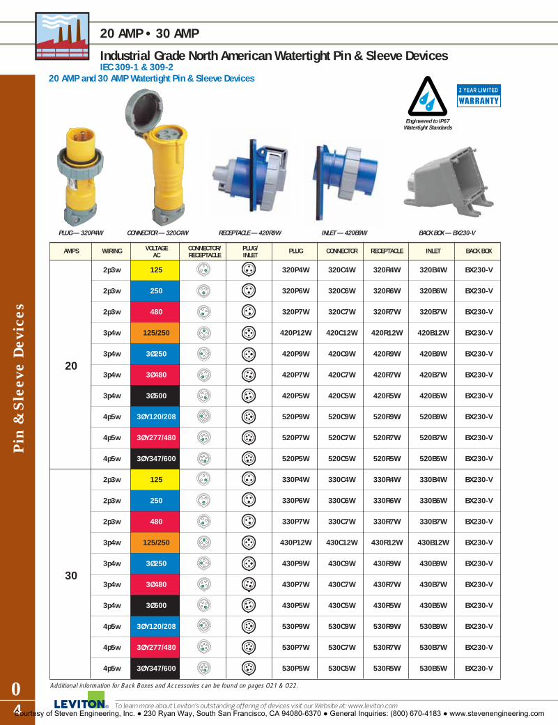
Pin
& S
leev
e Dev
ices
04
20 AMP • 30 AMP
Industrial Grade North American Watertight Pin & Sleeve DevicesIEC 309-1 & 309-2
To learn more about Leviton’s outstanding offering of devices visit our Website at: www.leviton.com
AMPS WIRING VOLTAGE CONNECTOR/ PLUG/ PLUG CONNECTOR RECEPTACLE INLET BACK BOXAC RECEPTACLE INLET
2p3w 125 320P4W 320C4W 320R4W 320B4W BX230-V
2p3w 250 320P6W 320C6W 320R6W 320B6W BX230-V
2p3w 480 320P7W 320C7W 320R7W 320B7W BX230-V
3p4w 125/250 420P12W 420C12W 420R12W 420B12W BX230-V
203p4w 3Ø250 420P9W 420C9W 420R9W 420B9W BX230-V
3p4w 3Ø480 420P7W 420C7W 420R7W 420B7W BX230-V
3p4w 3Ø600 420P5W 420C5W 420R5W 420B5W BX230-V
4p5w 3ØY120/208 520P9W 520C9W 520R9W 520B9W BX230-V
4p5w 3ØY277/480 520P7W 520C7W 520R7W 520B7W BX230-V
4p5w 3ØY347/600 520P5W 520C5W 520R5W 520B5W BX230-V
2p3w 125 330P4W 330C4W 330R4W 330B4W BX230-V
2p3w 250 330P6W 330C6W 330R6W 330B6W BX230-V
2p3w 480 330P7W 330C7W 330R7W 330B7W BX230-V
3p4w 125/250 430P12W 430C12W 430R12W 430B12W BX230-V
303p4w 3Ø250 430P9W 430C9W 430R9W 430B9W BX230-V
3p4w 3Ø480 430P7W 430C7W 430R7W 430B7W BX230-V
3p4w 3Ø600 430P5W 430C5W 430R5W 430B5W BX230-V
4p5w 3ØY120/208 530P9W 530C9W 530R9W 530B9W BX230-V
4p5w 3ØY277/480 530P7W 530C7W 530R7W 530B7W BX230-V
4p5w 3ØY347/600 530P5W 530C5W 530R5W 530B5W BX230-V
Additional information for Back Boxes and Accessories can be found on pages O21 & O22.
Engineered to IP67Watertight Standards
2 YEAR LIMITED
20 AMP and 30 AMP Watertight Pin & Sleeve Devices
PLUG — 320P4W CONNECTOR — 320C4W RECEPTACLE — 420R9W INLET — 420B9W BACK BOX — BX230-V
Courtesy of Steven Engineering, Inc. ● 230 Ryan Way, South San Francisco, CA 94080-6370 ● General Inquiries: (800) 670-4183 ● www.stevenengineering.com

Pin &
Sleeve D
evices
O5For answers to technical questions, call Leviton’s Techline at 1-800-824-3005
60 AMP • 100 AMP
Industrial Grade North American Watertight Pin & Sleeve DevicesIEC 309-1 & 309-2
AMPS WIRING VOLTAGE CONNECTOR/ PLUG/ PLUG CONNECTOR RECEPTACLE INLET BACK BOXAC RECEPTACLE INLET
2p3w 125 360P4W 360C4W 360R4W 360B4W BX60-V
2p3w 250 360P6W 360C6W 360R6W 360B6W BX60-V
2p3w 480 360P7W 360C7W 360R7W 360B7W BX60-V
3p4w 125/250 460P12W 460C12W 460R12W 460B12W BX60-V
603p4w 3Ø250 460P9W 460C9W 460R9W 460B9W BX60-V
3p4w 3Ø480 460P7W 460C7W 460R7W 460B7W BX60-V
3p4w 3Ø600 460P5W 460C5W 460R5W 460B5W BX60-V
4p5w 3ØY120/208 560P9W 560C9W 560R9W 560B9W BX60-V
4p5w 3ØY277/480 560P7W 560C7W 560R7W 560B7W BX60-V
4p5w 3ØY347/600 560P5W 560C5W 560R5W 560B5W BX60-V
2p3w 125 3100P4W 3100C4W 3100R4W 3100B4W BX100-V
2p3w 250 3100P6W 3100C6W 3100R6W 3100B6W BX100-V
2p3w 480 3100P7W 3100C7W 3100R7W 3100B7W BX100-V
3p4w 125/250 4100P12W 4100C12W 4100R12W 4100B12W BX100-V
1003p4w 3Ø250 4100P9W 4100C9W 4100R9W 4100B9W BX100-V
3p4w 3Ø480 4100P7W 4100C7W 4100R7W 4100B7W BX100-V
3p4w 3Ø600 4100P5W 4100C5W 4100R5W 4100B5W BX100-V
4p5w 3ØY120/208 5100P9W 5100C9W 5100R9W 5100B9W BX100-V
4p5w 3ØY277/480 5100P7W 5100C7W 5100R7W 5100B7W BX100-V
4p5w 3ØY347/600 5100P5W 5100C5W 5100R5W 5100B5W BX100-V
Additional information for Back Boxes and Accessories can be found on pages O21 & O22.
Engineered to IP67Watertight Standards
2 YEAR LIMITED
60 AMP and 100 AMP Watertight Pin & Sleeve Devices
PLUG — 4100P12W CONNECTOR — 4100C12W RECEPTACLE — 360R6W INLET — 360B7W BACK BOX — BX100-V
Courtesy of Steven Engineering, Inc. ● 230 Ryan Way, South San Francisco, CA 94080-6370 ● General Inquiries: (800) 670-4183 ● www.stevenengineering.com

To learn more about Leviton’s outstanding offering of devices visit our Website at: www.leviton.com
PLUG & CONNECTOR DIMENSIONS
Industrial Grade North American Watertight Pin & Sleeve Devices
Pin
& S
leev
e Dev
ice
Dim
ensi
ons
O6
60A, 100A PLUG
20A, 30A CONNECTOR
60A, 100A CONNECTOR
Plug Dimensions
CATALOG NO. AMPS UNIT A B CORD GRIP RANGE
320P 20inch 5.83 2.80 .350 –.860mm 148 71 9 – 22
420P 20inch 6.46 3.11 .350 –.860mm 164 79 9 – 22
520P 20inch 6.61 3.43 .437 –1.187mm 168 87 11 – 30
330P 30inch 6.85 3.70 .437 –1.187mm 174 94 11 – 30
430P 30inch 6.85 3.70 .437 –1.187mm 174 94 11 – 30
530P 30inch 7.40 3.98 .437 –1.450 mm 188 101 11 – 37
360P 60inch 10.83 4.49 .670 –1.625mm 275 114 17 – 41
460P 60inch 10.83 4.49 .670 –1.625mm 275 114 17 – 41
560P 60inch 10.83 4.49 .670 –1.625mm 275 114 17 – 41
3100P 100inch 12.3 5 .950 –1.875mm 312 127 24 – 48
4100P 100inch 12.3 5 .950 –1.875mm 312 127 24 – 48
5100P 100inch 12.3 5 .950 –1.875mm 312 127 24 – 48
Connector Dimensions
CATALOG NO. AMPS UNIT A B CORD GRIP RANGE
320C 20inch 6.73 3.19 .350 –.860mm 171 81 9 – 22
420C 20inch 7.36 3.46 .350 – .860mm 187 88 9 – 22
520C 20inch 7.95 3.82 .437 –1.187mm 202 97 11 – 30
330C 30inch 7.95 4.02 .437 –1.187mm 202 102 11 – 30
430C 30inch 7.95 4.02 .437 –1.187mm 202 102 11 – 30
530C 30inch 8.27 4.29 .437 –1.450 mm 210 109 11 – 37
360C 60inch 11.26 4.41 .670 –1.625mm 286 112 17 – 41
460C 60inch 11.26 4.41 .670 –1.625mm 286 112 17 – 41
560C 60inch 11.26 4.41 .670 –1.625mm 286 112 17 – 41
3100C 100inch 12.8 4.84 .950 –1.875mm 325 123 24 – 48
4100C 100inch 12.8 4.84 .950 – 1.875mm 325 123 24 – 48
5100C 100inch 12.8 4.84 .950 –1.875mm 325 123 24 – 48
Engineered to IP67Watertight Standards
2 YEAR LIMITED
A
B
A
B
A
B
A
B
20A, 30A PLUG
Courtesy of Steven Engineering, Inc. ● 230 Ryan Way, South San Francisco, CA 94080-6370 ● General Inquiries: (800) 670-4183 ● www.stevenengineering.com

Pin &
Sleeve D
evices
O7For answers to technical questions, call Leviton’s Techline at 1-800-824-3005
INLET & RECEPTACLE DIMENSIONS
Industrial Grade North American Watertight Pin & Sleeve Devices
20A, 30A INLET
Drilling PlanInlets & Receptacles
Inlet DimensionsCATALOG AMPS UNIT A BNO.
320B 20inch 1.85 0.39mm 47 10
420B 20inch 2.09 0.39mm 53 10
520B 20inch 2.32 0.39mm 59 10
330B 30inch 2.36 0.47mm 60 12
430B 30inch 2.36 0.47mm 60 12
530B 30inch 2.64 .47mm 67 12
360B 60inch 3.15 1.97mm 80 50
460B 60inch 3.15 1.97mm 80 50
560B 60inch 3.15 1.97mm 80 50
3100B 100inch 3.50 2.21mm 89 56
4100B 100inch 3.50 2.21mm 89 56
5100B 100inch 3.50 2.21mm 89 56
Receptacle DimensionsCATALOG AMPS UNIT A B CNO.
320R 20inch 1.77 2.24 3.74mm 45 57 95
420R 20inch 1.77 2.24 3.74mm 45 57 95
520R 20inch 1.85 2.24 3.90mm 47 57 99
330R 30inch 2.20 2.40 4.10mm 56 61 104
430R 30inch 2.20 2.40 4.10mm 56 61 104
530R 30inch 2.20 2.44 4.37mm 56 62 111
360R 60inch 3.50 1.89 4.37mm 89 48 111
460R 60inch 3.50 1.89 4.37mm 89 48 111
560R 60inch 3.50 1.89 4.37mm 89 48 111
3100R 100inch 3.94 2.28 4.80mm 100 58 122
4100R 100inch 3.94 2.28 4.80mm 100 58 122
5100R 100inch 3.94 2.28 4.80mm 100 58 122
A
B
C (min)
B
Clearance hole diameter D
DEVICE SIZE A B C (min) Dinches mm inchesmm inches mm inches mm
20A; 3-wire:Receptacle 3.26 83 3.12 79.5 3.94 100 0.185 4.7
Inlet 3.26 83 3.12 79.5 3.94 100 0.185 4.7
20A; 4-wire:Receptacle 3.26 83 3.12 79.5 4.33 110 0.185 4.7
Inlet 3.26 83 3.12 79.5 4.33 110 0.185 4.7
20A;5-wire:Receptacle 3.26 83 3.12 79.5 4.92 125 0.236 6.0
Inlet 3.26 83 3.12 79.5 4.92 125 0.185 4.7
30A;3-wire:Receptacle 3.26 83 3.12 79.5 5.12 130 0.236 6.0
Inlet 3.26 83 3.12 79.5 5.12 130 0.185 4.7
30A;4-wire:Receptacle 3.26 83 3.12 79.5 5.12 130 0.236 6.0
Inlet 3.26 83 3.12 79.5 5.12 130 0.185 4.7
30A;5-wire:Receptacle 3.26 83 3.12 79.5 5.71 145 0.236 6.0
Inlet 3.26 83 3.12 79.5 5.71 145 0.185 4.7
60A All 2.76 70 2.40 61 6.69 170 0.224 5.7100A All 3.47 88 2.80 71 7.87 200 0.280 7.1
Engineered to IP67Watertight Standards
2 YEAR LIMITED
AB60A, 100A INLET
BA20A, 30A RECEPTACLE
AB
C
60A, 100A RECEPTACLEBA
C
Courtesy of Steven Engineering, Inc. ● 230 Ryan Way, South San Francisco, CA 94080-6370 ● General Inquiries: (800) 670-4183 ● www.stevenengineering.com

Pin
& S
leev
e Dev
ice
Tec
hnic
al I
nfor
mat
ion
O8
TECHNICAL INFORMATION
Industrial Grade North American Watertight Pin & Sleeve Devices
To learn more about Leviton’s outstanding offering of devices visit our Website at: www.leviton.com
� Listed to UL 1682 and 1686� Certified to CSA Standard C22.2 number 182.1� Classified to IEC Standards 309-1 and 309-2 for both North
American-rated and International-rated voltages and services� CE marking per low-voltage directives 73/23/EEC, 93/68/EEC
4100P12W 4100C12W
PART MATERIAL
Housing Valox 357Internal CordClamp Asmbly ThermoplasticExternal Cord Clamp Asmbly Valox 357Gland Cap Valox 357Grommet Chloroprene Onion SkinCover with Arm Valox 357Arm Spring “Performance Grade”
Stainless SteelCover Eyelet Nickel-Plated BrassSealing Gasket Solid ChloropreneContact Carrier Nylon for 20 and 30 Amp
devices; Reinforced nylon for 60 and 100 Amp devices
Phase, Ground Sleeve BrassSleeve Spring Stainless Steel20, 30, 60A Terminal Screws Brass100A Terminal Screws Stainless SteelInternal Screws Zinc-plated SteelExternal Screws Acid-proof Stainless Steel
PART MATERIAL
Housing Valox 357Locking Ring Valox 357Mounting Flange Valox 357Contact Carrier Nylon for 20 and 30 Amp
devices; Reinforced nylon for 60 and 100 Amp devices
Phase, Ground Pins Brass20, 30, 60A Terminal Screws Brass100A Terminal Screws Stainless SteelSealing Gasket Solid Chloroprene
Material SpecificationsInlets
Connectors
PART MATERIAL
Housing Valox 357Mounting Flange Valox 357Cover with Arm Valox 357Arm Spring “Performance Grade”
Stainless SteelCover Eyelet Nickel-Plated BrassSealing Gasket Solid Chloroprene20, 30, 60A Terminal Screws Brass100A Terminal Screws Stainless SteelPhase, Ground Sleeves BrassSleeve Spring Stainless Steel
Receptacles
PART MATERIAL
Housing Valox 357Locking Ring Valox 357Sealing Gasket Solid ChloropreneInternal CordClamp Asmbly ThermoplasticExternal Cord Clamp Asmbly Valox 357Gland Cap Valox 357Grommet Chloroprene Onion SkinContact Carrier Nylon for 20 and 30 Amp
devices; Reinforced nylon for 60 and 100 Amp devices
Ground, Phase Pins Brass20, 30, 60A Terminal Screws Brass100A Terminal Screws Stainless SteelInternal Screws Zinc-plated SteelExternal Screws Acid-proof Stainless Steel
Plugs
STANDARDS & CERTIFICATIONSPin & Sleeve: Inlets, Connectors, Plugs, Receptacles
UL CSA NOM CE IEC1682 & 1686 C22.2 No. 182.1 309-1 & 309-2
E164321 & E164322 LR700925 � � �
Valox® is a registered trademark of GE.
Engineered to IP67Watertight Standards
2 YEAR LIMITED
Courtesy of Steven Engineering, Inc. ● 230 Ryan Way, South San Francisco, CA 94080-6370 ● General Inquiries: (800) 670-4183 ● www.stevenengineering.com

Pin &
Sleeve D
evices
O9
TECHNICAL INFORMATION
Industrial Grade North American Watertight Pin & Sleeve DevicesIndustrial Grade North American Watertight Pin & Sleeve Devices
Engineered to IP67Watertight Standards
2 YEAR LIMITED
Performance Specifications – UL 1682 & 1686Electrical
Dielectric Voltage Devices rated≤ 300V: 2000V for 1 min. Devices rated >300V: 3000V for 1 min.
Insulation Resistance 500 V for 1 min. Insulation Resistance ≥ 5 megohms
Ground Path Current Apply high current for short time (See Table 1) and maintain continuity
Overload 150% of rated current and 100% of rated voltage for 50 cycles (Power factor 0.75–0.80)
Current Interrupting Certified for current interrupting at full-rated current and voltage
Temperature Rise Max 30°C rise at full rated current (after overload)
Resistance to Arcing Continuation of overload for additional 200 cycles
Endurance with Load Device # Cycles with Load20A 5000 Rated Current, Voltage 30A,60A 1000 Rated Current, Voltage100A 250 Rated Current, Voltage(Power Factor 0.75 – 0.80)
Mechanical
Mold Stress Relief 70°C for 7 hrsHumidity 32°C, 93% humidity, 168 hrsCable Secureness Pull force and apply torque for
1 minute (See Table 2)Impact Drop from 30" 8 times after
conditioning to -25°C, for 6 hrsCrush 250 lbs for 1 min after -25°C for 6 hrsWithdrawal Force Pull for one minute (See Table 3)Strength of Insulating 110% of specified tightening torque Base and Support on terminal screwsEndurance Device Total # Cycles
(connect & disconnect)20A 5000 30A,60A 2000 100A 500
Polarization Integrity Matching devices will not mate so that ground is energized even when polarization feature is removed and 40-lb insertion force applied
Environmental
Flammability V2 or better on 20 and 30 amp devices per UL 94 or CSA 22.2 No 0.6 ; V-0 on 60 & 100 amp devices
Resistance Ferrous parts immersed in to Corrosion 10% ammonium chloride solution Moisture Resistance Watertight: Device immersed for per UL 1682 24 hrs in 5 cm of 25°C water
Splashproof: 1" dia. water stream at 15 PSI from 10 ft. for 5 minutes
UV Resistance Exposed plastic materials are UV stabilized
460C12W460P7W
Short-Time Grounding Test Currents
Minimum Size EquipmentDevice Rating, Grounding Conductor Time, Test
Amperes (Copper) Seconds Current,AmperesAWG (mm2)
20 12 (3.3) 4 47030 10 (5.3) 4 75060 10 (5.3) 4 750100 8 (8.4) 4 1180
Ground-path integrity is of critical importance to safe operation of industrialequipment. Leviton pin and sleeve devices are tested by applying a test currentthrough their ground path that far exceeds the device rating. All devices areproperly wired and connected to line current at rated values. Then the groundpath is subjected to a dramatic, sudden increase in current for 4 seconds. In allcases, the ground pin, sleeve, and terminals of the devices must sustain the test current, continue to function properly, and show no evidence of damage ordeterioration in any electrical or mechanical elements of the ground path. Testcurrent values and test parameters are displayed in the above chart.
Cord Secureness Test Values
Device Rating Force TorqueMaximum
Amperes Displacementlb N ft-lb N•M inches mm
20 30 133 0.4 0.54 ≤3/32 2.3830 75 333 0.5 0.68 ≤3/32 2.3860 150 667 1.0 1.4 ≤3/32 2.38100 150 667 2.0 2.7 ≤3/32 2.38
Heavy cord stress is typical of industrial applications. To assure you of top per-formance, Leviton pin and sleeve devices are subjected to a punishing series oftests to confirm they can absorb heavy cord pulls. The cord conductors wired todevices are simultaneously twisted and pulled. Values for the applied twistingtorque and force of pull are shown above. In all cases, the cord displacement isless than 3/32 inches.
Minimum Withdrawal Force
Device Rating, Amperes Minimum Withdrawal Forcelb N
20 5 2230 6 2760 15 67100 20 89
In industrial settings, inadvertent disconnection of power can be troublesome atbest, dangerous at worst, and unacceptable in any case. To verify that Levitonpin and sleeve plugs and connectors remain securely connected, they are tested to establish the minimum force required for withdrawal. In establishingthese minimum withdrawal forces, the plugs and connectors are properly mated,but not locked with locking rings or other mechanical means. The pins andsleeves provide the only resistance to the force of withdrawal. In all cases, thevalues in the table above show the minimum force required to separate the plugsand connectors.
For answers to technical questions, call Leviton’s Techline at 1-800-824-3005Courtesy of Steven Engineering, Inc. ● 230 Ryan Way, South San Francisco, CA 94080-6370 ● General Inquiries: (800) 670-4183 ● www.stevenengineering.com

Pin
& S
leev
e Dev
ices
O10
MECHANICAL INTERLOCK FEATURES
Industrial Grade North American Watertight Mechanical InterlocksIEC 309-1 & 309-2
To learn more about Leviton’s outstanding offering of devices visit our Website at: www.leviton.com
by Leviton
Type 3R, 4X & 12KIP67
PowerSwitch® Mechanical Interlocks
� 20 Amp Non-Fused & Fused � 30 Amp Non-Fused & Fused
� 60 Amp Non-Fused & Fused � 100 Amp Non-FusedPowerSwitch Mechanical Interlock devices incorporate a disconnect safety switch and IEC receptacle ina non-metallic watertight enclosure. The interlock mechanism prevents making and breaking of powerunder load. “The switch cannot be actuated to the ON position until an IEC compatible plug is fullyinserted, and the plug cannot be removed until the switch is in the OFF position.”
The complete IEC 309-1 and 309-2 system of plugs, connectors, inlets and mechanical interlockdevices can be used for both retrofit and new installations enhancing safety and performance in criticalpower connections.
560MI7W60 Amp
420MI9W20 Amp
420MF9W20 Amp, Fused
Fused Models Accept“Class J” Time-Delay
Fuses
Engineered to IP67Watertight Standards
2 YEAR LIMITED
Courtesy of Steven Engineering, Inc. ● 230 Ryan Way, South San Francisco, CA 94080-6370 ● General Inquiries: (800) 670-4183 ● www.stevenengineering.com

Pin &
Sleeve D
evices
O11For answers to technical questions, call Leviton’s Techline at 1-800-824-3005
MECHANICAL INTERLOCK FEATURES
Industrial Grade North American Watertight Mechanical Interlocks
2 YEAR LIMITEDLiquid-tight conduit fitting can beinstalled for top or bottom feed
One fitting supplied:• 20-30 Amp – 3/4"• 60 Amp – 11/4"• 100 Amp – 11/2"
Integrated lockouthandle meets OSHAsafety regulations
Impact, UV and chemical-resistant Valox enclosurerated to UL and IEC water-tight standards
• Type 3R, 4X & 12K• IP67
Circuit identification pad formeans of identifying specificequipment loads
Handle with padlock installed
Color-coded receptacle cover indicates voltage rating of deviceand seals against water and othercontaminants when not in use
Red “pistol grip” handle provides visual confirmationof switch’s status
Stainless steel screws arecaptive and will not fall outwhen cover is opened
Brass threaded inserts will notstrip, provide higher torque, andform tighter seal between backbox and cover
Pre-wired grounding plateconnects to metal conduitgrounding system
Rugged hinge mechanism pivots180º for easy access duringinstallation and maintenance
Pre-wired IEC receptacle accepts allmanufacturer’s IEC 309-2 plugs
Disconnect switch with integrated fuseholder offers proven performance in acompact package• Fused cartridges accept “Class J” fuses
(not included)• One factory installed auxiliary contact
(normally opened – 10 Amp). Additionalauxiliary contact available (normallyclosed — 10 Amp)
• Easily accessible neutral and ground terminal blocks
Compact non-fused mechanicalinterlocks are easy to wire
420MF9W
420MF9W
420MI9W
Fused Models Accept “Class J” Time-Delay Fuses
by Leviton
Generous wiring spacefor drip loop or top tobottom wiring
STANDARDS & CERTIFICATIONSMechanical Interlocks
UL 231 & UL1686 UL 98 UL 508 CSA C22.2 NOM CE IECFused Non-Fused No. 182.1 & 14 309-1 & 309-2
E171391 LR700925 � � �
Courtesy of Steven Engineering, Inc. ● 230 Ryan Way, South San Francisco, CA 94080-6370 ● General Inquiries: (800) 670-4183 ● www.stevenengineering.com

Pin
& S
leev
e Dev
ices
O12
20 AMP • 30 AMP
Industrial Grade North American Watertight Mechanical InterlocksNon-Fused & Fused
To learn more about Leviton’s outstanding offering of devices visit our Website at: www.leviton.com
Engineered to IP67Watertight Standards
2 YEAR LIMITED
NON-FUSED
420MF9W
*Consult factory for your specific application.
by LevitonFused Models Accept
“Class J” Time-Delay Fuses
FUSED
Type 3R, 4X & 12KIP67
AMPS WIRING VOLTAGE RECEPTACLE PLUG MECHANICAL HP MECHANICAL HP USE PLUG AC CONFIG. CONFIG. INTERLOCK RATING INTERLOCK RATING CAT. NO.
2p3w 240 320MI6W 3 — — 320P6W
2p3w 480 320MI7W 5 — — 320P7W
3p4w 125/250 420MI12W * 420MF12W * 420P12W
3p4w 3Ø240 420MI9W 5 420MF9W 5 420P9W
20 3p4w 3Ø480 420MI7W 10 420MF7W 10 420P7W
3p4w 3Ø600 420MI5W 15 420MF5W 15 420P5W
4p5w 3ØY120/208 520MI9W 5 — — 520P9W
4p5w 3ØY277/480 520MI7W 10 — — 520P7W
4p5w 3ØY347/600 520MI5W 15 — — 520P5W
2p3w 240 330MI6W 5 — — 330P6W
2p3w 480 330MI7W 10 — — 330P7W
3p4w 125/250 430MI12W * 430MF12W * 430P12W
3p4w 3Ø240 430MI9W 10 430MF9W 7.5 430P9W
30 3p4w 3Ø480 430MI7W 20 430MF7W 15 430P7W
3p4w 3Ø600 430MI5W 25 430MF5W 20 430P5W
4p5w 3ØY120/208 530MI9W 10 — — 530P9W
4p5w 3ØY277/480 530MI7W 20 530MF7W 15 530P7W
4p5w 3ØY347/600 530MI5W 25 530MF5W 20 530P5W
Courtesy of Steven Engineering, Inc. ● 230 Ryan Way, South San Francisco, CA 94080-6370 ● General Inquiries: (800) 670-4183 ● www.stevenengineering.com

Pin &
Sleeve D
evices
O13For answers to technical questions, call Leviton’s Techline at 1-800-824-3005
60 AMP • 100 AMP
Industrial Grade North American Watertight Mechanical InterlocksNon-Fused & Fused
Type 3R, 4X & 12KIP67
AMPS WIRING VOLTAGE RECEPTACLE PLUG MECHANICAL HORSEPOWER USE PLUG AC CONFIG. CONFIG. INTERLOCK RATING CAT. NO.
2p3w 125 3100MI4W 5 3100P4W
2p3w 240 3100MI6W 15 3100P6W
2p3w 480 3100MI7W 25 3100P7W
3p4w 125/250 4100MI12W * 4100P12W
3p4w 3Ø240 4100MI9W 30 4100P9W
100 3p4w 3Ø480 4100MI7W 50 4100P7W
3p4w 3Ø600 4100MI5W 50 4100P5W
4p5w 3ØY120/208 5100MI9W 25 5100P9W
4p5w 3ØY277/480 5100MI7W 50 5100P7W
4p5w 3ØY347/600 5100MI5W 50 5100P5W
*Consult factory for your specific application.
2 YEAR LIMITED
Engineered to IP67Watertight Standards
by Leviton
420P12W
Fused Models Accept“Class J” Time-Delay Fuses
NON-FUSED FUSED
Type 3R, 4X & 12KIP67
AMPS WIRING VOLTAGE RECEPTACLE PLUG MECHANICAL HP MECHANICAL HP USE PLUG AC CONFIG. CONFIG. INTERLOCK RATING INTERLOCK RATING CAT. NO.
2p3w 240 360MI6W 10 360MF6W * 360P6W
2p3w 480 360MI7W 20 — — 360P7W
3p4w 125/250 460MI12W * 460MF12W * 460P12W
3p4w 3Ø240 460MI9W 20 460MF9W 15 460P9W
60 3p4w 3Ø480 460MI7W 40 460MF7W 30 460P7W
3p4w 3Ø600 460MI5W 40 460MF5W 50 460P5W
4p5w 3ØY120/208 560MI9W 20 560MF9W 15 560P9W
4p5w 3ØY277/480 560MI7W 40 — — 560P7W
4p5w 3ØY347/600 560MI5W 40 — — 560P5W
NON-FUSED
560MI7W
Courtesy of Steven Engineering, Inc. ● 230 Ryan Way, South San Francisco, CA 94080-6370 ● General Inquiries: (800) 670-4183 ● www.stevenengineering.com

Pin
& S
leev
e Dev
ices
O14
MECHANICAL INTERLOCK DIMENSIONS
Industrial Grade North American Watertight Mechanical InterlocksNon-Fused & Fused
To learn more about Leviton’s outstanding offering of devices visit our Website at: www.leviton.com
2 YEAR LIMITED
12.8
8 (3
27.1
)
14.8
8 (3
78.0
)
16.8
9 (4
28.9
)
17.7
2 (4
50.0
)
8.54(217)7.71
(195.9)5.71(145)3.70
(94.1)
9.37(238.0)
6.89(175.0)
19.0
6 (4
84.1
)
18.1
3 (4
60.6
)
18.5
4 (4
71.0
)
9.80(248.9)
9.35(237.4)
60 AMP FUSED & NON-FUSED &100 AMP NON-FUSED
8.78(223.0)
6.30(160.0)
12.9
5 (3
29.0
)
12.0
6 (3
06.4
)
8.29(211.0)7.94
(201.7)
12.5
2 (3
18.0
)
7.95(202.0)
7.12(180.9)
5.12(130.0)
3.11(79.1)
6.85
(174
.1)
8.86
(255
.0)
10.8
6 (2
76.0
)
11.6
9 (2
97.0
)
0.33(8.5)
20 AMP & 30 AMP FUSED AND NON-FUSED
Courtesy of Steven Engineering, Inc. ● 230 Ryan Way, South San Francisco, CA 94080-6370 ● General Inquiries: (800) 670-4183 ● www.stevenengineering.com

Pin &
Sleeve D
evices
O15For answers to technical questions, call Leviton’s Techline at 1-800-824-3005
TECHNICAL INFORMATION
Industrial Grade North American Watertight Mechanical Interlocks20, 30, 60 and 100 AMP
by Leviton
2 YEAR LIMITED
Engineered to IP67Watertight Standards
� Enclosures are rated Type 3R, 4X & 12K, IP67� Listed to UL 231 and 1686� Certified to CSA Standard C22.2 number 182.1& 14� Classified to IEC Standards 309-1 and 309-2 for both North
American-rated voltages and services� CE marking per low-voltage directives 73/23/EEC, 93/68/EEC� Switches are listed to UL 508 for Non-Fused and UL98 for
Fused models (including 100 Amp Non-Fused)
Material Specifications20 and 30 Amp Devices
PART MATERIAL
Housing Cover Valox 357Housing Base Valox 357Cover with Arm Valox 357Locking Ring Valox 357Cover Arm Eyelet Nickel-Plated BrassHousing Gasket Solid ChloropreneSealing Gasket Solid ChloropreneHandle Valox 357Actuator Shaft Valox 357Locking Mechanism Zinc-Coated SteelContact Carrier NylonPhase and Ground Sleeves BrassGround Contact BrassConduit Grounding Plate Zinc-Coated SteelConduit Hub (1") Die-Cast ZincSwitch Reinforced NylonSwitch Terminal Contacts BrassInternal Screws Zinc-Coated SteelHousing Screws Stainless Steel
Additional Components for 60 Amp Devices
PART MATERIAL
Ground Bus BrassNeutral Bus BrassActuator Shaft Zinc-Coated SteelContact Carrier Reinforced NylonConduit Hub (11⁄ 2") Die-Cast ZincLocking Mechanism Valox 357
Additional Components for 100 Amp Devices
PART MATERIAL
Ground Terminal Plated Brass/SteelGround Terminal Block NylonNeutral Terminal Plated Brass/SteelNeutral Terminal Block NylonTerminal Shaft Key Die-Cast AluminumActuator Shaft Zinc-Coated SteelContact Carrier Reinforced NylonConduit Hub (2") Die-Cast ZincSwitch Reinforced NylonLocking Mechanism Valox 357
Valox® is a registered trademark of GE.
ENVIRONMENTAL
Flammability No 0.6; V-0 for watertight enclosureRain (3R) per UL 50 Water spray @ 5 psi from all
sides for 1 hrHosedown (4X) per UL 50 Water spray @ 65 gal/min for 5 min.Dust (12K) per UL 50 Cement Dust Circulated @
1000 ft /minute for 5 minutesGasket Aging 70°C for 168 hoursUV Resistance Exposed plastic materials
are UV stabilizedOperating Temperature -40°C to +60°C
(-40°F to +140°F)
MECHANICALMold Stress Relief 70°C for 7 hoursKnockout Test Remains in place with 20 lb pushCrush 100 lbImpact 1.2 lb steel ball dropped from 5 ftCold Impact Same as above, after conditioning
to -35°CStrength of Insulating 110% of specified tightening Base and Support torque on terminal screwsPullout 18 lb pull on internal wires
Performance Specifications
Ground PathIntegrity
STANDARDS & CERTIFICATIONSMechanical Interlocks
UL231 & UL 98 UL 508 CSA NOM CE IECUL1686 Fused Non-Fused C22.2 309-1 & 309-2
� � � � � � �
ELECTRICALDevice Current Applied Duration20 A 40 A 2 min30 A 60 A 2 min60 A 120 A 4 min
100 A 200 A 6 minCurrent Interrupting Certified for current interrupting
at full-rated current and voltageEndurance 6000 operations at rated
current and voltage (Power factor 0.75 – 0.80)
Dielectric 1000 V plus twice ratedvoltage for 1 minute
Courtesy of Steven Engineering, Inc. ● 230 Ryan Way, South San Francisco, CA 94080-6370 ● General Inquiries: (800) 670-4183 ● www.stevenengineering.com

Inte
rnat
iona
l-R
ated
Pin
& S
leev
e Dev
ices
O16
16 AMP • 32 AMP • 63 AMP • 125 AMP
Industrial Grade International-Rated Pin & Sleeve Devices
To learn more about Leviton’s outstanding offering of devices visit our Website at: www.leviton.com
2 YEAR LIMITED
Engineered to IP44 Splashproof Standards
International Rated Devices
Engineered to UL & IECWatertight Standards
432P3WL, 432C3WL & All 125A Devices listed onthis page have North American Rated Construction
SP516P6 SP516C6 SP516R6 SP516B6
International-Rated DevicesLeviton offers international-rated pin and sleeve devices available in 16, 32, 63 and 125 Amps. These IEC 309-1and 309-2 compliant devices are ideal for use overseas where voltage and amperage requirements differ fromNorth American standards, but where rigorous performance, quality, and reliability criteria need to be met. 16, 32 and 63 Amp devices have an environmental classification of splashproof (IP44), and 125 Amp devices areclassified as watertight (IP67).
Ordering Information*
AMPS WIRING VOLTAGE CONNECTOR/ PLUG/ PLUG CONNECTOR RECEPTACLE INLETAC RECEPTACLE INLET
2p3w 100 – 130 SP316P4 SP316C4 SP316R4 SP316B4
162p3w 250 SP316P6 SP316C6 SP316R6 SP316B6
3p4w 380 – 415 SP416P6 SP416C6 SP416R6 SP416B6
4p5w 200/346 – 240/415 SP516P6 SP516C6 SP516R6 SP516B6
2p3w 100 – 130 SP332P4 SP332C4 SP332R4 SP332B4
322p3w 250 SP332P6 SP332C6 SP332R6 SP332B6
3p4w 380 – 415 SP432P6 SP432C6 SP432R6 SP432B6
3p4w 3Ø380 – 3Ø440 432P3WL† 432C3WL† — —
4p5w 200/346 – 240/415 SP532P6 SP532C6 SP532R6 SP532B6
2p3w 250 SP363P6 SP363C6 SP363R6 SP363B6
63 3p4w 380 – 415 SP463P6 SP463C6 SP463R6 SP463B6
4p5w 200/346 – 240/415 SP563P6 SP563C6 SP563R6 SP563B6
2p3w 250 3125P6W 3125C6W 3125R6W 3125B6W
125 3p4w 380 – 415 4125P6W 4125C6W 4125R6W 4125B6W
4p5w 200/346 – 240/415 5125P6W 5125C6W 5125R6W 5125B6W
*Consult the factory for availability before placing your order. These are specialty order items and are not regularly stocked. †This device has North American 30 Amp construction and is used in refrigerated container applications.
Courtesy of Steven Engineering, Inc. ● 230 Ryan Way, South San Francisco, CA 94080-6370 ● General Inquiries: (800) 670-4183 ● www.stevenengineering.com
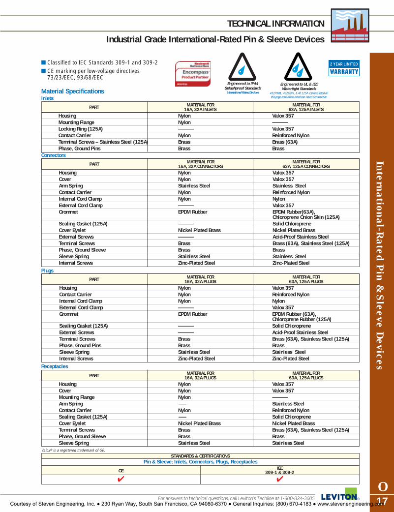
International-Rated P
in & S
leeve Devices
O17For answers to technical questions, call Leviton’s Techline at 1-800-824-3005
TECHNICAL INFORMATION
Industrial Grade International-Rated Pin & Sleeve Devices
� Classified to IEC Standards 309-1 and 309-2 � CE marking per low-voltage directives
73/23/EEC, 93/68/EEC
Material SpecificationsInlets
Engineered to IP44 Splashproof Standards
International Rated Devices
Engineered to UL & IECWatertight Standards
432P3WL, 432C3WL & All 125A Devices listed onthis page have North American Rated Construction
PART MATERIAL FOR MATERIAL FOR16A, 32A INLETS 63A, 125A INLETS
Housing Nylon Valox 357Mounting Flange Nylon —Locking Ring (125A) — Valox 357Contact Carrier Nylon Reinforced NylonTerminal Screws – Stainless Steel (125A) Brass Brass (63A)Phase, Ground Pins Brass Brass
PART MATERIAL FOR MATERIAL FOR16A, 32A CONNECTORS 63A, 125A CONNECTORS
Housing Nylon Valox 357Cover Nylon Valox 357Arm Spring Stainless Steel Stainless SteelContact Carrier Nylon Reinforced NylonInternal Cord Clamp Nylon NylonExternal Cord Clamp — Valox 357Grommet EPDM Rubber EPDM Rubber(63A),
Chloroprene Onion Skin (125A)Sealing Gasket (125A) — Solid ChloropreneCover Eyelet Nickel Plated Brass Nickel Plated BrassExternal Screws — Acid-Proof Stainless SteelTerminal Screws Brass Brass (63A), Stainless Steel (125A)Phase, Ground Sleeve Brass BrassSleeve Spring Stainless Steel Stainless SteelInternal Screws Zinc-Plated Steel Zinc-Plated Steel
Connectors
PART MATERIAL FOR MATERIAL FOR16A, 32A PLUGS 63A, 125A PLUGS
Housing Nylon Valox 357Contact Carrier Nylon Reinforced NylonInternal Cord Clamp Nylon NylonExternal Cord Clamp — Valox 357Grommet EPDM Rubber EPDM Rubber (63A),
Chloroprene Rubber (125A)Sealing Gasket (125A) — Solid ChloropreneExternal Screws — Acid-Proof Stainless SteelTerminal Screws Brass Brass (63A), Stainless Steel (125A)Phase, Ground Pins Brass BrassSleeve Spring Stainless Steel Stainless SteelInternal Screws Zinc-Plated Steel Zinc-Plated Steel
Plugs
PART MATERIAL FOR MATERIAL FOR16A, 32A PLUGS 63A, 125A PLUGS
Housing Nylon Valox 357Cover Nylon Valox 357Mounting Flange Nylon —Arm Spring – Stainless SteelContact Carrier Nylon Reinforced NylonSealing Gasket (125A) – Solid ChloropreneCover Eyelet Nickel Plated Brass Nickel Plated BrassTerminal Screws Brass Brass (63A), Stainless Steel (125A)Phase, Ground Sleeve Brass BrassSleeve Spring Stainless Steel Stainless Steel
Receptacles
STANDARDS & CERTIFICATIONSPin & Sleeve: Inlets, Connectors, Plugs, Receptacles
CE IEC309-1 & 309-2
� �
2 YEAR LIMITED
Valox® is a registered trademark of GE.
Courtesy of Steven Engineering, Inc. ● 230 Ryan Way, South San Francisco, CA 94080-6370 ● General Inquiries: (800) 670-4183 ● www.stevenengineering.com
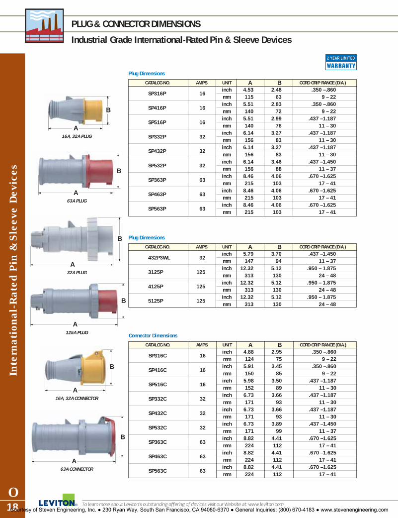
Inte
rnat
iona
l-R
ated
Pin
& S
leev
e Dev
ices
O18
PLUG & CONNECTOR DIMENSIONS
Industrial Grade International-Rated Pin & Sleeve Devices
To learn more about Leviton’s outstanding offering of devices visit our Website at: www.leviton.com
2 YEAR LIMITED
Plug Dimensions
CATALOG NO. AMPS UNIT A B CORD GRIP RANGE (DIA.)
SP316P 16inch 4.53 2.48 .350 –.860mm 115 63 9 – 22
SP416P 16inch 5.51 2.83 .350 –.860mm 140 72 9 – 22
SP516P 16inch 5.51 2.99 .437 –1.187mm 140 76 11 – 30
SP332P 32inch 6.14 3.27 .437 –1.187mm 156 83 11 – 30
SP432P 32inch 6.14 3.27 .437 –1.187mm 156 83 11 – 30
SP532P 32inch 6.14 3.46 .437 –1.450 mm 156 88 11 – 37
SP363P 63inch 8.46 4.06 .670 –1.625mm 215 103 17 – 41
SP463P 63inch 8.46 4.06 .670 –1.625mm 215 103 17 – 41
SP563P 63inch 8.46 4.06 .670 –1.625mm 215 103 17 – 41
Plug Dimensions
CATALOG NO. AMPS UNIT A B CORD GRIP RANGE (DIA.)
432P3WL 32inch 5.79 3.70 .437 –1.450 mm 147 94 11 – 37
3125P 125inch 12.32 5.12 .950 – 1.875mm 313 130 24 – 48
4125P 125inch 12.32 5.12 .950 – 1.875mm 313 130 24 – 48
5125P 125inch 12.32 5.12 .950 – 1.875mm 313 130 24 – 48
Connector Dimensions
CATALOG NO. AMPS UNIT A B CORD GRIP RANGE (DIA.)
SP316C 16inch 4.88 2.95 .350 –.860mm 124 75 9 – 22
SP416C 16inch 5.91 3.45 .350 –.860mm 150 85 9 – 22
SP516C 16inch 5.98 3.50 .437 –1.187mm 152 89 11 – 30
SP332C 32inch 6.73 3.66 .437 –1.187mm 171 93 11 – 30
SP432C 32inch 6.73 3.66 .437 –1.187mm 171 93 11 – 30
SP532C 32inch 6.73 3.89 .437 –1.450 mm 171 99 11 – 37
SP363C 63inch 8.82 4.41 .670 –1.625mm 224 112 17 – 41
SP463C 63inch 8.82 4.41 .670 –1.625mm 224 112 17 – 41
SP563C 63inch 8.82 4.41 .670 –1.625mm 224 112 17 – 41
A
B
16A, 32A PLUG
A
B
125A PLUG
A
B
16A, 32A CONNECTOR
A
B
63A CONNECTOR
A
B
63A PLUG
A
B
32A PLUG
Courtesy of Steven Engineering, Inc. ● 230 Ryan Way, South San Francisco, CA 94080-6370 ● General Inquiries: (800) 670-4183 ● www.stevenengineering.com

International-Rated P
in & S
leeve Devices
O19For answers to technical questions, call Leviton’s Techline at 1-800-824-3005
INLET & RECEPTACLE DIMENSIONS
Industrial Grade International-Rated Pin & Sleeve Devices
Inlet Dimensions for International-Rated Watertight devices
CATALOG NO. AMPS UNIT A B
3125B6W 125inch 3.50 2.21mm 89 56
4125B6W 125inch 3.50 2.21mm 89 56
5125B6W 125inch 3.50 2.21mm 89 56
Connector Dimensions
CATALOG NO. AMPS UNIT A B CORD GRIP RANGE (DIA.)
432C3WL 32inch 6.97 4.02 .437 –1.187mm 177 102 11 – 30
3125CW 125inch 12.80 4.80 .950 – 1.875mm 325 122 28 – 48
4125CW 125inch 12.80 4.80 .950 – 1.875mm 325 122 28 – 48
5125CW 125inch 12.80 4.80 .950 – 1.875mm 325 122 28 – 48
Receptacle Dimensions
CATALOG NO. AMPS UNIT A B C
SP316R 16inch 2.20 1.14 2.87mm 56 29 73
SP416R 16inch 2.28 1.18 3.43mm 58 30 87
SP516R 16inch 2.36 1.22 3.50mm 60 31 89
SP332R 32inch 2.76 1.34 3.66mm 70 34 93
SP432R 32inch 2.76 1.34 3.66mm 70 34 93
SP532R 32inch 2.76 1.34 3.90mm 71 34 99
SP363R 63inch 3.43 1.89 4.41mm 87 48 112
SP463R 63inch 3.43 1.89 4.41mm 87 48 112
SP563R 63inch 3.43 1.89 4.41mm 87 48 112
Receptacle Dimensions
CATALOG NO. AMPS UNIT A B C
3125R 125inch 3.94 2.28 4.80mm 100 58 122
4125R 125inch 3.94 2.28 4.80mm 100 58 122
5125R 125inch 3.94 2.28 4.80mm 100 58 122
A
B
125A CONNECTOR
16A, 32A RECEPTACLE
B A
C
63A RECEPTACLE
B A
C
125A RECEPTACLE
B A
C
A
B
32A CONNECTOR
2 YEAR LIMITED
125A INLETB A
Courtesy of Steven Engineering, Inc. ● 230 Ryan Way, South San Francisco, CA 94080-6370 ● General Inquiries: (800) 670-4183 ● www.stevenengineering.com

A
B
C (min)
B
Clearance hole diameter D
Drilling PlanInlets & Receptacles
DEVICE SIZE A B C (min) Dinches mm inches mm inches mm inches mm
16A; 3-wire:Receptacle 1.93 49 1.73 44 3.35 85 .185 4.7
Inlet 1.93 49 1.73 44 3.35 85 .185 4.7
16A; 4-wire:Receptacle 2.32 59 2.05 52 3.94 100 .185 4.7
Inlet 2.32 59 2.05 52 3.94 100 .185 4.7
16A;5-wire:Receptacle 2.32 59 2.05 52 3.94 100 .185 4.7
Inlet 2.32 59 2.05 52 3.94 100 .185 4.7
32A;3-wire:Receptacle 2.60 66 2.40 61 4.53 115 .185 4.7
Inlet 2.60 66 2.40 61 4.53 115 .185 4.7
32A;4-wire:Receptacle 2.60 66 2.40 61 4.53 115 .185 4.7
Inlet 2.60 66 2.40 61 4.53 115 .185 4.7
32A;5-wire:Receptacle 2.60 66 2.40 61 4.53 115 .185 4.7
Inlet 2.60 66 2.40 61 4.53 115 .185 4.7
63A All 2.76 70 2.40 61 6.69 170 .185 4.7
125A All 3.47 88 2.80 71 7.87 200 .280 7.1
DEVICE SIZE C D E E1 E2 G H H1
SP316B in 1.73-1.85 1.93 2.95 1.59 0.31 0.35 0.16 1.18mm 44-47 49 75 40.5 8 9 4 30
SP416B in 1.97-2.05 2.32 3.15 1.83 0.31 0.35 0.2 1.34mm 50-52 59 80 46.5 8 9 5 34
SP516B in 1.97-2.05 2.32 3.54 2.07 0.31 0.35 0.27 1.5mm 50-52 59 90 52.5 8 9 7 38
SP332B in 2.36-2.40 2.6 3.54 2.11 0.31 0.35 0.27 1.57mm 60-61 66 90 53.5 8 9 7 40
SP432B in 2.36-2.40 2.6 3.54 2.11 0.31 0.35 0.27 1.57mm 60-61 66 90 53.5 8 9 7 40
SP532B in 2.36-2.40 2.6 4.13 2.34 0.35 0.35 0.31 1.77mm 60-61 66 105 59.5 9 9 8 45
SP363B in 2.40 2.76 4.13 2.32 0.39 0.43 0.35 1.95mm 61 70 105 59 10 11 9 49.5
SP463B in 2.40 2.76 4.13 2.32 0.39 0.43 0.35 1.95mm 61 70 105 59 10 11 9 49.5
SP563B in 2.40 2.76 4.13 2.32 0.39 0.43 0.35 1.95mm 61 70 105 59 10 11 9 49.5
Inte
rnat
iona
l-R
ated
Pin
& S
leev
e Dev
ices
O20
INLET & RECEPTACLE DIMENSIONS
Industrial Grade International-Rated Pin & Sleeve Devices
To learn more about Leviton’s outstanding offering of devices visit our Website at: www.leviton.com
2 YEAR LIMITED
Inlet Dimensions
CATALOG NO. AMPS UNIT A B
SP316B 16inch .85 1.83mm 21.5 46.5
SP416B 16inch .83 1.85mm 21 47
SP516B 16inch .83 1.83mm 21 46.5
SP332B 32inch .95 2.19mm 24.5 55.5
SP432B 32inch .95 2.19mm 24.5 55.5
SP532B 32inch .98 2.19mm 25 55.5
SP363B 63inch 1.97 3.0mm 50 78
SP463B 63inch 1.97 3.0mm 50 78
SP563B 63inch 1.97 3.0mm 50 78
Inlet Panel Mounting Dimensions
EE1
HH1
AB
H1H
BA
E1E2
øD
B
C
C
C
øD C
B
ø4.2
ø4.2
16A, 32A INLET
A B
63A INLET
A B
Courtesy of Steven Engineering, Inc. ● 230 Ryan Way, South San Francisco, CA 94080-6370 ● General Inquiries: (800) 670-4183 ● www.stevenengineering.com

Dimensions for Valox® Adapter Plates
UNIT A B C D E F R
inch 2.78 3.86 4.50 3.88 .40 .20 1.28mm 70 98 114 98.5 10 5 32.5
inch 3.23 4.88 5.50 4.60 .40 .22 1.50 mm 82 124 140 117 10 5.5 38
60 Amp
100 Amp
Pin &
Sleeve D
evices
O21For answers to technical questions, call Leviton’s Techline at 1-800-824-3005
BACK BOXES & ACCESSORIES
Industrial Grade Pin & Sleeve Devices
2 YEAR LIMITED
20 Amp & 30 Amp – 1" Hub
BX230-V BX100-V
B A
C
D
E
G
F
60 Amp – 11/2" Hub
100 Amp – 2" Hub
Valox® Back Boxes forWatertight Inlets & Receptacles
APPLICATION CATALOG NO.
20 & 30 Amp BX230-VNo Adapter Plate Required
60 Amp BX60-VAdapter Plate Included
100 Amp BX100-VAdapter Plate Included
AP60 AP100
E
C B
D
R
B
C
F
A
Replacement Valox® Adapter Plates forLeviton & Hubbell Back Boxes
APPLICATION CATALOG NO.
60 Amp AP60Watertight Inlets & Receptacles
100 Amp AP100Watertight Inlets & Receptacles
Dimensions for Valox® Back Boxes
UNIT A B C D E F G
inch 6.69 5.91 4.53 3.90 2.35 2.35 0.25mm 170.0 150.0 115.0 99.0 60.0 60.0 6.5
inch 7.68 6.92 5.20 4.65 2.99 2.99 0.31mm 195.0 176.0 132.0 118.0 76.0 76.0 8.0
inch 8.23 7.39 6.30 5.71 3.99 3.33 0.33mm 209.0 188.0 160.0 145.0 101.0 84.5 8.5
Valox® is a registered trademark of GE.
(Same Geometry as BX60-V)
Courtesy of Steven Engineering, Inc. ● 230 Ryan Way, South San Francisco, CA 94080-6370 ● General Inquiries: (800) 670-4183 ● www.stevenengineering.com

PLG1 In Use with PLUG In Use with INLET
PROTECTIVE CLOSURE CAPSPC420 PC60 PC100
SAD125 L7902 STRAIGHT MALE LIQUID-TIGHT GRIP
For use with flexible metal conduit.
CA520 CA100
RA420 RA100
Pin
& S
leev
e Dev
ices
O22
PIN & SLEEVE ACCESSORIES
Industrial Grade Pin & Sleeve Devices
To learn more about Leviton’s outstanding offering of devices visit our Website at: www.leviton.com
Replacement Watertight Closure Cover Kit forConnectors and Receptacles
APPLICATION CATALOG NUMBER
20 Amp, 3-Wire CA32020 Amp, 4-Wire CA42020 Amp, 5-Wire CA52030 Amp, 3-, 4-Wire CA34330 Amp, 5-Wire CA530All 60 Amp CA060All 100 Amp CA100
APPLICATION CATALOG NUMBERWATERTIGHT & SPLASHPROOF
Can be used for any IEC 309-1 and 309-2 pin and PLG1sleeve plugs or inlets
Protective Closure Caps for Plugs and Inlets
APPLICATION APPLICATION WATERTIGHTNORTH AMERICAN INTERNATIONAL CATALOG NO.
20 Amp, 3-Wire 16 Amp, 3-Wire PC32020 Amp, 4-Wire 16 Amp, 4-Wire PC42020 Amp, 5-Wire 16 Amp, 5-Wire PC52030 Amp, 3-, 4-Wire 32 Amp, 3-, 4-Wire PC343030 Amp, 5-Wire 32 Amp, 5-Wire PC530All 60 Amp All 63 Amp PC60All 100 Amp All 125 Amp PC100
Lockout /Tagout for Pin and Sleeve Devices
Replacement Watertight Locking Ring for Plugs and Inlets
APPLICATION CATALOG NUMBER
20 Amp, 3-wire RA32020 Amp, 4-wire RA42020 Amp, 5-wire RA52030 Amp, 3-, 4-wire RA34330 Amp, 5-wire RA530All 60 Amp RA060All 100 Amp RA100
Replacement Grommets for Plugs and Connectors
APPLICATION CATALOG NUMBER
20A 3,4-Wire GROMT-02020A 5-Wire 30A 3,4-Wire GROMT-02330A 5-Wire GROMT-030All 60A GROMT-060All 100A GROMT-100
Replacement Mounting Feet
APPLICATION CATALOG NUMBER
For all Disconnects and MOUNT-KITMechanical Interlocks. Includes 4 feet and 4 mounting screws
Liquid-Tight Adapters
APPLICATION NPT SIZE ADAPTER STRAIGHT MALE CATALOG NO. FITTING CATALOG NO.
20 Amp, 3-,4-Wire 1/2" NPT SAA12 L790220 Amp, 5 Wire 1/2" NPT SAB12 L790230 Amp, 3-,4-Wire 3/4" NPT SAB34 L790330 Amp, 5 Wire 3/4" NPT SAC34 L790330 Amp, 5 Wire 1" NPT SAC100 L790460 Amp, All 11/4" NPT SAC125 L7905100 Amp, All 11/4" NPT SAD125 L7905
Mount-Kit
Courtesy of Steven Engineering, Inc. ● 230 Ryan Way, South San Francisco, CA 94080-6370 ● General Inquiries: (800) 670-4183 ● www.stevenengineering.com

Pin &
Sleeve D
evices
O23For answers to technical questions, call Leviton’s Techline at 1-800-824-3005
TECHNICAL INFORMATION
Industrial Grade Pin & Sleeve Devices
Making the Right Connection is as Easyas Matching Colors and Telling Time!
Leviton’s pin and sleeve devices areeasy to use. Matching amperage andvoltage requirements is literally as easyas matching colors and telling time. The amperage rating is related to thesize of the device; devices of the sameamperage are the same size. The voltage rating is related to the location of the ground sleeve on thefemale device and the number of conductors. This location is based on a clock face with the key-way at the 6 o’clock position. The ground sleeve is positioned at aspecific hour location, depending on the device's voltage rating. The clock position for plugs and inlets is a mirror image of the position formatching connectors and receptacles.For quick visual identification, voltageratings are also color-coded and thehousings of interconnecting units arealways the same color. All 125VACdevices are yellow; 250VAC are blue,etc. Matching up interconnectingdevices is as easy as matching colors.
125/250 VAC 3-pole, 4-wire
110 VAC 2-pole, 3-wire
125 VAC 2-pole, 3-wire
240 VAC 2-pole, 3-wire
250 VAC 2-pole, 3-wire
380-415 VAC3-pole, 4-wire
200/346-240/415 VAC4-pole, 5-wire
480 VAC2-pole, 3-wire
3Ø480 VAC3-pole, 4-wire
3ØY277/480 VAC4-pole, 5-wire
3Ø/250 VAC3-pole, 4-wire
3ØY120/208 VAC4-pole, 5-wire
3Ø/600 VAC 3-pole, 4-wire
3ØY347/600 VAC 4-pole, 5-wire
277 VAC 2-pole, 3-wire
3Ø380 VAC, 50Hz3Ø440 VAC, 60Hz 3-pole, 4-wire
Catalog Numbering SystemLeviton’s catalog numbering system is easy to use. Each letter or number provides a description of the product.Simply follow the six-part code below, made up of letters and numbers. Each catalog number contains the numberof conductors, amperage rating, device type, clock position of the ground sleeve, and environmental rating.For example, the catalog number below refers to a 3-wire, 20 amp receptacle with a grounding sleeve located at the6 o’clock position and an environmental classification of watertight.
R203 6 W
1ST DIGIT 2ND–4TH DIGIT LETTER GROUNDING SUFFIX
3 = 3 wire 16 = 16 Amp P = Plug W = Watertight
4 = 4 wire 20 = 20 Amp C = Connector
5 = 5 wire 30 = 30 Amp R = Receptacle
32 = 32 Amp B = Inlet
60 = 60 Amp MI = Mechanical
63 = 63 AmpInterlock
100 = 100 AmpMF = Mechanical
125 = 125 AmpInterlock Fused
AX = DisconnectSwitchNon-Fused
FAX = DisconnectSwitchFused
Clock position offemale groundingcontact
Rated Voltage Color
110V-130V
125V-250V
200V-250V
277V, 380V, 440V
346V-480V
500V and above
PREFIX
SP = Splashproof
DS = DisconnectSwitch
SP
DS
Not Used forDisconnects
Not Used forDisconnectsNot Used for
Disconnects
North AmericanGreen Dot • Represents
the Ground Sleeve of Female Devices
(Connectors & Receptacles)
Courtesy of Steven Engineering, Inc. ● 230 Ryan Way, South San Francisco, CA 94080-6370 ● General Inquiries: (800) 670-4183 ● www.stevenengineering.com

Wat
erti
ght
Saf
ety
Dis
conn
ect
Sw
itch
es
O24
SAFETY DISCONNECT SWITCH FEATURES
Industrial Grade Watertight Safety Disconnect SwitchesUL 98 & UL 508 Listed, CUL per CSA Specification, C22.2 No. 14 Certified
To learn more about Leviton’s outstanding offering of devices visit our Website at: www.leviton.com
2 YEAR LIMITED
Liquid-tight conduit fitting can beinstalled for top or bottom feed
One fitting supplied:• 30 Amp – 3/4"• 60 Amp – 11/4"• 100 Amp – 11/2"
Red “pistol grip” handle provides visual confirmationof switch’s status
Impact UV and chemical-resistantValox enclosure rated to UL and IECwatertight standards
• Type 3R, 4X & 12K• IP67
Circuit identification pad formeans of identifying specificequipment loads
Integrated lockout handle meetsOSHA safety regulations
Stainless steel screws arecaptive and will not fall outwhen cover is opened
Brass threaded inserts will notstrip, provide higher torque,and form tighter seal betweenback box and cover
Pre-wired grounding plates (top and bottom of enclosure)connect to metal conduitgrounding system
Rugged hinge mechanism pivots180º for easy access during installation and maintenance
Disconnect switch with integrated fuseholder offers proven performance in acompact package• Fused cartridges accept “Class J” fuses
(not included)• 1 Factory installed Auxiliary Contact
(Normally Open – 10 Amp)• Additional Auxiliary Contact Available
(Normally Closed – 10 Amp)• Easily accessible neutral and ground
terminal blocks
DS60-FAX
DS60-FAX
Fused Models Accept “Class J” Time-Delay Fuses
by Leviton
Generous wiring space fortop to bottom wiring
STANDARDS & CERTIFICATIONSSaftey Disconnect Switches
UL 98 Fused UL 508 CSA C22.2 NOM CE IEC(Including 100A Non-Fused - DS) Non-Fused No. 14 947-3
E63969 � � * �
Watertight Safety DisconnectSwitches Include —30 Amp Fused, 60 & 100 Amp(Fused & Non-Fused)
Meets 2002 NEC® Requirements 430.102 (A) and 430.102 (B)
Handle with padlock installed
*Not available on DS30-AX
Courtesy of Steven Engineering, Inc. ● 230 Ryan Way, South San Francisco, CA 94080-6370 ● General Inquiries: (800) 670-4183 ● www.stevenengineering.com
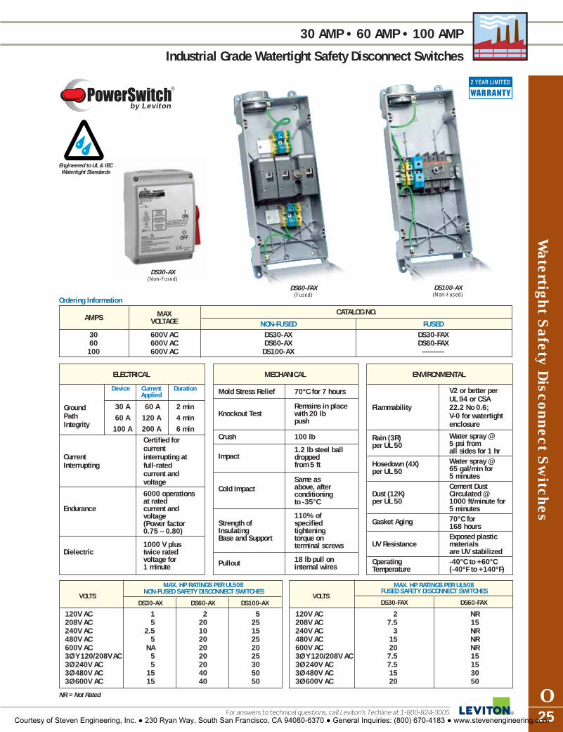
MAX CATALOG NO.AMPS VOLTAGE NON-FUSED FUSED
30 600V AC DS30-AX DS30-FAX60 600V AC DS60-AX DS60-FAX100 600V AC DS100-AX —
Watertight S
afety Disconnect S
witches
O25For answers to technical questions, call Leviton’s Techline at 1-800-824-3005
30 AMP • 60 AMP • 100 AMP
Industrial Grade Watertight Safety Disconnect Switches
2 YEAR LIMITED
MAX. HP RATINGS PER UL508NON-FUSED SAFETY DISCONNECT SWITCHES
DS30-AX DS60-AX DS100-AX
ELECTRICAL
Device Current DurationApplied
30 A 60 A 2 min60 A 120 A 4 min100 A 200 A 6 min
Certified forcurrent
Current interrupting at Interrupting full-rated
current and voltage
6000 operations at rated
Endurance current and voltage (Power factor 0.75 – 0.80)
1000 V plus Dielectric twice rated
voltage for 1 minute
MECHANICAL
Mold Stress Relief 70°C for 7 hours
Remains in place Knockout Test with 20 lb
push
Crush 100 lb
1.2 lb steel ball Impact dropped
from 5 ft
Same as Cold Impact above, after
conditioningto -35°C
110% of Strength of specified Insulating tightening Base and Support torque on
terminal screws
18 lb pull onPullout internal wires
ENVIRONMENTAL
V2 or better per UL 94 or CSA
Flammability 22.2 No 0.6; V-0 for watertight enclosure
Rain (3R) Water spray @ per UL 50 5 psi from
all sides for 1 hr
Hosedown (4X) Water spray @ per UL 50 65 gal/min for
5 minutesCement Dust
Dust (12K) Circulated @per UL 50 1000 ft/minute for
5 minutes
Gasket Aging 70°C for 168 hoursExposed plastic
UV Resistance materials are UV stabilized
Operating -40°C to +60°CTemperature (-40°F to +140°F)
DS30-AX(Non-Fused)
DS60-FAX(Fused)
DS100-AX(Non-Fused)
Engineered to UL & IECWatertight Standards
by Leviton
Ground PathIntegrity
Ordering Information
MAX. HP RATINGS PER UL508FUSED SAFETY DISCONNECT SWITCHES
DS30-FAX DS60-FAX
NR = Not Rated
VOLTS
120V AC 2 NR208V AC 7.5 15240V AC 3 NR480V AC 15 NR600V AC 20 NR3Ø Y 120/208V AC 7.5 153Ø 240V AC 7.5 153Ø 480V AC 15 303Ø 600V AC 20 50
VOLTS
120V AC 1 2 5208V AC 5 20 25240V AC 2.5 10 15480V AC 5 20 25600V AC NA 20 203Ø Y 120/208V AC 5 20 253Ø 240V AC 5 20 303Ø 480V AC 15 40 503Ø 600V AC 15 40 50
Courtesy of Steven Engineering, Inc. ● 230 Ryan Way, South San Francisco, CA 94080-6370 ● General Inquiries: (800) 670-4183 ● www.stevenengineering.com
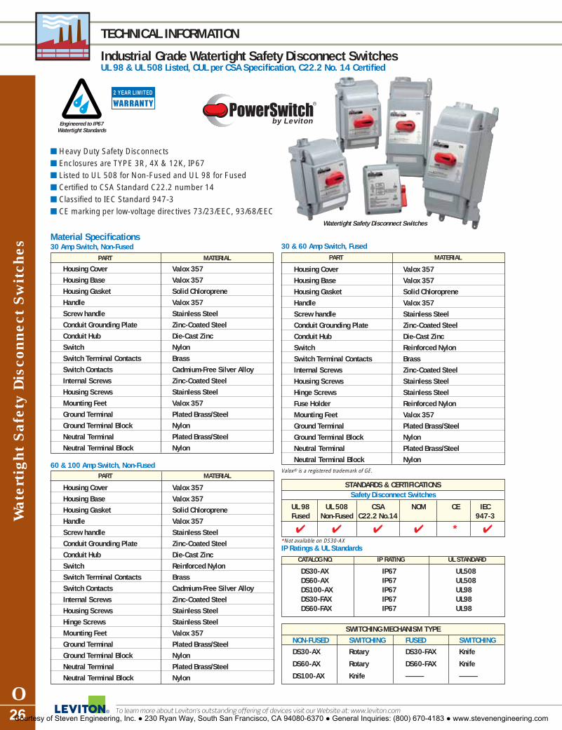
Wat
erti
ght
Saf
ety
Dis
conn
ect
Sw
itch
es
O26
TECHNICAL INFORMATION
Industrial Grade Watertight Safety Disconnect SwitchesUL 98 & UL 508 Listed, CUL per CSA Specification, C22.2 No. 14 Certified
To learn more about Leviton’s outstanding offering of devices visit our Website at: www.leviton.com
IP Ratings & UL StandardsCATALOG NO. IP RATING UL STANDARD
DS30-AX IP67 UL508DS60-AX IP67 UL508DS100-AX IP67 UL98DS30-FAX IP67 UL98DS60-FAX IP67 UL98
STANDARDS & CERTIFICATIONSSafety Disconnect Switches
UL 98 UL 508 CSA NOM CE IECFused Non-Fused C22.2 No.14 947-3
� � � � * �
by Leviton
� Heavy Duty Safety Disconnects� Enclosures are TYPE 3R, 4X & 12K, IP67� Listed to UL 508 for Non-Fused and UL 98 for Fused� Certified to CSA Standard C22.2 number 14� Classified to IEC Standard 947-3� CE marking per low-voltage directives 73/23/EEC, 93/68/EEC
Material Specifications30 Amp Switch, Non-Fused
PART MATERIAL
Housing Cover Valox 357
Housing Base Valox 357
Housing Gasket Solid Chloroprene
Handle Valox 357
Screw handle Stainless Steel
Conduit Grounding Plate Zinc-Coated Steel
Conduit Hub Die-Cast Zinc
Switch Nylon
Switch Terminal Contacts Brass
Switch Contacts Cadmium-Free Silver Alloy
Internal Screws Zinc-Coated Steel
Housing Screws Stainless Steel
Mounting Feet Valox 357
Ground Terminal Plated Brass/Steel
Ground Terminal Block Nylon
Neutral Terminal Plated Brass/Steel
Neutral Terminal Block Nylon
60 & 100 Amp Switch, Non-FusedPART MATERIAL
Housing Cover Valox 357
Housing Base Valox 357
Housing Gasket Solid Chloroprene
Handle Valox 357
Screw handle Stainless Steel
Conduit Grounding Plate Zinc-Coated Steel
Conduit Hub Die-Cast Zinc
Switch Reinforced Nylon
Switch Terminal Contacts Brass
Switch Contacts Cadmium-Free Silver Alloy
Internal Screws Zinc-Coated Steel
Housing Screws Stainless Steel
Hinge Screws Stainless Steel
Mounting Feet Valox 357
Ground Terminal Plated Brass/Steel
Ground Terminal Block Nylon
Neutral Terminal Plated Brass/Steel
Neutral Terminal Block Nylon
30 & 60 Amp Switch, FusedPART MATERIAL
Housing Cover Valox 357
Housing Base Valox 357
Housing Gasket Solid Chloroprene
Handle Valox 357
Screw handle Stainless Steel
Conduit Grounding Plate Zinc-Coated Steel
Conduit Hub Die-Cast Zinc
Switch Reinforced Nylon
Switch Terminal Contacts Brass
Internal Screws Zinc-Coated Steel
Housing Screws Stainless Steel
Hinge Screws Stainless Steel
Fuse Holder Reinforced Nylon
Mounting Feet Valox 357
Ground Terminal Plated Brass/Steel
Ground Terminal Block Nylon
Neutral Terminal Plated Brass/Steel
Neutral Terminal Block Nylon
*Not available on DS30-AX
Valox® is a registered trademark of GE.
SWITCHING MECHANISM TYPENON-FUSED SWITCHING FUSED SWITCHING
DS30-AX Rotary DS30-FAX Knife
DS60-AX Rotary DS60-FAX Knife
DS100-AX Knife — —
Engineered to IP67Watertight Standards
2 YEAR LIMITED
Watertight Safety Disconnect Switches
Courtesy of Steven Engineering, Inc. ● 230 Ryan Way, South San Francisco, CA 94080-6370 ● General Inquiries: (800) 670-4183 ● www.stevenengineering.com

Watertight S
afety Disconnect S
witches
O27For answers to technical questions, call Leviton’s Techline at 1-800-824-3005
SAFETY DISCONNECT SWITCH DIMENSIONS
Industrial Grade Watertight Safety Disconnect Switches
7.28(184.9)
5.24(133.1)
6.24(158.5)
7.28(90.9)
3.26(82.8)
0.44(11.1)
ON
OFF
30 AMP NON-FUSED
OFF
ON
11.59(294.4)
6.3(160.0)
8.78(223.0)
10.71(271.9)
12.52(318.0)
7.83(199.0)
7.48(190.1)
7.95(202.0)
7.12(180.9)
5.12(130.0)
3.11(79.1)
6.85
(174
.1)
8.86
(225
.0)
10.8
6 (2
75.9
)
11.6
9 (2
97.0
)
30 AMP FUSED & 60 AMP NON-FUSED
Courtesy of Steven Engineering, Inc. ● 230 Ryan Way, South San Francisco, CA 94080-6370 ● General Inquiries: (800) 670-4183 ● www.stevenengineering.com

Wat
erti
ght
Saf
ety
Dis
conn
ect
Sw
itch
es
O28 To learn more about Leviton’s outstanding offering of devices visit our Website at: www.leviton.com
SAFETY DISCONNECT SWITCH DIMENSIONS
Industrial Grade Watertight Safety Disconnect Switches
Auxiliary Contacts for Safety Disconnect Switches
2 YEAR LIMITED
12.8
8 (3
27.1
)
14.8
8 (3
78.0
)
16.8
9 (4
28.9
)
17.7
2 (4
50.0
)
OFF
ON
17.65(448.4)
16.73(424.9)
9.37(238.0)
6.89(175.0)
8.54(217)7.71
(195.9)5.71(145)3.70
(94.1)
8.94(227.2)
8.49(215.7)
18.54(471.0)
60 AMP FUSED & 100 AMP NON-FUSED
- Leviton Disconnect Switches automatically ship with one factory installed auxiliary contact, normally open.
- A second auxiliary contact may be added. Select from the table below.
DEVICE CATALOG NO. DESCRIPTION
For ALL non-fused and fused Normally open contact, disconnect switches
AUXNO10 Amp, early break type
Normally closed contact,AUXNC-NF10 Amp, early break type
For ALL fused disconnect Normally closed contact,switches AUXNC-F 10 Amp, early break type
Courtesy of Steven Engineering, Inc. ● 230 Ryan Way, South San Francisco, CA 94080-6370 ● General Inquiries: (800) 670-4183 ● www.stevenengineering.com

SINGLE POLE CAM-TYPE CONNECTORS
Industrial Grade Single Pole Cam-Type Connectors
Single Pole C
am-T
ype Connectors and S
tage Pin D
evices Index
INDEXCam Connectors and Stage Pin Devices forCommercial and Industrial ApplicationsStage Pin Devices—Overview, and Benefits . . . . . .P220, 60 and 100 AMP Stage Pin Devices . . . . . . . . .P3Cam Connectors—Overview, and Benefits . . . .P4, P5Ampacity Chart . . . . . . . . . . . . . . . . . . . . . . . . . . . .P6Up to 140 AMP
15 Series–Taper Nose . . . . . . . . . . . . . . . . . . . . .P7Up to 300 AMP
16 Series–Taper Nose . . . . . . . . . . . . . . . . . . . . .P818 Series–Ball Nose . . . . . . . . . . . . . . . . . . . . .P11
Up to 400 AMP16 Series–Taper Nose . . . . . . . . . . . . . . . . .P9, P1018 Series–Ball Nose . . . . . . . . . . . . . . . . .P12–P13
Up to 690 AMP17 Series–Taper Nose . . . . . . . . . . . . . . . . . . . .P1419 Series–Ball Nose . . . . . . . . . . . . . . . . . . . . .P1522 Series–Latching Ball Nose . . . . . . . . . . . . . .P1623 Series–Latching Taper Nose . . . . . . . . . . . . .P17
Product Accessories . . . . . . . . . . . . . . . . . . . . . . .P18Stage Pin Dimensional Drawings . . . . . . . . . . .P19–20Cam Connector Dimensional Drawings . . . . . .P21–26
SECTIONPSingle PoleCam-Type Connectors and Stage Pin Devices
Courtesy of Steven Engineering, Inc. ● 230 Ryan Way, South San Francisco, CA 94080-6370 ● General Inquiries: (800) 670-4183 ● www.stevenengineering.com

Sta
ge P
in D
evic
es
P2
STAGE PIN DEVICE FEATURES
Commercial Grade Stage Pin Devices
To learn more about Leviton’s outstanding offering of devices visit our Website at: www.leviton.com
Stage Pin Devices — Conforms to USITT (United States Institute for TheaterTechnology) S3 Standard for Stage Pin Connectors
Slit in male pin providesspring action to compensatefor wear
60 and 100 Amp versions have ruggedphenolic housings for superior hightemperature performance
Male pins and female contacts have a one-piece solid brass design for superior currentflow and resistance from abuse
Male pins and female contacts float to ensurecompatibility with all competitive products andimproved electrical connections
Terminal identification letterson device ensure quick andaccurate termination
20 Amp version is available with a clear cover to allow forvisual inspection of proper termination of conductors.Other colors available include white, blue, green, yellow, red and orange. Consult factory for availability.
100FP-E
100MP-E
Male Plug, Crimp Terminal Male Plug, Pressure Plate Terminal
20MP-CL
60 and 100 Amp plugs and connectors haveSSuurree GGrriipp™™ edge for easy handling
Courtesy of Steven Engineering, Inc. ● 230 Ryan Way, South San Francisco, CA 94080-6370 ● General Inquiries: (800) 670-4183 ● www.stevenengineering.com

Stage P
in Devices
P3
20, 60 & 100 AMP
Commercial Grade Stage Pin Devices
60MP-E
60FP-E
100MP-E
100FP-E
20, 60 and 100 AMP 125V Stage Pin Devices20A 125V, 2-P 3-W, GroundingDESCRIPTION CATALOG NO. COLOR*
Male Plug-Pressure Plate Terminal 20MP-E BlackMale Plug-Pressure Plate Terminal 20MP-CL Black w/ Clear CoverMale Plug-Crimp Terminal 20MC-E BlackMale Plug-Crimp Terminal 20MC-CL Black w/ Clear CoverFemale Connector-Pressure Plate Terminal 20FP-E BlackFemale Connector-Pressure Plate Terminal 20FP-CL Black w/ Clear CoverFemale Connector-Crimp Terminal 20FC-E BlackFemale Connector-Crimp Terminal 20FC-CL Black w/ Clear CoverPanel Mount Male Inlet-Set Screw Terminal, 20IS-E BlackSnap-In Mounting†Panel Mount Female Receptacle-Screw Terminal, 20RS-E BlackSnap-In Mounting†
60A 125V, 2-P 3-W, GroundingMale Plug-Set Screw Terminal 60MP-E BlackFemale Connector-Set Screw Terminal 60FP-E BlackPanel Mount Female Receptacle-Set Screw Terminal, 60RS-E Black Snap-In Mounting†Panel Mount Female Receptacle-Set Screw Terminal, 60RB-E BlackBolt-On Mounting†Panel Mount Male Inlet-Set Screw Terminal, 60IS-E BlackSnap-In Mounting†Panel Mount Male Inlet-Set Screw Terminal, 60IB-E BlackBolt-On Mounting†
100A 125V, 2-P 3-W, GroundingMale Plug-Set Screw Terminal 100MP-E BlackFemale Connector-Set Screw Terminal 100FP-E BlackPanel Mount Female Receptacle-Set Screw Terminal, 100RB-E BlackBolt-On Mounting†Panel Mount Male Inlet-Set Screw Terminal, 100IB-E BlackBolt-On Mounting†*For 20 Amp male plugs and female connectors, other cover colors are available in white, blue, green, yellow, red andorange. Consult factory for availability.
†SEE PAGE P19 and P20 FOR DIMENSIONAL DRAWINGS
Female Panel Mount, Snap-InMale Panel Mount, Bolt-On
20MP-CL
20FP-CL
For answers to technical questions, call Leviton’s Techline at 1-800-824-3005Courtesy of Steven Engineering, Inc. ● 230 Ryan Way, South San Francisco, CA 94080-6370 ● General Inquiries: (800) 670-4183 ● www.stevenengineering.com

SINGLE POLE CAM-TYPE CONNECTOR FEATURES
Commercial & Industrial Grade Single Pole Cam-Type Connectors
Sin
gle
Pole
Cam
-Typ
e Con
nect
ors
P4 To learn more about Leviton’s outstanding offering of devices visit our Website at: www.leviton.com
Leviton Cam-Type ConnectorsFeatures and Benefits� Intermateable and compatible with competitive cam-type
products—can be retrofitted to existing locations andpower distribution systems
� Locking and reinforcing ring won’t melt, break or crack� Shatter and crack proof—high durometer thermoplastic
elastomer (TPE) or neoprene rubber� Color-coded insulating sleeves—fast and easy phase
identification� Prevents arcing or burning—no movement of contact
surfaces� Self compensating for wear—slit and cam in male
contact provides spring action for longer usage� Quick connect/disconnect—twist and pull provided by
double cam male and cam button in female� High conductivity—positive, vibration-proof connection
provided by double cam design� Wide range of applications—usable with a wide range of
cable and amperage ratings� Meets NEC Code, UL Listed and CSA Certified. NEMA
3R-Rated for use in outside locations
Experience the DifferenceOur cam-type connectors are designed for easyassembly and disassembly without special tools. Aninsulated screw is used to tightly secure the contactinside the insulating sleeve, making assembly, dis-assembly and field repairs effortless. The connectorsuse plastic locking and reinforcement rings moldedinto insulating sleeves and receptacles. Under severestress and load conditions, plastic locking and rein-forcement rings will not melt, break or crack. Otherquality differences include:� Reusable sleeves and contacts� Preservation of cable length� Snug fit due to Helox shape of connection as well as
cable cutoffs that accommodate a wide range of cable sizes
� Hard thermoplastic elastomer screw head providesstrength and durability
� Collar around port provides protection for insulated screw� Quick check for cable-to-contact connection
Cam Connectors for Commercial and Industrial UseLeviton offers a wide variety of single pin cam-typecable connectors and panel mount receptacles thatsupply temporary electrical power distribution for mul-tiple indoor and outdoor applications. The heavy-dutyconnectors are the standard for the following markets:� Entertainment and Movie Industry� Concerts and Theme Parks� Carnival Equipment� Conventions. Other applications include:� Motor and Generator Splices� Mining and Construction Sites� Commercial and Navy Shipbuilding & Repair� Other temporary power applications.
Leviton manufactures the highest quality single pin connectors available. Our connectors are completely com-patible with competitive cam-type products and can beretrofitted to existing locations and power distribution systems. We offer a variety of quick connect/disconnectconnectors for various amperage ratings in a multitude ofcable sizes. Connectors are available in two styles:
� Field detachable� VulcanizedWe also offer ball nose and taper nose configurations.
Quality Product and DiversificationIn addition to high product quality comes diversitywhen doing business with Leviton. Leviton offersmany varieties of entertainment cable and the abilityto produce specialty cord sets for the entertain-ment/power distributon marketplace.
Courtesy of Steven Engineering, Inc. ● 230 Ryan Way, South San Francisco, CA 94080-6370 ● General Inquiries: (800) 670-4183 ● www.stevenengineering.com

16/18 Series double-setscrew with copper wirestrain relief
SINGLE POLE CAM-TYPE CONNECTOR FEATURES
Commercial Grade Single Pole Cam-Type Connectors
Single Pole C
am-T
ype Connectors
P5
Self compensating for wear—slit and cam in male contactprovides spring action forlonger usage
Shatter and crack proof—high durometer thermo-plastic elastomer (TPE)
Hard thermoplastic screw headprovides strength and durability
High conductivity—positive,vibration-proof connection provided by double cam design
Color-coded insulating sleevesfor easy phase identification
Collar around port providesprotection for insulated screw
Intermateable and compatible withcompetitive cam-type products—can be retrofitted to existing locationsand power distribution systems
16D26-R
16D35-E
16D26-E
15, 16, 18 Series ConnectorsCOMPONENT DESCRIPTIONSleeve SantopreneContact BrassStrain Relief Copper Wire
For answers to technical questions, call Leviton’s Techline at 1-800-824-3005Courtesy of Steven Engineering, Inc. ● 230 Ryan Way, South San Francisco, CA 94080-6370 ● General Inquiries: (800) 670-4183 ● www.stevenengineering.com

Sin
gle
Pole
Cam
-Typ
e Con
nect
ors
P6
SINGLE POLE CAM-TYPE AMPACITY CHART
Commercial & Industrial Grade Single Pole Cam-Type Connectors
To learn more about Leviton’s outstanding offering of devices visit our Website at: www.leviton.com
Ampacity ChartCABLE SIZE MAXIMUM ALLOWABLE AMPACITIES
60°C (140°F) CABLE 75°C (167°F) CABLE 90°C (194°F) CABLE
#8 60 70 80
#6 80 95 105
#4 105 125 140
#3 120 145 165
#2 140 170 190
#1 165 195 220
1/0 195 230 260
2/0 225 265 300
3/0 260 310 350
4/0 300 360 400
250MCM 340 405 455
300MCM 375 445 505
350MCM 420 505 570
400MCM 455 545 615
500MCM 515 620 690
Courtesy of Steven Engineering, Inc. ● 230 Ryan Way, South San Francisco, CA 94080-6370 ● General Inquiries: (800) 670-4183 ● www.stevenengineering.com

Single Pole C
am-T
ype Connectors
P7For answers to technical questions, call Leviton’s Techline at 1-800-824-3005
15 SERIES—TAPER NOSE—UP TO 140 AMP
Commercial Grade Single Pole Cam-Type Connectors
15 Series—Taper Nose—Up to 140 AMP, 600VRefer to Ampacity Chart for all cable sizes on page P6
Male Detachable PlugCABLE SIZE COMPLETE CAT NO. CONTACT CAT NO. INSULATOR CAT NO. TERMINATION TYPE#6–#4 15D21* 15D21-C 15SDM* Single Set Screw#6–#4 15D23*† 15D23-C 15SDM* Crimped�
Female Detachable PlugCABLE SIZE COMPLETE CAT NO. CONTACT CAT NO. INSULATOR CAT NO. TERMINATION TYPE#6–#4 15D22* 15D22-C 15SDF* Single Set Screw#6–#4 15D24*† 15D24-C 15SDF* Crimped�
Male Detachable PlugCABLE SIZE COMPLETE CAT NO. CONTACT CAT NO. INSULATOR CAT NO. TERMINATION TYPE#8 15D25* 15D26-C 15SDM* Crimped
Female Detachable PlugCABLE SIZE COMPLETE CAT NO. CONTACT CAT NO. INSULATOR CAT NO. TERMINATION TYPE#8 15D26* 15D26-C 15SDF-* Crimped
Protective Caps for All 15 Series InsulatorsSTYLE CAT NO. STYLE CAT NO.Male 15P21-E Female 15P22-E
Multi-Way Connectors�
STYLE DESCRIPTION CAT NO.Paralleling Tee Female-Male-Male 15A21††Tapping Tee Female-Female-Male 15A22††Double Female Female-Female 15A23††
SEE PAGE P21 FOR DIMENSIONAL DRAWINGS
15D21
SPECIFICATIONS AND FEATURES
• The 15 Series Taper Nose mini-cam plugs, recep-tacles and connectors are tough and reliable.Primary applications include carnivals and themeparks, as well as the entertainment industry
TESTING AND CODE COMPLIANCE
• UL Listed E-13399• NEMA 3R-Rated for use in outside locations• CSA Certified 152105
15D22
Black (-E) White (-W) Red (-R) Blue (-B) Green (-G) Yellow (-Y) Orange (-O) Brown (-H)
15R21-R
15A21-G
15P21-E
COLOR
*For color selections, add suffix to catalog number as follows: Black (-E), White (-W), Red (-R), Blue (-B), Green (-G),Yellow (-Y), Orange (-O) and Brown (-H).
†Available in Tour Grade (-T), Green (-G). Nickel Plated contact.††For color selections, add suffix to catalog number as follows: Black (-E), White (-W), Red (-R), Blue (-B) and Green (-G). �Contact Factory for Color Availability.
Courtesy of Steven Engineering, Inc. ● 230 Ryan Way, South San Francisco, CA 94080-6370 ● General Inquiries: (800) 670-4183 ● www.stevenengineering.com
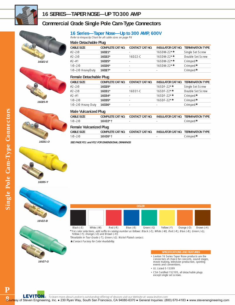
16V22-B
Sin
gle
Pole
Cam
-Typ
e Con
nect
ors
P8
16 SERIES—TAPER NOSE—UP TO 300 AMP
Commercial Grade Single Pole Cam-Type Connectors
To learn more about Leviton’s outstanding offering of devices visit our Website at: www.leviton.com
16 Series—Taper Nose—Up to 300 AMP, 600VRefer to Ampacity Chart for all cable sizes on page P6
Male Detachable PlugCABLE SIZE COMPLETE CAT NO. CONTACT CAT NO. INSULATOR CAT NO. TERMINATION TYPE#2–2/0 16D21* - 16SDM-22*� Single Set Screw#2–2/0 16D22* 16D22-C 16SDM-22*� Double Set Screw#2–#1 16D25* - 16SDM-22*� Crimped�
1/0–2/0 16D26* - 16SDM-22*� Crimped�
1/0–2/0 HeavyDuty 16D27* - - Crimped�
Female Detachable PlugCABLE SIZE COMPLETE CAT NO. CONTACT CAT NO. INSULATOR CAT NO. TERMINATION TYPE#2–2/0 16D29* - 16SDF-22*� Single Set Screw#2–2/0 16D31* 16D31-C 16SDF-22*� Double Set Screw#2–#1 16D34* - 16SDF-22*� Crimped�
1/0–2/0 16D35* - 16SDF-22*� Crimped�
1/0–2/0 Heavy Duty 16D36* - - Crimped�
Male Vulcanized PlugCABLE SIZE COMPLETE CAT NO. CONTACT CAT NO. INSULATOR CAT NO. TERMINATION TYPE1/0–2/0 16V22*† - - Crimped�
Female Vulcanized PlugCABLE SIZE COMPLETE CAT NO. CONTACT CAT NO. INSULATOR CAT NO. TERMINATION TYPE1/0–2/0 16V26*† - - Crimped�
SEE PAGE P21 and P22 FOR DIMENSIONAL DRAWINGS
16D22-E
16D31-O
16D25-R
16D35-Y
16V27-G
SPECIFICATIONS AND FEATURES
• Leviton 16 Series Taper Nose products are theconnectors of choice for concerts, sound stages,movie making, television production, sportingevents and conventions.
• UL Listed E-13399• CSA Certified 152105, all detachable plugs
except single set screws.
Black (-E) White (-W) Red (-R) Blue (-B) Green (-G) Yellow (-Y) Orange (-O) Brown (-H)
COLOR
*For color selections, add suffix to catalog number as follows: Black (-E), White (-W), Red (-R), Blue (-B), Green (-G),Yellow (-Y), Orange (-O) and Brown (-H).
†Available in Tour Grade (-T), Green (-G). Nickel Plated contact.�Contact Factory for Color Availability.
Courtesy of Steven Engineering, Inc. ● 230 Ryan Way, South San Francisco, CA 94080-6370 ● General Inquiries: (800) 670-4183 ● www.stevenengineering.com

Single Pole C
am-T
ype Connectors
P9For answers to technical questions, call Leviton’s Techline at 1-800-824-3005
16 SERIES—TAPER NOSE—UP TO 400 AMP
Commercial Grade Single Pole Cam-Type Connectors
SPECIFICATIONS AND FEATURES
• Leviton 16 Series Taper Nose products are theconnectors of choice for concerts, sound stages,movie making, television production, sportingevents and conventions.
• UL Listed E-13399• CSA Certified 152105, all detachable plugs
except single set screws.
16 Series—Taper Nose—Up to 400 AMP, 600VRefer to Ampacity Chart for all cable sizes on page P6
Male Detachable PlugCABLE SIZE COMPLETE CAT NO. CONTACT CAT NO. INSULATOR CAT NO. TERMINATION TYPE1/0–4/0 16D23* - 16SDM-14*� Single Set Screw1/0–4/0 16D24* 16D24-C 16SDM-14*� Double Set Screw3/0–4/0 16D28* - 16SDM-14*� Crimped
Female Detachable PlugCABLE SIZE COMPLETE CAT NO. CONTACT CAT NO. INSULATOR CAT NO. TERMINATION TYPE1/0–4/0 16D32* - 16SDF-14*� Single Set Screw1/0–4/0 16D33* 16D33-C 16SDF-14*� Double Set Screw3/0–4/0 16D37* 16D37-C 16SDF-14*� Crimped
Male Vulcanized PlugCABLE SIZE COMPLETE CAT NO. CONTACT CAT NO. INSULATOR CAT NO. TERMINATION TYPE3/0–4/0 16V24*† - - Crimped�
Female Vulcanized PlugCABLE SIZE COMPLETE CAT NO. CONTACT CAT NO. INSULATOR CAT NO. TERMINATION TYPE3/0–4/0 16V28*† 16V28-C - Crimped�
Protective Caps for All 16 Series InsulatorsSTYLE CAT NO. STYLE CAT NO.Male 16P21* Female 16P22*
SEE PAGE P21 and P22 FOR DIMENSIONAL DRAWINGS
Black (-E) White (-W) Red (-R) Blue (-B) Green (-G) Yellow (-Y) Orange (-O) Brown (-H)
COLOR
*For color selections, add suffix to catalog number as follows: Black (-E), White (-W), Red (-R), Blue (-B), Green (-G),Yellow (-Y), Orange (-O) and Brown (-H).
†Available in Tour Grade (-T), Black (-E), White (-W), Red (-R) and Blue (-B). Nickel Plated contact.�Contact factory for color availability
16D23-B
16D32-W
16V24-Y
16V28-E
16P22-E
16D24-Y
16D33-O
Courtesy of Steven Engineering, Inc. ● 230 Ryan Way, South San Francisco, CA 94080-6370 ● General Inquiries: (800) 670-4183 ● www.stevenengineering.com

Sin
gle
Pole
Cam
-Typ
e Con
nect
ors
P10
16 SERIES—TAPER NOSE—UP TO 400 AMP
Commercial Grade Single Pole Cam-Type Connectors
To learn more about Leviton’s outstanding offering of devices visit our Website at: www.leviton.com
16 Series—Taper Nose—Up to 400 AMP, 600VRefer to Ampacity Chart for all cable sizes on page P6
Male Panel ReceptaclesCABLE SIZE CAT NO. TERMINATION TYPE1/0–4/0 16R21* Double Set Screw#2–4/0 16R23*† Threaded Stud**
Female Panel ReceptaclesCABLE SIZE CAT NO. TERMINATION TYPE1/0–4/0 16R22* Double Set Screw#2–4/0 16R24*† Threaded Stud**
Female Panel Receptacles – with Micro SwitchCABLE SIZE CAT NO. TERMINATION TYPE#2–4/0 16RSW†† Threaded Stud�
Snap Back Cover for Male and Female Panel ReceptacleCAT NO.16S21*
Female Terminal ConnectorCABLE SIZE CAT NO. TERMINATION TYPE#2–4/0 16F21* Angled#2–4/0 16F22* Offset
Multi-Way ConnectorsSTYLE DESCRIPTION CAT NO.Paralleling Tee Female-Male-Male 16A21*�
Tapping Tee Female-Female-Male 16A22*�
3-Fer Male-Female-Female-Female 16A23*�
Reverse 3-Fer Female-Male-Male-Male 16A26*�
Double Female Female-Female 16A24*�
Double Male Male-Male 16A25*�
SEE PAGE P21 and P22 FOR DIMENSIONAL DRAWINGS **Threaded stud panel receptacles available in various lengths: Standard stud length is 3/4" – 1" stud length specify – 10 suffix; 1.125" stud length specify – 11 suffix; 1.25" stud length specify – 12 suffix; 1.50" stud length specify – 14 suffix; 2.00" stud length specify – 20 suffix (16R24 only). Other stud lengths available.
SPECIFICATIONS AND FEATURES
• Leviton 16 Series Taper Nose products are theconnectors of choice for concerts, sound stages,movie making, television production, sportingevents and conventions.
TESTING AND CODE COMPLIANCE
• UL Listed E-13399• CSA Certified 152105• NEMA 3R-Rated for use in outside locations
Black (-E) White (-W) Red (-R) Blue (-B) Green (-G) Yellow (-Y) Orange (-O) Brown (-H)
COLOR
*For color selections, add suffix to catalog number as follows: Black (-E), White (-W), Red (-R), Blue (-B), Green (-G),Yellow (-Y), Orange (-O) and Brown (-H).
†Available in Tour Grade (-T), Black (-E), White (-W), Red (-R), Blue (-B) and Green (-G). Nickel Plated contact.††For color selections, add suffix to catalog number as follows: Black (-E), White (-W), Red (-R), Blue (-B) and Green (-G). �Contact factory for color availability
16S21-O
16S21-E mounted on 16R24-14R
16R21-R
16F21-B
16A21-G
16A23-E
16A24-W
16RSW-R
Courtesy of Steven Engineering, Inc. ● 230 Ryan Way, South San Francisco, CA 94080-6370 ● General Inquiries: (800) 670-4183 ● www.stevenengineering.com

Single Pole C
am-T
ype Connectors
P11For answers to technical questions, call Leviton’s Techline at 1-800-824-3005
18 SERIES—BALL NOSE—UP TO 300 AMP
Commercial Grade Single Pole Cam-Type Connectors
18 Series—Ball Nose—Up to 300 AMP, 600VRefer to Ampacity Chart for all cable sizes on page P6
Male Detachable PlugCABLE SIZE COMPLETE CAT NO. CONTACT CAT NO. INSULATOR CAT NO. TERMINATION TYPE#2–2/0 18D21* - - Single Set Screw�
#2–2/0 18D22* - - Double Set Screw�
#2–#1 18D25* - - Crimped�
Female Detachable PlugCABLE SIZE COMPLETE CAT NO. CONTACT CAT NO. INSULATOR CAT NO. TERMINATION TYPE#2–2/0 18D29* - - Single Set Screw�
#2–2/0 18D31* - - Double Set Screw�
SEE PAGE P22 and P23 FOR DIMENSIONAL DRAWINGS
Black (-E) White (-W) Red (-R) Blue (-B) Green (-G) Yellow (-Y) Orange (-O) Brown (-H)
COLOR
* For color selections, add suffix to catalog number as follows: Black (-E), White (-W), Red (-R), Blue (-B), Green (-G), Yellow (-Y), Orange (-O) and Brown (-H).
� Contact factory for color availability
SPECIFICATIONS AND FEATURES
• The 18 Series Ball Nose pin and sleeve typeplugs, receptacles and connectors are used bythe broadcast industry in Canada, as well as thewelding industry in the United States
TESTING AND CODE COMPLIANCE
• UL Listed E-13399• CSA Certified 152105, all detachable plugs
except single set screws.
18D21-B
18D29-O
18D22-G
18D31-W
18D25-Y
Courtesy of Steven Engineering, Inc. ● 230 Ryan Way, South San Francisco, CA 94080-6370 ● General Inquiries: (800) 670-4183 ● www.stevenengineering.com

Sin
gle
Pole
Cam
-Typ
e Con
nect
ors
P12
18 SERIES—BALL NOSE—UP TO 400 AMP
Commercial Grade Single Pole Cam-Type Connectors
To learn more about Leviton’s outstanding offering of devices visit our Website at: www.leviton.com
18D23-Y
18D32-H
18D24-E
18 Series—Ball Nose—Up to 400 AMP, 600VRefer to Ampacity Chart for all cable sizes on page P6
Male Detachable PlugCABLE SIZE COMPLETE CAT NO. CONTACT CAT NO. INSULATOR CAT NO. TERMINATION TYPE1/0–4/0 18D23* - - Single Set Screw�
1/0–4/0 18D24* - - Double Set Screw
Female Detachable PlugCABLE SIZE COMPLETE CAT NO. CONTACT CAT NO. INSULATOR CAT NO. TERMINATION TYPE1/0–4/0 18D33* - - Double Set Screw
Protective Caps for All 18 Series Insulators�
STYLE CAT NO. STYLE CAT NO.Male 18P21*� Female 18P22*�
SEE PAGE P22 and P23 FOR DIMENSIONAL DRAWINGS
18D28-B
18D37-R
18V24-YSPECIFICATIONS AND FEATURES
• Leviton ECT 18 Series Taper Nose products arethe connectors of choice for concerts, soundstages, movie making, television production,sporting events and conventions.
TESTING AND CODE COMPLIANCE
• UL Listed E-13399• CSA Certified 152105, all detachable plugs
except single set screws.
Black (-E) White (-W) Red (-R) Blue (-B) Green (-G) Yellow (-Y) Orange (-O) Brown (-H)
COLOR
* For color selections, add suffix to catalog number as follows: Black (-E), White (-W), Red (-R), Blue (-B), Green (-G), Yellow (-Y), Orange (-O) and Brown (-H).
�Contact factory for color availability
Courtesy of Steven Engineering, Inc. ● 230 Ryan Way, South San Francisco, CA 94080-6370 ● General Inquiries: (800) 670-4183 ● www.stevenengineering.com

Single Pole C
am-T
ype Connectors
P13For answers to technical questions, call Leviton’s Techline at 1-800-824-3005
18 SERIES—BALL NOSE—UP TO 400 AMP
Commercial Grade Single Pole Cam-Type Connectors
SPECIFICATIONS AND FEATURES
• Leviton 18 Series Taper Nose products are theconnectors of choice for concerts, sound stages,movie making, television production, sportingevents and conventions.
TESTING AND CODE COMPLIANCE
• UL Listed E-13399• CSA Certified 152105
Black (-E) White (-W) Red (-R) Blue (-B) Green (-G) Yellow (-Y) Orange (-O) Brown (-H)
COLOR
* For color selections, add suffix to catalog number as follows: Black (-E), White (-W), Red (-R), Blue (-B), Green (-G),Yellow (-Y), Orange (-O) and Brown (-H).
� Contact factory for color availability
18 Series—Ball Nose—Up to 400 AMP, 600VRefer to Ampacity Chart for all cable sizes on page P6
Male Panel ReceptaclesCABLE SIZE CAT NO. TERMINATION TYPE#2–4/0 18R21* Threaded Stud**�
1/0–4/0 18R23* Double Set Screw�
Female Panel ReceptaclesCABLE SIZE CAT NO. TERMINATION TYPE#2–4/0 18R22* Threaded Stud**�
1/0–4/0 18R24* Double Set Screw
Female Terminal ConnectorCABLE SIZE CAT NO. TERMINATION TYPE#2–4/0 18F21* Angled�
Multi-Way ConnectorsSTYLE DESCRIPTION CAT NO.Tapping Tee Female-Female-Male 18A22�
Double Male Male-Male 18A25*�
SEE PAGE P22 and P23 FOR DIMENSIONAL DRAWINGS **Threaded stud panel receptacles available in various lengths: Standard stud length is 3/4" – 1.25" stud length specify – 12 suffix. Other stud lengths available.
18A22-E
18R22-G
18A25-E
Courtesy of Steven Engineering, Inc. ● 230 Ryan Way, South San Francisco, CA 94080-6370 ● General Inquiries: (800) 670-4183 ● www.stevenengineering.com

Sin
gle
Pole
Cam
-Typ
e Con
nect
ors
P14
17 SERIES—TAPER NOSE—UP TO 690 AMP
Industrial Grade Single Pole Cam-Type Connectors
To learn more about Leviton’s outstanding offering of devices visit our Website at: www.leviton.com
17 Series—Taper Nose—Up to 690 AMP, 600VRefer to Ampacity Chart for all cable sizes on page P6
Male Detachable PlugCABLE SIZE COMPLETE CAT NO. CONTACT CAT NO. INSULATOR CAT NO. TERMINATION TYPE250–350 MCM 17D21* - 17SDM*� Double Set Screw350–500 MCM 17D22* - 17SDM*� Double Set Screw
Female Detachable PlugCABLE SIZE COMPLETE CAT NO. CONTACT CAT NO. INSULATOR CAT NO. TERMINATION TYPE250–350 MCM 17D23* - - Double Set Screw350–500 MCM 17D24* - - Double Set Screw
Male Vulcanized PlugCABLE SIZE COMPLETE CAT NO. CONTACT CAT NO. INSULATOR CAT NO. TERMINATION TYPE350–500 MCM 17V22* - - Crimped�
500–750 MCM 17V23* - - Crimped�
Female Vulcanized PlugCABLE SIZE COMPLETE CAT NO. CONTACT CAT NO. INSULATOR CAT NO. TERMINATION TYPE500–750 MCM 17V26-E - - Crimped�
Protective Caps for All 17 Series InsulatorsSTYLE CAT NO. STYLE CAT NO.Male 17P21* Female 17P22*
Male Panel ReceptaclesCABLE SIZE CAT NO. TERMINATION TYPE STYLE250–750 MCM 17R21* Threaded Stud 90 Degree250–750 MCM 17R23* Threaded Stud 30 Degree�
Female Panel Receptacles
CABLE SIZE CAT NO. TERMINATION TYPE STYLE250–750 MCM 17R22* Threaded Stud 90 Degree250–750 MCM 17R24* Threaded Stud 30 Degree�
SEE PAGE P24 FOR DIMENSIONAL DRAWINGS
SPECIFICATIONS AND FEATURES
• The 17 Series Taper Nose connectors withstandgrueling, heavy-duty industrial use. Applicationsinclude generator test stations, water purificationplants, electro-chemical machining equipmentand other general industrial uses.
Black (-E) White (-W) Red (-R) Blue (-B) Green (-G) Yellow (-Y) Orange (-O) Brown (-H)
COLOR
* For color selections, add suffix to catalog number as follows: Black (-E), White (-W), Red (-R), Blue (-B), Green (-G), Yellow (-Y), Orange (-O) and Brown (-H).
�Contact factory for color availability
17D23-E
17V26-G
17R23-E
17P21-E
17D21-W
Courtesy of Steven Engineering, Inc. ● 230 Ryan Way, South San Francisco, CA 94080-6370 ● General Inquiries: (800) 670-4183 ● www.stevenengineering.com

Single Pole C
am-T
ype Connectors
P15For answers to technical questions, call Leviton’s Techline at 1-800-824-3005
19 SERIES—BALL NOSE—UP TO 600 AMP
Industrial Grade Single Pole Cam-Type Connectors
19 Series—Ball Nose—Up to 690 AMP, 600VRefer to Ampacity Chart for all cable sizes on page P6
Male Detachable PlugCABLE SIZE COMPLETE CAT NO. CONTACT CAT NO. INSULATOR CAT NO. TERMINATION TYPE250–350 MCM 19D21* - - Double Set Screw�
350–500 MCM 19D22* - - Double Set Screw
Female Detachable PlugCABLE SIZE COMPLETE CAT NO. CONTACT CAT NO. INSULATOR CAT NO. TERMINATION TYPE250–350 MCM 19D23* - - Double Set Screw�
350–500 MCM 19D24* - - Double Set Screw�
Male Vulcanized PlugCABLE SIZE COMPLETE CAT NO. CONTACT CAT NO. INSULATOR CAT NO. TERMINATION TYPE500–750 MCM 19V23* - - Crimped�
Protective Caps for All 19 Series InsulatorsSTYLE CAT NO. STYLE CAT NO.Male 19P21*� Female 19P22
Male Panel ReceptaclesCABLE SIZE CAT NO. TERMINATION TYPE STYLE250–750 MCM 19R21* Threaded Stud 90 Degree
Female Panel ReceptaclesCABLE SIZE CAT NO. TERMINATION TYPE STYLE250–750 MCM 19R22* Threaded Stud 90 Degree250–750 MCM 19R24* Threaded Stud 30 Degree�
SEE PAGE P24 and P25 FOR DIMENSIONAL DRAWINGS
SPECIFICATIONS AND FEATURES
• The 19 Series Ball Nose connectors are designedfor general industrial applications
Black (-E) White (-W) Red (-R) Blue (-B) Green (-G) Yellow (-Y) Orange (-O) Brown (-H)
COLOR
* For color selections, add suffix to catalog number as follows: Black (-E), White (-W), Red (-R), Blue (-B), Green (-G), Yellow (-Y), Orange (-O) and Brown (-H).
�Contact factory for color availability
19D21-E
19D23-E
19V23-E
19P21-E
Courtesy of Steven Engineering, Inc. ● 230 Ryan Way, South San Francisco, CA 94080-6370 ● General Inquiries: (800) 670-4183 ● www.stevenengineering.com

Sin
gle
Pole
Cam
-Typ
e Con
nect
ors
P16
22 SERIES—LATCHING BALL NOSE—UP TO 690 AMP
Industrial Grade Single Pole Cam-Type Connectors
To learn more about Leviton’s outstanding offering of devices visit our Website at: www.leviton.com
22 Series—Latching Ball Nose—Up to 690 Amp, 600VRefer to Ampacity Chart for all cable sizes on page P6
Male Latching PlugCABLE SIZE COMPLETE CAT NO. CONTACT CAT NO. INSULATOR CAT NO. TERMINATION TYPE250–350 MCM 22L211 - 22SVM3 Crimped350–500 MCM 22L222 22L22-C 22SVM3 Crimped350-500 MCM 22L22-S3† - - -500–750 MCM 22L233 22L23-C 22SVM3 Crimped
Female Latching PlugCABLE SIZE COMPLETE CAT NO. CONTACT CAT NO. INSULATOR CAT NO. TERMINATION TYPE250–350 MCM 22L241 - 22SVF3 Crimped350–500 MCM 22L252 22L25-C 22SVF3 Crimped350-500 MCM 22L25-S3† - - -500–750 MCM 22L263 - 22SVF3 Crimped
Protective Caps for All 22 Series InsulatorsSTYLE CAT NO. STYLE CAT NO.Male 19P21� Female 19P22�
Male Panel ReceptaclesCABLE SIZE CAT NO. TERMINATION TYPE STYLE250–750 MCM 22R213 Threaded Stud 90 Degree250–750 MCM 22R233 Threaded Stud 30 Degree
Female Panel ReceptaclesCABLE SIZE CAT NO. TERMINATION TYPE STYLE250–750 MCM 22R223 Threaded Stud 90 Degree250–750 MCM 22R244 Threaded Stud 30 Degree250-750 MCM 22R263 Threaded Stud 15 Degree
Female Panel Receptacles–with Micro SwitchCABLE SIZE CAT NO. TERMINATION TYPE STYLE250–750 MCM 22R283 Threaded Stud 15 Degree
SEE PAGE P25 and P26 FOR DIMENSIONAL DRAWINGS †Detachable�Contact factory for color availability
SPECIFICATIONS AND FEATURES
• The Leviton 22 series Cam-Type connectors arespecified in the United Facility Guide Specification(4FGS-16145).
• Leviton’s Cam-Type positive latching connectors andreceptacles are the standard used by Navy basesand shipyards in supplying 480 volts AC 3-phasepower to ships at dockside. Our latching connectorseries has been thoroughly and successfully testedby ETL Laboratories to meet Navy specifications,including intermateability with competition. Ourlatching connector series provides heavy duty, completely insulated connectors that are vibration-resistant and positively lock into place. Leviton latching connectors will not vibrate, twist or turn
loose, ensuring high conductivity and maximum efficiency. Leviton contacts can be retrofitted to existing locations and power distribution systems.Our male contacts are designed to provide 40%more surface contact with the female vs. competitiveproducts. The additional efficiency will help ensuregreater conductivity while preventing burnout.
• The connectors and all components are completelyinterchangeable with competitive cam-type products.
TESTING AND CODE COMPLIANCE
• ETL Tested, Report #521300• Waterproof (when vulcanized) and fire-resistant for
outside usage
22L25-E
22L22-S
22L21-R
22R24-E
22R28-W
22R23-E
22L22-E
Black (-E) White (-W) Red (-R) Blue (-B) Green (-G) Yellow (-Y) Orange (-O) Brown (-H)
COLOR
For color selections, add suffix to catalog number as follows:1 Black (-E), White (-W), Red (-R), Green (-G)2 Black (-E), White (-W), Red (-R), Yellow (-Y), Orange (-O), Brown (-H)3 Black (-E), White (-W), Red (-R)4 Black (-E), White (-W), Red (-R), Green (-G), Yellow (-Y), Orange (-O), Brown (-H)
22L25-E
Courtesy of Steven Engineering, Inc. ● 230 Ryan Way, South San Francisco, CA 94080-6370 ● General Inquiries: (800) 670-4183 ● www.stevenengineering.com

Single Pole C
am-T
ype Connectors
P17For answers to technical questions, call Leviton’s Techline at 1-800-824-3005
23 SERIES—LATCHING TAPER NOSE—UP TO 690 AMP
Industrial Grade Single Pole Cam-Type Connectors
SPECIFICATIONS AND FEATURES
• Leviton’s Cam-Type positive latching connectors andreceptacles are the standard used by Navy basesand shipyards in supplying 480 volts AC 3-phasepower to ships at dockside. Our latching connectorseries has been thoroughly and successfully testedby ETL Laboratories to meet Navy specifications,including intermateability with competition. Ourlatching connector series provides heavy duty, com-pletely insulated connectors that are vibration-resist-ant and positively lock into place. Leviton latchingconnectors will not vibrate, twist or turn loose, ensur-ing high conductivity and maximum efficiency.Leviton contacts can be retrofitted to existing
locations and power distribution systems. Our malecontacts are designed to provide 40% more surfacecontact with the female vs. competitive products. Theadditional efficiency will help ensure greater conduc-tivity while preventing burnout.
• The connectors and all components are completelyinterchangeable with competitive cam-type products.
TESTING AND CODE COMPLIANCE
• ETL Tested, Report #521300• Waterproof (when vulcanized) and fire-resistant for
outside usage
23 Series—Latching Taper Nose—Up to 690 Amp, 600VRefer to Ampacity Chart for all cable sizes on page P6
Male Latching PlugCABLE SIZE COMPLETE CAT NO. CONTACT CAT NO. INSULATOR CAT NO. TERMINATION TYPE350–500 MCM 23L221 - - Crimped500–750 MCM 23L232 - - Crimped
Female Latching PlugCABLE SIZE COMPLETE CAT NO. CONTACT CAT NO. INSULATOR CAT NO. TERMINATION TYPE350–500 MCM 23L254 - - Crimped500–750 MCM 23L265 - - Crimped
Protective Caps for All 22 Series InsulatorsSTYLE CAT NO. STYLE CAT NO.Male 17P217 Female 17P227
Male Panel ReceptaclesCABLE SIZE CAT NO. TERMINATION TYPE STYLE250–750 MCM 23R216 Threaded Stud 90 Degree250–750 MCM 23R234 Threaded Stud 30 Degree
Female Panel ReceptaclesCABLE SIZE CAT NO. TERMINATION TYPE STYLE250–750 MCM 23R227 Threaded Stud 90 Degree250–750 MCM 23R247 Threaded Stud 30 Degree
SEE PAGES 25 AND 26 FOR DIMENSIONAL DRAWINGS
23R21-E
23L24-R
23L25-G
Black (-E) White (-W) Red (-R) Blue (-B) Green (-G) Yellow (-Y) Orange (-O) Brown (-H)
COLOR
For color selections, add suffix to catalog number as follows:1 White (-W), Blue (-B), Green (-G), Yellow (-Y), Orange (-O), Brown (-H)2 Black (-E), White (-W), Red (-R), Blue (-B), Green (-G)3 Black (-E), White (-W), Red (-R)4 Black (-E), Blue (-B), Green (-G), Yellow (-Y), Orange (-O), Brown (-H)5 Black (-E), White (-W), Red (-R)6 Black (-E), Blue (-B), Green (-G)7 Black (-E), White (-W), Red (-R), Blue (-B), Green (-G), Yellow (-Y), Orange (-O), Brown (-H)� Contact factory for color availability
Courtesy of Steven Engineering, Inc. ● 230 Ryan Way, South San Francisco, CA 94080-6370 ● General Inquiries: (800) 670-4183 ● www.stevenengineering.com

Sin
gle
Pole
Cam
-Typ
e Con
nect
ors
P18
SINGLE POLE CAM-TYPE CONNECTORS—PRODUCT ACCESSORIES
Industrial Grade Single Pole Cam-Type Connectors
To learn more about Leviton’s outstanding offering of devices visit our Website at: www.leviton.com
“COM-A-LONG” Assembly Tool15 SeriesDESCRIPTION CAT. NO.For Female Plug 15CLM
For Male Plug 15CLF
16 Series & 18 SeriesDESCRIPTION CAT. NO.For Female Plug 16CLM
For Male Plug 16CLF
17 Series, 19 Series & 22/23 SeriesDESCRIPTION CAT. NO.For Female Plug 17CLM
For Male Plug 17CLF
Set Screws (10 per package)DESCRIPTION CAT. NO.15 Series A0001
16 Series & 18 Series A0002
Copper Shims (10 per package)DESCRIPTION CAT. NO.15 Series A0006
16 Series & 18 Series A0004
Strain Relief Wire (10 per package)DESCRIPTION CAT. NO.15 Series A0007
16 Series & 18 Series A0003
Insulated Screw (10 per package)DESCRIPTION CAT. NO.16 Series & 18 Series A0005
Lubricating SprayDESCRIPTION CAT. NO.16 Fluid Ounce Can C0001
Courtesy of Steven Engineering, Inc. ● 230 Ryan Way, South San Francisco, CA 94080-6370 ● General Inquiries: (800) 670-4183 ● www.stevenengineering.com

Stage P
in Devices
P19For answers to technical questions, call Leviton’s Techline at 1-800-824-3005
STAGE PIN PANEL MOUNT—DIMENSIONAL DRAWINGS
Commercial Grade Stage Pin Devices
Stage Pin Panel Mount—20 AMP20A Female Receptacle, Snap-In—page P3
1.98(50.2)
2.19(55.5)
.50(12.7).75
(19.1)
1.17
(29.
6)
1.35
(34.
3)
.74(18.8)
.10
(2.5
)
.94
(23.
7)
20A Male Inlet, Snap-In—page P3
1.98(50.2)
2.19(55.5)
.50(12.7).75
(19.1)
1.17
(29.
6)
1.35
(34.
3).74
(18.8)
.10
(2.5
)
.94
(23.
7)
.78
(19.
8)
.70
(17.
8)
Stage Pin Panel Mount—60 AMP60A Female Receptacle, Bolt-On—page P3
3.63(92.1)
5.38(136.5)
.88(22.2)1.38
(34.9)
4.75(120.6)
1.13
(28.
6)1.63
(42.
3)
.75(19.1
.25
(6.4
)
1.25
(31.
8)
60A Male Inlet, Bolt-On—page P3
3.63(92.1)
5.38(136.5)
.88(22.2)1.38
(34.9)
4.75(120.6)
1.13
(28.
6)1.63
(41.
3)
.75(19.1
.25
(6.4
)
1.25
(31.
8)
1.00
(25.
4)
Courtesy of Steven Engineering, Inc. ● 230 Ryan Way, South San Francisco, CA 94080-6370 ● General Inquiries: (800) 670-4183 ● www.stevenengineering.com

Sta
ge P
in D
evic
es
P20
STAGE PIN PANEL MOUNT—DIMENSIONAL DRAWINGS
Commercial Grade Stage Pin Devices
To learn more about Leviton’s outstanding offering of devices visit our Website at: www.leviton.com
Stage Pin Panel Mount—60 AMP60A Female Panel Receptacle, Snap-In—page P3
3.63(92.1)
.75(19.1)
4.32(109.7)
.88(22.2)1.38
(34.9)
1.16
(29.
5)1.70
(43.
2)
.13
(3.2
)
1.27
(32.
3)
60A Male Panel Receptacle, Snap-In—page P3
3.63(92.1)
.75(19.1)
4.32(109.7)
.88(22.2)1.38
(34.9)
1.16
(29.
5)1.70
(43.
2)
.13
(3.2
)
1.27
(32.
3)
.94
(23.
8)
Stage Pin Panel Mount—100 AMP100A Female Receptacle, Bolt-On—page P3
5.38(136.5)
1.00(25.4)1.97
(50.0)
4.75(120.6)
1.25
(31.
8)1.90
(48.
2)
.91(23.0)
.25
(6.4
)
1.25
(31.
8)
3.97(92.1)
100A Male Inlet, Bolt-On—page P3
5.38(136.5)
1.00(25.4)1.97
(50.0)
4.75(120.6)
1.25
(31.
8)1.90
(48.
2)
.91(23.0)
.25
(6.4
)
1.25
(31.
8)
1.28
(32.
4)
3.97(92.1)
Courtesy of Steven Engineering, Inc. ● 230 Ryan Way, South San Francisco, CA 94080-6370 ● General Inquiries: (800) 670-4183 ● www.stevenengineering.com

Single Pole C
am-T
ype Connectors
P21For answers to technical questions, call Leviton’s Techline at 1-800-824-3005
SINGLE POLE CAM-TYPE CONNECTORS—DIMENSIONAL DRAWINGS
Commercial Grade Single Pole Cam-Type Connectors
15 Series—Taper NoseMale and Female Detachable Plugs—page P7
Panel Receptacle Threaded Studs—page P7
16 Series—Taper NoseMale and Female Detachable Plugs—pages P8–P10
Male and Female Protective Caps—page P13
Ø 0.88(22.2)
4.38 (111.1)
.41–
.50
.35–
.40
Ø 0.88(22.2)
4.50 (114.3)
.41–
.50
.35–
.40
MALE DETACHABLE PLUG FEMALE DETACHABLE PLUG—
7.00 (177.8)
1.84(46.8)
Ø 1
.72
(43.
7)
6.88 (174.7)
1.84(46.8)
Ø 1
.72
(43.
7)
MALE DETACHABLE PLUG FEMALE DETACHABLE PLUG
0.50 (12.7)
Ø 0
.87
(22.
1)
Ø 0
.87
(22.
1)
Ø 0
.50
(12.
7)
2.63 (66.7)Ø 1.86 (47.2)
1.24 (31.5)
Ø 0.40(10.2) THRU
120˚
2.00 (50.8)
1.59 (40.5) 5/16-18 FULL THREAD TO SHOULDER
Ø 1.32(33.4)
0.50 (12.7)
Ø 0
.86
(2
1.8)
Ø 0.
87
(22.
1)
Ø 0.
50
(12.
7)
2.63 (66.7)
Ø 1.86 (47.2)
1.25 (31.6)
120˚
1.15 (29.1)
2.00 (50.8)
1.62 (41.0) 5/16-18 FULL THREADTO SHOULDER
Ø 1.32(33.4)
Ø 0.40(10.2) THRU
MALE PANEL RECEPTACLE TREADED STUD FEMALE PANEL RECEPTACLE TREADED STUD
1.70(43.2)
2.51
(6
3.7)
1.72(43.7)
2.51
(6
3.7)
MALE PROTECTIVE CAP FEMALE PROTECTIVE CAP
Ø 1
.48
(37.
6)
1.78
(45
.2)
5.87 (149.1)
Ø 1
.48
(37.
6)
1.78
(45
.2)
5.87 (149.1)
MALE VULCANIZED PLUG FEMALE VULCANIZED PLUG—
Male and Female Vulcanized Plugs—pages P14, P15
Courtesy of Steven Engineering, Inc. ● 230 Ryan Way, South San Francisco, CA 94080-6370 ● General Inquiries: (800) 670-4183 ● www.stevenengineering.com

Sin
gle
Pole
Cam
-Typ
e Con
nect
ors
P22
SINGLE POLE CAM-TYPE CONNECTORS—DIMENSIONAL DRAWINGS
Commercial Grade Single Pole Cam-Type Connectors
To learn more about Leviton’s outstanding offering of devices visit our Website at: www.leviton.com
16 Series—Taper NoseDouble Set Screw and Threaded Panel Receptacle Studs—page P10
Multi-Way Connectors—page P10
MULTI-WAY CONNECTOR—FEMALE TO FEMALE MULTI-WAY CONNECTOR—MALE TO MALE
0.50 (12.7)
2.25 SQ (57.2)
Ø 1
.50
(38.
1)
2.16 (54.8) 1.78
(45.3)0.56 (14.2)
1.50 SQ (38.1)
Ø 0.22 (5.6)
Ø 1
.47
(37.
3)
MALE DOUBLE SET SCREW PANEL RECEPTACLE
1/2-13 UNC 2A THREAD
0.50 (12.7)
2.25 SQ (57.2)
Ø 1
.50
(38.
1)
2.16 (54.8)
0.56 (14.2)
1.50 SQ (38.1)
Ø 0.22 (5.6)
Ø 1
.47
(37.
3)
MALE THREADED STUD PANEL RECEPTACLE
0.50 (12.7)
2.25SQ (57.2)
Ø 1
.50
(38.
1)
2.25 (57.3) 1.69
(50.8)0.56 (14.2)1.44
(36.5)
1.50 SQ (38.1)
Ø 0.22 (5.6)
Ø 1
.48
(37.
7 m
m)
Ø 1
.00
(25.
5)
FEMALE DOUBLE SET SCREW PANEL RECEPTACLE
0.50 (12.7)
Ø 1
.50
(38.
1 m
m)
2.25 (57.3)0.75 (19.1)0.56 (14.2)
1.44 (36.5)
1/2-13 UNC 2A THREAD
Ø 1
.48
(37.
7)
2.25 SQ (57.2)
1.50 SQ (38.1)
Ø 0.22 (5.6)
Ø 1
.00
(25.
4)
FEMALE THREADED STUD PANEL RECEPTACLE
0.75 (19.1)
0.75
(1
9.1)
1.50 SQ (38.1)
1.56 SQ THRU(39.7)
MOUNTING HOLEPATTERN
Ø 0.22 (4 PL.) (5.6)
PANEL CUTOUT DIMENSIONS
Ø 1.48(37.6)
4.50 (114.3)1.73 (44.0) Ø 1.48
(37.6)4.54
(117.7)
18 Series—Ball NoseMale and Female Detachable Plugs—pages P11, P12
Male and Female Vulcanized Plugs—pages P11, P12
6.16 (156.5) 1.84 (46.8)
Ø 1
.72
(43.
7)
6.77 (172.0) 1.84 (46.8)
Ø 1
.72
(43.
7)
Ø 1
.47
(37.
3)
5.42 (137.7)
Ø 1
.47
(37.
3)
5.22 (132.6)
MALE DETACHABLE PLUG FEMALE DETACHABLE PLUG—
MALE VULCANIZED PLUG FEMALE VULCANIZED PLUG
Courtesy of Steven Engineering, Inc. ● 230 Ryan Way, South San Francisco, CA 94080-6370 ● General Inquiries: (800) 670-4183 ● www.stevenengineering.com

Single Pole C
am-T
ype Connectors
P23For answers to technical questions, call Leviton’s Techline at 1-800-824-3005
SINGLE POLE CAM-TYPE CONNECTORS—DIMENSIONAL DRAWINGS
Commercial Grade Single Pole Cam-Type Connectors
18 Series—Ball Nose Male and Female Protective Caps—page P12
1.36 (34.4)
2.51
(63
.7)
1.10 (27.8)
2.51
(63
.7)
MALE PROTECTIVE CAP FEMALE PROTECTIVE CAP
Double Set Screw and Threaded Panel Receptacle Studs—page P13
0.50 (12.7)
2.25 SQ (57.2)
Ø 1
.50
(38.
1)
2.00 (50.8)
2.48 (63.0)
0.75 (19.1)
0.56 (14.2)0.94
(23.9)
1.50 SQ (38.1)
1/2-13 UNC 2A THREADØ 0.22
(5.6)
Ø 1
.47
(37.
3)
MALE THREADED STUD PANEL RECEPTACLE
2.25 SQ (57.2)
1.50 SQ(38.1)
Ø 0.22 (5.6)
0.50 (12.7)
Ø 1
.50
(38.
1)
2.00 (50.8)
2.48 (63.0)
1.78 (45.3)
0.56 (14.2)0.94
(23.9)
Ø 1
.47
(37.
3)
MALE DOUBLE SET SCREW PANEL RECEPTACLE
0.50 (12.7)
2.25 SQ (57.2)
Ø 1
.50
(38.
1)
2.00 (50.8)
2.67 (67.8)
0.75 (19.1)0.56 (14.2)0.94
(23.9)
1.50 SQ (38.1)
1/2-13 UNC 2A THREADØ 0.22
(5.6)
Ø 1
.47
(37.
3)
FEMALE THREADED STUD PANEL RECEPTACLE
2.25 SQ (57.2)
1.50 SQ (38.1)
Ø 0.22 (5.6)
0.50 (12.7)
Ø 1
.50
(38.
1)
2.00 (50.8)
2.67 (67.8)
1.78 (45.3)
0.56 (14.2)
0.94 (23.9)
Ø 1
.47
(37.
3)
FEMALE DOUBLE SET SCREW PANEL RECEPTACLE
0.75 (19.1)
0.75
(1
9.1)
1.50 SQ (38.1)
1.56 SQ THRU(39.7)
MOUNTING HOLEPATTERN
Ø 0.22 (4 PL.) (5.6)
PANEL CUTOUT DIMENSIONS
Multi-Way Connectors—page P13
MULTI-WAY CONNECTOR—FEMALE TO FEMALE MULTI-WAY CONNECTOR—MALE TO MALE
3.19 (81.0)
Ø 1
.50(
38.1
)
4.44 (112.8)
3.20 (81.2)
Ø 1
.50
(38.
1)
4.03 (102.4)
Courtesy of Steven Engineering, Inc. ● 230 Ryan Way, South San Francisco, CA 94080-6370 ● General Inquiries: (800) 670-4183 ● www.stevenengineering.com

Sin
gle
Pole
Cam
-Typ
e Con
nect
ors
P24
SINGLE POLE CAM-TYPE CONNECTORS—DIMENSIONAL DRAWINGS
Industrial Grade Single Pole Cam-Type Connectors
To learn more about Leviton’s outstanding offering of devices visit our Website at: www.leviton.com
19 Series—Ball NoseMale and Female Vulcanized Plugs—pages P15
MALE VULCANIZED PLUG—CRIMPED FEMALE VULCANIZED PLUG—CRIMPED
7.81 (198.5)
Ø 2
.26
(57.
4)
2.35
(59
.6)
9.38 (238.1)3.00 (76.2)
Ø 1
.50
(38.
1)
2.33
(59
.1)
17 Series—Taper NoseMale and Female Vulcanized Plugs—pages P14
8.75 (222.3)
Ø 2
.23
(56.
7)
2.39
(60
.7)
8.08 (205.3)
Ø 1
.94
(49.
2 )
2.31
(58
.6)
MALE VULCANIZED PLUG—CRIMPED FEMALE VULCANIZED PLUG—CRIMPED
Panel Receptacle Threaded Studs—page P14
Ø 4.48 (113.9)
Ø 2
.31
(58.
7)
2.4
7 S
Q
(62.
7)
1.00 (25.4)
BOLT CIRCLE Ø 3.50 (88.9) Ø 0.28 (4 PL.)
(7.1)
Ø 2.47 (62.7)
5.57 (141.4)
1/2-13 UNC THREADED STUD
MOUNTING HOLE PATTERN
0.63 (15.9)
2.39 (60.7)
4.43 (112.4)
2.84
(7
2.2)
5.04 (128.0)
0.50 (12.7)
1/2-13 UNC THREADED STUD
1.00
(25.4)
Ø 2.30
(58.4)
2.21 (56.1)
5.40
(13
7.2)
2.50 (63.5)
Ø 2.75 (69.9)
Ø 0.31 (7.9)
Ø 3.50 (88.9)
MOUNTING HOLE PATTERN2.
47 (
62.7
)
0.23
(5
.8)
MALE PANEL RECEPTACLE THREADED STUD—90° MALE PANEL RECEPTACLE THREADED STUD—30°
19 Series—Ball NoseMale and Female Detachable Plugs—page P15
7.81 (198.5)
Ø 2
.26
(57.
4)
2.53
(64
.1)
9.38 (238.1)3.00 (76.2)
Ø 1
.50
(38.
1)
2.51
(63.
6)
MALE DETACHABLE PLUG—DOUBLE SET SCREW FEMALE DETACHABLE PLUG—DOUBLE SET SCREW
Courtesy of Steven Engineering, Inc. ● 230 Ryan Way, South San Francisco, CA 94080-6370 ● General Inquiries: (800) 670-4183 ● www.stevenengineering.com

Single Pole C
am-T
ype Connectors
P25For answers to technical questions, call Leviton’s Techline at 1-800-824-3005
SINGLE POLE CAM-TYPE CONNECTORS—DIMENSIONAL DRAWINGS
Industrial Grade Single Pole Cam-Type Connectors
19 Series—Ball NosePanel Receptacle Threaded Studs—page P15
4.43 (112.4)2.
57 (
65.2
)4.02 (102.1)
0.50 (12.7)
1/2-13 UNC THREADED STUD
1.00
(25.4)
Ø 2.30
(58.4)
2.21 (56.1)
5.40
(13
7.2)
2.50 (63.5)
Ø 2.75 (69.9)
Ø 0.31 (7.9)
Ø 3.50 (88.9)
MOUNTING HOLE PATTERN
2.47
(6
2.7)
0.23
(5
.8)
4.43 (112.4)
2.84
(72
.2)
4.78 (121.5)
0.50 (12.7)
1/2-13 UNC THREADED STUD
1.00
(25.4)
Ø 2.30
(58.4)
2.21 (56.1)
5.40
(13
7.2)
2.50 (63.5)
Ø 2.75 (69.9)
Ø 0.31 (7.9)
Ø 3.50 (88.9)
MOUNTING HOLE PATTERN
2.47
(6
2.7)
0.23
(5
.8)
MALE PANEL RECEPTACLE THREADED STUD—30° FEMALE PANEL RECEPTACLE THREADED STUD—30°
22 Series—Latching Ball NoseMale and Female Ball Nose Latching Connectors—page P16
7.81 (198.5)
Ø 2
.26
(57.
4)
2.45
(62
.3)
BALL NOSE IN-LINE LATCHING MALE CONNECTORS—CRIMPED
9.38 (238.3)3.00 (76.2)
Ø 1
.50
(38.
1)
2.45
(62
.3)
BALL NOSE IN-LINE LATCHING FEMALE CONNECTORS—CRIMPED
BALL NOSE IN-LINE LATCHING MALE DETACHABLE CONNECTORS BALL NOSE IN-LINE FEMALE DETACHABLE CONNECTORS
FEMALE 15˚ PANEL RECEPTACLE FEMALE 15˚ PANEL RECEPTACLE WITH MICROSWITCH
7.66(194.5)
Ø 2
.26
(57.
4)
1.30
1.208.32
(211.4)
Ø 1
.50
(38.
1)Ø
2.2
6(5
7.4)1.30
1.20
4.50(114.3)
Ø 0.28(7.1)Ø 2.70
(68.6)
Ø 3.50(88.9)
5.44(138.1)
2.17(55.1)
0.50
(12
.7)
1/2-13UNC STUD
75˚
BOLTHOLES
BOLT HOLESTHRU HOLE
MOUNTING HOLE PATTERN
2.47(62.7)
2.47(62.7)
0.18
(4.6
)
Ø 4.50(114.3)
4.50(114.3)
5.44(138.1)
0.50
(12
.7)
4.50(116.4)
75˚
BOLTHOLES
Ø 4.50(114.3)
Ø 0.28(7.1)Ø 2.70
(68.6)
Ø 3.50(88.9)
BOLT HOLESTHRU HOLE
MOUNTING HOLE PATTERN
FACE OF MOUNTING PANEL
2.47(62.7)
2.47(62.7)
0.18
(4.6
)
Courtesy of Steven Engineering, Inc. ● 230 Ryan Way, South San Francisco, CA 94080-6370 ● General Inquiries: (800) 670-4183 ● www.stevenengineering.com

Sin
gle
Pole
Cam
-Typ
e Con
nect
ors
P26
SINGLE POLE CAM-TYPE CONNECTORS—DIMENSIONAL DRAWINGS
Industrial Grade Single Pole Cam-Type Connectors
To learn more about Leviton’s outstanding offering of devices visit our Website at: www.leviton.com
23 Series—Latching Taper NosePanel Receptacle Threaded Studs—page P17
Ø 4.48 (113.9)
Ø 2
.31
(58.
7)
2.47
SQ
(6
2.7)
1.00 (25.4)
BOLT CIRCLE Ø 3.50 (88.9)
Ø .28 (4 PL.)(7.1)
Ø 2.47 (62.7)
5.57 (141.4)
1/2-13 UNC THREADED STUD
MOUNTING HOLE PATTERN
0.63 (15.9)
2.39 (60.7)
Ø 4.48 (113.9)
Ø 2
.23
(56.
6 )
2.47
SQ
(6
2.7
)
1.13 (28.7)
BOLT CIRCLE Ø 3.50 (88.9)
Ø 0.28 (4 PL.)(7.1)
Ø 2.47 (62.7)
3.22 (81.8)
1/2-13 UNC THREADED STUD
MOUNTING HOLE PATTERN
0.63 (15.9)
2.52 (64.0)
90° MALE PANEL RECEPTACLE THREADED STUD
90° FEMALE PANEL RECEPTACLE THREADED STUD
Male and Female Protective Caps—page P17
1.27(32.1)
3.79 (96.3)
2.27
(57
.7)
3.98 (101.0)
2.27
(57
.7)
MALE PROTECTIVE CAP FEMALE PROTECTIVE CAP
23 Series—Latching Taper NoseMale and Female Taper Nose Latching Connectors—pages P17
8.75 (222.3)
Ø 2
.23
(56.
7)
2.39
(60
.7)
TAPER NOSE IN-LINE LATCHING MALE CONNECTORS—CRIMPED
8.08 (205.3)
Ø 1
.94
(49.
2)
2.49
(63
.1)
TAPER NOSE IN-LINE LATCHING FEMALE CONNECTORS—CRIMPED
Courtesy of Steven Engineering, Inc. ● 230 Ryan Way, South San Francisco, CA 94080-6370 ● General Inquiries: (800) 670-4183 ● www.stevenengineering.com

WIRE MESH SAFETY GRIPS
Industrial Grade Wire Mesh Safety Grips
Wire M
esh Safety G
rips Index
INDEXWire Mesh Safety GripsOverview . . . . . . . . . . . . . . . . . . . . . . . . . . . . . .Q2Technical Reference . . . . . . . . . . . . . . . . . . . . . .Q3Selecting Pulling and Support Grips . . . . . . .Q4–Q6Pulling Grips . . . . . . . . . . . . . . . . . . . . . . . .Q7–Q14Strain-Relief Grips . . . . . . . . . . . . . . . . . . .Q15–Q18Support Grips . . . . . . . . . . . . . . . . . . . . . .Q19–Q26
SECTIONQWire MeshSafety Grips
Courtesy of Steven Engineering, Inc. ● 230 Ryan Way, South San Francisco, CA 94080-6370 ● General Inquiries: (800) 670-4183 ● www.stevenengineering.com
Wir
e M
esh
Saf
ety
Gri
ps
Q2
WIRE MESH SAFETY GRIP FEATURES
Industrial Grade Wire Mesh Safety Grips
To learn more about Leviton’s outstanding offering of devices visit our Website at: www.leviton.com
A LARGE SELECTION OF WIRE MESH PULLING, STRAIN-RELIEF AND SUPPORT GRIPSLeviton Wire Mesh Safety Grips are built tough to provide the strength, reliability andgripping force required for today’s demanding wire management applications. Theyare designed to distribute stress over a large area so they can securely hold, pull orsupport the wire, rope, tubing or fiber optic cable to which they are applied.Leviton Wire Mesh Safety Grip products offer a wide selection of style, weave, attach-ment and wire options designed to meet the highest standards for strength, flexibility,durability and longevity.Leviton Wire Mesh Safety Grips are flexible holding devices used to pull cable, rope,or tubing into place; to support it after it has been installed, to prevent cable pullout;or to provide strain-relief that reduces the arc of bend at points of wire connections orterminations.
1. Pulling GripsPulling Grips are reusable tools for pulling insulated conductors or bare wires, cable, nylon andwire rope, fiber optic cable etc. Both flexible eye and rotating eye attachments are available.
2. Strain-Relief GripsStrain-Relief Grips are used to connect cable or flexible conduit to electrical enclosures andequipment.This prevents pullout and bending due to tension at the inner conductors at thepoint of termination.
3. Support GripsSupport Grips distribute the weight of the vertical or sloping runs of electrical and fiber opticcable, metal rods, tubing or hose over the entire length of the grip so that the cable is not subject to damage. A variety of hangers and bales are available. These grips are also availablein stainless steel for additional corrosion-resistance. Consult factory for availability.
Agency ApprovalsUL Listings and CSA Certifications are indicated on the appropriate product catalog pages. File numbers,are listed below.
AGENCY CONTROL NUMBER FILE NUMBERUnderwriters Laboratories, Inc. 965U E-173944
16G5 E-176347Canadian Standards Association — LR-702185
StandardsLeviton Wire Mesh Safety Grips meet the following standards:
NEC 300-19—Supporting cables in vertical raceways.NEC 351-2—Liquid-tight flexible metal conduit installations.NEC 400-7—Flexible cord installations.NEC 400-10—Strain-relief at joints and terminals.JIC H 13.11—Prevention of flexible hose failure.
Courtesy of Steven Engineering, Inc. ● 230 Ryan Way, South San Francisco, CA 94080-6370 ● General Inquiries: (800) 670-4183 ● www.stevenengineering.com

Wire M
esh Safety G
rips
Q3
WIRE MESH SAFETY GRIP TECHNICAL REFERENCES
Industrial Grade Wire Mesh Safety Grips
Technical ReferenceHazardous LocationsThe following product categories are suitable for use in hazardous locations per Class I, Div. 2; Class II, Div. 1 & 2; and Class III, Div. 1 & 2 requirements.
PRODUCT CATEGORY TYPEDeluxe Cord Grips Aluminum fitting
Nylon fittingNon-metallic
FlammabilityNon-metallic Deluxe Cord Grips will not support combustion. The ratings are listed below.
COMPONENT RATINGWire Mesh Grip 94HB1
Fitting 94V2
1A test method used by U.L. to determine a rate of burning and/or extent and time of burning of self-supporting plastics ina horizontal position (ASTM D 635-88, IEC 707-1981, ISO/DIS 1210.2).2A test method used by UL. for measuring the comparative extinguishing characteristics of solid plastics in a vertical position (IEC 707-1981, ISO/DIS 1210.2).
Wet LocationsThe strain-relief grips listed below are suitable for use in wet locations so long as a listed sealing ring isused between the box and the fitting.
PRODUCT CATEGORY TYPEDeluxe Cord Grip Aluminum fitting
Nylon fittingNon-metallic
Types of Wire Mesh Safety GripsPRODUCT GROUP DESCRIPTION MATERIALPulling Grips Junior Duty Galvanized steel wire
Light Duty Galvanized steel wireMedium Duty Galvanized steel wireHeavy Duty Galvanized steel wireHeavy Duty swivel Galvanized steel wireMS Multi-Weave, Rotating Eye Galvanized steel wireMS Multi-Weave, Flexible Eye Galvanized steel wireHigh Strength Galvanized steel wireSlack, Offset Eye Galvanized steel wireSlack, Offset Eye Galvanized steel wireSlack, Offset Eye Galvanized steel wire
Strain-Relief Grips Connection Wire Galvanized steelWide Range (with Gasket) Galvanized steel wireDeluxe Cord Grips Stainless steel wireLiquid-Tight (metallic cond.) Stainless steel wireLiquid-tight (Non-Metallic Cond.) Stainless steel wireNylon Cord Sealing Grips with Mesh Nylon
Support Grips Support Closed Tinned bronze or stainless steel1
Support Split with Lace Tinned bronze or stainless steel1
Support Split with Rod Tinned bronze or stainless steel1
Support Closed, Heavy Duty, Long Tinned bronze or stainless steel1
Support Split Lace, Heavy Duty, Long Tinned bronze or stainless steel1
Bus Drop Grips Galvanized steel wireSafety Springs Spring steel
1Stainless steel available on request. Contact your Leviton Representative.
For answers to technical questions, call Leviton’s Techline at 1-800-824-3005Courtesy of Steven Engineering, Inc. ● 230 Ryan Way, South San Francisco, CA 94080-6370 ● General Inquiries: (800) 670-4183 ● www.stevenengineering.com

WIRE MESH SAFETY GRIP SELECTION
Industrial Grade Wire Mesh Safety Grips
Wir
e M
esh
Saf
ety
Gri
ps
Q4 To learn more about Leviton’s outstanding offering of devices visit our Website at: www.leviton.com
TABLE 1Decimal and Fractional Inch Cable Diameters—for One or More Cables of Equal Diameter1 CABLE 2 CABLES 3 CABLES 4 CABLES GRIP DIAMETER
RANGE0.25–0.37 1/4–3/8 0.16–0.25 1/64–1/4 0.15–0.22 5/32–7/32 0.12–0.20 1/8–13/64 .250–.3750.37–0.50 3/8–1/2 0.25–0.36 1/4–23/64 0.22–0.33 7/32–21/64 0.20–0.28 13/64–9/32 .375–0.500.50–0.62 1/2–5/8 0.27–0.36 17/64–23/64 0.26–0.33 17/64–21/64 0.24–0.28 15/64–9/32 0.50–0.750.62–0.75 5/8–3/4 0.36–0.45 23/64–29/64 0.33–0.36 21/64–23/64 0.28–0.31 9/32–5/16 0.62–0.750.75–1.00 3/4–1 0.45–0.60 29/64–39/64 0.36–0.49 23/64–31/64 0.31–0.42 5/16–27/64 0.75–1.001.00–1.25 1–11/4 0.60–0.76 39/64–49/64 0.49–0.63 331/64–5/8 0.42–0.54 27/64–35/64 1.00–1.251.25–1.50 11/4–11/2 0.76–0.91 49/64–29/32 0.63–0.76 5/8–49/64 0.54–0.65 35/64–21/32 1.25–1.501.50–1.75 11/2–13/4 0.91–1.08 29/32–15/64 0.76–0.89 49/64–57/64 0.65–0.77 21/32–49/64 1.50–1.751.75–2.00 13/4–2 1.08–1.23 15/64–15/64 0.89–1.02 57/64–11/64 0.77–0.88 49/64–7/8 1.75–2.002.00–2.50 2–21/2 1.23–1.54 15/64–135/64 1.02–1.28 11/64–19/32 0.88–1.00 7/8–1 2.00–2.502.50–3.00 21/2–3 1.54–1.84 135/64–127/32 1.28–1.53 19/32–117/32 1.10–1.32 13/32–121/64 2.50–3.003.00–3.50 3–31/2 1.84–2.15 127/32–25/32 1.53–1.79 117/32–151/64 1.32–1.54 121/64–135/64 3.00–3.503.50–4.00 31/2–4 2.15–2.45 25/32–229/64 1.79–2.05 151/64–23/64 1.54–1.76 135/64–1-49/64 3.50–4.00
Decimal and Fractional Inch Cable Diameters—for One or More Cables of Equal Diameter5 CABLES 6 & 7 CABLES 8 CABLES 9 CABLES GRIP DIAMETER
RANGE0.11–0.14 7/64–9/64 0.10–0.11 3/32–7/64 0.09–0.10 3/32–7/64 0.06–0.09 1/16–3/32 .250–.3750.14–0.25 9/64–1/4 0.11–0.25 7/64–1/4 0.10–0.20 7/64–13/64 0.09–0.19 3/32–3/16 .375–0.500.21–0.25 7/32–1/4 0.19–0.22 3/16–7/32 0.17–0.20 11/64–13/64 0.15–0.19 5/32–3/16 0.50–0.750.25–0.29 1/4–19/64 0.22–0.26 7/32–17/64 0.20–0.23 13/64–15/64 0.19–0.22 3/16–7/32 0.62–0.750.29–0.38 19/64–3/8 0.26–0.34 17/64–11/32 0.23–0.31 15/64–5/16 0.22–0.31 7/32–5/16 0.75–1.000.38–0.48 3/8–31/64 0.34–0.43 11/32–7/16 0.31–0.39 5/16–25/64 0.29–0.36 19/64–23/64 1.00–1.250.48–0.58 31/64–37/64 0.43–0.52 7/16–33/64 0.39–0.46 25/64–15/32 0.36–0.43 23/64–7/16 1.25–1.500.58–0.67 37/64–43/64 0.52–0.60 33/64–39/64 0.46–0.54 15/32–35/64 0.43–0.49 7/16–31/64 1.50–1.750.67–0.77 43/64–49/64 0.60–0.69 39/64–11/16 0.54–0.62 35/64–5/8 0.49–0.57 31/64–37/64 1.75–2.000.77–0.96 49/64–31/32 0.69–0.86 11/16–55/64 0.62–0.77 5/8–49/64 0.57–0.72 37/64–23/32 2.00–2.500.96–1.16 31/32–15/32 0.86–1.03 55/64–11/32 0.77–0.93 49/6–15/16 0.72–0.86 23/32–55/64 2.50–3.001.16–1.35 15/32–123/64 1.03–1.20 11/32–113/64 0.93–1.08 15/16–15/64 0.86–1.00 55/64–1 3.00–3.501.35–1.54 123/64–135/64 1.20–1.37 113/64–13/8 1.08–1.24 15/64–115/64 1.00–1.14 1–19/64 3.50–4.00
Selecting Proper Sized Pulling and Support GripsHow to Select Proper Grip SizeExample: For five cables bundled together, each with a diameter of 0.42":1) Locate “5 Cables” column.2) Read down column to range (0.38"-0.48").3) Read across line to Grip Diameter Range (1.00-1.25).
Grip size is based on the outside diameter or circumference of the cable(s). Use Selection Table 1 to deter-mine the Grip Diameter Range for one or more cables of equal diameter. Use Selection Table 2 to determinethe Grip Diameter Range for cables of different diameters bundled together. (Note: In this case, the bundlemust be measured.) For your convenience, the Reference Tables provide approximate values for flexible cordand AWG or MCM wire.
Grip Selection Table for One or More Cables of Equal Diameter1) Read across top line for number of cables in one grip.2) Read down for diameter of each cable.3) Read across line to Grip Diameter Range column
Courtesy of Steven Engineering, Inc. ● 230 Ryan Way, South San Francisco, CA 94080-6370 ● General Inquiries: (800) 670-4183 ● www.stevenengineering.com

WIRE MESH SAFETY GRIP SELECTION
Industrial Grade Wire Mesh Safety Grips
Wire M
esh Safety G
rips
Q5
Selecting Proper Sized Pulling and Support GripsHow to Select Proper Grip SizeExample:For three different diameter cables bundled together with a measured circumference of 6.35".1) Read down Inches (Decimal) column for 6.35" (6.29-7.86 in.).2) Read across line to Grip Diameter Range (2.00-2.50).
Grip Selection Table for Cables of Different DiametersGrip Circumference Range refers to the circumference of all cables held together.1) 1. Determine Grip Circumference Range by measuring circumference of bundle of cables to be held
(as shown in illustration).2) Read down to locate correct range.3) Read across line to Grip Diameter Range Column.
TABLE 2Grip Circumference Range—for Cables of Different DiameterINCHES (FRACTIONAL) INCHES (DECIMAL) GRIP DIAMETER RANGE25/32–111/64 0.78–1.17 .250–.375111/64–137/64 1.17–1.57 .375–0.50137/64–115/16 1.57–1.94 0.50–.625115/16–23/8 1.94–2.37 0.62–0.7523/8–35/32 2.37–3.15 0.75–1.0035/32–315/16 3.15–3.94 1.00–1.25315/16–423/32 3.94–4.72 1.25–1.50423/32–533/64 4.72–5.51 1.50–1.75533/64–619/64 5.51–6.29 1.75–2.00619/64–755/64 6.29–7.86 2.00–2.50755/64–97/16 7.86–9.43 2.50–3.0097/16–111/64 9.43–11.01 3.00–3.50111/64–1237/64 11.01–12.58 3.50–4.00
Reference Table Cord DiametersFor your convenience, the following are nominal overall diameters (in inches) for flexible cord.
AT WIRE SIZE CONDUCTORSAND TYPE 2 3 4 518 SO, STO .36 .38 .41 .4918 SJO, SJTO .30 .32 .35 —16 SO, STO .39 .41 .44 .5216 SJO, SJTO .32 .34 .37 —14 SO, STO .52 .55 .59 .6712 SO, STO .60 .62 .68 .7410 SO, STO .65 .69 .74 .808 SO, STO .83 .88 .99 1.086 SO, STO .99 1.04 1.12 1.25
AWG OR APPROX. DIA. (INCHES)MCM THHN THW3/0 .5886474/0 .646 .705250 .716 .788300 .771 .843350 .822 .895400 .869 .942500 .955 1.03600 1.06 1.14700 1.13 1.21750 1.16 1.251000 1.32 1.40
AWG OR APPROX. DIA. (INCHES)MCM THHN THW14 .105 .16212 .122 .17910 .153 .1998 .201 .2596 .257 .3234 .328 .3723 .356 .4012 .388 .4331 .450 .5081/0 .491 .5492/0 .537 .595
Reference Table AWG or MCM DiametersThis table is to be used as a guide only. Sizes may vary by manufacturer.
For answers to technical questions, call Leviton’s Techline at 1-800-824-3005Courtesy of Steven Engineering, Inc. ● 230 Ryan Way, South San Francisco, CA 94080-6370 ● General Inquiries: (800) 670-4183 ● www.stevenengineering.com

Wir
e M
esh
Saf
ety
Gri
ps
Q6
WIRE MESH SAFETY GRIP SELECTION
Industrial Grade Wire Mesh Safety Grips
To learn more about Leviton’s outstanding offering of devices visit our Website at: www.leviton.com
Selecting Proper Sized Pulling and Support GripsStrength InformationThe approximate breaking strength of any Leviton Wire Mesh Safety Grip is based on working load informa-tion established by our engineering laboratories. In making these determinations, it is not possible to coverall applications and operating conditions. Variables such as diameter, gripping surface, number of itemsgripped, tension, movement, attachments, abrasion, corrosion, prior use and abuse must be assessed bythe user. Greater safety factors should be utilized when the conditions of application are vague or unknown.
For specific applications where strength and holding power are important, consult Leviton’s TechnicalServices Department. To determine the recommended working load safety factor for listed cable grips,divide the approximate breaking strength by 5 for pulling grips and by 10 for support grips. Leviton main-tains a 6 Sigma Safety Factor for this recommended working load (using average break strengths obtainedon new grips under lab test conditions).
Example: For pulling grips—33,000 ÷ 5 = 6,600 lbs. which is the workload factor.
Example: For support grips—10,080 ÷ 10 = 1,008 lbs. which is the workload factor.
All warranties concerning product quality or performance are based on wire mesh safety grips that areproperly stored and handled by the user, and grips that are maintained and inspected at a proper frequency in keeping with their use and condition.
Grip Cable Range—Fraction–Decimal–Millimeter ConversionINCHES (FRACTIONAL) INCHES (DECIMAL) METRIC (mm)1/4–23/64 0.25–0.36 6.35–9.133/8–31/64 0.37–0.49 9.52–12.301/2–39/64 0.50–0.61 12.70–15.485/8–47/64 0.62–0.74 15.88–18.653/4–63/64 0.75–0.99 19.05–25.001–115/64 1.00–1.24 25.40–31.3511/4–131/64 1.25–1.49 31.75–37.7011/2–163/64 1.50–1.99 38.10–50.402–231/64 2.00–2.49 50.80–63.1021/2–263/64 2.50–2.99 63.50–75.803–331/64 3.00–3.49 76.20–88.5031/2–363/64 3.50–3.99 88.90–101.20
Courtesy of Steven Engineering, Inc. ● 230 Ryan Way, South San Francisco, CA 94080-6370 ● General Inquiries: (800) 670-4183 ● www.stevenengineering.com

Wire M
esh Safety G
rips
Q7For answers to technical questions, call Leviton’s Techline at 1-800-824-3005
WIRE MESH PULLING GRIPS
Industrial Grade Wire Mesh Safety Grips
PULLING GRIPSLeviton Pulling Grips are reusable tools for pulling bare conductors, insulated wires, syntheticrope, wire rope, and fiber optic cable. These grips do not damage the cable, as the tensionremains uniform throughout the length of the grip. The mesh responds to fit either a singlecable or a bundle of cables. Leviton Pulling Grips may be used for pulling cable on overhead or underground applications,for stringing service or communication lines into factories, for pulling wire through conduit, andfor underground electrical pulls.Leviton Pulling Grips are woven in galvanized steel for greater strength and longer life. Levitonalso offers Pulling Kits that come in a vinyl mat with pockets that can be rolled and tied.
Pulling Grip Eye OptionsDESCRIPTION PAGE NO. ATTACHMENT INFORMATIONBale Eye—Medium Duty, Q9Single/Double WeaveBale Eye—Medium and Q10Heavy Duty,Single/Double WeaveFlexible Eye—Junior Duty, Q8Single WeaveFlexible Eye—Light Duty, Q8Single WeaveFlexible Eye—for Fiber Optic, Q9Multi-WeaveFlexible Eye—High Duty, Q13Multi-WeaveSlack Grips, Closed Mesh, Q14Double WeaveSlack Grips, Split Lace Mesh, Q14Double WeaveSlack Grips, Split Rod Mesh, Q14Single WeaveRotating Eye—Heavy Duty, Q11Double WeaveRotating Eye—Heavy Duty, Q12Multi-Weave
Note: To determine workload safety factor, divide approximate break strength by 5. See page Q6 for strength information
Bale EyeAttachment flexes to follow line of pullwith plastic tubing on bale.
Rotating EyeFor use in changing wire rope in large cranes and derricks.
Flexible Rope EyeBale has no plastic tubingfor better flexibility.
Offset Flexible EyeFor easy attachment ofthe pulling line.
Courtesy of Steven Engineering, Inc. ● 230 Ryan Way, South San Francisco, CA 94080-6370 ● General Inquiries: (800) 670-4183 ● www.stevenengineering.com
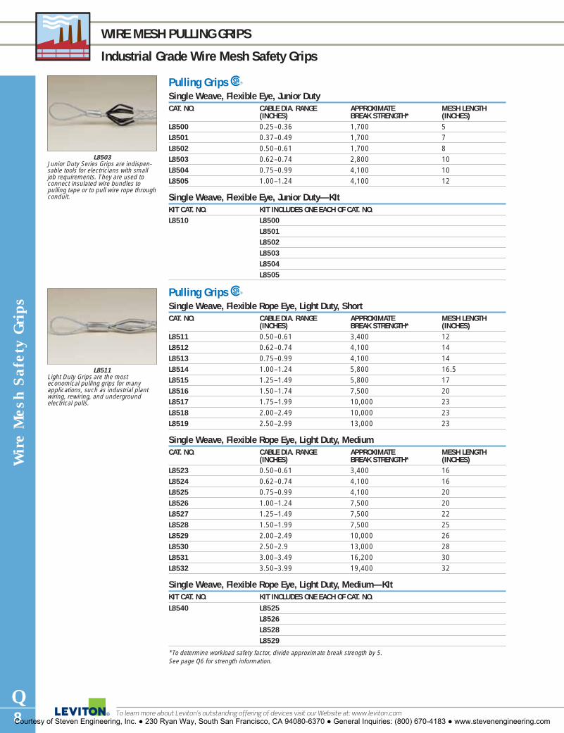
Wir
e M
esh
Saf
ety
Gri
ps
Q8
WIRE MESH PULLING GRIPS
Industrial Grade Wire Mesh Safety Grips
To learn more about Leviton’s outstanding offering of devices visit our Website at: www.leviton.com
L8503Junior Duty Series Grips are indispen-sable tools for electricians with smalljob requirements. They are used toconnect insulated wire bundles topulling tape or to pull wire rope throughconduit.
L8511Light Duty Grips are the most economical pulling grips for manyapplications, such as industrial plantwiring, rewiring, and underground electrical pulls.
Pulling Grips SSingle Weave, Flexible Eye, Junior DutyCAT. NO. CABLE DIA. RANGE APPROXIMATE MESH LENGTH
(INCHES) BREAK STRENGTH* (INCHES)L8500 0.25–0.36 1,700 5L8501 0.37–0.49 1,700 7L8502 0.50–0.61 1,700 8L8503 0.62–0.74 2,800 10L8504 0.75–0.99 4,100 10L8505 1.00–1.24 4,100 12
Single Weave, Flexible Eye, Junior Duty—KItKIT CAT. NO. KIT INCLUDES ONE EACH OF CAT. NO.L8510 L8500
L8501L8502L8503L8504L8505
Pulling Grips SSingle Weave, Flexible Rope Eye, Light Duty, ShortCAT. NO. CABLE DIA. RANGE APPROXIMATE MESH LENGTH
(INCHES) BREAK STRENGTH* (INCHES)L8511 0.50–0.61 3,400 12L8512 0.62–0.74 4,100 14L8513 0.75–0.99 4,100 14L8514 1.00–1.24 5,800 16.5L8515 1.25–1.49 5,800 17L8516 1.50–1.74 7,500 20L8517 1.75–1.99 10,000 23L8518 2.00–2.49 10,000 23L8519 2.50–2.99 13,000 23
Single Weave, Flexible Rope Eye, Light Duty, MediumCAT. NO. CABLE DIA. RANGE APPROXIMATE MESH LENGTH
(INCHES) BREAK STRENGTH* (INCHES)L8523 0.50–0.61 3,400 16L8524 0.62–0.74 4,100 16L8525 0.75–0.99 4,100 20L8526 1.00–1.24 7,500 20L8527 1.25–1.49 7,500 22L8528 1.50–1.99 7,500 25L8529 2.00–2.49 10,000 26L8530 2.50–2.9 13,000 28L8531 3.00–3.49 16,200 30L8532 3.50–3.99 19,400 32
Single Weave, Flexible Rope Eye, Light Duty, Medium—KItKIT CAT. NO. KIT INCLUDES ONE EACH OF CAT. NO.
L8540 L8525L8526L8528L8529
*To determine workload safety factor, divide approximate break strength by 5. See page Q6 for strength information.
Courtesy of Steven Engineering, Inc. ● 230 Ryan Way, South San Francisco, CA 94080-6370 ● General Inquiries: (800) 670-4183 ● www.stevenengineering.com

Wire M
esh Safety G
rips
Q9For answers to technical questions, call Leviton’s Techline at 1-800-824-3005
WIRE MESH PULLING GRIPS
Industrial Grade Wire Mesh Safety Grips
Pulling Grips SSingle/Double Weave, Bale Eye, Medium DutyCAT. NO. CABLE DIA. RANGE APPROXIMATE MESH LENGTH
(INCHES) BREAK STRENGTH* (INCHES)L8541 0.37–0.49 2,500 12L8542 0.50–0.74 3,400 14L8543 0.75–0.99 5,500 18L8544 1.00–1.24 8,100 22L8545 1.25–1.49 8,100 24L8546 1.50–1.99 8,100 26
Single/Double Weave, Bale Eye, Medium Duty—KItKIT CAT. NO. KIT INCLUDES ONE EACH OF CAT. NO.L8550 L8541
L8542L8543L8544L8545L8546
Pulling Grips—Fiber Optic Series SFiber Optic Pulling Grips are used for installation of fiber optic communication lines. They easily install oncables and are reusable. Applications include underground, overhead, through-conduit and/or enclosuretype pulls.Leviton fiber optic pulling grips are two-in-one reusable grips: the same tool features both a flexible eye anda swivel eye. The rounded, flexible eye attaches easily to pulling lines, and allows smoother passagethrough tight spaces than needle-eye designs.
Flexible/Swivel Eye Fiber Optic Grips Multi WeaveCAT. NO. CABLE DIA. APPROX. LENGTH (INCHES)
RANGE BREAK BALE MESH NOSE(INCHES) STRENGTH* (DIM. A) (DIM. M) DIA.
L8801 .10–.20 1,000 4.75 9 .8L8802 .21–.35 1,500 4.75 14 .8L8803 .35–.48 2,200 5.00 18 .9L8804 .42–.61 2,800 5.00 21 .9L8805 .53–.74 3,300 5.00 24 1.2L8806 .64–.87 4,700 5.00 27 1.2
*To determine workload safety factor, divide approximate break strength by 5. See page Q6 for strength information.
A M
L8545Single/Double Weave Pulling Grips areideal for longer pull applications.
L8801Fiber Optic Grips are made to pull deli-cate communication and data lines thathave a much smaller cable diameter.
Courtesy of Steven Engineering, Inc. ● 230 Ryan Way, South San Francisco, CA 94080-6370 ● General Inquiries: (800) 670-4183 ● www.stevenengineering.com

Wir
e M
esh
Saf
ety
Gri
ps
Q10
WIRE MESH PULLING GRIPS
Industrial Grade Wire Mesh Safety Grips
To learn more about Leviton’s outstanding offering of devices visit our Website at: www.leviton.com
Pulling Grips SThis series is recommended for heavy or rugged applications, and is ideally suited for overhead and under-ground installations. They are offered in short, standard or long mesh lengths.
Single/Double Weave, Bale Eye, Medium Duty, ShortCAT. NO. CABLE DIA. NOMINAL APPROX. LENGTH (INCHES) EYE SIZE
RANGE GRIP BREAK BALE MESH (INCHES)(INCHES) SIZE STRENGTH* (DIM. A) (DIM. M)
L8551 0.50–0.61 0.55 4,500 8 21 7/32
L8552 0.62–0.74 0.68 5,600 8 24 1/4L8553 0.75–0.99 0.87 6,800 8 24 1/4L8554 1.00–1.49 1.25 9,600 9 24 5/16
L8555 1.50–1.99 1.75 16,400 11 24 7/16
L8556 2.00–2.49 2.25 18,500 12 24 7/16
L8557 2.50–2.99 2.75 24,500 12 24 1/2L8558 3.00–3.49 3.25 24,500 14 24 1/2L8559 3.50–3.99 3.75 31,000 14 26 5/8
Single/Double Weave, Bale Eye, Medium Duty, StandardCAT. NO. CABLE DIA. NOMINAL APPROX. LENGTH (INCHES) EYE SIZE
RANGE GRIP BREAK BALE MESH (INCHES)(INCHES) SIZE STRENGTH* (DIM. A) (DIM. M)
L8563 0.75–0.99 0.87 6,800 9 36 1/4L8564 1.00–1.49 1.25 9,600 9 36 5/16
L8565 1.50–1.99 1.75 16,400 11 36 7/16
L8566 2.00–2.49 2.25 18,500 12 36 7/16
L8567 2.50–2.9 2.75 24,500 12 36 1/2L8568 3.00–3.49 3.25 24,500 14 36 1/2L8569 3.50–3.99 3.75 31,000 14 40 5/8
Single/Double Weave, Bale Eye, Medium Duty, Standard—KItKIT CAT. NO. KIT INCLUDES ONE EACH OF CAT. NO.L8560 L8563
L8564L8565L8566
Single/Double Weave, Bale Eye, Heavy Duty, LongCAT. NO. CABLE DIA. NOMINAL APPROX. MESH
RANGE GRIP BREAK DIM. M(INCHES) SIZE STRENGTH* (INCHES)
L8572 0.75–0.99 0.87 8,100 48L8573 1.00–1.49 1.25 11,600 48L8574 1.50–1.99 1.75 19,400 48L8575 2.00–2.49 2.25 19,400 48L8576 2.50–2.99 2.75 25,900 48L8577 3.00–3.49 3.25 25,900 48L8578 3.50–3.99 3.75 32,400 48
Note: See installation instructions supplied with grip for recommended swivels, links and clamps or accessories listing.*To determine workload safety factor, divide approximate break strength by 5. See page Q6 for strength information.
A M
L8552
Courtesy of Steven Engineering, Inc. ● 230 Ryan Way, South San Francisco, CA 94080-6370 ● General Inquiries: (800) 670-4183 ● www.stevenengineering.com

Wire M
esh Safety G
rips
Q11For answers to technical questions, call Leviton’s Techline at 1-800-824-3005
WIRE MESH PULLING GRIPS
Industrial Grade Wire Mesh Safety Grips
Pulling Grips SThese grips feature a double weave of galvanized steel strands for greater strength and added mesh contact with the cable. Leviton Double Weave Pulling Grips are designed to handle longer or heavier pullingjobs such as installation of underground cables, communication lines, and service lines.Double Weave Pulling Grips have a forged steel compact rotating eye which can be attached to a swivel.
Double Weave, Rotating Eye, Heavy Duty, ShortCAT. NO. CABLE DIA. NOMINAL APPROX. LENGTH (INCHES) EYE SIZE
RANGE GRIP BREAK BALE MESH (INCHES)(INCHES) SIZE STRENGTH* (DIM. A) (DIM. M)
L8581 0.50–0.61 0.55 5,600 5 11 7/8L8582 0.62–0.74 0.68 6,800 5 11 7/8L8583 0.75–0.99 0.87 9,600 6 20 1L8584 1.00–1.24 1.12 16,400 7 20 13/8L8585 1.25–1.49 1.37 16,400 7 21 13/8L8586 1.50–1.99 1.74 27,200 7 25 15/8L8587 2.00–2.49 2.24 33,000 8 26 17/8L8588 2.50–2.99 2.74 41,000 10 28 17/8L8589 3.00–3.49 3.24 48,000 10 30 17/8L8591 3.50–3.99 3.74 48,000 10 32 17/8L8592 4.00–4.49 4.24 48,000 10 33 17/8
Double Weave, Rotating Eye, Heavy Duty, StandardCAT. NO. CABLE DIA. NOMINAL APPROX. LENGTH (INCHES) EYE SIZE
RANGE GRIP BREAK BALE MESH (INCHES)(INCHES) SIZE STRENGTH* (DIM. A) (DIM. M)
L8601 0.50–0.61 0.55 5,600 5 16 7/8L8602 0.62–0.74 0.68 6,800 5 16 7/8L8603 0.75–0.99 0.87 9,600 6 32 1L8604 1.00–1.49 1.12 16,400 7 33 13/8L8605 1.50–1.99 1.74 16,400 7 34 13/8L8606 2.00–2.49 2.24 27,200 9 36 15/8L8607 2.50–2.99 2.74 33,000 10 38 17/8L8608 3.00–3.49 3.24 41,000 10 39 17/8L8609 3.50–3.99 3.74 48,000 10 41 17/8L8611 4.00–4.49 4.24 48,000 10 42 17/8L8612 4.50–4.99 4.74 48,000 10 58 17/8L8613 5.00–5.99 5.49 48,000 10 60 17/8L8614 6.00–6.99 6.49 48,000 10 66 17/8
Double Weave, Rotating Eye, Heavy Duty, Standard—KitKIT CAT. NO. KIT INCLUDES ONE EACH OF CAT. NO.L8600 L8603
L8604L8605L8606
Note: See installation instructions supplied with grip for recommended swivels, links and clamps or accessories listing.*To determine workload safety factor, divide approximate break strength by 5. See page Q6 for strength information.
A M
L8581
Courtesy of Steven Engineering, Inc. ● 230 Ryan Way, South San Francisco, CA 94080-6370 ● General Inquiries: (800) 670-4183 ● www.stevenengineering.com

Wir
e M
esh
Saf
ety
Gri
ps
Q12
WIRE MESH PULLING GRIPS
Industrial Grade Wire Mesh Safety Grips
To learn more about Leviton’s outstanding offering of devices visit our Website at: www.leviton.com
Pulling Grips—Multi-Weave Grips SLeviton Multi-Weave Pulling Grips are constructed of high strength galvanized steel strands and aredesigned for pulling aluminum or copper bare conductor, wire rope and insulated cables. These grips areused in applications such as distribution line stringing and overhead transmission.Multi-Weave Pulling Grips are available with a flexible or rotating eye which can be attached to a swivel.The forged steel flexible eye will thread through sheaves and blocks without binding, but is not a swivel andwill not turn under tension. The rotating eye can turn to relieve pulling torque when tension is relaxed.
Multi-Weave, Rotating EyeCAT. NO. CABLE DIA. NOMINAL APPROX. LENGTH (INCHES) COLOR EYE SIZE
RANGE GRIP BREAK BALE MESH CODE (INCHES)(INCHES) SIZE STRENGTH* (DIM. A) (DIM. M)
L8621 0.25–0.49 3/8 6,800 5 26 Dk. Green 7/8L8622 0.50–0.74 5/8 10,000 6 32 Brown 1L8623 0.75–0.99 7/8 14,400 6 41 Lt. Blue 1L8624 1.00–1.24 11/8 24,600 8 52 Gold 13/8L8625 1.25–1.49 13/8 30,600 8 56 Black 15/8L8626 1.50–1.74 15/8 30,600 9 60 Red 17/8L8627 1.75–1.99 2 48,000 10 70 Dk. Blue 17/8L8628 2.00–2.49 21/4 48,000 10 50 Yellow 17/8L8629 2.50–2.99 23/4 48,000 10 52 Orange 17/8L8631 3.00–3.49 31/4 48,000 10 54 Alum. 17/8L8632 3.50–3.99 33/4 48,000 10 56 Lt. Green 17/8
Multi-Weave, Flexible EyeCAT. NO. CABLE DIA. NOMINAL APPROX. LENGTH (INCHES) COLOR EYE SIZE
RANGE GRIP BREAK BALE MESH CODE (INCHES)(INCHES) SIZE STRENGTH* (DIM. A) (DIM. M)
L8641 0.25–0.49 3/8 6,800 9 26 Dk. Green 1/4L8642 0.50–0.74 5/8 10,000 9 32 Brown 5/16
L8643 0.75–0.99 7/8 14,400 11 41 Lt. Blue 3/8L8644 1.00–1.24 11/8 24,600 12 52 Gold 1/2L8645 1.25–1.49 13/8 30,600 12 56 Black 1/2L8646 1.50–1.74 15/8 30,600 12 60 Red 1/2L8647 1.75–1.99 2 48,000 15 70 Dk. Blue 5/8L8648 2.00–2.49 21/4 48,000 18 50 Yellow 5/8L8649 2.50–2.99 23/4 48,000 18 52 Orange 5/8L8651 3.00–3.49 31/4 48,000 18 54 Alum. 5/8L8652 3.50–3.99 33/4 48,000 18 56 Lt. Green 5/8
Note: It is recommended that a swivel be used for release of torque during a pull. Use a connecting link when a swivel isnot needed. Do not run grips or swivels over bullwheels while under tension. Do not use Multi-Weave for pulling rope.When higher loads are required, use Leviton’s high strength-style pulling grips. See installation instructions supplied withgrip for recommended swivels, links and clamps or accessories listing.
*To determine workload safety factor, divide approximate break strength by 5. See page Q6 for strength information.
A M
L8624
A M
L8644
Courtesy of Steven Engineering, Inc. ● 230 Ryan Way, South San Francisco, CA 94080-6370 ● General Inquiries: (800) 670-4183 ● www.stevenengineering.com
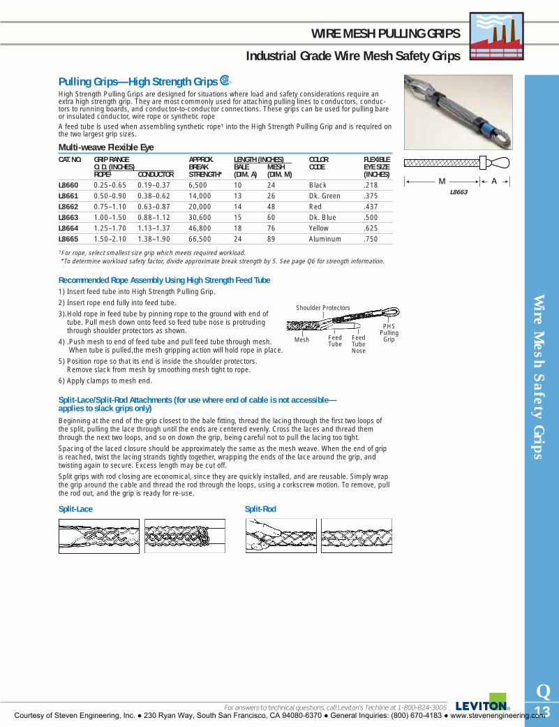
Wire M
esh Safety G
rips
Q13For answers to technical questions, call Leviton’s Techline at 1-800-824-3005
WIRE MESH PULLING GRIPS
Industrial Grade Wire Mesh Safety Grips
Pulling Grips—High Strength Grips SHigh Strength Pulling Grips are designed for situations where load and safety considerations require anextra high strength grip. They are most commonly used for attaching pulling lines to conductors, conduc-tors to running boards, and conductor-to-conductor connections. These grips can be used for pulling bareor insulated conductor, wire rope or synthetic rope A feed tube is used when assembling synthetic rope1 into the High Strength Pulling Grip and is required onthe two largest grip sizes.
Multi-weave Flexible EyeCAT.NO. GRIP RANGE APPROX. LENGTH (INCHES) COLOR FLEXIBLE
O. D. (INCHES) BREAK BALE MESH CODE EYE SIZEROPE1 CONDUCTOR STRENGTH* (DIM. A) (DIM. M) (INCHES)
L8660 0.25–0.65 0.19–0.37 6,500 10 24 Black .218L8661 0.50–0.90 0.38–0.62 14,000 13 26 Dk. Green .375L8662 0.75–1.10 0.63–0.87 20,000 14 48 Red .437L8663 1.00–1.50 0.88–1.12 30,600 15 60 Dk. Blue .500L8664 1.25–1.70 1.13–1.37 46,800 18 76 Yellow .625L8665 1.50–2.10 1.38–1.90 66,500 24 89 Aluminum .750
1For rope, select smallest size grip which meets required workload.*To determine workload safety factor, divide approximate break strength by 5. See page Q6 for strength information.
Recommended Rope Assembly Using High Strength Feed Tube1) Insert feed tube into High Strength Pulling Grip.
2) Insert rope end fully into feed tube.
3).Hold rope in feed tube by pinning rope to the ground with end oftube. Pull mesh down onto feed so feed tube nose is protrudingthrough shoulder protectors as shown.
4) .Push mesh to end of feed tube and pull feed tube through mesh.When tube is pulled,the mesh gripping action will hold rope in place.
5) Position rope so that its end is inside the shoulder protectors.Remove slack from mesh by smoothing mesh tight to rope.
6) Apply clamps to mesh end.
Split-Lace/Split-Rod Attachments (for use where end of cable is not accessible—applies to slack grips only) Beginning at the end of the grip closest to the bale fitting, thread the lacing through the first two loops ofthe split, pulling the lace through until the ends are centered evenly. Cross the laces and thread themthrough the next two loops, and so on down the grip, being careful not to pull the lacing too tight.
Spacing of the laced closure should be approximately the same as the mesh weave. When the end of gripis reached, twist the lacing strands tightly together, wrapping the ends of the lace around the grip, andtwisting again to secure. Excess length may be cut off.
Split grips with rod closing are economical, since they are quickly installed, and are reusable. Simply wrapthe grip around the cable and thread the rod through the loops, using a corkscrew motion. To remove, pullthe rod out, and the grip is ready for re-use.
Shoulder Protectors
Feed TubeNose
PHS PullingGripFeed
Tube Mesh
Split-Lace Split-Rod
L8663
Courtesy of Steven Engineering, Inc. ● 230 Ryan Way, South San Francisco, CA 94080-6370 ● General Inquiries: (800) 670-4183 ● www.stevenengineering.com

Wir
e M
esh
Saf
ety
Gri
ps
Q14
WIRE MESH PULLING GRIPS
Industrial Grade Wire Mesh Safety Grips
To learn more about Leviton’s outstanding offering of devices visit our Website at: www.leviton.com
PULLING GRIPS—SLACK GRIPSSlack Grips are reusable grips used for pulling slack in underground cable preparatory to finalplacement. They may also be used for cable removal. Slack Grips feature an offset eye for easyattachment to the pulling line. See attachment information for split lace and split rod on pageQ13.
Pulling Grips—Slack Grips Series SClosed Mesh, Double Weave, Offset Eye, Heavy Duty, MediumCAT. NO. CABLE DIA. RANGE APPROXIMATE MESH LENGTH
(INCHES) BREAK STRENGTH* (INCHES)L8671 0.75–0.99 3,000 13L8672 1.00–1.24 4,200 16L8673 1.25–1.49 5,500 17L8674 1.50–1.74 7,400 18L8675 1.75–1.99 11,000 19L8676 2.00–2.49 11,000 20L8677 2.50–2.99 11,000 21L8678 3.00–3.49 16,000 22L8679 3.50–3.99 16,000 23
Closed Mesh, Double Weave, Offset Eye, Heavy Duty, LongL8681 0.75–0.99 3,000 21L8682 1.00–1.24 5,500 21L8683 1.25–1.49 5,500 24L8684 1.50–1.99 7,400 26L8685 2.00–2.49 11,000 27L8686 2.50–2.99 11,000 30L8687 3.00–3.49 16,000 33L8688 3.50–3.99 16,000 36
Split Lace, Double Weave, Offset Eye, Heavy Duty, MediumCAT. NO. CABLE DIA. RANGE APPROXIMATE MESH LENGTH
(INCHES) BREAK STRENGTH* (INCHES)L8691 0.75–0.99 3,000 13L8692 1.00–1.24 4,100 16L8693 1.25–1.49 4,100 17L8694 1.50–1.74 5,500 18L8695 1.75–1.99 7,300 19L8696 2.00–2.49 7,300 20L8697 2.50–2.99 7,300 21L8698 3.00–3.49 9,200 22L8699 3.50–3.99 11,000 23
Split Lace, Double Weave, Offset Eye, Heavy Duty, LongL8701 0.75–0.99 3,000 21L8702 1.00–1.24 4,100 21L8703 1.25–1.49 4,100 24L8704 1.50–1.99 5,500 25L8705 2.00–2.49 7,300 27L8706 2.50–2.99 7,300 30L8707 3.00–3.49 9,200 33L8708 3.50–3.99 11,000 36
Split Rod, Single Weave, Offset Eye, Heavy Duty, MediumL8711 0.50–0.61 1,800 7L8712 0.62–0.74 1,900 9L8713 0.75–0.99 3,000 11L8714 1.00–1.24 4,100 12L8715 1.25–1.49 5,700 14L8716 1.50–1.74 5,800 16L8717 1.75–1.99 7,700 17L8718 2.00–2.49 9,300 20L8719 2.50–2.99 11,300 21L8721 3.00–3.49 15,100 22L8722 3.50–3.99 15,100 25*To determine workload safety factor, divide approximate break strength by 5. See page Q6 for strength information.
L8671
L8703
L8711
Courtesy of Steven Engineering, Inc. ● 230 Ryan Way, South San Francisco, CA 94080-6370 ● General Inquiries: (800) 670-4183 ● www.stevenengineering.com

Wire M
esh Safety G
rips
Q15For answers to technical questions, call Leviton’s Techline at 1-800-824-3005
WIRE MESH STRAIN-RELIEF GRIPS
Industrial Grade Wire Mesh Safety Grips
STRAIN-RELIEF GRIPSStrain-Relief Grips are used to connect cord or cable to electrical enclosures and equipment.These grips prevent pullout due to tension and limit the arc of bend at the point of entry; strainis distributed over the length of mesh rather than concentrated at one point or transferred tothe internal termination.
Wide-Range GripsU*R*Wide-Range Grips are recommended for use in wiring of enclosures, power boxes, machine tools, andpower centers. They include an insulated bushing (dust-tight).
Single Weave Galvanized Steel MeshCAT. NO. CABLE DIA. NPT MESH LENGTH MINIMUM DISTANCE
RANGE SIZE @ NOMINAL DIA. BETWEEN GRIPS(INCHES) (INCHES) (INCHES) (INCHES)
L7501 0.22–0.32 1/2 4 11/4L7502 0.30–0.43 1/2 41/2 11/4L7503 0.40–0.54 1/2 51/2 11/4L7504 0.52–0.73 3/4 51/2 11/2L7505 0.70–0.97 1 8 17/8L7506 0.94–1.25 11/4 9 23/8L7507 1.20–1.50 11/2 11 25/8L7508 1.40–1.75 2 13 31/4L7509 1.62–2.00 21/2 131/2 35/8L7511 2.00–2.45 21/2 131/2 35/8
Cord Sealing GripsU*R*Cord Sealing Grips with Mesh are nylon devices used to connect electrical cables to boxes, cabinets, push-buttons, enclosures, etc. They are liquid-tight devices that are highly resistant to impact and corrosion.Non-metallic cord sealing grips will not support combustion. The ratings are: Wire Mesh Grip-94 HB andFitting-94V-2. Cord Sealing Grip products are suitable for use in wet locations so long as a listed sealingring is used between the box and the fitting.
Nylon Cord Sealing Grips with Mesh—Straight and 90°CAT. NOS.STAINLESS STEEL MESH NON-METALLIC MESH CABLE DIA. NPTSTRAIGHT 90° STRAIGHT 90° RANGE (FORM
(INCHES) SIZE)L7521 — L7522 L7524 .187–.250— L7527 — L7528 .250–.312— L7532 — L7533 .312–.375 1/2"— L7536 — — .375–.437 (F2)L7538 L7541 L7539 L7542 .437–.500L75431 L75441 — — .500–.562L75451 L75461 — — .562–.625L7601 — L7602 L7604 .187–.250L7605 — — — .250–.375— L7612 — — .375–.437— L7549 — L7551 .437–.562 3/4"L7552 L7554 L7553 L7555 .500–.625 (F3)L7556 L7558 — L7559 .562–.687L7561 L7563 L7562 — .625–.750L75651 L75661 — — .687–.812L7567 — L7568 L7569 .437–.562— L7573 — L7574 .500–.625— L7582 — L7583 .625–.750 1"L7584 — — L7587 .687–.812 (F4)L7588 — — L7592 .750–.875L7597 — — — .875–1.0001Cable jacket may have to be stripped for clearance. NOTE: F2, F3 and F4 are fitting form sizes.*Cord Sealing Grips with non-metallic mesh are UL Listed and CSA Certified. Cord Sealing Grips with stainless steel meshare CSA Certified only.
L7504Galva. Steel mesh
L7521Straight—SS mesh
L752790°—SS mesh
L7553Straight—nylon mesh
Courtesy of Steven Engineering, Inc. ● 230 Ryan Way, South San Francisco, CA 94080-6370 ● General Inquiries: (800) 670-4183 ● www.stevenengineering.com

Wir
e M
esh
Saf
ety
Gri
ps
Q16
WIRE MESH STRAIN-RELIEF GRIP DIMENSIONS
Industrial Grade Wire Mesh Safety Grips
To learn more about Leviton’s outstanding offering of devices visit our Website at: www.leviton.com
B
A
H
F
G
E
D
C
D
D
E
H
G
C
C
B
A
F
Strain-Relief Grips—DimensionsDimensions for Nylon Cord-Sealing Fittings, Straight BodyFORM NPT A B C D E F G H (REF.)0 1/4" .500 .778 .370 .187 .921 .778 .687 1.251 3/8" 1.000 1.150 .500 .250 1.250 1.115 1.000 1.852 1/2" 1.000 1.300 .500 .300 1.450 1.250 1.100 2.003 3/4" 1.000 1.500 .550 .375 1.700 1.578 1.375 2.004 1" 1.000 1.850 .687 .375 1.800 1.900 1.650 2.125 11/4" 1.000 2.050 .687 .375 1.800 2.100 1.850 2.12
Dimensions for Nylon Cord-Sealing Fittings, 90° BodyFORM NPT A B C D E F G H (REF.)1 3/8" 1.000 1.150 1.100 .187 1.812 .450 1.687 2.352 1/2" 1.000 1.300 1.165 .187 1.900 .578 1.820 2.403 3/4" 1.000 1.500 1.600 .187 2.421 .593 2.218 2.754 1" 1.000 1.850 1.850 .187 2.656 .800 2.700 3.005 11/4" 1.000 2.050 1.965 .187 2.859 .750 2.812 3.25
Form 0
D
.562 Dia. Rev.
Irregular shape or ribdeformation on this corner permissible
Forms 1–5
Courtesy of Steven Engineering, Inc. ● 230 Ryan Way, South San Francisco, CA 94080-6370 ● General Inquiries: (800) 670-4183 ● www.stevenengineering.com

Wire M
esh Safety G
rips
Q17For answers to technical questions, call Leviton’s Techline at 1-800-824-3005
WIRE MESH STRAIN-RELIEF GRIPS
Industrial Grade Wire Mesh Safety Grips
Deluxe Cord GripsURDeluxe Cord Grips are woven of stainless steel mesh with an anodized aluminum body for corrosion resist-ance. They are offered in Single/Double Weave construction to help absorb direct pull, resist flexing andbinding, and eliminate strain. Aluminum fittings are offered in a variety of NPT thread sizes. They are recommended for indoor or outdoor use where moisture may be present in the wiring of pendant stations,processing equipment, hand tools, and extension cord sets. They are UL Listed and CSA Certified. DeluxeCord Grips are suitable for use in hazardous locations per Class I, Div. 2; Class II, Div. 1 and 2; and ClassIII, Div. 1 and 2. They are also suitable for use in wet locations as long as a listed sealing ring is usedbetween the box and the fitting.
Single/Double WeaveCAT. NOS. CABLE. DIA. NPTSTRAIGHT 90° MALE 45° MALE STRAIGHT RANGE SIZEMALE FEMALE (INCHES)L7701 — — — .187–.250L7702 — — — .250–.312L7703 — — L7822 .312–.375 3/8"L7704 — — — .375–.437L7705 L7761 — — .187–.250L7706 — L7802 — .250–.375L7707 L7763 L7803 L7826 .375–.500 1/2"L7708 L7764 L7804 L7827 .500–.625L7709 — — — .625–.750L7711 L7765 L7805 — .250–.375L7712 — L7806 — .375–.500L7700 L7767 L7807 L7831 .500–.625 3/4"L7713 L7768 L7808 L7832 .625–.750L7714 — — — .750–.875L7715 L7769 — — .437–.562L7716 — — L7833 .562–.687L7717 L7772 — L7834 .625–.750 1"L7718 — — — .750–.875L7719 — — L7836 .875–1.000L7721 — — — 1.000–1.125L7722 — — — 1.125–1.250L7723 — — — .750–.875L7724 — — — .875–1.000L7725 — L7810 — 1.000–1.125 11/4"L7726 L7778 — 1.125–1.250L7727 — L7820 — 1.250–1.375L7728 L7781 — — .750–.875L7729 L7782 — — .875–1.000L7731 — — — 1.000–1.125 11/2"L7732 L7784 — — 1.125–1.250L7733 L7785 — — 1.250–1.375L8011 — — — 1.312–1.437L7770 — — — 1.437–1.562L7750 — — — 1.562–1.687L7760 — — — 1.687–1.812L7780 — — — 1.750–1.875L7734 — — — 1.250–1.375L7736 — — — 1.500–1.625 2"L7737 L7789 — — 1.625–1.750— L7791 — — 1.750–1.875L8012 — — — 1.812–1.937L8013 — — — 1.937–2.062L7730 — — — 2.187–2.312L7739 — — — 1.75–1.875L7742 — — — 1.937–2.062 2-1/2"L7743 — — — 2.062–2.187L7744 — — — 2.187–2.312L7745 — — — 1.688–1.812 3"L7746 — — — 1.812–1.937L7747 — — — 1.937–2.062L7748 — — — 2.062–2.187L7751 — — — 2.312–2.437L7752 — — — 2.437–2.625L7754 — — — 2.812–3.000L7755 — — — 3.000–3.250
L7701Straight—Male
L776190°—Male
L780245°—Male
L7822Straight—Female
Courtesy of Steven Engineering, Inc. ● 230 Ryan Way, South San Francisco, CA 94080-6370 ● General Inquiries: (800) 670-4183 ● www.stevenengineering.com

Wir
e M
esh
Saf
ety
Gri
ps
Q18
WIRE MESH STRAIN-RELIEF GRIPS
Industrial Grade Wire Mesh Safety Grips
To learn more about Leviton’s outstanding offering of devices visit our Website at: www.leviton.com
Liquid-Tight GripsURLiquid-Tight Grips are woven stainless steel mesh with an anodized aluminum body for corrosion-resistance.They are used to connect liquid-tight flexible metal conduit to electrical enclosures to prevent conduit pullout. Each fitting is supplied with an insulated throat to ensure conductor insulation and protect againstdamage caused by flexing, heat expansion or contraction. Liquid-Tight Grips are recommended in the wiring of motors and any electrical enclosure where liquid-tightconduit is subject to motion or strain. UL Listed and CSA Certified.
Liquid-Tight GripsCAT. NOS. FITTING MESHSTRAIGHT 90° MALE 45° MALE STRAIGHT SIZE LENGTHMALE FEMALE (INCHES) (INCHES)— — L7931 L7951 3/8 25/8L7902 L7916 L7932 — 1/2 37/8L7903 L7917 — L7953 3/4 43/8L7904 L7918 — L7954 1 51/4L7905 L7919 — — 11/4 55/8L7906 L7921 — — 11/2 53/4L7907 L7922 — — 2 71/2L7908 — — — 21/2 95/8L7911 L7924 L7939 — 3 105/8L7912 — — — 4 12
Liquid-Tight Grips for Non-Metallic Type “A” Flexible ConduitCAT. NOS. FITTING MESHSTRAIGHT 90° MALE SIZE LENGTHMALE (INCHES) (INCHES)— L7999 3/8 9L7962 L7990 1/2 10— L7967 3/4 101/2— L7968 1 12L7965 L7969 11/4 17— L7971 11/2 211/2L7970 L7972 2 24
Connection Wire Mesh Grips RConnection Wire Mesh Grips provide additional strain-relief for plugs and connectors used on portableequipment in commercial and institutional applications, and industrial plant and construction site areaswhich incur abnormally high abuse. Grips are made of galvanized steel.
Connection Wire Mesh GripsCAT NO. CABLE DIA. EYE MESH
RANGE DIMENSIONS (A) LENGTH (M)(INCHES) (INCHES) (INCHES)
L8001 .30–.43 111/16 43/4L8002 .40–.56 111/16 6L8003 .52–.73 111/16 7L8004 .70–.85 115/16 81/2L8005 .82–1.00 115/16 81/2L8006 .94–1.25 115/16 101/2
M A
L7902Straight—Male
L792290°—Male
L7951Straight—Female
L799090°—Male
L7965Straight—Male
L8003
Courtesy of Steven Engineering, Inc. ● 230 Ryan Way, South San Francisco, CA 94080-6370 ● General Inquiries: (800) 670-4183 ● www.stevenengineering.com

Wire M
esh Safety G
rips
Q19For answers to technical questions, call Leviton’s Techline at 1-800-824-3005
WIRE MESH SUPPORT GRIPS
Industrial Grade Wire Mesh Safety Grips
SUPPORT GRIPSSupport Grips are designed to hold the weight of cable on vertical or sloping runs. They may beused indoors or outdoors to support electrical and fiber optic cable, metal rods and tubing. Leviton Support Grips are woven with tinned bronze wire. For applications requiring a greaterdegree of corrosion resistance, stainless steel wire is available on special order. For informationregarding selection of the proper-sized support grip, see pages Q4 and Q5.
StyleSINGLE “U” EYEFor use when cable is vertical and for applications where cablebends or where a single attachment is more advantageous forpositioning.
DOUBLE “U” EYEFor use when cable is vertical and extends through the gripwithout bending. Eyes may be fastened to open hooks, butshould not be more than 15° from the axis of vertical cable.When eyes are supported equally, this attachment offers a fullybalanced load.
OFFSET EYESimilar to single eye applications, but for use when offset posi-tioning is required.
LOCKING (UNIVERSAL) BALEAdjustable and self-locking, this attachment fits around a beam,pipe or other continuous structural object. The bale wrapsaround the object and is securely anchored in the bar.
Split Lace/Split RodSPLIT LACEBeginning at the lead end of the grip, thread the lacing throughthe first two loops of the split, pulling the lace through until theends are centered evenly. Cross laces and thread through thenext two loops, and so on down the grip, being careful not topull the lacing too tight. The spacing of the lace closure shouldbe approximately the same as that of the mesh weave. Whenthe end of grip is reached, twist the lacing strands tightlytogether; wrap the ends of the lace around the grip and twistagain to secure. Excess length may be cut off.
SPLIT RODSplit grips with rod closing install quickly and they are economi-cal and reusable. Simply wrap the grip around the cable andthread the rod through the loops, using a corkscrew motion. Toremove, pull the rod out; and the grip is ready for re-use.
Courtesy of Steven Engineering, Inc. ● 230 Ryan Way, South San Francisco, CA 94080-6370 ● General Inquiries: (800) 670-4183 ● www.stevenengineering.com

Wir
e M
esh
Saf
ety
Gri
ps
Q20
WIRE MESH SUPPORT GRIPS
Industrial Grade Wire Mesh Safety Grips
To learn more about Leviton’s outstanding offering of devices visit our Website at: www.leviton.com
Support Grips—Standard Closed Mesh SStandard Closed Mesh Support Grips are designed for loads up to 500 lbs. and vertical runs of no morethan 100 feet. Heavy-duty closed mesh support grips are designed for loads in excess of 500 lbs. They areavailable in a variety of eye styles and cable ranges for supporting electrical cable, metal rods and tubing.Closed mesh support grips are used when the end of the cable is accessible. Mesh is made of tinnedbronze material.
Single Eye, Closed Mesh, Single WeaveCAT. NO. CABLE DIA. APPROX. LENGTH (INCHES)
RANGE BREAK BALE MESH(INCHES) STRENGTH* (DIM. A) (DIM. M)
L9501 0.50–0.61 770 7 10L9502 0.62–0.74 960 8 10L9503 0.75–0.99 1,300 8 12L9504 1.00–1.24 1,680 9 12L9505 1.25–1.49 1,680 10 16L9506 1.50–1.74 1,680 12 17L9507 1.75–1.99 2,640 14 18L9508 2.00–2.49 3,760 16 18L9509 2.50–2.99 3,760 18 21L9511 3.00–3.49 5,040 21 26L9512 3.50–3.99 5,040 24 28
Double Eye, Closed Mesh, Single WeaveCAT. NO. CABLE DIA. APPROX. LENGTH (INCHES)
RANGE BREAK BALE MESH(INCHES) STRENGTH* (DIM. A) (DIM. M)
L9515 0.50–0.61 770 4 11L9516 0.62–0.74 1,150 4 11L9517 0.75–0.99 1,320 4 14L9518 1.00–1.24 1,920 5 15L9519 1.25–1.49 1,920 5 16L9521 1.50–1.74 1,920 6 18L9523 1.75–1.99 3,360 6 20L9524 2.00–2.49 3,360 6 22L9525 2.50–2.99 3,360 6 24L9526 3.00–3.49 5,280 8 26L9527 3.50–3.99 5,280 8 28
Offset Eye, Closed Mesh, Single WeaveCAT. NO. CABLE DIA. APPROX. LENGTH (INCHES)
RANGE BREAK BALE MESH(INCHES) STRENGTH* (DIM. A) (DIM. M)
L9531 0.50–0.61 770 4 11L9532 0.62–0.74 960 4 11L9533 0.75–0.99 960 4 14L9534 1.00–1.24 1,680 5 15L9535 1.25–1.49 1,680 5 16L9536 1.50–1.74 1,680 5 18L9537 1.75–1.99 2,640 6 20L9538 2.00–2.49 3,760 6 21L9539 2.50–2.99 3,760 8 24L9541 3.00–3.49 5,040 9 26L9542 3.50–3.99 5,040 9 28
Note: Support grips are also available in stainless steel—contact your Leviton Representative.*To determine workload safety factor, divide approximate break strength by 10. See page Q6 for strength information.
A M
L9502Single Eye
A M
L9515Double Eye
A M
L9531Offset Eye
Courtesy of Steven Engineering, Inc. ● 230 Ryan Way, South San Francisco, CA 94080-6370 ● General Inquiries: (800) 670-4183 ● www.stevenengineering.com

Wire M
esh Safety G
rips
Q21For answers to technical questions, call Leviton’s Techline at 1-800-824-3005
WIRE MESH SUPPORT GRIPS
Industrial Grade Wire Mesh Safety Grips
Support Grips—Standard Closed Mesh SLocking Bale, Closed Mesh, Single WeaveCAT. NO. CABLE DIA. APPROX. LENGTH (INCHES)
RANGE BREAK BALE MESH(INCHES) STRENGTH* (DIM. A) (DIM. M)
L9551 0.50–0.61 770 11 10L9552 0.62–0.74 1,150 11 10L9553 0.75–0.99 1,320 14 12L9554 1.00–1.24 1,920 15 12L9555 1.25–1.49 1,920 16 13L9556 1.50–1.74 1,920 18 17L9557 1.75–1.99 3,150 20 18L9558 2.00–2.49 3,360 21 18L9559 2.50–2.99 3,360 24 21L9561 3.00–3.49 5,280 26 23L9562 3.50–3.99 5,280 28 23.5
*To determine workload safety factor, divide approximate break strength by 10. See page Q6 for strength information.
Support Grips—Heavy Duty SHeavy Duty Support Grips handle continuous loads of over 500 lbs. in vertical runs greater than 100 ft. forcable diameters from 3/4" to 41/2".
Single Eye, Double Weave, Heavy Long, Closed MeshCAT. NO. CABLE DIA. APPROX. LENGTH (INCHES)
RANGE BREAK BALE MESH(INCHES) STRENGTH* (DIM. A) (DIM. M)
L9701 0.75–0.99 2,700 10 26L9702 1.00–1.24 4,720 10 29L9703 1.25–1.49 4,720 10 31L9704 1.50–1.99 4,720 10 35
Double Eye, Double Weave, Heavy Long, Closed Mesh CAT. NO. CABLE DIA. APPROX. LENGTH (INCHES)
RANGE BREAK BALE MESH(INCHES) STRENGTH* (DIM. A) (DIM. M)
L9711 0.75–0.99 2,700 10 26L9712 1.00–1.25 4,720 10 29L9713 1.25–1.49 4,720 10 31L9714 1.50–1.99 4,720 10 35L9715 2.00–2.49 10,080 10 37L9716 2.50–2.99 10,080 10 39L9717 3.00–3.49 10,080 10 41L9718 3.50–3.99 13,120 10 45L9719 4.00–4.49 13,120 10 47
*To determine workload safety factor, divide approximate break strength by 10. See page Q6 for strength information.
A M
L9551Locking Bale
A M
L9715Double Eye
Courtesy of Steven Engineering, Inc. ● 230 Ryan Way, South San Francisco, CA 94080-6370 ● General Inquiries: (800) 670-4183 ● www.stevenengineering.com

Wir
e M
esh
Saf
ety
Gri
ps
Q22
WIRE MESH SUPPORT GRIPS
Industrial Grade Wire Mesh Safety Grips
To learn more about Leviton’s outstanding offering of devices visit our Website at: www.leviton.com
L9571Single Eye
Support Grips—Standard Split LaceSSplit Lace Support Grips are designed for loads up to 500 lbs. and vertical runs of no more than 100 feet.Heavy-duty split lace support grips are available on page Q23. They are available in a variety of eye stylesand cable ranges for supporting electrical cable, metal rods and tubing. Split lace grips are utilized whenthe end of the cable cannot be feasibly accessed and the support grip is intended for permanent installa-tion. Mesh is made of tinned bronze material. For attachment information see page Q19.
Single Eye, Split Lace, Single WeaveCAT. NO. CABLE DIA. APPROX. LENGTH (INCHES)
RANGE BREAK BALE MESH(INCHES) STRENGTH* (DIM. A) (DIM. M)
L9571 0.50–0.61 770 7 11L9572 0.62–0.74 960 8 11L9573 0.75–0.99 1,320 8 14L9574 1.00–1.24 1,680 9 15L9575 1.25–1.49 1,680 10 16L9576 1.50–1.74 1,680 12 18L9577 1.75–1.99 2,640 14 20L9578 2.00–2.49 3,760 16 22L9579 2.50–2.99 3,760 18 24L9581 3.00–3.49 5,040 21 26L9582 3.50–3.99 5,040 24 28
Double Eye, Split Lace, Single WeaveCAT. NO. CABLE DIA. APPROX. LENGTH (INCHES)
RANGE BREAK BALE MESH(INCHES) STRENGTH* (DIM. A) (DIM. M)
L9585 0.50–0.61 770 4 11L9586 0.62–0.74 1,150 4 11L9587 0.75–0.99 1,320 4 14L9588 1.00–1.24 1,920 5 15L9589 1.25–1.49 1,920 5 16L9591 1.50–1.74 1,920 5 18L9592 1.75–1.99 3,150 6 20L9593 2.00–2.49 3,360 6 22L9594 2.50–2.99 3,360 6 24L9595 3.00–3.49 5,280 8 26L9596 3.50–3.99 5,280 8 28
Offset Eye, Split Lace, Single WeaveCAT. NO. CABLE DIA. APPROX. LENGTH (INCHES)
RANGE BREAK BALE MESH(INCHES) STRENGTH* (DIM. A) (DIM. M)
L9601 0.50–0.61 770 4 11L9602 0.62–0.74 960 4 11L9603 0.75–0.99 960 4 14L9604 1.00–1.24 1,680 5 15L9605 1.25–1.49 1,680 5 16L9606 1.50–1.74 1,680 5 18L9607 1.75–1.99 2,640 8 20L9608 2.00–2.49 3,760 8 22L9609 2.50–2.99 3,760 8 24L9611 3.00–3.49 5,040 9 26L9612 3.50–3.99 5,040 9 28
Note: Support grips are also available in stainless steel—contact your Leviton Representative.*To determine workload safety factor, divide approximate break strength by 10. See page Q6 for strength information.
A M
L9585Double Eye
A M
L9601Offset Eye
A M
Courtesy of Steven Engineering, Inc. ● 230 Ryan Way, South San Francisco, CA 94080-6370 ● General Inquiries: (800) 670-4183 ● www.stevenengineering.com

Wire M
esh Safety G
rips
Q23For answers to technical questions, call Leviton’s Techline at 1-800-824-3005
WIRE MESH SUPPORT GRIPS
Industrial Grade Wire Mesh Safety Grips
L9621Locking Bale
Support Grips—Standard Split LaceSLocking Bale, Split Lace, Single WeaveCAT. NO. CABLE DIA. APPROX. LENGTH (INCHES)
RANGE BREAK BALE MESH(INCHES) STRENGTH* (DIM. A) (DIM. M)
L9621 0.50–0.61 770 18 11L9622 0.62–0.74 1,150 18 11L9623 0.75–0.99 1,320 18 14L9624 1.00–1.24 1,920 18 15L9625 1.25–1.49 1,920 18 16L9626 1.50–1.74 1,920 18 18L9627 1.75–1.99 3,150 18 20L9628 2.00–2.49 3,360 18 22L9629 2.50–2.99 3,360 18 24
*To determine workload safety factor, divide approximate break strength by 10. See page Q6 for strength information.
Support Grips—Heavy Duty Split LaceSHeavy Duty Support Grips handle continuous loads of over 500 lbs. in vertical runs greater than 100 ft. forcable diameters from 3/4" to 41/2".
Single Eye, Double Weave, Heavy Long, Split LaceCAT. NO. CABLE DIA. APPROX. LENGTH (INCHES)
RANGE BREAK BALE MESH(INCHES) STRENGTH* (DIM. A) (DIM. M)
L9722 0.75–0.99 2,700 10 26L9723 1.00–1.24 4,720 10 29L9724 1.25–1.49 4,720 10 31L9725 1.50–1.99 4,720 10 35
Double Eye, Double Weave, Heavy Long, Split LaceCAT. NO. CABLE DIA. APPROX. LENGTH (INCHES)
RANGE BREAK BALE MESH(INCHES) STRENGTH* (DIM. A) (DIM. M)
L9731 0.75–0.99 2,700 10 26L9732 1.00–1.24 4,720 10 29L9733 1.25–1.49 4,720 10 31L9734 1.50–1.99 4,720 10 35L9735 2.00–2.49 10,080 10 37L9736 2.50–2.99 10,080 10 39L9737 3.00–3.49 10,080 10 41L9738 3.50–3.99 13,120 10 45L9739 4.00–4.49 13,120 10 47
*To determine workload safety factor, divide approximate break strength by 10. See page Q6 for strength information.
A M
L9731Double Eye
A M
Courtesy of Steven Engineering, Inc. ● 230 Ryan Way, South San Francisco, CA 94080-6370 ● General Inquiries: (800) 670-4183 ● www.stevenengineering.com

Wir
e M
esh
Saf
ety
Gri
ps
Q24
WIRE MESH SUPPORT GRIPS
Industrial Grade Wire Mesh Safety Grips
To learn more about Leviton’s outstanding offering of devices visit our Website at: www.leviton.com
Support Grips—Standard Split RodSSplit Rod Support Grips are designed for loads up to 500 lbs. and vertical runs of no more than 100 feet.They are available in a variety of eye styles and cable ranges for supporting electrical cable, metal rods andtubing. Split rod support grips are utilized when the end of the cable cannot be feasibly accessed and theinstallation is temporary. For attachment information see page Q19.
Single Eye, Split Rod, Single WeaveCAT. NO. CABLE DIA. APPROX. LENGTH (INCHES)
RANGE BREAK BALE MESH(INCHES) STRENGTH* (DIM. A) (DIM. M)
L9631 0.50–0.61 770 7 9L9632 0.62–0.74 960 8 9L9633 0.75–0.99 1,320 8 11L9634 1.00–1.24 1,680 9 13L9635 1.25–1.49 1,680 10 15L9636 1.50–1.74 1,680 12 16L9637 1.75–1.99 2,640 14 17L9638 2.00–2.49 3,760 16 20L9639 2.50–2.99 3,760 18 22L9641 3.00–3.49 6,560 21 24L9642 3.50–3.99 6,560 24 26
Double Eye, Split Rod, Single WeaveCAT. NO. CABLE DIA. APPROX. LENGTH (INCHES)
RANGE BREAK BALE MESH(INCHES) STRENGTH* (DIM. A) (DIM. M)
L9651 0.50–0.61 770 4 9L9652 0.62–0.74 1,150 4 9L9653 0.75–0.99 1,320 4 11L9654 1.00–1.24 1,920 5 13L9655 1.25–1.49 1,920 5 15L9656 1.50–1.74 1,920 5 16L9657 1.75–1.99 3,150 6 17L9658 2.00–2.49 3,360 6 20L9659 2.50–2.99 3,360 6 22L9661 3.00–3.49 7,520 8 24L9662 3.50–3.99 7,520 8 26
Offset Eye, Split Rod, Single WeaveCAT. NO. CABLE DIA. APPROX. LENGTH (INCHES)
RANGE BREAK BALE MESH(INCHES) STRENGTH* (DIM. A) (DIM. M)
L9671 0.50–0.61 770 4 9L9672 0.62–0.74 960 4 9L9673 0.75–0.99 960 4 11L9674 1.00–1.24 1,680 5 13L9675 1.25–1.49 1,680 5 15L9676 1.50–1.74 1,680 5 16L9677 1.75–1.99 2,640 6 17L9678 2.00–2.49 3,760 6 20L9679 2.50–2.99 3,760 6 22L9681 3.00–3.49 5,040 8 24L9682 3.50–3.99 5,040 8 26
*To determine workload safety factor, divide approximate break strength by 10. See page Q6 for strength information.
L9632Single Eye
A M
L9651Double Eye
A M
L9671Offset Eye
A M
Courtesy of Steven Engineering, Inc. ● 230 Ryan Way, South San Francisco, CA 94080-6370 ● General Inquiries: (800) 670-4183 ● www.stevenengineering.com

Wire M
esh Safety G
rips
Q25For answers to technical questions, call Leviton’s Techline at 1-800-824-3005
WIRE MESH SUPPORT GRIPS
Industrial Grade Wire Mesh Safety Grips
Support Grips—Standard Split RodSLocking Bale, Split Rod, Single WeaveCAT. NO. CABLE DIA. APPROX. LENGTH (INCHES)
RANGE BREAK BALE MESH(INCHES) STRENGTH* (DIM. A) (DIM. M)
L9688 0.50–0.61 770 10 9L9689 0.62–0.74 1,150 10 9L9691 0.75–0.99 1,320 10 11L9692 1.00–1.24 1,920 14 13L9693 1.25–1.49 1,920 14 15L9694 1.50–1.74 1,920 14 16L9695 1.75–1.99 3,150 14 17L9696 2.00–2.49 3,360 18 20L9697 2.50–2.99 3,360 18 22L9698 3.00–3.49 7,520 18 24L9699 3.50–3.99 7,520 18 26
*To determine workload safety factor, divide approximate break strength by 10. See page Q6 for strength information.
Support Grips—Bus-Drop SBus-Drop Grips are used as cable support. They relieve any direct tension from the critical connection andabsorb vibration and flexing. Bus-Drop Grips are woven of galvanized steel wire. They are offered witheither locking bale or single eye attachments.
Locking Bale & Single EyeCAT. NOS. CABLE DIA. APPROX.SINGLE LOCKING RANGE BREAK “U” EYE BALE (INCHES) STRENGTH*L7981 — .220–.320 1,100L7982 — .300–.430 1,100L7983 L7992 .410–.560 1,100L7984 L7993 .530–.730 1,100L7985 L7994 .700–.850 1,900L7986 L7995 .820–1.00 1,900L7987 — .960–1.25 1,900
Support Grips—Bus-Drop AccessoriesSafety Springs are used with Bus-Drop Grips to relieve sudden strains on the cable system. To use with single eye-type grips, disassemble drawbar from coil, place through the eye and replace the drawbar.
Safety SpringsDESCRIPTION CAT. NO. LENGTH (INCHES)Zinc Plated L7997 7.50Max. Load 40 Lbs.
Zinc Plated L7998 8.50Max. Load 80 Lbs.
Support HookDESCRIPTION CAT. NO.3/8" Right Hand Wood Screw, L7980Zinc Plated 41/2" Long
L9689Locking Bale
A M
L7984Single “U” Eye
L7992Locking Bale
L7998Safety Spring
Courtesy of Steven Engineering, Inc. ● 230 Ryan Way, South San Francisco, CA 94080-6370 ● General Inquiries: (800) 670-4183 ● www.stevenengineering.com

Wir
e M
esh
Saf
ety
Gri
ps
Q26
WIRE MESH SUPPORT GRIPS
Industrial Grade Wire Mesh Safety Grips
To learn more about Leviton’s outstanding offering of devices visit our Website at: www.leviton.com
Support Grips—Fiber Optic Grips SAll Leviton Fiber Optic Support Grips are designed to wrap securely around fiber optic cable without dam-aging it. They are designed to reduce stress on cable in vertical, sloping, or horizontal positions. Single-eyeor locking-bale style grips afford lasting support for a wide variety of applications where fiber optic cable is used.
Single Eye, Closed Mesh, Single WeaveCAT. NO. CABLE DIA. APPROX. LENGTH (INCHES)
RANGE BREAK BALE MESH(INCHES) STRENGTH* (DIM. A) (DIM. M)
L8807 .18–.25 300 3 1.7L8808 .23–.32 300 3 2.5L8809 .30–.39 300 4 2.5L8811 .37–.48 300 5 4L8812 .46–.58 400 6 4L8813 .56–.71 600 7 5.5L8814 .69–.88 800 8 6
Single Eye, Split Rod, Single WeaveCAT. NO. CABLE DIA. APPROX. LENGTH (INCHES)
RANGE BREAK BALE MESH(INCHES) STRENGTH* (DIM. A) (DIM. M)
L8815 .18–.25 300 3 2.5L8816 .23–.32 300 3 2.5L8817 .30–.39 300 4 2.5L8818 .37–.48 300 5 4L8819 .46–.58 400 6 5L8821 .56–.71 600 7 5L8822 .69–.88 800 8 6
Locking Bale, Closed Mesh, Single WeaveCAT. NO. CABLE DIA. APPROX. LENGTH (INCHES)
RANGE BREAK BALE MESH(INCHES) STRENGTH* (DIM. A) (DIM. M)
L8823 .18–.25 300 9 2.5L8824 .23–.36 300 9 2L8825 .30–.39 300 9 2.5L8826 .37–.48 300 10 4L8827 .46–.58 400 10 4L8828 .56–.71 600 10 5.5L8829 .69–.88 800 10 6
*To determine workload safety factor, divide approximate break strength by 10. See page Q6 for strength information.
A M
L8807Single Eye—closed mesh
A M
L8823Locking Bale
A M
L8821Single Eye—split rod
Courtesy of Steven Engineering, Inc. ● 230 Ryan Way, South San Francisco, CA 94080-6370 ● General Inquiries: (800) 670-4183 ● www.stevenengineering.com

Surge P
rotection Devices
INDEXIndustrial Surge Protective DevicesOverview . . . . . . . . . . . . . . . . . . . . . . . . . . . . . .R2Four-Outlet Plug-Ins . . . . . . . . . . . . . . . . . . . . . .R3
5100 Series . . . . . . . . . . . . . . . . . . . . . . . . . .R3Surge Strips . . . . . . . . . . . . . . . . . . . . . . . . . . . .R4Surge Protection Modules . . . . . . . . . . . . . . . . . .R5Surge Protection Panels . . . . . . . . . . . . . . . .R6, R7
74000 Series . . . . . . . . . . . . . . . . . . . . . . . . .R657000 Series . . . . . . . . . . . . . . . . . . . . . . . . .R752000 Series . . . . . . . . . . . . . . . . . . . . . . . . .R847000 and 52000-7M3 Series . . . . . . . . . . . .R942000 and 32000 Series . . . . . . . . . . . . . . . .R10
Low Voltage Communications SPD’s3400 and 3800 Series . . . . . . . . . . . . . . . . .R11Surge Counter: 51000 SMC . . . . . . . . . . . . . .R11
Equipment Cabinet SPD’s . . . . . . . . . . . . . . . . .R123800 Series . . . . . . . . . . . . . . . . . . . . . . . . .R12
Surge Protection Receptacles . . . . . . . . . . . . . .R13Decora SeriesFour-In-One Series . . . . . . . . . . . . . . . . . . . .R14
Commercial Surge Protection DevicesS1000 and S2000 Series Surge Strips . . . . . . . .R154950 Series Surge Strips . . . . . . . . . . . . . . . . . .R155500 and 5505 Series PDU’swith Surge Protection . . . . . . . . . . . . . . . . . . . .R16Rack-mounted Power Distribution Devices4505 Series 19" Rack Mount PDUs . . . . . . . . . .R17P1000 Series PDUs . . . . . . . . . . . . . . . . . . . . .R17Metered Series PDUs . . . . . . . . . . . . . . . . . . . .R18Switched Series PDUs . . . . . . . . . . . . . . . . . . .R19Residential Surge Protection DevicesMeter Socket Surge Adapter . . . . . . . . . . . . . . .R20Secondary Surge Arrestors . . . . . . . . . . . . . . . .R20General Purpose Plug-Ins . . . . . . . . . . . . . . . . .R2151000 Series Surge Protection Panels . . . . . . . .R213950 Series Module Bracket . . . . . . . . . . . . . . .R225950 Series Surge Modules . . . . . . . . . . . . . . .R22Uninterruptible Power SuppliesSine and Online Series UPS Systems . . . . . . . . .R23Pro, Slim and Strip Series UPS Systems . .R23, R24
SECTIONRSurge Protection,Power Distributionand UninterruptiblePower SupplyDevices
Courtesy of Steven Engineering, Inc. ● 230 Ryan Way, South San Francisco, CA 94080-6370 ● General Inquiries: (800) 670-4183 ● www.stevenengineering.com

SURGE PROTECTION DEVICE FEATURES
Industrial Grade Surge Protection Devices
To learn more about Leviton’s outstanding offering of devices visit our Website at: www.leviton.com
Sur
ge P
rote
ctio
n Dev
ices
R2
LEVITON’S SURGE PROTECTIVE DEVICES (SPD’S) ARE DESIGNED TO REDUCE THE RANDOM ENERGY SURGES OF VOLTAGETRANSIENTS AND ELECTRICAL NOISE ON THE POWER SUPPLY LINE. Volatile transients and noise are present in utility power lines, data networks, telephone lines, closed circuit andcable tv feeds, and any other power or control lines connected to electronic equipment.Leviton’s Surge Protection Devices can be used individually or as part of a coordinated application strategy, calledNetwork Protection, to protect sensitive electronic equipment, in industrial, commercial and residential locations,from the stress and degradation inflicted by voltage transients. Leviton Surge Protection Devices are listed to UL1449 Second Edition Standards.
Leviton’s outstanding Surge Protection Devices divert dam-aging voltage transients, or surges, away from electronicequipment. Transients are diverted away from sensitivemicrocircuitry, providing protection against catastrophicfailure, costly downtime and data disruptions.
Stand-Alone Low-Voltage SPDProvides surge protection for low-voltage data and communicationslines.5350-PT8 shown
Plug StripsAvailable in a variety of grades, its real time diagnostics monitorpower and suppression status.5300-PS shown
Receptacles 15-20 Amp single, duplex and four-in-one versions with 3-level MOVphase to neutral, phase to groundand neutral to ground protection.8280-IGB shown
Panel MountedProvides complete protection on allphases even if one module fails;modular design allows easy replace-ment of modules. NC, NO contactsfor remote status indication.57120-M3 shown
PDUs Mounts on 19" equipment rack;available with or without rocker-styleON/OFF switch; Resettable circuitbreaker protects against overloadingand power supply failure.5500-190 shown
Communication Modules Provide surge protection for DC-powered low-voltage data networkproducts.3803-485 shown
Multi-Phase Panel ProtectorProvides multiple-phase surgeprotection; 3-phase units are suit-able for WYE and Delta AC sys-tems. NC, NO contacts for remotestatus indication.42120-D43 shown
UPSsNew product line offers the latesttechnology and features availablein Uninterruptible Power Supplydevices.U1000-AKP shown
Features and Benefits� Provides seven-mode protection � User-replaceable modules � Real-time diagnostics monitor power and suppression
status for each mode � Diagnostic display panel of 74000/75000 units indicates
“Fault”, “Alert” and “Protection” status � Provides surge magnitude, time and date of each
surge event � Surge event history downloadable via RS-232 connection
74120-7M3
Courtesy of Steven Engineering, Inc. ● 230 Ryan Way, South San Francisco, CA 94080-6370 ● General Inquiries: (800) 670-4183 ● www.stevenengineering.com

Surge P
rotection Devices
R3
WALL MOUNTED SURGE PROTECTION
Industrial Grade Surge Protection Devices
SPECIFICATIONS AND FEATURES
• Connect directly to standard NEMA 5-15 wallreceptacles
• Diagnostic LED’s indicate power & protection status• Three mode protection for Normal & Common
protection: L-N,L-G, N-G• On-board thermal fusing & overcurrent protection
via resettable 15A breaker• Filtration reduces high frequency noise• Maximum continuous operating voltage5100 Series• Non-inductive design for compatibility with UPS &
SPS or transformer systems• Multi-component suppression circuitry
TESTING AND CODE COMPLIANCE
• UL 1449 Listed (File #E-146315)• Meets ANSI/IEEE C62.41 standards for both
Categories A & B• CSA Certified (File #LR-94773)• Lifetime Limited Downline Warranty for device &
equipment plugged into it
MATERIAL CHARACTERISTICS
Operating Temperature: -10°C to 60°CStorage Temperature: -35°C to 60°C
Four-Outlet Plug-In Surge Protection Devices — 15 AMP 120V 50, 60 Hz AC 5100 Series URDESCRIPTION CAT. NO. COLOR APPLICATION15A Four-Outlet Heavy-Duty DPI 5100-P Beige PC’s and peripherals, electronic
cash registers, digital sound systems, video equipment and microwave ovens
Clamping PerformanceSPECIFICATION 5100Max. single-pulse transient current 26kA(8x20µs, Amps peak)Rated single-pulse transient energy 320 Joules(10x1000µs, Joules)EMI/RFI noise rejection @ 50 Ohms 10-20dB 5kHz-100MHzCat. A ringwave (6kV, 200A,100kHz) 370VCat. B ringwave (6kV, 500A,100kHz) 420VCat B impulse (6kV, 3kA, 8x20µs) 490UL 1449 ratings (8x20µs @ 500A) 330/500/400V(L-N/L-G, N-G)Maximum continuous operating voltage 135V
5.85
(14
8.5)
3.50 (88.9)1.50(38.1)
5100-P
For answers to technical questions, call Leviton’s Techline at 1-800-824-3005Courtesy of Steven Engineering, Inc. ● 230 Ryan Way, South San Francisco, CA 94080-6370 ● General Inquiries: (800) 670-4183 ● www.stevenengineering.com

Sur
ge P
rote
ctio
n Dev
ices
R4
SURGE PROTECTION PLUG STRIPS
Industrial Grade Surge Protection Devices
To learn more about Leviton’s outstanding offering of devices visit our Website at: www.leviton.com
SPECIFICATIONS AND FEATURES
Plug Strips• Available in Industrial Specification Grade,
Commercial Specification Grade & General PurposeClassifications
• Clamping profile tightly tracks AC sine wave• Real-time diagnostics monitor power & suppression
status• Six protected outlets• Resettable circuit breaker & internal fusing• May be wall-mounted• Equipped with a 6-foot, 14-3AWG
power cord
TESTING AND CODE COMPLIANCE
5300-HPS• UL Listed 544 (File #118936)• UL Listed (File Nos. #1449, 1363, 1283)• CSA Certified (File #LR-94773)• Meets ANSI/IEEE C62.41 standards for both
Categories A & BPlug Strips• Lifetime Limited Downline Warranty for device &
equipment plugged into it
MATERIAL CHARACTERISTICS
5100-PS, 5200-PS, 5300-PSOperating Temperature: 0°C to 40°CStorage Temperature: -35°C to 60°C5300-HPSOperating Temperature: 0°C to 60°CStorage Temperature: -35°C to 60°C5100-IPS, 5300-IPS, 5100-IS2Operating Temperature:-10°C to 60°CStorage Temperature: -35°C to 60°C
Plug Strips URDESCRIPTION CAT. NO. RATING APPLICATION6-Outlet Plug Strip w/ON/OFF Switch 5300-PS 15A-120V AC Data-sensitive operations6-Outlet Plug Strip w/ON/OFF Switch 5300-S15 15A-120V AC Data-sensitive operationsw/15 ft. Power Cord6-Outlet Plug Strip w/ON/OFF Switch 5300-PST 15A-120V AC Telephone line/modem line protection6-Outlet Plug Strip w/ON/OFF Switch 5300-PSC 15A-120V AC CATV line surge protection6-Outlet Plug Strip 5300-HTS 15A-120V AC Continues to supply power to load if Hospital Grade Components protection is lost6-Outlet Plug Strip w/ON/OFF Switch 5300-IPS 15A-120V AC Rugged metal housing for use in
rough environmentsHeavy-Duty 6-Outlet Plug Strip 5200-PS 15A-120V AC For microprocessor-based equipmentw/ON/OFF SwitchHeavy-Duty 6-Outlet Plug Strip 5200-S15 15A-120V AC For microprocessor-based equipmentw/ON/OFF Switch, w/15 ft. Power CordGeneral-Duty 6-Outlet Plug Strip 5100-PS 15A-120V AC Compatible with Decora Home ControlGeneral-Duty 6-Outlet Plug Strip, 5100-S15 15A-120V AC Compatible with UPS and SPS systemsw/15 ft. Power CordGeneral-Duty 6-Outlet Plug Strip 5100-IPS 15A-120V AC Rugged metal housing for use in
rough environmentsGeneral-Duty 6-Outlet Plug Strip 5100-IS2 20A-120V AC Rugged metal housing for use in
rough environments
Clamping PerformanceDESCRIPTION 5100-PS 5200-PS 5300-PS GROUPMax. single-pulse transient current 26kA 39kA 52kA(8x20µs, Amps peak)Rated single-pulse transient energy 720 Joules 940 Joules 1480 Joules(10x1000µs, Joules)EMI/RFI noise rejection @ 10-30dB 40-50dB 50-60dB 50 Ohms 5kHz-100MHzCat. A ringwave (6kV, 200A,100kHz) 370V 230V 190VCat. B ringwave (6kV, 500A,100kHz) 420V 270V 210VCat B impulse (6kV, 3kA, 8x20µs) 490 370 310UL 1449 ratings (8x20µs @ 3kA) 400/400/400 330/400/330 330/330/330(L-N/L-G, N-G) 400/400/400 for
5300-HTS only
5300-HTS
5300-PSC
5100-OPS
Courtesy of Steven Engineering, Inc. ● 230 Ryan Way, South San Francisco, CA 94080-6370 ● General Inquiries: (800) 670-4183 ● www.stevenengineering.com
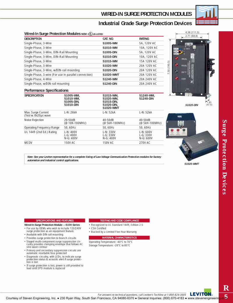
Surge P
rotection Devices
R5For answers to technical questions, call Leviton’s Techline at 1-800-824-3005
WIRED-IN SURGE PROTECTION MODULES
Industrial Grade Surge Protection Devices
SPECIFICATIONS AND FEATURES
Wired-In Surge Protection Module —5100 Series• For use by OEMs who wish to include 120/240V
surge protection as an equipment feature• Available with DIN-rail mounting• Provides surge protection to branch circuits• Staged multi-component surge suppression cir-
cuitry provides clamping envelope that follows ACsine-wave contour
• Primary and secondary suppression circuits areautomatic resettable fuse protected
• Diagnostic circuitry, with LEDs, to indicate surgeprotection status & acoustic alert if surge protec-tion is lost
• If surge protection is lost, power is still provided toload until SPD module is replaced
TESTING AND CODE COMPLIANCE
• Recognized to UL Standard 1449, Edition 2.5• CSA Certified• Backed by a Limited Five-Year Warranty
MATERIAL CHARACTERISTICS
Operating Temperature: -40°C to 70°CStorage Temperature: -20°C to 85°C
Wired-In Surge Protection Modules NOM CUUS LISTED
DESCRIPTION CAT. NO. RATINGSingle-Phase, 3-Wire 51005-WM 5A, 120V ACSingle-Phase, 3-Wire 51010-WM 10A, 120V ACSingle-Phase, 3-Wire, DIN-Rail Mounting 51005-DIN 5A, 120V ACSingle-Phase, 3-Wire, DIN-Rail Mounting 51010-DIN 10A, 120V ACSingle-Phase, 3-Wire 51015-WM 15A 120V ACSingle-Phase, 3-Wire 51020-WM 20A 120V ACSingle-Phase, 3-Wire, w/DIN-rail mounting 51020-DIN 20A 120V ACSingle-Phase, 3-wire (For use in parallel connection) 51020-WMT 20A 120V ACSingle-Phase, 4-Wire 51240-WM 20A 240V ACSingle-Phase, w/DIN-rail mounting 51240-DIN 20A 240V AC
Performance SpecificationsSPECIFICATION 51005-WM, 51015-WM, 51240-WM,
51010-WM, 51020-WM, 51240-DIN51005-DIN, 51015-DIN, 51010-DIN 51020-DIN,
51020-WMTMax. Surge Current L-N: 26kA L-N: 52kA L-N: 52kA(Test w. 8x20µs waveNoise Rejection 20-50dB 40-50dB 40-50dB
(@ 10K-100MHz) (@ 5kH-100MHz) (@ 5kH-100MHz)Operating Frequency Range 50, 60Hz 50, 60Hz 50, 60HzUL 1449 (2nd Ed.) Rating L-N: 400V L-N: 330V L-N: 600V
L-G: 400V L-G: 330V L-G: 330VN-G: 400V N-G: 400V N-G: 600V
MCOV 150V AC 150V AC 270V AC
Note: See your Leviton representative for a complete listing of Low-Voltage Communication Protection modules for factoryautomation and industrial control applications.
7.50
(19
0.5)
2.71 (68.8)4.38 (111.3)
1.85(47.0)51020-DIN
51020-WMT
Courtesy of Steven Engineering, Inc. ● 230 Ryan Way, South San Francisco, CA 94080-6370 ● General Inquiries: (800) 670-4183 ● www.stevenengineering.com

Sur
ge P
rote
ctio
n Dev
ices
R6
SURGE PROTECTION PANELS
Industrial Grade Surge Protection Devices
To learn more about Leviton’s outstanding offering of devices visit our Website at: www.leviton.com
74000 Series Panel Mount Devices UR NOM
DESCRIPTION CAT. NO. RATING MODULE NO.7-Mode, 3Ø WYE, 4-Wire + Ground 74120-7M3 120/208V AC (7) HC120-M407-Mode, 3Ø WYE, 4-Wire + Ground 74277-7M3 277/480V AC (7) HC277-M40
Performance Specifications: 74000 SeriesUL 1449 (2nd Ed) MAX. SURGE NOISE
IMPULSE (6kV/500A) CURRENT in KA REJECTIONCAT. NO. MCOV (Test w/8x20µs wave)
L-N L-G N-G L-N + L-G = per phase74120-7M3 150V AC 400 400 400 200 200 400 -40 dB
(@5K-100MHz)74277-7M3 320V AC 800 800 800 200 200 400 -40 dB
(@5K-100MHz)
SPECIFICATIONS AND FEATURES
74000 Series• Provides seven mode protection• Uses replaceable modules• Real-time diagnostics monitor power and suppres-
sion status for each mode• Surge magnitude, time and date is provided for
each surge event• Surge event history downloadable for storage via
RS-232 connection• AC sine wave tracking• Optically isolated dry contacts
TESTING AND CODE COMPLIANCE
• UL 1449 Edition 2.5 Listed (#E146315)• CSA Certified (#LR-94773)• Meets ANSI/IEEE C62.41 & C62.45 Categories
A, B & C
MATERIAL CHARACTERISTICS
Operating Temperature: -10ºC to 60ºCStorage Temperature: -20°C to 85°C
19.71 (500.3)
15.8
0 (1
40.0
)
8.33(211.6)
74120-7M3
Courtesy of Steven Engineering, Inc. ● 230 Ryan Way, South San Francisco, CA 94080-6370 ● General Inquiries: (800) 670-4183 ● www.stevenengineering.com

Surge P
rotection Devices
R7For answers to technical questions, call Leviton’s Techline at 1-800-824-3005
SURGE PROTECTION PANELS
Industrial Grade Surge Protection Devices
57000 Series Branch Panel Mounts URDESCRIPTION CAT. NO. CAT. NO. VOLTAGE RATING MODULE
W/O SURGE W/ SURGECOUNTER COUNTER
3-Phase WYE, 4-Wire & Ground 57120-M3 57120-CM3 120/208V AC (3) 120(1) 8120-GN
3-Phase WYE, 7-Mode, 57120-M3S 57120-C3S 120/208V AC (3) 120-M3SIntegral Disconnect, 4-Wire & Ground (1) 8120-GN3-Phase WYE, 4-Wire & Ground 57220-IM3 — 220/380V AC (3) 220
(1) 8250-GN3-Phase Delta, 3-Wire & Ground 57240-DM3 — 240V AC (3) 72403-Phase WYE, 4-Wire & Ground 57277-M3 57277-CM3 277/480V AC (3) 7277
(1) 8320-GN3-Phase WYE, 7-Mode, 57277-M3S 57277-C3S 277/480V AC (3) 7277-M3SIntegral Disconnect, 4-Wire & Ground (1) 8320-GN3-Phase WYE, 4-Wire & Ground 57346-M3 — 346/600V AC (3) 7346
(1) 8385-GN3-Phase WYE, 4-Wire & Ground 57347-M3S — 347/600V AC (3) 7347
(1) 8385-GN3-Phase Delta, 3-Wire & Ground 57480-DM3 — 480V AC (3) 74803-Phase Delta, 3-Wire & Ground 57600-DM3 — 600V AC (3) 7600
Remote SupervisorDESCRIPTION CAT. NO. Remote Supervisor 52000-RS
Performance Specifications: 57000 SeriesUL 1449 (2nd Ed) MAX. SURGE NOISE
IMPULSE (6kV/500A) CURRENT in KA REJECTIONCAT. NO. MCOV (Test w/8x20µs wave)
L-N L-G N-G L-L L-N + L-G = per phase57120-M3 150V AC 400 800 400 800 150 — 150 -20 to -40 dB57120-CM3 (@5K-10MHz)57120-M3S 150V AC 400 500 400 700 100 100 100 -20 to -40 dB57120-C3S (@5K-10MHz)57220-IM3 250V AC 600 1200 600 1200 150 — 150 -20dB to -40 dB
(@5K-10MHz)57240-DM3 250V AC — — — 700 L-L: 150 -20dB to -40 dB
(@5K-10MHz)57277-M3 320V AC 800 1800 800 1800 150 — 150 -20dB to -40 dB57277-MC3 (@5K-10MHz)57277-M3S 320V AC 900 1000 800 1500 100 100 200 -20dB to -40 dB57277-C3S (@5K-10MHz)57346-M3 385V AC 1000 2000 1000 2000 150 — 150 -20dB to -40 dB
(@5K-10MHz)57480-DM3 550V AC — — — 1500 L-L: 150 -20dB to -40 dB
(@5K-10MHz)57600-DM3 680V AC — — — 1800 L-L: 150 -20dB to -40 dB
(@5K-10MHz)57347-M3S 390V AC 1000 1000 1000 2000 100 100 200 -20dB to -40 dB
(@5K-10MHz)
TESTING AND CODE COMPLIANCE
57000 Series• UL 1449 Listed Edition 2.5 (File #E-146315)• CSA Certified (File #LR-94773)• 200 kA rated (M3S versions rated 100kA)• Meets ANSI/IEEE C62.41 & C62.45 Categories A, B & C• UL 945-V flame retardant thermoplastic (Front Bezel)• Backed by a Limited 10-Year Warranty
MATERIAL CHARACTERISTICS
Operating Temperature: -10°C to 60°CStorage Temperature: -20°C to 85°C
SPECIFICATIONS AND FEATURES
57000 Series• For installation at main distribution panels• Hybrid suppression circuitry with built-in redundancy
provides complete protection on all phases even if onemodule fails
• Modular design allows easy replacement of moduleswith the use of tools & without the need to shut downAC system power
• Provides Normal Mode (phase to neutral) & CommonMode (neutral to ground) protection for WYE-configured3-phase AC systems
• Dry contacts for remote monitoring57000 Series• “Series connection” parallel operated (Kelvin/feed-
through) rated for 100 Amps maximum continuous linecurrent using #3 AWG conductors
• Optically coupled remote-monitoring port allows use ofthe optional Remote Supervisor (Cat. No. 52000-RS)
• Dual-stage fuse protection for primary & secondarysurge suppression circuits
• Housed in NEMA-12 case with hinged cover, surface orflush mountable
• Noise rejection -20 to -40dBRemote Supervisor• For use with any Cat. No. 57000 or 52000 panel-
mounted SPD• Monitors up to 6 (series alarm daisy-chained) panel-
mounted SPDs• Single key-hole surface mounting using just 2 screws• Annunciator light shows steady GREEN when moni-
tored panel-mounted SPDs are normal, & FLASHINGRED in case of protection failure or power interruption
• 75dB acoustic beep tone draws attention to a potentialfailure
• Jack provided for simple connection to input port via#20 to #22 two-conductor twisted pair, with a wire runup to 5,000 ft. in length
14.9
0 (3
60.4
)
10.31 (261.9)5.00(127.0)
57120-M3
14.9
0 (3
60.4
)
10.31 (261.9)5.00
(127.0)57120-CM3
Courtesy of Steven Engineering, Inc. ● 230 Ryan Way, South San Francisco, CA 94080-6370 ● General Inquiries: (800) 670-4183 ● www.stevenengineering.com
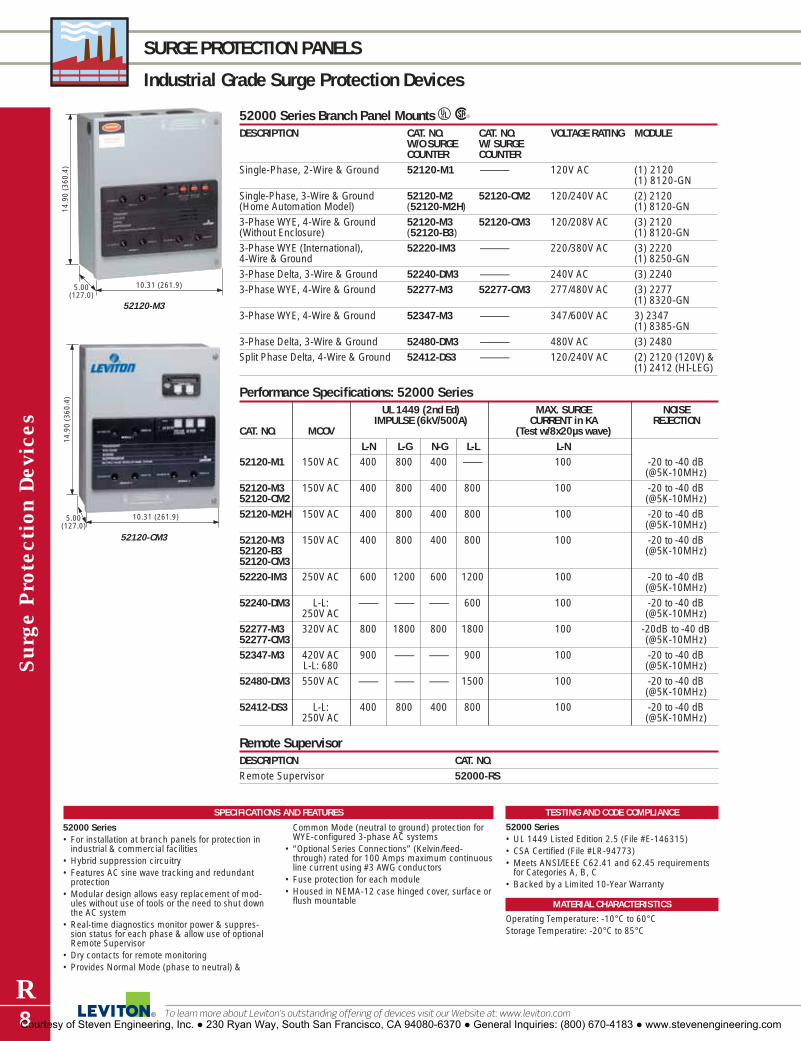
Sur
ge P
rote
ctio
n Dev
ices
R8
SURGE PROTECTION PANELS
Industrial Grade Surge Protection Devices
To learn more about Leviton’s outstanding offering of devices visit our Website at: www.leviton.com
TESTING AND CODE COMPLIANCE
52000 Series• UL 1449 Listed Edition 2.5 (File #E-146315)• CSA Certified (File #LR-94773)• Meets ANSI/IEEE C62.41 and 62.45 requirements
for Categories A, B, C• Backed by a Limited 10-Year Warranty
MATERIAL CHARACTERISTICS
Operating Temperature: -10°C to 60°CStorage Temperatire: -20°C to 85°C
SPECIFICATIONS AND FEATURES
52000 Series• For installation at branch panels for protection in
industrial & commercial facilities• Hybrid suppression circuitry• Features AC sine wave tracking and redundant
protection• Modular design allows easy replacement of mod-
ules without use of tools or the need to shut downthe AC system
• Real-time diagnostics monitor power & suppres-sion status for each phase & allow use of optionalRemote Supervisor
• Dry contacts for remote monitoring• Provides Normal Mode (phase to neutral) &
Common Mode (neutral to ground) protection forWYE-configured 3-phase AC systems
• “Optional Series Connections” (Kelvin/feed-through) rated for 100 Amps maximum continuousline current using #3 AWG conductors
• Fuse protection for each module• Housed in NEMA-12 case hinged cover, surface or
flush mountable
52000 Series Branch Panel Mounts URDESCRIPTION CAT. NO. CAT. NO. VOLTAGE RATING MODULE
W/O SURGE W/ SURGECOUNTER COUNTER
Single-Phase, 2-Wire & Ground 52120-M1 — 120V AC (1) 2120(1) 8120-GN
Single-Phase, 3-Wire & Ground 52120-M2 52120-CM2 120/240V AC (2) 2120(Home Automation Model) (52120-M2H) (1) 8120-GN3-Phase WYE, 4-Wire & Ground 52120-M3 52120-CM3 120/208V AC (3) 2120(Without Enclosure) (52120-B3) (1) 8120-GN3-Phase WYE (International), 52220-IM3 — 220/380V AC (3) 22204-Wire & Ground (1) 8250-GN3-Phase Delta, 3-Wire & Ground 52240-DM3 — 240V AC (3) 22403-Phase WYE, 4-Wire & Ground 52277-M3 52277-CM3 277/480V AC (3) 2277
(1) 8320-GN3-Phase WYE, 4-Wire & Ground 52347-M3 — 347/600V AC 3) 2347
(1) 8385-GN3-Phase Delta, 3-Wire & Ground 52480-DM3 — 480V AC (3) 2480Split Phase Delta, 4-Wire & Ground 52412-DS3 — 120/240V AC (2) 2120 (120V) &
(1) 2412 (HI-LEG)
Remote SupervisorDESCRIPTION CAT. NO. Remote Supervisor 52000-RS
Performance Specifications: 52000 SeriesUL 1449 (2nd Ed) MAX. SURGE NOISE
IMPULSE (6kV/500A) CURRENT in KA REJECTIONCAT. NO. MCOV (Test w/8x20µs wave)
L-N L-G N-G L-L L-N52120-M1 150V AC 400 800 400 — 100 -20 to -40 dB
(@5K-10MHz)52120-M3 150V AC 400 800 400 800 100 -20 to -40 dB52120-CM2 (@5K-10MHz)52120-M2H 150V AC 400 800 400 800 100 -20 to -40 dB
(@5K-10MHz)52120-M3 150V AC 400 800 400 800 100 -20 to -40 dB52120-B3 (@5K-10MHz)52120-CM352220-IM3 250V AC 600 1200 600 1200 100 -20 to -40 dB
(@5K-10MHz)52240-DM3 L-L: — — — 600 100 -20 to -40 dB
250V AC (@5K-10MHz)52277-M3 320V AC 800 1800 800 1800 100 -20dB to -40 dB52277-CM3 (@5K-10MHz)52347-M3 420V AC 900 — — 900 100 -20 to -40 dB
L-L: 680 (@5K-10MHz)52480-DM3 550V AC — — — 1500 100 -20 to -40 dB
(@5K-10MHz)52412-DS3 L-L: 400 800 400 800 100 -20 to -40 dB
250V AC (@5K-10MHz)
14.9
0 (3
60.4
)
10.31 (261.9)5.00(127.0)
52120-M3
14.9
0 (3
60.4
)
10.31 (261.9)5.00(127.0)
52120-CM3
Courtesy of Steven Engineering, Inc. ● 230 Ryan Way, South San Francisco, CA 94080-6370 ● General Inquiries: (800) 670-4183 ● www.stevenengineering.com

Surge P
rotection Devices
R9For answers to technical questions, call Leviton’s Techline at 1-800-824-3005
SURGE PROTECTION PANELS
Industrial Grade Surge Protection Devices
47000 & 52000-7M3 Series Branch Panel Mounts URDESCRIPTION CAT. NO. CAT. NO. VOLTAGE RATING MODULE
W/O SURGE W/ SURGE 3ø WYE (4-Wire & COUNTER COUNTER Ground)
7-Mode Panel Mount 47120-007 — 120/208V AC —(4-Wired + Ground)7-Mode Panel Mount w/NEMA 4X 47120-4X7 — 120/208V AC —Enclosure (4-Wire + Ground)7-Mode Panel Mount 47277-007 — 277/480V AC —(4-Wired + Ground)7-Mode Panel Mount w/NEMA 4X 47277-4X7 — 277/480V AC —Enclosure (4-Wire + Ground)7-Mode Panel Mount 47347-007 — 347/600V AC —(4-Wired + Ground)7-Mode Modular Panel Mount 52120-7M3 52120-7C3 120/208V AC (3) 120-7M3(4-Wired + Ground) (1) 8120-GN7-Mode Modular Panel Mount 52277-7M3 52277-7C3 277/480V AC (3) 220-7M3(4-Wired + Ground) (1) 8120-GN
37000, 47000 & 57000-7M3 Series Branch Panel Mounts URDESCRIPTION CAT. NO. CAT. NO. VOLTAGE RATING
W/O SURGE W/ SURGE 3ø WYE (4-Wire & COUNTER COUNTER Ground)
7-Mode Panel Mount 37120-007 — 120/208V ACType 1 Enclosure (4-Wired + Ground)7-Mode Panel Mount w/NEMA 37277-4X7 — 277/480V ACType 1 Enclosure (4-Wire + Ground)
Performance Specifications: 47000 and 52000-7M3 SeriesUL 1449 (2nd Ed) MAX. SURGE NOISE
IMPULSE (6kV/500A) CURRENT in KA REJECTIONCAT. NO. MCOV (Test w/8x20µs wave)
L-N L-G N-G L-L L-N + L-G = per phase47120-007 140V AC 330 400 330 600 200 200 400 -40 dB47120-4X7 (@10K-10MHz)47277-007 320V AC 700 800 700 1500 200 200 400 -40 dB47277-4X7 (@10K-10MHz)47347-007 390V AC 1200 1300 1200 2200 200 200 400 -40 dB
(@10K-10MHz)52120-7M3 150V AC 400 400 400 800 100 100 200 -20 to -40 dB52120-7C3 (@5K-10MHz)52277-7M3 320V AC 800 800 800 1500 100 100 200 -20 to -40 dB52277-7C3 (@5K-10MHz)
SPECIFICATIONS AND FEATURES
47000 & 52000-7M3 Series• Provides low-clamping, high surge current capability• Verifies fail-safe conditions for MOVs under steady-
state overvoltage• 200 kA rated per mode• Parallel wired to facilitate connection to any service
ampacity• Provides Normal Mode (phase to neutral) &
Common Mode (neutral to ground) protection forWYE-configured 3-phase AC systems
• Available with NEMA Type 4X enclosure for out-door/uncontrolled environments
TESTING AND CODE COMPLIANCE
47000 & 52000-7M3 Series• UL 1449 Listed Edition 2.5 (File #E-146315)• CSA Certified (File #LR-94773)• Meets ANSI/IEEE C62.41 and 62.45 requirements
for Categories A, B, C• Backed by a Limited 10-Year Warranty
MATERIAL CHARACTERISTICS
Operating Temperature: -10°C to 60°CStorage Temperatire: -20°C to 85°C
10.0
0 (2
54.0
)
10.00 (254.0)
4.00(101.6)
11.0
0 (2
79.4
)
47120-007
13.5
0 (3
42.9
)
11.25 (285.8)
5.69(144.5) 47120-4X7
Courtesy of Steven Engineering, Inc. ● 230 Ryan Way, South San Francisco, CA 94080-6370 ● General Inquiries: (800) 670-4183 ● www.stevenengineering.com

Sur
ge P
rote
ctio
n Dev
ices
R10
MULTI-PHASE PANEL PROTECTORS
Industrial Grade Surge Protection Devices
To learn more about Leviton’s outstanding offering of devices visit our Website at: www.leviton.com
32000 and 42000 Series for Branch Panels URDESCRIPTION CAT. NO. VOLTAGE RATINGSingle-Phase 32120-1 120/240V AC
42120-13-Phase WYE or 220V AC, 3Ø Delta 32120-DY3 120/208V AC
42120-DY3277/480V or 220/380V AC 32277-DY3 277/480V AC, 220/380V AC 3-Phase WYE or 240, 480V AC 3Ø Delta 42277-DY3 480V AC3-Phase WYE 32347-DY3 347/600V AC
42347-DY3Hi-Leg Split Phase Delta 32412-DS3 120/240V AC
42412-DS3Flush Mount Collar 42001-FMC —
Performance Specifications: 32000 and 42000 SeriesUL 1449 (2nd Ed) MAX. SURGE NOISE REJECTION
IMPULSE (6kV/500A) CURRENT in KA 3200 4200CAT. NO. MCOV (Test w/8x20µs wave) Series Series
L-N N-G L-L L-N32120-1 150V AC 500 500 70042120-132120-DY3 150V AC 500 500 70042120-DY332277-DY3 320V AC 900 800 150042277-DY3 80kA
32347-DY3 382V AC 1200 1000 200042347-DY3 L-L 660V AC32412-DS3 320V AC 400 700 80042412-DS3 L-L 264V AC (HiL-N)
SPECIFICATIONS AND FEATURES
32000 & 42000 Series• 32000 Series compatible with Decora Home
Automation devices• Dry contacts for remote monitoring (NO-C-NC)• Provide multiple-phase surge protection in com-
mercial & industrial environments• Compact design permits close installation to panel
& provides a short parallel suppression path• 3-phase units are suitable for WYE & Delta AC
systems• Easily surface-mounted or flush mountable with
use of flush collar accessory 42001 FMC• Real-time diagnostics monitor power & surge sup-
pression status of each phase by means of indica-tor light & acoustic alarm
• Equipped with normally open/normally closed drycontacts rated 5 Amps 120/240V AC via 3 color-coded AWG leads rated 600V AC for remote monitoring
TESTING AND CODE COMPLIANCE
32000 & 42000 Series• UL 1449 Listed Edition 2.5 (File #E-146315)• CSA Certified (File #LR-94773)• Meets ANSI/IEEE C62.41 and 62.45 requirements
for Categories A, B, C• Backed by a Limited 10-Year Warranty
MATERIAL CHARACTERISTICS
32000 & 42000 SeriesOperating Temperature: -10°C to 60°CStorage Temperature: -20°C to 85°C
-20 to -30 dB(@1.5K–1.2MHz)
-30 to -40 dB(@10K–10MHz)
7.50
(19
0.5)
6.25
(15
8.7)
4.25 (108.0)
3.25(82.5)
32120-DY3
7.50
(19
0.5)
6.25
(15
8.7)
4.25 (108.0)
3.25(82.5)
42120-DY3
Courtesy of Steven Engineering, Inc. ● 230 Ryan Way, South San Francisco, CA 94080-6370 ● General Inquiries: (800) 670-4183 ● www.stevenengineering.com

Surge P
rotection Devices
R11For answers to technical questions, call Leviton’s Techline at 1-800-824-3005
LOW VOLTAGE COMMUNICATION MODULES
Industrial Grade Surge Protection Devices
SPECIFICATIONS AND FEATURES
3400 & 3800 Series • Designed for mounting in standard equipment
cabinets• For use on Allen Bradley & “Blue Hose” devices• Two options for ground connection• Low clamping voltage• Withstands surges at programmable logic devices
in harsh electromagnetic or geographic areas• Provide transient voltage surge suppression for a
selection of programmable logic devices & othercomputer-related data network products
51000-SMC Surge Counter• Plug-in design provides fast, simple way to deter-
mine if surges are present• 3 settings indicate different sensitivity thresholds
based on IEEE C62.41 impulse & ringwave waveforms
• Key operated to prevent tampering • Excellent tool for determining if you need surge
protection in an office environment.
TESTING AND CODE COMPLIANCE
3400 & 3800 Series • UL 497B Listed (#E175161)• CSA Certified (#LR-94773)• Meets ANSI/IEEE C-62.41 requirements• Backed by a Limited 10-Year Warranty51000-SMC • Meets UL Standard 1436
MATERIAL CHARACTERISTICS
Operating Temperature: -40ºC to 60ºC (3803-DHP,3803-485, 3803-MOD, 3420-009, 3420-035); -10ºCto 85ºC (3803-SPX, 3803-CAN, 3860 Series)Storage Temperature: -40ºC to 90ºC (3803-DHP,3803-485, 3803-MOD, 3420-009, 3420-035); -20ºCto 85ºC (3803-SPX, 3803-CAN, 3860 Series)
3400 and 3800 Series Low Voltage Communication Surge Protection Modules URDESCRIPTION CAT. NO. RATING APPLICATION3-Pin Header Connector, Surface Mount 3803-DHP* 9.6V DC For programmable logic devices
and other computer-related data network products operating on “Blue Hose” networks
6-Pin Header Connector, Surface Mount 3803-485* 9.6C DC For programmable logic other devices and computer related data network products operating on Allen Bradley DH-485 data networks
5-Pin Header Connector Surface & 3803-SPX 13.6V DC For products operating on DIN-Rail Mount SERIPLEX control bus networksDB-9 Connector, Surface & 3803-CAN 25V DC For products operating on DIN-Rail Mount Honeywell control bus3-Pin Header Connector, Surface Mount 3803-MOD 9.6V DC For products operating on Modbus
and Modbus Plus networks3-Pin Header Connector, Surface Mount 3420-009* 9.6V DC For products operating on 4-20ma
Signal Loop networks, 9V DC3-PIN Header Connector, Surface Mount 3420-035* 38.5V DC For products operating on 4-20ma
Signal Loop networks, 38V DC4-Position Terminal Block Surface & 3860-GEF 100V DC For products operating on GE DIN-rail Mount Fanuc Control Bus networksRJ-45 Connector, Surface & 3861-ETH 19.8V DC For products operating on DIN-Rail Mount Ethernet PLC ports and
CAT 3 networksBNC Connector, Surface & 3862-CON 9.18V DC For ControlNet networksDIN-Rail Mount5-Pin Header Connector Surface 3863-DEV 19.8V DC For DeviceNet networks& DIN-Rail MountHospital Grade Din-Rail Mountable 3880-DIN 120V For plug-in surge protection inSurge Protected Duplex Receptacle equipment cabinetsw/LED & Audible Alarm
Surge Counter: 51000-SMC URDESCRIPTION CAT. NO. Plug-in Surge Counter 51000-SMC
*The Rockwell Automation Encompass Program references complementary products from third party manufacturerscommitted to providing quality products and services that enhance the Rockwell Automation Solution products and solvethe industrial automation needs of mutual customers.
**
2.26
(57
.4)
1.51 (38.3)
0.79 (20.0)
3803-485
3.00
(76
.2)
1.70 (43.2)
2.49 (63.2)
3803-SPX
5.63
(14
.3)
2.54 (64.5)
2.36 (5.99)
3880-DIN
51000-SMC
Courtesy of Steven Engineering, Inc. ● 230 Ryan Way, South San Francisco, CA 94080-6370 ● General Inquiries: (800) 670-4183 ● www.stevenengineering.com

1.66 (42.1)
0.85(21.5)
2.69
(68
.3)
3.28
(83
.3)
3.78
(96
.0)
3800-OEM
Sur
ge P
rote
ctio
n Dev
ices
R12
EQUIPMENT CABINET SURGE PROTECTION
Industrial Grade Surge Protection Devices
To learn more about Leviton’s outstanding offering of devices visit our Website at: www.leviton.com
Equipment Cabinet Surge Protection Modules 3800 Series URDESCRIPTION CAT. NO. RATINGFor DIN-Rail Mounting, w/Terminal Block; 120V AC 3800-DIN 120V AC (VRMS)Terminal Block; 120V AC 3800-0WM 120V AC (VRMS)Pigtail Wire Leads, 6" long; 120V AC 3800-OEM 120V AC (VRMS)For DIN-Rail Mounting, w/Terminal Block; 12V DC 3812-DIN 12V DCTerminal Block; 12V DC 3812-0WM 12V DCPigtail Wire Leads; 6" long; 12V DC 3812-OEM 12V DCFor DIN-Rail Mounting, w/Terminal Block; 24V DC 3824-DIN 24V DCTerminal Block; 24V DC 3824-0WM 24V DCPigtail Wire Leads; 6" long; 24V DC 3824-OEM 24V DCFor DIN-Rail Mounting, w/Terminal Block; 240V AC 3840-DIN 240V AC (VRMS)Terminal Block; 240V AC 3840-0WM 240V AC (VRMS)Pigtail Wire Leads; 6" long; 240V AC 3840-OEM 240V AC (VRMS)For DIN-Rail Mounting, w/Terminal Block; 48V DC 3848-DIN 48V DCTerminal Block; 48V DC 3848-0WM 48V DCPigtail Wire Leads; 6" long; 48V DC 3848-OEM 48V DC
Clamping Performance and Performance SpecificationCLAMPING PERFORMANCE CAT. NO. 3800 CAT. NO. 3840UL Standard 1449 permanently-wired test L-N: 500V Peak L-N: 330V Peak(8x20µs, 3000A) L-G: 500V Peak L-G: 400V Peak
N-G: 500V Peak N-G: 330V Peak
PERFORMANCE SPECIFICATION CAT. NO. 3800 CAT. NO. 3840Max. Single-Pulse L-N: 1300A L-N: 1300ATransient Current L-G: 6500A L-G: 6500A(8X20µS, Impulse) N-G: 6500A N-G: 6500A
Consult factory for detailed performance data for other models.
Equipment Cabinet Surge Protection Receptacles URDESCRIPTION CAT. NO. RATINGHospital Grade Duplex Receptacle 60Hz 3880-DIN 15A-120V @ 50, Single Convenience Outlet 60Hz 3801-DIN 15A-120V @ 50,
Performance Data (3880-DIN, 3801-DIN)CLAMPING MCOV† MAX. SINGLE PULSE TRANSIENT EMI-RFI NOISE REJECTION VOLTAGE* CURRENT (8X20µs, Amps peak) @50 ohms 5kHz-5MHz400/400/400V pk 150Vrms 24kA(L-N),12kA(L-G/N-G) -35dB
*UL 1449 Suppressed Voltage Ratings (SVR) Assigned at 6" length with 6k/500A per UL1449 (2nd Ed.)†Maximum Continuous Operating Voltage.
TESTING AND CODE COMPLIANCE
• UL 1449 Listed Edition 2.5(E146315/DC-E175161)• CSA Certified (#LR-94773) • Meets ANSI/IEEE C-62.41 & C-62.45 Categories A,
B & C (B & C ONLY for Cat Nos.3880-DIN & 3801-DIN)
• Backed by a Limited 10-Year Warranty
MATERIAL CHARACTERISTICS
Operating Temperature: -10°C to 60°CStorage Temperature: -20°C to 85°C
SPECIFICATIONS AND FEATURES
3800 Series• MOV-based suppression circuitry provides opti-
mum clamping• Provides Normal Mode protection for line-to-
neutral & common mode; line-to-ground & neutral-to-ground
• Noise rejection @ 5kHz-5MHz: -35db• 3800: 135V (MCOV); 3840: 250V (MCOV)• 3800-DIN, 3800-0WM: Terminal block accepts
22 AWG to 12 AWG conductors• Consult factory on additional ratings on 3812,
3824 & 3848
3880-DIN & 3801-DIN• Ideal for mounting in equipment cabinets where
convenient plugin surge protection is desired• Green LED indicates surge protection loss• Audible alarm w/integral disable (quiet) switch• Power continues to be provided to loads in the
event of protection loss• Terminal Block accepts #22-#12 AWG conductors
2.99
(75
.9)
2.49 (63.2)
1.00(25.4)3840-DIN
2.69
(68
.3)
3.28
(83
.3)
3.78
(96
.0)
1.66 (42.1)
0.85(21.59)
3800-DIN
Courtesy of Steven Engineering, Inc. ● 230 Ryan Way, South San Francisco, CA 94080-6370 ● General Inquiries: (800) 670-4183 ● www.stevenengineering.com

Surge P
rotection Devices
R13For answers to technical questions, call Leviton’s Techline at 1-800-824-3005
SURGE PROTECTION RECEPTACLES
Industrial Grade Surge Protection Devices
Hospital Grade Surge Protection Receptacles—120V NOM CUUS LISTED
DESCRIPTION CAT. NO. COLOR*Basic Cat. No. Denotes Brown
15A Duplex—Indicator Light, Audible Alarm 8280 I, W, A, T, R, B20A Duplex—Indicator Light, Audible Alarm 8380 I, W, GY, B, R20A Single—Indicator Light, Audible Alarm 8381 I, (No Brown)
Hospital Grade Isolated Ground Surge Protection Receptacles—120V URDESCRIPTION CAT. NO. COLOR*
Brown Not Available
15A Duplex—Indicator Light, Audible Alarm 8280-IG I, W, G, B, O15A Single—Indicator Light, Audible Alarm 8281-IG I, O20A Duplex—Indicator Light, Audible Alarm 8380-IG I, W, G, B, O 20A Single—Indicator Light, Audible Alarm 8381-IG I, W, B
Industrial Grade Surge Protection Receptacles—120V URDESCRIPTION CAT. NO. COLOR*
Basic Cat. No. Denotes Brown
15A Duplex—Indicator Light 5280 I, W, A, T, GY, B15A Duplex—Indicator Light, Audible Alarm 7280 I, W, A, GY, B20A Duplex—Indicator Light 5380 I, W, GY, B20A Duplex—Indicator Light, Audible Alarm 7380 I, W, GY, B
Industrial Grade Isolated Ground Surge Protection Receptacles—120V URDESCRIPTION CAT. NO. COLOR*
Basic Cat. No. Denotes Brown
15A Duplex—Indicator Light 5280-IG I, W, A, G, B, O20A Duplex—Indicator Light 5380-IG I, W, G, B, O
General DataSPECIFICATION DATA APPLICABLE TO ALLRated line voltage 120V (VRMS)Max. continuous operating voltage 150VMax. single-pulse transient current 24000A (L-N)(8x20µs, Amps peak) 12000A (L-G)
12000A (N-G)Rated single-pulse transient energy 320 Joules(10x1000µs, impulse)Noise rejection @ 5kHz-5MHz -35dB
Clamping PerformanceSPECIFICATION DATA APPLICABLE TO ALLUL Standard 1449 (2nd Edition) (L-N): 400V Peakpermanently-wired test (8x20µs, 3000A); (L-G): 400V PeakCSA and NOM Certified (N-G): 400V Peak
SPECIFICATIONS AND FEATURES
• Provides hard-wired point-of use surge protection forelectronic equipment in industrial, commercial andresidential applications
• 3-Level surge protection for phase to neutral, phaseto ground and neutral to ground
• All receptacles are back and side wired• Hospital Grade versions (indicated by green dot on
receptacle face) are suitable for high-abuse healthcare, industrial and commercial applications
• Isolated Ground versions (indicated by orange coloror orange triangle on receptacle face) provide a pureground path for use with isolated grounding systems
• Monitor/Indicator LED is ON continuously when pro-tection is active and OFF when protection circuit isdeactivated due to excessive transients
• All Hospital Grade devices and Cat. Nos. 7280 and7380 Industrial devices also provide an audible tonealert that sounds if protection is lost
• EMI/RFI filtering• Decora styling complements any interior and coordi-
nates with Leviton's popular line of Decora devices
TESTING AND CODE COMPLIANCE
• UL Listed Standard 1449 (Edition 2.5)• CSA certified• Meets ANSI/IEEE C62.41 standards for both
Categories A & B• All SPD receptacles are backed by a Limited
10-Year Warranty*
*COLOR
Basic Cat. Nos. shown above denote Brown device,except Hospital Grade IG devices not available inBrown. Colors available as listed above, add suffix to basic catalog numbers as follows: Ivory (-I), White (-W), Almond (-A), Light Almond (-T), Gray (-G or -GY), Blue (-B), Orange (-O), Red (-R).
3.28
(83
.3)
3.81
(96
.8)
2.70
(68
.6)
1.70 (43.2)
1.22 (31.0)
8380
3.28
(83
.3)
3.81
(96
.8)
2.70
(68
.6)
1.70 (43.2)
1.22(31.0)
8280-IGO
3.28
(83
.3)
3.81
(96
.8)
2.70
(68
.6)
1.70 (43.2)
1.22 (31.0)
5380-IGB
Note: For Acenti Sixplex and Duplex Surge Protective Receptacles, see page A5
Courtesy of Steven Engineering, Inc. ● 230 Ryan Way, South San Francisco, CA 94080-6370 ● General Inquiries: (800) 670-4183 ● www.stevenengineering.com
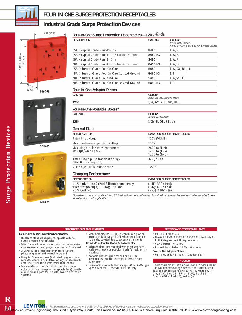
Sur
ge P
rote
ctio
n Dev
ices
R14
FOUR-IN-ONE SURGE PROTECTION RECEPTACLES
Industrial Grade Surge Protection Devices
To learn more about Leviton’s outstanding offering of devices visit our Website at: www.leviton.com
TESTING AND CODE COMPLIANCE
• UL 1449 Edition 2.5• Meets ANSI/IEEE C-62.41 & C-62.45 standards for
both Categories A & B requirements• CSA Certified (#152105)• Backed by a Limited 10-Year WarrantyFour-In-One Adapter Plates • UL Listed (File #E-13397 – Cat. No. 3254)
*COLOR
Colors available as listed above. For IG devices, BasicCat. No. denotes Orange device. Add suffix to basiccatalog numbers as follows: Ivory (-I), White (-W), Gray (-GY), Blue (-B, -BU or -BLU), Black (-E),Orange (-OR), Red (-R), Yellow (-Y
SPECIFICATIONS AND FEATURES
Four-In-One Surge Protection Receptacles• Replaces standard duplex receptacle with four
surge-protected receptacles• Ideal for locations where surge-protected recepta-
cles are needed and plug-in devices can’t be used• 3-Level surge protection for phase to neutral,
phase to ground and neutral to ground• Hospital Grade versions (indicated by green dot on
receptacle face) are suitable for high-abuse healthcare, industrial and commercial applications
• Isolated Ground versions (indicated by orangecolor or orange triangle on receptacle face) providea pure ground path for use with isolated groundingsystems
• Monitor/Indicator LED is ON continuously whenprotection is active and OFF when protection cir-cuit is deactivated due to excessive transients
Four-In-One Adapter Plates & Portable Box • Adapter plates not required with most standard
wallboxes; provides popular “flush fit” look for anyinstallation
• Portable Box designed for all Four-In-OneReceptacles (not UL Listed for extension cordapplications)
• Four-In-One Portable Box accepts #16/3 AWG TypeSJ to #12/3 AWG Type SO COPPER Only
Four-In-One Surge Protection Receptacles—120V URDESCRIPTION CAT. NO. COLOR*
Brown Not Available.For IG Devices, Basic Cat. No. Denotes Orange
15A Hospital Grade Four-In-One 8480 I, W, R15A Hospital Grade Four-In-One Isolated Ground 8480-IG I, W, B20A Hospital Grade Four-In-One 8490 I, W, R20A Hospital Grade Four-In-One Isolated Ground 8490-IG I, W, B15A Industrial Grade Four-In-One 5480 I, W, GY, BU, R15A Industrial Grade Four-In-One Isolated Ground 5480-IG I, B20A Industrial Grade Four-In-One 5490 I, W,GY, BU20A Industrial Grade Four-In-One Isolated Ground 5490-IG I, B
Four-In-One Adapter PlatesCAT. NO. COLOR*
Basic Cat. No. Denotes Brown
3254 I, W, GY, R, E, OR, BLU
Four-In-One Portable Boxes†CAT. NO. COLOR*
Brown Not Available
4254 I, GY, E, OR, BLU, Y
General DataSPECIFICATION DATA FOR SURGE RECEPTACLESRated line voltage 120V (VRMS)Max. continuous operating voltage 150VMax. single-pulse transient current 24000A (L-N)(8x20µs, Amps peak) 12000A (L-G)
12000A (N-G)Rated single-pulse transient energy 320 Joules(10x1000µs, impulse)Noise rejection @ 5kHz-5MHz -35dB
Clamping PerformanceSPECIFICATION DATA FOR SURGE RECEPTACLESUL Standard 1449 (2nd Edition) permanently- (L-N): 330V Peakwired test (8x20µs, 3000A); CSA and (L-G): 400V PeakNOM Certified (N-G): 400V Peak
†Portable boxes are not UL Listed. UL Listing does not apply when Four-In-One receptacles are used with portable boxesfor extension cord applications.
3.38
(85
.9)
4.50
(11
4.3)
SQ
.
3.38 (85.9)
1.15(29.2) 8490-R
3254-E
4254-Y
Courtesy of Steven Engineering, Inc. ● 230 Ryan Way, South San Francisco, CA 94080-6370 ● General Inquiries: (800) 670-4183 ● www.stevenengineering.com

S1000
S2000
5.17
(13
1.2)
3.54 (89.9)
1.54 (39.1)4900-P
4950-PSC
Surge P
rotection Devices
R15For answers to technical questions, call Leviton’s Techline at 1-800-824-3005
PLUG-IN SURGE PROTECTION DEVICES
Commercial Grade Surge Protection Devices
SPECIFICATIONS AND FEATURES
Plug Strips• Ground pin to outside for more transformer config-
urations• Diagnostic LEDs for surge protection, polarity and
ground verification• Resettable circuit breaker• Power line carrier compatible• Audible alarm indicates loss of protection• Four non-skid rubber feet on the bottomComputer Grade Plug Strips• Provides excellent surge suppression & EMI/RFI
noise attenuation for microprocessor-driven elec-tronic equipment
• Three-stage protection: line-to-neutral, line-to-ground, neutral-to-ground
• Built-in overload circuit-breaker switch with reset button
• Indicator lights confirm unit is operating & properlygrounded
• Clamping voltage: 330V all modes
Plug-Ins• Provide excellent surge suppression & EMI/RFI
noise attenuation for microprocessor-driven electronic equipment
• Indicator lights confirm unit is operating & properlygrounded
• Audible alarm indicates protection is no longeractive
• Clamping voltage: 330V all modes
TESTING AND CODE COMPLIANCE
Plug Strips• CSA Certified• UL Listed 1449 Edition 2.5• Meets ANSI/IEEE C62.41 Edition 2.5 and C62.45Computer Grade Plug Strips• UL Listed1449• Limited Lifetime WarrantyPlug-Ins• UL Listed1449• Limited Lifetime Warranty
S1000 & S2000 Series Plug StripsDESCRIPTION CAT. NO.S1000 Series Power Surge Strip (6 outlets) S1000-0PSS1000 Series TELCO/ CATV/SAT Surge Strip (6 outlets) S1000-PTCS2000 Series Power Surge Strip (9 outlets) S2000-0PSS2000 Series TELCO/ CATV/SAT Surge Strip (9 outlets) S2000-PTC
Computer Grade Plug Strips URDESCRIPTION CAT. NO. RATING APPLICATION7-Outlet (6 switched, 4950-PS 15A 125V AC EMI/RFI noise attenuation for 1 continuously live) Strip; beige micro-processor-driven electronic
equipment7-Outlet (6 switched, 4950-PST 15A 125V AC EMI/RFI noise attenuation for 1 continuously live) Strip w/Two RJ11 micro-processor-driven electronic Phone Jacks; beige equipment7-Outlet (6 switched, 4950-PSC 15A 125V AC EMI/RFI noise attenuation for 1 continuously live) Strip w/Two micro-processor-driven electronic F-type Coax Connectors; beige equipment
Plug-In Surge Suppressors URDESCRIPTION CAT. NO. RATING APPLICATION6-Outlet (2 front, 4 side switched) 4900-P 15A 125V AC EMI/RFI noise attenuation for Plug-in; beige micro-processor-driven electronic
equipment6-Outlet (2 front, 4 side switched) 4900-PT 15A 125V AC EMI/RFI noise attenuation for Plug-in w/Two RJ11 Phone Jacks; micro-processor-driven electronic beige equipment6-Outlet (2 front, 4 side switched) 4900-PC 15A 125V AC EMI/RFI noise attenuation for Plug-in w/Two F-type Coax micro-processor-driven electronic Connectors; beige equipment
Courtesy of Steven Engineering, Inc. ● 230 Ryan Way, South San Francisco, CA 94080-6370 ● General Inquiries: (800) 670-4183 ● www.stevenengineering.com

Sur
ge P
rote
ctio
n Dev
ices
R16
RACK-MOUNT SURGE PROTECTION DEVICES
Power Distribution Units with Surge Protection
To learn more about Leviton’s outstanding offering of devices visit our Website at: www.leviton.com
SPECIFICATIONS AND FEATURES
19" Rack Mount PDU’s with Surge Protection• Mounts on 19" equipment racks to provide point-
of-use surge suppression for electronic equipment• Clamping profile tightly tracks AC sine wave • 6 protected duplex receptacles-5 in back,
1 in front • Available with easy-access ON/OFF rocker-style
switch, or without switch to avoid unnecessaryequipment switching
• Resettable circuit breaker protects against over-loading & power supply failure
• Provided with 12-ft line cord with either NEMA 5-15P, L5-15P, 5-20P or L5-20P plug
TESTING AND CODE COMPLIANCE
19" Rack Mount PDU’s with Surge Protection• UL Recognized Component tested to UL 1449
standards Edition 2.5• Covered by a Lifetime Limited Downline Warranty
MATERIAL CHARACTERISTICS
Operating Temperature: -10°C to 60°C
Storage Temperature: -35°C to 60°C
19.00 (482.6)
1.71 (43.4)
4.55 (115.5)
5500-19019" Rack-Mount PDU’s with Surge Protection URDESCRIPTION CAT. NO. RATINGWith ON/OFF Switch, NEMA 5-15P St. Blade Plug 5500-190 15A 125VWithout ON/OFF Switch, NEMA 5-15P St. Blade Plug 5500-15N 15A 125VWith ON/OFF Switch, NEMA L5-15P Locking Plug 5500-15L 15A 125VWithout ON/OFF Switch, NEMA L5-15P Locking Plug 5500-NL 15A 125VWith ON/OFF Switch, NEMA 5-20P St. Blade Plug 5500-192 20A 125VWith ON/OFF Switch, NEMA 5-15P St. Blade Plug 5505-190 15A 125VWithout ON/OFF Switch, NEMA 5-20P St. Blade Plug 5500-20N 20A 125VWith ON/OFF Switch, NEMA L5-20P Locking Plug 5500-20L 20A 125VWithout ON/OFF Switch, NEMA L5-20P Locking Plug 5500-2NL 20A 125V
General DataSPECIFICATION 5500-190, 5505-190, 5500-15N, 5500-192,5500-20N,
5500-15L, 5500-NL 5500-20L, 5500-2NLRated line voltage (VRMS) 120V 120VLoad current 15A 20AMax. continuous operating voltage 135V 135VOperating frequency range 50, 60Hz 50, 60 Hz
Performance DataSPECIFICATION 5500 SERIES 5505 SERIESMax. single-pulse transient current 52kA 10kA(8x20µs, Amps peak)Rated single-pulse transient energy 1440 Joules 540 Joules(10x1000µs, Joules)Noise Rejection @ 100kHz – 30MHz -5 to -40dB -5 to -40dBUL 1449 (2nd Ed) Impulse 6kV/500A 330/330/330 400/400/400
Courtesy of Steven Engineering, Inc. ● 230 Ryan Way, South San Francisco, CA 94080-6370 ● General Inquiries: (800) 670-4183 ● www.stevenengineering.com

Surge P
rotection Devices
R17For answers to technical questions, call Leviton’s Techline at 1-800-824-3005
VERTICAL (ZERO-U) AND RACK MOUNT DEVICES
Commercial Grade Power Distribution Units
4505 Series 19” Rack Mount Power Distribution Units URDESCRIPTION CAT. NO. RATING INPUT OUTPUT[A] 10 Receptacle w/7 ft. power cord 4505-20L 120V 20A L5-20P 5-20R
10 Receptacle w/10 ft. power cord 4505-20T 120V 20A L5-20P 5-20R10 Receptacle w/15 ft. power cord 4505-20F 120V 20A L5-20P 5-20R
P1000 Series Vertical Power Distribution UnitsDESCRIPTION CAT. NO. RATING INPUT OUTPUT
16 Receptacle w/10 ft. power cord P1040-10S 120V 15A 5-15P 5-15R[B] 16 Receptacle w/10 ft. power cord P1041-10S 120V 20A 5-20P 5-20R
16 Receptacle w/10 ft. power cord P1042-10L 120V 20A L5-20P 5-20R24 Receptacle w/10 ft. power cord P1043-10S 120V 20A 5-20P 5-20R
[C] 24 Receptacle w/10 ft. power cord P1044-10L 120V 20A L5-20P 5-20R24 Receptacle w/10 ft. power cord P1045-10L 120V 30A L5-30P 5-20R24 Receptacle w/10 ft. power cord P1046-10L 208V 20A L6-20P C13
[D] 24 Receptacle w/10 ft. power cord P1047-10L 208V 30A L6-30P C13
P1000 Series Horizontal Power Distribution UnitsDESCRIPTION CAT. NO. RATING INPUT OUTPUT
10 Receptacle w/12 ft. power cord P1020-12S 120V 15A 5-15P 5-15R[E] 10 Receptacle w/12 ft. power cord P1021-12S 120V 20A 5-20P 5-20R
10 Receptacle w/12 ft. power cord P1022-12L 120V 20A L5-20P 5-20R20 Receptacle w/12 ft. power cord P1023-12L 120V 30A L5-30P 5-20R
[F] 12 Receptacle w/12 ft. power cord P1024-12L 120V 20A L6-20P C1312 Receptacle w/12 ft. power cord P1025-12L 120V 30A L6-30P C13
SPECIFICATIONS AND FEATURES
4505 Series PDUs• Mounts horizontally on 19” racks or cabinets• 10 receptacles• Resettable circuit breaker protects against
overloading• Most models available with locking plug• ?-Year product warrantyP1000 Series• Available in vertical zero-U or horizontal rack-
mount styles• Available in 120V or 208V options• LED indicators for power and grounding/polarity• All models feature circuit breaker protection to
prevent current overloads
• 208V PDUs come with 2-pole circuit breakers foradded safety
• 18AWG cold-rolled steel enclosure powder coatedblack
• Included mounting hardware allows attachment tomost common cabinets and racks
• 120V/30A PDUs and all 208V PDUs come withDP-rated cords
• 3-Year product warranty
TESTING AND CODE COMPLIANCE
4505 Series• Meets UL Standard 1363P1000 Series• Certified to UL 1363 or UL 60950-1, RoHS
compliant
A (30"L x 1.8"W x 1.75"D)
E (1.75"L x 17.5"W x 4.5"D)
F (30"L x 1.8"W x 1.75"D)
B D
B (30"L x 1.8"W x 1.75"D)C (48"L x 1.8"W x 1.75"D )D (48"L x 2.19"W x 2"D)
C
Courtesy of Steven Engineering, Inc. ● 230 Ryan Way, South San Francisco, CA 94080-6370 ● General Inquiries: (800) 670-4183 ● www.stevenengineering.com
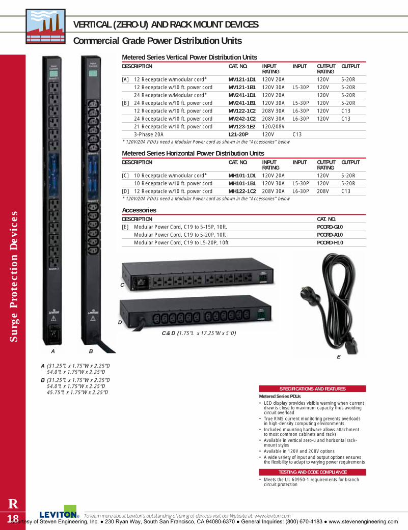
Sur
ge P
rote
ctio
n Dev
ices
R18
VERTICAL (ZERO-U) AND RACK MOUNT DEVICES
Commercial Grade Power Distribution Units
To learn more about Leviton’s outstanding offering of devices visit our Website at: www.leviton.com
Metered Series Vertical Power Distribution UnitsDESCRIPTION CAT. NO. INPUT INPUT OUTPUT OUTPUT
RATING RATING[A] 12 Receptacle w/modular cord* MV121-1D1 120V 20A 120V 5-20R
12 Receptacle w/10 ft. power cord MV121-1B1 120V 30A L5-30P 120V 5-20R24 Receptacle w/Modular cord* MV241-1D1 120V 20A 120V 5-20R
[B] 24 Receptacle w/10 ft. power cord MV241-1B1 120V 30A L5-30P 120V 5-20R12 Receptacle w/10 ft. power cord MV122-1C2 208V 30A L6-30P 120V C1324 Receptacle w/10 ft. power cord MV242-1C2 208V 30A L6-30P 120V C1321 Receptacle w/10 ft. power cord MV123-1E2 120/208V3-Phase 20A L21-20P 120V C13
* 120V/20A PDUs need a Modular Power cord as shown in the “Accessories” below
Metered Series Horizontal Power Distribution UnitsDESCRIPTION CAT. NO. INPUT INPUT OUTPUT OUTPUT
RATING RATING[C] 10 Receptacle w/modular cord* MH101-1D1 120V 20A 120V 5-20R
10 Receptacle w/10 ft. power cord MH101-1B1 120V 30A L5-30P 120V 5-20R[D] 12 Receptacle w/10 ft. power cord MH122-1C2 208V 30A L6-30P 208V C13* 120V/20A PDUs need a Modular Power cord as shown in the “Accessories” below
AccessoriesDESCRIPTION CAT. NO.[E] Modular Power Cord, C19 to 5-15P, 10ft. PCORD-G10
Modular Power Cord, C19 to 5-20P, 10ft PCORD-A10Modular Power Cord, C19 to L5-20P, 10ft PCORD-H10
SPECIFICATIONS AND FEATURES
Metered Series PDUs• LED display provides visible warning when current
draw is close to maximum capacity thus avoidingcircuit overload
• True RMS current monitoring prevents overloads in high-density computing environments
• Included mounting hardware allows attachment to most common cabinets and racks
• Available in vertical zero-u and horizontal rack-mount styles
• Available in 120V and 208V options• A wide variety of input and output options ensures
the flexibility to adapt to varying power requirements
TESTING AND CODE COMPLIANCE
• Meets the UL 60950-1 requirements for branchcircuit protection
A B
A (31.25"L x 1.75"W x 2.25"D54.0"L x 1.75"W x 2.25"D
B (31.25"L x 1.75"W x 2.25"D54.0"L x 1.75"W x 2.25"D45.75"L x 1.75"W x 2.25"D
C & D (1.75"L x 17.25"W x 5"D)
E
D
C
Courtesy of Steven Engineering, Inc. ● 230 Ryan Way, South San Francisco, CA 94080-6370 ● General Inquiries: (800) 670-4183 ● www.stevenengineering.com
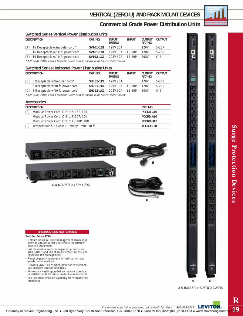
Surge P
rotection Devices
R19For answers to technical questions, call Leviton’s Techline at 1-800-824-3005
VERTICAL (ZERO-U) AND RACK MOUNT DEVICES
Commercial Grade Power Distribution Units
Switched Series Vertical Power Distribution UnitsDESCRIPTION CAT. NO. INPUT INPUT OUTPUT OUTPUT
RATING RATING[A] 16 Receptacle w/modular cord* SV161-1D1 120V 20A 120V 5-20R
16 Receptacle w/10 ft. power cord SV161-1B1 120V 30A L5-30P 120V 5-20R[B] 16 Receptacle w/10 ft. power cord SV162-1C2 208V 30A L6-30P 208V C13* 120V/20A PDUs need a Modular Power cord as shown in the “Accessories” below
Switched Series Horizontal Power Distribution UnitsDESCRIPTION CAT. NO. INPUT INPUT OUTPUT OUTPUT
RATING RATING[C] 8 Receptacle w/modular cord* SH081-1D1 120V 20A 120V 5-20R
8 Receptacle w/10 ft. power cord SH081-1B1 120V 30A L5-30P 120V 5-20R[D] 8 Receptacle w/10 ft. power cord SH082-1C2 208V 30A L6-30P 208V C13* 120V/20A PDUs need a Modular Power cord as shown in the “Accessories” below
AccessoriesDESCRIPTION CAT. NO.[E] Modular Power Cord, C19 to 5-15P, 10ft. PCORD-G10
Modular Power Cord, C19 to 5-20P, 10ft PCORD-A10Modular Power Cord, C19 to L5-20P, 10ft PCORD-H10
[F] Temperature & Relative Humidity Probe, 10 ft. TCORD-010
SPECIFICATIONS AND FEATURES
Switched Series PDUs• Remote individual outlet management allows shut
down of unused outlets and remote rebooting ofattached equipment
• Full featured network management provided viaWeb, SNMP, and Telnet allows remote access, con-figuration and management
• Power sequencing prevents in-rush current andavoids circuit overload
• Provides SNMP alerts when power or environmen-tal conditions exceed thresholds
• Firmware is easily upgraded via network downloadto installed units for future product enhancements
• External probe available separately for environmentalmonitoring A B
C
D
E
F
A & B (63.5"L x 1.75"W x 2.25"D)
C & D (1.75"L x 17"W x 7"D)
Courtesy of Steven Engineering, Inc. ● 230 Ryan Way, South San Francisco, CA 94080-6370 ● General Inquiries: (800) 670-4183 ● www.stevenengineering.com

Sur
ge P
rote
ctio
n Dev
ices
R20
METER SOCKET SURGE ADAPTER and SECONDARY SURGE ARRESTER
Residential Grade Surge Protection Devices
To learn more about Leviton’s outstanding offering of devices visit our Website at: www.leviton.com
TESTING AND CODE COMPLIANCE
• Surge arrester performance tested to IEEE C62.11(10,000 amps/4 x 10 µs), IEEE C62.11, C62.41 &C62.45 Category C Standards
• UL Listed Surge Arrester (465V Discharge voltage @ 1500 amps) (#E146315)
• CSA Certified (#LR94773)• Backed by a Limited 10-Year Warranty
MATERIAL CHARACTERISTICS
Operating Temperature: -10°C to 60°CStorage Temperature: -20°C to 85°C
SPECIFICATIONS AND FEATURES
Meter Socket Surge Adapter• Single 53mm MOV per line design (Line 1-Neutral,
Line 2-Neutral) provides a higher energy capacitythan smaller size (20mm) MOV’s
• Superior to multiple small MOV configurationswhere the protection is only as good as the weakestMOV in the chain
• Rated for 65,000 peak amps maximum surge current
• Nominal clamping voltage per line: 800V• Diagnostic LED’s: Green indicates surge protection
is active, Red indicates protection is no longeractive
• Designed for 120/240 volt single-phase ringless orring-type meters
• Rugged housing constructed of high-impact, non-conductive fiberglass-reinforced polycarbonate
• Available in popular jaw configurations, featuringspring-loaded, high-pressure copper-plated contacts for maximum conductivity
Secondary Surge Arresters• Units come with 18" pigtail leads• Constructed of high-impact, non-conductive,
fiberglass-reinforced polycarbonate• Compact design for easy installation
Ø6.
62 (
168.
2)
3.72 (4.5)
Ø6.
94 (
176.
3)
50240-MSA
3.03
(77
.0)
2.50 (63.5)1.10(27.9)
54175-SSA
3.12 (79.3)
3.12
(79
.3)
55175-ASA
Meter Socket Surge Adapter URDESCRIPTION CAT. NO. RATINGMeter Socket Surge Adapter w/LED’s Only 50240-MSA 120/240, 200A-4 JawMeter Socket Surge Adapter w/LED’s and 50240-ASA 120/240, 200A-4 JawAudible Alarm (Switchable)Meter Socket Surge Adapter w/LED’s and 50208-ASA 120/208, 200A-7 Jaw,3Ø, 4-Wire Audible Alarm (Switchable)
Secondary Surge Arresters URDESCRIPTION CAT. NO. MCOV RATINGSecondary Surge Arrester 54175-SSA 150V AC* 120/240, 200ASecondary Surge Arrester w/ LED’s 55175-ASA 180V AC 120/240, 200Aand Audible AlarmSecondary Surge Arrester 55175-SSA 180V AC 120/240, 200ASecondary Surge Arrester 55650-ASA 480V AC 277/480V AC, 480V DeltaW/LEDs and Audible Alarm 347/600V AC, 600V Delta
*MOV’s rated at 150V. UL assigns a derated MCOV of 132V for surge arrester applications
Courtesy of Steven Engineering, Inc. ● 230 Ryan Way, South San Francisco, CA 94080-6370 ● General Inquiries: (800) 670-4183 ● www.stevenengineering.com

Surge Protection Panel Performance SpecificationsUL 1449 (2nd Ed) MAX. SURGE CURRENT
CAT. NO. MCOV IMPULSE (6kV/500A) (Test w/8x20µs wave)51110-1 150 V AC L-N: 400V L-L: 800V L-N: 80kA51110-PTC 150V AC L-N: 400V L-L: 800V L-N: 80kA51110-CT8 150V AC L-N: 400V L-L: 800V L-N: 80kA51120-1 150V AC L-N: 500V L-L: 800V L-N: 50kA51120-3 150V AC L-N: 500V L-L: 800V L-N: 50kA51120-3R 180V AC L-N: 800V L-N: 50kA51120-PTC 150V AC L-N: 500V L-L: 800V L-N: 80kA
Surge P
rotection Devices
R21For answers to technical questions, call Leviton’s Techline at 1-800-824-3005
GENERAL PURPOSE PLUG-INs, SURGE PROTECTION PANELS
Residential Grade Surge Protection Devices
General Purpose Plug-In’s URDESCRIPTION CAT. NO. RATING6-Outlet Plug-in w/Power & Circuit Monitor Lights 3500-P 15A 120VUL 1449 (All Modes) 400V6-Outlet Plug-in w/two RJ11 Phone Jacks, 3500-PT 15A 120V6 ft. Phone Cord, Power & Circuit Monitor Lights UL 1449 (All Modes) 400V6-Outlet Plug-in w/two F Coax Cable Connectors, 3500-PC 15A 120V4 ft. Coax Cable Power & Circuit Monitor Lights UL 1449 (All Modes) 400V
51110 Series Residential Surge Protection Panels URDESCRIPTION CAT. NO. RATING1-Phase, 3-Wire & Ground 51110-1 120/240V ACMultimedia Panel: 1-Phase, 3-Wire & Ground with 51110-PTC 120/240V ACtwo pairs of phone/fax/modem terminals and CATV/Satellite F-ConnectorsMultimedia Panel: 1-Phase, 3-Wire & Ground with 51110-CT8 120/240V ACfour pairs of phone/fax/modem terminals and CATV/Satellite F-Connectors
51120 Series Surge Protection Panels URDESCRIPTION CAT. NO. RATING1-Phase, 3-Wire & Ground 51120-1 120/240V AC3-Phase WYE,4-Wire & Ground 51120-3 120/208V AC1-Phase, 3-Wire & Ground; 51120-3R 120/240V ACNEMA 3R Outdoor Enclosure1-Phase, 3-Wire & Ground; with RJ11Telephone 51120-PTC 120/240V ACand F-Connector CATV/Satellite Modules
SPECIFICATIONS AND FEATURES
General Purpose Plug-Ins• RFI filtering• 3-stage protection: hot-to-neutral, hot-to-ground,
neutral-to-ground• Built-in fuse protection• Monitor lights ON indicates circuit is powered
and protected51110 Series• 51110-PTC provides protection for 2 telco lines
and 2 coax feeds• 51110-CT8 provides protection for 4 telco lines
and 2 coax feeds• Compatible with Decora Home Controls (see
Section B)
51120 Series• Standard J-Box metal enclosures with pre-
punched knockouts; 51120-3R features NEMA 3Renclosure
• Compatible with Decora Home Controls (seeSection B)
TESTING AND CODE COMPLIANCE
• UL Listed 1449 Edition 2.5• Meets ANSI/IEEE C62.41 & C62.45 requirements
for Categories A, B & C• Backed by a Limited 10-Year Warranty• 51110 Series: CUL/US Certified • 51120 Series: UL Listed and CSA Certified
3500-PT
51110-PTC
7.00
(17
7.8)
7.00 (177.8) 4.06 (103.1
51120-1
Courtesy of Steven Engineering, Inc. ● 230 Ryan Way, South San Francisco, CA 94080-6370 ● General Inquiries: (800) 670-4183 ● www.stevenengineering.com

Sur
ge P
rote
ctio
n Dev
ices
R22
MODULAR SURGE PROTECTION STRIPS
Residential Grade Surge Protection Devices
To learn more about Leviton’s outstanding offering of devices visit our Website at: www.leviton.com
SPECIFICATIONS AND FEATURES
• Interchangeable modules accommodatechanging surge protection needs
• All modules easily snap in to the Cat. No.3950 Surge Module Bracket
• User-friendly design—no wiring required• Telephone/Fax/Modem Module acts as a
splitter, allowing the connection of twodevices
3950-BKT
Snap-In Surge Protection Modules
Snap-In Modules for Structured Media Enclosure Surge Module BracketLeviton’s snap-in surge protective modules provide customized surge protection for all low-voltage com-munication and data lines in the Structured Media Enclosure. All Series 5950 modules can snap-in to theCat. No. 3950-BKT Surge Module Bracket. The bracket, allows you to add and change modules to fit spe-cific protection needs. Choose from a selection of protection modules for Digital Satellite Systems, Ethernetsystems, Cable TV, Telephone/Fax/Modem and DSL/ADSL equipment. All devices attached to the modules are covered under the Leviton $50,000 Connected Equipment Warranty.
Snap-In ModulesSPECIFICATION CAT. NO.Satellite System/Cable TV Protection Module—4 Standard Beige—5951-SAF-connectors. 3-Amp fuse for over-current. Max. line voltage: 75V DC. Gray—5951-SATBreakdown Voltage Range: 70.4-110 Volts/Sec Ice—5951-SACEthernet Protection Module (10 Base-T Applications)—Two RJ45 Beige—5952-ETconnectors to protect two pair of transmit/receive lines. 10-Amp automatic Gray—5952-ETHResettable PTC fuses. Max. operating voltage: 16.6V DC. Ice—5952-ETCBreakdown Voltage Range: 2.62-19.2 Volts/SecCable TV System Protection Module—Two Standard F-type connectors. Beige—5953-PC3-Amp fuse for over-current. Max. line voltage: 75V DC. Gray—5953-PCGBreakdown Voltage Range: 70.4-110 Volts/Sec Ice—5953-PCCTelephone/Fax/Modem Protection Module–Three RJ11, 4-wire/2-pair Beige—5954-AT4connectors. 3-Position splitter allows for connection to a common line. Gray—5954-PT43-Amp fuse for over-current protection. Max. operating voltage: 150V rms Ice—5954-CT4(including ring voltage). Breakdown Voltage Range: 162-331 Volts/SecDSL/ADSL Subscriber Equipment Protection Module–Three RJ11, Beige—5955-DT4-wire/2pair connectors. 3-Amp fuse for over-current protection. Gray—5955-DTGMax. operating voltage: 150V rms (including ring voltage). Ice—5955-DTCBreakdown Voltage Range: 162-331 Volts/SecCat. 5 Ethernet Module Beige—5957-OCSTwo RJ45 Connectors with Ground Pin for Ethernet - Cat. 5 Grey—5957-C5GTwo Line Telephone Module Beige—5958-AT4One Input, One Output RJ11 Connector for 4-Wire POTS Grey—5958-PT4Four Line Telephone Module Beige—5959-BT8One Input, One Outpupt RJ45 Connector for 8-Wire POTS Grey—5959-GT8Surge Module Bracket 3950-BKT
TESTING AND CODE COMPLIANCE
CAT. NO. MCOV (VDC) CLAMPING TESTED TO MEET STANDARDSVOLTAGE (VDC)
5951 60 388 UL 452 ANSI/IEEE5952 16.6 23 UL497B C-62.365953 60 388 UL4525954 288 715 UL497A CSA5955 205 210 UL497A (#LR-94773)5957 16.6 23 UL497B5958 288 715 UL497A5959 288 715 UL497A
Courtesy of Steven Engineering, Inc. ● 230 Ryan Way, South San Francisco, CA 94080-6370 ● General Inquiries: (800) 670-4183 ● www.stevenengineering.com

Surge P
rotection Devices
R23For answers to technical questions, call Leviton’s Techline at 1-800-824-3005
POWER QUALITY
Commercial Grade Uninterruptible Power Supplies (UPS’s)
SPECIFICATIONS AND FEATURES
Sine Series Uniterruptible Power Supply• Line-Interactive technology provides rapid transfer
time (<4ms) and voltage regulation for minor sagsand swells
• True sine-wave output less than 3% THD • Selectable output voltage: 100V, 110V, 115V, 120V,
or 127V• Advanced Battery Management (ABM) extends
battery life by up to 50%• Included UPSMON software provides monitoring
and control capability• Energy-saving sleep mode reduces power
consumption• AC Surge Protection and Noise Filtering• User-replaceable, sealed, maintenance-free lead
acid batteries
On-Line Series Uniterruptible Power Supply• On-Line Double Conversion technology with zero
transfer time• Provides true sine-wave output at less than 3% THD • LED Display gives "Minutes Remaining" indicator
based on actual load • Selectable output voltage: 100V, 110V, 115V, 120V
or 127V• Advanced Battery Management (ABM) extends
battery life by up to 50%• Optional Extended Battery Packs provide additional
back up time • Included UPSMON software provides monitoring
and control capability• Energy-saving sleep mode reduces power
consumption• AC Surge Protection and Noise Filtering
• User-replaceable, sealed, maintenance-free leadacid batteries
• Includes interface for Emergency Power Off (EPO)
TESTING AND CODE COMPLIANCE
Sine Series Uniterruptible Power Supply• UL 1778 & cUL Listed• FCC compliant• ISO 9001 Certified• 2-Year Limited Product Warranty (covers parts,
labor, and battery)• 2-Year Limited Connected-Equipment WarrantyOn-Line Series Uniterruptible Power Supply• UL 1778 & cUL Listed• 2-Year Limited Product Warranty (covers parts,
labor, and battery)• 2-Year Limited Connected-Equipment Warranty
Sine Series Uninterruptible Power Supply (UPS’s) URDESCRIPTION OUTPUT FOOTPRINT OUTLET TYPICAL CAT. NO.
CAPACITY QTY & BACK-UP TIMETYPE FULL LOAD HALF LOAD
Line-Interactive, 800VA/560W Tower (4) 5-15R 5 Min 14 Min U0800-SKTrue Sine WaveLine-Interactive, 1000VA/700W Tower (4) 5-15R 5 Min 14 Min U1000-SKTrue Sine WaveLine-Interactive, 1500VA/1050W Tower (6) 5-15R 5 Min 19 Min U1500-SKTrue Sine WaveLine-Interactive, 2000VA/1400W Tower (6) 5-15R 10 Min 47 Min U2000-SKTrue Sine WaveLine-Interactive, 3000VA/2100W Tower (6) 5-15R 10 Min 47 Min U3000-SKTrue Sine WaveLine-Interactive, 800VA/560W Rack-mount, 2U (4) 5-15R 10 Min 20 Min U0800-SRMTrue Sine WaveLine-Interactive, 1500VA/1050W Rack-mount, 2U (4) 5-15R 5 Min 19 Min U1500-SRMTrue Sine WaveLine-Interactive, 3000VA/2100W Rack-mount, 2U (6) 5-15R 10 Min 47 Min U3000-SRMTrue Sine Wave
On-Line Series Uninterruptible Power Supply (UPS’s) URDESCRIPTION OUTPUT FOOTPRINT OUTLET TYPICAL CAT. NO.
CAPACITY QTY & BACK-UP TIMETYPE FULL LOAD HALF LOAD
On-Line, 700VA / 490W Tower (6) 5-15R 7 Min 15 Min U0700-VNLPure Sine WaveOn-Line, 1000VA / 700W Tower (6) 5-15R 7 Min 15 Min U1000-VNLPure Sine WaveOn-Line, 1500VA / 1050W Tower (6) 5-15R 7 Min 11 Min U1500-VNLPure Sine WaveOn-Line, 2000VA / 1400W Tower (6) 5-15R 7 Min 15 Min U2000-VNLPure Sine WaveOn-Line, 3000VA / 2100W Tower (6) 5-15R 6 Min 15 Min U3000-VNLPure Sine WaveOn-Line, 700VA / 490W Rack-mount, 2U (6) 5-15R 7 Min 15 Min U0700-VRMPure Sine WaveOn-Line, 1000VA / 700W Rack-mount, 2U (6) 5-15R 7 Min 15 Min U1000-VRMPure Sine WaveOn-Line, 1500VA / 1050W Rack-mount, 2U (6) 5-15R 7 Min 11 Min U1500-VRMPure Sine WaveOn-Line, 2000VA / 1400W Rack-mount, 2U (6) 5-15R 7 Min 15 Min U2000-VRMPure Sine WaveOn-Line, 3000VA / 2100W Rack-mount, 2U (6) 5-15R 6 Min 15 Min U3000-VRMPure Sine WaveOn-Line, 1000VA / 700W Rack-mount, 1U (6) 5-15R 5 Min 11 Min U1000-DRMPure Sine Wave
Uninterruptible Power Supplies (UPS’s)Leviton’s UPS product line offers the latest technology and features available to help prevent losses and costlydowntime associated with outages, sags and blackouts for computers, data and telecom and other sensitive loads.
U3000-VRM
U3000-VNL
8.30
(21
0.8)
6.70 (170.2)
17.20(436.9)
U1500-SK
Courtesy of Steven Engineering, Inc. ● 230 Ryan Way, South San Francisco, CA 94080-6370 ● General Inquiries: (800) 670-4183 ● www.stevenengineering.com

Sur
ge P
rote
ctio
n Dev
ices
R24
POWER QUALITY
Commercial Grade Uninterruptible Power Supplies (UPS’s)
To learn more about Leviton’s outstanding offering of devices visit our Website at: www.leviton.com
SPECIFICATIONS AND FEATURES
• Line-Interactive technology provides rapid transfertime (<4ms) and voltage regulation for minor sagsand swells
• Simulated sine-wave output• Selectable output voltage: 100V, 110V, 115V, 120V
or 127V• Advanced Battery Management (ABM) extends
battery life by up to 50%• Included UPSMON software provides monitoring
and control capability• Energy-saving sleep mode reduces power con-
sumption• AC Surge Protection and Noise Filtering• User-replaceable, sealed, maintenance-free lead
acid batteries
TESTING AND CODE COMPLIANCE
• UL 1778 & cUL Listed• FCC compliant• ISO 9001 Certified• 2-Year Limited Product Warranty (covers parts,
labor, and battery)• 2-Year Limited Connected-Equipment Warranty
Pro, Slim and Strip Series Uninterruptible Power Supplies (UPS’s) URDESCRIPTION OUTPUT FOOTPRINT OUTLET TYPICAL CAT. NO.
CAPACITY QTY & BACK-UP TIMETYPE FULL LOAD HALF LOAD
Line-Interactive, 425VA / 297W Tower (6) 5-15R 4 Min 17 Min U0425-AKPSimulated Sine WaveLine-Interactive, 625VA / 437W Tower (6) 5-15R 4 Min 11 Min U0625-AKPSimulated Sine WaveLine-Interactive, 825VA / 578W Tower (6) 5-15R 6 Min 20 Min U0825-AKPSimulated Sine WaveLine-Interactive, 1000VA / 700W Tower (5) 5-15R 4 Min 13 Min U1000-AKPSimulated Sine WaveLine-Interactive, 1500VA / 1050W Tower (6) 5-15R 5 Min 18 Min U1500-AKPSimulated Sine WaveLine-Interactive, 2200VA / 1540W Tower (6) 5-15R 5 Min 22 Min U2200-AKPSimulated Sine WaveLine-Interactive, 500VA / 350W Desktop (5) 5-15R 5 Min 20 Min U0500-AKPSimulated Sine WaveLine-Interactive, 600VA / 420W Rack-mount, 1U (5) 5-15R 7 Min 22 Min U0600-ARMSimulated Sine Wave
8.40
(21
3.4)
6.70 (170.2)
17.60 (447.0)
U2200-AKP
1.80
(44.
1)
16.60 (357.7)13.60(135.4)
U0500-AKP
19.00 (482.6)
1.70(43.2)
14.3(363.2)
U0600-AKP Face
U0600-AKP Back
U0625-AKP Face
U0625-AKP Back
Courtesy of Steven Engineering, Inc. ● 230 Ryan Way, South San Francisco, CA 94080-6370 ● General Inquiries: (800) 670-4183 ● www.stevenengineering.com

Lampholders Index
INDEXOverview . . . . . . . . . . . . . . . . . . . . . . . . . . . . . .S2Incandescent LampholdersOutlet Box, Keyless and Pull Chain . . . . . . . .S3, S4Metal Shell and Interiors . . . . . . . . . . . . . . . . . . .S5Phenolic Cap and Shell . . . . . . . . . . . . . . . . . . . .S5Multi-Lampholder Clusters . . . . . . . . . . . . . . . . .S6Porcelain Par Connectors . . . . . . . . . . . . . . . . . .S6Bayonet Socket–Single Contact . . . . . . . . . . . . . .S6Porcelain Mogul Base . . . . . . . . . . . . . . . . . . . .S7Socket Extensions . . . . . . . . . . . . . . . . . . . . . . . .S8Appliance Heating Receptacle . . . . . . . . . . . . . .S8Porcelain and Phenolic . . . . . . . . . . . . . . . . . . . .S8Porcelain Snap-In . . . . . . . . . . . . . . . . . . . . . . . .S9Porcelain Keyless–Commercial Units . . . . . . . . . .S9Porcelain Keyless Fixture Single Circuit-Medium Base . . . . . . . . . . . . . . . .S9Porcelain Keyless Medium Base–Side Angle Mounted . . . . . . . . . . . . . . . . . . . . .S10Phenolic Keyless Fixture–Medium Base . . . . . .S10Lampholders for Recessed Single Contact Lamps . . . . . . . . . . . . . . . . . . . . . . . . .S10Lampholders for Metal Halide and Quartz Halogen Lamps . . . . . . . . . . . . . . . . . . .S10Candle Sockets . . . . . . . . . . . . . . . . . . . .S10–S12Fluorescent LampholdersCompact Fluorescent Ceiling Lampholder . . . . . .S4Linear Fluorescent . . . . . . . . . . . . . . . . . .S13–S17
Medium Bi-Pin . . . . . . . . . . . . . . . . . . .S13–S15High Output . . . . . . . . . . . . . . . . . . . . .S13, S14Slimline . . . . . . . . . . . . . . . . . . . . . . . . .S13, S14Miniature . . . . . . . . . . . . . . . . . . . . . . . . . . .S16T-8 to T-5 Adapter . . . . . . . . . . . . . . . . . . . . .S16
4-Pin Long Twin Tube with 2G11 Base . . . . . . .S17Lamp Support Clips for Long Twin Tube . . . . . . .S18Compact Fluorescent Lampholders (CFL’s) . . . . . . . . . . . . . . . . .S19–S22For a complete listing of OEM products, see the OEM-100 Catalog.
SECTIONSLampholders
Courtesy of Steven Engineering, Inc. ● 230 Ryan Way, South San Francisco, CA 94080-6370 ● General Inquiries: (800) 670-4183 ● www.stevenengineering.com

LAMPHOLDERS
To learn more about Leviton’s outstanding offering of devices visit our Website at: www.leviton.com
Lam
phol
ders
S2
A VARIETY OF INCANDESCENT AND FLUORESCENT STYLES IN A RANGE OF RATINGS AND MATERIALSLeviton offers a complete selection of outlet box, incandescent, fluorescent and specialty lampholders, in various ratings andmaterials. The following pages offer a variety of types and styles.
OUTLET BOX LAMPHOLDERAvailable in keyless, pull chain andoutlet models, all featuring easytwist-lock mounting.Cat. No. 8827-CW4 shown
PORCELAIN MEDIUM BASELAMPHOLDER With a choice of mounting andwiring options, these lampholdersare ideal for a wide range of commercial and residentialincandescent fixtures. Cat. No. 8101 shown
CANDELABRA BASE LAMPHOLDER Keyless lampholders for chandeliersand other fixtures, featuring varioushickeys or double snap-in spring clips. Cat. No. 10014-800 shown
FLUORESCENT LAMPHOLDER FORMEDIUM BI-PIN LAMPSFeatures Lamp-Lock design for quickrelamping. Models dedicated forenergy-efficient T-8 lamps available.Cat. No. 13653-WP shown
COMPACT FLUORESCENTLAMPHOLDERS Available for all popular 2-pin and4-pin lamp bases, with a variety ofmounting options. Color-coded foreasy wattage identification.Cat. No. 26725-426 shown
PORCELAIN MOGUL BASELAMPHOLDER A complete selection of high-quality porcelain moguls withleads or screw terminals.Pulse-rated models available.Cat. No. 8756 shown
METAL SHELL LAMPHOLDERMedium base, electrolier lampholdersavailable in a variety of attractive finishes.Cat. No. 9346-PG shown
LONG TWIN-TUBE 2G11 BASE LAMPHOLDERSChoice of mounting and wiringoptions to reduce fixtureassembly time.Cat. No. 13453 shown
Courtesy of Steven Engineering, Inc. ● 230 Ryan Way, South San Francisco, CA 94080-6370 ● General Inquiries: (800) 670-4183 ● www.stevenengineering.com

Ø 1.63 (41.3)
1.52
(38
.5)
Ø 4.50 (114.3)
9875-2
Ø 1.33 (33.9)
2.01
(50
.9)
Ø 4.56 (115.9)
8827-CW2
Incandescent Lampholders
S3For answers to technical questions, call Leviton’s Techline at 1-800-824-3005
660W 600V • 660W 250V
Medium Base Incandescent Lampholders
SPECIFICATIONS AND FEATURES
• Twist-lock mounting• Pull chain models have bell at end of chain on
3 foot cord• Medium base
TESTING AND CODE COMPLIANCE
• UL Listed (File #E-3810)• CSA Certified (File #LR-1863)
Outlet Box Lampholders660 WATT 600V One-Piece Keyless Top Wired URDESCRIPTION/ WHITE UREA OD FITS BOX SIZETERMINALS CAT. NO.2 Terminal Screws 8829-CW1 41⁄2" 31⁄4" or 4"6" Pigtail Leads 8829-CW2 41⁄2" 31⁄4" or 4"4 Terminal Screws 8829-CW4 41⁄2" 31⁄4" or 4"
660 WATT 250V One-Piece Pull Chain Top Wired URDESCRIPTION/ WHITE UREA OD FITS BOX SIZETERMINALS CAT. NO.2 Terminal Screws 8827-CW1 41⁄2" 31⁄4" or 4"6" Pigtail Leads 8827-CW2 41⁄2" 31⁄4" or 4"2 Terminal Screws 8827-CW4 41⁄2" 31⁄4" or 4"with Captive Clamps
660 WATT 250V One-Piece Keyless Top Wired URDESCRIPTION/ PORCELAIN OD FITS BOX SIZETERMINALS CAT. NO.2 Screws� 9874 33⁄4" 31⁄4"2 Screws, no cage lip 9875 41⁄2" 31⁄4" or 4"6" Pigtail Leads, no cage lip 9875-2 41⁄2" 31⁄4" or 4"4 Screws 49875 41⁄2" 31⁄4" or 4"4 Quickwire Push-In� 9883 41⁄2" 31⁄4" or 4"
660 WATT 250V One-Piece Pull Chain Top Wired URDESCRIPTION/ PORCELAIN OD FITS BOX SIZETERMINALS CAT. NO.2 Screws 29816-C 41⁄2" 31⁄4" or 4"6" Pigtail Leads 29816-C2 41⁄2" 31⁄4" or 4"2 Screws w/Captive Clamps 49816-C 41⁄2" 31⁄4" or 4"for 4-Wire TerminalsInterior Mechanism for 29816-CM*2-Piece Outlet Box Lampholders�
*When existing stock is depleted, this item will be DISCONTINUED.CSA Certified except where indicated by�
Ø 1.74 (44.2)
2.01
(50
.9)
Ø 4.50 (115.3)
29816-C
Courtesy of Steven Engineering, Inc. ● 230 Ryan Way, South San Francisco, CA 94080-6370 ● General Inquiries: (800) 670-4183 ● www.stevenengineering.com

2.50
(63
.5)
Ø 4.56 (115.9)
9726-C
9860
2.50
(63
.5)
Ø 4.56 (115.9)
9716-C
Inca
ndes
cent
and
Flu
ores
cent
Lam
phol
ders
S4
660W 125V — 15 AMP-125V • 120W 250V
Medium Base Incandescent and GU24 Base Fluorescent Lampholders
To learn more about Leviton’s outstanding offering of devices visit our Website at: www.leviton.com
SPECIFICATIONS AND FEATURES
Outlet Box Incandescent Lampholders• 2-Pole, 2-Wire Outlet; 2-Pole, 3-Wire Outlet• Twist-lock mounting• Pull chain models have bell at end of chain on
3 foot cordFluorescent Ceiling Lampholder*• Installs indoors in closets, garages, basements,
utility rooms and attics• Reduces risk of fire in closets and closed spaces• Built of tough thermoplastic• Use with a standard wall switch• Pigtail leads provide easy installation
• Knockout holes on box enable multiple configurations
* Patent pending
TESTING AND CODE COMPLIANCE
Outlet Box Incandescent Lampholders• UL Listed (File #E-3810; E-7516)• CSA Certified (File #LR-1863)Fluorescent Ceiling Lampholder• cULus Listed• Meets NFPA 70, NEC Section 410.8B Requirements
and Canadian Electric Code Requirements for usein closets with lamp guard
• Backed by a Limited Two-Year Warranty
Outlet Box Lampholders660 WATT 125V Lampholder Outlet 15 AMP-125V One-Piece Pull Chain Side WiredUDESCRIPTION/ PORCELAIN OD FITS BOX SIZE NEMA CONFIG.TERMINALS2 Screws� 9716-C 41⁄2" 31⁄4" or 4"
660 WATT 125V Lampholder Outlet 15 AMP-125V One-Piece Pull Chain Top WiredURDESCRIPTION/ PORCELAIN OD FITS BOX SIZE NEMA CONFIG.TERMINALS2 Screws 9726-C 41⁄2" 31⁄4" or 4"
Ball and Chain AccessoriesDESCRIPTION BRASS FINISH NICKEL FINISHNo. 6 Chain; 1⁄8" Dia. Balls 18302-1 18302-1N
Connector for No. 6 Chain 9820 9820-N
Chain, 3 feet long, End Bell and 6 6-NConnector; use as extension or replacement; 1⁄25" Dia. Balls
DESCRIPTION BROWN WHITEInsulating Link; Thermoplastic 9839 9839-I13⁄4" Total Length
CSA Certified except where indicated by�
GU24 Base Fluorescent LampholderEnergy-Saving Keyless Bi-Pin Compact Fluorescent Ceiling Lampholder for Closets and Closed Spaces 120 WATT 250V AC DESCRIPTION CAT. NO.Lampholder with pigtail leads and knockout holes for multiple configurations 9860Lampholder with pigtail leads and knockout holes for multiple configurations; 9860-Bwith 13W BulbLampholder with pigtail leads and knockout holes for multiple configurations; 9860-BLwith 13W Bulb and Lamp GuardLamp Guard 9860-L13W Replacement Lamp 9865
Note: Not intended for use with incandescent lamps, dimmers or occupancy sensors.
5-15RG
W
1-15R W
18302-1N
9820
6
9839-I
Courtesy of Steven Engineering, Inc. ● 230 Ryan Way, South San Francisco, CA 94080-6370 ● General Inquiries: (800) 670-4183 ● www.stevenengineering.com
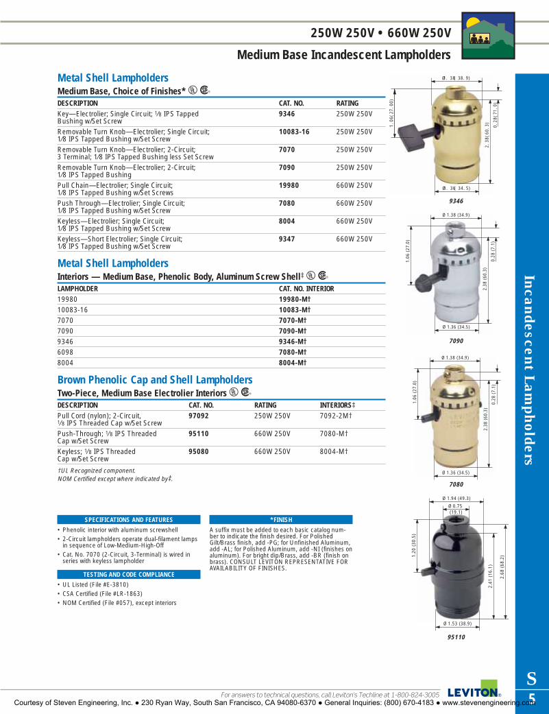
Ø 0.75 (19.1)
Ø 1.94 (49.3)
1.20
(30
.5)
2.68
(68
.2)
2.41
(16
.1)
Ø 1.53 (38.9)
95110
Ø 1.36 (34.5)
Ø 1.38 (34.9)
1.06
(27
.0)
0.28
(7.
1)
2.38
(60
.3)
7080
Ø 1. 38 ( 38. 9)
Ø 1. 36 ( 34. 5)
2.38
(60.
3)1.06
(27.
00)
0.28
(71.
0)
9346
Incandescent Lampholders
S5For answers to technical questions, call Leviton’s Techline at 1-800-824-3005
250W 250V • 660W 250V
Medium Base Incandescent Lampholders
SPECIFICATIONS AND FEATURES
• Phenolic interior with aluminum screwshell• 2-Circuit lampholders operate dual-filament lamps
in sequence of Low-Medium-High-Off• Cat. No. 7070 (2-Circuit, 3-Terminal) is wired in
series with keyless lampholder
TESTING AND CODE COMPLIANCE
• UL Listed (File #E-3810)• CSA Certified (File #LR-1863)• NOM Certified (File #057), except interiors
*FINISH
A suffix must be added to each basic catalog num-ber to indicate the finish desired. For PolishedGilt/Brass finish, add -PG; for Unfinished Aluminum,add -AL; for Polished Aluminum, add -NI (finishes onaluminum). For bright dip/Brass, add -BR (finish onbrass). CONSULT LEVITON REPRESENTATIVE FORAVAILABILITY OF FINISHES.
Metal Shell LampholdersMedium Base, Choice of Finishes* URDESCRIPTION CAT. NO. RATINGKey—Electrolier; Single Circuit; 1⁄8 IPS Tapped 9346 250W 250VBushing w/Set ScrewRemovable Turn Knob—Electrolier; Single Circuit; 10083-16 250W 250V1⁄8 IPS Tapped Bushing w/Set ScrewRemovable Turn Knob—Electrolier; 2-Circuit; 7070 250W 250V3 Terminal; 1⁄8 IPS Tapped Bushing less Set ScrewRemovable Turn Knob—Electrolier; 2-Circuit; 7090 250W 250V1⁄8 IPS Tapped BushingPull Chain—Electrolier; Single Circuit; 19980 660W 250V1⁄8 IPS Tapped Bushing w/Set ScrewsPush Through—Electrolier; Single Circuit; 7080 660W 250V1⁄8 IPS Tapped Bushing w/Set ScrewKeyless—Electrolier; Single Circuit; 8004 660W 250V1⁄8 IPS Tapped Bushing w/Set ScrewKeyless—Short Electrolier; Single Circuit; 9347 660W 250V1⁄8 IPS Tapped Bushing w/Set Screw
Metal Shell LampholdersInteriors — Medium Base, Phenolic Body, Aluminum Screw Shell‡URLAMPHOLDER CAT. NO. INTERIOR19980 19980-M†10083-16 10083-M†7070 7070-M†7090 7090-M†9346 9346-M†6098 7080-M†8004 8004-M†
Brown Phenolic Cap and Shell LampholdersTwo-Piece, Medium Base Electrolier Interiors URDESCRIPTION CAT. NO. RATING INTERIORS‡Pull Cord (nylon); 2-Circuit, 97092 250W 250V 7092-2M†1⁄8 IPS Threaded Cap w/Set ScrewPush-Through; 1⁄8 IPS Threaded 95110 660W 250V 7080-M†Cap w/Set ScrewKeyless; 1⁄8 IPS Threaded 95080 660W 250V 8004-M†Cap w/Set Screw
†UL Recognized component.NOM Certified except where indicated by‡.
2.38
(60
.3)
1.06
(27
.0)
Ø 1.38 (34.9)
Ø 1.36 (34.5)
0.28
(7.
1)
7090
Courtesy of Steven Engineering, Inc. ● 230 Ryan Way, South San Francisco, CA 94080-6370 ● General Inquiries: (800) 670-4183 ● www.stevenengineering.com

Inca
ndes
cent
Lam
phol
ders
S6
660W 250V
Medium, Candelabra Base, Par Connectors—Incandescent Lampholders
To learn more about Leviton’s outstanding offering of devices visit our Website at: www.leviton.com
SPECIFICATIONS AND FEATURES
• Pull chain models have bell at end of chain on 3 foot cord
• Medium and Candelabra bases• Par connectors have white, unglazed porcelain
body
TESTING AND CODE COMPLIANCE
• UL Listed (File #E-13405, E-3810)• CSA Certified (File #LR-5863, LR-1863)• NOM Certified (File #057)
Medium Base Multi-Lampholder ClustersTreated Aluminum Screw Shell URDESCRIPTION CAT. NO. RATING T TA B BA OAH T+B2-Light Twin 1⁄8 IPS 4020-A3A 660W 250V 15⁄16 5⁄16 — — —Male Top Bracket Only2-Light Twin 1⁄8 IPS 4015-D4F 660W 250V 111⁄16 5⁄16 111⁄16 7⁄16 33⁄8Male (top & bottom)2-Light Offset 1⁄8 IPS 4032-E5F 660W 250V 13⁄4 5⁄16 13⁄4 7⁄16 311⁄16Male (top & bottom)3-Light 1⁄8 IPS Male 341-D4U 660W 250V 13⁄4 1⁄2 13⁄4 7⁄16 31⁄2(top & bottom)‡2-Light Offset 1⁄8 IPS 4034-F5A 660W 250V 13⁄4 5⁄16 115⁄16 1⁄2 33⁄4+Male (top); Pullchain 1A 125V TSwitch (bottom) with1⁄2" usable shank�
2-Light Twin 1⁄8 IPS 4017-D2F 660W 250V 11⁄16 5⁄16 111⁄16 3⁄8 213⁄16+Male (top); Pullchain 1A 125V TSwitch (bottom)3⁄8" usable shank�
+Includes nut.Leads are No. 18 AWG 105°C plastic; 9" long, stripped 3⁄4"; untinned and pulled through top bracket.
Porcelain Par ConnectorsURDESCRIPTION CAT. NO. RATINGMedium Base for PAR #46 and #38 lamps. Leads 368-1 660W 125Vare No. 14 AWG 200°C SEW-2 Silicone Rubber Insulated; 18" Long, Stripped 3⁄4". Others available on inquiry‡Mogul Base for PAR #56 and #64 lamps. Leads are 357-8 1000W 125VNo. 14 150°C SEWF-2; 18" Long, Stripped 3⁄4". Others available upon request
Bayonet Socket — Single ContactCandelabra BaseDESCRIPTION CAT. NO. RATINGFlat Bracket. Leads are No. 18 AWG, 105°C Plastic; 905 Low Voltage6" Long, Stripped 3⁄4" (one black, one white)�‡
All devices are UL Listed except Cat. No. 905. Also CSA Certified except where indicated by�, and NOM Certified exceptwhere indicated by‡.
4017-D2F
1.69 (42.8) 1.81 (46.0)
0.31 (7.9) 0.38 (9.5)
BLACK
WHITE
TA
T B
BA
1.75 (44.5) 1.94 (49.2)
0.31 (7.9) 0.50 (12.7)
BLACK
WHITE
TA
T B
BA
4034-F5A
1.75 (44.5) 1.75 (44.5)
0.44 (11.1) 0.31 (7.9)
BLACK
WHITE
BA
B T
TA
4032-E5F
4034-F5A
341-D4U
4032-E5F
Courtesy of Steven Engineering, Inc. ● 230 Ryan Way, South San Francisco, CA 94080-6370 ● General Inquiries: (800) 670-4183 ● www.stevenengineering.com

1.63
(41
.3)
0.56
(14.
3)
1.75 (44.5)
1.38 (34.9)
1.63 (41.3)
2.25 (57.2)
8806
Ø 2.16 (54.8)
2.61
(66
.3)
8694
2.61
(66
.3)
Ø 2.16 (54.8)
8750
Ø 2.13 (54.0)
3.02
(76
.6)
8746
Incandescent Lampholders
S7For answers to technical questions, call Leviton’s Techline at 1-800-824-3005
1500W 600V • 660W 1000V
Mogul Base Incandescent Lampholders
SPECIFICATIONS AND FEATURES
• Cat. No. 8746 – Porcelain body gray glazed withceramic arc shield; Cat. No. 8750 – Porcelainbody yellow glazed; Cat. No. 8751 – Porcelainbody pink glazed
• All other moguls listed have white glazed porcelain body
• Copper-alloy nickel-plated screw shell
TESTING AND CODE COMPLIANCE
• UL Listed (File #E-13402)• CSA Certified (File #LR-1863)• NOM Certified (File #057)• Cat. No. 8751 complies with NFPA 70-2005
requirements for open-rated fixtures
Porcelain Mogul Base LampholdersWith Leads* URDESCRIPTION CAT. NO. RATING OD OHKeyless, Single Circuit. For high pressure 8746 1500W 600V 21⁄8 31⁄64sodium lamps up to 1000 watts. 5KV Pulse-rated8-32 Mounting Screws on 13⁄8" CentersKeyless, Single Circuit. Positon-oriented. 8750 1500W 600V 25⁄32 239⁄64For Super Metalarc HID lamps. 8-32 Mounting Screws on 13⁄8" CentersKeyless, Single Circuit. For high-pressure 8756 1500W 600V 25⁄32 239⁄64sodium lamps up to 400 watts. 4KV Pulse-rated8-32 Mounting Screws on 13⁄8" CentersLow Pressure Sodium. For use with all 8806 660W 1000V 13⁄8 15⁄8single-end bayonet base low pressure sodium lamps�‡Designed for Open-Fixture Shielded Metal 8751 1500W 600V, 25⁄32 239⁄64Halide Lamps. Complies with NFPA 70-2005 4KV Pulse Ratedfor Open-Rated Fixtures. 8-32 Mounting Screws on 13⁄8" Centers
*Leads types, lengths and ratings vary with the end use applications. Standard leads as well as variations available on inquiry.
Screw Terminals URDESCRIPTION CAT. NO. RATING OD OHKeyless; 2-Piece; Single-Pole� 8765 1500W 600V 25⁄16 223⁄64
Keyless;. Single Circuit with 8-32 8694 1500W 600V 25⁄32 239⁄64Lock Nuts on 13⁄8" Centers.Die-cast caps available upon request
CSA Certified except where indicated by�, and NOM Certified except where indicated by‡.
Courtesy of Steven Engineering, Inc. ● 230 Ryan Way, South San Francisco, CA 94080-6370 ● General Inquiries: (800) 670-4183 ● www.stevenengineering.com

Ø 2.31 (58.7)
1.53
(38
.9)
0.77
(19
.4)
Ø 2.19 (55.6)
9880
1.69
(42
.9)
1.94 (49.3)
1.94 (49.3)
19062
2.19
(55
.5)
Ø 1.63 (41.3)
1.00
(25
.4)
2005
Inca
ndes
cent
Lam
phol
ders
S8
660W 250V • 1500W 600V
Medium, Mogul and Candelabra Base Incandescent Lampholders
To learn more about Leviton’s outstanding offering of devices visit our Website at: www.leviton.com
Socket Extensions — Single CircuitMedium–Medium URDESCRIPTION CAT. NO. RATING2-Piece Porcelain; Mounting Hole 13⁄8" Dia. 2004 660W 250VExtension 11⁄4"*1-Piece Porcelain; Slotted Mounting Hole 13⁄8" Dia. 2005 660W 250VExtension 11⁄4"*1-Piece Phenolic. Extension 13⁄16"** 2006 660W 250V
*To be used with porcelain sockets only**To be used with phenolic sockets only
Mogul–Mogul URDESCRIPTION CAT. NO. RATING1-Piece Porcelain. Extension 23⁄8"‡ 8647 1500W 600V
Socket AdapterMogul-To-Porcelain Medium URDESCRIPTION CAT. NO. RATING1-piece. Meets Fed. Spec. W-L-142a‡ 8681 660W 250VSame as above, except 4 KV Pulse-Rated‡ 8681-400 660W 250V
4 KV Pulse-Rated
Appliance Heating ReceptaclePorcelain Two-Piece URDESCRIPTION CAT. NO. RATING2-piece Heating Receptacle. Gasket Furnished‡ 8110 660W 250V
Porcelain and Phenolic LampholdersPony Cleat Type URDESCRIPTION CAT. NO. RATING OD OH CCandelabra Base; Plastic. 10028 75W 125V 17⁄16 7⁄8 11⁄8Not UL Listed�‡Miniature Base, Plastic. 10020 75W 125V 15⁄16 7⁄8 31⁄32Not UL Listed�‡Medium Base, Phenolic 9063 660W 250V 17⁄8 11⁄2 115⁄16
Medium Base, Porcelain 19062 660W 250V 17⁄8 11⁄2 115⁄16
Surface Type URDESCRIPTION CAT. NO. RATING OD OH CMedium Base; Porcelain; 9880 660W 250V 25⁄16 11⁄2 13⁄8Low 2-PieceMedium Base; Porcelain; 9882 660W 250V 25⁄16 17⁄8 13⁄8High 2-Piece�‡CSA Certified except where indicated by�, and NOM Certified except where indicated by‡.
SPECIFICATIONS AND FEATURES
• Medium-to-Medium Extenders available in phenolic and porcelain
• Pony Cleat Receptacles have open wiring terminals• Two-piece surface-type lampholders have con-
cealed wiring terminals with wireways for top andcontinuous wiring
TESTING AND CODE COMPLIANCE
• UL Listed (File #E-3810; E-13396)• CSA Certified (File #LR-1863)• NOM Certified (File #057)
Courtesy of Steven Engineering, Inc. ● 230 Ryan Way, South San Francisco, CA 94080-6370 ● General Inquiries: (800) 670-4183 ● www.stevenengineering.com

1.47
(37
.3)
Ø 1.75 (44.4)
8101
1.52
(38
.5)
Ø 1.38 (34.9)
1.88
(47
.8)
3152
1.69
(42
.9)
0.16
(4.
0)
Ø 1.50 (38.1)
Ø 0.84 (21.4)
10085
Ø 1.69 (42.9)
Ø 1.36 (34.5)
1.64
(41
.6)
8880
Incandescent Lampholders
S9For answers to technical questions, call Leviton’s Techline at 1-800-824-3005
660W 250V • 250W 250V
Medium Base Incandescent Lampholders
SPECIFICATIONS AND FEATURES
• Suitable for a wide variety of fixtures, signs anddisplays
• Unglazed base and ring on two-piece lampholders
• Gasket supplied with two-piece ring type rated at90°C dry maximum
TESTING AND CODE COMPLIANCE
• UL Listed (File #E-3810)• CSA Certified (File #LR-1863)• NOM Certified (File #057)
Porcelain Snap-In Lampholders — Medium BaseScrew Terminals URDESCRIPTION CAT. NO. RATING OD OH1-Piece, Front Mounted. 1⁄4" Shoulder. 8880 660W 250V 111⁄16 11⁄2Panel Thickness: .025 –.062"1-Piece, Front Mounted. Shallow Back. 8875 660W 250V 111⁄16 111⁄16Panel Thickness: .030 –.062"
Porcelain Keyless Lampholders Commercial Units — Medium BaseSingle Circuit Screw Terminals URDESCRIPTION CAT. NO. RATING OD OHStraight Body with Cap. Screw Terminals. 10045 660W 250V 11⁄2 21⁄8Beaded Body for 11⁄2" Clamp Style 10065 660W 250V Body 11⁄2 21⁄8Shadeholder with Cap. Screw Terminals. Bead 15⁄8Adjustable Glass Retaining Ring with 20070 660W 250V 21⁄4 ringnut —Cap and Ring Nut. Screw Terminals.Straight Body with Leads. No. 18 AWG 10085 660W 250V 11⁄2 111⁄16105°C Plastic; 9" Long, Stripped 3⁄4" with Two 6/32 Mounting Screws
Porcelain Keyless Fixture Single Circuit — Medium BaseScrew Terminals URDESCRIPTION CAT. NO. RATING OD OH1-Piece, Front Mounted for Fixture or 9885 660W 600V 15⁄8 17⁄16Sign Use. Tapped 8-32 Bushings, Mounting Centers 113⁄16".2-Piece, Ring Type 9350 660W 250V 13⁄4 13⁄81-Piece with Removable Strap� 8871 660W 250V 111⁄16 19⁄16
Fixture Pan Lampholder with 3152-8 660W 250V 13⁄8 17⁄161⁄8" IPS Hickey
Leads URDESCRIPTION CAT. NO. RATING OD OH2-Piece Ring Type with Leads: No. 18 AWG, 8101 660W 250V 13⁄4 13⁄8105°C Plastic; 9" Long, Stripped 3⁄4"Angle Pan with Leads: No. 18 AWG Type AF 18315 660W 250V — —150°C Plastic; 9" Long, Stripped 3⁄4"Removable Bracket with Leads 8052-1 660W 250V 13⁄8 17⁄16
Screw-Mount Pulse-Rated Lampholder with 70052-100 660W 600V, 145⁄64 29⁄32Leads for Open-Fixture Lamps; 18 AWG 200ºC 4KV Pulse Rated600V SEW-2 (SF-2) wire; 9" Long, Stripped 1⁄2"
Two-Piece Pull Chain UDESCRIPTION CAT. NO. RATING OD OHRing Type; Screw Terminals; 9814 250W 250V 113⁄16 113⁄16Gasket Furnished�‡CSA Certified except where indicated by�, and NOM Certified except where indicated by‡.
Courtesy of Steven Engineering, Inc. ● 230 Ryan Way, South San Francisco, CA 94080-6370 ● General Inquiries: (800) 670-4183 ● www.stevenengineering.com

1.16 (29.5)
0.64(16.3)
Ø 0
.96
(24.
5)
560
Ø 1
.50
(38.
1)
3.00 (76.2)
4005
2.22
(56
.4)
1.44
(36
.5)
Ø 1.25 (31.7)
3352-1
Ø 0
.64
(16.
3)
1.56
(39
.7)
0.94 (23.9)
Ø 0.82(20.9)
1.22
(30
.9)
0.08 (2.0)
554
Inca
ndes
cent
Lam
phol
ders
S10
660W 600V • 660W 250V • 250W 250V • 3000W 600V
Medium Base, Metal Halide and Quartz Halogen Incandescent Lampholders
To learn more about Leviton’s outstanding offering of devices visit our Website at: www.leviton.com
SPECIFICATIONS AND FEATURES
• Cat. No. 3352 lampholder bodies have wireways• Side-Mounted lampholders are white glazed
porcelain with copper-alloy screwshell• Recessed Single-Contact lampholders have
porcelain body with nickel-plated steel housing • Cat. No. 560 has a metal lamp-positioning clip
(patent pending) that maintains lamp seatingposition
• Cat. No. 565 is designed for energy-efficient CDM lamps
• Cat. No. 570 twists in and is fully dimmable
TESTING AND CODE COMPLIANCE
• UL Listed (File #E-3810) Cat. Nos. 560, 565 and570: cULus (File #E-13405)
• CSA Certified (File #LR-1863)• NOM Certified (File #057)
Phenolic Keyless Fixture — Medium BaseScrew Terminals URDESCRIPTION CAT. NO. RATINGPermanent Bracket. Terminal Screws 3352-1 660W 250VBacked Out and StakedSame as 3352-1, with Shorter Bracket 3352-F 660W 250VRemovable Hickey. Terminal Screws Backed 3352-8 660W 250VOut and Staked
Hickeys and brackets are available in various types and sizes. Consult a Leviton representative for more information.
Porcelain Keyless, Side-Mounted — Medium BaseScrew Terminals URDESCRIPTION CAT. NO. RATINGSingle Lampholder w/Side Outlet Bushing—1⁄8 IPS 10091 660W 250VTwin Lampholder w/Bushed Flange—1⁄8 IPS 4010 660W 250VTwin Lampholder w/Single Outlet Bushing—1⁄8 IPS 4005 660W 250VSame as 4005 with 3⁄8 IPS Bushing 4006 660W 250V
All bushings are tapped and have set screw
Candle Sockets, Bottom Turn Knob — Medium BaseScrew Terminals UDESCRIPTION CAT. NO. RATINGThree-light, two-piece phenolic husk. 4063 250W 250V Lighting sequence: LO-MED-HI-OFF�
Lampholders for Recessed Single Contact LampsURDESCRIPTION CAT. NO. RATINGFront Flange Mount. Standard Leads are No. 18 AWG, 554 3000W 600VType SEW-2, 200°C, 18" Long, Stripped 3⁄4"‡Rear Flange Mount. Same Leads and Specs as No. 554‡ 555 3000W 600V
Lampholders for Metal Halide and Quartz Halogen LampsURDESCRIPTION CAT. NO. RATINGSingle-Ended Metal Halide for Lamps with a G8.5 Base. Lead-In Edge 560 660W 600V,on Body Ensures Proper Lamping. Standard Leads (2) are Black 5KV Pulse RatedNo. 18 AWG, Type SEW-2, 200ºC 600V Wire, 9" Long, Stripped .325"‡Single-Ended Metal Halide for Lamps with a GX8.5 Base, such as Philips 565 660W 600V,CDM-R11, rated up to 150W. Standard Leads (2) are Black No. 18 AWG, 5KV Pulse RatedSEW-2, 200ºC 600V Wire, 12" Long, Stripped 1⁄2"‡Twist-In Single-Ended Quartz Halogen for Lamps with a GU10 Base, 570 660W 600Vrated up to 150W. Fully Dimmable; Standard Leads (2) are White, No. 20 AWG Teflon® wire, rated 250ºC 600V, 6" Long, Stripped 1⁄2"‡
CSA Certified except where indicated by �, and NOM Certified except where indicated by‡.
Courtesy of Steven Engineering, Inc. ● 230 Ryan Way, South San Francisco, CA 94080-6370 ● General Inquiries: (800) 670-4183 ● www.stevenengineering.com

0.77 (19.4)Across Flats
1.22
(31
.0)
10014-800
Ø 0.78 (19.8)
2.09
(53
.1)
10025
Ø 1.16 (29.4)
1.03
(26
.2)
9805
1.75
(44
.5)
3.13
(79
.5)
0.46
(11.
6)
Ø 1.27 (32.1)
4155
Incandescent Lampholders
S11For answers to technical questions, call Leviton’s Techline at 1-800-824-3005
660W 250V • 250W 250V • 75W 125V
Candelabra and Medium Base Incandescent Lampholders
SPECIFICATIONS AND FEATURES
• Candle sockets for single-light applications• Fiber Disc Body for use with standard
candle tubes• Spring-tempered steel clip holds Cat. No.
10014-800 socket rigidly in place
TESTING AND CODE COMPLIANCE
• UL Listed (File #E-3810; E-13400)• CSA Certified (File #LR-1863)• NOM Certified (File #057)
Candle Sockets, Bottom Turn Knob — Medium BaseScrew Terminals URDESCRIPTION CAT. NO. RATING1-Piece Phenolic Body; 2 Leg Bracket; Single Light; 4155 660W 250VRemovable Interior; Knurl Nut and Lock Nut2-Piece Phenolic Husk & Removable Interior Husk; 4158 660W 250VSingle Light; Knurl Nut
Candle Sockets, Keyless* — Medium BaseFiber-Disc Body, Screw Terminals URDESCRIPTION CAT. NO. RATINGSolid Hickey, 2" Overall Height‡ 8684 660W 250VAdjustable Hickey. Overall Height: 4–53⁄4" 9800 660W 250
*Insulating paper liner pushes down against hickey projections.NOTE: These items are designed for use with standard socket candle tubes (115/16" dia.) and require a minimum of 13/16" dia. flat bottom of candle cup for clearance.
Candle Sockets, Phenolic — Medium BaseWith Removable Turn Knob, Screw Terminals URDESCRIPTION CAT. NO. RATINGRemovable Knob (Short Type), Adjustable Hickey. 9805* 250W 250VOverall Height: 4–51⁄2"Removable Knob, Removable 1-Leg Hickey. 9805-A* 250W 250VOverall Height: 27⁄16"
NOTE: These items are designed for use with standard socket candle tubes (115/16" dia.) and require a minimum of 13/16" dia. flat at bottom of candle for clearance.
Candelabra Base, Keyless*UR‡
DESCRIPTION CAT. NO. RATINGScrew Terminals; Solid Hickey. Overall Height: 2" 10025 75W 125VScrew Terminals; Solid Hickey. Overall Height: 11⁄2" 10027 75W 125VScrew Terminals; Adjustable Hickey: 31⁄4–43⁄4" 10026 75W 125V Double Snap-In Spring Clips. Height of socket from 10014-800 75W 125Vpanel is 1". Leads are No. 18 AWG 105°C plastic, 24" long, stripped 1⁄2"
*7/8" candle tube. All hickeys tapped 1/8 IPS.NOM Certified except where indicated by‡
Courtesy of Steven Engineering, Inc. ● 230 Ryan Way, South San Francisco, CA 94080-6370 ● General Inquiries: (800) 670-4183 ● www.stevenengineering.com

Ø 1.64 (41.7)
2.12
(54
.0)
55
1.88
(47
.8)
Ø 1.5 (38.1)
167
Ø 0.75 (19.0)
1.25
(31
.8)
267
Ø 0.78 (19.8)2.
09 (
53.1
)
20025
Inca
ndes
cent
Lam
phol
ders
S12
75W 125V • 660W 250V
Candelabra and Medium Base Incandescent Lampholders
To learn more about Leviton’s outstanding offering of devices visit our Website at: www.leviton.com
Candle Sockets — PorcelainCandelabra Base Screw Terminals UDESCRIPTION CAT. NO. RATINGSolid Hickey.* Overall Height: 23⁄32"�‡ 20025 75W 125V
*Other hickey sizes available
Keyless Heavy Duty Phenolic Single Circuit LampholdersTwo-Piece Pin Type URDESCRIPTION CAT. NO. RATINGCandelabra Base, Detachable Zinc-Plated Wire Hook. 267** 75W 125VAccepts No. 20 – No. 18 Stranded Insulated WireMedium Base, Detachable Zinc-Plated Wire Hook. 167** 660W 250VAccepts No. 14 – No. 12 Stranded Insulated Wire
Note: Linings assembled.**For temporary lighting — not waterproof.
Pigtail Type Medium Base with LeadsURDESCRIPTION CAT. NO. RATINGVinyl, Phenolic Interior & Screw Shell, Brass Shell 55** 660W 250VContact. Leads are No. 14 AWG, 6" Long, Stripped 3⁄4", Molded into Boots‡Phenolic with Brass Screw Shell. Leads Soldered 157** 660W 250Vand Hot Waxed in Deep Well are No. 14 AWG 6" LongSame as 157 above, with Left-Hand Screw Shell 157-X** 660W 250VRubber, Aluminum Screwshell. Leads are 124-D 660W 250VNo. 16 AWG, 6" Long, Soldered to Terminals and Sealed in Rubber Boot�
**For temporary lighting—not waterproof.All devices are UL Listed except Cat.No. 124-D. Also CSA Certified except where indicated by �, and NOM Certifiedexcept where indicated by‡Note: The listed products may be used at construction sites provided that bulb cages are used and suitable splices aremade. The listing for the products meets the OSHA requirement and is made for open wiring without a separate outlet box.
SPECIFICATIONS AND FEATURES
• Candle socket has white unglazed porcelain bodywith aluminum screw shell
• Choice of Pin-Type or Pigtail Type for temporarylighting applications
• Two-Piece Pin Type automatically pierces wire leads
TESTING AND CODE COMPLIANCE
• UL Listed (File #E-13400) 267**• UL Listed (File #E-3810) 55**, 157**, 157-X**
and 167**• CSA Certified (File #LR-1863)• NOM Certified (File #057)
Courtesy of Steven Engineering, Inc. ● 230 Ryan Way, South San Francisco, CA 94080-6370 ● General Inquiries: (800) 670-4183 ● www.stevenengineering.com

Fluorescent Lampholders
S13For answers to technical questions, call Leviton’s Techline at 1-800-824-3005
660W 600V • 660W 1000V • 660W 250V
Medium, High Output and Slimline—Linear Fluorescent Lampholders
SPECIFICATIONS AND FEATURES
• Silver-plated copper alloy contacts• Quickwire terminals accept No. 18 AWG twisted
and tinned, solder-dipped or solid leads • Lampholders are white, starter bases are black
TESTING AND CODE COMPLIANCE
• UL Listed (File #E-5833)• CSA Certified (File #LR-1863; LR-5863;
LR-2200)• NOM Certified (#057)
For High Output Lamps — Recessed Double Contact, Pedestal Type URDESCRIPTION CAT. NO. CAT. NO. RATING
PLUNGER FIXEDScrew Mount, Push-in wiring.* 13464 13465 660W 600VSame as 13464/13465 except with Internal 23464 23465 660W 600VShunt Connection for Electronic Ballasts*Slide-on, Shallow Base, 13550 13551 660W 600VQuickwire Terminals* Slide-on, Shallow Base for Power Groove 13556 13557 660W 600Vand Jacketed Lamps, Quickwire Terminals*
For Slimline, Single Pin Lamps URDESCRIPTION CAT. NO. CAT. NO. RATING
PLUNGER FIXEDButt-On Surface Mounting, 452 — 660W 1000V12" Leads‡ — 453 660W 600VPedestal Base, Slide-On 466 — 660W 1000V
— 467 660W 600VShallow Base, Slide-On or Lock-On 2536 — 660W 1000VMounting, Quickwire Terminals* — 2537 660W 600V
For Medium Bi-Pin LampsURDESCRIPTION CAT. NO. RATING
WHITEThin Body, Quickwire Terminals 431-W 660W 600VAccommodate Rapid-Start CircuitsPedestal type, Straight-in Wiring 390-1W 660W 600VThrough Wireways or Screw Terminals‡Same as above, with Starter Base‡ 391-1W 660W 600V
Starter BasesFor Medium Bi-Pin Lamps URDESCRIPTION CAT. NO. RATINGStarter Base; Screw Terminals, Black‡ 380 660W 250VStarter Base; with Leads, Black‡ 396 660W 250V
NOM Certified except where indicated by‡*Suitable for outdoor applications when properly enclosed
1.14
(29
.0)
2.30
(58
.3)
1.74
(44
.2)
1.66 (42.1) 1.44 (36.5)
13464
1.17
(29
.7)
1.84
(46
.7)
1.31 (33.3)1.28
(32.5)
2536
1.75
(44
.5)
1.17
(29
.7)
0.17
(4.
3)
1.31 (33.3) 1.12 (28.5)
2537
0.47
(11
.9)
0.97 (24.6)
1.25 (31.8) 1.06 (27.0)
396
Courtesy of Steven Engineering, Inc. ● 230 Ryan Way, South San Francisco, CA 94080-6370 ● General Inquiries: (800) 670-4183 ● www.stevenengineering.com

Fluo
resc
ent
Lam
phol
ders
S14
660W 600V • 660W 1000V • 75W 250V
Medium and Miniature Bi-Pin Lamps—Linear Fluorescent Lampholders
To learn more about Leviton’s outstanding offering of devices visit our Website at: www.leviton.com
For Medium and Miniature Bi-Pin Lamps — Surface Mount with Leads* URDESCRIPTION CAT. NO. RATING
WHITERapid-Start Medium Bi-Pin, 9" leads 395-W 660W 600VRapid-Start Medium Bi-Pin, Disconnect 389-W 660W 600V(paired with Cat. No. 395-W), 9" leads Miniature Bi-Pin for T5 Lamp, 6" leads 420-W 75W 250V
*Leads are No. 18 AWG, 105°C plastic insulated wire
For Slimline, Medium Bi-Pin, High Output Lamps — Snap-In with Quickwire URDESCRIPTION CAT. NO. CAT. NO. RATING
PLUNGER FIXEDSlimline‡ 516 — 660W 1000V
— 517 660W 600VMedium Bi-Pin, Stainless Steel 13518 — 660W 600VCoverplate & Clip — 13519 660W 600VMedium Bi-Pin, Same as above, 23518 — 660W 600Vwith Internal Shunt for Use with — 23519 660W 600VElectronic BallastsHigh Output 800mA and 1500mA‡ 523 — 660W 600V
— 524 660W 600V
NOM Certified except where indicated by‡
Medium Bi-Pin Spacing
0.64 (16.3)
47.75 (1212.9) FOR 48" LAMPS
0.55 (14.0)
13518PLUNGER STYLE
13519STATIONARY STYLE
Ø1.64 (41.7)
45°
0.18
8(4
.76)
1.52 (38.50)
PANEL OPENING FOR 13518/13519
PANEL THICKNESS 0.035-0.050 (0.89-1.27)
R 0.813 (20.64)
KEY for13518/13519
SPECIFICATIONS AND FEATURES
• Versatile snap-in mounting reduces fixtureassembly time
• Quickwire terminals accept either No. 18 AWG(stranded, twisted or tinned), No. 18 AWG solid orNo. 16 AWG solid.
• Internal Shunt versions stamped “S” on back foreasy identification
TESTING AND CODE COMPLIANCE
• UL Listed (File #E-5833)• CSA Certified (File #LR-5863; LR-1863)• NOM Certified (#057)
1.22
(31
.0)
0.97 (24.6)
0.44 (11.1)
1.25 (31.8)
0.53
(13
.5)
395-W
0.66
(16
.7)
0.75 (19.1)
0.48 (12.3)
1.28 (33.5)
420-W
13518 — see diagram right
Courtesy of Steven Engineering, Inc. ● 230 Ryan Way, South San Francisco, CA 94080-6370 ● General Inquiries: (800) 670-4183 ● www.stevenengineering.com

1.35
(34
.2)
0.22
(5.
9)
0.98 (24.9)
0.67 (17.0)
13653-WP
2.04
(51
.8)
0.38
(9
.7)
1.25 (31.8) 0.72 (18.3)
0.34 (8.6)
13357-N
1.68
(42
.6)
0.38
(4
.5)
0.72 (18.2)
1.25 (31.8)
0.34 (8.6)
13351-D
Fluorescent Lampholders
S15For answers to technical questions, call Leviton’s Techline at 1-800-824-3005
660W 600V
Medium Bi-Pin Lamps—Linear Fluorescent Lampholders
SPECIFICATIONS AND FEATURES
Lamp-Lock• Four-position lamp-lock socket
rotates 90°, forward and back, forquick relamping
• Lamp-Lock models have slim, lowprofile silhouette that fits 22 to 25gauge panels
• Chemical-resistant white thermo-plastic body
TESTING AND CODE COMPLIANCE
• UL Listed (File #E-5833)• CSA Certified (File #LR-1863;
LR-5863; LR-2200)• NOM Certified (#057)• Medium Bi-Pin lamps with Snap-
In/Slide-On Design and Lamp-Lockare VDE Certified to IEC
For Medium Bi-Pin Lamps — Turn-Type URDESCRIPTION CAT. NO. RATINGLow Profile, Slide-On, with Captive Nut 13353-N 660W 600VTall Profile, Slide-On, with Captive Nut 13357-N 660W 600VTall Profile without Side Grooves, 13359-N 660W 600VSlide-On, with Captive NutLow Profile Disconnect, Slide-On 13351-D 660W 600VTall Profile Disconnect, Slide-On 13354-D 660W 600VLow-Profile; Shunted, Slide-On 23351 660W 600V
For Medium Bi-Pin Lamps — Straight-In URDESCRIPTION CAT. NO. RATINGLow Profile, Slide-On 13150-UR5 660W 600VSelf-Locking; Slide-In, with Captive Nut. 13451-N 660W 600VFor use with T-8 Lamps
For Medium Bi-Pin Lamps — Snap-In/Slide-On Design and Lamp-Lock URDESCRIPTION CAT. NO. RATINGSnap-In or Slide-On Mounting Featuring Lamp-Lock, 13653-WP 660W 600Vwith Panel Locator Post. For T-8 and T-12 LampsSame as Above, Less Locator Post 13653-NP 660W 600VSame as 13653-WP, Except with Internal Shunt 23653-WP 660W 600VConnection for Electronic BallastsSame as Above, Less Locator Post 23653-NP 660W 600VSnap-In or Slide-On Mounting Featuring Lamp-Lock, 13652-WP 660W 600VOptional Panel Locator Post. Dedicated for Energy-Efficient T-8 Lamps OnlySame as 13652, Except with Internal Shunt 23652-WP 660W 600VConnection for Electronic BallastsSnap-In or Slide-On Mounting Featuring Lamp-Lock, 13652-WWP 600W 600Vfor Energy-Efficient T-8 Lamps Only. Wide-Wing DesignSame as Above, Less Locator Post 13652-WNP 600W 600VSame as 13652-WWP, Except with Internal Shunt Connection 23652-WWP 600W 600Vfor Electronic BallastsSame as Above, Less Locator Post 23652-WNP 600W 600VSnap-In or Slide-On Mounting Featuring Lamp-Lock, 13653-WWP 600W 600Vfor T-8 and T-12 Lamps. Wide-Wing DesignSame as Above, Less Locator Post 13653-WNP 600W 600VSame as 13653-WWP, Except with Internal Shunt Connection 23653-WWP 600W 600Vfor Electronic BallastsSame as Above, Less Locator Post 23653-WNP 600W 600V
NOTE: Also available with bottom push-in wiring. Contact your Leviton representative for further details.
1.02 (25.8)
0.38
(9.5
3)0.
31(7
.90)
1.00 (25.50)
Recommended Panel Thickness
0.02-0.03 (0.53-0.79)
0.18 (4.50)
Recommended Panel Opening for MediumBi-Pin Turn-Type LampholdersThis is only a recommendation —
lampholder will function over a wider range
Recommended Panel Opening for all -WP, -NPMedium Bi-Pin Snap-In/Slide-On Lampholders
0.38
(9.5
3)0.
31(7
.90)
Ø 0.18 (4.50)
1.031 (26.20)
Recommended PanelThickness0-021-0.031 (0.53-0.79)
Recommended Panel Opening for all -WWP, -WNP wide-wing models
Courtesy of Steven Engineering, Inc. ● 230 Ryan Way, South San Francisco, CA 94080-6370 ● General Inquiries: (800) 670-4183 ● www.stevenengineering.com

Fluo
resc
ent
Lam
phol
ders
S16
120W 600V • 660W 600V
Medium and Miniature Bi-Pin Lamps—Linear Fluorescent Lampholders
To learn more about Leviton’s outstanding offering of devices visit our Website at: www.leviton.com
For Medium Bi-Pin Lamps — Slide-On Design and Lamp-LockURDESCRIPTION CAT. NO. RATINGMedium Profile 0.91 (23.0) Lamp Center. Slide-On Mounting 13661 660W-600VFeaturing Lamp Lock. For T-8 and T-12 LampsSame as 13661, Except with Internal Shunt Connection 23661 660W-600Vfor Electronic BallastsTall Profile 1.18 (30.0) Lamp Center. Slide-On Mounting 13660 660W-600VFeaturing Lamp Lock. For T-8 and T-12 LampsSame as 13660, Except with Internal Shunt Connection 23660 660W-600Vfor Electronic Ballasts
For Miniature Bi-Pin Lamps — Snap-In/Slide-On Design and Lamp-LockURDESCRIPTION CAT. NO. RATINGLow Profile 0.62 (15.7) Lamp Center, Snap-In or Slide-On 13654-SWP 120W 600VMounting Featuring Lamp-Lock, with Panel Locator Post. For T-5 LampsSame as Above, Less Locator Post 13654-SNP 120W 600VTall Profile 0.98 (24.9) Lamp Center, Snap-In or Slide-On 13654-TWP 120W 600VMounting Featuring Lamp-Lock, with Panel Locator Post. For T-5 LampsSame as Above, Less Locator Post 13654-TNP 120W 600VLow Profile 0.62 (15.7) Lamp Center, Snap-In or Slide-On 23654-SWP 120W 600VMounting Featuring Lamp-Lock, with Panel Locator Post. For T-5 Lamps. Internal Shunt Connection for Electronic BallastsSame as Above, Less Locator Post 23654-SNP 120W 600VTall Profile 0.98 (24.9) Lamp Center, Snap-In or Slide-On 23654-TWP 120W 600VMounting Featuring Lamp-Lock, with Panel Locator Post. For T-5 Lamps. Internal Shunt Connection for Electronic Ballasts.Same as above, Less Locator Post 23654-TNP 120W 600V
T-8 to T-5 AdapterURLong T-8 to T-5 Adapter, converts existing T-8 fixtures to accept 13654-EXL 120W 600Venergy-efficient T-5 lamps; with Lamp Lock. Specify lamp length for proper orderingShort T-8 to T-5 Adapter, converts existing T-8 fixtures to 13654-EXS 120W-600Vaccept energy-efficient T-5 lamps; with Lamp-Lock.Specify lamp length for proper ordering
PANEL CUTOUT20–23 GAUGE PANELS
0.79 (20.0)
0.39
(10.
0)
0.28
(1
7.14
)
0.39 (1O.0)
0.14 (3.71)
Recommended Panel Opening for Miniature Bi-Pin Snap-In/Slide-On Lampholders
1.02 (25.9)
0.37
5(9
.53)
Recommended Panel Opening for T-8 to T-5 Adapter
0.38(9.7)
1.031(26.18)
0.35
0 (8
.89)
Recommended Panel Opening for Medium Bi-Pin Slide-On Lampholders
SPECIFICATIONS AND FEATURES
Lamp-Lock• Four-position lamp-lock socket rotates 90°,
forward and back, for quick relamping• Lamp-Lock models have slim, low profile silhou-
ette that fits 22 to 25 gauge panels• Chemical-resistant white thermoplastic bodyT-8 to T-5 Adapter• Cost-effective solution to incorporate miniature
bi-pin T-5 lamps into existing T-8 configurations
TESTING AND CODE COMPLIANCE
• UL Listed (File #E-5833)• CSA Certified (File #LR-1863; LR-5863;
LR-2200)• NOM Certified (#057)• Medium Bi-Pin Lamps with Slide-On Design and
Lamp-Lock are VDE Certified to IEC
1.11
(28
.2)
0.75 (19.1)0.37 (9.4)
13654-SNP
1.43
(36
.3)
1.19 (30.2)
1.39 (35.3)
0.34
(8.6
)
13654-EXL
1.43
(36
.3)
1.19 (30.2)
1.19 (30.2)
0.34
(8.6
)
13654-EXS
Courtesy of Steven Engineering, Inc. ● 230 Ryan Way, South San Francisco, CA 94080-6370 ● General Inquiries: (800) 670-4183 ● www.stevenengineering.com

Fluorescent Lampholders
S17For answers to technical questions, call Leviton’s Techline at 1-800-824-3005
660W 600V
Long Twin Tube with 2G11 Base—Compact Fluorescent Lampholders
4-Pin Long Twin-Tube with 2G11 Base — Slide-In Mounting URDESCRIPTION CAT. NO. RATINGSlide-In for 18-20 Ga. Panels, Quickwire Terminals 13452 660W 600V
4-Pin Long Twin-Tube with 2G11 Base — Bottom or Back Mounting URDESCRIPTION CAT. NO. RATINGVertical Snap-In Mounting, Side Push-In Wiring 13453 660W 600VSame as above, with Internal Shunt Connection for Electronic Ballasts 23453 660W 600VHorizontal Snap-In Mounting, Bottom Push-In Wiring 13454 660W 600VSame as above, with Internal Shunt Connection for Electronic Ballasts 23454 660W 600VHorizontal Screw-Mount. Bottom Push-In Wiring 13455 660W 600VSame as above, with Internal Shunt Connection for Electronic Ballasts 23455 660W 600V
Note: See page S18 for Lamp Support Clips
PANEL-THICKNESS.023-.039 (0.58–0.99) MAX., INCLUDING PAINT0.
524
(13.
31)
1.000 (25.4)
Recommended Panel Opening for13453, 23453, 13454 and 23454
0.95
(24
.1)
0.15
(3.8
)
1.32 (33.5)
0.86 (21.8)
0.39(9.9)
0.69(17.5)
0.86 (21.8)
0.39(9.9)
0.69(17.5)
0.30 (7.6) 0.52
(13.2)
1.94
(49
.3)
0.02
3-0.
040
(0.5
8-1.
02)
1.00
(25
.4)
0.52(13.2)
0.02
3-0.
040
(0.5
8-1.
02)
13453 and 23453 13453 23453
0.02
3-0.
040
(0.5
8-1.
02)
0.52(13.2)
0.26
(6.
6)
Ø 0.146 (3.71)
1.90 (48.3)
0.95 (24.1)
0.30
(7.
6)
13454 and 23454 13454 23454
Ø 0
.146
(3.
71)
Ø 0.174 (4.42)
0.96 (24.4)
0.94
(23
.9)
0.80 (20.3)
0.20 (5.1)
1.87 (47.5)
0.95 (24.1)
1.35
(34
.3)
0.83
(21
.1)
0.30
(7.
6)
R0.078 (1.98)
1.35 (34.3)
13455 and 23455
SPECIFICATIONS AND FEATURES
• Vertical Snap-In model allows wires to berouted on either top or bottom of panel
• Two wiring ports per contact speed harness wiring
• Internal Shunt models eliminate need forextra jumper wire in fixtures designed forelectronic ballasts
• Low-profile design for smaller, more compact fixtures
• Superior metal-spring lamp retainer clips
TESTING AND CODE COMPLIANCE
• UL Listed (File #E-5833)• CSA Certified (File #LR-1863)• NOM Certified (File #057)
13454
13453
Courtesy of Steven Engineering, Inc. ● 230 Ryan Way, South San Francisco, CA 94080-6370 ● General Inquiries: (800) 670-4183 ● www.stevenengineering.com

Fluo
resc
ent
Lam
phol
ders
S18
LAMP SUPPORT CLIPS
Lamp Support Clips for Long Twin Tube 2G11 Base Fluorescent Lampholders
To learn more about Leviton’s outstanding offering of devices visit our Website at: www.leviton.com
SPECIFICATIONS AND FEATURES
• Choice of quality lamp support clips in avariety of configurations for long twintube lamps with 2G11 base
• UV stable clear polycarbonate clips forvertical or horizontal mounting
• Stainless steel clips with UV stable clearpolycarbonate base for horizontalmounting only; short or tall versions
• Plastic clips for slide-on or screw-mount
Plastic and Stainless Steel Lamp Support ClipsDESCRIPTION CAT. NO.Plastic Lamp Support Clip, Slide-On 23452-A*Plastic Lamp Support Clip, Screw Mount 23452-B*Horizontal Snap-In Lamp Support Clip for 13454, 23454, 13455 23452-H*and 23455. UV-Stable, Clear PolycarbonateVertical Snap-In Lamp Support Clip for 13453 and 23453. 23452-V*UV-Stable, Clear PolycarbonateStainless Steel Horizontal Lamp Support Clip, Short Version 23452-MTSStainless Steel Horizontal Lamp Support Clip, Tall Version 23452-MTL
*Note: Leviton strongly recommends replacing support clips 23452-A, 23452-B, 23452-V and 23452-H during lamp replacement.
23452-V
23452-H
23452-MTS 23452-MTL
0.43 (10.9)
0.62
(15.
7)0.
17
0.43 (10.9)
0.20 (5.1)
PANEL THICKNESS.023-.039 (0.58-0.99) MAX.INCLUDING PAINT
Ø0.218 (5.54)
SUGGESTED PANEL CUTOUTFOR LAMP SUPPORT CLIPS
Vertical Lamp Support Clip—23452-V
0.78 (19.8)
1.12
(28.
4)
0.83
(21.
1)
0.17
(4.3
)
0.43 (10.9)
RO.37(9.4)
0.20 (5.1)
0.65 (16.5)
Horizontal Lamp Support Clip—23452-H
METAL CLIP
PLASTIC SUPPORT
0.69
(17
.5)
1.31
(33
.3)
0.56 (14.2) Horizontal Lamp Support Clip, Short23452-MTS
0.83
(21
.0)
1.45
(36
.8)
Horizontal Lamp Support Clip, Tall23452-MTL
Horizontal Lamp Support Clips23452-MTS, 234452-MTL
Courtesy of Steven Engineering, Inc. ● 230 Ryan Way, South San Francisco, CA 94080-6370 ● General Inquiries: (800) 670-4183 ● www.stevenengineering.com

Fluorescent Lampholders
S19For answers to technical questions, call Leviton’s Techline at 1-800-824-3005
75W 600V
Compact Fluorescent Lampholders (CFLs)
10mm Compact Fluorescent LampholdersFor G23 and G23-2 Lamp Bases — Rating: 75 WATT 600V URMOUNTING CAT. NO. COLOR LAMP PHILIPS OSRAM GE
BASE SYLVANIA LIGHTINGHorizontal Snap-In 26719-100 White G23,
G23-2Horizontal 26719-200 White G23,Screw-Down G23-2Vertical Top Snap-In 26719-300* White G234-Hole Vertical 26719-400 White G23,Screw-Down G23-2Vertical Bottom 26719-500 White G23,Snap-In G23-2
*Not compatible with 9-watt DTT lamps
For GX23 and GX23-2 Lamp Bases — Rating: 75 WATT 600V URMOUNTING CAT. NO. COLOR LAMP PHILIPS OSRAM GE
BASE SYLVANIA LIGHTINGHorizontal Snap-In 26720-100 White GX23,
w/Black GX23-2Horizontal 26720-200 White GX23, Screw-Down w/Black GX23-2Vertical Top Snap-In 26720-300* White GX23
w/Black4-Hole Vertical 26720-400 White GX23,Screw-Down w/Black GX23-2Vertical Bottom 26720-500 White GX23,Snap-In w/Black GX23-2
*Not compatible with 13-watt DTT lamps
PL-S DULUX S BIAX13W 13W 13WPL-C DULUX D DOUBLE 13W 13W BIAX
13W
PL-S DULUX S BIAX,5W, 7W 5W, 7W, 9W 5W, 7W9W DULUX D 9W
9W DOUBLE BIAX9W
26720-400
26720-300
26719-200
26719-100
SPECIFICATIONS AND FEATURES
• “Smart” CFL Lampholders arecolor-coded for easy wattage identi-fication
• Bottom Snap-In versions for easierpanel assembly
• Snap-In versions designed for 16 Ga. panels
• Metal-spring lamp-retainer clip pro-vides positive lamp retention and ismore durable than plastic clips
• Two wiring ports per contact speedharness wiring
• Four screw holes for greatermounting flexibility
• Wire-routing options for top or bot-tom side of mounting panel for easier assembly
• White thermoplastic body
TESTING AND CODE COMPLIANCE
• UL Listed (File #E-5833)• UL Listed for indoor and outdoor
applications when properly enclosed• CSA Certified (File #LR-1863) • NOM Certified (File #057)
1.01(25.65)
0.77-0.79(19.56-20.06)
0.88(22.35)
0.39(9.91)
0.39(9.91)
1.40(35.56)
0.68(17.27)
0.69
(17.
53)
0.13
(3.
30)
NOTE: PUNCH PANEL FROM THE DIRECTIONOF LAMPHOLDER INSERTION.RECOMMENDED PANEL THICKNESS0.023-0.039 (0.58-0.99) MAX INCLUDING PAINT
Horizontal Snap-In CFLs26720-100 Shown
1.00
(25
.4)
1.40
(35
.6)
1.00
(25
.4)
1.20 (30.6)1.09 (27.8)
0.22 (5.5)
NOTE: RECOMMENDED MOUNTINGSELF-THREADING #8 SCREW RECOMMENDED PANEL OPENING
0.81 (20.6)
0.81 (20.6)
Ø 0.19(4.75)
4-Hole Vertical Screw-Down CFLs — 26720-400 Shown
0.41(10.41)
0.56(14.22)
1.39(35.31)
PANEL CUTOUT
0.22(5.59)
R
0.87
(22
.10)
1.22
(30
.99)
1.22
(30
.99)
1.23(31.24)
0.13(3.30)
0.22(5.59)
1.33
(33
.78)
1.22
(30
.99)
1.40(35.56)
0.68(17.27)
NOTE: PUNCH PANEL FROM THE DIRECTIONOF LAMPHOLDER INSERTION.RECOMMENDED PANEL THICKNESS0.023-0.039 (0.58-0.99) MAX INCLUDING PAINT
Vertical Top Snap-In CFLs26720-300 Shown
Courtesy of Steven Engineering, Inc. ● 230 Ryan Way, South San Francisco, CA 94080-6370 ● General Inquiries: (800) 670-4183 ● www.stevenengineering.com

Fluo
resc
ent
Lam
phol
ders
S20 To learn more about Leviton’s outstanding offering of devices visit our Website at: www.leviton.com
75W 600V
Compact Fluorescent Lampholders (CFLs)
26725-419
26725-213
10mm Compact Fluorescent LampholdersFor G24d Lamp Bases 2-Pin — Rating: 75 WATT 600V URMOUNTING CAT. NO. COLOR LAMP PHILIPS OSRAM GE
BASE SYLVANIA LIGHTINGBottom Snap-InFor 16 Ga. Panels 26725-201 White G24d-1 PL-C DULUX D DOUBLEFor 18-20 Ga. Panels 26725-221 w/Black 10W, 13W 10W, 13W BIAX 10W, 13W For 16 Ga. Panels 26725-202 Green G24d-2 PL-C DULUX D DOUBLEFor 18-20 Ga. Panels 26725-222 18-W 18W BIAX 18WFor 16 Ga. Panels 26725-203 Orange G24d-3 PL-C DULUX D DOUBLEFor 18-20 Ga. Panels 26725-223 26W 26W BIAX 26WBottom Screw-Down4-Hole 26725-211 White G24d-1 PL-C DULUX D DOUBLE
w/Black 10W, 13W 10W, 13W BIAX4-Hole 26725-212 Green G24d-2 PL-C DULUX D DOUBLE
18W 18W BIAX 18W4-Hole 26725-213 Orange G24d-3 PL-C DULUX D 26W DOUBLE
26W DULUX T 26W BIAX 26W
For G24q and GX24q Lamp Bases 4-Pin — Rating: 75 WATT 600V Suitable for Dimming or Electronic Ballasts URMOUNTING CAT. NO. COLOR LAMP PHILIPS OSRAM GE
BASE SYLVANIA LIGHTINGBottom Snap-InFor 16 Ga. Panels 26725-401 White G24q-1 PL-C DULUX D/E DOUBLE For 18-20 Ga. Panels 26725-421 w/Black 10W, 13W 10W, 13W BIAX 10W, 13WFor 16 Ga. Panels 26725-402 Green G24q-2 PL-C DULUX D/E DOUBLEFor 18-20 Ga. Panels 26725-422 18W 18W BIAX 18WFor 16 Ga. Panels 26725-403 Orange G24q-3, PL-C 26W DULUX D/E DOUBLEFor 18-20 Ga. Panels 26725-423 GX24q-3 PL-T DULUX T/E BIAX
26W, 32W 26W, 32W 26WFor 16 Ga. Panels 26725-404 Yellow GX24q-4 PL-T 42W DULUX T/E PERFORMANCEFor 18-20 Ga. Panels 26725-424 42W BIAX 42WFor Universal ballast only, 26725-429 White G24q-3 PL-T 26W, DULUX T/E TRIPLE BIAX 18-20 Ga. Panels GX24q-4 32W, 42W 26W, 32W, 26W, 32W,
42W 42WBottom Screw-Down4-Hole 26725-411 White G24q-1 PL-C DULUX D/E DOUBLE
w/Black 10W, 13W 10W, 13W BIAX 10W, 13W4-Hole 26725-412 Green G24q-2 PL-C 18W DULUX D/E DOUBLE
18W BIAX 18W4-Hole 26725-413 Orange G24q-3, PL-C 26W DULUX D/E DOUBLE
GX24q-3 PL-T DULUX T/E BIAX 26W, 32W 26W, 32W 26W
4-Hole 26725-414 Yellow GX24q-4 PL-T 42W DULUX T/E PERFORMANCE42W BIAX 42W
4-Hole 26725-419 White G24q-3 PL-T 26W, DULUX T/E TRIPLE BIAX for Universal ballast only GX24q-4 32W, 42W 26W, 32W, 26W, 32W,
42W 42W
Note: Lamp names are trademarked by manufacturers
1.06
3 (2
7.0
)
1.40 (35.6)
0.68(17.3)
1.36 (34.6)
RECOMMENDED MOUNTINGHOLE PATTERN
4-Hole Bottom Screw-Down CFLs26725-213 Shown
0.68(17.27)
1.40(35.56)
1.40(35.56)
0.062(1.57)
0.560(14.22)
1.400(35.56)
0.360(9.14)
1.37(34.80)
0.15(3.81)
KEYWAY
0.267(6.78)
RECOMMENDED PANEL THICKNESS 18–20 GA.
Bottom Snap-In CFLs for 18–20 Ga Panels26725-421 Shown
SPECIFICATIONS AND FEATURES
• “Smart” CFL Lampholders are color-coded for easy wattage identification
• Bottom snap-in versions for easier panelassembly available for 16 Ga. and 18–20Ga. panels
• All 4-pin lampholders have internalrejection feature that prevents insertionof 2-pin lamps
• Metal-spring lamp-retainer clip providespositive lamp retention and is moredurable than plastic clips
• Two wiring ports per contact speed harness wiring
• Four screw holes for greater mountingflexibility
• Wire-routing options for top or bottomside of mounting panel for easier assembly
• White thermoplastic body
TESTING AND CODE COMPLIANCE
• UL Listed (File #E-5833)• UL Listed for indoor and outdoor
applications when properly enclosed• CSA Certified (File #LR-1863)• NOM Certified (File #057)
1.29
(32.
7)
0.81
(20.
6)
1.00 (25.4)
Courtesy of Steven Engineering, Inc. ● 230 Ryan Way, South San Francisco, CA 94080-6370 ● General Inquiries: (800) 670-4183 ● www.stevenengineering.com

Fluorescent Lampholders
S21For answers to technical questions, call Leviton’s Techline at 1-800-824-3005
75W 600V
Compact Fluorescent Lampholders (CFLs)
1.40 (35.6)
1.51
(38
.4)
1.40
(35
.6)
1.37 (34.8)
0.24 (6.2)
KEYWAY
RECOMMENDED PANELTHICKNESS — 18–20 GA.
0.036-0.04726725-426
26725-416
26725-425
26725-406
SPECIFICATIONS AND FEATURES
• “Smart” CFL Lampholders are color-coded foreasy wattage identification
• Bottom Snap-In versions for easier panel assem-bly available for 16 Ga. and 18–20 Ga. panels
• All 4-pin lampholders have internal rejection feature that prevents insertion of 2-pin lamps
• Metal-spring lamp-retainer clip provides positivelamp retention
• Two wiring ports per contact speed harness wiring• Wire-routing options for top or bottom side of
mounting panel for easier assembly• Bodies are white thermoplastic (with color-coding
as indicated)• Quick-connect push-in wiring terminals accept
No. 18 AWG solid or twisted-and –overtinnedleads, stripped 3/8 inch
TESTING AND CODE COMPLIANCE
• UL Listed (File #E-5833)• UL Listed for indoor and outdoor applications
when properly enclosed• CSA Certified (File #LR-1863)• NOM Certified (#057)
10mm Compact Fluorescent Lampholders for High-Wattage LampsFor GX24q Lamp Bases, 4-Pin — Rating: 75 WATT 600VSuitable for Dimming or Electronic Ballasts URMOUNTING CAT. NO. COLOR LAMP OSRAM GE
BASE SYLVANIA LIGHTINGBottom Snap-In 26725-405 Blue GX24q-5 DULUX T/E BIAX Q/E for 16 Ga. Panels 57W 57W4-Hole Bottom 26725-415 Blue GX24q-5 DULUX T/E BIAX Q/E Screw-Down 57W 57W2-Hole Bottom 26725-4A5 Blue GX24q-5 DULUX T/E BIAX Q/E Screw-Down, 57W 57WRound BodyBottom Snap-In 26725-425 Blue GX24q-5 DULUX T/E BIAX Q/E for 18–20 Ga. Panels 57W 57WBottom Snap-In 26725-406 Red GX24q-6 — BIAX Q/E for 16 Ga. Panels 70W4-Hole Bottom 26725-416 Red GX24q-6 — BIAX Q/E Screw-Down 70W2-Hole Bottom 26725-4A6 Red GX24q-6 — BIAX Q/E Screw-Down, 70WRound BodyBottom Snap-In 26725-426 Red GX24q-6 — BIAX Q/E for 18–20 Ga. Panels 70W
1.40 (35.6)
1.40
(35
.6)
1.12
(28
.6)
0.81
(20
.6)
1.00 (25.4) 1.36 (34.5)
0.68 (17.3 )
KEYWAY
RECOMMENDED MOUNTING SCREW #8 SELF-CUTTING RECOMMENDED HOLE PATTERN
1.00 (25.4)
1.29 (32.7)
4-Hole Bottom Screw-Down CFLs26725-415 Shown
1.40 (35.6)
1.51
(38
.4)
1.40
(35
.6)
1.37 (34.8)
0.24 (6.2)
KEYWAY
RECOMMENDED PANELTHICKNESS — 18–20 GA.
0.036-0.047
Bottom Snap-In CFLs for 18–20 Ga Panels26725-426 Shown
1.40
(35
.6)
0.27 (6.8)
0.56 (14.2)
0.36 (9.1)
0.06 (1.6)
RECOMMENDED PANEL OPENING
Courtesy of Steven Engineering, Inc. ● 230 Ryan Way, South San Francisco, CA 94080-6370 ● General Inquiries: (800) 670-4183 ● www.stevenengineering.com

Fluo
resc
ent
Lam
phol
ders
S22
75W 600V
Compact Fluorescent Lampholders (CFLs)
To learn more about Leviton’s outstanding offering of devices visit our Website at: www.leviton.com
1.40
(35
.6)
0.63
(1
5.9) KEYWAY
1.40 (35.6)
1.21
1.0(270.20
(5.2
0.94 (23.8)
Ø 0.14 (3.5)
Ø 0.25 (6.4)
Ø 1.33
(33.8
)
26725-4A5
26725-4A3
26725-4A2
10mm Compact Fluorescent Lampholders with Round BodiesFor G24d Lamp Bases, 2-Pin — Rating: 75 WATT 600VBottom Screw-Down Mounting URCAT. NO. COLOR LAMP PHILIPS OSRAM GE
BASE SYLVANIA LIGHTING26725-2A1 Black G24d-1 PL-C DULUX D DOUBLE BIAX
10W, 13W 10W, 13W 10W, 13W26725-2A2 Green G24d-2 PL-C, 18W DULUX D, 18W DOUBLE BIAX 18W
DULUX T, 18W26725-2A3 Orange G24d-3 PL-C, 26W DULUX D, 26W DOUBLE BIAX 26W
DULUX T, 26W
For G24q and GX24q Lamp Bases, 4-Pin — Rating: 75 WATT 600V Bottom Screw-Down Mounting — Suitable for Dimming or Electronic Ballasts URCAT. NO. COLOR LAMP PHILIPS OSRAM GE
BASE SYLVANIA LIGHTING26725-4A1 Black G24q-1 PL-C DULUX-D DOUBLE BIAX
10W, 13W 10W, 13W 10W, 13W TRIPLE BIAX 13W
26725-4A2 Green G24q-2 PL-C, 18W DULUX D, 18W DOUBLE BIAX, 18WGreen GX24q-2 PL-C, 18W DULUX T/E, 18W TRIPLE BIAX, 18W
26725-4A3 Orange G24q-3 PL-C, 26W DULUX D, 26W DOUBLE BIAX, 26WOrange GX24q-3 PL-T DULUX T/E TRIPLE BIAX
26W, 32W 26W, 32W 26W, 32W 26725-4A4 Yellow GX24q-4 PL-T, 42W DULUX T/E, 42W PERFORMANCE
BIAX 42W26725-4A5 Blue GX24q-5 — DULUX T/E, 57W BIAX Q/E, 57W26725-4A6 Red GX24q-6 — — BIAX Q/E, 70W26725-4A9 No color code G24q-3 PL-T DULUX T/E TRIPLE BIAXUniversal* White body GX24q-4 26W, 32W 26W, 32W, 26W, 32W, 42W
only 42W 42W
*For use with universal ballast onlyNote: Lamp names are trademarked by manufacturers
1.40
(35
.6)
0.63
(1
5.9) KEYWAY
1.40 (35.6)
1.21 (30.8)
1.09 (27.6)0.20
(5.2
0.94 (23.8)
Ø 0.14 (3.5)
Ø 0.25 (6.4)
Ø 1.33
(33.8
)
All Round-Body CFLs26725-4A5 Shown
1.13 (28.6)
0.94 (23.8)
34°
0.63
(1
5.9)
RECOMMENDED PANEL OPENING FOR ALLROUND-BODY CFLs
SPECIFICATIONS AND FEATURES
• “Smart” CFL Lampholders are color-coded for easy wattage identification
• All 4-pin lampholders have internalrejection feature that prevents insertionof 2-pin lamps
• Metal-spring lamp-retainer clip providespositive lamp retention and is moredurable than plastic clips
• Two wiring ports per contact speed harness wiring
• Wire-routing options for top or bottomside of mounting panel for easier assembly
• Bodies are white thermoplastic (withcolor-coding as indicated)
• Quick-connect push-in wiring terminalsaccept No. 18 AWG solid or twisted-and–overtinned leads, stripped 3/8 inch
TESTING AND CODE COMPLIANCE
• UL Listed (File #E-5833)• UL Listed for indoor and outdoor appli-
cations when properly enclosed• CSA Certified (File #LR-1863)• NOM Certified (#057)
Courtesy of Steven Engineering, Inc. ● 230 Ryan Way, South San Francisco, CA 94080-6370 ● General Inquiries: (800) 670-4183 ● www.stevenengineering.com

Appliance S
witches Index
SECTIONTAppliance SwitchesINDEXAppliance SwitchesSingle Pole Pull Chain . . . . . . . . . . . . . . . . . . . . . .T2Single Pole Rotary . . . . . . . . . . . . . . . . . . . . . . . . .T2Two Circuit Rotary . . . . . . . . . . . . . . . . . . . . . . . . .T3Single Pole Pushbutton . . . . . . . . . . . . . . . . . . . . .T3Door Jamb Switch . . . . . . . . . . . . . . . . . . . . . . . . .T3Fluorescent Starter Pushbutton . . . . . . . . . . . . . . .T4Single Pole Toggle . . . . . . . . . . . . . . . . . . . . . . . . .T4Feed-Through Cord Switch . . . . . . . . . . . . . . . . . . .T5Miniature Feed-Through Cord Switch . . . . . . . . . . .T5
Courtesy of Steven Engineering, Inc. ● 230 Ryan Way, South San Francisco, CA 94080-6370 ● General Inquiries: (800) 670-4183 ● www.stevenengineering.com

10041-500
10097-8
90572
3 AMP 125V • 6 AMP 125V
Commercial Grade Appliance Switches
To learn more about Leviton’s outstanding offering of devices visit our Website at: www.leviton.com
App
lian
ce S
wit
ches
T2
THE LEVITON WIRING DEVICES INCLUDED IN THIS SECTION CONSTITUTE ONLY A PARTIAL LISTING OF LEVITON’SCOMPLETE APPLIANCE DEVICE LINE.
To learn more about the availability of appliance devices to meet your specialized needs, please contact yourLeviton representative.
SPECIFICATIONS AND FEATURES
Single Pole Pull Chain Switches• Standard finish of metal chain is nickel• Standard leads are No. 18 AWG 105°C plastic
6" long, stripped 1/2"• 33/4" chain connector, 3' braided cord, end bell• Bushing 3/8-27 x 3/8" long• Piercing 13/32" dia.Single Pole Rotary Switches• Standard leads are No. 18 AWG 105°C plastic
6" long, stripped 1⁄2"Cat. No. 90572• Bushing 3/8-27 x 11⁄32" long; panel opening
13/32" dia.
TESTING AND CODE COMPLIANCE
• UL Recognized Component (File #E-7458)—Cat.Nos. 1689-75, 1689-50, 1691-50, 10041-500,90572, 90577-010
• UL Listed (File #E-7443)—Cat. No. 10097-8• CSA Certified (File #LR-3413)• NOM Certified (#057)
MATERIAL CHARACTERISTICS
Environmental: Flammability UL-94, V2 RatingOperating Temperature: -40°C to 120°C
Single Pole Pull Chain Switches3 AMP 125V AC-L 6 AMP 125V AC 3 AMP 250V AC 1⁄4 HP 125/250V URDESCRIPTION CAT. NO. SEQUENCEHeavy Duty, Single Circuit, Black and Red Leads 1689-75 ON-OFF (L1, OFF)Heavy Duty, Two Circuit, Four Positions, 1689-50 LOW-MED-HIGH-OFFBlack, Blue, Red Leads (L1, L2, L1 & 2, OFF)Heavy Duty, Two Speed, Four Positions, 1691-50 ONE-OFF-TWO-OFFBlack, Blue, Red Leads (L1, L2, L3, OFF)
3 AMP 125V 1 AMP 125VT 1 AMP 250V URDESCRIPTION CAT. NO. SEQUENCECompact, Single Circuit, Black Leads 10097-8 ON-OFF
3 AMP 125V AC-L 6 AMP 125V AC 3 AMP 250V AC URDESCRIPTION CAT. NO. SEQUENCECompact, Single Circuit, Black Leads 10041-500 ON-OFF
Single Pole Rotary Switches6 AMP 125V AC 3 AMP 250V AC URDESCRIPTION CAT. NO. SEQUENCENon-Removable Black Plastic Knob, Black Leads 90572 ON-OFFNon-Removable Metal Knob, Brass or 90577-010 ON-OFFNickel Finish, Black Leads
BLA
CK
RED
0.07
(1.
9)
0.37
(9.
5)
0.50
(12
.7)
0.85(21.6)
1.20 (30.4)
3/8–27 (9.5) UNS THREAD
3.75 (0.2)
0.68 (17.1)
3/8-27 UNS THREAD(9.5)
0.93 (23.7)
0.31 (7.9)
0.56
(14.
3)0.
95 (
24.1
)
1689-75—HEAVY DUTY PULL CHAIN SWITCH 10097-8—COMPACT PULL CHAIN SWITCH
1689-75
Courtesy of Steven Engineering, Inc. ● 230 Ryan Way, South San Francisco, CA 94080-6370 ● General Inquiries: (800) 670-4183 ● www.stevenengineering.com
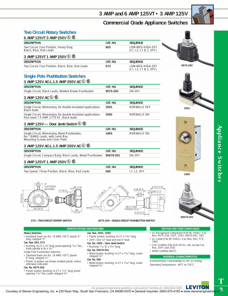
Appliance S
witches
T3
3 AMP and 6 AMP 125VT • 3 AMP 125V
Commercial Grade Appliance Switches
Two Circuit Rotary Switches6 AMP 125VT 3 AMP 250V URDESCRIPTION CAT. NO. SEQUENCETwo Circuit, Four Position, Heavy Duty, 663 LOW-MED-HIGH-OFFBlack, Blue, Red Leads (L1, L2, L1 & 2, OFF)
3 AMP 125VT 1 AMP 250V URDESCRIPTION CAT. NO. SEQUENCETwo Circuit, Four Position, Black, Blue, Red Leads 573 LOW-MED-HIGH-OFF
(L1, L2, L1 & 2, OFF)
Single Pole Pushbutton Switches3 AMP 125V AC-L 1.5 AMP 250V AC URDESCRIPTION CAT. NO. SEQUENCESingle Circuit, Black Leads, Molded Brown Pushbutton 9575-250 ON-OFF
3 AMP 125V AC URDESCRIPTION CAT. NO. SEQUENCESingle Circuit, Momentary, for double-insulated applications. 2591 NORMALLY OFFBlack leadsSingle Circuit, Momentary, for double-insulated applications. 2592 NORMALLY ONAlso rated 1.5 AMP 277V AC. Black leads
3 AMP 125V — Door Jamb Switch URDESCRIPTION CAT. NO. SEQUENCESingle Circuit, Momentary, Metal Pushbutton, 1865 NORMALLY ONNo. 18AWG Leads, with Jamb Box, Mounting Screws and Cover Plate
3 AMP 125V AC-L 1.5 AMP 250V AC URDESCRIPTION CAT. NO. SEQUENCESingle Circuit, Compact Body, Black Leads, Metal Pushbutton 90679-001 ON-OFF
3 AMP 125VT 1 AMP 250V URDESCRIPTION CAT. NO. SEQUENCETwo Speed, Three-Position, Black, Blue, Red Leads 585 L1, L2, OFF
TESTING AND CODE COMPLIANCE
• UL Recognized Component (File #E-7458)—Cat.Nos. 9575-250, 2591, 2592, 90679-001, 585
• UL Listed (File #E-7443)—Cat. Nos. 663, 573,1865
• CSA Certified (File #LR-3413)—All, except Cat.Nos. 2591 and 2592
• NOM Certified (#057)
MATERIAL CHARACTERISTICS
Environmental: Flammability UL-94, V2 RatingOperating Temperature: -40°C to 120°C
SPECIFICATIONS AND FEATURES
Rotary Switches• Standard leads are No. 18 AWG 105°C plastic 6"
long, stripped 1⁄2"Cat. Nos. 663, 573• Bushing 3/8-27 x 3/8" long; panel opening 13⁄32" dia.;
knob spindle 4-36 x 5⁄32"Single Pole Pushbutton Switches• Standard leads are No. 18 AWG 105°C plastic
6" long, stripped 1⁄2"• Plastic actuators are brown molded plastic unless
otherwise indicatedCat. No. 9575-250• Plastic button; bushing 3/8-27 x 11⁄32" long; panel
opening 11⁄32" dia. Leads stripped 3⁄4"
Cat. Nos. 2591, 2592• Plastic button; bushing 3/8-27 x 27⁄64" long • 2591: One 12" lead and one 6" leadCat. No. 1865 – Door Jamb Switch• Bushing 15⁄32-32 x 9⁄16" longCat. No. 90679-001• Metal button; bushing 3/8-27 x 27⁄64" long. Leads
stripped 3⁄4"Cat. No. 585• Metal button; bushing 3/8-27 x 27⁄64" long. Leads
stripped 3⁄4"
.32 (8.3)
.06 (1.5)IFFLATSIDEDBUSHING
.45 (11.5)
.79
(25.
4)
.17 (4.3)
.96 (24.5)
0.63 (15.9)
1.13
(28.
7)0.33(8.3)
3/8-27 UNS THREAD (9.5)
0.34 (8.7)0.70 (17.9)
0.06 (1.7)
0.20 (5.2)
573—TWO CIRCUIT ROTARY SWITCH 9575-250—SINGLE CIRCUIT PUSHBUTTON SWITCH
9575-250
2591
90679-001
1865
For answers to technical questions, call Leviton’s Techline at 1-800-824-3005Courtesy of Steven Engineering, Inc. ● 230 Ryan Way, South San Francisco, CA 94080-6370 ● General Inquiries: (800) 670-4183 ● www.stevenengineering.com

App
lian
ce S
wit
ches
T4
40 WATT 125V • 6 AMP 125V • 8 AMP 125V • 15 AMP 125V
Commercial Grade Appliance Switches
To learn more about Leviton’s outstanding offering of devices visit our Website at: www.leviton.com
Pushbutton Switches Fluorescent Starter40 WATT 125V AC URDESCRIPTION CAT. NO. SEQUENCEMetal Button, 2 Black, 2 Blue Leads 388 ON-OFFPlastic Button, 2 Black, 2 Blue Leads 9382 ON-OFF
Single Pole Toggle Switches 6 AMP 125V 3 AMP 250V URDESCRIPTION CAT. NO. SEQUENCESingle-Throw Ball Toggle. Nickel Finish ON-OFF Indicator 735 ON-OFFPlate keyed to bushing. #6-32 Brass Terminal Screws
6 AMP 125V 3 AMP 125VT 3 AMP 250V URDESCRIPTION CAT. NO. SEQUENCESingle-Throw Metal Bat Toggle. ON-OFF Indicator 720-L5 ON-OFFPlate keyed to bushing. No. 18 AWG leads.Same as above, with Molded Nylon Bat Toggle. Meets UL 1720-T ON-OFFrequirements for double insulated applications
8 AMP 125V URDESCRIPTION CAT. NO. SEQUENCESingle-Throw Metal Bat Toggle. Nickel Finish ON-OFF 738 ON-OFFIndicator Plate keyed to bushing with No. 16 AWG leads.Similar to Cat. No 738, with Black Molded Nylon Bat Toggle. 1738 ON-OFFNo. 16 AWG leads. For double insulated applications
15 AMP 125V AC 10 AMP 250V AC 3⁄4 HP 125/250V AC URDESCRIPTION CAT. NO. SEQUENCESingle-Throw Heavy-Duty Aluminum Bat Toggle. 5731 ON-OFFStamped with ON-OFF marking. Screw terminalsSingle-Throw Heavy-Duty Aluminum Bat Toggle. 5721 ON-OFFStamped with ON-OFF marking. Quick connect tabs
SPECIFICATIONS AND FEATURES
Cat. Nos. 388, 9382• Bushing 3⁄8-27 x 11⁄32" long; panel opening
13⁄32" dia.Cat. No. 735• Bushing 15⁄32-32 x 1⁄4" longCat. No. 720-L5• Bushing 15⁄32-32 x 1⁄4" longCat. No. 1720-T• Bushing 15⁄32-32 x 11⁄32" longCat. Nos. 1738, 738• Bushing 15⁄32-32 x 11⁄32" long; panel opening
1⁄2" dia.Cat. Nos. 5731, 5721• Bushing 15⁄32-32 x 31⁄64" long. Bat-type toggle
extends 11⁄16" from top of bushing
TESTING AND CODE COMPLIANCE
• UL Listed (File #E-18134)—Cat. Nos. 388, 9382• UL Listed (File #E-7458)—Cat. Nos. 735, 720-L5,
1720-T, 738, 1738, 5731, 5721• CSA Certified (File #LR-8255)—Cat. No. 388• CSA Certified (File #LR-3413)—Cat. Nos. 9382,
735, 720-L5, 1720-T, 738, 1738, 5731, 5721 • NOM Certified (#057)
MATERIAL CHARACTERISTICS
Environmental: Flammability UL-94, V2 RatingOperating Temperature: -40°C to 120°C
0.33(8.3)
TOTALTRAVEL
1.09
(27
.8)
IFFLATSIDEDBUSHING
0.20(5.2)
0.06(1.7)
0.66(16.7)
3/8-27 UNS THREAD
(9.5)MOUNTING HOLE: Ø 0.41 (10.3)
0.25(6.4)
1.34
(34
.1)
0.19
(4.
9)
0.45
(11.
5)
15/32-32 THREAD
(11.8)
0.70(17.9)
0.11(2.8)
0.52 (13.1)
0.07 (1.8)
MOUNTING HOLE: Ø 0.50 (12.7) PLUS KEY
0.64 (16.3)
0.25 (6.4)
0.06 (1.6)
388—FLUORESCENT STARTER SWITCH 735—SINGLE POLE TOGGLE SWITCH
388
1720-T
5731
735
Courtesy of Steven Engineering, Inc. ● 230 Ryan Way, South San Francisco, CA 94080-6370 ● General Inquiries: (800) 670-4183 ● www.stevenengineering.com

Appliance S
witches
T5For answers to technical questions, call Leviton’s Techline at 1-800-824-3005
3 AMP 125V • 8 AMP 125V
Commercial Grade Appliance Switches
Feed-Through Cord Switches3 AMP 125V 1⁄2 H.P. 125VDESCRIPTION CAT. NO. SEQUENCE COLOR*
Basic Cat. No. denotes Brown
Heavy Duty, Single Pole, 18/2 – 16/2 Type 5410 ON-OFF I, WSPT-1, SPT-2 or Round Cord 18/2, Type SVT and other cords up to 9⁄32" outer jacket.
Miniature Feed-Through Cord Switch6 AMP 125V 3 AMP 125VT 3 AMP 250VDESCRIPTION CAT. NO. COLOR*
Basic Cat. No. denotes Brown
Miniature Single Pole, ON-OFF Sequence, Captive Screw. 423-3 I, WFor use with #18 ga. SPT-1 conductors
TESTING AND CODE COMPLIANCE
• UL Listed (File #E-7458)• CSA Certified (File #LR-3413)• NOM Certified (#057)
*COLOR
Basic Cat. No. denotes Brown. Add the suffix to cata-log number as follows for additional color selections: Ivory (-I), White (-W).
MATERIAL CHARACTERISTICS
Environmental: Flammability UL-94, V2 RatingOperating Temperature: -40°C to 120°C
1.22
(30
.9)
0.15
(3.
7)
0.84 (21.4)
2.50 (63.5)
5410—FEED-THROUGH SWITCH
5410-W
423-3I
Courtesy of Steven Engineering, Inc. ● 230 Ryan Way, South San Francisco, CA 94080-6370 ● General Inquiries: (800) 670-4183 ● www.stevenengineering.com

T6
HOW TO USE THIS CATALOG
The L-101 Leviton Wiring Device Catalog is designed to help you find the device you’re seeking in the quickest and easiest way possible. Most product sections are divided into three distinct categories in the following sequence—Industrial Grade, CommercialGrade and Residential Grade—and grouped according to amperage and voltage, lowest to highest. For example, if you need toorder 15 Amp, 125 Volt Industrial Grade straight-blade duplex receptacles, begin your search with the main Table of Contents at thefront of the book. Here you’ll see that all straight blade receptacles are listed in Section G. Turn to Section G for a more detailed Tableof Contents on the first page. Each section page contains product descriptions, ratings and catalog numbers. There are also helpfulhighlights including Specifications and Features, Testing and Code Compliance, Color listing, Material Characteristics and dimen-sioned color product photos. Any product page in the L-101 Catalog can be clearly copied or faxed to customers and prospects foruse as a specifier sheet or as part of a presentation.
The Quick Reference Guide follows the main Table of Contents to help you pinpoint and locate specific products. TechnicalSection V provides general product and test data, industry standards, NEMA configuration charts, a glossary of wiring deviceterms, ANSI architectural symbols and other related information. Specific catalog numbers are listed in the exhaustive index atthe back of the catalog.
RATING
Choose GRADE, if appropriate
DIMENSIONED PHOTOGRAPH
WIRING/CERTIFICATIONS
CATALOG NUMBER
DESCRIPTION
Check for NEMA CONFIGURATION
WALLPLATE REFERENCE, if appropriate
SPECIFICATIONS & FEATURES
TESTING AND CODE COMPLIANCE
COLOR LISTING
MATERIAL CHARACTERISTICSL
K
J
I
H
G
F
E
D
C
B
A
I
D
E
H
B
J
G
K
F
L
C
A
Courtesy of Steven Engineering, Inc. ● 230 Ryan Way, South San Francisco, CA 94080-6370 ● General Inquiries: (800) 670-4183 ● www.stevenengineering.com

Electrical A
ccessories and Decorative D
evices IndexSECTIONU
Electrical Accessories andDecorative DevicesINDEXResidential Grade Electrical Accessories and Decorative DevicesTaps and Adapters . . . . . . . . . . . . . . . . . . . . . . . .U2Night Lights . . . . . . . . . . . . . . . . . . . . . . . . . . . . . .U3Guide Lights . . . . . . . . . . . . . . . . . . . . . . . . . . . . .U4Fluorescent Utility Lights . . . . . . . . . . . . . . . . . . . .U4Child Protection Devices . . . . . . . . . . . . . . . . . . . .U4Accessories . . . . . . . . . . . . . . . . . . . . . . . . . . . . . .U4Wallplates . . . . . . . . . . . . . . . . . . . . . . . . . . . . . . .U5
Courtesy of Steven Engineering, Inc. ● 230 Ryan Way, South San Francisco, CA 94080-6370 ● General Inquiries: (800) 670-4183 ● www.stevenengineering.com

Switch Tap13 AMP 125V 2-Pole 2-Wire Non-Grounding URDESCRIPTION CAT. NO. COLOR NEMA CONFIG.Plug-In Switch Tap 1469 I, W
Plug-In Outlet Adapters15 AMP 125V 2-Pole 2-Wire Non-Grounding URDESCRIPTION CAT. NO. COLOR NEMA CONFIG.Single-to-Triple 63 I, W3 round or flat plugs acceptedSingle-to-Triple Right Angle, 65 I, W3 round or flat plugs accepted�
Single-to-Triple, Swivel, 69 I, W3 flat plugs acceptedCube Tap, Vinyl, 531 I, W3 round or flat plugs accepted
15 AMP 125V 2-Pole 3-Wire Grounding URDESCRIPTION CAT. NO. COLOR NEMA CONFIG.3-Wire, Grounding Duplex-to-Six, 49686 I, W6 small or 4 large plugs accepted3-Wire, Grounding Single-to-Triple, 697 I, W3 straight or angle plugs acceptedH
3-Wire, Grounding Single-to-Triple, Vinyl, 699 Orange only3 straight or angle plugs accepted3-Wire, Grounding Single-to-Triple, 694 Orange, Green3 straight plugs acceptedTriple Cube Adapter 692 I, W
15 AMP 125V 2-Pole 2-Wire to 2-Pole 3-Wire Grounding URDESCRIPTION CAT. NO. COLOR NEMA CONFIG.Adapter, 2-Wire to Grounding, 274 Gray1 straight or 1 angle plug accepted�
2-Wire to Grounding, 698 I, W3 straight plugs accepted�
Note: All Leviton #274 and #698 adapters use the outlet wallplate screws for grounding.
Medium Base Lampholder Outlet Adapters660 WATT 125V 2-Pole 2-Wire URDESCRIPTION CAT. NO. COLOR NEMA CONFIG.Outlet-to-Lampholder� 61 I, WLampholder-to-Outlet 125 I, WKeyless Lampholder and 2 Outlets 1403 I, W, ESingle Lampholder-to-Twin Lampholder 128 I(660W-250V)
660 WATT 125V Max. Total 2-Pole 2-Wire URDESCRIPTION CAT. NO. COLOR NEMA CONFIG.Pull Chain Lampholder and 2 Outlets. 1406 I, W, EPull chain controls lamp socket ONLY. Outlet continuously live.
CSA Certified except where indicated by�
692-W
698-W
1403-W
69-W
1469-W
ADAPTERS
Residential Grade Devices
To learn more about Leviton’s outstanding offering of devices visit our Website at: www.leviton.com
Ele
ctri
cal Acc
esso
ries
and
Dec
orat
ive
Dev
ices
U2
LEVITON OFFERS A VARIETY OF ELECTRICAL ACCESSORIES FOR RESIDENTIAL USE,INCLUDING TAPS, SURFACE OUTLETS, ADAPTERS, NIGHT LIGHTS AND SAFETY ITEMSUSED FOR CHILD PROTECTION.
SPECIFICATIONS AND FEATURES
Plug-In Switch• Provides ON/OFF switching at outlet
locationPlug-In Outlet Adapters• Convenient expansion of outlet capacity
TESTING AND CODE COMPLIANCE
• UL Listed (File #E13393 – Cat. No. 125;File #E13394 – Cat. Nos. 1469, 49686,692, 694, 697, 698, 274, 128, 1403 and1406; File #E-13399 – Cat. Nos. 63, 65,69, 531)
• CSA Certified (File #LR-406 – Cat. No.125; File #LR-1523 – Cat. No. 63; File#LR-2780 – Cat. No. 128; File #LR-61476 – Cat. Nos. 65, 69, 531 and 1469:File #LR-91345 – Cat. No. 49686)
• NOM Certified (#057)• Backed by a Limited Two-Year Warranty
*COLOR
Basic Cat. No. denotes Brown device. Forother color selections, add suffix to catalognumber as follows: Ivory (-I), White (-W),Almond (-A) and Black (-E).
1-15R W
1-15R W
5-15RG
W
1-15R W
1-15R W
5-15RG
W
Courtesy of Steven Engineering, Inc. ● 230 Ryan Way, South San Francisco, CA 94080-6370 ● General Inquiries: (800) 670-4183 ● www.stevenengineering.com

48580-WHT
51012
49563-SWL
49563-PLM
Electrical A
ccessories and Decorative D
evices
U3For answers to technical questions, call Leviton’s Techline at 1-800-824-3005
NIGHT LIGHTS
Residential Grade Devices
SPECIFICATIONS AND FEATURES
Automatic Night Lights• Turn ON automatically at dusk and OFF automati-
cally at dawn, by sound or by movement dependingon model
• Long-life 4 watt bulb or LED included
TESTING AND CODE COMPLIANCE
• UL Listed (File #E-39445 – Cat. Nos. 16509,48566, 48581, 49563, 49566 and 51012; File #E-121173 – Cat. No. 48568)
• CSA Certified (File #LR-1863 – Cat. Nos. 48566,48568 and 49566)
• NOM Certified (#057)• Backed by a Limited Two-Year Warranty
*COLOR
Add suffix to catalog number as follows for color selections: Ivory (-I), White (-W).
Night LightsON/OFF Night Light 4 WATT 125V URDESCRIPTION CAT.NO COLOR*ON/OFF switching with sleek, contemporary styling 48566 I, W
Automatic Light Directing LED Night Light .25W 120V URDESCRIPTION CAT.NO COLORRemovable shade slides up and down to direct light 48585 W
Automatic Rotating Spotlight 120V URDESCRIPTION CAT.NO COLORAutomatic ON/OFF with 360° rotating head directs light and 49566 Wvaries intensity (2.4W)LED Automatic ON/OFF with 360° rotating head directs light and 49566-LED Wvaries intensity (.5W)
Automatic Night Light 4 WATT 125V URDESCRIPTION CAT.NO COLOR*
(Night Light Base)
Automatic ON/OFF sensor with sleek, contemporary styling 48568 I, W
Automatic LED Night Light .25W 120V URDESCRIPTION CAT.NO COLORAutomatic ON/OFF with light-reflecting, crystal-faceted shade 48580 BLU (Blue)
GRN (Green) WHT (White)
Automatic Sound-Activated Night Light 125V URDESCRIPTION CAT.NO COLORSound-Activated with adjustable sensitivity (4W) 51012 WLED Sound-Activated with adjustable sensitivity (.5W) 51012-LED W
Decorative Shade LED Night Lights .5W 120V URDESCRIPTION CAT.NO COLOR49563 Series—Consult your Leviton representative for available 49563 Wshade designs
48568-W
Leviton’s Energy Smart Living ProgramLeviton offers a broad range of energy-efficient lighting devices for homes and businesses.From dimmers, timers and motion sensors to night-lights and more, Leviton has the electricalproducts you need to save energy and conserve resources. Look for the Energy Smart Livinglogo, your assurance of an environmentally friendly lighting product. For more information,visit our website at www.leviton.com.
Courtesy of Steven Engineering, Inc. ● 230 Ryan Way, South San Francisco, CA 94080-6370 ● General Inquiries: (800) 670-4183 ● www.stevenengineering.com

Ele
ctri
cal Acc
esso
ries
and
Dec
orat
ive
Dev
ices
U4
UTILITY LIGHTS • CHILD PROTECTION DEVICES • ELECTRICAL ACCESSORIES
Residential Grade Devices
To learn more about Leviton’s outstanding offering of devices visit our Website at: www.leviton.com
Guide LightsURDESCRIPTION CAT.NO COLORButton-Style Neon Guide Light .25 Watt 120V AC 49567 WLED Guide Light with clear shade .5 Watt 120V AC 49568 W (Amber LED)
BLU (Blue LED)
Cool Glow Night Light URDESCRIPTION CAT.NO COLORElectro-Luminescent Guide Light 1 pack .03W 115V 16509-1PK WElectro-Luminescent Guide Light 2 pack .03W 115V 16509-2PK W
Utility LightsURDESCRIPTION CAT.NO COLOR6" Battery-Operated Fluorescent Light—With 4W replaceable bulb. 6511-6 (White base only) Requires 4 AA batteries (not included). 6V DC Jack for use with AC/DC adapter (Sold separately)6" Battery-Operated Closet Utility Light with ON/OFF switch (2 pack)— 6516-2PK (White base only)Requires 3 AA batteries (not included)
Child Protection DevicesOutlet Cover Night Light .25 WATT URDESCRIPTION CAT.NO COLORCool neon light on top outlet, cover on bottom outlet 48500 (White base only)
Outlet Caps URDESCRIPTION CAT.NO COLOROutlet Caps—12 Pack 12777 White only
Tamper Resistant Receptacles 15 AMP 125V 2-Pole 3-Wire Grounding URDESCRIPTION CAT. NO. COLOR NEMA CONFIG.Tamper Resistant Receptacle 5321 I, W
Electrical AccessoriesURDESCRIPTION CAT.NO COLORInsulated Staples—5/8" long, for use with 18/2 or smaller cord (40 Pieces) 12533 WhitePlastic Staples—for 1/2" 14/2 & 12/2 NM Cable (50 Pieces) 12536 WhiteWiring Fasteners—Includes 1/2" Plastic Staples, Coax Cable Fasteners 12537 White/Black/and 1/2" X 1" Metal Staples (47 Mixed Pieces) Metal MixNM Cable Fittings—3/8" dia. for 14/2, 14/3 & 12/3 NM Cable (4 Pack) 12538 —8" Cable Ties—Holds wires, cables, bundles and hoses; comes in 12540 White, assorted lengths and colors BL (Black)
NE (Neon)
SPECIFICATIONS AND FEATURES
Guide Lights• Energy-efficient with soft, comforting light• Compact Neon model keeps second outlet free• No bulb to replace in LED modelsUtility Lights• Battery operation adds light without wiring
anywhere extra light is needed• Includes adhesives for easy, anywhere mountingOutlet Caps• Insert into unused outlets to serve as a barrier• Can be easily removed by adults when needed for
lights and appliancesTamper Resistant Receptacle• Exclusive design helps prevent insertion of any-
thing but a properly rated plug• Floating shutters behind outlet faces block clear
access to energized contacts
TESTING AND CODE COMPLIANCE
• UL Listed (File #E-84313 – Cat. Nos. 48500; File #E-7416 – Cat. No. 12777; File #E-13399 –Cat. No. 5321)
• CSA Certified (File #LR-64317 – Cat. No. 48500;File #LR-406 – Cat. No. 5321)
• NOM Certified (#057)• Backed by a Limited Two-Year Warranty
*COLOR
Add suffix to catalog number as follows for color selections: Ivory (-I), White (-W), Black (-E).
6511-6
6516
49568
12540
5-15RG
W
Courtesy of Steven Engineering, Inc. ● 230 Ryan Way, South San Francisco, CA 94080-6370 ● General Inquiries: (800) 670-4183 ● www.stevenengineering.com

Electrical A
ccessories and Decorative D
evices
U5For answers to technical questions, call Leviton’s Techline at 1-800-824-3005
DECORATIVE WALLPLATES
Residential Grade Devices
The Finishing Touch®WallplatesAvailable in warm wood tones and decorative metals, The Finishing Touch® wallplates are perfect for decorating, redecorating or adding an accent to any room. These wallplates feature elegant and stylish finishes with an oversize silhouette for complete coverage.
Decorative Wood—Straight EdgeDESCRIPTION CAT. NO. COLOR1-GANG, 1-Toggle 89201-OAK Oak
89201-CHR Cherry89201-UNF Unfinished89201-WWP Whitewash
2-GANG, 2-Toggles 89209-OAK Oak89209-CHR Cherry89209-UNF Unfinished89209-WWP Whitewash
1-GANG, 1-Duplex 89203-OAK Oak89203-CHR Cherry89203-UNF Unfinished89203-WWP Whitewash
Wood—Scalloped EdgeDESCRIPTION CAT. NO. COLOR1-GANG, 1-Toggle 89201-CVP Pine2-GANG, 2 Toggle 89203-CVP Pine1-GANG, 1 Duplex 89209-CVP Pine
Wood—Beveled EdgeDESCRIPTION CAT. NO. COLOR1-GANG, 1-Toggle 89201-POK Oak1-GANG, 1-Duplex 89203-POK Oak
Decorative MetalDESCRIPTION CAT. NO. COLOR1-GANG, 1-Toggle 89301-ATB Antique Brass
89301-SSS Satin Chrome89601-STB Stepped Brass
2-GANG, 2-Toggles 89309-ATB Antique Brass89309-SSS Satin Chrome89609-STB Stepped Brass
1-GANG, 1-Duplex 89303-ATB Antique Brass89303-SSS Satin Chrome89603-STB Stepped Brass
SPECIFICATIONS AND FEATURES
Decorative Wood and Metal Wallplates• Genuine wood available in Oak, Cherry,
Whitewash and Unfinished• Metal available in Antique Brass, Satin Chrome
White Vinyl and Stepped Brass• Sturdy impact-resistant construction for long-
lasting performance• Modern design with oversized silhouette for
complete coverage• Clean attractive appearance• Smooth surface is easy to keep clean• Mounting screws included—Metal plates feature
matching-color screws
89201-OAK
89309-SSS
89601-STB
89203-CVP
89209-CHR
For the full offering of Decorative Wallplates contact your Leviton representative.
Courtesy of Steven Engineering, Inc. ● 230 Ryan Way, South San Francisco, CA 94080-6370 ● General Inquiries: (800) 670-4183 ● www.stevenengineering.com

U6
The L-101 Leviton Wiring Device Catalog is designed to help you find the device you’re seeking in the quickest and easiest way possible. Most product sections are divided into three distinct categories in the following sequence—Industrial Grade, CommercialGrade and Residential Grade—and grouped according to amperage and voltage, lowest to highest. For example, if you need toorder 15 Amp, 125 Volt Industrial Grade straight-blade duplex receptacles, begin your search with the main Table of Contents at thefront of the book. Here you’ll see that all straight blade receptacles are listed in Section G. Turn to Section G for a more detailed Tableof Contents on the first page. Each section page contains product descriptions, ratings and catalog numbers. There are also helpfulhighlights including Specifications and Features, Testing and Code Compliance, Color listing, Material Characteristics and dimen-sioned color product photos. Any product page in the L-101 Catalog can be clearly copied or faxed to customers and prospects foruse as a specificr sheet or as part of a presentation.
The Quick Reference Guide follows the main Table of Contents to help you pinpoint and locate specific products. TechnicalSection V provides general product and test data, industry standards, NEMA configuration charts, a glossary of wiring deviceterms, ANSI architectural symbols and other related information. Specific catalog numbers are listed in the exhaustive index atthe back of the catalog.
RATING
Choose GRADE, if appropriate
DIMENSIONED PHOTOGRAPH
WIRING/CERTIFICATIONS
CATALOG NUMBER
DESCRIPTION
Check for NEMA CONFIGURATION
WALLPLATE REFERENCE, if appropriate
SPECIFICATIONS & FEATURES
TESTING AND CODE COMPLIANCE
COLOR LISTING
MATERIAL CHARACTERISTICSL
K
J
I
H
G
F
E
D
C
B
A
I
D
E
H
B
J
G
K
F
L
C
A
TABLE OF CONTENTS with Quick Reference Index
Courtesy of Steven Engineering, Inc. ● 230 Ryan Way, South San Francisco, CA 94080-6370 ● General Inquiries: (800) 670-4183 ● www.stevenengineering.com

Technical Inform
ation IndexSECTIONV
Technical InformationINDEXList of Abbreviations . . . . . . . . . . . . . . . . . . . . . . .V2National Electrical Code (NEC) Requirements . . .V3Associations, Organizations and Standards . .V4, V5Certification Agencies and Markings . . . . . . . . . .V5UL, CSA and NEMA Standards Pertaining to Leviton . . . . . . . . . . . . . . . . . . . . . .V6High-Abuse, UL Listed Hospital Grade Wiring Devices . . . . . . . . . . . . . .V7Glossary of Electrical Wiring Device Terms . .V8–V10Switches . . . . . . . . . . . . . . . . . . . . . . . . . . . . . .V11Dimmers . . . . . . . . . . . . . . . . . . . . . . . . . . . . .V11Receptacles . . . . . . . . . . . . . . . . . . . . . . .V11, V12Ground Fault Circuit Interrupters (GFCI’s) . . . . .V12Enclosure Classifications . . . . . . . . . . . . . .V13–V15Materials Used in Wiring Devices . . . . . . .V15, V16ANSI Architectural Symbols . . . . . . . . . . . . . . .V17NEMA Straight Blade Configurations . . . . . . . . .V18NEMA Locking Configurations . . . . . . . . . . . . . .V19Horsepower Ratings for NEMA Configurations . .V20Circuit Wiring Diagrams . . . . . . . . . . . . . . .V21–V23Switch Wiring Diagrams . . . . . . . . . . . . . . . . . .V24Diameter Ranges of Jacketed Cord . . . . . . . . . .V25Wallplate Dimensions . . . . . . . . . . . . . . . . . . . .V26Telephone Wiring Devices — Codes and Standards . . . . . . . . . . . . . . . . . . . .V27Wire Color Codes and Jack Pin Designations . . .V28
Courtesy of Steven Engineering, Inc. ● 230 Ryan Way, South San Francisco, CA 94080-6370 ● General Inquiries: (800) 670-4183 ● www.stevenengineering.com

TECHNICAL INFORMATION
To learn more about Leviton’s outstanding offering of devices visit our Website at: www.leviton.com
Tec
hnic
al I
nfor
mat
ion
V2
ANSIAmerican National Standards Institute, Inc.11 West 42nd St., New York, NY 10036An independent organization that identifies industrial andpublic requirements for national consensus standards andcoordinates and manages their development, resolvesnational standards problems, and ensures effective participa-tion in international standardization.Various U.S. Government Agencies often adopt ANSIStandards. For example, the Department of Defense hasmade mandatory the use of ANSI Standard Y32.9-1972,“Graphic Symbols for Electrical Wiring and Layout Diagramsused in Architecture and Building Construction.” SuchStandards are often developed by specialized technical soci-eties for ANSI. The Standard referred to above was preparedby the Institute of Electrical and Electronics Engineers (IEEE)and the American Society of Mechanical Engineers (ASME).
GSAGeneral Services Administration Federal Supply ServiceCrystal Mall Bldg. 4, Washington, D.C. 20406The U.S. Government administration responsible for theapproval of Federal Specifications used in the purchase ofproducts by all Federal Agencies. The two most relevant Federal Specifications for ElectricalWiring Devices are:
W-C-596, for Electrical Power Connector, Plug,Receptacle and Cable OutletW-S-896, for Toggle and Lock, Flush MountedSwitches
Leviton devices that comply with these specifications, as verified by Underwriters Laboratories Inc., are also listed inthis catalog.
NECNational Electrical CodePublished by the NFPA (see listing)The purpose of the Code is the practical safeguarding of per-sons and property from hazards arising from the use of elec-tricity. This Code is sponsored by NFPA under the auspices ofANSI. It is revised every three years. OSHA (see listing) hasadopted the NEC as the code to follow in order to comply withOSHA requirements.
NEMANational Electrical Manufacturers Association2101 L St. NW, Washington, D.C. 20003An organization of electrical manufacturers that establishesstandards for manufacture and tests for performance and reliability of electrical products. NEMA tests are often thebasis or prerequisite for approval by the Federal Governmentand/or by Underwriter’s Laboratories, Inc.
NFPANational Fire Protection AssociationBattery March Park, Quincy, MA 02269An organization devoted to promoting the science andimproving the methods of Fire Protection. Membership isopen to anyone interested. Every three years, the NFPA produces a new edition of the NEC (see listing). The NFPAalso provides many other useful publications dealing with fireprevention.
OSHAOccupational Safety and Health Administration(U.S. Department of Labor), 200 Constitution Ave. NW.Washington D.C. 20210 (plus regional offices)That part of the U.S. Department of Labor responsible forassuring that employers provide safe and healthful workingconditions and equipment for employees, and that employeesproperly avail themselves of these conditions.In addition to specific regulations published in the FederalRegister, OSHA has also adopted the National Electrical Codein part for existing installations and equipment and com-pletely for new construction.Note: OSHA does not approve products. Compliance withOSHA regulations is contingent on two factors: The approvalor listing of the product by an authorized testing laboratory,such as UL (see listing), and the proper installation and/oruse of the product in accordance with OSHA guidelines.
ULUnderwriters Laboratories Inc.Northbrook, IL; Melville, NY; Santa Clara, CA“An independent, not-for-profit organization testing for publicsafety.” Tests by UL are the basis for acceptance by variousgovernment agencies. Listing by UL denotes initial testing and periodic retesting to assure continuing conformance to standards.
NOMNorma Official Mexicana(Mexican Official Standard) SECOFIAvenida Puent de Tecamachalco #6Col. Lomas de Tecamachalco 53950Naucalpan, Edomex Mexico
List of Abbreviations Used In Leviton Catalogs
INDUSTRY STANDARDS, RELEVANT DEFINITIONS, PERTINENT PRODUCT DATA, REPRESENTATIVE DIMENSIONAL DRAWINGSAND GENERAL PRODUCT REFERENCES ARE INCLUDED IN THIS SECTION.
Courtesy of Steven Engineering, Inc. ● 230 Ryan Way, South San Francisco, CA 94080-6370 ● General Inquiries: (800) 670-4183 ● www.stevenengineering.com

Technical Inform
ation
V3
TECHNICAL INFORMATION
National Electrical Code Requirements for Wiring DevicesNational Electrical Code NFPA No. 70-1996 (Selected Articles)
ARTICLE 90 — Introduction
ARTICLE 100 — Definitions
ARTICLE 110 — Requirements for Electrical Installations110-18 Arcing Parts110-21 Marking
ARTICLE 200 — Use and Identification of Grounded Conductors200-9 Means of Identification of Terminals 200-10 Identification of Terminals
ARTICLE 210 — Branch Circuits210-4 Multiwire Branch Circuits210-6 Branch Circuit Voltage Limitations210-7 Receptacles and Cord Connectors210-8 Ground Fault Protection for Personnel210-21 Outlet Devices210-24 Branch Circuit Requirements210-50 Required Outlets, General210-52 Dwelling Unit Receptacle Outlets 210-60 Guest Rooms210-63 Rooftop Heating, Air Conditioning and
Refrigeration Equipment Outlet210-70 Lighting Outlets Required
ARTICLE 220 — Branch Circuit, Feeder and Service Calculations220-4 Branch Circuits Required
ARTICLE 250 — Grounding250-45 Equipment Connected by Cord and Plug250-50 Equipment Grounding Conductor Connections250-51 Effective Grounding Path250-59 Cord and Plug Connected Equipment250-74 Connecting Receptacle Grounding
Terminal to Box
ARTICLE 310 — Conductors for General Wiring310-15 Ampacities
ARTICLE 380 — Switches380-1 Scope380-2 Switch Connections380-8 Accessibility and Grouping380-9 Faceplates for Flush-Mounted Snap Switches380-14 Rating and Use of Snap Switches380-15 Marking
ARTICLE 410 — Lighting Fixtures, Lampholders, Lamps, Receptacles410-29 Cord-Connected Showcases410-56 Receptacles, Cord Connectors and
Attachment Plugs410-57 Receptacles in Damp or Wet Locations410-58 Grounding-Type Receptacles, Adapters, Cord
Connectors and Attachment Plugs
ARTICLE 422 — Appliances422-22 Disconnection of Cord- and Plug-Connected
Appliances
ARTICLE 511 — Commercial Garages, Repair and Storage511-10 Ground Fault Circuit Interrupter Protection
for Personnel
ARTICLE 517 — Health Care Facilities517-3 Definitions517-12 Wiring Methods517-13 Grounding of Receptacles and Fixed Electric
Equipment517-16 Receptacles with Insulated Grounding Terminals517-18 General Care Areas517-19 Critical Care Areas517-19(e) Additional Protective Techniques517-20 Wet Locations517-21 Ground Fault Circuit Interrupter Protection
for Personnel517-31 Emergency System517-44 Sources of Power517-61 Wiring and Equipment
(a) Within Hazardous (Classified)Anesthetizing Locations
(b) Above Hazardous (Classified)Anesthetizing Locations
(c) Other-Than-Hazardous (Classified)Anesthetizing Locations
517-62 Grounding517-64 Low-Voltage Equipment and Instruments
ARTICLE 518 — Places of Assembly518-3(b) Temporary Wiring Receptacles
ARTICLE 550 — Mobile Homes and Mobile Home Parks550-5(c) Attachment Plug Cap550-8 Receptacle Outlets
ARTICLE 555 — Marinas and Boatyards555-3 Receptacles555-7 Grounding
ARTICLE 625 — Electrical Vehicle Charging System Equipment625-22 (New Article) GFCI Protection for Cord-
and Plug-Connected Electric Vehicle SupplyEquipment
ARTICLE 680 — Swimming Pools, Fountains and Similar Installations680-4 Definitions680-5 Transformers and Ground Fault Circuit
Interrupters680-6(a) Receptacles680-6(b) Lighting Fixtures, Lighting Outlets, Switching
Devices and Ceiling Fans680-7 Cord- and Plug-Connected Equipment680-40 Outdoor Installations680-41 Indoor Installations680-51 Lighting Fixtures, Submersible Pumps and Other
Submersible Equipment680-62 Cord- and Plug-Connected Equipment680-62 Therapeutic Tubs (Hydrotherapeutic Tanks)680-62(a) Ground Fault Circuit Interrupter680-62(c) Methods of Bonding
Industry Standards for Electrical Wiring Devices
For answers to technical questions, call Leviton’s Techline at 1-800-824-3005Courtesy of Steven Engineering, Inc. ● 230 Ryan Way, South San Francisco, CA 94080-6370 ● General Inquiries: (800) 670-4183 ● www.stevenengineering.com

Tec
hnic
al I
nfor
mat
ion
V4
TECHNICAL INFORMATION
To learn more about Leviton’s outstanding offering of devices visit our Website at: www.leviton.com
The following listings define the common acronyms used for avariety of organizations.
Standards Development OrganizationsPrimarily involved in the development and/or promulgation of standards
NFPA National Fire Protection Agency
IEC International Electrotechnical Commission
IEEE Institute of Electrical and Electronics Engineers
ANSI American National Standards Institute
CANENA Consejo de Armonizacion de Normas Electrotecnicasde Norte America (Council for Harmonization ofElectrotechnical Standardization of North America)
SAE Society of Automotive Engineers
ISA Instrument Society of America
SME Society of Manufacturing Engineers
ISO International Standards Organization
ASME American Society of Mechanical Engineers
Codes and Standards Installation codes and product safety, performance and interchangeability standards.
NEC National Electrical Code
NOM Normas Oficiales de Mexicanas (Official Mexican Standard)
NMX Normas Mexicanas
CEC Canadian Electrical Code
CEE European Electrotechnical Committee
Industry AssociationsFor the purpose of standardization, trade, and professional development, etc.
NMDA National Marine Distributor Association
NEMA National Electrical Manufacturers Association
ABYC American Boat and Yacht Council
EIA/TIA Electronics Industry Association/TelecommunicationsIndustry Association
NAED National Association of Electrical Distributors
NAW National Association of Wholesalers
BICISI Building Industry Consulting Services International
IBI Intelligent Building Institute
EPRI Electric Power Research Institute
NEMRA National Electrical Manufacturers RepresentativeAssociation
IAEI International Association of Electrical Inspectors
IFMA International Facilities Management Association
BOMA Building Owners Management Association
SEMI Semi-Conductor Equipment and Material International
CEMRA Canadian Electrical Manufacturers RepresentativesAssociation
NMRA National Marine Representative Association
EFI Electro-Federation Incorporated
NECA National Electrical Contractors Association
IECA Independent Electrical Contractors Association
ECOC Electrical Contractors of Canada
CANAME Camara Nacional de Manufacturas Electricas (Mexico)
Certification AgenciesPrimarily involved in certification of products or manufactur-ers to standards developed by the certification agency or by others.
UL Underwriters Laboratories Inc.
CSA Canadian Standards Association
ANCE National Association of Normalization and Certification of the Electrical Sector (Mexico)
TUV TUV Rheinland of N.A., Inc.
VDE Verband Deutscher Elektrotechniker (Germany)
BSI British Standards Institute
FM Factory Manual
NRTL National Recognized Testing Laboratories
OSHA Occupational Safety and Health Administration
FCC Federal Communications Commission
DESC Defense Electronic Supply Center
IAPA Independent Accident and Protection Association(Canada)
CE European Compliance (This is not a certification agency, butCE is the European Compliance Mark)
ETL ETL Testing Laboratories
Associations, Organizations and Standards
Courtesy of Steven Engineering, Inc. ● 230 Ryan Way, South San Francisco, CA 94080-6370 ● General Inquiries: (800) 670-4183 ● www.stevenengineering.com

Technical Inform
ation
V5For answers to technical questions, call Leviton’s Techline at 1-800-824-3005
TECHNICAL INFORMATION
European Agencies: IEC and CEE
The IECThe IEC is the International Electrotechnical Commission. Formed in 1906, it is a worldwide organization primarily involved inthe international standardization of electrical standards and equipment. As of 1994, 48 countries are represented in the IEC. IEC member countries produce and consume the majority of the world’s electrical energy. They also manufacture and use themajority of the world’s electrical products.The IEC works towards standardization of the following areas:
� Universal technical language; including definitions, and electrical symbols� Systems for ratings, testing requirements and methods of testing� Electrical system characteristics; including voltages, frequencies and tolerances� Dimensional requirements and tolerances� Universal electrical safety requirements
The CEEThe CEE is the European Electrotechnical Committee. The CEE works on safety standards, definitions for conformity and certificationsfor electrical equipment. Cooperation between the CEE and the IEC has led to worldwide publications for standards pertaining to electrical equipment.
Certification and Markings
Certification marks indicate a product has been tested to the requirements of a specific certification agency. Manufacturers maychoose a particular product identity (e.g. Specification Grade) even though no outside certification agency is involved. The fol-lowing table illustrates the variety of certification markings typically used for 15A and 20A Straight Blade Receptacles.
Typical Product Certification Marks — 15 & 20 Amp Straight Blade Receptacles. Products with these markings must meet the specific testingstandards indicated.
CSA, UL 498 CSA, C22.2, DESCCertification Mark UL498 C22.2, Hospital No. 42M, W-C-596F Certification Agency
No. 42M Grade Hosp. Grade
Spec Grade* No Product Testing Required — Manufacturer’s Term Only Manufacturer Only
Underwriters Laboratories Inc. X Recognized Component
for OEM use.
X Underwriters Laboratories Inc.
Canadian Standards X Association
X X Underwriters Laboratories Inc.
Canadian Standards X X Association
Underwriters Laboratories Inc. X X and Defense Electronic Supply
Center
Underwriters Laboratories Inc. X X X and Defense Electronic Supply
Center
*Includes variations such as Industrial Spec. Grade, Premium Spec. Grade, etc.NOTE: The C-UL listing mark is applied to products for the Canadian market evaluated by UL to Canadian safety standards. The C-UL US listing mark indicates compliancewith both U. S. and Canadian safety standards.
Cross ReferencesThe cross-reference guides supplied by manufacturers are convenient for determining compatible devices but they are not officialconfirmation of compliance to any standard or testing criteria. Similarly, common catalog numbers used by different manufacturersin no way imply compliance to any standard or testing criteria.
•Hospital Grade
•Hospital Grade
F SFed. Spec
F SFed. Spec
•Hospital Grade
Courtesy of Steven Engineering, Inc. ● 230 Ryan Way, South San Francisco, CA 94080-6370 ● General Inquiries: (800) 670-4183 ● www.stevenengineering.com

Tec
hnic
al I
nfor
mat
ion
V6
TECHNICAL INFORMATION
To learn more about Leviton’s outstanding offering of devices visit our Website at: www.leviton.com
UL Standards Pertaining to Leviton DevicesUL20 General-use switchesUL50 Enclosures for electrical equipmentUL94 Flammability testing for materialsUL486E Equipment and wiring terminalsUL498 Plugs, connectors, receptacles, inlets, outlets, taps
and adaptersUL508 Industrial equipment (including motor control
switches)UL514A Metallic boxes/covers/wallplatesUL514C Non-metallic boxes/covers/wallplatesUL817 CordsetsUL943 GFCI'sUL1363 Temporary power tapsUL1436 Outlet circuit testersUL1449 Surge suppression devicesUL1567 Switches and receptacles used with AL wireUL1682 Pin & Sleeve devices& 1686UL1776 High-pressure cleaning equipmentFS Federal Spec receptaclesWC596FFS Federal Spec switchesWS896
Note: Straight blade and locking NEMA configurations aredefined by UL 1681 and NEMA WD 6.
Each UL standard consists of requirements that cover three charac-teristics of the product being reviewed:1. Construction Material properties and general design2. Performance Mechanical and electrical testing3. Markings Identification of manufacturer, applicable
ratings, etc.
CSA Standards Pertaining to Leviton DevicesC22,2, No. 0.17 Polymeric materialsC22.2, No. 42 General-use receptacles,
attachment plugsC22.2, No. 55 Special-use switchesC22.2, No. 111 General-use switchesC22.2, No. 182.1 Industrial-type, special-use attachment
plugs, receptacles and connectors. Pin andsleeve devices
C22.2, No. 182.2 Industrial locking type
NEMA Standards Pertaining To Leviton Devices —In Accordance With NEMA Standard WD–1WD 1-1.01 CORD CONNECTORA cord connector is a portable receptacle which is provided with meansfor attachment to a flexible cord and which is not intended for permanentmounting.
NEMA Standard 7-13-1967
WD 1-1.02 GROUNDED CONDUCTOR (SYSTEM GROUND)A grounded conductor is a circuit conductor (normally current carrying)which is intentionally connected to earth ground. (It is identified as thewhite conductor.)
NEMA Standard 7-13-1967
WD 1-1.03 GROUNDING CONDUCTOR (EQUIPMENT GROUND)A grounding conductor is a conductor which connects noncurrent-carry-ing metal parts of equipment to earth ground to provide an intentionalpath for fault current to ground (It is bare, or, when covered, is identifiedas the green or green with yellow stripes conductor.)
NEMA Standard 7-13-1967
WD 1-1.04 LAMPHOLDERA lampholder is a device which is intended to support an electric lampmechanically and to connect it electrically to a circuit.
NEMA Standard 7-13-1967
WD 1-1.05 MALE BASE (INLET)A male base is a plug which is intended for flush or surface mountingon an appliance or equipment and which serves to connect utilizationequipment to a connector.
NEMA Standard 7-13-1967
WD 1-1.06 OUTLETA outlet is a point on the wiring system at which current is taken to supplyutilization equipment.
NEMA Standard 7-13-1967
WD 1-1.07 PLUGA plug is a device with male blades which, when inserted into a recep-tacle, establishes connection between the conductors of the attachedflexible cord and the conductors connected to the receptacle.
NEMA Standard 7-1-1967
WD 1-1.08 POLARIZATION (PLUGS AND RECEPTACLES)Polarization is a means of assuring the mating of plugs and receptaclesof the same rating in only the correct positon.
NEMA Standard 7-1-1967
WD 1-1.09 POLEThe term “pole” as used in designating plugs and receptacles refers toa terminal to which a circuit conductor (normally current carrying) isconnected. In switches, the number of poles indicates the number or conductorsbeing controlled.
NEMA Standard 7-1-1967
WD 1-1.10 RECEPTACLEA receptacle is a device with female contacts which is primarilyinstalled at an outlet or on equipment and which is intended to estab-lish electrical connection with an inserted plug.
NEMA Standard 7-1-1967
WD 1-1.11 SLANT SYMBOL (/)The “slant” line (/) as used in wiring device ratings indicates that two ormore voltage potentials are present simultaneously between differentterminals of a wiring device.
NEMA Standard 7-1-1967
WD 1-1.12 SWITCHA switch is a device for making, breaking, or changing the connectionsin an electric circuit.A. Single-pole Switch (Single-pole, Single-throw)
A switch which makes or breaks the connection ofone conductor.
B. Double-pole Switch (Double-pole, Single-throw)A switch which makes or breaks the connection oftwo conductors of a single branch circuit.
C. Three-way Switch (Single-pole, Double-throw)A switch which changes the connection of one con-ductor and which is normally used in pairs to con-trol one utilization equipment from two locations.
D. Four-way Switch (Double-pole, Double-throw Reversing)A form of double-pole switch which is used in con-junction with two three-way switches to control oneutilization equipment from three or more locations.
NEMA Standard 7-13-1967
WD 1-1.13 TERMINAL (ON A WIRING DEVICE)A terminal is a fixed location on a wiring device where a conductor isintended to be connected.
NEMA Standard 7-13-1967
WD 1-1.14 WIRE (PLUGS AND RECEPTACLES)The term “wire” as used in designating plugs and receptacles indicatesthe number or either normally current-carrying or equipment ground-ing connected conductors.
NEMA Standard 7-13-1967
UL, CSA and NEMA Standards Pertaining to Leviton Devices
Courtesy of Steven Engineering, Inc. ● 230 Ryan Way, South San Francisco, CA 94080-6370 ● General Inquiries: (800) 670-4183 ● www.stevenengineering.com

Technical Inform
ation
V7For answers to technical questions, call Leviton’s Techline at 1-800-824-3005
TECHNICAL INFORMATION
Why was it developed?Hospital Grade Listed devices were developed to provide maximumsafety in high-abuse applications where constant strenuous use of thedevice is common. These highest reliability devices are built to protectagainst possible human negligence and keep the devices safe and functional.
What are the applications for Hospital Grade, High Abuse Devices?Rough use occurs not just in hospitals, but every place where peoplecan’t or won’t be cautious with devices…the cleaning person whoyanks the floor waxer plug down the hall, the mechanic who pulls thedrill plug from the wall, or the child who removes the electric lawn-mower plug from 40 feet away!In addition, Leviton realized that devices in rough use situations areoften exposed to many corrosive liquids, such as cleaning fluids, rugshampoos, chlorinated water, sprays, salt air and chemical fumes. Ourcorrosion resistant devices permit use in environments where theseconditions are common.
Demanding Tests for UL Hospital Grade ListingLeviton has designed a line of wiring devices that withstand impact, wear,crushing, and corrosive environments that would destroy ordinary heavy-duty devices. Leviton's comprehensive line of Hospital Grade andIndustrial Grade plugs, connectors and receptacles include devices thathave passed a series of demanding UL Hospital Grade tests. This assuresthe end-user of top performance in the harshest industrial environments.Here are examples of how Leviton devices meet or exceed the require-ments of the most rigorous testing!
ReceptaclesAbrupt Removal of Plug TestA steel-bodied test plug withbrass blades is inserted into thereceptacle. A 10-pound weightdropped from at least 24 inchesyanks the plug out of the recepta-cle. This test is done eight timeswith the receptacle rotated intodifferent positions to create thegreatest stress on its face andcontact. After this, the groundingcontact must retain a four ounce,0.184" diameter grounding pin,with the receptacle face down, forone minute. “There shall be nobreakage of the receptacle thatinterferes with the receptacle function or the integrity of the enclosure.The receptacle shall maintain the grounding path integrity through thereceptacle.”
Ground Pin TestThe grounding contact of thereceptacle is conditioned by 20insertions with a 0.204" diameteroversized pin. “After condition-ing, a 0.184" diameter pin shallbe inserted in the groundingcontact and shall be capable ofsupporting at least four ouncesfor one minute.”
Power Blade Retention TestA test plug with oversized bladesof .075" is inserted into the cur-rent-carrying opening of the con-nector for 20 conditioning cycles.After the conditioning cycles,“the contact shall be capable ofsupporting for one minute 11⁄2lbs, secured to a single .055"thick solid steel blade withoutholes.”
Plugs and Connectors500 lb. Crush TestA wired plug or connector isplaced between two steel platesand subjected to a force which issteadily increased to 500 pounds.“There shall be no breakage,deformation or other effect thatmay interfere with the function ofthe device.” Leviton knows that inreal industrial environments,plugs and connectors arecrushed by forces exceeding 500lbs. Leviton performs the crushtest with force of 2500 lbs toensure that our devices withstandthe really heavy hits on the job.
Impact TestA wired plug or connector is sub-jected to impact from a 10 lb.weight dropped from a height of18 inches. “There shall be nobreakage, deformation or othereffect that may interfere with thefunction of the device.” Plugs andconnectors are subjected tosevere impacts in industrial set-tings. Therefore, Leviton exceedthe UL requirement by droppingthe weight from a height of 36inches.
Cord Pull TestThe cord must remain securelyfastened after straight pulls of30 pounds, and rotating pulls(in a 3-inch circle) of 10 poundsfor two hours. “Displacement ofconductors, insulation, andouter jacket of the flexible cordAWG 18 SVT shall not exceed1/32 inch. There shall be no cuts,rips, or tears in cord insulation.”Heavy-duty cord stress is typicalabuse for industrial plugs andconnectors. Leviton increases the weight in the straight cord pull test to175 lbs. with AWG 14 ST and in the rotating pull test to 20 lbs, ensuringpositive strain relief under industrial conditions.
Mechanical Drop TestA sample wired plug or connectoris suspended horizontally by itsattached cord and released sothat it impacts a hard wood sur-face 45 inches below the point ofsuspension — repeated for 1300cycles. “There shall be no break-age, deformation or other damagewhich would interfere with thefunctioning of the device.”
4oz.+
1.5 lb.
High-Abuse Wiring Devices — UL Listed Hospital Grade
Courtesy of Steven Engineering, Inc. ● 230 Ryan Way, South San Francisco, CA 94080-6370 ● General Inquiries: (800) 670-4183 ● www.stevenengineering.com

Tec
hnic
al I
nfor
mat
ion
V8
TECHNICAL INFORMATION
To learn more about Leviton’s outstanding offering of devices visit our Website at: www.leviton.com
General TermsAdapter — An accessory used for interconnecting non-mating devices or convertingan existing device for modified use.Ballast — A transformer that steps down AC line voltage to voltage that can beused by fluorescent or other types of lighting. Ballasts may be electromagnetic orelectronicCord Connector — A portable receptacle designed for attachment to or providedwith flexible cord, not intended for fixed mounting.Flanged Inlet — A plug intended for flush mounting on appliances or equipment toprovide a means for power connection via a cord connector.Flanged Outlet — A receptacle intended for flush mounting on appliances orequipment to provide a means for power connection via an inserted plug.Fluorescent Starter — A device with a voltage-sensitive switch and a capacitor thatprovides a high-voltage pulse to start a fluorescent lamp. Rated in watts.Lampholder — A device with contacts that establishes mechanical and electricalconnection to an inserted lamp.Plug — A device with male contacts intended for insertion into a receptacle toestablish electrical connection between the attached flexible cord and the conductors connected to the receptacle.Receptacle — A device with female contacts designed for fixed installation in astructure or piece of equipment and which is intended to establish electrical connection with an inserted plug.Switch — A device for making, breaking, or changing the connections in an electric circuit.Wallplate — A plate designed to enclose an electrical box, with or without a deviceinstalled within the box.
Adapter VariationsCube Tap — An adapter that converts one receptacle opening into multiple openings.Current Tap — An adapter designed for medium base lampholders which has oneor two receptacle openings. Available with or without integral switch.Duplex — An adapter that provides two female receptacle openings when pluggedinto a single receptacle opening.Grounding - An adapter that converts a two-wire receptacle opening into a two-pole,three-wire grounding receptacle opening.Lampholder — A threaded adapter that converts the thread size of the lampholderin which it is inserted so that the lampholder can accept an incandescent lampbulb of a different size thread.Molded-On — An adapter that is factory molded to a length of flexible cord.Series — An adapter wired in series to a flexible cord containing an in-line switchused to control electrical equipment plugged into the adapter.“W” Type — Same as “Y” type, except having three cord connectors arranged inthe form of the letter “W”.“Y” Type — An adapter in the form of a letter “Y”, having two cord connectors onone end and a male plug on the other end.
Cord ConnectorsAngle —A connector that allows the attached flexible cord to exit at right angles.Corrosion Resistant — A connector constructed of special materials and/or suitablyplated metal parts that is designed to withstand corrosive environments. Corrosionresistant devices must pass the ASTM B117-13 five-hundred hour Salt Spray (Fog)Test with no visible corrosion.Dust Proof — A connector designed so that dust will not interfere with its operation.The IP Suitability Rating designates the degree of protection a device offers againstthe ingress of foreign objects (e.g. IP 20). Explosion Proof — A connector constructed to meet the requirements of hazardouslocations as defined by the National Electrical Code, NFPA-70.Hospital Grade — A connector designed to meet the performance requirements ofhigh-abuse areas typically found in health care facilities. These connectors aretested to the Hospital Grade requirements of Underwriters Laboratories Inc.Standard 498.Locking — A connector designed to lock an inserted plug with a matching bladeconfiguration when the plug is rotated in a clockwise direction. The plug can onlybe removed by first turning it in a counter-clockwise direction.Midget — A connector designed with a smaller body diameter than standard connectors with a similar rating.Molded On — A connector that is factory molded to a length of flexible cord.Pin and Sleeve — A connector with hollow, cylindrical sleeve-type contacts.Straight Blade — A non-locking connector into which mating plugs are inserted at aright angle to the plane of the connector face. Weatherproof — A connector specially constructed so that exposure to weather willnot interfere with its operation.
Flanged InletsCorrosion Resistant — An inlet constructed of special materials and/or suitablyplated metal parts that is designed to withstand corrosive environments. Corrosionresistant devices must pass the ASTM B117-13 five-hundred hour Salt Spray (Fog)Test with no visible corrosion.Flush-Mounted — An inlet intended to be installed flush with the surface of a panelor a piece of equipment.Locking — An inlet designed to lock an inserted matching connector when the con-nector is rotated in a clockwise direction. The connector can only be removed byfirst turning it in a counter-clockwise direction.Midget — An inlet designed with a smaller body diameter than standard connectorswith a similar rating.Pin and Sleeve — An inlet with round pin-type contacts intended to mate with a connector having hollow cylindrical female contacts.Straight Blade — A non-locking inlet into which mating connectors are inserted at aright angle to the plane of the connector face. Surface-Mounted — An inlet designed to be surface mounted on a panel or piece ofequipment.Watertight — An inlet specially constructed so that water will not enter under speci-fied test conditions. The IP Suitability Rating designates the degree of protection adevice offers against the ingress of moisture and water (e.g. IP 55, IP 44).Weatherproof — An inlet specially constructed to protect it from the effects ofweather in outdoor locations.
Flanged OutletsCorrosion Resistant — An outlet constructed of special materials and/or suitablyplated metal parts that is designed to withstand corrosive environments. Corrosionresistant devices must pass the ASTM B17-13 five-hundred hour Salt Spray (Fog)Test with no visible corrosion.Flush-Mounted — An outlet intended to be installed flush with the surface of a panelor a piece of equipment.Locking — An outlet designed to lock an inserted plug with a matching blade configuration when the plug is rotated in a clockwise direction. The plug can onlybe removed by first turning it in a counter-clockwise direction.Midget — An outlet designed with a smaller body diameter than standard deviceswith a similar rating.Pin and Sleeve — An outlet with hollow cylindrical female contacts intended to matewith a plug having round pin contacts.Straight Blade — A non-locking outlet into which mating straight-blade plugs areinserted at a right angle to the plane of the outlet face. Surface-Mounted — An outlet designed to be surface mounted on a panel or pieceof equipment,Watertight — An outlet specially constructed so that water will not enter under specified test conditions. The IP Suitability Rating designates the degree of protec-tion a device offers against the ingress of moisture and water(e.g. IP 55, IP 44). Weatherproof — An outlet specially constructed so that exposure to weather will notinterfere with its operation.
Fluorescent StartersAutomatic Reset — A starter that automatically restarts a new replacement fluorescent lamp after the circuit is energized.Direct Current — A thermal-type starter designed for use on direct current (DC) circuits.Glow Discharge — A starter that provides a rapid lamp start-up and will continue totry to start a failed fluorescent lamp, causing the lamp to flicker until it is replaced.Manual Reset — A starter that automatically deactivates a failed fluorescent lamp toeliminate flickering. A reset button provides a means of activating the circuit afterlamp replacement.
LampholdersBayonet — Designed for incandescent lamps having an unthreaded metal shellwith two diametrically opposite keyways that mate with the keyways on the lam-pholder. Pushing down on the bulb and turning it clockwise in the lampholder locksthe bulb in place.Candelabra — A small screw-base threaded lampholder designed for candelabra-base incandescent lamps commonly used in chandeliers, night lights, and ornamental lighting.Circline — A four-contact, double-ended lampholder designed for use with tubular,circular fluorescent lamps. Compact Fluorescent — A lampholder designed for the Compact FluorescentLamps (CFL’s) that are increasingly being used to replace incandescent lamps forenergy efficiency.Dimmer — An electronic device with either a round knob, slide lever or finger-tipcontrolled buttons used to dim/brighten incandescent lighting. Available in a varietyof wattages; fluorescent version also available.
Glossary of Electrical Wiring Device Terms
Courtesy of Steven Engineering, Inc. ● 230 Ryan Way, South San Francisco, CA 94080-6370 ● General Inquiries: (800) 670-4183 ● www.stevenengineering.com
Technical Inform
ation
V9For answers to technical questions, call Leviton’s Techline at 1-800-824-3005
TECHNICAL INFORMATION
Double-Contact Recessed — Designed for high-output fluorescent lamps.Edison Base — An internally-threaded lampholder, with the inner shell approx. 1" indiameter. Designed for widely-used standard medium base lamps.Electrolier — Similar to the Edison Medium Base lampholder, but with a smallerouter diameter.Incandescent — Designed for use with all manufactured incandescent lamps, mostof which have threaded bases.Intermediate — A lampholder with a threaded screw shell designed for intermediatebase lamps that have a 13/32" threaded base (smaller than the standard 1" dia.medium base). Mostly used in decorative lighting. Key — A lampholder with a flat or round “key” knob that operates an internal switching mechanism (“Keyless” lampholders do not provide an internal switchingmechanism).Lumiline — A specially designed lampholder for tubular Lumiline-type incandescentlamps, typically used in bathrooms and retail display cases.Medium Base — Same as the Edison base lampholder. An internally-threadedlampholder, with the inner shell approx. 1" in diameter. Designed for widely-usedstandard medium base lamps.Miniature — Designed for the smallest available incandescent lamps with ascrew-in base, approx. 3/8" dia. Widely used in flashlights and toys, etc.Mogul — The largest screw-in type lampholder, designed for mogul incandescentlamps with a screw base of approx. 11/2" dia. Used in street lights and numerouscommercial/industrial applications. Medium Bi-Pin — A fluorescent lampholder with two contacts, used in pairs. Fortype T-8 tubular fluorescent lamps, approx. 1" in diameter.Miniature Bi-Pin — Similar to medium bi-pin lampholders, but designed for type T-5 tubular fluorescent lamps, approx. 5/8" in diameter.Outlet Box — Medium-base incandescent lampholder designed for mounting in31/4" or 4" electrical boxes. Available with or without pull-chain mechanism, andwith or without built-in receptacle. Pull-Chain — An incandescent lampholder with an internal switching mechanismthat is activated by pulling down on a beaded chain or cord.Push-Through — An incandescent lampholder with an insulated lever that is pushed from either side to activate an internal ON/OFF switching mechanism.Slimline Single-Pin — A fluorescent lampholder with a single contact designed forSlimline fluorescent lamps such as the T-12 (11/2" dia.), T-8 (1" dia.), and thesmaller version T-6 (3/4" dia.).Snap-In — An incandescent or compact fluorescent lampholder with factory-assembled spring clips that securely snap into a panel cutout without requiringadditional fasteners. Surface-Mounted — A lampholder of any type that mounts on a flat or plane surface.
PlugsAngle — A plug that allows the attached flexible cord to exit at right angles.Corrosion Resistant — A plug constructed of special materials and/or suitably platedmetal parts that is designed to withstand corrosive environments. Corrosion resist-ant devices must pass the ASTM B117-13 five-hundred hour Salt Spray (Fog) Testwith no visible corrosion.Dust Proof — A plug designed so that dust will not interfere with its operation. TheIP Suitability Rating designates the degree of protection a device offers against theingress of foreign objects (e.g. IP 20). Explosion Proof — A plug constructed to meet the requirements of hazardouslocations as defined by the National Electrical Code, NFPA-70.Hospital Grade — A plug designed to meet the performance requirements of high-abuse areas typically found in health care facilities. These plugs are tested to theHospital Grade requirements of Underwriter's Laboratories Inc. Standard 498.Locking — A plug designed to lock into a matching connector or receptacle configuration when the plug is rotated in a clockwise direction. The plug can onlybe removed by turning it in a counter-clockwise direction.Midget — A plug designed with a smaller body diameter than standard plugs with asimilar rating.Molded On — A plug that is factory molded to a length of flexible cord.Pin and Sleeve — A plug with round pin contacts.Straight Blade — A non-locking plug that is inserted at a right angle to the plane ofthe matching device face. Weatherproof — A plug specially constructed so that exposure to weather will notinterfere with its operation.
ReceptaclesAL/CU — 30A, 50A or 60A receptacles designated for use with aluminum or cop-per circuit conductors, identified by “AL/CU” stamped on the device.Receptacles without this designation must never be used with aluminum circuitconductors.
Clock Hanger — A single, recessed receptacle with a specialized cover plate thatprovides a hook or other means of supporting a wall clock.CO/ALR — 15A or 20A receptacles designated for use with aluminum or coppercircuit conductors, identified by “CO/ALR” stamped on the device. Receptacleswithout this designation must never be used with aluminum circuit conductors.Corrosion Resistant — A receptacle constructed of special materials and/or suitably plated metal parts that is designed to withstand corrosive environments.Corrosion resistant devices must pass the ASTM B117-13 five-hundred hour SaltSpray (Fog) Test with no visible corrosion.Display — Receptacle with a special cover plate intended for flush mounting onraised floors or walls.Duplex — Two receptacles built with a common body and mounting means;accepts two plugs.Dust Proof — A receptacle designed so that dust will not interfere with its operation.The IP Suitability Rating designates the degree of protection a device offers againstthe ingress of foreign objects (e.g. IP 20). Explosion Proof — A receptacle constructed to meet the requirements of hazardous locations as defined by the National Electrical Code, NFPA-70.Fan Hanger — A single receptacle with a specialized cover plate that provides ahook or other means of supporting a wall fan.Four-In-One or “Quad” — A receptacle in a common housing that accepts up to fourplugs. Four-In-One receptacles can be installed in place of duplex receptaclesmounted in a single-gang box, providing a convenient means of adding receptacleswithout rewiring. GFCI (Ground Fault Circuit Interrupter) — A receptacle with a built in circuit thatwill detect leakage current to ground on the load side of the device. When theGFCI detects leakage current to ground, it will interrupt power to the load side ofthe device, preventing a hazardous ground fault condition. GFCI receptaclesmust conform to UL Standard 943 Class A requirements, and their use isrequired by the National Electric Code NFPA-70 in a variety of indoor and outdoorlocations.Hospital Grade — A receptacle designed to meet the performance requirements ofhigh-abuse areas typically found in health care facilities. These receptacles aretested to the Hospital Grade requirements of Underwriters Laboratories Inc.Standard 498.Interchangeable — A receptacle or combination of receptacles with a commonmounting dimension that may be installed on a single or multiple-opening mountingstrap.Isolated Ground — Receptacles intended for use in an Isolated Grounding systemwhere the ground path is isolated from the facility grounding system. The groundingconnection on these receptacles is isolated from the mounting strap.Lighted (Illuminated) — A receptacle with a face that becomes illuminated when thedevice is connected to an energized electrical circuit.Locking — A receptacle designed to lock an inserted plug with a matching bladeconfiguration when the plug is rotated in a clockwise direction. The plug can onlybe removed by first turning it in a counter-clockwise direction.Pin and Sleeve — A receptacle with cylindrical sleeve-type contacts.Safety or Tamper-Resistant — A receptacle specially constructed so that access to its energized contacts is limited. Tamper-resistant receptacles are required by the National Electric Code NFPA-70 in specific pediatric care areas in health carefacilities.Single — A receptacle that accepts only one plug.Snap-In — A receptacle with factory-assembled spring clips that securely snap intoa panel cutout without requiring additional fasteners. Split-Circuit — A duplex receptacle that allows each receptacle to be wired toseparate circuits. Most duplex receptacles provide break-off tabs that allow themto be converted into split-circuit receptacles. Straight Blade — A non-locking receptacle into which mating plugs are inserted at aright angle to the plane of the receptacle face. Surface-Mounted — Any receptacle that mounts on a flat or plane surface.Surge-Suppression — A receptacle with built-in circuitry designed to protect its loadside from high-voltage transients and surges. The circuitry will limit transient voltagepeaks to help protect sensitive electronic equipment such as PC’s, modems,audio/video equipment, etc.Triplex — A receptacle with a common mounting means which accepts threeplugs.Weatherproof — A receptacle specially constructed so that exposure to weather willnot interfere with its operation.
SwitchesAC/DC — A switch designated for use with either Alternating Current (AC) or DirectCurrent (DC)AC Only — A switch designated for use with Alternating Current (AC) only.Dimmer — A switch with electronic circuitry that provides DIM/BRIGHT control oflighting loads.
Glossary of Electrical Wiring Device Terms
Courtesy of Steven Engineering, Inc. ● 230 Ryan Way, South San Francisco, CA 94080-6370 ● General Inquiries: (800) 670-4183 ● www.stevenengineering.com

Tec
hnic
al I
nfor
mat
ion
V10
TECHNICAL INFORMATION
To learn more about Leviton’s outstanding offering of devices visit our Website at: www.leviton.com
Door — A momentary contact switch, usually installed on a doorjamb, that isactivated when the door is opened or closed.Double-Pole, Single-Throw (DPST)— A switch that makes or breaks the connectionof two circuit conductors in a single branch circuit. This switch has four terminalscrews and ON/OFF markings.Double-Pole, Double-Throw (DPDT) — A switch that makes or breaks the connection of two conductors to two separate circuits. This switch has six termi-nal screws and is available in both momentary and maintained contact versions,and may also have a center OFF position.Feed-Through — An in-line switch that can be attached at any point on a length offlexible cord to provide switching control of attached equipment.Flush-Mounted — A switch designed for flush installation with the surface of a panelor equipment.Four-Way — A switch used in conjunction with two 3-Way switches to control asingle load (such as a light fixture) from three or more locations. This switch hasfour terminal screws and no ON/OFF marking.Horsepower Rated — A switch with a marked horsepower rating, intended for use inswitching motor loads.Interchangeable — A switch or combination of switches with a common mountingdimension that may be installed on a single or multiple-opening mounting strap.Lighted Handle — A switch with an integral lamp in its actuator (toggle, rocker orpushbutton) that illuminates when the switch is connected to an energized circuitand the actuator is in the OFF position.Locking — A switch equipped with a locking mechanism that requires a key tooperate the switching functions.Low-Voltage — A switch rated for use on low-voltage circuits of 50 volts or less.L-Rated — A switch specially designated with the letter “L” in its rating that is ratedfor controlling tungsten filament lamps on AC circuits only.Maintained Contact — A switch where the actuator (toggle, rocker, pushbutton orkey mechanism) makes and retains circuit contact when moved to the ON position.The contacts will only be opened when the actuator is manually moved to the OFFposition. Ordinary light switches are maintained contact switches.Manual Motor Controller — A switch designed for controlling small DC or AC motorloads, without overload protection. Mercury — A type of switch that uses mercury as the contact means for makingand breaking an electrical circuit. Momentary Contact — A switch that makes circuit contact only as long as theactuator (toggle, rocker, pushbutton or key mechanism) is held in the ON posi-tion, after which it returns automatically to the OFF position. This is a “NormallyOpen” switch. A “Normally Closed” switch will break circuit contact as long as itis held in the OFF position, and then automatically return to the ON position.Available in “Center OFF” versions with both Momentary ON and Momentary OFFpositions.Pendant — A type of switch designed for installation at the end of a length ofportable cord or cable,Pilot Light — A switch with an integral lamp in its actuator (toggle, rocker or push-button) that illuminates when the switch is connected to an energized circuit andthe actuator is in the ON position.Pull — A switch where the making or breaking of contacts is controlled by pullingdownward or outward on the actuator mechanism.Push Button — A switch with an actuator mechanism that is operated by depressing a button.Rotary — A switch where rotating the actuator in a clockwise direction makes thecircuit connection, and then rotating the actuator in either the same or oppositedirection breaks the connection.Single-Pole, Double-Throw (SPDT) — A switch that makes or breaks the connectionof a single conductor with either of two other single conductors. This switch has 3terminal screws, and is commonly used in pairs and called a “Three-Way” switch. Single-Pole, Single-Throw (SPST) — A switch that makes or breaks the connection of a single conductor in a single branch circuit. This switch has twoscrew terminals and ON/OFF designations. It is commonly referred to as a“Single-Pole” Switch.Slide — A switch with a slide-action actuator for making or breaking circuit con-tact. Dimmer switches and fan speed controls are also available with slide-action mechanisms for lighting and fan speed controlSurface-Mounted — Any switch that mounts on a flat or plane surface.Three-Position, Center OFF — A two circuit switch, either maintained or momen-tary contact, where the OFF position is designated as the center position of theactuator.Three-Way — A switch, always used in pairs, that controls a single load such as alight fixture from two locations. This switch has three terminal screws and has noON/OFF marking.Time Delay — A switch with an integral mechanism or electronic circuit that willautomatically switch a load OFF at a predetermined time interval.Timer — A switch with an integral mechanism or electronic circuit that can be set toswitch an electrical load ON at a predetermined time.
Toggle — A switch with a lever-type actuator that makes or breaks switch contact asits position is changed. T-Rated — A switch specially designated with the letter “T” in its rating that is ratedfor controlling tungsten filament lamps on direct current (DC) or alternating current(AC) circuits.
WallplatesCombination — A multiple- gang wallplate with openings in each gang to accommodate different devices.Decora® — Wallplates with Decora-size openings for compatibility with Leviton’sentire line of Decora devices. Available in a variety of multiple-gang configurations.Screwless-design snap-on versions also available.Flush — A wallplate designed for flush-mounting with wall surfaces or the planesurfaces of electrical equipment.Gang — A term that describes the number of devices a wallplate is sized to fit (i.e.“2- gang” designates two devices).Midway — Wallplates that are approx. 3/8" higher and wider than the standardsize that can be mounted onto larger volume outlet boxes and/or used to hidewall surface irregularities. These wallplates are approx. 1/4" deep to ensure aproper fit when used with protruding devices.Oversized — Wallplates that are approx. 3/4" higher and wider than the standardsize and are used to conceal greater wall irregularities than those hidden by Midwaywallplates. These wallplates are approx. 1/4" deep to ensure a proper fit when usedwith protruding devices.Modular — Individual-section wallplates with different openings that can be configured into a multi-gang plate.Multi-Gang — A wallplate that has two or more gangs.Tandem — A wallplate with individual gangs arranged vertically one above the other.Weatherproof (with Cover Closed) — A UL Listed cover that meets specific test stan-dards for use in wet and damp locations with the cover closed.Weatherproof (with Cover Open) — A UL Listed cover that meets specific test stan-dards for use in wet and damp locations with the cover open or closed.
Surge SuppressionClamping Voltage — The peak voltage that can be measured after a SurgeProtective Device has limited or “clamped” a transient voltage surge.Clamping voltage must be determined by using IEEE Standard C62 testing andevaluated by UL Standard 1449.Joule Rating — The measurement of a Surge Protective Device’s ability to absorbheat energy created by transient surges. Note that the Joule rating is not a part ofIEEE or UL Standards. It is not as significant a specification as Clamping Voltage,Maximum Surge Current and other parameters recognized by these agencies.Transient Voltage Surges — High-speed, high-energy electrical disturbancespresent on AC power lines and data and communication lines, generated by util-ity switching, motor-load switching and lightning strikes.Response Time — The interval of time it takes for a surge protective device to reactto a transient voltage surge. Note that this parameter is not a part of IEEE or ULStandards and is only based on estimations made by manufacturers.Surge Protective Device — See “Transient Voltage Surge Suppressor (TVSS)” definition.Transient Voltage Surge Suppressor (TVSS) — A device designed to protect sensi-tive electronic equipment such as computers and computer peripherals, logiccontrols, audio/video equipment and a wide range of microprocessor-based(computer chip) equipment from the harmful effects of transient voltage surges.Also referred to as a Surge Protective Device (SPD).Maximum (Peak) Surge Current — The peak surge current a Surge ProtectiveDevice can withstand, based on IEEE Standard C62.45 test waveforms.MOV (Metal Oxide Varistor) — The primary component used in most SurgeProtective Devices to clamp down transient voltages. UL 1449 Listing — The industry standard for Surge Protective Devices. A SurgeProtective Device must have a UL 1449 Surge Suppression rating on its label inorder to verify that the device has been tested with IEEE standardized waveforms.Devices without this identification should not be considered reliable surge protective devices.
Glossary of Electrical Wiring Device Terms
Courtesy of Steven Engineering, Inc. ● 230 Ryan Way, South San Francisco, CA 94080-6370 ● General Inquiries: (800) 670-4183 ● www.stevenengineering.com

Technical Inform
ation
V11For answers to technical questions, call Leviton’s Techline at 1-800-824-3005
TECHNICAL INFORMATION
SwitchesTypes of SwitchesSwitches used in branch circuit wiring are rated in two general cate-gories: AC ONLY and AC/DC. Originally, the electrical power furnished toresidences and businesses by utility companies was Direct Current orDC. Because DC current was always flowing at full value, the making orbreaking of a circuit created a rather strong arc during switch operation.For this reason, the contacts had to be widely gapped and the operationhad to be “quick make, quick break” to avoid excessive pitting or weldingof the contact points.Alternating current operates between zero and full power 120 times persecond. Because of the oscillating characteristic of AC power, the arcfrom an AC circuit is self-extinguishing on the “break” of the current. Thismeans a slower breaking action is possible on an AC switch, as opposedto the breaking action required of a switch made for use with continuousfull-power DC. The pulsating nature of AC can, however, cause a “chat-tering” or very fast series of “makes” and “breaks” if the circuit is closedtoo quickly. For this reason an AC ONLY switch works with a somewhatslower “fast make” and “break” than an AC/DC switch.Because the make and break actions of an AC/DC switch must be fast, itcan be rather noisy, and must use contact metals capable of enduringsuch comparatively violent action while still offering acceptable electricalconductivity. An alloy of copper is most often used.Silver and its oxides are better conductors than copper and its oxides.Silver is much softer than copper and therefore cannot be used in theAC/DC switch. However, silver can be used in the AC ONLY switchbecause of its gentler “fast make” characteristic, especially when silver isalloyed with cadmium oxide, a good conductor that’s quite hard.
Switch RatingsAC ONLY switches are often called AC Quiet switches because they canbe made to operate very quietly, unlike AC/DC switches. AC ONLYswitches are rated at their full current value for lighting, including tung-sten filament, quartz metal-halide, and fluorescent; and 80% currentvalue or full horsepower rating value for motor (inductive) loads. AC/DC switches used for incandescent lighting should have a “T” rating(tungsten-filament rating). The “T” rating assures end-users of thelongevity of the switch through the surge currents of a “make” actionacross a tungsten filament. Such capacity is already inherent in thedesign of AC Quiet switches.AC/DC switches are rated at only 50% of their current capacity for motorloads. A 20 amp AC/DC switch could be used to control a 10 amp motorload, while a 20 amp AC Quiet switch can operate a 16 amp motor load.In the past, MERCURY switches were available that operated by makingand breaking contact within a hermetically sealed capsule containing apool of mercury. MERCURY switches were actually silent in operation.However, due to health concerns about mercury, these switches are nolonger manufactured and sold. MERCURY switches may still be in serv-ice in some installations
Horsepower RatingsSwitches marked with Horsepower (HP) Ratings are suitable for con-trolling the motor loads of the HP ratings shown on the switch, as wellas loads with a lower HP rating.To qualify for an HP rating, a switch is tested at six times the full motorload current corresponding the HP rating marked on the switch. ForDC motor load controllers, the test is made at 10 times the full motorload current corresponding to the DC HP rating marked on the switch.The test is conducted on six samples and consists of 50 On-Off opera-tions at the load. For a 3/4 HP rating at 120/240 VAC, two sets of sixsamples each are tested in addition to the regular overload endurance,heating and insulation tests. The test circuit characteristics are:
For 3/4 HP Rating For 3/4 HP@ 120 VAC @ 240 VAC
Closed Circuit Volts 120 VAC 240 VACCurrent 82.8 amps 41.4 ampsPower-Factor 0.40 – 0.50 0.40 – 0.50
Note: The current at 240 VAC is 1/2 that at 120 VAC
All switches must be in good operating condition after the tests havebeen completed. There must be no excessive arcing, welding or burningof the contacts nor arc-over to ground (the switch frames are groundedduring the Stalled Rotor Test).
DimmersA common misconception about box-mounted dimmers is that they aresimply variable resistors (rheostats) that absorb power to dim the lights.In fact, a rheostat would be too bulky, inefficient and heat producing toever be practical as a wall-mounted dimmer. In the 1950’s, the advent ofsolid state technology and a type of semi-conductor called the TRIAC fos-tered the development of full-range dimmers and fan speed controls thatwere versatile, efficient and compact enough to fit in a standard wallbox.Leviton has always taken an active role in the development lighting con-trol technologies. Leviton introduced the Trimatron™ Rotary Dimmer thatwas only half as deep as conventional dimmers, allowing easier installa-tion and wiring in a crowded wallbox. Today, Leviton offers innovative all-digital lighting controls that feature scene lighting and multi-locationcontrol capabilities for sophisticated residential and commercial installa-tions. Leviton’s complete line of controls for incandescent, low-voltageand fluorescent lighting includes Decora-style and architectural specifi-cation grade devices, as well as traditional rotary devices. There is also awide selection of Fan Speed Controls See Section C for information on Leviton’s comprehensive line ofLighting and Fan Speed Controls.
ReceptaclesTypes of ReceptaclesReceptacles generally are made to accommodate either of two types ofplugs. Straight-Blade plugs are pushed in and pulled straight out.Locking plugs are pushed in and rotated slightly in a clockwise directionto a position were they cannot be pulled straight out. They must berotated counterclockwise back to the insertion position in order to bewithdrawn. This locking action is intended to prevent accidental discon-nection of the circuit by pulling the plug straight out unintentionally.
GroundingOriginally, residential electrical circuitry was “2-pole, 2-wire” and did nothave an equipment grounding means at the receptacle. The onlygrounding point was at the service entrance, where the neutral (white)conductor was grounded. The receptacle slot for the neutral wire,according to NEMA configuration 1-15R, must be longer than the slot forthe phase or hot wire (typically black or red). This enables certain itemsof equipment, like TV sets and home appliances, to have their externalmetal parts or casing grounded through the white neutral connection.Such equipment uses a polarized plug where the neutral plug blade iswider than the hot plug blade, ensuring that it mates properly with theNEMA 1-15R configuration receptacle. Receptacles designed for 2-pole,2-wire circuits do not have mounting straps that are connected to agrounding terminal. Leviton still offers 2-pole, 2-wire receptacles forreplacement use only in existing non-grounding systems.Experience proved that a single grounding point through the neutral con-ductor was not sufficiently safe. Conditions could occur where fault cur-rents and differences in potential lead to shocks, overheating, equipmentburnout and fire. Therefore, the 2-pole, 3-wire circuit was developed. Athird conductor, called the grounding conductor, does not carry currentduring normal circuit operation. It is connected to the neutral bus bar atthe service entrance and runs along with the current-carrying neutral andhot conductors .The grounding conductor is connected only to outletboxes, chassis and other non-current carrying components that maycarry current in case of damage or defects in the wiring system. It issometimes referred to as the “equipment grounding conductor.”The grounding contacts on the 2-pole, 3-wire receptacles are most com-monly shaped like a “U”, which is how the term “U-ground” evolved.The grounding contacts on these receptacles are securely fastened to themounting strap. In Leviton receptacles, the grounding contacts are per-manently riveted to the mounting strap, and in most Leviton HospitalGrade and Industrial Grade receptacles they are an integral part of thestrap. Many Leviton receptacles offer dual ground connection options tohelp ensure that the receptacle is properly connected to the groundingsystem: An integral green grounding screw for direct connection to thegreen or bare grounding wire, and a patented Groundamatic® self-grounding clip riveted to the strap to provide automatic ground connec-tion when the receptacle is mounted in a properly grounded metalwallbox.
Isolated-Ground ReceptaclesAlthough the conventional grounding system provides safety for person-nel and equipment, it may be a source of electrical interference that cancause problems in modern electronic equipment. Because the conven-tional grounding network runs through an entire facility, it can uninten-tionally function as a pick-up of transient electrical signals or “noise.”
Courtesy of Steven Engineering, Inc. ● 230 Ryan Way, South San Francisco, CA 94080-6370 ● General Inquiries: (800) 670-4183 ● www.stevenengineering.com

Tec
hnic
al I
nfor
mat
ion
V12
TECHNICAL INFORMATION
To learn more about Leviton’s outstanding offering of devices visit our Website at: www.leviton.com
These transient signals will then be introduced to equipment through theground connection. Microprocessor-based equipment, including com-puters, cash registers, medical equipment and audio/video equipment,may malfunction as a result of this noise.Isolated-Grounding Receptacles can help eliminate problems caused byelectrical interference in a conventional ground system. The ground con-tacts on Isolated-Ground Receptacles are electrically isolated from themounting strap and therefore they are isolated from the conventionalground system. The green ground screw is connected to a pure groundpath that is separate from a facility’s grounding network. The isolatedground network is relatively free of electrical noise because it is not a facil-ity-wide grounding path and it’s connected to ground at a single point.
ISOLATED-GROUNDING RECEPTACLES
Mounting StrapsThere are basically two kinds of mounting straps for receptacles. The“through” type passes between the receptacle body and cover. The“wrap-around” type acts as a cradle for the receptacle, surrounding itsside, ends and bottom surfaces.
Power Contact DesignThe “contact” does more than make contact with the plug blade — Itmust grip the plug blade for maximum electrical conductivity andmechanical strength. Leviton receptacles feature double-wipe contactsthat grip both sides of each blade, including the U-ground contacts thatare often single-wipe in receptacles made by other manufacturers.Leviton Hospital Grade and Industrial Grade receptacles feature triple-wipe contacts for added strength and durability in high-abuse applica-tions. Leviton contacts are made of the copper alloys that offer maximumstrength and electrical conductivity.
Wiring of Leviton Receptacles
Ground Fault Circuit Interrupters (GFCI’s)The Need for Ground Fault ProtectionCircuit breakers and fuses protect equipment and building structuresfrom overheating and fire caused by short circuits and high-current over-loads. However, the current level needed to trip a breaker is many timesgreater than the amount of current needed to deliver a powerful, andpossibly lethal electrical shock. For example, the hot conductor in anelectrical device can become exposed through a break in its insulation,and it may end up touching the device’s metal enclosure. The leakagecurrent that now flows through the metal enclosure will be conducted toground through any available path — including the body of a humanbeing that happens to touch the faulty device. This condition is called aGround Fault, and the current flowing through the person to ground canbe life threatening, though there is usually nowhere near enough currentto trip a circuit breaker.
How a GFCI WorksWhen there is a ground fault condition, all of the current flowing throughthe “hot” conductor is not returning through the neutral conductor. AGround Fault Circuit Interrupter (GFCI) monitors the difference in currentflow between hot and neutral conductors. If the GFCI senses even a verytiny difference in current flow between the conductors (a ground fault), itinterrupts the flow of electrical current through the device by opening itsinternal double-pole contacts. According to UL Standard 943 Class A,the GFCI must trip when there is a ground fault of 5 milliamps (±1mA).The GFCI must also trip within approximately 25 milliseconds.GFCI receptacles are rated for 15 or 20 amp circuits. They are used inplace of standard box-mounted duplex receptacles. GFCI receptaclescan also be feed-through wired to provide ground fault protection to feed-through wired receptacles downstream. See Section H for information on Leviton’s comprehensive line ofGround Fault Circuit Interrupter Devices.
UL 2006 Code Requirements (Effective July 28, 2006)• If a miswiring (line-load reversal) occurs during installation, the GFCImust not be capable of supplying power to either the GFCI's face or tofeed-through terminals• GFCIs must provide a visual and/or audible indication OR be able torender themselves incapable of delivering power when they no longeroffer ground fault protection based on a failure to pass their internal testNote that the National Electrical Code strongly recommends monthly testing of all GFCIs.
Leviton SmartLockPRO® GFCI with Lockout ActionThe TEST and RESET functions on Leviton's SmartLock GFCI worktogether so that a tripped GFCI cannot be reset if the GFCI circuit is nolonger providing ground fault protection. The RESET button is blocked ifGFCI protection has been compromised, eliminating the possibility ofend-users incorrectly assuming that a reset GFCI is providing groundfault protection when it actually is not.
LINE TERMINAL
CONVENTIONALGROUND
ISOLATEDGROUND
NEUTRAL TERMINAL
MOUNTING STRAPGROUNDED TO BOX
OUTLET BOX
BLACK
WHITE
GREENISOLATED GROUNDINGTERMINAL (ISOLATEDFROM STRAP)
Side WiringLoop wire around terminal screw. Screwhead locks wire againstterminal. For copper orcopper/clad aluminumconductors.
Quickwire™ ConnectionInsert wire into wire well.Wire is automaticallyclamped by springaction, insuring goodelectrical connection. Forcopper conductors only.
Quickwire™and ScrewOption of (1) side wiring or (2) Quickwire connection.NOTE: For continuouswiring, both sets of terminals (screw andQuickwire) can be usedtogether.
Back & Side WiringOption of (1) side wiring or (2) backwiring: Insert wire into well. Tightenscrew, thus clamping wire against ter-minal. Back wiring for copper or cop-per/clad aluminum conductors.
Two-Circuit ConversionTo power each outlet of a duplexreceptacle separately, simplybreak off the tab between thetwo terminals.
4.21 (106.9)
3.28 (83.3)
2.62 (66.5)
2.74 (69.6)
1.31 (33.3)
1.70 (43.2)
0.29 (7.4) 1.19 (30.2)
SmartLockPRO® GFCI RECEPTACLE7599 Series
Courtesy of Steven Engineering, Inc. ● 230 Ryan Way, South San Francisco, CA 94080-6370 ● General Inquiries: (800) 670-4183 ● www.stevenengineering.com

Technical Inform
ation
V13For answers to technical questions, call Leviton’s Techline at 1-800-824-3005
TECHNICAL INFORMATION
Enclosure Type DesignationsEnclosures serve the dual purpose of protecting personnel from incidental contact with the enclosed electrical equipment and protecting the enclosedequipment against specified environmental conditions. Enclosures are rated for use in specific environmental conditions by NEMA, UL, CSA and theIEC. The major rating systems used are the NEMA Type Numbers and the IEC Enclosure Classification Designation.
The IEC Enclosure Classification Designation — IP Suitability RatingsThe IP Suitability Ratings are a system for classifying the degree of protection provided by enclosures of electrical equipment. The higher the number inthe rating, the greater the degree of protection provided by the enclosure. Note that the rating will ONLY apply to properly installed equipment. The chartbelow defines the numerals in the IP Code.1. The First Numeral indicates the degree of protection for persons against access to hazardous parts inside the enclosure and/or against the ingress of
solid foreign objects2. The Second Numeral indicates the degree of protection of equipment inside enclosures against damage from the ingress of water.
Elements of the IP CodeMeaning for the Protection of Equipment
Code Letters First Number Second Number
Ingress Protection Against Ingress of Solid Foreign Objects Against Ingress of Water with Harmful Effects
IP O – Non protected O – Non protected
1 – ≥ 50 mm diameter 1 – Vertically dripping
2 – ≥ 12.5 mm diameter 2 – Dripping (15 °tilted)
3 – ≥ 2.5 mm diameter 3 – Spraying
4 – ≥1.0 mm 4 – Splashing
5 – Dust-protected 5 – Jetting
6 – Dust-tight 6 – Power jetting
7 – Temporary immersion
8 – Continuous immersion
Note: > denotes greater than or equal to.
Example: IP 54 Suitability Rating = Ingress Protection/Dust-protected/Splashing
NATIONAL ELECTRICAL MANUFACTURERS ASSOCIATIONNEMA Standards Publication No. 250-1991Enclosures for Electrical Equipment (1000 Volts max.)
Type Intended Use and Designation Description
An enclosure is a surroundingcase constructed to provide adegree of protection to person-nel against incidental contactwith the enclosed equipmentand to provide a degree of pro-tection to enclosed equipmentagainst the specified environ-mental conditions.
Type 1 Enclosures are intended for indooruse primarily to provide a degreeof protection against limitedamounts of falling dirt.
Type 2 Enclosures are intended for indooruse primarily to provide a degreeof protection against limitedamounts of falling water or dirt.
Type 3 Enclosures are intended for out-door use primarily to provide adegree of protection against rain,sleet, windblown dust, and dam-age from external ice formation.
UNDERWRITERS LABORATORIES INC.UL50 Standard for Enclosures for Electrical Equipment (10th Edition)
Type Intended Use and Designation Description
Enclosure — A surrounding caseconstructed to provide a degree ofprotection against incidental con-tact with the enclosed equipmentand to provide a degree of protec-tion to the enclosed equipmentagainst specified environmentalconditions.A complete enclosure shall beprovided for all live parts that maybe housed in it. The enclosureshall be tight and, unlessdesigned for a specific installation,such as a cast metal junction orpull box intended to be installed inpoured concrete, shall be pro-vided with means for mounting.
Type 1 Indoor use primarily to provide adegree of protection against lim-ited amounts of falling dirt.
Type 2 Indoor use primarily to provide adegree of protection against lim-ited amounts of falling water ordirt.
Type 3 Outdoor use primarily to provide adegree of protection against rain,sleet, windblown dust and dam-age from external ice formation.
CANADIAN STANDARDS ASSOCIATIONCAN/ CSA C22.2 No. 94-M91Special Purposes Enclosures
Type Intended Use and Designation Description
Enclosures — provide a degree ofprotection against accidental con-tact with the enclosed equipment,and to the enclosed equipmentagainst specified environmentalconditions.
No CSA equivalent.
Type 2 An enclosure for indoor use, con-structed so as to provide adegree of protection against drip-ping and light splashing of non-corrosive liquids, and falling dirt.
Type 3 An enclosure for either indoor oroutdoor use, constructed so as toprovide a degree of protectionagainst rain and snow, undam-aged by the external formation ofice on the enclosures.
Enclosure Types for Non-Hazardous Locations
Courtesy of Steven Engineering, Inc. ● 230 Ryan Way, South San Francisco, CA 94080-6370 ● General Inquiries: (800) 670-4183 ● www.stevenengineering.com

Tec
hnic
al I
nfor
mat
ion
V14
TECHNICAL INFORMATION
To learn more about Leviton’s outstanding offering of devices visit our Website at: www.leviton.com
Enclosure Types for Non-Hazardous LocationsNATIONAL ELECTRICAL MANUFACTURERS ASSOCIATIONNEMA Standards Publication No. 250-1991Enclosures for Electrical Equipment (1000 Volts max.)
Type Intended Use and Designation Description
Type 3R Enclosures are intended for out-door use primarily to provide adegree of protection against rain,sleet, and damage from externalice formation.
Type 3S Enclosures are intended for out-door use primarily to provide adegree of protection against rain,sleet, windblown dust, and to pro-vide for operation of externalmechanisms when ice laden.
Type 4 Enclosures are intended for indooror outdoor use primarily to providea degree of protection againstwindblown dust and rain, splash-ing water, hose-directed water,and damage from external ice formation.
Type 4X Enclosures are intended for indooror outdoor use primarily to provide a degree of protection against corrosion, windblown dust andrain, splashing water, hosedirected water, and damage fromexternal ice formation.
Type 5 Enclosures are intended for indooruse primarily to provide a degreeof protection against settling air-borne dust, falling dirt, and drip-ping noncorrosive liquids.
Type 6 Enclosures are intended for indooror outdoor use primarily to providea degree of protection againsthose-directed water, the entry ofwater during occasional tempo-rary submersion at a limiteddepth, and damage from externalice formation.
Type 6P Enclosures are intended for indooror outdoor use primarily to providea degree of protection againsthose-directed water, the entry ofwater during prolonged submer-sion at a limited depth, and dam-age from external ice formation.
Type 12 Enclosures are intended forindoor use primarily to provide adegree of protection against cir-culating dust, falling dirt, anddripping noncorrosive liquids.
Type 12K Enclosures with knockouts areintended for indoor use primarilyto provide a degree of protectionagainst circulating dust, falllingdirt, and dripping noncorrosiveliquids.
Type 13 Enclosures are intended for indooruse primarily to provide a degreeof protection against dust, spray-ing of water, oil, and noncorrosivecoolants.
UNDERWRITERS LABORATORIES INC.UL50 Standard for Enclosures for Electrical Equipment (10th Edition)
Type Intended Use and Designation Description
Type 3R Outdoor use primarily to provide adegree of protection against rain,sleet, and damage from externalice formation.
Type 3S Outdoor use primarily to provide adegree of protection against rain,sleet, windblown dust, and to provide for operation of externalmechanisms when ice laden.
Type 4 Indoor or outdoor use primarily toprovide a degree of protectionagainst windblown dust and rain,splashing water, hose-directedwater, and damage from externalice formation.
Type 4X Indoor or outdoor use primarily toprovide a degree of protectionagainst corrosion, windblown dustand rain, splashing water, hose-directed water and damage fromexternal ice formation.
Type 5 Indoor use primarily to provide adegree of protection against set-tling airborne dust, falling dirt, anddripping noncorrosive liquids.
Type 6 Indoor or outdoor use primarily toprovide a degree of protectionagainst hose-directed water, theentry of water during occasionaltemporary submersion at a limiteddepth, and damage from externalice formation.
Type 6P Indoor or outdoor use primarily toprovide a degree of protectionagainst hose-directed water, theentry of water during prolonged submersion at a limited depth,and damage from external ice formation.
Type 12 Indoor use primarily to provide adegree of protection against circu-lating dust, falling dirt, and drip-ping noncorrosive liquids.
Type 12K Indoor use primarily to provide adegree of protection against circulating dust, falling dirt, anddripping noncorrosive liquids.
Type 13 Indoor use primarily to provide a degree of protection against dust, spraying of water, oil, and noncorosive coolant.
CANADIAN STANDARDS ASSOCIATIONCAN/ CSA C22.2 No. 94-M91Special Purposes Enclosures
Type Intended Use and Designation Description
Type 3R An enclosure for either indoor oroutdoor use, constructed so as toprovide a degree of protectionagainst rain and snow, undam-aged by the external formation ofice on the enclosure.
Type 3S An enclosure for either indoor oroutdoor use, constructed so as toprovide a degree of protectionagainst rain, snow and windblowndust, the external mechanism(s)remain operable while ice covered.
Type 4 An enclosure for either indoor oroutdoor use, constructed so as toprovide a degree of protectionagainst rain, snow, windblowndust, splashing and hose-directedwater; undamaged by the externalformation of ice on the enclosure.
Type 4X An enclosure for either indoor oroutdoor use, constructed so as toprovide a degree of protectionagainst rain, snow, windblowndust, splashing and hose-directedwater; undamaged by the externalformation of ice on the enclosure.
Type 5 An enclosure for indoor use, con-structed so as to provide a degreeof protection against dripping andlight splashing of noncorrosive liq-uids and settling dust, lint, fibers,and flyings.
Type 6 An enclosure for either indoor oroutdoor use, constructed so as toprovide a degree of protectionagainst the entry of water duringoccasional temporary submersionat a limited depth; undamaged bythe external formation of ice onthe enclosure.
Type 6P An enclosure for either indoor oroutdoor use, constructed so as toprovide a degrer of protectionagainst the entry of water duringprolonged submersion at a limiteddepth; undamaged by the exter-nal formation of ice on the enclo-sure; resists extended corrosion.
Type 12 An enclosure for indoor use, con-structed so as to provide a degreeof protection against circulatingdust, lint, fibers, and flyings; drip-ping and light splashing of noncor-rosive liquids; not provided withknockouts.
Type 12K An enclosure for indoor use, con-structed so as to provide a degreeof protection against circulatingdust, lint, fibers, and flyings; dripping and light splashing of noncorrosive liquids; and pro-vided with knockouts.
Type 13 An enclosure for indoor use,constructed so as to provide adegree of protection against circulating dust, lint, fibers, andflyings; seepage and spraying ofnoncorrosive liquids includingoils and coolants.
Courtesy of Steven Engineering, Inc. ● 230 Ryan Way, South San Francisco, CA 94080-6370 ● General Inquiries: (800) 670-4183 ● www.stevenengineering.com

Technical Inform
ation
V15For answers to technical questions, call Leviton’s Techline at 1-800-824-3005
TECHNICAL INFORMATION
NEMA and IEC Enclosure Classifications
Comparing NEMA Enclosure Type Numbers and IECEnclosure Classification Designations (IP Suitability Rating)
IECIEC Publication 529, “Classification of Degrees of Protection Provided byEnclosures”, defines the IP (Ingress Protection) Suitability Rating. The IPSuitability Rating is a system for classifying the degree of protection pro-vided by enclosures of electrical equipment. The higher the number inthe rating, the greater the degree of protection provided by the enclosure.The first numeral of the code indicates the degree of protection for per-sons against access to hazardous parts inside the enclosure and/oragainst the ingress of solid foreign objects. The second numeral indicatesthe degree of protection of equipment inside enclosures against damagefrom the ingress of water. For a more detailed explanation of the IPSuitability Code, refer to page U-12.
The IP Suitability Rating defined by IEC 529 does not specify any degreeof protection against mechanical damage of equipment, risk of explo-sions, or conditions such as moisture (i.e. condensation), corrosivevapors, fungus, or vermin.
NEMANEMA Standards Publication 250 defines the NEMA Enclosure TypeNumbers. Unlike the IEC Enclosure Classification Designations, NEMAStandards Publication 250 does tests for environmental condition suchas corrosion, rust, icing, oil and coolants. For this reason and becausethe tests and evaluations for other characteristics are not identical, theIEC Enclosure Classification Designations cannot be exactly equated withNEMA Enclosure Type Numbers.
The table below provides an equivalent conversion from NEMAEnclosure Type Numbers to IEC Enclosure Classification Designations.Note that the NEMA Types meet or exceed the test requirements for theassociated IEC Classifications. Therefore, this table cannot be used toconvert from IEC Classifications to NEMA Types.
Converting NEMA Type Numbers to IEC Classification Designations(Note: This table cannot be used to convert IEC classification designations to NEMAtype numbers)
NEMA Enclosure Equivalent IEC Enclosure Type Number Classification Designation
1 IP102 IP113 IP543R IP143S IP544 and 4X IP565 IP526 and 6P IP6712 and 12K IP5213 IP54
Materials Used in Wiring DevicesThe following is an overview of the materials commonly used in wiringdevices. Note that specific brand names of materials used in Levitondevices are subject to change due to a variety of factors. These changeswill never compromise the quality, performance and durability features ofour wiring devices. Leviton is committed to maintaining the positive quali-ties of the materials being replaced and choosing new materials withsuperior qualities as they become available.
BrassThe type of brass commonly used in wiring devices is referred to asstandard or “70/30” brass. It is an alloy of 70% copper and 30% zincthat provides the strength and conductivity needed for power andground contacts, wiring terminals and terminal screws. It is also usedfor some mounting straps and wallplates.The Olin Corporation offers a series of alloys sometimes referred to as
High Performance Brass or “Olin Brass.” Olin brass is a copper alloyconsisting of more than 90% copper. It is more resilient than 70/30brass and used by Leviton to form the power contacts in someIndustrial Grade and Hospital Grade devices.
Phosphor BronzePhosphor Bronze, an alloy of copper and tin, is superior in strength to70/30 brass. The advantage of using phosphor bronze parts is that theycan be thinner than comparable parts made of standard brass withoutany loss in strength. For example, Leviton uses a phosphor bronze alloyof 95% copper and 5% tin to form power contacts in some IndustrialGrade receptacles. Phosphor bronze power contacts at .031" outperformbrass power contacts of a thicker gauge.
Beryllium CopperAn alloy of copper and .5% beryllium is used to form some of the compo-nents in Leviton Industrial Grade devices. Beryllium Copper providesexcellent strength, durability, electrical conductivity. It also retains itsresiliency at elevated temperatures. These properties make BerylliumCopper ideal for the contact arm in heavy-duty switches.
Silver-Cadmium OxideAlthough pure silver is an excellent conductor (superior to copper), itcannot be used for switch contacts. Over time, arcing caused by actuation would weld the silver contacts together. Silver-cadmiumoxide, an alloy of 90% silver and 10% cadmium oxide, is widely usedby Leviton to form switch contacts. Microscopic particles of cadmiumoxide in the silver will decompose due to the heat buildup, preventingthe contacts from welding together.
Zinc-Plated SteelIn additon to being strong and durable, zinc-plated steel provides ahigher degree of corrosion resistance than standard cold-rolled steel.Leviton uses zinc-plated steel mounting straps in many of their devices.Leviton also offers zinc-plated steel wallplates for power receptacles,available with either a brass or aluminum finish.
Nickel-Plated MetalsNickel-plating adds a high degree of corrosion resistance to either brassor steel. All the metal parts in Leviton Corrosion Resistant devices(blades, contacts, terminals, mounting straps and screws) are nickel-plated for maximum corrosion resistance. In some cases, cupronickelscrews are used, which provide a high degree of corrosion resistance.Leviton uses an electroless nickel-plating process. The standard platingprocess uses an electrical charge to coat the metal with nickel. This canproduce uneven results, leaving some areas of the metal more coatedthan others. The more effective electroless process involves submergingthe metal in a chemical bath where salts decompose and deposit nickelon the metal substrate. Every surface of the metal is evenly coated.Leviton uses this electroless process to ensure that their CorrosionResistant wiring devices provide maximum performance in extremelydamp and corrosive environments.
Stainless SteelType 430 Standard Stainless SteelType 430 stainless steel is resistant to the corrosive effects of moisture.Leviton offers a wide selection of wallplates made from this material.Leviton’s Raintight-While-In -Use Covers are supplied with stainless-steelmounting screws to help ensure a long service life in wet applications.Note that Type 430 Stainless Steel does have magnetic properties thatmay interfere with magnetic-sensitive equipment.
Type 302/304 Non-Magnetic Stainless SteelType 302/304 Non-Magnetic Stainless Steel is suitable for applicationswhere sensitive equipment may be affected by magnetic material. Forexample, navigational equipment in marine applications and MRI equip-ment in health care environments are susceptible to magnetic interfer-ence. In addition to being non-magnetic, Type 302/304 stainless Steel ismore corrosion resistant than Type 430 stainless steel. Types 302 and304 differ in composition, but there is virtually no difference betweenthem in terms of non-magnetic and corrosion-resistant properties.
Courtesy of Steven Engineering, Inc. ● 230 Ryan Way, South San Francisco, CA 94080-6370 ● General Inquiries: (800) 670-4183 ● www.stevenengineering.com

Tec
hnic
al I
nfor
mat
ion
V16
TECHNICAL INFORMATION
To learn more about Leviton’s outstanding offering of devices visit our Website at: www.leviton.com
Leviton offers a complete selection of wallplates made of Type 302/304Non-Magnetic Stainless Steel. These wallplates are ideal for any applica-tion where magnetic interference must be avoided. Leviton’s CorrosionResistant wiring devices feature non-magnetic stainless steel assemblyscrews to ensure their suitability in marine applications. For health careapplications where non-magnetic devices are desired, Leviton’s CorrosionResistant devices should also be used.
CO/ALR DevicesAluminum is used for residential wiring in Europe because it is a goodconductor and considerably cheaper than copper. Houses with aluminum wiring were built in the United States, but the practicestopped at least twenty years ago. It was discovered that poor connec-tions between aluminum wire and steel or brass terminal screws led to serious fires. There are still homes with aluminum wiring, and theNational Electrical Code stipulates that only CO/ALR devices are to beused in these applications.Aluminum wire tends to oxidize over time, and the oxide layer doesnot conduct electricity. This results in a poor connection with thewiring device terminal screws, particularly if they are steel. The con-nections gradually heat up to the point where fires are started insidethe walls. For this reason, all standard wiring devices contain thewarning, “For use with copper or copper-clad wire ONLY. Do not usewith aluminum wire.” The only exception to this are CO/ALR wiringdevices.Leviton offers a selection of CO/ALR devices for use with aluminumwire. In CO/ALR devices, the terminal screws are plating with the ele-ment Indium. Indium is an extremely soft metal that forms a gas-sealed connection with the aluminum wire, eliminating problemscaused by oxidation.
Thermoset and Thermoplastic MaterialThere are significant benefits in using thermoplastics in wiring devicesinstead of thermosets. Each type of thermoplastic also has particularcharacteristics that may make it ideally suited for a specific application.
ThermosetsThermoset components are manufactured by compression molding,where powdered material is molded by heat and pressure. Thermosetmaterials cannot be remolded. The major types of thermoset materialsare Phenolic, Urea and Melamine. Phenolic is primarily used for darkcolors, while Urea is used for lighter colors.
All thermoset materials provide dimensional stability when used inwiring devices. Phenolic is also a flame-resistant material. Thermosetsdo not provide a high degree of resistance to impacts, chemicals andsolvents, and therefore they are not suitable for heavy-duty applica-tions. Thermosets are not used in Leviton Industrial Grade devices.Urea is still widely used to manufacture wallplates.
ThermoplasticsThermoplastic components are manufactured by injection moldingwhere pellets of the material are heated to a liquid which can flow into a mold. Unlike thermosets, thermoplastics can be remolded. Thesematerials are the preferred choice for heavy-duty applications becausethey provide superior resistance to impacts, chemicals and solventscompared to thermosets. The following is a list of the major types ofthermoplastic materials, along with some well-known brand names.
� Nylon: Zytel® 101 Type 66 and Zytel Supertough ST 801 Type66
� Polycarbonate: Lexan®, Calibre®, Makrolon®
� Polyester: Valox®, Rynite®
� ABS
� Acrylic
� Polypropylene
Zytel® and Rynite® are registered trademaks of the Dupont Co.Lexan® and Valox® are registered trademaks of the General Electric Co.Calibre® is a registered trademark of the Dow Chemical Co.Makrolon® is a registered trademark of Bayer, Inc.
Chemical Resistance of Materials Commonly Used in Wiring Devices*
Nylon Melamine Phenolic Urea Polyvinyl Poly- Rubber Polyester Poly-CHEMICALS Chloride carbonate propylene
Acids C B B B A B B A A
Alcohol A A A A A A B A A
Caustic A B B B A C C B ABases
Gasoline A B A C A B B A A
Grease A A A A A B B A A
Kerosene A A A A A B A A A
Oil A A A A A B A A A
Solvents A A A A C C C B B
Water A A A A A A B A A
A – Completely resistant — Good to excellent for general use.B – Resistance is fair to good — Recommended for limited service.C – Slow attack. No recommended for use.
Thermoplastic EnhancementsUV StabilityThermoplastics provide varying degrees of UV (Ultraviolet Light) stability.For example, standard grade nylon will lose tensile strength and durabil-ity when exposed to sunlight and weathering. Discoloring will also occur.There are additives that will increase the UV stability of thermoplastics.UV Stabilized thermoplastics should be used when a device is intendedfor extensive outdoor use. For example, Leviton uses UV- stabilized Lexanin their Raintight-While-In-Use Cover, with excellent results.
Glass-Reinforced ThermoplasticsSeveral types of thermoplastics are available in glass-reinforced versions,including Rynite®, Lexan®, Valox® and nylon. Glass reinforcementincreases the rigidity of the material and also raises the operating temper-ature. For example, Leviton Momentary and Maintained ContactSwitches feature glass-reinforced thermoplastic construction, makingthese switches ideally suited for rugged applications.
Courtesy of Steven Engineering, Inc. ● 230 Ryan Way, South San Francisco, CA 94080-6370 ● General Inquiries: (800) 670-4183 ● www.stevenengineering.com

Technical Inform
ation
V17For answers to technical questions, call Leviton’s Techline at 1-800-824-3005
TECHNICAL INFORMATION
ANSI Architectural Symbols
1. LIGHTING OUTLETSCeiling Wall
1.1 Surface or Pendant Incandescent, Mercury-Vapor, or Similar Lamp Fixture
1.2 Recessed Incandescent, Mercury-Vapor, or Similar Lamp Fixture
1.3 Surface or Pendant Individual Fluorescent Fixture
1.4 Recessed Individual Fluorescent Fixture
1.5 Surface or Pendant Continuous Row Fluorescent Fixture
1.6 Recessed Continuous Row Fluorescent Fixture
1.7 Bare-Lamp Fluorescent Strip
1.8 Surface or Pendant Exit Light
1.9 Recessed Exit Light
1.10 Blanket Outlet
1.11 Junction Box
1.12 Outlet Controlled by Low-Voltage Switching when Relay is Installedin Outlet Box
2. RECEPTACLE OUTLETSGrounded Ungrounded
2.1 Single Receptacle Outlet
2.2 Duplex Receptacle Outlet
2.3 Triplex Receptacle Outlet
2.4 Quadruplex Receptacle Outlet
2.5 Duplex Receptacle Outlet — Split Wired
2.6 Triplex Receptacle Outlet — Split Wired
2.7 Single Special-Purpose Receptacle Outlet
2.8 Duplex Special-Purpose Receptacle Outlet
2.9 Range Outlet (typical)
Grounded Ungrounded2.10 Special Purpose Connection or Provision for Connection
2.11 Multi-outlet assembly
2.12 Clock Hanger Receptacle
2.13 Fan Hanger Receptacle
2.14 Floor Single Receptacle Outlet
2.15 Floor Duplex Receptacle Outlet
2.16 Floor Special-Purpose Outlet
3. SWITCH OUTLETS
3.1 Single-Pole Switch S3.2 Double-Pole Switch S23.3 Three-Way Switch S33.4 Four-Way Switch S43.5 Key-Operated Switch SK3.6 Switch and Pilot Lamp SP3.7 Switch for Low-Voltage switching System SL3.8 Maser Switch for Low-Voltage Switching System SLM3.9 Switch and Single Receptacle
3.10 Switch and Double Receptacle
3.11 Door Switch SD3.12 Time Switch ST3.13 Circuit Breaker Switch SCB3.14 Momentary Contact Switch or Pushbutton for Other Than
Signaling System SMC3.15 Ceiling Pull Switch
4. RESIDENTIAL OCCUPANCIES
4.1 Pushbutton
4.2 Buzzer
4.3 Bell
4.4 Combination Bell-Buzzer
4.5 Chime
4.6 Annunciator
R R
R R
X X
RX RX
B B
J J
L L
UNG
UNG
UNG
UNG
UNG
UNG
UNG
UNG
R
RUNG R
DWUNG DW
C UNGC
F UNGF
UNG
UNG
UNG
X inUNGX in
SS
S
CH
Courtesy of Steven Engineering, Inc. ● 230 Ryan Way, South San Francisco, CA 94080-6370 ● General Inquiries: (800) 670-4183 ● www.stevenengineering.com

Tec
hnic
al I
nfor
mat
ion
V18 To learn more about Leviton’s outstanding offering of devices visit our Website at: www.leviton.com
TECHNICAL INFORMATION
WIRING / VOLTAGE 15 AMPERE 20 AMPERE 30 AMPERE 50 AMPERE 60 AMPERERECEPTACLE PLUG RECEPTACLE PLUG RECEPTACLE PLUG RECEPTACLE PLUG RECEPTACLE PLUG
1125V
2250V
3277V AC
4600V
5125V
6250V
7277V AC
24347V AC
8480V AC
9600V
10125/250V
113Ø 250V
123Ø 480V
133Ø 600V
14125/250V
153Ø 250V
163Ø 480V
173Ø 600V
3ØY 18120/208V
3ØY 19277/480V
3ØY 20347/600V
3ØY 21120/208V
3ØY 22277/480V
3ØY 23347/600V
W1-15R W1-15P
G
W5-15RG
W5-15P
2-15P 2-20R 2-20P 2-30R
GW5-20R
G
W5-20P
G
6-15RG
6-15PG
6-20RG
6-20P
G
W7-15R
G
W7-15P
Z Y
X
11-15R ZY
X
11-15P
G
W
7-20RG
W
7-20P
G
W5-30R
2-30P
G
W5-30P
G
W5-50R
G
W5-50P
G
6-30RG
6-30PG
6-50RG
6-50P
G
W
7-30RG
W
7-30P
WY
X
10-20RW
Y
X10-20PW
Y X
10-30RW
YX
10-30P
Z Y
X
11-20R ZY
X
11-20P
GY X
W
14-15RG
YX
W
G
14-15PG
Y X
W
14-20RG
YX
W
14-20P
GZ X
Y
15-15RG
ZX
Y
15-15PG
Z X
Y
15-20RG
ZX
Y
15-20P
W
Z X
Y
18-15RW
ZX
Y
18-15PW
Z X
Y
18-20RW
ZX
Y
18-20P
Z Y
X
11-30R ZY
X
11-30P
G
W
7-50RG
W
7-50P
G
W
24-15RG
W
24-15PG
W
24-20RG
W
24-20PG
W
24-30RG
W
24-30PG
W
24-50RG
W
24-50P
W
Y X
10-50RW
YX
10-50P
Z Y
X
11-50R ZY
X
11-50P
G
Y X
W
14-30RG
YX
W
14-30PG
Y X
W
14-50RG
YX
W
14-50P
GZ X
Y
15-30RG
ZX
Y
G
15-30PG
Z X
Y
15-50RG
ZX
Y
15-50P
W
ZX
Y
18-30PW
Z X
Y
18-50RW
ZX
Y
18-50P
G
Y X
W
14-60RG
YX
W
14-60P
GZ X
Y
15-60RG
ZX
Y
15-60P
WZ X
Y
18-60RW
X Z
Y
18-60PW
Z X
Y
18-30R
NEMA Straight Blade Configurations
NEMA CONFIGURATIONS FOR GENERAL-PURPOSE NONLOCKING PLUGS AND RECEPTACLES
2-PO
LE 2
-WIR
E2-
POLE
3-W
IRE
GRO
UN
DIN
G3-
POLE
4-W
IRE
GROU
NDI
NG
4-PO
LE 5
-WIR
E GR
OUND
ING
3-PO
LE 3
-WIR
E4-
POLE
4-W
IRE
RESERVED FOR FUTURE CONFIGURATIONS
RESERVED FOR FUTURE CONFIGURATIONS
RESERVED FOR FUTURE CONFIGURATIONS
RESERVED FOR FUTURE CONFIGURATIONS
RESERVED FOR FUTURE CONFIGURATIONS
RESERVED FOR FUTURE CONFIGURATIONS
RESERVED FOR FUTURE CONFIGURATIONS
RESERVED FOR FUTURE CONFIGURATIONS
RESERVED FOR FUTURE CONFIGURATIONS
RESERVED FOR FUTURE CONFIGURATIONS
RESERVED FOR FUTURE CONFIGURATIONS
RESERVED FOR FUTURE CONFIGURATIONS
RESERVED FOR FUTURE CONFIGURATIONS
Courtesy of Steven Engineering, Inc. ● 230 Ryan Way, South San Francisco, CA 94080-6370 ● General Inquiries: (800) 670-4183 ● www.stevenengineering.com

Technical Inform
ation
V19For answers to technical questions, call Leviton’s Techline at 1-800-824-3005
TECHNICAL INFORMATION
NEMA Locking Configurations
NEMA CONFIGURATIONS FOR LOCKING TYPE PLUGS AND RECEPTACLES
WIRING / VOLTAGE 15 AMPERE 20 AMPERE 30 AMPERERECEPTACLE PLUG RECEPTACLE PLUG RECEPTACLE PLUG
L1125V
L2250V
L3277V AC
L4600V
L5125V
L6250V
L7277V AC
L24347V AC
L8480V AC
L9600V AC
L10125/250V
L113Ø 250V
L123Ø 480V
L133Ø 600V
L14125/250V
L153Ø 250V
L163Ø 480V
L173Ø 600V
L183ØY 120/208V
L193ØY 277/480V
L203ØY 347/600V
L213ØY 120/208V
L223ØY 277/480V
L233ØY 347/600V
2-PO
LE 2
-WIR
E2-
POLE
3-W
IRE
GRO
UN
DIN
G3-
POLE
4-W
IRE
GROU
NDI
NG
4-PO
LE 5
-WIR
EGR
OUN
DIN
G3-
POLE
3-W
IRE
4-PO
LE 4
-WIR
E
W W
W
G
G
X
Y
GW
L1-15R L1-15P
L2-20R L2-20PW W
GW
G
W
G
X
Y
G
X
Y
G
X
Y
G
X
Y
G
X
Y
W
X
Y
W
X
Y
W
X
Y
W
X
Y
Z
X
Y
W
X
YZ
X
Y
Z
X
Y
Z
X
Y
Z
X
Y
Z
X
Y
W
X
Y
G W
X
Y
G W
X
Y
G W
X
Y
G
Z
X
YG
Z
X
Y G
Z
X
YG
Z
X
Y G
Z
X
YG
Z
X
Y G
Z
X
YW
Z
X
Y W
Z
X
YG
Z
X
Y G
Z
X
YG
Z
X
Y G
Z
X
YW
Z
X
Y W
Z
X
YW
Z
X
Y W
Z
X
YW
Z
X
YW
Z
X
YW
Z
X
Y W
Z
X
YW
Z
X
Y W
Z
X
YW G
Z
X
YWG
Z
X
YWG
Z
X
YWG
Z
X
YWG
Z
X
Y WG
Z
X
YWG
Z
X
Y WG
Z
X
YWG
Z
X
Y WG
Z
X
YWG
Z
X
Y WG
Z
X
Y
Z
X
Y
G
X
Y
G
X
Y
G
X
Y
G
W
G
W
G
W
W
G
W
G
W
G
W
G
W
G
G
X
Y
G
X
Y
G
X
Y
G
X
Y
G
X
Y
Z
X
Y
ZX
Y
L5-15R L5-15P L5-20R L5-20P L5-30R L5-30P
L6-15R L6-15P L6-20R L6-20P L6-30R L6-30P
L7-15R L7-15P L7-20R L7-20P L7-30R L7-30P
L24-20R L24-20P
L8-20R L8-20P L8-30R L8-30P
L9-20R L9-20P L9-30R L9-30P
L10-20R L10-20P L10-30R L10-30P
L11-15R L11-15P L11-20R L11-20P L11-30P
L12-20R L12-20P L12-30R L12-30P
L13-30R L13-30P
L14-20R L14-20P L14-30R L14-30P
L15-20R L15-20P L15-30R L15-30P
L16-20R L16-20P L16-30R L16-30P
L17-30R L17-30P
L18-20R L18-20P
L19-30R L19-30PL19-20R L19-20P
L18-30R L18-30P
L20-20R L20-20P L20-30R L20-30P
L21-20R L21-20P L21-30R L21-30P
L22-20R L22-20P L22-30R L22-30P
L23-20R L23-20P L23-30R L23-30P
RESERVED FOR FUTURE CONFIGURATIONS
RESERVED FOR FUTURE CONFIGURATIONS
Z
X
Y
L11-30R
Courtesy of Steven Engineering, Inc. ● 230 Ryan Way, South San Francisco, CA 94080-6370 ● General Inquiries: (800) 670-4183 ● www.stevenengineering.com

Tec
hnic
al I
nfor
mat
ion
V20
TECHNICAL INFORMATION
To learn more about Leviton’s outstanding offering of devices visit our Website at: www.leviton.com
Horsepower Ratings for NEMA Configurations — for Plugs and Receptacles Only
STRAIGHT BLADE CONFIGURATIONS
NEMA AC HP Rating Rating1-15 0.5 15A-125V2-15 1.5* 15A-250V2-20 2* 20A-250V2-30 2* 30A-250V5-15 0.5 15A-125V5-20 1 20A-125V5-30 2 30A-125V5-50 2 50A-125V6-15 1.5* 15A-250V6-20 2* 20A-250V6-30 2* 30A-250V6-50 3* 50A-250V7-15 2 15A-277V AC Only7-20 2 20A-277V AC Only7-30 3 30A-277 V AC Only7-50 5 50A-277V AC Only10-20 2 L-L*/1 L-N 20A-125/250V10-30 2 L-L*/2 L-N 30A-125/250V10-50 3 L-L*/2 L-N 50A-125/250V11-15 2 15A-250V 3Ø11-20 3 20A-250V 3Ø11-30 3 30A-250V 3Ø11-50 7.5 50A-250V 3Ø14-15 1.5 L-L*/0.5 L-N 15A-125/250V14-20 2 L-L*/1 L-N 20A-125/250V14-30 2 L-L*/2 L-N 30A-125/250V14-50 3 L-L*/2 L-N 50A-125/250V14-60 3 L-L*/2 L-N 60A-125/250V15-15 2 15A-250V 3Ø15-20 3 20A-250V 3Ø15-30 3 30A-250V 3Ø15-50 7.5 50A-250V 3Ø15-60 10 60A-250V 3Ø18-15 2 15A-120/208V 3ØY18-20 2 20A-120/208V 3ØY18-30 3 30A-120/208V 3ØY18-50 7.5 50A-120/208V 3ØY18-60 7.5 60A-120/208V 3ØY
L-L Denotes phase-to-phase HP ratingL-N Denotes phase-to-neutral HP rating*Suitable for 208V motor applications at HP rating
LOCKING CONFIGURATIONS
NEMA AC HP Rating RatingL1-15 0.5 15A-125VL2-20 2* 20A-250VL5-15 0.5 15A-125VL5-20 1 20A-125VL5-30 2 30A-125VL6-15 1.5* 15A-250VL6-20 2* 20A-250VL6-30 2* 30A-250VL7-15 2 15A-277V AC OnlyL7-20 2 20A-277V AC OnlyL7-30 3 30A-277V AC OnlyL8-20 3 20A-480V AC OnlyL8-30 5 30A-480V AC OnlyL9-20 NA 20A-600V AC OnlyL9-30 NA 30A-600V AC OnlyL10-20 2 L-L*/1 L-N 20A-125/250VL10-30 2 L-L*/2 L-N 30A-125/250VL11-15 2 15A-250V 3ØL11-20 3 20A-250V 3ØL11-30 3 30A-250V 3ØL12-20 5 20A-480V 3ØL12-30 10 30A-480V 3ØL13-30 NA 30A-600V 3ØL14-20 2 L-L*/1 L-N 20A-125/250VL14-30 2 L-L*/2 L-N 30A-125/250VL15-20 3 20A-250V 3ØL15-30 3 30A-250V 3ØL16-20 5 20A-480V 3ØL16-30 10 30A-480V 3ØL17-30 NA 30A-600V 3ØL18-20 2 20A-120/208V 3ØYL18-30 3 30A-120/208V 3ØYL19-20 5 20A-277/480V 3ØYL19-30 10 30A-277/480V 3ØYL20-20 NA 20A-347/600V 3ØYL20-30 NA 30A-347/600V 3ØYL21-20 2 20A-120/208V 3ØYL21-30 3 30A-120/208V 3ØYL22-20 5 20A-277/480V 3ØYL22-30 10 30A-277/480V 3ØYL23-20 NA 20A-347/600V 3ØY
L-L Denotes phase-to-phase HP ratingL-N Denotes phase-to-neutral HP rating*Suitable for 208V motor applications at HP rating
Courtesy of Steven Engineering, Inc. ● 230 Ryan Way, South San Francisco, CA 94080-6370 ● General Inquiries: (800) 670-4183 ● www.stevenengineering.com

Technical Inform
ation
V21For answers to technical questions, call Leviton’s Techline at 1-800-824-3005
TECHNICAL INFORMATION
125V — 2-POLE, 2-WIRE
Circuit Wiring Diagrams
WIRING DIAGRAMS FOR NEMA CONFIGURATIONS
125VW
SYSGR
1-15R L1-15R ML1-R
125V — 2-POLE, 3-WIRE GROUNDING
125VW
GSYSGR
EQUIPGR
5-15R 5-20R 5-30R 5-50R L5-15R L5-20R L5-30R ML2-R
250V — 2-POLE, 3-WIRE GROUNDING
250V
G
EQUIPGR
6-15R 6-20R 6-30R 6-50R L6-15R L6-20R L6-30R
277V AC — 2-POLE, 3-WIRE GROUNDING
277VW
GSYSGR
EQUIPGR
7-15R 7-20R 7-30R 7-50R L7-15R L7-20R L7-30R
125/250V — 3-POLE, 3-WIRE
125V250V
125V
W
SYSGR
10-20R 10-30R 10-50R L10-20R L10-30R ML-3R
250V
2-20R 2-30R L2-20R
250V — 2-POLE, 2-WIRE
480V AC — 2-POLE, 3-WIRE GROUNDING
480V
G
EQUIPGR
L8-20R L8-30R
600V
G
EQUIPGR
L9-20R L9-30R
600V AC — 2-POLE, 3-WIRE GROUNDING
Courtesy of Steven Engineering, Inc. ● 230 Ryan Way, South San Francisco, CA 94080-6370 ● General Inquiries: (800) 670-4183 ● www.stevenengineering.com

Tec
hnic
al I
nfor
mat
ion
V22
TECHNICAL INFORMATION
To learn more about Leviton’s outstanding offering of devices visit our Website at: www.leviton.com
Circuit Wiring DiagramsWIRING DIAGRAMS FOR NEMA CONFIGURATIONS
3Ø 250V — 3-POLE, 3-WIRE
250V250V
250V
11-20R11-15R 11-30R 11-50R L11-20RL11-15R L11-30R
125/250V — 3-POLE, 4-WIRE GROUNDING
125V250V
125V
W
SYSGR
G
EQUIPGR
14-20R14-15R 14-30R L14-20R L14-30R14-50R 14-60R
3Ø 250V — 3-POLE, 4-WIRE GROUNDING
250V250V
250V
G
EQUIPGR
15-20R 15-30R 15-50R 15-60R L15-20R L15-30R15-15R
3Ø 480V — 3-POLE, 4-WIRE GROUNDING
L16-20R L16-30R
480V480V
480V
G
EQUIPGR
3Ø 480V — 3-POLE, 3-WIRE
480V480V
480V
L12-20R L12-30R
3Ø 600V — 3-POLE, 3-WIRE
250V250V
250V
L13-30R
3Ø 600V — 3-POLE, 4-WIRE GROUNDING
L17-30R
600V600V
600V
G
EQUIPGR
Courtesy of Steven Engineering, Inc. ● 230 Ryan Way, South San Francisco, CA 94080-6370 ● General Inquiries: (800) 670-4183 ● www.stevenengineering.com

Technical Inform
ation
V23For answers to technical questions, call Leviton’s Techline at 1-800-824-3005
TECHNICAL INFORMATION
Circuit Wiring Diagrams
WIRING DIAGRAMS FOR NEMA CONFIGURATIONS
3ØY 120/208V — 4-POLE, 4-WIRE
L18-30RL18-20R18-60R18-50R18-30R18-20R18-15R
120V208V
120V
208V
120V
208V
W
SYSGR
3ØY 277/480V — 4-POLE, 4-WIRE
L19-20R L19-30R
277V480V
277V
480V
277V
480V
W
SYSGR
3ØY 347/600V — 4-POLE, 4-WIRE
L20-20R L20-30R
347V600V
347V
600V
347V
600V
W
SYSGR
3ØY 277/480V — 4-POLE, 5-WIRE GROUNDING
277V480V
277V
480V
277V
480V
W
SYSGR
G
EQUIPGR
L22-20R L22-30R
3ØY 120/208V — 4-POLE, 5-WIRE GROUNDING
120V208V
120V
208V
120V
208V
W
SYSGR
G
EQUIPGR
L21-20R L21-30R
3ØY 347/600V — 4-POLE, 5-WIRE GROUNDING
347V600V
347V
600V
347V
600V
W
SYSGR
G
EQUIPGR
L23-20R L23-30R
Courtesy of Steven Engineering, Inc. ● 230 Ryan Way, South San Francisco, CA 94080-6370 ● General Inquiries: (800) 670-4183 ● www.stevenengineering.com

Tec
hnic
al I
nfor
mat
ion
V24
TECHNICAL INFORMATION
To learn more about Leviton’s outstanding offering of devices visit our Website at: www.leviton.com
Switch Wiring Diagrams
LINE
NEUTRAL
BLACK
WHITE
LINE
NEUTRAL
LINE RED LINE
GRD GRD GRD GRD
L
L
GRD GRD GRD
L
L
STANDARD TOGGLE TYPE SWITCHES
Single Pole Double Pole 3-Way to 3-Way 3-Way 4-Way 3-Way
LINE
NEUTRAL
BLACK
WHITE
GRD
LL
L
L
GRDGRD
LIGHTED HANDLE SWITCHES
Single-Pole Lighted 3-Way Lighted
Handle lightswhen load is OFF
LINE
NEUTRAL
BLACK
WHITE
LINE RED
L
L
L
M
GRDGRD
PILOT LIGHT SWITCHES
Single-Pole Pilot Double-Pole Pilot
Handle lightswhen load is ON
LINE
NEUTRAL
BLK
WHT
GRD
GRD
BB
BLK
WHT
LOAD
L
L L
3-WAY PILOT SWITCHES
LINE 1
NEUTRAL
LINE 2
L
L M
MB-1L-2
A-1B-2
L-1A-2GRD GRD
3-POSTION SWITCHES MOMENTARY AND MAINTAINED
Single-Pole, Double Throw Double-Pole, Double Throw(SPDT) Center OFF (DPDT) Center OFFHandle lights
when loadis ON
Courtesy of Steven Engineering, Inc. ● 230 Ryan Way, South San Francisco, CA 94080-6370 ● General Inquiries: (800) 670-4183 ● www.stevenengineering.com
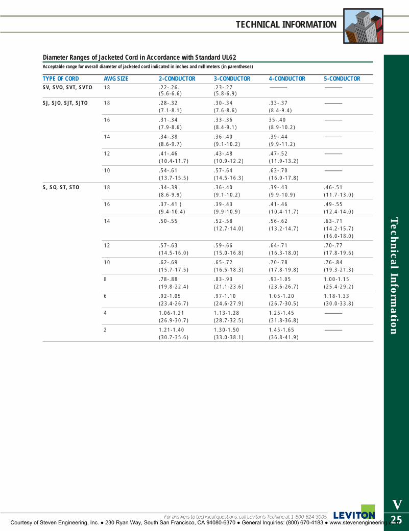
Technical Inform
ation
V25For answers to technical questions, call Leviton’s Techline at 1-800-824-3005
TECHNICAL INFORMATION
Diameter Ranges of Jacketed Cord in Accordance with Standard UL62Acceptable range for overall diameter of jacketed cord indicated in inches and millimeters (in parentheses)
TYPE OF CORD AWG SIZE 2-CONDUCTOR 3-CONDUCTOR 4-CONDUCTOR 5-CONDUCTORSV, SVO, SVT, SVTO 18 .22-.26. .23-.27 — —
(5.6-6.6) (5.8-6.9)
SJ, SJO, SJT, SJTO 18 .28-.32 .30-.34 .33-.37 —(7.1-8.1) (7.6-8.6) (8.4-9.4)
16 .31-.34 .33-.36 35-.40 —(7.9-8.6) (8.4-9.1) (8.9-10.2)
14 .34-.38 .36-.40 .39-.44 —(8.6-9.7) (9.1-10.2) (9.9-11.2)
12 .41-.46 .43-.48 .47-.52 —(10.4-11.7) (10.9-12.2) (11.9-13.2)
10 .54-.61 .57-.64 .63-.70 —(13.7-15.5) (14.5-16.3) (16.0-17.8)
S, SO, ST, STO 18 .34-.39 .36-.40 .39-.43 .46-.51 (8.6-9.9) (9.1-10.2) (9.9-10.9) (11.7-13.0)
16 .37-.41 ) .39-.43 .41-.46 .49-.55 (9.4-10.4) (9.9-10.9) (10.4-11.7) (12.4-14.0)
14 .50-.55 .52-.58 .56-.62 .63-.71(12.7-14.0) (13.2-14.7) (14.2-15.7)
(16.0-18.0)
12 .57-.63 .59-.66 .64-.71 .70-.77(14.5-16.0) (15.0-16.8) (16.3-18.0) (17.8-19.6)
10 .62-.69 .65-.72 .70-.78 .76-.84(15.7-17.5) (16.5-18.3) (17.8-19.8) (19.3-21.3)
8 .78-.88 .83-.93 .93-1.05 1.00-1.15(19.8-22.4) (21.1-23.6) (23.6-26.7) (25.4-29.2)
6 .92-1.05 .97-1.10 1.05-1.20 1.18-1.33(23.4-26.7) (24.6-27.9) (26.7-30.5) (30.0-33.8)
4 1.06-1.21 1.13-1.28 1.25-1.45 —(26.9-30.7) (28.7-32.5) (31.8-36.8)
2 1.21-1.40 1.30-1.50 1.45-1.65 —(30.7-35.6) (33.0-38.1) (36.8-41.9)
Courtesy of Steven Engineering, Inc. ● 230 Ryan Way, South San Francisco, CA 94080-6370 ● General Inquiries: (800) 670-4183 ● www.stevenengineering.com

Tec
hnic
al I
nfor
mat
ion
V26
TECHNICAL INFORMATION
To learn more about Leviton’s outstanding offering of devices visit our Website at: www.leviton.com
WALLPLATE DIMENSIONS
Standard Midway OversizesGangs 4.50 H x D* 4.88 H x .260 D 5.25 H x .260 D
(114.3 H x D*) (123.8 H x 6.5 D) (133.4 H x 6.5 D)
1 2.75 (69.9)W 3.13 (79.4)W 3.50 (88.9)W
2 4.56 (115.9)W 4.94 (125.4)W 5.31 (134.9)W
3 6.38 (161.9)W 6.75 (171.5)W —
4 8.19 (208.0)W
5 10 (254.0)W
6 11.81 (300.0)W
*DEPTHS OF STANDARD WALLPLATES: Plastic — .22 (5.6)Metal — .19 (4.7)
NOTE: This chart is based on the standard calculation of adding 1.81" (46.0) width for each gang in
multi-gang wallplates.
2.75 (69.9) 2.75 (69.9)
1.34 (34.1)
4.50
(114
.3)
4.50
(114
.3)
2.38
(60.
3)
2.66
(67.
5)
1.53
(38.
9)
.41 (10.3) .19 (4.7)
.94
(23.
8)
4.88
(123
.8)
.26 (6.5)
3.13 (79.4)
2.38
(60.
3)
.41 (10.3)
.94
(23.
8)
5.25
(133
.4)
3.50 (88.9)
2.38
(60.
3)
.41 (10.3)
.94
(23.
8)
.26 (6.5)
3.13 (79.4)
4.50
(114
.3)
2.75 (69.9)
STANDARDMIDWAY
OVERSIZED
4.88
(123
.8)
5.25
(133
.4)
3.50 (88.9)
STANDARD SIZE WALLPLATE81001 Series and 81003 Series
MIDWAY SIZE WALLPLATE80501 Series
OVERSIZED WALLPLATE85101 Series
4.56 (115.9)
Ø 2.15(54.5)
1.81 (46.0)
2.38
(60.
3)
4.50
(114
.3)
.19 (4.7)
4934 Series
4.56 (115.9)
Ø 2.47(62.6)
1.81 (46.0)
2.38
(60.
3)
4.50
(114
.3)
.19 (4.7)
S701
4.94 (125.4)
Ø 2.15(54.5)
1.81 (46.0)
2.38
(60.
3)
4.88
(123
.8)
.26 (6.5)
80526 Series
2.75 (69.9)
Ø 2.15(54.5)
2.50
(63.
5)
4.50
(114
.3)
.19 (4.7)
4927 Series
4.88
(123
.8)
.26 (6.5)3.13 (79.4)
Ø 2.15(54.5)
2.50
(63.
5)
80528 Series
POWER RECEPTACLE WALLPLATES
WALLPLATE SIZE COMPARISON
Wallplates
Courtesy of Steven Engineering, Inc. ● 230 Ryan Way, South San Francisco, CA 94080-6370 ● General Inquiries: (800) 670-4183 ● www.stevenengineering.com

Technical Inform
ation
V27For answers to technical questions, call Leviton’s Techline at 1-800-824-3005
TECHNICAL INFORMATION
Industry StandardsAt Leviton, our concern since deregulation has been the proliferation ofpoor quality devices and equipment being attached to the network.These devices meet few of the customary standards for mechanicalintegrity and combustibility and have caused a number of problems forthose who have installed them.The responsibility for ensuring that no sub-standard devices are con-nected to the network rests on everyone’s shoulders. In fact, the FCCrecently issued a Public Notice strongly reminding manufacturers, car-riers and customers that the manufacture and installation of substan-dard devices and equipment will not be tolerated — and that asubstantial fine is the penalty for noncompliance. Recently, organiza-tions such as the Federal Communications Commission (FCC),Underwriter’s Laboratories (UL), the Canadian Standards Association(CSA), and the Telecommunications Industry Association (TIA) havebeen developing standards for premise wiring systems, Additionally,Article 800 of the National Electrical Code (NEC), published by theNational Fire Protection Association (NFPA), mandated “listing” ofequipment connected to telecommunications networks. Leviton hasalways played a role in the standards-making process and will continueto do so. We wholeheartedly support this new standards environment.
Industry Basics: Drawing the LineThe dividing line between public network and customer premises iscalled the demarcation point. Equipment, including wiring, on the net-work side of the demarcation point is the property and responsibility ofthe local telephone company (telco). Equipment and wiring on the customer side is the responsibility of the customer, who may procureequipment, materials, and service from the provider of their choice. Asubscriber network interface (SNI) often called a “demarcation jack”, isrecommended to be installed at the demarcation point. A standard registered jack is often used at this point so that the network and thepremise wiring system can be quickly separated from each other. Thelocation of the SNI depends on local rules and on such factors as thenumber of units in the facility, access, and the type and age of con-necting hardware. The SNI may be inside the building or outside.
FCC Part 68 RequirementsThe equipment standards outlined in FCC Part 68 were developed longbefore divestiture to assure consumers, manufacturers and carriersthat terminal equipment and wiring could be connected withoutdegrading the network. Part 68 describes minimum requirements forthe mechanical or physical properties of wiring devices such as theamount of gold on jack contacts, electrical performance, dimensionalintegrity, material properties, and spring characteristics of contacts.Only equipment meeting FCC Part 68 standards may be manufacturedand connected to the network. The vast changes that have occurred inthe industry because of evolving deregulation have made it necessaryto modify Part 68. To this end, FCC Wiring Docket 88-57 was issued in1990. There have been numerous attempts to change this docket;however, as of this writing, the following guidelines are true:
� Since 1984, Part 68 specified that all connections to the network bemade through the standard plugs and standard telephone company-provided jacks described in Subpart F or Part 68. Now, Docket 88-57permits customers to connect to the carrier’s jack or wiring.
� The demarcation point has been redefined to be not more than 12inches from the protector, or when no protector is present, 12 inchesfrom the point of entry to the premises. In the past, the demarcationpoint could extend into the customer premise hundreds of feet, ifnecessary, depending on the wiring application. The new 12-inch rul-ing limits the carrier’s access to the customer premise.
� The carriers are not responsible for customer wiring unless they havean agreement for such responsibility. Because the customer can nowinstall a jack at the network interface, the customer is responsible forany wiring errors and malfunctions that occur.
� The “extraordinary procedures,” acceptance testing, and carrier noti-fication for wiring clause has been eliminated. The carrier is no longerrequired to take steps to protect the network from harm when there isa violation of Part 68 a failure during testing of newly installed wiring,or when harm has actually occurred. Once again, because the carri-ers now have less access to the customer premise, they will also haveless responsibility in maintaining the network.
� Customer-provided, as well as carrier-provided plugs and jacks mustmeet Subpart F of Part 68 when newly installed on or after January 1,1991. Prior to this ruling, Part 68 could be interpreted to require thatonly the jack at the network interface conform to Part 68.
Beware of the Number GameFCC Part 68, Subpart F, specifies that contacts in the telephone jacksmust have 50 micro-inches of gold over 100 micro-inches of nickel.Some manufacturers claim .5 microns of gold plating on their jack con-tacts. At 39.37 micro-inches per micron, that’s only 19.7 micro-inches— less than half of what is required to meet FCC Part 68 specifications.If jack contacts have not been plated with the right thickness or qualityof gold, corrosion at these critical points can cause signal degradation,equipment failure, and even damage to the public telephone network.Data networks are more at risk because even slight imperfections resultin transmission error or data loss.
Reduce Risks — Specify LevitonThere are no two ways about it. The risk to your operation and equip-ment is so great that it only makes sense to insist on top-quality stationproducts. When you specify Leviton jacks, you’re assured maximumcontact life with minimum resistance. We start with durable phosphor-bronze contacts and plate them with a full 50 micro-inches of lubri-cated hard gold over 100 micro-inches of nickel (or the electricalperformance equivalent as specified in FCC Part 68 requirements).Jack openings are built within precise tolerances. High-quality thermo-plastic rated UL 94V-0 resists distortion from changes in temperatureand humidity, physical stress, and aging. Spring contacts are engi-neered to maintain positive contact pressure over the life of the device.
Telecommunications Industry Association StandardsIf FCC regulations protect the telephone network from harm and ULrequirements protect the consumer from harm, who is responsible forproviding performance standards for the telecommunications industry?Recently, the FCC asked the Telecommunications Industry Association(TIA), a sister organization of the Electronic Industries Association (EIA),to take on this task, and they accepted the challenge. The TIA wasasked to define minimum standards for such things as how to wire abuilding, what kind of wire to use, and so on. The following standardswent into effect in 1991.
� Pathway Standard (EIA/TIA 569-A): This standard for installing pipeand conduit in commercial buildings is now available through TIAand the American National Standards Institute (ANSI).
� Residential/Light Commercial Wiring (EIA/TIA 570): A draft of thisstandard, which applies to premises with up to four telephone lines,has been reviewed by ANSI and TIA committees and released.
� Commercial Wiring Standard (EIA/TIA 568-A): The Commercial WiringStandard applies to premises with more than four telephone lines.This draft has also been reviewed and released by ANSI and TIA committees. At time of printing, the standards are undergoing majorrevisions and are currently up for ballot.
We’re the “Standards” PeopleBecause Leviton is an active participant in the formation of NorthAmerican codes and standards, you can be assured that our productdevelopment activities fully support this emerging standards environ-ment. In fact. we have prepared several publications which describestandard practices and provide installation guidelines for contractors.Many Leviton distributors also sponsor training programs dealing withtelecom wiring. And, of course, Leviton’s Applications EngineeringGroup is always ready to assist you with any questions you may haveabout standards and codes, standard practices, or any installationproblem.
Telephone Wiring Devices Codes and Standards
Courtesy of Steven Engineering, Inc. ● 230 Ryan Way, South San Francisco, CA 94080-6370 ● General Inquiries: (800) 670-4183 ● www.stevenengineering.com

Tec
hnic
al I
nfor
mat
ion
V28
TECHNICAL INFORMATION
To learn more about Leviton’s outstanding offering of devices visit our Website at: www.leviton.com
Electrical Network ConnectionFrom 1 to 25 single or multiple-pair circuits bridged to the network orother connected equipment.
Mechanical ArrangementCircuits are provided on numbered tip and ring positions on a minia-ture 50-pin ribbon connector (Amphenol-type). Pins 1 (ring) and 26(tip) are considered position 1. Pins 2 (ring) and 27 (tip) of the rib-bon connector are position 2. This pairing continues through twenty-five pairs.
Typical UsageMany key and PBX systems specify the RJ21X, or ‘Amphenol-type’ asthe network interface device. Many of these systems also use theRJ21X as a connector for stations or telephone sets, wired from theKSU or PBX Main Distribution Frame.Note: Sometimes an RJ11 or RJ14C can be installed in place of anRJ21X. While many smaller systems that require only a few lines mayshow the RJ21X as the ‘official’ jack required under registration, lesscomplex jacks such as the RJ11 or RJ14C can often be specified (per-haps in multiples). If the system requires only a few lines but theRJ21X is specified on the registration label, under FCC Part 68 youmay specify the RJ11C, RJ14C, RJ25C, or RJ61X instead. Many Leviton jacks can be used for the RJ21X configuration where‘intermixing’ is permitted. Substitution of these special jacks is oftenboth economical and practical. Contact Leviton Telcom ApplicationsEngineering for information about versions to meet your requirements.
ISDN Assignment of Contact Numbers as specified byISO Document 8877: 1987 (E)Contact assignments for plugs and jacks:
CONTACT TE NT POLARITYNUMBER 1 Power source 3 Power sink 3 +
2 Power source 3 Power sink 3 -
3 Transmit Receive +
4 Receive Transmit +
5 Receive Transmit -
6 Transmit Receive -
7 Power sink 2 Power source 2 -
8 Power sink 2 Power source 2 +
Note: For use in TE to TE interconnections, power source/sink 3 shall conformto the requirements specified in CCITT Recommendation 1.430, section 9.2 forpower source/sink 2.
Wire Color Codes and Jack Pin Designations
25-PAIR COLOR CODING/ISDN CONTACT ASSIGNMENTS
WIRE COLOR CODES
RJ21X
TIP
RING
ACCESSORY
GROUND
PAIR1
PAIR 2
GREEN
BLACK
YELLOW
RED
Courtesy of Steven Engineering, Inc. ● 230 Ryan Way, South San Francisco, CA 94080-6370 ● General Inquiries: (800) 670-4183 ● www.stevenengineering.com

1
THIS PAGE A0001–IPF01
CAT. NO. PAGE NO.A0001 . . . . . . . . . . . . . . .P18A0002 . . . . . . . . . . . . . . .P18A0003 . . . . . . . . . . . . . . .P18A0004 . . . . . . . . . . . . . . .P18A0005 . . . . . . . . . . . . . . .P18A0006 . . . . . . . . . . . . . . .P18A0007 . . . . . . . . . . . . . . .P18AC00R-10 . . . . . . . . . . . . . .A3AC00R-1L . . . . . . . . . . . . . .A3AC00R-7B . . . . . . . . . . . . .A3AC084 . . . . . . . . . . . . .A7, L17AC0SR-10 . . . . . . . . . . . . . .A4AC0SR-1L . . . . . . . . . . . . . .A4AC108-R*5 . . . . . . . . .A7, L17AC201-1L . . . . . . . . . . . . . .A4AC201-7L . . . . . . . . . . . . . .A4AC203-1L . . . . . . . . . . . . . .A4AC204-1L . . . . . . . . . . . . . .A4AC204-7L . . . . . . . . . . . . . .A4AC215 . . . . . . . . . . . . . . . .A5AC220 . . . . . . . . . . . . . . . .A5AC315 . . . . . . . . . . . . .A2, A5AC320 . . . . . . . . . . . . . . . .A5AC642 . . . . . . . . . . . . .A7, L17AC643 . . . . . . . . . . . . .A7, L17AC644 . . . . . . . . . . . . .A7, L17AC646 . . . . . . . . . . . . .A7, L17AC734 . . . . . . . . . . . . .A7, L17AC735 . . . . . . . . . . . . .A7, L17AC830 . . . . . . . . . . . . .A7, L17AC831 . . . . . . . . . . . . .A7, L17AC832 . . . . . . . . . . . . .A7, L17AC833 . . . . . . . . . . . . .A7, L17AC837 . . . . . . . . . . . . .A7, L17ACE04-1L . . . . . . . . . . . . . .A3ACE06-1L . . . . . . . . . . . . . .A3ACE06-1LW . . . . . . . . . . . . .A3ACF01-1L . . . . . . . . . . . . . .A3ACGF1 . . . . . . . . . . . . . . . .A5ACGF2 . . . . . . . . . . . . . . . .A5ACH06-7B . . . . . . . . . . . . .A3ACH08-1L . . . . . . . . . . . . . .A3ACI06-1L . . . . . . . . . . . . . .A3ACI06-ILW . . . . . . . . . . . . . .A3ACM06-1L . . . . . . . . . . . . .A3ACM10-1L . . . . . . . . . . . . .A3ACP0R-CB . . . . . . . . . . . . .A4ACP15-CB . . . . . . . . . . . . .A4ACS15-1L . . . . . . . . . . .A2, A4ACSIS-1L . . . . . . . . . . . . . .A4ACSR6 . . . . . . . . . . . . .A2, A5ACSSR . . . . . . . . . . . . . . . .A5ACT60-L . . . . . . . . . . . . . . .A4ACW14 . . . . . . . . . . . . . . . .A6ACWM1-STS . . . . . . . . . . . .A6ACWM2-STS . . . . . . . . . . . .A6ACWM3-STS . . . . . . . . . . . .A6
CAT. NO. PAGE NO.ACWM4-STS . . . . . . . . . . . .A6ACWM5-STS . . . . . . . . . . . .A6ACWM6-STS . . . . . . . . . . . .A6ACWP1-W . . . . . . . . . .A6, L17ACWP2 . . . . . . . . . . . .A6, L17ACWP3 . . . . . . . . . . . .A6, L17ACWP4 . . . . . . . . . . . .A6, L17ACWP5 . . . . . . . . . . . .A6, L17ACWP6 . . . . . . . . . . . .A6, L17ACX10-1L . . . . . . . . . . . . . .A3ACX12-7B . . . . . . . . . . . . . .A3AE6MA . . . . . . . . . . . . . . .J27AE6MC . . . . . . . . . . . . . . .J27AEC65 . . . . . . . . . . . . . . . .J23AEC80 . . . . . . . . . . . . . . . .J23AECCS . . . . . . . . . . . . . . . .J24AEH50 . . . . . . . . . . . . . . .J25AEHTK . . . . . . . . . . . . . . .J34AEI55 . . . . . . . . . . . . . . . .J24AEI65 . . . . . . . . . . . . . . . .J23AEI80 . . . . . . . . . . . . . . . .J23AEM65 . . . . . . . . . . . . . . .J23AEMRK . . . . . . . . . . . . . . .J34AEN24 . . . . . . . . . . . . . . .J24AEPC8 . . . . . . . . . . . . . . . .J24AEPHK . . . . . . . . . . . . . . .J25AEPI6 . . . . . . . . . . . . . . . .J24AEPI8 . . . . . . . . . . . . . . . .J24AEPIS . . . . . . . . . . . . . . . .J24AES36 . . . . . . . . . . . . . . . .J24AESS5 . . . . . . . . . . . . . . . .J25AESUB . . . . . . . . . . . . . . .J25BR15 . . . . . . . . . . . . . . . .G13BR20 . . . . . . . . . . . . . . . .G13BX60-V . . . . . . . . . . . . . . . .O5BX100-V . . . . . . . . . . . . . . .O5BX230-V . . . . . . . . . . . . . . .O4C0001 . . . . . . . . . . . . . . .P18C2623 . . . . . . . . . . . . . . .N12C2623-B . . . . . . . . . . . . .N12C2623-CY . . . . . . . . . . . . .N12C2651 . . . . . . . . . . . . . . .N13C2653 . . . . . . . . . . . . . . .N13CA060 . . . . . . . . . . . . . . .O22CA320 . . . . . . . . . . . . . . .O22CA343 . . . . . . . . . . . . . . .O22CA420 . . . . . . . . . . . . . . .O22CA520 . . . . . . . . . . . . . . .O22CA530 . . . . . . . . . . . . . . .O22CN100-0D0 . . . . . . . . . . .D18CN200-00C . . . . . . . . . . .D18CN220-00C . . . . . . . . . . .D18CN221-00C . . . . . . . . . . .D18CR015 . . . . . . . . . . . . . . .G14CR15 . . . . . . . . . . . . . . . .G14CR15S-G . . . . . . . . . . . . .G14CR020 . . . . . . . . . . . . . . .G14CR20 . . . . . . . . . . . . . . . .G14
CAT. NO. PAGE NO.CS63-60C . . . . . . . . . . . . .N26CS63-61C . . . . . . . . . . . . .N26CS63-64C . . . . . . . . . . . . .N26CS63-65C . . . . . . . . . . . . .N26CS63-69 . . . . . . . . . . . . . .N26CS63-70 . . . . . . . . . . . . . .N26CS63-75 . . . . . . . . . . . . . .N26CS63-77 . . . . . . . . . . . . . .N26CS81-64C . . . . . . . . . . . . .N26CS81-65C . . . . . . . . . . . . .N26CS81-69 . . . . . . . . . . . . . .N26CS81-75 . . . . . . . . . . . . . .N26CS82-64C . . . . . . . . . . . . .N26CS82-65C . . . . . . . . . . . . .N26CS82-69 . . . . . . . . . . . . . .N26CS82-75 . . . . . . . . . . . . . .N26CS83-64C . . . . . . . . . . . . .N26CS83-65C . . . . . . . . . . . . .N26CS83-69 . . . . . . . . . . . . . .N26CS83-75 . . . . . . . . . . . . . .N26CS84-64C . . . . . . . . . . . . .N26CS84-65C . . . . . . . . . . . . .N26CS84-69 . . . . . . . . . . . . . .N26CS84-75 . . . . . . . . . . . . . .N26CS115-2 . . . . . . . . . . . . . .F12CS120-2 . . . . . . . . . . . . . .F12CS215-2 . . . . . . . . . . . . . .F12CS220-2 . . . . . . . . . . . . . .F12CS315-2 . . . . . . . . . . . . . .F12CS320-2 . . . . . . . . . . . . . .F12CS415-2 . . . . . . . . . . . . . .F12CS420-2 . . . . . . . . . . . . . .F12CSB1-15 . . . . . . . . . . . . . .F12CSB1-20 . . . . . . . . . . . . . .F12CSB2-15 . . . . . . . . . . . . . .F12CSB2-20 . . . . . . . . . . . . . .F12CSB3-15 . . . . . . . . . . . . . .F12CSB3-20 . . . . . . . . . . . . . .F12CSB4-15 . . . . . . . . . . . . . .F12CSB4-20 . . . . . . . . . . . . . .F12D32CK . . . . . . . . . . . . . . . .C3D3204-1LW . . . . . . . . . . . . .C3D3204-2LW . . . . . . . . . . . . .C3D3206-1LW . . . . . . . . . . . . .C3D3206-2LW . . . . . . . . . . . . .C3D3208-1LW . . . . . . . . . . . . .C3D4000 Series . . . . . . . . . . .C6D4200 . . . . . . . . . . . . . . . .C5D4200-OW . . . . . . . . . . . . .C6D42CS . . . . . . . . . . . . . . . .C6D42ET . . . . . . . . . . . . . . . .C6D42IR . . . . . . . . . . . . . . . . .C6D42LI . . . . . . . . . . . . . . . . .C6D42LO . . . . . . . . . . . . . . . .C6D42M0 . . . . . . . . . . . . . . . .C6D42P1 . . . . . . . . . . . . . . . .C6D42P4 . . . . . . . . . . . . . . . .C6D42P8 . . . . . . . . . . . . . . . .C6
CAT. NO. PAGE NO.D42P9 . . . . . . . . . . . . . . . .C6D42RL . . . . . . . . . . . . . . . .C6D42SQ . . . . . . . . . . . . . . . .C6D670K . . . . . . . . . . . . . . .L31D675E . . . . . . . . . . . . . . . .L31D6701 . . . . . . . . . . . . . . . .L31D6706 . . . . . . . . . . . . . . . .L31D6710 . . . . . . . . . . . . . . . .L31D6720 . . . . . . . . . . . . . . . .L31D6721 . . . . . . . . . . . . . . . .L31D8000 . . . . . . . . . . . . . . . .C5DCK05-OC . . . . . . . . . . . . .C4DCK3D . . . . . . . . . . . . . . . .K5DCK4A . . . . . . . . . . . . . . . .K5DCK4D . . . . . . . . . . . . . . . .K5DCKS7 . . . . . . . . . . . . . . .C25 DRK0D-1LX . . . . . . . . . . . .K9 DRK0R-00 . . . . . . . .K12, C23DRKDD-1L . . . . . . . .C23-C24DRK0S-0LX . . . . . . . . . .K4, K9DRK1D-00X . . . . . . . . . . . .K4 DRK0S-0LX . . . . . . . . . . . . .K9DS30-AX . . . . . . . . . . . . . . .F9DS60-AX . . . . . . . . . . . . . . .F9DS100-AX . . . . . . . . . . . . . .F9DS30-FAX . . . . . . . . . . . . . .F9DS60-FAX . . . . . . . . . . . . . .F9HCA02-10E . . . . . . . . . . .K16HCCPRF-1TW . . . . . . . . . . K6HCCKR-E . . . . . . . . . . . . . .K6HCCUR . . . . . . . . . . . . . . . .K6 HCM06-1DW . . . . . . . . . . .K8HCMI0-1DW . . . . . . . . . . . .K8HCM06-1SW . . . . . . . . . . . .K9HCM10-1SW . . . . . . . . . . . .K9HCP03-10W . . . . . . . . . . .K10HCS10-1SW . . . . . . . . . . . .K9HKABH . . . . . . . . . . . . . . .J26HKABV . . . . . . . . . . . . . . .J26HKAVR . . . . . . . . . . . . . . .J26HKCDC . . . . . . . . . . . . . . .J26HKDVD . . . . . . . . . . . . . . .J26HKPOD . . . . . . . . . . . . . . .J26HKRMS . . . . . . . . . . . . . . .J26HXC3D-1TW . . . . . . . . . . . .K5HXC4A-1TW . . . . . . . . . . . .K5HXC4D-1TW . . . . . . . . . . . .K5HXC7S-1TW . . . . . . . . . . . .K5HXC10-1TW . . . . . . . . . . . .K4HXC1A-1TW . . . . . . . . . . . .K4HXC1D-1TW . . . . . . . . . . . .K4HXC2D-1TW . . . . . . . . . . . .K4HXM06-1TW . . . . . . . . . . . .K8HXM10-1TW . . . . . . . . . . . .K8HXS08-1TW . . . . . . . . . . . .K8HXP15-1TW . . . . . . . . . . .K10IPE04 . . . . . . . . . . . . . . . .C30IPF01 . . . . . . . . . . . . . . . .C30
CATALOG NUMBER ALPHANUMERIC INDEXImportant: Dash-numbers, indicating different product colors or other variations, are listed on the
same page as the basic catalog numbers shown below, unless otherwise indicated.
Courtesy of Steven Engineering, Inc. ● 230 Ryan Way, South San Francisco, CA 94080-6370 ● General Inquiries: (800) 670-4183 ● www.stevenengineering.com

2
CATALOG NUMBER ALPHANUMERIC INDEXImportant: Dash-numbers, indicating different product colors or other variations, are listed on thesame page as the basic catalog numbers shown below, unless otherwise indicated.
THIS PAGE IPF05–RA520
CAT. NO. PAGE NO.IPF05 . . . . . . . . . . . . . . . .C30IPI06 . . . . . . . . . . . . . . . .C30IPI10-1L . . . . . . . . . . . . . .C30IPIM10 . . . . . . . . . . . . . . .C30IPKIT . . . . . . . . . . . . . . . .C30IPM06 . . . . . . . . . . . . . . .C30IPP15-IL . . . . . . . . . . . . . . .D6IPPOR-1L . . . . . . . . . . . . . .D6IPQFK . . . . . . . . . . . . . . . .C30IP710 . . . . . . . . . . . . . . . .C30IPX10 . . . . . . . . . . . . . . . .C30KRS-A9519 . . . . . . . . . . . .H7KUS-A9519 . . . . . . . . . . . .H7L21-20P . . . . . . . . . . . . . .R18L7500 Series . . . . . . . . . . .Q15L7600 Series . . . . . . . . . . .Q15L7700 Series . . . . . . . . . . .Q17L7900 Series . . . . . .Q18, Q25L7902 . . . . . . . . . . . . . . . .O22L7903 . . . . . . . . . . . . . . . .O22L7904 . . . . . . . . . . . . . . . .O22L7905 . . . . . . . . . . . . . . . .O22L7918 . . . . . . . . . . . . . . .Q18L8000 Series . . . . . . . . . . .Q18L8500 Series . . . . . . .Q8–Q11L8600 Series . . . . . .Q11–Q14L8700 Series . . . . . . . . . . .Q14L8800 Series . . . . . . .Q9, Q26L9500 Series . . . . . .Q20–Q21L9600 Series . . . . . . .Q23,Q25L9700 Series . . . . . .Q21, Q23LVS-XXX . . . . . . . . . . . . . .D26MCM06-1L . . . . . . . .C23,C24MCM10 . . . . . . . . . . . . . .C24MCX10 . . . . . . . . . . . . . . .C24MDE03 . . . . . . . . . . . . . . .C23MDF01 . . . . . . . . . . . . . . .C23MDI06 . . . . . . . . . . . . . . .C23MDI10 . . . . . . . . . . . . . . .C23MDM06 . . . . . . . . . . . . . .C23MH101 . . . . . . . . . . . . . . .R18MH122 . . . . . . . . . . . . . . .R18ML1-AC . . . . . . . . . . . . . .N29ML1-AP . . . . . . . . . . . . . .N29ML1-C . . . . . . . . . . . . . . .N29ML1-P . . . . . . . . . . . . . . .N29ML1-PB . . . . . . . . . . . . . .N29ML1-PER . . . . . . . . . . . . .N29ML2-AC . . . . . . . . . . . . . .N29ML2-AP . . . . . . . . . . . . . .N29ML2-C . . . . . . . . . . . . . . .N29ML2-P . . . . . . . . . . . . . . .N29ML2-PB . . . . . . . . . . . . . .N29ML2-PER . . . . . . . . . . . . .N29ML3-AC . . . . . . . . . . . . . .N29ML3-AP . . . . . . . . . . . . . .N29ML3-C . . . . . . . . . . . . . . .N29
CAT. NO. PAGE NO.ML3-P . . . . . . . . . . . . . . .N29ML3-PB . . . . . . . . . . . . . .N29ML3-PER . . . . . . . . . . . . .N29MNE04 . . . . . . . . . . . . . . .C11MNF07 . . . . . . . . . . . . . . .C11MNF10 . . . . . . . . . . . . . . .C11MNI06 . . . . . . . . . . . . . . .C11MNI10 . . . . . . . . . . . . . . .C11MNI15 . . . . . . . . . . . . . . .C11MNK0R . . . . . . . . . . . . . .C11MNKIT . . . . . . . . . . . . . . .C11MNM06 . . . . . . . . . . . . . .C11MNM10 . . . . . . . . . . . . . .C11MNM15 . . . . . . . . . . . . . .C11MNS20-1L . . . . . . . . . . . .C12MNS20-D3 . . . . . . . . . . . .C12MNS20-D4 . . . . . . . . . . . .C12MNX10 . . . . . . . . . . . . . .C11MNX15 . . . . . . . . . . . . . .C11MNX20 . . . . . . . . . . . . . .C11MNX30 . . . . . . . . . . . . . .C11MN00C-1LW . . . . . . . . . . .C25 MN00R-DOW . . . . . . . . . .C11MN0LA . . . . . . . . . . . . . . .C11MN0SA . . . . . . . . . . . . . . .C11MSE0R-10 . . . . . . . . . . . .C23MS00R-10 . . . . . . . . . . . .C23MS2-P . . . . . . . . . . . . . . .N29MS2-AP . . . . . . . . . . . . . .N29MS302 . . . . . . . . . . . . . . . .F7MS302-S . . . . . . . . . . . . . . .F7MS303 . . . . . . . . . . . . . . . .F7MS303-S . . . . . . . . . . . . . . .F7MS402 . . . . . . . . . . . . . . . .F7MS403 . . . . . . . . . . . . . . . .F7MS602-BW . . . . . . . . . . . . .F7MS602-FW . . . . . . . . . . . . .F7MS603-BW . . . . . . . . . . . . .F7MS603-FW . . . . . . . . . . . . .F7MV121 . . . . . . . . . . . . . . .R18MV122 . . . . . . . . . . . . . . .R18MV123 . . . . . . . . . . . . . . .R18MV241 . . . . . . . . . . . . . . .R18MV242 . . . . . . . . . . . . . . .R18NE100-00C . . . . . . . .C4, D18NE200-00E . . . . . . . . . . .D18NE210 . . . . . . . . . . . . . . . .C4NE505 . . . . . . . . . . . . . . . .C4NE515 . . . . . . . . . . . . . . . .C4NE600 . . . . . . . . . . . . . . . .C4N13NC . . . . . . . . . . . .F7, E34N138 . . . . . . . . . . . . . . . .E27N751 . . . . . . . . . . . . . . . .E29N1302 . . . . . . . . . . . . . . . .F7N1303 . . . . . . . . . . . . . . . .F7N3302 . . . . . . . . . . . . . . . .F7N3303 . . . . . . . . . . . . . . . .F7N3602 . . . . . . . . . . . . . . . .F7
CAT. NO. PAGE NO.N3603 . . . . . . . . . . . . . . . .F7ODCCG . . . . . . . . . . . . . . . .D9ODCCG-000 . . .D10, D11, D12ODCOP . . . . . . . . . . . . . . .D18ODCOS-I1W . . . . . . . . . . . .D9ODCOS-I2W . . . . . . . . . . . .D9ODCOS-I7W . . . . . . . . . . . .D9ODSIOD-ID . . . . . . . . . . . . .D4ODSOD-TD . . . . . . . . . . . . .D4ODS10-ID . . . . . . . . . . . . . .D3ODS15-ID . . . . . . . . . . . . . .D3OPB15-ODW . . . . . . . . . . .D8OSA20-R00 . . . . . . . . . . .D15OSCO4-I0W . . . . . . .D12, D17OSCO5-M0W . . . . . .D10, D17OSCO5-U0W . . . . . .D11, D17OSC10-M0W . . . . . .D10, D17OSC10-U0W . . . . . . .D11, D17OSC15-I0W . . . . . . .D12, D17OSC20-M0W . . . . . .D10, D17OSC20-U0W . . . . . . . . . . .D11OSFHU-ITW . . . . . . . . . . . .D7OSFOA-00W . . . . . . . . . . .D7OSP15-R30 . . . . . . . . . . .D15OSP20-0D0 . . . . . . . . . . .D15OSP20-RD0 . . . . . . . . . . .D15OSPNA-000 . . . . . . . . . . .D15OSSMT-MD . . . . . . . . . . . . .D4OSSNL-ID . . . . . . . . . . . . . .D3OSS10-ID . . . . . . . . . . . . . .D3OSW12-M0W . . . . . .D13, D17OSWHB-I0W . . . . . . . . . . .D14OSWWV-I0W . . . . . . .D14, D17OSWLR-I0W . . . . . . .D14, D17P22 . . . . . . . . . . . . . . . . . .E15P32 . . . . . . . . . . . . . . . . . .E15P38 . . . . . . . . . . . . . . . . . .E24P48 . . . . . . . . . . . . . . . . . .E24 P326 . . . . . . . . . . . . . . . . .E25P1020-12S . . . . . . . . . . . .R17P1021-12S . . . . . . . . . . . .R17P1022-12L . . . . . . . . . . . .R17P1023-12L . . . . . . . . . . . .R17P1024-12L . . . . . . . . . . . .R17P1025-12L . . . . . . . . . . . .R17P1040-10S . . . . . . . . . . . .R17P1041-10S . . . . . . . . . . . .R17P1042-10L . . . . . . . . . . . .R17P1043-10S . . . . . . . . . . . .R17P1044-10L . . . . . . . . . . . .R17P1045-10L . . . . . . . . . . . .R17P1046-10L . . . . . . . . . . . .R17P1047-10L . . . . . . . . . . . .R17P1426 . . . . . . . . . . . . . . . .E28P2262 . . . . . . . . . . . . . . . .E25PB101-SGF . . . . . . . . . . . .H7PB103-SGF . . . . . . . . . . . .H7PCC55 . . . . . . . . . . . . . . . .J33
CAT. NO. PAGE NO.PCC55-KIT . . . . . . . . . . . .J24PCI65 . . . . . . . . . . . . . . . .J33PCI80 . . . . . . . . . . . . . . . .J33PCORD . . . . . . . . . . .R18, R19PC60 . . . . . . . . . . . . . . . .O22PC100 . . . . . . . . . . . . . . .O22PC320 . . . . . . . . . . . . . . .O22PC420 . . . . . . . . . . . . . . .O22PC520 . . . . . . . . . . . . . . .O22PC530 . . . . . . . . . . . . . . .O22PC3430 . . . . . . . . . . . . . .O22PEAUX . . . . . . . . . . . . . . . .C7PEAU7 . . . . . . . . . . . . . . . .C7PE100 . . . . . . . . . . . . . . . .C7PE200 . . . . . . . . . . . . . . . .C7PE300 . . . . . . . . . . . . . . . .C7PE400 . . . . . . . . . . . . . . . .C7PJ1 . . . . . . . . . . . . . . . . . . .E7PJ2 . . . . . . . . . . . . . . . . . . .E7PJ3 . . . . . . . . . . . . . . . . . . .E7PJ4 . . . . . . . . . . . . . . . . . . .E8PJ7 . . . . . . . . . . . . . . . . . .E12PJ8 . . . . . . . . . . . . . .E10, E29PJ11 . . . . . . . . . . . . . . . . .E13PJ13 . . . . . . . . . . . . . . . . .E16PJ18 . . . . . . . . . . . . . . . . .E23PJ23 . . . . . . . . . . . . . . . . .E16PJ26 . . . . . . . . . . . . . .B22, E4PJ82 . . . . . . . . . . . . .E10, E29PJ126 . . . . . . . . . . . . . . . .E25PJ226 . . . . . . . . . . . . . . . .E25PJ262 . . . . . . . . . . . . .B22, E4PJ263 . . . . . . . . . . . . .B22, E4PJ264 . . . . . . . . . . . . . . . . .E5PJ826 . . . . . . . . . . . . . . . .E27PLG1 . . . . . . . . . . . . . . . .O22PR150-1L . . . . . . . . . . . . . .D5 PR180-1L . . . . . . . . . . . . . .D5 PSC1 . . . . . . . . . . . . . . . .E29PSC7 . . . . . . . . . . . . . . . .E29PSC8 . . . . . . . . . . . . . . . .E29PSC14 . . . . . . . . . . . . . . .E29PSC26 . . . . . . . . . . . . . . .E29PSE1 . . . . . . . . . . . . . . . . .E29PSE7 . . . . . . . . . . . . . . . . .E29PSE8 . . . . . . . . . . . . . . . . .E29PSE14 . . . . . . . . . . . . . . . .E29PSE26 . . . . . . . . . . . . . . . .E29PS110-10 . . . . . . . . . . . . .D16PS110-1F . . . . . . . . . . . . .D16PS200-10 . . . . . . . . . . . . .D16PS200-1F . . . . . . . . . . . . .D16RA060 . . . . . . . . . . . . . . .O22RA100 . . . . . . . . . . . . . . .O22RA320 . . . . . . . . . . . . . . .O22RA343 . . . . . . . . . . . . . . .O22RA420 . . . . . . . . . . . . . . .O22RA520 . . . . . . . . . . . . . . .O22
Courtesy of Steven Engineering, Inc. ● 230 Ryan Way, South San Francisco, CA 94080-6370 ● General Inquiries: (800) 670-4183 ● www.stevenengineering.com

3
CATALOG NUMBER ALPHANUMERIC INDEXImportant: Dash-numbers, indicating different product colors or other variations, are listed on the
same page as the basic catalog numbers shown below, unless otherwise indicated.
THIS PAGE RA530–5G271
CAT. NO. PAGE NO.RA530 . . . . . . . . . . . . . . .O22RB241-XXX . . . . . . . . . . .D23RB243-XXX . . . . . . . . . . .D23RB421-XXX . . . . . . . . . . .D23RB423-XXX . . . . . . . . . . .D23RE4BD-XXX . . . . . . . . . . .D24RE4SD-XXX . . . . . . . . . . .D24RELAY-XXX . . . . . . . . . . . .D22RO8BD-XXX . . . . . . . . . . .D22RPI06 . . . . . . . . . . . . . . .C31RS110-10 . . . . . . . . . . . . .D16RS110-1F . . . . . . . . . . . . .D16RTD01-1L . . . . . . . . . . . .C31RTF01-1L . . . . . . . . . . . . .C31RZCOP-1LW . . . . . . . . . . .C21RZC1-1L . . . . . . . . . . . . . .C22RZC24-1L . . . . . . . . . . . . .C22RZCPG-0SG . . . . . . . . . . .C22RZCPG-BSG . . . . . . . . . . .C22RZCS1-1L . . . . . . . . . . . . .C22RZCS4-1L . . . . . . . . . . . . .C22RZI06-1L . . . . . . . . . . . . .C21RZI10-1L . . . . . . . . . . . . .C21RZM10-1L . . . . . . . . . . . .C21RZMR1-OSG . . . . . . . . . . .C22RZP03-1LW . . . . . . . . . . .C21RZP15-1LW . . . . . . . . . . .C21RZS15-1L . . . . . . . . . . . . .C21S48-N . . . . . . . . . . . . . . . .E24S54-N . . . . . . . . . . . . . . . .E18S73-N . . . . . . . . . . . . . . . .E12S112-N . . . . . . . . . . . . . . .E27S126 . . . . . . . . . . . . . . . . .E25S214-N . . . . . . . . . . . . . . .E26S426-N . . . . . . . . . . . . . . .E25S601 . . . . . . . . . . . . . . . . . .E9S602 . . . . . . . . . . . . . . . . . .E9S603 . . . . . . . . . . . . . . . . . .E9S604 . . . . . . . . . . . . . . . . . .E9S701 . . . . . . . . . . . . . . . . .E20S701-40 . . . . . . . . . . . . . .E20S746-N . . . . . . . . . . . . . . .E21S751 . . . . . . . . . . . . . . . . .E29S1000 Series . . . . . . . . . .R15S1426-N . . . . . . . . . . . . . .E28S2000 Series . . . . . . . . . .R15SAA12 . . . . . . . . . . . . . . .O22SAB12 . . . . . . . . . . . . . . .O22SAB34 . . . . . . . . . . . . . . .O22SAC34 . . . . . . . . . . . . . . .O22SAC100 . . . . . . . . . . . . . .O22SAC125 . . . . . . . . . . . . . .O22SAD125 . . . . . . . . . . . . . .O22SGAMP . . . . . . . . . . . . . . .J31SGC65 . . . . . . . . . . . . . . . .J33SGI65 . . . . . . . . . . . . . . . .J33SGI80 . . . . . . . . . . . . . . . .J33
CAT. NO. PAGE NO.SGO99 . . . . . . . . . . . . . . .J33SGVCK . . . . . . . . . . . . . . .J28SGVSM . . . . . . . . . . . . . . .J28SGVST . . . . . . . . . . . . . . . .J28SHO81 . . . . . . . . . . . . . . .R19SHO82 . . . . . . . . . . . . . . .R19SJ26 . . . . . . .B20, B22, E2, E4SJ262 . . . . . .B20, B22, E2, E4SJ263 . . . . . .B20, B22, E2, E4SJ264 . . . . . .B20, B23, E2, E5SJ265 . . . . . .B20, B23, E2, E5SJ266 . . . . . .B20, B23, E2, E5SO26 . . . . . . . . . . . . . . . . .E4SO262 . . . . . . . . . . . . . . . .E4SO263 . . . . . . . . . . . . . . . .E4SP316B . . . . . . . . . . . . . .O20SP316B4 . . . . . . . . . . . . .O16SP316B6 . . . . . . . . . . . . .O16SP316C . . . . . . . . . . . . . .O18SP316C4 . . . . . . . . . . . . .O16SP316C6 . . . . . . . . . . . . .O16SP316P . . . . . . . . . . . . . .O18SP316P4 . . . . . . . . . . . . .O16SP316P6 . . . . . . . . . . . . .O16SP316R . . . . . . . . . . . . . .O19SP316R4 . . . . . . . . . . . . .O16SP316R6 . . . . . . . . . . . . .O16SP332B . . . . . . . . . . . . . .O20SP332B4 . . . . . . . . . . . . .O16SP332B6 . . . . . . . . . . . . .O16SP322C . . . . . . . . . . . . . .O18SP332C4 . . . . . . . . . . . . .O16SP332C6 . . . . . . . . . . . . .O16SP332P . . . . . . . . . . . . . .O18SP332P4 . . . . . . . . . . . . .O16SP332P6 . . . . . . . . . . . . .O16SP332R . . . . . . . . . . . . . .O19SP332R4 . . . . . . . . . . . . .O16SP332R6 . . . . . . . . . . . . .O16SP363B . . . . . . . . . . . . . .O20SP363B6 . . . . . . . . . . . . .O16SP363C . . . . . . . . . . . . . .O18SP363C6 . . . . . . . . . . . . .O16SP363P . . . . . . . . . . . . . .O18SP363P6 . . . . . . . . . . . . .O16SP363R . . . . . . . . . . . . . .O19SP363R6 . . . . . . . . . . . . .O16SP416B . . . . . . . . . . . . . .O20SP416B6 . . . . . . . . . . . . .O16SP416C . . . . . . . . . . . . . .O18SP416C6 . . . . . . . . . . . . .O16SP416P . . . . . . . . . . . . . .O18SP416P6 . . . . . . . . . . . . .O16SP416R . . . . . . . . . . . . . .O19SP416R6 . . . . . . . . . . . . .O16SP432B . . . . . . . . . . . . . .O20SP432B6 . . . . . . . . . . . . .O16SP432C . . . . . . . . . . . . . .O18
CAT. NO. PAGE NO.SP432C6 . . . . . . . . . . . . .O16SP432P . . . . . . . . . . . . . .O18SP432P6 . . . . . . . . . . . . .O16SP432R . . . . . . . . . . . . . .O19SP432R6 . . . . . . . . . . . . .O16SP463B . . . . . . . . . . . . . .O20SP463B6 . . . . . . . . . . . . .O16SP463C . . . . . . . . . . . . . .O18SP463C6 . . . . . . . . . . . . .O16SP463P . . . . . . . . . . . . . .O18SP463P6 . . . . . . . . . . . . .O16SP463R . . . . . . . . . . . . . .O19SP463R6 . . . . . . . . . . . . .O16SP516B . . . . . . . . . . . . . .O20SP516B6 . . . . . . . . . . . . .O16SP516C . . . . . . . . . . . . . .O18SP516C6 . . . . . . . . . . . . .O16SP516P . . . . . . . . . . . . . .O18SP516P6 . . . . . . . . . . . . .O16SP516R . . . . . . . . . . . . . .O19SP516R6 . . . . . . . . . . . . .O16SP532B . . . . . . . . . . . . . .O20SP532B6 . . . . . . . . . . . . .O16SP532C . . . . . . . . . . . . . .O18SP532C6 . . . . . . . . . . . . .O16SP532P . . . . . . . . . . . . . .O18SP532P6 . . . . . . . . . . . . .O16SP532R . . . . . . . . . . . . . .O19SP532R6 . . . . . . . . . . . . .O16SP563B . . . . . . . . . . . . . .O20SP563B6 . . . . . . . . . . . . .O16SP563C . . . . . . . . . . . . . .O18SP563C6 . . . . . . . . . . . . .O16SP563P . . . . . . . . . . . . . .O18SP563P6 . . . . . . . . . . . . .O16SP563R . . . . . . . . . . . . . .O19SP563R6 . . . . . . . . . . . . .O16SV161 . . . . . . . . . . . . . . .R19SV162 . . . . . . . . . . . . . . .R19TBI03 . . . . . . . . . . . . . . . .C35TCORD . . . . . . . . . . . . . . .R19TGI06-1L . . . . . . . . . . . . .C28TGI10-1L . . . . . . . . . . . . .C28TGM10-1L . . . . . . . . . . . .C28TT00R . . . . . . . . . . . . . . .C27TTI06 . . . . . . . . . . . . . . . .C27TTI10 . . . . . . . . . . . . . . . .C27TTKIT . . . . . . . . . . . . . . . .C27TTKTR . . . . . . . . . . . . . . .C27TTM10 . . . . . . . . . . . . . . .C27T5979 . . . . . . . . . . . . . . . .E32T5979-GY . . . . . . . . . . . . .E32T5979-T . . . . . . . . . . . . . .E32T5979-W . . . . . . . . . . . . . .E32U0425 . . . . . . . . . . . . . . .R24U0500 . . . . . . . . . . . . . . .R24U0600 . . . . . . . . . . . . . . .R24U0625 . . . . . . . . . . . . . . .R24
CAT. NO. PAGE NO.U0700 . . . . . . . . . . . . . . .R23U0800 . . . . . . . . . . . . . . .R23U0825 . . . . . . . . . . . . . . .R24U1000 . . . . . . . . . . .R23, R24U1500 . . . . . . . . . . .R23, R24U2000 . . . . . . . . . . . . . . .R23U2200 . . . . . . . . . . . . . . .R24U3000 . . . . . . . . . . . . . . .R23VSHUB . . . . . . . . . . . . . . .J19VSIND . . . . . . . . . . . . . . . .J19VSOUT . . . . . . . . . . . . . . .J19VSQIP . . . . . . . . . . . . . . . .J19VZ00R-1L . . . . . . . . . . . . .C20VZ00R-7L . . . . . . . . . . . . .C20VZ00R-10 . . . . . . . . .C20, C22VZ0SR-10 . . . . . . . . . .C20, D6VZ0SR-1L . . . . . . . . . .C20, D6VZE04-1L . . . . . . . . . . . . .C19VZE06-1L . . . . . . . . . . . . .C19VZF01-1L . . . . . . . . . . . . .C19VZH06-7L . . . . . . . . . . . . .C19VZH08-1L . . . . . . . . . . . . .C19VZI06-1L . . . . . . . . . . . . . .C19VZKIT-CD . . . . . . . . .C19, C20VZKIT-CS . . . . . . . . .C19, C20VZKIT-MD .C19, C20, C21, C22VZKIT-MS . . . . .C19, C20, C22VZKIT-S4 . . . . . . . . . . . . . .C22VZKIT-Z4 . . . . . . . . . . . . . .C22VZM06-1L . . . . . . . . . . . . .C19VZM10-1L . . . . . . . . . . . . .C19VZS15-1LZ . . . . . . . . . . . .C19VZX10-1L . . . . . . . . . . . . .C19VZX12-7L . . . . . . . . . . . . .C19W1000 . . . . . . . . . . . . . . .L52WP1 . . . . . . . . . . . . . . . . .E33WP2 . . . . . . . . . . . . . . . . .E33WS402 . . . . . . . . . . . . . . . .F7Z1000 . . . . . . . . . . . .L50, L51ZMDSW-XXX . . . . . . . . . . .D262KL . . . . . . . . . . . . . . . . . .F104S255 . . . . . . . . . . . . . . . .L304W006 . . . . . . . . . . . . . . .L564W254 . . . . . . . . . . .L54, L564W256 . . . . . . . . . . . . . . .L295D000 . . . . . . . .L41, L42, L435D460 . . . . . . . . . . . . . . .L325S460 . . . . . . . . . . . . . . . .L325F100 . . . . . . . . . . . .J11, L495G108-B*5 . . . . . . . . . . . . .L35G108-R*5 . . . . . . . . . . . . .L35G110-B*5 . . . . . . . . . . . . .L35G110-R*5 . . . . . . . . . . . . .L35G210 . . . . . . . . . . . . . . . .L375G220 . . . . . . . . . . . . . . . .L375G240 . . . . . . . . . . . . . . . .L375G270 . . . . . . . . . . . .L26, L295G271 . . . . . . . . . . . . . . . .L27
Courtesy of Steven Engineering, Inc. ● 230 Ryan Way, South San Francisco, CA 94080-6370 ● General Inquiries: (800) 670-4183 ● www.stevenengineering.com

4
CATALOG NUMBER ALPHANUMERIC INDEXImportant: Dash-numbers, indicating different product colors or other variations, are listed on thesame page as the basic catalog numbers shown below, unless otherwise indicated.
THIS PAGE 5G34A–27CM-20
CAT. NO. PAGE NO.5G34A . . . . . . . . . . . . . . .L375G34B . . . . . . . . . . . . . . .L375G460 . . . . . . . . . . . . . . . .L325G596 . . . . . . . . . . . . . . . .L265G597 . . . . . . . . . . . . . . . .L275L000 . . . . .J4, L42, L43, L445P030 . . . . . . . . . . . . . . . .L415P130 . . . . . . . . . . . . . . . .L415P230 . . . . . . . . . . . . . . . .L415P330 . . . . . . . . . . . . . . . .L415R030 . . . . . . . . . . . . . . . .L415R1UA . . . . . . . . . . . . . . .L455R1UE . . . . . . . . . . . . . . .L455R100 . . . . . . . . . . . .L42, L505R130 . . . . . . . . . . . .L41, L425R2UA . . . . . . . . . . . . . . .L455R230 . . . . . . . . . . . .L41, L425R3UA . . . . . . . . . . . . . . .L455R330 . . . . . . . . . . . . . . . .L415R430 . . . . . . . . . . . . . . . .L425R440 . . . . . . . . . . . . . . . .L425R460 . . . . . . . . . . . . . . . .L425R730 . . . . . . . . . . . . . . . .L435R740 . . . . . . . . . . . . . . . .L435R760 . . . . . . . . . . . . . . . .L435R930 . . . . . . . . . . . . . . . .L435R940 . . . . . . . . . . . . . . . .L435R960 . . . . . . . . . . . . . . . .L435S100 . . . . . . . . . . . .L42, L435S180 . . . . . . . . . . . . . . . . .L35T000 . . . . . . . .L42, L43, L506D460 . . . . . . . . . . . . . . .L326S460 . . . . . . . . . . . . . . .L326S180 . . . . . . . . . . . . . . . . .L35W110 . . . . . . . . . . . . . . .L445W120 . . . . . . . . . . . . . . .L445W170 . . . . . . . . . . . . . . .L445W310 . . . . . . . . . . . . . . .L445W320 . . . . . . . . . . . . . . .L445W370 . . . . . . . . . . . . . . .L445W710 . . . . . . . . . . . . . . .L445W720 . . . . . . . . . . . . . . .L445W770 . . . . . . . . . . . . . . .L446 . . . . . . . . . . . . . . . . . . . . .S414W . . . . . . . . . . . . . . . . .N1714W33 . . . . . . . . . . . . . . . .M514W34 . . . . . . . . . . . . . . . .M514W47 . . . . . . . . . . . . . . . .M514W48 . . . . . . . . . . . . . . . .M514W49 . . . . . . . . . . . . . . . .M515A21 . . . . . . . . . . . . . . . .P715A22 . . . . . . . . . . . . . . . .P715A23 . . . . . . . . . . . . . . . .P715CLF . . . . . . . . . . . . . . . .P1815CLM . . . . . . . . . . . . . . .P1815D21 . . . . . . . . . . . . . . . .P715D22-SC . . . . . . . . . . . . . .P7
CAT. NO. PAGE NO.15D22 . . . . . . . . . . . . . . . .P715D23 . . . . . . . . . . . . . . . .P715D24 . . . . . . . . . . . . . . . .P715D25 . . . . . . . . . . . . . . . .P715P21-E . . . . . . . . . . . . . . .P715P22-E . . . . . . . . . . . . . . .P715SDF-S . . . . . . . . . . . . . . .P715SDM . . . . . . . . . . . . . . . .P715W33 . . . . . . . . . . . . . . . .M515W47 . . . . . . . . . . . . . . . .M515W48 . . . . . . . . . . . . . . . .M515W49 . . . . . . . . . . . . . . . .M516A21 . . . . . . . . . . . . . . .P1016A22 . . . . . . . . . . . . . . .P1016A23 . . . . . . . . . . . . . . .P1016A24 . . . . . . . . . . . . . . .P1016A25 . . . . . . . . . . . . . . .P1016A26 . . . . . . . . . . . . . . .P1016CLF . . . . . . . . . . . . . . . .P1816CLM . . . . . . . . . . . . . . .P1816D21 . . . . . . . . . . . . . . . .P816D22 . . . . . . . . . . . . . . . .P816D23 . . . . . . . . . . . . . . . .P916D24 . . . . . . . . . . . . . . . .P916D24-C . . . . . . . . . . . . . . .P916D25 . . . . . . . . . . . . . . . .P816D26 . . . . . . . . . . . . . . . .P816D27 . . . . . . . . . . . . . . . .P816D28 . . . . . . . . . . . . . . . .P916D31 . . . . . . . . . . . . . . . .P816D31-C . . . . . . . . . . . . . . .P816D32 . . . . . . . . . . . . . . . .P916D33 . . . . . . . . . . . . . . . .P916D33-C . . . . . . . . . . . . . . .P916D34 . . . . . . . . . . . . . . . .P816D35 . . . . . . . . . . . . . . . .P816D36 . . . . . . . . . . . . . . . .P816D37 . . . . . . . . . . . . . . . .P916D37-C . . . . . . . . . . . . . . .P916F21 . . . . . . . . . . . . . . . .P1016F22 . . . . . . . . . . . . . . . .P1016P21 . . . . . . . . . . . . . . . .P916P22 . . . . . . . . . . . . . . . .P916R21 . . . . . . . . . . . . . . .P1016R22 . . . . . . . . . . . . . . .P1016R23 . . . . . . . . . . . . . . .P1016R24 . . . . . . . . . . . . . . .P1016RSW . . . . . . . . . . . . . . .P1016SDF-14 . . . . . . . . . . . . . .P916SDF-22 . . . . . . . . . . .P8, P9 16SDM-14 . . . . . . . . . . . . .P916SDM-22 . . . . . . . . . . . . .P816V22 . . . . . . . . . . . . . . . . .P816V24 . . . . . . . . . . . . . . . . .P916V26 . . . . . . . . . . . . . . . . .P816V28 . . . . . . . . . . . . . . . . .P917CLF . . . . . . . . . . . . . . . .P1817CLM . . . . . . . . . . . . . . .P18
CAT. NO. PAGE NO.17D21 . . . . . . . . . . . . . . .P1417D22 . . . . . . . . . . . . . . .P1417D23 . . . . . . . . . . . . . . .P1417D24 . . . . . . . . . . . . . . .P1417P21 . . . . . . . . . . .P14, P1717P22 . . . . . . . . . . . . . . .P1717R21 . . . . . . . . . . .P14, P1717R22 . . . . . . . . . . . . . . .P1417R23 . . . . . . . . . . . . . . .P1417R24 . . . . . . . . . . . . . . .P1417SDM . . . . . . . . . . . . . . .P1417V22 . . . . . . . . . . . . . . . .P1417V23 . . . . . . . . . . . . . . . .P1417V26-E . . . . . . . . . . . . . .P1418A22 . . . . . . . . . . . . . . .P1318A25 . . . . . . . . . . . . . . .P1318D21 . . . . . . . . . . . . . . .P1118D22 . . . . . . . . . . . . . . .P1118D23 . . . . . . . . . . . . . . .P1218D24 . . . . . . . . . . . . . . .P1218D25 . . . . . . . . . . . . . . .P1118D25-C . . . . . . . . . . . . . .P1118D29 . . . . . . . . . . . . . . .P1118D31 . . . . . . . . . . . . . . .P1118D33 . . . . . . . . . . . . . . .P1218D34 . . . . . . . . . . . . . . .P1118D37 . . . . . . . . . . . . . . .P1218F21 . . . . . . . . . . . . . . . .P1318P21 . . . . . . . . . . . . . . .P1218P22 . . . . . . . . . . . . . . .P1218R21 . . . . . . . . . . . . . . .P1318R22 . . . . . . . . . . . . . . .P1318R23 . . . . . . . . . . . . . . .P1318R24 . . . . . . . . . . . . . . .P1319D21 . . . . . . . . . . . . . . .P1519D22 . . . . . . . . . . . . . . .P1519D23 . . . . . . . . . . . . . . .P1519D24 . . . . . . . . . . . . . . .P1519P21 . . . . . . . . . . . . . . .P1519R21 . . . . . . . . . . . . . . .P1519R22 . . . . . . . . . . . . . . .P1519R24 . . . . . . . . . . . . . . .P1519V23 . . . . . . . . . . . . . . .P1520FC-CL . . . . . . . . . . . . . . .P320FC-E . . . . . . . . . . . . . . . .P320FP-CL . . . . . . . . . . . . . . .P320FP-E . . . . . . . . . . . . . . . .P320IS-E . . . . . . . . . . . . . . . .P320MC-CL . . . . . . . . . . . . . .P320MC-E . . . . . . . . . . . . . . .P320MP-CL . . . . . . . . . . . . . .P3 20MP-E . . . . . . . . . . . . . . .P320RS-E . . . . . . . . . . . . . . . .P322L21 . . . . . . . . . . . . . . . .P1622L21-C . . . . . . . . . . . . . .P1622L22 . . . . . . . . . . . . . . . .P1622L22-C . . . . . . . . . . . . . .P1622L22-S . . . . . . . . . . . . . .P16
CAT. NO. PAGE NO.22L23 . . . . . . . . . . . . . . . .P1622L24 . . . . . . . . . . . . . . . .P1622L25 . . . . . . . . . . . . . . . .P1622L25-C . . . . . . . . . . . . . .P1622L25-S . . . . . . . . . . . . . .P1622L26 . . . . . . . . . . . . . . . .P1622R21 . . . . . . . . . . . . . . .P1622R22 . . . . . . . . . . . . . . .P1622R23 . . . . . . . . . . . . . . .P1622R24 . . . . . . . . . . . . . . .P1622R26 . . . . . . . . . . . . . . .P1622R28 . . . . . . . . . . . . . . .P1622SVF . . . . . . . . . . . . . . . .P1622SVM . . . . . . . . . . . . . . .P1623CM-10 . . . . . . . . . . . . .N2123CM-11 . . . . . . . . . . . . .N2123CM-13 . . . . . . . . . . . . .N2123CM-20 . . . . . . . . . . . . .N2123CM-30 . . . . . . . . . . . . .N2123L22 . . . . . . . . . . . . . . . .P1723L23 . . . . . . . . . . . . . . . .P1723L25 . . . . . . . . . . . . . . . .P1723L26 . . . . . . . . . . . . . . . .P1723R21 . . . . . . . . . . . . . . .P1723R22 . . . . . . . . . . . . . . .P1723R23 . . . . . . . . . . . . . . .P1723R24 . . . . . . . . . . . . . . .P1724CM-10 . . . . . . . . . . . . .N2124CM-20 . . . . . . . . . . . . .N2124CM-30 . . . . . . . . . . . . .N2124W34 . . . . . . . . . . . . . . .N1724W47 . . . . . . . . . . . . . . .N1724W49 . . . . . . . . . . . . . . .N1725W34 . . . . . . . . . . . . . . .N1725W47 . . . . . . . . . . . . . . .N1725W49 . . . . . . . . . . . . . . .N1726W . . . . . . . . . . . . .N17, N1826CM-10 . . . . . . . . . . . . .N2226CM-11 . . . . . . . . . . . . .N2226CM-13 . . . . . . . . . . . . .N2226CM-20 . . . . . . . . . . . . .N2226CM-21 . . . . . . . . . . . . .N2226CM-23 . . . . . . . . . . . . .N2226W08 . . . . . . . . . . . . . . .N1826W09 . . . . . . . . . . . . . . .N1826W47 . . . . . . . . . . . . . . .N1726W47-B . . . . . . . . . . . . .N1726W48 . . . . . . . . . . . . . . .N1726W49 . . . . . . . . . . . . . . .N1726W74 . . . . . . . . . . . . . . .N1826W75 . . . . . . . . . . . . . . .N1826W76 . . . . . . . . . . . . . . .N1826W81 . . . . . . . . . . . . . . .N1826W81-B . . . . . . . . . . . . .N1826W82 . . . . . . . . . . . . . . .N1826W83 . . . . . . . . . . . . . . .N1827CM-10 . . . . . . . . . . . . .N2227CM-20 . . . . . . . . . . . . .N22
®
Courtesy of Steven Engineering, Inc. ● 230 Ryan Way, South San Francisco, CA 94080-6370 ● General Inquiries: (800) 670-4183 ● www.stevenengineering.com

5
CATALOG NUMBER ALPHANUMERIC INDEXImportant: Dash-numbers, indicating different product colors or other variations, are listed on the
same page as the basic catalog numbers shown below, unless otherwise indicated.
THIS PAGE 26W08–430MI12W
CAT. NO. PAGE NO.27W08 . . . . . . . . . . . . . . .N1827W09 . . . . . . . . . . . . . . .N1827W47 . . . . . . . . . . . . . . .N1727W47-B . . . . . . . . . . . . .N1727W48 . . . . . . . . . . . . . . .N1727W49 . . . . . . . . . . . . . . .N1727W74 . . . . . . . . . . . . . . .N1827W75 . . . . . . . . . . . . . . .N1827W76 . . . . . . . . . . . . . . .N1827W81 . . . . . . . . . . . . . . .N1827W81-B . . . . . . . . . . . . .N1827W82 . . . . . . . . . . . . . . .N1827W83 . . . . . . . . . . . . . . .N1828W . . . . . . . . . . . . . . . . .N1928W08 . . . . . . . . . . . . . . .N1928W09 . . . . . . . . . . . . . . .N1928W47 . . . . . . . . . . . . . . .N1928W47-B . . . . . . . . . . . . .N1928W48 . . . . . . . . . . . . . . .N1928W49 . . . . . . . . . . . . . . .N1928W74 . . . . . . . . . . . . . . .N1928W75 . . . . . . . . . . . . . . .N1928W76 . . . . . . . . . . . . . . .N1928W77 . . . . . . . . . . . . . . .N1928W81 . . . . . . . . . . . . . . .N1928W82 . . . . . . . . . . . . . . .N1928W83 . . . . . . . . . . . . . . .N1929W08 . . . . . . . . . . . . . . .N1929W09 . . . . . . . . . . . . . . .N1929W47 . . . . . . . . . . . . . . .N1929W47-B . . . . . . . . . . . . .N1929W48 . . . . . . . . . . . . . . .N1929W49 . . . . . . . . . . . . . . .N1929W74 . . . . . . . . . . . . . . .N1929W75 . . . . . . . . . . . . . . .N1929W76 . . . . . . . . . . . . . . .N1929W77 . . . . . . . . . . . . . . .N1929W81 . . . . . . . . . . . . . . .N1929W82 . . . . . . . . . . . . . . .N1929W83 . . . . . . . . . . . . . . .N1941AB2 . . . . . . . . . . . . . . .L3541AB6 . . . . . . . . . . . . . . .L3341AW1 . . . . . . . . . . . . . . .L3541AW2 . . . . . . . . . . . . . . .L3541A10 . . . . . . . . . . . . . . . .L3541CMS . . . . . . . . . . .L38, L5741DW1 . . . . . . . . . . . . . . .L3541DW2 . . . . . . . . . . . . . . .L3541D10 . . . . . . . . . . . . . . . .L35410L2 . . . . . . . . . . . . . . . .L3541DR2 . . . . . . . . . . . .L36, L3841D1R . . . . . . . . . . . . . . .L3441DBR . . . . . . . . . . . . . . .L3641DR6 . . . . . . . . . . . . . . .L3541MB2 . . . . . . . . . . . . . . .L3841NB2 . . . . . . . . . . . . . . .L3541NB6 . . . . . . . . . . . . . . .L33
CAT. NO. PAGE NO.41880 . . . . . . . . . . . . . . . .L3845CM-60 . . . . . . . . . . . . .N2045CM-70C . . . . . . . . . . . .N2045CM-79C . . . . . . . . . . . .N2047CM-10 . . . . . . . . . . . . .N2047CM-20C . . . . . . . . . . . .N2047CM-29C . . . . . . . . . . . .N2047CM-60 . . . . . . . . . . . . .N2050W50 . . . . . . . . . . . . . . .N17 50W52 . . . . . . . . . . .N17–N1850W54 . . . . . . . . . . . . . . .N1952CM-62 . . . . . . . . . . . . .N2052CM-66C . . . . . . . . . . . .N2052CM-69C . . . . . . . . . . . .N2053CM-62 . . . . . . . . . . . . .N2153CM-66C . . . . . . . . . . . .N2153CM-69C . . . . . . . . . . . .N2155 . . . . . . . . . . . . . . . . . . .S1260FP-E . . . . . . . . . . . . . . . .P360IB-E . . . . . . . . . . . . . . . .P360IS-E . . . . . . . . . . . . . . . .P360MP-E . . . . . . . . . . . . . . .P360RB-E . . . . . . . . . . . . . . . .P360RS-E . . . . . . . . . . . . . . . .P361 . . . . . . . . . . . . . . . . . . .U261C05 . . . . . . . . . . . . . . . . .L363 . . . . . . . . . . . . . . . . . . .U265 . . . . . . . . . . . . . . . . . . .U269 . . . . . . . . . . . . . . . . . . .U2100FP-E . . . . . . . . . . . . . . .P3100IB-E . . . . . . . . . . . . . . .P3100MP-E . . . . . . . . . . . . . .P3100RB-E . . . . . . . . . . . . . . .P3101 . . . . . . . . . . . . . . . . .M15102 . . . . . . . . . . . . . . . . .M15113 . . . . . . . . . . . . . . . . .M16114 . . . . . . . . . . . . . . . . .M16115PR . . . . . . . . . . . . . . .M15115PV . . . . . . . . . . . . . . .M15123 . . . . . . . . . . . . . . . . .M15124-D . . . . . . . . . . . . . . . .S12125 . . . . . . . . . . . . . . . . . .U2128 . . . . . . . . . . . . . . . . . .U2157 . . . . . . . . . . . . . . . . . .S12157-X . . . . . . . . . . . . . . . .S12167 . . . . . . . . . . . . . . . . . .S12177BI . . . . . . . . . . . . . . . .C25177IR . . . . . . . . . . . . . . . .C25177RC . . . . . . . . . . . . . . .C25223 . . . . . . . . . . . . . . . . .G17267 . . . . . . . . . . . . . . . . . .S12274 . . . . . . . . . . . . . . . . . .U2275-T . . . . . . . . . . . . . . . .M14278 . . . . . . . . . . . . . . .G8, M8278-PM . . . . . . . . . . . . . .G8279 . . . . . . . . . . . . . .G10, M9279-PM . . . . . . . . . . . . . .G10287-T . . . . . . . . . . . . . . . .M14
CAT. NO. PAGE NO.306 . . . . . . . . . . . . . . . . .G17321 . . . . . . . . . . . . . . . . . .M5320B . . . . . . . . . . . . . . . . .O7320C . . . . . . . . . . . . . . . . .O6320C4W . . . . . . . . . . . . . . .O4320C6W . . . . . . . . . . . . . . .O4320C7W . . . . . . . . . . . . . . .O4320MI6W . . . . . . . . . . . . .012320MI7W . . . . . . . . . . . . .012320P . . . . . . . . . . . . . . . . .O6320P4W . . . . . . . . . . . . . . .O4320P6W . . . . . . . . . . .O4, O12320P7W . . . . . . . . . . .O4, O12320R . . . . . . . . . . . . . . . . .O7320R4W . . . . . . . . . . . . . . .O4320R6W . . . . . . . . . . . . . . .O4320R7W . . . . . . . . . . . . . . .O4330B . . . . . . . . . . . . . . . . .O7330B4W . . . . . . . . . . . . . . .O4330B6W . . . . . . . . . . . . . . .O4330B7W . . . . . . . . . . . . . . .O4330C . . . . . . . . . . . . . . . . .O6330C4W . . . . . . . . . . . . . . .O4330C6W . . . . . . . . . . . . . . .O4330C7W . . . . . . . . . . . . . . .O4330MI6W . . . . . . . . . . . . .O12330MI7W . . . . . . . . . . . . .O12330P . . . . . . . . . . . . . . . . .O6330P4W . . . . . . . . . . . . . . .O4330P6W . . . . . . . . . . .O4, O12330P7W . . . . . . . . . . .O4, O12330R . . . . . . . . . . . . . . . . .O7330R4W . . . . . . . . . . . . . . .O4330R6W . . . . . . . . . . . . . . .O4330R7W . . . . . . . . . . . . . . .O4341-D4U . . . . . . . . . . . . . . .S6357-8 . . . . . . . . . . . . . . . . .S6360B . . . . . . . . . . . . . . . . .O7360B4W . . . . . . . . . . . . . . .O5360B6W . . . . . . . . . . . . . . .O5360B7W . . . . . . . . . . . . . . .O5360C . . . . . . . . . . . . . . . . .O6360C4W . . . . . . . . . . . . . . .O5360C6W . . . . . . . . . . . . . . .O5360C7W . . . . . . . . . . . . . . .O5360MF6W . . . . . . . . . . . .O13360MI6W . . . . . . . . . . . . .O13360MI7W . . . . . . . . . . . . .O13360P4W . . . . . . . . . . . . . . .O5360P6W . . . . . . . . . . .O5, O13360P7W . . . . . . . . . . .O5, O13360R . . . . . . . . . . . . . . . . .O7360R4W . . . . . . . . . . . . . . .O5360R6W . . . . . . . . . . . . . . .O5360R7W . . . . . . . . . . . . . . .O5368-1 . . . . . . . . . . . . . . . . .S6380 . . . . . . . . . . . . . . . . . .S13388 . . . . . . . . . . . . . . . . . . .T4
CAT. NO. PAGE NO.389W . . . . . . . . . . . . . . . .S14390-1W . . . . . . . . . . . . . . .S13391-1W . . . . . . . . . . . . . . .S13395-W . . . . . . . . . . . . . . . .S14396 . . . . . . . . . . . . . . . . . .S13403 . . . . . . . . . . . . . . . . . .E36404 . . . . . . . . . . . . . . . . . .E36405 . . . . . . . . . . . . . . . . . .E36406 . . . . . . . . . . . . . . . . . .E3641LBL . . . . . . . . . . . . . . . .L60420B . . . . . . . . . . . . . . . . .O7420B5W . . . . . . . . . . . . . . .O4420B7W . . . . . . . . . . . . . . .O4420B9W . . . . . . . . . . . . . . .O4420B12W . . . . . . . . . . . . . .O4420C . . . . . . . . . . . . . . . . .O6420C5W . . . . . . . . . . . . . . .O4420C7W . . . . . . . . . . . . . . .O4420C9W . . . . . . . . . . . . . . .O4420C12W . . . . . . . . . . . . . .O4420MF5W . . . . . . . . . . . .O12420MF7W . . . . . . . . . . . .O12420MF9W . . . . . . . . . . . .O12420MF12W . . . . . . . . . . .O12420MI5W . . . . . . . . . . . . .O12420MI7W . . . . . . . . . . . . .O12420MI9W . . . . . . . . . . . . .O12420MI12W . . . . . . . . . . . .O12420P . . . . . . . . . . . . . . . . .O6420P5W . . . . . . . . . . .O4, O12420P7W . . . . . . . . . . .O4, O12420P9W . . . . . . . . . . .O4, O12420P12W . . . . . . . . . .O4, O12420R . . . . . . . . . . . . . . . . .O7420R5W . . . . . . . . . . . . . . .O4420R7W . . . . . . . . . . . . . . .O4420R9W . . . . . . . . . . . . . . .O4420R12W . . . . . . . . . . . . . .O4420-W . . . . . . . . . . . . . . . .S14423-3 . . . . . . . . . . . . . . . . .T5430B . . . . . . . . . . . . . . . . .O7430B5W . . . . . . . . . . . . . . .O4430B7W . . . . . . . . . . . . . . .O4430B9W . . . . . . . . . . . . . . .O4430B12W . . . . . . . . . . . . . .O4430C . . . . . . . . . . . . . . . . .O6430C5W . . . . . . . . . . . . . . .O4430C7W . . . . . . . . . . . . . . .O4430C9W . . . . . . . . . . . . . . .O4430C12W . . . . . . . . . . . . . .O4430MF5W . . . . . . . . . . . .O12430MF7W . . . . . . . . . . . .O12430MF9W . . . . . . . . . . . .O12430MF12W . . . . . . . . . . .O12430MI5W . . . . . . . . . . . . .O12430MI7W . . . . . . . . . . . . .O12430MI9W . . . . . . . . . . . . .O12430MI12W . . . . . . . . . . . .O12
Courtesy of Steven Engineering, Inc. ● 230 Ryan Way, South San Francisco, CA 94080-6370 ● General Inquiries: (800) 670-4183 ● www.stevenengineering.com

6
CATALOG NUMBER ALPHANUMERIC INDEXImportant: Dash-numbers, indicating different product colors or other variations, are listed on thesame page as the basic catalog numbers shown below, unless otherwise indicated.
THIS PAGE 430P–1281
CAT. NO. PAGE NO.430P . . . . . . . . . . . . . . . . .O6430P5W . . . . . . . . . . .O4, O12430P7W . . . . . . . . . . .O4, O12430P9W . . . . . . . . . . .O4, O12430P12W . . . . . . . . . .O4, O12430R . . . . . . . . . . . . . . . . .O7430R5W . . . . . . . . . . . . . . .O4430R7W . . . . . . . . . . . . . . .O4430R9W . . . . . . . . . . . . . . .O4430R12W . . . . . . . . . . . . . .O4431W . . . . . . . . . . . . . . . .S13432C3WL . . . . . . . . . . . . .O19432P3WL . . . . . . . . .O16, O18452 . . . . . . . . . . . . . . . . . .S13453 . . . . . . . . . . . . . . . . . .S13460B . . . . . . . . . . . . . . . . .O7460B5W . . . . . . . . . . . . . . .O5460B7W . . . . . . . . . . . . . . .O5460B9W . . . . . . . . . . . . . . .O5460B12W . . . . . . . . . . . . . .O5460C . . . . . . . . . . . . . . . . .O6460C5W . . . . . . . . . . . . . . .O5460C7W . . . . . . . . . . . . . . .O5460C9W . . . . . . . . . . . . . . .O5460C12W . . . . . . . . . . . . . .O5460MF5W . . . . . . . . . . . .O13460MF7W . . . . . . . . . . . .O13460MF9W . . . . . . . . . . . .O13460MF12W . . . . . . . . . . .O13460MI5W . . . . . . . . . . . . .O13460MI7W . . . . . . . . . . . . .O13460MI9W . . . . . . . . . . . . .O13460MI12W . . . . . . . . . . . .O13460P . . . . . . . . . . . . . . . . .O6460P5W . . . . . . . . . . .O5, O13460P7W . . . . . . . . . . .O5, O13460P9W . . . . . . . . . . .O5, O13460P12W . . . . . . . . . .O5, O13460R . . . . . . . . . . . . . . . . .O7460R5W . . . . . . . . . . . . . . .O5460R7W . . . . . . . . . . . . . . .O5460R9W . . . . . . . . . . . . . . .O5460R12W . . . . . . . . . . . . . .O5466 . . . . . . . . . . . . . . . . . .S13467 . . . . . . . . . . . . . . . . . .S13491RU . . . . . . . . . . . . . . .L53492RU . . . . . . . . . . . . . . .L53510-R . . . . . . . . . . . . . . . .N23515AN . . . . . . . . . . . . . . .M12515CA . . . . . . . . . . . . . . .M12515CR . . . . . . . . . . . . . . .M12515CV . . . . . . . . . . . . . . .M12515PA . . . . . . . . . . . . . . .M12515PR . . . . . . . . . . . . . . .M12515PV . . . . . . . . . . . . . . .M12516 . . . . . . . . . . . . . . . . . .S14517 . . . . . . . . . . . . . . . . . .S14
CAT. NO. PAGE NO.520B . . . . . . . . . . . . . . . . .O7520B5W . . . . . . . . . . . . . . .O4520B7W . . . . . . . . . . . . . . .O4520B9W . . . . . . . . . . . . . . .O4520C . . . . . . . . . . . . . . . . .O6520C5W . . . . . . . . . . . . . . .O4520C7W . . . . . . . . . . . . . . .O4520C9W . . . . . . . . . . . . . . .O4520CA . . . . . . . . . . . . . . .M13520CV . . . . . . . . . . . . . . .M13520MI5W . . . . . . . . . . . . .O12520MI7W . . . . . . . . . . . . .O12520MI9W . . . . . . . . . . . . .O12520P . . . . . . . . . . . . . . . . .O6520P5W . . . . . . . . . . .O4, O12520P7W . . . . . . . . . . .O4, O12520P9W . . . . . . . . . . .O4, O12520PA . . . . . . . . . . . . . . .M13520PV . . . . . . . . . . . . . . .M13520R . . . . . . . . . . . . . . . . .O7520R5W . . . . . . . . . . . . . . .O4520R7W . . . . . . . . . . . . . . .O4520R9W . . . . . . . . . . . . . . .O4523 . . . . . . . . . . . . . . . . . .S14524 . . . . . . . . . . . . . . . . . .S14530B . . . . . . . . . . . . . . . . .O7530B5W . . . . . . . . . . . . . . .O4530B7W . . . . . . . . . . . . . . .O4530B9W . . . . . . . . . . . . . . .O4530C . . . . . . . . . . . . . . . . .O6530C5W . . . . . . . . . . . . . . .O4530C7W . . . . . . . . . . . . . . .O4530C9W . . . . . . . . . . . . . . .O4530MF5W . . . . . . . . . . . .O12530MF7W . . . . . . . . . . . .O12530MI5W . . . . . . . . . . . . .O12530MI7W . . . . . . . . . . . . .O12530MI9W . . . . . . . . . . . . .O12530P . . . . . . . . . . . . . . . . .O6530P5W . . . . . . . . . . .O4, O12530P7W . . . . . . . . . . .O4, O12530P9W . . . . . . . . . . .O4, O12530R . . . . . . . . . . . . . . . . .O7530R5W . . . . . . . . . . . . . . .O4530R7W . . . . . . . . . . . . . . .O4530R9W . . . . . . . . . . . . . . .O4531 . . . . . . . . . . . . . . . . . .U2554 . . . . . . . . . . . . . . . . . .S10560 . . . . . . . . . . . . . . . . . .S10560B . . . . . . . . . . . . . . . . .O7560B5W . . . . . . . . . . . . . . .O5560B7W . . . . . . . . . . . . . . .O5560B9W . . . . . . . . . . . . . . .O5560C . . . . . . . . . . . . . . . . .O6560C5W . . . . . . . . . . . . . . .O5560C7W . . . . . . . . . . . . . . .O5560C9W . . . . . . . . . . . . . . .O5560MF9W . . . . . . . . . . . .O13
CAT. NO. PAGE NO.560MI5W . . . . . . . . .O12, O13560MI7W . . . . . . . . .O12, O13560MI9W . . . . . . . . . . . . .O13560P . . . . . . . . . . . . . . . . .O6560P5W . . . . . . . . . . .O5, O13560P7W . . . . . . . . . . .O5, O13560P9W . . . . . . . . . . .O5, O13560R . . . . . . . . . . . . . . . . .O7560R5W . . . . . . . . . . . . . . .O5560R7W . . . . . . . . . . . . . . .O5560R9W . . . . . . . . . . . . . . .O5565 . . . . . . . . . . . . . . . . . .S10570 . . . . . . . . . . . . . . . . . .S10573 . . . . . . . . . . . . . . . . . . .T3585 . . . . . . . . . . . . . . . . . . .T3612 . . . . . . . . . . . . . . . . .M15615CA . . . . . . . . . . . . . . .M12615PA . . . . . . . . . . . . . . .M12615PV . . . . . . . . . . . . . . .M12617 . . . . . . . . . . . . . . . . .M16620CA . . . . . . . . . . . . . . .M13620CV . . . . . . . . . . . . . . .M13620PA . . . . . . . . . . . . . . .M13620PR . . . . . . . . . . . . . . .M13620PV . . . . . . . . . . . . . . .M13638 . . . . . . . . . . . . . . . . .M15663 . . . . . . . . . . . . . . . . . . .T3688 . . . . . . . . . . . . . .G17, J35689 . . . . . . . . . . . . . .B26, J35690 . . . . . . . . . . . . . .B26, J35692 . . . . . . . . . . . . . . . . . .U2694 . . . . . . . . . . . . . . . . . .U2697 . . . . . . . . . . . . . . . . . .U2698 . . . . . . . . . . . . . . . . . .U2699 . . . . . . . . . . . . . . . . . .U2720-L5 . . . . . . . . . . . . . . . .T4735 . . . . . . . . . . . . . . . . . . .T4 738 . . . . . . . . . . . . . . . . . . .T4830-T . . . . . . . . . . . .G6, M14905 . . . . . . . . . . . . . . . . . .S6911 . . . . . . . . . . . . . .B8, C34930 . . . . . . . . . . . . . . . . .M14931 . . . . . . . . . . . . . . . . .M141101-2 . . . . . . . . . . . . . . . .F61101-2L . . . . . . . . . . . . . . .F61101-C . . . . . . . . . . . . . . .F121102-2 . . . . . . . . . . . . . . . .F61102-2L . . . . . . . . . . . . . . .F61102-C . . . . . . . . . . . . . . .F121103-2 . . . . . . . . . . . . . . . .F61103-2L . . . . . . . . . . . . . . .F61103-C . . . . . . . . . . . . . . .F121104-2 . . . . . . . . . . . . . . . .F61104-2L . . . . . . . . . . . . . . .F61104-C . . . . . . . . . . . . . . .F121121-2 . . . . . . . . . . . . . . . .F61121-2L . . . . . . . . . . . . . . .F61122-2 . . . . . . . . . . . . . . . .F6
CAT. NO. PAGE NO.1122-2L . . . . . . . . . . . . . . .F61123-2 . . . . . . . . . . . . . . . .F61123-2L . . . . . . . . . . . . . . .F61124-2 . . . . . . . . . . . . . . . .F61124-2L . . . . . . . . . . . . . . .F61201-2 . . . . . . . . . . . . . . . .F31201-2L . . . . . . . . . . . . . . .F31201-LH . . . . . . . . . . . . . . .F41201-PL . . . . . . . . . . . . . . .F41202-2 . . . . . . . . . . . . . . . .F31202-2L . . . . . . . . . . . . . . .F31202-PL . . . . . . . . . . . . . . .F41203-2 . . . . . . . . . . . . . . . .F31203-2L . . . . . . . . . . . . . . .F31203-LH . . . . . . . . . . . . . . .F41203-PL . . . . . . . . . . . . . . .F41204-2 . . . . . . . . . . . . . . . .F31204-2L . . . . . . . . . . . . . . .F31221-2 . . . . . . . . . . . . . . . .F31221-2L . . . . . . . . . . . . . . .F31221-2KL . . . . . . . . . . . . .F101221-7P . . . . . . . . . . . . . . .F41221-LH . . . . . . . . . . . . . . .F41221-PL . . . . . . . . . . . . . . .F41221-S . . . . . . . . . . . . . . . .F31222-2 . . . . . . . . . . . . . . . .F31222-2L . . . . . . . . . . . . . . .F31222 2KL . . . . . . . . . . . . .F101222-7P . . . . . . . . . . . . . . .F41222-S . . . . . . . . . . . . . . . .F31221-7L . . . . . . . . . . . . . . .F41222-PL . . . . . . . . . . . . . . .F41223-2 . . . . . . . . . . . . . . . .F31223-2L . . . . . . . . . . . . . . .F31223-2KL . . . . . . . . . . . . .F101223-7L . . . . . . . . . . . . . . .F41223-7P . . . . . . . . . . . . . . .F41223-LH . . . . . . . . . . . . . . .F41223-PL . . . . . . . . . . . . . . .F41223-S . . . . . . . . . . . . . . . .F31224-2 . . . . . . . . . . . . . . . .F31224-2L . . . . . . . . . . . . . . .F31224-2KL . . . . . . . . . . . . .F101224-S . . . . . . . . . . . . . . . .F31228 . . . . . . . . . . . . . . . .G161241 . . . . . . . . . . . . . . . . . .F31242 . . . . . . . . . . . . . . . . . .F31243 . . . . . . . . . . . . . . . . . .F31244 . . . . . . . . . . . . . . . . . .F31254 . . . . . . . . . . . . . . . . .G51254-H . . . . . . . . . . . . . . . .G51254-IG . . . . . . . . . . . . . . .G51256 . . . . . . . . . . . . . . . . . .F51257 . . . . . . . . . . . . . . . . . .F51257-L . . . . . . . . . . . . . . . .F51260 . . . . . . . . . . . . . . . . .F51262 . . . . . . . . . . . . . . . . . .F51281 . . . . . . . . . . . . . . . . . .F5
Courtesy of Steven Engineering, Inc. ● 230 Ryan Way, South San Francisco, CA 94080-6370 ● General Inquiries: (800) 670-4183 ● www.stevenengineering.com

7
CATALOG NUMBER ALPHANUMERIC INDEXImportant: Dash-numbers, indicating different product colors or other variations, are listed on the
same page as the basic catalog numbers shown below, unless otherwise indicated.
THIS PAGE 1281-L–2695
CAT. NO. PAGE NO.1281-L . . . . . . . . . . . . . . . .F51282 . . . . . . . . . . . . . . . . . .F51285 . . . . . . . . . . . . . . . . . .F51285-L . . . . . . . . . . . . . . . .F51286 . . . . . . . . . . . . . . . . . .F51287 . . . . . . . . . . . . . . . . . .F51287-L . . . . . . . . . . . . . . . .F51288 . . . . . . . . . . . . . . . . . .F51288-L . . . . . . . . . . . . . . . .F51306 . . . . . . . . . . . . . . . .G171373 . . . . . . . . . . . . . . . .G171374 . . . . . . . . . . . . . . . .G171403 . . . . . . . . . . . . . . . . .U21406 . . . . . . . . . . . . . . . . .U21420 . . . . . . . . . . . . . . . . .C351432 . . . . . . . . . . . . . . . . .E341433 . . . . . . . . . . . . . . . . .M51447 . . . . . . . . . . . . . . . . .M51448 . . . . . . . . . . . . . . . . .M51449 . . . . . . . . . . . . . . . . .M51451 . . . . . . . . . . . . . . . . .F141451-2 . . . . . . . . . . . . . . .F141451-4 . . . . . . . . . . . . . . .F141453 . . . . . . . . . . . . . . . . .F141453-2 . . . . . . . . . . . . . . .F141453-4 . . . . . . . . . . . . . . .F141461-XXX . . . . . . . . . . . . .F141463-XXX . . . . . . . . . . . . .F141469 . . . . . . . . . . . . . . . . .U21533 . . . . . . . . . . . . . . . . .M51547 . . . . . . . . . . . . . . . . .M51548 . . . . . . . . . . . . . . . . .M51549 . . . . . . . . . . . . . . . . .M51689-50 . . . . . . . . . . . . . . .T21689-75 . . . . . . . . . . . . . . .T21691-50 . . . . . . . . . . . . . . .T21720-T . . . . . . . . . . . . . . . .T41738 . . . . . . . . . . . . . . . . . .T41754 . . . . . . . . . . . . . .B17, I41754-IL . . . . . . . . . . . .B17, I41754-2 . . . . . . . . . . . .B17, I41755 . . . . . . . . . . . . . .B17, I41755-2 . . . . . . . . . . . .B17, I41759 . . . . . . . . . . . . . .B17, I41865 . . . . . . . . . . . . . . . . . .T31901 . . . . . . . . . . . . . . . . . .E71903 . . . . . . . . . . . . . . . . .E101909 . . . . . . . . . . . . . . . . . .E72004 . . . . . . . . . . . . . . . . . .S82005 . . . . . . . . . . . . . . . . . .S82006 . . . . . . . . . . . . . . . . . .S82152 . . . . . . . . . . . . . . . . .E362310 . . . . . . . . . . . . . . . . .N72310-IG . . . . . . . . . . . . . . .N72311 . . . . . . . . . . . . . . . . .N72311-B . . . . . . . . . . . . . . . .N72311-CY . . . . . . . . . . . . . . .N7
CAT. NO. PAGE NO.2311-PLB . . . . . . . . . . . . . .N72311-PLC . . . . . . . . . . . . . .N72313 . . . . . . . . . . . . . . . . .N72313-B . . . . . . . . . . . . . . . .N72313-CY . . . . . . . . . . . . . . .N72313-PLB . . . . . . . . . . . . . .N72313-PLC . . . . . . . . . . . . . .N72315 . . . . . . . . . . . . . . . . .N72316 . . . . . . . . . . . . . . . . .N72320 . . . . . . . . . . . . . . . . .N72320-IG . . . . . . . . . . . . . . .N72321 . . . . . . . . . . . . . . . . .N72321-PLB . . . . . . . . . . . . . .N72321-PLC . . . . . . . . . . . . . .N72321-CY . . . . . . . . . . . . . . .N72323 . . . . . . . . . . . . . . . . .N72323-CY . . . . . . . . . . . . . . .N72323-PLC . . . . . . . . . . . . . .N72325 . . . . . . . . . . . . . . . . .N72326 . . . . . . . . . . . . . . . . .N72330 . . . . . . . . . . . . . . . . .N72330-IG . . . . . . . . . . . . . . .N72331 . . . . . . . . . . . . . . . . .N72331-PLC . . . . . . . . . . . . . .N72333 . . . . . . . . . . . . . . . . .N72333-PLC . . . . . . . . . . . . . .N72335 . . . . . . . . . . . . . . . . .N72336 . . . . . . . . . . . . . . . . .N72340 . . . . . . . . . . . . . . . . .N82340-IG . . . . . . . . . . . . . . .N82341 . . . . . . . . . . . . . . . . .N82343 . . . . . . . . . . . . . . . . .N82345 . . . . . . . . . . . . . . . . .N82346 . . . . . . . . . . . . . . . . .N82350 . . . . . . . . . . . . . . . . .N82350-IG . . . . . . . . . . . . . . .N82351 . . . . . . . . . . . . . . . . .N82353 . . . . . . . . . . . . . . . . .N82355 . . . . . . . . . . . . . . . . .N82356 . . . . . . . . . . . . . . . . .N82360 . . . . . . . . . . . . . . . . .N82361 . . . . . . . . . . . . . . . . .N82363 . . . . . . . . . . . . . . . . .N82365 . . . . . . . . . . . . . . . . .N82366 . . . . . . . . . . . . . . . . .N82370 . . . . . . . . . . . . . . . . .N82371 . . . . . . . . . . . . . . . . .N82373 . . . . . . . . . . . . . . . . .N82375 . . . . . . . . . . . . . . . . .N82376 . . . . . . . . . . . . . . . . .N82380 . . . . . . . . . . . . . . . . .N82381 . . . . . . . . . . . . . . . . .N82383 . . . . . . . . . . . . . . . . .N82385 . . . . . . . . . . . . . . . . .N82386 . . . . . . . . . . . . . . . . .N82410 . . . . . . . . . . . . . . . . .N92410-IG . . . . . . . . . . . . . . .N92411 . . . . . . . . . . . . . . . . .N9
CAT. NO. PAGE NO.2413 . . . . . . . . . . . . . . . . .N92415 . . . . . . . . . . . . . . . . .N92416 . . . . . . . . . . . . . . . . .N92420 . . . . . . . . . . . . . . . . .N92420-IG . . . . . . . . . . . . . . .N92421 . . . . . . . . . . . . . . . . .N92423 . . . . . . . . . . . . . . . . .N92425 . . . . . . . . . . . . . . . . .N92426 . . . . . . . . . . . . . . . . .N92430 . . . . . . . . . . . . . . . .N102430-IG . . . . . . . . . . . . . .N102431 . . . . . . . . . . . . . . . .N102433 . . . . . . . . . . . . . . . .N102435 . . . . . . . . . . . . . . . .N102436 . . . . . . . . . . . . . . . .N102440 . . . . . . . . . . . . . . . .N102441 . . . . . . . . . . . . . . . .N102443 . . . . . . . . . . . . . . . .N102445 . . . . . . . . . . . . . . . .N102446 . . . . . . . . . . . . . . . .N102447 . . . . . . . . . . . . . . . . .N52450 . . . . . . . . . . . . . . . .N102451 . . . . . . . . . . . . . . . .N102453 . . . . . . . . . . . . . . . .N102455 . . . . . . . . . . . . . . . .N102456 . . . . . . . . . . . . . . . .N102460 . . . . . . . . . . . . . . . .N102461 . . . . . . . . . . . . . . . .N102463 . . . . . . . . . . . . . . . .N102465 . . . . . . . . . . . . . . . .N102466 . . . . . . . . . . . . . . . .N102510 . . . . . . . . . . . . . . . .N112510-IG . . . . . . . . . . . . . .N112511 . . . . . . . . . . . . . . . .N112513 . . . . . . . . . . . . . . . .N112515 . . . . . . . . . . . . . . . .N112516 . . . . . . . . . . . . . . . .N112520 . . . . . . . . . . . . . . . .N112520-IG . . . . . . . . . . . . . .N112521 . . . . . . . . . . . . . . . .N112523 . . . . . . . . . . . . . . . .N112525 . . . . . . . . . . . . . . . .N112526 . . . . . . . . . . . . . . . .N112530 . . . . . . . . . . . . . . . .N112530-IG . . . . . . . . . . . . . .N112531 . . . . . . . . . . . . . . . .N112533 . . . . . . . . . . . . . . . .N112536 . . . . . . . . . . . . . . . . .S132537 . . . . . . . . . . . . . . . . .S132545 . . . . . . . . . . . . . . . .N112546 . . . . . . . . . . . . . . . .N112547 . . . . . . . . . . . . . . . . .N52591 . . . . . . . . . . . . . . . . . .T32592 . . . . . . . . . . . . . . . . . .T32610 . . . . . . . . . . . . . . . .N122610-IG . . . . . . . . . . . . . .N122611 . . . . . . . . . . . . . . . .N122611-B . . . . . . . . . . . . . . .N12
CAT. NO. PAGE NO.2611-CY . . . . . . . . . . . . . .N122611-PLB . . . . . . . . . . . . .N122611-PLC . . . . . . . . . . . . .N122613 . . . . . . . . . . . . . . . .N122613-B . . . . . . . . . . . . . . .N122613-CY . . . . . . . . . . . . . .N122613-PLB . . . . . . . . . . . . .N122613-PLC . . . . . . . . . . . . .N122615 . . . . . . . . . . . . . . . .N122616 . . . . . . . . . . . . . . . .N122620 . . . . . . . . . . . . . . . .N122620-IG . . . . . . . . . . . . . .N122621 . . . . . . . . . . . . . . . .N122621-B . . . . . . . . . . . . . . .N122621-CY . . . . . . . . . . . . . .N122621-PLC . . . . . . . . . . . . .N122625F . . . . . . . . . . . . . . .N122623-PLC . . . . . . . . . . . . .N122626F . . . . . . . . . . . . . . .N122630 . . . . . . . . . . . . . . . .N122630-IG . . . . . . . . . . . . . .N122631 . . . . . . . . . . . . . . . .N122631-PLC . . . . . . . . . . . . .N122633 . . . . . . . . . . . . . . . .N122633-PLC . . . . . . . . . . . . .N122635 . . . . . . . . . . . . . . . .N122636 . . . . . . . . . . . . . . . .N122640 . . . . . . . . . . . . . . . .N132640-IG . . . . . . . . . . . . . .N132641 . . . . . . . . . . . . . . . .N132643 . . . . . . . . . . . . . . . .N132645 . . . . . . . . . . . . . . . .N132646 . . . . . . . . . . . . . . . .N132650 . . . . . . . . . . . . . . . .N132650-IG . . . . . . . . . . . . . .N132651-2 . . . . . . . . . . . . . . .F142653-2 . . . . . . . . . . . . . . .F142655 . . . . . . . . . . . . . . . .N132656 . . . . . . . . . . . . . . . .N132660 . . . . . . . . . . . . . . . .N132661 . . . . . . . . . . . . . . . .N132663 . . . . . . . . . . . . . . . .N132665 . . . . . . . . . . . . . . . .N132666 . . . . . . . . . . . . . . . .N132670 . . . . . . . . . . . . . . . .N132671 . . . . . . . . . . . . . . . .N132673 . . . . . . . . . . . . . . . .N132675 . . . . . . . . . . . . . . . .N132676 . . . . . . . . . . . . . . . .N132680 . . . . . . . . . . . . . . . .N142681 . . . . . . . . . . . . . . . .N142683 . . . . . . . . . . . . . . . .N142685 . . . . . . . . . . . . . . . .N142686 . . . . . . . . . . . . . . . .N142690 . . . . . . . . . . . . . . . .N142691 . . . . . . . . . . . . . . . .N142693 . . . . . . . . . . . . . . . .N142695 . . . . . . . . . . . . . . . .N14
Courtesy of Steven Engineering, Inc. ● 230 Ryan Way, South San Francisco, CA 94080-6370 ● General Inquiries: (800) 670-4183 ● www.stevenengineering.com

8
CATALOG NUMBER ALPHANUMERIC INDEXImportant: Dash-numbers, indicating different product colors or other variations, are listed on thesame page as the basic catalog numbers shown below, unless otherwise indicated.
THIS PAGE 2696–4710
CAT. NO. PAGE NO.2696 . . . . . . . . . . . . . . . .N142710 . . . . . . . . . . . . . . . .N142710-IG . . . . . . . . . . . . . .N142711 . . . . . . . . . . . . . . . .N142711-CY . . . . . . . . . . . . . .N142713 . . . . . . . . . . . . . . . .N142713-CY . . . . . . . . . . . . . .N142715 . . . . . . . . . . . . . . . .N142716 . . . . . . . . . . . . . . . .N142720 . . . . . . . . . . . . . . . .N142720-IG . . . . . . . . . . . . . .N142721 . . . . . . . . . . . . . . . .N142723 . . . . . . . . . . . . . . . .N142725 . . . . . . . . . . . . . . . .N142726 . . . . . . . . . . . . . . . .N142730 . . . . . . . . . . . . . . . .N152730-IG . . . . . . . . . . . . . .N152731 . . . . . . . . . . . . . . . .N152733 . . . . . . . . . . . . . . . .N152735 . . . . . . . . . . . . . . . .N152736 . . . . . . . . . . . . . . . .N152740 . . . . . . . . . . . . . . . .N152740-IG . . . . . . . . . . . . . .N152741 . . . . . . . . . . . . . . . .N152743 . . . . . . . . . . . . . . . .N152745 . . . . . . . . . . . . . . . .N152746 . . . . . . . . . . . . . . . .N152750 . . . . . . . . . . . . . . . .N152751 . . . . . . . . . . . . . . . .N152753 . . . . . . . . . . . . . . . .N152755 . . . . . . . . . . . . . . . .N152756 . . . . . . . . . . . . . . . .N152760 . . . . . . . . . . . . . . . .N152761 . . . . . . . . . . . . . . . .N152763 . . . . . . . . . . . . . . . .N152765 . . . . . . . . . . . . . . . .N152766 . . . . . . . . . . . . . . . .N152770 . . . . . . . . . . . . . . . .N162771 . . . . . . . . . . . . . . . .N162773 . . . . . . . . . . . . . . . .N162775 . . . . . . . . . . . . . . . .N162776 . . . . . . . . . . . . . . . .N162810 . . . . . . . . . . . . . . . .N162810-IG . . . . . . . . . . . . . .N162811 . . . . . . . . . . . . . . . .N162813 . . . . . . . . . . . . . . . .N162815 . . . . . . . . . . . . . . . .N162816 . . . . . . . . . . . . . . . .N162820 . . . . . . . . . . . . . . . .N162820-IG . . . . . . . . . . . . . .N162821 . . . . . . . . . . . . . . . .N162823 . . . . . . . . . . . . . . . .N162825 . . . . . . . . . . . . . . . .N162826 . . . . . . . . . . . . . . . .N162830 . . . . . . . . . . . . . . . .N162830-IG . . . . . . . . . . . . . .N162831 . . . . . . . . . . . . . . . .N16
CAT. NO. PAGE NO.2833 . . . . . . . . . . . . . . . .N162835 . . . . . . . . . . . . . . . .N162836 . . . . . . . . . . . . . . . .N163031-2 . . . . . . . . . . . . . . . .F33031-2L . . . . . . . . . . . . . . .F33031-LH . . . . . . . . . . . . . . .F43031-PL . . . . . . . . . . . . . . .F43032-2 . . . . . . . . . . . . . . . .F33032-2L . . . . . . . . . . . . . . .F33033-2 . . . . . . . . . . . . . . . .F33033-2L . . . . . . . . . . . . . . .F33032-PL . . . . . . . . . . . . . . .F43100B . . . . . . . . . . . . . . . .O73100B4W . . . . . . . . . . . . . .O53100B6W . . . . . . . . . . . . . .O53100B7W . . . . . . . . . . . . . .O53100C . . . . . . . . . . . . . . . .O63100C4W . . . . . . . . . . . . . .O53100C6W . . . . . . . . . . . . . .O53100C7W . . . . . . . . . . . . . .O53100MI4W . . . . . . . . . . . .O133100MI6W . . . . . . . . . . . .O133100MI7W . . . . . . . . . . . .O133100P . . . . . . . . . . . . . . . .O63100P4W . . . . . . . . . .O5, O133100P6W . . . . . . . . . .O5, O133100P7W . . . . . . . . . .O5, O133100R . . . . . . . . . . . . . . . .O73100R4W . . . . . . . . . . . . . .O53100R6W . . . . . . . . . . . . . .O53100R7W . . . . . . . . . . . . . .O53125B6W . . . . . . . . .O16, O193125C6W . . . . . . . . . . . . .O163125CW . . . . . . . . . . . . . .O193125P6W . . . . . . . . . . . . .O163125P . . . . . . . . . . . . . . .O183125R . . . . . . . . . . . . . . .O193125R6W . . . . . . . . . . . . .O163152-8 . . . . . . . . . . . . . . . .S93254 . . . . . . . . . . . . .G5, R14 3325-C . . . . . . . . . . . . . . .N243326-C . . . . . . . . . . . . . . .N243330 . . . . . . . . . . . . . . . .N253331-C . . . . . . . . . . . . . . .N253333-C . . . . . . . . . . . . . . .N253334-C . . . . . . . . . . . . . . .N253335-C . . . . . . . . . . . . . . .N253352-1 . . . . . . . . . . . . . . .S103352-8 . . . . . . . . . . . . . . .S103352-F . . . . . . . . . . . . . . .S103420-009 . . . . . . . . . . . . .R113420-035 . . . . . . . . . . . . .R113430 . . . . . . . . . . . . . . . .N253431-C . . . . . . . . . . . . . . .N253433-C . . . . . . . . . . . . . . .N253434-C . . . . . . . . . . . . . . .N253435-C . . . . . . . . . . . . . . .N253500-P . . . . . . . . . . . . . . .R21
CAT. NO. PAGE NO.3500-PC . . . . . . . . . . . . . .R213500-PT . . . . . . . . . . . . . .R213520 . . . . . . . . . . . . . . . .N243521-C . . . . . . . . . . . . . .N243523-C . . . . . . . . . . . . . . .N243524-C . . . . . . . . . . . . . . .N243525-C . . . . . . . . . . . . . . .N243720 . . . . . . . . . . . . . . . . .N83721 . . . . . . . . . . . . . . . . .N83723 . . . . . . . . . . . . . . . . .N83755 . . . . . . . . . . . . .N8, N253756 . . . . . . . . . . . . . . . . .N83762-C . . . . . . . . . . . . . . .N253763-C . . . . . . . . . . . . . . .N253764-C . . . . . . . . . . . . . . .N253765-C . . . . . . . . . . . . . . .N253769 . . . . . . . . . . . . . . . .N253771 . . . . . . . . . . . . . . . .N253775 . . . . . . . . . . . . . . . .N253777 . . . . . . . . . . . . . . . .N253800-DIN . . . . . . . . . . . . .R123800-OEM . . . . . . . . . . . .R123800-OWM . . . . . . . . . . . .R123801-DIN . . . . . . . . . . . . .R123803-485 . . . . . . . . . . . . .R113803-CAN . . . . . . . . . . . .R113803-MOD . . . . . . . . . . . .R113803-SPX . . . . . . . . . . . . .R113803-DHP . . . . . . . . . . . .R113812-DIN . . . . . . . . . . . . .R123812-OEM . . . . . . . . . . . .R123812-OWM . . . . . . . . . . . .R123824-DIN . . . . . . . . . . . . .R123824-OEM . . . . . . . . . . . .R123824-OWM . . . . . . . . . . . .R123840-DIN . . . . . . . . . . . . .R123840-OEM . . . . . . . . . . . .R123840-OWM . . . . . . . . . . . .R123848-DIN . . . . . . . . . . . . .R123848-OEM . . . . . . . . . . . .R123848-OWM . . . . . . . . . . . .R123860-GEF . . . . . . . . . . . . .R113861-ETH . . . . . . . . . . . . .R113862-CON . . . . . . . . . . . .R113863-DEV . . . . . . . . . . . . .R113880-DIN . . . . . . . . .R11, R123950-BKT . . . . . . . . . . . . .R224005 . . . . . . . . . . . . . . . . .S104006 . . . . . . . . . . . . . . . . .S104010 . . . . . . . . . . . . . . . . .S104015-D4F . . . . . . . . . . . . . .S64017-D2F . . . . . . . . . . . . . .S64020-A3A . . . . . . . . . . . . . .S64032-E5F . . . . . . . . . . . . . .S64034-F5A . . . . . . . . . . . . . .S64063 . . . . . . . . . . . . . . . . .S104090-24W . . . . . . . . . . . . .J304100B . . . . . . . . . . . . . . . .O7
CAT. NO. PAGE NO.4100B5W . . . . . . . . . . . . . .O54100B7W . . . . . . . . . . . . . .O54100B9W . . . . . . . . . . . . . .O54100B12W . . . . . . . . . . . .O134100C . . . . . . . . . . . . . . . .O64100C5W . . . . . . . . . . . . . .O54100C7W . . . . . . . . . . . . . .O54100C9W . . . . . . . . . . . . . .O54100C12W . . . . . . . . . . . . .O54100MI5W . . . . . . . . . . . .O134100MI7W . . . . . . . . . . . .O134100MI9W . . . . . . . . . . . .O134100MI12W . . . . . . . . . . .O134100P . . . . . . . . . . . . . . . .O64100P5W . . . . . . . . . .O5, O134100P7W . . . . . . . . . .O5, O134100P9W . . . . . . . . . .O5, O134100P12W . . . . . . . . .O5, O134100R . . . . . . . . . . . . . . . .O74100R5W . . . . . . . . . . . . . .O54100R7W . . . . . . . . . . . . . .O54100R9W . . . . . . . . . . . . . .O54100R12W . . . . . . . . . . . . .O54108W . . . . . . . . . . . . . . .L114125B6W . . . . . . . . .O16, O194125CW . . . . . . . . . . . . . .O194125C6W . . . . . . . . . . . . .O164125P . . . . . . . . . . . . . . .O184125P6W . . . . . . . . . . . . .O164125R . . . . . . . . . . . . . . .O194125R6W . . . . . . . . . . . . .O164155 . . . . . . . . . . . . . . . . .S114158 . . . . . . . . . . . . . . . . .S114254 . . . . . . . . . . . . .G5, R144505 Series . . . . . . . . . . .R174550 . . . . . . . . . . . . . . . . .N64550-IG . . . . . . . . . . . . . . .N64560 . . . . . . . . . . . . . . . . .N64560-IG . . . . . . . . . . . . . . .N64570-C . . . . . . . . . . . . . . . .N64570-CA . . . . . . . . . . . . . . .N64570-CY . . . . . . . . . . . . . . .N64570-IG . . . . . . . . . . . . . . .N64570-PLC . . . . . . . . . . . . . .N64579-C . . . . . . . . . . . . . . . .N64579-CY . . . . . . . . . . . . . . .N64579-PLC . . . . . . . . . . . . . .N64585-C . . . . . . . . . . . . . . . .N64585-CWP . . . . . . . . . . . .N304586-C . . . . . . . . . . . . . . . .N64586-CWP . . . . . . . . . . . .N304625A . . . . . . . . . . . . . . . .L224625B . . . . . . . . . . . . . . . .L184700 . . . . . . . . . . . . . . . . .N54700-IG . . . . . . . . . . . . . . .N54702-IIR . . . . . . . . . . . . . . .N54703-IIR . . . . . . . . . . . . . . .N54710 . . . . . . . . . . . . . . . . .N5
Courtesy of Steven Engineering, Inc. ● 230 Ryan Way, South San Francisco, CA 94080-6370 ● General Inquiries: (800) 670-4183 ● www.stevenengineering.com

9
CATALOG NUMBER ALPHANUMERIC INDEXImportant: Dash-numbers, indicating different product colors or other variations, are listed on the
same page as the basic catalog numbers shown below, unless otherwise indicated.
THIS PAGE 4710-IG–5458-SS
CAT. NO. PAGE NO.4710-IG . . . . . . . . . . . . . . .N54710-SS . . . . . . . . . . . . . . .N54715-C . . . . . . . . . . . . . . . .N54715-CWP . . . . . . . . . . . .N304715-FWP . . . . . . . . . . . .N304716-C . . . . . . . . . . . . . . . .N54716-CWP . . . . . . . . . . . .N304716-FWP . . . . . . . . . . . .N304720-C . . . . . . . . . . . . . . . .N54720-CA . . . . . . . . . . . . . . .N54720-CB . . . . . . . . . . . . . .N54720-CY . . . . . . . . . . . . . . .N54720-PLC . . . . . . . . . . . . . .N54729-C . . . . . . . . . . . . . . . .N54729-CB . . . . . . . . . . . . . .N54729-CY . . . . . . . . . . . . . . .N54729-PLC . . . . . . . . . . . . . .N54750 . . . . . . . . . . . . . . . . .N64760 . . . . . . . . . . . . . . . . .N64760-IG . . . . . . . . . . . . . . .N64770-C . . . . . . . . . . . . . . . .N64770-CA . . . . . . . . . . . . . . .N64770-CY . . . . . . . . . . . . . . .N64770-PLC . . . . . . . . . . . . . .N64779-C . . . . . . . . . . . . . . . .N64779-CY . . . . . . . . . . . . . . .N64779-PLC . . . . . . . . . . . . . .N64785-C . . . . . . . . . . . . . . . .N64786-C . . . . . . . . . . . . . . . .N64792 . . . . . . . . . . . . . . . .N304794-1R . . . . . . . . . . . . . .N304795-2R . . . . . . . . . . . . . .N304870 . . . . . . . . . . . . . . . . .N64880-C . . . . . . . . . . . . . . . .N64889-C . . . . . . . . . . . . . . . .N64900-P . . . . . . . . . . . . . . .R154900-PC . . . . . . . . . . . . . .R154900-PT . . . . . . . . . . . . . .R154925-2 . . . . . . . . . . . . . . .E344925C . . . . . . . . . . . . . . . .L544926 . . . . . . . . . . . . . . . . .E344927 . . . . . . . . . . . . . . . . .E194928 . . . . . . . . . . . . . . . . .E194934 . . . . . . . . . . . . . . . . .E194935L . . . . . . . . . . . . . . . .L534937 . . . . . . . . . . . . . . . .M164950-PS . . . . . . . . . . . . . .R154950-PSC . . . . . . . . . . . . .R154950-PST . . . . . . . . . . . . .R154970 . . . . . . . . . . . . . . . . .E344976 . . . . . . . . . . . . . . . . .E354976-FS . . . . . . . . . . . . . .E354978 . . . . . . . . . . . . . . . . .E354979 . . . . . . . . . . . . . . . . .E354980 . . . . . . . . . . . . . . . . .E354980L . . . . . . . . . . . . . . . .L534986 . . . . . . . . . . . . . . . . .E35
CAT. NO. PAGE NO.4990 . . . . . . . . . . . . .E34, H74992 . . . . . . . . . . . . .E34, H74996 . . . . . . . . . . . . .E35, H74998 . . . . . . . . . . . . .E35, H75000 . . . . . . . . . . . . . . . .G175015 . . . . . . . . . . . . . . . .G145028 . . . . . . . . . . . . . . . .G145029 . . . . . . . . . . . . . . . .G145031 . . . . . . . . . . . . . . . .G135032 . . . . . . . . . . . . .G15, M85032-I . . . . . . . . . . . . . . . .M85040 . . . . . . . . . . . . . . . .G145042 . . . . . . . . . . . . . . . .G145050 . . . . . . . . . . . . . . . .G105054 . . . . . . . . . . . . . . . . .G75059 . . . . . . . . . . . . . . . .G145088 . . . . . . . . . . . . . . . .G135089 . . . . . . . . . . . . . . . .G135098 . . . . . . . . . . . . . . . .G1350W50 . . . . . . . . . . .M5, N175100 . . . . . . . . . . . . . . . . .R35100B . . . . . . . . . . . . . . . .O75100B5W . . . . . . . . . . . . . .O55100B7W . . . . . . . . . . . . . .O55100B9W . . . . . . . . . . . . . .O55100C . . . . . . . . . . . . . . . .O65100C5W . . . . . . . . . . . . . .O55100C7W . . . . . . . . . . . . . .O55100C9W . . . . . . . . . . . . . .O55100-IPS . . . . . . . . . . . . . .R45100IS2 . . . . . . . . . . . . . . .R45100MI5W . . . . . . . . . . . .O135100MI7W . . . . . . . . . . . .O135100MI9W . . . . . . . . . . . .O135100P . . . . . . . . . . . . .R3, O65100-PS . . . . . . . . . . . . . . .R45100P5W . . . . . . . . . .O5, O135100P7W . . . . . . . . . .O5, O135100P9W . . . . . . . . . .O5, O135100R . . . . . . . . . . . . . . . .O75100R5W . . . . . . . . . . . . . .O55100R7W . . . . . . . . . . . . . .O55100R9W . . . . . . . . . . . . . .O55100-S15 . . . . . . . . . . . . . .R45125B6W . . . . . . . . .O16, O195125C6W . . . . . . . . . . . . .O165125CW . . . . . . . . . . . . . .O195125P . . . . . . . . . . . . . . .O185125P6W . . . . . . . . . . . . .O165125R . . . . . . . . . . . . . . .O195125R6W . . . . . . . . . . . . .O165200-PS . . . . . . . . . . . . . . .R45200-S15 . . . . . . . . . . . . . .R45206 . . . . . . . . . . . . .G10, M95207 . . . . . . . . . . . . . .G7, M85224 . . . . . . . . . . . . . . . . . .I25224-2 . . . . . . . . . . . . . . . . .I25225 . . . . . . . . . . . . . . . . . .I2
CAT. NO. PAGE NO.5226 . . . . . . . . . . . . . . . . . .I25239 . . . . . . . . . . . . . . . .M125240 . . . . . . . . . . . . . . . .M125241 . . . . . . . . . . . . . . . . . .I25242 . . . . . . . . . . . . . . . . .G45243 . . . . . . . . . . . . . . . . . .I25245 . . . . . . . . . . . . . . . . . .I25246 . . . . . . . . . . . . . . . . . .I25248-4 . . . . . . . . . . . . . . .G165248-CP . . . . . . . . . . . . . .G165249-CAP . . . . . . . . . . . . .G145249-FBA . . . . . . . . . . . . .G145250 . . . . . . . . . . . . . . . .G145251 . . . . . . . . . . . . . . . . .G45252 . . . . . . . . . . . . . . . . .G45256-VA . . . . . . . . . . . . . . .M65256-VB . . . . . . . . . . . . . .M65256-VG . . . . . . . . . . . . . .M65256-VY . . . . . . . . . . . . . . .M65258-SS . . . . . . . . . . . . . .G145259-VB . . . . . . . . . . . . . .M65259-VG . . . . . . . . . . . . . .M65259-VY . . . . . . . . . . . . . . .M65261 . . . . . . . . . . . . . . . . .G45261-CH . . . . . . . . . . .G4, J355261-CR . . . . . . . . . . . . .N205262 . . . . . . . . . . . . . . . . .G45262-IG . . . . . . . . . . . . . . .G45262-S . . . . . . . . . . . . . . . .G45266-C . . . . . . . . . . . . . . .M35266-CA . . . . . . . . . . . . . .M35266-CB . . . . . . . . . . . . . .M35266-CG . . . . . . . . . . . . . .M35266-CO . . . . . . . . . . . . . .M35266-CY . . . . . . . . . . . . . .M35266-N . . . . . . . . . . . . . . .M35266-PLB . . . . . . . . . . . . .M35266-PLC . . . . . . . . . . . . .M35269-C . . . . . . . . . . . . . . .M35269-CA . . . . . . . . . . . . . .M35269-CB . . . . . . . . . . . . . .M35269-CG . . . . . . . . . . . . . .M35269-CO . . . . . . . . . . . . . .M35269-CY . . . . . . . . . . . . . .M35269-N . . . . . . . . . . . . . . .M35269-PLB . . . . . . . . . . . . .M35269-PLC . . . . . . . . . . . . .M35278-C . . . . . . . . . . . . . . .M35278-CWP . . . . . . . . . . . . .M75278-FWP . . . . . . . . . . . . .M75279-C . . . . . . . . . . . . . . .M35279-CWP . . . . . . . . . . . . .M75279-FWP . . . . . . . . . . . . .M75280 . . . . . . . . . . . .B13, R135280-IG . . . . . . . . . .B13, R135292 . . . . . . . . . . . . . . . . .G45300-HTS . . . . . . . . . . . . . .R45300-IPS . . . . . . . . . . . . . .R4
CAT. NO. PAGE NO.5300-PS . . . . . . . . . . . . . . .R45300-PSC . . . . . . . . . . . . . .R45300-PST . . . . . . . . . . . . . .R45300-S15 . . . . . . . . . . . . . .R45320-CP . . . . . . . . . . . . . .G165320-S . . . . . . . . . . . . . . .G165320-4 . . . . . . . . . . . . . . .G165321 . . . . . . . . . . . . . . . . .U45325 . . . . . . . . . . . . . . . .B125325-I . . . . . . . . . . . . . . . .B95325-S . . . . . . . . . . . . . . .B125328 . . . . . . . . . . . . . . . .B125334 . . . . . . . . . . . . . . . . . .I25335 . . . . . . . . . . . . . . . . . .I25336 . . . . . . . . . . . . . . . . . .I25340 . . . . . . . . . . . . . . . .G145342 . . . . . . . . . . . . . . . .G145349-FBA . . . . . . . . . . . . .G145351 . . . . . . . . . . . . . . . . .G45352 . . . . . . . . . . . . . . . . .G45356-VA . . . . . . . . . . . . . . .M65356-VB . . . . . . . . . . . . . .M65356-VY . . . . . . . . . . . . . . .M65359-VB . . . . . . . . . . . . . .M65359-VY . . . . . . . . . . . . . . .M65361 . . . . . . . . . . . . . . . . .G45361-CH . . . . . . . . . . .G4, J355361-CR . . . . . . . . . . . . .N215362 . . . . . . . . . . . . . . . . .G45362-S . . . . . . . . . . . . . . . .G45362-IG . . . . . . . . . . . . . . .G45366-C . . . . . . . . . . . . . . .M45366-CA . . . . . . . . . . . . . .M45366-CG . . . . . . . . . . . . . .M45366-CY . . . . . . . . . . . . . .M45366-PLB . . . . . . . . . . . . .M45366-PLC . . . . . . . . . . . . .M45369-C . . . . . . . . . . . . . . .M45369-CA . . . . . . . . . . . . . .M45369-CG . . . . . . . . . . . . . .M45369-CY . . . . . . . . . . . . . .M45369-PLB . . . . . . . . . . . . .M45369-PLC . . . . . . . . . . . . .M45371 . . . . . . . . . . . . . .G6, M85371-IG . . . . . . . . . . . .G7, M85372 . . . . . . . . . . . . . .G7, M85372-IG . . . . . . . . . . . .G7, M85373 . . . . . . . . . . . . . .G9, M95374 . . . . . . . . . . . . . .G9, M95374-IG . . . . . . . . . . . .G9, M95376 . . . . . . . . . . . . . . . . .G75378 . . . . . . . . . . . . . . . . .G95380 . . . . . . . . . . . .B13, R135380-IG . . . . . . . . . .B13, R135410 . . . . . . . . . . . . . . . . . .T55456-VA . . . . . . . . . . . . . . .M65456-VY . . . . . . . . . . . . . . .M65458-SS . . . . . . . . . . . . . .G14
Courtesy of Steven Engineering, Inc. ● 230 Ryan Way, South San Francisco, CA 94080-6370 ● General Inquiries: (800) 670-4183 ● www.stevenengineering.com

10
CATALOG NUMBER ALPHANUMERIC INDEXImportant: Dash-numbers, indicating different product colors or other variations, are listed on thesame page as the basic catalog numbers shown below, unless otherwise indicated.
THIS PAGE 5459-VY–7899-XXX
CAT. NO. PAGE NO.5459-VY . . . . . . . . . . . . . . .M65461 . . . . . . . . . . . . . . . . .G45461-CR . . . . . . . . . . . . .N215462 . . . . . . . . . . . . . . . . .G45462-IG . . . . . . . . . . . . . . .G45466-C . . . . . . . . . . . . . . .M45466-CY . . . . . . . . . . . . . .M45469-C . . . . . . . . . . . . . . .M45469-CY . . . . . . . . . . . . . .M45478-C . . . . . . . . . . . . . . .M45478-CWP . . . . . . . . . . . . .M75479-C . . . . . . . . . . . . . . .M45479-CWP . . . . . . . . . . . . .M75480 . . . . . . . . . . . . .G5, R145480-IG . . . . . . . . . . .G5, R145490 . . . . . . . . . . . . .G5, R145490-IG . . . . . . . . . . .G5, R145500-NL . . . . . . . . . . . . . .R165500-2NL . . . . . . . . . . . . .R165500-15L . . . . . . . . . . . . .R165500-15N . . . . . . . . . . . . .R165500-20L . . . . . . . . . . . . .R165500-20N . . . . . . . . . . . . .R165500-190 . . . . . . . . . . . . .R165500-192 . . . . . . . . . . . . .R165501-8 . . . . . . . . . . . . . . .F125501-LH . . . . . . . . . . . . . .F135502-8 . . . . . . . . . . . . . . .F125503-LH . . . . . . . . . . . . . .F135505-190 . . . . . . . . . . . .R165585 . . . . . . . . . . . . . . . .G155601 Series . . . . . . . . . . . .B75601-Z2 . . . . . . . . . . . . . . .B85601-X2 . . . . . . . . . . . . . . .B85602-2 Series . . . . . . . . . . .B75603 Series . . . . . . . . . . . .B75604-2 Series . . . . . . . . . . .B75611 Series . . . . . . . . . . . .B85613 Series . . . . . . . . . . . .B85614-2 Series . . . . . . . . . . .B85618-2 . . . . . . . . . . . . . . . .B85621-2 . . . . . . . . . . . . . . . .B45621-C . . . . . . . . . . . . . . .B195623-2 . . . . . . . . . . . . . . . .B45623-C . . . . . . . . . . . . . . .B195624-2 . . . . . . . . . . . . . . . .B45624-C . . . . . . . . . . . . . . .B195625 . . . . . . . . . . . . . .B16, I35626 . . . . . . . . . . . . . .B16, I35627 . . . . . . . . . . . . . .B16, I35628-2 . . . . . . . . . . . . . . . .B65631-2 . . . . . . . . . . . . . . . .B65633-2 . . . . . . . . . . . . . . . .B65634 . . . . . . . . . . . . . .B16, I35636 . . . . . . . . . . . . . .B16, I35637 . . . . . . . . . . . . . .B16, I35638-2 . . . . . . . . . . . . . . . .B6
CAT. NO. PAGE NO.5639-2 . . . . . . . . . . . . . . . .B65640 . . . . . . . . . . . . . .B16, I35641 . . . . . . . . . . . . . . B16, I35643 . . . . . . . . . . . . . .B16, I35645 . . . . . . . . . . . . . . .B16 I35646 . . . . . . . . . . . . . .B16, I35649-2 . . . . . . . . . . . . . . . .B65651 . . . . . . . . . . . . . . . . .G45657-2 . . . . . . . . . . . . . . . .B55658-SS . . . . . . . . . . . . . .G145659-2 . . . . . . . . . . . . . . . .B65661 . . . . . . . . . . . . . . . . .G45661-CR . . . . . . . . . . . . .N205662 . . . . . . . . . . . . . . . . .G45662-IG . . . . . . . . . . . . . . .G45666-C . . . . . . . . . . . . . . .M35666-CA . . . . . . . . . . . . . .M35666-CY . . . . . . . . . . . . . .M35669-C . . . . . . . . . . . . . . .M35669-CY . . . . . . . . . . . . . .M35685-2 . . . . . . . . . . . . . . . .B55686-2 . . . . . . . . . . . . . . . .B55691-2 . . . . . . . . . . . . . . .B45691-C . . . . . . . . . . . . . . .B195693-2 . . . . . . . . . . . . . . . .B45693-C . . . . . . . . . . . . . . .B195694-C . . . . . . . . . . . . . . .B195721 . . . . . . . . . . . . . . . . . .T45731 . . . . . . . . . . . . . . . . . .T45801 . . . . . . . . . . . . . . . .G145821 . . . . . . . . . . . . . . . .G145822 . . . . . . . . . . . . . . . .G145823 . . . . . . . . . . . . . . . .G135824 . . . . . . . . . . . . . . . .G135842 . . . . . . . . . . . . . . . .G135844 . . . . . . . . . . . . . . . .G135891 . . . . . . . . . . . . . . . .G135951 . . . . . . . . . . . . . . . . .J145952 . . . . . . . . . . . . . . . . .J145953 . . . . . . . . . . . . . . . . .J145954 . . . . . . . . . . . . . . . . .J145955 . . . . . . . . . . . . . . . . .J145957 . . . . . . . . . . . . . . . . .J145958 . . . . . . . . . . . . . . . . .J145959 . . . . . . . . . . . . . . . . .J145976 . . . . . . . . . . . . . . . . .E325977 . . . . . . . . . . . . .H7, E32, 5978 . . . . . . . . . . . . . . . . .E325996 . . . . . . . . . . . . . . . . .E325997 . . . . . . . . . . . . .H7, E325998 . . . . . . . . . . . . . . . . .E326017 . . . . . . . . . . . . . . . . .M46017-L . . . . . . . . . . . . . . .N276017-Y . . . . . . . . . . . . . . . .M46018 . . . . . . . . . . .M4, K2, K36018-L . . . . . . . . . . . . . . .N276018-Y . . . . . . . . . . . . . . . .M46031 . . . . . . . . . . . . . . . .N27
CAT. NO. PAGE NO.6032 . . . . . . . . . . . . . . . .N27 6033 . . . . . . . . . . . . . . . .N276034 . . . . . . . . . . . . . . . .N276124H . . . . . . . . . . . . . . .D206151 . . . . . . . . . . . . .M12,C356161 . . . . . . . . . . . . . . . . .C356185 . . . . . . . . . . . . . . . . . .F56196 . . . . . . . . . . . . . . . . .H76196-FS . . . . . . . . . . .H7, E346196-V . . . . . . . . . . . . . . . .H76196-VFS . . . . . . . . . .H7, E346197 . . . . . . . . .B24, H4, E366210G . . . . . . . . . . . . . . . .L326212H . . . . . . . . . . . . . . .D196215M . . . . . . . . . . . . . . .D196227 . . . . . . . . . . . . . . . . .K136230M . . . . . . . . . . . . . . .D196250-3 . . . . . . . . . . . . . . .C356260M . . . . . . . . . . . . . . .D196280 . . . . . . . . . . . . . . . . .K136284 . . . . . . . . . . . . . . . . .K166285 . . . . . . . . . . . . . . . . .K166287 . . . . . . . . . . . . . . . . .K176288 . . . . . . . . . . . . . . . . .K176289 . . . . . . . . . . . . . . . . .K176291-WI . . . . . . . . . . . . . .K116293-WI . . . . . . . . . . . . . .K116294 . . . . . . . . . . . . . . . . .K126296 . . . . . . . . . . . . . . . . .K136298 . . . . . . . . . . . . . . . . .K136299 . . . . . . . . . . . . . . . . .K166312 . . . . . . . . . . . . . . . . . .K76315 . . . . . . . . . . . . . . . . . .K76316 . . . . . . . . . . . . . . . . . .K76320 . . . . . . . . . . . . . . . . . .K76337 . . . . . . . . . . . . . . . . .K146360-CR . . . . . . . . . . . . .N236361-CR . . . . . . . . . . . . .N236364-CR . . . . . . . . . . . . .N236365-CR . . . . . . . . . . . . .N236369-CR . . . . . . . . . . . . .N236370-CR . . . . . . . . . . . . .N236371-I . . . . . . . . . . . . . . .K126375 . . . . . . . . . . . . . . . . .K146375-CR . . . . . . . . . . . . .N236376 . . . . . . . . . . . . . . . . .K146377-CR . . . . . . . . . . . . .N236386 . . . . . . . . . . . . . . . . .K176512H . . . . . . . . . . . . . . .D19 6515M . . . . . . . . . . . . . . .D196516-2PK . . . . . . . . . . . . . .U46560M . . . . . . . . . . . . . . .D15 6593 . . . . . . . . . . . . . . . . .H56594 . . . . . . . . . . . . . . . . .H56602 . . . . . . . . . . . . . . . . .C336602-220 . . . . . . . . . . . . .C336613 . . . . . . . . . . . . . . . .C326615 . . . . . . . . . . . . . . . . .C32
CAT. NO. PAGE NO.6627 . . . . . . . . . . . . . . . . .C326628 . . . . . . . . . . . . . . . . .C326629 . . . . . . . . . . . . . . . . .C326630 . . . . . . . . . . . . . . . . .C326631 . . . . . . . . . . . . . . . . .C326633-P . . . . . . . . . . . . . . .C326637-P . . . . . . . . . . . . . . .C326639 . . . . . . . . . . . . . . . . .C336641 . . . . . . . . . . . . . . . . .C346643 . . . . . . . . . . . . . . . . .C346651 . . . . . . . . . . . . . . . .D206652 . . . . . . . . . . . . . . . .D206668 . . . . . . . . . . . . . . . .C326681 . . . . . . . . . . . . . . . . .C336683 . . . . . . . . . . . . . . . . .C336691 . . . . . . . . . . . . . . . . .C346693 . . . . . . . . . . . . . . . . .C346893 . . . . . . . . . . . . . . . . .H56894 . . . . . . . . . . . . . . . . .H57070 . . . . . . . . . . . . . . . . . .S57070-M . . . . . . . . . . . . . . . .S57080 . . . . . . . . . . . . . . . . . .S57080-M . . . . . . . . . . . . . . . .S57090 . . . . . . . . . . . . . . . . . .S57090-M . . . . . . . . . . . . . . . .S57092-2M . . . . . . . . . . . . . . .S57250-FR . . . . . . . . . . .G6, M87251-C . . . . . . . . . . . .G6, M87280 . . . . . . . . . . . .B13, R137299 . . . . . . . . .B15, B17, H47310-B . . . . . . . . . . . . . . .N247313 . . . . . . . . . . . . . . . . .G67314-C . . . . . . . . . . . . . . .N247379 . . . . . . . . . . . . . . . .N257380 . . . . . . . . . . . .B13, R137408-C . . . . . . . . . . . . . . .N247409-C . . . . . . . . . . . . . . .N247410-B . . . . . . . . . . . . . . .N247411-C . . . . . . . . . . . . . . .N247413-C . . . . . . . . . . . . . . .N247420-CR . . . . . . . . . . . . . .E337556 . . . . . . . . . . . . . . . .N247557 . . . . . . . . . . . . . . . .N247565-C . . . . . . . . . . . . . . .N247567-C . . . . . . . . . . . . . . .N247582 . . . . . . . . . . . . . . . .N247599 . . . . . . . . . . . . .B15, H47599-DIN . . . . . . . . . .B15, H47599-HG . . . . . . . . . .B15, H47599-L . . . . . . . . . . . . . . . .H47599-W . . . . . . . . . . . . . . .B97715-CR . . . . . . . . . . . . .N237717-CR . . . . . . . . . . . . .N237764-C . . . . . . . . . . . . . . .N257765-C . . . . . . . . . . . . . . .N257770 . . . . . . . . . . . . . . . .N237788-CR . . . . . . . . . . . . .N237899-XXX . . . . . . . . . .B15, H4
Courtesy of Steven Engineering, Inc. ● 230 Ryan Way, South San Francisco, CA 94080-6370 ● General Inquiries: (800) 670-4183 ● www.stevenengineering.com

11
CATALOG NUMBER ALPHANUMERIC INDEXImportant: Dash-numbers, indicating different product colors or other variations, are listed on the
same page as the basic catalog numbers shown below, unless otherwise indicated.
THIS PAGE 7958–17100-2WY
CAT. NO. PAGE NO.7958 . . . . . . . . . . . . . . . .N258004 . . . . . . . . . . . . . . . . . .S58004-M . . . . . . . . . . . . . . . .S58052-1 . . . . . . . . . . . . . . . .S98101 . . . . . . . . . . . . . . . . . .S98110 . . . . . . . . . . . . . . . . . .S88200 . . . . . . . . . . . . . . . . .G38200-H . . . . . . . . . . . . . . . .G38200-L . . . . . . . . . . . . . . . .G38200-IG . . . . . . . . . . . . . . .G38200-LIG . . . . . . . . . . . . . .G38200-SG . . . . . . . . . . . . . . .G38200-HL . . . . . . . . . . . . . . .G38200-PL . . . . . . . . . . . . . . .G38210 . . . . . . . . . . . . . . . . .G38210-IG . . . . . . . . . . . . . . .G38215-C . . . . . . . . . . . . . . .M38215-CT . . . . . . . . . . . . . .M38215-CAT . . . . . . . . . . . . . .M38215-PLC . . . . . . . . . . . . .M38219-C . . . . . . . . . . . . . . .M3 8219-CT . . . . . . . . . . . . . .M38219-PLC . . . . . . . . . . . . .M38256-V . . . . . . . . . . . . . . . .M68259-V . . . . . . . . . . . . . . . .M68280 . . . . . . . . . . . .B13, R138280-IGB . . . . . .B9, B13, R138281-IG . . . . . . . . . .B13, R138300 . . . . . . . . . . . . . . . . .G38300-H . . . . . . . . . . . . . . . .G38300-IG . . . . . . . . . . . . . . .G38300-L . . . . . . . . . . . . . . . .G38300-LIG . . . . . . . . . . . . . .G38300-SG . . . . . . . . . . . . . . .G38300-HL . . . . . . . . . . . . . . .G38300-PL . . . . . . . . . . . . . . .G38310 . . . . . . . . . . . . . . . . .G38310-IG . . . . . . . . . . . . . . .G38315-C . . . . . . . . . . . . . . .M48315-CAT . . . . . . . . . . . . . .M48315-CT . . . . . . . . . . . . . .M48315-PLC . . . . . . . . . . . . .M48319-C . . . . . . . . . . . . . . .M48319-CT . . . . . . . . . . . . . .M48319-PLC . . . . . . . . . . . . .M48330 . . . . . . . . . . . . . .G8, M88332-P . . . . . . . . . . . .G8, M88350 . . . . . . . . . . . . .G11, M98352-P . . . . . . . . . . .G11, M98356-V . . . . . . . . . . . . . . . .M68359-V . . . . . . . . . . . . . . . .M68360 . . . . . . . . . . . .G11,M108362-P . . . . . . . . . . .G11,M108380 . . . . . . . . . . . .B13, R128380-IG . . . . . . . . . .B13, R138381 . . . . . . . . . . . .B13, R138381-IG . . . . . . . . . .B13, R13
CAT. NO. PAGE NO.8400 . . . . . . . . . . . . . . . . .G38430 . . . . . . . . . . . . . .G8, M88432-P . . . . . . . . . . . .G8, M88450 . . . . . . . . . . . . .G10, M98450-IG . . . . . . . . . . .G10, M98452-P . . . . . . . . . . .G10, M98456-V . . . . . . . . . . . . . . . .M68459-V . . . . . . . . . . . . . . . .M68460 . . . . . . . . . . . .G11, M108462-P . . . . . . . . . . .G11,M108480 . . . . . . . . . . . . .G5, R148480-IG . . . . . . . . . . .G5, R148490 . . . . . . . . . . . . .G5, R148490-IG . . . . . . . . . . .G5, R148590 . . . . . . . . . . . . .B15, H48600 . . . . . . . . . . . . . . . . .G38647 . . . . . . . . . . . . . . . . . .S88656-V . . . . . . . . . . . . . . . .M68659-V . . . . . . . . . . . . . . . .M68681 . . . . . . . . . . . . . . . . . .S88681-400 . . . . . . . . . . . . . .S88684 . . . . . . . . . . . . . . . . .S118694 . . . . . . . . . . . . . . . . . .S78746 . . . . . . . . . . . . . . . . . .S78750 . . . . . . . . . . . . . . . . . .S78751 . . . . . . . . . . . . . . . . . .S78756 . . . . . . . . . . . . . . . . . .S78765 . . . . . . . . . . . . . . . . . .S78806 . . . . . . . . . . . . . . . . . .S78827-CW1 . . . . . . . . . . . . .S38827-CW2 . . . . . . . . . . . . .S38827-CW4 . . . . . . . . . . . . .S38829-CW1 . . . . . . . . . . . . .S38829-CW2 . . . . . . . . . . . . .S38829-CW4 . . . . . . . . . . . . .S38871 . . . . . . . . . . . . . . . . . .S98875 . . . . . . . . . . . . . . . . . .S98880 . . . . . . . . . . . . . . . . . .S98895 . . . . . . . . . . . . . . . . .H59063 . . . . . . . . . . . . . . . . . .S89151-N . . . . . . . . . . . . . . .M89332-P . . . . . . . . . . . .G7, M89346 . . . . . . . . . . . . . . . . . .S59346-M . . . . . . . . . . . . . . . .S59347 . . . . . . . . . . . . . . . . . .S59350 . . . . . . . . . . . . . . . . . .S99382 . . . . . . . . . . . . . . . . . .T49432-P . . . . . . . . . . . .G8, M89450-P . . . . . . . . . . .G10, M99452-P . . . . . . . . . . .G10, M99460 . . . . . . . . . . . .G11, M109460-IG . . . . . . . . . .G11, M109462-P . . . . . . . . . .G11, M109530-P . . . . . . . . . . . .G6, M89550-P . . . . . . . . . . . . .G9,M99575-250 . . . . . . . . . . . . . .T39630-P . . . . . . . . . . . .G7, M89650-P . . . . . . . . . . . .G9, M9
CAT. NO. PAGE NO.9716-C . . . . . . . . . . . . . . . .S49726-C . . . . . . . . . . . . . . . .S49730-A . . . . . . . . . . . .G7, M89730-P . . . . . . . . . . . . . . .M89750-A . . . . . . . . . . . .G9, M99750-P . . . . . . . . . . . .G9, M99800 . . . . . . . . . . . . . . . . .S119805 . . . . . . . . . . . . . . . . .S119805-A . . . . . . . . . . . . . . .S119814 . . . . . . . . . . . . . . . . . .S99820 . . . . . . . . . . . . . . . . . .S49839 . . . . . . . . . . . . . . . . . .S49860 Series . . . . . . . . . . . . .S49865 . . . . . . . . . . . . . . . . . .S49874 . . . . . . . . . . . . . . . . . .S39875 . . . . . . . . . . . . . . . . . .S39875-2 . . . . . . . . . . . . . . . .S39880 . . . . . . . . . . . . . . . . . .S89882 . . . . . . . . . . . . . . . . . .S89883 . . . . . . . . . . . . . . . . . .S39885 . . . . . . . . . . . . . . . . . .S99965-C . . . . . . . . . . . . . . .N2410014-800 . . . . . . . . . . . .S1110020 . . . . . . . . . . . . . . . . .S810025 . . . . . . . . . . . . . . . .S1110026 . . . . . . . . . . . . . . . .S1110027 . . . . . . . . . . . . . . . .S1110028 . . . . . . . . . . . . . . . . .S810041-500 . . . . . . . . . . . . .T210045 . . . . . . . . . . . . . . . . .S910065 . . . . . . . . . . . . . . . . .S910083-16 . . . . . . . . . . . . . .S510083-M . . . . . . . . . . . . . . .S510085 . . . . . . . . . . . . . . . . .S910091 . . . . . . . . . . . . . . . .S1010097-8 . . . . . . . . . . . . . . .T212533 . . . . . . . . . . . . . . . .U412536 . . . . . . . . . . . . . . . .U412537 . . . . . . . . . . . . . . . .U412538 . . . . . . . . . . . . . . . .U412540 . . . . . . . . . . . . . . . .U412650 . . . . . . . . . . . . . . .G1612777 . . . . . . . . . . . . . . . .U413150-UR5 . . . . . . . . . . . .S1513351-D . . . . . . . . . . . . . .S1513353-N . . . . . . . . . . . . . .S1513354-D . . . . . . . . . . . . . .S1513357-N . . . . . . . . . . . . . .S1513359-N . . . . . . . . . . . . . .S1513451-N . . . . . . . . . . . . . .S1513452 . . . . . . . . . . . . . . . .S1713453 . . . . . . . . . . . . . . . .S1713454 . . . . . . . . . . . . . . . .S1713455 . . . . . . . . . . . . . . . .S1713464 . . . . . . . . . . . . . . . .S1313465 . . . . . . . . . . . . . . . .S1313518 . . . . . . . . . . . . . . . .S1413519 . . . . . . . . . . . . . . . .S14
CAT. NO. PAGE NO.13550 . . . . . . . . . . . . . . . .S1313551 . . . . . . . . . . . . . . . .S1313556 . . . . . . . . . . . . . . . .S1313557 . . . . . . . . . . . . . . . .S1313652 . . . . . . . . . . . . . . . .S1513653 . . . . . . . . . . . . . . . .S1513654-EXL . . . . . . . . . . . .S1613654-EXS . . . . . . . . . . . .S1613654-SNP . . . . . . . . . . . .S1613654-SWP . . . . . . . . . . .S1513654-TNP . . . . . . . . . . . .S1613654-TWP . . . . . . . . . . .S1613660 . . . . . . . . . . . . . . . .S1613661 . . . . . . . . . . . . . . . .S1615378-C . . . . . . . . . . . . . .M415378-CWP . . . . . . . . . . . .M715379-C . . . . . . . . . . . . . .M415379-CWP . . . . . . . . . . . .M715656-VA . . . . . . . . . . . . . .M615656-VY . . . . . . . . . . . . . .M615659-VY . . . . . . . . . . . . . .M615678-C . . . . . . . . . . . . . .M715678-CWP . . . . . . . . . . . .M315679-C . . . . . . . . . . . . . .M315679-CWP . . . . . . . . . . . .M716241 . . . . . . . . . . . . . . .B1116242 . . . . . . . . . . . . . . .B1116251 . . . . . . . . . . . . . . .B1116252 . . . . . . . . . . . . . . .B1116262 . . . . . . . . . . . . . . .B1016262-HG . . . . . . . . . . . .B1016262-IG . . . . . . . . . . . . .B1016262-PL . . . . . . . . . . . . .B1016262-SGI . . . . . . . . .B9, B1016292-I . . . . . . . . . . .B9, B1116341 . . . . . . . . . . . . . . .B1116342 . . . . . . . . . . . . . . .B1116351 . . . . . . . . . . . . . . .B1116352 . . . . . . . . . . . . . . .B1116362-PLR . . . . . . . . . . . . .B916362-XX . . . . . . . . . . . . .B1016441 . . . . . . . . . . . . . . .B1116451 . . . . . . . . . . . . . . .B1116462 . . . . . . . . . . . . . . .B1116462-HG . . . . . . . . . . . .B1016509-1PK . . . . . . . . . . . . .U416509-2PK . . . . . . . . . . . . .U416592 . . . . . . . . . . . . . . . .H516593 . . . . . . . . . . . . . . . .H516641 . . . . . . . . . . . . . . .B1116651 . . . . . . . . . . . . . . .B1116662 . . . . . . . . . . . . . . .B1116893 . . . . . . . . . . . . . . . .H51689-50 . . . . . . . . . . . . . . .T21689-75 . . . . . . . . . . . . . . .T21691-50 . . . . . . . . . . . . . . .T217100-1WY . . . . . . . . . . .C2517100-2WY . . . . . . . . . . .C25
Courtesy of Steven Engineering, Inc. ● 230 Ryan Way, South San Francisco, CA 94080-6370 ● General Inquiries: (800) 670-4183 ● www.stevenengineering.com

12
CATALOG NUMBER ALPHANUMERIC INDEXImportant: Dash-numbers, indicating different product colors or other variations, are listed on thesame page as the basic catalog numbers shown below, unless otherwise indicated.
THIS PAGE 18201–48500
CAT. NO. PAGE NO.18201 . . . . . . . . . . . . . . . . .F318201-C . . . . . . . . . . . . . .F1318202 . . . . . . . . . . . . . . . . .F318202-C . . . . . . . . . . . . . .F1318203 . . . . . . . . . . . . . . . . .F318203-C . . . . . . . . . . . . . .F1318204 . . . . . . . . . . . . . . . .F318204-C . . . . . . . . . . . . . .F1318221 . . . . . . . . . . . . . . . . .F318222 . . . . . . . . . . . . . . . .F318223 . . . . . . . . . . . . . . . .F318224 . . . . . . . . . . . . . . . . .F318302-1 . . . . . . . . . . . . . . .S418315 . . . . . . . . . . . . . . . . .S919062 . . . . . . . . . . . . . . . . .S819980 . . . . . . . . . . . . . . . . .S519980-M . . . . . . . . . . . . . . .S520025 . . . . . . . . . . . . . . . .S1220070 . . . . . . . . . . . . . . . . .S920403 . . . . . . . . . . . . . . .N2821254 . . . . . . . . . . . . . . . .G521254-H . . . . . . . . . . . . . . .G521254-IG . . . . . . . . . . . . . .G521414-B . . . . . . . . . . . . . .N2821415-B . . . . . . . . . . . . . .N2823000-HG . . . . . . . . . . . .N2823001-HG . . . . . . . . . . . .N2823004-HG . . . . . . . . . . . .N2823030 . . . . . . . . . . . . . . .N2823031-A . . . . . . . . . . . . . .N2823034-A . . . . . . . . . . . . . .N2823452 . . . . . . . . . . . . . . . .S1823453 . . . . . . . . . . . . . . . .S1723454 . . . . . . . . . . . . . . . .S1723455 . . . . . . . . . . . . . . . .S1723464 . . . . . . . . . . . . . . . .S1323465 . . . . . . . . . . . . . . . .S1323518 . . . . . . . . . . . . . . . .S1423519 . . . . . . . . . . . . . . . .S1423652 Series . . . . . . . . . . .S1523653 Series . . . . . . . . . . .S1523654 Series . . . . . . . . . . .S1623660 . . . . . . . . . . . . . . . .S1623661 . . . . . . . . . . . . . . . .S1625403 . . . . . . . . . . . . . . .N2825414-B . . . . . . . . . . . . . .N2825415-B . . . . . . . . . . . . . .N2826115 . . . . . . . . . . . . . . . .C3326591-37C . . . . . . . . . . . . .H626592-E . . . . . . . . . . . . . . .H626666-31 . . . . . . . . . . . . .C1426666-37 . . . . . . . . . . . . .C1426719 Series . . . . . . . . . . .S1926720 Series . . . . . . . . . . .S1926725 Series . . . . . . .S20, S2126725-2A Series . . . . . . . .S2226725-4A Series . . . . . . . .S22
CAT. NO. PAGE NO.29816-C . . . . . . . . . . . . . . .S329816-C2 . . . . . . . . . . . . . .S329816-CM . . . . . . . . . . . . .S332120-1 . . . . . . . . . . . . .R1032120-DY3 . . . . . . . . . . . .R1032277-DY3 . . . . . . . . . . . .R1032347-DY3 . . . . . . . . . . . .R1032412-DS3 . . . . . . . . . . . .R1036592-E . . . . . . . . . . . . . . .H637120-007 . . . . . . . . . . . . .R937277-4X7 . . . . . . . . . . . . .R940050 . . . . . . . . . . . . . . . .L4040054 . . . . . . . . . . . .L40, L5740066 . . . . . . . . . . . . . . . .L3940067 . . . . . . . . . . . . . . . .L4140070 . . . . . . . . . . . . . . . .L6640072 . . . . . . . . . . . . . . . .L4040089 . . . . . . . . . . . . . . . .L2840201 . . . . . . . . . . . . . . . .L2140214 . . . . . . . . . . . . . . . .L2040215 . . . . . . . . . . . . . . . .S1340216 . . . . . . . . . . . . . . . .L2040223 . . . . . . . . . . . . . . . .L2040226 . . . . . . . . . . . . . . . .L2040238 . . . . . . . . . . . . . . . .L1840244 . . . . . . . . . . . . . . . .L2040249 . . . . . . . . . . . . . . . .L1840253 . . . . . . . . . . . . . . . .L2040257 . . . . . . . . . . . . . . . .L2040258 . . . . . . . . . . . . . . . .L1840259 . . . . . . . . . . . . . . . .L1840263 . . . . . . . . . . . . . . . .L2040266 . . . . . . . . . . . . . . . .L2040274 . . . . . . . . . . . . . . . .L2240278 . . . . . . . . . . . . . . . .L2240280 . . . . . . . . . . . . . . . .L1840539 . . . . . . . . . . . . . . . .L1940544 . . . . . . . . . . . . . . . .L1940549 . . . . . . . . . . . . . . . .L1840566 . . . . . . . . . . . . . . . .L1940580 . . . . . . . . . . . . . . . .L1840588 . . . . . . . . . . . . . . . .L1940638 . . . . . . . . . . . .B18, L1940649 . . . . . . . . . . . .B18, L1940680 . . . . . . . . . . . .B18, L1940681 . . . . . . . . . . .B18, B2440682 . . . . . . . . . . . . . . .B1840734 . . . . . . . . . . . . . . . . .L440735 . . . . . . . . . . . . . . . . .L440740 . . . . . . . . . . . . . . . .L6040782 . . . . . . . . . . . . . . . . .L440830 . . . . . . . . . . . . . . . . .L440831 . . . . . . . . . . . . . . . . .L440832 . . . . . . . . . . . . . . . . .L440833 . . . . . . . . . . . . . . . . .L540837 . . . . . . . . . . . . . . . . .L540839 . . . . . . . . . . . . . . . . .L540841 . . . . . . . . . . . . . . . .J29
CAT. NO. PAGE NO.40888 . . . . . . . . . . . . . . . .J3040905 . . . . . . . . . . . . . . . .J3040914 . . . . . . . . . . . . . . . .L2040944 . . . . . . . . . . . . . . . .L1940949 . . . . . . . . . . . . . . . .L1940951 . . . . . . . . . . . . . . . .J3240952 . . . . . . . . . . . . . . . .J3240959 . . . . . . . . . . . . . . . .L1940985 . . . . . . . . . . . . . .L4, L540988 . . . . . . . . . . . . . . . .L6540989 . . . . . . . . . . . . . . . .L6141010 . . . . . . . . . . . . . . . .L5841020 . . . . . . . . . . . . . . . .L5841030 . . . . . . . . . . . .L23, L5841034 . . . . . . . . . . . . . . . .L2241036 . . . . . . . . . . . . . . . .L2241038 . . . . . . . . . . . . . . . .L2241044 . . . . . . . . . . . . . . . .L2241046 . . . . . . . . . . . . . . . .L2241048 . . . . . . . . . . . . . . . .L2241054 . . . . . . . . . . . . . . . .L2141058 . . . . . . . . . . . . . . . .L2141080 . . . . . . . . . . . .L10, L6041084 . . . . . . . . . . . . . .L4, L741085 . . . . . . . . . . . . . . . . .L741086 . . . . . . . . . . . . . . . .L2241087 . . . . . . . . . . . . . . . .L1141088 . . . . . . . . . . . . . . . .L2241089 . . . . . . . . . . . . . . . .L1641091 . . . . . . . . . . . . . . . .L1041100 . . . . . . . . . . . . . . . .L6041106- . . . . . . . . . . . . .R6, L341108-R3 . . . . . . . . . . . . . .L341108-R5 . . . . . . . . . . . . . .L341108-R8 . . . . . . . . . . . . . .L341150 . . . . . . . . . . . . . . . .L5541188 . . . . . . . . . . . . . . . .L5441225 . . . . . . . . . . . . . . . .L5841290 . . . . . . . . . . . . . . . .L1441291 . . . . . . . . . . . . . . . .L1441292 . . . . . . . . . . . . . . . .L1441293 . . . . . . . . . . . . . . . .L1441294 . . . . . . . . . . . . . . . .L1441295 . . . . . . . . . . . . . . . .L1441296 . . . . . . . . . . . . . . . .L1441360 . . . . . . . . . . . . . . . .L2141361 . . . . . . . . . . . . . . . .L2241364 . . . . . . . . . . . . . . . .L2141365 . . . . . . . . . . . . . . . .L2141366 . . . . . . . . . . . . . . . .L2141367 . . . . . . . . . . . . . . . .L2141368 . . . . . . . . . . . . . . . .L2141600 . . . . . . . . . . . . . . . .L4041610 . . . . . . . . . . . . . . . .L4041620 . . . . . . . . . . . . . . . .L4041642 . . . . . . . . . . . . .B18, L941643 . . . . . . . . . . . . . . . . .L941644 . . . . . . . . . . . . . . . . .L9
CAT. NO. PAGE NO.41646 . . . . . . . . . . . . . . . . .L941647 . . . . . . . . . . . . . . . .L1541649 . . . . . . . . . . . . . . . .L1441650 . . . . . . . . . . . . . . . .L1141650-6 . . . . . . . . . . . . . .G1541650-F . . . . . . . . . . . . . .G1541652-000 . . . . . . . .G15, L1141652-006 . . . . . . . . . . . .L1141652-06F . . . . . . . . . . . .L1141652-6 . . . . . . . . . . . . . .G1541652-6F . . . . . . . . . . . . .G1541658 . . . . . . . . . . . . .B18, L9 41666 . . . . . . . . . . . . .B18, L9 41668 . . . . . . . . . . . . .B18, L9 41688 . . . . . . . . . . . . .B18, L942001-FMC . . . . . . . . . . .R1042080 . . . . . . . . . . . . . . . .L1042120-1 . . . . . . . . . . . . . .R1042120-DY3 . . . . . . . . . . . .R1042277-DY3 . . . . . . . . . . . .R1042347-DY3 . . . . . . . . . . . .R1042400 . . . . . . . . . . . . . . . .J1142412-DS3 . . . . . . . . . . . R1042777 . . . . . . . . . . . . . . . .L2343080 . . . . . . . . . . . . . . . .L1143105 . . . . . . . . . . . . . . . .L5843108 . . . . . . . . . . . . . . . .L5843112 . . . . . . . . . . . . . . . .L5843115 . . . . . . . . . . . . . . . .L5845224 . . . . . . . . . . . . . . . .L5846666 . . . . . . . . . . . . . . . .L6646700 . . . . . . . . . . . . . . . .L5847000 . . . . . . . . . . . . . . . .J2247120-007 . . . . . . . . . . . . .R947120-4X7 . . . . . . . . . . . . .R947277-007 . . . . . . . . . . . . .R947277-4X7 . . . . . . . . . . . . .R947347-007 . . . . . . . . . . . . .R947602 . . . . . . . . . . . . . . . . .J547603 . . . . . .J9, J10, J11, J3547604 . . . . . . . . . . . . . . . . .J647605 . . . .J3, J4, J6, J10, J1347606 . . . . . . . . . . . . . . . .J947609 . . . . . . . . . . . .J10, J1147611 . . . . . . . . . . . .J10, J1547612 . . . . . . . . . . . .J11, J1247616 . . . . . . . . . . . .J10, J1147617-XXX . . . . . . . .B26, J3547621 . . . . . . . . . . . . . . . .J3547689 . . . . . . . . . . . . . . . .L2847690 . . . . . . . . . . . .J18, J2147691 . . . . . . . . . . . . . . . .J1847693 . . . . . . . . . . . . . . . .J1648210 . . . . . . . . . . . .J17, J3448211 . . . . . . . . . . . .J29, J3148212 . . . . . . . . . . . . . . . .J1448213 . . . . . . . . . . . .J20, J2148500 . . . . . . . . . . . . . . . .U4
Courtesy of Steven Engineering, Inc. ● 230 Ryan Way, South San Francisco, CA 94080-6370 ● General Inquiries: (800) 670-4183 ● www.stevenengineering.com

13
CATALOG NUMBER ALPHANUMERIC INDEXImportant: Dash-numbers, indicating different product colors or other variations, are listed on the
same page as the basic catalog numbers shown below, unless otherwise indicated.
THIS PAGE 48566–80414
CAT. NO. PAGE NO.48566 . . . . . . . . . . . . . . . .U348568 . . . . . . . . . . . . . . . .U348580 . . . . . . . . . . . . . . . .U348585 . . . . . . . . . . . . . . . .U348642 . . . . . . . . . . . . . . .M1548643 . . . . . . . . . . . . . . .M1548646 . . . . . . . . . . . . . . .M1548648 . . . . . . . . . . . . . . .M1648900 . . . . . . . . . . . . . . . .L5849005 . . . . . . . . . . . .L29, L5449006 . . . . . . . . . . . .L27, L5649012 . . . . . . . . . . . . . . . .L3049013 . . . . . . . . . . . . . . . .L3049014 . . . . . . . . . . . . . . . .L3049018 . . . . . . . . . . . . . . . .L3049103 . . . . . . . . . . . . . . . .L3749104 . . . . . . . . . . . . . . . .L3749105 . . . . . . . . . . . . . . . .L3749200 . . . . . . . . . . . . . . . .L4049222 . . . . . . . . . . . . . . . .L2349252 . . . . . . . . . . . . . . . .L5549251 . . . . . . . . . . . . . . . .L5749253 . . . . . . . . . . . . . . . .L5449254 . . . . . . . . . . . . . . . .L5749255 . . . . . . . . . . . . . . . .L2949256 . . . . . . . . . . . .L27, L3049257 . . . . . . . . . . . . . . . .L2849258 . . . . . . . . . . . . . . . .L5549260 . . . . . . . . . . . . . . . .L5549261 . . . . . . . . . . . . . . . .L5549262 . . . . . . . . . . . .L27, L5649265 . . . . . . . . . . . . . . . .L5349280 . . . . . . . . . . . . . . . .L2949400 . . . . . . . . . . . . . . .L5449553 . . . . . . . . . . . . . . . .L6149560 . . . . . . . . . . . . . . . .L6549561 . . . . . . . . . . . . . . . .L6549562 . . . . . . . . . . . . . . . .L6549563 . . . . . . . . . . . . . . . .U349566 . . . . . . . . . . . . . . . .U349567 . . . . . . . . . . . . . . . .U449568 . . . . . . . . . . . . . . . .U449575 . . . . . . . . . . . . . . . .L6649660 . . . . . . . . . . . . . . . .L6549666 . . . . . . . . . . . . . . .L6649686 . . . . . . . . . . . . . . . .U249800 . . . . . . . .L49, L62, L6349816-C . . . . . . . . . . . . . . .S349855 . . . . . . . . . . . . . . . . .L649875 . . . . . . . . . . . . . . . . .S349882 . . . . . . . . . . . . .L6, L4949883 . . . . . . . . . . . . .L6, L4949884 . . . . . . . . . . . . .L6, L4949885 . . . . . . . . . . . . .L6, S4949886 . . . . . . . . .L7, L63, L6449887 . . . . . . . . . . . . . . . .L4949888 . . . . . . . . . . . . . . . . .L6
CAT. NO. PAGE NO.49889 . . . . . . . . . . . . .L7, L4949910 . . . . . . . . . . . . . . . .L1249990 . . . . . . . . . . . . . . . . .L749991 . . . . . . . . . . . . . . . . .L650208-ASA . . . . . . . . . . . .R2050240-ASA . . . . . . . . . . . .R2050240-MSA . . . . . . . . . . .R2051000-SMC . . . . . . . . . . .R1151005-DIN . . . . . . . . . . . . .R551005-WM . . . . . . . . . . . . .R551010-DIN . . . . . . . . . . . . .R551010-WM . . . . . . . . . . . . .R551012 . . . . . . . . . . . . . . . .U351015-WM . . . . . . . . . . . . .R551020-DIN . . . . . . . . . . . . .R551020-WM . . . . . . . . . . . . .R551020-WMT . . . . . . . . . . . .R551084 . . . . . . . . . . . . . . . .L6051110-1 . . . . . . . . . . . . . .R2151110-CT8 . . . . . . . . . . . .R2151110-PTC . . . . . . . .K15, R2151120-1 . . . . . . . . . .K15, R2151120-3 . . . . . . . . . .K15, R2151120-3R . . . . . . . . .K15, R2151120-PTC . . . . . . . . . . . .R1951240-DIN . . . . . . . . . . . . .R551240-WM . . . . . . . . . . . . .R552000-RS . . . . . . . . . . . . . .R852120-7C3 . . . . . . . . . . . . .R952120-7M3 . . . . . . . . . . . .R952120-B3 . . . . . . . . . . . . . .R852120-CM2 . . . . . . . . . . . .R852120-CM3 . . . . . . . . . . . .R852120-M1 . . . . . . . . . . . . .R852120-M2 . . . . . . . . . . . . .R852120-M2H . . . . . . . .K15, R852120-M3 . . . . . . . . . . . . .R852220-IM3 . . . . . . . . . . . . .R852240-DM3 . . . . . . . . . . . .R852277-7C3 . . . . . . . . . . . . .R952277-7M3 . . . . . . . . . . . .R952277-CM3 . . . . . . . . . . . .R852277-M3 . . . . . . . . . . . . .R852347-M3 . . . . . . . . . . . . .R852412-DS3 . . . . . . . . . . . . .R852455 . . . . . . . . . . . . . . . .L3252480-DM3 . . . . . . . . . . . .R854175-SSA . . . . . . . . . . . .R2054501-2 . . . . . . . . . . . . . .F1254502-2 . . . . . . . . . . . . . .F1254503-2 . . . . . . . . . . . . . .F1254504-2 . . . . . . . . . . . . . .F1254521-2 . . . . . . . . . . . . . .F1254522-2 . . . . . . . . . . . . . .F1254523-2 . . . . . . . . . . . . . .F1254524-2 . . . . . . . . . . . . . .F1255050 . . . . . . . . . . . . . . .G1055054 . . . . . . . . . . . . . . . .G8
CAT. NO. PAGE NO.55175-ASA . . . . . . . . . . . .R2055175-SSA . . . . . . . . . . . .R2055650-ASA . . . . . . . . . . . .R2057120-CM3 . . . . . . . . . . . .R757120-C3S . . . . . . . . . . . . .R757120-M3 . . . . . . . . . . . . .R757120-M3S . . . . . . . . . . . .R757220-IM3 . . . . . . . . . . . . .R757240-DM3 . . . . . . . . . . . .R757277-CM3 . . . . . . . . . . . .R757277-C3S . . . . . . . . . . . . .R757277-M3 . . . . . . . . . . . . .R757277-M3S . . . . . . . . . . . .R757277-MC3 . . . . . . . . . . . .R757346-M3 . . . . . . . . . . . . .R757347-M3S . . . . . . . . . . . .R757480-DM3 . . . . . . . . . . . .R757600-DM3 . . . . . . . . . . . .R759256 . . . . . . . . . . . . . . . .L5959257 . . . . . . . . . . . . . . . .L5959258 . . . . . . . . . . . . . . . .L5959259 . . . . . . . . . . . . . . . .L5959260 . . . . . . . . . . . . . . . .L5959596 . . . . . . . . . . . . . . . .L2660001 . . . . . . . . . . . . . . . .C1660002 . . . . . . . . . . . . . . . .C1660800 . . . . . . . . . . . . . . . .C1660800-3 . . . . . . . . . . . . . .C1661000 . . . . . . . . . . . . . . . .C1661000-3 . . . . . . . . . . . . . .C1661027 . . . . . . . . . . . . . . . .C166110G-R*6 . . . . . . . . . . . . .L361110-B*6 . . . . . . . . . . . . .L361110-R*6 . . . . . . . . . . . . .L361500 . . . . . . . . . . . . . . . .C1662000 . . . . . . . . . . . . . . . .C1662240 . . . . . . . . . . . . . . . .L346234A . . . . . . . . . . . . . . . .L346234B . . . . . . . . . . . . . . . .L3462460 . . . . . . . . . . . . . . . .L326616-X . . . . . . . . . . . . . . .C3366591-2C . . . . . . . . . . . . . .H666591-6C . . . . . . . . . . . . . .H666591-25C . . . . . . . . . . . . .H666591-WL . . . . . . . . . . . . .H666593-3 . . . . . . . . . . . . . .H666597-3 . . . . . . . . . . . . . . .H666891-3 . . . . . . . . . . . . . . .H666897-3 . . . . . . . . . . . . . . .H66910G . . . . . . . . . . . .L24, L2969104 . . . . . . . . . . . . . . . .L3469270 . . . . . . . . . . . .L25, L2969271 . . . . . . . . . . . . . . . .L2769586 . . . . . . . . . . . . . . . .L2569587 . . . . . . . . . . . . . . . .L2769591-3 . . . . . . . . . . . . . . .H669591-25 . . . . . . . . . . . . . .H669591-W3 . . . . . . . . . . . . .H6
CAT. NO. PAGE NO.69591-W25 . . . . . . . . . . . .H669593-3 . . . . . . . . . . . . . . .H669891-3 . . . . . . . . . . . . . . .H669891-W3 . . . . . . . . . . . . .H670052-100 . . . . . . . . . . . . .S971111 . . . . . . . . . . . . . . . .C1471113 . . . . . . . . . . . . . . . .C1471511 . . . . . . . . . . . . . . . .C1471513 . . . . . . . . . . . . . . . .C147299 . . . . . . . . . . . . . . . . . .I474120-7M3 . . . . . . . . . . . .R674277-7M3 . . . . . . . . . . . .R678001 . . . . . . . . . . . . . . . . .E778003 . . . . . . . . . . . . . . . .E1078004 . . . . . . . . . . . . . . . .E1378005 . . . . . . . . . . . . . . . .E2378009 . . . . . . . . . . . . . . . . .E778011 . . . . . . . . . . . . . . . . .E778012 . . . . . . . . . . . . . . . . .E878013 . . . . . . . . . . . . . . . .E1378014 . . . . . . . . . . . . . . . .E1678016 . . . . . . . . . . . . . . . .E1078021 . . . . . . . . . . . . . . . .E2478023 . . . . . . . . . . . . . . . . .E878025 . . . . . . . . . . . . . . . .E1678030 . . . . . . . . . . . . . . . .E1078036 . . . . . . . . . . . . . . . . .E880301-0S . . . . . . . . . . . . .L1080301-S . . . . .B20, B22,E2,E480309-0S . . . . . . . . . . . . .L1080309-S . . . .B20, B22, E2, E480311-0S . . . . . . . . . . . . .L1080311-S . . . .B20, B22, E2, E480312-0S . . . . . . . . . . . . .L1080312-S . . . .B20, B23, E2, E580314 . . . . . . . . . . . .B24, E3680321-S . . . .B20, B23, E2, E580326-S . . . .B20, B23, E2, E580381 . . . . . . .B18, B24, E3680400 . . . . . . .B24, C32, E3680401 . . . . . . . . . .B22, E4, L980401-CN . . . . . . . . . . . .B1980401-XXX . . . . . . . . . . . .E3080401-IG . . . . . . . . .B10, E3080401-N . . . . . . . . . . .B22, E480405 . . . . . . . . . . . . . . . .E2580407 . . . . . . . . . . . . .B23, E580408 . . . . . . . . . . . . .B23, E580409 . . . . . . . . . .B22, E4, L980409-CN . . . . . . . . . . . .B19 80409 . . . . . . . . . . . . .B22, E480411 . . . . . . . . . .B22, E4, L980411-CN . . . . . . . . . . . .B1980411-N . . . . . . . . . . .B22, E480412 . . . . . . . . . .B23, L9, E580412-CN . . . . . . . . . . . .B1980412-N . . . . . . . . . . .B23, E580414 . . . . . . . . .B24, E36, L9
Courtesy of Steven Engineering, Inc. ● 230 Ryan Way, South San Francisco, CA 94080-6370 ● General Inquiries: (800) 670-4183 ● www.stevenengineering.com

14
CATALOG NUMBER ALPHANUMERIC INDEXImportant: Dash-numbers, indicating different product colors or other variations, are listed on thesame page as the basic catalog numbers shown below, unless otherwise indicated.
THIS PAGE 80421–84085-40
CAT. NO. PAGE NO.80421 . . . . . . . . . . . . . . . .E2580423 . . . . . . . . . . . . .B23, E5 80431 . . . . . . . . . . . . . . . .E2580436 . . . . . . . . . . . . .B23, E580455 . . . . . . . . . . . . . . . .E2780479 . . . . . . . . . . . . . . . .E2780501 . . . . . . . . . . . . . . . . .E780503 . . . . . . . . . . . . . . . .E1080504 . . . . . . . . . . . . . . . .E1280505 . . . . . . . . . . . . . . . .E2380506 . . . . . . . . . . . . . . . .E2680508 . . . . . . . . . . . . . . . .E2780509 . . . . . . . . . . . . . . . . .E780511 . . . . . . . . . . . . . . . . .E780512 . . . . . . . . . . . . . . . . .E880513 . . . . . . . . . . . . . . . .E1380514 . . . . . . . . . . . . . . . .E1680516 . . . . . . . . . . . . . . . .E1080521 . . . . . . . . . . . . . . . .E2480525 . . . . . . . . . . . . . . . .E1680526 . . . . . . . . . . . . . . . .E1980528 . . . . . . . . . . . . . . . .E1980530 . . . . . . . . . . . . . . . .E2080532 . . . . . . . . . . . . . . . .E1980533 . . . . . . . . . . . . . . . .E1680601 . . . . . . . . . . . . .B22, E480605 . . . . . . . . . . . . . . . .E2580608 . . . . . . . . . . . . . . . .E2880609 . . . . . . . . . . . . .B22, E480611 . . . . . . . . . . . . .B22, E480612 . . . . . . . . . . . . .B23, E580700 . . . . . . . . . . . . . . . .E3680701 . . . . . . . . . . . . . . . . E780701-RE . . . . . . . . . . . . .E3080703 . . . . . . . . . . . . . . . .E1080703-XXX . . . . . . . . . . . .E3080703-IG . . . . . . . . . . . . .E2980703-RE . . . . . . . . . . . . .E2980704 . . . . . . . . . . . .E12, L2180704-IG . . . . . . . . . . . . .E2980705 . . . . . . . . . . . . . . . .E2380706 . . . . . . . . . . . . . . . .E2680707 . . . . . . . . . . . . . . . .E2580708 . . . . . . . . . . . . . . . .E2880709 . . . . . . . . . . . . . . . . .E780711 . . . . . . . . . . . . . . . . .E780712 . . . . . . . . . . . . . . . . .E880714 . . . . . . . . . . . . . . . .E1680716 . . . . . . . . . . . .E10, E2980718 . . . . . . . . . . . . . . . .E1480719 . . . . . . . . . . . . . . . .E1780720 . . . . . . . . . . . .E19, E3080721 . . . . . . . . . . . . . . . .E2480723 . . . . . . . . . . . . . . . . .E880726 . . . . . . . . . . . . . . . .E1980730 . . . . . . . . . . . . . . . .E1080731 . . . . . . . . . . . . . . . .E25
CAT. NO. PAGE NO.80732 . . . . . . . . . . . . . . . .E2580734 . . . . . . . . . . . . . . . .E1780735 . . . . . . . . . . . . . . . .E1680736 . . . . . . . . . . . . . . . . .E880743 . . . . . . . . . . . . . . . .E2480745 . . . . . . . . . . . . . . . .E2580746 . . . . . . . . . . . . . . . .E2780747 . . . . . . . . . . . . . . . .E2880781 . . . . . . . . . . . .E31, L1880782 . . . . . . . . . . . .E31, L1880800 . . . . . . . . . . . . . . . .C1480827 . . . . . . . . . . . . . . . .C1581000 . . . . . . . . . . . . . . . .C1481000-3 . . . . . . . . . . . . . .C1481000-L . . . . . . . . . . . . . .C1481000-L3 . . . . . . . . . . . . .C1481001 . . . . . . . . . . . . . . . . .E781001-PB . . . . . . . . . . . . . .E781003 . . . . . . . . . . . . . . . .E1081003-PB . . . . . . . . . . . . .E1081004 . . . . . . . . . . . . . . . .E1281005 . . . . . . . . . . . . . . . .E2381009 . . . . . . . . . . . . . . . . .E781009-PB . . . . . . . . . . . . . .E781011 . . . . . . . . . . . . . . . . .E781011-PB . . . . . . . . . . . . . .E781012 . . . . . . . . . . . . . . . . .E881012-PB . . . . . . . . . . . . . .E881013 . . . . . . . . . . . . . . . .E1381014 . . . . . . . . . . . . . . . .E1681017 . . . . . . . . . . . . . . . .E1381021 . . . . . . . . . . . . . . . .E2481023 . . . . . . . . . . . . . . . . .E881023-PB . . . . . . . . . . . . . .E881025 . . . . . . . . . . . . . . . .E1681036 . . . . . . . . . . . . . . . . .E881040 . . . . . . . . . . . . . . . .E2181045 . . . . . . . . . . . . . . . .E2881079 . . . . . . . . . . . . . . . .E2281080 . . . . . . . . . . . . . . . .E2281127 . . . . . . . . . . . . . . . .C1581401 . . . . . . . . . . . . .B22, E481401-PB . . . . . . . . . .B22, E481409 . . . . . . . . . . . . .B22, E481409-PB . . . . . . . . . . . . .B2281411 . . . . . . . . . . . . . . . . E481411-PB . . . . . . . . . . . . . .E4 81412 . . . . . . . . . . . . . . . . E581423 . . . . . . . . . . . . . . . . E581500 . . . . . . . . . . . . . . . .C1481500-3 . . . . . . . . . . . . . .C1481527 . . . . . . . . . . . . . . . .C1582000 . . . . . . . . . . . . . . . .C1482000-L . . . . . . . . . . . . . .C1482000-3 . . . . . . . . . . . . . .C1482000-L3 . . . . . . . . . . . . .C1482001 . . . . . . . . . . . . . . . . .E782003 . . . . . . . . . . . . . . . .E10
CAT. NO. PAGE NO.82004 . . . . . . . . . . . . . . . .E1282005 . . . . . . . . . . . . . . . .E2382009 . . . . . . . . . . . . . . . . .E782011 . . . . . . . . . . . . . . . . .E782012 . . . . . . . . . . . . . . . . .E882013 . . . . . . . . . . . . . . . .E1382014 . . . . . . . . . . . . . . . .E1682016 . . . . . . . . . . . . . . . .E1082021 . . . . . . . . . . . . . . . .E2482023 . . . . . . . . . . . . . . . . .E882025 . . . . . . . . . . . . . . . .E1682036 . . . . . . . . . . . . . . . . .E882080 . . . . . . . . . . . . . . . .E2282400 . . . . . . . . . . . . . . .B2482400-PRT . . . . . . . . . . . .E3682601 . . . . . . . . . . . . . . . . .E482602 . . . . . . . . . . . . . . . . .E482605 . . . . . . . . . . . . . . . .E2583000-PRT . . . . . . . . . . . .E3683001 . . . . . . . . . . . . . . . . .E783003 . . . . . . . . . . . . . . . .E1083004 . . . . . . . . . . . . . . . .E1283005 . . . . . . . . . . . . . . . .E2383009 . . . . . . . . . . . . . . . . .E783011 . . . . . . . . . . . . . . . . .E783012 . . . . . . . . . . . . . . . . .E883013 . . . . . . . . . . . . . . . .E1383014 . . . . . . . . . . . . . . . .E1683014-EXT . . . . . . . . . . . .E3583016 . . . . . . . . . . . . . . . .E1083025 . . . . . . . . . . . . . . . .E1683025-EXT . . . . . . . . . . . .E3583026 . . . . . . . . . . . . . . . .E1983028 . . . . . . . . . . . . . . . .E1983401 . . . . . . . . . . . . . . . . .E483409 . . . . . . . . . . . . . . . . .E483411 . . . . . . . . . . . . . . . . .E484000-PRT . . . . . . . . . . . .E3684001 . . . . . . . . . . . . . . . . .E784001-40 . . . . . . . . . . . . . .E784001-E40 . . . . . . . . . . . .E3084001-L0K . . . . . . . . . . . .E3484003 . . . . . . . . . . . . . . . .E1084003-40 . . . . . . . . . . . . .E1084003-E40 . . . . . . . . . . . .E2984003-IG . . . . . . . . . . . . .E2984004 . . . . . . . . . . . . . . . .E1284004-40 . . . . . . . . . . . . .E1284005 . . . . . . . . . . . . . . . .E2384005-40 . . . . . . . . . . . . .E2384006-40 . . . . . . . . . . . . .E2684007 . . . . . . . . . . . . . . . .E2384007-40 . . . . . . . . . . . . .E2384008-40 . . . . . . . . . . . . .E2784009 . . . . . . . . . . . . . . . . .E784009-40 . . . . . . . . . . . . . .E784011 . . . . . . . . . . . . . . . . .E784011-40 . . . . . . . . . . . . . .E7
CAT. NO. PAGE NO.84012 . . . . . . . . . . . . . . . . .E884012-40 . . . . . . . . . . . . . .E884013 . . . . . . . . . . . . . . . .E1384013-40 . . . . . . . . . . . . .E1384014 . . . . . . . . . . . . . . . .E1684014-40 . . . . . . . . . . . . .E1684016 . . . . . . . . . . . . . . . .E1084016-40 . . . . . . . . . . . . .E1084016-E40 . . . . . . . . . . . .E2984017-40 . . . . . . . . . . . . .E1384018-40 . . . . . . . . . . . . .E1484019 . . . . . . . . . . . . . . . .E1784019-40 . . . . . . . . . . . . .E1784020-40 . . . . . . . . . . . . .E1984021-40 . . . . . . . . . . . . .E2484022 . . . . . . . . . . . . . . . .E2084023-40 . . . . . . . . . . . . . .E884025 . . . . . . . . . . . . . . . .E1684025-40 . . . . . . . . . . . . .E1684026 . . . . . . . . . . . . . . . .E1984028 . . . . . . . . . . . . . . . .E1984030-40 . . . . . . . . . . . . .E1084033-40 . . . . . . . . . . . . .E1684034-40 . . . . . . . . . . . . .E1784035-40 . . . . . . . . . . . . .E1784036-40 . . . . . . . . . . . . . .E884037-40 . . . . . . . . . . . . .E1484039-40 . . . . . . . . . . . . .E2184040-40 . . . . . . . . . . . . .E2184041 . . . . . . . . . . . . . . . .E1184042-40 . . . . . . . . . . . . .E2384043 . . . . . . . . . . . . . . . .E2484045-40 . . . . . . . . . . . . .E2884046-40 . . . . . . . . . . . . .E2684047-40 . . . . . . . . . . . . .E2884048-40 . . . . . . . . . . . . . .E984049-40 . . . . . . . . . . . . . .E984050-40 . . . . . . . . . . . . . .E984052-40 . . . . . . . . . . . . .E1284055-40 . . . . . . . . . . . . .E1184056-40 . . . . . . . . . . . . .E1184057-40 . . . . . . . . . . . . .E1884061-40 . . . . . . . . . . . . .E1384062-40 . . . . . . . . . . . . .E1384064 . . . . . . . . . . . . . . . .E1684064-40 . . . . . . . . . . . . .E1684065-40 . . . . . . . . . . . . .E1684066-40 . . . . . . . . . . . . .E1784067-40 . . . . . . . . . . . . .E1784068-40 . . . . . . . . . . . . .E1784070-40 . . . . . . . . . . . . . .E984071-40 . . . . . . . . . . . . .E3584077-40 . . . . . . . . . . . . .E2684078-40 . . . . . . . . . . . . .E2784079-40 . . . . . . . . . . . . .E2284080-40 . . . . . . . . . . . . .E2284081-40 . . . . . . . . . . . . .E2284085-40 . . . . . . . . . . . . .E28
Courtesy of Steven Engineering, Inc. ● 230 Ryan Way, South San Francisco, CA 94080-6370 ● General Inquiries: (800) 670-4183 ● www.stevenengineering.com

15
CATALOG NUMBER ALPHANUMERIC INDEXImportant: Dash-numbers, indicating different product colors or other variations, are listed on the
same page as the basic catalog numbers shown below, unless otherwise indicated.
THIS PAGE 84087-40–97092
CAT. NO. PAGE NO.84087-40 . . . . . . . . . . . . .E2884088-40 . . . . . . . . . . . . .E2384092-40 . . . . . . . . . . . . .E2184101 . . . . . . . . . . . . . . . . .E784101-40 . . . . . . . . . . . . . .E784103 . . . . . . . . . . . . . . . .E1084103-40 . . . . . . . . . . . . .E1084105-40 . . . . . . . . . . . . .E2384109-40 . . . . . . . . . . . . . .E784111-40 . . . . . . . . . . . . . .E784112-40 . . . . . . . . . . . . . .E884114 . . . . . . . . . . . . . . . .E1684114-40 . . . . . . . . . . . . .E1684116-40 . . . . . . . . . . . . .E1084119-40 . . . . . . . . . . . . .E1784121-40 . . . . . . . . . . . . .E2484125-40 . . . . . . . . . . . . .E1684130-40 . . . . . . . . . . . . .E1084133-40 . . . . . . . . . . . . .E1684134-40 . . . . . . . . . . . . .E1784137 . . . . . . . . . . . . . . . .E1484137-40 . . . . . . . . . . . . .E1484146-40 . . . . . . . . . . . . .E2684147-40 . . . . . . . . . . . . .E2884400 . . . . . . . . . . . . . . .B2484400-PRT . . . . . . . . . . . .E3684401-40 . . . . . . . . . .B22, E4 84409-40 . . . . . . . . . .B22, E484411-40 . . . . . . . . . . . . . .E484412-40 . . . . . . . . . .B23, E584421-40 . . . . . . . . . . . . .E2584423-40 . . . . . . . . . .B23, E584436-40 . . . . . . . . . .B23, E584440 . . . . . . . . . . . . . . . .E3684441-40 . . . . . . . . . . . . .E3184442-40 . . . . . . . . . . . . .E3184444-40 . . . . . . . . . . . . .E3184455-40 . . . . . . . . . . . . .E2784500-PRT . . . . . . . . . . . .E3685000-PRT . . . . . . . . . . . .E3685001 . . . . . . . . . . . . . . . . .E785003 . . . . . . . . . . . . . . . .E1085004 . . . . . . . . . . . . . . . .E1285005 . . . . . . . . . . . . . . . .E2385006 . . . . . . . . . . . . . . . .E2685007 . . . . . . . . . . . . . . . .E2385008 . . . . . . . . . . . . . . . .E2785009 . . . . . . . . . . . . . . . . .E785011 . . . . . . . . . . . . . . . . .E785012 . . . . . . . . . . . . . . . . .E885013 . . . . . . . . . . . . . . . .E1385014 . . . . . . . . . . . . . . . .E1685016 . . . . . . . . . . . . . . . .E1085018 . . . . . . . . . . . . . . . .E1485019 . . . . . . . . . . . . . . . .E1785021 . . . . . . . . . . . . . . . .E2485023 . . . . . . . . . . . . . . . . .E8
CAT. NO. PAGE NO.85025 . . . . . . . . . . . . . . . .E1685030 . . . . . . . . . . . . . . . .E1085033 . . . . . . . . . . . . . . . .E1685036 . . . . . . . . . . . . . . . . .E885041 . . . . . . . . . . . . . . . .E1185047 . . . . . . . . . . . . . . . .E2885052 . . . . . . . . . . . . . . . .E1285064 . . . . . . . . . . . . . . . .E1685101 . . . . . . . . . . . . . . . . .E785103 . . . . . . . . . . . . . . . .E1085111 . . . . . . . . . . . . . . . . .E785114 . . . . . . . . . . . . . . . .E1685116 . . . . . . . . . . . . . . . .E1085400 . . . . . . . . . . . . . . .B2485400-PRT . . . . . . . . . . . .E3685500-PRT . . . . . . . . . . . .E3686000-PRT . . . . . . . . . . . .E3686001 . . . . . . . . . . . . . . . . .E786003 . . . . . . . . . . . . . . . .E1086004 . . . . . . . . . . L22, E1286005 . . . . . . . . . . . . . . . .E2386006 . . . . . . . . . . . . . . . .E2686007 . . . . . . . . . . . . . . . .E2386008 . . . . . . . . . . . . . . . .E2786009 . . . . . . . . . . . . . . . . .E786011 . . . . . . . . . . . . . . . . .E786012 . . . . . . . . . . . . . . . . .E886013 . . . . . . . . . . . . . . . .E1386014 . . . . . . . . . . . . . . . .E1686016 . . . . . . . . . . . . . . . .E1086017 . . . . . . . . . . . . . . . .E1386018 . . . . . . . . . . . . . . . .E1486019 . . . . . . . . . . . . . . . .E1786021 . . . . . . . . . . . . . . . .E2486023 . . . . . . . . . . . . . . . . .E886025 . . . . . . . . . . . . . . . .E1686030 . . . . . . . . . . . . . . . .E1086033 . . . . . . . . . . . . . . . .E1686034 . . . . . . . . . . . . . . . .E1786035 . . . . . . . . . . . . . . . .E1786036 . . . . . . . . . . . . . . . . .E886041 . . . . . . . . . . . . . . . .E1186046 . . . . . . . . . . . . . . . .E2686047 . . . . . . . . . . . . . . . .E2886052 . . . . . . . . . . . . . . . .E1286057 . . . . . . . . . . . . . . . .E1886062 . . . . . . . . . . . . . . . .E1386064 . . . . . . . . . . . . . . . .E1686077 . . . . . . . . . . . . . . . .E2786078 . . . . . . . . . . . . . . . .E2786079 . . . . . . . . . . . . . . . .E2286080 . . . . . . . . . . . . . . . .E2286085 . . . . . . . . . . . . . . . .E2886087 . . . . . . . . . . . . . . . .E2886101 . . . . . . . . . . . . . .E7, E886103 . . . . . . . . . . . . . . . .E1086105 . . . . . . . . . . . . . . . .E2386106 . . . . . . . . . . . . . . . .E26
CAT. NO. PAGE NO.86107 . . . . . . . . . . . . . . . .E1386108 . . . . . . . . . . . . . . . .E2786109 . . . . . . . . . . . . . . . . .E786111 . . . . . . . . . . . . . . . . .E786113 . . . . . . . . . . . . . . . .E1486114 . . . . . . . . . . . . . . . .E1686116 . . . . . . . . . . . . . . . .E1086400 . . . . . . . . . . . . . . .B2486400-PRT . . . . . . . . . . . .E3686593 . . . . . . . . . . . . . . . .H586601 . . . . . . . . . . . . . . . . .E486602 . . . . . . . . . . . . . . . . .E486605 . . . . . . . . . . . . . . . .E2586500-PRT . . . . . . . . . . . .E3686593 . . . . . . . . . . . . . . . .H587000-PRT . . . . . . . . . . . .E3687001 . . . . . . . . . . . . . . . . .E787003 . . . . . . . . . . . . . . . .E1087005 . . . . . . . . . . . . . . . .E2387009 . . . . . . . . . . . . . . . . .E787011 . . . . . . . . . . . . . . . . .E787012 . . . . . . . . . . . . . . . . .E887014 . . . . . . . . . . . . . . . .E1687016 . . . . . . . . . . . . . . . .E1087025 . . . . . . . . . . . . . . . .E1687400 . . . . . . . . . . . . . . .B2487400-PRT . . . . . . . . . . . .E3688000-PRT . . . . . . . . . . . .E3688101 . . . . . . . . . . . . . . . . .E788001 . . . . . . . . . . . . . . . . .E788003 . . . . . . . . . . . . . . . .E1088004 . . . . . . . . . . . . . . . .E1288005 . . . . . . . . . . . . . . . .E2388006 . . . . . . . . . . . . . . . .E2688007 . . . . . . . . . . . . . . . .E2388008 . . . . . . . . . . . . . . . .E2788009 . . . . . . . . . . . . . . . . .E788011 . . . . . . . . . . . . . . . . .E788012 . . . . . . . . . . . . . . . . .E888013 . . . . . . . . . . . . . . . .E1388014 . . . . . . . . . . . . . . . .E1688016 . . . . . . . . . . . . . . . .E1088017 . . . . . . . . . . . . . . . .E1388018 . . . . . . . . . . . . . . . .E1488019 . . . . . . . . . . . . . . . .E1788021 . . . . . . . . . . . . . . . .E2488023 . . . . . . . . . . . . . . . . .E888025 . . . . . . . . . . . . . . . .E1688030 . . . . . . . . . . . . . . . .E1088033 . . . . . . . . . . . . . . . .E1688034 . . . . . . . . . . . . . . . .E1788035 . . . . . . . . . . . . . . . .E1788036 . . . . . . . . . . . . . . . . .E888037 . . . . . . . . . . . . . . . .E1488041 . . . . . . . . . . . . . . . .E1188046 . . . . . . . . . . . . . . . .E2688047 . . . . . . . . . . . . . . . .E2888052 . . . . . . . . . . . . . . . .E12
CAT. NO. PAGE NO.88057 . . . . . . . . . . . . . . . .E1888062 . . . . . . . . . . . . . . . .E1388064 . . . . . . . . . . . . . . . .E1688078 . . . . . . . . . . . . . . . .E2788079 . . . . . . . . . . . . . . . .E2288080 . . . . . . . . . . . . . . . .E2288085 . . . . . . . . . . . . . . . .E2888087 . . . . . . . . . . . . . . . .E2888101 . . . . . . . . . . . . . . . . .E788103 . . . . . . . . . . . . . . . .E1088105 . . . . . . . . . . . . . . . .E2388106 . . . . . . . . . . . .E10, E2688111 . . . . . . . . . . . . . . . . .E788113 . . . . . . . . . . . . . . . .E1488114 . . . . . . . . . . . . . . . .E1688116 . . . . . . . . . . . . . . . .E1088400-PRT . . . . . . . . . . . .E3688500-PRT . . . . . . . . . . . .E3688605 . . . . . . . . . . . . . . . .E2589201 . . . . . . . . . . . . . . . .U589203 . . . . . . . . . . . . . . . .U589209 . . . . . . . . . . . . . . . .U589301 . . . . . . . . . . . . . . . .U589303 . . . . . . . . . . . . . . . .U589309 . . . . . . . . . . . . . . . .U589500-PRT . . . . . . . . . . . .E3690572 . . . . . . . . . . . . . . . . .T290577-010 . . . . . . . . . . . . .T290679-001 . . . . . . . . . . . . .T395080 . . . . . . . . . . . . . . . . .S595110 . . . . . . . . . . . . . . . . .S597092 . . . . . . . . . . . . . . . . .S5
Courtesy of Steven Engineering, Inc. ● 230 Ryan Way, South San Francisco, CA 94080-6370 ● General Inquiries: (800) 670-4183 ● www.stevenengineering.com

16
CATALOG NOTES
Courtesy of Steven Engineering, Inc. ● 230 Ryan Way, South San Francisco, CA 94080-6370 ● General Inquiries: (800) 670-4183 ● www.stevenengineering.com

17
CATALOG NOTES
Courtesy of Steven Engineering, Inc. ● 230 Ryan Way, South San Francisco, CA 94080-6370 ● General Inquiries: (800) 670-4183 ● www.stevenengineering.com

18
CATALOG NOTES
Courtesy of Steven Engineering, Inc. ● 230 Ryan Way, South San Francisco, CA 94080-6370 ● General Inquiries: (800) 670-4183 ● www.stevenengineering.com

19
CATALOG NOTES
Courtesy of Steven Engineering, Inc. ● 230 Ryan Way, South San Francisco, CA 94080-6370 ● General Inquiries: (800) 670-4183 ● www.stevenengineering.com

®Access Everything Leviton on One, Easy-to-Use Website
Clean, modern and easy to
navigate, our redesigned
website consolidates all
Leviton product group
sites into a single domain—
leviton.com. Whether you’re
an electrical professional
or consumer, you’ll find
everything Leviton has to
offer at your fingertips,
from our database-driven
product catalog to company
news, services and customer
support.
leviton.com at a glance:
• Pull-down menus link to our complete catalog for allLeviton products
• Powerful, user-friendly search capability
• New Distribution, OEM and Retail sections target your market
• Clean, modern and easy to navigate design
• One comprehensive websitewhere you can browse between product families without having to go to multiple websites
• And much more…
Start at theLeviton HomePage, your portal to thewide world ofleviton.com
Find what you’relooking for withour powerfulsearch engine
Select your area of interest
Explore theProduct Catalogand create listsfor your next project
Courtesy of Steven Engineering, Inc. ● 230 Ryan Way, South San Francisco, CA 94080-6370 ● General Inquiries: (800) 670-4183 ● www.stevenengineering.com

Inside Front Cover Inside Back Cover
Courtesy of Steven Engineering, Inc. ● 230 Ryan Way, South San Francisco, CA 94080-6370 ● General Inquiries: (800) 670-4183 ● www.stevenengineering.com

L-101
The Industry’s Premier Lineof Wiring DevicesIncluding Power Delivery and Data Connection Devices for Construction & Maintenance
LEVITON
Leviton Manufacturing Co., Inc. 59-25 Little Neck Parkway, Little Neck, NY 11362-2591Telephone: 1-800-323-8920 • FAX: 1-800-832-9538Tech Line (8:30AM–7:30PM E.S.T. Monday–Friday): 1-800-824-3005
Leviton Manufacturing of Canada, Ltd.165 Hymus Boulevard, Pointe Claire, Quebec H9R 1E9Telephone: 1-800-469-7890 • FAX: 1-800-563-1853
Leviton S. de R.L. de C.V.Lago Tana 43, Mexico DF, Mexico CP 11290 Tel. (+52) 55-5082-1040 • www.leviton.com.mx
©2007 Leviton Manufacturing Co., Inc. All rights reserved C-740/K7
THE FUTURE IS ONTHE FUTURE IS ON
®
Courtesy of Steven Engineering, Inc. ● 230 Ryan Way, South San Francisco, CA 94080-6370 ● General Inquiries: (800) 670-4183 ● www.stevenengineering.com


![Semester V (Third year] Branch/Course Civil Engineering V ...](https://static.fdokumen.com/doc/165x107/6321a517ae0f5e8191058b94/semester-v-third-year-branchcourse-civil-engineering-v-.jpg)