KUKA Sunrise.OS 1.11 KUKA Sunrise.Workbench 1.11
557
System Software KUKA Sunrise.OS 1.11 KUKA Sunrise.Workbench 1.11 Operating and Programming Instructions for System Integrators KUKA Roboter GmbH Issued: 29.07.2016 Version: KUKA Sunrise.OS 1.11 SI V1 KUKA Sun- rise.OS 1.11 KUKA Sun- rise.Wor...
-
Upload
khangminh22 -
Category
Documents
-
view
3 -
download
0
Transcript of KUKA Sunrise.OS 1.11 KUKA Sunrise.Workbench 1.11
System Software
KUKA Sunrise.OS 1.11 KUKA Sunrise.Workbench 1.11
Operating and Programming Instructions for System Integrators
KUKA Roboter GmbH
Issued: 29.07.2016
Version: KUKA Sunrise.OS 1.11 SI V1
KUKA Sun-
rise.OS 1.11
KUKA Sun-
rise.Wor...

KUKA Sunrise.OS 1.11 KUKA Sunrise.Wor...
2 / 557 Issued: 29.07.2016 Version: KUKA Sunrise.OS 1.11 SI V1
© Copyright 2016
KUKA Roboter GmbH
Zugspitzstraße 140
D-86165 Augsburg
Germany
This documentation or excerpts therefrom may not be reproduced or disclosed to third parties without the express permission of KUKA Roboter GmbH.
Other functions not described in this documentation may be operable in the controller. The user has no claims to these functions, however, in the case of a replacement or service work.
We have checked the content of this documentation for conformity with the hardware and software described. Nevertheless, discrepancies cannot be precluded, for which reason we are not able to guarantee total conformity. The information in this documentation is checked on a regular basis, how-ever, and necessary corrections will be incorporated in the subsequent edition.
Subject to technical alterations without an effect on the function.
Translation of the original documentation
KIM-PS5-DOC
Publication: Pub KUKA Sunrise.OS 1.11 SI (PDF) en
Book structure: KUKA Sunrise.OS 1.11 SI V1.1
Version: KUKA Sunrise.OS 1.11 SI V1

Contents
Contents
1 Introduction .................................................................................................. 17
1.1 Target group .............................................................................................................. 17
1.2 Industrial robot documentation ................................................................................... 17
1.3 Representation of warnings and notes ...................................................................... 17
1.4 Trademarks ................................................................................................................ 18
1.5 Terms used ................................................................................................................ 18
2 Product description ..................................................................................... 21
2.1 Overview of the robot system .................................................................................... 21
2.2 Overview of the software components ....................................................................... 21
2.3 Overview of KUKA Sunrise.OS .................................................................................. 22
2.4 Overview of KUKA Sunrise.Workbench ..................................................................... 23
2.5 Intended use of the system software ......................................................................... 24
3 Safety ............................................................................................................ 25
3.1 Legal framework ........................................................................................................ 25
3.1.1 Liability .................................................................................................................. 25
3.1.2 Intended use of the industrial robot ...................................................................... 25
3.1.3 EC declaration of conformity and declaration of incorporation ............................. 26
3.2 Safety functions ......................................................................................................... 26
3.2.1 Terms used ........................................................................................................... 27
3.2.2 Personnel .............................................................................................................. 28
3.2.3 Workspace, safety zone and danger zone ........................................................... 29
3.2.4 Safety-oriented functions ...................................................................................... 30
3.2.4.1 EMERGENCY STOP device ........................................................................... 31
3.2.4.2 Enabling device ............................................................................................... 31
3.2.4.3 “Operator safety” signal ................................................................................... 32
3.2.4.4 External EMERGENCY STOP device ............................................................. 32
3.2.4.5 External safety stop 1 (path-maintaining) ....................................................... 32
3.2.4.6 External enabling device .................................................................................. 33
3.2.4.7 External safe operational stop ......................................................................... 33
3.2.5 Triggers for safety-oriented stop reactions ........................................................... 33
3.2.6 Non-safety-oriented functions ............................................................................... 34
3.2.6.1 Mode selection ................................................................................................. 34
3.2.6.2 Software limit switches .................................................................................... 35
3.3 Additional protective equipment ................................................................................. 36
3.3.1 Jog mode .............................................................................................................. 36
3.3.2 Labeling on the industrial robot ............................................................................. 36
3.3.3 External safeguards .............................................................................................. 36
3.4 Safety measures ........................................................................................................ 37
3.4.1 General safety measures ...................................................................................... 37
3.4.2 Transportation ....................................................................................................... 38
3.4.3 Start-up and recommissioning .............................................................................. 38
3.4.4 Manual mode ........................................................................................................ 40
3.4.5 Automatic mode .................................................................................................... 41
3.4.6 Maintenance and repair ........................................................................................ 41
3.4.7 Decommissioning, storage and disposal .............................................................. 42
3.4.8 Safety measures for “single point of control” ........................................................ 42
3 / 557Issued: 29.07.2016 Version: KUKA Sunrise.OS 1.11 SI V1
4 / 557
KUKA Sunrise.OS 1.11 KUKA Sunrise.Wor...
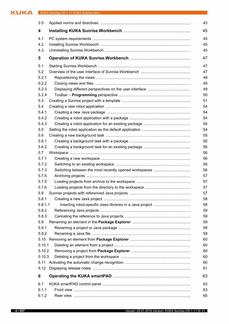
3.5 Applied norms and directives .................................................................................... 43
4 Installing KUKA Sunrise.Workbench ......................................................... 45
4.1 PC system requirements ........................................................................................... 45
4.2 Installing Sunrise.Workbench .................................................................................... 45
4.3 Uninstalling Sunrise.Workbench ................................................................................ 45
5 Operation of KUKA Sunrise.Workbench ................................................... 47
5.1 Starting Sunrise.Workbench ...................................................................................... 47
5.2 Overview of the user interface of Sunrise.Workbench .............................................. 47
5.2.1 Repositioning the views ........................................................................................ 49
5.2.2 Closing views and files ......................................................................................... 49
5.2.3 Displaying different perspectives on the user interface ........................................ 49
5.2.4 Toolbar – Programming perspective ................................................................... 50
5.3 Creating a Sunrise project with a template ................................................................ 51
5.4 Creating a new robot application ............................................................................... 54
5.4.1 Creating a new Java package .............................................................................. 54
5.4.2 Creating a robot application with a package ......................................................... 54
5.4.3 Creating a robot application for an existing package ............................................ 54
5.5 Setting the robot application as the default application ............................................. 54
5.6 Creating a new background task ............................................................................... 55
5.6.1 Creating a background task with a package ......................................................... 55
5.6.2 Creating a background task for an existing package ............................................ 56
5.7 Workspace ................................................................................................................. 56
5.7.1 Creating a new workspace ................................................................................... 56
5.7.2 Switching to an existing workspace ...................................................................... 56
5.7.3 Switching between the most recently opened workspaces .................................. 56
5.7.4 Archiving projects ................................................................................................. 57
5.7.5 Loading projects from archive to the workspace .................................................. 57
5.7.6 Loading projects from the directory to the workspace .......................................... 57
5.8 Sunrise projects with referenced Java projects ......................................................... 57
5.8.1 Creating a new Java project ................................................................................. 58
5.8.1.1 Inserting robot-specific class libraries in a Java project .................................. 58
5.8.2 Referencing Java projects .................................................................................... 59
5.8.3 Canceling the reference to Java projects ............................................................. 59
5.9 Renaming an element in the Package Explorer ...................................................... 59
5.9.1 Renaming a project or Java package ................................................................... 59
5.9.2 Renaming a Java file ............................................................................................ 59
5.10 Removing an element from Package Explorer ........................................................ 60
5.10.1 Deleting an element from a project ....................................................................... 60
5.10.2 Removing a project from Package Explorer ....................................................... 60
5.10.3 Deleting a project from the workspace ................................................................. 60
5.11 Activating the automatic change recognition ............................................................. 60
5.12 Displaying release notes ........................................................................................... 61
6 Operating the KUKA smartPAD .................................................................. 63
6.1 KUKA smartPAD control panel .................................................................................. 63
6.1.1 Front view ............................................................................................................. 63
6.1.2 Rear view ............................................................................................................. 65
Issued: 29.07.2016 Version: KUKA Sunrise.OS 1.11 SI V1

Contents
6.1.3 Disconnecting and connecting the smartPAD ...................................................... 66
6.2 KUKA smartHMI user interface .................................................................................. 68
6.2.1 Navigation bar ....................................................................................................... 69
6.2.2 Status display ....................................................................................................... 70
6.2.3 Keypad .................................................................................................................. 71
6.2.4 Station level .......................................................................................................... 71
6.2.5 Robot level ............................................................................................................ 73
6.3 Calling the main menu ............................................................................................... 75
6.4 Setting the user interface language ........................................................................... 76
6.5 Changing user group ................................................................................................. 77
6.6 CRR mode – controlled robot retraction .................................................................... 77
6.7 Changing the operating mode .................................................................................... 78
6.8 Activating the user keys ............................................................................................. 79
6.9 Resuming the safety controller .................................................................................. 80
6.10 Coordinate systems ................................................................................................... 80
6.11 “Override” window .................................................................................................... 82
6.12 “Jogging type” window ............................................................................................. 82
6.13 Jogging the robot ....................................................................................................... 84
6.13.1 “Jogging options” window .................................................................................. 84
6.13.2 Setting the jog override ......................................................................................... 86
6.13.3 Axis-specific jogging with the jog keys .................................................................. 87
6.13.4 Cartesian jogging with the jog keys ...................................................................... 87
6.13.4.1 Null space motion ............................................................................................ 88
6.14 Manually guiding the robot ......................................................................................... 89
6.15 Frame management ................................................................................................... 89
6.15.1 “Frames” view ...................................................................................................... 89
6.15.2 Teaching frames ................................................................................................... 91
6.15.3 Teaching frames with the hand guiding device ..................................................... 93
6.15.4 Manually addressing frames ................................................................................. 93
6.16 Program execution ..................................................................................................... 94
6.16.1 Selecting a robot application ................................................................................. 94
6.16.2 Setting the program run mode .............................................................................. 96
6.16.2.1 Program run modes ......................................................................................... 97
6.16.3 Setting the manual override .................................................................................. 97
6.16.4 Starting a robot application forwards (manually) .................................................. 98
6.16.5 Starting a robot application forwards (automatically) ............................................ 98
6.16.6 Resetting a robot application ................................................................................ 98
6.16.7 Repositioning the robot after leaving the path ...................................................... 98
6.16.8 Stopping a background application manually ....................................................... 99
6.16.9 Starting a background application manually ......................................................... 99
6.17 Display functions ........................................................................................................ 100
6.17.1 Displaying the end frame of the motion currently being executed ........................ 100
6.17.2 Displaying the axis-specific actual position ........................................................... 101
6.17.3 Displaying the Cartesian actual position ............................................................... 101
6.17.4 Displaying axis-specific torques ............................................................................ 102
6.17.5 Displaying an I/O group and changing the value of an output .............................. 103
6.17.6 Displaying information about the robot and robot controller ................................. 105
6.18 Backup Manager ........................................................................................................ 106
6.18.1 Overview of Backup Manager ............................................................................... 106
5 / 557Issued: 29.07.2016 Version: KUKA Sunrise.OS 1.11 SI V1

6 / 557
KUKA Sunrise.OS 1.11 KUKA Sunrise.Wor...
6.18.2 Backing up data manually .................................................................................... 109
6.18.3 Restoring data manually ....................................................................................... 109
6.18.4 Configuring the network path for restoration ........................................................ 109
7 Start-up and recommissioning ................................................................... 111
7.1 Switching the robot controller on/off .......................................................................... 111
7.1.1 Switching on the robot controller and starting the System Software .................... 111
7.1.2 Switching off the robot controller .......................................................................... 111
7.2 smartPAD software update ........................................................................................ 111
7.3 Performing a PDS firmware update ........................................................................... 112
7.4 Position mastering ..................................................................................................... 112
7.4.1 Mastering axes ..................................................................................................... 112
7.4.2 Manually unmastering axes .................................................................................. 113
7.5 Calibration ................................................................................................................. 113
7.5.1 Tool calibration ..................................................................................................... 113
7.5.1.1 TCP calibration: XYZ 4-point method .............................................................. 114
7.5.1.2 Defining the orientation: ABC 2-point method ................................................. 116
7.5.1.3 Defining the orientation: ABC world method ................................................... 118
7.5.2 Calibrating the base: 3-point method ................................................................... 119
7.6 Determining tool load data ......................................................................................... 121
8 Brake test ..................................................................................................... 125
8.1 Overview of the brake test ......................................................................................... 125
8.2 Creating the brake test application from the template ............................................... 127
8.2.1 Adapting the brake test application for testing against the minimum brake holding torque 130
8.2.2 Changing the motion sequence for torque value determination ........................... 130
8.2.3 Changing the starting position for the brake test .................................................. 131
8.3 Programming interface for the brake test .................................................................. 131
8.3.1 Evaluating the torques generated and determining the maximum absolute value 131
8.3.2 Polling the evaluation results of the maximum absolute torques .......................... 133
8.3.3 Creating an object for the brake test .................................................................... 134
8.3.4 Starting the execution of the brake test ................................................................ 135
8.3.5 Evaluating the brake test ...................................................................................... 136
8.3.5.1 Polling the results of the brake test ................................................................. 138
8.4 Performing a brake test ............................................................................................. 140
8.4.1 Evaluation results of the maximum absolute torques (display) ............................ 141
8.4.2 Results of the brake test (display) ....................................................................... 141
9 Project management ................................................................................... 143
9.1 Sunrise projects – overview ....................................................................................... 143
9.2 Frame management .................................................................................................. 143
9.2.1 Creating a new frame ........................................................................................... 144
9.2.2 Designating a frame as a base ............................................................................. 144
9.2.3 Moving a frame ..................................................................................................... 145
9.2.4 Deleting a frame ................................................................................................... 145
9.2.5 Displaying/editing frame properties ...................................................................... 146
9.2.6 Properties view for frames in application data ...................................................... 146
9.2.6.1 “General” tab ................................................................................................... 146
9.2.6.2 “Transformation” tab ...................................................................................... 147
Issued: 29.07.2016 Version: KUKA Sunrise.OS 1.11 SI V1
Contents
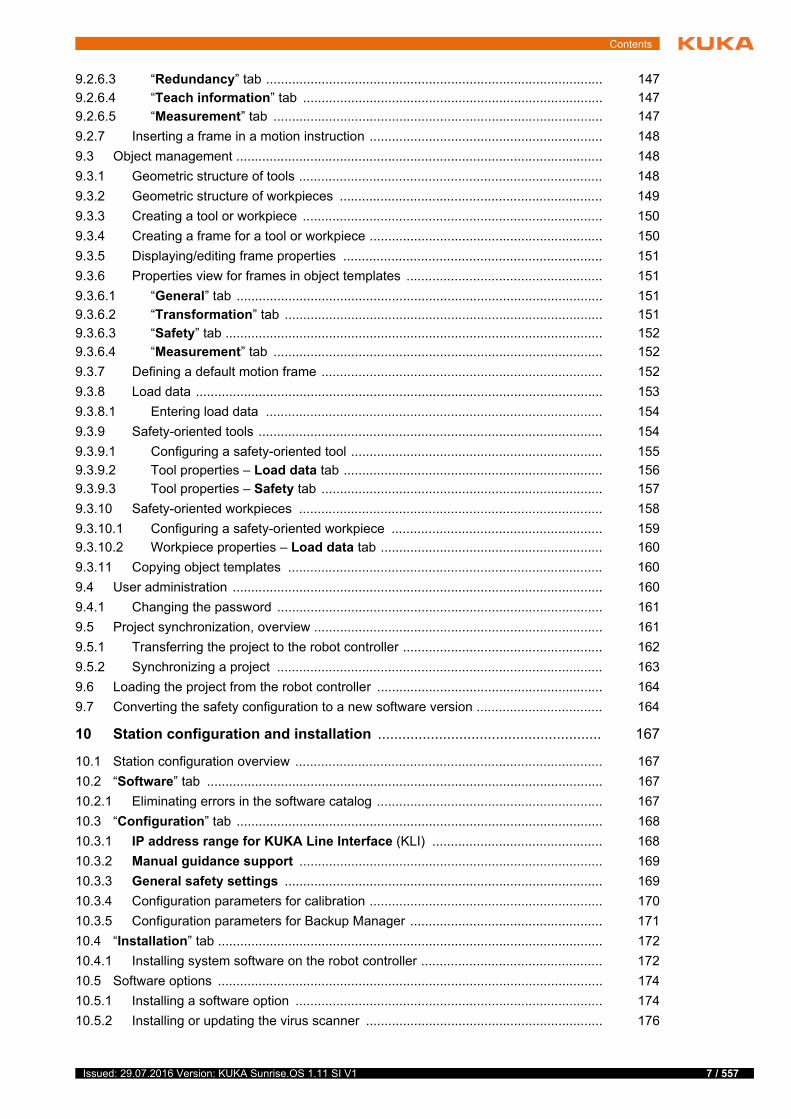
9.2.6.3 “Redundancy” tab ........................................................................................... 147
9.2.6.4 “Teach information” tab ................................................................................. 147
9.2.6.5 “Measurement” tab ......................................................................................... 147
9.2.7 Inserting a frame in a motion instruction ............................................................... 148
9.3 Object management ................................................................................................... 148
9.3.1 Geometric structure of tools .................................................................................. 148
9.3.2 Geometric structure of workpieces ....................................................................... 149
9.3.3 Creating a tool or workpiece ................................................................................. 150
9.3.4 Creating a frame for a tool or workpiece ............................................................... 150
9.3.5 Displaying/editing frame properties ...................................................................... 151
9.3.6 Properties view for frames in object templates ..................................................... 151
9.3.6.1 “General” tab ................................................................................................... 151
9.3.6.2 “Transformation” tab ...................................................................................... 151
9.3.6.3 “Safety” tab ...................................................................................................... 152
9.3.6.4 “Measurement” tab ......................................................................................... 152
9.3.7 Defining a default motion frame ............................................................................ 152
9.3.8 Load data .............................................................................................................. 153
9.3.8.1 Entering load data ........................................................................................... 154
9.3.9 Safety-oriented tools ............................................................................................. 154
9.3.9.1 Configuring a safety-oriented tool .................................................................... 155
9.3.9.2 Tool properties – Load data tab ...................................................................... 156
9.3.9.3 Tool properties – Safety tab ............................................................................ 157
9.3.10 Safety-oriented workpieces .................................................................................. 158
9.3.10.1 Configuring a safety-oriented workpiece ......................................................... 159
9.3.10.2 Workpiece properties – Load data tab ............................................................ 160
9.3.11 Copying object templates ..................................................................................... 160
9.4 User administration .................................................................................................... 160
9.4.1 Changing the password ........................................................................................ 161
9.5 Project synchronization, overview .............................................................................. 161
9.5.1 Transferring the project to the robot controller ...................................................... 162
9.5.2 Synchronizing a project ........................................................................................ 163
9.6 Loading the project from the robot controller ............................................................. 164
9.7 Converting the safety configuration to a new software version .................................. 164
10 Station configuration and installation ....................................................... 167
10.1 Station configuration overview ................................................................................... 167
10.2 “Software” tab ........................................................................................................... 167
10.2.1 Eliminating errors in the software catalog ............................................................. 167
10.3 “Configuration” tab ................................................................................................... 168
10.3.1 IP address range for KUKA Line Interface (KLI) .............................................. 168
10.3.2 Manual guidance support .................................................................................. 169
10.3.3 General safety settings ...................................................................................... 169
10.3.4 Configuration parameters for calibration ............................................................... 170
10.3.5 Configuration parameters for Backup Manager .................................................... 171
10.4 “Installation” tab ........................................................................................................ 172
10.4.1 Installing system software on the robot controller ................................................. 172
10.5 Software options ........................................................................................................ 174
10.5.1 Installing a software option ................................................................................... 174
10.5.2 Installing or updating the virus scanner ................................................................ 176
7 / 557Issued: 29.07.2016 Version: KUKA Sunrise.OS 1.11 SI V1
8 / 557
KUKA Sunrise.OS 1.11 KUKA Sunrise.Wor...
10.5.3 Installing a language package .............................................................................. 176
10.5.4 Uninstalling a software option ............................................................................... 176
11 Bus configuration ........................................................................................ 179
11.1 Configuration and I/O mapping in WorkVisual – overview ........................................ 179
11.2 Overview of field buses ............................................................................................. 179
11.3 Creating a new I/O configuration ............................................................................... 180
11.4 Opening an existing I/O configuration ....................................................................... 180
11.5 Creating Sunrise I/Os ................................................................................................ 181
11.5.1 “Create I/O signals” window ................................................................................ 182
11.5.2 Creating an I/O group and inputs/outputs within the group .................................. 183
11.5.3 Editing an I/O group ............................................................................................. 184
11.5.4 Deleting an I/O group ........................................................................................... 184
11.5.5 Changing an input/output of a group .................................................................... 184
11.5.6 Deleting an input/output of a group ...................................................................... 184
11.5.7 Exporting an I/O group as a template ................................................................... 184
11.5.8 Importing an I/O group from a template ................................................................ 185
11.6 Mapping the bus I/Os ................................................................................................ 185
11.6.1 I/O Mapping window ............................................................................................ 185
11.6.2 Buttons in the “I/O Mapping” window ................................................................... 186
11.6.3 Mapping Sunrise I/Os ........................................................................................... 187
11.7 Exporting the I/O configuration to the Sunrise project ............................................... 187
12 External control ........................................................................................... 189
12.1 Overview of external controller .................................................................................. 189
12.2 Configuring the external controller via the I/O system ............................................... 189
12.3 Configuring the external controller via the UDP interface .......................................... 190
12.4 External controller input signals ................................................................................. 190
12.5 External controller output signals .............................................................................. 191
12.6 Signal diagrams ......................................................................................................... 192
12.7 Configuring the external controller in the project settings .......................................... 193
12.7.1 Input/output parameters of the I/O interface ......................................................... 194
12.7.2 Input/output parameters of the UDP interface ...................................................... 195
12.8 Formatting of the UDP data packets ......................................................................... 195
12.8.1 Status messages of the robot controller ............................................................... 195
12.8.2 Controller messages of the external client ........................................................... 198
12.9 External control via UDP – Start-up example ............................................................ 199
12.9.1 Starting up the external controller ......................................................................... 199
12.9.2 Programming the external controller .................................................................... 200
12.10 Configuring the signal outputs for a project that is not externally controlled ............. 201
12.10.1 Output parameters of the I/O interface ................................................................. 202
12.10.2 Output parameters of the UDP interface .............................................................. 202
13 Safety configuration .................................................................................... 203
13.1 Overview of safety configuration ............................................................................... 203
13.2 Safety concept ........................................................................................................... 203
13.3 Permanent Safety Monitoring .................................................................................... 206
13.4 Event-driven Safety Monitoring ................................................................................. 207
13.5 Atomic Monitoring Functions ..................................................................................... 208
Issued: 29.07.2016 Version: KUKA Sunrise.OS 1.11 SI V1

Contents
13.5.1 Standard AMFs ..................................................................................................... 209
13.5.2 Parameterizable AMFs ......................................................................................... 210
13.5.3 Extended AMFs .................................................................................................... 212
13.5.4 Availability of the AMFs depending on the kinematic system ............................... 213
13.6 Worst-case reaction times of the safety functions in the case of a single fault .......... 213
13.6.1 Worst-case reaction times of the LBR iiwa monitoring functions .......................... 214
13.6.2 Worst-case reaction times of the KMP 400 monitoring functions ......................... 217
13.7 Deactivation of safety functions via an input .............................................................. 219
13.8 Safety configuration (SafetyConfiguration.sconf file) ................................................. 220
13.8.1 Overview of safety configuration and start-up ...................................................... 221
13.8.2 Opening the safety configuration .......................................................................... 222
13.8.2.1 Evaluating the safety configuration .................................................................. 222
13.8.2.2 Overview of the graphical user interface for the safety configuration .............. 223
13.8.3 Configuring the safety functions of the PSM mechanism ..................................... 224
13.8.3.1 Opening the Customer PSM table .................................................................. 224
13.8.3.2 Creating safety functions for the PSM mechanism .......................................... 226
13.8.3.3 Deleting safety functions of the PSM mechanism ........................................... 226
13.8.3.4 Editing existing safety functions of the PSM mechanism ................................ 226
13.8.4 Configuring the safe states of the ESM mechanism ............................................. 227
13.8.4.1 Adding a new ESM state ................................................................................. 227
13.8.4.2 Opening a table for an ESM state .................................................................... 228
13.8.4.3 Deleting an ESM state ..................................................................................... 229
13.8.4.4 Creating a safety function for the ESM state ................................................... 229
13.8.4.5 Deleting a safety function of an ESM state ...................................................... 230
13.8.4.6 Editing an existing safety function of an ESM state ......................................... 230
13.8.4.7 Deactivating the ESM mechanism ................................................................... 230
13.8.4.8 Switching between ESM states ....................................................................... 230
13.8.5 Mapping safety-oriented tools ............................................................................... 231
13.9 Activating the safety configuration ............................................................................. 233
13.9.1 Deactivating the safety configuration .................................................................... 233
13.9.2 Restoring the safety configuration ........................................................................ 234
13.10 Using and parameterizing the AMFs .......................................................................... 234
13.10.1 Evaluating the safety equipment on the KUKA smartPAD ................................... 234
13.10.2 Evaluating the operating mode ............................................................................. 235
13.10.3 Evaluating the motion enable ............................................................................... 235
13.10.4 Monitoring safe inputs ........................................................................................... 235
13.10.5 Manual guidance with enabling device and velocity monitoring ........................... 236
13.10.5.1 Monitoring of enabling switches on hand guiding devices ............................... 236
13.10.5.2 Monitoring functions during manual guidance ................................................. 238
13.10.5.3 Velocity monitoring during manual guidance ................................................... 238
13.10.6 Evaluating the position referencing ....................................................................... 239
13.10.7 Evaluating the torque referencing ......................................................................... 239
13.10.8 Velocity monitoring functions ................................................................................ 240
13.10.8.1 Defining axis-specific velocity monitoring ........................................................ 240
13.10.8.2 Defining Cartesian velocity monitoring ............................................................ 241
13.10.8.3 Direction-specific monitoring of Cartesian velocity .......................................... 243
13.10.9 Monitoring spaces ................................................................................................. 248
13.10.9.1 Defining Cartesian workspaces ....................................................................... 250
13.10.9.2 Defining Cartesian protected spaces ............................................................... 252
13.10.9.3 Defining axis-specific monitoring spaces ......................................................... 255
9 / 557Issued: 29.07.2016 Version: KUKA Sunrise.OS 1.11 SI V1

10 / 557
KUKA Sunrise.OS 1.11 KUKA Sunrise.Wor...
13.10.10 Monitoring the tool orientation .............................................................................. 256
13.10.11 Standstill monitoring (safe operational stop) ........................................................ 259
13.10.12 Activation delay for safety function ....................................................................... 259
13.10.13 Monitoring of forces and torques .......................................................................... 260
13.10.13.1 Axis torque monitoring ..................................................................................... 260
13.10.13.2 Collision detection ........................................................................................... 261
13.10.13.3 TCP force monitoring ...................................................................................... 262
13.10.13.4 Direction-specific monitoring of the external force on the TCP ....................... 264
13.11 Example of a safety configuration ............................................................................. 268
13.11.1 Task ...................................................................................................................... 268
13.11.2 Requirement ......................................................................................................... 269
13.11.3 Suggested solution for the task ............................................................................ 269
13.12 Position and torque referencing ................................................................................. 271
13.12.1 Position referencing .............................................................................................. 271
13.12.2 Torque referencing ............................................................................................... 273
13.12.3 Creating an application for position and torque referencing ................................. 274
13.12.4 External position referencing ................................................................................ 275
13.12.4.1 Configuring the input for external position referencing .................................... 275
13.13 Safety acceptance overview ...................................................................................... 275
13.13.1 Checklist – System safety functions ..................................................................... 276
13.13.2 Checklist for tool selection table ........................................................................... 280
13.13.3 Checklists for safety-oriented tools ....................................................................... 281
13.13.3.1 Pickup frame for fixed tools ............................................................................. 281
13.13.3.2 Pickup frame for activatable tools ................................................................... 282
13.13.3.3 Tool orientation ................................................................................................ 283
13.13.3.4 Tool-specific velocity component .................................................................... 283
13.13.3.5 Geometry data of the tool ................................................................................ 284
13.13.3.6 Load data of the tool ........................................................................................ 285
13.13.4 Checklist for safety-oriented workpieces .............................................................. 286
13.13.5 Checklist for rows used in the PSM tables ........................................................... 288
13.13.6 Checklists for ESM states ..................................................................................... 288
13.13.6.1 Used ESM states ............................................................................................. 288
13.13.6.2 Non-used ESM states ..................................................................................... 290
13.13.7 Checklists for AMFs used ..................................................................................... 290
13.13.7.1 AMF smartPAD Emergency Stop ................................................................. 290
13.13.7.2 AMF smartPAD enabling switch inactive .................................................... 290
13.13.7.3 AMF smartPAD enabling switch panic active ............................................. 290
13.13.7.4 AMF Hand guiding device enabling inactive .............................................. 290
13.13.7.5 AMF Hand guiding device enabling active .................................................. 291
13.13.7.6 AMF Test mode .............................................................................................. 291
13.13.7.7 AMF Automatic mode .................................................................................... 292
13.13.7.8 AMF Reduced-velocity mode ....................................................................... 292
13.13.7.9 AMF High-velocity mode ............................................................................... 292
13.13.7.10 AMF Motion enable ........................................................................................ 292
13.13.7.11 AMF Input signal ............................................................................................ 292
13.13.7.12 AMF Standstill monitoring of all axes ......................................................... 292
13.13.7.13 AMF Axis torque monitoring ........................................................................ 293
13.13.7.14 AMF Axis velocity monitoring ...................................................................... 293
13.13.7.15 AMF Position referencing ............................................................................. 293
13.13.7.16 AMF Torque referencing ............................................................................... 293
Issued: 29.07.2016 Version: KUKA Sunrise.OS 1.11 SI V1
Contents
13.13.7.17 AMF Axis range monitoring .......................................................................... 294
13.13.7.18 AMF Cartesian velocity monitoring .............................................................. 294
13.13.7.19 AMF Cartesian workspace monitoring / Cartesian protected space monitoring 294
13.13.7.20 AMF Collision detection ................................................................................ 295
13.13.7.21 AMF TCP force monitoring ........................................................................... 295
13.13.7.22 Base-related TCP force component AMF .................................................... 296
13.13.7.23 AMF Time delay .............................................................................................. 297
13.13.7.24 AMF Tool orientation ..................................................................................... 297
13.13.7.25 AMF Tool-related velocity component ......................................................... 298
13.13.8 Checklists – General safety settings ..................................................................... 299
13.13.8.1 smartPAD unplugging allowed ..................................................................... 299
13.13.8.2 Allow muting via input .................................................................................. 299
13.13.8.3 Allow external position referencing ............................................................. 300
13.13.9 Creating a safety configuration report ................................................................... 300
14 Basic principles of motion programming ................................................. 303
14.1 Overview of motion types ........................................................................................... 303
14.2 PTP motion type ........................................................................................................ 303
14.3 LIN motion type ......................................................................................................... 304
14.4 CIRC motion type ....................................................................................................... 304
14.5 SPL motion type ......................................................................................................... 305
14.6 Spline motion type ..................................................................................................... 305
14.6.1 Velocity profile for spline motions ......................................................................... 306
14.6.2 Modifications to spline blocks ............................................................................... 308
14.6.3 LIN-SPL-LIN transition .......................................................................................... 310
14.7 Manual guidance motion type .................................................................................... 311
14.8 Approximate positioning ............................................................................................. 312
14.9 Orientation control with LIN, CIRC, SPL .................................................................... 314
14.9.1 CIRC – reference system for the orientation control ............................................. 316
14.9.2 CIRC – combinations of reference system and type for the orientation control .... 317
14.10 Redundancy information ............................................................................................ 319
14.10.1 Redundancy angle ................................................................................................ 320
14.10.2 Status .................................................................................................................... 320
14.10.3 Turn ...................................................................................................................... 321
14.11 Singularities ............................................................................................................... 321
14.11.1 Kinematic singularities .......................................................................................... 321
14.11.2 System-dependent singularities ............................................................................ 323
15 Programming ............................................................................................... 325
15.1 Java Editor ................................................................................................................. 325
15.1.1 Opening a robot application in the Java Editor ..................................................... 325
15.1.2 Structure of a robot application ............................................................................. 325
15.1.3 Edit functions ........................................................................................................ 326
15.1.3.1 Renaming a variable ........................................................................................ 326
15.1.3.2 Auto-complete .................................................................................................. 326
15.1.3.3 Templates – Fast entry of Java statements ..................................................... 327
15.1.3.4 Creating user-specific templates ..................................................................... 328
15.1.3.5 Extracting methods .......................................................................................... 328
15.1.4 Displaying Javadoc information ............................................................................ 329
11 / 557Issued: 29.07.2016 Version: KUKA Sunrise.OS 1.11 SI V1

12 / 557
KUKA Sunrise.OS 1.11 KUKA Sunrise.Wor...
15.1.4.1 Configuration of the Javadoc browser ............................................................. 330
15.2 Symbols and fonts ..................................................................................................... 333
15.3 Data types ................................................................................................................. 333
15.3.1 Declaration ........................................................................................................... 334
15.3.2 Initialization ........................................................................................................... 334
15.3.2.1 Primitive data types ......................................................................................... 335
15.3.2.2 Complex data types ......................................................................................... 335
15.3.3 Dependency Injection ........................................................................................... 336
15.3.3.1 Dependency injection for Sunrise types .......................................................... 336
15.3.3.2 Dependency injection for dedicated types ....................................................... 339
15.4 Polling individual values of a vector ........................................................................... 341
15.5 Network communication via UDP and TCP/IP .......................................................... 342
15.6 Motion programming: PTP, LIN, CIRC ...................................................................... 342
15.6.1 Synchronous and asynchronous motion execution .............................................. 342
15.6.2 PTP ...................................................................................................................... 343
15.6.3 LIN ........................................................................................................................ 344
15.6.4 CIRC ..................................................................................................................... 344
15.6.5 LIN REL ................................................................................................................ 345
15.6.6 MotionBatch ......................................................................................................... 346
15.7 Motion programming: spline ...................................................................................... 347
15.7.1 Programming tips for spline motions .................................................................... 347
15.7.2 Creating a CP spline block ................................................................................... 348
15.7.3 Creating a JP spline block .................................................................................... 349
15.7.4 Using spline in a motion instruction ...................................................................... 350
15.8 Motion parameters ..................................................................................................... 350
15.8.1 Programming axis-specific motion parameters .................................................... 352
15.9 Programming manual guidance ................................................................................. 352
15.9.1 Axis-specific limits for manual guidance ............................................................... 354
15.10 Using tools and workpieces in the program ............................................................... 357
15.10.1 Integrating tools and workpieces .......................................................................... 357
15.10.2 Attaching tools and workpieces to the robot ......................................................... 358
15.10.2.1 Attaching a tool to the robot flange .................................................................. 358
15.10.2.2 Attaching a workpiece to other objects ............................................................ 359
15.10.2.3 Detaching objects ............................................................................................ 361
15.10.3 Moving tools and workpieces ............................................................................... 361
15.10.4 Integrating dedicated object classes with dependency injection .......................... 362
15.10.5 Commanding load changes to the safety controller ............................................. 365
15.11 Using inputs/outputs in the program .......................................................................... 367
15.11.1 Integrating an I/O group ....................................................................................... 369
15.11.2 Reading inputs/outputs ......................................................................................... 369
15.11.3 Setting outputs ..................................................................................................... 370
15.12 Polling axis torques ................................................................................................... 371
15.13 Reading Cartesian forces and torques ...................................................................... 372
15.13.1 Polling external Cartesian forces and torques ...................................................... 372
15.13.2 Polling forces and torques individually ................................................................. 373
15.13.3 Checking the reliability of the calculated values ................................................... 374
15.14 Polling the robot position ........................................................................................... 375
15.14.1 Polling the axis-specific actual or setpoint position .............................................. 376
15.14.2 Polling the Cartesian actual or setpoint position ................................................... 377
Issued: 29.07.2016 Version: KUKA Sunrise.OS 1.11 SI V1

Contents
15.14.3 Polling the Cartesian setpoint/actual value difference .......................................... 378
15.15 HOME position ........................................................................................................... 379
15.15.1 Changing the HOME position ............................................................................... 379
15.16 Polling system states ................................................................................................. 380
15.16.1 Polling the HOME position .................................................................................... 380
15.16.2 Polling the mastering state ................................................................................... 381
15.16.3 Polling “ready for motion” ...................................................................................... 381
15.16.3.1 Reacting to changes in the “ready for motion” signal ...................................... 381
15.16.4 Polling the robot activity ........................................................................................ 382
15.16.5 Polling the state of safety signals ......................................................................... 382
15.16.5.1 Polling the referencing state ............................................................................ 384
15.16.5.2 Reacting to a change in state of safety signals ............................................... 385
15.17 Changing and polling the program run mode ............................................................. 386
15.18 Changing and polling the override ............................................................................. 387
15.18.1 Reacting to an override change ............................................................................ 388
15.19 Conditions .................................................................................................................. 389
15.19.1 Complex conditions .............................................................................................. 391
15.19.2 Axis torque condition ............................................................................................ 391
15.19.3 Force condition ..................................................................................................... 392
15.19.3.1 Condition for Cartesian force from all directions .............................................. 394
15.19.3.2 Condition for normal force ............................................................................... 395
15.19.3.3 Condition for shear force ................................................................................. 396
15.19.4 Force component condition .................................................................................. 398
15.19.5 Condition for Cartesian torque .............................................................................. 400
15.19.5.1 Condition for Cartesian torque from all directions ............................................ 401
15.19.5.2 Condition for torque ......................................................................................... 402
15.19.5.3 Condition for tilting torque ................................................................................ 403
15.19.6 Torque component condition ................................................................................ 404
15.19.7 Path-related condition ........................................................................................... 405
15.19.8 Condition for Boolean signals ............................................................................... 408
15.19.9 Condition for the range of values of a signal ........................................................ 408
15.20 Break conditions for motion commands ..................................................................... 409
15.20.1 Defining break conditions ..................................................................................... 409
15.20.2 Evaluating the break conditions ............................................................................ 410
15.20.2.1 Polling a break condition .................................................................................. 411
15.20.2.2 Polling the robot position at the time of termination ......................................... 412
15.20.2.3 Polling a terminated motion (spline block, MotionBatch) ................................. 412
15.21 Path-related switching actions (Trigger) .................................................................... 413
15.21.1 Programming triggers ........................................................................................... 413
15.21.2 Programming a path-related switching action ....................................................... 414
15.21.3 Evaluating trigger information ............................................................................... 415
15.22 Monitoring processes (Monitoring) ............................................................................. 417
15.22.1 Listener for monitoring conditions ......................................................................... 417
15.22.2 Creating a listener object to monitor the condition ................................................ 418
15.22.3 Registering a listener for notification of change in state ....................................... 419
15.22.4 Activating or deactivating the notification service for listeners .............................. 420
15.22.5 Programming example for monitoring ................................................................... 421
15.23 Blocking wait for condition ......................................................................................... 421
15.24 Recording and evaluating data .................................................................................. 423
13 / 557Issued: 29.07.2016 Version: KUKA Sunrise.OS 1.11 SI V1
14 / 557
KUKA Sunrise.OS 1.11 KUKA Sunrise.Wor...
15.24.1 Creating an object for data recording ................................................................... 423
15.24.2 Specifying data to be recorded ............................................................................. 424
15.24.3 Starting data recording ......................................................................................... 426
15.24.4 Ending data recording .......................................................................................... 428
15.24.5 Polling states from the DataRecorder object ........................................................ 428
15.24.6 Example program for data recording .................................................................... 429
15.25 Defining user keys ..................................................................................................... 430
15.25.1 Creating a user key bar ........................................................................................ 431
15.25.2 Adding user keys to the bar .................................................................................. 432
15.25.3 Defining the function of a user key ....................................................................... 433
15.25.4 Labeling and graphical assignment of the user key bar ....................................... 435
15.25.4.1 Assigning a text element ................................................................................. 436
15.25.4.2 Assigning an LED icon .................................................................................... 437
15.25.5 Identifying safety-critical user keys ....................................................................... 438
15.25.6 Publishing a user key bar ..................................................................................... 439
15.26 Message programming .............................................................................................. 439
15.26.1 Programming user messages ............................................................................... 439
15.26.2 Programming user dialogs .................................................................................... 441
15.27 Program execution control ......................................................................................... 442
15.27.1 Pausing an application ......................................................................................... 442
15.27.2 Pausing motion execution .................................................................................... 442
15.27.3 FOR loop .............................................................................................................. 443
15.27.4 WHILE loop .......................................................................................................... 444
15.27.5 DO WHILE loop .................................................................................................... 445
15.27.6 IF ELSE branch .................................................................................................... 445
15.27.7 SWITCH branch ................................................................................................... 447
15.27.8 Examples of nested loops .................................................................................... 449
15.28 Continuing a paused application in Automatic mode (recovery) ............................... 450
15.29 Error treatment .......................................................................................................... 452
15.29.1 Handling of failed motion commands ................................................................... 452
15.29.2 Handling of failed synchronous motion commands .............................................. 452
15.29.3 Handling of failed asynchronous motion commands ............................................ 454
16 Background tasks ........................................................................................ 459
16.1 Using background tasks ............................................................................................ 459
16.2 Cyclic background task .............................................................................................. 461
16.3 Non-cyclic background task ....................................................................................... 463
16.4 Data exchange between tasks .................................................................................. 464
16.4.1 Declaring task functions ....................................................................................... 465
16.4.2 Implementing task functions ................................................................................. 466
16.4.3 Creating the providing task ................................................................................... 467
16.4.4 Using task functions ............................................................................................. 469
17 Programming with a compliant robot ........................................................ 473
17.1 Sensors and control ................................................................................................... 473
17.2 Available controllers – overview ................................................................................ 473
17.3 Using controllers in robot applications ....................................................................... 473
17.3.1 Creating a controller object ................................................................................... 474
17.3.2 Defining controller parameters ............................................................................. 474
Issued: 29.07.2016 Version: KUKA Sunrise.OS 1.11 SI V1
Contents
17.3.3 Transferring the controller object as a motion parameter ..................................... 474
17.4 Position controller ...................................................................................................... 475
17.5 Cartesian impedance controller ................................................................................. 475
17.5.1 Calculation of the forces on the basis of Hooke’s law .......................................... 475
17.5.2 Parameterization of the Cartesian impedance controller ...................................... 477
17.5.2.1 Representation of Cartesian degrees of freedom ............................................ 478
17.5.2.2 Defining controller parameters for individual degrees of freedom ................... 478
17.5.2.3 Controller parameters specific to the degrees of freedom ............................... 479
17.5.2.4 Controller parameters independent of the degrees of freedom ....................... 480
17.6 Cartesian impedance controller with overlaid force oscillation .................................. 483
17.6.1 Overlaying a simple force oscillation .................................................................... 483
17.6.2 Overlaying superposed force oscillations (Lissajous curves) ............................... 484
17.6.3 Parameterization of the impedance controller with overlaid force oscillation ....... 485
17.6.3.1 Controller parameters specific to the degrees of freedom ............................... 486
17.6.3.2 Controller parameters independent of the degrees of freedom ....................... 488
17.7 Static methods for impedance controller with superposed force oscillation ............... 490
17.7.1 Overlaying a constant force .................................................................................. 490
17.7.2 Overlaying a simple force oscillation .................................................................... 491
17.7.3 Overlaying a Lissajous oscillation ......................................................................... 492
17.7.4 Overlaying a spiral-shaped force oscillation ......................................................... 493
17.8 Axis-specific impedance controller ............................................................................. 495
17.8.1 Parameterization of the axis-specific impedance controller .................................. 495
17.8.2 Methods of the axis-specific impedance controller ............................................... 495
17.9 Holding the position under servo control .................................................................... 496
18 Diagnosis ..................................................................................................... 499
18.1 Field bus diagnosis .................................................................................................... 499
18.1.1 Displaying general field bus errors ....................................................................... 499
18.1.2 Displaying the error state of I/Os and I/O groups ................................................. 499
18.2 Displaying the protocol ............................................................................................... 499
18.2.1 “Protocol” view ..................................................................................................... 500
18.2.2 Filtering log entries ............................................................................................... 501
18.3 Display of error messages (Applications view) .......................................................... 502
18.4 Displaying messages of the virus scanner ................................................................. 505
18.5 Collecting diagnostic information for error analysis at KUKA ..................................... 505
18.5.1 Creating a diagnosis package with the smartHMI ................................................ 506
18.5.2 Creating a diagnosis package with the smartPAD ................................................ 506
18.5.3 Creating a diagnosis package with Sunrise.Workbench ....................................... 506
18.5.4 Loading existing diagnosis packages from the robot controller ............................ 507
19 Remote debugging ...................................................................................... 509
19.1 Debugging session sequence .................................................................................... 509
19.1.1 Remote debugging of tasks .................................................................................. 510
19.1.2 Starting the debugging session ............................................................................ 511
19.1.3 Ending the debugging session .............................................................................. 511
19.2 Debugging tasks ........................................................................................................ 512
19.2.1 Remote debugging of a robot application ............................................................. 513
19.2.2 Remote debugging of a background task ............................................................. 514
19.3 Fundamentals of remote debugging .......................................................................... 514
15 / 557Issued: 29.07.2016 Version: KUKA Sunrise.OS 1.11 SI V1

16 / 557
KUKA Sunrise.OS 1.11 KUKA Sunrise.Wor...
19.3.1 Overview of user interface – “Debugging” perspective ......................................... 514
19.3.2 Break points ......................................................................................................... 515
19.3.2.1 Creating and deleting break points .................................................................. 516
19.3.2.2 Deactivating and activating break points ......................................................... 517
19.3.2.3 Editing the properties of the break points ........................................................ 517
19.3.2.4 Overview of the “Break points” view ................................................................ 518
19.3.2.5 Conditional break point .................................................................................... 519
19.3.2.6 Suspend thread property ................................................................................. 521
19.3.3 Command pointer ................................................................................................. 521
19.3.4 Overview of the “Debugging” view ........................................................................ 522
19.3.5 Overview of the toolbar in the “Debugging” view .................................................. 523
19.3.5.1 Continuing execution (Resume) ...................................................................... 524
19.3.5.2 Jump into the method (Step in) ....................................................................... 525
19.3.5.3 Executing a method completely (Step over) .................................................... 525
19.3.5.4 Terminating the executed method (Step back) ............................................... 526
19.3.5.5 Executing code sections again (Back to frame) .............................................. 527
19.3.5.6 Defining the code section to be executed (Execution to line) .......................... 528
19.3.5.7 Pausing debugging (Pause) ............................................................................ 529
19.3.6 Variables view ...................................................................................................... 529
19.3.6.1 Displaying and modifying variables ................................................................. 531
19.3.6.2 Expanded context help for variables ............................................................... 532
19.3.7 Monitoring processes ........................................................................................... 533
19.3.7.1 Adding new monitoring expressions ................................................................ 534
19.3.7.2 Deleting monitoring expressions ..................................................................... 535
19.3.7.3 Evaluating monitoring expressions .................................................................. 535
19.3.8 Modifying source code .......................................................................................... 536
19.3.8.1 Impermissible modification of the source code ............................................... 536
19.3.8.2 Permissible modification of the source code ................................................... 537
20 Appendix ...................................................................................................... 539
20.1 Compatibility and migration of projects ...................................................................... 539
20.1.1 Modified task functions – adapting the programming ........................................... 539
21 KUKA Service ............................................................................................... 541
21.1 Requesting support ................................................................................................... 541
21.2 KUKA Customer Support ........................................................................................... 541
Index ............................................................................................................. 549
Issued: 29.07.2016 Version: KUKA Sunrise.OS 1.11 SI V1
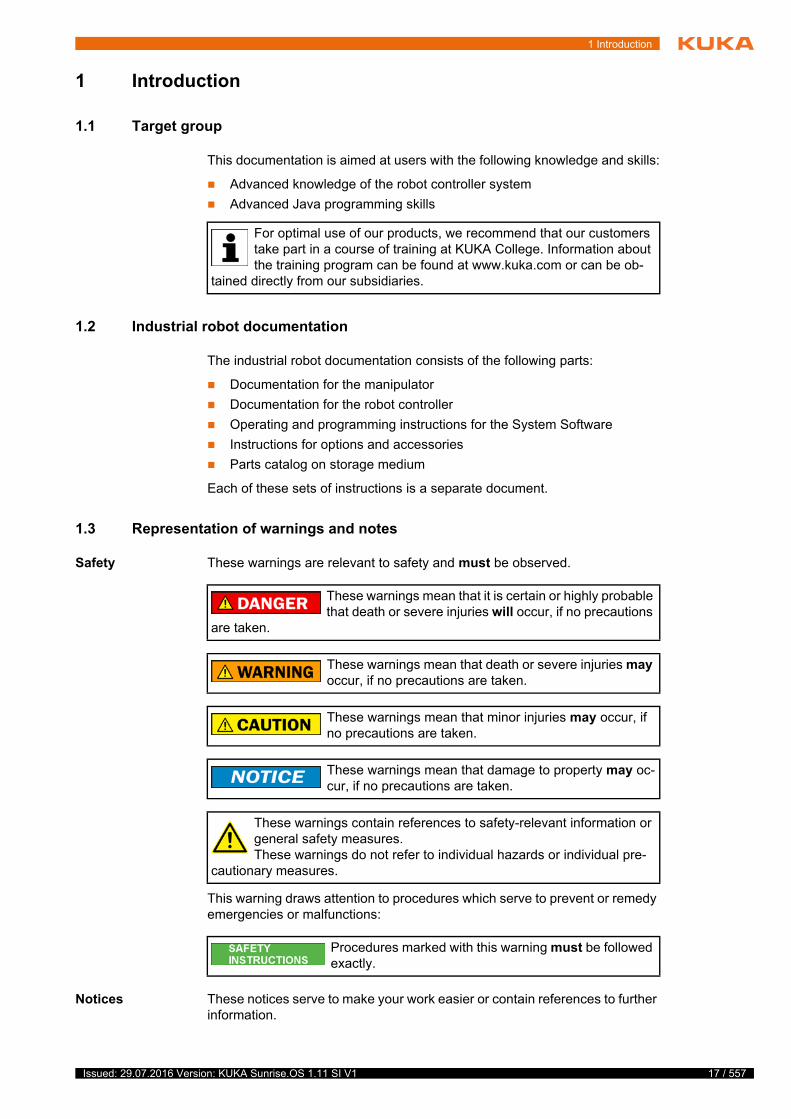
1 Introduction
1 Introduction
1.1 Target group
This documentation is aimed at users with the following knowledge and skills:
Advanced knowledge of the robot controller system
Advanced Java programming skills
1.2 Industrial robot documentation
The industrial robot documentation consists of the following parts:
Documentation for the manipulator
Documentation for the robot controller
Operating and programming instructions for the System Software
Instructions for options and accessories
Parts catalog on storage medium
Each of these sets of instructions is a separate document.
1.3 Representation of warnings and notes
Safety These warnings are relevant to safety and must be observed.
This warning draws attention to procedures which serve to prevent or remedy emergencies or malfunctions:
Notices These notices serve to make your work easier or contain references to further information.
t
t
For optimal use of our products, we recommend that our customers take part in a course of training at KUKA College. Information about the training program can be found at www.kuka.com or can be ob-
tained directly from our subsidiaries.
These warnings mean that it is certain or highly probable that death or severe injuries will occur, if no precautions
are taken.
These warnings mean that death or severe injuries may occur, if no precautions are taken.
These warnings mean that minor injuries may occur, if no precautions are taken.
These warnings mean that damage to property may oc-cur, if no precautions are taken.
These warnings contain references to safety-relevant information or general safety measures. These warnings do not refer to individual hazards or individual pre-
cautionary measures.
Procedures marked with this warning must be followed exactly.
17 / 557Issued: 29.07.2016 Version: KUKA Sunrise.OS 1.11 SI V1

18 / 557
KUKA Sunrise.OS 1.11 KUKA Sunrise.Wor...
1.4 Trademarks
Java is a trademark of Sun Microsystems (Oracle Corporation).
Windows is a trademark of Microsoft Corporation.
EtherCAT® is a registered trademark and patented technology, licensed by Beckhoff Automation GmbH, Germany.
1.5 Terms used
Tip to make your work easier or reference to further information.
Term Description
AMF Atomic Monitoring Function
Smallest unit of a monitoring function
API Application Programming Interface
Interface for programming applications.
ESM Event-Driven Safety Monitoring
Safety monitoring functions which are activated using defined events
Exception Exception or exceptional situation
An exception describes a procedure for forwarding information about certain program statuses, mainly error states, to other program levels for further processing.
Frame A frame is a 3-dimensional coordinate system that is described by its position and orientation relative to a reference system.
Points in space can be easily defined using frames. Frames are often arranged hierarchically in a tree structure.
FSoE Fail Safe over EtherCAT
FSoE is a protocol for transferring safety-relevant data via EtherCAT in conjunction with an FSoE master and an FSoE slave.
HRC Human-robot collaboration
Javadoc Javadoc is a documentation generated from specific Java comments.
JRE Java Runtime Environment
Runtime environment of the Java programming language
KLI KUKA Line Interface
Ethernet interface of the robot controller (not real-time-capable) for external communication.
KMP KUKA Mobile Platform
Designation for mobile platforms from KUKA
KUKA RoboticsAPI Java programming interface for KUKA robots
The RoboticsAPI is an object-oriented Java interface for controlling robots and peripheral devices.
KUKA smartHMI see “smartHMI”
KUKA smartPAD see “smartPAD”
KUKA Sunrise Cabinet
Control hardware for operating industrial robots
Issued: 29.07.2016 Version: KUKA Sunrise.OS 1.11 SI V1
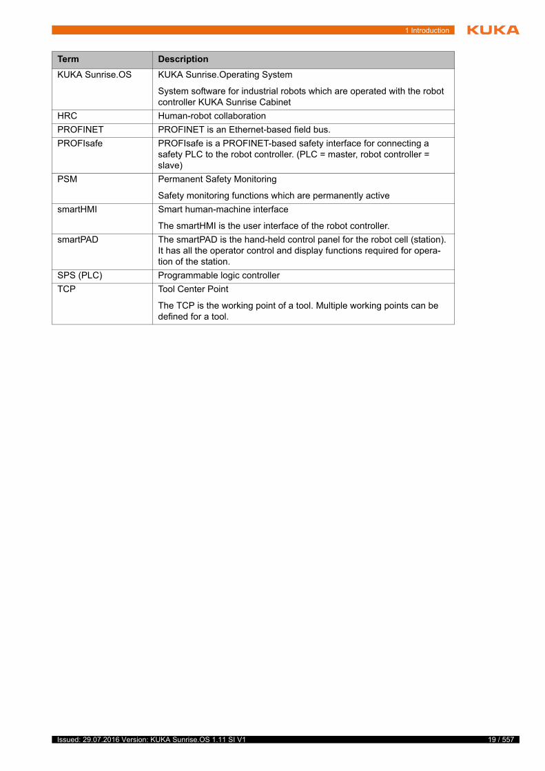
1 Introduction
KUKA Sunrise.OS KUKA Sunrise.Operating System
System software for industrial robots which are operated with the robot controller KUKA Sunrise Cabinet
HRC Human-robot collaboration
PROFINET PROFINET is an Ethernet-based field bus.
PROFIsafe PROFIsafe is a PROFINET-based safety interface for connecting a safety PLC to the robot controller. (PLC = master, robot controller = slave)
PSM Permanent Safety Monitoring
Safety monitoring functions which are permanently active
smartHMI Smart human-machine interface
The smartHMI is the user interface of the robot controller.
smartPAD The smartPAD is the hand-held control panel for the robot cell (station). It has all the operator control and display functions required for opera-tion of the station.
SPS (PLC) Programmable logic controller
TCP Tool Center Point
The TCP is the working point of a tool. Multiple working points can be defined for a tool.
Term Description
19 / 557Issued: 29.07.2016 Version: KUKA Sunrise.OS 1.11 SI V1

20 / 557
KUKA Sunrise.OS 1.11 KUKA Sunrise.Wor...
Issued: 29.07.2016 Version: KUKA Sunrise.OS 1.11 SI V1

2 Product description
2 Product description
2.1 Overview of the robot system
A robot system (>>> Fig. 2-1 ) comprises all the assemblies of an industrial robot, including the manipulator (mechanical system and electrical installa-tions), controller, connecting cables, end effector (tool) and other equipment.
The industrial robot consists of the following components:
Manipulator
KUKA Sunrise Cabinet robot controller
KUKA smartPAD control panel
Connecting cables
Software
Options, accessories
2.2 Overview of the software components
The following software components are used:
KUKA Sunrise.OS 1.11
KUKA Sunrise.Workbench 1.11
WorkVisual 4.0
2
t
s
Fig. 2-1: Overview of robot system
1 Connecting cable to the smartPAD
2 KUKA smartPAD control panel
3 Manipulator
4 Connecting cable to KUKA Sunrise Cabinet robot controller
5 KUKA Sunrise Cabinet robot controller
21 / 557Issued: 29.07.2016 Version: KUKA Sunrise.OS 1.11 SI V1
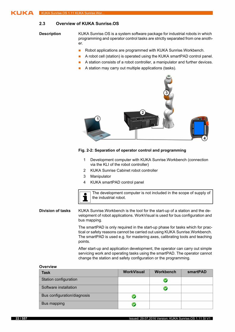
22 / 557
KUKA Sunrise.OS 1.11 KUKA Sunrise.Wor...
2.3 Overview of KUKA Sunrise.OS
Description KUKA Sunrise.OS is a system software package for industrial robots in which programming and operator control tasks are strictly separated from one anoth-er.
Robot applications are programmed with KUKA Sunrise.Workbench.
A robot cell (station) is operated using the KUKA smartPAD control panel.
A station consists of a robot controller, a manipulator and further devices.
A station may carry out multiple applications (tasks).
Division of tasks KUKA Sunrise.Workbench is the tool for the start-up of a station and the de-velopment of robot applications. WorkVisual is used for bus configuration and bus mapping.
The smartPAD is only required in the start-up phase for tasks which for prac-tical or safety reasons cannot be carried out using KUKA Sunrise.Workbench. The smartPAD is used e.g. for mastering axes, calibrating tools and teaching points.
After start-up and application development, the operator can carry out simple servicing work and operating tasks using the smartPAD. The operator cannot change the station and safety configuration or the programming.
Overview
Fig. 2-2: Separation of operator control and programming
1 Development computer with KUKA Sunrise.Workbench (connection via the KLI of the robot controller)
2 KUKA Sunrise Cabinet robot controller
3 Manipulator
4 KUKA smartPAD control panel
The development computer is not included in the scope of supply of the industrial robot.
Task WorkVisual Workbench smartPAD
Station configuration
Software installation
Bus configuration/diagnosis
Bus mapping
Issued: 29.07.2016 Version: KUKA Sunrise.OS 1.11 SI V1

2 Product description
2.4 Overview of KUKA Sunrise.Workbench
KUKA Sunrise.Workbench is the development environment for the robot cell (station). It offers the following functionalities for start-up and application de-velopment:
Start-up Installing the system software
Configuring the robot cell (station)
Editing the safety configuration
Creating the I/O configuration
Transferring the project to the robot controller
Application
development
Programming robot applications in Java
Managing projects and programs
Editing and managing runtime data
Project synchronization
Remote debugging (fault location and elimination)
Setting break points
Program execution in single-step operation (stop after each program line)
Displaying and modifying application variables during program execu-tion
Modifying a program during execution
Configuring safety settings
Activating the safety configuration
Programming
Remote debugging
Managing/editing runtime data
Creating frames
Teaching frames
Operating mode selection
Jogging
Mastering
Calibration
Load data determination
Setting/polling outputs
Polling inputs
Starting/stopping robot applications
Starting/stopping background applications
Creating a diagnosis package
Task WorkVisual Workbench smartPAD
23 / 557Issued: 29.07.2016 Version: KUKA Sunrise.OS 1.11 SI V1
24 / 557
KUKA Sunrise.OS 1.11 KUKA Sunrise.Wor...
2.5 Intended use of the system software
Use The system software is intended exclusively for the operation of KUKA axes in an industrial setting in conjunction with KUKA Sunrise Cabinet. KUKA axes include, for example, industrial robots and mobile platforms.
Each version of the system software may be operated exclusively in accor-dance with the specified system requirements.
Misuse Any use or application deviating from the intended use is deemed to be misuse and is not allowed. KUKA Roboter GmbH is not liable for any damage resulting from such misuse. The risk lies entirely with the user.
Examples of such misuse include:
Operating axes that are not KUKA axes
Operation of the system software not in accordance with the specified sys-tem requirements
Use of any debugger other than that provided by Sunrise.Workbench
Use for non-industrial applications for which specific product require-ments/standards exist (e.g. medical applications)
Issued: 29.07.2016 Version: KUKA Sunrise.OS 1.11 SI V1

3 Safety
3 Safety
3.1 Legal framework
3.1.1 Liability
The device described in this document is either an industrial robot or a com-ponent thereof.
Components of the industrial robot:
Manipulator
Robot controller
Hand-held control panel
Connecting cables
Software
Options, accessories
The industrial robot is built using state-of-the-art technology and in accor-dance with the recognized safety rules. Nevertheless, misuse of the industrial robot may constitute a risk to life and limb or cause damage to the industrial robot and to other material property.
The industrial robot may only be used in perfect technical condition in accor-dance with its designated use and only by safety-conscious persons who are fully aware of the risks involved in its operation. Use of the industrial robot is subject to compliance with this document and with the declaration of incorpo-ration supplied together with the industrial robot. Any functional disorders af-fecting safety must be rectified immediately.
Safety infor-
mation
Safety information cannot be held against KUKA Roboter GmbH. Even if all safety instructions are followed, this is not a guarantee that the industrial robot will not cause personal injuries or material damage.
No modifications may be carried out to the industrial robot without the autho-rization of KUKA Roboter GmbH. Additional components (tools, software, etc.), not supplied by KUKA Roboter GmbH, may be integrated into the indus-trial robot. The user is liable for any damage these components may cause to the industrial robot or to other material property.
In addition to the Safety chapter, this document contains further safety instruc-tions. These must also be observed.
3.1.2 Intended use of the industrial robot
The industrial robot is intended exclusively for the use designated in the “Pur-pose” chapter of the operating instructions or assembly instructions.
Any use or application deviating from the intended use is deemed to be misuse and is not allowed. The manufacturer is not liable for any damage resulting from such misuse. The risk lies entirely with the user.
Operation of the industrial robot in accordance with its intended use also re-quires compliance with the operating and assembly instructions for the individ-ual components, with particular reference to the maintenance specifications.
The user is responsible for the performance of a risk analysis. This indicates the additional safety equipment that is required, the installation of which is also the responsibility of the user.
Misuse Any use or application deviating from the intended use is deemed to be misuse and is not allowed. This includes e.g.:
f
t
y
25 / 557Issued: 29.07.2016 Version: KUKA Sunrise.OS 1.11 SI V1
26 / 557
KUKA Sunrise.OS 1.11 KUKA Sunrise.Wor...
Transportation of persons and animals
Use as a climbing aid
Operation outside the specified operating parameters
Use in potentially explosive environments
Operation without the required additional safety equipment
Outdoor operation
Underground operation
3.1.3 EC declaration of conformity and declaration of incorporation
The industrial robot constitutes partly completed machinery as defined by the EC Machinery Directive. The industrial robot may only be put into operation if the following preconditions are met:
The industrial robot is integrated into a complete system.
or: The industrial robot, together with other machinery, constitutes a com-plete system.
or: All safety functions and safeguards required for operation in the com-plete machine as defined by the EC Machinery Directive have been added to the industrial robot.
The complete system complies with the EC Machinery Directive. This has been confirmed by means of a conformity assessment procedure.
EC declaration of
conformity
The system integrator must issue an EC declaration of conformity for the com-plete system in accordance with the Machinery Directive. The EC declaration of conformity forms the basis for the CE mark for the system. The industrial robot must always be operated in accordance with the applicable national laws, regulations and standards.
The robot controller has a CE mark in accordance with the EMC Directive and the Low Voltage Directive.
Declaration of
incorporation
The partly completed machinery is supplied with a declaration of incorporation in accordance with Annex II B of the EC Machinery Directive 2006/42/EC. The assembly instructions and a list of essential requirements complied with in ac-cordance with Annex I are integral parts of this declaration of incorporation.
The declaration of incorporation declares that the start-up of the partly com-pleted machinery is not allowed until the partly completed machinery has been incorporated into machinery, or has been assembled with other parts to form machinery, and this machinery complies with the terms of the EC Machinery Directive, and the EC declaration of conformity is present in accordance with Annex II A.
3.2 Safety functions
Safety functions are distinguished according to the safety requirements that they fulfill:
Safety-oriented functions for the protection of personnel
The safety-oriented functions of the industrial robot meet the following safety requirements:
Category 3 and Performance Level d in accordance with EN ISO 13849-1
SIL 2 according to EN 62061
The requirements are only met on the following condition, however:
All safety-relevant mechanical and electromechanical components of the industrial robot are tested for correct functioning during start-up
Issued: 29.07.2016 Version: KUKA Sunrise.OS 1.11 SI V1
3 Safety
and at least once every 12 months, unless otherwise determined in ac-cordance with a workplace risk assessment. These include:
EMERGENCY STOP device on the smartPAD
Enabling device on the smartPAD
Enabling device on the media flange Touch (if present)
Keyswitch on the smartPAD
Safe outputs of the discrete safety interface
Non-safety-oriented functions for the protection of machines
The non-safety-oriented functions of the industrial robot do not meet spe-cific safety requirements:
3.2.1 Terms used
In the absence of the required operational safety func-tions and safeguards, the industrial robot can cause per-
sonal injury or material damage. If the required safety functions or safeguards are dismantled or deactivated, the industrial robot may not be op-erated.
During system planning, the safety functions of the overall system must also be planned and designed. The industrial robot must be in-tegrated into this safety system of the overall system.
Term Description
Axis range Range within which the axis may move The axis range must be defined for each axis.
Stopping distance Stopping distance = reaction distance + braking distance
The stopping distance is part of the danger zone.
Workspace The manipulator is allowed to move within its workspace. The work-space is derived from the individual axis ranges.
Automatic (AUT) Operating mode for program execution. The manipulator moves at the programmed velocity.
Operator(User)
The user of the industrial robot can be the management, employer or delegated person responsible for use of the industrial robot.
Danger zone The danger zone consists of the workspace and the stopping distances.
Service life The service life of a safety-relevant component begins at the time of delivery of the component to the customer.
The service life is not affected by whether the component is used in a robot controller or elsewhere or not, as safety-relevant components are also subject to aging during storage.
CRR Controlled Robot Retraction
CRR is an operating mode which can be selected when the industrial robot is stopped by the safety controller for one of the following reasons:
Industrial robot violates an axis-specific or Cartesian monitoring space.
Orientation of a safety-oriented tool is outside the monitored range.
Industrial robot violates a force or torque monitoring function.
A position sensor is not mastered or referenced.
A joint torque sensor is not referenced.
After changing to CRR mode, the industrial robot may once again be moved.
27 / 557Issued: 29.07.2016 Version: KUKA Sunrise.OS 1.11 SI V1
28 / 557
KUKA Sunrise.OS 1.11 KUKA Sunrise.Wor...
3.2.2 Personnel
The following persons or groups of persons are defined for the industrial robot:
User
Personnel
KUKA smartPAD See “smartPAD”
Manipulator The robot arm and the associated electrical installations
Safety zone The manipulator is not allowed to move within the safety zone. The safety zone is the area outside the danger zone.
Safety stop The safety stop is triggered by the safety controller, interrupts the work procedure and causes all robot motions to come to a standstill. The pro-gram data are retained in the case of a safety stop and the program can be resumed from the point of interruption.
The safety stop can be executed as a Stop category 0, Stop category 1 or Stop category 1 (path-maintaining).
Note: In this document, a safety stop of Stop category 0 is referred to as safety stop 0, a safety stop of Stop category 1 as safety stop 1 and a safety stop of Stop category 1 (path-maintaining) as safety stop 1 (path-maintaining).
smartPAD The smartPAD is the hand-held control panel for the robot cell (station). It has all the operator control and display functions required for opera-tion of the station.
Stop category 0 The drives are deactivated immediately and the brakes are applied.
Stop category 1 The manipulator is braked and does not stay on the programmed path. The manipulator is brought to a standstill with the drives. As soon as an axis is at a standstill, the drive is switched off and the brake is applied.
The internal electronic drive system of the robot performs safety-ori-ented monitoring of the braking process. Stop category 0 is executed in the event of a fault.
Note: Stop category 1 is currently only supported by the LBR iiwa. For other manipulators, Stop category 0 is executed.
Stop category 1 (path-maintaining)
The manipulator is braked and stays on the programmed path. At stand-still, the drives are deactivated and the brakes are applied.
If Stop category 1 (path-maintaining) is triggered by the safety controller, the safety controller monitors the braking process. The brakes are applied and the drives are switched off after 1 s at the latest. Stop cate-gory 1 is executed in the event of a fault.
System integrator (plant integrator)
System integrators are people who safely integrate the industrial robot into a complete system and commission it.
T1 Test mode, Manual Reduced Velocity (<= 250 mm/s)
Note: With manual guidance in T1, the velocity is not reduced, but rather limited through a safety-oriented velocity monitoring in accor-dance with the safety configuration.
Note: The maximum velocity of 250 mm/s does not apply to a mobile platform.
T2 Test mode, Manual High Velocity (> 250 mm/s permissible)
Term Description
All persons working with the industrial robot must have read and un-derstood the industrial robot documentation, including the safety chapter.
Issued: 29.07.2016 Version: KUKA Sunrise.OS 1.11 SI V1
3 Safety
User The user must observe the labor laws and regulations. This includes e.g.:
The user must comply with his monitoring obligations.
The user must carry out briefing at defined intervals.
Personnel Personnel must be instructed, before any work is commenced, in the type of work involved and what exactly it entails as well as any hazards which may ex-ist. Instruction must be carried out regularly. Instruction is also required after particular incidents or technical modifications.
Personnel includes:
System integrator
Operators, subdivided into:
Start-up, maintenance and service personnel
Operating personnel
Cleaning personnel
System integrator The industrial robot is safely integrated into a complete system by the system integrator.
The system integrator is responsible for the following tasks:
Installing the industrial robot
Connecting the industrial robot
Performing risk assessment
Implementing the required safety functions and safeguards
Issuing the EC declaration of conformity
Attaching the CE mark
Creating the operating instructions for the system
Operator The operator must meet the following preconditions:
The operator must be trained for the work to be carried out.
Work on the industrial robot must only be carried out by qualified person-nel. These are people who, due to their specialist training, knowledge and experience, and their familiarization with the relevant standards, are able to assess the work to be carried out and detect any potential hazards.
3.2.3 Workspace, safety zone and danger zone
Working zones are to be restricted to the necessary minimum size in order to prevent danger to persons or the risk of material damage. Safe axis range lim-itations required for personnel protection are configurable.
The danger zone consists of the workspace and the stopping distances of the manipulator. In the event of a stop, the manipulator is braked and comes to a
Installation, exchange, adjustment, operation, maintenance and re-pair must be performed only as specified in the operating or assembly instructions for the relevant component of the industrial robot and only
by personnel specially trained for this purpose.
Work on the electrical and mechanical equipment of the manipulator may only be carried out by KUKA Roboter GmbH.
Further information about configuring safe axis range limitations is contained in the “Safety configuration” chapter of the operating and programming instructions. (>>> 13 "Safety configuration" Page 203)
29 / 557Issued: 29.07.2016 Version: KUKA Sunrise.OS 1.11 SI V1

30 / 557
KUKA Sunrise.OS 1.11 KUKA Sunrise.Wor...
stop within the danger zone. The safety zone is the area outside the danger zone.
The danger zone must be protected by means of physical safeguards, e.g. by light barriers, light curtains or safety fences. If there are no physical safe-guards present, the requirements for collaborative operation in accordance with EN ISO 10218 must be met. There must be no shearing or crushing haz-ards at the loading and transfer areas.
3.2.4 Safety-oriented functions
The following safety-oriented functions are present and permanently defined in the industrial robot:
EMERGENCY STOP device
Enabling device
Locking of the operating mode (by means of a keyswitch)
The following safety-oriented functions are preconfigured and can be integrat-ed into the system via the safety interface of the robot controller:
Operator safety (= connection for the monitoring of physical safeguards)
External EMERGENCY STOP device
External safety stop 1 (path-maintaining)
Other safety-oriented functions may be configured, e.g.:
External enabling device
External safe operational stop
Axis-specific workspace monitoring
Cartesian workspace monitoring
Cartesian protected space monitoring
Velocity monitoring
Fig. 3-1: Example: axis range A1
1 Workspace 3 Stopping distance
2 Manipulator 4 Safety zone
Issued: 29.07.2016 Version: KUKA Sunrise.OS 1.11 SI V1
3 Safety
Standstill monitoring
Axis torque monitoring
Collision detection
The preconfigured safety functions are described in the following sections on safety.
3.2.4.1 EMERGENCY STOP device
The EMERGENCY STOP device for the industrial robot is the EMERGENCY STOP device on the smartPAD. The device must be pressed in the event of a hazardous situation or emergency.
Reaction of the industrial robot if the EMERGENCY STOP device is pressed:
The manipulator stops with a safety stop 1 (path-maintaining).
Before operation can be resumed, the EMERGENCY STOP device must be turned to release it.
If a holder is used for the smartPAD and conceals the EMERGENCY STOP device on the smartPAD, an external EMERGENCY STOP device must be in-stalled that is accessible at all times.
(>>> 3.2.4.4 "External EMERGENCY STOP device" Page 32)
3.2.4.2 Enabling device
The enabling devices of the industrial robot are the enabling switches on the smartPAD.
There are 3 enabling switches installed on the smartPAD. The enabling switches have 3 positions:
Not pressed
Center position
Fully pressed (panic position)
In the test modes and in CRR, the manipulator can only be moved if one of the enabling switches is held in the central position.
Releasing the enabling switch triggers a safety stop 1 (path-maintaining).
Fully pressing the enabling switch triggers a safety stop 1 (path-maintain-ing).
It is possible to hold 2 enabling switches in the center position simultane-ously for several seconds. This makes it possible to adjust grip from one enabling switch to another one. If 2 enabling switches are held simultane-ously in the center position for longer than 15 seconds, this triggers a safe-ty stop 1.
Further information about configuring the safety functions is con-tained in the “Safety configuration” chapter of the operating and pro-gramming instructions for system integrators. (>>> 13 "Safety
configuration" Page 203)
Tools and other equipment connected to the manipulator must be integrated into the EMERGENCY STOP circuit
on the system side if they could constitute a potential hazard.Failure to observe this precaution may result in death, severe injuries or con-siderable damage to property.
31 / 557Issued: 29.07.2016 Version: KUKA Sunrise.OS 1.11 SI V1
32 / 557
KUKA Sunrise.OS 1.11 KUKA Sunrise.Wor...
If an enabling switch malfunctions (e.g. jams in the central position), the indus-trial robot can be stopped using the following methods:
Press the enabling switch down fully.
Actuate the EMERGENCY STOP device.
Release the Start key.
3.2.4.3 “Operator safety” signal
The “operator safety” signal is used for monitoring physical safeguards, e.g. safety gates. In the default configuration, T2 and automatic operation are not possible without this signal. Alternatively, the requirements for collaborative operation in accordance with EN ISO 10218 must be met.
Reaction of the industrial robot in the event of a loss of signal during T2 or au-tomatic operation (default configuration):
The manipulator stops with a safety stop 1 (path-maintaining).
By default, operator safety is not active in the modes T1 (Manual Reduced Ve-locity) and CRR, i.e. the signal is not evaluated.
3.2.4.4 External EMERGENCY STOP device
Every operator station that can initiate a robot motion or other potentially haz-ardous situation must be equipped with an EMERGENCY STOP device. The system integrator is responsible for ensuring this.
Reaction of the industrial robot if the external EMERGENCY STOP device is pressed (default configuration):
The manipulator stops with a safety stop 1 (path-maintaining).
External EMERGENCY STOP devices are connected via the safety interface of the robot controller. External EMERGENCY STOP devices are not included in the scope of supply of the industrial robot.
3.2.4.5 External safety stop 1 (path-maintaining)
The external safety stop 1 (path-maintaining) can be triggered via an input on the safety interface (default configuration). The state is maintained as long as
The enabling switches must not be held down by adhe-sive tape or other means or tampered with in any other
way.Death, injuries or damage to property may result.
Following a loss of signal, automatic operation must not be resumed merely by closing the safeguard; the signal
for operator safety must first be set by an additional device, e.g. by an ac-knowledge button. It is the responsibility of the system integrator to ensure this. This is to prevent automatic operation from being resumed inadvertently while there are still persons in the danger zone, e.g. due to the safety gate closing accidentally.
This additional device must be designed in such a way that an actual check of the danger zone can be carried out first. Devices that do not al-low this (e.g. because they are automatically triggered by closure of the safeguard) are not permitted.
Failure to observe this may result in death to persons, severe injuries or considerable damage to property.
Issued: 29.07.2016 Version: KUKA Sunrise.OS 1.11 SI V1
3 Safety
the external signal is FALSE. If the external signal is TRUE, the manipulator can be moved again. No acknowledgement is required.
3.2.4.6 External enabling device
External enabling devices are required if it is necessary for more than one per-son to be in the danger zone of the industrial robot.
Multiple external enabling devices can be connected via the safety interface of the robot controller. External enabling devices are not included in the scope of supply of the industrial robot.
An external enabling device can be used for manual guidance of the robot. When enabling is active, the robot may only be moved at reduced velocity.
For manual guidance, safety-oriented velocity monitoring with a maximum permissible velocity of 250 mm/s is preconfigured. The maximum permissible velocity can be adapted.
The value for the maximum permissible velocity must be determined as part of a risk assessment.
3.2.4.7 External safe operational stop
The safe operational stop is a standstill monitoring function. It does not stop the robot motion, but monitors whether the robot axes are stationary.
The safe operational stop can be triggered via an input on the safety interface. The state is maintained as long as the external signal is FALSE. If the external signal is TRUE, the manipulator can be moved again. No acknowledgement is required.
3.2.5 Triggers for safety-oriented stop reactions
Stop reactions are triggered in response to operator actions or as a reaction to monitoring functions and errors. The following tables show the different stop reactions according to the operating mode that has been set.
Overview In KUKA Sunrise a distinction is made between the following triggers:
Permanently defined triggers
Permanently defined triggers for stop reactions and the associated stop category are preset by the system and cannot be changed. However, it is possible for the implemented stop reaction to be stepped up in the user-specific safety configuration.
User-specific triggers
In addition to the permanently defined triggers, the user can also configure other triggers for stop reactions including the associated stop category.
Permanently
defined triggers
The following triggers for stop reactions are permanently defined:
Further information about configuring the safety functions is con-tained in the “Safety configuration” chapter of the operating and pro-gramming instructions for system integrators. (>>> 13 "Safety
configuration" Page 203)
Trigger T1, T2, CRR AUT
Operating mode changed during operation
Safety stop 1 (path-maintaining)
Enabling switch released Safety stop 1 (path-maintaining)
-
33 / 557Issued: 29.07.2016 Version: KUKA Sunrise.OS 1.11 SI V1
34 / 557
KUKA Sunrise.OS 1.11 KUKA Sunrise.Wor...
User-specific
triggers
When creating a new Sunrise project, the system automatically generates a project-specific safety configuration. This contains the following user-specific stop reaction triggers preconfigured by KUKA (in addition to the permanently defined triggers):
Triggers for
manual guidance
If an enabling device is configured for manual guidance, the following addition-al triggers for stop reactions are permanently defined:
A maximum permissible velocity of 250 mm/s is preconfigured for manual guidance. The maximum permissible velocity can be adapted.
The value for the maximum permissible velocity must be determined as part of a risk assessment.
(>>> 13.10.5.3 "Velocity monitoring during manual guidance" Page 238)
3.2.6 Non-safety-oriented functions
3.2.6.1 Mode selection
The industrial robot can be operated in the following modes:
Manual Reduced Velocity (T1)
Manual High Velocity (T2)
Automatic (AUT)
Controlled robot retraction (CRR)
Enabling switch pressed fully down (panic position)
Safety stop 1 (path-maintaining)
-
Local E-STOP pressed Safety stop 1 (path-maintaining)
Error in safety controller Safety stop 1
Trigger T1, T2, CRR AUT
Trigger T1, CRR T2, AUT
Safety gate opened (oper-ator safety)
- Safety stop 1 (path-maintaining)
External E-STOP pressed Safety stop 1 (path-maintaining)
External safety stop Safety stop 1 (path-maintaining)
This default safety configuration is valid for the system software with-out additionally installed option packages or catalog elements. If ad-ditional option packages or catalog elements have been installed, the
default safety configuration may be modified.
Trigger T1, CRR T2, AUT
Manual guidance enabling switch released
Safety stop 1 (path-maintaining)
-
Manual guidance enabling switch pressed fully down (panic position)
Safety stop 1 (path-maintaining)
-
Maximum permissible velocity exceeded while manual guidance enabling signal is set
Safety stop 1 (path-maintaining)
Issued: 29.07.2016 Version: KUKA Sunrise.OS 1.11 SI V1
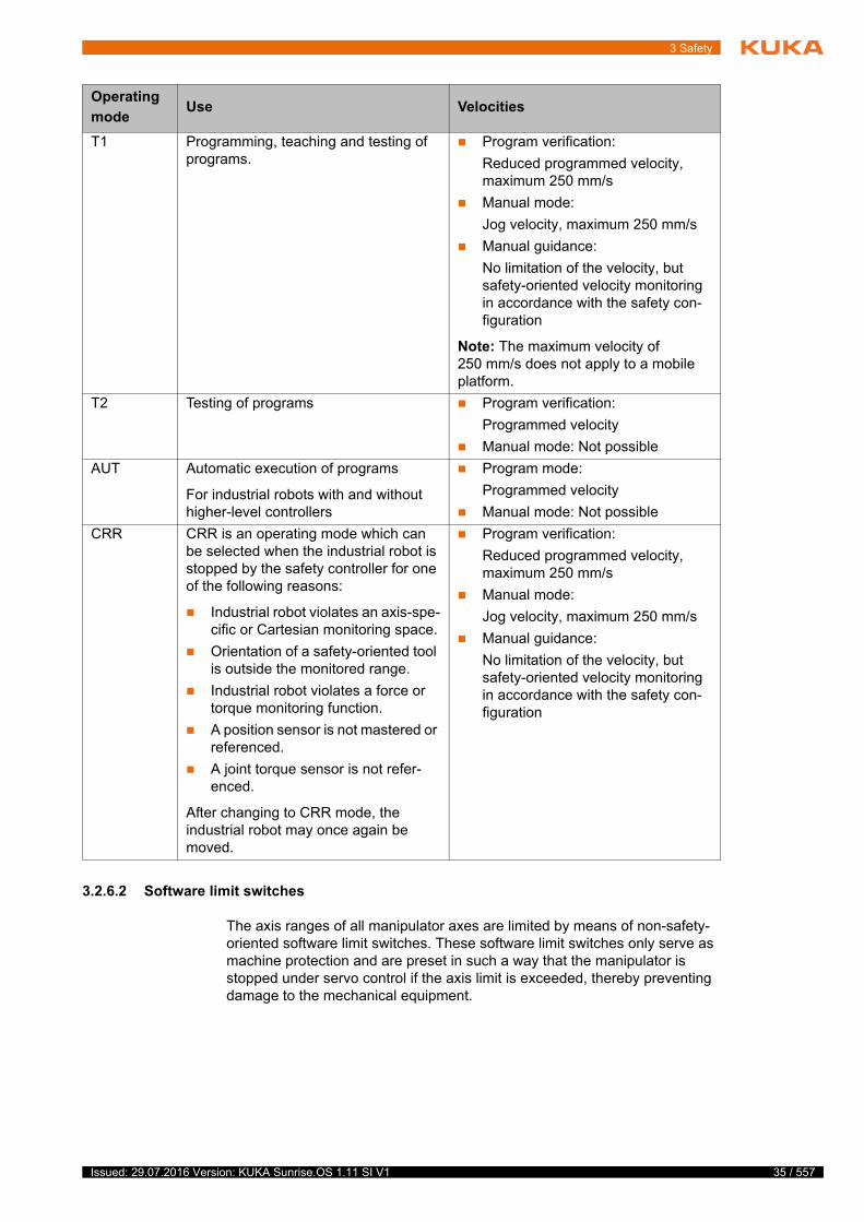
3 Safety
3.2.6.2 Software limit switches
The axis ranges of all manipulator axes are limited by means of non-safety-oriented software limit switches. These software limit switches only serve as machine protection and are preset in such a way that the manipulator is stopped under servo control if the axis limit is exceeded, thereby preventing damage to the mechanical equipment.
Operating
modeUse Velocities
T1 Programming, teaching and testing of programs.
Program verification:
Reduced programmed velocity, maximum 250 mm/s
Manual mode:
Jog velocity, maximum 250 mm/s
Manual guidance:
No limitation of the velocity, but safety-oriented velocity monitoring in accordance with the safety con-figuration
Note: The maximum velocity of 250 mm/s does not apply to a mobile platform.
T2 Testing of programs Program verification:
Programmed velocity
Manual mode: Not possible
AUT Automatic execution of programs
For industrial robots with and without higher-level controllers
Program mode:
Programmed velocity
Manual mode: Not possible
CRR CRR is an operating mode which can be selected when the industrial robot is stopped by the safety controller for one of the following reasons:
Industrial robot violates an axis-spe-cific or Cartesian monitoring space.
Orientation of a safety-oriented tool is outside the monitored range.
Industrial robot violates a force or torque monitoring function.
A position sensor is not mastered or referenced.
A joint torque sensor is not refer-enced.
After changing to CRR mode, the industrial robot may once again be moved.
Program verification:
Reduced programmed velocity, maximum 250 mm/s
Manual mode:
Jog velocity, maximum 250 mm/s
Manual guidance:
No limitation of the velocity, but safety-oriented velocity monitoring in accordance with the safety con-figuration
35 / 557Issued: 29.07.2016 Version: KUKA Sunrise.OS 1.11 SI V1
36 / 557
KUKA Sunrise.OS 1.11 KUKA Sunrise.Wor...
3.3 Additional protective equipment
3.3.1 Jog mode
In the operating modes T1 (Manual Reduced Velocity), T2 (Manual High Ve-locity) and CRR, the robot controller can only execute programs in jog mode. This means that it is necessary to hold down an enabling switch and the Start key in order to execute a program.
Releasing the enabling switch on the smartPAD triggers a safety stop 1 (path-maintaining).
Pressing fully down on the enabling switch on the smartPAD triggers a safety stop 1 (path-maintaining).
Releasing the Start key triggers a stop of Stop category 1 (path-maintain-ing).
3.3.2 Labeling on the industrial robot
All plates, labels, symbols and marks constitute safety-relevant parts of the in-dustrial robot. They must not be modified or removed.
Labeling on the industrial robot consists of:
Identification plates
Warning signs
Safety symbols
Designation labels
Cable markings
Rating plates
3.3.3 External safeguards
The access of persons to the danger zone of the industrial robot must be pre-vented by means of safeguards. Alternatively, the requirements for collabora-tive operation in accordance with EN ISO 10218 must be met. It is the responsibility of the system integrator to ensure this.
Physical safeguards must meet the following requirements:
They meet the requirements of EN ISO 14120.
They prevent access of persons to the danger zone and cannot be easily circumvented.
They are sufficiently fastened and can withstand all forces that are likely to occur in the course of operation, whether from inside or outside the en-closure.
They do not, themselves, represent a hazard or potential hazard.
The prescribed minimum clearance from the danger zone is maintained.
Safety gates (maintenance gates) must meet the following requirements:
They are reduced to an absolute minimum.
The interlocks (e.g. safety gate switches) are linked to the configured op-erator safety inputs of the robot controller.
Further information is contained in the technical data of the operating instructions or assembly instructions of the components of the indus-trial robot.
Issued: 29.07.2016 Version: KUKA Sunrise.OS 1.11 SI V1
3 Safety
Switching devices, switches and the type of switching conform to the re-quirements of Performance Level d and category 3 according to EN ISO 13849-1.
Depending on the risk situation: the safety gate is additionally safeguarded by means of a locking mechanism that only allows the gate to be opened if the manipulator is safely at a standstill.
The device for setting the signal for operator safety, e.g. the button for ac-knowledging the safety gate, is located outside the space limited by the safeguards.
Other safety
equipment
Other safety equipment must be integrated into the system in accordance with the corresponding standards and regulations.
3.4 Safety measures
3.4.1 General safety measures
The industrial robot may only be used in perfect technical condition in accor-dance with its intended use and only by safety-conscious persons. Operator errors can result in personal injury and damage to property.
It is important to be prepared for possible movements of the industrial robot even after the robot controller has been switched off and locked out. Incorrect installation (e.g. overload) or mechanical defects (e.g. brake defect) can cause the manipulator to sag. If work is to be carried out on a switched-off industrial robot, the manipulator must first be moved into a position in which it is unable to move on its own, whether the payload is mounted or not. If this is not pos-sible, the manipulator must be secured by appropriate means.
smartPAD The user must ensure that the industrial robot is only operated with the smart-PAD by authorized persons.
If more than one smartPAD is used in the overall system, it must be ensured that each smartPAD is unambiguously assigned to the corresponding indus-trial robot. It must be ensured that 2 smartPADs are not interchanged.
The smartPAD can be configured as unpluggable.
Further information is contained in the corresponding standards and regulations. These also include EN ISO 14120.
In the absence of operational safety functions and safe-guards, the industrial robot can cause personal injury or
material damage. If safety functions or safeguards are dismantled or deacti-vated, the industrial robot may not be operated.
Standing underneath the robot arm can cause death or serious injuries. Especially if the industrial robot is mov-
ing objects that can become detached (e.g. from a gripper). For this reason, standing underneath the robot arm is prohibited!
If the smartPAD is disconnected, the system can no lon-ger be switched off by means of the EMERGENCY
STOP device on the smartPAD. If the smartPAD is configured as unplugga-ble, at least one external EMERGENCY STOP device must be installed that is accessible at all times.Failure to observe this can lead to death, injury or property damage.
37 / 557Issued: 29.07.2016 Version: KUKA Sunrise.OS 1.11 SI V1
38 / 557
KUKA Sunrise.OS 1.11 KUKA Sunrise.Wor...
Modifications After modifications to the industrial robot, checks must be carried out to ensure the required safety level. The valid national or regional work safety regulations must be observed for this check. The correct functioning of all safety functions must also be tested.
New or modified programs must always be tested first in Manual Reduced Ve-locity mode (T1).
After modifications to the industrial robot, existing programs must always be tested first in Manual Reduced Velocity mode (T1). This applies to all compo-nents of the industrial robot and includes modifications to the software and configuration settings.
The robot may not be connected and disconnected when the robot controller is running.
Faults The following tasks must be carried out in the case of faults in the industrial robot:
Switch off the robot controller and secure it (e.g. with a padlock) to prevent unauthorized persons from switching it on again.
Indicate the fault by means of a label with a corresponding warning (tag-out).
Keep a record of the faults.
Eliminate the fault and carry out a function test.
3.4.2 Transportation
Manipulator The prescribed transport position of the manipulator must be observed. Trans-portation must be carried out in accordance with the operating instructions or assembly instructions of the robot.
Avoid vibrations and impacts during transportation in order to prevent damage to the manipulator.
Robot controller The prescribed transport position of the robot controller must be observed. Transportation must be carried out in accordance with the operating instruc-tions or assembly instructions of the robot controller.
Avoid vibrations and impacts during transportation in order to prevent damage to the robot controller.
3.4.3 Start-up and recommissioning
Before starting up systems and devices for the first time, a check must be car-ried out to ensure that the systems and devices are complete and operational, that they can be operated safely and that any damage is detected.
The valid national or regional work safety regulations must be observed for this check. The correct functioning of all safety functions must also be tested.
The operator must ensure that disconnected smartPADs are immediately removed from the system and stored out
of sight and reach of personnel working on the industrial robot. This prevents operational and non-operational EMERGENCY STOP devices from becom-ing interchanged.Failure to observe this can lead to death, injury or property damage.
Issued: 29.07.2016 Version: KUKA Sunrise.OS 1.11 SI V1
3 Safety
Function test The following tests must be carried out before start-up and recommissioning:
General test:
It must be ensured that:
The industrial robot is correctly installed and fastened in accordance with the specifications in the documentation.
There are no foreign bodies or loose parts on the industrial robot.
All required safety equipment is correctly installed and operational.
The power supply ratings of the industrial robot correspond to the local supply voltage and mains type.
The ground conductor and the equipotential bonding cable are sufficiently rated and correctly connected.
The connecting cables are correctly connected and the connectors are locked.
Test of the safety functions:
A function test must be carried out for all the safety-oriented functions to en-sure that they are working correctly:
(>>> 13.13 "Safety acceptance overview" Page 275)
Test of the safety-relevant mechanical and electromechanical compo-nents:
The following tests must be performed prior to start-up and at least once every 12 months unless otherwise determined in accordance with a workplace risk assessment:
Press the EMERGENCY STOP device on the smartPAD. A message must be displayed on the smartPAD indicating that the EMERGENCY STOP has been actuated. At the same time, no error message may be displayed about the EMERGENCY STOP device.
For all 3 enabling switches on the smartPAD and for the enabling switch on the media flange Touch (if present)
Move the robot in Test mode and release the enabling switch. The robot motion must be stopped. At the same time, no error message may be dis-
Prior to start-up, the passwords for the user groups must be modified in the project settings and transferred to the robot controller in an in-stallation procedure. The passwords must only be communicated to
authorized personnel.
The robot controller is preconfigured for the specific in-dustrial robot. If cables are interchanged, the manipula-
tor may receive incorrect data and can thus cause personal injury or material damage. If a system consists of more than one manipulator, always connect the connecting cables to the manipulators and their corresponding robot con-trollers.
If additional components (e.g. cables), which are not part of the scope of supply of KUKA Roboter GmbH, are integrated into the industrial robot, the user is responsible for ensuring that these components do
not adversely affect or disable safety functions.
If the internal cabinet temperature of the robot controller differs greatly from the ambient temperature, condensa-
tion can form, which may cause damage to the electrical components. Do not put the robot controller into operation until the internal temperature of the cabinet has adjusted to the ambient temperature.
39 / 557Issued: 29.07.2016 Version: KUKA Sunrise.OS 1.11 SI V1

40 / 557
KUKA Sunrise.OS 1.11 KUKA Sunrise.Wor...
played about the enabling device. If the state of the enabling switch is con-figured at an output, the test can also be performed via the output.
For all 3 enabling switches on the smartPAD and for the enabling switch on the media flange Touch (if present)
Move the robot in Test mode and press the enabling switch down fully. The robot motion must be stopped. At the same time, no error message may be displayed about the enabling device. If the state of the enabling switch is configured at an output, the test can also be performed via the output.
Turn the keyswitch on the smartPAD to the right and then back again. There must be no error message displayed on the smartPAD.
Test the switch-off capability of the safe inputs by switching the robot con-troller off and then on again. After it is switched on, no error message for a safe output may be displayed.
Test of the functional capability of the brakes:
For the KUKA LBR iiwa (all variants) a brake test is available which can be used to check whether the brake of each axis applies sufficient braking torque.
The brake test ensures that any impairment of the braking function is detected, e.g. due to wear, overheating, fouling or damage, thereby eliminating avoid-able risks.
The brake test must be performed regularly, unless an application-specific risk assessment has established that a malfunction of the mechanical brakes will not result in inadmissibly high risks. Determination of the interval at which the brake test is to be performed also constitutes part of the risk assessment.
In the absence of a corresponding risk assessment, the following applies:
The brake test must be carried out for each axis during start-up and recom-missioning of the industrial robot.
The brake test must be performed daily during operation.
3.4.4 Manual mode
Manual mode is the mode for setup work. Setup work is all the tasks that have to be carried out on the industrial robot to enable automatic operation. Setup work includes:
Jog mode
Teaching
Program verification
The following must be taken into consideration in manual mode:
New or modified programs must always be tested first in Manual Reduced Velocity mode (T1).
The manipulator and its tooling must never touch or project beyond the safety fence.
Workpieces, tooling and other objects must not become jammed as a re-sult of the industrial robot motion, nor must they lead to short-circuits or be liable to fall off.
All setup work must be carried out, where possible, from outside the safe-guarded area.
In the case of incomplete start-up of the system, additional substitute measures for minimizing risk must be taken and documented, e.g. in-stallation of a safety fence, attachment of a warning sign, locking of
the main switch. Start-up is incomplete, for example, if not all safety functions have yet been implemented, or if a function test of the safety functions has not yet been carried out.
Issued: 29.07.2016 Version: KUKA Sunrise.OS 1.11 SI V1
3 Safety
If the setup work has to be carried out inside the safeguarded area, the follow-ing must be taken into consideration:
In Manual Reduced Velocity mode (T1):
If it can be avoided, there must be no other persons inside the safeguard-ed area.
If it is necessary for there to be several persons inside the safeguarded ar-ea, the following must be observed:
Each person must have an enabling device.
All persons must have an unimpeded view of the industrial robot.
Eye-contact between all persons must be possible at all times.
The operator must be so positioned that he can see into the danger area and get out of harm’s way.
In Manual High Velocity mode (T2):
This mode may only be used if the application requires a test at a velocity higher than Manual Reduced Velocity.
Teaching is not permissible in this operating mode.
Before commencing the test, the operator must ensure that the enabling devices are operational.
There must be no-one present inside the safeguarded area. It is the re-sponsibility of the operator to ensure this.
3.4.5 Automatic mode
Automatic mode is only permissible in compliance with the following safety measures:
All safety equipment and safeguards are present and operational.
There are no persons in the system, or the requirements for collaborative operation in accordance with EN ISO 10218 have been met.
The defined working procedures are adhered to.
If the manipulator comes to a standstill for no apparent reason, the danger zone must not be entered until an EMERGENCY STOP has been triggered.
3.4.6 Maintenance and repair
After maintenance and repair work, checks must be carried out to ensure the required safety level. The valid national or regional work safety regulations must be observed for this check. The correct functioning of all safety functions must also be tested.
The purpose of maintenance and repair work is to ensure that the system is kept operational or, in the event of a fault, to return the system to an operation-al state. Repair work includes troubleshooting in addition to the actual repair itself.
The following safety measures must be carried out when working on the indus-trial robot:
Carry out work outside the danger zone. If work inside the danger zone is necessary, the user must define additional safety measures to ensure the safe protection of personnel.
Switch off the industrial robot and secure it (e.g. with a padlock) to prevent it from being switched on again. If it is necessary to carry out work with the robot controller switched on, the user must define additional safety mea-sures to ensure the safe protection of personnel.
41 / 557Issued: 29.07.2016 Version: KUKA Sunrise.OS 1.11 SI V1

42 / 557
KUKA Sunrise.OS 1.11 KUKA Sunrise.Wor...
If it is necessary to carry out work with the robot controller switched on, this may only be done in operating mode T1.
Label the system with a sign indicating that work is in progress. This sign must remain in place, even during temporary interruptions to the work.
The EMERGENCY STOP devices must remain active. If safety functions or safeguards are deactivated during maintenance or repair work, they must be reactivated immediately after the work is completed.
Faulty components must be replaced using new components with the same article numbers or equivalent components approved by KUKA Roboter GmbH for this purpose.
Cleaning and preventive maintenance work is to be carried out in accordance with the operating instructions.
Robot controller Even when the robot controller is switched off, parts connected to peripheral devices may still carry voltage. The external power sources must therefore be switched off if work is to be carried out on the robot controller.
The ESD regulations must be adhered to when working on components in the robot controller.
Voltages in excess of 60 V can be present in various components for several minutes after the robot controller has been switched off! To prevent life-threat-ening injuries, no work may be carried out on the industrial robot in this time.
Water and dust must be prevented from entering the robot controller.
3.4.7 Decommissioning, storage and disposal
The industrial robot must be decommissioned, stored and disposed of in ac-cordance with the applicable national laws, regulations and standards.
3.4.8 Safety measures for “single point of control”
Overview If certain components in the industrial robot are operated, safety measures must be taken to ensure complete implementation of the principle of “single point of control” (SPOC).
Components:
Tools for configuration of bus systems with online functionality
Since only the system integrator knows the safe states of actuators in the pe-riphery of the robot controller, it is his task to set these actuators to a safe state.
T1, T2, CRR In modes T1, T2 and CRR, a robot motion can only be initiated if an enabling switch is held down.
Before work is commenced on live parts of the robot sys-tem, the main switch must be turned off and secured
against being switched on again. The system must then be checked to en-sure that it is deenergized.It is not sufficient, before commencing work on live parts, to execute an EMERGENCY STOP or a safety stop, or to switch off the drives, as this does not disconnect the robot system from the mains power supply. Parts remain energized. Death or severe injuries may result.
The implementation of additional safety measures may be required. This must be clarified for each specific application; this is the respon-sibility of the user of the system.
Issued: 29.07.2016 Version: KUKA Sunrise.OS 1.11 SI V1
3 Safety
Tools for configu-
ration of bus
systems
If these components have an online functionality, they can be used with write access to modify programs, outputs or other parameters of the robot control-ler, without this being noticed by any persons located inside the system.
KUKA Sunrise.Workbench
WorkVisual from KUKA
Tools from other manufacturers
Safety measure:
In the test modes, programs, outputs or other parameters of the robot con-troller must not be modified using these components.
3.5 Applied norms and directives
Name Definition Edition
2006/42/EC Machinery Directive:
Directive 2006/42/EC of the European Parliament and of the Council of 17 May 2006 on machinery, and amending Direc-tive 95/16/EC (recast)
2006
2014/30/EU EMC Directive:
Directive 2014/30/EC of the European Parliament and of the Council of 26 February 2014 on the approximation of the laws of the Member States concerning electromagnetic compatibil-ity
2014
EN ISO 13850 Safety of machinery:
Emergency stop - Principles for design
2015
EN ISO 13849-1 Safety of machinery:
Safety-related parts of control systems - Part 1: General prin-ciples of design
2015
EN ISO 13849-2 Safety of machinery:
Safety-related parts of control systems - Part 2: Validation
2012
EN ISO 12100 Safety of machinery:
General principles of design, risk assessment and risk reduc-tion
2010
EN ISO 10218-1 Industrial robots – Safety requirements
Part 1: Robots
Note: Content equivalent to ANSI/RIA R.15.06-2012, Part 1
2011
EN 614-1 + A1 Safety of machinery:
Ergonomic design principles - Part 1: Terms and general prin-ciples
2009
EN 61000-6-2 Electromagnetic compatibility (EMC):
Part 6-2: Generic standards; Immunity for industrial environ-ments
2005
43 / 557Issued: 29.07.2016 Version: KUKA Sunrise.OS 1.11 SI V1
44 / 557
KUKA Sunrise.OS 1.11 KUKA Sunrise.Wor...
EN 61000-6-4 + A1 Electromagnetic compatibility (EMC):
Part 6-4: Generic standards; Emission standard for industrial environments
2011
EN 60204-1 + A1 Safety of machinery:
Electrical equipment of machines - Part 1: General require-ments
2009
EN 62061 + A1 Safety of machinery:
Functional safety of safety-related electrical, electronic and programmable electronic control systems
2012
Issued: 29.07.2016 Version: KUKA Sunrise.OS 1.11 SI V1
4 Installing KUKA Sunrise.Workbench
4 Installing KUKA Sunrise.Workbench
4.1 PC system requirements
Hardware Minimum requirements
PC with Pentium IV processor, min. 1500 MHz
1 GB RAM
1 GB free hard disk space
DirectX8-compatible graphics card with a resolution of 1024x768 pixels
Recommended specifications
PC with Pentium IV processor 2500 MHz
2 GB RAM
DirectX8-compatible graphics card with a resolution of 1280x1024 pixels
Software Windows 7
The following software is required for bus configuration:
WorkVisual 4.0
4.2 Installing Sunrise.Workbench
Preparation If an older version of Sunrise.Workbench is already installed:
Uninstall the old version first.
Precondition Local administrator rights
Procedure 1. Start the program SunriseWorkbench-[…]-Setup.exe. A window opens.
2. Select the language for the installation operation and confirm with OK.
The language selection only applies to the installation and not to Sun-rise.Workbench itself. The user interface language for Sunrise.Workbench is German by default.
3. An installation wizard opens. Follow the instructions in the wizard.
4.3 Uninstalling Sunrise.Workbench
Description Uninstallation removes all program files from the computer. User-specific files are retained, e.g. the workspace with the Sunrise projects.
Precondition Local administrator rights
Procedure 1. Call the list of installed programs in the Windows Control Panel.
2. In the list, select the program Sunrise Workbench and uninstall it.
Alternative
procedure
In the Windows Start menu, open the installation directory of Sun-rise.Workbench and click on Uninstall.
4
s
t
45 / 557Issued: 29.07.2016 Version: KUKA Sunrise.OS 1.11 SI V1

46 / 557
KUKA Sunrise.OS 1.11 KUKA Sunrise.Wor...
Issued: 29.07.2016 Version: KUKA Sunrise.OS 1.11 SI V1
5 Operation of KUKA Sunrise.Workbench
5 Operation of KUKA Sunrise.Workbench
5.1 Starting Sunrise.Workbench
Procedure 1. Double-click on the Sunrise.Workbench icon on the desktop.
Alternative:
In the Windows Start menu, open the installation directory and double-click on Sunrise Workbench.
The Workspace Launcher window opens.
2. In the Workspace box, specify the directory for the workspace in which projects are to be saved.
A default directory is suggested. The directory can be changed by clicking on the Browse… button.
If the workspace should not be queried the next time Sunrise.Work-bench is started, activate the option Use this as the default value[…] (set check mark).
Confirm the settings with OK.
3. A welcome screen opens the first time Sunrise.Workbench is started. There are different options here.
Click on Workbench to open the user interface of Sunrise.Work-bench.
Click on New Sunrise project to create a new Sunrise project directly. The project creation wizard opens.
(>>> 5.3 "Creating a Sunrise project with a template" Page 51)
5.2 Overview of the user interface of Sunrise.Workbench
The user interface of KUKA Sunrise.Workbench consists of several views. The combination of several views is called a perspective. KUKA Sun-rise.Workbench offers various preconfigured perspectives.
The Programming perspective is opened by default. Additional perspectives can be displayed.
t
f
47 / 557Issued: 29.07.2016 Version: KUKA Sunrise.OS 1.11 SI V1

48 / 557
KUKA Sunrise.OS 1.11 KUKA Sunrise.Wor...
Fig. 5-1: Overview of user interface – “Programming” perspective
Item Description
1 Menu bar
2 Toolbar
(>>> 5.2.4 "Toolbar – Programming perspective" Page 50)
3 Editor area
Opened files, e.g. robot applications, are displayed and edited here.
4 Perspective selection
Here it is possible to switch between various previously-used per-spectives by clicking on the name of the appropriate perspective or on the Open Perspective icon.
(>>> 5.2.3 "Displaying different perspectives on the user inter-face" Page 49)
5 Package Explorer view
This view contains the projects created and their corresponding files.
Issued: 29.07.2016 Version: KUKA Sunrise.OS 1.11 SI V1

5 Operation of KUKA Sunrise.Workbench
5.2.1 Repositioning the views
Procedure 1. Grip the view by the title bar while holding down the left mouse button and move it to the desired position on the user interface.
The possible positions for the view are indicated here by a gray frame.
2. Release the mouse button when the desired position for the view is select-ed.
5.2.2 Closing views and files
Procedure Click on the “X” at the top right of the corresponding tab.
5.2.3 Displaying different perspectives on the user interface
Description The user interface can be displayed in different perspectives. These can be selected via the menu sequence Window > Open Perspective or by clicking on the Open Perspective icon.
The perspectives are tailored to different types of work:
Perspectives can be adapted to the needs of the user. Examples:
Creating own perspectives
Showing/hiding views
Showing/hiding menus
Showing/hiding menu items
It is possible to save the adapted perspective as a default setting for the per-spective or under a separate name of its own.
6 The following views can be seen here:
Application data
This view displays the frames created for a project in a tree structure.
Object templates
This view displays the geometrical objects, tools and workpiec-es created for a project in a tree structure.
7 The following views can be seen here:
Tasks
This view displays the tasks which a user has created.
Javadoc
This view displays the Javadoc comments about the selected elements of a Java application.
Properties view
This view displays the properties of the selected object of a view, e.g. the properties of a project, frame or tool.
Item Description
Perspective Type of work
Programming This perspective has views suitable for editing Sunrise projects. For example, for station config-uration, safety configuration and application development.
Debug This perspective has views suitable for locating faults and eliminating programming faults.
49 / 557Issued: 29.07.2016 Version: KUKA Sunrise.OS 1.11 SI V1

50 / 557
KUKA Sunrise.OS 1.11 KUKA Sunrise.Wor...
Procedure To display views in the current perspective:
Select the menu sequence Window > Show View and the desired view.
Further views can be selected by clicking the menu item Other….
To reset the current perspective to the default setting:
Select the menu sequence Window > Reset Perspective… and answer the request for confirmation with Yes.
To save user-defined perspectives:
1. Select the menu sequence Window > Save Perspective As....
2. In the Name box, enter a name for the perspective and confirm it with OK.
If an existing perspective is selected and overwritten, the perspective will be opened with these settings in the future.
5.2.4 Toolbar – Programming perspective
The buttons available by default on the toolbar depend on the active perspec-tive. The buttons of the Programming perspective are described here.
Icon Name / description
New
Opens the wizard for creating new documents.
The arrow can be used to open the menu with the available wizards.
Save
Saves the currently opened and selected file.
Save All
Saves all files and projects that have been edited since the last save.
Opens the menu for printing a file.
Synchronize project
Synchronizes the selected project with the robot controller.
Debug project
Establishes a remote connection to the robot controller in order to debug an application during ongoing operation.
Sunrise project
Opens the wizard for creating a new Sunrise project.
New Java package
Opens the wizard for creating a new Java package in the selected project.
New Java class
Opens the wizard for creating a new Java class in the selected project.
The arrow can be used to open the menu with the available Java classes.
Search
Opens the wizard to search for words or text modules.
Issued: 29.07.2016 Version: KUKA Sunrise.OS 1.11 SI V1
5 Operation of KUKA Sunrise.Workbench
5.3 Creating a Sunrise project with a template
Procedure 1. Select the menu sequence File > New > Sunrise project. The project cre-ation wizard opens.
2. Enter the IP address of the robot controller to be created for the project in the IP address of controller: box.
It is possible to change the address again during subsequent project con-figuration.
3. Retain the Create new project (offline) setting.
Press Next > to switch to the next page.
4. Enter a name for the project in the Project name: box.
5. The default directory for projects is given in the Location: box.
A different directory can be selected: to do so, remove the check mark at Use default location and select Browse…. Then use the Browse for Folder dialog to select the desired file path and confirm with OK.
Press Next > to switch to the next page.
6. Select a template from the Topology template list.
The template determines which elements are subsequently preselected in the station configuration on the Topology tab. Irrespective of the template that is selected here, all elements are always available in Topology and the preselection can be modified as required.
Press Next > to switch to the next page.
7. If the selected template is a robot with a media flange, select the corre-sponding media flange.
8. By default, the mounting orientation of a floor-mounted robot is set (A=0°, B=0°, C=0°).
In the case of a ceiling- or wall-mounted robot, enter the direction of instal-lation relative to the floor-mounted robot:
a. Rotation about the Z axis in ° (A angle): Rotation of angle A about the Z axis of the robot base coordinate system (-180° ≤ A ≤ 180°).
Last Edit Location
Switches to the last edit location in the currently opened and selected file.
Back to ...
Switches back to the previous edit steps.
Forward to ...
Switches forward again to the subsequent edit steps.
Icon Name / description
The following IP address ranges are used by default by the robot con-troller for internal purposes. IP addresses from these ranges cannot therefore be assigned by the user.
169.254.0.0 … 169.254.255.255
172.16.0.0 … 172.16.255.255
172.17.0.0 … 172.17.255.255
192.168.0.0 … 192.168.0.255
The weight and height of the selected media flange are automatically taken into consideration by the system software.
51 / 557Issued: 29.07.2016 Version: KUKA Sunrise.OS 1.11 SI V1

52 / 557
KUKA Sunrise.OS 1.11 KUKA Sunrise.Wor...
b. Rotation about the Y axis in ° (B angle): Rotation of angle B about the Y axis (-90° ≤ B ≤ 90°). The rotation about the Y axis is relative to the rotated coordinate system from step a.
c. Rotation about the X axis in ° (C angle): Rotation of angle C about the X axis (-180° ≤ C ≤ 180°). The rotation about the X axis is relative to the rotated coordinate system from step b.
(>>> 6.10 "Coordinate systems" Page 80)
Press Next > to switch to the next page.
9. A summary of information on the project is displayed.
Remove the check mark at Create application (starts other wizard) and click on Finish. The project is created and added to the Package Explor-er.
If the check mark has been set at Create application (starts other wiz-ard), the wizard for application creation opens. A first robot application can be created directly for the newly-created project.
(>>> 5.4.2 "Creating a robot application with a package" Page 54)
Description The figure shows the structure of a newly created Sunrise project, in which no robot applications have yet been created or other changes have been made. The robot configured for the Sunrise project has a media flange.
The mounting orientation of the robot must be entered correctly. An incorrectly entered mounting orientation can have the following ef-fects:
Unexpected robot behavior under impedance control
Changed position of previously taught frames
Prevention of motion enable due to collision detection and TCP force monitoring
Unexpected behavior during jogging in the world or base coordinate sys-tem
Fig. 5-2: Overview of the project structure
Issued: 29.07.2016 Version: KUKA Sunrise.OS 1.11 SI V1
5 Operation of KUKA Sunrise.Workbench
Element Description
src Source folder of the project
The created robot applications and Java classes are stored in the source folder.
The Java package com.kuka.generated.ioAccess contains the Java class MediaFlangeIOGroup.java. The class already contains the methods required for programming in order to access the inputs/outputs of the media flange.
(>>> 15.11 "Using inputs/outputs in the program" Page 367)
The source folder also contains various XML files in which, in addition to the configuration data, the runtime data are saved, e.g. the frames and tools created by the user.
The XML files can be displayed but not edited.
JRE System Library System library for Java Runtime Environment
The system library contains the Java class libraries which can be used for standard Java programming.
Referenced libraries Referenced libraries
The referenced libraries can be used in the project. By default, the robot-specific Java class libraries are automatically added when a Sunrise project is created. The user has the option of adding further libraries.
generatedFiles Folder with subfolder IODescriptions
The data for the inputs/outputs configured for the media flange are saved in an XML file.
The XML file can be displayed but not edited.
KUKAJavaLib Folder with special libraries required for robot programming.
IOConfiguration.wvs I/O configuration for the media flange
The I/O configuration contains the complete bus structure of the media flange, including the I/O mapping.
The I/O configuration can be opened, edited and re-exported into the Sunrise project in WorkVisual.
Note: The I/O configuration is only carried out automatically for the inputs and outputs on the media flange. Further EtherCAT devices connected to the media flange must be configured with WorkVisual.
(>>> 11 "Bus configuration" Page 179)
SafetyConfiguration.sconf The file contains the safety functions preconfigured by KUKA. The configuration can be displayed and edited.
(>>> 13 "Safety configuration" Page 203)
StationSetup.cat The file contains the station configuration for the station (con-troller) selected when the project was created. The configura-tion can be displayed and edited.
The system software can be installed on the robot controller via the station configuration.
(>>> 10 "Station configuration and installation" Page 167)
The generatedFiles folder is used by the system and must not be used for saving files created by the user.
53 / 557Issued: 29.07.2016 Version: KUKA Sunrise.OS 1.11 SI V1

54 / 557
KUKA Sunrise.OS 1.11 KUKA Sunrise.Wor...
5.4 Creating a new robot application
Robot applications are Java programs. They define tasks that are to be exe-cuted in a station. They are transferred to the robot controller with the project and can be selected and executed using the smartPAD.
Robot applications are grouped into packages. This makes programming more transparent and makes it easier to use a package later in other projects.
5.4.1 Creating a new Java package
Procedure 1. Select the desired project in the Package Explorer view.
2. Select the menu sequence File > New > Package. The New Java pack-age window opens.
3. Enter a name for the package in the Name box.
4. Click on Finish. The package is created and added to the “src” folder for the project.
The package does not yet contain any files. An empty package is indicated by a white package icon. As soon as a package contains files, the icon turns brown.
5.4.2 Creating a robot application with a package
Procedure 1. Select the desired project in the Package Explorer view.
2. Select the menu sequence File > New > Robot application. The New ro-bot application window opens.
Alternatively: Use the arrow next to the New Java class button in the tool-bar to open the menu with the available Java classes and select Robot ap-plication. (>>> 5.2.4 "Toolbar – Programming perspective" Page 50)
3. In the Package box, enter the name of the package in which the applica-tion should be created.
4. Enter a name for the package in the Name box.
5. Click on Finish. The application and package are created and inserted into the project.
The Name.java application is opened in the editor area.
5.4.3 Creating a robot application for an existing package
Procedure 1. Select the desired package in the Package Explorer view.
2. Select the menu sequence File > New > Robot application. The New ro-bot application window opens.
Alternatively: Use the arrow next to the New Java class button in the tool-bar to open the menu with the available Java classes and select Robot ap-plication. (>>> 5.2.4 "Toolbar – Programming perspective" Page 50)
3. Enter a name for the package in the Name box.
4. Click on Finish. The application is created and inserted into the package.
The Name.java application is opened in the editor area.
5.5 Setting the robot application as the default application
Description A default application can be defined for every Sunrise project; it is automati-cally selected after a reboot of the robot controller or synchronization of the project.
Issued: 29.07.2016 Version: KUKA Sunrise.OS 1.11 SI V1

5 Operation of KUKA Sunrise.Workbench
In the case of an externally controlled project, it is essential to define a default application. This is automatically selected when the operating mode is switched to Automatic.
Procedure Right-click on the desired robot application in the Package Explorer view and select Sunrise > Set as default application from the context menu.
The robot application is indicated as the default application in the Package Explorer view and automatically set as the default application in the proj-ect settings.
Example
5.6 Creating a new background task
Background tasks are Java programs that are executed on the robot controller parallel to the robot application. For example, they can perform control tasks for peripheral devices.
The use and programming of background tasks are described here: (>>> 16 "Background tasks" Page 459)
The following properties are defined when the task is created:
Start type of the task
Automatic
The task is automatically started after the robot controller has booted (default).
Manual
The task must be started manually via the smartPAD. (This function is not yet supported.)
Task template
Cyclic background task
Template for tasks that are to be executed cyclically (default)
Non-cyclic background task
Template for tasks that are to be executed once
5.6.1 Creating a background task with a package
Procedure 1. Select the project in the Package Explorer.
2. Select the menu sequence File > New > Background task. The New background task window is opened.
3. In the Package box, enter the name of the package in which the task is to be created.
4. Enter a name for the task in the Name box.
5. Click on Next > and select the start type of the task.
6. Click on Next > and select the task template.
7. Click on Finish. The task and package are created and inserted into the project.
The Name.java task is opened in the editor area.
Fig. 5-3: Default application MainApp.java
55 / 557Issued: 29.07.2016 Version: KUKA Sunrise.OS 1.11 SI V1
56 / 557
KUKA Sunrise.OS 1.11 KUKA Sunrise.Wor...
5.6.2 Creating a background task for an existing package
Procedure 1. Select the package in the Package Explorer.
2. Select the menu sequence File > New > Background task. The New background task window is opened.
3. Enter a name for the task in the Name box.
4. Click on Next > and select the start type of the task.
5. Click on Next > and select the task template.
6. Click on Finish. The task is created and inserted into the package.
The Name.java task is opened in the editor area.
5.7 Workspace
The directory in which the created projects and user-defined settings for Sun-rise.Workbench are saved is called the workspace. The directory for the work-space must be defined by the user when Sunrise.Workbench is started for the first time. It is possible to create additional workspaces in Sunrise.Workbench and to switch between them.
5.7.1 Creating a new workspace
Procedure 1. Select the menu sequence File > Switch Workspace > Other.... The Workspace Launcher window opens.
2. In the Workspace box, manually enter the path to the new project direc-tory.
Alternative:
Click on Browse... to navigate to the directory where the new work-space should be created.
Create the new project directory by clicking on Create new folder. Click on OK to confirm.
The path to the new project directory is inserted in the Workspace box.
3. Click on OK to confirm the new workspace. Sunrise.Workbench restarts and the welcome screen opens.
5.7.2 Switching to an existing workspace
Precondition Other workspaces are available.
Procedure 1. Select the menu sequence File > Switch Workspace > Other.... The Workspace Launcher window opens.
2. Navigate to the desired workspace using Browse… and select it.
3. Confirm with OK. The path to the new project directory is applied in the Workspace Launcher window.
4. Confirm the selected workspace with OK. Sunrise.Workbench restarts and opens the selected workspace.
5.7.3 Switching between the most recently opened workspaces
Precondition Other workspaces are available.
Procedure 1. Select the menu sequence File > Switch Workspace. The most recently used workspaces are displayed in a list (max. 4).
Issued: 29.07.2016 Version: KUKA Sunrise.OS 1.11 SI V1
5 Operation of KUKA Sunrise.Workbench
2. Select the desired workspace from the list. Sunrise.Workbench restarts and opens the selected workspace.
5.7.4 Archiving projects
Procedure 1. Select the menu sequence File > Export.... The file export wizard opens.
2. In the General folder, select the Archive File option and click on Next >.
3. All the projects in the workspace are displayed in a list in the top left-hand area of the screen. Select the projects to be archived (set check mark).
4. Click on Browse… to navigate to the desired file location, enter the file name for the archive and click on Save.
5. Click on Finish. The archive file is created.
5.7.5 Loading projects from archive to the workspace
Precondition An archive file (e.g. a ZIP file) with the projects to be loaded is available.
The workspace does not contain any project with the name of the project to be loaded.
Procedure 1. Select the menu sequence File > Import…. The file import wizard opens.
2. In the General folder, select the Existing Projects into Workspace op-tion and click on Next >.
3. Activate the Select archive file radio button, click on Browse… to navi-gate to the desired archive file and select it.
4. Click on Open. All the projects in the archive are displayed in a list under Projects.
5. Select projects to be loaded to the workspace (check mark must be set).
6. Click on Finish. The selected projects are loaded.
5.7.6 Loading projects from the directory to the workspace
Precondition One or more projects are available in any directory.
The workspace does not contain any project with the name of the project to be loaded.
Procedure 1. Select the menu sequence File > Import…. The file import wizard opens.
2. In the General folder, select the Existing Projects into Workspace op-tion and click on Next >.
3. Activate the Select root directory radio button, click on Browse… to nav-igate to the desired directory and select it.
4. Click on OK. All the projects in the selected directory are displayed in a list under Projects.
5. Select projects to be loaded to the workspace (check mark must be set).
6. Click on Finish. The selected projects are loaded.
5.8 Sunrise projects with referenced Java projects
One or more Java projects can be referenced within a Sunrise project. The ref-erencing of Java projects allows them to be used in any number of Sunrise projects and thus on different robot controllers.
The referenced Java projects can in turn reference further Java projects. Only one Sunrise project may exist among all the cross-referenced projects.
57 / 557Issued: 29.07.2016 Version: KUKA Sunrise.OS 1.11 SI V1
58 / 557
KUKA Sunrise.OS 1.11 KUKA Sunrise.Wor...
5.8.1 Creating a new Java project
Procedure 1. Select the menu sequence File > New > Project.... The project creation wizard opens.
2. In the Java folder, select the Java Project option and click on Next >.
3. Enter the name of the Java project in the Project name box.
4. In the JRE area, select the JRE version that corresponds to the JRE ver-sion of the Sunrise project. This is generally JavaSE-1.6.
5. Click on Next > and then on Finish.
6. The first time a Java project is created in the workspace – or if the user’s preference has not yet been specified in previous Java projects – a query is displayed asking whether the Java perspective should be opened.
Select Yes or No as appropriate.
If the query should not be displayed when the next Java project is cre-ated in the workspace, activate the Remember my decision option (set check mark).
5.8.1.1 Inserting robot-specific class libraries in a Java project
Description If a Java project is used for robot programming, the specific KUKA libraries re-quired for this purpose must be inserted into the project. By default, these li-braries are not contained in a Java project.
The KUKA libraries must be copied from a compatible Sunrise project. Ideally, this should be a Sunrise project in which the Java project is referenced or will be referenced. The precondition for compatibility of referenced projects is that the RoboticsAPI versions match.
Precondition At least one compatible Sunrise project is available in the workspace.
Procedure 1. Copy the KUKAJavaLib folder of a compatible Sunrise project: Right-click on the folder in the Package Explorer and select Copy from the context menu.
2. Insert the KUKAJavaLib folder into the Java project: Right-click on the de-sired Java project in the Package Explorer and select Insert from the context menu.
3. Right-click again on the Java project and select Build Path > Configure Build Path… from the context menu. The Properties for Project window opens.
4. Select the Libraries tab in the Java Build Path and click on the Add JARs… button. The JAR Selection window opens.
5. All the projects in the workspace are displayed in a list. Expand the Java project where the referenced libraries are to be inserted.
6. Expand the KUKAJavaLib folder and select the existing JAR files.
7. Confirm your selection with OK. The JAR files are inserted on the Librar-ies tab of the build path.
When Sunrise projects are synchronized, referenced Java projects are also transferred onto the robot controller. If a further Sunrise proj-ect is referenced within a Sunrise project, synchronization is aborted
with an error message.
In the Java projects, all classes which should be referenced externally must be stored in a defined Java package. If referenced classes are created in the standard package, they cannot be found in the Sunrise
project.
Issued: 29.07.2016 Version: KUKA Sunrise.OS 1.11 SI V1

5 Operation of KUKA Sunrise.Workbench
8. Close the window by clicking on OK. The referenced libraries are inserted into the Java project.
5.8.2 Referencing Java projects
Precondition The referenced classes are saved in a defined Java package (not in the standard package).
For Java projects which use referenced KUKA libraries: In the referenced projects, the RoboticsAPI versions must match.
Procedure 1. In the Package Explorer, right-click on the project which is to be refer-enced for the Java project.
2. Select Build Path > Configure Build Path… from the context menu. The Properties for Project window opens.
3. Select the Projects tab in the Java Build Path and click on the Add … button. The Required Project Selection window opens.
4. All the projects in the workspace are displayed in a list. Select the Java projects to be referenced (set check mark).
5. Confirm your selection with OK. The selected projects are inserted on the Projects tab of the build path.
6. Close the window by clicking on OK.
5.8.3 Canceling the reference to Java projects
Description References to inadvertently added projects or projects that are not required (any longer) can be removed.
Procedure 1. In the Package Explorer, right-click on the project from which referenced projects should be removed.
2. Select Properties from the context menu. The Properties for Project window opens.
3. Select the Projects tab in the Java Build Path.
4. Select the projects that are not required and click on Remove.
5. Close the window by clicking on OK.
5.9 Renaming an element in the Package Explorer
In the Package Explorer view, the names of inserted elements can be changed, e.g. the names of projects, Java packages and Java files.
5.9.1 Renaming a project or Java package
Procedure 1. Right-click on the desired project or Java package. Select Refactoring > Rename in the context menu. The Rename Java Project or Rename Java Package window opens.
2. In the New name box, enter the desired name. Confirm with OK.
5.9.2 Renaming a Java file
Procedure 1. Right-click on the desired Java file. Select Refactoring > Rename in the context menu. The Rename Compilation Unit window opens.
2. In the New name box, enter the desired name. Click on Finish.
3. Possible conflicts are indicated before the renaming is completed. After acknowledging and checking these, click on Finish once more.
59 / 557Issued: 29.07.2016 Version: KUKA Sunrise.OS 1.11 SI V1

60 / 557
KUKA Sunrise.OS 1.11 KUKA Sunrise.Wor...
5.10 Removing an element from Package Explorer
In the Package Explorer view, inserted elements can be removed again, e.g. entire projects or individual Java packages and Java files of a project.
5.10.1 Deleting an element from a project
Description Elements created for a project can be deleted again. The elements are perma-nently deleted from the workspace and cannot be restored.
It is also possible to remove some – but not all – of the default elements of a project.
Procedure 1. Right-click on the element. Select Delete in the context menu.
2. Answer the request for confirmation with OK. The element is deleted.
5.10.2 Removing a project from Package Explorer
Description With this procedure, a project is only removed from the Package Explorer and is retained in the directory for the workspace on the data storage medium.
If required, the project can be reloaded from the directory into the workspace. The project is then available again in the Package Explorer.
(>>> 5.7.6 "Loading projects from the directory to the workspace" Page 57)
Procedure 1. Right-click on the desired project. Select Delete in the context menu. A re-quest for confirmation is displayed, asking if the project is really to be de-leted.
2. The check box next to Delete project content on disk (cannot be un-done) is activated by default. Leave it like this.
3. Confirm the request for confirmation with OK.
5.10.3 Deleting a project from the workspace
Description With this procedure, a project is removed from the Package Explorer and per-manently deleted from the directory for the workspace on the data storage me-dium. The project cannot be restored.
Procedure 1. Right-click on the desired project. Select Delete in the context menu. A re-quest for confirmation is displayed, asking if the project is really to be de-leted.
2. Activate the check box next to Delete project content on disk (cannot be undone).
3. Confirm the request for confirmation with OK.
5.11 Activating the automatic change recognition
Description The automatic change recognition is activated by default in Sunrise.Work-bench. If it has been deactivated, this could mean, for example, that the Java classes and files required for use of the signals may not be created in when exporting an I/O configuration from WorkVisual.
Procedure 1. Select the menu sequence Window > User definitions. The User defini-tions window is opened.
2. Select General > Workspace in the directory in the left area of the win-dow.
Issued: 29.07.2016 Version: KUKA Sunrise.OS 1.11 SI V1
5 Operation of KUKA Sunrise.Workbench
3. Activate the Update via native hooks or polling to activate the automatic change recognition.
5.12 Displaying release notes
Description The release notes contain information about the versions of the system soft-ware, e.g. new functions or system requirements. They can be displayed in the editor.
Procedure Select the menu sequence Help > Sunrise.OS Release Notes.
61 / 557Issued: 29.07.2016 Version: KUKA Sunrise.OS 1.11 SI V1

62 / 557
KUKA Sunrise.OS 1.11 KUKA Sunrise.Wor...
Issued: 29.07.2016 Version: KUKA Sunrise.OS 1.11 SI V1

6 Operating the KUKA smartPAD
6 Operating the KUKA smartPAD
6.1 KUKA smartPAD control panel
6.1.1 Front view
Function The smartPAD is the hand-held control panel for the industrial robot. The smartPAD has all the operator control and display functions required for oper-ation.
The smartPAD has a touch screen: the smartHMI can be operated with a fin-ger or stylus. An external mouse or external keyboard is not necessary.
Overview
t
t
Fig. 6-1: KUKA smartPAD, front view
Item Description
1 Button for disconnecting the smartPAD
(>>> 6.1.3 "Disconnecting and connecting the smartPAD" Page 66)
2 Keyswitch
The connection manager is called by means of the keyswitch. The switch can only be turned if the key is inserted.
The connection manager is used to change the operating mode.
(>>> 6.7 "Changing the operating mode" Page 78)
63 / 557Issued: 29.07.2016 Version: KUKA Sunrise.OS 1.11 SI V1
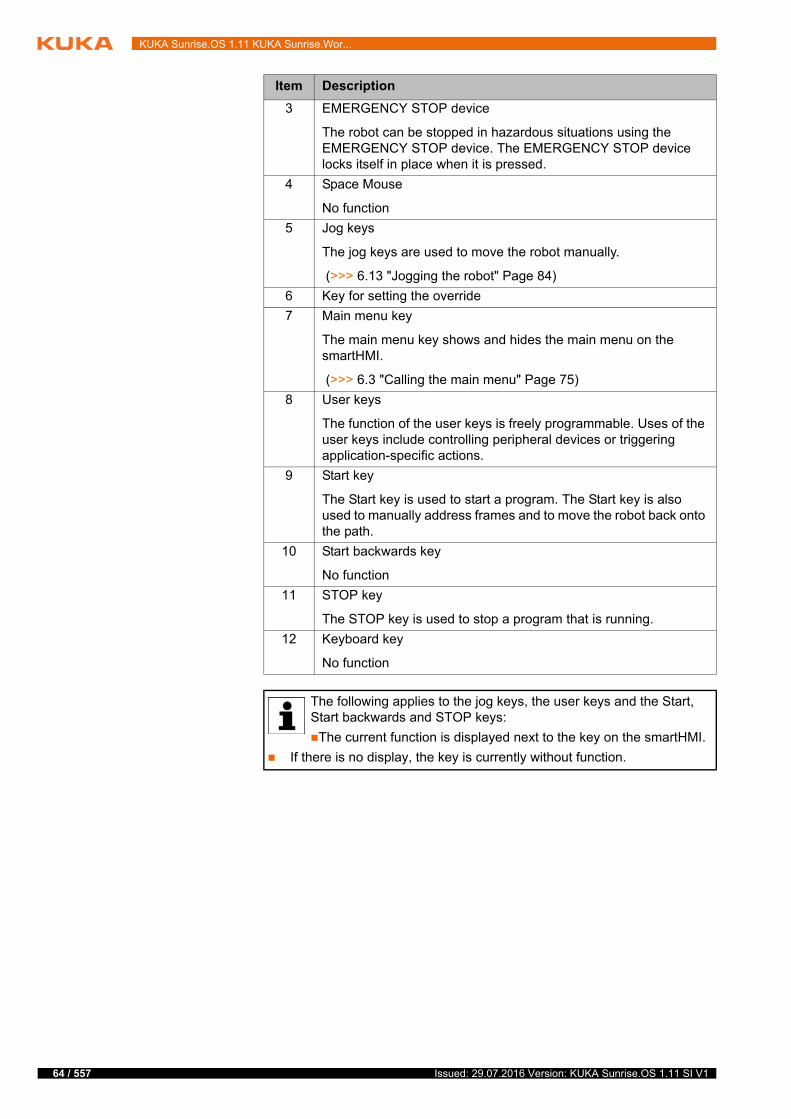
64 / 557
KUKA Sunrise.OS 1.11 KUKA Sunrise.Wor...
3 EMERGENCY STOP device
The robot can be stopped in hazardous situations using the EMERGENCY STOP device. The EMERGENCY STOP device locks itself in place when it is pressed.
4 Space Mouse
No function
5 Jog keys
The jog keys are used to move the robot manually.
(>>> 6.13 "Jogging the robot" Page 84)
6 Key for setting the override
7 Main menu key
The main menu key shows and hides the main menu on the smartHMI.
(>>> 6.3 "Calling the main menu" Page 75)
8 User keys
The function of the user keys is freely programmable. Uses of the user keys include controlling peripheral devices or triggering application-specific actions.
9 Start key
The Start key is used to start a program. The Start key is also used to manually address frames and to move the robot back onto the path.
10 Start backwards key
No function
11 STOP key
The STOP key is used to stop a program that is running.
12 Keyboard key
No function
The following applies to the jog keys, the user keys and the Start, Start backwards and STOP keys:
The current function is displayed next to the key on the smartHMI.
If there is no display, the key is currently without function.
Item Description
Issued: 29.07.2016 Version: KUKA Sunrise.OS 1.11 SI V1
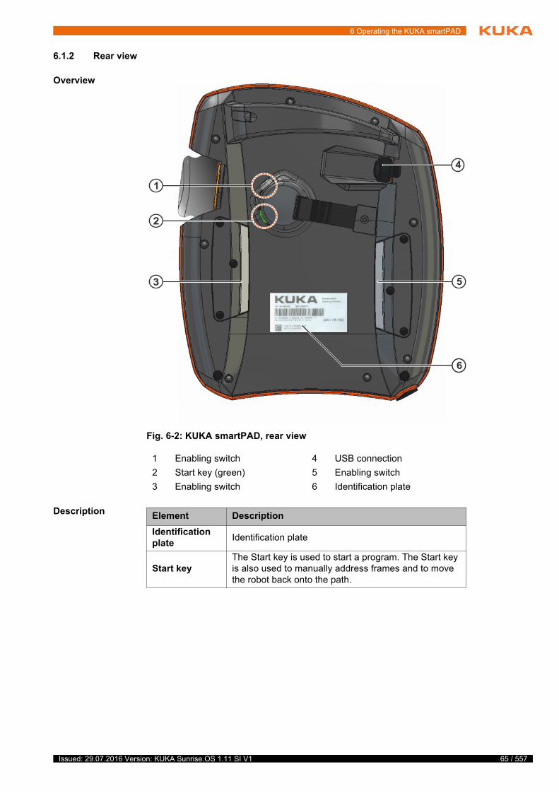
6 Operating the KUKA smartPAD
6.1.2 Rear view
Overview
Description
Fig. 6-2: KUKA smartPAD, rear view
1 Enabling switch 4 USB connection
2 Start key (green) 5 Enabling switch
3 Enabling switch 6 Identification plate
Element Description
Identification plate
Identification plate
Start keyThe Start key is used to start a program. The Start key is also used to manually address frames and to move the robot back onto the path.
65 / 557Issued: 29.07.2016 Version: KUKA Sunrise.OS 1.11 SI V1
66 / 557
KUKA Sunrise.OS 1.11 KUKA Sunrise.Wor...
6.1.3 Disconnecting and connecting the smartPAD
Description If disconnection of the smartPAD is configured as allowed in the station con-figuration of the project that is active on the robot controller, the smartPAD can be disconnected while the robot controller is running.
Precondition Disconnection of the smartPAD is allowed.
Procedure Disconnection:
1. Press the disconnect button on the smartPAD.
A message and a counter are displayed on the smartHMI. The counter runs for 25 s. During this time, the smartPAD can be disconnected from the robot controller.
Enabling switch
The enabling switch has 3 positions:
Not pressed
Center position
Fully pressed (panic position)
The enabling switch must be held in the center position in operating modes T1, T2 and CRR in order to be able to jog the manipulator.
By default, the enabling switch has no function in Auto-matic mode.
USB connec-tion
The USB connection is used e.g. for archiving data.
Only for FAT32-formatted USB sticks.
Element Description
If the smartPAD is disconnected, the system can no lon-ger be switched off by means of the EMERGENCY
STOP device on the smartPAD. If the smartPAD is configured as unplugga-ble, at least one external EMERGENCY STOP device must be installed that is accessible at all times.Failure to observe this can lead to death, injury or property damage.
The operator must ensure that disconnected smartPADs are immediately removed from the system and stored out
of sight and reach of personnel working on the industrial robot. This prevents operational and non-operational EMERGENCY STOP devices from becom-ing interchanged.Failure to observe this can lead to death, injury or property damage.
If the smartPAD is disconnected after the EMERGENCY STOP has been pressed, this EMERGENCY STOP re-
mains active, but only until the robot controller is rebooted. For this reason, disconnection of the smartPAD must not be used to prevent the EMERGEN-CY STOP device on the smartPAD from being released.If an EMERGENCY STOP is to be active with the smartPAD disconnected, this EMERGENCY STOP must always be triggered via an external EMER-GENCY STOP device.Failure to observe this can lead to death, injury or property damage.
Issued: 29.07.2016 Version: KUKA Sunrise.OS 1.11 SI V1
6 Operating the KUKA smartPAD
2. Disconnect the smartPAD from the robot controller.
If the counter expires without the smartPAD having been disconnected, this has no effect. The disconnect button can be pressed again at any time to display the counter again.
Connection:
Connect the smartPAD to the robot controller.
A smartPAD can be connected at any time. The connected smartPAD as-sumes the current operating mode of the robot controller. The smartHMI is au-tomatically displayed again.
If the smartPAD is disconnected without the counter running (e.g. if disconnection of the smartPAD is not allowed), this triggers an EMERGENCY STOP. The EMERGENCY STOP can be canceled by
reconnecting the smartPAD.
The user connecting a smartPAD to the robot controller must subsequently check whether the smartPAD is oper-
ational once again.The smartPAD is not operational in the following cases:
smartHMI is not displayed again.
It may take more than 30 seconds before the smartHMI is displayed again.
An error message is displayed in the Safety tile, indicating that there is a connection error to the smartPAD.
A non-operational smartPAD must be disconnected again and removed from the system. This prevents another user from trying to activate a non-opera-tional EMERGENCY STOP.Failure to observe this can lead to death, injury or property damage.
67 / 557Issued: 29.07.2016 Version: KUKA Sunrise.OS 1.11 SI V1
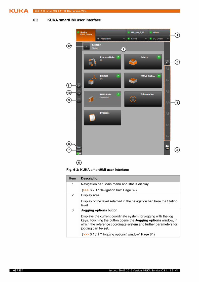
68 / 557
KUKA Sunrise.OS 1.11 KUKA Sunrise.Wor...
6.2 KUKA smartHMI user interface
Fig. 6-3: KUKA smartHMI user interface
Item Description
1 Navigation bar: Main menu and status display
(>>> 6.2.1 "Navigation bar" Page 69)
2 Display area
Display of the level selected in the navigation bar, here the Station level
3 Jogging options button
Displays the current coordinate system for jogging with the jog keys. Touching the button opens the Jogging options window, in which the reference coordinate system and further parameters for jogging can be set.
(>>> 6.13.1 "“Jogging options” window" Page 84)
Issued: 29.07.2016 Version: KUKA Sunrise.OS 1.11 SI V1
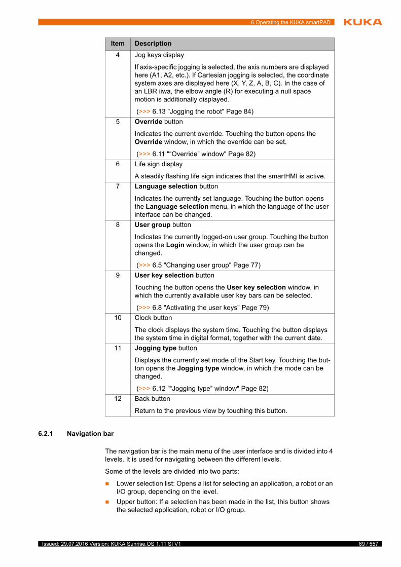
6 Operating the KUKA smartPAD
6.2.1 Navigation bar
The navigation bar is the main menu of the user interface and is divided into 4 levels. It is used for navigating between the different levels.
Some of the levels are divided into two parts:
Lower selection list: Opens a list for selecting an application, a robot or an I/O group, depending on the level.
Upper button: If a selection has been made in the list, this button shows the selected application, robot or I/O group.
4 Jog keys display
If axis-specific jogging is selected, the axis numbers are displayed here (A1, A2, etc.). If Cartesian jogging is selected, the coordinate system axes are displayed here (X, Y, Z, A, B, C). In the case of an LBR iiwa, the elbow angle (R) for executing a null space motion is additionally displayed.
(>>> 6.13 "Jogging the robot" Page 84)
5 Override button
Indicates the current override. Touching the button opens the Override window, in which the override can be set.
(>>> 6.11 "“Override” window" Page 82)
6 Life sign display
A steadily flashing life sign indicates that the smartHMI is active.
7 Language selection button
Indicates the currently set language. Touching the button opens the Language selection menu, in which the language of the user interface can be changed.
8 User group button
Indicates the currently logged-on user group. Touching the button opens the Login window, in which the user group can be changed.
(>>> 6.5 "Changing user group" Page 77)
9 User key selection button
Touching the button opens the User key selection window, in which the currently available user key bars can be selected.
(>>> 6.8 "Activating the user keys" Page 79)
10 Clock button
The clock displays the system time. Touching the button displays the system time in digital format, together with the current date.
11 Jogging type button
Displays the currently set mode of the Start key. Touching the but-ton opens the Jogging type window, in which the mode can be changed.
(>>> 6.12 "“Jogging type” window" Page 82)
12 Back button
Return to the previous view by touching this button.
Item Description
69 / 557Issued: 29.07.2016 Version: KUKA Sunrise.OS 1.11 SI V1
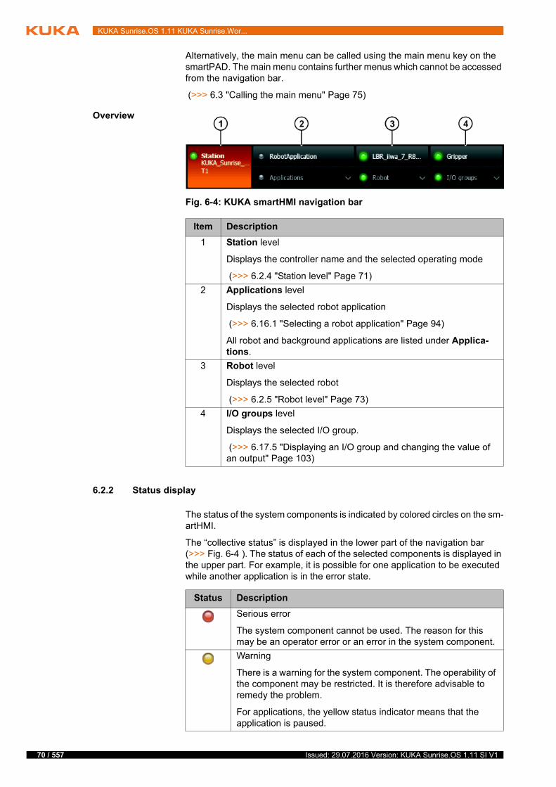
70 / 557
KUKA Sunrise.OS 1.11 KUKA Sunrise.Wor...
Alternatively, the main menu can be called using the main menu key on the smartPAD. The main menu contains further menus which cannot be accessed from the navigation bar.
(>>> 6.3 "Calling the main menu" Page 75)
Overview
6.2.2 Status display
The status of the system components is indicated by colored circles on the sm-artHMI.
The “collective status” is displayed in the lower part of the navigation bar (>>> Fig. 6-4 ). The status of each of the selected components is displayed in the upper part. For example, it is possible for one application to be executed while another application is in the error state.
Fig. 6-4: KUKA smartHMI navigation bar
Item Description
1 Station level
Displays the controller name and the selected operating mode
(>>> 6.2.4 "Station level" Page 71)
2 Applications level
Displays the selected robot application
(>>> 6.16.1 "Selecting a robot application" Page 94)
All robot and background applications are listed under Applica-tions.
3 Robot level
Displays the selected robot
(>>> 6.2.5 "Robot level" Page 73)
4 I/O groups level
Displays the selected I/O group.
(>>> 6.17.5 "Displaying an I/O group and changing the value of an output" Page 103)
Status Description
Serious error
The system component cannot be used. The reason for this may be an operator error or an error in the system component.
Warning
There is a warning for the system component. The operability of the component may be restricted. It is therefore advisable to remedy the problem.
For applications, the yellow status indicator means that the application is paused.
Issued: 29.07.2016 Version: KUKA Sunrise.OS 1.11 SI V1
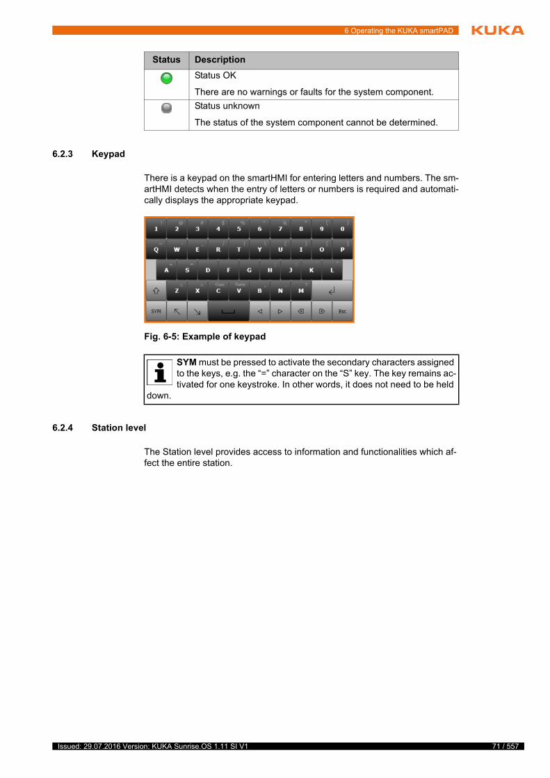
6 Operating the KUKA smartPAD
6.2.3 Keypad
There is a keypad on the smartHMI for entering letters and numbers. The sm-artHMI detects when the entry of letters or numbers is required and automati-cally displays the appropriate keypad.
6.2.4 Station level
The Station level provides access to information and functionalities which af-fect the entire station.
Status OK
There are no warnings or faults for the system component.
Status unknown
The status of the system component cannot be determined.
Status Description
Fig. 6-5: Example of keypad
SYM must be pressed to activate the secondary characters assigned to the keys, e.g. the “=” character on the “S” key. The key remains ac-tivated for one keystroke. In other words, it does not need to be held
down.
71 / 557Issued: 29.07.2016 Version: KUKA Sunrise.OS 1.11 SI V1
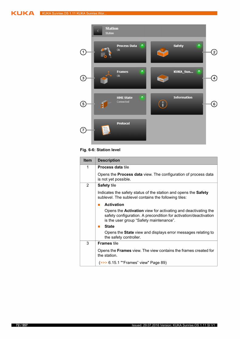
72 / 557
KUKA Sunrise.OS 1.11 KUKA Sunrise.Wor...
Fig. 6-6: Station level
Item Description
1 Process data tile
Opens the Process data view. The configuration of process data is not yet possible.
2 Safety tile
Indicates the safety status of the station and opens the Safety sublevel. The sublevel contains the following tiles:
Activation
Opens the Activation view for activating and deactivating the safety configuration. A precondition for activation/deactivation is the user group “Safety maintenance”.
State
Opens the State view and displays error messages relating to the safety controller.
3 Frames tile
Opens the Frames view. The view contains the frames created for the station.
(>>> 6.15.1 "“Frames” view" Page 89)
Issued: 29.07.2016 Version: KUKA Sunrise.OS 1.11 SI V1
6 Operating the KUKA smartPAD
6.2.5 Robot level
The Robot level gives access to information and functionalities which affect the selected robot.
4 KUKA_Sunrise_Cabinet_1 tile
Indicates the status of the robot controller and opens a sublevel. The sublevel contains the following tiles:
Boot state
Indicates the boot status of the robot controller.
Field buses
Indicates the status of the field buses. The tile is only displayed if I/O groups have been created and corresponding signals have been mapped with WorkVisual.
Backup Manager
Opens the Backup Manager view. The tile is only displayed if the Backup Manager has been installed.
(>>> 6.18 "Backup Manager" Page 106)
Virus scanner
Opens the Virus scanner view. The tile is only displayed if the virus scanner has been installed.
(>>> 18.4 "Displaying messages of the virus scanner" Page 505)
5 HMI state tile
Displays the connection status between the smartHMI and the robot controller.
6 Information tile
Opens the Information view and displays system information, e.g. the IP address of the robot controller.
(>>> 6.17.6 "Displaying information about the robot and robot controller" Page 105)
7 Protocol tile
Opens the Protocol view and displays the logged events and changes in state of the system. The display can be filtered based on various criteria.
(>>> 18.2 "Displaying the protocol" Page 499)
Item Description
73 / 557Issued: 29.07.2016 Version: KUKA Sunrise.OS 1.11 SI V1
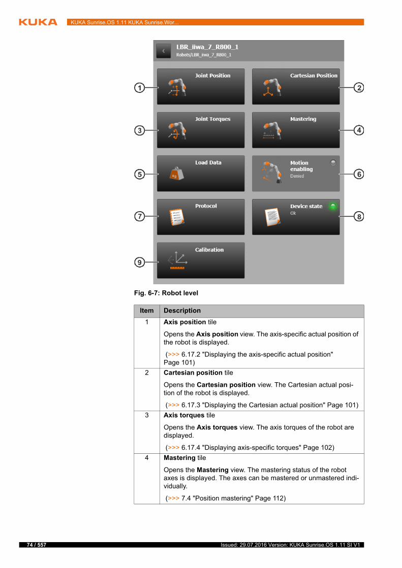
74 / 557
KUKA Sunrise.OS 1.11 KUKA Sunrise.Wor...
Fig. 6-7: Robot level
Item Description
1 Axis position tile
Opens the Axis position view. The axis-specific actual position of the robot is displayed.
(>>> 6.17.2 "Displaying the axis-specific actual position" Page 101)
2 Cartesian position tile
Opens the Cartesian position view. The Cartesian actual posi-tion of the robot is displayed.
(>>> 6.17.3 "Displaying the Cartesian actual position" Page 101)
3 Axis torques tile
Opens the Axis torques view. The axis torques of the robot are displayed.
(>>> 6.17.4 "Displaying axis-specific torques" Page 102)
4 Mastering tile
Opens the Mastering view. The mastering status of the robot axes is displayed. The axes can be mastered or unmastered indi-vidually.
(>>> 7.4 "Position mastering" Page 112)
Issued: 29.07.2016 Version: KUKA Sunrise.OS 1.11 SI V1
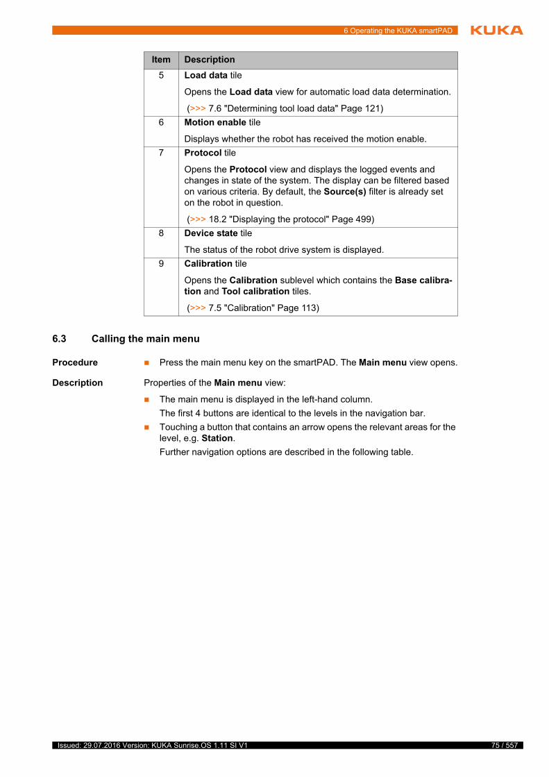
6 Operating the KUKA smartPAD
6.3 Calling the main menu
Procedure Press the main menu key on the smartPAD. The Main menu view opens.
Description Properties of the Main menu view:
The main menu is displayed in the left-hand column.
The first 4 buttons are identical to the levels in the navigation bar.
Touching a button that contains an arrow opens the relevant areas for the level, e.g. Station.
Further navigation options are described in the following table.
5 Load data tile
Opens the Load data view for automatic load data determination.
(>>> 7.6 "Determining tool load data" Page 121)
6 Motion enable tile
Displays whether the robot has received the motion enable.
7 Protocol tile
Opens the Protocol view and displays the logged events and changes in state of the system. The display can be filtered based on various criteria. By default, the Source(s) filter is already set on the robot in question.
(>>> 18.2 "Displaying the protocol" Page 499)
8 Device state tile
The status of the robot drive system is displayed.
9 Calibration tile
Opens the Calibration sublevel which contains the Base calibra-tion and Tool calibration tiles.
(>>> 7.5 "Calibration" Page 113)
Item Description
75 / 557Issued: 29.07.2016 Version: KUKA Sunrise.OS 1.11 SI V1
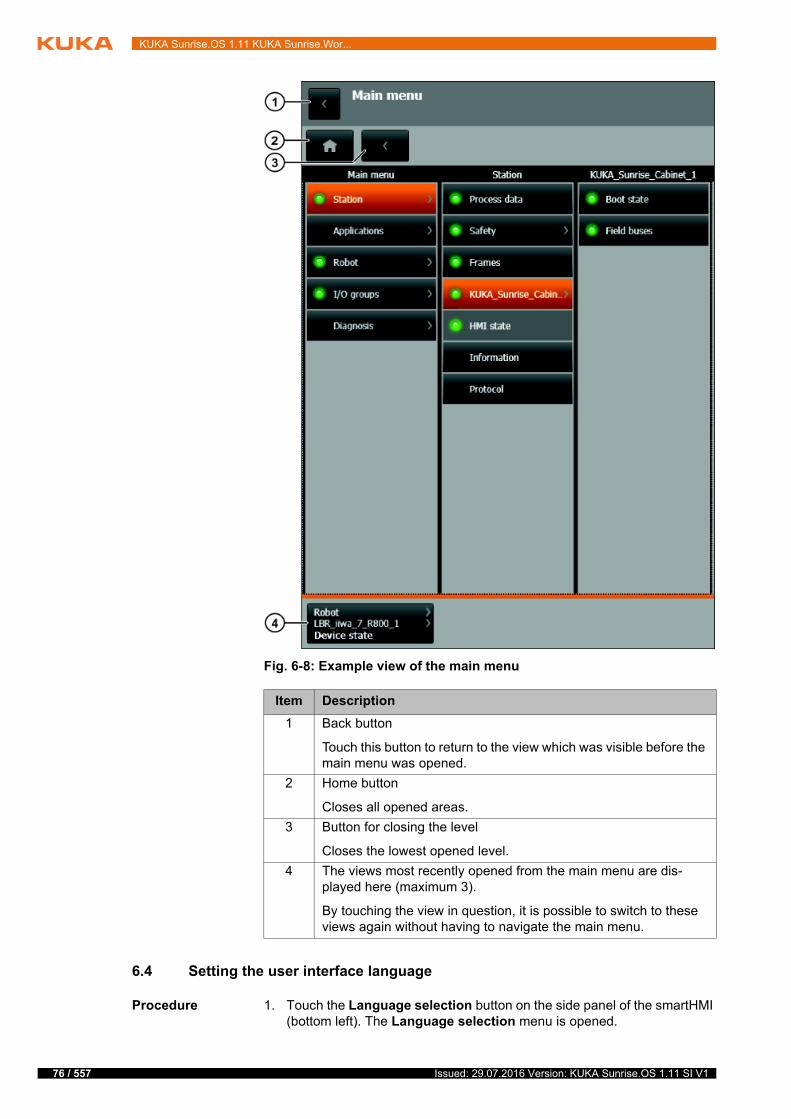
76 / 557
KUKA Sunrise.OS 1.11 KUKA Sunrise.Wor...
6.4 Setting the user interface language
Procedure 1. Touch the Language selection button on the side panel of the smartHMI (bottom left). The Language selection menu is opened.
Fig. 6-8: Example view of the main menu
Item Description
1 Back button
Touch this button to return to the view which was visible before the main menu was opened.
2 Home button
Closes all opened areas.
3 Button for closing the level
Closes the lowest opened level.
4 The views most recently opened from the main menu are dis-played here (maximum 3).
By touching the view in question, it is possible to switch to these views again without having to navigate the main menu.
Issued: 29.07.2016 Version: KUKA Sunrise.OS 1.11 SI V1
6 Operating the KUKA smartPAD
2. Select the desired language.
Description The user interface on the smartHMI is available in the following languages:
6.5 Changing user group
Description Different functions can be executed on the robot controller, depending on the user group.
The following user groups are available:
Operator
The user group for the operator is the default user group.
Safety maintenance technician
The safety maintenance technician is responsible for starting up the safety equipment of the industrial robot and activating the safety configuration on the robot controller.
The user group is protected by means of a password.
When the system is booted, the default user group is selected.
If no actions are carried out in the user interface within 300 s, the robot con-troller switches to the default user group for safety reasons.
Procedure 1. Touch the User group button. The Login window opens.
2. Select the desired user group.
3. Enter the password and confirm with Login.
4. It is possible to switch back to the default user group by pressing the Log off button.
6.6 CRR mode – controlled robot retraction
Description CRR is an operating mode to which the system can be switched when the ro-bot is stopped by the safety controller for one of the following reasons:
Robot violates an axis-specific or Cartesian monitoring space.
Orientation of a safety-oriented tool is outside the monitored range.
Robot violates a force or torque monitoring function.
A position sensor is not mastered or referenced.
A joint torque sensor is not referenced.
Chinese (simplified) Polish
Danish Portuguese
German Romanian
English Russian
Finnish Swedish
French Slovak
Greek Slovenian
Italian Spanish
Japanese Czech
Korean Turkish
Dutch Hungarian
If a functionality is called for which the currently logged-on user group has insufficient rights, the Login window opens automatically. The re-quired user group is then preset in the window.
77 / 557Issued: 29.07.2016 Version: KUKA Sunrise.OS 1.11 SI V1
78 / 557
KUKA Sunrise.OS 1.11 KUKA Sunrise.Wor...
Once the operating mode has been switched to CRR, the robot can be moved again.
Use CRR mode can be used, for example, to retract the robot in the case of a space or force monitoring violation or to master the robot with a Cartesian ve-locity monitoring function active.
If the cause of the stop is no longer present and if no further stop is requested for 4 seconds by one of the specified causes, the operating mode automatical-ly changes to T1.
Motion velocity The motion velocity of the set working point in CRR mode corresponds to the jog velocity in T1 mode:
Program mode: Reduced programmed velocity, maximum 250 mm/s
Jog mode: Jog velocity, maximum 250 mm/s
Manual guidance: No limitation of the velocity, but safety-oriented velocity monitoring functions in accordance with the safety configuration
6.7 Changing the operating mode
Description The operating mode can be set with the smartPAD using the connection man-ager.
Precondition The key is in the switch for calling the connection manager
Procedure 1. On the smartPAD, turn the switch for the connection manager to the right. The connection manager is displayed.
2. Select the operating mode.
3. Turn the switch for the connection manager to the left.
The selected operating mode is now active and is displayed in the naviga-tion bar of the smartHMI.
It is possible to change the operating mode while an application is running on the robot controller. The industrial robot then stops with a safety stop 1 and the application is paused. Once the new operating
mode has been set, the application can resume.
Operating
modeUse Velocities
T1 Programming, teaching and testing of programs.
Program verification:
Reduced programmed velocity, maximum 250 mm/s
Manual mode:
Jog velocity, maximum 250 mm/s
Manual guidance:
No limitation of the velocity, but safety-oriented velocity monitoring in accordance with the safety con-figuration
Note: The maximum velocity of 250 mm/s does not apply to a mobile platform.
T2 Testing of programs Program verification:
Programmed velocity
Manual mode: Not possible
Issued: 29.07.2016 Version: KUKA Sunrise.OS 1.11 SI V1

6 Operating the KUKA smartPAD
6.8 Activating the user keys
Description The user keys on the smartPAD can be assigned functions. All the user key functions of a running application are available to the operator. In order to be able to use the desired functions, the operator must activate the corresponding user key bar.
Procedure 1. Touch the User key selection button.
The User key selection window opens. The user key bars currently avail-able are displayed.
2. Select the desired user key bar by pressing the corresponding name.
The text or image on the smartHMI next to the user keys changes accord-ing to the bar selected. The user keys now have the corresponding func-tions.
3. Touch the User key selection button or an area outside the window.
The User key selection window closes.
AUT Automatic execution of programs
For industrial robots with and without higher-level controllers
Program mode:
Programmed velocity
Manual mode: Not possible
CRR CRR is an operating mode which can be selected when the industrial robot is stopped by the safety controller for one of the following reasons:
Industrial robot violates an axis-spe-cific or Cartesian monitoring space.
Orientation of a safety-oriented tool is outside the monitored range.
Industrial robot violates a force or torque monitoring function.
A position sensor is not mastered or referenced.
A joint torque sensor is not refer-enced.
After changing to CRR mode, the industrial robot may once again be moved.
Program verification:
Reduced programmed velocity, maximum 250 mm/s
Manual mode:
Jog velocity, maximum 250 mm/s
Manual guidance:
No limitation of the velocity, but safety-oriented velocity monitoring in accordance with the safety con-figuration
Operating
modeUse Velocities
79 / 557Issued: 29.07.2016 Version: KUKA Sunrise.OS 1.11 SI V1
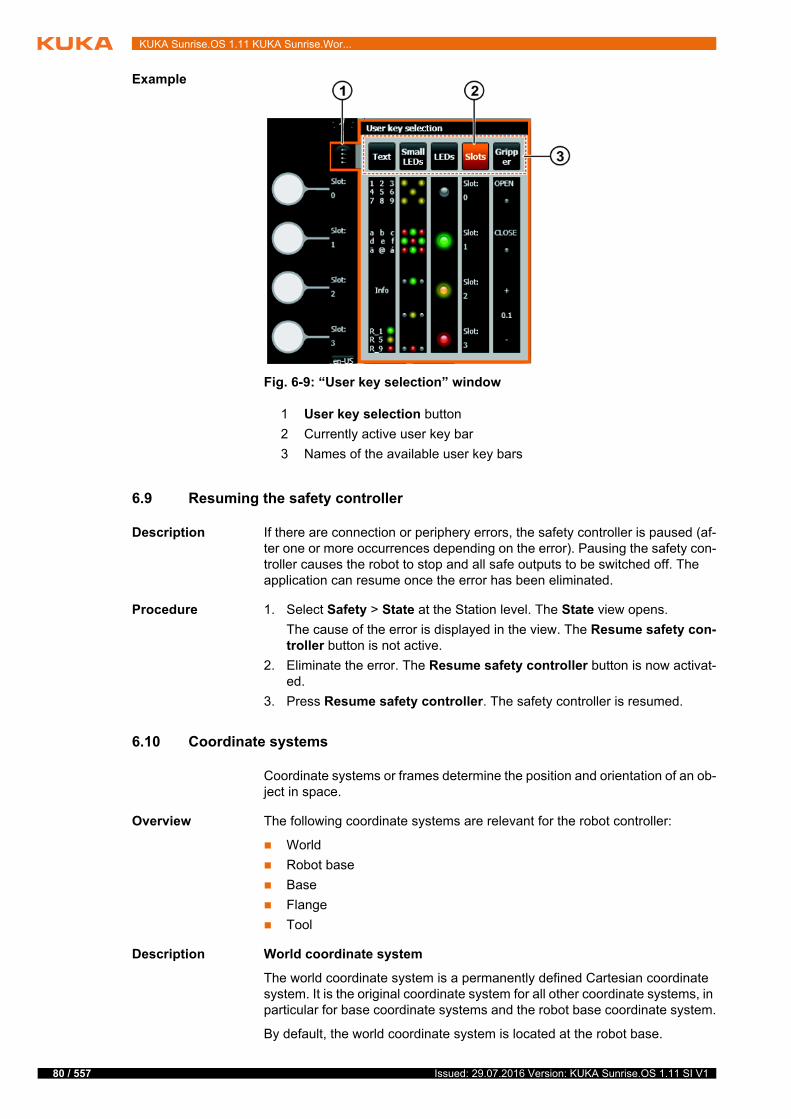
80 / 557
KUKA Sunrise.OS 1.11 KUKA Sunrise.Wor...
Example
6.9 Resuming the safety controller
Description If there are connection or periphery errors, the safety controller is paused (af-ter one or more occurrences depending on the error). Pausing the safety con-troller causes the robot to stop and all safe outputs to be switched off. The application can resume once the error has been eliminated.
Procedure 1. Select Safety > State at the Station level. The State view opens.
The cause of the error is displayed in the view. The Resume safety con-troller button is not active.
2. Eliminate the error. The Resume safety controller button is now activat-ed.
3. Press Resume safety controller. The safety controller is resumed.
6.10 Coordinate systems
Coordinate systems or frames determine the position and orientation of an ob-ject in space.
Overview The following coordinate systems are relevant for the robot controller:
World
Robot base
Base
Flange
Tool
Description World coordinate system
The world coordinate system is a permanently defined Cartesian coordinate system. It is the original coordinate system for all other coordinate systems, in particular for base coordinate systems and the robot base coordinate system.
By default, the world coordinate system is located at the robot base.
Fig. 6-9: “User key selection” window
1 User key selection button
2 Currently active user key bar
3 Names of the available user key bars
Issued: 29.07.2016 Version: KUKA Sunrise.OS 1.11 SI V1
6 Operating the KUKA smartPAD
Robot base coordinate system
The robot base coordinate system is a Cartesian coordinate system, which is always located at the robot base. It defines the position of the robot relative to the world coordinate system.
By default, the robot base coordinate system is identical to the world coordi-nate system. It is possible to define a rotational offset of the robot relative to the world coordinate system by changing the mounting orientation in Sun-rise.Workbench. By default, the direction of installation of the floor-mounted robot is set (A=0°, B=0°, C=0°).
Base coordinate system
In order to define motions in Cartesian space, a reference coordinate system (base) must be specified.
By default, the world coordinate system is used as the base coordinate system for a motion. Additional base coordinate systems relative to the world coordi-nate system can be defined.
(>>> 7.5.2 "Calibrating the base: 3-point method " Page 119)
Flange coordinate system
The flange coordinate system describes the current position and orientation of the robot flange center point. It does not have a fixed location and is moved with the robot.
The flange coordinate system is used as an origin for coordinate systems which describe tools mounted on the flange.
Tool coordinate system
The tool coordinate system is a Cartesian coordinate system which is located at the working point of the mounted tool. This is called the TCP (Tool Center Point).
Any number of frames can be defined for a tool and can be selected as the TCP. The origin of the tool coordinate system is generally identical to the flange coordinate system.
(>>> 9.3.1 "Geometric structure of tools" Page 148)
The tool coordinate system is offset to the tool center point by the user.
(>>> 7.5.1 "Tool calibration" Page 113)
Position and orientation
In order to determine the position and orientation of an object, translation and rotation relative to a reference coordinate system are specified. 6 coordinates are used for this purpose.
Translation
Rotation
Coordinate Description
Distance X Translation along the X axis of the reference system
Distance Y Translation along the Y axis of the reference system
Distance Z Translation along the Z axis of the reference system
Coordinate Description
Angle A Rotation about the Z axis of the reference system
Angle B Rotation about the Y axis of the reference system
Angle C Rotation about the X axis of the reference system
81 / 557Issued: 29.07.2016 Version: KUKA Sunrise.OS 1.11 SI V1
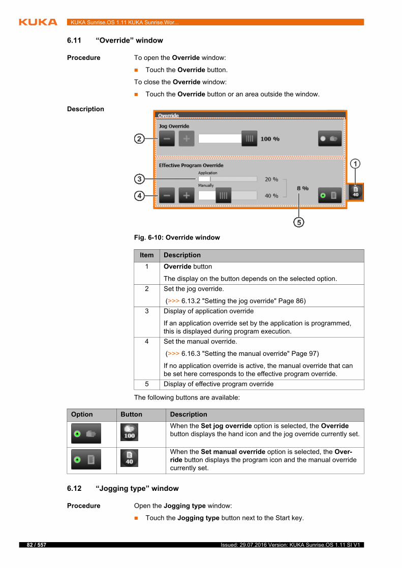
82 / 557
KUKA Sunrise.OS 1.11 KUKA Sunrise.Wor...
6.11 “Override” window
Procedure To open the Override window:
Touch the Override button.
To close the Override window:
Touch the Override button or an area outside the window.
Description
The following buttons are available:
6.12 “Jogging type” window
Procedure Open the Jogging type window:
Touch the Jogging type button next to the Start key.
Fig. 6-10: Override window
Item Description
1 Override button
The display on the button depends on the selected option.
2 Set the jog override.
(>>> 6.13.2 "Setting the jog override" Page 86)
3 Display of application override
If an application override set by the application is programmed, this is displayed during program execution.
4 Set the manual override.
(>>> 6.16.3 "Setting the manual override" Page 97)
If no application override is active, the manual override that can be set here corresponds to the effective program override.
5 Display of effective program override
Option Button Description
When the Set jog override option is selected, the Override button displays the hand icon and the jog override currently set.
When the Set manual override option is selected, the Over-ride button displays the program icon and the manual override currently set.
Issued: 29.07.2016 Version: KUKA Sunrise.OS 1.11 SI V1
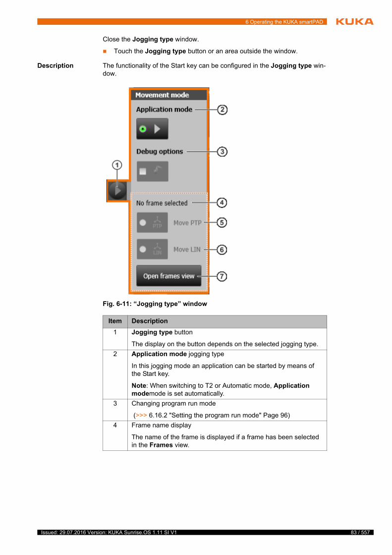
6 Operating the KUKA smartPAD
Close the Jogging type window.
Touch the Jogging type button or an area outside the window.
Description The functionality of the Start key can be configured in the Jogging type win-dow.
Fig. 6-11: “Jogging type” window
Item Description
1 Jogging type button
The display on the button depends on the selected jogging type.
2 Application mode jogging type
In this jogging mode an application can be started by means of the Start key.
Note: When switching to T2 or Automatic mode, Application modemode is set automatically.
3 Changing program run mode
(>>> 6.16.2 "Setting the program run mode" Page 96)
4 Frame name display
The name of the frame is displayed if a frame has been selected in the Frames view.
83 / 557Issued: 29.07.2016 Version: KUKA Sunrise.OS 1.11 SI V1
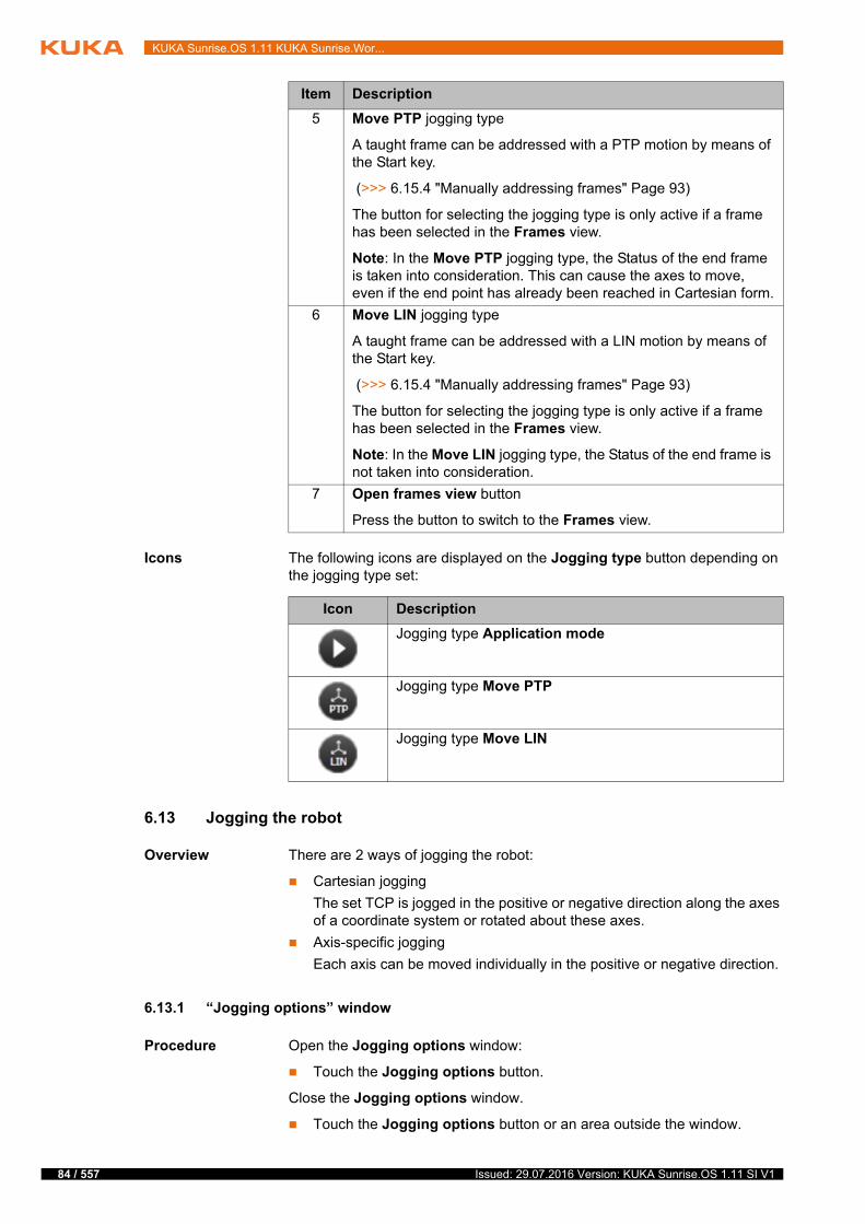
84 / 557
KUKA Sunrise.OS 1.11 KUKA Sunrise.Wor...
Icons The following icons are displayed on the Jogging type button depending on the jogging type set:
6.13 Jogging the robot
Overview There are 2 ways of jogging the robot:
Cartesian jogging
The set TCP is jogged in the positive or negative direction along the axes of a coordinate system or rotated about these axes.
Axis-specific jogging
Each axis can be moved individually in the positive or negative direction.
6.13.1 “Jogging options” window
Procedure Open the Jogging options window:
Touch the Jogging options button.
Close the Jogging options window.
Touch the Jogging options button or an area outside the window.
5 Move PTP jogging type
A taught frame can be addressed with a PTP motion by means of the Start key.
(>>> 6.15.4 "Manually addressing frames" Page 93)
The button for selecting the jogging type is only active if a frame has been selected in the Frames view.
Note: In the Move PTP jogging type, the Status of the end frame is taken into consideration. This can cause the axes to move, even if the end point has already been reached in Cartesian form.
6 Move LIN jogging type
A taught frame can be addressed with a LIN motion by means of the Start key.
(>>> 6.15.4 "Manually addressing frames" Page 93)
The button for selecting the jogging type is only active if a frame has been selected in the Frames view.
Note: In the Move LIN jogging type, the Status of the end frame is not taken into consideration.
7 Open frames view button
Press the button to switch to the Frames view.
Item Description
Icon Description
Jogging type Application mode
Jogging type Move PTP
Jogging type Move LIN
Issued: 29.07.2016 Version: KUKA Sunrise.OS 1.11 SI V1
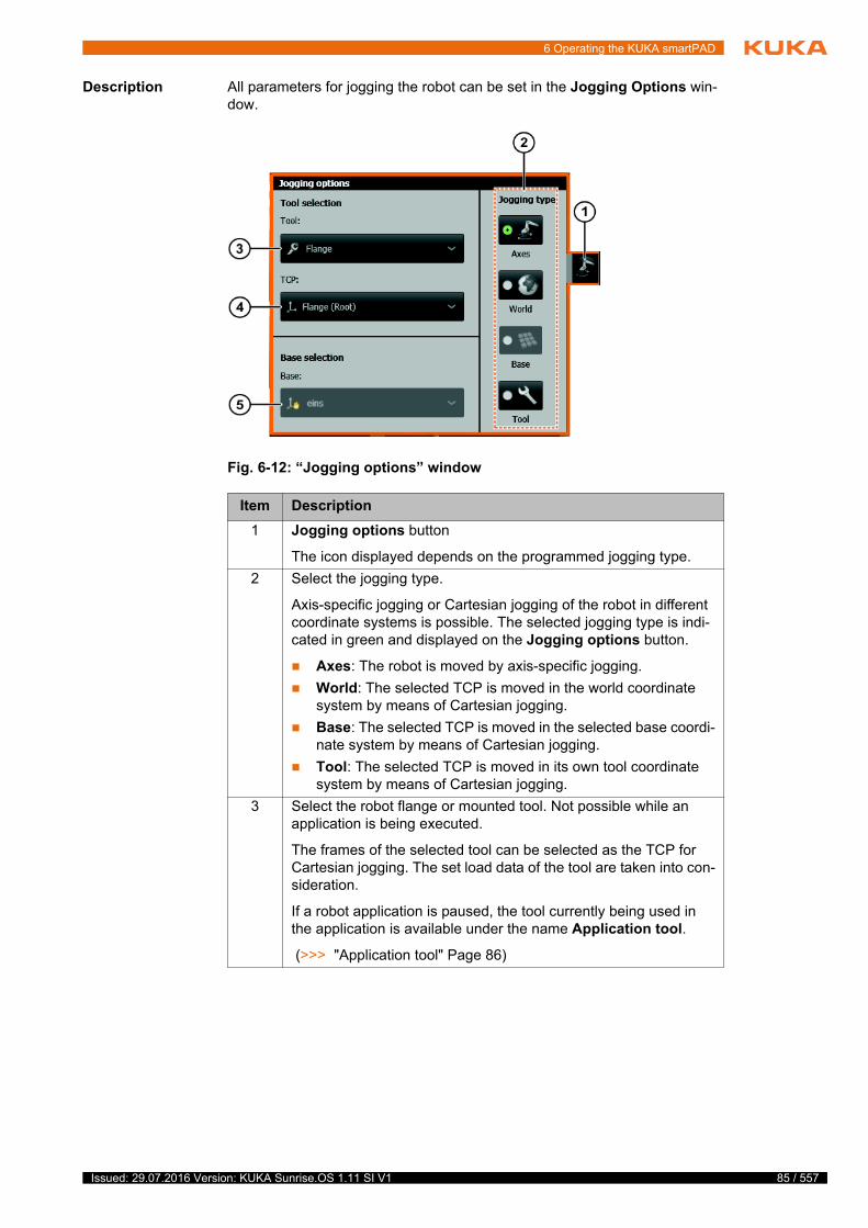
6 Operating the KUKA smartPAD
Description All parameters for jogging the robot can be set in the Jogging Options win-dow.
Fig. 6-12: “Jogging options” window
Item Description
1 Jogging options button
The icon displayed depends on the programmed jogging type.
2 Select the jogging type.
Axis-specific jogging or Cartesian jogging of the robot in different coordinate systems is possible. The selected jogging type is indi-cated in green and displayed on the Jogging options button.
Axes: The robot is moved by axis-specific jogging.
World: The selected TCP is moved in the world coordinate system by means of Cartesian jogging.
Base: The selected TCP is moved in the selected base coordi-nate system by means of Cartesian jogging.
Tool: The selected TCP is moved in its own tool coordinate system by means of Cartesian jogging.
3 Select the robot flange or mounted tool. Not possible while an application is being executed.
The frames of the selected tool can be selected as the TCP for Cartesian jogging. The set load data of the tool are taken into con-sideration.
If a robot application is paused, the tool currently being used in the application is available under the name Application tool.
(>>> "Application tool" Page 86)
85 / 557Issued: 29.07.2016 Version: KUKA Sunrise.OS 1.11 SI V1

86 / 557
KUKA Sunrise.OS 1.11 KUKA Sunrise.Wor...
Application tool The application tool consists of all the frames located below the robot flange during the runtime. These can be the frames of a tool or workpiece, for exam-ple, that are connected to the robot flange with the attachTo command. They may also include frames generated in the application and linked directly or in-directly to the flange during the runtime.
The application tool is then only available in the jogging options when a robot application is paused, and if a motion command was sent to the robot control-ler prior to pausing.
If the application tool is set in the jogging options, all frames located hier-archically under the flange coordinate system during the runtime can be selected as the TCP for jogging. The origin frame of the application tool on the robot flange is available under the name ApplicationTool(Root) for selection as the TCP for jogging.
If the application tool is set in the jogging options and the application re-sumed, the following occurs: the frame with which the current motion com-mand is executed in the application is automatically set as the TCP.
6.13.2 Setting the jog override
Description The jog override determines the velocity of the robot during jogging. The ve-locity actually achieved by the robot with a jog override setting of 100% de-pends on various factors, including the robot type. However, the velocity of the set working point cannot exceed 250 mm/s.
Procedure 1. Touch the Override button. The Override window is opened.
(>>> 6.11 "“Override” window" Page 82)
2. Activate the Set jog override option if it is not already active.
3. Set the desired jog override. It can be set using either the plus/minus keys or by means of the slider.
Plus/minus keys: The override can be set in steps to the following val-ues: 100%, 75%, 50%, 30%, 10%, 5%, 3%, 1%, 0%.
Slider: The override can be adjusted in 1% steps.
4. Touch the Override button or an area outside the window to close the win-dow.
4 Select the TCP.
All the frames of the selected tool are available as the TCP. The TCP set here is retained. This is also the case if a different TCP is active in a paused application.
Exception: If a robot application is paused and the application tool is set, the manually set TCP is not retained when the applica-tion is resumed. The TCP changes according to the TCP currently used in the application.
(>>> "Application tool" Page 86)
5 Base selection. Only possible when the jogging type Base is selected.
All frames which were designated in Sunrise.Workbench as a base are available as a base.
Item Description
Option Description
Set jog override option activated
Issued: 29.07.2016 Version: KUKA Sunrise.OS 1.11 SI V1
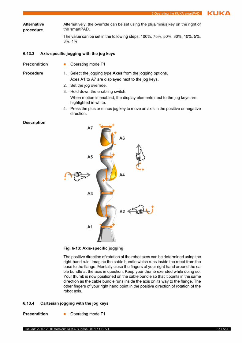
6 Operating the KUKA smartPAD
Alternative
procedure
Alternatively, the override can be set using the plus/minus key on the right of the smartPAD.
The value can be set in the following steps: 100%, 75%, 50%, 30%, 10%, 5%, 3%, 1%.
6.13.3 Axis-specific jogging with the jog keys
Precondition Operating mode T1
Procedure 1. Select the jogging type Axes from the jogging options.
Axes A1 to A7 are displayed next to the jog keys.
2. Set the jog override.
3. Hold down the enabling switch.
When motion is enabled, the display elements next to the jog keys are highlighted in white.
4. Press the plus or minus jog key to move an axis in the positive or negative direction.
Description
The positive direction of rotation of the robot axes can be determined using the right-hand rule. Imagine the cable bundle which runs inside the robot from the base to the flange. Mentally close the fingers of your right hand around the ca-ble bundle at the axis in question. Keep your thumb exended while doing so. Your thumb is now positioned on the cable bundle so that it points in the same direction as the cable bundle runs inside the axis on its way to the flange. The other fingers of your right hand point in the positive direction of rotation of the robot axis.
6.13.4 Cartesian jogging with the jog keys
Precondition Operating mode T1
Fig. 6-13: Axis-specific jogging
87 / 557Issued: 29.07.2016 Version: KUKA Sunrise.OS 1.11 SI V1
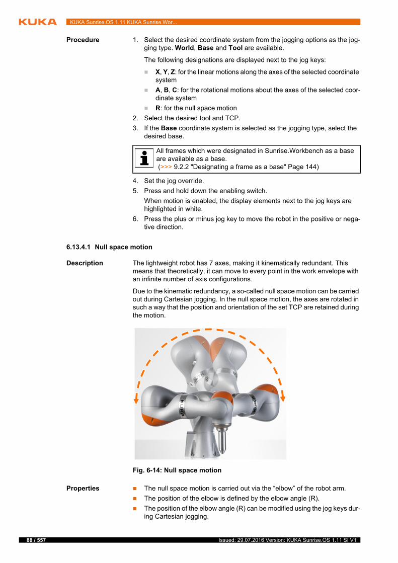
88 / 557
KUKA Sunrise.OS 1.11 KUKA Sunrise.Wor...
Procedure 1. Select the desired coordinate system from the jogging options as the jog-ging type. World, Base and Tool are available.
The following designations are displayed next to the jog keys:
X, Y, Z: for the linear motions along the axes of the selected coordinate system
A, B, C: for the rotational motions about the axes of the selected coor-dinate system
R: for the null space motion
2. Select the desired tool and TCP.
3. If the Base coordinate system is selected as the jogging type, select the desired base.
4. Set the jog override.
5. Press and hold down the enabling switch.
When motion is enabled, the display elements next to the jog keys are highlighted in white.
6. Press the plus or minus jog key to move the robot in the positive or nega-tive direction.
6.13.4.1 Null space motion
Description The lightweight robot has 7 axes, making it kinematically redundant. This means that theoretically, it can move to every point in the work envelope with an infinite number of axis configurations.
Due to the kinematic redundancy, a so-called null space motion can be carried out during Cartesian jogging. In the null space motion, the axes are rotated in such a way that the position and orientation of the set TCP are retained during the motion.
Properties The null space motion is carried out via the “elbow” of the robot arm.
The position of the elbow is defined by the elbow angle (R).
The position of the elbow angle (R) can be modified using the jog keys dur-ing Cartesian jogging.
All frames which were designated in Sunrise.Workbench as a base are available as a base. (>>> 9.2.2 "Designating a frame as a base" Page 144)
Fig. 6-14: Null space motion
Issued: 29.07.2016 Version: KUKA Sunrise.OS 1.11 SI V1
6 Operating the KUKA smartPAD
Areas of appli-
cation
The optimal axis configuration can be set for a given position and orienta-tion of the TCP. This is especially useful in a limited working space.
When a software limit switch is reached, you can attempt to move the robot out of the range of the limit switches by changing the elbow angle.
6.14 Manually guiding the robot
Description The robot can be guided using a hand guiding device.
Manual guidance is supported by default in all operating modes except CRR mode. In the station configuration, it is possible to configure manual guidance as not allowed in Test mode and/or Automatic mode.
Precondition Hand guiding device with safety-oriented enabling device (enabling switch) is present and configured.
No application is selected or the application has one of the following states:
Selected
Motion paused
Error
Manual guidance is allowed in the set operating mode.
Procedure 1. Press and hold down the enabling switch on the hand guiding device.
2. Guide the TCP to the desired position.
3. Once the position has been reached, release the enabling switch.
6.15 Frame management
6.15.1 “Frames” view
Procedure To open the view:
Select Frames at the Station level. The Frames view opens.
Description The view contains the frames created for the station. Additional frames can be created and the frames taught here. The position and orientation of a frame in space and the associated redundancy information are recorded during teach-ing.
Taught frames can be addressed manually.
Taught frames can be used as end points of motions. If an application is run and the end frame of a motion is addressed, this is selected in the Frames view.
(>>> 6.17.1 "Displaying the end frame of the motion currently being exe-cuted" Page 100)
In manual guidance, incorrectly selected parameters (e.g. incorrect load data, incorrect tool) or incorrect infor-
mation (e.g. from defective torque sensors) can be interpreted as external forces. This can result in unpredictable motions of the robot.
If the robot is manually guided, an EMERGENCY STOP device must be installed. It must always be within reach of the operator.
89 / 557Issued: 29.07.2016 Version: KUKA Sunrise.OS 1.11 SI V1

90 / 557
KUKA Sunrise.OS 1.11 KUKA Sunrise.Wor...
Fig. 6-15: Frames view
Item Description
1 Frame path
Path to the frames of the currently displayed hierarchy level: Goes from World to the direct parent frame (here Box)
2 Frames of the current hierarchy level
A frame can be selected by touching it. The frame selected here is marked with a hand icon. The hand icon means that this frame can be used as the base for jogging and can be calibrated.
3 Properties of the selected frame
Name of the frame
Comment
Tool used while teaching the frame
Date and time of the last modification
4 Create frame button
Creates a frame at the currently displayed hierarchy level.
5 Create child frame button
The button can be used to create a child frame for a selected frame. If no frame is selected, the button is disabled.
Issued: 29.07.2016 Version: KUKA Sunrise.OS 1.11 SI V1
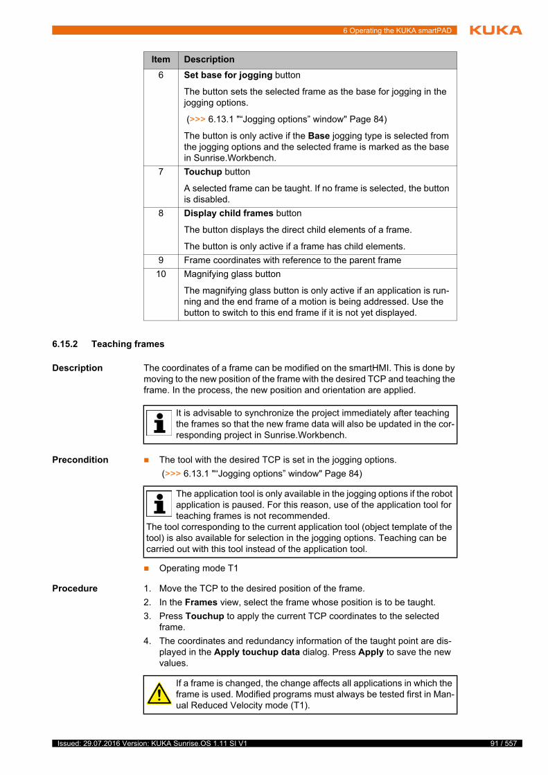
6 Operating the KUKA smartPAD
6.15.2 Teaching frames
Description The coordinates of a frame can be modified on the smartHMI. This is done by moving to the new position of the frame with the desired TCP and teaching the frame. In the process, the new position and orientation are applied.
Precondition The tool with the desired TCP is set in the jogging options.
(>>> 6.13.1 "“Jogging options” window" Page 84)
Operating mode T1
Procedure 1. Move the TCP to the desired position of the frame.
2. In the Frames view, select the frame whose position is to be taught.
3. Press Touchup to apply the current TCP coordinates to the selected frame.
4. The coordinates and redundancy information of the taught point are dis-played in the Apply touchup data dialog. Press Apply to save the new values.
6 Set base for jogging button
The button sets the selected frame as the base for jogging in the jogging options.
(>>> 6.13.1 "“Jogging options” window" Page 84)
The button is only active if the Base jogging type is selected from the jogging options and the selected frame is marked as the base in Sunrise.Workbench.
7 Touchup button
A selected frame can be taught. If no frame is selected, the button is disabled.
8 Display child frames button
The button displays the direct child elements of a frame.
The button is only active if a frame has child elements.
9 Frame coordinates with reference to the parent frame
10 Magnifying glass button
The magnifying glass button is only active if an application is run-ning and the end frame of a motion is being addressed. Use the button to switch to this end frame if it is not yet displayed.
Item Description
It is advisable to synchronize the project immediately after teaching the frames so that the new frame data will also be updated in the cor-responding project in Sunrise.Workbench.
The application tool is only available in the jogging options if the robot application is paused. For this reason, use of the application tool for teaching frames is not recommended.
The tool corresponding to the current application tool (object template of the tool) is also available for selection in the jogging options. Teaching can be carried out with this tool instead of the application tool.
If a frame is changed, the change affects all applications in which the frame is used. Modified programs must always be tested first in Man-ual Reduced Velocity mode (T1).
91 / 557Issued: 29.07.2016 Version: KUKA Sunrise.OS 1.11 SI V1
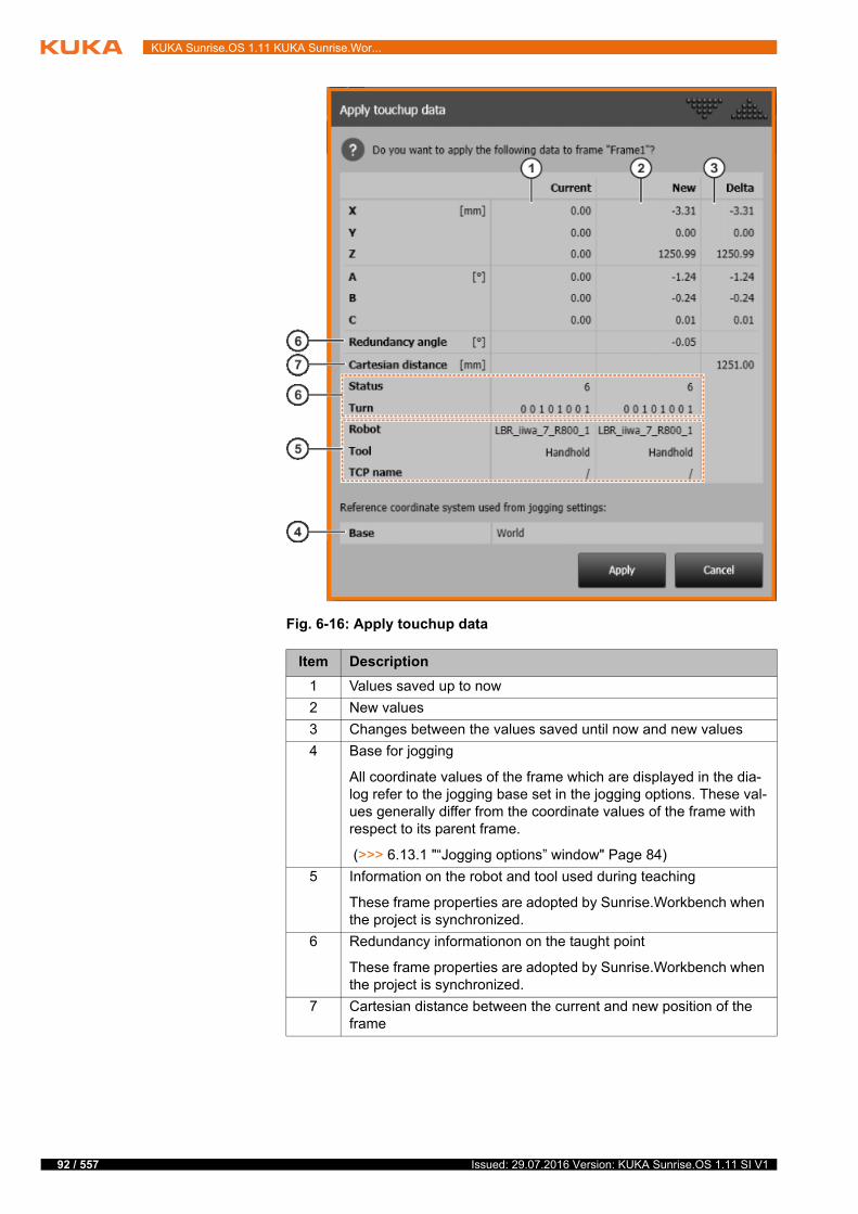
92 / 557
KUKA Sunrise.OS 1.11 KUKA Sunrise.Wor...
Fig. 6-16: Apply touchup data
Item Description
1 Values saved up to now
2 New values
3 Changes between the values saved until now and new values
4 Base for jogging
All coordinate values of the frame which are displayed in the dia-log refer to the jogging base set in the jogging options. These val-ues generally differ from the coordinate values of the frame with respect to its parent frame.
(>>> 6.13.1 "“Jogging options” window" Page 84)
5 Information on the robot and tool used during teaching
These frame properties are adopted by Sunrise.Workbench when the project is synchronized.
6 Redundancy informationon on the taught point
These frame properties are adopted by Sunrise.Workbench when the project is synchronized.
7 Cartesian distance between the current and new position of the frame
Issued: 29.07.2016 Version: KUKA Sunrise.OS 1.11 SI V1
6 Operating the KUKA smartPAD
6.15.3 Teaching frames with the hand guiding device
Description Frames can be taught using a hand guiding device. Here, the TCP is moved by hand to the desired position.
Manual guidance is supported by default in all operating modes except CRR mode. In the station configuration, it is possible to configure manual guidance as not allowed in Test mode and/or Automatic mode.
Precondition Hand guiding device with safety-oriented enabling device (enabling switch) is present and configured.
The tool with the desired TCP is set in the jogging options.
No robot application is selected or the robot application has one of the fol-lowing states:
Selected
Motion paused
Error
The Frames view is open.
The frames to be taught have been created.
Manual guidance is allowed in the set operating mode.
Procedure 1. Press and hold down the enabling switch on the hand guiding device.
2. Guide the TCP to the desired position.
3. Once the position has been reached, release the enabling switch.
4. In the Frames view, select the frame whose position is to be taught.
5. Press Touchup to apply the current TCP coordinates to the selected frame.
The coordinates and redundancy information of the taught point are dis-played in the Apply touchup data dialog.
6. Press Apply to save the new values.
6.15.4 Manually addressing frames
Description Taught frames can be manually addressed with a PTP or LIN motion. In a PTP motion, the frame is approached by the quickest route, whereas in a LIN mo-tion it is approached on a predictable path.
When a frame is being addressed, a warning message is displayed in the fol-lowing cases:
The selected tool does not correspond to the tool with which the frame was taught.
The selected TCP does not correspond to the TCP with which the frame was taught.
The transformation of the TCP frame has been modified.
If the frame can still be reached, it is possible to move to it.
Precondition The frame has been taught.
In manual guidance, incorrectly selected parameters (e.g. incorrect load data, incorrect tool) or incorrect infor-
mation (e.g. from defective torque sensors) can be interpreted as external forces. This can result in unpredictable motions of the robot.
If the robot is manually guided, an EMERGENCY STOP device must be installed. It must always be within reach of the operator.
93 / 557Issued: 29.07.2016 Version: KUKA Sunrise.OS 1.11 SI V1
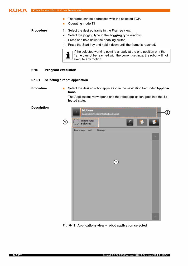
94 / 557
KUKA Sunrise.OS 1.11 KUKA Sunrise.Wor...
The frame can be addressed with the selected TCP.
Operating mode T1
Procedure 1. Select the desired frame in the Frames view.
2. Select the jogging type in the Jogging type window.
3. Press and hold down the enabling switch.
4. Press the Start key and hold it down until the frame is reached.
6.16 Program execution
6.16.1 Selecting a robot application
Procedure Select the desired robot application in the navigation bar under Applica-tions.
The Applications view opens and the robot application goes into the Se-lected state.
Description
If the selected working point is already at the end position or if the frame cannot be reached with the current settings, the robot will not execute any motion.
Fig. 6-17: Applications view – robot application selected
Issued: 29.07.2016 Version: KUKA Sunrise.OS 1.11 SI V1

6 Operating the KUKA smartPAD
The following buttons are available:
Status display The robot application can have the following states:
Item Description
1 Current status of the robot application
The status is displayed as text and as an icon.
(>>> "Status display" Page 95)
2 Display of robot application
The name of the selected robot application is displayed, here Motion.
3 Message window
Error messages and user messages programmed in the applica-tion are displayed.
Button Description
Deselect button
Deselects the selected robot application and closes the Applications view. A paused robot application is reset before it is deselected.
The button is only active if the robot application is in the Selected, Motion paused or Error state.
Reset button
Resets a paused robot application. “Reset” means that the robot application is reset to the start of the program and goes into the Selected state.
The button is only active when the robot application is paused.
Icon State Description
Selected The application is selected.
Start The application is initialized.
Running The application is executed.
Motion paused The application is paused.
If the application is paused using the smart-PAD, for example by pressing the STOP key, only motion execution is stopped. Other com-mands, e.g. switching of outputs, are executed in the Motion paused state until a synchro-nous motion command is reached.
Error An error occurred while the application was running.
95 / 557Issued: 29.07.2016 Version: KUKA Sunrise.OS 1.11 SI V1
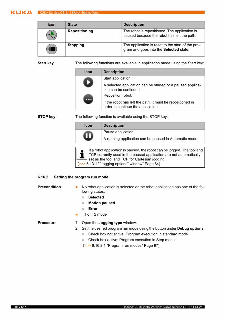
96 / 557
KUKA Sunrise.OS 1.11 KUKA Sunrise.Wor...
Start key The following functions are available in application mode using the Start key:
STOP key The following function is available using the STOP key:
6.16.2 Setting the program run mode
Precondition No robot application is selected or the robot application has one of the fol-lowing states:
Selected
Motion paused
Error
T1 or T2 mode
Procedure 1. Open the Jogging type window.
2. Set the desired program run mode using the button under Debug options.
Check box not active: Program execution in standard mode
Check box active: Program execution in Step mode
(>>> 6.16.2.1 "Program run modes" Page 97)
Repositioning The robot is repositioned. The application is paused because the robot has left the path.
Stopping The application is reset to the start of the pro-gram and goes into the Selected state.
Icon State Description
Icon Description
Start application.
A selected application can be started or a paused applica-tion can be continued.
Reposition robot.
If the robot has left the path, it must be repositioned in order to continue the application.
Icon Description
Pause application.
A running application can be paused in Automatic mode.
If a robot application is paused, the robot can be jogged. The tool and TCP currently used in the paused application are not automatically set as the tool and TCP for Cartesian jogging.
(>>> 6.13.1 "“Jogging options” window" Page 84)
Issued: 29.07.2016 Version: KUKA Sunrise.OS 1.11 SI V1

6 Operating the KUKA smartPAD
6.16.2.1 Program run modes
6.16.3 Setting the manual override
Description The manual override determines the velocity of the robot during program exe-cution.
The manual override is specified as a percentage of the programmed velocity. In T1 mode, the maximum velocity is 250 mm/s, irrespective of the override that is set.
If no application override set by the application is active, the manual override corresponds to the effective program override with which the robot actually moves.
If an application override set by the application is active, the effective program override is calculated as follows:
Effective program override = manual override · application override
Precondition Robot application has been selected.
Procedure 1. Touch the Override button. The Override window is opened.
(>>> 6.11 "“Override” window" Page 82)
2. Activate the Set manual override option if it is not already active.
Button Description
Standard mode
The program is executed through to the end without stop-ping.
Step mode
The program is executed with a stop after each motion command. The Start key must be pressed again for each motion command.
The end point of an approximated motion is not approx-imated but rather addressed with exact positioning.
Exception: Approximated motions which were sent to the robot controller asynchronously before Step mode was activated and which are waiting there to be execut-ed will stop at the approximate positioning point. For these motions, the approximate positioning arc will be executed when the program is resumed.
In a spline motion, the entire spline block is executed as one motion and then stopped.
In a MotionBatch, the entire batch is not executed but rather exact positioning is carried out after each individ-ual motion of the batch.
The program run mode can also be set and polled in the source code of the application. (>>> 15.17 "Changing and polling the program run mode" Page 386)
Option Description
Set manual override option activated
97 / 557Issued: 29.07.2016 Version: KUKA Sunrise.OS 1.11 SI V1
98 / 557
KUKA Sunrise.OS 1.11 KUKA Sunrise.Wor...
3. Set the desired manual override. It can be set using either the plus/minus keys or by means of the slider.
Plus/minus keys: The override can be set in steps to the following val-ues: 100%, 75%, 50%, 30%, 10%, 5%, 3%, 1%, 0%.
Slider: The override can be adjusted in 1% steps.
4. Touch the Override button or an area outside the window to close the win-dow.
Alternative
procedure
Alternatively, the override can be set using the plus/minus key on the right of the smartPAD.
The value can be set in the following steps: 100%, 75%, 50%, 30%, 10%, 5%, 3%, 1%.
6.16.4 Starting a robot application forwards (manually)
Precondition Robot application has been selected.
T1 or T2 mode
Procedure 1. Select the program run mode.
2. Press and hold down the enabling switch.
3. Press Start key and hold it down. The robot application is executed.
To pause a robot application that has been started manually, release the Start key. If the robot application is paused, it can be reset.
6.16.5 Starting a robot application forwards (automatically)
Precondition Robot application has been selected.
Automatic mode
The project is not controlled externally.
Procedure Press the Start key. The robot application is executed.
To pause a robot application that has been started in Automatic mode, press the STOP key. If the robot application is paused, it can be reset.
6.16.6 Resetting a robot application
Description In order to restart a paused robot application from the beginning, it must be re-set. This returns the robot application to the initial state (Selected state).
Precondition Robot application is paused.
Procedure Select Reset in the Applications view.
Alternative
procedure
Select the Reset button in the navigation bar under Applications.
6.16.7 Repositioning the robot after leaving the path
Description The following events can cause the robot to leave its planned path:
Triggering of a non-path-maintaining stop
Jogging during a paused application
The robot can be repositioned using the Start key. Repositioning means that the robot is returned to the Cartesian position at which it left the path. The ap-plication can then be resumed from there.
Issued: 29.07.2016 Version: KUKA Sunrise.OS 1.11 SI V1
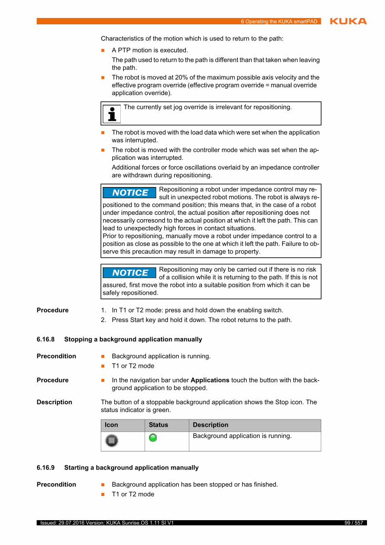
6 Operating the KUKA smartPAD
Characteristics of the motion which is used to return to the path:
A PTP motion is executed.
The path used to return to the path is different than that taken when leaving the path.
The robot is moved at 20% of the maximum possible axis velocity and the effective program override (effective program override = manual override application override).
The robot is moved with the load data which were set when the application was interrupted.
The robot is moved with the controller mode which was set when the ap-plication was interrupted.
Additional forces or force oscillations overlaid by an impedance controller are withdrawn during repositioning.
Procedure 1. In T1 or T2 mode: press and hold down the enabling switch.
2. Press Start key and hold it down. The robot returns to the path.
6.16.8 Stopping a background application manually
Precondition Background application is running.
T1 or T2 mode
Procedure In the navigation bar under Applications touch the button with the back-ground application to be stopped.
Description The button of a stoppable background application shows the Stop icon. The status indicator is green.
6.16.9 Starting a background application manually
Precondition Background application has been stopped or has finished.
T1 or T2 mode
The currently set jog override is irrelevant for repositioning.
Repositioning a robot under impedance control may re-sult in unexpected robot motions. The robot is always re-
positioned to the command position; this means that, in the case of a robot under impedance control, the actual position after repositioning does not necessarily corresond to the actual position at which it left the path. This can lead to unexpectedly high forces in contact situations.Prior to repositioning, manually move a robot under impedance control to a position as close as possible to the one at which it left the path. Failure to ob-serve this precaution may result in damage to property.
Repositioning may only be carried out if there is no risk of a collision while it is returning to the path. If this is not
assured, first move the robot into a suitable position from which it can be safely repositioned.
Icon Status Description
Background application is running.
99 / 557Issued: 29.07.2016 Version: KUKA Sunrise.OS 1.11 SI V1
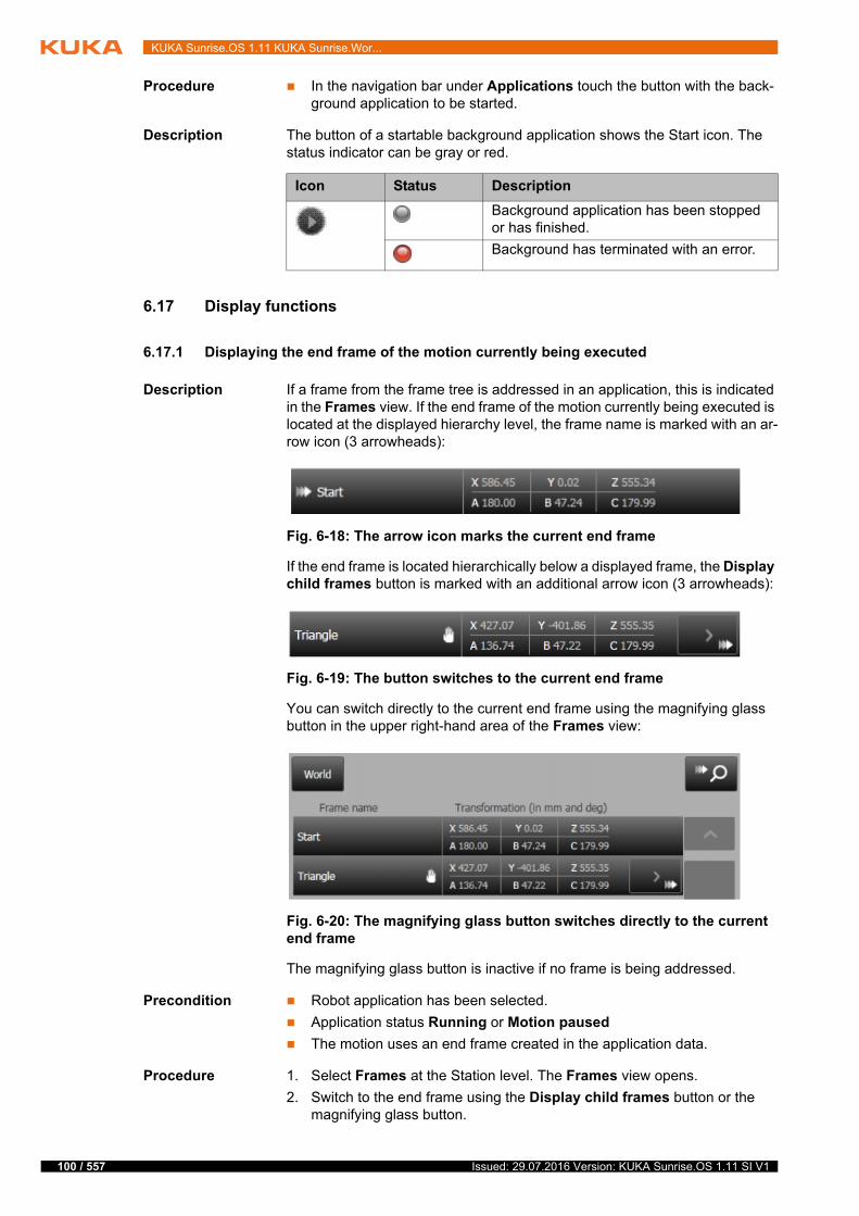
100 / 557
KUKA Sunrise.OS 1.11 KUKA Sunrise.Wor...
Procedure In the navigation bar under Applications touch the button with the back-ground application to be started.
Description The button of a startable background application shows the Start icon. The status indicator can be gray or red.
6.17 Display functions
6.17.1 Displaying the end frame of the motion currently being executed
Description If a frame from the frame tree is addressed in an application, this is indicated in the Frames view. If the end frame of the motion currently being executed is located at the displayed hierarchy level, the frame name is marked with an ar-row icon (3 arrowheads):
If the end frame is located hierarchically below a displayed frame, the Display child frames button is marked with an additional arrow icon (3 arrowheads):
You can switch directly to the current end frame using the magnifying glass button in the upper right-hand area of the Frames view:
The magnifying glass button is inactive if no frame is being addressed.
Precondition Robot application has been selected.
Application status Running or Motion paused
The motion uses an end frame created in the application data.
Procedure 1. Select Frames at the Station level. The Frames view opens.
2. Switch to the end frame using the Display child frames button or the magnifying glass button.
Icon Status Description
Background application has been stopped or has finished.
Background has terminated with an error.
Fig. 6-18: The arrow icon marks the current end frame
Fig. 6-19: The button switches to the current end frame
Fig. 6-20: The magnifying glass button switches directly to the current end frame
Issued: 29.07.2016 Version: KUKA Sunrise.OS 1.11 SI V1
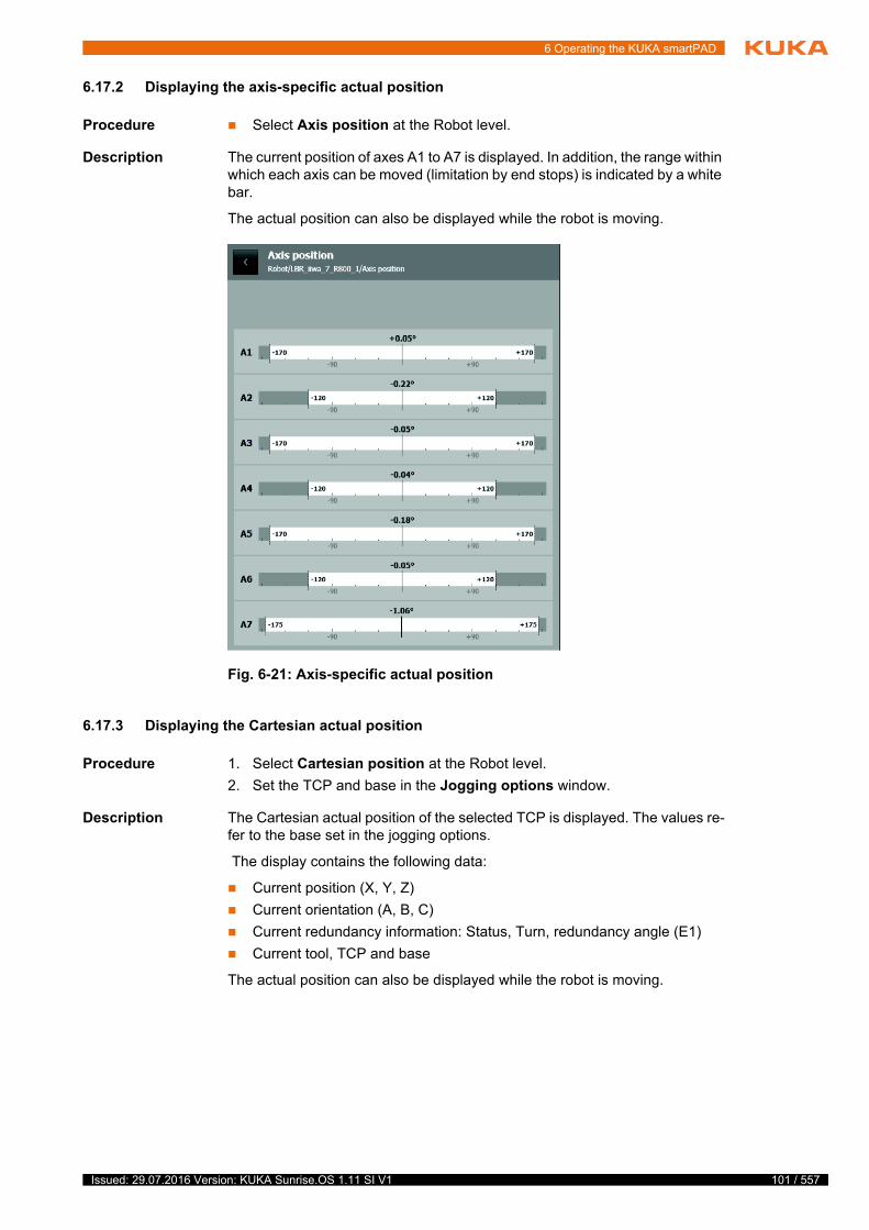
6 Operating the KUKA smartPAD
6.17.2 Displaying the axis-specific actual position
Procedure Select Axis position at the Robot level.
Description The current position of axes A1 to A7 is displayed. In addition, the range within which each axis can be moved (limitation by end stops) is indicated by a white bar.
The actual position can also be displayed while the robot is moving.
6.17.3 Displaying the Cartesian actual position
Procedure 1. Select Cartesian position at the Robot level.
2. Set the TCP and base in the Jogging options window.
Description The Cartesian actual position of the selected TCP is displayed. The values re-fer to the base set in the jogging options.
The display contains the following data:
Current position (X, Y, Z)
Current orientation (A, B, C)
Current redundancy information: Status, Turn, redundancy angle (E1)
Current tool, TCP and base
The actual position can also be displayed while the robot is moving.
Fig. 6-21: Axis-specific actual position
101 / 557Issued: 29.07.2016 Version: KUKA Sunrise.OS 1.11 SI V1

102 / 557
KUKA Sunrise.OS 1.11 KUKA Sunrise.Wor...
6.17.4 Displaying axis-specific torques
Procedure Select Axis torques at the Robot level.
Description The current torque values for axes A1 to A7 are displayed. In addition, the sen-sor measuring range for each axis is displayed (white bar).
If the maximum permissible torque on a joint is exceeded, the dark gray area of the bar for the axis in question turns orange. Only the violated area is indi-cated in color (either the negative or positive part).
The display contains the following data:
Current absolute torques
Current external torques
Current tool
The axis-specific torques can also be displayed while the robot is moving.
Fig. 6-22: Cartesian actual position
The refresh rate of the displayed values is limited. Briefly occurring peak values are therefore not displayed under certain circumstances.
The external torques are only displayed correctly if the correct tool has been specified.
Issued: 29.07.2016 Version: KUKA Sunrise.OS 1.11 SI V1

6 Operating the KUKA smartPAD
6.17.5 Displaying an I/O group and changing the value of an output
Precondition To change an output: Operating mode T1, T2 or CRR
Procedure 1. In the navigation bar, select the desired I/O group from I/O groups. The inputs/outputs of the selected group are displayed.
2. Select the output to be changed.
3. An input box is displayed for numeric outputs. Enter the desired value.
4. Press and hold down the enabling switch. Change the value of the input with the appropriate button.
Fig. 6-23: Axis-specific torques
The outputs can be changed irrespective of the safety controller sta-tus, for example even if an EMERGENCY STOP is pressed.
103 / 557Issued: 29.07.2016 Version: KUKA Sunrise.OS 1.11 SI V1

104 / 557
KUKA Sunrise.OS 1.11 KUKA Sunrise.Wor...
Description
Fig. 6-24: Inputs/outputs of an I/O group
Item Description
1 Name of the input/output
2 Type of input/output
3 Value of the input/output
The value is displayed as a decimal number.
4 Buttons for changing outputs
If an output is selected, its value can be changed. Precondition: The enabling switch is pressed.
The buttons available depend on the output type.
5 Signal properties
The properties and the current value of the selected input or out-put are displayed.
6 Signal direction
The icons indicate whether the signal is an input or an output.
Issued: 29.07.2016 Version: KUKA Sunrise.OS 1.11 SI V1
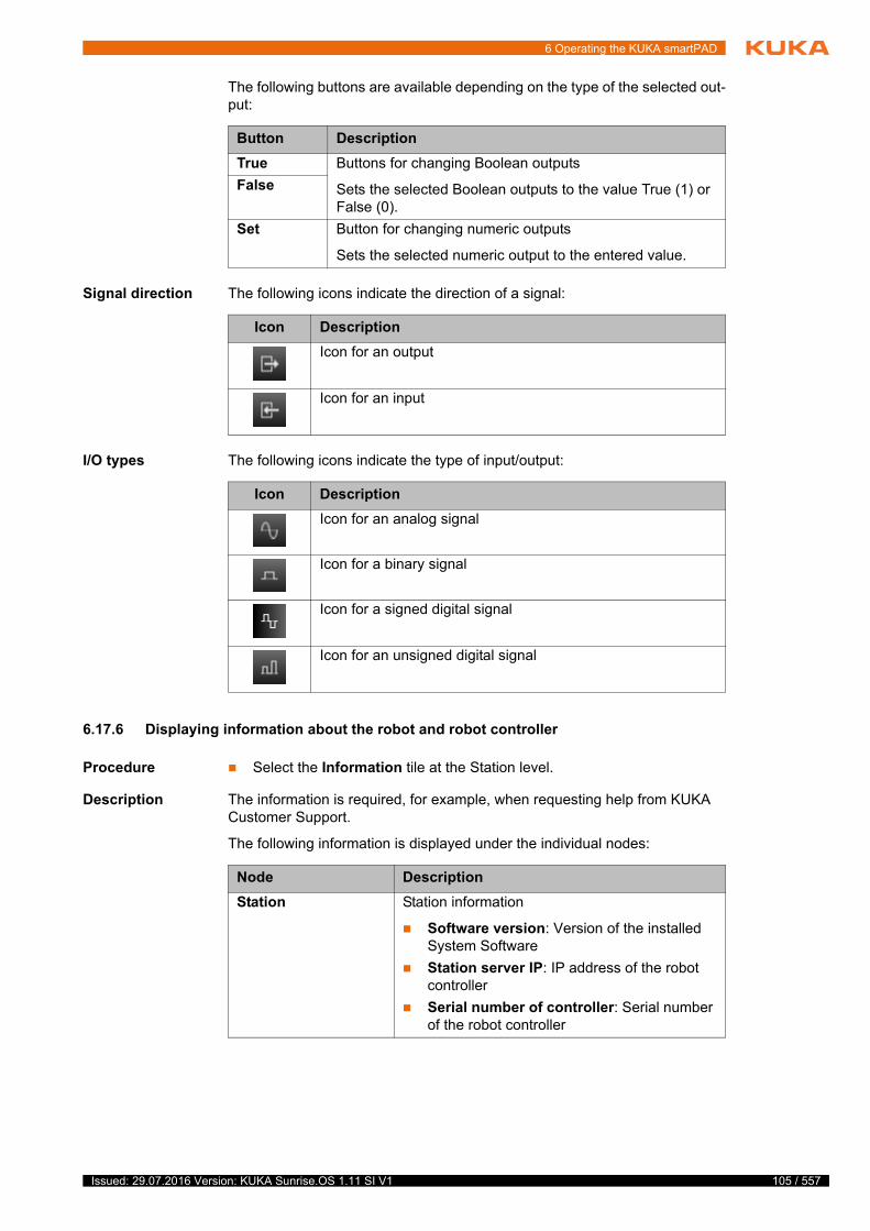
6 Operating the KUKA smartPAD
The following buttons are available depending on the type of the selected out-put:
Signal direction The following icons indicate the direction of a signal:
I/O types The following icons indicate the type of input/output:
6.17.6 Displaying information about the robot and robot controller
Procedure Select the Information tile at the Station level.
Description The information is required, for example, when requesting help from KUKA Customer Support.
The following information is displayed under the individual nodes:
Button Description
True Buttons for changing Boolean outputs
Sets the selected Boolean outputs to the value True (1) or False (0).
False
Set Button for changing numeric outputs
Sets the selected numeric output to the entered value.
Icon Description
Icon for an output
Icon for an input
Icon Description
Icon for an analog signal
Icon for a binary signal
Icon for a signed digital signal
Icon for an unsigned digital signal
Node Description
Station Station information
Software version: Version of the installed System Software
Station server IP: IP address of the robot controller
Serial number of controller: Serial number of the robot controller
105 / 557Issued: 29.07.2016 Version: KUKA Sunrise.OS 1.11 SI V1

106 / 557
KUKA Sunrise.OS 1.11 KUKA Sunrise.Wor...
6.18 Backup Manager
6.18.1 Overview of Backup Manager
The Backup Manager makes it possible to back up and restore robot controller data manually. Automatic backup of data at a predefined interval can also be preconfigured in the station configuration.
The following data are backed up and restored:
Project data
Catalogs of the installed software
User-specific files (directory: C:\KRC\UserData)
The target directory for backups and the source directory for restorations is preconfigured. The target and source directory is either the local directory D:\ProjectBackup on the robot controller or a shared network directory.
Precondition Backup Manager is installed.
Procedure Open the Backup Manager view:
Select the KUKA_Sunrise_Cabinet_1 > Backup Manager tile at the Sta-tion level.
User interface Information about the smartHMI
Connection IP
Connection state
<Robot name>/Type plate
Robot information
Serial number: Serial number of the con-nected robot
Connected robot: Type of the connected ro-bot
Installed robot: Robot type specified in the station configuration of Sunrise.Workbench
Operating time [h]
The operating hours meter is running as long as the drives are switched on.
Node Description
If the target directory for backups is on a network drive, it is advisable to perform a connection test during start-up.Test by carrying out a manual backup. If this fails, e.g. because the
target directory in the network is not accessible due to a defective configura-tion, this is indicated in an error message.
Issued: 29.07.2016 Version: KUKA Sunrise.OS 1.11 SI V1

6 Operating the KUKA smartPAD
Description
Fig. 6-25: Backup Manager view
Item Description
1 Status indicator of the backup
Deactivated: Automatic backup is not configured.
Ready: Automatic backup is activated.
Running: A backup is in progress (started manually or auto-matically).
2 Information about the next automatic backup (if activated)
Date and time
Target directory
107 / 557Issued: 29.07.2016 Version: KUKA Sunrise.OS 1.11 SI V1

108 / 557
KUKA Sunrise.OS 1.11 KUKA Sunrise.Wor...
3 “Manual backup/restoration” area
When the view is opened for the first time, only this area and the status indicator are displayed. This is the default view.
The area contains the following buttons:
Backup now
(>>> 6.18.2 "Backing up data manually" Page 109)
Restore
The button cannot be activated until the backup copy that is to be restored has been selected using the magnifying glass but-ton.
(>>> 6.18.3 "Restoring data manually" Page 109)
Configure source path
Displays the “Configure source path” area. After this the button is inactive.
Cancel
Hides the “Configure source path” area again. The button is in-active in the default view.
4 Information about the most recent successful backup
Date and time
Target directory
5 “Configure source path” area
The source directory from which restoration is to be carried out can be defined here. By default, the source directory defined in the station configuration is preset.
The following source directories are available for selection:
Local from D:\ProjectBackup: The source directory is the di-rectory D:\ProjectBackup on the robot controller.
Network: The source directory is located on a network drive.
The network path to the source directory can be configured.
(>>> 6.18.4 "Configuring the network path for restoration" Page 109)
6 Information about the backup copy selected for restoration
Project name
Date and time of the backup
7 Magnifying glass button
Opens a dialog in which the backup copy to be restored can be selected. The dialog displays all backup copies contained in the configured source directory.
8 Load data set button
Opens a dialog in which the user can select and apply ready-made restoration configurations.
The button is only active if the file for restoration configurations is configured in the station configuration and the file is saved under the configured path on the robot controller.
Item Description
Issued: 29.07.2016 Version: KUKA Sunrise.OS 1.11 SI V1

6 Operating the KUKA smartPAD
6.18.2 Backing up data manually
Description The backup copies are saved in the target directory in the following folder structure:
IP address_Project name\BACKUP_No.
Precondition No data backup is in progress.
Procedure Press Backup now in the Backup Manager view. The backup is carried out.
6.18.3 Restoring data manually
Precondition No application is selected.
Robot is not being jogged or manually guided.
No data backup is in progress.
Procedure 1. Press Configure source path in the Backup Manager view.
2. If not already preset, select the source from which restoration is to be car-ried out. If required, configure the desired network path for restoration.
(>>> 6.18.4 "Configuring the network path for restoration" Page 109)
3. Press the magnifying glass button. A dialog is opened. The backup copies available in the specified source directory are listed.
4. Select the desired backup copy and press Select. The dialog is closed and information about the selected backup copy is displayed.
5. Press Restore. Restoration commences.
A progress bar indicates how far the process is. Following an automatic re-boot of the robot controller, restoration is completed.
6.18.4 Configuring the network path for restoration
Description The network parameters can be entered manually or loaded from a preconfig-ured data set:
Element Description
IP address IP address of the robot controller
Project name Name of the project installed on the robot controller
No. Number of the backup copy
The BACKUP folder with the highest number always con-tains the most recent backup copy.
Parameter Description
Network path Network path to source directory, e.g. \\192.168.40.171\Backup\Restore
Server user name User name for the network path
The parameter is only relevant if authentication is required for network access.
Server password Password for the network path
The parameter is only relevant if authentication is required for network access.
IP address IP address of the robot controller to be restored
Subnet Mask Subnet mask in which the IP address of the robot controller is located
109 / 557Issued: 29.07.2016 Version: KUKA Sunrise.OS 1.11 SI V1
110 / 557
KUKA Sunrise.OS 1.11 KUKA Sunrise.Wor...
Precondition For loading from a data set:
The file for restoration configurations is configured in the station configu-ration.
The file is saved under the configured path on the robot controller.
Procedure 1. Press Configure source path in the Backup Manager view.
2. Select Network as the source if this is not already preset.
3. Enter network parameters or load them from a data set.
To load from a data set, proceed as follows:
a. Press Load data set. The Available restoration configurations dia-log opens. All available configurations are listed. Every entry contains the name of the robot controller that is to be restored. The network path is indicated below this.
b. The selection can be reduced by filtering the entries by the name of the robot controller. To do so, enter the name or part of the name in the dialog. e.g. *Controller.
c. Select the desired entry and press Import.
The IP addresses of the robot controller and the server must be locat-ed in the same range. IP address and subnet mask of the robot con-troller to be restored must be selected accordingly.
Issued: 29.07.2016 Version: KUKA Sunrise.OS 1.11 SI V1

7 Start-up and recommissioning
7 Start-up and recommissioning
7.1 Switching the robot controller on/off
7.1.1 Switching on the robot controller and starting the System Software
Procedure Turn the main switch on the robot controller to the “I” position.
The system software starts automatically.
Description The robot controller is ready for operation when the status indicator for the boot state of the robot controller lights up green:
Boot state tile at the Station level under the KUKA_Sunrise_Cabinet_1 tile .
7.1.2 Switching off the robot controller
Procedure Turn the main switch on the robot controller to the “0” position.
7.2 smartPAD software update
When the robot controller is rebooted or the smartPAD is plugged into a run-ning robot controller, the version of the smartPAD software is automatically checked. If there are conflicts between the smartPAD software and the system software on the robot controller, the smartPAD software must be updated.
Characteristics of the smartPAD software update:
The update is carried out automatically in T1, T2 and CRR modes.
No update is possible in Automatic mode.
If the smartPAD is connected in Automatic mode and a version conflict is recognized, no user input may be entered on the smartPAD. The operating mode must be switched to T1 or T2 to start the update automatically.
No user input may be entered during the smartPAD update.
Following a successful update, the smartPAD is automatically rebooted.
t
t
The robot controller is supplied with an operational version of the Sys-tem Software. Therefore, no installation is required during initial start-up.
Installation becomes necessary, for example, if the station configuration changes. (>>> 10 "Station configuration and installation" Page 167)
If an application is still running when the robot controller is switched off, active motions are stopped. This can re-
sult in the robot being damaged. For this reason, the robot controller must only be switched off when no more applications are running and the robot is stationary.
Do not interrupt the update, as the smartPAD may other-wise be damaged.
Do not disconnect the smartPAD from the robot controller during the up-date.
Do not disconnect the robot controller from the power supply during the update.
111 / 557Issued: 29.07.2016 Version: KUKA Sunrise.OS 1.11 SI V1
112 / 557
KUKA Sunrise.OS 1.11 KUKA Sunrise.Wor...
7.3 Performing a PDS firmware update
Description If the robot controller is rebooted or the drive bus connection restored, the sys-tem checks for every connected PDS whether the current PDS firmware ver-sion matches the firmware version on the robot controller. If the firmware version of at least one of the PDSs is older than the version on the robot con-troller, a PDS firmware update must be performed.
The following error message is displayed under the Device state tile:
Firmware update is required. Select "Diagnosis" > "PDS firmware update" in the main menu in order to update the firmware.
Procedure In the main menu, select Diagnosis > PDS firmware update.
The update is started and a blocking dialog is displayed. No user input may be entered during the smartPAD update.
Once the update has been successfully completed, the dialog is closed.
7.4 Position mastering
During position mastering, a defined mechanical robot axis position is as-signed to a motor angle. Only with a mastered robot is it possible for taught positions to be addressed with high repeatability. An unmastered robot can only be moved manually (axis-specific jogging in T1 or CRR mode).
7.4.1 Mastering axes
Description The LBR iiwa has a Hall effect mastering sensor in every axis. The mastering position of the axis (zero position) is located in the center of a defined series of magnets. It is automatically detected by the mastering sensor when it pass-es over the series of magnets during a rotation of the axis.
Before the actual mastering takes place, an automatic search run is performed in order to find a defined premastering position.
If the search run is successful, the axis is moved into the premastering posi-tion. The axis is then moved in such a way that the mastering sensor passes over the series of magnets. The motor position at the moment when the mas-tering position of the axis is detected is saved as the zero position of the motor.
Following the update of the smartPAD software, the robot controller must be rebooted in order to fully display the smartHMI and be able to use the system.
The update may take up to 5 hours and must not be in-terrupted:
Do not disconnect the robot from the robot controller during the update.
Do not disconnect the robot controller from the power supply during the update.
If the update is interrupted, it is possible that the robot controller may enter the error state with the result that the robot can no longer be moved. This fault can only be rectified by KUKA Service.
Issued: 29.07.2016 Version: KUKA Sunrise.OS 1.11 SI V1
7 Start-up and recommissioning
Precondition Operating mode T1 or CRR
Procedure 1. Select Mastering at the Robot level. The Mastering view opens.
2. Press and hold down the enabling switch.
3. Press the Master button for the unmastered axis.
First of all, the premastering position is located by means of a search run. The mastering run is then performed. Once mastering has been carried out successfully, the axis moves to the calculated mastering position (zero position).
7.4.2 Manually unmastering axes
Description The saved mastering position of an axis can be deleted. This unmasters the axis. No motion is executed during unmastering.
Precondition Operating mode T1
Procedure 1. Select Mastering at the Robot level. The Mastering view opens.
2. Press the Unmaster button for the mastered axis. The axis is unmastered.
7.5 Calibration
7.5.1 Tool calibration
Description During tool calibration, the user assigns a Cartesian coordinate system (tool coordinate system) to a tool mounted on the mounting flange.
The tool coordinate system has its origin at a user-defined point. This is called the TCP (Tool Center Point). The TCP is generally situated at the working point of the tool. A tool can have several TCPs.
Advantages of tool calibration:
The tool can be moved in a straight line in the tool direction.
The tool can be rotated about the TCP without changing the position of the TCP.
In program mode: The programmed velocity is maintained at the TCP along the path.
The repeatability and reproducibility of mastering are only guaranteed if the procedure is always identical. The following rules must be ob-served during mastering:
When one axis is being mastered, all axes should be in the vertical stretch position. If this is not possible, mastering must always be carried out in the same axis position.
Always master the individual axes in the same order.
Always carry out mastering without a load. Mastering with a load is not currently supported.
The mastering velocity is independent of the set jog override.
If the search run or the mastering fails, the process is aborted and the robot stops.
113 / 557Issued: 29.07.2016 Version: KUKA Sunrise.OS 1.11 SI V1

114 / 557
KUKA Sunrise.OS 1.11 KUKA Sunrise.Wor...
Overview Tool calibration consists of 2 steps:
7.5.1.1 TCP calibration: XYZ 4-point method
Description The TCP of the tool to be calibrated is moved to a reference point from 4 dif-ferent directions. The reference point can be freely selected. The robot con-troller calculates the TCP from the different flange positions.
The 4 flange positions with which the reference point is addressed must main-tain a certain minimum distance between one another. If the points are too close to one another, the position data cannot be saved. A corresponding error message is generated.
The quality of the calibration can be assessed by means of the translational calculation error which is determined during calibration. If this error exceeds a defined limit value, it is advisable to calibrate the TCP once more.
Fig. 7-1: TCP calibration principle
Step Description
1 Define the origin of the tool coordinate system
The following methods are available:
XYZ 4-point
(>>> 7.5.1.1 "TCP calibration: XYZ 4-point method" Page 114)
2 Definition of the orientation of the tool coordinate system
The following methods are available:
ABC 2-point
(>>> 7.5.1.2 "Defining the orientation: ABC 2-point meth-od" Page 116)
ABC World
(>>> 7.5.1.3 "Defining the orientation: ABC world method" Page 118)
Issued: 29.07.2016 Version: KUKA Sunrise.OS 1.11 SI V1
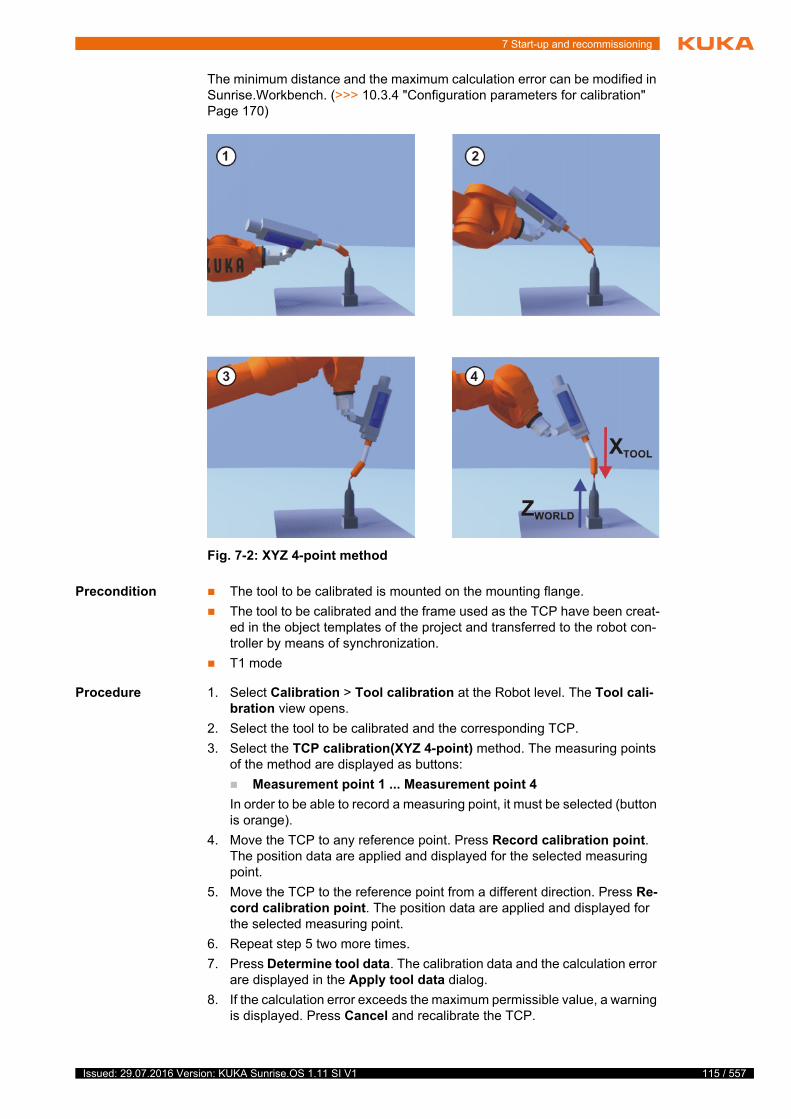
7 Start-up and recommissioning
The minimum distance and the maximum calculation error can be modified in Sunrise.Workbench. (>>> 10.3.4 "Configuration parameters for calibration" Page 170)
Precondition The tool to be calibrated is mounted on the mounting flange.
The tool to be calibrated and the frame used as the TCP have been creat-ed in the object templates of the project and transferred to the robot con-troller by means of synchronization.
T1 mode
Procedure 1. Select Calibration > Tool calibration at the Robot level. The Tool cali-bration view opens.
2. Select the tool to be calibrated and the corresponding TCP.
3. Select the TCP calibration(XYZ 4-point) method. The measuring points of the method are displayed as buttons:
Measurement point 1 ... Measurement point 4
In order to be able to record a measuring point, it must be selected (button is orange).
4. Move the TCP to any reference point. Press Record calibration point. The position data are applied and displayed for the selected measuring point.
5. Move the TCP to the reference point from a different direction. Press Re-cord calibration point. The position data are applied and displayed for the selected measuring point.
6. Repeat step 5 two more times.
7. Press Determine tool data. The calibration data and the calculation error are displayed in the Apply tool data dialog.
8. If the calculation error exceeds the maximum permissible value, a warning is displayed. Press Cancel and recalibrate the TCP.
Fig. 7-2: XYZ 4-point method
115 / 557Issued: 29.07.2016 Version: KUKA Sunrise.OS 1.11 SI V1
116 / 557
KUKA Sunrise.OS 1.11 KUKA Sunrise.Wor...
9. If the calculation error is below the configured limit, press Apply to save the calibration data.
10. Either close the Calibration view or define the orientation of the tool coor-dinate system with the ABC 2-point or ABC World method.
(>>> 7.5.1.2 "Defining the orientation: ABC 2-point method" Page 116)
(>>> 7.5.1.3 "Defining the orientation: ABC world method" Page 118)
11. Synchronize the project in order to save the calibration data including the calculation error in Sunrise.Workbench.
7.5.1.2 Defining the orientation: ABC 2-point method
Description The robot controller is notified of the axes of the tool coordinate system by ad-dressing a point on the X axis and a point in the XY plane.
The points must maintain a defined minimum distance from one another. If the points are too close to one another, the position data cannot be saved. A cor-responding error message is generated.
The minimum distance can be modified in Sunrise.Workbench. (>>> 10.3.4 "Configuration parameters for calibration" Page 170)
This method is used for tools with edges and corners which the user can em-ploy for orientation. Furthermore, it is used if it is necessary to define the axis directions with particular precision.
This method is not available for safety-oriented tools.
Issued: 29.07.2016 Version: KUKA Sunrise.OS 1.11 SI V1

7 Start-up and recommissioning
Precondition The tool to be calibrated is mounted on the mounting flange.
The TCP of the tool has already been measured.
Operating mode T1
Procedure 1. Only if the Calibration view was closed following TCP calibration:
Select Calibration > Tool calibration at the Robot level. The Tool cali-bration view opens.
2. Only if the Calibration view was closed following TCP calibration:
Select the mounted tool and the corresponding TCP of the tool.
3. Select the Defining the orientation(ABC 2-point) method. The measur-ing points of the method are displayed as buttons:
TCP
Negative X axis
Positive Y value on XY plane
In order to be able to record a measuring point, it must be selected (button is orange).
4. Move the TCP to any reference point. Press Record calibration point. The position data are applied and displayed for the selected measuring point.
Fig. 7-3: ABC 2-point method
117 / 557Issued: 29.07.2016 Version: KUKA Sunrise.OS 1.11 SI V1
118 / 557
KUKA Sunrise.OS 1.11 KUKA Sunrise.Wor...
5. Move the tool so that the reference point on the X axis has a negative X value (i.e. move against the tool direction). Press Record calibration point. The position data are applied and displayed for the selected mea-suring point.
6. Move the tool so that the reference point in the XY plane has a positive Y value. Press Record calibration point. The position data are applied and displayed for the selected measuring point.
7. Press Determine tool data. The calibration data are displayed in the Ap-ply tool data dialog.
8. Press Apply to save the calibration data.
9. Synchronize the project in order to save the calibration data in Sun-rise.Workbench.
7.5.1.3 Defining the orientation: ABC world method
Description The user aligns the axes of the tool coordinate system parallel to the axes of the world coordinate system. This communicates the orientation of the tool co-ordinate system to the robot controller.
There are 2 variants of this method:
5D: The user communicates the tool direction to the robot controller. By default, the tool direction is the X axis. The orientation of the other axes is defined by the system and cannot be influenced by the user.
The system always defines the orientation of the other axes in the same way. If the tool subsequently has to be calibrated again, e.g. after a crash, it is therefore sufficient to define the tool direction again. Rotation about the tool direction need not be taken into consideration.
6D: The user communicates the direction of all 3 axes to the robot control-ler.
This method is used for tools that do not have corners which the user can em-ploy for orientation, e.g rounded tools such as adhesive or welding nozzles.
Precondition The tool to be calibrated is mounted on the mounting flange.
The TCP of the tool has already been measured.
Operating mode T1
Procedure 1. Only if the Calibration view was closed following TCP calibration:
Select Calibration > Tool calibration at the Robot level. The Tool cali-bration view opens.
2. Only if the Calibration view was closed following TCP calibration:
Select the mounted tool and the corresponding TCP of the tool.
3. Select the Defining the orientation(ABC world) method.
4. Select the ABC World 5D or ABC world 6D option.
5. If ABC World 5D is selected:
Align +XTOOL parallel to -ZWORLD. (+XTOOL = tool direction)
If ABC world 6D is selected:
Align the axes of the tool coordinate system as follows.
+XTOOL parallel to -ZWORLD. (+XTOOL = tool direction)
+YTOOL parallel to +YWORLD
+ZTOOL parallel to +XWORLD
6. Press Determine tool data. The calibration data are displayed in the Ap-ply tool data dialog.
7. Press Apply to save the calibration data.
Issued: 29.07.2016 Version: KUKA Sunrise.OS 1.11 SI V1
7 Start-up and recommissioning
8. Synchronize the project in order to save the calibration data in Sun-rise.Workbench.
7.5.2 Calibrating the base: 3-point method
Description During base calibration, the user assigns a Cartesian coordinate system (base coordinate system) to a frame selected as the base. The base coordinate sys-tem has its origin at a user-defined point.
Advantages of base calibration:
The TCP can be jogged along the edges of the work surface or workpiece.
Points can be taught relative to the base. If it is necessary to offset the base, e.g. because the work surface has been offset, the points move with it and do not need to be retaught.
The origin and 2 further points of a base are addressed with the 3-point meth-od. These 3 points define the base.
The points must maintain a defined minimum distance from the origin and min-imum angles between the straight lines (origin – X axis and origin – XY plane). If the points are too close to one another or if the angle between the straight lines is too small, the position data cannot be saved. A corresponding error message is generated.
The minimum distance and angles can be modified in Sunrise.Workbench. (>>> 10.3.4 "Configuration parameters for calibration" Page 170)
119 / 557Issued: 29.07.2016 Version: KUKA Sunrise.OS 1.11 SI V1
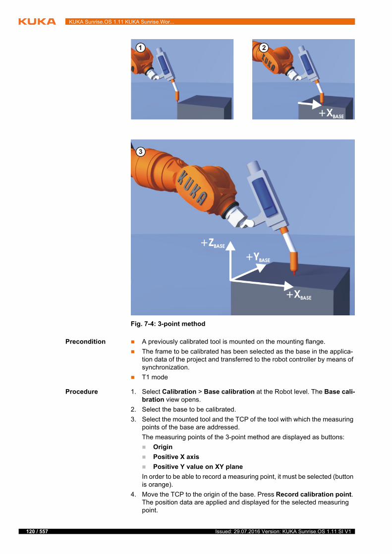
120 / 557
KUKA Sunrise.OS 1.11 KUKA Sunrise.Wor...
Precondition A previously calibrated tool is mounted on the mounting flange.
The frame to be calibrated has been selected as the base in the applica-tion data of the project and transferred to the robot controller by means of synchronization.
T1 mode
Procedure 1. Select Calibration > Base calibration at the Robot level. The Base cali-bration view opens.
2. Select the base to be calibrated.
3. Select the mounted tool and the TCP of the tool with which the measuring points of the base are addressed.
The measuring points of the 3-point method are displayed as buttons:
Origin
Positive X axis
Positive Y value on XY plane
In order to be able to record a measuring point, it must be selected (button is orange).
4. Move the TCP to the origin of the base. Press Record calibration point. The position data are applied and displayed for the selected measuring point.
Fig. 7-4: 3-point method
Issued: 29.07.2016 Version: KUKA Sunrise.OS 1.11 SI V1

7 Start-up and recommissioning
5. Move the TCP to a point on the positive X axis of the base. Press Record calibration point. The position data are applied and displayed for the se-lected measuring point.
6. Move the TCP to a point in the XY plane with a positive Y value. Press Re-cord calibration point. The position data are applied and displayed for the selected measuring point.
7. Press Determine base data. The calibration data are displayed in the Ap-ply base data dialog.
8. Press Apply to save the calibration data.
9. Synchronize the project in order to save the calibration data in Sun-rise.Workbench.
7.6 Determining tool load data
Description During load data determination, the robot performs multiple measurement runs with different orientations of wrist axes A5, A6 and A7. The load data are calculated from the data recorded during the measurement runs.
The mass and the position of the center of mass of the tool mounted on the robot flange can currently be determined. It is also possible to specify the mass and to determine the position of the center of mass on the basis of the mass that is already known.
At the start of load data determination, axis A7 is moved to the zero position and axis A5 is positioned in such a way that axis A6 is aligned perpendicular to the weight. During the measurement runs, axis A6 has to be able to move between -95° and +95°, while axis A7 has to be able to move from 0° to -90°.
The remaining robot axes (A1 to A4) are not moved during load data determi-nation. They remain in the starting position during measurement.
The quality of the load data determination may be influenced by the following constraints:
Mass of the tool
Load data determination becomes more reliable as the mass of the tool in-creases. This is because measurement uncertainties have a greater influ-ence on a smaller mass.
Supplementary loads
Supplementary loads mounted on the robot, e.g. dress packages, lead to incorrect load data.
Start position from which load data determination is started
A suitable start position should be determined first and meet the following criteria:
Axes A1 to A5 are as far away as possible from singularity positions.
The criterion is relevant if the mass is to be determined during load data determination. If load data determination is only possible in poses for which axes A1 to A5 are close to singularity positions, the mass can be specified. If only the center of mass is to be determined on the basis of the specified mass, the criterion of axis position is irrelevant.
The suitability of the start position for load data determination in the case of a robot for which automatic load data determination is to be carried out must be checked before the load that is to be determined is mounted on the robot.
Load data determination cannot yet be used reliably for masses of less than one kilogram.
121 / 557Issued: 29.07.2016 Version: KUKA Sunrise.OS 1.11 SI V1
122 / 557
KUKA Sunrise.OS 1.11 KUKA Sunrise.Wor...
A robot pose is suitable as a start position for load data determination if there are only slight external torques acting on the load-free robot in this position. This can be checked via the display of the external axis torques.
(>>> 6.17.4 "Displaying axis-specific torques" Page 102)
If the mass is to be determined during load data determination, all ex-ternal axis torques are relevant and should be checked where possible in advance for the load-free robot. If only the center of mass is to be determined on the basis of a specified mass, only the external axis torque of axis A6 is relevant.
Interference torques during the measurement runs
During the measurement runs, no interference torques may be ap-plied, e.g. by pulling or pushing the robot.
Moving parts, e.g. dress packages, generate interference torques that shift the center of mass during the measurement run.
For the load data determination for safety-oriented tools, it must be ensured that the modified load data are not automatically transferred to the safety con-figuration located on the robot controller. (>>> 9.3.9 "Safety-oriented tools" Page 154)
The load data determined for a safety-oriented tool must first be updated in Sunrise.Workbench by means of project synchronization. This changes the safety configuration of the project in Sunrise.Workbench; the project must then be re-transferred to the robot controller by synchronizing the project again.
Preparation Determine the start position from which load data determination is to be started.
Precondition The tool is mounted on the mounting flange.
The tool has been created in the object templates of the project and trans-ferred to the robot controller by means of synchronization.
The robot is in the desired start position.
There is a sufficiently large workspace available in the wrist axis range.
T1, T2 or AUT mode
Procedure 1. Select Load data at the Robot level. The Load data view opens.
2. Select the mounted tool from the selection list.
The application of interference torques during load data determina-tion results in falsified load data. (>>> 9.3.8 "Load data" Page 153)
If a changed safety configuration is activated on the robot controller, the safety maintenance technician must carry out safety acceptance. (>>> 13.13 "Safety acceptance overview" Page 275)
To avoid spending unnecessary time performing verifications, it is advisable to mark a tool as safety-oriented only when the load data have been correctly entered or determined and have been transferred to Sunrise.Workbench.
If parts of the mounted tool project behind the flange plane (in the negative Z direction relative to the flange
coordinate system), there is a risk of the tool colliding with the manipulator during the measurement runs.If the motion of the axes during load data determination is unknown to the op-erator, or if a collision between the tool and manipulator cannot be ruled out (e.g. for the initial load data determination for a tool), it is advisable to deter-mine the load data in T1 mode. This does not affect the quality of the mea-surement results.
Issued: 29.07.2016 Version: KUKA Sunrise.OS 1.11 SI V1

7 Start-up and recommissioning
3. If T1 or T2 mode is set, press and hold down the enabling switch until load data determination has been completed.
4. Press Determining the load data.
5. If the tool already has a mass, the operator will be asked if the mass is to be redetermined.
Select Use existing mass if the currently saved mass is to be re-tained.
Select Redetermine mass if the mass is to be determined again.
6. The robot starts the measurement runs and the load data are determined. A progress bar is displayed.
Once load data determination has been completed, the determined load data are displayed in the Apply load data dialog.
Press Apply to save the determined load data.
7. Synchronize the project so that the load data are saved in Sunrise.Work-bench.
When the load data for a safety-oriented tool have been determined, the safety configuration changes as a result of the project synchronization.
8. If necessary, synchronize the project in order to transfer the changed safe-ty configuration to the robot controller.
Overview
If the currently saved mass is to be retained in the load determination, it must be ensured that the specified mass value is correct. Other-wise, the center of mass cannot be determined accurately.
If the motion enable signal is withdrawn during load data determina-tion, e.g. by an EMERGENCY STOP or by releasing the enabling switch (T1, T2), the load data determination is aborted and must be
restarted.
Fig. 7-5: Determining the load data
123 / 557Issued: 29.07.2016 Version: KUKA Sunrise.OS 1.11 SI V1

124 / 557
KUKA Sunrise.OS 1.11 KUKA Sunrise.Wor...
Item Description
1 Tool selection list
The tools created in the object templates are available for selec-tion here.
2 Load data display
Displays the current load data of the selected tool.
3 Display of axes used
Displays the axes that are moved for load data determination.
4 Determining the load data button
Starts load data determination. The button is only active if a tool has been selected and the motion enable signal has been issued.
Issued: 29.07.2016 Version: KUKA Sunrise.OS 1.11 SI V1
8 Brake test
8 Brake test
8.1 Overview of the brake test
Description Each robot axis has a holding brake integrated into the drive train. The brakes have 2 functions:
Stopping the robot when the servo control is deactivated or the robot is de-energized.
Switching the robot to the safe state “Standstill” in the event of a fault.
The brake test checks whether the brake holding torque applied by each brake is high enough, i.e. whether it exceeds a specific reference torque. This refer-ence torque can be specified by the programmer or read from the motor data.
Execution A precondition for execution of the brake test is that the robot is at operating temperature.
The brake test is manually executed by means of an application. A prepared brake test application for the LBR iiwa is available from Sunrise.Workbench.
If the prepared brake test application is used, the robot is moved prior to the actual brake test and the resulting maximum absolute torque is determined for each axis. In the brake test application, the torque determined is communicat-ed to the brake test as the reference holding torque.
The determination of the maximum absolute torques is referred to in the fol-lowing as torque value determination.
Procedure When a brake is tested, the following steps are carried out by default:
1. The axis moves at constant velocity over a small axis angle of max. 5° (on the output side). The gravitation and friction are determined during this motion.
2. When the axis has returned to its starting position and the axis drive is sta-tionary, the brake is closed.
3. One of the following values is used as the holding torque to be tested: the reference holding torque determined, the minimum brake holding torque or the motor holding torque.
The holding torque to be tested is defined internally by the system accord-ing to the following rules:
a. If the reference holding torque is greater than the lowest value of the minimum brake and motor holding torques, then the lowest value of the minimum brake and motor holding torques is used as the holding torque to be tested.
t
s
t
Unless otherwise determined by a risk assessment, the brake test must be performed regularly:
The brake test must be carried out for each axis during start-up and recommissioning of the industrial robot.
The brake test must be performed daily during operation.
The user can carry out a risk assessment to determine whether the brake test is required for the specific application and, if so, how often it is to be per-formed.
It is advisable to remove the torque value determination from the ap-plication and to test the brakes against the minimum brake holding torque. If a torque specified by the programmer is tested, a risk anal-
ysis must first be carried out to determine whether there is any danger if the brakes show a lower torque than the minimum brake holding torque.
125 / 557Issued: 29.07.2016 Version: KUKA Sunrise.OS 1.11 SI V1
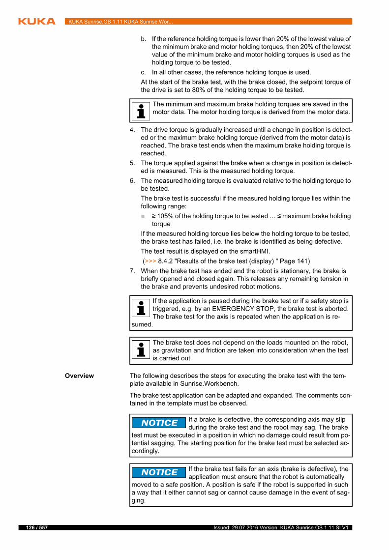
126 / 557
KUKA Sunrise.OS 1.11 KUKA Sunrise.Wor...
b. If the reference holding torque is lower than 20% of the lowest value of the minimum brake and motor holding torques, then 20% of the lowest value of the minimum brake and motor holding torques is used as the holding torque to be tested.
c. In all other cases, the reference holding torque is used.
At the start of the brake test, with the brake closed, the setpoint torque of the drive is set to 80% of the holding torque to be tested.
4. The drive torque is gradually increased until a change in position is detect-ed or the maximum brake holding torque (derived from the motor data) is reached. The brake test ends when the maximum brake holding torque is reached.
5. The torque applied against the brake when a change in position is detect-ed is measured. This is the measured holding torque.
6. The measured holding torque is evaluated relative to the holding torque to be tested.
The brake test is successful if the measured holding torque lies within the following range:
≥ 105% of the holding torque to be tested … ≤ maximum brake holding torque
If the measured holding torque lies below the holding torque to be tested, the brake test has failed, i.e. the brake is identified as being defective.
The test result is displayed on the smartHMI.
(>>> 8.4.2 "Results of the brake test (display) " Page 141)
7. When the brake test has ended and the robot is stationary, the brake is briefly opened and closed again. This releases any remaining tension in the brake and prevents undesired robot motions.
Overview The following describes the steps for executing the brake test with the tem-plate available in Sunrise.Workbench.
The brake test application can be adapted and expanded. The comments con-tained in the template must be observed.
The minimum and maximum brake holding torques are saved in the motor data. The motor holding torque is derived from the motor data.
If the application is paused during the brake test or if a safety stop is triggered, e.g. by an EMERGENCY STOP, the brake test is aborted. The brake test for the axis is repeated when the application is re-
sumed.
The brake test does not depend on the loads mounted on the robot, as gravitation and friction are taken into consideration when the test is carried out.
If a brake is defective, the corresponding axis may slip during the brake test and the robot may sag. The brake
test must be executed in a position in which no damage could result from po-tential sagging. The starting position for the brake test must be selected ac-cordingly.
If the brake test fails for an axis (brake is defective), the application must ensure that the robot is automatically
moved to a safe position. A position is safe if the robot is supported in such a way that it either cannot sag or cannot cause damage in the event of sag-ging.
Issued: 29.07.2016 Version: KUKA Sunrise.OS 1.11 SI V1
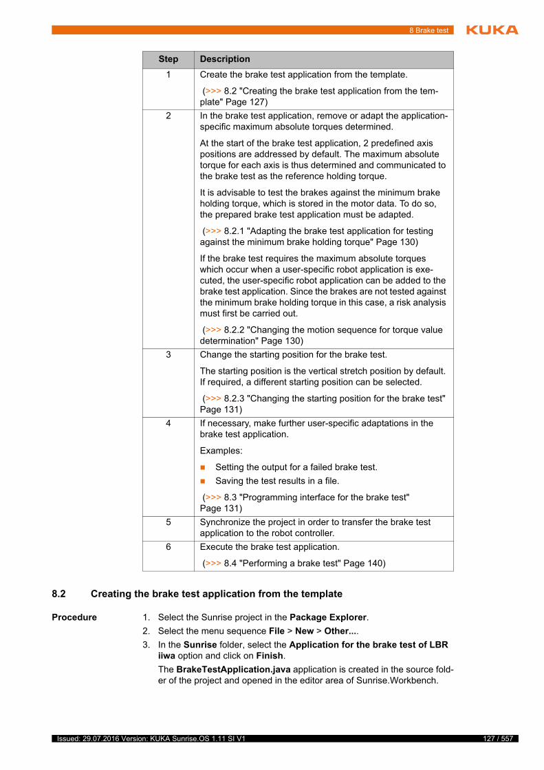
8 Brake test
8.2 Creating the brake test application from the template
Procedure 1. Select the Sunrise project in the Package Explorer.
2. Select the menu sequence File > New > Other....
3. In the Sunrise folder, select the Application for the brake test of LBR iiwa option and click on Finish.
The BrakeTestApplication.java application is created in the source fold-er of the project and opened in the editor area of Sunrise.Workbench.
Step Description
1 Create the brake test application from the template.
(>>> 8.2 "Creating the brake test application from the tem-plate" Page 127)
2 In the brake test application, remove or adapt the application-specific maximum absolute torques determined.
At the start of the brake test application, 2 predefined axis positions are addressed by default. The maximum absolute torque for each axis is thus determined and communicated to the brake test as the reference holding torque.
It is advisable to test the brakes against the minimum brake holding torque, which is stored in the motor data. To do so, the prepared brake test application must be adapted.
(>>> 8.2.1 "Adapting the brake test application for testing against the minimum brake holding torque" Page 130)
If the brake test requires the maximum absolute torques which occur when a user-specific robot application is exe-cuted, the user-specific robot application can be added to the brake test application. Since the brakes are not tested against the minimum brake holding torque in this case, a risk analysis must first be carried out.
(>>> 8.2.2 "Changing the motion sequence for torque value determination" Page 130)
3 Change the starting position for the brake test.
The starting position is the vertical stretch position by default. If required, a different starting position can be selected.
(>>> 8.2.3 "Changing the starting position for the brake test" Page 131)
4 If necessary, make further user-specific adaptations in the brake test application.
Examples:
Setting the output for a failed brake test.
Saving the test results in a file.
(>>> 8.3 "Programming interface for the brake test" Page 131)
5 Synchronize the project in order to transfer the brake test application to the robot controller.
6 Execute the brake test application.
(>>> 8.4 "Performing a brake test" Page 140)
127 / 557Issued: 29.07.2016 Version: KUKA Sunrise.OS 1.11 SI V1
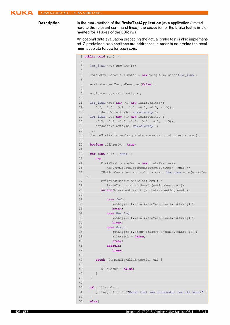
128 / 557
KUKA Sunrise.OS 1.11 KUKA Sunrise.Wor...
Description In the run() method of the BrakeTestApplication.java application (limited here to the relevant command lines), the execution of the brake test is imple-mented for all axes of the LBR iiwa.
An optional data evaluation preceding the actual brake test is also implement-ed. 2 predefined axis positions are addressed in order to determine the maxi-mum absolute torque for each axis.
1 public void run() {2 ...
3 lbr_iiwa.move(ptpHome());
4 ...
5 TorqueEvaluator evaluator = new TorqueEvaluator(lbr_iiwa);6 ...
7 evaluator.setTorqueMeasured(false);8
9 evaluator.startEvaluation();
10 ...
11 lbr_iiwa.move(new PTP(new JointPosition( 12 0.5, 0.8, 0.2, 1.0, -0.5, -0.5, -1.5)).
13 setJointVelocityRel(relVelocity));
14 lbr_iiwa.move(new PTP(new JointPosition(15 -0.5, -0.8, -0.2, -1.0, 0.5, 0.5, 1.5)).
16 setJointVelocityRel(relVelocity));
17 ...
18 TorqueStatistic maxTorqueData = evaluator.stopEvaluation();
19
20 boolean allAxesOk = true;21
22 for (int axis : axes) {
23 try {24 BrakeTest brakeTest = new BrakeTest(axis, 25 maxTorqueData.getMaxAbsTorqueValues()[axis]);
26 IMotionContainer motionContainer = lbr_iiwa.move(brakeTest);
27 BrakeTestResult brakeTestResult =
28 BrakeTest.evaluateResult(motionContainer);
29 switch(brakeTestResult.getState().getLogLevel())30 {
31 case Info:
32 getLogger().info(brakeTestResult.toString());
33 break;34 case Warning:
35 getLogger().warn(brakeTestResult.toString());
36 break;37 case Error:
38 getLogger().error(brakeTestResult.toString());
39 allAxesOk = false;40 break;41 default:42 break;43 }
44 catch (CommandInvalidException ex) {45 ...
46 allAxesOk = false;47 }
48 }
49
50 if (allAxesOk){51 getLogger().info("Brake test was successful for all axes.");
52 }
53 else{
Issued: 29.07.2016 Version: KUKA Sunrise.OS 1.11 SI V1

8 Brake test
54 getLogger().error("Brake test failed for at least one axis.");
55 }
56 }
Line Description
3 Address the starting position from which the robot is moved to determine the maximum absolute torque for each axis.
The starting position is the vertical stretch position by default.
5 Prepare the data evaluation.
In order to perform an axis-specific evaluation of the torques determined during a motion sequence, an instance of the TorqueEvaluator class must be created.
7 Select the torques to be used for the data evaluation.
The measured torques are not used, but instead the torques that are calculated using the robot model during the motion se-quence. Measurements are susceptible to malfunctions. The calculation of the torque values ensures that no interference torques resulting from dynamic effects (e.g. robot accelera-tion) are incorporated into the data evaluation.
9 Start the data evaluation.
The data evaluation is started with the startEvaluation() com-mand of the TorqueEvaluator class.
11 … 16 Carry out the motion sequence to determine the maximum ab-solute torques
2 predefined axis positions are each addressed with a PTP motion.
18 End the data evaluation and poll the data.
The stopEvaluation() command of the TorqueEvaluator class ends the data evaluation and returns the result as a value of type TorqueStatistic. The result is saved in the variable max-TorqueData.
20 Variable for the evaluation of the brake test
The result of the brake test is saved for later evaluation via the variable allAxesOk. It is set to “false” if the brake test of an axis fails or is aborted due to an error. Otherwise it retains the value “true”.
22 … 54 Execute the brake test
The brakes are tested one after the other, starting with the brake of axis A1.
1. Lines 24, 25: An object of type BrakeTest is created. In the process, the corresponding axis and the previously deter-mined maximum absolute torque are transferred as the reference holding torque.
2. Line 26: The brake test is executed as a motion command.
3. Lines 27 ... 54: The result of the brake test is evaluated and displayed on the smartHMI.
129 / 557Issued: 29.07.2016 Version: KUKA Sunrise.OS 1.11 SI V1

130 / 557
KUKA Sunrise.OS 1.11 KUKA Sunrise.Wor...
8.2.1 Adapting the brake test application for testing against the minimum brake holding
torque
Description The brake test checks whether the brakes apply the minimum brake holding torque. It is therefore advisable to adapt the prepared brake test application in accordance with the following description.
If the brake test is to be executed without reference holding torques being de-termined and made available to the brake test, all the command lines relevant for torque value determination must be removed from the brake test applica-tion. As a consequence, the brake test application then starts with the motion to the starting position for the brake test.
In addition, when creating the BrakeTest instance, the parameter with which the reference torque is transferred must be removed.
Procedure 1. Open the brake test application in Sunrise.Workbench.
2. Make the following changes to the run() method of the application:
Delete all command lines which are relevant for torque value determi-nation.
When calling the constructor of the BrakeTest class, delete the follow-ing parameters:
maxTorqueData.getMaxAbsTorqueValues()[axis]
The following code remains in the line:
3. Save changes.
8.2.2 Changing the motion sequence for torque value determination
Description The brake test application created from the template contains a prepared mo-tion sequence for determining the maximum absolute torques generated in each axis.
The robot is moved from the vertical stretch position by default. A different starting position can be selected.
2 pre-defined axis positions are each addressed from the starting position with a PTP motion. In order to determine the maximum absolute torques that arise in a specific robot application, and to use these as reference holding torques for the brake test, application-specific motion sequences must be inserted into the brake test application.
Fig. 8-1: Transferring the reference torque for the brake test
1 Constructor of the class BrakeTest with transfer of reference torque
BrakeTest brakeTest = new brakeTest(axis);
Issued: 29.07.2016 Version: KUKA Sunrise.OS 1.11 SI V1

8 Brake test
Procedure 1. Open the brake test application in Sunrise.Workbench.
2. If necessary, make the following changes to the run() method of the appli-cation:
Replace the ptpHome() motion that brings the robot to the starting po-sition with a motion to the desired starting position.
Replace the predefined motion sequence with the appropriate applica-tion code.
3. Save changes.
8.2.3 Changing the starting position for the brake test
Description By default, the brake test application created from the template executes the brake test to the end position of the motion sequence in order to determine the maximum absolute torque. If this position is not suitable for the brake test, a motion to the desired starting position must be programmed before the brake test is executed.
8.3 Programming interface for the brake test
With the BrakeTest class, the RoboticsAPI offers a programming interface for the execution of the brake test. The brake test is executed as a motion com-mand.
In addition, using the TorqueEvaluator class, the torques measured during a motion sequence can be evaluated and the maximum absolute torque for each axis can be determined. This torque can be used as the reference holding torque for the brake test.
8.3.1 Evaluating the torques generated and determining the maximum absolute value
Description In order to perform an axis-specific evaluation of the torques determined dur-ing a motion sequence, an object of the TorqueEvaluator class must first be created. The LBR instance for whose axes the maximum absolute torque val-ues are to be determined is transferred to the constructor of the TorqueEvalu-ator class.
Fig. 8-2: Motion sequence for torque value determination
1 ptpHome() motion to starting position
2 Predefined motion sequence for torque value determination
To determine the gravitation and friction, the axes of an LBR iiwa are moved towards the mechanical zero position. The maximum travel is 5° on the output side.
131 / 557Issued: 29.07.2016 Version: KUKA Sunrise.OS 1.11 SI V1
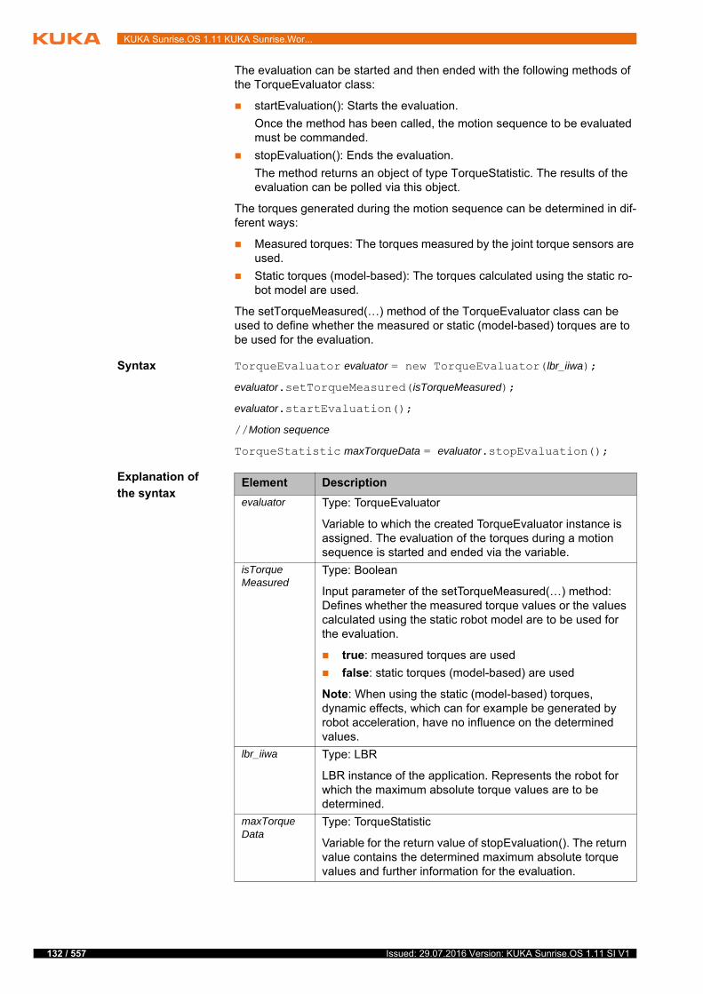
132 / 557
KUKA Sunrise.OS 1.11 KUKA Sunrise.Wor...
The evaluation can be started and then ended with the following methods of the TorqueEvaluator class:
startEvaluation(): Starts the evaluation.
Once the method has been called, the motion sequence to be evaluated must be commanded.
stopEvaluation(): Ends the evaluation.
The method returns an object of type TorqueStatistic. The results of the evaluation can be polled via this object.
The torques generated during the motion sequence can be determined in dif-ferent ways:
Measured torques: The torques measured by the joint torque sensors are used.
Static torques (model-based): The torques calculated using the static ro-bot model are used.
The setTorqueMeasured(…) method of the TorqueEvaluator class can be used to define whether the measured or static (model-based) torques are to be used for the evaluation.
Syntax TorqueEvaluator evaluator = new TorqueEvaluator(lbr_iiwa);
evaluator.setTorqueMeasured(isTorqueMeasured);
evaluator.startEvaluation();
//Motion sequence
TorqueStatistic maxTorqueData = evaluator.stopEvaluation();
Explanation of
the syntaxElement Description
evaluator Type: TorqueEvaluator
Variable to which the created TorqueEvaluator instance is assigned. The evaluation of the torques during a motion sequence is started and ended via the variable.
isTorqueMeasured
Type: Boolean
Input parameter of the setTorqueMeasured(…) method: Defines whether the measured torque values or the values calculated using the static robot model are to be used for the evaluation.
true: measured torques are used
false: static torques (model-based) are used
Note: When using the static (model-based) torques, dynamic effects, which can for example be generated by robot acceleration, have no influence on the determined values.
lbr_iiwa Type: LBR
LBR instance of the application. Represents the robot for which the maximum absolute torque values are to be determined.
maxTorqueData
Type: TorqueStatistic
Variable for the return value of stopEvaluation(). The return value contains the determined maximum absolute torque values and further information for the evaluation.
Issued: 29.07.2016 Version: KUKA Sunrise.OS 1.11 SI V1
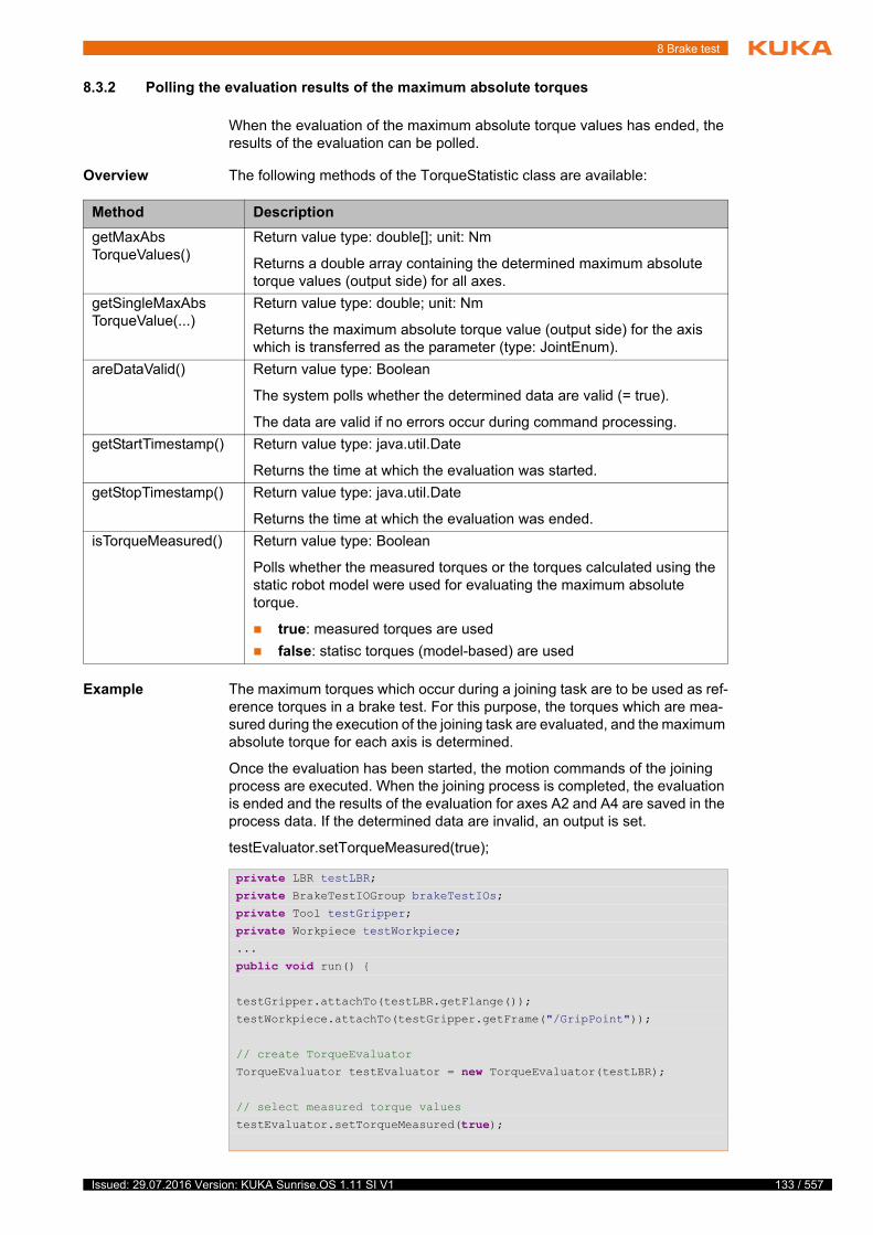
8 Brake test
8.3.2 Polling the evaluation results of the maximum absolute torques
When the evaluation of the maximum absolute torque values has ended, the results of the evaluation can be polled.
Overview The following methods of the TorqueStatistic class are available:
Example The maximum torques which occur during a joining task are to be used as ref-erence torques in a brake test. For this purpose, the torques which are mea-sured during the execution of the joining task are evaluated, and the maximum absolute torque for each axis is determined.
Once the evaluation has been started, the motion commands of the joining process are executed. When the joining process is completed, the evaluation is ended and the results of the evaluation for axes A2 and A4 are saved in the process data. If the determined data are invalid, an output is set.
testEvaluator.setTorqueMeasured(true);
Method Description
getMaxAbsTorqueValues()
Return value type: double[]; unit: Nm
Returns a double array containing the determined maximum absolute torque values (output side) for all axes.
getSingleMaxAbsTorqueValue(...)
Return value type: double; unit: Nm
Returns the maximum absolute torque value (output side) for the axis which is transferred as the parameter (type: JointEnum).
areDataValid() Return value type: Boolean
The system polls whether the determined data are valid (= true).
The data are valid if no errors occur during command processing.
getStartTimestamp() Return value type: java.util.Date
Returns the time at which the evaluation was started.
getStopTimestamp() Return value type: java.util.Date
Returns the time at which the evaluation was ended.
isTorqueMeasured() Return value type: Boolean
Polls whether the measured torques or the torques calculated using the static robot model were used for evaluating the maximum absolute torque.
true: measured torques are used
false: statisc torques (model-based) are used
private LBR testLBR;private BrakeTestIOGroup brakeTestIOs;private Tool testGripper;private Workpiece testWorkpiece;...
public void run() {
testGripper.attachTo(testLBR.getFlange());
testWorkpiece.attachTo(testGripper.getFrame("/GripPoint"));
// create TorqueEvaluator
TorqueEvaluator testEvaluator = new TorqueEvaluator(testLBR);
// select measured torque values
testEvaluator.setTorqueMeasured(true);
133 / 557Issued: 29.07.2016 Version: KUKA Sunrise.OS 1.11 SI V1
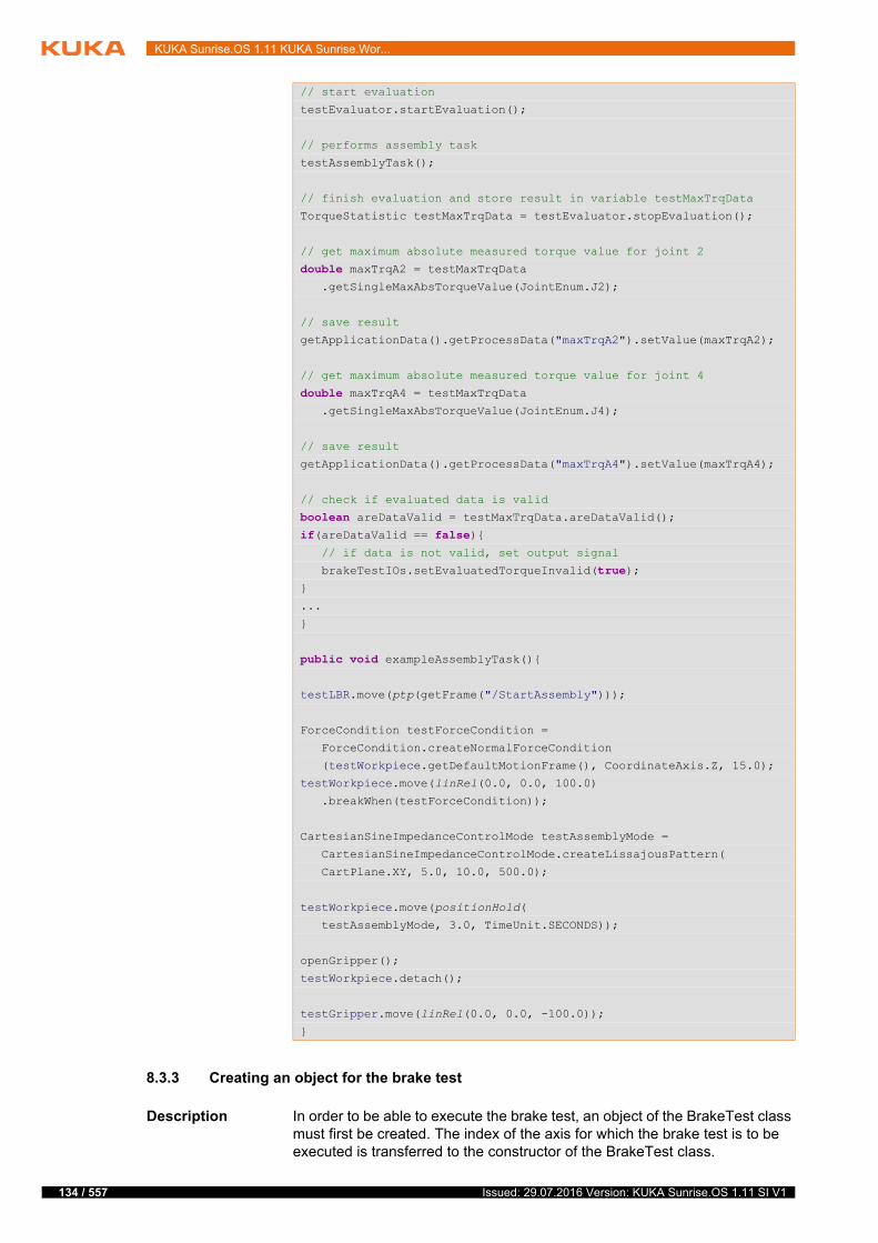
134 / 557
KUKA Sunrise.OS 1.11 KUKA Sunrise.Wor...
8.3.3 Creating an object for the brake test
Description In order to be able to execute the brake test, an object of the BrakeTest class must first be created. The index of the axis for which the brake test is to be executed is transferred to the constructor of the BrakeTest class.
// start evaluation
testEvaluator.startEvaluation();
// performs assembly task
testAssemblyTask();
// finish evaluation and store result in variable testMaxTrqData
TorqueStatistic testMaxTrqData = testEvaluator.stopEvaluation();
// get maximum absolute measured torque value for joint 2
double maxTrqA2 = testMaxTrqData .getSingleMaxAbsTorqueValue(JointEnum.J2);
// save result
getApplicationData().getProcessData("maxTrqA2").setValue(maxTrqA2);
// get maximum absolute measured torque value for joint 4
double maxTrqA4 = testMaxTrqData .getSingleMaxAbsTorqueValue(JointEnum.J4);
// save result
getApplicationData().getProcessData("maxTrqA4").setValue(maxTrqA4);
// check if evaluated data is valid
boolean areDataValid = testMaxTrqData.areDataValid();if(areDataValid == false){ // if data is not valid, set output signal
brakeTestIOs.setEvaluatedTorqueInvalid(true);}
...
}
public void exampleAssemblyTask(){
testLBR.move(ptp(getFrame("/StartAssembly")));
ForceCondition testForceCondition =
ForceCondition.createNormalForceCondition
(testWorkpiece.getDefaultMotionFrame(), CoordinateAxis.Z, 15.0);
testWorkpiece.move(linRel(0.0, 0.0, 100.0)
.breakWhen(testForceCondition));
CartesianSineImpedanceControlMode testAssemblyMode =
CartesianSineImpedanceControlMode.createLissajousPattern(
CartPlane.XY, 5.0, 10.0, 500.0);
testWorkpiece.move(positionHold(
testAssemblyMode, 3.0, TimeUnit.SECONDS));
openGripper();
testWorkpiece.detach();
testGripper.move(linRel(0.0, 0.0, -100.0));
}
Issued: 29.07.2016 Version: KUKA Sunrise.OS 1.11 SI V1

8 Brake test
Optionally, the torque parameter can be used to transfer a reference holding torque, e.g. the maximum absolute axis torque which occurs in a specific ap-plication.
As a general rule, the brake test must check whether the brakes apply the min-imum brake holding torque. It is therefore advisable not to specify the torque parameter.
Syntax BrakeTest brakeTest = new BrakeTest(axis, <torque>);
Explanation of
the syntax
8.3.4 Starting the execution of the brake test
Description The brake test is executed by a motion command which is made available via the BrakeTest class. In order to execute the brake test, the move(…) or move-Async(…) method is called with the robot instance used in the application, and the object created for the brake test is transferred.
Element Description
brakeTest Type: BrakeTest
Variable to which the created BrakeTest instance is assigned. The execution of the brake test is commanded via the variable as a motion command.
axis Type: int
Index of the axis whose brake is to be tested.
0 … 6: Axes A1 … A7
torque Type: double; unit: Nm
Reference holding torque (output side) specified by the user, e.g. the maximum absolute torque that has been determined beforehand for an axis-specific motion sequence.
If no reference holidng torque is specified, the brake test uses the lowest of the following values as the holding torque: minimum brake holding torque or motor holding torque.
If a reference holding torque is specified, one of the follow-ing values is used as the holding torque to be tested: the specified reference holding torque (torque), the minimum brake holding torque or the motor torque.
The holding torque to be tested is defined internally by the system according to the following rules:
1. If the reference holding torque is greater than the lowest value of the minimum brake and motor holding torques, then the lowest value of the minimum brake and motor holding torques is used as the holding torque to be test-ed.
2. If the reference holding torque is lower than 20% of the lowest value of the minimum brake and motor holding torques, then 20% of the lowest value of the minimum brake and motor holding torques is used as the holding torque to be tested.
3. In all other cases, the reference holding torque is used.
Note: The minimum and maximum brake holding torques are saved in the motor data. The motor holding torque is derived from the motor data.
135 / 557Issued: 29.07.2016 Version: KUKA Sunrise.OS 1.11 SI V1
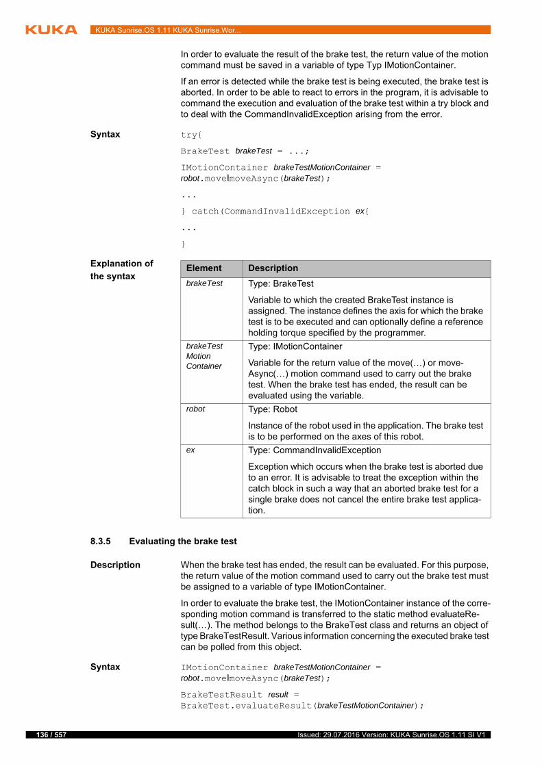
136 / 557
KUKA Sunrise.OS 1.11 KUKA Sunrise.Wor...
In order to evaluate the result of the brake test, the return value of the motion command must be saved in a variable of type Typ IMotionContainer.
If an error is detected while the brake test is being executed, the brake test is aborted. In order to be able to react to errors in the program, it is advisable to command the execution and evaluation of the brake test within a try block and to deal with the CommandInvalidException arising from the error.
Syntax try{
BrakeTest brakeTest = ...;
IMotionContainer brakeTestMotionContainer = robot.moveΙmoveAsync(brakeTest);
...
} catch(CommandInvalidException ex{
...
}
Explanation of
the syntax
8.3.5 Evaluating the brake test
Description When the brake test has ended, the result can be evaluated. For this purpose, the return value of the motion command used to carry out the brake test must be assigned to a variable of type IMotionContainer.
In order to evaluate the brake test, the IMotionContainer instance of the corre-sponding motion command is transferred to the static method evaluateRe-sult(…). The method belongs to the BrakeTest class and returns an object of type BrakeTestResult. Various information concerning the executed brake test can be polled from this object.
Syntax IMotionContainer brakeTestMotionContainer = robot.moveΙmoveAsync(brakeTest);
BrakeTestResult result = BrakeTest.evaluateResult(brakeTestMotionContainer);
Element Description
brakeTest Type: BrakeTest
Variable to which the created BrakeTest instance is assigned. The instance defines the axis for which the brake test is to be executed and can optionally define a reference holding torque specified by the programmer.
brakeTestMotionContainer
Type: IMotionContainer
Variable for the return value of the move(…) or move-Async(…) motion command used to carry out the brake test. When the brake test has ended, the result can be evaluated using the variable.
robot Type: Robot
Instance of the robot used in the application. The brake test is to be performed on the axes of this robot.
ex Type: CommandInvalidException
Exception which occurs when the brake test is aborted due to an error. It is advisable to treat the exception within the catch block in such a way that an aborted brake test for a single brake does not cancel the entire brake test applica-tion.
Issued: 29.07.2016 Version: KUKA Sunrise.OS 1.11 SI V1
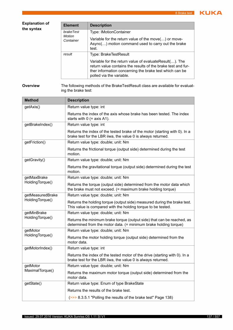
8 Brake test
Explanation of
the syntax
Overview The following methods of the BrakeTestResult class are available for evaluat-ing the brake test:
Element Description
brakeTestMotionContainer
Type: IMotionContainer
Variable for the return value of the move(…) or move-Async(…) motion command used to carry out the brake test.
result Type: BrakeTestResult
Variable for the return value of evaluateResult(…). The return value contains the results of the brake test and fur-ther information concerning the brake test which can be polled via the variable.
Method Description
getAxis() Return value type: int
Returns the index of the axis whose brake has been tested. The index starts with 0 (= axis A1).
getBrakeIndex() Return value type: int
Returns the index of the tested brake of the motor (starting with 0). In a brake test for the LBR iiwa, the value 0 is always returned.
getFriction() Return value type: double; unit: Nm
Returns the frictional torque (output side) determined during the test motion.
getGravity() Return value type: double; unit: Nm
Returns the gravitational torque (output side) determined during the test motion.
getMaxBrakeHoldingTorque()
Return value type: double; unit: Nm
Returns the torque (output side) determined from the motor data which the brake must not exceed. (= maximum brake holding torque)
getMeasuredBrakeHoldingTorque()
Return value type: double; unit: Nm
Returns the holding torque (output side) measured during the brake test. This value is compared with the holding torque to be tested.
getMinBrakeHoldingTorque()
Return value type: double; unit: Nm
Returns the minimum brake torque (output side) that can be reached, as determined from the motor data. (= minimum brake holding torque)
getMotorHoldingTorque()
Return value type: double; unit: Nm
Returns the motor holding torque (output side) determined from the motor data.
getMotorIndex() Return value type: int
Returns the index of the tested motor of the drive (starting with 0). In a brake test for the LBR iiwa, the value 0 is always returned.
getMotorMaximalTorque()
Return value type: double; unit: Nm
Returns the maximum motor torque (output side) determined from the motor data.
getState() Return value type: Enum of type BrakeState
Returns the results of the brake test.
(>>> 8.3.5.1 "Polling the results of the brake test" Page 138)
137 / 557Issued: 29.07.2016 Version: KUKA Sunrise.OS 1.11 SI V1
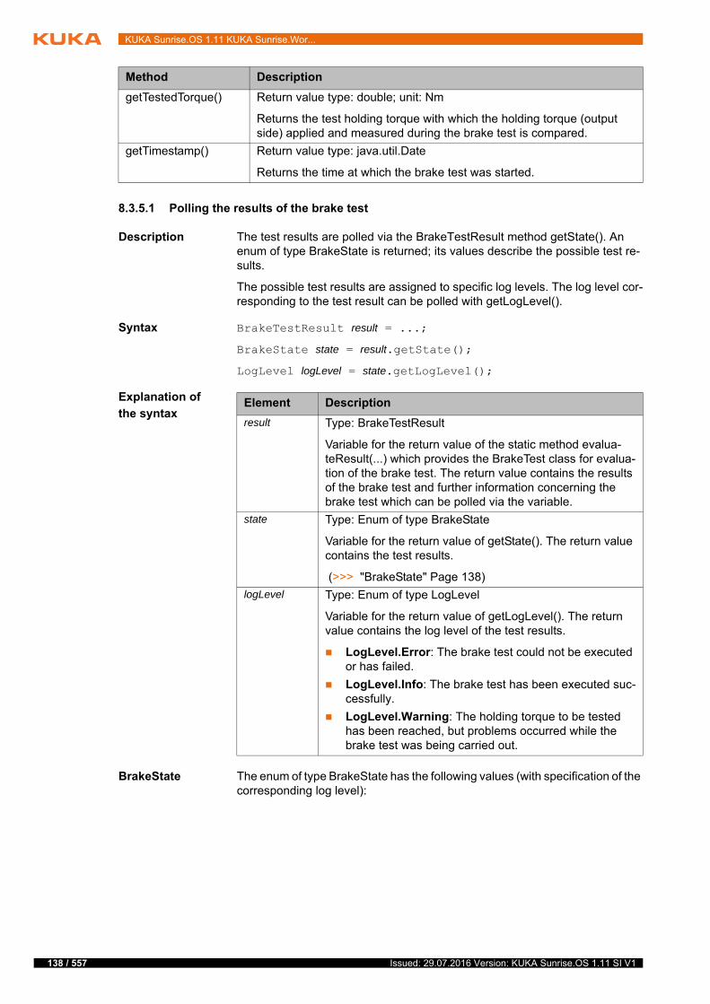
138 / 557
KUKA Sunrise.OS 1.11 KUKA Sunrise.Wor...
8.3.5.1 Polling the results of the brake test
Description The test results are polled via the BrakeTestResult method getState(). An enum of type BrakeState is returned; its values describe the possible test re-sults.
The possible test results are assigned to specific log levels. The log level cor-responding to the test result can be polled with getLogLevel().
Syntax BrakeTestResult result = ...;
BrakeState state = result.getState();
LogLevel logLevel = state.getLogLevel();
Explanation of
the syntax
BrakeState The enum of type BrakeState has the following values (with specification of the corresponding log level):
getTestedTorque() Return value type: double; unit: Nm
Returns the test holding torque with which the holding torque (output side) applied and measured during the brake test is compared.
getTimestamp() Return value type: java.util.Date
Returns the time at which the brake test was started.
Method Description
Element Description
result Type: BrakeTestResult
Variable for the return value of the static method evalua-teResult(...) which provides the BrakeTest class for evalua-tion of the brake test. The return value contains the results of the brake test and further information concerning the brake test which can be polled via the variable.
state Type: Enum of type BrakeState
Variable for the return value of getState(). The return value contains the test results.
(>>> "BrakeState" Page 138)
logLevel Type: Enum of type LogLevel
Variable for the return value of getLogLevel(). The return value contains the log level of the test results.
LogLevel.Error: The brake test could not be executed or has failed.
LogLevel.Info: The brake test has been executed suc-cessfully.
LogLevel.Warning: The holding torque to be tested has been reached, but problems occurred while the brake test was being carried out.
Issued: 29.07.2016 Version: KUKA Sunrise.OS 1.11 SI V1
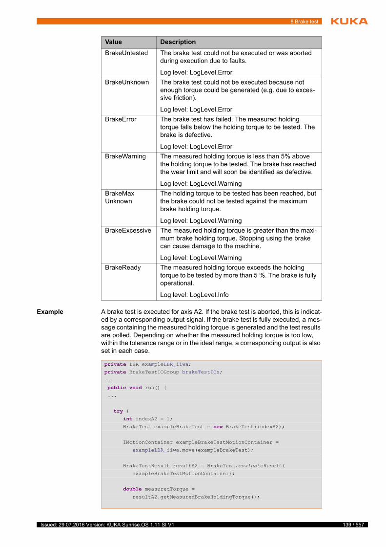
8 Brake test
Example A brake test is executed for axis A2. If the brake test is aborted, this is indicat-ed by a corresponding output signal. If the brake test is fully executed, a mes-sage containing the measured holding torque is generated and the test results are polled. Depending on whether the measured holding torque is too low, within the tolerance range or in the ideal range, a corresponding output is also set in each case.
Value Description
BrakeUntested The brake test could not be executed or was aborted during execution due to faults.
Log level: LogLevel.Error
BrakeUnknown The brake test could not be executed because not enough torque could be generated (e.g. due to exces-sive friction).
Log level: LogLevel.Error
BrakeError The brake test has failed. The measured holding torque falls below the holding torque to be tested. The brake is defective.
Log level: LogLevel.Error
BrakeWarning The measured holding torque is less than 5% above the holding torque to be tested. The brake has reached the wear limit and will soon be identified as defective.
Log level: LogLevel.Warning
BrakeMaxUnknown
The holding torque to be tested has been reached, but the brake could not be tested against the maximum brake holding torque.
Log level: LogLevel.Warning
BrakeExcessive The measured holding torque is greater than the maxi-mum brake holding torque. Stopping using the brake can cause damage to the machine.
Log level: LogLevel.Warning
BrakeReady The measured holding torque exceeds the holding torque to be tested by more than 5 %. The brake is fully operational.
Log level: LogLevel.Info
private LBR exampleLBR_iiwa;private BrakeTestIOGroup brakeTestIOs;...
public void run() { ...
try { int indexA2 = 1; BrakeTest exampleBrakeTest = new BrakeTest(indexA2);
IMotionContainer exampleBrakeTestMotionContainer =
exampleLBR_iiwa.move(exampleBrakeTest);
BrakeTestResult resultA2 = BrakeTest.evaluateResult(
exampleBrakeTestMotionContainer);
double measuredTorque = resultA2.getMeasuredBrakeHoldingTorque();
139 / 557Issued: 29.07.2016 Version: KUKA Sunrise.OS 1.11 SI V1

140 / 557
KUKA Sunrise.OS 1.11 KUKA Sunrise.Wor...
8.4 Performing a brake test
Description If the brake test application is paused while a brake is being tested (e.g. by pressing the Start button on the smartPAD or due to a stop request), the brake test is aborted.
If the brake test application is resumed, the aborted brake test will be repeated for the axis in question. If the axis is no longer in the position in which the abort-ed brake test was started, it must be repositioned by pressing the Start key. Only then can the application be resumed.
Precondition The brake test application has been configured and is available on the ro-bot controller.
No persons or objects are present within the motion range of the robot.
Program run mode Continuous (standard mode)
The robot is at operating temperature.
Procedure Select and start the brake test application.
a. If configured (optional LBR iiwa): the torques measured during a mo-tion sequence are evaluated for each axis, and the maximum absolute torque for each axis is determined.
The result of the evaluation is displayed on the smartHMI.
b. The brakes are tested one after the other, starting with axis A1.
The brake test results are displayed individually for each axis on the smartHMI.
getLogger().info("Measured torque for A2: " + measuredTorque);
BrakeState state = resultA2.getState();
if(state == BrakeState.BrakeError)
brakeTestIOs.setA2_BrakeError(true); else if(state == BrakeState.BrakeWarning)
brakeTestIOs.setA2_BrakeWarning(true); else if(state == BrakeState.BrakeReady)
brakeTestIOs.setA2_BrakeOK(true);
} catch (CommandInvalidException ex) { brakeTestIOs.setBrakeTest_Aborted(true); ex.printStackTrace();
}
}
If the functional capability of a brake is not guaranteed and the drives are switched off, the robot can sag. If, dur-
ing the brake test, a brake is identified as being defective (test result = "Failed"), the robot must be taken out of operation immediately.
Issued: 29.07.2016 Version: KUKA Sunrise.OS 1.11 SI V1
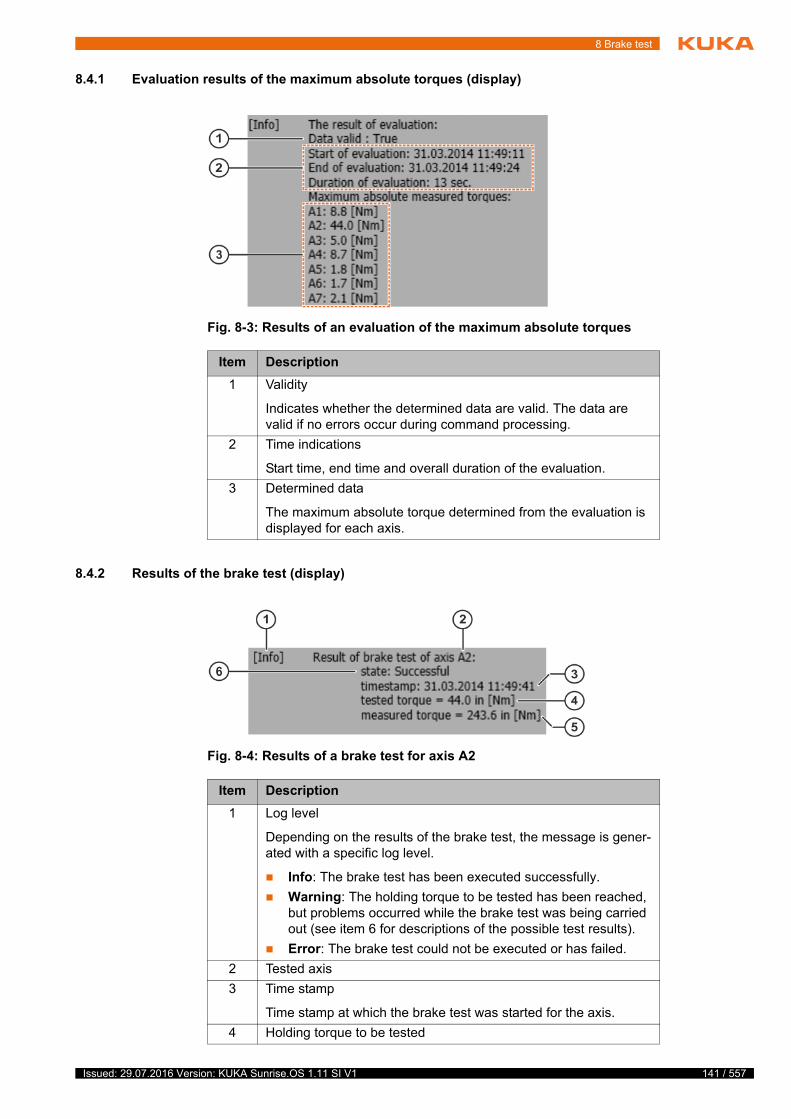
8 Brake test
8.4.1 Evaluation results of the maximum absolute torques (display)
8.4.2 Results of the brake test (display)
Fig. 8-3: Results of an evaluation of the maximum absolute torques
Item Description
1 Validity
Indicates whether the determined data are valid. The data are valid if no errors occur during command processing.
2 Time indications
Start time, end time and overall duration of the evaluation.
3 Determined data
The maximum absolute torque determined from the evaluation is displayed for each axis.
Fig. 8-4: Results of a brake test for axis A2
Item Description
1 Log level
Depending on the results of the brake test, the message is gener-ated with a specific log level.
Info: The brake test has been executed successfully.
Warning: The holding torque to be tested has been reached, but problems occurred while the brake test was being carried out (see item 6 for descriptions of the possible test results).
Error: The brake test could not be executed or has failed.
2 Tested axis
3 Time stamp
Time stamp at which the brake test was started for the axis.
4 Holding torque to be tested
141 / 557Issued: 29.07.2016 Version: KUKA Sunrise.OS 1.11 SI V1
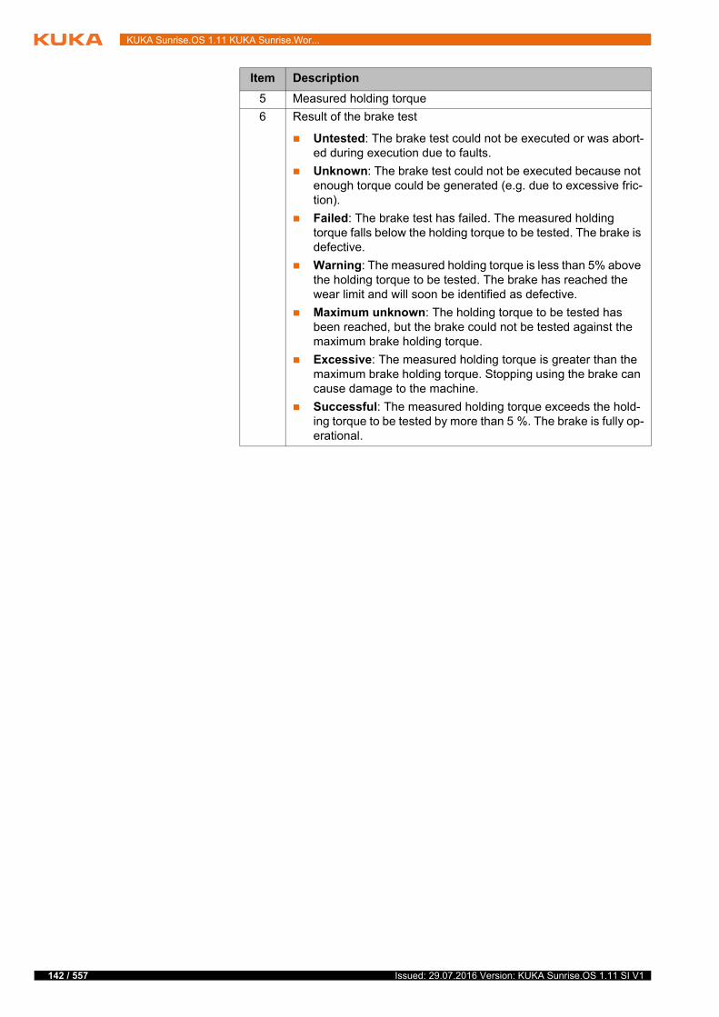
142 / 557
KUKA Sunrise.OS 1.11 KUKA Sunrise.Wor...
5 Measured holding torque
6 Result of the brake test
Untested: The brake test could not be executed or was abort-ed during execution due to faults.
Unknown: The brake test could not be executed because not enough torque could be generated (e.g. due to excessive fric-tion).
Failed: The brake test has failed. The measured holding torque falls below the holding torque to be tested. The brake is defective.
Warning: The measured holding torque is less than 5% above the holding torque to be tested. The brake has reached the wear limit and will soon be identified as defective.
Maximum unknown: The holding torque to be tested has been reached, but the brake could not be tested against the maximum brake holding torque.
Excessive: The measured holding torque is greater than the maximum brake holding torque. Stopping using the brake can cause damage to the machine.
Successful: The measured holding torque exceeds the hold-ing torque to be tested by more than 5 %. The brake is fully op-erational.
Item Description
Issued: 29.07.2016 Version: KUKA Sunrise.OS 1.11 SI V1

9 Project management
9 Project management
9.1 Sunrise projects – overview
A Sunrise project contains all the data which are required for the operation of a station. A Sunrise project comprises:
Station configuration
The station configuration describes the static properties of the station. Ex-amples include hardware and software components.
Applications
Applications contain the source code for executing a task for the station. They are programmed in Java with KUKA Sunrise.Workbench and are ex-ecuted on the robot controller. A Sunrise project can have any number of applications.
Runtime data
Runtime data are all the data which are used by the applications during the runtime. These include, for example, end points for motions, tool data and process parameters.
Safety configuration
The safety configuration contains the configured safety functions.
I/O configuration (optional)
The I/O configuration contains the inputs/outputs of the used field buses mapped in WorkVisual. The inputs/outputs can be used in the application.
Sunrise projects are created and managed with KUKA Sunrise.Workbench.
(>>> 5.3 "Creating a Sunrise project with a template" Page 51)
There may only be 1 Sunrise project on the robot controller at any one time. This is transferred from Sunrise.Workbench to the robot controller by means of project synchronization.
(>>> 9.5 "Project synchronization, overview" Page 161)
9.2 Frame management
Overview Frames are coordinate transformations which describe the position of points in space or objects in a station. The coordinate transformations are arranged hierarchically in a tree structure. In this hierarchy, each frame has a higher-lev-el parent frame with which it is linked through the transformation.
The root element or origin of the transformation is the world coordinate system which by default is located at the robot base. This means that all frames are directly or indirectly related to the world coordinate system.
A transformation describes the relative position of 2 coordinate systems to each other, i.e. how a frame is offset and oriented with respect to its parent frame.
The position of a frame with respect to its parent frame is defined by the fol-lowing transformation data:
X, Y, Z: offset of the origin along the axes of the parent frame
A, B, C: rotational offset of the axis angles of the parent frame
Rotational angle of the frames:
Angle A: rotation about the Z axis
Angle B: rotation about the Y axis
Angle C: rotation about the X axis
j
t
143 / 557Issued: 29.07.2016 Version: KUKA Sunrise.OS 1.11 SI V1
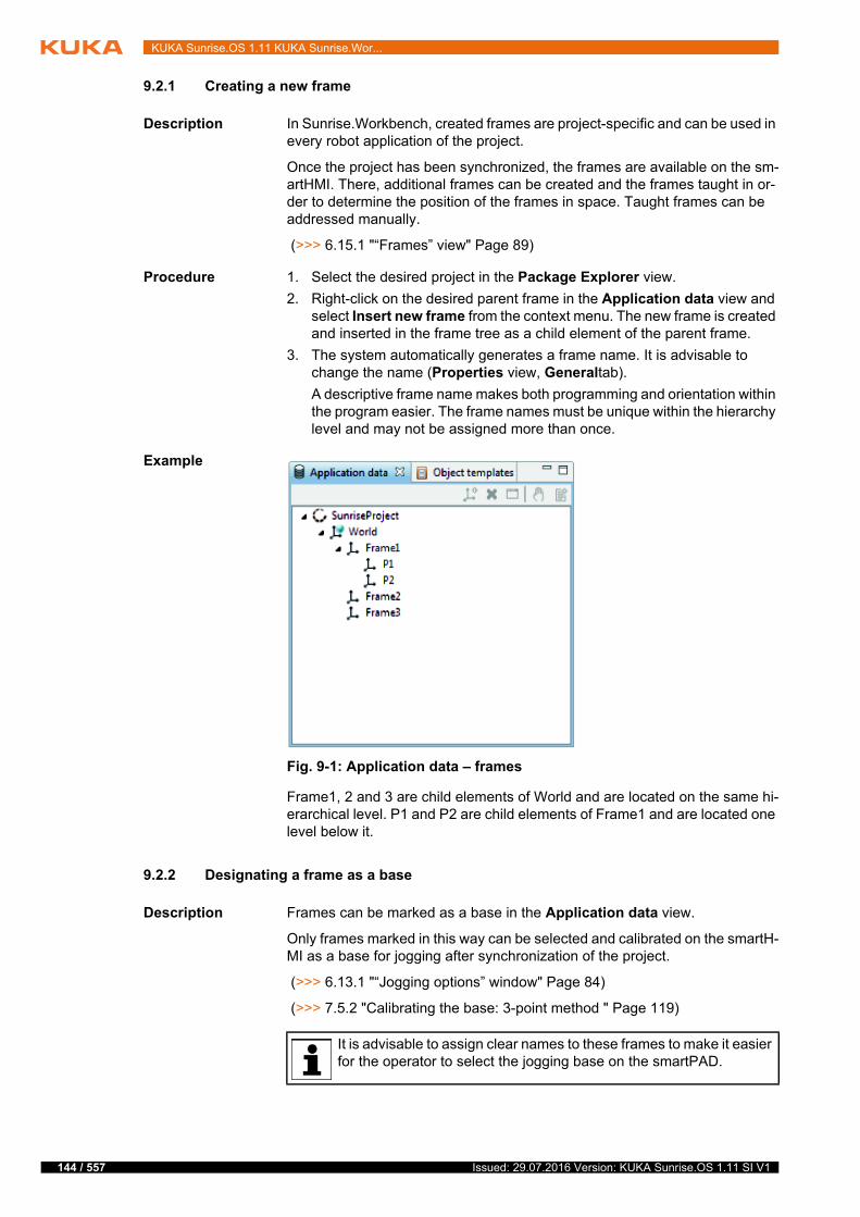
144 / 557
KUKA Sunrise.OS 1.11 KUKA Sunrise.Wor...
9.2.1 Creating a new frame
Description In Sunrise.Workbench, created frames are project-specific and can be used in every robot application of the project.
Once the project has been synchronized, the frames are available on the sm-artHMI. There, additional frames can be created and the frames taught in or-der to determine the position of the frames in space. Taught frames can be addressed manually.
(>>> 6.15.1 "“Frames” view" Page 89)
Procedure 1. Select the desired project in the Package Explorer view.
2. Right-click on the desired parent frame in the Application data view and select Insert new frame from the context menu. The new frame is created and inserted in the frame tree as a child element of the parent frame.
3. The system automatically generates a frame name. It is advisable to change the name (Properties view, Generaltab).
A descriptive frame name makes both programming and orientation within the program easier. The frame names must be unique within the hierarchy level and may not be assigned more than once.
Example
Frame1, 2 and 3 are child elements of World and are located on the same hi-erarchical level. P1 and P2 are child elements of Frame1 and are located one level below it.
9.2.2 Designating a frame as a base
Description Frames can be marked as a base in the Application data view.
Only frames marked in this way can be selected and calibrated on the smartH-MI as a base for jogging after synchronization of the project.
(>>> 6.13.1 "“Jogging options” window" Page 84)
(>>> 7.5.2 "Calibrating the base: 3-point method " Page 119)
Fig. 9-1: Application data – frames
It is advisable to assign clear names to these frames to make it easier for the operator to select the jogging base on the smartPAD.
Issued: 29.07.2016 Version: KUKA Sunrise.OS 1.11 SI V1
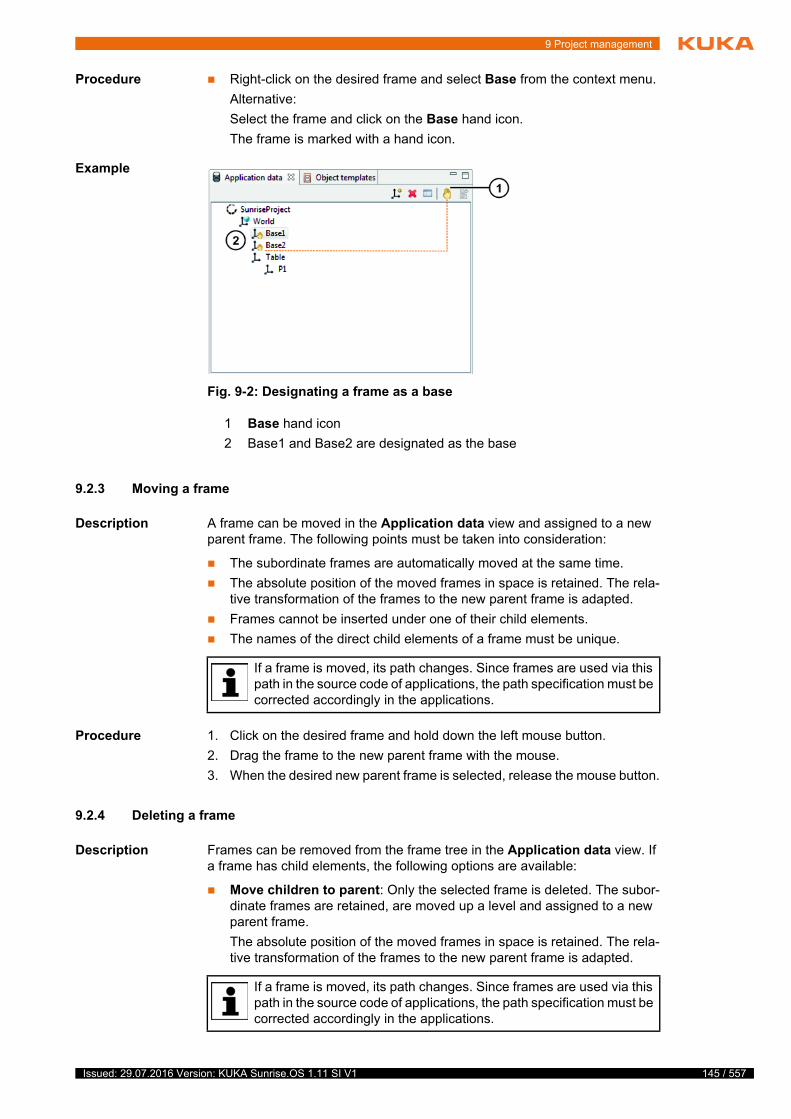
9 Project management
Procedure Right-click on the desired frame and select Base from the context menu.
Alternative:
Select the frame and click on the Base hand icon.
The frame is marked with a hand icon.
Example
9.2.3 Moving a frame
Description A frame can be moved in the Application data view and assigned to a new parent frame. The following points must be taken into consideration:
The subordinate frames are automatically moved at the same time.
The absolute position of the moved frames in space is retained. The rela-tive transformation of the frames to the new parent frame is adapted.
Frames cannot be inserted under one of their child elements.
The names of the direct child elements of a frame must be unique.
Procedure 1. Click on the desired frame and hold down the left mouse button.
2. Drag the frame to the new parent frame with the mouse.
3. When the desired new parent frame is selected, release the mouse button.
9.2.4 Deleting a frame
Description Frames can be removed from the frame tree in the Application data view. If a frame has child elements, the following options are available:
Move children to parent: Only the selected frame is deleted. The subor-dinate frames are retained, are moved up a level and assigned to a new parent frame.
The absolute position of the moved frames in space is retained. The rela-tive transformation of the frames to the new parent frame is adapted.
Fig. 9-2: Designating a frame as a base
1 Base hand icon
2 Base1 and Base2 are designated as the base
If a frame is moved, its path changes. Since frames are used via this path in the source code of applications, the path specification must be corrected accordingly in the applications.
If a frame is moved, its path changes. Since frames are used via this path in the source code of applications, the path specification must be corrected accordingly in the applications.
145 / 557Issued: 29.07.2016 Version: KUKA Sunrise.OS 1.11 SI V1

146 / 557
KUKA Sunrise.OS 1.11 KUKA Sunrise.Wor...
Delete parent and child frames: Deletes the selected frame and all sub-ordinate frames.
Procedure 1. Right-click on the frame to be deleted and select Delete from the context menu. A frame without child elements is deleted immediately.
2. If the frame has child elements, the system asks whether these should also be deleted. Select the desired option.
3. Only with the Move children to parent option: if a name conflict occurs when moving the child elements, a notification message appears and the delete operation is canceled.
Remedy: Rename one of the frames in question and repeat the delete op-eration.
9.2.5 Displaying/editing frame properties
Procedure 1. Select the frame in the Application data view. The properties of the frame are displayed in the Properties view, distributed over various tabs. Some of the properties can be edited, others are for display only.
2. Select the desired tab and enter the new value.
9.2.6 Properties view for frames in application data
9.2.6.1 “General” tab
The General tab contains general information relating to the frame.
The position and orientation of a frame is generally defined during teaching with the robot. However, it is also possible to enter the posi-tion values of a frame manually or to change them at a later stage.
The following points must be taken into consideration:
Modifying the transformation data not only moves the current frame but also all of its subordinate child elements, and it applies to all applications in which these frames are used.
The taught values of Status, Turn and redundancy angle are retained. Under certain circumstances, it may no longer be possible to address the frame or its child elements.
After a modification to the transformation data, all programs in which the frame is used must be tested in Manual Reduced Velocity mode (T1).
For physical variables, the value can be entered with the unit. If this is compatible with the preset unit, the value is converted accordingly, e.g. cm into mm or ° into rad. If no unit is entered, the preset unit is
used.
Parameter Description
Name Name of the frame
Comment A comment on the frame can be entered here (optional).
Project Project in which the frame was created (display only)
Last modification Date and time of the last modification (display only)
Issued: 29.07.2016 Version: KUKA Sunrise.OS 1.11 SI V1
9 Project management
9.2.6.2 “Transformation” tab
The Transformation tab contains the transformation data of the frame.
9.2.6.3 “Redundancy” tab
The Redundancy tab contains the redundancy information relating to the frame.
9.2.6.4 “Teach information” tab
The Teach information tab contains information about a taught frame (dis-play only).
9.2.6.5 “Measurement” tab
The Measurement tab contains information about base calibration (for frames marked as a base; display only).
Parameter Description
X, Y, Z Translational offset of the frame relative to its parent frame
A, B, C Rotational offset of the frame relative to its par-ent frame
If the transformation data of a frame that has been calibrated as a base are edited, the calibration information is deleted.
Parameter Description
E1 Value of the redundancy angle
(>>> 9.2.6.3 "“Redundancy” tab" Page 147)
Status (>>> 14.10.2 "Status" Page 320)
Turn (>>> 14.10.3 "Turn" Page 321)
Parameter Description
Device Robot that was used for teaching
Tool Tool that was used for teaching
TCP Frame path for the TCP that was used for teach-ing
X, Y, Z Translational offset of the TCP relative to the ori-gin frame of the tool
A, B, C Rotational offset of the TCP relative to the origin frame of the tool
If a frame that has been calibrated as a base is retaught, the calibra-tion information is deleted.
Parameter Description
Measurement method
Method used
Last modification Date and time of the last modification
147 / 557Issued: 29.07.2016 Version: KUKA Sunrise.OS 1.11 SI V1
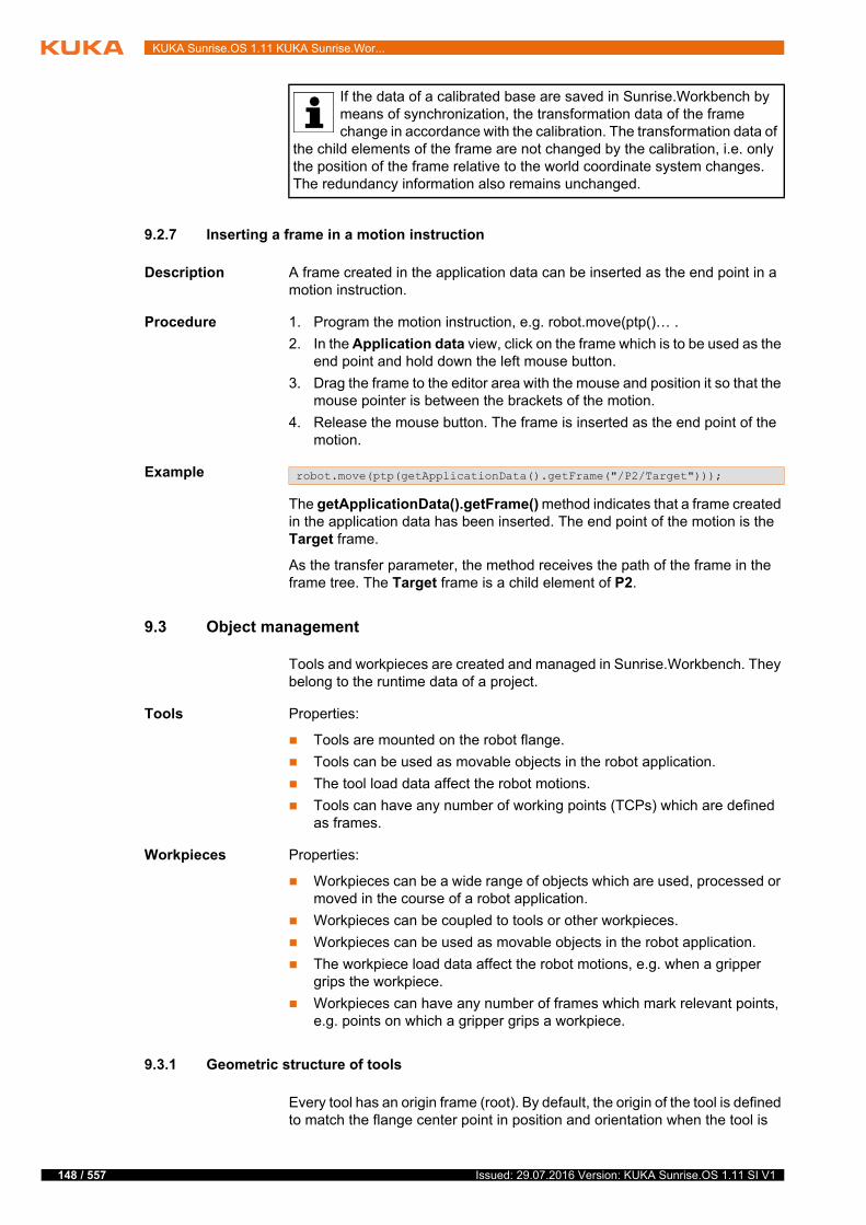
148 / 557
KUKA Sunrise.OS 1.11 KUKA Sunrise.Wor...
9.2.7 Inserting a frame in a motion instruction
Description A frame created in the application data can be inserted as the end point in a motion instruction.
Procedure 1. Program the motion instruction, e.g. robot.move(ptp()… .
2. In the Application data view, click on the frame which is to be used as the end point and hold down the left mouse button.
3. Drag the frame to the editor area with the mouse and position it so that the mouse pointer is between the brackets of the motion.
4. Release the mouse button. The frame is inserted as the end point of the motion.
Example
The getApplicationData().getFrame() method indicates that a frame created in the application data has been inserted. The end point of the motion is the Target frame.
As the transfer parameter, the method receives the path of the frame in the frame tree. The Target frame is a child element of P2.
9.3 Object management
Tools and workpieces are created and managed in Sunrise.Workbench. They belong to the runtime data of a project.
Tools Properties:
Tools are mounted on the robot flange.
Tools can be used as movable objects in the robot application.
The tool load data affect the robot motions.
Tools can have any number of working points (TCPs) which are defined as frames.
Workpieces Properties:
Workpieces can be a wide range of objects which are used, processed or moved in the course of a robot application.
Workpieces can be coupled to tools or other workpieces.
Workpieces can be used as movable objects in the robot application.
The workpiece load data affect the robot motions, e.g. when a gripper grips the workpiece.
Workpieces can have any number of frames which mark relevant points, e.g. points on which a gripper grips a workpiece.
9.3.1 Geometric structure of tools
Every tool has an origin frame (root). By default, the origin of the tool is defined to match the flange center point in position and orientation when the tool is
If the data of a calibrated base are saved in Sunrise.Workbench by means of synchronization, the transformation data of the frame change in accordance with the calibration. The transformation data of
the child elements of the frame are not changed by the calibration, i.e. only the position of the frame relative to the world coordinate system changes. The redundancy information also remains unchanged.
robot.move(ptp(getApplicationData().getFrame("/P2/Target")));
Issued: 29.07.2016 Version: KUKA Sunrise.OS 1.11 SI V1
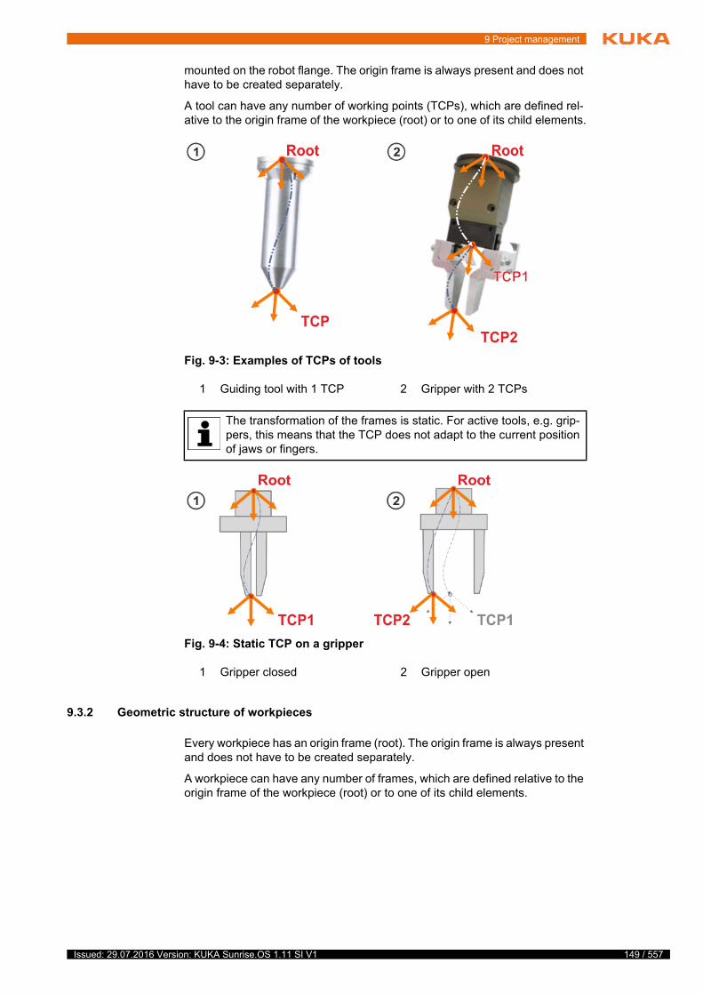
9 Project management
mounted on the robot flange. The origin frame is always present and does not have to be created separately.
A tool can have any number of working points (TCPs), which are defined rel-ative to the origin frame of the workpiece (root) or to one of its child elements.
9.3.2 Geometric structure of workpieces
Every workpiece has an origin frame (root). The origin frame is always present and does not have to be created separately.
A workpiece can have any number of frames, which are defined relative to the origin frame of the workpiece (root) or to one of its child elements.
Fig. 9-3: Examples of TCPs of tools
1 Guiding tool with 1 TCP 2 Gripper with 2 TCPs
The transformation of the frames is static. For active tools, e.g. grip-pers, this means that the TCP does not adapt to the current position of jaws or fingers.
Fig. 9-4: Static TCP on a gripper
1 Gripper closed 2 Gripper open
149 / 557Issued: 29.07.2016 Version: KUKA Sunrise.OS 1.11 SI V1

150 / 557
KUKA Sunrise.OS 1.11 KUKA Sunrise.Wor...
9.3.3 Creating a tool or workpiece
Description Tools and workpieces created in Sunrise.Workbench are project-specific and can be used in every robot application of the project.
The created tools can be selected in the jogging options on the smartHMI after the project is synchronized.
(>>> 6.13.1 "“Jogging options” window" Page 84)
Procedure 1. Select the project in the Package Explorer.
2. In the Object templates view, open the list of object templates.
3. To create a tool, right-click on the object type Template Group for Tools and select Insert new tool from the context menu. The object template for the tool is created.
4. To create a workpiece, right-click on the object type Template Group for Workpieces and select Insert new workpiece from the context menu. The object template for the workpiece is created.
5. The system automatically generates an object name. It is advisable to change the name in the Properties view.
The object names must be unique. A descriptive name makes both pro-gramming and orientation within the program easier.
6. Enter the load data in the Properties view.
(>>> 9.3.8 "Load data" Page 153)
9.3.4 Creating a frame for a tool or workpiece
Description Each frame created for a tool or workpiece can be programmed in the robot application as the reference point for motions.
After the project is synchronized, the frames of a tool can be selected as the TCP for Cartesian jogging on the smartHMI.
(>>> 6.13.1 "“Jogging options” window" Page 84)
The frames of a tool (TCPs) can be calibrated with robot relative to the flange coordinate system.
(>>> 7.5.1 "Tool calibration" Page 113)
Fig. 9-5: Examples of frames of workpieces
Issued: 29.07.2016 Version: KUKA Sunrise.OS 1.11 SI V1
9 Project management
If the data of a calibrated tool are saved in Sunrise.Workbench by means of synchronization, the transformation data of the frame change in accordance with the calibration.
Procedure 1. Select the desired project in the Package Explorer view.
2. In the Object templates view, open the list of object templates.
3. Right-click on the object template and select Insert new frame from the context menu. The frame is created.
At the top hierarchy level, the parent frame of the created frame is the or-igin frame of the object.
4. To insert a new frame under an existing frame of the object, right-click on this parent frame and select Insert new frame from the context menu. The frame is created.
5. The system automatically generates a frame name. It is advisable to change the name (Properties view, Generaltab).
A descriptive frame name makes both programming and orientation within the program easier. The frame names must be unique within the hierarchy level and may not be assigned more than once.
6. Enter the transformation data of the frame with respect to its parent frame (Properties view, Transformationtab).
Boxes X, Y, Z: Offset of the frame along the axes of the parent frame
Boxes A, B, C: Orientation of the frame relative to the parent frame
9.3.5 Displaying/editing frame properties
Procedure 1. Select the frame in the Object templates view. The properties of the frame are displayed in the Properties view, distributed over various tabs.
2. Select the desired tab and enter the new value.
9.3.6 Properties view for frames in object templates
9.3.6.1 “General” tab
The General tab contains general information relating to the frame.
9.3.6.2 “Transformation” tab
The Transformation tab contains the transformation data of the frame.
The tool data of the TCP used to execute a Cartesian motion influ-ence the robot velocity. Incorrectly entered tool data can cause unex-pectedly high Cartesian velocities at the installed tool. The velocity of
250 mm/s may be exceeded in T1 mode.
For physical variables, the value can be entered with the unit. If this is compatible with the preset unit, the value is converted accordingly, e.g. cm into mm or ° into rad. If no unit is entered, the preset unit is
used.
Parameter Description
Name Name of the frame
Comment A comment on the frame can be entered here (optional).
151 / 557Issued: 29.07.2016 Version: KUKA Sunrise.OS 1.11 SI V1

152 / 557
KUKA Sunrise.OS 1.11 KUKA Sunrise.Wor...
The value ranges apply to safety-oriented frames of tools. Frames with trans-formation data outside this range of values cannot be used as safety-oriented frames.
9.3.6.3 “Safety” tab
Safety-oriented tool frames can be configured on the Safety tab. The tab is not available for frames of workpieces.
9.3.6.4 “Measurement” tab
The Measurement tab contains information about tool calibration (display on-ly).
9.3.7 Defining a default motion frame
Description If a tool or workpiece has a frame with which a large part of the motions must be executed, this frame can be defined as the default frame for motions.
Parameter Description
X, Y, Z Translational offset of the frame relative to its parent frame
-10,000 mm … +10,000 mm
A, B, C Rotational offset of the frame relative to its par-ent frame
Any
Parameter Description
Radius Radius of the sphere on the safety-oriented frame
25 … 10000 mm
Safety-oriented Check box active: Frame is safety-oriented frame
Check box not active: Frame is not a safety-oriented frame
The check box can only be edited under the fol-lowing conditions:
The frame belongs to a safety-oriented tool.
A permissible value has been entered for the radius.
(>>> 9.3.9 "Safety-oriented tools" Page 154)
Parameter Description
Measurement method
Method used
Calculation error Translational or rotational calculation error which specifies the quality of the calibration (unit: mm or °)
Last modification Date and time of the last modification
If the transformation data of a calibrated tool are edited, the calibra-tion information is deleted.
Issued: 29.07.2016 Version: KUKA Sunrise.OS 1.11 SI V1
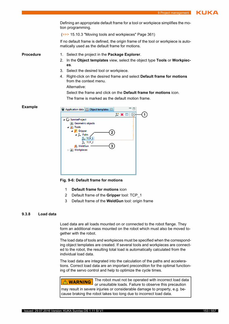
9 Project management
Defining an appropriate default frame for a tool or workpiece simplifies the mo-tion programming.
(>>> 15.10.3 "Moving tools and workpieces" Page 361)
If no default frame is defined, the origin frame of the tool or workpiece is auto-matically used as the default frame for motions.
Procedure 1. Select the project in the Package Explorer.
2. In the Object templates view, select the object type Tools or Workpiec-es.
3. Select the desired tool or workpiece.
4. Right-click on the desired frame and select Default frame for motions from the context menu.
Alternative:
Select the frame and click on the Default frame for motions icon.
The frame is marked as the default motion frame.
Example
9.3.8 Load data
Load data are all loads mounted on or connected to the robot flange. They form an additional mass mounted on the robot which must also be moved to-gether with the robot.
The load data of tools and workpieces must be specified when the correspond-ing object templates are created. If several tools and workpieces are connect-ed to the robot, the resulting total load is automatically calculated from the individual load data.
The load data are integrated into the calculation of the paths and accelera-tions. Correct load data are an important preconditon for the optimal function-ing of the servo control and help to optimize the cycle times.
Fig. 9-6: Default frame for motions
1 Default frame for motions icon
2 Default frame of the Gripper tool: TCP_1
3 Default frame of the WeldGun tool: origin frame
The robot must not be operated with incorrect load data or unsuitable loads. Failure to observe this precaution
may result in severe injuries or considerable damage to property, e.g. be-cause braking the robot takes too long due to incorrect load data.
153 / 557Issued: 29.07.2016 Version: KUKA Sunrise.OS 1.11 SI V1
154 / 557
KUKA Sunrise.OS 1.11 KUKA Sunrise.Wor...
Sources Load data can be obtained from the following sources:
Manufacturer information
Manual calculation
CAD programs
The load data of tools can be determined automatically.
(>>> 7.6 "Determining tool load data" Page 121)
9.3.8.1 Entering load data
Procedure 1. Select the desired project in the Package Explorer view.
2. In the Object templates view, open the list of object templates.
3. Select the desired tool or workpiece.
4. In the Properties view, select the Load data tab and enter the load data:
Mass: Mass of the object
Boxes MS X, MS Y, MS Z: Position of the center of mass relative to the origin frame of the object
Boxes MS A, MS B, MS C: Orientation of the principal inertia axes rel-ative to the origin frame of the object The principal inertia axes run through the center of mass.
Boxes jX, jY, jZ: Principal moments of inertia
Example Principal moment of inertia jX:
jX is the inertia about the X axis of the principal inertia axes. This is rotated through MS A, MS B and MS C relative to the origin frame of the object and shifted in the center of mass.
jY and jZ are the analogous principal moments of inertia about the Y and Z axes.
9.3.9 Safety-oriented tools
Description Up to 50 safety-oriented tools can be defined in a Sunrise project. Safety-ori-ented tools can each be modeled using up to 6 configurable spheres.
The properties of safety-oriented tools are relevant for the following configu-rable safety functions:
Monitoring of Cartesian spaces
The spheres can be monitored against the limits of activated Cartesian monitoring spaces.
(>>> 13.10.9 "Monitoring spaces" Page 248)
Monitoring of the translational Cartesian velocity
The velocity of the sphere center points is monitored.
(>>> 13.10.8 "Velocity monitoring functions" Page 240)
Collision detection and TCP force monitoring functions
Only correctly specified load data ensure the accuracy of these monitoring functions. The load data of safety-oriented tools, in particular the mass and center of mass of the tools, must be configured. In the case of tools with
comparatively high moments of inertia (> 0.1 kg m2), these data must also be specified in order to ensure the accuracy of these monitoring functions.
(>>> 13.10.13.2 "Collision detection" Page 261)
(>>> 13.10.13.3 "TCP force monitoring" Page 262)
(>>> 13.10.13.4 "Direction-specific monitoring of the external force on the TCP" Page 264)
Issued: 29.07.2016 Version: KUKA Sunrise.OS 1.11 SI V1

9 Project management
Safety-oriented
frames
Just like any other tool, a safety-oriented tool can have any number of frames. In order to configure the monitoring spheres, suitable frames must be defined as safety-oriented frames. The center of the sphere is situated, by definition, at the origin of the safety-oriented frame. The radius of the sphere is defined in the frame properties.
If workpieces are used that are to be taken into consideration for safety-orient-ed Cartesian space or velocity monitoring, e.g. due to the dimensions of the workpieces, the spheres of the safety-oriented tool must be configured ac-cordingly.
Safety-oriented frames are also relevant for the following configurable, tool-specific safety monitoring functions:
Monitoring of the tool orientation (only available for robots)
One of the safety-oriented frames can be defined as the tool orientation frame. Safety-oriented monitoring of the orientation of this frame can be carried out.
(>>> 13.10.10 "Monitoring the tool orientation" Page 256)
Direction-specific monitoring of the Cartesian velocity (available for robots and mobile platforms)
One of the safety-oriented frames can be defined as the monitoring point for the tool-specific velocity monitoring. A second frame can additionally be defined as the orientation for the monitoring. This orientation frame de-fines the orientation of the coordinate system in which the velocity of the monitoring point is described. In tool-specific velocity monitoring, a com-ponent of this velocity can be monitored.
(>>> 13.10.8.3 "Direction-specific monitoring of Cartesian velocity" Page 243)
Example For a safety-oriented gripper, 3 monitoring spheres are configured.
9.3.9.1 Configuring a safety-oriented tool
Precondition Tool and corresponding frames have been created.
When using the AMFs Collision detection, TCP force monitoring and Base-related TCP force component: The correct load data of the tool, in particular the mass and center of mass of the tool, are known.
Procedure 1. Select the desired project in the Package Explorer view.
2. In the Object templates view, select the tool that is to be safety-oriented.
3. In the Properties view, select the Safety tab and activate the Safety-ori-ented check box.
Fig. 9-7: Safety-oriented gripper
155 / 557Issued: 29.07.2016 Version: KUKA Sunrise.OS 1.11 SI V1
156 / 557
KUKA Sunrise.OS 1.11 KUKA Sunrise.Wor...
The tool icon in the Object templates view is highlighted in yellow and marked with a sphere symbol.
4. Select the Load data tab and enter any missing tool load data.
Tools with load data outside the specified range of values cannot be used as safety-oriented tools.
(>>> 9.3.9.2 "Tool properties – Load data tab" Page 156)
Further information on the load data can be found here: (>>> 9.3.8 "Load data" Page 153)
5. In the Object templates view, select the tool frame that is to be safety-ori-ented.
6. In the Properties view, select the Safety tab.
7. Enter the radius of the monitoring sphere on the safety-oriented frame.
8. Set the check mark at Safety-oriented.
The frame icon in the Object templates view is highlighted in yellow.
9. Select the Transformationtab and enter any missing transformation data of the frame with respect to its parent frame.
Frames with transformation data outside the specified range of values cannot be used as safety-oriented frames.
(>>> 9.3.6.2 "“Transformation” tab" Page 151)
10. Repeat steps 5 to 9 to define further safety-oriented tool frames.
11. If required, set the safety-oriented frames that are necessary for tool-spe-cific safety monitoring functions:
a. Select the safety-oriented tool in the Object templates view.
b. In the Properties view, select the Safety tab.
c. Under Safety properties assign the desired safety-oriented frames to the tool-specific safety monitoring functions.
(>>> 9.3.9.3 "Tool properties – Safety tab" Page 157)
The icons of the assigned frames are marked with a sphere symbol in the Object templates view.
9.3.9.2 Tool properties – Load data tab
The Load data tab contains the load data of the tool.
The value ranges apply to safety-oriented tools. Tools with load data outside these ranges of values cannot be used as safety-oriented tools.
To avoid spending unnecessary time performing verifications, mark a tool as safety-oriented only when the load data have been correctly entered or determined and have been transferred to Sunrise.Work-
bench.
Alternative procedure for marking a tool or frame as safety-oriented:
Right-click on the tool or frame in the Object templates view and select Safety-oriented from the context menu.
Alternative procedure for assigning a safety-oriented frame to a tool-specific safety monitoring function:
Right-click on the safety-oriented frame in the Object templates view and select the desired tool-specific safety monitoring function from the context menu.
Issued: 29.07.2016 Version: KUKA Sunrise.OS 1.11 SI V1
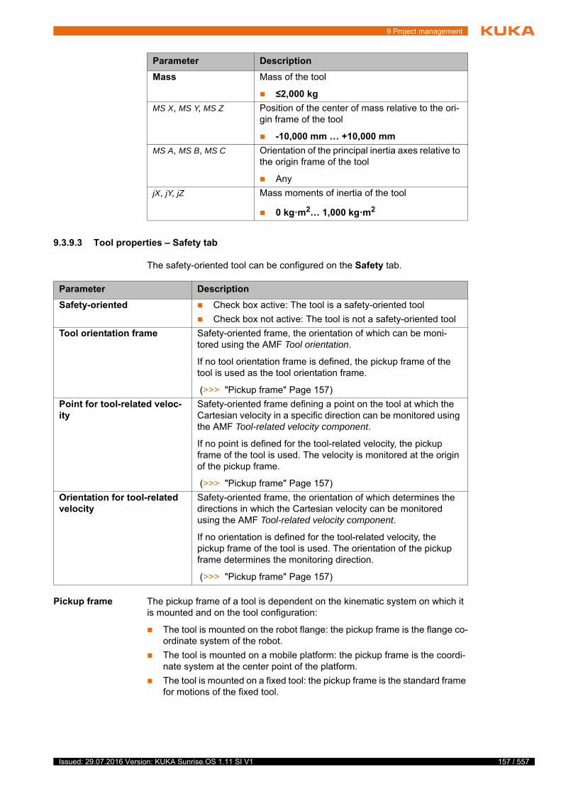
9 Project management
9.3.9.3 Tool properties – Safety tab
The safety-oriented tool can be configured on the Safety tab.
Pickup frame The pickup frame of a tool is dependent on the kinematic system on which it is mounted and on the tool configuration:
The tool is mounted on the robot flange: the pickup frame is the flange co-ordinate system of the robot.
The tool is mounted on a mobile platform: the pickup frame is the coordi-nate system at the center point of the platform.
The tool is mounted on a fixed tool: the pickup frame is the standard frame for motions of the fixed tool.
Parameter Description
Mass Mass of the tool
≤2,000 kg
MS X, MS Y, MS Z Position of the center of mass relative to the ori-gin frame of the tool
-10,000 mm … +10,000 mm
MS A, MS B, MS C Orientation of the principal inertia axes relative to the origin frame of the tool
Any
jX, jY, jZ Mass moments of inertia of the tool
0 kg·m2… 1,000 kg·m2
Parameter Description
Safety-oriented Check box active: The tool is a safety-oriented tool
Check box not active: The tool is not a safety-oriented tool
Tool orientation frame Safety-oriented frame, the orientation of which can be moni-tored using the AMF Tool orientation.
If no tool orientation frame is defined, the pickup frame of the tool is used as the tool orientation frame.
(>>> "Pickup frame" Page 157)
Point for tool-related veloc-ity
Safety-oriented frame defining a point on the tool at which the Cartesian velocity in a specific direction can be monitored using the AMF Tool-related velocity component.
If no point is defined for the tool-related velocity, the pickup frame of the tool is used. The velocity is monitored at the origin of the pickup frame.
(>>> "Pickup frame" Page 157)
Orientation for tool-related velocity
Safety-oriented frame, the orientation of which determines the directions in which the Cartesian velocity can be monitored using the AMF Tool-related velocity component.
If no orientation is defined for the tool-related velocity, the pickup frame of the tool is used. The orientation of the pickup frame determines the monitoring direction.
(>>> "Pickup frame" Page 157)
157 / 557Issued: 29.07.2016 Version: KUKA Sunrise.OS 1.11 SI V1
158 / 557
KUKA Sunrise.OS 1.11 KUKA Sunrise.Wor...
9.3.10 Safety-oriented workpieces
Description Loads picked up by the robot, e.g. a gripped workpiece, exert an additional force on the robot and influence the torques measured by the joint torque sen-sors. The safety controller requires the load data of a workpiece for calculation of the external torques.
The safety controller can only process the load data of safety-oriented work-pieces. Up to 8 safety-oriented workpieces can be configured for a Sunrise project.
The properties of safety-oriented workpieces are relevant for the following configurable safety functions:
Collision detection
The load data of the active safety-oriented workpiece are taken into con-sideration when the external torque is calculated.
(>>> 13.10.13.2 "Collision detection" Page 261)
TCP force monitoring functions
The load data of the heaviest safety-oriented workpiece are taken into consideration when the external Cartesian force exerted on the TCP of a safety-oriented tool or on the flange of a kinematic system is determined. The same applies to determination of the external Cartesian force exerted in a specific direction on the TCP of a safety-oriented tool or on the flange of a kinematic system.
(>>> 13.10.13.3 "TCP force monitoring" Page 262)
(>>> 13.10.13.4 "Direction-specific monitoring of the external force on the TCP" Page 264)
During a process, picking up and setting down different workpieces can result in load changes. The workpiece load data are integrated into the monitoring functions in various ways:
In the case of TCP force monitoring functions, the safety controller auto-matically considers all load situations when estimating the force. These possible load situations are:
The heaviest safety-oriented workpiece has been picked up.
No workpiece has been picked up.
During collision detection, the user must explicitly inform the safety con-troller which safety-oriented workpiece is currently activated.
(>>> 15.10.5 "Commanding load changes to the safety controller" Page 365)
If a safety-oriented workpiece is activated, the safety controller perma-nently takes its load data into consideration. If this workpiece is to be de-activated or if a different safety-oriented workpiece is to be activated, an explicit command is required. No safety-oriented workpiece is activated af-ter the robot controller is rebooted.
Safety-oriented workpieces are not activated in the source code of robot applications and background tasks in a safety-oriented way. This is why, in the event of an error, collision detection may use load data which devi-ate from the actual workpiece load. These deviations are misinterpreted as external axis torques. At low velocities and accelerations, the maximum deviation corresponds to the weight of the heaviest workpiece which can be picked up in the application.
When using the AMFs Collision detection, TCP force monitoring and Base-related TCP force component, it is advisable to configure as safety-oriented workpieces all those workpieces picked up by the ro-
bot while one of the monitoring functions is active.
Issued: 29.07.2016 Version: KUKA Sunrise.OS 1.11 SI V1
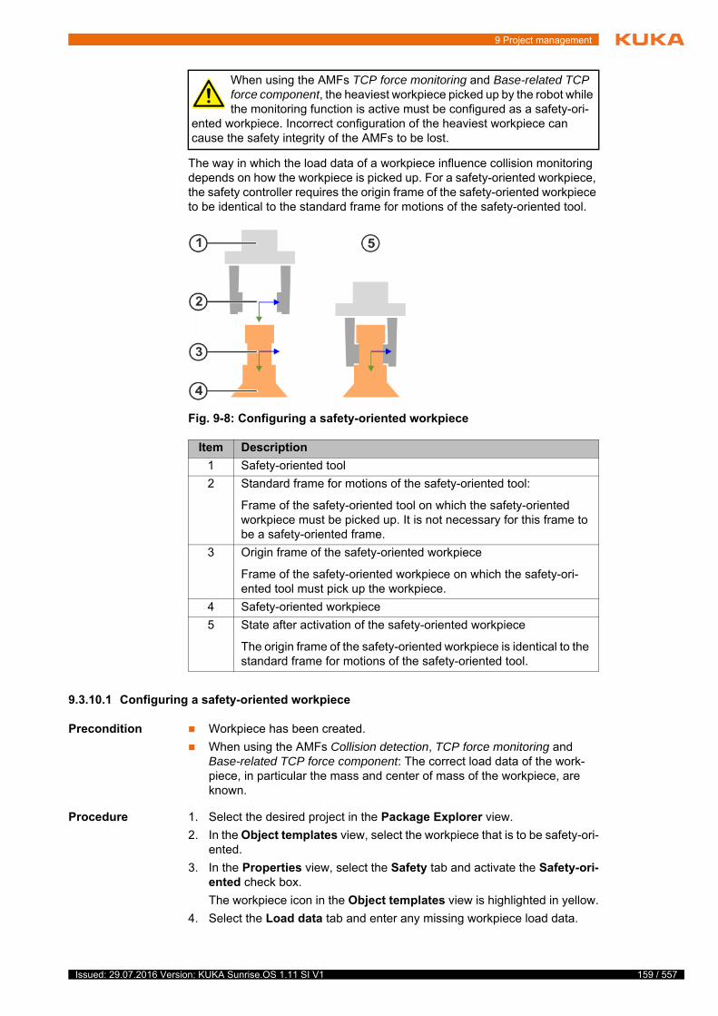
9 Project management
The way in which the load data of a workpiece influence collision monitoring depends on how the workpiece is picked up. For a safety-oriented workpiece, the safety controller requires the origin frame of the safety-oriented workpiece to be identical to the standard frame for motions of the safety-oriented tool.
9.3.10.1 Configuring a safety-oriented workpiece
Precondition Workpiece has been created.
When using the AMFs Collision detection, TCP force monitoring and Base-related TCP force component: The correct load data of the work-piece, in particular the mass and center of mass of the workpiece, are known.
Procedure 1. Select the desired project in the Package Explorer view.
2. In the Object templates view, select the workpiece that is to be safety-ori-ented.
3. In the Properties view, select the Safety tab and activate the Safety-ori-ented check box.
The workpiece icon in the Object templates view is highlighted in yellow.
4. Select the Load data tab and enter any missing workpiece load data.
When using the AMFs TCP force monitoring and Base-related TCP force component, the heaviest workpiece picked up by the robot while the monitoring function is active must be configured as a safety-ori-
ented workpiece. Incorrect configuration of the heaviest workpiece can cause the safety integrity of the AMFs to be lost.
Fig. 9-8: Configuring a safety-oriented workpiece
Item Description
1 Safety-oriented tool
2 Standard frame for motions of the safety-oriented tool:
Frame of the safety-oriented tool on which the safety-oriented workpiece must be picked up. It is not necessary for this frame to be a safety-oriented frame.
3 Origin frame of the safety-oriented workpiece
Frame of the safety-oriented workpiece on which the safety-ori-ented tool must pick up the workpiece.
4 Safety-oriented workpiece
5 State after activation of the safety-oriented workpiece
The origin frame of the safety-oriented workpiece is identical to the standard frame for motions of the safety-oriented tool.
159 / 557Issued: 29.07.2016 Version: KUKA Sunrise.OS 1.11 SI V1
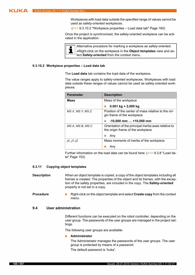
160 / 557
KUKA Sunrise.OS 1.11 KUKA Sunrise.Wor...
Workpieces with load data outside the specified range of values cannot be used as safety-oriented workpieces.
(>>> 9.3.10.2 "Workpiece properties – Load data tab" Page 160)
Once the project is synchronized, the safety-oriented workpiece can be acti-vated in the application.
9.3.10.2 Workpiece properties – Load data tab
The Load data tab contains the load data of the workpiece.
The value ranges apply to safety-oriented workpieces. Workpieces with load data outside these ranges of values cannot be used as safety-oriented work-pieces.
Further information on the load data can be found here: (>>> 9.3.8 "Load da-ta" Page 153)
9.3.11 Copying object templates
Description When an object template is copied, a copy of the object templates including all frames is created. The properties of the object and its frames, with the excep-tion of the safety properties, are included in the copy. The Safety-oriented property is not set in a copy.
Procedure Right-click on the object template and select Create copy from the context menu.
9.4 User administration
Different functions can be executed on the robot controller, depending on the user group. The passwords of the user groups are managed in the project set-tings.
The following user groups are available:
Administrator
The Administrator manages the passwords of the user groups. The user group is protected by means of a password.
The default password is “kuka”.
Alternative procedure for marking a workpiece as safety-oriented:
Right-click on the workpiece in the Object templates view and se-lect Safety-oriented from the context menu.
Parameter Description
Mass Mass of the workpiece
0.001 kg + 2,000 kg
MS X, MS Y, MS Z Position of the center of mass relative to the ori-gin frame of the workpiece
-10,000 mm … +10,000 mm
MS A, MS B, MS C Orientation of the principal inertia axes relative to the origin frame of the workpiece
Any
jX, jY, jZ Mass moments of inertia of the workpiece
Any
Issued: 29.07.2016 Version: KUKA Sunrise.OS 1.11 SI V1

9 Project management
Operator
The user group for the operator is the default user group.
Safety maintenance technician
The safety maintenance technician is responsible for starting up the safety equipment of the industrial robot and activating the safety configuration on the robot controller. The user group is protected by means of a password.
The default password is “argus”.
9.4.1 Changing the password
Description The passwords for the user groups on the robot controller are defined in the project settings. If these passwords are changed, they can only be activated by an installation of the system software on the robot controller.
Precondition User group “Administrator”
Procedure 1. Right-click on the desired project in the Package Explorer view and select Sunrise > Change project settings from the context menu.
The Properties for [Sunrise Project] window opens.
2. Select Sunrise > Passwords in the directory in the left area of the win-dow.
3. Click on Login and enter the Administrator password. Confirm the pass-word with OK.
4. Select the user group for which the password is to be changed.
5. Enter the new password twice.
For security reasons, the entries are displayed encrypted. Upper and low-er case are distinguished.
6. Click on Save and close the window.
9.5 Project synchronization, overview
In project synchronization, project data are transferred between Sun-rise.Workbench and the robot controller. In the process, the projects are com-pared with one another. If there are different projects or version conflicts, the user can choose the direction in which to transfer the project data.
The following cases are distinguished:
Prior to start-up, the passwords for the user groups must be modified in the project settings and transferred to the robot controller in an in-stallation procedure. The passwords must only be communicated to
authorized personnel.
If the administrator password is forgotten, KUKA Service must be no-tified and restore the default passwords. Using the default password for the user group “Administrator”, the passwords for the user groups
on the robot controller must then be changed again.
If only the Administrator password is modified, no installation is re-quired. The Administrator merely manages the passwords in Sun-rise.Workbench. The modified Administrator password immediately
takes effect locally and is saved on the robot controller during project syn-chronization.
The password must consist of at least one character. Only characters that can be entered via the smartHMI are permissible.
161 / 557Issued: 29.07.2016 Version: KUKA Sunrise.OS 1.11 SI V1

162 / 557
KUKA Sunrise.OS 1.11 KUKA Sunrise.Wor...
There is no project on the robot controller yet or there is a different project from the one to be transferred
(>>> 9.5.1 "Transferring the project to the robot controller" Page 162)
The same project exists on the robot controller and in Sunrise.Workbench but in different versions
There are different versions of the project:
When the project data are modified in Sunrise.Workbench only
When the project data are modified on the robot controller only
When the project data are modified on both sides
(>>> 9.5.2 "Synchronizing a project" Page 163)
9.5.1 Transferring the project to the robot controller
Description The procedure described here applies if no project is on the robot controller yet or if there is a different project from the one to be transferred.
Precondition Network connection to the robot controller
The system software is installed.
(>>> 10.4.1 "Installing system software on the robot controller" Page 172)
The installed system software is compatible with the station configuration of the project to be transferred.
Procedure 1. Select the desired project in the Package Explorer view.
2. Click on the Synchronize project button.
The system scans the robot controller for existing project data. If the scan fails, the cause of the error is displayed in a message.
3. If the scan is successful, the Project synchronization window opens.
4. Click on Execute.
5. If the safety configuration or I/O configuration is modified, a dialog indi-cates that the robot controller must be rebooted in order to complete the synchronization.
Click on OK to transfer the project to the robot controller. Once the transfer is completed, the robot controller automatically reboots.
Transfer of the project can be stopped with Cancel.
6. The progress of the project transfer is displayed in a dialog both in Sun-rise.Workbench and on the smartPAD. Once the transfer is completed, the dialog is automatically closed and the robot controller automatically re-boots.
If the transfer fails, a corresponding dialog is displayed both in Sun-rise.Workbench and on the smartPAD. In addition, the cause of the error is displayed in Sunrise.Workbench.
Fig. 9-9: Transferring the project to the controller
Issued: 29.07.2016 Version: KUKA Sunrise.OS 1.11 SI V1

9 Project management
Confirm the dialog in Sunrise.Workbench and on the smartPAD with OK.
7. If the safety configuration is modified, activate this on the robot controller.
(>>> 13.9 "Activating the safety configuration" Page 233)
9.5.2 Synchronizing a project
Description The procedure described here applies if the same project exists on both sides but in different versions.
Precondition Network connection to the robot controller
If a project is transferred to the robot controller: No application is running on the robot controller.
Procedure 1. Select the desired project in the Package Explorer view.
2. Click on the Synchronize project button.
The system scans the robot controller for existing project data. If the scan fails, the cause of the error is displayed in a message.
3. If the project in Sunrise.Workbench is identical to the project on the robot controller, a dialog indicates that no synchronization is necessary. Confirm the dialog with OK. Synchronization is aborted.
4. If the scan is successful, the Project synchronization window opens.
Information is displayed for both projects. The direction of synchronization is set by default to transfer the more current project version.
If modifications have been made to the project data on both sides, the sys-tem recognizes this as a conflict and displays a warning. The direction of synchronization can be set:
Check mark activated by Deploy to controller: The project is trans-ferred from Sunrise.Workbench to the robot controller.
Check mark activated by Load to local project: The project is trans-ferred from the robot controller to Sunrise.Workbench.
5. If required, change the direction of synchronization.
6. Click on Execute.
7. Only in the case of transfer to the robot controller: If the safety configura-tion or I/O configuration is modified, a dialog indicates that the robot con-troller must be rebooted in order to complete the synchronization.
Click on OK to transfer the project to the robot controller. Once the transfer is completed, the robot controller automatically reboots.
Transfer of the project can be stopped with Cancel.
8. The progress of the project transfer is displayed in a dialog both in Sun-rise.Workbench and on the smartPAD. When the transfer is completed,
Fig. 9-10: Updating a project
163 / 557Issued: 29.07.2016 Version: KUKA Sunrise.OS 1.11 SI V1
164 / 557
KUKA Sunrise.OS 1.11 KUKA Sunrise.Wor...
the dialog is automatically closed. If the safety configuration or I/O config-uration is modified, the robot controller is automatically rebooted.
If the transfer fails, a corresponding dialog is displayed both in Sun-rise.Workbench and on the smartPAD. In addition, the cause of the error is displayed in Sunrise.Workbench.
Confirm the dialog in Sunrise.Workbench and on the smartPAD with OK.
9. If the safety configuration is modified, activate this on the robot controller.
(>>> 13.9 "Activating the safety configuration" Page 233)
9.6 Loading the project from the robot controller
Description A project can be loaded from the robot controller if the project is not located in the workspace of Sunrise.Workbench.
Precondition Network connection to the robot controller
The workspace does not contain any project with the name of the project to be loaded.
Procedure 1. Select the menu sequence File > New > Sunrise project. The project cre-ation wizard opens.
2. Enter the IP address of the robot controller from which the project is to be loaded in the IP address of controller: box.
3. Select the Load project from controller option.
4. Click on Next >. The system checks whether there is a project on the robot controller.
5. If there is a project is on the robot controller and there is no project with the same name in the workspace, a summary of information on the project is displayed.
Click on Finish. The project is created in the workspace and then dis-played in the Package Explorer.
9.7 Converting the safety configuration to a new software version
Description If a new software version of Sunrise.Workbench is installed, a Sunrise project which was created with an earlier software version can be loaded to the work-space and continue to be used.
The station configuration changes when the Sunrise project is loaded. Saving the station configuration will transfer the corresponding safety configuration to the new version.
Precondition The Sunrise project is archived or saved in any directory.
New version of Sunrise.Workbench is installed.
Procedure 1. Load the Sunrise project into the workspace.
2. Open the station configuration of the project and click on Save.
3. The system asks whether the modifications to the project should be ac-cepted. Click on Save and apply.
4. The safety configuration is updated and its parameters are converted. When the operation is completed, this is indicated by a message. Confirm with OK.
The IP address of the robot controller can be displayed on the sm-artHMI. (>>> 6.17.6 "Displaying information about the robot and robot controller" Page 105)
Issued: 29.07.2016 Version: KUKA Sunrise.OS 1.11 SI V1

9 Project management
5. Further steps are required in order to be able to use the updated project on the robot controller:
a. Install the system software.
b. Synchronize the project.
c. Reactivate the safety configuration.
d. Carry out safety acceptance.
165 / 557Issued: 29.07.2016 Version: KUKA Sunrise.OS 1.11 SI V1

166 / 557
KUKA Sunrise.OS 1.11 KUKA Sunrise.Wor...
Issued: 29.07.2016 Version: KUKA Sunrise.OS 1.11 SI V1
10 Station configuration and installat...
10 Station configuration and installation
10.1 Station configuration overview
Procedure Open the station configuration:
Double-click on the file StationSetup.cat in the Package Explorer view.
The file contains the station configuration of the project.
The station configuration can be edited and installed using the following tabs:
Topology The Topology tab displays the hardware components of the station. The to-pology can be restructured or modified.
Software The Software tab displays the software catalog of Sunrise.Workbench. The user can select the catalog elements to be installed or uninstalled in the proj-ect.
The elements that can be selected depend on the topology and the software options installed in Sunrise.Workbench.
Configuration The Configuration tab displays the configuration of the robot controller. The configuration can be changed. The parameters that can be configured depend on the topology and the software options installed in Sunrise.Workbench.
IP address and subnet mask of the robot controller
IP address range for KUKA Line Interface (KLI)
Manual guidance support
General safety settings
Parameters for calibration
Type of media flange (if present on robot)
Installation direction (default: floor-mounted installation)
Installation The system software is installed on the robot controller via the Installation tab.
10.2 “Software” tab
10.2.1 Eliminating errors in the software catalog
Description A software catalog containing errors prevents installation of the System Soft-ware on the robot controller. The errors must be eliminated before installation.
Possible causes of errors are:
Missing reference to a catalog element
Some catalog elements are dependent on others. If a catalog element that is required by another one is deselected in the software catalog or re-moved by being uninstalled, the remaining catalog element is marked in red.
Catalog element used, but not installed
If a catalog element that is not installed in Sunrise.Workbench is used in a project, this catalog element is indicated and marked in red.
Example This example describes the options for elimination of errors.
t
t
f
The installation and use of software options in the project may cause further parameters to be added.
167 / 557Issued: 29.07.2016 Version: KUKA Sunrise.OS 1.11 SI V1
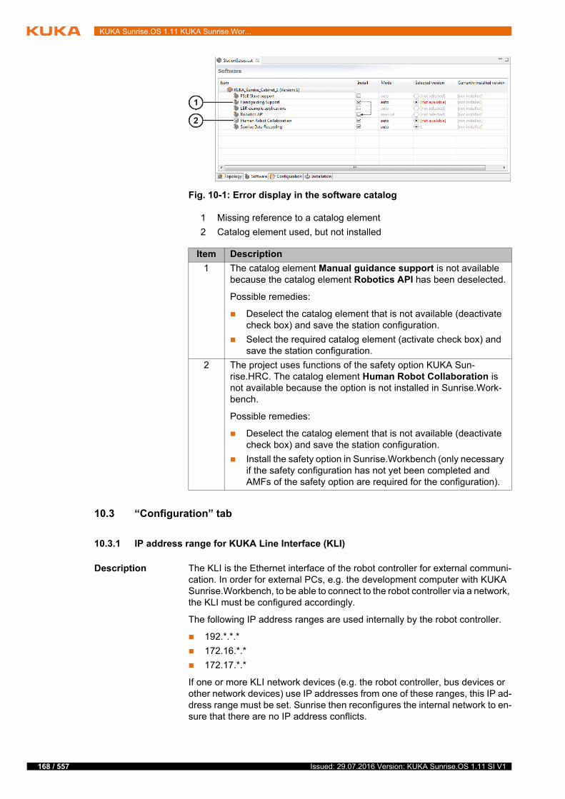
168 / 557
KUKA Sunrise.OS 1.11 KUKA Sunrise.Wor...
10.3 “Configuration” tab
10.3.1 IP address range for KUKA Line Interface (KLI)
Description The KLI is the Ethernet interface of the robot controller for external communi-cation. In order for external PCs, e.g. the development computer with KUKA Sunrise.Workbench, to be able to connect to the robot controller via a network, the KLI must be configured accordingly.
The following IP address ranges are used internally by the robot controller.
192.*.*.*
172.16.*.*
172.17.*.*
If one or more KLI network devices (e.g. the robot controller, bus devices or other network devices) use IP addresses from one of these ranges, this IP ad-dress range must be set. Sunrise then reconfigures the internal network to en-sure that there are no IP address conflicts.
Fig. 10-1: Error display in the software catalog
1 Missing reference to a catalog element
2 Catalog element used, but not installed
Item Description
1 The catalog element Manual guidance support is not available because the catalog element Robotics API has been deselected.
Possible remedies:
Deselect the catalog element that is not available (deactivate check box) and save the station configuration.
Select the required catalog element (activate check box) and save the station configuration.
2 The project uses functions of the safety option KUKA Sun-rise.HRC. The catalog element Human Robot Collaboration is not available because the option is not installed in Sunrise.Work-bench.
Possible remedies:
Deselect the catalog element that is not available (deactivate check box) and save the station configuration.
Install the safety option in Sunrise.Workbench (only necessary if the safety configuration has not yet been completed and AMFs of the safety option are required for the configuration).
Issued: 29.07.2016 Version: KUKA Sunrise.OS 1.11 SI V1

10 Station configuration and installat...
Field buses How the KLI has to be configured depends, among other things, on whether an Ethernet-based field bus is installed on the robot controller.
Ethernet-based field buses are:
KUKA Sunrise.ProfiNet M/S
10.3.2 Manual guidance support
Robots that have a hand guiding device with a safety-oriented enabling device can be guided manually if no application is selected or if an application is paused.
An application is paused if it has one of the following states:
Selected
Motion paused
Error
Manual guidance is supported by default in all operating modes except CRR mode. It is possible to configure manual guidance as not allowed in Test mode and/or Automatic mode.
Configuration parameters in the catalog element Manual guidance support:
10.3.3 General safety settings
The smartPAD can be configured as unpluggable.
Unplugging of the smartPAD is a safety function. The correct functioning of this safety function must be tested during initial start-up and recommissioning of the industrial robot.
Parameter Description
IP address range for KUKA Line Interface
The following IP address ranges are available:
192.*.*.*
172.16.*.*
172.17.*.*
Other
Default: Other
Parameter Description
Enable manual guidance in Automatic mode
Manual guidance in Automatic mode
True: Manual guidance is allowed in Automatic mode.
False: Manual guidance is not allowed in Automatic mode.
Default: True
Enable manual guidance in the test modes
Manual guidance in Test mode (T1, T2)
True: Manual guidance is allowed in Test mode.
False: Manual guidance is not allowed in Test mode.
Default: True
In order to be able to use the motion command handguiding() for manual guidance, the parameter Enable manual guidance in Auto-matic mode must be set to False. If the parameter is set to True,
manual guidance is not possible for the running application.
169 / 557Issued: 29.07.2016 Version: KUKA Sunrise.OS 1.11 SI V1
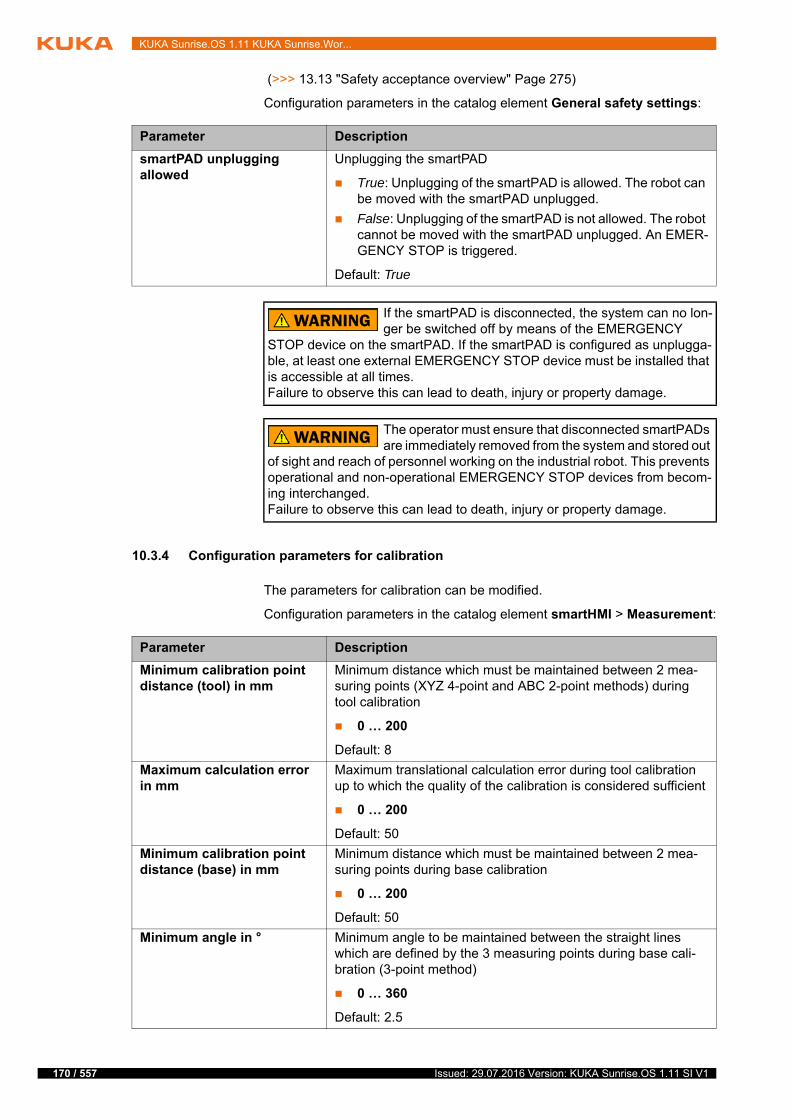
170 / 557
KUKA Sunrise.OS 1.11 KUKA Sunrise.Wor...
(>>> 13.13 "Safety acceptance overview" Page 275)
Configuration parameters in the catalog element General safety settings:
10.3.4 Configuration parameters for calibration
The parameters for calibration can be modified.
Configuration parameters in the catalog element smartHMI > Measurement:
Parameter Description
smartPAD unplugging allowed
Unplugging the smartPAD
True: Unplugging of the smartPAD is allowed. The robot can be moved with the smartPAD unplugged.
False: Unplugging of the smartPAD is not allowed. The robot cannot be moved with the smartPAD unplugged. An EMER-GENCY STOP is triggered.
Default: True
If the smartPAD is disconnected, the system can no lon-ger be switched off by means of the EMERGENCY
STOP device on the smartPAD. If the smartPAD is configured as unplugga-ble, at least one external EMERGENCY STOP device must be installed that is accessible at all times.Failure to observe this can lead to death, injury or property damage.
The operator must ensure that disconnected smartPADs are immediately removed from the system and stored out
of sight and reach of personnel working on the industrial robot. This prevents operational and non-operational EMERGENCY STOP devices from becom-ing interchanged.Failure to observe this can lead to death, injury or property damage.
Parameter Description
Minimum calibration point distance (tool) in mm
Minimum distance which must be maintained between 2 mea-suring points (XYZ 4-point and ABC 2-point methods) during tool calibration
0 … 200
Default: 8
Maximum calculation error in mm
Maximum translational calculation error during tool calibration up to which the quality of the calibration is considered sufficient
0 … 200
Default: 50
Minimum calibration point distance (base) in mm
Minimum distance which must be maintained between 2 mea-suring points during base calibration
0 … 200
Default: 50
Minimum angle in ° Minimum angle to be maintained between the straight lines which are defined by the 3 measuring points during base cali-bration (3-point method)
0 … 360
Default: 2.5
Issued: 29.07.2016 Version: KUKA Sunrise.OS 1.11 SI V1

10 Station configuration and installat...
10.3.5 Configuration parameters for Backup Manager
If the software option KUKA Sunrise.BackupRestore is installed, the catalog element Backup Manager is available on the Configuration tab.
Configuration parameters in the catalog element Backup Manager:
Parameter Description
Automatic backup active/inactive
Activation/deactivation of automatic backup
active: The robot controller automatically carries out back-ups.
The following parameters determine the time and the inter-val:
Time [hh:mm]: Time of backup
Default: 0.00
Time interval [days]: Backup interval in days
Default: 7
Note: If the robot controller was switched off at the config-ured time, it carries out a data backup as soon as it is switched on at the next configured time. It only carries out one backup, even if the time was missed more than once.
inactive: No automatic backup.
Default: inactive
Backup mode Target and source directory for backups and restorations
Local: The target directory for backups and the source direc-tory for restorations is the directory D:\ProjectBackup on the robot controller.
Note: If the backup of the projects and user data takes up too much memory, the local memory may be full before the max-imum configured number of backup copies has been reached. In this case, no further backup is possible.
network storage: The target directory for backups and the source directory for restorations is a network path:
Network path
If during backup and/or restoration the robot controller must access the network and an authentication is required, the user name and password for the network path must be spec-ified:
User name for network path
Password for network path
Note: Any other network path can be set on the robot con-troller for restorations.
Default: Local
171 / 557Issued: 29.07.2016 Version: KUKA Sunrise.OS 1.11 SI V1

172 / 557
KUKA Sunrise.OS 1.11 KUKA Sunrise.Wor...
CSV file Network configurations for restorations must be entered in a CSV file and saved on the robot controller. The data set with the network configurations can then be loaded using the Backup Manager and the source directory from which the data are to be restored can be selected.
Example of a CSV file:
The following points must be observed when creating the CSV file:
The header data set must contain the columns specified in the example file.
The column names must not be modified.
The columns can be saved in any order.
Further columns can be added, e.g. to save additional information.
10.4 “Installation” tab
10.4.1 Installing system software on the robot controller
Description During installation, all configuration data relevant for operation of the industrial robot are transferred from Sunrise.Workbench to the robot controller. These include:
Station configuration
Safety configuration
Passwords for user groups
The following points must be observed during installation:
The robot type and media flange (if present) set in the station configuration must match the robot connected to the robot controller (see identification
Maximum number of back-ups
Maximum number of backup copies
1 … 50
Once the maximum number of backup copies has been reached, the oldest backup copy is overwritten.
If more backup copies than the permissible number are present, e.g. because the maximum number has been reduced, the excess backup copies will be deleted next time a backup is made (starting with the oldest).
Default: 1
Restore-configuration file Path to a file with network configurations for restorations
The file must be present in CSV format and copied manually to the robot controller.
Note: It is advisable to save the file on drive D:\. If it is saved on C:\, it is not possible to rule out the possibility of it being over-written in the case of a restoration or installation.
Parameter Description
IP_adress;subnetmask;BM_Username;BM_Password;BM_ProjectRestoreDirectoryPath;Server
192.168.0.131;255.255.0.0;User41;pwd82p;\\Server\Path\Restore;Restore3Backup857
192.168.0.239;255.255.0.0;User66;pwd24ppp;\\Server\Path\Restore;Restore0Remote415
192.168.0.151;255.255.0.0;User38;pwd75ppp;\\Server\Path\Lokal;Lokal1Restore705
...
Issued: 29.07.2016 Version: KUKA Sunrise.OS 1.11 SI V1
10 Station configuration and installat...
plate). If the data do not match, the robot cannot be moved after installa-tion.
The safety configuration is not yet active after installation. The robot can-not be moved until the safety configuration has been activated.
(>>> 13.9 "Activating the safety configuration" Page 233)
Installation If the station configuration or the password for a user group on the robot con-troller changes, installation must be carried out again:
Change to the station configuration on the Topology tab
Change to the station configuration on the Software tab
Examples:
Installation of additional software options
Incompatible version changes of existing software packages
Incompatible version changes can occur if a project that was created with an older version of Sunrise.Workbench is loaded into the work-space.
Change to the station configuration on the Configuration tab
Change of password for a user group on the robot controller in the project settings
Precondition Network connection to the robot controller
The station configuration is completed.
Procedure 1. Select the Installation tab.
By default, the Installation events window displays the warnings and er-rors which occur during installation (check mark next to Show only warn-ings and errors.).
2. If all events which occur during installation are to be displayed, remove the check mark next to Show only warnings and errors..
3. Click on Install. The installation is prepared and the Installation window opens.
The Configured IP box is marked in color:
Marked in green: Network connection is present. Continue with step 5.
Marked in red: Network connection is not present.
Possible causes include:
The network cable is not connected correctly.
The configured IP address does not match the IP address of the robot controller.
Software updates may result in undesired modifications to the Sun-rise project. If the robot controller is reinstalled following a software update, all applications must therefore be tested in Manual Reduced
Velocity mode (T1).
If only the Administrator password is modified, no installation is re-quired. The Administrator merely manages the passwords in Sun-rise.Workbench. The modified Administrator password immediately
takes effect locally and is saved on the robot controller during project syn-chronization.
173 / 557Issued: 29.07.2016 Version: KUKA Sunrise.OS 1.11 SI V1

174 / 557
KUKA Sunrise.OS 1.11 KUKA Sunrise.Wor...
4. Only if the Configured IP box is marked in red:
If the configured IP address matches the actual address of the robot controller, there is no network connection to the robot controller. Es-tablish network connection.
If the IP address of the robot controller is different from the configured address, enter the current IP address of the robot controller in the Ac-tual IP box. To do this, double-click in the box.
5. To continue the installation, click on OK.
6. Only relevant if the IP address in the Actual IP box has been changed: If the red marking under Configured IP persists or the installation fails, there is no network connection to the robot controller with this IP address.
Establish a network connection and restart the installation process (return to step 3).
7. Confirm the reboot prompt with OK. The robot controller is rebooted and the installation is completed.
10.5 Software options
The functionalities of the following installable software options are described in this documentation:
KUKA Sunrise.AntiVirus
Virus scanner for protection against viruses
(>>> 10.5.2 "Installing or updating the virus scanner" Page 176)
KUKA Sunrise.BackupRestore
Backup manager for backing up and restoring data
KUKA Sunrise.SafeOperation
Safety option with additional safety monitoring functions, e.g. velocity monitoring functions or Cartesian workspace monitoring functions
KUKA Sunrise.HRC
Safety option with additional safety monitoring functions for HRC applica-tions, e.g. collision detection or TCP force monitoring
10.5.1 Installing a software option
Description If a software option is supplied together with KUKA Sunrise.Workbench, it is automatically installed during installation of Sunrise.Workbench. If Sun-rise.Workbench is already installed, the software option must be installed sub-sequently.
Software options are provided for installation as ZIP archives. The archive names have the following composition:
Fig. 10-2: The robot controller cannot be reached
Issued: 29.07.2016 Version: KUKA Sunrise.OS 1.11 SI V1

10 Station configuration and installat...
Article number;revision number (2-digit);product name;build version
Installation is carried out in 3 parts:
Installation of the software option in Sunrise.Workbench
Depending on the software option, the software catalog of Sunrise.Work-bench is expanded by one or more entries.
Selection of the software option for installation in the station configuration of the Sunrise project
Installation of the system software on the robot controller
Once the robot controller has been rebooted, the new software is available for the station.
Precondition Local administrator rights
Sunrise.Workbench is installed.
Data storage medium with the software to be installed
Procedure 1. Select the menu sequence Help > Install new software .... The Install window is opened.
2. To the right of the Work with box, click on Add. The Add repository win-dow is opened.
Alternatively: Drag the ZIP archive of the software into the window, then continue with step 5.
3. Click on Archive …, navigate to the directory in which the ZIP archive of the software is located and select the archive.
4. Confirm your selection with Open. The Position box now displays the in-stallation path. Confirm the path with OK.
5. In the Install window, the installation path is adopted in the Work with box.
The window now also displays a check box with the name of the new soft-ware.
Activate the check box with the name of the new software.
6. Leave the other settings in the Install window as they are and click on Next >.
7. An installation details overview is displayed. Click on Next >.
8. A license agreement is displayed. In order to be able to install the soft-ware, the agreement must be accepted. Then click on Finish. The instal-lation is started.
9. A safety warning concerning unsigned contents is displayed. Confirm with OK.
10. A message indicates that Sunrise.Workbench must be restarted in order to apply the changes. Click on Restart now.
11. Sunrise.Workbench restarts. This completes installation in Sunrise.Work-bench.
12. Open the station configuration in the desired Sunrise project. The new software entries are displayed on the Software tab.
13. If the check mark is set in the Install column for the new entries, the new software has automatically been selected for installation.
If not, set the check mark for the new entries.
14. Save the station configuration. The system asks whether the modifications to the project should be accepted. Click on Save and apply.
15. Install the system software on the robot controller. Once the robot control-ler has been rebooted, the new software is available for the station.
175 / 557Issued: 29.07.2016 Version: KUKA Sunrise.OS 1.11 SI V1

176 / 557
KUKA Sunrise.OS 1.11 KUKA Sunrise.Wor...
10.5.2 Installing or updating the virus scanner
Description Once the virus scanner has been installed on the robot controller, a tile for the virus scanner is available on the smartHMI. This tile can be used, for example, to display the version of the installed virus scanner and messages about virus-es that have been found.
(>>> 18.4 "Displaying messages of the virus scanner" Page 505)
Precondition Local administrator rights
Sunrise.Workbench is installed.
Data storage medium with the software to be installed
In the case of an update on the robot controller: Network connection with-out Internet access or with an active firewall
During the update, the virus scanner is briefly inactive.
Procedure (>>> 10.5.1 "Installing a software option" Page 174)
10.5.3 Installing a language package
Description The user interface on the smartHMI is available in the following languages:
Languages which are only available after software is delivered can be installed later if required.
Precondition Local administrator rights
Sunrise.Workbench is installed.
Data storage medium with the software to be installed
Procedure (>>> 10.5.1 "Installing a software option" Page 174)
10.5.4 Uninstalling a software option
Description Software options that are no longer required can be uninstalled in Sun-rise.Workbench.
The following points must be observed when uninstalling safety options:
Following uninstallation, the AMFs provided by an option are no longer available.
It is advisable to check what version is currently installed on the robot controller before updating the virus scanner. Do not perform a down-grade.
Chinese (simplified) Polish
Danish Portuguese
German Romanian
English Russian
Finnish Swedish
French Slovak
Greek Slovenian
Italian Spanish
Japanese Czech
Korean Turkish
Dutch Hungarian
Issued: 29.07.2016 Version: KUKA Sunrise.OS 1.11 SI V1
10 Station configuration and installat...
In the case of existing projects, an AMF that is no longer available is only displayed in the selection table if a cell that uses the AMF is selected in the safety configuration.
The safety configuration of existing projects is retained, even if it uses AMFs of an uninstalled safety option. The user can continue to use it with-out restrictions.
If the existing safety configuration uses AMFs of an uninstalled safety op-tion, it can no longer be modified. Saving of the configuration is prevented.
Procedure 1. Select the menu sequence Help > Install new software .... The Install window is opened.
2. Click on the link by What is already installed?. The Installation details for Sunrise Workbench is opened.
3. Select the Installed software tab (if it is not already selected).
4. In the list of installed software, select the option that is no longer required.
5. Click on Uninstall. The Uninstall window is opened. The details of the software to be uninstalled can be viewed here.
6. Click on Finish. The uninstallation is started.
A progress bar indicates the progress of the uninstallation.
7. A message indicates that Sunrise.Workbench must be restarted in order to apply the changes. Click on Restart now.
8. Sunrise.Workbench restarts. This completes uninstallation in Sun-rise.Workbench.
It is possible to select several options simultaneously and uninstall them together.
It is advisable not to uninstall the Sunrise.Workbench software or components of it under any circumstances.
This can result in unpredictable problems.
177 / 557Issued: 29.07.2016 Version: KUKA Sunrise.OS 1.11 SI V1

178 / 557
KUKA Sunrise.OS 1.11 KUKA Sunrise.Wor...
Issued: 29.07.2016 Version: KUKA Sunrise.OS 1.11 SI V1
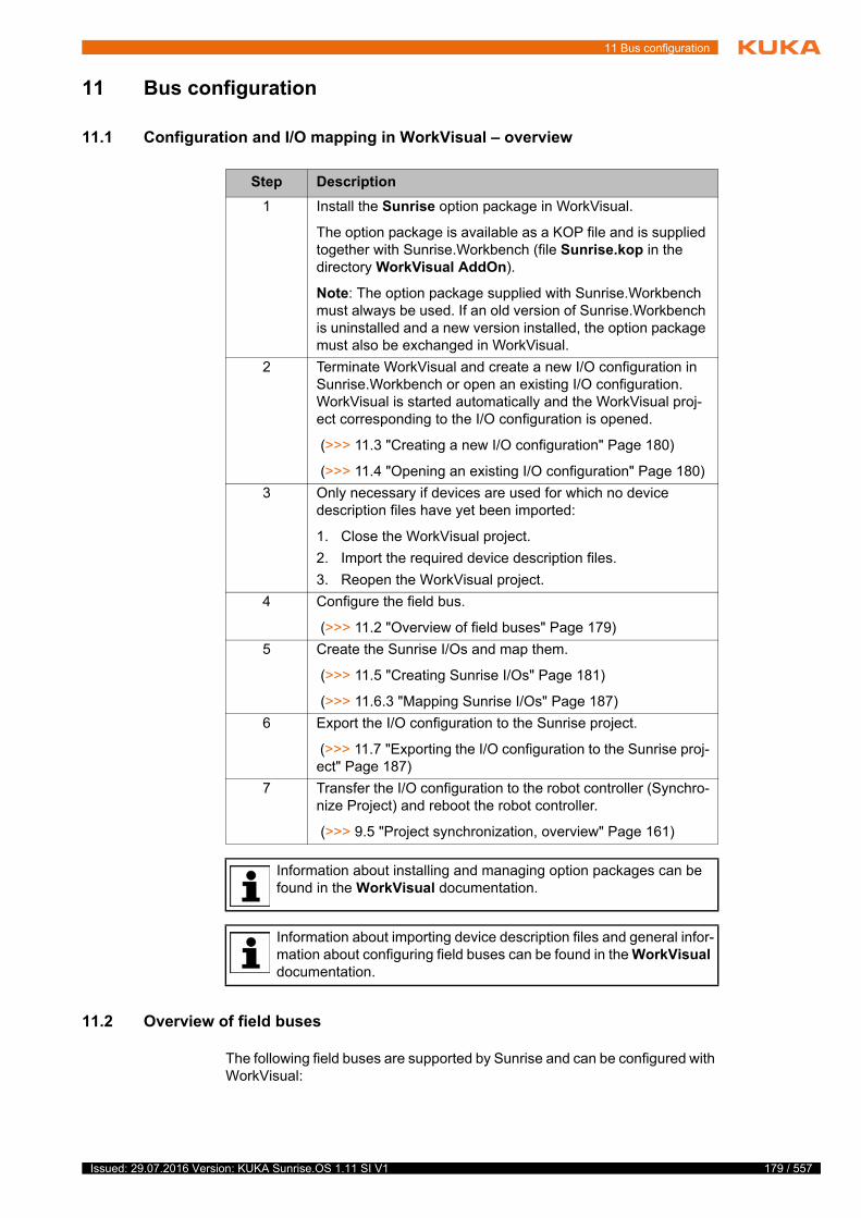
11 Bus configuration
11 Bus configuration
11.1 Configuration and I/O mapping in WorkVisual – overview
11.2 Overview of field buses
The following field buses are supported by Sunrise and can be configured with WorkVisual:
s
f
Step Description
1 Install the Sunrise option package in WorkVisual.
The option package is available as a KOP file and is supplied together with Sunrise.Workbench (file Sunrise.kop in the directory WorkVisual AddOn).
Note: The option package supplied with Sunrise.Workbench must always be used. If an old version of Sunrise.Workbench is uninstalled and a new version installed, the option package must also be exchanged in WorkVisual.
2 Terminate WorkVisual and create a new I/O configuration in Sunrise.Workbench or open an existing I/O configuration. WorkVisual is started automatically and the WorkVisual proj-ect corresponding to the I/O configuration is opened.
(>>> 11.3 "Creating a new I/O configuration" Page 180)
(>>> 11.4 "Opening an existing I/O configuration" Page 180)
3 Only necessary if devices are used for which no device description files have yet been imported:
1. Close the WorkVisual project.
2. Import the required device description files.
3. Reopen the WorkVisual project.
4 Configure the field bus.
(>>> 11.2 "Overview of field buses" Page 179)
5 Create the Sunrise I/Os and map them.
(>>> 11.5 "Creating Sunrise I/Os" Page 181)
(>>> 11.6.3 "Mapping Sunrise I/Os" Page 187)
6 Export the I/O configuration to the Sunrise project.
(>>> 11.7 "Exporting the I/O configuration to the Sunrise proj-ect" Page 187)
7 Transfer the I/O configuration to the robot controller (Synchro-nize Project) and reboot the robot controller.
(>>> 9.5 "Project synchronization, overview" Page 161)
Information about installing and managing option packages can be found in the WorkVisual documentation.
Information about importing device description files and general infor-mation about configuring field buses can be found in the WorkVisual documentation.
179 / 557Issued: 29.07.2016 Version: KUKA Sunrise.OS 1.11 SI V1
180 / 557
KUKA Sunrise.OS 1.11 KUKA Sunrise.Wor...
11.3 Creating a new I/O configuration
Precondition Sunrise project without I/O configuration
Procedure 1. Select the project in the Package Explorer.
2. Select the menu sequence File > New > I/O configuration.
WorkVisual is started and the WorkVisual project corresponding to the I/O configuration is opened. The file IOConfiguration.wvs is inserted into the Sunrise project; this can be used to call the corresponding WorkVisual project.
11.4 Opening an existing I/O configuration
Precondition Sunrise project with I/O configuration
Procedure 1. Double-click on the file IOConfiguration.wvs. WorkVisual is started and the WorkVisual project corresponding to the I/O configuration is opened.
2. Right-click on the inactive robot controller on the Hardware tab in the Proj-ect structure window.
3. Select Set as active controller from the context menu. The I/O Mapping window opens. The Sunrise I/Os can be edited.
Field bus Description
PROFINET An Ethernet-based field bus. Data exchange is carried out on a client-server basis. PROFINET is installed on the robot controller.
PROFIBUS Universal field bus which enables communication between devices from different manufacturers without special interface adaptations. Data exchange is carried out on a master-slave basis.
EtherCAT An Ethernet-based field bus suitable for real-time requirements.
For configuration of a field bus, the documentation of the field bus is required.
The I/O configuration is created automatically for the media flange set in the project. If a media flange with an EtherCAT output (e.g. media flange IO pneumatic) is used and additional EtherCAT devices are
connected, these must be configured using WorkVisual.
When connecting additional EtherCAT devices to a media flange with an EtherCAT output, e.g. media flange IO pneumatic, it must be en-sured that the number of available signals on the bus is limited.
If there are too many connected devices, this can result in overloading of the bus and loss of communication. Under certain circumstances, the robot can then no longer be moved.
If the robot controller is used as a PROFINET master or device, hard-ware problems can result in an inability to access bus devices. In this case, use of a diagnostic tool, such as WorkVisual, Step 7 or Wire-
Shark, is recommended.
Issued: 29.07.2016 Version: KUKA Sunrise.OS 1.11 SI V1
11 Bus configuration
11.5 Creating Sunrise I/Os
Precondition Field bus configuration has been completed.
The robot controller has been set as the active controller.
Procedure 1. Select an input or output module of the configured bus on the Field buses tab in the top right-hand corner of the I/O Mapping window.
(>>> 11.6.1 "I/O Mapping window" Page 185)
2. Select the Sunrise I/Os tab in the top left-hand corner of the I/O Mapping window.
3. In the bottom left-hand corner of the I/O Mapping window, click on the Creates signals at the provider button. The Create I/O signals window is opened.
(>>> 11.5.1 "“Create I/O signals” window" Page 182)
4. Create an I/O group and inputs/outputs within the group.
(>>> 11.5.2 "Creating an I/O group and inputs/outputs within the group" Page 183)
5. Click on OK. The Sunrise I/Os are saved. The Create I/O signals window is closed.
The created I/O group is displayed on the Sunrise I/Os tab of the I/O Mapping window. The signals can now be mapped.
(>>> 11.6.3 "Mapping Sunrise I/Os" Page 187)
181 / 557Issued: 29.07.2016 Version: KUKA Sunrise.OS 1.11 SI V1

182 / 557
KUKA Sunrise.OS 1.11 KUKA Sunrise.Wor...
11.5.1 “Create I/O signals” window
Overview
The window for creating and editing the Sunrise I/Os and Sunrise I/O groups consists of the following areas:
Signal properties In the Edit I/O area, new signals can be created and their properties defined:
Fig. 11-1: “Create I/O signals” window
Area Description
Edit I/O group In this area, I/O groups are created and edited. It is also possi-ble to save I/O groups as a template or to import previously cre-ated templates.
Edit I/O signals In this area, the input/output signals of an I/O group are dis-played.
Edit I/O In this area, the inputs/outputs of an I/O group are created and edited.
Input boxes are displayed with a red frame if values must be entered or if incorrect values have been entered. A help text is displayed when the mouse pointer is moved over the box.
Property Description
I/O name Enter the name of the input or output.
Description Enter a description for the input or output (optional).
Issued: 29.07.2016 Version: KUKA Sunrise.OS 1.11 SI V1
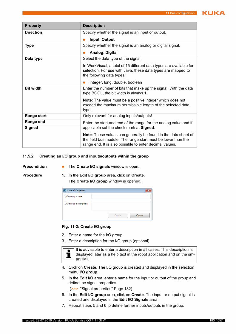
11 Bus configuration
11.5.2 Creating an I/O group and inputs/outputs within the group
Precondition The Create I/O signals window is open.
Procedure 1. In the Edit I/O group area, click on Create.
The Create I/O group window is opened.
2. Enter a name for the I/O group.
3. Enter a description for the I/O group (optional).
4. Click on Create. The I/O group is created and displayed in the selection menu I/O group.
5. In the Edit I/O area, enter a name for the input or output of the group and define the signal properties.
(>>> "Signal properties" Page 182)
6. In the Edit I/O group area, click on Create. The input or output signal is created and displayed in the Edit I/O Signals area.
7. Repeat steps 5 and 6 to define further inputs/outputs in the group.
Direction Specify whether the signal is an input or output.
Input, Output
Type Specify whether the signal is an analog or digital signal.
Analog, Digital
Data type Select the data type of the signal.
In WorkVisual, a total of 15 different data types are available for selection. For use with Java, these data types are mapped to the following data types:
integer, long, double, boolean
Bit width Enter the number of bits that make up the signal. With the data type BOOL, the bit width is always 1.
Note: The value must be a positive integer which does not exceed the maximum permissible length of the selected data type.
Range start Only relevant for analog inputs/outputs!
Enter the start and end of the range for the analog value and if applicable set the check mark at Signed.
Note: These values can generally be found in the data sheet of the field bus module. The range start must be lower than the range end. It is also possible to enter decimal values.
Range end
Signed
Property Description
Fig. 11-2: Create I/O group
It is advisable to enter a description in all cases. This description is displayed later as a help text in the robot application and on the sm-artHMI.
183 / 557Issued: 29.07.2016 Version: KUKA Sunrise.OS 1.11 SI V1
184 / 557
KUKA Sunrise.OS 1.11 KUKA Sunrise.Wor...
11.5.3 Editing an I/O group
Precondition The Create I/O signals window is open.
The inputs/outputs of the group are not mapped.
Procedure 1. Select the desired I/O group from the I/O group selection menu.
2. Click on Edit. The Rename I/O group window is opened.
3. Change the name of the I/O group and/or the corresponding description (optional). Confirm with Apply.
11.5.4 Deleting an I/O group
Precondition The Create I/O signals window is open.
The inputs/outputs of the group are not mapped.
Procedure 1. Select the desired I/O group from the I/O group selection menu.
2. Click on Delete. If signals have already been created for the I/O group, a request for confirmation is displayed.
3. Reply to the request for confirmation with Yes. The I/O group is deleted.
11.5.5 Changing an input/output of a group
Precondition The Create I/O signals window is open.
The signals that are to be changed are not mapped.
Procedure 1. Select the I/O group of the signal from the I/O group selection menu.
2. In the Edit I/O Signals area, click on the desired input or output.
3. In the Edit I/O area, edit the signal properties as required.
(>>> "Signal properties" Page 182)
4. Click on Change. The changes are saved.
11.5.6 Deleting an input/output of a group
Precondition The Create I/O signals window is open.
The signals that are to be deleted are not mapped.
Procedure 1. Select the I/O group of the signal from the I/O group selection menu.
2. In the Edit I/O Signals area, click on the desired input or output.
3. Click on Delete.
11.5.7 Exporting an I/O group as a template
Description I/O groups can be saved as a template. The template contains all the in-puts/outputs belonging to the saved I/O group. This enables I/O groups, once created, to be reused. The mapping of the inputs and outputs is not saved, however.
After exporting the template, the templates created in WorkVisual are avail-able in Sunrise.Workbench in the IOTemplates folder of the project.
Precondition The Create I/O signals window is open.
All the changes can be discarded by clicking on the Discard button.
Issued: 29.07.2016 Version: KUKA Sunrise.OS 1.11 SI V1
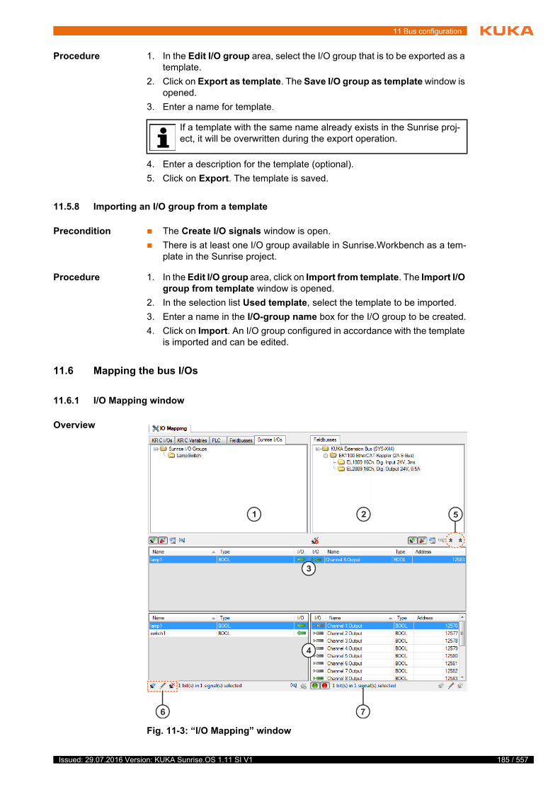
11 Bus configuration
Procedure 1. In the Edit I/O group area, select the I/O group that is to be exported as a template.
2. Click on Export as template. The Save I/O group as template window is opened.
3. Enter a name for template.
4. Enter a description for the template (optional).
5. Click on Export. The template is saved.
11.5.8 Importing an I/O group from a template
Precondition The Create I/O signals window is open.
There is at least one I/O group available in Sunrise.Workbench as a tem-plate in the Sunrise project.
Procedure 1. In the Edit I/O group area, click on Import from template. The Import I/O group from template window is opened.
2. In the selection list Used template, select the template to be imported.
3. Enter a name in the I/O-group name box for the I/O group to be created.
4. Click on Import. An I/O group configured in accordance with the template is imported and can be edited.
11.6 Mapping the bus I/Os
11.6.1 I/O Mapping window
Overview
If a template with the same name already exists in the Sunrise proj-ect, it will be overwritten during the export operation.
Fig. 11-3: “I/O Mapping” window
185 / 557Issued: 29.07.2016 Version: KUKA Sunrise.OS 1.11 SI V1

186 / 557
KUKA Sunrise.OS 1.11 KUKA Sunrise.Wor...
11.6.2 Buttons in the “I/O Mapping” window
Some of these buttons are displayed in several places. In such cases, they re-fer to the side of the I/O Mapping window on which they are located.
Edit
Item Description
1 Displays the Sunrise I/O groups
The signals in the I/O group selected here are displayed in the overviews lower down.
2 Displays the inputs/outputs of the bus modules
The signals in the module selected here are displayed in the over-views lower down.
3 Connection overview
Displays the mapped signals. These are the signals of the I/O group selected under Sunrise I/Os, which are mapped to the bus module selected under Field buses.
4 Signal overview
Here the signals can be mapped.
(>>> 11.6.3 "Mapping Sunrise I/Os" Page 187)
5 The arrow buttons allow the connection and signal overviews to be collapsed and expanded independently of one another.
Collapse connection view (left-hand arrow symbol pointing up)
Expand connection view (left-hand arrow symbol pointing down)
Collapse signal view (right-hand arrow symbol pointing up)
Expand signal view (right-hand arrow symbol pointing down)
6 Buttons for creating and editing the Sunrise I/Os
7 Displays how many bits the selected signals contain.
For the I/O mapping in Sunrise, only the Sunrise I/Os and Field bus-es tabs are relevant.
Button Name/description
Creates signals at the provider
Opens the Create I/O signals window.
(>>> 11.5.1 "“Create I/O signals” window" Page 182)
The button is only active if an input or output module is selected on the Field buses tab and a signal of the I/O group is selected in the signal overview.
Issued: 29.07.2016 Version: KUKA Sunrise.OS 1.11 SI V1
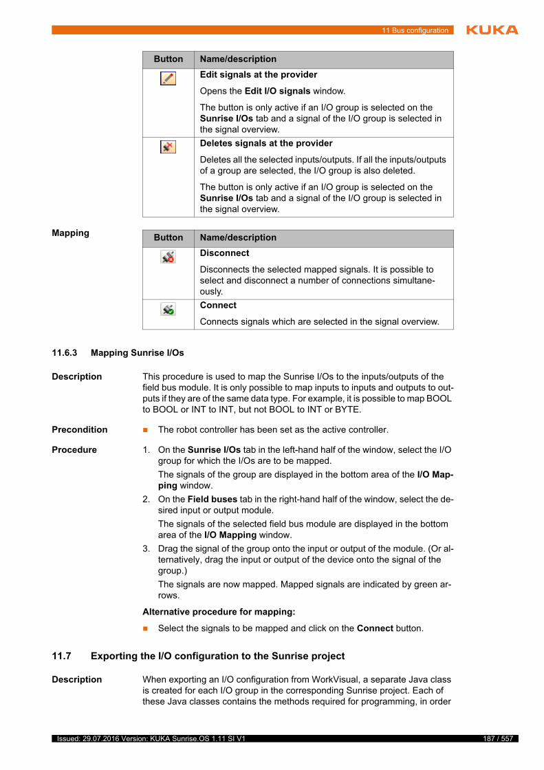
11 Bus configuration
Mapping
11.6.3 Mapping Sunrise I/Os
Description This procedure is used to map the Sunrise I/Os to the inputs/outputs of the field bus module. It is only possible to map inputs to inputs and outputs to out-puts if they are of the same data type. For example, it is possible to map BOOL to BOOL or INT to INT, but not BOOL to INT or BYTE.
Precondition The robot controller has been set as the active controller.
Procedure 1. On the Sunrise I/Os tab in the left-hand half of the window, select the I/O group for which the I/Os are to be mapped.
The signals of the group are displayed in the bottom area of the I/O Map-ping window.
2. On the Field buses tab in the right-hand half of the window, select the de-sired input or output module.
The signals of the selected field bus module are displayed in the bottom area of the I/O Mapping window.
3. Drag the signal of the group onto the input or output of the module. (Or al-ternatively, drag the input or output of the device onto the signal of the group.)
The signals are now mapped. Mapped signals are indicated by green ar-rows.
Alternative procedure for mapping:
Select the signals to be mapped and click on the Connect button.
11.7 Exporting the I/O configuration to the Sunrise project
Description When exporting an I/O configuration from WorkVisual, a separate Java class is created for each I/O group in the corresponding Sunrise project. Each of these Java classes contains the methods required for programming, in order
Edit signals at the provider
Opens the Edit I/O signals window.
The button is only active if an I/O group is selected on the Sunrise I/Os tab and a signal of the I/O group is selected in the signal overview.
Deletes signals at the provider
Deletes all the selected inputs/outputs. If all the inputs/outputs of a group are selected, the I/O group is also deleted.
The button is only active if an I/O group is selected on the Sunrise I/Os tab and a signal of the I/O group is selected in the signal overview.
Button Name/description
Button Name/description
Disconnect
Disconnects the selected mapped signals. It is possible to select and disconnect a number of connections simultane-ously.
Connect
Connects signals which are selected in the signal overview.
187 / 557Issued: 29.07.2016 Version: KUKA Sunrise.OS 1.11 SI V1
188 / 557
KUKA Sunrise.OS 1.11 KUKA Sunrise.Wor...
to be able to read the inputs/outputs of an I/O group and write to the outputs of an I/O group.
The classes and methods are saved in the Java package com.kuka.generat-ed.ioAccess in the source folder of the Sunrise project.
The structure of the Sunrise project after exporting an I/O configuration is de-scribed here:
(>>> 15.11 "Using inputs/outputs in the program" Page 367)
Precondition The robot controller has been set as the active controller.
The automatic change recognition is activated in Sunrise.Workbench.
(>>> 5.11 "Activating the automatic change recognition" Page 60)
Procedure 1. Select the menu sequence File > Import / Export. The import/export wiz-ard for files opens.
2. Select Export the I/O configuration to the Sunrise Workbench proj-ect..
3. Click on Next > and then on Finish. The configuration is exported to the Sunrise project.
4. A message is displayed as to whether the export was successfully com-pleted. If Sunrise I/Os have not been mapped, this is also indicated.
Click Close to terminate the wizard.
5. Close WorkVisual by selecting File > Exit.
The source code of the Java classes of the package com.kuka.gen-erated.ioAccess must not be changed manually. To expand the functionality of an I/O group, it is possible to derive further classes
from the classes created or to continue to use objects from these classes, e.g. as arrays of their own classes (aggregating).
It is not essential to map all the Sunrise I/Os that have been created.
Issued: 29.07.2016 Version: KUKA Sunrise.OS 1.11 SI V1

12 External control
12 External control
12.1 Overview of external controller
If the processes of the station are to be controlled by an external controller in Automatic mode, the Sunrise project on the robot controller must be config-ured for external control.
Default appli-
cation
A default application must be assigned to every project that is to be controlled externally.
The default application has the following characteristics:
It is automatically selected when the operating mode is switched to Auto-matic.
It can only be started via the input signal App_Start (not by means of the Start key on the smartPAD).
It cannot be deselected again in Automatic mode.
Interfaces External controller and robot controller can communicate via the following in-terfaces:
I/O system of the robot controller
Network protocol UDP
The input/output signals for communication are predefined:
The external controller can start, pause and resume the default application via the input signals.
(>>> 12.4 "External controller input signals" Page 190)
The output signals can be used to provide information about the status of the default application and the station to the external controller.
(>>> 12.5 "External controller output signals" Page 191)
Precondition In order to be able to start an application, the following preconditions must be met:
The robot is mastered (all axes).
A Sunrise project has been configured for external control.
AUT mode
If configured: the input signal App_Enable has a HIGH level or is TRUE.
The motion enable signal is present.
12.2 Configuring the external controller via the I/O system
The following steps are required for configuring the external controller via the I/O system:
2
x
t
Step Description
1 Configure and map inputs/outputs for communication with the external controller in WorkVisual.
(>>> 12.4 "External controller input signals" Page 190)
(>>> 12.5 "External controller output signals" Page 191)
2 Export I/O configuration from WorkVisual to Sunrise.Work-bench.
3 Create the default application for the external controller.
189 / 557Issued: 29.07.2016 Version: KUKA Sunrise.OS 1.11 SI V1
190 / 557
KUKA Sunrise.OS 1.11 KUKA Sunrise.Wor...
12.3 Configuring the external controller via the UDP interface
The following steps are required for configuring the external controller via the UDP network protocol:
Use of the UDP is illustrated by the following example:
(>>> 12.9 "External control via UDP – Start-up example" Page 199)
12.4 External controller input signals
App_Start The input signal is absolutely vital for an externally controlled project.
The default application is started and resumed in Automatic mode by the ex-ternal controller by means of a rising edge of the signal (change from FALSE to TRUE).
App_Enable The input signal is optionally configurable.
The default application can be paused by the higher-level controller in Auto-matic mode using this signal. For this, the signal must have a LOW level or be FALSE.
Get_State The input signal is only available if the UDP interface is used.
The external controller can use this signal to poll application and station sta-tuses from the robot controller. The value of the signal can be TRUE or FALSE.
System response The input signal App_Enable has a higher priority than the input signal App_Start. If the input signal App_Enable is configured, the default applica-tion can only be started if App_Enable has a HIGH level or is TRUE.
The following table describes the system behavior when the App_Enable sig-nal is configured.
4 Configure the external controller in the project settings.
(>>> 12.7 "Configuring the external controller in the project settings" Page 193)
5 Transfer the project to the robot controller by means of syn-chronization.
The physical inputs/outputs used for communication with the external controller must not be multiply mapped.
Step Description
Step Description
1 Create the default application for the external controller.
2 Configure the external controller in the project settings.
(>>> 12.7 "Configuring the external controller in the project settings" Page 193)
3 Transfer the project to the robot controller by means of syn-chronization.
Issued: 29.07.2016 Version: KUKA Sunrise.OS 1.11 SI V1
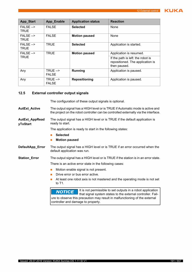
12 External control
12.5 External controller output signals
The configuration of these output signals is optional.
AutExt_Active The output signal has a HIGH level or is TRUE if Automatic mode is active and the project on the robot controller can be controlled externally via the interface.
AutExt_AppRead
yToStart
The output signal has a HIGH level or is TRUE if the default application is ready to start.
The application is ready to start in the following states:
Selected
Motion paused
DefaultApp_Error The output signal has a HIGH level or is TRUE if an error occurred when the default application was run.
Station_Error The output signal has a HIGH level or is TRUE if the station is in an error state.
There is an active error state in the following cases:
Motion enable signal is not present.
Drive error or bus error active.
At least one robot axis is not mastered and the operating mode is not set to T1.
App_Start App_Enable Application status Reaction
FALSE --> TRUE
FALSE Selected None
FALSE --> TRUE
FALSE Motion paused None
FALSE --> TRUE
TRUE Selected Application is started.
FALSE --> TRUE
TRUE Motion paused Application is resumed.
If the path is left: the robot is repositioned. The application is then paused.
Any TRUE --> FALSE
Running Application is paused.
Any TRUE --> FALSE
Repositioning Application is paused.
It is not permissible to set outputs in a robot application that signal system states to the external controller. Fail-
ure to observe this precaution may result in malfunctioning of the external controller and damage to property.
191 / 557Issued: 29.07.2016 Version: KUKA Sunrise.OS 1.11 SI V1

192 / 557
KUKA Sunrise.OS 1.11 KUKA Sunrise.Wor...
12.6 Signal diagrams
Fig. 12-1: Automatic system start and normal operation
Fig. 12-2: Restart after user stop
Issued: 29.07.2016 Version: KUKA Sunrise.OS 1.11 SI V1
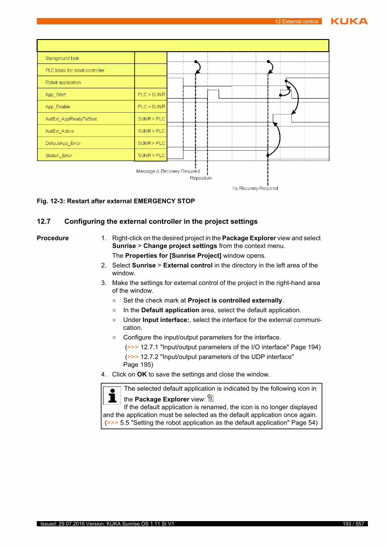
12 External control
12.7 Configuring the external controller in the project settings
Procedure 1. Right-click on the desired project in the Package Explorer view and select Sunrise > Change project settings from the context menu.
The Properties for [Sunrise Project] window opens.
2. Select Sunrise > External control in the directory in the left area of the window.
3. Make the settings for external control of the project in the right-hand area of the window.
Set the check mark at Project is controlled externally.
In the Default application area, select the default application.
Under Input interface:, select the interface for the external communi-cation.
Configure the input/output parameters for the interface.
(>>> 12.7.1 "Input/output parameters of the I/O interface" Page 194)
(>>> 12.7.2 "Input/output parameters of the UDP interface" Page 195)
4. Click on OK to save the settings and close the window.
Fig. 12-3: Restart after external EMERGENCY STOP
The selected default application is indicated by the following icon in
the Package Explorer view: If the default application is renamed, the icon is no longer displayed
and the application must be selected as the default application once again. (>>> 5.5 "Setting the robot application as the default application" Page 54)
193 / 557Issued: 29.07.2016 Version: KUKA Sunrise.OS 1.11 SI V1
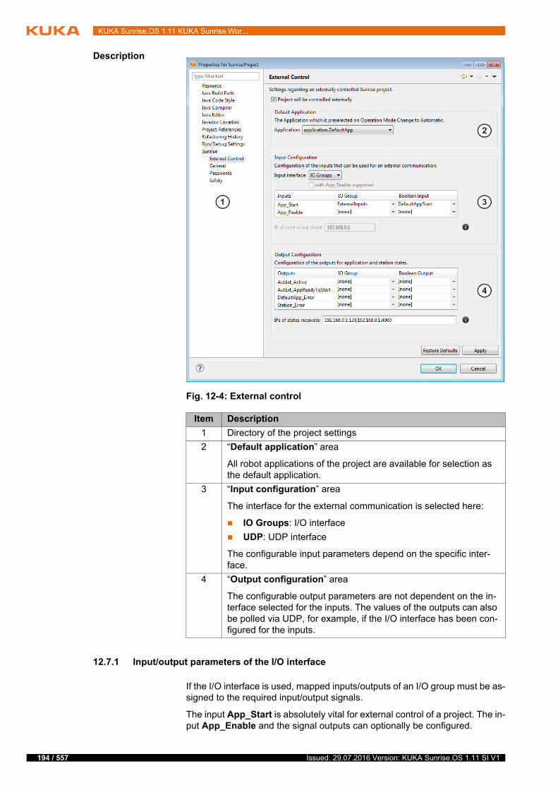
194 / 557
KUKA Sunrise.OS 1.11 KUKA Sunrise.Wor...
Description
12.7.1 Input/output parameters of the I/O interface
If the I/O interface is used, mapped inputs/outputs of an I/O group must be as-signed to the required input/output signals.
The input App_Start is absolutely vital for external control of a project. The in-put App_Enable and the signal outputs can optionally be configured.
Fig. 12-4: External control
Item Description
1 Directory of the project settings
2 “Default application” area
All robot applications of the project are available for selection as the default application.
3 “Input configuration” area
The interface for the external communication is selected here:
IO Groups: I/O interface
UDP: UDP interface
The configurable input parameters depend on the specific inter-face.
4 “Output configuration” area
The configurable output parameters are not dependent on the in-terface selected for the inputs. The values of the outputs can also be polled via UDP, for example, if the I/O interface has been con-figured for the inputs.
Issued: 29.07.2016 Version: KUKA Sunrise.OS 1.11 SI V1
12 External control
12.7.2 Input/output parameters of the UDP interface
12.8 Formatting of the UDP data packets
Form and length of the UDP data packets for the data exchange are pre-defined:
UTF-8 coding
Data arrays are separated by a semicolon.
12.8.1 Status messages of the robot controller
Description In the case of the UDP interface, application and station statuses are trans-ferred from the robot controller to an external controller by means of so-called status messages.
In the following cases, the robot controller sends status messages to the cli-ents that are configured as recipients of status messages in the project set-tings:
Following receipt of the control message from an external client
Following the change in state of an output signal
The data packet sent by the robot controller consists of the following data ar-rays:
Column Description
I/O group All I/O groups of the I/O configuration of the project are available.
Boolean input All inputs of the I/O group selected in the I/O group column are available.
Boolean output All outputs of the I/O group selected in the I/O group column are available.
Parameter Description
with App_Enable sup-ported
Use of the input signal App_Enable
Check box not active (default): App_Enable is not evaluated.
Check box active: App_Enable is evaluated.
IP of controlling client: IP address of the client configured for external control of the proj-ect
IPs of state receivers: List of clients to receive status information (optional)
For each client, the IP address must be specified in the following format together with the corresponding port:
IP_address_1:Port_1;IP_address_2:Port_2;...
Note: It is advisable to specify the IP address and port of the con-trolling client in order to inform it of changes of state.
195 / 557Issued: 29.07.2016 Version: KUKA Sunrise.OS 1.11 SI V1
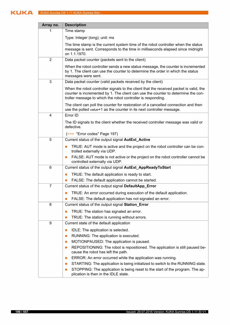
196 / 557
KUKA Sunrise.OS 1.11 KUKA Sunrise.Wor...
Array no. Description
1 Time stamp
Type: Integer (long); unit: ms
The time stamp is the current system time of the robot controller when the status message is sent. Corresponds to the time in milliseconds elapsed since midnight on 1.1.1970.
2 Data packet counter (packets sent to the client)
When the robot controller sends a new status message, the counter is incremented by 1. The client can use the counter to determine the order in which the status messages were sent.
3 Data packet counter (valid packets received by the client)
When the robot controller signals to the client that the received packet is valid, the counter is incremented by 1. The client can use the counter to determine the con-troller message to which the robot controller is responding.
The client can poll the counter for restoration of a cancelled connection and then use the polled value+1 as the counter in its next controller message.
4 Error ID
The ID signals to the client whether the received controller message was valid or defective.
(>>> "Error codes" Page 197)
5 Current status of the output signal AutExt_Active
TRUE: AUT mode is active and the project on the robot controller can be con-trolled externally via UDP.
FALSE: AUT mode is not active or the project on the robot controller cannot be controlled externally via UDP.
6 Current status of the output signal AutExt_AppReadyToStart
TRUE: The default application is ready to start.
FALSE: The default application cannot be started.
7 Current status of the output signal DefaultApp_Error
TRUE: An error occurred during execution of the default application.
FALSE: The default application has not signaled an error.
8 Current status of the output signal Station_Error
TRUE: The station has signaled an error.
TRUE: The station is running without errors.
9 Current state of the default application
IDLE: The application is selected.
RUNNING: The application is executed.
MOTIONPAUSED: The application is paused.
REPOSITIONING: The robot is repositioned. The application is still paused be-cause the robot has left the path.
ERROR: An error occurred while the application was running.
STARTING: The application is being initialized to switch to the RUNNING state.
STOPPING: The application is being reset to the start of the program. The ap-plication is then in the IDLE state.
Issued: 29.07.2016 Version: KUKA Sunrise.OS 1.11 SI V1
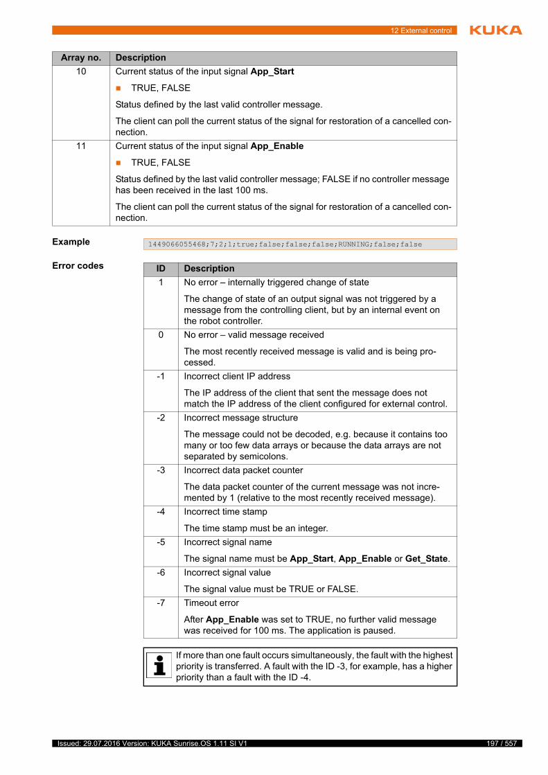
12 External control
Example
Error codes
10 Current status of the input signal App_Start
TRUE, FALSE
Status defined by the last valid controller message.
The client can poll the current status of the signal for restoration of a cancelled con-nection.
11 Current status of the input signal App_Enable
TRUE, FALSE
Status defined by the last valid controller message; FALSE if no controller message has been received in the last 100 ms.
The client can poll the current status of the signal for restoration of a cancelled con-nection.
Array no. Description
1449066055468;7;2;1;true;false;false;false;RUNNING;false;false
ID Description
1 No error – internally triggered change of state
The change of state of an output signal was not triggered by a message from the controlling client, but by an internal event on the robot controller.
0 No error – valid message received
The most recently received message is valid and is being pro-cessed.
-1 Incorrect client IP address
The IP address of the client that sent the message does not match the IP address of the client configured for external control.
-2 Incorrect message structure
The message could not be decoded, e.g. because it contains too many or too few data arrays or because the data arrays are not separated by semicolons.
-3 Incorrect data packet counter
The data packet counter of the current message was not incre-mented by 1 (relative to the most recently received message).
-4 Incorrect time stamp
The time stamp must be an integer.
-5 Incorrect signal name
The signal name must be App_Start, App_Enable or Get_State.
-6 Incorrect signal value
The signal value must be TRUE or FALSE.
-7 Timeout error
After App_Enable was set to TRUE, no further valid message was received for 100 ms. The application is paused.
If more than one fault occurs simultaneously, the fault with the highest priority is transferred. A fault with the ID -3, for example, has a higher priority than a fault with the ID -4.
197 / 557Issued: 29.07.2016 Version: KUKA Sunrise.OS 1.11 SI V1
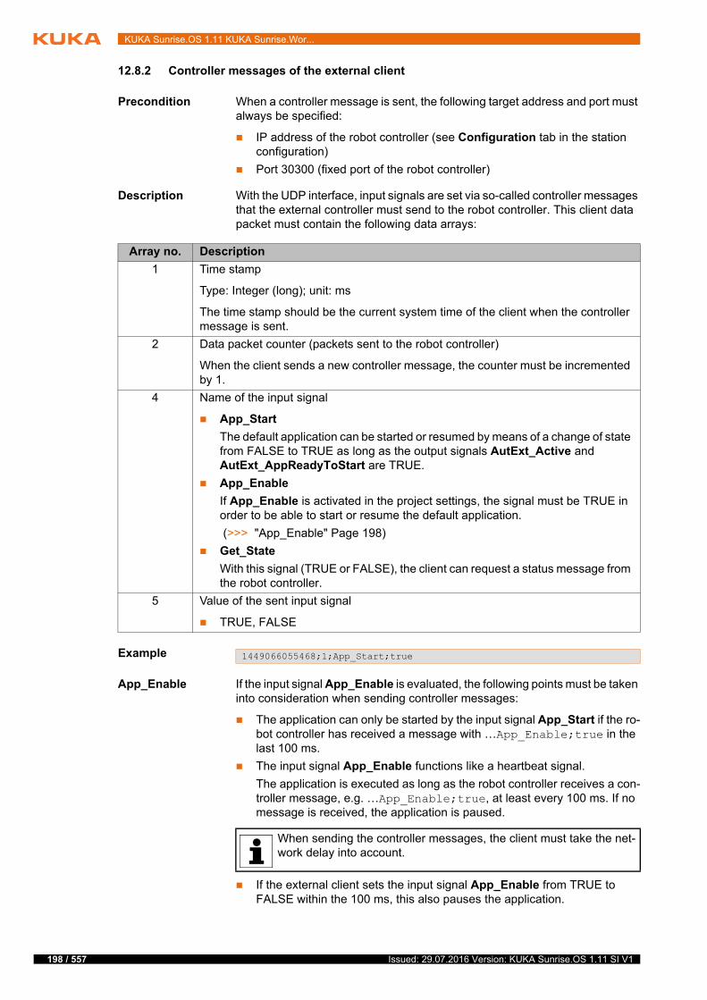
198 / 557
KUKA Sunrise.OS 1.11 KUKA Sunrise.Wor...
12.8.2 Controller messages of the external client
Precondition When a controller message is sent, the following target address and port must always be specified:
IP address of the robot controller (see Configuration tab in the station configuration)
Port 30300 (fixed port of the robot controller)
Description With the UDP interface, input signals are set via so-called controller messages that the external controller must send to the robot controller. This client data packet must contain the following data arrays:
Example
App_Enable If the input signal App_Enable is evaluated, the following points must be taken into consideration when sending controller messages:
The application can only be started by the input signal App_Start if the ro-bot controller has received a message with …App_Enable;true in the last 100 ms.
The input signal App_Enable functions like a heartbeat signal.
The application is executed as long as the robot controller receives a con-troller message, e.g. …App_Enable;true, at least every 100 ms. If no message is received, the application is paused.
If the external client sets the input signal App_Enable from TRUE to FALSE within the 100 ms, this also pauses the application.
Array no. Description
1 Time stamp
Type: Integer (long); unit: ms
The time stamp should be the current system time of the client when the controller message is sent.
2 Data packet counter (packets sent to the robot controller)
When the client sends a new controller message, the counter must be incremented by 1.
4 Name of the input signal
App_Start
The default application can be started or resumed by means of a change of state from FALSE to TRUE as long as the output signals AutExt_Active and AutExt_AppReadyToStart are TRUE.
App_Enable
If App_Enable is activated in the project settings, the signal must be TRUE in order to be able to start or resume the default application.
(>>> "App_Enable" Page 198)
Get_State
With this signal (TRUE or FALSE), the client can request a status message from the robot controller.
5 Value of the sent input signal
TRUE, FALSE
1449066055468;1;App_Start;true
When sending the controller messages, the client must take the net-work delay into account.
Issued: 29.07.2016 Version: KUKA Sunrise.OS 1.11 SI V1
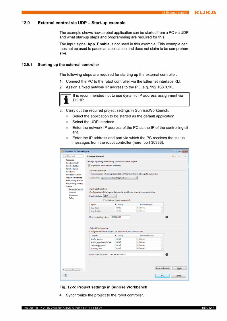
12 External control
12.9 External control via UDP – Start-up example
The example shows how a robot application can be started from a PC via UDP and what start-up steps and programming are required for this.
The input signal App_Enable is not used in this example. This example can thus not be used to pause an application and does not claim to be comprehen-sive.
12.9.1 Starting up the external controller
The following steps are required for starting up the external controller:
1. Connect the PC to the robot controller via the Ethernet interface KLI.
2. Assign a fixed network IP address to the PC, e.g. 192.168.0.10.
3. Carry out the required project settings in Sunrise.Workbench.
Select the application to be started as the default application.
Select the UDP interface.
Enter the network IP address of the PC as the IP of the controlling cli-ent.
Enter the IP address and port via which the PC receives the status messages from the robot controller (here: port 30333).
4. Synchronize the project to the robot controller.
It is recommended not to use dynamic IP address assignment via DCHP.
Fig. 12-5: Project settings in Sunrise.Workbench
199 / 557Issued: 29.07.2016 Version: KUKA Sunrise.OS 1.11 SI V1
200 / 557
KUKA Sunrise.OS 1.11 KUKA Sunrise.Wor...
5. Select AUT mode.
Once the robot is ready to move, all status indicators on the smartHMI are green and the application can be started via the UDP interface.
12.9.2 Programming the external controller
On the PC used for external control, there must be a program that can gener-ate and send UDP data packets.
Precondition The correct target address and port have been assigned to the data pack-ets that are to be sent:
IP address of the robot controller (see Configuration tab in the station configuration)
Port 30300 (fixed port of the robot controller)
Description Following a reboot of the robot controller, the robot application can be started with a controller message with App_Start:
If the value to be transferred for the counter is not known, a socket on the PC must be opened that can receive UDP messages at port 30333. Get_State can then be used to poll the current counter value:
If the socket is now polled for received messages, a status message should now be present as the answer from the robot controller, e.g.:
The received message shows that the current value of the data packet counter is 1337. The counter value 1338 must therefore be transferred in the next data packet.
In order to restart a robot application, the state of the signal from App_Start must change from FALSE to TRUE. For this purpose, the following packets are sent:
If a firewall is used, it must be ensured that it does not block the in-coming and outgoing UDP data packets.
1457449078435;1;App_Start;true
The first number in the packet is the time stamp that must be used to document when the packet was sent. Here, and in the following code examples, this number must always be replaced with a current time
stamp in milliseconds. (When using Java, such a number can be generated, for example, with java.lang.System.currentTimeMillis().)
Following a reboot of the robot controller, the value 1 must always be transferred for the data packet counter. For each subsequent data packet, the counter must be incremented by 1.
1457450539457;0;Get_State;true
In Sunrise.Workbench, port 30333 has been defined in the project settings as the port via which the PC receives the status messages from the robot controller. If a different port is to be used, it can be en-
tered in the project settings.
1457450539459;4;1337;-3;true;true;false;false;IDLE;false;true
1457450539511;1338;App_Start;false
1457450539511;1339;App_Start;true
Issued: 29.07.2016 Version: KUKA Sunrise.OS 1.11 SI V1
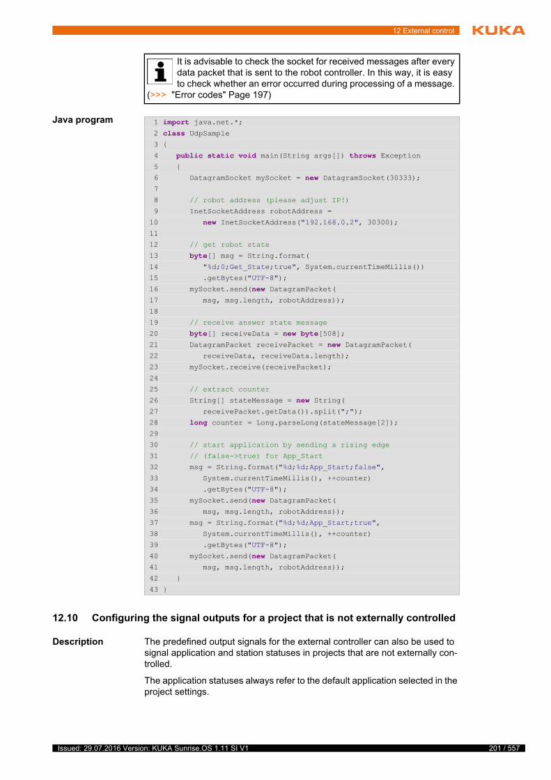
12 External control
Java program
12.10 Configuring the signal outputs for a project that is not externally controlled
Description The predefined output signals for the external controller can also be used to signal application and station statuses in projects that are not externally con-trolled.
The application statuses always refer to the default application selected in the project settings.
It is advisable to check the socket for received messages after every data packet that is sent to the robot controller. In this way, it is easy to check whether an error occurred during processing of a message.
(>>> "Error codes" Page 197)
1 import java.net.*;2 class UdpSample 3 {
4 public static void main(String args[]) throws Exception 5 {
6 DatagramSocket mySocket = new DatagramSocket(30333);7
8 // robot address (please adjust IP!)
9 InetSocketAddress robotAddress =
10 new InetSocketAddress("192.168.0.2", 30300);11
12 // get robot state
13 byte[] msg = String.format(14 "%d;0;Get_State;true", System.currentTimeMillis())
15 .getBytes("UTF-8");
16 mySocket.send(new DatagramPacket(17 msg, msg.length, robotAddress));
18
19 // receive answer state message
20 byte[] receiveData = new byte[508];21 DatagramPacket receivePacket = new DatagramPacket(22 receiveData, receiveData.length);
23 mySocket.receive(receivePacket);
24
25 // extract counter
26 String[] stateMessage = new String(27 receivePacket.getData()).split(";");
28 long counter = Long.parseLong(stateMessage[2]);29
30 // start application by sending a rising edge
31 // (false->true) for App_Start
32 msg = String.format("%d;%d;App_Start;false",
33 System.currentTimeMillis(), ++counter)
34 .getBytes("UTF-8");
35 mySocket.send(new DatagramPacket(36 msg, msg.length, robotAddress));
37 msg = String.format("%d;%d;App_Start;true",
38 System.currentTimeMillis(), ++counter)
39 .getBytes("UTF-8");
40 mySocket.send(new DatagramPacket(41 msg, msg.length, robotAddress));
42 }
43 }
201 / 557Issued: 29.07.2016 Version: KUKA Sunrise.OS 1.11 SI V1
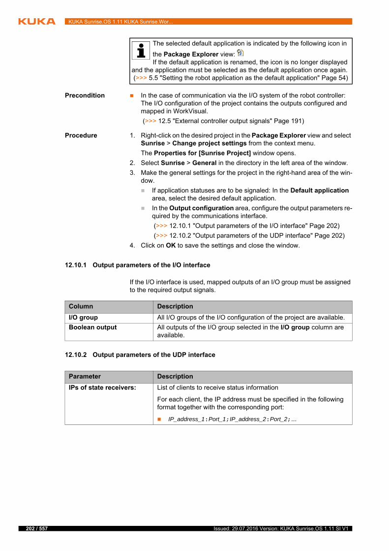
202 / 557
KUKA Sunrise.OS 1.11 KUKA Sunrise.Wor...
Precondition In the case of communication via the I/O system of the robot controller: The I/O configuration of the project contains the outputs configured and mapped in WorkVisual.
(>>> 12.5 "External controller output signals" Page 191)
Procedure 1. Right-click on the desired project in the Package Explorer view and select Sunrise > Change project settings from the context menu.
The Properties for [Sunrise Project] window opens.
2. Select Sunrise > General in the directory in the left area of the window.
3. Make the general settings for the project in the right-hand area of the win-dow.
If application statuses are to be signaled: In the Default application area, select the desired default application.
In the Output configuration area, configure the output parameters re-quired by the communications interface.
(>>> 12.10.1 "Output parameters of the I/O interface" Page 202)
(>>> 12.10.2 "Output parameters of the UDP interface" Page 202)
4. Click on OK to save the settings and close the window.
12.10.1 Output parameters of the I/O interface
If the I/O interface is used, mapped outputs of an I/O group must be assigned to the required output signals.
12.10.2 Output parameters of the UDP interface
The selected default application is indicated by the following icon in
the Package Explorer view: If the default application is renamed, the icon is no longer displayed
and the application must be selected as the default application once again. (>>> 5.5 "Setting the robot application as the default application" Page 54)
Column Description
I/O group All I/O groups of the I/O configuration of the project are available.
Boolean output All outputs of the I/O group selected in the I/O group column are available.
Parameter Description
IPs of state receivers: List of clients to receive status information
For each client, the IP address must be specified in the following format together with the corresponding port:
IP_address_1:Port_1;IP_address_2:Port_2;...
Issued: 29.07.2016 Version: KUKA Sunrise.OS 1.11 SI V1

13 Safety configuration
13 Safety configuration
13.1 Overview of safety configuration
The safety configuration defines the safety-oriented functions in order to inte-grate the industrial robot safely into the system. Safety-oriented functions serve to protect human operators when they work with the robot.
The safety configuration is an integral feature of a Sunrise project and is man-aged in tabular form. The individual safety functions are grouped in KUKA Sunrise.Workbench on an application-specific basis. The safety configuration is then transferred with the project to the controller and activated there.
13.2 Safety concept
Overview The safety configuration must implement all safety functions which are re-quired to operate the industrial robot. A safety function monitors the entire sys-tem on the basis of specific criteria. These are described by individual monitoring functions, so-called AMFs (Atomic Monitoring Functions). To con-figure a safety function, several AMFs can be linked to form complex safety monitoring functions. In addition, the safety function defines a suitable reaction which is triggered in case of error.
f
t
y
f
Serious damage and injury or death can result from in-correct safety configuration. If a new or changed safety
configuration is activated, the safety maintenance technician must conduct tests to ensure that the configured safety parameters have been correctly ap-plied and that the safety functions of the configuration are fully functional (safety acceptance).
Configuration of the safety functions, activation and deactivation of the safety functions and safety acceptance may only be carried out by a trained safety maintenance technician. The safety maintenance
technician is responsible for ensuring that the safety configuration is only ac-tivated on those robots for which it is intended.The safety configuration is not checked for plausibility by KUKA Sun-rise.Workbench.
In the case of incomplete start-up of the system, additional substitute measures for minimizing risk must be taken and documented, e.g. in-stallation of a safety fence, attachment of a warning sign, locking of
the main switch. Start-up is incomplete, for example, if not all safety functions have yet been implemented, or if a function test of the safety functions has not yet been carried out.
The system integrator must verify that the safety configuration suffi-ciently reduces risks during collaborative operation (HRC).It is advisable to perform this verification in accordance with the infor-
mation and instructions for operating collaborative robots in ISO/TS 15066.
States with various safety settings are defined in the safety configu-ration as part of the ESM mechanism (Event-Driven Safety Monitor-ing). It is possible to switch between these in the application. Since
switching between these states is carried out by means of non-safety-orient-ed signals, all configured states must be consistent. This means that each state must ensure a sufficient degree of safety, regardless of the time or place of activation (i.e. regardless of the current process step).
203 / 557Issued: 29.07.2016 Version: KUKA Sunrise.OS 1.11 SI V1
204 / 557
KUKA Sunrise.OS 1.11 KUKA Sunrise.Wor...
Example: In a specific area of the robot's workspace, the velocity at the TCP must not exceed 500 mm/s (“Workspace monitoring” and “Velocity monitoring” monitoring functions). Otherwise, the robot must stop immediately (reaction in case of error).
PSM and ESM The Sunrise safety concept provides 2 different monitoring mechanisms:
Permanent safety-oriented monitoring
The safety functions of the PSM mechanism (Permanent Safety Monitor-ing) are always active. It is only possible to deactivate individual safety functions by changing the safety configuration.
The PSM mechanism is used to constantly monitor the system. It imple-ments basic safety settings which are independent of the process step be-ing carried out. These include, for example, EMERGENCY STOP functions, the enabling switch on the smartPAD, the definition of a cell area or safety functions that depend on the operating mode.
Event-dependent safety-oriented monitoring
The ESM mechanism (Event-driven Safety Monitoring) defines safe states. It is possible to switch between these in the application. A safe ESM state contains the safety functions required in the corresponding pro-cess step.
Since switching is carried out by means of non-safety-oriented signals, the defined state must ensure a sufficient degree of safety, regardless of the time or place of activation.
The ESM mechanism allows specific safety functions to be adapted for specific processes. This is of particular importance for human-robot collab-oration applications, as these often require various safety settings de-pending on the situation. The required parameters, such as permissible velocity, collision values or spatial limits, can be individually defined for each process step using an ESM state.
AMF The smallest unit of a safety monitoring function is called an Atomic Monitoring Function (AMF).
Each AMF supplies an elementary, safety-relevant piece of information, for example if a safe input is set or if the Automatic operating mode is selected.
Atomic Monitoring Functions can have 2 different states and are LOW-active. This means that if a monitoring function is violated, the state switches from “1” to “0”.
State “0”: The AMF is violated.
State “1”: The AMF is not violated.
For example, the AMF smartPAD Emergency Stop is violated if the EMER-GENCY STOP device on the operator panel is pressed.
Safety function A safe ESM state is defined with up to 20 safety functions. The safety func-tions of the ESM mechanism use exactly one AMF. If this AMF is violated, the safety function and thus the entire ESM state is considered to be violated.
For safety functions of the PSM mechanism, up to 3 AMFs are logically linked to one another. This allows complex safety monitoring functions to be imple-mented. If all AMFs of a safety function of the PSM mechanism are violated, the entire safety function is considered to be violated.
Safety interfaces Various safety interfaces are available for exchanging safety-oriented signals between a higher-level controller and a robot controller. The safe inputs of these interfaces can be used to connect safety devices, for example external EMERGENCY STOP devices or safety gates, and to evaluate the correspond-ing input signals. The safe outputs of these interfaces can be used to signal the violation of safety functions.
Issued: 29.07.2016 Version: KUKA Sunrise.OS 1.11 SI V1

13 Safety configuration
Ethernet safety interfaces (only slave function available)
PROFINET / PROFIsafe
EtherCAT/FSoE
Discrete safety interfaces
CIB_SR/X11
Reactions A suitable reaction is defined for each safety function. This reaction must take place in the case of an error and put the system into a safe state.
The following reactions can be configured:
Safety stop 0 is triggered.
Safety stop 1 is triggered.
Safety stop 1 (path-maintaining) is triggered.
This is the recommended stop reaction. It has the lowest impact on the process, as an application can be resumed without the need to reposition the robot.
Safe output is set to “0” (LOW level).
The reactions can be used for any number of safety functions. A reaction is triggered once one of the safety functions using this reaction is violated. This makes it possible, for example, to inform a higher-level controller via a safe output when specific errors occur.
With the PSM mechanism, it is possible to trigger several different reactions when a specific combination of AMFs is violated. For example, a safety stop can be triggered as well as a safe output. To do so, 2 safety functions must be configured with identical AMF combinations.
If different stop reactions are configured, a violation triggers the stronger stop reaction. In other words, it triggers the stop reaction which causes an earlier safety-oriented disconnection of the drives. If several safety functions use the same output signal as a reaction, this signal is set to “0” once one of the safety functions is violated.
Time behavior All the safety-oriented outputs use LOW as a safe state.
If a safety function which uses a safety output as a reaction is violated, this out-put is immediately set to LOW.
The PROFINET bus can be configured in WorkVisual. Further infor-mation about the concrete configuration of the field bus is contained in the corresponding field bus documentation.
Further information on interface X11 can be found in the operating in-structions for KUKA Sunrise Cabinet.
It is advisable to only configure a safety stop 0 if it is necessary to im-mediately switch off the drives and apply the brakes as a reaction.
In crushing situations, safety stop 1 and safety stop 1 (path-maintaining) can result in higher crushing forces
due to the controlled stop on a planned braking path. It is therefore advisable to use safety stop 0 for safety monitoring functions which recognize crushing situations (e.g. the AMF Collision detection, TCP force monitoring).
Setting a safe output can only be configured as a reaction for safety functions of the PSM mechanism. It cannot be configured for safety functions of the ESM mechanism.
205 / 557Issued: 29.07.2016 Version: KUKA Sunrise.OS 1.11 SI V1
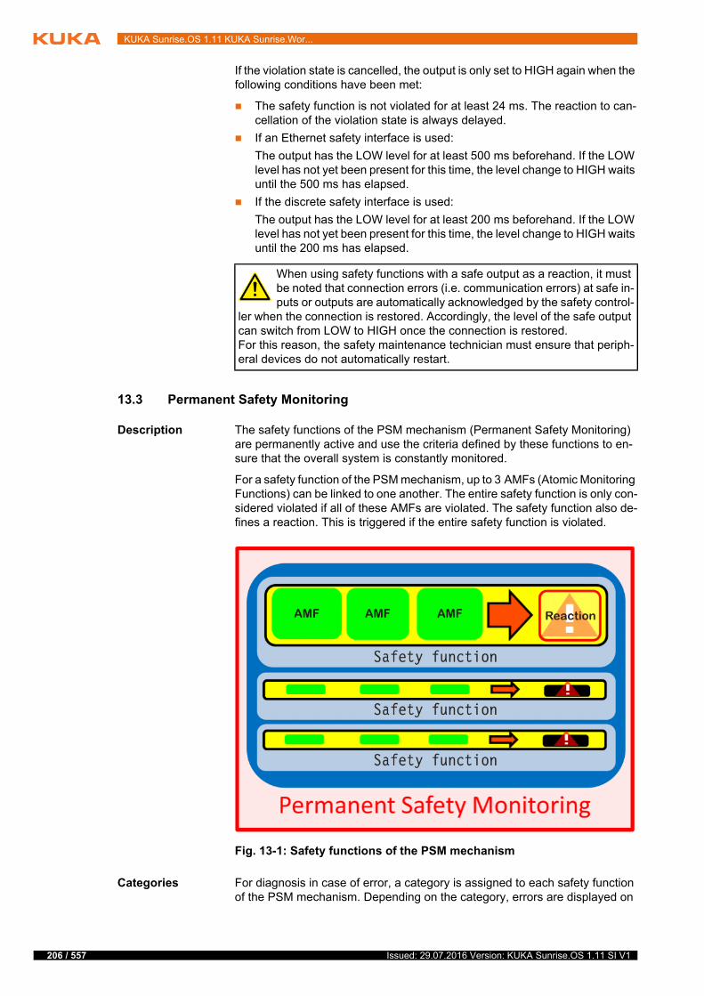
206 / 557
KUKA Sunrise.OS 1.11 KUKA Sunrise.Wor...
If the violation state is cancelled, the output is only set to HIGH again when the following conditions have been met:
The safety function is not violated for at least 24 ms. The reaction to can-cellation of the violation state is always delayed.
If an Ethernet safety interface is used:
The output has the LOW level for at least 500 ms beforehand. If the LOW level has not yet been present for this time, the level change to HIGH waits until the 500 ms has elapsed.
If the discrete safety interface is used:
The output has the LOW level for at least 200 ms beforehand. If the LOW level has not yet been present for this time, the level change to HIGH waits until the 200 ms has elapsed.
13.3 Permanent Safety Monitoring
Description The safety functions of the PSM mechanism (Permanent Safety Monitoring) are permanently active and use the criteria defined by these functions to en-sure that the overall system is constantly monitored.
For a safety function of the PSM mechanism, up to 3 AMFs (Atomic Monitoring Functions) can be linked to one another. The entire safety function is only con-sidered violated if all of these AMFs are violated. The safety function also de-fines a reaction. This is triggered if the entire safety function is violated.
Categories For diagnosis in case of error, a category is assigned to each safety function of the PSM mechanism. Depending on the category, errors are displayed on
When using safety functions with a safe output as a reaction, it must be noted that connection errors (i.e. communication errors) at safe in-puts or outputs are automatically acknowledged by the safety control-
ler when the connection is restored. Accordingly, the level of the safe output can switch from LOW to HIGH once the connection is restored.For this reason, the safety maintenance technician must ensure that periph-eral devices do not automatically restart.
Fig. 13-1: Safety functions of the PSM mechanism
Issued: 29.07.2016 Version: KUKA Sunrise.OS 1.11 SI V1

13 Safety configuration
the smartPAD and saved in the LOG file. For this reason, it is advisable to se-lect these carefully.
The following categories are available:
13.4 Event-driven Safety Monitoring
The ESM mechanism (Event-driven Safety Monitoring) makes it possible to switch between different safe ESM states depending on the situation.
Up to 10 safe states can be defined. Switching between states can be carried out in the robot application or in a background task.
(>>> 13.8.4.8 "Switching between ESM states" Page 230)
A safe ESM state is defined with up to 20 safety functions which must ensure a sufficient degree of safety in every situation. An ESM state becomes active when the program switches to this ESM state. As long as the ESM state is ac-tive, all corresponding safety functions are monitored in addition to the perma-nently active safety functions.
Use of the ESM mechanism is optional. The ESM mechanism is deactivated if no ESM state is defined in the safety configuration.
When using the ESM mechanism, exactly one safe state is always active. It is not possible to switch it off in the application.
The safety functions of an ESM state each contain a single AMF which is as-signed to a suitable stop reaction.
Once a safety function of the active ESM state is violated, a stop is triggered. The type of stop reaction will be the strongest of all the violated safety func-tions in all ESM states (either active or inactive). In other words, it triggers the stop reaction which causes the earliest safety-oriented disconnection of the drives.
Category Recommended use
None For safety functions which cannot be assigned a category
Output For safety functions which use setting an output as a reaction
In this category, no diagnostic information is provided in case of viola-tion.
Enabling device For safety functions which evaluate an enabling switch
In this category, no diagnostic information is provided in case of violation because enabling is a normal operating state and not an error state.
Local EMERGENCY STOP
For safety functions which evaluate an EMERGENCY STOP triggered by the EMERGENCY STOP device on the smartPAD
External EMER-GENCY STOP
For safety functions which evaluate an EMERGENCY STOP triggered by an external EMERGENCY STOP device
Operator safety For safety functions which evaluate the signal for operator safety
Safe operational stop For safety functions which monitor robot standstill
Collision detection For safety functions which are used for collision detection or force moni-toring
Safety stop For safety functions which use a safety stop as a reaction and cannot be assigned to another category. Example: external safety stop
Velocity monitoring For safety functions which are used for monitoring an axis-specific or Cartesian velocity
Workspace monitor-ing
For safety functions which are used for monitoring an axis-specific or Cartesian space
207 / 557Issued: 29.07.2016 Version: KUKA Sunrise.OS 1.11 SI V1
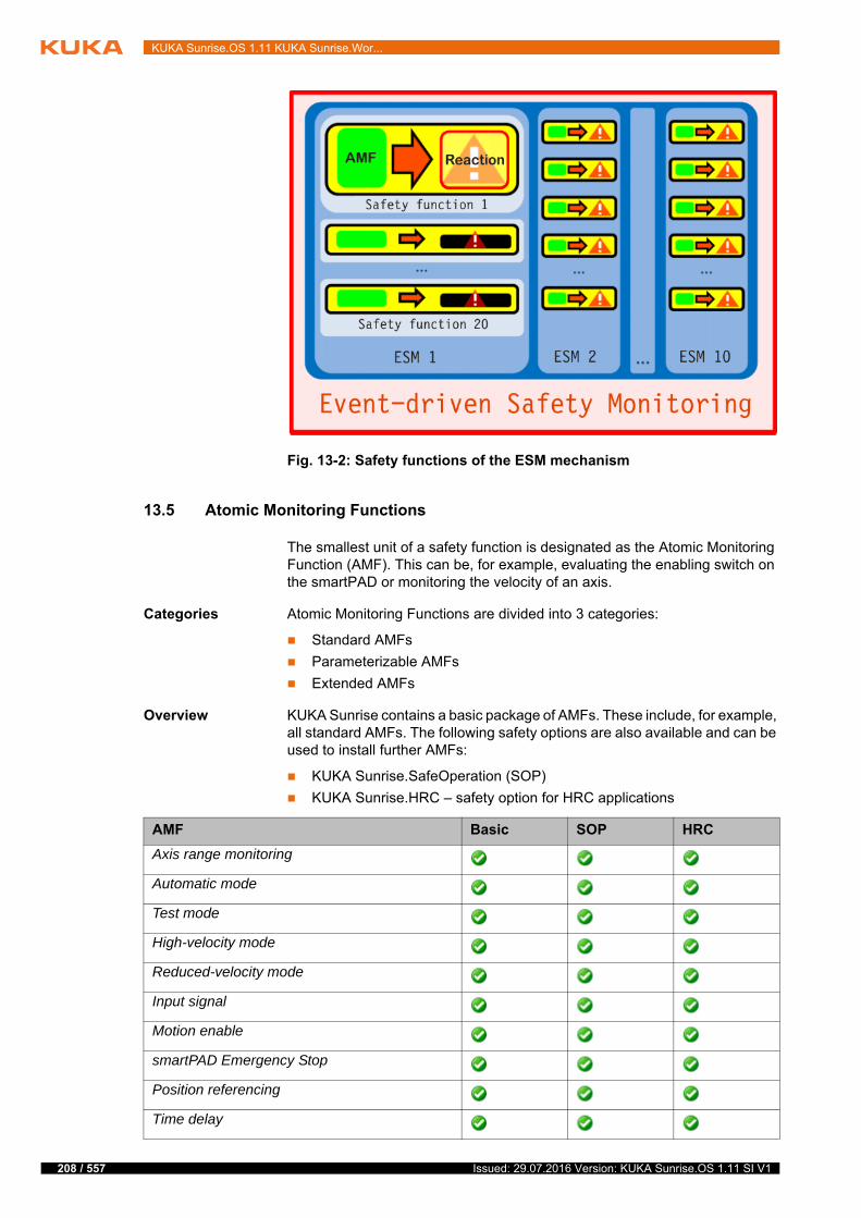
208 / 557
KUKA Sunrise.OS 1.11 KUKA Sunrise.Wor...
13.5 Atomic Monitoring Functions
The smallest unit of a safety function is designated as the Atomic Monitoring Function (AMF). This can be, for example, evaluating the enabling switch on the smartPAD or monitoring the velocity of an axis.
Categories Atomic Monitoring Functions are divided into 3 categories:
Standard AMFs
Parameterizable AMFs
Extended AMFs
Overview KUKA Sunrise contains a basic package of AMFs. These include, for example, all standard AMFs. The following safety options are also available and can be used to install further AMFs:
KUKA Sunrise.SafeOperation (SOP)
KUKA Sunrise.HRC – safety option for HRC applications
Fig. 13-2: Safety functions of the ESM mechanism
AMF Basic SOP HRC
Axis range monitoring
Automatic mode
Test mode
High-velocity mode
Reduced-velocity mode
Input signal
Motion enable
smartPAD Emergency Stop
Position referencing
Time delay
Issued: 29.07.2016 Version: KUKA Sunrise.OS 1.11 SI V1
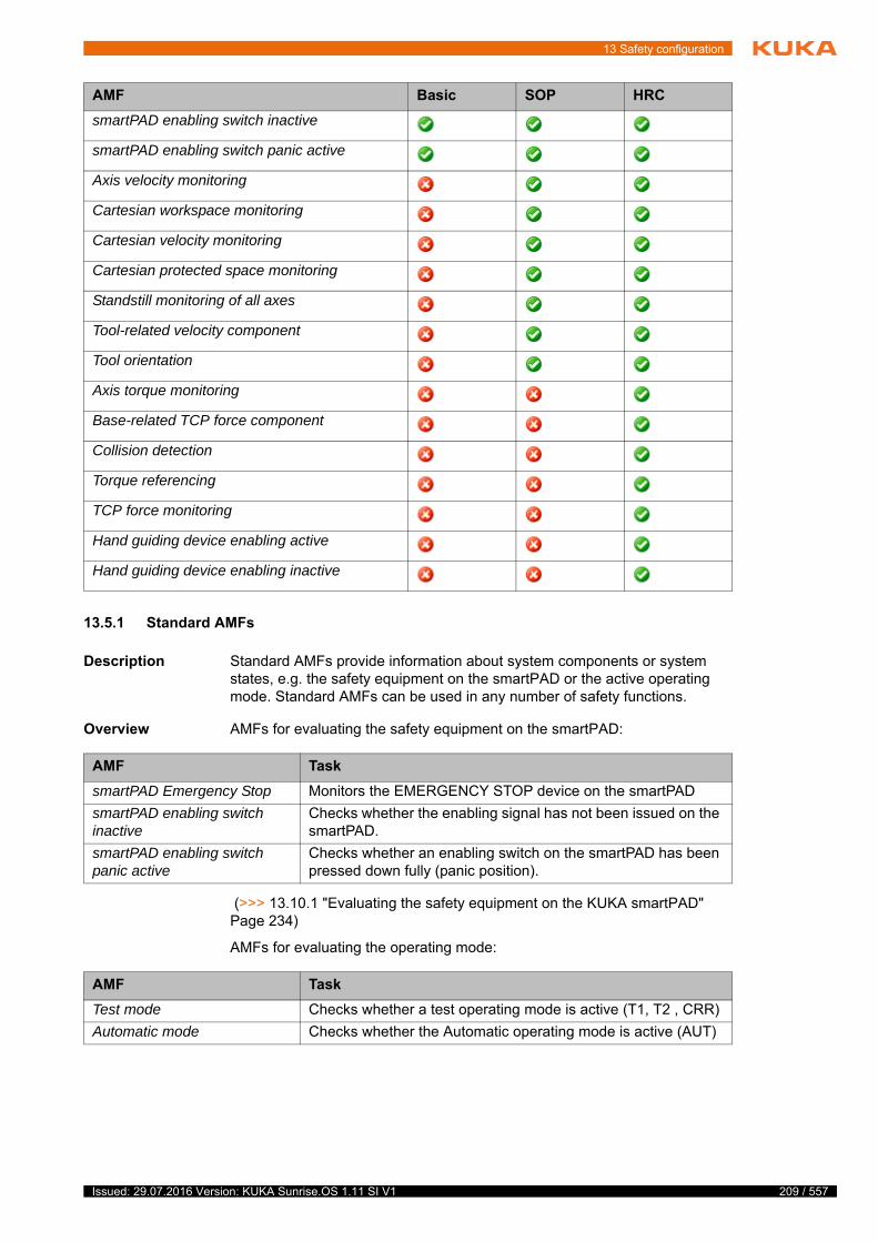
13 Safety configuration
13.5.1 Standard AMFs
Description Standard AMFs provide information about system components or system states, e.g. the safety equipment on the smartPAD or the active operating mode. Standard AMFs can be used in any number of safety functions.
Overview AMFs for evaluating the safety equipment on the smartPAD:
(>>> 13.10.1 "Evaluating the safety equipment on the KUKA smartPAD" Page 234)
AMFs for evaluating the operating mode:
smartPAD enabling switch inactive
smartPAD enabling switch panic active
Axis velocity monitoring
Cartesian workspace monitoring
Cartesian velocity monitoring
Cartesian protected space monitoring
Standstill monitoring of all axes
Tool-related velocity component
Tool orientation
Axis torque monitoring
Base-related TCP force component
Collision detection
Torque referencing
TCP force monitoring
Hand guiding device enabling active
Hand guiding device enabling inactive
AMF Basic SOP HRC
AMF Task
smartPAD Emergency Stop Monitors the EMERGENCY STOP device on the smartPAD
smartPAD enabling switch inactive
Checks whether the enabling signal has not been issued on the smartPAD.
smartPAD enabling switch panic active
Checks whether an enabling switch on the smartPAD has been pressed down fully (panic position).
AMF Task
Test mode Checks whether a test operating mode is active (T1, T2 , CRR)
Automatic mode Checks whether the Automatic operating mode is active (AUT)
209 / 557Issued: 29.07.2016 Version: KUKA Sunrise.OS 1.11 SI V1

210 / 557
KUKA Sunrise.OS 1.11 KUKA Sunrise.Wor...
(>>> 13.10.2 "Evaluating the operating mode" Page 235)
AMFs for evaluating the motion enable:
(>>> 13.10.3 "Evaluating the motion enable" Page 235)
13.5.2 Parameterizable AMFs
Description In contrast to standard AMFs, parameterizable AMFs additionally have one or more parameters. These can be configured depending on the values at which the AMF is to be considered violated (e.g. monitoring limits).
Up to 100 instances are available for each parameterizable AMF. In this way, differently parameterized versions of the AMF can be configured and used. The instance of an AMF may be used multiple times in the table in which the safety functions are configured.
Overview AMF for evaluating safe inputs:
AMFs for evaluating the enabling signal on the hand guiding device:
(>>> 13.10.5 "Manual guidance with enabling device and velocity monitoring" Page 236)
AMFs for evaluating the referencing status:
Reduced-velocity mode Checks whether an operating mode with reduced velocity is active (T1, CRR)
Note: In the case of a mobile platform, the velocity is not reduced in T1 and CRR mode.
High-velocity mode Checks whether an operating mode with programmed velocity is active (T2 , AUT)
AMF Task
AMF Task
Motion enable Monitors the motion enable signal
Motion enable is refused if a safety stop is active.
AMF Task
Input signal Monitors a safe input
(>>> 13.10.4 "Monitoring safe inputs" Page 235)
AMF Task
Hand guiding device enabling inactive
Checks whether the enabling signal has not been issued on the hand guiding device.
Hand guiding device enabling active
Checks whether the enabling signal has been issued on the hand guiding device.
The AMF is used to activate further monitoring functions during manual guidance with an enabling device.
Issued: 29.07.2016 Version: KUKA Sunrise.OS 1.11 SI V1
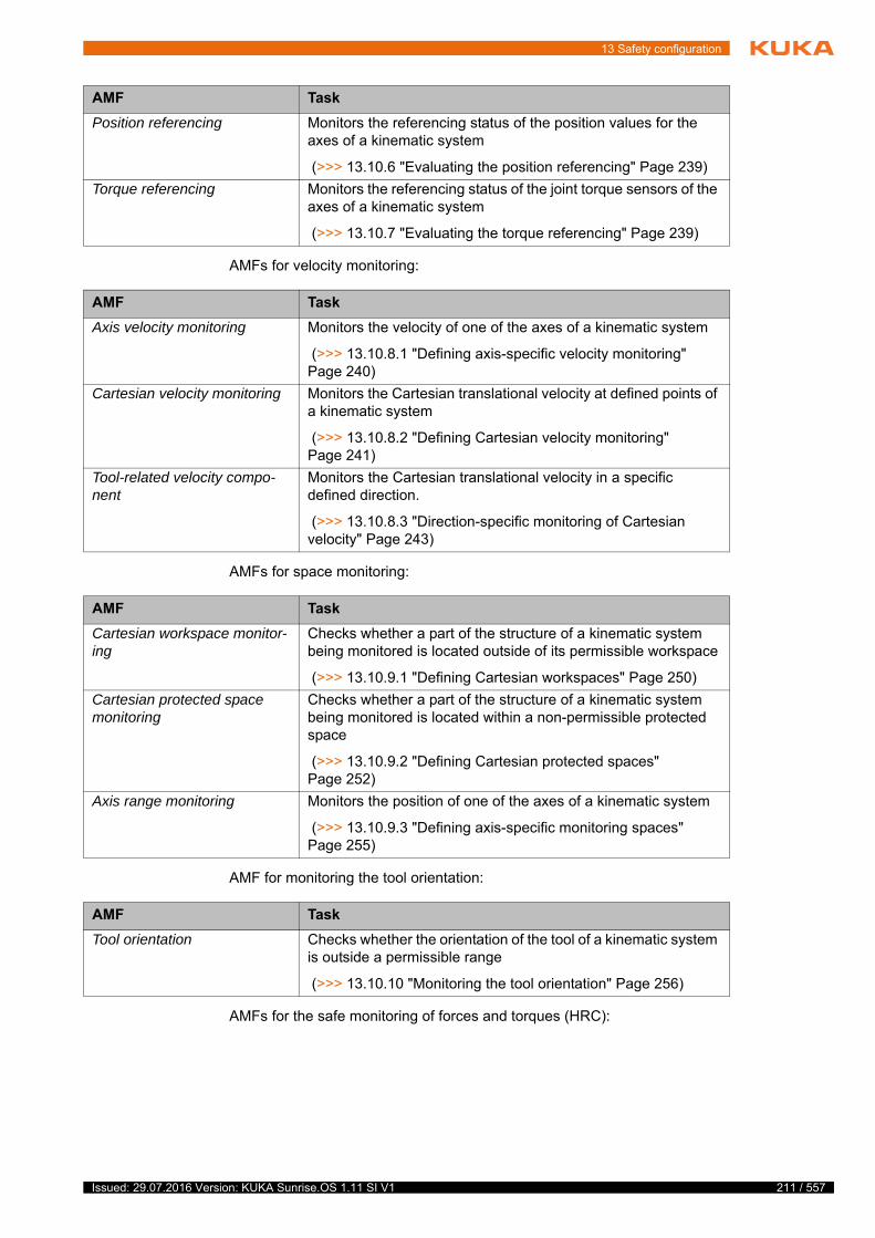
13 Safety configuration
AMFs for velocity monitoring:
AMFs for space monitoring:
AMF for monitoring the tool orientation:
AMFs for the safe monitoring of forces and torques (HRC):
AMF Task
Position referencing Monitors the referencing status of the position values for the axes of a kinematic system
(>>> 13.10.6 "Evaluating the position referencing" Page 239)
Torque referencing Monitors the referencing status of the joint torque sensors of the axes of a kinematic system
(>>> 13.10.7 "Evaluating the torque referencing" Page 239)
AMF Task
Axis velocity monitoring Monitors the velocity of one of the axes of a kinematic system
(>>> 13.10.8.1 "Defining axis-specific velocity monitoring" Page 240)
Cartesian velocity monitoring Monitors the Cartesian translational velocity at defined points of a kinematic system
(>>> 13.10.8.2 "Defining Cartesian velocity monitoring" Page 241)
Tool-related velocity compo-nent
Monitors the Cartesian translational velocity in a specific defined direction.
(>>> 13.10.8.3 "Direction-specific monitoring of Cartesian velocity" Page 243)
AMF Task
Cartesian workspace monitor-ing
Checks whether a part of the structure of a kinematic system being monitored is located outside of its permissible workspace
(>>> 13.10.9.1 "Defining Cartesian workspaces" Page 250)
Cartesian protected space monitoring
Checks whether a part of the structure of a kinematic system being monitored is located within a non-permissible protected space
(>>> 13.10.9.2 "Defining Cartesian protected spaces" Page 252)
Axis range monitoring Monitors the position of one of the axes of a kinematic system
(>>> 13.10.9.3 "Defining axis-specific monitoring spaces" Page 255)
AMF Task
Tool orientation Checks whether the orientation of the tool of a kinematic system is outside a permissible range
(>>> 13.10.10 "Monitoring the tool orientation" Page 256)
211 / 557Issued: 29.07.2016 Version: KUKA Sunrise.OS 1.11 SI V1
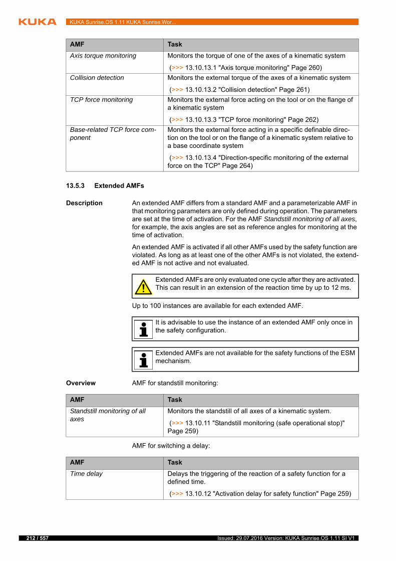
212 / 557
KUKA Sunrise.OS 1.11 KUKA Sunrise.Wor...
13.5.3 Extended AMFs
Description An extended AMF differs from a standard AMF and a parameterizable AMF in that monitoring parameters are only defined during operation. The parameters are set at the time of activation. For the AMF Standstill monitoring of all axes, for example, the axis angles are set as reference angles for monitoring at the time of activation.
An extended AMF is activated if all other AMFs used by the safety function are violated. As long as at least one of the other AMFs is not violated, the extend-ed AMF is not active and not evaluated.
Up to 100 instances are available for each extended AMF.
Overview AMF for standstill monitoring:
AMF for switching a delay:
AMF Task
Axis torque monitoring Monitors the torque of one of the axes of a kinematic system
(>>> 13.10.13.1 "Axis torque monitoring" Page 260)
Collision detection Monitors the external torque of the axes of a kinematic system
(>>> 13.10.13.2 "Collision detection" Page 261)
TCP force monitoring Monitors the external force acting on the tool or on the flange of a kinematic system
(>>> 13.10.13.3 "TCP force monitoring" Page 262)
Base-related TCP force com-ponent
Monitors the external force acting in a specific definable direc-tion on the tool or on the flange of a kinematic system relative to a base coordinate system
(>>> 13.10.13.4 "Direction-specific monitoring of the external force on the TCP" Page 264)
Extended AMFs are only evaluated one cycle after they are activated. This can result in an extension of the reaction time by up to 12 ms.
It is advisable to use the instance of an extended AMF only once in the safety configuration.
Extended AMFs are not available for the safety functions of the ESM mechanism.
AMF Task
Standstill monitoring of all axes
Monitors the standstill of all axes of a kinematic system.
(>>> 13.10.11 "Standstill monitoring (safe operational stop)" Page 259)
AMF Task
Time delay Delays the triggering of the reaction of a safety function for a defined time.
(>>> 13.10.12 "Activation delay for safety function" Page 259)
Issued: 29.07.2016 Version: KUKA Sunrise.OS 1.11 SI V1
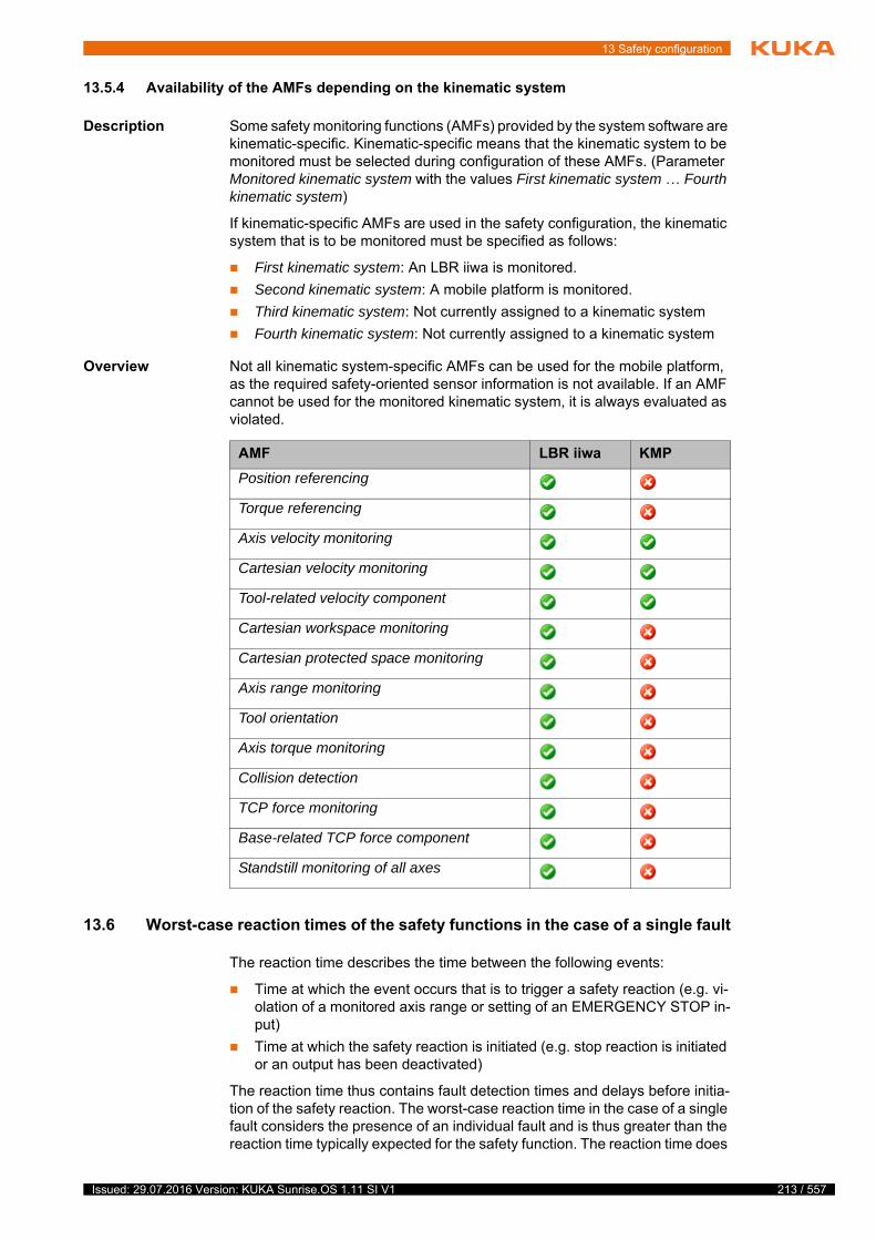
13 Safety configuration
13.5.4 Availability of the AMFs depending on the kinematic system
Description Some safety monitoring functions (AMFs) provided by the system software are kinematic-specific. Kinematic-specific means that the kinematic system to be monitored must be selected during configuration of these AMFs. (Parameter Monitored kinematic system with the values First kinematic system … Fourth kinematic system)
If kinematic-specific AMFs are used in the safety configuration, the kinematic system that is to be monitored must be specified as follows:
First kinematic system: An LBR iiwa is monitored.
Second kinematic system: A mobile platform is monitored.
Third kinematic system: Not currently assigned to a kinematic system
Fourth kinematic system: Not currently assigned to a kinematic system
Overview Not all kinematic system-specific AMFs can be used for the mobile platform, as the required safety-oriented sensor information is not available. If an AMF cannot be used for the monitored kinematic system, it is always evaluated as violated.
13.6 Worst-case reaction times of the safety functions in the case of a single fault
The reaction time describes the time between the following events:
Time at which the event occurs that is to trigger a safety reaction (e.g. vi-olation of a monitored axis range or setting of an EMERGENCY STOP in-put)
Time at which the safety reaction is initiated (e.g. stop reaction is initiated or an output has been deactivated)
The reaction time thus contains fault detection times and delays before initia-tion of the safety reaction. The worst-case reaction time in the case of a single fault considers the presence of an individual fault and is thus greater than the reaction time typically expected for the safety function. The reaction time does
AMF LBR iiwa KMP
Position referencing
Torque referencing
Axis velocity monitoring
Cartesian velocity monitoring
Tool-related velocity component
Cartesian workspace monitoring
Cartesian protected space monitoring
Axis range monitoring
Tool orientation
Axis torque monitoring
Collision detection
TCP force monitoring
Base-related TCP force component
Standstill monitoring of all axes
213 / 557Issued: 29.07.2016 Version: KUKA Sunrise.OS 1.11 SI V1

214 / 557
KUKA Sunrise.OS 1.11 KUKA Sunrise.Wor...
not include the time between initiation of a stop reaction and the robot coming to a standstill.
The reaction time of a safety function depends on the monitoring function (AMF) used, the linked reaction and the monitored kinematic system.
For the stop reactions, the reaction time for the safety stop 0 is specified in each case. For safety stop 1 and safety stop 1 (path-maintaining), the reaction time may be longer in the case of defective stopping with the drives. This fault is detected by monitoring the braking ramps. The reaction time thus depends on the actual motion up to triggering of the braking ramp monitoring. Deacti-vation of the motor power can be delayed by a maximum of 1 second for safety stop 1 and safety stop 1 (path-maintaining).
If multiple monitoring functions (AMFs) are combined in a PSM table row, the monitoring function with the longest reaction time determines the reaction time of the safety function.
13.6.1 Worst-case reaction times of the LBR iiwa monitoring functions
Axis range
monitoring
Input signal
CIB_SR
Fig. 13-3: Reaction time of a safety function
1 Reaction time
2 Braking time
3 Stopping time = Reaction time + Braking time
v Velocity
t Time
t0 Time at which the triggering event occurs
t1 Time at which the safety reaction is initiated
t2 Time at which the robot comes to a standstill
Reaction Reaction time
Stop 0 22 ms
CIB_SR output 253 ms
PROFIsafe output 49 ms + PROFIsafe master watchdog time
FSoE output 49 ms + FSoE master watchdog time
Reaction Reaction time
Stop 0 159 ms
CIB_SR output 322 ms
PROFIsafe output 142 ms + PROFIsafe master watchdog time
FSoE output 142 ms + FSoE master watchdog time
Issued: 29.07.2016 Version: KUKA Sunrise.OS 1.11 SI V1

13 Safety configuration
Input signal
PROFIsafe
*: For PROFIsafe inputs, delay y must additionally be taken into consideration. This delay is dependent on the watchdog time of the PROFIsafe slave and is set by the PROFIsafe master:
y = 24 ms * Floor(slave watchdog time / 12 ms)
Input signal FSoE
**: For FSoE inputs, delay y must additionally be taken into consideration. This delay is dependent on the watchdog time of the FSoE slave and is set by the FSoE master:
y = 24 ms * Floor(slave watchdog time / 12 ms)
Input signal
media flange
"Touch"
smartPAD
Emergency Stop
smartPAD
enabling switch
panic active
smartPAD
enabling switch
inactive
Reaction Reaction time
Stop 0 53 ms + y*
CIB_SR output 240 ms + y*
PROFIsafe output Watchdog time * [2 + Ceil(24 ms / watchdog time)]
FSoE output 36 ms + y* + FSoE master watchdog time
Reaction Reaction time
Stop 0 53 ms + y**
CIB_SR output 240 ms + y**
PROFIsafe output 36 ms + y** + PROFIsafe master watchdog time
FSoE output Watchdog time * [2 + Ceil(24 ms / watchdog time)]
Reaction Reaction time
Stop 0 159 ms
CIB_SR output 346 ms
PROFIsafe output 142 ms + PROFIsafe master watchdog time
FSoE output 142 ms + FSoE master watchdog time
Reaction Reaction time
Stop 0 159 ms
CIB_SR output 346 ms
PROFIsafe output 142 ms + PROFIsafe master watchdog time
FSoE output 142 ms + FSoE master watchdog time
Reaction Reaction time
Stop 0 159 ms
CIB_SR output 346 ms
PROFIsafe output 142 ms + PROFIsafe master watchdog time
FSoE output 142 ms + FSoE master watchdog time
Reaction Reaction time
Stop 0 159 ms
CIB_SR output 346 ms
PROFIsafe output 142 ms + PROFIsafe master watchdog time
FSoE output 142 ms + FSoE master watchdog time
215 / 557Issued: 29.07.2016 Version: KUKA Sunrise.OS 1.11 SI V1

216 / 557
KUKA Sunrise.OS 1.11 KUKA Sunrise.Wor...
Axis velocity
monitoring
Cartesian
workspace
monitoring
Cartesian velocity
monitoring
Cartesian
protected space
monitoring
Standstill
monitoring of all
axes
Tool-related
velocity
component
Tool orientation
Axis torque
monitoring
Reaction Reaction time
Stop 0 28 ms
CIB_SR output 253 ms
PROFIsafe output 49 ms + PROFIsafe master watchdog time
FSoE output 49 ms + FSoE master watchdog time
Reaction Reaction time
Stop 0 22 ms
CIB_SR output 253 ms
PROFIsafe output 49 ms + PROFIsafe master watchdog time
FSoE output 49 ms + FSoE master watchdog time
Reaction Reaction time
Stop 0 22 ms
CIB_SR output 253 ms
PROFIsafe output 49 ms + PROFIsafe master watchdog time
FSoE output 49 ms + FSoE master watchdog time
Reaction Reaction time
Stop 0 28 ms
CIB_SR output 253 ms
PROFIsafe output 49 ms + PROFIsafe master watchdog time
FSoE output 49 ms + FSoE master watchdog time
Reaction Reaction time
Stop 0 22 ms
CIB_SR output 253 ms
PROFIsafe output 49 ms + PROFIsafe master watchdog time
FSoE output 49 ms + FSoE master watchdog time
Reaction Reaction time
Stop 0 22 ms
CIB_SR output 265 ms
PROFIsafe output 61 ms + PROFIsafe master watchdog time
FSoE output 61 ms + FSoE master watchdog time
Issued: 29.07.2016 Version: KUKA Sunrise.OS 1.11 SI V1
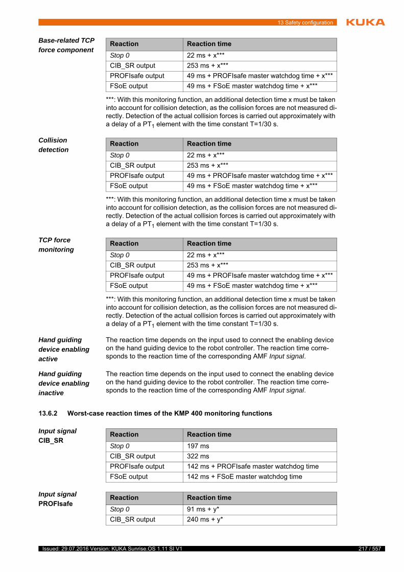
13 Safety configuration
Base-related TCP
force component
***: With this monitoring function, an additional detection time x must be taken into account for collision detection, as the collision forces are not measured di-rectly. Detection of the actual collision forces is carried out approximately with a delay of a PT1 element with the time constant T=1/30 s.
Collision
detection
***: With this monitoring function, an additional detection time x must be taken into account for collision detection, as the collision forces are not measured di-rectly. Detection of the actual collision forces is carried out approximately with a delay of a PT1 element with the time constant T=1/30 s.
TCP force
monitoring
***: With this monitoring function, an additional detection time x must be taken into account for collision detection, as the collision forces are not measured di-rectly. Detection of the actual collision forces is carried out approximately with a delay of a PT1 element with the time constant T=1/30 s.
Hand guiding
device enabling
active
The reaction time depends on the input used to connect the enabling device on the hand guiding device to the robot controller. The reaction time corre-sponds to the reaction time of the corresponding AMF Input signal.
Hand guiding
device enabling
inactive
The reaction time depends on the input used to connect the enabling device on the hand guiding device to the robot controller. The reaction time corre-sponds to the reaction time of the corresponding AMF Input signal.
13.6.2 Worst-case reaction times of the KMP 400 monitoring functions
Input signal
CIB_SR
Input signal
PROFIsafe
Reaction Reaction time
Stop 0 22 ms + x***
CIB_SR output 253 ms + x***
PROFIsafe output 49 ms + PROFIsafe master watchdog time + x***
FSoE output 49 ms + FSoE master watchdog time + x***
Reaction Reaction time
Stop 0 22 ms + x***
CIB_SR output 253 ms + x***
PROFIsafe output 49 ms + PROFIsafe master watchdog time + x***
FSoE output 49 ms + FSoE master watchdog time + x***
Reaction Reaction time
Stop 0 22 ms + x***
CIB_SR output 253 ms + x***
PROFIsafe output 49 ms + PROFIsafe master watchdog time + x***
FSoE output 49 ms + FSoE master watchdog time + x***
Reaction Reaction time
Stop 0 197 ms
CIB_SR output 322 ms
PROFIsafe output 142 ms + PROFIsafe master watchdog time
FSoE output 142 ms + FSoE master watchdog time
Reaction Reaction time
Stop 0 91 ms + y*
CIB_SR output 240 ms + y*
217 / 557Issued: 29.07.2016 Version: KUKA Sunrise.OS 1.11 SI V1
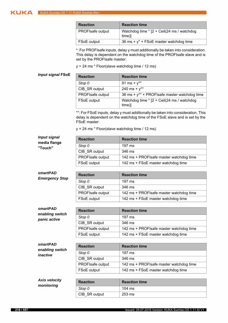
218 / 557
KUKA Sunrise.OS 1.11 KUKA Sunrise.Wor...
*: For PROFIsafe inputs, delay y must additionally be taken into consideration. This delay is dependent on the watchdog time of the PROFIsafe slave and is set by the PROFIsafe master:
y = 24 ms * Floor(slave watchdog time / 12 ms)
Input signal FSoE
**: For FSoE inputs, delay y must additionally be taken into consideration. This delay is dependent on the watchdog time of the FSoE slave and is set by the FSoE master:
y = 24 ms * Floor(slave watchdog time / 12 ms)
Input signal
media flange
"Touch"
smartPAD
Emergency Stop
smartPAD
enabling switch
panic active
smartPAD
enabling switch
inactive
Axis velocity
monitoring
PROFIsafe output Watchdog time * [2 + Ceil(24 ms / watchdog time)]
FSoE output 36 ms + y* + FSoE master watchdog time
Reaction Reaction time
Reaction Reaction time
Stop 0 91 ms + y**
CIB_SR output 240 ms + y**
PROFIsafe output 36 ms + y** + PROFIsafe master watchdog time
FSoE output Watchdog time * [2 + Ceil(24 ms / watchdog time)]
Reaction Reaction time
Stop 0 197 ms
CIB_SR output 346 ms
PROFIsafe output 142 ms + PROFIsafe master watchdog time
FSoE output 142 ms + FSoE master watchdog time
Reaction Reaction time
Stop 0 197 ms
CIB_SR output 346 ms
PROFIsafe output 142 ms + PROFIsafe master watchdog time
FSoE output 142 ms + FSoE master watchdog time
Reaction Reaction time
Stop 0 197 ms
CIB_SR output 346 ms
PROFIsafe output 142 ms + PROFIsafe master watchdog time
FSoE output 142 ms + FSoE master watchdog time
Reaction Reaction time
Stop 0 197 ms
CIB_SR output 346 ms
PROFIsafe output 142 ms + PROFIsafe master watchdog time
FSoE output 142 ms + FSoE master watchdog time
Reaction Reaction time
Stop 0 104 ms
CIB_SR output 253 ms
Issued: 29.07.2016 Version: KUKA Sunrise.OS 1.11 SI V1
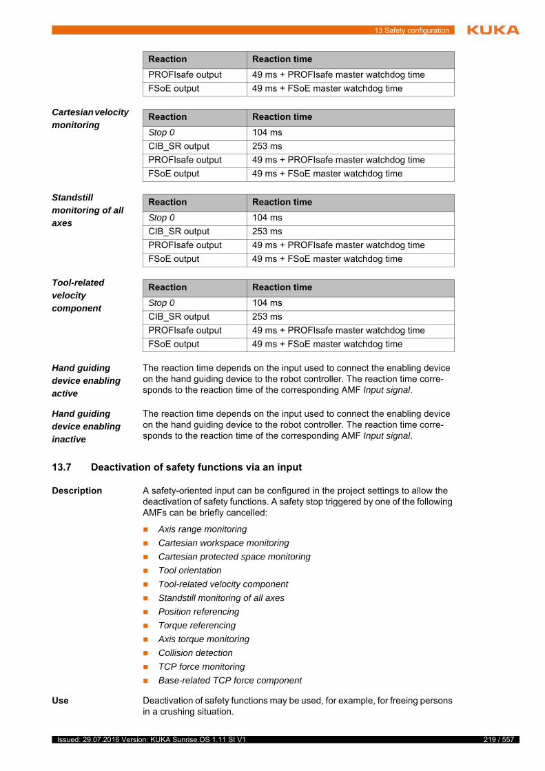
13 Safety configuration
Cartesian velocity
monitoring
Standstill
monitoring of all
axes
Tool-related
velocity
component
Hand guiding
device enabling
active
The reaction time depends on the input used to connect the enabling device on the hand guiding device to the robot controller. The reaction time corre-sponds to the reaction time of the corresponding AMF Input signal.
Hand guiding
device enabling
inactive
The reaction time depends on the input used to connect the enabling device on the hand guiding device to the robot controller. The reaction time corre-sponds to the reaction time of the corresponding AMF Input signal.
13.7 Deactivation of safety functions via an input
Description A safety-oriented input can be configured in the project settings to allow the deactivation of safety functions. A safety stop triggered by one of the following AMFs can be briefly cancelled:
Axis range monitoring
Cartesian workspace monitoring
Cartesian protected space monitoring
Tool orientation
Tool-related velocity component
Standstill monitoring of all axes
Position referencing
Torque referencing
Axis torque monitoring
Collision detection
TCP force monitoring
Base-related TCP force component
Use Deactivation of safety functions may be used, for example, for freeing persons in a crushing situation.
PROFIsafe output 49 ms + PROFIsafe master watchdog time
FSoE output 49 ms + FSoE master watchdog time
Reaction Reaction time
Reaction Reaction time
Stop 0 104 ms
CIB_SR output 253 ms
PROFIsafe output 49 ms + PROFIsafe master watchdog time
FSoE output 49 ms + FSoE master watchdog time
Reaction Reaction time
Stop 0 104 ms
CIB_SR output 253 ms
PROFIsafe output 49 ms + PROFIsafe master watchdog time
FSoE output 49 ms + FSoE master watchdog time
Reaction Reaction time
Stop 0 104 ms
CIB_SR output 253 ms
PROFIsafe output 49 ms + PROFIsafe master watchdog time
FSoE output 49 ms + FSoE master watchdog time
219 / 557Issued: 29.07.2016 Version: KUKA Sunrise.OS 1.11 SI V1
220 / 557
KUKA Sunrise.OS 1.11 KUKA Sunrise.Wor...
To cancel a safety stop triggered by one of the defined AMFs, the config-ured input must be set to HIGH.
As long as the input is HIGH, the robot can be moved for a maximum of 5 seconds. Every further safety stop triggered by one of the defined AMFs in this time does not become active.
After this time, the input must be reset and set again.
Velocity
monitoring
While the safety functions are deactivated, all axis-specific velocity monitoring functions and the Cartesian velocity monitoring function remain active.
For all kinematic systems, safety-oriented monitoring of the Cartesian velocity of 250 mm/s of the robot and tools is additionally active. This additional Carte-sian velocity monitoring is active irrespective of the operating mode.
Procedure 1. Right-click on the desired project in the Package Explorer view and select Sunrise > Change project settings from the context menu.
The Properties for [Sunrise Project] window opens.
2. Select Sunrise > Safety in the directory in the left area of the window.
3. Make the following settings in the right-hand part of the window:
Set the check mark at Allow muting via input.
Select the input that is to allow the deactivation of safety functions.
The inputs of the discrete safety interface and of the Ethernet safety interface can be used as long as they are configured in WorkVisual.
(>>> "Safety interfaces" Page 204)
4. Click on OK to save the settings and close the window.
13.8 Safety configuration (SafetyConfiguration.sconf file)
The safety configuration is an integral feature of a Sunrise project. It is man-aged in tabular form.
When creating a new Sunrise project, a standard safety configuration is auto-matically generated (SafetyConfiguration.sconf file).
(>>> 5.3 "Creating a Sunrise project with a template" Page 51)
The standard safety configuration contains permanently active safety func-tions predefined by KUKA.
Further safety functions and safe ESM states can be configured. Safety-ori-ented tools can also be mapped.
After the safety configuration has been transferred to the robot controller, it must be activated and safety acceptance must be carried out.
The enabling device of the hand guiding device can be used as an in-put for deactivating safety functions. In this case, it must be taken into consideration in the risk assessment that every time the enabling
switch on the hand guiding device is used, a safety stop that is active at the time of the enabling can be canceled if it was triggered by one of the defined safety functions.
Further information on the standard safety configuration can be found in the “Safety” chapter.
Issued: 29.07.2016 Version: KUKA Sunrise.OS 1.11 SI V1
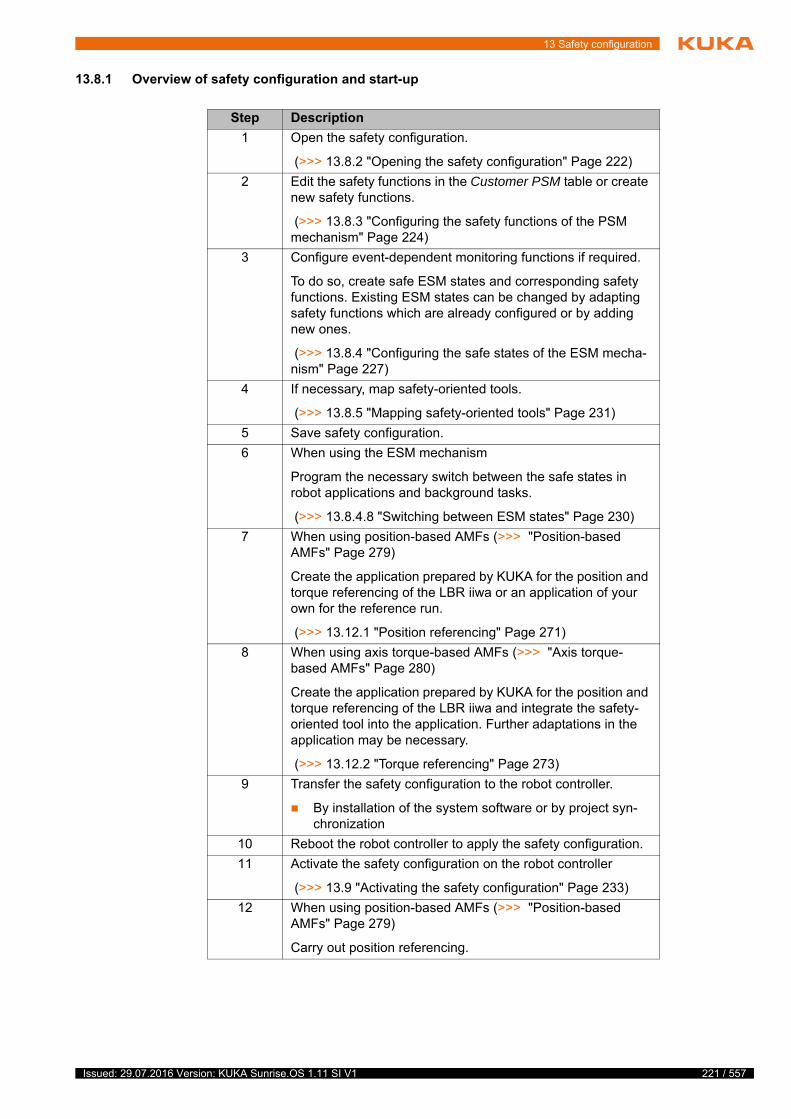
13 Safety configuration
13.8.1 Overview of safety configuration and start-up
Step Description
1 Open the safety configuration.
(>>> 13.8.2 "Opening the safety configuration" Page 222)
2 Edit the safety functions in the Customer PSM table or create new safety functions.
(>>> 13.8.3 "Configuring the safety functions of the PSM mechanism" Page 224)
3 Configure event-dependent monitoring functions if required.
To do so, create safe ESM states and corresponding safety functions. Existing ESM states can be changed by adapting safety functions which are already configured or by adding new ones.
(>>> 13.8.4 "Configuring the safe states of the ESM mecha-nism" Page 227)
4 If necessary, map safety-oriented tools.
(>>> 13.8.5 "Mapping safety-oriented tools" Page 231)
5 Save safety configuration.
6 When using the ESM mechanism
Program the necessary switch between the safe states in robot applications and background tasks.
(>>> 13.8.4.8 "Switching between ESM states" Page 230)
7 When using position-based AMFs (>>> "Position-based AMFs" Page 279)
Create the application prepared by KUKA for the position and torque referencing of the LBR iiwa or an application of your own for the reference run.
(>>> 13.12.1 "Position referencing" Page 271)
8 When using axis torque-based AMFs (>>> "Axis torque-based AMFs" Page 280)
Create the application prepared by KUKA for the position and torque referencing of the LBR iiwa and integrate the safety-oriented tool into the application. Further adaptations in the application may be necessary.
(>>> 13.12.2 "Torque referencing" Page 273)
9 Transfer the safety configuration to the robot controller.
By installation of the system software or by project syn-chronization
10 Reboot the robot controller to apply the safety configuration.
11 Activate the safety configuration on the robot controller
(>>> 13.9 "Activating the safety configuration" Page 233)
12 When using position-based AMFs (>>> "Position-based AMFs" Page 279)
Carry out position referencing.
221 / 557Issued: 29.07.2016 Version: KUKA Sunrise.OS 1.11 SI V1
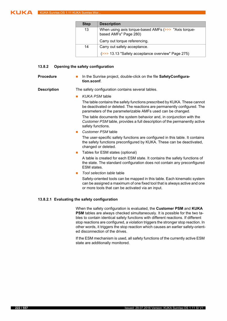
222 / 557
KUKA Sunrise.OS 1.11 KUKA Sunrise.Wor...
13.8.2 Opening the safety configuration
Procedure In the Sunrise project, double-click on the file SafetyConfigura-tion.sconf.
Description The safety configuration contains several tables.
KUKA PSM table
The table contains the safety functions prescribed by KUKA. These cannot be deactivated or deleted. The reactions are permanently configured. The parameters of the parameterizable AMFs used can be changed.
The table documents the system behavior and, in conjunction with the Customer PSM table, provides a full description of the permanently active safety functions.
Customer PSM table
The user-specific safety functions are configured in this table. It contains the safety functions preconfigured by KUKA. These can be deactivated, changed or deleted.
Tables for ESM states (optional)
A table is created for each ESM state. It contains the safety functions of the state. The standard configuration does not contain any preconfigured ESM states.
Tool selection table table
Safety-oriented tools can be mapped in this table. Each kinematic system can be assigned a maximum of one fixed tool that is always active and one or more tools that can be activated via an input.
13.8.2.1 Evaluating the safety configuration
When the safety configuration is evaluated, the Customer PSM and KUKA PSM tables are always checked simultaneously. It is possible for the two ta-bles to contain identical safety functions with different reactions. If different stop reactions are configured, a violation triggers the stronger stop reaction. In other words, it triggers the stop reaction which causes an earlier safety-orient-ed disconnection of the drives.
If the ESM mechanism is used, all safety functions of the currently active ESM state are additionally monitored.
13 When using axis torque-based AMFs (>>> "Axis torque-based AMFs" Page 280)
Carry out torque referencing.
14 Carry out safety acceptance.
(>>> 13.13 "Safety acceptance overview" Page 275)
Step Description
Issued: 29.07.2016 Version: KUKA Sunrise.OS 1.11 SI V1

13 Safety configuration
13.8.2.2 Overview of the graphical user interface for the safety configuration
The description of the user interface elements refers to the configuration of safety functions. The tool selection table is described separately.
Fig. 13-4: Graphical user interface for safety configuration
Item Description
1 Table selected
Contains the configured safety functions of the selected PSM table or of the selected ESM state.
2 Selection table
With respect to the cell selected in the highlighted table row, the category, AMF or reaction of a safety function can be selected here.
3 Instance table
This area displays the instances of the AMF marked in the selec-tion table as well as the table rows in which they are used.
4 Parameter table
The parameter values of the AMF instance selected in the instance table are displayed here. The values can be changed.
5 Information display
Information about the selected category, AMF or reaction
223 / 557Issued: 29.07.2016 Version: KUKA Sunrise.OS 1.11 SI V1
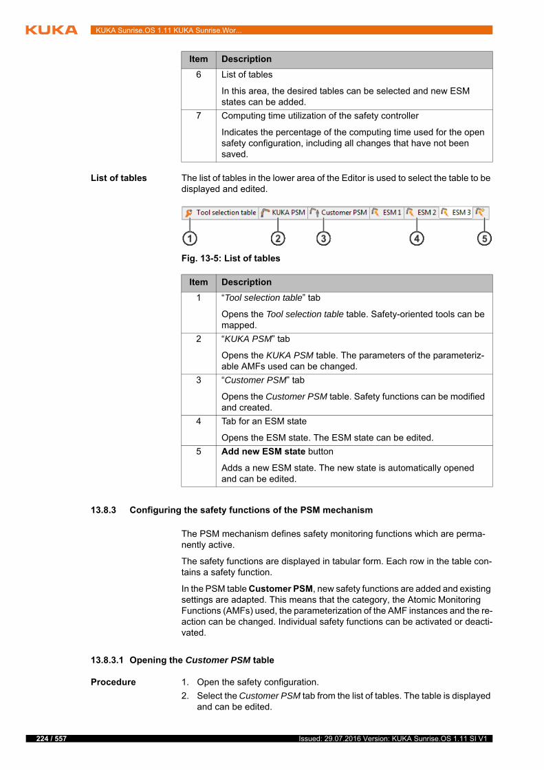
224 / 557
KUKA Sunrise.OS 1.11 KUKA Sunrise.Wor...
List of tables The list of tables in the lower area of the Editor is used to select the table to be displayed and edited.
13.8.3 Configuring the safety functions of the PSM mechanism
The PSM mechanism defines safety monitoring functions which are perma-nently active.
The safety functions are displayed in tabular form. Each row in the table con-tains a safety function.
In the PSM table Customer PSM, new safety functions are added and existing settings are adapted. This means that the category, the Atomic Monitoring Functions (AMFs) used, the parameterization of the AMF instances and the re-action can be changed. Individual safety functions can be activated or deacti-vated.
13.8.3.1 Opening the Customer PSM table
Procedure 1. Open the safety configuration.
2. Select the Customer PSM tab from the list of tables. The table is displayed and can be edited.
6 List of tables
In this area, the desired tables can be selected and new ESM states can be added.
7 Computing time utilization of the safety controller
Indicates the percentage of the computing time used for the open safety configuration, including all changes that have not been saved.
Item Description
Fig. 13-5: List of tables
Item Description
1 “Tool selection table” tab
Opens the Tool selection table table. Safety-oriented tools can be mapped.
2 “KUKA PSM” tab
Opens the KUKA PSM table. The parameters of the parameteriz-able AMFs used can be changed.
3 “Customer PSM” tab
Opens the Customer PSM table. Safety functions can be modified and created.
4 Tab for an ESM state
Opens the ESM state. The ESM state can be edited.
5 Add new ESM state button
Adds a new ESM state. The new state is automatically opened and can be edited.
Issued: 29.07.2016 Version: KUKA Sunrise.OS 1.11 SI V1

13 Safety configuration
The following buttons are available:
Fig. 13-6: PSM table Customer PSM
Item Description
1 Active column
Defines whether the safety function is active. Deactivated safety functions are not monitored.
Check box active: safety function is active.
Check box not active: safety function is deactivated.
2 Category column
Defines the category of the safety function. In the event of an error, the category is shown on the smartHMI as the cause of error.
3 Columns AMF 1, AMF 2, AMF 3
Define the individual AMFs of the safety function. Up to 3 AMFs can be used. The safety function is violated if all of the AMFs used are violated.
4 Reaction column
Defines the reaction of the safety function. It is triggered if the safety function is violated.
5 Number of safety functions currently configured
A total of 100 rows are available for configuring the user-specific safety monitoring functions.
6 Buttons for editing the table
7 Selected row
The row containing the currently selected safety function is high-lighted in gray.
225 / 557Issued: 29.07.2016 Version: KUKA Sunrise.OS 1.11 SI V1
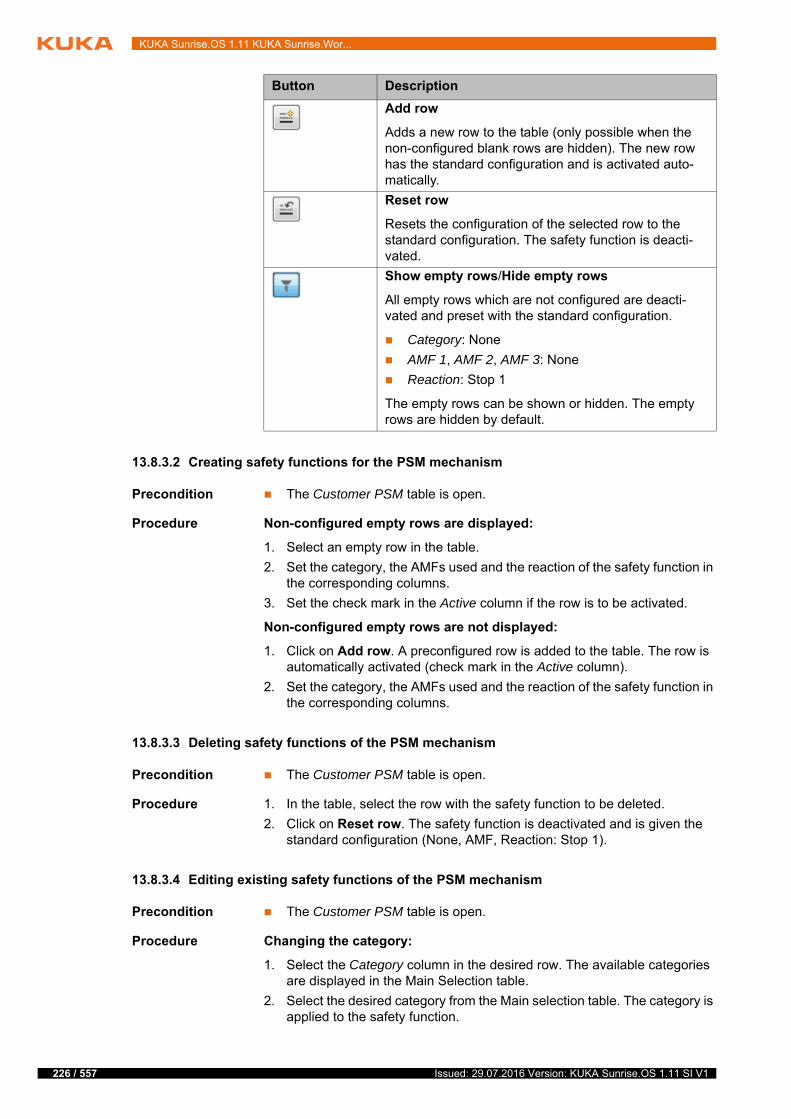
226 / 557
KUKA Sunrise.OS 1.11 KUKA Sunrise.Wor...
13.8.3.2 Creating safety functions for the PSM mechanism
Precondition The Customer PSM table is open.
Procedure Non-configured empty rows are displayed:
1. Select an empty row in the table.
2. Set the category, the AMFs used and the reaction of the safety function in the corresponding columns.
3. Set the check mark in the Active column if the row is to be activated.
Non-configured empty rows are not displayed:
1. Click on Add row. A preconfigured row is added to the table. The row is automatically activated (check mark in the Active column).
2. Set the category, the AMFs used and the reaction of the safety function in the corresponding columns.
13.8.3.3 Deleting safety functions of the PSM mechanism
Precondition The Customer PSM table is open.
Procedure 1. In the table, select the row with the safety function to be deleted.
2. Click on Reset row. The safety function is deactivated and is given the standard configuration (None, AMF, Reaction: Stop 1).
13.8.3.4 Editing existing safety functions of the PSM mechanism
Precondition The Customer PSM table is open.
Procedure Changing the category:
1. Select the Category column in the desired row. The available categories are displayed in the Main Selection table.
2. Select the desired category from the Main selection table. The category is applied to the safety function.
Button Description
Add row
Adds a new row to the table (only possible when the non-configured blank rows are hidden). The new row has the standard configuration and is activated auto-matically.
Reset row
Resets the configuration of the selected row to the standard configuration. The safety function is deacti-vated.
Show empty rows/Hide empty rows
All empty rows which are not configured are deacti-vated and preset with the standard configuration.
Category: None
AMF 1, AMF 2, AMF 3: None
Reaction: Stop 1
The empty rows can be shown or hidden. The empty rows are hidden by default.
Issued: 29.07.2016 Version: KUKA Sunrise.OS 1.11 SI V1
13 Safety configuration
Changing the AMF used:
1. Select the AMF 1, AMF 2 or AMF 3 column in the desired row. The avail-able AMFs are displayed in the Main selection table.
2. Select the desired AMF from the Main selection table. The AMF is applied to the safety function.
3. For multiply instanced AMFs: select the desired instance from the Main se-lection table. The instance is applied to the safety function.
4. For parameterizable AMFs: in the parameter table, set the parameter of the AMF in the Value column and insert the settings with the Enter key.
Changing a reaction:
1. Select the Reaction column in the desired row. The available reactions are displayed in the Main selection table.
2. Select the desired reaction from the Main selection table. The reaction is applied to the safety function.
3. If the Output reaction has been selected: in the Parameter table, select the output bit whose signal is to be set to LOW if a safety function is vio-lated. Accept the setting with the Enter key.
Activating/deactivating a safety function:
Click on the Active column in the desired row. The check mark is set / re-moved.
13.8.4 Configuring the safe states of the ESM mechanism
Using the ESM mechanism, various safety settings are defined by configu-rable safe states. Up to 10 safe states can be created. The states are num-bered sequentially from 1 to 10 and can therefore be identified unambiguously.
A safe state is defined in a table with up to 20 safety functions. These safety functions define the safety settings which must be valid for the state.
A safe state is represented in a table. Each row in the table contains a safety function.
Use of the ESM mechanism is optional. The ESM mechanism is activated if at least one ESM state is configured. If no ESM states are configured, the mech-anism is deactivated.
If the ESM mechanism is active, exactly one safe state is valid. The safety functions of this state are monitored in addition to the permanently active safe-ty functions. Depending on the situation, it is possible to switch between the configured safe states. Switching can be carried out in the robot application or in a background task.
(>>> 13.8.4.8 "Switching between ESM states" Page 230)
An ESM state is active until it is commanded to switch to another ESM state.
The configured ESM state with the lowest number is automatically active when the controller is booted.
13.8.4.1 Adding a new ESM state
Up to 10 safe states can be created for the ESM mechanism. If this number is reached, the tab for adding new states is hidden.
Procedure 1. Open the safety configuration.
Once the safety configurations are transferred to the robot controller and activated, only the activated safety functions are available.
227 / 557Issued: 29.07.2016 Version: KUKA Sunrise.OS 1.11 SI V1
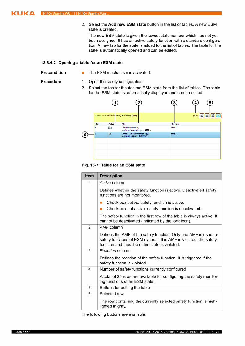
228 / 557
KUKA Sunrise.OS 1.11 KUKA Sunrise.Wor...
2. Select the Add new ESM state button in the list of tables. A new ESM state is created.
The new ESM state is given the lowest state number which has not yet been assigned. It has an active safety function with a standard configura-tion. A new tab for the state is added to the list of tables. The table for the state is automatically opened and can be edited.
13.8.4.2 Opening a table for an ESM state
Precondition The ESM mechanism is activated.
Procedure 1. Open the safety configuration.
2. Select the tab for the desired ESM state from the list of tables. The table for the ESM state is automatically displayed and can be edited.
The following buttons are available:
Fig. 13-7: Table for an ESM state
Item Description
1 Active column
Defines whether the safety function is active. Deactivated safety functions are not monitored.
Check box active: safety function is active.
Check box not active: safety function is deactivated.
The safety function in the first row of the table is always active. It cannot be deactivated (indicated by the lock icon).
2 AMF column
Defines the AMF of the safety function. Only one AMF is used for safety functions of ESM states. If this AMF is violated, the safety function and thus the entire state is violated.
3 Reaction column
Defines the reaction of the safety function. It is triggered if the safety function is violated.
4 Number of safety functions currently configured
A total of 20 rows are available for configuring the safety monitor-ing functions of an ESM state.
5 Buttons for editing the table
6 Selected row
The row containing the currently selected safety function is high-lighted in gray.
Issued: 29.07.2016 Version: KUKA Sunrise.OS 1.11 SI V1

13 Safety configuration
13.8.4.3 Deleting an ESM state
Procedure 1. Open the safety configuration.
2. Select the tab for the ESM state to be deleted from the list of tables.
3. Click on Delete state.
4. Reply to the request for confirmation with Yes. The state is deleted.
Once the safety configuration is saved and closed, an ESM state is automati-cally removed if it has the following settings:
All rows have the standard configuration (AMF: None, Reaction: Stop 1)
The first row is activated and all other rows are deactivated.
13.8.4.4 Creating a safety function for the ESM state
Precondition The table for the desired ESM state is open.
Procedure Non-configured empty rows are displayed:
1. Select an empty row in the table.
2. Set the AMF used and the reaction of the safety function in the corre-sponding columns.
3. Set the check mark in the Active column if the row is to be activated.
Non-configured empty rows are not displayed:
1. Click on Add row. A preconfigured row is added to the table. The row is automatically activated (check mark in the Active column).
2. Set the AMF used and the reaction of the safety function in the corre-sponding columns.
Button Description
Delete state
Deletes the entire state The delete operation must be confirmed via a dialog.
Add row
Adds a new row to the table (only possible when the non-configured blank rows are hidden). The new row has the standard configuration and is activated auto-matically.
Reset row
Resets the configuration of the selected row to the standard configuration. The safety function is deacti-vated (exception: the first row of the table is always active).
Show empty rows/Hide empty rows
All empty rows which are not configured are deacti-vated and preset with the standard configuration.
AMF: None
Reaction: Stop 1
The empty rows can be shown or hidden. The empty rows are hidden by default.
229 / 557Issued: 29.07.2016 Version: KUKA Sunrise.OS 1.11 SI V1
230 / 557
KUKA Sunrise.OS 1.11 KUKA Sunrise.Wor...
13.8.4.5 Deleting a safety function of an ESM state
Precondition The table for the desired ESM state is open.
Procedure 1. In the table, select the row with the safety function to be deleted.
2. Click on Reset row. The safety function is deactivated and is given the standard configuration (None, AMF, Reaction: Stop 1).
13.8.4.6 Editing an existing safety function of an ESM state
Precondition The table for the desired ESM state is open.
Procedure Changing the AMF used:
1. Select the AMF column in the desired row. The available AMFs are dis-played in the Main selection table.
2. Select the desired AMF from the Main selection table. The AMF is applied to the safety function.
3. For multiply instanced AMFs: select the desired instance from the Main se-lection table. The instance is applied to the safety function.
4. For parameterizable AMFs: in the parameter table, set the parameter of the AMF in the Value column and insert the settings with the Enter key.
Changing a reaction:
1. Select the Reaction column in the desired row. The available reactions are displayed in the Main selection table.
2. Select the desired reaction from the Main selection table. The reaction is applied to the safety function.
Activating/deactivating a safety function:
Click on the Active column in the desired row. The check mark is set / re-moved.
13.8.4.7 Deactivating the ESM mechanism
Use of the ESM mechanism is optional. It can be deactivated.
Procedure Delete all ESM states.
13.8.4.8 Switching between ESM states
Description The setESMState(…) method can be used to activate an ESM state and switch between the different ESM states. The method belongs to the LBR class and can be used in robot applications or background tasks.
Syntax robot.setESMState(state);
Explanation of
the syntaxElement Description
robot Type: LBR
Name of the robot for which the ESM state is activated
state Type: String
Number of the ESM state which is activated
1 … 10
If a non-configured ESM state is specified, the robot stops with a safety stop 1.
Issued: 29.07.2016 Version: KUKA Sunrise.OS 1.11 SI V1

13 Safety configuration
Example In an application, the LBR iiwa is to be guided by hand. For this purpose, a suitable start position is addressed. In order to address the start position, ESM state 3 must be activated. ESM state 3 ensures sensitive collision detection and monitors the Cartesian velocity.
Manual guidance is to begin once the start point has been reached. ESM state 8 must be activated for manual guidance. ESM state 8 requires enabling on the hand guiding device but permits a higher Cartesian velocity than ESM state 3.
13.8.5 Mapping safety-oriented tools
Description Each kinematic system can be assigned a maximum of one fixed safety-ori-ented tool that is always active and one or more safety-oriented tools that can be activated via an input.
Assignment of a fixed tool (always active)
A fixed tool is coupled to the flange of the configured kinematic system and cannot be uncoupled or changed. The fixed tool can be a machining tool, a tool for picking up workpieces or a tool that can pick up other tools, e.g. a tool changer.
The assignment of multiple fixed tools to a kinematic system is not al-lowed. In this case, all tool-dependent monitoring functions of this kinemat-ic system enter the safe state.
Assignment of tools that can be activated (via an input)
The tool is activated when the configured input signal is HIGH.
If a fixed tool is configured for this kinematic system, the activatable tool is coupled to the pickup frame of the fixed tool (standard frame for motions). If no fixed tool is configured for a kinematic system, it is coupled to the flange of the kinematic system.
If an activatable tool is configured for a kinematic system, exactly one ac-tivatable tool must always be active for this kinematic system. This means that exactly one of the input signals configured for this kinematic system must be HIGH.
If multiple activatable tools are active simultaneously, or if none of the ac-tivatable tools is active, all tool-dependent monitoring functions of this ki-nematic system enter the safe state. For this reason, the tool No tool must be activated if the activatable tool is uncoupled.
Procedure 1. Open the safety configuration.
2. Select the Tool selection table tab from the list of tables. Map the tools as desired.
3. Save the safety configuration.
@Inject
private LBR robot;// ...
public void run() {// ...
robot.setESMState("3");
robot.move(lin(getFrame("Start")).setCartVelocity(300));
robot.setESMState("8");
robot.move(handGuiding());
// ...
}
231 / 557Issued: 29.07.2016 Version: KUKA Sunrise.OS 1.11 SI V1

232 / 557
KUKA Sunrise.OS 1.11 KUKA Sunrise.Wor...
Overview
The following buttons are available:
Fig. 13-8: Tool selection table table
Item Description
1 State of the mapped tool
Check box active: The tool is always active or activatable.
Check box not active: The tool is deactivated.
2 Kinematic system to which the tool is assigned
First kinematic system: Robot
Second kinematic system: Mobile platform
Third kinematic system: No function
Fourth kinematic system: No function
3 Tool assigned to the kinematic system
No tool: No tool is assigned to the kinematic system.
All safety-oriented tools defined in the object templates are available for selection.
4 Activation of the tool
Always active: The tool is always active.
A maximum of 1 fixed tool can be assigned to each kinematic system.
The tool can be activated via a safe input
The safe inputs of the Ethernet safety interface used are avail-able.
5 Number of tools currently mapped
A total of 50 rows are available for mapping.
6 Buttons for editing the table
7 Information display
Information about the selected parameter
8 Selection table
The table contains the values available for the parameter selected in the configuration line.
Issued: 29.07.2016 Version: KUKA Sunrise.OS 1.11 SI V1
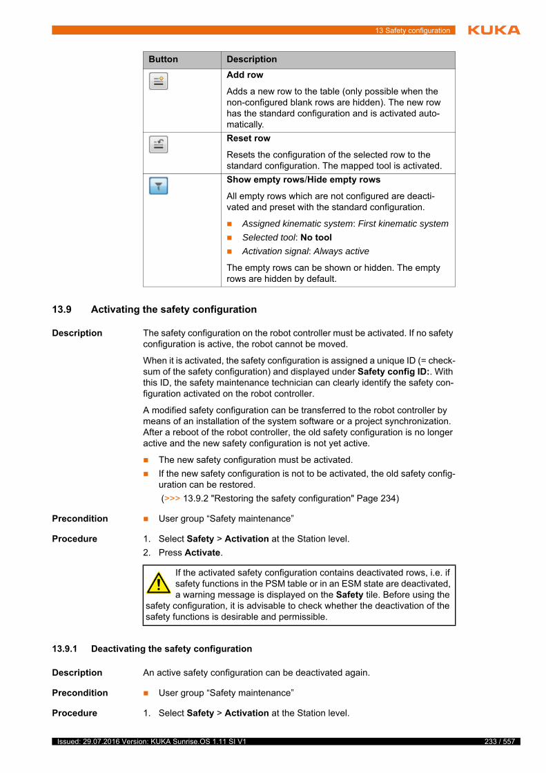
13 Safety configuration
13.9 Activating the safety configuration
Description The safety configuration on the robot controller must be activated. If no safety configuration is active, the robot cannot be moved.
When it is activated, the safety configuration is assigned a unique ID (= check-sum of the safety configuration) and displayed under Safety config ID:. With this ID, the safety maintenance technician can clearly identify the safety con-figuration activated on the robot controller.
A modified safety configuration can be transferred to the robot controller by means of an installation of the system software or a project synchronization. After a reboot of the robot controller, the old safety configuration is no longer active and the new safety configuration is not yet active.
The new safety configuration must be activated.
If the new safety configuration is not to be activated, the old safety config-uration can be restored.
(>>> 13.9.2 "Restoring the safety configuration" Page 234)
Precondition User group “Safety maintenance”
Procedure 1. Select Safety > Activation at the Station level.
2. Press Activate.
13.9.1 Deactivating the safety configuration
Description An active safety configuration can be deactivated again.
Precondition User group “Safety maintenance”
Procedure 1. Select Safety > Activation at the Station level.
Button Description
Add row
Adds a new row to the table (only possible when the non-configured blank rows are hidden). The new row has the standard configuration and is activated auto-matically.
Reset row
Resets the configuration of the selected row to the standard configuration. The mapped tool is activated.
Show empty rows/Hide empty rows
All empty rows which are not configured are deacti-vated and preset with the standard configuration.
Assigned kinematic system: First kinematic system
Selected tool: No tool
Activation signal: Always active
The empty rows can be shown or hidden. The empty rows are hidden by default.
If the activated safety configuration contains deactivated rows, i.e. if safety functions in the PSM table or in an ESM state are deactivated, a warning message is displayed on the Safety tile. Before using the
safety configuration, it is advisable to check whether the deactivation of the safety functions is desirable and permissible.
233 / 557Issued: 29.07.2016 Version: KUKA Sunrise.OS 1.11 SI V1
234 / 557
KUKA Sunrise.OS 1.11 KUKA Sunrise.Wor...
2. Press Deactivate.
3. Check whether the safety configuration has been deactivated successful-ly.
Following successful deactivation, the robot can no longer be moved. A corresponding message is displayed under the Safety tile.
13.9.2 Restoring the safety configuration
Description If a new safety configuration is transferred to the robot controller, but is not to be activated, the most recently active safety configuration can be restored.
Precondition User group “Safety maintenance”
Procedure 1. Select Safety > Activation at the Station level.
2. Press Reset.
13.10 Using and parameterizing the AMFs
Up to 100 instances are available for each parameterizable AMF. As the pro-cessing power of the safety controller is limited, this quantity cannot be used to the full in practice.
Each instance of the AMF used in the safety configuration requires part of the available processing power. The processing time required by an AMF instance depends, for example, on the number of parameters and the complexity of the corresponding calculations.
How often an AMF instance is used in the safety configuration, how many lines are used in the Customer PSM table and how many ESM states are used are not relevant for the processing power.
Response if the processing power of the safety controller is exceeded:
The required processing time of a safety configuration is calculated auto-matically on saving the safety configuration. If it is too great, a warning is displayed. It is nonetheless saved.
The transfer of an excessively large safety configuration to the robot con-troller is prevented. Project synchronization and installation of the system software are canceled in this case with a corresponding error message.
13.10.1 Evaluating the safety equipment on the KUKA smartPAD
The smartPAD has an EMERGENCY STOP device and an enabling device. The corresponding safety-oriented functions are preconfigured in the KUKA PSM table and cannot be changed.
Further safety functions evaluated by the safety equipment on the smartPAD can be configured. The following standard AMFs are available for this pur-pose:
AMF Description
smartPAD Emergency Stop The AMF is violated if the EMERGENCY STOP device on the smartPAD is pressed.
smartPAD enabling switch inactive
The AMF is violated if no enabling signal is issued on the smart-PAD (no enabling switch is pressed on the smartPAD or an enabling switch is fully pressed).
smartPAD enabling switch panic active
The AMF is violated if an enabling switch on the smartPAD is fully pressed (panic position).
Issued: 29.07.2016 Version: KUKA Sunrise.OS 1.11 SI V1

13 Safety configuration
13.10.2 Evaluating the operating mode
The set operating mode has a powerful effect on the behavior of the industrial robot and determines which safety precautions are required.
The following standard AMFs are available for configuring a safety function to evaluate the set operating mode:
13.10.3 Evaluating the motion enable
Description The robot cannot be moved without the motion enable. The motion enable can be cancelled for various reasons, e.g. if enabling is not issued in Test mode or if the EMERGENCY STOP is pressed on the smartPAD.
The AMF for motion enable functions like a group signal for all configured stop conditions. In particular, it can be be used for switching off peripheral devices. For safety functions which receive the evaluation of the motion enable, a safe output should therefore be configured as the reaction. If a safety stop is set as the reaction, the robot cannot be moved.
Example Switching off a tool (category: Output)
A tool (e.g. a laser) which is connected to an output is to be switched off when the motion enable is canceled. It is only to be switched off if the operator safety is violated.
13.10.4 Monitoring safe inputs
Description The inputs of the discrete safety interface and of the Ethernet safety interface can be used as safe inputs as long as they are configured in WorkVisual.
(>>> "Safety interfaces" Page 204)
Safety equipment can be connected to the safe inputs, e.g. external EMER-GENCY STOP devices or safety gates. The AMF Input signal is used to eval-uate the associated input signal.
AMF Description
Test mode The AMF is violated if a test operating mode is active (T1, T2 , CRR).
Automatic mode The AMF is violated if the active operating mode is an automatic mode (AUT).
Reduced-velocity mode The AMF is violated if an operating mode is active whose veloc-ity is reduced to a maximum of 250 mm/s (T1, CRR).
Note: In the case of a mobile platform, the velocity is not reduced in T1 and CRR mode.
High-velocity mode The AMF is violated if an operating mode is active in which the robot is moved with a programmed velocity (T2, AUT).
AMF Description
Motion enable The AMF is violated if the motion enable is not issued due to a stop request.
Note: This AMF is only suitable for use with an output as a reaction.
AMF1 AMF2 AMF3 Reaction
Input signal (operator safety)
- Motion enable Output (tool)
235 / 557Issued: 29.07.2016 Version: KUKA Sunrise.OS 1.11 SI V1
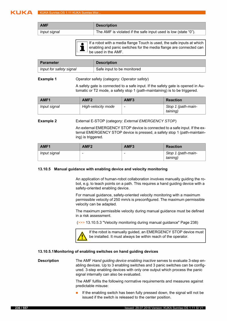
236 / 557
KUKA Sunrise.OS 1.11 KUKA Sunrise.Wor...
Example 1 Operator safety (category: Operator safety)
A safety gate is connected to a safe input. If the safety gate is opened in Au-tomatic or T2 mode, a safety stop 1 (path-maintaining) is to be triggered.
Example 2 External E-STOP (category: External EMERGENCY STOP)
An external EMERGENCY STOP device is connected to a safe input. If the ex-ternal EMERGENCY STOP device is pressed, a safety stop 1 (path-maintain-ing) is triggered.
13.10.5 Manual guidance with enabling device and velocity monitoring
An application of human-robot collaboration involves manually guiding the ro-bot, e.g. to teach points on a path. This requires a hand guiding device with a safety-oriented enabling device.
For manual guidance, safety-oriented velocity monitoring with a maximum permissible velocity of 250 mm/s is preconfigured. The maximum permissible velocity can be adapted.
The maximum permissible velocity during manual guidance must be defined in a risk assessment.
(>>> 13.10.5.3 "Velocity monitoring during manual guidance" Page 238)
13.10.5.1Monitoring of enabling switches on hand guiding devices
Description The AMF Hand guiding device enabling inactive serves to evaluate 3-step en-abling devices. Up to 3 enabling switches and 3 panic switches can be config-ured. 3-step enabling devices with only one output which process the panic signal internally can also be evaluated.
The AMF fulfils the following normative requirements and measures against predictable misuse:
If the enabling switch has been fully pressed down, the signal will not be issued if the switch is released to the center position.
AMF Description
Input signal The AMF is violated if the safe input used is low (state “0”).
If a robot with a media flange Touch is used, the safe inputs at which enabling and panic switches for the media flange are connected can be used in the AMF.
Parameter Description
Input for safety signal Safe input to be monitored
AMF1 AMF2 AMF3 Reaction
Input signal High-velocity mode - Stop 1 (path-main-taining)
AMF1 AMF2 AMF3 Reaction
Input signal - - Stop 1 (path-main-taining)
If the robot is manually guided, an EMERGENCY STOP device must be installed. It must always be within reach of the operator.
Issued: 29.07.2016 Version: KUKA Sunrise.OS 1.11 SI V1
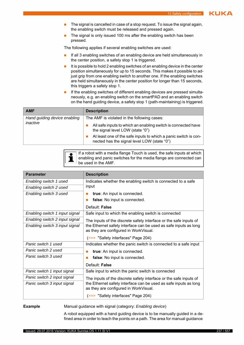
13 Safety configuration
The signal is cancelled in case of a stop request. To issue the signal again, the enabling switch must be released and pressed again.
The signal is only issued 100 ms after the enabling switch has been pressed.
The following applies if several enabling switches are used:
If all 3 enabling switches of an enabling device are held simultaneously in the center position, a safety stop 1 is triggered.
It is possible to hold 2 enabling switches of an enabling device in the center position simultaneously for up to 15 seconds. This makes it possible to ad-just grip from one enabling switch to another one. If the enabling switches are held simultaneously in the center position for longer than 15 seconds, this triggers a safety stop 1.
If the enabling switches of different enabling devices are pressed simulta-neously, e.g. an enabling switch on the smartPAD and an enabling switch on the hand guiding device, a safety stop 1 (path-maintaining) is triggered.
Example Manual guidance with signal (category: Enabling device)
A robot equipped with a hand guiding device is to be manually guided in a de-fined area in order to teach the points on a path. The area for manual guidance
AMF Description
Hand guiding device enabling inactive
The AMF is violated in the following cases:
All safe inputs to which an enabling switch is connected have the signal level LOW (state “0”)
At least one of the safe inputs to which a panic switch is con-nected has the signal level LOW (state “0”)
If a robot with a media flange Touch is used, the safe inputs at which enabling and panic switches for the media flange are connected can be used in the AMF.
Parameter Description
Enabling switch 1 used Indicates whether the enabling switch is connected to a safe input
true: An input is connected.
false: No input is connected.
Default: False
Enabling switch 2 used
Enabling switch 3 used
Enabling switch 1 input signal Safe input to which the enabling switch is connected
The inputs of the discrete safety interface or the safe inputs of the Ethernet safety interface can be used as safe inputs as long as they are configured in WorkVisual.
(>>> "Safety interfaces" Page 204)
Enabling switch 2 input signal
Enabling switch 3 input signal
Panic switch 1 used Indicates whether the panic switch is connected to a safe input
true: An input is connected.
false: No input is connected.
Default: False
Panic switch 2 used
Panic switch 3 used
Panic switch 1 input signal Safe input to which the panic switch is connected
The inputs of the discrete safety interface or the safe inputs of the Ethernet safety interface can be used as safe inputs as long as they are configured in WorkVisual.
(>>> "Safety interfaces" Page 204)
Panic switch 2 input signal
Panic switch 3 input signal
237 / 557Issued: 29.07.2016 Version: KUKA Sunrise.OS 1.11 SI V1
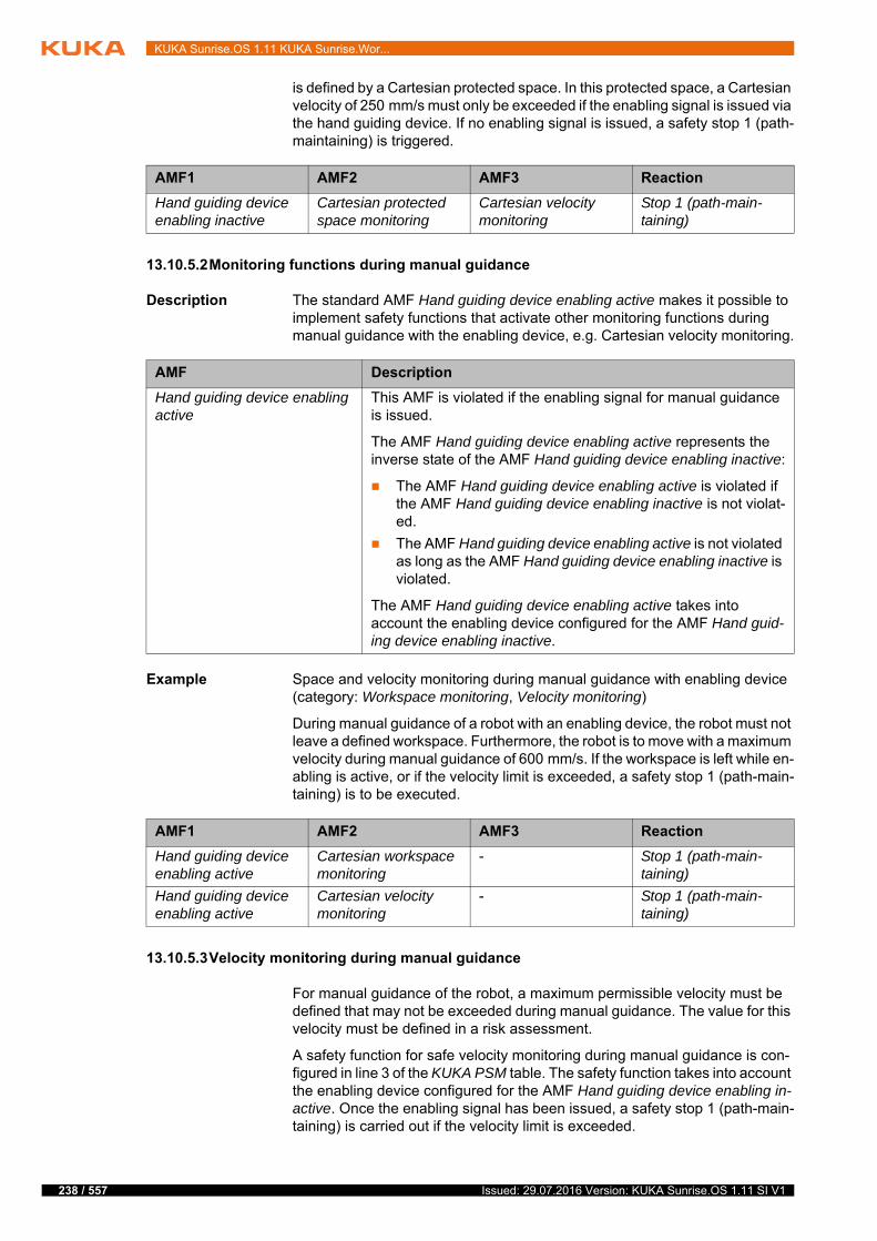
238 / 557
KUKA Sunrise.OS 1.11 KUKA Sunrise.Wor...
is defined by a Cartesian protected space. In this protected space, a Cartesian velocity of 250 mm/s must only be exceeded if the enabling signal is issued via the hand guiding device. If no enabling signal is issued, a safety stop 1 (path-maintaining) is triggered.
13.10.5.2Monitoring functions during manual guidance
Description The standard AMF Hand guiding device enabling active makes it possible to implement safety functions that activate other monitoring functions during manual guidance with the enabling device, e.g. Cartesian velocity monitoring.
Example Space and velocity monitoring during manual guidance with enabling device (category: Workspace monitoring, Velocity monitoring)
During manual guidance of a robot with an enabling device, the robot must not leave a defined workspace. Furthermore, the robot is to move with a maximum velocity during manual guidance of 600 mm/s. If the workspace is left while en-abling is active, or if the velocity limit is exceeded, a safety stop 1 (path-main-taining) is to be executed.
13.10.5.3Velocity monitoring during manual guidance
For manual guidance of the robot, a maximum permissible velocity must be defined that may not be exceeded during manual guidance. The value for this velocity must be defined in a risk assessment.
A safety function for safe velocity monitoring during manual guidance is con-figured in line 3 of the KUKA PSM table. The safety function takes into account the enabling device configured for the AMF Hand guiding device enabling in-active. Once the enabling signal has been issued, a safety stop 1 (path-main-taining) is carried out if the velocity limit is exceeded.
AMF1 AMF2 AMF3 Reaction
Hand guiding device enabling inactive
Cartesian protected space monitoring
Cartesian velocity monitoring
Stop 1 (path-main-taining)
AMF Description
Hand guiding device enabling active
This AMF is violated if the enabling signal for manual guidance is issued.
The AMF Hand guiding device enabling active represents the inverse state of the AMF Hand guiding device enabling inactive:
The AMF Hand guiding device enabling active is violated if the AMF Hand guiding device enabling inactive is not violat-ed.
The AMF Hand guiding device enabling active is not violated as long as the AMF Hand guiding device enabling inactive is violated.
The AMF Hand guiding device enabling active takes into account the enabling device configured for the AMF Hand guid-ing device enabling inactive.
AMF1 AMF2 AMF3 Reaction
Hand guiding device enabling active
Cartesian workspace monitoring
- Stop 1 (path-main-taining)
Hand guiding device enabling active
Cartesian velocity monitoring
- Stop 1 (path-main-taining)
Issued: 29.07.2016 Version: KUKA Sunrise.OS 1.11 SI V1

13 Safety configuration
The instance of the AMF Cartesian velocity monitoring that is used has the fol-lowing preset parameter values:
Monitored kinematic system: First kinematic system
Maximum velocity: 250 mm/s
The parameter values can be modified. (>>> 13.10.8.2 "Defining Cartesian velocity monitoring" Page 241)
13.10.6 Evaluating the position referencing
Description Position referencing checks whether the saved zero position of the motor of an axis (= saved mastering position) corresponds to the actual mechanical zero position.
The safety integrity of the safety functions based upon this is limited until the position referencing test has been performed. This includes, for example, safely monitored Cartesian and axis-specific robot positions, safely monitored Cartesian velocities, TCP force monitoring and collision detection.
The AMF Position referencing can be used to check whether the position val-ues of all axes are referenced.
Example Monitoring the position referencing status (category: Safety stop)
A robot with non-referenced axes may only be moved at a reduced velocity of maximum 250 mm/s. The reduced velocity is intended to prevent hazards aris-ing as a result of position referencing not having been performed or having failed.
To ensure this, the referencing status of all axes is monitored in the operating modes with high velocity (T2 and AUT). As soon as the position of at least one axis is not successfully referenced, a safety stop 1 (path-maintaining) is trig-gered.
13.10.7 Evaluating the torque referencing
Description The referencing test of the joint torque sensors checks whether the expected external torque, which can be calculated for an axis based on the robot model and the given load data, corresponds to the value determined on the basis of the measured value of the joint torque sensor. If the difference between these
AMF Description
Position referencing The AMF is violated in the following cases:
The position of at least one axis of the monitored kinematic system is not referenced.
The position referencing of at least one axis has failed.
Parameter Description
Monitored kinematic system Kinematic system to be monitored
First kinematic system: Robot
Second kinematic system: No function
Third kinematic system: No function
Fourth kinematic system: No function
AMF1 AMF2 AMF3 Reaction
High-velocity mode - Position referencing Stop 1 (path-main-taining)
239 / 557Issued: 29.07.2016 Version: KUKA Sunrise.OS 1.11 SI V1
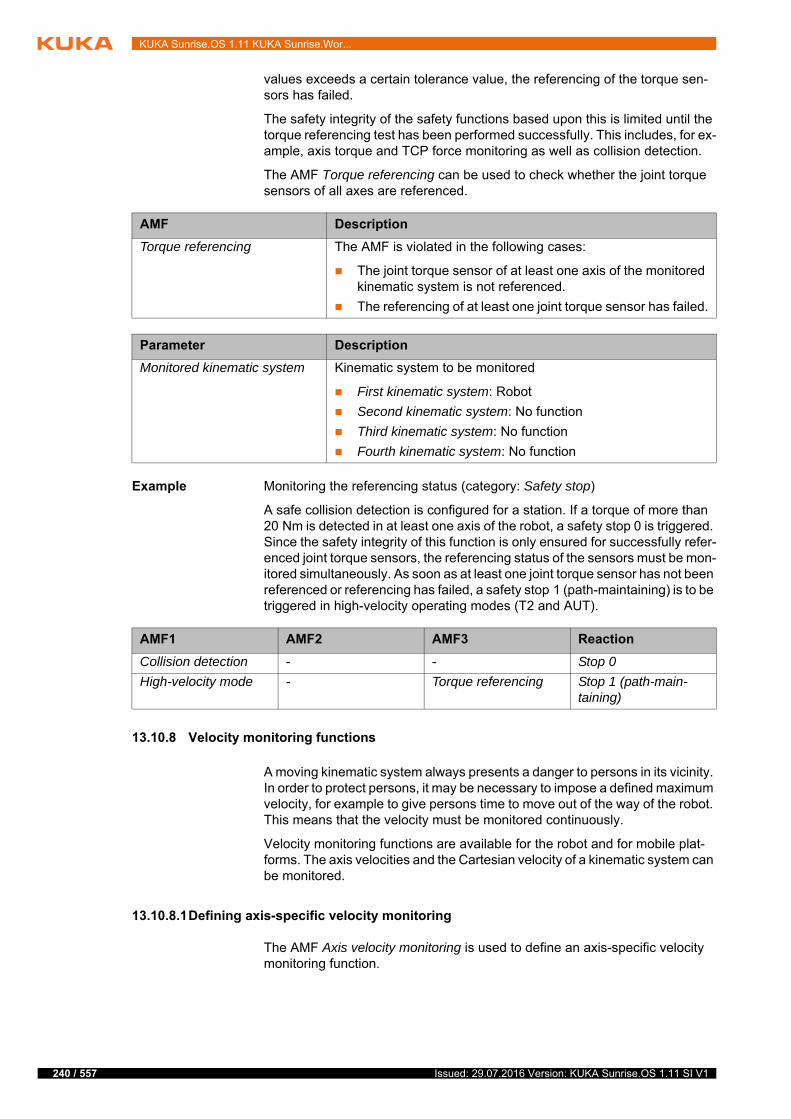
240 / 557
KUKA Sunrise.OS 1.11 KUKA Sunrise.Wor...
values exceeds a certain tolerance value, the referencing of the torque sen-sors has failed.
The safety integrity of the safety functions based upon this is limited until the torque referencing test has been performed successfully. This includes, for ex-ample, axis torque and TCP force monitoring as well as collision detection.
The AMF Torque referencing can be used to check whether the joint torque sensors of all axes are referenced.
Example Monitoring the referencing status (category: Safety stop)
A safe collision detection is configured for a station. If a torque of more than 20 Nm is detected in at least one axis of the robot, a safety stop 0 is triggered. Since the safety integrity of this function is only ensured for successfully refer-enced joint torque sensors, the referencing status of the sensors must be mon-itored simultaneously. As soon as at least one joint torque sensor has not been referenced or referencing has failed, a safety stop 1 (path-maintaining) is to be triggered in high-velocity operating modes (T2 and AUT).
13.10.8 Velocity monitoring functions
A moving kinematic system always presents a danger to persons in its vicinity. In order to protect persons, it may be necessary to impose a defined maximum velocity, for example to give persons time to move out of the way of the robot. This means that the velocity must be monitored continuously.
Velocity monitoring functions are available for the robot and for mobile plat-forms. The axis velocities and the Cartesian velocity of a kinematic system can be monitored.
13.10.8.1Defining axis-specific velocity monitoring
The AMF Axis velocity monitoring is used to define an axis-specific velocity monitoring function.
AMF Description
Torque referencing The AMF is violated in the following cases:
The joint torque sensor of at least one axis of the monitored kinematic system is not referenced.
The referencing of at least one joint torque sensor has failed.
Parameter Description
Monitored kinematic system Kinematic system to be monitored
First kinematic system: Robot
Second kinematic system: No function
Third kinematic system: No function
Fourth kinematic system: No function
AMF1 AMF2 AMF3 Reaction
Collision detection - - Stop 0
High-velocity mode - Torque referencing Stop 1 (path-main-taining)
Issued: 29.07.2016 Version: KUKA Sunrise.OS 1.11 SI V1
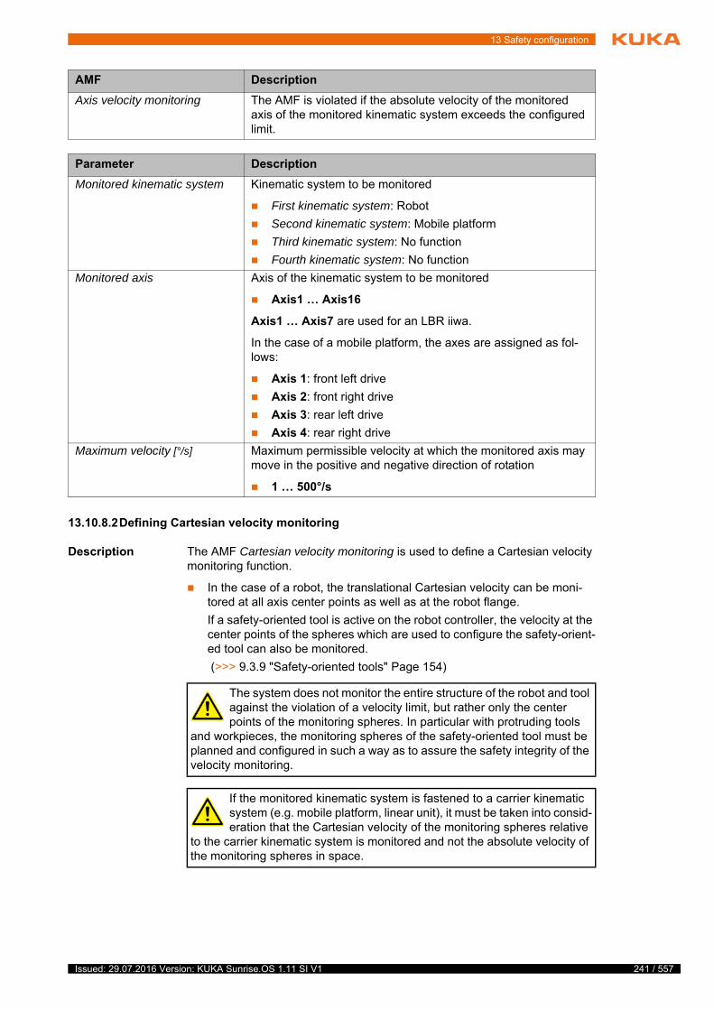
13 Safety configuration
13.10.8.2Defining Cartesian velocity monitoring
Description The AMF Cartesian velocity monitoring is used to define a Cartesian velocity monitoring function.
In the case of a robot, the translational Cartesian velocity can be moni-tored at all axis center points as well as at the robot flange.
If a safety-oriented tool is active on the robot controller, the velocity at the center points of the spheres which are used to configure the safety-orient-ed tool can also be monitored.
(>>> 9.3.9 "Safety-oriented tools" Page 154)
AMF Description
Axis velocity monitoring The AMF is violated if the absolute velocity of the monitored axis of the monitored kinematic system exceeds the configured limit.
Parameter Description
Monitored kinematic system Kinematic system to be monitored
First kinematic system: Robot
Second kinematic system: Mobile platform
Third kinematic system: No function
Fourth kinematic system: No function
Monitored axis Axis of the kinematic system to be monitored
Axis1 … Axis16
Axis1 … Axis7 are used for an LBR iiwa.
In the case of a mobile platform, the axes are assigned as fol-lows:
Axis 1: front left drive
Axis 2: front right drive
Axis 3: rear left drive
Axis 4: rear right drive
Maximum velocity [°/s] Maximum permissible velocity at which the monitored axis may move in the positive and negative direction of rotation
1 … 500°/s
The system does not monitor the entire structure of the robot and tool against the violation of a velocity limit, but rather only the center points of the monitoring spheres. In particular with protruding tools
and workpieces, the monitoring spheres of the safety-oriented tool must be planned and configured in such a way as to assure the safety integrity of the velocity monitoring.
If the monitored kinematic system is fastened to a carrier kinematic system (e.g. mobile platform, linear unit), it must be taken into consid-eration that the Cartesian velocity of the monitoring spheres relative
to the carrier kinematic system is monitored and not the absolute velocity of the monitoring spheres in space.
241 / 557Issued: 29.07.2016 Version: KUKA Sunrise.OS 1.11 SI V1

242 / 557
KUKA Sunrise.OS 1.11 KUKA Sunrise.Wor...
In the case of a mobile platform, the translational Cartesian velocity can be monitored at 4 defined points near the corners of the platform.
If a safety-oriented tool is active on the robot controller, the velocity at the center points of the spheres which are used to configure the safety-orient-ed tool can be monitored additionally or as an alternative.
Only velocity components within the plane of the platform are taken into consideration.
Fig. 13-9: Velocity monitoring for platforms (monitored structure)
1 Monitored structure: Robot and tool
2 Monitored structure: Robot
3 Monitored structure: Tool
4 Monitored structure: Tool (no safety-oriented tool active)
AMF Description
Cartesian velocity monitoring The AMF is violated if the Cartesian translational velocity at at least one point of the monitored kinematic system exceeds the defined limit.
The AMF is additionally violated in the following cases:
An axis is not mastered.
The referencing of a mastered axis has failed.
Note: If an AMF is violated due to loss of mastering, the robot can only be moved and mastered again by switching to CRR mode.
Parameter Description
Monitored kinematic system Kinematic system to be monitored
First kinematic system: Robot
Second kinematic system: Mobile platform
Third kinematic system: No function
Fourth kinematic system: No function
Monitored structure Structure to be monitored
Issued: 29.07.2016 Version: KUKA Sunrise.OS 1.11 SI V1
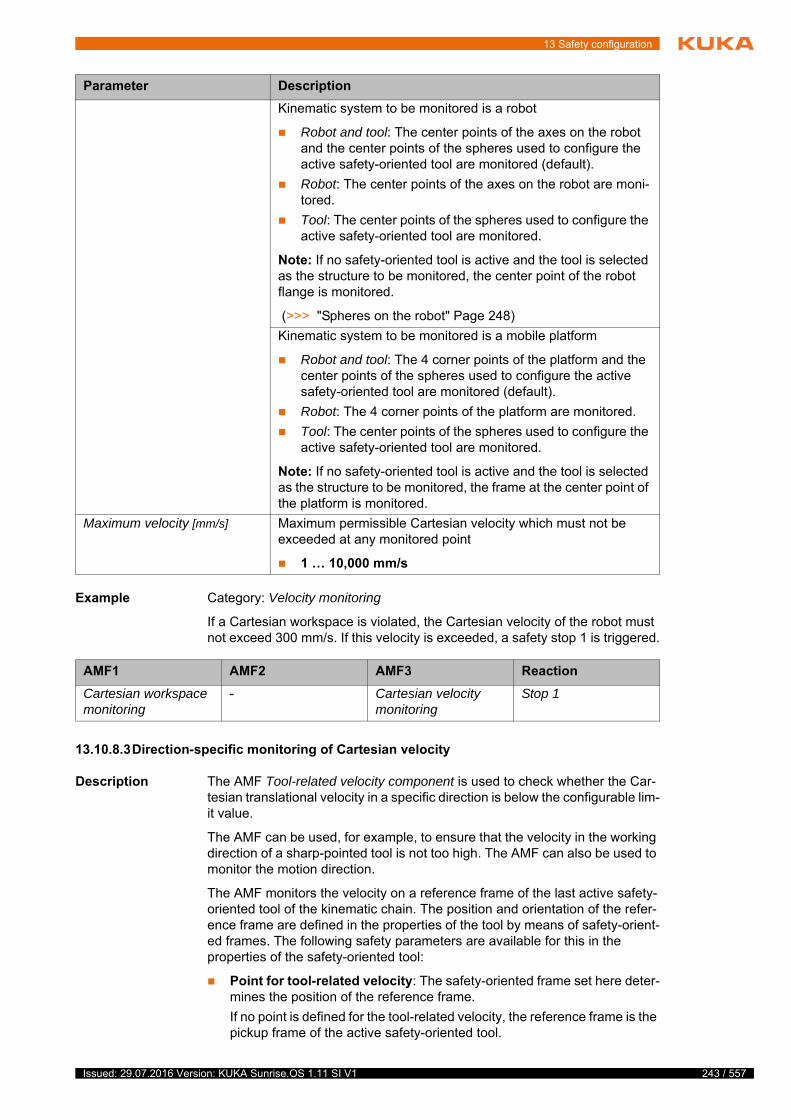
13 Safety configuration
Example Category: Velocity monitoring
If a Cartesian workspace is violated, the Cartesian velocity of the robot must not exceed 300 mm/s. If this velocity is exceeded, a safety stop 1 is triggered.
13.10.8.3Direction-specific monitoring of Cartesian velocity
Description The AMF Tool-related velocity component is used to check whether the Car-tesian translational velocity in a specific direction is below the configurable lim-it value.
The AMF can be used, for example, to ensure that the velocity in the working direction of a sharp-pointed tool is not too high. The AMF can also be used to monitor the motion direction.
The AMF monitors the velocity on a reference frame of the last active safety-oriented tool of the kinematic chain. The position and orientation of the refer-ence frame are defined in the properties of the tool by means of safety-orient-ed frames. The following safety parameters are available for this in the properties of the safety-oriented tool:
Point for tool-related velocity: The safety-oriented frame set here deter-mines the position of the reference frame.
If no point is defined for the tool-related velocity, the reference frame is the pickup frame of the active safety-oriented tool.
Kinematic system to be monitored is a robot
Robot and tool: The center points of the axes on the robot and the center points of the spheres used to configure the active safety-oriented tool are monitored (default).
Robot: The center points of the axes on the robot are moni-tored.
Tool: The center points of the spheres used to configure the active safety-oriented tool are monitored.
Note: If no safety-oriented tool is active and the tool is selected as the structure to be monitored, the center point of the robot flange is monitored.
(>>> "Spheres on the robot" Page 248)
Kinematic system to be monitored is a mobile platform
Robot and tool: The 4 corner points of the platform and the center points of the spheres used to configure the active safety-oriented tool are monitored (default).
Robot: The 4 corner points of the platform are monitored.
Tool: The center points of the spheres used to configure the active safety-oriented tool are monitored.
Note: If no safety-oriented tool is active and the tool is selected as the structure to be monitored, the frame at the center point of the platform is monitored.
Maximum velocity [mm/s] Maximum permissible Cartesian velocity which must not be exceeded at any monitored point
1 … 10,000 mm/s
Parameter Description
AMF1 AMF2 AMF3 Reaction
Cartesian workspace monitoring
- Cartesian velocity monitoring
Stop 1
243 / 557Issued: 29.07.2016 Version: KUKA Sunrise.OS 1.11 SI V1
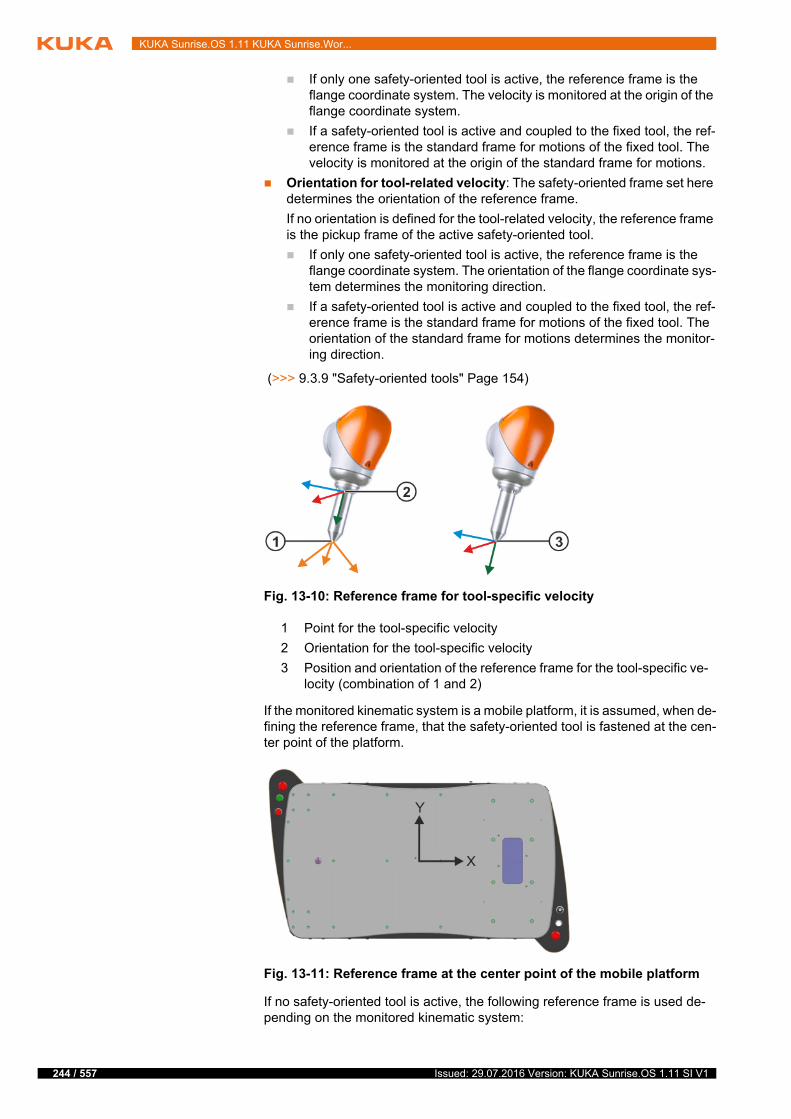
244 / 557
KUKA Sunrise.OS 1.11 KUKA Sunrise.Wor...
If only one safety-oriented tool is active, the reference frame is the flange coordinate system. The velocity is monitored at the origin of the flange coordinate system.
If a safety-oriented tool is active and coupled to the fixed tool, the ref-erence frame is the standard frame for motions of the fixed tool. The velocity is monitored at the origin of the standard frame for motions.
Orientation for tool-related velocity: The safety-oriented frame set here determines the orientation of the reference frame.
If no orientation is defined for the tool-related velocity, the reference frame is the pickup frame of the active safety-oriented tool.
If only one safety-oriented tool is active, the reference frame is the flange coordinate system. The orientation of the flange coordinate sys-tem determines the monitoring direction.
If a safety-oriented tool is active and coupled to the fixed tool, the ref-erence frame is the standard frame for motions of the fixed tool. The orientation of the standard frame for motions determines the monitor-ing direction.
(>>> 9.3.9 "Safety-oriented tools" Page 154)
If the monitored kinematic system is a mobile platform, it is assumed, when de-fining the reference frame, that the safety-oriented tool is fastened at the cen-ter point of the platform.
If no safety-oriented tool is active, the following reference frame is used de-pending on the monitored kinematic system:
Fig. 13-10: Reference frame for tool-specific velocity
1 Point for the tool-specific velocity
2 Orientation for the tool-specific velocity
3 Position and orientation of the reference frame for the tool-specific ve-locity (combination of 1 and 2)
Fig. 13-11: Reference frame at the center point of the mobile platform
Issued: 29.07.2016 Version: KUKA Sunrise.OS 1.11 SI V1

13 Safety configuration
For a robot: frame at the center point of the robot flange
For a mobile platform: frame at the center point of the platform
The component of the velocity vector in a specific direction of the reference frame is monitored. During configuration of the AMF, this direction is specified as a component of the velocity vector in the coordinate system of the reference frame. One of the total of 6 components of the coordinate system (X, Y and Z components, each in the positive and negative direction) can be selected.
Furthermore, the maximum velocity that the selected component of the veloc-ity vector must not exceed is also defined.
Example 1 A sharp-pointed tool may be moved in its working direction at a maximum of 25 mm/s. For this, the tool is marked as safety-oriented and the tool tip is cre-ated as a safety-oriented frame. This frame is used to define the position and orientation of the reference frame in the properties of the safety-oriented tool.
An instance of the AMF Tool-related velocity component is configured in such a way that the positive Z component of the velocity vector in the coordinate
If the monitored kinematic system is fastened to a carrier kinematic system (e.g. mobile platform, linear unit), it must be taken into consid-eration that the velocity of the monitored point relative to the carrier
kinematic system is monitored and not the absolute velocity in space.
AMF Description
Tool-related velocity compo-nent
The AMF is violated if the configured component of the velocity vector in the coordinate system of the reference frame of the monitored kinematic system exceeds the maximum defined value.
In the case of an LBR iiwa, the AMF is additionally violated in the following cases:
An axis is not mastered.
The referencing of a mastered axis has failed.
Parameter Description
Monitored kinematic system Kinematic system to be monitored
First kinematic system: Robot
Second kinematic system: Mobile platform
Third kinematic system: No function
Fourth kinematic system: No function
Maximum velocity [mm/s] Maximum Cartesian velocity for the monitored component of the velocity vector
1 … 10000 mm/s
Note: When selecting the maximum velocity, it must be noted that, particularly in the case of highly dynamic motions, low velocities against the commanded direction of motion may occur due to overshoot. For this reason, it is recommended that the maximum velocity should not be set too low.
Component of the velocity vector
Monitored component of the velocity vector (direction of moni-toring)
X positive or X negative
Y positive or Y negative
Z positive or Z negative
245 / 557Issued: 29.07.2016 Version: KUKA Sunrise.OS 1.11 SI V1
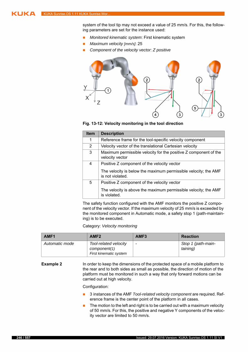
246 / 557
KUKA Sunrise.OS 1.11 KUKA Sunrise.Wor...
system of the tool tip may not exceed a value of 25 mm/s. For this, the follow-ing parameters are set for the instance used:
Monitored kinematic system: First kinematic system
Maximum velocity [mm/s]: 25
Component of the velocity vector: Z positive
The safety function configured with the AMF monitors the positive Z compo-nent of the velocity vector. If the maximum velocity of 25 mm/s is exceeded by the monitored component in Automatic mode, a safety stop 1 (path-maintain-ing) is to be executed.
Category: Velocity monitoring
Example 2 In order to keep the dimensions of the protected space of a mobile platform to the rear and to both sides as small as possible, the direction of motion of the platform must be monitored in such a way that only forward motions can be carried out at high velocity.
Configuration:
3 instances of the AMF Tool-related velocity component are required. Ref-erence frame is the center point of the platform in all cases.
The motion to the left and right is to be carried out with a maximum velocity of 50 mm/s. For this, the positive and negative Y components of the veloc-ity vector are limited to 50 mm/s.
Fig. 13-12: Velocity monitoring in the tool direction
Item Description
1 Reference frame for the tool-specific velocity component
2 Velocity vector of the translational Cartesian velocity
3 Maximum permissible velocity for the positive Z component of the velocity vector
4 Positive Z component of the velocity vector
The velocity is below the maximum permissible velocity; the AMF is not violated.
5 Positive Z component of the velocity vector
The velocity is above the maximum permissible velocity; the AMF is violated.
AMF1 AMF2 AMF3 Reaction
Automatic mode Tool-related velocity component(1) First kinematic system
- Stop 1 (path-main-taining)
Issued: 29.07.2016 Version: KUKA Sunrise.OS 1.11 SI V1

13 Safety configuration
The backward motion is to be carried out with a maximum velocity of 20 mm/s. For this, the negative X component of the velocity vector is lim-ited to 20 mm/s.
Parameterization of the configured instances:
Instance 1:
Monitored kinematic system: Second kinematic system
Maximum velocity [mm/s]: 50
Component of the velocity vector: Y positive
Instance 2:
Monitored kinematic system: Second kinematic system
Maximum velocity [mm/s]: 50
Component of the velocity vector: Y negative
Instance 3:
Monitored kinematic system: Second kinematic system
Maximum velocity [mm/s]: 20
Component of the velocity vector: X negative
Fig. 13-13: Protected space limitation by means of velocity monitoring in the direction of motion
Item Description
1 Approximate dimensions of the desired protected space
2 Reference frame for the tool-specific velocity component
3 Velocity vector of the translational Cartesian velocity
4 Maximum permissible velocity for the negative Y component of the velocity vector
5 Maximum permissible velocity for the negative X component of the velocity vector
6 Maximum permissible velocity for the positive Y component of the velocity vector
247 / 557Issued: 29.07.2016 Version: KUKA Sunrise.OS 1.11 SI V1
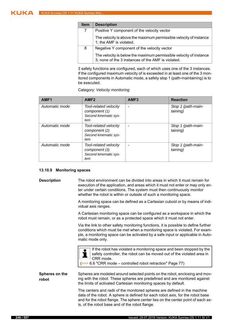
248 / 557
KUKA Sunrise.OS 1.11 KUKA Sunrise.Wor...
3 safety functions are configured, each of which uses one of the 3 instances. If the configured maximum velocity of is exceeded in at least one of the 3 mon-itored components in Automatic mode, a safety stop 1 (path-maintaining) is to be executed.
Category: Velocity monitoring
13.10.9 Monitoring spaces
Description The robot environment can be divided into areas in which it must remain for execution of the application, and areas which it must not enter or may only en-ter under certain conditions. The system must then continuously monitor whether the robot is within or outside of such a monitoring space.
A monitoring space can be defined as a Cartesian cuboid or by means of indi-vidual axis ranges.
A Cartesian monitoring space can be configured as a workspace in which the robot must remain, or as a protected space which it must not enter.
Via the link to other safety monitoring functions, it is possible to define further conditions which must be met when a monitoring space is violated. For exam-ple, a monitoring space can be activated by a safe input or applicable in Auto-matic mode only.
Spheres on the
robot
Spheres are modeled around selected points on the robot, enclosing and mov-ing with the robot. These spheres are predefined and are monitored against the limits of activated Cartesian monitoring spaces by default.
The centers and radii of the monitored spheres are defined in the machine data of the robot. A sphere is defined for each robot axis, for the robot base and for the robot flange. The sphere center lies on the center point of each ax-is, of the robot base and of the robot flange.
7 Positive Y component of the velocity vector
The velocity is above the maximum permissible velocity of instance 1; the AMF is violated.
8 Negative Y component of the velocity vector
The velocity is below the maximum permissible velocity of instance 3; none of the 3 instances of the AMF is violated.
Item Description
AMF1 AMF2 AMF3 Reaction
Automatic mode Tool-related velocity component (1) Second kinematic sys-tem
- Stop 1 (path-main-taining)
Automatic mode Tool-related velocity component (2) Second kinematic sys-tem
- Stop 1 (path-main-taining)
Automatic mode Tool-related velocity component (3) Second kinematic sys-tem
- Stop 1 (path-main-taining)
If the robot has violated a monitoring space and been stopped by the safety controller, the robot can be moved out of the violated area in CRR mode.
(>>> 6.6 "CRR mode – controlled robot retraction" Page 77)
Issued: 29.07.2016 Version: KUKA Sunrise.OS 1.11 SI V1

13 Safety configuration
The dimensions of the monitored spheres vary according to robot type and the media flange used:
r = sphere radius
z, y = sphere center point relative to the robot base coordinate system
Variant 1: LBR iiwa 7 R800 with media flange Touch
Variant 2: LBR iiwa 7 R800 with media flange (all variants except media flange Touch)
Variant 3: LBR iiwa 14 R820 with media flange Touch
Variant 4: LBR iiwa 14 R820 with media flange (all variants except media flange Touch)
Base A1 A2 A3 A4 A5 A6 A7 Flange
r [mm] 135 90 125 90 125 90 80 85 65
z [mm] 50 90 340 538 740 935 1140 1130 1240
y [mm] -30
Base A1 A2 A3 A4 A5 A6 A7 Flange
r [mm] 135 90 125 90 125 90 80 85 65
z [mm] 50 90 340 538 740 935 1140 1130 1220
y [mm] -30
Fig. 13-14: Spheres on the LBR iiwa 7 R800 (variant 2)
Base A1 A2 A3 A4 A5 A6 A7 Flange
r [mm] 150 100 140 90 131 90 80 85 65
z [mm] 50 160 360 580 780 980 1180 1170 1280
y [mm] -30
Base A1 A2 A3 A4 A5 A6 A7 Flange
r [mm] 150 100 140 90 131 90 80 85 65
249 / 557Issued: 29.07.2016 Version: KUKA Sunrise.OS 1.11 SI V1

250 / 557
KUKA Sunrise.OS 1.11 KUKA Sunrise.Wor...
Spheres on tool If a safety-oriented tool is active on the robot controller, the spheres on the ro-bot are monitored by default, as are the spheres used to configure the safety-oriented tool.
(>>> 9.3.9 "Safety-oriented tools" Page 154)
Selecting
monitoring
spheres
It is not necessary or appropriate to include all robot and tool spheres in the Cartesian workspace monitoring of every application.
Example: If the entry of a tool into a protected space is programmed to acti-vate further monitoring functions, only the tool spheres must be monitored.
The structure to be monitored can be selected when configuring Cartesian monitoring spaces:
Robot and tool (default)
Only tool
Only robot
Stopping
distance
If the robot is stopped by a monitoring function, it requires a certain stopping distance before coming to a standstill.
The stopping distance depends primarily on the following factors:
Robot type
Velocity of the robot
Position of the robot axes
Payload
13.10.9.1Defining Cartesian workspaces
Description A Cartesian workspace is defined as a cuboid whose position and orientation in space are defined relative to the world coordinate system.
These monitoring spheres are monitored against the limits of activated Carte-sian workspaces and must move within these workspaces.
The AMF Cartesian workspace monitoring is used to define a Cartesian work-space. The AMF is violated as soon as one of the monitored spheres is no lon-ger completely within the defined workspace.
The AMF is additionally violated in the following cases:
z [mm] 50 160 360 580 780 980 1180 1170 1260
y [mm] -30
Base A1 A2 A3 A4 A5 A6 A7 Flange
The system does not monitor the entire structure of the robot and tool against the violation of a space, but rather only the monitoring spheres. In particular with protruding tools and workpieces, the mon-
itoring spheres of the safety-oriented tool must be planned and configured in such a way as to assure the safety integrity of workspaces and protected spaces.
The stopping distance when a monitoring function is triggered varies according to the specific robot type. This aspect must be taken into account by the system integrator during parameterization of the mon-
itoring functions as part of the safety assessment.
Further information about the stopping distances and stopping times can be found in the assembly or operating instructions of the relevant robot.
Issued: 29.07.2016 Version: KUKA Sunrise.OS 1.11 SI V1
13 Safety configuration
An axis is not mastered.
The referencing of a mastered axis has failed.
One corner of the cuboid is defined relative to the world coordinate system. This is the origin of the workspace and is defined by the following parameters:
Based on this defined origin, the size of the workspace is determined along the coordinate axes:
If the monitored kinematic system is fastened to a carrier kinematic system (e.g. mobile platform, linear unit), it must be taken into consid-eration that the position and orientation of the monitoring space are
relative to the world coordinate system and are thus defined relative to the alignment of the base of the monitored kinematic system. For this reason, the monitoring space is also moved in the event of a change in position or incli-nation of the carrier kinematic system.
Parameter Description
Monitored kinematic system Kinematic system to be monitored
First kinematic system: Robot
Second kinematic system: No function
Third kinematic system: No function
Fourth kinematic system: No function
Monitored structure Structure to be monitored
Robot and tool: The spheres on the robot and the spheres used to configure the safety-oriented tool are monitored. (Default)
Robot: The spheres on the robot are monitored.
Tool: The spheres used to configure the safety-oriented tool are monitored.
Note: If no safety-oriented tool is configured and the tool is selected as the structure to be monitored, the sphere on the robot flange is monitored. (>>> "Spheres on the robot" Page 248)
Parameter Description
X, Y, Z [mm] Offset of the origin of the workspace along the X, Y and Z axes of the world coordinate system
-100,000 mm … +100,000 mm
A, B, C [°] Orientation of the origin of the workspace about the axes of the world coordinate system, specified by the rotational angles A, B, C
0° … 359°
Parameter Description
Length [mm] Length of the workspace (= distance along the positive X axis of the origin)
0 mm … 100,000 mm
251 / 557Issued: 29.07.2016 Version: KUKA Sunrise.OS 1.11 SI V1
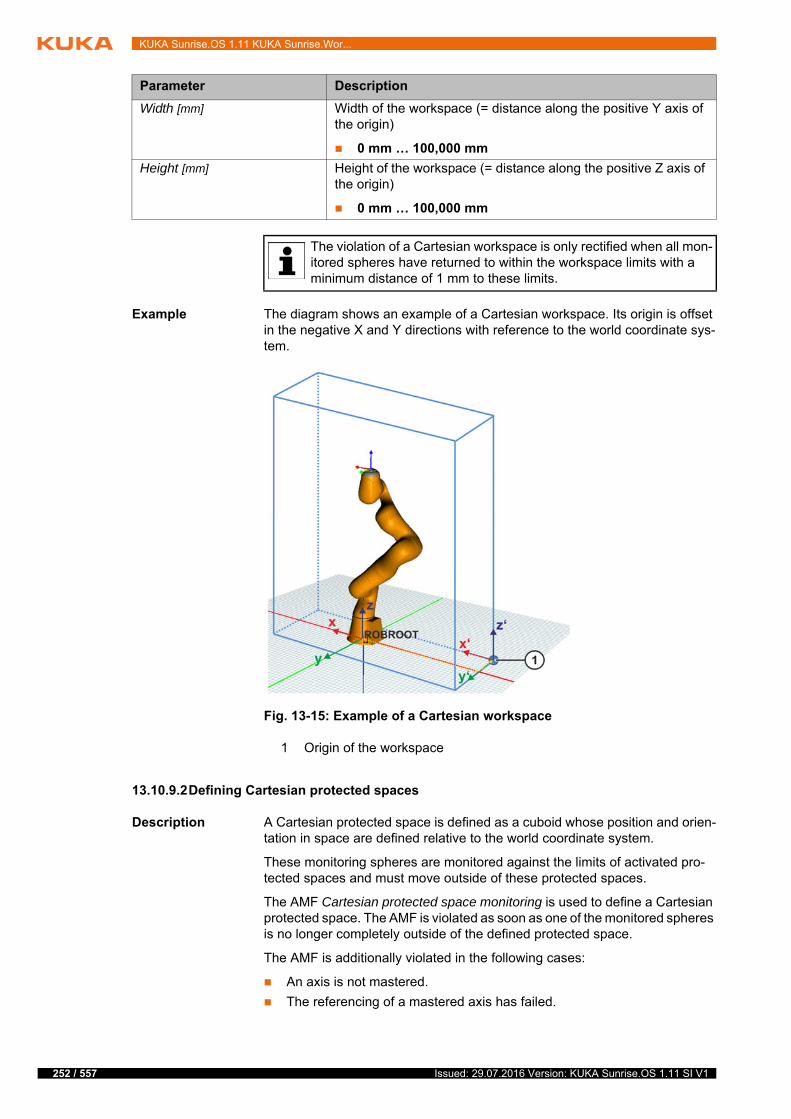
252 / 557
KUKA Sunrise.OS 1.11 KUKA Sunrise.Wor...
Example The diagram shows an example of a Cartesian workspace. Its origin is offset in the negative X and Y directions with reference to the world coordinate sys-tem.
13.10.9.2Defining Cartesian protected spaces
Description A Cartesian protected space is defined as a cuboid whose position and orien-tation in space are defined relative to the world coordinate system.
These monitoring spheres are monitored against the limits of activated pro-tected spaces and must move outside of these protected spaces.
The AMF Cartesian protected space monitoring is used to define a Cartesian protected space. The AMF is violated as soon as one of the monitored spheres is no longer completely outside of the defined protected space.
The AMF is additionally violated in the following cases:
An axis is not mastered.
The referencing of a mastered axis has failed.
Width [mm] Width of the workspace (= distance along the positive Y axis of the origin)
0 mm … 100,000 mm
Height [mm] Height of the workspace (= distance along the positive Z axis of the origin)
0 mm … 100,000 mm
Parameter Description
The violation of a Cartesian workspace is only rectified when all mon-itored spheres have returned to within the workspace limits with a minimum distance of 1 mm to these limits.
Fig. 13-15: Example of a Cartesian workspace
1 Origin of the workspace
Issued: 29.07.2016 Version: KUKA Sunrise.OS 1.11 SI V1
13 Safety configuration
If a very narrow protected space is configured, the robot may be able to move into and out of the protected space without the space violation being detected. Possible cause: Due to a very high tool velocity, the protected space is only violated during a very short interval.
Assuming that the following minimum values are configured:
Radius of tool sphere: 25 mm
Thickness of protected space: 0 mm
In this case, tool velocities of over 4 m/s are required for the robot to pass through the protected space without detection.
The following measures are recommended in order to prevent robots from passing through protected spaces undetected:
Configure Cartesian velocity monitoring (do not allow a value greater than 4 m/s).
OR: When configuring the protected space, select sufficient values for the length, width and height of the protected space.
OR: When configuring the tool spheres, select sufficient values for the ra-dius.
One corner of the cuboid is defined relative to the world coordinate system. This is the origin of the protected space and is defined by the following param-eters:
If the monitored kinematic system is fastened to a carrier kinematic system (e.g. mobile platform, linear unit), it must be taken into consid-eration that the position and orientation of the monitoring space are
relative to the world coordinate system and are thus defined relative to the alignment of the base of the monitored kinematic system. For this reason, the monitoring space is also moved in the event of a change in position or incli-nation of the carrier kinematic system.
Parameter Description
Monitored kinematic system Kinematic system to be monitored
First kinematic system: Robot
Second kinematic system: No function
Third kinematic system: No function
Fourth kinematic system: No function
Monitored structure Structure to be monitored
Robot and tool: The spheres on the robot and the spheres used to configure the safety-oriented tool are monitored. (Default)
Robot: The spheres on the robot are monitored.
Tool: The spheres used to configure the safety-oriented tool are monitored.
Note: If no safety-oriented tool is configured and the tool is selected as the structure to be monitored, the sphere on the robot flange is monitored. (>>> "Spheres on the robot" Page 248)
253 / 557Issued: 29.07.2016 Version: KUKA Sunrise.OS 1.11 SI V1
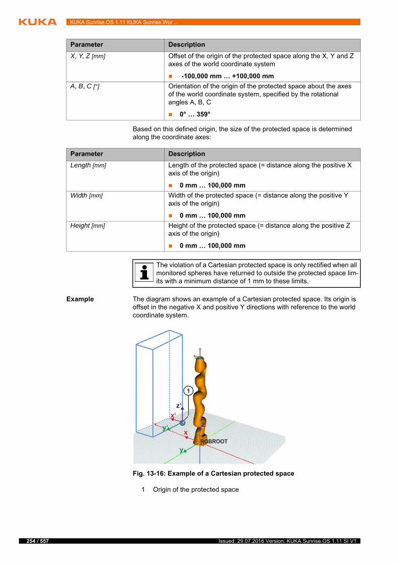
254 / 557
KUKA Sunrise.OS 1.11 KUKA Sunrise.Wor...
Based on this defined origin, the size of the protected space is determined along the coordinate axes:
Example The diagram shows an example of a Cartesian protected space. Its origin is offset in the negative X and positive Y directions with reference to the world coordinate system.
Parameter Description
X, Y, Z [mm] Offset of the origin of the protected space along the X, Y and Z axes of the world coordinate system
-100,000 mm … +100,000 mm
A, B, C [°] Orientation of the origin of the protected space about the axes of the world coordinate system, specified by the rotational angles A, B, C
0° … 359°
Parameter Description
Length [mm] Length of the protected space (= distance along the positive X axis of the origin)
0 mm … 100,000 mm
Width [mm] Width of the protected space (= distance along the positive Y axis of the origin)
0 mm … 100,000 mm
Height [mm] Height of the protected space (= distance along the positive Z axis of the origin)
0 mm … 100,000 mm
The violation of a Cartesian protected space is only rectified when all monitored spheres have returned to outside the protected space lim-its with a minimum distance of 1 mm to these limits.
Fig. 13-16: Example of a Cartesian protected space
1 Origin of the protected space
Issued: 29.07.2016 Version: KUKA Sunrise.OS 1.11 SI V1
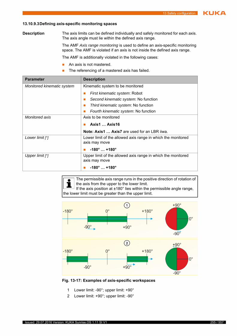
13 Safety configuration
13.10.9.3Defining axis-specific monitoring spaces
Description The axis limits can be defined individually and safely monitored for each axis. The axis angle must lie within the defined axis range.
The AMF Axis range monitoring is used to define an axis-specific monitoring space. The AMF is violated if an axis is not inside the defined axis range.
The AMF is additionally violated in the following cases:
An axis is not mastered.
The referencing of a mastered axis has failed.
Parameter Description
Monitored kinematic system Kinematic system to be monitored
First kinematic system: Robot
Second kinematic system: No function
Third kinematic system: No function
Fourth kinematic system: No function
Monitored axis Axis to be monitored
Axis1 … Axis16
Note: Axis1 … Axis7 are used for an LBR iiwa.
Lower limit [°] Lower limit of the allowed axis range in which the monitored axis may move
-180° … +180°
Upper limit [°] Upper limit of the allowed axis range in which the monitored axis may move
-180° … +180°
The permissible axis range runs in the positive direction of rotation of the axis from the upper to the lower limit.If the axis position at ±180° lies within the permissible angle range,
the lower limit must be greater than the upper limit.
Fig. 13-17: Examples of axis-specific workspaces
1 Lower limit: -90°; upper limit: +90°
2 Lower limit: +90°; upper limit: -90°
255 / 557Issued: 29.07.2016 Version: KUKA Sunrise.OS 1.11 SI V1
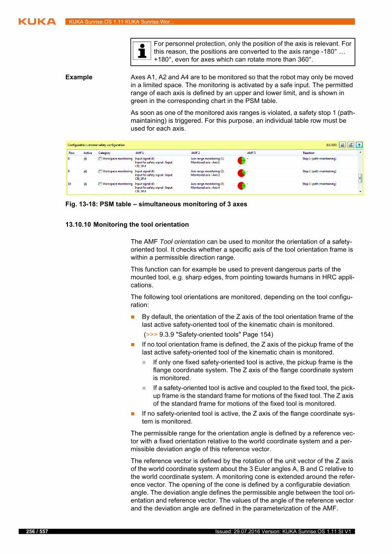
256 / 557
KUKA Sunrise.OS 1.11 KUKA Sunrise.Wor...
Example Axes A1, A2 and A4 are to be monitored so that the robot may only be moved in a limited space. The monitoring is activated by a safe input. The permitted range of each axis is defined by an upper and lower limit, and is shown in green in the corresponding chart in the PSM table.
As soon as one of the monitored axis ranges is violated, a safety stop 1 (path-maintaining) is triggered. For this purpose, an individual table row must be used for each axis.
13.10.10 Monitoring the tool orientation
The AMF Tool orientation can be used to monitor the orientation of a safety-oriented tool. It checks whether a specific axis of the tool orientation frame is within a permissible direction range.
This function can for example be used to prevent dangerous parts of the mounted tool, e.g. sharp edges, from pointing towards humans in HRC appli-cations.
The following tool orientations are monitored, depending on the tool configu-ration:
By default, the orientation of the Z axis of the tool orientation frame of the last active safety-oriented tool of the kinematic chain is monitored.
(>>> 9.3.9 "Safety-oriented tools" Page 154)
If no tool orientation frame is defined, the Z axis of the pickup frame of the last active safety-oriented tool of the kinematic chain is monitored.
If only one fixed safety-oriented tool is active, the pickup frame is the flange coordinate system. The Z axis of the flange coordinate system is monitored.
If a safety-oriented tool is active and coupled to the fixed tool, the pick-up frame is the standard frame for motions of the fixed tool. The Z axis of the standard frame for motions of the fixed tool is monitored.
If no safety-oriented tool is active, the Z axis of the flange coordinate sys-tem is monitored.
The permissible range for the orientation angle is defined by a reference vec-tor with a fixed orientation relative to the world coordinate system and a per-missible deviation angle of this reference vector.
The reference vector is defined by the rotation of the unit vector of the Z axis of the world coordinate system about the 3 Euler angles A, B and C relative to the world coordinate system. A monitoring cone is extended around the refer-ence vector. The opening of the cone is defined by a configurable deviation angle. The deviation angle defines the permissible angle between the tool ori-entation and reference vector. The values of the angle of the reference vector and the deviation angle are defined in the parameterization of the AMF.
For personnel protection, only the position of the axis is relevant. For this reason, the positions are converted to the axis range -180° … +180°, even for axes which can rotate more than 360°.
Fig. 13-18: PSM table – simultaneous monitoring of 3 axes
Issued: 29.07.2016 Version: KUKA Sunrise.OS 1.11 SI V1
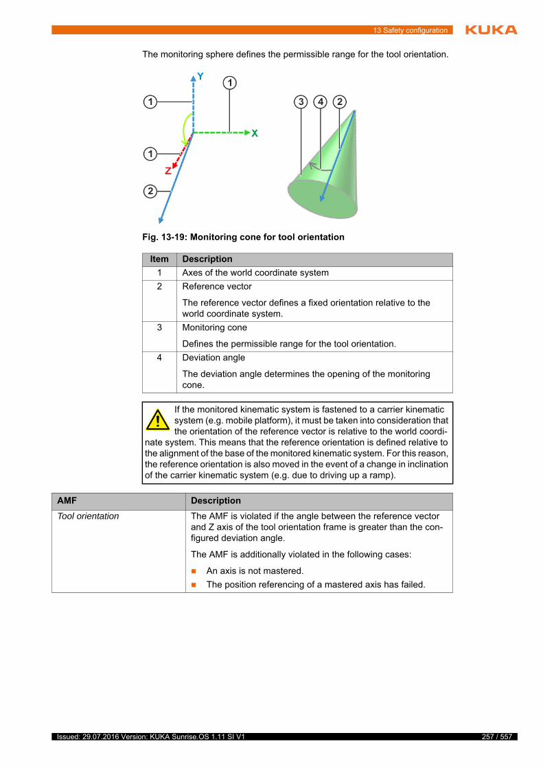
13 Safety configuration
The monitoring sphere defines the permissible range for the tool orientation.
Fig. 13-19: Monitoring cone for tool orientation
Item Description
1 Axes of the world coordinate system
2 Reference vector
The reference vector defines a fixed orientation relative to the world coordinate system.
3 Monitoring cone
Defines the permissible range for the tool orientation.
4 Deviation angle
The deviation angle determines the opening of the monitoring cone.
If the monitored kinematic system is fastened to a carrier kinematic system (e.g. mobile platform), it must be taken into consideration that the orientation of the reference vector is relative to the world coordi-
nate system. This means that the reference orientation is defined relative to the alignment of the base of the monitored kinematic system. For this reason, the reference orientation is also moved in the event of a change in inclination of the carrier kinematic system (e.g. due to driving up a ramp).
AMF Description
Tool orientation The AMF is violated if the angle between the reference vector and Z axis of the tool orientation frame is greater than the con-figured deviation angle.
The AMF is additionally violated in the following cases:
An axis is not mastered.
The position referencing of a mastered axis has failed.
257 / 557Issued: 29.07.2016 Version: KUKA Sunrise.OS 1.11 SI V1
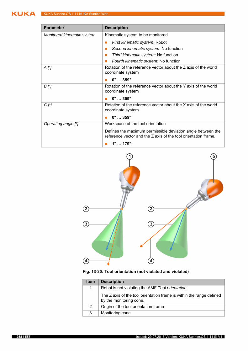
258 / 557
KUKA Sunrise.OS 1.11 KUKA Sunrise.Wor...
Parameter Description
Monitored kinematic system Kinematic system to be monitored
First kinematic system: Robot
Second kinematic system: No function
Third kinematic system: No function
Fourth kinematic system: No function
A [°] Rotation of the reference vector about the Z axis of the world coordinate system
0° … 359°
B [°] Rotation of the reference vector about the Y axis of the world coordinate system
0° … 359°
C [°] Rotation of the reference vector about the X axis of the world coordinate system
0° … 359°
Operating angle [°] Workspace of the tool orientation
Defines the maximum permissible deviation angle between the reference vector and the Z axis of the tool orientation frame.
1° … 179°
Fig. 13-20: Tool orientation (not violated and violated)
Item Description
1 Robot is not violating the AMF Tool orientation.
The Z axis of the tool orientation frame is within the range defined by the monitoring cone.
2 Origin of the tool orientation frame
3 Monitoring cone
Issued: 29.07.2016 Version: KUKA Sunrise.OS 1.11 SI V1
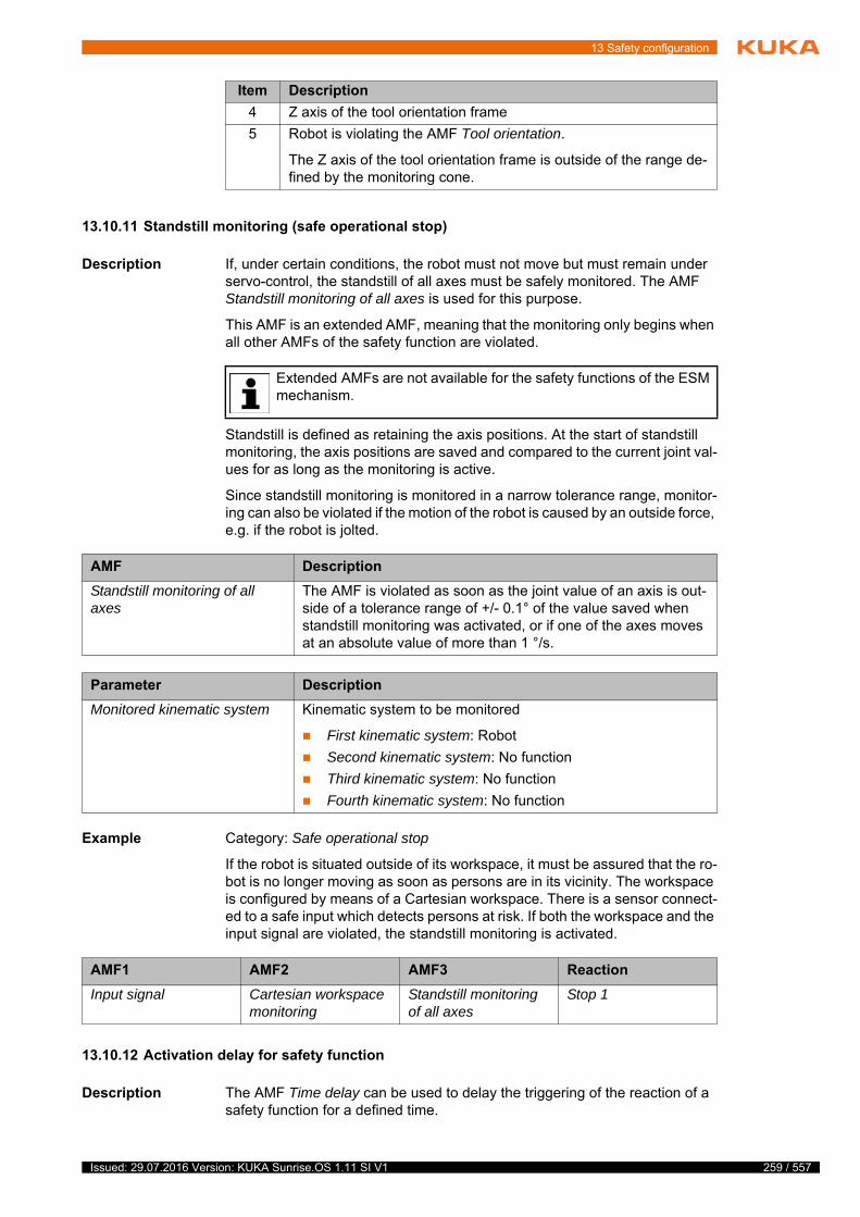
13 Safety configuration
13.10.11 Standstill monitoring (safe operational stop)
Description If, under certain conditions, the robot must not move but must remain under servo-control, the standstill of all axes must be safely monitored. The AMF Standstill monitoring of all axes is used for this purpose.
This AMF is an extended AMF, meaning that the monitoring only begins when all other AMFs of the safety function are violated.
Standstill is defined as retaining the axis positions. At the start of standstill monitoring, the axis positions are saved and compared to the current joint val-ues for as long as the monitoring is active.
Since standstill monitoring is monitored in a narrow tolerance range, monitor-ing can also be violated if the motion of the robot is caused by an outside force, e.g. if the robot is jolted.
Example Category: Safe operational stop
If the robot is situated outside of its workspace, it must be assured that the ro-bot is no longer moving as soon as persons are in its vicinity. The workspace is configured by means of a Cartesian workspace. There is a sensor connect-ed to a safe input which detects persons at risk. If both the workspace and the input signal are violated, the standstill monitoring is activated.
13.10.12 Activation delay for safety function
Description The AMF Time delay can be used to delay the triggering of the reaction of a safety function for a defined time.
4 Z axis of the tool orientation frame
5 Robot is violating the AMF Tool orientation.
The Z axis of the tool orientation frame is outside of the range de-fined by the monitoring cone.
Item Description
Extended AMFs are not available for the safety functions of the ESM mechanism.
AMF Description
Standstill monitoring of all axes
The AMF is violated as soon as the joint value of an axis is out-side of a tolerance range of +/- 0.1° of the value saved when standstill monitoring was activated, or if one of the axes moves at an absolute value of more than 1 °/s.
Parameter Description
Monitored kinematic system Kinematic system to be monitored
First kinematic system: Robot
Second kinematic system: No function
Third kinematic system: No function
Fourth kinematic system: No function
AMF1 AMF2 AMF3 Reaction
Input signal Cartesian workspace monitoring
Standstill monitoring of all axes
Stop 1
259 / 557Issued: 29.07.2016 Version: KUKA Sunrise.OS 1.11 SI V1

260 / 557
KUKA Sunrise.OS 1.11 KUKA Sunrise.Wor...
This AMF is an extended AMF, meaning that the delay time only starts running when all other AMFs of the safety function are violated.
Example Category: Safety stop
A robot whose axes are not referenced is to be allowed to be moved in Auto-matic mode for a limited time. Once this time has elapsed, e.g. after 2 hours, a safety stop 1 (path-maintaining) is triggered.
13.10.13 Monitoring of forces and torques
The LBR iiwa is fitted with position and joint torque sensors in all axes. These make it possible to measure and react to external forces and torques.
13.10.13.1Axis torque monitoring
Axis torque monitoring can limit and monitor the torques of individual axes.
The following points must be observed when using axis torque monitoring:
Successful torque referencing is a precondition.
Extended AMFs are not available for the safety functions of the ESM mechanism.
AMF Description
Time delay This AMF is violated if the set time has expired.
If the same instance of the AMF is used for several safety functions, the delay time begins running from the first activation.
Parameter Description
Delay time Amount of time by which the triggering of the reaction of a safety function is delayed.
12 ms … 24 h
The time can be entered in milliseconds (ms), seconds (s), min-utes (min) and hours (h). Each delay is a multiple of 12 ms, meaning that it is rounded up to the next multiple of 12.
AMF1 AMF2 AMF3 Reaction
Automatic mode Position referencing Time delay Stop 1 (path-main-taining)
If the permissible forces or torques are exceeded continuously due to jamming, it is possible to move the robot free by changing to CRR mode.
AMF Description
Axis torque monitoring The AMF is violated if the torque of the monitored axis exceeds or falls below the configured torque limit.
Issued: 29.07.2016 Version: KUKA Sunrise.OS 1.11 SI V1
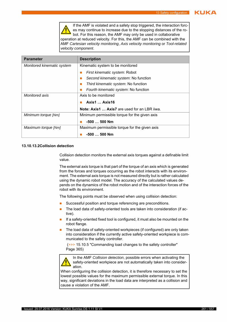
13 Safety configuration
13.10.13.2Collision detection
Collision detection monitors the external axis torques against a definable limit value.
The external axis torque is that part of the torque of an axis which is generated from the forces and torques occurring as the robot interacts with its environ-ment. The external axis torque is not measured directly but is rather calculated using the dynamic robot model. The accuracy of the calculated values de-pends on the dynamics of the robot motion and of the interaction forces of the robot with its environment.
The following points must be observed when using collision detection:
Successful position and torque referencing are preconditions.
The load data of safety-oriented tools are taken into consideration (if ac-tive).
If a safety-oriented fixed tool is configured, it must also be mounted on the robot flange.
The load data of safety-oriented workpieces (if configured) are only taken into consideration if the currently active safety-oriented workpiece is com-municated to the safety controller.
(>>> 15.10.5 "Commanding load changes to the safety controller" Page 365)
If the AMF is violated and a safety stop triggered, the interaction forc-es may continue to increase due to the stopping distances of the ro-bot. For this reason, the AMF may only be used in collaborative
operation at reduced velocity. For this, the AMF can be combined with the AMF Cartesian velocity monitoring, Axis velocity monitoring or Tool-related velocity component.
Parameter Description
Monitored kinematic system Kinematic system to be monitored
First kinematic system: Robot
Second kinematic system: No function
Third kinematic system: No function
Fourth kinematic system: No function
Monitored axis Axis to be monitored
Axis1 … Axis16
Note: Axis1 … Axis7 are used for an LBR iiwa.
Minimum torque [Nm] Minimum permissible torque for the given axis
-500 … 500 Nm
Maximum torque [Nm] Maximum permissible torque for the given axis
-500 … 500 Nm
In the AMF Collision detection, possible errors when activating the safety-oriented workpiece are not automatically taken into consider-ation.
When configuring the collision detection, it is therefore necessary to set the lowest possible values for the maximum permissible external torque. In this way, significant deviations in the load data are interpreted as a collision and cause a violation of the AMF.
261 / 557Issued: 29.07.2016 Version: KUKA Sunrise.OS 1.11 SI V1

262 / 557
KUKA Sunrise.OS 1.11 KUKA Sunrise.Wor...
13.10.13.3TCP force monitoring
Description In TCP force monitoring, the external force acting on the tool or robot flange is monitored against a definable limit value.
The external force on the TCP is not measured directly but is rather calculated using the dynamic robot model. The accuracy of the calculated external force
Workpieces that have been picked up must not come loose uninten-tionally and fall down while the monitoring is active. The user must en-sure this when using the AMF.
If the monitored kinematic system is fastened to a carrier kinematic system (e.g. mobile platform, linear unit), it must be ensured that the carrier kinematic system does not move while the AMF is being used.
As long as the robot base of the monitored kinematic system is being accel-erated, the safety integrity of the AMF is not assured.
If the monitored kinematic system is fastened to a carrier kinematic system (e.g. mobile platform, linear unit), it must be ensured, during use of the AMF, that the mounting direction of the monitored kinemat-
ic system does not differ from the configured mounting direction (e.g. due to tilting of the mobile platform). Otherwise, the safety integrity of the AMF is not assured.
AMF Description
Collision detection This AMF is violated if the external torque of at least one axis exceeds the configured limit value.
If the AMF is violated and a safety stop triggered, the interaction forc-es may continue to increase due to the stopping distances of the ro-bot. For this reason, the AMF may only be used in collaborative
operation at reduced velocity. For this, the AMF can be combined with the AMF Cartesian velocity monitoring, Axis velocity monitoring or Tool-related velocity component.
External forces on the robot or tool with short distances to the robot axes can only cause slight external torques in the robot axes under certain circumstances. If the AMFs are used, this can pose a safety
risk, particularly in potential crushing situations during collaborative opera-tion. Critical crushing situations can arise on the robot itself, between the ro-bot and the surroundings or between the tool and the surroundings.It is therefore advisable to avoid potentially critical incidents of crushing by using suitable equipment for the robot cell and/or by using one of the follow-ing AMFs: Cartesian workspace monitoring, Cartesian protected space mon-itoring, Axis range monitoring or Tool orientation.
Parameter Description
Monitored kinematic system Kinematic system to be monitored
First kinematic system: Robot
Second kinematic system: No function
Third kinematic system: No function
Fourth kinematic system: No function
Maximum external torque [Nm] Maximum permissible external torque
0 … 30 Nm
Issued: 29.07.2016 Version: KUKA Sunrise.OS 1.11 SI V1
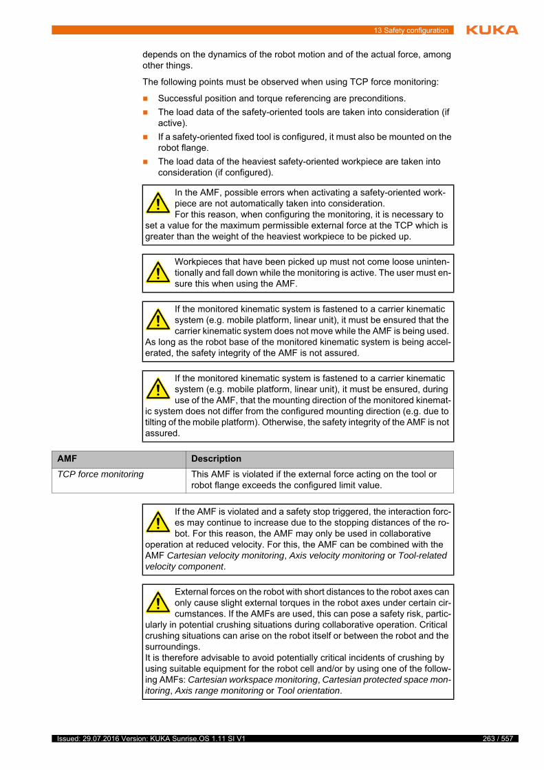
13 Safety configuration
depends on the dynamics of the robot motion and of the actual force, among other things.
The following points must be observed when using TCP force monitoring:
Successful position and torque referencing are preconditions.
The load data of the safety-oriented tools are taken into consideration (if active).
If a safety-oriented fixed tool is configured, it must also be mounted on the robot flange.
The load data of the heaviest safety-oriented workpiece are taken into consideration (if configured).
In the AMF, possible errors when activating a safety-oriented work-piece are not automatically taken into consideration.For this reason, when configuring the monitoring, it is necessary to
set a value for the maximum permissible external force at the TCP which is greater than the weight of the heaviest workpiece to be picked up.
Workpieces that have been picked up must not come loose uninten-tionally and fall down while the monitoring is active. The user must en-sure this when using the AMF.
If the monitored kinematic system is fastened to a carrier kinematic system (e.g. mobile platform, linear unit), it must be ensured that the carrier kinematic system does not move while the AMF is being used.
As long as the robot base of the monitored kinematic system is being accel-erated, the safety integrity of the AMF is not assured.
If the monitored kinematic system is fastened to a carrier kinematic system (e.g. mobile platform, linear unit), it must be ensured, during use of the AMF, that the mounting direction of the monitored kinemat-
ic system does not differ from the configured mounting direction (e.g. due to tilting of the mobile platform). Otherwise, the safety integrity of the AMF is not assured.
AMF Description
TCP force monitoring This AMF is violated if the external force acting on the tool or robot flange exceeds the configured limit value.
If the AMF is violated and a safety stop triggered, the interaction forc-es may continue to increase due to the stopping distances of the ro-bot. For this reason, the AMF may only be used in collaborative
operation at reduced velocity. For this, the AMF can be combined with the AMF Cartesian velocity monitoring, Axis velocity monitoring or Tool-related velocity component.
External forces on the robot with short distances to the robot axes can only cause slight external torques in the robot axes under certain cir-cumstances. If the AMFs are used, this can pose a safety risk, partic-
ularly in potential crushing situations during collaborative operation. Critical crushing situations can arise on the robot itself or between the robot and the surroundings.It is therefore advisable to avoid potentially critical incidents of crushing by using suitable equipment for the robot cell and/or by using one of the follow-ing AMFs: Cartesian workspace monitoring, Cartesian protected space mon-itoring, Axis range monitoring or Tool orientation.
263 / 557Issued: 29.07.2016 Version: KUKA Sunrise.OS 1.11 SI V1

264 / 557
KUKA Sunrise.OS 1.11 KUKA Sunrise.Wor...
Accuracy of force
detection
The accuracy of TCP force detection is dependent on the robot pose. The safety controller recognizes non-permissible poses and sets the AMF TCP force monitoring to “violated” with a corresponding error message.
Non-permissible poses are those in which it is possible for TCP forces to have a short distance to all robot axes. This applies to singularity poses and poses near singularities.
(>>> 14.11 "Singularities" Page 321)
External forces on the robot reduce the accuracy of TCP force detection. In many cases, the safety controller can automatically detect the external forces acting on the robot. The AMF TCP force monitoring is violated in this case.
13.10.13.4Direction-specific monitoring of the external force on the TCP
Description The AMF Base-related TCP force component is used to monitor the external force acting in a specific direction on the tool or on the robot flange relative to a base coordinate system against a definable limit value.
By default, the world coordinate system is used as the base coordinate sys-tem. No other base coordinate system can currently be defined for this moni-toring function.
The AMF monitors the force along the component of a reference coordinate system. The orientation of the reference coordinate system corresponds by default to the orientation of the base coordinate system. The orientation of the reference coordinate system relative to the base coordinate system can be modified in the AMF.
Parameter Description
Monitored kinematic system Kinematic system to be monitored
First kinematic system: Robot
Second kinematic system: No function
Third kinematic system: No function
Fourth kinematic system: No function
Maximum TCP force [N] Maximum permissible external force on the TCP
50 … 1,000 N
It is not possible to guarantee that the safety controller will always au-tomatically detect external forces acting on the robot. The user must ensure that the external forces act exclusively on the TCP in order to
assure the safety integrity of the AMF TCP force monitoring.
Issued: 29.07.2016 Version: KUKA Sunrise.OS 1.11 SI V1

13 Safety configuration
The external force on the TCP is not measured directly but is rather calculated using the dynamic robot model. The accuracy of the calculated external force depends on the dynamics of the robot motion and of the actual force, among other things.
The following points must be observed when monitoring base-related TCP force components:
Successful position and torque referencing are preconditions.
The load data of the safety-oriented tools are taken into consideration (if active).
If a safety-oriented fixed tool is configured, it must also be mounted on the robot flange.
The load data of the heaviest safety-oriented workpiece are taken into consideration (if configured).
The monitoring of individual force components has advantages over TCP force monitoring:
The monitoring function can be used in a larger workspace.
Workpieces have no influence on horizontal monitoring functions.
Possible errors when activating a safety-oriented workpiece are automat-ically taken into consideration. This results in additional external forces in
Fig. 13-21: Base-related TCP force monitoring
1 World coordinate system (= base coordinate system for the monitor-ing function)
2 World coordinate system is located by default in the base of the robot.
3 Negative X component of the TCP force vector
4 Negative Y component of the TCP force vector
5 Positive Z component of the TCP force vector
6 TCP force vector
In the AMF, possible errors when activating a safety-oriented work-piece are not automatically taken into consideration.For this reason, when configuring the monitoring, it is necessary to
set a value for the maximum permissible external force at the TCP which is greater than the weight component of the heaviest safety-oriented workpiece in the monitored direction.
265 / 557Issued: 29.07.2016 Version: KUKA Sunrise.OS 1.11 SI V1
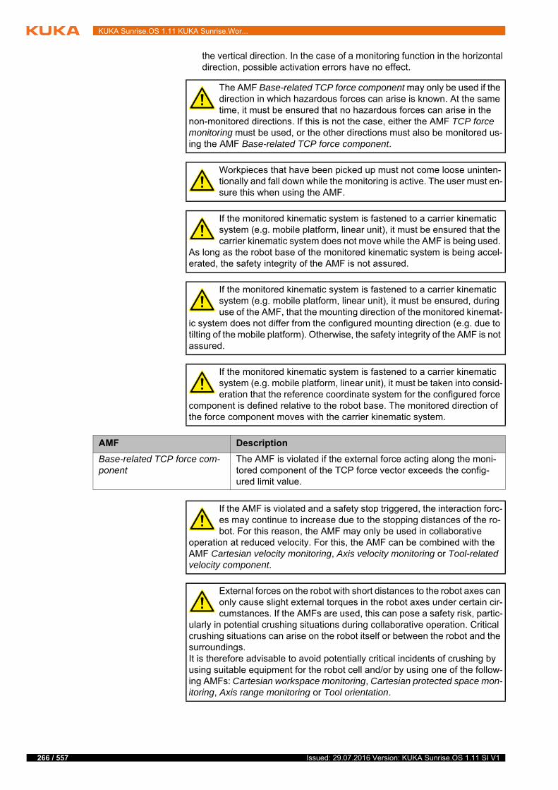
266 / 557
KUKA Sunrise.OS 1.11 KUKA Sunrise.Wor...
the vertical direction. In the case of a monitoring function in the horizontal direction, possible activation errors have no effect.
The AMF Base-related TCP force component may only be used if the direction in which hazardous forces can arise is known. At the same time, it must be ensured that no hazardous forces can arise in the
non-monitored directions. If this is not the case, either the AMF TCP force monitoring must be used, or the other directions must also be monitored us-ing the AMF Base-related TCP force component.
Workpieces that have been picked up must not come loose uninten-tionally and fall down while the monitoring is active. The user must en-sure this when using the AMF.
If the monitored kinematic system is fastened to a carrier kinematic system (e.g. mobile platform, linear unit), it must be ensured that the carrier kinematic system does not move while the AMF is being used.
As long as the robot base of the monitored kinematic system is being accel-erated, the safety integrity of the AMF is not assured.
If the monitored kinematic system is fastened to a carrier kinematic system (e.g. mobile platform, linear unit), it must be ensured, during use of the AMF, that the mounting direction of the monitored kinemat-
ic system does not differ from the configured mounting direction (e.g. due to tilting of the mobile platform). Otherwise, the safety integrity of the AMF is not assured.
If the monitored kinematic system is fastened to a carrier kinematic system (e.g. mobile platform, linear unit), it must be taken into consid-eration that the reference coordinate system for the configured force
component is defined relative to the robot base. The monitored direction of the force component moves with the carrier kinematic system.
AMF Description
Base-related TCP force com-ponent
The AMF is violated if the external force acting along the moni-tored component of the TCP force vector exceeds the config-ured limit value.
If the AMF is violated and a safety stop triggered, the interaction forc-es may continue to increase due to the stopping distances of the ro-bot. For this reason, the AMF may only be used in collaborative
operation at reduced velocity. For this, the AMF can be combined with the AMF Cartesian velocity monitoring, Axis velocity monitoring or Tool-related velocity component.
External forces on the robot with short distances to the robot axes can only cause slight external torques in the robot axes under certain cir-cumstances. If the AMFs are used, this can pose a safety risk, partic-
ularly in potential crushing situations during collaborative operation. Critical crushing situations can arise on the robot itself or between the robot and the surroundings.It is therefore advisable to avoid potentially critical incidents of crushing by using suitable equipment for the robot cell and/or by using one of the follow-ing AMFs: Cartesian workspace monitoring, Cartesian protected space mon-itoring, Axis range monitoring or Tool orientation.
Issued: 29.07.2016 Version: KUKA Sunrise.OS 1.11 SI V1
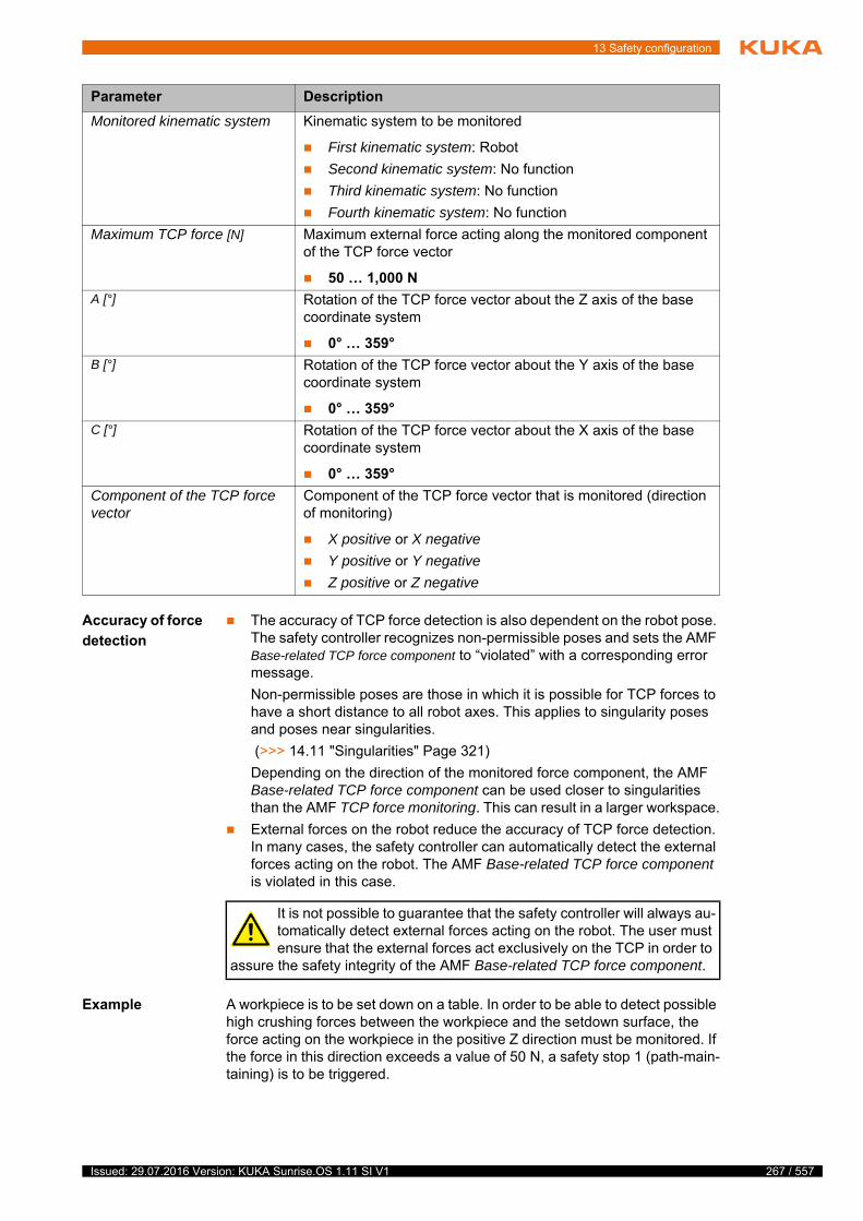
13 Safety configuration
Accuracy of force
detection
The accuracy of TCP force detection is also dependent on the robot pose. The safety controller recognizes non-permissible poses and sets the AMF Base-related TCP force component to “violated” with a corresponding error message.
Non-permissible poses are those in which it is possible for TCP forces to have a short distance to all robot axes. This applies to singularity poses and poses near singularities.
(>>> 14.11 "Singularities" Page 321)
Depending on the direction of the monitored force component, the AMF Base-related TCP force component can be used closer to singularities than the AMF TCP force monitoring. This can result in a larger workspace.
External forces on the robot reduce the accuracy of TCP force detection. In many cases, the safety controller can automatically detect the external forces acting on the robot. The AMF Base-related TCP force component is violated in this case.
Example A workpiece is to be set down on a table. In order to be able to detect possible high crushing forces between the workpiece and the setdown surface, the force acting on the workpiece in the positive Z direction must be monitored. If the force in this direction exceeds a value of 50 N, a safety stop 1 (path-main-taining) is to be triggered.
Parameter Description
Monitored kinematic system Kinematic system to be monitored
First kinematic system: Robot
Second kinematic system: No function
Third kinematic system: No function
Fourth kinematic system: No function
Maximum TCP force [N] Maximum external force acting along the monitored component of the TCP force vector
50 … 1,000 N
A [°] Rotation of the TCP force vector about the Z axis of the base coordinate system
0° … 359°
B [°] Rotation of the TCP force vector about the Y axis of the base coordinate system
0° … 359°
C [°] Rotation of the TCP force vector about the X axis of the base coordinate system
0° … 359°
Component of the TCP force vector
Component of the TCP force vector that is monitored (direction of monitoring)
X positive or X negative
Y positive or Y negative
Z positive or Z negative
It is not possible to guarantee that the safety controller will always au-tomatically detect external forces acting on the robot. The user must ensure that the external forces act exclusively on the TCP in order to
assure the safety integrity of the AMF Base-related TCP force component.
267 / 557Issued: 29.07.2016 Version: KUKA Sunrise.OS 1.11 SI V1
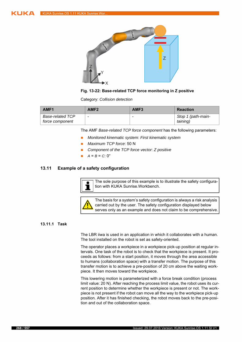
268 / 557
KUKA Sunrise.OS 1.11 KUKA Sunrise.Wor...
Category: Collision detection
The AMF Base-related TCP force component has the following parameters:
Monitored kinematic system: First kinematic system
Maximum TCP force: 50 N
Component of the TCP force vector: Z positive
A = B = C: 0°
13.11 Example of a safety configuration
13.11.1 Task
The LBR iiwa is used in an application in which it collaborates with a human. The tool installed on the robot is set as safety-oriented.
The operator places a workpiece in a workpiece pick-up position at regular in-tervals. One task of the robot is to check that the workpiece is present. It pro-ceeds as follows: from a start position, it moves through the area accessible to humans (collaboration space) with a transfer motion. The purpose of this transfer motion is to achieve a pre-position of 20 cm above the waiting work-piece. It then moves toward the workpiece.
This lowering motion is parameterized with a force break condition (process limit value: 20 N). After reaching the process limit value, the robot uses its cur-rent position to determine whether the workpiece is present or not. The work-piece is not present if the robot can move all the way to the workpiece pick-up position. After it has finished checking, the robot moves back to the pre-posi-tion and out of the collaboration space.
Fig. 13-22: Base-related TCP force monitoring in Z positive
AMF1 AMF2 AMF3 Reaction
Base-related TCP force component
- - Stop 1 (path-main-taining)
The sole purpose of this example is to illustrate the safety configura-tion with KUKA Sunrise.Workbench.
The basis for a system’s safety configuration is always a risk analysis carried out by the user. The safety configuration displayed below serves only as an example and does not claim to be comprehensive.
Issued: 29.07.2016 Version: KUKA Sunrise.OS 1.11 SI V1
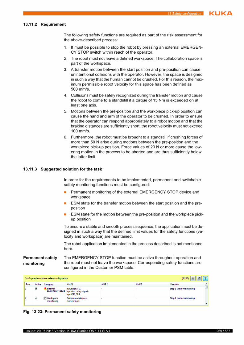
13 Safety configuration
13.11.2 Requirement
The following safety functions are required as part of the risk assessment for the above-described process:
1. It must be possible to stop the robot by pressing an external EMERGEN-CY STOP switch within reach of the operator.
2. The robot must not leave a defined workspace. The collaboration space is part of the workspace.
3. A transfer motion between the start position and pre-position can cause unintentional collisions with the operator. However, the space is designed in such a way that the human cannot be crushed. For this reason, the max-imum permissible robot velocity for this space has been defined as 500 mm/s.
4. Collisions must be safely recognized during the transfer motion and cause the robot to come to a standstill if a torque of 15 Nm is exceeded on at least one axis.
5. Motions between the pre-position and the workpiece pick-up position can cause the hand and arm of the operator to be crushed. In order to ensure that the operator can respond appropriately to a robot motion and that the braking distances are sufficiently short, the robot velocity must not exceed 100 mm/s.
6. Furthermore, the robot must be brought to a standstill if crushing forces of more than 50 N arise during motions between the pre-position and the workpiece pick-up position. Force values of 20 N or more cause the low-ering motion in the process to be aborted and are thus sufficiently below the latter limit.
13.11.3 Suggested solution for the task
In order for the requirements to be implemented, permanent and switchable safety monitoring functions must be configured:
Permanent monitoring of the external EMERGENCY STOP device and workspace
ESM state for the transfer motion between the start position and the pre-position
ESM state for the motion between the pre-position and the workpiece pick-up position
To ensure a stable and smooth process sequence, the application must be de-signed in such a way that the defined limit values for the safety functions (ve-locity and workspace) are maintained.
The robot application implemented in the process described is not mentioned here.
Permanent safety
monitoring
The EMERGENCY STOP function must be active throughout operation and the robot must not leave the workspace. Corresponding safety functions are configured in the Customer PSM table.
Fig. 13-23: Permanent safety monitoring
269 / 557Issued: 29.07.2016 Version: KUKA Sunrise.OS 1.11 SI V1
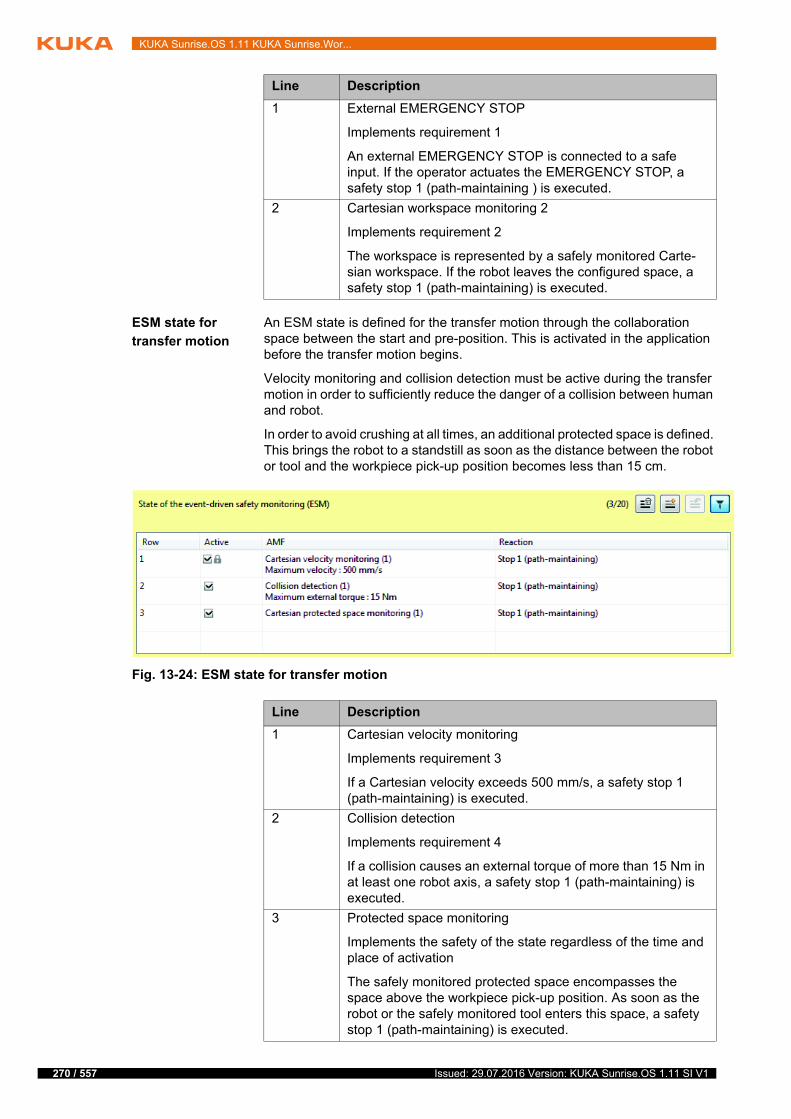
270 / 557
KUKA Sunrise.OS 1.11 KUKA Sunrise.Wor...
ESM state for
transfer motion
An ESM state is defined for the transfer motion through the collaboration space between the start and pre-position. This is activated in the application before the transfer motion begins.
Velocity monitoring and collision detection must be active during the transfer motion in order to sufficiently reduce the danger of a collision between human and robot.
In order to avoid crushing at all times, an additional protected space is defined. This brings the robot to a standstill as soon as the distance between the robot or tool and the workpiece pick-up position becomes less than 15 cm.
Line Description
1 External EMERGENCY STOP
Implements requirement 1
An external EMERGENCY STOP is connected to a safe input. If the operator actuates the EMERGENCY STOP, a safety stop 1 (path-maintaining ) is executed.
2 Cartesian workspace monitoring 2
Implements requirement 2
The workspace is represented by a safely monitored Carte-sian workspace. If the robot leaves the configured space, a safety stop 1 (path-maintaining) is executed.
Fig. 13-24: ESM state for transfer motion
Line Description
1 Cartesian velocity monitoring
Implements requirement 3
If a Cartesian velocity exceeds 500 mm/s, a safety stop 1 (path-maintaining) is executed.
2 Collision detection
Implements requirement 4
If a collision causes an external torque of more than 15 Nm in at least one robot axis, a safety stop 1 (path-maintaining) is executed.
3 Protected space monitoring
Implements the safety of the state regardless of the time and place of activation
The safely monitored protected space encompasses the space above the workpiece pick-up position. As soon as the robot or the safely monitored tool enters this space, a safety stop 1 (path-maintaining) is executed.
Issued: 29.07.2016 Version: KUKA Sunrise.OS 1.11 SI V1

13 Safety configuration
ESM state for
workpiece pick-
up position
A specific ESM state is defined for the motions between the pre-position and the workpiece pick-up position. This is activated in the application before the lowering motion begins.
Velocity monitoring and force monitoring must be active during the motion in order to sufficiently reduce the danger of crushing the operator’s hand or lower arm.
The state must ensure a sufficient degree of safety, regardless of the time or place of activation. The low permissible velocity and the active force monitor-ing mean that no further measures are necessary.
13.12 Position and torque referencing
13.12.1 Position referencing
Description Position referencing checks whether the saved zero position of the motor of an axis (= saved mastering position) corresponds to the actual mechanical zero position.
In the case of an LBR iiwa, referencing is carried out continuously by the sys-tem when an axis moves at less than 30 °/s. Referencing is successful when the mastering sensor detects the mechanical zero position of the axis in a nar-row range around the saved zero position of the motor.
Referencing fails in the following cases:
The mastering sensor does not detect the mechanical zero position of the axis in the range around the saved zero position of the motor.
The mastering sensor detects the mechanical zero position of the axis at an unexpected point.
For other robots, the axis positions can only be referenced via an external sys-tem. The interface for external position referencing must be configured.
(>>> 13.12.4 "External position referencing" Page 275)
Fig. 13-25: ESM state for workpiece pick-up position
Line Description
1 Cartesian velocity monitoring
Implements requirement 5
If a Cartesian velocity exceeds 100 mm/s, a safety stop 1 (path-maintaining) is executed.
2 Force monitoring
Implements requirement 6
If a contact situation causes a force of more than 50 N to be exerted at the TCP, a stop 0 is executed.
271 / 557Issued: 29.07.2016 Version: KUKA Sunrise.OS 1.11 SI V1

272 / 557
KUKA Sunrise.OS 1.11 KUKA Sunrise.Wor...
The safety integrity of the safety functions based upon this is limited until the position referencing test has been performed. This includes, for example, safely monitored Cartesian and axis-specific robot positions, safely monitored Cartesian velocities, TCP force monitoring and collision detection.
If position referencing fails on at least one axis, all AMFs based on safe axis positions are violated. (>>> "Position-based AMFs" Page 279)
Requirement The position of an axis is not referenced after the following events:
Robot controller is rebooted.
The axis is remastered.
Torque referencing of the axis fails.
The maximum torque of the joint torque sensor of the axis has been ex-ceeded.
These events do not lead to a violation of the safe position-based safety func-tions. The robot can be moved, but the safety integrity of the safety functions is no longer assured.
The safety functions based on safe positions are only violated after these events if the position referencing of an axis fails. Referencing must be suc-cessfully carried out before safety-critical applications can be executed.
The position referencing status can be used as an AMF in the safety configu-ration. (>>> 13.10.6 "Evaluating the position referencing" Page 239)
Precondition The position of an axis is referenced when the axis is moved over the saved zero position of the motor and the mastering sensor detects the zero position of the axis in a range of 0° +/- 0.5°.
Preconditions for this:
The velocity at which the axis is moved over the zero position must be < 30 °/s.
At the very least, a defined axis-specific range before and after the zero position must be passed through. The motion direction is not relevant.
The axis-specific range of motion is robot-specific:
Execution Position referencing of all axes is continuously performed by the system when the above conditions are met. Position referencing can be carried out in a tar-geted manner the following ways:
Automatically while the program is running, when an axis moves over the zero position at less than 30 °/s.
Jogging each axis individually over the zero position.
Executing the application prepared by KUKA. The axes are moved over the zero position from the vertical stretch position.
An application for position and torque referencing of the LBR iiwa is avail-able from Sunrise.Workbench. Position and torque referencing can be car-ried out simultaneously with this application.
(>>> 13.12.3 "Creating an application for position and torque referencing" Page 274)
If the maximum torque of a joint torque sensor is exceeded for longer than 3 seconds, the brake of the corresponding axis is opened auto-matically for a few milliseconds. The opening of the brakes is repeat-
ed every 3 seconds until the maximum torque is no longer exceeded.
Robot variant A1 A2 A3 A4 A5 A6 A7
LBR iiwa 7 R800 ±10.5° ±10.5° ±10.5° ±10.5° ±10.5° ±14° ±14°
LBR iiwa 14 R820 ±9.5° ±9.5° ±10.5° ±10.5° ±10.5° ±14° ±14°
Issued: 29.07.2016 Version: KUKA Sunrise.OS 1.11 SI V1

13 Safety configuration
13.12.2 Torque referencing
Description The LBR iiwa has a joint torque sensor in each axis which reliably determines the torque currently acting on the axis. These data are used for calculating and monitoring externally acting torques or Cartesian forces, for example.
During referencing of the joint torque sensors, the system checks whether the expected external torque of an axis matches the actual external torque of the axis:
The expected torque is calculated using the robot model and the specified load data for each axis.
The actual torque is determined on the basis of the measured value of the joint torque sensor for each axis.
If the difference between the expected torque and the actual torque exceeds a certain tolerance value, the referencing of the torque sensors has failed.
The safety integrity of the safety functions based upon this is limited until the torque referencing test has been performed successfully. This includes, for ex-ample, axis torque and TCP force monitoring as well as collision detection.
If torque referencing fails on at least one axis, all AMFs based on safe torque values are violated. (>>> "Axis torque-based AMFs" Page 280)
Requirement The joint torque sensor of an axis is not referenced after the following events:
Robot controller is rebooted.
Position referencing of the axis fails.
The maximum torque of the joint torque sensor of the axis has been ex-ceeded.
These events do not lead to a violation of the safety functions based on safe torque values. The robot can be moved, but the safety integrity of the safety functions is no longer assured.
The safety functions based on safe torque values are only violated after these events if torque referencing of one axis fails. Referencing must be successfully carried out before safety-critical applications can be executed.
The torque referencing status can be used as an AMF in the safety configura-tion. (>>> 13.10.7 "Evaluating the torque referencing" Page 239)
Execution An application for position and torque referencing of the LBR iiwa is available from Sunrise.Workbench. Position and torque referencing can be carried out simultaneously with this application.
(>>> 13.12.3 "Creating an application for position and torque referencing" Page 274)
A total of 10 measured joint torque values must be given for each axis. For this purpose, 5 measurement poses are defined in the application, each of which can be addressed with positive and negative directions of axis rotation. If the poses cannot be addressed, they must be adapted in the application.
If it is not possible to reference from the vertical stretch position, a user-specific application for position referencing must be created and executed.
If the maximum torque of a joint torque sensor is exceeded for longer than 3 seconds, the brake of the corresponding axis is opened auto-matically for a few milliseconds. The opening of the brakes is repeat-
ed every 3 seconds until the maximum torque is no longer exceeded.
273 / 557Issued: 29.07.2016 Version: KUKA Sunrise.OS 1.11 SI V1

274 / 557
KUKA Sunrise.OS 1.11 KUKA Sunrise.Wor...
The safety controller evaluates the external torque for all 10 measured values and determines the mean value of the external torque for each axis. Referenc-ing is successful if this mean value is below a defined tolerance. Otherwise, referencing has failed.
13.12.3 Creating an application for position and torque referencing
Description The following points must be observed if the application for torque referencing needs to be edited due to measurement poses which cannot be addressed:
The joint torque values must be measured while the robot is stationary.
A wait time of at least 2.5 seconds in which the robot does not move is re-quired between the moment the measurement pose is reached and the measurement itself. Wait times which are too short can reduce the refer-encing accuracy due to oscillations on the robot.
The measurement is started with the method sendSafetyCommand().
There may be a maximum of 15 s between 2 consecutive measurements.
Procedure 1. Select the Sunrise project in the Package Explorer.
2. Select the menu sequence File > New > Other....
3. In the Sunrise folder, select the Application for position and GMS ref-erencing of the LBR iiwa option and click on Finish.
During torque referencing, each of the measurement poses must be addressed in sequence with positive and negative directions of axis rotation before the next measurement pose is addressed. The safety
integrity of the referencing of the joint torque sensors is otherwise not given.
Before carrying out torque referencing, the user must ensure the fol-lowing points:
The load data of the fixed tool mounted on the robot flange must match the load data with which the fixed safety-oriented tool is config-ured.
The load data of the tool coupled with the fixed tool (if present) must match the load data of the activated safety-oriented tool.
The load data of the workpiece that is picked up (if present) must match the load data of the activated safety-oriented workpiece.
Workpieces that are not taken into consideration by the safety controller must not be picked up.
No supplementary loads, e.g. dress packages, may be fastened to the ro-bot.
If one of these points is not met, the safety integrity of the referencing of the joint torque sensors is not given.
If the monitored kinematic system is fastened to a carrier kinematic system (e.g. mobile platform, linear unit), the user must ensure that the following points are observed:
The carrier kinematic system must not be moved during torque referenc-ing.
The mounting direction of the kinematic system to be referenced must not differ from the configured mounting direction (e.g. due to tilting of the mobile platform).
If any of these points is not met, the safety integrity of the referencing of the joint torque sensors is not given.
Issued: 29.07.2016 Version: KUKA Sunrise.OS 1.11 SI V1

13 Safety configuration
The PositionAndGMSReferencing.java application is created in the source folder of the project and opened in the editor area of Sunrise.Work-bench.
4. If measurement poses cannot be addressed due to the system configura-tion, adapt them in the application.
5. Synchronize the project in order to transfer the application to the robot controller.
13.12.4 External position referencing
Description The user has the possibility of implementing his own test method or an exter-nal system for position referencing, e.g. a tracker, a navigation system or an absolute encoder. Confirmation that the external position referencing has been successfully carried out must be communicated to the robot controller via a safety-oriented input.
The input for external position referencing can be configured in the project set-tings. If the external signal at this input changes from LOW to HIGH and back to LOW within 2 seconds, the position referencing has been successfully con-firmed.
13.12.4.1Configuring the input for external position referencing
Description The safety-oriented input that allows external position referencing is config-ured in the project settings.
Procedure 1. Right-click on the desired project in the Package Explorer view and select Sunrise > Change project settings from the context menu.
The Properties for [Sunrise Project] window opens.
2. Select Sunrise > Safety in the directory in the left area of the window.
3. Make the following settings in the right-hand part of the window:
Set the check mark at Allow external position referencing.
Select the input that is to be used for external position referencing.
The inputs of the discrete safety interface and of the Ethernet safety interface can be used as long as they are configured in WorkVisual.
(>>> "Safety interfaces" Page 204)
The enabling device of the hand guiding device can also be used as an input.
4. Click on OK to save the settings and close the window.
13.13 Safety acceptance overview
The system must not be put into operation until the safety acceptance proce-dure has been completed successfully. For successful safety acceptance, the points in the checklists must be completed fully and confirmed in writing by the safety maintenance technician.
External position referencing is merely an interface for setting the po-sition referencing. The safety maintenance personnel is responsible for the correct use of the referencing input, i.e.:
They must provide a suitable test method for position mastering.
The test method for position mastering must be sufficiently accurate. The accuracy of the position-based AMFs depends on the accuracy of the test method.
They must ensure that the input is only set after the position mastering has been successfully tested.
275 / 557Issued: 29.07.2016 Version: KUKA Sunrise.OS 1.11 SI V1
276 / 557
KUKA Sunrise.OS 1.11 KUKA Sunrise.Wor...
Safety acceptance must be carried out in the following cases:
Following initial start-up or recommissioning of the industrial robot
After a change to the industrial robot
After a change to the safety configuration
After a software update, e.g. of the system software
Safety acceptance after a software update is only necessary if the ID of the safety configuration (= checksum) has changed as a result of the up-date.
The system integrator determines the required safety functions using the risk analysis as a basis. Once the safety configuration is activated on the robot controller, the safety functions must be tested for correct functioning.
The following checklists must be used to verify whether the configured safety parameters have been correctly transferred.
The checklists must be processed in the following order:
1. Checklist for basic test of the safety configuration
(>>> 13.13 "Safety acceptance overview" Page 275)
2. Checklists for checking the mapped safety-oriented tools
(>>> 13.13.2 "Checklist for tool selection table" Page 280)
(>>> 13.13.3 "Checklists for safety-oriented tools" Page 281)
3. Checklists for checking the safety-oriented workpieces
(>>> 13.13.4 "Checklist for safety-oriented workpieces" Page 286)
4. Checklist for checking the rows used in the KUKA PSM table and in the Customer PSM table
(>>> 13.13.5 "Checklist for rows used in the PSM tables" Page 288)
5. Checklists for checking the ESM states which have been used and not used
(>>> 13.13.6 "Checklists for ESM states" Page 288)
6. Checklists for checking the AMFs used
(>>> 13.13.7 "Checklists for AMFs used" Page 290)
7. Checklists for checking the general safety-oriented settings
(>>> 13.13.8 "Checklists – General safety settings" Page 299)
It is possible to create a report of the current safety configuration.
(>>> 13.13 "Safety acceptance overview" Page 275)
13.13.1 Checklist – System safety functions
Checklist Serial number of the robot: ____________________
ID of the safety configuration: ____________________
Name of safety maintenance technician: ____________________
The completed checklists, confirmed in writing, must be kept as doc-umentary evidence.
If a test requires persons to be present in the danger zone, the test must be conducted in T1 mode.
Issued: 29.07.2016 Version: KUKA Sunrise.OS 1.11 SI V1
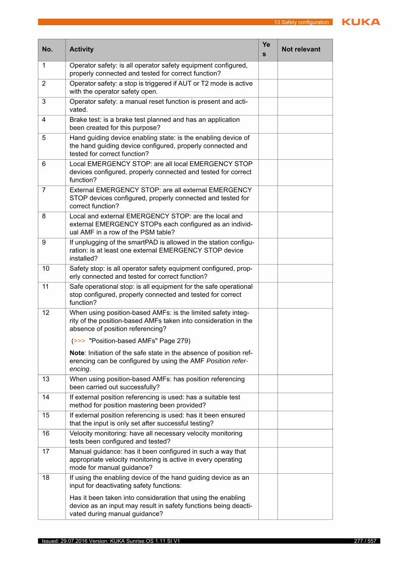
13 Safety configuration
No. ActivityYe
sNot relevant
1 Operator safety: is all operator safety equipment configured, properly connected and tested for correct function?
2 Operator safety: a stop is triggered if AUT or T2 mode is active with the operator safety open.
3 Operator safety: a manual reset function is present and acti-vated.
4 Brake test: is a brake test planned and has an application been created for this purpose?
5 Hand guiding device enabling state: is the enabling device of the hand guiding device configured, properly connected and tested for correct function?
6 Local EMERGENCY STOP: are all local EMERGENCY STOP devices configured, properly connected and tested for correct function?
7 External EMERGENCY STOP: are all external EMERGENCY STOP devices configured, properly connected and tested for correct function?
8 Local and external EMERGENCY STOP: are the local and external EMERGENCY STOPs each configured as an individ-ual AMF in a row of the PSM table?
9 If unplugging of the smartPAD is allowed in the station configu-ration: is at least one external EMERGENCY STOP device installed?
10 Safety stop: is all operator safety equipment configured, prop-erly connected and tested for correct function?
11 Safe operational stop: is all equipment for the safe operational stop configured, properly connected and tested for correct function?
12 When using position-based AMFs: is the limited safety integ-rity of the position-based AMFs taken into consideration in the absence of position referencing?
(>>> "Position-based AMFs" Page 279)
Note: Initiation of the safe state in the absence of position ref-erencing can be configured by using the AMF Position refer-encing.
13 When using position-based AMFs: has position referencing been carried out successfully?
14 If external position referencing is used: has a suitable test method for position mastering been provided?
15 If external position referencing is used: has it been ensured that the input is only set after successful testing?
16 Velocity monitoring: have all necessary velocity monitoring tests been configured and tested?
17 Manual guidance: has it been configured in such a way that appropriate velocity monitoring is active in every operating mode for manual guidance?
18 If using the enabling device of the hand guiding device as an input for deactivating safety functions:
Has it been taken into consideration that using the enabling device as an input may result in safety functions being deacti-vated during manual guidance?
277 / 557Issued: 29.07.2016 Version: KUKA Sunrise.OS 1.11 SI V1
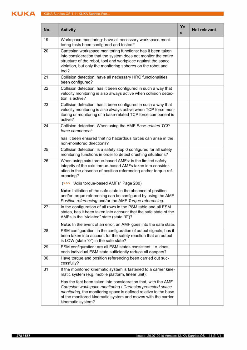
278 / 557
KUKA Sunrise.OS 1.11 KUKA Sunrise.Wor...
19 Workspace monitoring: have all necessary workspace moni-toring tests been configured and tested?
20 Cartesian workspace monitoring functions: has it been taken into consideration that the system does not monitor the entire structure of the robot, tool and workpiece against the space violation, but only the monitoring spheres on the robot and tool?
21 Collision detection: have all necessary HRC functionalities been configured?
22 Collision detection: has it been configured in such a way that velocity monitoring is also always active when collision detec-tion is active?
23 Collision detection: has it been configured in such a way that velocity monitoring is also always active when TCP force mon-itoring or monitoring of a base-related TCP force component is active?
24 Collision detection: When using the AMF Base-related TCP force component:
has it been ensured that no hazardous forces can arise in the non-monitored directions?
25 Collision detection: is a safety stop 0 configured for all safety monitoring functions in order to detect crushing situations?
26 When using axis torque-based AMFs: is the limited safety integrity of the axis torque-based AMFs taken into consider-ation in the absence of position referencing and/or torque ref-erencing?
(>>> "Axis torque-based AMFs" Page 280)
Note: Initiation of the safe state in the absence of position and/or torque referencing can be configured by using the AMF Position referencing and/or the AMF Torque referencing.
27 In the configuration of all rows in the PSM table and all ESM states, has it been taken into account that the safe state of the AMFs is the “violated” state (state “0”)?
Note: In the event of an error, an AMF goes into the safe state.
28 PSM configuration: in the configuration of output signals, has it been taken into account for the safety reaction that an output is LOW (state “0”) in the safe state?
29 ESM configuration: are all ESM states consistent, i.e. does each individual ESM state sufficiently reduce all dangers?
30 Have torque and position referencing been carried out suc-cessfully?
31 If the monitored kinematic system is fastened to a carrier kine-matic system (e.g. mobile platform, linear unit):
Has the fact been taken into consideration that, with the AMF Cartesian workspace monitoring / Cartesian protected space monitoring, the monitoring space is defined relative to the base of the monitored kinematic system and moves with the carrier kinematic system?
No. ActivityYe
sNot relevant
Issued: 29.07.2016 Version: KUKA Sunrise.OS 1.11 SI V1

13 Safety configuration
By signing, the signatory confirms the correct and complete performance of the safety acceptance test.
Position-based
AMFs
The safety integrity of position-based AMFs is only given without limitations when position referencing has been carried out successfully. (Position-based AMFs are only supported by robot types that have corresponding sensor sys-tems, e.g. LBR iiwa.)
32 If the monitored kinematic system is fastened to a carrier kine-matic system (e.g. mobile platform, linear unit):
Has the fact been taken into consideration that, with the AMF Cartesian velocity monitoring, it is not the absolute velocity, but the velocity of the monitored kinematic system relative to the carrier kinematic system that is monitored?
33 If the monitored kinematic system is fastened to a carrier kine-matic system (e.g. mobile platform, linear unit):
Has the fact been taken into consideration that, with the AMF Tool-related velocity component, it is not the absolute velocity, but the velocity of the monitored kinematic system relative to the carrier kinematic system that is monitored?
34 If the monitored kinematic system is fastened to a carrier kine-matic system (e.g. mobile platform):
Has the fact been taken into consideration that, with the AMF Tool orientation, the reference orientation is defined relative to the carrier kinematic system and moves with the carrier kine-matic system?
35 If the monitored kinematic system is fastened to a carrier kine-matic system (e.g. mobile platform):
Has the fact been taken into consideration that, with the AMF Base-related TCP force component, the reference coordinate sys-tem is defined relative to the robot base and the monitored direction of the force component moves with the carrier kine-matic system?
36 If the monitored kinematic system is fastened to a carrier kine-matic system (e.g. mobile platform, linear unit):
Has the fact been taken into consideration that the safety integrity of the AMFs Collision detection, TCP force monitoring and Base-related TCP force component is only assured as long as the carrier kinematic system is at a standstill?
No. ActivityYe
sNot relevant
Place, date
Signature
AMF Position referencing Torque referencing
Standstill monitoring of all axes
Axis range monitoring
Cartesian velocity monitoring
Tool-related velocity component
Cartesian workspace monitoring
279 / 557Issued: 29.07.2016 Version: KUKA Sunrise.OS 1.11 SI V1

280 / 557
KUKA Sunrise.OS 1.11 KUKA Sunrise.Wor...
Axis torque-
based AMFs
The safety integrity of axis torque-based AMFs is only given without limitations when position and/or torque referencing has been carried out successfully. (Axis torque-based AMFs are only supported by robot types that have corre-sponding sensor systems, e.g. LBR iiwa.)
13.13.2 Checklist for tool selection table
Description If one of the following AMFs is used in the safety configuration, it is necessary to check the mapped safety-oriented tools:
Cartesian velocity monitoring
Only if the monitoring spheres on the tool are configured as a structure to be monitored.
Tool-related velocity component
Cartesian workspace monitoring / Cartesian protected space monitoring
Only if the monitoring spheres on the tool are configured as a structure to be monitored.
Tool orientation
Collision detection
TCP force monitoring
Base-related TCP force component
Torque referencing
For each activated row of the tool selection table, it is necessary to check whether the selected tool has been correctly assigned to the kinematic sys-tem. This can be checked, for example, using a suitable test for verification of the tool parameters. A test is suitable if it checks a tool parameter whose value differs significantly from that of the other safety-oriented tools:
In the case of significantly different geometric dimensions, it is advisable to check whether the geometric tool data have been specified correctly.
(>>> 13.13.3.5 "Geometry data of the tool" Page 284)
In the case of significantly different geometric dimensions, it is advisable to check whether the geometric tool data have been specified correctly.
(>>> 13.13.3.6 "Load data of the tool" Page 285)
In the case of significantly different parameters when using the AMF Tool orientation, it is advisable to check whether the tool orientation that is to be monitored is correctly configured.
(>>> 13.13.3.3 "Tool orientation" Page 283)
Cartesian protected space monitoring
Tool orientation
AMF Position referencing Torque referencing
AMF Position referencing Torque referencing
Axis torque monitoring
Collision detection
TCP force monitoring
Base-related TCP force component
Issued: 29.07.2016 Version: KUKA Sunrise.OS 1.11 SI V1
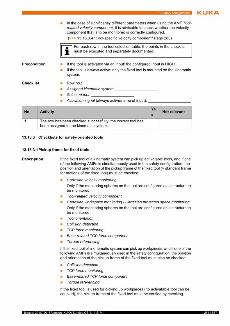
13 Safety configuration
In the case of significantly different parameters when using the AMF Tool-related velocity component, it is advisable to check whether the velocity component that is to be monitored is correctly configured.
(>>> 13.13.3.4 "Tool-specific velocity component" Page 283)
Precondition If the tool is activated via an input: the configured input is HIGH.
If the tool is always active: only the fixed tool is mounted on the kinematic system.
Checklist Row no.: ____________________
Assigned kinematic system: ____________________
Selected tool: ____________________
Activation signal (always active/name of input): ____________________
13.13.3 Checklists for safety-oriented tools
13.13.3.1Pickup frame for fixed tools
Description If the fixed tool of a kinematic system can pick up activatable tools, and if one of the following AMFs is simultaneously used in the safety configuration, the position and orientation of the pickup frame of the fixed tool (= standard frame for motions of the fixed tool) must be checked:
Cartesian velocity monitoring
Only if the monitoring spheres on the tool are configured as a structure to be monitored.
Tool-related velocity component
Cartesian workspace monitoring / Cartesian protected space monitoring
Only if the monitoring spheres on the tool are configured as a structure to be monitored.
Tool orientation
Collision detection
TCP force monitoring
Base-related TCP force component
Torque referencing
If the fixed tool of a kinematic system can pick up workpieces, and if one of the following AMFs is simultaneously used in the safety configuration, the position and orientation of the pickup frame of the fixed tool must also be checked:
Collision detection
TCP force monitoring
Base-related TCP force component
Torque referencing
If the fixed tool is used for picking up workpieces (no activatable tool can be coupled), the pickup frame of the fixed tool must be verified by checking
For each row in the tool selection table, the points in the checklist must be executed and separately documented.
No. ActivityYe
sNot relevant
1 The row has been checked successfully: the correct tool has been assigned to the kinematic system.
281 / 557Issued: 29.07.2016 Version: KUKA Sunrise.OS 1.11 SI V1
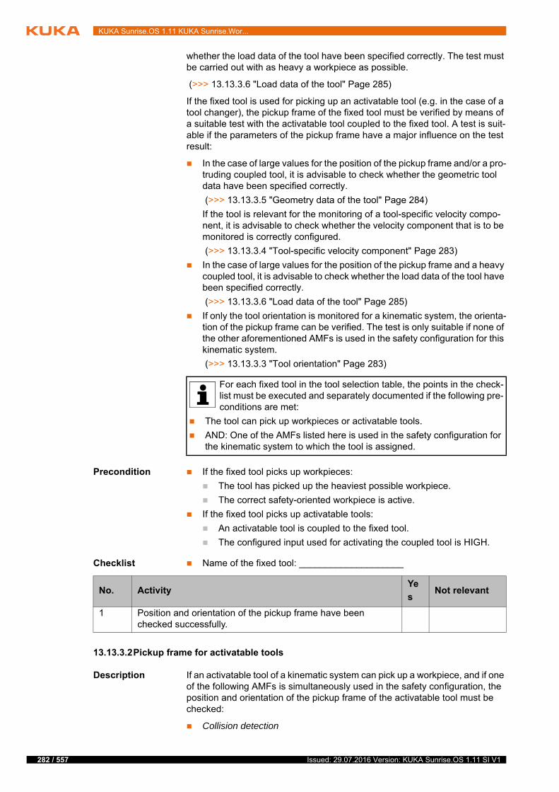
282 / 557
KUKA Sunrise.OS 1.11 KUKA Sunrise.Wor...
whether the load data of the tool have been specified correctly. The test must be carried out with as heavy a workpiece as possible.
(>>> 13.13.3.6 "Load data of the tool" Page 285)
If the fixed tool is used for picking up an activatable tool (e.g. in the case of a tool changer), the pickup frame of the fixed tool must be verified by means of a suitable test with the activatable tool coupled to the fixed tool. A test is suit-able if the parameters of the pickup frame have a major influence on the test result:
In the case of large values for the position of the pickup frame and/or a pro-truding coupled tool, it is advisable to check whether the geometric tool data have been specified correctly.
(>>> 13.13.3.5 "Geometry data of the tool" Page 284)
If the tool is relevant for the monitoring of a tool-specific velocity compo-nent, it is advisable to check whether the velocity component that is to be monitored is correctly configured.
(>>> 13.13.3.4 "Tool-specific velocity component" Page 283)
In the case of large values for the position of the pickup frame and a heavy coupled tool, it is advisable to check whether the load data of the tool have been specified correctly.
(>>> 13.13.3.6 "Load data of the tool" Page 285)
If only the tool orientation is monitored for a kinematic system, the orienta-tion of the pickup frame can be verified. The test is only suitable if none of the other aforementioned AMFs is used in the safety configuration for this kinematic system.
(>>> 13.13.3.3 "Tool orientation" Page 283)
Precondition If the fixed tool picks up workpieces:
The tool has picked up the heaviest possible workpiece.
The correct safety-oriented workpiece is active.
If the fixed tool picks up activatable tools:
An activatable tool is coupled to the fixed tool.
The configured input used for activating the coupled tool is HIGH.
Checklist Name of the fixed tool: ____________________
13.13.3.2Pickup frame for activatable tools
Description If an activatable tool of a kinematic system can pick up a workpiece, and if one of the following AMFs is simultaneously used in the safety configuration, the position and orientation of the pickup frame of the activatable tool must be checked:
Collision detection
For each fixed tool in the tool selection table, the points in the check-list must be executed and separately documented if the following pre-conditions are met:
The tool can pick up workpieces or activatable tools.
AND: One of the AMFs listed here is used in the safety configuration for the kinematic system to which the tool is assigned.
No. ActivityYe
sNot relevant
1 Position and orientation of the pickup frame have been checked successfully.
Issued: 29.07.2016 Version: KUKA Sunrise.OS 1.11 SI V1
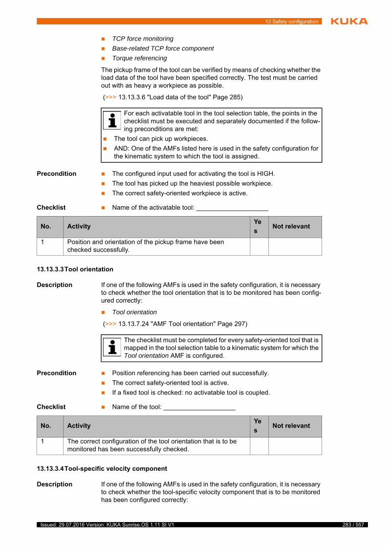
13 Safety configuration
TCP force monitoring
Base-related TCP force component
Torque referencing
The pickup frame of the tool can be verified by means of checking whether the load data of the tool have been specified correctly. The test must be carried out with as heavy a workpiece as possible.
(>>> 13.13.3.6 "Load data of the tool" Page 285)
Precondition The configured input used for activating the tool is HIGH.
The tool has picked up the heaviest possible workpiece.
The correct safety-oriented workpiece is active.
Checklist Name of the activatable tool: ____________________
13.13.3.3Tool orientation
Description If one of the following AMFs is used in the safety configuration, it is necessary to check whether the tool orientation that is to be monitored has been config-ured correctly:
Tool orientation
(>>> 13.13.7.24 "AMF Tool orientation" Page 297)
Precondition Position referencing has been carried out successfully.
The correct safety-oriented tool is active.
If a fixed tool is checked: no activatable tool is coupled.
Checklist Name of the tool: ____________________
13.13.3.4Tool-specific velocity component
Description If one of the following AMFs is used in the safety configuration, it is necessary to check whether the tool-specific velocity component that is to be monitored has been configured correctly:
For each activatable tool in the tool selection table, the points in the checklist must be executed and separately documented if the follow-ing preconditions are met:
The tool can pick up workpieces.
AND: One of the AMFs listed here is used in the safety configuration for the kinematic system to which the tool is assigned.
No. ActivityYe
sNot relevant
1 Position and orientation of the pickup frame have been checked successfully.
The checklist must be completed for every safety-oriented tool that is mapped in the tool selection table to a kinematic system for which the Tool orientation AMF is configured.
No. ActivityYe
sNot relevant
1 The correct configuration of the tool orientation that is to be monitored has been successfully checked.
283 / 557Issued: 29.07.2016 Version: KUKA Sunrise.OS 1.11 SI V1
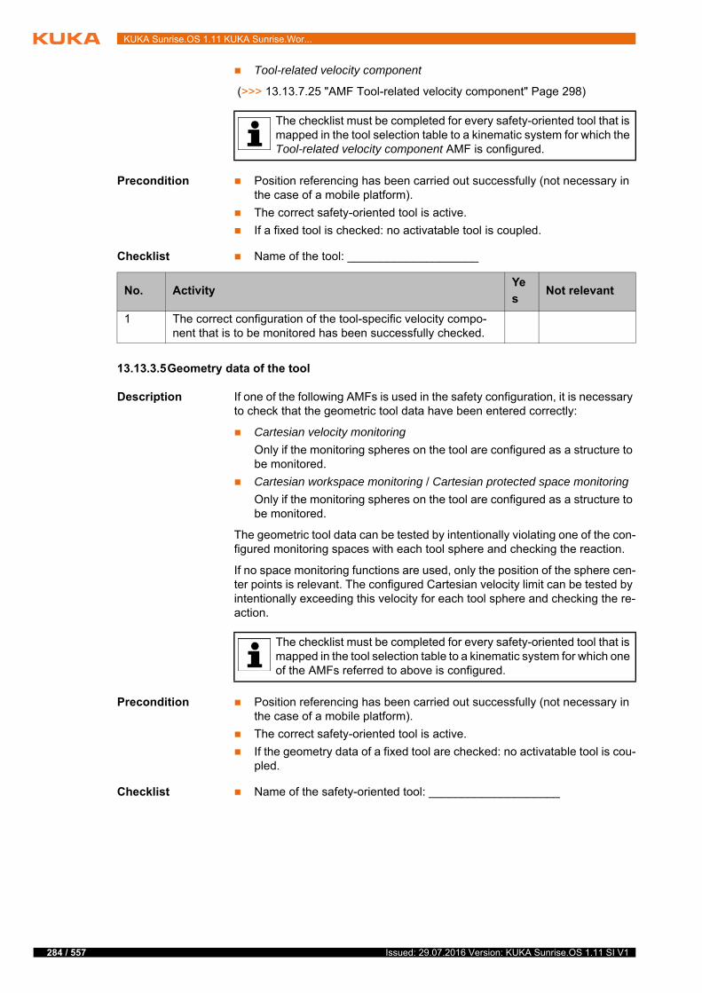
284 / 557
KUKA Sunrise.OS 1.11 KUKA Sunrise.Wor...
Tool-related velocity component
(>>> 13.13.7.25 "AMF Tool-related velocity component" Page 298)
Precondition Position referencing has been carried out successfully (not necessary in the case of a mobile platform).
The correct safety-oriented tool is active.
If a fixed tool is checked: no activatable tool is coupled.
Checklist Name of the tool: ____________________
13.13.3.5Geometry data of the tool
Description If one of the following AMFs is used in the safety configuration, it is necessary to check that the geometric tool data have been entered correctly:
Cartesian velocity monitoring
Only if the monitoring spheres on the tool are configured as a structure to be monitored.
Cartesian workspace monitoring / Cartesian protected space monitoring
Only if the monitoring spheres on the tool are configured as a structure to be monitored.
The geometric tool data can be tested by intentionally violating one of the con-figured monitoring spaces with each tool sphere and checking the reaction.
If no space monitoring functions are used, only the position of the sphere cen-ter points is relevant. The configured Cartesian velocity limit can be tested by intentionally exceeding this velocity for each tool sphere and checking the re-action.
Precondition Position referencing has been carried out successfully (not necessary in the case of a mobile platform).
The correct safety-oriented tool is active.
If the geometry data of a fixed tool are checked: no activatable tool is cou-pled.
Checklist Name of the safety-oriented tool: ____________________
The checklist must be completed for every safety-oriented tool that is mapped in the tool selection table to a kinematic system for which the Tool-related velocity component AMF is configured.
No. ActivityYe
sNot relevant
1 The correct configuration of the tool-specific velocity compo-nent that is to be monitored has been successfully checked.
The checklist must be completed for every safety-oriented tool that is mapped in the tool selection table to a kinematic system for which one of the AMFs referred to above is configured.
Issued: 29.07.2016 Version: KUKA Sunrise.OS 1.11 SI V1
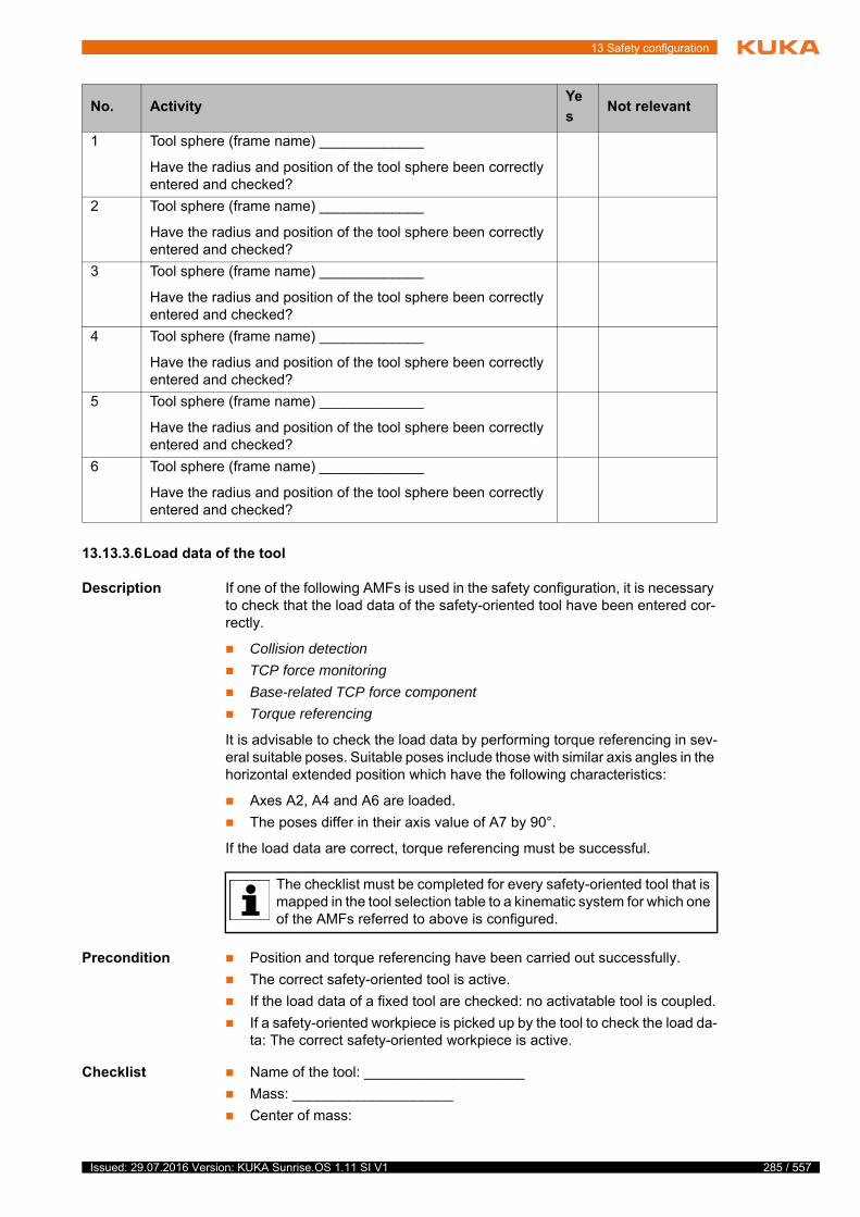
13 Safety configuration
13.13.3.6Load data of the tool
Description If one of the following AMFs is used in the safety configuration, it is necessary to check that the load data of the safety-oriented tool have been entered cor-rectly.
Collision detection
TCP force monitoring
Base-related TCP force component
Torque referencing
It is advisable to check the load data by performing torque referencing in sev-eral suitable poses. Suitable poses include those with similar axis angles in the horizontal extended position which have the following characteristics:
Axes A2, A4 and A6 are loaded.
The poses differ in their axis value of A7 by 90°.
If the load data are correct, torque referencing must be successful.
Precondition Position and torque referencing have been carried out successfully.
The correct safety-oriented tool is active.
If the load data of a fixed tool are checked: no activatable tool is coupled.
If a safety-oriented workpiece is picked up by the tool to check the load da-ta: The correct safety-oriented workpiece is active.
Checklist Name of the tool: ____________________
Mass: ____________________
Center of mass:
No. ActivityYe
sNot relevant
1 Tool sphere (frame name) _____________
Have the radius and position of the tool sphere been correctly entered and checked?
2 Tool sphere (frame name) _____________
Have the radius and position of the tool sphere been correctly entered and checked?
3 Tool sphere (frame name) _____________
Have the radius and position of the tool sphere been correctly entered and checked?
4 Tool sphere (frame name) _____________
Have the radius and position of the tool sphere been correctly entered and checked?
5 Tool sphere (frame name) _____________
Have the radius and position of the tool sphere been correctly entered and checked?
6 Tool sphere (frame name) _____________
Have the radius and position of the tool sphere been correctly entered and checked?
The checklist must be completed for every safety-oriented tool that is mapped in the tool selection table to a kinematic system for which one of the AMFs referred to above is configured.
285 / 557Issued: 29.07.2016 Version: KUKA Sunrise.OS 1.11 SI V1
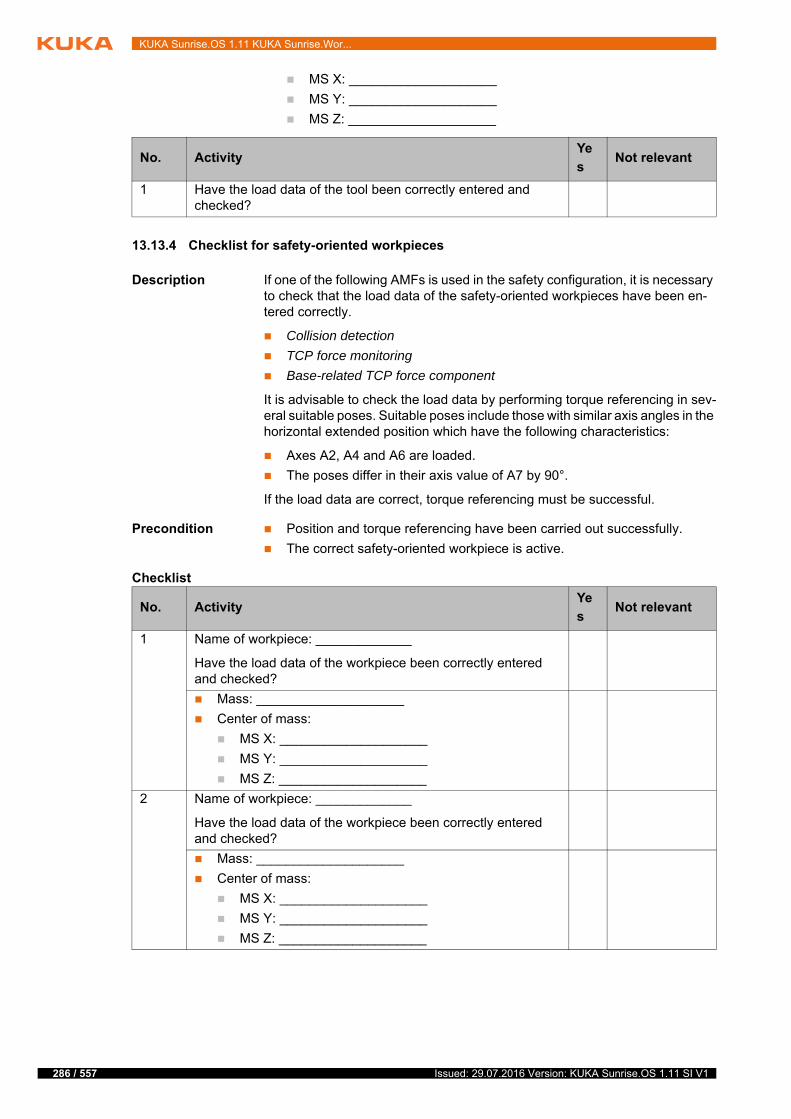
286 / 557
KUKA Sunrise.OS 1.11 KUKA Sunrise.Wor...
MS X: ____________________
MS Y: ____________________
MS Z: ____________________
13.13.4 Checklist for safety-oriented workpieces
Description If one of the following AMFs is used in the safety configuration, it is necessary to check that the load data of the safety-oriented workpieces have been en-tered correctly.
Collision detection
TCP force monitoring
Base-related TCP force component
It is advisable to check the load data by performing torque referencing in sev-eral suitable poses. Suitable poses include those with similar axis angles in the horizontal extended position which have the following characteristics:
Axes A2, A4 and A6 are loaded.
The poses differ in their axis value of A7 by 90°.
If the load data are correct, torque referencing must be successful.
Precondition Position and torque referencing have been carried out successfully.
The correct safety-oriented workpiece is active.
Checklist
No. ActivityYe
sNot relevant
1 Have the load data of the tool been correctly entered and checked?
No. ActivityYe
sNot relevant
1 Name of workpiece: _____________
Have the load data of the workpiece been correctly entered and checked?
Mass: ____________________
Center of mass:
MS X: ____________________
MS Y: ____________________
MS Z: ____________________
2 Name of workpiece: _____________
Have the load data of the workpiece been correctly entered and checked?
Mass: ____________________
Center of mass:
MS X: ____________________
MS Y: ____________________
MS Z: ____________________
Issued: 29.07.2016 Version: KUKA Sunrise.OS 1.11 SI V1

13 Safety configuration
3 Name of workpiece: _____________
Have the load data of the workpiece been correctly entered and checked?
Mass: ____________________
Center of mass:
MS X: ____________________
MS Y: ____________________
MS Z: ____________________
4 Name of workpiece: _____________
Have the load data of the workpiece been correctly entered and checked?
Mass: ____________________
Center of mass:
MS X: ____________________
MS Y: ____________________
MS Z: ____________________
5 Name of workpiece: _____________
Have the load data of the workpiece been correctly entered and checked?
Mass: ____________________
Center of mass:
MS X: ____________________
MS Y: ____________________
MS Z: ____________________
6 Name of workpiece: _____________
Have the load data of the workpiece been correctly entered and checked?
Mass: ____________________
Center of mass:
MS X: ____________________
MS Y: ____________________
MS Z: ____________________
7 Name of workpiece: _____________
Have the load data of the workpiece been correctly entered and checked?
Mass: ____________________
Center of mass:
MS X: ____________________
MS Y: ____________________
MS Z: ____________________
No. ActivityYe
sNot relevant
287 / 557Issued: 29.07.2016 Version: KUKA Sunrise.OS 1.11 SI V1

288 / 557
KUKA Sunrise.OS 1.11 KUKA Sunrise.Wor...
13.13.5 Checklist for rows used in the PSM tables
Description Each row in the PSM table KUKA PSM and in the PSM table Customer PSM must be tested to verify that the expected reaction is triggered. If the reaction is to switch off an output, the test must also ensure that the output is correctly connected.
A row in the PSM table can be tested by violating 2 of its AMFs at a time. It is then possible to test the remaining AMF separately in a targeted manner. If fewer than 3 AMFs are used in a row, the unassigned columns are regarded as violated AMFs.
(>>> 13.13.7 "Checklists for AMFs used" Page 290)
Checklist Row no.: ____________________
13.13.6 Checklists for ESM states
13.13.6.1Used ESM states
Description Each row in the ESM state must be tested to verify that the expected reaction is triggered when the configured AMF is violated.
(>>> 13.13.7 "Checklists for AMFs used" Page 290)
8 Name of workpiece: _____________
Have the load data of the workpiece been correctly entered and checked?
Mass: ____________________
Center of mass:
MS X: ____________________
MS Y: ____________________
MS Z: ____________________
No. ActivityYe
sNot relevant
For each row in the PSM table, the points in the checklist must be ex-ecuted and separately documented.
No. ActivityYe
sNot relevant
1 AMF 1 was tested successfully. Precondition: AMF 2 and AMF 3 are violated.
AMF 1: ______________________________________
2 AMF 2 was tested successfully. Precondition: AMF 1 and AMF 3 are violated.
AMF 2: ______________________________________
3 AMF 3 was tested successfully. Precondition: AMF 1 and AMF 2 are violated.
AMF 3: ______________________________________
For each ESM state, the points in the checklist must be executed and separately documented.
Issued: 29.07.2016 Version: KUKA Sunrise.OS 1.11 SI V1
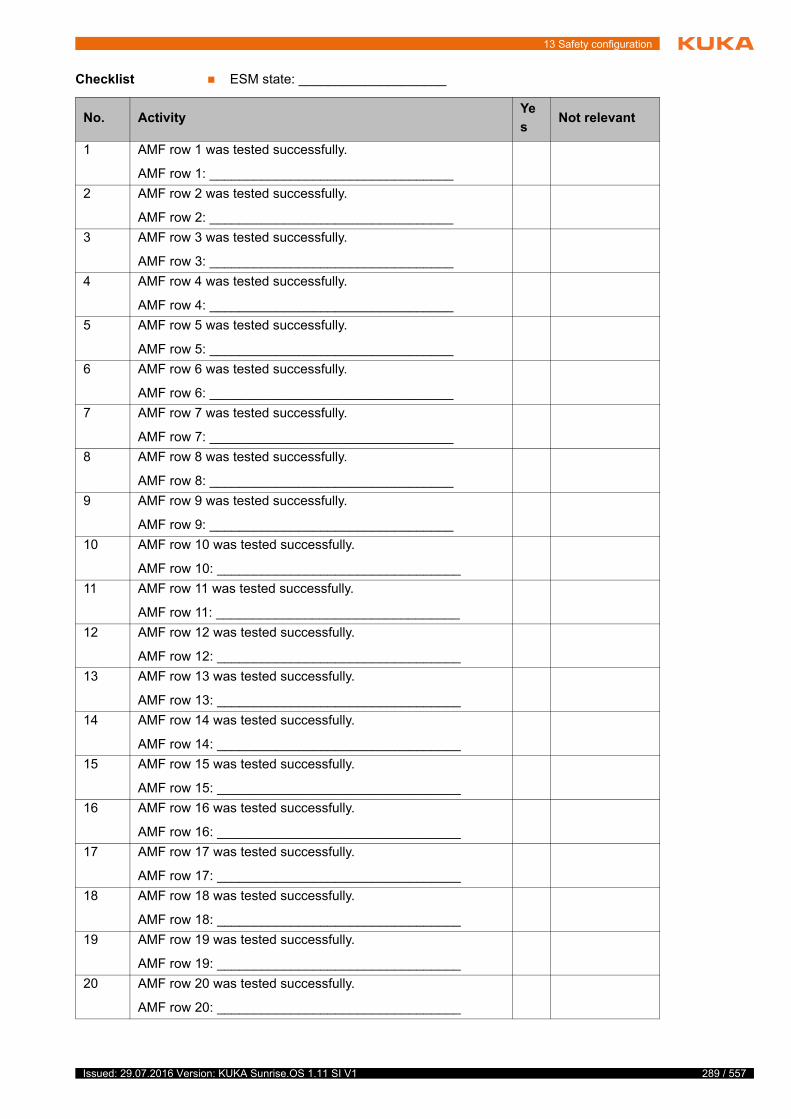
13 Safety configuration
Checklist ESM state: ____________________
No. ActivityYe
sNot relevant
1 AMF row 1 was tested successfully.
AMF row 1: _________________________________
2 AMF row 2 was tested successfully.
AMF row 2: _________________________________
3 AMF row 3 was tested successfully.
AMF row 3: _________________________________
4 AMF row 4 was tested successfully.
AMF row 4: _________________________________
5 AMF row 5 was tested successfully.
AMF row 5: _________________________________
6 AMF row 6 was tested successfully.
AMF row 6: _________________________________
7 AMF row 7 was tested successfully.
AMF row 7: _________________________________
8 AMF row 8 was tested successfully.
AMF row 8: _________________________________
9 AMF row 9 was tested successfully.
AMF row 9: _________________________________
10 AMF row 10 was tested successfully.
AMF row 10: _________________________________
11 AMF row 11 was tested successfully.
AMF row 11: _________________________________
12 AMF row 12 was tested successfully.
AMF row 12: _________________________________
13 AMF row 13 was tested successfully.
AMF row 13: _________________________________
14 AMF row 14 was tested successfully.
AMF row 14: _________________________________
15 AMF row 15 was tested successfully.
AMF row 15: _________________________________
16 AMF row 16 was tested successfully.
AMF row 16: _________________________________
17 AMF row 17 was tested successfully.
AMF row 17: _________________________________
18 AMF row 18 was tested successfully.
AMF row 18: _________________________________
19 AMF row 19 was tested successfully.
AMF row 19: _________________________________
20 AMF row 20 was tested successfully.
AMF row 20: _________________________________
289 / 557Issued: 29.07.2016 Version: KUKA Sunrise.OS 1.11 SI V1
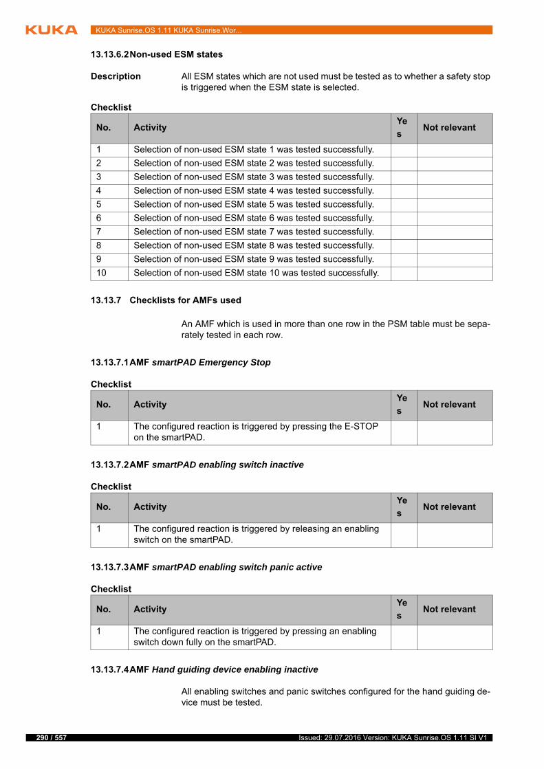
290 / 557
KUKA Sunrise.OS 1.11 KUKA Sunrise.Wor...
13.13.6.2Non-used ESM states
Description All ESM states which are not used must be tested as to whether a safety stop is triggered when the ESM state is selected.
Checklist
13.13.7 Checklists for AMFs used
An AMF which is used in more than one row in the PSM table must be sepa-rately tested in each row.
13.13.7.1AMF smartPAD Emergency Stop
Checklist
13.13.7.2AMF smartPAD enabling switch inactive
Checklist
13.13.7.3AMF smartPAD enabling switch panic active
Checklist
13.13.7.4AMF Hand guiding device enabling inactive
All enabling switches and panic switches configured for the hand guiding de-vice must be tested.
No. ActivityYe
sNot relevant
1 Selection of non-used ESM state 1 was tested successfully.
2 Selection of non-used ESM state 2 was tested successfully.
3 Selection of non-used ESM state 3 was tested successfully.
4 Selection of non-used ESM state 4 was tested successfully.
5 Selection of non-used ESM state 5 was tested successfully.
6 Selection of non-used ESM state 6 was tested successfully.
7 Selection of non-used ESM state 7 was tested successfully.
8 Selection of non-used ESM state 8 was tested successfully.
9 Selection of non-used ESM state 9 was tested successfully.
10 Selection of non-used ESM state 10 was tested successfully.
No. ActivityYe
sNot relevant
1 The configured reaction is triggered by pressing the E-STOP on the smartPAD.
No. ActivityYe
sNot relevant
1 The configured reaction is triggered by releasing an enabling switch on the smartPAD.
No. ActivityYe
sNot relevant
1 The configured reaction is triggered by pressing an enabling switch down fully on the smartPAD.
Issued: 29.07.2016 Version: KUKA Sunrise.OS 1.11 SI V1
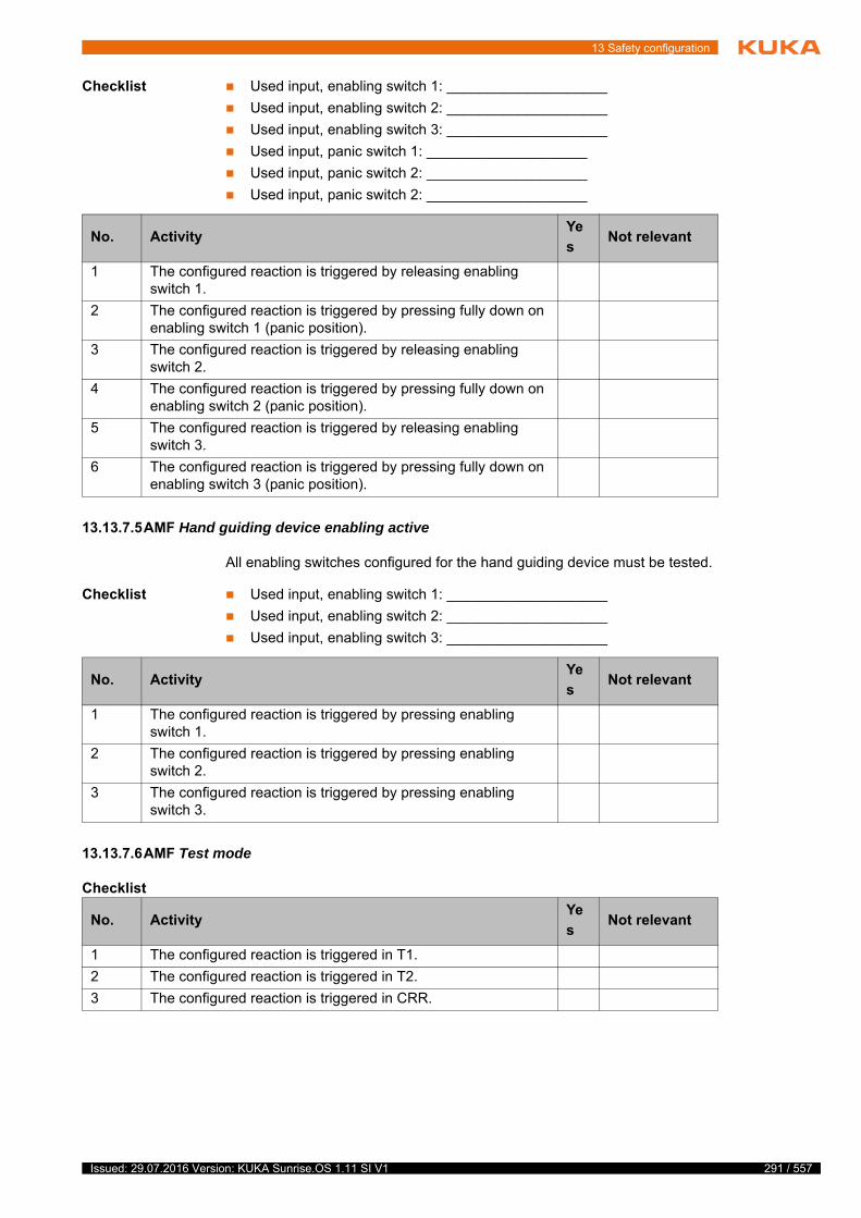
13 Safety configuration
Checklist Used input, enabling switch 1: ____________________
Used input, enabling switch 2: ____________________
Used input, enabling switch 3: ____________________
Used input, panic switch 1: ____________________
Used input, panic switch 2: ____________________
Used input, panic switch 2: ____________________
13.13.7.5AMF Hand guiding device enabling active
All enabling switches configured for the hand guiding device must be tested.
Checklist Used input, enabling switch 1: ____________________
Used input, enabling switch 2: ____________________
Used input, enabling switch 3: ____________________
13.13.7.6AMF Test mode
Checklist
No. ActivityYe
sNot relevant
1 The configured reaction is triggered by releasing enabling switch 1.
2 The configured reaction is triggered by pressing fully down on enabling switch 1 (panic position).
3 The configured reaction is triggered by releasing enabling switch 2.
4 The configured reaction is triggered by pressing fully down on enabling switch 2 (panic position).
5 The configured reaction is triggered by releasing enabling switch 3.
6 The configured reaction is triggered by pressing fully down on enabling switch 3 (panic position).
No. ActivityYe
sNot relevant
1 The configured reaction is triggered by pressing enabling switch 1.
2 The configured reaction is triggered by pressing enabling switch 2.
3 The configured reaction is triggered by pressing enabling switch 3.
No. ActivityYe
sNot relevant
1 The configured reaction is triggered in T1.
2 The configured reaction is triggered in T2.
3 The configured reaction is triggered in CRR.
291 / 557Issued: 29.07.2016 Version: KUKA Sunrise.OS 1.11 SI V1
292 / 557
KUKA Sunrise.OS 1.11 KUKA Sunrise.Wor...
13.13.7.7AMF Automatic mode
Checklist
13.13.7.8AMF Reduced-velocity mode
Checklist
13.13.7.9AMF High-velocity mode
Checklist
13.13.7.10AMF Motion enable
Checklist
13.13.7.11AMF Input signal
Checklist Input used: ____________________
Instance of the input used: ____________________
13.13.7.12AMF Standstill monitoring of all axes
Checklist Monitoring instance: ____________________
Monitored kinematic system: ____________________
No. ActivityYe
sNot relevant
1 The configured reaction is triggered in AUT.
No. ActivityYe
sNot relevant
1 The configured reaction is triggered in T1.
2 The configured reaction is triggered in CRR.
No. ActivityYe
sNot relevant
1 The configured reaction is triggered in T2.
2 The configured reaction is triggered in AUT.
No. ActivityYe
sNot relevant
1 The configured reaction is triggered if the E-STOP is pressed on the smartPAD.
No. ActivityYe
sNot relevant
1 The configured reaction is triggered if the input is LOW (state “0”).
No. ActivityYe
sNot relevant
1 The configured reaction is triggered if one axis of the moni-tored kinematic system is moved.
Issued: 29.07.2016 Version: KUKA Sunrise.OS 1.11 SI V1
13 Safety configuration
13.13.7.13AMF Axis torque monitoring
Description The AMF can be tested by displaying the current measured axis torques on the smartPAD and then subjecting the monitored axis to gravitational force or manual loading.
Checklist Monitoring instance: ____________________
Monitored kinematic system: ____________________
Monitored axis: ____________________
Maximum permissible axis torque: ____________________
Minimum permissible axis torque: ____________________
13.13.7.14AMF Axis velocity monitoring
Description The AMF can be tested by moving the monitored axis at a velocity of approx. 10% over the configured velocity limit.
Checklist Monitoring instance: ____________________
Monitored kinematic system: ____________________
Monitored axis: ____________________
Maximum permissible axis velocity: ____________________
13.13.7.15AMF Position referencing
Checklist Monitoring instance: ____________________
Monitored kinematic system: ____________________
13.13.7.16AMF Torque referencing
Checklist Monitoring instance: ____________________
No. ActivityYe
sNot relevant
1 The configured reaction is triggered if the axis torque exceeds the maximum permissible value.
2 The configured reaction is triggered if the axis torque falls below the minimum permissible value.
No. ActivityYe
sNot relevant
1 The configured reaction is triggered if the maximum permissi-ble axis velocity is exceeded.
This AMF is violated after the robot controller is rebooted.
No. ActivityYe
sNot relevant
1 The configured reaction is triggered if one or more axes of the monitored kinematic system is not referenced.
This AMF is violated after the robot controller is rebooted.
293 / 557Issued: 29.07.2016 Version: KUKA Sunrise.OS 1.11 SI V1
294 / 557
KUKA Sunrise.OS 1.11 KUKA Sunrise.Wor...
Monitored kinematic system: ____________________
13.13.7.17AMF Axis range monitoring
Checklist Monitoring instance: ____________________
Monitored kinematic system: ____________________
Monitored axis: ____________________
Lower limit of the permissible axis range: ____________________
Upper limit of the permissible axis range: ____________________
13.13.7.18AMF Cartesian velocity monitoring
Description The AMF can be tested by moving a monitored point of the monitored kinemat-ic system at a Cartesian velocity of approx. 10% over the configured velocity limit.
It must also be tested whether the structure to be monitored is correctly con-figured. This involves violating the velocity monitoring, both with the monitor-ing spheres on the robot and on the tool (if both structures are monitored), or just with the monitoring spheres on the robot or on the tool.
Checklist Monitoring instance: ____________________
Monitored kinematic system: ____________________
Monitored structure: ____________________
Maximum permissible Cartesian velocity: ____________________
13.13.7.19AMF Cartesian workspace monitoring / Cartesian protected space monitoring
Description The first step is to test whether the orientation of the monitoring space is cor-rectly configured. This involves violating 2 adjoining space surfaces at a mini-mum of 3 different points in each case.
The second step is to test whether the size of the monitoring space is correctly configured. This involves violating the other space surfaces at a minimum of 1 point in each case. In total, at least 10 points must be addressed.
No. ActivityYe
sNot relevant
1 The configured reaction is triggered if one or more axes of the monitored kinematic system is not referenced.
No. ActivityYe
sNot relevant
1 The configured reaction is triggered if the lower limit of the per-missible axis range is exceeded.
2 The configured reaction is triggered if the upper limit of the permissible axis range is exceeded.
No. ActivityYe
sNot relevant
1 The configured reaction is triggered if the maximum permissi-ble Cartesian velocity is exceeded at a monitored point.
2 The configured reaction is triggered if the velocity monitoring is violated by the monitoring spheres on the robot.
3 The configured reaction is triggered if the velocity monitoring is violated only by the monitoring spheres on the tool.
Issued: 29.07.2016 Version: KUKA Sunrise.OS 1.11 SI V1

13 Safety configuration
The third step is to test whether the structure to be monitored is correctly con-figured. This involves violating the space monitoring, both with the monitoring spheres on the robot and on the tool (if both structures are to be monitored), or just with the monitoring spheres on the robot or on the tool.
Checklist Type of monitoring space: ____________________
Instance of the monitoring space: ____________________
Monitored kinematic system: ____________________
Monitored structure: ____________________
Offset of the origin of the monitoring space:
X: ____________________ mm
Y: ____________________ mm
Z: ____________________ mm
Orientation of the origin of the monitoring space:
A: ____________________ °
B: ____________________ °
C: ____________________ °
Length of the monitoring space: ____________________ mm
Width of the monitoring space: ____________________ mm
13.13.7.20AMF Collision detection
Description The AMF can be tested by displaying the current measured external axis torques on the smartPAD and then loading the individual axes.
Precondition Torque referencing has been carried out successfully.
Checklist Monitoring instance: ____________________
Monitored kinematic system:
Maximum permissible external axis torque: ____________________
13.13.7.21AMF TCP force monitoring
Description In order to test the AMF, suitable measuring equipment is required, e.g. a spring balance.
During the test, it must be noted that the monitoring function automatically takes into consideration possible errors on activating safety-oriented work-pieces. This means that the response may be triggered before the permissible external TCP force has been reached.
No. ActivityYe
sNot relevant
1 The correct configuration of the monitoring space has been tested as above and the configured reaction is triggered if the monitoring space is violated.
2 The configured reaction is triggered if the space monitoring is violated on the monitoring spheres on the robot.
3 The configured reaction is triggered if the space monitoring is violated on the monitoring spheres on the tool.
No. ActivityYe
sNot relevant
1 The configured reaction is triggered if the external torque of one or more axes of the monitored kinematic system exceeds the maximum permissible external torque.
295 / 557Issued: 29.07.2016 Version: KUKA Sunrise.OS 1.11 SI V1

296 / 557
KUKA Sunrise.OS 1.11 KUKA Sunrise.Wor...
Premature triggering of the reaction can be prevented by carrying out the test as follows:
Tool has not picked up a workpiece.
No workpiece is activated in the application.
Apply the TCP force in the direction of gravitational acceleration (vertically downwards) or perpendicular to the direction of gravitational acceleration.
Checklist Monitoring instance: ____________________
Monitored kinematic system: ____________________
Maximum permissible external TCP force: ____________________
13.13.7.22Base-related TCP force component AMF
Description In order to test the AMF, suitable measuring equipment is required, e.g. a spring balance.
A force just below the configured maximum permissible TCP force must be ap-plied to the tool or robot flange in 2 different directions:
Along the direction of the configured force component
In a direction perpendicular to the direction of the configured force compo-nent
This is to ensure that the AMF is only violated if an excessively high force is applied along the direction of the configured force component.
During the test, it must be noted that the monitoring function automatically takes into consideration possible errors on activating safety-oriented work-pieces. This means that the response may be triggered before the permissible external TCP force has been reached.
If, for example, a workpiece is picked up and activated during the test, this ad-ditionally considered force corresponds to the weight of the heaviest safety-oriented workpiece. The considered force acts against gravitational accelera-tion (vertically upwards).
Checklist Monitoring instance: ____________________
Monitored kinematic system: ____________________
Maximum permissible external TCP force: ____________________
Monitored component of the force vector: ____________________
Base-related orientation:
A: _____________ °
B: _____________ °
C: _____________ °
No. ActivityYe
sNot relevant
1 The configured reaction is triggered if the external force acting on the TCP exceeds the maximum permissible force.
No. ActivityYe
sNot relevant
1 The configured reaction is triggered if the external force acting along the direction of the monitored component of the force vector exceeds the maximum permissible force.
2 The configured reaction is not triggered if the force applied in one direction is perpendicular to the direction of the monitored force component.
Issued: 29.07.2016 Version: KUKA Sunrise.OS 1.11 SI V1
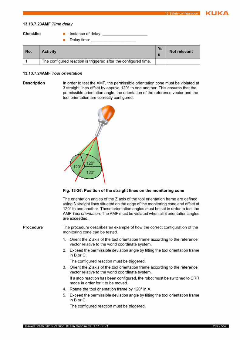
13 Safety configuration
13.13.7.23AMF Time delay
Checklist Instance of delay: ____________________
Delay time: ____________________
13.13.7.24AMF Tool orientation
Description In order to test the AMF, the permissible orientation cone must be violated at 3 straight lines offset by approx. 120° to one another. This ensures that the permissible orientation angle, the orientation of the reference vector and the tool orientation are correctly configured.
The orientation angles of the Z axis of the tool orientation frame are defined using 3 straight lines situated on the edge of the monitoring cone and offset at 120° to one another. These orientation angles must be set in order to test the AMF Tool orientation. The AMF must be violated when all 3 orientation angles are exceeded.
Procedure The procedure describes an example of how the correct configuration of the monitoring cone can be tested.
1. Orient the Z axis of the tool orientation frame according to the reference vector relative to the world coordinate system.
2. Exceed the permissible deviation angle by tilting the tool orientation frame in B or C.
The configured reaction must be triggered.
3. Orient the Z axis of the tool orientation frame according to the reference vector relative to the world coordinate system.
If a stop reaction has been configured, the robot must be switched to CRR mode in order for it to be moved.
4. Rotate the tool orientation frame by 120° in A.
5. Exceed the permissible deviation angle by tilting the tool orientation frame in B or C.
The configured reaction must be triggered.
No. ActivityYe
sNot relevant
1 The configured reaction is triggered after the configured time.
Fig. 13-26: Position of the straight lines on the monitoring cone
297 / 557Issued: 29.07.2016 Version: KUKA Sunrise.OS 1.11 SI V1
298 / 557
KUKA Sunrise.OS 1.11 KUKA Sunrise.Wor...
6. Orient the Z axis of the tool orientation frame according to the reference vector relative to the world coordinate system.
If a stop reaction has been configured, the robot must be switched to CRR mode in order for it to be moved.
7. Rotate the tool orientation frame by 120° in A.
8. Exceed the permissible deviation angle by tilting the tool orientation frame in B or C.
The configured reaction must be triggered.
Checklist Monitoring instance: ____________________
Monitored kinematic system: ____________________
Safety-oriented tool used: ____________________
Orientation of the reference vector relative to the world coordinate system:
A: _____________ °
B: _____________ °
C: _____________ °
Permissible workspace (deviation angle): _____________ °
13.13.7.25AMF Tool-related velocity component
Description For the test, a motion with the configured point for the tool-specific velocity component must be programmed. The test motion must include a reorienta-tion of the tool in order to check the correct configuration of the monitored point.
The test must be performed twice:
Once at a velocity slightly above the maximum permissible velocity.
Once at a velocity slightly below the maximum permissible velocity.
This is to ensure that the velocity limit is only violated by the configured mon-itored point.
The test must be carried out for every instance of the AMF and for ev-ery tool that is mapped in the tool selection table to a kinematic sys-tem for which the AMF Tool orientation is configured.
(>>> 13.13.3.3 "Tool orientation" Page 283)
If a fixed tool that can pick up activatable tools is configured, the fixed tool must be checked in addition to the activatable tools without an ac-tivatable tool being coupled.
Example: 4 instances of the AMF are configured, with 5 different tools that can be selected for fastening to the fixed tool. At least 6 tests are required for verification of all AMF instances and tool orientations. If, on the other hand, only 2 different tools are available for selection for fastening on the fixed tool, 4 tests are sufficient.
No. ActivityYe
sNot relevant
1 The correct configuration of the monitoring cone has been checked and the configured reaction is triggered when the per-missible angle for all 3 straight lines has been exceeded.
The test must be carried out for every instance of the AMF and for ev-ery tool that is mapped in the tool selection table to a kinematic sys-tem for which the AMF Tool-related velocity component is configured.
(>>> 13.13.3.4 "Tool-specific velocity component" Page 283)
Issued: 29.07.2016 Version: KUKA Sunrise.OS 1.11 SI V1
13 Safety configuration
Checklist Monitoring instance: ____________________
Monitored kinematic system: ____________________
Safety-oriented tool used: ____________________
Monitored component of the velocity vector: ____________________
Maximum permissible Cartesian velocity of the monitored component: ____________________
13.13.8 Checklists – General safety settings
13.13.8.1smartPAD unplugging allowed
Description The safety parameter smartPAD unplugging allowed in the station configu-ration determines whether it is possible to move the robot with the smartPAD unplugged. The configured response must be tested while the robot is moving in Automatic mode.
Disconnection not allowed:
If the smartPAD is disconnected, the robot is stopped with a safety stop.
Disconnection allowed:
If the smartPAD is disconnected, the robot continues moving.
Checklist smartPAD unplugging allowed (true/false): ____________________
13.13.8.2Allow muting via input
Description If a safety-oriented input that allows the deactivation of safety functions is con-figured in the project settings, a safety stop triggered by one of the following AMFs can be briefly cancelled:
Axis range monitoring
Cartesian workspace monitoring
Cartesian protected space monitoring
Tool orientation
Tool-related velocity component
If a fixed tool that can pick up activatable tools is configured, the fixed tool must be checked in addition to the activatable tools. The fixed tool must be tested with no activatable tool coupled.
Example: 4 instances of the AMF are configured, with 5 different tools that can be selected for fastening to the fixed tool. At least 6 tests are required for verification of all AMF instances and tool-related velocity components. If, on the other hand, only 2 different tools are available for selection for fastening on the fixed tool, 4 tests are sufficient.
No. ActivityYe
sNot relevant
1 The configured reaction is triggered if the motion is executed with a velocity that exceeds the maximum permissible velocity.
2 The configured reaction is not triggered if the motion is exe-cuted with a velocity that is below the maximum permissible velocity.
No. Activity Yes
1 The expected response occurs if the smartPAD is unplugged while the robot is moving in Automatic mode.
299 / 557Issued: 29.07.2016 Version: KUKA Sunrise.OS 1.11 SI V1
300 / 557
KUKA Sunrise.OS 1.11 KUKA Sunrise.Wor...
Standstill monitoring of all axes
Position referencing
Torque referencing
Axis torque monitoring
Collision detection
TCP force monitoring
Base-related TCP force component
The configured input must be tested. For this, a safety stop must be triggered using at least one of the above AMFs, e.g. by violating a workspace or activat-ing a standstill monitoring function.
Deactivation of safety functions via an input not allowed:
If the configured input is set to HIGH and retains this value, the robot can-not be moved when the corresponding AMF is violated.
Deactivation of safety functions via an input allowed:
If the configured input is set to HIGH and retains this value, the robot can be moved for 5 seconds even though the corresponding AMF is violated.
Checklist Allow muting via input (true/false): ____________________
Configured input: ____________________
13.13.8.3Allow external position referencing
Description If a safety-oriented input that allows external position referencing is configured in the project settings, this input must be tested.
The axis positions are not referenced after a reboot of the robot controller. If the safety configuration contains a position-based AMF, the warning "Axis not referenced" is displayed. The warning may no longer be displayed if the input via which the external position referencing is carried out is set to HIGH for less than 2 seconds..
Checklist Allow external position referencing (true/false): ____________________
Configured input: ____________________
13.13.9 Creating a safety configuration report
Description A report of the current safety configuration can be created and displayed in the Editor. The report can be edited and printed for documentation purposes.
The safety configuration report contains the following information for the un-ambiguous assignment of the safety configuration:
Name of the Sunrise project to which the safety configuration belongs
Safety version used
Safety ID (checksum of the safety configuration)
The safety ID must match the ID of the safety configuration which is acti-vated on the robot controller and is to be tested.
No. Activity Yes
1 The expected response occurs when the configured input is set to HIGH and an attempt is made to move the robot.
No. Activity Yes
1 The expected response occurs if the configured input is set to HIGH for less than 2 seconds.
Issued: 29.07.2016 Version: KUKA Sunrise.OS 1.11 SI V1
13 Safety configuration
Date and time of the last modification to the safety configuration
Checklists The report provides the following checklists matching the safety configuration:
Checklist for checking the rows used in the Customer PSM table
Checklists for checking the ESM states which have been used and not used
Checklists for checking the AMFs used
Checklists for checking the general safety-oriented settings
Warnings The plausibility of the safety configuration is checked. There are warnings for the following situations:
One row in the Customer PSM table is deactivated.
One row in an ESM state is deactivated.
Unplugging of the smartPAD is allowed, but no external EMERGENCY STOP is used.
The input for deactivating safety functions is used in the tool selection ta-ble.
The safety maintenance technician must give reasons why a warning may be ignored.
Procedure Right-click on the desired project in the Package Explorer view and select Sunrise > Create safety configuration report from the context menu.
The report of the current safety configuration is created and opened in the editor area.
The checklists provided by the safety configuration report are not suf-ficient for a complete safety acceptance procedure. The following ad-ditional checklists must be used for complete safety acceptance:
Checklist for basic test of the safety configuration
Checklists for checking the safety-oriented tool
Checklist for checking the safety-oriented workpieces
Checklist for checking the tool selection table
301 / 557Issued: 29.07.2016 Version: KUKA Sunrise.OS 1.11 SI V1

302 / 557
KUKA Sunrise.OS 1.11 KUKA Sunrise.Wor...
Issued: 29.07.2016 Version: KUKA Sunrise.OS 1.11 SI V1

14 Basic principles of motion programm...
14 Basic principles of motion programming
This chapter describes the theoretical principles of motion programming.
The programming of motions in KUKA Sunrise.Workbench is described in the following chapter: (>>> 15 "Programming" Page 325)
14.1 Overview of motion types
The following motion types can be programmed as an individual motion:
Point-to-point motion (PTP)
(>>> 14.2 "PTP motion type" Page 303)
Linear motion (LIN)
(>>> 14.3 "LIN motion type " Page 304)
Circular motion (CIRC)
(>>> 14.4 "CIRC motion type" Page 304)
Manual guidance motion with hand guiding device
(>>> 14.7 "Manual guidance motion type" Page 311)
The following types of motion can be programmed as segments of a CP spline block:
Linear motion (LIN)
Circular motion (CIRC)
Polynomial motion (SPL)
The following types of motion can be programmed as segments of a JP spline block:
Point-to-point motion (PTP)
(>>> 14.6 "Spline motion type" Page 305)
The following motions are known as CP (“Continuous Path”) motions:
LIN, CIRC, SPL, CP spline blocks
The following motions are known as JP (“Joint Path”) motions:
PTP, JP spline blocks
14.2 PTP motion type
The robot guides the TCP along the fastest path to the end point. The fastest path is generally not the shortest path in space and is thus not a straight line. As the motions of the robot axes are simultaneous and rotational, curved paths can be executed faster than straight paths.
PTP is a fast positioning motion. The exact path of the motion is not predict-able, but is always the same, as long as the general conditons are not changed.
4
s
The start point of a motion is always the end point of the previous mo-tion.
303 / 557Issued: 29.07.2016 Version: KUKA Sunrise.OS 1.11 SI V1
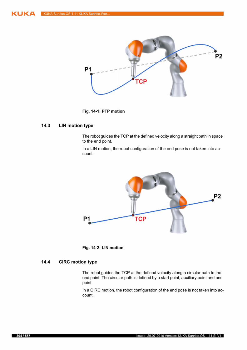
304 / 557
KUKA Sunrise.OS 1.11 KUKA Sunrise.Wor...
14.3 LIN motion type
The robot guides the TCP at the defined velocity along a straight path in space to the end point.
In a LIN motion, the robot configuration of the end pose is not taken into ac-count.
14.4 CIRC motion type
The robot guides the TCP at the defined velocity along a circular path to the end point. The circular path is defined by a start point, auxiliary point and end point.
In a CIRC motion, the robot configuration of the end pose is not taken into ac-count.
Fig. 14-1: PTP motion
Fig. 14-2: LIN motion
Issued: 29.07.2016 Version: KUKA Sunrise.OS 1.11 SI V1
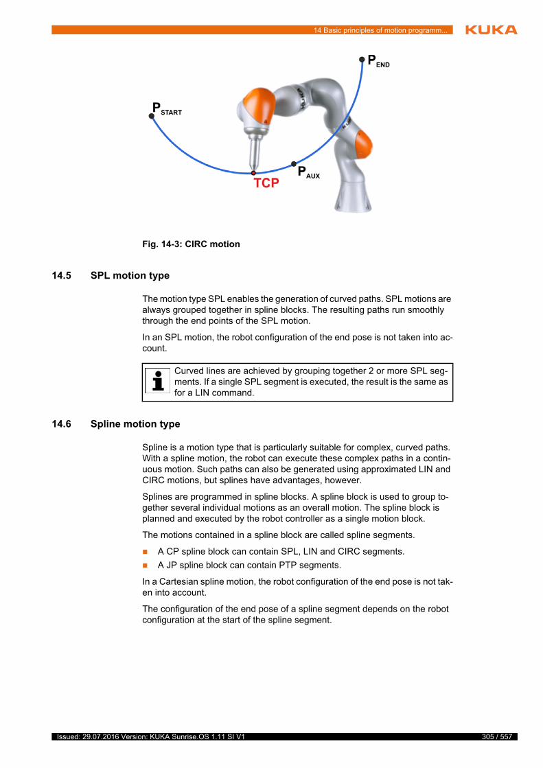
14 Basic principles of motion programm...
14.5 SPL motion type
The motion type SPL enables the generation of curved paths. SPL motions are always grouped together in spline blocks. The resulting paths run smoothly through the end points of the SPL motion.
In an SPL motion, the robot configuration of the end pose is not taken into ac-count.
14.6 Spline motion type
Spline is a motion type that is particularly suitable for complex, curved paths. With a spline motion, the robot can execute these complex paths in a contin-uous motion. Such paths can also be generated using approximated LIN and CIRC motions, but splines have advantages, however.
Splines are programmed in spline blocks. A spline block is used to group to-gether several individual motions as an overall motion. The spline block is planned and executed by the robot controller as a single motion block.
The motions contained in a spline block are called spline segments.
A CP spline block can contain SPL, LIN and CIRC segments.
A JP spline block can contain PTP segments.
In a Cartesian spline motion, the robot configuration of the end pose is not tak-en into account.
The configuration of the end pose of a spline segment depends on the robot configuration at the start of the spline segment.
Fig. 14-3: CIRC motion
Curved lines are achieved by grouping together 2 or more SPL seg-ments. If a single SPL segment is executed, the result is the same as for a LIN command.
305 / 557Issued: 29.07.2016 Version: KUKA Sunrise.OS 1.11 SI V1
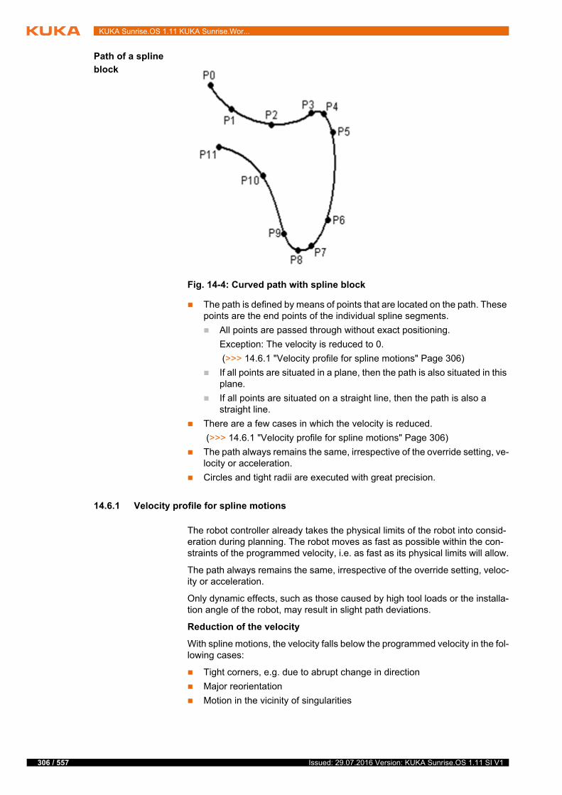
306 / 557
KUKA Sunrise.OS 1.11 KUKA Sunrise.Wor...
Path of a spline
block
The path is defined by means of points that are located on the path. These points are the end points of the individual spline segments.
All points are passed through without exact positioning.
Exception: The velocity is reduced to 0.
(>>> 14.6.1 "Velocity profile for spline motions" Page 306)
If all points are situated in a plane, then the path is also situated in this plane.
If all points are situated on a straight line, then the path is also a straight line.
There are a few cases in which the velocity is reduced.
(>>> 14.6.1 "Velocity profile for spline motions" Page 306)
The path always remains the same, irrespective of the override setting, ve-locity or acceleration.
Circles and tight radii are executed with great precision.
14.6.1 Velocity profile for spline motions
The robot controller already takes the physical limits of the robot into consid-eration during planning. The robot moves as fast as possible within the con-straints of the programmed velocity, i.e. as fast as its physical limits will allow.
The path always remains the same, irrespective of the override setting, veloc-ity or acceleration.
Only dynamic effects, such as those caused by high tool loads or the installa-tion angle of the robot, may result in slight path deviations.
Reduction of the velocity
With spline motions, the velocity falls below the programmed velocity in the fol-lowing cases:
Tight corners, e.g. due to abrupt change in direction
Major reorientation
Motion in the vicinity of singularities
Fig. 14-4: Curved path with spline block
Issued: 29.07.2016 Version: KUKA Sunrise.OS 1.11 SI V1

14 Basic principles of motion programm...
Reduction of the velocity due to major reorientation can be avoided with spline segments by programming the orientation control SplineOrientationTy-pe.Ignore.
(>>> 14.9 "Orientation control with LIN, CIRC, SPL" Page 314)
Reduction of the velocity to 0
With spline motions, exact positioning is carried out in the following cases:
Successive spline segments with the same end points
Successive LIN and/or CIRC segments. Cause: inconstant velocity direc-tion.
In the case of LIN-CIRC transitions, the velocity also drops to 0 if the straight line is a tangent of the circle. This is caused by the fact that at the transition point between the straight line (curvature equals 0) and the circle (curvature is not equal to 0) the curvature characteristic is not constant.
Exceptions:
In the case of successive LIN segments that result in a straight line and in which the orientations change uniformly, the velocity is not reduced.
In the case of a CIRC-CIRC transition, the velocity is not reduced if both circles have the same center point and the same radius and if the orienta-tions change uniformly. Since the required accuracy is difficult to achieve by teaching the end point and auxiliary point, calculation of the points on the circle is recommended.
Fig. 14-5: Exact positioning at P2
Fig. 14-6: Exact positioning at P2
Fig. 14-7: P2 is executed without exact positioning.
307 / 557Issued: 29.07.2016 Version: KUKA Sunrise.OS 1.11 SI V1
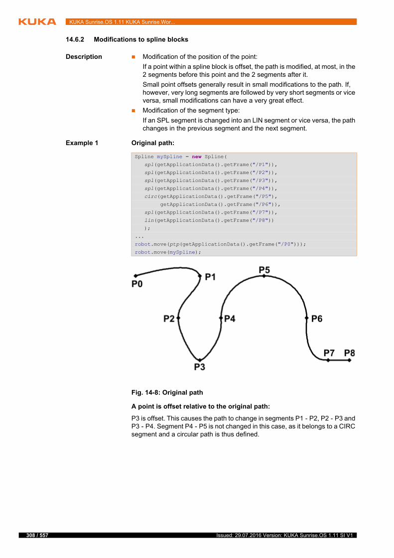
308 / 557
KUKA Sunrise.OS 1.11 KUKA Sunrise.Wor...
14.6.2 Modifications to spline blocks
Description Modification of the position of the point:
If a point within a spline block is offset, the path is modified, at most, in the 2 segments before this point and the 2 segments after it.
Small point offsets generally result in small modifications to the path. If, however, very long segments are followed by very short segments or vice versa, small modifications can have a very great effect.
Modification of the segment type:
If an SPL segment is changed into an LIN segment or vice versa, the path changes in the previous segment and the next segment.
Example 1 Original path:
A point is offset relative to the original path:
P3 is offset. This causes the path to change in segments P1 - P2, P2 - P3 and P3 - P4. Segment P4 - P5 is not changed in this case, as it belongs to a CIRC segment and a circular path is thus defined.
Spline mySpline = new Spline( spl(getApplicationData().getFrame("/P1")),
spl(getApplicationData().getFrame("/P2")),
spl(getApplicationData().getFrame("/P3")),
spl(getApplicationData().getFrame("/P4")),
circ(getApplicationData().getFrame("/P5"),
getApplicationData().getFrame("/P6")),
spl(getApplicationData().getFrame("/P7")),
lin(getApplicationData().getFrame("/P8"))
);
...
robot.move(ptp(getApplicationData().getFrame("/P0")));
robot.move(mySpline);
Fig. 14-8: Original path
Issued: 29.07.2016 Version: KUKA Sunrise.OS 1.11 SI V1
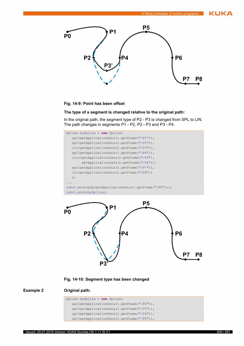
14 Basic principles of motion programm...
The type of a segment is changed relative to the original path:
In the original path, the segment type of P2 - P3 is changed from SPL to LIN. The path changes in segments P1 - P2, P2 - P3 and P3 - P4.
Example 2 Original path:
Fig. 14-9: Point has been offset
Spline mySpline = new Spline( spl(getApplicationData().getFrame("/P1")),
spl(getApplicationData().getFrame("/P2")),
lin(getApplicationData().getFrame("/P3")),
spl(getApplicationData().getFrame("/P4")),
circ(getApplicationData().getFrame("/P5"),
getApplicationData().getFrame("/P6")),
spl(getApplicationData().getFrame("/P7")),
lin(getApplicationData().getFrame("/P8"))
);
...
robot.move(ptp(getApplicationData().getFrame("/P0")));
robot.move(mySpline);
Fig. 14-10: Segment type has been changed
Spline mySpline = new Spline( spl(getApplicationData().getFrame("/P2")),
spl(getApplicationData().getFrame("/P3")),
spl(getApplicationData().getFrame("/P4")),
spl(getApplicationData().getFrame("/P5")),
309 / 557Issued: 29.07.2016 Version: KUKA Sunrise.OS 1.11 SI V1

310 / 557
KUKA Sunrise.OS 1.11 KUKA Sunrise.Wor...
The following frame coordinates were taught:
A point is offset relative to the original path:
P3 is moved slightly in the Y direction. This causes the path to change in all the segments illustrated.
Since P2 - P3 and P3 - P4 are very short segments and P1 - P2 and P4 - P5 are long segments, the slight offset causes the path to change greatly.
Remedy:
Distribute the points more evenly.
Program straight lines (except very short ones) as LIN segments
14.6.3 LIN-SPL-LIN transition
In the case of a LIN-SPL-LIN segment sequence, it is usually desirable for the SPL segment to be located within the smaller angle between the two straight lines. Depending on the start and end point of the SPL segment, the path may also move outside this area.
);
...
robot.move(mySpline);
Fig. 14-11: Original path
Frame X Y Z
P2 100.0 0.0 0.0
P3 102.0 0.0 0.0
P4 104.0 0.0 0.0
P5 204.0 0.0 0.0
Frame X Y Z
P3 102.0 1.0 0.0
Fig. 14-12: Point has been offset
Issued: 29.07.2016 Version: KUKA Sunrise.OS 1.11 SI V1

14 Basic principles of motion programm...
The path remains inside the smaller angle if the following conditions are met:
The extensions of the two LIN segments intersect.
2/3 ≤ a/b ≤ 3/2
a = distance from start point of the SPL segment to intersection of the LIN segments
b = distance from intersection of the LIN segments to end point of the SPL segment
14.7 Manual guidance motion type
Description The robot can be guided using a hand guiding device. The hand guiding de-vice is a device equipped with an enabling device and which is required for the manual guidance of the robot.
Manual guidance mode can be switched on in the application using the motion command handGuiding(). Manual guidance begins at the actual position which was reached before the mode was switched on.
(>>> 15.9 "Programming manual guidance" Page 352)
In Manual guidance mode, the robot reacts compliantly to outside forces and can be manually guided to any point in the Cartesian space. The impedance parameters are automatically set when the robot is switched to Manual guid-ance mode. The impedance parameters for manual guidance cannot be mod-ified.
A manual guidance motion command can only be executed by an application in Automatic mode. If the application is paused in Manual guidance mode, e.g. because of a safety stop triggered by an EMERGENCY STOP, the manual guidance motion is terminated. When the application is resumed, the next mo-tion command is executed directly.
Precondition Hand guiding device with enabling device
Manual guidance in Automatic mode is configured as not allowed (param-eter Enable manual guidance in Automatic mode = false)
(>>> 10.3.2 "Manual guidance support" Page 169)
Fig. 14-13: LIN-SPL-LIN
311 / 557Issued: 29.07.2016 Version: KUKA Sunrise.OS 1.11 SI V1
312 / 557
KUKA Sunrise.OS 1.11 KUKA Sunrise.Wor...
ESM state for manual guidance motion has been configured.
The ESM state contains the AMF Hand guiding device enabling inactive, which monitors the enabling switch on the hand guiding device.
(>>> 13.10.5.1 "Monitoring of enabling switches on hand guiding devices" Page 236)
The robot can be guided manually when the enabling switch on the hand guiding device is pressed and held in the center position. If the enabling switch is pressed down fully or released, the signal for manual guidance is cancelled and the robot remains in its current position.
ESM state for all motions except manual guidance motion has been con-figured.
The ESM state does not contain the AMF Hand guiding device enabling inactive. The signal at the hand guiding device is not evaluated.
Automatic mode
The safety equipment must be HRC-compliant.
14.8 Approximate positioning
Approximate positioning means that the motion does not stop exactly at the end point of the programmed motion, allowing continuous robot motion. Dur-ing motion programming, different parameters can influence the approximate positioning.
The point at which the original path is left and the approximate positioning arc begins is referred to as the approximate positioning point.
PTP motion
The TCP leaves the path that would lead directly to the end point and moves, instead, along a path that allows it to pass the end point without exact position-ing. The path thus goes past the point and no longer passes through it.
In Manual guidance mode, incorrectly selected parameters (e.g. in-correct load data, incorrect tool), incorrect information (e.g. from de-fective torque sensors) or additional overlaid forces can be
interpreted as external forces. This can result in unpredictable robot motions.
If the signal for manual guidance is issued before Manual guidance mode is switched on in the application, Manual guidance mode will be active as soon as it is switched on. This means that motion execution
is not paused when the mode is switched on, making for a smooth transition between Application mode and Manual guidance mode.Precondition for this response: the application velocity is less than the maxi-mum permissible velocity configured for manual guidance. (>>> 13.10.5.3 "Velocity monitoring during manual guidance" Page 238)If the application is executed at a higher velocity, the application is paused before switching to manual guidance mode. (Then release the enabling switch, press the Start key and wait until the application is paused again.)
To approximate motions without exact positioning, they must be exe-cuted asynchronously or grouped in a MotionBatch. (>>> 15.6.1 "Synchronous and asynchronous motion execution"
Page 342) (>>> 15.6.6 "MotionBatch" Page 346)
In the case of approximate positioning of motions executed synchro-nously, an exact positioning point is executed at the start of the ap-proximate positioning arc. This also applies, in the case of
synchronous execution, to the last motion within a MotionBatch.
Issued: 29.07.2016 Version: KUKA Sunrise.OS 1.11 SI V1

14 Basic principles of motion programm...
During programming, the relative maximum distance from the end point at which the TCP may deviate from its original path in axis space is defined. A relative distance of 100% corresponds to the entire path from the start point to the end point of the motion.
The approximation contour executed by the TCP is not necessarily the shorter path in Cartesian space. The approximated point can thus also be located within the approximate positioning arc.
LIN motion
The TCP leaves the path that would lead directly to the end point and moves along a shorter path. During programming of the motion, the maximum dis-tance from the end point at which the TCP may deviate from its original path is defined.
CIRC motion
The TCP leaves the path that would lead directly to the end point and moves along a shorter path. During programming of the motion, the maximum dis-tance from the end point at which the TCP may deviate from its original path is defined.
The auxiliary point may fall within the approximate positioning range and not be passed through exactly. This is dependent on the position of the auxiliary point and the programmed approximation parameters.
Fig. 14-14: PTP motion, P2 is approximated
Fig. 14-15: LIN motion, P2 is approximated
Fig. 14-16: CIRC motion, PEND is approximated
313 / 557Issued: 29.07.2016 Version: KUKA Sunrise.OS 1.11 SI V1
314 / 557
KUKA Sunrise.OS 1.11 KUKA Sunrise.Wor...
All spline blocks and all individual motions can be approximated with one an-other. It makes no difference whether they are CP or JP spline blocks, nor is the motion type of the individual motion relevant.
The motion type of the approximate positioning arc always corresponds to the second motion. In the case of PTP-LIN approximation, for example, the ap-proximate positioning arc is of type CP.
If a spline block is approximated, the entire last segment is approximated. If the spline block only consists of one segment, a maximum of half the segment is approximated (this also applies for PTP, LIN and CIRC).
Approximate positioning not possible due to time:
If approximation is not possible due to delayed motion commanding, the robot waits at the start of the approximate positioning arc. The robot moves again as soon as it has been possible to plan the next block. The robot then executes the approximate positioning arc. Approximate positioning is thus technically possible; it is merely delayed.
No approximate positioning in Step mode:
In Step mode, the robot stops exactly at the end point, even in the case of ap-proximated motions.
In the case of approximate positioning from one spline block to another spline block, the result of this exact positioning is that the path is different in the last segment of the first block and in the first segment of the second block in rela-tion to the path in standard mode.
In all other segments of both spline blocks, the path is identical in both pro-gram run modes.
Approximated motions which were sent to the robot controller asynchronously before Step mode was activated and which are waiting there to be executed will stop at the approximate positioning point. For these motions, the approxi-mate positioning arc will be executed when the program is resumed.
14.9 Orientation control with LIN, CIRC, SPL
Description The orientation of the TCP can be different at the start point and end point of a motion. During motion programming, it is possible to define how to deal with the different orientations.
Orientation control is set as a motion parameter by the setOrientationType(…) method. Orientation control is a value of type Enum SplineOrientationType.
Issued: 29.07.2016 Version: KUKA Sunrise.OS 1.11 SI V1

14 Basic principles of motion programm...
Orientation control Description
Constant The orientation of the TCP remains constant during the motion.
The orientation of the start point is retained. The orientation of the end point is not taken into consideration.
Ignore The orientation of the TCP changes during the motion.
This option is only available for individual spline segments, not for the entire spline block or individual motions. The controller calculates the orientation control on the basis of the orientation of the surrounding control points, unless their orientation is also ignored.
Ignore is used if no specific orientation is required for a spline seg-ment.
(>>> "Ignore" Page 316)
Note: In the case of Ignore, the orientation of the end point is not taken into consideration. If it is important for the taught orientation to be maintained at the end point, e.g. to avoid collisions, Ignore must not be used.
OriJoint The orientation of the TCP changes continuously during the motion. This is done by linear transformation (axis-specific motion) of the wrist axis angles.
Note: Use OriJoint if, with VariableOrientation, the robot passes through a wrist axis singularity. The orientation of the TCP changes continuously during the motion, but not uniformly. OriJoint is thus not suitable if a specific orientation must be maintained exactly, e.g. in the case of laser welding.
VariableOrientation During the motion, a continuous transition of the orientation of the TCP occurs from the orientation of the start point to the orientation of the end point.
If the orientation control is not set, this orientation control applies as the default.
Fig. 14-17: Constant orientation (constant)
315 / 557Issued: 29.07.2016 Version: KUKA Sunrise.OS 1.11 SI V1

316 / 557
KUKA Sunrise.OS 1.11 KUKA Sunrise.Wor...
CIRC motion It is possible to define for CIRC motions whether the orientation control is to be space-related or path-related.
(>>> 14.9.1 "CIRC – reference system for the orientation control" Page 316)
During CIRC motions, the robot controller only takes the orientation of the end point into consideration. It is possible to define whether, and to what extent, the orientation of the auxiliary point is to be taken into consideration. The ori-entation behavior at the end point can also be defined.
Ignore The orientation type SplineOrientationType.Ignore is used if no specific orien-tation is required at a point. The robot controller ignores the taught or pro-grammed orientation of the point. Instead, it calculates the optimal orientation for this point on the basis of the orientations of the surrounding points. This re-duces the cycle time.
Example:
The taught or programmed orientation of P3 and P4 is ignored.
SplineOrientationType.Ignore is not allowed for the following spline segments:
The first and last segment in a spline block
CIRC segments with OrientationReferenceSystem.Path
Segments followed by a CIRC segment with OrientationReferenceSys-tem.Path
Segments followed by a segment with SplineOrientationType.Constant
Successive segments in a spline block with the same end point
14.9.1 CIRC – reference system for the orientation control
Description It is possible to define for CIRC motions whether the orientation control is to be space-related or path-related.
Fig. 14-18: Variable orientation (VariableOrientation or OriJoint)
robot.move(P0);
Spline path6 = new Spline( spl(P1),
spl(P2),
spl(P3).setOrientationType(SplineOrientationType.Ignore),
spl(P4).setOrientationType(SplineOrientationType.Ignore),
spl(P5),
spl(P6)
),
...
robot.move(path6);
Issued: 29.07.2016 Version: KUKA Sunrise.OS 1.11 SI V1
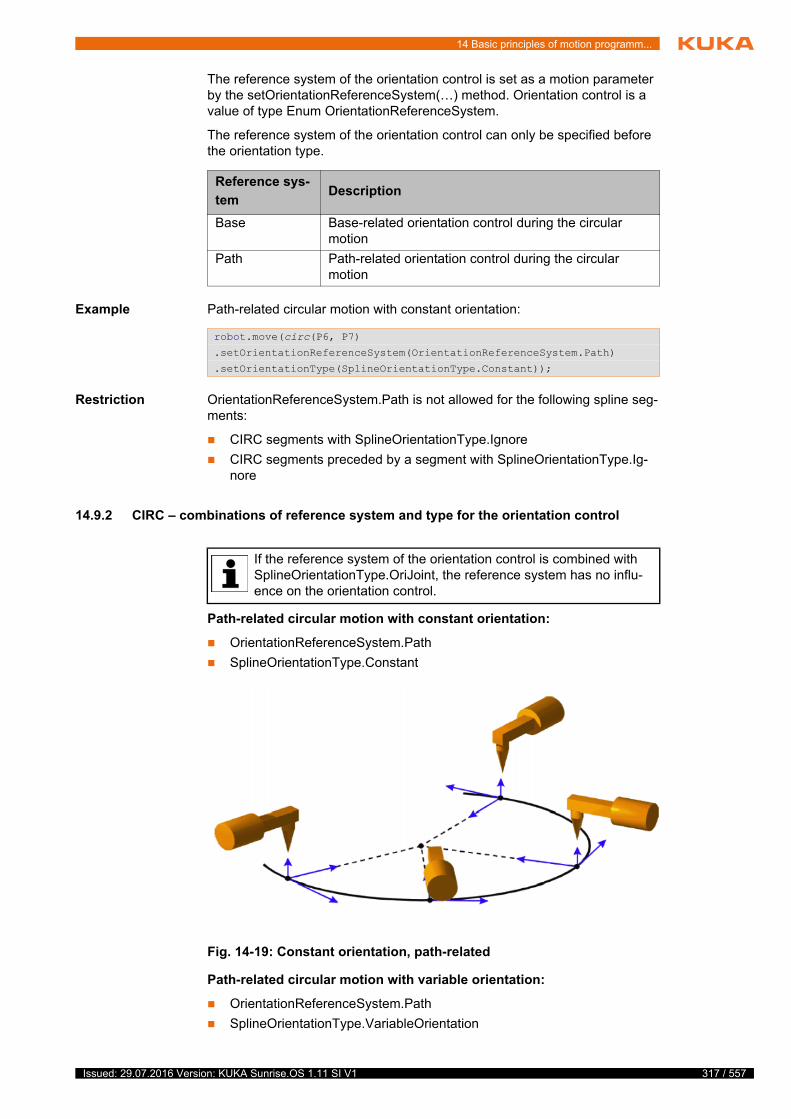
14 Basic principles of motion programm...
The reference system of the orientation control is set as a motion parameter by the setOrientationReferenceSystem(…) method. Orientation control is a value of type Enum OrientationReferenceSystem.
The reference system of the orientation control can only be specified before the orientation type.
Example Path-related circular motion with constant orientation:
Restriction OrientationReferenceSystem.Path is not allowed for the following spline seg-ments:
CIRC segments with SplineOrientationType.Ignore
CIRC segments preceded by a segment with SplineOrientationType.Ig-nore
14.9.2 CIRC – combinations of reference system and type for the orientation control
Path-related circular motion with constant orientation:
OrientationReferenceSystem.Path
SplineOrientationType.Constant
Path-related circular motion with variable orientation:
OrientationReferenceSystem.Path
SplineOrientationType.VariableOrientation
Reference sys-
temDescription
Base Base-related orientation control during the circular motion
Path Path-related orientation control during the circular motion
robot.move(circ(P6, P7)
.setOrientationReferenceSystem(OrientationReferenceSystem.Path)
.setOrientationType(SplineOrientationType.Constant));
If the reference system of the orientation control is combined with SplineOrientationType.OriJoint, the reference system has no influ-ence on the orientation control.
Fig. 14-19: Constant orientation, path-related
317 / 557Issued: 29.07.2016 Version: KUKA Sunrise.OS 1.11 SI V1
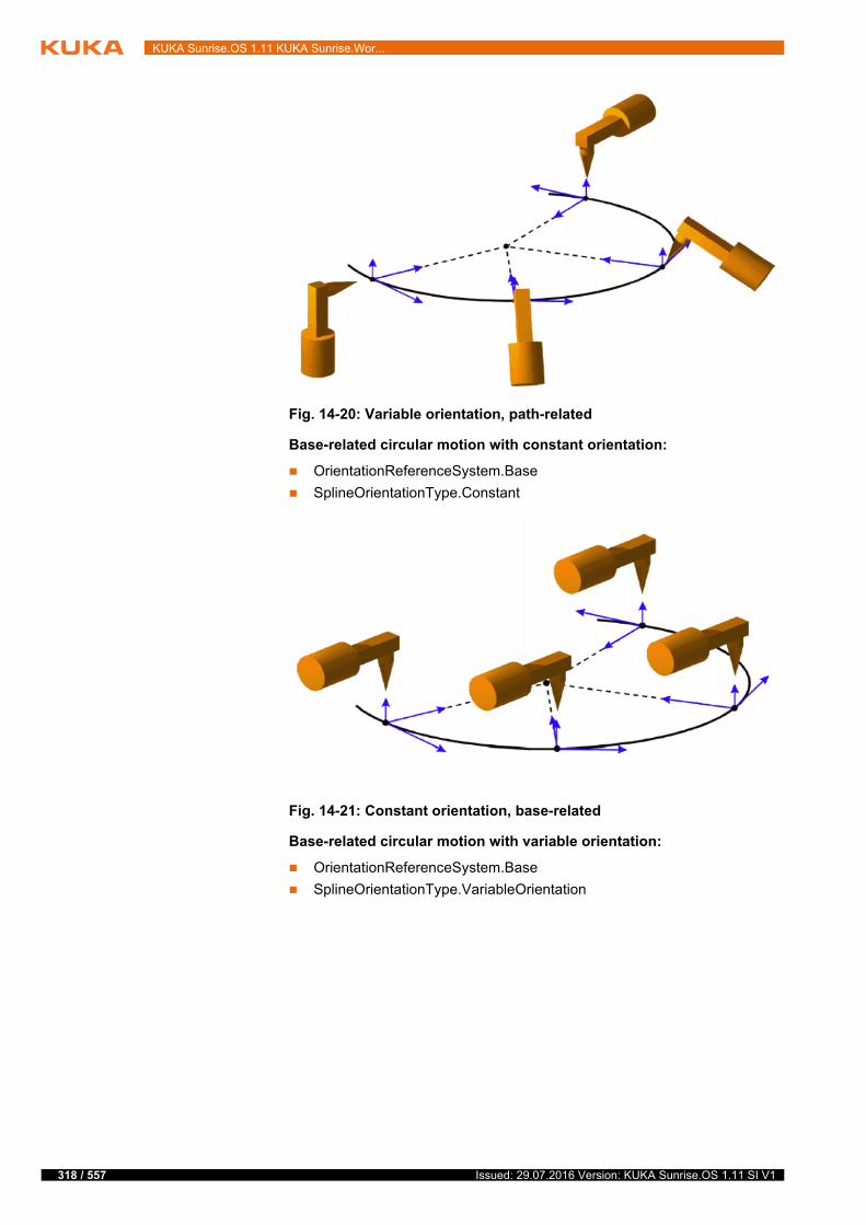
318 / 557
KUKA Sunrise.OS 1.11 KUKA Sunrise.Wor...
Base-related circular motion with constant orientation:
OrientationReferenceSystem.Base
SplineOrientationType.Constant
Base-related circular motion with variable orientation:
OrientationReferenceSystem.Base
SplineOrientationType.VariableOrientation
Fig. 14-20: Variable orientation, path-related
Fig. 14-21: Constant orientation, base-related
Issued: 29.07.2016 Version: KUKA Sunrise.OS 1.11 SI V1
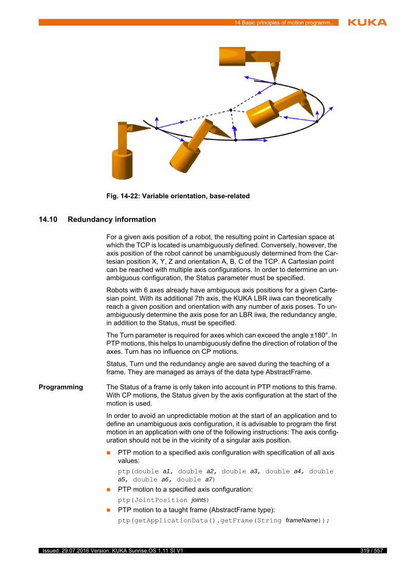
14 Basic principles of motion programm...
14.10 Redundancy information
For a given axis position of a robot, the resulting point in Cartesian space at which the TCP is located is unambiguously defined. Conversely, however, the axis position of the robot cannot be unambiguously determined from the Car-tesian position X, Y, Z and orientation A, B, C of the TCP. A Cartesian point can be reached with multiple axis configurations. In order to determine an un-ambiguous configuration, the Status parameter must be specified.
Robots with 6 axes already have ambiguous axis positions for a given Carte-sian point. With its additional 7th axis, the KUKA LBR iiwa can theoretically reach a given position and orientation with any number of axis poses. To un-ambiguously determine the axis pose for an LBR iiwa, the redundancy angle, in addition to the Status, must be specified.
The Turn parameter is required for axes which can exceed the angle ±180°. In PTP motions, this helps to unambiguously define the direction of rotation of the axes. Turn has no influence on CP motions.
Status, Turn und the redundancy angle are saved during the teaching of a frame. They are managed as arrays of the data type AbstractFrame.
Programming The Status of a frame is only taken into account in PTP motions to this frame. With CP motions, the Status given by the axis configuration at the start of the motion is used.
In order to avoid an unpredictable motion at the start of an application and to define an unambiguous axis configuration, it is advisable to program the first motion in an application with one of the following instructions: The axis config-uration should not be in the vicinity of a singular axis position.
PTP motion to a specified axis configuration with specification of all axis values:
ptp(double a1, double a2, double a3, double a4, double a5, double a6, double a7)
PTP motion to a specified axis configuration:
ptp(JointPosition joints)
PTP motion to a taught frame (AbstractFrame type):
ptp(getApplicationData().getFrame(String frameName));
Fig. 14-22: Variable orientation, base-related
319 / 557Issued: 29.07.2016 Version: KUKA Sunrise.OS 1.11 SI V1

320 / 557
KUKA Sunrise.OS 1.11 KUKA Sunrise.Wor...
14.10.1 Redundancy angle
With its 7th axis, the KUKA LBR iiwa is able to reach a point in space with a theoretically unlimited number of different axis configurations. An unambigu-ous pose is defined via the redundancy angle.
In an LBR iiwa, the redundancy angle has the value of the 3rd axis.
The following applies for all motions:
The redundancy angle of the end frame is taken into account when the ro-bot that was used when teaching the frame also executes the motion com-mand. In particular, the robot name defined in the station configuration must match the device specified in the frame properties.
If the robots do not match or if calculated frames are used, the redundancy angle given at the start of motion by the axis configuration is retained.
14.10.2 Status
The Status specification prevents ambiguous axis positions. The Status is de-scribed by a binary number with 3 bits.
Bit 0 Bit 0 specifies the position of the wrist root point (intersection of axes A5, A6, A7) with reference to the X-axis of the coordinate system of axis A1. The align-ment of the A1 coordinate system is identical to the robot base coordinate sys-tem if axis A1 is at 0°. It moves with axis A1.
Bit 1 In an LBR iiwa, bit 1 specifies the position of axis A4.
Bit 2 In an LBR iiwa, bit 2 specifies the position of axis A6.
The following applies for PTP motions:
The Status of the end frame is taken into account when the robot which was used when teaching the frame also executes the motion command. In particular, the robot name defined in the station configuration must match the device specified in the frame properties.
If the robots do not match or if calculated frames are used, the Status given at the start of motion by the axis configuration is retained.
The following applies for CP motions:
Position Value
Overhead area
The robot is in the overhead area if the X value of the position of the wrist root point, relative to the A1 coordi-nate system, is negative.
Bit 0 = 1
Basic area
The robot is in the basic area if the X value of the posi-tion of the wrist root point, relative to the A1 coordinate system, is positive.
Bit 0 = 0
Position Value
A4 < 0° Bit 1 = 1
A4 ≥ 0° Bit 1 = 0
Position Value
A6 ≤ 0° Bit 2 = 1
A6 > 0° Bit 2 = 0
Issued: 29.07.2016 Version: KUKA Sunrise.OS 1.11 SI V1

14 Basic principles of motion programm...
The Status of the end frame is not taken into account. The Status given by the axis configuration at the start of the motion is retained.
Exception: A change of Status is possible if the end frame is addressed with the SplineOrientationType.OriJoint orientation control. The status of the end frame is not taken into consideration in this case either. The Status at the end of the motion is determined by the path planning, which selects the shortest route to the end frame.
14.10.3 Turn
The Turn specification makes it possible to move axes through angles greater than +180° or less than -180° without the need for special motion strategies (e.g. auxiliary points). The Turn is specified by a binary number with 7 bits.
With rotational axes, the individual bits determine the sign before the axis val-ue in the following way:
Bit = 0: Angle ≥ 0°
Bit = 1: Angle < 0°
The Turn is not taken into account in an LBR iiwa because none of its axes can rotate over ±180°.
14.11 Singularities
Due to the axis position, Cartesian motions of the robot may be limited. Due to the combination of axis positions of the entire robot, no motions can be trans-ferred from the drives to the flange (or to an object on the flange, e.g. a tool) in at least one Cartesian direction. In this case, or if very slight Cartesian changes require very large changes to the axis angles, one speaks of singu-larity positions.
14.11.1 Kinematic singularities
The flexibility due to the redundancy of a 7-axis robot, in contrast to the 6-axis robot, requires 2 or more kinematic conditions (e.g. extended position, 2 rota-tional axes coincide) to be active at the same time in order reach a singularity position. There are 4 different robot positions in which flange motion in one Cartesian direction is no longer possible. Here only the position of 1 or 2 axes is important in each case. The other axes can take any position.
A4 singularity This kinematic singularity is given when A4 = 0°. It is called the extended po-sition.
Value Bit 6 Bit 5 Bit 4 Bit 3 Bit 2 Bit 1 Bit 0
0 A7 ≥ 0° A6 ≥ 0° A5 ≥ 0° A4 ≥ 0° A3 ≥ 0° A2 ≥ 0° A1 ≥ 0°
1 A7 < 0° A6 < 0° A5 < 0° A4 < 0° A3 < 0° A2 < 0° A1 < 0°
It is advisable to move the robot as slowly as possible near singular-ities.
321 / 557Issued: 29.07.2016 Version: KUKA Sunrise.OS 1.11 SI V1
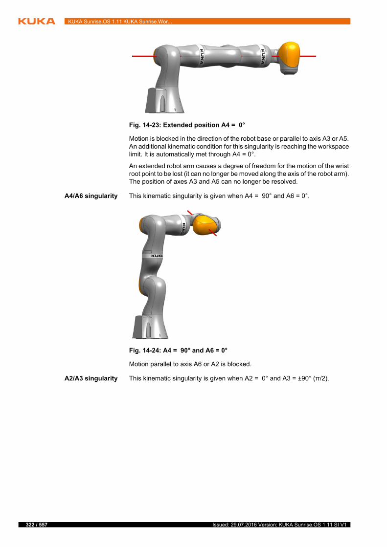
322 / 557
KUKA Sunrise.OS 1.11 KUKA Sunrise.Wor...
Motion is blocked in the direction of the robot base or parallel to axis A3 or A5. An additional kinematic condition for this singularity is reaching the workspace limit. It is automatically met through A4 = 0°.
An extended robot arm causes a degree of freedom for the motion of the wrist root point to be lost (it can no longer be moved along the axis of the robot arm). The position of axes A3 and A5 can no longer be resolved.
A4/A6 singularity This kinematic singularity is given when A4 = 90° and A6 = 0°.
Motion parallel to axis A6 or A2 is blocked.
A2/A3 singularity This kinematic singularity is given when A2 = 0° and A3 = ±90° (π/2).
Fig. 14-23: Extended position A4 = 0°
Fig. 14-24: A4 = 90° and A6 = 0°
Issued: 29.07.2016 Version: KUKA Sunrise.OS 1.11 SI V1
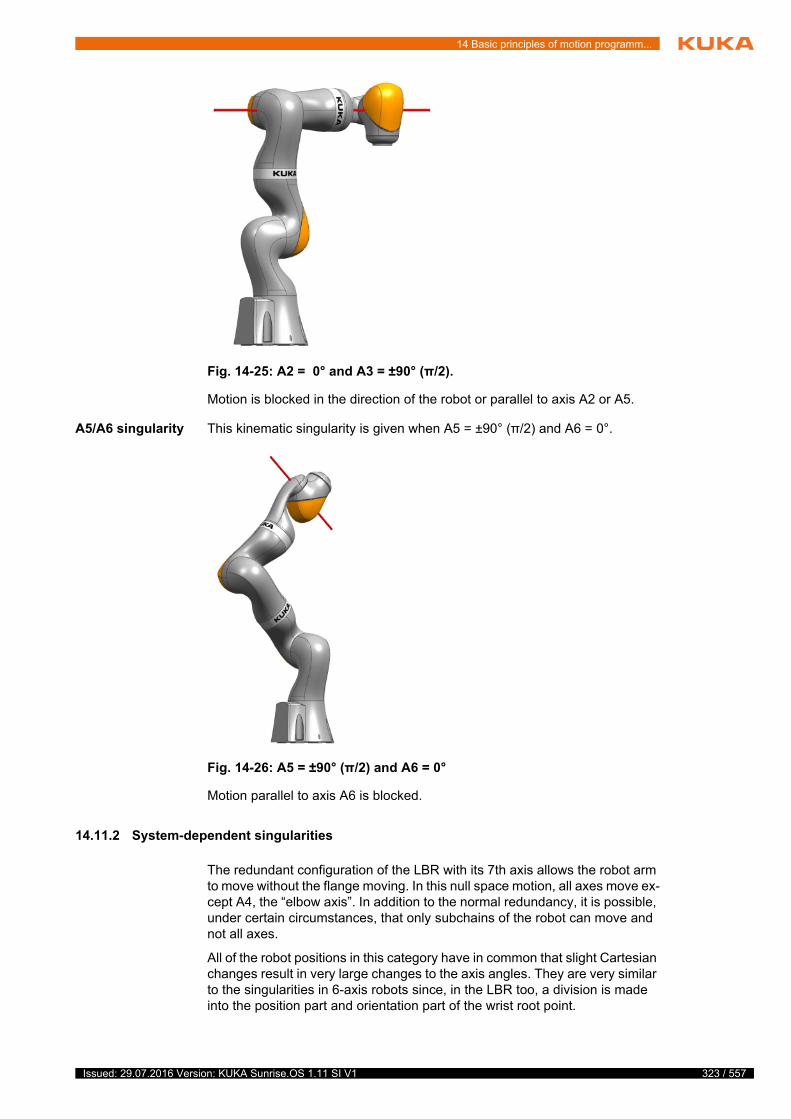
14 Basic principles of motion programm...
Motion is blocked in the direction of the robot or parallel to axis A2 or A5.
A5/A6 singularity This kinematic singularity is given when A5 = ±90° (π/2) and A6 = 0°.
Motion parallel to axis A6 is blocked.
14.11.2 System-dependent singularities
The redundant configuration of the LBR with its 7th axis allows the robot arm to move without the flange moving. In this null space motion, all axes move ex-cept A4, the “elbow axis”. In addition to the normal redundancy, it is possible, under certain circumstances, that only subchains of the robot can move and not all axes.
All of the robot positions in this category have in common that slight Cartesian changes result in very large changes to the axis angles. They are very similar to the singularities in 6-axis robots since, in the LBR too, a division is made into the position part and orientation part of the wrist root point.
Fig. 14-25: A2 = 0° and A3 = ±90° (π/2).
Fig. 14-26: A5 = ±90° (π/2) and A6 = 0°
323 / 557Issued: 29.07.2016 Version: KUKA Sunrise.OS 1.11 SI V1
324 / 557
KUKA Sunrise.OS 1.11 KUKA Sunrise.Wor...
Wrist axis singu-
larity
Wrist axis singularity means the axis position A6 = 0°. The position of axes A5 and A7 can thus no longer be resolved. There are an infinite number of ways to position these two axes to generate the same position on the flange.
A1 singularity If the wrist root point is directly over A1, no reference value can be specified for the redundancy circle according to the definition above. The reason for this is that any A1 value is permissible here for A3 = 0°.
Every axis position of A1 can be compensated for with a combination of A5, A6 and A7 so that the flange position remains unchanged.
A2 singularity With an extended “shoulder”, the position of axes A1 and A3 can no longer be resolved according to the pattern above.
A2/A4 singularity If A1 and A7 coincide, the position of axes A1 and A7 can no longer be re-solved according to the pattern above.
System-dependent singularities can be avoided in most cases by a suitable elbow position.
Issued: 29.07.2016 Version: KUKA Sunrise.OS 1.11 SI V1
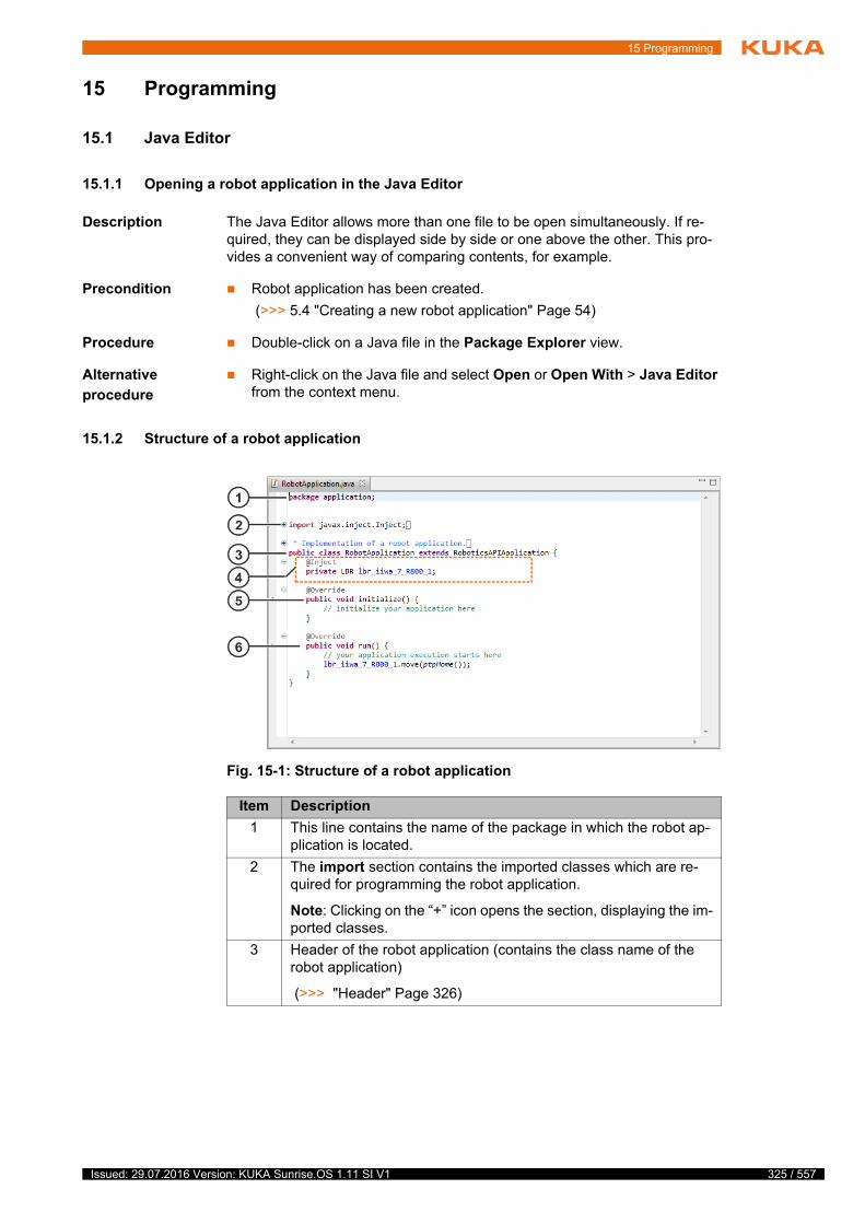
15 Programming
15 Programming
15.1 Java Editor
15.1.1 Opening a robot application in the Java Editor
Description The Java Editor allows more than one file to be open simultaneously. If re-quired, they can be displayed side by side or one above the other. This pro-vides a convenient way of comparing contents, for example.
Precondition Robot application has been created.
(>>> 5.4 "Creating a new robot application" Page 54)
Procedure Double-click on a Java file in the Package Explorer view.
Alternative
procedure
Right-click on the Java file and select Open or Open With > Java Editor from the context menu.
15.1.2 Structure of a robot application
Fig. 15-1: Structure of a robot application
Item Description
1 This line contains the name of the package in which the robot ap-plication is located.
2 The import section contains the imported classes which are re-quired for programming the robot application.
Note: Clicking on the “+” icon opens the section, displaying the im-ported classes.
3 Header of the robot application (contains the class name of the robot application)
(>>> "Header" Page 326)
325 / 557Issued: 29.07.2016 Version: KUKA Sunrise.OS 1.11 SI V1
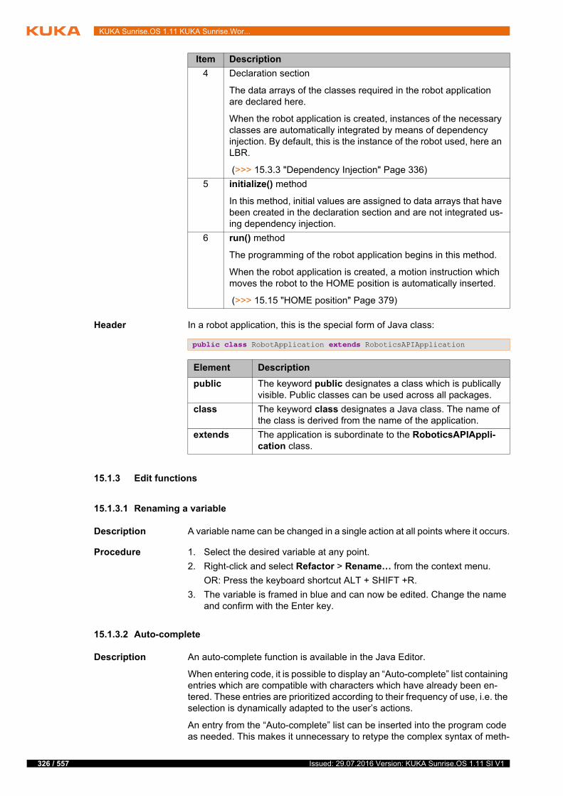
326 / 557
KUKA Sunrise.OS 1.11 KUKA Sunrise.Wor...
Header In a robot application, this is the special form of Java class:
15.1.3 Edit functions
15.1.3.1 Renaming a variable
Description A variable name can be changed in a single action at all points where it occurs.
Procedure 1. Select the desired variable at any point.
2. Right-click and select Refactor > Rename… from the context menu.
OR: Press the keyboard shortcut ALT + SHIFT +R.
3. The variable is framed in blue and can now be edited. Change the name and confirm with the Enter key.
15.1.3.2 Auto-complete
Description An auto-complete function is available in the Java Editor.
When entering code, it is possible to display an “Auto-complete” list containing entries which are compatible with characters which have already been en-tered. These entries are prioritized according to their frequency of use, i.e. the selection is dynamically adapted to the user’s actions.
An entry from the “Auto-complete” list can be inserted into the program code as needed. This makes it unnecessary to retype the complex syntax of meth-
4 Declaration section
The data arrays of the classes required in the robot application are declared here.
When the robot application is created, instances of the necessary classes are automatically integrated by means of dependency injection. By default, this is the instance of the robot used, here an LBR.
(>>> 15.3.3 "Dependency Injection" Page 336)
5 initialize() method
In this method, initial values are assigned to data arrays that have been created in the declaration section and are not integrated us-ing dependency injection.
6 run() method
The programming of the robot application begins in this method.
When the robot application is created, a motion instruction which moves the robot to the HOME position is automatically inserted.
(>>> 15.15 "HOME position" Page 379)
Item Description
public class RobotApplication extends RoboticsAPIApplication
Element Description
public The keyword public designates a class which is publically visible. Public classes can be used across all packages.
class The keyword class designates a Java class. The name of the class is derived from the name of the application.
extends The application is subordinate to the RoboticsAPIAppli-cation class.
Issued: 29.07.2016 Version: KUKA Sunrise.OS 1.11 SI V1

15 Programming
ods, for example. All that is then required is to enter the variable elements in the syntax manually.
Procedure 1. Begin typing the code.
2. Press CTRL + space bar. The “Auto-complete” list containing the available entries is displayed.
3. Select the appropriate entry from the list and press the Enter key. The en-try is inserted in the program code.
If an entry is selected, the Javadoc information on this entry is displayed automatically.
(>>> 15.1.4 "Displaying Javadoc information" Page 329)
4. Complete the syntax if necessary.
Navigating and
filtering
There are various ways to navigate to the “Auto-complete” list and to filter the available entries:
Use the arrow keys on the keyboard to move from one entry to the next (up or down)
Scrolling
Complete the entered code with additional characters. The list is filtered and only the entries which correspond to the characters are displayed.
Press CTRL + space bar. Only the available template suggestions are dis-played.
15.1.3.3 Templates – Fast entry of Java statements
Description Templates for fast entry are available for common Java statements, e.g. FOR loops.
Procedure 1. Begin typing the code.
2. Press CTRL + space bar (twice). A list of the template suggestions that are compatible with the characters already entered is displayed.
3. Accept the instruction with the Enter key. Or double-click on a different in-struction.
4. Complete the syntax.
Alternative
procedure
Selecting templates in the Templates view:
1. Select the menu sequence Window > Show View > Other.... The Show View window opens.
2. In the General folder, select Templates. Confirm with OK. The Tem-plates view opens.
3. Position the cursor in the line in which the code template is to be inserted.
4. Double-click on the desired Java instruction in the Templates view. The code is inserted in the editor.
5. Complete the syntax.
When entering a dot operator for a data array or enum, the “Auto-complete” list is automatically displayed. The list contains the follow-ing entries:
Available methods of the corresponding class (only for data arrays)
Available constants of the corresponding class
If the list contains only one matching entry, this can automatically be inserted into the program code by pressing CTRL + space bar.
327 / 557Issued: 29.07.2016 Version: KUKA Sunrise.OS 1.11 SI V1
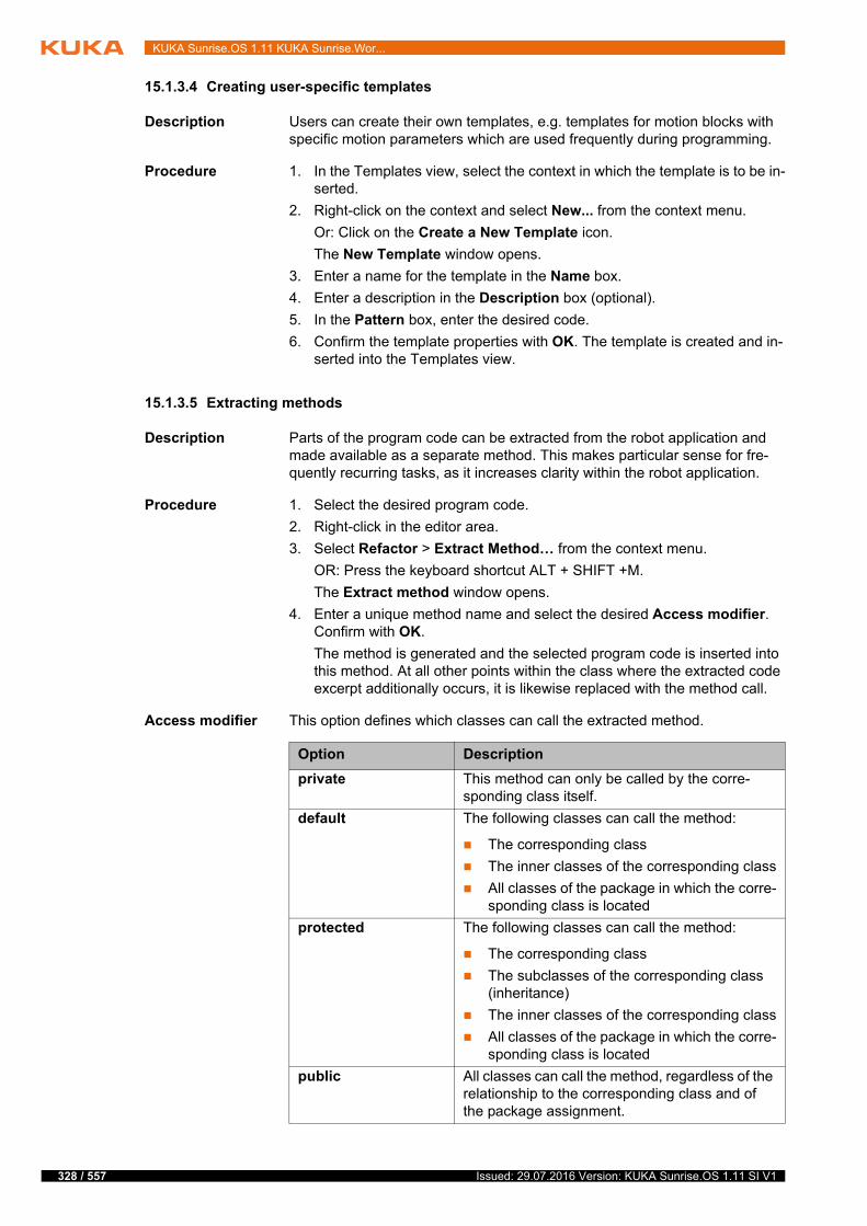
328 / 557
KUKA Sunrise.OS 1.11 KUKA Sunrise.Wor...
15.1.3.4 Creating user-specific templates
Description Users can create their own templates, e.g. templates for motion blocks with specific motion parameters which are used frequently during programming.
Procedure 1. In the Templates view, select the context in which the template is to be in-serted.
2. Right-click on the context and select New... from the context menu.
Or: Click on the Create a New Template icon.
The New Template window opens.
3. Enter a name for the template in the Name box.
4. Enter a description in the Description box (optional).
5. In the Pattern box, enter the desired code.
6. Confirm the template properties with OK. The template is created and in-serted into the Templates view.
15.1.3.5 Extracting methods
Description Parts of the program code can be extracted from the robot application and made available as a separate method. This makes particular sense for fre-quently recurring tasks, as it increases clarity within the robot application.
Procedure 1. Select the desired program code.
2. Right-click in the editor area.
3. Select Refactor > Extract Method… from the context menu.
OR: Press the keyboard shortcut ALT + SHIFT +M.
The Extract method window opens.
4. Enter a unique method name and select the desired Access modifier. Confirm with OK.
The method is generated and the selected program code is inserted into this method. At all other points within the class where the extracted code excerpt additionally occurs, it is likewise replaced with the method call.
Access modifier This option defines which classes can call the extracted method.
Option Description
private This method can only be called by the corre-sponding class itself.
default The following classes can call the method:
The corresponding class
The inner classes of the corresponding class
All classes of the package in which the corre-sponding class is located
protected The following classes can call the method:
The corresponding class
The subclasses of the corresponding class (inheritance)
The inner classes of the corresponding class
All classes of the package in which the corre-sponding class is located
public All classes can call the method, regardless of the relationship to the corresponding class and of the package assignment.
Issued: 29.07.2016 Version: KUKA Sunrise.OS 1.11 SI V1
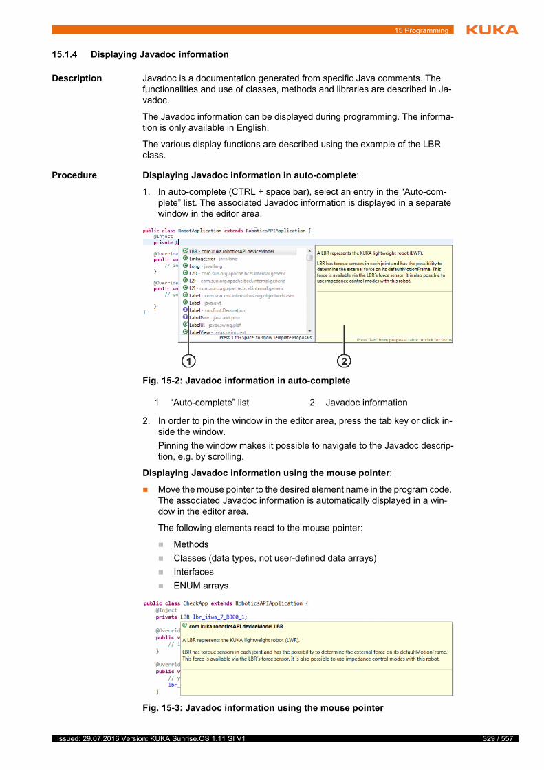
15 Programming
15.1.4 Displaying Javadoc information
Description Javadoc is a documentation generated from specific Java comments. The functionalities and use of classes, methods and libraries are described in Ja-vadoc.
The Javadoc information can be displayed during programming. The informa-tion is only available in English.
The various display functions are described using the example of the LBR class.
Procedure Displaying Javadoc information in auto-complete:
1. In auto-complete (CTRL + space bar), select an entry in the “Auto-com-plete” list. The associated Javadoc information is displayed in a separate window in the editor area.
2. In order to pin the window in the editor area, press the tab key or click in-side the window.
Pinning the window makes it possible to navigate to the Javadoc descrip-tion, e.g. by scrolling.
Displaying Javadoc information using the mouse pointer:
Move the mouse pointer to the desired element name in the program code. The associated Javadoc information is automatically displayed in a win-dow in the editor area.
The following elements react to the mouse pointer:
Methods
Classes (data types, not user-defined data arrays)
Interfaces
ENUM arrays
Fig. 15-2: Javadoc information in auto-complete
1 “Auto-complete” list 2 Javadoc information
Fig. 15-3: Javadoc information using the mouse pointer
329 / 557Issued: 29.07.2016 Version: KUKA Sunrise.OS 1.11 SI V1
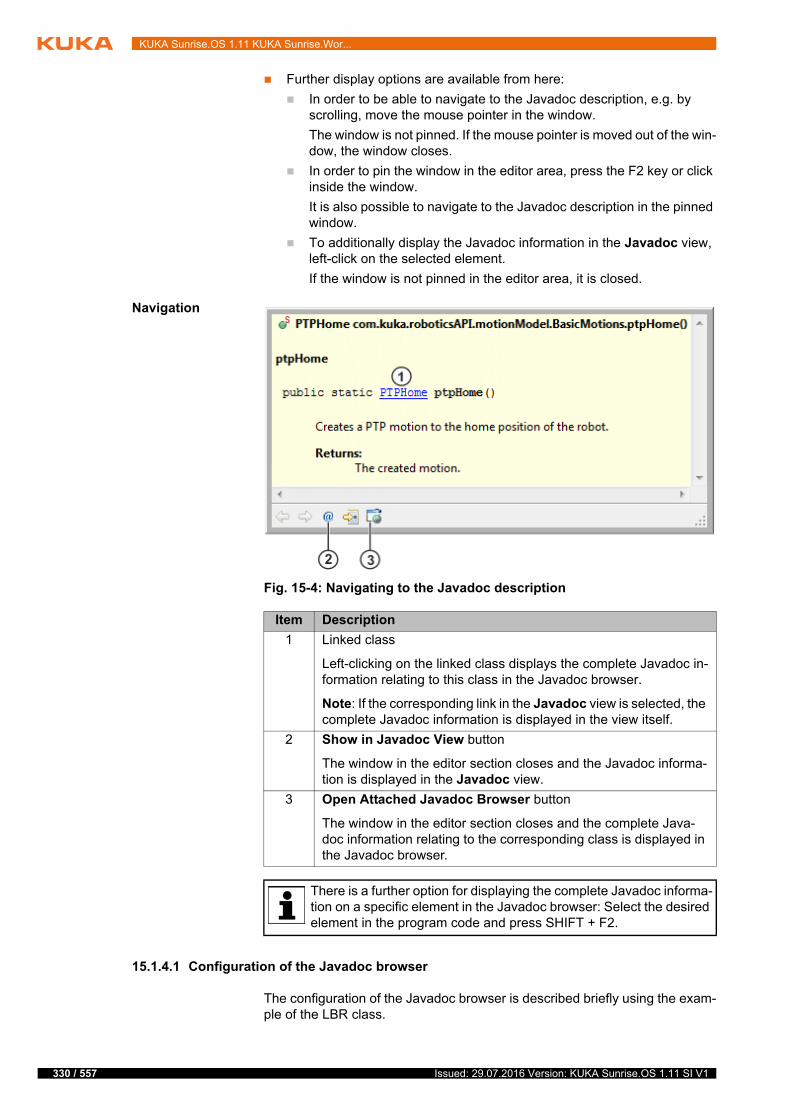
330 / 557
KUKA Sunrise.OS 1.11 KUKA Sunrise.Wor...
Further display options are available from here:
In order to be able to navigate to the Javadoc description, e.g. by scrolling, move the mouse pointer in the window.
The window is not pinned. If the mouse pointer is moved out of the win-dow, the window closes.
In order to pin the window in the editor area, press the F2 key or click inside the window.
It is also possible to navigate to the Javadoc description in the pinned window.
To additionally display the Javadoc information in the Javadoc view, left-click on the selected element.
If the window is not pinned in the editor area, it is closed.
Navigation
15.1.4.1 Configuration of the Javadoc browser
The configuration of the Javadoc browser is described briefly using the exam-ple of the LBR class.
Fig. 15-4: Navigating to the Javadoc description
Item Description
1 Linked class
Left-clicking on the linked class displays the complete Javadoc in-formation relating to this class in the Javadoc browser.
Note: If the corresponding link in the Javadoc view is selected, the complete Javadoc information is displayed in the view itself.
2 Show in Javadoc View button
The window in the editor section closes and the Javadoc informa-tion is displayed in the Javadoc view.
3 Open Attached Javadoc Browser button
The window in the editor section closes and the complete Java-doc information relating to the corresponding class is displayed in the Javadoc browser.
There is a further option for displaying the complete Javadoc informa-tion on a specific element in the Javadoc browser: Select the desired element in the program code and press SHIFT + F2.
Issued: 29.07.2016 Version: KUKA Sunrise.OS 1.11 SI V1
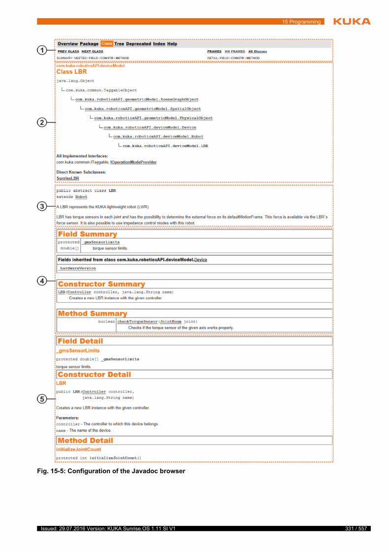
15 Programming
Fig. 15-5: Configuration of the Javadoc browser
331 / 557Issued: 29.07.2016 Version: KUKA Sunrise.OS 1.11 SI V1
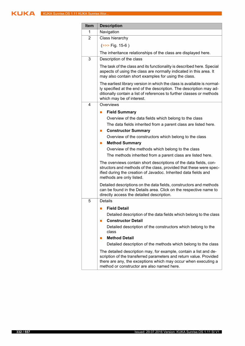
332 / 557
KUKA Sunrise.OS 1.11 KUKA Sunrise.Wor...
Item Description
1 Navigation
2 Class hierarchy
(>>> Fig. 15-6 )
The inheritance relationships of the class are displayed here.
3 Description of the class
The task of the class and its functionality is described here. Special aspects of using the class are normally indicated in this area. It may also contain short examples for using the class.
The earliest library version in which the class is available is normal-ly specified at the end of the description. The description may ad-ditionally contain a list of references to further classes or methods which may be of interest.
4 Overviews
Field Summary
Overview of the data fields which belong to the class
The data fields inherited from a parent class are listed here.
Constructor Summary
Overview of the constructors which belong to the class
Method Summary
Overview of the methods which belong to the class
The methods inherited from a parent class are listed here.
The overviews contain short descriptions of the data fields, con-structors and methods of the class, provided that these were spec-ified during the creation of Javadoc. Inherited data fields and methods are only listed.
Detailed descriptions on the data fields, constructors and methods can be found in the Details area. Click on the respective name to directly access the detailed description.
5 Details
Field Detail
Detailed description of the data fields which belong to the class
Constructor Detail
Detailed description of the constructors which belong to the class
Method Detail
Detailed description of the methods which belong to the class
The detailed description may, for example, contain a list and de-scription of the transferred parameters and return value. Provided there are any, the exceptions which may occur when executing a method or constructor are also named here.
Issued: 29.07.2016 Version: KUKA Sunrise.OS 1.11 SI V1
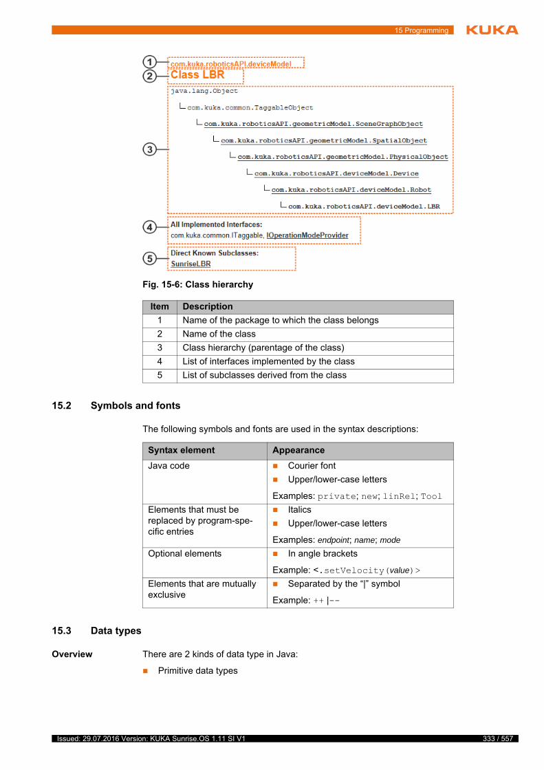
15 Programming
15.2 Symbols and fonts
The following symbols and fonts are used in the syntax descriptions:
15.3 Data types
Overview There are 2 kinds of data type in Java:
Primitive data types
Fig. 15-6: Class hierarchy
Item Description
1 Name of the package to which the class belongs
2 Name of the class
3 Class hierarchy (parentage of the class)
4 List of interfaces implemented by the class
5 List of subclasses derived from the class
Syntax element Appearance
Java code Courier font
Upper/lower-case letters
Examples: private; new; linRel; Tool
Elements that must be replaced by program-spe-cific entries
Italics
Upper/lower-case letters
Examples: endpoint; name; mode
Optional elements In angle brackets
Example: <.setVelocity(value)>
Elements that are mutually exclusive
Separated by the “|” symbol
Example: ++ |--
333 / 557Issued: 29.07.2016 Version: KUKA Sunrise.OS 1.11 SI V1
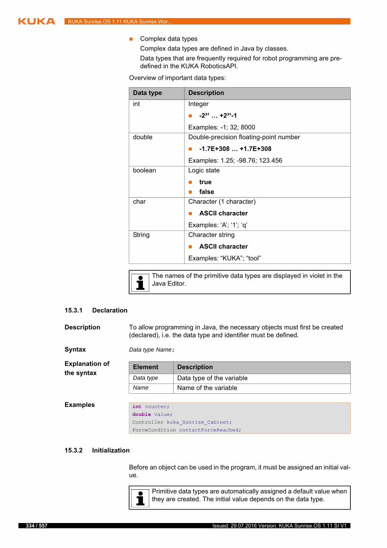
334 / 557
KUKA Sunrise.OS 1.11 KUKA Sunrise.Wor...
Complex data types
Complex data types are defined in Java by classes.
Data types that are frequently required for robot programming are pre-defined in the KUKA RoboticsAPI.
Overview of important data types:
15.3.1 Declaration
Description To allow programming in Java, the necessary objects must first be created (declared), i.e. the data type and identifier must be defined.
Syntax Data type Name;
Explanation of
the syntax
Examples
15.3.2 Initialization
Before an object can be used in the program, it must be assigned an initial val-ue.
Data type Description
int Integer
-2³¹ … +2³¹-1
Examples: -1; 32; 8000
double Double-precision floating-point number
-1.7E+308 … +1.7E+308
Examples: 1.25; -98.76; 123.456
boolean Logic state
true
false
char Character (1 character)
ASCII character
Examples: ‘A’; ‘1’; ‘q’
String Character string
ASCII character
Examples: “KUKA”; “tool”
The names of the primitive data types are displayed in violet in the Java Editor.
Element Description
Data type Data type of the variable
Name Name of the variable
int counter;double value;Controller kuka_Sunrise_Cabinet;
ForceCondition contactForceReached;
Primitive data types are automatically assigned a default value when they are created. The initial value depends on the data type.
Issued: 29.07.2016 Version: KUKA Sunrise.OS 1.11 SI V1
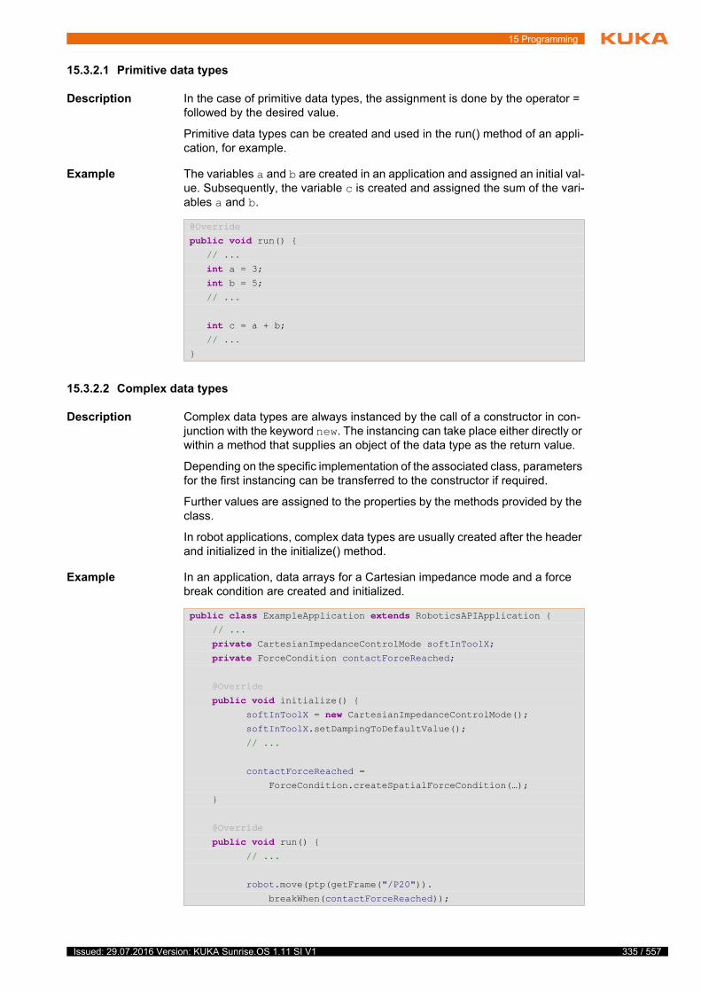
15 Programming
15.3.2.1 Primitive data types
Description In the case of primitive data types, the assignment is done by the operator = followed by the desired value.
Primitive data types can be created and used in the run() method of an appli-cation, for example.
Example The variables a and b are created in an application and assigned an initial val-ue. Subsequently, the variable c is created and assigned the sum of the vari-ables a and b.
15.3.2.2 Complex data types
Description Complex data types are always instanced by the call of a constructor in con-junction with the keyword new. The instancing can take place either directly or within a method that supplies an object of the data type as the return value.
Depending on the specific implementation of the associated class, parameters for the first instancing can be transferred to the constructor if required.
Further values are assigned to the properties by the methods provided by the class.
In robot applications, complex data types are usually created after the header and initialized in the initialize() method.
Example In an application, data arrays for a Cartesian impedance mode and a force break condition are created and initialized.
@Override
public void run() { // ...
int a = 3; int b = 5; // ...
int c = a + b; // ...
}
public class ExampleApplication extends RoboticsAPIApplication { // ...
private CartesianImpedanceControlMode softInToolX; private ForceCondition contactForceReached;
@Override
public void initialize() { softInToolX = new CartesianImpedanceControlMode(); softInToolX.setDampingToDefaultValue();
// ...
contactForceReached =
ForceCondition.createSpatialForceCondition(…);
}
@Override
public void run() { // ...
robot.move(ptp(getFrame("/P20")).
breakWhen(contactForceReached));
335 / 557Issued: 29.07.2016 Version: KUKA Sunrise.OS 1.11 SI V1
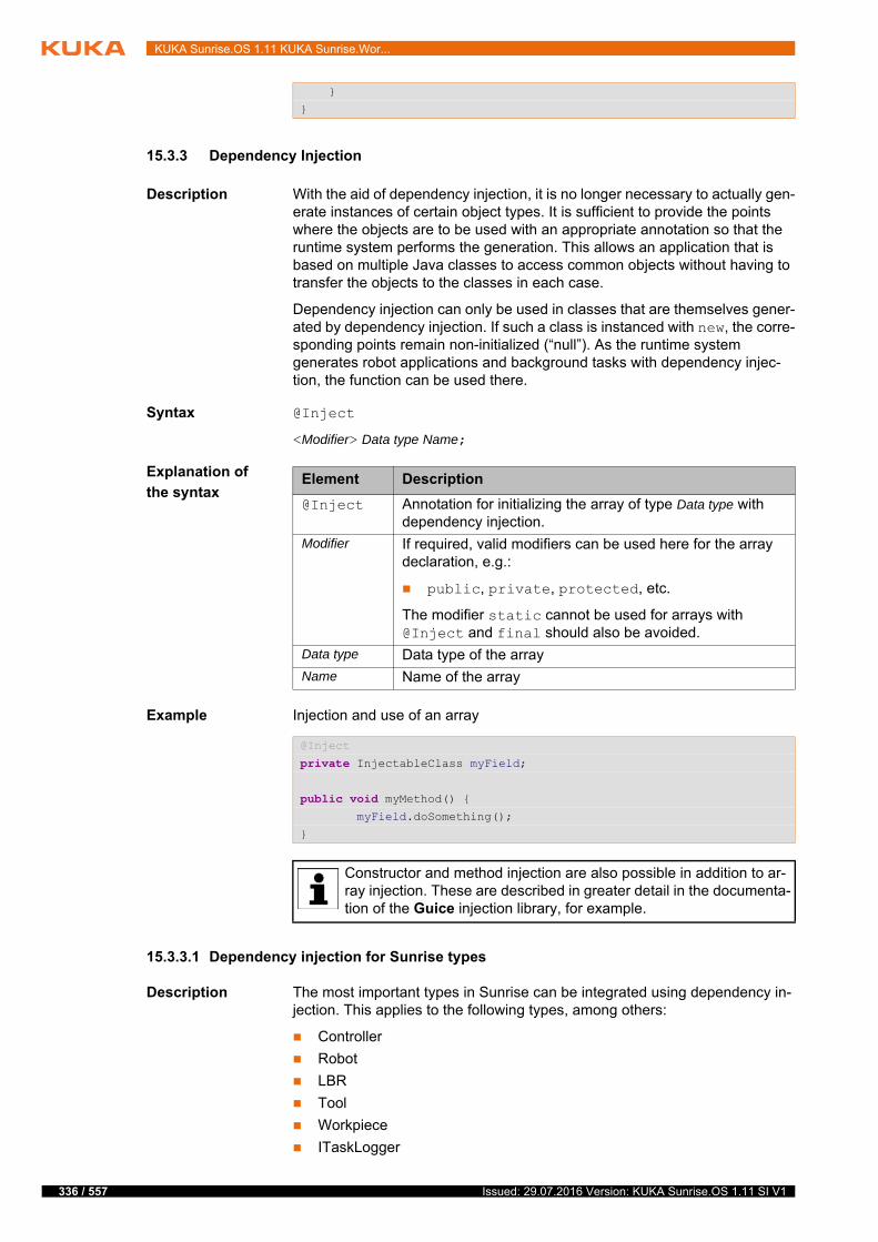
336 / 557
KUKA Sunrise.OS 1.11 KUKA Sunrise.Wor...
15.3.3 Dependency Injection
Description With the aid of dependency injection, it is no longer necessary to actually gen-erate instances of certain object types. It is sufficient to provide the points where the objects are to be used with an appropriate annotation so that the runtime system performs the generation. This allows an application that is based on multiple Java classes to access common objects without having to transfer the objects to the classes in each case.
Dependency injection can only be used in classes that are themselves gener-ated by dependency injection. If such a class is instanced with new, the corre-sponding points remain non-initialized (“null”). As the runtime system generates robot applications and background tasks with dependency injec-tion, the function can be used there.
Syntax @Inject
<Modifier> Data type Name;
Explanation of
the syntax
Example Injection and use of an array
15.3.3.1 Dependency injection for Sunrise types
Description The most important types in Sunrise can be integrated using dependency in-jection. This applies to the following types, among others:
Controller
Robot
LBR
Tool
Workpiece
ITaskLogger
}
}
Element Description
@Inject Annotation for initializing the array of type Data type with dependency injection.
Modifier If required, valid modifiers can be used here for the array declaration, e.g.:
public, private, protected, etc.
The modifier static cannot be used for arrays with @Inject and final should also be avoided.
Data type Data type of the array
Name Name of the array
@Inject
private InjectableClass myField;
public void myMethod() { myField.doSomething();
}
Constructor and method injection are also possible in addition to ar-ray injection. These are described in greater detail in the documenta-tion of the Guice injection library, for example.
Issued: 29.07.2016 Version: KUKA Sunrise.OS 1.11 SI V1

15 Programming
IApplicationData
All generated I/O groups
All classes created in Sunrise.Workbench which are derived from Tool or Workpiece and have been configured as Class of Template in the prop-erties of an object template.
Procedure To call Javadoc of UseRoboticsAPIContext:
1. Move the mouse pointer over RoboticsAPIApplication in the header of an application.
2. A window opens. In it, click on the link Available type for Dependency Injection.
3. The Javadoc file is displayed in the editor area.
Examples An LBR iiwa and a gripper are integrated in a robot application by means of dependency injection. An object template with the name “Gripper” has been created for the gripper. The gripper is attached to the robot during initialization. Motions with both devices are executed in the application.
In addition, a logger object is integrated which is used to display LOG informa-tion of the smartHMI.
Other classes and interfaces in addition to those described here can also be integrated using dependency injection. A list of these objects can be found in the Javadoc of UseRoboticsAPIContext.
If object templates are to be integrated using dependency injection, the annotation @Named("TemplateName") must additionally be used. The name of the object template as configured in the Object tem-
plates view must be entered as the TemplateName.
public class ExampleApplication extends RoboticsAPIApplication { @Inject
private ITaskLogger logger; @Inject
private IApplicationData data;
@Inject
private LBR robot;
@Inject
@Named("Gripper")
private Tool gripper;
@Override
public void initialize() { // initialize your application here
gripper.attachTo(robot.getFlange());
logger.info("Application initialized!");
}
@Override
public void run() { // your application execution starts here
robot.move(ptpHome());
robot.move(ptp(data.getFrame("/Start")));
// ...
logger.info("Move gripper");
gripper.move(linRel().setXOffset(25.0));
// ...
337 / 557Issued: 29.07.2016 Version: KUKA Sunrise.OS 1.11 SI V1
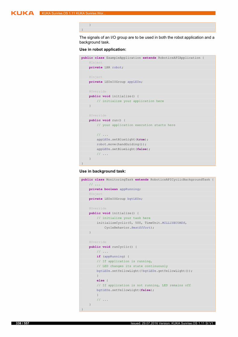
338 / 557
KUKA Sunrise.OS 1.11 KUKA Sunrise.Wor...
The signals of an I/O group are to be used in both the robot application and a background task.
Use in robot application:
Use in background task:
}
}
public class ExampleApplication extends RoboticsAPIApplication { @Inject
private LBR robot;
@Inject
private LEDsIOGroup appLEDs;
@Override
public void initialize() { // initialize your application here
}
@Override
public void run() { // your application execution starts here
// ...
appLEDs.setBlueLight(true); robot.move(handGuiding());
appLEDs.setBlueLight(false); // ...
}
}
public class MonitoringTask extends RoboticsAPICyclicBackgroundTask { // ...
private boolean appRunning; @Inject
private LEDsIOGroup bgtLEDs;
@Override
public void initialize() { // initialize your task here
initializeCyclic(0, 500, TimeUnit.MILLISECONDS,
CycleBehavior.BestEffort);
}
@Override
public void runCyclic() { // ...
if (appRunning) { // If application is running,
// LED changes its state continuously
bgtLEDs.setYellowLight(!bgtLEDs.getYellowLight());
}
else { // If application is not running, LED remains off
bgtLEDs.setYellowLight(false); }
// ...
}
}
Issued: 29.07.2016 Version: KUKA Sunrise.OS 1.11 SI V1

15 Programming
15.3.3.2 Dependency injection for dedicated types
Description A class can be used via dependency injection if it meets one of the following conditions:
The class has a public constructor without parameters. An @Inject anno-tation on the constructor is not absolutely essential in this case.
The class has a public constructor with an @Inject annotation which either contains no parameters or for which all parameters can be obtained via dependency injection.
All classes that are present in an application and meet the specified conditions can be integrated in all constituent parts of the application using @Inject. A new instance of the class is generated by default for each integration using @Inject.
Singletons If a dedicated class is provided with the annotation @Singleton in addition to dependency injection, this results in only one instance of this class being used in the application. This means that all objects of this class generated via de-pendency injection refer to the same instance.
State variables, e.g. of tool and workpiece classes, can be used by various program sections through this mechanism.
(>>> 15.10.4 "Integrating dedicated object classes with dependency injec-tion" Page 362)
Example The classes Vehicle, Motor and Wheel are used in a project. The classes Motor and Wheel are to be available in the Vehicle class via dependency injection. As a vehicle usually only has one motor (or engine), the Motor class is to be defined as a singleton.
2 objects of each of the classes Motor and Wheel are integrated in the Ve-hicle class. Comparison of the objects is then intended to show that the ob-jects of the Motor class refer to the same instance whereas the objects of the Wheel class refer to different instances.
The Vehicle class is likewise integrated in a robot application using depen-dency injection. An object of the ITaskLogger class is integrated in both the robot application and the Vehicle class by means of dependency injection. Integrating the ITaskLogger interface via dependency injection also enables information from the Vehicle class to be displayed on the smartHMI.
Wheel class:
Motor class:
Use of the annotation @Singleton enables an application to be sub-divided into multiple classes which can be called from the main appli-cation.
This procedure represents an alternative to the process data, though the state variables are not automatically saved.
public class Wheel{
@Inject
public Wheel() {} // ...
}
@Singleton
public class Motor{
339 / 557Issued: 29.07.2016 Version: KUKA Sunrise.OS 1.11 SI V1

340 / 557
KUKA Sunrise.OS 1.11 KUKA Sunrise.Wor...
Vehicle class:
Robot application (CarApplication class):
@Inject
public Motor() {} // ...
}
public class Vehicle { @Inject
private ITaskLogger logger; @Inject
private Wheel frontWheel; @Inject
private Wheel rearWheel;
@Inject
private Motor motor; @Inject
private Motor additionalMotor;
// ...
@Inject
private Vehicle() { }
public void setCarStatus() { frontWheel.setName("FrontWheel");
rearWheel.setName("RearWheel");
motor.setName("Motor");
additionalMotor.setName("AdditionalMotor");
// ...
}
public void printCarStatus() { logger.info("**************************");
logger.info("Comparing the instances of Wheel:");
if (frontWheel == rearWheel { logger.info(frontWheel + " and " +
rearWheel + " are equal.");
}
else { logger.info(frontWheel + " and " +
rearWheel + " are NOT equal.");
}
logger.info("Comparing the instances of Motor:");
if (motor == additionalMotor { logger.info(motor + " and " + additionalMotor +
" are equal.");
}
else { logger.info(motor + " and " + additionalMotor +
" are NOT equal.");
}
logger.info("**************************");
}
// ...
}
Issued: 29.07.2016 Version: KUKA Sunrise.OS 1.11 SI V1
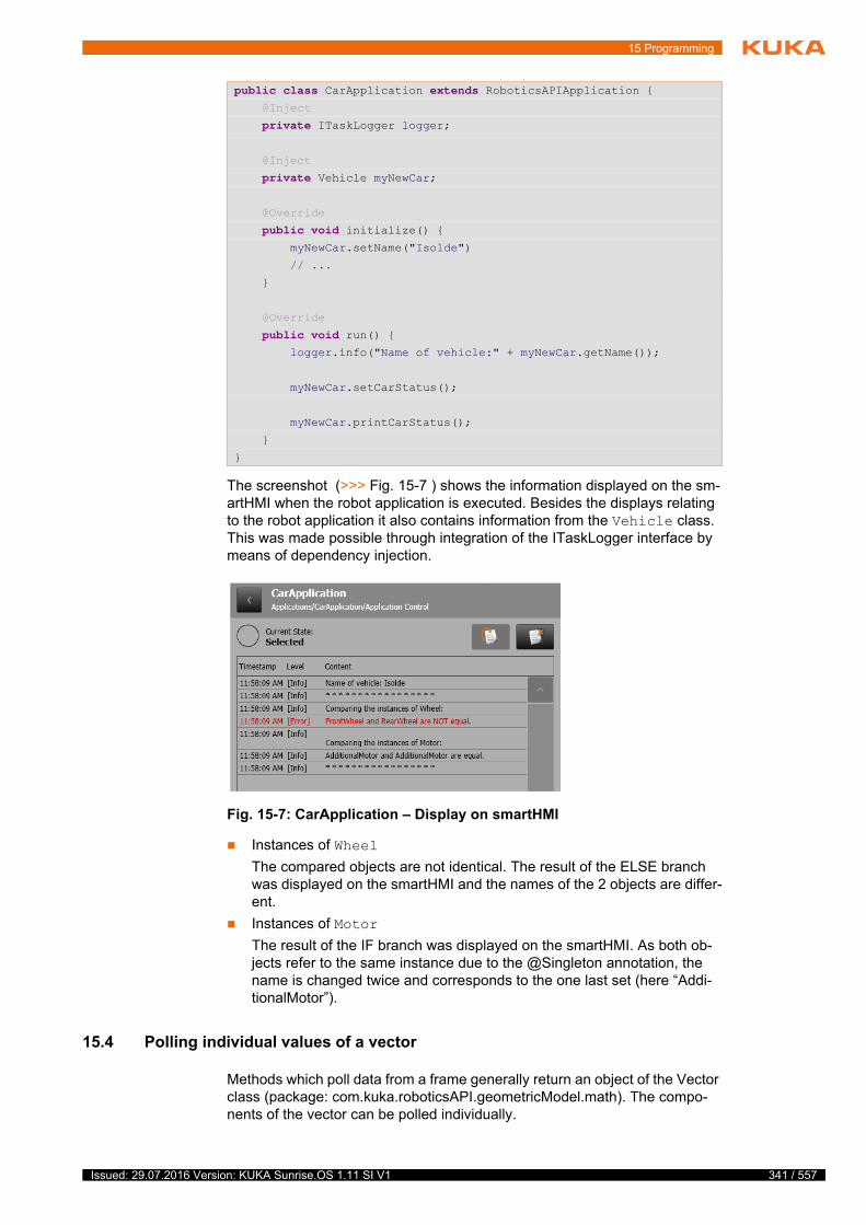
15 Programming
The screenshot (>>> Fig. 15-7 ) shows the information displayed on the sm-artHMI when the robot application is executed. Besides the displays relating to the robot application it also contains information from the Vehicle class. This was made possible through integration of the ITaskLogger interface by means of dependency injection.
Instances of Wheel
The compared objects are not identical. The result of the ELSE branch was displayed on the smartHMI and the names of the 2 objects are differ-ent.
Instances of Motor
The result of the IF branch was displayed on the smartHMI. As both ob-jects refer to the same instance due to the @Singleton annotation, the name is changed twice and corresponds to the one last set (here “Addi-tionalMotor”).
15.4 Polling individual values of a vector
Methods which poll data from a frame generally return an object of the Vector class (package: com.kuka.roboticsAPI.geometricModel.math). The compo-nents of the vector can be polled individually.
public class CarApplication extends RoboticsAPIApplication { @Inject
private ITaskLogger logger;
@Inject
private Vehicle myNewCar;
@Override
public void initialize() { myNewCar.setName("Isolde")
// ...
}
@Override
public void run() { logger.info("Name of vehicle:" + myNewCar.getName());
myNewCar.setCarStatus();
myNewCar.printCarStatus();
}
}
Fig. 15-7: CarApplication – Display on smartHMI
341 / 557Issued: 29.07.2016 Version: KUKA Sunrise.OS 1.11 SI V1

342 / 557
KUKA Sunrise.OS 1.11 KUKA Sunrise.Wor...
Overview The following methods of the Vector class are available:
15.5 Network communication via UDP and TCP/IP
Certain ports are enabled on the robot controller for communication with ex-ternal devices via UDP or TCP/IP.
The following port numbers (client or server socket) can be used in a robot ap-plication:
30,000 to 30,010
15.6 Motion programming: PTP, LIN, CIRC
15.6.1 Synchronous and asynchronous motion execution
Description In Sunrise, motion commands can be used for all movable objects of a station. A movable object can be a robot, for example, but also a tool which is attached to the robot flange or a workpiece held by a tool (e.g. a gripper).
Motion commands can be executed synchronously and asynchronously. The following methods are available for this:
move(…) for synchronous execution
Synchronous means that the motion commands are sent in steps to the real-time controller and executed. The further execution of the program is interrupted until the motion has been executed. Only then is the next com-mand sent.
moveAsync(…) for asynchronous execution
Asynchronous means that the next program line is executed directly after the motion command is sent. The asynchronous execution of motions is required for approximating motions, for example.
Method Description
getX() Return value type: double
Polls for the X component of the vector
getY() Return value type: double
Polls for the Y component of the vector
getZ() Return value type: double
Polls for the Z component of the vector
get(index) Return value type: double
Polls for the components determined by the index parame-ter
Values of index (type: int):
0: X component of the vector
1: Y component of the vector
2: Z component of the vector
In the case of complex program structures and asynchro-nous motion execution, the exact motion sequence is not
predictable. If asynchronous motions are approximated, this can result in the robot performing an approximate positioning motion at an unexpected point.Such unexpected approximate positioning motions can be avoided by group-ing together approximated individual motions in a MotionBatch. (>>> 15.6.6 "MotionBatch" Page 346)
Issued: 29.07.2016 Version: KUKA Sunrise.OS 1.11 SI V1

15 Programming
The way in which the different motion types are programmed is shown by way of example for the object “robot”.
Motion programming for tools and workpieces is described here: (>>> 15.10.3 "Moving tools and workpieces" Page 361)
Syntax Executing a motion synchronously:
Object.move(Motion);
Executing a motion asynchronously:
Object.moveAsync(Motion);
Explanation of
the syntax
15.6.2 PTP
Description Executes a point-to-point motion to the end point. The coordinates of the end point are absolute.
The end point can be programmed in the following ways:
Insert a frame from the application data in a motion instruction.
Create a frame in the program and use it in the motion instruction.
Specify the angles of axes A1 … A7. All axis values must always be spec-ified.
Syntax PTP motion with a specified frame:
ptp(getApplicationData().getFrame("/End point"))<.Motion parameters>
PTP motion with specified axis angles:
ptp(A1, A2, … A7)<.Motion parameters>
During programming, it is possible to specify values with a higher ac-curacy than the robot can achieve. For example, it is possible to spec-ify position data in the nanometer range, but it is not possible to
achieve this accuracy.
Element Description
Object Object of the station which is being moved
The variable name of the object declared and initialized in the application is specified here.
Motion Motion which is being executed
The motion to be executed is defined by the following ele-ments:
Motion type or block: ptp, lin, circ, spl or spline, splineJP, batch
Target position
Further optional motion parameters
The redundancy information for the end point – Status, Turn and re-dundancy angle – must be correctly specified. Otherwise, the end point cannot be correctly addressed.
343 / 557Issued: 29.07.2016 Version: KUKA Sunrise.OS 1.11 SI V1
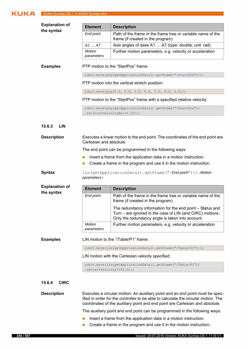
344 / 557
KUKA Sunrise.OS 1.11 KUKA Sunrise.Wor...
Explanation of
the syntax
Examples PTP motion to the “StartPos” frame:
PTP motion into the vertical stretch position:
PTP motion to the “StartPos” frame with a specified relative velocity:
15.6.3 LIN
Description Executes a linear motion to the end point. The coordinates of the end point are Cartesian and absolute.
The end point can be programmed in the following ways:
Insert a frame from the application data in a motion instruction.
Create a frame in the program and use it in the motion instruction.
Syntax lin(getApplicationData().getFrame("/End point"))<.Motion parameters>
Explanation of
the syntax
Examples LIN motion to the “/Table/P1” frame:
LIN motion with the Cartesian velocity specified:
15.6.4 CIRC
Description Executes a circular motion. An auxiliary point and an end point must be spec-ified in order for the controller to be able to calculate the circular motion. The coordinates of the auxiliary point and end point are Cartesian and absolute.
The auxiliary point and end point can be programmed in the following ways:
Insert a frame from the application data in a motion instruction.
Create a frame in the program and use it in the motion instruction.
Element Description
End point Path of the frame in the frame tree or variable name of the frame (if created in the program)
A1 … A7 Axis angles of axes A1 … A7 (type: double; unit: rad)
Motion parameters
Further motion parameters, e.g. velocity or acceleration
robot.move(ptp(getApplicationData().getFrame("/StartPos")));
robot.move(ptp(0.0, 0.0, 0.0, 0.0, 0.0, 0.0, 0.0));
robot.move(ptp(getApplicationData().getFrame("/StartPos"))
.setJointVelocityRel(0.25));
Element Description
End point Path of the frame in the frame tree or variable name of the frame (if created in the program)
The redundancy information for the end point – Status and Turn – are ignored in the case of LIN (and CIRC) motions. Only the redundancy angle is taken into account.
Motion parameters
Further motion parameters, e.g. velocity or acceleration
robot.move(lin(getApplicationData().getFrame("/Table/P1")));
robot.move(lin(getApplicationData().getFrame("/Table/P1"))
.setCartVelocity(150.0));
Issued: 29.07.2016 Version: KUKA Sunrise.OS 1.11 SI V1
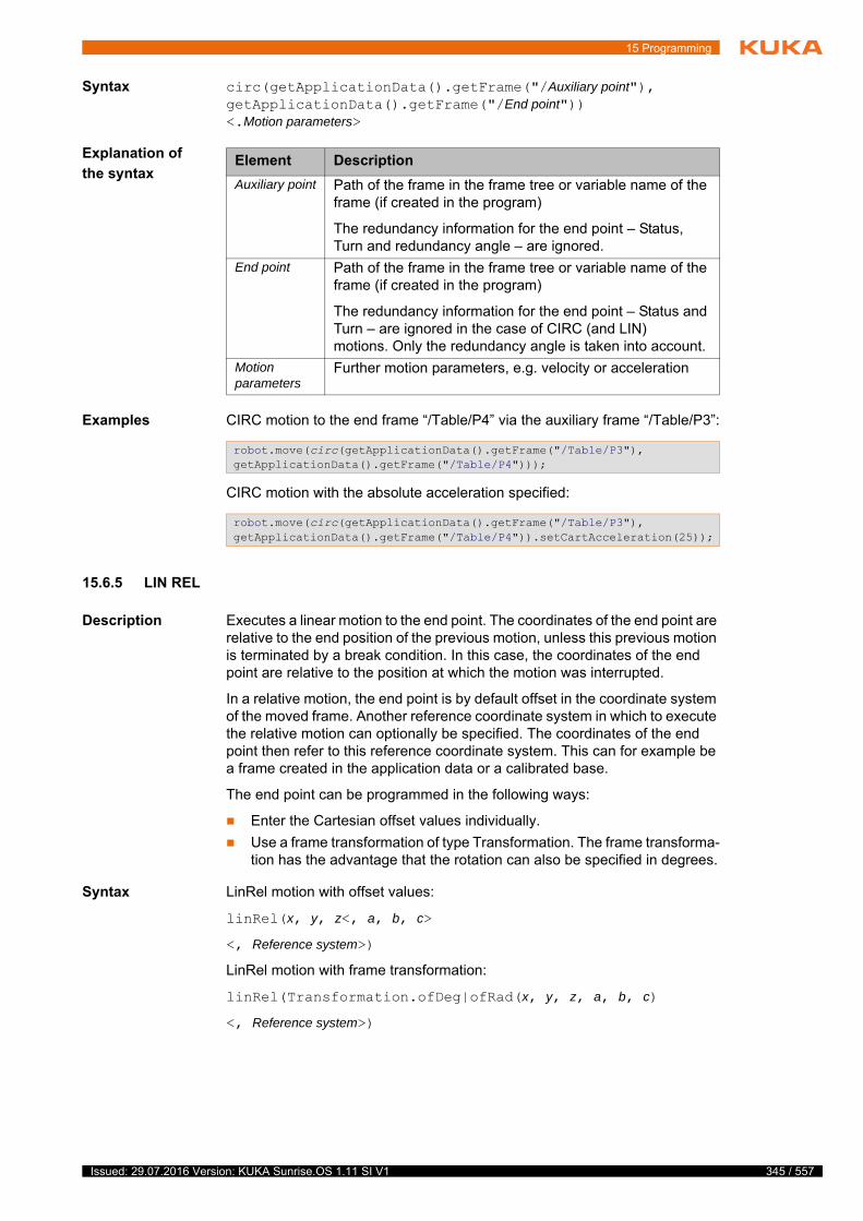
15 Programming
Syntax circ(getApplicationData().getFrame("/Auxiliary point"), getApplicationData().getFrame("/End point"))<.Motion parameters>
Explanation of
the syntax
Examples CIRC motion to the end frame “/Table/P4” via the auxiliary frame “/Table/P3”:
CIRC motion with the absolute acceleration specified:
15.6.5 LIN REL
Description Executes a linear motion to the end point. The coordinates of the end point are relative to the end position of the previous motion, unless this previous motion is terminated by a break condition. In this case, the coordinates of the end point are relative to the position at which the motion was interrupted.
In a relative motion, the end point is by default offset in the coordinate system of the moved frame. Another reference coordinate system in which to execute the relative motion can optionally be specified. The coordinates of the end point then refer to this reference coordinate system. This can for example be a frame created in the application data or a calibrated base.
The end point can be programmed in the following ways:
Enter the Cartesian offset values individually.
Use a frame transformation of type Transformation. The frame transforma-tion has the advantage that the rotation can also be specified in degrees.
Syntax LinRel motion with offset values:
linRel(x, y, z<, a, b, c>
<, Reference system>)
LinRel motion with frame transformation:
linRel(Transformation.ofDeg|ofRad(x, y, z, a, b, c)
<, Reference system>)
Element Description
Auxiliary point Path of the frame in the frame tree or variable name of the frame (if created in the program)
The redundancy information for the end point – Status, Turn and redundancy angle – are ignored.
End point Path of the frame in the frame tree or variable name of the frame (if created in the program)
The redundancy information for the end point – Status and Turn – are ignored in the case of CIRC (and LIN) motions. Only the redundancy angle is taken into account.
Motion parameters
Further motion parameters, e.g. velocity or acceleration
robot.move(circ(getApplicationData().getFrame("/Table/P3"), getApplicationData().getFrame("/Table/P4")));
robot.move(circ(getApplicationData().getFrame("/Table/P3"), getApplicationData().getFrame("/Table/P4")).setCartAcceleration(25));
345 / 557Issued: 29.07.2016 Version: KUKA Sunrise.OS 1.11 SI V1
346 / 557
KUKA Sunrise.OS 1.11 KUKA Sunrise.Wor...
Explanation of
the syntax
Examples The moving frame is the TCP of a gripper. This TCP moves 100 mm in the X direction and 200 mm in the negative Z direction in the tool coordinate system from the current position. The orientation of the TCP does not change.
The robot moves 10 mm from the current position in the coordinate system of the P1 frame. The robot additionally rotates 30° about the Z and Y axes of the coordinate system of the P1 frame.
15.6.6 MotionBatch
Description Several individual motions can be grouped in a MotionBatch and thus trans-mitted to the robot controller at the same time. As a result, motions can be ap-proximated within the MotionBatch.
The motion parameters, e.g. velocity, acceleration, orientation control, etc. can be programmed for the entire batch or per motion.
Both variants can appear together, e.g. to assign another parameter value to an individual motion than to the batch.
Syntax Object.move(batch(
Motion,
Motion,
…
Motion,
Motion
)<.Motion parameter>);
Element Description
x, y, z Offset in the X, Y and Z directions (type: double, unit: mm)
a, b, c Rotation about the Z, Y and X axes (type: double)
The unit depends on the method used:
Offset values and Transformation.ofRad: rad
Transformation.ofDeg: degrees
Reference system
Type: AbstractFrame
Reference coordinate system in which the motion is exe-cuted
gripper.getFrame("/TCP2").move(linRel(100, 0, -200));
robot.move(linRel(Transformation.ofDeg(10, 10, 10, 30, 30, 0), getApplicationData().getFrame("/P1")));
Only axis-specific motion parameters, e.g. setJoint…Rel(…), can be specified for the entire batch. Cartesian motion parameters, e.g. set-Cart…(…), must be specified in the individual block.
The individual block parameter overwrites the batch parameter. This also applies if a lower parameter value is specified for the batch than for the individual block.
Issued: 29.07.2016 Version: KUKA Sunrise.OS 1.11 SI V1
15 Programming
Explanation of
the syntax
15.7 Motion programming: spline
15.7.1 Programming tips for spline motions
The number of spline segments in a spline block is only limited by the available memory.
The planning of a spline motion with many small segments and small dis-tances between points can take a very long time. To avoid excessively long planning times:
Program a maximum of 500 segments per spline block.
If possible, program distances between points > 5 mm.
Spline motions (with many segments) can be programmed using an array of spline segments.
A spline block should cover only 1 process (e.g. 1 adhesive seam). More than one process in a spline block leads to a loss of structural clarity within the program and makes changes more difficult.
Use LIN and CIRC segments in cases where the workpiece necessitates straight lines and arcs. (Exception: use SPL segments for very short straight lines.) Otherwise, use SPL segments, particularly if the points are close together.
Procedure for defining the path:
a. First teach or calculate a few characteristic points. Example: points at which the curve changes direction.
b. Test the path. At points where the accuracy is still insufficient, add more SPL points.
Avoid successive LIN and/or CIRC segments, as this often reduces the ve-locity to 0. To avoid this:
Program SPL segments between LIN and CIRC segments. The length of the SPL segments must be at least > 0.5 mm. Depending on the ac-tual path, significantly larger SPL segments may be required.
Replace a LIN segment with several SPL segments in a straight line. In this way, the path becomes a straight line.
Avoid successive points with identical Cartesian coordinates, as this re-duces the velocity to 0.
If the robot executes points which lie on a work surface, a collision with the work surface is possible when approaching the first point.
Element Description
Object Object of the station which is being moved
The variable name of the object declared and initialized in the application is specified here.
Motion Motion with or without motion parameters
ptp, lin, circ or spline
Motion parameters
Motion parameters which are programmed at the end of the batch apply to the entire batch.
Only axis-specific motion parameters can be programmed!
347 / 557Issued: 29.07.2016 Version: KUKA Sunrise.OS 1.11 SI V1
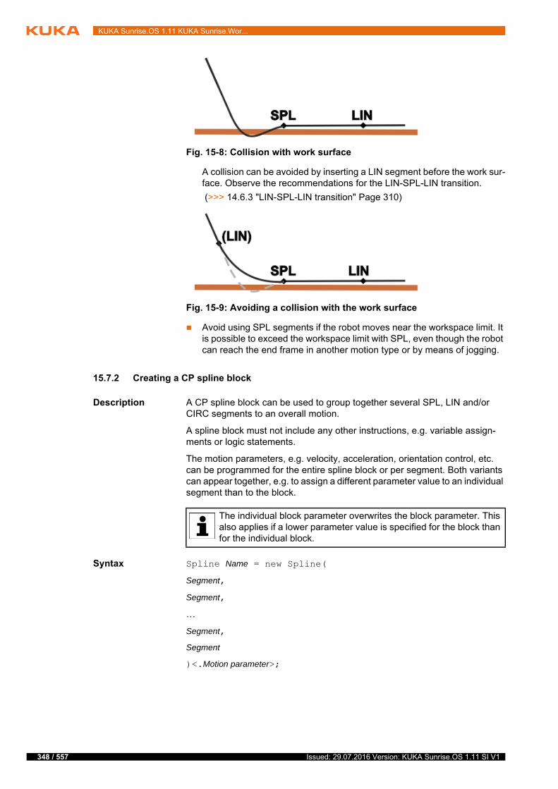
348 / 557
KUKA Sunrise.OS 1.11 KUKA Sunrise.Wor...
A collision can be avoided by inserting a LIN segment before the work sur-face. Observe the recommendations for the LIN-SPL-LIN transition.
(>>> 14.6.3 "LIN-SPL-LIN transition" Page 310)
Avoid using SPL segments if the robot moves near the workspace limit. It is possible to exceed the workspace limit with SPL, even though the robot can reach the end frame in another motion type or by means of jogging.
15.7.2 Creating a CP spline block
Description A CP spline block can be used to group together several SPL, LIN and/or CIRC segments to an overall motion.
A spline block must not include any other instructions, e.g. variable assign-ments or logic statements.
The motion parameters, e.g. velocity, acceleration, orientation control, etc. can be programmed for the entire spline block or per segment. Both variants can appear together, e.g. to assign a different parameter value to an individual segment than to the block.
Syntax Spline Name = new Spline(
Segment,
Segment,
…
Segment,
Segment
)<.Motion parameter>;
Fig. 15-8: Collision with work surface
Fig. 15-9: Avoiding a collision with the work surface
The individual block parameter overwrites the block parameter. This also applies if a lower parameter value is specified for the block than for the individual block.
Issued: 29.07.2016 Version: KUKA Sunrise.OS 1.11 SI V1
15 Programming
Explanation of
the syntax
Example
15.7.3 Creating a JP spline block
Description A JP spline block can be used to group together several PTP segments as an overall motion.
A spline block must not include any other instructions, e.g. variable assign-ments or logic statements.
The motion parameters, e.g. velocity, acceleration, etc. can be programmed for the entire spline block or per segment. Both variants can appear together, e.g. to assign a different parameter value to an individual segment than to the block.
Syntax SplineJP Name = new SplineJP(
Segment,
Segment,
…
Segment,
Segment
)<.Motion parameter>;
Explanation of
the syntax
Example
Element Description
Name Name of the spline block
Segment Motion with or without motion parameters
spl, lin or circ
Motion parameters
Motion parameters which are programmed at the end of the spline block apply to the entire spline block.
Spline mySpline = new Spline( spl(getApplicationData().getFrame("/P1")),
circ(getApplicationData().getFrame("/P2"),
getApplicationData().getFrame("/P3")),
spl(getApplicationData().getFrame("/P4")).setCartVelocity(150),
lin(getApplicationData().getFrame("/P5"))
).setCartVelocity(250);
The individual block parameter overwrites the block parameter. This also applies if a lower parameter value is specified for the block than for the individual block.
Element Description
Name Name of the spline block
Segment PTP motion with or without motion parameters
Motion parameters
Motion parameters which are programmed at the end of the spline block apply to the entire spline block.
SplineJP mySpline = new SplineJP( ptp(getApplicationData().getFrame("/P1")),
ptp(getApplicationData().getFrame("/P2"))
).setJointVelocityRel(0.75);
349 / 557Issued: 29.07.2016 Version: KUKA Sunrise.OS 1.11 SI V1
350 / 557
KUKA Sunrise.OS 1.11 KUKA Sunrise.Wor...
15.7.4 Using spline in a motion instruction
Description The spline motion programmed in a spline block is used as the motion type in the motion instruction.
Syntax Object.move(spline block);
Explanation of
the syntax
Example
15.8 Motion parameters
The required motion parameters can be added in any order to the motion in-struction. Dot separators and “set” methods are used for this purpose.
Overview
Element Description
Object Object of the station which is being moved
The variable name of the object declared and initialized in the application is specified here.
Spline block Name of the spline block
robot.move(mySpline);
Method Description
setCartVelocity(…) Absolute Cartesian velocity (type: double, unit: mm/s)
> 0.0
This value specifies the maximum Cartesian velocity at which the robot may move during the motion. Due to limitations in path planning, the maximum velocity may not be reached and the actual velocity may be lower.
If no velocity is specified, the motion is executed with the fastest possi-ble velocity.
Note: This parameter cannot be set for PTP motions.
setJointVelocity-Rel(…)
Axis-specific relative velocity (type: double, unit: %)
0.0 … 1.0
Refers to the maximum value of the axis velocity in the machine data.
(>>> 15.8.1 "Programming axis-specific motion parameters" Page 352)
setCartAccelera-tion(…)
Absolute Cartesian velocity (type: double, unit: mm/s2)
> 0.0
If no acceleration is specified, the motion is executed with the fastest possible acceleration.
Note: This parameter cannot be set for PTP motions.
setJointAcceleration-Rel(…)
Axis-specific relative acceleration (type: double, unit: %)
0.0 … 1.0
Refers to the maximum value of the axis acceleration in the machine data.
(>>> 15.8.1 "Programming axis-specific motion parameters" Page 352)
Issued: 29.07.2016 Version: KUKA Sunrise.OS 1.11 SI V1

15 Programming
setCartJerk(…) Absolute Cartesian jerk (type: double, unit: mm/s3)
> 0.0
If no jerk is specified, the motion is executed with the fastest possible change in acceleration.
Note: This parameter cannot be set for PTP motions.
setJointJerkRel(…) Axis-specific relative jerk (type: double, unit: %)
0.0 … 1.0
Refers to the maximum value of the axis-specific change in acceleration in the machine data.
(>>> 15.8.1 "Programming axis-specific motion parameters" Page 352)
setBlendingRel(…) Relative approximation distance (type: double)
0.0 … 1.0
The relative approximation distance is the furthest distance before the end point at which approximate positioning can begin. If “0.0” is set, the approximation parameter does not have any effect.
The maximum distance (= 1.0) is always the length of the individual motion or the length of the last segment in the case of splines. For motions which are not commanded within a spline, only the range between 0% and 50% is available for approximate positioning. In this case, if a value greater than 50% is parameterized, approximate posi-tioning nevertheless begins at 50% of the block length.
setBlendingCart(…) Absolute approximation distance (type: double, unit: mm)
≥ 0.0
The absolute approximation distance is the furthest distance before the end point at which approximate positioning can begin. If “0.0” is set, the approximation parameter does not have any effect.
setBlendingOri(…) Orientation parameter for approximate positioning (type: double, unit: rad)
≥ 0.0
Approximation starts, at the earliest, when the absolute difference of the dominant orientation angle for the end orientation falls below the value set here. If “0.0” is set, the approximation parameter does not have any effect.
setOrientation-Type(…)
Orientation control (type: Enum)
Constant
Ignore
OriJoint
VariableOrientation (default)
(>>> 14.9 "Orientation control with LIN, CIRC, SPL" Page 314)
setOrientationRefer-enceSystem(…)
Only relevant for CIRC motions: Reference system of orientation control (type: Enum)
Base
Path
(>>> 14.9.1 "CIRC – reference system for the orientation control" Page 316)
Method Description
351 / 557Issued: 29.07.2016 Version: KUKA Sunrise.OS 1.11 SI V1

352 / 557
KUKA Sunrise.OS 1.11 KUKA Sunrise.Wor...
15.8.1 Programming axis-specific motion parameters
Description The following axis-specific motion parameters can be programmed:
Relative velocity setJointVelocityRel(…)
Relative acceleration setJointAccelerationRel(…)
Relative jerk setJointJerkRel(…)
There are various ways of specifying these axis-specific relative values. A val-id value for all axes, different values for each individual axis or a value for an individual axis.
By way of example, these possibilities are described using the relative veloci-ty:
setJointVelocityRel(Value)
If a value of type double is transferred, the relative velocity applies to all axes.
setJointVelocityRel(Array_variable)
In order to assign each axis its own relative velocity, a double array is transferred with the corresponding axis values. In an array, the axis values of up to 12 axes can be defined, beginning with axis A1.
setJointVelocityRel(Axis, Value)
To specify the relative velocity of an individual axis, this axis is transferred as JointEnum.
Examples All axes move at 50% of maximum velocity:
Axis A5 moves at 50%, all other axes move at 20% of maximum velocity:
Axis A4 moves at 50% of maximum velocity, all other axes move at maximum velocity:
15.9 Programming manual guidance
Description The robot can be guided using a hand guiding device. Manual guidance mode can be switched on in the application using the motion command handGuid-ing(). Manual guidance begins at the actual position which was reached before the mode was switched on.
If Manual guidance mode is used in the application, at least 2 ESM states must be configured:
ESM state for manual guidance motion
The ESM state contains the AMF Hand guiding device enabling inactive, which checks whether the enabling signal has not been issued on the hand guiding device.
(>>> 13.10.5 "Manual guidance with enabling device and velocity moni-toring" Page 236)
It is advisable to configure a safety stop 1 (path-maintaining) as the stop reaction for the AMF Hand guiding device enabling inactive. Following a
robot.move(ptp(getApplicationData().getFrame("/P1"))
.setJointVelocityRel(0.5));
double[] velRelJoints = {0.2, 0.2, 0.2, 0.2, 0.5, 0.2, 0.2};robot.move(ptp(getApplicationData().getFrame("/P1"))
.setJointVelocityRel(velRelJoints));
robot.move(ptp(getApplicationData().getFrame("/P1"))
.setJointVelocityRel(JointEnum.J4, 0.5));
Issued: 29.07.2016 Version: KUKA Sunrise.OS 1.11 SI V1
15 Programming
path-maintaining stop, the application can be resumed directly by pressing the Start key.
If a non-path-maintaining stop reaction is configured for the AMF Hand guiding device enabling inactive, the robot must first be repositioned fol-lowing manual guidance before the application can be resumed.
ESM state for all motions except manual guidance motion
The ESM state does not contain the AMF Hand guiding device enabling inactive. The signal at the hand guiding device is not evaluated.
In the application, motions before and after manual guidance are generally re-quired. It is advisable to monitor each of these motions using an ESM state which does not evaluate the signal on the hand guiding device, and to only switch to the ESM state for the manual guidance motion directly before switch-ing to Manual guidance mode. If this is carried out in the application in this manner, the response is as follows:
If the signal for manual guidance is issued before Manual guidance mode is switched on in the application, Manual guidance mode will be active as soon as it is switched on. This means that the application is not paused when the mode is switched on, making for a smooth transition between Application mode and Manual guidance mode.
Precondition for this response: the application velocity is less than the maximum permissible velocity configured for manual guidance.
(>>> 13.10.5.3 "Velocity monitoring during manual guidance" Page 238)
If the application is executed at a higher velocity, the application is paused before switching to manual guidance mode. (Then release the enabling switch, press the Start key and wait until the application is paused again.)
If the signal for manual guidance is first issued when Manual guidance mode is already switched on in the application, the Start key must be pressed in order to manually guide the robot. The pause in the application allows the operator to move his hand to the hand guiding device.
Manual guidance mode has ended when the signal for manual guidance has been cancelled, e.g. by releasing the enabling switch. The application is paused and can only be resumed by pressing the Start key. The pause in the application allows the operator to remove his hand from the hand guiding device.
A risk assessment must determine whether it is permissible to config-ure a path-maintaining stop reaction for the EMS state which monitors the enabling switch on the hand guiding device.
If, when switching to Manual guidance mode, the appli-cation is in an ESM state which does not contain a Hand
guiding device enabling inactive AMF, the robot can nevertheless be manu-ally guided in one situation: the enabling switch on the hand guiding device is pressed and a Hand guiding device enabling inactive AMF is configured in any other ESM state or in the PSM table.This combination must be avoided under all circumstances: in a situation like this, the application is not paused when manual guidance is terminated and the enabling switch on the hand guiding device is released. Instead, the ap-plication is resumed without any further operator actions. If further motions follow manual guidance, these are executed directly while the operator’s hand is still on the hand guiding device and thus within the robot’s motion range.
Switching between ESM states is effected via non-safety-oriented signals. For this reason, it must be ensured that the defined ESM state always assures a sufficient degree of safety, regardless of the
time or place of activation. (>>> 13.2 "Safety concept" Page 203)
353 / 557Issued: 29.07.2016 Version: KUKA Sunrise.OS 1.11 SI V1

354 / 557
KUKA Sunrise.OS 1.11 KUKA Sunrise.Wor...
Preparation The handGuiding() motion command belongs to the HRCMotions class. The class must be manually inserted into the import section of the robot applica-tion. The following line must be programmed:
Syntax Object.move(handGuiding());
Explanation of
the syntax
Example
15.9.1 Axis-specific limits for manual guidance
Description The axis range of each axis is limited by means of software limit switches. For manual guidance, user-specific axis limits can additionally be defined in the ro-bot application.
Defining a lower and an upper axis limit results in a permissible axis range, in which manual guidance is freely possible, and 2 non-permissible axis ranges between the upper/lower axis limit and the respective software limit switch.
import static com.kuka.roboticsAPI.motionModel.HRCMotions.*;
To enable the HRCMotions class to be integrated, the catalog ele-ment Manual guidance support must be selected in the station con-figuration (Software tab).
Element Description
Object Object of the station which is being moved
The variable name of the object declared and initialized in the application is specified here.
1 robot.setESMState("1");
2 robot.move(ptp(getApplicationData().getFrame("/P1")));
3 robot.setESMState("2");
4 robot.move(handGuiding());
5 robot.setESMState("1");
6 robot.move(ptp(getApplicationData().getFrame("/P2")));
Line Description
1 ESM state 1 is activated for the robot. In this example, ESM state 1 monitors the operator safety.
2 Frame "/P1" is addressed with a PTP motion.
3 ESM state 2 is activated for the robot. ESM state 2 monitors the enabling switch on the hand guiding device.
If a signal has not yet been issued via the switch, the config-ured stop reaction is triggered and the application is paused.
4 Manual guidance mode is activated.
The robot can be guided manually as soon as the enabling switch on the hand guiding device is pressed and held in the center position.
When the signal for manual guidance has been cancelled, e.g. by releasing the enabling switch, Manual guidance mode has ended. The stop reaction configured for ESM state 2 is trig-gered and motion execution is paused.
5 ESM state 1 is activated for the robot. In this example, ESM state 1 monitors the operator safety.
Motion execution remains paused. The Start key must be pressed in order to resume the application.
6 Frame "/P2" is addressed with a PTP motion.
Issued: 29.07.2016 Version: KUKA Sunrise.OS 1.11 SI V1
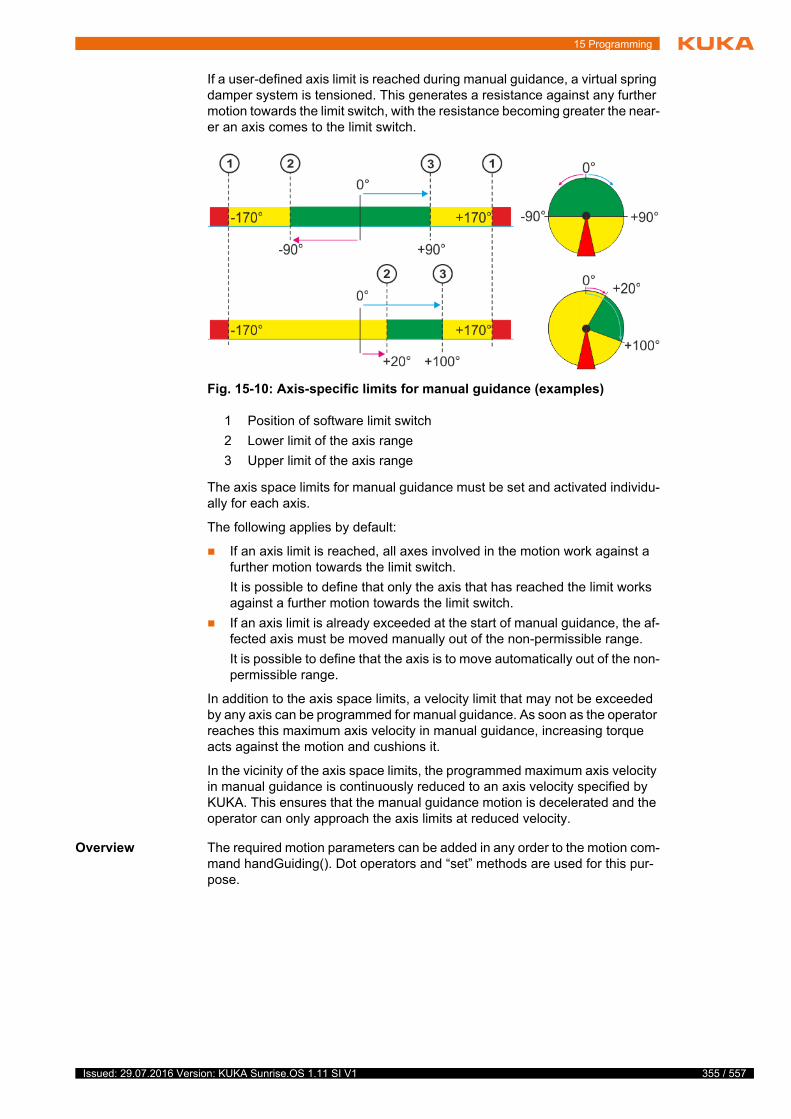
15 Programming
If a user-defined axis limit is reached during manual guidance, a virtual spring damper system is tensioned. This generates a resistance against any further motion towards the limit switch, with the resistance becoming greater the near-er an axis comes to the limit switch.
The axis space limits for manual guidance must be set and activated individu-ally for each axis.
The following applies by default:
If an axis limit is reached, all axes involved in the motion work against a further motion towards the limit switch.
It is possible to define that only the axis that has reached the limit works against a further motion towards the limit switch.
If an axis limit is already exceeded at the start of manual guidance, the af-fected axis must be moved manually out of the non-permissible range.
It is possible to define that the axis is to move automatically out of the non-permissible range.
In addition to the axis space limits, a velocity limit that may not be exceeded by any axis can be programmed for manual guidance. As soon as the operator reaches this maximum axis velocity in manual guidance, increasing torque acts against the motion and cushions it.
In the vicinity of the axis space limits, the programmed maximum axis velocity in manual guidance is continuously reduced to an axis velocity specified by KUKA. This ensures that the manual guidance motion is decelerated and the operator can only approach the axis limits at reduced velocity.
Overview The required motion parameters can be added in any order to the motion com-mand handGuiding(). Dot operators and “set” methods are used for this pur-pose.
Fig. 15-10: Axis-specific limits for manual guidance (examples)
1 Position of software limit switch
2 Lower limit of the axis range
3 Upper limit of the axis range
355 / 557Issued: 29.07.2016 Version: KUKA Sunrise.OS 1.11 SI V1

356 / 557
KUKA Sunrise.OS 1.11 KUKA Sunrise.Wor...
Example
Method Description
setAxisLimitsEnabled(…)
Activation of the user-specific axis limits for manual guidance (type: boolean[])
true: Axis limit active
false: Axis limit not active
Note: This method refers to the limits that the user can set using the methods setAxisLimitsMax(…) and setAxisLimitsMin(…). The outermost axis limits of the robot (software limit switches) are always monitored.
setAxisLimitsMax(…) Upper axis limits (type: double[]; unit: rad)
setAxisLimitsMin(…) Lower axis limits (type: double[]; unit: rad)
Note: The lower axis limit must always be lower than the corresponding upper axis limit.
setAxisLimitViolationFreezesAll(…)
Response if an axis limit is reached (type: boolean)
true: If an axis limit is reached, all axes involved in the motion work against a further motion towards the limit switch.
false: If an axis limit is reached, only the affected axis works against a further motion towards the limit switch.
Default: true
If this value is not set, the default value is automatically applied.
setAxisSpeedLimit(…)
Velocity limitation for all axes (type: double; unit: rad/s)
≥ 0.0
setPermanentPullOnViolationAtStart(…)
Response if an axis limit is already exceeded at the start of manual guid-ance (type: boolean)
true: When the enabling signal for manual guidance is issued, the axis is moved automatically out of the non-permissible range. When the permissible range is reached, the motion is stopped automatical-ly.
false: When the enabling signal for manual guidance is issued, the axis does not move. It must be moved out of the non-permissible range manually.
Default: false
If this value is not set, the default value is automatically applied.
@Inject
private LBR robot;private HandGuidingMotion motion;// ...
motion = handGuiding()
.setAxisLimitsMax(+1.407, +0.872, +0.087, -0.785, +0.087,
+1.571, +0.087)
.setAxisLimitsMin(-1.407, +0.175, -0.087, -1.571, -0.087,
-1.571, -0.087)
.setAxisLimitsEnabled(false, true, false, true, false, true, false) .setAxisSpeedLimit(0.5)
.setAxisLimitViolationFreezesAll(true) .setPermanentPullOnViolationAtStart(true);
robot.move(motion);
Issued: 29.07.2016 Version: KUKA Sunrise.OS 1.11 SI V1
15 Programming
15.10 Using tools and workpieces in the program
An application consitutes a programmed model of a real station and must therefore contain all movable objects and fixed geometric objects in the sta-tion. Examples of movable objects for a station are robots, tools and workpiec-es. Examples of fixed objects are support tables or conveyors.
Robots are automatically declared and initialized when the robot application is created. Tools and workpieces used in the robot application must be integrat-ed using dependency injection.
Tools and workpieces with load data and geometric data are created and man-aged in the Object templates view.
(>>> 9.3 "Object management" Page 148)
Data types The data types for the objects in a station are predefined in the RoboticsAPI, e.g.:
15.10.1 Integrating tools and workpieces
Description Tools and workpieces created in the object templates can be integrated into robot applications and background tasks using dependency injection. The name of the template is specified by means of an additional annotation.
Syntax @Inject
@Named("Template name")
private Data type Object name;
Explanation of
the syntax
Example Tools and workpieces in the object templates:
Data type Object
Controller Robot controller
LBR Lightweight robot
Tool Tool
Workpiece Workpiece
Element Description
@Inject Annotation for integrating resources by means of depen-dency injection
@Named Annotation for specifying the object template to be used
Template name
Name of the object template as specified in the Object templates view
private The keyword designates locally valid variables. Locally valid means that the data array can only be used by the corresponding class.
Data type Class of the resource (Tool or Workpiece) that is to be inte-grated
Object name Name of the identifier, as it is to be used in the application
The annotation @Named may be omitted for tools if there is only one single object template for a tool. The annotation is always required for workpieces.
357 / 557Issued: 29.07.2016 Version: KUKA Sunrise.OS 1.11 SI V1

358 / 557
KUKA Sunrise.OS 1.11 KUKA Sunrise.Wor...
Declaration of the objects in the robot application:
15.10.2 Attaching tools and workpieces to the robot
In order to be able to use tools and workpieces as movable objects in motion instructions, they must be attached to the robot in the application via the meth-od attachTo(…).
Tools are directly or indirectly attached to the robot flange.
Workpieces are indirectly attached to the robot via a tool or another work-piece.
As soon as a tool or workpiece is attached to the robot via the method attach-To(…), the load data from the robot controller are taken into account. In addi-tion, all frames of the attached object can be used for the motion programming.
(>>> 9.3.8 "Load data" Page 153)
15.10.2.1Attaching a tool to the robot flange
Description Via the method attachTo(…), the origin frame of a tool is attached to the flange of a robot used in the application. The robot flange is accessed via the method getFlange().
Syntax Tool.attachTo(Robot.getFlange());
Fig. 15-11: Object templates
public class ExampleApplication extends RoboticsAPIApplication { @Inject
@Named("Gripper")
private Tool gripper;
@Inject
@Named("GuidingTool")
private Tool guidingTool;
@Inject
@Named("Pen")
private Workpiece pen;
@Override
public void initialize() { // initialize your application here
}
@Override
public void run() { // your application execution starts here
}
}
Issued: 29.07.2016 Version: KUKA Sunrise.OS 1.11 SI V1
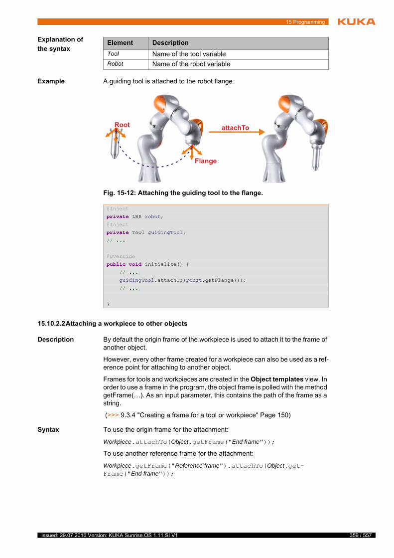
15 Programming
Explanation of
the syntax
Example A guiding tool is attached to the robot flange.
15.10.2.2Attaching a workpiece to other objects
Description By default the origin frame of the workpiece is used to attach it to the frame of another object.
However, every other frame created for a workpiece can also be used as a ref-erence point for attaching to another object.
Frames for tools and workpieces are created in the Object templates view. In order to use a frame in the program, the object frame is polled with the method getFrame(…). As an input parameter, this contains the path of the frame as a string.
(>>> 9.3.4 "Creating a frame for a tool or workpiece" Page 150)
Syntax To use the origin frame for the attachment:
Workpiece.attachTo(Object.getFrame("End frame"));
To use another reference frame for the attachment:
Workpiece.getFrame("Reference frame").attachTo(Object.get-Frame("End frame"));
Element Description
Tool Name of the tool variable
Robot Name of the robot variable
Fig. 15-12: Attaching the guiding tool to the flange.
@Inject
private LBR robot;@Inject
private Tool guidingTool;// ...
@Override
public void initialize() { // ...
guidingTool.attachTo(robot.getFlange());
// ...
}
359 / 557Issued: 29.07.2016 Version: KUKA Sunrise.OS 1.11 SI V1
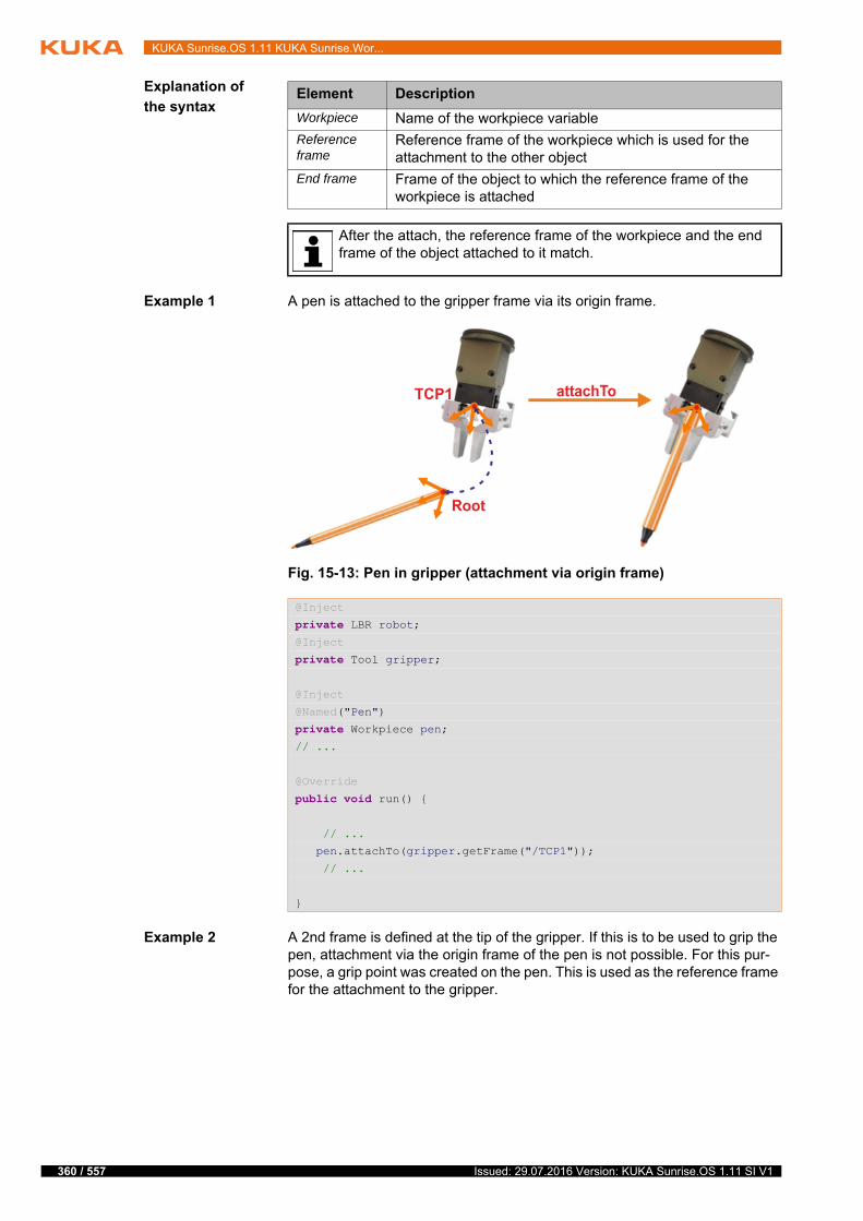
360 / 557
KUKA Sunrise.OS 1.11 KUKA Sunrise.Wor...
Explanation of
the syntax
Example 1 A pen is attached to the gripper frame via its origin frame.
Example 2 A 2nd frame is defined at the tip of the gripper. If this is to be used to grip the pen, attachment via the origin frame of the pen is not possible. For this pur-pose, a grip point was created on the pen. This is used as the reference frame for the attachment to the gripper.
Element Description
Workpiece Name of the workpiece variable
Reference frame
Reference frame of the workpiece which is used for the attachment to the other object
End frame Frame of the object to which the reference frame of the workpiece is attached
After the attach, the reference frame of the workpiece and the end frame of the object attached to it match.
Fig. 15-13: Pen in gripper (attachment via origin frame)
@Inject
private LBR robot;@Inject
private Tool gripper;
@Inject
@Named("Pen")
private Workpiece pen;// ...
@Override
public void run() {
// ...
pen.attachTo(gripper.getFrame("/TCP1"));
// ...
}
Issued: 29.07.2016 Version: KUKA Sunrise.OS 1.11 SI V1
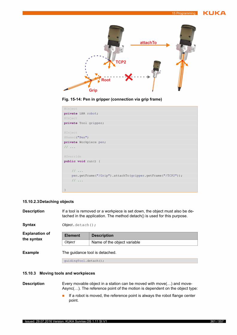
15 Programming
15.10.2.3Detaching objects
Description If a tool is removed or a workpiece is set down, the object must also be de-tached in the application. The method detach() is used for this purpose.
Syntax Object.detach();
Explanation of
the syntax
Example The guidance tool is detached.
15.10.3 Moving tools and workpieces
Description Every movable object in a station can be moved with move(…) and move-Async(…). The reference point of the motion is dependent on the object type:
If a robot is moved, the reference point is always the robot flange center point.
Fig. 15-14: Pen in gripper (connection via grip frame)
@Inject
private LBR robot;@Inject
private Tool gripper;
@Inject
@Named("Pen")
private Workpiece pen;// ...
@Override
public void run() {
// ...
pen.getFrame("/Grip").attachTo(gripper.getFrame("/TCP2"));
// ...
}
Element Description
Object Name of the object variable
guidingTool.detach();
361 / 557Issued: 29.07.2016 Version: KUKA Sunrise.OS 1.11 SI V1
362 / 557
KUKA Sunrise.OS 1.11 KUKA Sunrise.Wor...
If a tool or workpiece is moved, the reference point is by default the default motion frame which was defined for this object in the Object templates view.
(>>> 9.3.7 "Defining a default motion frame" Page 152)
In this case, the tool or workpiece is linked directly to the motion command via the variable name declared in the application.
However, any other frame created for a tool or workpiece can also be pro-grammed as a reference point of the motion.
In this case, using the method getFrame(…), the path to the frame of the object used for the motion must be specified (on the basis of the origin frame of the object).
Syntax To use the default frame of the object for the motion:
Object.move(Motion);
To use a different frame of the object for the motion:
Object.getFrame("Moved frame").move(Motion));
Explanation of
the syntax
Examples The PTP motion to point P1 is executed with the default frame of the gripper.
The PTP motion to point P1 is executed with a different frame than the default frame of the gripper, here TCP1:
A pen is gripped. The next motion is a PTP motion to point P20. This point is executed with the default frame of the workpiece “pen”.
15.10.4 Integrating dedicated object classes with dependency injection
Description Tools and workpieces created in the object templates are based on the class-es Tool and Workpiece. Specific properties or functions that tools and work-pieces generally have are not considered by these basic classes. For a gripper, examples might include functions for opening and closing.
Such specific object properties and functions can be defined in separate object classes. The following steps are required in order to be able to use the user-defined object classes in the same way as the basic classes in applications:
Element Description
Object Object of the station which is being moved
The variable name of the object declared and initialized in the application is specified here.
Moved frame Path to the frame of the object which is used for the motion
Motion Motion which is being executed
gripper.attachTo(robot.getFlange());
gripper.move(ptp(getApplicationData().getFrame("/P1")));
gripper.attachTo(robot.getFlange());
gripper.getFrame("/TCP1").move(ptp(getApplicationData().getFrame("/P1")));
gripper.attachTo(robot.getFlange());
// ...
pen.attachTo(gripper.getFrame("/TCP1"));
pen.move(ptp(getApplicationData().getFrame("/P20"));
Issued: 29.07.2016 Version: KUKA Sunrise.OS 1.11 SI V1

15 Programming
Singletons Object classes that are derived from Tool and used in a Sunrise project as de-scribed here are always integrated as singletons. This means that each object annotated with the type of the object class refers to the same instance.
By default, object classes that are derived from Workpiece are not singletons. When annotating, a new instance is therefore created every time. Workpieces can be made singletons by placing the annotation @Singleton before the header of the class.
Procedure Derive a new object class from a basic class:
1. Select the desired Sunrise project in the Package Explorer.
2. Select the menu sequence File > New > Class. The New Java class win-dow opens.
3. In the Package: box, enter a name for the Java package in which the new class is to be created.
4. Enter a name for the new class in the Name box.
5. To the right of the Superclass: box, click on Browse.... The Superclass selection window is opened.
6. Enter the name of the basic class in the Select type box (Tool or Work-piece).
Step Description
1 Derive a new object class from a suitable basic class:
Basic class for tools:
com.kuka.roboticsAPI.geometricModel.Tool
Basic class for workpieces:
com.kuka.roboticsAPI.geometricModel.Workpiece
The constructor of the created object class must have the fol-lowing properties:
Visibility level public
Transfer parameter of type String (name of the object tem-plate is transferred)
Must not be annotated with @Inject
2 Define object properties and functions in the new object class.
3 In the object templates, assign the new object class to the desired objects. For this, enter the full identifier (Package name.Class name) of the object class under Template class in the Properties view.
Note: Object templates that use an object class derived from a basic class are integrated into an application such as this by means of dependency injection.
Entering the object class as a template in the properties is especially important because the load data of the templates are then automati-cally assigned to the integrated object. If this is not done, the object
class behaves like a specially created class without dependencies. (>>> 15.3.3.2 "Dependency injection for dedicated types" Page 339)If the load data are required for motions (e.g. for a robot under impedance control), this can result in unexpected motions of the robot.
Dependency injection can also be used in dedicated classes. For ex-ample, the ITaskLogger can be integrated in order to display output information on the smartHMI.
363 / 557Issued: 29.07.2016 Version: KUKA Sunrise.OS 1.11 SI V1

364 / 557
KUKA Sunrise.OS 1.11 KUKA Sunrise.Wor...
7. Confirm the selection with OK. The name of the basic class is now dis-played in the Superclass: box.
8. Click on Finish. The Java package with the newly created class is inserted into the source folder of the Sunrise project and opened in the editor area.
9. Create a constructor with the desired properties.
10. The required arrays and methods can now be defined.
Example Step 1:
For a gripper, the object class Gripper is created using the procedure de-scribed above. The class Gripper is derived from the basic class Tool and ex-pands the basic class to include the functions for opening and closing the gripper.
Step 2:
An object template with the name “ExampleGripper” is created for the gripper. The object class Gripper is assigned to the object template:
Entry under Template class in the Properties view: tools.Gripper
The name of the Java package (here “tools”) that contains the class Grip-per must be specified.
Step 3:
1 package tools;2 import com.kuka.roboticsAPI.geometricModel.Tool;3 public class Gripper extends Tool {4 @Inject
5 private ITaskLogger logger;6
7 public Gripper(String name) {8 super(name);9 }
10
11 /**
12 * Opens the gripper
13 */
14 public void openGripper(){15 // ...
16 logger.info("Gripper is open.");
17 }
18
19 /**
20 * Closes the gripper
21 */
22 public void closeGripper(){23 // ...
24 logger.info("Gripper is closed.");
25 }
26 }
Line Description
1 Name of the Java package that contains the class Gripper
4 … 5 Integration of the ITaskLogger interface by means of depen-dency injection
7 … 9 Standard constructor of the class Gripper (adopted from Tool)
14 … 11 Method openGripper() for opening the gripper
22 … 25 Method closeGripper() for closing the gripper
16, 24 Information displayed on smartHMI with the aid of the ITask-Logger interface
Issued: 29.07.2016 Version: KUKA Sunrise.OS 1.11 SI V1

15 Programming
The object class Gripper and the corresponding functions can be used in the robot application.
15.10.5 Commanding load changes to the safety controller
Description The safety controller requires the load data of a workpiece for calculation of the external torques. The safety controller can only process the load data of safety-oriented workpieces.
(>>> 9.3.10 "Safety-oriented workpieces" Page 158)
During a process, picking up and setting down different workpieces can result in load changes. During collision detection, the user must explicitly inform the safety controller via the method setSafetyWorkpiece(…) which safety-oriented workpiece is currently activated. For this purpose, this workpiece is transferred as an input parameter.
The setSafetyWorkpiece(…) method belongs to the LBR class and can be used in both robot applications and background tasks. A precondition for the transfer of a safety-oriented workpiece to the method is that an instance of the workpiece has been created from the object templates.
(>>> 15.10.1 "Integrating tools and workpieces" Page 357)
1 public class ExampleApplication extends RoboticsAPIApplication {2 @Inject
3 private LBR robot;4 @Inject
5 private Gripper gripper;6
7 @Override
8 public void initialize() {9 // initialize your application here
10 // ...
11 gripper.attachTo(robot.getFlange());
12 // ...
13 }
14
15 @Override
16 public void run() {17 // your application execution starts here
18 // ...
19 gripper.openGripper();
20 gripper.move(lin(getFrame("/GripPos")));
21 gripper.closeGripper();
22 // ...
23 }
24 }
Line Description
4 … 5 A tool of type Gripper is integrated.
The tool has the functions defined in the object class Gripper.
11 The tool is attached to the robot flange.
19 … 21 The functions defined in the object class Gripper are used to program a gripping process:
Open gripper, move to grip position, close gripper.
Only a safety-oriented workpiece may be transferred to setSafety-Workpiece(…) . If a non-safety-oriented workpiece is transferred, an exceptional error occurs.
365 / 557Issued: 29.07.2016 Version: KUKA Sunrise.OS 1.11 SI V1
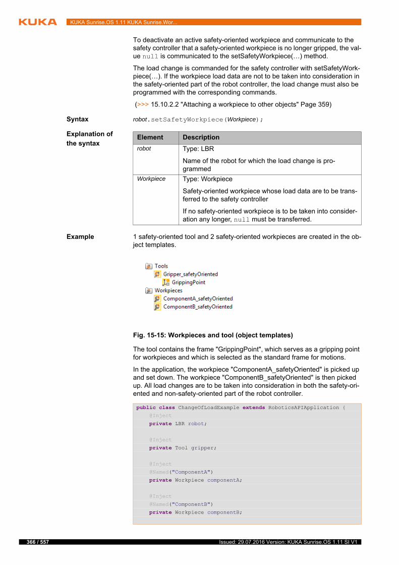
366 / 557
KUKA Sunrise.OS 1.11 KUKA Sunrise.Wor...
To deactivate an active safety-oriented workpiece and communicate to the safety controller that a safety-oriented workpiece is no longer gripped, the val-ue null is communicated to the setSafetyWorkpiece(…) method.
The load change is commanded for the safety controller with setSafetyWork-piece(…). If the workpiece load data are not to be taken into consideration in the safety-oriented part of the robot controller, the load change must also be programmed with the corresponding commands.
(>>> 15.10.2.2 "Attaching a workpiece to other objects" Page 359)
Syntax robot.setSafetyWorkpiece(Workpiece);
Explanation of
the syntax
Example 1 safety-oriented tool and 2 safety-oriented workpieces are created in the ob-ject templates.
The tool contains the frame "GrippingPoint", which serves as a gripping point for workpieces and which is selected as the standard frame for motions.
In the application, the workpiece "ComponentA_safetyOriented" is picked up and set down. The workpiece "ComponentB_safetyOriented" is then picked up. All load changes are to be taken into consideration in both the safety-ori-ented and non-safety-oriented part of the robot controller.
Element Description
robot Type: LBR
Name of the robot for which the load change is pro-grammed
Workpiece Type: Workpiece
Safety-oriented workpiece whose load data are to be trans-ferred to the safety controller
If no safety-oriented workpiece is to be taken into consider-ation any longer, null must be transferred.
Fig. 15-15: Workpieces and tool (object templates)
public class ChangeOfLoadExample extends RoboticsAPIApplication { @Inject
private LBR robot;
@Inject
private Tool gripper;
@Inject
@Named("ComponentA")
private Workpiece componentA;
@Inject
@Named("ComponentB")
private Workpiece componentB;
Issued: 29.07.2016 Version: KUKA Sunrise.OS 1.11 SI V1
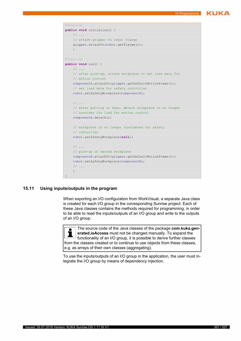
15 Programming
15.11 Using inputs/outputs in the program
When exporting an I/O configuration from WorkVisual, a separate Java class is created for each I/O group in the corresponding Sunrise project. Each of these Java classes contains the methods required for programming, in order to be able to read the inputs/outputs of an I/O group and write to the outputs of an I/O group.
To use the inputs/outputs of an I/O group in the application, the user must in-tegrate the I/O group by means of dependency injection.
@Override
public void initialize() { // ...
// attach gripper to robot flange
gripper.attachTo(robot.getFlange());
}
@Override
public void run() { // ...
// after pick-up, attach workpiece to set load data for
// motion control
componentA.attachTo(gripper.getDefaultMotionFrame());
// set load data for safety controller
robot.setSafetyWorkpiece(componentA);
// ...
// after putting it down, detach workpiece to no longer
// consider its load for motion control
componentA.detach();
// workpiece is no longer considered for safety
// controller
robot.setSafetyWorkpiece(null);
// ...
// pick-up of second workpiece
componentB.attachTo(gripper.getDefaultMotionFrame());
robot.setSafetyWorkpiece(componentB);
// ...
}
}
The source code of the Java classes of the package com.kuka.gen-erated.ioAccess must not be changed manually. To expand the functionality of an I/O group, it is possible to derive further classes
from the classes created or to continue to use objects from these classes, e.g. as arrays of their own classes (aggregating).
367 / 557Issued: 29.07.2016 Version: KUKA Sunrise.OS 1.11 SI V1
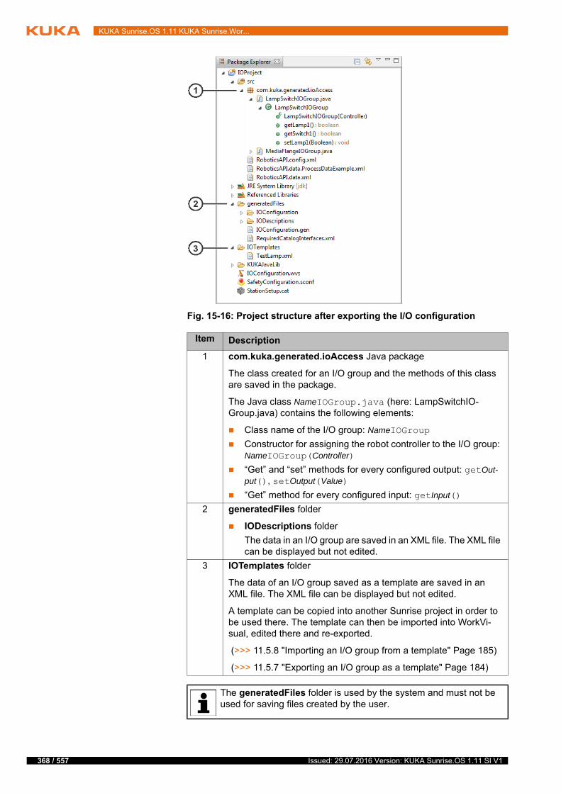
368 / 557
KUKA Sunrise.OS 1.11 KUKA Sunrise.Wor...
Fig. 15-16: Project structure after exporting the I/O configuration
Item Description
1 com.kuka.generated.ioAccess Java package
The class created for an I/O group and the methods of this class are saved in the package.
The Java class NameIOGroup.java (here: LampSwitchIO-Group.java) contains the following elements:
Class name of the I/O group: NameIOGroup
Constructor for assigning the robot controller to the I/O group: NameIOGroup(Controller)
“Get” and “set” methods for every configured output: getOut-put(), setOutput(Value)
“Get” method for every configured input: getInput()
2 generatedFiles folder
IODescriptions folder
The data in an I/O group are saved in an XML file. The XML file can be displayed but not edited.
3 IOTemplates folder
The data of an I/O group saved as a template are saved in an XML file. The XML file can be displayed but not edited.
A template can be copied into another Sunrise project in order to be used there. The template can then be imported into WorkVi-sual, edited there and re-exported.
(>>> 11.5.8 "Importing an I/O group from a template" Page 185)
(>>> 11.5.7 "Exporting an I/O group as a template" Page 184)
The generatedFiles folder is used by the system and must not be used for saving files created by the user.
Issued: 29.07.2016 Version: KUKA Sunrise.OS 1.11 SI V1
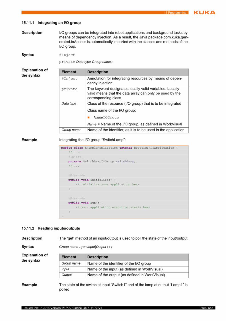
15 Programming
15.11.1 Integrating an I/O group
Description I/O groups can be integrated into robot applications and background tasks by means of dependency injection. As a result, the Java package com.kuka.gen-erated.ioAccess is automatically imported with the classes and methods of the I/O group.
Syntax @Inject
private Data type Group name;
Explanation of
the syntax
Example Integrating the I/O group “SwitchLamp”:
15.11.2 Reading inputs/outputs
Description The “get” method of an input/output is used to poll the state of the input/output.
Syntax Group name.getInput|Output();
Explanation of
the syntax
Example The state of the switch at input “Switch1” and of the lamp at output “Lamp1” is polled.
Element Description
@Inject Annotation for integrating resources by means of depen-dency injection
private The keyword designates locally valid variables. Locally valid means that the data array can only be used by the corresponding class.
Data type Class of the resource (I/O group) that is to be integrated
Class name of the I/O group:
NameIOGroup
Name = Name of the I/O group, as defined in WorkVisual
Group name Name of the identifier, as it is to be used in the application
public class ExampleApplication extends RoboticsAPIApplication { // ...
@Inject
private SwitchLampIOGroup switchLamp; // ...
@Override
public void initialize() { // initialize your application here
}
@Override
public void run() { // your application execution starts here
}
}
Element Description
Group name Name of the identifier of the I/O group
Input Name of the input (as defined in WorkVisual)
Output Name of the output (as defined in WorkVisual)
369 / 557Issued: 29.07.2016 Version: KUKA Sunrise.OS 1.11 SI V1

370 / 557
KUKA Sunrise.OS 1.11 KUKA Sunrise.Wor...
15.11.3 Setting outputs
Description The “set” method of an output is used to change the value of the output.
Syntax Group name.setOutput(Value);
Explanation of
the syntax
Example The lamp at output “Lamp1” is switched on and then switched off after 2000 ms.
public void run() { // ...
switchLamp.getLamp1();
switchLamp.getSwitch1();
// ...
}
Outputs are switched in certain situations although a safety-oriented stop request is present (e.g. in the case
of a pressed EMERGENCY STOP or violated space monitoring). This can cause unexpected motions of the connected periphery (e.g opening of a grip-per).The following situations can now occur:
Background task switches output.
Function called via user key switches output.
Robot applications continue running to the next synchronous motion command after a stop request. The code executed up to that point switches the output.
The behavior described can also be desirable; however, there must never be any danger to human and machine. This must be ensured by the system in-tegrator, e.g. by means of de-energizing outputs with hazard potential.
It is not permissible to set outputs in a robot application that signal system states to the external controller. Fail-
ure to observe this precaution may result in malfunctioning of the external controller and damage to property.
No “set” methods are available for inputs. They can only be read.
Element Description
Group name Name of the identifier of the I/O group
Output Name of the output (as defined in WorkVisual)
Value Value of the output
The data type of the value to be transferred depends on the output type.
public void run() { // ...
switchLamp.setLamp1(true); ThreadUtil.milliSleep(2000);
switchLamp.setLamp1(false); // ...
}
Issued: 29.07.2016 Version: KUKA Sunrise.OS 1.11 SI V1

15 Programming
15.12 Polling axis torques
Description Certain robot types, e.g. the LBR iiwa, have a joint torque sensor in each axis which measures the torque acting on the axis. The interface ITorqueSensiti-veRobot contains the methods required for polling sensor data from the robot.
getMeasuredTorque()
The measured torque values can be polled and evaluated in the applica-tion via the method getMeasuredTorque().
getExternalTorque()
Frequently, it is not the pure measured values which are of interest but rather only the externally acting torques, without the component resulting from the weight of the robot and mass inertias during motion. These values are referred to as external torques. These external torques be accessed via the method getExternalTorque().
getSingleTorqueValue(…), getTorqueValues()
The methods getMeasuredTorque() and getTorqueValues() return an ob-ject of the type TorqueSensorData containing the torque sensor data of all axes. From this object, it is then possible to poll either all values as an ar-ray with getTorqueValues(…) or a single axis value with getSingle-TorqueValue(…).
Syntax To poll the measured sensor data:
TorqueSensorData measuredData = robot.getMeasuredTorque();
To poll externally acting torque data:
TorqueSensorData externalData = robot.getExternalTorque();
To poll torque values of all axes from the sensor data:
double[] allValues = measuredData|externalData.getTorqueValues();
To poll torque values of a specific axis from the sensor data:
double singleValue = measuredData|externalData.getSingleTorqueValues(joint);
Explanation of
the syntax
In order to be able to display external torques correctly, the load mounted on the robot must be configured correctly and communicat-ed to the system.
When polling the torque sensor data with Java, no real-time behavior is available. This means that the data supplied by the system in the program were already created several milliseconds earlier.
Element Description
measuredData
Type: TorqueSensorData
Variable for the return value of getMeasuredTorque(). The return value contains the measured sensor data.
externalData Type: TorqueSensorData
Variable for the return value of getExternalTorque(). The return value contains the externally acting torques.
robot Type: LBR
Name of the robot from which the sensor data are polled
allValues Type: double[]; unit: Nm
Array with all torque values which are polled from the sen-sor data
371 / 557Issued: 29.07.2016 Version: KUKA Sunrise.OS 1.11 SI V1
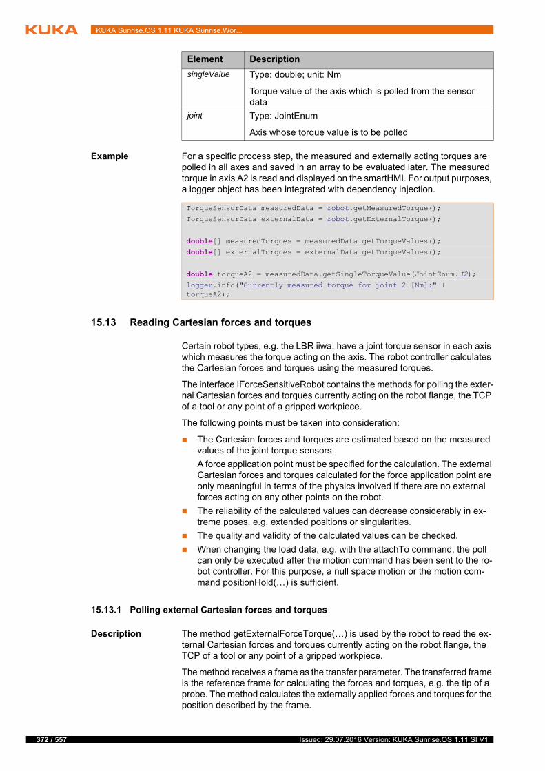
372 / 557
KUKA Sunrise.OS 1.11 KUKA Sunrise.Wor...
Example For a specific process step, the measured and externally acting torques are polled in all axes and saved in an array to be evaluated later. The measured torque in axis A2 is read and displayed on the smartHMI. For output purposes, a logger object has been integrated with dependency injection.
15.13 Reading Cartesian forces and torques
Certain robot types, e.g. the LBR iiwa, have a joint torque sensor in each axis which measures the torque acting on the axis. The robot controller calculates the Cartesian forces and torques using the measured torques.
The interface IForceSensitiveRobot contains the methods for polling the exter-nal Cartesian forces and torques currently acting on the robot flange, the TCP of a tool or any point of a gripped workpiece.
The following points must be taken into consideration:
The Cartesian forces and torques are estimated based on the measured values of the joint torque sensors.
A force application point must be specified for the calculation. The external Cartesian forces and torques calculated for the force application point are only meaningful in terms of the physics involved if there are no external forces acting on any other points on the robot.
The reliability of the calculated values can decrease considerably in ex-treme poses, e.g. extended positions or singularities.
The quality and validity of the calculated values can be checked.
When changing the load data, e.g. with the attachTo command, the poll can only be executed after the motion command has been sent to the ro-bot controller. For this purpose, a null space motion or the motion com-mand positionHold(…) is sufficient.
15.13.1 Polling external Cartesian forces and torques
Description The method getExternalForceTorque(…) is used by the robot to read the ex-ternal Cartesian forces and torques currently acting on the robot flange, the TCP of a tool or any point of a gripped workpiece.
The method receives a frame as the transfer parameter. The transferred frame is the reference frame for calculating the forces and torques, e.g. the tip of a probe. The method calculates the externally applied forces and torques for the position described by the frame.
singleValue Type: double; unit: Nm
Torque value of the axis which is polled from the sensor data
joint Type: JointEnum
Axis whose torque value is to be polled
Element Description
TorqueSensorData measuredData = robot.getMeasuredTorque();
TorqueSensorData externalData = robot.getExternalTorque();
double[] measuredTorques = measuredData.getTorqueValues();double[] externalTorques = externalData.getTorqueValues();
double torqueA2 = measuredData.getSingleTorqueValue(JointEnum.J2);
logger.info("Currently measured torque for joint 2 [Nm]:" + torqueA2);
Issued: 29.07.2016 Version: KUKA Sunrise.OS 1.11 SI V1

15 Programming
For a meaningful calculation in terms of the physics involved, the transferred frame must describe a point which is mechanically fixed to the flange. The giv-en frame must also be statically connected to the robot flange frame in the frame structure.
Optionally, a second frame can be transferred to the method as a parameter. This frame specifies the orientation of a coordinate system in which the forces and torques are represented.
Syntax ForceSensorData data = robot.getExternalForceTorque(measureFrame<, orientationFrame>);
Explanation of
the syntax
Examples Polling of the external forces and torques acting on the robot flange:
Polling of the external forces and torques acting on the robot flange with the orientation of the world coordinate system:
15.13.2 Polling forces and torques individually
Description The external Cartesian forces and torques polled with getExternalForce-Torque() can be polled separately from one another. The class ForceSensor-Data provides the following methods for this:
getForce()
getTorque()
The result of these pollings is a vector in each case. The values for each de-gree of freedom can be polled individually with the methods of the Vector class.
(>>> 15.4 "Polling individual values of a vector" Page 341)
Syntax To poll a force vector:
Vector force = data.getForce();
To poll a torque vector:
Vector torque = data.getTorque();
Element Description
data Type: ForceSensorData
Variable for the return value of getExternalForce-Torque(…). The return value contains the calculated Carte-sian forces and torques.
robot Type: LBR
Name of the robot
measureFrame
Type: AbstractFrame
Reference frame for calculation of the Cartesian forces and torques.
orientationFrame
Type: AbstractFrame
Optional: Orientation of the frame in which the forces and torques are represented.
ForceSensorData data = robot.getExternalForceTorque(robot.getFlange());
ForceSensorData data = robot.getExternalForceTorque(robot.getFlange(), World.Current.getRootFrame());
373 / 557Issued: 29.07.2016 Version: KUKA Sunrise.OS 1.11 SI V1

374 / 557
KUKA Sunrise.OS 1.11 KUKA Sunrise.Wor...
Explanation of
the syntax
Example Poll of the Cartesian force which is currently acting on the robot flange in the X direction:
15.13.3 Checking the reliability of the calculated values
Description In unfavorable robot positions, the calculated Cartesian forces and torques can deviate from the actual forces and torques applied. In particular near sin-gularities, several of the calculated values are highly unreliable and can be in-valid. Depending on the axis position, this only applies to some of the calculated values.
The quality and validity of the calculated values can be evaluated and polled in the program. The class ForceSensorData provides the following methods for this:
getForceInaccuracy(), getTorqueInaccuracy()
The inaccuracy of the calculated force and torque values can be polled.
The result of these pollings is a vector in each case. The values for each degree of freedom can be polled individually with the methods of the Vec-tor class.
(>>> 15.4 "Polling individual values of a vector" Page 341)
Depending on the axis position, the quality of the calculated values for the individual degrees of freedom may be different. By polling the individual values, it is possible to determine the degrees of freedom for which the cal-culation of forces and torques in the current pose supplies valid values.
isForceValid(…), isTorqueValid(…)
The validity of the calculated force and torque values can be polled.
A limit value for the maximum permissible inaccuracy up to which the cal-culated values are still valid is transferred as a parameter for each method.
Syntax Polling the inaccuracy of the calculated values:
Vector force = data.getForceInaccuracy();
Vector torque = data.getTorqueInaccuracy();
Polling the validity of the calculated values:
boolean valid = data.isForceValid(tolerance);
boolean valid =data.isTorqueValid(tolerance);
Element Description
force Type: vector (com.kuka.roboticsAPI.geometricModel.math)
Vector with the Cartesian forces which act in the X, Y and Z directions (unit: N)
torque Type: vector (com.kuka.roboticsAPI.geometricModel.math)
Vector with the Cartesian torques which act about the X, Y and Z axes (unit: Nm)
data Type: ForceSensorData
Variable for the return value of getExternalForce-Torque(…). The return value contains the calculated Carte-sian forces and torques.
ForceSensorData data = robot.getExternalForceTorque(robot.getFlange());
Vector force = data.getForce();
double forceInX = force.getX();
Issued: 29.07.2016 Version: KUKA Sunrise.OS 1.11 SI V1

15 Programming
Explanation of
the syntax
Example A certain statement block should only be executed if the external Cartesian forces acting along the axes of the flange coordinate system have been calcu-lated with an accuracy of 20 N or better.
15.14 Polling the robot position
The axis-specific and Cartesian robot position can be polled in the application. It is possible to poll the actual and the setpoint position for each.
Overview The following methods of the Robot class are available:
Element Description
force Type: vector (com.kuka.roboticsAPI.geometricModel.math)
Vector with the values for the inaccuracy with which the Cartesian forces acting in the X, Y and Z directions are cal-culated (unit: N)
torque Type: vector (com.kuka.roboticsAPI.geometricModel.math)
Vector with the values for the inaccuracy with which the Cartesian torques acting about the X, Y and Z axes are cal-culated (unit: Nm)
data Type: ForceSensorData
Variable for the return value of getExternalForce-Torque(…). The return value contains the calculated Carte-sian forces and torques.
tolerance Type: double; unit: N or Nm
Limit value for the maximum permissible inaccuracy up to which the calculated Cartesian forces and torques are still valid
valid Type: boolean
Variable for the return value of isForceValid(…) or isTorqueValid(…)
true: The inaccuracy value in all Cartesian directions is less than or equal to the limit value defined with toleran-ce.
false: The inaccuracy value in one or more Cartesian directions exceeds the tolerance value
ForceSensorData data = robot.getExternalForceTorque(robot.getFlange());
if (data.isForceValid(20)){ //do something
}
Method Description
getCommandedCartesianPo-sition(…)
Return value type: Frame
Polls for the Cartesian setpoint position
getCommandedJointPosition() Return value type: JointPosition
Polls for the axis-specific setpoint position
getCurrentCartesianPosi-tion(…)
Return value type: Frame
Polls for the Cartesian actual position
375 / 557Issued: 29.07.2016 Version: KUKA Sunrise.OS 1.11 SI V1
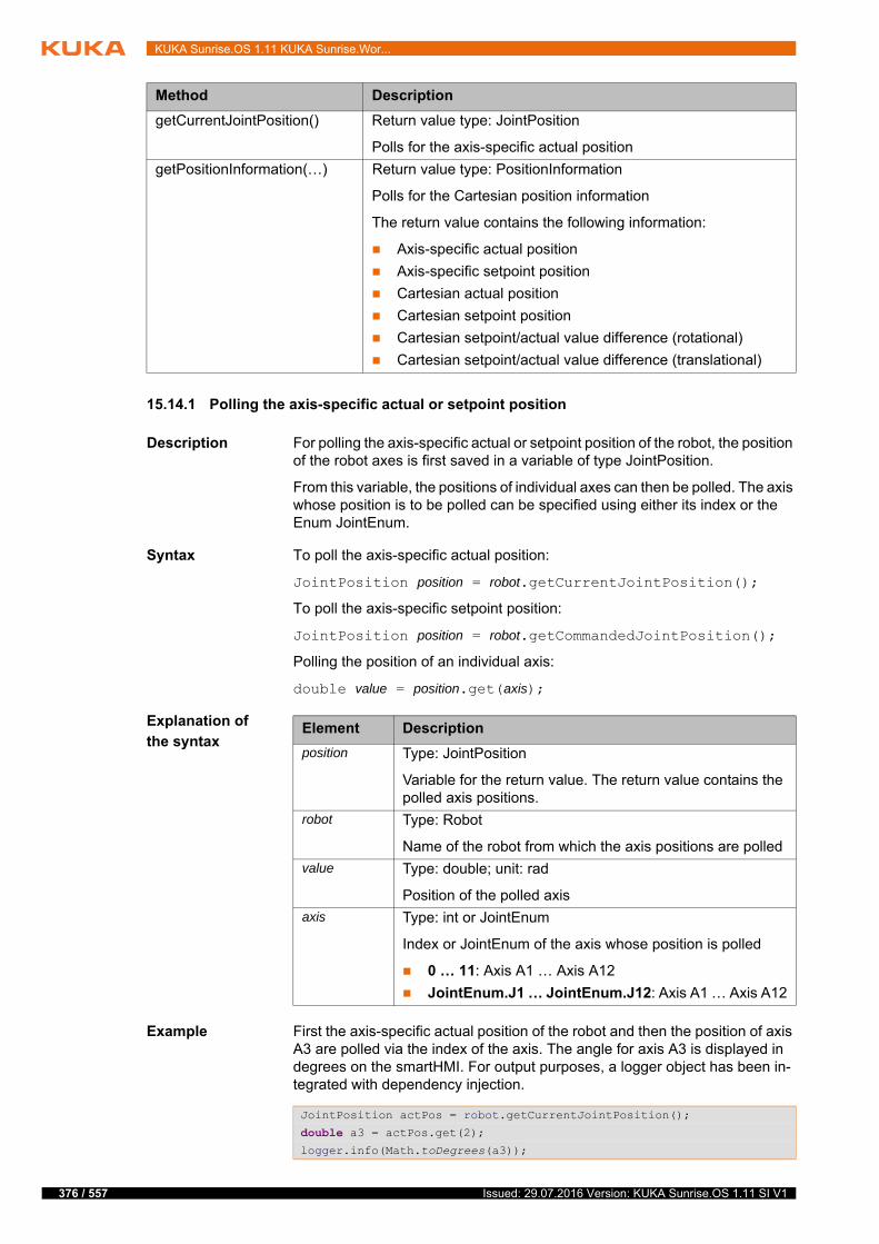
376 / 557
KUKA Sunrise.OS 1.11 KUKA Sunrise.Wor...
15.14.1 Polling the axis-specific actual or setpoint position
Description For polling the axis-specific actual or setpoint position of the robot, the position of the robot axes is first saved in a variable of type JointPosition.
From this variable, the positions of individual axes can then be polled. The axis whose position is to be polled can be specified using either its index or the Enum JointEnum.
Syntax To poll the axis-specific actual position:
JointPosition position = robot.getCurrentJointPosition();
To poll the axis-specific setpoint position:
JointPosition position = robot.getCommandedJointPosition();
Polling the position of an individual axis:
double value = position.get(axis);
Explanation of
the syntax
Example First the axis-specific actual position of the robot and then the position of axis A3 are polled via the index of the axis. The angle for axis A3 is displayed in degrees on the smartHMI. For output purposes, a logger object has been in-tegrated with dependency injection.
getCurrentJointPosition() Return value type: JointPosition
Polls for the axis-specific actual position
getPositionInformation(…) Return value type: PositionInformation
Polls for the Cartesian position information
The return value contains the following information:
Axis-specific actual position
Axis-specific setpoint position
Cartesian actual position
Cartesian setpoint position
Cartesian setpoint/actual value difference (rotational)
Cartesian setpoint/actual value difference (translational)
Method Description
Element Description
position Type: JointPosition
Variable for the return value. The return value contains the polled axis positions.
robot Type: Robot
Name of the robot from which the axis positions are polled
value Type: double; unit: rad
Position of the polled axis
axis Type: int or JointEnum
Index or JointEnum of the axis whose position is polled
0 … 11: Axis A1 … Axis A12
JointEnum.J1 … JointEnum.J12: Axis A1 … Axis A12
JointPosition actPos = robot.getCurrentJointPosition();
double a3 = actPos.get(2);logger.info(Math.toDegrees(a3));
Issued: 29.07.2016 Version: KUKA Sunrise.OS 1.11 SI V1

15 Programming
15.14.2 Polling the Cartesian actual or setpoint position
Description It is possible to poll the Cartesian actual or setpoint position of the robot flange as well as every other frame below it. This means every frame of an object which is attached to the robot flange via the attachTo command, e.g. the TCP of a tool or the frame of a gripped workpiece.
The result of the polling, i.e. the Cartesian position, refers by default to the world coordinate system. Optionally, it is possible to specify another reference coordinate system relative to which the Cartesian position is polled. This can for example be a frame created in the application data or a calibrated base.
The result of the polling is saved in a variable of type Frame and contains all the necessary redundancy information (redundancy angle, Status and Turn). From this variable, the position (X, Y, Z) and orientation (A, B, C) of the frame can be polled via the type-specific get methods.
Syntax To poll the Cartesian actual position:
Frame position = robot.getCurrentCartesianPosition(frameOnFlange<, referenceFrame>);
To poll the Cartesian setpoint position:
Frame position = robot.getCommandedCartesianPosition(frameOnFlange<, referenceFrame>);
Explanation of
the syntax
Examples Cartesian actual position of the robot flange with reference to the world coor-dinate system:
Cartesian actual position of the TCP of a tool with reference to a base:
Element Description
position Type: Frame
Variable for the return value. The return value contains the polled Cartesian position.
robot Type: Robot
Name of the robot from which the Cartesian position is polled
frameOnFlange
Type: ObjectFrame
Robot flange or a frame subordinated to the flange whose Cartesian position is polled
referenceFrame
Type: AbstractFrame
Reference coordinate system relative to which the Carte-sian position is polled. If no reference coordinate system is specified, the Cartesian position refers to the world coordi-nate system.
Frame cmdPos = robot.getCurrentCartesianPosition(robot.getFlange());
tool.attachTo(robot.getFlange());
// ...
Frame cmdPos = robot.getCurrentCartesianPosition(tool.getFrame("/TCP"), getApplicationData().getFrame("/Base"));
377 / 557Issued: 29.07.2016 Version: KUKA Sunrise.OS 1.11 SI V1

378 / 557
KUKA Sunrise.OS 1.11 KUKA Sunrise.Wor...
15.14.3 Polling the Cartesian setpoint/actual value difference
Description The Cartesian setpoint/actual value difference (= difference between the pro-grammed and measured position) can be polled with the getPositionInforma-tion(…) method.
The result of the polling is saved in a variable of type PositionInformation. From this variable, the translational and rotational setpoint/actual value differ-ences can be polled separately from each other.
Syntax To poll position information:
PositionInformation info = robot.getPositionInformation(frameOnFlange<, referenceFrame>);
To poll the translational setpoint/actual value difference:
Vector translatoryDiff = info.getTranslationOffset();
To poll the rotational setpoint/actual value difference:
Rotation rotatoryDiff = info.getRotationOffset();
Explanation of
the syntax
The Cartesian actual/setpoint value position saved in the PositionIn-fomation object can be read with the methods getCurrentCartesian-Position(…) and getCommandedCartesianPosition(…) that have
already been described.
Element Description
info Type: PositionInformation
Variable for the return value. The return value contains the polled position information.
robot Type: Robot
Name of the robot from which the position information is polled
frameOnFlange
Type: ObjectFrame
Robot flange or a frame subordinated to the flange whose position information is being polled
referenceFrame
Type: AbstractFrame
Reference coordinate system relative to which the position information is polled. If no reference coordinate system is specified, the position information refers to the world coor-dinate system.
translatoryDiff Type: vector (com.kuka.roboticsAPI.geometricModel.math)
Translational setpoint/actual value difference in the X, Y, Z directions (type: double, unit: mm)
The offset values for each degree of freedom can be polled individually with the “get” methods of the Vector class.
(>>> 15.4 "Polling individual values of a vector" Page 341)
rotatoryDiff Type: rotation (com.kuka.roboticsAPI.geometric-Model.math)
Setpoint/actual value difference of the axis angles A, B, C (type: double, unit: rad)
The offset values for each degree of freedom can be polled individually with the “get” methods of the Rotation class - getAlphaRad(), getBetaRad, getGammaRad().
Issued: 29.07.2016 Version: KUKA Sunrise.OS 1.11 SI V1

15 Programming
Example Reading of the translational setpoint/actual value difference in the X direction and the setpoint/actual value difference of the axis angle C.
15.15 HOME position
The HOME position is an application-specific position of the robot. It can be reset for an application during initialization.
The HOME position has the following values by default:
15.15.1 Changing the HOME position
Description The HOME position in an application can be changed with setHomePosi-tion(…). The method belongs to the Robot class.
A HOME position must meet the following conditions:
Good starting position for program execution
Good standstill position. For example, the stationary robot must not be an obstacle.
The new HOME position can be transferred as an axis-specific or Cartesian position (frame). It is only applicable in the application in which it was changed. Other applications continue to use the HOME position with the default values.
Syntax robot.setHomePosition(home);
Explanation of
the syntax
Examples To transfer an axis-specific position as the HOME position:
tool.attachTo(robot.getFlange());
// ...
PositionInformation posInf = robot.getPositionInformation(tool.getFrame("/TCP"), getApplicationData().getFrame("/Base"));
Vector transDiff = posInf.getTranslationOffset();
Rotation rotDiff = posInf.getRotationOffset();
double transOffsetInX = transDiff.getX();double rotOffsetofC = rotDiff.getGammaRad();
Axis A1 A2 A3 A4 A5 A6 A7
Pos. 0° 0° 0° 0° 0° 0° 0°
Element Description
robot Type: Robot
Name of the robot to which the new HOME position refers
home Type: JointPosition; unit: rad
1st option: transfer the axis position of the robot in the new HOME position.
Type: AbstractFrame
2nd option: transfer a frame as the new HOME position.
Note: The frame must contain all redundancy information so that the axis positions of the robot in the HOME position are unambiguous. This is the case with a taught frame, for example.
379 / 557Issued: 29.07.2016 Version: KUKA Sunrise.OS 1.11 SI V1
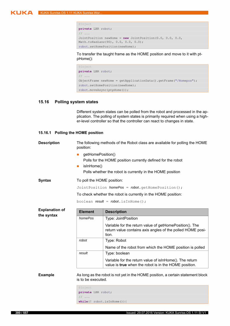
380 / 557
KUKA Sunrise.OS 1.11 KUKA Sunrise.Wor...
To transfer the taught frame as the HOME position and move to it with pt-pHome():
15.16 Polling system states
Different system states can be polled from the robot and processed in the ap-plication. The polling of system states is primarily required when using a high-er-level controller so that the controller can react to changes in state.
15.16.1 Polling the HOME position
Description The following methods of the Robot class are available for polling the HOME position:
getHomePosition()
Polls for the HOME position currently defined for the robot
isInHome()
Polls whether the robot is currently in the HOME position
Syntax To poll the HOME position:
JointPosition homePos = robot.getHomePosition();
To check whether the robot is currently in the HOME position:
boolean result = robot.isInHome();
Explanation of
the syntax
Example As long as the robot is not yet in the HOME position, a certain statement block is to be executed.
@Inject
private LBR robot;// ...
JointPosition newHome = new JointPosition(0.0, 0.0, 0.0, Math.toRadians(90), 0.0, 0.0, 0.0);
robot.setHomePosition(newHome);
@Inject
private LBR robot;// ...
ObjectFrame newHome = getApplicationData().getFrame("/Homepos");
robot.setHomePosition(newHome);
robot.moveAsync(ptpHome());
Element Description
homePos Type: JointPosition
Variable for the return value of getHomePosition(). The return value contains axis angles of the polled HOME posi-tion.
robot Type: Robot
Name of the robot from which the HOME position is polled
result Type: boolean
Variable for the return value of isInHome(). The return value is true when the robot is in the HOME position.
@Inject
private LBR robot;// ...
while(! robot.isInHome()){
Issued: 29.07.2016 Version: KUKA Sunrise.OS 1.11 SI V1
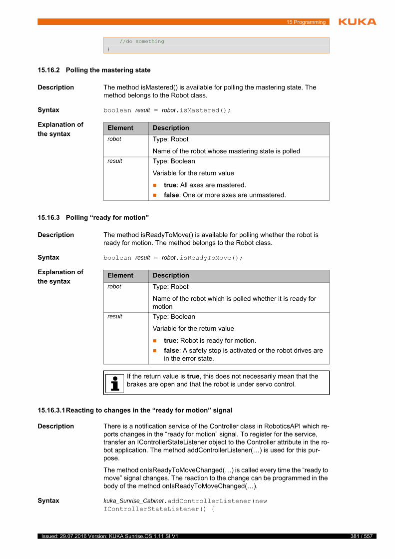
15 Programming
15.16.2 Polling the mastering state
Description The method isMastered() is available for polling the mastering state. The method belongs to the Robot class.
Syntax boolean result = robot.isMastered();
Explanation of
the syntax
15.16.3 Polling “ready for motion”
Description The method isReadyToMove() is available for polling whether the robot is ready for motion. The method belongs to the Robot class.
Syntax boolean result = robot.isReadyToMove();
Explanation of
the syntax
15.16.3.1Reacting to changes in the “ready for motion” signal
Description There is a notification service of the Controller class in RoboticsAPI which re-ports changes in the “ready for motion” signal. To register for the service, transfer an IControllerStateListener object to the Controller attribute in the ro-bot application. The method addControllerListener(…) is used for this pur-pose.
The method onIsReadyToMoveChanged(…) is called every time the “ready to move” signal changes. The reaction to the change can be programmed in the body of the method onIsReadyToMoveChanged(…).
Syntax kuka_Sunrise_Cabinet.addControllerListener(new IControllerStateListener() {
//do something
}
Element Description
robot Type: Robot
Name of the robot whose mastering state is polled
result Type: Boolean
Variable for the return value
true: All axes are mastered.
false: One or more axes are unmastered.
Element Description
robot Type: Robot
Name of the robot which is polled whether it is ready for motion
result Type: Boolean
Variable for the return value
true: Robot is ready for motion.
false: A safety stop is activated or the robot drives are in the error state.
If the return value is true, this does not necessarily mean that the brakes are open and that the robot is under servo control.
381 / 557Issued: 29.07.2016 Version: KUKA Sunrise.OS 1.11 SI V1
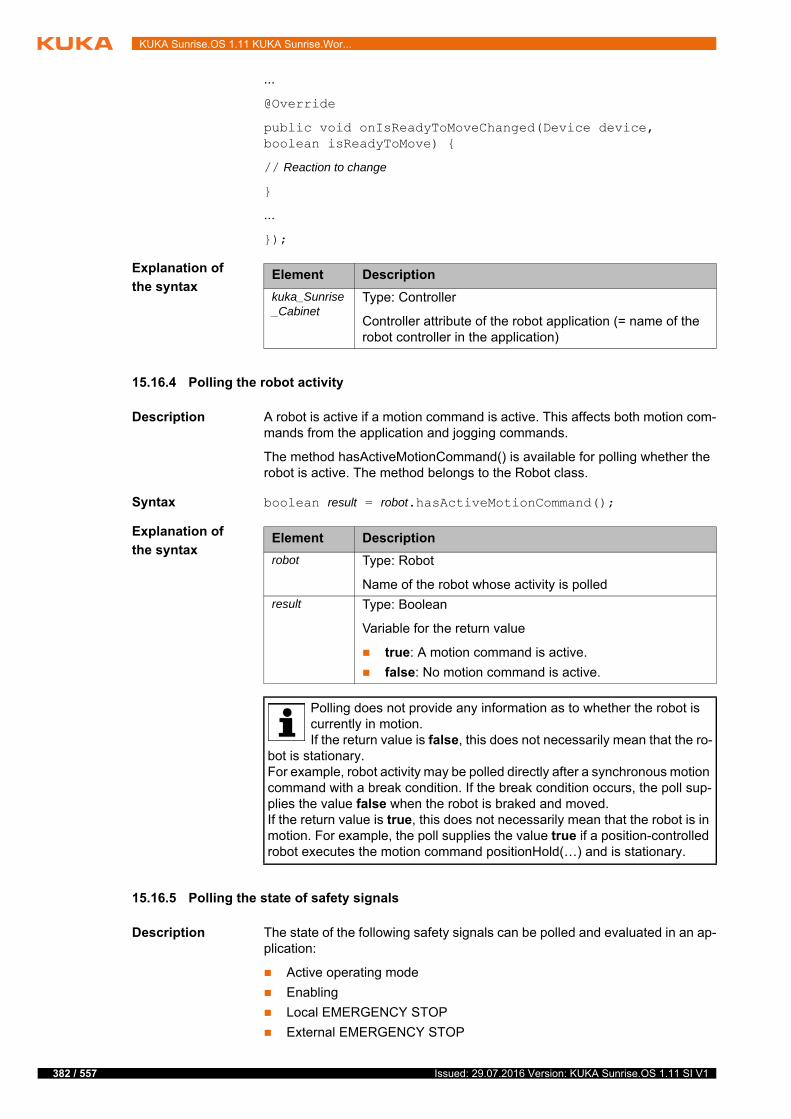
382 / 557
KUKA Sunrise.OS 1.11 KUKA Sunrise.Wor...
...
@Override
public void onIsReadyToMoveChanged(Device device, boolean isReadyToMove) {
// Reaction to change
}
...
});
Explanation of
the syntax
15.16.4 Polling the robot activity
Description A robot is active if a motion command is active. This affects both motion com-mands from the application and jogging commands.
The method hasActiveMotionCommand() is available for polling whether the robot is active. The method belongs to the Robot class.
Syntax boolean result = robot.hasActiveMotionCommand();
Explanation of
the syntax
15.16.5 Polling the state of safety signals
Description The state of the following safety signals can be polled and evaluated in an ap-plication:
Active operating mode
Enabling
Local EMERGENCY STOP
External EMERGENCY STOP
Element Description
kuka_Sunrise_Cabinet
Type: Controller
Controller attribute of the robot application (= name of the robot controller in the application)
Element Description
robot Type: Robot
Name of the robot whose activity is polled
result Type: Boolean
Variable for the return value
true: A motion command is active.
false: No motion command is active.
Polling does not provide any information as to whether the robot is currently in motion.If the return value is false, this does not necessarily mean that the ro-
bot is stationary.For example, robot activity may be polled directly after a synchronous motion command with a break condition. If the break condition occurs, the poll sup-plies the value false when the robot is braked and moved.If the return value is true, this does not necessarily mean that the robot is in motion. For example, the poll supplies the value true if a position-controlled robot executes the motion command positionHold(…) and is stationary.
Issued: 29.07.2016 Version: KUKA Sunrise.OS 1.11 SI V1

15 Programming
“Operator safety” signal
Stop request (safety stop)
Referencing state of position and joint torque sensors
The state of the different safety signals is first polled via the method getSafe-tyState() and grouped in an object of type ISafetyState.
From this object, the states of individual safety signals can then be polled. The interface ISafetyState contains the methods required for this.
Syntax ISafetyState currentState = kinematics.getSafetyState();
Explanation of
the syntax
Precondition The EMERGENCY STOP signal and the “Operator Safety” signal can only be evaluated if the following conditions are met in the safety configuration:
The selected category matches the safety function:
Category Local EMERGENCY STOP for local EMERGENCY STOP
Category External EMERGENCY STOP for external EMERGENCY STOP
Category Operator safety for operator safety
The configured reaction is a safety stop (no output).
Overview Methods of the ISafetyState interface
The implementing class of the interface is SunriseSafetyState (package: com.kuka.roboticsAPI.controllerModel.sunrise).
Element Description
currentState Type: ISafetyState
Variable for the return value. The return value contains the state of the safety signals at the time of polling with get-SafetyState().
Note: This does not apply to the referencing states. Refer-encing states are not polled until the corresponding meth-ods of the ISafetyState object are called.
kinematics Type: MovableDevice
Kinematic system for which the state of the safety signals is polled
Method Description
getEmergencyStopInt() Return value type: Enum of type EmergencyStop
Checks whether a local E-STOP is activated.
ACTIVE: Local E-STOP is activated.
INACTIVE: Local E-STOP is not activated.
NOT_CONFIGURED: Not relevant, as a local E-STOP is al-ways configured.
getEmergencyStopEx() Return value type: Enum of type EmergencyStop
Checks whether an external E-STOP is activated.
ACTIVE: External E-STOP is activated.
INACTIVE: External E-STOP is not activated.
NOT_CONFIGURED: No external EMERGENCY STOP is configured.
383 / 557Issued: 29.07.2016 Version: KUKA Sunrise.OS 1.11 SI V1
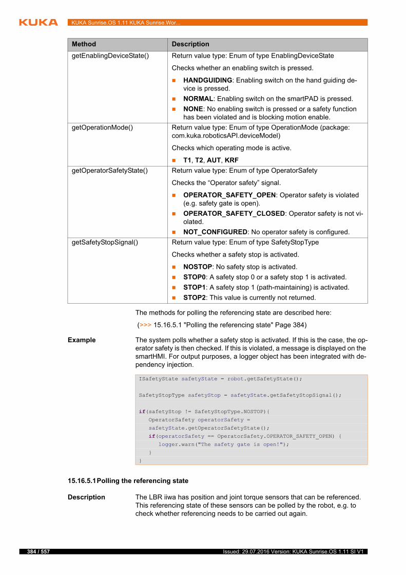
384 / 557
KUKA Sunrise.OS 1.11 KUKA Sunrise.Wor...
The methods for polling the referencing state are described here:
(>>> 15.16.5.1 "Polling the referencing state" Page 384)
Example The system polls whether a safety stop is activated. If this is the case, the op-erator safety is then checked. If this is violated, a message is displayed on the smartHMI. For output purposes, a logger object has been integrated with de-pendency injection.
15.16.5.1Polling the referencing state
Description The LBR iiwa has position and joint torque sensors that can be referenced. This referencing state of these sensors can be polled by the robot, e.g. to check whether referencing needs to be carried out again.
getEnablingDeviceState() Return value type: Enum of type EnablingDeviceState
Checks whether an enabling switch is pressed.
HANDGUIDING: Enabling switch on the hand guiding de-vice is pressed.
NORMAL: Enabling switch on the smartPAD is pressed.
NONE: No enabling switch is pressed or a safety function has been violated and is blocking motion enable.
getOperationMode() Return value type: Enum of type OperationMode (package: com.kuka.roboticsAPI.deviceModel)
Checks which operating mode is active.
T1, T2, AUT, KRF
getOperatorSafetyState() Return value type: Enum of type OperatorSafety
Checks the “Operator safety” signal.
OPERATOR_SAFETY_OPEN: Operator safety is violated (e.g. safety gate is open).
OPERATOR_SAFETY_CLOSED: Operator safety is not vi-olated.
NOT_CONFIGURED: No operator safety is configured.
getSafetyStopSignal() Return value type: Enum of type SafetyStopType
Checks whether a safety stop is activated.
NOSTOP: No safety stop is activated.
STOP0: A safety stop 0 or a safety stop 1 is activated.
STOP1: A safety stop 1 (path-maintaining) is activated.
STOP2: This value is currently not returned.
Method Description
ISafetyState safetyState = robot.getSafetyState();
SafetyStopType safetyStop = safetyState.getSafetyStopSignal();
if(safetyStop != SafetyStopType.NOSTOP){ OperatorSafety operatorSafety =
safetyState.getOperatorSafetyState();
if(operatorSafety == OperatorSafety.OPERATOR_SAFETY_OPEN) { logger.warn("The safety gate is open!");
}
}
Issued: 29.07.2016 Version: KUKA Sunrise.OS 1.11 SI V1
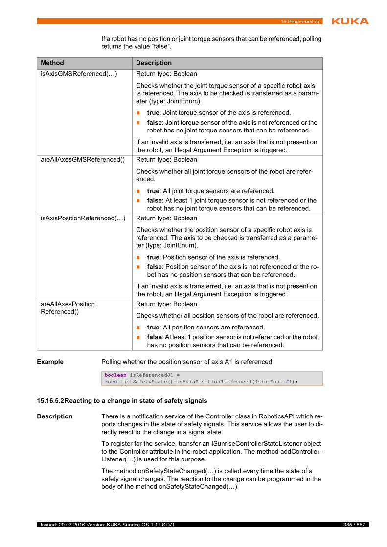
15 Programming
If a robot has no position or joint torque sensors that can be referenced, polling returns the value “false”.
Example Polling whether the position sensor of axis A1 is referenced
15.16.5.2Reacting to a change in state of safety signals
Description There is a notification service of the Controller class in RoboticsAPI which re-ports changes in the state of safety signals. This service allows the user to di-rectly react to the change in a signal state.
To register for the service, transfer an ISunriseControllerStateListener object to the Controller attribute in the robot application. The method addController-Listener(…) is used for this purpose.
The method onSafetyStateChanged(…) is called every time the state of a safety signal changes. The reaction to the change can be programmed in the body of the method onSafetyStateChanged(…).
Method Description
isAxisGMSReferenced(…) Return type: Boolean
Checks whether the joint torque sensor of a specific robot axis is referenced. The axis to be checked is transferred as a param-eter (type: JointEnum).
true: Joint torque sensor of the axis is referenced.
false: Joint torque sensor of the axis is not referenced or the robot has no joint torque sensors that can be referenced.
If an invalid axis is transferred, i.e. an axis that is not present on the robot, an Illegal Argument Exception is triggered.
areAllAxesGMSReferenced() Return type: Boolean
Checks whether all joint torque sensors of the robot are refer-enced.
true: All joint torque sensors are referenced.
false: At least 1 joint torque sensor is not referenced or the robot has no joint torque sensors that can be referenced.
isAxisPositionReferenced(…) Return type: Boolean
Checks whether the position sensor of a specific robot axis is referenced. The axis to be checked is transferred as a parame-ter (type: JointEnum).
true: Position sensor of the axis is referenced.
false: Position sensor of the axis is not referenced or the ro-bot has no position sensors that can be referenced.
If an invalid axis is transferred, i.e. an axis that is not present on the robot, an Illegal Argument Exception is triggered.
areAllAxesPositionReferenced()
Return type: Boolean
Checks whether all position sensors of the robot are referenced.
true: All position sensors are referenced.
false: At least 1 position sensor is not referenced or the robot has no position sensors that can be referenced.
boolean isReferencedJ1 = robot.getSafetyState().isAxisPositionReferenced(JointEnum.J1);
385 / 557Issued: 29.07.2016 Version: KUKA Sunrise.OS 1.11 SI V1
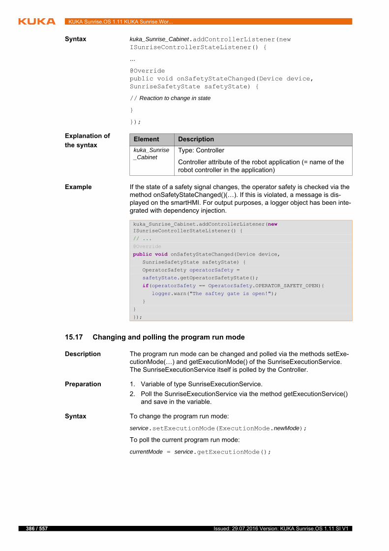
386 / 557
KUKA Sunrise.OS 1.11 KUKA Sunrise.Wor...
Syntax kuka_Sunrise_Cabinet.addControllerListener(new ISunriseControllerStateListener() {
...
@Overridepublic void onSafetyStateChanged(Device device, SunriseSafetyState safetyState) {
// Reaction to change in state
}
});
Explanation of
the syntax
Example If the state of a safety signal changes, the operator safety is checked via the method onSafetyStateChanged()(…). If this is violated, a message is dis-played on the smartHMI. For output purposes, a logger object has been inte-grated with dependency injection.
15.17 Changing and polling the program run mode
Description The program run mode can be changed and polled via the methods setExe-cutionMode(…) and getExecutionMode() of the SunriseExecutionService. The SunriseExecutionService itself is polled by the Controller.
Preparation 1. Variable of type SunriseExecutionService.
2. Poll the SunriseExecutionService via the method getExecutionService() and save in the variable.
Syntax To change the program run mode:
service.setExecutionMode(ExecutionMode.newMode);
To poll the current program run mode:
currentMode = service.getExecutionMode();
Element Description
kuka_Sunrise_Cabinet
Type: Controller
Controller attribute of the robot application (= name of the robot controller in the application)
kuka_Sunrise_Cabinet.addControllerListener(new ISunriseControllerStateListener() {
// ...
@Override
public void onSafetyStateChanged(Device device, SunriseSafetyState safetyState) {
OperatorSafety operatorSafety =
safetyState.getOperatorSafetyState();
if(operatorSafety == OperatorSafety.OPERATOR_SAFETY_OPEN){ logger.warn("The saftey gate is open!");
}
}
});
Issued: 29.07.2016 Version: KUKA Sunrise.OS 1.11 SI V1
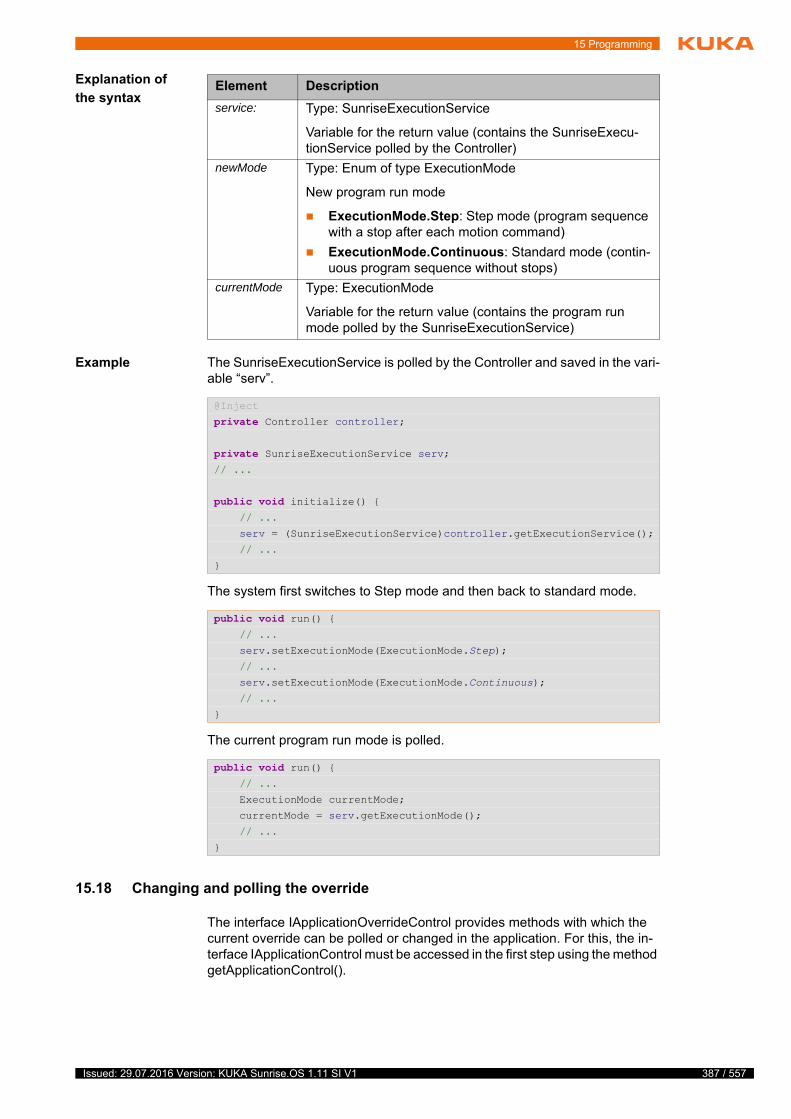
15 Programming
Explanation of
the syntax
Example The SunriseExecutionService is polled by the Controller and saved in the vari-able “serv”.
The system first switches to Step mode and then back to standard mode.
The current program run mode is polled.
15.18 Changing and polling the override
The interface IApplicationOverrideControl provides methods with which the current override can be polled or changed in the application. For this, the in-terface IApplicationControl must be accessed in the first step using the method getApplicationControl().
Element Description
service: Type: SunriseExecutionService
Variable for the return value (contains the SunriseExecu-tionService polled by the Controller)
newMode Type: Enum of type ExecutionMode
New program run mode
ExecutionMode.Step: Step mode (program sequence with a stop after each motion command)
ExecutionMode.Continuous: Standard mode (contin-uous program sequence without stops)
currentMode Type: ExecutionMode
Variable for the return value (contains the program run mode polled by the SunriseExecutionService)
@Inject
private Controller controller;
private SunriseExecutionService serv;// ...
public void initialize() { // ...
serv = (SunriseExecutionService)controller.getExecutionService();
// ...
}
public void run() { // ...
serv.setExecutionMode(ExecutionMode.Step);
// ...
serv.setExecutionMode(ExecutionMode.Continuous);
// ...
}
public void run() { // ...
ExecutionMode currentMode;
currentMode = serv.getExecutionMode();
// ...
}
387 / 557Issued: 29.07.2016 Version: KUKA Sunrise.OS 1.11 SI V1
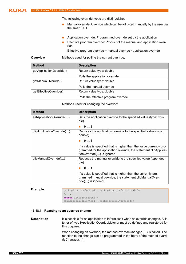
388 / 557
KUKA Sunrise.OS 1.11 KUKA Sunrise.Wor...
The following override types are distinguished:
Manual override: Override which can be adjusted manually by the user via the smartPAD
Application override: Programmed override set by the application
Effective program override: Product of the manual and application over-ride
Effective program override = manual override · application override
Overview Methods used for polling the current override:
Methods used for changing the override:
Example
15.18.1 Reacting to an override change
Description It is possible for an application to inform itself when an override changes. A lis-tener of type IApplicationOverrideListener must be defined and registered for this purpose.
When changing an override, the method overrideChanged(…) is called. The reaction to the change can be programmed in the body of the method overri-deChanged(…).
Method Description
getApplicationOverride() Return value type: double
Polls the application override
getManualOverride() Return value type: double
Polls the manual override
getEffectiveOverride() Return value type: double
Polls the effective program override
Method Description
setApplicationOverride(…) Sets the application override to the specified value (type: dou-ble)
0 … 1
clipApplicationOverride(…) Reduces the application override to the specified value (type: double)
0 … 1
If a value is specified that is higher than the value currently pro-grammed for the application override, the statement clipApplica-tionOverride(…) is ignored.
clipManualOverride(…) Reduces the manual override to the specified value (type: dou-ble)
0 … 1
If a value is specified that is higher than the currently pro-grammed manual override, the statement clipManualOver-ride(…) is ignored.
getApplicationControl().setApplicationOverride(0.5);
// ...
double actualOverride = getApplicationControl().getEffectiveOverride();
Issued: 29.07.2016 Version: KUKA Sunrise.OS 1.11 SI V1
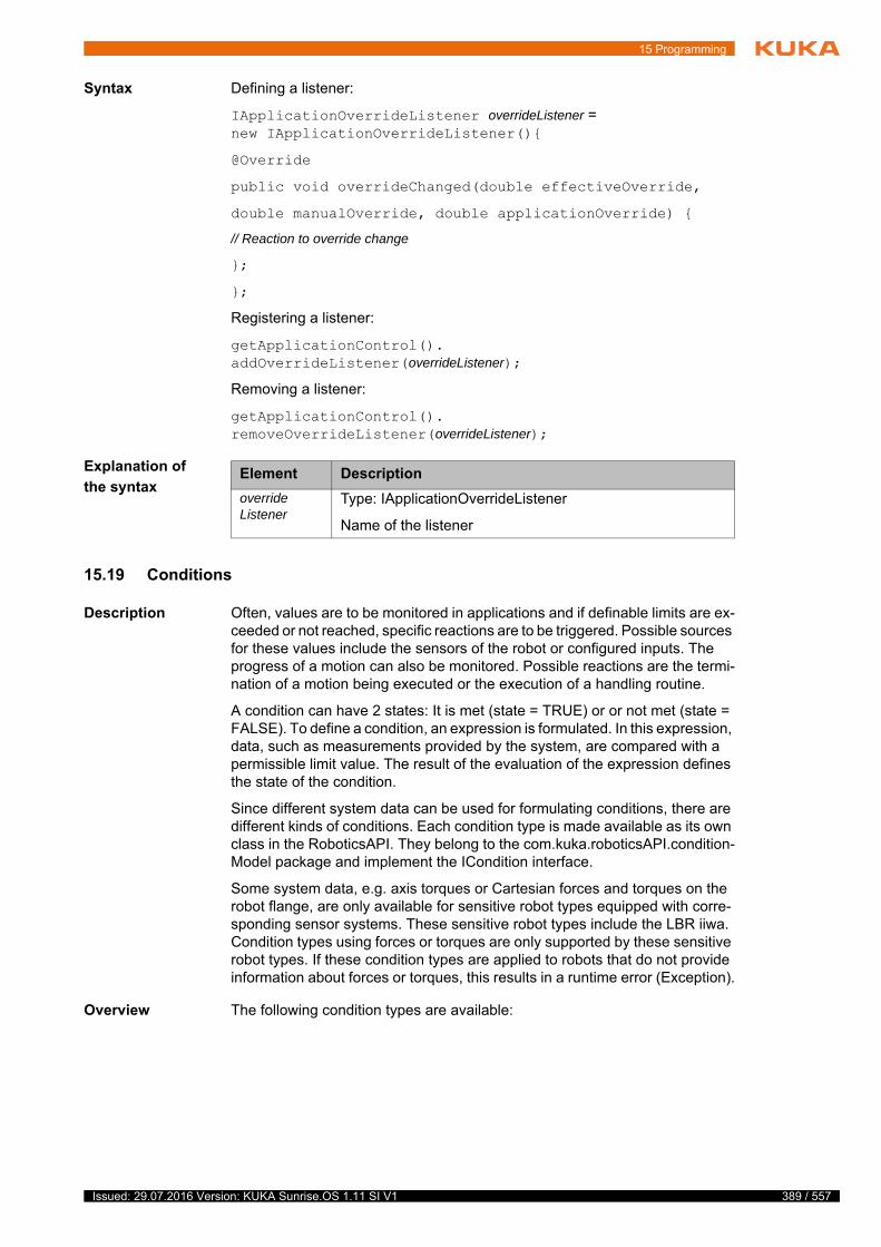
15 Programming
Syntax Defining a listener:
IApplicationOverrideListener overrideListener = new IApplicationOverrideListener(){
@Override
public void overrideChanged(double effectiveOverride,
double manualOverride, double applicationOverride) {
// Reaction to override change
};
};
Registering a listener:
getApplicationControl().addOverrideListener(overrideListener);
Removing a listener:
getApplicationControl().removeOverrideListener(overrideListener);
Explanation of
the syntax
15.19 Conditions
Description Often, values are to be monitored in applications and if definable limits are ex-ceeded or not reached, specific reactions are to be triggered. Possible sources for these values include the sensors of the robot or configured inputs. The progress of a motion can also be monitored. Possible reactions are the termi-nation of a motion being executed or the execution of a handling routine.
A condition can have 2 states: It is met (state = TRUE) or or not met (state = FALSE). To define a condition, an expression is formulated. In this expression, data, such as measurements provided by the system, are compared with a permissible limit value. The result of the evaluation of the expression defines the state of the condition.
Since different system data can be used for formulating conditions, there are different kinds of conditions. Each condition type is made available as its own class in the RoboticsAPI. They belong to the com.kuka.roboticsAPI.condition-Model package and implement the ICondition interface.
Some system data, e.g. axis torques or Cartesian forces and torques on the robot flange, are only available for sensitive robot types equipped with corre-sponding sensor systems. These sensitive robot types include the LBR iiwa. Condition types using forces or torques are only supported by these sensitive robot types. If these condition types are applied to robots that do not provide information about forces or torques, this results in a runtime error (Exception).
Overview The following condition types are available:
Element Description
overrideListener
Type: IApplicationOverrideListener
Name of the listener
389 / 557Issued: 29.07.2016 Version: KUKA Sunrise.OS 1.11 SI V1
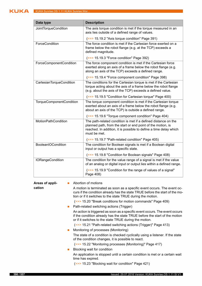
390 / 557
KUKA Sunrise.OS 1.11 KUKA Sunrise.Wor...
Areas of appli-
cation
Abortion of motions
A motion is terminated as soon as a specific event occurs. The event oc-curs if the condition already has the state TRUE before the start of the mo-tion or if it switches to the state TRUE during the motion.
(>>> 15.20 "Break conditions for motion commands" Page 409)
Path-related switching actions (Trigger)
An action is triggered as soon as a specific event occurs. The event occurs if the condition already has the state TRUE before the start of the motion or if it switches to the state TRUE during the motion.
(>>> 15.21 "Path-related switching actions (Trigger)" Page 413)
Monitoring of processes (Monitoring)
The state of a condition is checked cyclically using a listener. If the state of the condition changes, it is possible to react.
(>>> 15.22 "Monitoring processes (Monitoring)" Page 417)
Blocking wait for condition
An application is stopped until a certain condition is met or a certain wait time has expired.
(>>> 15.23 "Blocking wait for condition" Page 421)
Data type Description
JointTorqueCondition The axis torque condition is met if the torque measured in an axis lies outside of a defined range of values.
(>>> 15.19.2 "Axis torque condition" Page 391)
ForceCondition The force condition is met if the Cartesian force exerted on a frame below the robot flange (e.g. at the TCP) exceeds a defined magnitude.
(>>> 15.19.3 "Force condition" Page 392)
ForceComponentCondition The force component condition is met if the Cartesian force exerted along an axis of a frame below the robot flange (e.g. along an axis of the TCP) exceeds a defined range.
(>>> 15.19.4 "Force component condition" Page 398)
CartesianTorqueCondition The conditions for the Cartesian torque is met if the Cartesian torque acting about the axis of a frame below the robot flange (e.g. about the axis of the TCP) exceeds a defined value.
(>>> 15.19.5 "Condition for Cartesian torque" Page 400)
TorqueComponentCondition The torque component condition is met if the Cartesian torque exerted about an axis of a frame below the robot flange (e.g. about an axis of the TCP) is outside a defined range.
(>>> 15.19.6 "Torque component condition" Page 404)
MotionPathCondition The path-related condition is met if a defined distance on the planned path, from the start or end point of the motion, is reached. In addition, it is possible to define a time delay which must be met.
(>>> 15.19.7 "Path-related condition" Page 405)
BooleanIOCondition The condition for Boolean signals is met if a Boolean digital input or output has a specific state.
(>>> 15.19.8 "Condition for Boolean signals" Page 408)
IORangeCondition The condition for the value range of a signal is met if the value of an analog or digital input or output lies within a defined range.
(>>> 15.19.9 "Condition for the range of values of a signal" Page 408)
Issued: 29.07.2016 Version: KUKA Sunrise.OS 1.11 SI V1
15 Programming
15.19.1 Complex conditions
Conditions can be logically linked to one another so that it is possible to define complex conditions. The logic operators required for this are available as ICondition methods. The calling ICondition object is linked to one or more con-ditions, which are transferred as parameters.
The operators can be called several times in a row and in this way, parenthe-ses and nesting of operations can be realized. The evaluation is thus depen-dent on the order of calling.
Operators
Example
15.19.2 Axis torque condition
Description The axis torque condition is used to check whether the external torque deter-mined in an axis lies outside of a defined range of values.
(>>> 15.12 "Polling axis torques" Page 371)
Operator Description/syntax
NOT Inversion of the calling ICondition object
ICondition invert();
XOR EITHER/OR operation linking the calling ICondition object with a further condition
ICondition xor(ICondition other);
other: further condition
AND AND operation linking the calling ICondition object with one or more additional conditions
ICondition and(ICondition other1, ICondition other2, …);
other1, other2, …: further conditions
OR OR operation linking the calling ICondition object with one or more additional conditions
ICondition or(ICondition other1, ICondition other2, …);
other1, other2, …: further conditions
JointTorqueCondition condA = …;
JointTorqueCondition condB = …;
JointTorqueCondition condC = …;
JointTorqueCondition condD = …;
ICondition combi1, combi2, combi3, combi4;
// NOT A
combi1 = condA.invert();
// A AND B AND C
combi2 = condA.and(condB, condC);
// (A OR B) AND C
combi3 = condA.or(condB).and(condC);
// (A OR B) AND (C OR D)
combi4 = condA.or(condB).and(condC.or(condD));
391 / 557Issued: 29.07.2016 Version: KUKA Sunrise.OS 1.11 SI V1
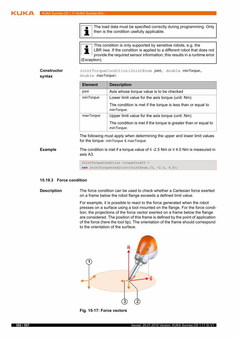
392 / 557
KUKA Sunrise.OS 1.11 KUKA Sunrise.Wor...
Constructor
syntax
JointTorqueCondition(JointEnum joint, double minTorque, double maxTorque)
The following must apply when determining the upper and lower limit values for the torque: minTorque ≤ maxTorque.
Example The condition is met if a torque value of ≤ -2.5 Nm or ≥ 4.0 Nm is measured in axis A3.
15.19.3 Force condition
Description The force condition can be used to check whether a Cartesian force exerted on a frame below the robot flange exceeds a defined limit value.
For example, it is possible to react to the force generated when the robot presses on a surface using a tool mounted on the flange. For the force condi-tion, the projections of the force vector exerted on a frame below the flange are considered. The position of this frame is defined by the point of application of the force (here the tool tip). The orientation of the frame should correspond to the orientation of the surface.
The load data must be specified correctly during programming. Only then is the condition usefully applicable.
This condition is only supported by sensitive robots, e.g. the LBR iiwa. If the condition is applied to a different robot that does not provide the required sensor information, this results in a runtime error
(Exception).
Element Description
joint Axis whose torque value is to be checked
minTorque Lower limit value for the axis torque (unit: Nm)
The condition is met if the torque is less than or equal to minTorque.
maxTorque Upper limit value for the axis torque (unit: Nm)
The condition is met if the torque is greater than or equal to minTorque.
JointTorqueCondition torqueCondJ3 =
new JointTorqueCondition(JointEnum.J3, -2.5, 4.0);
Fig. 15-17: Force vectors
Issued: 29.07.2016 Version: KUKA Sunrise.OS 1.11 SI V1

15 Programming
The following force vectors are relevant:
Normal force N:
The normal force is the projection of the force exerted on the surface nor-mal (= vector which is perpendicular to the surface). This results in the part of the force exerted vertically on the surface. For example, pressure is ex-erted via the normal force in order to fit a component.
Shear force S:
The shear force is the projection of the force exerted on the surface. This results in the part of the force exerted parallel to the surface. The shear force is generated by friction.
Methods Force conditions are of the data type ForceCondition. ForceCondition contains the following static methods for programming conditions:
createSpatialForceCondition(…): Condition for Cartesian force from all di-rections
createNormalForceCondition(…): Condition for normal force
createShearForceCondition(…): Condition for shear force
To formulate the condition, a frame below the flange coordinate system (e.g. the tip of a tool) is defined as a reference system. The forces which are exerted relative to this frame are determined. The orientation of the reference system can be optionally defined via an orientation frame. This can be used, for ex-ample, to define the position of the surface on which the force is exerted.
A limit value is defined to determine the minimum force magnitude which meets the condition.
The Cartesian force is calculated from the values of the joint torque sensors. The reliability of the calculated force values varies depending on the axis con-figuration. If the quality of the force calculation is also to be taken into account, it is possible to specify a value for the maximum permissible inaccuracy. If the system calculates an inaccuracy exceeding this value, the force condition is also met.
1 Frame which specifies the orientation of the reference frame (here: orientation of the surface)
2 Point of application of the force, here the tip of the tool
3 Reference frame below the flange onto which the force vector is pro-jected. The position of the frame corresponds to the point of applica-tion of the force. The orientation corresponds to the orientation of the surface.
The load data must be specified correctly during programming. Only then is the condition usefully applicable.
The force estimation cannot return meaningful values near singularity positions. It is advisable not to use the force component condition for this type of axis configuration. Alternatively, the axis torque condition
can be used or the axis position can be adapted using the redundancy so as to ensure that there is no singularity.
This condition is only supported by sensitive robots, e.g. the LBR iiwa. If the condition is applied to a different robot that does not provide the required sensor information, this results in a runtime error
(Exception).
393 / 557Issued: 29.07.2016 Version: KUKA Sunrise.OS 1.11 SI V1
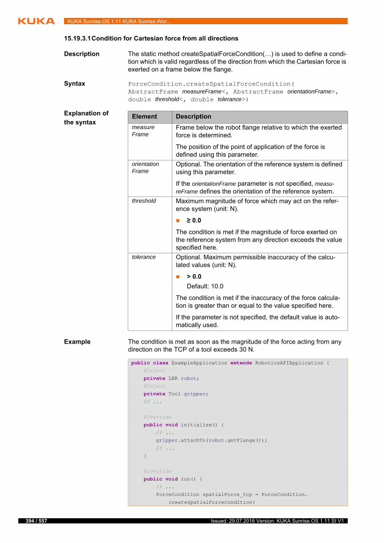
394 / 557
KUKA Sunrise.OS 1.11 KUKA Sunrise.Wor...
15.19.3.1Condition for Cartesian force from all directions
Description The static method createSpatialForceCondition(…) is used to define a condi-tion which is valid regardless of the direction from which the Cartesian force is exerted on a frame below the flange.
Syntax ForceCondition.createSpatialForceCondition(AbstractFrame measureFrame<, AbstractFrame orientationFrame>, double threshold<, double tolerance>)
Explanation of
the syntax
Example The condition is met as soon as the magnitude of the force acting from any direction on the TCP of a tool exceeds 30 N.
Element Description
measureFrame
Frame below the robot flange relative to which the exerted force is determined.
The position of the point of application of the force is defined using this parameter.
orientationFrame
Optional. The orientation of the reference system is defined using this parameter.
If the orientationFrame parameter is not specified, measu-reFrame defines the orientation of the reference system.
threshold Maximum magnitude of force which may act on the refer-ence system (unit: N).
≥ 0.0
The condition is met if the magnitude of force exerted on the reference system from any direction exceeds the value specified here.
tolerance Optional. Maximum permissible inaccuracy of the calcu-lated values (unit: N).
> 0.0
Default: 10.0
The condition is met if the inaccuracy of the force calcula-tion is greater than or equal to the value specified here.
If the parameter is not specified, the default value is auto-matically used.
public class ExampleApplication extends RoboticsAPIApplication { @Inject
private LBR robot; @Inject
private Tool gripper; // ...
@Override
public void initialize() { // ...
gripper.attachTo(robot.getFlange());
// ...
}
@Override
public void run() { // ...
ForceCondition spatialForce_tcp = ForceCondition.
createSpatialForceCondition(
Issued: 29.07.2016 Version: KUKA Sunrise.OS 1.11 SI V1
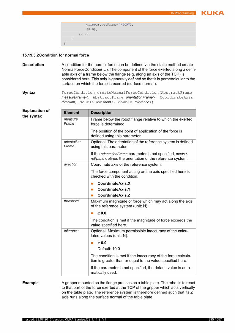
15 Programming
15.19.3.2Condition for normal force
Description A condition for the normal force can be defined via the static method create-NormalForceCondition(…). The component of the force exerted along a defin-able axis of a frame below the flange (e.g. along an axis of the TCP) is considered here. This axis is generally defined so that it is perpendicular to the surface on which the force is exerted (surface normal).
Syntax ForceCondition.createNormalForceCondition(AbstractFrame measureFrame<, AbstractFrame orientationFrame>, CoordinateAxis direction, double threshold<, double tolerance>)
Explanation of
the syntax
Example A gripper mounted on the flange presses on a table plate. The robot is to react to that part of the force exerted at the TCP of the gripper which acts vertically on the table plate. The reference system is therefore defined such that its Z axis runs along the surface normal of the table plate.
gripper.getFrame("/TCP"),
30.0);
// ...
}
}
Element Description
measureFrame
Frame below the robot flange relative to which the exerted force is determined.
The position of the point of application of the force is defined using this parameter.
orientationFrame
Optional. The orientation of the reference system is defined using this parameter.
If the orientationFrame parameter is not specified, measu-reFrame defines the orientation of the reference system.
direction Coordinate axis of the reference system.
The force component acting on the axis specified here is checked with the condition.
CoordinateAxis.X
CoordinateAxis.Y
CoordinateAxis.Z
threshold Maximum magnitude of force which may act along the axis of the reference system (unit: N).
≥ 0.0
The condition is met if the magnitude of force exceeds the value specified here.
tolerance Optional. Maximum permissible inaccuracy of the calcu-lated values (unit: N).
> 0.0
Default: 10.0
The condition is met if the inaccuracy of the force calcula-tion is greater than or equal to the value specified here.
If the parameter is not specified, the default value is auto-matically used.
395 / 557Issued: 29.07.2016 Version: KUKA Sunrise.OS 1.11 SI V1
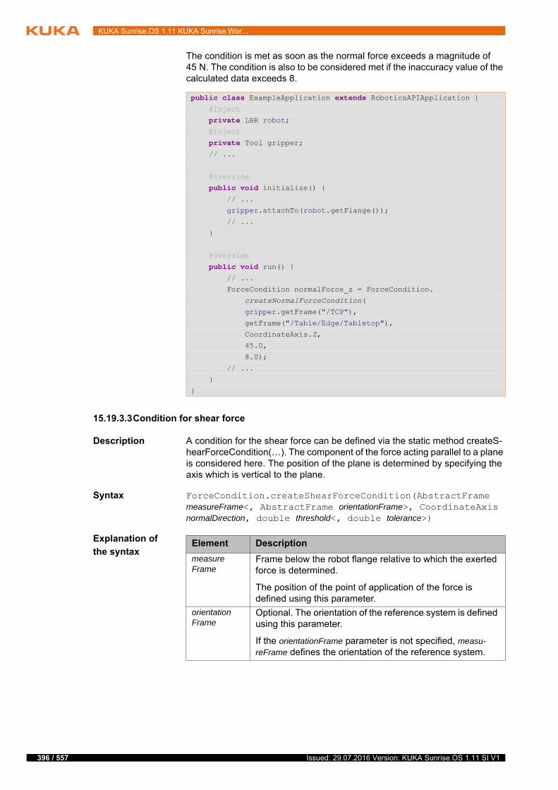
396 / 557
KUKA Sunrise.OS 1.11 KUKA Sunrise.Wor...
The condition is met as soon as the normal force exceeds a magnitude of 45 N. The condition is also to be considered met if the inaccuracy value of the calculated data exceeds 8.
15.19.3.3Condition for shear force
Description A condition for the shear force can be defined via the static method createS-hearForceCondition(…). The component of the force acting parallel to a plane is considered here. The position of the plane is determined by specifying the axis which is vertical to the plane.
Syntax ForceCondition.createShearForceCondition(AbstractFrame measureFrame<, AbstractFrame orientationFrame>, CoordinateAxis normalDirection, double threshold<, double tolerance>)
Explanation of
the syntax
public class ExampleApplication extends RoboticsAPIApplication { @Inject
private LBR robot; @Inject
private Tool gripper; // ...
@Override
public void initialize() { // ...
gripper.attachTo(robot.getFlange());
// ...
}
@Override
public void run() { // ...
ForceCondition normalForce_z = ForceCondition.
createNormalForceCondition(
gripper.getFrame("/TCP"),
getFrame("/Table/Edge/Tabletop"),
CoordinateAxis.Z,
45.0,
8.0);
// ...
}
}
Element Description
measureFrame
Frame below the robot flange relative to which the exerted force is determined.
The position of the point of application of the force is defined using this parameter.
orientationFrame
Optional. The orientation of the reference system is defined using this parameter.
If the orientationFrame parameter is not specified, measu-reFrame defines the orientation of the reference system.
Issued: 29.07.2016 Version: KUKA Sunrise.OS 1.11 SI V1

15 Programming
Example A gripper mounted on the flange presses on a table plate. The force at the TCP of the gripper is to be determined using the orientation of the table plate. This process considers the shear force which acts parallel to the XY plane of the measurement point, defined by the TCP and the position of the table.
To define the XY plane, the axis perpendicular to this plane must be specified as a parameter. This is the Z axis.
The condition is met as soon as the shear force exceeds a magnitude of 25 N. The condition is also to be considered met if the inaccuracy value of the cal-culated data exceeds 5.
normalDirection
Coordinate axis of the reference system.
The axis specified here defines the surface normal of a plane. The force component acting parallel to this plane is checked.
CoordinateAxis.X
CoordinateAxis.Y
CoordinateAxis.Z
threshold Maximum magnitude of force which may be exerted paral-lel to the reference system plane defined by its surface nor-mal (unit: N).
≥ 0.0
The condition is met if the magnitude of force exceeds the value specified here.
tolerance Optional. Maximum permissible inaccuracy of the calcu-lated values (unit: N).
> 0.0
Default: 10.0
The condition is met if the inaccuracy of the force calcula-tion is greater than or equal to the value specified here.
If the parameter is not specified, the default value is auto-matically used.
Element Description
public class ExampleApplication extends RoboticsAPIApplication { @Inject
private LBR robot; @Inject
private Tool gripper; // ...
@Override
public void initialize() { // ...
gripper.attachTo(robot.getFlange());
// ...
}
@Override
public void run() { // ...
ForceCondition shearForce_xyPlane = ForceCondition.
createShearForceCondition(
gripper.getFrame("/TCP"),
getFrame("/Table/Edge/Tabletop"),
397 / 557Issued: 29.07.2016 Version: KUKA Sunrise.OS 1.11 SI V1
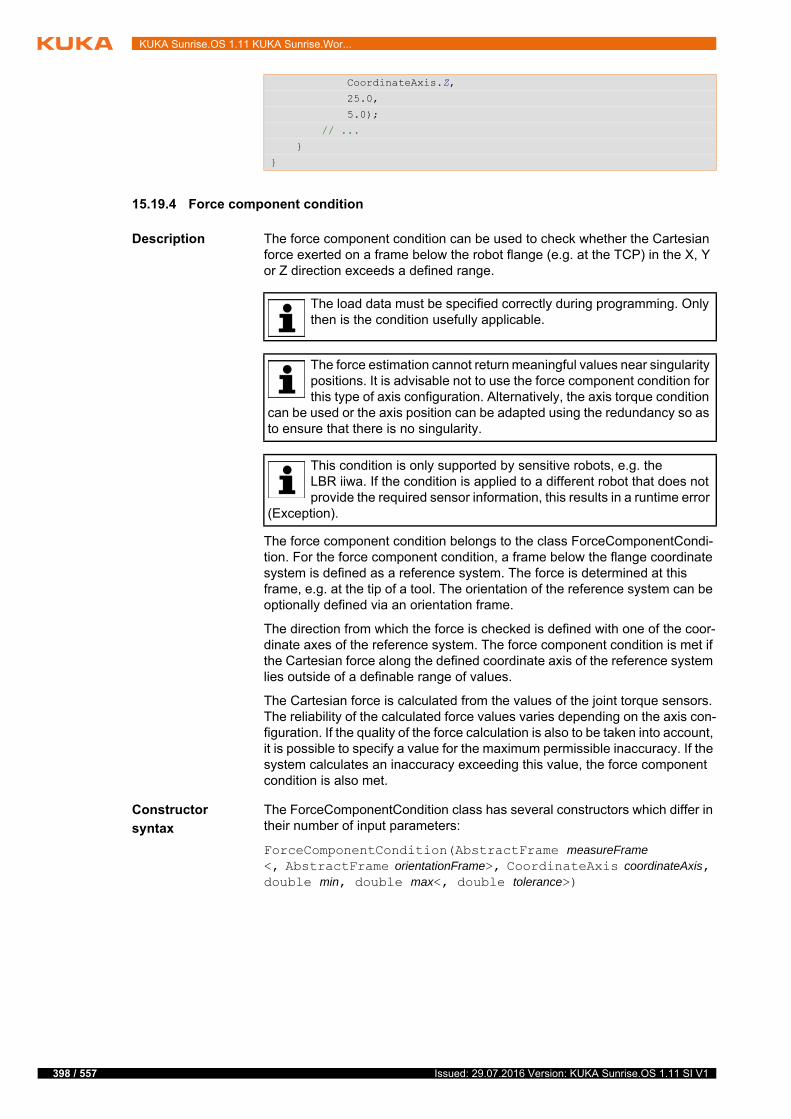
398 / 557
KUKA Sunrise.OS 1.11 KUKA Sunrise.Wor...
15.19.4 Force component condition
Description The force component condition can be used to check whether the Cartesian force exerted on a frame below the robot flange (e.g. at the TCP) in the X, Y or Z direction exceeds a defined range.
The force component condition belongs to the class ForceComponentCondi-tion. For the force component condition, a frame below the flange coordinate system is defined as a reference system. The force is determined at this frame, e.g. at the tip of a tool. The orientation of the reference system can be optionally defined via an orientation frame.
The direction from which the force is checked is defined with one of the coor-dinate axes of the reference system. The force component condition is met if the Cartesian force along the defined coordinate axis of the reference system lies outside of a definable range of values.
The Cartesian force is calculated from the values of the joint torque sensors. The reliability of the calculated force values varies depending on the axis con-figuration. If the quality of the force calculation is also to be taken into account, it is possible to specify a value for the maximum permissible inaccuracy. If the system calculates an inaccuracy exceeding this value, the force component condition is also met.
Constructor
syntax
The ForceComponentCondition class has several constructors which differ in their number of input parameters:
ForceComponentCondition(AbstractFrame measureFrame<, AbstractFrame orientationFrame>, CoordinateAxis coordinateAxis, double min, double max<, double tolerance>)
CoordinateAxis.Z,
25.0,
5.0);
// ...
}
}
The load data must be specified correctly during programming. Only then is the condition usefully applicable.
The force estimation cannot return meaningful values near singularity positions. It is advisable not to use the force component condition for this type of axis configuration. Alternatively, the axis torque condition
can be used or the axis position can be adapted using the redundancy so as to ensure that there is no singularity.
This condition is only supported by sensitive robots, e.g. the LBR iiwa. If the condition is applied to a different robot that does not provide the required sensor information, this results in a runtime error
(Exception).
Issued: 29.07.2016 Version: KUKA Sunrise.OS 1.11 SI V1
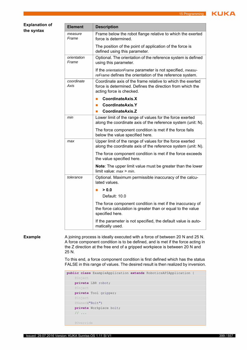
15 Programming
Explanation of
the syntax
Example A joining process is ideally executed with a force of between 20 N and 25 N. A force component condition is to be defined, and is met if the force acting in the Z direction at the free end of a gripped workpiece is between 20 N and 25 N.
To this end, a force component condition is first defined which has the status FALSE in this range of values. The desired result is then realized by inversion.
Element Description
measureFrame
Frame below the robot flange relative to which the exerted force is determined.
The position of the point of application of the force is defined using this parameter.
orientationFrame
Optional. The orientation of the reference system is defined using this parameter.
If the orientationFrame parameter is not specified, measu-reFrame defines the orientation of the reference system.
coordinateAxis
Coordinate axis of the frame relative to which the exerted force is determined. Defines the direction from which the acting force is checked.
CoordinateAxis.X
CoordinateAxis.Y
CoordinateAxis.Z
min Lower limit of the range of values for the force exerted along the coordinate axis of the reference system (unit: N).
The force component condition is met if the force falls below the value specified here.
max Upper limit of the range of values for the force exerted along the coordinate axis of the reference system (unit: N).
The force component condition is met if the force exceeds the value specified here.
Note: The upper limit value must be greater than the lower limit value: max > min.
tolerance Optional. Maximum permissible inaccuracy of the calcu-lated values.
> 0.0
Default: 10.0
The force component condition is met if the inaccuracy of the force calculation is greater than or equal to the value specified here.
If the parameter is not specified, the default value is auto-matically used.
public class ExampleApplication extends RoboticsAPIApplication { @Inject
private LBR robot; @Inject
private Tool gripper; @Inject
@Named("Bolt")
private Workpiece bolt; // ...
@Override
399 / 557Issued: 29.07.2016 Version: KUKA Sunrise.OS 1.11 SI V1
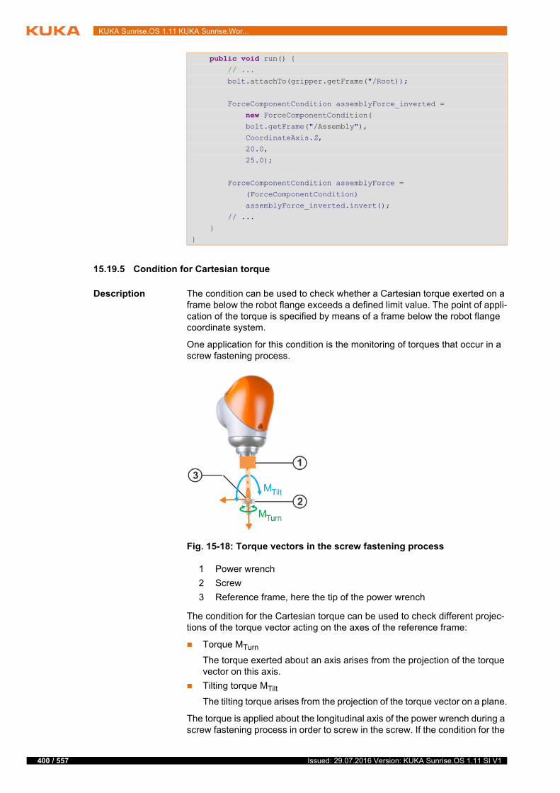
400 / 557
KUKA Sunrise.OS 1.11 KUKA Sunrise.Wor...
15.19.5 Condition for Cartesian torque
Description The condition can be used to check whether a Cartesian torque exerted on a frame below the robot flange exceeds a defined limit value. The point of appli-cation of the torque is specified by means of a frame below the robot flange coordinate system.
One application for this condition is the monitoring of torques that occur in a screw fastening process.
The condition for the Cartesian torque can be used to check different projec-tions of the torque vector acting on the axes of the reference frame:
Torque MTurn
The torque exerted about an axis arises from the projection of the torque vector on this axis.
Tilting torque MTilt
The tilting torque arises from the projection of the torque vector on a plane.
The torque is applied about the longitudinal axis of the power wrench during a screw fastening process in order to screw in the screw. If the condition for the
public void run() { // ...
bolt.attachTo(gripper.getFrame("/Root));
ForceComponentCondition assemblyForce_inverted =
new ForceComponentCondition( bolt.getFrame("/Assembly"),
CoordinateAxis.Z,
20.0,
25.0);
ForceComponentCondition assemblyForce =
(ForceComponentCondition)
assemblyForce_inverted.invert();
// ...
}
}
Fig. 15-18: Torque vectors in the screw fastening process
1 Power wrench
2 Screw
3 Reference frame, here the tip of the power wrench
Issued: 29.07.2016 Version: KUKA Sunrise.OS 1.11 SI V1
15 Programming
torque is used, it is possible to ensure that the maximum permissible values are not exceeded when fastening screws.
The tilting torque arises during a screw fastening process as a result of unde-sired tilting of the power wrench about the longitudinal axis, forwards or to the side. If the condition for the tilting torque is configured, it is possible to check whether the tilting torque is within an acceptable range of values.
Methods Conditions for the Cartesian torque are of data type CartesianTorqueCondi-tion. CartesianTorqueCondition contains the following static methods for pro-gramming conditions:
createSpatialTorqueCondition(…): Condition for Cartesian torque from all directions
createTurningTorqueCondition(…): Condition for torque
createTiltingTorqueCondition(…): Condition for tilting torque
To formulate the condition, a frame is defined as a reference system below the flange coordinate system. The torque is determined at this frame, e.g. at the tip of a power wrench. The orientation of the reference system can be option-ally defined via an orientation frame. In this way, the desired orientation of the screw can be specified, for example.
A limit value is defined to determine the minimum Cartesian torque magnitude which meets the condition.
The Cartesian torque is calculated from the values of the joint torque sensors. The reliability of the calculated Cartesian torques varies depending on the axis configuration. If the quality of the calculation is also to be taken into account, it is possible to specify a value for the maximum permissible inaccuracy. If the system calculates an inaccuracy exceeding this value, the condition for the Cartesian torque is also met.
15.19.5.1Condition for Cartesian torque from all directions
Description The static method createSpatialTorqueCondition(…) is used to define a con-dition which is valid regardless of the direction from which the Cartesian torque is exerted on a frame below the flange.
Syntax CartesianTorqueCondition.createSpatialTorqueCondition(AbstractFrame measureFrame<, AbstractFrame orientationFrame>, double threshold<, double tolerance>)
The load data must be specified correctly during programming. Only then is the condition usefully applicable.
The force estimation cannot return meaningful values near singularity positions. It is advisable not to use the force component condition for this type of axis configuration. Alternatively, the axis torque condition
can be used or the axis position can be adapted using the redundancy so as to ensure that there is no singularity.
This condition is only supported by sensitive robots, e.g. the LBR iiwa. If the condition is applied to a different robot that does not provide the required sensor information, this results in a runtime error
(Exception).
401 / 557Issued: 29.07.2016 Version: KUKA Sunrise.OS 1.11 SI V1

402 / 557
KUKA Sunrise.OS 1.11 KUKA Sunrise.Wor...
15.19.5.2Condition for torque
Description A condition for the torque can be defined via the static method createTurning-TorqueCondition(…). The component of the overall torque applied about a de-finable axis of a frame below the flange (e.g. about an axis of the TCP) is considered here.
Syntax CartesianTorqueCondition.createTurningTorqueCondi-tion(AbstractFrame measureFrame<, AbstractFrame orienta-tionFrame>, CoordinateAxis direction, double threshold<, double tolerance>)
Element Description
measureFrame
Frame below the robot flange at which the exerted torque is determined.
The position of the point of application of the torque is defined using this parameter.
orientationFrame
Optional. The orientation of the reference system is defined using this parameter.
If the orientationFrame parameter is not specified, measu-reFrame defines the orientation of the reference system.
threshold Maximum magnitude of the torque which may act on the reference system (unit: Nm).
≥ 0.0
The condition is met if the magnitude of the torque exerted on the reference system from any direction exceeds the value specified here.
tolerance Optional. Maximum permissible inaccuracy of the calcu-lated values (unit: Nm).
> 0.0
Default: 10.0
The condition is met if the inaccuracy of the torque calcula-tion is greater than or equal to the value specified here.
If the parameter is not specified, the default value is auto-matically used.
Element Description
measureFrame
Frame below the robot flange at which the exerted torque is determined.
The position of the point of application of the torque is defined using this parameter.
orientationFrame
Optional. This parameter defines the orientation of the frame relative to which the torque is determined.
If the orientationFrame parameter is not specified, measu-reFrame defines the orientation of the reference system.
Issued: 29.07.2016 Version: KUKA Sunrise.OS 1.11 SI V1

15 Programming
15.19.5.3Condition for tilting torque
Description A condition for the tilting torque can be defined via the static method createTil-tingTorqueCondition(…). The component of the overall torque applied to a plane of the reference system is considered here. The position of the plane is determined by specifying the axis which is vertical to the plane (surface nor-mal).
Syntax CartesianTorqueCondition.createTiltingTorqueCondi-tion(AbstractFrame measureFrame<, AbstractFrame orienta-tionFrame>, CoordinateAxis normalDirection, double threshold<, double tolerance>)
direction Coordinate axis of the reference system.
The component of the overall torque acting on the axis specified here of the reference system is checked using this condition.
CoordinateAxis.X
CoordinateAxis.Y
CoordinateAxis.Z
threshold Maximum magnitude of the torque that may be applied to the axis of the reference system (unit: Nm).
≥ 0.0
The condition is met if the magnitude of the torque exceeds the value specified here.
tolerance Optional. Maximum permissible inaccuracy of the calcu-lated values (unit: Nm).
> 0.0
Default: 10.0
The condition is met if the inaccuracy of the torque calcula-tion is greater than or equal to the value specified here.
If the parameter is not specified, the default value is auto-matically used.
Element Description
Element Description
measureFrame
Frame below the robot flange at which the exerted torque is determined.
The position of the point of application of the torque is defined using this parameter.
orientationFrame
Optional. This parameter defines the orientation of the frame relative to which the torque is determined.
If the orientationFrame parameter is not specified, measu-reFrame defines the orientation of the reference system.
normalDirection
Coordinate axis of the reference system.
The axis specified here defines the surface normal of a plane. The component of the overall torque applied to the plane is checked.
CoordinateAxis.X
CoordinateAxis.Y
CoordinateAxis.Z
403 / 557Issued: 29.07.2016 Version: KUKA Sunrise.OS 1.11 SI V1

404 / 557
KUKA Sunrise.OS 1.11 KUKA Sunrise.Wor...
15.19.6 Torque component condition
Description The torque component condition can be used to check whether the Cartesian torque exerted about the X, Y or Z axis of a frame below the robot flange (e.g. about an axis of the TCP) is outside a defined range. It is used for monitoring the Cartesian torque in a specific direction, e.g. for monitoring screw fastening processes.
The torque component condition is represented by the class TorqueCompo-nentCondition. For the torque component condition, a frame below the flange coordinate system is defined as a reference system. The torque is determined at this frame, e.g. at the tip of a power wrench. The orientation of the reference system can be optionally defined via an orientation frame.
The direction in which the torque is checked is defined with one of the coordi-nate axes of the reference system. The torque component condition is met if the Cartesian torque about the defined coordinate axis of the reference system lies outside a definable range of values.
The Cartesian torque is calculated from the values of the joint torque sensors. The reliability of the calculated Cartesian torques varies depending on the axis configuration. If the quality of the calculation is also to be taken into account, it is possible to specify a value for the maximum permissible inaccuracy. If the system calculates an inaccuracy exceeding this value, the torque component condition is also met.
threshold Maximum magnitude of the tilting torque that may be applied to the plane of the reference system defined by its surface normal (unit: Nm).
≥ 0.0
The condition is met if the magnitude of the torque exceeds the value specified here.
tolerance Optional. Maximum permissible inaccuracy of the calcu-lated values (unit: Nm).
> 0.0
Default: 10.0
The condition is met if the inaccuracy of the torque calcula-tion is greater than or equal to the value specified here.
If the parameter is not specified, the default value is auto-matically used.
Element Description
The load data must be specified correctly during programming. Only then is the condition usefully applicable.
The force estimation cannot return meaningful values near singularity positions. It is advisable not to use the force component condition for this type of axis configuration. Alternatively, the axis torque condition
can be used or the axis position can be adapted using the redundancy so as to ensure that there is no singularity.
This condition is only supported by sensitive robots, e.g. the LBR iiwa. If the condition is applied to a different robot that does not provide the required sensor information, this results in a runtime error
(Exception).
Issued: 29.07.2016 Version: KUKA Sunrise.OS 1.11 SI V1

15 Programming
Constructor
syntax
The TorqueComponentCondition class has several constructors which differ in their number of input parameters:
TorqueComponentCondition(AbstractFrame measureFrame<, AbstractFrame orientationFrame>, CoordinateAxis component, double min, double max<, double tolerance>)
15.19.7 Path-related condition
Description Path-related conditions are always used in conjunction with a motion com-mand. They serve as break conditions or triggers for path-related switching ac-tions.
The condition defines a point on the planned path (switching point) on which a motion is to be terminated or a desired action is to be triggered. If the switch-ing point is reached, the condition is met.
Element Description
measureFrame
Frame below the robot flange relative to which the exerted torque is determined.
The position of the point of application of the torque is defined using this parameter.
orientationFrame
Optional. This parameter defines the orientation of the frame relative to which the torque is determined.
If the orientationFrame parameter is not specified, measu-reFrame defines the orientation of the reference system.
coordina-teAxis
Coordinate axis of the frame relative to which the exerted torque is determined. Defines the direction in which the acting torque is checked.
CoordinateAxis.X
CoordinateAxis.Y
CoordinateAxis.Z
min Lower limit of the range of values for the torque exerted about the coordinate axis of the reference system (unit: Nm).
The torque component condition is met if the torque falls below the value specified here.
max Upper limit of the range of values for the torque exerted about the coordinate axis of the reference system (unit: Nm).
The torque component condition is met if the torque exceeds the value specified here.
Note: The upper limit value must be greater than the lower limit value: max > min.
tolerance Optional. Maximum permissible inaccuracy of the calcu-lated values (unit: Nm).
> 0.0
Default: 10.0
The condition is met if the inaccuracy of the torque calcula-tion is greater than or equal to the value specified here.
If the parameter is not specified, the default value is auto-matically used.
405 / 557Issued: 29.07.2016 Version: KUKA Sunrise.OS 1.11 SI V1
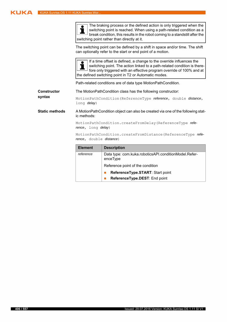
406 / 557
KUKA Sunrise.OS 1.11 KUKA Sunrise.Wor...
The switching point can be defined by a shift in space and/or time. The shift can optionally refer to the start or end point of a motion.
Path-related conditions are of data type MotionPathCondition.
Constructor
syntax
The MotionPathCondition class has the following constructor:
MotionPathCondition(ReferenceType reference, double distance, long delay)
Static methods A MotionPathCondition object can also be created via one of the following stat-ic methods:
MotionPathCondition.createFromDelay(ReferenceType refe-rence, long delay)
MotionPathCondition.createFromDistance(ReferenceType refe-rence, double distance)
The braking process or the defined action is only triggered when the switching point is reached. When using a path-related condition as a break condition, this results in the robot coming to a standstill after the
switching point rather than directly at it.
If a time offset is defined, a change to the override influences the switching point. The action linked to a path-related condition is there-fore only triggered with an effective program override of 100% and at
the defined switching point in T2 or Automatic modes.
Element Description
reference Data type: com.kuka.roboticsAPI.conditionModel.Refer-enceType
Reference point of the condition
ReferenceType.START: Start point
ReferenceType.DEST: End point
Issued: 29.07.2016 Version: KUKA Sunrise.OS 1.11 SI V1

15 Programming
Maximum offset The switching point can only be offset within certain limits. The limits apply to the entire offset, comprising the shift in space and time.
Negative offset, at most to the start point of the motion
Positive offset, at most to the end point of the motion
The following parameterizations may not be used, as they will inevitably lead to an offset beyond the permissible limits and thus to a runtime error:
Even if a valid value combination has been used, the switching point can nev-ertheless be offset beyond the permissible limits. In these cases, the response is as follows:
A condition which is met before the start of the motion triggers the motion at the start point.
A condition which is met after the end of the motion is never a trigger.
distance Offset in space relative to the reference point of the condi-tion.
For CP motions, distance specifies the Cartesian distance between the switching point and reference point (= dis-tance along the path which connects the switching point and reference point) and not the shortest distance between these points. (unit: mm)
For PTP motions, distance does not specify a Cartesian dis-tance but rather a path parameter without a unit.
Negative value: Offset contrary to the direction of mo-tion
Positive value: Offset in the direction of motion
(>>> "Maximum offset" Page 407)
delay Offset in time relative to the path point defined by distance. Or if distance is not defined, to the reference point of the condition. (unit: ms)
Negative value: Offset contrary to the direction of mo-tion
Positive value: Offset in the direction of motion
Phases in which the application is paused are not included in the time measurement.
(>>> "Maximum offset" Page 407)
Element Description
Value combination Effect
reference = ReferenceType.START
distance < 0
The switching point is before the start of the motion.
reference = ReferenceType.START
distance = 0
delay < 0
reference = ReferenceType.DEST
distance > 0
The switching point is after the end of the motion.
reference = ReferenceType.DEST
distance = 0
delay > 0
407 / 557Issued: 29.07.2016 Version: KUKA Sunrise.OS 1.11 SI V1
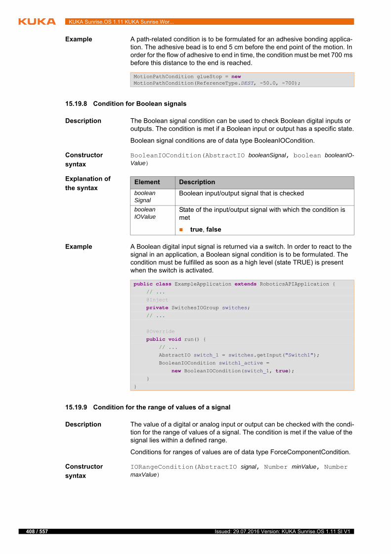
408 / 557
KUKA Sunrise.OS 1.11 KUKA Sunrise.Wor...
Example A path-related condition is to be formulated for an adhesive bonding applica-tion. The adhesive bead is to end 5 cm before the end point of the motion. In order for the flow of adhesive to end in time, the condition must be met 700 ms before this distance to the end is reached.
15.19.8 Condition for Boolean signals
Description The Boolean signal condition can be used to check Boolean digital inputs or outputs. The condition is met if a Boolean input or output has a specific state.
Boolean signal conditions are of data type BooleanIOCondition.
Constructor
syntax
BooleanIOCondition(AbstractIO booleanSignal, boolean booleanIO-Value)
Explanation of
the syntax
Example A Boolean digital input signal is returned via a switch. In order to react to the signal in an application, a Boolean signal condition is to be formulated. The condition must be fulfilled as soon as a high level (state TRUE) is present when the switch is activated.
15.19.9 Condition for the range of values of a signal
Description The value of a digital or analog input or output can be checked with the condi-tion for the range of values of a signal. The condition is met if the value of the signal lies within a defined range.
Conditions for ranges of values are of data type ForceComponentCondition.
Constructor
syntax
IORangeCondition(AbstractIO signal, Number minValue, Number maxValue)
MotionPathCondition glueStop = new MotionPathCondition(ReferenceType.DEST, -50.0, -700);
Element Description
booleanSignal
Boolean input/output signal that is checked
booleanIOValue
State of the input/output signal with which the condition is met
true, false
public class ExampleApplication extends RoboticsAPIApplication { // ...
@Inject
private SwitchesIOGroup switches; // ...
@Override
public void run() { // ...
AbstractIO switch_1 = switches.getInput("Switch1");
BooleanIOCondition switch1_active =
new BooleanIOCondition(switch_1, true); }
}
Issued: 29.07.2016 Version: KUKA Sunrise.OS 1.11 SI V1

15 Programming
Explanation of
the syntax
Example A temperature sensor returns an analog input signal whose value can lie in the range between 0 °C and 2000 °C. As soon as a threshold of 35 °C is exceed-ed, a condition for monitoring the sensor signal should be met.
15.20 Break conditions for motion commands
For certain processes a planned motion must not be fully executed but rather terminated when definable events occur. For example, in joining processes, the robot must stop if a force threshold is reached.
15.20.1 Defining break conditions
Description Break conditions are conditions which cause a motion to be terminated. A break condition is met if it already has the state TRUE before the start of the motion or if it switches to the state TRUE during the motion.
Conditions are defined as objects of type ICondition. The available condition types belong to the package com.kuka.roboticsAPI.conditionModel.
An overview of the available condition types can be found here:
To define a break condition for a motion, an object of the desired condition type is transferred to the motion command via the method breakWhen().
breakWhen(…) can be called several times when programming a motion com-mand to define different break conditions for a motion. The individual break conditions are then linked by a logic OR operation.
The following points must be taken into consideration when programming break conditions:
Element Description
signal Analog or digital input/output signal that is checked
minValue Lower limit of the range of values in which the condition is met
The value returned by the signal must be greater than or equal to minValue.
maxValue Upper limit of the range of values in which the condition is met
The value returned by the signal must be less than or equal to maxValue.
public class ExampleApplication extends RoboticsAPIApplication { // ...
@Inject
private SensorIOGroup sensors; // ...
@Override
public void run() { // ...
AbstractIO temperatureSensor =
sensors.getInput("TemperatureSensor2");
IORangeCondition tempHigher35 =
new IORangeCondition(temperatureSensor, 35.0, 2000.0); }
}
409 / 557Issued: 29.07.2016 Version: KUKA Sunrise.OS 1.11 SI V1
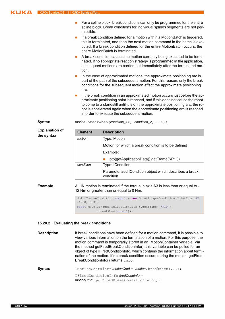
410 / 557
KUKA Sunrise.OS 1.11 KUKA Sunrise.Wor...
For a spline block, break conditions can only be programmed for the entire spline block. Break conditions for individual splines segments are not per-missible.
If a break condition defined for a motion within a MotionBatch is triggered, this is terminated, and then the next motion command in the batch is exe-cuted. If a break condition defined for the entire MotionBatch occurs, the entire MotionBatch is terminated.
A break condition causes the motion currently being executed to be termi-nated. If no appropriate reaction strategy is programmed in the application, subsequent motions are carried out immediately after the terminated mo-tion.
In the case of approximated motions, the approximate positioning arc is part of the path of the subsequent motion. For this reason, only the break conditions for the subsequent motion affect the approximate positioning arc.
If the break condition in an approximated motion occurs just before the ap-proximate positioning point is reached, and if this does not cause the robot to come to a standstill until it is on the approximate positioning arc, the ro-bot is accelerated again when the approximate positioning arc is reached in order to execute the subsequent motion.
Syntax motion.breakWhen(condition_1<, condition_2, … >);
Explanation of
the syntax
Example A LIN motion is terminated if the torque in axis A3 is less than or equal to -12 Nm or greater than or equal to 0 Nm.
15.20.2 Evaluating the break conditions
Description If break conditions have been defined for a motion command, it is possible to view various information on the termination of a motion: For this purpose, the motion command is temporarily stored in an IMotionContainer variable. Via the method getFiredBreakConditionInfo(), this variable can be polled for an object of type IFiredConditionInfo, which contains the information about termi-nation of the motion. If no break condition occurs during the motion, getFired-BreakConditionInfo() returns zero.
Syntax IMotionContainer motionCmd = motion.breakWhen(...);
IFiredConditionInfo firedCondInfo = motionCmd.getFiredBreakConditionInfo();
Element Description
motion Type: Motion
Motion for which a break condition is to be defined
Example:
ptp(getApplicationData().getFrame("/P1"))
condition Type: ICondition
Parameterized ICondition object which describes a break condition
JointTorqueCondition cond_1 = new JointTorqueCondition(JointEnum.J3, -12.0, 0.0);
robot.move(lin(getApplicationData().getFrame("/P10"))
.breakWhen(cond_1));
Issued: 29.07.2016 Version: KUKA Sunrise.OS 1.11 SI V1

15 Programming
Explanation of
the syntax
Overview The following methods are available in the IFiredConditionInfo interface:
15.20.2.1Polling a break condition
Description The condition which caused the termination of a motion can be polled via the method getFiredCondition(). The return value is of type ICondition and can be compared to the transferred break conditions via the equals(…) method.
The poll is particularly useful if several break conditions for a motion have been defined by repeatedly calling the breakWhen(…) method.
Syntax ICondition firedCondition = firedCondInfo.getFiredCondition();
Explanation of
the syntax
Example The break conditions “cond1” and “cond2” are generated.
The break conditions “cond1” and “cond2” are transferred to a LIN motion with breakWhen(…). The “motionCmd” variable of type IMotionContainer can be used to evaluate the motion command.
Element Description
motion Motion instruction
Example:
lbr.move(ptp(getApplicationData().getFrame("/P1"))
motionCmd Type: IMotionContainer
Temporary memory for the motion command
firedCondInfo Type: IFiredConditionInfo
Information about termination of the motion
Method Description
getFiredCondition() Return value type: ICondition
Polls for the condition which caused a motion to be terminated
getPositionInfo() Return value type: PositionInformation
Polls for robot position valid at the time when the break condi-tion was triggered.
getStoppedMotion() Return value type: IMotion
Polls for the segment of a spline block or the motion of a MotionBatch which was terminated
Element Description
firedCondition Type: ICondition
Variable for the return value. The variable contains the condition which caused the motion to be terminated.
firedCondInfo Type: IFiredConditionInfo
Information about termination of the motion
ICondition cond1;
ICondition cond2;
cond1 = new ...;cond2 = new ...;
IMotionContainer motionCmd =
robot.move(lin(getApplicationData().getFrame("P10"))
.breakWhen(cond1).breakWhen(cond2));
411 / 557Issued: 29.07.2016 Version: KUKA Sunrise.OS 1.11 SI V1

412 / 557
KUKA Sunrise.OS 1.11 KUKA Sunrise.Wor...
The information about the termination of the motion are polled by "motionC-md". If the polled information is not equal to null, the motion has been termi-nated. The system only polls for the triggered break condition in this case.
15.20.2.2Polling the robot position at the time of termination
Description The robot position at the time when the break condition was triggered can be polled via the method getPositionInfo().
The following position information can be accessed via the return value of type PositionInformation.
Axis-specific actual position
Cartesian actual position
Axis-specific setpoint position
Cartesian setpoint position
Setpoint/actual value difference (translational)
Setpoint/actual value difference (rotational)
Syntax PositionInformation firedPosInfo = firedCondInfo.getPositionInfo();
Explanation of
the syntax
Example The Cartesian actual position of the robot at the time when the break condition was triggered is polled via the method getCurrentCartesianPosition().
15.20.2.3Polling a terminated motion (spline block, MotionBatch)
Description Break conditions can be defined for an entire spline block or MotionBatch. If a break condition occurs, the entire spline block or MotionBatch is terminated.
The method getStoppedMotion() can be used to poll which spline segment or which motion of a MotionBatch has been terminated. The return value is of type IMotion.
Syntax IMotion stoppedMotion = firedCondInfo.getStoppedMotion();
IFiredConditionInfo firedInfo = motionCmd.getFiredConditionInfo();
if(firedInfo != null){ ICondition firedCond = firedInfo.getFiredCondition();
if(firedCond.equals(cond1)){ // ...
}
// ...
}
Element Description
firedPosInfo Type: PositionInformation
Variable for the return value. The return value contains the position information at the time when the break condition was triggered.
firedCondInfo Type: IFiredConditionInfo
Information about termination of the motion
PositionInformation firedPosInfo = firedInfo.getPositionInfo();
Frame firedCurrPos = firedPosInfo.getCurrentCartesianPosition();
Issued: 29.07.2016 Version: KUKA Sunrise.OS 1.11 SI V1
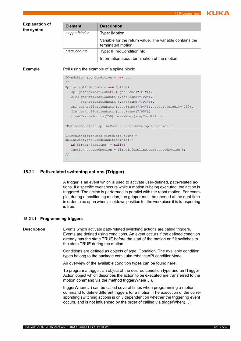
15 Programming
Explanation of
the syntax
Example Poll using the example of a spline block:
15.21 Path-related switching actions (Trigger)
A trigger is an event which is used to activate user-defined, path-related ac-tions. If a specific event occurs while a motion is being executed, the action is triggered. The action is performed in parallel with the robot motion. For exam-ple, during a positioning motion, the gripper must be opened at the right time in order to be open when a setdown position for the workpiece it is transporting is free.
15.21.1 Programming triggers
Description Events which activate path-related switching actions are called triggers. Events are defined using conditions. An event occurs if the defined condition already has the state TRUE before the start of the motion or if it switches to the state TRUE during the motion.
Conditions are defined as objects of type ICondition. The available condition types belong to the package com.kuka.roboticsAPI.conditionModel.
An overview of the available condition types can be found here:
To program a trigger, an object of the desired condition type and an ITrigger-Action object which describes the action to be executed are transferred to the motion command via the method triggerWhen(…).
triggerWhen(…) can be called several times when programming a motion command to define different triggers for a motion. The execution of the corre-sponding switching actions is only dependent on whether the triggering event occurs, and is not influenced by the order of calling via triggerWhen(…).
Element Description
stoppedMotion Type: IMotion
Variable for the return value. The variable contains the terminated motion.
firedCondInfo Type: IFiredConditionInfo
Information about termination of the motion
ICondition stopCondition = new ...;// ...
Spline splineMotion = new Spline( spl(getApplicationData().getFrame("/P1")),
circ(getApplicationData().getFrame("/P2"),
getApplicationData().getFrame("/P3")),
spl(getApplicationData().getFrame("/P4")).setCartVelocity(150),
lin(getApplicationData().getFrame("/P5"))
).setCartVelocity(250).breakWhen(stopCondition);
IMotionContainer splineCont = robot.move(splineMotion);
IFiredConditionInfo firedInfoSpline = splineCont.getFiredConditionInfo();
if(firedInfoSpline != null){ IMotion stoppedMotion = firedInfoSpline.getStoppedMotion();
// ...
}
413 / 557Issued: 29.07.2016 Version: KUKA Sunrise.OS 1.11 SI V1
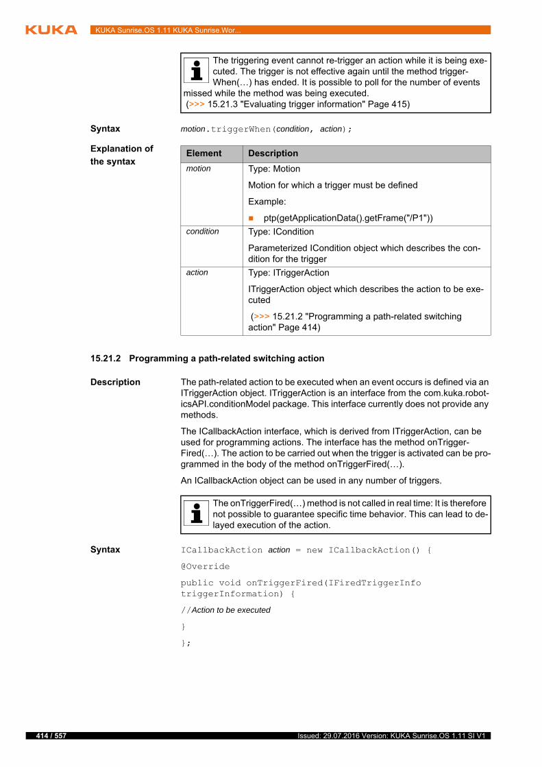
414 / 557
KUKA Sunrise.OS 1.11 KUKA Sunrise.Wor...
Syntax motion.triggerWhen(condition, action);
Explanation of
the syntax
15.21.2 Programming a path-related switching action
Description The path-related action to be executed when an event occurs is defined via an ITriggerAction object. ITriggerAction is an interface from the com.kuka.robot-icsAPI.conditionModel package. This interface currently does not provide any methods.
The ICallbackAction interface, which is derived from ITriggerAction, can be used for programming actions. The interface has the method onTrigger-Fired(…). The action to be carried out when the trigger is activated can be pro-grammed in the body of the method onTriggerFired(…).
An ICallbackAction object can be used in any number of triggers.
Syntax ICallbackAction action = new ICallbackAction() {
@Override
public void onTriggerFired(IFiredTriggerInfo triggerInformation) {
//Action to be executed
}
};
The triggering event cannot re-trigger an action while it is being exe-cuted. The trigger is not effective again until the method trigger-When(…) has ended. It is possible to poll for the number of events
missed while the method was being executed. (>>> 15.21.3 "Evaluating trigger information" Page 415)
Element Description
motion Type: Motion
Motion for which a trigger must be defined
Example:
ptp(getApplicationData().getFrame("/P1"))
condition Type: ICondition
Parameterized ICondition object which describes the con-dition for the trigger
action Type: ITriggerAction
ITriggerAction object which describes the action to be exe-cuted
(>>> 15.21.2 "Programming a path-related switching action" Page 414)
The onTriggerFired(…) method is not called in real time: It is therefore not possible to guarantee specific time behavior. This can lead to de-layed execution of the action.
Issued: 29.07.2016 Version: KUKA Sunrise.OS 1.11 SI V1

15 Programming
Explanation of
the syntax
Example During motion to point “P1”, output “DO1” is always switched at the moment when input “DI1” is TRUE.
15.21.3 Evaluating trigger information
The method onTriggerFired(…) is called when a trigger is activated. The ob-ject triggerInformation of type IFiredTriggerInfo, which contains various information about the activating trigger, is transferred to the method onTrigger-Fired(…). This trigger information can be polled.
Overview The following methods of the IFiredTriggerInfo class are available:
Element Description
action Type: ICallbackAction
ICallbackAction object which describes the action trans-ferred with triggerWhen(…)
onTriggerFired(…)
Method whose execution is fired by the trigger
triggerInformation
Type: IFiredTriggerInfo
Contains information about the firing trigger
(>>> 15.16.5.2 "Reacting to a change in state of safety signals" Page 385)
//set trigger action
ICallbackAction toggleOut_1 = new ICallbackAction() {
@Override
public void onTriggerFired(IFiredTriggerInfo triggerInformation) {
//toggle output state when trigger fired
if(IOs.getDO1()) {
IOs.setDO1(false); }
else {
IOs.setDO1(true); }
}
};
//set trigger condition
BooleanIOCondition buttonPressed = new BooleanIOCondition(IOs.getInput("DI1"), true);
//motion with trigger
robot.move(ptp(P1)).triggerWhen(buttonPressed, toggleOut_1));
robot.move(ptp(P2));
415 / 557Issued: 29.07.2016 Version: KUKA Sunrise.OS 1.11 SI V1

416 / 557
KUKA Sunrise.OS 1.11 KUKA Sunrise.Wor...
To poll for the position information obtained with getPositionInformation(), the following methods of the PositionInformation class are available:
Example 1 When the trigger is fired, the triggering time and condition are displayed on the smartHMI. For output purposes, a logger object has been integrated with de-pendency injection.
Method Description
getFiredCondition() Return value type: ICondition
Polls for the condition which fired the trigger
getMissedEvents() Return value type: int
Polls for how many times the event which fired the trigger still occurred while the triggered action was being executed
Note: The triggering event cannot re-trigger an action while it is being executed.
getMotionContainer() Return value type: IMotionContainer
Polls for the motion command, during the execution of which the trigger was fired
getPositionInforma-tion()
Return value type: PositionInformation
Polls for position information valid at the time when the trigger was fired.
The return value contains the following position information:
Axis-specific actual position
Cartesian actual position
Axis-specific setpoint position
Cartesian setpoint position
Setpoint/actual value difference (translational)
Setpoint/actual value difference (rotational)
getTriggerTime() Return value type: java.util.Date
Polls for the time at which the trigger was fired
Method Description
getCommandedCartesianPo-sition()
Return value type: Frame
Polls for the Cartesian setpoint position at triggering time
getCommandedJointPosition() Return value type: JointPosition
Polls for the axis-specific setpoint position at triggering time
getCurrentCartesianPosition() Return value type: Frame
Polls for the Cartesian actual position at triggering time
getCurrentJointPosition() Return value type: JointPosition
Polls for the axis-specific actual position at triggering time
BooleanIOCondition in1 = new BooleanIOCondition(_input_1, true);
ICallbackAction ica = new ICallbackAction() {
@Override
public void onTriggerFired(IFiredTriggerInfo triggerInformation) {
logger.info("TriggerTime: "+ triggerInformation
.getTriggerTime().toString());
logger.info("TriggerCondition: "+ triggerInformation
Issued: 29.07.2016 Version: KUKA Sunrise.OS 1.11 SI V1

15 Programming
Example 2 The axis-specific and Cartesian robot position at triggering time are polled.
15.22 Monitoring processes (Monitoring)
Monitoring means keeping a process under surveillance using a listener so that it is possible to react to certain events while an application is running.
These events are changes in state of defined conditions. The listener monitors the state of the condition. If the state of the condition changes, the listener is notified and the predetermined handling routine is triggered as a reaction.
During execution of a handling routine, the listener is not informed if further events occur. Once the handling routine has been completed, these events are only transferred to the listener and handled if the appropriate notification type has been defined.
(>>> 15.22.3 "Registering a listener for notification of change in state" Page 419)
15.22.1 Listener for monitoring conditions
Various listener interfaces are available from the package com.kuka.robotic-sAPI.conditionModel for monitoring a condition. The listeners differ in type in that they are each notified of a certain change in state of the monitored condi-tion.
Each listener type declares a method which is executed when the listener is notified. The desired handling routine is programmed in the body of this meth-od.
.getFiredCondition().toString());
}
};
robot.move(ptp(getApplicationData().getFrame("/P1"))
.triggerWhen(in1, ica));
BooleanIOCondition in1 = new BooleanIOCondition(_input_1, true);
ICallbackAction ica = new ICallbackAction() {
@Override
public void onTriggerFired(IFiredTriggerInfo triggerInformation) {
PositionInformation posInfo = triggerInformation
.getPositionInformation();
posInfo.getCommandedCartesianPosition();
posInfo.getCommandedJointPosition();
posInfo.getCurrentCartesianPosition();
posInfo.getCommandedJointPosition();
};
};
robot.move(ptp(getApplicationData().getFrame("/P1"))
.triggerWhen(in1, ica));
417 / 557Issued: 29.07.2016 Version: KUKA Sunrise.OS 1.11 SI V1
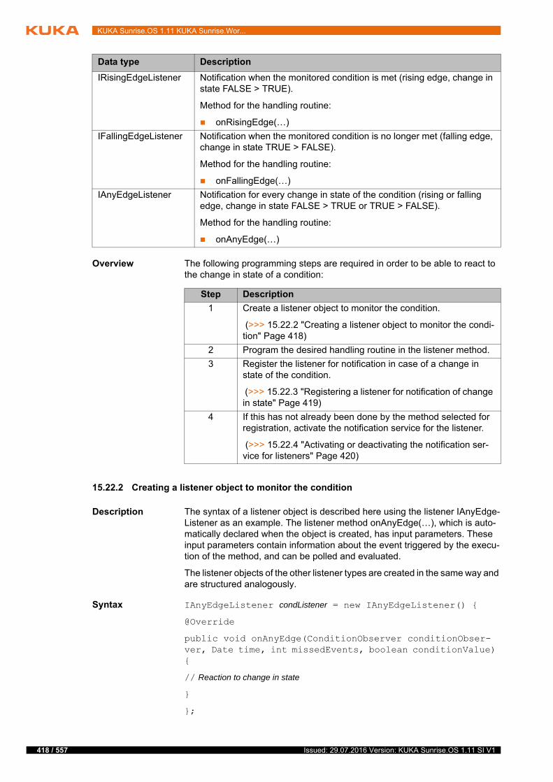
418 / 557
KUKA Sunrise.OS 1.11 KUKA Sunrise.Wor...
Overview The following programming steps are required in order to be able to react to the change in state of a condition:
15.22.2 Creating a listener object to monitor the condition
Description The syntax of a listener object is described here using the listener IAnyEdge-Listener as an example. The listener method onAnyEdge(…), which is auto-matically declared when the object is created, has input parameters. These input parameters contain information about the event triggered by the execu-tion of the method, and can be polled and evaluated.
The listener objects of the other listener types are created in the same way and are structured analogously.
Syntax IAnyEdgeListener condListener = new IAnyEdgeListener() {
@Override
public void onAnyEdge(ConditionObserver conditionObser-ver, Date time, int missedEvents, boolean conditionValue) {
// Reaction to change in state
}
};
Data type Description
IRisingEdgeListener Notification when the monitored condition is met (rising edge, change in state FALSE > TRUE).
Method for the handling routine:
onRisingEdge(…)
IFallingEdgeListener Notification when the monitored condition is no longer met (falling edge, change in state TRUE > FALSE).
Method for the handling routine:
onFallingEdge(…)
IAnyEdgeListener Notification for every change in state of the condition (rising or falling edge, change in state FALSE > TRUE or TRUE > FALSE).
Method for the handling routine:
onAnyEdge(…)
Step Description
1 Create a listener object to monitor the condition.
(>>> 15.22.2 "Creating a listener object to monitor the condi-tion" Page 418)
2 Program the desired handling routine in the listener method.
3 Register the listener for notification in case of a change in state of the condition.
(>>> 15.22.3 "Registering a listener for notification of change in state" Page 419)
4 If this has not already been done by the method selected for registration, activate the notification service for the listener.
(>>> 15.22.4 "Activating or deactivating the notification ser-vice for listeners" Page 420)
Issued: 29.07.2016 Version: KUKA Sunrise.OS 1.11 SI V1
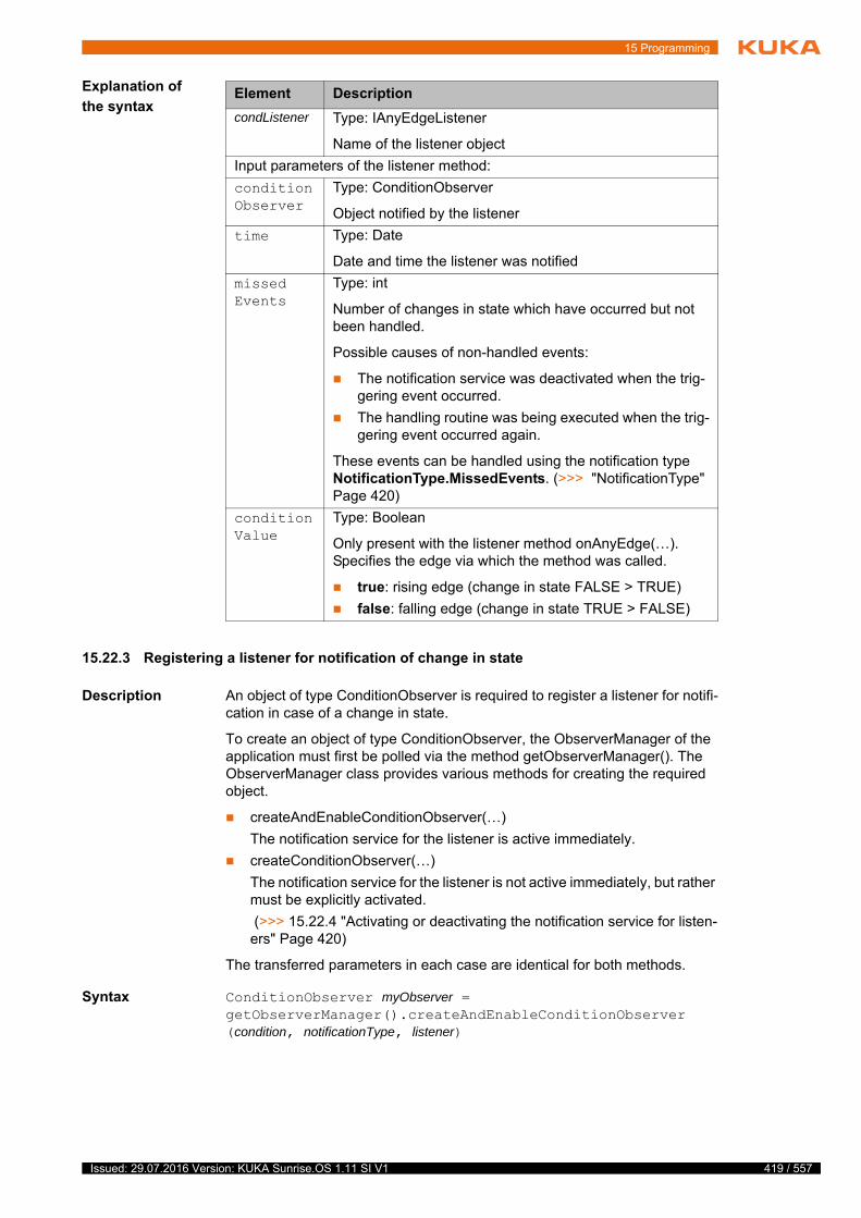
15 Programming
Explanation of
the syntax
15.22.3 Registering a listener for notification of change in state
Description An object of type ConditionObserver is required to register a listener for notifi-cation in case of a change in state.
To create an object of type ConditionObserver, the ObserverManager of the application must first be polled via the method getObserverManager(). The ObserverManager class provides various methods for creating the required object.
createAndEnableConditionObserver(…)
The notification service for the listener is active immediately.
createConditionObserver(…)
The notification service for the listener is not active immediately, but rather must be explicitly activated.
(>>> 15.22.4 "Activating or deactivating the notification service for listen-ers" Page 420)
The transferred parameters in each case are identical for both methods.
Syntax ConditionObserver myObserver = getObserverManager().createAndEnableConditionObserver(condition, notificationType, listener)
Element Description
condListener Type: IAnyEdgeListener
Name of the listener object
Input parameters of the listener method:
conditionObserver
Type: ConditionObserver
Object notified by the listener
time Type: Date
Date and time the listener was notified
missedEvents
Type: int
Number of changes in state which have occurred but not been handled.
Possible causes of non-handled events:
The notification service was deactivated when the trig-gering event occurred.
The handling routine was being executed when the trig-gering event occurred again.
These events can be handled using the notification type NotificationType.MissedEvents. (>>> "NotificationType" Page 420)
conditionValue
Type: Boolean
Only present with the listener method onAnyEdge(…). Specifies the edge via which the method was called.
true: rising edge (change in state FALSE > TRUE)
false: falling edge (change in state TRUE > FALSE)
419 / 557Issued: 29.07.2016 Version: KUKA Sunrise.OS 1.11 SI V1
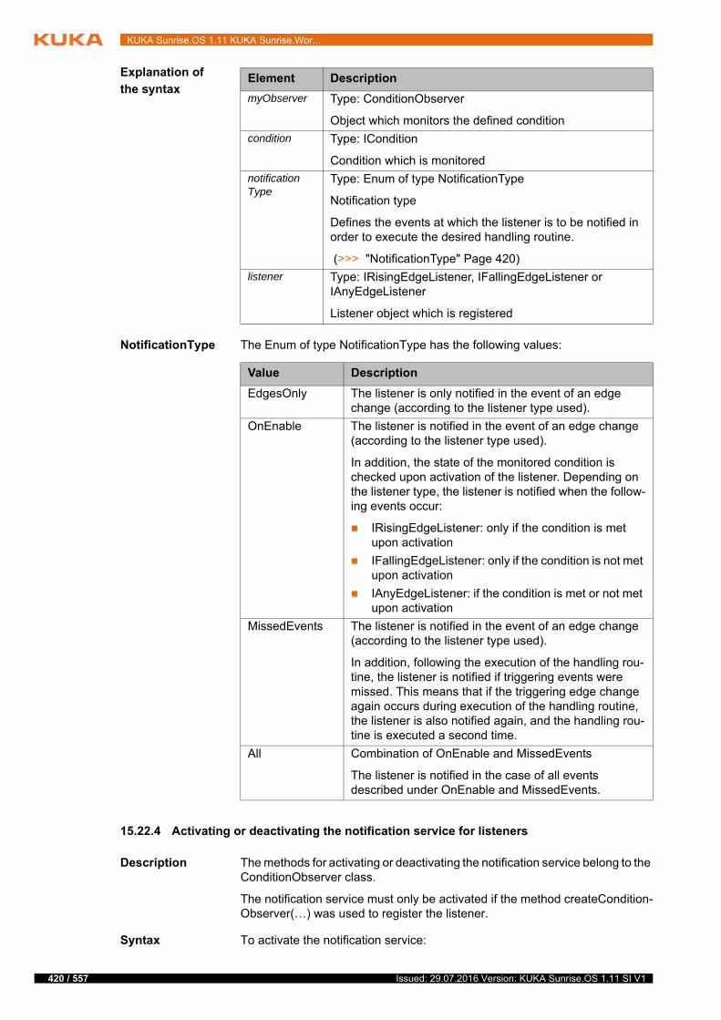
420 / 557
KUKA Sunrise.OS 1.11 KUKA Sunrise.Wor...
Explanation of
the syntax
NotificationType The Enum of type NotificationType has the following values:
15.22.4 Activating or deactivating the notification service for listeners
Description The methods for activating or deactivating the notification service belong to the ConditionObserver class.
The notification service must only be activated if the method createCondition-Observer(…) was used to register the listener.
Syntax To activate the notification service:
Element Description
myObserver Type: ConditionObserver
Object which monitors the defined condition
condition Type: ICondition
Condition which is monitored
notificationType
Type: Enum of type NotificationType
Notification type
Defines the events at which the listener is to be notified in order to execute the desired handling routine.
(>>> "NotificationType" Page 420)
listener Type: IRisingEdgeListener, IFallingEdgeListener or IAnyEdgeListener
Listener object which is registered
Value Description
EdgesOnly The listener is only notified in the event of an edge change (according to the listener type used).
OnEnable The listener is notified in the event of an edge change (according to the listener type used).
In addition, the state of the monitored condition is checked upon activation of the listener. Depending on the listener type, the listener is notified when the follow-ing events occur:
IRisingEdgeListener: only if the condition is met upon activation
IFallingEdgeListener: only if the condition is not met upon activation
IAnyEdgeListener: if the condition is met or not met upon activation
MissedEvents The listener is notified in the event of an edge change (according to the listener type used).
In addition, following the execution of the handling rou-tine, the listener is notified if triggering events were missed. This means that if the triggering edge change again occurs during execution of the handling routine, the listener is also notified again, and the handling rou-tine is executed a second time.
All Combination of OnEnable and MissedEvents
The listener is notified in the case of all events described under OnEnable and MissedEvents.
Issued: 29.07.2016 Version: KUKA Sunrise.OS 1.11 SI V1
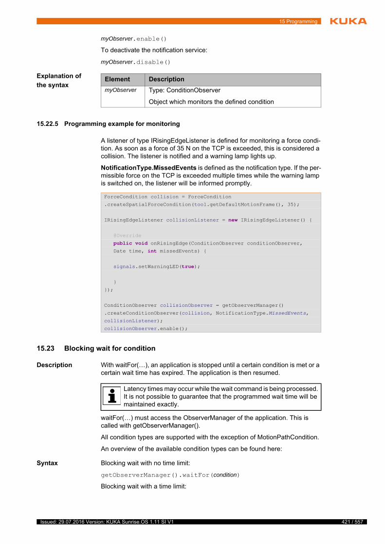
15 Programming
myObserver.enable()
To deactivate the notification service:
myObserver.disable()
Explanation of
the syntax
15.22.5 Programming example for monitoring
A listener of type IRisingEdgeListener is defined for monitoring a force condi-tion. As soon as a force of 35 N on the TCP is exceeded, this is considered a collision. The listener is notified and a warning lamp lights up.
NotificationType.MissedEvents is defined as the notification type. If the per-missible force on the TCP is exceeded multiple times while the warning lamp is switched on, the listener will be informed promptly.
15.23 Blocking wait for condition
Description With waitFor(…), an application is stopped until a certain condition is met or a certain wait time has expired. The application is then resumed.
waitFor(…) must access the ObserverManager of the application. This is called with getObserverManager().
All condition types are supported with the exception of MotionPathCondition.
An overview of the available condition types can be found here:
Syntax Blocking wait with no time limit:
getObserverManager().waitFor(condition)
Blocking wait with a time limit:
Element Description
myObserver Type: ConditionObserver
Object which monitors the defined condition
ForceCondition collision = ForceCondition
.createSpatialForceCondition(tool.getDefaultMotionFrame(), 35);
IRisingEdgeListener collisionListener = new IRisingEdgeListener() {
@Override
public void onRisingEdge(ConditionObserver conditionObserver, Date time, int missedEvents) {
signals.setWarningLED(true);
}
});
ConditionObserver collisionObserver = getObserverManager()
.createConditionObserver(collision, NotificationType.MissedEvents,
collisionListener);
collisionObserver.enable();
Latency times may occur while the wait command is being processed. It is not possible to guarantee that the programmed wait time will be maintained exactly.
421 / 557Issued: 29.07.2016 Version: KUKA Sunrise.OS 1.11 SI V1

422 / 557
KUKA Sunrise.OS 1.11 KUKA Sunrise.Wor...
boolean result = getObserverManager().waitFor(condition, timeout, timeUnit)
Explanation of
the syntax
Example A wait for a Boolean input signal is required in the application. The application is to be blocked for a maximum of 30 seconds. If the input signal is not sup-plied within this time, a defined handling routine is then to be executed.
Element Description
condition Type: ICondition
Condition which is waited for
If the condition is already met when waitFor(…) is called, the application is immediately resumed.
timeout Type: long
Maximum wait time
If the condition of the defined wait time does not occur, the application is also resumed without the occurrence of the condition.
timeUnit Type: Enum of type TimeUnit
Unit of the specified wait time
The Enum TimeUnit is an integral part of the standard Java library.
result Type: boolean
Variable for the return value of waitFor(…). The return value is true if the condition occurs within the specified wait time.
Note: If no wait time is defined, waitFor(…) does not sup-ply a return value.
public class ExampleApplication extends RoboticsAPIApplication { // ...
@Inject
private SwitchIOGroup inputs; // ...
@Override
public void run() { // ...
Input input = inputs.getInput ("Input");
BooleanIOCondition inputCondition =
new BooleanIOCondition(input, true);
boolean result = getObserverManager(). waitFor(inputCondition, 30, TimeUnit.SECONDS);
if(!result){ //do something
}
else{ //continue program
}
}
}
Issued: 29.07.2016 Version: KUKA Sunrise.OS 1.11 SI V1
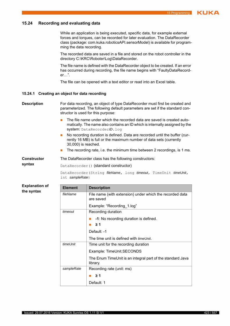
15 Programming
15.24 Recording and evaluating data
While an application is being executed, specific data, for example external forces and torques, can be recorded for later evaluation. The DataRecorder class (package: com.kuka.roboticsAPI.sensorModel) is available for program-ming the data recording.
The recorded data are saved in a file and stored on the robot controller in the directory C:\KRC\Roboter\Log\DataRecorder.
The file name is defined with the DataRecorder object to be created. If an error has occurred during recording, the file name begins with “FaultyDataRecord-er…”.
The file can be opened with a text editor or read into an Excel table.
15.24.1 Creating an object for data recording
Description For data recording, an object of type DataRecorder must first be created and parameterized. The following default parameters are set if the standard con-structor is used for this purpose:
The file name under which the recorded data are saved is created auto-matically. The name also contains an ID which is internally assigned by the system: DataRecorderID.log
No recording duration is defined. Data are recorded until the buffer (cur-rently 16 MB) is full or the maximum number of data sets (currently 30,000) is reached.
The recording rate, i.e. the minimum time between 2 recordings, is 1 ms.
Constructor
syntax
The DataRecorder class has the following constructors:
DataRecorder() (standard constructor)
DataRecorder(String fileName, long timeout, TimeUnit timeUnit, int sampleRate)
Explanation of
the syntaxElement Description
fileName File name (with extension) under which the recorded data are saved
Example: “Recording_1.log”
timeout Recording duration
-1: No recording duration is defined.
≥ 1
Default: -1
The time unit is defined with timeUnit.
timeUnit Time unit for the recording duration
Example: TimeUnit.SECONDS
The Enum TimeUnit is an integral part of the standard Java library.
sampleRate Recording rate (unit: ms)
≥ 1
Default: 1
423 / 557Issued: 29.07.2016 Version: KUKA Sunrise.OS 1.11 SI V1

424 / 557
KUKA Sunrise.OS 1.11 KUKA Sunrise.Wor...
Example 1 Data are to be recorded every 100 ms for a duration of 5 s and written to the file Recording_1.log.
Example 2 The DataRecorder object is generated using the standard constructor. This only specifies that data are recorded every 1 ms for an indefinite duration. The recorded data are to be written to the file Recording_2.log. The file name is de-fined with the corresponding “set” method.
15.24.2 Specifying data to be recorded
Using dot operators and the corresponding “add” method, the data to be re-corded are added to the DataRecorder object created for this purpose. The si-multaneous recording of various data is possible.
Overview The following “add” methods of the DataRecorder class are available:
The DataRecorder class offers “set” methods which can be used to adapt the parameter values, in particular when using the standard constructor.
setFileName(…), setSampleRate(…), setTimeout(…, …)
In setTimeout(…, …), the first parameter defines the recording duration and the second parameter defines the corresponding time unit.
DataRecorder rec_1 = new DataRecorder("Recording_1.log", 5, TimeUnit.SECONDS, 100);
DataRecorder rec_2 = new DataRecorder();rec_2.setFileName("Recording_2.log");
Method Description
addInternalJointTorque(…) Return value type: DataRecorder
Recording of the measured axis torques of the robot which is transferred as a parameter (type: robot)
addExternalJointTorque(…) Return value type: DataRecorder
Recording of the external axis torques (adjusted to the model) of the robot which is transferred as a parameter (type: robot)
addCartesianForce(…) Return value type: DataRecorder
Recording of the Cartesian forces along the X, Y and Z axes of the frame which is transferred as a parameter (unit: N). The variance of the Cartesian forces is also recorded.
A second frame can be transferred as a parameter in order to define the orientation for the force measurement. If no separate frame is specified for the orientation, null must be transferred.
Issued: 29.07.2016 Version: KUKA Sunrise.OS 1.11 SI V1

15 Programming
addCartesianTorque(…) Return value type: DataRecorder
Recording of the Cartesian torques along the X, Y and Z axes of the frame transferred as a parameter (unit: Nm). The variance of the Cartesian forces is also recorded.
A second frame can be transferred as a parameter in order to define the orientation for the torque measurement. If no sepa-rate frame is specified for the orientation, null must be trans-ferred.
Parameters:
AbstractFrame measureFrame
Frame attached to the robot flange, e.g. the TCP of a tool. Defines the position of the measurement point.
AbstractFrame orientationFrame
Defines the orientation of the measurement point.
Note: Both parameters must always be transferred together. The orientation may be null.
addCommandedJointPosi-tion(…)
Return value type: DataRecorder
Recording of the axis-specific setpoint position of the robot which is transferred as a parameter (type: robot). As a second parameter, the unit in which the axis angles are recorded must be transferred (Enum of type: AngleUnit).
addCurrentJointPosition(…) Return value type: DataRecorder
Recording of the axis-specific actual position of the robot which is transferred as a parameter (type: robot). As a second param-eter, the unit in which the axis angles are recorded must be transferred (Enum of type: AngleUnit).
Parameters:
Robot robot
AngleUnit angleUnit
AngleUnit.Degree: Axis angle in degrees
AngleUnit.Radian: Axis angle in rad
addCommandedCartesianPo-sitionXYZ(…)
Return value type: DataRecorder
Recording of the Cartesian setpoint position (translational sec-tion)
The measurement point and reference coordinate system rela-tive to which the position is recorded are transferred as parame-ters.
Method Description
425 / 557Issued: 29.07.2016 Version: KUKA Sunrise.OS 1.11 SI V1
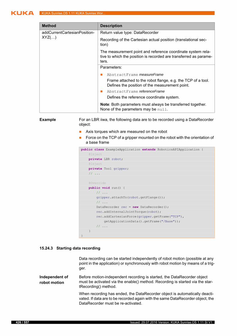
426 / 557
KUKA Sunrise.OS 1.11 KUKA Sunrise.Wor...
Example For an LBR iiwa, the following data are to be recorded using a DataRecorder object:
Axis torques which are measured on the robot
Force on the TCP of a gripper mounted on the robot with the orientation of a base frame
15.24.3 Starting data recording
Data recording can be started independently of robot motion (possible at any point in the application) or synchronously with robot motion by means of a trig-ger.
Independent of
robot motion
Before motion-independent recording is started, the DataRecorder object must be activated via the enable() method. Recording is started via the star-tRecording() method.
When recording has ended, the DataRecorder object is automatically deacti-vated. If data are to be recorded again with the same DataRecorder object, the DataRecorder must be re-activated.
addCurrentCartesianPosition-XYZ(…)
Return value type: DataRecorder
Recording of the Cartesian actual position (translational sec-tion)
The measurement point and reference coordinate system rela-tive to which the position is recorded are transferred as parame-ters.
Parameters:
AbstractFrame measureFrame
Frame attached to the robot flange, e.g. the TCP of a tool. Defines the position of the measurement point.
AbstractFrame referenceFrame
Defines the reference coordinate system.
Note: Both parameters must always be transferred together. None of the parameters may be null.
Method Description
public class ExampleApplication extends RoboticsAPIApplication { @Inject
private LBR robot; @Inject
private Tool gripper; // ...
@Override
public void run() { // ...
gripper.attachTo(robot.getFlange());
// ...
DataRecorder rec = new DataRecorder(); rec.addInternalJointTorque(robot);
rec.addCartesianForce(gripper.getFrame("TCP"),
getApplicationData().getFrame("/Base"));
// ...
}
}
Issued: 29.07.2016 Version: KUKA Sunrise.OS 1.11 SI V1
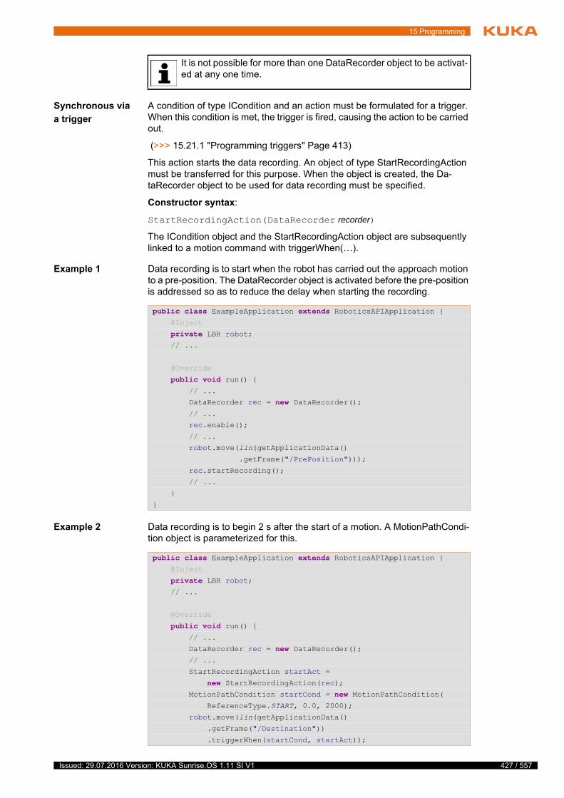
15 Programming
Synchronous via
a trigger
A condition of type ICondition and an action must be formulated for a trigger. When this condition is met, the trigger is fired, causing the action to be carried out.
(>>> 15.21.1 "Programming triggers" Page 413)
This action starts the data recording. An object of type StartRecordingAction must be transferred for this purpose. When the object is created, the Da-taRecorder object to be used for data recording must be specified.
Constructor syntax:
StartRecordingAction(DataRecorder recorder)
The ICondition object and the StartRecordingAction object are subsequently linked to a motion command with triggerWhen(…).
Example 1 Data recording is to start when the robot has carried out the approach motion to a pre-position. The DataRecorder object is activated before the pre-position is addressed so as to reduce the delay when starting the recording.
Example 2 Data recording is to begin 2 s after the start of a motion. A MotionPathCondi-tion object is parameterized for this.
It is not possible for more than one DataRecorder object to be activat-ed at any one time.
public class ExampleApplication extends RoboticsAPIApplication { @Inject
private LBR robot; // ...
@Override
public void run() { // ...
DataRecorder rec = new DataRecorder(); // ...
rec.enable();
// ...
robot.move(lin(getApplicationData()
.getFrame("/PrePosition")));
rec.startRecording();
// ...
}
}
public class ExampleApplication extends RoboticsAPIApplication { @Inject
private LBR robot; // ...
@Override
public void run() { // ...
DataRecorder rec = new DataRecorder(); // ...
StartRecordingAction startAct =
new StartRecordingAction(rec); MotionPathCondition startCond = new MotionPathCondition( ReferenceType.START, 0.0, 2000);
robot.move(lin(getApplicationData()
.getFrame("/Destination"))
.triggerWhen(startCond, startAct));
427 / 557Issued: 29.07.2016 Version: KUKA Sunrise.OS 1.11 SI V1

428 / 557
KUKA Sunrise.OS 1.11 KUKA Sunrise.Wor...
15.24.4 Ending data recording
Data recording can be ended independent of robot motion (possible at any point in the application), or synchronous with robot motion by means of a trig-ger.
In addition, recording is automatically ended when the application ends or when the recording duration specified in the DataRecorder object used has been reached.
Independent of
robot motion
Recording can be stopped at any time via the stopRecording() method.
Synchronous via
a trigger
A condition of type ICondition and an action must be formulated for a trigger. When this condition is met, the trigger is fired, causing the action to be carried out.
(>>> 15.21.1 "Programming triggers" Page 413)
This action ends the data recording. An object of type StopRecordingAction must be transferred for this purpose. When the object is created, the Da-taRecorder object to be used for data recording must be specified.
Constructor syntax:
StopRecordingAction(DataRecorder recorder)
The ICondition object and the StopRecordingAction object are linked to a mo-tion command with triggerWhen(…).
15.24.5 Polling states from the DataRecorder object
Overview The following methods of the DataRecorder class are available:
// ...
}
}
Method Description
isEnabled() Return value type: Boolean
The system polls whether the DataRecorder object is activated (= true).
isRecording() Return value type: Boolean
The system polls whether data recording is running (= true).
Issued: 29.07.2016 Version: KUKA Sunrise.OS 1.11 SI V1

15 Programming
15.24.6 Example program for data recording
The following are to be recorded during an assembly process: the torques act-ing externally on the axes of an LBR iiwa and the Cartesian forces acting on the TCP of a gripper on the robot flange. The data are to be recorded every 10 ms.
Recording is to begin synchronously with robot motion when the force acting from any direction on the TCP of the gripper exceeds 20 N. When the assem-bly process ends, recording is to end as well.
The file is then to be evaluated if it is available after a maximum of 5 s.
isFileAvailable() Return value type: Boolean
The system polls whether the file with the recorded data is already saved on the robot controller and whether it is available for evaluation (= true).
awaitFileAvailable(…) Return value type: Boolean
Blocks the calling application or background task until the defined block-ing duration has expired or until the file with the recorded data is saved on the robot controller and is available for evaluation (= true).
The blocking statement returns the value “false” if the file is not available within the maximum blocking duration.
Syntax:
awaitFileAvailable(long timeout, java.util.concur-rent.TimeUnit timeUnit)
Parameters:
timeout: maximum blocking duration
timeUnit: time unit for the maximum blocking time
Method Description
public class ExampleApplication extends RoboticsAPIApplication { @Inject
private LBR robot; @Inject
private Tool gripper; // ...
@Override
public void run() { // ...
gripper.attachTo(robot.getFlange());
// ...
DataRecorder rec = new DataRecorder();
rec.setFileName("Recording.log");
rec.setSampleRate(10);
rec.addExternalJointTorque(robot);
rec.addCartesianForce(gripper.getFrame("/TCP"), null);
StartRecordingAction startAction =
new StartRecordingAction(rec); ForceCondition startCondition = ForceCondition
.createSpatialForceCondition(
gripper.getFrame("/TCP"), 20.0);
429 / 557Issued: 29.07.2016 Version: KUKA Sunrise.OS 1.11 SI V1
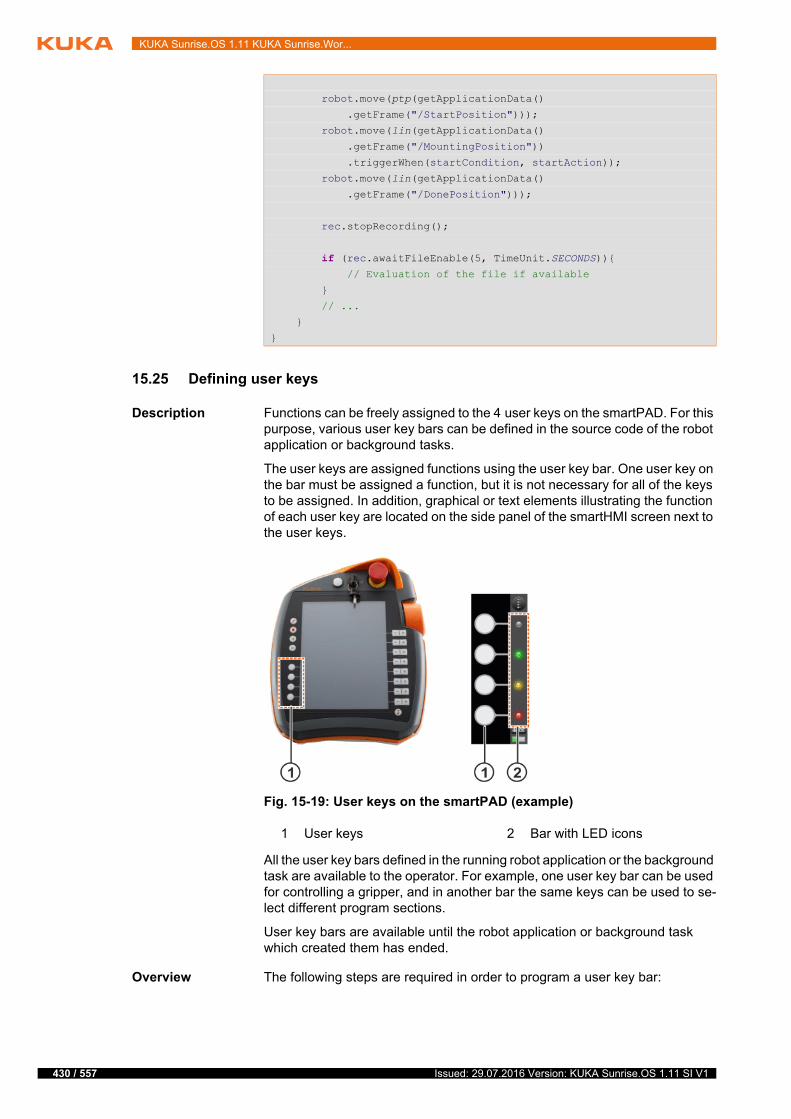
430 / 557
KUKA Sunrise.OS 1.11 KUKA Sunrise.Wor...
15.25 Defining user keys
Description Functions can be freely assigned to the 4 user keys on the smartPAD. For this purpose, various user key bars can be defined in the source code of the robot application or background tasks.
The user keys are assigned functions using the user key bar. One user key on the bar must be assigned a function, but it is not necessary for all of the keys to be assigned. In addition, graphical or text elements illustrating the function of each user key are located on the side panel of the smartHMI screen next to the user keys.
All the user key bars defined in the running robot application or the background task are available to the operator. For example, one user key bar can be used for controlling a gripper, and in another bar the same keys can be used to se-lect different program sections.
User key bars are available until the robot application or background task which created them has ended.
Overview The following steps are required in order to program a user key bar:
robot.move(ptp(getApplicationData()
.getFrame("/StartPosition")));
robot.move(lin(getApplicationData()
.getFrame("/MountingPosition"))
.triggerWhen(startCondition, startAction));
robot.move(lin(getApplicationData()
.getFrame("/DonePosition")));
rec.stopRecording();
if (rec.awaitFileEnable(5, TimeUnit.SECONDS)){
// Evaluation of the file if available
}
// ...
}
}
Fig. 15-19: User keys on the smartPAD (example)
1 User keys 2 Bar with LED icons
Issued: 29.07.2016 Version: KUKA Sunrise.OS 1.11 SI V1

15 Programming
15.25.1 Creating a user key bar
Description The following methods are required in order to create a user key bar:
getApplicationUI()
This method is used to access the interface to the smartHMI graphical user interface from a robot application or a background task. Return value type: ITaskUI
createUserKeyBar(…)
This method is used to create the user key bar. It is part of the ITaskUI in-terface.
Syntax IUserKeyBar keybar = getApplicationUI().createUserKeyBar("name");
Explanation of
the syntax
Example A user key bar for controlling a gripper is created.
Step Description
1 Create a user key bar.
(>>> 15.25.1 "Creating a user key bar" Page 431)
2 Add user keys to the bar (at least one).
(>>> 15.25.2 "Adding user keys to the bar" Page 432)
3 Define the function which is to be executed if the user key is actuated.
(>>> 15.25.3 "Defining the function of a user key" Page 433)
4 Assign at least one graphical or text element to the area along the left side panel of the smartHMI next to the user key.
(>>> 15.25.4 "Labeling and graphical assignment of the user key bar" Page 435)
5 For user keys which trigger functions associated with a risk: Define the warning message to be displayed when the user key is actuated. The message appears before the function can be triggered.
(>>> 15.25.5 "Identifying safety-critical user keys" Page 438)
6 Publish a user key bar.
(>>> 15.25.6 "Publishing a user key bar" Page 439)
Element Description
keybar Type: IUserKeyBar
Name of the user key bar created with createUserKey-Bar(…)
name Type: String
Name under which the user key bar is displayed on the smartHMI (>>> Fig. 6-9 )
The number of characters which can be displayed is lim-ited.
A maximum of 12 to 15 characters is recommended.
IUserKeyBar gripperBar = getApplicationUI().createUserKeyBar("Gripper");
431 / 557Issued: 29.07.2016 Version: KUKA Sunrise.OS 1.11 SI V1

432 / 557
KUKA Sunrise.OS 1.11 KUKA Sunrise.Wor...
15.25.2 Adding user keys to the bar
Description A newly created user key bar does not have any user keys to start with. The user keys to be used must be added to the bar.
The IUserKeyBar interface provides the following methods for this purpose:
addUserKey(…)
Adds a single user key to the bar.
addDoubleUserKey(…)
Combines 2 neighboring user keys to a double key and adds this to the bar. The corresponding areas on the side panel of the smartHMI screen are also combined into a larger area.
When adding a user key to a bar, the user defines the function to be executed when the user key is actuated (e.g. opening a gripper, changing a parameter, etc.). Depending on the programming, both pressing and releasing the user key can be interpreted as actuation and linked to a function.
A user key bar must have at least one user key. Each user key is assigned a unique number. This number is transferred when a user key is added.
Syntax Adding a single key:
IUserKey key = keybar.addUserKey(slot, listener, ignoreEvents);
Adding a double key:
IUserKey doubleKey = keybar.addDoubleUserKey(slot, listener, igno-reEvents);
Explanation of
the syntax
Fig. 15-20: Numbering of the user keys
1 Single keys 2 Double keys
Element Description
keybar Type: IUserKeyBar
Name of the user key bar to which a user key is added
key Type: IUserKey
Name of the single key added to the bar
doubleKey Type: IUserKey
Name of the double key added to the bar
Issued: 29.07.2016 Version: KUKA Sunrise.OS 1.11 SI V1

15 Programming
Example The user keys are assigned the following functions for controlling a gripper:
The top user key is to be used to open the gripper, and the key below it is to close the gripper.
The two lower user keys are combined in a double key. This is to be used to increase and decrease the velocity of the gripper.
The functions for opening and closing the gripper are not to be called again until the respective function has ended.
15.25.3 Defining the function of a user key
Description In order to define which function is to be executed when a user key is actuated, a listener object of type IUserKeyListener must be created. The on-KeyEvent(…) method is automatically declared when the object is created.
The listener method onKeyEvent(…) is called when the following events oc-cur:
The user key is pressed.
The user key is released.
slot Type: int
Number of the user key which is added.
Single keys:
0 … 3
Double keys:
0, 2
listener Type: IUserKeyListener
Name of the listener used to define the function to be exe-cuted when the user key is actuated
(>>> 15.25.3 "Defining the function of a user key" Page 433)
ignoreEvents Type: boolean
Defines whether there is a reaction if the user key is re-actuated while the key function is being executed
true: If the key is actuated while the function is being ex-ecuted, it has no effect.
false: It is counted how many times the key is actuated while the function is being executed. The function is re-peated this many times.
Element Description
IUserKeyBar gripperBar = getApplicationUI().createUserKeyBar("Gripper");
IUserKeyListener openGripperListener = ...;
IUserKeyListener closeGripperListener = ...;
IUserKeyListener gripperVelocityListener = ...;
IUserKey openKey = gripperBar.addUserKey(0,
openGripperListener, true);IUserKey closeKey = gripperBar.addUserKey(1,
closeGripperListener, true);IUserKey velocityKey = gripperBar.addDoubleUserKey(2,
gripperVelocityListener, false);
433 / 557Issued: 29.07.2016 Version: KUKA Sunrise.OS 1.11 SI V1
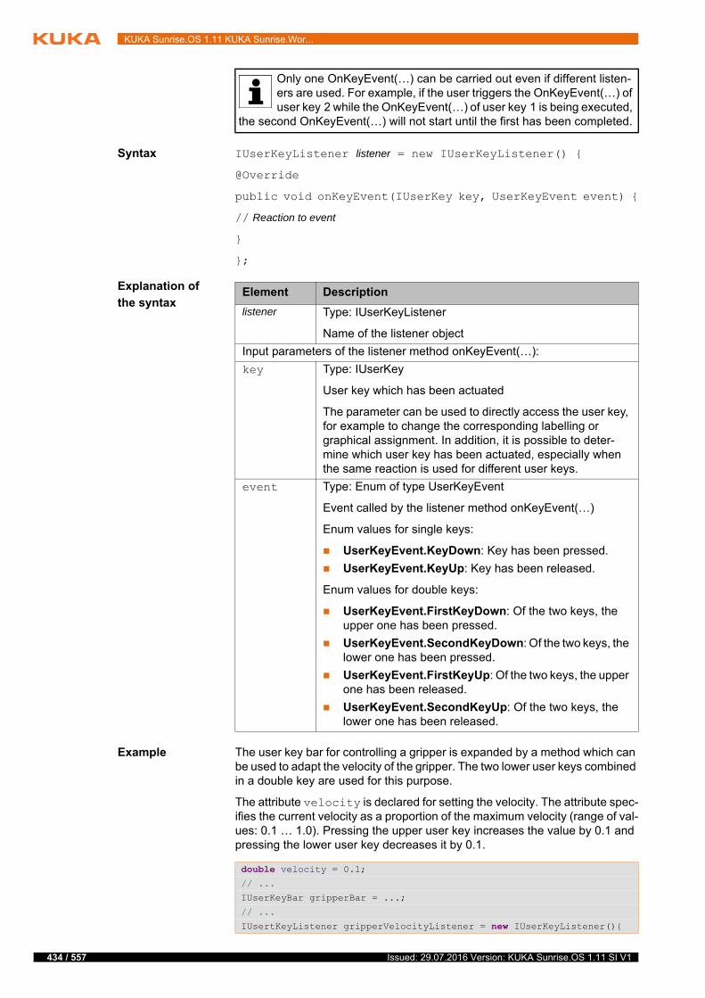
434 / 557
KUKA Sunrise.OS 1.11 KUKA Sunrise.Wor...
Syntax IUserKeyListener listener = new IUserKeyListener() {
@Override
public void onKeyEvent(IUserKey key, UserKeyEvent event) {
// Reaction to event
}
};
Explanation of
the syntax
Example The user key bar for controlling a gripper is expanded by a method which can be used to adapt the velocity of the gripper. The two lower user keys combined in a double key are used for this purpose.
The attribute velocity is declared for setting the velocity. The attribute spec-ifies the current velocity as a proportion of the maximum velocity (range of val-ues: 0.1 … 1.0). Pressing the upper user key increases the value by 0.1 and pressing the lower user key decreases it by 0.1.
Only one OnKeyEvent(…) can be carried out even if different listen-ers are used. For example, if the user triggers the OnKeyEvent(…) of user key 2 while the OnKeyEvent(…) of user key 1 is being executed,
the second OnKeyEvent(…) will not start until the first has been completed.
Element Description
listener Type: IUserKeyListener
Name of the listener object
Input parameters of the listener method onKeyEvent(…):
key Type: IUserKey
User key which has been actuated
The parameter can be used to directly access the user key, for example to change the corresponding labelling or graphical assignment. In addition, it is possible to deter-mine which user key has been actuated, especially when the same reaction is used for different user keys.
event Type: Enum of type UserKeyEvent
Event called by the listener method onKeyEvent(…)
Enum values for single keys:
UserKeyEvent.KeyDown: Key has been pressed.
UserKeyEvent.KeyUp: Key has been released.
Enum values for double keys:
UserKeyEvent.FirstKeyDown: Of the two keys, the upper one has been pressed.
UserKeyEvent.SecondKeyDown: Of the two keys, the lower one has been pressed.
UserKeyEvent.FirstKeyUp: Of the two keys, the upper one has been released.
UserKeyEvent.SecondKeyUp: Of the two keys, the lower one has been released.
double velocity = 0.1;// ...
IUserKeyBar gripperBar = ...;
// ...
IUsertKeyListener gripperVelocityListener = new IUserKeyListener(){
Issued: 29.07.2016 Version: KUKA Sunrise.OS 1.11 SI V1

15 Programming
15.25.4 Labeling and graphical assignment of the user key bar
Description At least one graphical or text element must be assigned to the area along the left side panel of the smartHMI next to the user key. LED icons of various col-ors and sizes are available as graphical elements. These elements can be adapted during the runtime of the robot application or the background task.
In order to clearly position the individual elements, the area next to the user key is divided into a grid with 3x3 spaces. This also applies for user keys that have been grouped together as a double key. In the case of double keys, the grid stretches over both fields.
One element can be set in each grid space. This grid space is defined by the value of the enum UserKeyAlignment. If a new element is allocated to a grid space which has already been assigned, the existing element is deleted.
UserKey
alignment
@Override
public void onKeyEvent(IUserKey key, IUserKeyEvent event){ if(event == UserKeyEvent.FirstKeyDown && velocity <= 0.9){ velocity = velocity + 0.1;
}
else if(event == UserKeyEvent.SecondKeyDown && velocity >= 0.2){ velocity = velocity – 0.1;
}
}
};
// ...
IUserKey velocityKey = gripperBar.addDoubleUserKey(2,
gripperVelocityListener, false);
Fig. 15-21: Division of the grid
1 Single keys 2 Double keys
Grid space no.
Value
1 UserKeyAlignment.TopLeft
2 UserKeyAlignment.TopMiddle
3 UserKeyAlignment.TopRight
4 UserKeyAlignment.MiddleLeft
5 UserKeyAlignment.Middle
6 UserKeyAlignment.MiddleRight
7 UserKeyAlignment.BottomLeft
8 UserKeyAlignment.BottomMiddle
9 UserKeyAlignment.BottomRight
435 / 557Issued: 29.07.2016 Version: KUKA Sunrise.OS 1.11 SI V1
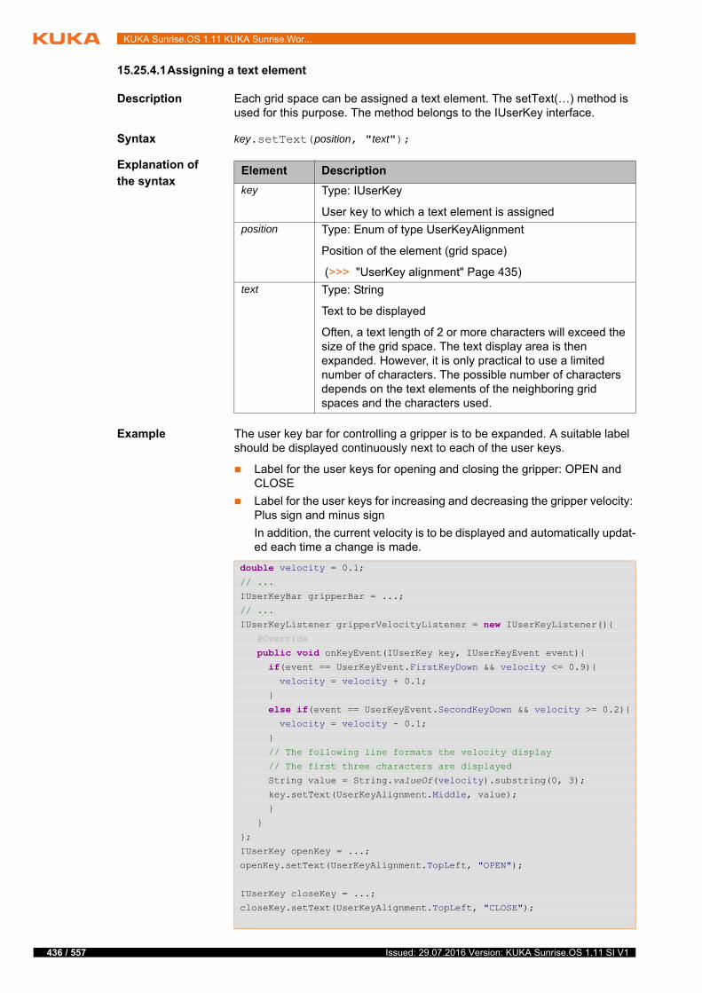
436 / 557
KUKA Sunrise.OS 1.11 KUKA Sunrise.Wor...
15.25.4.1Assigning a text element
Description Each grid space can be assigned a text element. The setText(…) method is used for this purpose. The method belongs to the IUserKey interface.
Syntax key.setText(position, "text");
Explanation of
the syntax
Example The user key bar for controlling a gripper is to be expanded. A suitable label should be displayed continuously next to each of the user keys.
Label for the user keys for opening and closing the gripper: OPEN and CLOSE
Label for the user keys for increasing and decreasing the gripper velocity: Plus sign and minus sign
In addition, the current velocity is to be displayed and automatically updat-ed each time a change is made.
Element Description
key Type: IUserKey
User key to which a text element is assigned
position Type: Enum of type UserKeyAlignment
Position of the element (grid space)
(>>> "UserKey alignment" Page 435)
text Type: String
Text to be displayed
Often, a text length of 2 or more characters will exceed the size of the grid space. The text display area is then expanded. However, it is only practical to use a limited number of characters. The possible number of characters depends on the text elements of the neighboring grid spaces and the characters used.
double velocity = 0.1;// ...
IUserKeyBar gripperBar = ...;
// ...
IUserKeyListener gripperVelocityListener = new IUserKeyListener(){ @Override
public void onKeyEvent(IUserKey key, IUserKeyEvent event){ if(event == UserKeyEvent.FirstKeyDown && velocity <= 0.9){ velocity = velocity + 0.1;
}
else if(event == UserKeyEvent.SecondKeyDown && velocity >= 0.2){ velocity = velocity - 0.1;
}
// The following line formats the velocity display
// The first three characters are displayed
String value = String.valueOf(velocity).substring(0, 3);
key.setText(UserKeyAlignment.Middle, value);
}
}
};
IUserKey openKey = ...;
openKey.setText(UserKeyAlignment.TopLeft, "OPEN");
IUserKey closeKey = ...;
closeKey.setText(UserKeyAlignment.TopLeft, "CLOSE");
Issued: 29.07.2016 Version: KUKA Sunrise.OS 1.11 SI V1
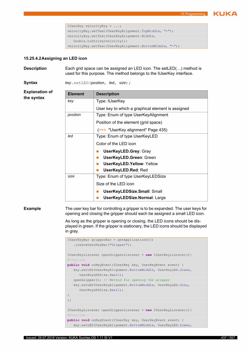
15 Programming
15.25.4.2Assigning an LED icon
Description Each grid space can be assigned an LED icon. The setLED(…) method is used for this purpose. The method belongs to the IUserKey interface.
Syntax key.setLED(position, led, size);
Explanation of
the syntax
Example The user key bar for controlling a gripper is to be expanded. The user keys for opening and closing the gripper should each be assigned a small LED icon.
As long as the gripper is opening or closing, the LED icons should be dis-played in green. If the gripper is stationary, the LED icons should be displayed in gray.
IUserKey velocityKey = ...;
velocityKey.setText(UserKeyAlignment.TopMiddle, "+");
velocitykey.setText(UserKeyAlignment.Middle,
Double.toString(velocity));
velocityKey.setText(UserKeyAlignment.BottomMiddle, "-");
Element Description
key Type: IUserKey
User key to which a graphical element is assigned
position Type: Enum of type UserKeyAlignment
Position of the element (grid space)
(>>> "UserKey alignment" Page 435)
led Type: Enum of type UserKeyLED
Color of the LED icon
UserKeyLED.Grey: Gray
UserKeyLED.Green: Green
UserKeyLED.Yellow: Yellow
UserKeyLED.Red: Red
size Type: Enum of type UserKeyLEDSize
Size of the LED icon
UserKeyLEDSize.Small: Small
UserKeyLEDSize.Normal: Large
IUserKeyBar gripperBar = getApplicationUI()
.createUserKeyBar("Gripper");
IUserKeyListener openGripperListener = new IUserKeyListener(){@Override
public void onKeyEvent(IUserKey key, UserKeyEvent event) { key.setLED(UserKeyAlignment.BottomMiddle, UserKeyLED.Green,
UserKeyLEDSize.Small);
openGripper(); // Method for opening the gripper
key.setLED(UserKeyAlignment.BottomMiddle, UserKeyLED.Grey,
UserKeyLEDSize.Small);
}
};
IUserKeyListener openGripperListener = new IUserKeyListener(){@Override
public void onKeyEvent(IUserKey key, UserKeyEvent event) { key.setLED(UserKeyAlignment.BottomMiddle, UserKeyLED.Green,
437 / 557Issued: 29.07.2016 Version: KUKA Sunrise.OS 1.11 SI V1
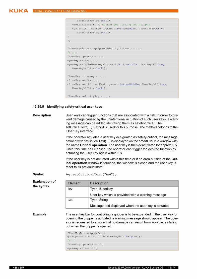
438 / 557
KUKA Sunrise.OS 1.11 KUKA Sunrise.Wor...
15.25.5 Identifying safety-critical user keys
Description User keys can trigger functions that are associated with a risk. In order to pre-vent damage caused by the unintentional actuation of such user keys, a warn-ing message can be added identifying them as safety-critical. The setCriticalText(…) method is used for this purpose. The method belongs to the IUserKey interface.
If the operator actuates a user key designated as safety-critical, the message defined with setCriticalText(…) is displayed on the smartHMI in a window with the name Critical operation. The user key is then deactivated for approx. 5 s. Once this time has elapsed, the operator can trigger the desired function by actuating the user key again within 5 s.
If the user key is not actuated within this time or if an area outside of the Crit-ical operation window is touched, the window is closed and the user key is reset to its previous state.
Syntax key.setCriticalText("text");
Explanation of
the syntax
Example The user key bar for controlling a gripper is to be expanded. If the user key for opening the gripper is actuated, a warning message should appear. The oper-ator is requested to ensure that no damage can result from workpieces falling out when the gripper is opened.
UserKeyLEDSize.Small);
closeGripper(); // Method for closing the gripper
key.setLED(UserKeyAlignment.BottomMiddle, UserKeyLED.Grey,
UserKeyLEDSize.Small);
}
};
IUserKeyListener gripperVelocityListener = ...;
// ...
IUserKey openKey = ...;
openKey.setText...;
openKey.setLED(UserKeyAlignment.BottomMiddle, UserKeyLED.Grey,
UserKeyLEDSize.Small);
IUserKey closeKey = ...;
closeKey.setText...;
closeKey.setLED(UserKeyAlignment.BottomMiddle, UserKeyLED.Grey,
UserKeyLEDSize.Small);
IUserKey velocityKey = ...;
Element Description
key Type: IUserKey
User key which is provided with a warning message
text Type: String
Message text displayed when the user key is actuated
IUserKeyBar gripperBar = getApplicationUI().createUserKeyBar("Gripper");
// ...
IUserKey openKey = ...;
openKey.setText...;
Issued: 29.07.2016 Version: KUKA Sunrise.OS 1.11 SI V1
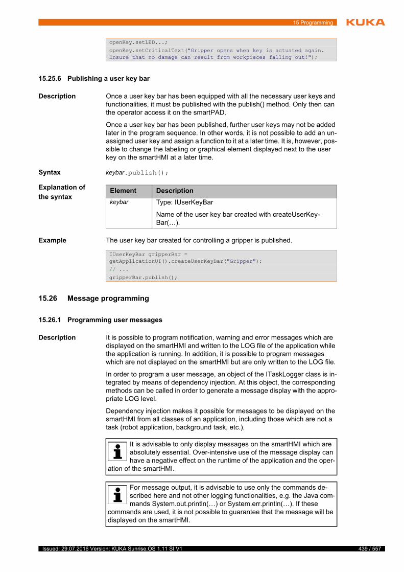
15 Programming
15.25.6 Publishing a user key bar
Description Once a user key bar has been equipped with all the necessary user keys and functionalities, it must be published with the publish() method. Only then can the operator access it on the smartPAD.
Once a user key bar has been published, further user keys may not be added later in the program sequence. In other words, it is not possible to add an un-assigned user key and assign a function to it at a later time. It is, however, pos-sible to change the labeling or graphical element displayed next to the user key on the smartHMI at a later time.
Syntax keybar.publish();
Explanation of
the syntax
Example The user key bar created for controlling a gripper is published.
15.26 Message programming
15.26.1 Programming user messages
Description It is possible to program notification, warning and error messages which are displayed on the smartHMI and written to the LOG file of the application while the application is running. In addition, it is possible to program messages which are not displayed on the smartHMI but are only written to the LOG file.
In order to program a user message, an object of the ITaskLogger class is in-tegrated by means of dependency injection. At this object, the corresponding methods can be called in order to generate a message display with the appro-priate LOG level.
Dependency injection makes it possible for messages to be displayed on the smartHMI from all classes of an application, including those which are not a task (robot application, background task, etc.).
openKey.setLED...;
openKey.setCriticalText("Gripper opens when key is actuated again. Ensure that no damage can result from workpieces falling out!");
Element Description
keybar Type: IUserKeyBar
Name of the user key bar created with createUserKey-Bar(…).
IUserKeyBar gripperBar = getApplicationUI().createUserKeyBar("Gripper");
// ...
gripperBar.publish();
It is advisable to only display messages on the smartHMI which are absolutely essential. Over-intensive use of the message display can have a negative effect on the runtime of the application and the oper-
ation of the smartHMI.
For message output, it is advisable to use only the commands de-scribed here and not other logging functionalities, e.g. the Java com-mands System.out.println(…) or System.err.println(…). If these
commands are used, it is not possible to guarantee that the message will be displayed on the smartHMI.
439 / 557Issued: 29.07.2016 Version: KUKA Sunrise.OS 1.11 SI V1
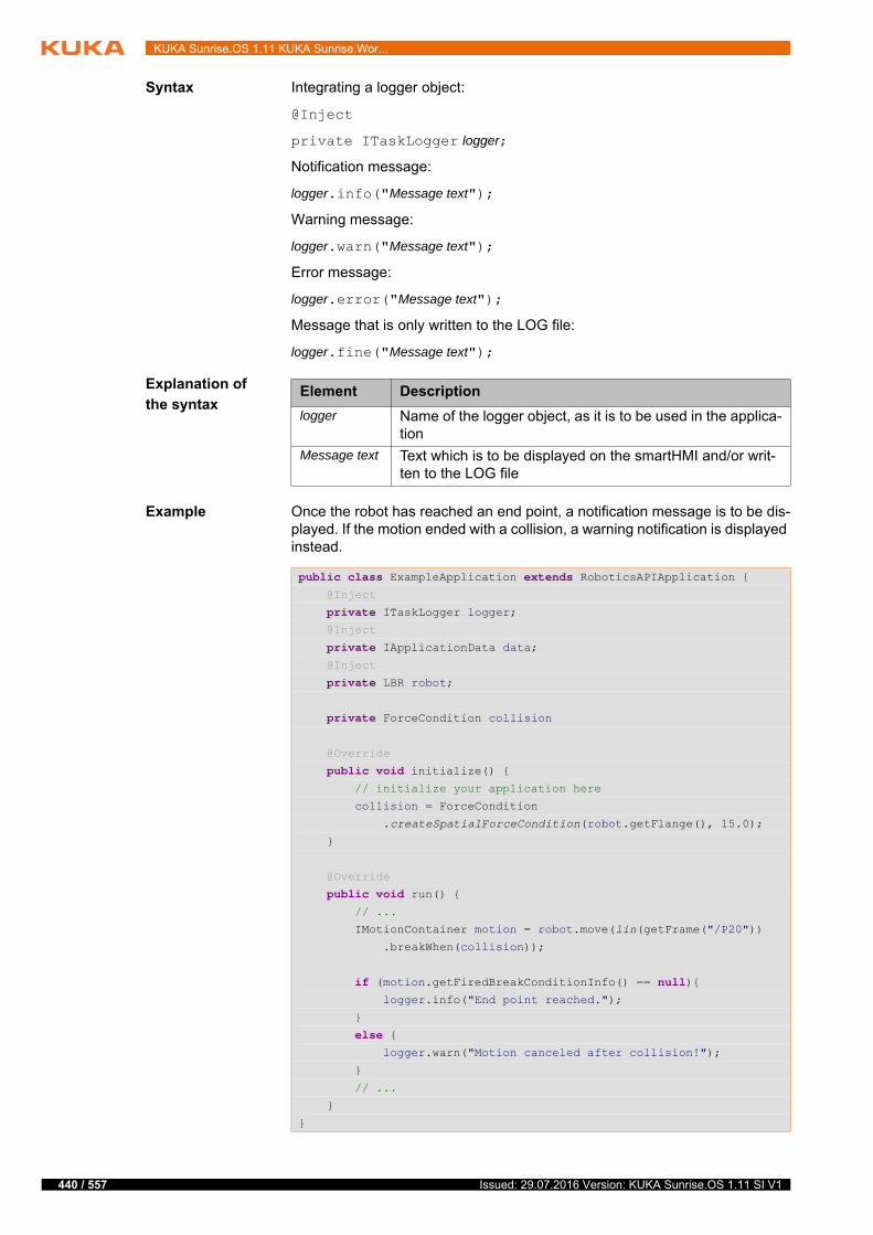
440 / 557
KUKA Sunrise.OS 1.11 KUKA Sunrise.Wor...
Syntax Integrating a logger object:
@Inject
private ITaskLogger logger;
Notification message:
logger.info("Message text");
Warning message:
logger.warn("Message text");
Error message:
logger.error("Message text");
Message that is only written to the LOG file:
logger.fine("Message text");
Explanation of
the syntax
Example Once the robot has reached an end point, a notification message is to be dis-played. If the motion ended with a collision, a warning notification is displayed instead.
Element Description
logger Name of the logger object, as it is to be used in the applica-tion
Message text Text which is to be displayed on the smartHMI and/or writ-ten to the LOG file
public class ExampleApplication extends RoboticsAPIApplication { @Inject
private ITaskLogger logger; @Inject
private IApplicationData data; @Inject
private LBR robot;
private ForceCondition collision
@Override
public void initialize() { // initialize your application here
collision = ForceCondition
.createSpatialForceCondition(robot.getFlange(), 15.0);
}
@Override
public void run() { // ...
IMotionContainer motion = robot.move(lin(getFrame("/P20"))
.breakWhen(collision));
if (motion.getFiredBreakConditionInfo() == null){ logger.info("End point reached.");
}
else { logger.warn("Motion canceled after collision!");
}
// ...
}
}
Issued: 29.07.2016 Version: KUKA Sunrise.OS 1.11 SI V1
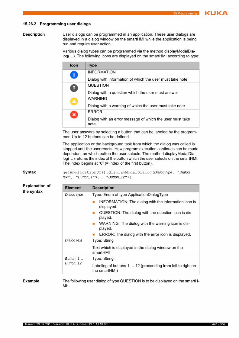
15 Programming
15.26.2 Programming user dialogs
Description User dialogs can be programmed in an application. These user dialogs are displayed in a dialog window on the smartHMI while the application is being run and require user action.
Various dialog types can be programmed via the method displayModalDia-log(…). The following icons are displayed on the smartHMI according to type:
The user answers by selecting a button that can be labeled by the program-mer. Up to 12 buttons can be defined.
The application or the background task from which the dialog was called is stopped until the user reacts. How program execution continues can be made dependent on which button the user selects. The method displayModalDia-log(…) returns the index of the button which the user selects on the smartHMI. The index begins at “0” (= index of the first button).
Syntax getApplicationUI().displayModalDialog(Dialog type, "Dialog text", "Button_1"<, … "Button_12">)
Explanation of
the syntax
Example The following user dialog of type QUESTION is to be displayed on the smartH-MI:
Icon Type
INFORMATION
Dialog with information of which the user must take note
QUESTION
Dialog with a question which the user must answer
WARNING
Dialog with a warning of which the user must take note
ERROR
Dialog with an error message of which the user must take note
Element Description
Dialog type Type: Enum of type ApplicationDialogType
INFORMATION: The dialog with the information icon is displayed.
QUESTION: The dialog with the question icon is dis-played.
WARNING: The dialog with the warning icon is dis-played.
ERROR: The dialog with the error icon is displayed.
Dialog text Type: String
Text which is displayed in the dialog window on the smartHMI
Button_1 … Button_12
Type: String
Labeling of buttons 1 … 12 (proceeding from left to right on the smartHMI)
441 / 557Issued: 29.07.2016 Version: KUKA Sunrise.OS 1.11 SI V1

442 / 557
KUKA Sunrise.OS 1.11 KUKA Sunrise.Wor...
15.27 Program execution control
15.27.1 Pausing an application
Description An application can be paused with the halt() method.
The halt() method pauses the motion currently being executed, and the appli-cation state on the smartHMI switches to Motion paused.
halt() causes a blocking stop of the calling thread. If further threads are running at the same time, these will continue to be executed. The application execution is only stopped if halt() is called in the application thread. It is therefore advis-able not to call halt() in handling routines for path-related switching actions or in handling routines for monitoring processes. Instead, it is advisable to use the pause() method in these handling routines.
(>>> 15.27.2 "Pausing motion execution" Page 442)
The motion and paused thread may only be resumed via the Start key on the smartPAD. Pressing the Start key causes the paused motion to resume. The paused thread is resumed with the instruction following halt() in the source code.
Syntax getApplicationControl().halt();
15.27.2 Pausing motion execution
Description Motion execution can be paused with the pause() method.
The behavior corresponds to pausing the application via the smartPAD. The pause() method pauses the motion currently being executed, and the applica-tion state on the smartHMI switches to Motion paused.
Fig. 15-22: Example of a user dialog
int direction = getApplicationUI().displayModalDialog( ApplicationDialogType.QUESTION,
"Where do you want to go to?",
"To the left", "To the right", "To HOME-Position");
switch (direction) { case 0: robot.move(ptp(getApplicationData().getFrame("/Left")));
break; case 1: robot.move(ptp(getApplicationData().getFrame("/Right")));
break; case 2: robot.move(ptpHome());
break;}
Issued: 29.07.2016 Version: KUKA Sunrise.OS 1.11 SI V1
15 Programming
pause() does not cause a blocking wait. The application continues to be exe-cuted until a synchronous motion command is reached.
Motion execution may only be resumed via the Start key on the smartPAD.
Syntax getApplicationControl().pause();
15.27.3 FOR loop
Description The FOR loop, also called counting loop, repeats a statement block as long as a defined condition is met.
A counter is defined, which is increased or decreased by a constant value with each execution of the loop. At the beginning of a loop execution, the system checks if a defined condition is met. This condition is generally formulated by comparing the counter with a limit value. If the condition is no longer met, the loop is no longer executed and the program is continued after the loop.
The FOR loop is generally used if it is known how often a loop must be exe-cuted.
FOR loops can be nested.
(>>> 15.27.8 "Examples of nested loops" Page 449)
Syntax for (int Counter = Start value; Condition; Counting statement){
Statement_1;
<...
Statement_n;
}
Explanation of
the syntax
Example
Element Description
Counters Counter for the number of loops executed
The counter is assigned a start value. With each execution of the loop, the counter is increased or decreased by a constant value.
Start value Start value of the counter
Condition Condition for the loop execution
The counter is generally compared with a limit value. The result of the comparison is always of type Boolean. The loop is ended as soon as the comparison returns FALSE, meaning that the condition is no longer met.
Counting statement
The counting statement determines the amount by which the counter is changed with each execution of the loop. The increment and counting direction can be specified in different ways.
Examples:
Start value ++|--: With each execution of the loop, the start value is increased or decreased by a value of 1.
Start value +|- Increment: With each execution of the loop, the start value is increased or decreased by the specified increment.
for (int i = 0; i < 10; i++){ logger.info(i);
}
443 / 557Issued: 29.07.2016 Version: KUKA Sunrise.OS 1.11 SI V1

444 / 557
KUKA Sunrise.OS 1.11 KUKA Sunrise.Wor...
The value of the variable i is increased by 1 with every cycle. The current val-ue of i is displayed on the smartHMI with every cycle. The loop is executed a total of 10 times. The values of 0 to 9 are displayed in the process. For output purposes, a logger object has been integrated with dependency injection.
15.27.4 WHILE loop
Description The WHILE loop repeats a statement block for as long as a certain condition is fulfilled. It is also called a rejecting loop because the condition is checked before every loop execution.
If the condition is no longer met, the statement block of the loop is no longer executed and the program is resumed after the loop. If the condition is not al-ready fulfilled before the first execution, the statement block is not executed at all.
The WHILE loop is generally used if it is unknown how often a loop must be executed, e.g. because the repetition condition is calculated or is a specific signal.
WHILE loops can be nested.
(>>> 15.27.8 "Examples of nested loops" Page 449)
Syntax while (Repetition condition){
Statement_1;
<...
Statement_n;
}
Explanation of
the syntax
Example 1
Before the loop is executed the system checks whether an input signal is set. As long as this is the case, the loop will be executed again and again and the smartHMI will display the input as TRUE. If the input signal has been reset, the loop will not be executed (any longer) and the input will be displayed as FALSE. For output purposes, a logger object has been integrated with depen-dency injection.
Example 2
With every loop execution, the value of the variable w is increased by a random number between 1 and 6. As long as the sum of all random numbers is less than 21, the loop will be executed. It is not possible to predict the exact number
Element Description
Repetition condition
Type: boolean
Possible:
Variable of type Boolean
Logic operation, e.g. a comparison, with a result of type Boolean
while(input1 == true){ logger.info("Input 1 is TRUE.");
}
logger.info("Input 1 is FALSE.");
int w = 0;Random num = new Random();
while (w <= 21) { w = w + (num.nextInt(6) + 1);
}
Issued: 29.07.2016 Version: KUKA Sunrise.OS 1.11 SI V1

15 Programming
of cycles. It is possible that the loop is ended after 4 cycles (3 x 6 and 1 x 3) or only after 21 cycles (21 x1).
15.27.5 DO WHILE loop
Description The DO WHILE loop repeats a statement block until a certain condition is ful-filled. It is also called a post-test loop because the condition is only checked after every loop execution.
The statement block is executed at least once. When the condition is met, the loop is terminated and the program is resumed.
The DO WHILE loop is generally used if a loop must be executed at least once, but it is unknown how often e.g. because the break condition is being calculat-ed or is a specific signal.
DO WHILE loops can be nested.
(>>> 15.27.8 "Examples of nested loops" Page 449)
Syntax do {
Statement_1;
<...
Statement_n;
} while (Break condition);
Explanation of
the syntax
Example
Random numbers between 1 and 6 are generated until the “dice” shows a 6. The dice must be thrown at least once.
15.27.6 IF ELSE branch
Description The IF ELSE branch is also called a conditional branch. Depending on a con-dition, either the first statement block (IF block) or the second statement block (ELSE block) is executed.
The ELSE block is executed if the IF condition is not met. The ELSE block may be omitted. If the IF condition is not met, then no further statements are exe-cuted.
It is possible to check further conditions and to link them to statements after the IF block using else if. As soon as one of these conditions is met and the corresponding statements are executed, the subsequent branches are no longer checked.
Several IF statements can be nested in each other.
Element Description
Break condi-tion
Type: Boolean
Possible:
Variable of type Boolean
Logic operation, e.g. a comparison, with a result of type Boolean
int num;
do { num = (int) (Math.random()*6+1);} while (num!=6);
445 / 557Issued: 29.07.2016 Version: KUKA Sunrise.OS 1.11 SI V1
446 / 557
KUKA Sunrise.OS 1.11 KUKA Sunrise.Wor...
Syntax if (Condition_1){
Statement_1;
<...
Statement_n;
}
<else if (Condition_2){
Statement_1;
<...
Statement_n;
}>
<else {
Statement_1;
<...
Statement_n;
}>
Explanation of
the syntax
Example 1 IF branch without else
If variable a has the value 17, variable b is assigned the value 1.
Example 2 IF branch within a FOR loop without else
The loop is executed 5 times. If variable a has the value 3, the value of a is increased by 5 once only.
The values 1, 2, 8, 9 and 10 are displayed on the smartHMI. For output pur-poses, a logger object has been integrated with dependency injection.
Example 3 IF ELSE branch with else if
Element Description
Condition Type: boolean
Possible:
Variable of type Boolean
Logic operation, e.g. a comparison, with a result of type Boolean
int a;int b;
if (a == 17){ b = 1;
}
for(int a = 1; a <= 10; a++){ if(a == 3){ a = a + 5;
}
logger.info(a);
}
double velAct = 0.0;double velDesired = 130.0;
Issued: 29.07.2016 Version: KUKA Sunrise.OS 1.11 SI V1

15 Programming
In a program, a test run for a vehicle is to be carried out. This test run is only meaningful at a specific command velocity.
The IF statement checks whether the actual velocity velAct is lower than the command velocity velDesired. If this is the case, the vehicle accelerates. If this is not the case, it continues with else if.
The IF ELSE statement checks whether the actual velocity velAct is higher than the command velocity velDesired. If this is the case, the vehicle is braked. If this is not the case, the ELSE block is excecuted with the test run.
15.27.7 SWITCH branch
Description The SWITCH branch is also called a multiple branch. Generally, a SWITCH branch corresponds to a multiply nested IF branch.
In a SWITCH block, different CASE blocks can be executed which are desig-nated by CASE labels (jump labels). Depending on the result of an expression, the corresponding CASE block is selected and executed. The program jumps to the CASE label and is resumed at this point.
The keyword break at the end of a CASE block means that the SWITCH block is left. If no break follows at the end of an instruction block, all subse-quent instructions (not only instructions with CASE labels) are executed until either a BREAK label is reached or all instructions have been executed.
A DEFAULT block can optionally be programmed. If no condition is met for jumping to a CASE label, the DEFAULT block is executed.
Syntax switch (expression){
case Constant_1:
Statement_1;
<...
Statement_n;>
< break;>
<...
case Constant_n:
Statement_1;>
<...
Statement_n;>
< break;>
< default:
Statement_1;>
<...
// ...
if (velAct < velDesired) { accelerating();
}
else if (velAct > velDesired) { braking();
}
else { testrun();
}
447 / 557Issued: 29.07.2016 Version: KUKA Sunrise.OS 1.11 SI V1
448 / 557
KUKA Sunrise.OS 1.11 KUKA Sunrise.Wor...
Statement_n;>
< break;>
}
Explanation of
the syntax
Example 1 SWITCH branch with BREAK and DEFAULT instruction:
If variable a has the value 1, the program jumps to the label case 1. The vari-able b is assigned the value 10. The BREAK instruction causes the SWITCH block to be left. Program execution is resumed with the next command after the closing bracket of the SWITCH block.
If variable a has the value 2 at the start, variable b is assigned the value 20. If a has the value 3 at the start, b is assigned the value 30.
The DEFAULT statement is optional. It is nonetheless advisable for it always to be set. If variable a has a value at the start that is not covered by a CASE statement (e.g. 0 or 5), the instructions in the DEFAULT block are executed. In this example, this means that variable b is assigned the value 40.
Example 2 The keyword break may be omitted in a CASE statement. Cases in which this is practically applied include the following:
The identical statement is to be executed in multiple CASE instances (e.g. a = 1, 2 or 3). See SWITCH statement with fall-through (variant 1).
For a CASE instance, specific statements and additional statements appli-cable to another instance are to be executed. See SWITCH statement with fall-through (variant 2).
SWITCH statement with fall-through (variant 1):
Element Description
Expression Type: int, byte, short, char, enum
Constant Type: int, byte, short, char, enum
The data type of the constant must match the data type of the expression.
Note: Constants of type char must be specified with ' , e.g. case 'a'
// ...
int a, b;switch (a){case 1: b = 10;
break;case 2: b = 20;
break;case 3: b = 30;
break;default: b = 40;
break;}
// next command
// ...
int a, b;switch (a){case 1:
Issued: 29.07.2016 Version: KUKA Sunrise.OS 1.11 SI V1
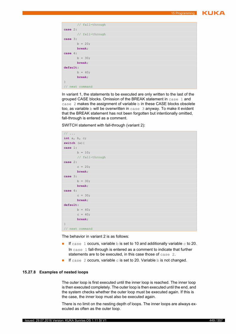
15 Programming
In variant 1, the statements to be executed are only written to the last of the grouped CASE blocks. Omission of the BREAK statement in case 1 and case 2 makes the assignment of variable b in these CASE blocks obsolete too, as variable b will be overwritten in case 3 anyway. To make it evident that the BREAK statement has not been forgotten but intentionally omitted, fall-through is entered as a comment.
SWITCH statement with fall-through (variant 2):
The behavior in variant 2 is as follows:
If case 1 occurs, variable b is set to 10 and additionally variable c to 20.
In case 1 fall-through is entered as a comment to indicate that further statements are to be executed, in this case those of case 2.
If case 2 occurs, variable c is set to 20. Variable b is not changed.
15.27.8 Examples of nested loops
The outer loop is first executed until the inner loop is reached. The inner loop is then executed completely. The outer loop is then executed until the end, and the system checks whether the outer loop must be executed again. If this is the case, the inner loop must also be executed again.
There is no limit on the nesting depth of loops. The inner loops are always ex-ecuted as often as the outer loop.
// fall-through
case 2: // fall-through
case 3: b = 20;
break;case 4: b = 30;
break;default: b = 40;
break;}
// next command
// ...
int a, b, c;switch (a){case 1: b = 10;
// fall-through
case 2: c = 20;
break;case 3: b = 30;
break;case 4: c = 30;
break;default: b = 40;
c = 40;
break;}
// next command
449 / 557Issued: 29.07.2016 Version: KUKA Sunrise.OS 1.11 SI V1

450 / 557
KUKA Sunrise.OS 1.11 KUKA Sunrise.Wor...
FOR in FOR loop
The outer loop determines that the inner loop is executed 3 times. The counter of the outer loop starts with the value i = 1.
Once the smartHMI has displayed the start of the 1st cycle, the counter of the inner loop starts with the value k = 10. The value of variable k is decreased by 1 with every cycle. The current value of k is displayed on the smartHMI with every cycle. If variable k has the value 1, the inner loop will be executed for the last time.
Then the outer loop is ended and the value of variable i is increased by 1. The 2nd cycle begins. For output purposes, a logger object has been integrated with dependency injection.
FOR in WHILE
loop
The following rules apply in a dice game:
The total sum of all rolls must be at least 21 (poll with WHILE loop).
The dice are rolled 3 times in each round (FOR loop).
Only even numbers (2, 4 and 6) are counted (IF poll with modulo).
15.28 Continuing a paused application in Automatic mode (recovery)
Description If a paused application is to be continued in Automatic mode, the higher-level controller must be able to determine whether the robot is still situated on its programmed path. If the robot is no longer situated on the path, e.g. following a non-path-maintaining stop or because it was jogged while the program was paused, there must be a suitable strategy for automatically repositioning the robot.
This return strategy may only be applied if it can be ensured that there is no risk of a collision while the robot is returning to the path. If this is not ensured, the robot must be manually repositioned by the user.
RoboticsAPI provides the IRecovery interface for automatic repositioning. It is possible to access the interface from robot applications and background tasks:
IRecovery getRecovery()
Overview The interface IRecovery provides methods for polling whether robots must be repositioned in order to resume a paused application and which return strategy is applied.
for (int i = 1; i < 4; i++) { logger.info(i + ".Cycle begins");
for (int k = 10; k > 0; k--) { logger.info("..." + k);
}
}
int sum = 0;int round = 1;int diceRoll = 0;Random num = new Random();
while (sum < 21) { round ++;
for (int i = 1; i <= 3; i++){ diceRoll = (num.nextInt(6) + 1);
if (diceRoll % 2 == 0) sum += diceRoll;
}
}
Issued: 29.07.2016 Version: KUKA Sunrise.OS 1.11 SI V1
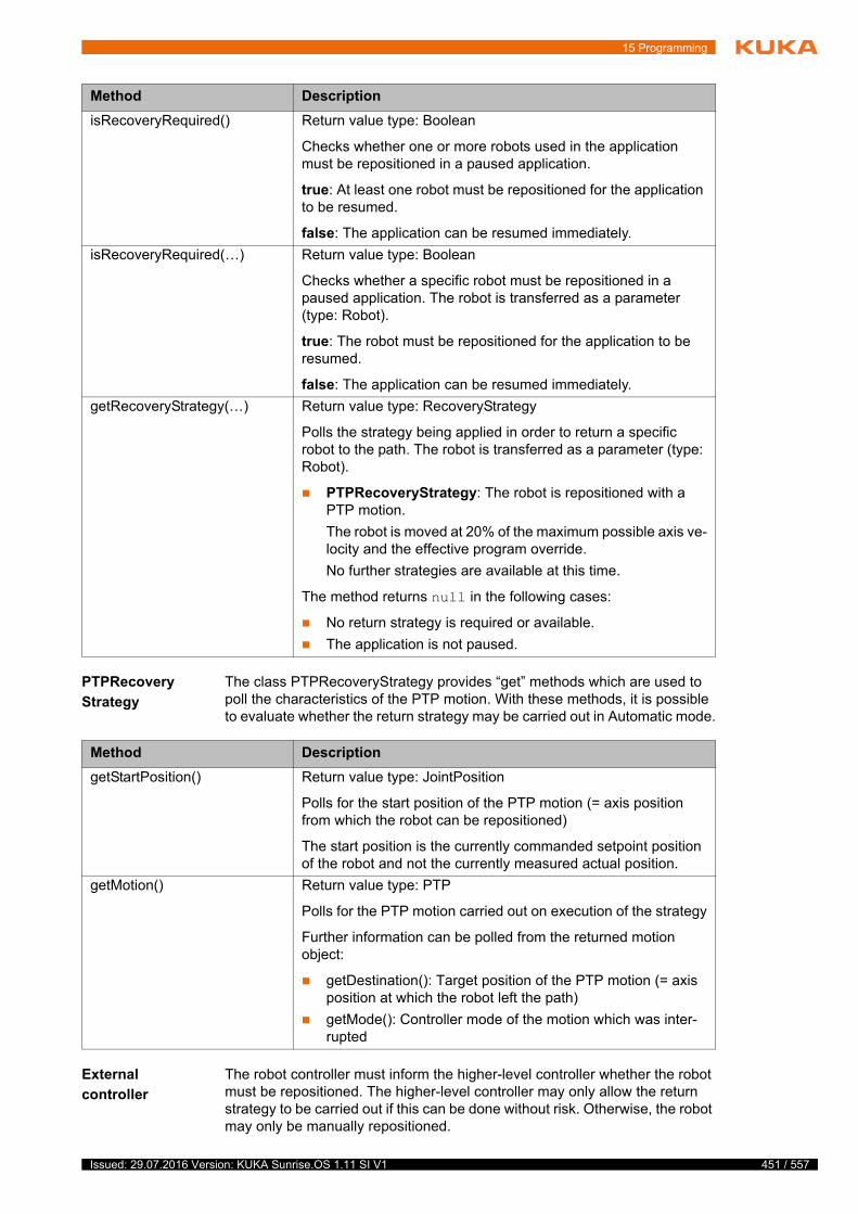
15 Programming
PTPRecovery
Strategy
The class PTPRecoveryStrategy provides “get” methods which are used to poll the characteristics of the PTP motion. With these methods, it is possible to evaluate whether the return strategy may be carried out in Automatic mode.
External
controller
The robot controller must inform the higher-level controller whether the robot must be repositioned. The higher-level controller may only allow the return strategy to be carried out if this can be done without risk. Otherwise, the robot may only be manually repositioned.
Method Description
isRecoveryRequired() Return value type: Boolean
Checks whether one or more robots used in the application must be repositioned in a paused application.
true: At least one robot must be repositioned for the application to be resumed.
false: The application can be resumed immediately.
isRecoveryRequired(…) Return value type: Boolean
Checks whether a specific robot must be repositioned in a paused application. The robot is transferred as a parameter (type: Robot).
true: The robot must be repositioned for the application to be resumed.
false: The application can be resumed immediately.
getRecoveryStrategy(…) Return value type: RecoveryStrategy
Polls the strategy being applied in order to return a specific robot to the path. The robot is transferred as a parameter (type: Robot).
PTPRecoveryStrategy: The robot is repositioned with a PTP motion.
The robot is moved at 20% of the maximum possible axis ve-locity and the effective program override.
No further strategies are available at this time.
The method returns null in the following cases:
No return strategy is required or available.
The application is not paused.
Method Description
getStartPosition() Return value type: JointPosition
Polls for the start position of the PTP motion (= axis position from which the robot can be repositioned)
The start position is the currently commanded setpoint position of the robot and not the currently measured actual position.
getMotion() Return value type: PTP
Polls for the PTP motion carried out on execution of the strategy
Further information can be polled from the returned motion object:
getDestination(): Target position of the PTP motion (= axis position at which the robot left the path)
getMode(): Controller mode of the motion which was inter-rupted
451 / 557Issued: 29.07.2016 Version: KUKA Sunrise.OS 1.11 SI V1
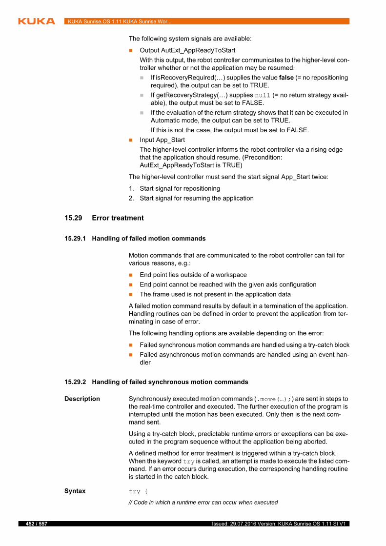
452 / 557
KUKA Sunrise.OS 1.11 KUKA Sunrise.Wor...
The following system signals are available:
Output AutExt_AppReadyToStart
With this output, the robot controller communicates to the higher-level con-troller whether or not the application may be resumed.
If isRecoveryRequired(…) supplies the value false (= no repositioning required), the output can be set to TRUE.
If getRecoveryStrategy(…) supplies null (= no return strategy avail-able), the output must be set to FALSE.
If the evaluation of the return strategy shows that it can be executed in Automatic mode, the output can be set to TRUE.
If this is not the case, the output must be set to FALSE.
Input App_Start
The higher-level controller informs the robot controller via a rising edge that the application should resume. (Precondition: AutExt_AppReadyToStart is TRUE)
The higher-level controller must send the start signal App_Start twice:
1. Start signal for repositioning
2. Start signal for resuming the application
15.29 Error treatment
15.29.1 Handling of failed motion commands
Motion commands that are communicated to the robot controller can fail for various reasons, e.g.:
End point lies outside of a workspace
End point cannot be reached with the given axis configuration
The frame used is not present in the application data
A failed motion command results by default in a termination of the application. Handling routines can be defined in order to prevent the application from ter-minating in case of error.
The following handling options are available depending on the error:
Failed synchronous motion commands are handled using a try-catch block
Failed asynchronous motion commands are handled using an event han-dler
15.29.2 Handling of failed synchronous motion commands
Description Synchronously executed motion commands (.move(…);) are sent in steps to the real-time controller and executed. The further execution of the program is interrupted until the motion has been executed. Only then is the next com-mand sent.
Using a try-catch block, predictable runtime errors or exceptions can be exe-cuted in the program sequence without the application being aborted.
A defined method for error treatment is triggered within a try-catch block. When the keyword try is called, an attempt is made to execute the listed com-mand. If an error occurs during execution, the corresponding handling routine is started in the catch block.
Syntax try {
// Code in which a runtime error can occur when executed
Issued: 29.07.2016 Version: KUKA Sunrise.OS 1.11 SI V1
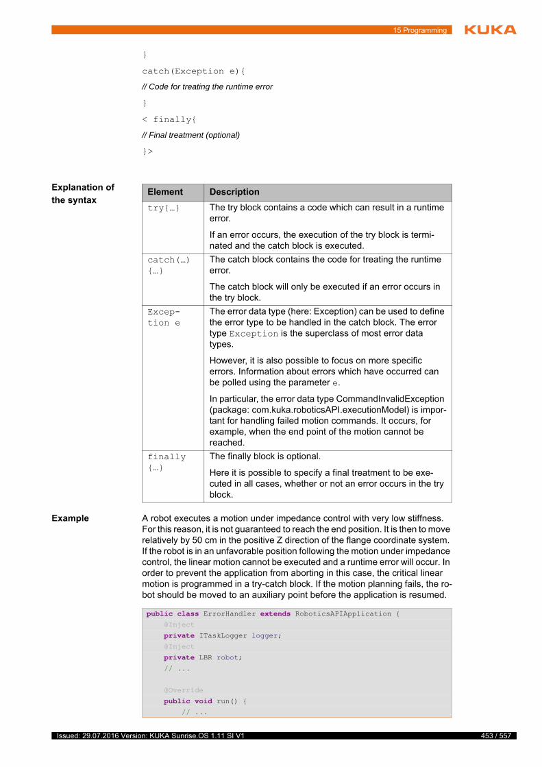
15 Programming
}
catch(Exception e){
// Code for treating the runtime error
}
< finally{
// Final treatment (optional)
}>
Explanation of
the syntax
Example A robot executes a motion under impedance control with very low stiffness. For this reason, it is not guaranteed to reach the end position. It is then to move relatively by 50 cm in the positive Z direction of the flange coordinate system. If the robot is in an unfavorable position following the motion under impedance control, the linear motion cannot be executed and a runtime error will occur. In order to prevent the application from aborting in this case, the critical linear motion is programmed in a try-catch block. If the motion planning fails, the ro-bot should be moved to an auxiliary point before the application is resumed.
Element Description
try{…} The try block contains a code which can result in a runtime error.
If an error occurs, the execution of the try block is termi-nated and the catch block is executed.
catch(…){…}
The catch block contains the code for treating the runtime error.
The catch block will only be executed if an error occurs in the try block.
Excep-tion e
The error data type (here: Exception) can be used to define the error type to be handled in the catch block. The error type Exception is the superclass of most error data types.
However, it is also possible to focus on more specific errors. Information about errors which have occurred can be polled using the parameter e.
In particular, the error data type CommandInvalidException (package: com.kuka.roboticsAPI.executionModel) is impor-tant for handling failed motion commands. It occurs, for example, when the end point of the motion cannot be reached.
finally{…}
The finally block is optional.
Here it is possible to specify a final treatment to be exe-cuted in all cases, whether or not an error occurs in the try block.
public class ErrorHandler extends RoboticsAPIApplication { @Inject
private ITaskLogger logger; @Inject
private LBR robot; // ...
@Override
public void run() { // ...
453 / 557Issued: 29.07.2016 Version: KUKA Sunrise.OS 1.11 SI V1

454 / 557
KUKA Sunrise.OS 1.11 KUKA Sunrise.Wor...
15.29.3 Handling of failed asynchronous motion commands
Description In the case of asynchronously executed motion commands (.moveA-sync(…);), the next program line is executed directly after the motion com-mand is sent.
An event handler is used in order to react to a failed asynchronous motion command.
This event handler is an object of type IErrorHandler and defines the method handleError(…). The transfer of further motion commands to the real-time controller is blocked during execution of the method handleError(…). The ap-plication remains at a standstill.
The handling routine is defined with handleError(…). Information on the failed motion command can be accessed via the input parameters of the method. The method returns a parameter of type ErrorHandlingAction. The final reac-tion to the error is selected via this parameter.
The following reactions are available:
The application is terminated with an error.
The motion execution is paused and can only be resumed by the user pressing the Start key on the smartPAD.
The error is ignored and the application is resumed.
The defined event handler must be registered before it can be used in the ap-plication. The method getApplicationControl().registerMoveAsyncErrorHan-dler(…) is used for this purpose. The method belongs to the IApplicationControl interface.
Syntax Defining the event handler:
IErrorHandler errorHandler = new IErrorHandler(){
CartesianImpedanceControlMode softMode =
new CartesianImpedanceControlMode();
softMode.parametrize(CartDOF.ALL).setStiffness(10.0);
robot.move(ptp(getFrame("/Start"))
.setMode(softMode).setJointVelocityRel(0.3));
try{ logger.info("1: Try to execute linear motion");
robot.move(linRel(0.0, 0.0, 500.0)
.setJointVelocityRel(0.5));
}
catch(CommandInvalidException e){ logger.info("2: Motion not executable");
robot.move(ptp(getFrame("/AuxiliaryPoint"))
.setJointVelocityRel(0.5));
}
finally{ logger.info(
"3: Commands in finally block are executed");
}
logger.info("4: Application continues here.");
// ...
}
Issued: 29.07.2016 Version: KUKA Sunrise.OS 1.11 SI V1
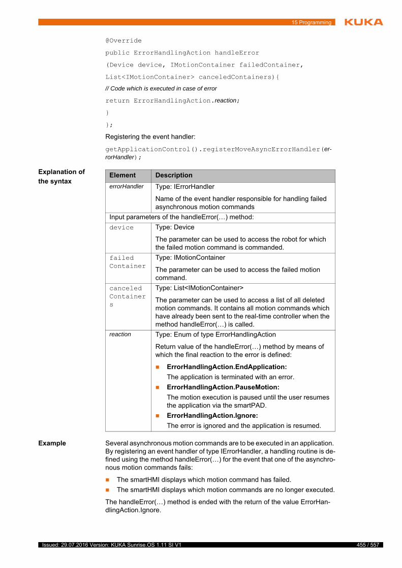
15 Programming
@Override
public ErrorHandlingAction handleError
(Device device, IMotionContainer failedContainer,
List<IMotionContainer> canceledContainers){
// Code which is executed in case of error
return ErrorHandlingAction.reaction;
}
};
Registering the event handler:
getApplicationControl().registerMoveAsyncErrorHandler(er-rorHandler);
Explanation of
the syntax
Example Several asynchronous motion commands are to be executed in an application. By registering an event handler of type IErrorHandler, a handling routine is de-fined using the method handleError(…) for the event that one of the asynchro-nous motion commands fails:
The smartHMI displays which motion command has failed.
The smartHMI displays which motion commands are no longer executed.
The handleError(…) method is ended with the return of the value ErrorHan-dlingAction.Ignore.
Element Description
errorHandler Type: IErrorHandler
Name of the event handler responsible for handling failed asynchronous motion commands
Input parameters of the handleError(…) method:
device Type: Device
The parameter can be used to access the robot for which the failed motion command is commanded.
failedContainer
Type: IMotionContainer
The parameter can be used to access the failed motion command.
canceledContainers
Type: List<IMotionContainer>
The parameter can be used to access a list of all deleted motion commands. It contains all motion commands which have already been sent to the real-time controller when the method handleError(…) is called.
reaction Type: Enum of type ErrorHandlingAction
Return value of the handleError(…) method by means of which the final reaction to the error is defined:
ErrorHandlingAction.EndApplication:
The application is terminated with an error.
ErrorHandlingAction.PauseMotion:
The motion execution is paused until the user resumes the application via the smartPAD.
ErrorHandlingAction.Ignore:
The error is ignored and the application is resumed.
455 / 557Issued: 29.07.2016 Version: KUKA Sunrise.OS 1.11 SI V1

456 / 557
KUKA Sunrise.OS 1.11 KUKA Sunrise.Wor...
public class ErrorHandler extends RoboticsAPIApplication { // fields which need to be injected
@Inject
private ITaskLogger logger; @Inject
private LBR robot;
// not injected fields
private IErrorHandler errorHandler;
@Override
public void initialize(){
errorHandler = new IErrorHandler() { @Override
public ErrorHandlingAction handleError(Device device, IMotionContainer failedContainer,
List<IMotionContainer> canceledContainers) {
logger.warn("Excecution of the following motion failed: "
+ failedContainer.getCommand().toString());
logger.info("The following motions will not be executed:");
for (int i = 0; i < canceledContainers.size(); i++) { logger.info(canceledContainers.get(i)
.getCommand().toString());
}
return ErrorHandlingAction.Ignore
}
};
getApplicationControl()
.registerMoveAsyncErrorHandler(errorHandler);
}
@Override
public void run(){ robot.move(ptpHome());
robot.move(ptp(getFrame("/PrePos")));
// ...
robot.moveAsync(ptp(getFrame("/P1")));
robot.moveAsync(ptp(getFrame("/P2")));
robot.moveAsync(lin(getFrame("/P3")));
robot.moveAsync(ptp(getFrame("/P4")));
robot.moveAsync(ptp(getFrame("/P5")));
robot.moveAsync(ptp(getFrame("/P6")));
robot.moveAsync(ptp(getFrame("/P7")));
robot.moveAsync(ptp(getFrame("/P8")));
robot.moveAsync(ptp(getFrame("/P9")));
// ...
robot.move(ptpHome());
Issued: 29.07.2016 Version: KUKA Sunrise.OS 1.11 SI V1
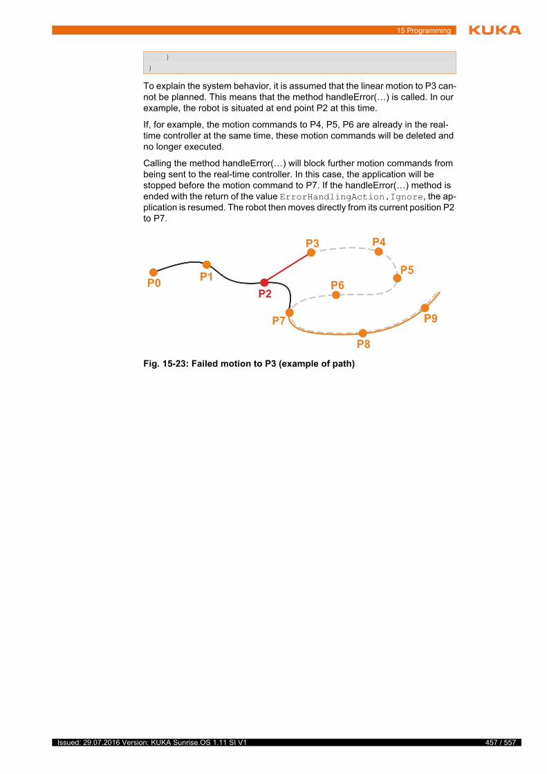
15 Programming
To explain the system behavior, it is assumed that the linear motion to P3 can-not be planned. This means that the method handleError(…) is called. In our example, the robot is situated at end point P2 at this time.
If, for example, the motion commands to P4, P5, P6 are already in the real-time controller at the same time, these motion commands will be deleted and no longer executed.
Calling the method handleError(…) will block further motion commands from being sent to the real-time controller. In this case, the application will be stopped before the motion command to P7. If the handleError(…) method is ended with the return of the value ErrorHandlingAction.Ignore, the ap-plication is resumed. The robot then moves directly from its current position P2 to P7.
}
}
Fig. 15-23: Failed motion to P3 (example of path)
457 / 557Issued: 29.07.2016 Version: KUKA Sunrise.OS 1.11 SI V1

458 / 557
KUKA Sunrise.OS 1.11 KUKA Sunrise.Wor...
Issued: 29.07.2016 Version: KUKA Sunrise.OS 1.11 SI V1
16 Background tasks
16 Background tasks
16.1 Using background tasks
Activities Background tasks are used in order to be able to perform tasks in the back-ground, parallel to a running robot application, or to implement cyclical pro-cesses that are to be run continuously in the background. Multiple background tasks can run simultaneously and independently of the running robot applica-tion.
Background tasks are used, in particular, to control and monitor peripheral de-vices and to implement the corresponding higher-level logic. Examples:
Switching signal lamps
Monitoring and evaluating sensor information
This means that no higher-level controller, e.g. a PLC, is required for smaller applications, as the robot controller can perform such tasks by itself.
Properties Background tasks, like robot applications, are implemented as Java classes. They are similar in structure to robot applications: they have a run() method that contains the commands to be executed.
Background tasks are an integral feature of the Sunrise project. They are cre-ated in Sunrise.Workbench and transferred to the robot controller when the project is synchronized.
(>>> 5.6 "Creating a new background task" Page 55)
There are 2 types of background task that differ in terms of their duration:
Cyclic background task
Executed cyclically. The cyclical behavior can be adapted by the program-mer depending on the task to be performed.
Non-cyclic background task
Executed once.
Background tasks also differ in terms of their start type:
Manual
The task must be started manually via the smartPAD. (This function is not yet supported.)
Automatic
The task is automatically started when the robot controller is booted and stopped when it is shut down.
t
In the case of outputs that are switched by a background task, the fol-lowing points must be observed:
The outputs are switched, irrespective of whether a robot application is currently being executed.
The outputs are also switched if the robot application is paused due to an EMERGENCY STOP or missing enabling signal.
The outputs are also switched if a stop request from the safety controller is active (this also applies if outputs are switched by a robot application).
Background tasks must not be used for moving the robot or influencing parameters that might affect motions. This
is the task of the robot application. Calling motion commands or modifying motion-specific parameters in a background task can result in unspecified behavior of the robot and thus cause personal injury and damage to property.
459 / 557Issued: 29.07.2016 Version: KUKA Sunrise.OS 1.11 SI V1

460 / 557
KUKA Sunrise.OS 1.11 KUKA Sunrise.Wor...
In background tasks many objects of the application can be accessed by means of dependency injection.
(>>> 15.3.3 "Dependency Injection" Page 336)
If a background task requires access to information from the running robot ap-plication or other background tasks that are not accessible via dependency in-jection, a separate interface is available for data exchange.
(>>> 16.4 "Data exchange between tasks" Page 464)
Synchronization
behavior
When synchronizing the Sunrise project, the associated background tasks with Automatic start type exhibit the following behavior:
Tasks not yet present
Both cyclic and non-cyclic tasks are transferred to the controller and sub-sequently started.
Tasks already present
If the task to be synchronized (cyclic or non-cyclic) is already present on the controller, it will be terminated if it is still running. The synchronization is then executed and the task automatically restarted.
Tasks no longer present
If a background task has been deleted from the associated project and synchronization is carried out, the task is terminated before synchroniza-tion on the controller. It is then no longer available after synchronization.
Runtime behavior After a non-cyclic task has been started, it is executed fully in accordance with its programming. When it reaches the end of its run() method, it is terminated and not restarted until the next synchronization or the next reboot of the con-troller.
When started, a cyclic task is first instanced. The run() method of the task is then repeatedly called on a regular basis. These background tasks are there-fore permanently executed as long as the controller is running.
If an error which cannot be intercepted and rectified occurs in a task (cyclic or non-cyclic), the task is automatically terminated.
If a background task has been terminated because of an unhandled error, the task can only be restarted by rebooting the robot controller or carrying out project synchronization of Sunrise.Workbench on the
robot controller.
Issued: 29.07.2016 Version: KUKA Sunrise.OS 1.11 SI V1
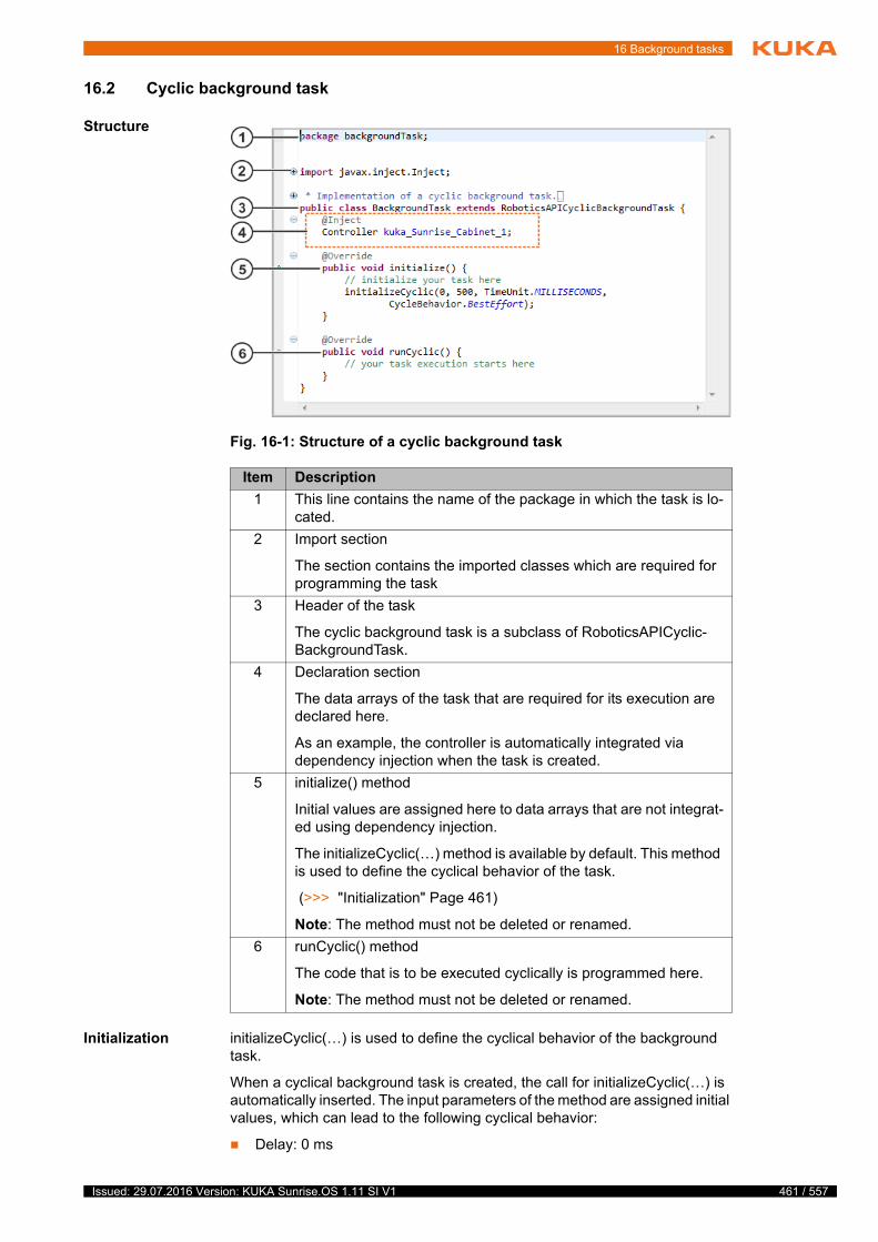
16 Background tasks
16.2 Cyclic background task
Structure
Initialization initializeCyclic(…) is used to define the cyclical behavior of the background task.
When a cyclical background task is created, the call for initializeCyclic(…) is automatically inserted. The input parameters of the method are assigned initial values, which can lead to the following cyclical behavior:
Delay: 0 ms
Fig. 16-1: Structure of a cyclic background task
Item Description
1 This line contains the name of the package in which the task is lo-cated.
2 Import section
The section contains the imported classes which are required for programming the task
3 Header of the task
The cyclic background task is a subclass of RoboticsAPICyclic-BackgroundTask.
4 Declaration section
The data arrays of the task that are required for its execution are declared here.
As an example, the controller is automatically integrated via dependency injection when the task is created.
5 initialize() method
Initial values are assigned here to data arrays that are not integrat-ed using dependency injection.
The initializeCyclic(…) method is available by default. This method is used to define the cyclical behavior of the task.
(>>> "Initialization" Page 461)
Note: The method must not be deleted or renamed.
6 runCyclic() method
The code that is to be executed cyclically is programmed here.
Note: The method must not be deleted or renamed.
461 / 557Issued: 29.07.2016 Version: KUKA Sunrise.OS 1.11 SI V1
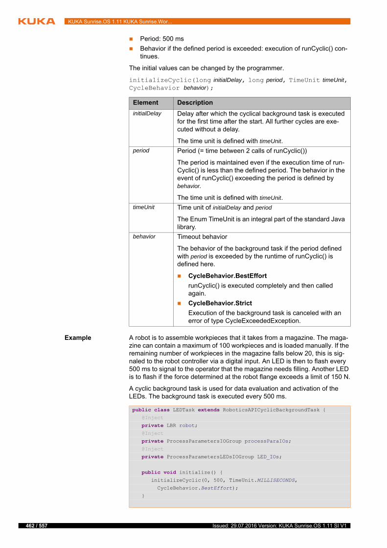
462 / 557
KUKA Sunrise.OS 1.11 KUKA Sunrise.Wor...
Period: 500 ms
Behavior if the defined period is exceeded: execution of runCyclic() con-tinues.
The initial values can be changed by the programmer.
initializeCyclic(long initialDelay, long period, TimeUnit timeUnit, CycleBehavior behavior);
Example A robot is to assemble workpieces that it takes from a magazine. The maga-zine can contain a maximum of 100 workpieces and is loaded manually. If the remaining number of workpieces in the magazine falls below 20, this is sig-naled to the robot controller via a digital input. An LED is then to flash every 500 ms to signal to the operator that the magazine needs filling. Another LED is to flash if the force determined at the robot flange exceeds a limit of 150 N.
A cyclic background task is used for data evaluation and activation of the LEDs. The background task is executed every 500 ms.
Element Description
initialDelay Delay after which the cyclical background task is executed for the first time after the start. All further cycles are exe-cuted without a delay.
The time unit is defined with timeUnit.
period Period (= time between 2 calls of runCyclic())
The period is maintained even if the execution time of run-Cyclic() is less than the defined period. The behavior in the event of runCyclic() exceeding the period is defined by behavior.
The time unit is defined with timeUnit.
timeUnit Time unit of initialDelay and period
The Enum TimeUnit is an integral part of the standard Java library.
behavior Timeout behavior
The behavior of the background task if the period defined with period is exceeded by the runtime of runCyclic() is defined here.
CycleBehavior.BestEffort
runCyclic() is executed completely and then called again.
CycleBehavior.Strict
Execution of the background task is canceled with an error of type CycleExceededException.
public class LEDTask extends RoboticsAPICyclicBackgroundTask { @Inject
private LBR robot; @Inject
private ProcessParametersIOGroup processParaIOs; @Inject
private ProcessParametersLEDsIOGroup LED_IOs;
public void initialize() { initializeCyclic(0, 500, TimeUnit.MILLISECONDS,
CycleBehavior.BestEffort);
}
Issued: 29.07.2016 Version: KUKA Sunrise.OS 1.11 SI V1
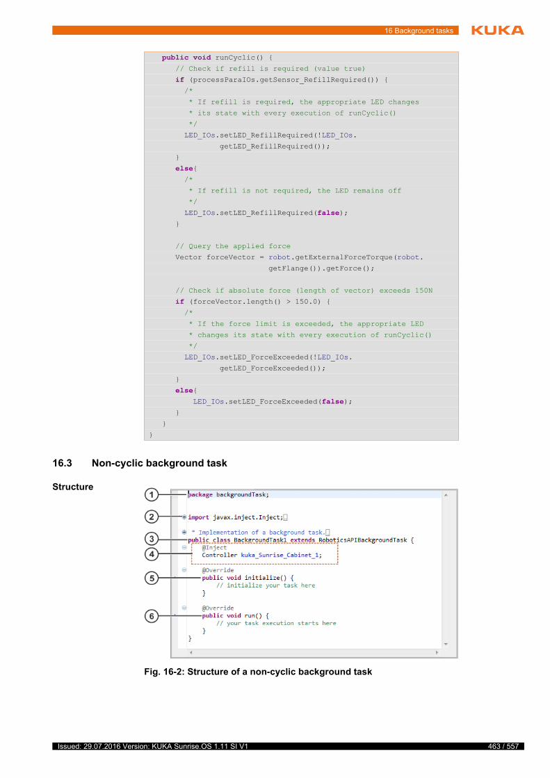
16 Background tasks
16.3 Non-cyclic background task
Structure
public void runCyclic() { // Check if refill is required (value true)
if (processParaIOs.getSensor_RefillRequired()) { /*
* If refill is required, the appropriate LED changes
* its state with every execution of runCyclic()
*/
LED_IOs.setLED_RefillRequired(!LED_IOs.
getLED_RefillRequired());
}
else{ /*
* If refill is not required, the LED remains off
*/
LED_IOs.setLED_RefillRequired(false); }
// Query the applied force
Vector forceVector = robot.getExternalForceTorque(robot.
getFlange()).getForce();
// Check if absolute force (length of vector) exceeds 150N
if (forceVector.length() > 150.0) { /*
* If the force limit is exceeded, the appropriate LED
* changes its state with every execution of runCyclic()
*/
LED_IOs.setLED_ForceExceeded(!LED_IOs.
getLED_ForceExceeded());
}
else{ LED_IOs.setLED_ForceExceeded(false); }
}
}
Fig. 16-2: Structure of a non-cyclic background task
463 / 557Issued: 29.07.2016 Version: KUKA Sunrise.OS 1.11 SI V1

464 / 557
KUKA Sunrise.OS 1.11 KUKA Sunrise.Wor...
16.4 Data exchange between tasks
Description The mechanism described here can be used to exchange data between run-ning tasks. One task can provide task functions (providing task) that can be accessed by other tasks (requesting tasks).
Example: Accessing and processing information from the running robot appli-cation in a background task.
It is not relevant for programming whether data are exchanged between a background task and a robot application or between 2 background tasks. The providing task may be either a robot application or a background task. For this reason, background tasks and robot applications are grouped together as tasks.
Overview The following steps are required in order for the providing task and the re-questing task to be able to communicate with one another:
Item Description
1 This line contains the name of the package in which the task is lo-cated.
2 Import section
The section contains the imported classes which are required for programming the task
3 Header of the task
The non-cyclic background task is a subclass of RoboticsAPI-BackgroundTask.
4 Declaration section
The data arrays of the task that are required for its execution are declared here.
As an example, the controller is automatically integrated via dependency injection when the task is created.
5 initialize() method
Initial values are assigned here to data arrays that are not integrat-ed using dependency injection.
Note: The method must not be deleted or renamed.
6 run() method
The code that is to be executed once is programmed here. The runtime is not limited.
Note: The method must not be deleted or renamed.
Step Description
1 Create an interface and declare the desired task functions.
(>>> 16.4.1 "Declaring task functions" Page 465)
2 Implement the interface in which the task functions are declared.
The interface can be implemented directly by the providing task or by a specially created class. The declared task func-tions must be programmed in the implementing class.
(>>> 16.4.2 "Implementing task functions" Page 466)
Issued: 29.07.2016 Version: KUKA Sunrise.OS 1.11 SI V1
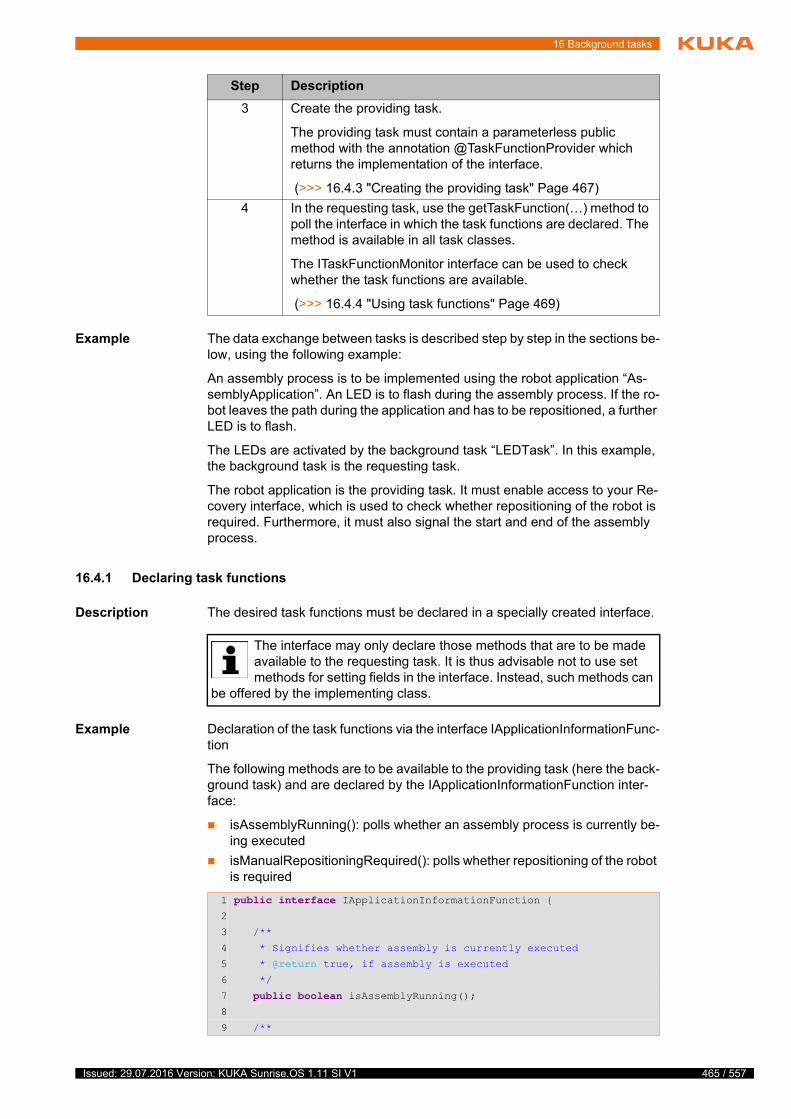
16 Background tasks
Example The data exchange between tasks is described step by step in the sections be-low, using the following example:
An assembly process is to be implemented using the robot application “As-semblyApplication”. An LED is to flash during the assembly process. If the ro-bot leaves the path during the application and has to be repositioned, a further LED is to flash.
The LEDs are activated by the background task “LEDTask”. In this example, the background task is the requesting task.
The robot application is the providing task. It must enable access to your Re-covery interface, which is used to check whether repositioning of the robot is required. Furthermore, it must also signal the start and end of the assembly process.
16.4.1 Declaring task functions
Description The desired task functions must be declared in a specially created interface.
Example Declaration of the task functions via the interface IApplicationInformationFunc-tion
The following methods are to be available to the providing task (here the back-ground task) and are declared by the IApplicationInformationFunction inter-face:
isAssemblyRunning(): polls whether an assembly process is currently be-ing executed
isManualRepositioningRequired(): polls whether repositioning of the robot is required
3 Create the providing task.
The providing task must contain a parameterless public method with the annotation @TaskFunctionProvider which returns the implementation of the interface.
(>>> 16.4.3 "Creating the providing task" Page 467)
4 In the requesting task, use the getTaskFunction(…) method to poll the interface in which the task functions are declared. The method is available in all task classes.
The ITaskFunctionMonitor interface can be used to check whether the task functions are available.
(>>> 16.4.4 "Using task functions" Page 469)
Step Description
The interface may only declare those methods that are to be made available to the requesting task. It is thus advisable not to use set methods for setting fields in the interface. Instead, such methods can
be offered by the implementing class.
1 public interface IApplicationInformationFunction {2
3 /**
4 * Signifies whether assembly is currently executed
5 * @return true, if assembly is executed6 */
7 public boolean isAssemblyRunning();8
9 /**
465 / 557Issued: 29.07.2016 Version: KUKA Sunrise.OS 1.11 SI V1
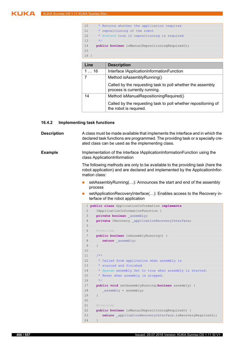
466 / 557
KUKA Sunrise.OS 1.11 KUKA Sunrise.Wor...
16.4.2 Implementing task functions
Description A class must be made available that implements the interface and in which the declared task functions are programmed. The providing task or a specially cre-ated class can be used as the implementing class.
Example Implementation of the interface IApplicationInformationFunction using the class ApplicationInformation
The following methods are only to be available to the providing task (here the robot application) and are declared and implemented by the ApplicationInfor-mation class:
setAssemblyRunning(…): Announces the start and end of the assembly process
setApplicationRecoveryInterface(…): Enables access to the Recovery in-terface of the robot application
10 * Returns whether the application requires
11 * repositioning of the robot
12 * @return true if repositioning is required13 */
14 public boolean isManualRepositioningRequired();15
16 }
Line Description
1 … 16 Interface IApplicationInformationFunction
7 Method isAssemblyRunning()
Called by the requesting task to poll whether the assembly process is currently running.
14 Method isManualRepositioningRequired()
Called by the requesting task to poll whether repositioning of the robot is required.
1 public class ApplicationInformation implements 2 IApplicationInformationFunction {
3 private boolean _assembly;4 private IRecovery _applicationRecoveryInterface;5
6 @Override
7 public boolean isAssemblyRunning() {8 return _assembly;9 }
10
11 /**
12 * Called from application when assembly is
13 * started and finished
14 * @param assembly Set to true when assembly is started. 15 * Reset when assembly is stopped.
16 */
17 public void setAssemblyRunning(boolean assembly) {18 _assembly = assembly;
19 }
20
21 @Override
22 public boolean isManualRepositioningRequired() {23 return _applicationRecoveryInterface.isRecoveryRequired();24 }
Issued: 29.07.2016 Version: KUKA Sunrise.OS 1.11 SI V1
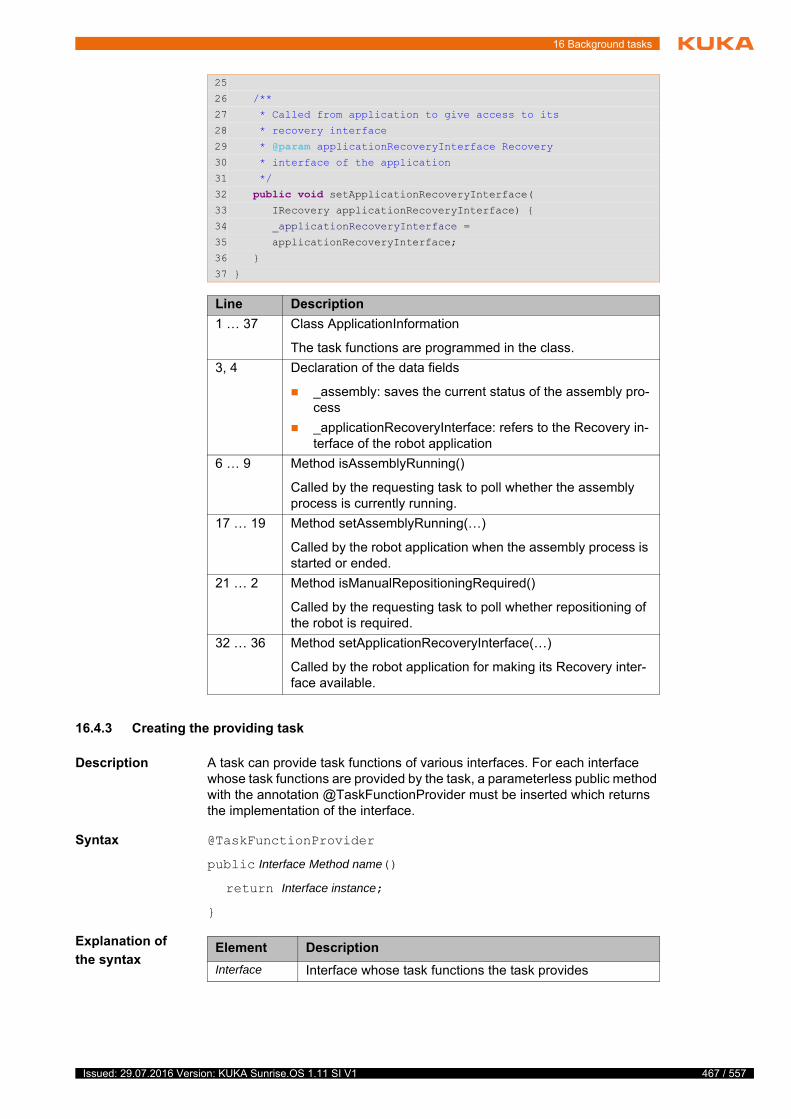
16 Background tasks
16.4.3 Creating the providing task
Description A task can provide task functions of various interfaces. For each interface whose task functions are provided by the task, a parameterless public method with the annotation @TaskFunctionProvider must be inserted which returns the implementation of the interface.
Syntax @TaskFunctionProvider
public Interface Method name()
return Interface instance;
}
Explanation of
the syntax
25
26 /**
27 * Called from application to give access to its
28 * recovery interface
29 * @param applicationRecoveryInterface Recovery 30 * interface of the application
31 */
32 public void setApplicationRecoveryInterface(33 IRecovery applicationRecoveryInterface) {
34 _applicationRecoveryInterface =
35 applicationRecoveryInterface;
36 }
37 }
Line Description
1 … 37 Class ApplicationInformation
The task functions are programmed in the class.
3, 4 Declaration of the data fields
_assembly: saves the current status of the assembly pro-cess
_applicationRecoveryInterface: refers to the Recovery in-terface of the robot application
6 … 9 Method isAssemblyRunning()
Called by the requesting task to poll whether the assembly process is currently running.
17 … 19 Method setAssemblyRunning(…)
Called by the robot application when the assembly process is started or ended.
21 … 2 Method isManualRepositioningRequired()
Called by the requesting task to poll whether repositioning of the robot is required.
32 … 36 Method setApplicationRecoveryInterface(…)
Called by the robot application for making its Recovery inter-face available.
Element Description
Interface Interface whose task functions the task provides
467 / 557Issued: 29.07.2016 Version: KUKA Sunrise.OS 1.11 SI V1
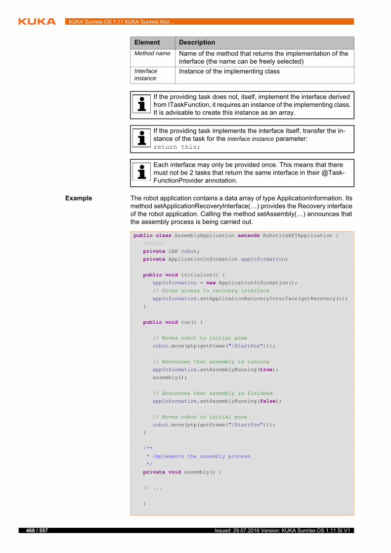
468 / 557
KUKA Sunrise.OS 1.11 KUKA Sunrise.Wor...
Example The robot application contains a data array of type ApplicationInformation. Its method setApplicationRecoveryInterface(…) provides the Recovery interface of the robot application. Calling the method setAssembly(…) announces that the assembly process is being carried out.
Method name Name of the method that returns the implementation of the interface (the name can be freely selected)
Interface instance
Instance of the implementing class
If the providing task does not, itself, implement the interface derived from ITaskFunction, it requires an instance of the implementing class. It is advisable to create this instance as an array.
If the providing task implements the interface itself, transfer the in-stance of the task for the Interface instance parameter:return this;
Each interface may only be provided once. This means that there must not be 2 tasks that return the same interface in their @Task-FunctionProvider annotation.
Element Description
public class AssemblyApplication extends RoboticsAPIApplication { @Inject
private LBR robot; private ApplicationInformation appInformation;
public void initialize() { appInformation = new ApplicationInformation(); // Gives access to recovery interface
appInformation.setApplicationRecoveryInterface(getRecovery());
}
public void run() {
// Moves robot to initial pose
robot.move(ptp(getFrame("/StartPos")));
// Announces that assembly is running
appInformation.setAssemblyRunning(true); assembly();
// Announces that assembly is finished
appInformation.setAssemblyRunning(false);
// Moves robot to initial pose
robot.move(ptp(getFrame("/StartPos")));
}
/**
* Implements the assembly process
*/
private void assembly() {
// ...
}
Issued: 29.07.2016 Version: KUKA Sunrise.OS 1.11 SI V1
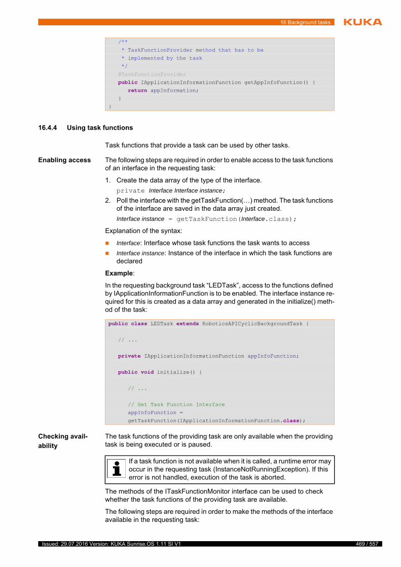
16 Background tasks
16.4.4 Using task functions
Task functions that provide a task can be used by other tasks.
Enabling access The following steps are required in order to enable access to the task functions of an interface in the requesting task:
1. Create the data array of the type of the interface.
private Interface Interface instance;
2. Poll the interface with the getTaskFunction(…) method. The task functions of the interface are saved in the data array just created.
Interface instance = getTaskFunction(Interface.class);
Explanation of the syntax:
Interface: Interface whose task functions the task wants to access
Interface instance: Instance of the interface in which the task functions are declared
Example:
In the requesting background task “LEDTask”, access to the functions defined by IApplicationInformationFunction is to be enabled. The interface instance re-quired for this is created as a data array and generated in the initialize() meth-od of the task:
Checking avail-
ability
The task functions of the providing task are only available when the providing task is being executed or is paused.
The methods of the ITaskFunctionMonitor interface can be used to check whether the task functions of the providing task are available.
The following steps are required in order to make the methods of the interface available in the requesting task:
/**
* TaskFunctionProvider method that has to be
* implemented by the task
*/
@TaskFunctionProvider
public IApplicationInformationFunction getAppInfoFunction() { return appInformation; }
}
public class LEDTask extends RoboticsAPICyclicBackgroundTask {
// ...
private IApplicationInformationFunction appInfoFunction;
public void initialize() {
// ...
// Get Task Function Interface
appInfoFunction =
getTaskFunction(IApplicationInformationFunction.class);
If a task function is not available when it is called, a runtime error may occur in the requesting task (InstanceNotRunningException). If this error is not handled, execution of the task is aborted.
469 / 557Issued: 29.07.2016 Version: KUKA Sunrise.OS 1.11 SI V1

470 / 557
KUKA Sunrise.OS 1.11 KUKA Sunrise.Wor...
1. Create the data array of the type of the interface.
private ITaskFunctionMonitor monitor;
2. Use the TaskFunctionMonitor.create(…) method to initialize the monitor for the task functions to be monitored. The instance of the interface in which the task functions are declared is transferred to the method as a pa-rameter.
monitor = TaskFunctionMonitor.create(Interface instance);
Explanation of the syntax:
monitor: Instance of the ITaskFunctionMonitor interface
Interface instance: Instance of the interface in which the task functions are declared
The following methods are available in the ITaskFunctionMonitor interface:
Example:
In the method runCyclic() of the background task “LEDTask”, polling is to be carried out to ascertain whether the assembly process is currently being exe-cuted. For this, the interface IApplicationInformationFunction offers the meth-od isAssemblyRunning().
The requesting background task “LEDTask” can only poll whether the assem-bly process is being executed if the robot application is running or paused. For this reason, the availability of the function must be checked before isAssem-blyRunning() is called:
Method Description
isAvailable() Return value type: Boolean
Specifies whether the task functions of the providing task are available (true = available).
await(time, unit)
Return value type: Boolean
If the task functions are not available when the providing task is called, the system waits a defined time for them to become available (true = task functions available within the defined wait time).
Parameters:
time (type: long): duration of maximum wait time. The unit is defined by the parameter unit.
unit (type: TimeUnit): unit of time
public class LEDTask extends RoboticsAPICyclicBackgroundTask {
// ...
private IApplicationInformationFunction appInfoFunction; private ITaskFunctionMonitor appInfoMonitor;
public void initialize() {
// ...
// Get Task Function Interface
appInfoFunction =
getTaskFunction(IApplicationInformationFunction.class);
/*
* Create ITaskFunctionMonitor for
* IApplicationInformationFunction
*/
Issued: 29.07.2016 Version: KUKA Sunrise.OS 1.11 SI V1
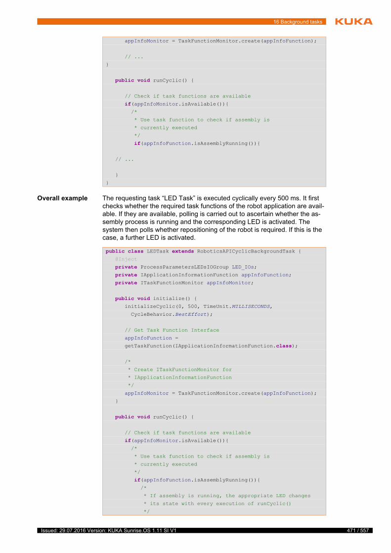
16 Background tasks
Overall example The requesting task “LED Task” is executed cyclically every 500 ms. It first checks whether the required task functions of the robot application are avail-able. If they are available, polling is carried out to ascertain whether the as-sembly process is running and the corresponding LED is activated. The system then polls whether repositioning of the robot is required. If this is the case, a further LED is activated.
appInfoMonitor = TaskFunctionMonitor.create(appInfoFunction);
// ...
}
public void runCyclic() {
// Check if task functions are available
if(appInfoMonitor.isAvailable()){ /*
* Use task function to check if assembly is
* currently executed
*/
if(appInfoFunction.isAssemblyRunning()){
// ...
}
}
public class LEDTask extends RoboticsAPICyclicBackgroundTask { @Inject
private ProcessParametersLEDsIOGroup LED_IOs; private IApplicationInformationFunction appInfoFunction; private ITaskFunctionMonitor appInfoMonitor;
public void initialize() { initializeCyclic(0, 500, TimeUnit.MILLISECONDS,
CycleBehavior.BestEffort);
// Get Task Function Interface
appInfoFunction =
getTaskFunction(IApplicationInformationFunction.class);
/*
* Create ITaskFunctionMonitor for
* IApplicationInformationFunction
*/
appInfoMonitor = TaskFunctionMonitor.create(appInfoFunction);
}
public void runCyclic() {
// Check if task functions are available
if(appInfoMonitor.isAvailable()){ /*
* Use task function to check if assembly is
* currently executed
*/
if(appInfoFunction.isAssemblyRunning()){ /*
* If assembly is running, the appropriate LED changes
* its state with every execution of runCyclic()
*/
471 / 557Issued: 29.07.2016 Version: KUKA Sunrise.OS 1.11 SI V1
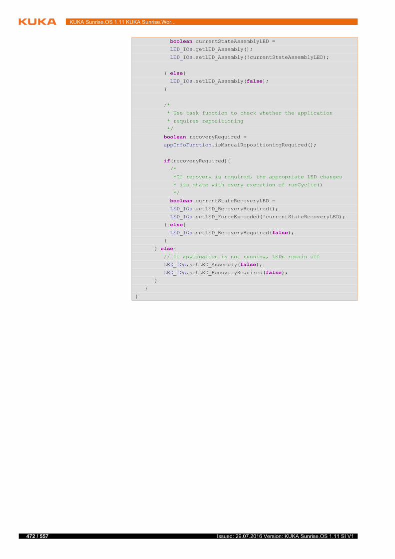
472 / 557
KUKA Sunrise.OS 1.11 KUKA Sunrise.Wor...
boolean currentStateAssemblyLED = LED_IOs.getLED_Assembly();
LED_IOs.setLED_Assembly(!currentStateAssemblyLED);
} else{ LED_IOs.setLED_Assembly(false); }
/*
* Use task function to check whether the application
* requires repositioning
*/
boolean recoveryRequired = appInfoFunction.isManualRepositioningRequired();
if(recoveryRequired){ /*
*If recovery is required, the appropriate LED changes
* its state with every execution of runCyclic()
*/
boolean currentStateRecoveryLED = LED_IOs.getLED_RecoveryRequired();
LED_IOs.setLED_ForceExceeded(!currentStateRecoveryLED);
} else{ LED_IOs.setLED_RecoveryRequired(false); }
} else{ // If application is not running, LEDs remain off
LED_IOs.setLED_Assembly(false); LED_IOs.setLED_RecoveryRequired(false); }
}
}
Issued: 29.07.2016 Version: KUKA Sunrise.OS 1.11 SI V1

17 Programming with a compliant robot
17 Programming with a compliant robot
17.1 Sensors and control
Without additional equipment, a standard industrial robot can only be operated under position control. The aim of position control is to keep the difference be-tween the specified and actual robot position as small as possible at all times.
Apart from position sensors for determining the current joint position, the KU-KA LBR iiwa also has joint torque sensors in every axis, which allow the cur-rent joint torques to be measured. These data enable the use of an impedance controller in addition to position control, thus making it possible to implement compliant behavior of the robot. The underlying model is a virtual spring damp-er system with configurable values for stiffness and damping. Furthermore, additional forces and force oscillations can be overlaid.
The special sensor technology and the available controller mechanisms make the KUKA LBR iiwa highly sensitive and compliant. This enables it to react very quickly to process forces and makes it particularly suitable for a wide range of joining tasks and for interaction with humans.
17.2 Available controllers – overview
The KUKA LBR iiwa can be operated with a number of different controllers. For each control type, a separate class is provided by the RoboticsAPI in the package com.kuka.roboticsAPI.motionModel.controlModeModel. The shared superclass is AbstractMotionControlMode.
17.3 Using controllers in robot applications
Description In robot applications, the controller to be used is set separately for every mo-tion command. The following steps are required by default for this:
Controller Description
Position controller Data type: PositionControlMode
The aim of position control is to execute the specified path with the maximum possible positional accuracy and without path deviation. By default, external influences such as obstacles or process forces are not taken into account.
Cartesian impedance control-ler
Data type: CartesianImpedanceControlMode
The Cartesian impedance controller is modeled on a virtual spring damper system with configurable values for stiffness and damping. This spring is extended between the setpoint and actual positions of the TCP. This allows the robot to react in a compliant manner to external influences.
Cartesian impedance control-ler with overlaid force oscilla-tion
Data type: CartesianSineImpedanceControlMode
Special form of the Cartesian impedance controller. In addition to the compliant behavior, constant force setpoints and sinusoi-dal force oscillations can be overlaid. This controller can be used to implement force-dependent search runs and vibration motions for joining processes, for example.
Axis-specific impedance con-troller
Data type: JointImpedanceControlMode
The axis-specific impedance controller is modeled on a virtual spring damper system with configurable values for stiffness and damping for each axis.
473 / 557Issued: 29.07.2016 Version: KUKA Sunrise.OS 1.11 SI V1
474 / 557
KUKA Sunrise.OS 1.11 KUKA Sunrise.Wor...
Procedure 1. Create the controller object of the desired controller data type.
2. Parameterize the controller object to define the control response.
3. Set the controller as the motion parameter for a motion command.
17.3.1 Creating a controller object
Description To be able to use a controller, a variable of the desired controller data type must first be created and initialized. By default, the controller object is gener-ated using the standard constructor.
Syntax Controller mode controlMode;
controlMode = new Controller mode();
Explanation of
the syntax
Example Creating a Cartesian impedance controller:
17.3.2 Defining controller parameters
The parameters that can be set depend on the type of the controller used. The individual controller classes in the KUKA RoboticsAPI provide specific “set” and “get” methods for each parameter.
(>>> 17.5.2 "Parameterization of the Cartesian impedance controller" Page 477)
(>>> 17.6.3 "Parameterization of the impedance controller with overlaid force oscillation" Page 485)
(>>> 17.8 "Axis-specific impedance controller" Page 495)
17.3.3 Transferring the controller object as a motion parameter
Description The controller object is transferred to a motion as a parameter using the com-mand setMode(…). If no controller object is transferred as a parameter to a motion, the motion is automatically executed with position control.
Syntax movableObject.move(motion.setMode(controlMode));
Explanation of
the syntax
Element Description
Controller mode
Data type of the controller. Subclass of AbstractMotionCon-trolMode.
controlMode Name of controller object
CartesianImpedanceControlMode cartImpCtrlMode;
cartImpCtrlMode = new CartesianImpedanceControlMode();
Motions which use the Cartesian impedance controller must not con-tain any poses in the proximity of singularity positions.
Element Description
motion Type: Motion
Motion to be executed
controlMode Type: Subclass of AbstractMotionControlMode
Name of controller object
Issued: 29.07.2016 Version: KUKA Sunrise.OS 1.11 SI V1
17 Programming with a compliant robot
17.4 Position controller
With position control, the motors are controlled in such a way that the current position of the robot always matches the setpoint position specified by the con-troller with just a minimal difference. The position controller is particularly suit-able in cases where precise positioning is required.
The position controller is represented by the class PositionControlMode. The data type has no configurable parameters for adapting the robot.
If the controller mode of a motion is not explicitly specified, then the position controller is used.
17.5 Cartesian impedance controller
The Cartesian impedance controller is represented by the class Cartesian-ImpedanceControlMode.
The impedance controller refers by default to the coordinate system with which the motion command is executed.
Examples:
robot.move(…);
The impedance controller refers to the flange coordinate system of the ro-bot.
gripper.move(…);
The impedance controller refers to the standard frame defined for gripper motions.
gripper.getFrame("/TipCenter").move(...);
The impedance controller refers to the tool coordinate system that extends from the “TipCenter” frame on the gripper.
Behavior of the
robot
Under impedance control, the robot’s behavior is compliant. It is sensitive and can react to external influences such as obstacles or process forces. The ap-plication of external forces can cause the robot to leave the planned path.
The underlying model is based on virtual springs and dampers, which are stretched out due to the difference between the currently measured and the specified position of the TCP. The characteristics of the springs are described by stiffness values, and those of the dampers are described by damping val-ues. These parameters can be set individually for every translational and ro-tational dimension.
17.5.1 Calculation of the forces on the basis of Hooke’s law
If the measured and specified robot positions correspond, the virtual springs are slack. As the robot’s behavior is compliant, an external force or a motion command results in a deviation between the setpoint and actual positions of the robot. This results in a deflection of the virtual springs, leading to a force in accordance with Hooke’s law.
The resultant force F can be calculated on the basis of Hooke’s law using the set spring stiffness C and the deflection ∆x:
F = C · ∆x
If the robot is moved under impedance control, the programmed robot configuration, e.g. the status value, cannot be guaranteed.
475 / 557Issued: 29.07.2016 Version: KUKA Sunrise.OS 1.11 SI V1
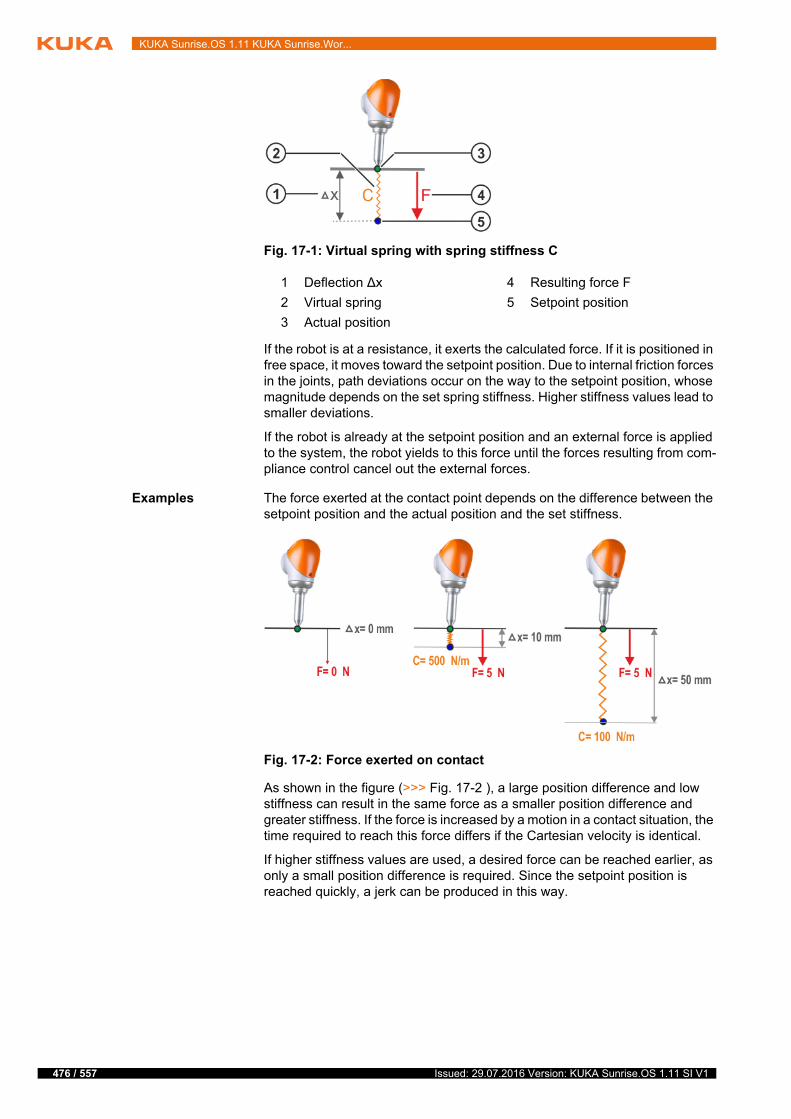
476 / 557
KUKA Sunrise.OS 1.11 KUKA Sunrise.Wor...
If the robot is at a resistance, it exerts the calculated force. If it is positioned in free space, it moves toward the setpoint position. Due to internal friction forces in the joints, path deviations occur on the way to the setpoint position, whose magnitude depends on the set spring stiffness. Higher stiffness values lead to smaller deviations.
If the robot is already at the setpoint position and an external force is applied to the system, the robot yields to this force until the forces resulting from com-pliance control cancel out the external forces.
Examples The force exerted at the contact point depends on the difference between the setpoint position and the actual position and the set stiffness.
As shown in the figure (>>> Fig. 17-2 ), a large position difference and low stiffness can result in the same force as a smaller position difference and greater stiffness. If the force is increased by a motion in a contact situation, the time required to reach this force differs if the Cartesian velocity is identical.
If higher stiffness values are used, a desired force can be reached earlier, as only a small position difference is required. Since the setpoint position is reached quickly, a jerk can be produced in this way.
Fig. 17-1: Virtual spring with spring stiffness C
1 Deflection ∆x 4 Resulting force F
2 Virtual spring 5 Setpoint position
3 Actual position
Fig. 17-2: Force exerted on contact
Issued: 29.07.2016 Version: KUKA Sunrise.OS 1.11 SI V1
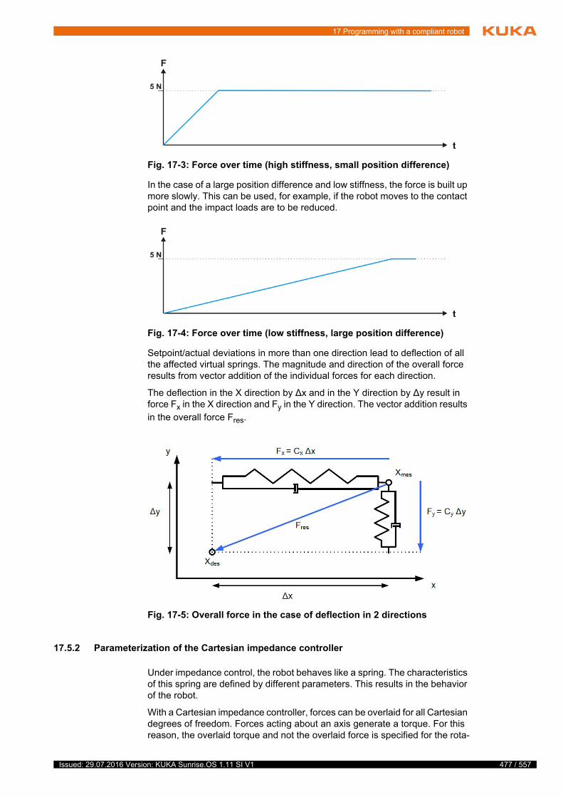
17 Programming with a compliant robot
In the case of a large position difference and low stiffness, the force is built up more slowly. This can be used, for example, if the robot moves to the contact point and the impact loads are to be reduced.
Setpoint/actual deviations in more than one direction lead to deflection of all the affected virtual springs. The magnitude and direction of the overall force results from vector addition of the individual forces for each direction.
The deflection in the X direction by ∆x and in the Y direction by ∆y result in force Fx in the X direction and Fy in the Y direction. The vector addition results in the overall force Fres.
17.5.2 Parameterization of the Cartesian impedance controller
Under impedance control, the robot behaves like a spring. The characteristics of this spring are defined by different parameters. This results in the behavior of the robot.
With a Cartesian impedance controller, forces can be overlaid for all Cartesian degrees of freedom. Forces acting about an axis generate a torque. For this reason, the overlaid torque and not the overlaid force is specified for the rota-
Fig. 17-3: Force over time (high stiffness, small position difference)
Fig. 17-4: Force over time (low stiffness, large position difference)
Fig. 17-5: Overall force in the case of deflection in 2 directions
477 / 557Issued: 29.07.2016 Version: KUKA Sunrise.OS 1.11 SI V1
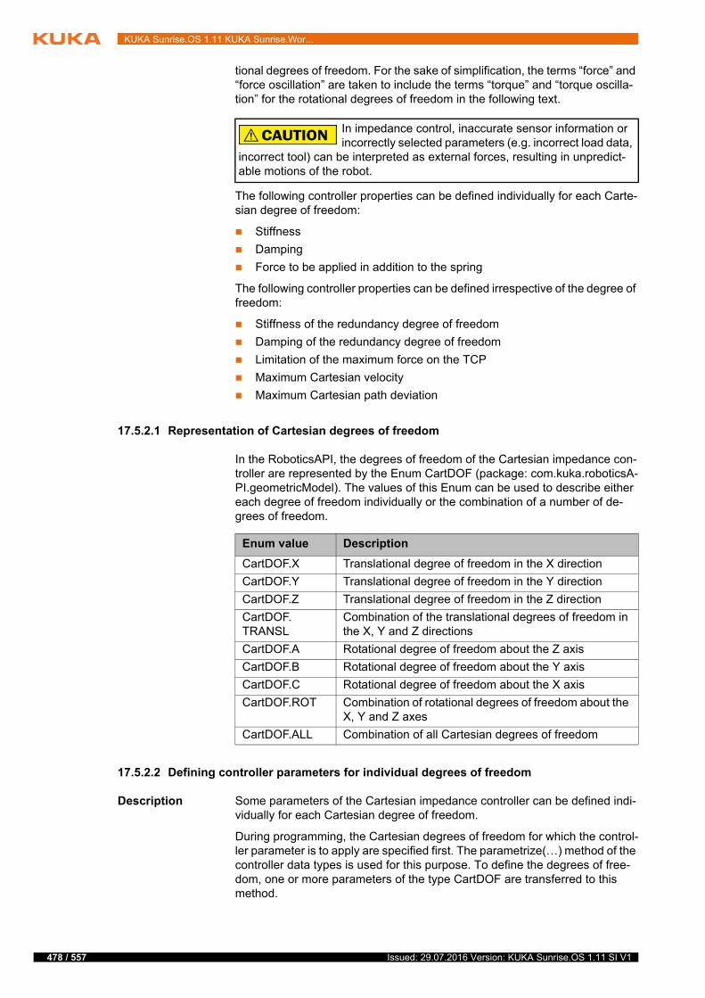
478 / 557
KUKA Sunrise.OS 1.11 KUKA Sunrise.Wor...
tional degrees of freedom. For the sake of simplification, the terms “force” and “force oscillation” are taken to include the terms “torque” and “torque oscilla-tion” for the rotational degrees of freedom in the following text.
The following controller properties can be defined individually for each Carte-sian degree of freedom:
Stiffness
Damping
Force to be applied in addition to the spring
The following controller properties can be defined irrespective of the degree of freedom:
Stiffness of the redundancy degree of freedom
Damping of the redundancy degree of freedom
Limitation of the maximum force on the TCP
Maximum Cartesian velocity
Maximum Cartesian path deviation
17.5.2.1 Representation of Cartesian degrees of freedom
In the RoboticsAPI, the degrees of freedom of the Cartesian impedance con-troller are represented by the Enum CartDOF (package: com.kuka.roboticsA-PI.geometricModel). The values of this Enum can be used to describe either each degree of freedom individually or the combination of a number of de-grees of freedom.
17.5.2.2 Defining controller parameters for individual degrees of freedom
Description Some parameters of the Cartesian impedance controller can be defined indi-vidually for each Cartesian degree of freedom.
During programming, the Cartesian degrees of freedom for which the control-ler parameter is to apply are specified first. The parametrize(…) method of the controller data types is used for this purpose. To define the degrees of free-dom, one or more parameters of the type CartDOF are transferred to this method.
In impedance control, inaccurate sensor information or incorrectly selected parameters (e.g. incorrect load data,
incorrect tool) can be interpreted as external forces, resulting in unpredict-able motions of the robot.
Enum value Description
CartDOF.X Translational degree of freedom in the X direction
CartDOF.Y Translational degree of freedom in the Y direction
CartDOF.Z Translational degree of freedom in the Z direction
CartDOF.TRANSL
Combination of the translational degrees of freedom in the X, Y and Z directions
CartDOF.A Rotational degree of freedom about the Z axis
CartDOF.B Rotational degree of freedom about the Y axis
CartDOF.C Rotational degree of freedom about the X axis
CartDOF.ROT Combination of rotational degrees of freedom about the X, Y and Z axes
CartDOF.ALL Combination of all Cartesian degrees of freedom
Issued: 29.07.2016 Version: KUKA Sunrise.OS 1.11 SI V1
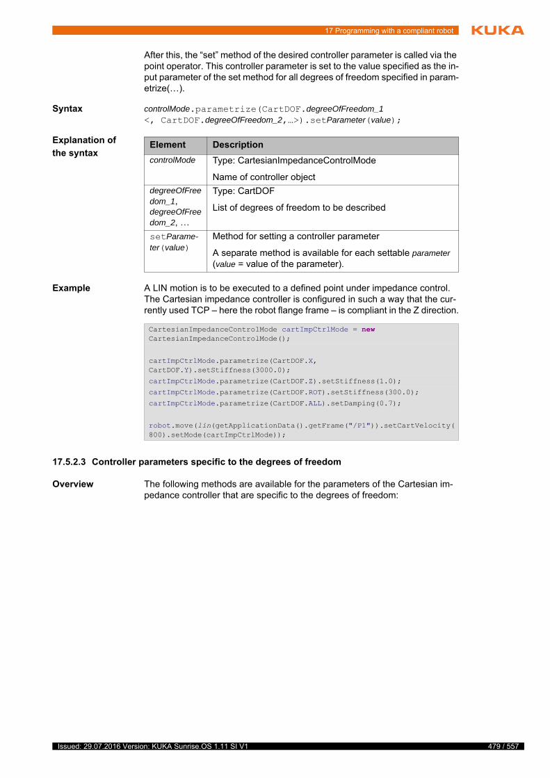
17 Programming with a compliant robot
After this, the “set” method of the desired controller parameter is called via the point operator. This controller parameter is set to the value specified as the in-put parameter of the set method for all degrees of freedom specified in param-etrize(…).
Syntax controlMode.parametrize(CartDOF.degreeOfFreedom_1 <, CartDOF.degreeOfFreedom_2,…>).setParameter(value);
Explanation of
the syntax
Example A LIN motion is to be executed to a defined point under impedance control. The Cartesian impedance controller is configured in such a way that the cur-rently used TCP – here the robot flange frame – is compliant in the Z direction.
17.5.2.3 Controller parameters specific to the degrees of freedom
Overview The following methods are available for the parameters of the Cartesian im-pedance controller that are specific to the degrees of freedom:
Element Description
controlMode Type: CartesianImpedanceControlMode
Name of controller object
degreeOfFreedom_1, degreeOfFreedom_2, …
Type: CartDOF
List of degrees of freedom to be described
setParame-ter(value)
Method for setting a controller parameter
A separate method is available for each settable parameter (value = value of the parameter).
CartesianImpedanceControlMode cartImpCtrlMode = new CartesianImpedanceControlMode();
cartImpCtrlMode.parametrize(CartDOF.X, CartDOF.Y).setStiffness(3000.0);
cartImpCtrlMode.parametrize(CartDOF.Z).setStiffness(1.0);
cartImpCtrlMode.parametrize(CartDOF.ROT).setStiffness(300.0);
cartImpCtrlMode.parametrize(CartDOF.ALL).setDamping(0.7);
robot.move(lin(getApplicationData().getFrame("/P1")).setCartVelocity(800).setMode(cartImpCtrlMode));
479 / 557Issued: 29.07.2016 Version: KUKA Sunrise.OS 1.11 SI V1
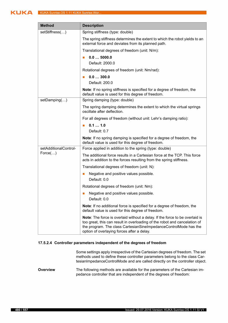
480 / 557
KUKA Sunrise.OS 1.11 KUKA Sunrise.Wor...
17.5.2.4 Controller parameters independent of the degrees of freedom
Some settings apply irrespective of the Cartesian degrees of freedom. The set methods used to define these controller parameters belong to the class Car-tesianImpedanceControlMode and are called directly on the controller object.
Overview The following methods are available for the parameters of the Cartesian im-pedance controller that are independent of the degrees of freedom:
Method Description
setStiffness(…) Spring stiffness (type: double)
The spring stiffness determines the extent to which the robot yields to an external force and deviates from its planned path.
Translational degrees of freedom (unit: N/m):
0.0 … 5000.0
Default: 2000.0
Rotational degrees of freedom (unit: Nm/rad):
0.0 … 300.0
Default: 200.0
Note: If no spring stiffness is specified for a degree of freedom, the default value is used for this degree of freedom.
setDamping(…) Spring damping (type: double)
The spring damping determines the extent to which the virtual springs oscillate after deflection.
For all degrees of freedom (without unit: Lehr’s damping ratio):
0.1 … 1.0
Default: 0.7
Note: If no spring damping is specified for a degree of freedom, the default value is used for this degree of freedom.
setAdditionalControl-Force(…)
Force applied in addition to the spring (type: double)
The additional force results in a Cartesian force at the TCP. This force acts in addition to the forces resulting from the spring stiffness.
Translational degrees of freedom (unit: N):
Negative and positive values possible.
Default: 0.0
Rotational degrees of freedom (unit: Nm):
Negative and positive values possible.
Default: 0.0
Note: If no additional force is specified for a degree of freedom, the default value is used for this degree of freedom.
Note: The force is overlaid without a delay. If the force to be overlaid is too great, this can result in overloading of the robot and cancelation of the program. The class CartesianSineImpedanceControlMode has the option of overlaying forces after a delay.
Issued: 29.07.2016 Version: KUKA Sunrise.OS 1.11 SI V1

17 Programming with a compliant robot
Method Description
setNullSpaceStiff-ness(…)
Spring stiffness of the redundancy degree of freedom (type: double, unit: Nm/rad)
The spring stiffness determines the extent to which the robot yields to an external force and deviates from its planned path.
≥ 0.0
Note: If no spring stiffness is specified for the redundancy degree of freedom, a default value is used for this degree of freedom.
setNullSpaceDamp-ing(…)
Spring damping of the redundancy degree of freedom (type: double)
The spring damping determines the extent to which the virtual springs oscillate after deflection.
0.3 … 1.0
Note: If no spring damping is specified for the redundancy degree of freedom, a default value is used for this degree of freedom.
setMaxControl-Force(…)
Limitation of the maximum force on the TCP
The maximum force applied to the TCP by the virtual springs is limited. The maximum force required to deflect the virtual spring is thus also defined. Whether or not the motion is to be aborted if the maximum force at the TCP is exceeded is also defined.
Syntax:
setMaxControlForce(maxForceX, maxForceY, maxForceZ, maxTorqueA, maxTorqueB, maxTorqueC, addStopCondition)
Explanation of the syntax:
maxForceXΙYΙZ: Maximum force at the TCP in the corresponding Car-tesian direction (type: double, unit: N)
≥ 0.0
maxTorqueAΙBΙC: Maximum torque at the TCP in the corresponding rotational direction (type: double, unit: Nm)
≥ 0.0
addStopCondition: Cancelation of the motion if the maximum force at the TCP is exceeded (type: boolean)
true: Motion is aborted.
false: Motion is not aborted.
Note: If the force limitation is only to be applied for individual degrees of freedom, correspondingly high values must be assigned to those degrees of freedom that are not to be limited.
481 / 557Issued: 29.07.2016 Version: KUKA Sunrise.OS 1.11 SI V1
482 / 557
KUKA Sunrise.OS 1.11 KUKA Sunrise.Wor...
Example 1 A robot under impedance control is to be compliant in its redundant degree of freedom in order to be able to respond to obstacles during the motion. For this, stiffness and damping of the redundant degree of freedom are parameterized for the impedance controller.
Example 2 A robot is to move along a table plate in compliant mode. A Cartesian imped-ance controller is parameterized for this. A high stiffness value is set for the Z direction of the tool coordinate system in the TCP. An additional force of 20 N is also to be applied. The motion is aborted if a force limit of 50 N in the Z di-rection is exceeded. A low stiffness value is set in the XY plane. The Cartesian
setMaxCartesianVe-locity(…)
Maximum Cartesian velocity
The motion is aborted if the defined velocity limit is exceeded.
Syntax:
setMaxCartesianVelocity(maxVelocityX, maxVelocityY, max-VelocityZ, maxVelocityA, maxVelocityB, maxVelocityC)
Explanation of the syntax:
maxVelocityXΙYΙZ: Maximum permissible translational velocity at the TCP in the corresponding Cartesian direction (type: double, unit: mm/s)
≥ 0.0
maxVelocityAΙBΙC: Maximum permissible rotational velocity at the TCP in the corresponding rotational direction (type: double, unit: rad/s)
≥ 0.0
Note: If the velocity limitation is only to be applied for individual degrees of freedom, correspondingly high values must be assigned to those degrees of freedom that are not to be limited.
setMaxPathDevia-tion(…)
Maximum Cartesian path deviation
Defines the maximum permissible Cartesian path deviation from the cur-rently planned setpoint position for a compliant motion. The motion is aborted if the defined maximum path deviation is exceeded.
Syntax:
setMaxPathDeviation(maxDeviationX, maxDeviationY, maxDe-viationZ, maxDeviationA, maxDeviationB, maxDeviationC)
Explanation of the syntax:
maxDeviationXΙYΙZ: Maximum permissible path deviation at the TCP in the corresponding Cartesian direction (type: double, unit: mm)
≥ 0.0
maxDeviationAΙBΙC: Maximum permissible rotational deviation at the TCP in the corresponding rotational direction (type: double, unit: rad/s)
≥ 0.0
Note: If the path deviation is only to be applied for individual degrees of freedom, correspondingly high values must be assigned to those degrees of freedom that are not to be limited.
Method Description
CartesianImpedanceControlMode mode = new CartesianImpedanceControlMode();
mode.setNullSpaceStiffness(10.0);
mode.setNullSpaceDamping(0.7);
Issued: 29.07.2016 Version: KUKA Sunrise.OS 1.11 SI V1
17 Programming with a compliant robot
deviation in the X and Y directions must not exceed 10 mm, however. Suitable higher values are specified for all other parameters.
17.6 Cartesian impedance controller with overlaid force oscillation
The Cartesian impedance controller with overlaid force oscillation is a special form of the Cartesian impedance controller. The force can be overlaid sepa-rately for each Cartesian degree of freedom.
Force oscillations about an axis generate torque oscillations. Overlaying torque oscillations can result in the generation of rotational oscillations.
Overlaying constant or sinusoidal forces causes the robot to move. Suitable combinations of oscillations in the individual degrees of freedom can be used to generate different motion patterns.
Using overlaid oscillations, it is possible to implement compliant pendulum motions for search runs and vibrations in the tool for joining processes.
The Cartesian impedance controller with overlaid force oscillation is repre-sented by the class CartesianSineImpedanceControlMode.
Behavior of the
robot
In this form of impedance control, the overlaid force causes the robot to leave the planned path in a targeted way. The new path is thus determined by a wide range of different parameters.
In addition to stiffness and damping, further parameters can be defined, e.g. frequency and amplitude. The programmed velocity of the robot also plays a significant role for the actual path.
17.6.1 Overlaying a simple force oscillation
By overlaying a simple force oscillation, the working point is diverted from the planned path (= path without overlaid oscillations) and is instead moved from the start point to the end point of the motion in a sinusoidal path.
Example The robot executes a relative motion in the Y direction of the tool coordinate system in the TCP. A sinusoidal force oscillation in the X direction is overlaid. The result is a wave-like path in the XY plane of the coordinate system.
CartesianImpedanceControlMode mode = new CartesianImpedanceControlMode();
mode.parametrize(CartDOF.Z).setStiffness(3000.0);
mode.parametrize(CartDOF.Z).setAdditionalControlForce(20.0);
mode.setMaxControlForce(100.0, 100.0, 50.0, 20.0, 20.0, 20.0, true);
mode.parametrize(CartDOF.X, CartDOF.Y).setStiffness(10.0);
mode.setMaxPathDeviation(10.0, 10.0, 50.0, 2.0, 2.0, 2.0);
Overlaying additional forces has a strong influence on the robot mo-tion and the forces exerted by the robot. For example, low stiffness and high overlaid forces can cause the robot to accelerate suddenly.
Parameterization must therefore be carried out with caution if working with force activations. For example, begin by overlaying low forces and approach the appropriate force values step by step. In addition, the motion resulting from the overlaid force must always be tested in T1 mode first.
483 / 557Issued: 29.07.2016 Version: KUKA Sunrise.OS 1.11 SI V1
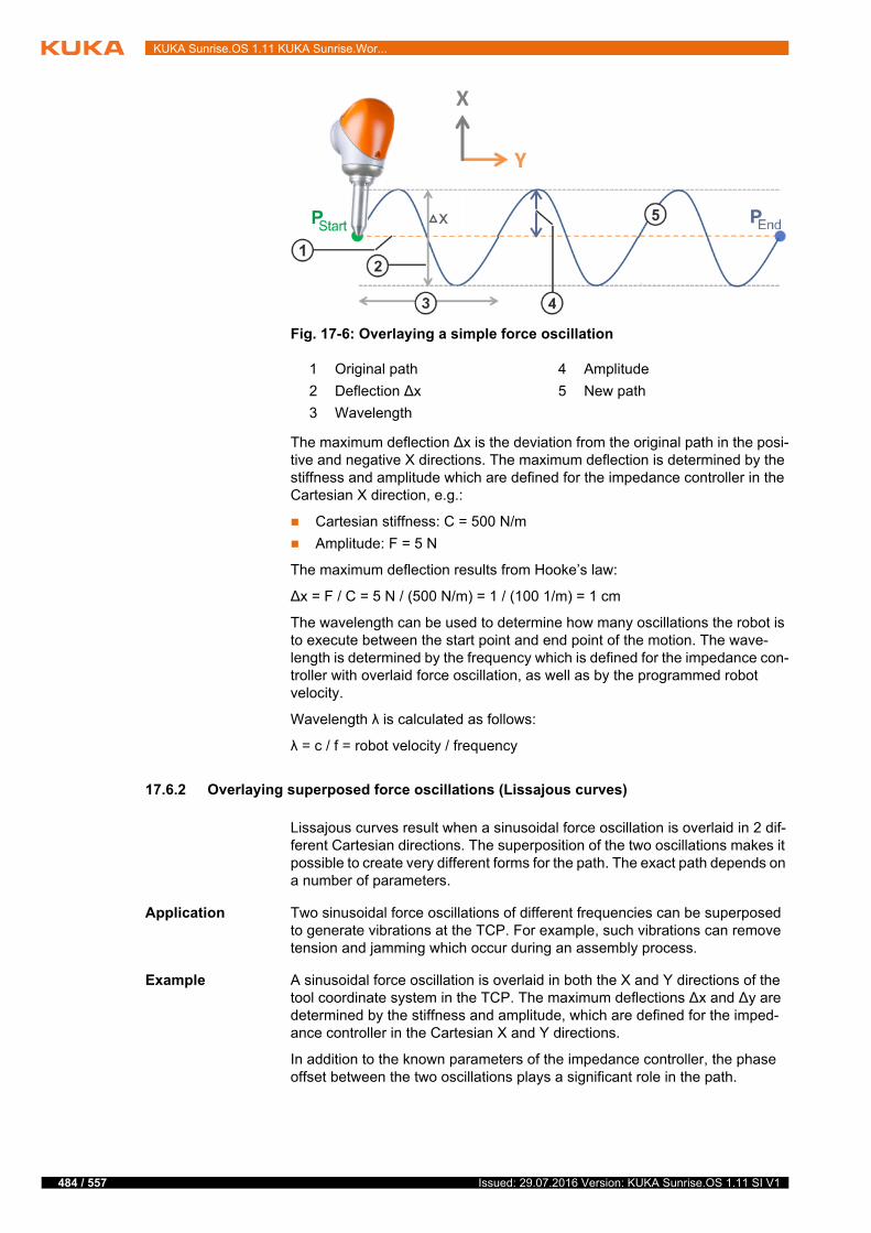
484 / 557
KUKA Sunrise.OS 1.11 KUKA Sunrise.Wor...
The maximum deflection ∆x is the deviation from the original path in the posi-tive and negative X directions. The maximum deflection is determined by the stiffness and amplitude which are defined for the impedance controller in the Cartesian X direction, e.g.:
Cartesian stiffness: C = 500 N/m
Amplitude: F = 5 N
The maximum deflection results from Hooke’s law:
∆x = F / C = 5 N / (500 N/m) = 1 / (100 1/m) = 1 cm
The wavelength can be used to determine how many oscillations the robot is to execute between the start point and end point of the motion. The wave-length is determined by the frequency which is defined for the impedance con-troller with overlaid force oscillation, as well as by the programmed robot velocity.
Wavelength λ is calculated as follows:
λ = c / f = robot velocity / frequency
17.6.2 Overlaying superposed force oscillations (Lissajous curves)
Lissajous curves result when a sinusoidal force oscillation is overlaid in 2 dif-ferent Cartesian directions. The superposition of the two oscillations makes it possible to create very different forms for the path. The exact path depends on a number of parameters.
Application Two sinusoidal force oscillations of different frequencies can be superposed to generate vibrations at the TCP. For example, such vibrations can remove tension and jamming which occur during an assembly process.
Example A sinusoidal force oscillation is overlaid in both the X and Y directions of the tool coordinate system in the TCP. The maximum deflections ∆x and ∆y are determined by the stiffness and amplitude, which are defined for the imped-ance controller in the Cartesian X and Y directions.
In addition to the known parameters of the impedance controller, the phase offset between the two oscillations plays a significant role in the path.
Fig. 17-6: Overlaying a simple force oscillation
1 Original path 4 Amplitude
2 Deflection ∆x 5 New path
3 Wavelength
Issued: 29.07.2016 Version: KUKA Sunrise.OS 1.11 SI V1
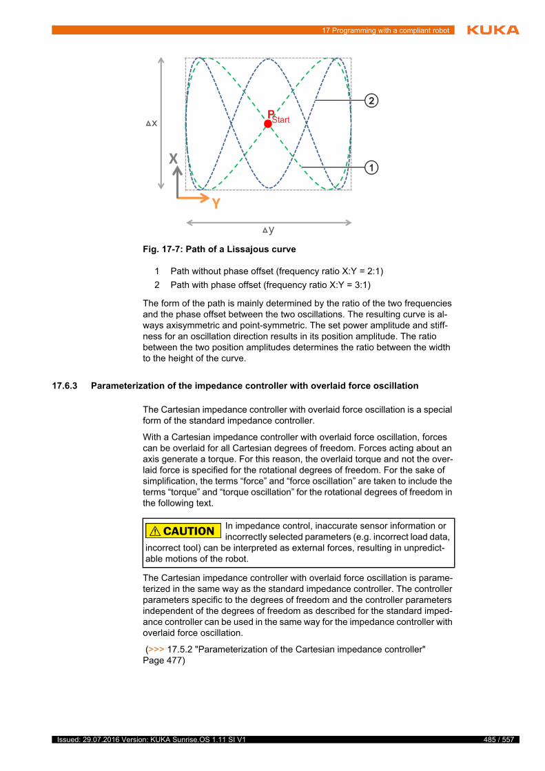
17 Programming with a compliant robot
The form of the path is mainly determined by the ratio of the two frequencies and the phase offset between the two oscillations. The resulting curve is al-ways axisymmetric and point-symmetric. The set power amplitude and stiff-ness for an oscillation direction results in its position amplitude. The ratio between the two position amplitudes determines the ratio between the width to the height of the curve.
17.6.3 Parameterization of the impedance controller with overlaid force oscillation
The Cartesian impedance controller with overlaid force oscillation is a special form of the standard impedance controller.
With a Cartesian impedance controller with overlaid force oscillation, forces can be overlaid for all Cartesian degrees of freedom. Forces acting about an axis generate a torque. For this reason, the overlaid torque and not the over-laid force is specified for the rotational degrees of freedom. For the sake of simplification, the terms “force” and “force oscillation” are taken to include the terms “torque” and “torque oscillation” for the rotational degrees of freedom in the following text.
The Cartesian impedance controller with overlaid force oscillation is parame-terized in the same way as the standard impedance controller. The controller parameters specific to the degrees of freedom and the controller parameters independent of the degrees of freedom as described for the standard imped-ance controller can be used in the same way for the impedance controller with overlaid force oscillation.
(>>> 17.5.2 "Parameterization of the Cartesian impedance controller" Page 477)
Fig. 17-7: Path of a Lissajous curve
1 Path without phase offset (frequency ratio X:Y = 2:1)
2 Path with phase offset (frequency ratio X:Y = 3:1)
In impedance control, inaccurate sensor information or incorrectly selected parameters (e.g. incorrect load data,
incorrect tool) can be interpreted as external forces, resulting in unpredict-able motions of the robot.
485 / 557Issued: 29.07.2016 Version: KUKA Sunrise.OS 1.11 SI V1
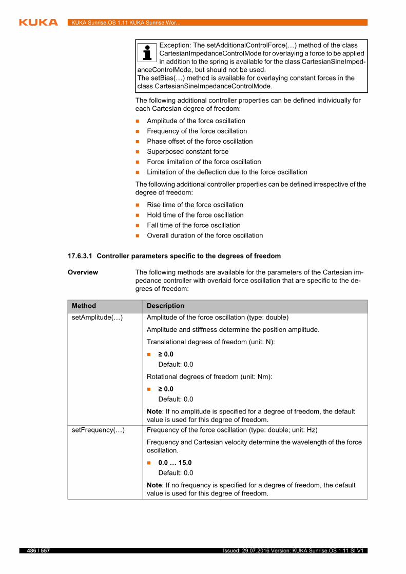
486 / 557
KUKA Sunrise.OS 1.11 KUKA Sunrise.Wor...
The following additional controller properties can be defined individually for each Cartesian degree of freedom:
Amplitude of the force oscillation
Frequency of the force oscillation
Phase offset of the force oscillation
Superposed constant force
Force limitation of the force oscillation
Limitation of the deflection due to the force oscillation
The following additional controller properties can be defined irrespective of the degree of freedom:
Rise time of the force oscillation
Hold time of the force oscillation
Fall time of the force oscillation
Overall duration of the force oscillation
17.6.3.1 Controller parameters specific to the degrees of freedom
Overview The following methods are available for the parameters of the Cartesian im-pedance controller with overlaid force oscillation that are specific to the de-grees of freedom:
Exception: The setAdditionalControlForce(…) method of the class CartesianImpedanceControlMode for overlaying a force to be applied in addition to the spring is available for the class CartesianSineImped-
anceControlMode, but should not be used.The setBias(…) method is available for overlaying constant forces in the class CartesianSineImpedanceControlMode.
Method Description
setAmplitude(…) Amplitude of the force oscillation (type: double)
Amplitude and stiffness determine the position amplitude.
Translational degrees of freedom (unit: N):
≥ 0.0
Default: 0.0
Rotational degrees of freedom (unit: Nm):
≥ 0.0
Default: 0.0
Note: If no amplitude is specified for a degree of freedom, the default value is used for this degree of freedom.
setFrequency(…) Frequency of the force oscillation (type: double; unit: Hz)
Frequency and Cartesian velocity determine the wavelength of the force oscillation.
0.0 … 15.0
Default: 0.0
Note: If no frequency is specified for a degree of freedom, the default value is used for this degree of freedom.
Issued: 29.07.2016 Version: KUKA Sunrise.OS 1.11 SI V1

17 Programming with a compliant robot
setPhaseDeg(…) Phase offset of the force oscillation at the start of the force overlay (type: double; unit: °)
≥ 0.0
Default: 0.0
Note: If no phase offset is specified for a degree of freedom, the default value is used for this degree of freedom.
setBias(…) Constant force overlaid (type: double)
Using setBias(…), a constant force can be overlaid in addition to the overlaid force oscillation. This force adds to the force resulting from the spring stiffness and defined force oscillation.
If a constant force is overlaid without an additional force oscillation, this results in a force characteristic which rises as a function of the rise time defined with setRiseTime(…) and then remains constant. setRise-Time(…) belongs to the controller parameters independent of the degrees of freedom (>>> 17.6.3.1 "Controller parameters specific to the degrees of freedom" Page 486).
If a constant force is overlaid in addition to a force oscillation, the force oscillation is offset in the defined direction.
Translational degrees of freedom (unit: N):
Negative and positive values possible.
Default: 0.0
Rotational degrees of freedom (unit: Nm):
Negative and positive values possible.
Default: 0.0
Note: If no additional constant force is overlaid for a degree of freedom, the default value is used for this degree of freedom.
Method Description
487 / 557Issued: 29.07.2016 Version: KUKA Sunrise.OS 1.11 SI V1
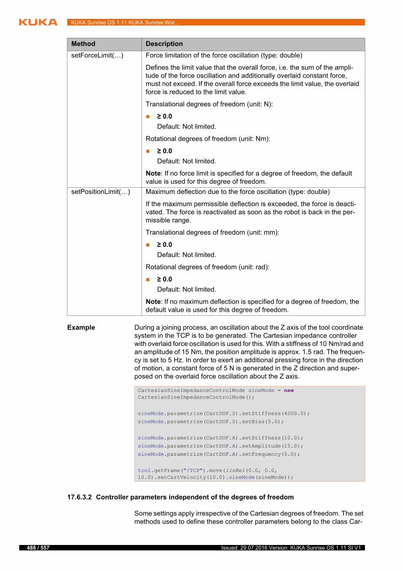
488 / 557
KUKA Sunrise.OS 1.11 KUKA Sunrise.Wor...
Example During a joining process, an oscillation about the Z axis of the tool coordinate system in the TCP is to be generated. The Cartesian impedance controller with overlaid force oscillation is used for this. With a stiffness of 10 Nm/rad and an amplitude of 15 Nm, the position amplitude is approx. 1.5 rad. The frequen-cy is set to 5 Hz. In order to exert an additional pressing force in the direction of motion, a constant force of 5 N is generated in the Z direction and super-posed on the overlaid force oscillation about the Z axis.
17.6.3.2 Controller parameters independent of the degrees of freedom
Some settings apply irrespective of the Cartesian degrees of freedom. The set methods used to define these controller parameters belong to the class Car-
setForceLimit(…) Force limitation of the force oscillation (type: double)
Defines the limit value that the overall force, i.e. the sum of the ampli-tude of the force oscillation and additionally overlaid constant force, must not exceed. If the overall force exceeds the limit value, the overlaid force is reduced to the limit value.
Translational degrees of freedom (unit: N):
≥ 0.0
Default: Not limited.
Rotational degrees of freedom (unit: Nm):
≥ 0.0
Default: Not limited.
Note: If no force limit is specified for a degree of freedom, the default value is used for this degree of freedom.
setPositionLimit(…) Maximum deflection due to the force oscillation (type: double)
If the maximum permissible deflection is exceeded, the force is deacti-vated. The force is reactivated as soon as the robot is back in the per-missible range.
Translational degrees of freedom (unit: mm):
≥ 0.0
Default: Not limited.
Rotational degrees of freedom (unit: rad):
≥ 0.0
Default: Not limited.
Note: If no maximum deflection is specified for a degree of freedom, the default value is used for this degree of freedom.
Method Description
CartesianSineImpedanceControlMode sineMode = new CartesianSineImpedanceControlMode();
sineMode.parametrize(CartDOF.Z).setStiffness(4000.0);
sineMode.parametrize(CartDOF.Z).setBias(5.0);
sineMode.parametrize(CartDOF.A).setStiffness(10.0);
sineMode.parametrize(CartDOF.A).setAmplitude(15.0);
sineMode.parametrize(CartDOF.A).setFrequency(5.0);
tool.getFrame("/TCP").move(linRel(0.0, 0.0, 10.0).setCartVelocity(10.0).sineMode(sineMode));
Issued: 29.07.2016 Version: KUKA Sunrise.OS 1.11 SI V1

17 Programming with a compliant robot
tesianSineImpedanceControlMode and are called directly on the controller ob-ject.
Overview The following methods are available for the parameters of the Cartesian im-pedance controller with overlaid force oscillation that are independent of the degrees of freedom:
Overall duration
of the force oscil-
lation
The overall duration is the sum of the rise time, hold time and fall time of the force oscillation:
Rise time
Time in which the amplitude of the force oscillation is built up.
Hold time
Time in which the force oscillation is executed with the defined amplitude.
Method Description
setTotalTime(…) Overall duration of the force oscillation (type: double; unit: s)
(>>> "Overall duration of the force oscillation" Page 489)
≥ 0.0
Default: Unlimited
setRiseTime(…) Rise time of the force oscillation (type: double; unit: s)
≥ 0.0
Default: 0.0
Note: If no rise time is specified for a degree of freedom, the default value is used. This means that the amplitude rises abruptly to the defined value without a transition. If the force to be overlaid is too great, this can result in overloading of the robot and cancelation of the pro-gram.
setHoldTime(…) Hold time of the force oscillation (type: double; unit: s)
≥ 0.0
Default: Unlimited
Note: If no hold time is specified for a degree of freedom, the default value is used. This means that the overlaid force oscillation ends with the corresponding motion.
setFallTime(…) Fall time of the force oscillation (type: double; unit: s)
≥ 0.0
Default: 0.0
Note: If no fall time is specified for a degree of freedom, the default value is used. This means that the amplitude falls abruptly to zero with-out a transition. If the drop in force is too great, this can result in over-loading of the robot and cancelation of the program.
setStayActiveUntil-PatternFinished(…)
Response if the motion duration is exceeded (type: boolean)
If the force oscillation lasts longer than the motion, it is possible to define whether the oscillation is terminated or continued after the end of the motion.
true: Oscillation is continued after the end of the motion.
false: Oscillation is terminated at the end of the motion.
Default: false
Note: If the response when the motion duration is exceeded is not spec-ified, the default value is used.
489 / 557Issued: 29.07.2016 Version: KUKA Sunrise.OS 1.11 SI V1

490 / 557
KUKA Sunrise.OS 1.11 KUKA Sunrise.Wor...
Fall time
Time in which the amplitude of the force oscillation is reduced back to zero.
Rise time, hold time and fall time of the force oscillation can be defined indi-vidually, or indirectly by defining the overall duration of the force oscillation.
If the overall duration is defined using setTotalTime(…), the rise time and fall time are defined automatically.
Calculation:
Rise time = fall time = (1/frequency) 0.5
Of the frequencies defined for the force oscillation (relative to all degrees of freedom), the frequency that results in the largest possible rise and fall times is used for the calculation.
If exclusively constant forces are overlaid, the frequency of all degrees of freedom is 0.0 Hz. Rise and fall time are set to 0.0 s.
If the calculated sum of rise time and fall time exceeds the defined overall duration, the rise time and fall time are each set to 25% of the overall du-ration and the hold time to 50%.
If the overall duration of the force oscillation is shorter than the duration of the corresponding motion, the force oscillation ends before the end of the motion. The response if the motion duration is exceeded is defined using setStayAc-tiveUntilPatternFinished(…).
17.7 Static methods for impedance controller with superposed force oscillation
Overview The Cartesian impedance controller with overlaid force oscillation can also be configured via static methods of the class CartesianSineImpedanceControl-Mode. This simplifies the programming, in particular of Lissajous curves, as the user only has to specify a few parameters. The remaining parameters which are important for the implementation are calculated and set automati-cally. Default values are used for all other parameters. Additional settings are made as described using the parametrize(…) function and the set methods of CartesianSineImpedanceControlMode.
createDesiredForce(…): Static method for constant force
createSinePattern(…): Static method for simple force oscillations
createLissajousPattern(…): Static method for Lissajous curves
createSpiralPattern(…): Static method for spirals
Specification of
Cartesian planes
In contrast to simple oscillations, no individual degree of freedom is transferred to Lissajous curves and spirals, but rather the plane in which the path is to run. The plane is specified via the Enum CartPlane (the package com.kuka.robot-icsAPI.geometricModel).
17.7.1 Overlaying a constant force
Description The createDesiredForce(…) method overlays a constant force, that does not change over time, in one Cartesian direction.
Syntax controlMode = CartesianSineImpedanceControlMode.createDesi-redForce(CartDOF.degreeOfFreedom, force, stiffness);
Enum value Description
CartPlane.XY Path in the XY plane
CartPlane.XZ Path in the XZ plane
CartPlane.YZ Path in the YZ plane
Issued: 29.07.2016 Version: KUKA Sunrise.OS 1.11 SI V1
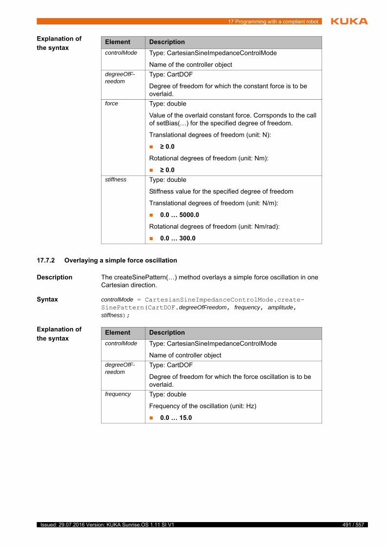
17 Programming with a compliant robot
Explanation of
the syntax
17.7.2 Overlaying a simple force oscillation
Description The createSinePattern(…) method overlays a simple force oscillation in one Cartesian direction.
Syntax controlMode = CartesianSineImpedanceControlMode.create-SinePattern(CartDOF.degreeOfFreedom, frequency, amplitude, stiffness);
Explanation of
the syntax
Element Description
controlMode Type: CartesianSineImpedanceControlMode
Name of the controller object
degreeOfF-reedom
Type: CartDOF
Degree of freedom for which the constant force is to be overlaid.
force Type: double
Value of the overlaid constant force. Corrsponds to the call of setBias(…) for the specified degree of freedom.
Translational degrees of freedom (unit: N):
≥ 0.0
Rotational degrees of freedom (unit: Nm):
≥ 0.0
stiffness Type: double
Stiffness value for the specified degree of freedom
Translational degrees of freedom (unit: N/m):
0.0 … 5000.0
Rotational degrees of freedom (unit: Nm/rad):
0.0 … 300.0
Element Description
controlMode Type: CartesianSineImpedanceControlMode
Name of controller object
degreeOfF-reedom
Type: CartDOF
Degree of freedom for which the force oscillation is to be overlaid.
frequency Type: double
Frequency of the oscillation (unit: Hz)
0.0 … 15.0
491 / 557Issued: 29.07.2016 Version: KUKA Sunrise.OS 1.11 SI V1

492 / 557
KUKA Sunrise.OS 1.11 KUKA Sunrise.Wor...
Example From the current position, a relative motion of 15 cm is to be executed in the Y direction. The motion is to run in a wave path with a deflection of approx. 10 cm (derived from the amplitude and stiffness) and a frequency of 2 Hz in the X direction.
17.7.3 Overlaying a Lissajous oscillation
Description The createLissajousPattern(…) method is used to generate a 2-dimensional oscillation in one plane. The plane is transferred as a value of type CartPlane. The other transferred parameters refer to the first degree of freedom of the specified plane (example: for CartPlane.XY, the specified values are relative to CartDOF.X).
The parameters of the second degree of freedom of the plane are calculated to produce a Lissajous curve with the following characteristics:
Amplitude ratio, 1st degree of freedom : 2nd degree of freedom: 1 : 1
Frequency ratio, 1st degree of freedom : 2nd degree of freedom: 1 : 0.4
Phase offset between 1st and 2nd degree of freedom: ½ · pi
Syntax controlMode = CartesianSineImpedanceControlMode.crea-teLissajousPattern(CartPlane.plane, frequency, amplitude, stiffness);
Explanation of
the syntax
amplitude Type: double
Amplitude of the oscillation which is overlaid in the direc-tion of the specified degree of freedom
Translational degrees of freedom (unit: N):
≥ 0.0
Rotational degrees of freedom (unit: Nm):
≥ 0.0
stiffness Type: double
Stiffness value for the specified degree of freedom
Translational degrees of freedom (unit: N/m):
0.0 … 5000.0
Rotational degrees of freedom (unit: Nm/rad):
0.0 … 300.0
Element Description
CartesianSineImpedanceControlMode sineMode;
sineMode = CartesianSineImpedanceControlMode.createSinePattern(CartDOF.X, 2.0, 50.0, 500.0);
robot.move(linRel(0.0, 150.0, 0.0).setCartVelocity(100).setMode(sineMode));
Element Description
controlMode Type: CartesianSineImpedanceControlMode
Name of controller object
plane Type: Enum of type CartPlane
Plane in which the Lissajous oscillation is to be overlaid
Issued: 29.07.2016 Version: KUKA Sunrise.OS 1.11 SI V1
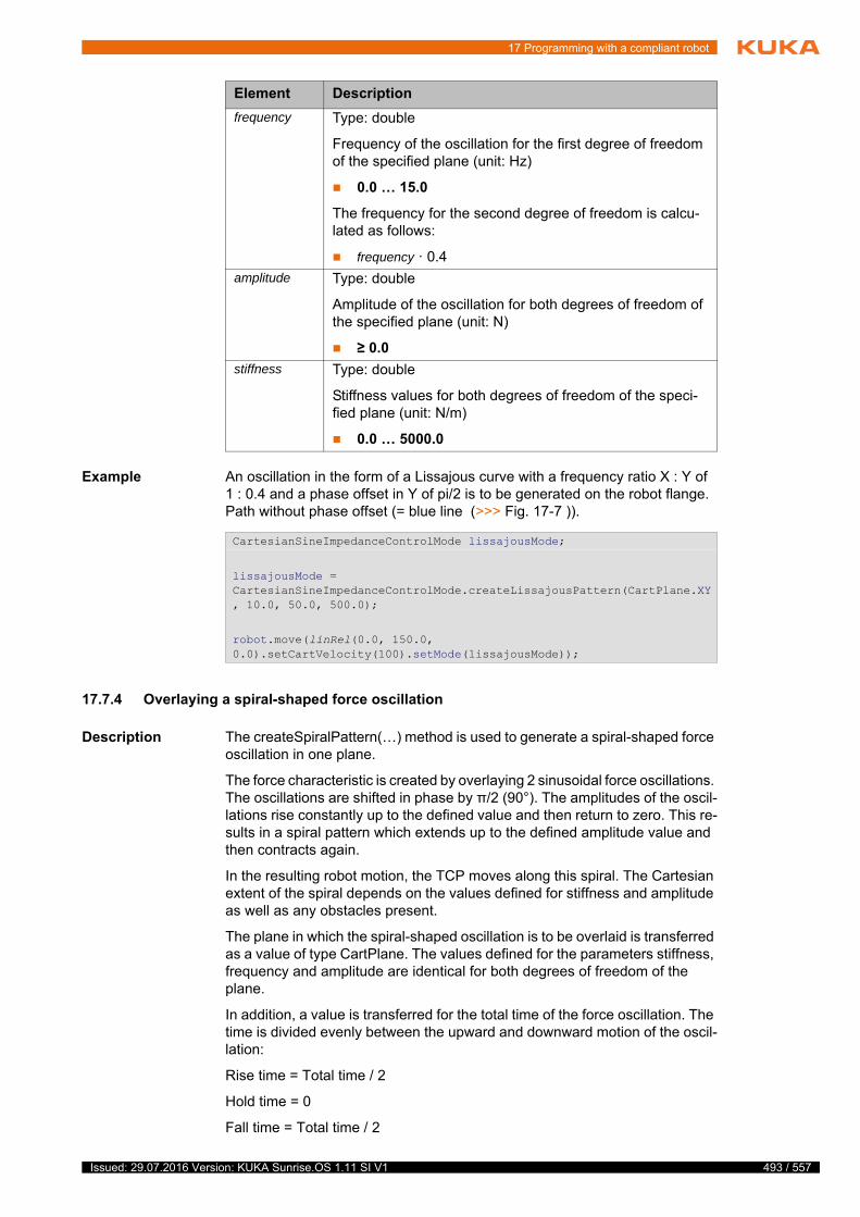
17 Programming with a compliant robot
Example An oscillation in the form of a Lissajous curve with a frequency ratio X : Y of 1 : 0.4 and a phase offset in Y of pi/2 is to be generated on the robot flange. Path without phase offset (= blue line (>>> Fig. 17-7 )).
17.7.4 Overlaying a spiral-shaped force oscillation
Description The createSpiralPattern(…) method is used to generate a spiral-shaped force oscillation in one plane.
The force characteristic is created by overlaying 2 sinusoidal force oscillations. The oscillations are shifted in phase by π/2 (90°). The amplitudes of the oscil-lations rise constantly up to the defined value and then return to zero. This re-sults in a spiral pattern which extends up to the defined amplitude value and then contracts again.
In the resulting robot motion, the TCP moves along this spiral. The Cartesian extent of the spiral depends on the values defined for stiffness and amplitude as well as any obstacles present.
The plane in which the spiral-shaped oscillation is to be overlaid is transferred as a value of type CartPlane. The values defined for the parameters stiffness, frequency and amplitude are identical for both degrees of freedom of the plane.
In addition, a value is transferred for the total time of the force oscillation. The time is divided evenly between the upward and downward motion of the oscil-lation:
Rise time = Total time / 2
Hold time = 0
Fall time = Total time / 2
frequency Type: double
Frequency of the oscillation for the first degree of freedom of the specified plane (unit: Hz)
0.0 … 15.0
The frequency for the second degree of freedom is calcu-lated as follows:
frequency · 0.4
amplitude Type: double
Amplitude of the oscillation for both degrees of freedom of the specified plane (unit: N)
≥ 0.0
stiffness Type: double
Stiffness values for both degrees of freedom of the speci-fied plane (unit: N/m)
0.0 … 5000.0
Element Description
CartesianSineImpedanceControlMode lissajousMode;
lissajousMode = CartesianSineImpedanceControlMode.createLissajousPattern(CartPlane.XY, 10.0, 50.0, 500.0);
robot.move(linRel(0.0, 150.0, 0.0).setCartVelocity(100).setMode(lissajousMode));
493 / 557Issued: 29.07.2016 Version: KUKA Sunrise.OS 1.11 SI V1
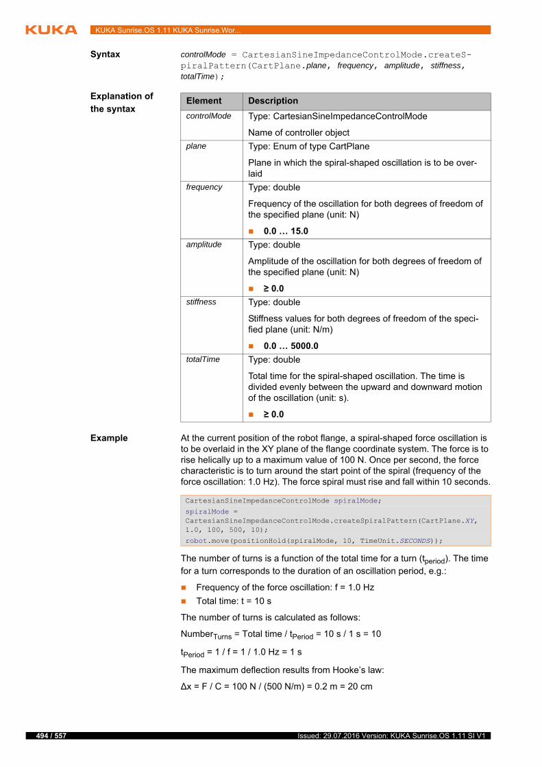
494 / 557
KUKA Sunrise.OS 1.11 KUKA Sunrise.Wor...
Syntax controlMode = CartesianSineImpedanceControlMode.createS-piralPattern(CartPlane.plane, frequency, amplitude, stiffness, totalTime);
Explanation of
the syntax
Example At the current position of the robot flange, a spiral-shaped force oscillation is to be overlaid in the XY plane of the flange coordinate system. The force is to rise helically up to a maximum value of 100 N. Once per second, the force characteristic is to turn around the start point of the spiral (frequency of the force oscillation: 1.0 Hz). The force spiral must rise and fall within 10 seconds.
The number of turns is a function of the total time for a turn (tperiod). The time for a turn corresponds to the duration of an oscillation period, e.g.:
Frequency of the force oscillation: f = 1.0 Hz
Total time: t = 10 s
The number of turns is calculated as follows:
NumberTurns = Total time / tPeriod = 10 s / 1 s = 10
tPeriod = 1 / f = 1 / 1.0 Hz = 1 s
The maximum deflection results from Hooke’s law:
∆x = F / C = 100 N / (500 N/m) = 0.2 m = 20 cm
Element Description
controlMode Type: CartesianSineImpedanceControlMode
Name of controller object
plane Type: Enum of type CartPlane
Plane in which the spiral-shaped oscillation is to be over-laid
frequency Type: double
Frequency of the oscillation for both degrees of freedom of the specified plane (unit: N)
0.0 … 15.0
amplitude Type: double
Amplitude of the oscillation for both degrees of freedom of the specified plane (unit: N)
≥ 0.0
stiffness Type: double
Stiffness values for both degrees of freedom of the speci-fied plane (unit: N/m)
0.0 … 5000.0
totalTime Type: double
Total time for the spiral-shaped oscillation. The time is divided evenly between the upward and downward motion of the oscillation (unit: s).
≥ 0.0
CartesianSineImpedanceControlMode spiralMode;
spiralMode = CartesianSineImpedanceControlMode.createSpiralPattern(CartPlane.XY, 1.0, 100, 500, 10);
robot.move(positionHold(spiralMode, 10, TimeUnit.SECONDS));
Issued: 29.07.2016 Version: KUKA Sunrise.OS 1.11 SI V1
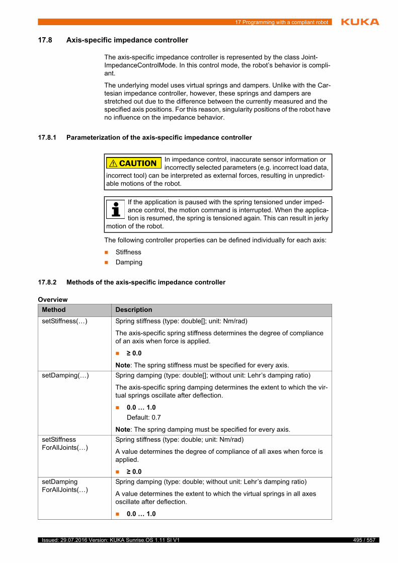
17 Programming with a compliant robot
17.8 Axis-specific impedance controller
The axis-specific impedance controller is represented by the class Joint-ImpedanceControlMode. In this control mode, the robot’s behavior is compli-ant.
The underlying model uses virtual springs and dampers. Unlike with the Car-tesian impedance controller, however, these springs and dampers are stretched out due to the difference between the currently measured and the specified axis positions. For this reason, singularity positions of the robot have no influence on the impedance behavior.
17.8.1 Parameterization of the axis-specific impedance controller
The following controller properties can be defined individually for each axis:
Stiffness
Damping
17.8.2 Methods of the axis-specific impedance controller
Overview
In impedance control, inaccurate sensor information or incorrectly selected parameters (e.g. incorrect load data,
incorrect tool) can be interpreted as external forces, resulting in unpredict-able motions of the robot.
If the application is paused with the spring tensioned under imped-ance control, the motion command is interrupted. When the applica-tion is resumed, the spring is tensioned again. This can result in jerky
motion of the robot.
Method Description
setStiffness(…) Spring stiffness (type: double[]; unit: Nm/rad)
The axis-specific spring stiffness determines the degree of compliance of an axis when force is applied.
≥ 0.0
Note: The spring stiffness must be specified for every axis.
setDamping(…) Spring damping (type: double[]; without unit: Lehr’s damping ratio)
The axis-specific spring damping determines the extent to which the vir-tual springs oscillate after deflection.
0.0 … 1.0
Default: 0.7
Note: The spring damping must be specified for every axis.
setStiffnessForAllJoints(…)
Spring stiffness (type: double; unit: Nm/rad)
A value determines the degree of compliance of all axes when force is applied.
≥ 0.0
setDampingForAllJoints(…)
Spring damping (type: double; without unit: Lehr’s damping ratio)
A value determines the extent to which the virtual springs in all axes oscillate after deflection.
0.0 … 1.0
495 / 557Issued: 29.07.2016 Version: KUKA Sunrise.OS 1.11 SI V1

496 / 557
KUKA Sunrise.OS 1.11 KUKA Sunrise.Wor...
Constructor
syntax
JointImpedanceControlMode jointImp = new JointImpedanceCont-rolMode(A1, A2, ... A7);
Explanation of
the syntax
Example 1 7 axes are to be controlled using the axis-specific impedance controller. Initial values for the axis-specific spring stiffnesses are defined in the constructor of the controller. The stiffness for axis A4 is to be modified subsequently. The spring damping is to be identical for all axes.
Example 2 7 axes are to be controlled using the axis-specific impedance controller. Initial values for the axis-specific spring stiffnesses are defined in the constructor of the controller. The spring stiffness and spring damping are subsequently to be identical for all axes.
17.9 Holding the position under servo control
Description Using the motion command positionHold(…), the robot can hold its Cartesian setpoint position over a set period of time and remain under servo control.
If the robot is operated in compliance control, it can remove itself from its set-point position. Whether, how far and in which direction the robot moves from the current Cartesian setpoint position (= position at the start of the command positionHold(…)) depends on the set controller parameters and the resulting forces. In addition, the compliant robot under servo control can be forced off its setpoint position by external forces.
Syntax object.move(positionHold(controlMode, time, unit));
Explanation of
the syntax
Element Description
jointImp Type: JointImpedanceControlMode
Name of the controller object
A1 … A7 Type: double; unit: Nm/rad
Axis-specific spring stiffnesses
The number of values is dependent on the axis selection (here: 7 axes).
JointImpedanceControlMode jointImp
= new JointImpedanceControlMode(2000.0, 2000.0, 2000.0, 2000.0, 100.0, 100.0, 100.0);
...
jointImp.setStiffness(2000.0, 2000.0, 2000.0, 1500.0, 100.0, 100.0, 100.0);
jointImp.setDampingForAllJoints(0.5);
JointImpedanceControlMode jointImp
= new JointImpedanceControlMode(2000.0, 2000.0, 2000.0, 2000.0, 100.0, 100.0, 100.0);
...
jointImp.setStiffnessForAllJoints(100);
jointImp.setDampingForAllJoints(0.5);
Element Description
controlMode Type: Subclass of AbstractMotionControlMode
Name of controller object
Issued: 29.07.2016 Version: KUKA Sunrise.OS 1.11 SI V1

17 Programming with a compliant robot
Example The robot is to be held in its current position for 10 seconds. During this time, the robot is switched to “soft” mode in the Cartesian X direction.
time Type: long
Indicates how long the specified controlMode is to be held. The value must be >= 0. A value of < 0 indicates infinite.
unit Type: Enum of type TimeUnit
Unit of the specified time
The Enum TimeUnit is an integral part of the standard Java library.
Element Description
CartesianImpedanceControlMode controlMode = new CartesianImpedanceControlMode();
controlMode.parametrize(CartDOF.X).setStiffness(1000.0);
controlMode.parametrize(CartDOF.ALL).setDamping(0.7);
robot.move(positionHold(controlMode, 10, TimeUnit.SECONDS));
497 / 557Issued: 29.07.2016 Version: KUKA Sunrise.OS 1.11 SI V1

498 / 557
KUKA Sunrise.OS 1.11 KUKA Sunrise.Wor...
Issued: 29.07.2016 Version: KUKA Sunrise.OS 1.11 SI V1

18 Diagnosis
18 Diagnosis
18.1 Field bus diagnosis
18.1.1 Displaying general field bus errors
Description The general error state of the connected field buses can be displayed on the smartHMI.
Procedure 1. Select the KUKA_Sunrise_Cabinet_1 tile at the Station level.
The status indicator of the Field buses tile indicates the collective state of all field buses connected to the controller.
2. Select the Field buses tile.
The detail view opens with error information about the currently connected field buses.
18.1.2 Displaying the error state of I/Os and I/O groups
Description The status indicator in the I/O groups area of the navigation bar of the smartH-MI displays the state of the configured I/O groups.
The lower indicator shows the collective state of all configured I/O groups.
The upper indicator shows the state of the selected I/O group.
Procedure In the navigation bar, select the desired I/O group from I/O groups.
The detail view of the I/O group opens. Any faulty inputs/outputs are indi-cated.
18.2 Displaying the protocol
A protocol of the events and changes in state of the system can be displayed on the smartHMI.
Procedure 1. Open the Station level or the Robot level.
2. Select the Protocol tile. The Protocol view opens.
If the view is opened via the Robot level, only those log entries are dis-played by default which affect the robot selected in the navigation bar.
s
s
WorkVisual can be used for precise error analysis. Additional infor-mation about field bus diagnosis with WorkVisual is contained in the WorkVisual documentation.
If the robot controller is used as a PROFINET master or device, hard-ware problems can result in an inability to access bus devices. In this case, use of a diagnostic tool, such as WorkVisual, Step 7 or Wire-
Shark, is recommended.
If PROFINET is used and errors occur at individual terminals, not only the affected inputs/outputs, but all configured PROFINET I/Os are marked as faulty.
499 / 557Issued: 29.07.2016 Version: KUKA Sunrise.OS 1.11 SI V1
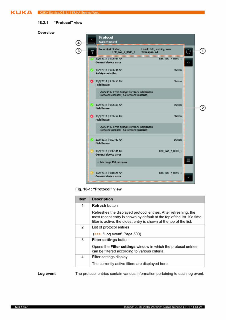
500 / 557
KUKA Sunrise.OS 1.11 KUKA Sunrise.Wor...
18.2.1 “Protocol” view
Overview
Log event The protocol entries contain various information pertaining to each log event.
Fig. 18-1: “Protocol” view
Item Description
1 Refresh button
Refreshes the displayed protocol entries. After refreshing, the most recent entry is shown by default at the top of the list. If a time filter is active, the oldest entry is shown at the top of the list.
2 List of protocol entries
(>>> "Log event" Page 500)
3 Filter settings button
Opens the Filter settings window in which the protocol entries can be filtered according to various criteria.
4 Filter settings display
The currently active filters are displayed here.
Issued: 29.07.2016 Version: KUKA Sunrise.OS 1.11 SI V1

18 Diagnosis
Log level The following icons display the log level of an event:
18.2.2 Filtering log entries
Precondition The Protocol view is open.
Procedure 1. Touch the Filter settings button. The Filter settings window opens.
2. Select the desired filters with the appropriate buttons.
3. Touch the Filter settings button or an area outside the window.
The Filter settings window is closed and the selected filters are activated.
Fig. 18-2: Information about the log event
Item Description
1 Log level of the event
(>>> "Log level" Page 501)
2 Date and time of the log event (system time of the robot controller)
3 Source of the log event (robot or station)
4 Button to maximize/minimize the detail view
The button is only available if more than 2 symptoms are present.
5 Symptoms of the log event (detail view)
By default, up to 2 symptoms are displayed per event.
6 Category or brief description of the log event
Icon Description
Error
Critical event which results in a system error state
Warning
Critical event which can result in an error
Information
Non-critical event or information pertaining to the change in state
The filters are reset when the Protocol view is closed. When the view is re-opened, the default settings are reactivated.
501 / 557Issued: 29.07.2016 Version: KUKA Sunrise.OS 1.11 SI V1
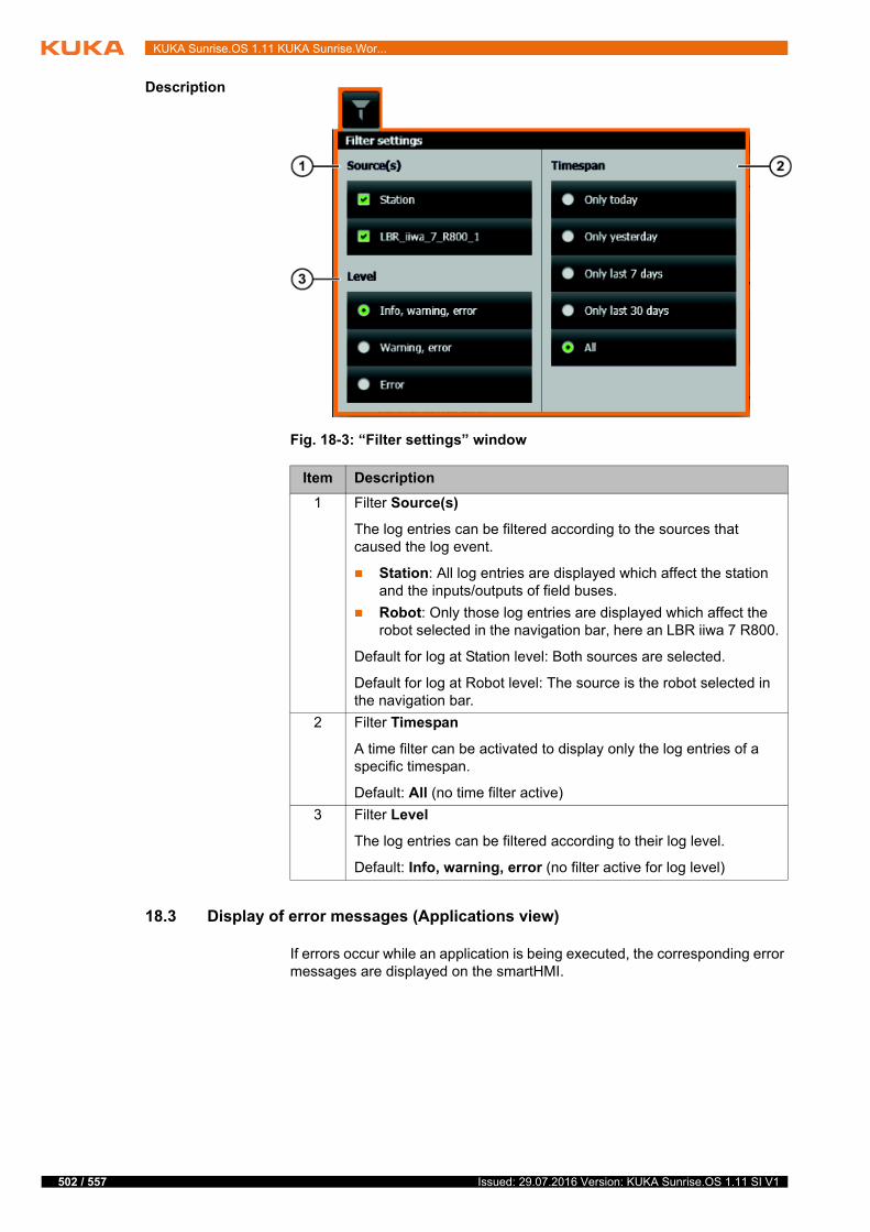
502 / 557
KUKA Sunrise.OS 1.11 KUKA Sunrise.Wor...
Description
18.3 Display of error messages (Applications view)
If errors occur while an application is being executed, the corresponding error messages are displayed on the smartHMI.
Fig. 18-3: “Filter settings” window
Item Description
1 Filter Source(s)
The log entries can be filtered according to the sources that caused the log event.
Station: All log entries are displayed which affect the station and the inputs/outputs of field buses.
Robot: Only those log entries are displayed which affect the robot selected in the navigation bar, here an LBR iiwa 7 R800.
Default for log at Station level: Both sources are selected.
Default for log at Robot level: The source is the robot selected in the navigation bar.
2 Filter Timespan
A time filter can be activated to display only the log entries of a specific timespan.
Default: All (no time filter active)
3 Filter Level
The log entries can be filtered according to their log level.
Default: Info, warning, error (no filter active for log level)
Issued: 29.07.2016 Version: KUKA Sunrise.OS 1.11 SI V1

18 Diagnosis
Fig. 18-4: Configuration of error message (example)
Item Description
1 Time stamp
Time at which the error occurred
2 Level
Log level of the message. Errors have the log level Error.
3 Error message
4 Information when application is terminated, e.g. following a real-time error
503 / 557Issued: 29.07.2016 Version: KUKA Sunrise.OS 1.11 SI V1
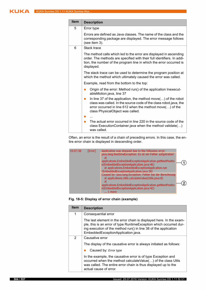
504 / 557
KUKA Sunrise.OS 1.11 KUKA Sunrise.Wor...
Often, an error is the result of a chain of preceding errors. In this case, the en-tire error chain is displayed in descending order.
5 Error type
Errors are defined as Java classes. The name of the class and the corresponding package are displayed. The error message follows (see item 3).
6 Stack trace
The method calls which led to the error are displayed in ascending order. The methods are specified with their full identifiers. In addi-tion, the number of the program line in which the error occurred is displayed.
The stack trace can be used to determine the program position at which the method which ultimately caused the error was called.
Example, read from the bottom to the top:
Origin of the error: Method run() of the application Inexecut-ableMotion.java, line 37
In line 37 of the application, the method move(…) of the robot class was called. In the source code of the class robot.java, the error occurred in line 612 when the method move(…) of the class PhysicalObject was called.
...
The actual error occurred in line 220 in the source code of the class ExecutionContainer.java when the method validate(…) was called.
Fig. 18-5: Display of error chain (example)
Item Description
1 Consequential error
The last element in the error chain is displayed here. In the exam-ple, this is an error of type RuntimeException which occurred dur-ing execution of the method run() in line 38 of the application EmbeddedExceptionApplication.java.
2 Causative error
The display of the causative error is always initiated as follows:
Caused by: Error type
In the example, the causative error is of type Exception and occurred when the method calculateValue(…) of the class Utils was called. The entire error chain is thus displayed up to the actual cause of error.
Item Description
Issued: 29.07.2016 Version: KUKA Sunrise.OS 1.11 SI V1
18 Diagnosis
18.4 Displaying messages of the virus scanner
Precondition Virus scanner is installed.
(>>> 10.5.2 "Installing or updating the virus scanner" Page 176)
Procedure Select > KUKA_Sunrise_Cabinet_1 > Virus scanner at the Station lev-el. The Virus scanner view opens.
Description The Virus scanner view contains the following data:
Virus scanner state: active / inactive
Version of virus definition file: version of the virus scanner
Messages about detected viruses: The message generated when a virus is found contains the following data:
Name of the virus
Name of the file in which the virus is located, including path specifica-tion
Date and time of detection
If viruses are found, the status display of the Virus scanner tile switches to “Warning”. The status of the files affected by the viruses is automatically set to “Quarantine”.
18.5 Collecting diagnostic information for error analysis at KUKA
For error analysis, KUKA Customer Support requires diagnostic data from the robot controller.
For this purpose, a ZIP file called KRCDiag is created, which can be archived on the robot controller under D:\DiagnosisPackages or on a USB stick con-nected to the robot controller. The diagnosis package KRCDiag contains the data which KUKA Customer Support requires to analyze an error. These in-clude information about the system resources, machine data and much more.
Sunrise.Workbench can also be used to access the diagnostic information. For this purpose, either an existing diagnosis package is loaded from the robot controller or a new package is created.
Messages from the virus scanner can also be displayed using the Protocol tile.
If the robot can no longer be moved due to a virus infection, the fol-lowing options are available to the user:
Reinstall the system software on the robot controller.
If the robot can still not be moved, create the diagnosis package KRCDi-ag and contact KUKA Service.
Projects and applications are not included in the diagnosis package. It is advisible to transfer these data separately, as they can contain important information for troubleshooting.
Recommendation: If possible, only collect diagnostic information when the robot is stationary.
If the collection of diagnostic information fails while an application is running, stop and cancel the application and restart the diagnostic process.
505 / 557Issued: 29.07.2016 Version: KUKA Sunrise.OS 1.11 SI V1

506 / 557
KUKA Sunrise.OS 1.11 KUKA Sunrise.Wor...
18.5.1 Creating a diagnosis package with the smartHMI
Description With this procedure, the diagnois package KRCDiag can be created and ar-chived on the robot controller under D:\DiagnosisPackages or on a USB stick.
Procedure 1. For archiving to a USB stick: Plug the USB stick into the robot controller and wait until the LED on the USB stick remains permanently lit.
2. In the main menu, select Diagnosis > Create diagnosis package and se-lect the desired file location.
Hard disk
USB stick
The diagnostic information is compiled. Progress is displayed in a window. Once the operation has been completed, this is also indicated in the win-dow. The window is then automatically hidden again.
18.5.2 Creating a diagnosis package with the smartPAD
Description This procedure uses keys on the smartPAD instead of menu items. It can thus also be used if the smartHMI is not available.
The KRCDiag diagnosis package is created and archived on the robot con-troller under D:\DiagnosisPackages.
Procedure 1. Press the “Main menu” key and hold it down.
2. Press the keypad key twice.
3. Release the “Main menu” key.
The diagnostic information is grouped. Progress is displayed in a window. Once the operation has been completed, this is also indicated in the win-dow. The window is then automatically hidden again.
18.5.3 Creating a diagnosis package with Sunrise.Workbench
Precondition Network connection to the robot controller
Procedure 1. Right-click on the project in the Package Explorer and select Sunrise > Create diagnosis package from the context menu. The wizard for creat-ing the diagnosis package opens.
2. Select Browse... and navigate to the directory in which the diagnosis package KRCDiag is to be created. If necessary, create a folder for the diagnosis package by clicking on Create new folder. Click on OK to con-firm.
3. Click on Next >. The diagnosis package is created in the specified folder.
4. To navigate to the folder in which the diagnosis package was created, e.g. to send it directly by e-mail, click on Open target folder in Windows Ex-plorer.
5. Click on Finish. The wizard is closed.
The key sequence described in the procedure must be executed with-in 2 seconds.
Projects and applications are not included in the diagnosis package. It is advisible to transfer these data separately, as they can contain important information for troubleshooting.
Issued: 29.07.2016 Version: KUKA Sunrise.OS 1.11 SI V1

18 Diagnosis
18.5.4 Loading existing diagnosis packages from the robot controller
Precondition Network connection to the robot controller
Procedure 1. Right-click on the project in the Package Explorer and select Sunrise > Create diagnosis package from the context menu. The wizard for creat-ing the diagnosis package opens.
2. Select Browse... and navigate to the directory in which the diagnosis package KRCDiag is to be copied. If necessary, create a folder for the di-agnosis package by clicking on Create new folder. Click on OK to con-firm.
3. Activate the radio button Load existing diagnosis packages from con-troller and select the desired diagnosis packages.
4. Click on Next >. The diagnosis package is copied into the specified folder.
If the folder already contains a diagnosis package of the same name, a user dialog is displayed. The copying operation can be canceled.
5. To navigate to the folder into which the diagnosis package was copied, e.g. to send it directly by e-mail, click on Open target folder in Windows Explorer.
6. Click on Finish. The wizard is closed.
507 / 557Issued: 29.07.2016 Version: KUKA Sunrise.OS 1.11 SI V1

508 / 557
KUKA Sunrise.OS 1.11 KUKA Sunrise.Wor...
Issued: 29.07.2016 Version: KUKA Sunrise.OS 1.11 SI V1
19 Remote debugging
19 Remote debugging
Remote debugging is used for the discovery and diagnosis of errors in pro-grams.
Remote debugging is carried out using Sunrise.Workbench for applications and background tasks running on the controller.
Since remote debugging is largely identical for applications and background tasks, the term “task” is used generically below.
19.1 Debugging session sequence
t
Advanced Java Eclipse programming skills are a prerequisite for use of remote debugging.
Step Description
1 Starting a debugging session
When starting a debugging session, a remote connection is established between Sunrise.Workbench and the robot con-troller. The project in the workspace of Sunrise.Workbench and the active project on the robot controller are automatically checked for consistency and synchronization is requested if required.
(>>> 19.1.2 "Starting the debugging session" Page 511)
2 Performing remote debugging of the task
The programmer uses break points to define the positions in the program code at which execution of the task is to be inter-rupted during remote debugging.
If remote debugging is to be carried out for an application that has not yet been started, the application must be started man-ually via the smartPAD once the remote connection has been established.
Once task execution has been stopped at a break point, fur-ther program execution can be controlled by Sunrise.Work-bench by executing the source code of the task step by step. On completion of a step, task execution is automatically stopped.
(>>> 19.3.2 "Break points" Page 515)
509 / 557Issued: 29.07.2016 Version: KUKA Sunrise.OS 1.11 SI V1
510 / 557
KUKA Sunrise.OS 1.11 KUKA Sunrise.Wor...
19.1.1 Remote debugging of tasks
Description Remote debugging is used to detect and diagnose errors in programs and tasks.
Tools that support this process are called debuggers. The remote debugger integrated into Sunrise.Workbench is based on the standard Java and Eclipse debugger.
In the case of remote debugging of programs, the debugger is run on a differ-ent computer than the program that is to be checked. In the case of remote debugging of tasks, the Sunrise.Workbench debugger is used; the task itself is executed on the controller.
During remote debugging, a connection is established between Sunrise.Work-bench and the robot controller. A debugging session is started in this way. Dur-ing remote debugging, the execution of tasks running on the controller can be monitored via Sunrise.Workbench and it is possible to influence program exe-cution. Errors can be diagnosed and the source code can be optimized.
The Debugging perspective contains the most important views for remote de-bugging.
Remote debugging of tasks running on the controller is described below. Gen-eral knowledge of remote debugging is assumed. The most important funda-mentals are summarized in the chapters. (>>> 19.3 "Fundamentals of remote debugging" Page 514)
Overview The functionalities offered by the debugger include the following:
Performance of online diagnosis
Stopping program execution at defined positions using break points
Line-by-line or section-by-section execution of the source code of running tasks
3 Using debugging functions
While task execution is interrupted, debugger functions, such as the observation and modification of variable values, can be used. Adaptation of the source code is also possible.
(>>> 19.3.6 "Variables view" Page 529)
(>>> 19.3.7 "Monitoring processes" Page 533)
(>>> 19.3.8 "Modifying source code" Page 536)
4 Ending a debugging session
When ending a debugging session, the remote connection to the controller is disconnected. Execution of the running task can now no longer be influenced by Sunrise.Workbench. If modifications have been made to the code, project synchroni-zation is offered.
(>>> 19.1.3 "Ending the debugging session" Page 511)
Step Description
While a debugging session is running, the smartPAD is used for start-ing applications and issuing the motion enable signal.
All safety functions configured for the project are also active during re-mote debugging.
Issued: 29.07.2016 Version: KUKA Sunrise.OS 1.11 SI V1

19 Remote debugging
Tracking of the process by means of observation of variables and monitor-ing expressions
Modification of variable values
19.1.2 Starting the debugging session
Description To start a debugging session, a remote connection must be established be-tween Sunrise.Workbench and the robot controller.
The Java processes running on the controller can then be viewed.
Once the first active break point has been reached, execution of the corre-sponding task is paused and the functions of the debugger can be used.
(>>> 19.3.2 "Break points" Page 515)
Precondition Network connection between robot controller and development computer.
The project that is active on the robot controller is located in the workspace of Sunrise.Workbench.
Procedure 1. Select the desired project in the Package Explorer.
2. Click on the Debug project button.
The system scans the robot controller for existing project data. If the scan fails, the cause of the error is displayed in a message.
3. If the scan is successful, the Project synchronization window opens. Se-lect the desired synchronization direction.
4. Click on Execute.
5. The system signals that the remote connection to the robot controller has been established successfully.
The remote connection is established with OK and the debugging ses-sion is started.
Transfer of the project can be stopped with Cancel.
6. When the first active break point is reached, the corresponding task is paused.
If the Debugging perspective is not active, the dialog Confirm change of perspective is displayed in Sunrise.Workbench. It is recommended that the dialog is ended with Yes to switch to the Debugging perspective of Sunrise.Workbench.
(>>> 19.3.1 "Overview of user interface – “Debugging” perspective" Page 514)
Once the task has been paused, its source code is opened in the editor area. The current position of the command pointer is indicated by the fact that the next command line to be executed is selected.
19.1.3 Ending the debugging session
Description In order to end the debugging session correctly, the remote connection be-tween Sunrise.Workbench and the robot controller must be disconnected. If modifications have been made to the code during remote debugging, synchro-nization of the project is offered.
Precondition Network connection between robot controller and development computer.
The project that is active on the controller is located in the workspace of Sunrise.Workbench.
No application is running on the controller.
511 / 557Issued: 29.07.2016 Version: KUKA Sunrise.OS 1.11 SI V1
512 / 557
KUKA Sunrise.OS 1.11 KUKA Sunrise.Wor...
Procedure 1. Click on Stop debug mode.
During an active debugging session, this replaces the Debug project but-ton.
2. If modifications were made to the source code of the task during the de-bugging session, the Retain project changes dialog opens:
Synchronize project is used to synchronize the project and transfer the changes to the controller.
With Cancel, the changes are only saved permanently for the project in the workspace of Sunrise.Workbench. On the controller, the chang-es are deleted after switching off and back on.
19.2 Debugging tasks
Overview Debugging can be performed for all tasks running on the controller. In order to debug an application, it may be necessary to start the application via the smartPAD.
It is advisable to use the Synchronize project option, as the system response may otherwise be different after a
reboot. If the reboot is not carried out immediately, these changes in behavior may be unexpected and could result in damage to the machine.
If execution of a task is paused when the connection is disconnected, task execution is resumed automatically
immediately after disconnection. This also applies to the running application. In Automatic mode, and in the Test modes if the enabling switch and Start button are pressed, the robot may move. It is thus advisable to disconnect the remote connection only if the application has been terminated, or to pause motion execution first by pressing the Start button on the smartPAD.
Remote debugging influences the time response of tasks. The time response may therefore deviate from the real time response during normal execution of the task.
Irrespective of the mode, the system response may change. Debugging of a task in Automatic mode must be
carried out with particular care.Interventions that result in a change of state must be tested in Manual Re-duced Velocity mode (T1).Interventions and commands that cause a change of state include:
Modification of program execution
Execution of additional commands
Motion commands
Modification of variables
Modification of the source code during debugging
Setting inputs/outputs
Changes of values, e.g. by calling set methods
This can lead to deviations from the program execution of the task. The de-viations may have an effect beyond the duration of the debugging session. Unexpected robot motions are also possible.
Issued: 29.07.2016 Version: KUKA Sunrise.OS 1.11 SI V1

19 Remote debugging
As soon as the first active break point is reached after the remote connection has been established, execution of the corresponding task can be controlled via Sunrise.Workbench. Various functions are available for this. The selected function determines the command line up to which the task is continued.
If task execution is paused during debugging, additional functions are avail-able and changes can be made to the source code:
Available functions:
(>>> 19.3.5 "Overview of the toolbar in the “Debugging” view" Page 523)
Additional functions of the debugger:
(>>> 19.3.6 "Variables view" Page 529)
(>>> 19.3.7 "Monitoring processes" Page 533)
Information about modification of the source code during debugging:
(>>> 19.3.8 "Modifying source code" Page 536)
19.2.1 Remote debugging of a robot application
Description A possible procedure for debugging a robot application is described below.
Precondition Debugging session started
Application started in accordance with the selected operating mode
Procedure 1. On reaching an active break point, the application is stopped by the de-bugger. Program execution can now be influenced by Sunrise.Work-bench.
2. At the break point, pressing the corresponding button in the toolbar of the Debugging view or using the corresponding keyboard shortcut defines the step at which the application is to be resumed.
3. The application is resumed until the command line defined by selecting the function is reached. If a code section to be executed contains motion com-mands, this has a special effect on the sequence.
4. In order to continue the application on reaching a synchronous motion command or to execute an asynchronous motion command, the following actions must additionally be carried out on the smartPAD in accordance with the operating mode:
T1, T2:
Press and hold down the enabling switch.
Press and hold down the Start key.
AUT:
The smartPAD is also required during the debugging of tasks, e.g.:
Issuing motion enable signal
Starting applications
Pausing motion commands
Executing motion commands in the test modes
Stopping an application prematurely
A running application can be ended via the smartPAD during debug-ging. In this case, all break points are temporarily deactivated to en-sure that the application is terminated correctly.
If the application for which debugging is being carried out does not contain any active break points, it is executed completely without stopping and then terminated.
513 / 557Issued: 29.07.2016 Version: KUKA Sunrise.OS 1.11 SI V1
514 / 557
KUKA Sunrise.OS 1.11 KUKA Sunrise.Wor...
In AUT mode, no additional operator action is required. The motion is executed immediately.
5. Once the program section has been executed, the application is stopped.
Exception: With Resume, the application is continued until the next break point or the end of the application is reached.
6. Debugging functions, such as the observation of variables or the changing of values, can be used between the individual steps.
19.2.2 Remote debugging of a background task
Description Debugging can also be carried out for background tasks. If a background task contains active break points, execution of the background task is stopped at these points during a debugging session.
Debugging of background tasks is essentially carried out in the same way as debugging of applications. Background tasks do not have to be started sepa-rately. Furthermore, background tasks should not contain motion commands. Debugging of background tasks is thus not affected by the selected operating mode.
Precondition Remote connection has been established.
All background tasks are running automatically on the controller.
Procedure 1. On reaching an active break point, the background task is stopped by the debugger. Program execution can now be influenced by Sunrise.Work-bench.
2. At the break point, pressing the corresponding button in the toolbar of the Debugging view or using the corresponding keyboard shortcut defines the step at which the application is to be resumed.
3. The background task is resumed until the command line defined by select-ing the function is reached.
4. Once the program section has been executed, the background task is stopped.
Exception: With Resume, the background task is continued until the next break point or the end of a non-cyclical background task is reached.
5. Debugging functions, such as the observation of variables or the changing of values, can be used between the individual steps.
19.3 Fundamentals of remote debugging
19.3.1 Overview of user interface – “Debugging” perspective
The Debugging perspective contains a suitable arrangement of views that are useful for remote debugging.
The standard configuration of the Debugging perspective is displayed below. The Debugging perspective can be expanded to include additional views.
Issued: 29.07.2016 Version: KUKA Sunrise.OS 1.11 SI V1
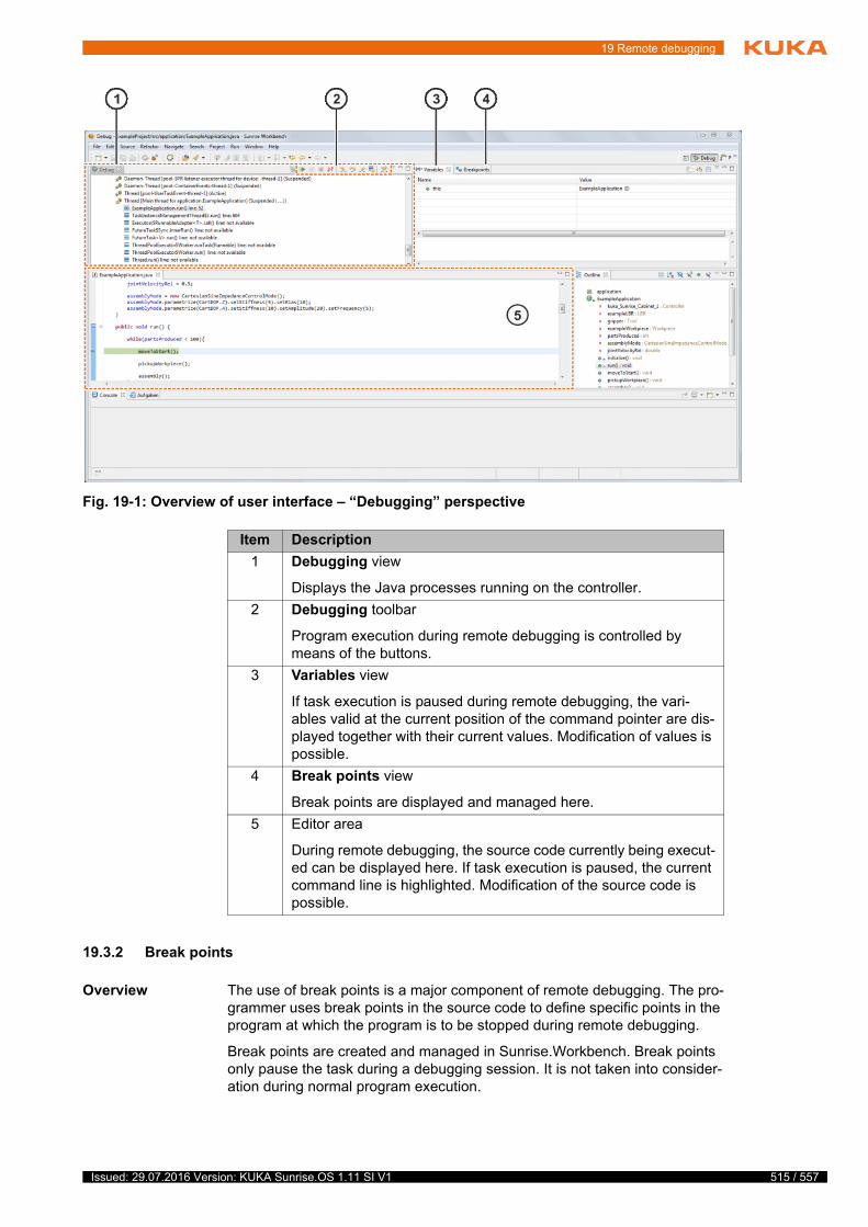
19 Remote debugging
19.3.2 Break points
Overview The use of break points is a major component of remote debugging. The pro-grammer uses break points in the source code to define specific points in the program at which the program is to be stopped during remote debugging.
Break points are created and managed in Sunrise.Workbench. Break points only pause the task during a debugging session. It is not taken into consider-ation during normal program execution.
Fig. 19-1: Overview of user interface – “Debugging” perspective
Item Description
1 Debugging view
Displays the Java processes running on the controller.
2 Debugging toolbar
Program execution during remote debugging is controlled by means of the buttons.
3 Variables view
If task execution is paused during remote debugging, the vari-ables valid at the current position of the command pointer are dis-played together with their current values. Modification of values is possible.
4 Break points view
Break points are displayed and managed here.
5 Editor area
During remote debugging, the source code currently being execut-ed can be displayed here. If task execution is paused, the current command line is highlighted. Modification of the source code is possible.
515 / 557Issued: 29.07.2016 Version: KUKA Sunrise.OS 1.11 SI V1
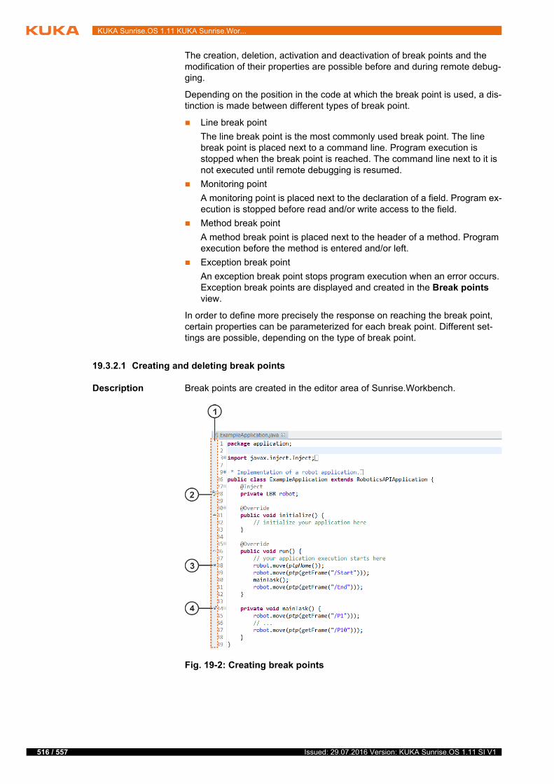
516 / 557
KUKA Sunrise.OS 1.11 KUKA Sunrise.Wor...
The creation, deletion, activation and deactivation of break points and the modification of their properties are possible before and during remote debug-ging.
Depending on the position in the code at which the break point is used, a dis-tinction is made between different types of break point.
Line break point
The line break point is the most commonly used break point. The line break point is placed next to a command line. Program execution is stopped when the break point is reached. The command line next to it is not executed until remote debugging is resumed.
Monitoring point
A monitoring point is placed next to the declaration of a field. Program ex-ecution is stopped before read and/or write access to the field.
Method break point
A method break point is placed next to the header of a method. Program execution before the method is entered and/or left.
Exception break point
An exception break point stops program execution when an error occurs. Exception break points are displayed and created in the Break points view.
In order to define more precisely the response on reaching the break point, certain properties can be parameterized for each break point. Different set-tings are possible, depending on the type of break point.
19.3.2.1 Creating and deleting break points
Description Break points are created in the editor area of Sunrise.Workbench.
Fig. 19-2: Creating break points
Issued: 29.07.2016 Version: KUKA Sunrise.OS 1.11 SI V1
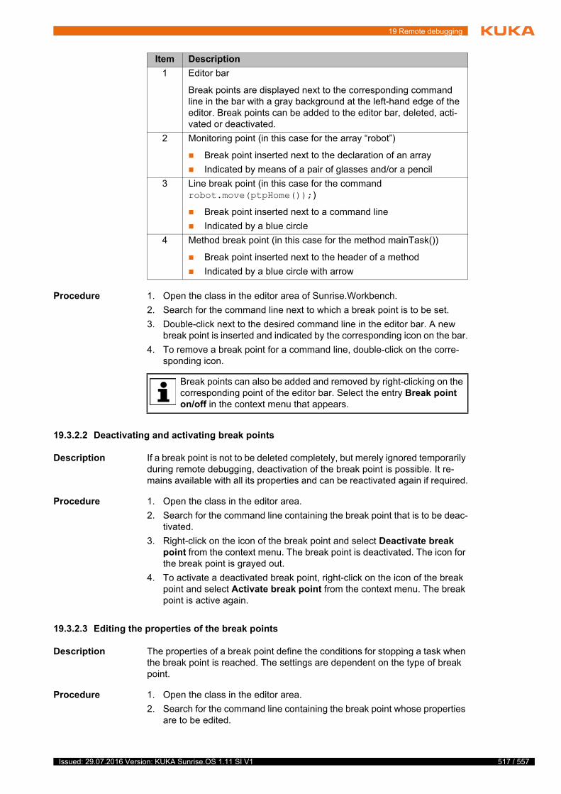
19 Remote debugging
Procedure 1. Open the class in the editor area of Sunrise.Workbench.
2. Search for the command line next to which a break point is to be set.
3. Double-click next to the desired command line in the editor bar. A new break point is inserted and indicated by the corresponding icon on the bar.
4. To remove a break point for a command line, double-click on the corre-sponding icon.
19.3.2.2 Deactivating and activating break points
Description If a break point is not to be deleted completely, but merely ignored temporarily during remote debugging, deactivation of the break point is possible. It re-mains available with all its properties and can be reactivated again if required.
Procedure 1. Open the class in the editor area.
2. Search for the command line containing the break point that is to be deac-tivated.
3. Right-click on the icon of the break point and select Deactivate break point from the context menu. The break point is deactivated. The icon for the break point is grayed out.
4. To activate a deactivated break point, right-click on the icon of the break point and select Activate break point from the context menu. The break point is active again.
19.3.2.3 Editing the properties of the break points
Description The properties of a break point define the conditions for stopping a task when the break point is reached. The settings are dependent on the type of break point.
Procedure 1. Open the class in the editor area.
2. Search for the command line containing the break point whose properties are to be edited.
Item Description
1 Editor bar
Break points are displayed next to the corresponding command line in the bar with a gray background at the left-hand edge of the editor. Break points can be added to the editor bar, deleted, acti-vated or deactivated.
2 Monitoring point (in this case for the array “robot”)
Break point inserted next to the declaration of an array
Indicated by means of a pair of glasses and/or a pencil
3 Line break point (in this case for the command robot.move(ptpHome());)
Break point inserted next to a command line
Indicated by a blue circle
4 Method break point (in this case for the method mainTask())
Break point inserted next to the header of a method
Indicated by a blue circle with arrow
Break points can also be added and removed by right-clicking on the corresponding point of the editor bar. Select the entry Break point on/off in the context menu that appears.
517 / 557Issued: 29.07.2016 Version: KUKA Sunrise.OS 1.11 SI V1

518 / 557
KUKA Sunrise.OS 1.11 KUKA Sunrise.Wor...
3. Right-click on the icon of the break point and select Breakpoint proper-ties from the context menu. The Properties dialog opens.
4. Select Breakpoint properties. Edit the properties of the break point.
5. Confirm with OK. The dialog is closed.
19.3.2.4 Overview of the “Break points” view
The view contains a list of the break points of all classes in the workspace of Sunrise.Workbench. The view offers the following functions:
Display of all break points
Activation, deactivation and deletion of break points
Modification of break point properties
Addition of exception break points
Overview
The functionalities offered by the buttons in the toolbar include the following:
Fig. 19-3: “Break points” view
Item Description
1 Activation of the break point
Check box active: Break point is activated.
Check box not active: Break point is not activated.
2 Designation of the break point
The designation is composed of special properties of the break point in order to enable unambiguous identification.
3 Break point list
List of the break points of all classes in the workspace
4 Break point properties
The properties of the break point selected in the list can be dis-played and edited in this area.
Issued: 29.07.2016 Version: KUKA Sunrise.OS 1.11 SI V1
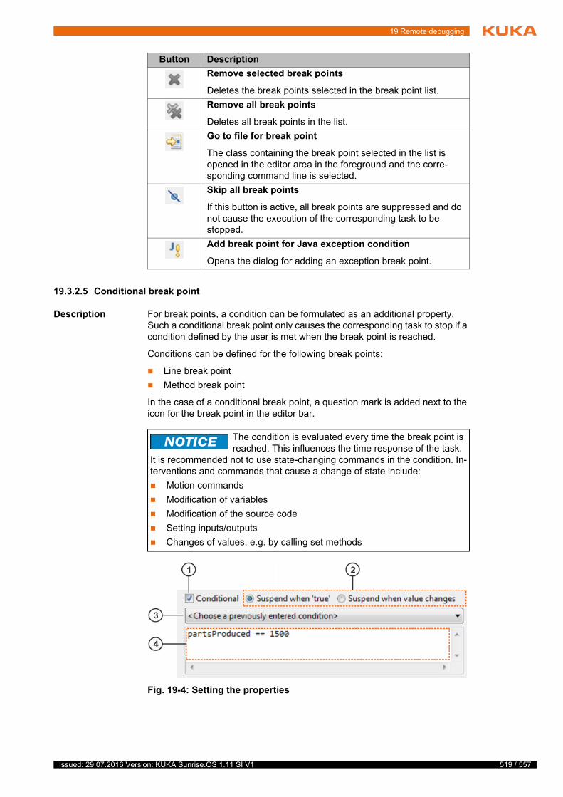
19 Remote debugging
19.3.2.5 Conditional break point
Description For break points, a condition can be formulated as an additional property. Such a conditional break point only causes the corresponding task to stop if a condition defined by the user is met when the break point is reached.
Conditions can be defined for the following break points:
Line break point
Method break point
In the case of a conditional break point, a question mark is added next to the icon for the break point in the editor bar.
Button Description
Remove selected break points
Deletes the break points selected in the break point list.
Remove all break points
Deletes all break points in the list.
Go to file for break point
The class containing the break point selected in the list is opened in the editor area in the foreground and the corre-sponding command line is selected.
Skip all break points
If this button is active, all break points are suppressed and do not cause the execution of the corresponding task to be stopped.
Add break point for Java exception condition
Opens the dialog for adding an exception break point.
The condition is evaluated every time the break point is reached. This influences the time response of the task.
It is recommended not to use state-changing commands in the condition. In-terventions and commands that cause a change of state include:
Motion commands
Modification of variables
Modification of the source code
Setting inputs/outputs
Changes of values, e.g. by calling set methods
Fig. 19-4: Setting the properties
519 / 557Issued: 29.07.2016 Version: KUKA Sunrise.OS 1.11 SI V1
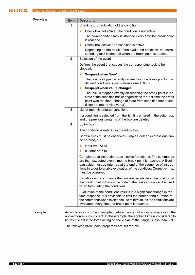
520 / 557
KUKA Sunrise.OS 1.11 KUKA Sunrise.Wor...
Overview
Example An application is to be interrupted before the start of a joining operation if the applied force is insufficient. In this example, the applied force is considered to be insufficient if the force acting on the Z axis of the flange is less than 5 N.
The following break point properties are set for this:
Item Description
1 Check box for activation of the condition
Check box not active: The condition is not active.
The corresponding task is stopped every time the break point is reached.
Check box active: The condition is active.
Depending on the result of the evaluated condition, the corre-sponding task is stopped when the break point is reached.
2 Selection of the event
Defines the event that causes the corresponding task to be stopped.
Suspend when 'true'
The task is stopped exactly on reaching the break point if the defined condition is met (return value TRUE).
Suspend when value changes
The task is stopped exactly on reaching the break point if the state of the condition has changed since the last time the break point was reached (change of state from condition met to con-dition not met or vice versa).
3 List of recently entered conditions
If a condition is selected from the list, it is entered in the editor box and the previous contents of the box are deleted.
4 Editor box
The condition is entered in the editor box.
Certain rules must be observed. Simple Boolean expressions can be entered, e.g.:
input == FALSE
counter <= 510
Complex Java instructions can also be formulated. The commands are then executed every time the break point is reached. A Bool-ean value must be returned at the end of the sequence of instruc-tions in order to enable evaluation of the condition. Correct syntax must be observed.
Variables and commands that are also available at the position of the break point in the source code of the task or class can be used when formulating the conditions.
Evaluation of the conditions results in a significant change in the time response. It is advisable to limit the number and duration of the commands used to an absolute minimum, as the conditions are evaluated every time the break point is reached.
Issued: 29.07.2016 Version: KUKA Sunrise.OS 1.11 SI V1
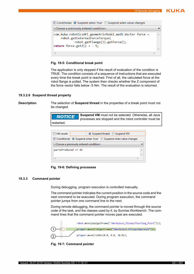
19 Remote debugging
The application is only stopped if the result of evaluation of the condition is TRUE. The condition consists of a sequence of instructions that are executed every time the break point is reached. First of all, the calculated force at the robot flange is polled. The system then checks whether the Z component of the force vector falls below -5 Nm. The result of the evaluation is returned.
19.3.2.6 Suspend thread property
Description The selection of Suspend thread in the properties of a break point must not be changed.
19.3.3 Command pointer
During debugging, program execution is controlled manually.
The command pointer indicates the current position in the source code and the next command to be executed. During program execution, the command pointer jumps from one command line to the next.
During remote debugging, the command pointer is moved through the source code of the task, and the classes used by it, by Sunrise.Workbench. The com-mand lines that the command pointer moves past are executed.
Fig. 19-5: Conditional break point
Suspend VM must not be selected. Otherwise, all Java processes are stopped and the robot controller must be
restarted.
Fig. 19-6: Defining processes
Fig. 19-7: Command pointer
521 / 557Issued: 29.07.2016 Version: KUKA Sunrise.OS 1.11 SI V1

522 / 557
KUKA Sunrise.OS 1.11 KUKA Sunrise.Wor...
19.3.4 Overview of the “Debugging” view
Description The Debug view contains the toolbar and a list of all Java processes running on the controller. These processes are referred to as threads. The task for which debugging is carried out is one of the threads running on the controller.
In the Debug view, the corresponding stack trace is displayed beneath a thread. The stack trace contains the current method calls of a thread and is used for tracking program execution.
Example In a robot application, the method assembly() is called in the method run() in order to assemble a component. The method assembly() then calls the meth-od checking() to check whether the assembly process has been successfully completed:
Item Description
1 Position of the command pointer (blue arrow)
The command pointer indicates the next command to be executed. The current position of the command pointer in the source code is indicated by a blue arrow.
2 Next command line to be executed
The next command line to be executed is highlighted in color.
Fig. 19-8: Overview of “Debugging” view
Item Description
1 Toolbar
Program execution during remote debugging is controlled by means of the buttons.
2 Task thread
Thread of the executed task. The designation contains the name of the executed tasks (here application.ExampleApplication). The corresponding stack trace is located beneath the thread.
3 Stack trace
The stack trace of the task thread contains the methods that are relevant for execution of the task. The called methods are specified with their identifiers. In this way, the user can identify the relevant methods.
The methods are specified in the order in which they are called.
public void run(){ // ...
assembly();
// ...
}
Issued: 29.07.2016 Version: KUKA Sunrise.OS 1.11 SI V1
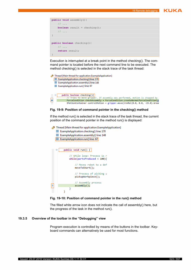
19 Remote debugging
Execution is interrupted at a break point in the method checking(). The com-mand pointer is located before the next command line to be executed. The method checking() is selected in the stack trace of the task thread:
If the method run() is selected in the stack trace of the task thread, the current position of the command pointer in the method run() is displayed:
The filled white arrow icon does not indicate the call of assembly() here, but the progress of the task in the method run().
19.3.5 Overview of the toolbar in the “Debugging” view
Program execution is controlled by means of the buttons in the toolbar. Key-board commands can alternatively be used for most functions.
public void assembly(){ // ...
boolean result = checking(); // ...
}
public boolean checking(){ // ...
return result;}
Fig. 19-9: Position of command pointer in the checking() method
Fig. 19-10: Position of command pointer in the run() method
523 / 557Issued: 29.07.2016 Version: KUKA Sunrise.OS 1.11 SI V1
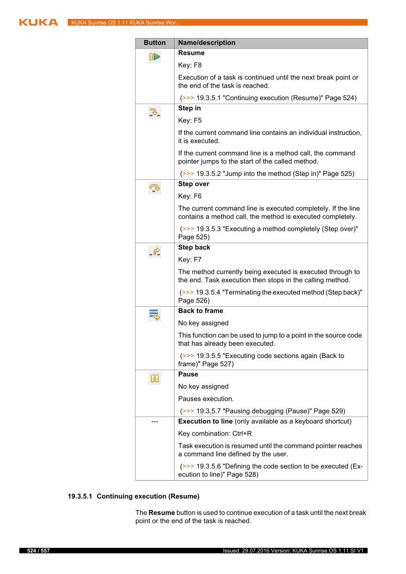
524 / 557
KUKA Sunrise.OS 1.11 KUKA Sunrise.Wor...
19.3.5.1 Continuing execution (Resume)
The Resume button is used to continue execution of a task until the next break point or the end of the task is reached.
Button Name/description
Resume
Key: F8
Execution of a task is continued until the next break point or the end of the task is reached.
(>>> 19.3.5.1 "Continuing execution (Resume)" Page 524)
Step in
Key: F5
If the current command line contains an individual instruction, it is executed.
If the current command line is a method call, the command pointer jumps to the start of the called method.
(>>> 19.3.5.2 "Jump into the method (Step in)" Page 525)
Step over
Key: F6
The current command line is executed completely. If the line contains a method call, the method is executed completely.
(>>> 19.3.5.3 "Executing a method completely (Step over)" Page 525)
Step back
Key: F7
The method currently being executed is executed through to the end. Task execution then stops in the calling method.
(>>> 19.3.5.4 "Terminating the executed method (Step back)" Page 526)
Back to frame
No key assigned
This function can be used to jump to a point in the source code that has already been executed.
(>>> 19.3.5.5 "Executing code sections again (Back to frame)" Page 527)
Pause
No key assigned
Pauses execution.
(>>> 19.3.5.7 "Pausing debugging (Pause)" Page 529)
--- Execution to line (only available as a keyboard shortcut)
Key combination: Ctrl+R
Task execution is resumed until the command pointer reaches a command line defined by the user.
(>>> 19.3.5.6 "Defining the code section to be executed (Ex-ecution to line)" Page 528)
Issued: 29.07.2016 Version: KUKA Sunrise.OS 1.11 SI V1

19 Remote debugging
19.3.5.2 Jump into the method (Step in)
Description If the current command line contains a method call, the command pointer jumps to the start of the called method when Step in is used.
If the current command line contains not a method call, but an individual in-struction, the command line is executed and the command pointer jumps to the next command line.
Example The application was interrupted before the call of the pickupWorkpiece() meth-od. Step in causes the command pointer to jump to the start of the method:
19.3.5.3 Executing a method completely (Step over)
Description Step over executes the current command line and the command pointer jumps to the next program line.
If the command line contains a method call, the method is executed complete-ly as long as it does not contain a break point.
Formatting Since the source code is executed step by step during remote debugging, the formatting of the source text influences the number of steps required for com-plete execution of the commands when using Step over.
Formatting example: Object of type CartesianImpedanceControlMode
With the following formatting, 3 steps are required when using Step over:
The source code of the called method is only displayed if the source code of this method is available. If the source code is not available, the warning Source not found is displayed.
Execution can be resumed.
The user has no way of viewing the command currently being executed.
In this case, Step back takes the user back to source code that can be displayed.
(>>> 19.3.5.4 "Terminating the executed method (Step back)" Page 526)
Use of Step over is recommended for jumping into a motion command (robot.move(…)).
(>>> 19.3.5.3 "Executing a method completely (Step over)" Page 525)
Fig. 19-11: Jump to method
CartesianImpedanceControlMode mode =
525 / 557Issued: 29.07.2016 Version: KUKA Sunrise.OS 1.11 SI V1
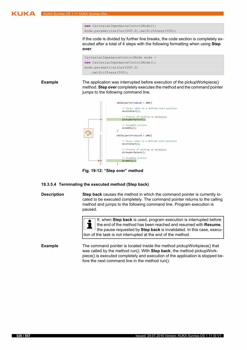
526 / 557
KUKA Sunrise.OS 1.11 KUKA Sunrise.Wor...
If the code is divided by further line breaks, the code section is completely ex-ecuted after a total of 4 steps with the following formatting when using Step over:
Example The application was interrupted before execution of the pickupWorkpiece() method. Step over completely executes the method and the command pointer jumps to the following command line.
19.3.5.4 Terminating the executed method (Step back)
Description Step back causes the method in which the command pointer is currently lo-cated to be executed completely. The command pointer returns to the calling method and jumps to the following command line. Program execution is paused.
Example The command pointer is located inside the method pickupWorkpiece() that was called by the method run(). With Step back, the method pickupWork-piece() is executed completely and execution of the application is stopped be-fore the next command line in the method run():
new CartesianImpedanceControlMode();mode.parametrize(CartDOF.Z).setStiffness(500);
CartesianImpedanceControlMode mode =
new CartesianImpedanceControlMode();mode.parametrize(CartDOF.Z)
.setStiffness(500);
Fig. 19-12: “Step over” method
If, when Step back is used, program execution is interrupted before the end of the method has been reached and resumed with Resume, the pause requested by Step back is invalidated. In this case, execu-
tion of the task is not interrupted at the end of the method.
Issued: 29.07.2016 Version: KUKA Sunrise.OS 1.11 SI V1

19 Remote debugging
19.3.5.5 Executing code sections again (Back to frame)
Editing
Back to frame can be used to run program sections that have already been executed again. By default, the command pointer jumps to the start of the method that is currently being executed. Program execution is then paused.
In the Debugging view, it is possible to return to each call level of the task us-ing the stack trace. To do so, the desired method is selected in the stack trace. Back to frame causes the command pointer to jump to the start of this meth-od.
Once the command pointer has been placed at a previously executed position in the code by means of Back to frame, the following code can be executed (again).
Example The command pointer is currently located in the pickupWorkpiece() method. By default, Back to frame causes it to jump back to the start of the method. Execution of the task is resumed from there.
Fig. 19-13: “Step back” to calling method
Back to frame changes the normal program execution. If state-changing interventions are carried out in the cur-
rent method or its submethods, this can result in unexpected system behav-ior and unexpected robot motions.Interventions and commands that cause a change of state include:
Motion commands
Modification of variables
Modification of the source code
Setting inputs/outputs
Changes of values, e.g. by calling set methods
When Back to frame is used, modifications to arrays or external data that were not carried out in the affected code section are not undone.
527 / 557Issued: 29.07.2016 Version: KUKA Sunrise.OS 1.11 SI V1
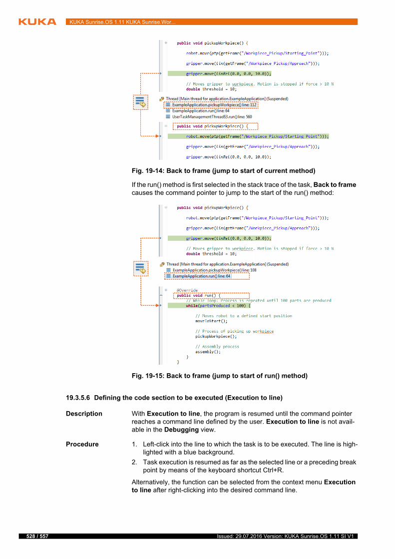
528 / 557
KUKA Sunrise.OS 1.11 KUKA Sunrise.Wor...
If the run() method is first selected in the stack trace of the task, Back to frame causes the command pointer to jump to the start of the run() method:
19.3.5.6 Defining the code section to be executed (Execution to line)
Description With Execution to line, the program is resumed until the command pointer reaches a command line defined by the user. Execution to line is not avail-able in the Debugging view.
Procedure 1. Left-click into the line to which the task is to be executed. The line is high-lighted with a blue background.
2. Task execution is resumed as far as the selected line or a preceding break point by means of the keyboard shortcut Ctrl+R.
Alternatively, the function can be selected from the context menu Execution to line after right-clicking into the desired command line.
Fig. 19-14: Back to frame (jump to start of current method)
Fig. 19-15: Back to frame (jump to start of run() method)
Issued: 29.07.2016 Version: KUKA Sunrise.OS 1.11 SI V1

19 Remote debugging
19.3.5.7 Pausing debugging (Pause)
Task execution can be paused manually by pressing the Pause button.
When pausing, as when reaching a break point, the current command line is displayed in the editor area. If the corresponding source code is not available when using Pause, the warning Source not found is displayed in the editor area.
19.3.6 Variables view
The Variables view is integrated into the Debugging perspective.
It contains a table with all variables that are available at the currently indicated position of the command pointer.
The variables are not available during execution of a task. The updated values are only displayed while execution is paused.
The request for pausing task execution at the selected command line is only valid once. If execution is stopped before the command line is reached, and then resumed with Resume, execution is not stopped
when the command line is reached.
If the Pause function is used, the user must ensure that the corre-sponding thread task is selected in the Debugging view. The func-tioning of the controller may otherwise be adversely affected to such
an extent that a reboot of the controller is required.Motion commands that have already been sent to the controller are not paused by the Pause function, but processed in the controller and executed.
The Start/Pause key on the smartPAD is only used to pause motion commands. Pausing via the smartPAD only affects execution of the application if a synchronous motion command is due to be executed,
as the command pointer only jumps to the next motion line after the motion command has been completed.
If variable values change during remote debugging, program execu-tion will be modified.
529 / 557Issued: 29.07.2016 Version: KUKA Sunrise.OS 1.11 SI V1

530 / 557
KUKA Sunrise.OS 1.11 KUKA Sunrise.Wor...
Fig. 19-16: Variables view
Item Description
1 Table of available variables
The table contains the currently available arrays and local vari-ables and their values. Only those variables that are available at the position of the command pointer in the selected method in the stack trace of the Debugging view are displayed.
The Name column contains the variable name. Variables with a complex type are displayed hierarchically. Variables with complex data types can be expanded and their arrays displayed using the icon to the left of the name.
The current value of the variable is displayed in the Value column. In the case of variables with complex data types, the result of the call of the toString() method is displayed by default. The values of primitive data types and string values can be modified directly in the table.
2 Detailed information
This area contains detailed information about the variable selected in the table. The variable value is displayed for primitive data types and strings. In the case of complex data types, the result of the call of the toString() method is displayed by default.
Issued: 29.07.2016 Version: KUKA Sunrise.OS 1.11 SI V1

19 Remote debugging
19.3.6.1 Displaying and modifying variables
Description Irrespective of their visibility, variables and their values can be displayed and modified in the Variables view.
Precondition Task execution is paused.
Procedure By default, only those variables that are available at the position of the com-mand pointer in the selected method in the stack trace of the Debugging view are displayed:
1. In order to display variables that are available in a different method, select the method in the stack trace of the Debugging view.
Fig. 19-17: Displaying variables
Item Description
1 Instance
The variable this refers to the instance of the class whose method has been selected in the stack trace and in whose source code the command pointer is currently displayed. During remote debugging of a task, the robot that is being used can be accessed, e.g. via the instance of the class. Here is the application for which remote de-bugging is being carried out.
2 Representation of complex data types
Variables with a complex data type (here the class CartesianSin-eImpedanceControlMode) are displayed in a hierarchical struc-ture. Expanding the structure displays the fields of the referenced object. Fields of primitive data types and strings are at the bottom level.
3 Changes of values
The values of primitive data types and string values can be modi-fied directly in the table. Once a value has been modified, the vari-able is highlighted in yellow in the table.
531 / 557Issued: 29.07.2016 Version: KUKA Sunrise.OS 1.11 SI V1
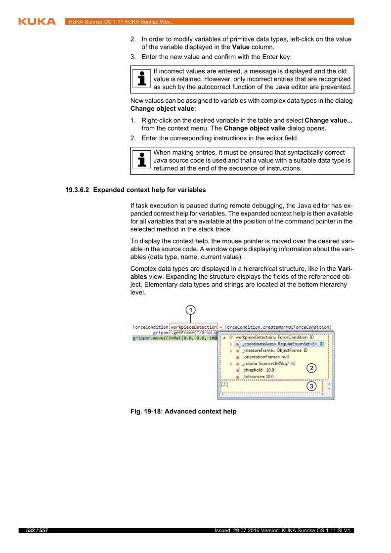
532 / 557
KUKA Sunrise.OS 1.11 KUKA Sunrise.Wor...
2. In order to modify variables of primitive data types, left-click on the value of the variable displayed in the Value column.
3. Enter the new value and confirm with the Enter key.
New values can be assigned to variables with complex data types in the dialog Change object value:
1. Right-click on the desired variable in the table and select Change value... from the context menu. The Change object valie dialog opens.
2. Enter the corresponding instructions in the editor field.
19.3.6.2 Expanded context help for variables
If task execution is paused during remote debugging, the Java editor has ex-panded context help for variables. The expanded context help is then available for all variables that are available at the position of the command pointer in the selected method in the stack trace.
To display the context help, the mouse pointer is moved over the desired vari-able in the source code. A window opens displaying information about the vari-ables (data type, name, current value).
Complex data types are displayed in a hierarchical structure, like in the Vari-ables view. Expanding the structure displays the fields of the referenced ob-ject. Elementary data types and strings are located at the bottom hierarchy level.
If incorrect values are entered, a message is displayed and the old value is retained. However, only incorrect entries that are recognized as such by the autocorrect function of the Java editor are prevented.
When making entries, it must be ensured that syntactically correct Java source code is used and that a value with a suitable data type is returned at the end of the sequence of instructions.
Fig. 19-18: Advanced context help
Issued: 29.07.2016 Version: KUKA Sunrise.OS 1.11 SI V1

19 Remote debugging
19.3.7 Monitoring processes
Description During remote debugging, data can also be monitored that are not available as variables. These include, for example, the current position of the robot.
Monitoring expressions can be formulated in Sunrise.Workbench. The moni-toring expressions are managed in the Expressions view and evaluated each time task execution is stopped during a debugging session. Both individual ex-pressions and more complex instruction sequences can be entered. Correct syntax must be observed.
Configured monitoring expressions are not deleted after the end of the debug-ging session and are thus also taken into consideration in subsequent debug-ging sessions.
Procedure Display the Expressions view:
Menu sequence Window > Show View
The Expressions view can be selected via the Other… menu item.
Item Description
1 Variable (source code)
Variable in the source code for which the expanded context help is displayed.
2 Variable (context help)
Expanded context help for the variable. The designation and value are displayed. In the case of complex data types, the data type is also specified.
Variables with a complex type are displayed hierarchically in a tree structure.
3 Details
Details of the selected component are displayed here. In the case of variables with primitive data types and strings, the correspond-ing value is displayed; in the case of variables with a complex data type, the result of the call of toString() is displayed by default.
It is recommended that monitoring expressions are only used for polling states and that no state-changing com-
mands are used in the expressions.Interventions and commands that cause a change of state include:
Motion commands
Modification of variables
Modification of the source code
Setting inputs/outputs
Changes of values, e.g. by calling set methods
533 / 557Issued: 29.07.2016 Version: KUKA Sunrise.OS 1.11 SI V1
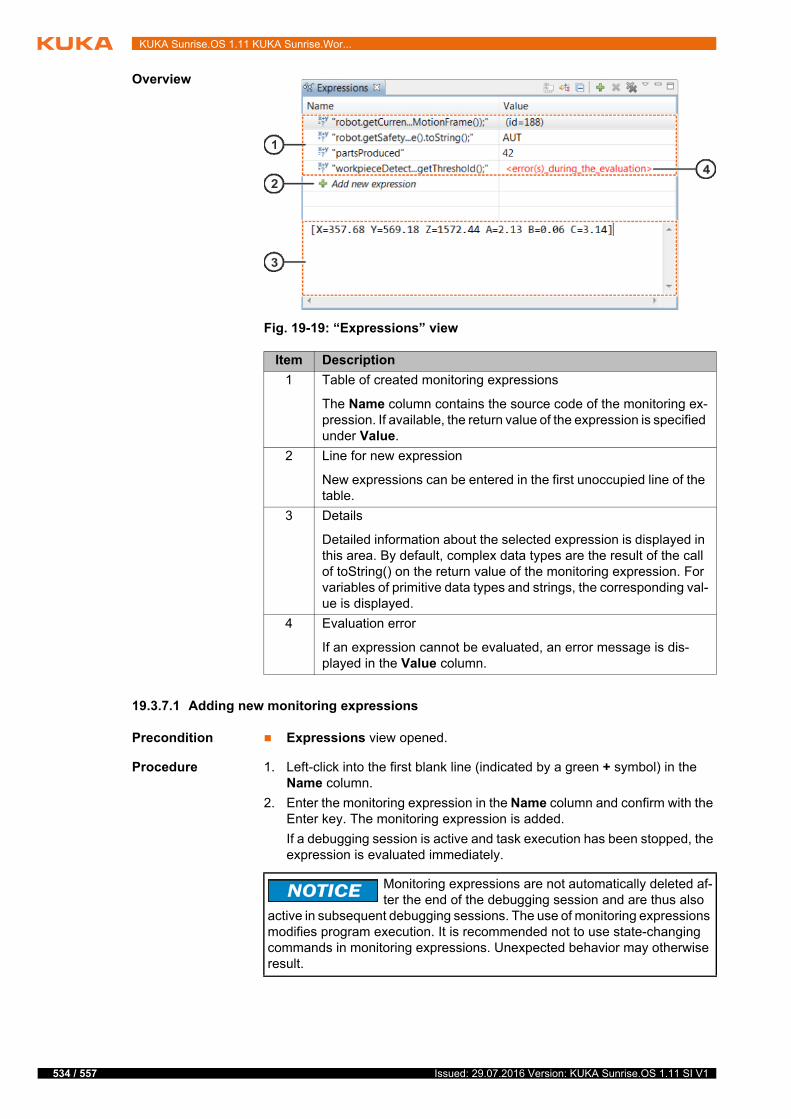
534 / 557
KUKA Sunrise.OS 1.11 KUKA Sunrise.Wor...
Overview
19.3.7.1 Adding new monitoring expressions
Precondition Expressions view opened.
Procedure 1. Left-click into the first blank line (indicated by a green + symbol) in the Name column.
2. Enter the monitoring expression in the Name column and confirm with the Enter key. The monitoring expression is added.
If a debugging session is active and task execution has been stopped, the expression is evaluated immediately.
Fig. 19-19: “Expressions” view
Item Description
1 Table of created monitoring expressions
The Name column contains the source code of the monitoring ex-pression. If available, the return value of the expression is specified under Value.
2 Line for new expression
New expressions can be entered in the first unoccupied line of the table.
3 Details
Detailed information about the selected expression is displayed in this area. By default, complex data types are the result of the call of toString() on the return value of the monitoring expression. For variables of primitive data types and strings, the corresponding val-ue is displayed.
4 Evaluation error
If an expression cannot be evaluated, an error message is dis-played in the Value column.
Monitoring expressions are not automatically deleted af-ter the end of the debugging session and are thus also
active in subsequent debugging sessions. The use of monitoring expressions modifies program execution. It is recommended not to use state-changing commands in monitoring expressions. Unexpected behavior may otherwise result.
Issued: 29.07.2016 Version: KUKA Sunrise.OS 1.11 SI V1
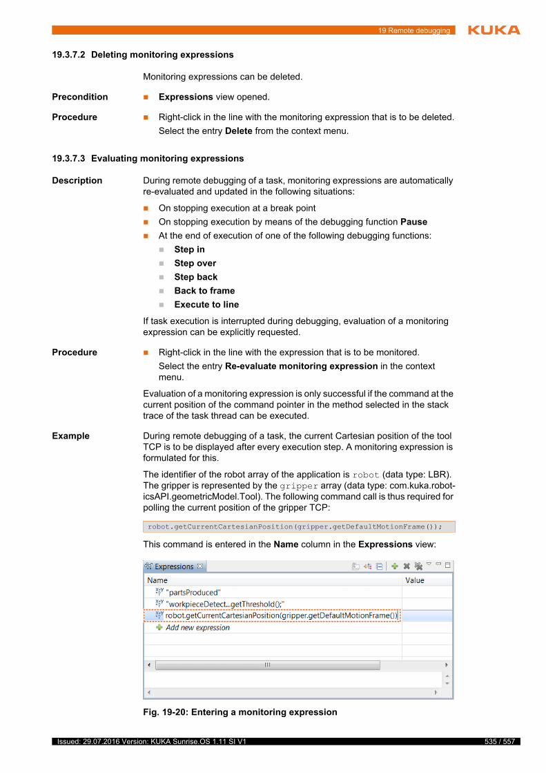
19 Remote debugging
19.3.7.2 Deleting monitoring expressions
Monitoring expressions can be deleted.
Precondition Expressions view opened.
Procedure Right-click in the line with the monitoring expression that is to be deleted.
Select the entry Delete from the context menu.
19.3.7.3 Evaluating monitoring expressions
Description During remote debugging of a task, monitoring expressions are automatically re-evaluated and updated in the following situations:
On stopping execution at a break point
On stopping execution by means of the debugging function Pause
At the end of execution of one of the following debugging functions:
Step in
Step over
Step back
Back to frame
Execute to line
If task execution is interrupted during debugging, evaluation of a monitoring expression can be explicitly requested.
Procedure Right-click in the line with the expression that is to be monitored.
Select the entry Re-evaluate monitoring expression in the context menu.
Evaluation of a monitoring expression is only successful if the command at the current position of the command pointer in the method selected in the stack trace of the task thread can be executed.
Example During remote debugging of a task, the current Cartesian position of the tool TCP is to be displayed after every execution step. A monitoring expression is formulated for this.
The identifier of the robot array of the application is robot (data type: LBR). The gripper is represented by the gripper array (data type: com.kuka.robot-icsAPI.geometricModel.Tool). The following command call is thus required for polling the current position of the gripper TCP:
This command is entered in the Name column in the Expressions view:
robot.getCurrentCartesianPosition(gripper.getDefaultMotionFrame());
Fig. 19-20: Entering a monitoring expression
535 / 557Issued: 29.07.2016 Version: KUKA Sunrise.OS 1.11 SI V1
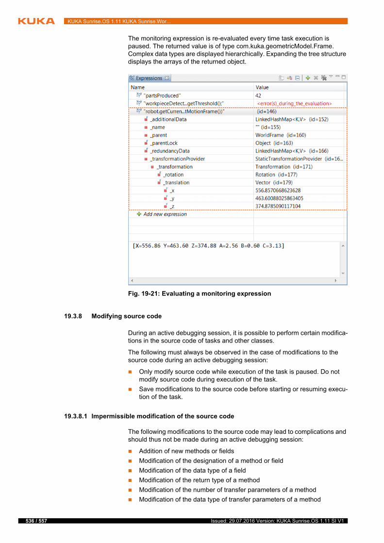
536 / 557
KUKA Sunrise.OS 1.11 KUKA Sunrise.Wor...
The monitoring expression is re-evaluated every time task execution is paused. The returned value is of type com.kuka.geometricModel.Frame. Complex data types are displayed hierarchically. Expanding the tree structure displays the arrays of the returned object.
19.3.8 Modifying source code
During an active debugging session, it is possible to perform certain modifica-tions in the source code of tasks and other classes.
The following must always be observed in the case of modifications to the source code during an active debugging session:
Only modify source code while execution of the task is paused. Do not modify source code during execution of the task.
Save modifications to the source code before starting or resuming execu-tion of the task.
19.3.8.1 Impermissible modification of the source code
The following modifications to the source code may lead to complications and should thus not be made during an active debugging session:
Addition of new methods or fields
Modification of the designation of a method or field
Modification of the data type of a field
Modification of the return type of a method
Modification of the number of transfer parameters of a method
Modification of the data type of transfer parameters of a method
Fig. 19-21: Evaluating a monitoring expression
Issued: 29.07.2016 Version: KUKA Sunrise.OS 1.11 SI V1
19 Remote debugging
Generation of syntax errors in the code
19.3.8.2 Permissible modification of the source code
The following must be taken into consideration if, during debugging of a task, modifications are made in the source code of this task or in the source code of the classes used in it:
If modifications are made to the source code in a method that is currently located in the stack trace of the task thread, the command pointer jumps to the start of this method after saving the change.
After saving an impermissible modification of the source code during remote debugging, a dialog opens with a corresponding warning message.
Next button: The debugging session can be resumed.
Disconnect button: The debugging session can be aborted and the re-mote connection disconnected. It is advisable to abort the debugging session and reestablish the remote connection.
The jump by the command pointer to the start of a meth-od on saving modifies the normal program sequence.
This can result in unexpected system behavior and unexpected robot mo-tions.
537 / 557Issued: 29.07.2016 Version: KUKA Sunrise.OS 1.11 SI V1

538 / 557
KUKA Sunrise.OS 1.11 KUKA Sunrise.Wor...
Issued: 29.07.2016 Version: KUKA Sunrise.OS 1.11 SI V1
20 Appendix
20 Appendix
20.1 Compatibility and migration of projects
From Version 1.8 onwards, KUKA Sunrise.OS contains new features that af-fect the upward compatibility of projects created using an earlier software ver-sion (< 1.8).
Task functions in the RoboticsAPI
Some task functions have been renamed or are now used differently.
The migration of projects that use these task functions can thus lead to compiler errors. The programming must be adapted.
(>>> 20.1.1 "Modified task functions – adapting the programming" Page 539)
I/O configuration
The current version of WorkVisual generates a changed folder structure when exporting the I/O configuration in Sunrise.Workbench (the folder generatedFiles now contains the folder IOConfiguration).
If a project is synchronized that still has the old folder structure, the I/O configuration is not transferred and no I/Os are available on the robot con-troller.
In order to generate the new folder, the I/O configuration of the project must be opened in WorkVisual and exported again in Sunrise.Workbench. Precondition: The option package supplied with the new software (KOP file Sunrise) is installed in WorkVisual. Only then is the new folder gener-ated on exporting.
If, following the export, the folder generatedFiles contains the folder IO-Configuration, the project can be synchronized on the robot controller.
20.1.1 Modified task functions – adapting the programming
The modified task functions and the adaptations required in the tasks are de-scribed here in order to be able to continue using tasks created with a software version < 1.8.
ITaskLogger If using ITaskLogger references:
Modify the package name for ITaskLogger:
Previously: import com.kuka.roboticsAPI.applicationModel.tasks.ITaskLogger;
Now: import com.kuka.task.ITaskLogger;
ITaskFunction If using the interface ITaskFunction (>>> 16.4 "Data exchange between tasks" Page 464):
The interface ITaskFunction has been dispensed with. The following referenc-es in the interface in which the task functions are declared must therefore be deleted:
Delete the following addition in the header of the interface:
extends ITaskFunction
Delete the following import:
import com.kuka.roboticsAPI.applicationMo-del.tasks.ITaskFunction;
The interface ITaskFunctionProvider and the @ProvidedFunctions annotation have been replaced by the @TaskFunctionProvider annotation. For this rea-
2
A
x
539 / 557Issued: 29.07.2016 Version: KUKA Sunrise.OS 1.11 SI V1

540 / 557
KUKA Sunrise.OS 1.11 KUKA Sunrise.Wor...
son, the following changes are required in the task that provides the task func-tions (providing task):
Delete the following annotation: @ProvidedFunctions(…)
Delete the following addition in the header of the task:
implements ITaskFunctionProvider
Delete the method createTaskFunctions() and the corresponding Map in-stance:
public Map<Class<? extends ITaskFunction>, ITaskFunc-tion> createTaskFunctions(){...}
For each interface whose task functions the task provides, insert a param-eterless public method with the annotation @TaskFunctionProvider that returns implementation of the interface:
@TaskFunctionProvider
public Interface Method name()
return Interface instance;
}
Interface: Interface whose task functions the task provides
Method name: Name of the method that returns the implementation of the interface (the name can be freely selected)
Interface instance: Instance of the implementing class
Delete the following import:
import com.kuka.roboticsAPI.applicationModel.tasks.*
The method getTaskFunction(…) now directly returns the interface in which the task functions are declared. For this reason, the following changes are re-quired in the task that accesses the task functions (requesting task):
Change the type of data array used to access the task functions:
Data type previously: ITaskFunctionAccessor<Interface>
Interface: Interface in which the task functions are declared.
Data type now: Interface
The method getTaskFunction(…) now directly returns the interface.
Remove the .get() method from the calls of the modified variable.
If the accessor methods isAvailable() or await(…) have been used, create a new data array of type ITaskFunctionMonitor and initialize it with the method TaskFunctionMonitor.create(…). The instance of the interface in which the task functions are declared is transferred to the method as a pa-rameter.
private ITaskFunctionMonitor Monitor;
Monitor = TaskFunctionMonitor.create(Interface instance);
If the providing task implements the interface itself, transfer the in-stance of the task for the parameter Interface instance:return this;
Issued: 29.07.2016 Version: KUKA Sunrise.OS 1.11 SI V1

21 KUKA Service
21 KUKA Service
21.1 Requesting support
Introduction This documentation provides information on operation and operator control, and provides assistance with troubleshooting. For further assistance, please contact your local KUKA subsidiary.
Information The following information is required for processing a support request:
Description of the problem, including information about the duration and frequency of the fault
As comprehensive information as possible about the hardware and soft-ware components of the overall system
The following list gives an indication of the information which is relevant in many cases:
Model and serial number of the kinematic system, e.g. the manipulator
Model and serial number of the controller
Model and serial number of the energy supply system
Designation and version of the system software
Designations and versions of other software components or modifica-tions
Diagnostic package KRCDiag
Additionally for KUKA Sunrise: Existing projects including applications
For versions of KUKA System Software older than V8: Archive of the software (KRCDiag is not yet available here.)
Application used
External axes used
21.2 KUKA Customer Support
Availability KUKA Customer Support is available in many countries. Please do not hesi-tate to contact us if you have any questions.
Argentina Ruben Costantini S.A. (Agency)
Luis Angel Huergo 13 20
Parque Industrial
2400 San Francisco (CBA)
Argentina
Tel. +54 3564 421033
Fax +54 3564 428877
Australia KUKA Robotics Australia Pty Ltd
45 Fennell Street
Port Melbourne VIC 3207
Australia
Tel. +61 3 9939 9656
www.kuka-robotics.com.au
2
A
v
541 / 557Issued: 29.07.2016 Version: KUKA Sunrise.OS 1.11 SI V1
542 / 557
KUKA Sunrise.OS 1.11 KUKA Sunrise.Wor...
Belgium KUKA Automatisering + Robots N.V.
Centrum Zuid 1031
3530 Houthalen
Belgium
Tel. +32 11 516160
Fax +32 11 526794
www.kuka.be
Brazil KUKA Roboter do Brasil Ltda.
Travessa Claudio Armando, nº 171
Bloco 5 - Galpões 51/52
Bairro Assunção
CEP 09861-7630 São Bernardo do Campo - SP
Brazil
Tel. +55 11 4942-8299
Fax +55 11 2201-7883
www.kuka-roboter.com.br
Chile Robotec S.A. (Agency)
Santiago de Chile
Chile
Tel. +56 2 331-5951
Fax +56 2 331-5952
www.robotec.cl
China KUKA Robotics China Co., Ltd.
No. 889 Kungang Road
Xiaokunshan Town
Songjiang District
201614 Shanghai
P. R. China
Tel. +86 21 5707 2688
Fax +86 21 5707 2603
www.kuka-robotics.com
Germany KUKA Roboter GmbH
Zugspitzstr. 140
86165 Augsburg
Germany
Tel. +49 821 797-1926
Fax +49 821 797-41 1926
www.kuka-roboter.de
Issued: 29.07.2016 Version: KUKA Sunrise.OS 1.11 SI V1

21 KUKA Service
France KUKA Automatisme + Robotique SAS
Techvallée
6, Avenue du Parc
91140 Villebon S/Yvette
France
Tel. +33 1 6931660-0
Fax +33 1 6931660-1
www.kuka.fr
India KUKA Robotics India Pvt. Ltd.
Office Number-7, German Centre,
Level 12, Building No. - 9B
DLF Cyber City Phase III
122 002 Gurgaon
Haryana
India
Tel. +91 124 4635774
Fax +91 124 4635773
www.kuka.in
Italy KUKA Roboter Italia S.p.A.
Via Pavia 9/a - int.6
10098 Rivoli (TO)
Italy
Tel. +39 011 959-5013
Fax +39 011 959-5141
www.kuka.it
Japan KUKA Robotics Japan K.K.
YBP Technical Center
134 Godo-cho, Hodogaya-ku
Yokohama, Kanagawa
240 0005
Japan
Tel. +81 45 744 7691
Fax +81 45 744 7696
Canada KUKA Robotics Canada Ltd.
6710 Maritz Drive - Unit 4
Mississauga
L5W 0A1
Ontario
Canada
Tel. +1 905 670-8600
Fax +1 905 670-8604
www.kuka-robotics.com/canada
543 / 557Issued: 29.07.2016 Version: KUKA Sunrise.OS 1.11 SI V1

544 / 557
KUKA Sunrise.OS 1.11 KUKA Sunrise.Wor...
Korea KUKA Robotics Korea Co. Ltd.
RIT Center 306, Gyeonggi Technopark
1271-11 Sa 3-dong, Sangnok-gu
Ansan City, Gyeonggi Do
426-901
Korea
Tel. +82 31 501-1451
Fax +82 31 501-1461
Malaysia KUKA Robot Automation (M) Sdn Bhd
South East Asia Regional Office
No. 7, Jalan TPP 6/6
Taman Perindustrian Puchong
47100 Puchong
Selangor
Malaysia
Tel. +60 (03) 8063-1792
Fax +60 (03) 8060-7386
Mexico KUKA de México S. de R.L. de C.V.
Progreso #8
Col. Centro Industrial Puente de Vigas
Tlalnepantla de Baz
54020 Estado de México
Mexico
Tel. +52 55 5203-8407
Fax +52 55 5203-8148
www.kuka-robotics.com/mexico
Norway KUKA Sveiseanlegg + Roboter
Sentrumsvegen 5
2867 Hov
Norway
Tel. +47 61 18 91 30
Fax +47 61 18 62 00
Austria KUKA Roboter CEE GmbH
Gruberstraße 2-4
4020 Linz
Austria
Tel. +43 7 32 78 47 52
Fax +43 7 32 79 38 80
www.kuka.at
Issued: 29.07.2016 Version: KUKA Sunrise.OS 1.11 SI V1
21 KUKA Service
Poland KUKA Roboter Austria GmbH
Spółka z ograniczoną odpowiedzialnością
Oddział w Polsce
Ul. Porcelanowa 10
40-246 Katowice
Poland
Tel. +48 327 30 32 13 or -14
Fax +48 327 30 32 26
Portugal KUKA Robots IBÉRICA, S.A.
Rua do Alto da Guerra n° 50
Armazém 04
2910 011 Setúbal
Portugal
Tel. +351 265 729 780
Fax +351 265 729 782
www.kuka.com
Russia KUKA Robotics RUS
Werbnaja ul. 8A
107143 Moskau
Russia
Tel. +7 495 781-31-20
Fax +7 495 781-31-19
www.kuka-robotics.ru
Sweden KUKA Svetsanläggningar + Robotar AB
A. Odhners gata 15
421 30 Västra Frölunda
Sweden
Tel. +46 31 7266-200
Fax +46 31 7266-201
Switzerland KUKA Roboter Schweiz AG
Industriestr. 9
5432 Neuenhof
Switzerland
Tel. +41 44 74490-90
Fax +41 44 74490-91
www.kuka-roboter.ch
545 / 557Issued: 29.07.2016 Version: KUKA Sunrise.OS 1.11 SI V1

546 / 557
KUKA Sunrise.OS 1.11 KUKA Sunrise.Wor...
Spain KUKA Robots IBÉRICA, S.A.
Pol. Industrial
Torrent de la Pastera
Carrer del Bages s/n
08800 Vilanova i la Geltrú (Barcelona)
Spain
Tel. +34 93 8142-353
Fax +34 93 8142-950
www.kuka.es
South Africa Jendamark Automation LTD (Agency)
76a York Road
North End
6000 Port Elizabeth
South Africa
Tel. +27 41 391 4700
Fax +27 41 373 3869
www.jendamark.co.za
Taiwan KUKA Robot Automation Taiwan Co., Ltd.
No. 249 Pujong Road
Jungli City, Taoyuan County 320
Taiwan, R. O. C.
Tel. +886 3 4331988
Fax +886 3 4331948
www.kuka.com.tw
Thailand KUKA Robot Automation (M)SdnBhd
Thailand Office
c/o Maccall System Co. Ltd.
49/9-10 Soi Kingkaew 30 Kingkaew Road
Tt. Rachatheva, A. Bangpli
Samutprakarn
10540 Thailand
Tel. +66 2 7502737
Fax +66 2 6612355
www.kuka-roboter.de
Czech Republic KUKA Roboter Austria GmbH
Organisation Tschechien und Slowakei
Sezemická 2757/2
193 00 Praha
Horní Počernice
Czech Republic
Tel. +420 22 62 12 27 2
Fax +420 22 62 12 27 0
Issued: 29.07.2016 Version: KUKA Sunrise.OS 1.11 SI V1

21 KUKA Service
Hungary KUKA Robotics Hungaria Kft.
Fö út 140
2335 Taksony
Hungary
Tel. +36 24 501609
Fax +36 24 477031
USA KUKA Robotics Corporation
51870 Shelby Parkway
Shelby Township
48315-1787
Michigan
USA
Tel. +1 866 873-5852
Fax +1 866 329-5852
www.kukarobotics.com
UK KUKA Robotics UK Ltd
Great Western Street
Wednesbury West Midlands
WS10 7LL
UK
Tel. +44 121 505 9970
Fax +44 121 505 6589
www.kuka-robotics.co.uk
547 / 557Issued: 29.07.2016 Version: KUKA Sunrise.OS 1.11 SI V1

548 / 557
KUKA Sunrise.OS 1.11 KUKA Sunrise.Wor...
Issued: 29.07.2016 Version: KUKA Sunrise.OS 1.11 SI V1

Index
Index
Symbols“Ready for motion”, polling 381
Numbers2006/42/EC 432014/30/EU 433-point method 11995/16/EC 43
AABC 2-point method 116ABC world method 118Accessories 21, 25Activation delay, for safety function 259Actual position, axis-specific 101Actual position, Cartesian 101addCartesianForce(…) 424addCartesianTorque(…) 425addCommandedCartesianPositionXYZ(…) 425addCommandedJointPosition(…) 425addControllerListener(…) 381, 385addCurrentCartesianPositionXYZ(…) 426addCurrentJointPosition(…) 425addDoubleUserKey(…) 432addExternalJointTorque(…) 424addInternalJointTorque(…) 424addUserKey(…) 432Administrator 160Allow muting via input 299AMF 18ANSI/RIA R.15.06-2012 43API 18App_Enable 190, 198App_Start 190, 452Appendix 539Application data (view) 49Application mode 83Application override 82, 97, 99, 388Application tool 86Application, pausing 442Applied norms and directives 43Approximate positioning 312Approximate positioning point 312areAllAxesGMSReferenced() 385areAllAxesPositionReferenced() 385areDataValid() 133Asynchronous motion execution 342attachTo(…) 358AUT 27AutExt_Active 191AutExt_AppReadyToStart 191, 452Auto-complete 326Automatic 27Automatic mode 41Automatic mode (standard AMF) 208, 209, 235Auxiliary point 304, 344awaitFileAvailable(…) 429Axis limit 255
Axis range 27, 255Axis range monitoring (parameterizable AMF) 208, 211, 255Axis torque condition 391Axis torque monitoring 260Axis torque monitoring (parameterizable AMF) 209, 212, 260Axis torques, polling 371Axis velocity monitoring (parameterizable AMF) 209, 211, 241Axis-specific impedance controller 473, 495Axis-specific monitoring spaces, defining 255Axis-specific position, polling 376
BBackground application, starting 99Background application, stopping 99Background task, new 55Background tasks 459Backup Manager 106Backup manager 174Backup Manager, configuration 171Base coordinate system 81, 119Base for jogging 144Base-related TCP force component (AMF) 296Base-related TCP force component (paramete-rizable AMF) 209, 212, 266Base, calibration 119Blocking wait 421BooleanIOCondition 390Brake defect 37Brake test 125Brake test application, template 127Brake test, evaluation 136Brake test, performing 140Brake test, polling results 138Brake test, programming interface 131Brake test, results (display) 141Brake test, start of execution 135Brake test, starting position 131Brake, defective 126BrakeState (enum) 138BrakeTest (class) 131, 134BrakeTestResult (class) 137Braking distance 27Break conditions for motions 409Break conditions, evaluating 410Break point, conditional 519Break point, view 518Break points 515breakWhen(…) 411breakWhen() 409Bus I/Os, mapping 185
CCalibration 113Calibration, base 119Calibration, tool 113
549 / 557Issued: 29.07.2016 Version: KUKA Sunrise.OS 1.11 SI V1

550 / 557
KUKA Sunrise.OS 1.11 KUKA Sunrise.Wor...
Cartesian impedance controller 473, 475, 483Cartesian position, polling 377Cartesian protected space monitoring (parame-terizable AMF) 209, 211, 252Cartesian protected spaces, defining 252Cartesian setpoint/actual value difference, pol-ling 378Cartesian velocity monitoring (parameterizable AMF) 209, 211, 242Cartesian workspace monitoring (parameteriz-able AMF) 209, 211, 250Cartesian workspaces 250CartesianTorqueCondition 390CE mark 26Checksum, safety configuration 233CIRC 344CIRC, motion type 304Circular motion 344Cleaning work 42clipApplicationOverride(…) 388clipManualOverride(…) 388Collision detection 261Collision detection (parameterizable AMF) 209, 212, 262Command pointer 521Compatibility 539Complex conditions 391Complex data types 335Condition for Boolean signals 408Condition for the range of values of a signal 408Condition, Cartesian torque 400Conditional branch 445Connecting cables 21, 25Constant force, overlaying 490Continuous Path 303Controller object, creating 474Controller parameters, defining 474Controllers, overview 473Coordinate system, for jog keys 68Coordinate systems 80Counting loop 443CP motion 303CP spline block 303CP Spline block, creating 348Create child frame (button) 90Create frame (button) 90createAndEnableConditionObserver(…) 419createConditionObserver(…) 419createDesiredForce(…) 490createLissajousPattern(…) 490createNormalForceCondition(…) 393, 395createShearForceCondition(…) 393, 396createSinePattern(…) 490createSpatialForceCondition(…) 393, 394createSpatialTorqueCondition(…) 401createSpiralPattern(…) 490createTiltingTorqueCondition(…) 401, 403createTurningTorqueCondition(…) 401, 402createUserKeyBar(…) 431CRR 27, 77Cyclic background task 461
DDanger zone 27Data types 333Data, backing up manually 109Data, recording and evaluating 423Data, restoring manually 109DataRecorder 423Debug (perspective) 49Debug project (button) 50Debugging session, ending 511Debugging session, starting 511Debugging, view 522Declaration 334Declaration of conformity 26Declaration of incorporation 25, 26Decommissioning 42Default application 54, 189, 193, 202Default frame for motions 152DefaultApp_Error 191Dependency Injection 336Dependency injection 336, 339Deselect (button) 95detach() 361Diagnosis 499Diagnosis package, creating 506Diagnosis package, loading from the robot cont-roller 507Diagnostic information, collecting 505Display child frames (button) 91Displaying, robot controller information 105Displaying, robot information 105displayModalDialog(…) 441Disposal 42DO WHILE loop 445Documentation, industrial robot 17
EEC declaration of conformity 26Effective program override 97, 99, 388Electromagnetic compatibility (EMC) 43, 44EMC Directive 26, 43EMERGENCY STOP 64EMERGENCY STOP device 30, 31, 32EMERGENCY STOP smartPAD (standard AMF) 208, 209, 234EMERGENCY STOP, external 30, 32EN 60204-1 + A1 44EN 61000-6-2 43EN 61000-6-4 + A1 44EN 614-1 + A1 43EN 62061 + A1 44EN ISO 10218-1 43EN ISO 12100 43EN ISO 13849-1 43EN ISO 13849-2 43EN ISO 13850 43enable(), DataRecorder 426Enabling device 30, 31Enabling device, external 30, 33Enabling switch 65, 66Enabling switches 31
Issued: 29.07.2016 Version: KUKA Sunrise.OS 1.11 SI V1
Index
equals(…) 411Error treatment 452ESM 18, 222ESM mechanism 227ESM state, deleting 229ESM state, new 227Event-driven Safety Monitoring 207Exception 18External control 189External E-STOP 236External position referencing 271, 275
FFast entry, Java 327Faults 38Field bus diagnosis 499Field bus, Ethernet-based 169Field buses, overview 179File, closing 49Filter settings 500Flange coordinate system 81Fonts 333FOR loop 443Force component condition 398Force condition 392ForceComponentCondition 390ForceCondition 390Frame 18Frame management 143Frame, deleting 145Frame, designation as base 144Frame, moving 145Frame, properties, application data 146Frame, properties, object templates 151Frames, addressing 93Frames, teaching 91Frames, teaching with hand guiding device 93Frames, view 89FSoE 18Function test 39
GGeneral safety measures 37Get_State 190getAlphaRad() 378getApplicationData().getFrame() 148getApplicationOverride() 388getApplicationUI() 431getAxis() 137getBetaRad() 378getBrakeIndex() 137getCommandedCartesianPosition(…) 375getCommandedCartesianPosition() 416getCommandedJointPosition() 375, 416getCurrentCartesianPosition() 375, 416getCurrentJointPosition() 376, 416getEffectiveOverride() 388getEmergencyStopEx() 383getEmergencyStopInt() 383getEnablingDeviceState() 384getExecutionMode() 386
getExternalForceTorque(…) 372, 373getExternalTorque() 371getFiredBreakConditionInfo() 410getFiredCondition() 411, 412, 416getFlange() 358getForce() 373getForceInaccuracy() 374getFrame(…) 359, 362getFriction() 137getGammaRad() 378getGravity() 137getHomePosition() 380getLogLevel() 138getManualOverride() 388getMaxAbsTorqueValues() 133getMaxBrakeHoldingTorque() 137getMeasuredBrakeHoldingTorque() 137getMeasuredTorque() 371getMinBrakeHoldingTorque() 137getMissedEvents() 416getMotion() 451getMotionContainer() 416getMotorHoldingTorque() 137getMotorIndex() 137getMotorMaximalTorque() 137getObserverManager() 419, 421getOperationMode() 384getOperatorSafetyState() 384getPositionInfo() 411getPositionInformation(…) 376getPositionInformation() 378, 416getRecovery() 450getRecoveryStrategy(…) 451getRotationOffset() 378getSafetyState() 383getSafetyStopSignal() 384getSingleMaxAbsTorqueValue(...) 133getSingleTorqueValue(…) 371getStartPosition() 451getStartTimestamp() 133getState() 137, 138getStoppedMotion() 411, 412getStopTimestamp() 133getTestedTorque() 138getTimestamp() 138getTorque() 373getTorqueInaccuracy() 374getTorqueValues() 371getTranslationOffset() 378getTriggerTime() 416Graphics card 45
Hhalt() 442Hand guiding device enabling activated (parameterizable AMF) 209, 210, 238Hand guiding device enabling deactivated (parameterizable AMF) 209, 210, 237Hand-held control panel 21, 25handGuiding() 311, 352Handling of failed motion commands 452
551 / 557Issued: 29.07.2016 Version: KUKA Sunrise.OS 1.11 SI V1

552 / 557
KUKA Sunrise.OS 1.11 KUKA Sunrise.Wor...
Hard disk space 45Hardware 45hasActiveMotionCommand() 382High-velocity mode (standard AMF) 208, 210, 235HOME position 379HOME position, changing 379HOME position, polling 380Hooke’s law 475HRC 18, 19
II/O configuration, exporting 187I/O configuration, new 180I/O configuration, opening 180I/O group, creating 183I/O group, deleting 184I/O group, editing 184I/O group, exporting as a template 184I/O group, importing from a template 185I/O Mapping (window) 185, 186IAnyEdgeListener 418IApplicationOverrideControl (interface) 387ICallbackAction, interface 414ICondition (inferface) 389IControllerStateListener 381Identification plate 65IF ELSE branch 445IFallingEdgeListener 418IForceSensitiveRobot (interface) 372Industrial robot 25Initialization 334initialize() 326, 461, 464initializeCyclic(…) 461Input signal (parameterizable AMF) 208, 210, 236Inputs/outputs, display 103Installation 167Installation direction 167Installation, KUKA Sunrise.Workbench 45Intended use 24, 25Introduction 17IORangeCondition 390IP address, robot controller 105IP addresses 51IRecovery, interface 450IRisingEdgeListener 418ISafetyState (interface) 383isAxisGMSReferenced(…) 385isAxisPositionReferenced(…) 385isEnabled() 428isFileAvailable() 429isForceValid(…) 374isInHome() 380isMastered() 381isReadyToMove() 381isRecording() 428isRecoveryRequired(…) 451isRecoveryRequired() 451isTorqueMeasured() 133isTorqueValid(…) 374
ISunriseControllerStateListener 385ITaskFunction 539ITaskFunctionMonitor 469ITaskLogger 539ITorqueSensitiveRobot (interface) 371ITriggerAction, interface 414IUserKeyBar (interface) 432
JJava Editor 325Java Editor, opening 325Java file, renaming 59Java package, new 54Java project, new 58Java projects, referencing 59Javadoc 18Javadoc (view) 49Javadoc browser, configuration 330Javadoc information, displaying 329Jog keys 64, 87Jog mode 36Jog override 82, 86Jogging options (button) 68, 85Jogging type (button) 69, 83Jogging, axis-specific 84, 87Jogging, Cartesian 84, 87Jogging, robot 84JointTorqueCondition 390JP motionJoint Path 303JP spline block 303JP Spline block, creating 349JRE 18
KKeyboard key 64Keypad 71KLI 18, 167, 168KMP 18Knowledge, required 17KRCDiag 505KUKA Customer Support 105, 541KUKA Line Interface 168KUKA PSM 222, 234KUKA RoboticsAPI 18KUKA smartHMI 18, 68KUKA smartPAD 18, 28, 63KUKA Sunrise Cabinet 18, 21KUKA Sunrise.OS 19
LLabeling 36Language 69, 76Language package, installing 176Language selection (button) 69Liability 25LIN 344LIN REL 345LIN, motion type 304Linear motion 344, 345Lissajous oscillation, overlaying 492Load data 153
Issued: 29.07.2016 Version: KUKA Sunrise.OS 1.11 SI V1
Index
Load data, entering 154Log entries, filtering 501Loops, nesting 449Low Voltage Directive 26
MMachinery Directive 26, 43Main menu key 64Main menu, calling 75Maintenance 41Manipulator 21, 25, 28, 30Manual guidance mode 352Manual guidance support 167, 169Manual guidance, motion type 311Manual guidance, programming 352Manual guidance, velocity limitation 355Manual mode 40Manual override 82, 97, 99, 388Mapping, inputs/outputs 187Mastering 112Mastering state, polling 381Mastering, deleting 113Media flange Touch 236, 237Menu bar 48Message programming 439Message window 95Methods, extracting 328Mode selection 34Monitoring 390, 417Monitoring of processes 390Monitoring processes 417Monitoring spaces 248Monitoring, physical safeguards 32Motion enable (standard AMF) 208, 210, 235Motion execution, pausing 442Motion parameters 350Motion programming, basic principles 303Motion types 303MotionBatch 346MotionPathCondition 390Mounting orientation 51, 81move(…) 342, 361, 452moveAsync(…) 342, 361, 454Multiple branches 447
NNavigation bar 69New frame, creating 90, 144New Java class (button) 50New Java package (button) 50Non-cyclic background task 463Non-safety-oriented functions 34Normal force 393NotificationType, Enum 420Null space motion 88
OObject management 148Object templates (view) 49Object templates, copying 160ObserverManager 419, 421
onIsReadyToMoveChanged(…) 381onKeyEvent(…), IUserKeyListener 433onSafetyStateChanged(…) 385onTriggerFired(…) 414Operating mode, changing 78Operating time 106Operation, KUKA smartPAD 63Operation, KUKA Sunrise.Workbench 47Operator 27, 29, 161Operator safety 30, 32Operators 391Options 21, 25Orientation control 351Orientation control, LIN, CIRC, SPL 314Output, change 103Overload 37Override 86, 97, 388Override (button) 69, 82Override, changing and polling 387Overview of the robot system 21
PPackage Explorer (view) 48Panic position 31Password, changing 161Path-related condition 405Path-related switching actions 390, 413Pausing, robot application 98PDS firmware update 112Performance Level 26Permanent Safety Monitoring 206Personnel 28Perspective, selection 48Perspectives, display 49Plant integrator 28Point-to-point 303Point-to-point motion 343Pollling, robot position 375Position and torque referencing 271Position controller 473, 475Position referencing 271Position referencing (parameterizable AMF) 208, 211, 239positionHold(…) 496Post-test loop 445Preventive maintenance work 42Primitive data types 335Processor 45Product description 21PROFINET 19PROFIsafe 19Program execution 94Program execution control 442Program run mode, changing and polling 386Program run mode, setting 96Program run modes 97Programming 325Programming (perspective) 49Project management 143Project synchronization 161Project, loading from the robot controller 164
553 / 557Issued: 29.07.2016 Version: KUKA Sunrise.OS 1.11 SI V1
554 / 557
KUKA Sunrise.OS 1.11 KUKA Sunrise.Wor...
Project, synchronization 161Project, synchronizing 162, 163Projects, archiving 57Projects, loading to workspace 57Properties (view) 49Protected space 248, 252Protective equipment 36Protocol, display 499Protocol, view 500PSM 19PSM mechanism 224PTP 343PTP, motion type 303PTPRecoveryStrategy (class) 451
RRAM 45Reaction distance 27Ready for motion signal, reacting to change 381Recommissioning 38, 111Reduced-velocity mode (standard AMF) 208, 210, 235Redundancy angle 320Redundancy information 147, 319Reference, canceling 59Referencing state, polling 384Rejecting loop 444Release notes, displaying 61Remote debugging 509Renaming, variable 326Repair 41Reset (button) 95Resetting, robot application 98Retraction, robot 77Robot activity, polling 382Robot application, new 54Robot application, pausing 98Robot application, resetting 95, 98Robot application, selecting 94, 95Robot application, starting automatically 98Robot application, starting manually 98Robot base coordinate system 81Robot controller 25Robot controller, switching on/off 111Robot level 73Robot position, polling 375Robot, repositioning 98RoboticsAPI 18run() 326, 464runCyclic() 461
SSafe operational stop 259Safe operational stop, external 30, 33Safeguards, external 36Safety 25Safety acceptance overview 275Safety concept 203Safety configuration 203Safety configuration, activating 233Safety configuration, conversion 164
Safety configuration, deactivating 233Safety configuration, opening 222Safety configuration, restoring 234Safety controller, resuming 80Safety function, new for ESM 229Safety function, new for PSM 226Safety functions 26Safety functions, configuration 224, 227Safety functions, deactivation via an input 219Safety instructions 17Safety maintenance technician 77, 161Safety of machinery 43, 44Safety signal, state, polling 382Safety stop 28Safety stop 0 28Safety stop 1 28Safety stop 1 (path-maintaining) 28Safety stop, external 30, 32, 33Safety zone 28, 29, 30Safety-oriented functions 30Safety-oriented stop reactions 33Safety-oriented tool, configuring 155Safety-oriented tools 154Safety-oriented tools, mapping 231Safety-oriented workpiece, configuring 159Safety-oriented workpieces 158Safety, legal framework 25SafetyConfiguration.sconf (file) 53, 222Serial number, robot 106Serial number, robot controller 105Service life 27Service, KUKA Roboter GmbH 541Set base for jogging (button) 91Set methods 350setAdditionalControlForce(…) 480setAmplitude(…) 486setApplicationOverride(…) 388setAxisLimitsEnabled(…) 356setAxisLimitsMax(…) 356setAxisLimitsMin(…) 356setAxisLimitViolationFreezesAll(…) 356setAxisSpeedLimit(…) 356setBias(…) 487setBlendingCart(…) 351setBlendingOri(…) 351setBlendingRel(…) 351setCartAcceleration(…) 350setCartJerk(…) 351setCartVelocity(…) 350setCriticalText(…), IUserKey 438setDamping(…) 480, 495setDampingForAllJoints(…) 495setExecutionMode(…) 386setFallTime(…) 489setForceLimit(…) 488setFrequency(…) 486setHoldTime(…) 489setHomePosition(…) 379setJointAccelerationRel(…) 350, 352setJointJerkRel(…) 351, 352setJointVelocityRel(…) 350, 352
Issued: 29.07.2016 Version: KUKA Sunrise.OS 1.11 SI V1
Index
setLED(…), IUserKey 437setMaxCartesianVelocity(…) 482setMaxControlForce(…) 481setMaxPathDeviation(…) 482setNullSpaceDamping(…) 481setNullSpaceStiffness(…) 481setOrientationReferenceSystem(…) 317, 351setOrientationType(…) 314, 351setPermanentPullOnViolationAtStart(…) 356setPhaseDeg(…) 487setPositionLimit(…) 488setRiseTime(…) 489setSafetyWorkpiece(…) 365setStayActiveUntilPatternFinished(…) 489setStiffness(…) 480, 495setStiffnessForAllJoints(…) 495setText(…), IUserKey 436setTotalTime(…) 489Shear force 393Simple force oscillation, overlaying 491Single point of control 42Singletons 339, 363Singularities 321Singularity 315smartHMI 19, 68smartPAD 19, 28, 37, 63smartPAD enabling switch deactivated (standard AMF) 209, 234smartPAD enabling switch panic activated (standard AMF) 209, 234smartPAD unplugging allowed 299smartPAD, disconnecting/connecting 66smartPAD, software update 111Software 21, 25, 45Software components 21Software limit switches 35Software option, installing 174Software option, uninstalling 176Software options 174Space Mouse 64Spiral-shaped force oscillation, overlaying 493SPL, motion type 305Spline segment 305Spline, motion type 305SPOC 42SPS (PLC) 19Standstill monitoring 259Standstill monitoring of all axes (extended AMF) 209, 212, 259Start backwards key 64Start key 64, 65Start-up 38, 111startEvaluation() 132Starting, robot application 98Starting, System Software 111startRecording() 426StartRecordingAction 427Station configuration 167Station configuration, overview 167Station level 71Station_Error 191
StationSetup.cat (file) 53, 167Status 320Status display 70Stop category 0 28Stop category 1 28Stop category 1 (path-maintaining) 28STOP key 64Stop reactions, safety-oriented 33stopEvaluation() 132Stopping distance 27, 30, 250stopRecording() 428StopRecordingAction 428Storage 42Structure, robot application 325Sunrise I/Os, changing 184Sunrise I/Os, creating 181Sunrise I/Os, deleting 184Sunrise project (button) 50Sunrise project, new 51Sunrise.Workbench, starting 47Sunrise.Workbench, user interface 47SunriseExecutionService 386SunriseSafetyState (class) 383Support request 541Surface normal 393SWITCH branch 447Switching off, robot controller 111Switching on, robot controller 111Symbols 333Synchronize project (button) 50Synchronous motion execution 342System integrator 26, 28, 29System requirements, PC 45System software, installing 172System states, polling 380
TT1 28T2 28Target group 17Task functions 539Task, remote debugging 510Tasks (view) 49TCP 19, 113, 150TCP force monitoring 262TCP force monitoring (parameterizable AMF) 209, 212, 263Template, for Sunrise project 51Templates 327Templates, user-specific 328Terms used 18Terms used, safety 27Terms, used 18Test mode (standard AMF) 208, 209, 235Tilting torque 400Time delay (extended AMF) 208, 212, 260Tool calibration 113Tool Center Point 113Tool coordinate system 81, 113Tool frame, creating 150Tool load data, determining 121
555 / 557Issued: 29.07.2016 Version: KUKA Sunrise.OS 1.11 SI V1

556 / 557
KUKA Sunrise.OS 1.11 KUKA Sunrise.Wor...
Tool orientation (parameterizable AMF) 209, 211, 257Tool orientation, monitoring 256Tool-specific velocity component (parameteriz-able AMF) 209, 211, 245Tool, creating 150Tool, integrating 357Tool, switching off 235Toolbar 48Torque 400Torque component condition 404Torque referencing 273Torque referencing (parameterizable AMF) 209, 211, 240Torque value determination 130TorqueComponentCondition 390TorqueEvaluator (class) 129, 131, 132Torques, axis-specific 102TorqueStatistic (class) 129, 132, 133Touch screen 63Trademarks 18Training 17Transportation 38Trigger 390, 413Trigger information, evaluating 415Triggers, programming 413triggerWhen(…) 413Turn 321Type, robot 106
UUninstallation, Sunrise.Workbench 45Unmastering 113USB connection 65Use, contrary to intended use 25Use, improper 25User 27, 29User administration 160User dialogs, programming 441User group (button) 69User group, changing 77User group, default 77, 161User interface, KUKA smartHMI 68User interface, Sunrise.Workbench 47User key bar, creating 431User key selection (button) 80User keys 64User keys (button) 69User keys, activation 79User keys, defining 430User messages, programming 439User PSM 222UserKeyAlignment (enum) 435
VVariable, renaming 326Velocity 86Velocity monitoring functions 240Version, System Software 105View, frames 89View, protocol 500
Views, repositioning 49Virus scanner 174Virus scanner, displaying messages 505Virus scanner, installing 176
WwaitFor(…) 421Warnings 17WHILE loop 444Workpiece frame, creating 150Workpiece, creating 150Workpiece, integrating 357Workspace 27, 29, 30, 248, 250, 255Workspace, new 56Workspace, Sunrise.Workbench 56Workspace, switching 56Workspaces, switching 56World coordinate system 80
XXYZ 4-point method 114
Issued: 29.07.2016 Version: KUKA Sunrise.OS 1.11 SI V1

557 / 557Issued: 29.07.2016 Version: KUKA Sunrise.OS 1.11 SI V1
KUKA Sunrise.OS 1.11 KUKA Sunrise.Wor...