KU1267 Menggambar Teknik
28
1 Fakultas Teknologi Industri Institut Teknologi Bandung @2013 KU1267 Menggambar Teknik Teori Proyeksi 2 Hasil Pembelajaran Umum Memberikan keterampilan menggunakan gambar teknik (2D dan 3D) sebagai media komunikasi standar dalam rekayasa teknik Khusus Memahami teori proyeksi serta mampu memilih dan merepresentasikan pandangan Memahami teknik-teknik setsa serta mampu melakukan perancangan sketsa bebas (freehand)
-
Upload
independent -
Category
Documents
-
view
1 -
download
0
Transcript of KU1267 Menggambar Teknik

1
Fakultas Teknologi Industri
Institut Teknologi Bandung
@2013
KU1267
Menggambar Teknik
Teori Proyeksi
2
Hasil Pembelajaran
Umum
Memberikan keterampilan menggunakan gambar
teknik (2D dan 3D) sebagai media komunikasi standar
dalam rekayasa teknik
Khusus
Memahami teori proyeksi serta mampu memilih dan
merepresentasikan pandangan
Memahami teknik-teknik setsa serta mampu
melakukan perancangan sketsa bebas (freehand)

2
3
Metoda Proyeksi
4
Metoda Proyeksi

3
5
Metoda Proyeksi
6
Metoda Proyeksi

4
7
Metoda Proyeksi
8
Changing Viewpoint
Changing the position of the object relative to the line of sight creates
different views of the same object

5
9
Perspective Projection
Radiating lines of sight
produce a perspective
projection
10
Parallel Projection
Parallel lines of sight
produce a parallel
projection

6
11
Parallel Projection
Parallel projection techniques can be used to
create multiview or pictorial drawings
12
Orthographic Projection
Orthographic projection is used to create this front multiview drawing by
projecting details onto a projection plane that is parallel to the view of the
object selected as the front

7
13
Multiview Drawing of an Object
For this object three views are created:
front, top and right side. The views are
aligned so that common dimensions
are shared between views
14
Six Principal Views
Each view is
perpendicular to and
aligned with the
adjacent views
8
15
Unfolding the Box
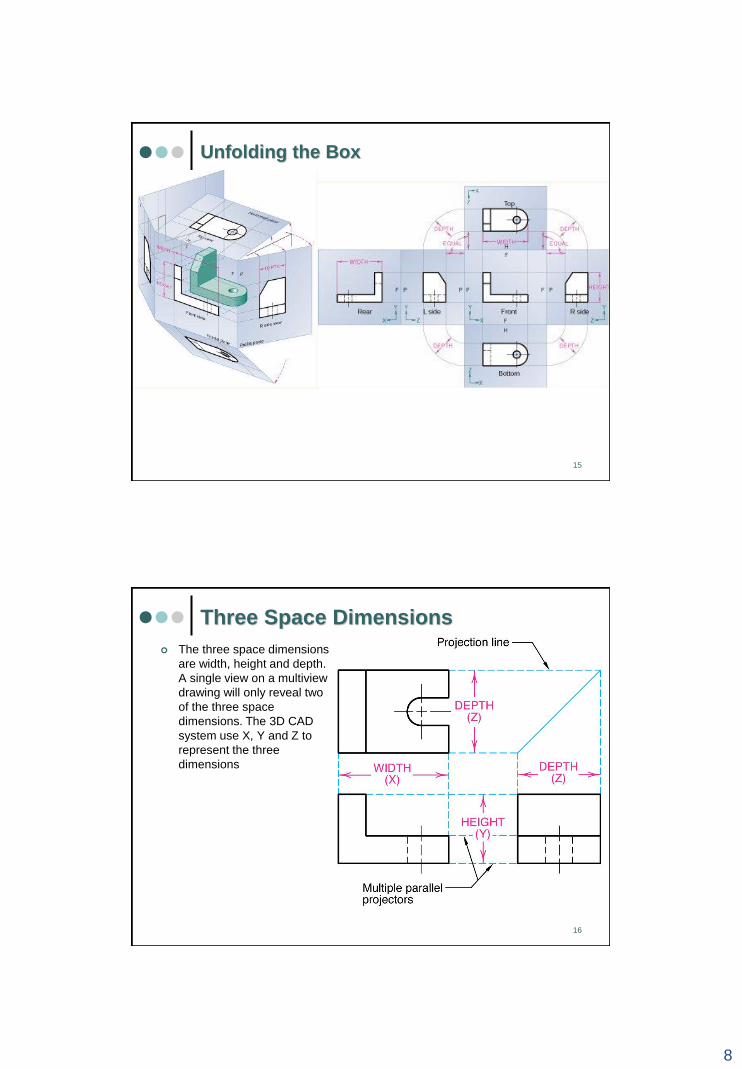
16
Three Space Dimensions
The three space dimensions
are width, height and depth.
A single view on a multiview
drawing will only reveal two
of the three space
dimensions. The 3D CAD
system use X, Y and Z to
represent the three
dimensions
9
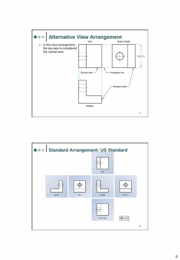
17
Alternative View Arrangement
In this view arrangement,
the top view is considered
the central view
18
Standard Arrangement: US Standard

10
19
Standard Arrangement: ISO Standard
20
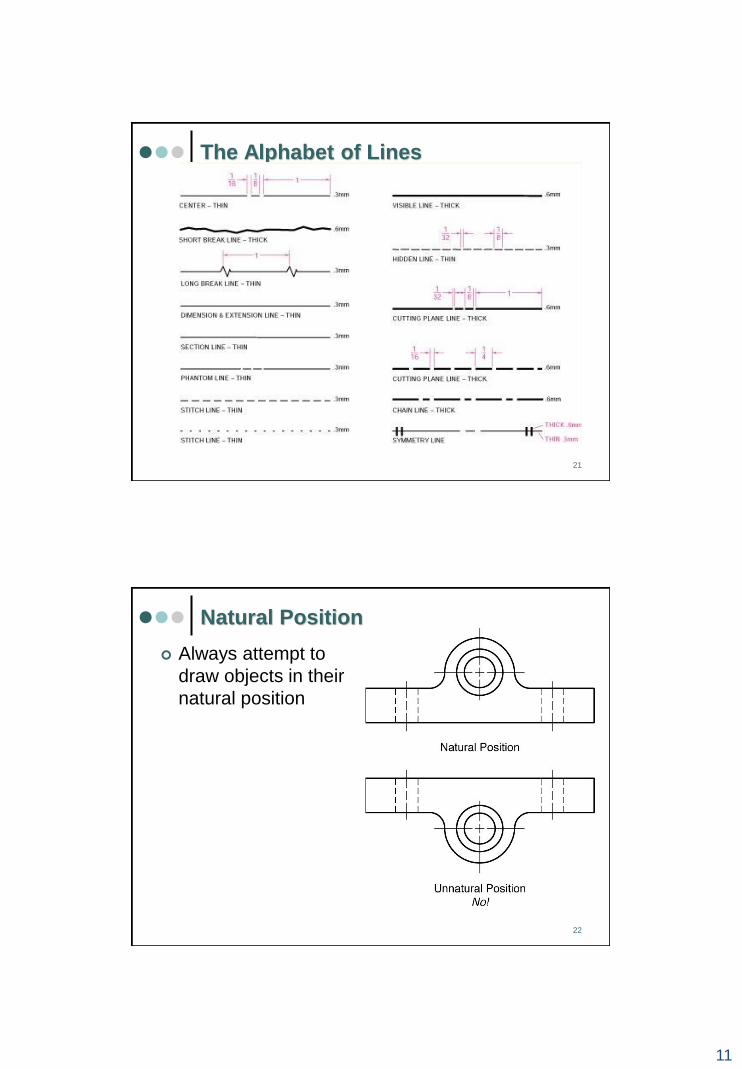
The Alphabet of Lines
The alphabet of line is a set of ASME standard linetypes used on technical
drawing
11
21
The Alphabet of Lines
22
Natural Position
Always attempt to
draw objects in their
natural position

12
23
Minimum Number of Views
Select the minimum number of views needed to completely describe an
object. Eliminate views that are mirror of other views
24
Most Descriptive Views
Select those views
which are the most
descriptive and have
the fewest hidden
lines. In this example,
the right side view has
fewer hidden lines
than the left side view

13
25
Multiview Drawing of Solid Primitive
Shapes
26
Tangent Partial Cylinder
No line is drawn at the place
where the partial cylinder
becomes tangent to another
feature, such as the vertical
face of the side

14
27
Nontangent Partial Cylinder
When transition of a rounded
end to another feature is not
tangent, a line is used at the
point of intersection
28
Representation of Machine Holes

15
29
Representation of Machine Holes
30
Representation of Machine Holes

16
31
Representing Fillet and Rounded Corners
Lines are added to parts with fillets and rounds, for clarity.
32
Internal and External Chamfers

17
33
Runouts
Runouts are used
to represent
corners with
fillets that
intersect
cylinders
34
A Partial View: Symmetrical Object
The partial view is created along a center line or
a break line

18
35
Revolution Convention
Used to simplify the representation of ribs and
webs
Sketsa
Metoda untuk mengkomunikasikan ide desain
secara cepat
Dokumentasi tahap awal dalam fase perancangan
Visualisasi bentuk suatu benda yang diimajinasikan
Digunakan oleh berbagai pihak: eksekutif, engineers,
teknisi, non-teknisi
Keterampilan mensketsa wajib dimiliki oleh
setiap engineers
36

19
Teknik Sketsa
3 metoda dalam membuat gambar teknik
Freehand drawing = sketsa
37
Teknik Sketsa
Freehand drawing dikelompokan berdasarkan tingkat:
Kerincian
Struktur
Kendala
38

20
Contoh Sketsa
Multiview sketch
Pictorial sketch
39
Alat Bantu Sketsa Bebas (Freehand)
(A) square grid
(B) isometric grid
(C) perspective grid
40

21
Garis Lurus
41
Sketsa Proporsional
Untuk membuat
sketsa secara
proporsional,
diperlukan
beberapa tahapan
dan garis bantu
42

22
Sketsa Monitor Komputer
4-
43
43
Klasifikasi
Sketsa
44

23
Sketsa Isometrik
Sketsa yang
mengilustrasikan
ketiga dimensi
benda dalam satu
gambar dengan
menggunakan
proyeksi paralel
Panjang dan lebar
benda kerja
digambarkan 30
dari garis horizontal
45
Langkah-
langkah
menyusun
Sketsa
Isometrik
46
24
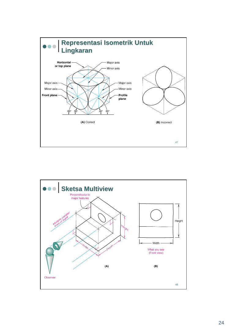
Representasi Isometrik Untuk
Lingkaran
47
Sketsa Multiview
48

25
Six Principles
Views
49
Jenis-jenis Garis
50
26
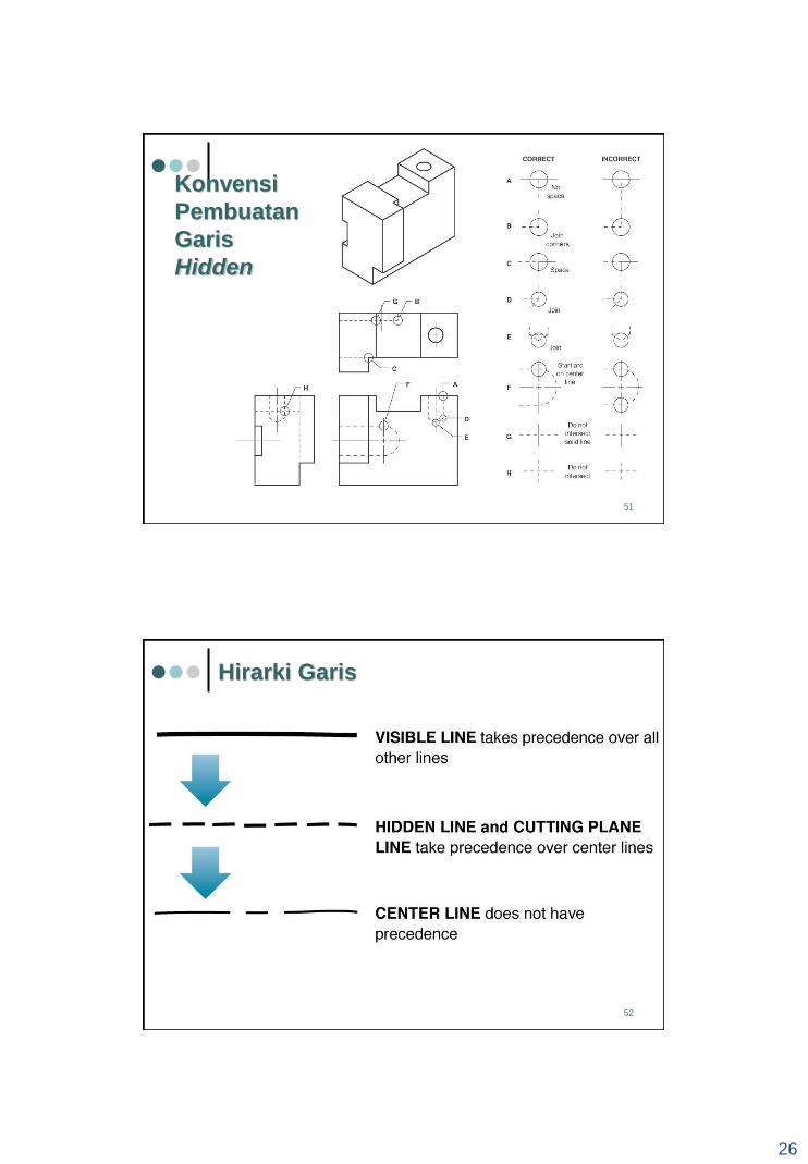
Konvensi
Pembuatan
Garis
Hidden
51
Hirarki Garis
52

27
Hirarki Garis
53
Aplikasi Center
Line
54

28
Konvensi Center Line
55
Tugas 1
Lihat board
http://forum.ti.itb.ac.id
56