ktk-product-guide-300.pdf - Allforbuildings
185
PRODUCT GUIDE G.I. INDUSTRIAL HOLDING S.p.A. participates in the ECC programme for LCP-HP, FCU and AHU. Check on-going validity of certificate: www.eurovent-certification.com or www.certiflash.com
-
Upload
khangminh22 -
Category
Documents
-
view
3 -
download
0
Transcript of ktk-product-guide-300.pdf - Allforbuildings

PR
OD
UC
T G
UID
E
VIS
IT w
ww
.ktk
.it
200K
TGP
2000
XB
XX
PR
OD
UC
T G
UID
E
G.I. INDUSTRIAL HOLDING S.p.A. participates in the ECC programme for LCP-HP, FCU and AHU. Check on-going validity of certificate: www.eurovent-certification.com or www.certiflash.com
G.I. INDUSTRIAL HOLDING S.p.A. is not responsible for possible errors of this catalogue and can change, without prior notice, the present data.
Via Max Piccini, 11/13 • 33061 RIVIGNANO TEOR • ITALYTel. +39 0432 823011 • Fax +39 0432 773855www.ktk.it • e-mail: [email protected]
Sales Offices:
Europe:
Via G. Ambrosio, 433053 LATISANA • ITALYTel. +39 0431 1967011 • Fax +39 0431 1967060www.gind.it • e-mail: [email protected]
Russia and other C.I.S. Countries:
REGUS AVION Business CenterLeningradskiy Prospect, 47/2125167 MOSCOW • RUSSIAN FEDERATIONTel. +7 495 139 46 39 • Fax. +7 495 139 46 39www.gind.it • e-mail: [email protected]
Production Plants:
Via Max Piccini, 11/1333061 RIVIGNANO TEOR • ITALY
Via G. Ambrosio, 433053 LATISANA • ITALY
Via J. Keplero, 2735028 PIOVE DI SACCO • ITALY
GIMEK Zrt - Rozália Park, 11H-2051 BIATORBÁGY • HUNGARYwww.gimek.hu
A Company of:
03.2019

CO
MP
AN
Y P
RO
FIL
E
1
.OUR IDENTITYCUSTOMIZED SOLUTIONS FOR 40 YEARS.
KTK KLIMATECHNIK, with its deep background of 40 years of experience, is a key worldwide brand of Air Conditioning and Process Cooling business, characterized by skilled know-how, flexibility and innovation.The strong point of KTK KLIMATECHNIK is indeed the possibility to offer focused, custom responses to highly specific needs, especially in large systems.Combining experience with advanced technology, innovative research and development solutions, KTK KLIMATECHNIK designs, manufactures and customizes a complete range of machines, especially dedicated to the industrial process and to the air conditioning of commercial and industrial environments.

.QUALITYTOTAL QUALITY: THE HEART OF OUR PHILOSOPHY.
The Company production, spreading over 4 European production plants, is divided between modern assembly lines and work islands.In both cases, the whole production process is subject to thorough checks and controls, both at the end and at intermediate steps. Each unit must go through strict testing, simulating operational conditions on the customer’s site even in the most demanding situations.Pressure, temperature, sound level, vibrations: every- thing is checked to make sure it complies with set parameters.The Service Network, relying on very skilled Profession-als, is available to carry out unit’s start-up on Customer’s premises to ensure the perfect unit’s functioning.
A FULLY CERTIFIED SYSTEM.
We believe in the Customer satisfaction and pursue this objective through the development of solutions to ensure the best performance over time and the maximum reliability of our products.The internationally recognized certifications can be summarized as follows:
•CE. It certifies that every unit leaving our production lines is built in accordance with the standards required by the European Union.
•BV. Certification for pressurised fluids which guarantees the correct implementation of cooling and hydraulic circuits in units with compressors.
•UNI EN ISO 9001. The first Italian Company in the sector to adhere to the programme in 1999, proving the special attention dedicated to the correct man-agement of the industrial process.
•EUROVENT. Attesting the reliability of Company data on product performance, it is a guarantee of the actual quality of KTK KLIMATECHNIK products and their characteristics.
2
KTK KLIMATECHNIK product ranges are compliant to ErP 2018 European Regulations.- ErP 2018 SEER. The Regulation n. 2016/2281 fixing precise efficiency standards for cooling only units.- ErP 2018 SCOP. The Regulation n. 813/2013 fixing precise efficiency standards for heat pump units.
ErP SCOPErP SEER
G.I. INDUSTRIAL HOLDING S.p.A. participates in the ECC programme for LCP-HP, FCU and AHU. Check on-going validity of certificate: www.eurovent-certification.com or www.certiflash.com

CO
MP
AN
Y P
RO
FIL
E
.ENVIRONMENTLOW GWP REFRIGERANT: HFO-R1234ze, R452B AND R513A.
In a market more and more concerned with environmental issues, KTK KLIMATECHNIK is able to provide the widest offer of liquid Chillers operating with low GWP refrigerants. The latest generation refrigerant HFO-R1234ze, with GWP<1 (Global Warming Potential), is the most environmentally sustainable refrigerant on the market to meet even the strictest international environmental regulations. KTK KLIMATECHNIK provides two new ranges of Aircooled or Watercooled liquid Chillers both with Turbocor or Screw compressors specially designed for HFO-R1234ze refrigerant.Moreover, the units in the catalogue with traditional R410A and R134a refrigerants can be supplied, on request, with low GWP alternatives, respectively R452B and R513A.
.INNOVATIONTHE HIGHEST EFFICIENCY.
The highest today’s challenge in HVAC business is ensuring maximum comfort with the lowest energy consumption. Thanks to its continuous research in new technical solutions, KTK KLIMATECHNIK offers its newest and widest high efficiency range characterized by A CLASS energy efficiency with the highest SEER/ESEER/IPLV/SCOP, including models with Scroll, Screw, Turbocor and Centrifugal compressors.
3GWP100AR5 = Global Warming Potential calculated over a 100-years period according to 5th Assessment Report (2014) of IPCC Institute.
R410A R452B
1924
676
R134a R513A
1300
647
HFO-R1234ze
<1

4
.THE STRENGHT OF A GLOBAL GROUPA MULTI-BRAND GROUP FOR THE WIDEST PRODUCT RANGE.
Created from the integration of industrial leading Com-panies operating from 40 years in various businesses of thermo-technical industry, G.I. INDUSTRIAL HOLDING is now a Global Group manufacturing and marketing a complete range of solutions for Comfort and Indu-strial Cooling: from Air Conditioning and Air Treatment of service and industrial environments, to Close Con-trol systems, to Industrial Process Cooling.G.I. INDUSTRIAL HOLDING can claim a wide knowledge of the HVAC field due to its long history and Group structure, where each branch has a deep know-how and a focused specialization.
CLINT brand is focused on the segment of liquid Chillers, Packaged Roof Top units and Fan Coil units.
KTK KLIMATECHNIK is the European top level brand focused on applications for Industrial Process Cooling and special Air Conditioning systems.
MONTAIR is the trademark dedicated to cooling systems for Data Centres and Telecom Applications.
NOVAIR is a leading brand in the Air Treatment and Ventilation sectors.

.THE GROUP STRUCTUREG.I. INDUSTRIAL HOLDING
The Company production is spread over 4 manufacturing plants in Italy and Hungary.The International markets are supported by 4 Sales Offices based in Italy, Russia, United Arab Emirates and Malaysia and a network of over 60 worldwide Distributors.
5
Sales Offices:•Latisana–ITALY.GroupHeadquarters,EuropeandNorth&SouthAfricaRegional
Office.•Moscow–RUSSIA.Russia&otherC.I.S.CountriesRegionalOffice.•Dubai–UNITEDARABEMIRATES(G.I.MIDDLEEASTFze).Middle-East&Central
Africa Regional Office.•Klang–MALAYSIA(G.I.INDUSTRIALASIAHOLDINGSdnBhd).AsiaPacificRegional
Office.
Manufacturing facilities:•Latisana-ITALY.Small&mediumliquidChillersManufacturingPlant.•RivignanoTeor-ITALY.LargeliquidChillersManufacturingPlant.•PiovediSacco-ITALY.CloseControlBusinessUnitandManufacturingPlant.•Biatorbágy-HUNGARY(GIMEKZrt).PackagedRoofTopunits,AirHandlingUnits,
Dry-Coolers and Fan Coil units Manufacturing Plant.
G.I. INDUSTRIAL HOLDING is a Company of the multinational G.I. HOLDING Group, which signed in 2017 a Strategic Collaboration agreement with the multinational FUJITSU GENERAL LIMITED, for joint development of dedicated product ranges of residential and commercial air conditioners.
Latisana – ITALY. G.I. HOLDING Headquarters, Europe and North & South Africa Regional Office and Production Plant.
CO
MP
AN
Y P
RO
FIL
E
Piove di Sacco – ITALY. Close Control Business Unit and Production Plant.
Rivignano Teor – ITALY. Production Plant. Biatorbágy – HUNGARY (GIMEK Zrt). Production Plant.

.REFERENCESDEDICATED SOLUTIONSFOR DIFFERENT APPLICATIONS.
OFFICE BUILDINGS & PLANTSROBERTBOSCHAutomotiveComponents,Reutlingen&Salzgitter, GermanyDAIMLERMERCEDES-BENZR&DCentre,Ulm,GermanyVOLKSWAGEN Emden Halle 18, Emden, GermanyMICHELIN Tires Plant, Karlsruhe, GermanySAPHeadquarters&ServiceCentre,Walldorf&St.Leon,GermanySWRTELEVISIONBroadcastingCentre,Baden-Baden,GermanyTÜV SÜD Quality Certification Institute, Mannheim, GermanyWMF Tableware, Geislingen, GermanySWISS PRIME PACK Plastic Packaging, Niederuzwil, SwitzerlandSWISSCOMOffices,Berna,SwitzerlandROLEX Headquarters, Genève, SwitzerlandFUNDERMAX Furniture Plant, Wiener Neudorf, AustriaROCHE DIAGNOSTICS Offices, Graz, AustriaLENZINGFIBERSChemicalCompany,HeiligenkreuzimLafnitztal, AustriaCHAMBEROFLABOUR,Villach,AustriaBÖHLERWELDING,Kapfenberg,AustriaTONSTUDIO SUNSHINE MUSIC Recording Studio, Wien, AustriaHÜBLHAUSTECHNIKBuildingDesign,Graz,Austria
SHOPPING MALLS, BUSINESS CENTRES & SHOWROOMSSCHULTHEISSQUARTIERShoppingMall&BusinessCentre,Berlin,GermanyAXELSPRINGERVERLAGBusinessCentre,Berlin,GermanyBÜROGEBÄUDEDBLISTERDREIECKBusinessCentre,Hannover, GermanyGALERIA KAUFHOF Shopping Mall, Hannover, GermanyKARSTADTOBERPOLLINGERShoppingMall,Munchen,GermanyCITYGATEBREMENShoppingMall&BusinessCentre,Bremen,GermanyKEPLER-QUARTIERResidential&BusinessCentre,Mannheim, GermanyMÖMAXFurnitureShoppingMall,Mannheim,GermanyDASA Working World Exhibition, Dortmund, GermanyLEBERSTRAßE20BusinessCentre,Wien,AustriaMERCEDES WITTWAR KONRAD Car Showroom, Graz, AustriaIMPULSZENTRUMBusinessCentre,Graz,Austria
6
REFERENCES

INDUSTRIAL PROCESS COOLING, DATA CENTRES AND LABORATORIESBISCHOF+KLEINPlasticPackagingCompany,Lengerich, GermanyROTTENDORF Pharmaceutical, Ennigerloh, GermanyWAYANDPlasticCompany,Idar-Oberstein,GermanyZAGZYKLOTRONRadioisotopesforMedicineandEngineering, Eggenstein-Leopoldshafen, GermanyEDELSTAHL ROSSWAG Steel Forging Components, Pfinztal, GermanyUSAIRFORCEMilitaryAirBaseDataCentre,Ramstein, GermanyMGBMIGROSDatacenter,Herdern,SwitzerlandTEOXANEBeautyLaboratories,Geneve,SwitzerlandEGGERÖSTERREICHERWoodPanelsPlant,St. Johann in Tirol, Austria
SCHOOLS AND UNIVERSITIESGEORG-AUGUSTGÖTTINGENUniversity,Göttingen,GermanyKIT University - KARLSRUHER INSTITUT FÜR TECHNOLOGIE, Karlsruhe, GermanyAACHEN University - CENTRE FOR WIND POWER DRIVES, Aachen, GermanyZURICHUniversity,Zurich,Switzerland HOSPITALS, HOTELS & RESIDENTIALKIT University Campus - KARLSRUHER INSTITUT FÜR TECHNOLOGIE Campus Nord, Eggenstein-Leopoldshafen, GermanyKLINIKUMLANDAU-SüdlicheWeinstraßeHospital,Landau, GermanyMOVENPICKREGENSDORFHotel,Zurich,SwitzerlandLAINZHospital,Wien,Austria
CO
MP
AN
Y P
RO
FIL
E
7

PRODUCTS
8
System lineRemote Condensers, Dry-Coolers and remote Hydronic Modules.
Upper linePackaged Roof Top units with single or double skin for medium and wide areas.
Top lineAircooled, watercooled and condenserless liquid Chillers for wide areas.
PRODUCT RANGEKTK KLIMATECHNIK offers a complete range of aircooled, watercooled and condenserless liquid Chillers and Heat Pumps especially dedicated to the industrial processes and customized air conditioning applications, with a wide capacity from 5 to 9000 kW. The offer also includes Packaged Roof Top units from 60 to 250 kW, Condensing units, Remote Condensers and Dry-Coolers.A wide range of models is also available with the low GWPrefrigerantsR452B,R513AandHFO-R1234ze.
Junior lineAircooled, watercooled and condenserless liquid Chillers for small and medium areas. Condensing units.

CO
MP
AN
Y P
RO
FIL
E
9
The MULTIPOWER liquid Chillers and Heat Pumps range is based on multi-Scroll technology. This ensures an high efficiency at partial load since the cooling power is split among the different compressors based on the actual need detected by the system.The family includes both aircooled and watercooled models withawidecapacity range,alsowithR452B refrigerant.
The ENERGYPOWER aircooled liquid Chillers provide airconditioning, ambient heating and domestic hot water at the same time and with the same unit.Those Multifunctional units for 4-Pipe systems are especially suitable for hotels, hospitals or multi-purpose buildings with service and residential users. Units feature Scroll or Screw compressorsandarealsoavailablewithR452BorR513Arefrigerant.
TheTURBOLINEaircooledandwatercooledliquidChillers, equipped with Turbocor Magnetic Levitation compressors, are at the top level in energy efficiency. The units feature the highest EER and SEER/ESEER in the market and the lowest starting current, in addition to maximum reliability and extra silent operation. The family also includes models with R513A or the innovative HFO-R1234ze refrigerant with GWP <1 (Global Warming Potential).
The CENTRITEK watercooled liquid Chillers are dedicated to extra-wide commercial or industrial areas. Units feature high capacity Centrifugal compressors, which ensure the key benefits of extremely high EER and SEER/ESEER, together with high reliability.
The AIRPLUS single skin packaged Roof Top units feature Scroll or Digital Scroll compressors and EC Inverter Plug-Fans.Units are also available with Free-Cooling technology with 2 or 3 dampers.
The AIRMAXI double skin packaged Roof Top units feature Scroll or Inverter Scroll compressors and radial fans or EC Inverter Plug-Fans.The wide range includes several sections for air mixing or Free-Cooling and the additional Heat Recovery with Cross-flow, WheelorThermodynamicCoil-Boosttechnology.
The AQUAPLUS aircooled, watercooled and condenserless range of liquid Chillers and Heat Pumps is the best solution for medium areas in commercial and service buildings.Compactness and easy installation are the key benefits of those units, which can also feature the additional AQUALO-GIK technology, a built-in hydronic kit with variable speed cir-culating pump which makes the use of inertial tank superflu-ous.ModelswithR452Brefrigerantarealsoavailable.
The MAXIPOWER aircooled, watercooled and condenserless liquid Chillers are equipped with latest generation Screw compressors. The high cooling capacity makes them suitable for comfort of wide areas and cooling of industrial processes.The family also includes models with R513A or the innovative HFO-R1234ze refrigerant with GWP <1 (Global Warming Potential).
The IDROINVERTER liquid Chillers and Heat Pumps range is based on Inverter technology applied overall on com-pressors, pumps and fans. Units are capable to adapt their power and energy consumption to every need, for the highest efficiency at partial load. The family includes both aircooled and watercooled models with a wide capacity range.
ThededicatedHeatPumpsoftheMIDYLINEseriesprovideambient heating, domestic hot water and air conditioning. Optimized for heating mode, the units can produce hot water up to 60 °C. The range features AQUALOGIK technology, a built-in hydronic kit with variable speed circulating pump which makes the use of inertial tank superfluous.

10
MODEL NAME DESCRIPTION
TWA/WP 212÷682 S/K/P/A
COMPRESSORS = ScrollS/I = Inverter ScrollS/T = Digital ScrollVV = ScrewVV/I = Inverter ScrewTT = Turbocor (Magnetic Levitation)CC = Centrifugal
REFRIGERANTK = R410AG = R452BY = R134aJ = R513AH = R1234zeZ = R407C
EVAPORATORP = Plate… = Shell and Tube
ENERGY CLASSA = A Class AF = Double A Class
VERSIONSWP = Reversible Heat PumpSL = SilencedSSL = Super-silencedSP = Tank and PumpST = AQUALOGIK technologyAP = High ESP fansEC = EC Inverter fansMS = Mixing BoxECO = EconomizerREC-FX = Cross-Flow Heat RecoveryREC-WH = Wheel Heat RecoveryMC = Microchannel condensing coilsDR = Operation with Dry-Cooler
SERIES LINEJ = JUNIOR LINE JWA = Aircooled liquid Chiller with axial fans JWR = Aircooled liquid Chiller with EC Inverter Plug-Fans JWH = Watercooled liquid Chiller JEE = Condenserless liquid Chiller JCA = Condensing unit with axial fans JCR = Condensing unit with radial fans
T = TOP LINE
TWA = Aircooled liquid Chiller TWH = Watercooled liquid Chiller TEE = Condenserless liquid Chiller
A, W or M = SYSTEM LINE ARC = Remote Condenser WRC = Dry-Cooler MR = Remote Hydronic Module
U = UPPER LINE URT = Packaged Roof Top unit
TWA WP 212÷682 S / K / P / A

CO
MP
AN
Y P
RO
FIL
E
11

PagePower (kW)
Heating
Cooling
12
CHAPTER 1 - JUNIOR LINE
JWA 7÷20 S/IK/P/A 0 125 250
A CLASS energy efficiency aircooled liquid Chillers and Heat Pumps with axial fans, Inverter Scroll compressor, plate exchanger and high efficiency EC Inverter circulator
6.0-22 kW
28 - 296.7-25 kW
JWA 24÷40 S/IK/P/A 0 125 250
A CLASS energy efficiency aircooled liquid Chillers and Heat Pumps with axial fans, Inverter Scroll compressor and plate exchanger
26-42kW
30 - 3129-48 kW
JWA/FC 24÷40 S/K/P 0 125 250
Aircooled liquid Chillers Free-Cooling with axial fans, Scroll compressor and plate exchanger
28-43 kW 32 - 33
-
JWR 7÷34 S/IK/P/A 0 125 250
A CLASS energy efficiency aircooled liquid Chillers and Heat Pumps with EC Inverter Plug-Fans, Inverter Scroll compressor and plate exchanger for indoor ducted installation
6.0-36 kW
34 - 356.7-40 kW
JWA 051÷172 S/IK/P/A 0 125 250
A CLASS energy efficiency aircooled liquid Chillers and Heat Pumps with axial fans, Inverter Scroll compressors and plate exchanger
50-179 kW
36 - 3755-195 kW
JWA 051÷172 S/K/P/AF 0 125 250
A CLASS energy efficiency aircooled liquid Chillers and Heat Pumps with axial fans, Scroll compressors and plate exchanger
51-183 kW 38 - 39
55-198 kW
JWA/WP 051÷172 S/K/P/A 0 125 250
A CLASS energy efficiency aircooled reversible Heat Pumps withaxial fans, Scroll compressors and plate exchanger
56-197 kW 40 - 41
48-161 kW

LEGENDA
Version Compressor Fan Exchanger Solution Refrigerant
Cooling only
Rotary
Axial
Plate
4-Pipe system
R410A
Heating only
Inverter Scroll
Radial
Shell and Tube
Web Monitoring R452B
Cooling & Heating
Digital Scroll High ESP Radial
Flooded Shell and Tube
Silenced
R134A
Scroll
EC Inverter Plug-Fan
Microchannel
Super silenced R513A
Inverter Screw Single Skin
R1234ze
Screw
Double Skin
R407C
Turbocor Solution
Mixing Box
H²O
Inverter Centrifugal
Free-Cooling
Economizer
Centrifugal Domestic Hot Water Economizer and ThermodynamicCoil-Boost Heat Recovery
AquaLogik Economizer andCross-flow Heat Recovery
A Class Cooling
Economizer andWheel Heat Recovery
A Class Heating
PagePower (kW)
Heating
Cooling 1234
13
CHAPTER 1 - JUNIOR LINE
JWA 051÷172 S/K/P 0 125 250
Aircooled liquid Chillers and Heat Pumps with axial fans,Scroll compressors and plate exchanger
48-178 kW 42 - 43
54-187 kW
JWA/FC 051÷172 S/K/P 0 125 250
Aircooled liquid Chillers Free-Cooling with axial fans,Scroll compressors and plate exchanger
53-174 kW 44 - 45
-
JWA 051÷172 S/K 0 125 250
Aircooled liquid Chillers and Heat Pumps with axial fans,Scroll compressors and shell and tube exchanger
49-179 kW 46 - 47
56-188 kW
JWA/E 071÷182 S/K/P 0 125 250
Aircooled liquid Chillers with axial fans, Scroll compressorsand plate exchanger
65-180 kW 48 - 49
-
JWA/ML/ST 11÷18 S/Z/P 0 125 250
A CLASS energy efficiency aircooled dedicated Heat Pumps with domestic hot water production, axial fans, Scroll compressor,plate exchanger and hydronic kit
11-23 kW
50 - 517.3-16 kW
PagePower (kW)
Heating
Cooling
14
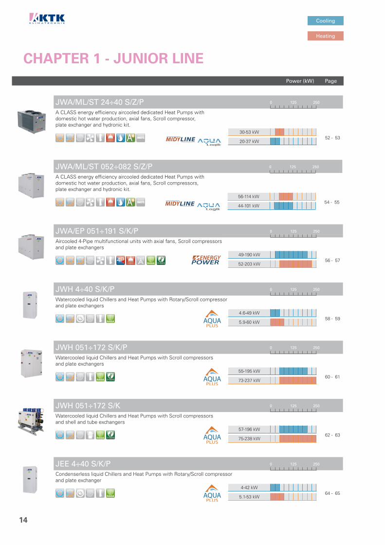
CHAPTER 1 - JUNIOR LINE
JWA/ML/ST 24÷40 S/Z/P 0 125 250
A CLASS energy efficiency aircooled dedicated Heat Pumps with domestic hot water production, axial fans, Scroll compressor,plate exchanger and hydronic kit.
30-53 kW
52 - 5320-37 kW
JWA/ML/ST 052÷082 S/Z/P 0 125 250
A CLASS energy efficiency aircooled dedicated Heat Pumps with domestic hot water production, axial fans, Scroll compressors,plate exchanger and hydronic kit.
56-114 kW
54 - 5544-101 kW
JWA/EP 051÷191 S/K/P 0 125 250
Aircooled 4-Pipe multifunctional units with axial fans, Scroll compressors and plate exchangers
49-190 kW
56 - 5752-203 kW
JWH 4÷40 S/K/P 0 125 250
Watercooled liquid Chillers and Heat Pumps with Rotary/Scroll compressorand plate exchangers
4.6-49 kW 58 - 59
5.9-60 kW
JWH 051÷172 S/K/P 0 125 250
Watercooled liquid Chillers and Heat Pumps with Scroll compressors and plate exchangers
55-195 kW 60 - 61
73-237 kW
JWH 051÷172 S/K 0 125 250
Watercooled liquid Chillers and Heat Pumps with Scroll compressors and shell and tube exchangers
57-196 kW 62 - 63
75-238 kW
JEE 4÷40 S/K/P 0 125 250
Condenserless liquid Chillers and Heat Pumps with Rotary/Scroll compressorand plate exchanger
4-42 kW 64 - 65
5.1-53 kW

LEGENDA
Version Compressor Fan Exchanger Solution Refrigerant
Cooling only
Rotary
Axial
Plate
4-Pipe system
R410A
Heating only
Inverter Scroll
Radial
Shell and Tube
Web Monitoring R452B
Cooling & Heating
Digital Scroll High ESP Radial
Flooded Shell and Tube
Silenced
R134A
Scroll
EC Inverter Plug-Fan
Microchannel
Super silenced R513A
Inverter Screw Single Skin
R1234ze
Screw
Double Skin
R407C
Turbocor Solution
Mixing Box
H²O
Inverter Centrifugal
Free-Cooling
Economizer
Centrifugal Domestic Hot Water Economizer and ThermodynamicCoil-Boost Heat Recovery
AquaLogik Economizer andCross-flow Heat Recovery
A Class Cooling
Economizer andWheel Heat Recovery
A Class Heating
PagePower (kW)
Heating
Cooling 1234
15
JEE 051÷172 S/K/P 0 125 250
Condenserless liquid Chillers and Heat Pumps with Scroll compressors and plate exchanger
51-176 kW 66 - 67
60-194 kW
CHAPTER 1 - JUNIOR LINE
JCA 4÷40 S/K 0 125 250
Aircooled condensing units and reversible condensing units withaxial fans and Rotary/Scroll compressor
4.5-46 kW 68 - 69
4.8-52 kW
JCA 051÷172 S/K 0 125 250
Aircooled condensing units and reversible condensing units withaxial fans and Scroll compressors
51-188 kW 70 - 71
56-193 kW
JCR 4÷34 S/K 0 125 250
Aircooled condensing units and reversible condensing units withradial fans and Rotary/Scroll compressor for indoor ducted installation
4.5-37 kW 72 - 73
4.8-41 kW
JCR 051÷172 S/K 0 125 250
Aircooled condensing units and reversible condensing units withradial fans and Scroll compressors
51-188 kW 74 - 75
56-193 kW

PagePower (kW)
Heating
Cooling
16
CHAPTER 2 - TOP LINE
TWA 202÷702 S/IK/P/A 160 800 1600
A CLASS energy efficiency aircooled liquid Chillers and Heat Pumps with axial fans, Inverter Scroll compressors and plate exchanger
198-668 kW
78 - 79214-728 kW
TWA 212÷682 S/K/P/AF 160 800 1600
A CLASS energy efficiency aircooled liquid Chillers and Heat Pumps with axial fans, Scroll compressors and plate exchanger
197-692 kW
80 - 81214-754 kW
TWA/WP 212÷682 S/K/P/A 160 800 1600
A CLASS energy efficiency aircooled reversible Heat Pumps withaxial fans, Scroll compressors and plate exchanger
227-762 kW
82 - 83194-671 kW
TWA 212÷1102 S/K/P 160 800 1600
Aircooled liquid Chillers and Heat Pumps with axial fans,Scroll compressors and plate exchanger
199-1051 kW
84 - 85228-1210 kW
TWA/FC 212÷1102 S/K/P 160 800 1600
Aircooled liquid Chillers Free-Cooling with axial fans,Scroll compressors and plate exchanger
208-1102 kW
86 - 87-
TWA 212÷1102 S/K 160 800 1600
Aircooled liquid Chillers and Heat Pumps with axial fans,Scroll compressors and shell and tube exchanger
200-1062 kW
88 - 89229-1222 kW
TWA 202÷1352 VV/H/A 160 800 1600
A CLASS energy efficiency aircooled liquid Chillers with axial fans, (Inverter) Screw compressors and shell and tube exchanger
197-1353 kW
90 - 91-
LEGENDA
Version Compressor Fan Exchanger Solution Refrigerant
Cooling only
Rotary
Axial
Plate
4-Pipe system
R410A
Heating only
Inverter Scroll
Radial
Shell and Tube
Web Monitoring R452B
Cooling & Heating
Digital Scroll High ESP Radial
Flooded Shell and Tube
Silenced
R134A
Scroll
EC Inverter Plug-Fan
Microchannel
Super silenced R513A
Inverter Screw Single Skin
R1234ze
Screw
Double Skin
R407C
Turbocor Solution
Mixing Box
H²O
Inverter Centrifugal
Free-Cooling
Economizer
Centrifugal Domestic Hot Water Economizer and ThermodynamicCoil-Boost Heat Recovery
AquaLogik Economizer andCross-flow Heat Recovery
A Class Cooling
Economizer andWheel Heat Recovery
A Class Heating
PagePower (kW)
Heating
Cooling 1234
17
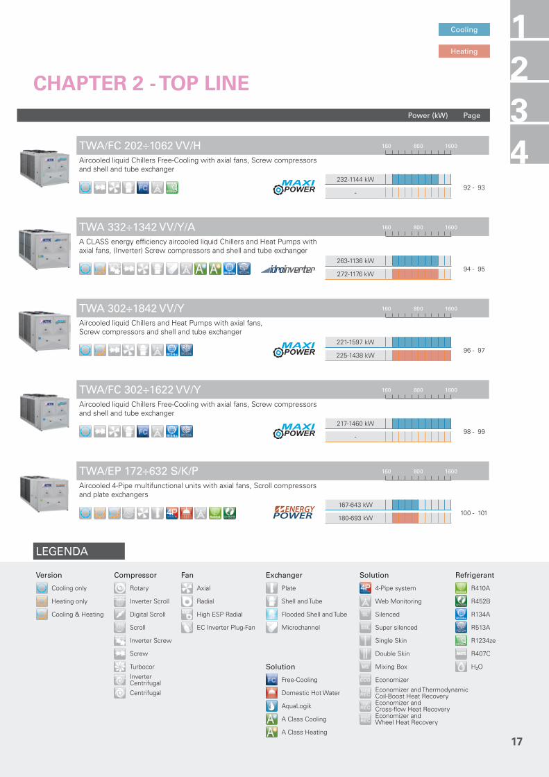
CHAPTER 2 - TOP LINE
TWA/FC 202÷1062 VV/H 160 800 1600
Aircooled liquid Chillers Free-Cooling with axial fans, Screw compressors and shell and tube exchanger
232-1144 kW
92 - 93-
TWA 332÷1342 VV/Y/A 160 800 1600
A CLASS energy efficiency aircooled liquid Chillers and Heat Pumps with axial fans, (Inverter) Screw compressors and shell and tube exchanger
263-1136 kW
94 - 95272-1176 kW
TWA 302÷1842 VV/Y 160 800 1600
Aircooled liquid Chillers and Heat Pumps with axial fans,Screw compressors and shell and tube exchanger
221-1597 kW
96 - 97225-1438 kW
TWA/FC 302÷1622 VV/Y 160 800 1600
Aircooled liquid Chillers Free-Cooling with axial fans, Screw compressors and shell and tube exchanger
217-1460 kW
98 - 99-
TWA/EP 172÷632 S/K/P 160 800 1600
Aircooled 4-Pipe multifunctional units with axial fans, Scroll compressors and plate exchangers
167-643 kW
100 - 101180-693 kW

PagePower (kW)
Heating
Cooling
18
CHAPTER 2 - TOP LINE
TWA/EP 362÷1492 VV/Y 160 800 1600
Aircooled 4-Pipe multifunctional units with axial fans,(Inverter) Screw compressors and shell and tube exchangers
278-1133 kW
102 - 103283-1156 kW
TWA 281÷1432 TT/H 160 800 1600
A CLASS energy efficiency aircooled liquid Chillers with axial fans,Turbocor (magnetic levitation) compressors and flooded shell and tube exchanger
262-1340 kW
104 - 105-
TWA/FC 281÷1432 TT/H 160 800 1600
Aircooled liquid Chillers Free-Cooling with axial fans,Turbocor (magnetic levitation) compressors and flooded shell and tube exchanger
279-1386 kW
106 - 107-
TWA 251÷1502 TT/Y 160 800 1600
A CLASS energy efficiency aircooled liquid Chillers with axial fans,Turbocor (magnetic levitation) compressors and flooded shell and tube exchanger
248-1456 kW
108 - 109-
TWA/FC 251÷1502 TT/Y 160 800 1600
Aircooled liquid Chillers Free-Cooling with axial fans,Turbocor (magnetic levitation) compressors and flooded shell and tube exchanger
246-1443 kW
110 - 111-
TWH 212÷1102 S/K/P 160 800 1600
Watercooled liquid Chillers and Heat Pumps with Scroll compressors and plate exchangers
224-1242 kW
112 - 113290-1531 kW
TWH 212÷1102 S/K 160 800 1600
Watercooled liquid Chillers and Heat Pumps with Scroll compressors and shell and tube exchangers
225-1254 kW
114 - 115291-1546 kW

LEGENDA
Version Compressor Fan Exchanger Solution Refrigerant
Cooling only
Rotary
Axial
Plate
4-Pipe system
R410A
Heating only
Inverter Scroll
Radial
Shell and Tube
Web Monitoring R452B
Cooling & Heating
Digital Scroll High ESP Radial
Flooded Shell and Tube
Silenced
R134A
Scroll
EC Inverter Plug-Fan
Microchannel
Super silenced R513A
Inverter Screw Single Skin
R1234ze
Screw
Double Skin
R407C
Turbocor Solution
Mixing Box
H²O
Inverter Centrifugal
Free-Cooling
Economizer
Centrifugal Domestic Hot Water Economizer and ThermodynamicCoil-Boost Heat Recovery
AquaLogik Economizer andCross-flow Heat Recovery
A Class Cooling
Economizer andWheel Heat Recovery
A Class Heating
PagePower (kW)
Heating
Cooling 1234
19
TWH 202÷1352 VV/H/A 160 800 1600
A CLASS energy efficiency watercooled liquid Chillers with(Inverter) Screw compressors and shell and tube exchangers
234-1650 kW
116 - 117-
CHAPTER 2 - TOP LINE
TWH 321÷1321 VV/Y/A 160 800 1600
A CLASS energy efficiency watercooled liquid Chillers with(Inverter) Screw compressors and flooded shell and tube exchangers
280-1289 kW
118 - 119-
TWH 322÷2583 VV/Y 160 800 1600
Watercooled liquid Chillers with Screw compressors andshell and tube exchangers
267-2473 kW
120 - 121-
TEE 322÷2583 VV/Y 160 800 1600
Condenserless liquid Chillers with Screw compressors andshell and tube exchanger
235-2168 kW
122 - 123-
TWH 341÷2061 TT/H 160 800 1600
A CLASS energy efficiency watercooled liquid Chillers with Turbocor (magnetic levitation) compressors and flooded shell and tube exchangers for cooling tower operation
321-1922 kW
124 - 125-

PagePower (kW)
Heating
Cooling
20
CHAPTER 2 - TOP LINE
TWH/DR 341÷2061 TT/H 160 800 1600
A CLASS energy efficiency watercooled liquid Chillers with Turbocor (magnetic levitation) compressors and flooded shell and tube exchangers for Dry-Cooler operation
301-1802 kW
126 - 127-
TWH 291÷4061 TT/Y 160 800 1600
A CLASS energy efficiency watercooled liquid Chillers with Turbocor (magnetic levitation) compressors and flooded shell and tube exchangers for cooling tower operation
319-3912 kW
128 - 129-
TWH/DR 291÷1541 TT/Y 160 800 1600
A CLASS energy efficiency watercooled liquid Chillers with Turbocor (magnetic levitation) compressors and flooded shell and tube exchangers for Dry-Cooler operation
298-1584 kW
130 - 131-
TWH 1601÷8302 CC/Y 160 800 1600
A CLASS energy efficiency watercooled liquid Chillers with(Inverter) centrifugal compressors and flooded shell and tube exchangers
1050-9000 kW
132 - 133-

LEGENDA
Version Compressor Fan Exchanger Solution Refrigerant
Cooling only
Rotary
Axial
Plate
4-Pipe system
R410A
Heating only
Inverter Scroll
Radial
Shell and Tube
Web Monitoring R452B
Cooling & Heating
Digital Scroll High ESP Radial
Flooded Shell and Tube
Silenced
R134A
Scroll
EC Inverter Plug-Fan
Microchannel
Super silenced R513A
Inverter Screw Single Skin
R1234ze
Screw
Double Skin
R407C
Turbocor Solution
Mixing Box
H²O
Inverter Centrifugal
Free-Cooling
Economizer
Centrifugal Domestic Hot Water Economizer and ThermodynamicCoil-Boost Heat Recovery
AquaLogik Economizer andCross-flow Heat Recovery
A Class Cooling
Economizer andWheel Heat Recovery
A Class Heating
PagePower (kW)
Heating
Cooling 1234
21
CHAPTER 3 - SYSTEM LINE
ARC 1111÷4222 K 0 0 0
Remote aircooled Condensers with axial fans
- 136 - 137
-
ARC/SL 1111÷4222 K 0 0 0
Silenced Remote aircooled Condensers with axial fans
- 138 - 139
-
ARC/SSL 2111÷4222 K 0 0 0
Super silenced Remote aircooled Condensers with axial fans
- 140 - 141
-
ARC 4141÷5282 Y 0 0 0
Remote aircooled Condensers with axial fans
- 142 - 143
-
ARC/SL 4231÷5282 Y 0 0 0
Silenced Remote aircooled Condensers with axial fans
- 144 - 145
-
ARC/SSL 4151÷5281 Y 0 0 0
Super silenced Remote aircooled Condensers with axial fans
- 146 - 147
-

PagePower (kW)
Heating
Cooling
22
CHAPTER 3 - SYSTEM LINE
WRC 3121÷5282 0 0 0
Dry-Coolers with axial fans
- 148 - 149
-
WRC/SL 3122÷5281 0 0 0
Silenced Dry-Coolers with axial fans
- 150 - 151
-
WRC/SSL 3132÷5282 0 0 0
Super silenced Dry-Coolers with axial fans
- 152 - 153
-
MR 50÷80 0 0 0
Remote Hydronic Modules
- 154 - 155
-
MR 1500÷2500 0 0 0
Remote Hydronic Modules with pump kit
- 156 - 157
-
LEGENDA
Version Compressor Fan Exchanger Solution Refrigerant
Cooling only
Rotary
Axial
Plate
4-Pipe system
R410A
Heating only
Inverter Scroll
Radial
Shell and Tube
Web Monitoring R452B
Cooling & Heating
Digital Scroll High ESP Radial
Flooded Shell and Tube
Silenced
R134A
Scroll
EC Inverter Plug-Fan
Microchannel
Super silenced R513A
Inverter Screw Single Skin
R1234ze
Screw
Double Skin
R407C
Turbocor Solution
Mixing Box
H²O
Inverter Centrifugal
Free-Cooling
Economizer
Centrifugal Domestic Hot Water Economizer and ThermodynamicCoil-Boost Heat Recovery
AquaLogik Economizer andCross-flow Heat Recovery
A Class Cooling
Economizer andWheel Heat Recovery
A Class Heating
PagePower (kW)
Heating
Cooling 1234
23
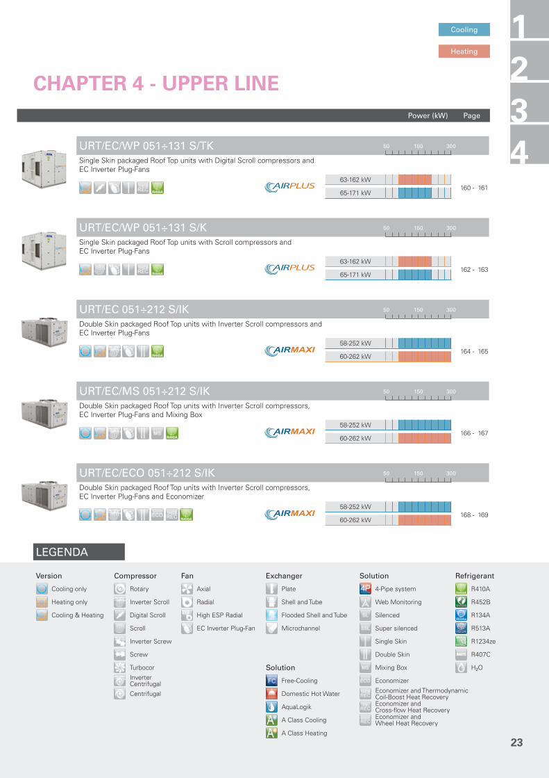
CHAPTER 4 - UPPER LINE
URT/EC/WP 051÷131 S/TK 50 150 300
Single Skin packaged Roof Top units with Digital Scroll compressors and EC Inverter Plug-Fans
63-162 kW
160 - 16165-171 kW
URT/EC/WP 051÷131 S/K 50 150 300
Single Skin packaged Roof Top units with Scroll compressors andEC Inverter Plug-Fans
63-162 kW
162 - 16365-171 kW
URT/EC 051÷212 S/IK 50 150 300
Double Skin packaged Roof Top units with Inverter Scroll compressors andEC Inverter Plug-Fans
58-252 kW
164 - 16560-262 kW
URT/EC/MS 051÷212 S/IK 50 150 300
Double Skin packaged Roof Top units with Inverter Scroll compressors, EC Inverter Plug-Fans and Mixing Box
58-252 kW
166 - 16760-262 kW
URT/EC/ECO 051÷212 S/IK 50 150 300
Double Skin packaged Roof Top units with Inverter Scroll compressors, EC Inverter Plug-Fans and Economizer
58-252 kW
168 - 16960-262 kW

PagePower (kW)
Heating
Cooling
24
CHAPTER 4 - UPPER LINE
URT/EC/ECO/REC-FX 051÷212 S/IK 50 150 300
Double Skin packaged Roof Top units with Inverter Scroll compressors, EC Inverter Plug-Fans, Economizer and Cross-flow Heat Recovery
58-252 kW
170 - 17160-262 kW
URT/EC/ECO/REC-WH 051÷212 S/IK 50 150 300
Double Skin packaged Roof Top units with Inverter Scroll compressors, EC Inverter Plug-Fans, Economizer and Wheel Heat Recovery
58-252 kW
172 - 17360-262 kW
URT 051÷212 S/K 50 150 300
Double Skin packaged Roof Top units with Scroll compressorsand radial fans or EC Inverter Plug-Fans
58-252 kW
174 - 17560-262 kW
URT/MS 051÷212 S/K 50 150 300
Double Skin packaged Roof Top units with Scroll compressors,radial fans or EC Inverter Plug-Fans and Mixing Box
58-252 kW
176 - 17760-262 kW
URT/ECO 051÷212 S/K 50 150 300
Double Skin packaged Roof Top units with Scroll compressors,radial fans or EC Inverter Plug-Fans and Economizer
58-252 kW
178 - 17960-262 kW
URT/ECO/REC-FX 051÷212 S/K 50 150 300
Double Skin packaged Roof Top units with Scroll compressors,radial fans or EC Inverter Plug-Fans, Economizer and Cross-flow Heat Recovery
58-252 kW
180 - 18160-262 kW
URT/ECO/REC-WH 051÷212 S/K 50 150 300
Double Skin packaged Roof Top units with Scroll compressors, radial fans or EC Inverter Plug-Fans, Economizer and Wheel Heat Recovery
58-252 kW
182 - 18360-262 kW

LEGENDA
Version Compressor Fan Exchanger Solution Refrigerant
Cooling only
Rotary
Axial
Plate
4-Pipe system
R410A
Heating only
Inverter Scroll
Radial
Shell and Tube
Web Monitoring R452B
Cooling & Heating
Digital Scroll High ESP Radial
Flooded Shell and Tube
Silenced
R134A
Scroll
EC Inverter Plug-Fan
Microchannel
Super silenced R513A
Inverter Screw Single Skin
R1234ze
Screw
Double Skin
R407C
Turbocor Solution
Mixing Box
H²O
Inverter Centrifugal
Free-Cooling
Economizer
Centrifugal Domestic Hot Water Economizer and ThermodynamicCoil-Boost Heat Recovery
AquaLogik Economizer andCross-flow Heat Recovery
A Class Cooling
Economizer andWheel Heat Recovery
A Class Heating
1234
25

26

27
1234 JU
NIO
R L
INE
CH
AP
TE
R 1
- J
UN
IOR
LIN
E
1
Aircooled, Watercooled & Condenserless liquid Chillers and Heat Pumps for small and medium areas. Condensing units.
JWA 7÷20 S/IK/P/A 28 - 29JWA 24÷40 S/IK/P/A 30 - 31JWA/FC 24÷40 S/K/P 32 - 33JWR 7÷34 S/IK/P/A 34 - 35JWA 051÷172 S/IK/P/A 36 - 37JWA 051÷172 S/K/P/AF 38 - 39JWA/WP 051÷172 S/K/P/A 40 - 41JWA 051÷172 S/K/P 42 - 43JWA/FC 051÷172 S/K/P 44 - 45JWA 051÷172 S/K 46 - 47JWA/E 071÷182 S/K/P 48 - 49JWA/ML/ST 11÷18 S/Z/P 50 - 51JWA/ML/ST 24÷40 S/Z/P 52 - 53JWA/ML/ST 052÷082 S/Z/P 54 - 55JWA/EP 051÷191 S/K/P 56 - 57JWH 4÷40 S/K/P 58 - 59JWH 051÷172 S/K/P 60 - 61JWH 051÷172 S/K 62 - 63JEE 4÷40 S/K/P 64 - 65JEE 051÷172 S/K/P 66 - 67JCA 4÷40 S/K 68 - 69JCA 051÷172 S/K 70 - 71JCR 4÷34 S/K 72 - 73JCR 051÷172 S/K 74 - 75

28
JWA 7÷20 S/IK/P/AA CLASS ENERGY EFFICIENCY AIRCOOLED LIQUID CHILLERS AND HEAT PUMPS WITH AXIAL FANS, INVERTER SCROLL COMPRESSOR, PLATE EXCHANGER AND HIGH EFFICIENCY EC INVERTER CIRCULATOR.
The JWA 7÷20 S/IK/P/A series is the winning choice for ideal comfort in residential and commercial environments. The range, in A CLASS energy efficiency, features Inverter technology on the compressor, for an high efficiency at partial loads. The range excels for its compact sizes, quietness and optimised water circuit, on a peraluman structure. Particular design features enable immediate and effective use, easy installation and lasting reliability. These extremely compact and high-tech units offer you ideal comfort in all seasons.The unit features high efficiency integrated circulator with EC Inverter brushless electronic motor.The Heat Pump version is designed for hot water production up to 55°C.
The units are already compliant to ErP 2021 European Regulations.
FROM 6.0 KW TO 22 KW.
VERSION
JWACooling only
JWA/WPReversible Heat Pump
FEATURES
• Structure with supporting frame, in peraluman, galvanized sheet and with rubber shock absorbers on the frame.
• DC INVERTER Scroll compressor with internal overheat protection and crankcase heater.• Axial fans with low ventilation and special wing profile, directly coupled to external rotor motors.• Condenser made of copper tubes and aluminium finned coil, complete with drain pan for WP
version only.• Evaporator AISI 316 stainless steel braze welded plates type, complete with water differential
pressure switch. On the Heat Pump units it is always installed an antifreeze heater.• Electronic expansion valve.• R410A refrigerant.• Electrical board includes: main switch with door lock device, fuses, compressor and pump remote
control switch.• Condensing Control is included: electronic proportional device that ensures efficient and
continuous functioning of the unit with outside air temperature down to –20 °C in cooling mode. It also allows to reduce the sound level especially at night. It consists of a fans speed controller with continuous speed regulation and high and low pressure transducers on cooling circuit.
• Functioning in heating mode with outside air temperature down to -15 °C.• Water circuit includes: water differential pressure switch, high efficiency EC Inverter circulator,
safety valve and expansion vessel.• High efficiency circulator with EC Inverter brushless electronic motor with 3 speeds selectable by
the user.• Microprocessor control and regulation system.
ACCESSORIES
FACTORY FITTED ACCESSORIES:
TX Coil with pre-coated finsFE Antifreeze heater for evaporator
LOOSE ACCESSORIES:
CR Remote control panelIS Modbus RTU protocol, RS485 serial
interfaceRP Coils protection metallic guardsFP Coils protection metallic guards
with filter

29
CLEARANCE AREA
1234
Electrical board side
TECHNICAL DATA - JWA 7÷20 S/IK/P/AMODEL 7 9 11 14 16 18 20
CoolingCooling capacity (1) kW 6.0 7.6 9.3 12.4 15.7 19.0 22.4Absorbed power (1) kW 1.8 2.4 3.0 3.8 4.9 6.0 7.2EER (1) 3.33 3.17 3.10 3.26 3.20 3.17 3.11
Cooling (EN14511)
Cooling capacity (1) kW 6.0 7.6 9.3 12.4 15.6 18.9 22.5Absorbed power (1) kW 1.8 2.4 3.0 3.8 4.9 6.0 7.2EER (1) 3.33 3.17 3.10 3.26 3.18 3.15 3.13ESEER 4.61 4.29 4.25 4.84 4.82 4.76 4.56EUROVENT Class A A A A A A ASEER (2) 4.12 4.11 4.10 4.68 4.74 4.71 4.72Energy Efficiency (2) % 162 161 161 184 187 185 186
HeatingHeating capacity (3) kW 6.7 8.8 10.9 14.1 17.5 20.9 24.8Absorbed power (3) kW 1.9 2.5 3.2 4.0 4.9 5.9 7.0COP (3) 3.53 3.52 3.41 3.53 3.57 3.54 3.54
Heating (EN14511)
Heating capacity (3) kW 6.7 8.8 10.9 14.1 17.5 20.9 24.8Absorbed power (3) kW 1.9 2.5 3.2 4.0 4.9 5.9 7.0COP (3) 3.53 3.52 3.41 3.53 3.57 3.54 3.54EUROVENT Class A A A A A A ASCOP (4) 3.49 3.34 3.45 3.42 3.56 3.60 3.85Energy Efficiency (4) % 136 131 135 134 139 141 151Energy Class (4) A+ A+ A+ A+ A+ A+ A++
Compressor Quantity n° 1 1 1 1 1 1 1
Electrical characteristics
Power supply V/Ph/Hz 230/1/50 400/3+N/50Max. running current A 16 16 16 13 13 15 18Max. starting current A 10 10 10 8 8 9 10
Water circuitWater flow l/s 0.29 0.36 0.44 0.59 0.75 0.91 1.07Pump available static pressure kPa 53 56 52 76 82 70 60Water connections ”G 1” 1” 1” 1”1/4 1”1/4 1”1/4 1”1/4
Sound pressure (5) dB(A) 49 49 52 53 53 53 53
WeightsTransport weight Kg 101 113 123 195 197 199 201Operating weight Kg 126 138 148 245 247 249 251
DIMENSIONSMODEL 7 9 11 14 16 18 20L STD mm 870 870 870 1160 1160 1160 1160W STD mm 320 320 320 500 500 500 500H STD mm 1100 1100 1100 1270 1270 1270 1270
ErP SCOPErP SEER
NOTES1. Chilled water from 12 to 7 °C, ambient air temperature 35 °C.2. Seasonal energy efficiency of cooling at low temperature. According to EU
Regulation n. 2016/2281.3. Heated water from 40 to 45 °C, ambient air temperature 7 °C d.b./6 °C w.b.4. Seasonal energy efficiency of heating at low temperature with average climatic
conditions. According to EU Regulation n. 811/2013.5. Sound pressure level measured in free field conditions at 1 m from the unit.
According to ISO 3744.N.B. Weights of WP version are specified on technical brochure.
1
JUN
IOR
LIN
E
JWA 7÷11 S/IK/P/A
200 200 800 200
JWA 14÷20 S/IK/P/A
200 200 800 200

30
JWA 24÷40 S/IK/P/AA CLASS ENERGY EFFICIENCY AIRCOOLED LIQUID CHILLERS AND HEAT PUMPS WITH AXIAL FANS, INVERTER SCROLL COMPRESSOR AND PLATE EXCHANGER.
The liquid Chillers and Heat Pumps of the JWA 24÷40 S/IK/P/A series, with R410A refrigerant, are designed to satisfy the needs of small and medium domestic and service sector environments.With a peraluman structure corrosion-resistant over time, these units can be combined with Fan Coil units or with intermediate heat exchangers for process cooling applications.All units feature A CLASS energy efficiency and are equipped with Inverter control on Scroll compressor for a better efficiency at partial loads (SEER/ESEER/IPLV/SCOP). The Microchannel condensing coil, available on the dedicated version, ensures an even higher efficiency (high EER), having a better heat exchange than traditional coils.A wide range of accessories, factory fitted or supplied separately, complete the outstanding versatility and functionality of the series.The Heat Pump version is designed for hot water production up to 55°C.
The units are already compliant to ErP 2021 European Regulations.
FROM 26 KW TO 42 KW.
VERSION
JWACooling only
JWA/MCCooling only with MICROCHANNEL condensing coil
JWA/WPReversible Heat Pump
FEATURES
• Structure with supporting frame, in peraluman and galvanized sheet.• DC INVERTER Scroll compressor with oil sight glass, internal overheat protection and crankcase heater.• Axial fans with low ventilation and special wing profile, directly coupled to external rotor motors.• Condenser made of copper tube and aluminum finned coils or aluminium MICROCHANNEL coils.• Evaporator AISI 316 stainless steel braze welded plates type, complete with water differential
pressure switch. On the Heat Pump units it is always installed an antifreeze heater.• Electronic expansion valve.• R410A refrigerant.• Electrical board includes: main switch with door lock device, fuses and pump remote control switch.• Condensing Control is included: electronic proportional device that ensures efficient and
continuous functioning of the unit with outside air temperature down to –20 °C in cooling mode. It also allows to reduce the sound level especially at night. It consists of a fans speed controller with continuous speed regulation and high and low pressure transducers on cooling circuit.
• Functioning in heating mode with outside air temperature down to -15 °C.• Microprocessor control and regulation system.
ACCESSORIES
FACTORY FITTED ACCESSORIES:
BT Low water temperature kitTX Coil with pre-coated finsTXB Coil with epoxy treatmentPS Single circulating pumpFE Antifreeze heater for evaporator
LOOSE ACCESSORIES:
CR Remote control panelIS Modbus RTU protocol, RS485 serial
interfaceRP Coils protection metallic guardsFP Coils protection metallic guards
with filterAG Rubber shock absorbers

31
CLEARANCE AREA
1234
Electrical board side
TECHNICAL DATA - JWA 24÷40 S/IK/P/AMODEL 24 27 34 40
Cooling STD versions
Cooling capacity (1) kW 25.8 30.5 35.9 42.3Absorbed power (1) kW 8.0 9.5 11.3 13.4EER (1) 3.23 3.21 3.18 3.16
Cooling STD versions (EN14511)
Cooling capacity (1) kW 25.6 30.3 35.7 42.1Absorbed power (1) kW 8.1 9.7 11.5 13.6EER (1) 3.16 3.12 3.10 3.10ESEER 4.57 4.31 4.31 4.27EUROVENT Class A A A ASEER (2) 4.42 4.16 4.21 4.22Energy Efficiency (2) % 174 163 165 166
Cooling MC versions
Cooling capacity (1) kW 25.8 30.5 35.9 42.3Absorbed power (1) kW 7.9 9.4 11.2 13.3EER (1) 3.27 3.24 3.21 3.18
Cooling MC versions (EN14511)
Cooling capacity (1) kW 25.6 30.3 35.7 42.1Absorbed power (1) kW 8.0 9.6 11.4 13.5EER (1) 3.20 3.16 3.13 3.12ESEER 4.63 4.36 4.36 4.32EUROVENT Class A A A ASEER (2) 4.48 4.21 4.26 4.27Energy Efficiency (2) % 176 165 167 168
Heating STD versions
Heating capacity (3) kW 28.7 34.3 40.4 48.0Absorbed power (3) kW 8.1 9.9 11.8 14.0COP (3) 3.54 3.46 3.42 3.43
Heating STD versions (EN14511)
Heating capacity (3) kW 28.9 34.5 40.7 48.3Absorbed power (3) kW 8.3 10.1 12.0 14.3COP (3) 3.48 3.42 3.39 3.38EUROVENT Class A A A ASCOP (4) 3.34 3.23 3.33 3.41Energy Efficiency (4) % 131 126 130 133Energy Class (4) A+ A+ A+ A+
Compressor Quantity n° 1 1 1 1
EvaporatorWater flow l/s 1.23 1.46 1.72 2.02Pressure drops kPa 20 29 31 31Water connections ”G 1 ¼” 1 ¼” 1 ¼” 1 ¼”
Electrical characteristics
Power supply V/Ph/Hz 400/3+N/50Max. running current A 21 24 27 34Max. starting current A 11 14 15 18
Unit with pumpPump available static pressure kPa 140 115 150 105Water connections ”G 1 ¼” 1 ¼” 1 ¼” 1 ¼”
Sound pressureSTD versions (5) dB(A) 51 53 53 53MC versions (5) dB(A) 50 52 52 52
WeightsTransport weight Kg 224 239 269 283Operating weight Kg 229 244 275 289
DIMENSIONSMODEL 24 27 34 40L STD/MC mm 1850 1850 1850 1850W STD/MC mm 1000 1000 1000 1000H STD/MC mm 1300 1300 1300 1300
ErP SCOPErP SEER
NOTES1. Chilled water from 12 to 7 °C, ambient air temperature 35 °C.2. Seasonal energy efficiency of cooling at low temperature. According to EU
Regulation n. 2016/2281.3. Heated water from 40 to 45 °C, ambient air temperature 7 °C d.b./6 °C w.b.4. Seasonal energy efficiency of heating at low temperature with average climatic
conditions. According to EU Regulation n. 811/2013.5. Sound pressure level measured in free field conditions at 1 m from the unit.
According to ISO 3744.N.B. Data of MC version are specified on technical brochure.N.B. Weights of WP version are specified on technical brochure.
1
JUN
IOR
LIN
E
JWA 24÷40 S/IK/P/A
500 800 800 800

32
JWA/FC 24÷40 S/K/PAIRCOOLED LIQUID CHILLERS FREE-COOLING WITH AXIAL FANS, SCROLL COMPRESSORAND PLATE EXCHANGER.
The liquid Chillers of the JWA/FC 24÷40 S/K/P series, with R410A refrigerant, offer innovative technology to meet the needs of systems for both domestic as well as industrial applications requiring the production of cooled water continuously year-round.During the cold months, in the FREE-COOLING operation mode, the return liquid of the system is cooled directly by forced convection of outdoor air through the condensing coil, thus saving energy by not operating the unit’s Scroll compressors. A 3-way valve system is controlled by the electronic microprocessor controller, allowing functioning in CHILLER, FREE-COOLING or MIXED (simultaneously CHILLER and FREE-COOLING) modes.
FROM 28 KW TO 43 KW.
VERSION
JWA/FCCooling only
JWA/FC/SPCooling only with tank and pump
FEATURES
• Self-supporting galvanized steel frame protected with additional protection achieved via polyester powder painting.
• Scroll compressors with oil sight glass, internal overheat protection and crankcase heater.• Axial fans with low ventilation and special wing profile, directly coupled to external rotor motors.• Condenser made of copper tubes and aluminium finned coil combined with FREE-COOLING coil.• Evaporator AISI 316 stainless steel braze welded plates type, complete with water differential
pressure switch.• R410A refrigerant.• Electrical board includes: main switch with door lock device, fuses, compressor and pump remote
control switch.• Condensing Control is included: electronic proportional device that ensures efficient and
continuous functioning of the unit with outside air temperature down to –20 °C. It also allows to reduce the sound level especially at night. It consists of a fans speed controller with continuous speed regulation, high and low pressure transducers on cooling circuit and an electrical heater on electrical board.
• Water circuit for SP version includes: insulated tank, circulating pump, safety valve, gauge and expansion vessel.
• Microprocessor control and regulation system.
ACCESSORIES
FACTORY FITTED ACCESSORIES:
BT Low water temperature kitTX Coil with pre-coated finsPS Single circulating pump
LOOSE ACCESSORIES:
CR Remote control panelIS Modbus RTU protocol, RS485 serial
interfaceRP Coils protection metallic guardsAG Rubber shock absorbers

33
CLEARANCE AREA
1234
Electrical board side
TECHNICAL DATA - JWA/FC 24÷40 S/K/PMODEL 24 27 34 40
CoolingCooling capacity (1) kW 27.9 31.4 37.3 42.8Absorbed power (1) kW 9.5 11.0 13.9 15.6EER (1) 2.94 2.85 2.68 2.74
Cooling (EN14511)
Cooling capacity (1) kW 27.5 30.9 36.7 42.1Absorbed power (1) kW 9.9 11.5 14.5 16.3EER (1) 2.78 2.69 2.53 2.58SEER (2) 3.84 3.83 3.90 3.88Energy Efficiency (2) % 151 150 153 152
Free-Cooling cycle
Air temperature (3) °C -1.7 -2.7 0.5 -1.2Absorbed power (3) kW 0.98 0.98 1.96 1.96
Compressor Quantity n° 1 1 1 1
Water circuitWater flow l/s 1.55 1.74 2.07 2.37Pressure drops kPa 117 142 132 141Water connections ”G 1” 1” 1” 1”
Electrical characteristics
Power supply V/Ph/Hz 400/3+N/50Max. running current A 20 22 29 32Max. starting current A 144 144 162 201
Unit SP version
Water flow l/s 1.55 1.74 2.07 2.37Pump available static pressure kPa 109 152 150 129Tank water volume l 150 150 150 150Water connections ”G 1” 1” 1” 1”
Sound pressure STD/SP version (4) dB(A) 51 52 52 52
WeightsTransport weight (5) Kg 415 430 470 485Operating weight (5) Kg 437 452 499 515
DIMENSIONSMODEL 24 27 34 40L STD/SP mm 1850 1850 1850 1850W STD/SP mm 900 900 900 900H STD/SP mm 1840 1840 1840 1840
ErP SEER
NOTES1. Chilled water (with ethylene glycol at 30%) from 15 to 10 °C, ambient air
temperature 35 °C.2. Seasonal energy efficiency of cooling at low temperature. According to EU
Regulation n. 2016/2281.3. Ambient air temperature at which the cooling capacity indicated in point (1) is
reached.4. Sound pressure level measured in free field conditions at 1 m from the unit.
According to ISO 3744.5. Unit without tank and pump.
1
JUN
IOR
LIN
E
JWA/FC 24÷40 S/K/P
500 800 800 800

34
JWR 7÷34 S/IK/P/AA CLASS ENERGY EFFICIENCY AIRCOOLED LIQUID CHILLERS AND HEAT PUMPS WITH EC INVERTER PLUG-FANS, INVERTER SCROLL COMPRESSOR AND PLATE EXCHANGER FOR INDOOR DUCTED INSTALLATION.
The A CLASS indoor liquid Chillers of the JWR 7÷34 S/IK/P/A series, with R410A refrigerant and EC Inverter Plug-Fans, are designed for small and medium domestic or service sector systems with particular difficulty in positioning units outside the building.With a prepainted plate structure, these units can be combined with Fan Coil units or with intermediate heat exchangers for process cooling applications.These units are equipped with particular technical and design adjustments that enable an immediate and efficient use, in addition to remarkably quiet operation and a significant useful head of the fan.A wide range of accessories, factory fitted or supplied separately, complete the outstanding versatility and functionality of the series.The Heat Pump version is designed for hot water production up to 55°C.
The models 14÷34 are already compliant to ErP 2021 European Regulations.
FROM 6.0 KW TO 36 KW.
VERSION
JWRCooling only
JWR/WPReversible Heat Pump
FEATURES
• Self-supporting prepainted steel frame.• DC INVERTER Scroll compressor with internal overheat protection and crankcase heater.• High efficiency reverse blade EC INVERTER PLUG-FAN, with electronic speed control.• Condenser made of copper tubes and aluminium finned coil, complete with drain pan for WP
version only.• Evaporator AISI 316 stainless steel braze welded plates type, complete with water differential
pressure switch. On the Heat Pump units it is always installed an antifreeze heater.• Electronic expansion valve.• R410A refrigerant.• Electrical board includes: main switch with door lock device, fuses, compressor (7÷20) and pump
remote control switch.• Condensing Control is included: electronic proportional device that ensures efficient and
continuous functioning of the unit with outside air temperature down to –20 °C in cooling mode. It also allows to reduce the sound level especially at night. It consists of a fans speed controller with continuous speed regulation and high and low pressure transducers on cooling circuit.
• Functioning in heating mode with outside air temperature down to -15 °C.• Microprocessor control and regulation system.
ACCESSORIES
FACTORY FITTED ACCESSORIES:
BT Low water temperature kitTX Coil with pre-coated finsPS Single circulating pumpFE Antifreeze heater for evaporator
LOOSE ACCESSORIES:
CR Remote control panelIS Modbus RTU protocol, RS485 serial
interfaceRP Coils protection metallic guardsFP Coils protection metallic guards
with filterAG Rubber shock absorbers

35
CLEARANCE AREA
1234
Electrical board side
TECHNICAL DATA - JWR 7÷34 S/IK/P/AMODEL 7 9 11 14 16 18 20 24 27 34
CoolingCooling capacity (1) kW 6.0 7.6 9.3 12.4 15.7 19.0 22.4 25.8 30.5 35.9Absorbed power (1) kW 1.9 2.5 3.1 4.3 5.4 6.5 7.7 9.3 10.3 12.1EER (1) 3.16 3.04 3.00 2.88 2.91 2.92 2.91 2.77 2.96 2.97
Cooling (EN14511)
Cooling capacity (1) kW 6.0 7.6 9.3 12.4 15.6 18.9 22.5 25.6 30.3 35.7Absorbed power (1) kW 1.9 2.5 3.1 4.3 5.4 6.5 7.7 9.4 10.5 12.3EER (1) 3.16 3.04 3.00 2.88 2.89 2.91 2.92 2.72 2.89 2.90ESEER 4.47 4.27 4.12 4.05 4.26 4.28 4.44 3.84 3.80 3.82EUROVENT Class A A A A A A A A A ASEER (2) 3.84 3.84 3.98 4.32 4.30 4.23 4.33 4.32 4.10 4.12Energy Efficiency (2) % 151 151 156 170 169 166 170 170 161 162
HeatingHeating capacity (3) kW 6.7 8.8 10.9 14.1 17.5 20.9 24.8 28.7 34.3 40.4Absorbed power (3) kW 2.0 2.6 3.3 4.5 5.4 6.4 7.5 9.4 10.7 12.6COP (3) 3.35 3.38 3.30 3.13 3.24 3.27 3.31 3.05 3.21 3.21
Heating (EN14511)
Heating capacity (3) kW 6.7 8.8 10.9 14.1 17.5 20.9 24.8 28.9 34.5 40.7Absorbed power (3) kW 2.0 2.6 3.3 4.5 5.4 6.4 7.5 9.6 10.9 12.8COP (3) 3.35 3.38 3.30 3.13 3.24 3.27 3.31 3.01 3.17 3.18EUROVENT Class A A A A A A A A A ASCOP (4) 3.38 3.27 3.41 3.30 3.43 3.49 3.77 3.21 3.23 3.22Energy Efficiency (4) % 132 128 133 129 134 137 148 125 126 126Energy Class (4) A+ A+ A+ A+ A+ A+ A+ A+ A+ A+
Compressor Quantity n° 1 1 1 1 1 1 1 1 1 1
EvaporatorWater flow l/s 0.29 0.36 0.44 0.59 0.75 0.91 1.07 1.23 1.46 1.72Pressure drops kPa 18 14 18 25 20 29 30 20 29 31Water connections ”G 1” 1” 1” 1 ¼” 1 ¼” 1 ¼” 1 ¼” 1 ¼” 1 ¼” 1 ¼”
Fan available static pressure Pa 80 80 80 115 115 115 115 150 150 150
Electrical characteristics
Power supply V/Ph/Hz 230/1/50 400/3+N/50Max. running current A 17 17 17 14 14 16 19 22 22 25Max. starting current A 11 11 11 9 9 10 11 12 12 13
Unit with pumpPump available static pressure kPa 53 56 52 76 82 70 60 140 115 150Water connections ”G 1” 1” 1” 1 ¼” 1 ¼” 1 ¼” 1 ¼” 1 ¼” 1 ¼” 1 ¼”
Sound pressure (5) dB(A) 57 58 59 60 60 61 71 71 71 72
WeightsTransport weight Kg 131 136 143 203 213 215 217 353 359 374Operating weight Kg 132 137 144 205 215 217 219 356 362 377
DIMENSIONSMODEL 7 9 11 14 16 18 20 24 27 34L STD mm 900 900 900 900 900 900 900 1500 1500 1500W STD mm 550 550 550 690 690 690 690 800 800 800H STD mm 1500 1500 1500 1750 1750 1750 1750 1600 1600 1600
ErP SCOPErP SEER
NOTES1. Chilled water from 12 to 7 °C, ambient air
temperature 35 °C.2. Seasonal energy efficiency of cooling at low
temperature. According to EU Regulationn. 2016/2281.
3. Heated water from 40 to 45 °C, ambient air temperature 7 °C d.b./6 °C w.b.
4. Seasonal energy efficiency of heating at low temperature with average climatic conditions. According to EU Regulation n. 811/2013.
5. Sound pressure level measured in free field conditions at 1 m from the unit. According to ISO 3744.
1
JUN
IOR
LIN
E
JWR 7÷11 S/IK/P/A
100 800 800 800
JWR 14÷20 S/IK/P/A
100 800 800 1000
JWR 24÷34 S/IK/P/A
1200 800 800 100

36
JWA 051÷172 S/IK/P/AA CLASS ENERGY EFFICIENCY AIRCOOLED LIQUID CHILLERS AND HEAT PUMPS WITH AXIAL FANS, INVERTER SCROLL COMPRESSORS AND PLATE EXCHANGER.
The A CLASS energy efficiency liquid Chillers and Heat Pumps of JWA 051÷172 S/IK/P/A series, with R410A refrigerant, are designed to satisfy the needs of medium-sized service sector or industrial ambients.They are used, combined with Fan Coil units, for the air conditioning or heating of the rooms or to remove the heat developed during industrial processes.They are equipped with axial fans, Inverter Scroll compressors and plate exchanger, even in the super silent version. All units feature A CLASS energy efficiency and are equipped with Inverter control on Scroll compressor for a better efficiency at partial loads (SEER/ESEER/IPLV/SCOP). The Microchannel condensing coils, available on dedicated versions, ensure an even higher efficiency (high EER), having a better heat exchange than traditional coils. Furthermore, Inverter control is also available on circulating pump and fans (EC Inverter) for a further efficiency improvement. A wide range of accessories, factory fitted or supplied separately, complete the outstanding versatility and functionality of the series.Are available as option the new EC Inverter fans with high available static pressure and efficiency for indoor ducted installation.The Heat Pump versions are designed for hot water production up to 55°C.
The units are already compliant to ErP 2021 European Regulations.
FROM 50 KW TO 179 KW.
VERSION
JWACooling only
JWA/MCCooling only with MICROCHANNEL condensing coil
JWA/WPReversible Heat Pump
JWA/SSLSuper silenced cooling only
JWA/MC/SSLSuper silenced cooling only with MICROCHANNEL condensing coil
JWA/WP/SSLSuper silenced reversible Heat Pump
FEATURES
• Self-supporting galvanized steel frame protected with additional protection achieved via polyester powder painting.
• DC INVERTER Scroll and ON-OFF Scroll compressors with oil sight glass, internal overheat protection and crankcase heater.
• Axial fans directly coupled to an electric motor with external rotor.• Condenser made of copper tube and aluminum finned coil or aluminium MICROCHANNEL coil.• Evaporator AISI 316 stainless steel braze welded plates type with one circuit on the refrigerant
side and one on the water side in 051÷131 models; with two independent circuits on the refrigerant side and one on the water side in 152÷172 models, complete with water differential pressure switch. On the Heat Pump units it is always installed an antifreeze heater.
• Electronic expansion valve.• Electronic high and low pressure gauges.• R410A refrigerant.• Electrical board includes: main switch with door safety interlock, fuses, thermal protection relays
for compressors and thermocontacts for fans.• Condensing Control is included: electronic proportional device that ensures efficient and
continuous functioning of the unit with outside air temperature down to –20 °C in cooling mode. It also allows to reduce the sound level especially at night. It consists of a fans speed controller with continuous speed regulation, high and low pressure transducers on cooling circuit and an electrical heater on electrical board.
• Functioning in heating mode with outside air temperature down to -15 °C.• Microprocessor control and regulation system.
ACCESSORIES
FACTORY FITTED ACCESSORIES:
IM Automatic circuit breakersSL Unit silencementRFM Cooling circuit shut-off valve on
discharge lineRFL Cooling circuit shut-off valve on
liquid lineBT Low water temperature kitEC EC Inverter fansECH EC Inverter fans with high available
static pressureDS DesuperheaterRT Total heat recoveryTX Coil with pre-coated fins
TXB Coil with epoxy treatmentPS Single circulating pumpPSI Inverter single circulating pumpPD Double circulating pumpPDI Inverter double circulating pumpFE Antifreeze heater for evaporatorFN Antifreeze heater for pipesFG Antifreeze heater for single pump
and pipesFM Antifreeze heater for double pump
and pipesIS Modbus RTU protocol, RS485 serial
interfaceISB BACnet MSTP protocol, RS485 serial
interface
ISBT BACnet TCP/IP protocol, Ethernet portISL LonWorks protocol, FTT-10 serial
interface
LOOSE ACCESSORIES:
MN High and low pressure gaugesCR Remote control panelRP Coils protection metallic guardsFP Coils protection metallic guards
with filterAG Rubber shock absorbersAM Spring shock absorbers

37
CLEARANCE AREA
Electrical board side
1234
TECHNICAL DATA - JWA 051÷172 S/IK/P/AMODEL 051 061 071 081 091 101 111 131 152 172
Cooling STD versions
Cooling capacity (1) kW 49.9 57.7 65.7 74.8 85.9 97.7 112 130 152 179Absorbed power (1) kW 15.6 18.1 20.4 23.6 27.0 30.3 35.0 40.5 47.2 55.6EER (1) 3.20 3.19 3.22 3.17 3.18 3.22 3.20 3.21 3.22 3.22
Cooling STD versions (EN14511)
Cooling capacity (1) kW 49.6 57.4 65.4 74.4 85.4 97.2 112 129 151 178Absorbed power (1) kW 15.9 18.4 20.7 24.0 27.5 30.8 35.6 41.1 47.8 56.2EER (1) 3.12 3.12 3.16 3.10 3.11 3.16 3.15 3.14 3.16 3.17ESEER 4.07 4.13 4.03 3.99 3.93 4.09 4.01 4.02 3.97 4.00EUROVENT Class A A A A A A A A A ASEER (2) 4.17 4.20 4.19 4.21 4.21 4.22 4.22 4.19 4.17 4.20Energy Efficiency (2) % 164 165 165 165 165 166 166 165 164 165
Cooling MC versions
Cooling capacity (1) kW 49.9 57.7 65.7 74.8 85.9 97.7 112 130 152 179Absorbed power (1) kW 15.4 17.9 20.2 23.4 26.7 30.0 34.7 40.1 46.7 55.0EER (1) 3.24 3.22 3.25 3.20 3.22 3.26 3.23 3.24 3.25 3.25
Cooling MC versions (EN14511)
Cooling capacity (1) kW 49.6 57.4 65.4 74.4 85.4 97.2 112 129 151 178Absorbed power (1) kW 15.7 18.2 20.5 23.8 27.2 30.5 35.2 40.7 47.3 55.6EER (1) 3.16 3.15 3.19 3.13 3.14 3.19 3.18 3.17 3.19 3.20ESEER 4.11 4.17 4.07 4.03 3.97 4.13 4.05 4.06 4.01 4.04EUROVENT Class A A A A A A A A A ASEER (2) 4.21 4.24 4.23 4.25 4.25 4.26 4.26 4.23 4.21 4.24Energy Efficiency (2) % 165 167 166 167 167 167 167 166 165 167
Heating STD versions
Heating capacity (3) kW 53.7 62.2 71.0 80.7 92.6 105 121 140 164 193Absorbed power (3) kW 16.2 18.7 21.2 24.5 28.0 31.4 36.4 41.8 49.0 57.7COP (3) 3.31 3.33 3.35 3.29 3.31 3.34 3.32 3.35 3.35 3.34
Heating STD versions (EN14511)
Heating capacity (3) kW 54.1 62.6 71.4 81.2 93.2 106 122 141 165 194Absorbed power (3) kW 16.6 19.2 21.6 25.1 28.8 32.2 37.2 43.0 50.0 58.8COP (3) 3.26 3.26 3.31 3.24 3.24 3.30 3.28 3.27 3.30 3.30EUROVENT Class A A A A A A A A A ASCOP (4) 3.47 3.43 3.42 3.62 3.64 3.46 3.56 3.53 3.44 3.43Energy Efficiency (4) % 136 134 134 142 143 135 139 138 135 134Energy Class (4) A+ A+ A+ A+ - - - - - -
CompressorQuantity n° 2 2 2 2 2 2 2 2 4 4Refrigerant circuits n° 1 1 1 1 1 1 1 1 2 2Capacity steps n° Stepless
EvaporatorWater flow l/s 2.38 2.76 3.14 3.57 4.10 4.67 5.35 6.21 7.26 8.55Pressure drops kPa 41 40 32 39 47 40 35 44 33 30Water connections ”G 1 ½” 1 ½” 2 ½” 2 ½” 2 ½” 2 ½” 2 ½” 2 ½” 2 ½” 2 ½”
Electrical characteristics
Power supply V/Ph/Hz 400/3/50Max. running current A 45 45 54 54 63 69 89 89 112 129Max. starting current A 128 128 176 176 187 237 230 230 245 297
Unit with pumpPump available static pressure kPa 140 135 140 125 130 180 175 160 160 145Water connections ”G 2 ½” 2 ½” 2 ½” 2 ½” 2 ½” 2 ½” 2 ½” 2 ½” 2 ½” 2 ½”
ECH fan available static pressure
STD versions Pa 70 60 100 80 75 80 80 80 75 65SSL versions Pa 70 60 95 90 80 80 80 80 --- ---MC versions Pa 60 65 95 80 80 75 75 75 75 75MC/SSL versions Pa 60 65 95 80 80 75 75 75 --- ---
Sound pressure
STD versions (5) dB(A) 58 58 62 62 62 62 63 63 63 63STD versions with SL accessory (5) dB(A) 55 55 59 59 59 59 60 60 61 61
SSL versions (5) dB(A) 57 57 61 61 61 61 62 62 --- ---MC versions (5) dB(A) 57 57 61 61 61 61 62 62 62 62MC versions with SL accessory (5) dB(A) 55 55 59 59 59 59 60 60 60 60MC/SSL versions (5) dB(A) 53 53 57 57 56 56 57 57 --- ---
WeightsTransport weight Kg 614 688 747 756 765 857 1086 1095 1449 1494Operating weight Kg 620 695 755 765 775 870 1100 1110 1470 1520
DIMENSIONSMODEL 051 061 071 081 091 101 111 131 152 172
LSTD-MC mm 2350 2350 2350 2350 2350 3550 3550 3550 4700 4700
SSL-MC/SSL mm 2350 2350 2350 3550 3550 3550 4700 4700 --- ---W STD-SSL-MC-MC/SSL mm 1100 1100 1100 1100 1100 1100 1100 1100 1100 1100
HSTD-MC mm 1920 2220 2220 2220 2220 1920 2220 2220 2220 2220
SSL-MC/SSL mm 1920 2220 2220 1920 1920 2220 2220 2220 --- ---
ErP SCOPErP SEER
NOTES1. Chilled water from 12 to 7 °C, ambient air temperature 35 °C.2. Seasonal energy efficiency of cooling at low temperature. According to EU
Regulation n. 2016/2281.3. Heated water from 40 to 45 °C, ambient air temperature 7 °C d.b./6 °C w.b.4. Seasonal energy efficiency of heating at low temperature with average climatic
conditions. According to EU Regulation n. 811/2013.5. Sound pressure level measured in free field conditions at 1 m from the unit.
According to ISO 3744.N.B. Weights of SSL and WP versions are specified on technical brochure.N.B. Data of MC versions are specified on technical brochure.
1
JUN
IOR
LIN
E
JWA 051÷172 S/IK/P/A
300 800 800 1800

38
JWA 051÷172 S/K/P/AFA CLASS ENERGY EFFICIENCY AIRCOOLED LIQUID CHILLERS AND HEAT PUMPS WITH AXIAL FANS, SCROLL COMPRESSORS AND PLATE EXCHANGER.
The liquid Chillers and Heat Pumps of the JWA 051÷172 S/K/P/AF series, with R410A refrigerant, are designed for medium-sized service sector or industrial ambients and feature A CLASS energy efficiency.They are used, combined with Fan Coil units, for the air conditioning or heating of the rooms or to remove the heat developed during industrial processes.Equipped with axial fans, Scroll compressors and plate exchanger, even in the super silent version, these units can be completed by a hydraulic circuit with tank, with pump, with tank and pump or with AQUALOGIK technology.The AQUALOGIK smart control system optimises the water set point and modulates the power supply voltage of the pump and the fans, thus making the use of the inertial tank superfluous. This obtains high energy efficiency, quiet operation and optimised dimensions and costs.A wide range of accessories, factory fitted or supplied separately, complete the outstanding versatility and functionality of the series.Are available as option the new EC Inverter fans with high available static pressure and efficiency for indoor ducted installation.The Heat Pump versions are designed for hot water production up to 55°C.
The units are already compliant to ErP 2021 European Regulations.
JWA 051÷172 S/G/P/AFOn request, units can be supplied with R452B refrigerant.
FROM 51 KW TO 183 KW.
VERSION
JWACooling only
JWA/WPReversible Heat Pump
JWA/SSLSuper silenced cooling only
JWA/WP/SSLSuper silenced reversible Heat Pump
JWA/STCooling only with AQUALOGIK technology
JWA/WP/STReversible Heat Pump with AQUALOGIK technology
JWA/SSL/STSuper silenced cooling only with AQUALOGIK technology
JWA/WP/SSL/STSuper silenced reversible Heat Pump with AQUALOGIK technology
FEATURES
• Self-supporting galvanized steel frame protected with additional protection achieved via polyester powder painting.
• Scroll compressors with oil sight glass, internal overheat protection and crankcase heater.• Axial fans directly coupled to an electric motor with external rotor.• Condenser made of copper tubes and aluminium finned coil.• Evaporator AISI 316 stainless steel braze welded plates type with one circuit on the refrigerant
side and one on the water side in 051÷131 models; with two independent circuits on the refrigerant side and one on the water side in 152÷172 models, complete with water differential pressure switch. On the Heat Pump units it is always installed an antifreeze heater.
• R410A refrigerant. On request R452B refrigerant.• Electrical board includes: main switch with door safety interlock, fuses, thermal protection relays
for compressors and thermocontacts for fans.• On ST versions water circuit includes: INVERTER circulating pump, safety valve and expansion vessel.• On ST versions Condensing Control is included: electronic proportional device that ensures
efficient and continuous functioning of the unit with outside air temperature down to –20 °C in cooling mode. It also allows to reduce the sound level especially at night. It consists of a fans speed controller with continuous speed regulation, an high/low pressure transducer on cooling circuit and an electrical heater on electrical board.
• Functioning in heating mode with outside air temperature down to -15 °C.• Microprocessor control and regulation system (with AQUALOGIK technology on ST versions).
ACCESSORIES
FACTORY FITTED ACCESSORIES:
IM Automatic circuit breakersSL Unit silencementRFM Cooling circuit shut-off valve on
discharge lineRFL Cooling circuit shut-off valve on
liquid lineCT Condensing control down to 0 °CCC Condensing control down to -20 °CBT Low water temperature kitEC EC Inverter fansECH EC Inverter fans with high available
static pressure
DS DesuperheaterRT Total heat recoveryTX Coil with pre-coated finsSI Inertial tankPS Single circulating pumpPD Double circulating pumpFE Antifreeze heater for evaporatorFN Antifreeze heater for pipesFO Antifreeze heater for tank and pipesFG Antifreeze heater for single pump
and pipesFM Antifreeze heater for double pump
and pipesFUM Antifreeze heater for tank, single
pump and pipes
FDM Antifreeze heater for tank, double pump and pipes
SS Soft startIS Modbus RTU protocol, RS485 serial
interface
LOOSE ACCESSORIES:
MN High and low pressure gaugesCR Remote control panelRP Coils protection metallic guardsFP Coils protection metallic guards
with filterAG Rubber shock absorbersAM Spring shock absorbers

39
CLEARANCE AREA
1234
Electrical board side
TECHNICAL DATA - JWA 051÷172 S/K/P/AFMODEL 051 061 071 081 091 101 111 131 152 172
CoolingCooling capacity (1) kW 51.1 59.1 67.2 76.6 87.9 100 115 133 156 183Absorbed power (1) kW 16.0 18.5 20.9 24.2 27.6 31.0 35.8 41.5 48.3 56.9EER (1) 3.19 3.19 3.22 3.17 3.18 3.23 3.21 3.20 3.23 3.22
Cooling (EN14511)
Cooling capacity (1) kW 50.8 58.7 66.9 76.2 87.4 99.5 114 132 155 182Absorbed power (1) kW 16.3 18.9 21.2 24.6 28.1 31.5 36.3 42.2 48.9 57.5EER (1) 3.12 3.11 3.16 3.10 3.11 3.16 3.14 3.13 3.17 3.17ESEER 3.89 3.90 3.92 3.83 3.89 3.79 3.76 3.89 3.77 3.99EUROVENT Class A A A A A A A A A ASEER (2) 4.11 4.15 4.14 4.13 4.13 4.16 4.19 4.10 4.10 4.12Energy Efficiency (2) % 161 163 163 162 162 163 165 161 161 162
HeatingHeating capacity (3) kW 55.4 64.1 72.9 83.1 95.3 109 124 144 169 198Absorbed power (3) kW 16.8 19.4 22.0 25.4 28.8 32.5 37.7 43.4 51.0 59.7COP (3) 3.30 3.30 3.31 3.27 3.31 3.35 3.29 3.32 3.31 3.32
Heating (EN14511)
Heating capacity (3) kW 55.8 64.5 73.3 83.6 95.9 110 125 145 170 199Absorbed power (3) kW 17.3 19.9 22.5 26.1 29.7 33.4 38.6 44.7 52.1 61.2COP (3) 3.23 3.24 3.26 3.20 3.23 3.29 3.24 3.24 3.26 3.25EUROVENT Class A A A A A A A A A ASCOP (4) 3.36 3.32 3.31 3.50 3.52 3.35 3.44 3.41 3.33 3.32Energy Efficiency (4) % 131 130 129 137 138 131 135 133 130 130Energy Class (4) A+ A+ A+ A+ - - - - - -
CompressorQuantity n° 2 2 2 2 2 3 3 3 4 4Refrigerant circuits n° 1 1 1 1 1 1 1 1 2 2Capacity steps n° 2 3 4
EvaporatorWater flow l/s 2.44 2.82 3.21 3.66 4.20 4.78 5.49 6.35 7.45 8.74Pressure drops kPa 43 42 33 41 49 42 37 46 35 31Water connections ”G 1 ½” 1 ½” 2 ½” 2 ½” 2 ½” 2 ½” 2 ½” 2 ½” 2 ½” 2 ½”
Electrical characteristics
Power supply V/Ph/Hz 400/3/50Max. running current A 38 44 51 57 68 73 85 102 113 136Max. starting current A 132 142 148 172 212 169 200 246 229 280
Electrical characteristics (ST versions)
Power supply V/Ph/Hz 400/3/50Max. running current A 42 48 54 60 71 78 90 106 118 140Max. starting current A 135 145 152 176 215 173 204 250 233 284
Unit with tank and pump
Pump available static pressure kPa 140 135 130 125 160 175 160 140 130 140Tank water volume l 400 400 400 400 400 400 400 400 600 600Water connections ”G 2 ½” 2 ½” 2 ½” 2 ½” 2 ½” 2 ½” 2 ½” 2 ½” 2 ½” 2 ½”
Unit ST versionsWater flow l/s 2.44 2.82 3.21 3.66 4.20 4.78 5.49 6.35 7.45 8.74Pump available static pressure kPa 140 135 130 125 160 150 145 130 120 105Water connections ”G 2 ½” 2 ½” 2 ½” 2 ½” 2 ½” 2 ½” 2 ½” 2 ½” 2 ½” 2 ½”
ECH fan available static pressure
STD versions Pa 70 60 100 80 75 80 80 80 75 65SSL versions Pa 70 60 95 90 80 80 80 80 --- ---ST versions Pa 70 60 100 80 75 80 80 80 75 65SSL/ST versions Pa 70 60 95 90 80 80 80 80 --- ---
Sound pressureSTD and ST versions (5) dB(A) 58 58 62 62 62 62 63 63 63 63With SL accessory (5) dB(A) 56 56 60 60 60 60 61 61 61 61SSL and SSL/ST versions (5) dB(A) 54 54 58 58 57 57 58 58 --- ---
WeightsTransport weight (6) Kg 574 606 625 679 728 836 973 1015 1305 1367Operating weight (6) Kg 570 650 700 710 720 850 990 1000 1380 1420
Weights(ST versions)
Transport weight Kg 589 621 640 694 743 856 993 1035 1325 1387Operating weight Kg 593 625 645 700 749 863 1002 1044 1340 1407
DIMENSIONSMODEL 051 061 071 081 091 101 111 131 152 172
LSTD-ST mm 2350 2350 2350 2350 2350 3550 3550 3550 4700 4700
SSL-SSL/ST mm 2350 2350 2350 3550 3550 3550 4700 4700 -- --W STD-SSL-ST-SSL/ST mm 1100 1100 1100 1100 1100 1100 1100 1100 1100 1100
HSTD-SSL-ST-SSL/ST mm 1920 2220 2220 2220 2220 1920 2220 2220 2220 2220
SSL-SSL/ST mm 1920 2220 2220 1920 1920 2220 2220 2220 --- ---
ErP SCOPErP SEER
NOTES1. Chilled water from 12 to 7 °C, ambient air temperature 35 °C.2. Seasonal energy efficiency of cooling at low temperature. According to EU
Regulation n. 2016/2281.3. Heated water from 40 to 45 °C, ambient air temperature 7 °C d.b./6 °C w.b.4. Seasonal energy efficiency of heating at low temperature with average climatic
conditions. According to EU Regulation n. 811/2013.5. Sound pressure level measured in free field conditions at 1 m from the unit.
According to ISO 3744.6. Unit without tank and pump.N.B. Weights of SSL and WP versions are specified on technical brochure.
1
JUN
IOR
LIN
E
JWA 051÷172 S/K/P/AF
300 800 800 1800

40
JWA/WP 051÷172 S/K/P/AA CLASS ENERGY EFFICIENCY AIRCOOLED REVERSIBLE HEAT PUMPS WITHAXIAL FANS, SCROLL COMPRESSORS AND PLATE EXCHANGER.
The reversible Heat Pumps of the JWA/WP 051÷172 S/K/P/A series, with R410A refrigerant, are designed for medium-sized service sector or industrial ambients and feature A CLASS energy efficiency.They are used, combined with terminal units, for the heating or air conditioning of the rooms and are supplied with Modbus RTU protocol through RS485 serial interface.Equipped with axial fans, Scroll compressors and plate exchanger, even in the super silent version, these units can be completed by a hydraulic circuit with tank, with pump, with tank and pump or with AQUALOGIK technology.The AQUALOGIK smart control system optimises the water set point and modulates the power supply voltage of the pump and the fans, thus making the use of the inertial tank superfluous. This obtains high energy efficiency, quiet operation and optimised dimensions and costs.A wide range of accessories, factory fitted or supplied separately, complete the outstanding versatility and functionality of the series.Are available as option the new EC Inverter fans with high available static pressure and efficiency for indoor ducted installation.Units are designed for hot water production up to 55°C.
JWA/WP 051÷172 S/G/P/AOn request, units can be supplied with R452B refrigerant.
FROM 56 KW TO 197 KW.
VERSION
JWA/WPReversible Heat Pump
JWA/WP/SSLSuper silenced reversible Heat Pump
JWA/WP/STReversible Heat Pump with AQUALOGIK technology
JWA/WP/SSL/STSuper silenced reversible Heat Pump with AQUALOGIK technology
FEATURES
• Self-supporting galvanized steel frame protected with additional protection achieved via polyester powder painting.
• Scroll compressors with oil sight glass, internal overheat protection and crankcase heater.• Axial fans directly coupled to an electric motor with external rotor.• Condenser made of copper tubes and aluminium finned coil.• Evaporator AISI 316 stainless steel braze welded plates type with one circuit on the refrigerant
side and one on the water side in 051÷131 models; with two independent circuits on the refrigerant side and one on the water side in 152÷172 models, complete with water differential pressure switch. On the units it is always installed an antifreeze heater.
• R410A refrigerant. On request R452B refrigerant.• Electrical board includes: main switch with door safety interlock, fuses, thermal protection relays
for compressors and thermocontacts for fans.• On ST versions water circuit includes: INVERTER circulating pump, safety valve and expansion vessel.• On ST versions Condensing Control is included: electronic proportional device that ensures
efficient and continuous functioning of the unit with outside air temperature down to –20 °C in cooling mode. It also allows to reduce the sound level especially at night. It consists of a fans speed controller with continuous speed regulation, an high/low pressure transducer on cooling circuit and an electrical heater on electrical board.
• Functioning in heating mode with outside air temperature down to -15 °C.• Microprocessor control and regulation system (with AQUALOGIK technology on ST versions).
ACCESSORIES
FACTORY FITTED ACCESSORIES:
IM Automatic circuit breakersSL Unit silencementRFM Cooling circuit shut-off valve on
discharge lineRFL Cooling circuit shut-off valve on
liquid lineCT Condensing control down to 0 °CCC Condensing control down to -20 °CBT Low water temperature kitEC EC Inverter fansECH EC Inverter fans with high available
static pressure
DS DesuperheaterRT Total heat recoveryTX Coil with pre-coated finsSI Inertial tankPS Single circulating pumpPD Double circulating pumpFN Antifreeze heater for pipesFO Antifreeze heater for tank and pipesFG Antifreeze heater for single pump
and pipesFM Antifreeze heater for double pump
and pipesFUM Antifreeze heater for tank, single
pump and pipes
FDM Antifreeze heater for tank, double pump and pipes
SS Soft startIS Modbus RTU protocol, RS485 serial
interface
LOOSE ACCESSORIES:
MN High and low pressure gaugesCR Remote control panelRP Coils protection metallic guardsAG Rubber shock absorbersAM Spring shock absorbers

41
CLEARANCE AREA
1234
Electrical board side
TECHNICAL DATA - JWA/WP 051÷172 S/K/P/AMODEL 051 061 071 081 091 101 111 131 152 172
HeatingHeating capacity (1) kW 55.7 63.6 71.4 81.6 94.2 109 124 142 163 197Absorbed power (1) kW 16.9 19.5 21.8 24.4 28.2 33.3 37.2 43.2 49.9 59.0COP (1) 3.30 3.26 3.28 3.34 3.34 3.27 3.33 3.29 3.27 3.34
Heating (EN14511)
Heating capacity (1) kW 56.0 63.9 71.7 81.9 94.6 109 124 143 164 198Absorbed power (1) kW 17.1 19.8 22.2 24.8 28.6 33.7 37.8 44.1 50.9 60.2COP (1) 3.27 3.23 3.23 3.30 3.31 3.23 3.28 3.24 3.22 3.29EUROVENT Class A A A A A A A A A ASCOP (2) 3.36 3.32 3.31 3.50 3.52 3.35 3.44 3.41 3.33 3.32Energy Efficiency (2) % 131 130 129 137 138 131 135 133 130 130Energy Class (2) A+ A+ A+ A+ - - - - - -
CoolingCooling capacity (3) kW 48.2 54.9 62.5 71.9 82.3 94.5 108 125 139 161Absorbed power (3) kW 15.8 18.7 20.7 23.7 28.5 32.0 35.6 41.8 48.0 56.7EER (3) 3.05 2.94 3.02 3.03 2.89 2.95 3.03 2.99 2.90 2.84
Cooling (EN14511)
Cooling capacity (3) kW 48.0 54.6 62.2 71.6 82.0 94.2 108 124 138 160Absorbed power (3) kW 16.0 19.0 21.0 24.0 28.8 32.3 36.0 42.4 48.6 57.4EER (3) 3.00 2.87 2.96 2.98 2.85 2.92 3.00 2.92 2.84 2.79ESEER 3.71 3.70 3.71 3.81 3.90 3.85 3.66 3.63 3.78 3.67EUROVENT Class B C B B C B B B C C
CompressorQuantity n° 2 2 2 2 2 3 3 3 4 4Refrigerant circuits n° 1 1 1 1 1 1 1 1 2 2Capacity steps n° 2 3 4
EvaporatorWater flow l/s 2.30 2.62 2.99 3.44 3.93 4.52 5.16 5.97 6.64 7.69Pressure drops kPa 28 30 31 28 28 23 29 39 38 37Water connections ”G 1 ½” 1 ½” 1 ½” 2 ½” 2 ½” 2 ½” 2 ½” 2 ½” 2 ½” 2 ½”
Electrical characteristics
Power supply V/Ph/Hz 400/3/50Max. running current A 35 41 48 54 65 72 81 102 109 132Max. starting current A 130 140 144 169 209 169 197 246 225 276
Electrical characteristics (ST versions)
Power supply V/Ph/Hz 400/3/50Max. running current A 39 45 51 57 68 77 86 106 114 136Max. starting current A 133 143 148 173 212 173 201 250 229 280
Unit with tank and pump
Pump available static pressure kPa 155 150 140 135 150 195 185 165 160 150Tank water volume l 400 400 400 400 400 400 400 400 600 600Water connections ”G 2 ½” 2 ½” 2 ½” 2 ½” 2 ½” 2 ½” 2 ½” 2 ½” 2 ½” 2 ½”
Unit ST versionsWater flow l/s 2.30 2.62 2.99 3.44 3.93 4.52 5.16 5.97 6.64 7.69Pump available static pressure kPa 155 145 140 135 125 165 150 135 130 120Water connections ”G 2 ½” 2 ½” 2 ½” 2 ½” 2 ½” 2 ½” 2 ½” 2 ½” 2 ½” 2 ½”
ECH fan available static pressure
STD versions Pa 70 60 100 100 100 95 60 65 60 65SSL versions Pa 70 60 65 60 60 95 60 60 60 60ST versions Pa 70 60 100 100 100 95 60 65 60 65SSL/ST versions Pa 70 60 65 60 60 95 60 60 60 60
Sound pressureSTD and ST versions (4) dB(A) 57 57 61 61 61 61 62 62 62 62With SL accessory (4) dB(A) 55 55 59 59 59 59 60 60 60 60SSL and SSL/ST versions (4) dB(A) 53 53 57 57 56 56 57 57 57 58
WeightsTransport weight (5) Kg 635 644 693 760 807 926 1076 1126 1235 1414Operating weight (5) Kg 640 650 700 770 820 940 1090 1140 1250 1430
Weights(ST versions)
Transport weight Kg 650 659 708 775 822 946 1096 1146 1255 1434Operating weight Kg 655 665 715 785 830 960 1110 1160 1270 1450
DIMENSIONSMODEL 051 061 071 081 091 101 111 131 152 172
LSTD-ST mm 2350 2350 2350 2350 2350 2350 3550 3550 3550 3550
SSL-SSL/ST mm 2350 2350 2350 2350 2350 3550 3550 4700 4700 4700W STD-SSL-ST-SSL/ST mm 1100 1100 1100 1100 1100 1100 1100 1100 1100 1100H STD-SSL-ST-SSL/ST mm 1920 1920 1920 2220 2220 2220 2220 2220 2220 2220
ErP SCOP
NOTES1. Heated water from 40 to 45 °C, ambient air temperature 7 °C d.b./6 °C w.b.2. Seasonal energy efficiency of heating at low temperature with average climatic
conditions. According to EU Regulation n. 811/2013.3. Chilled water from 12 to 7 °C, ambient air temperature 35 °C.4. Sound pressure level measured in free field conditions at 1 m from the unit.
According to ISO 3744.5. Unit without tank and pump.N.B. Weights of SSL versions are specified on technical brochure.
1
JUN
IOR
LIN
E
JWA/WP 051÷172 S/K/P/A
300 800 800 1800

42
JWA 051÷172 S/K/PAIRCOOLED LIQUID CHILLERS AND HEAT PUMPS WITH AXIAL FANS,SCROLL COMPRESSORS AND PLATE EXCHANGER.
The liquid Chillers and Heat Pumps of the JWA 051÷172 S/K/P series, with R410A refrigerant, are designed for medium-sized service sector or industrial ambients.They are used, combined with Fan Coil units, for the air conditioning of the rooms or to remove the heat developed during industrial processes. They can be supplied with Modbus RTU protocol through RS485 serial interface.Equipped with axial fans, Scroll compressors and plate exchanger, even in the super silent version, these units can be completed by a hydraulic circuit with tank, with pump, with tank and pump or with AQUALOGIK technology.The AQUALOGIK smart control system optimises the water set point and modulates the power supply voltage of the pump and the fans, thus making the use of the inertial tank superfluous. This obtains high energy efficiency, quiet operation and optimised dimensions and costs.A wide range of accessories, factory fitted or supplied separately, complete the outstanding versatility and functionality of the series.Are available as option the new EC Inverter fans with high available static pressure and efficiency for indoor ducted installation.
JWA 051÷172 S/G/POn request, units can be supplied with R452B refrigerant.
FROM 48 KW TO 178 KW.
VERSION
JWACooling only
JWA/WPReversible Heat Pump
JWA/SSLSuper silenced cooling only
JWA/WP/SSLSuper silenced reversible Heat Pump
JWA/STCooling only with AQUALOGIK technology
JWA/WP/STReversible Heat Pump with AQUALOGIK technology
JWA/SSL/STSuper silenced cooling only with AQUALOGIK technology
JWA/WP/SSL/STSuper silenced reversible Heat Pump with AQUALOGIK technology
FEATURES
• Self-supporting galvanized steel frame protected with additional protection achieved via polyester powder painting.
• Scroll compressors with oil sight glass, internal overheat protection and crankcase heater.• Axial fans directly coupled to an electric motor with external rotor.• Condenser made of copper tubes and aluminium finned coil.• Evaporator AISI 316 stainless steel braze welded plates type with one circuit on the refrigerant
side and one on the water side in 051÷131 models; with two independent circuits on the refrigerant side and one on the water side in 152÷172 models, complete with water differential pressure switch. On the Heat Pump units it is always installed an antifreeze heater.
• R410A refrigerant. On request R452B refrigerant.• Electrical board includes: main switch with door safety interlock, fuses, thermal protection relays
for compressors and thermocontacts for fans.• On ST versions water circuit includes: INVERTER circulating pump, safety valve and expansion vessel.• On ST versions Condensing Control is included: electronic proportional device that ensures
efficient and continuous functioning of the unit with outside air temperature down to –20 °C in cooling mode. It also allows to reduce the sound level especially at night. It consists of a fans speed controller with continuous speed regulation, an high/low pressure transducer on cooling circuit and an electrical heater on electrical board.
• Microprocessor control and regulation system (with AQUALOGIK technology on ST versions).
ACCESSORIES
FACTORY FITTED ACCESSORIES:
IM Automatic circuit breakersSL Unit silencementRFM Cooling circuit shut-off valve on
discharge lineRFL Cooling circuit shut-off valve on
liquid lineCT Condensing control down to 0 °CCC Condensing control down to -20 °CBT Low water temperature kitEC EC Inverter fans
ECH EC Inverter fans with high available static pressure
DS DesuperheaterRT Total heat recoveryTX Coil with pre-coated finsSI Inertial tankPS Single circulating pumpPD Double circulating pumpFE Antifreeze heater for evaporatorFN Antifreeze heater for pipesFO Antifreeze heater for tank and pipesFG Antifreeze heater for single pump
and pipesFM Antifreeze heater for double pump
and pipesFUM Antifreeze heater for tank, single
pump and pipes
FDM Antifreeze heater for tank, double pump and pipes
SS Soft startIS Modbus RTU protocol, RS485 serial
interface
LOOSE ACCESSORIES:
MN High and low pressure gaugesCR Remote control panelRP Coils protection metallic guardsFP Coils protection metallic guards
with filterAG Rubber shock absorbersAM Spring shock absorbers
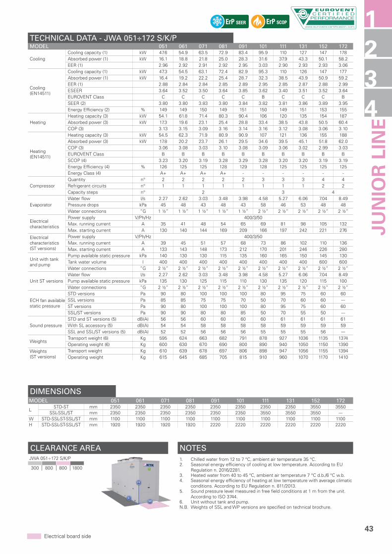
43
CLEARANCE AREA
1234
Electrical board side
TECHNICAL DATA - JWA 051÷172 S/K/PMODEL 051 061 071 081 091 101 111 131 152 172
CoolingCooling capacity (1) kW 47.6 54.9 63.5 72.9 83.4 95.9 110 127 147 178Absorbed power (1) kW 16.1 18.8 21.8 25.0 28.3 31.6 37.9 43.3 50.1 58.2EER (1) 2.96 2.92 2.91 2.92 2.95 3.03 2.90 2.93 2.93 3.06
Cooling (EN14511)
Cooling capacity (1) kW 47.3 54.5 63.1 72.4 82.9 95.3 110 126 147 177Absorbed power (1) kW 16.4 19.2 22.2 25.4 28.7 32.3 38.5 43.9 50.9 59.2EER (1) 2.88 2.84 2.84 2.85 2.89 2.95 2.85 2.87 2.88 2.99ESEER 3.64 3.52 3.50 3.64 3.85 3.62 3.40 3.51 3.52 3.64EUROVENT Class C C C C C B C C C BSEER (2) 3.80 3.80 3.83 3.80 3.84 3.82 3.81 3.86 3.89 3.95Energy Efficiency (2) % 149 149 150 149 151 150 149 151 153 155
HeatingHeating capacity (3) kW 54.1 61.8 71.4 80.3 90.4 106 120 135 154 187Absorbed power (3) kW 17.3 19.6 23.1 25.4 28.8 33.4 38.5 43.8 50.5 60.4COP (3) 3.13 3.15 3.09 3.16 3.14 3.16 3.12 3.08 3.06 3.10
Heating (EN14511)
Heating capacity (3) kW 54.5 62.3 71.9 80.9 90.9 107 121 136 155 188Absorbed power (3) kW 17.8 20.2 23.7 26.1 29.5 34.6 39.5 45.1 51.8 62.0COP (3) 3.06 3.08 3.03 3.10 3.08 3.09 3.06 3.02 2.99 3.03EUROVENT Class B B B B B B B B B BSCOP (4) 3.23 3.20 3.19 3.28 3.29 3.28 3.20 3.20 3.19 3.19Energy Efficiency (4) % 126 125 125 128 129 128 125 125 125 125Energy Class (4) A+ A+ A+ A+ - - - - - -
CompressorQuantity n° 2 2 2 2 2 3 3 3 4 4Refrigerant circuits n° 1 1 1 1 1 1 1 1 2 2Capacity steps n° 2 3 4
EvaporatorWater flow l/s 2.27 2.62 3.03 3.48 3.98 4.58 5.27 6.06 7.04 8.49Pressure drops kPa 45 48 43 48 43 58 46 53 48 48Water connections ”G 1 ½” 1 ½” 1 ½” 1 ½” 1 ½” 2 ½” 2 ½” 2 ½” 2 ½” 2 ½”
Electrical characteristics
Power supply V/Ph/Hz 400/3/50Max. running current A 35 41 48 54 65 69 81 98 105 132Max. starting current A 130 140 144 169 209 166 197 242 221 276
Electrical characteristics (ST versions)
Power supply V/Ph/Hz 400/3/50Max. running current A 39 45 51 57 68 73 86 102 110 136Max. starting current A 133 143 148 173 212 170 201 246 226 280
Unit with tank and pump
Pump available static pressure kPa 140 130 130 115 135 160 165 150 145 130Tank water volume l 400 400 400 400 400 400 400 400 600 600Water connections ”G 2 ½” 2 ½” 2 ½” 2 ½” 2 ½” 2 ½” 2 ½” 2 ½” 2 ½” 2 ½”
Unit ST versionsWater flow l/s 2.27 2.62 3.03 3.48 3.98 4.58 5.27 6.06 7.04 8.49Pump available static pressure kPa 135 130 125 115 110 130 135 120 115 100Water connections ”G 2 ½” 2 ½” 2 ½” 2 ½” 2 ½” 2 ½” 2 ½” 2 ½” 2 ½” 2 ½”
ECH fan available static pressure
STD versions Pa 90 80 100 100 100 80 95 75 60 60SSL versions Pa 85 85 75 75 70 50 70 60 60 ---ST versions Pa 90 80 100 100 100 80 95 75 60 60SSL/ST versions Pa 90 90 80 80 85 50 70 55 50 ---
Sound pressureSTD and ST versions (5) dB(A) 56 56 60 60 60 60 61 61 61 61With SL accessory (5) dB(A) 54 54 58 58 58 58 59 59 59 59SSL and SSL/ST versions (5) dB(A) 52 52 56 56 56 55 55 55 56 ---
WeightsTransport weight (6) Kg 595 624 663 682 791 878 927 1036 1135 1374Operating weight (6) Kg 600 630 670 690 800 890 940 1050 1150 1390
Weights(ST versions)
Transport weight Kg 610 639 678 697 806 898 947 1056 1155 1394Operating weight Kg 615 645 685 705 815 910 960 1070 1170 1410
DIMENSIONSMODEL 051 061 071 081 091 101 111 131 152 172
LSTD-ST mm 2350 2350 2350 2350 2350 2350 2350 2350 3550 3550
SSL-SSL/ST mm 2350 2350 2350 2350 2350 2350 3550 3550 3550 ---W STD-SSL-ST-SSL/ST mm 1100 1100 1100 1100 1100 1100 1100 1100 1100 1100H STD-SSL-ST-SSL/ST mm 1920 1920 1920 1920 2220 2220 2220 2220 2220 2220
ErP SCOPErP SEER
NOTES1. Chilled water from 12 to 7 °C, ambient air temperature 35 °C.2. Seasonal energy efficiency of cooling at low temperature. According to EU
Regulation n. 2016/2281.3. Heated water from 40 to 45 °C, ambient air temperature 7 °C d.b./6 °C w.b.4. Seasonal energy efficiency of heating at low temperature with average climatic
conditions. According to EU Regulation n. 811/2013.5. Sound pressure level measured in free field conditions at 1 m from the unit.
According to ISO 3744.6. Unit without tank and pump.N.B. Weights of SSL and WP versions are specified on technical brochure.
1
JUN
IOR
LIN
E
JWA 051÷172 S/K/P
300 800 800 1800

44
JWA/FC 051÷172 S/K/PAIRCOOLED LIQUID CHILLERS FREE-COOLING WITH AXIAL FANS, SCROLL COMPRESSORS AND PLATE EXCHANGER.
The liquid Chillers of the JWA/FC 051÷172 S/K/P series, with R410A refrigerant, offer innovative technology for both domestic as well as industrial applications requiring the production of cooled water continuously year-round.During the cold months, in the FREE-COOLING operation mode, the return liquid of the system is cooled directly by forced convection of outdoor air through the condensing coil, thus saving energy by not operating the unit’s Scroll compressors. A 3-way valve system is controlled by the electronic microprocessor controller, allowing functioning in CHILLER, FREE-COOLING or MIXED (simultaneously CHILLER and FREE-COOLING) modes.Are available as option the new EC Inverter fans with high available static pressure and efficiency for ducted installation.
JWA/FC 051÷172 S/G/POn request, units can be supplied with R452B refrigerant.
FROM 53 KW TO 174 KW.
VERSION
JWA/FCCooling only
FEATURES
• Self-supporting galvanized steel frame protected with additional protection achieved via polyester powder painting.
• Scroll compressors with oil sight glass, internal overheat protection and crankcase heater.• Axial fans directly coupled to an electric motor with external rotor.• Condenser made of copper tubes and aluminium finned coil combined with FREE-COOLING coil.• Evaporator AISI 316 stainless steel braze welded plates type with one circuit on the refrigerant
side and one on the water side in 051÷131 models; with two independent circuits on the refrigerant side and one on the water side in 152÷172 models, complete with water differential pressure switch.
• Electronic high and low pressure gauges.• R410A refrigerant. On request R452B refrigerant.• Electrical board includes: main switch with door safety interlock, fuses, thermal protection relays
for compressors and thermocontacts for fans.• Condensing Control is included: electronic proportional device that ensures efficient and
continuous functioning of the unit with outside air temperature down to –20 °C. It also allows to reduce the sound level especially at night. It consists of a fans speed controller with continuous speed regulation, high and low pressure transducers on cooling circuit and an electrical heater on electrical board.
• Microprocessor control and regulation system.
ACCESSORIES
FACTORY FITTED ACCESSORIES:
IM Automatic circuit breakersSL Unit silencementRFM Cooling circuit shut-off valve on
discharge lineRFL Cooling circuit shut-off valve on
liquid lineBT Low water temperature kitEC EC Inverter fans
ECH EC Inverter fans with high available static pressure
TX Coil with pre-coated finsSI Inertial tankPS Single circulating pumpPD Double circulating pumpSS Soft startIS Modbus RTU protocol, RS485 serial
interfaceISB BACnet MSTP protocol, RS485 serial
interface
ISBT BACnet TCP/IP protocol, Ethernet portISL LonWorks protocol, FTT-10 serial
interface
LOOSE ACCESSORIES:
MN High and low pressure gaugesCR Remote control panelRP Coils protection metallic guardsAG Rubber shock absorbersAM Spring shock absorbers

45
CLEARANCE AREA
1234
Electrical board side
TECHNICAL DATA - JWA/FC 051÷172 S/K/PMODEL 051 061 071 081 091 101 111 131 152 172
CoolingCooling capacity (1) kW 52.7 59.5 68.1 76.7 85.7 99.1 114 130 151 174Absorbed power (1) kW 18.1 20.3 23.3 26.1 29.3 36.8 42.2 48.4 54.4 64.9EER (1) 2.91 2.93 2.92 2.94 2.92 2.69 2.70 2.69 2.78 2.68
Cooling (EN14511)
Cooling capacity (1) kW 52.0 58.8 67.3 75.9 84.9 98.2 113 129 150 172Absorbed power (1) kW 18.8 21.0 24.1 26.9 30.1 37.7 43.5 49.9 55.7 66.4EER (1) 2.77 2.80 2.79 2.82 2.82 2.60 2.60 2.59 2.69 2.59SEER (2) 3.81 3.84 3.89 3.85 3.84 3.80 3.83 3.83 3.83 3.86Energy Efficiency (2) % 149 151 153 151 151 149 150 150 150 151
Free-Cooling cycle
Air temperature (3) °C 2.1 1.3 0.0 -2.4 -3.5 1.0 0.0 -1.1 -3.0 -4.8Absorbed power (3) kW 2 2 2 2 2 6 6 6 8 8
CompressorQuantity n° 2 2 2 2 2 3 3 3 4 4Refrigerant circuits n° 1 1 1 1 1 1 1 1 2 2Capacity steps n° 2 3 4
Water circuitWater flow l/s 2.72 3.07 3.52 3.96 4.43 5.09 5.88 6.70 7.78 8.93Pressure drops kPa 115 105 120 100 100 100 135 145 102 106Water connections ”G 2” 2” 2” 2” 2” 2 ½” 2 ½” 2 ½” 2 ½” 2 ½”
Electrical characteristics
Power supply V/Ph/Hz 400/3/50Max. running current A 35 41 48 54 65 76 85 102 113 136Max. starting current A 130 140 144 169 209 173 201 246 229 280
Unit with tank and pump
Pump available static pressure kPa 120 125 100 115 100 190 145 125 150 125Tank water volume l 400 400 400 400 400 400 400 400 600 600Water connections ”G 2 ½” 2 ½” 2 ½” 2 ½” 2 ½” 2 ½” 2 ½” 2 ½” 2 ½” 2 ½”
ECH fan available static pressure Pa 110 110 110 105 105 60 60 60 65 65
Sound pressureSTD version (4) dB(A) 59 59 59 59 59 60 60 60 61 61With SL accessory (4) dB(A) 57 57 57 57 57 58 58 58 59 59
WeightsTransport weight (5) Kg 923 932 951 980 999 1308 1317 1350 1472 1510Operating weight (5) Kg 970 980 1000 1030 1050 1390 1400 1435 1560 1600
DIMENSIONSMODEL 051 061 071 081 091 101 111 131 152 172L STD mm 3550 3550 3550 3550 3550 4700 4700 4700 4700 4700W STD mm 1100 1100 1100 1100 1100 1100 1100 1100 1100 1100H STD mm 2220 2220 2220 2220 2220 2235 2235 2235 2235 2235
ErP SEER
NOTES1. Chilled water (with ethylene glycol at 30%) from 15 to 10 °C, ambient air
temperature 35 °C.2. Seasonal energy efficiency of cooling at low temperature. According to EU
Regulation n. 2016/2281.3. Ambient air temperature at which the cooling capacity indicated in point (1) is
reached.4. Sound pressure level measured in free field conditions at 1 m from the unit.
According to ISO 3744.5. Unit without tank and pump.
1
JUN
IOR
LIN
E
JWA/FC 051÷172 S/K/P
300 800 800 1800

46
JWA 051÷172 S/KAIRCOOLED LIQUID CHILLERS AND HEAT PUMPS WITH AXIAL FANS, SCROLL COMPRESSORS AND SHELL AND TUBE EXCHANGER.
The liquid Chillers and Heat Pumps of the JWA 051÷172 S/K series, with R410A refrigerant, are designed for medium-sized service sector or industrial ambients.They are used, combined with Fan Coil units, for the air conditioning of the rooms or to remove the heat developed during industrial processes. They can be supplied with Modbus RTU protocol through RS485 serial interface.Equipped with axial fans, Scroll compressors and shell and tube exchanger, even in the super silent version, these units can be completed by a hydraulic circuit with tank, with pump, with tank and pump or with AQUALOGIK technology.The AQUALOGIK smart control system optimises the water set point and modulates the power supply voltage of the pump and the fans, thus making the use of the inertial tank superfluous. This obtains high energy efficiency, quiet operation and optimised dimensions and costs.A wide range of accessories, factory fitted or supplied separately, complete the outstanding versatility and functionality of the series.Are available as option the new EC Inverter fans with high available static pressure and efficiency for indoor ducted installation.
JWA 051÷172 S/GOn request, units can be supplied with R452B refrigerant.
FROM 49 KW TO 179 KW.
VERSION
JWACooling onlyJWA/WPReversible Heat PumpJWA/SSLSuper silenced cooling onlyJWA/WP/SSLSuper silenced reversible Heat PumpJWA/STCooling only with AQUALOGIK technologyJWA/WP/STReversible Heat Pump with AQUALOGIK technologyJWA/SSL/STSuper silenced cooling only with AQUALOGIK technologyJWA/WP/SSL/STSuper silenced reversible Heat Pump with AQUALOGIK technology
FEATURES
• Self-supporting galvanized steel frame protected with additional protection achieved via polyester powder painting.
• Scroll compressors with oil sight glass, internal overheat protection and crankcase heater.• Axial fans directly coupled to an electric motor with external rotor.• Condenser made of copper tubes and aluminium finned coil.• Shell and tube type evaporator with one circuit on the refrigerant side and one on the water side
in 051÷131 models; with two independent circuits on the refrigerant side and one on the water side in 152÷172 models, complete with water differential pressure switch.
• R410A refrigerant. On request R452B refrigerant.• Electrical board includes: main switch with door safety interlock, fuses, thermal protection relays
for compressors and thermocontacts for fans.• On ST versions water circuit includes: INVERTER circulating pump, safety valve and expansion vessel.• On ST versions Condensing Control is included: electronic proportional device that ensures
efficient and continuous functioning of the unit with outside air temperature down to –20 °C in cooling mode. It also allows to reduce the sound level especially at night. It consists of a fans speed controller with continuous speed regulation, an high/low pressure transducer on cooling circuit and an electrical heater on electrical board.
• Microprocessor control and regulation system (with AQUALOGIK technology on ST versions).
ACCESSORIES
FACTORY FITTED ACCESSORIES:
IM Automatic circuit breakersSL Unit silencementRFM Cooling circuit shut-off valve on
discharge lineRFL Cooling circuit shut-off valve on
liquid lineCT Condensing control down to 0 °CCC Condensing control down to -20 °CBT Low water temperature kitEC EC Inverter fansECH EC Inverter fans with high available
static pressureHR Desuperheater
HRT/S Total heat recovery in seriesHRT/P Total heat recovery in parallelTX Coil with pre-coated finsEW External water connectionsSP Inertial tankPU Single circulating pumpPD Double circulating pumpSPU Inertial tank and single circulating
pumpSPD Inertial tank and double circulating
pumpFE Antifreeze heater for evaporatorFN Antifreeze heater for pipesFQ Antifreeze heater on evaporator/tank
and pipesFZ Antifreeze heater for evaporator,
single pump and pipesFH Antifreeze heater for evaporator,
double pump and pipes
FU Antifreeze heater for evaporator/tank, single pump and pipes
FD Antifreeze heater for evaporator/tank, double pump and pipes
SS Soft startIS Modbus RTU protocol, RS485 serial
interface
LOOSE ACCESSORIES:
MN High and low pressure gaugesCR Remote control panelRP Coils protection metallic guardsFP Coils protection metallic guards
with filterAG Rubber shock absorbersAM Spring shock absorbersFL Flow switch

47
CLEARANCE AREA
1234
Electrical board side
TECHNICAL DATA - JWA 051÷172 S/KMODEL 051 061 071 081 091 101 111 131 152 172
CoolingCooling capacity (1) kW 49.0 55.0 62.4 73.3 84.3 95.2 109 129 149 179Absorbed power (1) kW 16.6 18.8 21.5 25.3 28.6 31.6 37.5 43.7 50.7 58.8EER (1) 2.95 2.93 2.90 2.90 2.95 3.01 2.91 2.95 2.94 3.04
Cooling (EN14511)
Cooling capacity (1) kW 48.8 54.7 62.0 72.8 83.9 94.7 108 128 148 178Absorbed power (1) kW 16.8 19.1 21.9 25.8 29.0 32.1 38.1 44.3 51.4 59.5EER (1) 2.90 2.86 2.83 2.82 2.89 2.95 2.83 2.89 2.88 2.99ESEER 3.74 3.57 3.44 3.60 3.85 3.60 3.37 3.61 3.54 3.67EUROVENT Class C C C C C B C C C BSEER (2) 3.84 3.84 3.83 3.80 3.91 3.86 3.81 3.88 3.81 3.93Energy Efficiency (2) % 151 151 150 149 153 151 149 152 149 154
HeatingHeating capacity (3) kW 55.7 61.9 70.2 80.7 91.4 105 119 137 156 188Absorbed power (3) kW 17.8 19.6 22.8 25.7 29.1 33.4 38.1 44.2 51.1 61.0COP (3) 3.13 3.16 3.08 3.14 3.14 3.14 3.12 3.10 3.05 3.08
Heating (EN14511)
Heating capacity (3) kW 56.0 62.2 70.7 81.3 91.9 106 120 138 157 189Absorbed power (3) kW 18.0 20.0 23.5 26.6 29.8 34.2 39.1 45.1 52.3 62.3COP (3) 3.11 3.11 3.01 3.06 3.08 3.10 3.07 3.06 3.00 3.03EUROVENT Class B B B B B B B B C BSCOP (4) 3.28 3.23 3.20 3.29 3.31 3.27 3.19 3.19 3.19 3.19Energy Efficiency (4) % 128 126 125 129 129 128 125 125 125 125Energy Class (4) A+ A+ A+ A+ - - - - - -
CompressorQuantity n° 2 2 2 2 2 3 3 3 4 4Refrigerant circuits n° 1 1 1 1 1 1 1 1 2 2Capacity steps n° 2 3 4
EvaporatorWater flow l/s 2.31 2.60 2.95 3.46 3.98 4.50 5.15 6.09 7.04 8.45Pressure drops kPa 22 29 50 55 40 39 45 36 43 38Water connections ”G 1 ½” 1 ½” 2” 2” 2 ½” 2 ½” 2 ½” 3” 3” 3”
Electrical characteristics
Power supply V/Ph/Hz 400/3/50Max. running current A 35 41 48 54 65 69 81 98 105 132Max. starting current A 130 140 144 169 209 166 197 242 221 276
Electrical characteristics (ST versions)
Power supply V/Ph/Hz 400/3/50Max. running current A 39 45 51 57 68 73 86 102 110 136Max. starting current A 133 143 148 173 212 170 201 246 226 280
Unit with tank and pump
Pump available static pressure kPa 160 150 125 110 140 180 170 170 150 140Tank water volume l 470 470 470 470 470 470 470 470 660 660Water connections ”G 2 ½” 2 ½” 2 ½” 2 ½” 2 ½” 2 ½” 2 ½” 2 ½” 2 ½” 2 ½”
Unit ST versionsWater flow l/s 2.31 2.60 2.95 3.46 3.98 4.50 5.15 6.09 7.04 8.45Pump available static pressure kPa 160 150 120 105 110 145 135 140 120 110Water connections ”G 2 ½” 2 ½” 2 ½” 2 ½” 2 ½” 2 ½” 2 ½” 2 ½” 2 ½” 2 ½”
ECH fan available static pressure
STD versions Pa 90 80 100 100 100 80 95 75 60 60SSL versions Pa 85 85 75 75 70 50 70 60 60 ---ST versions Pa 90 80 100 100 100 80 95 75 60 60SSL/ST versions Pa 90 90 80 80 85 50 70 55 50 ---
Sound pressureSTD and ST versions (5) dB(A) 56 56 60 60 60 60 61 61 61 61With SL accessory (5) dB(A) 54 54 58 58 58 58 59 59 59 59SSL and SSL/ST versions (5) dB(A) 52 52 56 56 56 55 55 55 56 ---
WeightsTransport weight (6) Kg 641 661 701 719 844 931 971 1112 1192 1428Operating weight (6) Kg 660 680 720 740 870 960 1000 1150 1230 1470
Weights(ST versions)
Transport weight Kg 655 675 715 735 860 950 990 1130 1210 1450Operating weight Kg 660 690 730 750 875 970 1010 1150 1230 1470
DIMENSIONSMODEL 051 061 071 081 091 101 111 131 152 172
LSTD-ST mm 2350 2350 2350 2350 2350 2350 2350 2350 3550 3550
SSL-SSL/ST mm 2350 2350 2350 2350 2350 2350 3550 3550 3550 ---W STD-SSL-ST-SSL/ST mm 1100 1100 1100 1100 1100 1100 1100 1100 1100 1100H STD-SSL-ST-SSL/ST mm 1920 1920 1920 1920 2220 2220 2220 2220 2220 2220
ErP SCOPErP SEER
NOTES1. Chilled water from 12 to 7 °C, ambient air temperature 35 °C.2. Seasonal energy efficiency of cooling at low temperature. According to EU
Regulation n. 2016/2281.3. Heated water from 40 to 45 °C, ambient air temperature 7 °C d.b./6 °C w.b.4. Seasonal energy efficiency of heating at low temperature with average climatic
conditions. According to EU Regulation n. 811/2013.5. Sound pressure level measured in free field conditions at 1 m from the unit.
According to ISO 3744.6. Unit without tank and pump.N.B. Weights of SSL and WP versions are specified on technical brochure.
1
JUN
IOR
LIN
E
JWA 051÷172 S/K
300 800 800 1800

48
JWA/E 071÷182 S/K/PAIRCOOLED LIQUID CHILLERS WITH AXIAL FANS, SCROLL COMPRESSORS AND PLATE EXCHANGER.
The liquid Chillers of JWA/E 071÷182 S/K/P series, with R410A refrigerant, are designed for medium-sized service sector or industrial ambients.They are used, combined with Fan Coil units, for the air conditioning of the rooms.The AQUAPLUS EASY range is made of 4 sizes from 65 to 180 kW, and features V design condensing coils, axial fans, single or double cooling circuit with Scroll compressors and plate exchanger.Units, also available in super silent version, can be completed with tank and single or double pump, available as accessory.
FROM 65 KW TO 180 KW.
VERSION
JWA/ECooling only
JWA/E/SSLSuper silenced cooling only
FEATURES
• Self-supporting galvanized steel frame protected with additional protection achieved via polyester powder painting.
• Scroll compressors with oil sight glass, internal overheat protection and crankcase heater.• Axial fans directly coupled to an electric motor with external rotor.• Condenser made of copper tubes and aluminium finned coils.• Evaporator AISI 316 stainless steel braze welded plates type with one circuit on the refrigerant
side and one on the water side in 071÷091 models, with two independent circuits on the refrigerant side and one on the water side in 142÷182 models, complete with water differential pressure switch.
• R410A refrigerant.• Electrical board includes: main switch with door safety interlock, fuses, thermal protection relays
for compressors and thermocontacts for fans.• Microprocessor control and regulation system.
ACCESSORIES
FACTORY FITTED ACCESSORIES:
IM Automatic circuit breakersSL Unit silencementCT Condensing control down to 0 °CCC Condensing control down to -20 °CSI1-SI2 Inertial tankPS Single circulating pumpPD Double circulating pumpFE Antifreeze heater for evaporatorFN Antifreeze heater for pipesFO1-FO2 Antifreeze heater for tank and pipesFG Antifreeze heater for single pump
and pipesFM Antifreeze heater for double pump
and pipesFUM1-FUM2 Antifreeze heater for tank, single
pump and pipesFDM1-FDM2 Antifreeze heater for tank, double
pump and pipesIS Modbus RTU protocol, RS485 serial
interface
LOOSE ACCESSORIES:
MN High and low pressure gaugesCR Remote control panelRP Coils protection metallic guardsAG Rubber shock absorbersAM Spring shock absorbers

49
CLEARANCE AREA
1234
Electrical board side
TECHNICAL DATA - JWA/E 071÷182 S/K/PMODEL 071 091 142 182
CoolingCooling capacity (1) kW 65.5 90.0 131 180Absorbed power (1) kW 22.2 30.3 44.4 60.6EER (1) 2.95 2.97 2.94 2.97
Cooling (EN14511)
Cooling capacity (1) kW 64.9 89.6 130 179Absorbed power (1) kW 22.6 30.8 45.2 61.6EER (1) 2.87 2.91 2.87 2.91ESEER 3.39 3.73 3.39 3.73EUROVENT Class C B C BSEER (2) 3.80 3.83 3.80 3.83Energy Efficiency (2) % 149 150 149 150
CompressorQuantity n° 2 2 4 4Refrigerant circuits n° 1 1 2 2Capacity steps n° 2 4
EvaporatorWater flow l/s 3.12 4.30 6.24 8.60Pressure drops kPa 43 48 43 48Water connections ”G 2” 2” 2” 2”
Electrical characteristics
Power supply V/Ph/Hz 400/3/50Max. running current A 53.5 66.5 107 133Max. starting current A 170 235 340 470
Unit with tank and pump
Pump available static pressure kPa 145 135 135 120SI1 Tank water volume l 150 150 150 150SI2 Tank water volume l - - 300 300Water connections ”G 2” 2” 2” 2”
Sound pressureSTD version (3) dB(A) 60 60 62 62With SL accessory (3) dB(A) 58 58 60 60SSL version (3) dB(A) 55 55 57 57
WeightsTransport weight (4) Kg 547 596 1114 1211Operating weight (4) Kg 550 600 1120 1220
DIMENSIONSMODEL 071 091 142 182L STD mm 2200 2200 2200 2200W STD mm 1100 1100 2200 2200H STD mm 2045 2045 2045 2045
ErP SEER
NOTES1. Chilled water from 12 to 7 °C, ambient air temperature 35 °C.2. Seasonal energy efficiency of cooling at low temperature. According to EU
Regulation n. 2016/2281.3. Sound pressure level measured in free field conditions at 1 m from the unit.
According to ISO 3744.4. Unit without tank and pump.N.B. Weights of SSL version are specified on technical brochure.
1
JUN
IOR
LIN
E
JWA/E 071÷182 S/K/P
800 0 800 0

50
JWA/ML/ST 11÷18 S/Z/PA CLASS ENERGY EFFICIENCY AIRCOOLED DEDICATED HEAT PUMPS WITH DOMESTIC HOT WATER PRODUCTION, AXIAL FANS, SCROLL COMPRESSOR,PLATE EXCHANGER AND HYDRONIC KIT.
MIDYLINE is the line of Heat Pumps dedicated to hot water production up to 60 °C and operations up to -20 °C external air temperature, with Scroll compressors, axial fans and integrated hydronic kit. The unit, featuring A CLASS energy efficiency, is designed to singly handle winter heating, summer air conditioning and the production of high temperature hot water, making use of the electrical energy and heat accumulated in the clean air source, free and infinite, which can also transfer heat to homes. Flexibility is the main feature of MIDYLINE series, which is also combined with heating units and managed by the innovative, intelligent AQUALOGIK control system, optimizing the water set-point and regulating power supply voltage to the pump and fans, making the use of an inertial tank unnecessary. This results in performance with elevated energy efficiency, silent functioning, optimized dimensions and costs. MIDYLINE is also able to operate in extreme conditions where the external air temperature is very low, as well as intelligently managing integrated elements such as furnaces and electrical heaters. Based on the external air sensor, the microprocessor activates the single integration elements in the system.
FROM 11 KW TO 23 KW.
VERSION
JWA/ML/STHeat pump with AQUALOGIK technology
JWA/ML/WP/STReversible heat pump with AQUALOGIK technology
FEATURES
• Structure with supporting frame, in peraluman, galvanized sheet and with rubber shock absorbers on the frame.
• Scroll compressor with internal overheat protection and crankcase heater.• Axial fans with low ventilation and special wing profile, directly coupled to external rotor motors.• Condenser made of copper tube and aluminium finned coil, complete with drain pan.• Evaporator AISI 316 stainless steel braze welded plates type, completed with water differential
pressure switch and antifreeze heater.• R407C refrigerant.• Electrical board includes: main switch with door lock device, fuses and compressor remote control switch.• Condensing Control is included: electronic proportional device that ensures efficient and
continuous functioning of the unit with outside air temperature down to –20 °C in cooling mode. It also allows to reduce the sound level especially at night. It consists of a fans speed controller with continuous speed regulation, an high/low pressure transducer on cooling circuit and an electrical heater on electrical board.
• Functioning in heating mode with outside air temperature down to -20 °C.• The production of hot water up to 60 °C is reachable with outside air temperature down to -15 °C.
With outside air temperature of -20 °C the reachable production of hot water is up to 45 °C.• Water circuit includes variable speed circulating pump, safety valve, gauge and expansion vessel.• Microprocessor control and regulation system with AQUALOGIK technology.
ACCESSORIES
FACTORY FITTED ACCESSORIES:
EH Supplementary electrical heaterKC Gas burner integration kitTX Coil with pre-coated fins
LOOSE ACCESSORIES:
HW Storage tank for domestic hot water production
CR Remote control panelIS Modbus RTU protocol, RS485 serial
interfaceRP Coils protection metallic guards

51
CLEARANCE AREA
1234
Electrical board side
TECHNICAL DATA - JWA/ML/ST 11÷18 S/Z/PMODEL 11* 14* 11** 14** 18
Heating
Heating capacity (1) kW 11.5 16.0 11.5 16.0 22.5Absorbed power (1) kW 3.2 4.6 3.2 4.6 6.5COP (1) 3.59 3.48 3.59 3.48 3.46Heating capacity (2) kW 11.3 15.8 11.3 15.8 22.4Absorbed power (2) kW 2.7 3.8 2.7 3.8 5.4COP (2) 4.19 4.16 4.19 4.16 4.15
Heating (EN14511)
Heating capacity (1) kW 11.9 16.4 11.9 16.4 23.0Absorbed power (1) kW 3.2 4.6 3.2 4.6 6.5COP (1) 3.72 3.57 3.72 3.57 3.54EUROVENT Class A A A A ASCOP (3) 4.71 4.95 4.71 4.95 5.12Energy Efficiency (3) % 185 195 185 195 202Energy Class (3) A++ A++ A++ A++ A+
Cooling
Cooling capacity (4) kW 7.3 10.5 7.3 10.5 16.0Absorbed power (4) kW 2.5 3.6 2.5 3.6 5.2EER (4) 2.92 2.92 2.92 2.92 3.08Cooling capacity (5) kW 10.8 15.5 10.8 15.5 21.2Absorbed power (5) kW 2.7 4.0 2.7 4.0 6.1EER (5) 4.00 3.88 4.00 3.88 3.48
Cooling (EN14511)
Cooling capacity (4) kW 7.0 10.2 7.0 10.2 15.6Absorbed power (4) kW 2.8 3.9 2.8 3.9 5.6EER (4) 2.50 2.62 2.50 2.62 2.79ESEER 2.80 3.12 2.80 3.12 3.11EUROVENT Class E D E D C
Compressor Quantity n° 1 1 1 1 1
Supplementary electrical heater
Power supply V/Ph/Hz 230/1/50Heating capacity kW 4/6 4/6 4/6 4/6 4/6Absorbed current A 18/26 18/26 18/26 18/26 18/26Steps n° 2 2 2 2 2
Electrical characteristics
Power supply V/Ph/Hz 230/1/50 400/3+N/50Max. running current A 26 35 13 15 19Max. starting current A 102 165 45 69 106
Water circuitWater flow l/s 0.54 0.75 0.54 0.75 1.07Pump available static pressure kPa 231 185 231 185 156Water connections ”G 1” 1” 1” 1” 1”
Sound pressure (6) dB(A) 52 52 52 52 52
WeightsTransport weight Kg 205 208 205 208 210Operating weight Kg 209 212 209 212 214
DIMENSIONSMODEL 11* 14* 11** 14** 18L STD mm 1160 1160 1160 1160 1160W STD mm 500 500 500 500 500H STD mm 1270 1270 1270 1270 1270
ErP SCOP
NOTES1. Heated water from 40 to 45 °C, ambient air temperature 7 °C d.b./6 °C w.b.2. Heated water from 30 to 35 °C, ambient air temperature 7 °C d.b./6 °C w.b.3. Seasonal energy efficiency of heating at low temperature with average climatic
conditions. According to EU Regulation n. 811/2013.4. Chilled water from 12 to 7 °C, ambient air temperature 35 °C.5. Chilled water from 23 to 18 °C, ambient air temperature 35 °C.6. Sound pressure level measured in free field conditions at 1 m from the unit.
According to ISO 3744.N.B. Weights of WP version are specified on technical brochure.N.B. * = Single phaseN.B. ** = Three phase
1
JUN
IOR
LIN
E
JWA/ML/ST 11÷18 S/Z/P
200 200 800 200

52
JWA/ML/ST 24÷40 S/Z/PA CLASS ENERGY EFFICIENCY AIRCOOLED DEDICATED HEAT PUMPS WITH DOMESTIC HOT WATER PRODUCTION, AXIAL FANS, SCROLL COMPRESSOR, PLATE EXCHANGER AND HYDRONIC KIT.
MIDYLINE, featuring A CLASS energy efficiency, is the innovative series of Heat Pumps dedicated to hot water production up to 60 °C and operation up to -20 °C external air temperature, with Scroll compressors, axial fans and integrated hydronic kit. The unit, designed to originate and control – throughout the year – the best comfort conditions in rooms with a high rate of daily attendance, such as enclosed areas destined to the activities of the service sector, autonomously handles winter heating, summer air conditioning and the production of high temperature sanitary hot water. The MIDYLINE series, designed with an extremely compact structure for simple installation operations, uses only the electric energy and the heat accumulated in the air, to transfer heat to the rooms, thus allowing considerable energy savings, a high rate of reliability and the shortest start-up times. Flexibility is the main feature of the MIDYLINE series, which is indeed combined with terminal units and managed by the innovative, intelligent AQUALOGIK control and optimization system. This makes the use of an inertial tank unnecessary and it guarantees performances with elevated energy efficiency and silent functioning.
FROM 30 KW TO 53 KW.
VERSION
JWA/ML/STHeat pump with AQUALOGIK technology
JWA/ML/WP/STReversible heat pump with AQUALOGIK technology
FEATURES
• Structure with supporting frame, in peraluman and galvanized sheet.• Scroll compressors with oil sight glass, internal overheat protection and crankcase heater.• Axial fans with low ventilation and special wing profile, directly coupled to external rotor motors.• Condenser made of copper tubes and aluminium finned coils.• Evaporator AISI 316 stainless steel braze welded plates type, completed with water differential
pressure switch and antifreeze heater.• R407C refrigerant.• Electrical board includes: main switch with door lock device, fuses and compressor remote control switch.• Condensing Control is included: electronic proportional device that ensures efficient and
continuous functioning of the unit with outside air temperature down to –20 °C in cooling mode. It also allows to reduce the sound level especially at night. It consists of a fans speed controller with continuous speed regulation, an high/low pressure transducer on cooling circuit and an electrical heater on electrical board.
• Functioning in heating mode with outside air temperature down to -20 °C.• The production of hot water up to 60 °C is reachable with outside air temperature down to -15 °C.
With outside air temperature of -20 °C the reachable production of hot water is up to 45 °C.• Water circuit includes variable speed circulating pump, safety valve, gauge and expansion vessel.• Microprocessor control and regulation system with AQUALOGIK technology.
ACCESSORIES
FACTORY FITTED ACCESSORIES:
EH Supplementary electrical heaterKC Gas burner integration kitTX Coil with pre-coated fins
LOOSE ACCESSORIES:
HW Storage tank for domestic hot water production
CR Remote control panelIS Modbus RTU protocol, RS485 serial
interfaceRP Coils protection metallic guardsAG Rubber shock absorbers

53
CLEARANCE AREA
1234
Electrical board side
TECHNICAL DATA - JWA/ML/ST 24÷40 S/Z/PMODEL 24 27 40
Heating
Heating capacity (1) kW 30.7 40.2 52.6Absorbed power (1) kW 8.0 10.9 13.6COP (1) 3.84 3.69 3.87Heating capacity (2) kW 29.8 40.0 50.2Absorbed power (2) kW 6.7 9.2 11.4COP (2) 4.45 4.35 4.40
Heating (EN14511)
Heating capacity (1) kW 31.4 41.1 53.5Absorbed power (1) kW 8.0 10.9 13.6COP (1) 3.93 3.77 3.93EUROVENT Class A A ASCOP (3) 4.42 4.32 4.27Energy Efficiency (3) % 174 170 168Energy Class (3) A++ A++ A++
Cooling
Cooling capacity (4) kW 20.4 28.9 37.3Absorbed power (4) kW 6.6 9.3 11.7EER (4) 3.09 3.11 3.19Cooling capacity (5) kW 27.6 39.3 47.8Absorbed power (5) kW 7.7 10.7 12.8EER (5) 3.58 3.67 3.73
Cooling (EN14511)
Cooling capacity (4) kW 19.8 28.2 36.5Absorbed power (4) kW 7.2 10.0 12.5EER (4) 2.75 2.82 2.92ESEER 3.11 3.16 3.27EUROVENT Class C C B
Compressor Quantity n° 1 1 1
Supplementary electrical heater
Power supply V/Ph/Hz 400/3/50Heating capacity kW 6/10 6/10 6/10Absorbed current A 26/43 26/43 26/43Steps n° 2 2 2
Electrical characteristics
Power supply V/Ph/Hz 400/3+N/50Max. running current A 28 36 42Max. starting current A 109 139 179
Water circuitWater flow l/s 1.47 1.92 2.51Pump available static pressure kPa 230 227 195Water connections ”G 2” 2” 2”
Sound pressure (6) dB(A) 61 62 64
WeightsTransport weight Kg 220 235 265Operating weight Kg 224 239 269
DIMENSIONSMODEL 24 27 40L STD mm 1850 1850 1850W STD mm 1000 1000 1000H STD mm 1300 1300 1300
ErP SCOP
NOTES1. Heated water from 40 to 45 °C, ambient air temperature 7 °C d.b./6 °C w.b.2. Heated water from 30 to 35 °C, ambient air temperature 7 °C d.b./6 °C w.b.3. Seasonal energy efficiency of heating at low temperature with average climatic
conditions. According to EU Regulation n. 811/2013.4. Chilled water from 12 to 7 °C, ambient air temperature 35 °C.5. Chilled water from 23 to 18 °C, ambient air temperature 35 °C.6. Sound pressure level measured in free field conditions at 1 m from the unit.
According to ISO 3744.N.B. Weights of WP version are specified on technical brochure.
1
JUN
IOR
LIN
E
JWA/ML/ST 24÷40 S/Z/P
500 800 800 800

54
JWA/ML/ST 052÷082 S/Z/PA CLASS ENERGY EFFICIENCY AIRCOOLED DEDICATED HEAT PUMPS WITH DOMESTIC HOT WATER PRODUCTION, AXIAL FANS, SCROLL COMPRESSORS, PLATE EXCHANGER AND HYDRONIC KIT.
MIDYLINE, featuring A CLASS energy efficiency, is the innovative series of Heat Pumps dedicated to hot water production up to 60 °C and operation up to -20 °C external air temperature, with Scroll compressors, axial fans and integrated hydronic kit. The unit, designed to originate and control – throughout the year – the best comfort conditions in rooms with a high rate of daily attendance, such as enclosed areas destined to the activities of the service sector, autonomously handles winter heating, summer air conditioning and the production of high temperature sanitary hot water. The MIDYLINE series, designed with an extremely compact structure for simple installation operations, uses only the electric energy and the heat accumulated in the air, to transfer heat to the rooms, thus allowing considerable energy savings, a high rate of reliability and the shortest start-up times. Flexibility is the main feature of the MIDYLINE series, which is indeed combined with terminal units and managed by the innovative, intelligent AQUALOGIK control and optimization system. This makes the use of an inertial tank unnecessary and it guarantees performances with elevated energy efficiency and silent functioning.Are available as option the new EC Inverter fans with high available static pressure and efficiency for indoor ducted installation.
FROM 56 KW TO 114 KW.
VERSION
JWA/ML/STHeat pump with AQUALOGIK technology
JWA/ML/WP/STReversible heat pump with AQUALOGIK technology
JWA/ML/SSL/STSuper silenced Heat Pump with AQUALOGIK technology
JWA/ML/WP/SSL/STSuper silenced reversible Heat Pump with AQUALOGIK technology
FEATURES
• Self-supporting galvanized steel frame protected with additional protection achieved via polyester powder painting.
• Scroll compressors with oil sight glass, internal overheat protection and crankcase heater.• Axial fans directly coupled to an electric motor with external rotor.• Condenser made of copper tubes and aluminium finned coil.• Evaporator AISI 316 stainless steel braze welded plates type with two independent circuits on
the refrigerant side and one on the water side, complete with flow switch and antifreeze heater.• R407C refrigerant.• Electrical board includes: main switch with door safety interlock, fuses, thermal protection relays
for compressors and pump and thermocontacts for fans.• Condensing Control is included: electronic proportional device that ensures efficient and
continuous functioning of the unit with outside air temperature down to –20 °C in cooling mode. It also allows to reduce the sound level especially at night. It consists of a fans speed controller with continuous speed regulation, an high/low pressure transducer on cooling circuit and an electrical heater on electrical board.
• Functioning in heating mode with outside air temperature down to -20 °C.• The production of hot water up to 60 °C is reachable with outside air temperature down to -15 °C.
With outside air temperature of -20 °C the reachable production of hot water is up to 45 °C.• Water circuit includes: INVERTER circulating pump, safety valve and expansion vessel.• Microprocessor control and regulation system with AQUALOGIK technology.
ACCESSORIES
FACTORY FITTED ACCESSORIES:
IM Automatic circuit breakersSL Unit silencementRFM Cooling circuit shut-off valve on
discharge lineRFL Cooling circuit shut-off valve on
liquid lineEC EC Inverter fansECH EC Inverter fans with high available
static pressureDS DesuperheaterKC Gas burner integration kit
FN Antifreeze heater for pipesFG Antifreeze heater for single pump
and pipesSS Soft startTX Coil with pre-coated finsIS Modbus RTU protocol, RS485 serial
interface
LOOSE ACCESSORIES:
HW Storage tank for domestic hot water production
MN High and low pressure gaugesCR Remote control panelRP Coils protection metallic guardsAG Rubber shock absorbersAM Spring shock absorbers

55
CLEARANCE AREA
1234
Electrical board side
TECHNICAL DATA - JWA/ML/ST 052÷082 S/Z/PMODEL 052 062 072 082
Heating
Heating capacity (1) kW 57.2 78.3 92.7 114Absorbed power (1) kW 16.3 20.8 25.7 33.7COP (1) 3.51 3.76 3.61 3.38Heating capacity (2) kW 55.7 74.4 91.1 112Absorbed power (2) kW 13.7 17.4 21.5 27.1COP (2) 4.07 4.28 4.24 4.13
Heating (EN14511)
Heating capacity (1) kW 58.0 79.2 93.6 116Absorbed power (1) kW 16.3 20.8 25.7 33.7COP (1) 3.56 3.81 3.64 3.43EUROVENT Class A A A ASCOP (3) 4.92 5.52 5.11 4.80Energy Efficiency (3) % 194 218 201 189Energy Class (3) A++ A++ A++ A++
Cooling
Cooling capacity (4) kW 44.3 60.4 78.6 101Absorbed power (4) kW 16.4 23.6 34.8 39.1EER (4) 2.70 2.56 2.26 2.58Cooling capacity (5) kW 60.3 81.8 101 130Absorbed power (5) kW 18.7 27.5 37.6 42.2EER (5) 3.22 2.97 2.69 3.08
Cooling (EN14511)
Cooling capacity (4) kW 43.6 59.6 77.7 99.7Absorbed power (4) kW 17.1 24.4 35.7 40.4EER (4) 2.55 2.44 2.18 2.47ESEER 3.08 2.99 2.81 2.96EUROVENT Class D E F E
CompressorQuantity n° 2 2 2 2Refrigerant circuits n° 2 2 2 2Capacity steps n° 2
Electrical characteristics
Power supply V/Ph/Hz 400/3/50Max. running current A 44 56 68 84Max. starting current A 125 159 205 246
Water circuitWater flow l/s 2.73 3.74 4.43 5.46Pump available static pressure kPa 165 145 130 110Water connections ”G 2 ½” 2 ½” 2 ½” 2 ½”
ECH fan available static pressure
ST versions Pa 90 80 100 100SSL/ST versions Pa 90 90 80 85
Sound pressureSTD version (6) dB(A) 60 61 62 64With SL accessory (6) dB(A) 58 59 60 62SSL version (6) dB(A) 56 57 58 60
WeightsTransport weight Kg 746 837 856 913Operating weight Kg 755 855 875 935
DIMENSIONSMODEL 052 062 072 082
LSTD mm 2350 2350 2350 2350SSL mm 2350 2350 2350 3550
W STD/SSL mm 1100 1100 1100 1100
HSTD mm 1920 2220 2220 2220SSL mm 2220 2220 2220 2220
ErP SCOP
NOTES1. Heated water from 40 to 45 °C, ambient air temperature 7 °C d.b./6 °C w.b.2. Heated water from 30 to 35 °C, ambient air temperature 7 °C d.b./6 °C w.b.3. Seasonal energy efficiency of heating at low temperature with average climatic
conditions. According to EU Regulation n. 811/2013.4. Chilled water from 12 to 7 °C, ambient air temperature 35 °C.5. Chilled water from 23 to 18 °C, ambient air temperature 35 °C.6. Sound pressure level measured in free field conditions at 1 m from the unit.
According to ISO 3744.N.B. Weights of SSL and WP versions are specified on technical brochure.
1
JUN
IOR
LIN
E
JWA/ML/ST 052÷082 S/Z/P
300 800 800 1800

56
JWA/EP 051÷191 S/K/PAIRCOOLED 4-PIPE MULTIFUNCTIONAL UNITS WITH AXIAL FANS, SCROLL COMPRESSORS AND PLATE EXCHANGERS.
ENERGYPOWER is the range of high efficiency multifunctional units for 4-Pipe systems.The units JWA/EP 051÷191 S/K/P feature R410A refrigerant and Scroll compressors activated in series based on the requested thermal load, to reach high EER/COP/TER and SEER/ESEER/IPLV/SCOP energy values. Thanks to the advanced control system, the units can simultaneously fulfill the heating, cooling and domestic hot water request of the building. The unit can manage the opposed thermal loads at the same time and reach the highest possible efficiency. ENERGYPOWER units make the traditional layout of the technical plants easier because the production of thermal energy for the several users are joint in one unit only; the result is an advantage in terms of installation, maintenance and management and in the meantime of the comfort needs.Are available as option the new EC Inverter fans with high available static pressure and efficiency for indoor ducted installation.Units are designed for hot water production up to 55°C.
JWA/EP 051÷191 S/G/POn request, units can be supplied with R452B refrigerant.
FROM 49 KW TO 190 KW.
VERSION
JWA/EPMultifunctional unit
JWA/EP/SSLSuper silenced multifunctional unit
FEATURES
• Self-supporting galvanized steel frame protected with additional protection achieved via polyester powder painting.
• Scroll compressors with oil sight glass, internal overheat protection and crankcase heater.• Axial fans directly coupled to an electric motor with external rotor.• Copper tube and aluminum finned coil.• Condenser AISI 316 stainless steel braze welded plates type with one circuit on the refrigerant
side and one on the water side. On the units it is always installed an antifreeze heater.• Evaporator AISI 316 stainless steel braze welded plates type with one circuit on the refrigerant
side and one on the water side, complete with water differential pressure switch. On the units it is always installed an antifreeze heater.
• Electronic expansion valve.• Electronic high and low pressure gauges.• R410A refrigerant. On request R452B refrigerant.• Electrical board includes: main switch with door safety interlock, fuses, thermal protection relays
for compressors and thermocontacts for fans.• Condensing Control is included: electronic proportional device that ensures efficient and
continuous functioning of the unit with outside air temperature down to –20 °C in cooling mode. It also allows to reduce the sound level especially at night. It consists of a fans speed controller with continuous speed regulation, high and low pressure transducers on cooling circuit and an electrical heater on electrical board.
• Functioning in heating mode with outside air temperature down to -15 °C.• Microprocessor control and regulation system.
ACCESSORIES
FACTORY FITTED ACCESSORIES:
IM Automatic circuit breakersSL Unit silencementRFM Cooling circuit shut-off valve on
discharge lineRFL Cooling circuit shut-off valve on
liquid lineBT Low water temperature kitEC EC Inverter fansECH EC Inverter fans with high available
static pressureTX Coil with pre-coated finsPSC Single circulating pump cooling sidePSIC Inverter single circulating pump
cooling sidePDC Double circulating pump cooling sidePDIC Inverter double circulating pump
cooling side
PSH Single circulating pump heating sidePSIH Inverter single circulating pump
heating sidePDH Double circulating pump heating sidePDIH Inverter double circulating pump
heating sideFN Antifreeze heater for pipesFGC Antifreeze heater for single pump
and pipes cooling sideFMC Antifreeze heater for double pump
and pipes cooling sideFGH Antifreeze heater for single pump
and pipes heating sideFMH Antifreeze heater for double pump
and pipes heating sideSS Soft startTS Touch screen InterfaceWM Web Monitoring - Wireless remote
monitoring (GPRS/EDGE/3G/TCP-IP)IS Modbus RTU protocol, RS485 serial
interface
ISB BACnet MSTP protocol, RS485 serial interface
ISBT BACnet TCP/IP protocol, Ethernet portISL LonWorks protocol, FTT-10 serial
interfaceIAV Remote set-point, 0-10 V signalIAA Remote set-point, 4-20 mA signalIAS Remote signal for second set-point
activationIDL Demand limit from digital inputCP Potential free contacts
LOOSE ACCESSORIES:
MN High and low pressure gaugesCR Remote control panelRP Coils protection metallic guardsAG Rubber shock absorbersAM Spring shock absorbers

57
CLEARANCE AREA
1234
Electrical board side
TECHNICAL DATA - JWA/EP 051÷191 S/K/PMODEL 051 061 071 081 091 101 111 121 141 171 191
Cooling onlyCooling capacity (1) kW 48.6 55.9 63.2 72.2 81.8 92.7 105 118 134 159 190Absorbed power (1) kW 16.8 19.3 21.9 24.4 27.9 32.5 38.0 42.3 46.5 57.4 68.5EER (1) 2.89 2.90 2.89 2.96 2.93 2.85 2.76 2.79 2.88 2.77 2.77
Cooling only (EN14511)
Cooling capacity (1) kW 48.3 55.5 62.8 71.7 81.3 92.2 105 117 133 158 189Absorbed power (1) kW 17.1 19.6 22.3 24.9 28.4 33.1 38.5 42.9 47.2 58.3 69.5EER (1) 2.82 2.83 2.82 2.88 2.86 2.79 2.73 2.73 2.82 2.71 2.72
Heating onlyHeating capacity (2) kW 52.2 59.7 67.0 75.5 86.0 98.4 111 127 142 171 203Absorbed power (2) kW 16.0 18.7 21.2 23.4 26.5 30.0 35.1 39.5 42.8 52.5 61.2COP (2) 3.26 3.19 3.16 3.23 3.25 3.28 3.16 3.22 3.32 3.26 3.32
Heating only (EN14511)
Heating capacity (2) kW 52.5 60.0 67.4 75.9 86.4 98.8 112 128 143 172 204Absorbed power (2) kW 16.3 19.0 21.6 23.9 27.0 30.5 35.7 40.3 43.9 53.7 62.7COP (2) 3.22 3.16 3.12 3.18 3.20 3.24 3.14 3.18 3.26 3.20 3.25SCOP (3) 3.49 3.46 3.36 3.36 3.38 3.93 3.58 3.53 3.73 3.73 3.75Energy Efficiency (3) % 137 135 131 131 132 154 140 138 146 146 147Energy Class (3) A+ A+ A+ A+ -- -- -- -- -- -- --
Cooling + Heating
Cooling capacity (4) kW 49.6 56.5 62.9 71.8 83.3 94.0 110 126 140 168 203Heating capacity (4) kW 64.9 73.9 82.5 94.1 109 123 143 163 181 217 261Absorbed power (4) kW 15.3 17.4 19.6 22.3 25.2 29.4 32.6 37.2 40.7 49.0 58.4TER (4) 7.48 7.49 7.42 7.44 7.63 7.38 7.76 7.77 7.89 7.86 7.95
Cooling + Heating (EN14511)
Cooling capacity (4) kW 49.3 56.2 62.5 71.3 82.8 93.4 109 125 139 167 202Heating capacity (4) kW 65.2 74.3 82.9 94.6 110 124 144 164 182 218 262Absorbed power (4) kW 15.6 17.7 20.0 22.8 25.7 30.0 33.1 37.8 41.4 49.8 59.3TER (4) 7.34 7.37 7.27 7.28 7.50 7.25 7.64 7.65 7.75 7.73 7.82
CompressorQuantity n° 2 2 2 2 2 3 3 3 2 3 3Refrigerant circuits n° 1 1 1 1 1 1 1 1 1 1 1Capacity steps n° 2 3 2 3
Evaporator - cooling side
Water flow l/s 2.32 2.67 3.02 3.45 3.91 4.43 5.02 5.64 6.40 7.60 9.08Pressure drops kPa 35 41 53 50 49 51 38 46 50 52 52Water connections “G 2 ½” 2 ½” 2 ½” 2 ½” 2 ½” 2 ½” 2 ½” 2 ½” 2 ½” 3” 3”
Condenser - heating side
Water flow l/s 2.49 2.85 3.20 3.61 4.11 4.70 5.30 6.07 6.78 8.17 9.70Pressure drops kPa 31 35 38 42 40 35 34 42 48 43 45Water connections “G 2 ½” 2 ½” 2 ½” 2 ½” 2 ½” 2 ½” 2 ½” 2 ½” 2 ½” 3” 3”
Electrical characteristics
Power supply V/Ph/Hz 400/3/50Max. running current A 40 46 54 59 66 77 84 95 100 128 151Max. starting current A 164 166 178 191 234 201 217 263 314 304 359
Unit with pump - cooling side
Pump available static pressure kPa 150 140 120 115 130 115 115 95 150 135 115Water connections “G 2 ½” 2 ½” 2 ½” 2 ½” 2 ½” 2 ½” 2 ½” 2 ½” 2 ½” 3” 3”
Unit with pump - heating side
Pump available static pressure kPa 150 140 130 120 135 125 115 160 150 135 115Water connections “G 2 ½” 2 ½” 2 ½” 2 ½” 2 ½” 2 ½” 2 ½” 2 ½” 2 ½” 3” 3”
ECH fan available static pressure
STD version Pa 95 100 95 95 95 100 60 50 60 50 50SSL version Pa 70 85 70 70 70 90 50 50 60 50 50
Sound pressureSTD version (5) dB(A) 60 62 62 63 63 63 65 65 69 70 70With SL accessory (5) dB(A) 58 60 60 61 61 61 63 63 67 68 68SSL version (5) dB(A) 55 57 57 58 58 58 60 60 64 65 65
WeightsTransport weight Kg 750 760 815 905 925 1030 1055 1085 1295 1500 1545Operating weight Kg 765 775 830 925 950 1060 1085 1115 1335 1545 1595
DIMENSIONSMODEL 051 061 071 081 091 101 111 121 141 171 191
LSTD mm 2350 2350 2350 2350 2350 2350 2350 2350 3550 3550 3550SSL mm 2350 2350 2350 2350 2350 3550 3550 3550 3550 4700 4700
W STD/SSL mm 1100 1100 1100 1100 1100 1100 1100 1100 1100 1100 1100H STD/SSL mm 1920 1920 1920 2220 2220 2220 2220 2220 2220 2220 2220
ErP SCOP
NOTES1. Chilled water from 12 to 7 °C, ambient air temperature 35 °C.2. Heated water from 40 to 45 °C, ambient air temperature 7 °C d.b./6 °C w.b.3. Seasonal energy efficiency of heating at low temperature with average climatic
conditions. According to EU Regulation n. 811/2013.4. Chilled water from 12 to 7 °C, heated water from 40 to 45 °C.5. Sound pressure level measured in free field conditions at 1 m from the unit.
According to ISO 3744.N.B. Weights of SSL version are specified on technical brochure.
1
JUN
IOR
LIN
E
JWA/EP 051÷191 S/K/P
300 800 800 1800

58
JWH 4÷40 S/K/PWATERCOOLED LIQUID CHILLERS AND HEAT PUMPS WITH ROTARY/SCROLL COMPRESSOR AND PLATE EXCHANGERS.
FROM 5 KW TO 49 KW.
VERSION
JWHCooling only
JWH/WPReversible Heat Pump
JWH/SPCooling only with tank and pump
JWH/WP/SPReversible Heat Pump with tank and pump
The JWH 4÷40 S/K/P liquid Chillers and Heat Pumps, with R410A refrigerant, are designed for small and medium domestic or industrial systems which require medium-low power, space-saving units and quiet operation. These units are ideal for indoor installation and, equipped with a self-contained structure, they reduce the overall dimensions to a minimum while making installation and maintenance operations easier.These units can be combined with Fan Coil units or with intermediate heat exchangers for process cooling applications.Equipped with prepainted plate structure, Rotary/Scroll compressor and plate exchangers, these units have cooling and hydraulic circuits complete with everything necessary for quick installation and high energy efficiency, even in tank and pump version.A wide range of accessories, factory fitted or supplied separately, completes the outstanding versatility and functionality of the series.
FEATURES
• Self-supporting prepainted steel frame.• Rotary/Scroll compressor with internal overheat protection and crankcase heater, if needed.• Condenser AISI 316 stainless steel braze welded plates type, with pressostatic valve.• Evaporator AISI 316 stainless steel braze welded plates type, complete with water differential
pressure switch.• R410A refrigerant.• Electrical board includes: main switch with door lock device, fuses, compressor and pump
remote control switch.• Water circuit for SP version includes: insulated tank, circulating pump, safety valve, gauge and
expansion vessel.• Microprocessor control and regulation system.
ACCESSORIES
FACTORY FITTED ACCESSORIES:
BT Low water temperature kitPS Single circulating pumpFE Antifreeze heater for evaporatorFA Antifreeze heater for tank
LOOSE ACCESSORIES:
CR Remote control panelIS Modbus RTU protocol, RS485 serial
interfacePV Pressure valve (for cooling only
versions)VV Pressure valve and solenoid valve
(for WP versions)AG Rubber shock absorbers

59
CLEARANCE AREA
Electrical board side
1234
TECHNICAL DATA - JWH 4÷40 S/K/PMODEL 4 5 7 8 9 11 14
CoolingCooling capacity (1) kW 4.6 5.8 7.1 8.3 9.6 11.6 14.3Absorbed power (1) kW 1.1 1.4 1.8 2.0 2.3 2.9 3.4EER (1) 4.18 4.14 3.94 4.15 4.17 4.00 4.21
Cooling (EN14511)
Cooling capacity (1) kW 4.6 5.7 7.0 8.2 9.5 11.5 14.2Absorbed power (1) kW 1.2 1.5 2.0 2.2 2.5 3.2 3.7EER (1) 3.83 3.70 3.47 3.80 3.78 3.58 3.80ESEER 4.45 4.25 4.16 4.40 4.45 4.26 4.51SEER (2) 5.17 5.11 5.16 5.11 5.23 5.21 5.31Energy Efficiency (2) % 199 196 198 196 201 200 204
HeatingHeating capacity (3) kW 5.9 7.2 8.8 10.4 12.5 14.9 17.5Absorbed power (3) kW 1.4 1.7 2.2 2.5 3.0 3.5 4.3COP (3) 4.21 4.24 4.00 4.16 4.17 4.26 4.07
Heating (EN14511)
Heating capacity (3) kW 5.1 6.7 8.4 9.8 11.9 13.7 17.1Absorbed power (3) kW 1.5 1.8 2.5 2.8 3.7 3.9 4.5COP (3) 3.38 3.64 3.31 3.51 3.25 3.56 3.81SCOP (4) 4.20 4.15 3.85 4.18 4.31 4.38 4.34Energy Efficiency (4) % 160 158 146 159 164 167 166Energy Class (4) A++ A++ A+ A++ A++ A++ A++
Compressor Type Rotary ScrollQuantity n° 1 1 1 1 1 1 1
EvaporatorWater flow l/s 0.22 0.28 0.34 0.40 0.46 0.55 0.68Pressure drops kPa 21 30 44 26 30 45 42Water connections ”G 1” 1” 1” 1” 1” 1” 1”
CondenserWater flow l/s 0.07 0.09 0.11 0.12 0.14 0.17 0.21Pressure drops kPa 3 4 5 6 8 10 5Water connections ”G 1” 1” 1” 1” 1” 1” 1”
Electrical characteristics
Power supply V/Ph/Hz 230/1/50 400/3+N/50Max. running current A 8 10 13 14 16 22 9Max. starting current A 37 43 62 62 75 86 50
Unit SP versions
Water flow l/s 0.22 0.28 0.34 0.40 0.46 0.55 0.68Pump available static pressure kPa 40 33 38 55 50 35 128Tank water volume l 50 50 50 50 50 50 50Water connections ”G 1” 1” 1” 1” 1” 1” 1”
Sound pressure STD/SP version (5) dB(A) 36 36 36 36 37 39 39
Weights Transport weight (6) Kg 77 78 80 84 87 90 93Operating weight (6) Kg 78 79 81 85 88 91 95
MODEL 16 18 20 24 27 34 40
CoolingCooling capacity (1) kW 17.1 20.0 23.0 27.7 33.6 39.7 49.2Absorbed power (1) kW 4.1 4.8 5.5 6.8 7.9 9.3 11.5EER (1) 4.17 4.17 4.18 4.07 4.25 4.27 4.28
Cooling (EN14511)
Cooling capacity (1) kW 17.0 19.8 22.8 27.5 33.3 39.4 48.8Absorbed power (1) kW 4.4 5.2 6.0 7.4 8.7 10.1 12.1EER (1) 3.86 3.79 3.79 3.72 3.83 3.92 4.03ESEER 4.39 4.48 4.42 4.40 4.64 4.65 4.67SEER (2) 5.61 6.37 6.35 5.53 6.10 6.49 6.25Energy Efficiency (2) % 216 247 246 213 236 252 242
HeatingHeating capacity (3) kW 20.8 24.3 28.4 33.8 39.8 47.0 59.5Absorbed power (3) kW 5.4 6.1 7.0 8.2 10.1 11.7 14.4COP (3) 3.85 3.98 4.06 4.12 3.94 4.02 4.13
Heating (EN14511)
Heating capacity (3) kW 19.7 22.5 26.3 31.8 37.9 44.5 56.4Absorbed power (3) kW 5.6 6.3 7.2 8.9 10.8 12.4 15.2COP (3) 3.50 3.59 3.67 3.56 3.50 3.58 3.71SCOP (4) 3.95 4.05 4.05 4.31 3.94 4.18 4.28Energy Efficiency (4) % 150 154 154 164 150 159 163Energy Class (4) A+ A++ A++ A++ A+ A++ A++
Compressor Type ScrollQuantity n° 1 1 1 1 1 1 1
EvaporatorWater flow l/s 0.82 0.96 1.10 1.32 1.61 1.90 2.35Pressure drops kPa 29 40 47 48 60 49 54Water connections ”G 1” 1” 1” 1” 1” 1” 1”
CondenserWater flow l/s 0.25 0.30 0.34 0.41 0.50 0.58 0.73Pressure drops kPa 8 10 13 20 21 22 22Water connections ”G 1” 1” 1” 1” 1” 1” 1”
Electrical characteristics
Power supply V/Ph/Hz 400/3+N/50Max. running current A 11 14 15 18 20 23 29Max. starting current A 71 74 74 142 142 147 197
Unit SP versions
Water flow l/s 0.82 0.96 1.10 1.32 1.61 1.90 2.35Pump available static pressure kPa 131 100 93 187 160 131 155Tank water volume l 50 50 50 150 150 150 150Water connections ”G 1” 1” 1” 1” 1” 1” 1”
Sound pressure STD/SP version (5) dB(A) 40 41 43 43 43 44 44
Weights Transport weight (6) Kg 96 98 100 190 198 204 218Operating weight (6) Kg 98 100 102 193 201 207 221
DIMENSIONSMODEL 4 5 7 8 9 11 14 16 18 20 24 27 34 40
LSTD mm 550 550 550 550 550 550 550 550 550 550 550 550 550 550SP mm 550 550 550 550 550 550 550 550 550 550 1100 1100 1100 1100
W STD/SP mm 550 550 550 550 550 550 550 550 550 550 550 550 550 550H STD/SP mm 1200 1200 1200 1200 1200 1200 1200 1200 1200 1200 1200 1200 1200 1200
ErP SCOPErP SEER
NOTES1. Chilled water from 12 to 7 °C, water temperature at the condenser from 15 to 35 °C.2. Seasonal energy efficiency of cooling at medium temperature. According to EU
Regulation n. 2016/2281.3. Heated water from 40 to 45 °C, water temperature at the evaporator from 15 to 10 °C.4. Seasonal energy efficiency of heating at low temperature with average climatic
conditions. According to EU Regulation n. 811/2013.5. Sound pressure level measured in free field conditions at 1 m from the unit.
According to ISO 3744.6. Unit without tank and pump.N.B. Weights of WP versions are specified on technical brochure.
1
JUN
IOR
LIN
E
JWH 4÷40 S/K/P
500 800 800 800
JWH/SP 24÷40 S/K/P
500 800 800 800

60
JWH 051÷172 S/K/PWATERCOOLED LIQUID CHILLERS AND HEAT PUMPS WITH SCROLL COMPRESSORSAND PLATE EXCHANGERS.
The JWH 051÷172 S/K/P liquid Chillers and Heat Pumps, with R410A refrigerant, are designed for medium-sized domestic or industrial systems which require medium power, space-saving units and quiet operation. This range is ideal for indoor installation and, equipped with a self-contained structure, it reduces the overall dimensions to a minimum while at the same time making installation and maintenance operations easier. These units are used to remove the heat developed during industrial processes or, combined with Fan Coil units, for the air conditioning of the rooms. They can be supplied with Modbus RTU protocol through RS485 serial interface. Equipped with polyester powder plate painting structure, Scroll compressors and plate exchangers, these units have cooling and hydraulic circuits complete with everything necessary for quick installation and high energy efficiency, even in the version with tank and pump; and a series of accessories, factory fitted or supplied separately, like desuperheater and total heat recovery, rounds off the variety of equipment in this product range.
JWH 051÷172 S/G/POn request, units can be supplied with R452B refrigerant.
FROM 55 KW TO 195 KW.
VERSION
JWHCooling only
JWH/WPReversible Heat Pump
FEATURES
• Self-supporting galvanized steel frame protected with additional protection achieved via polyester powder painting.
• Scroll compressors with oil sight glass, internal overheat protection and crankcase heater.• Condenser AISI 316 stainless steel braze welded plates type with one circuit on the refrigerant
side and one on the water side in 051÷131 models; with two independent circuits on the refrigerant side and one on the water side in 152÷172 models.
• Evaporator AISI 316 stainless steel braze welded plates type with one circuit on the refrigerant side and one on the water side in 051÷131 models; with two independent circuits on the refrigerant side and one on the water side in 152÷172 models, complete with water differential pressure switch.
• R410A refrigerant. On request R452B refrigerant.• Electrical board includes: main switch with door safety interlock, fuses, thermal protection relays
for compressors, interface relay and terminals for external connections.• Microprocessor control and regulation system.
ACCESSORIES
FACTORY FITTED ACCESSORIES:
IM Automatic circuit breakersSL Unit silencementRFM Cooling circuit shut-off valve on
discharge lineRFL Cooling circuit shut-off valve on
liquid lineBT Low water temperature kitDS DesuperheaterRT Total heat recoveryFE Antifreeze heater for evaporatorFO Antifreeze heater for tank and pipesSS Soft startIS Modbus RTU protocol, RS485 serial
interface
LOOSE ACCESSORIES:
MN High and low pressure gaugesCR Remote control panelSPU Inertial tank and single circulating
pumpSPD Inertial tank and double circulating
pumpPV2 2-Way electronic pressostatic valvePV3 3-Way electronic pressostatic valveAG Rubber shock absorbersAM Spring shock absorbers

61
CLEARANCE AREA
1234
Electrical board side
TECHNICAL DATA - JWH 051÷172 S/K/PMODEL 051 061 071 081 091 101 111 131 152 172
CoolingCooling capacity (1) kW 55.4 62.5 72.1 82.5 97.2 112 130 149 170 195Absorbed power (1) kW 12.8 14.3 16.6 18.7 21.8 25.7 28.5 32.8 37.7 43.7EER (1) 4.33 4.37 4.34 4.41 4.46 4.36 4.56 4.54 4.51 4.46
Cooling (EN14511)
Cooling capacity (1) kW 55.0 62.1 71.6 82.0 96.7 111 129 148 169 194Absorbed power (1) kW 13.6 15.3 17.6 19.9 22.9 27.3 29.9 34.3 39.3 45.6EER (1) 4.04 4.06 4.06 4.13 4.22 4.08 4.33 4.32 4.31 4.26ESEER 5.06 4.95 5.03 5.20 5.58 4.90 5.26 5.47 5.27 5.49SEER (2) 5.28 5.13 5.14 5.12 5.64 5.20 5.72 6.17 5.78 6.16Energy Efficiency (2) % 203 197 198 197 218 200 221 239 223 238
HeatingHeating capacity (3) kW 72.5 80.1 93.3 105 121 140 159 180 205 237Absorbed power (3) kW 18.0 20.0 23.2 25.7 28.8 33.2 38.4 42.7 51.7 56.7COP 4.03 4.01 4.02 4.09 4.20 4.22 4.14 4.22 3.97 4.18
Heating (EN14511)
Heating capacity (3) kW 72.8 80.6 93.4 105 122 141 159 180 205 237Absorbed power (3) kW 18.3 20.5 23.3 26.1 29.4 33.9 38.5 42.8 51.8 56.9COP (3) 3.98 3.94 4.01 4.04 4.14 4.15 4.13 4.21 3.96 4.17SCOP (4) 4.29 4.03 4.77 5.15 5.11 5.05 5.37 5.31 4.76 4.76Energy Efficiency (4) % 164 153 183 198 196 194 207 204 182 182
CompressorQuantity n° 2 2 2 2 2 3 3 3 4 4Refrigerant circuits n° 1 1 1 1 1 1 1 1 2 2Capacity steps n° 2 3 4
EvaporatorWater flow l/s 2.65 2.99 3.44 3.94 4.64 5.38 6.23 7.14 8.12 9.33Pressure drops kPa 54 48 49 51 44 57 53 59 49 48Water connections ”G 1 ¼” 1 ¼” 1 ¼” 1 ¼” 2 ½” 2 ½” 2 ½” 2 ½” 2 ½” 2 ½”
CondenserWater flow l/s 3.26 3.67 4.24 4.84 5.69 6.60 7.59 8.71 9.92 11.41Pressure drops kPa 47 51 52 43 46 54 36 39 43 48Water connections ”G 1 ¼” 1 ¼” 1 ¼” 2 ½” 2 ½” 2 ½” 2 ½” 2 ½” 2 ½” 2 ½”
Electrical characteristics
Power supply V/Ph/Hz 400/3/50Max. running current A 33 39 43 49 60 64 73 90 98 120Max. starting current A 128 137 139 164 204 161 189 234 213 264
Unit with tank and pump
Pump available static pressure kPa 100 100 90 130 115 120 105 75 110 65Tank water volume l 300 300 300 300 300 300 300 300 300 300Water connections ”G 2 ½” 2 ½” 2 ½” 2 ½” 2 ½” 2 ½” 2 ½” 2 ½” 2 ½” 2 ½”
Sound pressureSTD version (5) dB(A) 55 56 56 57 58 57 57 59 59 60With SL accessory (5) dB(A) 50 51 51 52 53 52 52 54 54 55
WeightsTransport weight (6) Kg 384 393 411 423 453 622 658 681 767 803Operating weight (6) Kg 390 400 420 435 470 640 680 705 790 830
DIMENSIONSMODEL 051 061 071 081 091 101 111 131 152 172
UNITL mm 1200 1200 1200 1200 1200 2285 2285 2285 2285 2285W mm 680 680 680 680 680 680 680 680 680 680H mm 1520 1520 1520 1520 1520 1520 1520 1520 1520 1520
UNIT + SPU/SPDL mm 2310 2310 2310 2310 2310 3395 3395 3395 3395 3395W mm 680 680 680 680 680 680 680 680 680 680H mm 1520 1520 1520 1520 1520 1520 1520 1520 1520 1520
ErP SCOPErP SEER
NOTES1. Chilled water from 12 to 7 °C, water temperature at the condenser from 30 to 35 °C.2. Seasonal energy efficiency of cooling at medium temperature. According to EU
Regulation n. 2016/2281.3. Heated water from 40 to 45 °C, water temperature at the evaporator from 15 to 10 °C.4. Seasonal energy efficiency of heating at low temperature with average climatic
conditions. According to EU Regulation n. 811/2013.5. Sound pressure level measured in free field conditions at 1 m from the unit.
According to ISO 3744.6. Unit without tank and pump.N.B. Weights of WP version are specified on technical brochure.
1
JUN
IOR
LIN
E
JWH 051÷172 S/K/P
0 300 800 300

62
JWH 051÷172 S/KWATERCOOLED LIQUID CHILLERS AND HEAT PUMPS WITH SCROLL COMPRESSORS AND SHELL AND TUBE EXCHANGERS.
The JWH 051÷172 S/K liquid Chillers and Heat Pumps, with R410A refrigerant, are designed for medium-sized domestic or industrial systems which require medium power, space-saving units and quiet operation. This range is ideal for indoor installation and, equipped with a self-contained structure, it reduces the overall dimensions to a minimum while at the same time making installation and maintenance operations easier. These units are used to remove the heat developed during industrial processes or, combined with Fan Coil units, for the air conditioning of the rooms. They can be supplied with Modbus RTU protocol through RS485 serial interface. Equipped with Scroll compressors and shell and tube exchangers, these units have cooling and hydraulic circuits complete with everything necessary for quick installation and high energy efficiency, even in the version with tank and pump; a series of accessories, factory fitted or supplied separately, like desuperheater and total heat recovery, rounds off the variety of equipment in this product range.
JWH 051÷172 S/GOn request, units can be supplied with R452B refrigerant.
FROM 57 KW TO 196 KW.
VERSION
JWHCooling only
JWH/WPReversible Heat Pump
JWH/SSLSuper silenced cooling only
JWH/WP/SSLSuper silenced reversible Heat Pump
FEATURES
• Self-supporting galvanized steel frame protected with additional protection achieved via polyester powder painting.
• Scroll compressors with oil sight glass, internal overheat protection and crankcase heater.• Shell and tube type condenser with one circuit on the refrigerant side and one on the water side
in 051÷131 models; with two independent circuits on the refrigerant side and one on the water side in 152÷172 models.
• Shell and tube type evaporator with one circuit on the refrigerant side and one on the water side in 051÷131 models; with two independent circuits on the refrigerant side and one on the water side in 152÷172 models, complete with water differential pressure switch.
• R410A refrigerant. On request R452B refrigerant.• Electrical board includes: main switch with door safety interlock, fuses, thermal protection relays
for compressors, interface relay and terminals for external connections.• Microprocessor control and regulation system.
ACCESSORIES
FACTORY FITTED ACCESSORIES:
IM Automatic circuit breakersSL Unit silencementRFM Cooling circuit shut-off valve on
discharge lineRFL Cooling circuit shut-off valve on
liquid lineBT Low water temperature kitHR DesuperheaterHRT Total heat recoverySP Inertial tankSPU Inertial tank and single circulating
pumpSPD Inertial tank and double circulating
pump
FE Antifreeze heater for evaporatorFB Antifreeze heater for evaporator
and tankFU Antifreeze heater for evaporator,
tank, single pump and pipesFD Antifreeze heater for evaporator,
tank, double pump and pipesSS Soft startIS Modbus RTU protocol, RS485 serial
interface
LOOSE ACCESSORIES:
MN High and low pressure gaugesCR Remote control panelPV2 2-Way electronic pressostatic valvePV3 3-Way electronic pressostatic valveAG Rubber shock absorbersAM Spring shock absorbersFL Flow switch

63
CLEARANCE AREA
1234
Electrical board side
TECHNICAL DATA - JWH 051÷172 S/KMODEL 051 061 071 081 091 101 111 131 152 172
CoolingCooling capacity (1) kW 57.0 62.6 70.9 82.9 98.3 111 129 151 172 196Absorbed power (1) kW 13.2 14.3 16.4 18.9 22.0 25.7 28.2 33.1 38.2 44.1EER (1) 4.32 4.38 4.32 4.39 4.47 4.32 4.57 4.56 4.50 4.44
Cooling (EN14511)
Cooling capacity (1) kW 56.7 62.2 70.4 82.2 97.6 110 128 150 171 195Absorbed power (1) kW 13.7 14.9 17.2 19.9 23.1 26.9 29.4 34.5 39.7 45.7EER (1) 4.14 4.17 4.10 4.14 4.23 4.10 4.36 4.36 4.31 4.27ESEER 5.19 5.03 4.93 5.12 5.57 4.87 5.19 5.54 5.19 5.48SEER (2) 5.13 5.18 5.16 5.17 5.71 5.19 5.74 6.21 5.83 6.19Energy Efficiency (2) % 197 199 198 199 220 200 222 240 225 240
HeatingHeating capacity (3) kW 74.6 80.3 91.7 106 122 139 158 182 208 238Absorbed power (3) kW 18.6 20.0 22.9 26.0 29.1 33.2 38.0 43.1 52.3 57.3COP 4.01 4.02 4.00 4.08 4.19 4.19 4.16 4.22 3.98 4.15
Heating (EN14511)
Heating capacity (3) kW 75.1 80.9 92.5 106 123 140 159 183 210 239Absorbed power (3) kW 19.3 20.9 24.0 27.1 30.6 34.8 39.6 44.8 54.4 59.4COP (3) 3.89 3.88 3.86 3.92 4.03 4.03 4.02 4.08 3.85 4.03SCOP (4) 4.16 4.39 4.39 4.53 4.62 4.57 4.85 4.64 4.72 4.84Energy Efficiency (4) % 158 168 168 173 177 175 186 178 181 186
CompressorQuantity n° 2 2 2 2 2 3 3 3 4 4Refrigerant circuits n° 1 1 1 1 1 1 1 1 2 2Capacity steps n° 2 3 4
EvaporatorWater flow l/s 2.72 2.99 3.39 3.96 4.70 5.30 6.16 7.21 8.22 9.36Pressure drops kPa 32 42 55 74 62 55 57 49 63 49Water connections ”G 1 ½” 1 ½” 2” 2” 2” 2 ½” 2 ½” 3” 3” 3”
CondenserWater flow l/s 3.35 3.67 4.17 4.86 5.75 6.53 7.51 8.80 10.04 11.47Pressure drops kPa 15 17 18 20 27 33 23 30 20 27Water connections ”G 2 ½” 2 ½” 2 ½” 2 ½” 2 ½” 2 ½” 2 ½” 2 ½” 2 ½” 2 ½”
Electrical characteristics
Power supply V/Ph/Hz 400/3/50Max. running current A 33 39 43 49 60 64 73 90 98 120Max. starting current A 128 137 139 164 204 161 189 234 213 264
Unit with tank and pump
Pump available static pressure kPa 150 145 130 140 110 165 165 140 135 105Tank water volume l 470 470 470 470 470 470 470 470 660 660Water connections ”G 2” 2” 2” 2” 2” 2 ½” 2 ½” 2 ½” 2 ½” 2 ½”
Sound pressureSTD version (5) dB(A) 57 57 58 59 60 60 61 62 62 63With SL accessory (5) dB(A) 54 54 55 56 57 57 58 59 59 60SSL version (5) dB(A) 52 52 53 54 55 55 56 57 57 58
WeightsTransport weight (6) Kg 465 470 478 488 504 590 606 657 840 856Operating weight (6) Kg 495 500 510 520 540 630 650 710 900 920
DIMENSIONSMODEL 051 061 071 081 091 101 111 131 152 172L STD/SSL mm 2100 2100 2300 2100 2700 2400 2400 2400 2400 2600W STD/SSL mm 830 830 830 830 830 830 830 830 830 830H STD/SSL mm 1300 1300 1300 1300 1300 1300 1300 1300 1450 1450
ErP SCOPErP SEER
NOTES1. Chilled water from 12 to 7 °C, water temperature at the condenser from 30 to 35 °C.2. Seasonal energy efficiency of cooling at medium temperature. According to EU
Regulation n. 2016/2281.3. Heated water from 40 to 45 °C, water temperature at the evaporator from 15 to 10 °C.4. Seasonal energy efficiency of heating at low temperature with average climatic
conditions. According to EU Regulation n. 811/2013.5. Sound pressure level measured in free field conditions at 1 m from the unit.
According to ISO 3744.6. Unit without tank and pump.N.B. Weights of SSL and WP versions are specified on technical brochure.
1
JUN
IOR
LIN
E
JWH 051÷172 S/K
500 500 800 1500

64
JEE 4÷40 S/K/PCONDENSERLESS LIQUID CHILLERS AND HEAT PUMPS WITH ROTARY/SCROLL COMPRESSOR AND PLATE EXCHANGER.
The liquid Chillers and Heat Pumps for remote condensation of the JEE 4÷40 S/K/P series, with R410A refrigerant, are designed for domestic or service sector systems which require medium power, space-saving units and quiet operation. Combined with remote condenser, these units are ideal for indoor installation and, equipped with a self-contained structure, they reduce the overall dimensions to a minimum while at the same time making installation and maintenance operations easier.Equipped with prepainted plate structure, Rotary/Scroll compressor and plate exchanger, these units have cooling and hydraulic circuits designed for quick installation and high energy efficiency, even in the version with tank and pump.A wide range of accessories, factory fitted or supplied separately, completes the outstanding versatility and functionality of the series.
FROM 4 KW TO 42 KW.
VERSION
JEECooling only
JEE/WPReversible Heat Pump
JEE/SPCooling only with tank and pump
JEE/WP/SPReversible Heat Pump with tank and pump
FEATURES
• Self-supporting prepainted steel frame.• Rotary/Scroll compressor with internal overheat protection and crankcase heater, if needed.• Evaporator AISI 316 stainless steel braze welded plates type, complete with water differential
pressure switch.• R410A refrigerant.• Electrical board includes: main switch with door lock device, fuses, compressor and pump remote
control switch.• Water circuit for SP version includes: insulated tank, circulating pump, safety valve, gauge and
expansion vessel.• Microprocessor control and regulation system.
ACCESSORIES
FACTORY FITTED ACCESSORIES:
BT Low water temperature kitPS Single circulating pumpRL Liquid receiverFE Antifreeze heater for evaporatorFA Antifreeze heater for tank
LOOSE ACCESSORIES:
CR Remote control panelIS Modbus RTU protocol, RS485 serial
interfaceAG Rubber shock absorbers

65
1234
TECHNICAL DATA - JEE 4÷40 S/K/PMODEL 4 5 7 8 9 11 14
CoolingCooling capacity (1) kW 4.0 5.1 6.2 7.3 8.5 10.1 12.1Absorbed power (1) kW 1.4 1.8 2.1 3.0 3.3 3.7 3.3
HeatingHeating capacity (2) kW 5.1 6.4 8.2 9.4 10.7 13.2 15.5Absorbed power (2) kW 1.5 1.9 2.4 2.7 3.0 4.2 4.5
CompressorType Rotary ScrollQuantity n° 1 1 1 1 1 1 1
EvaporatorWater flow l/s 0.19 0.24 0.30 0.35 0.41 0.48 0.58Pressure drops kPa 15 15 20 18 20 25 35Water connections ”G 1” 1” 1” 1” 1” 1” 1”
ConnectionsDelivery line Ø mm 12 12 12 12 12 12 16Liquid line Ø mm 10 10 10 10 10 10 12
Electrical characteristics
Power supply V/Ph/Hz 230/1/50 400/3+N/50Max. running current A 8 10 13 14 16 22 9Max. starting current A 37 43 62 62 75 86 50
Unit SP versions
Water flow l/s 0.19 0.24 0.30 0.35 0.41 0.48 0.58Pump available static pressure kPa 50 45 75 70 70 60 180Tank water volume l 50 50 50 50 50 50 50Water connections ”G 1” 1” 1” 1” 1” 1” 1”
Sound pressure STD/SP version (3) dB(A) 36 36 36 36 37 39 39
WeightsTransport weight (4) Kg 74 75 77 81 84 87 86Operating weight (4) Kg 75 76 78 82 85 88 88
MODEL 16 18 20 24 27 34 40
CoolingCooling capacity (1) kW 14.5 17.0 20.0 24.1 28.8 33.9 41.5Absorbed power (1) kW 5.2 6.0 7.1 7.8 9.3 10.9 13.3
HeatingHeating capacity (2) kW 18.5 22.0 25.9 30.4 36.4 43.0 53.2Absorbed power (2) kW 5.5 6.5 7.7 8.3 10.1 11.7 14.2
CompressorType ScrollQuantity n° 1 1 1 1 1 1 1
EvaporatorWater flow l/s 0.69 0.81 0.96 1.15 1.38 1.62 1.98Pressure drops kPa 28 35 39 40 45 40 40Water connections ”G 1” 1” 1” 1” 1” 1” 1”
ConnectionsDelivery line Ø mm 16 16 16 22 22 22 22Liquid line Ø mm 12 12 12 12 12 12 16
Electrical characteristics
Power supply V/Ph/Hz 400/3+N/50Max. running current A 11 14 15 18 20 23 29Max. starting current A 71 74 74 142 142 147 197
Unit SP versions
Water flow l/s 0.69 0.81 0.96 1.15 1.38 1.62 1.98Pump available static pressure kPa 170 140 110 215 130 155 235Tank water volume l 50 50 50 150 150 150 150Water connections ”G 1” 1” 1” 1” 1” 1” 1”
Sound pressure STD/SP version (3) dB(A) 40 41 43 43 43 44 44
WeightsTransport weight (4) Kg 89 91 93 183 189 195 206Operating weight (4) Kg 91 93 95 186 192 198 209
DIMENSIONSMODEL 4 5 7 8 9 11 14 16 18 20 24 27 34 40
LSTD mm 550 550 550 550 550 550 550 550 550 550 550 550 550 550SP mm 550 550 550 550 550 550 550 550 550 550 1100 1100 1100 1100
W STD/SP mm 550 550 550 550 550 550 550 550 550 550 550 550 550 550H STD/SP mm 1200 1200 1200 1200 1200 1200 1200 1200 1200 1200 1200 1200 1200 1200
NOTES1. Chilled water from 12 to 7 °C, condensing temperature 50 °C.2. Heated water from 40 to 45 °C, evaporating temperature 0 °C.3. Sound pressure level measured in free field conditions at 1 m from the unit.
According to ISO 3744.4. Unit without tank and pump.N.B. Weights of WP versions are specified on technical brochure.
1
JUN
IOR
LIN
E
CLEARANCE AREA
Electrical board side
JEE 4÷40 S/K/P
500 800 800 800
JEE/SP 24÷40 S/K/P
500 800 800 800

66
JEE 051÷172 S/K/PCONDENSERLESS LIQUID CHILLERS AND HEAT PUMPS WITH SCROLL COMPRESSORSAND PLATE EXCHANGER.
JEE 051÷172 S/K/P series liquid Chillers and Heat Pumps for remote condensation, with R410A refrigerant, are designed to meet the needs of residential or industrial-type systems requiring high power together with space-saving and quiet operation. These units are ideal for indoor installation and, equipped with a self-contained structure, minimise overall dimensions while also facilitating installation and maintenance operations. Equipped with polyester plate powder painting structure, Scroll compressors and plate exchanger they have refrigerant and hydraulic circuits, even in the version with tank, with pump or tank and pump, complete with everything necessary for quick installation operations and for high energy efficiencies. A number of accessories, factory fitted or supplied separately, such as the desuperheater or the total heat recovery, enhance and complete the equipment of this range.
FROM 51 KW TO 176 KW.
VERSION
JEECooling only
JEE/WPReversible Heat Pump
FEATURES
• Self-supporting galvanized steel frame protected with additional protection achieved via polyester powder painting.
• Scroll compressors with oil sight glass, internal overheat protection and crankcase heater.• Evaporator AISI 316 stainless steel braze welded plates type with one circuit on the refrigerant
side and one on the water side in 051÷131 models; with two independent circuits on the refrigerant side and one on the water side in 152÷172 models, complete with water differential pressure switch.
• R410A refrigerant.• Electrical board includes: main switch with door safety interlock, fuses, thermal protection relays
for compressors, interface relay and terminals for external connections.• Microprocessor control and regulation system.
ACCESSORIES
FACTORY FITTED ACCESSORIES:
IM Automatic circuit breakersSL Unit silencementRFM Cooling circuit shut-off valve on
discharge lineRFL Cooling circuit shut-off valve on
liquid lineBT Low water temperature kitDS DesuperheaterRT Total heat recoveryFE Antifreeze heater for evaporatorFO Antifreeze heater for tank and pipesSS Soft startIS Modbus RTU protocol, RS485 serial
interface
LOOSE ACCESSORIES:
MN High and low pressure gaugesCR Remote control panelSPU Inertial tank and single circulating
pumpSPD Inertial tank and double circulating
pumpAG Rubber shock absorbersAM Spring shock absorbers

67
CLEARANCE AREA
1234
Electrical board side
TECHNICAL DATA - JEE 051÷172 S/K/PMODEL 051 061 071 081 091 101 111 131 152 172
CoolingCooling capacity (1) kW 50.8 57.1 64.3 73.6 87.1 98.8 114 134 149 176Absorbed power (1) kW 15.4 17.3 19.0 21.6 25.8 29.4 32.9 38.7 43.5 51.5
HeatingHeating capacity (2) kW 59.5 65.8 74.3 84.7 96.5 107 122 148 157 194Absorbed power (2) kW 18.0 20.0 22.3 24.7 27.8 32.8 37.2 41.1 50.8 56.5
CompressorQuantity n° 2 2 2 2 2 3 3 3 4 4Refrigerant circuits n° 1 1 1 1 1 1 1 1 2 2Capacity steps n° 2 3 4
EvaporatorWater flow l/s 2.43 2.73 3.07 3.52 4.16 4.72 5.42 6.41 7.10 8.41Pressure drops kPa 47 42 41 42 40 48 44 51 41 40Water connections ”G 1 ¼” 1 ¼” 1 ¼” 1 ¼” 2 ½” 2 ½” 2 ½” 2 ½” 2 ½” 2 ½”
ConnectionsDelivery line Ø mm 28 28 28 28 28 28 28 28 2 x 28 2 x 28Liquid line Ø mm 22 22 22 22 22 22 22 22 2 x 22 2 x 22
Electrical characteristics
Power supply V/Ph/Hz 400/3/50Max. running current A 33 39 43 49 60 64 73 90 98 120Max. starting current A 128 137 139 164 204 161 189 234 213 264
Unit with tank and pump
Pump available static pressure kPa 105 110 100 135 120 130 120 110 120 100Tank water volume l 300 300 300 300 300 300 300 300 300 300Water connections ”G 2 ½” 2 ½” 2 ½” 2 ½” 2 ½” 2 ½” 2 ½” 2 ½” 2 ½” 2 ½”
Sound pressureSTD version (3) dB(A) 55 56 56 57 58 57 57 59 59 60With SL accessory (3) dB(A) 50 51 51 52 53 52 52 54 54 55
WeightsTransport weight (4) Kg 347 357 376 386 397 562 581 595 669 708Operating weight (4) Kg 350 360 380 390 405 570 590 605 680 720
DIMENSIONSMODEL 051 061 071 081 091 101 111 131 152 172
UNITL mm 1200 1200 1200 1200 1200 2285 2285 2285 2285 2285W mm 680 680 680 680 680 680 680 680 680 680H mm 1520 1520 1520 1520 1520 1520 1520 1520 1520 1520
UNIT + SPU/SPDL mm 2310 2310 2310 2310 2310 3395 3395 3395 3395 3395W mm 680 680 680 680 680 680 680 680 680 680H mm 1520 1520 1520 1520 1520 1520 1520 1520 1520 1520
NOTES1. Chilled water from 12 to 7 °C, condensing temperature 50 °C.2. Heated water from 40 to 45 °C, evaporating temperature 0 °C.3. Sound pressure level measured in free field conditions at 1 m from the unit.
According to ISO 3744.4. Unit without tank and pump.N.B. Weights of WP version are specified on technical brochure.
1
JUN
IOR
LIN
E
JEE 051÷172 S/K/P
0 300 800 300

68
JCA 4÷40 S/KAIRCOOLED CONDENSING UNITS AND REVERSIBLE CONDENSING UNITS WITH AXIAL FANS AND ROTARY/SCROLL COMPRESSOR.
The condensing units and reversible condensing units of the JCA 4÷40 S/K series, with R410A refrigerant, are designed for small and medium-sized domestic or industrial systems.With a peraluman structure, these outdoor units are combined with evaporators in split system air conditioning installations, allowing the rooms to be cooled and dehumidified or to be heated. They can also be used in combination with hydronic evaporating units, generally in air conditioning applications.They are equipped with Rotary/Scroll compressors and axial fans, and they enable immediate and efficient use thanks to particular technical and design adjustments.A wide range of accessories, factory fitted or supplied separately, completes the outstanding versatility and functionality of the series.
FROM 4.5 KW TO 46 KW.
VERSION
JCACooling only
JCA/WPReversible Heat Pump
FEATURES
• Structure with supporting frame, in peraluman and galvanized sheet.• Rotary/Scroll compressor with internal overheat protection and crankcase heater, if needed.• Axial fans with low ventilation and special wing profile, directly coupled to external rotor motors.• Condenser in copper tubes and aluminium finned coil complete with drain pan for WP version only (4÷20).• R410A refrigerant.• Electrical board includes: main switch with door lock device, fuses and compressor remote control switch.• Microprocessor control and regulation system (WP only).
ACCESSORIES
FACTORY FITTED ACCESSORIES:
CC Condensing control down to -20 °CTX Coil with pre-coated finsRL Liquid receiverVS Solenoid valve
LOOSE ACCESSORIES:
RP Coils protection metallic guardsFP Coils protection metallic guards
with filterAG Rubber shock absorbers

69
CLEARANCE AREA
1234
Electrical board side
TECHNICAL DATA - JCA 4÷40 S/KMODEL 4 5 7 8 9 11 14
CoolingCooling capacity (1) kW 4.5 5.6 6.8 8.0 9.2 10.8 13.2Absorbed power (1) kW 1.4 1.8 2.1 2.5 2.9 3.7 4.1
HeatingHeating capacity (2) kW 4.8 5.9 7.3 8.4 9.7 11.3 13.7Absorbed power (2) kW 1.5 1.9 2.3 2.6 3.0 3.8 4.2
CompressorQuantity n° 1 1 1 1 1 1 1Type Rotary Scroll
ConnectionsSuction line Ø mm 16 16 16 16 16 16 18Liquid line Ø mm 10 10 10 10 10 10 12
Electrical characteristics
Power supply V/Ph/Hz 230/1/50 400/3+N/50Max. running current A 7 9 11 11 15 18 7Max. starting current A 37 43 62 62 79 86 58
Sound pressure (3) dB(A) 49 49 49 49 51 52 52
WeightsTransport weight Kg 81 83 83 87 90 92 109Operating weight Kg 8 84 84 88 91 93 111
MODEL 16 18 20 24 27 34 40
CoolingCooling capacity (1) kW 15.8 19.1 21.2 26.4 30.9 36.6 45.9Absorbed power (1) kW 5.1 6.2 7.1 8.6 9.2 11.5 14.2
HeatingHeating capacity (2) kW 16.8 19.9 22.0 27.4 33.2 40.9 51.9Absorbed power (2) kW 5.3 6.4 7.3 8.8 9.8 11.9 15.2
CompressorQuantity n° 1 1 1 1 1 1 1Type Scroll
ConnectionsSuction line Ø mm 18 22 22 28 28 28 28Liquid line Ø mm 12 12 12 12 12 12 16
Electrical characteristics
Power supply V/Ph/Hz 400/3+N/50Max. running current A 10 10 12 23 29 30 39Max. starting current A 61 58 74 142 147 142 167
Sound pressure (3) dB(A) 52 52 52 53 54 55 56
WeightsTransport weight Kg 111 113 115 218 232 252 266Operating weight Kg 114 116 118 221 235 256 271
DIMENSIONSMODEL 4 5 7 8 9 11 14 16 18 20 24 27 34 40L STD mm 870 870 870 870 870 870 1160 1160 1160 1160 1850 1850 1850 1850W STD mm 320 320 320 320 320 320 500 500 500 500 1000 1000 1000 1000H STD mm 1100 1100 1100 1100 1100 1100 1270 1270 1270 1270 1300 1300 1300 1300
NOTES1. Average evaporating temperature 5 °C, ambient
air temperature 35 °C.2. Average condensing temperature 40 °C, ambient
air temperature 7 °C d.b./6 °C w.b.3. Sound pressure level measured in free field
conditions at 1 m from the unit. According to ISO 3744.
N.B. Weights of WP version are specified on technical brochure.
1
JUN
IOR
LIN
E
JCA 4÷11 S/K
200 200 800 200
JCA 14÷20 S/K
200 200 800 200
JCA 24÷40 S/K
500 800 800 800

70
JCA 051÷172 S/KAIRCOOLED CONDENSING UNITS AND REVERSIBLE CONDENSING UNITS WITH AXIAL FANS AND SCROLL COMPRESSORS.
The condensing units and reversible condensing units of the JCA 051÷172 S/K series, with R410A refrigerant, are designed to satisfy the needs of medium and large-sized domestic or industrial systems.These outdoor units are combined with evaporators in split system air conditioning installations, allowing the rooms to be cooled and dehumidified or to be heated. They can also be used in combination with hydronic evaporating units in both air conditioning and industrial process cooling applications.They are equipped with Scroll compressors and axial fans, and they enable immediate and efficient use thanks to particular technical and design adjustments.A wide range of accessories, factory fitted or supplied separately, completes the outstanding versatility and functionality of the series.
FROM 51 KW TO 188 KW.
VERSION
JCACooling only
JCA/WPReversible Heat Pump
JCA/SSLSuper silenced cooling only
JCA/WP/SSLSuper silenced reversible Heat Pump
FEATURES
• Self-supporting galvanized steel frame protected with additional protection achieved via polyester powder painting.
• Scroll compressors with oil sight glass, internal overheat protection and crankcase heater.• Axial fans directly coupled to an electric motor with external rotor.• Condenser made of copper tubes and aluminium finned coil.• R410A refrigerant.• Electrical board includes: main switch with door safety interlock, fuses, thermal protection relays
for compressors and thermocontacts for fans.• Microprocessor control and regulation system.
ACCESSORIES
FACTORY FITTED ACCESSORIES:
IM Automatic circuit breakersSL Unit silencementRFM Cooling circuit shut-off valve on
discharge lineRFL Cooling circuit shut-off valve on
liquid lineCT Condensing control down to 0 °CCC Condensing control down to -20 °CEC EC Inverter fansTX Coil with pre-coated finsRL Liquid receiverVS Solenoid valveBP Hot gas by-pass valveFF Dryer filter and sight glassSS Soft startIS Modbus RTU protocol, RS485
serial interfaceCP Potential free contacts
LOOSE ACCESSORIES:
MN High and low pressure gaugesCR Remote control panelRP Coils protection metallic guardsFP Coils protection metallic guards
with filterAG Rubber shock absorbersAM Spring shock absorbers

71
CLEARANCE AREA
1234
Electrical board side
TECHNICAL DATA - JCA 051÷172 S/KMODEL 051 061 071 081 091 101 111 131 152 172
CoolingCooling capacity (1) kW 50.6 58.6 66.9 77.2 88.4 102 117 134 156 188Absorbed power (1) kW 17.4 19.7 22.5 25.8 29.5 34.2 39.2 45.6 53.2 63.2
HeatingHeating capacity (2) kW 55.5 63.5 73.6 83.9 94.5 109 125 142 162 193Absorbed power (2) kW 14.7 16.0 19.1 21.7 24.4 27.9 32.7 36.6 41.7 49.5
CompressorQuantity n° 2 2 2 2 2 3 3 3 4 4Refrigerant circuits n° 1 1 1 1 1 1 1 1 2 2Capacity steps n° 2 3 4
ConnectionsSuction line Ø mm 1x35 1x35 1x35 1x35 1x35 1x42 1x42 1x42 2x35 2x35Liquid line Ø mm 1x22 1x22 1x22 1x22 1x22 1x28 1x28 1x28 2x22 2x22
Electrical characteristics
Power supply V/Ph/Hz 400/3/50Max. running current A 40 43 52 56 65 75 85 98 111 132Max. starting current A 163 165 175 188 232 199 218 265 243 299
Sound pressureSTD version (3) dB(A) 56 56 60 60 60 60 61 61 61 61With SL accessory (3) dB(A) 54 54 58 58 58 58 59 59 59 59SSL version (3) dB(A) 52 52 56 56 56 55 55 55 56 ---
WeightsTransport weight Kg 550 575 615 625 670 770 800 830 980 1090Operating weight Kg 560 585 625 635 680 785 815 845 1005 1120
DIMENSIONSMODEL 051 061 071 081 091 101 111 131 152 172
LSTD mm 2350 2350 2350 2350 2350 2350 2350 2350 3550 3550SSL mm 2350 2350 2350 2350 2350 2350 3550 3550 3550 ---
W STD/SSL mm 1100 1100 1100 1100 1100 1100 1100 1100 1100 1100H STD/SSL mm 1920 1920 1920 1920 2220 2220 2220 2220 2220 2220
NOTES1. Average evaporating temperature 5 °C, ambient air temperature 35 °C.2. Average condensing temperature 40 °C, ambient air temperature 7 °C d.b./6 °C w.b.3. Sound pressure level measured in free field conditions at 1 m from the unit.
According to ISO 3744.N.B. Weights of SSL and WP versions are specified on technical brochure.
1
JUN
IOR
LIN
E
JCA 051÷172 S/K
300 800 800 1800
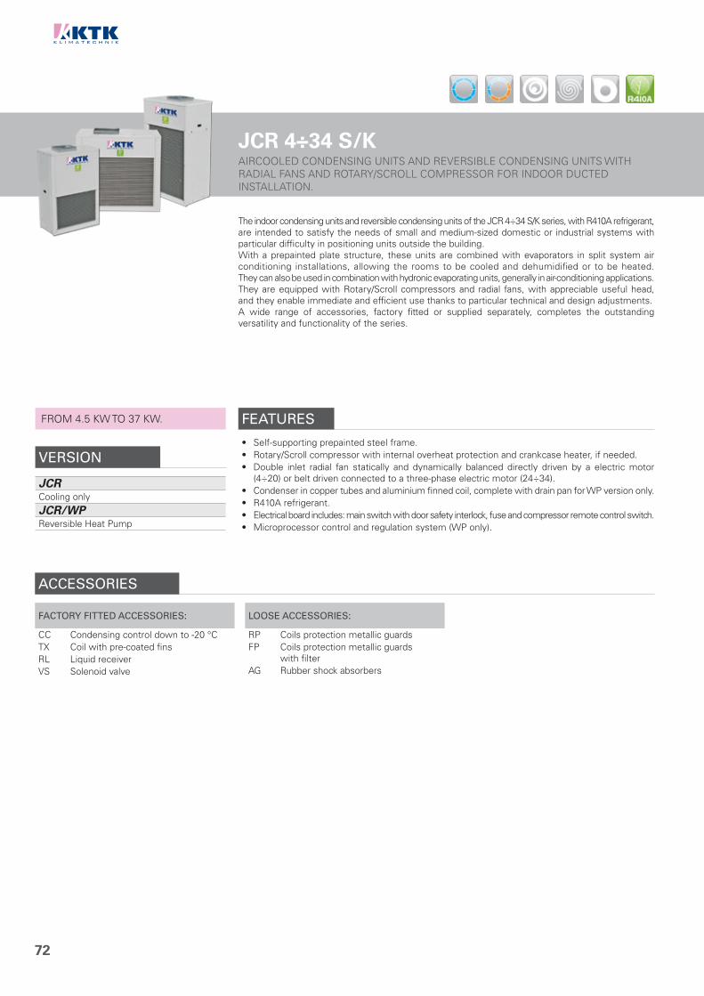
72
JCR 4÷34 S/KAIRCOOLED CONDENSING UNITS AND REVERSIBLE CONDENSING UNITS WITH RADIAL FANS AND ROTARY/SCROLL COMPRESSOR FOR INDOOR DUCTED INSTALLATION.
The indoor condensing units and reversible condensing units of the JCR 4÷34 S/K series, with R410A refrigerant, are intended to satisfy the needs of small and medium-sized domestic or industrial systems with particular difficulty in positioning units outside the building.With a prepainted plate structure, these units are combined with evaporators in split system air conditioning installations, allowing the rooms to be cooled and dehumidified or to be heated. They can also be used in combination with hydronic evaporating units, generally in air-conditioning applications.They are equipped with Rotary/Scroll compressors and radial fans, with appreciable useful head, and they enable immediate and efficient use thanks to particular technical and design adjustments.A wide range of accessories, factory fitted or supplied separately, completes the outstanding versatility and functionality of the series.
FROM 4.5 KW TO 37 KW.
VERSION
JCRCooling only
JCR/WPReversible Heat Pump
FEATURES
• Self-supporting prepainted steel frame.• Rotary/Scroll compressor with internal overheat protection and crankcase heater, if needed.• Double inlet radial fan statically and dynamically balanced directly driven by a electric motor
(4÷20) or belt driven connected to a three-phase electric motor (24÷34).• Condenser in copper tubes and aluminium finned coil, complete with drain pan for WP version only.• R410A refrigerant.• Electrical board includes: main switch with door safety interlock, fuse and compressor remote control switch.• Microprocessor control and regulation system (WP only).
ACCESSORIES
FACTORY FITTED ACCESSORIES:
CC Condensing control down to -20 °CTX Coil with pre-coated finsRL Liquid receiverVS Solenoid valve
LOOSE ACCESSORIES:
RP Coils protection metallic guardsFP Coils protection metallic guards
with filterAG Rubber shock absorbers

73
CLEARANCE AREA
1234
Electrical board side
TECHNICAL DATA - JCR 4÷34 S/KMODEL 4 5 7 8 9 11 14
CoolingCooling capacity (1) kW 4.5 5.6 6.8 8.0 9.2 10.8 13.2Absorbed power (1) kW 1.5 1.9 2.2 2.6 3.0 3.8 4.9
HeatingHeating capacity (2) kW 4.8 5.9 7.3 8.4 9.7 11.3 13.7Absorbed power (2) kW 1.6 2.0 2.4 2.7 3.1 3.9 5.0
CompressorQuantity n° 1 1 1 1 1 1 1Type Rotary Scroll
ConnectionsSuction line Ø mm 16 16 16 16 16 16 18Liquid line Ø mm 10 10 10 10 10 10 12
Available static pressure Pa 90 90 80 80 80 80 115
Electrical characteristics
Power supply V/Ph/Hz 230/1/50 400/3+N/50Max. running current A 10 12 13 14 17 21 11Max. starting current A 40 46 65 65 82 89 61
Sound pressure (3) dB(A) 49 49 49 49 51 52 52
WeightsTransport weight Kg 120 121 123 126 131 133 190Operating weight Kg 121 122 124 127 132 134 192
MODEL 16 18 20 24 27 34
CoolingCooling capacity (1) kW 15.8 19.1 21.2 26.4 30.9 36.6Absorbed power (1) kW 5.9 7.0 7.9 10.3 10.4 13.5
HeatingHeating capacity (2) kW 16.8 19.9 22.0 27.4 33.2 40.9Absorbed power (2) kW 6.1 7.2 8.1 10.5 11.0 13.9
CompressorQuantity n° 1 1 1 1 1 1Type Scroll
ConnectionsSuction line Ø mm 18 22 22 28 28 28Liquid line Ø mm 12 12 12 12 12 12
Available static pressure Pa 115 115 115 150 150 160
Electrical characteristics
Power supply V/Ph/Hz 400/3+N/50Max. running current A 14 14 15 27 33 36Max. starting current A 64 61 77 146 151 148
Sound pressure (3) dB(A) 52 53 62 62 62 63
WeightsTransport weight Kg 200 202 204 313 319 334Operating weight Kg 203 205 207 316 322 338
DIMENSIONSMODEL 4 5 7 8 9 11 14 16 18 20 24 27 34L STD mm 900 900 900 900 900 900 900 900 900 900 1500 1500 1500W STD mm 550 550 550 550 550 550 690 690 690 690 800 800 800H STD mm 1425 1425 1425 1425 1425 1425 1725 1725 1725 1725 1425 1425 1425
NOTE1. Average evaporating temperature 5 °C,
ambient air temperature 35 °C.2. Average condensing temperature 40 °C,
ambient air temperature 7 °C d.b./6 °C w.b.3. Sound pressure level measured in free field
conditions at 1 m from the unit. According to ISO 3744.
N.B. Weights of WP version are specified on technical brochure.
1
JUN
IOR
LIN
E
JCR 4÷11 S/K
100 800 800 800
JCR 14÷20 S/K
100 800 800 1000
JCR 24÷34 S/K
1200 800 800 100

74
JCR 051÷172 S/KAIRCOOLED CONDENSING UNITS AND REVERSIBLE CONDENSING UNITS WITH RADIAL FANS AND SCROLL COMPRESSORS.
The indoor condensing units and reversible condensing units of the JCR 051÷172 S/K series, with R410A refrigerant, are designed to satisfy the needs of medium-sized domestic or industrial systems with particular difficulty in positioning units outside the building.These units are combined with evaporators in split system air conditioning installations, allowing the rooms to be cooled and dehumidified or to be heated. They can also be used in combination with hydronic evaporating units in both air conditioning and industrial process cooling applications.They are equipped with Scroll compressors and radial fans even in a high ESP version, and they enable immediate and efficient use thanks to particular technical and design adjustments.A wide range of accessories, factory fitted or supplied separately, completes the outstanding versatility and functionality of the series.
FROM 51 KW TO 188 KW.
VERSION
JCRCooling only
JCR/APCooling only with high ESP fans
JCR/WPReversible Heat Pump
JCR/WP/APReversible Heat Pump with high ESP fans
FEATURES
• Self-supporting galvanized steel frame protected with additional protection achieved via polyester powder painting.
• Scroll compressors with oil sight glass, internal overheat protection and crankcase heater.• Radial type fans coupled to 3-phase motors by V belt and variable pulley.• Condenser made of copper tubes and aluminium finned coil.• R410A refrigerant.• Electrical board includes: main switch with door safety interlock, fuses, thermal protection relays
for compressors and thermocontacts for fans.• Microprocessor control and regulation system.
ACCESSORIES
FACTORY FITTED ACCESSORIES:
IM Automatic circuit breakersSL Unit silencementRFM Cooling circuit shut-off valve on
discharge lineRFL Cooling circuit shut-off valve on
liquid lineCC Condensing control down to -20 °CTX Coil with pre-coated finsRL Liquid receiverVS Solenoid valveBP Hot gas by-pass valveFF Dryer filter and sight glassSS Soft startIS Modbus RTU protocol, RS485
serial interfaceCP Potential free contacts
LOOSE ACCESSORIES:
MN High and low pressure gaugesCR Remote control panelRP Coils protection metallic guardsFP Coils protection metallic guards
with filterAG Rubber shock absorbersAM Spring shock absorbers

75
CLEARANCE AREA
1234
Electrical board side
TECHNICAL DATA - JCR 051÷172 S/KMODEL 051 061 071 081 091 101 111 131 152 172
CoolingCooling capacity (1) kW 50.6 58.6 66.9 77.2 88.4 102 117 134 156 188Absorbed power (1) kW 18.3 21.4 24.9 28.2 31.9 36.6 43.2 49.6 58.2 69.2
HeatingHeating capacity (2) kW 55.5 63.5 73.6 83.9 94.5 109 125 142 162 193Absorbed power (2) kW 15.6 17.7 21.5 24.1 26.8 30.3 36.7 40.6 46.7 55.5
CompressorQuantity n° 2 2 2 2 2 3 3 3 4 4Refrigerant circuits n° 1 1 1 1 1 1 1 1 2 2Capacity steps n° 2 3 4
ConnectionsSuction line Ø mm 1x35 1x35 1x35 1x35 1x35 1x42 1x42 1x42 2x35 2x35Liquid line Ø mm 1x22 1x22 1x22 1x22 1x22 1x28 1x28 1x28 2x22 2x22
Available static pressure
STD version Pa 165 147 120 120 105 115 135 135 190 105High ESP version Pa 298 288 263 263 245 256 --- --- 400 ---
Electrical characteristics
Power supply V/Ph/Hz 400/3/50Max. running current A 43 48 57 61 70 80 94 107 122 146Max. starting current A 166 169 180 193 237 204 227 275 255 313
Sound pressure
STD version (3) dB(A) 65 65 66 66 66 67 67 67 67 67STD version with SL accessory (3) dB(A) 62 62 63 63 63 64 64 64 64 64High ESP version (3) dB(A) 66 66 67 67 67 68 --- --- 68 ---High ESP version with SL accessory (3) dB(A) 63 63 64 64 64 65 --- --- 65 ---
WeightsTransport weight Kg 595 600 670 680 725 825 865 895 1080 1185Operating weight Kg 605 610 680 690 735 840 880 910 1105 1215
DIMENSIONSMODEL 051 061 071 081 091 101 111 131 152 172L STD/AP mm 2350 2350 2350 2350 2350 2350 2350 2350 3550 3550W STD/AP mm 1100 1100 1100 1100 1100 1100 1100 1100 1100 1100H STD/AP mm 1705 1705 1705 1705 2005 2005 2005 2005 2005 2005
NOTES1. Average evaporating temperature 5 °C, ambient air temperature 35 °C.2. Average condensing temperature 40 °C, ambient air temperature 7 °C d.b./6 °C w.b.3. Sound pressure level measured in free field conditions at 1 m from the unit.
According to ISO 3744.N.B. Weights of WP versions are specified on technical brochure.
1
JUN
IOR
LIN
E
JCR 051÷172 S/K
300 800 800 1800

76

77
1234 TO
P L
INE
CH
AP
TE
R 2
- T
OP
LIN
E
2
Aircooled, Watercooled & Condenserless liquid Chillers and Heat Pumps for wide areas.
TWA 202÷702 S/IK/P/A 78 - 79TWA 212÷682 S/K/P/AF 80 - 81TWA/WP 212÷682 S/K/P/A 82 - 83TWA 212÷1102 S/K/P 84 - 85TWA/FC 212÷1102 S/K/P 86 - 87TWA 212÷1102 S/K 88 - 89TWA 202÷1352 VV/H/A 90 - 91TWA/FC 202÷1062 VV/H 92 - 93TWA 332÷1342 VV/Y/A 94 - 95TWA 302÷1842 VV/Y 96 - 97TWA/FC 302÷1622 VV/Y 98 - 99TWA/EP 172÷632 S/K/P 100 - 101TWA/EP 362÷1492 VV/Y 102 - 103TWA 281÷1432 TT/H 104 - 105TWA/FC 281÷1432 TT/H 106 - 107TWA 251÷1502 TT/Y 108 - 109TWA/FC 251÷1502 TT/Y 110 - 111TWH 212÷1102 S/K/P 112 - 113TWH 212÷1102 S/K 114 - 115TWH 202÷1352 VV/H/A 116 - 117TWH 321÷1321 VV/Y/A 118 - 119TWH 322÷2583 VV/Y 120 - 121TEE 322÷2583 VV/Y 122 - 123TWH 341÷2061 TT/H 124 - 125TWH/DR 341÷2061 TT/H 126 - 127TWH 291÷4061 TT/Y 128 - 129TWH/DR 291÷1541 TT/Y 130 - 131TWH 1601÷8302 CC/Y 132 - 133

78
TWA 202÷702 S/IK/P/AA CLASS ENERGY EFFICIENCY AIRCOOLED LIQUID CHILLERS AND HEAT PUMPS WITH AXIAL FANS, INVERTER SCROLL COMPRESSORS AND PLATE EXCHANGER
The A CLASS energy efficiency liquid Chillers and Heat Pumps of the TWA 202÷702 S/IK/P/A series, with R410A refrigerant, are designed to satisfy the needs of medium and wide-sized service sector or industrial ambients.They are used, combined with Fan Coil units, for the air conditioning or heating of the rooms or to remove the heat developed during industrial processes.All units feature A CLASS energy efficiency and are equipped with Inverter control on Scroll compressor for a better efficiency at partial loads (SEER/ESEER/IPLV/SCOP). The Microchannel condensing coils, available on dedicated versions, ensure an even higher efficiency (high EER), having a better heat exchange than traditional coils. Furthermore, Inverter control is also available on circulating pumps and fans (EC Inverter) for a further efficiency improvement.The units are characterized by multi-compressor design on double cooling circuit, to reach high energy performances, reduction of current at start-up, elimination of inertial tanks and excellent silent functioning. The use of components built in large series makes them highly reliable and the management of an high number of compressors allows increased life span with reduction of machine stopping risks and easier maintenance operations. A wide range of accessories, factory fitted or supplied separately, complete the outstanding versatility and functionality of the series.Are available as option the new EC Inverter fans with high available static pressure and efficiency.The Heat Pump versions are designed for hot water production up to 55°C.
The units are already compliant to ErP 2021 European Regulations.
FROM 196 KW TO 668 KW.
VERSION
TWACooling only
TWA/MCCooling only with MICROCHANNEL condensing coils
TWA/WPReversible Heat Pump
TWA/SSLSuper silenced cooling only
TWA/MC/SSLSuper silenced cooling only with MICROCHANNEL condensing coils
TWA/WP/SSLSuper silenced reversible Heat Pump
FEATURES
• Self-supporting galvanized steel frame protected with additional protection achieved via polyester powder painting.
• DC INVERTER Scroll and ON-OFF Scroll compressors with oil sight glass, internal overheat protection and crankcase heater.
• Axial fans directly coupled to an electric motor with external rotor.• Condenser made of copper tube and aluminum finned coils or aluminium MICROCHANNEL coils.• Evaporator AISI 316 stainless steel braze welded plates type with two independent circuits on
the refrigerant side and one on the water side, complete with water differential pressure switch. On the Heat Pump units it is always installed an antifreeze heater.
• Cooling circuit shut-off valve on liquid line in 302÷702 models.• Electronic expansion valve.• Electronic high and low pressure gauges.• R410A refrigerant.• Electrical board includes: main switch with door safety interlock, fuses or magnetothermic switches,
thermal protection relays for compressors and thermocontacts for fans.• Condensing Control is included: electronic proportional device that ensures efficient and
continuous functioning of the unit with outside air temperature down to –20 °C in cooling mode. It also allows to reduce the sound level especially at night. It consists of a fans speed controller with continuous speed regulation, high and low pressure transducers on cooling circuit and an electrical heater on electrical board.
• Functioning in heating mode with outside air temperature down to -15 °C.• Microprocessor control and regulation system.
ACCESSORIES
FACTORY FITTED ACCESSORIES:
IM Automatic circuit breakersSL Unit silencementRFM Cooling circuit shut-off valve on
discharge lineRFL Cooling circuit shut-off valve on
liquid lineBT Low water temperature kitEC EC Inverter fansECH EC Inverter fans with high available
static pressureDS DesuperheaterRT Total heat recoveryTX Coil with pre-coated finsTXB Coil with epoxy treatment
EW External water connectionsPS Single circulating pumpPSI Inverter single circulating pumpPD Double circulating pumpPDI Inverter double circulating pumpFE Antifreeze heater for evaporatorFN Antifreeze heater for pipesFG Antifreeze heater for single pump
and pipesFM Antifreeze heater for double pump
and pipesIS Modbus RTU protocol, RS485 serial
interfaceISB BACnet MSTP protocol, RS485 serial
interfaceISBT BACnet TCP/IP protocol, Ethernet port
ISL LonWorks protocol, FTT-10 serial interface
IAV Remote set-point, 0-10 V signalIAA Remote set-point, 4-20 mA signalIAS Remote signal for second set-point
activationIDL Demand limit from digital input
LOOSE ACCESSORIES:
MN High and low pressure gaugesCR Remote control panelRP Coils protection metallic guardsFP Coils protection metallic guards
with filterAG Rubber shock absorbersAM Spring shock absorbers

79
CLEARANCE AREA
1234
Electrical board side
TECHNICAL DATA - TWA 202÷702 S/IK/P/AMODEL 202 242 302 332 372 402 442 482 542 702
Cooling STD versions
Cooling capacity (1) kW 196 234 287 316 349 383 422 458 515 668Absorbed power (1) kW 61 73 90 98 109 120 133 144 163 211EER (1) 3.21 3.21 3.19 3.22 3.20 3.19 3.17 3.18 3.16 3.17
Cooling STD versions (EN14511)
Cooling capacity (1) kW 195 233 286 315 348 382 421 457 514 666Absorbed power (1) kW 62 74 91 99 110 121 134 145 164 213EER (1) 3.15 3.15 3.14 3.18 3.16 3.16 3.14 3.15 3.13 3.13ESEER 4.03 3.97 4.01 4.03 4.12 4.06 4.14 4.22 4.24 4.29EUROVENT Class A A A A A A A A A ASEER (2) 4.19 4.30 4.22 4.21 4.18 4.22 4.25 4.18 4.28 4.33Energy Efficiency (2) % 165 169 166 165 164 166 167 164 168 170
Cooling MC versions
Cooling capacity (1) kW 196 234 287 316 349 383 422 458 515 668Absorbed power (1) kW 60 72 89 97 108 119 132 143 161 209EER (1) 3.27 3.25 3.22 3.26 3.23 3.22 3.20 3.20 3.20 3.20
Cooling MC versions (EN14511)
Cooling capacity (1) kW 195 233 286 315 348 382 421 457 514 666Absorbed power (1) kW 61 73 90 98 109 120 133 144 162 211EER (1) 3.20 3.19 3.18 3.21 3.19 3.18 3.17 3.17 3.17 3.16ESEER 4.07 4.01 4.05 4.07 4.16 4.10 4.18 4.26 4.28 4.33EUROVENT Class A A A A A A A A A ASEER (2) 4.22 4.33 4.25 4.24 4.21 4.25 4.28 4.21 4.31 4.36Energy Efficiency (2) % 159 170 167 159 162 167 168 165 169 171
Heating STD versions
Heating capacity (3) kW 212 253 311 343 379 417 458 497 559 724Absorbed power (3) kW 63 75 93 102 112 124 137 148 169 218COP (3) 3.37 3.37 3.34 3.36 3.38 3.36 3.34 3.36 3.31 3.32
Heating STD versions (EN14511)
Heating capacity (3) kW 213 254 312 344 380 418 459 499 561 726Absorbed power (3) kW 65 77 95 104 115 127 140 151 172 223COP (3) 3.28 3.30 3.28 3.31 3.30 3.29 3.28 3.30 3.26 3.26EUROVENT Class A A A A A A A A A ASCOP (4) 3.67 3.57 3.60 3.52 3.61 3.45 3.46 3.41 3.47 3.46Energy Efficiency (4) % 144 140 141 138 141 135 135 133 136 135
CompressorQuantity n° 2+2 2+2 2+2 2+2 2+2 3+3 3+3 3+3 3+3 3+3Refrigerant circuits n° 2 2 2 2 2 2 2 2 2 2Capacity steps n° Stepless
EvaporatorWater flow l/s 9.36 11.18 13.71 15.10 16.67 18.30 20.16 21.88 24.61 31.92Pressure drops kPa 38 36 35 37 40 32 33 36 32 37Water connections DN 80 80 80 80 80 150 150 150 150 150
Electrical characteristics
Power supply V/Ph/Hz 400/3/50Max. running current A 137 156 194 211 173 250 202 320 355 460Max. starting current A 305 334 407 424 386 428 415 534 617 800
Unit with pumpPump available static pressure kPa 160 140 170 185 170 165 145 185 175 145Water connections DN 100 100 100 100 100 150 150 150 150 150
Sound pressure
STD versions (5) dB(A) 69 71 72 72 72 72 73 73 74 75STD versions with SL accessory (5) dB(A) 66 67 68 69 69 69 70 70 71 72
SSL versions (5) dB(A) 63 64 65 64 65 66 66 67 67 ---MC versions (5) dB(A) 68 70 71 71 71 71 72 72 73 74MC versions with SL accessory (5) dB(A) 65 66 67 68 68 68 69 69 70 71
MC/SSL versions (5) dB(A) 62 63 64 63 64 65 65 66 67 ---
WeightsTransport weight Kg 2251 2384 2511 2791 2851 3186 3248 3658 3836 4392Operating weight Kg 2270 2410 2550 2830 2890 3230 3300 3710 3900 4470
DIMENSIONSMODEL 202 242 302 332 372 402 442 482 542 702
LSTD-MC mm 4000 4000 4000 5000 5000 5000 5000 6200 6200 7200
SSL-MC/SSL mm 5000 5000 5000 6200 6200 6200 6200 7200 7200 ---W STD-SSL-MC-MC/SSL mm 2200 2200 2200 2200 2200 2200 2200 2200 2200 2200H STD-SSL-MC-MC/SSL mm 2100 2100 2100 2100 2100 2100 2100 2100 2100 2100
ErP SCOPErP SEER
NOTES1. Chilled water from 12 to 7 °C, ambient air temperature 35 °C.2. Seasonal energy efficiency of cooling at low temperature. According to EU
Regulation n. 2016/2281.3. Heated water from 40 to 45 °C, ambient air temperature 7 °C d.b./6 °C w.b.4. Seasonal energy efficiency of heating at low temperature with average climatic
conditions. According to EU Regulation n. 811/2013.5. Sound pressure level measured in free field conditions at 1 m from the unit.
According to ISO 3744.N.B. Weights of SSL and WP versions are specified on technical brochure.N.B. Data of MC versions are specified on technical brochure.
2
TOP
LIN
E
TWA 202÷702 S/IK/P/A
500 1800 1000 1800

80
TWA 212÷682 S/K/P/AFA CLASS ENERGY EFFICIENCY AIRCOOLED LIQUID CHILLERS AND HEAT PUMPS WITH AXIAL FANS, SCROLL COMPRESSORS AND PLATE EXCHANGER.
FROM 197 KW TO 692 KW.
VERSION
TWACooling only
TWA/WPReversible Heat Pump
TWA/SSLSuper silenced cooling only
TWA/WP/SSLSuper silenced reversible Heat Pump
The TWA 212÷682 S/K/P/AF liquid Chillers and Heat Pumps are characterized by A CLASS energy efficiency.The units are characterized by multi-compressor design on double cooling circuit, to reach high energy performances, reduction of current at start-up, elimination of inertial tanks and excellent silent functioning. The use of components built in large series makes them highly reliable and the management of an high number of compressors allows increased life span with reduction of machine stopping risks and easier maintenance operations. A wide range of accessories, factory fitted or supplied separately, complete the outstanding versatility and functionality of the series.Are available as option the new EC Inverter fans with high available static pressure and efficiency.The Heat Pump versions are designed for hot water production up to 55°C.
The units are already compliant to ErP 2021 European Regulations.
TWA 212÷682 S/G/P/AFOn request, units can be supplied with R452B refrigerant.
FEATURES
• Self-supporting galvanized steel frame protected with additional protection achieved via polyester powder painting.
• Scroll compressors with oil sight glass, internal overheat protection and crankcase heater.• Axial fans directly coupled to an electric motor with external rotor.• Condenser made of copper tubes and aluminium finned coils.• Evaporator AISI 316 stainless steel braze welded plates type with two independent circuits on
the refrigerant side and one on the water side, complete with water differential pressure switch. On the Heat Pump units it is always installed an antifreeze heater.
• Cooling circuit shut-off valve on liquid line in 302÷682 models.• Electronic expansion valve.• Electronic high and low pressure gauges.• R410A refrigerant. On request R452B refrigerant.• Electrical board includes: main switch with door safety interlock, fuses or magnetothermic switches,
thermal protection relays for compressors and thermocontacts for fans.• Functioning in heating mode with outside air temperature down to -15 °C.• Microprocessor control and regulation system.
ACCESSORIES
FACTORY FITTED ACCESSORIES:
IM Automatic circuit breakersSL Unit silencementRFM Cooling circuit shut-off valve on
discharge lineRFL Cooling circuit shut-off valve on
liquid lineCT Condensing control down to 0 °CCC Condensing control down to -20 °CBT Low water temperature kitEC EC Inverter fansECH EC Inverter fans with high available
static pressureDS DesuperheaterRT Total heat recoveryTX Coil with pre-coated finsEW External water connections
PS Single circulating pumpPSI Inverter single circulating pumpPD Double circulating pumpPDI Inverter double circulating pumpFE Antifreeze heater for evaporatorFN Antifreeze heater for pipesFG Antifreeze heater for single pump
and pipesFM Antifreeze heater for double pump
and pipesSS Soft startIS Modbus RTU protocol, RS485 serial
interfaceISB BACnet MSTP protocol, RS485 serial
interfaceISBT BACnet TCP/IP protocol, Ethernet portISL LonWorks protocol, FTT-10 serial
interface
IAV Remote set-point, 0-10 V signalIAA Remote set-point, 4-20 mA signalIAS Remote signal for second set-point
activationIDL Demand limit from digital input
LOOSE ACCESSORIES:
MN High and low pressure gaugesCR Remote control panelRP Coils protection metallic guardsFP Coils protection metallic guards
with filterAG Rubber shock absorbersAM Spring shock absorbers

81
CLEARANCE AREA
Electrical board side
1234
TECHNICAL DATA - TWA 212÷682 S/K/P/AFMODEL 212 222 242 272 302 342 362
CoolingCooling capacity (1) kW 197 220 245 271 300 329 361Absorbed power (1) kW 62 69 76 83 95 105 111EER (1) 3.18 3.19 3.22 3.27 3.16 3.13 3.25
Cooling (EN14511)
Cooling capacity (1) kW 196 219 244 270 299 328 360Absorbed power (1) kW 63 70 77 84 96 105 112EER (1) 3.11 3.13 3.17 3.21 3.11 3.12 3.21ESEER 3.75 3.80 3.90 4.01 3.90 4.15 4.13EUROVENT Class A A A A A A ASEER (2) 4.13 4.14 4.18 4.24 4.10 4.10 4.22Energy Efficiency (2) % 162 163 164 167 161 161 166
HeatingHeating capacity (3) kW 214 239 266 295 325 359 391Absorbed power (3) kW 65 73 81 88 99 109 119COP (3) 3.29 3.27 3.28 3.35 3.28 3.29 3.29
Heating (EN14511)
Heating capacity (3) kW 215 240 267 296 327 360 393Absorbed power (3) kW 67 75 83 90 102 112 122COP (3) 3.21 3.20 3.22 3.29 3.21 3.21 3.22EUROVENT Class A A A A A A ASCOP (4) 3.35 3.42 3.35 3.34 3.37 3.34 3.35Energy Efficiency (4) % 131 134 131 131 132 131 131
CompressorQuantity n° 3+3 3+3 3+3 3+3 4+4 4+4 4+4Refrigerant circuits n° 2 2 2 2 2 2 2Capacity steps n° 6 8
EvaporatorWater flow l/s 9.41 10.51 11.71 12.95 14.33 15.72 17.25Pressure drops kPa 45 49 44 42 50 39 46Water connections DN 80 80 80 80 80 80 80
Electrical characteristics
Power supply V/Ph/Hz 400/3/50Max. running current A 152 166 187 199 224 241 258Max. starting current A 276 299 354 367 357 409 426
Unit with pump Pump available static pressure kPa 155 135 205 185 180 185 170Water connections DN 100 100 100 100 100 100 100
Sound pressureSTD version (5) dB(A) 69 71 72 72 72 72 73With SL accessory (5) dB(A) 66 68 69 69 69 69 70SSL version (5) dB(A) 63 65 66 67 66 67 68
Weights Transport weight Kg 1854 2171 2289 2317 2437 2680 2690Operating weight Kg 1870 2190 2310 2340 2460 2710 2720
MODEL 412 442 482 562 622 682
CoolingCooling capacity (1) kW 396 435 485 538 609 692Absorbed power (1) kW 124 137 154 169 192 220EER (1) 3.19 3.18 3.15 3.18 3.17 3.15
Cooling (EN14511)
Cooling capacity (1) kW 394 433 484 536 607 690Absorbed power (1) kW 126 139 155 171 194 222EER (1) 3.13 3.12 3.12 3.13 3.13 3.11ESEER 4.06 4.08 4.10 4.11 4.05 4.09EUROVENT Class A A A A A ASEER (2) 4.14 4.13 4.16 4.13 4.11 4.13Energy Efficiency (2) % 163 162 163 162 161 162
HeatingHeating capacity (3) kW 431 473 526 586 663 754Absorbed power (3) kW 129 143 162 176 202 231COP (3) 3.34 3.31 3.25 3.33 3.28 3.26
Heating (EN14511)
Heating capacity (3) kW 433 475 528 588 665 756Absorbed power (3) kW 133 147 165 181 206 236COP (3) 3.26 3.23 3.20 3.25 3.23 3.20EUROVENT Class A A A A A ASCOP (4) 3.36 3.32 3.36 3.21 3.24 3.43Energy Efficiency (4) % 131 130 131 125 127 134
CompressorQuantity n° 5+5 5+5 6+6 6+6 6+6 6+6Refrigerant circuits n° 2 2 2 2 2 2Capacity steps n° 8 10
EvaporatorWater flow l/s 18.92 20.78 23.17 25.70 29.10 33.06Pressure drops kPa 49 49 33 41 34 32Water connections DN 80 80 150 150 150 150
Electrical characteristics
Power supply V/Ph/Hz 400/3/50Max. running current A 274 324 358 391 446 500Max. starting current A 407 492 525 558 623 678
Unit with pump Pump available static pressure kPa 155 125 185 170 160 145Water connections DN 100 100 100 100 150 150
Sound pressureSTD version (5) dB(A) 74 74 73 74 75 75With SL accessory (5) dB(A) 71 71 70 71 72 72SSL version (5) dB(A) 68 68 68 69 --- ---
Weights Transport weight Kg 2869 3004 3512 3642 4420 4458Operating weight Kg 2900 3040 3560 3690 4480 4520
DIMENSIONSMODEL 212 222 242 272 302 342 362 412 442 482 562 622 682
LSTD mm 4000 4000 4000 4000 5000 5000 5000 5000 5000 6200 6200 7200 7200SSL mm 5000 5000 5000 5000 6200 6200 6200 6200 6200 7200 7200 --- ---
W STD/SSL mm 2200 2200 2200 2200 2200 2200 2200 2200 2200 2200 2200 2200 2200H STD/SSL mm 2100 2100 2100 2100 2100 2100 2100 2100 2100 2100 2100 2100 2100
ErP SCOPErP SEER
NOTES1. Chilled water from 12 to 7 °C, ambient air temperature 35 °C.2. Seasonal energy efficiency of cooling at low temperature. According to EU
Regulation n. 2016/2281.3. Heated water from 40 to 45 °C, ambient air temperature 7 °C d.b./6 °C w.b.4. Seasonal energy efficiency of heating at low temperature with average climatic
conditions. According to EU Regulation n. 811/2013.5. Sound pressure level measured in free field conditions at 1 m from the unit.
According to ISO 3744.N.B. Weights of SSL and WP versions are specified on technical brochure.
2
TOP
LIN
E
TWA 212÷682 S/K/P/AF
500 1800 1000 1800

82
TWA/WP 212÷682 S/K/P/AA CLASS ENERGY EFFICIENCY AIRCOOLED REVERSIBLE HEAT PUMPSWITH AXIAL FANS, SCROLL COMPRESSORS AND PLATE EXCHANGER.
FROM 227 KW TO 762 KW.
VERSION
TWA/WPReversible Heat Pump
TWA/WP/SSLSuper silenced reversible Heat Pump
The TWA/WP 212÷682 S/K/P/A reversible Heat Pumps are characterized by A CLASS energy efficiency.The units are characterized by multi-compressor design on double cooling circuit, to reach high energy performances, reduction of current at start-up, elimination of inertial tanks and excellent silent functioning. The use of components built in large series makes them highly reliable and the management of an high number of compressors allows increased life span with reduction of machine stopping risks and easier maintenance operations. A wide range of accessories, factory fitted or supplied separately, complete the outstanding versatility and functionality of the series.Are available as option the new EC Inverter fans with high available static pressure and efficiency.Units are designed for hot water production up to 55°C.
TWA/WP 212÷682 S/G/P/AOn request, units can be supplied with R452B refrigerant.
FEATURES
• Self-supporting galvanized steel frame protected with additional protection achieved via polyester powder painting.
• Scroll compressors with oil sight glass, internal overheat protection and crankcase heater.• Axial fans directly coupled to an electric motor with external rotor.• Condenser made of copper tubes and aluminium finned coils.• Evaporator AISI 316 stainless steel braze welded plates type with two independent circuits on
the refrigerant side and one on the water side, complete with water differential pressure switch. On the units it is always installed an antifreeze heater.
• Cooling circuit shut-off valve on liquid line in 302÷682 models.• Electronic expansion valve.• Electronic high and low pressure gauges.• R410A refrigerant. On request R452B refrigerant.• Electrical board includes: main switch with door safety interlock, fuses or magnetothermic switches,
thermal protection relays for compressors and thermocontacts for fans.• Functioning in heating mode with outside air temperature down to -15 °C.• Microprocessor control and regulation system.
ACCESSORIES
FACTORY FITTED ACCESSORIES:
IM Automatic circuit breakersSL Unit silencementRFM Cooling circuit shut-off valve on
discharge lineRFL Cooling circuit shut-off valve on
liquid lineCT Condensing control down to 0 °CCC Condensing control down to -20 °CBT Low water temperature kitEC EC Inverter fansECH EC Inverter fans with high available
static pressureDS DesuperheaterRT Total heat recovery
TX Coil with pre-coated finsEW External water connectionsPS Single circulating pumpPSI Inverter single circulating pumpPD Double circulating pumpPDI Inverter double circulating pumpFN Antifreeze heater for pipesFG Antifreeze heater for single pump
and pipesFM Antifreeze heater for double pump
and pipesSS Soft startIS Modbus RTU protocol, RS485 serial
interfaceISB BACnet MSTP protocol, RS485 serial
interface
ISBT BACnet TCP/IP protocol, Ethernet portISL LonWorks protocol, FTT-10 serial
interfaceIAV Remote set-point, 0-10 V signalIAA Remote set-point, 4-20 mA signalIAS Remote signal for second set-point
activationIDL Demand limit from digital input
LOOSE ACCESSORIES:
MN High and low pressure gaugesCR Remote control panelRP Coils protection metallic guardsAG Rubber shock absorbersAM Spring shock absorbers

83
CLEARANCE AREA
Electrical board side
1234
TECHNICAL DATA - TWA/WP 212÷682 S/K/P/AMODEL 212 222 242 272 302 342 362
HeatingHeating capacity (1) kW 227 256 272 294 342 369 389Absorbed power (1) kW 66 75 81 85 102 106 112COP (1) 3.44 3.41 3.36 3.46 3.35 3.48 3.47
Heating (EN14511)
Heating capacity (1) kW 228 257 273 295 343 370 390Absorbed power (1) kW 68 77 83 87 105 108 115COP (1) 3.35 3.34 3.29 3.39 3.27 3.43 3.39EUROVENT Class A A A A A A ASCOP (2) 3.35 3.42 3.35 3.34 3.37 3.34 3.35Energy Efficiency (2) % 131 134 131 131 132 131 131
CoolingCooling capacity (3) kW 194 217 239 259 294 322 339Absorbed power (3) kW 68 75 78 85 100 107 113EER (3) 2.85 2.89 3.06 3.05 2.94 3.01 3.00
Cooling (EN14511)
Cooling capacity (3) kW 193 216 238 258 293 321 338Absorbed power (3) kW 69 76 79 86 101 108 114EER (3) 2.80 2.84 3.01 3.00 2.90 2.97 2.96ESEER 3.64 3.69 3.79 3.89 3.79 4.03 4.01EUROVENT Class C C B B C B B
CompressorQuantity n° 3+3 3+3 3+3 3+3 4+4 4+4 4+4Refrigerant circuits n° 2 2 2 2 2 2 2Capacity steps n° 6 8
EvaporatorWater flow l/s 9.27 10.37 11.42 12.37 14.05 15.38 16.20Pressure drops kPa 44 55 42 38 49 37 41Water connections DN 80 80 80 80 80 80 80
Electrical characteristics
Power supply V/Ph/Hz 400/3/50Max. running current A 152 166 187 199 224 241 258Max. starting current A 276 299 354 367 357 409 426
Unit with pump Pump available static pressure kPa 155 130 205 190 180 185 175Water connections DN 100 100 100 100 100 100 100
Sound pressureSTD version (4) dB(A) 69 67 68 68 68 69 70With SL accessory (4) dB(A) 66 64 65 65 65 66 67SSL version (4) dB(A) 58 60 61 61 61 62 62
Weights Transport weight Kg 1954 2291 2409 2437 2567 2820 2830Operating weight Kg 1970 2310 2430 2460 2590 2850 2860
MODEL 412 442 482 562 622 682
HeatingHeating capacity (1) kW 420 476 532 566 677 762Absorbed power (1) kW 125 141 157 169 202 226COP (1) 3.36 3.38 3.39 3.35 3.35 3.37
Heating (EN14511)
Heating capacity (1) kW 422 478 533 568 679 764Absorbed power (1) kW 128 144 160 172 206 230COP (1) 3.30 3.32 3.33 3.30 3.30 3.32EUROVENT Class A A A A A ASCOP (2) 3.36 3.32 3.36 3.21 3.24 3.43Energy Efficiency (2) % 131 130 131 125 127 134
CoolingCooling capacity (3) kW 359 421 475 512 597 671Absorbed power (3) kW 127 144 162 172 207 241EER (3) 2.83 2.92 2.93 2.98 2.88 2.78
Cooling (EN14511)
Cooling capacity (3) kW 358 419 474 510 595 669Absorbed power (3) kW 128 146 163 174 209 243EER (3) 2.80 2.87 2.91 2.93 2.85 2.75ESEER 3.94 3.96 3.98 3.99 3.93 3.97EUROVENT Class C C B B C C
CompressorQuantity n° 5+5 5+5 6+6 6+6 6+6 6+6Refrigerant circuits n° 2 2 2 2 2 2Capacity steps n° 8 10
EvaporatorWater flow l/s 17.15 20.11 22.69 24.46 28.52 32.06Pressure drops kPa 46 46 32 37 33 30Water connections DN 80 80 150 150 150 150
Electrical characteristics
Power supply V/Ph/Hz 400/3/50Max. running current A 274 324 358 391 446 500Max. starting current A 407 492 525 558 623 678
Unit with pump Pump available static pressure kPa 160 130 185 175 160 145Water connections DN 100 100 100 100 150 150
Sound pressureSTD version (4) dB(A) 70 73 73 73 73 74With SL accessory (4) dB(A) 67 70 70 70 70 71SSL version (4) dB(A) 62 63 64 65 --- ---
Weights Transport weight Kg 3019 3164 3702 3832 4660 4698Operating weight Kg 3050 3200 3750 3880 4720 4770
DIMENSIONSMODEL 212 222 242 272 302 342 362 412 442 482 562 622 682
LSTD mm 2800 4000 4000 4000 4000 5000 5000 5000 5000 6200 6200 7200 7200SSL mm 4000 4000 5000 5000 5000 5000 5000 5000 6200 6200 7200 --- ---
W STD/SSL mm 2200 2200 2200 2200 2200 2200 2200 2200 2200 2200 2200 2200 2200H STD/SSL mm 2100 2100 2100 2100 2100 2100 2100 2100 2100 2100 2100 2100 2100
ErP SCOP
NOTES1. Heated water from 40 to 45 °C, ambient air temperature 7 °C d.b./6 °C w.b.2. Seasonal energy efficiency of heating at low temperature with average climatic
conditions. According to EU Regulation n. 811/2013.3. Chilled water from 12 to 7 °C, ambient air temperature 35 °C.4. Sound pressure level measured in free field conditions at 1 m from the unit.
According to ISO 3744.N.B. Weights of SSL version are specified on technical brochure.
2
TOP
LIN
E
TWA/WP 212÷682 S/K/P/A
500 1800 1000 1800

84
TWA 212÷1102 S/K/PAIRCOOLED LIQUID CHILLERS AND HEAT PUMPS WITH AXIAL FANS, SCROLL COMPRESSORS AND PLATE EXCHANGER.
FROM 199 KW TO 1051 KW.
VERSION
TWACooling only
TWA/WPReversible Heat Pump
TWA/SSLSuper silenced cooling only
TWA/WP/SSLSuper silenced reversible Heat Pump
The liquid Chillers and Heat Pumps of the TWA 212÷1102 S/K/P series, with R410A refrigerant, are designed for large-sized service sector or industrial ambients.The units are characterized by multi-compressor design on double cooling circuit, to reach high energy performances, reduction of current at start-up, elimination of inertial tanks and excellent silent functioning. The use of components built in large series makes them highly reliable and the management of an high number of compressors allows increased life span with reduction of machine stopping risks and easier maintenance operations. A wide range of accessories, factory fitted or supplied separately, complete the outstanding versatility and functionality of the series.Are available as option the new EC Inverter fans with high available static pressure and efficiency.
TWA 212÷1102 S/G/POn request, units can be supplied with R452B refrigerant.
FEATURES
• Self-supporting galvanized steel frame protected with additional protection achieved via polyester powder painting.
• Scroll compressors with oil sight glass, internal overheat protection and crankcase heater.• Axial fans directly coupled to an electric motor with external rotor.• Condenser made of copper tubes and aluminium finned coils.• Evaporator AISI 316 stainless steel braze welded plates type with two independent circuits on
the refrigerant side and one on the water side, complete with water differential pressure switch. On the Heat Pump units it is always installed an antifreeze heater.
• Cooling circuit shut-off valve on liquid line in 302÷1102 models.• Electronic expansion valve.• Electronic high and low pressure gauges.• R410A refrigerant. On request R452B refrigerant.• Electrical board includes: main switch with door safety interlock, fuses or magnetothermic switches,
thermal protection relays for compressors and thermocontacts for fans.• Microprocessor control and regulation system.
ACCESSORIES
FACTORY FITTED ACCESSORIES:
IM Automatic circuit breakersSL Unit silencementRFM Cooling circuit shut-off valve on
discharge lineRFL Cooling circuit shut-off valve on
liquid lineCT Condensing control down to 0 °CCC Condensing control down to -20 °CBT Low water temperature kitEC EC Inverter fansECH EC Inverter fans with high available
static pressureDS DesuperheaterRT Total heat recoveryTX Coil with pre-coated finsEW External water connections
PS Single circulating pumpPSI Inverter single circulating pumpPD Double circulating pumpPDI Inverter double circulating pumpFE Antifreeze heater for evaporatorFN Antifreeze heater for pipesFG Antifreeze heater for single pump
and pipesFM Antifreeze heater for double pump
and pipesSS Soft startIS Modbus RTU protocol, RS485 serial
interfaceISB BACnet MSTP protocol, RS485 serial
interfaceISBT BACnet TCP/IP protocol, Ethernet portISL LonWorks protocol, FTT-10 serial
interface
IAV Remote set-point, 0-10 V signalIAA Remote set-point, 4-20 mA signalIAS Remote signal for second set-point
activationIDL Demand limit from digital input
LOOSE ACCESSORIES:
MN High and low pressure gaugesCR Remote control panelRP Coils protection metallic guardsFP Coils protection metallic guards
with filterAG Rubber shock absorbersAM Spring shock absorbers

85
CLEARANCE AREA
Electrical board side
1234
TECHNICAL DATA - TWA 212÷1102 S/K/PMODEL 212 222 242 272 302 342 362 412 442
CoolingCooling capacity (1) kW 199 226 251 276 304 335 367 403 444Absorbed power (1) kW 69 80 85 94 104 113 122 132 155EER (1) 2.88 2.83 2.95 2.94 2.92 2.96 3.01 3.05 2.86
Cooling (EN14511)
Cooling capacity (1) kW 198 225 250 275 303 334 365 402 442Absorbed power (1) kW 70 81 86 95 105 115 124 134 157EER (1) 2.84 2.78 2.89 2.89 2.87 2.91 2.95 3.00 2.81ESEER 3.54 3.65 3.66 3.77 3.76 3.88 3.73 3.90 3.75EUROVENT Class C C C C C B B B CSEER (2) 3.82 3.81 3.86 3.96 3.90 4.03 4.13 4.12 4.11Energy Efficiency (2) % 150 149 151 155 153 158 162 175 161
HeatingHeating capacity (3) kW 228 255 283 310 338 369 401 441 510Absorbed power (3) kW 73 83 90 103 108 121 132 141 164COP (3) 3.12 3.07 3.14 3.01 3.13 3.05 3.04 3.13 3.11
Heating (EN14511)
Heating capacity (3) kW 228 255 283 311 338 370 402 442 511Absorbed power (3) kW 73 83 90 103 108 122 133 142 165COP (3) 3.12 3.07 3.14 3.01 3.12 3.04 3.03 3.12 3.10EUROVENT Class B B B B B B B B BSCOP (4) 3.20 3.21 3.22 3.21 3.22 3.19 3.19 3.19 3.19Energy Efficiency (4) % 125 126 126 125 126 125 125 125 125
CompressorQuantity n° 3+3 3+3 3+3 3+3 4+4 4+4 4+4 5+5 5+5Refrigerant circuits n° 2 2 2 2 2 2 2 2 2Capacity steps n° 6 8
EvaporatorWater flow l/s 9.51 10.80 11.99 13.19 14.52 16.01 17.53 19.25 21.21Pressure drops kPa 40 51 62 54 50 49 59 47 59Water connections DN 80 80 80 80 80 80 80 80 80
Electrical characteristics
Power supply V/Ph/Hz 400/3/50Max. running current A 152 166 179 191 216 233 250 274 316Max. starting current A 276 299 347 359 349 401 418 407 484
Unit with pump Pump available static pressure kPa 155 130 175 160 180 170 145 140 110Water connections DN 100 100 100 100 100 100 100 100 100
Sound pressureSTD version (5) dB(A) 66 66 67 69 67 69 70 68 69With SL accessory (5) dB(A) 63 63 64 66 64 65 66 65 66SSL version (5) dB(A) 57 57 59 61 58 60 62 59 61
Weights Transport weight Kg 1654 1674 1763 1961 2199 2457 2566 2610 3179Operating weight Kg 1670 1690 1780 1980 2220 2480 2590 2640 3210
MODEL 482 562 622 682 762 862 962 1102
CoolingCooling capacity (1) kW 495 546 602 671 751 845 942 1051Absorbed power (1) kW 170 184 211 243 275 303 336 365EER (1) 2.91 2.97 2.85 2.76 2.73 2.79 2.80 2.88
Cooling (EN14511)
Cooling capacity (1) kW 493 544 599 669 749 842 939 1047Absorbed power (1) kW 172 186 214 246 277 306 339 369EER (1) 2.87 2.92 2.81 2.72 2.70 2.75 2.77 2.84ESEER 3.71 3.72 3.67 3.76 3.67 3.69 3.73 3.81EUROVENT Class C B C C D C C CSEER (2) 4.17 4.17 4.12 4.19 4.10 4.15 4.17 4.12Energy Efficiency (2) % 167 164 162 165 161 163 164 169
HeatingHeating capacity (3) kW 564 620 684 776 861 962 1078 1210Absorbed power (3) kW 182 202 223 249 282 312 349 383COP (3) 3.10 3.07 3.07 3.12 3.05 3.08 3.09 3.16
Heating (EN14511)
Heating capacity (3) kW 565 621 685 777 862 963 1079 1211Absorbed power (3) kW 183 203 224 250 283 313 350 384COP (3) 3.09 3.07 3.06 3.11 3.05 3.08 3.08 3.15EUROVENT Class B B B B B B B BSCOP (4) - - - - - - - -Energy Efficiency (4) % - - - - - - - -
CompressorQuantity n° 6+6 6+6 6+6 6+6 6+6 6+6 6+6 6+6Refrigerant circuits n° 2 2 2 2 2 2 2 2Capacity steps n° 10
EvaporatorWater flow l/s 23.65 26.09 28.76 32.06 35.88 40.37 45.01 50.21Pressure drops kPa 49 60 58 49 41 51 42 52Water connections DN 80 80 80 150 150 150 150 150
Electrical characteristics
Power supply V/Ph/Hz 400/3/50Max. running current A 350 375 422 485 545 598 676 746Max. starting current A 518 543 600 662 759 812 938 1007
Unit with pump Pump available static pressure kPa 165 145 135 125 165 140 130 100Water connections DN 100 100 150 150 150 150 150 150
Sound pressureSTD version (5) dB(A) 68 70 72 73 73 73 73 74With SL accessory (5) dB(A) 65 67 69 70 70 70 70 71SSL version (5) dB(A) 60 62 64 65 64 65 --- ---
Weights Transport weight Kg 3294 3463 3517 3682 4200 4518 4918 5044Operating weight Kg 3330 3500 3560 3730 4260 4580 4990 5120
DIMENSIONSMODEL 212 222 242 272 302 342 362 412 442 482 562 622 682 762 862 962 1102
LSTD mm 2800 2800 2800 2800 4000 4000 4000 4000 5000 5000 5000 5000 5000 6200 6200 7200 7200SSL mm 2800 2800 2800 2800 4000 4000 4000 4000 5000 5000 5000 5000 6200 7200 7200 --- ---
W STD/SSL mm 2200 2200 2200 2200 2200 2200 2200 2200 2200 2200 2200 2200 2200 2200 2200 2200 2200H STD/SSL mm 2100 2100 2100 2100 2100 2100 2100 2100 2100 2100 2100 2100 2100 2100 2100 2100 2100
ErP SCOPErP SEER
NOTES1. Chilled water from 12 to 7 °C, ambient air temperature 35 °C.2. Seasonal energy efficiency of cooling at low temperature. According to EU
Regulation n. 2016/2281.3. Heated water from 40 to 45 °C, ambient air temperature 7 °C d.b./6 °C w.b.4. Seasonal energy efficiency of heating at low temperature with average climatic
conditions. According to EU Regulation n. 811/2013.5. Sound pressure level measured in free field conditions at 1 m from the unit.
According to ISO 3744.N.B. Weights of SSL and WP versions are specified on technical brochure.
2
TOP
LIN
E
TWA 212÷1102 S/K/P
500 1800 1000 1800

86
TWA/FC 212÷1102 S/K/PAIRCOOLED LIQUID CHILLERS FREE-COOLING WITH AXIAL FANS, SCROLL COMPRESSORS AND PLATE EXCHANGER.
The liquid Chillers of the TWA/FC 212÷1102 S/K/P series, with R410A refrigerant, provide advanced technology, flexible and reliable, through an intelligent control module which optimizes the operating times and the powers delivered by the Scroll compressors, according to the needs of the systems, both civil and industrial, where the production of chilled water is required in continuous service throughout the year. During the cold months, in FREE-COOLING operating mode, the liquid returning from the system is cooled directly, by way of the forced convection of outside air through the condensing coil, thus reducing the energy required for the Scroll compressors operation that the units are equipped with. A system of 3-way valves, controlled by the electronic microprocessor controller that manages the entire unit, can, depending on outside air temperature, operate in CHILLER, FREE-COOLING or MIXED (CHILLER and FREE-COOLING at the same time) mode. TWA/FC 212÷1102 S/K/P allows the reduction of inrush currents generated, the elimination of inertial accumulation tanks and an excellent silent functioning, as the fans adjust their speed to the actual load of the system, providing great benefits especially at night.Are available as option the new EC Inverter fans with high available static pressure and efficiency.
TWA/FC 212÷1102 S/G/POn request, units can be supplied with R452B refrigerant.
FROM 208 KW TO 1102 KW.
VERSION
TWA/FCCooling only
FEATURES
• Self-supporting galvanized steel frame protected with additional protection achieved via polyester powder painting.
• Scroll compressors with oil sight glass, internal overheat protection and crankcase heater.• Axial fans directly coupled to an electric motor with external rotor.• Condenser made of copper tubes and aluminium finned coils combined with FREE-COOLING coils.• Evaporator AISI 316 stainless steel braze welded plates type with two independent circuits on
the refrigerant side and one on the water side, complete with water differential pressure switch.• Cooling circuit shut-off valve on liquid line in 302÷1102 models.• Electronic expansion valve.• Electronic high and low pressure gauges.• R410A refrigerant. On request R452B refrigerant.• Electrical board includes: main switch with door safety interlock, fuses or magnetothermic switches,
thermal protection relays for compressors and thermocontacts for fans.• Condensing Control is included: electronic proportional device that ensures efficient and
continuous functioning of the unit with outside air temperature down to –20 °C. It also allows to reduce the sound level especially at night. It consists of a fans speed controller with continuous speed regulation, high and low pressure transducers on cooling circuit and an electrical heater on electrical board.
• Microprocessor control and regulation system.
ACCESSORIES
FACTORY FITTED ACCESSORIES:
IM Automatic circuit breakersSL Unit silencementRFM Cooling circuit shut-off valve on
discharge lineRFL Cooling circuit shut-off valve on
liquid lineBT Low water temperature kitEC EC Inverter fansECH EC Inverter fans with high available
static pressureTX Coil with pre-coated fins
PS Single circulating pumpPSI Inverter single circulating pumpPD Double circulating pumpPDI Inverter double circulating pumpSS Soft startIS Modbus RTU protocol, RS485 serial
interfaceISB BACnet MSTP protocol, RS485 serial
interfaceISBT BACnet TCP/IP protocol, Ethernet portISL LonWorks protocol, FTT-10 serial
interfaceIAV Remote set-point, 0-10 V signal
IAA Remote set-point, 4-20 mA signalIAS Remote signal for second set-point
activationIDL Demand limit from digital input
LOOSE ACCESSORIES:
MN High and low pressure gaugesCR Remote control panelRP Coils protection metallic guardsAG Rubber shock absorbersAM Spring shock absorbers

87
CLEARANCE AREA
1234
Electrical board side
TECHNICAL DATA - TWA/FC 212÷1102 S/K/PMODEL 212 222 242 272 302 342 362 412 442
CoolingCooling capacity (1) kW 208 236 263 290 328 365 401 441 483Absorbed power (1) kW 76 87 88 98 108 123 132 147 163EER (1) 2.74 2.71 2.99 2.96 3.04 2.97 3.04 3.00 2.96
Cooling (EN14511)
Cooling capacity (1) kW 206 234 260 287 325 362 398 438 479Absorbed power (1) kW 78 89 91 101 111 126 135 150 167EER (1) 2.64 2.63 2.86 2.84 2.93 2.87 2.95 2.92 2.87SEER (2) 3.81 3.87 3.97 4.03 4.12 4.10 4.25 4.44 4.10Energy Efficiency (2) % 149 152 156 158 162 161 167 175 161
Free-Cooling cycle
Air temperature (3) °C -2.0 -2.8 -2.5 -0.2 -2.7 -3.5 -1.0 -2.0 -1.0Absorbed power (3) kW 7.0 7.0 10.5 10.5 14.0 14.0 14.0 14.0 17.5
CompressorQuantity n° 3+3 3+3 3+3 3+3 4+4 4+4 4+4 5+5 5+5Refrigerant circuits n° 2 2 2 2 2 2 2 2 2Capacity steps n° 4 6
Water circuitWater flow l/s 11.02 12.38 13.87 15.31 17.32 19.34 21.21 23.33 25.52Pressure drops kPa 102 126 165 124 112 106 115 100 120Water connections DN 100 100 100 100 100 100 100 100 100
Electrical characteristics
Power supply V/Ph/Hz 400/3/50Max. running current A 152 166 187 199 232 249 266 282 332Max. starting current A 276 299 354 367 365 417 433 415 500
Unit with pumpPump available static pressure kPa 150 115 70 100 95 80 105 115 85Water connections DN 100 100 100 100 100 100 100 100 100
Sound pressureSTD version (4) dB(A) 66 67 68 69 69 70 70 70 71With SL accessory (4) dB(A) 64 64 65 66 66 67 67 67 67
WeightsTransport weight Kg 2175 2185 2360 2435 2990 3020 3220 3510 3920Operating weight Kg 2310 2320 2500 2630 3190 3220 3470 3770 4250
MODEL 482 562 622 682 762 862 962 1102
CoolingCooling capacity (1) kW 536 590 665 738 827 920 1014 1102Absorbed power (1) kW 179 199 230 266 305 340 368 412EER (1) 2.99 2.96 2.89 2.77 2.71 2.71 2.76 2.67
Cooling (EN14511)
Cooling capacity (1) kW 532 585 659 731 818 911 1004 1102Absorbed power (1) kW 183 204 236 273 314 349 378 412EER (1) 2.91 2.87 2.79 2.68 2.61 2.61 2.66 2.67SEER (2) 4.43 4.25 4.24 4.26 4.10 4.14 4.14 4.14Energy Efficiency (2) % 174 167 167 167 161 163 163 163
Free-Cooling cycle
Air temperature (3) °C -2.2 -2.7 -3.0 -3.5 -2.5 -0.1 0.1 -0.4Absorbed power (3) kW 17.5 17.5 17.5 21.0 24.5 28.0 31.5 31.5
CompressorQuantity n° 6+6 6+6 6+6 6+6 6+6 6+6 6+6 6+6Refrigerant circuits n° 2 2 2 2 2 2 2 2Capacity steps n° 8
Water circuitWater flow l/s 28.28 31.09 35.11 38.89 43.64 48.52 53.51 58.13Pressure drops kPa 121 132 148 152 172 151 162 173Water connections DN 125 125 125 150 150 150 150 150
Electrical characteristics
Power supply V/Ph/Hz 400/3/50Max. running current A 365 391 438 500 561 622 699 769Max. starting current A 533 558 615 678 774 835 961 1031
Unit with pumpPump available static pressure kPa 110 90 60 160 125 125 90 110Water connections DN 125 125 125 150 150 150 150 150
Sound pressureSTD version (4) dB(A) 71 71 74 75 75 75 75 76With SL accessory (4) dB(A) 67 68 70 71 71 71 71 72
WeightsTransport weight Kg 4180 4220 5060 5240 5830 6880 7410 7530Operating weight Kg 4520 4560 5460 5650 6320 7600 8220 8340
DIMENSIONSMODEL 212 222 242 272 302 342 362 412 442 482 562 622 682 762 862 962 1102L STD mm 4000 4000 4000 4000 5000 5000 5000 5000 6200 6200 6200 7200 7200 8400 9600 10600 10600W STD mm 2200 2200 2200 2200 2200 2200 2200 2200 2200 2200 2200 2200 2200 2200 2200 2200 2200H STD mm 2360 2360 2360 2360 2360 2360 2360 2360 2360 2360 2360 2360 2360 2360 2360 2360 2360
ErP SEER
NOTES1. Chilled water (with ethylene glycol at 30%) from 15 to 10 °C, ambient air
temperature 35 °C.2. Seasonal energy efficiency of cooling at low temperature. According to EU
Regulation n. 2016/2281.3. Ambient air temperature at which the cooling capacity indicated in point (1) is
reached.4. Sound pressure level measured in free field conditions at 1 m from the unit.
According to ISO 3744.
2
TOP
LIN
E
TWA/FC 212÷1102 S/K/P
500 1800 1000 1800

88
TWA 212÷1102 S/KAIRCOOLED LIQUID CHILLERS AND HEAT PUMPS WITH AXIAL FANS, SCROLL COMPRESSORS AND SHELL AND TUBE EXCHANGER.
FROM 200 KW TO 1062 KW.
VERSION
TWACooling only
TWA/WPReversible Heat Pump
TWA/SSLSuper silenced cooling only
TWA/WP/SSLSuper silenced reversible Heat Pump
The liquid Chillers and Heat Pumps of the TWA 212÷1102 S/K series, with R410A refrigerant, are designed for large-sized service sector or industrial ambients.The units are characterized by multi-compressor design on double cooling circuit, to reach high energy performances, reduction of current at start-up, elimination of inertial tanks and excellent silent functioning. The use of components built in large series makes them highly reliable and the management of an high number of compressors allows increased life span with reduction of machine stopping risks and easier maintenance operations. A wide range of accessories, factory fitted or supplied separately, complete the outstanding versatility and functionality of the series.Are available as option the new EC Inverter fans with high available static pressure and efficiency.
TWA 212÷1102 S/GOn request, units can be supplied with R452B refrigerant.
FEATURES
• Self-supporting galvanized steel frame protected with additional protection achieved via polyester powder painting.
• Scroll compressors with oil sight glass, internal overheat protection and crankcase heater.• Axial fans directly coupled to an electric motor with external rotor.• Condenser made of copper tubes and aluminium finned coils.• Shell and tube evaporator with two independent circuits on the refrigerant side and one on the water
side, complete with water differential pressure switch.• Cooling circuit shut-off valve on liquid line in 302÷1102 models.• Electronic expansion valve.• Electronic high and low pressure gauges.• R410A refrigerant. On request R452B refrigerant.• Electrical board includes: main switch with door safety interlock, fuses or magnetothermic switches,
thermal protection relays for compressors and thermocontacts for fans.• Microprocessor control and regulation system.
ACCESSORIES
FACTORY FITTED ACCESSORIES:
IM Automatic circuit breakersSL Unit silencementRFM Cooling circuit shut-off valve on
discharge lineRFL Cooling circuit shut-off valve on
liquid lineCT Condensing control down to 0 °CCC Condensing control down to -20 °CBT Low water temperature kitEC EC Inverter fansECH EC Inverter fans with high available
static pressureHR DesuperheaterHRT/S Total heat recovery in seriesHRT/P Total heat recovery in parallelTX Coil with pre-coated fins
EW External water connectionsPU Single circulating pumpPUI Inverter single circulating pumpPD Double circulating pumpPDI Inverter double circulating pumpFE Antifreeze heater for evaporatorFN Antifreeze heater for pipesFZ Antifreeze heater for evaporator,
single pump and pipesFH Antifreeze heater for evaporator,
double pump and pipesSS Soft startIS Modbus RTU protocol, RS485 serial
interfaceISB BACnet MSTP protocol, RS485 serial
interfaceISBT BACnet TCP/IP protocol, Ethernet portISL LonWorks protocol, FTT-10 serial
interface
IAV Remote set-point, 0-10 V signalIAA Remote set-point, 4-20 mA signalIAS Remote signal for second set-point
activationIDL Demand limit from digital input
LOOSE ACCESSORIES:
MN High and low pressure gaugesCR Remote control panelRP Coils protection metallic guardsFP Coils protection metallic guards
with filterAG Rubber shock absorbersAM Spring shock absorbersFL Flow switch

89
CLEARANCE AREA
Electrical board side
1234
TECHNICAL DATA - TWA 212÷1102 S/KMODEL 212 222 242 272 302 342 362 412 442
CoolingCooling capacity (1) kW 200 224 248 270 302 328 367 404 445Absorbed power (1) kW 70 80 86 97 105 115 121 136 158EER (1) 2.86 2.80 2.88 2.78 2.88 2.85 3.03 2.97 2.82
Cooling (EN14511)
Cooling capacity (1) kW 199 223 247 269 301 326 365 403 444Absorbed power (1) kW 71 81 87 98 106 117 123 137 159EER (1) 2.80 2.75 2.84 2.74 2.84 2.79 2.97 2.94 2.79ESEER 3.47 3.69 3.70 3.62 3.72 3.72 3.80 3.83 3.86EUROVENT Class C C C C C C B B CSEER (2) 3.82 3.81 3.86 3.96 3.90 4.03 4.13 4.11 4.11Energy Efficiency (2) % 150 149 151 155 153 158 162 175 161
HeatingHeating capacity (3) kW 229 252 280 304 336 362 401 442 512Absorbed power (3) kW 74 83 91 106 109 123 130 145 167COP (3) 3.09 3.04 3.08 2.87 3.08 2.94 3.08 3.05 3.07
Heating (EN14511)
Heating capacity (3) kW 229 252 280 305 336 363 402 443 513Absorbed power (3) kW 74 83 91 107 109 124 131 146 168COP (3) 3.09 3.04 3.08 2.86 3.07 2.93 3.07 3.04 3.06EUROVENT Class B B B C B C B B BSCOP (4) 3.19 3.20 3.21 3.22 3.21 3.22 3.23 3.19 3.20Energy Efficiency (4) % 125 125 125 126 125 126 126 125 125
CompressorQuantity n° 3+3 3+3 3+3 3+3 4+4 4+4 4+4 5+5 5+5Refrigerant circuits n° 2 2 2 2 2 2 2 2 2Capacity steps n° 6 8
EvaporatorWater flow l/s 9.44 10.58 11.71 12.75 14.26 15.49 17.33 19.08 21.01Pressure drops kPa 45 42 45 50 48 56 55 45 33Water connections DN 100 100 100 100 100 100 100 125 125
Electrical characteristics
Power supply V/Ph/Hz 400/3/50Max. running current A 152 166 179 191 216 233 250 274 316Max. starting current A 276 299 347 359 349 401 418 407 484
Unit with pump Pump available static pressure kPa 150 140 195 170 180 165 150 140 135Water connections DN 100 100 100 100 100 100 100 100 100
Sound pressureSTD version (5) dB(A) 66 66 67 69 67 69 70 68 69With SL accessory (5) dB(A) 63 63 64 66 64 65 66 65 66SSL version (5) dB(A) 57 57 59 61 58 60 62 59 61
Weights Transport weight Kg 1703 1723 1813 2003 2253 2532 2642 2691 3283Operating weight Kg 1750 1770 1860 2050 2310 2600 2710 2780 3380
MODEL 482 562 622 682 762 862 962 1102
CoolingCooling capacity (1) kW 510 551 614 684 766 862 961 1062Absorbed power (1) kW 174 186 214 250 281 307 340 369EER (1) 2.93 2.96 2.87 2.74 2.73 2.81 2.83 2.88
Cooling (EN14511)
Cooling capacity (1) kW 508 549 611 682 763 858 958 1058Absorbed power (1) kW 176 188 217 252 284 311 343 373EER (1) 2.89 2.92 2.82 2.71 2.69 2.76 2.79 2.84ESEER 3.78 3.75 3.69 3.77 3.60 3.67 3.75 3.80EUROVENT Class C B C C D C C CSEER (2) 4.17 4.17 4.12 4.19 4.10 4.15 4.17 4.12Energy Efficiency (2) % 167 164 162 165 161 163 164 169
HeatingHeating capacity (3) kW 581 626 698 791 878 981 1100 1222Absorbed power (3) kW 186 204 226 257 288 316 353 388COP (3) 3.12 3.07 3.09 3.08 3.05 3.10 3.12 3.15
Heating (EN14511)
Heating capacity (3) kW 582 627 699 792 879 982 1101 1223Absorbed power (3) kW 187 205 227 258 289 317 354 389COP (3) 3.12 3.06 3.08 3.07 3.04 3.10 3.11 3.14EUROVENT Class B B B B B B B BSCOP (4) - - - - - - - -Energy Efficiency (4) % - - - - - - - -
CompressorQuantity n° 6+6 6+6 6+6 6+6 6+6 6+6 6+6 6+6Refrigerant circuits n° 2 2 2 2 2 2 2 2Capacity steps n° 10
EvaporatorWater flow l/s 24.08 26.02 28.99 32.30 36.17 40.71 45.38 50.15Pressure drops kPa 43 54 59 46 55 62 47 52Water connections DN 125 125 125 150 150 150 150 150
Electrical characteristics
Power supply V/Ph/Hz 400/3/50Max. running current A 350 375 422 485 545 598 676 746Max. starting current A 518 543 600 662 759 812 938 1007
Unit with pump Pump available static pressure kPa 165 150 130 130 150 125 125 95Water connections DN 100 100 150 150 150 150 150 150
Sound pressureSTD version (5) dB(A) 68 70 72 73 73 73 73 74With SL accessory (5) dB(A) 65 67 69 70 70 70 70 71SSL version (5) dB(A) 60 62 64 65 64 65 --- ---
Weights Transport weight Kg 3383 3565 3605 3840 4385 4705 5210 5330Operating weight Kg 3480 3670 3720 3970 4540 4860 5470 5590
DIMENSIONSMODEL 212 222 242 272 302 342 362 412 442 482 562 622 682 762 862 962 1102
LSTD mm 2800 2800 2800 2800 4000 4000 4000 4000 5000 5000 5000 5000 5000 6200 6200 7200 7200SSL mm 2800 2800 2800 2800 4000 4000 4000 4000 5000 5000 5000 5000 6200 7200 7200 --- ---
W STD/SSL mm 2200 2200 2200 2200 2200 2200 2200 2200 2200 2200 2200 2200 2200 2200 2200 2200 2200H STD/SSL mm 2100 2100 2100 2100 2100 2100 2100 2100 2100 2100 2100 2100 2100 2100 2100 2100 2100
ErP SCOPErP SEER
NOTES1. Chilled water from 12 to 7 °C, ambient air temperature 35 °C.2. Seasonal energy efficiency of cooling at low temperature. According to EU
Regulation n. 2016/2281.3. Heated water from 40 to 45 °C, ambient air temperature 7 °C d.b./6 °C w.b.4. Seasonal energy efficiency of heating at low temperature with average climatic
conditions. According to EU Regulation n. 811/2013.5. Sound pressure level measured in free field conditions at 1 m from the unit.
According to ISO 3744.N.B. Weights of SSL and WP versions are specified on technical brochure.
2
TOP
LIN
E
TWA 212÷1102 S/K
500 1800 1000 1800

90
TWA 202÷1352 VV/H/AA CLASS ENERGY EFFICIENCY AIRCOOLED LIQUID CHILLERS WITH AXIAL FANS, (INVERTER) SCREW COMPRESSORS AND SHELL AND TUBE EXCHANGER.
The TWA 202÷1352 VV/H/A units in A CLASS energy efficiency, with HFO-R1234ze refrigerant, are designed to provide an effective solution to highly selective system needs. The latest generation refrigerant HFO-R1234ze, with GWP<1 (Global Warming Potential), is the most environmentally sustainable refrigerant on the market, and meets the strictest international environmental regulations.The innovative heat exchangers, traditional or Microchannel, the Screw compressors and the new design optimized in every detail ensure the reach of the highest efficiency. Furthermore, accessories as the Inverter control on one or both Screw compressors, fans and on circulating pumps (EC Inverter) are also available for getting the highest efficiency at part load. The super silenced versions, obtained through acoustic insulation on compressors and on whole structure and wider exchangers, are particularly suitable for installations where extremely quiet operation are essential for the ideal execution of the system.Are available as option the new EC Inverter fans with high available static pressure and efficiency.
The units are already compliant to ErP 2021 European Regulations if provided with EC accessory (EC Inverter fans). FROM 197 KW TO 1353 KW.
VERSION
TWACooling only
TWA/MCCooling only with MICROCHANNEL condensing coils
TWA/SSLSuper silenced cooling only
TWA/MC/SSLSuper silenced cooling only with MICROCHANNEL condensing coils
FEATURES
• Self-supporting galvanized steel frame protected with additional protection achieved via polyester powder painting.
• Screw compressors with built-in oil separator, suction filter, crankcase heater, oil sight glass, thermal protection and stepless capacity steps.
• Axial fans directly coupled to an electric motor with external rotor.• Condenser made of copper tube and aluminum finned coils or aluminium MICROCHANNEL coils.• Shell and tube evaporator with two independent circuits on the refrigerant side and one on the water
side, complete with water differential pressure switch.• Cooling circuit shut-off valves on discharge and liquid line.• Electronic expansion valve.• Electronic high and low pressure gauges.• HFO-R1234ze refrigerant.• Electrical board includes: main switch with door safety interlock, fuses, thermal protection relays
for compressors and thermocontacts for fans.• Condensing Control is included: electronic proportional device that ensures efficient and
continuous functioning of the unit with outside air temperature down to 0 °C. It also allows to reduce the sound level especially at night. It consists of a fans speed controller with continuous speed regulation and high and low pressure transducers on cooling circuit.
• Microprocessor control and regulation system.ACCESSORIES
FACTORY FITTED ACCESSORIES:
IM Automatic circuit breakersSL Unit silencementCC Condensing control down to -20 °CBT Low water temperature kitEC EC Inverter fansECH EC Inverter fans with high available
static pressureHR DesuperheaterHRT/S Total heat recovery in seriesHRT/P Total heat recovery in parallelTX Coil with pre-coated finsTXB Coil with epoxy treatmentEW External water connectionsSP Inertial tankPU Single circulating pumpPUI Inverter single circulating pumpPD Double circulating pumpPDI Inverter double circulating pumpSPU Inertial tank and single circulating
pumpSPUI Inertial tank and Inverter single
circulating pump
SPD Inertial tank and double circulating pump
SPDI Inertial tank and Inverter double circulating pump
FE Antifreeze heater for evaporatorFX Antifreeze heater for evaporator and
pipesFB Antifreeze heater for evaporator/tankFQ Antifreeze heater on evaporator/tank
and pipesFZ Antifreeze heater for evaporator,
single pump and pipesFH Antifreeze heater for evaporator,
double pump and pipesFU Antifreeze heater for evaporator/tank,
single pump and pipesFD Antifreeze heater for evaporator/tank,
double pump and pipesII Inverter on one compressorID Inverter on all compressorsSS Soft startWM Web Monitoring - Wireless remote
monitoring (GPRS/EDGE/3G/TCP-IP)IS Modbus RTU protocol, RS485 serial
interface
ISB BACnet MSTP protocol, RS485 serial interface
ISBT BACnet TCP/IP protocol, Ethernet portISL LonWorks protocol, FTT-10 serial
interfaceIAV Remote set-point, 0-10 V signalIAA Remote set-point, 4-20 mA signalIAS Remote signal for second set-point
activationIDL Demand limit from digital inputCP Potential free contacts
LOOSE ACCESSORIES:
MN High and low pressure gaugesCR Remote control panelRP Coils protection metallic guardsFP Coils protection metallic guards
with filterAG Rubber shock absorbersAM Spring shock absorbersFL Flow switch

91
CLEARANCE AREA
Electrical board side
1234
TECHNICAL DATA - TWA 202÷1352 VV/H/AMODEL 202 262 312 362 412 472 552Cooling STD version
Cooling capacity (1) kW 197 261 309 366 406 464 548Absorbed power (1) kW 63 83 98 116 129 147 168EER (1) 3.13 3.14 3.15 3.16 3.15 3.16 3.26
Cooling STD version (EN14511)
Cooling capacity (1) kW 197 260 308 365 405 463 547Absorbed power (1) kW 63 84 99 117 130 149 169EER (1) 3.13 3.10 3.11 3.12 3.12 3.11 3.24ESEER 3.88 3.92 4.09 3.98 4.24 4.20 4.24EUROVENT Class A A A A A A ASEER (2) 3.81 3.84 4.01 3.89 4.15 4.10 4.17Energy Efficiency (2) % 149 151 157 153 163 161 164
Cooling MC version
Cooling capacity (1) kW 197 261 309 366 406 464 548Absorbed power (1) kW 62 81 96 114 126 144 165EER (1) 3.18 3.22 3.22 3.21 3.22 3.22 3.32
Cooling MCversion (EN14511)
Cooling capacity (1) kW 197 260 308 365 405 463 547Absorbed power (1) kW 62 82 97 115 127 146 166EER (1) 3.18 3.17 3.18 3.17 3.19 3.17 3.30ESEER 4.00 4.04 4.21 4.10 4.37 4.33 4.37EUROVENT Class A A A A A A ASEER (2) 3.92 3.96 4.13 4.01 4.27 4.23 4.30Energy Efficiency (2) % 154 155 162 157 168 166 169
CompressorQuantity n° 2 2 2 2 2 2 2Refrigerant circuits n° 2 2 2 2 2 2 2Capacity steps n° Stepless
EvaporatorWater flow l/s 9.41 12.47 14.76 17.49 19.40 22.17 26.18Pressure drops kPa 39 37 32 34 31 28 37Water connections DN 125 125 150 150 150 150 150
Electrical characteristics
Power supply V/Ph/Hz 400/3/50Max. running current A 203 275 319 355 413 467 512Max. starting current A 291 417 488 586 642 723 783
Unit with tank and pump
Pump available static pressure kPa 155 185 180 155 140 180 160Tank water volume l 2000 2000 2000 2000 2000 2000 2000Water connections DN 100 100 100 100 125 125 150
Sound pressureSTD version (3) dB(A) 75 76 76 77 77 78 78With SL accessory (3) dB(A) 72 73 73 74 74 75 75SSL version (3) dB(A) 67 68 68 69 69 70 70
Weights Transport weight (4) Kg 2700 3215 3540 4015 4120 4625 5165Operating weight (4) Kg 2790 3300 3670 4180 4280 4820 5430
MODEL 612 722 812 982 1062 1232 1352Cooling STD version
Cooling capacity (1) kW 608 717 809 980 1064 1228 1353Absorbed power (1) kW 189 223 249 300 333 379 422EER (1) 3.22 3.22 3.25 3.27 3.20 3.24 3.21
Cooling STD version (EN14511)
Cooling capacity (1) kW 606 714 806 978 1061 1224 1348Absorbed power (1) kW 191 225 251 302 336 383 427EER (1) 3.17 3.17 3.21 3.24 3.16 3.20 3.16ESEER 4.22 4.24 4.25 4.26 4.19 4.20 4.18EUROVENT Class A A A A A A ASEER (2) 4.16 4.17 4.17 4.18 4.11 4.14 4.11Energy Efficiency (2) % 163 164 164 164 161 163 161
Cooling MC version
Cooling capacity (1) kW 608 717 809 980 1064 1228 1353Absorbed power (1) kW 185 219 244 294 326 371 414EER (1) 3.29 3.27 3.32 3.33 3.26 3.31 3.27
Cooling MCversion (EN14511)
Cooling capacity (1) kW 606 714 806 978 1061 1224 1348Absorbed power (1) kW 187 221 246 296 329 375 418EER (1) 3.24 3.23 3.28 3.30 3.22 3.26 3.22ESEER 4.35 4.37 4.38 4.39 4.32 4.33 4.31EUROVENT Class A A A A A A ASEER (2) 4.28 4.30 4.30 4.31 4.23 4.26 4.23Energy Efficiency (2) % 168 169 169 169 166 168 166
CompressorQuantity n° 2 2 2 2 2 2 2Refrigerant circuits n° 2 2 2 2 2 2 2Capacity steps n° Stepless
EvaporatorWater flow l/s 29.05 34.26 38.65 46.82 50.84 58.67 64.64Pressure drops kPa 33 40 42 30 38 47 54Water connections DN 150 200 200 200 200 250 250
Electrical characteristics
Power supply V/Ph/Hz 400/3/50Max. running current A 597 670 731 764 831 951 1039Max. starting current A 896 947 1091 1206 1244 1450 1494
Unit with tank and pump
Pump available static pressure kPa 145 160 140 120 170 180 155Tank water volume l 3000 3000 3000 - - - -Water connections DN 150 150 150 - - - -
Sound pressureSTD version (3) dB(A) 78 80 81 82 82 84 84With SL accessory (3) dB(A) 75 77 78 79 79 81 81SSL version (3) dB(A) 70 72 73 74 74 76 76
Weights Transport weight (4) Kg 5260 6240 7460 8995 9435 11230 11560Operating weight (4) Kg 5520 6570 7880 9500 9910 11800 12190
DIMENSIONSMODEL 202 262 312 362 412 472 552 612 722 812 982 1062 1232 1352
LSTD mm 4400 5000 5000 5550 5550 6700 6700 6700 8900 10050 11100 12250 13400 13400SSL mm 5000 5550 5550 6700 6700 8900 8900 8900 10050 11100 12250 13400 - -
W STD-SSL-MC-MC/SSL mm 2200 2200 2200 2200 2200 2200 2200 2200 2200 2200 2200 2200 2200 2200
HSTD mm 2100 2100 2100 2100 2100 2100 2100 2100 2100 2550 2550 2550 2550 2550SSL mm 2100 2100 2100 2100 2100 2100 2100 2100 2550 2550 2550 2550 - -
ErP SEER
NOTES1. Chilled water from 12 to 7 °C, ambient air temperature 35 °C.2. Seasonal energy efficiency of cooling at low temperature. According to EU
Regulation n. 2016/2281.3. Sound pressure level measured in free field conditions at 1 m from the unit.
According to ISO 3744.4. Unit without tank and pump.N.B. Weights of SSL versions are specified on technical brochure.N.B. Data of MC versions are specified on technical brochure.
2
TOP
LIN
E
TWA 202÷1352 VV/H/A
500 1800 1000 1800

92
TWA/FC 202÷1062 VV/HAIRCOOLED LIQUID CHILLERS FREE-COOLING WITH AXIAL FANS, SCREW COMPRESSORS AND SHELL AND TUBE EXCHANGER.
The liquid Chillers of the TWA/FC 202÷1062 VV/H series, with HFO-R1234ze refrigerant, offer innovative technology to meet the needs of large systems for both domestic as well as industrial applications requiring the production of cooled water continuously year-round. The latest generation refrigerant HFO-R1234ze, with GWP<1 (Global Warming Potential), is the most environmentally sustainable refrigerant on the market, and meets the strictest international environmental regulations.During the cold months, in FREE-COOLING operating mode, the liquid returning from the system is cooled directly by forced convection of outdoor air through the condensing coil, thus saving energy by not operating the unit’s Screw compressors. A 3-Way valve system is controlled by the electronic microprocessor controller, allowing functioning in CHILLER, FREE-COOLING or MIXED (simultaneously CHILLER and FREE-COOLING) modes.Are available as option the new EC Inverter fans with high available static pressure and efficiency.
The units are already compliant to ErP 2021 European Regulations if provided with EC accessory (EC Inverter fans).
FROM 232 KW TO 1144 KW.
VERSION
TWA/FCCooling only
FEATURES
• Self-supporting galvanized steel frame protected with additional protection achieved via polyester powder painting.
• Screw compressors with built-in oil separator, suction filter, crankcase heater, oil sight glass, thermal protection and stepless capacity steps.
• Axial fans directly coupled to an electric motor with external rotor.• Condenser made of copper tubes and aluminium finned coils combined with FREE-COOLING coils.• Shell and tube evaporator with two independent circuits on the refrigerant side and one on the water
side, complete with water differential pressure switch.• Cooling circuit shut-off valves on discharge and liquid line.• Electronic expansion valve.• Electronic high and low pressure gauges.• HFO-R1234ze refrigerant.• Electrical board includes: main switch with door safety interlock, fuses, thermal protection relays
for compressors and thermocontacts for fans.• Condensing Control is included: electronic proportional device that ensures efficient and
continuous functioning of the unit with outside air temperature down to –20 °C. It also allows to reduce the sound level especially at night. It consists of a fans speed controller with continuous speed regulation, high and low pressure transducers on cooling circuit and an electrical heater on electrical board.
• Microprocessor control and regulation system.
ACCESSORIES
FACTORY FITTED ACCESSORIES:
IM Automatic circuit breakersSL Unit silencementBT Low water temperature kitEC EC Inverter fansECH EC Inverter fans with high available
static pressureHRT/P Total heat recovery in parallelTX Coil with pre-coated finsSP Inertial tankPU Single circulating pumpPUI Inverter single circulating pumpPD Double circulating pumpPDI Inverter double circulating pumpSPU Inertial tank and single circulating
pump
SPUI Inertial tank and Inverter single circulating pump
SPD Inertial tank and double circulating pump
SPDI Inertial tank and Inverter double circulating pump
II Inverter on one compressorID Inverter on all compressorsSS Soft startWM Web Monitoring - Wireless remote
monitoring (GPRS/EDGE/3G/TCP-IP)IS Modbus RTU protocol, RS485 serial
interfaceISB BACnet MSTP protocol, RS485 serial
interfaceISBT BACnet TCP/IP protocol, Ethernet port
ISL LonWorks protocol, FTT-10 serial interface
IAV Remote set-point, 0-10 V signalIAA Remote set-point, 4-20 mA signalIAS Remote signal for second set-point
activationIDL Demand limit from digital inputCP Potential free contacts
LOOSE ACCESSORIES:
MN High and low pressure gaugesCR Remote control panelRP Coils protection metallic guardsAG Rubber shock absorbersAM Spring shock absorbersFL Flow switch

93
CLEARANCE AREA
1234
Electrical board side
TECHNICAL DATA - TWA/FC 202÷1062 VV/HMODEL 202 262 312 362 412 472 552 612 722 812 982 1062
CoolingCooling capacity (1) kW 232 297 350 404 444 519 604 684 801 891 1044 1144Absorbed power (1) kW 67 87 107 125 142 158 187 205 239 271 338 362EER (1) 3.46 3.41 3.27 3.23 3.13 3.28 3.23 3.34 3.35 3.29 3.09 3.16
Cooling (EN14511)
Cooling capacity (1) kW 231 295 346 401 440 516 600 678 796 885 1035 1132Absorbed power (1) kW 68 89 111 128 146 161 191 211 244 277 347 374EER (1) 3.40 3.31 3.12 3.13 3.01 3.20 3.14 3.21 3.26 3.19 2.98 3.03SEER (2) 3.92 3.96 4.13 4.01 4.27 4.23 4.30 4.28 4.30 4.30 4.31 4.23Energy Efficiency (2) % 154 155 162 157 168 166 169 168 169 169 169 166
Free-Cooling cycle
Air temperature (3) °C 2.0 0.0 1.3 1.0 -0.5 -0.5 0.5 -1.0 -0.5 -0.5 -1.0 0.0Absorbed power (3) kW 10.8 10.8 14.4 14.4 14.4 18.0 21.6 21.6 21.6 25.2 28.8 32.4
CompressorQuantity n° 2 2 2 2 2 2 2 2 2 2 2 2Refrigerant circuits n° 2 2 2 2 2 2 2 2 2 2 2 2Capacity steps n° Stepless
Water circuitWater flow l/s 11.6 14.9 17.5 20.2 22.2 25.9 30.2 34.2 40.1 44.6 52.2 57.2Pressure drops kPa 77 96 143 118 132 77 104 124 98 108 138 169Water connections DN 100 100 100 125 125 125 150 150 150 150 200 200
Electrical characteristics
Power supply V/Ph/Hz 400/3/50Max. running current A 211 275 327 355 413 467 520 605 670 731 764 831Max. starting current A 299 417 496 586 642 723 791 904 947 1091 1206 1244
Unit with tank and pump
Pump available static pressure kPa 148 114 117 137 158 193 146 106 162 132 112 111Tank water volume l 2000 2000 2000 2000 2000 2000 2000 2000 3000 - - -Water connections DN 100 100 100 125 125 125 150 150 150 150 200 200
Sound pressureSTD version (4) dB(A) 75 76 76 77 77 78 78 78 80 81 82 82With SL accessory (4) dB(A) 72 73 73 74 74 75 75 75 77 78 79 79
WeightsTransport weight (5) Kg 3150 3420 4020 4410 4560 5440 6800 7280 8420 8900 10690 11570Operating weight (5) Kg 3390 3720 4400 4850 5040 6010 7420 7980 9420 10000 11890 12940
DIMENSIONSMODEL 202 262 312 362 412 472 552 612 722 812 982 1062L STD mm 4400 4400 5550 5550 5550 6700 10050 10050 10050 10050 12250 13400W STD mm 2200 2200 2200 2200 2200 2200 2200 2200 2200 2200 2200 2200H STD mm 2360 2360 2360 2360 2360 2360 2360 2360 2750 2750 2750 2750
ErP SEER
NOTES1. Chilled water (with ethylene glycol at 30%) from 15 to 10 °C, ambient air
temperature 35 °C.2. Seasonal energy efficiency of cooling at low temperature. According to EU
Regulation n. 2016/2281.3. Ambient air temperature at which the cooling capacity indicated in point (1) is
reached.4. Sound pressure level measured in free field conditions at 1 m from the unit.
According to ISO 3744.5. Unit without tank and pump.
2
TOP
LIN
E
TWA/FC 202÷1062 VV/H
500 1800 1000 1800

94
TWA 332÷1342 VV/Y/AA CLASS ENERGY EFFICIENCY AIRCOOLED LIQUID CHILLERS AND HEAT PUMPS WITH AXIAL FANS, (INVERTER) SCREW COMPRESSORS AND SHELL AND TUBE EXCHANGER.
The TWA 332÷1342 VV/Y/A units in A CLASS energy efficiency have extremely high efficiency levels due to reduced electrical absorption and a high efficiency of the compressor-exchanger combination.The latest generation Screw compressors and the new design optimized in every detail ensure the reach of the highest efficiency. Furthermore, accessories as the Inverter control on Screw compressors, on circulating pumps and EC Inverter on fans are also available for getting the highest efficiency at part load. The super silenced version, obtained through acoustic insulation on compressors and wider exchangers, is particularly suitable for installations where extremely quiet operation are essential for the ideal execution of the system.The Microchannel condensing coils, available on dedicated versions, ensure an even higher efficiency (high EER), having a better heat exchange than traditional coils. A wide range of accessories, factory fitted or supplied separately, complete the outstanding versatility and functionality of the series.Are available as option the new EC Inverter fans with high available static pressure and efficiency.The Heat Pump versions are designed for hot water production up to 55°C.
The models 332÷402 are already compliant to ErP 2021 European Regulations.The models 462÷1342 are already compliant to ErP 2021 European Regulations if provided with EC accessory (EC Inverter fans).
TWA 332÷1342 VV/J/AOn request, units can be supplied with R513A refrigerant.
FROM 263 KW TO 1136 KW.
VERSION
TWACooling onlyTWA/MCCooling only with MICROCHANNEL condensing coilsTWA/WPReversible Heat PumpTWA/SSLSuper silenced cooling onlyTWA/MC/SSLSuper silenced cooling only with MICROCHANNEL condensing coilsTWA/WP/SSLSuper silenced reversible Heat Pump
FEATURES
• Self-supporting galvanized steel frame protected with additional protection achieved via polyester powder painting.
• Screw compressors with built-in oil separator, suction filter, crankcase heater, oil sight glass, thermal protection and stepless capacity steps.
• Axial fans directly coupled to an electric motor with external rotor.• Condenser made of copper tube and aluminum finned coils or aluminium MICROCHANNEL coils.• Shell and tube evaporator with two independent circuits on the refrigerant side and one on the
water side, complete with water differential pressure switch.• Cooling circuit shut-off valves on discharge and liquid line.• Electronic expansion valve.• Electronic high and low pressure gauges.• R134a refrigerant. On request R513A refrigerant.• Electrical board includes: main switch with door safety interlock, fuses, thermal protection relays
for compressors and thermocontacts for fans.• Condensing Control is included: electronic proportional device that ensures efficient and
continuous functioning of the unit with outside air temperature down to 0 °C in cooling mode. It also allows to reduce the sound level especially at night. It consists of a fans speed controller with continuous speed regulation and high and low pressure transducers on cooling circuit.
• Functioning in heating mode with outside air temperature down to -10 °C.• Microprocessor control and regulation system.ACCESSORIES
FACTORY FITTED ACCESSORIES:
IM Automatic circuit breakersSL Unit silencementCC Condensing control down to -20 °CBT Low water temperature kitEC EC Inverter fansECH EC Inverter fans with high available
static pressureHR DesuperheaterHRT/S Total heat recovery in seriesHRT/P Total heat recovery in parallelTX Coil with pre-coated finsTXB Coil with epoxy treatmentEW External water connectionsSP Inertial tankPU Single circulating pumpPUI Inverter single circulating pumpPD Double circulating pumpPDI Inverter double circulating pumpSPU Inertial tank and single circulating
pump
SPUI Inertial tank and Inverter single circulating pump
SPD Inertial tank and double circulating pump
SPDI Inertial tank and Inverter double circulating pump
FE Antifreeze heater for evaporatorFX Antifreeze heater for evaporator and
pipesFB Antifreeze heater for evaporator/tankFQ Antifreeze heater on evaporator/tank
and pipesFZ Antifreeze heater for evaporator,
single pump and pipesFH Antifreeze heater for evaporator,
double pump and pipesFU Antifreeze heater for evaporator/tank,
single pump and pipesFD Antifreeze heater for evaporator/tank,
double pump and pipesII Inverter on one compressorID Inverter on all compressorsSS Soft startWM Web Monitoring - Wireless remote
monitoring (GPRS/EDGE/3G/TCP-IP)
IS Modbus RTU protocol, RS485 serial interface
ISB BACnet MSTP protocol, RS485 serial interface
ISBT BACnet TCP/IP protocol, Ethernet portISL LonWorks protocol, FTT-10 serial
interfaceIAV Remote set-point, 0-10 V signalIAA Remote set-point, 4-20 mA signalIAS Remote signal for second set-point
activationIDL Demand limit from digital inputCP Potential free contacts
LOOSE ACCESSORIES:
MN High and low pressure gaugesCR Remote control panelRP Coils protection metallic guardsFP Coils protection metallic guards
with filterAG Rubber shock absorbersAM Spring shock absorbersFL Flow switch

95
CLEARANCE AREA
1234
Electrical board side
TECHNICAL DATA - TWA 332÷1342 VV/Y/AMODEL 332 352 402 462 482 602 742 912 1202 1342
Cooling STD versions
Cooling capacity (1) kW 263 313 359 413 464 574 696 839 959 1136Absorbed power (1) kW 82 96 114 131 146 179 219 256 305 352EER (1) 3.21 3.26 3.15 3.15 3.18 3.21 3.18 3.28 3.14 3.23
Cooling STD versions (EN14511)
Cooling capacity (1) kW 262 312 358 412 463 573 694 837 956 1132Absorbed power (1) kW 83 97 115 132 147 180 221 258 308 356EER (1) 3.16 3.22 3.11 3.12 3.15 3.18 3.14 3.24 3.10 3.18ESEER 3.89 4.01 3.93 4.01 4.03 3.98 3.91 4.03 4.01 4.00EUROVENT Class A A A A A A A A A ASEER (2) 4.13 4.25 4.22 4.22 4.23 4.26 4.15 4.34 4.33 4.26Energy Efficiency (2) % 162 167 166 166 166 167 163 171 170 167
Cooling MC versions
Cooling capacity (1) kW 263 313 359 413 464 574 696 839 959 1136Absorbed power (1) kW 80 94 112 128 143 175 215 251 299 345EER (1) 3.29 3.33 3.21 3.23 3.24 3.28 3.24 3.34 3.21 3.29
Cooling MCversions (EN14511)
Cooling capacity (1) kW 262 312 358 412 463 573 694 837 956 1132Absorbed power (1) kW 81 95 113 129 144 176 217 253 302 349EER (1) 3.23 3.28 3.17 3.19 3.22 3.26 3.20 3.31 3.17 3.24ESEER 3.93 4.05 3.97 4.05 4.07 4.02 3.95 4.07 4.05 4.04EUROVENT Class A A A A A A A A A ASEER (2) 4.14 4.26 4.23 4.23 4.24 4.27 4.16 4.35 4.34 4.27Energy Efficiency (2) % 163 167 166 166 167 168 163 171 171 168
Heating STD versions
Heating capacity (3) kW 272 324 372 428 480 594 721 869 993 1176Absorbed power (3) kW 81 95 113 130 144 177 217 253 302 348COP (3) 3.36 3.41 3.29 3.29 3.33 3.36 3.32 3.43 3.29 3.38
Heating STDversions (EN14511)
Heating capacity (3) kW 273 325 373 430 482 596 723 872 996 1180Absorbed power (3) kW 83 97 116 133 147 181 222 259 309 356COP (3) 3.29 3.34 3.23 3.23 3.27 3.29 3.26 3.36 3.22 3.31EUROVENT Class A A A A A A A A A ASCOP (4) 3.20 3.32 3.34 3.33 3.32 3.34 3.32 3.36 3.32 3.36Energy Efficiency (4) % 125 130 131 130 130 131 130 131 130 131
CompressorQuantity n° 2 2 2 2 2 2 2 2 2 2Refrigerant circuits n° 2 2 2 2 2 2 2 2 2 2Capacity steps n° Stepless
EvaporatorWater flow l/s 12.57 14.95 17.15 19.73 22.17 27.42 33.25 40.09 45.82 54.28Pressure drops kPa 30 26 49 44 34 28 42 34 39 48Water connections DN 125 125 150 150 150 150 150 200 200 200
Electrical characteristics
Power supply V/Ph/Hz 400/3/50Max. running current A 201 237 261 301 337 393 485 580 664 720Max. starting current A 263 281 337 361 405 504 596 785 827 855
Unit with tank and pump
Pump available static pressure kPa 130 150 155 140 175 160 165 145 120 160Tank water volume l 2000 2000 2000 2000 2000 2000 3000 3000 --- ---Water connections DN 100 100 100 125 125 150 150 150 200 200
Sound pressure
STD versions (5) dB(A) 76 76 76 76 77 76 77 77 77 78STD versions with SL accessory (5) dB(A) 73 73 73 73 74 73 74 74 74 75
SSL versions (5) dB(A) 66 66 66 65 66 66 67 68 68 ---MC versions (5) dB(A) 75 75 75 75 76 75 76 76 76 77MC versions with SL accessory (5) dB(A) 72 72 72 72 73 72 73 73 73 74MC/SSL versions (5) dB(A) 65 65 65 64 65 65 66 67 67 ---
WeightsTransport weight (6) Kg 3562 3609 3719 4127 4820 5311 6437 7583 7683 8656Operating weight (6) Kg 3690 3740 3850 4390 5070 5540 6790 8070 8170 9230
DIMENSIONSMODEL 332 352 402 462 482 602 742 912 1202 1342
LSTD-MC mm 4400 4400 5000 5550 6200 6700 8900 11100 11100 11100
SSL-MC/SSL mm 5550 5550 5550 6700 8900 8900 11100 11100 11100 ---W STD-SSL-MC-MC/SSL mm 2200 2200 2200 2200 2200 2200 2200 2200 2200 2200
HSTD-MC mm 2100 2100 2100 2100 2100 2100 2100 2100 2100 2500
SSL-MC/SSL mm 2100 2100 2100 2100 2100 2100 2100 2500 2500 ---
ErP SCOPErP SEER
NOTES1. Chilled water from 12 to 7 °C, ambient air temperature 35 °C.2. Seasonal energy efficiency of cooling at low temperature. According to EU
Regulation n. 2016/2281.3. Heated water from 40 to 45 °C, ambient air temperature 7 °C d.b./6 °C w.b.4. Seasonal energy efficiency of heating at low temperature with average climatic
conditions. According to EU Regulation n. 811/2013.5. Sound pressure level measured in free field conditions at 1 m from the unit.
According to ISO 3744.6. Unit without tank and pump.N.B. Weights of SSL and WP versions are specified on technical brochure.N.B. Data of MC versions are specified on technical brochure.
2
TOP
LIN
E
TWA 332÷1342 VV/Y/A
500 1800 1000 1800

96
TWA 302÷1842 VV/YAIRCOOLED LIQUID CHILLERS AND HEAT PUMPS WITH AXIAL FANS, SCREW COMPRESSORS AND SHELL AND TUBE EXCHANGER.
FROM 221 KW TO 1597 KW.
VERSION
TWACooling only
TWA/WPReversible Heat Pump
TWA/SSLSuper silenced cooling only
TWA/WP/SSLSuper silenced reversible Heat Pump
TWA 302÷1842 VV/Y series liquid Chillers and Heat Pumps, with R134a refrigerant, are designed for large service sector or industrial-type ambients.They are used, together with Fan Coil units, for air conditioning of rooms, or to remove the heat created during industrial processes. Equipped with axial fans, Screw compressors and shell and tube exchanger, even in the super silent version, they can be completed with a hydraulic circuit with tank, pump, or tank and pump. The use of large condensing coils and high efficiency fans, as well as optimisation of the hydraulic and cooling circuit and the use of latest generation Screw compressors, combined with a adequate sizing of the user system, ensure high operating efficiency with a considerably reduction in energy consumption.A wide range of accessories, factory fitted or supplied separately, complete the outstanding versatility and functionality of the series.Are available as option the new EC Inverter fans with high available static pressure and efficiency.
TWA 302÷1842 VV/JOn request, units can be supplied with R513A refrigerant.
FEATURES
• Self-supporting galvanized steel frame protected with additional protection achieved via polyester powder painting.
• Screw compressors with built-in oil separator, suction filter, crankcase heater, oil sight glass, thermal protection and stepless capacity steps.
• Axial fans directly coupled to an electric motor with external rotor.• Condenser made of copper tubes and aluminium finned coils.• Shell and tube evaporator with two independent circuits on the refrigerant side and one on the water
side, complete with water differential pressure switch.• Cooling circuit shut-off valves on discharge and liquid line.• Electronic expansion valve.• Electronic high and low pressure gauges.• R134a refrigerant. On request R513A refrigerant.• Electrical board includes: main switch with door safety interlock, fuses, thermal protection relays
for compressors and thermocontacts for fans.• Condensing Control is included: electronic proportional device that ensures efficient and
continuous functioning of the unit with outside air temperature down to 0 °C in cooling mode. It also allows to reduce the sound level especially at night. It consists of a fans speed controller with continuous speed regulation and high and low pressure transducers on cooling circuit.
• Microprocessor control and regulation system.ACCESSORIES
FACTORY FITTED ACCESSORIES:
IM Automatic circuit breakersSL Unit silencementCC Condensing control down to -20 °CBT Low water temperature kitEC EC Inverter fansECH EC Inverter fans with high available
static pressureHR DesuperheaterHRT/S Total heat recovery in seriesHRT/P Total heat recovery in parallelTX Coil with pre-coated finsEW External water connectionsSP Inertial tankPU Single circulating pumpPUI Inverter single circulating pumpPD Double circulating pumpPDI Inverter double circulating pumpSPU Inertial tank and single circulating
pump
SPUI Inertial tank and Inverter single circulating pump
SPD Inertial tank and double circulating pump
SPDI Inertial tank and Inverter double circulating pump
FE Antifreeze heater for evaporatorFX Antifreeze heater for evaporator and
pipesFB Antifreeze heater for evaporator/tankFQ Antifreeze heater on evaporator/tank
and pipesFZ Antifreeze heater for evaporator,
single pump and pipesFH Antifreeze heater for evaporator,
double pump and pipesFU Antifreeze heater for evaporator/tank,
single pump and pipesFD Antifreeze heater for evaporator/tank,
double pump and pipesII Inverter on one compressorID Inverter on all compressorsSS Soft startWM Web Monitoring - Wireless remote
monitoring (GPRS/EDGE/3G/TCP-IP)
IS Modbus RTU protocol, RS485 serial interface
ISB BACnet MSTP protocol, RS485 serial interface
ISBT BACnet TCP/IP protocol, Ethernet portISL LonWorks protocol, FTT-10 serial
interfaceIAV Remote set-point, 0-10 V signalIAA Remote set-point, 4-20 mA signalIAS Remote signal for second set-point
activationIDL Demand limit from digital inputCP Potential free contacts
LOOSE ACCESSORIES:
MN High and low pressure gaugesCR Remote control panelRP Coils protection metallic guardsFP Coils protection metallic guards
with filterAG Rubber shock absorbersAM Spring shock absorbersFL Flow switch

97
CLEARANCE AREA
Electrical board side
1234
TECHNICAL DATA - TWA 302÷1842 VV/YMODEL 302 322 342 392 452 492 592 732
CoolingCooling capacity (1) kW 221 262 302 348 393 453 549 684Absorbed power (1) kW 80 88 112 137 156 167 197 231EER (1) 2.76 2.98 2.70 2.54 2.52 2.71 2.79 2.96
Cooling (EN14511)
Cooling capacity (1) kW 220 261 301 347 391 451 547 681Absorbed power (1) kW 81 89 113 139 158 168 199 234EER (1) 2.71 2.93 2.67 2.50 2.48 2.68 2.75 2.91ESEER 3.44 3.62 3.54 3.38 3.37 3.69 3.58 3.60EUROVENT Class C B D E E D C BSEER (2) 3.80 3.88 4.00 4.02 4.04 4.15 4.10 4.10Energy Efficiency (2) % 149 152 157 158 159 163 161 161
HeatingHeating capacity (3) kW 225 255 289 338 390 457 536 662Absorbed power (3) kW 75 78 91 105 120 138 160 191COP (3) 3.00 3.27 3.18 3.22 3.25 3.31 3.35 3.47
Heating (EN14511)
Heating capacity (3) kW 225 255 289 338 390 457 536 665Absorbed power (3) kW 75 78 91 106 121 143 161 197COP (3) 3.00 3.27 3.18 3.19 3.22 3.20 3.33 3.38EUROVENT Class C A B B A B A ASCOP (4) 3.20 3.21 3.30 3.30 3.49 3.20 3.23 3.49Energy Efficiency (4) % 125 125 129 129 137 125 126 137
CompressorQuantity n° 2 2 2 2 2 2 2 2Refrigerant circuits n° 2 2 2 2 2 2 2 2Capacity steps n° Stepless
EvaporatorWater flow l/s 10.56 12.52 14.43 16.63 18.78 21.64 26.23 32.68Pressure drops kPa 50 49 38 50 53 43 54 57Water connections DN 100 100 125 125 125 125 150 150
Electrical characteristics
Power supply V/Ph/Hz 400/3/50Max. running current A 194 194 230 254 286 321 377 421Max. starting current A 256 256 274 330 346 389 488 510
Unit with tank and pump
Pump available static pressure kPa 135 180 185 160 140 165 135 100Tank water volume l 1100 1100 1100 1100 1100 2000 2000 2000Water connections DN 100 100 100 100 125 125 150 150
Sound pressureSTD version (5) dB(A) 77 77 77 77 76 76 77 77With SL accessory (5) dB(A) 74 74 74 74 73 73 74 74SSL version (5) dB(A) 67 67 67 66 67 67 67 68
Weights Transport weight Kg 2640 2730 2780 2920 3120 3800 4070 5270Operating weight Kg 2740 2820 2920 3060 3250 3930 4330 5500
MODEL 902 1102 1272 1432 1622 1732 1842
CoolingCooling capacity (1) kW 806 954 1089 1218 1347 1475 1597Absorbed power (1) kW 284 334 402 443 494 531 554EER (1) 2.84 2.86 2.71 2.75 2.73 2.78 2.88
Cooling (EN14511)
Cooling capacity (1) kW 803 950 1084 1213 1342 1469 1589Absorbed power (1) kW 287 338 407 448 499 537 562EER (1) 2.80 2.82 2.67 2.71 2.69 2.74 2.83ESEER 3.66 3.61 3.49 3.59 3.57 3.68 3.63EUROVENT Class C C D C D C CSEER (2) 4.12 4.13 4.14 4.14 4.15 4.36 4.36Energy Efficiency (2) % 162 162 163 163 163 171 171
HeatingHeating capacity (3) kW 767 850 1044 1172 1306 1438 ---Absorbed power (3) kW 225 260 318 350 395 418 ---COP (3) 3.41 3.27 3.28 3.35 3.31 3.44 ---
Heating (EN14511)
Heating capacity (3) kW 770 853 1048 1176 1311 1443 ---Absorbed power (3) kW 231 266 328 360 406 431 ---COP (3) 3.33 3.21 3.20 3.27 3.23 3.35 ---EUROVENT Class A A B A A A ---SCOP (4) - - - - - - ---Energy Efficiency (4) % - - - - - - ---
CompressorQuantity n° 2 2 2 2 2 2 2Refrigerant circuits n° 2 2 2 2 2 2 2Capacity steps n° Stepless
EvaporatorWater flow l/s 38.51 45.58 52.03 58.19 64.36 70.47 76.30Pressure drops kPa 55 53 62 55 55 60 82Water connections DN 200 200 200 200 200 200 250
Electrical characteristics
Power supply V/Ph/Hz 400/3/50Max. running current A 549 641 705 705 873 896 912Max. starting current A 754 804 840 840 1665 1541 1557
Unit with tank and pump
Pump available static pressure kPa 130 105 155 135 210 190 150Tank water volume l 2000 2000 --- --- --- --- ---Water connections DN 150 200 200 200 200 200 200
Sound pressureSTD version (5) dB(A) 77 78 78 79 79 80 80With SL accessory (5) dB(A) 74 75 75 76 76 77 77SSL version (5) dB(A) 69 69 70 70 70 70 ---
Weights Transport weight Kg 5480 6250 7255 7715 8160 8840 10100Operating weight Kg 5770 6600 7710 8150 8700 9380 10620
DIMENSIONSMODEL 302 322 342 392 452 492 592 732 902 1102 1272 1432 1622 1732 1842
L
STD mm 3350 3350 3350 3350 4400 5550 5550 6700 6700 7750 10050 10050 10050 11100 13400SSL mm 3350 3350 3350 4400 4400 5550 6700 7750 7750 10050 10050 11100 13400 13400 ---WP mm 4400 4400 4400 4400 5550 6700 6700 7750 7750 8900 12250 12250 13400 13400 ---
WP/SSL mm 4400 4400 4400 5550 5550 6700 6700 7750 8900 11100 13400 13400 --- --- ---W STD-SSL-WP-WP/SSL mm 2200 2200 2200 2200 2200 2200 2200 2200 2200 2200 2200 2200 2200 2200 2200
HSTD/WP mm 2100 2100 2100 2100 2100 2100 2100 2100 2100 2100 2100 2500 2500 2500 2500
SSL-WP/SSL mm 2100 2100 2100 2100 2100 2100 2100 2100 2100 2100 2500 2500 2500 2500 ---
ErP SCOPErP SEER
NOTES1. Chilled water from 12 to 7 °C, ambient air temperature 35 °C.2. Seasonal energy efficiency of cooling at low temperature. According to EU
Regulation n. 2016/2281.3. Heated water from 40 to 45 °C, ambient air temperature 7 °C d.b./6 °C w.b.4. Seasonal energy efficiency of heating at low temperature with average climatic
conditions. According to EU Regulation n. 811/2013.5. Sound pressure level measured in free field conditions at 1 m from the unit.
According to ISO 3744.N.B. Weights of SSL and WP versions are specified on technical brochure.
2
TOP
LIN
E
TWA 302÷1842 VV/Y
500 1800 1000 1800

98
TWA/FC 302÷1622 VV/YAIRCOOLED LIQUID CHILLERS FREE-COOLING WITH AXIAL FANS, SCREW COMPRESSORS AND SHELL AND TUBE EXCHANGER.
The liquid Chillers of the TWA/FC 302÷1622 VV/Y series, with R134a refrigerant, offer innovative technology to meet the needs of large systems for both domestic as well as industrial applications requiring the production of cooled water continuously year-round.During the cold months, in FREE-COOLING operating mode, the liquid returning from the system is cooled directly by forced convection of outdoor air through the condensing coil, thus saving energy by not operating the unit’s Screw compressors. A 3-Way valve system is controlled by the electronic microprocessor controller, allowing functioning in CHILLER, FREE-COOLING or MIXED (simultaneously CHILLER and FREE-COOLING) modes.Are available as option the new EC Inverter fans with high available static pressure and efficiency.
TWA/FC 302÷1622 VV/JOn request, units can be supplied with R513A refrigerant.
FROM 217 KW TO 1460 KW.
VERSION
TWA/FCCooling only
FEATURES
• Self-supporting galvanized steel frame protected with additional protection achieved via polyester powder painting.
• Screw compressors with built-in oil separator, suction filter, crankcase heater, oil sight glass, thermal protection and stepless capacity steps.
• Axial fans directly coupled to an electric motor with external rotor.• Condenser made of copper tubes and aluminium finned coils combined with FREE-COOLING coils.• Shell and tube evaporator with two independent circuits on the refrigerant side and one on the
water side, complete with water differential pressure switch.• Cooling circuit shut-off valves on discharge and liquid line.• Electronic expansion valve.• Electronic high and low pressure gauges.• R134a refrigerant. On request R513A refrigerant.• Electrical board includes: main switch with door safety interlock, fuses, thermal protection relays
for compressors and thermocontacts for fans.• Condensing Control is included: electronic proportional device that ensures efficient and
continuous functioning of the unit with outside air temperature down to –20 °C. It also allows to reduce the sound level especially at night. It consists of a fans speed controller with continuous speed regulation, high and low pressure transducers on cooling circuit and an electrical heater on electrical board.
• Microprocessor control and regulation system.
ACCESSORIES
FACTORY FITTED ACCESSORIES:
IM Automatic circuit breakersSL Unit silencementBT Low water temperature kitEC EC Inverter fansECH EC Inverter fans with high available
static pressureHRT/P Total heat recovery in parallelTX Coil with pre-coated finsSP Inertial tankPU Single circulating pumpPUI Inverter single circulating pumpPD Double circulating pumpPDI Inverter double circulating pumpSPU Inertial tank and single circulating
pump
SPUI Inertial tank and Inverter single circulating pump
SPD Inertial tank and double circulating pump
SPDI Inertial tank and Inverter double circulating pump
II Inverter on one compressorID Inverter on all compressorsSS Soft startWM Web Monitoring - Wireless remote
monitoring (GPRS/EDGE/3G/TCP-IP)IS Modbus RTU protocol, RS485 serial
interfaceISB BACnet MSTP protocol, RS485 serial
interfaceISBT BACnet TCP/IP protocol, Ethernet port
ISL LonWorks protocol, FTT-10 serial interface
IAV Remote set-point, 0-10 V signalIAA Remote set-point, 4-20 mA signalIAS Remote signal for second set-point
activationIDL Demand limit from digital inputCP Potential free contacts
LOOSE ACCESSORIES:
MN High and low pressure gaugesCR Remote control panelRP Coils protection metallic guardsAG Rubber shock absorbersAM Spring shock absorbersFL Flow switch

99
CLEARANCE AREA
1234
Electrical board side
TECHNICAL DATA - TWA/FC 302÷1622 VV/YMODEL 302 322 342 392 452 492 592
CoolingCooling capacity (1) kW 217 258 315 375 418 473 569Absorbed power (1) kW 83 97 114 148 157 184 210EER (1) 2.61 2.66 2.76 2.53 2.66 2.57 2.71
Cooling (EN14511)
Cooling capacity (1) kW 215 255 311 371 413 469 565Absorbed power (1) kW 85 100 118 152 162 188 215EER (1) 2.53 2.55 2.64 2.44 2.55 2.49 2.63SEER (2) 3.80 3.83 3.93 3.89 4.10 4.10 4.16Energy Efficiency (2) % 149 150 154 153 161 161 163
Free-Cooling cycle
Air temperature (3) °C -2.5 -2.0 -2.0 -4.5 -3.7 -4.0 -3.5Absorbed power (3) kW 8 12 12 12 12 16 20
CompressorQuantity n° 2 2 2 2 2 2 2Refrigerant circuits n° 2 2 2 2 2 2 2Capacity steps n° Stepless
Water circuitWater flow l/s 11.22 13.34 16.29 19.38 21.61 24.45 29.42Pressure drops kPa 125 170 180 168 191 130 115Water connections DN 100 100 100 125 125 125 150
Electrical characteristics
Power supply V/Ph/Hz 400/3/50Max. running current A 194 201 237 261 293 337 393Max. starting current A 256 263 281 337 353 405 504
Unit with tank and pump
Pump available static pressure kPa 125 105 130 105 100 140 105Tank water volume l 1100 1100 1100 1100 1100 1100 2000Water connections DN 100 100 100 125 125 125 150
Sound pressureSTD version (4) dB(A) 75 75 76 76 76 77 77With SL accessory (4) dB(A) 72 72 73 73 73 74 74
WeightsTransport weight (5) Kg 3250 3320 3620 3805 4180 4510 5310Operating weight (5) Kg 3450 3520 3870 4060 4530 4850 5700
MODEL 732 902 1102 1272 1432 1622
CoolingCooling capacity (1) kW 709 847 994 1139 1288 1460Absorbed power (1) kW 263 316 370 434 490 541EER (1) 2.70 2.68 2.69 2.62 2.63 2.70
Cooling (EN14511)
Cooling capacity (1) kW 702 838 984 1126 1272 1436Absorbed power (1) kW 270 325 380 447 507 565EER (1) 2.60 2.58 2.59 2.52 2.51 2.54SEER (2) 4.11 4.17 4.15 4.12 4.13 4.13Energy Efficiency (2) % 161 164 163 162 162 162
Free-Cooling cycle
Air temperature (3) °C -4.3 -4.3 -4.6 -4.7 -4.1 -3.9Absorbed power (3) kW 20 22 22 25 29 36
CompressorQuantity n° 2 2 2 2 2 2Refrigerant circuits n° 2 2 2 2 2 2Capacity steps n° Stepless
Water circuitWater flow l/s 36.65 43.79 51.38 58.88 66.58 75.47Pressure drops kPa 160 164 160 200 225 300Water connections DN 150 150 200 200 200 200
Electrical characteristics
Power supply V/Ph/Hz 400/3/50Max. running current A 437 565 649 713 720 896Max. starting current A 526 770 812 848 855 1688
Unit with tank and pump
Pump available static pressure kPa 115 130 140 170 120 115Tank water volume l 2000 2000 2000 --- --- ---Water connections DN 150 150 200 200 200 200
Sound pressureSTD version (4) dB(A) 77 79 79 79 79 80With SL accessory (4) dB(A) 74 76 76 76 76 77
WeightsTransport weight (5) Kg 6820 7710 8605 9590 10070 11750Operating weight (5) Kg 7420 8350 9410 10550 10900 12970
DIMENSIONSMODEL 302 322 342 392 452 492 592 732 902 1102 1272 1432 1622L STD mm 4400 4400 4400 4400 5550 5550 6700 10050 10050 10050 10050 11100 13400W STD mm 2200 2200 2200 2200 2200 2200 2200 2200 2200 2200 2200 2200 2200H STD mm 2360 2360 2360 2360 2360 2360 2360 2360 2360 2750 2750 2750 2750
ErP SEER
NOTES1. Chilled water (with ethylene glycol at 30%) from 15 to 10 °C, ambient air
temperature 35 °C.2. Seasonal energy efficiency of cooling at low temperature. According to EU
Regulation n. 2016/2281.3. Ambient air temperature at which the cooling capacity indicated in point (1) is
reached.4. Sound pressure level measured in free field conditions at 1 m from the unit.
According to ISO 3744.5. Unit without tank and pump.
2
TOP
LIN
E
TWA/FC 302÷1622 VV/Y
500 1800 1000 1800

100
TWA/EP 172÷632 S/K/PAIRCOOLED 4-PIPE MULTIFUNCTIONAL UNITS WITH AXIAL FANS, SCROLL COMPRESSORS AND PLATE EXCHANGERS.
ENERGYPOWER is the range of high efficiency multifunctional units for 4-Pipe systems.The units TWA/EP 172÷632 S/K/P feature R410A refrigerant and Scroll compressors activated in series based on the requested thermal load, to reach high EER/COP/TER and SEER/ESEER/IPLV/SCOP energy values. The units are characterized by double cooling circuit. Thanks to the advanced control system, ENERGYPOWER units can simultaneously fulfill the heating, cooling and domestic hot water request of the building. The unit can manage the opposed thermal loads at the same time and reach the highest possible efficiency. ENERGYPOWER units make the traditional layout of the technical plants easier because the production of thermal energy for the several users are joint in one unit only; the result is an advantage in terms of installation, maintenance and management and in the meantime of the comfort needs.Are available as option the new EC Inverter fans with high available static pressure and efficiency.Units are designed for hot water production up to 55°C.
TWA/EP 172÷632 S/G/POn request, units can be supplied with R452B refrigerant.
FROM 167 KW TO 643 KW.
VERSION
TWA/EPMultifunctional unit
TWA/EP/SSLSuper silenced multifunctional unit
FEATURES
• Self-supporting galvanized steel frame protected with additional protection achieved via polyester powder painting.
• Scroll compressors with oil sight glass, internal overheat protection and crankcase heater.• Axial fans directly coupled to an electric motor with external rotor.• Copper tube and aluminum finned coils.• Condenser AISI 316 stainless steel braze welded plates type with two independent circuits on
the refrigerant side and one on the water side. On the units it is always installed an antifreeze heater.• Evaporator AISI 316 stainless steel braze welded plates type with two independent circuits on
the refrigerant side and one on the water side, complete with water differential pressure switch. On the units it is always installed an antifreeze heater.
• Electronic expansion valve.• Electronic high and low pressure gauges.• R410A refrigerant. On request R452B refrigerant.• Electrical board includes: main switch with door safety interlock, fuses, thermal protection relays
for compressors and thermocontacts for fans.• Condensing Control is included: electronic proportional device that ensures efficient and
continuous functioning of the unit with outside air temperature down to –20 °C in cooling mode. It also allows to reduce the sound level especially at night. It consists of a fans speed controller with continuous speed regulation, high and low pressure transducers on cooling circuit and an electrical heater on electrical board.
• Functioning in heating mode with outside air temperature down to -15 °C.• Microprocessor control and regulation system.
ACCESSORIES
FACTORY FITTED ACCESSORIES:
IM Automatic circuit breakersSL Unit silencementRFM Cooling circuit shut-off valve on
discharge lineRFL Cooling circuit shut-off valve on
liquid lineBT Low water temperature kitEC EC Inverter fansECH EC Inverter fans with high available
static pressureTX Coil with pre-coated finsPSC Single circulating pump cooling sidePSIC Inverter single circulating pump
cooling sidePDC Double circulating pump cooling sidePDIC Inverter double circulating pump
cooling side
PSH Single circulating pump heating sidePSIH Inverter single circulating pump
heating sidePDH Double circulating pump heating sidePDIH Inverter double circulating pump
heating sideFNC Antifreeze heater for pipes cooling
sideFNH Antifreeze heater for pipes heating
sideFGC Antifreeze heater for single pump
and pipes cooling sideFMC Antifreeze heater for double pump
and pipes cooling sideFGH Antifreeze heater for single pump
and pipes heating sideFMH Antifreeze heater for double pump
and pipes heating sideSS Soft startTS Touch screen InterfaceWM Web Monitoring - Wireless remote
monitoring (GPRS/EDGE/3G/TCP-IP)
IS Modbus RTU protocol, RS485 serial interface
ISB BACnet MSTP protocol, RS485 serial interface
ISBT BACnet TCP/IP protocol, Ethernet portISL LonWorks protocol, FTT-10 serial
interfaceIAV Remote set-point, 0-10 V signalIAA Remote set-point, 4-20 mA signalIAS Remote signal for second set-point
activationIDL Demand limit from digital inputCP Potential free contacts
LOOSE ACCESSORIES:
MN High and low pressure gaugesCR Remote control panelRP Coils protection metallic guardsAG Rubber shock absorbersAM Spring shock absorbers

101
CLEARANCE AREA
1234
Electrical board side
TECHNICAL DATA - TWA/EP 172÷632 S/K/PMODEL 172 212 222 242 272 302 342 392 492 542 592 632
Cooling onlyCooling capacity (1) kW 167 190 216 241 264 301 339 395 459 522 583 643Absorbed power (1) kW 57 69 75 85 93 104 114 140 169 193 210 225EER (1) 2.93 2.75 2.88 2.84 2.84 2.89 2.97 2.82 2.72 2.70 2.78 2.86
Cooling only (EN14511)
Cooling capacity (1) kW 166 189 215 240 263 300 338 394 457 520 581 641Absorbed power (1) kW 58 70 76 85 94 105 115 141 171 195 212 227EER (1) 2.86 2.70 2.83 2.82 2.80 2.86 2.94 2.79 2.67 2.67 2.74 2.82
Heating onlyHeating capacity (2) kW 180 204 231 257 281 318 361 427 515 570 632 693Absorbed power (2) kW 55 64 72 79 86 97 109 128 159 168 195 208COP (2) 3.25 3.20 3.22 3.25 3.28 3.28 3.31 3.34 3.24 3.39 3.24 3.33
Heating only (EN14511)
Heating capacity (2) kW 181 205 232 258 282 319 362 429 517 572 634 696Absorbed power (2) kW 56 65 73 80 87 98 111 131 162 172 200 214COP (2) 3.23 3.15 3.18 3.23 3.24 3.26 3.26 3.27 3.19 3.33 3.17 3.25SCOP (3) 3.52 3.36 3.65 3.58 3.43 3.63 3.68 3.51 3.51 3.80 3.56 3.53Energy Efficiency (3) % 138 131 143 140 134 142 144 137 137 149 139 138
Cooling + Heating
Cooling capacity (4) kW 170 195 214 243 270 303 334 405 465 543 594 652Heating capacity (4) kW 220 255 281 318 351 396 436 527 613 712 777 849Absorbed power (4) kW 50 60 67 75 81 93 102 122 148 169 183 197TER (4) 7.80 7.50 7.39 7.48 7.67 7.52 7.55 7.64 7.28 7.43 7.49 7.62
Cooling + Heating (EN14511)
Cooling capacity (4) kW 169 194 213 242 269 302 333 404 463 541 592 650Heating capacity (4) kW 221 256 282 319 352 397 438 529 615 715 780 852Absorbed power (4) kW 51 61 68 76 82 94 103 123 150 171 185 199TER (4) 7.65 7.38 7.28 7.38 7.57 7.44 7.49 7.59 7.19 7.35 7.42 7.55
CompressorQuantity n° 4 4 4 4 4 4 6 6 6 6 6 6Refrigerant circuits n° 2 2 2 2 2 2 2 2 2 2 2 2Capacity steps n° 4 6
Evaporator - cooling side
Water flow l/s 7.98 9.08 10.32 11.51 12.61 14.38 16.20 18.87 21.93 24.94 27.85 30.72Pressure drops kPa 34 33 36 35 42 36 45 44 53 43 34 40Water connections DN 100 100 100 100 100 100 100 100 125 150 150 150
Condenser - heating side
Water flow (4) l/s 8.60 9.75 11.04 12.28 13.43 15.19 17.25 20.40 24.61 27.23 30.20 33.11Pressure drops (4) kPa 35 36 39 30 37 33 43 43 42 49 48 54Water connections (4) DN 100 100 100 100 100 100 100 100 125 150 150 150
Electrical characteristics
Power supply V/Ph/Hz 400/3/50Max. running current A 133 151 171 186 201 227 255 301 386 416 453 483Max. starting current A 301 328 347 400 415 488 432 515 647 755 792 822
Unit with pump - cooling side
Pump available static pressure kPa 175 170 160 150 130 145 125 160 125 165 165 145Water connections DN 100 100 100 100 100 100 100 100 125 150 150 150
Unit with pump - heating side
Pump available static pressure kPa 170 165 150 145 125 140 120 150 110 150 140 120Water connections DN 100 100 100 100 100 100 100 100 125 150 150 150
Sound pressureSTD version (5) dB(A) 70 70 71 71 71 72 74 74 76 77 78 79With SL accessory (5) dB(A) 68 68 69 69 69 70 72 72 74 75 76 77SSL version (5) dB(A) 64 64 65 65 65 66 66 66 70 70 71 72
WeightsTransport weight Kg 2200 2230 2350 2390 2420 3180 3420 3530 4530 4600 5320 5350Operating weight Kg 2300 2330 2450 2500 2530 3310 3560 3680 4730 4840 5630 5670
DIMENSIONSMODEL 172 212 222 242 272 302 342 392 492 542 592 632
LSTD mm 3350 3350 3350 3350 3350 5000 5000 5000 6200 6200 7200 7200SSL mm 3350 3350 3350 5000 5000 5000 6200 6200 7200 7200 7200 7200
W STD/SSL mm 2200 2200 2200 2200 2200 2200 2200 2200 2200 2200 2200 2200H STD/SSL mm 2100 2100 2100 2100 2100 2100 2100 2100 2100 2100 2100 2100
ErP SCOP
NOTES1. Chilled water from 12 to 7 °C, ambient air temperature 35 °C.2. Heated water from 40 to 45 °C, ambient air temperature 7 °C d.b./6 °C w.b.3. Seasonal energy efficiency of heating at low temperature with average climatic
conditions. According to EU Regulation n. 811/2013.4. Chilled water from 12 to 7 °C, heated water from 40 to 45 °C.5. Sound pressure level measured in free field conditions at 1 m from the unit.
According to ISO 3744.N.B. Weights of SSL version are specified on technical brochure.
2
TOP
LIN
E
TWA/EP 172÷632 S/K/P
500 1800 1000 1800

102
TWA/EP 362÷1492 VV/YAIRCOOLED 4-PIPE MULTIFUNCTIONAL UNITS WITH AXIAL FANS, (INVERTER) SCREW COMPRESSORS AND SHELL AND TUBE EXCHANGERS.
ENERGYPOWER is the range of high efficiency multifunctional units for 4-Pipe systems.The units TWA/EP 362÷1492 VV/Y ENERGYPOWER, with R134a refrigerant, are provided with latest generation Screw compressors, to reach high EER/COP/TER and SEER/ESEER/IPLV/SCOP energy values. Thanks to the advanced control system, the units can simultaneously fulfill the heating, cooling and domestic hot water request of the building. The unit can manage the opposed thermal loads at the same time and reach the highest possible efficiency. ENERGYPOWER units make the traditional layout of the technical plants easier because the production of thermal energy for the several users are joint in one unit only; the result is an advantage in terms of installation, maintenance and management and in the meantime of the comfort needs. Furthermore, accessories as the Inverter control on one or both Screw compressors, fans and on circulating pumps (EC Inverter) are also available for getting the highest efficiency at part load.Are available as option the new EC Inverter fans with high available static pressure and efficiency.
TWA/EP 362÷1492 VV/JOn request, units can be supplied with R513A refrigerant.
FROM 278 KW TO 1133 KW.
VERSION
TWA/EPMultifunctional unit
TWA/EP/SSLSuper silenced multifunctional unit
FEATURES
• Self-supporting galvanized steel frame protected with additional protection achieved via polyester powder painting.
• Screw compressors with built-in oil separator, suction filter, crankcase heater, oil sight glass, thermal protection and stepless capacity steps.
• Axial fans directly coupled to an electric motor with external rotor.• Copper tube and aluminum finned coils.• Shell and tube type condenser, with two independent circuits on the refrigerant side and one on
the water side.• Shell and tube evaporator, with two independent circuits on the refrigerant side and one on the
water side, complete with water differential pressure switch.• Cooling circuit shut-off valves on discharge and liquid line.• Electronic expansion valve.• Electronic high and low pressure gauges.• R134a refrigerant. On request R513A refrigerant.• Electrical board includes: main switch with door safety interlock, fuses, thermal protection relays
for compressors and thermocontacts for fans.• Condensing Control is included: electronic proportional device that ensures efficient and
continuous functioning of the unit with outside air temperature down to 0 °C in cooling mode. It also allows to reduce the sound level especially at night. It consists of a fans speed controller with continuous speed regulation and high and low pressure transducers on cooling circuit.
• Microprocessor control and regulation system.
ACCESSORIES
FACTORY FITTED ACCESSORIES:
IM Automatic circuit breakersSL Unit silencementCC Condensing control down to -20 °CBT Low water temperature kitEC EC Inverter fansECH EC Inverter fans with high available
static pressureTX Coil with pre-coated finsPUC Single circulating pump cooling sidePUIC Inverter single circulating pump
cooling sidePDC Double circulating pump cooling sidePDIC Inverter double circulating pump
cooling sideFI Antifreeze heater for evaporator
and condenser
FNC Antifreeze heater for pipes coolingside
FNH Antifreeze heater for pipes heating side
FGC Antifreeze heater for single pumpand pipes cooling side
FMC Antifreeze heater for double pumpand pipes cooling side
II Inverter on one compressorID Inverter on all compressorsSS Soft startTS Touch screen InterfaceWM Web Monitoring - Wireless remote
monitoring (GPRS/EDGE/3G/TCP-IP)IS Modbus RTU protocol, RS485 serial
interfaceISB BACnet MSTP protocol, RS485 serial
interface
ISBT BACnet TCP/IP protocol, Ethernet portISL LonWorks protocol, FTT-10 serial
interfaceIAV Remote set-point, 0-10 V signalIAA Remote set-point, 4-20 mA signalIAS Remote signal for second set-point
activationIDL Demand limit from digital inputCP Potential free contacts
LOOSE ACCESSORIES:
MN High and low pressure gaugesCR Remote control panelRP Coils protection metallic guardsAG Rubber shock absorbersAM Spring shock absorbersFL Flow switch

103
CLEARANCE AREA
1234
Electrical board side
TECHNICAL DATA - TWA/EP 362÷1492 VV/YMODEL 362 412 482 552 632 742 882 1082 1292 1492
Cooling onlyCooling capacity (1) kW 278 312 366 423 484 564 676 822 978 1133Absorbed power (1) kW 89 100 116 133 153 177 210 258 315 365EER (1) 3.12 3.12 3.16 3.18 3.16 3.19 3.22 3.19 3.10 3.10
Cooling only (EN14511)
Cooling capacity (1) kW 277 311 364 421 482 562 674 819 974 1128Absorbed power (1) kW 90 101 118 135 155 179 212 261 319 370EER (1) 3.08 3.08 3.08 3.12 3.11 3.14 3.18 3.14 3.05 3.05
Heating onlyHeating capacity (2) kW 283 320 375 431 490 572 672 838 990 1156Absorbed power (2) kW 86 91 107 122 139 159 190 231 271 313COP (2) 3.29 3.52 3.50 3.53 3.53 3.60 3.54 3.63 3.65 3.69
Heating only (EN14511)
Heating capacity (2) kW 284 321 376 432 491 574 674 840 992 1159Absorbed power (2) kW 88 93 109 124 141 162 193 235 276 319COP (2) 3.23 3.45 3.45 3.48 3.48 3.54 3.49 3.57 3.59 3.63SCOP (3) 3.20 3.42 3.41 3.40 3.39 3.69 3.63 3.71 3.90 4.00Energy Efficiency (3) % 125 134 133 133 133 145 142 145 153 157
Cooling + Heating
Cooling capacity (4) kW 276 318 370 429 492 575 686 834 996 1181Heating capacity (4) kW 359 404 469 544 621 726 865 1054 1261 1495Absorbed power (4) kW 83 87 99 115 130 152 179 220 265 314TER (4) 7.65 8.30 8.47 8.46 8.56 8.56 8.66 8.58 8.52 8.52
Cooling + Heating (EN14511)
Cooling capacity (4) kW 275 317 368 427 490 573 684 831 992 1176Heating capacity (4) kW 360 405 470 545 622 728 867 1057 1264 1499Absorbed power (4) kW 84 88 101 117 132 154 181 223 269 319TER (4) 7.56 8.20 8.30 8.31 8.42 8.45 8.57 8.47 8.39 8.39
CompressorQuantity n° 2 2 2 2 2 2 2 2 2 2Refrigerant circuits n° 2 2 2 2 2 2 2 2 2 2Capacity steps n° Stepless
Evaporator - cooling side
Water flow l/s 13.28 14.91 17.49 20.21 23.12 26.95 32.30 39.27 46.73 54.13Pressure drops kPa 33 43 51 48 48 46 48 47 52 64Water connections DN 100 100 125 125 125 150 150 150 150 200
Condenser - heating side
Water flow (4) l/s 17.15 19.30 22.41 25.99 29.67 34.69 41.33 50.36 60.25 71.43Pressure drops (4) kPa 34 37 31 29 28 32 29 32 32 34Water connections (4) DN 100 100 125 125 125 150 150 150 150 200
Electrical characteristics
Power supply V/Ph/Hz 400/3/50Max. running current A 237 237 269 301 309 393 445 580 664 720Max. starting current A 281 281 345 361 369 504 534 785 827 855
Unit with pumpPump available static pressure kPa 185 155 155 140 155 140 115 135 100 145Water connections DN 100 100 125 125 125 150 150 150 150 200
Sound pressureSTD version (5) dB(A) 77 77 77 78 78 78 79 80 80 81With SL accessory (5) dB(A) 73 73 74 75 74 75 76 76 76 77SSL version (5) dB(A) 67 67 68 69 69 70 70 72 72 72
WeightsTransport weight Kg 4090 4110 4820 5460 5970 6950 8100 9340 9760 10430Operating weight Kg 4330 4460 5280 5980 6480 7570 8880 10200 10740 11800
DIMENSIONSMODEL 362 412 482 552 632 742 882 1082 1292 1492
LSTD mm 5550 5550 6700 7750 8900 8900 10050 11100 11100 11100SSL mm 6700 6700 7750 7750 8900 10050 11100 12250 12250 12250
W STD/SSL mm 2200 2200 2200 2200 2200 2200 2200 2200 2200 2200
HSTD mm 2100 2100 2100 2100 2100 2500 2500 2500 2500 2500SSL mm 2100 2100 2100 2100 2500 2500 2500 2500 2500 2500
ErP SCOP
NOTES1. Chilled water from 12 to 7 °C, ambient air temperature 35 °C.2. Heated water from 40 to 45 °C, ambient air temperature 7 °C d.b./6 °C w.b.3. Seasonal energy efficiency of heating at low temperature with average climatic
conditions. According to EU Regulation n. 811/2013.4. Chilled water from 12 to 7 °C, heated water from 40 to 45 °C.5. Sound pressure level measured in free field conditions at 1 m from the unit.
According to ISO 3744.N.B. Weights of SSL version are specified on technical brochure.
2
TOP
LIN
E
TWA/EP 362÷1492 VV/Y
500 1800 1000 1800

104
TWA 281÷1432 TT/HA CLASS ENERGY EFFICIENCY AIRCOOLED LIQUID CHILLERS WITH AXIAL FANS, TURBOCOR (MAGNETIC LEVITATION) COMPRESSORS AND FLOODED SHELL AND TUBE EXCHANGER.
The innovative TWA 281÷1432 TT/H TURBOLINE units, with HFO-R1234ze refrigerant, are designed to provide an effective solution to highly selective system needs. The latest generation refrigerant HFO-R1234ze, with GWP<1 (Global Warming Potential), is the most environmentally sustainable refrigerant on the market, and meets the strictest international environmental regulations. Furthermore, thanks to Turbocor compressors, the units perform with top efficiency at partial loads, low inrush currents, an excellent silent functioning and reduced weight.The use of TURBOCOR dynamic partial-load oil-free magnetic levitation compressors managed by the TURBOSOFT self-adaptive electronic control, of flooded shell & tube evaporator and innovative heat exchangers, traditional or Microchannel, results in a high energy efficiency with unequalled SEER/ESEER/IPLV values, with minimum water content, and an excellent silent functioning. Compared to traditional units, equipped with Screw compressors, TURBOLINE units have low operational costs during their entire operating period, even lower than 50%. Besides, the units are equipped with a WEB MONITORING system for the monitoring and remote management of the units through the GPRS/EDGE/3G/TCP-IP communication protocol. Users enabled to the use of this service can, by a dedicated Web page, have access to the Monitoring, Managing and Statistics activities.Are available as option the new EC Inverter fans with high available static pressure and efficiency.
The units are already compliant to ErP 2021 European Regulations.
FROM 262 KW TO 1340 KW.
VERSION
TWACooling only
TWA/MCCooling only with MICROCHANNEL coils
FEATURES
• Self-supporting galvanized steel frame protected with additional protection achieved via polyester powder painting.
• Semi-hermetic centrifugal compressors with dual Turbocor turbine, oil free, magnetic rising rotor, thermal protection, continuous capacity adjustment system thanks to built-in INVERTER, automatic anti-cavitation system. The power circuit of the compressor is fitted with a set of electrolytic condensers to control the rising in the event of a power failure, reactor for the power factor correction, EMI filter for electromagnetic compatibility.
• Axial fans directly coupled to an electric motor with external rotor.• Condenser made of copper tube and aluminum finned coils or aluminium MICROCHANNEL coils.• High efficiency flooded shell and tube type evaporator, with one or two independent circuits on
the refrigerant side and one on the water side, complete with water differential pressure switch.• Cooling circuit shut-off valves on suction, discharge and liquid line.• Electronic expansion valve.• Electronic high and low pressure gauges.• HFO-R1234ze refrigerant.• Electrical board includes: main on-off switch with door lock, fuses, electronic/digital overload device
to protect the compressors and thermo-contacts for fans, interface relay and terminals for external connections.
• Condensing Control is included: electronic proportional device that ensures efficient and continuous functioning of the unit with outside air temperature down to –20 °C. It also allows to reduce the sound level especially at night. It consists of a fans speed controller with continuous speed regulation, high and low pressure transducers on cooling circuit and an electrical heater on electrical board.
• TURBOSOFT control and regulation system is fitted with RS485 serial interface and Web Monitoring device for remote monitoring via GPRS/EDGE/3G/TCP-IP network.
ACCESSORIES
FACTORY FITTED ACCESSORIES:
IM Automatic circuit breakersEC EC Inverter fansECH EC Inverter fans with high available
static pressureHR DesuperheaterHRT/S Total heat recovery in seriesHRT/P Total heat recovery in parallelTX Coil with pre-coated finsTXB Coil with epoxy treatmentEW External water connectionsPU Single circulating pumpPD Double circulating pumpFE Antifreeze heater for evaporator
FX Antifreeze heater for evaporator and pipes
FZ Antifreeze heater for evaporator,single pump and pipes
FH Antifreeze heater for evaporator, double pump and pipes
TS Touch screen InterfaceISB BACnet MSTP protocol, RS485 serial
interfaceISBT BACnet TCP/IP protocol, Ethernet portISL LonWorks protocol, FTT-10 serial
interfaceIAV Remote set-point, 0-10 V signalIAA Remote set-point, 4-20 mA signalIAS Remote signal for second set-point
activation
IDL Demand limit from digital inputCP Potential free contacts
LOOSE ACCESSORIES:
MN High and low pressure gaugesCR Remote control panelRP Coils protection metallic guardsFP Coils protection metallic guards
with filterAG Rubber shock absorbersAM Spring shock absorbersFL Flow switch

105
CLEARANCE AREA
1234
Electrical board side
TECHNICAL DATA - TWA 281÷1432 TT/HMODEL 281 361 561 721 831 1071 1431 562 722 1432
Cooling STD version
Cooling capacity (1) kW 262 335 524 670 777 1000 1340 524 670 1340Absorbed power (1) kW 76 94 154 191 228 280 377 154 193 381EER (1) 3.45 3.56 3.40 3.51 3.41 3.57 3.55 3.40 3.51 3.55
Cooling STDversion (EN14511)
Cooling capacity (1) kW 261 334 522 668 774 997 1336 523 668 1335Absorbed power (1) kW 77 95 156 193 231 283 381 155 195 386EER (1) 3.39 3.52 3.35 3.46 3.35 3.52 3.51 3.37 3.46 3.51ESEER 4.70 4.82 4.87 5.17 5.02 5.17 5.19 4.70 4.93 4.99EUROVENT Class A A A A A A A A A ASEER (2) 4.58 4.78 4.60 4.75 4.66 4.90 4.91 4.59 4.72 4.89Energy Efficiency (2) % 180 188 181 187 183 193 193 181 186 193
Cooling MC version
Cooling capacity (1) kW 262 335 524 670 777 1000 1340 524 670 1340Absorbed power (1) kW 72 89 145 181 216 264 356 145 183 360EER 3.64 3.76 3.59 3.70 3.60 3.79 3.76 3.59 3.70 3.76
Cooling MCversion (EN14511)
Cooling capacity (1) kW 259 334 518 668 774 997 1336 519 668 1335Absorbed power (1) kW 73 90 147 183 219 267 360 146 185 365EER (1) 3.55 3.71 3.52 3.65 3.53 3.73 3.71 3.55 3.65 3.71ESEER 4.92 5.06 5.12 5.42 5.26 5.43 5.44 4.93 5.17 4.99EUROVENT Class A A A A A A A A A ASEER (2) 4.82 5.04 4.88 5.00 4.92 5.18 5.19 4.87 4.96 5.16Energy Efficiency (2) % 190 199 192 197 194 204 205 192 195 203
CompressorQuantity n° 1 1 2 2 3 3 4 2 2 4Refrigerant circuits n° 1 1 1 1 1 1 1 2 2 2Capacity steps n° Stepless
EvaporatorWater flow l/s 12.52 16.01 25.04 32.01 37.12 47.78 64.02 25.04 32.01 64.02Pressure drops kPa 40 47 47 50 40 43 32 47 50 32Water connections DN 100 100 125 125 150 150 150 125 125 150
Electrical characteristics
Power supply V/Ph/Hz 400/3/50Max. running current A 173 173 339 347 505 520 678 339 347 678Max. starting current A 25 25 191 199 357 372 530 191 199 530
Unit with pumpPump available static pressure kPa 140 120 110 125 105 120 145 110 125 145Water connections DN 100 100 150 150 150 150 200 150 150 200
Sound pressureSTD version (3) dB(A) 70 70 71 71 71 71 72 71 71 72MC version (3) dB(A) 69 69 70 70 70 70 71 70 70 71
WeightsTransport weight Kg 2610 3000 4050 4460 6050 6820 8100 4290 4700 8400Operating weight Kg 2670 3070 4150 4580 6210 7010 8400 4390 4820 8700
DIMENSIONSMODEL 281 361 561 721 831 1071 1431 562 722 1432L STD/MC mm 4000 5000 6200 7200 8400 10050 11700 6200 7200 11700W STD/MC mm 2200 2200 2200 2200 2200 2200 2200 2200 2200 2200H STD/MC mm 2100 2100 2100 2100 2500 2500 2500 2100 2100 2500
ErP SEER
NOTES1. Chilled water from 12 to 7 °C, ambient air temperature 35 °C.2. Seasonal energy efficiency of cooling at low temperature. According to EU
Regulation n. 2016/2281.3. Sound pressure level measured in free field conditions at 1 m from the unit.
According to ISO 3744.N.B. Data of MC version are specified on technical brochure.
2
TOP
LIN
E
TWA 281÷1432 TT/H
500 1800 1000 1800

106
TWA/FC 281÷1432 TT/HAIRCOOLED LIQUID CHILLERS FREE-COOLING WITH AXIAL FANS,TURBOCOR (MAGNETIC LEVITATION) COMPRESSORS AND FLOODED SHELL AND TUBE EXCHANGER.
The innovative TWA/FC 281÷1432 TT/H TURBOLINE units, with HFO-R1234ze refrigerant and FREE-COOLING technology, are designed to provide an effective solution to installation requirements of large areas, both commercial and industrial, where the production of chilled water is required in continuous service throughout the year. The latest generation refrigerant HFO-R1234ze, with GWP<1 (Global Warming Potential), is the most environmentally sustainable refrigerant on the market, and meets the strictest international environmental regulations. Furthermore, thanks to Turbocor compressors, the units perform with top efficiency at partial loads, low inrush currents, an excellent silent functioning and reduced weight. The unit, designed with specific attention to every aspect of construction and combined with the use of TURBOCOR dynamic partialization oil-free magnetic levitation compressors - managed by the TURBOSOFT self-adaptive electronic control - and with the use of flooded shell & tube evaporator, achieves a high rate of energy efficiency, with unequalled SEER/ESEER/IPLV values, with minimum water content, and an excellent silent functioning. Depending on outside air temperature, the microprocessor controller manages the functioning in CHILLER, FREE-COOLING or MIXED (both CHILLER and FREE-COOLING) mode. The units are also equipped with a WEB MONITORING system for the monitoring and remote management of the units through the communication protocol GPRS/EDGE/3G/TCP-IP. Users enabled to the use of this service can, by a dedicated Web page, have access to the Monitoring, Managing and Statistics activities.Are available as option the new EC Inverter fans with high available static pressure and efficiency.
The units are already compliant to ErP 2021 European Regulations. FROM 279 KW TO 1386 KW.
VERSION
TWA/FCCooling only
FEATURES
• Self-supporting galvanized steel frame protected with additional protection achieved via polyester powder painting.
• Semi-hermetic centrifugal compressors with dual Turbocor turbine, oil free, magnetic rising rotor, thermal protection, continuous capacity adjustment system thanks to built-in INVERTER, automatic anti-cavitation system. The power circuit of the compressor is fitted with a set of electrolytic condensers to control the rising in the event of a power failure, reactor for the power factor correction, EMI filter for electromagnetic compatibility.
• Axial fans directly coupled to an electric motor with external rotor.• Condenser made of copper tubes and aluminium finned coils combined with FREE-COOLING coils.• High efficiency flooded shell and tube type evaporator, with one or two independent circuits on
the refrigerant side and one on the water side, complete with water differential pressure switch.• Cooling circuit shut-off valves on suction, discharge and liquid line.• Electronic expansion valve.• Electronic high and low pressure gauges.• HFO-R1234ze refrigerant.• Electrical board includes: main on-off switch with door lock, fuses, electronic/digital overload device
to protect the compressors and thermo-contacts for fans, interface relay and terminals for external connections.
• Condensing Control is included: electronic proportional device that ensures efficient and continuous functioning of the unit with outside air temperature down to –20 °C. It also allows to reduce the sound level especially at night. It consists of a fans speed controller with continuous speed regulation, high and low pressure transducers on cooling circuit and an electrical heater on electrical board.
• TURBOSOFT control and regulation system is fitted with RS485 serial interface and Web Monitoring device for remote monitoring via GPRS/EDGE/3G/TCP-IP network.
ACCESSORIES
FACTORY FITTED ACCESSORIES:
IM Automatic circuit breakersEC EC Inverter fansECH EC Inverter fans with high available
static pressureHRT/P Total heat recovery in parallelTX Coil with pre-coated finsPU Single circulating pumpPD Double circulating pumpTS Touch screen Interface
ISB BACnet MSTP protocol, RS485 serial interface
ISBT BACnet TCP/IP protocol, Ethernet portISL LonWorks protocol, FTT-10 serial
interfaceIAV Remote set-point, 0-10 V signalIAA Remote set-point, 4-20 mA signalIAS Remote signal for second set-point
activationIDL Demand limit from digital inputCP Potential free contacts
LOOSE ACCESSORIES:
MN High and low pressure gaugesCR Remote control panelRP Coils protection metallic guardsAG Rubber shock absorbersAM Spring shock absorbersFL Flow switch

107
CLEARANCE AREA
1234
Electrical board side
TECHNICAL DATA - TWA/FC 281÷1432 TT/HMODEL 281 361 561 721 831 1071 1431 562 722 1432
CoolingCooling capacity (1) kW 279 348 554 698 837 1040 1386 554 698 1386Absorbed power (1) kW 75 95 160 193 242 283 387 160 193 387EER (1) 3.72 3.66 3.46 3.62 3.46 3.67 3.58 3.46 3.62 3.58
Cooling (EN14511)
Cooling capacity (1) kW 277 345 551 694 831 1031 1366 551 694 1366Absorbed power (1) kW 77 98 163 198 248 292 407 163 198 407EER (1) 3.60 3.52 3.38 3.51 3.35 3.53 3.36 3.38 3.51 3.36SEER (2) 4.70 4.72 4.57 4.79 4.63 4.95 4.89 4.57 4.78 4.89Energy Efficiency (2) % 185 186 180 189 182 195 193 180 188 193
Free-Cooling cycle
Air temperature (3) °C 3.0 2.5 1.5 -1.0 0.0 0.5 -1.0 1.5 -1.0 -1.0Absorbed power (3) kW 10.8 14.4 21.6 21.6 25.2 32.4 36.0 21.6 21.6 36.0
CompressorQuantity n° 1 1 2 2 3 3 4 2 2 4Refrigerant circuits n° 1 1 1 1 1 1 1 2 2 2Capacity steps n° Stepless
Water circuitWater flow l/s 14.42 17.98 28.63 36.07 43.26 53.75 71.63 28.63 36.07 71.63Pressure drops kPa 88 103 78 94 101 142 253 78 94 253Water connections DN 100 100 125 125 150 150 150 125 125 150
Electrical characteristics
Power supply V/Ph/Hz 400/3/50Max. running current A 173 181 347 347 505 520 678 347 347 678Max. starting current A 25 33 199 199 357 372 530 199 199 530
Unit with pumpPump available static pressure kPa 140 125 110 180 150 150 160 110 180 160Water connections DN 100 100 150 150 150 150 200 150 150 200
Sound pressure (4) dB(A) 69 70 71 71 71 71 72 71 71 72
WeightsTransport weight Kg 3620 3730 5560 5640 7890 8910 10800 5740 5820 11000Operating weight Kg 3900 4030 6040 6160 8610 9810 11840 6220 6340 12040
DIMENSIONSMODEL 281 361 561 721 831 1071 1431 562 722 1432L STD mm 5000 5000 7200 7200 8400 10050 11700 7200 7200 11700W STD mm 2200 2200 2200 2200 2200 2200 2200 2200 2200 2200H STD mm 2360 2360 2360 2360 2750 2750 2750 2360 2360 2750
ErP SEER
NOTES1. Chilled water (with ethylene glycol at 30%) from 15 to 10 °C, ambient air
temperature 35 °C.2. Seasonal energy efficiency of cooling at low temperature. According to EU
Regulation n. 2016/2281.3. Ambient air temperature at wich the cooling capacity indicated in point (1) is
reached.4. Sound pressure level measured in free field conditions at 1 m from the unit.
According to ISO 3744.
2
TOP
LIN
E
TWA/FC 281÷1432 TT/H
500 1800 1000 1800

108
TWA 251÷1502 TT/YA CLASS ENERGY EFFICIENCY AIRCOOLED LIQUID CHILLERS WITH AXIAL FANS, TURBOCOR (MAGNETIC LEVITATION) COMPRESSORS AND FLOODED SHELL AND TUBE EXCHANGER.
FROM 248 KW TO 1456 KW.
VERSION
TWACooling only
TWA/MCCooling only with MICROCHANNEL coils
The innovative TWA 251÷1502 TT/Y TURBOLINE units, with R134a refrigerant, are designed to provide an effective solution to highly selective system needs. Efficiency at partial loads, low inrush currents, an excellent silent functioning, reduced weight and the specific design and handling of every manufacturing aspect make the TURBOLINE series the top unit of the range.The use of TURBOCOR dynamic partial-load oil-free magnetic levitation compressors managed by the TURBOSOFT self-adaptive electronic control, of flooded shell & tube evaporator and innovative heat exchangers, traditional or Microchannel, results in a high energy efficiency with unequalled SEER/ESEER/IPLV values, with minimum water content, and an excellent silent functioning. Compared to traditional units, equipped with Screw compressors, TURBOLINE units have low operational costs during their entire operating period, even lower than 50%. Besides, the units are equipped with a WEB MONITORING system for the monitoring and remote management of the units through the GPRS/EDGE/3G/TCP-IP communication protocol. Users enabled to the use of this service can, by a dedicated Web page, have access to Monitoring, Managing and Statistics activities.Are available as option the new EC Inverter fans with high available static pressure and efficiency.
The units are already compliant to ErP 2021 European Regulations.
TWA 251÷1502 TT/JOn request, units can be supplied with R513A refrigerant.
FEATURES
• Self-supporting galvanized steel frame protected with additional protection achieved via polyester powder painting.
• Semi-hermetic centrifugal compressors with dual Turbocor turbine, oil free, magnetic rising rotor, thermal protection, continuous capacity adjustment system thanks to built-in INVERTER, automatic anti-cavitation system. The power circuit of the compressor is fitted with a set of electrolytic condensers to control the rising in the event of a power failure, reactor for the power factor correction, EMI filter for electromagnetic compatibility.
• Axial fans directly coupled to an electric motor with external rotor.• Condenser made of copper tube and aluminum finned coils or aluminium MICROCHANNEL coils.• High efficiency flooded shell and tube type evaporator, with one or two independent circuits on
the refrigerant side and one on the water side, complete with water differential pressure switch.• Cooling circuit shut-off valves on suction, discharge and liquid line.• Electronic expansion valve.• Electronic high and low pressure gauges.• R134a refrigerant. On request R513A refrigerant.• Electrical board includes: main on-off switch with door lock, fuses, electronic/digital overload
device to protect the compressors and thermo-contacts for fans, interface relay and terminals for external connections.
• Condensing Control is included: electronic proportional device that ensures efficient and continuous functioning of the unit with outside air temperature down to –20 °C. It also allows to reduce the sound level especially at night. It consists of a fans speed controller with continuous speed regulation, high and low pressure transducers on cooling circuit and an electrical heater on electrical board.
• TURBOSOFT control and regulation system is fitted with RS485 serial interface and Web Monitoring device for remote monitoring via GPRS/EDGE/3G/TCP-IP network.
ACCESSORIES
FACTORY FITTED ACCESSORIES:
IM Automatic circuit breakersEC EC Inverter fansECH EC Inverter fans with high available
static pressureHR DesuperheaterHRT/S Total heat recovery in seriesHRT/P Total heat recovery in parallelTX Coil with pre-coated finsTXB Coil with epoxy treatmentEW External water connectionsPU Single circulating pumpPD Double circulating pump
FE Antifreeze heater for evaporatorFX Antifreeze heater for evaporator and
pipesFZ Antifreeze heater for evaporator,
single pump and pipesFH Antifreeze heater for evaporator,
double pump and pipesTS Touch screen InterfaceISB BACnet MSTP protocol, RS485 serial
interfaceISBT BACnet TCP/IP protocol, Ethernet portISL LonWorks protocol, FTT-10 serial
interfaceIAV Remote set-point, 0-10 V signalIAA Remote set-point, 4-20 mA signal
IAS Remote signal for second set-point activation
IDL Demand limit from digital inputCP Potential free contacts
LOOSE ACCESSORIES:
MN High and low pressure gaugesCR Remote control panelRP Coils protection metallic guardsFP Coils protection metallic guards
with filterAG Rubber shock absorbersAM Spring shock absorbersFL Flow switch

109
CLEARANCE AREA
Electrical board side
1234
TECHNICAL DATA - TWA 251÷1502 TT/YMODEL 251 291 341 411 521 641 801 981 1101Cooling STD version
Cooling capacity (1) kW 248 282 335 403 509 627 770 929 1075Absorbed power (1) kW 73 81 97 116 150 185 221 274 311EER (1) 3.40 3.48 3.45 3.47 3.39 3.39 3.48 3.39 3.46
Cooling STDversion (EN14511)
Cooling capacity (1) kW 247 281 334 402 507 624 767 925 1072Absorbed power (1) kW 74 82 98 117 152 188 224 278 315EER (1) 3.32 3.43 3.40 3.42 3.34 3.33 3.43 3.32 3.41ESEER 4.24 4.47 4.57 4.69 4.69 4.50 4.72 4.51 4.81EUROVENT Class A A A A A A A A ASEER (2) 4.32 4.48 4.49 4.58 4.55 4.57 4.73 4.68 4.74Energy Efficiency (2) % 170 176 177 180 179 180 186 184 187
Cooling MC version
Cooling capacity (1) kW 248 282 335 403 509 627 770 929 1075Absorbed power (1) kW 64 73 86 106 133 163 198 243 281EER 3.88 3.86 3.90 3.80 3.83 3.85 3.89 3.82 3.83
Cooling MCversion (EN14511)
Cooling capacity (1) kW 248 282 335 403 509 627 770 929 1075Absorbed power (1) kW 64 73 86 106 133 163 198 243 281EER (1) 3.88 3.86 3.90 3.80 3.83 3.85 3.89 3.82 3.83ESEER 4.79 4.96 5.13 5.20 5.27 5.07 5.26 5.04 5.33EUROVENT Class A A A A A A A A ASEER (2) 4.17 4.29 4.42 4.55 4.56 4.63 4.57 4.65 4.62Energy Efficiency (2) % 164 169 174 179 179 182 180 183 182
CompressorQuantity n° 1 1 1 1 1 2 2 2 3Refrigerant circuits n° 1 1 1 1 1 1 1 1 1Capacity steps n° Stepless
EvaporatorWater flow l/s 11.85 13.47 16.01 19.25 24.32 29.96 36.79 44.39 51.36Pressure drops kPa 64 40 40 35 44 56 46 68 46Water connections DN 100 100 100 125 125 150 150 150 150
Electrical characteristics
Power supply V/Ph/Hz 400/3/50Max. running current A 168 168 168 262 270 337 509 517 763Max. starting current A 25 25 25 33 41 194 280 288 534
Unit with pump Pump available static pressure kPa 150 200 195 165 175 145 155 120 170Water connections DN 100 100 100 125 125 150 150 150 150
Sound pressure STD version (3) dB(A) 69 69 69 69 70 70 70 69 70MC version (3) dB(A) 68 68 68 68 69 69 69 68 69
Weights Transport weight Kg 2440 2440 2770 2790 3590 4020 4055 5710 6460Operating weight Kg 2510 2510 2900 2920 3730 4170 4225 5910 6680
MODEL 1291 1501 522 642 802 982 1102 1292 1502Cooling STD version
Cooling capacity (1) kW 1260 1456 509 627 770 929 1075 1260 1456Absorbed power (1) kW 362 433 145 185 221 274 309 362 433EER (1) 3.48 3.36 3.51 3.39 3.48 3.39 3.48 3.48 3.36
Cooling STDversion (EN14511)
Cooling capacity (1) kW 1256 1450 507 624 767 925 1072 1256 1450Absorbed power (1) kW 366 439 147 188 224 278 312 366 439EER (1) 3.43 3.31 3.46 3.33 3.43 3.32 3.43 3.43 3.31ESEER 4.44 4.78 4.35 4.33 4.43 4.61 4.15 4.46 4.70EUROVENT Class A A A A A A A A ASEER (2) 4.78 4.65 4.69 4.69 4.69 4.62 4.67 4.78 4.62Energy Efficiency (2) % 188 183 185 185 185 182 184 188 182
Cooling MC version
Cooling capacity (1) kW 1260 1456 509 627 770 929 1075 1260 1456Absorbed power (1) kW 328 381 132 163 198 243 279 328 381EER 3.84 3.82 3.86 3.85 3.89 3.82 3.85 3.84 3.82
Cooling MCversion (EN14511)
Cooling capacity (1) kW 1260 1456 509 627 770 929 1075 1260 1456Absorbed power (1) kW 328 381 132 163 198 243 279 328 381EER (1) 3.84 3.82 3.86 3.85 3.89 3.82 3.85 3.84 3.82ESEER 4.90 5.41 4.79 4.87 4.93 5.16 4.57 4.92 5.30EUROVENT Class A A A A A A A A ASEER (2) 4.67 4.64 4.55 4.67 4.55 4.56 4.72 4.67 4.64Energy Efficiency (2) % 184 183 179 184 179 179 186 184 183
CompressorQuantity n° 4 4 2 2 2 2 4 4 4Refrigerant circuits n° 1 1 2 2 2 2 2 2 2Capacity steps n° Stepless
EvaporatorWater flow l/s 60.20 69.56 24.32 29.96 36.79 44.39 51.36 60.20 69.56Pressure drops kPa 50 59 44 56 46 68 41 50 59Water connections DN 200 200 125 150 150 150 150 200 200
Electrical characteristics
Power supply V/Ph/Hz 400/3/50Max. running current A 658 1002 329 337 509 517 650 658 1002Max. starting current A 515 773 186 194 280 288 507 515 773
Unit with pump Pump available static pressure kPa 220 185 175 145 155 120 170 220 185Water connections DN 200 200 125 150 150 150 150 200 200
Sound pressure STD version (3) dB(A) 71 71 70 70 70 69 70 71 71MC version (3) dB(A) 70 70 69 69 69 68 69 70 70
Weights Transport weight Kg 7430 7640 3700 4250 4270 5820 6690 7570 7850Operating weight Kg 7660 7880 3845 4405 4445 6030 6915 7805 8095
DIMENSIONSMODEL 251 291 341 411 521 641 801 981 1101 1291 1501 522 642 802 982 1102 1292 1502L STD/MC mm 4000 4000 5000 5000 6200 7200 7200 8400 10050 11100 11100 6200 7200 7200 8400 10050 11100 11100W STD/MC mm 2200 2200 2200 2200 2200 2200 2200 2200 2200 2200 2200 2200 2200 2200 2200 2200 2200 2200H STD/MC mm 2100 2100 2100 2100 2100 2100 2100 2500 2500 2500 2500 2100 2100 2100 2500 2500 2500 2500
ErP SEER
NOTES1. Chilled water from 12 to 7 °C, ambient air temperature 35 °C.2. Seasonal energy efficiency of cooling at low temperature. According to EU
Regulation n. 2016/2281.3. Sound pressure level measured in free field conditions at 1 m from the unit.
According to ISO 3744.N.B. Data of MC version are specified on technical brochure.
2
TOP
LIN
E
TWA 251÷1502 TT/Y
500 1800 1000 1800

110
TWA/FC 251÷1502 TT/YAIRCOOLED LIQUID CHILLERS FREE-COOLING WITH AXIAL FANS, TURBOCOR (MAGNETIC LEVITATION) COMPRESSORS AND FLOODED SHELL AND TUBE EXCHANGER.
The innovative TWA/FC 251÷1502 TT/Y TURBOLINE units, with R134a refrigerant and FREE-COOLING technology, are designed to provide an effective solution to installation requirements of large areas, both commercial and industrial, where the production of chilled water is required in continuous service throughout the year. The unit, designed with specific attention to every aspect of construction and combined with the use of TURBOCOR dynamic partialization oil-free magnetic levitation compressors - managed by the TURBOSOFT self-adaptive electronic control - and with the use of flooded shell & tube evaporator, achieves a high rate of energy efficiency, with unequalled SEER/ESEER/IPLV values, with minimum water content, and an excellent silent functioning. Depending on outside air temperature, the microprocessor controller manages the functioning in CHILLER, FREE-COOLING or MIXED (both CHILLER and FREE-COOLING) mode. The units are also equipped with a WEB MONITORING system for the monitoring and remote management of the units through the communication protocol GPRS/EDGE/3G/TCP-IP. Users enabled to the use of this service can, by a dedicated Web page, have access to the Monitoring, Managing and Statistics activities.Are available as option the new EC Inverter fans with high available static pressure and efficiency.
The units are already compliant to ErP 2021 European Regulations.
TWA/FC 251÷1502 TT/JOn request, units can be supplied with R513A refrigerant.
FROM 246 KW TO 1443 KW.
VERSION
TWA/FCCooling only
FEATURES
• Self-supporting galvanized steel frame protected with additional protection achieved via polyester powder painting.
• Semi-hermetic centrifugal compressors with dual Turbocor turbine, oil free, magnetic rising rotor, thermal protection, continuous capacity adjustment system thanks to built-in INVERTER, automatic anti-cavitation system. The power circuit of the compressor is fitted with a set of electrolytic condensers to control the rising in the event of a power failure, reactor for the power factor correction, EMI filter for electromagnetic compatibility.
• Axial fans directly coupled to an electric motor with external rotor.• Condenser made of copper tubes and aluminium finned coils combined with FREE-COOLING coils.• High efficiency flooded shell and tube type evaporator, with one or two independent circuits on
the refrigerant side and one on the water side, complete with water differential pressure switch.• Cooling circuit shut-off valves on suction, discharge and liquid line.• Electronic expansion valve.• Electronic high and low pressure gauges.• R134a refrigerant. On request R513A refrigerant.• Electrical board includes: main on-off switch with door lock, fuses, electronic/digital overload device
to protect the compressors and thermo-contacts for fans, interface relay and terminals for external connections.
• Condensing Control is included: electronic proportional device that ensures efficient and continuous functioning of the unit with outside air temperature down to –20 °C. It also allows to reduce the sound level especially at night. It consists of a fans speed controller with continuous speed regulation, high and low pressure transducers on cooling circuit and an electrical heater on electrical board.
• TURBOSOFT control and regulation system is fitted with RS485 serial interface and Web Monitoring device for remote monitoring via GPRS/EDGE/3G/TCP-IP network.
ACCESSORIES
FACTORY FITTED ACCESSORIES:
IM Automatic circuit breakersEC EC Inverter fansECH EC Inverter fans with high available
static pressureHRT/P Total heat recovery in parallelTX Coil with pre-coated finsPU Single circulating pumpPD Double circulating pump
TS Touch screen InterfaceISB BACnet MSTP protocol, RS485 serial
interfaceISBT BACnet TCP/IP protocol, Ethernet portISL LonWorks protocol, FTT-10 serial
interfaceIAV Remote set-point, 0-10 V signalIAA Remote set-point, 4-20 mA signalIAS Remote signal for second set-point
activationIDL Demand limit from digital input
CP Potential free contacts
LOOSE ACCESSORIES:
MN High and low pressure gaugesCR Remote control panelRP Coils protection metallic guardsAG Rubber shock absorbersAM Spring shock absorbersFL Flow switch

111
CLEARANCE AREA
1234
Electrical board side
TECHNICAL DATA - TWA/FC 251÷1502 TT/YMODEL 251 291 341 411 521 641 801 981 1101
CoolingCooling capacity (1) kW 246 281 333 400 495 588 696 869 1046Absorbed power (1) kW 71 80 94 116 146 171 204 257 307EER (1) 3.46 3.51 3.54 3.45 3.39 3.44 3.41 3.38 3.41
Cooling (EN14511)
Cooling capacity (1) kW 244 279 331 397 491 582 690 861 1033Absorbed power (1) kW 73 82 96 119 150 177 210 265 321EER (1) 3.34 3.40 3.45 3.34 3.27 3.29 3.29 3.25 3.22SEER (2) 4.44 4.55 4.64 4.58 4.55 4.65 4.63 4.75 4.68Energy Efficiency (2) % 175 179 183 180 179 183 182 187 184
Free-Cooling cycle
Air temperature (3) °C -2.5 0.5 -2.9 0.0 -2.8 -2.3 -0.5 -0.2 1.0Absorbed power (3) kW 10.8 10.8 10.8 14.4 18.0 21.6 21.6 25.2 32.4
CompressorQuantity n° 1 1 1 1 1 2 2 2 3Refrigerant circuits n° 1 1 1 1 1 1 1 1 1Capacity steps n° Stepless
Water circuitWater flow l/s 12.69 14.50 17.18 20.64 25.54 30.34 35.91 44.84 53.97Pressure drops kPa 92 97 88 105 115 155 125 144 220Water connections DN 100 100 100 125 125 150 150 150 150
Electrical characteristics
Power supply V/Ph/Hz 400/3/50Max. running current A 168 168 168 262 270 337 509 517 763Max. starting current A 25 25 25 33 41 194 280 288 534
Unit with pumpPump available static pressure kPa 135 125 115 110 150 140 155 105 160Water connections DN 100 100 100 125 125 150 150 150 150
Sound pressure (4) dB(A) 68 68 69 69 69 70 70 69 70
WeightsTransport weight Kg 3040 3200 3600 3700 4500 5150 5500 7700 8800Operating weight Kg 3180 3360 3810 3930 4730 5400 5810 8080 9250
MODEL 1291 1501 522 642 802 982 1102 1292 1502
CoolingCooling capacity (1) kW 1229 1443 495 588 696 869 981 1229 1443Absorbed power (1) kW 357 425 143 171 204 257 280 357 425EER (1) 3.44 3.40 3.46 3.44 3.41 3.38 3.50 3.44 3.40
Cooling (EN14511)
Cooling capacity (1) kW 1211 1421 491 582 690 861 970 1211 1421Absorbed power (1) kW 375 447 147 177 210 265 291 375 447EER (1) 3.23 3.18 3.34 3.29 3.29 3.25 3.33 3.23 3.18SEER (2) 4.74 4.70 4.64 4.81 4.64 4.64 4.80 4.74 4.70Energy Efficiency (2) % 187 185 183 189 183 183 189 187 185
Free-Cooling cycle
Air temperature (3) °C 1.0 1.0 -2.8 -2.3 -0.5 -0.2 1.5 1.0 1.0Absorbed power (3) kW 36.0 36.0 18.0 21.6 21.6 25.2 32.4 36.0 36.0
CompressorQuantity n° 4 4 2 2 2 2 4 4 4Refrigerant circuits n° 1 1 2 2 2 2 2 2 2Capacity steps n° Stepless
Water circuitWater flow l/s 63.42 74.46 25.54 30.34 35.91 44.84 50.62 63.42 74.46Pressure drops kPa 256 275 115 155 125 144 188 256 275Water connections DN 200 200 125 150 150 150 150 200 200
Electrical characteristics
Power supply V/Ph/Hz 400/3/50Max. running current A 658 1002 329 337 509 517 650 658 1002Max. starting current A 515 773 186 194 280 288 507 515 773
Unit with pumpPump available static pressure kPa 205 145 150 140 155 105 200 205 145Water connections DN 200 200 125 150 150 150 150 200 200
Sound pressure (4) dB(A) 70 70 69 70 70 69 70 71 71
WeightsTransport weight Kg 10000 10300 4700 5400 5700 7800 9100 10200 10500Operating weight Kg 10480 10790 4930 5650 6010 8180 9550 10680 10990
DIMENSIONSMODEL 251 291 341 411 521 641 801 981 1101 1291 1501 522 642 802 982 1102 1292 1502L STD mm 4000 4000 5000 5000 6200 7200 7200 8400 10050 11100 11100 6200 7200 7200 8400 10050 11100 11100W STD mm 2200 2200 2200 2200 2200 2200 2200 2200 2200 2200 2200 2200 2200 2200 2200 2200 2200 2200H STD mm 2360 2360 2360 2360 2360 2360 2360 2750 2750 2750 2750 2360 2360 2360 2750 2750 2750 2750
ErP SEER
NOTES1. Chilled water (with ethylene glycol at 30%) from 15 to 10 °C, ambient air
temperature 35 °C.2. Seasonal energy efficiency of cooling at low temperature. According to EU
Regulation n. 2016/2281.3. Ambient air temperature at wich the cooling capacity indicated in point (1) is
reached.4. Sound pressure level measured in free field conditions at 1 m from the unit.
According to ISO 3744.
2
TOP
LIN
E
TWA/FC 251÷1502 TT/Y
500 1800 1000 1800

112
TWH 212÷1102 S/K/PWATERCOOLED LIQUID CHILLERS AND HEAT PUMPS WITH SCROLL COMPRESSORS AND PLATE EXCHANGERS.
FROM 224 KW TO 1242 KW.
VERSION
TWHCooling only
TWH/WPReversible Heat Pump
TWH/SSLSuper silenced cooling only
TWH/WP/SSLSuper silenced reversible Heat Pump
The TWH 212÷1102 S/K/P series liquid Chillers and Heat Pumps, with R410A refrigerant, are designed for medium and large domestic or industrial systems which require medium-high power, space-saving units and quiet operation. These units are ideal for indoor installation and, equipped with a self contained structure, they reduce the overall dimensions to a minimum while at the same time making installation and maintenance operations easier.The units are characterized by multi-compressor design on double cooling circuit, to reach high energy performances, reduction of current at start-up, elimination of inertial tanks and excellent silent functioning. The use of components built in large series makes them highly reliable and the management of an high number of compressors allows increased life span with reduction of machine stopping risks and easier maintenance operations. A wide range of accessories, factory fitted or supplied separately, complete the outstanding versatility and functionality of the series.
TWH 212÷1102 S/G/POn request, units can be supplied with R452B refrigerant.
FEATURES
• Self-supporting galvanized steel frame protected with additional protection achieved via polyester powder painting.
• Scroll compressors with oil sight glass, internal overheat protection and crankcase heater.• Condenser AISI 316 stainless steel braze welded plates type with two independent circuits on
the refrigerant side and one on the water side.• Evaporator AISI 316 stainless steel braze welded plates type with two independent circuits on
the refrigerant side and one on the water side, complete with water differential pressure switch.• Cooling circuit shut-off valve on liquid line in 302÷1102 models.• Electronic expansion valve.• Electronic high and low pressure gauges.• R410A refrigerant. On request R452B refrigerant.• Electrical board includes: main switch with door safety interlock, fuses, thermal protection relays
for compressors, interface relay and terminals for external connections.• Microprocessor control and regulation system.
ACCESSORIES
FACTORY FITTED ACCESSORIES:
IM Automatic circuit breakersSL Unit silencementRFM Cooling circuit shut-off valve on
discharge lineRFL Cooling circuit shut-off valve on
liquid lineBT Low water temperature kitDS DesuperheaterRT Total heat recoveryFE Antifreeze heater for evaporatorSS Soft start
IS Modbus RTU protocol, RS485 serial interface
ISB BACnet MSTP protocol, RS485 serial interface
ISBT BACnet TCP/IP protocol, Ethernet portISL LonWorks protocol, FTT-10 serial
interfaceIAV Remote set-point, 0-10 V signalIAA Remote set-point, 4-20 mA signalIAS Remote signal for second set-point
activationIDL Demand limit from digital input
LOOSE ACCESSORIES:
MN High and low pressure gaugesCR Remote control panelPV2 2-Way electronic pressostatic valvePV3 3-Way electronic pressostatic valveAG Rubber shock absorbersAM Spring shock absorbers

113
CLEARANCE AREA
Electrical board side
1234
TECHNICAL DATA - TWH 212÷1102 S/K/PMODEL 212 222 242 272 302 342 362 412 442
CoolingCooling capacity (1) kW 224 250 274 308 345 383 422 462 509Absorbed power (1) kW 52 57 63 70 78 86 95 104 115EER (1) 4.31 4.39 4.35 4.40 4.42 4.45 4.44 4.44 4.43
Cooling (EN14511)
Cooling capacity (1) kW 223 249 273 307 343 382 420 460 507Absorbed power (1) kW 55 60 66 74 82 90 99 109 121EER (1) 4.08 4.16 4.11 4.17 4.20 4.26 4.23 4.21 4.20ESEER 5.16 5.27 5.25 5.45 5.26 5.51 5.57 5.23 5.57EUROVENT Class D D D D D C D D DSEER (2) 5.27 5.52 5.56 5.87 5.61 5.99 6.08 6.08 6.14Energy Efficiency (2) % 203 213 214 227 216 232 235 235 238
HeatingHeating capacity (3) kW 290 320 349 394 437 484 534 584 640Absorbed power (3) kW 66 74 80 88 101 111 119 135 144COP (3) 4.39 4.32 4.36 4.48 4.33 4.36 4.49 4.33 4.44
Heating (EN14511)
Heating capacity (3) kW 291 321 350 396 438 485 536 585 642Absorbed power (3) kW 67.5 77.5 81.4 89.8 102 112 121 136 146COP (3) 4.31 4.14 4.30 4.41 4.29 4.33 4.44 4.29 4.39EUROVENT Class D D D C D D C D CSCOP (4) 5.23 5.36 5.49 5.50 5.77 5.71 5.78 5.78 5.74Energy Efficiency (4) % 201 206 212 212 223 220 223 223 222
CompressorQuantity n° 3+3 3+3 3+3 3+3 4+4 4+4 4+4 5+5 5+5Refrigerant circuits n° 2 2 2 2 2 2 2 2 2Capacity steps n° 6 8
EvaporatorWater flow l/s 10.70 11.94 13.09 14.72 16.48 18.30 20.16 22.07 24.32Pressure drops kPa 54 51 56 56 60 47 52 60 57Water connections DN 80 80 80 80 80 80 80 80 80
CondenserWater flow l/s 13.19 14.67 16.10 18.06 20.21 22.41 24.70 27.04 29.81Pressure drops kPa 70 74 81 76 67 59 65 75 76Water connections DN 80 80 80 80 80 80 80 80 80
Electrical characteristics
Power supply V/Ph/Hz 400/3/50Max. running current A 136 151 163 176 201 218 234 251 293Max. starting current A 261 284 331 344 334 385 402 384 461
Sound pressureSTD version (5) dB(A) 62 64 65 65 65 66 66 66 67With SL accessory (5) dB(A) 58 60 61 61 61 62 62 62 63SSL version (5) dB(A) 55 56 57 57 57 58 58 58 59
Weights Transport weight Kg 1047 1103 1123 1159 1352 1422 1442 1642 1730Operating weight Kg 1080 1140 1160 1200 1400 1480 1500 1700 1800
MODEL 482 562 622 682 762 862 962 1102
CoolingCooling capacity (1) kW 562 622 696 786 895 1015 1129 1242Absorbed power (1) kW 129 144 157 176 204 230 261 287EER (1) 4.36 4.32 4.43 4.47 4.39 4.41 4.33 4.33
Cooling (EN14511)
Cooling capacity (1) kW 559 619 693 783 891 1011 1124 1236Absorbed power (1) kW 135 151 164 183 213 239 273 301EER (1) 4.13 4.11 4.24 4.29 4.18 4.22 4.12 4.11ESEER 5.30 5.38 4.56 4.70 4.39 4.49 4.26 4.10EUROVENT Class D D D C D D D DSEER (2) 5.95 5.96 5.91 6.22 6.08 6.16 6.03 6.03Energy Efficiency (2) % 230 230 228 241 235 238 233 233
HeatingHeating capacity (3) kW 710 783 874 986 1113 1255 1391 1531Absorbed power (3) kW 164 181 203 224 259 289 321 357COP (3) 4.33 4.33 4.31 4.40 4.30 4.34 4.33 4.29
Heating (EN14511)
Heating capacity (3) kW 713 787 875 987 1114 1257 1393 1533Absorbed power (3) kW 167 185 204 225 260 291 323 359COP (3) 4.28 4.26 4.29 4.39 4.28 4.32 4.31 4.27EUROVENT Class D D D C D D D DSCOP (4) - - - - - - - -Energy Efficiency (4) % - - - - - - - -
CompressorQuantity n° 6+6 6+6 6+6 6+6 6+6 6+6 6+6 6+6Refrigerant circuits n° 2 2 2 2 2 2 2 2Capacity steps n° 10
EvaporatorWater flow l/s 26.85 29.72 33.25 37.55 42.76 48.49 53.94 59.34Pressure drops kPa 70 59 60 53 66 61 70 79Water connections DN 80 80 150 150 150 150 150 150
CondenserWater flow l/s 33.01 36.60 40.75 45.98 52.51 59.48 66.41 73.05Pressure drops kPa 70 77 60 53 65 61 70 78Water connections DN 80 80 150 150 150 150 150 150
Electrical characteristics
Power supply V/Ph/Hz 400/3/50Max. running current A 326 352 399 454 506 559 629 699Max. starting current A 494 519 576 631 720 773 891 961
Sound pressureSTD version (5) dB(A) 67 68 71 72 73 73 74 74With SL accessory (5) dB(A) 63 63 67 68 69 69 70 70SSL version (5) dB(A) 59 59 63 64 65 65 66 66
Weights Transport weight Kg 1930 1968 2806 2884 3184 3558 3658 3708Operating weight Kg 2000 2050 2900 3000 3300 3700 3800 3850
DIMENSIONSMODEL 212 222 242 272 302 342 362 412 442 482 562 622 682 762 862 962 1102L STD/SSL mm 2500 2500 2500 2500 3000 3000 3000 3550 3550 4000 4000 4650 4650 4650 4650 4650 4650W STD/SSL mm 800 800 800 800 800 800 800 800 800 800 800 1350 1350 1350 1350 1350 1350H STD/SSL mm 1900 1900 1900 1900 1900 1900 1900 1900 1900 1900 1900 1900 1900 1900 1900 1900 1900
ErP SCOPErP SEER
NOTES1. Chilled water from 12 to 7 °C, water temperature at the condenser from 30 to 35 °C.2. Seasonal energy efficiency of cooling at low temperature. According to EU
Regulation n. 2016/2281.3. Heated water from 40 to 45 °C, water temperature at the evaporator from 15 to 10 °C.4. Seasonal energy efficiency of heating at low temperature with average climatic
conditions. According to EU Regulation n. 811/2013.5. Sound pressure level measured in free field conditions at 1 m from the unit.
According to ISO 3744.N.B. Weights of SSL and WP versions are specified on technical brochure.
2
TOP
LIN
E
TWH 212÷1102 S/K/P
500 500 800 500

114
TWH 212÷1102 S/KWATERCOOLED LIQUID CHILLERS AND HEAT PUMPS WITH SCROLL COMPRESSORS AND SHELL AND TUBE EXCHANGERS.
FROM 225 KW TO 1254 KW.
VERSION
TWHCooling only
TWH/WPReversible Heat Pump
TWH/SSLSuper silenced cooling only
TWH/WP/SSLSuper silenced reversible Heat Pump
The TWH 212÷1102 S/K series liquid Chillers and Heat Pumps, with R410A refrigerant, are designed for medium and large domestic or industrial systems which require medium-high power, space-saving units and quiet operation. These units are ideal for indoor installation and, equipped with a self contained structure, they reduce the overall dimensions to a minimum while at the same time making installation and maintenance operations easier.The units are characterized by multi-compressor design on double cooling circuit, to reach high energy performances, reduction of current at start-up, elimination of inertial tanks and excellent silent functioning. The use of components built in large series makes them highly reliable and the management of an high number of compressors allows increased life span with reduction of machine stopping risks and easier maintenance operations. A wide range of accessories, factory fitted or supplied separately, complete the outstanding versatility and functionality of the series.
TWH 212÷1102 S/GOn request, units can be supplied with R452B refrigerant.
FEATURES
• Self-supporting galvanized steel frame protected with additional protection achieved via polyester powder painting.
• Scroll compressors with oil sight glass, internal overheat protection and crankcase heater.• Shell and tube type condenser with two independent circuits on the refrigerant side and one on
the water side.• Shell and tube evaporator with two independent circuits on the refrigerant side and one on the water
side, complete with water differential pressure switch.• Cooling circuit shut-off valve on liquid line in 302÷1102 models.• Electronic expansion valve.• Electronic high and low pressure gauges.• R410A refrigerant. On request R452B refrigerant.• Electrical board includes: main switch with door safety interlock, fuses, thermal protection relays
for compressors, interface relay and terminals for external connections.• Microprocessor control and regulation system.
ACCESSORIES
FACTORY FITTED ACCESSORIES:
IM Automatic circuit breakersSL Unit silencementRFM Cooling circuit shut-off valve on
discharge lineRFL Cooling circuit shut-off valve on
liquid lineBT Low water temperature kitHR DesuperheaterHRT Total heat recoveryFE Antifreeze heater for evaporatorSS Soft start
IS Modbus RTU protocol, RS485 serial interface
ISB BACnet MSTP protocol, RS485 serial interface
ISBT BACnet TCP/IP protocol, Ethernet portISL LonWorks protocol, FTT-10 serial
interfaceIAV Remote set-point, 0-10 V signalIAA Remote set-point, 4-20 mA signalIAS Remote signal for second set-point
activationIDL Demand limit from digital input
LOOSE ACCESSORIES:
MN High and low pressure gaugesCR Remote control panelPV2 2-Way electronic pressostatic valvePV3 3-Way electronic pressostatic valveAG Rubber shock absorbersAM Spring shock absorbersFL Flow switch

115
CLEARANCE AREA
Electrical board side
1234
TECHNICAL DATA - TWH 212÷1102 S/KMODEL 212 222 242 272 302 342 362 412 442
CoolingCooling capacity (1) kW 225 248 271 302 343 375 422 464 511Absorbed power (1) kW 53 57 64 72 79 88 94 107 117EER (1) 4.25 4.35 4.23 4.19 4.34 4.26 4.49 4.34 4.37
Cooling (EN14511)
Cooling capacity (1) kW 225 248 271 302 343 375 422 464 511Absorbed power (1) kW 53 57 64 72 79 88 94 107 117EER (1) 4.25 4.35 4.23 4.19 4.34 4.26 4.49 4.34 4.37ESEER 5.22 5.30 5.40 5.46 5.38 5.50 5.92 5.35 5.71EUROVENT Class D C D D C C C C CSEER (2) 5.31 5.52 5.52 5.67 5.58 5.81 6.26 6.03 6.19Energy Efficiency (2) % 204 213 213 219 215 224 242 233 240
HeatingHeating capacity (3) kW 291 317 345 386 434 474 534 586 642Absorbed power (3) kW 67 74 81 91 102 113 118 139 147COP (3) 4.34 4.28 4.26 4.24 4.25 4.19 4.53 4.22 4.37
Heating (EN14511)
Heating capacity (3) kW 293 319 346 387 436 476 536 589 644Absorbed power (3) kW 69 77 83 93 105 116 121 143 151COP (3) 4.25 4.14 4.17 4.16 4.15 4.10 4.43 4.12 4.26EUROVENT Class B C B B C C B C BSCOP (4) 4.93 5.20 5.13 4.97 5.26 5.04 5.28 5.31 5.16Energy Efficiency (4) % 189 200 197 191 202 194 203 204 198
CompressorQuantity n° 3+3 3+3 3+3 3+3 4+4 4+4 4+4 5+5 5+5Refrigerant circuits n° 2 2 2 2 2 2 2 2 2Capacity steps n° 6 8
EvaporatorWater flow l/s 10.75 11.85 12.95 14.43 16.39 17.92 20.16 22.17 24.41Pressure drops kPa 38 38 24 27 31 25 25 36 31Water connections DN 125 125 150 150 150 150 150 150 150
CondenserWater flow l/s 13.28 14.57 16.01 17.87 20.16 22.12 24.65 27.28 30.00Pressure drops kPa 31 28 31 36 35 36 31 35 44Water connections DN 65 65 65 65 65 65 65 80 80
Electrical characteristics
Power supply V/Ph/Hz 400/3/50Max. running current A 136 151 163 176 201 218 234 251 293Max. starting current A 261 284 331 344 334 385 402 384 461
Sound pressureSTD version (5) dB(A) 62 64 65 65 65 66 66 66 67With SL accessory (5) dB(A) 58 60 61 61 61 62 62 62 63SSL version (5) dB(A) 55 56 57 57 57 58 58 58 59
Weights Transport weight Kg 1370 1399 1544 1554 1819 2024 2076 2449 2493Operating weight Kg 1470 1500 1680 1690 1950 2230 2280 2650 2700
MODEL 482 562 622 682 762 862 962 1102
CoolingCooling capacity (1) kW 579 628 710 801 913 1035 1152 1254Absorbed power (1) kW 132 146 159 181 208 233 264 290EER (1) 4.39 4.30 4.47 4.43 4.39 4.44 4.36 4.32
Cooling (EN14511)
Cooling capacity (1) kW 579 628 710 801 913 1035 1152 1254Absorbed power (1) kW 132 146 160 182 208 233 265 291EER (1) 4.39 4.30 4.44 4.40 4.39 4.44 4.35 4.31ESEER 5.59 5.61 5.81 5.28 5.19 4.96 5.08 4.97EUROVENT Class C C C C C C C CSEER (2) 6.11 6.04 6.02 6.25 6.22 6.29 6.22 6.16Energy Efficiency (2) % 236 234 233 242 241 244 241 238
HeatingHeating capacity (3) kW 731 791 891 1005 1135 1280 1419 1546Absorbed power (3) kW 168 183 206 231 264 292 325 361COP (3) 4.35 4.32 4.33 4.35 4.30 4.38 4.37 4.28
Heating (EN14511)
Heating capacity (3) kW 734 794 894 1009 1140 1287 1425 1554Absorbed power (3) kW 173 189 212 238 273 303 335 373COP (3) 4.24 4.20 4.22 4.24 4.18 4.25 4.25 4.17EUROVENT Class B B B B B B B BSCOP (4) - - - - - - - -Energy Efficiency (4) % - - - - - - - -
CompressorQuantity n° 6+6 6+6 6+6 6+6 6+6 6+6 6+6 6+6Refrigerant circuits n° 2 2 2 2 2 2 2 2Capacity steps n° 10
EvaporatorWater flow l/s 27.66 30.00 33.92 38.27 43.62 49.45 55.04 59.91Pressure drops kPa 34 34 27 38 38 59 45 53Water connections DN 150 150 150 150 200 200 200 200
CondenserWater flow l/s 33.97 36.98 41.52 46.92 53.56 60.58 67.65 73.77Pressure drops kPa 42 47 49 43 55 30 35 40Water connections DN 80 80 80 80 80 100 100 100
Electrical characteristics
Power supply V/Ph/Hz 400/3/50Max. running current A 326 352 399 454 506 559 629 699Max. starting current A 494 519 576 631 720 773 891 961
Sound pressureSTD version (5) dB(A) 67 68 71 72 73 73 74 74With SL accessory (5) dB(A) 63 63 67 68 69 69 70 70SSL version (5) dB(A) 59 59 63 64 65 65 66 66
Weights Transport weight Kg 2728 2863 3568 3446 3772 4300 4370 4440Operating weight Kg 2960 3160 3950 3800 4110 4650 4720 4790
DIMENSIONSMODEL 212 222 242 272 302 342 362 412 442 482 562 622 682 762 862 962 1102L STD/SSL mm 3000 3000 3000 3000 3000 3000 3000 3000 3000 3300 3300 3300 4000 4000 4000 4000 4000W STD/SSL mm 800 800 800 800 1350 1350 1350 1350 1350 1350 1350 1350 1350 1350 1350 1350 1350H STD/SSL mm 1900 1900 1900 1900 1900 1900 1900 1900 1900 1900 1900 1900 1900 1900 1900 1900 1900
ErP SCOPErP SEER
NOTES1. Chilled water from 12 to 7 °C, water temperature at the condenser from 30 to 35 °C.2. Seasonal energy efficiency of cooling at low temperature. According to EU
Regulation n. 2016/2281.3. Heated water from 40 to 45 °C, water temperature at the evaporator from 15 to 10 °C.4. Seasonal energy efficiency of heating at low temperature with average climatic
conditions. According to EU Regulation n. 811/2013.5. Sound pressure level measured in free field conditions at 1 m from the unit.
According to ISO 3744.N.B. Weights of SSL and WP versions are specified on technical brochure.
2
TOP
LIN
E
TWH 212÷1102 S/K
500 500 800 500
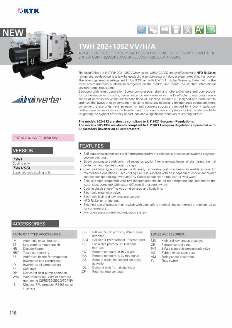
116
TWH 202÷1352 VV/H/AA CLASS ENERGY EFFICIENCY WATERCOOLED LIQUID CHILLERS WITH (INVERTER) SCREW COMPRESSORS AND SHELL AND TUBE EXCHANGERS.
The liquid Chillers of the TWH 202÷1352 VV/H/A series, with A CLASS energy efficiency and HFO-R1234zerefrigerant, are designed to satisfy the needs of the service sector or industrial systems requiring high power.The latest generation refrigerant HFO-R1234ze, with GWP<1 (Global Warming Potential), is the most environmentally sustainable refrigerant on the market, and meets the strictest international environmental regulations.Equipped with latest generation Screw compressors, shell and tube exchangers and connections for condensation with cooling tower water or well water or with a Dry-Cooler, these units have a series of accessories which are factory fitted or supplied separately. Designed and produced to optimize the layout of each component so as to make any necessary maintenance operations more convenient, these units have an essential and compact structure intended for indoor installation. Furthermore, accessories as the Inverter control on one Screw compressor or both is also available for getting the highest efficiency at part load and a significant reduction of starting current.
The models 202÷312 are already compliant to ErP 2021 European Regulations.The models 362÷1352 are already compliant to ErP 2021 European Regulations if provided with ID accessory (Inverter on all compressors).
FROM 234 KW TO 1650 KW.
VERSION
TWHCooling only
TWH/SSLSuper silenced cooling only
FEATURES
• Self-supporting galvanized steel frame protected with additional protection achieved via polyester powder painting.
• Screw compressors with built-in oil separator, suction filter, crankcase heater, oil sight glass, thermal protection and stepless capacity steps.
• Shell and tube type condenser, with easily removable cast iron heads to enable access for maintenance operations. Each cooling circuit is supplied with an independent condenser. Water connections for cooling tower and Dry-Cooler operation; on request for well water.
• Shell and tube evaporator with two independent circuits on the refrigerant side and one on the water side, complete with water differential pressure switch.
• Cooling circuit shut-off valves on discharge and liquid line.• Electronic expansion valve.• Electronic high and low pressure gauges.• HFO-R1234ze refrigerant.• Electrical board includes: main switch with door safety interlock, fuses, thermal protection relays
for compressors.• Microprocessor control and regulation system.
ACCESSORIES
FACTORY FITTED ACCESSORIES:
IM Automatic circuit breakersBT Low water temperature kitHR DesuperheaterHRT Total heat recoveryFE Antifreeze heater for evaporatorII Inverter on one compressorID Inverter on all compressorsSS Soft startDP Device for heat pump operationWM Web Monitoring - Wireless remote
monitoring (GPRS/EDGE/3G/TCP-IP)IS Modbus RTU protocol, RS485 serial
interface
ISB BACnet MSTP protocol, RS485 serial interface
ISBT BACnet TCP/IP protocol, Ethernet portISL LonWorks protocol, FTT-10 serial
interfaceIAV Remote set-point, 0-10 V signalIAA Remote set-point, 4-20 mA signalIAS Remote signal for second set-point
activationIDL Demand limit from digital inputCP Potential free contacts
LOOSE ACCESSORIES:
MN High and low pressure gaugesCR Remote control panelPV3 3-Way electronic pressostatic valveAG Rubber shock absorbersAM Spring shock absorbersFL Flow switch

117
CLEARANCE AREA
1234
Electrical board side
TECHNICAL DATA - TWH 202÷1352 VV/H/AMODEL 202 262 312 362 412 472 552
CoolingCooling capacity (1) kW 234 310 375 437 488 558 655Absorbed power (1) kW 44 57 66 80 89 100 117EER (1) 5.32 5.44 5.68 5.46 5.48 5.58 5.60
Cooling (EN14511)
Cooling capacity (1) kW 233 309 373 436 487 557 653Absorbed power (1) kW 45 59 68 83 92 103 121EER (1) 5.18 5.23 5.46 5.27 5.32 5.39 5.42ESEER 5.75 5.80 6.00 5.97 6.01 6.02 6.05EUROVENT Class A A A A A A ASEER (2) 5.68 5.71 5.89 5.88 5.90 5.91 5.94Energy Efficiency (2) % 219 220 228 227 228 228 230
CompressorQuantity n° 2 2 2 2 2 2 2Refrigerant circuits n° 2 2 2 2 2 2 2Capacity steps n° Stepless
EvaporatorWater flow l/s 11.18 14.81 17.92 20.88 23.32 26.66 31.29Pressure drops kPa 36 37 42 39 32 31 35Water connections DN 125 150 150 150 200 200 200
CondenserWater flow l/s 13.28 17.53 21.07 24.70 27.57 31.44 36.88Pressure drops kPa 17 28 34 36 36 35 32Water connections DN 80 80 80 80 80 80 100
Electrical characteristics
Power supply V/Ph/Hz 400/3/50Max. running current A 144 190 220 260 290 334 384Max. starting current A 199 257 318 373 420 504 492
Sound pressureSTD version (3) dB(A) 76 76 76 76 76 76 76SSL version (3) dB(A) 72 72 72 72 72 72 72
WeightsTransport weight Kg 2140 2445 2640 2860 3090 3230 4180Operating weight Kg 2300 2660 2840 3100 3420 3550 4590
MODEL 612 722 812 982 1062 1232 1352
CoolingCooling capacity (1) kW 736 868 980 1160 1278 1475 1650Absorbed power (1) kW 131 154 174 222 242 275 304EER (1) 5.62 5.64 5.63 5.23 5.28 5.36 5.43
Cooling (EN14511)
Cooling capacity (1) kW 734 866 977 1157 1274 1469 1644Absorbed power (1) kW 135 159 180 229 250 285 314EER (1) 5.42 5.45 5.44 5.06 5.10 5.16 5.23ESEER 6.04 6.03 5.98 5.97 6.01 5.99 6.42EUROVENT Class A A A A A A ASEER (2) 5.93 5.94 5.96 5.88 5.89 5.91 6.33Energy Efficiency (2) % 229 230 230 227 228 228 245
CompressorQuantity n° 2 2 2 2 2 2 2Refrigerant circuits n° 2 2 2 2 2 2 2Capacity steps n° Stepless
EvaporatorWater flow l/s 35.16 41.47 46.82 55.42 61.06 70.47 78.83Pressure drops kPa 45 39 38 39 49 57 54Water connections DN 200 200 250 250 250 250 250
CondenserWater flow l/s 41.42 48.83 55.14 66.03 72.62 83.61 93.36Pressure drops kPa 34 37 37 37 37 35 32Water connections DN 100 100 100 125 125 125 150
Electrical characteristics
Power supply V/Ph/Hz 400/3/50Max. running current A 436 489 549 701 761 873 961Max. starting current A 576 692 782 1144 1174 1372 1416
Sound pressureSTD version (3) dB(A) 77 78 79 80 80 81 82SSL version (3) dB(A) 73 74 75 76 76 77 78
WeightsTransport weight Kg 4560 5205 5670 6950 7080 9060 10050Operating weight Kg 5110 5880 6470 7220 7880 10030 11230
DIMENSIONSMODEL 202 262 312 362 412 472 552 612 722 812 982 1062 1232 1352L STD/SSL mm 3700 3700 3700 3800 3900 3900 3900 4900 4900 4900 5300 5300 5550 5500W STD/SSL mm 1000 1100 1100 1150 1200 1200 1200 1200 1300 1300 1400 1400 2000 2000H STD/SSL mm 1800 1800 1900 1950 2000 2050 2150 2150 2250 2300 2450 2450 2500 2550
ErP SEER
NOTES1. Chilled water from 12 to 7 °C, water temperature at the condenser from 30 to 35 °C.2. Seasonal energy efficiency of cooling at low temperature. According to EU
Regulation n. 2016/2281.3. Sound pressure level measured in free field conditions at 1 m from the unit.
According to ISO 3744.N.B. Weights of SSL version are specified on technical brochure.
2
TOP
LIN
E
TWH 202÷1352 VV/H/A
500 500 800 500

118
TWH 321÷1321 VV/Y/AA CLASS ENERGY EFFICIENCY WATERCOOLED LIQUID CHILLERS WITH (INVERTER) SCREW COMPRESSORS AND FLOODED SHELL AND TUBE EXCHANGERS.
The A CLASS liquid Chillers of the TWH 321÷1321 VV/Y/A series, with R134a refrigerant, are designed to satisfy the needs of the service sector or industrial systems requiring high power.These units are characterized by an high efficiency (EER) and are equipped with latest generation Screw compressors, flooded shell and tube exchangers and connections for condensation with cooling tower water or well water or with a Dry-Cooler. Furthermore, they have a series of accessories which are factory fitted or supplied separately such as desuperheater, total heat recovery and, if neccessary, a device for operating a Heat Pump. Designed and produced to optimize the layout of each component so as to make any necessary maintenance operations more convenient, these units have an essential and compact structure intended for indoor installation. The units can be equipped with Inverter control on one or on both the Screw compressors, to significantly reduce the inrush current of the unit. The solution with double Inverter allows, in addition to the above described, to increase the power efficiency of the unit in the same size, adapting to the different needs and solutions.
The units are already compliant to ErP 2021 European Regulations.
TWH 321÷1321 VV/J/AOn request, units can be supplied with R513A refrigerant. FROM 280 KW TO 1289 KW.
VERSION
TWHCooling only
TWH/SSLSuper silenced cooling only
FEATURES
• Self-supporting galvanized steel frame protected with additional protection achieved via polyester powder painting.
• Screw compressors with suction filter, oil sight glass, thermal protection and stepless capacity steps. Oil separator and crankcase heater installed on cooling circuit.
• Shell and tube type condenser, with easily removable cast iron heads to enable access for maintenance operations. Water connections for cooling tower and Dry-Cooler operation; on request for well water.
• High efficiency flooded shell and tube type evaporator, with one circuit on the refrigerant side and one on the water side, complete with water differential pressure switch.
• Cooling circuit shut-off valves on suction, discharge and liquid line.• Electronic expansion valve.• Electronic high and low pressure gauges.• R134a refrigerant. On request R513A refrigerant.• Electrical board includes: main switch with door safety interlock, fuses, thermal protection relays
for compressors.• Microprocessor control and regulation system.
ACCESSORIES
FACTORY FITTED ACCESSORIES:
IM Automatic circuit breakersBT Low water temperature kitHR DesuperheaterHRT Total heat recoveryFE Antifreeze heater for evaporatorII Inverter on one compressorID Inverter on all compressorsSS Soft startDP Device for heat pump operationWM Web Monitoring - Wireless remote
monitoring (GPRS/EDGE/3G/TCP-IP)IS Modbus RTU protocol, RS485 serial
interface
ISB BACnet MSTP protocol, RS485 serial interface
ISBT BACnet TCP/IP protocol, Ethernet portISL LonWorks protocol, FTT-10 serial
interfaceIAV Remote set-point, 0-10 V signalIAA Remote set-point, 4-20 mA signalIAS Remote signal for second set-point
activationIDL Demand limit from digital inputCP Potential free contacts
LOOSE ACCESSORIES:
MN High and low pressure gaugesCR Remote control panelPV3 3-Way electronic pressostatic valveAG Rubber shock absorbersAM Spring shock absorbersFL Flow switch

119
CLEARANCE AREA
1234
Electrical board side
TECHNICAL DATA - TWH 321÷1321 VV/Y/AMODEL 321 341 391 451 491 591 651 731 901 1101 1321
CoolingCooling capacity (1) kW 280 341 392 448 507 626 711 792 961 1126 1289Absorbed power (1) kW 50 60 69 79 88 108 121 132 160 188 217EER (1) 5.60 5.68 5.68 5.67 5.76 5.80 5.88 6.00 6.01 5.99 5.94
Cooling (EN14511)
Cooling capacity (1) kW 279 340 391 446 505 623 708 789 957 1122 1284Absorbed power (1) kW 51 61 70 81 90 111 124 135 164 192 222EER (1) 5.47 5.57 5.59 5.51 5.61 5.61 5.71 5.84 5.84 5.84 5.78ESEER 6.80 6.84 6.87 6.53 6.56 6.65 6.60 6.80 6.83 6.82 6.69EUROVENT Class A A A A A A A A A A ASEER (2) 7.03 7.20 7.25 7.11 7.27 7.34 7.46 7.63 7.66 7.67 7.62Energy Efficiency (2) % 273 280 282 276 283 286 290 297 298 299 297
Cooling *Cooling capacity (1) kW 329 401 459 527 595 734 833 928 1125 1319 1510Absorbed power (1) kW 60 73 84 96 107 131 148 161 194 228 263EER (1) 5.48 5.49 5.46 5.49 5.56 5.60 5.63 5.76 5.80 5.79 5.74
Cooling * (EN14511)
Cooling capacity (1) kW 328 399 458 524 592 730 828 923 1119 1312 1502Absorbed power (1) kW 61 75 85 99 110 135 153 166 200 235 271EER (1) 5.38 5.32 5.39 5.29 5.38 5.41 5.41 5.56 5.60 5.58 5.54ESEER 7.86 7.87 7.92 7.44 7.63 7.62 7.68 7.81 7.75 7.85 7.68EUROVENT Class A A A A A A A A A A A
CompressorQuantity n° 2 2 2 2 2 2 2 2 2 2 2Refrigerant circuits n° 1 1 1 1 1 1 1 1 1 1 1Capacity steps n° Stepless
EvaporatorWater flow l/s 13.38 16.29 18.73 21.40 24.22 29.91 33.97 37.84 45.91 53.80 61.59Pressure drops kPa 28 32 26 60 54 57 57 54 56 57 61Water connections DN 100 100 100 125 125 125 125 150 150 150 150
CondenserWater flow l/s 15.77 19.16 22.03 25.18 28.43 35.07 39.75 44.15 53.56 62.78 71.95Pressure drops kPa 46 39 42 62 52 60 62 65 58 58 59Water connections DN 80 100 100 100 125 125 125 125 150 150 150
Electrical characteristics
Power supply V/Ph/Hz 400/3/50Max. running current A 178 214 238 270 292 354 398 438 456 536 622Max. starting current A 240 258 314 330 434 465 487 549 558 598 775
Sound pressureSTD version (3) dB(A) 76 76 77 77 77 77 77 79 79 80 80SSL version (3) dB(A) 72 72 73 73 73 73 73 75 75 76 76
WeightsTransport weight Kg 2690 2830 2913 3215 3602 3980 4210 4745 5210 5675 6500Operating weight Kg 2750 2900 3000 3500 3700 4100 4350 4900 5400 5900 6750
DIMENSIONSMODEL 321 341 391 451 491 591 651 731 901 1101 1321L STD/SSL mm 3700 3700 3700 4200 4200 4200 4200 4200 4200 4500 4600W STD/SSL mm 1300 1300 1300 1400 1400 1400 1400 1400 1600 1600 1600H STD/SSL mm 2100 2100 2100 2200 2200 2200 2200 2200 2250 2250 2250
ErP SEER
NOTES1. Chilled water from 12 to 7 °C, water temperature at the condenser from 30 to 35 °C.2. Seasonal energy efficiency of cooling at low temperature. According to EU
Regulation n. 2016/2281.3. Sound pressure level measured in free field conditions at 1 m from the unit.
According to ISO 3744.N.B. Weights of SSL version are specified on technical brochure.* Unit provided with Inverter on both compressors.
2
TOP
LIN
E
TWH 321÷1321 VV/Y/A
500 500 800 500

120
TWH 322÷2583 VV/YWATERCOOLED LIQUID CHILLERS WITH SCREW COMPRESSORS ANDSHELL AND TUBE EXCHANGERS.
The liquid Chillers of the TWH 322÷2583 VV/Y series, with R134a refrigerant, are designed to satisfy the needs of the service sector or industrial systems requiring high power.Equipped with latest generation Screw compressors, shell and tube exchangers and connections for condensation with cooling tower water or well water or with a Dry-Cooler, these units can also be produced in super silent versions. Furthermore, they have a series of accessories which are factory fitted or supplied separately such as heat recovery in series or in parallel, soft start and, if necessary, a device for operating a Heat Pump. Designed and produced to optimize the layout of each component so as to make any necessary maintenance operations more convenient, these units have an essential and compact structure intended for indoor installation.
TWH 322÷2583 VV/JOn request, units can be supplied with R513A refrigerant.
FROM 267 KW TO 2473 KW.
VERSION
TWHCooling only
TWH/SSLSuper silenced cooling only
FEATURES
• Self-supporting galvanized steel frame protected with additional protection achieved via polyester powder painting.
• Screw compressors with built-in oil separator, suction filter, crankcase heater, oil sight glass, thermal protection and stepless capacity steps.
• Shell and tube type condenser, with easily removable cast iron heads to enable access for maintenance operations. Each cooling circuit is supplied with an independent condenser. Water connections for cooling tower and Dry-Cooler operation; on request for well water.
• Shell and tube type evaporator, with two or three independent circuits on the refrigerant side and one on the water side, complete with water differential pressure switch.
• Cooling circuit shut-off valves on discharge and liquid line.• Electronic expansion valve.• Electronic high and low pressure gauges.• R134a refrigerant. On request R513A refrigerant.• Electrical board includes: main switch with door safety interlock, fuses, thermal protection relays
for compressors.• Microprocessor control and regulation system.
ACCESSORIES
FACTORY FITTED ACCESSORIES:
IM Automatic circuit breakersBT Low water temperature kitHR DesuperheaterHRT Total heat recoveryFE Antifreeze heater for evaporatorII Inverter on one compressorID Inverter on all compressorsSS Soft startDP Device for heat pump operationWM Web Monitoring - Wireless remote
monitoring (GPRS/EDGE/3G/TCP-IP)IS Modbus RTU protocol, RS485 serial
interface
ISB BACnet MSTP protocol, RS485 serial interface
ISBT BACnet TCP/IP protocol, Ethernet portISL LonWorks protocol, FTT-10 serial
interfaceIAV Remote set-point, 0-10 V signalIAA Remote set-point, 4-20 mA signalIAS Remote signal for second set-point
activationIDL Demand limit from digital inputCP Potential free contacts
LOOSE ACCESSORIES:
MN High and low pressure gaugesCR Remote control panelPV3 3-Way electronic pressostatic valveAG Rubber shock absorbersAM Spring shock absorbersFL Flow switch
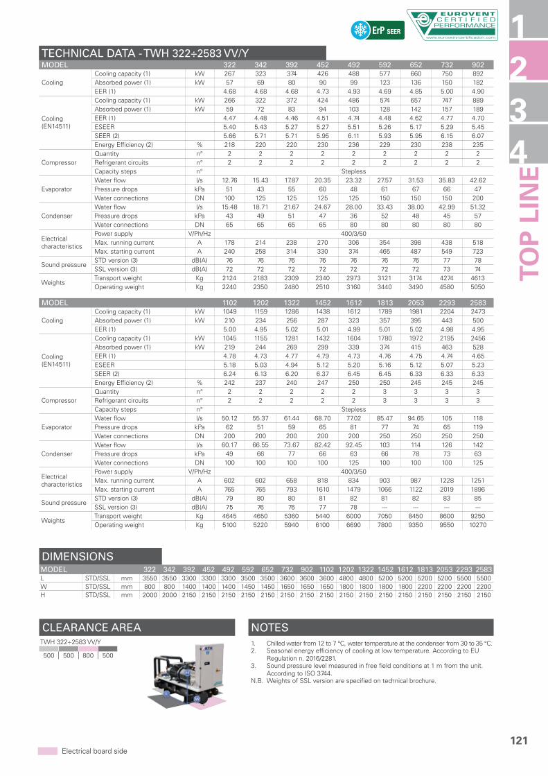
121
CLEARANCE AREA
1234
Electrical board side
TECHNICAL DATA - TWH 322÷2583 VV/YMODEL 322 342 392 452 492 592 652 732 902
CoolingCooling capacity (1) kW 267 323 374 426 488 577 660 750 892Absorbed power (1) kW 57 69 80 90 99 123 136 150 182EER (1) 4.68 4.68 4.68 4.73 4.93 4.69 4.85 5.00 4.90
Cooling (EN14511)
Cooling capacity (1) kW 266 322 372 424 486 574 657 747 889Absorbed power (1) kW 59 72 83 94 103 128 142 157 189EER (1) 4.47 4.48 4.46 4.51 4.74 4.48 4.62 4.77 4.70ESEER 5.40 5.43 5.27 5.27 5.51 5.26 5.17 5.29 5.45SEER (2) 5.66 5.71 5.71 5.95 6.11 5.93 5.95 6.15 6.07Energy Efficiency (2) % 218 220 220 230 236 229 230 238 235
CompressorQuantity n° 2 2 2 2 2 2 2 2 2Refrigerant circuits n° 2 2 2 2 2 2 2 2 2Capacity steps n° Stepless
EvaporatorWater flow l/s 12.76 15.43 17.87 20.35 23.32 27.57 31.53 35.83 42.62Pressure drops kPa 51 43 55 60 48 61 67 66 47Water connections DN 100 125 125 125 125 150 150 150 200
CondenserWater flow l/s 15.48 18.71 21.67 24.67 28.00 33.43 38.00 42.99 51.32Pressure drops kPa 43 49 51 47 36 52 48 45 57Water connections DN 65 65 65 65 80 80 80 80 80
Electrical characteristics
Power supply V/Ph/Hz 400/3/50Max. running current A 178 214 238 270 306 354 398 438 518Max. starting current A 240 258 314 330 374 465 487 549 723
Sound pressureSTD version (3) dB(A) 76 76 76 76 76 76 76 77 78SSL version (3) dB(A) 72 72 72 72 72 72 72 73 74
WeightsTransport weight Kg 2124 2183 2309 2340 2973 3121 3174 4274 4613Operating weight Kg 2240 2350 2480 2510 3160 3440 3490 4580 5050
MODEL 1102 1202 1322 1452 1612 1813 2053 2293 2583
CoolingCooling capacity (1) kW 1049 1159 1286 1438 1612 1789 1981 2204 2473Absorbed power (1) kW 210 234 256 287 323 357 395 443 500EER (1) 5.00 4.95 5.02 5.01 4.99 5.01 5.02 4.98 4.95
Cooling (EN14511)
Cooling capacity (1) kW 1045 1155 1281 1432 1604 1780 1972 2195 2456Absorbed power (1) kW 219 244 269 299 339 374 415 463 528EER (1) 4.78 4.73 4.77 4.79 4.73 4.76 4.75 4.74 4.65ESEER 5.18 5.03 4.94 5.12 5.20 5.16 5.12 5.07 5.23SEER (2) 6.24 6.13 6.20 6.37 6.45 6.45 6.33 6.33 6.33Energy Efficiency (2) % 242 237 240 247 250 250 245 245 245
CompressorQuantity n° 2 2 2 2 2 3 3 3 3Refrigerant circuits n° 2 2 2 2 2 3 3 3 3Capacity steps n° Stepless
EvaporatorWater flow l/s 50.12 55.37 61.44 68.70 77.02 85.47 94.65 105 118Pressure drops kPa 62 51 59 65 81 77 74 65 119Water connections DN 200 200 200 200 200 250 250 250 250
CondenserWater flow l/s 60.17 66.55 73.67 82.42 92.45 103 114 126 142Pressure drops kPa 49 66 77 66 63 66 78 73 63Water connections DN 100 100 100 100 125 100 100 100 125
Electrical characteristics
Power supply V/Ph/Hz 400/3/50Max. running current A 602 602 658 818 834 903 987 1228 1251Max. starting current A 765 765 793 1610 1479 1066 1122 2019 1896
Sound pressureSTD version (3) dB(A) 79 80 80 81 82 81 82 83 85SSL version (3) dB(A) 75 76 76 77 78 --- --- --- ---
WeightsTransport weight Kg 4645 4650 5360 5440 6000 7050 8450 8600 9250Operating weight Kg 5100 5220 5940 6100 6690 7800 9350 9550 10270
DIMENSIONSMODEL 322 342 392 452 492 592 652 732 902 1102 1202 1322 1452 1612 1813 2053 2293 2583L STD/SSL mm 3550 3550 3300 3300 3300 3500 3500 3600 3600 3600 4800 4800 5200 5200 5200 5200 5500 5500W STD/SSL mm 800 800 1400 1400 1400 1450 1450 1650 1650 1650 1800 1800 1800 1800 2200 2200 2200 2200H STD/SSL mm 2000 2000 2150 2150 2150 2150 2150 2150 2150 2150 2150 2150 2150 2150 2150 2150 2150 2150
ErP SEER
NOTES1. Chilled water from 12 to 7 °C, water temperature at the condenser from 30 to 35 °C.2. Seasonal energy efficiency of cooling at low temperature. According to EU
Regulation n. 2016/2281.3. Sound pressure level measured in free field conditions at 1 m from the unit.
According to ISO 3744.N.B. Weights of SSL version are specified on technical brochure.
2
TOP
LIN
E
TWH 322÷2583 VV/Y
500 500 800 500

122
TEE 322÷2583 VV/YCONDENSERLESS LIQUID CHILLERS WITH SCREW COMPRESSORS ANDSHELL AND TUBE EXCHANGER.
The liquid Chillers for remote condensation of TEE 322÷2583 VV/Y series, with R134a refrigerant, are designed to satisfy the needs of the service sector or industrial systems which require high power with continual refrigerant delivery, space-saving units and quiet operation.Combined with the remote condenser, these units are ideal for indoor installation and, equipped with a self-supporting structure that sustains the main components, they reduce the overall dimensions to a minimum while at the same time making installation and maintenance operations easier.Equipped with latest generation Screw compressors and shell and tube exchanger, these units can also be produced in a super silent version. They have cooling and hydraulic circuits complete with everything necessary for quick installation and high energy efficiency. A series of accessories, factory fitted or supplied separately, rounds off the variety of equipment in this product range.
TEE 322÷2583 VV/JOn request, units can be supplied for R513A refrigerant.
FROM 235 KW TO 2168 KW.
VERSION
TEECooling only
TEE/SSLSuper silenced cooling only
FEATURES
• Self-supporting galvanized steel frame protected with additional protection achieved via polyester powder painting.
• Screw compressors with built-in oil separator, suction filter, crankcase heater, oil sight glass, thermal protection and stepless capacity steps.
• Shell and tube type evaporator, with two or three independent circuits on the refrigerant side and one on the water side, complete with water differential pressure switch.
• Cooling circuit shut-off valves on discharge and liquid line.• Electronic expansion valve.• Electronic high and low pressure gauges.• R134a refrigerant. On request R513A refrigerant.• Electrical board includes: main switch with door safety interlock, fuses, thermal protection relays
for compressors.• Microprocessor control and regulation system.
ACCESSORIES
FACTORY FITTED ACCESSORIES:
IM Automatic circuit breakersBT Low water temperature kitHR DesuperheaterHRT Total heat recoveryFE Antifreeze heater for evaporatorII Inverter on one compressorID Inverter on all compressorsSS Soft startWM Web Monitoring - Wireless remote
monitoring (GPRS/EDGE/3G/TCP-IP)IS Modbus RTU protocol, RS485 serial
interface
ISB BACnet MSTP protocol, RS485 serial interface
ISBT BACnet TCP/IP protocol, Ethernet portISL LonWorks protocol, FTT-10 serial
interfaceIAV Remote set-point, 0-10 V signalIAA Remote set-point, 4-20 mA signalIAS Remote signal for second set-point
activationIDL Demand limit from digital inputCP Potential free contacts
LOOSE ACCESSORIES:
MN High and low pressure gaugesCR Remote control panelAG Rubber shock absorbersAM Spring shock absorbersFL Flow switch

123
CLEARANCE AREA
1234
Electrical board side
TECHNICAL DATA - TEE 322÷2583 VV/YMODEL 322 342 392 452 492 592 652 732 902
CoolingCooling capacity (1) kW 235 279 325 375 424 526 599 672 778Absorbed power (1) kW 73 85 103 118 133 158 176 193 228
CompressorQuantity n° 2 2 2 2 2 2 2 2 2Refrigerant circuits n° 2 2 2 2 2 2 2 2 2Capacity steps n° Stepless
EvaporatorWater flow l/s 11.23 13.33 15.53 17.92 20.26 25.13 28.62 32.11 37.17Pressure drops kPa 49 34 39 41 34 50 48 55 51Water connections DN 100 125 125 125 125 150 150 150 150
ConnectionsDelivery line Ø mm 2x42 2x42 2x54 2x54 2x54 2x64 2x64 2x76 2x76Liquid line Ø mm 2x35 2x35 2x35 2x35 2x35 2x42 2x42 2x42 2x54
Electrical characteristics
Power supply V/Ph/Hz 400/3/50Max. running current A 178 214 238 270 306 354 398 438 518Max. starting current A 240 258 314 330 374 465 487 549 723
Sound pressureSTD version (2) dB(A) 76 76 76 76 76 76 76 77 78SSL version (2) dB(A) 72 72 72 72 72 72 72 73 74
WeightsTransport weight Kg 1480 1820 1840 1860 1900 2420 2540 2590 3190Operating weight Kg 1570 1960 1990 2010 2040 2680 2820 2850 3460
MODEL 1102 1202 1322 1452 1612 1813 2053 2293 2583
CoolingCooling capacity (1) kW 905 1015 1140 1282 1433 1566 1733 1909 2168Absorbed power (1) kW 262 296 327 364 417 456 498 550 631
CompressorQuantity n° 2 2 2 2 2 3 3 3 3Refrigerant circuits n° 2 2 2 2 2 3 3 3 3Capacity steps n° Stepless
EvaporatorWater flow l/s 43.24 48.49 54.47 61.25 68.47 74.82 82.80 91.21 104Pressure drops kPa 57 55 56 52 69 78 57 67 95Water connections DN 150 200 200 200 200 250 250 250 250
ConnectionsDelivery line Ø mm 2x76 2x76 2x89 2x89 2x89 3x76 3x89 3x89 3x89Liquid line Ø mm 2x54 2x54 2x54 2x54 2x54 3x54 3x54 3x54 3x54
Electrical characteristics
Power supply V/Ph/Hz 400/3/50Max. running current A 602 602 658 818 834 903 987 1228 1251Max. starting current A 765 765 793 1610 1479 1066 1122 2019 1896
Sound pressureSTD version (2) dB(A) 79 80 80 81 82 81 82 83 85SSL version (2) dB(A) 75 76 76 77 78 --- --- --- ---
WeightsTransport weight Kg 3225 3525 4445 4530 4600 4980 6430 6555 6740Operating weight Kg 3480 3980 4980 5040 5100 5570 7130 7290 7440
DIMENSIONSMODEL 322 342 392 452 492 592 652 732 902 1102 1202 1322 1452 1612 1813 2053 2293 2583L STD/SSL mm 3300 3300 3700 3700 3700 3800 4000 4000 4300 4300 4300 5100 5100 5100 4800 5300 5300 5300W STD/SSL mm 800 800 800 800 800 1080 1080 1080 1080 1080 1080 1080 1080 1080 1600 1600 1600 1600H STD/SSL mm 1700 1700 1700 1700 1700 1700 2100 2100 2100 2100 2100 2100 2100 2100 2100 2100 2100 2100
NOTES1. Chilled water from 12 to 7 °C, condensing temperature 50 °C.2. Sound pressure level measured in free field conditions at 1 m from the unit.
According to ISO 3744.N.B. Weights of SSL version are specified on technical brochure.
2
TOP
LIN
E
TEE 322÷2583 VV/Y
500 500 800 500

124
TWH 341÷2061 TT/HA CLASS ENERGY EFFICIENCY WATERCOOLED LIQUID CHILLERS WITH TURBOCOR (MAGNETIC LEVITATION) COMPRESSORS AND FLOODED SHELL AND TUBE EXCHANGERS FOR COOLING TOWER OPERATION.
The innovative TWH 341÷2061 TT/H TURBOLINE units for cooling tower operation, featuring A CLASS energy efficiency and HFO-R1234ze refrigerant, are designed to provide an effective solution to highly selective system needs. The latest generation refrigerant HFO-R1234ze, with GWP<1 (Global warming Potential), is the most environmentally sustainable refrigerant on the market, and meets the strictest international environmental regulations. Furthermore, thanks to Turbocor compressors, the units perform with top efficiency at partial loads, low inrush currents, an excellent silent functioning and reduced weight.Using TURBOCOR dynamic partial-load oil-free magnetic levitation compressors, managed by the TURBOSOFT self-adaptive electronic control and flooded shell and tube evaporators, provide high energy performance, with unbeatable SEER/ESEER/IPLV values, with minimum water content, and an excellent silent functioning. Compared to traditional Screw compressor units, TURBOLINE units have low operational costs during their entire use, with a savings that can even reach 50%. Besides, the units are equipped with the WEB MONITORING system, for remotely managing and monitoring the units by means of GPRS/EDGE/3G/TCP-IP communication protocol. The users enabled to use this service can, by a dedicated Web page, access Monitoring, Management and Statistics activities.
The units are already compliant to ErP 2021 European Regulations.
FROM 321 KW TO 1922 KW.
VERSION
TWHCooling only for cooling tower
FEATURES
• Self-supporting galvanized steel frame protected with additional protection achieved via polyester powder painting.
• Semi-hermetic centrifugal compressors with dual Turbocor turbine, oil free, magnetic rising rotor, thermal protection, continuous capacity adjustment system thanks to built-in INVERTER, automatic anti-cavitation system. The power circuit of the compressor is fitted with a set of electrolytic condensers to control the rising in the event of a power failure, reactor for the power factor correction, EMI filter for electromagnetic compatibility.
• Shell and tube type condenser, with easily removable cast iron heads to enable access for maintenance operations.
• High efficiency flooded shell and tube type evaporator, with one circuit on the refrigerant side and one on the water side, complete with water differential pressure switch.
• Cooling circuit shut-off valves on suction, discharge and liquid line.• Electronic expansion valve.• Electronic high and low pressure gauges.• HFO-R1234ze refrigerant.• Electrical board includes: main on-off switch with door lock, fuses, electronic/digital overload device
to protect the compressors, interface relay and terminals for external connections.• TURBOSOFT control and regulation system is fitted with RS485 serial interface and Web
Monitoring device for remote monitoring via GPRS/EDGE/3G/TCP-IP network.
ACCESSORIES
FACTORY FITTED ACCESSORIES:
IM Automatic circuit breakersHR DesuperheaterHRT Total heat recoveryFE Antifreeze heater for evaporatorTS Touch screen InterfaceISB BACnet MSTP protocol, RS485 serial
interface
ISBT BACnet TCP/IP protocol, Ethernet portISL LonWorks protocol, FTT-10 serial
interfaceIAV Remote set-point, 0-10 V signalIAA Remote set-point, 4-20 mA signalIAS Remote signal for second set-point
activationIDL Demand limit from digital inputCP Potential free contacts
LOOSE ACCESSORIES:
MN High and low pressure gaugesCR Remote control panelAG Rubber shock absorbersAM Spring shock absorbersFL Flow switch

125
CLEARANCE AREA
1234
Electrical board side
TECHNICAL DATA - TWH 341÷2061 TT/HMODEL 341 681 1031 1371 1711 2061
CoolingCooling capacity (1) kW 321 639 958 1279 1601 1922Absorbed power (1) kW 54 108 162 216 271 325EER (1) 5.94 5.92 5.91 5.92 5.91 5.91
Cooling (EN14511)
Cooling capacity (1) kW 320 637 955 1276 1595 1916Absorbed power (1) kW 56 110 165 220 277 331EER (1) 5.71 5.79 5.79 5.80 5.76 5.79ESEER 8.51 8.85 8.87 8.93 8.99 9.03EUROVENT Class A A A A A ASEER (2) 7.16 7.63 7.72 7.85 7.90 7.97Energy Efficiency (2) % 278 297 301 306 308 311
CompressorQuantity n° 1 2 3 4 5 6Refrigerant circuits n° 1 1 1 1 1 1Capacity steps n° Stepless
EvaporatorWater flow l/s 15.34 30.53 45.77 61.11 76.49 91.83Pressure drops kPa 45 46 45 34 52 50Water connections DN 100 125 150 150 200 200
CondenserWater flow l/s 17.93 35.69 53.51 71.43 89.44 107Pressure drops kPa 49 50 49 50 55 52Water connections DN 100 125 150 150 200 200
Electrical characteristics
Power supply V/Ph/Hz 400/3/50Max. running current A 150 300 450 600 750 900Max. starting current A 5 155 305 455 605 755
Sound pressure (3) dB(A) 72 74 76 76 77 78
WeightsTransport weight Kg 1798 2837 3924 6408 7741 11474Operating weight Kg 1930 3100 4340 7120 8780 13140
DIMENSIONSMODEL 341 681 1031 1371 1711 2061L STD mm 3400 3400 3450 4550 5500 6500W STD mm 1100 1150 1800 1800 1800 1800H STD mm 1800 1950 2050 2100 2100 2150
ErP SEER
NOTES1. Chilled water from 12 to 7 °C, water temperature at the condenser from 30 to 35 °C.2. Seasonal energy efficiency of cooling at low temperature. According to EU
Regulation n. 2016/2281.3. Sound pressure level measured in free field conditions at 1 m from the unit.
According to ISO 3744.
2
TOP
LIN
E
TWH 341÷2061 TT/H
500 500 800 500

126
TWH/DR 341÷2061 TT/HA CLASS ENERGY EFFICIENCY WATERCOOLED LIQUID CHILLERS WITH TURBOCOR (MAGNETIC LEVITATION) COMPRESSORS AND FLOODED SHELL AND TUBE EXCHANGERS FOR DRY-COOLER OPERATION.
The innovative TWH/DR 341÷2061 TT/H TURBOLINE units for Dry-Cooler operation, featuring A CLASS energy efficiency and HFO-R1234ze refrigerant, are designed to provide an effective solution to highly selective system needs. The latest generation refrigerant HFO-R1234ze, with GWP<1 (Global warming Potential), is the most environmentally sustainable refrigerant on the market, and meets the strictest international environmental regulations. Furthermore, thanks to Turbocor compressors, the units perform with top efficiency at partial loads, low inrush currents, an excellent silent functioning and reduced weight.Using TURBOCOR dynamic partial-load oil-free magnetic levitation compressors, managed by the TURBOSOFT self-adaptive electronic control and flooded shell and tube evaporators, provide high energy performance, with unbeatable SEER/ESEER/IPLV values, with minimum water content, and an excellent silent functioning. Compared to traditional Screw compressor units, TURBOLINE units have low operational costs during their entire use, with a savings that can even reach 50%. Besides, the units are equipped with the WEB MONITORING system, for remotely managing and monitoring the units by means of GPRS/EDGE/3G/TCP-IP communication protocol. The users enabled to use this service can, by a dedicated Web page, access Monitoring, Management and Statistics activities.
The units are already compliant to ErP 2021 European Regulations.
FROM 301 KW TO 1802 KW.
VERSION
TWH/DRCooling only for Dry-Cooler
FEATURES
• Self-supporting galvanized steel frame protected with additional protection achieved via polyester powder painting.
• Semi-hermetic centrifugal compressors with dual Turbocor turbine, oil free, magnetic rising rotor, thermal protection, continuous capacity adjustment system thanks to built-in INVERTER, automatic anti-cavitation system. The power circuit of the compressor is fitted with a set of electrolytic condensers to control the rising in the event of a power failure, reactor for the power factor correction, EMI filter for electromagnetic compatibility.
• Shell and tube type condenser, with easily removable cast iron heads to enable access for maintenance operations.
• High efficiency flooded shell and tube type evaporator, with one circuit on the refrigerant side and one on the water side, complete with water differential pressure switch.
• Cooling circuit shut-off valves on suction, discharge and liquid line.• Electronic expansion valve.• Electronic high and low pressure gauges.• HFO-R1234ze refrigerant.• Electrical board includes: main on-off switch with door lock, fuses, electronic/digital overload device
to protect the compressors, interface relay and terminals for external connections.• TURBOSOFT control and regulation system is fitted with RS485 serial interface and Web
Monitoring device for remote monitoring via GPRS/EDGE/3G/TCP-IP network.
ACCESSORIES
FACTORY FITTED ACCESSORIES:
IM Automatic circuit breakersHR DesuperheaterHRT Total heat recoveryFE Antifreeze heater for evaporatorTS Touch screen InterfaceISB BACnet MSTP protocol, RS485 serial
interface
ISBT BACnet TCP/IP protocol, Ethernet portISL LonWorks protocol, FTT-10 serial
interfaceIAV Remote set-point, 0-10 V signalIAA Remote set-point, 4-20 mA signalIAS Remote signal for second set-point
activationIDL Demand limit from digital inputCP Potential free contacts
LOOSE ACCESSORIES:
MN High and low pressure gaugesCR Remote control panelAG Rubber shock absorbersAM Spring shock absorbersFL Flow switch

127
CLEARANCE AREA
1234
Electrical board side
TECHNICAL DATA - TWH/DR 341÷2061 TT/HMODEL 341 681 1031 1371 1711 2061
CoolingCooling capacity (1) kW 301 603 899 1203 1499 1802Absorbed power (1) kW 71 142 212 283 354 424EER (1) 4.24 4.25 4.24 4.25 4.23 4.25
Cooling (EN14511)
Cooling capacity (1) kW 300 601 896 1200 1494 1797Absorbed power (1) kW 72 144 215 286 359 429EER (1) 4.17 4.17 4.17 4.20 4.16 4.19
CompressorQuantity n° 1 2 3 4 5 6Refrigerant circuits n° 1 1 1 1 1 1Capacity steps n° Stepless
EvaporatorWater flow l/s 14.38 28.81 42.95 57.48 71.62 86.10Pressure drops kPa 41 42 41 30 47 44Water connections DN 100 125 150 150 200 200
CondenserWater flow l/s 19.4 38.8 58.0 77.7 96.7 116Pressure drops kPa 55 56 55 56 62 58Water connections DN 100 125 150 150 200 200
Electrical characteristics
Power supply V/Ph/Hz 400/3/50Max. running current A 150 300 450 600 750 900Max. starting current A 5 155 305 455 605 755
Sound pressure (2) dB(A) 72 74 76 76 77 78
WeightsTransport weight Kg 1849 2919 4065 6587 7942 11716Operating weight Kg 1990 3200 4510 7340 9040 13460
DIMENSIONSMODEL 341 681 1031 1371 1711 2061L STD mm 3400 3400 3450 4550 5500 6500W STD mm 1100 1150 1800 1800 1800 1800H STD mm 1800 1950 2050 2100 2100 2150
ErP SEER
NOTES1. Chilled water from 12 to 7 °C, temperature at the condenser (with ethylene
glycol at 35%) from 40 to 45 °C.2. Sound pressure level measured in free field conditions at 1 m from the unit.
According to ISO 3744.
2
TOP
LIN
E
TWH/DR 341÷2061 TT/H
500 500 800 500

128
TWH 291÷4061 TT/YA CLASS ENERGY EFFICIENCY WATERCOOLED LIQUID CHILLERS WITH TURBOCOR (MAGNETIC LEVITATION) COMPRESSORS AND FLOODED SHELL AND TUBE EXCHANGERS FOR COOLING TOWER OPERATION.
The innovative TWH 291÷4061 TT/Y TURBOLINE units for cooling tower operation, featuring A CLASS energy efficiency, are designed to provide an effective solution to highly selective system needs. Efficiency at partial loads, low breakaway starting current, low levels of operational noise, reduced weight and the specific design and handling every manufacturing aspect, make the TURBOLINE series the top of the range.Using TURBOCOR dynamic partial-load oil-free magnetic levitation compressors, managed by the TURBOSOFT self-adaptive electronic control and flooded shell and tube evaporators, provide high energy performance, with unbeatable SEER/ESEER/IPLV values, with minimum water content, and an excellent silent functioning. Compared to traditional Screw compressor units, TURBOLINE units have low operational costs during their entire use, with a savings that can even reach 50%. Besides, the units are equipped with the WEB MONITORING system, for remotely managing and monitoring the units by means of GPRS/EDGE/3G/TCP-IP communication protocol. The users enabled to use this service can, by a dedicated Web page, access Monitoring, Management and Statistics activities.
The units are already compliant to ErP 2021 European Regulations.
TWH 291÷4061 TT/JOn request, units can be supplied with R513A refrigerant. FROM 319 KW TO 3912 KW.
VERSION
TWHCooling only for cooling tower
FEATURES
• Self-supporting galvanized steel frame protected with additional protection achieved via polyester powder painting.
• Semi-hermetic centrifugal compressors with dual Turbocor turbine, oil free, magnetic rising rotor, thermal protection, continuous capacity adjustment system thanks to built-in INVERTER, automatic anti-cavitation system. The power circuit of the compressor is fitted with a set of electrolytic condensers to control the rising in the event of a power failure, reactor for the power factor correction, EMI filter for electromagnetic compatibility.
• Shell and tube type condenser, with easily removable cast iron heads to enable access for maintenance operations.
• High efficiency flooded shell and tube type evaporator, with one circuit on the refrigerant side and one on the water side, complete with water differential pressure switch.
• Cooling circuit shut-off valves on suction, discharge and liquid line.• Electronic expansion valve.• Electronic high and low pressure gauges.• R134a refrigerant. On request R513A refrigerant.• Electrical board includes: main on-off switch with door lock, fuses, electronic/digital overload device
to protect the compressors, interface relay and terminals for external connections.• TURBOSOFT control and regulation system is fitted with RS485 serial interface and Web
Monitoring device for remote monitoring via GPRS/EDGE/3G/TCP-IP network.
ACCESSORIES
FACTORY FITTED ACCESSORIES:
IM Automatic circuit breakersHR DesuperheaterHRT Total heat recoveryFE Antifreeze heater for evaporatorTS Touch screen InterfaceISB BACnet MSTP protocol, RS485 serial
interface
ISBT BACnet TCP/IP protocol, Ethernet portISL LonWorks protocol, FTT-10 serial
interfaceIAV Remote set-point, 0-10 V signalIAA Remote set-point, 4-20 mA signalIAS Remote signal for second set-point
activationIDL Demand limit from digital inputCP Potential free contacts
LOOSE ACCESSORIES:
MN High and low pressure gaugesCR Remote control panelAG Rubber shock absorbersAM Spring shock absorbersFL Flow switch

129
CLEARANCE AREA
1234
Electrical board side
TECHNICAL DATA - TWH 291÷4061 TT/YMODEL 291 391 471 581 651 771 881 1041 1161 1301
CoolingCooling capacity (1) kW 319 421 519 642 712 838 962 1040 1260 1302Absorbed power (1) kW 55 71 85 110 121 141 166 170 213 206EER (1) 5.80 5.93 6.11 5.84 5.88 5.94 5.80 6.12 5.92 6.32
Cooling (EN14511)
Cooling capacity (1) kW 318 420 517 640 710 835 958 1036 1255 1298Absorbed power (1) kW 55 72 87 112 123 143 167 174 216 210EER (1) 5.78 5.83 5.94 5.71 5.77 5.84 5.74 5.95 5.81 6.18ESEER 8.12 8.29 8.51 8.57 8.66 8.70 8.55 8.97 8.70 9.21EUROVENT Class A A A A A A A A A ASEER (2) 7.01 7.36 7.69 7.48 7.65 7.71 7.55 7.97 7.79 8.31Energy Efficiency (2) % 272 286 300 291 298 300 294 311 304 324
CompressorQuantity n° 1 1 1 2 2 2 3 2 3 2Refrigerant circuits n° 1 1 1 1 1 1 1 1 1 1Capacity steps n° Stepless
EvaporatorWater flow l/s 15.24 20.11 24.80 30.67 34.02 40.04 45.96 49.69 60.20 62.21Pressure drops kPa 46 48 50 49 42 53 57 53 59 45Water connections DN 100 100 100 125 125 125 150 150 150 150
CondenserWater flow l/s 17.87 23.51 28.86 35.93 39.80 46.77 53.89 57.81 70.38 72.05Pressure drops kPa 46 45 37 45 38 46 47 48 44 47Water connections DN 100 100 125 125 125 125 150 150 150 150
Electrical characteristics
Power supply V/Ph/Hz 400/3/50Max. running current A 145 231 187 290 462 462 435 374 693 420Max. starting current A 2 2 2 147 233 233 292 189 464 212
Sound pressure (3) dB(A) 72 74 74 75 76 77 76 76 77 77
WeightsTransport weight Kg 1795 2060 2360 2870 3225 3325 3715 3540 4235 4155Operating weight Kg 1920 2230 2580 3120 3560 3660 4070 3940 4720 4740
MODEL 1391 1461 1541 1691 2031 2421 2501 2701 3381 4061
CoolingCooling capacity (1) kW 1427 1563 1676 1787 1944 2080 2382 2600 3245 3912Absorbed power (1) kW 238 257 281 295 306 341 396 411 511 617EER (1) 6.00 6.08 5.96 6.06 6.35 6.10 6.02 6.33 6.35 6.34
Cooling (EN14511)
Cooling capacity (1) kW 1423 1559 1671 1783 1939 2075 2376 2592 3234 3898Absorbed power (1) kW 242 260 286 298 311 346 401 419 522 631EER (1) 5.88 6.00 5.84 5.98 6.23 6.00 5.93 6.19 6.20 6.18ESEER 8.74 8.89 8.77 9.16 9.26 8.96 8.99 9.24 9.26 9.31EUROVENT Class A A A A A A A A A ASEER (2) 7.97 8.06 7.99 8.16 8.56 8.56 8.56 8.56 8.56 8.56Energy Efficiency (2) % 311 314 312 318 334 334 334 334 334 334
CompressorQuantity n° 3 3 4 3 3 4 4 4 5 6Refrigerant circuits n° 1 1 1 1 1 1 1 1 1 1Capacity steps n° Stepless
EvaporatorWater flow l/s 68.18 74.68 80.08 85.38 92.88 99.38 114 124 155 187Pressure drops kPa 45 54 48 28 36 36 37 48 58 62Water connections DN 200 200 200 200 200 200 250 250 300 300
CondenserWater flow l/s 79.55 86.96 93.50 99.47 108 116 133 144 179 216Pressure drops kPa 42 49 35 36 45 46 36 46 50 52Water connections DN 200 200 200 200 200 250 250 250 300 300
Electrical characteristics
Power supply V/Ph/Hz 400/3/50Max. running current A 561 561 924 630 630 748 840 840 1050 1260Max. starting current A 376 376 695 422 422 563 632 632 842 1052
Sound pressure (3) dB(A) 78 78 79 78 78 78 79 79 80 80
WeightsTransport weight Kg 4725 4825 7355 7730 7880 8350 9330 9430 14440 18420Operating weight Kg 5310 5410 8190 8760 8910 9400 10520 10620 16590 21260
DIMENSIONSMODEL 291 391 471 581 651 771 881 1041 1161 1301 1391 1461 1541 1691 2031 2421 2501 2701 3381 4061L STD mm 3400 3400 3400 3400 3400 3400 3400 3400 3450 3450 3450 3450 4500 4500 4500 4500 4750 4750 5750 6750W STD mm 1100 1150 1150 1150 1250 1250 1700 1300 1800 1400 1800 1800 1750 1800 1800 1800 1800 1800 1950 2100H STD mm 1800 1850 1950 1950 2000 2000 2000 2050 2050 2100 2100 2100 2100 2150 2150 2150 2200 2200 2350 2400
ErP SEER
NOTES1. Chilled water from 12 to 7 °C, water temperature at the condenser from 30 to 35 °C.2. Seasonal energy efficiency of cooling at low temperature. According to EU
Regulation n. 2016/2281.3. Sound pressure level measured in free field conditions at 1 m from the unit.
According to ISO 3744.
2
TOP
LIN
E
TWH 291÷4061 TT/Y
500 500 800 500

130
TWH/DR 291÷1541 TT/YA CLASS ENERGY EFFICIENCY WATERCOOLED LIQUID CHILLERS WITH TURBOCOR (MAGNETIC LEVITATION) COMPRESSORS AND FLOODED SHELL AND TUBE EXCHANGERS FOR DRY-COOLER OPERATION.
The innovative TWH/DR 291÷1541 TT/Y TURBOLINE units for Dry-Cooler operation, featuring A CLASS energy efficiency, are designed to provide an effective solution for highly selective system needs. Efficiency at partial loads, low breakaway starting current, low levels of operational noise, reduced weight, specific design and handling of every manufacturing aspect, make the TURBOLINE series the top of the range.Using TURBOCOR dynamic partial-load oil-free magnetic levitation compressors, managed by the TURBOSOFT self-adaptive electronic control and flooded shell and tube evaporators, provide high energy performance, with unbeatable SEER/ESEER/IPLV values, with minimum water content, and an excellent silent functioning. Compared to traditional Screw compressor units, TURBOLINE units have low operational costs during their entire use, with savings that can even reach 50%. Besides, the units are equipped with WEB MONITORING system, for remotely managing and monitoring the units by means of GPRS/EDGE/3G/TCP-IP communication protocol. The users enabled to use this service can, by a dedicated Web page, access Monitoring, Management and Statistics activities.
The units are already compliant to ErP 2021 European Regulations.
TWH/DR 291÷1541 TT/JOn request, units can be supplied with R513A refrigerant. FROM 298 KW TO 1584 KW.
VERSION
TWH/DRCooling only for Dry-Cooler
FEATURES
• Self-supporting galvanized steel frame protected with additional protection achieved via polyester powder painting.
• Semi-hermetic centrifugal compressors with dual Turbocor turbine, oil free, magnetic rising rotor, thermal protection, continuous capacity adjustment system thanks to built-in INVERTER, automatic anti-cavitation system. The power circuit of the compressor is fitted with a set of electrolytic condensers to control the rising in the event of a power failure, reactor for the power factor correction, EMI filter for electromagnetic compatibility.
• Shell and tube type condenser, with easily removable cast iron heads to enable access for maintenance operations.
• High efficiency flooded shell and tube type evaporator, with one circuit on the refrigerant side and one on the water side, complete with water differential pressure switch.
• Cooling circuit shut-off valves on suction, discharge and liquid line.• Electronic expansion valve.• Electronic high and low pressure gauges.• R134a refrigerant. On request R513A refrigerant.• Electrical board includes: main on-off switch with door lock, fuses, electronic/digital overload device
to protect the compressors, interface relay and terminals for external connections.• TURBOSOFT control and regulation system is fitted with RS485 serial interface and Web
Monitoring device for remote monitoring via GPRS/EDGE/3G/TCP-IP network.
ACCESSORIES
FACTORY FITTED ACCESSORIES:
IM Automatic circuit breakersHR DesuperheaterHRT Total heat recoveryFE Antifreeze heater for evaporatorTS Touch screen InterfaceISB BACnet MSTP protocol, RS485 serial
interface
ISBT BACnet TCP/IP protocol, Ethernet portISL LonWorks protocol, FTT-10 serial
interfaceIAV Remote set-point, 0-10 V signalIAA Remote set-point, 4-20 mA signalIAS Remote signal for second set-point
activationIDL Demand limit from digital inputCP Potential free contacts
LOOSE ACCESSORIES:
MN High and low pressure gaugesCR Remote control panelAG Rubber shock absorbersAM Spring shock absorbersFL Flow switch

131
CLEARANCE AREA
1234
Electrical board side
TECHNICAL DATA - TWH/DR 291÷1541 TT/YMODEL 291 391 581 771 871 1161 1541
CoolingCooling capacity (1) kW 298 395 598 792 894 1185 1584Absorbed power (1) kW 70 92 141 186 211 277 372EER (1) 4.26 4.29 4.24 4.26 4.24 4.28 4.26
Cooling (EN14511)
Cooling capacity (1) kW 297 394 596 789 891 1180 1579Absorbed power (1) kW 71 94 144 189 214 282 376EER (1) 4.18 4.19 4.14 4.17 4.16 4.18 4.20
CompressorQuantity n° 1 1 2 2 3 3 4Refrigerant circuits n° 1 1 1 1 1 1 1Capacity steps n° Stepless
EvaporatorWater flow l/s 14.24 18.87 28.57 37.84 42.71 56.62 75.68Pressure drops kPa 44 45 48 50 54 56 42Water connections DN 100 100 125 125 150 150 200
CondenserWater flow l/s 19.20 25.40 38.55 51.02 57.64 76.26 102Pressure drops kPa 58 52 57 53 59 52 40Water connections DN 100 100 125 125 150 150 200
Electrical characteristics
Power supply V/Ph/Hz 400/3/50Max. running current A 145 231 290 462 435 693 924Max. starting current A 2 2 147 233 292 464 695
Sound pressure (2) dB(A) 72 74 75 76 76 77 78
WeightsTransport weight Kg 1840 2115 2955 3430 3855 4415 7555Operating weight Kg 1980 2300 3220 3790 4240 4940 8450
DIMENSIONSMODEL 291 391 581 771 871 1161 1541L STD mm 3400 3400 3400 3400 3400 3450 4500W STD mm 1100 1150 1150 1250 1700 1800 1750H STD mm 1800 1850 1950 2000 2000 2050 2100
ErP SEER
NOTES1. Chilled water from 12 to 7 °C, temperature at the condenser (with ethylene
glycol at 35%) from 40 to 45 °C.2. Sound pressure level measured in free field conditions at 1 m from the unit.
According to ISO 3744.
2
TOP
LIN
E
TWH/DR 291÷1541 TT/Y
500 500 800 500

132
TWH 1601÷8302 CC/YA CLASS ENERGY EFFICIENCY WATERCOOLED LIQUID CHILLERS WITH (INVERTER) CENTRIFUGAL COMPRESSORS AND FLOODED SHELL AND TUBE EXCHANGERS.
The TWH 1601÷8302 CC/Y CENTRITEK units, with R134a refrigerant and innovative technology, are the technologic and innovative heart of the most selective air conditioning and refrigeration systems. These units, provided with touch screen interface and featuring A CLASS energy efficiency, are designed especially for large size systems, intensively used throughout the year. The units, equipped with Inverter technology (optional), combined with the use of last generation Centrifugal compressors, reach outstanding EER and ESEER/IPLV energy coefficients: respectively up to 6,2 at full load and up to 10 at partial load. The extremely high reliability of the series is achieved through the careful control of power, even at partial loads, which minimizes the number of stops and starts and extends the useful life of the compressor. The solidity of the mechanical parts and the wide range of solutions in terms of accessories and system arrangements make the unit sturdy, but at the same time flexible, suitable for any type of application. In addition, the units are equipped with a WEB MONITORING system, for the monitoring and remote management of the units through the communication protocol GPRS/EDGE/3G/TCP-IP. Users enabled to the use of this service can, by using a specific webpage, have access to the Monitoring, Managing and Statistics activities.
FROM 1050 KW TO 9000 KW.
VERSION
TWHCooling only
FEATURES
• Self-supporting galvanized steel frame protected with additional protection achieved via polyester powder painting.
• Single stage gear driven semi – hermetic Centrifugal compressor with high strength aluminum alloy impeller. The compressor is complete with gear drive and loading and unloading mechanism consisting of inlet guide vanes. The electric motor is an accessible hermetically sealed liquid refrigerant cooled squirrel cage two pole induction motor.
• Shell and tube type condenser, with easily removable cast iron heads to enable access for maintenance operations.
• High efficiency flooded shell and tube type evaporator, with one circuit on the refrigerant side and one on the water side, complete with water differential pressure switch.
• R134a refrigerant.• Lubrication system with submersible oil pump, to prevent any sudden changes in tension.• Electrical board includes: main on-off switch with door lock, fuses, electronic/digital overload device
to protect the compressors, interface relay and terminals for external connections.• CENTRISOFT control and regulation system is fitted with RS485 serial interface and Web
monitoring device for remote monitoring via GPRS/EDGE/3G/TCP-IP network.
ACCESSORIES
FACTORY FITTED ACCESSORIES:
MW Marine water boxesPW High water pressure heat exchangersCK Cupro – Nickel or Stainless Steel tubesFE Antifreeze heater for evaporatorIV Inverter on compressorSS Soft start

133
CLEARANCE AREA
1234
Electrical board side
TECHNICAL DATA - TWH 1601÷8302 CC/YMODEL 1601 2301 2801 3701Cooling capacity (1) kW 1050÷2150 1950÷3000 2650÷3000 3000÷4400
WeightsTransport weight Kg 9350 14550 15900 15900Operating weight Kg 10100 17100 19000 19000
MODEL 1902 3202 5102 8302Cooling capacity (1) kW 1400÷2300 2100÷4300 4000÷6000 5600÷9000
WeightsTransport weight Kg 20200 20200 26850 26850Operating weight Kg 23400 23400 31300 31300
DIMENSIONSMODEL 1601 2301 2801 3701 1902 3202 5102 8302Max length STD mm 4270 4450 4450 4450 5560 5560 5710 5710Max width STD mm 2670 2700 2700 2700 2540 2540 2970 2970Max height STD mm 2030 2490 2650 2650 2350 2350 3130 2870
ErP SEER
NOTES1. Chilled water from 12 to 7 °C, water temperature at the condenser from 30 to 35 °C.
2
TOP
LIN
E
TWH 1601÷8302 CC/Y

134

135
1234 S
YS
TE
M L
INE
CH
AP
TE
R 3
- S
YS
TE
M L
INE
3
Remote Condensers, Dry-Coolers and Hydronic Modules.
ARC 1111÷4222 K 136 - 137ARC/SL 1111÷4222 K 138 - 139ARC/SSL 2111÷4222 K 140 - 141ARC 4141÷5282 Y 142 - 143ARC/SL 4231÷5282 Y 144 - 145ARC/SSL 4151÷5281 Y 146 - 147WRC 3121÷5282 148 - 149WRC/SL 3122÷5281 150 - 151WRC/SSL 3132÷5282 152 - 153MR 50÷80 154 - 155MR 1500÷2500 156 - 157

136
ARC 1111÷4222 KREMOTE AIRCOOLED CONDENSERS WITH AXIAL FANS.
VERSION
ARCBase unit
The Remote aircooled Condensers with axial fans of the ARC series are designed to be combined with evaporating units with R410A refrigerant (JEE /S/K/P).These units, available in three configurations depending on the level of noiselessness required, Standard, Silenced (SL) and Super silenced (SSL), are equipped with latest generation axial fans, with motor fan shrouds having a large radius of curvature to eliminate all the air flow turbulence and with larger plenum to uniform the air distribution on the cooling coil.The units can be installed with either horizontal or vertical air delivery, as needed.
FEATURES
• Frame in oven painted with a polyurethane resin and galvanised steel casework.• The cowlings of the motorfans are made with a wide bending radius to eliminate any turbulence
in the air flow.• Heat exchanger is made with corrugated tubes with a greater heat exchange surface, fins cut
with a special louver configuration to give the best external coefficient of heat exchange.
ACCESSORIES
FACTORY FITTED ACCESSORIES:
SD Wiring integrated in branch circuit boxFR Fan speed control
LOOSE ACCESSORIES:
SVV Supports for vertical air flow versions
COMBINATIONSJEE S/K/P 4 5 7 8 9 11 14 16 18 20 24 27 34 40
ARC 1111 1111 1111 1111 1111 1112 2111 2111 2112 2113 3111 3112 3113 2121
JEE S/K/P 051 061 071 081 091 101 111 131 152 172
ARC 3114 3121 3122 3123 3124 3125 3131 3132 4221 4222

137
DIMENSIONAL
1234
TECHNICAL DATA - ARC 1111÷4222 KMODEL 1111 1112 2111 2112 2113 2121 3111 3112 3113 3114Fan Quantity n° 1 1 1 1 1 1 1 1 1 1
ConnectionsIn Ø mm 22 28 22 28 28 35 28 28 28 35Out Ø mm 18 18 18 18 18 28 22 22 22 28
Electrical characteristics
Power supply V/Ph/Hz 230/1/50 400/3/50Absorbed power kW 0.22 0.22 0.83 0.83 0.83 1.90 0.63 1.90 1.90 1.90Absorbed current A 0.97 0.97 1.45 1.45 1.45 3.2 1.25 3.20 3.20 3.20
Sound pressure STD version (1) dB(A) 43 43 51 51 51 58 46 58 58 58
WeightsTransport weight Kg 89 89 89 94 94 169 158 158 158 178Operating weight Kg 90 91 90 96 96 174 161 163 164 184
MODEL 3121 3122 3123 3124 3125 3131 3132 4221 4222Fan Quantity n° 2 2 2 2 2 3 3 4 4
ConnectionsIn Ø mm 35 42 35 42 42 42 54 2x35 2x35Out Ø mm 28 35 28 35 35 35 35 2x28 2x28
Electrical characteristics
Power supply V/Ph/Hz 400/3/50Absorbed power kW 1.26 1.26 3.80 3.80 3.80 5.70 5.70 5.76 7.20Absorbed current A 2.50 2.50 6.40 6.40 6.40 9.60 9.60 11.60 15.20
Sound pressure STD version (1) dB(A) 48 48 60 60 60 62 62 54 55
WeightsTransport weight Kg 178 198 178 198 218 304 322 555 555Operating weight Kg 184 207 184 207 230 313 336 573 569
DIMENSIONSMODEL 1111 1112 2111 2112 2113 2121 3111 3112 3113 3114 3121 3122 3123 3124 3125 3131 3132 4221 4222L STD mm 1130 1130 1130 1130 1130 1910 1490 1490 1490 1490 2630 2630 2630 2630 2630 3770 3770 3230 3230W STD mm 900 900 900 900 900 900 1260 1260 1260 1260 1260 1260 1260 1260 1260 1260 1260 2400 2400H STD mm 980 980 980 980 980 990 990 990 990 990 990 990 990 990 990 990 990 1565 1565
NOTES1. Sound pressure level measured in free field conditions at 10 m from the unit.
According to ISO 3744.N.B. Combinations are made at condensing temperature 50 °C, ambient air
temperature 35 °C.N.B. Clearance areas are specified on installation, use and maintenance manual.
3
SY
ST
EM
LIN
E
ARC 1111÷4222 K

138
ARC/SL 1111÷4222 KSILENCED REMOTE AIRCOOLED CONDENSERS WITH AXIAL FANS.
VERSION
ARC/SLSilenced unit
The Remote aircooled Condensers with axial fans of the ARC/SL series are designed to be combined with evaporating units with R410A refrigerant (JEE S/K/P).These units, available in three configurations depending on the level of noiselessness required, Standard, Silenced (SL) and Super silenced (SSL), are equipped with latest generation axial fans, with motor fan shrouds having a large radius of curvature to eliminate all the air flow turbulence and with larger plenum to uniform the air distribution on the cooling coil.The units can be installed with either horizontal or vertical air delivery, as needed.
FEATURES
• Frame in oven painted with a polyurethane resin and galvanised steel casework.• The cowlings of the motorfans are made with a wide bending radius to eliminate any turbulence
in the air flow.• Heat exchanger is made with corrugated tubes with a greater heat exchange surface, fins cut
with a special louver configuration to give the best external coefficient of heat exchange.
ACCESSORIES
FACTORY FITTED ACCESSORIES:
SD Wiring integrated in branch circuit boxFR Fan speed control
LOOSE ACCESSORIES:
SVV Supports for vertical air flow versions
COMBINATIONSJEE S/K/P 4 5 7 8 9 11 14 16 18 20 24 27 34 40
ARC/SL 1111 1111 1111 1112 1113 2111 2112 2113 2121 3111 3111 3111 3112 3120
JEE S/K/P 051 061 071 081 091 101 111 131 152 172
ARC/SL 3121 3122 3123 3124 3131 3132 3133 3134 4221 4222

139
DIMENSIONAL
1234
TECHNICAL DATA - ARC/SL 1111÷4222 KMODEL 1111 1112 1113 2111 2112 2113 2121 3111 3112 3120Fan Quantity n° 1 1 1 1 1 1 2 1 1 2
ConnectionsIn Ø mm 22 22 22 22 22 28 28 35 35 28Out Ø mm 18 18 18 18 18 18 22 28 28 22
Electrical characteristics
Power supply V/Ph/Hz 230/1/50Absorbed power kW 0.22 0.22 0.22 0.22 0.55 0.55 0.55 1.35 1.35 1.15Absorbed current A 0.97 0.97 0.97 0.97 0.97 0.97 0.97 2.20 2.20 2.20
Sound pressure SL version (1) dB(A) 43 43 43 43 43 43 43 52 52 42
WeightsTransport weight Kg 89 89 89 89 89 94 99 158 169 215Operating weight Kg 90 91 92 90 90 96 105 161 174 221
MODEL 3121 3122 3123 3124 3131 3132 3133 3134 4221 4222Fan Quantity n° 2 2 2 2 3 3 3 3 4 4
ConnectionsIn Ø mm 35 42 35 42 42 42 54 54 2x35 2x42Out Ø mm 28 35 28 35 35 35 35 35 2x28 2x35
Electrical characteristics
Power supply V/Ph/Hz 400/3/50Absorbed power kW 0.88 0.88 2.70 2.70 1.89 4.05 4.05 4.05 4.60 4.60Absorbed current A 1.46 1.46 4.40 4.40 3.75 6.60 6.60 6.60 8.80 8.80
Sound pressure SL version (1) dB(A) 43 43 54 54 50 56 56 56 48 48
WeightsTransport weight Kg 178 198 178 198 304 304 322 351 555 603Operating weight Kg 184 207 184 207 313 313 336 369 569 625
DIMENSIONSMODEL 1111 1112 1113 2111 2112 2113 2121 3111 3112 3120 3121 3122 3123 3124 3131 3132 3133 3134 4221 4222L SL mm 1130 1130 1130 1130 1130 1130 1910 1490 1490 2630 2630 2630 2630 2630 3770 3770 3770 3770 3230 3230W SL mm 900 900 900 900 900 900 900 1260 1260 1260 1260 1260 1260 1260 1260 1260 1260 1260 2400 2400H SL mm 980 980 980 980 980 980 980 990 990 990 990 990 990 990 990 990 990 990 1565 1565
NOTES1. Sound pressure level measured in free field conditions at 10 m from the unit.
According to ISO 3744.N.B. Combinations are made at condensing temperature 50 °C, ambient air
temperature 35 °C.N.B. Clearance areas are specified on installation, use and maintenance manual.
3
SY
ST
EM
LIN
E
ARC/SL 1111÷4222 K

140
ARC/SSL 2111÷4222 KSUPER SILENCED REMOTE AIRCOOLED CONDENSERS WITH AXIAL FANS.
VERSION
ARC/SSLSuper silenced unit
The Remote aircooled Condensers with axial fans of the ARC/SSL series are designed to be combined with evaporating units with R410A refrigerant (JEE S/K/P).These units, available in three configurations depending on the level of noiselessness required, Standard, Silenced (SL) and Super silenced (SSL), are equipped with latest generation axial fans, with motor fan shrouds having a large radius of curvature to eliminate all the air flow turbulence and with larger plenum to uniform the air distribution on the cooling coil.The units can be installed with either horizontal or vertical air delivery, as needed.
FEATURES
• Frame in oven painted with a polyurethane resin and galvanised steel casework.• The cowlings of the motorfans are made with a wide bending radius to eliminate any turbulence
in the air flow.• Heat exchanger is made with corrugated tubes with a greater heat exchange surface, fins cut
with a special louver configuration to give the best external coefficient of heat exchange.
ACCESSORIES
FACTORY FITTED ACCESSORIES:
SD Wiring integrated in branch circuit boxFR Fan speed control
LOOSE ACCESSORIES:
SVV Supports for vertical air flow versions
COMBINATIONSJEE S/K/P 4 5 7 8 9 11 14 16 18 20 24 27 34 40
ARC/SSL 2111 2111 2111 2111 2111 2112 2112 3111 3111 3111 3112 3121 3121 3121
JEE S/K/P 051 061 071 081 091 101 111 131 152 172
ARC/SSL 3124 3131 3132 3133 3141 4121 4131 4132 4221 4222

141
DIMENSIONAL
1234
TECHNICAL DATA - ARC/SSL 2111÷4222 KMODEL 2111 2112 3111 3112 3121 3124 3131 3132Fan Quantity n° 1 1 1 1 2 2 3 3
ConnectionsIn Ø mm 22 28 28 35 35 42 42 42Out Ø mm 18 18 22 28 28 35 35 35
Electrical characteristics
Power supply V/Ph/Hz 230/1/50 400/3/50Absorbed power kW 0.13 0.94 0.24 0.24 0.47 0.47 0.42 0.71Absorbed current A 0.59 1.60 0.55 0.55 1.10 1.10 0.81 1.65
Sound pressure SSL version (1) dB(A) 34 22 41 41 43 43 39 45
WeightsTransport weight Kg 48 79 158 178 178 198 304 304Operating weight Kg 49 81 161 181 184 207 313 313
MODEL 3133 3141 4121 4131 4132 4221 4222Fan Quantity n° 3 4 2 3 3 4 4
ConnectionsIn Ø mm 54 35 42 42 54 2x35 2x35Out Ø mm 35 28 35 35 42 2x28 2x28
Electrical characteristics
Power supply V/Ph/Hz 400/3/50Absorbed power kW 0.71 0.94 1.78 2.67 2.67 3.56 3.56Absorbed current A 1.65 2.20 4.44 6.66 6.66 8.88 8.88
Sound pressure SSL version (1) dB(A) 45 46 46 48 48 49 49
WeightsTransport weight Kg 322 407 434 545 586 555 603Operating weight Kg 336 419 450 557 604 569 625
DIMENSIONSMODEL 2111 2112 3111 3112 3121 3124 3131 3132 3133 3141 4121 4131 4132 4221 4222L SSL mm 1130 1130 1490 1490 2630 2630 3770 3770 3770 4910 3230 4580 4580 3230 3230W SSL mm 900 900 1260 1260 1260 1260 1260 1260 1260 1260 1380 1380 1380 2400 2400H SSL mm 980 980 990 990 990 990 990 990 990 990 1565 1565 1565 1565 1565
NOTES1. Sound pressure level measured in free field conditions at 10 m from the unit.
According to ISO 3744.N.B. Combinations are made at condensing temperature 50 °C, ambient air
temperature 35 °C.N.B. Clearance areas are specified on installation, use and maintenance manual.
3
SY
ST
EM
LIN
E
ARC/SSL 2111÷4222 K

142
ARC 4141÷5282 YREMOTE AIRCOOLED CONDENSERS WITH AXIAL FANS.
VERSION
ARCBase unit
The Remote aircooled Condensers with axial fans of the ARC series are designed to be combined with evaporating units with R134a refrigerant (TEE VV/Y).These units, available in three configurations depending on the level of noiselessness required, Standard, Silenced (SL) and Super silenced (SSL), are equipped with latest generation axial fans, with motor fan shrouds having a large radius of curvature to eliminate all the air flow turbulence and with larger plenum to uniform the air distribution on the cooling coil.The units, except the V shaped ones, can be installed with either horizontal or vertical air delivery, as needed.
ARC 4141÷5282 JOn request, units can be supplied for R513A refrigerant.
FEATURES
• Frame in oven painted with a polyurethane resin and galvanised steel casework.• The cowlings of the motorfans are made with a wide bending radius to eliminate any turbulence
in the air flow.• Heat exchanger is made with corrugated tubes with a greater heat exchange surface, fins cut
with a special louver configuration to give the best external coefficient of heat exchange.
ACCESSORIES
FACTORY FITTED ACCESSORIES:
SD Wiring integrated in branch circuit boxFR Fan speed control
LOOSE ACCESSORIES:
SVV Supports for vertical air flow versions
COMBINATIONSTEE VV/Y 322 342 392 452 492 592 652 732 902 1102 1202 1322 1452 1612 1813 2053 2293 2583
ARC Y 4141 4151 4161 4171 4172 4251 4261 4271 4281 4282 5261 5271 5281 5282 3x4251 3x4252 3x4262 3x4272
TEE VV/J 322 342 392 452 492 592 652 732 902 1102 1202 1322 1452 1612 1813 2053 2293 2583
ARC J 4141 4151 4161 4171 4172 4251 4261 4271 4281 4282 5261 5271 5281 5282 3x4251 3x4252 3x4262 3x4272

143
DIMENSIONAL
1234
TECHNICAL DATA - ARC 4141÷5282 YMODEL 4141 4151 4161 4171 4172 4251 4252 4261 4262Fan Quantity n° 4 5 6 7 7 10 10 12 12
ConnectionsIn Ø mm 2x64 2x64 2x76 2x76 2x76 2x64 2x64 2x76 2x76Out Ø mm 2x42 2x42 2x42 2x54 2x54 2x42 2x42 2x42 2x42
Electrical characteristics
Power supply V/Ph/Hz 400/3/50Absorbed power kW 7.20 9.00 10.80 12.60 12.60 18.00 68.40 21.60 21.60Absorbed current A 15.20 19.00 22.80 26.60 26.60 38.00 38.00 45.60 45.60
Sound pressure STD version (1) dB(A) 55 56 57 56 56 59 59 59 59
WeightsTransport weight Kg 822 1016 1210 1302 1404 1590 1467 1754 1902Operating weight Kg 854 1055 1282 1366 1489 1660 1521 1854 2033
MODEL 4271 4272 4281 4282 5261 5271 5281 5282Fan Quantity n° 14 14 16 16 12 14 16 16
ConnectionsIn Ø mm 2x76 2x76 2x76 2x76 2x76 2x76 2x76 2x76Out Ø mm 2x54 2x54 2x54 2x54 2x64 2x64 2x64 2x64
Electrical characteristics
Power supply V/Ph/Hz 400/3/50Absorbed power kW 25.20 25.20 28.80 28.80 34.30 34.30 39.20 57.60Absorbed current A 53.20 53.20 60.80 60.80 72.80 72.80 83.20 115.20
Sound pressure STD version (1) dB(A) 59 59 60 60 63 63 64 70
WeightsTransport weight Kg 2043 2214 2331 2528 3971 4218 4769 4769Operating weight Kg 2196 2367 2463 2702 4102 4369 4940 4940
DIMENSIONSMODEL 4141 4151 4161 4171 4172 4251 4252 4261 4262 4271 4272 4281 4282 5261 5271 5281 5282L STD mm 5930 7280 8630 9980 9980 7280 7280 8630 8630 9980 9980 11330 11330 7990 9240 10490 10490W STD mm 1380 1380 1380 1380 1380 2400 2400 2400 2400 2400 2400 2400 2400 2400 2400 2400 2400H STD mm 1565 1565 1565 1565 1565 1565 1565 1565 1565 1565 1565 1565 1565 2260 2260 2260 2260
NOTES1. Sound pressure level measured in free field conditions at 10 m from the unit.
According to ISO 3744.N.B. Combinations are made at condensing temperature 50 °C, ambient air
temperature 35 °C.N.B. Clearance areas are specified on installation, use and maintenance manual.
3
SY
ST
EM
LIN
E
ARC 4141÷4282 Y
ARC 5261÷5282 Y

144
ARC/SL 4231÷5282 YSILENCED REMOTE AIRCOOLED CONDENSERS WITH AXIAL FANS.
VERSION
ARC/SLSilenced unit
The Remote aircooled Condensers with axial fans of the ARC/SL series are designed to be combined with evaporating units with R134a refrigerant (TEE VV/Y).These units, available in three configurations depending on the level of noiselessness required, Standard, Silenced (SL) and Super silenced (SSL), are equipped with latest generation axial fans, with motor fan shrouds having a large radius of curvature to eliminate all the air flow turbulence and with larger plenum to uniform the air distribution on the cooling coil.The units, except the V shaped ones, can be installed with either horizontal or vertical air delivery, as needed.
ARC/SL 4231÷5282 JOn request, units can be supplied for R513A refrigerant.
FEATURES
• Frame in oven painted with a polyurethane resin and galvanised steel casework.• The cowlings of the motorfans are made with a wide bending radius to eliminate any turbulence
in the air flow.• Heat exchanger is made with corrugated tubes with a greater heat exchange surface, fins cut
with a special louver configuration to give the best external coefficient of heat exchange.
ACCESSORIES
FACTORY FITTED ACCESSORIES:
SD Wiring integrated in branch circuit boxFR Fan speed control
LOOSE ACCESSORIES:
SVV Supports for vertical air flow versions
COMBINATIONSTEE VV/Y 322 342 392 452 492 592 652 732 902 1102 1202 1322 1452 1612 1813 2053 2293 2583
ARC/SL Y 4231 4232 4241 4242 4251 4261 4271 4281 5261 5271 5281 5282 2x4272 2x4282 3x5171 3x5172 3x5251 3x5252
TEE VV/J 322 342 392 452 492 592 652 732 902 1102 1202 1322 1452 1612 1813 2053 2293 2583
ARC/SL J 4231 4232 4241 4242 4251 4261 4271 4281 5261 5271 5281 5282 2x4272 2x4282 3x5171 3x5172 3x5251 3x5252

145
DIMENSIONAL
1234
TECHNICAL DATA - ARC/SL 4231÷5282 YMODEL 4231 4232 4241 4242 4251 4261 4271 4272 4281Fan Quantity n° 6 6 8 8 10 12 14 14 16
ConnectionsIn Ø mm 2x54 2x54 2x54 2x54 2x64 2x76 2x76 2x76 2x76Out Ø mm 2x42 2x42 2x35 2x42 2x42 2x42 2x54 2x54 2x54
Electrical characteristics
Power supply V/Ph/Hz 400/3/50Absorbed power kW 6.90 6.90 9.20 9.20 11.50 13.80 16.10 16.10 18.40Absorbed current A 13.20 13.20 17.60 17.60 22.00 26.40 30.80 30.80 35.20
Sound pressure SL version (1) dB(A) 50 50 51 51 52 52 52 52 53
WeightsTransport weight Kg 891 965 1179 1278 1467 1754 2043 2214 2331Operating weight Kg 924 1008 1222 1334 1521 1854 2160 2367 2463
MODEL 4282 5171 5172 5251 5252 5261 5271 5281 5282Fan Quantity n° 16 7 7 10 10 12 14 16 16
ConnectionsIn Ø mm 2x76 2x76 2x76 2x76 2x76 2x76 2x76 2x76 2x76Out Ø mm 2x54 2x54 2x54 2x54 2x54 2x54 2x64 2x64 2x64
Electrical characteristics
Power supply V/Ph/Hz 400/3/50Absorbed power kW 18.40 10.92 10.92 15.60 15.60 18.72 21.84 24.96 38.40Absorbed current A 35.20 20.30 20.30 29.00 29.00 34.80 40.60 46.40 65.60
Sound pressure SL version (1) dB(A) 53 53 53 55 55 56 56 57 65
WeightsTransport weight Kg 2528 2097 2283 2942 3117 3668 4218 4769 4769Operating weight Kg 2702 2183 2396 3027 3227 3799 4369 4940 4940
DIMENSIONSMODEL 4231 4232 4241 4242 4251 4261 4271 4272 4281 4282 5171 5172 5251 5252 5261 5271 5281 5282L SL mm 4580 4580 5930 5930 7280 8630 9980 9980 11330 11330 10275 10275 6740 6740 7990 9240 10490 10490W SL mm 2400 2400 2400 2400 2400 2400 2400 2400 2400 2400 1170 1170 2400 2400 2400 2400 2400 2400H SL mm 1565 1565 1565 1565 1565 1565 1565 1565 1565 1565 1805 1805 2260 2260 2260 2260 2260 2260
NOTES1. Sound pressure level measured in free field conditions at 10 m from the unit.
According to ISO 3744.N.B. Combinations are made at condensing temperature 50 °C, ambient air
temperature 35 °C.N.B. Clearance areas are specified on installation, use and maintenance manual.
3
SY
ST
EM
LIN
E
ARC/SL 4231÷4282 Y
ARC/SL 5171÷5282 Y

146
ARC/SSL 4151÷5281 YSUPER SILENCED REMOTE AIRCOOLED CONDENSERS WITH AXIAL FANS.
VERSION
ARC/SSLSuper silenced unit
The remote aircooled Condensers with axial fans of the ARC/SSL series are designed to be combined with evaporating units with R134a refrigerant (TEE VV/Y).These units, available in three configurations depending on the level of noiselessness required, Standard, Silenced (SL) and Super silenced (SSL), are equipped with latest generation axial fans, with motor fan shrouds having a large radius of curvature to eliminate all the air flow turbulence and with larger plenum to uniform the air distribution on the cooling coil.The units, except the V shaped ones, can be installed with either horizontal or vertical air delivery, as needed.
ARC/SSL 4151÷5281 JOn request, units can be supplied for R513A refrigerant.
FEATURES
• Frame in oven painted with a polyurethane resin and galvanised steel casework.• The cowlings of the motorfans are made with a wide bending radius to eliminate any turbulence
in the air flow.• Heat exchanger is made with corrugated tubes with a greater heat exchange surface, fins cut
with a special louver configuration to give the best external coefficient of heat exchange.
ACCESSORIES
FACTORY FITTED ACCESSORIES:
SD Wiring integrated in branch circuit boxFR Fan speed control
LOOSE ACCESSORIES:
SVV Supports for vertical air flow versions
COMBINATIONSTEE VV/Y 322 342 392 452 492 592 652 732 902 1102 1202 1322 1452 1612 1813 2053 2293 2583
ARC/SSL Y 4151 4161 4171 4251 4251 4261 4272 4282 5271 5272 5281 2x4271 2x4281 2x4282 3x4261 3x4271 3x4272 3x4281
TEE VV/J 322 342 392 452 492 592 652 732 902 1102 1202 1322 1452 1612 1813 2053 2293 2583
ARC/SSL J 4151 4161 4171 4251 4251 4261 4272 4282 5271 5272 5281 2x4271 2x4281 2x4282 3x4261 3x4271 3x4272 3x4281

147
DIMENSIONAL
1234
TECHNICAL DATA - ARC/SSL 4151÷5281 YMODEL 4151 4161 4171 4251 4261 4271Fan Quantity n° 5 6 7 10 12 14
ConnectionsIn Ø mm 2x64 2x76 2x76 2x64 2x76 2x76Out Ø mm 2x42 2x42 2x54 2x42 2x42 2x54
Electrical characteristics
Power supply V/Ph/Hz 400/3/50Absorbed power kW 4.45 5.34 6.23 8.90 10.68 12.46Absorbed current A 11.10 13.32 15.54 22.20 26.64 31.08
Sound pressure SSL version (1) dB(A) 50 51 50 53 53 53
WeightsTransport weight Kg 1016 1210 1404 1467 1902 2214Operating weight Kg 1055 1282 1489 1521 2033 2367
MODEL 4272 4281 4282 5271 5272 5281Fan Quantity n° 14 16 16 14 14 16
ConnectionsIn Ø mm 2x76 2x54 2x54 2x76 2x76 2x76Out Ø mm 2x54 2x54 2x54 2x64 2x64 2x64
Electrical characteristics
Power supply V/Ph/Hz 400/3/50Absorbed power kW 12.46 14.24 14.24 12.74 12.74 14.56Absorbed current A 31.08 35.52 35.52 31.78 31.78 36.32
Sound pressure SSL version (1) dB(A) 53 54 54 57 57 58
WeightsTransport weight Kg 2043 2528 2331 3971 4218 3769Operating weight Kg 2156 2702 2463 4088 4369 3940
DIMENSIONSMODEL 4151 4161 4171 4251 4261 4271 4272 4281 4282 5271 5272 5281L SSL mm 7280 8630 9980 7280 8630 9980 9980 11330 11330 9240 9240 10490W SSL mm 1380 1380 1380 2400 2400 2400 2400 2400 2400 2400 2400 2400H SSL mm 1565 1565 1565 1565 1565 1565 1565 1565 1565 2262 2262 2262
NOTES1. Sound pressure level measured in free field conditions at 10 m from the unit.
According to ISO 3744.N.B. Combinations are made at condensing temperature 50 °C, ambient air
temperature 35 °C.N.B. Clearance areas are specified on installation, use and maintenance manual.
3
SY
ST
EM
LIN
E
ARC/SSL 4151÷4282 Y
ARC/SSL 5271÷5281 Y

148
WRC 3121÷5282DRY-COOLERS WITH AXIAL FANS.
VERSION
WRCBase unit
The Dry-Coolers with axial fans of the WRC series are designed to be combined with watercooled liquid Chillers (JWH and TWH).These units, available in three configurations depending on the level of noiselessness required, Standard, Silenced (SL) and Super silenced (SSL), are equipped with latest generation axial fans, with motor fan shrouds having a large radius of curvature to eliminate all the air flow turbulence and with larger plenum to uniform the air distribution on the cooling coil.The units, except the V shaped ones, can be installed with either horizontal or vertical air delivery, as needed.
FEATURES
• Frame in pre-painted galvanised steel casework.• The cowlings of the motorfans are made with a wide bending radius to eliminate any turbulence
in the air flow.• Heat exchanger with fins cut and special louver configuration to give the best external coefficient
of heat exchange and threated warer connections.
ACCESSORIES
FACTORY FITTED ACCESSORIES:
SD Wiring integrated in branch circuit boxFR Fan speed control
LOOSE ACCESSORIES:
SVV Supports for vertical air flow versions
COMBINATIONSJWH S/K/PJWH S/G/P 051 061 071 081 091 101 111 131 152 172
WRC 3121 4111 3132 3134 4121 4122 3141 4131 4132 3151
JWH S/K JWH S/G 051 061 071 081 091 101 111 131 152 172
WRC 3121 4111 3132 3134 4121 4122 3141 4131 4132 3151
TWH S/K/PTWH S/G/P 212 222 242 272 302 342 362 412 442 482 562 622 682 762 862 962 1102
WRC 4141 4141 4152 4152 4241 4241 4242 4243 4243 4252 4261 5261 5261 5271 5282 5282 2x4262
TWH S/KTWH S/G 212 222 242 272 302 342 362 412 442 482 562 622 682 762 862 962 1102
WRC 4141 4141 4152 4152 4241 4241 4242 4243 4243 4252 4261 5261 5261 5271 5282 5282 2x4262
TWH VV/H/A 202 262 312 362 412 472 552 612 722 812 982 1062 1232 1352
WRC 4141 4231 4241 4242 4243 4252 4261 5261 5271 5282 5282 2x4262 2x5261 2x5262
TWH VV/Y/ATWH VV/J/A 321 341 391 451 491 591 651 731 901 1101 1321
WRC 4152 4241 4241 4242 4243 4261 5261 5261 5271 5282 2x4262
TWH VV/YTWH VV/J 322 342 392 452 492 592 652 732 902 1102 1202 1322 1452 1612 1813 2053 2293 2583
WRC 4151 4231 4241 4242 4243 4252 4261 5261 5271 5282 5282 2x4262 2x5261 2x5262 2x5271 2x5281 3x4262 3x5261
TWH/DR TT/H 341 681 1031 1371 1711 2061
WRC 4242 5271 5282 2x4262 2x5271 2x5282
TWH/DR TT/YTWH/DR TT/J 291 391 581 771 871 1161 1541
WRC 4242 4252 5271 5282 5282 2x4262 2x5282

149
DIMENSIONAL
1234
TECHNICAL DATA - WRC 3121÷5282MODEL 3121 3131 3132 3133 3134 3141 3151 4111 4121 4122 4131 4132 4141 4151 4152
FanAir flow m³/s 4.67 7.32 7.01 6.56 12.31 15.44 17.86 5.18 10.83 10.37 16.25 15.55 20.73 27.08 25.92Quantity n° 2 3 3 3 3 4 5 1 2 2 3 3 4 5 5
ConnectionsIn Ø mm 42 42 54 54 54 54 80 42 70 70 80 102 102 70 70Out Ø mm 42 42 54 54 54 54 80 42 70 70 80 102 102 70 70
Electrical characteristics
Power supply V/Ph/Hz 400/3/50Absorbed power kW 1.32 1.98 1.98 1.98 4.95 6.60 8.25 2.00 4.00 4.00 6.00 6.00 8.00 10.00 10.00Absorbed current A 2.6 3.9 3.9 3.9 9.3 12.4 15.5 4.0 8.0 8.0 12.0 12.0 16.0 20.0 20.0
Sound pressure STD version (1) dB(A) 49 51 51 51 57 58 59 49 52 52 53 53 54 55 55
WeightsTransport weight Kg 145 191 205 245 239 337 516 182 308 326 470 497 646 684 724Operating weight Kg 160 211 225 265 259 367 566 197 333 351 520 547 706 754 794
MODEL 4231 4232 4241 4242 4243 4251 4252 4261 4262 5261 5262 5271 5281 5282
FanAir flow m³/s 31.96 30.45 44.80 42.62 40.60 53.28 50.75 63.93 65.33 68.50 65.33 76.22 91.33 87.11Quantity n° 6 6 8 8 8 10 10 12 12 12 12 14 16 16
ConnectionsIn Ø mm 102 2x10² 102 102 2x10² 2x10² 3x10² 3x10² 3x10² 4x80 4x80 6x10² 4x10² 6x10²Out Ø mm 102 2x10² 102 102 2x10² 2x10² 3x10² 3x10² 3x10² 4x80 4x80 6x10² 4x10² 6x10²
Electrical characteristics
Power supply V/Ph/Hz 400/3/50Absorbed power kW 12.00 12.00 16.00 16.00 16.00 20.00 20.00 24.00 24.00 24.00 24.00 28.00 32.00 32.00Absorbed current A 24.0 24.0 32.0 32.0 32.0 40.0 40.0 48.0 48.0 48.0 48.0 56.0 64.0 64.0
Sound pressure STD version (1) dB(A) 56 56 57 57 57 58 58 58 59 59 59 59 60 60
WeightsTransport weight Kg 860 910 994 1204 1274 1548 1638 1892 3390 3060 3390 3890 3960 4380Operating weight Kg 950 1000 1094 1304 1374 1658 1748 2032 3530 3360 3690 4240 4360 4780
DIMENSIONSMODEL 3121 3131 3132 3133 3134 3141 3151 4111 4121 4122 4131 4132 4141 4151 4152L STD mm 2425 3525 3525 3525 3525 4625 5725 1803 3278 3278 4753 4753 6228 7703 7703W STD mm 630 630 630 630 630 630 630 795 795 795 795 795 795 795 795H STD mm 1098 1098 1098 1098 1098 1098 1098 1272 1272 1272 1272 1272 1272 1272 1272
MODEL 4231 4232 4241 4242 4243 4251 4252 4261 4262 5261 5262 5271 5281 5282L STD mm 4783 4783 6258 6258 6258 7733 7733 9208 9208 6920 6920 8020 9120 9120W STD mm 878 878 878 878 878 878 878 878 878 2350 2350 2350 2350 2350H STD mm 2322 2322 2322 2322 2322 2322 2322 2322 2322 2450 2450 2450 2450 2450
NOTES1. Sound pressure level measured in free field conditions at 10 m from the unit.
According to ISO 3744.N.B. Combinations are made at ambient air temperature 35 °C, In-Out water
temperature 50/45°C (with ethylene glycol at 35%).N.B. Clearance areas are specified on installation, use and maintenance manual.
3
SY
ST
EM
LIN
E
WRC 3121÷5262
WRC 5271÷5282

150
WRC/SL 3122÷5281SILENCED DRY-COOLERS WITH AXIAL FANS.
VERSION
WRC/SLSilenced unit
The Dry-Coolers with axial fans of the WRC/SL series are designed to be combined with watercooled liquid Chillers (JWH and TWH).These units, available in three configurations depending on the level of noiselessness required, Standard, Silenced (SL) and Super silenced (SSL), are equipped with latest generation axial fans, with motor fan shrouds having a large radius of curvature to eliminate all the air flow turbulence and with larger plenum to uniform the air distribution on the cooling coil.The units, except the V shaped ones, can be installed with either horizontal or vertical air delivery, as needed.
FEATURES
• Frame in pre-painted galvanised steel casework.• The cowlings of the motorfans are made with a wide bending radius to eliminate any turbulence
in the air flow.• Heat exchanger with fins cut and special louver configuration to give the best external coefficient
of heat exchange and threated warer connections.
ACCESSORIES
FACTORY FITTED ACCESSORIES:
SD Wiring integrated in branch circuit boxFR Fan speed control
LOOSE ACCESSORIES:
SVV Supports for vertical air flow versions
COMBINATIONSJWH S/K/PJWH S/G/P 051 061 071 081 091 101 111 131 152 172
WRC/SL 3122 3131 3141 4121 4131 3151 3152 4132 4142 4142
JWH S/KJWH S/G 051 061 071 081 091 101 111 131 152 172
WRC/SL 3122 3131 3141 4121 4131 3151 3152 4132 4142 4142
TWH S/K/PTWH S/G/P 212 222 242 272 302 342 362 412 442 482 562 622 682 762 862 962 1102
WRC/SL 4152 4152 4231 4231 4242 4243 4251 4252 4252 4262 5261 5271 5271 5281 2x4252 2x4261 2x5262
TWH S/KTWH S/G 212 222 242 272 302 342 362 412 442 482 562 622 682 762 862 962 1102
WRC/SL 4152 4152 4231 4231 4242 4243 4251 4252 4252 4262 5261 5271 5271 5281 2x4252 2x4261 2x5262
TWH VV/H/A 202 262 312 362 412 472 552 612 722 812 982 1062 1232 1352
WRC/SL 4152 4241 4242 4251 4252 4262 5261 5271 5281 2x4252 2x4261 2x5262 2x5271 2x5272
TWH VV/Y/ATWH VV/J/A 321 341 391 451 491 591 651 731 901 1101 1321
WRC/SL 4231 4242 4243 4251 4252 5261 5271 5271 5281 2x4261 2x5262
TWH VV/YTWH VV/J 322 342 392 452 492 592 652 732 902 1102 1202 1322 1452 1612 1813 2053 2293 2583
WRC/SL 4152 4241 4242 4251 4252 4262 5261 5271 5281 2x4252 2x4261 2x5262 2x5271 2x5272 2x5281 3x5261 3x5262 3x5271
TWH/DR TT/H 341 681 1031 1371 1711 2061
WRC/SL 4251 5281 2x4261 2x5262 2x5281 4x4261
TWH/DR TT/YTWH/DR TT/J 291 391 581 771 871 1161 1541
WRC/SL 4251 4262 5281 2x4261 2x4261 2x5262 4x4261

151
DIMENSIONAL
1234
TECHNICAL DATA - WRC/SL 3122÷5281MODEL 3122 3131 3132 3141 3151 3152 4121 4131 4132 4141 4142 4151 4152
FanAir flow m³/s 4.67 6.01 5.66 8.01 9.04 10.90 8.24 13.10 11.78 16.49 15.71 20.61 19.64Quantity n° 2 3 3 4 5 5 2 3 3 4 4 5 5
ConnectionsIn Ø mm 42 54 54 54 70 80 54 70 70 80 102 102 102Out Ø mm 42 54 54 54 70 80 54 70 70 80 102 102 102
Electrical characteristics
Power supply V/Ph/Hz 400/3/50Absorbed power kW 1.32 1.20 1.20 1.60 2.00 3.30 2.50 3.75 3.75 5.00 5.00 6.25 6.25Absorbed current A 2.6 2.1 2.1 2.8 3.5 6.5 4.6 6.9 6.9 9.2 9.2 11.5 11.5
Sound pressure SL version (1) dB(A) 49 44 44 45 46 52 45 47 47 48 48 49 49
WeightsTransport weight Kg 145 145 145 145 388 448 308 388 497 611 646 684 724Operating weight Kg 160 165 165 175 438 498 333 438 547 671 706 754 794
MODEL 4231 4241 4242 4243 4251 4252 4261 4262 5261 5262 5271 5272 5281
FanAir flow m³/s 21.95 34.90 32.26 29.27 40.32 36.58 48.39 43.90 52.33 49.08 61.06 57.26 65.44Quantity n° 6 8 8 8 10 10 12 12 12 12 14 14 16
ConnectionsIn Ø mm 2x10² 102 102 102 2x10² 2x10² 3x10² 3x10² 2x10² 2x10² 2x10² 4x80 4x80Out Ø mm 2x10² 102 102 102 2x10² 2x10² 3x10² 3x10² 2x10² 2x10² 2x10² 4x80 4x80
Electrical characteristics
Power supply V/Ph/Hz 400/3/50Absorbed power kW 7.50 10.00 10.00 10.00 12.50 12.50 15.00 15.00 15.00 15.00 17.50 17.50 20.00Absorbed current A 13.8 18.4 18.4 18.4 23.0 23.0 27.6 27.6 27.6 27.6 32.2 32.2 36.8
Sound pressure SL version (1) dB(A) 50 51 51 51 51 51 52 52 52 52 53 53 53
WeightsTransport weight Kg 910 994 1204 1274 1548 1638 1892 2200 3060 3390 3510 3890 4380Operating weight Kg 1000 1094 1304 1374 1658 1748 2032 2340 3360 3690 3860 4240 4780
DIMENSIONSMODEL 3122 3131 3132 3141 3151 3152 4121 4131 4132 4141 4142 4151 4152L SL mm 2425 3525 3525 4625 5725 5725 3278 4753 4753 6228 6228 7703 7703W SL mm 630 630 630 630 630 630 795 795 795 795 795 795 795H SL mm 1098 1098 1098 1098 1098 1098 1272 1272 1272 1272 1272 1272 1272
MODEL 4231 4241 4242 4243 4251 4252 4261 4262 5261 5262 5271 5272 5281L SL mm 4783 6258 6258 6258 7733 7733 9208 9208 6920 6920 8020 8020 9120W SL mm 878 878 878 878 878 878 878 878 2350 2350 2350 2350 2350H SL mm 2322 2322 2322 2322 2322 2322 2322 2322 2450 2450 2450 2450 2450
NOTES1. Sound pressure level measured in free field conditions at 10 m from the unit.
According to ISO 3744.N.B. Combinations are made at ambient air temperature 35 °C, In-Out water
temperature 50/45°C (with ethylene glycol at 35%).N.B. Clearance areas are specified on installation, use and maintenance manual.
3
SY
ST
EM
LIN
E
WRC/SL 3122÷4262
WRC/SL 5261÷5281

152
WRC/SSL 3132÷5282SUPER SILENCED DRY-COOLERS WITH AXIAL FANS.
VERSION
WRC/SSLSuper silenced unit
The Dry-Coolers with axial fans of the WRC/SSL series are designed to be combined with watercooled liquid Chillers (JWH and TWH).These units, available in three configurations depending on the level of noiselessness required, Standard, Silenced (SL) and Super silenced (SSL), are equipped with latest generation axial fans, with motor fan shrouds having a large radius of curvature to eliminate all the air flow turbulence and with larger plenum to uniform the air distribution on the cooling coil.The units, except the V shaped ones, can be installed with either horizontal or vertical air delivery, as needed.
FEATURES
• Frame in pre-painted galvanised steel casework.• The cowlings of the motorfans are made with a wide bending radius to eliminate any turbulence
in the air flow.• Heat exchanger with fins cut and special louver configuration to give the best external coefficient
of heat exchange and threated warer connections.
ACCESSORIES
FACTORY FITTED ACCESSORIES:
SD Wiring integrated in branch circuit boxFR Fan speed control
LOOSE ACCESSORIES:
SVV Supports for vertical air flow versions
COMBINATIONSJWH S/K/PJWH S/G/P 051 061 071 081 091 101 111 131 152 172
WRC/SSL 3132 3141 3151 4131 4132 4141 4151 4152 4231 4241
JWH S/KJWH S/G 051 061 071 081 091 101 111 131 152 172
WRC/SSL 3132 3141 3151 4131 4132 4141 4151 4152 4231 4241
TWH S/K/PTWH S/G/P 212 222 242 272 302 342 362 412 442 482 562 622 682 762 862 962 1102
WRC/SSL 4242 4242 4252 4252 4262 4262 4264 5271 5271 5282 2x4261 2x4262 2x4263 2x5261 2x5282 2x5282 3x4264
TWH S/KTWH S/G 212 222 242 272 302 342 362 412 442 482 562 622 682 762 862 962 1102
WRC/SSL 4242 4242 4252 4252 4262 4262 4264 5271 5271 5282 2x4261 2x4262 2x4263 2x5261 2x5282 2x5282 3x4264
TWH VV/H/A 202 262 312 362 412 472 552 612 722 812 982 1062 1232 1352
WRC/SSL 4242 4253 4262 4264 5271 5282 2x4261 2x4262 2x5261 2x5282 2x5282 3x4264 2x5271 2x5282
TWH VV/Y/ATWH VV/J/A 321 341 391 451 491 591 651 731 901 1101 1321
WRC/SSL 4252 4262 4262 4264 5271 2x4261 2x4262 2x4263 2x5261 2x5282 3x4264
TWH VV/YTWH VV/J 322 342 392 452 492 592 652 732 902 1102 1202 1322 1452 1612 1813 2053 2293 2583
WRC/SSL 4251 4253 4262 4264 5271 5282 2x4261 2x4262 2x5261 2x5282 2x5282 3x4264 2x5271 2x5282 3x5282 4x5261 4x5271 4x5282
TWH/DR TT/H 341 681 1031 1371 1711 2061
WRC/SSL 4264 2x5261 2x5282 3x4264 4x4264 4x5282
TWH/DR TT/YTWH/DR TT/J 291 391 581 771 871 1161 1541
WRC/SSL 4264 5282 2x5261 2x5282 2x5282 3x4264 4x5282

153
DIMENSIONAL
1234
TECHNICAL DATA - WRC/SSL 3132÷5282MODEL 3132 3141 3142 3151 3152 4131 4132 4141 4151 4152 4231 4241
FanAir flow m³/s 3.83 5.51 5.11 6.88 6.38 7.80 7.64 9.87 13.11 12.33 15.58 20.78Quantity n° 3 4 4 5 5 3 3 4 5 5 6 8
ConnectionsIn Ø mm 54 54 54 70 70 70 70 80 80 80 102 102Out Ø mm 54 54 54 70 70 70 70 80 80 80 102 102
Electrical characteristics
Power supply V/Ph/Hz 400/3/50Absorbed power kW 0.57 0.76 0.76 0.95 0.95 1.41 1.41 1.48 1.85 1.85 2.22 2.96Absorbed current A 1.1 1.5 1.5 1.9 1.9 3.0 3.0 4.8 6.0 6.0 7.2 9.6
Sound pressure SSL version (1) dB(A) 35 36 36 37 37 38 38 38 38 38 39 40
WeightsTransport weight Kg 191 256 273 332 363 470 497 611 562 684 710 994Operating weight Kg 211 286 303 382 413 520 547 671 632 754 800 1094
MODEL 4242 4251 4252 4253 4261 4262 4263 4264 5261 5271 5281 5282
FanAir flow m³/s 19.53 25.97 24.40 24.40 31.17 29.29 30.56 27.35 31.50 36.75 39.66 36.77Quantity n° 8 10 10 10 12 12 12 12 12 14 16 16
ConnectionsIn Ø mm 102 102 2x10² 102 102 2x10² 3x10² 2x10² 2x10² 2x10² 2x10² 4x80Out Ø mm 102 102 2x10² 102 102 2x10² 3x10² 2x10² 2x10² 2x10² 2x10² 4x80
Electrical characteristics
Power supply V/Ph/Hz 400/3/50Absorbed power kW 2.96 3.70 3.70 3.70 4.40 4.40 5.64 5.64 4.44 5.18 7.52 7.52Absorbed current A 9.6 12.0 12.0 12.0 14.4 14.4 12.0 12.0 14.4 16.8 16.0 16.0
Sound pressure SSL version (1) dB(A) 40 41 41 41 42 42 43 43 42 42 44 44
WeightsTransport weight Kg 1204 1278 1548 1548 1562 1892 1892 2200 3060 3510 3960 4380Operating weight Kg 1304 1388 1658 1658 1702 2032 2032 2340 3360 3860 4360 4780
DIMENSIONSMODEL 3132 3141 3142 3151 3152 4131 4132 4141 4151 4152 4231 4241L SSL mm 3525 4625 4625 5725 5725 4753 4753 6228 7703 7703 4783 6258W SSL mm 630 630 630 630 630 795 795 795 795 795 878 878H SSL mm 1098 1098 1098 1098 1098 1272 1272 1272 1272 1272 2322 2322
MODEL 4242 4251 4252 4253 4261 4262 4263 4264 5261 5271 5281 5282L SSL mm 6258 7733 7733 7733 9208 9208 9208 9208 6920 8020 9120 9120W SSL mm 878 878 878 878 878 878 878 878 2350 2350 2350 2350H SSL mm 2322 2322 2322 2322 2322 2322 2322 2322 2450 2450 2450 2450
NOTES1. Sound pressure level measured in free field conditions at 10 m from the unit.
According to ISO 3744.N.B. Combinations are made at ambient air temperature 35 °C, In-Out water
temperature 50/45°C (with ethylene glycol at 35%).N.B. Clearance areas are specified on installation, use and maintenance manual.
3
SY
ST
EM
LIN
E
WRC/SSL 3132÷4264
WRC/SSL 5261÷5282

154
MR 50÷80REMOTE HYDRONIC MODULES.
The Remote Hydronic Modules of the MR 50÷80 series are intended to solve technical problems resulting from thermal inertia in air conditioning systems for both residential and industrial use.Installing a tank for cooled water allows units to reduce the operating cycles of the compressors, thus extending the useful life of the machines. It also results in a greater capacity of the system itself, a remarkable operational saving and a greater flexibility, being able to work with temperatures other than the design temperatures.
50 lt. AND 80 lt.
VERSION
MR 5050 lt. tank
MR 8080 lt. tank
FEATURES
• Self-supporting frame in peraluman. Easy to remove front panel allows access to the inside of the unit for maintenance and other necessary operations.
• Water circuit includes: insulated inertial tank, safety valve, automatic air release valves, expansion vessel inserted in the storage tank, gauge, air vent valve, plant charge and water drain.

155
CLEARANCE AREA
1234
Electrical board side
TECHNICAL DATA - MR 50÷80MODEL 50 80
Water circuit
Tank water volume lt. 50 80Expansion vessel lt. 3 3Safety valve bar 3 3Water connections ”G 1” 1”
WeightsTransport weight Kg 28 36Operating weight Kg 78 116
DIMENSIONSMODEL 50 80L STD mm 240 340W STD mm 320 500H STD mm 1100 1270
3
SY
ST
EM
LIN
E
MR 50÷80
600 600 600 800

156
MR 1500÷2500REMOTE HYDRONIC MODULES WITH PUMP KIT.
The Remote Hydronic Modules with pump kit of the MR 1500÷2500 series are designed to solve technical problems resulting from thermal inertia in air conditioning systems for both residential and industrial use.Installing a tank for cooled water allows units to reduce the operating cycles of the compressors, thus extending the useful life of the machines. It also results in a greater capacity of the system itself, a remarkable operational saving and a greater flexibility, being able to work with temperatures other than the design temperatures. The tanks are available with a capacity of 1500 and 2500 litres, with circulating pump or double circulating pump accessory and are complete with all the components necessary for a quick on-site installation.
1500 lt. AND 2500 lt.
VERSION
MR 1500With 1500 lt. tank
MR 2500With 2500 lt. tank
FEATURES
• Self-supporting galvanized steel frame further protected with polyester powder painting. Easy to remove panels allow access to the inside of the unit for maintenance and other necessary operations.
• Electrical board. Present only with the accessories circulating pump, it includes main switch with door safety interlock; automatic switches for protection of circulating pumps, of secondary circuit and of antifreeeze heaters, signalling lamps, interface relay and clamps for external connections.
• Water circuit includes: insulated inertial tank, safety valve, automatic air release valves, expansion vessel, gauge, automatic filling group, plant charge and discharge water shut-off valve.
ACCESSORIES
FACTORY FITTED ACCESSORIES:
PU1-PU5 Single circulating pumpPD1-PD5 Double circulating pumpFA Antifreeze heater for tankFUM Antifreeze heater for tank, single
pump and pipesFDM Antifreeze heater for tank, double
pump and pipes

157
CLEARANCE AREA
1234
Electrical board side
TECHNICAL DATA - MR 1500÷2500MODEL 1500 2500
Pump kit
Tank water volume l 1500 2500Expansion vessel l 2x25 3x25Safety valve bar 3 3Water connections ”G 4” 4”
Transport weight
STD version Kg 470 520STD+PU1 Kg 513 565STD+PU2 Kg 569 617STD+PU3 Kg 569 617STD+PU4 Kg 634 686STD+PU5 Kg 740 796STD+PD1 Kg 586 638STD+PD2 Kg 696 740STD+PD3 Kg 696 740STD+PD4 Kg 826 878STD+PD5 Kg 1055 990
Operating weight
STD version Kg 1970 3020STD+PU1 Kg 2014 3066STD+PU2 Kg 2070 3118STD+PU3 Kg 2070 3118STD+PU4 Kg 2135 3187STD+PU5 Kg 2241 3297STD+PD1 Kg 2088 3140STD+PD2 Kg 2198 3242STD+PD3 Kg 2198 3242STD+PD4 Kg 2328 3380STD+PD5 Kg 2557 3492
PUMPS ELECTRICAL CHARACTERISTICS
Nominal absorbed power
PU1 kW 3 3PU2 kW 5.5 5.5PU3 kW 7.5 7.5PU4 kW 15 15PU5 kW 22 22PD1 kW 6 6PD2 kW 11 11PD3 kW 15 15PD4 kW 30 30PD5 kW 44 44
Max. running current
PU1 A 5.6 5.6PU2 A 11 11PU3 A 14.6 14.6PU4 A 28.6 28.6PU5 A 40.3 40.3PD1 A 11.2 11.2PD2 A 22 22PD3 A 29.2 29.2PD4 A 57.2 57.2PD5 A 80.6 80.6
DIMENSIONSMODEL 1500 2500L STD mm 1900 1900W STD mm 2260 2260H STD mm 1780 1780
3
SY
ST
EM
LIN
E
MR 1500÷2500
800 800 800 800

158

159
1234 U
PP
ER
LIN
E
CH
AP
TE
R 4
- U
PP
ER
LIN
E
4Packaged Roof Top units with single or double skin for medium and wide areas.
URT/EC/WP 051÷131 S/TK 160 - 161URT/EC/WP 051÷131 S/K 162 - 163URT/EC 051÷212 S/IK 164 - 165URT/EC/MS 051÷212 S/IK 166 - 167URT/EC/ECO 051÷212 S/IK 168 - 169URT/EC/ECO/REC-FX 051÷212 S/IK 170 - 171URT/EC/ECO/REC-WH 051÷212 S/IK 172 - 173URT 051÷212 S/K 174 - 175URT/MS 051÷212 S/K 176 - 177URT/ECO 051÷212 S/K 178 - 179URT/ECO/REC-FX 051÷212 S/K 180 - 181URT/ECO/REC-WH 051÷212 S/K 182 - 183

160
URT/EC/WP 051÷131 S/TKSINGLE SKIN PACKAGED ROOF TOP UNITS WITH DIGITAL SCROLL COMPRESSORS AND EC INVERTER PLUG-FANS.
FROM 63 KW TO 162 KW.
VERSION
URT/EC/WPReversible heat pump
URT/EC/WP/MSReversible Heat Pump with Free-Cooling section (2 dampers)
URT/EC/WP/ECOReversible Heat Pump with Economizer (Free-Cooling section with 3 dampers)
The single skin packaged Roof Top units of the AIRPLUS series are the ideal solution for air conditioning of medium-wide surfaces such as shopping malls and restaurants, canteens or for industrial areas. The units are equipped with Digital Scroll compressors with R410A refrigerant, and are available in Reversible Heat Pump version also with Free-Cooling with 2 or 3 dampers. A better efficiency at partial loads is guaranteed by the Digital Scroll technology on compressor since its power is varied according to the requested thermal load. AIRPLUS is equipped with EC Inverter Plug-Fans with high energy efficiency backward blades both for intake as well as delivery, managed by an electronic control adjusting fans’ rotational speed to adapt the air flow to the system capacity. The unit can easily adapt to diverse engineering needs thanks to the possibility of selecting onsite the air flow direction, choosing among 8 positions of both intake and output air direction. The unit’s structure is made of a frame with extruded aluminium profiles and prepainted panels, and features flat type filters with varying efficiency levels, maintaining high air quality and high comfort.The unit can be equipped, as an option, with the innovative Thermodynamic Coil-Boost Heat Recovery to achieve better performance and efficiency both in cooling and heating up to 15%.
FEATURES
• Structure of base perimeter made of galvanised steel sheet elements. The frame is made of extruded aluminium alloy profiles connected by 3 way joints. The assembling of the base to the frame is of dual support and grants the walking on the base panels installation of which is effected without sticking out screws. The perimeter panels are realised in prepainted sheet steel, they can be easily removed and allow access inside the unit for maintenance and repair operations.
• DIGITAL Scroll and ON-OFF Scroll compressors with oil sight glass, internal overheat protection and crankcase heater.
• Condenser and evaporator with copper tube and aluminium finned coil.• High efficiency delivery & intake reverse blade EC INVERTER PLUG-FANS, with electronic speed
control to easily adapt to the system characteristics.• The air treatment section has removable panels allowing the selection of intake and output
configurations that adapt to the specific needs of the system.• Electronic expansion valve.• R410A refrigerant.• Electrical board includes: door interlocking isolator, fuses, thermal protection relays on compressors,
thermocontacts for the fans of the condensing section and contactors for the fan motors of the air handling section.
• Electronic proportional device to decrease the sound level, with a continuous regulation of the fan speed. This device also allows the cooling functioning of the unit by external temperature till -20°C.
• Microprocessor for the automatic control of the unit.
ACCESSORIES
FACTORY FITTED ACCESSORIES:
IM Automatic circuit breakersSL Unit silencementTHCB Thermodynamic Coil-Boost Heat
Recovery (ECO only)RFM Cooling circuit shut-off valve on
discharge lineRFL Cooling circuit shut-off valve on
liquid lineTXC Condensing coil with pre-coated finsTXE Evaporating coil with pre-coated fins
FT Plate filters efficiency M6-F7-F8AT Constant air flow regulation controlAT/P Constant available static pressure
regulation controlWS2 Hot water coil with 3-Way valveEHG Electrical heater with step regulationCH Enthalpic control (ECO only)SQ Air quality sensorPF Filter differential pressure switchIS Modbus RTU protocol, RS485 serial
interfaceISB BACnet MSTP protocol, RS485 serial
interface
ISBT BACnet TCP/IP protocol, Ethernet portISL LonWorks protocol, FTT-10 serial
interfaceCP Potential free contacts
LOOSE ACCESSORIES:
MN High and low pressure gaugesCS Dampers rain hoodCR Remote control panelRP Coils protection metallic guardsAG Rubber shock absorbers

161
CLEARANCE AREA
1234
Electrical board side
TECHNICAL DATA - URT/EC/WP 051÷131 S/TKMODEL 051 061 071 081 091 101 111 131
HeatingHeating capacity (1) kW 62.9 71.1 81.2 92.9 107 123 142 162Absorbed power (1),(2) kW 18.6 21.7 25.2 28.1 31.0 38.1 42.6 50.1
Heating (EN14511)
SCOP (3) 3.15 3.27 3.28 3.31 3.48 3.16 3.47 3.32Energy Efficiency (3) % 123 128 128 129 136 123 136 130
CoolingCooling capacity (4) kW 64.9 73.8 85.6 96.8 111 128 147 171Absorbed power (2),(4) kW 20.9 24.2 27.2 30.0 35.4 41.1 45.9 54.1
Cooling (EN14511)
SEER (5) 3.43 3.38 3.44 3.48 3.38 3.44 3.55 3.52Energy Efficiency (5) % 134 132 135 136 132 135 139 138
Air treatment section
Air flow m³/s 2.50 2.78 3.34 3.61 4.44 4.44 5.83 6.67Available static pressure Pa 200 200 200 200 200 200 200 200Fan n° 1 1 1 1 1 1 2 2Filter Tipo G4 G4 G4 G4 G4 G4 G4 G4
Air intake sectionAir flow m³/s 2.00 2.22 2.67 2.89 3.55 3.55 4.72 5.33Available static pressure Pa 100 100 100 100 100 100 100 100Fan n° 1 1 1 1 1 1 1 1
Condensing section
Compressor n° 2 2 2 2 2 3 3 3Refrigerant circuits n° 1 1 1 1 1 1 1 1Capacity steps n° 2 2 3
Hot water coil
Heating capacity (6) kW 65.4 68.6 74.9 78.9 84.9 84.9 103 110Air pressure drops Pa 16 19 26 30 43 43 68 86Water flow (6) l/s 1.56 1.64 1.79 1.89 2.03 2.03 2.46 2.62Water pressure drops kPa 12 14 15 17 18 18 24 28Water connections ”G 2 2 2 2 2 2 2 2
Electrical heater
Power supply V/Ph/Hz 400/3/50 400/3/50Heating capacity kW 21 27 27 27 40 40 40 48Max. absorbed current A 30 39 39 39 59 59 59 69Steps n° 2 2 2 2 4 4 4 4
Electrical characteristics
Power supply V/Ph/Hz 400/3/50 400/3/50Max. running current A 53 56 65 69 79 91 110 131Max. starting current A 190 165 188 201 208 215 242 260
Sound pressure STD/MS/ECO versions (7) dB(A) 56 56 60 60 60 60 61 61
WeightsTransport weight Kg 1280 1315 1370 1380 1475 1570 1920 2020Operating weight Kg 1265 1300 1355 1365 1460 1555 1900 2000
MS - ECOMS. Free-Cooling section with 2 dampers - Further to components of the basic version, includes two wing profile aluminium dampers with spring return servomotors (dampers with opposite movement).ECO. Free-Cooling section with 3 dampers - Further to components of the basic version, includes return air EC INVERTER PLUG-FANS; motorized wing profile aluminium dampers (dampers with opposite movement). Exhaust, recirculation and fresh air are controlled through the microprocessor fitted in the base unit; this microprocessor, according to the temperature of the return and fresh air, modulates the opening of the dampers and controls the cooling circuit capacity steps to ensure comfort conditions of the handled air. The adjustments of the ECO versions are automatically controlled both in free-cooling and free-heating mode.
DIMENSIONSMODEL 051 061 071 081 091 101 111 131L STD/MS/ECO mm 2930 2930 2930 2930 2930 2930 3930 3930W STD/MS/ECO mm 2200 2200 2200 2200 2200 2200 2200 2200H STD/MS/ECO mm 2370 2370 2370 2370 2370 2370 2370 2370
ErP SCOP
NOTES1. Condenser inlet air temperature 20 °C, ambient air temperature 7 °C d.b./6 °C w.b.2. Excluded the power absorbed by fans of air treatment section.3. Seasonal energy efficiency of heating with average climatic conditions.
According to EU Regulation n. 2016/2281.4. Evaporator inlet air temperature 27 °C d.b./19 °C w.b.; ambient air temperature 35 °C.5. Seasonal energy efficiency of cooling. According to EU Regulation n. 2016/2281.6. Inlet air temperature 20 °C, water temperature 70/60 °C.7. Sound pressure level measured in free field conditions at 1 m from the unit.
According to ISO 3744.N.B. Weights of MS and ECO versions are specified on technical brochure.
4
UP
PE
R L
INE
URT/EC/WP 051÷131 S/TK
1000 1800 1000 1000

162
URT/EC/WP 051÷131 S/KSINGLE-SKIN PACKAGED ROOF TOP UNITS WITH SCROLL COMPRESSORS ANDEC INVERTER PLUG-FANS.
FROM 63 KW TO 162 KW.
VERSION
URT/EC/WPReversible Heat Pump
URT/EC/WP/MSReversible Heat Pump with Free-Cooling section (2 dampers)
URT/EC/WP/ECOReversible Heat Pump with Economizer (Free-Cooling section with 3 dampers)
The single skin packaged Roof Top units of the AIRPLUS series are the ideal solution for air conditioning of medium-wide surfaces such as shopping malls and restaurants, canteens or for industrial areas. The units are equipped with Scroll compressors with R410A refrigerant, and are available in Reversible Heat Pump version also with Free-Cooling with 2 or 3 dampers. AIRPLUS is equipped with EC Inverter Plug-Fans with high energy efficiency backward blades both for intake as well as delivery, managed by an electronic control adjusting fans’ rotational speed to adapt the air flow to the system capacity. The unit can easily adapt to diverse engineering needs thanks to the possibility of selecting onsite the air flow direction, choosing among 8 positions of both intake and output air direction. The unit’s structure is made of a frame with extruded aluminium profiles and prepainted panels, and features flat type filters with varying efficiency levels, maintaining high air quality and high comfort.The unit can be equipped, as an option, with the innovative Thermodynamic Coil-Boost Heat Recovery to achieve better performance and efficiency both in cooling and heating up to 15%.
FEATURES
• Structure of base perimeter made of galvanised steel sheet elements. The frame is made of extruded aluminium alloy profiles connected by 3 way joints. The assembling of the base to the frame is of dual support and grants the walking on the base panels installation of which is effected without sticking out screws. The perimeter panels are realised in prepainted sheet steel, they can be easily removed and allow access inside the unit for maintenance and repair operations.
• Scroll compressors with oil sight glass, internal overheat protection and crankcase heater.• Condenser and evaporator with copper tube and aluminium finned coil.• High efficiency delivery & intake reverse blade EC INVERTER PLUG-FANS, with electronic speed
control to easily adapt to the system characteristics.• The air treatment section has removable panels allowing the selection of intake and output
configurations that adapt to the specific needs of the system.• R410A refrigerant.• Electrical board includes: door interlocking isolator, fuses, thermal protection relays on compressors,
thermocontacts for the fans of the condensing section and contactors for the fan motors of the air handling section.
• Microprocessor for the automatic control of the unit.
ACCESSORIES
FACTORY FITTED ACCESSORIES:
IM Automatic circuit breakersSL Unit silencementTHCB Thermodynamic Coil-Boost Heat
Recovery (ECO only)RFM Cooling circuit shut-off valve on
discharge lineRFL Cooling circuit shut-off valve on
liquid lineCT Condensing control down to 0 °CCC Condensing control down to -20 °CTXC Condensing coil with pre-coated fins
TXE Evaporating coil with pre-coated finsFT Plate filters efficiency M6-F7-F8AT Constant air flow regulation controlAT/P Constant available static pressure
regulation controlWS2 Hot water coil with 3-Way valveEHG Electrical heater with step regulationCH Enthalpic control (ECO only)SQ Air quality sensorPF Filter differential pressure switchIS Modbus RTU protocol, RS485 serial
interfaceISB BACnet MSTP protocol, RS485 serial
interface
ISBT BACnet TCP/IP protocol, Ethernet portISL LonWorks protocol, FTT-10 serial
interfaceCP Potential free contacts
LOOSE ACCESSORIES:
MN High and low pressure gaugesCS Dampers rain hoodCR Remote control panelRP Coils protection metallic guardsAG Rubber shock absorbers

163
CLEARANCE AREA
1234
Electrical board side
TECHNICAL DATA - URT/EC/WP 051÷131 S/KMODEL 051 061 071 081 091 101 111 131
HeatingHeating capacity (1) kW 62.9 71.1 81.2 92.9 107 123 142 162Absorbed power (1),(2) kW 18.6 21.7 25.2 28.1 31.0 38.1 42.6 50.1
Heating (EN14511)
SCOP (3) 3.09 3.21 3.21 3.24 3.41 3.10 3.40 3.26Energy Efficiency (3) % 121 125 125 127 133 121 133 127
CoolingCooling capacity (4) kW 64.9 73.8 85.6 96.8 111 128 147 171Absorbed power (2),(4) kW 20.9 24.2 27.2 30.0 35.4 41.1 45.9 54.1
Cooling (EN14511)
SEER (5) 3.18 3.16 3.28 3.38 3.32 3.31 3.41 3.39Energy Efficiency (5) % 124 123 128 132 130 129 133 133
Air treatment section
Air flow m³/s 2.50 2.78 3.34 3.61 4.44 4.44 5.83 6.67Available static pressure Pa 200 200 200 200 200 200 200 200Fan n° 1 1 1 1 2 2 2 2Filter Tipo G4 G4 G4 G4 G4 G4 G4 G4
Air intake sectionAir flow m³/s 2.00 2.22 2.67 2.89 3.55 3.55 4.72 5.33Available static pressure Pa 100 100 100 100 100 100 100 100Fan n° 1 1 1 1 1 1 1 1
Condensing section
Compressor n° 2 2 2 2 2 3 3 3Refrigerant circuits n° 1 1 1 1 1 1 1 1Capacity steps n° 2 2 3
Hot water coil
Heating capacity (6) kW 65.4 68.6 74.9 78.9 84.9 84.9 103 110Air pressure drops Pa 16 19 26 30 43 43 68 86Water flow (6) l/s 1.56 1.64 1.79 1.89 2.03 2.03 2.46 2.62Water connections ”G 2 2 2 2 2 2 2 2
Electrical heater
Power supply V/Ph/Hz 400/3/50 400/3/50Heating capacity kW 21 27 27 27 40 40 40 48Max. absorbed current A 30 39 39 39 59 59 59 69Steps n° 2 2 2 2 4 4 4 4
Electrical characteristics
Power supply V/Ph/Hz 400/3/50 400/3/50Max. running current A 53 56 65 69 79 91 110 131Max. starting current A 190 165 188 201 208 215 242 260
Sound pressure STD/MS/ECO versions (7) dB(A) 56 56 60 60 60 60 61 61
WeightsTransport weight Kg 1280 1315 1370 1380 1475 1570 1920 2020Operating weight Kg 1265 1300 1355 1365 1460 1555 1900 2000
MS - ECOMS. Free-Cooling section with 2 dampers - Further to components of the basic version, includes two wing profile aluminium dampers with spring return servomotors (dampers with opposite movement).ECO. Free-Cooling section with 3 dampers - Further to components of the basic version, includes return air EC INVERTER PLUG-FANS; motorized wing profile aluminium dampers (dampers with opposite movement). Exhaust, recirculation and fresh air are controlled through the microprocessor fitted in the base unit; this microprocessor, according to the temperature of the return and fresh air, modulates the opening of the dampers and controls the cooling circuit capacity steps to ensure comfort conditions of the handled air. The adjustments of the ECO versions are automatically controlled both in free-cooling and free-heating mode.
DIMENSIONSMODEL 051 061 071 081 091 101 111 131L STD/MS/ECO mm 2930 2930 2930 2930 2930 2930 3930 3930W STD/MS/ECO mm 2200 2200 2200 2200 2200 2200 2200 2200H STD/MS/ECO mm 2370 2370 2370 2370 2370 2370 2370 2370
ErP SCOP
NOTES1. Condenser inlet air temperature 20 °C, ambient air temperature 7 °C d.b./6 °C w.b.2. Excluded the power absorbed by fans of air treatment section.3. Seasonal energy efficiency of heating with average climatic conditions.
According to EU Regulation n. 2016/2281.4. Evaporator inlet air temperature 27 °C d.b./19 °C w.b.; ambient air temperature 35 °C.5. Seasonal energy efficiency of cooling. According to EU Regulation n. 2016/2281.6. Inlet air temperature 20 °C, water temperature 70/60 °C.7. Sound pressure level measured in free field conditions at 1 m from the unit.
According to ISO 3744.N.B. Weights of MS and ECO versions are specified on technical brochure.
4
UP
PE
R L
INE
URT/EC/WP 051÷131 S/K
1000 1800 1000 1000
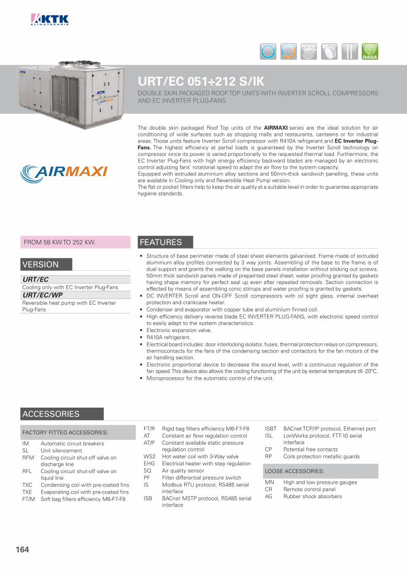
164
URT/EC 051÷212 S/IKDOUBLE SKIN PACKAGED ROOF TOP UNITS WITH INVERTER SCROLL COMPRESSORS AND EC INVERTER PLUG-FANS.
FROM 58 KW TO 252 KW.
VERSION
URT/ECCooling only with EC Inverter Plug-Fans
URT/EC/WPReversible heat pump with EC Inverter Plug-Fans
The double skin packaged Roof Top units of the AIRMAXI series are the ideal solution for air conditioning of wide surfaces such as shopping malls and restaurants, canteens or for industrial areas. Those units feature Inverter Scroll compressor with R410A refrigerant and EC Inverter Plug-Fans. The highest efficiency at partial loads is guaranteed by the Inverter Scroll technology on compressor since its power is varied proportionally to the requested thermal load. Furthermore, the EC Inverter Plug-Fans with high energy efficiency backward blades are managed by an electronic control adjusting fans’ rotational speed to adapt the air flow to the system capacity.Equipped with extruded aluminium alloy sections and 50mm-thick sandwich panelling, these units are available in Cooling only and Reversible Heat Pump version.The flat or pocket filters help to keep the air quality at a suitable level in order to guarantee appropriate hygiene standards.
FEATURES
• Structure of base perimeter made of steel sheet elements galvanised. Frame made of extruded aluminium alloy profiles connected by 3 way joints. Assembling of the base to the frame is of dual support and grants the walking on the base panels installation without sticking out screws. 50mm thick sandwich panels made of prepainted steel sheet; water proofing granted by gaskets having shape memory for perfect seal up even after repeated removals. Section connection is effected by means of assembling conic stirrups and water proofing is granted by gaskets.
• DC INVERTER Scroll and ON-OFF Scroll compressors with oil sight glass, internal overheat protection and crankcase heater.
• Condenser and evaporator with copper tube and aluminium finned coil.• High efficiency delivery reverse blade EC INVERTER PLUG-FANS, with electronic speed control
to easily adapt to the system characteristics.• Electronic expansion valve.• R410A refrigerant.• Electrical board includes: door interlocking isolator, fuses, thermal protection relays on compressors,
thermocontacts for the fans of the condensing section and contactors for the fan motors of the air handling section.
• Electronic proportional device to decrease the sound level, with a continuous regulation of the fan speed. This device also allows the cooling functioning of the unit by external temperature till -20°C.
• Microprocessor for the automatic control of the unit.
ACCESSORIES
FACTORY FITTED ACCESSORIES:
IM Automatic circuit breakersSL Unit silencementRFM Cooling circuit shut-off valve on
discharge lineRFL Cooling circuit shut-off valve on
liquid lineTXC Condensing coil with pre-coated finsTXE Evaporating coil with pre-coated finsFT/M Soft bag filters efficiency M6-F7-F8
FT/R Rigid bag filters efficiency M6-F7-F8AT Constant air flow regulation controlAT/P Constant available static pressure
regulation controlWS2 Hot water coil with 3-Way valveEHG Electrical heater with step regulationSQ Air quality sensorPF Filter differential pressure switchIS Modbus RTU protocol, RS485 serial
interfaceISB BACnet MSTP protocol, RS485 serial
interface
ISBT BACnet TCP/IP protocol, Ethernet portISL LonWorks protocol, FTT-10 serial
interfaceCP Potential free contactsRP Coils protection metallic guards
LOOSE ACCESSORIES:
MN High and low pressure gaugesCR Remote control panelAG Rubber shock absorbers

165
CLEARANCE AREA
1234
Electrical board side
TECHNICAL DATA - URT/EC 051÷212 S/IKMODEL 051 061 071 081 091 101 111 131 152 172 212
CoolingCooling capacity (1) kW 57.9 65.8 77.6 87.4 98.6 113 129 145 168 198 252Absorbed power (1),(2) kW 19.4 21.8 24.6 26.2 30.8 37.8 40.4 43.3 54.6 61.5 85.1
Cooling (EN14511)
SEER (3) 3.53 3.53 3.72 3.89 3.77 3.55 3.74 3.94 3.62 3.81 3.55Energy Efficiency (3) % 138 138 146 153 148 139 147 155 142 149 139
HeatingHeating capacity (4) kW 60.2 67.2 76.8 88.6 101 115 133 151 173 204 262Absorbed power (2),(4) kW 16.8 17.9 20.2 22.8 25.2 32.2 34.0 40.0 45.7 50.4 70.5
Heating (EN14511)
SCOP (5) 3.22 3.34 3.34 3.37 3.54 3.22 3.54 3.38 3.33 3.54 3.23Energy Efficiency (5) % 126 131 131 132 139 126 139 132 130 139 126
Air treatment section
Air flow m³/s 2.67 3.30 4.05 4.05 4.84 5.49 6.32 6.32 8.20 9.79 12.31Available static pressure Pa 250 250 250 250 250 250 250 250 250 250 250Fan n° 1 1 2 2 2 2 2 2 2 4 4Filter Tipo G4 G4 G4 G4 G4 G4 G4 G4 G4 G4 G4
Condensing section
Compressor n° 2 2 2 2 2 2 2 2 4 4 4Refrigerant circuits n° 1 1 1 1 1 1 1 1 2 2 2Capacity steps n° Stepless Stepless
Hot water coil
Heating capacity (6) kW 85 100 125 125 150 175 200 200 250 300 350Air pressure drops Pa 30 31 31 31 31 30 36 36 35 35 57Water flow (6) l/s 2.03 2.39 2.99 2.99 3.58 4.18 4.78 4.78 5.97 7.17 8.36Water pressure drops kPa 45 47 48 48 49 44 51 51 53 57 45Water connections ”G 1 ”½ 1 ”½ 1” ½ 1” ½ 1” ½ 2” 2” 2” 2” 2 ½” 2 ½”
Electrical heater
Power supply V/Ph/Hz 400/3/50 400/3/50Heating capacity kW 15 21 27 27 27 41 41 41 41 48 55Max. absorbed current A 22 30 39 39 39 59 59 59 59 69 79Steps n° 2 2 2 2 2 4 4 4 4 4 4
Electrical characteristics
Power supply V/Ph/Hz 400/3/50 400/3/50Max. running current A 46 47 56 60 69 88 93 102 126 148 170Max. starting current A 169 169 179 192 236 212 225 269 258 315 344
Sound pressure (7) dB(A) 57 57 57 57 57 58 59 59 60 60 61
WeightsTransport weight Kg 990 1050 1150 1250 1260 1450 1810 1860 2230 2400 3180Operating weight Kg 975 1035 1135 1235 1245 1430 1790 1840 2210 2380 3150
COMPLEMENTARY SECTIONS
UM Section with preparation for HumidifierUM/EN Section Humidifier with electrodes immersedF/CD Condensation endothermic hot air generator with modulating gas burner
DIMENSIONSMODEL 051 061 071 081 091 101 111 131 152 172 212L STD mm 2980 3080 3190 3190 3290 3770 4500 4500 5150 5300 7370W STD mm 2200 2200 2200 2200 2200 2200 2200 2200 2200 2200 2200H STD mm 2100 2340 2340 2340 2340 2340 2340 2340 2340 2510 2510
ErP SCOPErP SEER
NOTES1. Evaporator inlet air temperature 27 °C d.b./19 °C w.b.; ambient air temperature 35 °C.2. Excluded the power absorbed by fans of air treatment section.3. Seasonal energy efficiency of cooling. According to EU Regulation n. 2016/2281.4. Condenser inlet air temperature 20 °C, ambient air temperature 7 °C d.b./6 °C w.b.5. Seasonal energy efficiency of heating with average climatic conditions.
According to EU Regulation n. 2016/2281.6. Inlet air temperature 20 °C, water temperature 70/60 °C.7. Sound pressure level measured in free field conditions at 1 m from the unit.
According to ISO 3744.N.B. Weights of WP version are specified on technical brochure.
4
UP
PE
R L
INE
URT/EC 051÷101 S/IK
800 1700 800 1700
URT/EC 111÷212 S/IK
1000 1700 1000 1700

166
URT/EC/MS 051÷212 S/IKDOUBLE SKIN PACKAGED ROOF TOP UNITS WITH INVERTER SCROLL COMPRESSORS, EC INVERTER PLUG-FANS AND MIXING BOX.
FROM 58 KW TO 252 KW.
VERSION
URT/EC/MSCooling only with EC Inverter Plug-Fans and Mixing Box
URT/EC/WP/MSReversible Heat Pump with EC Inverter Plug-Fans and Mixing Box
The double skin packaged Roof Top units of the AIRMAXI series are the ideal solution for air conditioning of wide surfaces such as shopping malls and restaurants, canteens or for industrial areas. Those units feature Inverter Scroll compressor with R410A refrigerant and EC Inverter Plug-Fans. The highest efficiency at partial loads is guaranteed by the Inverter Scroll technology on compressor since its power is varied proportionally to the requested thermal load. Furthermore, the EC Inverter Plug-Fans with high energy efficiency backward blades are managed by an electronic control adjusting fans’ rotational speed to adapt the air flow to the system capacity.Equipped with extruded aluminium alloy sections and 50mm-thick sandwich panelling, these units are available in Cooling only and Reversible Heat Pump version.The flat or pocket filters help to keep the air quality at a suitable level in order to guarantee appropriate hygiene standards.The MS units have an high level of modularity and adaptability to every plant-engineering need: these units feature, in addition to the basic sections, a MIXING BOX.
FEATURES
• Structure of base perimeter made of steel sheet elements galvanised. Frame made of extruded aluminium alloy profiles connected by 3 way joints. Assembling of the base to the frame is of dual support and grants the walking on the base panels installation without sticking out screws. 50mm thick sandwich panels made of prepainted steel sheet; water proofing granted by gaskets having shape memory for perfect seal up even after repeated removals. Section connection is effected by means of assembling conic stirrups and water proofing is granted by gaskets.
• DC INVERTER Scroll and ON-OFF Scroll compressors with oil sight glass, internal overheat protection and crankcase heater.
• Condenser and evaporator with copper tube and aluminium finned coil.• High efficiency delivery reverse blade EC INVERTER PLUG-FANS, with electronic speed control
to easily adapt to the system characteristics.• Electronic expansion valve.• R410A refrigerant.• Electrical board includes: door interlocking isolator, fuses, thermal protection relays on compressors,
thermocontacts for the fans of the condensing section and contactors for the fan motors of the air handling section.
• Electronic proportional device to decrease the sound level, with a continuous regulation of the fan speed. This device also allows the cooling functioning of the unit by external temperature till -20°C.
• Microprocessor for the automatic control of the unit.
ACCESSORIES
FACTORY FITTED ACCESSORIES:
IM Automatic circuit breakersSL Unit silencementRFM Cooling circuit shut-off valve on
discharge lineRFL Cooling circuit shut-off valve on
liquid lineTXC Condensing coil with pre-coated finsTXE Evaporating coil with pre-coated finsFT/M Soft bag filters efficiency M6-F7-F8
FT/R Rigid bag filters efficiency M6-F7-F8AT Constant air flow regulation controlAT/P Constant available static pressure
regulation controlWS2 Hot water coil with 3-Way valveEHG Electrical heater with step regulationSQ Air quality sensorPF Filter differential pressure switchIS Modbus RTU protocol, RS485 serial
interfaceISB BACnet MSTP protocol, RS485 serial
interface
ISBT BACnet TCP/IP protocol, Ethernet portISL LonWorks protocol, FTT-10 serial
interfaceCP Potential free contactsRP Coils protection metallic guards
LOOSE ACCESSORIES:
MN High and low pressure gaugesCR Remote control panelAG Rubber shock absorbers

167
CLEARANCE AREA
1234
Electrical board side
TECHNICAL DATA - URT/EC/MS 051÷212 S/IKMODEL 051 061 071 081 091 101 111 131 152 172 212
CoolingCooling capacity (1) kW 57.9 65.8 77.6 87.4 98.6 113 129 145 168 198 252Absorbed power (1),(2) kW 19.4 21.8 24.6 26.2 30.8 37.8 40.4 43.3 54.6 61.5 85.1
Cooling (EN14511)
SEER (3) 3.53 3.53 3.72 3.89 3.77 3.55 3.74 3.94 3.62 3.81 3.55Energy Efficiency (3) % 138 138 146 153 148 139 147 155 142 149 139
HeatingHeating capacity (4) kW 60.2 67.2 76.8 88.6 101 115 133 151 173 204 262Absorbed power (2),(4) kW 16.8 17.9 20.2 22.8 25.2 32.2 34.0 40.0 45.7 50.4 70.5
Heating (EN14511)
SCOP (5) 3.22 3.34 3.34 3.37 3.54 3.22 3.54 3.38 3.33 3.54 3.23Energy Efficiency (5) % 126 131 131 132 139 126 139 132 130 139 126
Air treatment section
Air flow m³/s 2.67 3.30 4.05 4.05 4.84 5.49 6.32 6.32 8.20 9.79 12.31Available static pressure Pa 250 250 250 250 250 250 250 250 250 250 250Fan n° 1 1 2 2 2 2 2 2 2 4 4Filter Tipo G4 G4 G4 G4 G4 G4 G4 G4 G4 G4 G4
Condensing section
Compressor n° 2 2 2 2 2 2 2 2 4 4 4Refrigerant circuits n° 1 1 1 1 1 1 1 1 2 2 2Capacity steps n° Stepless Stepless
Hot water coil
Heating capacity (6) kW 85 100 125 125 150 175 200 200 250 300 350Air pressure drops Pa 30 31 31 31 31 30 36 36 35 35 57Water flow (6) l/s 2.03 2.39 2.99 2.99 3.58 4.18 4.78 4.78 5.97 7.17 8.36Water pressure drops kPa 45 47 48 48 49 44 51 51 53 57 45Water connections ”G 1 ”½ 1 ”½ 1” ½ 1” ½ 1” ½ 2” 2” 2” 2” 2 ½” 2 ½”
Electrical heater
Power supply V/Ph/Hz 400/3/50 400/3/50Heating capacity kW 15 21 27 27 27 41 41 41 41 48 55Max. absorbed current A 22 30 39 39 39 59 59 59 59 69 79Steps n° 2 2 2 2 2 4 4 4 4 4 4
Electrical characteristics
Power supply V/Ph/Hz 400/3/50 400/3/50Max. running current A 46 47 56 60 69 88 93 102 126 148 170Max. starting current A 169 169 179 192 236 212 225 269 258 315 344
Sound pressure (7) dB(A) 57 57 57 57 57 58 59 59 60 60 61
WeightsTransport weight Kg 1070 1135 1245 1340 1360 1560 1940 1990 2300 2520 3465Operating weight Kg 1055 1120 1225 1320 1340 1540 1920 1970 2280 2500 3435
COMPLEMENTARY SECTIONS
UM Section with preparation for HumidifierUM/EN Section Humidifier with electrodes immersedF/CD Condensation endothermic hot air generator with modulating gas burner
MIXING BOXMS. Further to components of the basic section, includes two wing profile aluminium dampers with spring return servomotors; the opposite movement is ensured by transmission of nylon gear.
DIMENSIONSMODEL 051 061 071 081 091 101 111 131 152 172 212L STD mm 3430 3530 3640 3640 3740 4220 4950 4950 5600 5750 7850W STD mm 2200 2200 2200 2200 2200 2200 2200 2200 2200 2200 2200H STD mm 2100 2340 2340 2340 2340 2340 2340 2340 2340 2510 2510
ErP SCOPErP SEER
NOTES1. Evaporator inlet air temperature 27 °C d.b./19 °C w.b.; ambient air temperature 35 °C.2. Excluded the power absorbed by fans of air treatment section.3. Seasonal energy efficiency of cooling. According to EU Regulation n. 2016/2281.4. Condenser inlet air temperature 20 °C, ambient air temperature 7 °C d.b./6 °C w.b.5. Seasonal energy efficiency of heating with average climatic conditions.
According to EU Regulation n. 2016/2281.6. Inlet air temperature 20 °C, water temperature 70/60 °C.7. Sound pressure level measured in free field conditions at 1 m from the unit.
According to ISO 3744.N.B. Weights of WP version are specified on technical brochure.
4
UP
PE
R L
INE
URT/EC/MS 051÷101 S/IK
800 1700 800 1700
URT/EC/MS 111÷212 S/IK
1000 1700 1000 1700

168
URT/EC/ECO 051÷212 S/IKDOUBLE SKIN PACKAGED ROOF TOP UNITS WITH INVERTER SCROLL COMPRESSORS, EC INVERTER PLUG-FANS AND ECONOMIZER.
FROM 58 KW TO 252 KW.
VERSION
URT/EC/ECOCooling only with EC Inverter Plug-Fans and Economizer
URT/EC/WP/ECOReversible Heat Pump with EC Inverter Plug-Fans and Economizer
The double skin packaged Roof Top units of the AIRMAXI series are the ideal solution for air conditioning of wide surfaces such as shopping malls and restaurants, canteens or for industrial areas. Those units feature Inverter Scroll compressor with R410A refrigerant and EC Inverter Plug-Fans. The highest efficiency at partial loads is guaranteed by the Inverter Scroll technology on compressor since its power is varied proportionally to the requested thermal load. Furthermore, the EC Inverter Plug-Fans with high energy efficiency backward blades are managed by an electronic control adjusting fans’ rotational speed to adapt the air flow to the system capacity.Equipped with extruded aluminium alloy sections and 50mm-thick sandwich panelling, these units are available in Cooling only and Reversible Heat Pump version.The flat or pocket filters help to keep the air quality at a suitable level in order to guarantee appropriate hygiene standards.The ECO units have an high level of modularity and adaptability to every plant-engineering need: these units feature, in addition to the basic sections, an ECONOMIZER automatically controlled both in FREE-COOLING or FREE-HEATING.The unit can be equipped, as an option, with the innovative Thermodynamic Coil-Boost Heat Recovery to achieve better performance and efficiency both in cooling and heating up to 15%.
FEATURES
• Structure of base perimeter made of steel sheet elements galvanised. Frame made of extruded aluminium alloy profiles connected by 3 way joints. Assembling of the base to the frame is of dual support and grants the walking on the base panels installation without sticking out screws. 50mm thick sandwich panels made of prepainted steel sheet; water proofing granted by gaskets having shape memory for perfect seal up even after repeated removals. Section connection is effected by means of assembling conic stirrups and water proofing is granted by gaskets.
• DC INVERTER Scroll and ON-OFF Scroll compressors with oil sight glass, internal overheat protection and crankcase heater.
• Condenser and evaporator with copper tube and aluminium finned coil.• High efficiency delivery & intake reverse blade EC INVERTER PLUG-FANS, with electronic speed
control to easily adapt to the system characteristics.• Electronic expansion valve.• R410A refrigerant.• Electrical board includes: door interlocking isolator, fuses, thermal protection relays on compressors,
thermocontacts for the fans of the condensing section and contactors for the fan motors of the air handling section.
• Electronic proportional device to decrease the sound level, with a continuous regulation of the fan speed. This device also allows the cooling functioning of the unit by external temperature till -20°C.
• Microprocessor for the automatic control of the unit.
ACCESSORIES
FACTORY FITTED ACCESSORIES:
IM Automatic circuit breakersSL Unit silencementTHCB Thermodynamic Coil-Boost Heat
Recovery (ECO only)RFM Cooling circuit shut-off valve on
discharge lineRFL Cooling circuit shut-off valve on
liquid lineTXC Condensing coil with pre-coated finsTXE Evaporating coil with pre-coated finsFT/M Soft bag filters efficiency M6-F7-F8
FT/R Rigid bag filters efficiency M6-F7-F8AT Constant air flow regulation controlAT/P Constant available static pressure
regulation controlWS2 Hot water coil with 3-Way valveEHG Electrical heater with step regulationCH Enthalpic control (ECO only)SQ Air quality sensorPF Filter differential pressure switchIS Modbus RTU protocol, RS485 serial
interfaceISB BACnet MSTP protocol, RS485 serial
interface
ISBT BACnet TCP/IP protocol, Ethernet portISL LonWorks protocol, FTT-10 serial
interfaceCP Potential free contactsRP Coils protection metallic guards
LOOSE ACCESSORIES:
MN High and low pressure gaugesCR Remote control panelAG Rubber shock absorbers

169
CLEARANCE AREA
1234
Electrical board side
TECHNICAL DATA - URT/EC/ECO 051÷212 S/IKMODEL 051 061 071 081 091 101 111 131 152 172 212
CoolingCooling capacity (1) kW 57.9 65.8 77.6 87.4 98.6 113 129 145 168 198 252Absorbed power (1),(2) kW 19.4 21.8 24.6 26.2 30.8 37.8 40.4 43.3 54.6 61.5 85.1
Cooling (EN14511)
SEER (3) 3.53 3.53 3.72 3.89 3.77 3.55 3.74 3.94 3.62 3.81 3.55Energy Efficiency (3) % 138 138 146 153 148 139 147 155 142 149 139
HeatingHeating capacity (4) kW 60.2 67.2 76.8 88.6 101 115 133 151 173 204 262Absorbed power (2),(4) kW 16.8 17.9 20.2 22.8 25.2 32.2 34.0 40.0 45.7 50.4 70.5
Heating (EN14511)
SCOP (5) 3.22 3.34 3.34 3.37 3.54 3.22 3.54 3.38 3.33 3.54 3.23Energy Efficiency (5) % 126 131 131 132 139 126 139 132 130 139 126
Air treatment section
Air flow m³/s 2.67 3.30 4.05 4.05 4.84 5.49 6.32 6.32 8.20 9.79 12.31Available static pressure Pa 250 250 250 250 250 250 250 250 250 250 250Fan n° 1 1 2 2 2 2 2 2 2 4 4Filter Tipo G4 G4 G4 G4 G4 G4 G4 G4 G4 G4 G4
Air intake sectionAir flow m³/s 2.67 3.30 4.05 4.05 4.84 5.49 6.32 6.32 8.20 9.79 12.31Available static pressure Pa 100 100 100 100 100 100 100 100 100 100 100Fan n° 1 1 2 2 2 2 2 2 2 4 4
Condensing section
Compressor n° 2 2 2 2 2 2 2 2 4 4 4Refrigerant circuits n° 1 1 1 1 1 1 1 1 2 2 2Capacity steps n° Stepless Stepless
Hot water coil
Heating capacity (6) kW 85 100 125 125 150 175 200 200 250 300 350Air pressure drops Pa 30 31 31 31 31 30 36 36 35 35 57Water flow (6) l/s 2.03 2.39 2.99 2.99 3.58 4.18 4.78 4.78 5.97 7.17 8.36Water pressure drops kPa 45 47 48 48 49 44 51 51 53 57 45Water connections ”G 1 ”½ 1 ”½ 1” ½ 1” ½ 1” ½ 2” 2” 2” 2” 2 ½” 2 ½”
Electrical heater
Power supply V/Ph/Hz 400/3/50 400/3/50Heating capacity kW 15 21 27 27 27 41 41 41 41 48 55Max. absorbed current A 22 30 39 39 39 59 59 59 59 69 79Steps n° 2 2 2 2 2 4 4 4 4 4 4
Electrical characteristics
Power supply V/Ph/Hz 400/3/50 400/3/50Max. running current A 46 47 56 60 69 88 93 102 126 148 170Max. starting current A 169 169 179 192 236 212 225 269 258 315 344
Sound pressure (7) dB(A) 57 57 57 57 57 58 59 59 60 60 61
WeightsTransport weight Kg 1500 1610 1740 1840 1860 2000 2400 2450 3020 3370 4190Operating weight Kg 1480 1590 1720 1820 1840 1975 2375 2425 2990 3335 4150
COMPLEMENTARY SECTIONS
UM Section with preparation for HumidifierUM/EN Section Humidifier with electrodes immersedF/CD Condensation endothermic hot air generator with modulating gas burner
ECONOMIZERECO. Further to components of the basic section, includes: return air fan with electrical motor, complete of adjustable transmission, mounted on elastic supports; motorized wing profile aluminium dampers, the opposite movement is ensured by transmission of nylon gear. Exhaust, recirculation and fresh air are controlled through the microprocessor fitted in the base unit; this microprocessor, according to the temperature of the return and fresh air, modulates the opening of the dampers and controls the cooling circuit capacity steps to ensure comfort conditions of the handled air. The adjustments of the ECO versions are automatically controlled both in free-cooling and free-heating mode.
DIMENSIONSMODEL 051 061 071 081 091 101 111 131 152 172 212L STD mm 5260 5480 5570 5570 5650 6170 6900 6900 8080 8470 11020W STD mm 2200 2200 2200 2200 2200 2200 2200 2200 2200 2200 2200H STD mm 2100 2340 2340 2340 2340 2340 2340 2340 2340 2510 2510
ErP SCOPErP SEER
NOTES1. Evaporator inlet air temperature 27 °C d.b./19 °C w.b.; ambient air temperature 35 °C.2. Excluded the power absorbed by fans of air treatment section.3. Seasonal energy efficiency of cooling. According to EU Regulation n. 2016/2281.4. Condenser inlet air temperature 20 °C, ambient air temperature 7 °C d.b./6 °C w.b.5. Seasonal energy efficiency of heating with average climatic conditions.
According to EU Regulation n. 2016/2281.6. Inlet air temperature 20 °C, water temperature 70/60 °C.7. Sound pressure level measured in free field conditions at 1 m from the unit.
According to ISO 3744.N.B. Weights of WP version are specified on technical brochure.
4
UP
PE
R L
INE
URT/EC/ECO 051÷101 S/IK
800 1700 800 1700
URT/EC/ECO 111÷212 S/IK
1000 1700 1000 1700

170
URT/EC/ECO/REC-FX 051÷212 S/IKDOUBLE SKIN PACKAGED ROOF TOP UNITS WITH INVERTER SCROLL COMPRESSORS, EC INVERTER PLUG-FANS, ECONOMIZER AND CROSS-FLOW HEAT RECOVERY.
FROM 58 KW TO 252 KW.
VERSION
URT/EC/ECO/REC-FXCooling only with EC Inverter Plug-Fans, Economizer and Cross-flow Heat Recovery
URT/EC/WP/ECO/REC-FXReversible Heat Pump with EC Inverter Plug-Fans, Economizer and Cross-flow Heat Recovery
The double skin packaged Roof Top units of the AIRMAXI series are the ideal solution for air conditioning of wide surfaces such as shopping malls and restaurants, canteens or for industrial areas. Those units feature Inverter Scroll compressor with R410A refrigerant and EC Inverter Plug-Fans. The highest efficiency at partial loads is guaranteed by the Inverter Scroll technology on compressor since its power is varied proportionally to the requested thermal load. Furthermore, the EC Inverter Plug-Fans with high energy efficiency backward blades are managed by an electronic control adjusting fans’ rotational speed to adapt the air flow to the system capacity.Equipped with extruded aluminium alloy sections and 50mm-thick sandwich panelling, these units are available in Cooling only and Reversible Heat Pump version.The flat or pocket filters help to keep the air quality at a suitable level in order to guarantee appropriate hygiene standards.The ECO/REC-FX units have an high level of modularity and adaptability to every plant-engineering need: these units feature, in addition to the basic sections, an ECONOMIZER automatically controlled both in FREE-COOLING or FREE-HEATING and a CROSS-FLOW HEAT RECOVERY.
FEATURES
• Structure of base perimeter made of steel sheet elements galvanised. Frame made of extruded aluminium alloy profiles connected by 3 way joints. Assembling of the base to the frame is of dual support and grants the walking on the base panels installation without sticking out screws. 50mm thick sandwich panels made of prepainted steel sheet; water proofing granted by gaskets having shape memory for perfect seal up even after repeated removals. Section connection is effected by means of assembling conic stirrups and water proofing is granted by gaskets.
• DC INVERTER Scroll and ON-OFF Scroll compressors with oil sight glass, internal overheat protection and crankcase heater.
• Condenser and evaporator with copper tube and aluminium finned coil.• High efficiency delivery & intake reverse blade EC INVERTER PLUG-FANS, with electronic speed
control to easily adapt to the system characteristics.• Electronic expansion valve.• R410A refrigerant.• Electrical board includes: door interlocking isolator, fuses, thermal protection relays on compressors,
thermocontacts for the fans of the condensing section and contactors for the fan motors of the air handling section.
• Electronic proportional device to decrease the sound level, with a continuous regulation of the fan speed. This device also allows the cooling functioning of the unit by external temperature till -20°C.
• Microprocessor for the automatic control of the unit.
ACCESSORIES
FACTORY FITTED ACCESSORIES:
IM Automatic circuit breakersSL Unit silencementRFM Cooling circuit shut-off valve on
discharge lineRFL Cooling circuit shut-off valve on
liquid lineTXC Condensing coil with pre-coated finsTXE Evaporating coil with pre-coated finsFT/M Soft bag filters efficiency M6-F7-F8FT/R Rigid bag filters efficiency M6-F7-F8
AT Constant air flow regulation controlAT/P Constant available static pressure
regulation controlWS2 Hot water coil with 3-Way valveEHG Electrical heater with step regulationCH Enthalpic control (ECO only)SQ Air quality sensorPF Filter differential pressure switchIS Modbus RTU protocol, RS485 serial
interfaceISB BACnet MSTP protocol, RS485 serial
interface
ISBT BACnet TCP/IP protocol, Ethernet portISL LonWorks protocol, FTT-10 serial
interfaceCP Potential free contactsRP Coils protection metallic guards
LOOSE ACCESSORIES:
MN High and low pressure gaugesCR Remote control panelAG Rubber shock absorbers

171
CLEARANCE AREA
1234
Electrical board side
TECHNICAL DATA - URT/EC/ECO/REC-FX 051÷212 S/IKMODEL 051 061 071 081 091 101 111 131 152 172 212
CoolingCooling capacity (1) kW 57.9 65.8 77.6 87.4 98.6 113 129 145 168 198 252Absorbed power (1),(2) kW 19.4 21.8 24.6 26.2 30.8 37.8 40.4 43.3 54.6 61.5 85.1
Cooling (EN14511)
SEER (3) 3.53 3.53 3.72 3.89 3.77 3.55 3.74 3.94 3.62 3.81 3.55Energy Efficiency (3) % 138 138 146 153 148 139 147 155 142 149 139
HeatingHeating capacity (4) kW 60.2 67.2 76.8 88.6 101 115 133 151 173 204 262Absorbed power (2),(4) kW 16.8 17.9 20.2 22.8 25.2 32.2 34.0 40.0 45.7 50.4 70.5
Heating (EN14511)
SCOP (5) 3.22 3.34 3.34 3.37 3.54 3.22 3.54 3.38 3.33 3.54 3.23Energy Efficiency (5) % 126 131 131 132 139 126 139 132 130 139 126
Air treatment section
Air flow m³/s 2.67 3.30 4.05 4.05 4.84 5.49 6.32 6.32 8.20 9.79 12.31Available static pressure Pa 250 250 250 250 250 250 250 250 250 250 250Fan n° 1 1 2 2 2 2 2 2 2 4 4Filter Tipo G4 G4 G4 G4 G4 G4 G4 G4 G4 G4 G4
Air intake sectionAir flow m³/s 2.67 3.30 4.05 4.05 4.84 5.49 6.32 6.32 8.20 9.79 12.31Available static pressure Pa 100 100 100 100 100 100 100 100 100 100 100Fan n° 1 1 2 2 2 2 2 2 2 4 4
Condensing section
Compressor n° 2 2 2 2 2 2 2 2 4 4 4Refrigerant circuits n° 1 1 1 1 1 1 1 1 2 2 2Capacity steps n° Stepless Stepless
Hot water coil
Heating capacity (6) kW 85 100 125 125 150 175 200 200 250 300 350Air pressure drops Pa 30 31 31 31 31 30 36 36 35 35 57Water flow (6) l/s 2.03 2.39 2.99 2.99 3.58 4.18 4.78 4.78 5.97 7.17 8.36Water pressure drops kPa 45 47 48 48 49 44 51 51 53 57 45Water connections ”G 1 ”½ 1 ”½ 1” ½ 1” ½ 1” ½ 2” 2” 2” 2” 2 ½” 2 ½”
Electrical heater
Power supply V/Ph/Hz 400/3/50 400/3/50Heating capacity kW 15 21 27 27 27 41 41 41 41 48 55Max. absorbed current A 22 30 39 39 39 59 59 59 59 69 79Steps n° 2 2 2 2 2 4 4 4 4 4 4
Electrical characteristics
Power supply V/Ph/Hz 400/3/50 400/3/50Max. running current A 46 47 56 60 69 88 93 102 126 148 170Max. starting current A 169 169 179 192 236 212 225 269 258 315 344
Sound pressure (7) dB(A) 57 57 57 57 57 58 59 59 60 60 61
WeightsTransport weight Kg 1645 1720 1910 2020 2040 2210 2640 2690 3260 3590 4390Operating weight Kg 1620 1695 1885 1995 2015 2185 2610 2660 3225 3555 4350
COMPLEMENTARY SECTIONS
UM Section with preparation for HumidifierUM/EN Section Humidifier with electrodes immersedF/CD Condensation endothermic hot air generator with modulating gas burner
ECONOMIZER AND CROSS-FLOW HEAT RECOVERYECO/REC-FX. Further to the components of the ECO section, it includes: static recovery device made of aluminium with moisture drain pan, flat filters inspectable through hinged door and dampers with return spring servomotors (fresh air damper + air recirculation damper + exhaust air damper + 2 Free-Cooling dampers). Also the adjustment of this section is included into the unit control.
DIMENSIONSMODEL 051 061 071 081 091 101 111 131 152 172 212L STD mm 6060 6060 6270 6270 6450 7050 7870 7870 9120 9380 11650W STD mm 2200 2200 2200 2200 2200 2200 2200 2200 2200 2200 2200H STD mm 2100 2340 2340 2340 2340 2340 2340 2340 2340 2510 2510
ErP SCOPErP SEER
NOTES1. Evaporator inlet air temperature 27 °C d.b./19 °C w.b.; ambient air temperature 35 °C.2. Excluded the power absorbed by fans of air treatment section.3. Seasonal energy efficiency of cooling. According to EU Regulation n. 2016/2281.4. Condenser inlet air temperature 20 °C, ambient air temperature 7 °C d.b./6 °C w.b.5. Seasonal energy efficiency of heating with average climatic conditions.
According to EU Regulation n. 2016/2281.6. Inlet air temperature 20 °C, water temperature 70/60 °C.7. Sound pressure level measured in free field conditions at 1 m from the unit.
According to ISO 3744.N.B. Weights of WP version are specified on technical brochure.
4
UP
PE
R L
INE
URT/EC/ECO/REC-FX 051÷101 S/IK
800 1700 800 1700
URT/EC/ECO/REC-FX 111÷212 S/IK
1000 1700 1000 1700

172
URT/EC/ECO/REC-WH 051÷212 S/IKDOUBLE SKIN PACKAGED ROOF TOP UNITS WITH INVERTER SCROLL COMPRESSORS, EC INVERTER PLUG-FANS, ECONOMIZER AND WHEEL HEAT RECOVERY.
FROM 58 KW TO 252 KW.
VERSION
URT/EC/ECO/REC-WHCooling only with EC Inverter Plug-Fans, Economizer and Wheel Heat Recovery
URT/EC/WP/ECO/REC-WHReversible Heat Pump with EC Inverter Plug-Fans, Economizer and Wheel Heat Recovery
The double skin packaged Roof Top units of the AIRMAXI series are the ideal solution for air conditioning of wide surfaces such as shopping malls and restaurants, canteens or for industrial areas. Those units feature Inverter Scroll compressor with R410A refrigerant and EC Inverter Plug-Fans. The highest efficiency at partial loads is guaranteed by the Inverter Scroll technology on compressor since its power is varied proportionally to the requested thermal load. Furthermore, the EC Inverter Plug-Fans with high energy efficiency backward blades are managed by an electronic control adjusting fans’ rotational speed to adapt the air flow to the system capacity.Equipped with extruded aluminium alloy sections and 50mm-thick sandwich panelling, these units are available in Cooling only and Reversible Heat Pump version.The flat or pocket filters help to keep the air quality at a suitable level in order to guarantee appropriate hygiene standards.The ECO/REC-WH units have an high level of modularity and adaptability to every plant-engineering need: these units feature, in addition to the basic sections, an ECONOMIZER automatically controlled both in FREE-COOLING or FREE-HEATING and a WHEEL HEAT RECOVERY, able to treat up to 100% of total air flow.
FEATURES
• Structure of base perimeter made of steel sheet elements galvanised. Frame made of extruded aluminium alloy profiles connected by 3 way joints. Assembling of the base to the frame is of dual support and grants the walking on the base panels installation without sticking out screws. 50mm thick sandwich panels made of prepainted steel sheet; water proofing granted by gaskets having shape memory for perfect seal up even after repeated removals. Section connection is effected by means of assembling conic stirrups and water proofing is granted by gaskets.
• DC INVERTER Scroll and ON-OFF Scroll compressors with oil sight glass, internal overheat protection and crankcase heater.
• Condenser and evaporator with copper tube and aluminium finned coil.• High efficiency delivery & intake reverse blade EC INVERTER PLUG-FANS, with electronic speed
control to easily adapt to the system characteristics.• Electronic expansion valve.• R410A refrigerant.• Electrical board includes: door interlocking isolator, fuses, thermal protection relays on compressors,
thermocontacts for the fans of the condensing section and contactors for the fan motors of the air handling section.
• Electronic proportional device to decrease the sound level, with a continuous regulation of the fan speed. This device also allows the cooling functioning of the unit by external temperature till -20°C.
• Microprocessor for the automatic control of the unit.
ACCESSORIES
FACTORY FITTED ACCESSORIES:
IM Automatic circuit breakersSL Unit silencementRFM Cooling circuit shut-off valve on
discharge lineRFL Cooling circuit shut-off valve on
liquid lineTXC Condensing coil with pre-coated finsTXE Evaporating coil with pre-coated finsFT/M Soft bag filters efficiency M6-F7-F8FT/R Rigid bag filters efficiency M6-F7-F8
AT Constant air flow regulation controlAT/P Constant available static pressure
regulation controlWS2 Hot water coil with 3-Way valveEHG Electrical heater with step regulationCH Enthalpic control (ECO only)SQ Air quality sensorPF Filter differential pressure switchIS Modbus RTU protocol, RS485 serial
interfaceISB BACnet MSTP protocol, RS485 serial
interface
ISBT BACnet TCP/IP protocol, Ethernet portISL LonWorks protocol, FTT-10 serial
interfaceCP Potential free contactsRP Coils protection metallic guards
LOOSE ACCESSORIES:
MN High and low pressure gaugesCR Remote control panelAG Rubber shock absorbers

173
CLEARANCE AREA
1234
Electrical board side
TECHNICAL DATA - URT/EC/ECO/REC-WH 051÷212 S/IKMODEL 051 061 071 081 091 101 111 131 152 172 212
CoolingCooling capacity (1) kW 57.9 65.8 77.6 87.4 98.6 113 129 145 168 198 252Absorbed power (1),(2) kW 19.4 21.8 24.6 26.2 30.8 37.8 40.4 43.3 54.6 61.5 85.1
Cooling (EN14511)
SEER (3) 3.53 3.53 3.72 3.89 3.77 3.55 3.74 3.94 3.62 3.81 3.55Energy Efficiency (3) % 138 138 146 153 148 139 147 155 142 149 139
HeatingHeating capacity (4) kW 60.2 67.2 76.8 88.6 101 115 133 151 173 204 262Absorbed power (2),(4) kW 16.8 17.9 20.2 22.8 25.2 32.2 34.0 40.0 45.7 50.4 70.5
Heating (EN14511)
SCOP (5) 3.22 3.34 3.34 3.37 3.54 3.22 3.54 3.38 3.33 3.54 3.23Energy Efficiency (5) % 126 131 131 132 139 126 139 132 130 139 126
Air treatment section
Air flow m³/s 2.67 3.30 4.05 4.05 4.84 5.49 6.32 6.32 8.20 9.79 12.31Available static pressure Pa 250 250 250 250 250 250 250 250 250 250 250Fan n° 1 1 2 2 2 2 2 2 2 4 4Filter Tipo G4 G4 G4 G4 G4 G4 G4 G4 G4 G4 G4
Air intake sectionAir flow m³/s 2.67 3.30 4.05 4.05 4.84 5.49 6.32 6.32 8.20 9.79 12.31Available static pressure Pa 100 100 100 100 100 100 100 100 100 100 100Fan n° 1 1 2 2 2 2 2 2 2 4 4
Condensing section
Compressor n° 2 2 2 2 2 2 2 2 4 4 4Refrigerant circuits n° 1 1 1 1 1 1 1 1 2 2 2Capacity steps n° Stepless Stepless
Hot water coil
Heating capacity (6) kW 85 100 125 125 150 175 200 200 250 300 350Air pressure drops Pa 30 31 31 31 31 30 36 36 35 35 57Water flow (6) l/s 2.03 2.39 2.99 2.99 3.58 4.18 4.78 4.78 5.97 7.17 8.36Water pressure drops kPa 45 47 48 48 49 44 51 51 53 57 45Water connections ”G 1 ”½ 1 ”½ 1” ½ 1” ½ 1” ½ 2” 2” 2” 2” 2 ½” 2 ½”
Electrical heater
Power supply V/Ph/Hz 400/3/50 400/3/50Heating capacity kW 15 21 27 27 27 41 41 41 41 48 55Max. absorbed current A 22 30 39 39 39 59 59 59 59 69 79Steps n° 2 2 2 2 2 4 4 4 4 4 4
Electrical characteristics
Power supply V/Ph/Hz 400/3/50 400/3/50Max. running current A 46 47 56 60 69 88 93 102 126 148 170Max. starting current A 169 169 179 192 236 212 225 269 258 315 344
Sound pressure (7) dB(A) 57 57 57 57 57 58 59 59 60 60 61
WeightsTransport weight Kg 1645 1720 1910 2020 2040 2210 2640 2690 3260 3590 4390Operating weight Kg 1620 1695 1885 1995 2015 2185 2610 2660 3225 3555 4350
COMPLEMENTARY SECTIONS
UM Section with preparation for HumidifierUM/EN Section Humidifier with electrodes immersedF/CD Condensation endothermic hot air generator with modulating gas burner
ECONOMIZER AND WHEEL HEAT RECOVERYECO/REC-WH. Further to the components of the ECO section, includes: high efficiency wheel-type heat recovery device made of aluminium with hygroscopic treatment, managed by a constant-speed electric motor, with moisture drain pan and dampers with spring return (fresh air damper + air recirculation damper + exhaust air damper). Also the adjustment of this section is included into the unit control.
DIMENSIONSMODEL 051 061 071 081 091 101 111 131 152 172 212L STD mm 6060 6060 6270 6270 6450 7050 7870 7870 9120 9380 11650W STD mm 2200 2200 2200 2200 2200 2200 2200 2200 2200 2200 2200H STD mm 2100 2340 2340 2340 2340 2340 2340 2340 2340 2510 2510
ErP SCOPErP SEER
NOTES1. Evaporator inlet air temperature 27 °C d.b./19 °C w.b.; ambient air temperature 35 °C.2. Excluded the power absorbed by fans of air treatment section.3. Seasonal energy efficiency of cooling. According to EU Regulation n. 2016/2281.4. Condenser inlet air temperature 20 °C, ambient air temperature 7 °C d.b./6 °C w.b.5. Seasonal energy efficiency of heating with average climatic conditions.
According to EU Regulation n. 2016/2281.6. Inlet air temperature 20 °C, water temperature 70/60 °C.7. Sound pressure level measured in free field conditions at 1 m from the unit.
According to ISO 3744.N.B. Weights of WP version are specified on technical brochure.
4
UP
PE
R L
INE
URT/EC/ECO/REC-WH 051÷101 S/IK
800 1700 800 1700
URT/EC/ECO/REC-WH 111÷212 S/IK
1000 1700 1000 1700

174
URT 051÷212 S/KDOUBLE SKIN PACKAGED ROOF TOP UNITS WITH SCROLL COMPRESSORS AND RADIAL FANS OR EC INVERTER PLUG-FANS.
FROM 58 KW TO 252 KW.
VERSION
URTCooling only with radial fans
URT/WPReversible Heat Pump with radial fans
URT/ECCooling only with EC Inverter Plug-Fans
URT/EC/WPReversible Heat Pump with EC Inverter Plug-Fans
The packaged Roof Top air conditioning units of the AIRMAXI series are ideal for the air conditioning of large surface areas for public use such as halls, shopping centres, cafeterias, restaurants and health centres, or for industrial environments such as food processing or preservation centres.Those units feature Scroll compressors with R410A refrigerant and radial fans or EC Inverter Plug-Fans. The EC Inverter Plug-Fans with high energy efficiency backward blades both for intake as well as delivery are managed by an electronic control adjusting fans’ rotational speed to adapt the air flow to the system capacity.Equipped with extruded aluminium alloy sections and 50mm-thick sandwich panelling, these units are available in Cooling only and Reversible Heat Pump version.The flat or pocket filters help to keep the air quality at a suitable level in order to guarantee appropriate hygiene standards.
FEATURES
• Structure of base perimeter made of steel sheet elements galvanised. Frame made of extruded aluminium alloy profiles connected by 3 way joints. Assembling of the base to the frame is of dual support and grants the walking on the base panels installation without sticking out screws. 50mm thick sandwich panels made of prepainted steel sheet; water proofing granted by gaskets having shape memory for perfect seal up even after repeated removals. Section connection is effected by means of assembling conic stirrups and water proofing is granted by gaskets.
• Scroll compressors with oil sight glass, internal overheat protection and crankcase heater.• Condenser and evaporator with copper tube and aluminium finned coil.• Delivery radial fans coupled to 3-phase motors by V belt and variable pulley.• High efficiency delivery reverse blade EC INVERTER PLUG-FANS, with electronic speed control
to easily adapt to the system characteristics.• R410A refrigerant.• Electrical board includes: door interlocking isolator, fuses, thermal protection relays on compressors,
thermocontacts for the fans of the condensing section and contactors for the fan motors of the air handling section.
• Microprocessor for the automatic control of the unit.
ACCESSORIES
FACTORY FITTED ACCESSORIES:
IM Automatic circuit breakersSL Unit silencementRFM Cooling circuit shut-off valve on
discharge lineRFL Cooling circuit shut-off valve on
liquid lineCT Condensing control down to 0 °CCC Condensing control down to -20 °CTXC Condensing coil with pre-coated finsTXE Evaporating coil with pre-coated fins
FT/M Soft bag filters efficiency M6-F7-F8FT/R Rigid bag filters efficiency M6-F7-F8AT Constant air flow regulation controlAT/P Constant available static pressure
regulation controlWS2 Hot water coil with 3-Way valveEHG Electrical heater with step regulationSQ Air quality sensorPF Filter differential pressure switchIS Modbus RTU protocol, RS485 serial
interfaceISB BACnet MSTP protocol, RS485 serial
interface
ISBT BACnet TCP/IP protocol, Ethernet portISL LonWorks protocol, FTT-10 serial
interfaceCP Potential free contactsRP Coils protection metallic guards
LOOSE ACCESSORIES:
MN High and low pressure gaugesCR Remote control panelAG Rubber shock absorbers

175
CLEARANCE AREA
1234
Electrical board side
TECHNICAL DATA - URT 051÷212 S/KMODEL 051 061 071 081 091 101 111 131 152 172 212
CoolingCooling capacity (1) kW 57.9 65.8 77.6 87.4 98.6 113 129 145 168 198 252Absorbed power (1),(2) kW 19.4 21.8 24.6 26.2 30.8 37.8 40.4 43.3 54.6 61.5 85.1
Cooling (EN14511)
SEER (3) 3.26 3.32 3.49 3.65 3.54 3.28 3.51 3.70 3.39 3.57 3.33Energy Efficiency (3) % 127 130 137 143 139 128 137 145 133 140 130
HeatingHeating capacity (4) kW 60.2 67.2 76.8 88.6 101 115 133 151 173 204 262Absorbed power (2),(4) kW 16.8 17.9 20.2 22.8 25.2 32.2 34.0 40.0 45.7 50.4 70.5
Heating (EN14511)
SCOP (5) 3.09 3.21 3.21 3.24 3.41 3.09 3.40 3.25 3.20 3.40 3.11Energy Efficiency (5) % 121 125 125 127 133 121 133 127 125 133 121
Air treatment section
Air flow m³/s 2.67 3.30 4.05 4.05 4.84 5.49 6.32 6.32 8.20 9.79 12.31Available static pressure Pa 250 250 250 250 250 250 250 250 250 250 250Fan n° 1 1 1 1 1 1 1 1 1 1 1Filter Tipo G4 G4 G4 G4 G4 G4 G4 G4 G4 G4 G4
Air treatment section(EC version)
Air flow m³/s 2.67 3.30 4.05 4.05 4.84 5.49 6.32 6.32 8.20 9.79 12.31Available static pressure Pa 250 250 250 250 250 250 250 250 250 250 250Fan n° 1 1 2 2 2 2 2 2 2 4 4Filter Tipo G4 G4 G4 G4 G4 G4 G4 G4 G4 G4 G4
Condensing section
Compressor n° 2 2 2 2 2 3 3 3 4 4 4Refrigerant circuits n° 1 1 1 1 1 1 1 1 2 2 2Capacity steps n° 2 3 3 4
Hot water coil
Heating capacity (6) kW 85 100 125 125 150 175 200 200 250 300 350Air pressure drops Pa 30 31 31 31 31 30 36 36 35 35 57Water flow (6) l/s 2.03 2.39 2.99 2.99 3.58 4.18 4.78 4.78 5.97 7.17 8.36Water pressure drops kPa 45 47 48 48 49 44 51 51 53 57 45Water connections ”G 1 ”½ 1 ”½ 1” ½ 1” ½ 1” ½ 2” 2” 2” 2” 2 ½” 2 ½”
Electrical heater
Power supply V/Ph/Hz 400/3/50 400/3/50Heating capacity kW 15 21 27 27 27 41 41 41 41 48 55Max. absorbed current A 22 30 39 39 39 59 59 59 59 69 79Steps n° 2 2 2 2 2 4 4 4 4 4 4
Electrical characteristics
Power supply V/Ph/Hz 400/3/50 400/3/50Max. running current A 50 53 63 67 76 94 100 109 133 150 173Max. starting current A 173 175 186 199 243 218 232 276 265 317 347
Electrical characteristics (EC version)
Power supply V/Ph/Hz 400/3/50 400/3/50Max. running current A 46 47 56 60 69 88 93 102 126 148 170Max. starting current A 169 169 179 192 236 212 225 269 258 315 344
Sound pressureSTD version (7) dB(A) 58 58 58 58 58 59 60 60 61 61 62EC version (7) dB(A) 57 57 57 57 57 58 59 59 60 60 61
WeightsTransport weight Kg 1030 1085 1180 1280 1300 1540 1900 1950 2270 2480 3320Operating weight Kg 1015 1070 1165 1265 1285 1520 1880 1930 2250 2460 3290
Weights(EC version)
Transport weight Kg 990 1050 1150 1250 1260 1450 1810 1860 2230 2400 3180Operating weight Kg 975 1035 1135 1235 1245 1430 1790 1840 2210 2380 3150
COMPLEMENTARY SECTIONS
UM Section with preparation for HumidifierUM/EN Section Humidifier with electrodes immersedF/CD Condensation endothermic hot air generator with modulating gas burner
DIMENSIONSMODEL 051 061 071 081 091 101 111 131 152 172 212L STD/EC mm 2980 3080 3190 3190 3290 3770 4500 4500 5150 5300 7370W STD/EC mm 2200 2200 2200 2200 2200 2200 2200 2200 2200 2200 2200H STD/EC mm 2100 2340 2340 2340 2340 2340 2340 2340 2340 2510 2510
ErP SCOPErP SEER
NOTES1. Evaporator inlet air temperature 27 °C d.b./19 °C w.b.; ambient air temperature 35 °C.2. Excluded the power absorbed by fans of air treatment section.3. Seasonal energy efficiency of cooling. According to EU Regulation n. 2016/2281.4. Condenser inlet air temperature 20 °C, ambient air temperature 7 °C d.b./6 °C w.b.5. Seasonal energy efficiency of heating with average climatic conditions.
According to EU Regulation n. 2016/2281.6. Inlet air temperature 20 °C, water temperature 70/60 °C.7. Sound pressure level measured in free field conditions at 1 m from the unit.
According to ISO 3744.N.B. Weights of WP versions are specified on technical brochure.
4
UP
PE
R L
INE
URT 051÷101 S/K
800 1700 800 1700
URT 111÷212 S/K
1000 1700 1000 1700

176
URT/MS 051÷212 S/KDOUBLE SKIN PACKAGED ROOF TOP UNITS WITH SCROLL COMPRESSORS,RADIAL FANS OR EC INVERTER PLUG-FANS AND MIXING BOX.
FROM 58 KW TO 252 KW.
VERSION
URT/MSCooling only with radial fans and Mixing Box
URT/WP/MSReversible Heat Pump with radial fans and Mixing Box
URT/EC/MSCooling only with EC Inverter Plug-Fans and Mixing Box
URT/EC/WP/MSReversible Heat Pump with EC Inverter Plug-Fans and Mixing Box
The packaged Roof Top air conditioning units of the AIRMAXI series are ideal for the air conditioning of large surface areas for public use such as halls, shopping centres, cafeterias, restaurants and health centres, or for industrial environments such as food processing or preservation centres.Those units feature Scroll compressors with R410A refrigerant and radial fans or EC Inverter Plug-Fans. The EC Inverter Plug-Fans with high energy efficiency backward blades both for intake as well as delivery are managed by an electronic control adjusting fans’ rotational speed to adapt the air flow to the system capacity.Equipped with extruded aluminium alloy sections and 50mm-thick sandwich panelling, these units are available in Cooling only and Reversible Heat Pump version.The flat or pocket filters help to keep the air quality at a suitable level in order to guarantee appropriate hygiene standards.The MS units have an high level of modularity and adaptability to every plant-engineering need: these units feature, in addition to the basic sections, a MIXING BOX.
FEATURES
• Structure of base perimeter made of steel sheet elements galvanised. Frame made of extruded aluminium alloy profiles connected by 3 way joints. Assembling of the base to the frame is of dual support and grants the walking on the base panels installation without sticking out screws. 50mm thick sandwich panels made of prepainted steel sheet; water proofing granted by gaskets having shape memory for perfect seal up even after repeated removals. Section connection is effected by means of assembling conic stirrups and water proofing is granted by gaskets.
• Scroll compressors with oil sight glass, internal overheat protection and crankcase heater.• Condenser and evaporator with copper tube and aluminium finned coil.• Delivery radial fans coupled to 3-phase motors by V belt and variable pulley.• High efficiency delivery reverse blade EC INVERTER PLUG-FANS, with electronic speed control
to easily adapt to the system characteristics.• R410A refrigerant.• Electrical board includes: door interlocking isolator, fuses, thermal protection relays on compressors,
thermocontacts for the fans of the condensing section and contactors for the fan motors of the air handling section.
• Microprocessor for the automatic control of the unit.
ACCESSORIES
FACTORY FITTED ACCESSORIES:
IM Automatic circuit breakersSL Unit silencementRFM Cooling circuit shut-off valve on
discharge lineRFL Cooling circuit shut-off valve on
liquid lineCT Condensing control down to 0 °CCC Condensing control down to -20 °CTXC Condensing coil with pre-coated finsTXE Evaporating coil with pre-coated fins
FT/M Soft bag filters efficiency M6-F7-F8FT/R Rigid bag filters efficiency M6-F7-F8AT Constant air flow regulation controlAT/P Constant available static pressure
regulation controlWS2 Hot water coil with 3-Way valveEHG Electrical heater with step regulationSQ Air quality sensorPF Filter differential pressure switchIS Modbus RTU protocol, RS485 serial
interfaceISB BACnet MSTP protocol, RS485 serial
interface
ISBT BACnet TCP/IP protocol, Ethernet portISL LonWorks protocol, FTT-10 serial
interfaceCP Potential free contactsRP Coils protection metallic guards
LOOSE ACCESSORIES:
MN High and low pressure gaugesCR Remote control panelAG Rubber shock absorbers

177
CLEARANCE AREA
1234
Electrical board side
TECHNICAL DATA - URT/MS 051÷212 S/KMODEL 051 061 071 081 091 101 111 131 152 172 212
CoolingCooling capacity (1) kW 57.9 65.8 77.6 87.4 98.6 113 129 145 168 198 252Absorbed power (1),(2) kW 19.4 21.8 24.6 26.2 30.8 37.8 40.4 43.3 54.6 61.5 85.1
Cooling (EN14511)
SEER (3) 3.26 3.32 3.49 3.65 3.54 3.28 3.51 3.70 3.39 3.57 3.33Energy Efficiency (3) % 127 130 137 143 139 128 137 145 133 140 130
HeatingHeating capacity (4) kW 60.2 67.2 76.8 88.6 101 115 133 151 173 204 262Absorbed power (2),(4) kW 16.8 17.9 20.2 22.8 25.2 32.2 34.0 40.0 45.7 50.4 70.5
Heating (EN14511)
SCOP (5) 3.09 3.21 3.21 3.24 3.41 3.09 3.40 3.25 3.20 3.40 3.11Energy Efficiency (5) % 121 125 125 127 133 121 133 127 125 133 121
Air treatment section
Air flow m³/s 2.67 3.30 4.05 4.05 4.84 5.49 6.32 6.32 8.20 9.79 12.31Available static pressure Pa 250 250 250 250 250 250 250 250 250 250 250Fan n° 1 1 1 1 1 1 1 1 1 1 1Filter Tipo G4 G4 G4 G4 G4 G4 G4 G4 G4 G4 G4
Air treatment section(EC version)
Air flow m³/s 2.67 3.30 4.05 4.05 4.84 5.49 6.32 6.32 8.20 9.79 12.31Available static pressure Pa 250 250 250 250 250 250 250 250 250 250 250Fan n° 1 1 2 2 2 2 2 2 2 4 4Filter Tipo G4 G4 G4 G4 G4 G4 G4 G4 G4 G4 G4
Condensing section
Compressor n° 2 2 2 2 2 3 3 3 4 4 4Refrigerant circuits n° 1 1 1 1 1 1 1 1 2 2 2Capacity steps n° 2 3 3 4
Hot water coil
Heating capacity (6) kW 85 100 125 125 150 175 200 200 250 300 350Air pressure drops Pa 30 31 31 31 31 30 36 36 35 35 57Water flow (6) l/s 2.03 2.39 2.99 2.99 3.58 4.18 4.78 4.78 5.97 7.17 8.36Water pressure drops kPa 45 47 48 48 49 44 51 51 53 57 45Water connections ”G 1 ”½ 1 ”½ 1” ½ 1” ½ 1” ½ 2” 2” 2” 2” 2 ½” 2 ½”
Electrical heater
Power supply V/Ph/Hz 400/3/50 400/3/50Heating capacity kW 15 21 27 27 27 41 41 41 41 48 55Max. absorbed current A 22 30 39 39 39 59 59 59 59 69 79Steps n° 2 2 2 2 2 4 4 4 4 4 4
Electrical characteristics
Power supply V/Ph/Hz 400/3/50 400/3/50Max. running current A 50 53 63 67 76 94 100 109 133 150 173Max. starting current A 173 175 186 199 243 218 232 276 265 317 347
Electrical characteristics (EC version)
Power supply V/Ph/Hz 400/3/50 400/3/50Max. running current A 46 47 56 60 69 88 93 102 126 148 170Max. starting current A 169 169 179 192 236 212 225 269 258 315 344
Sound pressureSTD version (7) dB(A) 58 58 58 58 58 59 60 60 61 61 62EC version (7) dB(A) 57 57 57 57 57 58 59 59 60 60 61
WeightsTransport weight Kg 1110 1170 1285 1380 1400 1610 2000 2050 2370 2600 3570Operating weight Kg 1095 1155 1265 1360 1380 1590 1980 2030 2350 2580 3540
Weights(EC version)
Transport weight Kg 1070 1135 1245 1340 1360 1560 1940 1990 2300 2520 3465Operating weight Kg 1055 1120 1225 1320 1340 1540 1920 1970 2280 2500 3435
COMPLEMENTARY SECTIONS
UM Section with preparation for HumidifierUM/EN Section Humidifier with electrodes immersedF/CD Condensation endothermic hot air generator with modulating gas burner
MIXING BOXMS. Further to components of the basic section, includes two wing profile aluminium dampers with spring return servomotors; the opposite movement is ensured by transmission of nylon gear.
DIMENSIONSMODEL 051 061 071 081 091 101 111 131 152 172 212L STD/EC mm 3430 3530 3640 3640 3740 4220 4950 4950 5600 5750 7850W STD/EC mm 2200 2200 2200 2200 2200 2200 2200 2200 2200 2200 2200H STD/EC mm 2100 2340 2340 2340 2340 2340 2340 2340 2340 2510 2510
ErP SCOPErP SEER
NOTES1. Evaporator inlet air temperature 27 °C d.b./19 °C w.b.; ambient air temperature 35 °C.2. Excluded the power absorbed by fans of air treatment section.3. Seasonal energy efficiency of cooling. According to EU Regulation n. 2016/2281.4. Condenser inlet air temperature 20 °C, ambient air temperature 7 °C d.b./6 °C w.b.5. Seasonal energy efficiency of heating with average climatic conditions.
According to EU Regulation n. 2016/2281.6. Inlet air temperature 20 °C, water temperature 70/60 °C.7. Sound pressure level measured in free field conditions at 1 m from the unit.
According to ISO 3744.N.B. Weights of WP versions are specified on technical brochure.
4
UP
PE
R L
INE
URT/MS 051÷101 S/K
800 1700 800 1700
URT/MS 111÷212 S/K
1000 1700 1000 1700

178
URT/ECO 051÷212 S/KDOUBLE SKIN PACKAGED ROOF TOP UNITS WITH SCROLL COMPRESSORS,RADIAL FANS OR EC INVERTER PLUG-FANS AND ECONOMIZER.
FROM 58 KW TO 252 KW.
VERSION
URT/ECOCooling only with radial fans and Economizer
URT/WP/ECOReversible Heat Pump with radial fans and Economizer
URT/EC/ECOCooling only with EC Inverter Plug-Fans and Economizer
URT/EC/WP/ECOReversible Heat Pump with EC Inverter Plug-Fans and Economizer
The packaged Roof Top air conditioning units of the AIRMAXI series are ideal for the air conditioning of large surface areas for public use such as halls, shopping centres, cafeterias, restaurants and health centres, or for industrial environments such as food processing or preservation centres.Those units feature Scroll compressors with R410A refrigerant and radial fans or EC Inverter Plug-Fans. The EC Inverter Plug-Fans with high energy efficiency backward blades both for intake as well as delivery are managed by an electronic control adjusting fans’ rotational speed to adapt the air flow to the system capacity.Equipped with extruded aluminium alloy sections and 50mm-thick sandwich panelling, these units are available in Cooling only and Reversible Heat Pump version.The flat or pocket filters help to keep the air quality at a suitable level in order to guarantee appropriate hygiene standards.The ECO units have an high level of modularity and adaptability to every plant-engineering need: these units feature, in addition to the basic sections, an ECONOMIZER automatically controlled both in FREE-COOLING or FREE-HEATING.The unit can be equipped, as an option, with the innovative Thermodynamic Coil-Boost Heat Recovery to achieve better performance and efficiency both in cooling and heating up to 15%.
FEATURES
• Structure of base perimeter made of steel sheet elements galvanised. Frame made of extruded aluminium alloy profiles connected by 3 way joints. Assembling of the base to the frame is of dual support and grants the walking on the base panels installation without sticking out screws. 50mm thick sandwich panels made of prepainted steel sheet; water proofing granted by gaskets having shape memory for perfect seal up even after repeated removals. Section connection is effected by means of assembling conic stirrups and water proofing is granted by gaskets.
• Scroll compressors with oil sight glass, internal overheat protection and crankcase heater.• Condenser and evaporator with copper tube and aluminium finned coil.• Delivery & intake radial fans coupled to 3-phase motors by V belt and variable pulley.• High efficiency delivery & intake reverse blade EC INVERTER PLUG-FANS, with electronic speed
control to easily adapt to the system characteristics.• R410A refrigerant.• Electrical board includes: door interlocking isolator, fuses, thermal protection relays on compressors,
thermocontacts for the fans of the condensing section and contactors for the fan motors of the air handling section.
• Microprocessor for the automatic control of the unit.
ACCESSORIES
FACTORY FITTED ACCESSORIES:
IM Automatic circuit breakersSL Unit silencementTHCB Thermodynamic Coil-Boost Heat
Recovery (ECO only)RFM Cooling circuit shut-off valve on
discharge lineRFL Cooling circuit shut-off valve on
liquid lineCT Condensing control down to 0 °CCC Condensing control down to -20 °CTXC Condensing coil with pre-coated fins
TXE Evaporating coil with pre-coated finsFT/M Soft bag filters efficiency M6-F7-F8FT/R Rigid bag filters efficiency M6-F7-F8AT Constant air flow regulation controlAT/P Constant available static pressure
regulation controlWS2 Hot water coil with 3-Way valveEHG Electrical heater with step regulationCH Enthalpic control (ECO only)SQ Air quality sensorPF Filter differential pressure switchIS Modbus RTU protocol, RS485 serial
interface
ISB BACnet MSTP protocol, RS485 serial interface
ISBT BACnet TCP/IP protocol, Ethernet portISL LonWorks protocol, FTT-10 serial
interfaceCP Potential free contactsRP Coils protection metallic guards
LOOSE ACCESSORIES:
MN High and low pressure gaugesCR Remote control panelAG Rubber shock absorbers

179
CLEARANCE AREA
1234
Electrical board side
TECHNICAL DATA - URT/ECO 051÷212 S/KMODEL 051 061 071 081 091 101 111 131 152 172 212
CoolingCooling capacity (1) kW 57.9 65.8 77.6 87.4 98.6 113 129 145 168 198 252Absorbed power (1),(2) kW 19.4 21.8 24.6 26.2 30.8 37.8 40.4 43.3 54.6 61.5 85.1
Cooling (EN14511)
SEER (3) 3.26 3.32 3.49 3.65 3.54 3.28 3.51 3.70 3.39 3.57 3.33Energy Efficiency (3) % 127 130 137 143 139 128 137 145 133 140 130
HeatingHeating capacity (4) kW 60.2 67.2 76.8 88.6 101 115 133 151 173 204 262Absorbed power (2),(4) kW 16.8 17.9 20.2 22.8 25.2 32.2 34.0 40.0 45.7 50.4 70.5
Heating (EN14511)
SCOP (5) 3.09 3.21 3.21 3.24 3.41 3.09 3.40 3.25 3.20 3.40 3.11Energy Efficiency (5) % 121 125 125 127 133 121 133 127 125 133 121
Air treatment section
Air flow m³/s 2.67 3.30 4.05 4.05 4.84 5.49 6.32 6.32 8.20 9.79 12.31Available static pressure Pa 250 250 250 250 250 250 250 250 250 250 250Fan n° 1 1 1 1 1 1 1 1 1 1 1Filter Tipo G4 G4 G4 G4 G4 G4 G4 G4 G4 G4 G4
Air treatment section(EC version)
Air flow m³/s 2.67 3.30 4.05 4.05 4.84 5.49 6.32 6.32 8.20 9.79 12.31Available static pressure Pa 250 250 250 250 250 250 250 250 250 250 250Fan n° 1 1 2 2 2 2 2 2 2 4 4Filter Tipo G4 G4 G4 G4 G4 G4 G4 G4 G4 G4 G4
Air intake sectionAir flow m³/s 2.67 3.30 4.05 4.05 4.84 5.49 6.32 6.32 8.20 9.79 12.31Available static pressure Pa 100 100 100 100 100 100 100 100 100 100 100Fan n° 1 1 1 1 1 1 1 1 1 1 1
Air intake section (EC version)
Air flow m³/s 2.67 3.30 4.05 4.05 4.84 5.49 6.32 6.32 8.20 9.79 12.31Available static pressure Pa 100 100 100 100 100 100 100 100 100 100 100Fan n° 1 1 2 2 2 2 2 2 2 4 4
Condensing section
Compressor n° 2 2 2 2 2 3 3 3 4 4 4Refrigerant circuits n° 1 1 1 1 1 1 1 1 2 2 2Capacity steps n° 2 3 3 4
Hot water coil
Heating capacity (6) kW 85 100 125 125 150 175 200 200 250 300 350Air pressure drops Pa 30 31 31 31 31 30 36 36 35 35 57Water flow (6) l/s 2.03 2.39 2.99 2.99 3.58 4.18 4.78 4.78 5.97 7.17 8.36Water pressure drops kPa 45 47 48 48 49 44 51 51 53 57 45Water connections ”G 1 ”½ 1 ”½ 1” ½ 1” ½ 1” ½ 2” 2” 2” 2” 2 ½” 2 ½”
Electrical heater
Power supply V/Ph/Hz 400/3/50 400/3/50Heating capacity kW 15 21 27 27 27 41 41 41 41 48 55Max. absorbed current A 22 30 39 39 39 59 59 59 59 69 79Steps n° 2 2 2 2 2 4 4 4 4 4 4
Electrical characteristics
Power supply V/Ph/Hz 400/3/50 400/3/50Max. running current A 50 53 63 67 76 94 100 109 133 150 173Max. starting current A 173 175 186 199 243 218 232 276 265 317 347
Electrical characteristics (EC version)
Power supply V/Ph/Hz 400/3/50 400/3/50Max. running current A 46 47 56 60 69 88 93 102 126 148 170Max. starting current A 169 169 179 192 236 212 225 269 258 315 344
Sound pressureSTD version (7) dB(A) 58 58 58 58 58 59 60 60 61 61 62EC version (7) dB(A) 57 57 57 57 57 58 59 59 60 60 61
WeightsTransport weight Kg 1570 1690 1810 1910 1930 2160 2560 2610 3130 3500 4520Operating weight Kg 1550 1670 1790 1890 1910 2135 2535 2585 3100 3465 4480
Weights(EC version)
Transport weight Kg 1500 1610 1740 1840 1860 2000 2400 2450 3020 3370 4190Operating weight Kg 1480 1590 1720 1820 1840 1975 2375 2425 2990 3335 4150
COMPLEMENTARY SECTIONS
UM Section with preparation for HumidifierUM/EN Section Humidifier with electrodes immersedF/CD Condensation endothermic hot air generator with modulating gas burner
ECONOMIZERECO. Further to components of the basic section, includes: return air fan with electrical motor, complete of adjustable transmission, mounted on elastic supports; motorized wing profile aluminium dampers, the opposite movement is ensured by transmission of nylon gear. Exhaust, recirculation and fresh air are controlled through the microprocessor fitted in the base unit; this microprocessor, according to the temperature of the return and fresh air, modulates the opening of the dampers and controls the cooling circuit capacity steps to ensure comfort conditions of the handled air. The adjustments of the ECO versions are automatically controlled both in free-cooling and free-heating mode.
DIMENSIONSMODEL 051 061 071 081 091 101 111 131 152 172 212L STD/EC mm 5260 5480 5570 5570 5650 6170 6900 6900 8080 8470 11020W STD/EC mm 2200 2200 2200 2200 2200 2200 2200 2200 2200 2200 2200H STD/EC mm 2100 2340 2340 2340 2340 2340 2340 2340 2340 2510 2510
ErP SCOPErP SEER
NOTES1. Evaporator inlet air temperature 27 °C d.b./19 °C w.b.; ambient air temperature 35 °C.2. Excluded the power absorbed by fans of air treatment section.3. Seasonal energy efficiency of cooling. According to EU Regulation n. 2016/2281.4. Condenser inlet air temperature 20 °C, ambient air temperature 7 °C d.b./6 °C w.b.5. Seasonal energy efficiency of heating with average climatic conditions.
According to EU Regulation n. 2016/2281.6. Inlet air temperature 20 °C, water temperature 70/60 °C.7. Sound pressure level measured in free field conditions at 1 m from the unit.
According to ISO 3744.N.B. Weights of WP versions are specified on technical brochure.
4
UP
PE
R L
INE
URT/ECO 051÷101 S/K
800 1700 800 1700
URT/ECO 111÷212 S/K
1000 1700 1000 1700

180
URT/ECO/REC-FX 051÷212 S/KDOUBLE SKIN PACKAGED ROOF TOP UNITS WITH SCROLL COMPRESSORS,RADIAL FANS OR EC INVERTER PLUG-FANS, ECONOMIZER AND CROSS-FLOW HEAT RECOVERY.
FROM 58 KW TO 252 KW.
VERSION
URT/ECO/REC-FXCooling only with radial fans, Economizer and Cross-flow Heat Recovery
URT/WP/ECO/REC-FXReversible Heat Pump with radial fans, Economizer and Cross-flow Heat Recovery
URT/EC/ECO/REC-FXCooling only with EC Inverter Plug-Fans, Economizer and Cross-flow Heat Recovery
URT/EC/WP/ECO/REC-FXReversible Heat Pump with EC Inverter Plug-Fans, Economizer and Cross-flow Heat Recovery
The packaged Roof Top air conditioning units of the AIRMAXI series are ideal for the air conditioning of large surface areas for public use such as halls, shopping centres, cafeterias, restaurants and health centres, or for industrial environments such as food processing or preservation centres.Those units feature Scroll compressors with R410A refrigerant and radial fans or EC Inverter Plug-Fans. The EC Inverter Plug-Fans with high energy efficiency backward blades both for intake as well as delivery are managed by an electronic control adjusting fans’ rotational speed to adapt the air flow to the system capacity.Equipped with extruded aluminium alloy sections and 50mm-thick sandwich panelling, these units are available in Cooling only and Reversible Heat Pump version.The flat or pocket filters help to keep the air quality at a suitable level in order to guarantee appropriate hygiene standards.The ECO/REC-FX units have an high level of modularity and adaptability to every plant-engineering need: these units feature, in addition to the basic sections, an ECONOMIZER automatically controlled both in FREE-COOLING or FREE-HEATING and a CROSS-FLOW HEAT RECOVERY.
FEATURES
• Structure of base perimeter made of steel sheet elements galvanised. Frame made of extruded aluminium alloy profiles connected by 3 way joints. Assembling of the base to the frame is of dual support and grants the walking on the base panels installation without sticking out screws. 50mm thick sandwich panels made of prepainted steel sheet; water proofing granted by gaskets having shape memory for perfect seal up even after repeated removals. Section connection is effected by means of assembling conic stirrups and water proofing is granted by gaskets.
• Scroll compressors with oil sight glass, internal overheat protection and crankcase heater.• Condenser and evaporator with copper tube and aluminium finned coil.• Delivery & intake radial fans coupled to 3-phase motors by V belt and variable pulley.• High efficiency delivery & intake reverse blade EC INVERTER PLUG-FANS, with electronic speed
control to easily adapt to the system characteristics.• R410A refrigerant.• Electrical board includes: door interlocking isolator, fuses, thermal protection relays on compressors,
thermocontacts for the fans of the condensing section and contactors for the fan motors of the air handling section.
• Microprocessor for the automatic control of the unit.
ACCESSORIES
FACTORY FITTED ACCESSORIES:
IM Automatic circuit breakersSL Unit silencementRFM Cooling circuit shut-off valve on
discharge lineRFL Cooling circuit shut-off valve on
liquid lineCT Condensing control down to 0 °CCC Condensing control down to -20 °CTXC Condensing coil with pre-coated finsTXE Evaporating coil with pre-coated finsFT/M Soft bag filters efficiency M6-F7-F8
FT/R Rigid bag filters efficiency M6-F7-F8AT Constant air flow regulation controlAT/P Constant available static pressure
regulation controlWS2 Hot water coil with 3-Way valveEHG Electrical heater with step regulationCH Enthalpic control (ECO only)SQ Air quality sensorPF Filter differential pressure switchIS Modbus RTU protocol, RS485 serial
interfaceISB BACnet MSTP protocol, RS485 serial
interface
ISBT BACnet TCP/IP protocol, Ethernet portISL LonWorks protocol, FTT-10 serial
interfaceCP Potential free contactsRP Coils protection metallic guards
LOOSE ACCESSORIES:
MN High and low pressure gaugesCR Remote control panelAG Rubber shock absorbers

181
CLEARANCE AREA
1234
Electrical board side
TECHNICAL DATA - URT/ECO/REC-FX 051÷212 S/KMODEL 051 061 071 081 091 101 111 131 152 172 212
CoolingCooling capacity (1) kW 57.9 65.8 77.6 87.4 98.6 113 129 145 168 198 252Absorbed power (1),(2) kW 19.4 21.8 24.6 26.2 30.8 37.8 40.4 43.3 54.6 61.5 85.1
Cooling (EN14511)
SEER (3) 3.26 3.32 3.49 3.65 3.54 3.28 3.51 3.70 3.39 3.57 3.33Energy Efficiency (3) % 127 130 137 143 139 128 137 145 133 140 130
HeatingHeating capacity (4) kW 60.2 67.2 76.8 88.6 101 115 133 151 173 204 262Absorbed power (2),(4) kW 16.8 17.9 20.2 22.8 25.2 32.2 34.0 40.0 45.7 50.4 70.5
Heating (EN14511)
SCOP (5) 3.09 3.21 3.21 3.24 3.41 3.09 3.40 3.25 3.20 3.40 3.11Energy Efficiency (5) % 121 125 125 127 133 121 133 127 125 133 121
Air treatment section
Air flow m³/s 2.67 3.30 4.05 4.05 4.84 5.49 6.32 6.32 8.20 9.79 12.31Available static pressure Pa 250 250 250 250 250 250 250 250 250 250 250Fan n° 1 1 1 1 1 1 1 1 1 1 1Filter Tipo G4 G4 G4 G4 G4 G4 G4 G4 G4 G4 G4
Air treatment section(EC version)
Air flow m³/s 2.67 3.30 4.05 4.05 4.84 5.49 6.32 6.32 8.20 9.79 12.31Available static pressure Pa 250 250 250 250 250 250 250 250 250 250 250Fan n° 1 1 2 2 2 2 2 2 2 4 4Filter Tipo G4 G4 G4 G4 G4 G4 G4 G4 G4 G4 G4
Air intake sectionAir flow m³/s 2.67 3.30 4.05 4.05 4.84 5.49 6.32 6.32 8.20 9.79 12.31Available static pressure Pa 100 100 100 100 100 100 100 100 100 100 100Fan n° 1 1 1 1 1 1 1 1 1 1 1
Air intake section (EC version)
Air flow m³/s 2.67 3.30 4.05 4.05 4.84 5.49 6.32 6.32 8.20 9.79 12.31Available static pressure Pa 100 100 100 100 100 100 100 100 100 100 100Fan n° 1 1 2 2 2 2 2 2 2 4 4
Condensing section
Compressor n° 2 2 2 2 2 3 3 3 4 4 4Refrigerant circuits n° 1 1 1 1 1 1 1 1 2 2 2Capacity steps n° 2 3 3 4
Hot water coil
Heating capacity (6) kW 85 100 125 125 150 175 200 200 250 300 350Air pressure drops Pa 30 31 31 31 31 30 36 36 35 35 57Water flow (6) l/s 2.03 2.39 2.99 2.99 3.58 4.18 4.78 4.78 5.97 7.17 8.36Water pressure drops kPa 45 47 48 48 49 44 51 51 53 57 45Water connections ”G 1 ”½ 1 ”½ 1” ½ 1” ½ 1” ½ 2” 2” 2” 2” 2 ½” 2 ½”
Electrical heater
Power supply V/Ph/Hz 400/3/50 400/3/50Heating capacity kW 15 21 27 27 27 41 41 41 41 48 55Max. absorbed current A 22 30 39 39 39 59 59 59 59 69 79Steps n° 2 2 2 2 2 4 4 4 4 4 4
Electrical characteristics
Power supply V/Ph/Hz 400/3/50 400/3/50Max. running current A 50 53 63 67 76 94 100 109 133 150 173Max. starting current A 173 175 186 199 243 218 232 276 265 317 347
Electrical characteristics (EC version)
Power supply V/Ph/Hz 400/3/50 400/3/50Max. running current A 46 47 56 60 69 88 93 102 126 148 170Max. starting current A 169 169 179 192 236 212 225 269 258 315 344
Sound pressureSTD version (7) dB(A) 58 58 58 58 58 59 60 60 61 61 62EC version (7) dB(A) 57 57 57 57 57 58 59 59 60 60 61
WeightsTransport weight Kg 1715 1800 1980 2090 2110 2370 2800 2850 3370 3720 4720Operating weight Kg 1690 1775 1955 2065 2085 2345 2770 2820 3335 3685 4680
Weights(EC version)
Transport weight Kg 1645 1720 1910 2020 2040 2210 2640 2690 3260 3590 4390Operating weight Kg 1620 1695 1885 1995 2015 2185 2610 2660 3225 3555 4350
COMPLEMENTARY SECTIONS
UM Section with preparation for HumidifierUM/EN Section Humidifier with electrodes immersedF/CD Condensation endothermic hot air generator with modulating gas burner
ECONOMIZER AND CROSS-FLOW HEAT RECOVERYECO/REC-FX. Further to the components of the ECO section, it includes: static recovery device made of aluminium with moisture drain pan, flat filters inspectable through hinged door and dampers with return spring servomotors (fresh air damper + air recirculation damper + exhaust air damper + 2 Free-Cooling dampers). Also the adjustment of this section is included into the unit control.
DIMENSIONSMODEL 051 061 071 081 091 101 111 131 152 172 212L STD/EC mm 6060 6060 6270 6270 6450 7050 7870 7870 9120 9380 11650W STD/EC mm 2200 2200 2200 2200 2200 2200 2200 2200 2200 2200 2200H STD/EC mm 2100 2340 2340 2340 2340 2340 2340 2340 2340 2510 2510
ErP SCOPErP SEER
NOTES1. Evaporator inlet air temperature 27 °C d.b./19 °C w.b.; ambient air temperature 35 °C.2. Excluded the power absorbed by fans of air treatment section.3. Seasonal energy efficiency of cooling. According to EU Regulation n.
2016/2281.4. Condenser inlet air temperature 20 °C, ambient air temperature 7 °C d.b./6 °C w.b.5. Seasonal energy efficiency of heating with average climatic conditions.
According to EU Regulation n. 2016/2281.6. Inlet air temperature 20 °C, water temperature 70/60 °C.7. Sound pressure level measured in free field conditions at 1 m from the unit.
According to ISO 3744.N.B. Weights of WP versions are specified on technical brochure.
4
UP
PE
R L
INE
URT/ECO/REC-FX 051÷101 S/K
800 1700 800 1700
URT/ECO/REC-FX 111÷212 S/K
1000 1700 1000 1700

182
URT/ECO/REC-WH 051÷212 S/KDOUBLE SKIN PACKAGED ROOF TOP UNITS WITH SCROLL COMPRESSORS,RADIAL FANS OR EC INVERTER PLUG-FANS, ECONOMIZER AND WHEEL HEAT RECOVERY.
FROM 58 KW TO 252 KW.
VERSION
URT/ECO/REC-WHCooling only with radial fans, Economizer and Wheel Heat Recovery
URT/WP/ECO/REC-WHReversible Heat Pump with radial fans, Economizer and Wheel Heat Recovery
URT/EC/ECO/REC-WHCooling only with EC Inverter Plug-Fans, Economizer and Wheel Heat Recovery
URT/EC/WP/ECO/REC-WHReversible Heat Pump with EC Inverter Plug-Fans, Economizer and Wheel Heat Recovery
The packaged Roof Top air conditioning units of the AIRMAXI series are ideal for the air conditioning of large surface areas for public use such as halls, shopping centres, cafeterias, restaurants and health centres, or for industrial environments such as food processing or preservation centres.Those units feature Scroll compressors with R410A refrigerant and radial fans or EC Inverter Plug-Fans. The EC Inverter Plug-Fans with high energy efficiency backward blades both for intake as well as delivery are managed by an electronic control adjusting fans’ rotational speed to adapt the air flow to the system capacity.Equipped with extruded aluminium alloy sections and 50mm-thick sandwich panelling, these units are available in Cooling only and Reversible Heat Pump version.The flat or pocket filters help to keep the air quality at a suitable level in order to guarantee appropriate hygiene standards.The ECO/REC-WH units have an high level of modularity and adaptability to every plant-engineering need: these units feature, in addition to the basic sections, an ECONOMIZER automatically controlled both in FREE-COOLING or FREE-HEATING and a WHEEL HEAT RECOVERY, able to treat up to 100% of total air flow.
FEATURES
• Structure of base perimeter made of steel sheet elements galvanised. Frame made of extruded aluminium alloy profiles connected by 3 way joints. Assembling of the base to the frame is of dual support and grants the walking on the base panels installation without sticking out screws. 50mm thick sandwich panels made of prepainted steel sheet; water proofing granted by gaskets having shape memory for perfect seal up even after repeated removals. Section connection is effected by means of assembling conic stirrups and water proofing is granted by gaskets.
• Scroll compressors with oil sight glass, internal overheat protection and crankcase heater.• Condenser and evaporator with copper tube and aluminium finned coil.• Delivery & intake radial fans coupled to 3-phase motors by V belt and variable pulley.• High efficiency delivery & intake reverse blade EC INVERTER PLUG-FANS, with electronic speed
control to easily adapt to the system characteristics.• Electronic expansion valve.• R410A refrigerant.• Electrical board includes: door interlocking isolator, fuses, thermal protection relays on compressors,
thermocontacts for the fans of the condensing section and contactors for the fan motors of the air handling section.
• Microprocessor for the automatic control of the unit.
ACCESSORIES
FACTORY FITTED ACCESSORIES:
IM Automatic circuit breakersSL Unit silencementRFM Cooling circuit shut-off valve on
discharge lineRFL Cooling circuit shut-off valve on
liquid lineCT Condensing control down to 0 °CCC Condensing control down to -20 °CTXC Condensing coil with pre-coated finsTXE Evaporating coil with pre-coated finsFT/M Soft bag filters efficiency M6-F7-F8
FT/R Rigid bag filters efficiency M6-F7-F8AT Constant air flow regulation controlAT/P Constant available static pressure
regulation controlWS2 Hot water coil with 3-Way valveEHG Electrical heater with step regulationCH Enthalpic control (ECO only)SQ Air quality sensorPF Filter differential pressure switchIS Modbus RTU protocol, RS485 serial
interfaceISB BACnet MSTP protocol, RS485 serial
interface
ISBT BACnet TCP/IP protocol, Ethernet portISL LonWorks protocol, FTT-10 serial
interfaceCP Potential free contactsRP Coils protection metallic guards
LOOSE ACCESSORIES:
MN High and low pressure gaugesCR Remote control panelAG Rubber shock absorbers

183
CLEARANCE AREA
1234
Electrical board side
TECHNICAL DATA - URT/ECO/REC-WH 051÷212 S/KMODEL 051 061 071 081 091 101 111 131 152 172 212
CoolingCooling capacity (1) kW 57.9 65.8 77.6 87.4 98.6 113 129 145 168 198 252Absorbed power (1),(2) kW 19.4 21.8 24.6 26.2 30.8 37.8 40.4 43.3 54.6 61.5 85.1
Cooling (EN14511)
SEER (3) 3.26 3.32 3.49 3.65 3.54 3.28 3.51 3.70 3.39 3.57 3.33Energy Efficiency (3) % 127 130 137 143 139 128 137 145 133 140 130
HeatingHeating capacity (4) kW 60.2 67.2 76.8 88.6 101 115 133 151 173 204 262Absorbed power (2),(4) kW 16.8 17.9 20.2 22.8 25.2 32.2 34.0 40.0 45.7 50.4 70.5
Heating (EN14511)
SCOP (5) 3.09 3.21 3.21 3.24 3.41 3.09 3.40 3.25 3.20 3.40 3.11Energy Efficiency (5) % 121 125 125 127 133 121 133 127 125 133 121
Air treatment section
Air flow m³/s 2.67 3.30 4.05 4.05 4.84 5.49 6.32 6.32 8.20 9.79 12.31Available static pressure Pa 250 250 250 250 250 250 250 250 250 250 250Fan n° 1 1 1 1 1 1 1 1 1 1 1Filter Tipo G4 G4 G4 G4 G4 G4 G4 G4 G4 G4 G4
Air treatment section(EC version)
Air flow m³/s 2.67 3.30 4.05 4.05 4.84 5.49 6.32 6.32 8.20 9.79 12.31Available static pressure Pa 250 250 250 250 250 250 250 250 250 250 250Fan n° 1 1 2 2 2 2 2 2 2 4 4Filter Tipo G4 G4 G4 G4 G4 G4 G4 G4 G4 G4 G4
Air intake sectionAir flow m³/s 2.67 3.30 4.05 4.05 4.84 5.49 6.32 6.32 8.20 9.79 12.31Available static pressure Pa 100 100 100 100 100 100 100 100 100 100 100Fan n° 1 1 1 1 1 1 1 1 1 1 1
Air intake section (EC version)
Air flow m³/s 2.67 3.30 4.05 4.05 4.84 5.49 6.32 6.32 8.20 9.79 12.31Available static pressure Pa 100 100 100 100 100 100 100 100 100 100 100Fan n° 1 1 2 2 2 2 2 2 2 4 4
Condensing section
Air flow m³/s 6.9 7.1 6.9 6.7 6.7 9.8 14.0 13.9 13.9 13.4 20.0Compressor n° 2 2 2 2 2 3 3 3 4 4 4Refrigerant circuits n° 1 1 1 1 1 1 1 1 2 2 2Capacity steps n° 2 3 3 4
Hot water coil
Heating capacity (6) kW 85 100 125 125 150 175 200 200 250 300 350Air pressure drops Pa 30 31 31 31 31 30 36 36 35 35 57Water flow (6) l/s 2.03 2.39 2.99 2.99 3.58 4.18 4.78 4.78 5.97 7.17 8.36Water pressure drops kPa 45 47 48 48 49 44 51 51 53 57 45Water connections ”G 1 ”½ 1 ”½ 1” ½ 1” ½ 1” ½ 2” 2” 2” 2” 2 ½” 2 ½”
Electrical heater
Power supply V/Ph/Hz 400/3/50 400/3/50Heating capacity kW 15 21 27 27 27 41 41 41 41 48 55Max. absorbed current A 22 30 39 39 39 59 59 59 59 69 79Steps n° 2 2 2 2 2 4 4 4 4 4 4
Electrical characteristics
Power supply V/Ph/Hz 400/3/50 400/3/50Max. running current A 50 53 63 67 76 94 100 109 133 150 173Max. starting current A 173 175 186 199 243 218 232 276 265 317 347
Electrical characteristics (EC version)
Power supply V/Ph/Hz 400/3/50 400/3/50Max. running current A 46 47 56 60 69 88 93 102 126 148 170Max. starting current A 169 169 179 192 236 212 225 269 258 315 344
Sound pressureSTD version (7) dB(A) 58 58 58 58 58 59 60 60 61 61 62EC version (7) dB(A) 57 57 57 57 57 58 59 59 60 60 61
WeightsTransport weight Kg 1715 1800 1980 2090 2110 2370 2800 2850 3370 3720 4720Operating weight Kg 1690 1775 1955 2065 2085 2345 2770 2820 3335 3685 4680
Weights(EC version)
Transport weight Kg 1645 1720 1910 2020 2040 2210 2640 2690 3260 3590 4390Operating weight Kg 1620 1695 1885 1995 2015 2185 2610 2660 3225 3555 4350
COMPLEMENTARY SECTIONS
UM Section with preparation for HumidifierUM/EN Section Humidifier with electrodes immersedF/CD Condensation endothermic hot air generator with modulating gas burner
ECONOMIZER AND WHEEL HEAT RECOVERYECO/REC-WH. Further to the components of the ECO section, includes: high efficiency wheel-type heat recovery device made of aluminium with hygroscopic treatment, managed by a constant-speed electric motor, with moisture drain pan and dampers with spring return (fresh air damper + air recirculation damper + exhaust air damper). Also the adjustment of this section is included into the unit control.
DIMENSIONSMODEL 051 061 071 081 091 101 111 131 152 172 212L STD/EC mm 6060 6060 6270 6270 6450 7050 7870 7870 9120 9380 11650W STD/EC mm 2200 2200 2200 2200 2200 2200 2200 2200 2200 2200 2200H STD/EC mm 2100 2340 2340 2340 2340 2340 2340 2340 2340 2510 2510
ErP SCOPErP SEER
NOTES1. Evaporator inlet air temperature 27 °C d.b./19 °C w.b.; ambient air temperature 35 °C.2. Excluded the power absorbed by fans of air treatment section.3. Seasonal energy efficiency of cooling. According to EU Regulation n. 2016/2281.4. Condenser inlet air temperature 20 °C, ambient air temperature 7 °C d.b./6 °C w.b.5. Seasonal energy efficiency of heating with average climatic conditions.
According to EU Regulation n. 2016/2281.6. Inlet air temperature 20 °C, water temperature 70/60 °C.7. Sound pressure level measured in free field conditions at 1 m from the unit.
According to ISO 3744.N.B. Weights of WP versions are specified on technical brochure.
4
UP
PE
R L
INE
URT/ECO/REC-WH 051÷101 S/K
800 1700 800 1700
URT/ECO/REC-WH 111÷212 S/K
1000 1700 1000 1700

PR
OD
UC
T G
UID
E
VIS
IT w
ww
.ktk
.it
200K
TGP
2000
XB
XX
PR
OD
UC
T G
UID
E
G.I. INDUSTRIAL HOLDING S.p.A. participates in the ECC programme for LCP-HP, FCU and AHU. Check on-going validity of certificate: www.eurovent-certification.com or www.certiflash.com
G.I. INDUSTRIAL HOLDING S.p.A. is not responsible for possible errors of this catalogue and can change, without prior notice, the present data.
Via Max Piccini, 11/13 • 33061 RIVIGNANO TEOR • ITALYTel. +39 0432 823011 • Fax +39 0432 773855www.ktk.it • e-mail: [email protected]
Sales Offices:
Europe:
Via G. Ambrosio, 433053 LATISANA • ITALYTel. +39 0431 1967011 • Fax +39 0431 1967060www.gind.it • e-mail: [email protected]
Russia and other C.I.S. Countries:
REGUS AVION Business CenterLeningradskiy Prospect, 47/2125167 MOSCOW • RUSSIAN FEDERATIONTel. +7 495 139 46 39 • Fax. +7 495 139 46 39www.gind.it • e-mail: [email protected]
Production Plants:
Via Max Piccini, 11/1333061 RIVIGNANO TEOR • ITALY
Via G. Ambrosio, 433053 LATISANA • ITALY
Via J. Keplero, 2735028 PIOVE DI SACCO • ITALY
GIMEK Zrt - Rozália Park, 11H-2051 BIATORBÁGY • HUNGARYwww.gimek.hu
A Company of:
03.2019