
Ksb-B-PUMP-English.pdf - Motralec
70
Type Series Booklet B-Pump Page 1-1 of 71 1 General 1.1 Application 1.2 Operating data Capacity up to 2600 m 3 /hr Total head up to 160 m Speed up to 3500 RPM Temperature up to 105°C Suspended Depth up to 120 m 1.3 Design Main pump parts are the Pump Bowl Assembly, Column Pipe Assembly, and Discharge Head Assembly. Bowl Assembly consists of single or multistage radially split, interchangeable intermediate bowls. Column Pipe Assembly consists of interchangeable lengths of the column pipes and variable setting depth. Discharge head assembly consists of discharge head with packed stuffing zone/mechanical seal and thrust bearing arrangement (in case of solid shaft drive only). 1.4 Designation B 10 B / 7 Pump Series Minimum bore-hole, size (inches) Impeller Type, Series Number of Stages 1.5 Types of Impellers Specific Speed for Impeller Type B, nq ≈ 54 Specific Speed for Impeller Type D, nq ≈ 74 Specific Speed for Impeller Type F, nq ≈ 82 1.6 Discharge Head Executions VN = Above Floor Discharge VU = Below Floor Discharge 1.7 Drive Types Available V1 = Electric motor Type V1 (Flanged Mounted) ET = Vertical Hollow Shaft Motor (VHS) KT = Hollow Shaft Gear Head EK = Hollow Shaft Motor with Hollow Shaft Gear Head (Combination Drive) RT = Belt Head Drive – Diesel Engine via flat belt B-PUMP Revision 02 ; 05-2015 B-Pumps are suitable for water supply schemes, irrigation schemes, lowering of ground water level and dewatering of mines, quarries, construction sites and sea water applications. These are particularly suitable for narrow bore holes. Minimum bore hole sizes required ranges from 150mm to 600mm. www.motralec.com / [email protected] / 01.39.97.65.10
-
Upload
khangminh22 -
Category
Documents
-
view
1 -
download
0
Transcript of Ksb-B-PUMP-English.pdf - Motralec

Type Series Booklet
B-Pump
Page 1-1 of 71
1 General
1.1 Application
1.2 Operating data Capacity up to 2600 m3/hr
Total head up to 160 m
Speed up to 3500 RPM
Temperature up to 105°C
Suspended Depth up to 120 m
1.3 Design Main pump parts are the Pump Bowl Assembly, Column Pipe Assembly, and Discharge Head Assembly. Bowl Assembly consists of single or multistage radially split, interchangeable intermediate bowls. Column Pipe Assembly consists of interchangeable lengths of the column pipes and variable setting depth. Discharge head assembly consists of discharge head with packed stuffing zone/mechanical seal and thrust bearing arrangement (in case of solid shaft drive only).
1.4 Designation B 10 B / 7
Pump Series
Minimum bore-hole, size (inches)
Impeller Type, Series
Number of Stages
1.5 Types of Impellers Specific Speed for Impeller Type B, nq ≈ 54
Specific Speed for Impeller Type D, nq ≈ 74
Specific Speed for Impeller Type F, nq ≈ 82
1.6 Discharge Head Executions VN = Above Floor Discharge
VU = Below Floor Discharge
1.7 Drive Types Available V1 = Electric motor Type V1 (Flanged Mounted)
ET = Vertical Hollow Shaft Motor (VHS)
KT = Hollow Shaft Gear Head
EK = Hollow Shaft Motor with Hollow Shaft Gear Head (Combination Drive)
RT = Belt Head Drive – Diesel Engine via flat belt
B-PUMP
Revision 02 ; 05-2015
B-Pumps are suitable for water supply schemes, irrigation schemes, lowering of ground water level and dewatering of mines, quarries, construction sites and sea water applications. These are particularly suitable for narrow bore holes. Minimum bore hole sizes required ranges from 150mm to 600mm.
www.motralec.com / [email protected] / 01.39.97.65.10

Type Series Booklet
B-Pump Contents List
1 General .......................................................................................................................................................... 1-1 1.1 Application.................................................................................................................................................................................................1-1 1.2 Operating data ..........................................................................................................................................................................................1-1 1.3 Design .......................................................................................................................................................................................................1-1 1.4 Designation ...............................................................................................................................................................................................1-1 1.5 Types of Impellers.....................................................................................................................................................................................1-1 1.6 Discharge Head Executions......................................................................................................................................................................1-1 1.7 Drive Types Available ...............................................................................................................................................................................1-1 1.8 Steps for Preparing a B-Pump Offer....................................................................................................................................................1-1 1.8.1 Operating Data..........................................................................................................................................................................................1-1 1.8.2 Dimensional Details ..................................................................................................................................................................................1-1 1.8.3 Execution Details ......................................................................................................................................................................................1-2 1.8.4 Scope of Supply ........................................................................................................................................................................................1-2 1.9 Selection Chart..........................................................................................................................................................................................1-3 1.9.1 50 Hz.........................................................................................................................................................................................................1-3 1.9.2 60 Hz.........................................................................................................................................................................................................1-9 1.10 Material of Construction ............................................................................................................................................................................1-1 1.10.1 Possible Executions ..................................................................................................................................................................................1-2 1.11 Pump Dimensions.....................................................................................................................................................................................1-1 2 Pump Data ..................................................................................................................................................... 2-1 2.1 Capacity Limitations ..................................................................................................................................................................................2-1 2.1.1 Pump media ..............................................................................................................................................................................................2-1 2.1.2 Capacity ....................................................................................................................................................................................................2-1 2.1.3 Total Head Pressure .................................................................................................................................................................................2-1 2.1.4 Testing Standards.....................................................................................................................................................................................2-2 2.1.5 Maximum Speed .......................................................................................................................................................................................2-2 2.1.6 Shaft Rating/Selection ..............................................................................................................................................................................2-3 2.1.7 Max. Number of Stages ............................................................................................................................................................................2-4 2.1.8 Special Limits ............................................................................................................................................................................................2-5 2.2 Start...........................................................................................................................................................................................................2-8 2.2.1 Starting Torque .........................................................................................................................................................................................2-8 2.2.2 Torque Md .................................................................................................................................................................................................2-8 2.2.3 Moment of inertia/ Gyration.......................................................................................................................................................................2-8 2.3 NPSH of the Pump (HH) & NPSH of the plant (HHA)................................................................................................................................2-10 2.4 Weights ...................................................................................................................................................................................................2-11 2.4.1 Component Weight .................................................................................................................................................................................2-11 2.4.2 Weight of complete Bowl assembly ........................................................................................................................................................2-13 2.4.3 Weight of the Pumped Medium Filling ....................................................................................................................................................2-14 2.5 Pump Filling Volume ...............................................................................................................................................................................2-14 2.5.1 Volume of the completely filled pump .....................................................................................................................................................2-14 3 Construction (Design) Description ................................................................................................................. 3-1 3.1 General .....................................................................................................................................................................................................3-1 3.1.1 Type and Design .......................................................................................................................................................................................3-1 3.1.2 Arrangement and Installation ....................................................................................................................................................................3-1 3.2 Pump Casing.............................................................................................................................................................................................3-1 3.2.1 Suction Casing..........................................................................................................................................................................................3-1 3.2.2 Intermediate Bowls....................................................................................................................................................................................3-1 3.2.3 Discharge Casing......................................................................................................................................................................................3-1 3.3 Impeller .....................................................................................................................................................................................................3-1 3.3.1 Impeller Type ............................................................................................................................................................................................3-1 3.3.2 Casing Wear ring ......................................................................................................................................................................................3-1 3.4 Shafts ........................................................................................................................................................................................................3-2 3.4.1 Pump Shaft and Column Shaft Connection ..............................................................................................................................................3-2 3.4.2 Drive/Top shaft..........................................................................................................................................................................................3-2 3.4.3 Shaft Protection.........................................................................................................................................................................................3-3 3.5 Thrust Balancing .......................................................................................................................................................................................3-3 3.6 Bearings and Lubrication ..........................................................................................................................................................................3-3 3.6.1 Bearing......................................................................................................................................................................................................3-3 3.6.2 Thrust Bearing Arrangement.....................................................................................................................................................................3-7 3.7 Shaft Sealing.............................................................................................................................................................................................3-7 3.7.1 Stuffing Box Packing.................................................................................................................................................................................3-7 3.8 Drive..........................................................................................................................................................................................................3-9 3.8.1 Types of drive............................................................................................................................................................................................3-9 3.8.2 Couplings ..................................................................................................................................................................................................3-9 3.8.3 Motor Stool and Discharge Head............................................................................................................................................................3-10
Revision 02 ; 05-2015
www.motralec.com / [email protected] / 01.39.97.65.10

Type Series Booklet
B-Pump
3.8.4 Safety against Reverse Rotation. ...........................................................................................................................................................3-10 3.8.5 Rising Main .............................................................................................................................................................................................3-11 3.9 Scope of Supply ......................................................................................................................................................................................3-22 3.9.1 Standard equipment................................................................................................................................................................................3-22 3.9.2 Normal Accessories ................................................................................................................................................................................3-22 3.9.3 Special Accessories................................................................................................................................................................................3-22 3.10 Inlet .........................................................................................................................................................................................................3-22 3.10.1 Inlet Strainer............................................................................................................................................................................................3-22 3.10.2 Suction Strainer with Foot Valve.............................................................................................................................................................3-23 3.10.3 3.12.3 Suction Pipes ...............................................................................................................................................................................3-23 3.10.4 3.12.4 Suction Elbow ..............................................................................................................................................................................3-23 3.10.5 Inlet Design of Pump Chamber...............................................................................................................................................................3-24 3.11 Protection of the Upper Surface..............................................................................................................................................................3-25 4 Illustrations................................................................................................................................................... 4-27 4.1 Sectional Views and List of the Individual Parts .....................................................................................................................................4-27 4.1.1 Pump Body..............................................................................................................................................................................................4-27 4.1.2 Column Pipe............................................................................................................................................................................................4-29 4.1.3 Discharge Head ......................................................................................................................................................................................4-31 5 Spare Parts .................................................................................................................................................. 5-36
6 Sample Sectional Drawing with Parts List ................................................................................................... 6-37
Revision 02 ; 05-2015
www.motralec.com / [email protected] / 01.39.97.65.10

Type Series Booklet
B-Pump
List of Tables & Illustrations
Illustration 1: Family Curves - B Type Impeller at 2900 RPM .....................................................................................................................................................................................................1-3 Illustration 2: Family Curves - D Type Impeller at 2900 RPM .....................................................................................................................................................................................................1-4 Illustration 3: Family Curves - B Type Impeller at 1450 RPM .....................................................................................................................................................................................................1-5 Illustration 4: Family Curves - D Type Impeller at 1450 RPM .....................................................................................................................................................................................................1-6 Illustration 5: Family Curves - F Type Impeller for 1450 RPM.....................................................................................................................................................................................................1-7 Illustration 6: Family Curves - B Type Impeller for 980 RPM ......................................................................................................................................................................................................1-8 Illustration 7: Family Curves - B Type Impeller for 3480 & 1740 RPM......................................................................................................................................................................................1-10 Illustration 8: Family Curves - D & F Type Impeller for 3480 & 1740 RPM...............................................................................................................................................................................1-11 Table 1: Material Possibilities for the Bowl Assembly (B6-B16)..................................................................................................................................................................................................1-1 Table 2: Material Possibilities for the Bowl Assembly (B18-B24)................................................................................................................................................................................................1-1 Table 3: Material Possibilities for the Column Assembly.............................................................................................................................................................................................................1-2 Table 4: Material Possibilities for the Discharge Assembly.........................................................................................................................................................................................................1-2 Table 5: Possible Executions of the Pump ..................................................................................................................................................................................................................................1-2 Table 6: Various Dimensions of the pump...................................................................................................................................................................................................................................1-1 Table 7: Minimum and Maximum capacity ..................................................................................................................................................................................................................................2-1 Table 8: Pressure & Temperature Limitations .............................................................................................................................................................................................................................2-1 Table 9: Maximum rotational speed of pump in RPM .................................................................................................................................................................................................................2-2 Table 10: Selection of column length according to pump operational speed in RPM.................................................................................................................................................................2-2 Table 11: Bearing size according to pump operational speed in RPM. ......................................................................................................................................................................................2-2 Table 12: P/n maximum for the pump shaft.................................................................................................................................................................................................................................2-3 Table 13: P/n max for intermediate shaft and maximum axial stress of the intermediate coupling............................................................................................................................................2-3 Table 14: Material conversion factors..........................................................................................................................................................................................................................................2-3 Table 15: P/n max for flexible coupling, Type of construction according to HS 173, Material GG .............................................................................................................................................2-4 Table 16: Maximum Number of Stages .......................................................................................................................................................................................................................................2-4 Table 17: Cross section of the Column pipe in cm2.....................................................................................................................................................................................................................2-5 Table 18: Cross-section of shaft in cm2. ......................................................................................................................................................................................................................................2-5 Table 19: Co-efficient of elasticity of the shaft material...............................................................................................................................................................................................................2-5 Table 20: Permissible difference in extension .............................................................................................................................................................................................................................2-6 Figure 2: Extension difference between shaft and column pipe..................................................................................................................................................................................................2-6 Table 21: Admissible contamination ............................................................................................................................................................................................................................................2-6 Figure 3: Change of Q/H characteristic curve as well as efficiency curve by enlarging running clearances..............................................................................................................................2-7 Table 22: Correction Factor f .......................................................................................................................................................................................................................................................2-7 Table 23: Impeller Neck Diameters (mm)....................................................................................................................................................................................................................................2-7 Figure 4: Starting Torque Curve ..................................................................................................................................................................................................................................................2-8 Table 24: Pump Moment of Inertia GD2 in kgm2..........................................................................................................................................................................................................................2-9 Table 25: Moment of inertia GD2 in kgm2 of intermediate and drive shaft. .................................................................................................................................................................................2-9 Table 26: Moment of inertia GD2 for flexible coupling, according to HS 173. ...........................................................................................................................................................................2-10 Table 27: Measurement B = minimum water level over the bottom edge of the suction casing / Min. submergence. ............................................................................................................2-10 Table 28: Weight of the pump bowl assemblies in kg. ..............................................................................................................................................................................................................2-11 Table 29: Weights of the column sets in kg. VN. model / design / type. ...................................................................................................................................................................................2-13 Table 30: Weight of the Discharge Head (VN type) in kg..........................................................................................................................................................................................................2-13 Table 31: Weight of Pump Rotor in kg.......................................................................................................................................................................................................................................2-13 Figure 5: Weight of Column Shaft in kg, according to Column length Le ..................................................................................................................................................................................2-14 Table 32: Weight of the pump side of the coupling half, according to HS 173 .........................................................................................................................................................................2-14 Table 33: Content of the complete pumping unit in (dm3/m), depending on the column line –NW ..........................................................................................................................................2-14 Table 34: Impeller entry cross section in cm2. .............................................................................................................................................................................................................................3-2 Table 35: Possible column shaft connection on pump shaft in mm. ...........................................................................................................................................................................................3-2 Table 36: Drive shaft and key on coupling seat in mm on the pump side...................................................................................................................................................................................3-2 Figure 6: Hydraulic axial thrust Pax in kg dependent on the total head at operating point for Impeller type B............................................................................................................................3-4 Figure 7: Hydraulic axial thrust Pax in kg dependent on the head at operating point for Impeller type D and F.........................................................................................................................3-4 Table 37: BUA – Bearing permissible axial thrust kN for single and double bearing installations.............................................................................................................................................3-5 Table 38: Possible bearings for different pump size ...................................................................................................................................................................................................................3-5 Table 39: Clearance of pump bearing in mm ..............................................................................................................................................................................................................................3-6 Table 40: Clearance of the intermediate shaft bearing in mm (Rising main without shaft enclosing tube) ................................................................................................................................3-6 Table 41: Clearance of the intermediate shaft bearing in mm (rising main with shaft enclosing tube) ......................................................................................................................................3-6 Table 42: Required Grease Quantity in grams ............................................................................................................................................................................................................................3-7 Table 43: Packing materials.........................................................................................................................................................................................................................................................3-8 Figure 9: Friction performance depending on the stuffing box pressure at 1450 rpm. ...............................................................................................................................................................3-8 Figure 10: Type of Drives.............................................................................................................................................................................................................................................................3-9 Table 44: Coupling Types for various Intermediate shaft diameters...........................................................................................................................................................................................3-9 Figure 11: Discharge Head Losses ...........................................................................................................................................................................................................................................3-10 Table 45: Bearing type, lubrication and shaft protection. ..........................................................................................................................................................................................................3-11 Figure 12: Friction losses in kW/100 m shaft length..................................................................................................................................................................................................................3-12 Table 46: Connection between column pipe diameter and possible shaft diameter of the intermediate shaft. .......................................................................................................................3-13 Table 47: Possible Column Pipe connection with Pump Bowl Assembly .................................................................................................................................................................................3-13 Table 48: VN type maximum installation depth in m depending on the diameter of the intermediate shaft in mm..................................................................................................................3-14 Table 49: VU- type maximum Installation depth in m depending on the diameter of the intermediate shaft in mm. ...............................................................................................................3-14 Table 50: set length of normal rising pipe, dependent from intermediate shaft diameter, coupling & lubrication type and max admissible speed ................................................................3-14
Revision 02 ; 05-2015
www.motralec.com / [email protected] / 01.39.97.65.10

Type Series Booklet
B-Pump Table 51: Top Pipes (Measurements in mm) ............................................................................................................................................................................................................................3-14 Figure 13: Discharge tee pipe....................................................................................................................................................................................................................................................3-14 Table 52: Discharge Tee Pipe Dimensions ...............................................................................................................................................................................................................................3-15 Figure 14: Column Pipe Friction Losses without Shaft Enclosing Tube (1200, 1600, 2100)....................................................................................................................................................3-16 Figure 15: Column Pipe Friction Losses without Shaft Enclosing Tube (1200, 1600, 2100) Higher Q. ...................................................................................................................................3-17 Figure 16: Column Pipe Friction Losses without Shaft Enclosing Tube (3050 mm).................................................................................................................................................................3-18 Figure 17: Column Pipe Friction Losses without Shaft Enclosing Tube (3050 mm) Higher Q .................................................................................................................................................3-19 Figure 18: Column Pipe Friction Losses with Shaft Enclosing Tube (2100, 3050)...................................................................................................................................................................3-20 Figure 19: Column Pipe Friction Losses with Shaft Enclosing Tube (2100, 3050) Higher Q ...................................................................................................................................................3-21 Figure 20: Flow Resistance in suction strainer with foot valve..................................................................................................................................................................................................3-22 Figure 21: Suction Elbow...........................................................................................................................................................................................................................................................3-23 Table 53: Upper surface protection with the help of painting materials. ...................................................................................................................................................................................3-25 Table 54: Upper surface protection with the help of painting materials. ...................................................................................................................................................................................3-25 Table 55: Upper surface protection with the help of painting materials. ...................................................................................................................................................................................3-26 Figure 29: Lubrication Arrangement for Shaft Enclosing Tube .................................................................................................................................................................................................4-31 Figure 30: Motor Stool with Thrust Bearing Arrangement .........................................................................................................................................................................................................4-31 Figure 31; Discharge Piece for Shaft Enclosing Tube...............................................................................................................................................................................................................4-31 Figure 32: Stuffing Box Housing ................................................................................................................................................................................................................................................4-32 Figure 33: Motor Stool with Double Bearing Arrangement........................................................................................................................................................................................................4-32 Figure 34: Motor Stool & Discharge Head.................................................................................................................................................................................................................................4-32 Table 56: Discharge Head Dimensions .....................................................................................................................................................................................................................................4-33 Figure 39: Sectional Drawing with Parts List .............................................................................................................................................................................................................................6-37
Revision 02 ; 05-2015
www.motralec.com / [email protected] / 01.39.97.65.10

Page 1-1 of 71
1.8 Steps for Preparing a B-Pump Offer
1.8.1 Operating Data
1 Considering Capacity, Dynamic Head & rpm given by the customer check for the required pump by consulting the family curve at the given speed (See 1.9 Selection Chart)
2 Select the pump with maximum efficiency.
Check the max. number of stages of the selected pump. 3
Reduce the efficiency if required as per the pump curve. On the basis of number of stages.
Calculate the approximate pump input by using the formulae (Q*H*density*g/(1000*Eff. From curve/100)) for kW 4 (Q*H/(367*Eff. From curve/100)) for kW or [Q*H/(273*Eff. From curve/100)] for hP; can be used if the density of the medium
is 1000 kg/m3
5 A- Determine the head loss (m) in column pipe (see 3.8.5.4.7, Figure 14 and 3.8.5.4.9, Figure 16). In case of Shaft Enclosing Tube Arrangement see 3.8.5.4.11, Figure 18.
6 B- For Friction Losses in Discharge Head, see 3.8.3.3, Figure 11
7 C- Calculate the head loss (m) due to suction strainer &/or foot valve from 3.10.2.1, Figure 20
8 Adding A, B & C in the pump head will give the bowl assembly head
9 Calculate the Pump efficiency using the relation (pump head / bowl head) * Bowl Efficiency
10 Calculate the bowl power input from the above mentioned formulae but using bowl assembly head
Calc. the drive rating after adding the following factors into pump input
up to 7.5 kW (10hp) Approx. 20%
from 7.5 KW to 40 Kw (53hp) Approx. 15% 11
%01 .xorppA sdrawno Wk 04 morf
12 Note the NPSH required from the graph of the required pump
If the required speed of customer is not that of the pump curve then use the following relations to calculate the new values of Q, H, Power & NPSH required
Q2 = (N2 / N1) * Q1
H2 = (N2 / N1)^2 * H1
P2 = (N2 / N1)^3 * P1
13
NPSH2 = (N2 / N1)^2 * NPSH1
14 Material combination as per type series booklet of B-Pump
15 Coating for Sea water use Special Epoxy coating 450 microns
1.8.2 Dimensional Details
Installation Depth/Pump Length/Setting Depth 16
or Sump Depth / Pit Depth as given by customer
17 Minimum clearance between suction strainer / foot valve & pit/sump floor = dia of the suction strainer.
18 Dia / Length of Suction Strainer as per product Introduction booklet
19 Dia / Length of Bowl Assembly as per product Introduction booklet
20 Dia of column Pipe as per product Introduction booklet
(Pump Length - Foot Valve length - Suction Strainer Length - Bowl Assy. Length) 21 Length of Column Pip =
(Sump Depth - Clearance - Foot Valve length - Suction Strainer Length - Bowl Assy. Length)
22 Dia of Discharge Head Nozzle = Dia of column pipe
23 Dia of Column Shaft is calculated on the basis of Pump input, rpm & material of shaft
24 Note the Minimum Submergence of center line of first stage impeller from the product introduction booklet of B-Pump
Type Series Booklet
B-Pump
Revision 02 ; 05-2015
www.motralec.com / [email protected] / 01.39.97.65.10

Type Series Booklet
B-Pump
Page 1-2 of 71
1.8.3 Execution Details
25 Pump Execution Flanged / Threaded
26 Performance Testing ISO 9906
27 Material / Pressure Test EN 10204 ( 2.1 / 2.2 ),..
28 Delivery Flange Standard BSTable10,EN1092ASME
29 Discharge Above / Below Floor
1.8.4 Scope of Supply
01 No. B…. Pump comprising of:
Flanged/Threaded Bowl Assembly B…...
Flanged/Threaded Column Assembly
Dis. Head Assy (V1/ET/KT/EK/RT, as per Product Introduction Booklet)
30
Motor Stool & Thrust bearing Arrangement (only for V1 Design)
31 01 No. Suction Strainer
32 01 No. Foot Valve
33 01 Set of Erection Clamps (04 halves)
34 01 No. Mechanical Seal
35 01 No. Shaft Enclosing Tube Arrangement
Revision 02 ; 05-2015
www.motralec.com / [email protected] / 01.39.97.65.10

Type Series Booklet
B-Pump
Page 1-3 of 71
1.9 Selection Chart
1.9.1 50 Hz
1.9.1.1 2900 RPM
Illustration 1: Family Curves - B Type Impeller at 2900 RPM
Revision 02 ; 05-2015
www.motralec.com / [email protected] / 01.39.97.65.10

Type Series Booklet
B-Pump
Page 1-4 of 71
Illustration 2: Family Curves - D Type Impeller at 2900 RPM
Revision 02 ; 05-2015
www.motralec.com / [email protected] / 01.39.97.65.10

Type Series Booklet
B-Pump
Page 1-5 of 71
1.9.1.2 1450 RPM
Illustration 3: Family Curves - B Type Impeller at 1450 RPM
Revision 02 ; 05-2015
www.motralec.com / [email protected] / 01.39.97.65.10

Type Series Booklet
B-Pump
Page 1-6 of 71
Illustration 4: Family Curves - D Type Impeller at 1450 RPM
Revision 02 ; 05-2015
www.motralec.com / [email protected] / 01.39.97.65.10

Type Series Booklet
B-Pump
Page 1-7 of 71
Illustration 5: Family Curves - F Type Impeller for 1450 RPM
Revision 02 ; 05-2015
www.motralec.com / [email protected] / 01.39.97.65.10

Type Series Booklet
B-Pump
Page 1-8 of 71
1.9.1.3 980 RPM
Illustration 6: Family Curves - B Type Impeller for 980 RPM
Revision 02 ; 05-2015
www.motralec.com / [email protected] / 01.39.97.65.10

Type Series Booklet
B-Pump
Page 1-9 of 71
1.9.2 60 Hz
1.9.2.1 3480, 1740 RPM
Revision 02 ; 05-2015
www.motralec.com / [email protected] / 01.39.97.65.10

Type Series Booklet
B-Pump
Page 1-10 of 71
Illustration 7: Family Curves - B Type Impeller for 3480 & 1740 RPM
Revision 02 ; 05-2015
www.motralec.com / [email protected] / 01.39.97.65.10

Part #
Part designation
Cast iron
Tin Bronze
GGG-NiCr Nb 202
Duplex
Bowl Assembly (B6-B16)
GG
BZ
D2-01
D2-02
1.4517
106 Suction Piece/Casing
GG-25 G Cusn-10 GGG-NiCr Nb 20 2 (Ni Resist D2)
1.4517 107 Discharge Piece/Casing
112
Intermediate Bowl/Pump Bowl
502 Wear Ring / Casing Wear Ring
GG-25
Pb Sn BZ-15
1.4408
Casing wear Ring NA
230 & 503
Impeller
G Cu Sn-10
1.4517
545.1 & .3
Bearing Sleeve / Brg. Bush (Suc & Dis piece) Pb Sn BZ-15
1.4462
211
Pump Shaft
1.4021
1.4571 / AISI 316
1.4462
545.2
Rubber Bearing
Steel / Rubber Lined
Bronze/Rub. Lined
SS / Rub. Lined
Non Metallic Bearing (Thordon)
Pump Shaft Coupling (Screwed/Threaded)
1.4021
1.4571 / AISI 316
1.4462
Fasteners
A2/ 6.8 *
A4
1.4462
Part #
Part designation
Cast iron
Tin Bronze
D2
Duplex
Bowl Assembly (B18-B24)
GG
BZ-01
BZ-02
D2-03
1.4517
106 Suction Piece/Casing GG-25
G Cu Sn-10
GGG-NiCrNb20 2 (Ni Resist D2)
1.4517
107 Discharge Piece/Casing
112
Intermediate Bowl/Pump Bowl
502 Wear Ring / Casing Wear Ring
GG-25
Pb Sn BZ-15
1.4408
1.4517
230 & 503
Impeller & Wear Ring
G CuSn-10
545.1 & .3
Bearing Sleeve / Brg. Bush (Suc & Dis piece)
Pb Sn BZ-15
211
Pump Shaft 1.4021
1.4571 / AISI 316
1.4462
545.2
Rubber Bearing
Steel/Rub.Lined
Bronze/Rub.Lined
SS/Rubber
Non Metallic Bearing (Thordon)
852
Pump Shaft Coupling (Screwed/Threaded)
1.4021
1.4401 / AISI 316
1.4571
1.4462
Fasteners
A4
1.4462
1.10 Material of Construction
Table 1: Material Possibilities for the Bowl Assembly (B6-B16) *On demand or as per requirement
Table 2: Material Possibilities for the Bowl Assembly (B18-B24)
Type Series Booklet
B-Pump
Revision 02 ; 05-2015
www.motralec.com / [email protected] / 01.39.97.65.10

Page 1-11 of 71
Type Series Booklet
B-Pump
Illustration 8: Family Curves - D & F Type Impeller for 3480 & 1740 RPM
Revision 02 ; 05-2015
www.motralec.com / [email protected] / 01.39.97.65.10

Type Series Booklet
B-Pump
Page 1-1 of 71
1.11 Pump Dimensions Impeller Type B B B D B D F B D F B D D B B B B
Size 6 7 8 8 10 10 10 12 12 12 14 14 16 18 20 22 24
Length of one Stage for Flanged Execution
380 445 480 535 630 580 745 610 * 690 890 955 1050 1050
Length of one Stage for Threaded Execution
435 500 535 590 675 625 745 655 735 NA NA NA NA
Length of each Additional Stage 100 120 140 165 250 200 300 235 270 300 335 400 410
Max no. of Stages at 1450 rpm
25 21 18 15 9 12 8 10 8 7 6 5 3
Max length - flanged execution
2780 2845 2860 2845 2630 2780 2845 2725 2580 2690 2630 2650 2700
Max length - Threaded Execution
2825 2890 2905 2890 2675 2825 2845 2770 NA NA NA NA NA
Bow
l Ass
embl
y
Diameter 140 165 190 240 290 338 390 430 472 560 600
Threaded 190 230 260 295 340 355 --- 722 Suction Strainer Length Flanged 235 275 315 310 390 470
540 650 730
Column Pipe Dia (inch) 3”,4”
4”,5”
5”, 6” 6”, 7” 7” 7”,
8”
8”, 10” 10” 8”,
10” 10” 10”,12”
12”,14”
14”,16”
16”,18”
18”,20”
Minimum Submergence of 1st Impeller 005 054 004 053 003
Suction Strainer Dia (inch) 4” 5” 6” 7” 8” 10” 12” 14” 16”
Length of Foot Valve 135 165 185 270 365 410 490 560 630
Min. Clearance B/w Suction strainer & Floor 100 125 150 175 200 250 300 350 400
Table 6: Various Dimensions of the pump
All dimensions in mm.
*) For B14 length of single stage in case of shaft enclosing tube arrangement is (220+235+230) = 685 mm
Revision 02 ; 05-2015
www.motralec.com / [email protected] / 01.39.97.65.10

Type Series Booklet
B-Pump
2 Pump Data
2.1 Capacity Limitations
2.1.1 Pump media
Contaminatedriver waterbrackishleach
Viscous/combustibleoils
CleanWell waterDrinking waterCooling waterCondensateSea waterSalty water
2.1.2
Qopt
Qmin
Qmax 1.35 Qopt
Capacity
Capacity at best efficiency point
0.55 Qopt(B6-B16),0.65 Qopt(B18-B24)
Table 7: Minimum and Maximum capacity
2.1.3
Ht
HD
Ht
HD
Hgeo1
Hgeo2
Hw1
Total Head Pressure= Ht + HD
= Head under ground level
= Head above ground level
= Hgeo1 + Hw1
= Hgeo2 + Hw2 + 10 x (P2 – P1)/γ
= Geodetic head (Static Head) from water level to pump ground
= Geodetic head from pump ground to the center of delivery nozzle
= Frictional Losses in (an estimation can be 5% of Ht):
•
•
•
•
Suction Strainer
Suction pipe
Rising Main
Discharge Head
Pump Head H
Hw2
P2
P1
γ
= Friction losses in Delivery Line
= Pressure on the water level from delivery side
= Pressure on water level from the suction side
= Specific gravity in kg/dm3
As estimation pumping H w1 can be assumed 5% from Ht
2.1.3.1 Maximum pump pressure at outlet nozzle Figure 1: Schematic Diagram
In all pump types and material variants the pump pressure Pe maximum at Q=0 should not exceed the value of 16bar. In case of pumped media with specific gravity γ less than 1 Kg/dm3, the final pressure during hydraulic trial run with water should not exceed maximumadmissible test pressure. If the values in Table 8 are exceeded, then the pump can be tested only with reduced speed.
Part
Suction Casing
Guide Vane Casing
Stuffing Box Casing
Discharge Casing
Column Pipe
Cool Water Chamber 10 kg/cm2
8” to 24” = 24.5 bar / 25 kg/cm2
6” & 7” = 19.6 bar / 20 kg/cm2
10 bar 0oC to 105oC
Max Test Pressure Max Inlet Pressure Temperature
Table 8: Pressure & Temperature Limitations
Page 2-1 of 71
Type Series Booklet
B-Pump
Revision 02 ; 05-2015
www.motralec.com / [email protected] / 01.39.97.65.10

Type Series Booklet
B-Pump
2.1.3.2 Test Pressure with Water
The test pressure is normally 1.5 times that of the operational pressure. The pressure test is done with cold water.
2.1.4 Testing Standards
Note: ISO 9906 Class L has replaced the following Standards 1.ANSI – Hydraulic Institute Standard 2.BS 5316 Part 1 & 2 3.ISO 3555 Class B 4. ISO 2548 Class C 5. DIN 1944 / III, II, I (with negative tolerance)
Testing can be performed as per following standard: ISO 9906 Class L
2.1.5 Maximum SpeedThe following speed limits must be considered:
1. Pump Size (Table 9)
2. Length of the column pipe set, categorized according to the diameter of the shaft (Table 10)
3. Angular Contact Ball Bearing (Table 11)
The lowest of the above mentioned speeds is then valid for the complete pump.
2.1.5.1
Pump size
Determination of Pump Size
6
B+D
F
7
3600
1800
8 10
3000
12 14
1800
16 18 20 22
1500
24
Impeller Type
Table 9: Maximum rotational speed of pump in RPM
2.1.5.2 Length of Column Set
Diameter of Shaft
20
Top Column Pipe
300*
400**
600
900
1200
3050
1525
1800
2000 3600 3000
2200
1800
1800
1800
3600 3000 1800
25 30 35 45 60 70
Column Set Length in mm
Table 10: Selection of column length according to pump operational speed in RPM.
* below DN 350, ** above DN 350 Note: For shaft diameter greater than 70, consult design office.
2.1.5.3
Brg. BUA Type
N Max. RPM
Brg. BUA Type
N Max. RPM
IntermediateColumn Pipe
Angular Contact Ball Bearing (V1 arrangement)
7306
8000
7317
3200
7307
7500
7318
3000
7308
6700
7319
2800
7309
6000
7320
2600
7310
5300
7322
2200
7311
4800
7324
1900
7312
4500
7326
1800
7313
4300
7328
1700
7314
3800
7330
1600
7315
3600
7332
1600
7316
3400
7338
1200
Table 11: Bearing size according to pump operational speed in RPM.
Page 2-2 of 71
Type Series Booklet
B-Pump
Revision 02 ; 05-2015
www.motralec.com / [email protected] / 01.39.97.65.10

B-Pump
Type Series Booklet
B-Pump
Revision 02 ; 05-2015
www.motralec.com / [email protected] / 01.39.97.65.10

Type Series Booklet
B-Pump
Page 2-4 of 71
An example for conversion from Standard Material is:
Normal Material of Intermediate Shaft = St 50 SH
Shaft Diameter = 35 mm
Cone Coupling P/nmax = 0.033
New Material of intermediate shaft = 1.4507
Conversion Factor =2.18
2.1.6.3 Selection of Flexible Coupling
Type S0 S1 S1A 2BN 3BN 4BN 5BN
P/n max 0.0012 0.0052 0.009 0.024 0.05 0.127 0.224
n max 8350 5550 4450 4500 3500 2900 2200
Table 15: P/n max for flexible coupling, Type of construction according to HS 173, Material GG
P = Prime Mover rating (kW)
n = revolution (RPM)
In case of gear drive, of more than 5 – 20 switching in an hour the determined P/n value is to be increased by 20%. However in case of gear drive, up to 40 switching in an hour the determined P/n value is to be increased by 30%.
2.1.7 Max. Number of Stages Pump Size 6 7 8 10 12 14 16 18 20 22 24
Type
RPM
B B B D B D F B D F B D D B B B B
1450 25 21 18 15 9 12 8 10 8 7 6 5
2900 16 10 8 12 5 7
1750 25 21 18 15 9 12 8 10 8 7 6 5
3500 12 9 6 10
Table 16: Maximum Number of Stages
Revision 02 ; 05-2015
www.motralec.com / [email protected] / 01.39.97.65.10

DIN Terminology Material WSZ # Coefficient of Elasticity kg/cm2 Ew
M St 60-2 1.0542.6 0361 2.1x106
X22 Cr Ni 17 1.4057 1364 2.1x106 X20 Cr 13 V 1.4021.05 1220 2.1x106 X10 Cr Ni Mo Ti 1810 1.4571 1300 2.3x106 X2Cr Ni Mo N 225 1.4462 1647 2.03x10⁶
Table 19:Coefficient of elasticity of Shaft Material
B-Pump
Type Series Booklet
B-Pump
Revision 02 ; 05-2015
www.motralec.com / [email protected] / 01.39.97.65.10

Type Series Booklet
B-Pump
Page 2-6 of 71
The axial play of the pump determines the maximal permissible extension difference (Table 20) and maximum installation depth of the pump. The measurement of the depth with reference to the axial play is required to be carried out in case of column pipe and shaft of steel at more than a certain length Lo (Table 20). In case of material of shaft with a different co-efficient of elasticity (e.g. bronze, E = 2.1x10⁶ kg/cm2) a recalculation is always required
Pump Size 6 7 8 10 12 14 1) 16 18 20 22 24
∆� Permissible length(mm) 2) 61 01 6 7 5
Lo (M) 30 40 50
Table 20: Permissible difference in extension
1) B14D: ∆� permissible length = 5 mm
2) In case of switched off rotor the ∆� permissible length can be greater (any questions may be directed to the design office).
Figure 2: Extension difference between shaft and column pipe. (valid only for materials with a co-efficient of elasticity less than 2.1x10⁶ kg/cm2)
2.1.8.2 Maximum Solid Contents
If the flow medium contains sand or other solids, the pump parts as well as column shaft and shaft bearings are subjected to premature wear and tear depending upon the content type and grain size of the solids. In Table 21 the impurities are divided into three groups. According to the level of the impurities/suspensions the column bearing design is to be fixed, as well as the guarantee for specific parts of the pumps is to be limited or even refused. In the choice of the material, special consideration is to be given to the stability against wear and tear. Whenever there is contamination, the smallest revolution should be chosen.
gniraeB stnetnoC diloS 1) eetnarauG Limitations Group Degree of impurity Ppm Volume
% Weight % Grain 2) Rising
Main Suction Casing
Discharge Casing
I Slight 25 <0.001 <0.002 Unprotected No (exception natural wear and tear)
II Moderate 25-250 0.001 to 0.01
0.0025 to 0.025
Protected Unprotected Liquid lubricated bearing, casing wear ring inter stage bush
III Considerable > 250 >0.01 >0.025
Max 0.5 mm
Protected Unprotected Complete pump body
Table 21: Admissible contamination
Revision 02 ; 05-2015
www.motralec.com / [email protected] / 01.39.97.65.10

Type Series Booklet
B-Pump
Page 2-7 of 71
1). Outside lubrication see 3.6.2.1, Page 3-7
2). Sharp edged Quartz (Silica) is more dangerous than rounded or soft minerals. Similarly those solids which are smaller than the bearing play or throttle gap are more detrimental to the life span of the bearings than those which are larger and cannot enter the gaps because of their size.
2.1.8.3 Tolerance – Impeller / Casing Wear Ring
The gap between impeller skirt and the casing wear ring are dependent on the operational temperature and the pumping media. With the increase in the gap the head (H) and efficiency (η) are changed (see Figure 3).
Casing Wear Rings are provided only on Suction Side. A tolerance of 0.3mm is taken in the impeller diameter while plotting the efficiency and head given in the selection charts.
Figure 3: Change of Q/H characteristic curve as well as efficiency curve by enlarging running clearances.
2.1.8.4 Drop of efficiency (η) and the Head (H) by Increased Tolerance
If the operational condition demands increased play, then the resulting efficiency drops and the associated head (H) drop should be taken into account during designing the pump. The correction factor for the efficiency drop in the field of optimum efficiency should be used from Table 22. As the pumps have been provided with a casing wear ring on the suction side, the clearance gap enlargement has a very minor effect. Both the factors listed in the Table 22 can therefore be used for all practical purposes.
Case Wear Ring Tolerance 0.3<s≤0.5mm
Size 6” – 12” 14” – 24”
Correction Factor f 0.95 0.98
Table 22: Correction Factor f
According to Q-H Curve, the correction factor reaches the value 1.0 against capacity. The 0-point lies in the field between 0-point without clearance gap enlargement and a point which lie lower than 0.5 x ∆H (see Figure 3).
2.1.8.4.1 Impeller neck Diameter (Inlet)
Various specifications prescribe certain tolerance dependent from impeller neck diameters. In Table 23 the diameters for individuals pump size are given.
6 7 8 10 12 14 16 18 20 22 24 Pump Size
B B B D B D F B D F B D B D B B B B
Impeller Ø 75 90 105 120 135 150 160 160 180 190 180 210 210 240 240 260 320 330
Table 23: Impeller Neck Diameters (mm)
Index 1 = Operating data with enlarged running clearance (tolerance)
Index 2 = Operating data without enlarged running clearance (tolerance) = Design data for index 1
Revision 02 ; 05-2015
www.motralec.com / [email protected] / 01.39.97.65.10

Type Series Booklet
B-Pump
Page 2-8 of 71
2.2 Start
2.2.1 Starting Torque The initial breakaway torque amounts to approximately 15% from rated moment. In Figure 4 the approximate running at start is shown
I. With open gate valve
II. Against closed gate valve – Impeller type “B”
III. Against closed gate valve – Impeller type “D” and “F” shown.
Figure 4: Starting Torque Curve
2.2.2 Torque Md The torque can be calculated with this formula
Md = 9549 x P/n, where:
P = Power requirement at the shaft (motor rating) in kW
n = Revolutions of the pump rpm
9549 = Constant
The motor suppliers can be provided with sheet 1063.48 for pumps with impeller of high speed ‘B’ and with sheet BT 2752 for pumps with impeller of high speed ‘D’ and ‘F’; which gives detail for the torque curve in practice with sufficient exactness.
2.2.3 Moment of inertia/ Gyration The total moment of inertia of the complete pump can be calculated in the following manner:
GD2 TOTAL = GD2 PUMP + n x GD2 intermediate shaft + GD2 driving shaft + GD2 coupling
N = number of standard column pipe sets.
Revision 02 ; 05-2015
www.motralec.com / [email protected] / 01.39.97.65.10

Type Series Booklet
B-Pump
Page 2-9 of 71
2.2.3.1 Pump Bowl Assembly
Pump filled with water
Pump Size
6 7 8 10 12 14 16 18 20 22 24
Impeller Type B B B D B D F B D F B D B D B B B B
Stages 1 0.006 0.012 0.025 0.035 0.072 0.073 0.074 0.17 0.18 0.19 0.34 0.37 0.65 0.68 1.2 1.8 2.9 4.8
2 0.011 0.023 0.045 0.06 0.134 0.136 0.138 0.32 0.34 0.36 0.64 0.69 1.2 1.26 2.2 3.4 5.5 9.3
3 0.016 0.034 0.065 0.085 0.196 0.199 0.202 0.47 0.5 0.53 0.94 1.01 1.75 1.84 3.2 5 8.1 13.8
4 0.021 0.045 0.085 0.11 0.258 0.262 0.266 0.62 0.66 0.7 1.24 1.33 2.3 2.42 4.2 6.6 10.7 18.3
5 0.026 0.056 0.105 0.135 0.32 0.325 0.33 0.77 0.82 0.87 1.54 1.65 2.85 3 5.2 8.2 13.3 22.8
6 0.031 0.067 0.125 0.16 0.382 0.388 0.394 0.92 0.98 1.04 1.84 1.97 3.4 3.58 6.2 9.8
7 0.036 0.078 0.145 0.185 0.444 0.451 0.458 1.07 1.14 1.21 2.14 2.29 3.95 4.16 7.2
8 0.041 0.089 0.165 0.21 0.506 0.514 0.522 1.22 1.3 1.38 2.44 2.61 4.5 4.74
9 0.046 0.1 0.185 0.235 0.568 0.577 0.586 1.37 1.46 2.74 2.93
10 0.051 0.111 0.205 0.26 0.63 0.64 1.52 1.62 3.04 3.25
11 0.056 0.122 0.225 0.285 0.692 0.703 1.67 1.78
12 0.061 0.133 0.245 0.31 0.754 0.766 1.82 1.94
13 0.066 0.144 0.265 0.335 0.816 0.829
14 0.071 0.155 0.285 0.36 0.878 0.892
15 0.076 0.166 0.305 0.385 0.94 0.955
16 0.081 0.177 0.325 0.41
17 0.086 0.188 0.345 0.435
18 0.091 0.199 0.365 0.46
19 0.096 0.21
20 0.101 0.221
21 0.106 0.232
22 0.111
23 0.116
24 0.121
25 0.126
Table 24: Pump Moment of Inertia GD2 in kgm2.
2.2.3.2 Intermediate and Driving Shaft
Shaft Drive/Top shaft Intermediate Shaft
Length of the pipe ( mm) 300 600 900 1200 1525 2000 3050
20 0.0025 0.0028 0.0032 0.0035 0.0009 0.0011 0.00136
25 0.0028 0.0031 0.0035 0.0038 0.0031 0.0036 0.0049
30 0.0047 0.0054 0.0062 0.0069 0.0057 0.0083 0.094
35 0.0064 0.0079 0.0094 0.0109 0.101 0.0125 0.0164
45 0.0181 0.022 0.0259 0.0298 0.0252 0.0439
60 0.066 0.078 0.090 0.102 0.147 Shaf
t – ø
(mm
)
70 0.135 0.157 0.180 0.202
0.303
Table 25: Moment of inertia GD2 in kgm2 of intermediate and drive shaft.
Revision 02 ; 05-2015
www.motralec.com / [email protected] / 01.39.97.65.10

Type Series Booklet
B-Pump
Page 2-10 of 71
2.2.3.3 Flexible Coupling
Size S0 S1 S1a 2BN 3BN 4BN 5BN
GD2 (kgm2) 0.0010 0.0033 0.0094 0.0214 0.0428 0.1292 0.3625
Table 26: Moment of inertia GD2 for flexible coupling, according to HS 173.
For other types of coupling, moment of inertia can be taken from the respective manufacturer’s catalogue.
2.3 NPSH of the Pump (HH) & NPSH of the plant (HHA) Every impeller has its own flow pattern. The Q dependent NPSH (HH) value can be taken from the characteristic curves. This value must be minimum at the exit from the plant so that vaporization of the pumped fluid (cavitation) in the impeller is avoided.
HHA > HH
The (HH) values on the characteristic curve have been constructed on a 3% head drop and should be applied to the upper edge of the first impeller’s vane. It also contains a safety margin, which must not be deducted, as it takes into consideration casting inaccuracies and head losses in the pump.
External safety margin should also be considered in addition to this.
The minimum submergence is the minimum water level over the lower edge of the suction casing for starting the pump and is marked through the measurement “B” in the Table 27.
Pump Size 6 7 8 10 12 14 16 18 20 22 24
Impeller Type B B B D B D F B D F B D B D B B B B
Measurement (B) [mm] 300 350 400 450 500
Table 27: Measurement B = minimum water level over the bottom edge of the suction casing / Min. submergence.
Revision 02 ; 05-2015
www.motralec.com / [email protected] / 01.39.97.65.10

Type Series Booklet
B-Pump
Page 2-11 of 71
2.4 Weights The total unit weight consists of the following components:
1. Pump body
2. Rising main
3. Shaft enclosing Tube
4. Discharge head
5. Motor stool
6. Bearing Assembly
7. Motor (See Motor Catalogue)
2.4.1 Component Weight
2.4.1.1 Pump Bowl Assembly
The weights are approximate and can be taken for all material variants; however, for price calculations these have limited application.
Pump size 6 7 8 10 12 14 16 18 20 22 24 1 22 32 44 72 112 160 220 295 385 530 640
2 28 41 56 96 154 222 305 407 545 785 940
3 34 50 68 120 196 284 390 519 705 1040 1240
4 40 59 80 144 238 346 475 631 865 1295 1540
5 46 68 92 168 280 408 560 743 1025 1550 1840
6 52 77 104 192 322 470 645 855 1185
7 58 86 116 216 364 532 730 967
8 64 95 128 240 406 594 815
9 70 104 140 264 448 686
10 76 113 152 288 490 718
11 82 122 164 312 532
12 88 131 176 336 574
13 94 140 188 360
14 100 149 200 384
15 106 158 212 408
16 112 167 224
17 118 176 236
18 124 185 248
19 130 194
20 136 203
21 142 212
22 148
23 154
24 160
No.
of S
tage
s
25 166
Table 28: Weight of the pump bowl assemblies in kg.
Revision 02 ; 05-2015
www.motralec.com / [email protected] / 01.39.97.65.10

Type Series Booklet
B-Pump
Page 2-12 of 71
2.4.1.2 Rising main
2.4.1.2.1 Flanged execution
A standard column pipe set includes:
1 column pipe with 2 Flanges
1 Bearing spider with bearing bush / rubber bearing
1 Intermediate shaft with Shaft Protecting Sleeve
1 Shaft coupling
1 set of fasteners + Gaskets/O-Rings
A standard upper column pipe set (top set) consists of:
1 column pipe with 2 Flanges
1 Shaft coupling
1 set of fasteners + Gaskets/O-Rings
2.4.1.2.2 Threaded Execution
A standard column pipe set includes:
1 column pipe with bearing socket
1 Intermediate shaft with Shaft Protecting Sleeve
1 Shaft coupling
A standard upper column pipe set consists of:
1 column pipe line (top set) with 1 Flange + 1 side threaded – maximum length of top set is 1220 mm.
1 Shaft coupling
1 Set of fasteners + Gaskets/O-Rings
Following weights are of flanged column pipes without shaft enclosing tube. For threaded execution the weights can be reduced by 10%.
WEIGHT OF RISING MAIN SET
Rising Main Nominal Diameters (NW) SHAFT Ø
(mm)
Rising
Main Sets 80 100 125 150 200 250 300 350 400
1525 21.7 26.7 31.8
2000 35.5 33.0 39.3
2700 43.0 42.2 50.4 20
3050 46.8 46.8 55.9
7.62 5251 34.7 58.6 80.1
0.33 0002 42.9 72.5 97.7
2.24 0072 54.9 92.9 123.7 25
3050
46.8 61.0 103.1 136.6
1.73 5251 61.5 83.4 117.6
1.64 0002 76.2 101.9 142.4
4.95 0072 97.9 129.1 178.9 30
3050
66.1 108.7 142.7 197.1
1.46 5251 88.3 115.8 148.6
7.97 0002 107.6 141.4 181.4
2700 102.6 136.1 179.1 229.7 35
3050
114.0 150.3 197.9 253.9
9.69 5251 127.1 157.1
6.811 0002 155.1 192.4
7.051 0072 196.4 244.3 45
3050
166.70 217.05 270.29
1525 174.4 231.21 303.3
1800 191.4 251.78 328.9
60
2700
246.9 319.10 412.75
Revision 02 ; 05-2015
www.motralec.com / [email protected] / 01.39.97.65.10

Type Series Booklet
B-Pump
Page 2-13 of 71
3050 268.47 345.28 445.33
1525 183.5 240.31 312.46
2000 212.8 275.84 356.68
2700 256.0 328.20 421.85 70
3050
277.58 354.38 454.44
Table 29: Weights of the column sets in kg. VN. model / design / type.
2.4.1.3 Shaft Enclosing Tube
Consult Design Office
2.4.1.4 Discharge Head (type VN) without Motor stool.
Discharge Head Type VN 1342A VN 1342 VN 1830 VN 2030 VN 2541A VN 2541 VN 3051
Weight 88 84 80 88 165 165 170
Table 30: Weight of the Discharge Head (VN type) in kg
2.4.1.5 Thrust Bearing Assembly
Consult Design Office
2.4.1.6 Motor Stool
Consult Design Office
2.4.1.7 Bearings
Consult Design Office
2.4.2 Weight of complete Bowl assembly Following weights are required for the calculation of axial thrust or for the installation.
2.4.2.1 Weight of pump Rotor Assembly
The complete weight of bowl assembly of 1st stage pump consists of unit weight of pump shaft, impellers, clamping sleeve and sand guard. Weight of the intermediate / column shaft is not included (see Figure 5)
Pump Size 6 7 8 10 12 14 16 18 20 22 24
1st Stage 2.4 3.8 5.8 10.3 17.2 29.1 38.5 54 67 80 94
Each Additional Stage 1.2 1.8 2.8 4.9 8.4 15.1 21.7 30.5 41 52 63
Table 31: Weight of Pump Rotor in kg
2.4.2.2 Weight of the Intermediate Shaft
The weight of the intermediate shaft is required only for the thrust bearing load. For the calculation of the total pump weight it is already included in the rising main. For pump rotor weight, see Table 31, in which the weight of the drive shaft is included.
Refer to Figure 5 which gives weights of the shaft in kg (depending on the length Le)
Revision 02 ; 05-2015
www.motralec.com / [email protected] / 01.39.97.65.10

Type Series Booklet
B-Pump
Page 2-14 of 71
Figure 5: Weight of Column Shaft in kg, according to Column length Le
2.4.2.3 Weight of the Pump Side (Flexible Coupling)
Size S0 S1 S1A 2BN 3BN 4BN 5BN
Weight (kg) 2 3 6 9.5 15 30 58
Table 32: Weight of the pump side of the coupling half, according to HS 173
2.4.3 Weight of the Pumped Medium Filling For static calculation of the base plate, the total aggregate weight of the pump with the filling medium is required.
For simplification, to measure the maximum possible weights from the drop down level to the suction strainer, generally the total volume of the medium filling the pumping unit is taken as a base. The submerged weight and the water thrust on the shafts are not considered.
The weight of the medium GFg is calculated as follows:
I (dm3) content of the complete pump aggregate (2.5.1)
γ (kg/dm3) density of the pumping medium
2.5 Pump Filling Volume
2.5.1 Volume of the completely filled pump The volume of the complete pumping unit consists of the total installation depth (including suction strainer) and the Nominal Diameter (NW) of the rising main. Pump assembly and the Discharge Head (VN) should be considered in addition to the Rising Main length. For the Discharge Head, 1 m column pipe length can be assumed. In Table 33 the content per running meter of the column line is given depending on NW.
NW 80 100 125 150 175 200
I (dm3/m) 5.2 7.8 12.2 17.6 25.4 32.5
NW 250 300 350 400 500
I (dm3/m) 50.9 72.2 97.1 126 195
Table 33: Content of the complete pumping unit in (dm3/m), depending on the column line –NW
Revision 02 ; 05-2015
www.motralec.com / [email protected] / 01.39.97.65.10

Type Series Booklet
B-Pump
Page 2-15 of 71
Example:
1. Bowl assembly
Pump without Suction Strainer
Discharge head Type VN
Rising Main NW 200
Installation depth = 10m (bottom of the suction casing)
I = (10+1) m x 32.5 dm3/m = ~ 360dm3
Revision 02 ; 05-2015
www.motralec.com / [email protected] / 01.39.97.65.10

Type Series Booklet
B-Pump
Page 3-1 of 71
3 Construction (Design) Description
3.1 General
3.1.1 Type and Design Complete pumping unit consists of pump, rising main, discharge head, suction pipe and/or suction strainer, foot valve. The axial thrust on Rotor and Intermediate shaft is taken care by provision of angular contact ball bearings (Thrust Bearings) provided in Discharge Head Assembly for V1 design while in ET (VHS) Design, the thrust bearings are provided in the VHS Motor. Each rising main set consists of Column Pipe, Bearing Spider with Rubber or Metal Bearing, Coupling (Threaded or Cone type) and intermediate shaft with shaft protecting sleeve.
3.1.1.1 Rotational Direction
Looking from the drive-end towards the pump, the rotational direction is counter-clock wise.
3.1.2 Arrangement and Installation Installation is exclusively vertical. The pumping unit has been designed to suit outdoor Installation. The thrust bearings are sealed against the penetration of dust, sand, spray water etc through radial seal ring (bottom end and bearing cover at the top end) in thrust Bearing Assembly.
Discharge nozzle orientation is parallel to the axis of the shaft and is of:
VN Design: Discharge nozzle above ground on discharge head.
VU Design: Discharge nozzle below ground on the rising main (discharge tee pipe)
Irrespective of the discharge nozzle orientation (mentioned above) installation can be of following two types
Wet Installation
The pump stands completely or partially installed in the pumping medium up to the level of 1st stage impeller. The minimum submergence of the impeller of 1st stage should correspond to the measurement “B” (minimum submergence). In case there is a Suction Pipe attached with Suction Strainer then the water level can fall below the level of 1st Stage impeller. In this case care should be taken that the cavitation does not take place. For this the minimum medium level should be 1.0 x NWsuction casing over the upper edge of the suction strainer.
Dry Installation
Dry pit installation is also possible for DWT under special condition. The supply line is connected with the suction casing through special foot elbow .A typical unit in dry installation is also called dry pit pump. For the minimum submergence, the same applies as in case of wet installation. Complete details can be provided on a case to case basis by the design department.
3.2 Pump Casing Casing parts (suction casing, discharge casing and intermediate bowls) are vertically split with respect to the shaft. The individual casing parts are tightened together through Stud/Nut arrangement.
3.2.1 Suction Casing The suction casing has a threaded connection for suction Pipe or suction strainer up to the sizes B16D. Flanged connections can also be provided on request.
From sizes B18 and above, the suction casing is available with flanged connection only. In suction casing bearings are also provided.
3.2.2 Intermediate Bowls The number of Intermediate bowls is equal to the number of stages of the pump. The Intermediate bowls have hydraulic shrouds, to guide the flow from impeller to the outlet.
Each Intermediate bowl has a Rubber Bearing and a bowl sleeve.
3.2.3 Discharge Casing Discharge casing has threaded as well as flanged connections depending upon the column set assembly. The internal hub takes up the pump bearing from the discharge side as well as the lowest shaft enclosing tube in certain cases.
3.3 Impeller
3.3.1 Impeller Type Impellers are single suction, mixed flow (radial & axial). Up to size 16, impellers are fixed by providing a clamping sleeve and from size 18 and above impellers are fixed by providing a key, stage sleeve and nut on the pump shaft.
3.3.2 Casing Wear ring Suction Piece and intermediate bowls are fitted with interchangeable casing wearing rings.
The material of the wearing ring has a difference of approx. 50 HBN less than the rotating part and therefore it tends to erode (for example stainless steel), hence it is required to increase the play of casing wear ring see 2.1.8.3.
Revision 02 ; 05-2015
www.motralec.com / [email protected] / 01.39.97.65.10

Type Series Booklet
B-Pump
Page 3-2 of 71
3.3.2.1 Impeller – Entry Cross Sections
Pump Size 6 7 8 10 12 14 16 18 20 22 24
Impeller Type B B B D B D F B D F B D B D B B B B
Impeller cross section 26 38 50 76 83 115 148 118 176 210 160 263 210 327 286 429 527 536
Table 34: Impeller entry cross section in cm2.
3.4 Shafts Pump Shaft is always subjected to pump medium.
Intermediate Shaft: In standard design, Shaft Protecting Sleeve protects the shaft in the bearing area. In oil lubricated design, it is protected by shaft enclosing tube in which case oil acts as a lubricant.
There is no protection in the stuffing box region.
As special design the drive shaft is protected through a warm drawn up shaft-protecting sleeve in area of stuffing box packing.
3.4.1 Pump Shaft and Column Shaft Connection Pump Size 6 7 8 10 12 , 14 & 16 18, 20. 22 24
Threaded 20 20, 25 25, 30 25, 30, 35 25, 30, 35, 45 35, 45
Cou
plin
g
Cone 30 30, 35 30, 35, 45 45, 60, 70
Table 35: Possible column shaft connection on pump shaft in mm.
If the required diameter in design calculations for intermediate shaft is greater than the one given in Table 35, then there are two possibilities as far as the pump shaft is concerned.
Select complete shaft (including Top shaft) in better material. The smallest diameter to be fixed according to Table 13 and Table 14 (page 2-3)
Special design. Fix intermediate shaft diameter according to Table 13, Table 46 and Table 47 (page 3-13); and use reduced lower intermediate shaft diameter according to Table 35 in a better material (Examine according to Table 14)
3.4.2 Drive/Top shaft In V1 design the top shaft passes through thrust bearing arrangement above the discharge head for taking up necessary axial thrust and in ET design (VHS drive) it passes through the motor’s hollow-shaft and is coupled with the motor coupling.
BUA Bearing 7309 7311 7312 7313 7314 7315 7316
Shaft – Ø 25 33 33 33 38 43 38
Key 1) b*h (mm) 8x 7 10 x 8 10 x 8 10 x 8 10 x 8 12 x 8 10 x 8
BUA Bearing 7317 7318 7319 7320 7322 7324 7326
Shaft – Ø 53 38 48 48 63 53 63
Key 1) b*h (mm) 16 x 10 10 x 8 14 x 9 14 x 9 18 x 11 16 x 10 18 x 11
Table 36: Drive shaft and key on coupling seat in mm on the pump side.
Revision 02 ; 05-2015
www.motralec.com / [email protected] / 01.39.97.65.10

Type Series Booklet
B-Pump
Page 3-3 of 71
1) Measurement according to DIN 6885
b = width of fitting key, h = height of fitting key
3.4.3 Shaft Protection The intermediate and drive shafts are not protected against the medium. By the use of shaft enclosing tube only those shafts can be protected which lie above the maximum medium level. An adequate corrosion protection is possible only through selection of shaft material, which is resistant to medium.
3.5 Thrust Balancing The impeller does not take up any hydraulic axial thrust. The hydraulic axial thrust and the complete rotor and intermediate shaft weight is taken up through a thrust bearing. The hydraulic axial thrust is internal thrust of the pump and does not limit the installation work.
3.6 Bearings and Lubrication
3.6.1 Bearing There are 3 types of bearings which can be offered with B-Pump:
• Grease lubricated anti-friction bearing
• Medium lubricated guide bearings in pump and in the rising main.
• External water / oil lubricated plain bearing in the rising main.
3.6.1.1 Thrust Bearing Arrangement
The thrust bearing takes up the axial thrust directed towards suction side as well as the radial thrust. The thrust bearing with Angular Contact Bearings can also take up the additional axial force directed towards discharge side.
3.6.1.1.1 Axial Bearing Load
Thrust bearing shall be loaded through following components.
Pax ↓ directed towards suction side
Weight of the intermediate / column shaft. Figure 5
Weight of the pump rotor. Table 31
Weight of the drive shaft.
Weight of the pump-side coupling half.Table 32
Hydraulic axial thrust of the pump (Figure 6 & Figure 7)
Pax ↑ directed towards delivery side
Pax ↑ = Pz x Fws (max intake pressure x shaft cross section)
Fws = dws2 x π/4 (cm2)
Pax = Pax �– Pax � (kg)
Pz (kg/cm2) intake pressure
dws (cm) effective diameter in the shaft sealing
Hydraulic axial thrust can be seen by looking the pump head from operating point in meters against pump size.
As a rule the hydraulic axial thrust is directed towards the suction side of the pump. If the pump stands under intake pressure, which is higher than the atmospheric pressure the axial thrust directed toward suction side shall be relieved.
Revision 02 ; 05-2015
www.motralec.com / [email protected] / 01.39.97.65.10

Type Series Booklet
B-Pump
Page 3-4 of 71
Figure 6: Hydraulic axial thrust Pax in kg dependent on the total head at operating point for Impeller type B.
Figure 7: Hydraulic axial thrust Pax in kg dependent on the head at operating point for Impeller type D and F
Revision 02 ; 05-2015
www.motralec.com / [email protected] / 01.39.97.65.10

Type Series Booklet
B-Pump
Page 3-5 of 71
The diagrams are independent from the speed and size of impeller.
3.6.1.1.2 Selection of Bearing Stool
Consider speed limitations according to Table 9 & Table 10 Page 2-2.
a. Bearing according Table 11 for P/N limitation.
b. Check the admissible axial thrust of the bearing in O arrangement as well in tandem arrangement according to Table 37.
Discharge head size 8 (Exception: size 8 with 45 and 60 BUA) and larger (from 75 BUA)
a. Bearing according to Table 11
b. Checking of admissible axial thrust of bearing in O-arrangement as well in Tandem arrangement according to illustration 52.
Bearing Type (BUA) Single Arrangement
RPM 7309 7311 7312 7313 7314 7315 7316 7317 7318 7319 7320 7322 7324 7326
1450 7.686 10.833 12.149 13.736 15.124 16.909 18.182 19.454 20.992 22.645 25.802 28.612 30.264 31.917
1740 7.240 10.205 11.445 12.939 14.247 15.928 17.128 18.327 19.775 21.332 24.306 26.953 28.51 30.067 P ax
Perm
issi
ble
2900 6.244 8.802 9.870 11.16 12.288 13.738 14.773 15.807 17.056 18.399 20.964 23.247 24.59 25.933
Bearing Type (BUA) Double (O & X) Arrangement
RPM 7309 7311 7312 7313 7314 7315 7316 7317 7318 7319 7320 7322 7324 7326
1450 12.397 17.546 19.835 22.123 24.793 26.954 29.116 32.913 34.329 36.363 41.322 46.280 49.587 51.239
1740 11.678 16.528 18.685 20.841 23.356 25.392 27.428 30.063 32.339 34.256 38.926 43.598 46.712 48.269 P ax
Perm
issi
ble
2900 10.072 14.256 16.116 17.975 20.144 21.900 23.657 25.230 27.892 29.545 33.574 37.603 40.289 41.632
Table 37: BUA – Bearing permissible axial thrust kN for single and double bearing installations.
3.6.1.1.3 Area of Usage
Bearing Type Pump Size
7309 6, 7, 8, 10, 12
7311 6, 7, 8, 10, 12
7312 6, 7, 8, 10, 12
7313 6, 7, 8, 10, 12, 14
7314 6, 7, 8, 10, 12, 14
7315 6, 7, 8, 10, 12, 14,16
7316 6, 7, 8, 10, 12,14, 16, 18
7317 6, 7, 8, 10, 12,14, 16, 18
7318 6, 7, 8, 10, 12,14, 16, 18
7319 6, 7, 8, 10, 12,14, 16, 18
7320 14, 16,18,20,22,24
7322 14, 16, 18,20,22,24
7324 14,16, 18, 20,22,24
7326 16, 18,20, 22,24
Table 38: Possible bearings for different pump size
Revision 02 ; 05-2015
www.motralec.com / [email protected] / 01.39.97.65.10

Type Series Booklet
B-Pump
Page 3-6 of 71
Bearing play according to intermediate shaft
3.6.1.1.4 Bearings Temperature
The permissible bearing temperatures amount to the following by a temperature of the liquid t ≤ 105oC and a surrounding temperature of 20oC:
Bearing:
7309-7315 60oC1) 7316-7326 70oC1)
1) Measured at the outer wall of the bearing cover
In case the operating conditions demand higher temperatures then the bearing temperatures can be increased by 10oC Maximum.
3.6.1.2 Pump Bearing
Bearings provided in the pump are guide bearings (plain bearings). They can not take up the axial forces. Bearing of the suction side is provided in suction casing and is medium lubricated.
The bearing of the delivery side is fitted in the discharge piece, with the exception of B20, B22 with intermediate shaft > 60 and B24 with intermediate shaft > 80. In those case, a bearing spider is fitted in the discharge piece.
3.6.1.3 Bearing Clearance
The bearing clearances given in the following section refer to the diameters of the bearings and shafts and are for new components.
3.6.1.3.1 Pumps
Pump size 6 – 8 10 – 12 14 – 16 18 20 22 – 24
Suction casing M Min.
Max.
0.065
0.228
0.080
0.279
0.105
0.290
0.130
0.350
0.130
0.350
0.130
0.280
Pump bowl G Min.
Max
0.200
0.383
0.200
0.389
0.340
0.730
0.350
0.740
0.370
0.790
0.336
0.571
Delivery casing M
Cle
aran
ce
Min.
Max.
0.065
0.228
0.080
0.279
0.130
0.234
0.130
0.234
0.1301)
0.234
0.1302)
0.280
Table 39: Clearance of pump bearing in mm
M = metal, G = rubber
1) for intermediate shaft > 60 Ø Bearing
2) for intermediate shaft > 80 Ø
3.6.1.3.2 Rising Main
a. Standard design (medium lubricated) - without shaft enclosing tube
Intermediate shaft – Ø 20 25 30 35 45 60 70
Rubber bearing Min.
Max
0.31
0.59
0.32
0.63
0.33
0.64
0.34
0.73
0.35
0.74
Metal bearing Cle
aran
ce
Min.
Max
0.080
0.146
0.100
0.178
0.120
0.212
Table 40: Clearance of the intermediate shaft bearing in mm (Rising main without shaft enclosing tube)
b. Special Design (External Lubrication) – with Shaft enclosing tube
Intermediate shaft – Ø 20 25 30 35 45 60 70
Metal bearing 1)
Oil lubrication
Min.
Max
0.065
0.150
0.080
0.181
0.100
0.220
Rubber bearing 2)
External water lubrication Cle
aran
ce
Min
Max
0.31
0.59
0.32
0.63
0.33
0.64
0.34
0.73
0.35
0.74
Table 41: Clearance of the intermediate shaft bearing in mm (rising main with shaft enclosing tube)
Revision 02 ; 05-2015
www.motralec.com / [email protected] / 01.39.97.65.10

Type Series Booklet
B-Pump
Page 3-7 of 71
1) Shaft without shaft protecting sleeve
2) Shaft with shaft protecting sleeve
3.6.1.3.3 Bearing
Angular Contact Bearing
Bearing with the suffix “UA” is for coupled arrangement through Tandem arrangement and the load distribution is even. In O-arrangement a bearing is coupled without clearance.
3.6.1.4 Friction Losses
Friction losses in thrust bearings and radial bearings in the pump can be ignored. For losses in column pipe, refer to 3.8.5.4.6
3.6.2 Thrust Bearing Arrangement
3.6.2.1 Lubrication
Selection of suitable lubricant depends on the operating conditions i.e.; speed, ambient temperature and operating temperature.
For the selection, the bearing manufacturer’s manual shall be consulted. For special cases, the information can also be taken from lubricant manufacturers.
3.6.2.1.1 BUA- Bearing Arrangement
For lubrication of the bearing, grease that has metal soaps as thickener and mineral oils as base are used.
Lithium soap greases are suitable which are remarkable for resistance to temperature and are slightly water sensitive. For higher temperatures and water entry these greases are preferred.
They should have the following characteristics.
Drop point not under 160°C
Worked penetration by 25°C 265 to 295mm/10mm
3.6.2.1.2 Re lubricating and Lubricating Time
BUA- Bearing Bracket
Re-greasing depends on the bearing size and lubricating time
a. 1st Lubrication after 24 operating hours with three-fold grease quantity from the Table 42.
b. 2nd Re-lubrication after further 24 operating hours with three-fold grease quantity from the Table 42
c. Regular re-lubrication after 800 operating hours with the normal grease quantity.
Bearing Arrangement 7309 7311 7312 7313 7314 7315 7316 7317 7318 7319 7320 7322 7324 7326 7330
O 260 260 390 390 390 900 900 900 900 900 900 900 900 900 900 Initial Fill (grams)
T 300 300 450 450 450 1000 1000 1000 1000 1000 1000 1000 1000 1000 1000
O 35 35 50 50 50 80 80 80 80 80 80 80 80 80 80 Re-Lubrication (grams) T 50 50 70 70 70 100 100 100 100 100 100 100 100 100 100
Table 42: Required Grease Quantity in grams
O = O arrangement, T = Tandem arrangement
3.7 Shaft Sealing
3.7.1 Stuffing Box Packing Stuffing box packing is fitted in the discharge head.
Stuffing box pressure reduces with increase in installation depth, height of the rising main and the head loss because of the frictional losses in the rising main.
VSM-Stuffing box
Application of lantern ring is recommended only when it is required to prevent air from entering in the stuffing box zone during stand still of the pump.
Sealing water quantity can be adjusted according to packing condition and lie between 30 and 200 dm3/h with a water pressure of 1-3 kg/cm2. In the sealing water pipeline non-return valve should be installed so that during operation of the pump stuffing box pressure variant/ change does not let the packing ring run dry.
N version VSM version
Figure 8: Stuffing Box Arrangement
Revision 02 ; 05-2015
www.motralec.com / [email protected] / 01.39.97.65.10

Type Series Booklet
B-Pump
Page 3-8 of 71
3.7.1.1 3.7.1.2 Packing Material
Material of the packing ring must be selected according to the pump media and its temperature. Use only specified gland-packing material/make. In the following table few packing types are mentioned.
Designation Manufacturer Operating Temp.
Buraflon/5846 Burgmann
Araflon/6426 Burgmann
Isaraflon/3435 Burgmann
Thermoflon/6230 Burgmann
Water t ≤ 105°C
Table 43: Packing materials
3.7.1.2 Friction Losses
The frictional losses in Stuffing Box Zone can be calculated according to figure 7. Friction Performance PR given corresponds to 1450 RPM. For other speeds, it must be converted accordingly. Example:
n = 2900 rpm; 45 BUA, Stuffing Box pressure 10 kg/cm2 PR = 2900/1450*0.8 = 1.6 kW
Figure 9: Friction performance depending on the stuffing box pressure at 1450 rpm.
Stuffing Box Pressure p[kg/cm2]
Fric
tiona
l Los
s P R
[kW
]
Revision 02 ; 05-2015
www.motralec.com / [email protected] / 01.39.97.65.10

Type Series Booklet
B-Pump
Page 3-9 of 71
3.7.1.3 Leakage Water
There is a leakage of medium in the Stuffing Box Zone. Its quantity depends on the stuffing box pressure, type of packing, packing material, pump speed, situation of the packing (wear) as well as the pump medium. Specification of a leakage quantity is therefore not possible. Leakage should however be at least 6 dm3/h.
3.8 Drive
3.8.1 Types of drive
1. V1 Electric motor, V1
2. Hollow shaft motor, ET
3. Hollow shaft bevel gear drive, KT
4. Hollow shaft motor with hollow shaft bevel drive, EK (combination drives)
5. Diesel Engine via flat belt – Belt Head Drive (RT)
Figure 10: Type of Drives
In hollow shaft drive the axial thrust of the pump (see 2.4.2) is taken up by the motor bearing. Gear drive arrangement can be adopted for driving the vertical turbine pumps through electric motors and diesel engines or as combination drives.
For diesel engine installations it is to be ensured that pump and the engine should be installed on separate foundations. The minimum distance of both the shaft extensions should not be less than 1 meter. Universal joint Cardon Shafts can be used for coupling.
3.8.1.1 Driver Power Requirement / Reserve
Power requirement shall be determined from the operating point of the pump, friction losses through shaft sealing (illustration 66) are still to be added. The minimum power rating of the drive shall conform to the following limitations of performance.
For smooth performance requirement
Up to 25 kW min. 20%
From 25-75 kW min. 15%
Over 75 kW min 10%
3.8.2 Couplings
3.8.2.1 Fixed Coupling – Intermediate Shaft
Shaft Diameter 20 25 30 35 45 60 70
Cone Coupling
Threaded Coupling
Table 44: Coupling Types for various Intermediate shaft diameters
Revision 02 ; 05-2015
www.motralec.com / [email protected] / 01.39.97.65.10

Type Series Booklet
B-Pump
Page 3-10 of 71
3.8.2.1.1 Switching Frequency
Maximum Power transfer of the cone coupling (see 2.1.6.2 ) is measured for constant operation of the pump. The transferable efficiency diminishes to:
• 0.8 times from the given values by 2-10 switching /day
• 0.5 times from the given values by 10-50 switching /day
Higher switching number should be avoided.
No restriction exists for threaded couplings.
3.8.2.1.2 Reverse Safety
For Threaded coupling designs, a Non Reverse arrangement (Back Stop Unit) is provided so that the threaded couplings do not loosen by reverse rotation. Hollow shaft motor and hollow shaft bevel drive have built-in non-reverse ratchets, V1 Design Motors do not have this arrangement. Before coupling the motor the direction of rotation shall be observed.
3.8.2.2 Flexible Coupling
Coupling types according to HS 173 for Elastic Couplings shall be used. The pump side shaft diameter for the coupling to be considered according to illustration: 49. Other coupling types are also possible.
Switching frequency according to manufacturer’s specification.
3.8.3 Motor Stool and Discharge Head
3.8.3.1 Motor Stool for V1 motors
Motor Stools can be categorized according to the following:
VN = Discharge nozzle above ground
VU = Discharge nozzle below ground
Motor Stool for V1 motor are steel fabricated with bearing casing including thrust bearing to take up the axial thrust and weight of the rotating parts.
Motor Stool sizes are classified according to IEC-Frame reference of motors (DIN 42 676/77). For motors other than IEC-Frames, special design motor stool are fabricated. Shaft seal is provided in discharge head.
The base plate is quadratic for VN type discharge head and motor stool. Discharge Head and Motor Stool are separate basically and are fastened together through stud/nut arrangement. For standard type the design pressure of discharge head is 24.5 bar. The discharge flange is generally according to BS 10 Table ‘D’. Discharge Flange can also be provided as per following standards:
• ANSI B 16.5
• DIN 2533 ND 16
3.8.3.2 Discharge Head for Hollow shaft motors and gear units
Discharge head for hollow shaft motor is made of grey cast iron GG-25. In VN type, the motor is directly mounted on the Discharge head. The discharge pressure is 16 kg/cm2. The discharge flange is according to BS 10 Table ‘D’. Discharge Flange can also be provided as per following standards:
• ANSI B 16.5
• DIN 2533 ND 16
Discharge head selection and measurements according to 4.1.3.6.1, Table 56, Figure 36, Figure 37, Figure 35, Figure 38
3.8.3.3 Discharge Head Losses
The losses in the discharge head can be calculated from following figure:
Figure 11: Discharge Head Losses
3.8.4 Safety against Reverse Rotation. Hollow shaft motors and drives are always provided with non-reverse ratchet. It protects the pump from reverse rotation (Turbine operation) as a result of the back flow of the water filling present in the rising main.
Revision 02 ; 05-2015
www.motralec.com / [email protected] / 01.39.97.65.10
Type Series Booklet
B-Pump
Page 3-11 of 71
3.8.5 Rising Main The price of rising main is a major part of the total price of the pumping unit of DWT. Therefore the selection of the rising main must be done very carefully. Following points have to be considered while selecting the rising main.
• Discharge Flow of the pump
• NW (nominal diameter) of the discharge casing (compare Table 47)
• Intermediate shaft diameter (compare Table 13, Table 42 and Table 50)
3.8.5.1 Design Types of Rising Main
There are following design types
FG MG
FGS MGS
FMS MMS
It means
1. F = Flange
2. M = Socket
3. G = Rubber bearing
4. M = Metal bearing
5. S = Shaft protecting sleeve
FG and MG are standard types, all the other are special types.
3.8.5.2 Bearing Spider- Bearing in Rising Main
Numbers of bearing spiders in all sizes are equal to the number of intermediate column pipes.
Exceptions:
In B20 and higher, where shaft diameter is greater than 60mm the number of bearing spider is equal to the number of intermediate columns pipes plus one. The top column pipe is not counted in the total number of columns.
3.8.5.2.1 Bearing Types / Lubrication / Shaft Protection
Bearing Lubrication Shaft Protection
Rubber With pumped media (Standard) Shaft protecting sleeve in 1.4301
Oil: with shaft enclosing tube Shaft protecting sleeve in 1.4301 Metal
Water: with shaft enclosing tube Shaft protecting sleeve in 1.4301
Table 45: Bearing type, lubrication and shaft protection.
Revision 02 ; 05-2015
www.motralec.com / [email protected] / 01.39.97.65.10
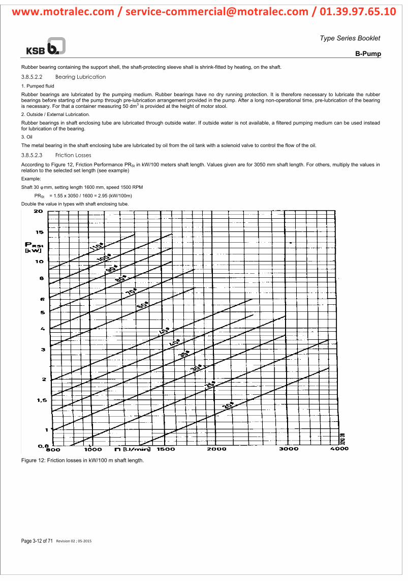
Type Series Booklet
B-Pump
Page 3-12 of 71
Rubber bearing containing the support shell, the shaft-protecting sleeve shall is shrink-fitted by heating, on the shaft.
3.8.5.2.2 Bearing Lubrication
1. Pumped fluid
Rubber bearings are lubricated by the pumping medium. Rubber bearings have no dry running protection. It is therefore necessary to lubricate the rubber bearings before starting of the pump through pre-lubrication arrangement provided in the pump. After a long non-operational time, pre-lubrication of the bearing is necessary. For that a container measuring 50 dm3 is provided at the height of motor stool. 2. Outside / External Lubrication.
Rubber bearings in shaft enclosing tube are lubricated through outside water. If outside water is not available, a filtered pumping medium can be used instead for lubrication of the bearing. 3. Oil
The metal bearing in the shaft enclosing tube are lubricated by oil from the oil tank with a solenoid valve to control the flow of the oil.
3.8.5.2.3 Friction Losses
According to Figure 12, Friction Performance PRSt in kW/100 meters shaft length. Values given are for 3050 mm shaft length. For others, multiply the values in relation to the selected set length (see example) Example:
Shaft 30 φ mm, setting length 1600 mm, speed 1500 RPM
PRSt = 1.55 x 3050 / 1600 = 2.95 (kW/100m)
Double the value in types with shaft enclosing tube.
Figure 12: Friction losses in kW/100 m shaft length.
Revision 02 ; 05-2015
www.motralec.com / [email protected] / 01.39.97.65.10

Type Series Booklet
B-Pump
Page 3-13 of 71
3.8.5.3 Intermediate Shaft
3.8.5.3.1 Determination of Diameter
For intermediate shaft diameter carried out according to Table 13. The motor rated output is taken 1.3 times that of pump output.
Through material selection the performance can be influenced very strongly (see Table 14). For selection of cone coupling consider the admissible switch frequency (3.8.2.1.1)
3.8.5.3.2 Possibilities of Installation
Column pipe Column pipe mm inch 20 25 30 35 45 60 70
80 3 ○ ● ○ ● ○ ○
100 4 ○ ● ○ ● ○ ● ○
125 5 ○ ● ○ ● ○ ● ○ ● ○
150 6 ○ ● ○ ● ○ ● ○ ● ○ ●
175 7 ● ○ ● ○ ● ○ ● ○
200 8 ● ○ ○ ● ○ ● ○ ●
250 10 ○ ○ ● ○ ● ○ ● ○ ●
300 12 ○ ● ○ ● ○ ● ○ ●
400 16 ○ ● ○ ●
500 20 ○
Table 46: Connection between column pipe diameter and possible shaft diameter of the intermediate shaft.
o- open shaft ●- shaft inclosing tube
3.8.5.4 Installation depth
3.8.5.4.1 Possible Column Pipe Connection
Thread Execution (in inches) Flanged Execution (in mm) Type Size 3 4 5 6 7 8 10 12 14 80 100 125 150 175 200 250 300 350 400 500
B6B
B7B
B8B
B8D
B10B
B10D
B10F
B12B
B12D
B12F
B14B
B14D
B16D
B18B
B20B
B22B
B24B
Table 47: Possible Column Pipe connection with Pump Bowl Assembly
Revision 02 ; 05-2015
www.motralec.com / [email protected] / 01.39.97.65.10
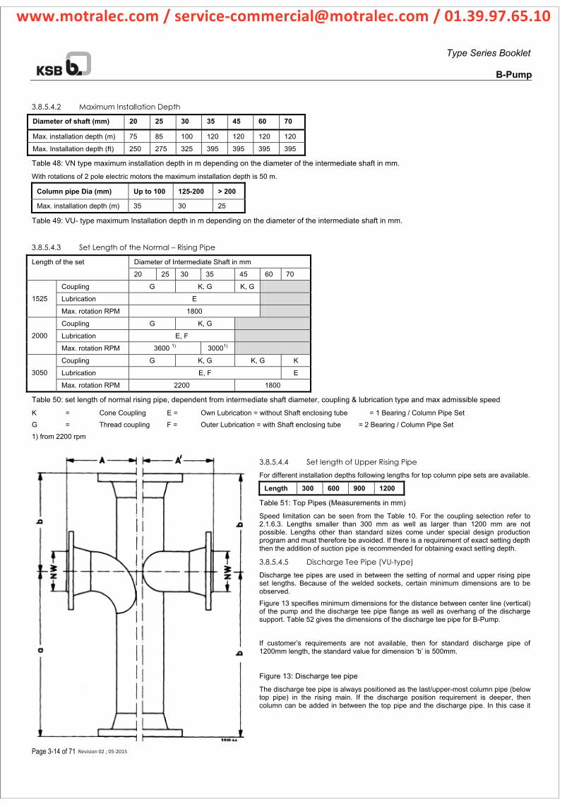
Type Series Booklet
B-Pump
Page 3-14 of 71
3.8.5.4.2 Maximum Installation Depth
Diameter of shaft (mm) 20 25 30 35 45 60 70
Max. installation depth (m) 75 85 100 120 120 120 120
Max. Installation depth (ft) 250 275 325 395 395 395 395
Table 48: VN type maximum installation depth in m depending on the diameter of the intermediate shaft in mm.
With rotations of 2 pole electric motors the maximum installation depth is 50 m.
Column pipe Dia (mm) Up to 100 125-200 > 200
Max. installation depth (m) 35 30 25
Table 49: VU- type maximum Installation depth in m depending on the diameter of the intermediate shaft in mm.
3.8.5.4.3 Set Length of the Normal – Rising Pipe
Diameter of Intermediate Shaft in mm Length of the set
20 25 30 35 45 60 70
Coupling G K, G K, G
E noitacirbuL 1525
Max. rotation RPM 1800
Coupling G K, G
,E noitacirbuL F 2000
Max. rotation RPM 3600 1) 30001)
Coupling G K, G K, G K
,E noitacirbuL E F3050
0081 0022 MPR noitator .xaM
Table 50: set length of normal rising pipe, dependent from intermediate shaft diameter, coupling & lubrication type and max admissible speed
K = Cone Coupling E = Own Lubrication = without Shaft enclosing tube = 1 Bearing / Column Pipe Set
G = Thread coupling F = Outer Lubrication = with Shaft enclosing tube = 2 Bearing / Column Pipe Set
1) from 2200 rpm
3.8.5.4.4 Set length of Upper Rising Pipe
For different installation depths following lengths for top column pipe sets are available.
Length 300 600 900 1200
Table 51: Top Pipes (Measurements in mm)
Speed limitation can be seen from the Table 10. For the coupling selection refer to 2.1.6.3. Lengths smaller than 300 mm as well as larger than 1200 mm are not possible. Lengths other than standard sizes come under special design production program and must therefore be avoided. If there is a requirement of exact setting depth then the addition of suction pipe is recommended for obtaining exact setting depth.
3.8.5.4.5 Discharge Tee Pipe (VU-type)
Discharge tee pipes are used in between the setting of normal and upper rising pipe set lengths. Because of the welded sockets, certain minimum dimensions are to be observed.
Figure 13 specifies minimum dimensions for the distance between center line (vertical) of the pump and the discharge tee pipe flange as well as overhang of the discharge support. Table 52 gives the dimensions of the discharge tee pipe for B-Pump.
If customer’s requirements are not available, then for standard discharge pipe of 1200mm length, the standard value for dimension ‘b’ is 500mm.
Figure 13: Discharge tee pipe
The discharge tee pipe is always positioned as the last/upper-most column pipe (below top pipe) in the rising main. If the discharge position requirement is deeper, then column can be added in between the top pipe and the discharge pipe. In this case it
Revision 02 ; 05-2015
www.motralec.com / [email protected] / 01.39.97.65.10

Type Series Booklet
B-Pump
Page 3-15 of 71
must be noted that pump assembly is not pushed out of the position due to discharge piping force and heat expansion otherwise it can even lead to break down of the pump. In addition to this, for deeper discharge setting, it should be made sure that the bearings above the discharge pipe are properly lubricated and protected against dry running, especially in free-delivery systems.
Nominal Diameter (mm)
80 100 125 150 175 200 250 300 350 400 500
270 300 370 410 470 530 550 630 630 a
170 190 210 220 250 260 290 290 310 b
210 250 280 320 370 440 510 590 460 A
220 240 250 290 310 370 410 440 410
Contact Design Dept.
Contact Design Dept.
A’
Table 52: Discharge Tee Pipe Dimensions
3.8.5.4.6 Column Pipe Friction Losses
For shafts without shaft enclosing tube, and length of rising pipe 1200, 1600 and 2100 mm see Figure 14. For shaft without shaft enclosing tube and rising pipe length of 3050 and 2000 mm Figure 15. For shaft with shaft enclosing tube and length rising pipe 3050, 2100, and 2000 mm see Figure 18.
The column pipe line losses should be maintained between 1 and 10 meter per 100 meters column pipe length. The upper limits are only allowable when setting depths are 10 meters or more.
The column pipe connection combinations can be seen from the dimension tables.
Revision 02 ; 05-2015
www.motralec.com / [email protected] / 01.39.97.65.10

Type Series Booklet
B-Pump
Page 3-16 of 71
3.8.5.4.7 5 ft long column friction losses (Open Line Shaft Design)
Figure 14: Column Pipe Friction Losses without Shaft Enclosing Tube (1200, 1600, 2100)
The values are applicable for set lengths of 1200 mm (shafts ø 30 to 110 mm). Table values are to be multiplied by 1.2, for set lengths of 1600 mm with shafts of ø 20, 25, 30, 35, and 45 mm and for set lengths of 2100 mm with shafts ø 60, 70mm.
Revision 02 ; 05-2015
www.motralec.com / [email protected] / 01.39.97.65.10
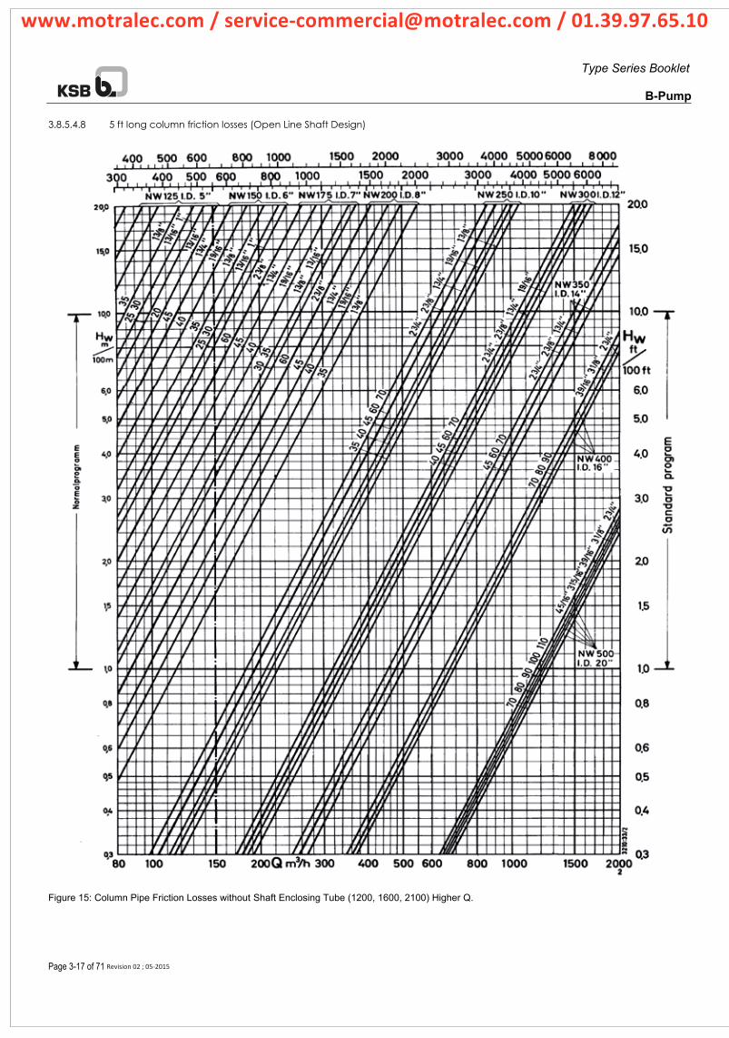
Type Series Booklet
B-Pump
Page 3-17 of 71
3.8.5.4.8 5 ft long column friction losses (Open Line Shaft Design)
Figure 15: Column Pipe Friction Losses without Shaft Enclosing Tube (1200, 1600, 2100) Higher Q.
Revision 02 ; 05-2015
www.motralec.com / [email protected] / 01.39.97.65.10

Type Series Booklet
B-Pump
Page 3-18 of 71
3.8.5.4.9 10 ft long column friction losses (Open line shaft version)
Figure 16: Column Pipe Friction Losses without Shaft Enclosing Tube (3050 mm)
Revision 02 ; 05-2015
www.motralec.com / [email protected] / 01.39.97.65.10

Type Series Booklet
B-Pump
Page 3-19 of 71
3.8.5.4.10 10 ft long column friction losses (Open line shaft version)
Figure 17: Column Pipe Friction Losses without Shaft Enclosing Tube (3050 mm) Higher Q
Revision 02 ; 05-2015
www.motralec.com / [email protected] / 01.39.97.65.10

Type Series Booklet
B-Pump
Page 3-20 of 71
3.8.5.4.11 10 ft long column friction losses (With Shaft enclosing tube)
Figure 18: Column Pipe Friction Losses with Shaft Enclosing Tube (2100, 3050)
The values are valid for set lengths of 3050 mm, 2100 mm with screwed coupling; in case of cone coupling the values in the table are to be multiplied with 1.2.
Revision 02 ; 05-2015
www.motralec.com / [email protected] / 01.39.97.65.10

Type Series Booklet
B-Pump
Page 3-21 of 71
3.8.5.4.12 10 ft long column friction losses (Shaft enclosing tube)
Figure 19: Column Pipe Friction Losses with Shaft Enclosing Tube (2100, 3050) Higher Q
Revision 02 ; 05-2015
www.motralec.com / [email protected] / 01.39.97.65.10

Type Series Booklet
B-Pump
Page 3-22 of 71
3.9 Scope of Supply
3.9.1 Standard equipment Scope of supply of DWT unit consists of the following items:
Type I:
1. Complete bowl assembly
2. Rising main with rubber bearing for lubrication through pumping media
3. Discharge head assembly
4. Flexible coupling (for V1 design)
5. Priming Funnel or Tank
6. Erection & Mounting Clamps for rising main
6. Motor (if ordered)
Type II
Scope of supply according to I, with addition of Shaft Enclosing tube and oil lubrication arrangement for line shaft rubber bearings.
Type III
Scope of supply according to I, with addition of Shaft Enclosing tube and oil lubrication arrangement (oil tank) and solenoid valve, if ordered, for line shaft bronze bearings.
3.9.2 Normal Accessories The following items are not included in the standard scope of supply but they should be recommended to the customer.
Drawing tool for cone coupling, impeller pulling and opening device: for tightening of clamping sleeve of impeller (up to B 16), suction strainer with foot valve (for medium lubricated design) as well as inlet strainer (for rising main with shaft enclosing tube)
3.9.3 Special Accessories • Oil level indicator,
• Flow meter,
• Thermometer (PT100 for thrust bearing),
• Pressure controller,
• Pressure/ vacuum gauge,
• Foundation base frame,
• Foot elbow,
• Non-return valve,
• Switch and control equipment.
3.10 Inlet
3.10.1 Inlet Strainer Coarse contamination is kept out of the pump through inlet strainer. If the strainer gets clogged or blocked, possibility exists that the pump runs dry and mechanical failure may occur. First indication of clogging is the reduction in capacity and head.
Resistance of inlet strainer is approx. 1/3 of the suction strainer with foot valve (see Figure 20)
(3.2.1 to be consulted, socket connection is possible only up to pump size B16D)
Figure 20: Flow Resistance in suction strainer with foot valve
Revision 02 ; 05-2015
www.motralec.com / [email protected] / 01.39.97.65.10

Type Series Booklet
B-Pump
Page 3-23 of 71
3.10.2 Suction Strainer with Foot Valve Regarding contamination the same applies as for inlet strainer. In foot valves danger exists that cone of the valve is not properly closed due to fine deposits.
For long pressure lines it is recommended to install non-return valve in addition to foot valve. Through the provision of N.R.V, pressure on the pump is avoided. It should be ensured that the non-return valve reacts quickly and gets closed before the foot valve.
If it is not certain, it is better to dispense with the foot valve and a pre-lubrication of the rising main. In this situation the first impeller should stand under water during the operation. If the application of foot valve due to water level cannot be avoided, then pressure impact safety must be installed with the non-return valve.
Refer to (3.2.1, socket-connection is possible only to the pump size 16D)
3.10.2.1 Flow Resistance in Suction Strainer with Foot Valve
If the difference between NPSH required and NPSH available is less, resistance in the suction line is to be considered while frictional losses in suction pipe can be neglected. If NPSH available is less than NPSH required, cavitation occurs in the pump.
See Figure 20
3.10.3 3.12.3 Suction Pipes Standard pipes lengths are of 1500 and 3000 mm. However, for adjustment in the exact installation depths, shorter lengths can also be supplied. The diameter of the suction pipes is designed according to the connection diameter of the pump suction.
The lower end of the suction pipe must be at least 1.0 NW of suction pipe under the lowest water level Ht.
3.10.4 3.12.4 Suction Elbow For dry installation pumps, special suction elbows according to Figure 21 are available. These shall be mounted axially in the ground plate of the foundation, which prevents radial shifting of the pump.
To use the suction elbow a pipe length of a least 20D must be provided before the suction elbow, a straight pipe length be tried between the suction elbow and pump suction. The NPSH available values can be reduced up to 0.5 to 1.0 meters according to design of the intake.
Figure 21: Suction Elbow
Revision 02 ; 05-2015
www.motralec.com / [email protected] / 01.39.97.65.10
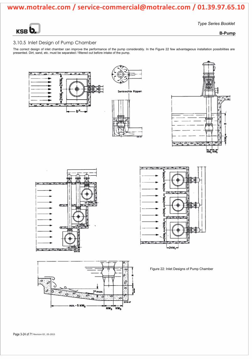
Type Series Booklet
B-Pump
Page 3-24 of 71
3.10.5 Inlet Design of Pump Chamber The correct design of inlet chamber can improve the performance of the pump considerably. In the Figure 22 few advantageous installation possibilities are presented. Dirt, sand, etc. must be separated / filtered out before intake of the pump.
Figure 22: Inlet Designs of Pump Chamber
Revision 02 ; 05-2015
www.motralec.com / [email protected] / 01.39.97.65.10

Type Series Booklet
B-Pump
Page 3-25 of 71
3.11 Protection of the Upper Surface All steels and casting material, with the exception of non rusting materials, have, if not mentioned specifically, a color coating (paint) according to the material norms ZN 35.
For mediums which have significant corrosive properties for iron, it is not always possible to use special materials which are corrosion resistant to the pumped medium due to high costs of the material and manufacturing. The quality of the painting must be specified.
Table 53, Table 54 & Table 55 give general idea of the paints/coating materials.
edistuO edisnI )dradnatS( ylbmessA lwoB
Pre-Treatment Shot Blasting, De Rusting St 2 DIN 12944
Primer 1 Component Alkyd primer Red Oxide, 0.05mm
Top Coat Black Bitumen 0.08mm
Column Assembly (Standard) Inside Outside
tsuR tnemtaerT-erP Protected
remirP
Top Coat Black Bitumen 0.08mm
Discharge Head Assembly (Standard) Inside Outside
Pre-Treatment Shot Blasting, De Rusting St 2 DIN 12944
Primer 1 Component Alkyd primer Red Oxide, 0.05mm
Top Coat I component Alkyd based synthetic enamel, RAL 5002 (KSB Blue), 0.04mm
Table 53: Upper surface protection with the help of painting materials.
edistuO edisnI )yxopE dradnatS( ylbmessA lwoB
Pre-Treatment Shot Blasting SA 2-1/2, DIN 12944
Primer 2 Component epoxy resin based zinc paint, red thickness 0.04mm
Top Coat 2 component epoxy resin based coat, black C-200, Thickness 0.3mm
Column Assembly (Standard Epoxy) Inside Outside
Pre-Treatment Shot Blasting SA 2-1/2, DIN 12944
Primer 2 Component epoxy resin based zinc paint, red thickness 0.04mm
Top Coat 2 component epoxy resin based coat, black C-200, Thickness 0.3mm
Discharge Head Assembly (Standard Epoxy) Inside
(In contact with medium)
Outside
(Not in Contact with medium)
Pre-Treatment Shot Blasting SA 2-1/2, DIN 12944 Shot Blasting, De Rusting St 2 DIN 12944
Primer 2 Component epoxy resin based zinc paint, red thickness 0.04mm
1 Component Alkyd primer Red Oxide, 0.05mm
Top Coat 2 component epoxy resin based coat, black C-200, Thickness 0.25mm
I component Alkyd based synthetic enamel, RAL 5002 (KSB Blue), 0.04mm
Table 54: Upper surface protection with the help of painting materials.
Revision 02 ; 05-2015
www.motralec.com / [email protected] / 01.39.97.65.10

Type Series Booklet
B-Pump
Page 3-26 of 71
edistuO edisnI )yxopE laicepS( ylbmessA lwoB
Pre-Treatment Shot Blasting SA 2-1/2, DIN 12944
Primer 2 Component epoxy resin based zinc paint, red thickness 0.04mm
Top Coat 2 component epoxy resin based coat, black C-200, Thickness 0.45mm
Column Assembly (Special Epoxy) Inside Outside
Pre-Treatment Shot Blasting SA 2-1/2, DIN 12944
Primer 2 Component epoxy resin based zinc paint, red thickness 0.04mm
Top Coat 2 component epoxy resin based coat, black C-200, Thickness 0.45mm
Discharge Head Assembly (Special Epoxy) Inside
(In contact with medium)
Outside
(Not in Contact with medium)
Pre-Treatment Shot Blasting SA 2-1/2, DIN 12944 Shot Blasting, De Rusting St 2 DIN 12944
Primer 2 Component epoxy resin based zinc paint, red thickness 0.04mm
1 Component Alkyd primer Red Oxide, 0.05mm
Top Coat 2 component epoxy resin based coat, black C-200, Thickness 0.45mm
I component Alkyd based synthetic enamel, RAL 5002 (KSB Blue), 0.04mm
Table 55: Upper surface protection with the help of painting materials.
Revision 02 ; 05-2015
www.motralec.com / [email protected] / 01.39.97.65.10

Type Series Booklet
B-Pump
Page 4-27 of 71
13-17
544
758
916400
106545
271531320
541
902920
502
545112
400
545
902920
270
211
107
901920
13-17
544
758
916400
106545
271531320
541
902920
502
545112
400
545
902920
270
211
107
901920
4 Illustrations
4.1 Sectional Views and List of the Individual Parts
4.1.1 Pump Body
In case of placing an order for spare parts the following must be given under all circumstances:
Pump type, order number (see the rating plate /
instructions plate), the name of the part, parts number, number of pieces, number of the sectional view,
instructions about delivery / dispatch.
Figure 23: Bowl Assembly with Flanged Suction Strainer Figure 24: Bowl Assembly with Threaded Suction Strainer
Revision 02 ; 05-2015
www.motralec.com / [email protected] / 01.39.97.65.10

Type Series Booklet
B-Pump
Page 4-28 of 71
748
106
545
502320
541940
112
569
107
545
Figure 25: Bowl Assembly for B18-B24
Revision 02 ; 05-2015
www.motralec.com / [email protected] / 01.39.97.65.10
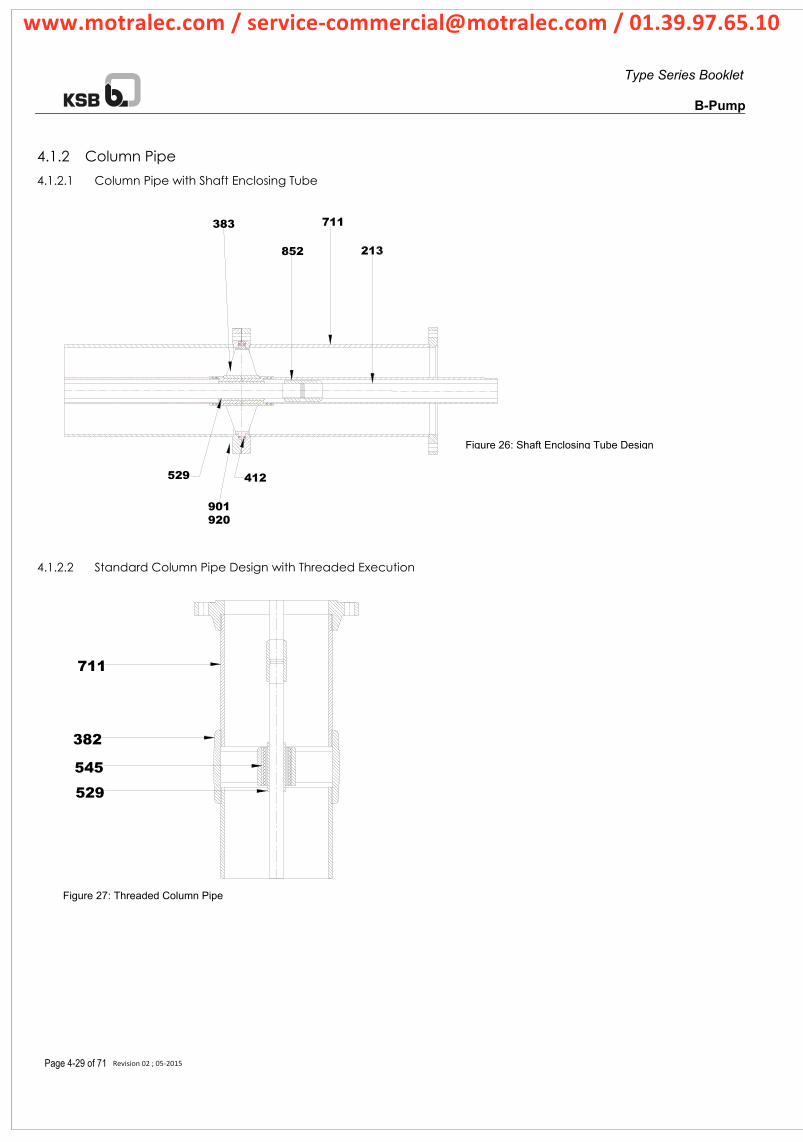
Type Series Booklet
B-Pump
Page 4-29 of 71
711383
412
901920
529
711
382
545
529
4.1.2 Column Pipe
4.1.2.1 Column Pipe with Shaft Enclosing Tube
4.1.2.2 Standard Column Pipe Design with Threaded Execution
Figure 26: Shaft Enclosing Tube Design
Figure 27: Threaded Column Pipe
Revision 02 ; 05-2015
www.motralec.com / [email protected] / 01.39.97.65.10

Type Series Booklet
B-Pump
Page 4-30 of 71
4.1.2.3 Standard Column Pipe Design with Flanged Execution
In case of placing an order for spare parts, the following must be given under all circumstances:
Pump type, order number (see the rating plate / instructions plate on the discharge head), the name of the part, parts number, number of pieces, number of the sectional view, instructions about delivery / dispatch.
711
212
529
383
901920
545
211
852
213
711
Figure 28: Flanged Column Pipe
Revision 02 ; 05-2015
www.motralec.com / [email protected] / 01.39.97.65.10

Type Series Booklet
B-Pump
Page 4-31 of 71
4.1.3 Discharge Head
4.1.3.1 Lubrication Arrangement for Shaft Enclosing Tube
Figure 29: Lubrication Arrangement for Shaft Enclosing Tube
4.1.3.2 Motor Stool with Thrust Bearing Arrangement
Figure 30: Motor Stool with Thrust Bearing Arrangement
4.1.3.3 Discharge Piece for Shaft Enclosing Tube Design
Figure 31; Discharge Piece for Shaft Enclosing Tube
840
400
320350
400
714
107
545
569outlet forlubricationmedium
412
144
160
400
412
568
OIL TANK
Revision 02 ; 05-2015
www.motralec.com / [email protected] / 01.39.97.65.10

Type Series Booklet
B-Pump
Page 4-32 of 71
4.1.3.4 Stuffing Box Housing
Figure 32: Stuffing Box Housing
4.1.3.5 Motor Stool with Double Bearing Arrangement
341
422360
350
816860861924321636320
213
Figure 33: Motor Stool with Double Bearing Arrangement
4.1.3.6 Discharge Head with Solid Shaft and Stuffing Box Housing
861
526
320
914
350
341
452902920
451914902920
461
545
144
160x
DETAIL - X
451636
452
461
451
Y
DETAIL , Y ,
421
Figure 34: Motor Stool & Discharge Head
452
461
458
451
461
452
636
451
Revision 02 ; 05-2015
www.motralec.com / [email protected] / 01.39.97.65.10

Type Series Booklet
B-Pump
Page 4-33 of 71
In case of placing an order for spare parts the following must be given under all circumstances:
Pump type, order number (see the rating plate / instructions plate on the Discharge head), the name of the part, parts number, number of pieces, number of the sectional view, instructions about delivery / dispatch.
4.1.3.6.1 Discharge Head Dimensions:
Type a b e f h g NWst ShaftØ NWd d Foundation Bolt Material
VN 1342 A 425 148 210 297 350 75, 100 25, 30, 35 100 M 16 x 250mm Cast Iron
VN 1342 425 148 210 297 350 100, 125 25, 30, 35 125 M 16 x 250mm Cast Iron
VN 1830 425 148 210 297 350 150, 175 25, 30, 35 150 M 16 x 250mm Cast Iron
VN 2030 440 171.5 200 400 370 175, 200 25, 30, 35 200 M 16 x 250mm Cast Iron
VN 2541 A 600 225 290 470 430 200 25, 30, 35, 45 200 M 16 x 300mm Cast Iron
VN 2541 600 225 290 470 430 250 30, 35, 45 250 M 16 x 300mm Cast Iron
VN 3051 700 290 305 570 600 200, 250 30, 35, 45 300
As p
er F
lang
e St
anda
rd
M 20 x 250mm Steel Fabricated
Table 56: Discharge Head Dimensions
Revision 02 ; 05-2015
www.motralec.com / [email protected] / 01.39.97.65.10

Type Series Booklet
B-Pump
Page 4-34 of 71
Figure 36: VN 1830 & VN 2030
Figure 37: VN 2541 & VN 2541A
Figure 35: VN 1342 & VN 1342A
Revision 02 ; 05-2015
www.motralec.com / [email protected] / 01.39.97.65.10

Type Series Booklet
B-Pump
Page 4-35 of 71
Figure 38: VN 3051
Revision 02 ; 05-2015
www.motralec.com / [email protected] / 01.39.97.65.10

Type Series Booklet
B-Pump
Page 5-36 of 71
5 Spare Parts When ordering spare parts, always please specify the item numbers, designations of the components concerned, and the works number / serial number of the pump. This will avoid any delays in delivery and possible queries. The works number of the pump is given on the title page of instruction manuals, and is also stamped on the pump rating plate. Following is the recommended spare parts list in accordance with VDMA 24296 (recommended spares). For a more specific spare parts list, please consult the O&M Manual supplied with each order.
Item No. Designation Qty. Remarks
211 Pump Shaft 1
212 Column Shaft Z
213 Top Shaft 1
230 Impeller 1
271.1 Sand guard 1
271.2 Sand guard -
320 Angular contact ball bearing -
321 Deep groove ball bearing -
382.1 Bearing body 1
384 Thrust bearing disc 1
400.1 Flat gasket 1
400.2 Flat gasket S
400.3 Flat gasket 1
400.4 Flat gasket 2
400.5 Flat gasket 1
412.1 O-ring 1
422.1 Felt ring -
422.2 Felt ring -
461 Stuffing box packing (in meters) -
502 Casing wear ring S
521 Stages sleeve S-1 Only from size 14 upwards.
524 Shaft protecting sleeve 1 If fitted.
526 Centering sleeve -
529 Bearing sleeve 1
540 Bush 1
541 Stage bush S-1 Not applicable to sizes 6-7-14 and above.
52-1 Clamping sleeve complete S Upto size 12 inclusive.
544 Threaded bush 1
545.1 Bearing bush 1
545.2 Bearing bush / rubber S
545.3 Bearing bush 1
851 Cone coupling -
852 Screwed coupling Z + 1
920.1 Nut with 2 flats - Only from size 14 and upward.
931.1 Tab washer - Only from size 14 and upward.
931.2 Tab washer -
Revision 02 ; 05-2015
www.motralec.com / [email protected] / 01.39.97.65.10

Type Series Booklet
B-Pump
Page 6-37 of 71
6 Sample Sectional Drawing with Parts List
Figure 39: Sectional Drawing with Parts List
Revision 02 ; 05-2015
www.motralec.com / [email protected] / 01.39.97.65.10