KALADY RICE MILLERS CONSORTIUM PVT. LTD. - DCMSME
34
KALADY RICE MILLERS CONSORTIUM PVT. LTD. MATTOOR KALADY ERNAKULAM DISTRICT KERALA PROPOSAL FOR SETTING UP OF A COMMON FACILITY CENTRE UNDER SMALL INDUSTRIES CLUSTER DEVELOPMENT PROGRAMME SCHEME OF OFFICE OF DC (SSI)
-
Upload
khangminh22 -
Category
Documents
-
view
5 -
download
0
Transcript of KALADY RICE MILLERS CONSORTIUM PVT. LTD. - DCMSME

K A L A D Y R I C E
M I L L E R S
C O N S O R T I U M P V T .
L T D .
M A T T O O R
K A L A D Y
E R N A K U L A M D I S T R I C T K E R A L A
PROPOSAL FOR SETTING UP OF A COMMON
FACILITY CENTRE UNDER SMALL
INDUSTRIES CLUSTER DEVELOPMENT
PROGRAMME SCHEME OF OFFICE OF DC (SSI)
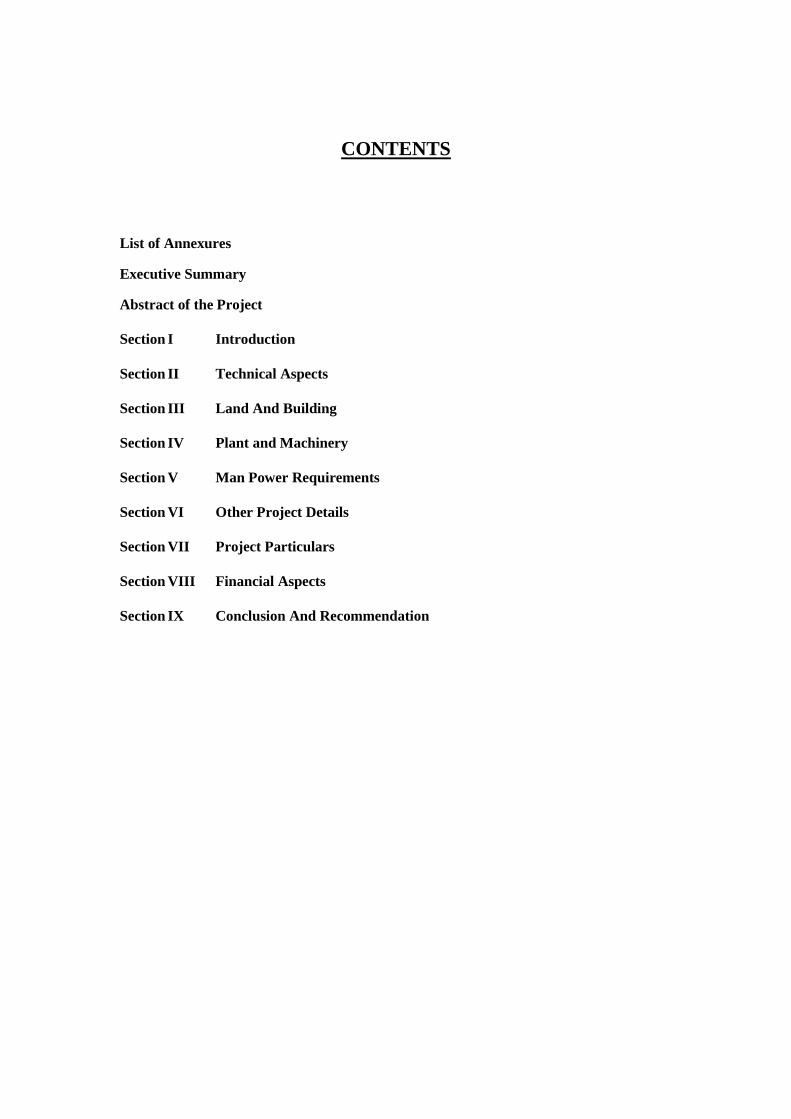
CONTENTS
List of Annexures
Executive Summary
Abstract of the Project
Section I Introduction
Section II Technical Aspects
Section III Land And Building
Section IV Plant and Machinery
Section V Man Power Requirements
Section VI Other Project Details
Section VII Project Particulars
Section VIII Financial Aspects
Section IX Conclusion And Recommendation

LIST OF ANNEXURES
1. Land and Building
11. Plant and Machinery
111. Supporting Equipments
IV. Preliminary and Pre-operative Expense
V. Utilities
VI. Man Power Requirements
VII. Consumable Stores
VIII. Annual Repair and Maintenance Expenses
IX. Phased Revenue Programme
X. Computation of Working Capital and Margin Money Requirement
XI. Project Cost and Source of Finance
XII. Depreciation Staight Line Method
XIII. Depreciation Written Down Vakue Method
XIV. Profitability Estimates
XV. Computation of Income Tax
XVI. Cash Flow Statement
XVII. Projected Balance Sheet
XVIII. Internal Rate Of Return
XIX. Break Even Analysis
XX. Pay Back Period

EXECUTIVE SUMMARY
a. Industrial Department of Kerala State Government has identified the
Rice Mill Cluster at Ernakulam under cluster development programme
and approved as SIDO cluster. There are 70 Modern rice mills and 55
small conventional rice mills are functioning in Ernakulam district
under SSI sector. In this Cluster Development Programme presently 33
modern rice mill industries in Ernakulam District have formed a
consortium under the name and style of M/S. KALADY RICE
MILLERS CONSORTIUM PVT. LTD. The remaining rice mills will
become a member of this consortium immediately. The Diagnostic
Study conducted on this Cluster will found some major issues and
recommend certain solutions. The immediate requirements of this
cluster is a common facility centre for bran oil extraction for getting
value addition for their rice bran, which will benefit the units by
getting an additional income of around Rs.17 lakhs. The first phase of
this common facility centre - Bran Oil Extraction section is under
implementation. In addition to this consortium has started a common
centre for tyre and rice mill spare parts which directly transfer the
benefits of bulk purchase to cluster. They also started a common a
laboratory for testing the quality of rice, bran, water etc, for consortium
members. The value addition of rice bran is completed only after
installing a bran oil refinery section. By implementing both these
extraction and refinery section of the common facility centre, each unit
of the cluster will get around 22% value addition for their bran. Thus
this CFC will improve the performance of this rice mill cluster in total.
b. The total project cost is estimated to be Rs. 645 lakhs of which 90% of
fixed capital Rs.572.10 lakhs can be obtained as grant from
Government of India under ‘Small Industries Cluster Development
Programme’ scheme and balance Rs. 72.90 lakhs is to be shared by the
beneficiaries and stake holders. The operating capital for this CFC is Rs.
9.33 lakhs which is included in the project. The projected performance
of this common facility centre for the first eight years of operation is
appended. The unit will generate profit from the first year of operation.
The project is technically feasible and overall economics of the project
is very attractive.
c. The active support for the project from the industrial department of
Kerala in the form of implementing agency will benefit the rice mills at
Ernakulam District and especially those in consortium.
d. The consortium will provide the necessary land and building for setting
up this common facility centre as their contribution and execute
necessary agreements and undertakings with the implementing agency -
Industrial Department of Kerala.
e. The day to day operating expense of the common facility centre in terms
of electricity charges, labour charges etc. will be borne by the
consortium and the required periodic maintenance, modernisation etc.
will be met by the corpus fund raised from the profit of the common
facility centre. This fund is also utilised for future modernisation,
upgradation etc. of the CFC.
f. The consortium will appoint necessary technical experts and skilled
labours for running the common facility centre.

ABSTRACT OF PROJECT
1. Project : Proposal for setting up of a refinery
section of common facility centre under
small industries cluster development
programme schemeof office of DC (SSI)
2. Name of the Project : Centralised Bran oil refining unit under
Cluster Development Project.
3. Implementing Agency : Goverment of Kerala through industrial
department.
4. Location of CFC : Mattoor, Kalady, Ernakulam Dist.
5. Address of the unit
a) CFC: M/s. KALADY RICE MILLERS
CONSORTIUM Pvt. Ltd. Door No. ,
Mattoor, Kalady.
b) Taluk : Aluva
c) Village : Kalady
d) Panchayat : Kalady
6. Capacity Utilisation : 1st Year - 65%
2nd Year - 75%
3rd Year - 80%
4th Year - 85%
7. Man power requirements/
Employment Potential : A. Administration :
General Manager - 1
Accountant - 2
Office Staff - 3
6 Nos.
B. Production :
Production Supervisor - 3
Chemist - 2
Machine Operator - 6
Maintanance Staff - 2
Boiler operator - 1
Skilled Workers - 3
Unskilled Workers - 6
23 Nos.

8. Cost of Project:
(Rs. In Lakhs)
Land : 25.00
Technical Civil Work : 50.00
Plant andMachinery : 425.86
Supporting Equipments : 84.80
Contingency : 23.79
Preliminary and
Pre-operative expenses : 26.22
Operating Capital : 9.33
Total Project Cost 645.00
9. Means of Finance :
Contribution from consortium : 72.90 Lakhs
( 10% of fixed assets + operating capital )
Grant from DCSSI under small industries cluster
development programme for setting common
facility centre : 572.10 Lakhs
( 90% of fixed assets )
Total : 645.00 Lakhs
10. Break Even Point :
a) Operating B. E. P. :
(i) Percentage of installed
capacity : 35.79%
(ii) In terms of sale : 142.27 Lakhs
(b) Cash B. E. P. :
(i) Percentage of installed
capacity : 8.20%
(ii) In terms of sales : 32.59 Lakhs
15. Internal rate of return : 11 %(After Tax)
16 % (Before Tax)
16. Pay back period : 7 Years 9 Months
17. Facilities Required :
Grant from DCSSI under
small industries cluster : 572.10 Lakhs
development programme
for setting common
facility centre

SECTION - I INTRODUCTION
BACKGROUND OF RICE MILL CLUSTER
There are 70 Modern rice mills and 55 small conventional rice mills are
functioning in Ernakulam district under SSI sector. The capital investment of
these industries vary from 50 to 600 lakhs. Total turn over per annum is about
Rs. 1465 Crores. Rice Mill industry in Ernakulam District is creating
employment opportunities directly to 3000 persons and indirectly to 1500
persons. The power requirement per each unit is around 100 to 350 HP.
Presently around 33 small scale modern rice mills have formed a
consortium under the name and style of M/s. ‘Kalady Rice Millers
Consortium Pvt. Ltd.’ The remaining units will become the members of this
consortium immediately.
Major Issues and Immediate Solution
Rice bran is the most important source of edible oil among the
unconventional source. Rice bran is the brown coating around the white starchy
rice kernel, which is obtained by de husking paddy and polishing the rice.
Rice bran oil is considered healthy oil because it contains useful functional
food unsaturated fatty acid especially mono unsaturated fatty acids. It also
contains high vitamin E it improves the blood circulation of human body.
Even though the commercial value of rice bran is very high, the rice mill
units did not get the adequate price for their by products. Rice bran is a highly
sensitive products and its quality deteriorate while storing. High quality oil is
extracted only from fresh bran. Oils in bran contain some free fatty acids. The
enzymatic hydrolysis goes on storing them and leads to rancidity. To avoid this
the bran is made to process within 2 or 3 days from their production.
Besides in Kerala one or two bran oil extraction units are functioning. Most
of the extraction units are in Karnataka. So this bran is sold only through
middlemen. Now rice mill units does not get adequate price for their bran.
Only starting a common facility centre for bran oil extraction and refining
can solve this problem. So that fresh bran can be processed and rice mill units
will get maximum value addition for their by products.
BACKGROUND OF CONSORTIUM
The consortium already started a tyre and mill stores bank. The
consortium will purchase tyres for trucks and LCVs directly from tyre
manufacturing companies in bulk. Consortium will supply tyres to cluster
members. The margin obtained is directly transferred to cluster units. Same
methodology is adopted in the case of common mill stores.

A common lab was setup by the consortium for the testing of quality of
rice, oil content water required for par boiling etc. This lab can also be utilised
for testing the quality of refined rice bran oil.
A common facility centre for bran oil extraction is under
implementation. The proposed capacity of the bran oil extraction unit is 100
MT. The average yield from this plant is 21%. The total capital outlay of the
implementing project is Rs. 283 Lakhs.
Infact a bran oil refinery is required for complete processing of bran. So
a bran oil refinery is to be installed as a forward integration to the
implementing extraction plant.
Benefits for members.
Presently the rice bran produce in these rice mills are procured by bran
agents or by bran extraction refineries in an out side Kerala. They procured rice
bran at very low price of the range of Rs. 7 to Rs. 7.50 per Kg. in the peak
demand period. If they feel that the availability of bran is increased in this
cluster they try to reduce the price. The rice mill owners are forced to sell their
bran at these price because of no other alternative and this rice bran will decay
within two to three days by the development of fatty acids. Once these fatty
acids developed in these bran the quality will deteriorate and price may go
down to Rs. 2 to Rs. 3 per kg
The consortium members can utilise this common facility centre for bran
oil extraction and refining. The following calculation will show the benefits
raised for the cluster units by installing this common facility centre.
The average out put of rice bran from each unit = 3 M.T./day
The total present output of rice bran from
33 member unit = 3M.T.X33 = 99M.T
Say 100 M.T./day
Present revenue raised by selling this rice bran
= 100M.T x Rs. 7000 = Rs.700000
After installing this proposed common facility centre the revenue will
increase as follows.
The average yield of refined rice bran oil from
this 100 MT bran = 100 x 21% x 94% = 19.74 MT.
The present market value of refined edible bran oil = Rs. 47,000/MT
The total revenue by selling refined edible
bran oil per day = 19.74 MT x Rs. 47,000 = Rs. 9,27,780/-
Service charge paid to common facility centre
a) Bran oil extraction = Rs. 925/MT of extracted
bran oil = 100 MT x 21% x Rs. 975 = Rs. 20,475/-
b) Extracted bran oil refining = Rs. 2,650/MT of refined
bran oil = 100MT x 21% x 94% x Rs.2,650 = Rs. 52,311/-.

Net profit derived from the common facility centre
per day = Rs. 9,27,780 - ( 700000 + 20,475 + 52,311) = Rs. 1,54,994/-
The average value addition obtained per unit = Rs. 1,54,994 / 33
= Rs. 4,696.78/day
The monthly value addition per unit = Rs. 4,696.78 x 30
= Rs. 1,40,903/-
The annual value addition per unit = Rs. 1,40,903 x 12 = Rs. 16,90,843/-
By implementing this common facility centre each cluster unit will get a
value addition of Rs. 16,90,843 annually. Presently this benefits are exploited
by middle men and bran oil refineries.
Modus of operant
The common facility centre will extract and refine bran oil from bran of
rice mill cluster. It charge a nominal amount for meeting operational expenses
and making corpus fund for future modernisation, up gradation and sustenance
of the common facility centre. The remaining rice mills who are presently not
a member of the consortium can also utilise this common facility centre. So
there is no under capacity utilisation of common facility centre.

SECTION - II
TECHNICAL ASPECTS
STAGE - I ACID DEGUMMING WITH WASHING.
Physical refining - also called steam refining - is the combined
neutralisation and deodorisation of fats and oils by steam stripping under
vacuum.
This process is well suited to most edible oils provided they are
thoroughly degummed and purified which is the main condition for producing
first class edible end products.
Main advantages of the physical refining system towards the conventional one
are:
1. The refining factor of the whole refining process is superior in physical
refining than in chemical refining mode.
2. Moreover, in physical refining, there is no production of soapstock, a
main source of pollution in alkali refining.
3. Production costs as well as investment costs are lower in physical
refining.
4. The treatment of effluent water is reduced to a minimum i.e.: floor
washing water and bleed-off of the barometric water systems from
bleaching, deodorising and acid gums drying units.
To obtain first quality oils, it is essential to make sure the crude oils
entering the deodoriser are free of impurities.
Specifically designed for the physical refining of unsaturated oils, the
“acid degumming” is the first step in the refining line. However for complete
elimination of all impurities and undesirable compounds, the oil is further pre-
treated and bleached.
Therefore physical refining of unsaturated oils rice bran oil, comprises 3 steps:
1. Acid degumming step with washing
2. Dry pretreatment combined with bleaching step Deodorising step
3. Deodorising step.
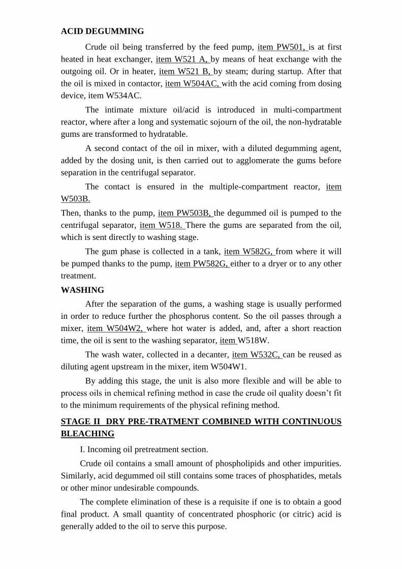
ACID DEGUMMING
Crude oil being transferred by the feed pump, item PW501, is at first
heated in heat exchanger, item W521 A, by means of heat exchange with the
outgoing oil. Or in heater, item W521 B, by steam; during startup. After that
the oil is mixed in contactor, item W504AC, with the acid coming from dosing
device, item W534AC.
The intimate mixture oil/acid is introduced in multi-compartment
reactor, where after a long and systematic sojourn of the oil, the non-hydratable
gums are transformed to hydratable.
A second contact of the oil in mixer, with a diluted degumming agent,
added by the dosing unit, is then carried out to agglomerate the gums before
separation in the centrifugal separator.
The contact is ensured in the multiple-compartment reactor, item
W503B.
Then, thanks to the pump, item PW503B, the degummed oil is pumped to the
centrifugal separator, item W518. There the gums are separated from the oil,
which is sent directly to washing stage.
The gum phase is collected in a tank, item W582G, from where it will
be pumped thanks to the pump, item PW582G, either to a dryer or to any other
treatment.
WASHING
After the separation of the gums, a washing stage is usually performed
in order to reduce further the phosphorus content. So the oil passes through a
mixer, item W504W2, where hot water is added, and, after a short reaction
time, the oil is sent to the washing separator, item W518W.
The wash water, collected in a decanter, item W532C, can be reused as
diluting agent upstream in the mixer, item W504W1.
By adding this stage, the unit is also more flexible and will be able to
process oils in chemical refining method in case the crude oil quality doesn’t fit
to the minimum requirements of the physical refining method.
STAGE II DRY PRE-TRATMENT COMBINED WITH CONTINUOUS
BLEACHING
I. Incoming oil pretreatment section.
Crude oil contains a small amount of phospholipids and other impurities.
Similarly, acid degummed oil still contains some traces of phosphatides, metals
or other minor undesirable compounds.
The complete elimination of these is a requisite if one is to obtain a good
final product. A small quantity of concentrated phosphoric (or citric) acid is
generally added to the oil to serve this purpose.

This acid attacks the hydratable, the non-hydratable phospholipids and
other compounds including the heavy metals contained in the crude oil.
Sedimentation from oils treated with phosphoric acid is very low and
separation can be done by filtration in the bleaching plant as a cheap alternative
to the centrifugal operation otherwise required.
For some qualities of oils or fats, phosphoric acid may be replaced by
citric acid.
II. Bleaching with filtration step.
1. The main purpose of bleaching is ofcourse to remove colouring matters
by adsorption to obtain finished product with the desired colour.
2. In the case of physical refining, bleaching-filtration ensures also final
purification of oil thanks to complete elimination of residual gums,
phosphatides and all undesirable matter precipitated in pretreatment.
3. In the case of palm oil, the bleaching carried at low temperature has no
any decoloration effect. Effective bleaching for this oil is carried out
during deodorisationneutralisation at high temperature and is called
“heat bleach”.
The pretreated oil, after addition of phosphoric/citric acid enters in
contact with activated bleaching earth.
After contacting, the mixture is sent to the bleacher (under vacuum)
where live steam injection helps to contact the earth and the oil particles. The
oil/earth mixture is then filtered in hermetic filters for a perfect handling.
Process description
Crude oil or acid degummed oil is pumped from the buffer tank item
T501 into acid mixer T504AC in which acid is continuously fed via a dosing
pump item PT534AC.
The intimate mixture oil/acid is then introduced into the multi
compartment reactor, item T503/635, where oil is mixed with bleaching earth
stored in earth tank, item 630, and delivered by a variable speed metering
screw, item 607. In this reactor, the reaction time of both bleaching earth and
citric acid is extended.
From the bottom of the multi compartment reactor, item T503/635, the
oil is sucked into the upper part of the bleacher (heater part, item 621) where it
is heated up to the required temperature.
This procedure ensures optimum deaeration of both oil and earth, as
well as intimate mixing of both together with acid activation.
From there, the oil overflows to the bleacher itself.

Vertical partitions ensure a uniform flow of the mixture and a well-
determined retention time without any risk of short-circuiting. Finally, the oil-
earth mixture is sent to filters, item 616A,by means of pump, item P622.
The filters are of the hermetic type operating alternatively except for
small size plants where one filter only is supplied.
The filtered oil is kept under vacuum in filtered oil receiver, item 6828,
to avoid any oxidation at this stage of the refining line and then pumped with
the pump, item P682B, through security filter, item 616B, to ensure that traces
of impurities are eliminated.
After the filtration operation, oil recovery from spent cake is done by
steam blowing and the spent cake is discharged and evacuated. The vapours are
collected into a decanting tank, item 682A, and scrubbed into item 629.
The filter cake discharge needs no manual intervention, as the cake of
earth is detached by vibrations from the filter leaf.
The main advantages:
Savings of both labour and floor space, as well as in a lower bleaching
earth consumption to obtain the same bleaching result.
Accurate and convenient metering of oil and earth for obtaining quickly
oil of the desired colour.
Continuous and perfect dispersion of bleaching earth in the oil, ensuring
simultaneous and intimate contact of all earth particles with the processed oil
under optimum conditions of vacuum (55 Torr), temperature (90-1O0°C).
Uniform holding time of the oil-earth mixture in the bleacher (30
minutes).
Oil filtration in hermetic leaf filters with stainless steel frames and
cloths, requiring practically no maintenance.
Filtered oil is kept under vacuum during whole process.
No formation of decomposition residues.
No decantation/settling during bleaching, due to effective agitation.
A safety filter is foreseen for removal of possible earth traces after main
filtration.
Oil content in spent cakes not exceeding 24%.
If requested, the filtration operation can be completely computerised
thus avoiding any human supervision. For the standard model however, a few
valves only must be operated to control cleaning of the filters, which can easily
be done by the operator in charge of the other refining sections, especially
when these are also continuous in operation.

STAGE III DE WAXING OF RICE BRAN OIL WITH SUPER
FILTERS
PROCESS DESCRIPTION
Rice bran oil contains approximately 2.5 to 3% waxes. So also the
tristearin portion is approximately 2%. The GS2U triglycerides portion also
plays a very important role while desiging the dewaxing plant for rice bran oil.
The rice bran dewaxing can be performed at two steps depending the
clarity & marketability of the refined oil required in the market. However
process execution differs depending the process route selected.
In case of deacidification route, it is advisible to carry out dewaxing after
bleaching step at relatively higher temperature to remove the high melting
waxes present in the oil. This also helps in improving the color of bleached-
dewaxed oil before it enters the deacidification step.
By dewaxing the Rice Bran oil, high melting point waxes are removed
from the oil. Sometimes small quantities of high melting point stearins are
removed also.
The process is realised in three steps:
first the oil is cooled in plate heat exchangers
in a second step the oil cooled slowly. In order to have a good crystal
formation and has to remain a few hours at low temperature before filtration
finally the oil is filtered on super filters by simple gravity feed without
applying any external pup pressure whatsoever to maintain the crystal once
formed.
The oil is first continuously cooled from 95°C by means of cold oil in
plate cooler, item D1081A.
For starting up a plate heat exchanger, item D1 081 B, cooled with water
can be foreseen. Above two heat exchangers can possibly be installed in other
parts of the refinery.
The oil flow continuously in the oil coolers, item D1002, where the oil is
gradually cooled by means of cold water circulating inside cooling coils. From
the cooler, the oil overflows to the crystalizer, item D 1003, where the oil
remains for a certain time before filtration.
The oil is then filtered in a super filter:
SUPER FILTER designed by Miura Engineering Co. Ltd, Japan for de-
waxing Rice bran oil.
1.1. Process description: The crystallized wax oil is fed in to the SUPER
FILTER at a head pressure of 0.3 to 0.5 Kg/CM2. Wax accumulated
during the process on the specially selected filter element can be melted
and removed by means of steam circulating through the inbuilt steam

coils at 3 to 4 Kg/CM2 pressure. Filtrate from the SUPER FILTER flows
into the product oil tank through the filtrate trough, where as the melted
wax drops in to the wax-receiving pan and then discharge in to the crude
wax tank. Cooling water is circulated through the built in steam coils to
allow the SUPER FI LTER to cool down sufficiently to the desired
condition. Now the SUPER FILTER is ready to go for the next cycle of
operation.
1.2. System advantages:
Energy saving and highly efficient automatic de-waxing filter.
Compact in construction yet meets the required larger filtration area and
needs less space for installation.
Need not be installed in the cold room.
Wax removal after the filtration is possible in a short time without
opening the filter.
Cooling of filter to desired operating condition is achieved in a less time.
So that the next cycle can be quickly started.
Filtrate discharge outlet are attached to each leaf, therefore it is easy to
detect a defective filter leaf. .
Maintenance is easy.
Filter element can sustain more no. of cycles and need not be replaced
frequently.
SUPER FILTER operations can be manned by single person.
Utility consumption is minimum.
Oil loss in the wax is minimum.
Filter aid need not be added in the oil.
The filtered oil is collected in a tank, item 01082B, with a level control
and from where it will be pumped by the pump, item P01082B, to the heat
exchange and further process.
STAGE IV CONTINUOUS DEODORISING
DEODORISER
Deodorising plants have always been extremely precious tools at the
disposal of the vegetable oil industry. But now, more than ever, market demand
tends to be scrupulously specific. The key-word today is simplicity: simplicity
of design, & operation in more and more complex markets with advanced
automation.
This new challenge is highly stimulating: we modified our previous
generation of continuous deodoriser into a low-maintenance single-tower

operation, now integrating the entire process, with a particulary intense and
dynamic mixing of oil in all deodorising trays.
The deodoriser is in the form of a vertical column with a sequence of oil
deaeration, oil heating, oil deodorising and oil cooling and vapours
condensation. It is virtually a deodorising plant by itself.
Heating is done in the upper tray. Heat recovery/cooling is performed in
the bottom tray(s), whilst deodorising comprises of one to several trays, the
number of which is determined by the plant capacity.
The buffer feed/deaeration tank occupies a separate tray inside the tower
as well as the deodorised oil buffer tank feeding the outgoing oil pump.
The lowest tray is used for channelling the vapour flow and condensing
the fatty acid vapours ensuring recovery of the distilate before the gases are
sucked by the vacuum unit.
The gas chimney is in the centre of the deodoriser and reinforces the
column construction, enhancing further the security of the vessel.
This sequential design offers the advantage that a common standard
vessel can be used, for practically any capacity. This obviously facilitates
design, construction and, therefore, fast delivery, with of course a better and
stricter quality control.
Increasing the capacity is also easy: just add one or two trays and, for
major increases, adjust the heating capacity via an external heater and the
cooling capacity by adding a second water cooling vessel.
The continuous flow in the deodorising installation facilitates the
systematic use of heat exchangers, reducing consumption of steam and fuel to
heat the incoming and consumption of cooling water to cool the finished
product. Besides, both steam and water consumption are more or less constant,
without major fluctuations, creating ideal heat transfer conditions.
Deodorising and all additional processes are operated at the same vacuum
(about 3-4 mbar), guaranteeing by adequate processing time and temperature &
the perfect quality of the finished product.
PROCESS DESCRIPTION
1. The Deaerator Buffer Feed Tank:
The oil is being continuously transferred from the bleaching plant to the
deaerator/buffer tray, item 802, included in the same deodorising column,
operated at the same vacuum as the deodoriser to allow a perfect deaeration of
the oil. It also acts as buffer feed capacity.

2. The Oil Heat Exchange:
The deaerated oil is then cohtinuously sent by pump, item P802, through a
heat exchanger, item 880A, (located in one -or more- tray(s) of the deodorising
column) to preheat it by means of the deodorised oil.
The heat exchange is done by circulating the bleached oil inside the coils
cooling tray located below the deodorising stages and operates under vacuum
with live steam injection, cooling the outgoing oil prior to discharge from
deodoriser.
3. The Final Heating.
The final heating of the oil to deodorisation temperature is carried out in
the first tray of the deodoriser., item 821 A. This tray can be described as a
cylinder containing several heating coils. The dimensions are selected to
facilitate maintenance, giving direct access to the coils and partitions.
The tray is equipped with live steam distribution pipes, located under the
coils, to increase the transfer coefficient by thorough agitation.
Let us finally mention that the trays are nearly horizontal - a 3° slope is
maintained for drainage - which guarantees uniform oil depth and behaviour
throughout the channels.
4. The Deodorisinq Trav(s)
The deodorising trays, item 822Q, can be described, as the heating tray, as
a circle but divided in two or three concentric channels, except for one major
point, the route followed by the oil, which is now a single plug flow; this
ensures the longest minimum path of any oil particle and thus the more uniform
residence time.
The heated oil enters the upper deodorising tray through the central
overflow and circulates from channel to channel via openings, all located along
the same sectional partition that closes the central radius of the tray.
An overflow located close to the outward channel partition collects the oil
to distribute it, via a pipe, to the inner channel of the next tray, and so forth.
While flowing systematically within the trays and from tray to tray, the
oil is constantly in contact with stripping steam.
The steam is released by holes in the injection pipes. Those are fully
circular and, they therefore have a minimum of elbows and weldings, making
design and fabrication more simple, fully reliable and, what is more, permitting
cleaning from the outside. This routine cleaning operation consists in inserting
into the coils a flexible pipe with high pressure water. Caustic soda is no longer
a necessity.

The agitation and mixing of steam with oil is enhanced with the
incorporation of series of steam lift pumps (mammoth pumps) in the
deodorising trays. It is worth noting that these pumps have a minimum of
welding for easy maintenance.
The oil depth is such that it guarantees optimum contact between the live
steam and the oil, as well as maximum contact surface of the oil with the
vacuum.
Residence time is calculated to comply with the specific clients
requirements.
5. The Cooling Tray
The oil from the deodorising trays, flows by gravity to the Heat Recovery
Column, item 880A, located at the bottom of the deodoriser. In this (these)
tray(s), the oil is cooled by means of the bleached oil circulating inside the
coils, under vacuum and with continuous steam injection for improved heat
exchange and final removal of undesired volatile compounds.
This cylindrical tray is divided into successive sectors or compartments,
each of them containing coils. Coils are wound around a hollow pipe, in order
to reduce the oil volume and to enhance the efficiency of the heat exchange. It
is designed as a perfect counter-current heat exchange.
5. The Deodorised Oil Butter Tray
Deodorised oil overflows into this compartment, item 880B, that acts as
feed to the outgoing oil pump, item P822. Citric acid or any antioxidant in a
water solution can be added at this stage and still under vacuum.
6. Final Oil Cooling and Shutdown Cooling
Finally, the finished oil is cooled, down to an adequate storage
temperature by further heat exchange with incoming oil whenever possible,
and/or by a water-cooled heat exchanger, item 881X. During shutdown., the
cooler can be used as a safety cooler. The same cooler can also be used to help
startup by pre-heating the oil by steam.
After final cooling, the oil is filtered in hermetic polishing filters, item
816B.
7. Fatty acids Recovery Tray
All gases collected in the central chimney will pass through a series of
sprays, which ensure a good contact with cooled fatty acids. This cooling and
contact, item 814/23, combined with a lower velocity will allow catching
nearly all fatty acids distillates present in the gas flow.

Liquid fatty acids accumulated at the bottom, from where they are sent by
pump, item P814AG, through a cooler, item 881AG, back to the sprayers.
Level switches regularly eliminate the excess of condensed fatty acids.
The special De Smet designed sprayer system ensure complete
condensation and minimise possible volatile matters being carried over into the
hot well via the vacuum system.
Fatty acids are collected at the bottom of the condenser/separator stage,
item 814, and are delivered by the fatty acids recycling pump, item P814AG, to
the customer’s storage tank.
A Few Words To Conclude
Simplicity of operation, extremely low maintenance, attractive
consumptions and complete security seem to be the key-words to describe
deodoriser, descendant of a long tradition of excellence.
THE IMPORTANT FEATURES OF CONTINUOUS DEODORISER
DESIGN:
Single vessel design incorporating all items, ensures extremelly reduced
floor space, reduced building & erection costs, eases
installation,...
Ideal bed height for perfect deodorising and neutralising
Cooling under vacuum by heat exchange with the bleached oil, in order
to ensure a top quality oil; cooling under vacuum is a must - spiral heat
exchangers are prohibited - for unsaturated oils
At the outlet of the deodoriser, the oil is cooled down in the heat
exchanger cooler 880A, kept under sparge steam agitation and at the
same vacuum as the deodoriser.
Large number of sparge steam holes per sq.m.and efficient steam lift
agitation pumps.
chamfered sparge steam holes to avoid blockage
Sparge steam ring pipes can be easily cleaned from outside the
deodoriser by using High Pressure spraying nozzle inside the pipe
Live steam injection devices of simple but most effective design:
achieving even distribution, perfect agitation and intimate contact of
steam with the oil.
Systematic design to avoid short circuiting and ensure a constant
residence time
Particularly efficient fatty acids condensation, since it is done by means
of cooled liquid condensed fatty acids (no heat transfer loss and reduced
condenser size) and in cocurrent with the vapours.
No overheating of oil is possible because of constant immersion of
heating coils and intense oil agitation by the sparge steam.

Only de-aerated and preheated oil enters the deodoriser.
The plant is designed in a way that there are no cooled surfaces in
contact with hot oil or gases. Any re-condensing of distilled fatty acids
or other matters in the deodoriser is therefore safely avoided.
Correct balancing of all heat exchange surfaces result in maximum
energy savings and lowest specific steam, water and fuel consumption.
Very easy access to the deodoriser trays for occasional inspection
Top heating tray with a large evaporation surface to avoid carry-over,
especially for physical refining of olive or other foaming oils
The final heater and the cooler/heat exchanger are incorporated in the
deodoriser tower to reduce installation and maintenance costs thanks to
their extreme reliability
Low operating pressure in deodoriser
Excellent scrubbing system to further reduce pollution of barometric
water, less than 8-10 ppm of fatty matters increase in barometric cooling
water passage
All vessels and pipes in contact with the hot oil are made of stainless
steel ensuring excellent oil stability.

SECTION - III LAND AND BUILDING
LAND :
The common facility centre is proposed to set up in 150 Cents of land
Kalady Village, Aluva Taluk, Ernakulam District. The cost of Land for
common facility centre is Rs. 25.00 Lakhs including land developments.
TECHNICAL CIVIL WORK :
The proposed factory and office building have a total plinth area of 800
Sq.Mtrs. required for common facility centre. This refinery is planning to setup
adjacent to bran oil extraction plant, so that the extracted oil can be fed to the
refinery. The total construction cost of the proposed factory building including
technical civil work is Rs. 40 lakhs.
An effluent treatment plant is required for treating the effluent generated
form the refinery. An investment of Rs. 10 lakhs is required for this treatment
system.
The consortium will provide this land and building as their
contribution. The consortium will execute necessary agreements and
undertakings with the implementing agency.
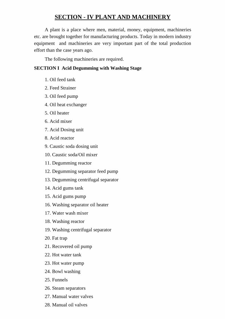
SECTION - IV PLANT AND MACHINERY
A plant is a place where men, material, money, equipment, machineries
etc. are brought together for manufacturing products. Today in modern industry
equipment and machineries are very important part of the total production
effort than the case years ago.
The following machineries are required.
SECTION I Acid Degumming with Washing Stage
1. Oil feed tank
2. Feed Strainer
3. Oil feed pump
4. Oil heat exchanger
5. Oil heater
6. Acid mixer
7. Acid Dosing unit
8. Acid reactor
9. Caustic soda dosing unit
10. Caustic soda/Oil mixer
11. Degumming reactor
12. Degumming separator feed pump
13. Degumming centrifugal separator
14. Acid gums tank
15. Acid gums pump
16. Washing separator oil heater
17. Water wash mixer
18. Washing reactor
19. Washing centrifugal separator
20. Fat trap
21. Recovered oil pump
22. Hot water tank
23. Hot water pump
24. Bowl washing
25. Funnels
26. Steam separators
27. Manual water valves
28. Manual oil valves

29. Manual steam valves
30. Carbon steel piping material
31. Stainless steel piping material
32. Steam traps
33. Non electric measuring/control instruments
34. Electric control/measuring instruments
35. Air piping material
36. Motor/operation control centre
37. Electric circuits control equipment
38. Electric wiring material
39. Insulation
SECTION 2. Dry Pretreatment Combined with
1. Oil dryer/ buffer feed tank
2. Oil feed pump
3. Oil heater
4. Acid mixer
5. Acid dosting unit
6. Acid reactor
7. Bleaching earth hopper
8. Bleaching earth dosing device
9. Oil/ earth mixer
10. Continuous heater - bleacher
11. Bleached oil pump
12. Bleaching filters
13. Spent earth collecting hoppers
14. Bleached oil tank
15. Bleached oil pump
16. Safety filters
17. Recovered oil tank
18. Filter blowing vapours scrubber
19. Vacuum production unit
20. Filter elements cloning tank
21. Funnels
22. Steam separators

23. Manual valves
24. On/Off valves
25. Control valves
26. Carbon steel piping material
27. Stainless steel piping material
28. Steam traps
29. Electric control/measuring instruments
30. Air piping material
31. Motor/operation control centre
32. Electric circuits control equipment
33. Electric wiring material
34. Insulation
SECTION 3 Dewaxing of Rice Bran Oil With Super Filter
1. Oil feed tank
2. Oil feed pump
3. Oil heat exchanger
4. Oil water heat exchanger
5. Crystallizers
6. Maturator
7. Main super filters
8. Dewaxed oil buffer vessel
9. Filtered oil pump
10. Secondary safety filters
11. Chiller
12. Glycol water tank
13. Glycol water pump
14. Funnels
15. Steam separators
16. Manual water valves
17. Manual oil valves
18. Manual steam valves
19. Carbon steel piping material
20 Steam traps
21. Non electric measuring control instruments

22. Electric control measuring instruments
23. Air piping material
24. Motor operation control centre
25. Electric circuits control equipemt
26. Electric wiring material
27. Insulation
SECTION 4 Continous Deodorising
1. Oil feed pump
2. Deodoriser
3. Oil heater
4. Continous deodoriser
5. Heat exchanger
6. Oil buffer tray
7. Feed buffer/ Deaeration tray
8. Fatty acid condenser/Separator
9. Citric acid dosing unit
10.Deodoriser oil discharge pump
11. Final oil cooler/ Shutdown cooler
12. Oil heat exchanger
13. Final oil cooler
14. Polishing filters
15. Vaccum production unit
16. Start - Up Ejector
17. Sparge Steam Superheater
18. Fatty acid distillates condenser
19. Fatty acid separator
20. Duct from F.A. Separator to vacuum production unit
21. Fatty acids circulating pump
22. Fatty acids cooler
23. Fatty acids tempered water pump
24. Funels
25. Steam separators
26. Manual valves
27. On/off valves

28. Control valves
29. Carbon steel piping material
30. Stainless steel piping material.
31. Steam traps
32. Non electric measuring/control instruments
33.Air piping material
34. Motor operation control centre
35.Electric circuits control equipmet
36. Electric wiring material
37. Insulation
SECTION 5 High Temperature Heating System
1. High temperature heater
2. Thermal fluid expansion tank
3. Thermal fluid circulating pump
4. Manual thermal fluid valves
5. Thermal fluid piping material
SECTION 6 Accessories for Refining
1. Plate heat exchangers
2. Dosing units
3. Manual valves
4. Pneumatic on/off valves
5. Controlled Modulated Valves
6. Carbon steel piping material
7. Stainless steel piping material
8. Steam tracing material
9. Steam condensate piping material
10. Centrifugal pumps
11. Volumetric pumps
12. Non electric measuring control instrumnets
13. Pneumatic measuring control instruments
14. Electric measuring control instruments
15. Air piping material
16. Motor operation control centre

17. Electric wiring material
Supporting Equipments
1. Chimney & Furnace
2. Solvent extract oil storage tank 100 MT capacity
3. Refined oil storage tank 100 MT capacity
4. Process tank 15 MT Capacity
5. Industrial electrification
6. Cooling tower with pond circulation pump etc.

SECTION - V MAN POWER REQUIREMENTS
The consortium will arrange necessary technical experts and skilled
operators for running this common facility centre. The continuity of
professionals and skilled workers are ensured by the consortium.
According to organisational structure envisaged for the common facility
centre, General Managers will be in charge of functions of the unit. He looks
after the production, and finance. There will be three Production Supervisors,
two chemists, six machine operators, one Boiler operator, two maintenance
staff, three skilled workers and six unskilled workers reporting to General
Manager.
There will be two accountant in helping Managers in matters like
accounting, book keeping, banking and other finance related affairs. There will
be three Office Staff in charge of office matters.
In total there will be 29 persons including Manager employed in the
refinery section of common facility centre. The monthly salary and benefits
will come to Rs. 1,96,075/- shown in Annexure - VI.

SECTION - VI OTHER PROJECT DETAILS
A. UTILITIES :
1. Power :
Required power is available from Kerala State Electricity Board. The total
connected load for common facility centre is 190 K.W. The annual electric
charge is Rs. 26.05 lakhs at fully capacity utilisation. Details are given in
Annexure - V. The consortium will pay this amount from the service charge
obtained from its members.
B. MISCELLANEOUS EXPENSES :
These items includes repair and maintenance of building, plant and
machineries, postage charges, cost of printing and stationary items, insurance
charges, effluent disposal etc. An amount of Rs.28.41 lakhs per annum has to
be incurred towards for the smooth operation of the unit. The details of
estimation are given in Annexure - VIII.
C. PRELIMINARY AND PRE-OPERATIVE EXPENSES :
These items include company registration, project report preparation,
building design and drawing, technical consultancy fee, trial production, laison
work etc. Thus the preliminary and pre operative expense required for
implementing the proposed project is approximately Rs. 26.22 lakhs. The
details of estimation are given in Annexure - IV.
PLANT CAPACITY AND CAPACITY UTILISATION
The refinery section of common facility centre will have a processing
capacity of 50 MT of extracted bran oil per day. Because of down time and
other various reasons, the capacity may not be releasable and it is assumed that
65% of the capacity utilisation will be achieved during first year and 75%
during second year 80% during third year and 85% capacity utilisation will be
achieved, fourth year onwards.
The extraction section of common facility centre will charge the service
charge of Rs. 925 for extracting 1 MT of rice bran. This refinery section will
charge an amount of Rs. 2,650 for refining 1 MT of extracted bran oil.
The details are shown in Annexure IX.

Presently around 33 rice mill units are members of this consortium. The
average production of bran of each unit is 3 MT. The remaining 37 modern rice
mills and 55 small conventional rice mills of the cluster will join this
consortium immediately.
The average yield of extracted bran oil is 21% from bran. There is a
process loss of 6% while refining this extracted oil.
The de oiled rice bran is actaully a by-product of solvent extraction of rice
bran. This de-oiled rice bran is sold to cattled feed industries, so that value
additon is ensured.
The other by-product - wax is sold to wax manufacturing units and other
by-product gum is heated to 150oC and treated with sulphuric acid, then it is
sold to soap manufacturing industries as acid oil.
The facility for recovery of tocopherols and tocotrienols from rice bran
oil will be included in the project in later stage.
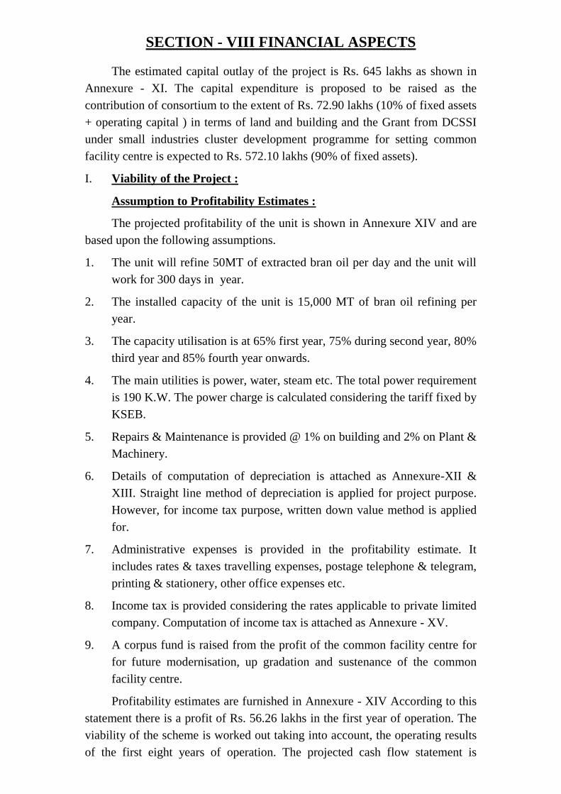
SECTION - VIII FINANCIAL ASPECTS
The estimated capital outlay of the project is Rs. 645 lakhs as shown in
Annexure - XI. The capital expenditure is proposed to be raised as the
contribution of consortium to the extent of Rs. 72.90 lakhs (10% of fixed assets
+ operating capital ) in terms of land and building and the Grant from DCSSI
under small industries cluster development programme for setting common
facility centre is expected to Rs. 572.10 lakhs (90% of fixed assets).
I. Viability of the Project :
Assumption to Profitability Estimates :
The projected profitability of the unit is shown in Annexure XIV and are
based upon the following assumptions.
1. The unit will refine 50MT of extracted bran oil per day and the unit will
work for 300 days in year.
2. The installed capacity of the unit is 15,000 MT of bran oil refining per
year.
3. The capacity utilisation is at 65% first year, 75% during second year, 80%
third year and 85% fourth year onwards.
4. The main utilities is power, water, steam etc. The total power requirement
is 190 K.W. The power charge is calculated considering the tariff fixed by
KSEB.
5. Repairs & Maintenance is provided @ 1% on building and 2% on Plant &
Machinery.
6. Details of computation of depreciation is attached as Annexure-XII &
XIII. Straight line method of depreciation is applied for project purpose.
However, for income tax purpose, written down value method is applied
for.
7. Administrative expenses is provided in the profitability estimate. It
includes rates & taxes travelling expenses, postage telephone & telegram,
printing & stationery, other office expenses etc.
8. Income tax is provided considering the rates applicable to private limited
company. Computation of income tax is attached as Annexure - XV.
9. A corpus fund is raised from the profit of the common facility centre for
for future modernisation, up gradation and sustenance of the common
facility centre.
Profitability estimates are furnished in Annexure - XIV According to this
statement there is a profit of Rs. 56.26 lakhs in the first year of operation. The
viability of the scheme is worked out taking into account, the operating results
of the first eight years of operation. The projected cash flow statement is
appended as Annexure - XVI. As per cash flow statement there is cash surplus
adequate to meet all the probable payments and debt servicing.
The internal rate of return of the project is 11% after tax which is
computed in Annexure - XVIII.
Break even level of operation is computed in Annexure -XIX. Operating
BEP works out to 35.79% of the installed capacity and the cash BEP works out
to 8.20% of installed capacity.
II. Implementation Period
Phase I : Collection of all information, data, preparation of drawings and
inviting quotations etc. A detailed schedule in terms of bar charts is
prepared for implementing the project. This will be carried out
within a period of three months.
Phase II : Actual implementation of the project. This will take at least
18 months as a supply period of the machines will take 12 to 14 months.
Besides it will take around 8 to 10 months for land development and building
construction. The tentative date of trial production will be November 2006 and
commercial operation will be carried out within 45 days from the date of trial
production.

SECTION - IX
CONCLUSION AND RECOMMENDATION
M/s. KALADY RICE MILLERS CONSORTIUM PVT. LTD, Mattoor,
Kalady, is planning to set up a refinery section of common facility centre for
refining bran oil under Small Industries Cluster Development Programme
scheme. Presently about 33 industrial units in Ernakulam District have joined
the consortium and remaining industries will join immediately. The proposed
annual capacity of the unit is 15,000 MT of bran oil refining per year. The
required technical knowhow for production is indigenously available.
The implementation agency for the proposed common facility centre is
Government of Kerala (Industrial Department).
This common facility centre will not create any atmospheric pollution.
The estimated capital outlay of the project is Rs. 645 lakhs as is proposed
to be financed as follows :
(Rs. in Lakhs)
Contribution from consortium members 72.90
Grand from Govt 572.10
645.00
The projected profitability estimated of the unit for first 8 years are
satisfactory. The unit is expected to make an average operating profit of 66.57
lakhs per annum for the first 8 years. The project is technically feasible and
commercially viable.
K. SAJIL KUMAR, M.Tech A.M.I.E., C.E.
CHARTERED ENGINEER & CONSULTANT
A2, ASHOK APARTMENT, NEAR CIVIL SATATION
KAKKANAD, ERNAKULAM, KERALA – 682 030
Phone: +91 9388607508
Email: [email protected]