Julian - MedicalStore
72
Julian Anaesthetic Workstation Instructions for Use Software 2.n 1-36-96
-
Upload
khangminh22 -
Category
Documents
-
view
1 -
download
0
Transcript of Julian - MedicalStore
JulianAnaesthetic WorkstationInstructions for UseSoftware 2.n
1-3
6-9
6

How to use these Instructions for Use
In the header is the subject…of the main chapter.Underneath is the title of the subchapter, to help you find your way around quickly.
On each page…the instructions for usecombining text with illustrations. The information istranslated directly into actions to enable the user to learn „hands-on“ how to use the workstation.
Left-hand column: the text…provides explanations and guides the user clearly andergonomically with brief directions on the use of theproduct. Bullet points indicate the steps to be followed, and where there are several steps, numbers refer to theillustration and indicate the sequence.
Right-hand column: the illustration… provides the link with the text and serves as a guide to the workstation. Points mentioned in the text areemphasised and non-essential information is omitted.
Screen displays guide the user and confirm the steps to be followed.
How to use these Instructions for Use
2
1 Press the »MAN/SPONT« key,
2 and confirm with the rotary knob.
Display (example):
O2 flush
– For flushing and rapidly filling the breathing
system and breathing bag with O2 while
bypassing the Vapor unit.
3 Press the »O2 +« button.
O2 flows into the breathing system without
anaesthetic gas as long as the button is held
down.
Julian
12
OperationSelecting the ventilation modeMAN/ SPONT
JulianD
3
MAN/SPONTPleth
40
0
CO2
40 360.8 0.658 56
38
98 67
5.2 8
4.0030
Volumeter starten: Bestätigen!
O2
SpO2
N 2O
Hal.
Fi Fet
etCO2
AMV
Freq
Grenzen
CO2-Al.aus/ein
AlarmInfo
Liste
Kurven
Konfig.
Frischgas O2 + N2O
O2 % L/min
VT
0.35 0Volumeter --s
--0 5 10
0.5 1
Frischgas
internextern
Maintenance ...................................................... 5, 116Maintenance intervals ............................................. 116Major hardware fault ................................................. 53MAN/SPONT ........................................................... 37Manual calibration .............................................. 75, 92Manual ventilation ..................................................... 37Measured gas recirculation system, connecting ...... 109Measured gas, scavenging ..................................... 110Measuring parameters, setting ............................ 70, 84Measuring systems ................................................. 133MEDIBUS ................................................................ 85Message – Cause – Remedy .................................. 120Microbial filter ................................................... 97, 103Microbial filter 654 St ....................................... 97, 103Mobile telephones ...................................................... 9Monitor defaults, activating ....................................... 71Monitoring functions, selecting/setting ...................... 15
Non-rebreathing systems .......................................... 50Nuclear spin tomography ............................................ 9
O2 concentration, setting ......................................... 36O2 cylinders ............................................................. 23O2 emergency metering ........................................... 30O2 flush ............................................................. 23, 30O2 sensor, replacing .............................................. 117Operating characteristics ........................................ 137Operating concept ................................................... 12
Paediatric hoses ...................................................... 49Patient, change ........................................................ 47PCV ......................................................................... 43Power failure ............................................................ 20Power failure ............................................................ 52Power supply ........................................................... 24Preparation ............................................................... 22Pulse tone, setting .............................................. 69, 83
Record ............................................................... 71, 85
Safety checks ............................................................ 5Sample line ........................................................ 79, 96Scale, selecting .................................................. 69, 83Screen ergonomics .................................................. 12Screen layout ........................................................... 16Secretion aspiration .................................................. 30Secretion aspiration, dismantling .............................. 98Secretion aspiration, preparation ............................ 108Secretion, aspirating ................................................. 46Self-test .................................................................... 31Soda lime, changing ................................................. 47SpO2 alarms on/off .................................................. 72SpO2 measurement .......................................... 76, 135SpO2 sensor ............................................................ 76Spontaneous breathing ............................................. 37Standard page ................................................... 17, 56Standard screen ....................................................... 88
Standby ............................................................. 47, 54Starting up ......................................................... 26, 33Sterilization ............................................................. 102Suction rate .............................................................. 84Switch-off time lag .................................................... 54Symbols ................................................................. 141System compliance ............................... 32, 39, 40, 133
Technical data ........................................................ 132Time ......................................................................... 89Trend memory, deleting ............................................ 59Trend page ........................................................ 17, 58
UMDNS code ........................................................ 137Uninterruptible power supply UPS ...................... 20, 52
Vapor ................................................................. 27, 46Vapor, setting ........................................................... 46Ventilation mode ....................................................... 37Ventilation mode IPPV .............................................. 40Ventilation mode MAN/SPONT ................................. 37Ventilation mode PCV ............................................... 43Ventilation parameters for IPPV .......................... 40, 90Ventilation parameters for PCV ........................... 43, 90Ventilation parameters, selecting/setting ................... 14Ventilator ................................................................ 132Volumeter function .................................................... 67
Wall-mounted unit ................................................... 114Waste gas connector ..................................... 101, 110Water separator, replacing .................................... 117Water trap ................................................................ 27What‘s what ........................................................... 126
Zoom function .......................................................... 59
143
Index

IndexAbbreviations ......................................................... 140Absorber, dismantling ............................................... 99Absorber, filling and installing ................................. 107Accessories ................................................................ 5Advisory ........................................................... 63, 120Airway temperature measurement ............................. 80Alarm ................................................................. 63, 75Alarm info ........................................................... 64, 52Alarm limits ............................................................... 61Alarm sound, setting ........................................... 69, 83Alarm tone sequence ................................................ 64Alarms ...................................................................... 63Alarms, FRESH GAS EXTERNAL ............................ 51Alarms, IPPV ............................................................ 42Alarms, MAN/SPONT .............................................. 39Alarms, PCV ............................................................ 45Alarms, selecting ................................................ 60, 72Ambient conditions ................................................. 132Anaesthetic agent ....................................... 74, 93, 114Anaesthetic agent scavenging system AGS ....................................... 23, 28, 100, 111AutoSet .................................................................... 62Auxiliary devices ....................................................... 24Auxiliary power socket .............................................. 24
Backup gas cylinders ............................................... 29Basic configurations ................................................. 88Basic pages ............................................................. 17Batteries ................................................................. 118Battery ..................................................................... 19Bellows, installation ................................................ 107Bellows, removal ...................................................... 99Breathing bag ......................................................... 108Breathing hoses ..................................................... 108Breathing hoses, installing ...................................... 108Breathing system .............................................. 28, 133Breathing system, dismantling .................................. 98Breathing system, installing ..................................... 106Breathing system, opening ...................................... 100
C-Lock ECG synchronization ........................... 77, 136Calibration ......................................................... 75, 92Care ......................................................................... 96Care list .................................................................. 104Carrier gas, selecting ............................................... 36Caution ............................................................ 63, 120Checking against checklist ....................................... 26Checklist .................................................................. 26Children, ventilating .................................................. 49Classification .......................................................... 137Cleaning ................................................................. 102CO2 alarms on/off .............................................. 64, 72CO2 unit, setting ................................................ 70, 84CO2, setting ............................................................. 84COM1 ..................................................................... 85COM2 ..................................................................... 85
COM3 ..................................................................... 85Compliance ...................................................... 32, 133Configuring in operation ........................................... 68Configuring in standby .............................................. 82Connection ................................................................. 5Cooling air filter, cleaning ............................... 116, 117Curves ............................................................... 66, 88
Data page .......................................................... 17, 57Date ......................................................................... 89Default alarm limits, setting ................................. 86, 87Default setting, fresh gas .......................................... 91Default setting, IPPV ................................................. 90Default setting, PCV ................................................. 90Default values ........................................................... 82Disinfecting ............................................................ 102Disposal ................................................................. 118Disposing of the used device .................................. 118
ECG signal .............................................................. 77Emergency ......................................................... 33, 52Emergency metering ................................................. 30Emergency mode ..................................................... 52Emergency ventilation bag ........................ 29, 101, 111End of operation ....................................................... 54Equipotential bonding ............................................... 24Explosion hazard areas ............................................... 5
First-time operation .................................................. 20Flow sensor, installation .......................................... 106Flow sensor, removal ............................................... 99For your safety and that of your patients ...................... 5Fresh gas flow, setting ............................................. 36Fresh gas metering ........................................... 91, 132Fresh gas, setting ..................................................... 36
Gas cylinders ........................................................... 23Gas cylinders ........................................................... 23Gas failure ................................................................ 53Gas supply ....................................................... 22, 127
HLM alarm mode ..................................................... 73HLM mode ............................................................... 73
Intended use .............................................................. 9Intended use ............................................................... 9Interfaces ............................................................... 130Interfaces, configuring ........................................ 85, 86IPPV ......................................................................... 40
Language ................................................................. 89Leakage test ............................................................. 48Liability ....................................................................... 5Limits ....................................................................... 60Limits, adjusting ....................................................... 62List ........................................................................... 65
142
Index
Contents
3
Contents
Index 142
For Your Safety and that of Your Patients 5
Intended Use 7
Operating Concept 11
Before Using for the First Time 19
Preparation 21
Starting Up 25
Operation 35
Monitoring 55
Configuring in Standby Mode 81
Care 95
Julian as Wall-mounted Unit 113
Maintenance Intervals 115
What's what 125
Technical Data 131
Fault – Cause – Remedy 119
Abbreviations / Symbols 139

4
Symbols
Symbol Meaning
G Suppress alarm tone for 2 minutes
Q Call up standard page
S Call up basic pages in succession
E Standby / operation switch
ª Pulse rate
Fresh gas flowing
u Action in progress
✓ Action has been completed successfully
? Repeat calibration
_ Upper and lower alarm limits
> Upper alarm limit only
< Lower alarm limit only
_ Alarm monitoring inactive
– – Alarm limit deactivated
* * * * Enter 4-digit password
! Advisory message
!! Caution message
!!! Warning message
m Protection class type B (body)
m Protection class type BF (body floating)
P Connection for equipotential bonding
Connection for equipotential bonding
z Close menu, back to previous menu
Connection for non-rebreathing systems
J Available operating time with>XX min uninterruptible power supply UPS
141
Symbols
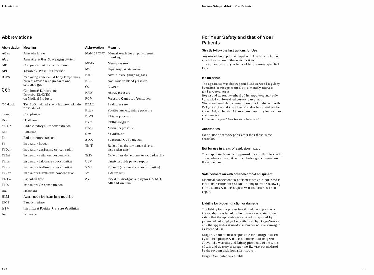
Abbreviations
Abbreviation Meaning
AGas Anaesthetic gas
AGS Anaesthesia Gas Scavenging System
AIR Compressed air for medical use
APL Adjustable Pressure Limitation
BTPS Measuring condition at body temperature,current atmospheric pressure andsaturated gas
ç Conformité EuropéenneDirective 93/42/ECon Medical Products
CC-Lock The SpO2 s ignal is synchronized with theECG signal
Compl. Compliance
Des. Desflurane
etCO2 End-expiratory CO2 concentration
Enf. Enflurane
Fet End-expiratory fraction
Fi Inspiratory fraction
Fi Des Inspiratory desflurane concentration
Fi Enf Inspiratory enflurane concentration
Fi Hal Inspiratory halothane concentration
Fi Iso Inspiratory isoflurane concentration
Fi Sev Inspiratory sevoflurane concentration
FLOW Expiration flow
Fi O2 Inspiratory O2 concentration
Hal. Halothane
HLM Alarm mode for heart-lung machine
INOP Function failure
IPPV Intermittent Positive Pressure Ventilation
Iso. Isoflurane
Abbreviation Meaning
MAN/SPONT Manual ventilation / spontaneousbreathing
MEAN Mean pressure
MV Expiratory minute volume
N2O Nitrous oxide (laughing gas)
NiBP Non-invasive blood pressure
O2 Oxygen
PAW Airway pressure
PCV Pressure Controlled Ventilation
PEAK Peak pressure
PEEP Positive end-expiratory pressure
PLAT Plateau pressure
Pleth Plethysmogram
Pmax Maximum pressure
Sev. Sevoflurane
SpO2 Functional O2 saturation
Tip:Ti Ratio of inspiratory pause time toinspiration time
TI:TE Ratio of inspiration time to expiration time
USV Uninterruptible power supply
VAC Vacuum (e.g. for secretion aspiration)
VT Tidal volume
ZV Piped medical gas supply for O2, N2O,AIR and vacuum
Abbreviations
140
For Your Safety and that of YourPatients
Strictly follow the Instructions for Use
Any use of the apparatus requires full understanding andstrict observation of these instructions. The apparatus is only to be used for purposes specifiedhere.
Maintenance
The apparatus must be inspected and serviced regularlyby trained service personnel at six monthly intervals (and a record kept). Repair and general overhaul of the apparatus may only be carried out by trained service personnel.We recommend that a service contract be obtained withDrägerService and that all repairs also be carried out bythem. Only authentic Dräger spare parts may be used formaintenance. Observe chapter "Maintenance Intervals".
Accessories
Do not use accessory parts other than those in the order list.
Not for use in areas of explosion hazard
This apparatus is neither approved nor certified for use inareas where combustible or explosive gas mixtures arelikely to occur.
Safe connection with other electrical equipment
Electrical connections to equipment which is not listed inthese Instructions for Use should only be made followingconsultations with the respective manufacturers or anexpert.
Liability for proper function or damage
The liability for the proper function of the apparatus isirrevocably transferred to the owner or operator to theextent that the apparatus is serviced or repaired bypersonnel not employed or authorized by DrägerServiceor if the apparatus is used in a manner not conforming toits intended use.
Dräger cannot be held responsible for damage causedby non-compliance with the recommendations givenabove. The warranty and liability provisions of the termsof sale and delivery of Dräger are likewise not modifiedby the recommendations given above.
Dräger Medizintechnik GmbH
For Your Safety and that of Your Patients
5

Contents
Abbreviations ........................................................................................ 140
Symbols ............................................................................................... 141
139
Abbreviations / SymbolsContents
Abbreviations / Symbols

138
Contents
Intended Use ............................................................................................. 9
7
Intended UseContents
Intended Use

8
Operating data
Operating voltage 90 – 265 V~
Power input 400 W typically, max. 2.3 kW
Uninterruptible power supply with fully charged battery: typically 30 min(auxiliary sockets are not powered!)
Mains fuse Automatic circuit-breaker 10 A
Auxiliary sockets Each with two fuses 2 A T2L 250V DIN 41662, IEC 127-2/III
Medical gas supply O2 2.7 to 5.5 barN2O 2.7 to 5.5 barAIR 2.7 to 5.5 bar
Drive gas consumptionOperation MV ±1 L/min AIR or O2 Standby and MAN/SPONT 0 L/min
Dimensions of Julian W x H x D 68 cm x 133 cm x 68 cm
Dimensions of the storage tray W x D 43 cm x 29 cm
Dimensions of the breathing system W x H x D 31 cm x 35 cm x 21 cm
Weight of Julian Approx. 90 kg(Ready for operation without Vapor units and gas cylinders)
Weight of breathing system without soda lime 4.8 kg
Screen Electro-luminescent screen, 10.4" diagonal
Protection classDevice I, type B conforming to EN 60601-1
SpO2 sensor Type BF
electrically isolated from protective earth
Electromagnetic compatibility EMC Tested to EN 60601-1-2
Classification II baccording to Directive 93/42/ECAppendix IX
UMDNS Code 10-134Universal Medical DeviceNomenclature System
137
Technical Data

SensorsType Compatible with Nellcor sensors
Oxisensor, Oxiband and Durasensor
Wavelengths 660 nm (red)920 nm (infrared)
Acoustic pulse signal A tone is produced for each detected pulse, tone pitch proportional to oxygen saturation
C-Lock-ECG synchronization (optional)
Requirements for ECG synchronization signal Pos. pulse with voltage >4.5 V,
>10 ms duration for driving 2 mA
Max. permissible signal delay with reference to current QRS complex 40 ms
Socket for 2-pin jack-plug, dia. 3.5
Jack layout
Signal isolation from other electronic components
Dielectric strength 4 kV
Interfaces
Analog outputPlug connector 9-pin sub-D, electrical isolation 1.5 kVPAW 0 to 100 mbar; 0 to 5 V =; PIN 3Flow 0 to 150 L/min; 0 to 5 V=; PIN 6CO2 0 to 10 kPa; 0 to 5 V=; PIN 9Earth PIN 1, 4, 7
COM1 record (printer)Connector 9-pin sub-D, electrical isolation 1.5 kVPin assignment 1 shield
2 TxD3 RxD5 GND
COM2 (MEDIBUS 1)Connector 9-pin sub-D, electrical isolation 1.5 kVPin assignment 1 shield
2 TxD3 RxD5 GND
COM3 (MEDIBUS 2)Connector 9-pin sub-D, electrical isolation 1.5 kVPin assignment 1 shield
2 TxD3 RxD5 GND
Technical Data
136
Ground
Signal
Intended Use
Julian Anaesthetic Workstation for patients with a bodyweight of 5 kg and over with the use of IPPV ventilation.
For the use of:
– Inhalation anaesthesia in rebreathing systems
– Inhalation anaesthesia in semi-closed to virtuallyclosed systems with "low flow" and "minimal flow"techniques (for minimal gas and anaesthetic agentconsumption).
– Inhalation anaesthesia in non-rebreathing systems,with separate fresh gas outlet for the connection ofe.g. the Bain system or Magill system
with a fresh gas flow of 0.5 to 12 L/min.
Ventilation modes:
– Automatic ventilation (IPPV)and pressure-controlled ventilation (PCV).
– Manual ventilation (MAN).
– Spontaneous ventilation (SPONT).
The following measured values are displayed:
– Peak pressure, mean pressure, plateau pressure andPEEP
– Expiratory minute ventilationTidal volume VTBreathing ratePatient compliance
– Inspiratory and expiratory concentration of O2, N2O,anaesthetic gas and CO2
optional:
– Functional oxygen saturation (SpO2) and pulse rate.
The following parameters are displayed as curves:
– Airway pressure
– Expiratory flow
– Inspiratory and expiratory concentration of O2, CO2
and anaesthetic gas
optional:
– Plethysmogram
Trend curves and measured value lists are also available.
Monitoring by means of adjustable alarm limits that are automaticallyadapted to the ventilation mode.
The workstation may only be used under thesupervision of qualified medical personnel, so thatassistance can be provided immediately in the eventof any malfunctions.
Explosive anaesthetics, such as ether or cyclo-propane, must not be used due to the risk of fire.
Mobile radio telephones must not be used within 10 metres of the workstation!Mobile telephones may interfere with the operation ofelectrical and electronic medical equipment.
Julian must not be used with nuclear spintomography (MRT, NMR, NMI)!Operation of the apparatus may be impaired.
Intended Use
9
Intended Use

10
Anaesthetic gas measurement (infrared spectrometry)
Sample rate (selectable) 60 mL/min or 200 mL/minDelay time for sampling Less than 1 s
Display range for N2O 0 to 100 vol%Accuracy Better than ±2.5 vol% absolute or 4 % of measured valueResolution 0.1 vol%
Display range for halothane and isoflurane 0 to 8.5 vol%Accuracy for0 to 4 vol% Better than ±0.2 vol% absolute4 to 8.5 vol% Better than 10 % of measured value
Display range for enflurane and sevoflurane 0 to 9.9 vol%Accuracy for 0 to 4 vol% Better than ±0.2 vol% absolute4 to 9.9 vol% Better than 10% of measured value
Display range for desflurane 0 to 22 vol%Accuracy for0 to 8 vol% Better than ±0.4 vol% absolute8 to 22 vol% Better than 10 % of measured value
Response time t 10...90at 200 mL/min 350 msat 60 mL/min 1 s
Warm-up phase 4 min (accuracy as specified by DIN ISO 11196) for first measured values
Zero drift Within the ranges specified above
Automatic anaesthetic gas identification The measurement accuracy required by ISO standards is attained at the latest 4 minutes after switching on the apparatus. The threshold level for automatic identification equals 0.15 % by volume.Anaesthetic gases are identified from a concentration of 0.4 % by volume upwards. If a mixture is present, the gas with the higher concentration is measured.
SpO2 measurement, optional(light absorption)
Display range 0 to 100 % SpO2Accuracy (adults)between 70 and 100 % SpO2 Better than ±2 % SpO2
between 50 and 70 % SpO2 Better than ±3 % SpO2
between 0 and 50 % SpO2 Not specified
Accuracy (neonates)between 70 and 95 % SpO2 Better than ±3 % SpO2
between 0 and 70 % SpO2 Not specifiedbetween 95 and 100 % SpO2 Not specified
Actualization time Once per heartbeat
Pulse rate 20 to 250 per minuteAccuracy ±2 per minute
135
Technical Data

Flow measurement(hot wire anemometry)
Tidal volume VTRange 0.02 to 9.99 LResolution 0.01 LAccuracy (under calibration conditions Better than ±8 % of the measured value or 0.01 L, the larger valueand 1013 hPa) applies
Minute volume MVRange 0 to 99.9 L/minResolution 0.1 L/minAccuracy Better than ±8 % of the measured value(under calibration conditions and BTPS*)
Respiration rateRange 0 to 60 per minuteResolution ±1 per minuteAccuracy ±1 per minute
Airway temperature measurement(NTC resistance)
Measuring range 20 to 50 °CResolution 1 KAccuracy ±0.5 K in the range from 30 to 41 °C
CO2 measurement(infrared spectrometry)
Sample rate 60 mL/min or(selectable) 200 mL/minDelay time for sampling Less than 1 s
Measuring range 0 to 9.9 kPa (0 to 80 mmHg)Resolution 0.1 kPaAccuracy ±0.2 vol% or 5 % of measured value
Response time t10...90
at 200 mL/min 300 msat 60 mL/min 1 s
Warm-up phase 4 min (accuracy as specified by DIN EN 864)2 min for first measured values
Zero drift Within the ranges specified above
___________
* BTPS: Body temperature, current atmospheric pressure, gas saturated
Technical Data
134
Contents
Screen ergonomics .................................................................................12Selecting / setting ventilation parameters.................................................. 14Selecting / setting monitoring functions.....................................................15
Screen layout .......................................................................................... 16Three basic screens for monitoring........................................................... 17The standard screen.................................................................................17The data screen....................................................................................... 17The trend screen...................................................................................... 18
Operating ConceptContents
11
Operating Concept

Operating Concept
Screen ergonomics
All the settings required for
– Fresh gas delivery
– Ventilation
– Monitoring
are entered on the system screen using the appropriatekeys and the rotary knob.The keys are grouped in function fields:
Left-hand fieldFresh gas delivery
Right-hand fieldVentilation
Middle fieldMonitoring
The main functions for anaesthesia, e.g. selection of N2O or AIR, or selection of ventilation modes, can beselected directly by keys with permanently definedfunctions ("hardkeys"):
1 Left-hand blockThe »N2O« or »AIR« keys are used to select the gas to be mixed with O2 for the fresh gas mix.
2 Right-hand blockThe »MAN SPONT«, »IPPV« oder »PCV«keys select the ventilation mode.
These function keys are located in the bottom row on thecontrol panel.Left-hand block for fresh gas settingRight-hand block for ventilation
Operating ConceptScreen ergonomics
12
.12....
N O2 AIRMAN
SPONTIPPV PCV
Monitoring
VentilationFresh gas delivery
Pleth
IPPV
alarmlimits
auto setlimits
alarminfo
list
curves
CO240
0
PAW
0
20
config.
O2
SpO2
N 2O
Hal.
40 360.8 0.658 56
Fi Fet
etCO2 38
98 67
6.0 10MV
freq
600
VTmL
10 1:2 10 0
PEEP mbar
Freq.1/min
TI:TE TIP:TI %
25
Pmax mbar
Freshgas O2+N2O
4.00O2 % L/min
30
_
CO2
Ve
.12....
N O2 AIRMAN
SPONTIPPV PCV
Pleth
IPPV
alarmlimits
auto setlimits
alarminfo
list
curves
CO240
0
PAW
0
20
config.
O2
SpO2
N 2O
Hal.
40 360.8 0.658 56
Fi Fet
etCO2 38
98 67
6.0 10MV
freq
600
VTmL
10 1:2 10 0
PEEP mbar
Freq.1/min
TI:TE TIP:TI %
25
Pmax mbar
Freshgas O2+N2O
4.00O2 % L/min
30
1 2
_
CO2
Ve
Breathing system
Total gas volume Approx. 4.5 L enclosed gas volume
Compliance with filled absorber container, without breathing hoses Approx. 4.5 mL/mbar
Absorber volume 1.5 L
Leakage (EN 740) <150 mL/30 mbar
Pressure limiting valve APLAdjustment range 5 to 70 mbar
±15 % of setting
Exp. resistance (EN 740) 4.87 hPa at 60 L/min
Insp. resistance (EN 740) 4.65 hPa at 60 L/min
absorber container filled with DrägerSorb 800
Measuring systems
Pressure measurement (piezoresistive)
Airway pressure –10 to 99 mbarResolution 1 mbarAccuracy Better than ±4 % of measured value or at least 1 mbar,
the larger value applies.
O2 measurement(fuel cell in sidestream)
Sample rate 60 mL/min or 200 mL/minDelay time for sampling Less than 1 secondMeasuring range 5 to 100 vol%
Resolution 1 vol%Accuracy Calibration in air:
±3 vol% in the range from 5 to 50 vol%±5 vol% in the range from 50 to 100 vol%Calibration with 100 % O2:±3 vol% in the range from 5 to 100 vol%
Drift Within the ranges specified above
Response time t10...90
at 200 mL/min 500 msat 60 mL/min 1 s
133
Technical Data

Technical Data
Ambient conditions
In operation:Temperature 10 to 35 °CAir pressure 700 to 1060 hPaRel. humidity 20 to 80 % (no condensation)CO2 concentration of ambient air 300 to 800 ppm
In storage:Temperature –20 to 60 °C
O2 sensor max. 50 °CAir pressure 500 to 1100 hPaRel. humidity <98 % (no condensation)
Fresh gas(electronic mixer)
Settings:
O2 concentration 25 to 100% by vol., at least 25% by vol., 250 mL/min.± 5% of set value
Fresh gas flow 0 and 0.5 to 12 L/min± 10% of set value or max. ±100 mL
O2 flush >35 L/min
Ventilator(electronically controlled, pneumatically driven bellows in bottle ventilator)
Settings:
Pressure limit Pmaxfor IPPV 10 to 70 mbar
±10 % of setting or at least ±2 mbarfor PCV (PEEP+1) to 70 mbar
±10 % of setting or at least ±2 mbar
Tidal volume 50 to 1400 mL± 15% of the setting for inspiration flows ≥ 10 L/min.
Ventilation frequency 6 to 60 per minute
Tinsp 0.2 to 6.7 seconds
Texp 0.33 to 8 seconds
Insp/Exp. time ratio TI : TE 1 : 4 to 2 : 1 with automatic ventilation
Plateau time ratio TIP : TI 0 to 50 %
Inspiratory flow (PCV) 5 to 50 L/min ±10 %Can be set to up to 75 L/min by DrägerService
Inspiratory flow (IPPV) 3 to 75 L/min(cannot be set directly; depends on the setting for VT, Freq. TI:TE and TIP:TI)
PEEP 0 to 20 mbar±10 % of setting or at least ±2 mbar
Technical Data
132
Complementary "softkeys" with variable functions areprovided at the bottom edge of the screen, above eachgroup of hardkeys. These softkeys are used to set thefresh gas delivery parameters and ventilation parameters.
1 Left-hand block:The keys for setting the O2 concentration and freshgas flow.
2 Right-hand block:The keys for setting the parameters for the relevantventilation mode. The example shows the parametersfor IPPV controlled ventilation.
These softkeys have different functions, depending onthe operating status or ventilation mode.
The current parameter values are displayed in the softkeyfield.
In a prominent position at the bottom right-hand side:
The "turn-and-push" rotary knob is the main operating control of the apparatus and has thefollowing functions in all setting operations:
3 select = turn
4 confirm = press
– to confirm the selected carrier gas or a ventilationmode,
– to set and confirm the parameters for fresh gas andventilation modes,
– to set and confirm the monitoring functions.
Beside the rotary knob:
The standby key E for switching over to standby mode.
5 Press standby key E and confirm by pressing therotary knob.
13
Operating Concept Screen ergonomics
.12....
N O2 AIRMAN
SPONTIPPV PCV
Pleth
IPPV
alarmlimits
auto setlimits
alarminfo
list
curves
CO240
0
PAW
0
20
config.
O2
SpO2
N 2O
Hal.
40 360.8 0.658 56
Fi Fet
etCO2 38
98 67
6.0 10MV
freq
600
VTmL
10 1:2 10 0
PEEP mbar
Freq.1/min
TI:TE TIP:TI %
25
Pmax mbar
Freshgas O2+N2O
4.00O2 % L/min
301 2
_
CO2
Ve
.12....
N O2 AIRMAN
SPONTIPPV PCV
Pleth
IPPV
alarmlimits
auto setlimits
alarminfo
list
curves
CO240
0
PAW
0
20
config.
O2
SpO2
N 2O
Hal.
40 360.8 0.658 56
Fi Fet
etCO2 38
98 67
6.0 10MV
freq
600
VTmL
10 1:2 10 0
PEEP mbar
Freq.1/min
TI:TE TIP:TI %
25
Pmax mbar
Freshgas O2+N2O
4.00O2 % L/min
30
3
5
4
_
CO2
Ve

Operating ConceptScreen ergonomics
14
Selecting / setting ventilation parameters
Example: PEEP ventilation parameter
1 Press the softkey »PEEP«.
2 Select the PEEP value = turn the rotary knob.
3 Confirm the PEEP value = press the rotary knob.
The keys for the various monitoring functions are locatedon the right-hand side of the screen.
These keys also have different functions = softkeys,depending on the monitoring screen required.
Julian
1
2
3
.12....
N O2 AIRMAN
SPONTIPPV PCV
Pleth
IPPV
alarmlimits
auto setlimits
alarminfo
list
curves
CO240
0
PAW
0
20
config.
O2
SpO2
N 2O
Hal.
40 360.8 0.658 56
Fi Fet
etCO2 38
98 67
6.0 10MV
freq
600
VTmL
10 1:2 10 0
PEEP mbar
Freq.1/min
TI:TE TIP:TI %
25
Pmax mbar
Freshgas O2+N2O
4.00O2 % L/min
30
_
CO2
Ve
Contents
Ambient conditions ...............................................................................132
Fresh gas .............................................................................................. 132
Ventilator ...............................................................................................132
Breathing system ..................................................................................133
Measuring systems ...............................................................................133Pressure measurement ..........................................................................133O2 measurement....................................................................................133Flow measurement................................................................................. 134
Airway temperature measurement ....................................................... 134CO2 measurement................................................................................. 134Anaesthetic gas measurement................................................................ 135SpO2 measurement............................................................................... 135C-Lock-ECG synchronization (optional)..................................................136
Interfaces .............................................................................................. 136
Operating data ...................................................................................... 137
131
Technical DataContents
Technical Data

Interface panel
1 Analog Analog output for three curves
2 COM3 RS232 interface for MEDIBUS
3 COM2 RS232 interface for MEDIBUS
4 COM1 RS232 interface for printer
5 SA-Bus For DrägerService only
6 CAN1 Interface for PM 8060 vitara (haemodynamic screen), optional
7 CAN2 Interface for parameter box PB 8800, optional
8 Temp Socket for temperature sensor, optional
9 SpO2 Socket for SpO2 sensor, optional
10 Sync Socket for C-Lock-ECG synchronization of the optional SpO2 measurement
What's what
130
Analog
COM 3
Sync.
SpO2
COM 2CAN 1
Temp.
CAN 2
COM 1
SA-Bus
[
m
6 7 8 9 10
1
2
3
4
5
15
Operating Concept Screen ergonomics
Selecting / setting monitoring functions
For example, to change the lower alarm limit of the end-tidal CO2 concentration.
1 Press the »alarm limits « softkey. The alarm limitsmenu is displayed on the screen.
● Select the alarm limit value = turn the rotary knob.Confirm the selection = press the rotary knob.
The limit value is highlighted.Example: lower alarm limit etCO2: <30
● Set the alarm limit value = turn the rotary knob.
● Confirm the new alarm limit = press the rotary knob.The cursor returns to the zsymbol.
Julian
1
Pleth
IPPV
CO240
0
PAW
600 10 1:2 10 0251.0050
9867386.0290.8
--95
3.0
--20
1.00.0
408
12050
--
Select limit: Turn and confirm ! !
4230
0
20FiO2
FiHal.
PAW
SpO2
etCO2
MV
alarmlimits
auto set limits
alarminfo
list
curves
config.
O2 % L/minPEEP mbar
Freq.1/min
VTmL
TI:TE TIP:TI %
Pmax mbar
Freshgas O2 + N2O
Pleth
IPPV
CO240
0
600 10 1:2 10 0251.0050
9867386.0290.8
--95
3.0
--20
1.00.0
408
12050
--
Adjust limit value: Turn and confirm !
4230
PAW
0
20FiO2
FiHal.
PAW
SpO2
etCO2
MV
alarmlimits
auto set limits
alarminfo
list
curves
config.
O2 % L/minPEEP mbar
Freq.1/min
VTmL
TI:TE TIP:TI %
Pmax mbar
Freshgas O2 + N2O

Operating ConceptScreen ergonomics Screen layout
16
Pleth
IPPV
alarmlimits
auto setlimits
alarminfo
list
curves
CO240
0
PAW
0
20
config.
O2
SpO2
N 2O
Hal.
40 360.8 0.658 56
Fi Fet
etCO2 38
98 67
6.0 10MV
freq
600
VTmL
10 1:2 10 0
PEEP mbar
Freq.1/min
TI:TE TIP:TI %
25
Pmax mbar
Freshgas O2+N2O
4.00O2 % L/min
30
_
CO2
Ve
➀ ➁ ➂ ➃
➄ ➅ ➆ ➇
Exit the alarm limits menu:
1 Press the rotary knobor
2 Press the Q key.
The function keys for standard functions are located onthe right-hand side of the control panel.
G Suppress the acoustic alarm for 2 minutes.
S Select the screen page.
Q Back to standard page.
Screen layout
➀ Status field:Displays information on the current operating mode
➁ Graphics field:For curves and bargraphs
➂ Alarm field:Displays information on the alarms, warnings, etc. and their priority
➃ Numerical value field:For numerical values
➄ Lower softkeys – for fresh gas parameters
➅ Prompt field:For user guidance
➆ Lower softkeys – for ventilation parameters
➇ Right-hand softkeys – for monitoring:For rapid selection of the desired monitoring function
.12....
N O2 AIRMAN
SPONTIPPV PCV
Pleth
IPPV
alarmlimits
auto setlimits
alarminfo
list
curves
CO240
0
PAW
0
20
config.
O2
SpO2
N 2O
Hal.
40 360.8 0.658 56
Fi Fet
etCO2 38
98 67
6.0 10MV
freq
600
VTmL
10 1:2 10 0
PEEP mbar
Freq.1/min
TI:TE TIP:TI %
25
Pmax mbar
Freshgas O2+N2O
4.00O2 % L/min
30
_
CO2
Ve
Julian
2
1
Rear view
1 Gas supply ports
2 Sample gas return with filter
3 O2 sensor (behind the sealing screw)
4 Interface panel
5 Bacterial filter for suction system
6 Waste gas connector
7 Transfer hose to anaesthetic gas scavenging systemAGS
8 Anaesthetic gas scavenging system AGS
9 Power cable
10 Cooling air filters
11 Connection for sample line with water separatorand water trap
12 Auxiliary power sockets
13 Pin for earth cable
129
What's what
1
2
3
4
5
6
7
8
10
9
11 12 13
MT-
49
0-9
8

10 Softkeys for setting ventilation
11 Power supply indicator
12 Alarm indication LEDs
13 Key for suppressing the acoustic alarm for 2 minutes
14 Key for changing monitoring screen pages
15 Key for calling up the standard screen
16 User advisory field
17 Rotary knob for selection, setting and confirmation
18 Key for switching to standby mode
Screen with user interface
1 Status field showing the current ventilation mode
2 Curve field for curves and bar graphs
3 Alarm field for alarm messages and their priority
4 Measurement field for numerical values
5 Softkeys for monitoring functions
6 Keys for selecting the carrier gas (N2O or AIR)
7 Softkeys for setting the fresh gas flow
8 Status line for fresh gas
9 Keys for selecting the ventilation mode
What's what
128
N O2 AIRMAN
SPONTIPPV PCV
Pleth
IPPV
alarmlimits
auto setlimits
alarminfo
list
curves
CO240
0
PAW
0
20
config.
O2
SpO2
N 2O
Hal.
40 360.8 0.658 56
Fi Fet
etCO2 38
98 67
6.0 10MV
freq
600
VTmL
10 1:2 10 0
PEEP mbar
Freq.1/min
TI:TE TIP:TI %
25
Pmax mbar
Freshgas O2+N2O
4.00O2 % L/min
30
.12....
_
CO2
Ve
1 2 3 4 5
6 7 8 9 10
11
12
13
14
15
16
17
18
17
Operating ConceptScreen layout
Three basic screens for monitoring
To call up the standard screen, data screen and trendscreen in succession:
1 Briefly press the S key until the desired screen isdisplayed.
Back to the standard screen:
2 Press the Q key.
The fresh gas and ventilation parameters can be set bymeans of the softkeys in each of the three basic screens.
The standard screenwith three selectable curves.The most important numerical values are displayed ingroups on the right-hand side of the screen.
The data screencontains all the numerical values with their units ofmeasure.
Julian
21
Pleth
IPPV
alarmlimits
auto setlimits
alarminfo
list
curves
CO240
0
PAW
0
20
config.
O2
SpO2
N 2O
Hal.
40 360.8 0.658 56
Fi Fet
etCO2 38
98 67
6.0 10MV
freq
600
VTmL
10 1:2 10 0
PEEP mbar
Freq.1/min
TI:TE TIP:TI %
25
Pmax mbar
Freshgas O2+N2O
4.00O2 % L/min
30
_
CO2
Ve
IPPVPAW
40
20
0
600 10 1:2 10 0251.0050
O2
%
N2O%
Hal.%
0 3640 33
0.8 0.658 56
Fi FetCO2
mmHg
98 67
6.00.60
10
2720
51565
MV
VT
freq
peak
plat.
PEEP
mean
compliance
mbar
mL/mbar
L/min
L
34AW-temp. °C
1/min 01. Nov. 98
sys. comp. 6.40 mL/mbarleckage 10 mL/min
01-108 : 00
12 : 00
SpO2
% 1/min alarmlimits
auto set limits
alarminfo
list
config.
Freshgas O2 + N2O
O2 % L/minPEEP mbar
Freq.1/min
VTmL
TI:TE TIP:TI %
Pmax mbar

Operating ConceptScreen layout
18
The trend screendisplays the recorded progress of the numerical valuesover time since measurement started. The currentmeasured values are displayed on the right-hand side.
Display (example):
Trends for CO2 and minute ventilation MV
IPPV
40 360.8 0.658 56
38
98 67
6.0 10
600 10 1:2 10 0251.0050
PAW
40
20
0
11:00 12:00 13:00
60
30
0
15
10
5
0
Select zoom area: Turn ! Zoom in: Press !
CO2
MV
O2
SpO2
N 2O
Iso.
Fi Fet
etCO2
MV
freq
alarmlimits
AGasN2O
CO2
MV
O2
compl.
SpO2
pulse
fulltrend
O2 % L/minPEEP mbar
Freq.1/min
VTmL
TI:TE TIP:TI %
Pmax mbar
Freshgas O2 + N2O
_
CO2
Ve
Gas supply panel
1 O2 flush
2 O2 emergency metering
3 Secretion aspiration on/off switch
4 Rotary knob for secretion aspiration suction
5 Secretion aspiration pressure gauge
6 Central gas supply O2 pressure gauge
7 Central gas supply AIR pressure gauge
8 Central gas supply N2O pressure gauge
127
What's what
2468
10
12
0
O2 Air N O2
Safety-O 2
Vac.
L/ min
kPa x 100bar
62.5
O2
kPa x 100bar
62.5
kPa x 100bar
62.5
+
4 3 2 1
6 7 8
5

What's what
Front view
1 Screen with user interface
2 Rotary knob for selection, setting and confirmation
3 Main power switch
4 Writing top
5 Catch to unlock the breathing system
6 Bellows
7 Absorber
8 Drawer
9 Suction system
10 Compact breathing system
11 Gas supply panel
12 Vapors with interlock system
13 Mounting rail for accessories
14 Shelf for patient monitor
126
What's what
1
2
3
4
5
6
7
8
14
13
12
11
10
9
1-3
6-9
6
Contents
Charging the battery for emergency operation ...................................... 20
When Julian is not in use ........................................................................ 20
19
Before Using for the First TimeContents
Before Using for the First Time

Before Using for the First Time
Fit the enclosed O2 sensor, page 117 "Replacing O2 sensor"Fit the flow sensor, page 106
Charging the battery for emergencyoperation
Julian has a built-in uninterruptible power supply UPSwhich maintains the power supply for 30 minutes in theevent of a mains failure, provided that the battery ischarged. The switch-over to the battery-powered UPS is automaticand is indicated on the screen by the message:POWER FAIL!
The battery recharges automatically when the workstationis plugged into the mains.
The battery must be charged for 10 hours before usingthe Workstation for the first time.
● Plug the mains plug of the Julian workstation into themains socket. The mains voltage must correspond tothe voltage specified on the nameplate.
1 The green LED NNNN lights up.
● Leave Julian connected to the mains for 10 hours.The workstation does not have to be switched on.
The devices connected to auxiliary power sockets wi llnot be powered by the UPS in the event of a powerfailure.
When Julian is not in use
● Charge battery at least every 4 weeks. Allowing it to run down can lead to damage.
If Julian is out of use for an extended period:
● Leave the workstation connected to the mains at alltimes.
1 The green LED NNNN is lit.
20
Before Using for the First TimeCharging the battery for emergency operationWhen Julian is not in use
1
Contents
Front view ............................................................................................. 126Gas supply panel................................................................................... 127Screen with user interface......................................................................128
Rear view .............................................................................................. 129Interface panel....................................................................................... 130
125
What's whatContents
What's what

124
Contents
Connecting the gas supply ..................................................................... 22Connecting the backup gas cylinders for O2 and N2O .............................23Caution when handling O2 cylinders......................................................... 23
Connecting the anaesthetic gas scavenging system ............................. 23
Connecting the power supply ................................................................. 24Connecting auxiliary systems.................................................................... 24Equipotential bonding............................................................................... 24Connecting the power supply................................................................... 24
21
PreparationContents
Preparation

Preparation
Use only cleaned and disinfected parts!
Connecting the gas supply
1 Screw the central gas supply pressure hoses for O2,AIR and N2O into the ports on the back of the gassupply block.The two ports at the front are reserved for the backupgas cylinders.
2 The vacuum supply block (VAC) is available as optionfor secretion aspiration.
Plug the other end of the pressure hoses into the wallsupply points.
● Make sure the gas pressures of the central gassupply are between 2.7 and 5.5 bar:
3 All three pressure gauges in the green zone.
22
PreparationConnecting the gas supply
N2O AIR O2 VAC1 2
JulianD
3
123
Fault – Cause – Remedy
Message Cause Remedy
PRESSURE LIMIT !! The ventilator is operating in pressure-limited mode.Lung compliance has changed.Tube kinked.Microbial filter clogged on the inspiratoryside.
Check tube/microbial filter.If necessary, increase Pmax or reduce VT
PRESSURE ERR ! Pressure sensor defective. Call DrägerService.
PRESSURE EXP > !!! End-expiratory pressure is more than 10 mbar above the set PEEP.
Increase expiration time. Check hose system and microbial filter.Drain water trap.
PULSE SPO2 < !!! Pulse rate has dropped below the setalarm limit.
Check patient's condition!
PULSE SPO2 > !! Pulse rate exceeds upper alarm limit. Check patient's condition!Correct alarm limit if necessary.
SPO2 < !!! Oxygen saturation is below the set loweralarm limit.
Check ventilation.
Check O2 concentration of the fresh gas.
SPO2 > !! Oxygen saturation exceeds the upperalarm limit.
Check O2 concentration of the fresh gas flow.
Check ventilation.
SPO2 INOP ! SpO2 measurement faulty. Call DrägerService.
SPO2 PULSE ? !!! No pulse signal detected by SpO2measurement for approx. 10 seconds.
Check patient's condition!
Check SpO2 sensor!
SPO2 SENSOR? ! SpO2 sensor not plugged in. Check sensor connection.
SPEAKER FAIL ! No alarm tone, loudspeaker faulty. Call DrägerService.
SYSTEM ERROR !!! Internal device error.Automatic switchover to MAN/SPONT.
Version without rotary knob for O2emergency metering: Julian automatically delivers an O2 flowof 4 L/min.
Version with rotary knob for O2emergency metering:Set »Safety O 2« rotary knob to desiredO2 flow. Range 0 to 12 L/min.This O2 flow flows through the Vaporunit.
Immediately ventilate the patient byhand.
Set »Safety O 2« rotary knob for O2emergency metering to desired O2 flow.Range 0 to 12 L/min.
Immediately ventilate the patient byhand.Check Vapor unit setting.
Call DrägerService.
VENT INOP !!! The ventilator control unit is performingan internal restart. This restart proceduretakes about 15 seconds.
After about 15 seconds, Julian isrestored to its previous operating mode.
WATER TRAP ! The collecting jar of the water trap at the back of the unit is full.The prism of the water trap is mistedover with condensation.
Empty the jar.
Wipe the prism dry.

Fault – Cause – Remedy
Message Cause Remedy
JULIAN COM 2 ! Communication via the RS 232 inter-face COM 2 has been interrupted.
Check the plug connection on Julian andthe connected device.
MV < !! Minute volume below the lower alarmlimit.
Check breathing system.Check setting of ventilator.
Tube blocked/kinked. Check tube.
Leak in breathing system. Seal breathing system.
Ventilation volume reduced by pressurelimitation.
Correct ventilation pattern.
Inadequate fresh gas flow. Increase fresh gas flow.
MV > !! Minute volume exceeds upper alarmlimit.
Correct tidal volume or respiration rate.
MIXED AGENT ! The anaesthetic gas has beenconfused. Mixture of two anaestheticagent present.
Check fresh gas setting. Wait a while.
MIXER INOP !!! Fault in the fresh gas mixer system.Automatic switchover to MAN/SPONT.A constant flow of 4 L/min O2 ismaintained.
Patient must immediately beventilated by hand!Call DrägerService.
N2O INOP ! N2O gas measurement faulty. Call DrägerService.
N2O SUPPLY !!! N2O supply has failed. Open the N2O backup cylinder.
The central supply connector is notplugged in or the N2O hose is kinked.
Check connection to central supply.Restore N2O supply.
N2O cylinder empty. Connect a full N2O cylinder.
NO FRESHGAS !!! Fault on switching over to the externalfresh gas outlet.
Call Dräger Service.
O2 INOP ! O2 sensor worn or defective Replace O2 sensor, page 117
O2 SUPPLY !!! The oxygen supply has failed. Open the O2 backup cylinder.
The central supply connector is notplugged in or the O2 hose is kinked.
Check connection to central supply.Restore O2 supply.
O2 cylinder empty. Connect a full O2 cylinder.
PAW > !!! Airway pressure exceeds upper alarmlimit.
Check hose system.
Ventilation hose kinked.
Stenosis.
Pressure limit set too high. Correct pressure limit.
PAW NEGATIVE !!! Inadequate supply of fresh gas. Set adequate fresh gas flow on theanaesthetic unit.
Mean pressure pmean less than –2 mbar.
Airway pressure PAW less than –7 mbar.
P MAX? ! PCV pressure limit not reached. Check stroke volume.Correct pressure limit, inspiratory flowor inspiration time if necessary.
POWER FAIL ! Power supply failure. Check battery capacity.Prepare manual ventilation.
Short-circuit in one of the devicesconnected to the auxiliary sockets.
Remove the device plug from theauxiliary socket. Press the switch on theback panel.
122
Connecting the backup gas cylinders for O 2 and N 2O
Even if the workstation is connected to a central gassupply, the cylinders must remain on the apparatus asbackup supply.
● On the back of the workstation:place full cylinders in the cylinder holders and securein position.
1 Screw the pressure reducing adapters onto thecylinder valves.
2 Screw the gas hoses into the ports on the front of thegas supply block.
Switch over immediately to cylinder supply if the centralgas supply fails:
● Open the cylinder valves.
Caution when handling O 2 cylinders
● Do not oil or grease the O2 cylinder valves or O2pressure reducing adapters, and do not handle withgreasy fingers. Danger of explosion!
● The cylinder valves must be opened / closed by hand. Do not use tools.
● If a cylinder valve is leaky or difficult to operate, itmust be repaired by an expert.
Connecting the anaesthetic gas scavengingsystem
3 Connect the transfer hose to the waste gas port andto the port of the scavenging system.
4 Connect the scavenging hose to the port of thescavenging system.
5 Connect the anaesthetic waste gas probe to theaspirating hose.
6 Ensure that the second connection to the scavengingsystem is sealed by a screw plug.
● Follow the Instructions for Use of the anaesthetic gasscavenging system.
23
PreparationConnecting the gas supply
Connecting the anaesthetic gas scavenging system
N2O
11
O2
2 2
6
3
3
5
4
3

Connecting the power supply
Connecting auxiliary systems
1 connect to auxiliary sockets on the back of theworkstation.
The auxiliary sockets are not powered by theuninterruptible power supply UPS in the event of apower failure!
Do not connect HF surgical devices to the auxiliarysockets!Connecting equipment to the auxiliary sockets may causethe patient leakage current to rise above the permittedvalues in the event of failure of a protective earthconductor.The risk of electric shock cannot be excluded in suchcases.Additional power adapter sockets must not be connectedto the auxiliary sockets.
Equipotential bondinge.g. for intracardial or intracranial operations.
2 Connect one end of the earth cable to one of theconnecting pins on the back of the workstation.
● Connect the other end of the earth cable to thespecified equipotential bonding point, e.g. on theoperating table or ceiling lamp.
Connecting the power supply
The mains voltage must be the same as specified on thenameplate on the back of the workstation.Voltage range: 90 to 265 V
● Plug the mains plug into the wall socket.
24
PreparationConnecting the power supply
1
2
Fault – Cause – Remedy
Message Cause Remedy
CO2/AGA INOP ! CO2 / anaesthetic gas measurementfaulty, and consequently:aspiratory O2 measurement faulty.
Call DrägerService.
CO2 INOP ! CO2 gas measurement faulty. Call DrägerService.
CO2 LINE? ! Sample line blocked. Check sample line, filter in T-piece andwater separator; replace if necessary.Check that hose to anaesthetic gasscavenging system is not kinked.
COOLING ? ! Internal temperature in apparatus is toohigh or fan for mixer electronics isdefective.
Clean filter on the back panel.Call DrägerService.
EMERGENCY O2 OPEN ! O2 emergency metering has opened innormal operation.
Close O2 emergency metering.
ET CO2 > !! Upper alarm limit for end-expiratoryCO2 concentration has been exceededfor at least two breaths.
Check ventilation.
ET CO2 < !! End-expiratory CO2 concentration hasfallen below lower alarm limit for at leasttwo breaths.
Check ventilation.
FI HAL > !!!FI ISO > !!!FI ENF > !!!FI DES > !!!FI SEV > !!!
The inspiratory gas concentration of therelevant anaesthetic agent exceeds theupper alarm limit.The upper alarm limit has beenexceeded for at least two breaths.
Check setting of anaesthetic vaporizer.
FI HAL < !!FI ISO < !!FI ENF < !!FI DES < !!FI SEV < !!
Inspiratory gas concentration of therelevant anaesthetic agent is below thelower alarm limit.The value has remained below the loweralarm limit for at least two breaths.
Check setting of anaesthetic vaporizer.
FI O2 < !!! Inspiratory O2 concentration is belowthe lower alarm limit.
Check O2 supply.
Check O2 concentration in fresh gasflow.
FI O2 > !! Inspiratory O2 concentration exceedsupper alarm limit.O2 flush used.
Check O2 concentration in fresh gasflow.
FI O2 INOP ! Aspirating O2 measurement defective. Call DrägerService.
O2 sensor exhausted. Replace O2 sensor, page 117.
O2 sensor not used. Use O2 sensor, page 117.
FLOW INOP ! Flow sensor defective. Replace flow sensor, page 106.
GAS FAILURE !!! Failure of the O2 and AIR supply. Open backup O2 cylinder.Check connection to central supply.
INSP CO2 > !! The inspiratory CO2 concentrationexceeds the fixed upper limit of 5 mmHg.
Replace the soda lime in the anaestheticunit system.
Valve discs in breathing systemdefective.
Set sample rate to 200 mL/min due tohigh frequency and time constant of CO2 sensor.
121

Fault – Cause – Remedy
Julian divides the alarm messages into three priorityclasses identified by exclamation marks:!!! Warning = Message with top priority!! Caution = Message with middle priority! Advisory = Message with least priority
Fault – Cause – Remedy
120
The messages are listed below in alphabetical order.The list is intended to help identify the cause of an alarmmessage and to remedy the fault rapidly.
Message Cause Remedy
AGAS INOP ! Anaesthetic gas measurement faulty. Call DrägerService.
AGT NOT SEL ! The manually selected anaesthetic gasdoes not correspond to the gasidentified by the measurement.
Check and select the anaesthetic agentor switch over to automatic anaestheticgas identification.
AIR SUPPLY !!!orAIR SUPPLY !
Compressed air supply has failed.Central supply connector not pluggedin.
Check connection to central supply.
Compressed air hose kinked.
Air compressor failure. Check compressor.
APNEA CO2 !!! Breathing/ventilation has stopped.No breath detected for 30 seconds.
Patient must immediately be ventilated by hand!Check ventilator setting. Ensure it is notdisconnected.
No breath detected for 60 seconds inthe "MAN/SPONT alarm limits" alarmmode.
Patient must immediately beventilated by hand!Check patient's spontaneous breathingability.
APNEA PRESSURE !!! Breathing/ventilation has stopped.No change of pressure detected for 15 seconds.
Patient must immediately beventilated by hand!
Inadequate supply of fresh gas. Check fresh gas setting.
Leak in hose system. Check that hose system is notdisconnected.
APNEA VOL !!! Breathing/ventilation has stopped.No expiratory tidal volume for 15 seconds.
Patient must immediately beventilated by hand!
Check patient's spontaneous breathingability.
Check ventilator setting.
Inadequate supply of fresh gas. Check fresh gas setting.
Tube kinked. Check hose system.
AW Temp > !!! Breathing gas temperature above 40 °C.
If using a breathing gas humidifier:disconnect humidifier.
If using heated breathing hoses: removeplug of hose heater.
AW TEMP INOP ! Airway temperature sensor defective. Check sensor lead.
Replace sensor.
BATTERY LOW !!! The battery capacity of the uninterrup-tible power supply is almost exhausted.
Check patient's condition!Prepare manual ventilation with 100 %O2.
Contents
Checking the workstation against the checklist .................................... 26Switching on............................................................................................ 26
Gas pressures .........................................................................................29Central gas supply................................................................................... 29Backup gas cylinders............................................................................... 29Suction system.........................................................................................30O2 flush .................................................................................................. 30O2 emergency metering........................................................................... 30Preparing Julian for the self-test................................................................ 31
Self-test ...................................................................................................31Electronics............................................................................................... 31Fresh gas mixer........................................................................................31Ventilator and breathing system ............................................................... 31
System compliance ................................................................................ 32Leakage................................................................................................... 32
Emergency start ......................................................................................33
25
Starting UpContents
Starting Up

Starting Up
Checking the workstation against the checklist
Preconditions:The workstation must be prepared as described onpages 95 to 105 and assembled ready for operation asdescribed on pages 106 to 111.The gas supply and power supply must be connected.
Switching on
1 Switch on Julian: press the power switch » «.
Version without rotary knob for O 2 emergencymetering: After switching on, Julian delivers an O2 flow of 4 L/minfor manual ventilation.This O2 flow is switched off automatically by Julian assoon as the »cancel test « key appears afteracknowledging the checklist.
The opening screen appears with the current softwareversion after about 10 seconds. Julian now loads itssoftware and tests its internal memory.
The checklist is displayed after about 40 seconds.
● Check the components as instructed in the checklist on the screen.
If the self-test has to be interrupted, e.g. for a quick startin an emergency:
● Acknowledge the checklist:Press the rotary knob.After a few seconds, the »cancel test « softkey appears on the right-hand edge of the screen.
● Press the »cancel test « key. See "Emergency start"on page 33 to continue.
Starting UpChecking the workstation against the checklist
26
JulianD
1
Technology for life
SW-version 2.001. Nov. 98
Please wait !
Julian
Check-list Julian
Vapor
Safety fill
Vapor Mont
Interlock system
Handwheel set to zero,fill level o.k.Stopper inserted and locked into positionVaporiser present and locked into positionnon used vapor blocked
WatertrapGas scavenging systemBreathing systemSoda limeEmergency breathing bag
level ok ?connected and ready fir usecomplete and fixed in placeno colour changepresent and functional
Central gas supplyBack up cylindersSuction unitO2-Flush
O2 pressure, AIR, N2O pressure, 2,7 barO2 pressure > 50 bar, N2O pressure > 30 barfunctionalaudible flow, breathing bag fills
Julian o.k. according to check-list? Please confirm !
Examine machine according to check-list prior to operation
Before commencing test, close y-piece, connect gas sample-lineand set APL valve to 30 mbar and "Man"
Contents
Fault – Cause – Remedy ..............................................................................120
119
Fault – Cause – RemedyContents
Fault – Cause – Remedy

Disposing of batteries and O 2 sensors
Batteries and O2 sensors:
● must not be incinerated or thrown into a fire – risk ofexplosion!
● must not be opened forcibly – danger of chemicalburns!
● must not be recharged.
Batteries must be handled as special waste:
● They must be disposed of in conformity with the localwaste disposal regulations.
Spent O2 sensors can also be returned to DrägerMedizintechnik GmbH.
Disposing of the used device
– At the end of its useful life.
Julian can be returned to Dräger Medizintechnik GmbHfor disposal.
Maintenance IntervalsDisposing of batteries and O 2 sensorsDisposing of the used device
118
"Vapor" anaesthetic vaporizer (example: Vapor 19.3)
Only use Vapor 19.3, Vapor 2000 or Devapor. Follow the Instructions for Use for the particularvaporizer used.
1 Handwheel to "0" and engaged.
2 Filled to sufficient level.
3 Sealing slide valve inserted and screwed tight.
● The plug-in adapter must fit evenly on the connectionblock.
4 The locking lever must point to the left = locked.
5 The unused Vapor unit must be locked by the interlock slider (example: left-hand Vapor locked).
Water trap
● Remove water trap container by pulling downwardsand empty if necessary.
● Observe the hygiene regulations of the hospital.
● Replace container from below.
When using the "Waterlock" water trap
● See separate Instructions for Use
27
Starting UpChecking the workstation against the checklist
3 3
4
5
4
1
2 2
1

AGS anaesthetic gas scavenging system
1 The transfer hose from the waste gas port must beconnected.
2 The scavenging hose must be connected; the anaesthetic waste gas probe must be pluggedinto the Dräger wall socket and the indicator must begreen.
3 The float must be between the two marks.
Breathing system
● Complete and engaged, with both valve discsinserted, bellows fitted and hoses securelyconnected.
● Soda lime renewed, no violet discoloration.
28
Starting UpChecking the workstation against the checklist
3
21
2
1
Cleaning the cooling air filters
– clean filters monthly.
1 Remove all three cooling air filters from their mount.
● Clean in warm water to which a detergent has beenadded; dry thoroughly.
● Insert the cooling air filters in their mount withoutcreasing.
● Replace the cooling air filters after not more than oneyear. The filters can be disposed of as domesticwaste.
Replacing the water separator
– When soiledor
– when the messageCO2 line? ! is displayed (if the sample line is correctly installed and free of anyblockage).
● Grip the water separator by its sides and pull it out.
● Push the new water separator into the holder as far aspossible.
● The old water separator can be disposed of asdomestic waste.
Replacing the "Waterlock" water trap:
● See separate Instructions for Use.
Replacing the O 2 sensor
– When the messageFIO2 INOP! is displayed or
– when the sensor can no longer be calibrated.
1 Remove the screw.
2 Remove the spent O2 sensor from the screw andinsert a new O2 sensor in the screw.
1 Refit the screw.
● Dispose of the spent O2 sensor, see page 118.
117
Maintenance IntervalsCleaning the cooling air filters
Replacing the water separatorReplacing the O 2 sensor
1
2
1
1
1

Maintenance Intervals
The workstation and its components must be cleaned and disinfected before every maintenance operation -even when returning for repair!
Water separator Replace when dirty or when the message CO2 line?! is displayed (if the sample line is correctly installed and free of any blockage).Can be disposed of as domestic waste.
O2 sensor Replace when calibration is no longer possible or whenthe message FIO2 INOP! is displayed. Disposal, see page 118.
Flow sensor Replace when calibration is no longer possible or when the message FLOW INOP! is displayed. Can be incinerated with little pollution at temperatures of more than 800 °C.
Bacterial filter for secretion aspiration Replace after two weeks. Must be disposed of as infectious special waste. Can be incinerated with little pollution at temperatures of more than 800 °C.
Bacterial filter Replace every six months. for measured gas recirculation Can be incinerated with little pollution at temperatures of more
than 800 °C.
Cooling air filter (set of 3) Should be cleaned and thoroughly dried or replaced every month. Must be replaced after one year at the latest. Can be disposed of as domestic waste.
Lithium battery for data backup (set of 2) Must be replaced by professionals after two years. Must be disposed of in accordance with local waste disposal regulations.
Lead gel battery in power pack (set of 2) Julian should be used in battery mode without a patient at least every 4 weeks.A fully charged battery should keep the workstation operating for at least 30 minutes. If not, get lead gel battery (set of 2) replaced by professionals.Must be replaced by professionals after 2 years.Must be disposed of in accordance with local waste disposal regulations.
Optical measuring set for determining the anaesthetic gas concentration Must be checked by professionals every six months.
Time-keeper RAM Must be replaced by professionals after three years. Must be disposed of in accordance with the local waste disposal regulations.
Inspection and maintenance Must be carried out by professionals every six months
Maintenance Intervals
116
Emergency ventilating bag
Example: Dräger Resutator 2000
● Ready for operation.
Central gas supply
Gas pressures:
1 All pressure gauges in the green zone.
Backup gas cylinders
2 Slowly open the cylinder valves.
Check the cylinder pressure gauges:
3 O2 pressure greater than 50 bar,
4 N2O pressure greater than 30 bar.
2 Reclose the cylinder valves.
29
Starting UpChecking the workstation against the checklist
224 3
N2O O2
JulianD
3

Suction system
1 Switch to I.
2 Set suction pressure with rotary knob »Vac.«.
3 Block the secretion viewing window or kink thesuction hose.
4 Measure the suction pressure on the pressure gauge.
1 Switch to 0.
O2 flush
5 Press »O2 +« button.
6 The breathing bag inflates.
7 O2 flows from the Y-piece.
Version with rotary knob for O 2 emergency metering
8 Turn on rotary knob »Safety O 2« for O2 emergencymetering.
6 The breathing bag inflates.
7 O2 flows from the Y-piece.
8 Turn off rotary knob »Safety O 2« for O2 emergencymetering again.
30
Starting UpChecking the workstation against the checklist
7
JulianD
6
58
JulianD
4
13 2
Contents
Cleaning the cooling air filters ..............................................................117
Replacing the water separator ............................................................. 117
Replacing the O 2 sensor .......................................................................117
Disposing of batteries and O 2 sensors ................................................ 118
Disposing of the used device ............................................................... 118
115
Maintenance IntervalsContents
Maintenance Intervals

Julian as Wall-mounted Unit
Features
The wall-mounted unit is fixed to the wall and is availablein left or right-hand hinged versions.
The supply lines are permanently connected to the wall-mounted unit.
The auxiliary power sockets and the grounding pins forearth leads are located on the left and right sides of thelower half of the unit.
The AGS anaesthetic gas scavenging line is built into theunit.
The on/off switch and display symbols for anaestheticgas aspiration are located in the lower half of the unit.
The bacterial filter for secretion aspiration is located onthe left side of the unit.
The wall-mounted unit must be installed by qualifie dpersonnel only.We recommend DrägerService.
Preparation
Julian can be swung clear of the wall on its hinges to gainaccess to the back panel.
1 Pull the handle to swing the unit about 30° clear of thewall.
● Connect the sampling line for anaesthetic gasmeasurement to the back panel.
After connecting the sample line:
● Swing the unit back against the wall until it latchesinto place.
● Pull gently to check that Julian is fixed to the wall.
● Always return the device to the wall position in orderto save space and avoid damage.
Anaesthetic gas aspiration
2 Switch on = switch pointing upwards, symbol lights up green.
Switch off = switch pointing downwards, symbol unlit.
Operation and Care as per standard Julianmodel.
JulianD
1
2
Julian as Wall-mounted Unit
114
Preparing Julian for the self-test
● Make sure that the breathing system is securelyconnected.
1 Close the Y-piece = plug firmly on to the cone.
2 Ensure that the sample line is connected to the Y-piece and to the water trap on the back of theworkstation.
Self-test
If all points on the checklist are OK:
● Confirm = press the rotary knob.The self-test is started. The self-test is run automatically and takes 3 to 4 minutes.
Julian carries out the following automatic tests andactions:
Electronics
– Testing and calibration of gas metering bench– Testing and calibration of O2 sensor– Testing of pressure sensor for airway pressure
measurement– Testing the flow sensor– Testing the battery– Activating the default settings for alarm limits,
monitoring parameters and the default settings of the ventilator and fresh gas settings
Fresh gas mixer
– Testing of gas supply O2, N2O, AIR – Testing of gas inlet valves– Calibration of pressures sensors in the compressed
air supply– Testing of O2 emergency metering – Testing of fresh gas failure monitoring (optional)
Ventilator and breathing system
– Testing and calibration of PEEP/Pmax valves– Testing of safety valve– Testing of MAN/AUTO switch-over valve – Calibration of flow monitoring valve– Testing of time monitoring valve– Testing of bellows
31
Starting UpChecking the workstation against the checklist
2
2
1

System compliance
Julian determines the current system compliance.Depending on the breathing hoses used, the systemcompliance is 5 to 6 mL/bar.
Leakage
Julian determines the current leakage of the breathingsystem and breathing hoses.The system tolerates leaks of up to 150 mL/min.
For leaks of more than 150 mL/min:
● Check the breathing system and repeat the leak test.
Display (example):
A tick (✓) indicates that the relevant test point has beencompleted successfully.The clock symbol uuuu indicates the test stage is currentlyin progress.
Malfunctions detected in the self-test and any gas failuresare displayed on the screen. Some malfunctions can beaccepted by confirming = pressing the rotary knob, forexample no AIR supply (AIR FAILURE!!!).Other malfunctions need to be corrected before startingup the workstation, for example no O2 supply (O2 FAILURE!!!).
Julian switches to standby after the self-test.
Display:
Starting UpChecking the workstation against the checklist
32
Self-test
electronics
freshgasmixer
ventilatorandbreathing system
systemcompliance
leakage
✓
✓
✓
3.40 mL/mbar
20 mL/mbar
canceltest
deletetrend
leakagetest
config.
JulianSW-version 2.0
01. Nov. 98
Standby
4.00L/min
30
Operation with , orMAN
SPONTIPPV PCV
O2 %
Freshgas O2+N2O
Contents
Features ................................................................................................ 114Preparation............................................................................................ 114Anaesthetic gas aspiration......................................................................114
113
Julian as Wall-mounted UnitContents
Julian as Wall-mounted Unit

112
Emergency start
This procedure should only be used when there is notime for the self-test!
1 Switch on the workstation.
Version without rotary knob for O2 emergencymetering:After switching on, Julian delivers an O2 flow of 4 L/min for manual ventilation.
Version with rotary knob for O2 emergency metering:
2 Set rotary knob »Safety-O 2« for O2 emergency metering to the desired O2 flow. Range 0 to 12 L/min.
● Wait for the software to be internally loaded and forthe electronics to be self-tested. The checklist appears after about 40 seconds.
● Confirm the checklist: press the rotary knob. After a few seconds, the »Cancel test « softkey isdisplayed on the right-hand edge of the screen.
Display:
● Press the softkey »Cancel test «.
The apparatus only runs through a minimal test.
Julian is ready for operation about 1 minute afterswitching on. Calibration of the O2 sensor is completeafter about 2 minutes.
The leakage and compliance test is not performed.The accuracy levels specified in the "Technical Data"cannot be guaranteed.
To prevent abuse of this facility, the self-test ca n onlybe cancelled 10 times in succession.The self-test cannot be cancelled the next time that Julianis started and a complete self-test must be run through.
33
Starting UpEmergency start
JulianD
1
2
Self-test
electronics
freshgasmixer
ventilatorandbreathing system
✓ canceltest
39

The workstation switches to standby mode aftercompleting the minimal test.
Display (example):
If no key is pressed in standby mode for two minutes, the standby screen is switched off and a screen saverwith the Dräger logo is displayed instead.
To switch the standby screen on again:
● Press the rotary knob or any other key.
To start Julian:
Version with rotary knob for O 2 emergency metering:
● Turn rotary knob for O2 emergency metering to 0.
● Select fresh gas setting and ventilation mode. See »Operation«, page 36 onwards.
34
Starting UpEmergency start
deletetrend
leakage test
config.
JulianSW version 2.0
01. Nov. 98
Standby
2.00L/min
100
Operation with , orMAN
SPONTIPPV PCV
Freshgas O2
O2 %
First interruption of self-test
Fitting emergency ventilation bag
Example: Dräger Resutator 2000
● Insert the adapter in the bag so that the rubber flangeis uniformly located in the groove of the adapter.
● Press the retaining ring together completely with thelarge eyelet pointing towards the bag and clamp itover the bead on the bag.
1 Place the diaphragm in the bottom part of the valvewith the lip facing downwards.Screw the upper part of the valve onto the bottompart.
2 Plug the patient valve into the bag adapter.
Connecting the anaesthetic gas scavenging systemAGS
3 Connect the transfer hose to the excess gasconnector and to the port of the scavenging system.
4 Connect the suction hose to the port of thescavenging system.
5 Connect the anaesthetic waste gas connector to thesuction hose.
6 Ensure that the second port on the scavengingsystem is sealed with the sealing screw.
● Note the Instructions for Use of the anaesthetic gasscavenging system AGS.
6
3
3
5
4
3
111
CareAssembling
1
2

Fitting waste gas connector
1 Push waste gas connector into the aperture all theway to the stop, angle downwards.
2 Fit hose to connector.
Sample gas scavenging
If the sample gas is not to be recirculated:
● Use hose 11 90 520, connector M 33 151 andsealing cap (optional).
2 Connect the hose to the port of the sample gas outlet port.
3 Fit the connector with sleeve to the free end of thehose.Insert the connector in the coupling of the anaestheticgas scavenging system until it clicks into place.
4 Fit the cap to seal the port.
1
2
CareAssembling
110
2
3
4
Contents
Setting the fresh gas concentrations ..................................................... 36Adjustment ranges................................................................................... 36Selecting the carrier gas...........................................................................36Setting the O2 concentration.................................................................... 36Setting the fresh gas flow......................................................................... 37
Selecting the ventilation mode ............................................................... 37MAN/SPONT ventilation mode................................................................. 37Manual ventilation..................................................................................... 37Spontaneous breathing.............................................................................37IPPV ventilation mode...............................................................................40Starting IPPV............................................................................................41PCV ventilation mode............................................................................... 43Starting PCV............................................................................................ 44
Setting the Vapor unit ............................................................................. 46
Aspirating secretion ................................................................................ 46
Changing patients ...................................................................................47
Changing soda lime ................................................................................ 47
Leakage test ........................................................................................... 48
Ventilating children ................................................................................. 49Connecting the breathing hoses............................................................... 49
Using non-rebreathing systems ..............................................................50
In the event of a power failure ................................................................52
In the event of a gas failure .................................................................... 53
In the event of a Major Hardware Fault .................................................. 53
End of Operation .....................................................................................54
35
OperationContents
Operation

Operation
Setting the fresh gas concentrations
The fresh gas settings are displayed in the Standbyscreen:
– »Fresh gas O 2 + N2O«or »Fresh gas O 2 + AIR«
– O2 concentration »O2 % «
– Fresh gas flow »L/ min «
The settings correspond to the configurable defaultvalues after switching on and after entering standbymode. The fresh gas settings can be modified beforeselecting the ventilation mode.Fresh gas does not flow in standby mode. The fresh gasflow is not enabled until a ventilation mode has beenstarted.
Adjustment ranges and default settings on delivery
Selecting the carrier gas
1 Press the »N2O« or »AIR« hardkey. The yellow LED in the selected key flashes.
● Press the rotary knob to confirm. The yellow LEDlights up constantly.
The selected fresh gas components are displayed on thescreen.
Setting the O 2 concentration
2 Press the softkey »O2% «.
The key field is highlighted against a whitebackground.
● Set and confirm the O2 concentration by means of therotary knob.
* Only in MAN/SPONT mode
OperationSetting the fresh gas concentrations
36
Julian
1
2
deletetrend
leakagetest
config.
JulianSW-version 2.0
01. Nov. 98
Standby
4.00L/min
30
Operation with , orMAN
SPONTIPPV PCV
O2 %
Freshgas O2+N2O
Fresh gas parameters
Adjustment range
Default settingon delivery
Carrier gas AIR or N2O N2O
O2 % 25 to 100 100
Fresh gas flowL/min
0* ; 0,5 to 12 2
1 Press the overflow protection float into the rising pipeuntil it clicks into place. The float must move freelywithout falling out.
2 Uniformly button the silicone sleeve onto the cover.
● Connect the bottle cap to the secretion collectingbottles.
● Place the secretion collecting bottle in the innersleeve and the rinsing bottle in the outer sleeve.
3 Fit the vacuum hose to the port on the Julian and tothe thin port on the cap.
4 Fit the suction hose to the thick port on the cap.
5 Fit the secretion inspection window in the suctionhose.
Connecting the measured gas recirculation system
6 Fit the short hose to the port of the measured gasoutlet.
7 Fit the long hose to the port of the recirculationsystem.
109
CareAssembling
4
5
3
3
4
51
2
6
7

Installing the breathing hoses
1 Fit the microbial filters on the inspiration andexpiration ports of the breathing system until theyaudibly engage.
2 Connect the 2.3 L breathing bag to the breathinghose with a connecting sleeve. Plug the breathinghose onto the angled connector and hang thebreathing bag on the hook.
3 Plug the breathing hoses into the microbial filters and connect them to the Y-piece.
● Do not use antistatic or conductive breathinghoses!Fire hazard when using HF electrosurgery.
4 Fit the water trap container from underneath.
5 Screw the sample line onto the Y-piece and watertrap.
Only use original sample line. Other lines maychange the technical data of the device.
Alcohol and agents containing alcohol must not beallowed to penetrate the sample line!Alcohol distorts the results of the concentrationmeasurement.
Preparing the suction system
6 Plug the bacterial filter into the port on the back panelof the Julian.
● Replace the bacterial filter every two weeks.
● The filter must be disposed of as infectious specialwaste. It can be incinerated with little pollution attemperatures of more than 800 °C.
45 5
CareAssembling
108
31
2
6
Setting the fresh gas flow
1 Press the softkey »L/ min «.
The key field is highlighted against a light background.
● Set and confirm the fresh gas flow by means of therotary knob.
Julian is fitted with an electronic O2 minimum dosingsystem to avoid hypoxic gas mixtures. For fresh gas flowsettings below 1 L/min, the O2 concentration isautomatically increased to a value corresponding to anO2 flow of 250 mL/min. If this control system isactivated, the O2 value is highlighted in addition to theactive softkey »L/ min «.
Version with fresh gas failure detection (optional):During operation, Julian checks that the bellows aresufficiently full.
If the message „Fresh gas ? !!“ appears:
● Increase the fresh gas flow
The default settings valid whenever Julian is switched oncan also be modified; see "Setting default values" onpage 82.
Selecting the ventilation mode
MAN/ SPONT ventilation mode
Choose between manual ventilation MAN and sponta-neous breathing SPONT on the APL pressure-limitingvalve.
Manual ventilation
2 Set the lever of the APL pressure-limiting valve toMAN.
3 Set the pressure limit = rotate lever.
Spontaneous breathing
4 Set the lever of the APL pressure-limiting valve toSPONT. The valve is open for a free spontaneous breathingstroke regardless of the set pressure limit.
37
OperationSetting the fresh gas flow
Selecting the ventilation modeMAN/ SPONT
Julian
1
MA
N
MA
N
3
2
SP
ON
TSP
ON
T
4

1 Press the »MAN/ SPONT« key,
2 and confirm with the rotary knob.
Display (example):
O2 flush
– For flushing and rapidly filling the breathing systemand breathing bag with O2 while bypassing the Vapor unit.
3 Press the »O2 +« button.O2 flows into the breathing system withoutanaesthetic gas as long as the button is held down.
OperationSelecting the ventilation modeMAN/ SPONT
38
Julian
12
JulianD
3
MAN/SPONTPleth
40
0
CO2
40 360.8 0.658 56
38
98 67
5.2 8
4.0030
Start volumeter: Confirm !
O2
SpO2
N 2O
Hal.
Fi Fet
etCO2
MV
freq
alarmlimits
CO2-al.on/off
alarminfo
list
curves
config.
Freshgas O2 + N2Ofresh gas
O2 % L/min
VT
0.35 0Volumeter --s
--0 5 10
0.5 1
_
CO2
Ve
internalexternal
Installing the bellows
● Hold the breathing system from above to prevent itdropping out and
1 uniformly slide the tightly compressed bellows ontothe connector.
2 Insert the container in the breathing system frombelow and turn it clockwise as far as possible.
Filling and installing the absorber
3 Push the insert fully into the absorber.
● Fill the absorber with fresh soda lime– up to the MAX mark.Only use Drägersorb 800!
If the breathing system is to remain unused during thenext 24 hours:
● Only fill with soda lime immediately before use!Soda lime dries out when exposed to ambient air and sun for a longer period of time. This reduces the CO2 absorption capacity and the effectiveness of the indicator.
4 Insert the absorber in the breathing system frombelow and turn clockwise as far as possible.
5 Slot in the breathing system – as far as possible.
6 Fold down the writing top.
107
CareAssembling
MAX
3 4
2
1
55
6

Assembling
Installing the breathing system
1 Place the bottom section on a flat surface.
2 Fit the valve plate on the bottom section.
3 Insert both valve discs.
4 Tightly fit the cover.
5 Tighten all five sealing screws a quarter-turn.
6 Hang the breathing system into the slot-in unit.
Inserting the flow sensor
7 Insert the flow sensor with the electric connection inthe slot.
8 Push in the expiration port with the nose of the port inthe slot.
● Tighten the knurled nut by hand.
1
23
3
5
4
5
5 5
5
5
CareAssembling
106
8
7
6
39
OperationSelecting the ventilation mode
MAN/ SPONT
Certain alarms are automatically switched off inMAN/SPONT ventilation mode in order to avoid artefacts.The deactivated alarms are identified by the grey back-ground in the table.
– – : The default setting on delivery is outside themonitoring range and the corresponding alarm limitis switched off.
To set the values of the alarm limits during operation seepage 60.
To set the default alarm limits see page 86.
Alarm limits in MAN/SPONTmode
Default setting on delivery
SpO2 ONON
– – 92
Pulse H ONON
12050
etCO2 ONON
50 (mmHg)– –
FiCO2 OFF
MV OFFOFF
– –– –
FiO2 OFFON
– –20
Fi Hal. ONOFF
1.5– –
Fi Iso. ONOFF
2.3– –
Fi Enf. ONOFF
3.4– –
Fi Des. ONOFF
12.0– –
Fi Sev. ONOFF
3.4– –
PAW ONOFF
40 – –
Apnoea pressure OFF
Apnoea flow OFF
Apnoea CO2 ON activated after60 seconds
_
_
_
_
_
_
_
_
_
_
_
>

IPPV ventilation mode
IPPV = Intermittent Positive Pressure VentilationVolume-controlled ventilation with fixed mandatory minutevolume (MV), set with the tidal volume (VT), breathingrate (Freq.) and the ratio of inspiration time to expiration(TI:TE ).
Presetting the ventilation parameters for IPPV
1 Press the »IPPV« hardkey; its LED flashes.
● The six ventilation parameters for IPPV are displayedon the screen with their default settings.
2 Press the softkey for the desired ventilationparameter.
3 Set and confirm the ventilation parameter with therotary knob.
Display (example):
Adjustment ranges and default settings on delivery
For tidal volumes VT of less than 200 mL:
● Use the paediatric hose set, see "Ventilating children", page 49.
In IPPV ventilation mode, automatic system compliancecompensation takes place, and the applied tidal volumetherefore corresponds to the set volume.
* The default values can be set specifically for each hospital, see page 82.
40
OperationSelecting the ventilation modeIPPV
Julian
2
31
Ventilation parameters Adjustmentrange
Default setting on delivery *
Pressure limit Pmax [mbar]
10 to 70 25
Tidal volume VT [mL]
50 to 1400 600
Frequency Freq.[1/min]
6 to 60 12
Insp/Exp ratioTI : TE
2 : 1, 1 : 1, 1 : 2, 1 : 3, 1 : 4
1 : 2
Insp. pause time :Insp. time TIP : TI [% ]
0 to 50 10
PEEP [mbar] 0 to 20 0
deletetrend
leakagetest
config.
JulianSW- version 2.0
01. Nov. 98
Standby
To Start IPPV: Confirm !
4.00 30 600 12 1:2 10 025O2 % L/min
VTmL
PEEP mbar
Freq.1/min
TI:TE TIP:TI %
Pmax mbar
Freshgas O2+N2O
105
The parts should preferably be cleaned and disinfected in a washing machine, otherwise byimmersion.
Julian and its components must not be treated with formaldehyde vapours or ethylene oxide!
CareCare list
Sterilization
Washing machine2)
93 °C 10 minutesWiping3) Immersion3) Steam, 134 °C,
10 minutes
no outside no no
no outside no no
no yes no no
yes no possible yes
yes no possible yes
yes no possible yes
yes no possible yes
yes no possible yes
yes no possible yes
yes no possible yes
yes no possible yes
yes no possible yes
yes no possible yes
yes no possible yes
no outside4) no yes, max. 24 times
no outside no yes, max. 10 times
no outside possible 5) no
yes no possible no
no yes no no
yes no possible yes
yes no possible no
yes no possible no
yes no possible no
yes no possible yes
yes no possible yes
yes no possible yes
2)Only use cleaningagents, no alkaline orchlorine-releasingsubstances. Risk ofcorrosion!
3)Surface disinfectantsbased on aldehydes,alcohols and quaternaryammonium compounds,such as Buraton 10 F(Schülke & Mayr GmbH)or Incidin Perfect(Henkel Hygiene GmbH)can be used to ensurecompatibility.
4)Do not use any agentscontaining alcohol.
5) Disinfect the flowsensor in 70% ethanolsolution for approx. 1 hour and leave to dry in air for at least30 minutes.
How
Disinfection and cleaning 4)

Care list for Julian anaesthetic workstation
Only applies for non-infectious patients.
When used with infectious patients, all parts in co ntact with breathing gas must additionally besterilized after disinfection and cleaning.
104
CareCare list
What How often
Conditioning intervals 1)
Filter on Y-piece
Filter on inspiration and expiration port
Without filter
Julian workstation
Vapor 19.3 / Devapor unit Daily
Power cable, compressed gas hoses,equipotential bonding lead Monthly
Breathing bag with twin connector and hose
Daily Daily Per patient
Breathing hoses Daily Per patient Per patient
Bellows Weekly Weekly Daily
Y-piece Daily Per patient Per patient
Cover of breathing system with APL valve
Weekly Weekly Daily
Middle and bottom part of breathingsystem
Weekly Weekly Daily
Container of bellows Weekly Weekly Weekly
Valve discs (use a cassette) Weekly Weekly Daily
Expiration port Weekly Weekly Daily
Absorber and insert Weekly Weekly Daily
Water trap (monitoring) Daily Daily Daily
Microbial filter 654 St ––– Daily –––
Filter of the measured gasrecirculation system
Weekly Weekly Weekly
Flow sensor Weekly Weekly Daily
AGS housing Weekly
AGS flow tube (without filter) Weekly
Container for AGS buffer volume Weekly
AGS transfer hose Weekly
Scavenging hose with connector Monthly
Waste gas connector with tube Weekly
Hose of sample gas return or hose ofsample gas scavenging
Weekly
Emergency breathing bag, itsdiaphragm, upper and lower valveparts (Dräger Resutator 2000)
After each use
Silicone sleeve of secretion collectingbottle and rinsing bottle, their lid withfloat, suction hose and inspectionwindow
As required, but at least daily
1) The conditioning intervals depend on the use and position of the filters. The table ismerely intended as a rough guide. The instructions of the hospital's hygiene officer shallprevail!
Components whichcan be conditioned
Front daily, other surfaces weekly
Starting IPPV
1 Press the »IPPV« hardkey
2 and confirm with the rotary knob.
Display (example):
The preset ventilation parameters are displayed on thescreen.
The symbol rotates in the softkey »L/min« to indicatethat fresh gas is flowing.
If a change in ventilation parameters is required:
● Press the corresponding softkey. Set and confirm theventilation parameter with the rotary knob.
41
OperationSelecting the ventilation mode
IPPV
Julian
1 2
Pleth
IPPV
alarmlimits
auto setlimits
alarminfo
list
curves
CO240
0
PAW
0
20
config.
O2
SpO2
N 2O
Hal.
40 360.8 0.658 56
Fi Fet
etCO2 38
98 67
6.0 10MV
freq
600
VTmL
10 1:2 10 0
PEEP mbar
Freq.1/min
TI:TE TIP:TI %
25
Pmax mbar
Freshgas O2+N2O
4.00O2 % L/min
30
_
CO2
Ve

OperationSelecting the ventilation modeIPPV
42
Alarms effective in IPPV mode
– – : The default setting on delivery is outside themonitoring range and the corresponding alarm limitis switched off.
To set the values of the alarm limits during operation seepage 60.
To set the default alarm limits see page 86.
Alarm limits In IPPV mode Default setting on delivery
SpO2 ONON
– – 92
Pulse H ONON
12050
etCO2 ONON
50 (mmHg)– –
FiCO2 ON Fixed upper alarmlimit 5 mmHg
MV ONON
– –3.0
FiO2 ONON
– –20
Fi Hal. ONON
1.5– –
Fi Iso. ONON
2.3– –
Fi Enf. ONON
3.4– –
Fi Des. ONON
12.0– –
Fi Sev. ONON
3.4– –
PAW ONON
40 8
Apnoea pressure ON Active after 15 seconds
Apnoea flow ON Active after 15 seconds
Apnoea CO2 ON Active after 30 seconds
_
_
_
_
_
_
_
_
_
_
>
_
Microbial filter 654 St
● Wipe the surface with a disposable cloth.
Do not clean with solvents such as naphtha, alcohol orether.Do not clean the filter in cleaning and disinfectin gmachines.Do not immerse the filter in disinfectant solution.
● Sterilize the filter at max. 134 °C in a hot steamsterilizer.Do not use ethylene oxide sterilization!Do not sterilize when connected!
● Mark each sterilization in the corresponding field onthe filter housing (e.g. with a water-resistant pen).
The filter can be sterilized up to 24 times.
The filter must be discarded:
– if the pressure rise in the resistance test is greaterthan 2 mbar.
– after being sterilized 24 times at the most.
● The filter must be sterilized once more in hot steam at134 °C after use and can then be disposed of asplastic with ordinary domestic waste.Note the hygiene regulations of the hospital.
All the components are listed in the care list for Juian onpages 104 and 105, together with the correspondingintervals and appropriate means.
103
CareDisinfecting / cleaning / sterilizing

Disinfecting / cleaning / sterilizing
Only products from the list of surface disinfectants maybe used for disinfection. To ensure material compatiblity,products based on the following agents may be used:
– Aldehydes– Alcohols– Quaternary ammonium compounds.
The following products are not suitable:
– Compounds containing alkylamines– Compounds containing phenols– Halogen-releasing compounds– Strong organic acids– Oxygen-releasing compounds.
Users in the Federal Republic of Germany are advised touse disinfectants specified in the current list published bythe German Society for Hygiene and Microbiology(DGHM). The DGHM list also specifies the active agentof each disinfectant.Users in countries in which the DGHM list is not availableare advised to use the agents mentioned above.
Alcohols and agents containing alcohol must not beallowed to seep into the sample line!Alcohol can distort the measurement results.
Breathing system
All parts of the breathing system, valve discs, bel lows,bellows container, Y-piece, breathing hoses, watertrap containers, breathing bag, parts of the absorb erand Resutator 2000, parts of the secretion aspirato rand parts of the anaesthetic gas scavenging system
● Disinfect in hot liquid disinfectant – in a disinfectingmachine at 93 °C for 10 minutes.Only use cleaning agent, no alkaline or chlorine-releasing substances – risk of corrosion!
All parts of the breathing system (except the flowsensor!), Y-piece, breathing hoses, water trapcontainers, breathing bag, parts of the absorber, p artsof the secretion aspirator and parts of the anaesth eticgas scavenging system
● can be sterilized in hot steam at 134 °C.
Surfaces of Julian, compressed gas hoses, cables an dVapor 19.3 / Vapor 2000 / Devapor
The surface of the apparatus must not be treated wi thagents containing alcohol.
● Wipe off impurities with a damp disposable cloth.
● Disinfect with a wipe-on disinfectant, e.g. Buraton 10 F (made by Schülke & Mayr GmbH).Note the manufacturer's Instructions for Use.Do not allow any liquids to enter openings in theapparatus.
Flow-Sensor
● Disinfect for approx. 1 hour in 70 % ethanol solution.Leave the sensor to dry in air for at least 30 minutes,otherwise the remaining alcohol can damage thesensor when calibrated.The flow sensor cannot be autoclaved.
● The flow sensor can be reused as long as it can becalibrated successfully.
● The flow sensor must be disposed of as infectiousspecial waste. It can be incinerated with little pollutionat temperatures of more than 800 °C.
CareDisinfecting / cleaning / sterilizing
102
PCV ventilation mode
PCV = Pressure Controlled Ventilation
In pressure controlled ventilation mode, the applied tidalvolume depends on the ventilation parameters Pmax,insp. Flow, insp. Time, PEEP and the lung compliance.Changes in ventilation parameters or lung complianceinfluence the tidal volume and the MV minute volumemust therefore be monitored constantly.
Presetting ventilation parameters for PCV
1 Press »PCV« its LED flashes.
● The five ventilation parameters for PCV appear on thescreen with the default settings.
2 Press the softkey of the relevant ventilation parameter.
3 Set and confirm the ventilation parameter with therotary knob.
Display (example):
Adjustment ranges and default settings on delivery
When ventilating infants weighing less than 20 kg:
● Use the paediatric hose set; see page 49 "Ventilating children".
–––––––––––* The default settings can be set specifically for each hospital,
see page 82.
** Can be set by DrägerService.
43
OperationSelecting the ventilation mode
PCV
1
Julian
2
1 3
Ventilation parameter Adjustmentrange
Default settingon delivery*
Pressure limitPmax [mbar]
(PEEP+1) to 70
15
Frequency Freq.[1/min]
6 to 60 12
Insp./Exp. ratio [TI : TE]
2: 1, 1: 1, 1: 2,1: 3, 1: 4
1 : 2
Insp. flow [L/min] 5 to 50 (75**) 30
PEEP [mbar] 0 to 20 0
JulianSW version 2.0
01. Nov. 98
Standby
4.0030 12 1:2 30 015
deletetrend
leakage test
config.
To Start PCV : Confirm !
O2 % L/minPEEP mbar
Freq.1/min
TI:TE Insp.FlowL/min
Pmax mbar
Freshgas O2+N2O

44
OperationSelecting the ventilation modePCV
Starting PCV
1 Press »PCV«.
2 Confirm by pressing the rotary knob.
Display (example):
The preset ventilation parameters appear on the screen.
Fresh gas flows, as indicated by the rotating symbol in the softkey »L/min«.
If a change in ventilation parameters is required:
● Press the relevant softkey. Set and confirm theventilation parameter with the rotary knob.
Julian
1 2
Pleth
PCV
CO240
0
PAW
0
20 O2
SpO2
N 2O
Hal.
40 360.8 0.658 56
Fi Fet
etCO2 38
98 67
4.3 10MV
freq
10 1:2 30 0184.0030
alarmlimits
alarminfo
list
curves
config.
PEEP mbar
Freq.1/min
TI:TE Insp. flow L/min
Pmax mbar
Freshgas O2 + N2O
O2 % L/min
_
CO2
Ve
Removing waste gas connector
1 Pull hose off connector.
2 Remove waste gas connector completely.
Dismantling emergency ventilation bag
Example: Dräger Resutator 2000
● Disconnect the mask or ventilation tube from thepatient valve.
● Pull the patient valve out of the bag.
● Compress the retaining ring on the bag completelyand remove it.
● Pull the adapter out of the bag.
● Unscrew the bottom part of the valve and remove thediaphragm.The small diaphragm must remain in the upperpart of the valve
● Prepare the individual parts for disinfection andcleaning in a washing machine.
1
2
101
CareDismantling components

Opening the breathing system
– Weekly
1 Loosen the five sealing screws a quarter-turn with thekey supplied.
● Remove the cover.
2 Remove the two valve discs.
● Lift off the metal valve plate.
● Keep the valve discs in a cassette to protect themagainst damage and prepare them for disinfection and cleaning in a washing machine.
● Prepare the housing parts for disinfection and cleaning in a washing machine.
Dismantle the anaesthetic gas scavenging systemAGS
3 Remove the scavenging hose.
4 Remove the transfer hose.
5 Remove the anaesthetic gas scavenging system.
● Prepare the individual parts for disinfection andcleaning in a washing machine.
1 1
1 1
1
100
CareDismantling components
2
2
5
4
4
3
45
OperationSelecting the ventilation mode
PCV
Alarms effective in PCV mode
– – : The default setting on delivery is outside themonitoring range and the corresponding alarm limitis switched off.
To set the values of the alarm limits during operation seepage 60.
To set the default alarm limits see page 86.
Alarm limits In PCV mode Default setting ondelivery
SpO2 ONON
– – 92
Pulse H ONON
12050
etCO2 ONON
50 (mmHg)– –
FiCO2 ON Fixed upper alarmlimit 5 mmHg
MV ONON
– –3.0
FiO2 ONON
– –20
Fi Hal. ONON
1.5– –
Fi Iso. ONON
2.3– –
Fi Enf. ONON
3.4– –
Fi Des. ONON
12.0– –
Fi Sev. ONON
3.4– –
PAW ONON
40 8
Apnoea pressure ON Active after 15 seconds
Apnoea flow ON Active after 15 seconds
Apnoea CO2 ON Active after 30 seconds
_
_
_
_
_
_
_
_
_
_
>
_

Setting the Vapor unit
1 Lock the unused Vapor unit= push lever fully in the direction of the unused Vapor(example: left-hand Vapor locked).
2 Press the O button and
3 set the handwheel to the required anaesthetic agentconcentration.
Aspirating secretion
● Swing the bottles forwards.
1 Set the switch to I.
2 Seal the "fingertip" or kink the suction hose and
3 Set the appropriate suction pressure for the patientwith the rotary knob »Vac.« and
4 check on the pressure gauge.
Observe the hygiene regulations of the hospital!
After aspirating
● Rinse the suction hose with the water purifier.
1 Set the switch to 0.
JulianD
2
4
13
46
OperationSetting the Vapor unitAspirating secretion
2
1
3
Dismantling the breathing system
7 Fold up the writing top.
8 Pull the catch and at the same time pull out the slot-inmodule.
9 Hold breathing system by the handle and pullupwards to remove.
Removing the flow sensor
1 Unscrew the expiration port.
2 Remove the flow sensor.
The flow sensor cannot be disinfected / cleaned in awashing machine, nor can it be sterilized in high-temperature steam.
● The flow sensor must be disinfected in 70 % ethanolsolution for approx. 1 hour.Leave the sensor to dry in air for at least 30 minutes,otherwise the remaining alcohol can damage thesensor when calibrated.
● The flow sensor can be reused as long as it can becalibrated successfully.
Removing the absorber and bellows
3 Turn the absorber counterclockwise and pull itdownwards.
● Empty the soda lime; it can be disposed of withordinary domestic waste.
4 Remove the insert from the absorber.
5 Turn the container of the bellows counterclockwiseand pull it downwards.
6 Remove the bellows.
● Prepare the absorber, container of the bellows andthe bellows for disinfection and cleaning in a washingmachine.
99
CareDismantling components
4
MAX
3
6
5
1
2
7
8
9

Dismantling the suction system
1 Remove the suction hose and vacuum hose.
2 Grip the silicone sleeve of the bottle cap and pull itoff.
3 Remove the secretion collecting bottle and flushingbottle from the bracket and empty them.Note the hygiene regulations of the hospital.
4 Remove the silicone sleeve from the lid of thesecretion collecting bottle.
5 Remove the overflow protection float from the risingpipe.Store the parts together for disinfection and cleaningin a washing machine.
6 Replace the bacterial filter in the back panel of theJulian – if soaked through or if contamination issuspected.The filter must be replaced at the latest every twoweeks.
● The bacterial filter must be disposed of as infectiousspecial waste. It can be incinerated with little pollutionat temperatures of more than 800 °C.
2
3 3
1
1
98
CareDismantling components
4
5
6
Changing patients
To switch Julian to standby:
● Press the Standby key E and confirm with the rotary knob.
The functions of the workstation are switched off.The set alarm limits are cancelled and the default alarmsettings are valid again.
The default settings are loaded for dosing anaestheticgas and for the ventilation parameters.
If the ventilation hoses have been changed:
● Perform a leakage test, page 48.
Changing soda lime
– If 2/3 of the absorber charge has turned violet.
– If the inspiratory CO2 concentration FiCO2 equals 5 mmHg or more.
● Press the Standby key E and confirm by pressingthe rotary knob.
1 Raise the writing top.
2 Pull the catch and draw out the breathing system atthe same time.
3 Turn the absorber counterclockwise and pull it outdownwards.
● Drain the used soda lime and dispose of withdomestic waste.
● Fill the absorber with fresh soda lime up to the MAXmark.
● Fit the absorber to the breathing system from belowand turn it clockwise as far as it will go.
● Push the breathing system inwards until it clicks intoplace.
● Fold down the writing top.
47
OperationChanging patients
Changing soda lime
1
2
MAX
3
deletetrend
leakagetest
config.
JulianSW-version 2.0
01. Nov. 98
Standby
4.00L/min
30
Operation with , orMAN
SPONTIPPV PCV
O2 %
Freshgas O2+N2O

Leakage test
Must not be performed when a patient is connected t othe workstation!
– When the soda lime has been changedor
– when the breathing hoses have been changed.
1 Close the Y-piece = place firmly on the cone.
2 Ensure that the sample line is connected to the Y-piece and to the water trap at the back of theworkstation.
● Press the softkey »leakage «.
Julian performs the leakage test for IPPV/PCV, durationapprox. 30 seconds.The breathing bag and its hose are not included in thetest.
Display:
After the test has been successfully completed, the clocksymbol disappears and Julian displays the values forleakage and system compliance for a few seconds. The results of the leakage test are continually displayedon the data screen.
To return to the standby screen:
● Press the rotary knob.
48
OperationLeakage test
2
2
1
Leakage test
System-compliance
Leakage
Please wait.
● Do not damage the breathing hoses!Always hold the hoses by the connection sleeve andnot by the spiral ribbing when removing andconnecting the breathing hoses, otherwise the spiralribbing may be torn off the sleeve.Breathing hoses with damaged spiral ribbing caneasily be kinked and interrupt ventilation!Always check the breathing hoses for damage prior touse.Damaged breathing hoses must not be used.
Removing microbial filters
On the sleeve of the microbial filter:
● Press together the surfaces marked »PRESS« andpull the filter off the connection at the same time.Do not use force, otherwise the sleeve may bedamaged.
● Prepare the microbial filter for conditioning inaccordance with the separate Instructions for Use.
97
CareDismantling components

Care
Dismantling components
Dismantling sample line
● Unscrew the sample line from the Y-piece and watertrap on the back of the unit.The sample line is not reusable and can be disposedof with ordinary domestic waste.
Removing water trap container
● Pull the container of the water trap down and off, andempty it.Note the hygiene regulations of the hospital!
● Prepare the container of the water trap for disinfectionand cleaning in a washing machine.
When using the "Waterlock" water trap
● See separate Instructions for Use.
Removing breathing hoses
● Remove the breathing hoses and breathing bag.
● Dismantle Y-piece and connector.
● Prepare the breathing hoses, breathing bag and Y-piece for disinfection and cleaning in a washingmachine.
96
CareDismantling components
Ventilating children
For tidal volumes VT of less than 200 mL:
● Use paediatric hoses.
Connecting the breathing hoses
1 Use Y-piece with connection for sample line.
● The inspiratory and expiratory microbial filter 654 St should not be used – thisreduces the system compliance.
2 Connect 0.5 L breathing bag with socket to thebreathing hose with the large connection sleeves.Slip the breathing hose over the angled socket. Hang the 0.5 L breathing bag onto the hook.
3 Slip the breathing hoses with the large sleeves ontothe inspiratory and expiratory sockets and connect thesmall sleeves to the Y-piece.
4 Connect the sample line to the Y-piece and watertrap.
● Set the sample rate to 200 mL/min, page 84.
If the measured gas is not recirculated:
● Increase the tidal volume VT in accordance with thesample rate.
Volumeter function:
● Select »Child« scale, page 67.
To determine system compliance and leakage:
5 Firmly connect the Y-piece to the cone.
● Determine the system compliance and leakage, see „Leakage test“ on page 48.Set a correspondingly higher tidal volume VT inaccordance with the airway pressure PAW.
● Use PCV or IPPV ventilation mode.
49
OperationVentilating children
3
2
1
4
5

Using non-rebreathing systems
Example: Bain system
● Prepare the Bain system in accordance with theseparate Instructions for Use.
For the specified monitoring of O2, CO2 and anaestheticagents:
1 Screw the sample line to the Luer lock connection ofthe mask manifold pipe and to the water trap on theback of the workstation.
For mask pipes without sample line connector:
● Place a T-piece with filter between the mask pipe andfresh gas connection port.
or:
● where applicable, use the Luer lock connection of afilter.
2 Connect the fresh gas hose of the Bain system to thefresh gas outlet.
3 Connect the anaesthetic gas scavenging system AGSto the Bain system.
● Note the Instructions for Use of the Bain system.
Display (example):
In MAN/ SPONT ventilation mode:
● Press the softkey »Fresh gas internal/ external «,select »Fresh gas external « and confirm by pressingthe rotary knob.
50
OperationUsing non-rebreathing systems
3
2
1
MAN/SPONTPleth
40
0
CO2
40 360.8 0.658 56
38
98 67
5.2 8
4.0030
Start volumeter: Confirm !
O2
SpO2
N 2O
Hal.
Fi Fet
etCO2
MV
freq
alarmlimits
CO2-al.on/off
alarminfo
list
curves
config.
Freshgas O2 + N2Ofresh gas
O2 % L/min
VT
0.35 0Volumeter --s
--0 5 10
0.5 1
_
CO2
Ve
internalexternal
Contents
Dismantling components ........................................................................96Dismantling sample line............................................................................ 96Removing water trap container................................................................. 96Removing breathing hoses........................................................................96Removing microbial filters......................................................................... 97Dismantling the suction system................................................................. 98Dismantling the breathing system..............................................................99Removing the flow sensor.........................................................................99Removing the absorber and bellows......................................................... 99Opening the breathing system................................................................ 100Dismantle the anaesthetic gas scavenging system AGS..........................100Removing waste gas connector..............................................................101Dismantling emergency ventilation bag................................................... 101
Disinfecting / cleaning / sterilizing ...................................................... 102Breathing system................................................................................... 102Surfaces................................................................................................ 102Flow-Sensor.......................................................................................... 102Microbial filter 654 St............................................................................. 103
Care list for Julian anaesthetic workstation ......................................... 104
Assembling ........................................................................................... 106Installing the breathing system................................................................106Inserting the flow sensor........................................................................ 106Installing the bellows.............................................................................. 107Filling and installing the absorber............................................................107Installing the breathing hoses................................................................. 108Preparing the suction system..................................................................108Connecting the measured gas recirculation system................................ 109Fitting waste gas connector....................................................................110Sample gas scavenging..........................................................................110Fitting emergency ventilation bag............................................................111Connecting the anaesthetic gas scavenging system AGS.......................111
95
CareContents
Care

94 51
OperationUsing non-rebreathing systems
Display (example):
The airway pressure (PAW), minute volume (MV) andfrequency are not measured.
● Set the fresh gas flow. The fresh gas supply must beat least twice the minute volume in order to preventrebreathing.
Certain alarms are automatically switched off in order toavoid artefacts.The inactive alarm limits are highlighted by the greybackground in the following table.
FRESHGAS EXTERNAL
CO240
0
30 280.8 0.8 58 57
38
98 67
-- --
6.0030
Pleth
O2
SpO2
N 2O
Hal.
Fi Fet
etCO2
MV
freq
CO2 al.on/off
alarmlimit
alarminfo
list
curves
config.
Freshgas O2 + N2O
O2 % L/minfresh gas
_
CO2
Ve
internalexternal
Alarm limits In external freshgas mode
Default setting on delivery
SpO2 ONON
– – 92
Pulse H ONON
12050
etCO2 ONON
50 (mmHg)– –
FiCO2 ON Fixed upper alarmlimit 5 mmHg
MV OFFOFF
– –– –
FiO2 OFFON
– –20
Fi Hal. ONOFF
1.5– –
Fi Iso. ONOFF
2.3– –
Fi Enf. ONOFF
3.4– –
Fi Des. ONOFF
12.0– –
Fi Sev. ONAUS
3.4– –
PAW ONOFF
40 – –
Apnoea pressure OFF
Apnoea flow OFF
Apnoea CO2 ON
_
_
_
>
_
_
_
_
_
_
_
_

Switch off the external fresh gas output:
● Press the softkey »Fresh gas internal/ external « andconfirm by pressing the rotary knob.
Julian switches over to MAN/ SPONT ventilation mode
or
● Press the »IPPV« or »PCV« key and confirm with the rotary knob.
Julian then switches over directly to controlled ventilation via the original rebreathing system.
When changing from the external non-rebreathing systemto the rebreathing system of the Julian:
● Reconnect the sample line to the Y-piece.
In the event of a power failure
Julian automatically switches over to the integrateduninterruptible power supply (UPS).If the battery is charged, operation will be maintained foran average of 30 minutes.
The message
POWER FAIL!
appears on the screen
together with the remaining available battery capacity inpercent.Example:
JJJJ 95 %
If the battery is almost completely discharged, themessage BATTERY LOW !!! appears on the screen.
In the event of a power failure if the battery is discharged,Julian switches over automatically to MAN/ SPONTventilation mode. The fresh gas mixer is deactivated.
Version without rotary knob for O 2 emergencymetering:Julian automatically delivers an O2 flow of 4 L/min. This O2 flow bypasses the Vapor unit, and so the patientno longer receives any anaesthetic agent.
Version with rotary knob for O 2 emergency metering:● Set rotary knob »Safety-O 2« for O2 emergency
metering to the desired O2 flow. Range 0 to 12 L/min. This O2 flow flows through the Vapor unit.
● Check Vapor unit setting.
● Ventilate patient manually!
OperationUsing non-rebreathing systemsIn the event of a power failure
52
JulianD
Pleth
IPPV POWER FAIL !
alarmlimits
95 %
auto setlimits
alarminfo
list
curves
CO240
0
PAW
0
20
config.
O2
SpO2
J
N 2O
Hal.
40 360.8 0.658 56
Fi Fet
etCO2 38
98 67
6.0 10MV
freq
600
VTmL
10 1:2 10 0
PEEP mbar
Freq.1/min
TI:TE TIP:TI %
25
Pmax mbar
Freshgas O2+N2O
1.00O2 % L/min
50
_
CO2
Ve
O2 linearity test
● First perform the "100 vol.% O2 calibration". Then:
● Turn the rotary knob to select the line»linearity test O 2«and press to confirm.
After approx. 20 seconds:
● Display (example):O2 21 vol.%A display in the range between 18 and 24 vol.% iscorrect.If the display is outside this range, the O2 sensor isdefective or spent (replace O2 sensor, see page 117).
Selecting anaesthetic agent
Julian automatically recognizes the anaesthetic agentused and switches measurement and monitoring of theanaesthetic agent concentration to the identified gas.
If »auto « is selected in the menu »anesth. agent «, theanaesthetic agent is selected automatically.
The anaesthetic agent can also be selected manually:
● Turn the rotary knob to select the column»anaesth. agent « and press to confirm.
Under the »selection « line:
● Turn the rotary knob to select »man« and press toconfirm.
● Turn the rotary knob to select the line »gas« and pressto confirm.
● Turn the rotary knob until the required gas appears inthe display window.Press the rotary knob to confirm the selection.
● Check that the manually selected anaesthetic agent iscompatible with the Vapor unit.
The user is responsible for manual selection of theanaesthetic agent and for correctly filling theanaesthetic vaporizer!
93
Configuring in Standby ModeManual calibration
Selecting anaesthetic agent
Standby / Configuration
calibration default settings
O2-sensor21 vol.%
gas sensor
more
✓
✓ pulse tonealarm soundscaleparametersrecordinterfacesalarm limitscurvesbasic configurationsIPPV default settingsPCV default settingsfresh gas delivery
0 1 2 3 4 5 6 7 8 9 1 2 3 4 5 6 7 8 9 adult child
selection
auto man
Isoflurane
Confirm to select Isoflurane.
gas
anesth. agent
✓
✓
Standby / Configuration
O2-sensor21 Vol.%
gas sensor
more
O2-sensor100 Vol.%
linearitytest O2
calibration
First calibrate with 100 vol.% O2 then expose sample-line toto ambient air for about 2 minutes !
O2 21 Vol. %
If the displayed value is outsidethe range 18 to 24 vol.% O2 the sensor is defective.

Configuring in Standby ModeManual calibration
92
Manual calibration
Julian calibrates its sensors automatically during opera-tion. The message CAL appears instead of the currentmeasured value during a calibration process. Calibration of the O2 sensor and zero calibration of theother gas sensors can be repeated manually, for instanceif automatic calibration was unsuccessful.
In standby / configuration mode:
● Turn the rotary knob to select the »calibration «column and press to confirm.
● Select and confirm the appropriate line with the rotaryknob, for example:»O2-sensor21 vol.% «
The calibration process is started when the selection isconfirmed. The clock symbol Uappears after the relevantline, i.e. calibration is in progress.
When calibration is complete, a tick (✓) appears insteadof the clock symbol. A question mark (?) indicates thatcalibration must be repeated because the previouscalibration was defective.
To improve the measuring accuracy of high O2 concen-trations, an additional 100 vol% O2 calibration and alinearity test of the O2 sensor can be performed underthe menu option »more «.
Other settings can already be made during the calibrationprocess.
100 Vol.% O 2 calibration
● Use a separate O2 source, e.g. O2 flowmeter.O2 from the Julian breathing system is not suitable, asit still contains traces of anaesthetic gas.
● Unscrew the sample line from the Y-piece and place itin the continuous flow of the O2 source.
● Turn the rotary knob to select the line»O2-sensor100 vol.% «and press to confirm.
● Allow the O2 flow to continue flowing into the sampleline.
A tick (✓) appears after the field when calibration iscomplete.
● Screw the sample line back on to the Y-piece.
Standby / Configuration
anesth. agent calibration default settings
O2-sensor21 vol.%
gas sensor
more
✓
✓selection auto man
pulse tonealarm soundscaleparametersrecordinterfacesalarm limitscurvesbasic configurationsIPPV default settingsPCV default settingsfresh gas delivery
0 1 2 3 4 5 6 7 8 9 1 2 3 4 5 6 7 8 9 adult child
The anestheticagent is automati-cally selected bygas identification
Isoflurane
✓
✓
Standby / Configuration
O2-sensor21 Vol.%
gas sensor
more
O2-sensor100 Vol.%
linearitytest O2
calibration
In the event of a gas failure
Julian activates an alarm if the O2 or AIR or N2O supplyfails.
● Open the valve on the corresponding backup gas cylinder on the rear of the workstation.
● Reconnect the central gas supply.
If there is no backup supply of gas available, Julianreplaces the set gas mixture with AIR or O2:
Julian delivers 100 % AIR if the O2 supply fails.Julian delivers 100 % O2 if the N2O supply fails.Julian delivers 100 % O2 if the AIR supply fails.
The amount of fresh gas flow (L/min) remains constant.
Fresh gas metering is still possible even in the event offailure of one of the gases. For example, if the N2Osupply fails, AIR can be selected as the carrier gas.
In the event of a Major Hardware Fault
such as the failure of the fresh gas mixer, the message:SYSTEM FAULT!!! will be displayed.
In the event of total system failure including the screen,an alarm will sound for about 30 seconds. In such cases Julian switches to MAN/ SPONT ventilationmode.
Version without rotary knob for O 2 emergencymetering:Julian automatically delivers an O2 flow of 4 L/min*. This O2 flow bypasses the Vapor unit, and so the patientno longer receives any anaesthetic agent.
Version with rotary knob for O 2 emergency metering:● Set rotary knob for O2 emergency metering to the
desired O2 flow. Range 0 to 12 L/min. This O2 flow flows through the Vapor unit.
● Check the Vapor unit setting.
● Ventilate the patient manually!
* Can be adjusted to up to 8 L/min O2 by DrägerService.
N2O O2
53
OperationIn the event of a gas failure
In the Event of a Major Hardware Fault

End of Operation
To switch Julian to Standby:
● Press the standby key E and confirm by pressingthe rotary knob.The workstation is now on standby. The fresh gas flow is switched off.Manual ventilation is not possible!
The following default values are activated in standbymode:Fresh gas default valuesVentilation parametersAlarm limits
To switch Julian off:
● Press the power switch » « down completely.
The apparatus is switched off after 10 seconds.
● Remove the gas supply probes from the wall sockets.
● Leave Julian plugged into the power supply in order tocharge the uninterruptible power supply (UPS).
To switch off the anaesthetic gas scavenging systemAGS:
● Pull back the black sleeve on the connector of thesuction hose to release the connector.
Julian is equipped with a switch-off time-lag. Themessage "System will be closed down and switched off"appears for 10 seconds after pressing the main powerswitch. Julian can immediately be restarted by pressingthe main power switch again during this time.The switch-off time-lag is not active during the self-test.
54
End of Operation
Setting the fresh gas default settings
● Select and confirm the line »fresh gas default settings « with the rotary knob.The softkeys for the fresh gas settings are displayed:
Display (example):
To modify the settings:
1 Press the keys »N2O« or »Air « to select the defaultcarrier gas and press the rotary knob to confirm.
2 Press the softkey »O2 % «.
Set the default O2 concentration with the rotary knoband press to confirm.
3 Press the softkey »L/ min «.
Set and confirm the default fresh gas flow with therotary knob.
To return to the »fresh gas default settings « menu:
● Press the rotary knob.
91
Configuring in Standby ModeSetting default values
Julian
1
2 3
Standby / Configuration
0 1 2 3 4 5 6 7 8 9 1 2 3 4 5 6 7 8 9 adult child
default settings
pulse tonealarm soundscaleparametersrecordinterfacesalarm limitscurvesbasic configurationsIPPV default settingsPCV default settingsfresh gas delivery
Modify default settings or confirm ! Carrier gas selection via hardkey.
2.00100O2 % L/min
Freshgas O2
anesth. agent calibration
O2-sensor21 vol.%
gas sensor
more
✓
✓selection auto man
The anestheticagent is automati-cally selected bygas identification
Isoflurane

Configuring in Standby ModeSetting default values
90
IPPV default settings
● Select and confirm the line »IPPV default settings «with the rotary knob.The softkeys for IPPV are displayed:
Display (example):
To modify the settings:
● Press the relevant softkey.
● Set and confirm with the rotary knob.
To return to the »default settings «:
● Press the rotary knob.
PCV default settings
● Select and confirm the line »PCV default settings «with the rotary knob.The softkeys for PCV are displayed:
Display (example):
To modify the settings*:
● Press the relevant softkey.
● Set and confirm with the rotary knob.
To return to the »default settings « menu:
● Press the rotary knob.
_____________
* Maximum setting for Pmax: 30 mbar.
Standby / Configuration
0 1 2 3 4 5 6 7 8 9 1 2 3 4 5 6 7 8 9 adult child
default settings
pulse tonealarm soundscaleparametersrecordinterfacesalarm limitscurvesbasic configurationsIPPV default settingsPCV default settingsfresh gas delivery
Modify default settings or confirm .
600 12 1:2 10 025
PEEP mbar
Freq.1/min
VT
mL
TI:TE TIP:TI
%
Pmax
mbar
anesth. agent calibration
O2-sensor21 vol.%
gas sensor
more
✓
✓selection auto man
The anestheticagent is automati-cally selected bygas identification
Isoflurane
Standby / Configuration
anesth. agent calibration
0 1 2 3 4 5 6 7 8 9 1 2 3 4 5 6 7 8 9 adult child
default settings
pulse tonealarm soundscaleparametersrecordinterfacesalarm limitscurvesbasic configurationsIPPV default settingsPCV default settingsfresh gas delivery
Modify default settings or confirm .
12 1:2 10 015
PEEP mbar
freq.1/min
TI:TE Insp. flow L/min
Pmax
mbar
O2-sensor21 vol.%
gas sensor
more
✓
✓selection auto man
The anestheticagent is automati-cally selected bygas identification
Isoflurane
Contents
Selecting the standard screen ................................................................56
Selecting the data screen .......................................................................57
Selecting the trend screen ..................................................................... 58Zoom function.......................................................................................... 59To delete the trend memory...................................................................... 59
Alarms ..................................................................................................... 60Displaying and setting alarm limits............................................................ 60Adapting limits – AutoSet......................................................................... 62
If an alarm occurs ................................................................................... 63
Alarm info ................................................................................................64
CO2 alarms on / off ................................................................................. 64
List display .............................................................................................. 65Delete list................................................................................................. 65
Selecting curves ..................................................................................... 66
Using the volumeter function ................................................................. 67Starting the volumeter...............................................................................67
Configuring in operation ......................................................................... 68Setting the monitoring functions................................................................69Setting the pulse tone...............................................................................69Setting the alarm sound............................................................................69Selecting the scale................................................................................... 69Setting the measuring parameters............................................................ 70Record..................................................................................................... 71Time.........................................................................................................71Activating monitor defaults........................................................................71
Selecting alarms ..................................................................................... 72Default..................................................................................................... 72Alarm mode for the heart-lung machine HLM............................................ 73
Selecting the anaesthetic agent ............................................................. 74
Manual calibration ...................................................................................75
SpO2 Measurement (optional)................................................................. 76Sensor selection.......................................................................................76C-lock-ECG synchronization (optional)..................................................... 77Tips to prevent artefacts........................................................................... 78Applying the Durasensor DS-100 A.......................................................... 79
Airway temperature measurement (optional)..........................................80
55
MonitoringContents
Monitoring

Monitoring
Selecting the standard screen
The standard screen is automatically displayed on thescreen whenever a ventilation mode is selected(MAN/SPONT or IPPV or PCV). This page can alwaysbe selected during operation:
1 Press the Q keyor
2 Press the S key several times.
Display (example):
The most important parameters are grouped together onthe right-hand side of the screen.
Three curves are displayed on the left-hand side (to select other curves, see page 66).
Measured values shown in grey
Calibration is performed automatically by Julian. Themeasured values are shown in grey until sufficient dataare available and until the sensors have reached theiroperating temperature.In this way, Julian indicates that the accuracy of thesedata is still reduced in comparison with the "Technicaldata". For maximum accuracy the sensors can be calibratedmanually – see page 75.
When measuring CO2, anaesthetic agent and N2O, theirnumerical values are shown in grey during the warm-upphase whenever the workstation is switched on.
The display CAL appears instead of the numerical valueduring automatic calibration of the O2 sensor (every 24 hours).
The flow sensor is automatically calibrated as soon as aCO2 s ignal is detected by the gas measuring system.Julian takes account of the relevant gas mixture whencalculating the volumetric concentrations.
MonitoringSelecting the standard screen
56
Julian
21
Pleth
IPPV
alarmlimits
auto setlimits
alarminfo
list
curves
CO240
0
PAW
0
20
config.
O2
SpO2
N 2O
Hal.
40 360.8 0.658 56
Fi Fet
etCO2 38
98 67
6.0 10MV
freq
600
VTmL
10 1:2 10 0
PEEP mbar
Freq.1/min
TI:TE TIP:TI %
25
Pmax mbar
Freshgas O2+N2O
4.00O2 % L/min
30
_
CO2
Ve
Setting the date/time:
● Select and confirm the »time « line with the rotaryknob.The cursor bar marks the hours.
● Press the rotary knob to confirm and the value ishighlighted against a white background. It can now beadjusted and confirmed with the rotary knob.The minutes are adjusted and confirmed in the sameway.
● Set and confirm the date as described above.
Setting the language of the display texts:
The last language selected is highlighted by a greybackground.
The following alternatives can be selected:
English (GB) Swedish (SW)French (F) Norwegian (N)German (D) Portuguese (P)Dutch (NL) Polish (PL)Italian (I) English (USA)Spanish (E) Japanese (Kanji) (JP)Danish (DK)
To change the language setting:
● Turn the rotary knob to select the line »language « andpress to confirm.
● Select and confirm the relevant country code with therotary knob. The texts in the menu now appear in thelanguage selected.
Setting the tone sequence:
● Turn the rotary knob to select the line »tone sequence « and press to confirm.
● Select and confirm either the Dräger alarm tonesequence or the standard European alarm tonesequence.
89
Configuring in Standby ModeSetting default values

Configuring in Standby ModeSetting default values
88
Configuring curves
Three standard curves can be configured for each of theventilation modes: MAN/SPONT, IPPV, PCV and Freshgas external.
● Turn the rotary knob to select the line »curves « andpress to confirm.The selection menu appears in the left-hand field.
Display (example):
● Select the required ventilation mode with the rotaryknob:
The »Standard IPPV screen « has been selected in theexample:
The currently selected parameters appear in the left-handfield, followed by the selection menu with the curveswhich can be selected.
● Select the required parameter in the selection menuwith the aid of the rotary knob and press to confirm.The parameter appears against a white background.
● Select and confirm the position of the new parameterwith the rotary knob.The corresponding position remains unused if »blank «is selected.
Setting basic configurations
for time, date, language and tone sequence.
● Turn the rotary knob to select the line »basic configurations « and press to confirm.The selection menu appears in the left-hand field.
Display (example):
Standby / Configuration
anesth. agent calibration
0 1 2 3 4 5 6 7 8 9 1 2 3 4 5 6 7 8 9 adult child
default settings
Screen configuration menu.
pulse tonealarm soundscaleparametersrecordinterfacesalarm limitscurvesbasic configurationsIPPV default settingsPCV default settingsfresh gas delivery
default curves Man./Spont.
default curves IPPV
default curves PCV default curves freshgas external
Standby / Configuration
anesth. agent calibration
0 1 2 3 4 5 6 7 8 9 1 2 3 4 5 6 7 8 9 adult child
default settings
To select curve position: turn and confirm .
pulse tonealarm soundscaleparametersrecordinterfacesalarm limitscurvesbasic configurationsIPPV default settingsPCV default settingsfresh gas delivery
CO2
PAW
Pleth
default curves IPPV
CO2
PAW
Flow
VolumeterPleth
O2
AGas
blankPressures
Standby / configuration
anesth. agent Calibration
0 1 2 3 4 5 6 7 8 9 1 2 3 4 5 6 7 8 9 adult child
default settings
Menu for setting time, date, language and tone sequence.
pulse tonealarm soundscaleparametersrecordinterfacesalarm limitscurvesbasic configurationsIPPV default settingsPCV default settingsfresh gas delivery
time
datelanguagetone sequence
08 : 15day month year27 - 10 - 98English (GB)Dräger Euro-stand.
Selecting the data screen
● Press the S key several times until the data page appears.
Display (example):
All numerical values are displayed on the data screenwith their units of measure. The bar display on the left ofthe screen shows the change in airway pressure PAWover time. The lines cutting across the bar graph markthe upper and lower alarm limits. To set the alarm limitsfor PAW, see page 60.
The system compliance (Sys.-Compl.) and leakage aredisplayed in the right-hand field, together with the time ofthe last test.
57
MonitoringSelecting the data screen
IPPVPAW
40
20
0
600 10 1:2 10 0251.0050
O2
%
N2O%
Hal.%
0 3640 33
0.8 0.658 56
Fi FetCO2
mmHg
98 67
6.00.60
10
2720
51565
MV
VT
freq
peak
plat.
PEEP
mean
compliance
mbar
mL/mbar
L/min
L
34AW-temp. °C
1/min 01. Nov. 98
sys. comp. 6.40 mL/mbarleckage 10 mL/min
01-108 : 00
12 : 00
SpO2
% 1/min alarmlimits
auto set limits
alarminfo
list
config.
Freshgas O2 + N2O
O2 % L/minPEEP mbar
Freq.1/min
VTmL
TI:TE TIP:TI %
Pmax mbar

Selecting the trend screen
Displays the measured values over time since the start ofmeasurement.
Maximum storable time: 8 hours.
The following display combinations can be selected:– CO2/MV– AGas/N2O– O2/compliance*– SpO2/pulse rate
● Press the S key several times until the trend screen appears.
AMV and compliance trends are scaled in accordancewith the setting in the configuration menu for adults orchildren.
AMV trend scale:
0 to 3 L/min for children0 to 15 L/min for adults
Compliance trend scale:
0 to 20 mL/mbar for children0 to 100 mL/mbar for adults
Display (example):
Trend CO2 and MV
Selecting other display combinations
● Press the appropriate softkey:
»AGas N 2O«or»O2 compl. «or»SpO2 pulse «
The softkey disappears if a measuring function is notavailable.
____________
* Lung properties can be monitored continuously with the compliancetrend display so that ventilation can be adjusted accordingly.Patient compliance is not measured in MAN/SPONT ventilationmode.
58
MonitoringSelecting the trend screen
IPPV
40 360.8 0.658 56
38
98 67
6.0 10
600 10 1:2 10 0251.0050
PAW
40
20
0
11:00 12:00 13:00
60
30
0
15
10
5
0
Select zoom area: Turn ! Zoom in: Press !
CO2
MV
O2
SpO2
N 2O
Iso.
Fi Fet
etCO2
MV
freq
alarmlimits
AGasN2O
CO2
MV
O2
compl.
SpO2
pulse
fulltrend
O2 % L/minPEEP mbar
Freq.1/min
VTmL
TI:TE TIP:TI %
Pmax mbar
Freshgas O2 + N2O
_
CO2
Ve
87
Configuring in Standby ModeSetting default values
Adjustment range for default alarm limits
Fixed alarm limits / times:
FiCO2 Fixed upper alarm limit 5 mmHg (deactivated in MAN/SPONT).
Apnoea pressure after 15 secondsApnoea flow after 15 secondsApnoea CO2 after 15 seconds
(after 60 seconds in MAN/SPONT)
– – : The default value set on delivery is outside themonitoring range and the corresponding alarm limitis therefore switched off.
The newly set default alarm limits are valid whenev erthe apparatus is switched on or started up fromstandby mode.
Certain alarm limits are switched off automatically inMAN/SPONT ventilation mode and when using theexternal fresh gas outlet: see tables, alarm limits for MAN/SPONT, page 39 and alarm limits for non-rebreathing systems, page 51.
Alarm limit Adjustment range Default value set on delivery
SpO2 [% ]
51 to 10050 to 99
– – 92
Pulse H[1/min]
31 to 30030 to 299
12050
etCO2[mmHg]
1 to 750 to 74
50 (mmHg)– –
MV [L/min]
0.1 to 390 to 38.9
123.0
FiO2 [Vol.% ]
19 to 10018 to 99
– –20
Fi Hal. [Vol.% ]
0.1 to 70 to 6.9
1.5– –
Fi Iso. [Vol.% ]
0.1 to 70 to 6.9
2.3– –
Fi Enf. [Vol.% ]
0.1 to 70 to 6.9
3.4– –
Fi Des. [Vol.% ]
0.1 to 21.90 to 21.8
12.0– –
Fi Sev. [Vol.% ]
0.1 to 9.90 to 9.8
3.4– –
PAW[mbar]
5 to 980 to 35
40 8
_
_
_
_
_
_
_
_
_
_
_

Configuring in Standby ModeSetting default values
86
InterfaceChoice between configuration of COM2 or COM3.
Baud rateTransmission speed (variable, see Instructions for Use ofthe equipment to be connected).
ParityThis display is invariable for MEDIBUS and is shown onlyfor information.
Data bitsThis display is invariable for MEDIBUS and is shown onlyfor information.
Stop bitsThis display is invariable for MEDIBUS and is shown onlyfor information.
Setting default alarm limits
● Turn the rotary knob to select the line »alarm limits «and press to confirm.The »alarm limits « menu appears in the left-hand field.
Display (example):
● Select and confirm the required alarm limit with therotary knob.The default alarm limit is highlighted against a whitebackground.
● Set and confirm the value with the rotary knob. Thevalue is then displayed in normal mode. The cursor bar jumps to the next default alarm limit.
● Set the next default alarm limit as described above.
Setting default alarm limits for anaesthetic agents
● Turn the rotary knob to select the line »anaesth. agent « and press to confirm.The corresponding menu is displayed.
Standby / Configuration
anesth. agent calibration
0 1 2 3 4 5 6 7 8 9 1 2 3 4 5 6 7 8 9 adult child
default settings
Menu for configuration of default alarm limits.
pulse tonealarm soundscaleparametersrecordinterfacesalarm limitscurvesbasic configurationsIPPV default settingsPCV default settingsfresh gas delivery
--95
4030
12050
3.0
--
--
20
408
SpO2
etCO2
MV
Fi O2
PAW
anaesth. agent
Zoom function
The trend display can be magnified with the zoomfunction after half-an-hour of operation.
To select the range:
● Turn the rotary knob = the dashed frames move.
To enlarge the selected area to the full width of thedisplay:
● Press the rotary knob.A new dashed frame appears after a correspondingperiod of operation and can also be enlarged.
To return to the overall trend:
● Press the softkey »full trend « and the complete trendis displayed again.
To delete the trend memory
Only possible in standby mode.The trend memory and list are deleted together!
In standby mode:
● Press the softkey »delete trend «.
The system asks you to confirm that the trend is really tobe deleted.
To delete:
● Press the softkey »delete «.
The stored trend for the anaesthetic gas concentration isdeleted automatically when a new anaesthetic gas isselected.
59
Monitoring Selecting the trend screen
IPPV
40 360.8 0.658 56
38
98 67
6.0 10
600 10 1:2 10 0251.0050
PAW
40
20
0
11:00 12:00 13:00
60
30
0
15
10
5
0
Select zoom area: Turn ! Zoom in: Press !
CO2
MV
O2
SpO2
N 2O
Iso.
Fi Fet
etCO2
MV
freq
alarmlimits
AGasN2O
CO2
MV
O2
compl.
SpO2
pulse
fulltrend
O2 % L/minPEEP mbar
Freq.1/min
VTmL
TI:TE TIP:TI %
Pmax mbar
Freshgas O2 + N2O
_
CO2
Ve
deletetrend
leakagetest
config.
JulianSW-version 2.0
01. Nov. 98
Standby
4.00L/min
30
Operation with , orMAN
SPONTIPPV PCV
O2 %
Freshgas O2+N2O
do notdelete
config.
JulianSW-version 2.0
01. Nov. 98
Standby
4.00L/min
30
Operation with , orMAN
SPONTIPPV PCV
O2 %
Freshgas O2+N2O
delete

Alarms
Displaying and setting alarm limits
Alarms can be displayed and set from all three basicscreens (standard, data and trend screen) duringoperation.
The default alarm limits for the ventilation mode areactivated automatically when changing from standby to aventilation mode.
These default alarm limits can be used unchanged or theycan be set individually for the patient.
The individual settings are deleted on changing fromventilation mode to standby and the default alarm limitsare reactivated.
To call up alarm limits:
● Press the softkey »alarm limits «.
Display (example):
The measured values and their alarm limits are shown onthe right-hand side.The curves with the alarm limits represented by dashedlines are shown on the left.
Example etCO2:The upper alarm limit (42 mmHg) and the lower alarmlimit (30 mmHg) are shown alongside the measured value(38 mmHg).
A deactivated alarm limit is indicated by two dashes (– –).
To set an alarm limit:
● Place the cursor bar on the alarm limit by turning therotary knob and press to confirm.The alarm limit is highlighted.
● Set the new value by turning the rotary knob andpress to confirm.The new alarm limit is now effective. The cursor barreturns to the zzzz symbol.
MonitoringAlarms
60
Pleth
IPPV
CO240
0
600 10 1:2 10 0251.0050
9867386.0290.8
--95
3.0
--20
1.00.0
408
12050
--
Adjust limit value: Turn and confirm !
4230
PAW
0
20FiO2
FiHal.
PAW
SpO2
etCO2
MV
alarmlimits
auto set limits
alarminfo
list
curves
config.
O2 % L/minPEEP mbar
Freq.1/min
VTmL
TI:TE TIP:TI %
Pmax mbar
Freshgas O2 + N2O
38 4230etCO2
85
Configuring in Standby ModeSetting default values
Record
This function is used to determine the type of event thattriggers an entry in the record list or a printout on theconnected record printer.
● Select the line »record « with the rotary knob andpress to confirm. The »record « menu appears on the left-hand side.
Display (example):
Timeinterval -started (min)A list entry is activated after a fixed time interval inminutes.
NiBP-startedAn entry is made after every NiBP measurement with newmeasured values. This entry can be read by an externalDräger monitor via the MEDIBUS interface.
Warning- startedAn entry is made whenever an alarm is triggered.
Caution- startedAn entry is made whenever a caution message istriggered.
● Turn the rotary knob to select the event triggering theentry and press to confirm.
Configuring the interfaces
Julian has three serial interfaces:COM1, COM2, COM3.COM2 and COM3 are configured as MEDIBUS*interfaces and COM1 as printer interface. The interfacescan be adapted to the connected equipment.
● Turn the rotary knob to select the line »interfaces «and press to confirm.The »interfaces « menu appears in the left-hand field.
Display (example):
COM2 is configured in the upper half of the menu andCOM1 and COM3 in the bottom half.
_____________
* MEDIBUS: Dräger communications protocol for medical equipment.
Standby / Configuration
anesth. agent calibration
0 1 2 3 4 5 6 7 8 9 1 2 3 4 5 6 7 8 9 adult child
default settings
list entry: time intervall (min) NiBP started warning started caution started
printer entry: time intervall (min) NiBP started warning started caution started
1 2 5 10 offon offon offon off
1 2 5 10 offon offon offon off
Menu for configuration of list and printer entries.
pulse tonealarm soundscaleparametersrecordinterfacesalarm limitscurvesbasic configurationsIPPV default settingsPCV default settingsfresh gas delivery
Standby / Configuration
anesth. agent calibration
0 1 2 3 4 5 6 7 8 9 1 2 3 4 5 6 7 8 9 adult child
default settings
Menu for configuration of Medibus and printer ports.
pulse tonealarm soundscaleparametersrecordinterfacesalarm limitscurvesbasic configurationsIPPV default settingsPCV default settingsfresh gas delivery
COM 2 (Medibus):baud rateparitydata bitsstop bits
COM 1 (printer), COM 3 (Medibus):config. of: baude rateparitydata bitsstop bits
1.2 9.6even81
COM 1 COM 31.2 2.4 4.8 9.6 19.2
even noneodd7 81 2

84
Configuring in Standby ModeSetting default values
Setting the measuring parameters
● Select the line »parameters « with the rotary knob andpress to confirm.The »parameters « menu appears in the left-hand field.
Display (example):
Switch SpO2 measurement (optional) on/off:
● Select the line »SpO2 measurement « with the rotaryknob and press to confirm.
● Select »on« or »off « with the rotary knob and press to confirm.
Select the sample rate for gas measurement:
● Select the line »sample rate « with the rotary knob and press to confirm.
● Select »60« or »200 mL/ min « with the rotary knoband press to confirm.
For paediatric use:
● Select a sample rate of 200 mL/min in order to obtainmore accurate values on account of the high frequen-cies and time constant of the measuring system.
● Recirculate the measured gas, see page 109.
If the measured gas is not recirculated:
● Increase the minute volume accordingly in order tomaintain the volume balance.
For adult use:
● Select a sample rate of 60 or 200 mL/min.Recommendation: select 200 mL/min and recirculatethe measured gas, see page 109.
Set CO2 unit:
● Select the line »CO2 unit « with the rotary knob andpress to confirm. The last value selected is highlightedby a grey background.
● Select the required unit of measure by turning therotary knob and press to confirm.
Standby / Configuration
anesth. agent calibration
0 1 2 3 4 5 6 7 8 9 1 2 3 4 5 6 7 8 9 adult child
SpO2-measure.
sample rate
CO2 unit
on off
60 200 mL/min
mmHg kPa vol%
default settings
Menu for configuration of measurement parameters.
pulse tonealarm soundscaleparametersrecordinterfacesalarm limitscurvesbasic configurationsIPPV default settingsPCV default settingsfresh gas delivery
Adjustment range of the alarm limits
To quit the alarm limits menu:
● Press the rotary knobor
● Press the Q key.
61
MonitoringAlarms
Alarm limit Adjustment range
SpO2[% ]
51 to 10050 to 99
Pulse H[1/min]
21 to 25020 to 249
etCO2[mmHg]
1 to 750 to 74
MV[L/min]
0.1 to 390 to 38.9
FiO2 [Vol.% ]
19 to 10018 to 99
Fi Hal. [Vol.% ]
0.1 to 70 to 6.9
Fi Iso.[Vol.% ]
0.1 to 70 to 6.9
Fi Enf. [Vol.% ]
0.1 to 70 to 6.9
Fi Des.[Vol.% ]
0.1 to 21.90 to 21.8
Fi Sev. [Vol.% ]
0.1 to 9.90 to 9.8
PAW[mbar]
5 to 980 to 35
_
_
_
_
_
_
_
_
_
_
_

Adapting limits – AutoSet
When the ventilation settings have been made, Julian canautomatically adapt the alarm limits for the minute volume(MV) and airway pressure (PAW) to the currentventilation settings in IPPV mode.
● Press the softkey »auto set limits «.
The new alarm limits for the set MV and PAW arecalculated by Julian as follows:
To reset individual alarm limits for MV and PAW:
● See "Displaying and setting alarm limits" on page 60.
To reuse all default alarm limits:
● See "Configuring in standby mode, setting default alarm limits" on page 72.
62
MonitoringAlarms
Upper alarm limit Lower alarm limit
MV[L/min]
VT x f x 1.4At least 2.0
VT x f x 0.6At least 0.5
PAW[mbar]
(Pmax + 10) PEEP + Pmax – PEEP
4
The menu requests the user to enter a 4-digit passwordin order to prevent unauthorized tampering with the basicsettings. This password is notified during system training.The function can be disabled by DrägerService ifrequired.
● Turn the rotary knob to select the digits con-secutivelyfrom the line provided and press to confirm. The pass-word is indicated underneath with asterisks (* * * * ).The menu for selecting the default settings appearswhen the password has been entered correctly.
Display (example):
Setting the pulse tone (optional)
0 = OFF9 = Maximum volume
● Select the line »pulse tone « by turning the rotary knoband press to confirm. The cursor automatically jumpsto the last value selected (example 5).
● Set the value with the rotary knob and press toconfirm.
Setting the alarm sound
1 = Minimum volume9 = Maximum volume
● Select the line »alarm sound « by turning the rotaryknob and press to confirm. The cursor automaticallyjumps to the last value selected (example 4).
● Set the value with the rotary knob and press toconfirm. Set a sufficiently loud alarm sound!
The audible »NO O2« and »NO FRESH GAS« alarms arealways sounded at maximum volume.
Julian complies with national regulations in certaincountries that stipulate a minimum volume of 45 dB (A).Settings 1 to 4 are programmed at 45 dB (A) for thesecountries.
Selecting the scale
To adapt the scale for the volumeter function and trendcurve.
● Select the line »scale « with the rotary knob and pressto confirm.
● Select »adult « or »child « with the rotary knob andpress to confirm.
83
Configuring in Standby ModeSetting default values
Standby / Configuration
0 1 2 3 4 5 6 7 8 9 1 2 3 4 5 6 7 8 9 adult child
default settings
pulse tonealarm soundscaleparametersrecordinterfacesalarm limitscurvesbasic configurationsIPPV default settingsPCV default settingsfresh gas delivery
anesth. agent calibration

82
Configuring in Standby ModeSetting default values
Configuring in Standby Mode
The default settings for the monitoring functions and thefresh gas and ventilation parameters can be configured instandby mode. The default settings for the monitoringfunctions and the choice of anaesthetic gas are validwhenever the apparatus is switched on. The defaultvalues for the alarm limits, fresh gas parameters andventilation parameters are valid after each standby.
● Switch Julian to standby mode.
● Press the softkey »config. «.
Display (example):
The following settings can be made in the menu:
– Default settings
– Calibration
– Anaesth. agent
Fields highlighted by a grey background contain thecurrently valid settings.
The symbol zzzz indicates a return to the previous menu level.
● Select, set and confirm the new settings with therotary knob.
Setting default values
Default values are valid whenever the apparatus isswitched on. The default monitoring settings can beactivated during operation with activate monitordefaults, see "Activating monitor defaults" on page 71.
● Select and confirm the default settings with therotary knob.
Display (example):
Standby / Configuration
anesth. agent calibration default settings
O2-sensor21 vol.%
gas sensor
more
✓
✓selection auto man
pulse tonealarm soundscaleparametersrecordinterfacesalarm limitscurvesbasic configurationsIPPV default settingsPCV default settingsfresh gas delivery
0 1 2 3 4 5 6 7 8 9 1 2 3 4 5 6 7 8 9 adult child
The anestheticagent is automati-cally selected bygas identification
Isoflurane
These default settings are passwordprotected.The default settings are activeon start-up.
To change the default settingsenter the password:
0 1 2 3 4 5 6 7 8 9
Turn and confirm .
Standby / Configuration
default settings
* * *
anesth. agent calibration
O2-sensor21 vol.%
gas sensor
more
✓
✓selection auto man
The anestheticagent is automati-cally selected bygas identification
Isoflurane
If an alarm occurs
Alarm messages are assigned to three priority classes by Julian, depending on their urgency, and identified byexclamation marks:
Warning !!! = message with top priorityA warning message requires immediate action
Caution !! = message with medium priorityA caution message requires prompt action
Advisory ! = message with lowest priorityAn advisory message requires to be noted and actiontaken if necessary
If several alarms occur simultaneously, Julian displays thealarm with the highest priority. The others are notdisplayed.
All warning, caution and advisory messages that havebeen emitted can be displayed by pressing the »alarm Info « softkey.
Each time an alarm message is displayed, the alarm lampeither flashes or lights up continuously and an audibletone sequence is emitted to indicate the alarm priorityclass:
Warning:
1 Red lamp flashes, accompanied by a continuous tone.
Caution:
1 Yellow lamp flashes, accompanied by an intermittenttone every 30 seconds.
Advisory:
1 Yellow lamp lights up continuously, accompanied by asingle tone.
The alarm tone can be suppressed for two minutes:
2 Press the G key and its yellow LED lights up.
To reactivate the alarm tone:
2 Press the G key and its yellow LED goes out.
A list of alarm messages can be found on page 120,"Message – Cause – Remedy".
63
MonitoringIf an alarm occurs
Julian
21

Alarm info
This function is used to list all active alarms / warnings inorder of priority.
● Press and hold the softkey »alarm info «.
Display (example):
Active alarms: FIO2 <<<< !!!
Active warning:ETCO2 <<<< !!
The display only remains visible as long as the softkey ispressed.
CO2 alarms on / off
The alarm limits for etCO2, insp. CO2 and CO2 apnoeamonitoring can be switched off with the softkey »CO2-al. on/ off « in MAN/SPONT mode.
In this case, the symbol CO2 g appears alongside themeasured end-expiratory CO2 concentration.
The CO2 alarm limits are reactivated by pressing thesoftkey again. The deactivated CO2 alarm limits arereactivated automatically when changing to a differentventilation mode.
The CO2 alarm limits can also be activated anddeactivated under "Alarm limits" in the configurationscreen in all ventilation modes, see page 72.
National and European standards require a minimummonitoring with alarm function. These standards may notbe met if the alarm function of the etCO2 monitoringparameter is deactivated.
MonitoringCO2 alarms on/ offAlarm info
64
Pleth
IPPV
CO240
0
PAW
0
20
600 10 1:2 10 0251.0050
ETCO2 !!
FIO2 !!!FIO2 !!! alarm
limits
auto setlimits
alarminfo
list
curves
config.
O2 % L/minPEEP mbar
Freq.1/min
VTmL
TI:TE TIP:TI %
Pmax mbar
Freshgas O2 + N2O
MAN/SPONT
CO240
0
40 360.8 0.658 56
38
98 67
5.2 8
4.0030
VT
0.35 0Volumeter --s
Start volumeter:Confirm !
--0 5 10
0.5 1
Pleth
SpO2
etCO2 freq
MV
O2
Hal.
N2O
Fi Fet
alarmlimits
CO2-al.on /off
alarmInfo
list
curves
config.
O2 % L/min
Freshgas O2 + N2Ofresh gas
_
CO2
Ve
internalexternal
Contents
Setting default values ............................................................................. 82Setting the pulse tone...............................................................................83Setting the alarm sound............................................................................83Selecting the scale................................................................................... 83Setting the measuring parameters............................................................ 84Record..................................................................................................... 85Time.........................................................................................................85Configuring the interfaces........................................................................ 85Interface...................................................................................................86Setting default alarm limits........................................................................ 86Setting default alarm limits for anaesthetic agents..................................... 86Adjustment range for default alarm limits...................................................87Configuring curves................................................................................... 88Setting basic configurations......................................................................88IPPV default settings................................................................................ 90PCV default settings.................................................................................90Setting the fresh gas default settings........................................................ 91
Manual calibration ...................................................................................92100 Vol.% O2 calibration..........................................................................92O2 linearity test........................................................................................ 93
Selecting anaesthetic agent ................................................................... 93
81
Configuring in Standby ModeContents
Configuring in Standby Mode

Airway temperature measurement (optional)
Parts required:
– Temperature sensor 84 05 371– Y-piece with connection
for temperature sensor M 30 543– T-piece 86 00 224– Filter 86 00 225
1 Connect Y-piece to respiratory hoses.
2 Insert T-piece into Y-piece.
3 Insert filter into T-piece.
4 Insert temperature sensor into Y-piece.
5 Connect temperature sensor plug to »Temp.« socketat the back of the workstation.
● The airway temperature is displayed in the datasection of the screen:
AW temp. XX °C
The upper alarm limit is fixed. If the airway temperatureexceeds 40°C, the »AW Temp > !!!« alarm will beactivated.
80
Monitoring Airway temperature measurement
4
3
2
1
5
List display
Record of measured values, alarms and ventilationmodes to facilitate compilation of the anaesthetic record.The control criteria for entries can be configured, see"Record" on page 71.
● Press the softkey »list «.
Display (example):
"Open" the previous page:
● Select »previous page « by turning the rotary knob and press to confirm.
"Open" the next page:
● Select »next page « by turning the rotary knob and press to confirm.
Return to the standard page:
● Place cursor on the zzzz symbol by turning the rotary knob and press to confirm.
or
● Press the Q key.
Delete list
The list and trend memory are deleted together!Only possible in standby!
In standby:
● Press the softkey »delete trend «.
Delete trends and list:
● Press the softkey »delete «.
65
MonitoringList display
IPPVnext page previous page
alarmtime HR/Puls NiBP/mmHgSys/M/Dia
SpO2 etCO2 MV O2Fi/Fet
AGASFi/Fet
PAWPeak/Peep
99
98
99
40
38
40
6.0
5.9
6.1
30/26
25/20
30/26
1.6/0.6
0.8/0.7
0.8/0.7
33/10
30/10
30/10
FI HAL
FI O2
12:13
12:15
12:20
65
65
66
!!!
!!!
600 10 1:2 10 0251.0050O2 % L/min
PEEP mbar
Freq.1/min
VTmL
TI:TE TIP:TI %
Pmax mbar
Freshgas O2 + N2O
PAW
40
20
0
deletetrend
leakagetest
config.
JulianSW-version 2.0
01. Nov. 98
Standby
4.00L/min
30
Operation with , orMAN
SPONTIPPV PCV
O2 %
Freshgas O2+N2O

Selecting curves
Only possible from the standard screen!
Three curves can be selected and positioned for themomentary ventilation mode in this menu.
The following curves can be selected:
AGas Curve of anaesthetic agent concentration atthe Y-piece
CO2 Curve of CO2 concentration at the Y-piece
Flow Expiration flow
O2 Curve of O2 concentration at the Y-piece
PAW Airway pressure
Pleth The plethysmogram derived from SpO2 measurement (optional)
Volumeter A display mode showing the minute volume and tidal volume VT as bar graphs
Pressures Digital indication of the measured value for PPEAK, PPLAT, PMEAN and PEEP
blank Blank field
● Press the softkey »curves «.
Display (example):
The names of the curves in each curve field are displayedtogether with the choice of possible parameters. Thecurrent curves are highlighted by a grey background.
In the example, the PAW curve is to be replaced by thevolumeter display.
● Turn the rotary knob to select the required parameter (»volumeter « ) and press to confirm.
The cursor jumps to the zzzz symbol of the positioningmenu.
● Select the desired position with the rotary knob and press to confirm.
Display (example):
The curve is replaced and the cursor returns to the zzzzsymbol in the selection menu.
To return to the standard page:
● Press the rotary knob.
If a curve field is to remain blank:
● Select »blank « with the rotary knob and press to confirm.
66
MonitoringSelecting curves
Pleth
IPPV
40 360.8 0.658 56
38
98 67
6.0 10
600 10 1:2 10 0251.0050
Select curve: Turn and confirm !
SpO2
etCO2 freq
MV
O2
Hal.
N2O
Fi Fet
alarmlimits
auto set limits
alarminfo
list
curves
config.
O2 % L/minPEEP mbar
Freq.1/min
VTmL
TI:TE TIP:TI %
Pmax mbar
Freshgas O2 + N2O
CO2
PAW
Flow
VolumeterPleth
O2
AGas
blank
CO2
PAW
Pleth
Pressures
_
CO2
Ve
Pleth
IPPV
40 360.8 0.658 56
38
98 67
6.0 10
600 10 1:2 10 0251.0050
Select curve position: Turn and confirm !
SpO2
etCO2 freq
MV
O2
Hal.
N2O
Fi Fet
alarmlimits
auto set limits
alarminfo
list
curves
config.
O2 % L/minPEEP mbar
Freq.1/min
VTmL
TI:TE TIP:TI %
Pmax mbar
Freshgas O2 + N2O
CO2
Volumeter
PlethCO2
PAW
Flow
VolumeterPleth
O2
AGas
blankPressures
_
CO2
Ve
Applying the Durasensor DS-100 A
Reusable sensor for short-term monitoring of relativelyquiet patients weighing over 40 kg.
The sensor is preferably positioned on the index finger,although other fingers can also be used. The little fingershould be used if the patient is particularly large orobese.
● Open the clip slightly and slide the sensor onto thefinger. The tip of the finger must touch the end andthe soft padding should rest on the nail and tip of thefinger. The lead should be on top of the finger.
● Ensure that the finger is not compressed or hurt bythe clip.
● Change the application site after not more than 4 hours in order to avoid a build-up of blood pressure(blocked circulation).
Follow the specific Instructions for Use when using otherNellcor sensors!
79
Monitoring SpO 2 Measurement

Monitoring SpO 2 Measurement
78
Tips to prevent artefacts
Only use Nellcor sensors in the recommended positions,otherwise incorrect measurements and tissue damagemay result.
Damaged sensors with exposed electrical contacts mustnot be used – danger of electric shock.
Used adhesive strips of the Oxiband-OXI-A/N and OXI-P/I sensor must not be reused, as they may notadhere properly.The strips must not be stretched unduly.Never use two strips together, as this may lead to venouspulsation and failure of the pulse signal.
High intrathoracic pressure, pressure on the thorax andother consecutive impairments of the venous flow canlead to venous pulsation with failure of the pulse signal.
The pulse signal may fail in the presence of shock, lowblood pressure, severe vasoconstriction, major anaemia,hypothermia, arterial occlusion proximal to the sensor andasystolia.
The sensor must be protected from exposure to brightlight (e.g. surgical lamps and direct sunlight), otherwisethe pulse signal may fail or inaccurate results may beobtained.
The sensor should not be positioned on limbs togetherwith an arterial catheter, sphygmomanometer cuff orintravascular venous infusion, otherwise the pulse signalmay fail and measurement become inaccurate.
Measurement accuracy may be reduced in the presenceof significant concentrations of dyshaemoglobins, suchas carboxyhaemoglobin or methaemoglobin.
Intravascular dyes, such as methylene blue, may alsoimpair measurement accuracy.
Electrocautery can impair the measuring accuracy; theleads and sensor should therefore be positioned as faraway as possible from the electrocautery and its neutralelectrode.
Sensor performance may be impaired and lead toinaccurate results if the patient moves violently. Thesensor should be applied to a different site in such casesin order to reduce the risk of artefacts due to movement.
Using the volumeter function
To observe and assess ventilation in manual andpressure controlled ventilation modes and duringspontaneous breathing.
➀ Upper bar:Current tidal volume VT, preceded by the numerical value.
➁ Lower bar:Volumeter (minute volume measurement), preceded by the numerical value.
The scale of the bar display depends on the defaultsetting, see "Configuring in operation, selecting thescale" on page 69 and "Configuring in standby mode, selecting the scale"on page 83.
Starting the volumeter
● Press the rotary knob.The values are deleted and volumeter restarted if therotary knob is pressed again before 60 seconds have elapsed.
The elapsed time in seconds is displayed above the barwith the summed volume on the left. The individualbreaths are separated by segments in the bar. Thevolumeter stops automatically with an acoustic signalafter 60 seconds.The measured values are displayed for 4 minutes andthen erased.
67
MonitoringUsing the volumeter function
Setting Tidal volume VTin L
Minute volume MV
in L/min
Scale for children
0.2 2
Scale for adults
1.0 10
MAN/SPONTPleth
40
0
CO2
40 360.8 0.658 56
38
98 67
5.2 8
4.0030
VT
0.35 0
Volumeter started. To re-start: Confirm !
0.5 1
O2
SpO2
N 2O
Hal.
Fi Fet
etCO2
MV
freq
alarmlimits
CO2-al.on / off
alarminfo
list
curves
config.
Freshgas O2 + N2O
O2 % L/min
Volumeter 46 s
4.10 5 10
fresh gas
_
CO2
Ve
internalexternal
➀
➁
VT
0.35 0 0.5 1Volumeter 46 s
4.10 5 10

Configuring in operation
The configuration menus are used to select or modifyindividual monitoring functions for the measurements inprogress.The settings entered here are only valid while measu-rement is in progress and are deleted on switching tostandby mode.
In the standard screen (example) or data screen:
● Press the softkey »config. «.
Display (example):
The softkeys for fresh gas and ventilation parametersremain active.
The values highlighted in grey represent the currentsettings.
Pleth
IPPV
alarmlimits
auto setlimits
alarminfo
list
curves
CO240
0
PAW
0
20
config.
O2
SpO2
N 2O
Hal.
40 360.8 0.658 56
Fi Fet
etCO2 38
98 67
6.0 10MV
freq
600
VTmL
10 1:2 10 0
PEEP mbar
Freq.1/min
TI:TE TIP:TI %
25
Pmax mbar
Freshgas O2+N2O
4.00O2 % L/min
30
_
CO2
Ve
MonitoringConfiguring in operation
68
O2-Sensor21 Vol.%
gas sensor
IPPVanesth. agent calibration
pulse tonealarm soundscaleparametersrecordactivate monitor defaults
0 1 2 3 4 5 6 7 8 9 1 2 3 4 5 6 7 8 9 adult child
alarms
600 10 1:2 10 0251.0050
settings
✓
✓
O2 % L/minPEEP mbar
Freq.1/min
VTmL
TI:TE TIP:TI %
Pmax mbar
Freshgas O2 + N2O
selection
auto man
default
CO2 on off
SpO2 on off
HLM on off
Isoflurane
PAW
40
20
0
The anesthetic agent is automati-cally selected by gas identification
● Select the appropriate sensor.
On the back of the Julian:
1 Swing the flap over the socket »SpO2« to the left andinsert the sensor plug.
C-lock-ECG synchronization (optional)
If the patient is highly agitated or the arterial flow is verylow, the measurement signals of the SpO2 measurementcan be improved with the C-Lock-ECG synchronization.In this case, Julian receives two separate signals thattransmit the heart activity:
– An optical signal from the SpO2 sensorand– An electrical signal from the separate ECG monitor.
Julian uses the R-wave of the ECG signal to identify thepulse and to synchronize with the SpO2 measurement.
2 Channel the ECG signal of the ECG monitor with thecable andyesck-plug to the back of the Julian (»Sync. « socket). See the "Technical data" on page 131 for therequirements for the electrical signal and plug layout.
In the event of a delayed ECG signal
Synchronization may be impaired if the ECG signal isdelayed by more than 40 milliseconds to the QRScomplex.
If you suspect a fault of this kind:
● Use the Julian without C-Lock-ECG synchronization.
1
77
Monitoring SpO 2 Measurement
2EKGMonitor

Monitoring SpO 2 Measurement
76
SpO2 Measurement (optional)
Sensor selection
Only use Nellcor sensors.Note the Instructions for Use of the sensors –incorrect positioning or use can cause tissue damage.
Select the sensor according to the following criteria:
– Patient weight
– Patient mobility
– Possible application site
– Patient perfusion
– Duration of use
The following table listing the specific sensor typesavailable and their characteristics is intended as an aidfor selection.
OXISENSOR I-20, OXISENSOR D-20,DURASENSOR DS-100 A, OXISENSOR D-25 andOXISENSOR R-15 are registered trademarks.
–––––––––––––
1) in unopened, undamaged packaging
Sensor type OXISENSOR OXISENSOR DURASENSOR OXISENSOR OXI SENSORI-20 D-20 DS-100 A D-25 R-15
Age group Infants Children Adults Adults Adults
Patient 1 to 20 kg 10 to 50 kg >40 kg >30 kg >50 kgweight
Duration Short and long-term Short and long-term Short-term Short and long-term Short and long-termof use monitoring monitoring monitoring zeitüberwachung monitoring
Patient Limited Limited Immobile Limited Immobilemobility mobility mobility patients only mobility patients only
Preferred Toe Finger Finger Finger Nosemeasuring site
Sterility1) Sterile packaging Sterile packaging ____ Sterile packaging Sterile packaging
Setting the monitoring functions● Select the »settings « column by turning the rotary
knob and press to confirm.
Display (example):
Setting the pulse tone
0 = OFF9 = Maximum volume
● Select the line »pulse tone « by turning the rotary knoband press to confirm. The cursor automatically jumpsto the last value selected (in the example: setting 5).
● Set the value with the rotary knob and press toconfirm.
Setting the alarm sound
1 = Minimum volume9 = Maximum volume
● Select the line »alarm sound « by turning the rotaryknob and press to confirm. The cursor automaticallyjumps to the last value selected (in the example:setting 4).
● Set the value with the rotary knob and press toconfirm.Set a sufficiently loud alarm sound!
The audible »NO O2« and »NO FRESH GAS« alarms arealways sounded at maximum volume.
Julian complies with national regulations in certaincountries that stipulate a minimum volume of 45 dB (A).Settings 1 to 4 are programmed at 45 dB (A) for thesecountries.
Selecting the scale
To adapt the scale for the volumeter function and trendcurve.
● Select the line »scale « with the rotary knob and pressto confirm.
● Select »adult « or »child « with the rotary knob andpress to confirm.
69
MonitoringConfiguring in operation
Setting the monitoring functions
O2-Sensor21 Vol.%
gas sensor
IPPVanesth. agent calibration
pulse tonealarm soundscaleparametersrecordactivate monitor defaults
0 1 2 3 4 5 6 7 8 9 1 2 3 4 5 6 7 8 9 adult. child
alarms
600 10 1:2 10 0251.0050
✓
✓
O2 % L/minPEEP mbar
Freq.1/min
VTmL
TI:TE TIP:TI %
Pmax mbar
Freshgas O2 + N2O
selection
auto man
Standard
CO2 on off
SpO2 on off
HLM on off
Isoflurane
PAW
40
20
0
The anesthetic agent is automati-cally selected by gas identification
settings

Setting the measuring parameters
● Select the line »parameters « with the rotary knob andpress to confirm.The »parameters « menu appears in the left-hand field.
Display (example):
Switch SpO2 measurement (optional) on/off:
● Select the line »SpO2 measurement « with the rotaryknob and press to confirm.
● Select »on« or »off « with the rotary knob and press toconfirm.
Select the sample rate for gas measurement:
● Select the line »sample rate « with the rotary knob andpress to confirm.
● Select »60« or »200 mL/ min « with the rotary knoband press to confirm.
For paediatric use:
● Select a sample rate of 200 mL/min in order to obtainmore accurate values on account of the high frequen-cies and time constant of the measuring system.
● Recirculate the measured gas, see page 109.
If the measured gas is not recirculated:
● Increase the minute volume accordingly in order tomaintain the volume balance.
For adult use:
● Select a sample rate of 60 or 200 mL/min.Recommendation: select 200 mL/min and recirculatethe measured gas, see page 109.
Set CO2 unit:
● Select the line »CO2 unit « with the rotary knob andpress to confirm. The last value selected is highlightedby a grey background.
● Select the required unit of measure by turning therotary knob and press to confirm.
IPPV
0 1 2 3 4 5 6 7 8 9 1 2 3 4 5 6 7 8 9 adult child
600 10 1:2 10 0251.0050O2 % L/min
PEEP mbar
Freq.1/min
VTmL
TI:TE TIP:TI %
Pmax mbar
Freshgas O2 + N2O
PAW
40
20
0
settings
puls tonealarm soundScaleparameterrecordactivate monitor defaults
SpO2-measure.
sample rate
CO2 unit
on off
60 200 mL/min
mmHg kPa vol%
Menu for configuration of measurement parameters.
anesth. agent calibrationalarms
70
MonitoringConfiguring in operationSetting the monitoring functions
Manual calibration
Julian calibrates its sensors automatically duringoperation. The message CAL appears instead of thecurrent measured value during a calibration process.Calibration of the O2 sensor and zero calibration of theother gas sensors can be repeated manually, for instanceif automatic calibration was unsuccessful.
● Turn the rotary knob to select the »calibration «column and press to confirm.
● Select and confirm the appropriate line with the rotaryknob, for example:»O2-Sensor21 vol.% «
The calibration process is started when the selection isconfirmed. The clock symbol UUUU appears after therelevant line, i.e. calibration is in progress.
When calibration is complete, a tick (✓) appears insteadof the clock symbol. A question mark (?) indicates thatcalibration must be repeated because the previouscalibration was defective.
Other settings can already be made during the calibrationprocess.
O2-Sensor21 Vol.%
gas sensor
IPPVanesth. agent calibration
pulse tonealarm soundscaleparametersrecordactivate monitor defaults
0 1 2 3 4 5 6 7 8 9 1 2 3 4 5 6 7 8 9 adult child
alarms
600 10 1:2 10 0251.0050
settings
✓
✓
O2 % L/minPEEP mbar
Freq.1/min
VTmL
TI:TE TIP:TI %
Pmax mbar
Freshgas O2 + N2O
selection
auto man
default
CO2 on off
SpO2 on off
HLM on off
Isoflurane
PAW
40
20
0
The anesthetic agent is automati-cally selected by gas identification
75
MonitoringConfiguring in operation
Manual calibration
O2-sensor21 Vol.%
gas sensor
IPPV
600 10 1:2 10 0251.0050
✓
O2 % L/minPEEP mbar
Freq.1/min
VTmL
TI:TE TIP:TI %
Pmax mbar
Freshgas O2 + N2O
PAW
40
20
0
calibration

Selecting the anaesthetic agent
Julian automatically recognizes the anaesthetic gas usedand switches measurement and monitoring of theanaesthetic gas concentration to the identified gas.
If a mixture of two anaesthetic agents is detected,the system generates a caution message:AGAS MIXTURE !!The anaesthetic agent with the higher concentration ismonitored and displayed. As long as a mixture of twoanaesthetic agents is present (e.g. after changing theanaesthetic agent), the values of the anaesthetic agentconcentration are displayed in grey = reduced accuracy.
Displays Fi and Fet give information about theanaesthetic agent mixture situation:
Fi display Fet display Situation
grey light AGAS mixture inspiratory only
grey grey AGAS mixture inspiratory and expiratory
light grey AGAS mixture expiratory only
light light No more AGAS mixture
The anaesthetic agent can also be selected manually:
● Turn the rotary knob to select the column »anasth.agent « and press to confirm.
● Turn the rotary knob to select the line »man« andpress to confirm.
● Turn the rotary knob to select the column »gas« andpress to confirm.
● Turn the rotary knob until the required gas appears inthe display window.Press the rotary knob to confirm the selection.
The user is responsible for manual selection of theanaesthetic agent and for correctly filling of theanaesthetic vaporizer!
74
MonitoringConfiguring in operation Selecting the anaesthetic agent
Pleth
IPPV
alarmlimits
auto setlimits
alarminfo
list
curves
CO240
0
PAW
0
20
config.
O2
SpO2
N 2O
Hal.
40 360.8 0.658 56
Fi Fet
etCO2 38
98 67
6.0 10MV
freq
600
VTmL
10 1:2 10 0
PEEP mbar
Freq.1/min
TI:TE TIP:TI %
25
Pmax mbar
Freshgas O2+N2O
4.00O2 % L/min
30
_
CO2
Ve
O2-Sensor21 Vol.%
gas sensor
IPPVcalibration
pulse tonealarm soundscaleparametersrecordactivate monitor defaults
0 1 2 3 4 5 6 7 8 9 1 2 3 4 5 6 7 8 9 adult. child
alarms
600 10 1:2 10 0251.0050
settings
✓
✓
O2 % L/minPEEP mbar
Freq.1/min
VTmL
TI:TE TIP:TI %
Pmax mbar
Freshgas O2 + N2O
selection
auto man
Standard
CO2 on off
SpO2 on off
HLM on off
Isoflurane
PAW
40
20
0
Confirm to select Isoflurane.
anesth. agent
gas
Record
This function is used to determine the type of event thattriggers an entry in the record list or a printout on theconnected logging printer.
● Select the line »record « with the rotary knob andpress to confirm. The »record « menu appears on the left-hand side.
Display (example):
Time interval -started (min)A list entry is activated after a fixed time interval inminutes.
NiBP-startedAn entry is made after every NiBP measurement with newmeasured values. This entry can be read by an externalDräger monitor via the MEDIBUS interface.
warning- startedAn entry is made whenever an alarm is triggered.
caution- startedAn entry is made whenever a caution message istriggered.
● Turn the rotary knob to select the event triggering theentry and press to confirm.
Activating monitor defaults
This function is used to activate the default monitoringsettings configured in standby mode and active wheneverthe apparatus is switched on.
● Select the line »activate monitor defaults « with therotary knob and press to confirm.
IPPV
0 1 2 3 4 5 6 7 8 9 1 2 3 4 5 6 7 8 9 adult child
600 10 1:2 10 0251.0050O2 % L/min
PEEP mbar
Freq.1/min
VTmL
TI:TE TIP:TI %
Pmax mbar
Freshgas O2 + N2O
PAW
40
20
0
settings
puls tonealarm soundScaleparameterrecordactivate monitor defaults
Menu for configuration of measurement parameters.
list entry: time intervall (min) NiBP started warning started caution started
printer entry: time intervall (min) NiBP started warning started caution started
1 2 5 10 offon offon offon off
1 2 5 10 offon offon offon off
anesth. agent calibrationalarms
71
MonitoringConfiguring in operation
Setting the monitoring functions

Selecting alarms
● Turn the rotary knob to select the column »alarms «and press to confirm.
Default
This function is used to activate the default alarm limitsset in the standby configuration which are effectivewhenever the apparatus is switched to standby.
Setting default alarm limits:
● Select the »default settings « menu by turning therotary knob and press to confirm.See page 86 for the further procedure.
CO2 alarms on/ off
To activate / deactivate all CO2 alarms, including theapnoea alarm.
● Turn the rotary knob to select »CO2 on« or »CO2 off «and press to confirm.
SpO2 alarms on/ off
To activate/deactivate all SpO2 alarms.
● Turn the rotary knob to select »SpO2 on« or »SpO2
off « and press to confirm.
Deactivated alarms are indicated by the symbol _ in themeasurement field.
National and European standards require minimummonitoring with alarm function. These standards may notbe met when the alarm function of the monitoringparameter etCO2 or SpO2 is deactivated.
72
MonitoringConfiguring in operationSelecting alarms
O2-Sensor21 Vol.%
gas sensor
IPPVanesth. agent calibration
pulse tonealarm soundscaleparametersrecordactivate monitor defaults
0 1 2 3 4 5 6 7 8 9 1 2 3 4 5 6 7 8 9 adult. child
600 10 1:2 10 0251.0050
✓
✓
O2 % L/minPEEP mbar
Freq.1/min
VTmL
TI:TE TIP:TI %
Pmax mbar
Freshgas O2 + N2O
selection
auto man
Standard
on off
SpO2 on off
HLM on off
Isoflurane
PAW
40
20
0
The anesthetic agent is automati-cally selected by gas identification
settingsalarms
CO2
Alarm mode for the heart-lung machine HLM
HLM alarm mode can be used independently of theactive ventilation mode for patient monitoring when usingthe heart-lung machine.
In HLM alarm mode,
– all apnoea alarms are deactivated.
– the gas concentrations are measured continuouslyregardless of the respiratory phase.
– the SpO2 alarms are deactivated. They are reactivated automatically when pulsationsare detected by the apparatus again after switchingoff the HLM alarm mode.
Selecting HLM alarm mode
● Press the softkey »config «.
● Turn the rotary knob to select the column »alarms «and press to confirm.
● Turn the rotary knob to select the line »HLM on « andpress to confirm.
● Display (example):
The lung is kept open with constant airway pressure.
HLM alarm mode can be switched off at any time:
● Press the softkey »HLM off «.
In standby mode, the HLM alarm mode is automaticallydeactivated.
73
MonitoringConfiguring in operation
Selecting alarms
MAN/SPONT HLMCO2
40
0
30 300.8 0.80.0 0.0
5
-- --
-.- --
6.0030
SpO2
etCO2 freq
MV
O2
Hal.
N2O
Fi Fet
alarmlimit
HLMoff
alarminfo
list
curves
config.
O2 % L/min
Freshgas O2 + AIR
PAW
0
20
fresh gas
_
internalexternal
_