Jammer Cell Phone - يولخلا فتاهلا شوشم
88
1 Sudan University of Sciences and Technology College of Engineering School of Electrical and Nuclear Engineering Jammer Cell Phone خلويتف اللهاوش ا مشA project Submitted In Partial Fulfillment for the Requirements of the Degree of B.Sc. (Honor) In Electrical Engineering Prepared By: 1. Eyhab Ahmed Authman Altaher. 2. Mohammed Isam Eldeen Hamed Nasr Eldeen 3. Wisal Eid Abd Arrahman Eid Supervised By: T. Jafar Babeker Othman. November 2020
-
Upload
khangminh22 -
Category
Documents
-
view
1 -
download
0
Transcript of Jammer Cell Phone - يولخلا فتاهلا شوشم

1
Sudan University of Sciences and
Technology
College of Engineering
School of Electrical and Nuclear
Engineering
Jammer Cell Phone
مشوش الهاتف الخلوي
A project Submitted In Partial Fulfillment for the Requirements
of the Degree of B.Sc. (Honor) In Electrical Engineering
Prepared By:
1. Eyhab Ahmed Authman Altaher.
2. Mohammed Isam Eldeen Hamed Nasr Eldeen
3. Wisal Eid Abd Arrahman Eid
Supervised By:
T. Jafar Babeker Othman.
November 2020

I
قال الله عز وجل:
الحمد لله الذي "ولقد ءاتينا داوود وسليمان علما وقاال "فضلنا على كثير من عباده المؤمنين
51:72سورة النمل:

II
Dedication
Dedicated to our University and its teachers and specially to Teacher
Jafar Babeker Othman. Also would like to thank Albushra Gamar
Aldeen who told me to handle this project and make it up when I was
at first year in my university, Sudan University of Science and
Technology.
Dedicated to our families, those who keep backing us up with their
money, care and even their words.

III
Acknowledgement
would like first thank Allah who without Him this project couldn’t see the light
then we thank our humble, beloved, advisor Teacher, Jafar Babeker Othman,
who supported us by giving us all information, instructions and any sort of
knowledge that could help us moving forward and keep going ahead. Also we
thank those who supported us at backgrounds.
IV
ABSTRACT
Mobile jammer is used to prevent mobile phones from receiving or transmitting
signal switch the base station.
This research presents the design of Jammer Cell-Phone. This research have
implemented the First section of the device due limitations of obtaining the rest
of the required components but the design and the calculations have been
measured to achieve the full design. The design if manufactured correctly shall
be capable of jamming the GSM 900 and GSM 1800 simultaneously and
therefore jams the three well-known carriers in Sudan (MTN (Ariba), Zain, and
Sudani).
This research went through two phases:
Phase one: Studying Jammers devices/circuits and GSM networks.
Phase two: studying the Radio frequency methodology and acknowledge its
participation in our project and design. Then collecting the parts and studying
their behavior in real-time Systems.
Only implemented design of jammer cellphone.
Keywords: Jammer, GSM.
V
المستخلص
ارة مشوش الهاتف يستخدم ليمنع الهواتف الخلوية من ارسال واستقبال اإلش
المحولة من المحطة األساسية.
هذا البحث يقدم التصميم. لكن الحسابات والتصميم تم قياسها للحصول على
يكون قادر علىالتصميم الكامل. إذا تم تصميم المشروع بطريقة صحيحة سوف
على التوالي وبالتالي تشويش الشرائح GSM 1800 وGSM 900تشويش
الثالث المعروفة في السودان )زين, أريبا, سوداني(.
ر بمرحلتين:هذا المشروع م
. GSMالمرحلة األولى: دراسة أجهزة/دوائر المشوشات و دراسة شبكات
روع المرحلة الثانية: دراسة طرق تردد الراديوي واإلقرار بأنها مشاركة في المش
وفي التصميم.
تم تطبيق جزء التصميم فقط.
. GSMالكلمات المفتاحية: مشوش,
VI
TABLE OF CONTENTS
Page
No.
I االية
DEDICATION II
ACKNOWLEDGEMENT III
ABSTRACT IV
V مستخلص
TABLE OF CONTENTS VI
LIST OF FIGURES XII
LIST OF TABLES XIV
LIST OF ABBREVIATIONS XV
CHAPTER ONE
INTRODUCTION
1.1 General Concepts ( Or Overview ) 2
1.2 Problem Statement 3
1.3 Research Objectives 3
1.4 Research Methodology 3
1.5 Research Layout 4
CHAPTER TWO
JAMMER
2.1 Introduction 6

VII
2.2 Cellphone Jammer Circuit 7
2.3 Mobile Jammer Techniques 7
2.3.1 Noise Strategy 8
2.3.2 Phase Strategy 8
2.4 Common Jamming Techniques 9
2.4.1 Spoofing 9
2.4.2 Shielding Attacks 10
2.4.3 Denial of Service 10
2.5 Types of Jammers 11
- Type "A" Device: Jammers 11
- Type "B" Device: Intelligent Cellular Disablers 12
- Type "C" Device: Intelligent Beacon Disablers 13
- Type "D" Device: Direct Receive & Transmit Jammer 14
- Type "E" Device: EMI Shield-Passive Jamming 15
2.6 Avalanche Breakdown 15
2.7 Application of Jammer Cell-Phone 16
2.8 Anti-Jamming Techniques 17
2.9 Future Scope of Jamming Technology 17
CHAPTER THREE
GLOBAL SYSTEM FOR MOBILE COMMUNICATIO
-N
3.1 Introduction 19
3.3.1 Generations of Cellular Networks 19

VIII
3.2 Definition 20
3.3 Basics of GSM 21
3.3.1 Features of GSM 23
3.3.2 Architecture of The GSM System 23
- Major Components 23
- Subsystems 24
- Standardized Interfaces 24
3.4 The GSM Network Systems 25
3.4.1 Cell Phones 26
- Time Division Multiple Access (TDMA) 26
- Code Division Multiple Access (CDMA) 27
- TDMA vs. CDMA 27
3.5 GSM Operations 27
3.5.1 Mobile Phone to Public Switched Telephone Network
(PSTN)
27
3.5.2 Public Switched Telephone Network (PSTN) to Mobile
Phone
28
3.6 GSM Protocol Stack 29
3.6.1 Mobile Station (MS) Protocols 30
- Layer 1 30
- Layer 2 30
- Layer 3 30
3.6.2 Mobile Station (MS) to Base Transceiver Station 31
IX
(BTS) Protocols
3.6.3 Base Station Controller (BSC) Protocols 31
3.6.4 Mobile Switching Center (MSC) Protocols 32
3.7 GSM User Services 33
3.7.1 Tele- Service 33
3.7.2 Voice Calls 33
3.7.3 Video Texts and Facsimile 33
3.7.4 Short Text Messages 34
3.8 Bearer Services 34
3.9 Supplementary Services 34
3.9.1 Conferencing 34
3.9.2 Call Waiting 34
3.9.3 Call Hold 35
3.9.4 Call Forwarding 35
3.9.5 Call Barring 35
3.9.6 Number Identification 35
- Calling Line Identification Presentation 35
- Calling Line Identification Restriction 35
- Connected Line Identification Presentation 35
- Connected Line Identification Restriction 35
3.9.7 Malicious Call Identification 36
3.9.8 Closed User Groups (CUGs) 36
3.9.9 Unstructured Supplementary Services Data (USSD) 36

X
3.10 GSM Security and Encryption 36
3.10.1 Mobile Station Authentication 36
3.10.2 Signaling and Data Confidentiality 37
3.10.3 Subscriber Identity Confidentiality 38
3.11 GSM Billing 38
3.11.1 Telephony Service 38
3.11.2 Short Messaging Service (SMS) Service 39
3.11.3 General Packet Radio Service (GPRS) Services 39
3.11.4 Supplementary Services 40
CHAPTER FOUR
APPLICATION OF JAMMER CELL-PHONE
Introduction 42
4.1 Design Parameters 42
4.1.1 The Distance to be Jammed (D) 42
4.1.2 The Frequency Bands 43
4.2 Jamming-to-signal Ratio (J/S) 44
4.3 System Design 46
4.3.1 Power Calculations 46
4.3.2 The Proposed circuit 46
4.3.3 Block of Jammer Device 47
Power Supply 47
- Transformer 47

XI
- Rectification 47
- Filter 48
- Regulator 48
The IF (Intermediate Frequency) Section 48
- Triangle Wave Generator 49
- Noise Generator 53
- Mixer 53
4.4 Clamper 54
RF (Radio Frequency) Section 58
- Voltage control Ocsillator (VCO) 58
- Power Amplifier 60
- Antenna 61
CHAPTER FIVE
CONCLUSION AND RECOMMENDATIONS
5.1 Conclusion 67
5.2 Recommendations 68
REFERENCES 69

XII
LIST OF FIGURES
Figure
No.
Title Page
No.
2.1 Mobile jammer and jammer radius 9
2.2 Avalanche breakdown 16
3.1 GSM 19
3.2 GSM network 25
3.3 GSM network overview 26
3.4 GSM protocol stacks 30
4.1 Frequency bands of sims 44
4.2 Jammer block 47
4.3 Parts of the power supply 48
4.4 555 timer circuit 50
4.5 555 timer construction & pinout 51
4.6 Astable 555 timer 52
4.7 Mixer 53
4.8 Postive diode clamper 54
4.9 Sweep generator 55
4.10 Mixer (summer) with noise generator 56
4.11 Mixer (summer) with clamper 57
4:12 IF Simulation 58
4.13 CVCO55CL 59
4.14 CVCO55BE 60

XIII
4.15 IC PF08109B 61
4.16 Antenna calculation laws 63
4.17 RF-diagram 64

XIV
LIST OF TABLES
Table
No.
Title Page No.
3.1 Generations of cellular network 19
3.2 GSM milestones 22
4.1 Frequency bands of sims 43
XV
LIST OF ABBREVIATIONS
GSM Global system for mobile
DCS Personal Communications Network
CDMA Code Division Multiple Access
TDMA Time Division Multiple Access
VCO Voltage Control Oscillator
Vcc Source Voltage IC Integrated Circuit
PCB Printed Circuit Board
FSPL Free Space/Path Loss IF Intermediate Frequency
RF Radio Frequency
VHF Very High Frequency
CJC Cell phone Jamming Circuit
SNR Signal to Noise Ratio
J/S Jamming to signal Ration
D Distance
Bj Bandwidth of jammer
𝑃j Power of jammer
𝑃t Power of transmitter
𝐺𝑗𝑟 Antenna Gain from jammer to receiver
𝐺𝑟𝑗 Antenna Gain from receiver jammer
𝐺𝑡𝑟 Antenna Gain from transmitter receiver
𝐺𝑟𝑡 Antenna Gain from receiver to transmitter
XVI
𝑅𝑡𝑟 Range between Transmitter and receiver
𝑅𝑗𝑟 Range between jammer and receiver
𝐿𝑟 Power loss of receiver
𝐿𝑗 Power loss of jammer
𝐵𝑟 Bandwidth of receiver

1
CHAPTER ONE

2
CHAPTER ONE
INTRODUCTION
1.1 Overview
Communication jamming devices were first developed and used by military.
This interest comes from the fundamental objective of denying the successful
transport of information from the sender (tactical commanders) to the receiver
(the army personnel), and vice versa. Nowadays, mobile (or cell) phones are
becoming essential tools in our daily life, also jammer devices are becoming
civilian products rather than electronics warfare devices. Here in Sudan, for
example, with a rather low population (around 5 million), three main cell phone
carries are available; namely; the first two use the GSM 900 system, while the
third uses the GSM 1800 system. Needless to say, the wide use of mobile phones
could create some problems as the sound of ringing becomes annoying or
disrupting. This could happen in some places like conference rooms, law courts,
libraries, lecture rooms and mosques.
Mobile Jammers were originally developed for law enforcement and the military
to interrupt communications by criminals and terrorists to foil the use of certain
remotely detonated explosives. The civilian applications were apparent with
growing public resentment over usage of mobile phones in public areas on the
rise & reckless invasion of privacy.
Mobile jammers' effect can vary widely based on factors such as proximity to
towers, indoor and outdoor settings, presence of buildings and landscape, even
temperature and humidity play a role. The choice of mobile jammers is based on
the required range starting with the personal pocket mobile jammer that can be
carried along with you to ensure undisrupted meeting with your client or a
personal portable mobile jammer for your room or medium power mobile

3
jammer or high power mobile jammer for your organization to very high power
military jammers to jam large campuses.
1.2 Research Problem
A cell phone jammer is an instrument used to prevent cellular phones from
receiving signals from base stations. When used, the jammer effectively disables
cellular phones. These devices can be used in practically any location, but are
found primarily in places where a phone call would be particularly disruptive
because silence is expected.
Some students use their cell-phones in lecture rooms, labs and in
Exam rooms; therefore jammer cellphones must be used.
1.3 Research Objective
The main objective of this project is to design a cell phone jammer circuit with
hardware part with high flexibility and minimum cost and making it available for
use or modification by students, graduates and researchers; therefore its an open-
source for everyone.
1.4 Research Methodology
In order to implement a CJC (Cell phone Jamming Circuit) in form of a PCB
circuit hardware chip to make the sending (jamming) frequency tolerable and
suiting the targeted device, a small set of requirements is considered and goes
through each development phase for those set of requirements, design,
implements is added in ever increasing until the application is ready for
integration, installation and maintenance phase.

4
1.5 Research Layout
This project contains five chapter, each chapter includes different
concepts which related to Jammer Cell-Phone; chapter one talks about
introduction. Chapter two full of topics which talks about jammer and
Anti-Jammer devices.
Chapter three talks about GSM and its architecture. Chapter four talks
about the Design of jammer. Chapter five contains conculusion,
recommendations and references.

5
CHAPTER TWO

6
CHAPTER TWO
JAMMER
2.1 Introduction
A GSM (Global System for mobile communication) jammer is a device that
transmit signal at the frequency at which the GSM system operates, the jamming
success when the mobile phones in the area where the jammer is located are
disabled.
Communication jamming devices were first developed and used by military.
This interest comes from the fundamental objective of denying the successful
transport of information from the sender (tactical commanders) to the receiver
(the army personnel), and vice-versa. Nowadays, mobile (or cell) phones are
becoming essential tools in our daily life. Here in Sudan, for example, with a
rather low population (around more than 40 million), three main cell phone
carries are available; namely; Zain, MTN (Ariba), and sudani The first two use
the GSM 900 system, while the third uses the GSM 1800 system. Needless to
say, the wide use of mobile phones could create some problems as the sound of
ringing becomes annoying or disrupting. This could happen in some places like
conference rooms, law courts, libraries, lecture rooms and mosques. One way to
stop these disrupting ringings is to install a device in such places which will
inhibit the use of mobiles, i.e., make them obsolete. Such a device is known as
cell phone jammer or "GSM jammer", which is basically some kind of electronic
countermeasure device. The technology behind cell phone jamming is very
simple. The jamming device broadcasts an RF signal in the frequency range
reserved for cell phones that interferes with the cell phone signal, which results
in a "no network available" display on the cell phone screen. All phones within
the effective radius of the jammer are silenced. It should be mentioned that cell

7
phone jammers are illegal devices in most countries. According to the Federal
Communications Commission (FCC) in the USA: "The manufacture,
importation, sale, or offer for sale, of devices designed to block or jam wireless
transmissions is prohibited". However, recently, there has been an increasing
demand for portable cell phone jammers. We should mention that this project,
presented in this report, is solely done for educational purposes. There is no
intention to manufacture or sell such devices in Sudan, or elsewhere. In this
project, a device that will jam both GSM 900 and GSM 1800 services will be
designed, built, and tested.
2.2 Cellphone Jammer Circuit
Jamming in wireless networks is defined as the disruption of existing GSM
communications by decreasing the signal-to-noise ratio at receiver sides through
the transmission of interfering mobile signals. Hence, A CJC device is device
that executes this duty.
The jamming device broadcasts an RF signal in the frequency range reserved for
cell phones that interferes with the cell phone signal, which results in a "no
network available" display on the cell phone screen[10].
2.3 Mobile Jammer Techniques
Jammers are malicious wireless nodes planted by an attacker to cause intentional
interference in a wireless network. Depending upon the attack strategy, a jammer
can either have the same or different capabilities from legitimate nodes in the
network which they are attacking. The jamming effect of a jammer depends on
its radio transmitter power, location and influence on the network or the targeted
node.

8
A jammer may jam a network in various ways to make the jamming as effective
as possible. Basically, a jammer can be either elementary or advanced depending
upon its functionality. For the elementary jammers, we divided them into two
sub- groups: proactive and reactive. The advanced ones are also classified into
two sub-types function-specific and smart-hybrid.[10]
2.3.1 Noise Strategy
The main idea here is to insert additional noise in receivers which prevent them
from getting the correct information from the receiving signal. Almost all the
techniques which will be discussed later depend on these strategies[10].
2.3.2 Phase Strategy
The main idea is to change the phase of signals to prevent the receivers which
uses this phase to receive signal in correct phase[10].

9
2.4 Common Jamming Techniques
The figure 2.1 is about mobile jammer and jammer radius
Figure 2.1: Mobile jammer and jammer radius
There are several ways to jam an RF device. The three most common techniques
can be categorized as follows:
2.4.1 Spoofing
In this kind of jamming, the device forces the mobile to turn off itself. This type
is very difficult to be implemented since the jamming device first detects any
mobile phone in a specific area, then the device sends the signal to disable the
mobile phone. Some types of this technique can detect if a nearby mobile phone
is there and sends a message to tell the user to switch the phone to the silent
mode (Intelligent Beacon Disablers)[4].

10
2.4.2 Shielding Attacks
This is known as TEMPEST or EMF shielding. This kind requires closing an
area in a faraday cage so that any device inside this cage can not transmit or
receive RF signal from outside of the cage. This area can be as large as
buildings, for example[4].
2.4.3 Denial of Service
This technique is referred to DOS. In this technique, the device transmits a noise
signal at the same operating frequency of the mobile phone in order to decrease
the signal-to-noise ratio (SNR) of the mobile under its minimum value. This kind
of jamming technique is the simplest one since the device is always on. Our
device is of this type.
Mobile phone jamming devices are an alternative to more expensive measures
against mobile phones, such as Faraday cages, which are mostly suitable as built
in protection for structures. They were originally developed for law enforcement
and the military to interrupt communications by criminals and terrorists. Some
were also designed to foil the use of certain remotely detonated explosives. The
civilian applications were apparent, so over time many companies originally
contracted to design jammers for government use switched over to sell these
devices to private entities. Since then, there has been a slow but steady increase
in their purchase and use, especially in major metropolitan areas. GSM, used in
digital cellular and PCS-based systems, operates in the 900-MHz and 1800-MHz
bands in Europe and Asia and in the 1900-MHz (sometimes referred to as 1.9-
GHz) band in the United States. Jammers can broadcast on any frequency and
are effective against AMPS, CDMA, TDMA, GSM, PCS, DCS and Nextel
systems. Old fashioned analog cell phones and today's digital devices are equally
susceptible to jamming. A jamming device transmits on the same radio

11
frequencies as the cell phone that is 900MHz and 1800MHZ disrupting the
communication between the phone and the cell-phone base station in the town. It
is a called a “denial-of-service attack. The jammer denies service of the radio
spectrum to the cell-phone users within range of the jamming device. Older
jammers sometimes were limited to working on phones using only analogue or
older digital mobile phone standards. Newer models such as the double band
jammers can block all widely used systems (AMPS, GSM, etc) and are even
very effective against newer phones which hop to different frequencies and
systems when interfered with. As the dominant network technology and
frequencies used for mobile phones vary worldwide, some work only in specific
regions such as Europe and North America. The power of the jammer's effect
can vary widely based on factors such as proximity to towers, indoor and
outdoor settings, presence of buildings and landscape, even temperature and
humidity play a role. There are concerns that crudely designed jammers may
disrupt the functioning of medical devices such as pacemakers. However, like
cell phones, most of the devices in common use operate at low enough power
output (<1W) to avoid causing any problems[4].
2.5 Types of Jammers
- Type "A" Device: JAMMERS
In this device we overpower cell phone's signal with a stronger signal, This type
of device comes equipped with several independent oscillators transmitting
jamming signals capable of blocking frequencies used by paging devices as well
as those used by cellular/PCS systems control channels for call establishment.
When active in a designated area, such devices will (by means of RF
interference) prevent all pagers and mobile phones located in that area from
receiving and transmitting calls. This type of device transmits only a jamming

12
signal and has very poor frequency selectivity, which leads to interference with a
larger amount of communication spectrum than it was originally intended to
target. Technologist Jim Mahan said, “There are two types. One is called brute
force jamming, which just blocks everything. The problem is, it’s like power-
washing the airwaves and it bleeds over into the public broadcast area. The other
puts out a small amount of interference, and you could potentially confine it
within a single cell block. You could use lots of little pockets of small jamming
to keep a facility under control[7].
- Type "B" Device: INTELLIGENT CELLULAR
DISABLERS
Unlike jammers, Type B devices do not transmit an interfering signal on the
control channels. The device, when located in a designated quiet area, functions
as a detector. It has a unique identification number for communicating with the
cellular base station. When a Type “B” device detects the presence of a mobile
phone in the quiet room; the „filtering (i.e. the prevention of authorization of call
establishment) is done by the software at the base station. When the base station
sends the signaling transmission to a target user, the device after detecting
simultaneously the presence of that signal and the presence of the target user,
signals the base station that the target user is in a quiet room; therefore, do not
establish the communication.
Messages can be routed to the user’s voice- mail box, if the user subscribes to a
voice-mail service. This process of detection and interruption of call
establishment is done during the interval normally reserved for signaling and
handshaking. For emergency users, the intelligent detector device makes
provisions for designated users who have emergency status. These users must
pre-register their phone numbers with the service providers. When an incoming

13
call arrives, the detector recognizes that number and the call are established for a
specified maximum duration, say two minutes. The emergency users are also
allowed to make out going calls. Similarly, the system is capable of recognizing
and allowing all emergency calls routed to 911.
It should be noted that the Type B detector device being an integral part of the
cellular/PCS systems, would need to be provisioned by the cellular/PCS service
providers or provisioned by a third-party working cooperatively with full support
of the cellular/PCS service providers[7].
- Type "C" Device: INTELLIGENT BEACON DISABLERS
Unlike jammers, Type C devices do not transmit an interfering signal on the
control channels. The device, when located in a designated quiet area, functions
as a beacon and any compatible terminal is instructed to disable its ringer or
disable its operation, while within the coverage area of the beacon. Only
terminals which have a compatible receiver would respond and this would
typically be built on a separate technology from cellular/PCS, e.g., cordless
wireless, paging, ISM, Bluetooth. On leaving the coverage area of the beacon,
the handset must re-enable its normal function.
This technology does not cause interference and does not require any changes to
existing PCS/cellular operators. The technology does require intelligent handsets
with a separate receiver for the beacon system from the cellular/PCS receiver. It
will not prevent normal operation for incompatible legacy terminals within a
“quiet” coverage area, thus effective deployment will be problematic for many
years.
While general uninformed users would lose functionality, pre-designated
“emergency” users could be informed of a “bypass terminal key sequence” to

14
inhibit response to the beacon. Assuming the beacon system uses a technology
with its own license (or in the license exempt band), no change to the regulations
are needed to deploy such a system. With this system, it would be extremely
difficult to police misuse of the “bypass key sequence” by users[7].
- Type "D" Device: DIRECT RECEIVE & TRANSMIT
JAMMERS
This jammer behaves like a small, independent and portable base station, which
can directly interact intelligently or unintelligently with the operation of the local
mobile phone. The jammer is predominantly in receiving mode and will
intelligently choose to interact and block the cell phone directly if it is within
close proximity of the jammer.
This selective jamming technique uses a discriminating receiver to target the
jamming transmitter. The benefit of such targeting selectivity is much less
electromagnetic pollution in terms of raw power transmitted and frequency
spectrum from the jammer, and therefore much less disruptive to passing traffic.
The jam signal would only stay on as long as the mobile continues to make a link
with the base station, otherwise there would be no jamming transmission – the
technique forces the link to break or unhook and then it retreats to a passive
receive mode again.
This technique could be implemented without cooperation from PCS/cellular
providers, but Could negatively impact PCS/cellular system operation. This
technique has an added advantage over Type B in that no added overhead time or
effort is spent negotiating with the cellular network. As well as Type B, this
device could discriminate 911 calls and allow for breakthroughs” during
emergencies[7].
15
- Type "E" Device: EMI SHIELD - PASSIVE JAMMING
This technique is using EMI suppression techniques to make a room into what is
called a Faraday cage. Although labor intensive to construct, the Faraday cage
essentially blocks, or greatly attenuates, virtually all electromagnetic radiation
from entering or leaving the cage or in this case a target room.
With current advances in EMI shielding techniques and commercially available
products one could conceivably implement this into the architecture of newly
designed buildings for so-called “quiet-conference” rooms. Emergency calls
would be blocked unless there was a way to receive and decode the 911
transmissions, pass by coax outside the room and re-transmitted.
This passive configuration is currently legal in Canada for any commercial or
residential location insofar as DOC Industry Canada is concerned, however
municipal or provincial building code by- laws may or may not allow this type of
construction[7].
2.6 Avalanche Breakdown
Is a phenomenon that can occur in both insulating and semiconducting materials.
It is a form of electric current multiplication that can allow very large currents
within materials which are otherwise good insulators. It is a type of electron
avalanche.
A diode that operates in the reverse bias mode, in Zener diodes a Zener diode has
a highly doped n and p region which leads to a narrow depletion region and a
high electric field across the depletion region.
What happens inside the depletion region is that the high reverse bias voltage
increases the velocity of minority carriers across the junction[10].

16
Figure 2.2: Avalanche breakdown.
Avalanche breakdown occurs in semiconductors where a very high potential
gradient exists. When this occurs electrons rapidly gain momentum and may hit
the crystal lattice through which they travel with such energy that they can
dislodge other charge carriers creating hole electron pairs. In turn these carriers
are accelerated and may similarly hit the lattice and dislodge further carriers
2.7 Application of Jammer Cell-Phone
-To maintain the complete silence in the library and lecture hall.
-To avoid fraud in examination hall.
-To avoid disturbance in class room.

17
-For providing security in business conference, board of directors rooms,
seminars, etc…
-For providing calm and peaceful atmosphere in Hospitals.
-Church/Mosques/Cathedral/Temple/Religious establishment.
2.8 Anti-Jamming Techniques
The anti-jamming system for mobile networks should provide fast-detecting and
fast-reacting mechanism which can identify and localize a jammer quickly.
When an anti-jammer is built the frequency generated will be extremely high,
resulting in a breakdown of series connections of the capacitors. When the
process of charging and discharging gets damaged the circuit of EMP JAMMER
breaks down and hence acquires the original state and the mobile regains its
original signals. There are several ways to counter jamming an RF device.
Moreover, since the same jammer may move and cause jamming in other areas
in the networks, how to prevent jamming based on historical jamming
information will be very interesting.
2.9 Future scope of Jamming Technology
-While the law clearly prohibits using a device to actively disrupt a cell-phone
signal, there are no rules against passive cell-phone blocking.
-Companies are working on devices that control a cell-phone but do not jam the
signal.

18
CHAPTER THREE

19
CHAPTER THREE
GLOBAL SYSTEM FOR MOBILE COMMUNICATION
The figure 3.1 shown Symbol of GSM
Figure 3.1: Symbol of GSM
3.1 Introduction
3.1.1 Generations of Cellular Network
Table3.1: Generations of Cellular Network
Feature/
Decade
1980s 1990s 1999-2002 2002-2010 2010-
2020
Generation First Second 2.5G Third,
3.5G
Fourth/
Five
20
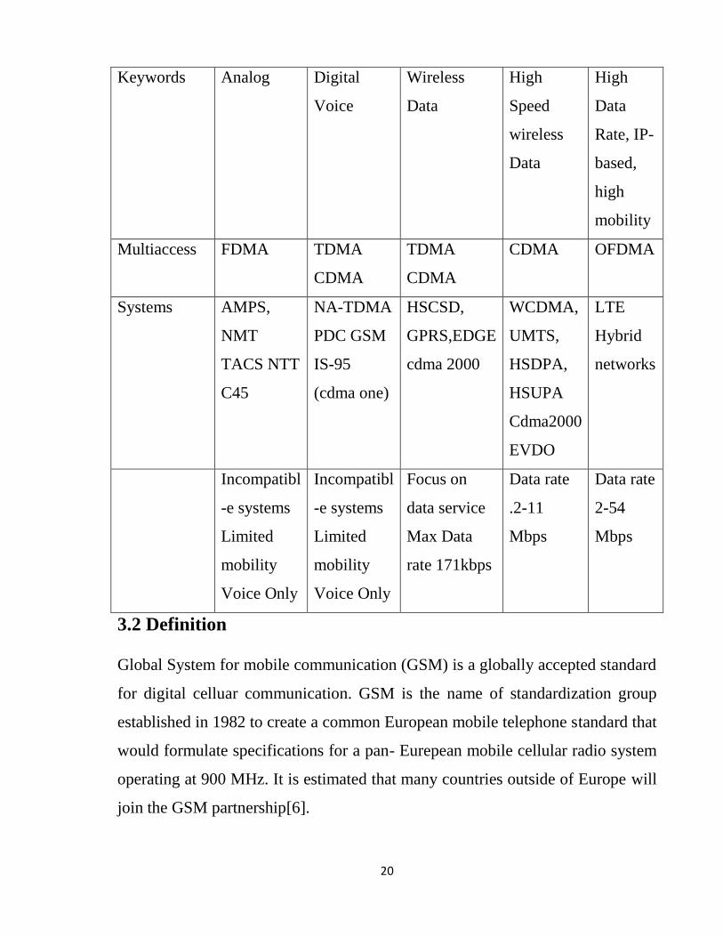
Keywords Analog Digital
Voice
Wireless
Data
High
Speed
wireless
Data
High
Data
Rate, IP-
based,
high
mobility
Multiaccess FDMA TDMA
CDMA
TDMA
CDMA
CDMA OFDMA
Systems AMPS,
NMT
TACS NTT
C45
NA-TDMA
PDC GSM
IS-95
(cdma one)
HSCSD,
GPRS,EDGE
cdma 2000
WCDMA,
UMTS,
HSDPA,
HSUPA
Cdma2000
EVDO
LTE
Hybrid
networks
Incompatibl
-e systems
Limited
mobility
Voice Only
Incompatibl
-e systems
Limited
mobility
Voice Only
Focus on
data service
Max Data
rate 171kbps
Data rate
.2-11
Mbps
Data rate
2-54
Mbps
3.2 Definition
Global System for mobile communication (GSM) is a globally accepted standard
for digital celluar communication. GSM is the name of standardization group
established in 1982 to create a common European mobile telephone standard that
would formulate specifications for a pan- Eurepean mobile cellular radio system
operating at 900 MHz. It is estimated that many countries outside of Europe will
join the GSM partnership[6].

21
3.3 Basics of GSM
-GSM stands for Global System for Mobile Communication. It is a digital
cellular technology used for transmitting mobile voice and data services.
-The concept of GSM emerged from a cell-based mobile radio system at Bell
Laboratories in the early 1970s.
-GSM is the name of a standardization group established in 1982 to create a
common European mobile telephone standard.
-GSM is the most widely accepted standard in telecommunications and it is imp
lemented globally.
-GSM is a circuit-switched system that divides each 200 kHz channel into eight
25 kHz timeslots. GSM operates on the mobile communication bands 900 MHz
and 1800 MHz in most parts of the world. In the US, GSM operates in the bands
850 MHz and 1900 MHz.
-GSM owns a market share of more than 70 percent of the world's digital cellular
subscribers.
-GSM makes use of narrowband Time Division Multiple Access (TDMA)
technique for transmitting signals.
-GSM was developed using digital technology. It has an ability to carry 64 kbps
to 120 Mbps of data rates.
-Presently GSM supports more than one billion mobile subscribers in more than
210 countries throughout the world.
-GSM provides basic to advanced voice and data services including roaming
service. Roaming is the ability to use your GSM phone number in another GSM
network.

22
GSM digitizes and compresses data, then sends it down through a channel with
two other streams of user data, each in its own timeslot.
Throughout the evolution of celluar telecommunications, varius systems have
been developed without the benefit of standardardized specifications. This
presented many problems directely related to compatibility, especially with the
development of digital radio technology. The GSM standard is intended to
address these problems.
From 1982 to 1985 discussions were held to decide between building an analog
or digital. After multipule field tests, a digital system was adopted for GSM. The
next task was to decide between a narrow or broadband solution. In may 1987,
the narrowband time division multiple access (TDMA) solution was chosen[6].
A summary of GSM milestones is given below table
Table3.2: GSM MileStones
Year Milestone
1982 GSM formed
1986 Field test
1987 TDMA chosen of understanding
1988 Memorandum of understanding signed
1989 Validation of GSM system
1990 Pre-operation system
1991 Commercial system start-up
1992 Coverage of large cities/airports
1993 Coverage of main roads
1995 Coverage of rural areas
23
3.3.1 Features of GSM:
Listed below are the features of GSM that account for its popularity and wide
accepatance [6]:
-Improved spectrum efficiency
-International roaming.
-Low-cost mobile sets and base stations (BSs).
-High-quality speech.
-Compatibility with Integrated Services Digital Network (ISDN) and other
telephone company services.
-Support for new services.
3.3.2 Architecture of the GSM system
GSM is a PLMN (Public Land Mobile Network)
Several providers can setup mobile networks following the GSM standard within
each country[6].
- Major components
-MS (mobile station).
-BTS (base transceiver station) or BS or cell site.
-BSC (base station controller).
-MSC (mobile switching center).
-LR (location registers): Visitor Location Registers (VLR), Home Location
Registers (HLR).
24
-EIR (Equipment Identity Register)[6].
- Subsystems:
-RSS (radio subsystem): covers all radio aspects.
-NSS (network and switching subsystem): call forwarding, handoff,
switching, location tracking, etc.
-OSS (operation support subsystem): management of the network[6].
- Standardized interfaces:
-Allows provider to mix and match vendor equipment.
The additional components of the GSM architecture comprise of databases and
messaging systems’ functions:
-Home Location Register (HLR)
-Visitor Location Register (VLR)
-Equipment Identity Register (EIR)
-Authentication Center (AuC)
-SMS Serving Center (SMS SC)
-Gateway MSC (GMSC)
-Chargeback Center (CBC)
-Transcoder and Adaptation Unit (TRAU)[6]
25
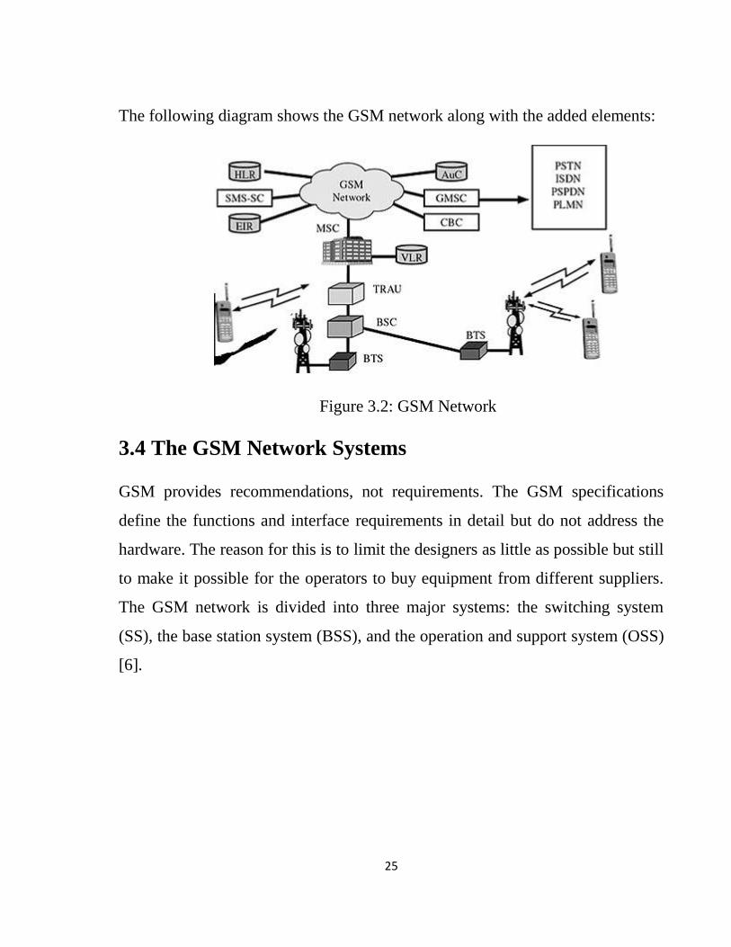
The following diagram shows the GSM network along with the added elements:
Figure 3.2: GSM Network
3.4 The GSM Network Systems
GSM provides recommendations, not requirements. The GSM specifications
define the functions and interface requirements in detail but do not address the
hardware. The reason for this is to limit the designers as little as possible but still
to make it possible for the operators to buy equipment from different suppliers.
The GSM network is divided into three major systems: the switching system
(SS), the base station system (BSS), and the operation and support system (OSS)
[6].
26
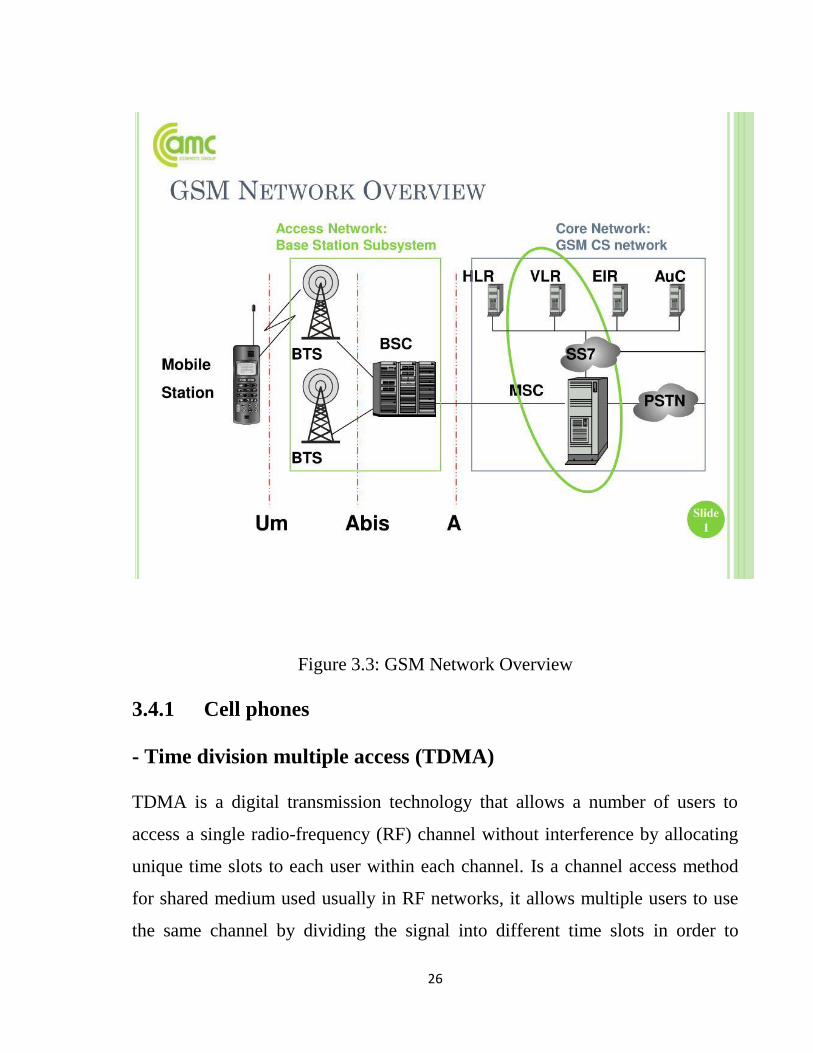
Figure 3.3: GSM Network Overview
3.4.1 Cell phones
- Time division multiple access (TDMA)
TDMA is a digital transmission technology that allows a number of users to
access a single radio-frequency (RF) channel without interference by allocating
unique time slots to each user within each channel. Is a channel access method
for shared medium used usually in RF networks, it allows multiple users to use
the same channel by dividing the signal into different time slots in order to

27
increase the amount of data that can be carried. The user sends information using
their own timeslot [6].
- Code division multiple access (CDMA)
Takes an entirely different approach from TDMA. CDMA, it digitalizes data
then spread it over the whole available Bandwidth. Multiple calls are laid over
each other on the channel, but each assigned a unique code, in other words
CDMA is a form of spread spectrum. Simply this means that data is sent in small
pieces over a number of the discrete frequencies that are available within the
bandwidth. Verizon, Sprint and most other U.S. carriers use CDMA, which
require no sim card. All of the users send in the same wide-band chunk of
spectrum. Each user's signal is spread through the entire bandwidth signed with a
unique spreading code [6].
- TDMA vs. CDMA
TDMA and CDMA are transparent to each other. In real-time high power
CDMA signal increase the noise for TDMA receivers, while high power TDMA
signal jams and cause an overloading at the CDMA receivers[6].
3.5 GSM Operations
Once a Mobile Station initiates a call, a series of events takes place. Analyzing
these events can give an insight into the operation of the GSM system[6].
3.5.1 Mobile Phone to Public Switched Telephone Network (PSTN)
When a mobile subscriber makes a call to a PSTN telephone subscriber, the
following sequence of events takes place [6]:
I. The MSC/VLR receives the message of a call request.

28
II. The MSC/VLR checks if the mobile station is authorized to access the
network. If so, the mobile station is activated. If the mobile station is not
authorized, then the service will be denied.
III. MSC/VLR analyzes the number and initiates a call setup with the PSTN.
IV. MSC/VLR asks the corresponding BSC to allocate a traffic channel (a radio
channel and a timeslot).
V. The BSC allocates the traffic channel and passes the information to the
mobile station.
VI. The called party answers the call and the conversation takes place.
VII. The mobile station keeps on taking measurements of the radio channels in
the present cell and the neighboring cells and passes the information to the BSC.
The BSC decides if a handover is required. If so, a new traffic channel is
allocated to the mobile station and the handover takes place. If handover is not
required, the mobile station continues to transmit in the same frequency.
3.5.2 Public Switched Telephone Network (PSTN) to Mobile Phone
When a PSTN subscriber calls a mobile station, the following sequence of events
takes place:
I. The Gateway MSC receives the call and queries the HLR for the information
needed to route the call to the serving MSC/VLR.
II. The GMSC routes the call to the MSC/VLR.
III. The MSC checks the VLR for the location area of the MS.
IV. The MSC contacts the MS via the BSC through a broadcast message, that is,
through a paging request.
V. The MS responds to the page request.

29
VI. The BSC allocates a traffic channel and sends a message to the MS to tune to
the channel. The MS generates a ringing signal and, after the subscriber answers,
the speech connection is established.
VII. Handover, if required, takes place, as discussed in the earlier case.
To transmit the speech over the radio channel in the stipulated time, the MS
codes it at the rate of 13 Kbps. The BSC transcodes the speech to 64 Kbps and
sends it over a land link or a radio link to the MSC. The MSC then forwards the
speech data to the PSTN. In the reverse direction, the speech is received at 64
Kbps at the BSC and the BSC transcodes it to 13 Kbps for radio transmission
[6].
3.6 GSM Protocol Stack
GSM architecture is a layered model that is designed to allow communications
between two different systems. The lower layers assure the services of the upper-
layer protocols. Each layer passes suitable notifications to ensure the transmitted
data has been formatted, transmitted, and received accurately[6].

30
The GSM protocol stacks diagram is shown in figure 3.4:
Figure 3.4: GSM protocol Stacks
3.6.1 Mobile Station (MS) Protocols
Based on the interface, the GSM signaling protocol is assembled into three
general layers [6]:
- Layer 1: The physical layer. It uses the channel structures over the air
interface.
- Layer 2: The data-link layer. Across the Um interface, the data-link layer is a
modified version of the Link Access Protocol for the D channel (LAP-D)
protocol used in ISDN, called Link Access Protocol on the Dm channel (LAP-
Dm). Across the A interface, the Message Transfer Part (MTP), Layer 2 of SS7
is used.
- Layer 3: GSM signaling protocol’s third layer is divided into three sub-layers:
31
I. Radio Resource Management (RR),
II. Mobility Management (MM), and
III. Connection Management (CM).
3.6.2 Mobile Station (MS) to Base Transceiver Station (BTS)
Protocols
The RR layer is the lower layer that manages a link, both radio and fixed,
between the MS and the MSC. For this formation, the main components
involved are the MS, BSS, and MSC. The responsibility of the RR layer is to
manage the RR-session, the time when a mobile is in a dedicated mode, and the
radio channels including the allocation of dedicated channels.
The MM layer is stacked above the RR layer. It handles the functions that arise
from the mobility of the subscriber, as well as the authentication and security
aspects. Location management is concerned with the procedures that enable the
system to know the current location of a powered on MS so that incoming call
routing can be completed.
The CM layer is the topmost layer of the GSM protocol stack. This layer is
responsible for Call Control, Supplementary Service Management, and Short
Message Service Management. Each of these services are treated as individual
layer within the CM layer. Other functions of the CC sublayer include call
establishment, selection of the type of service (including alternating between
services during a call), and call release [6].
3.6.3 Base Station Controller (BSC) Protocols
The BSC uses a different set of protocols after receiving the data from the BTS.
The Abis interface is used between the BTS and BSC. At this level, the radio

32
resources at the lower portion of Layer 3 are changed from the RR to the Base
Transceiver Station Management (BTSM). The BTS management layer is a relay
function at the BTS to the BSC.
The RR protocols are responsible for the allocation and reallocation of traffic
channels between the MS and the BTS. These services include controlling the
initial access to the system, paging for MT calls, the handover of calls between
cell sites, power control, and call termination. The BSC still has some radio
resource management in place for the frequency coordination, frequency
allocation, and the management of the overall network layer for the Layer 2
interfaces.
To transit from the BSC to the MSC, the BSS mobile application part or the
direct application part is used, and SS7 protocols is applied by the relay, so that
the MTP 1-3 can be used as the prime architecture [6].
3.6.4 Mobile Switching Center (MSC) Protocols
At the MSC, starting from the BSC, the information is mapped across the A
interface to the MTP Layers 1 through 3. Here, Base Station System
Management Application Part (BSS MAP) is said to be the equivalent set of
radio resources. The relay process is finished by the layers that are stacked on
top of Layer 3 protocols, they are BSS MAP/DTAP, MM, and CM. This
completes the relay process. To find and connect to the users across the network,
MSCs interact using the control signaling network. Location registers are
included in the MSC databases to assist in the role of determining how and
whether connections are to be made to roaming users.
Each GSM MS user is given a HLR that in turn comprises of the user’s location
and subscribed services. VLR is a separate register that is used to track the
location of a user. When the users move out of the HLR covered area, the VLR

33
is notified by the MS to find the location of the user. The VLR in turn, with the
help of the control network, signals the HLR of the MS’s new location. With the
help of location information contained in the user’s HLR, the MT calls can be
routed to the user [6].
3.7 GSM User Services
GSM offers much more than just voice telephony. Contact your local GSM
network operator to the specific services that you can avail.
GSM offers three basic types of services [6]:
-Telephony services or Tele-services.
-Data services or bearer services.
-Supplementary services.
3.7.1 Tele-Services
The abilities of a Bearer Service are used by a Tele-service to transport data.
These services are further transited in the following ways:
3.7.2 Voice Calls
The most basic Tele-service supported by GSM is telephony. This includes full-
rate speech at 13 kbps and emergency calls, where the nearest emergency-service
provider is notified by dialing three digits.
3.7.3 Videotext and Facsimile
Another group of Tele-services includes Videotext access, Tele-text
transmission, Facsimile alternate speech and Facsimile Group 3, Automatic
facsimile Group 3, etc.

34
3.7.4 Short Text Messages
Short Messaging Service (SMS) service is a text messaging service that allows
sending and receiving text messages on your GSM mobile phone. In addition to
simple text messages, other text data including news, sports, financial, language,
and location-based data can also be transmitted.
3.8 Bearer Services
Data services or Bearer Services are used through a GSM phone. to receive and
send data is the essential building block leading to widespread mobile Internet
access and mobile data transfer. GSM currently has a data transfer rate of 9.6k.
New developments that will push up data transfer rates for GSM users are
HSCSD (high speed circuit switched data) and GPRS (general packet radio
service) are now available.
3.9 Supplementary Services
Supplementary services are additional services that are provided in addition to
Tele-services and bearer services. These services include caller identification,
call forwarding, call waiting, multiparty conversations, and barring of outgoing
(international) calls, among others. A brief description of supplementary services
is given here:
3.9.1 Conferencing: It allows a mobile subscriber to establish a multiparty
conversation, i.e., a simultaneous conversation between three or more
subscribers to setup a conference call. This service is only applicable to normal
telephony.
3.9.2 Call Waiting: This service notifies a mobile subscriber of an incoming
call during a conversation. The subscriber can answer, reject, or ignore the
incoming call[6].

35
3.9.3 Call Hold: This service allows a subscriber to put an incoming call on
hold and resume after a while. The call hold service is applicable to normal
telephony.
3.9.4 Call Forwarding: Call Forwarding is used to divert calls from the
original recipient to another number. It is normally set up by the subscriber
himself. It can be used by the subscriber to divert calls from the Mobile Station
when the subscriber is not available, and so to ensure that calls are not lost.
3.9.5 Call Barring: Call Barring is useful to restrict certain types of outgoing
calls such as ISD or stop incoming calls from undesired numbers. Call barring is
a flexible service that enables the subscriber to conditionally bar calls.
3.9.6 Number Identification: There are following supplementary services
related to number identification:
- Calling Line Identification Presentation: This service displays the
telephone number of the calling party on your screen.
- Calling Line Identification Restriction: A person not wishing their
number to be presented to others subscribes to this service.
- Connected Line Identification Presentation: This service is
provided to give the calling party the telephone number of the person to
whom they are connected. This service is useful in situations such as
forwardings where the number connected is not the number dialed.
- Connected Line Identification Restriction: There are times when
the person called does not wish to have their numbers presented and so they
would subscribe to this person. Normally, this overrides the presentation
service[6].
36
3.9.7 Malicious Call Identification: The malicious call identification
service was provided to combat the spread of obscene or annoying calls. The
victim should subscribe to this service, and then they could cause known
malicious calls to be identified in the GSM network, using a simple
command[6].
3.9.8 Closed User Groups (CUGs): This service is meant for groups of
subscribers who wish to call only each other and no one else[6].
3.9.9 Unstructured Supplementary Services Data (USSD): This
service allows operator-defined individual services[6].
3.10 GSM Security and Encryption
GSM is the most secured cellular telecommunications system available today.
GSM has its security methods standardized. GSM maintains end-to-end security
by retaining the confidentiality of calls and anonymity of the GSM subscriber.
Temporary identification numbers are assigned to the subscriber’s number to
maintain the privacy of the user. The privacy of the communication is
maintained by applying encryption algorithms and frequency hopping that can be
enabled using digital systems and signaling.
This chapter gives an outline of the security measures implemented for GSM
subscribers[6].
3.10.1 Mobile Station Authentication
The GSM network authenticates the identity of the subscriber through the use of
a challenge response mechanism. A 128-bit Random Number (RAND) is sent to
the MS. The MS computes the 32-bit Signed Response (SRES) based on the
encryption of the RAND with the authentication algorithm (A3) using the

37
individual subscriber authentication key (Ki). Upon receiving the SRES from the
subscriber, the GSM network repeats the calculation to verify the identity of the
subscriber.
The individual subscriber authentication key (Ki) is never transmitted over the
radio channel, as it is present in the subscriber's SIM, as well as the AUC, HLR,
and VLR databases. If the received SRES agrees with the calculated value, the
MS has been successfully authenticated and may continue. If the values do not
match, the connection is terminated and an authentication failure is indicated to
the MS.
The calculation of the signed response is processed within the SIM. It provides
enhanced security, as confidential subscriber information such as the IMSI or the
individual subscriber authentication key (Ki) is never released from the SIM
during the authentication process[6].
3.10.2 Signaling and Data Confidentiality
The SIM contains the ciphering key generating algorithm (A8) that is used to
produce the 64-bit ciphering key (Kc). This key is computed by applying the
same random number (RAND) used in the authentication process to ciphering
key generating algorithm (A8) with the individual subscriber authentication key
(Ki).
GSM provides an additional level of security by having a way to change the
ciphering key, making the system more resistant to eavesdropping. The
ciphering key may be changed at regular intervals as required. As in case of
the authentication process, the computation of the ciphering key (Kc) takes
place internally within the SIM. Therefore, sensitive information such as the
individual subscriber authentication key (Ki) is never revealed by the SIM.

38
Encrypted voice and data communications between the MS and the network
is accomplished by using the ciphering algorithm A5. Encrypted
communication is initiated by a ciphering mode request command from the
GSM network. Upon receipt of this command, the mobile station begins
encryption and decryption of data using the ciphering algorithm (A5) and the
ciphering key (Kc)[6].
3.10.3 Subscriber Identity Confidentiality
To ensure subscriber identity confidentiality, the Temporary Mobile
Subscriber Identity (TMSI) is used. Once the authentication and encryption
procedures are done, the TMSI is sent to the mobile station. After the receipt,
the mobile station responds. The TMSI is valid in the location area in which it
was issued. For communications outside the location area, the Location Area
Identification (LAI) is necessary in addition to the TMSI[6].
3.11 GSM Billing
GSM service providers are doing billing based on the services they are
providing to their customers. All the parameters are simple enough to charge
a customer for the provided services.
This chapter provides an overview of the frequently used billing techniques
and parameters applied to charge a GSM subscriber[6].
3.11.1 Telephony Service
These services can be charged on per call basis. The call initiator has to pay
the charges, and the incoming calls are nowadays free. A customer can be
charged based on different parameters such as:
-International call or long distance call.
39
-Local call.
-Call made during peak hours.
-Call made during night time.
-Discounted call during weekends.
-Call per minute or per second.
-Many more other criteria can be designed by a service provider to charge
their customers[6].
3.11.2 Short Messaging Service (SMS) Service
Most of the service providers charge their customers’ SMS services based on the
number of text messages sent. There are other prime SMS services available
where service providers charge more than normal SMS charge. These services
are being availed in collaboration of Television Networks or Radio Networks to
demand SMS from the audiences.
Most of the time, the charges are paid by the SMS sender but for some services
like stocks and share prices, mobile banking facilities, and leisure booking
services, etc. the recipient of the SMS has to pay for the service[6].
3.11.3 General Packet Radio Service (GPRS) Services
General Packet Radio service is a packet oriented mobile data standard on the 2G
and 3G cellular mobile communication network’s global system for mobile
communications. GPRS was established by European Telecommunications
Standards Institute (ETSI). It is now maintained by the 3rd Generation
Partnership Project (3GPP).

40
Using GPRS service, you can browse, play games on the Internet, and download
movies. So a service provider will charge you based on the data uploaded as well
as data downloaded on your mobile phone. These charges will be based on per
Kilo Byte data downloaded/uploaded.
Additional parameter could be a quality of service (QOS) provided to you. If you
want to watch a movie, then a low (QOS) may work because some data loss may
be acceptable, but if you are downloading a zip file, then a single byte loss will
corrupt your complete downloaded file.
Another parameter could be peak and off peak time to download a data file or to
browse the Internet[6].
3.11.4 Supplementary Services
Most of the supplementary services are being provided based on monthly rental
or absolutely free. For example, call waiting, call forwarding, calling number
identification, and call on hold are available at zero cost.
Call barring is a service, which service providers use just to recover their dues,
etc… otherwise this service is not being used by any subscriber.
Call conferencing service is a form of simple telephone call where the customers
are charged for multiple calls made at a time. No service provider charges extra
charge for this service.
Closed User Group (CUG) is very popular and is mainly being used to give
special discounts to the users if they are making calls to a particular defined
group of subscribers.
Advice of Charge (AOC) can be charged based on the number of queries made
by a subscriber.

41
CHAPTER FOUR
42
CHAPTER FOUR
APPLICATION OF JAMMER CELL-PHONE
Introduction
This Chapter describe the design of Jammer Cell Phone Research. Its talks about
design parameters that should be taken as a reference in this research. Also
contains block of jammer device which has Power supply, Intermediate
frequency, and Radio frequency. Output power calculated due to frequency
bands. All components of jammer device selected carefully also due to frequency
bands for GSM 900 and GSM 1800.
4.1 Design Parameters
Based on the above, our device which is related to the DOS technique is
transmitting noise on the same frequencies of the two bands GSM 900 MHz, and
GSM 1.8 GHz (known also as DCS 1800 band). We focused on some design
parameters to establish the device specifications. These parameters are as
follows:
4.1.1 The Distance to be Jammed (D)
This parameter is very important in our design, since the amount of the output
power of the jammer depends on the area that we need to jam. Later on we will
see the relationship between the output power and the distance D. Our design is
established upon D =10 meters for DCS 1800 band and D=20 meters for GSM
900 band[4].

43
4.1.2 The frequency bands
Table 4.1: Frequency Bands of Sims.
UPLINK (Handset
transmit)
DOWNLINK
(Handset receive)
USED IN
SUDAN
BY:
GSM 900 880-900 MHz 935-945 MHz Ariba
GSM 900 900-915 MHz 945-960 MHz Zain
DCS 1800 1740-1760
MHz
1835-1855
MHz
Sudani

44
The figure 4.1 shown frequency bands of Sims:
Figure 4.1: Frequency Bands of Sims.
In our design, the jamming frequency must be the same as the downlink, because
it needs lower power to do jamming than the uplink range and there is no need to
jam the base station itself[4].
4.2 Jamming–to-Signal Ratio J/S
Jamming is successful when the jamming signal denies the usability of the
communication transmission. In digital communications, the usability is denied
when the error rate of the transmission can’t be compensated by error correction.
Usually, a successful jamming attack requires that the jammer power is roughly
equal to signal power at the receiver (mobile device)[4].

45
The general equation of the jamming-to-signal ratio is given as follows:
J/S=Pj Gjr Grj Rtr2 Lr Br / Pr Gtr Grt R2jr Lj Bj (1)
where:
Pj =jammer power,
Gjr = antenna gain from jammer to receiver,
Grj =antenna gain from receiver to jammer,
Rtr =range between communication transmitter and receiver,
Br =communication receiver bandwidth,
Lr =communication signal loss,
Pt =transmitter power,
Gtr = antenna gain from transmitter to receiver,
Grt =antenna gain from receiver to transmitter,
Rjr =range between jammer and communication receiver,
Bj =jammer bandwidth,
and Lj =jamming signal loss.
For GSM[4],
The specified system SNRmin is 9 dB which will be used as the worst case
scenario for the jammer. The maximum power at the mobile device Pr is -15
dBm. This is obtained from the carrier to noise ratio
𝐶𝑁𝑅 = 𝐶/𝑁= (𝑉𝑐/𝑉𝑛)2. (2)
Free space loss F The free-space loss (or path loss) is given by:
46
Path loss (db) =32.44 + 20 log d (km) + 20 log f(MHz) (3)
The maximum free space loss (worst case F) happens when the maximum
frequency is used in the above equation. Using 1880 MHz gives:
F (dB)=32.44+20 log 0.01 + 20 log 1885 which gives F=57.8 dB.
Worst case (F) happens when the Maximum Frequency is used in the above
equation.
4.3 System Design
4.3.1 Power calculations
Here, we need to find the power that is needed to be transmitted to jam any cell
phone within a distance of around 10 meters for DCS. From the above
considerations, we can find the required output power from the device, as
follows: Using SNR=9 dB and the maximum power signal for mobile receiver=-
15 dBm, gives J=-24 dBm. But, our goal is to find the output power from the
device, so when we add the free space loss to the amount of power at the mobile
receiver we get our target:
Output power=-24dBm+57.8dB=33.8 dBm
4.3.2 The Proposed Circuit
Cell phone jammer device have three main important circuits. When they are
combined together, the output of that circuit will works as a jammer. The three
main circuits are follows: Power supply, IF section and RF section[10].

47
4.3.3 Block of Jammer Device
Figure 4.2 shows the block diagram for the jammer to be designed.
Figure 4.2: Jammer Block
The Power supply
This is used to supply the other sections with the needed voltages. Any power
supply consists of the following main parts[4]:
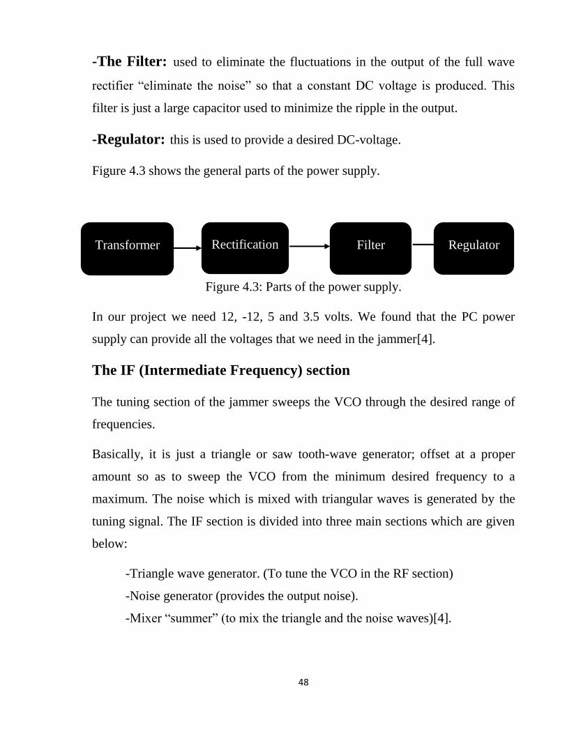
-Transformer: - is used to transform the 220VAC to other levels of voltages.
-Rectification: - this part is to convert the AC voltage to a DC one. We have
two methods for rectification:
A] Half wave-rectification:
The output voltage appears only during positive cycles of the input signal.
B] Full wave -rectification:
A rectified output voltage occurs during both the positive and negative cycles of
the input signal.
Power
supply IF Section RF Section RF Jamming
Signal
48
-The Filter: used to eliminate the fluctuations in the output of the full wave
rectifier “eliminate the noise” so that a constant DC voltage is produced. This
filter is just a large capacitor used to minimize the ripple in the output.
-Regulator: this is used to provide a desired DC-voltage.
Figure 4.3 shows the general parts of the power supply.
Figure 4.3: Parts of the power supply.
In our project we need 12, -12, 5 and 3.5 volts. We found that the PC power
supply can provide all the voltages that we need in the jammer[4].
The IF (Intermediate Frequency) section
The tuning section of the jammer sweeps the VCO through the desired range of
frequencies.
Basically, it is just a triangle or saw tooth-wave generator; offset at a proper
amount so as to sweep the VCO from the minimum desired frequency to a
maximum. The noise which is mixed with triangular waves is generated by the
tuning signal. The IF section is divided into three main sections which are given
below:
-Triangle wave generator. (To tune the VCO in the RF section)
-Noise generator (provides the output noise).
-Mixer “summer” (to mix the triangle and the noise waves)[4].
Rectification Filter Regulator Transformer

49
-Triangle wave generator:
The main use of the triangle wave is to sweep the VCO through the desired
frequency range.
We want to cover the downlink through our VCO, i.e., 935-960 MHz for
VCO66CL, and 1835-1855MHz for VCO55BE.
In our design, we will use 555 timer IC operating in the a-stable mode to
generate the sweeping signal. The output frequency depends on the charging and
discharging of the capacitor, resistors values and the power supply for the IC[4].

50
Figure 4.6 shows how we can use the 555timer in the general A-stable mode
Figure 4.4: 555 Timer circuit.

51
Figure 4.5: 555 Timer Construction & Pinout
The charging time for the capacitor can be found as follows:
Tc=0.693 * (Ra + Rb) * C (4)
For discharging time, the following equation can be used:
Td=0.693 * Rb * C (5)
The output frequency can be calculated as follows:
52
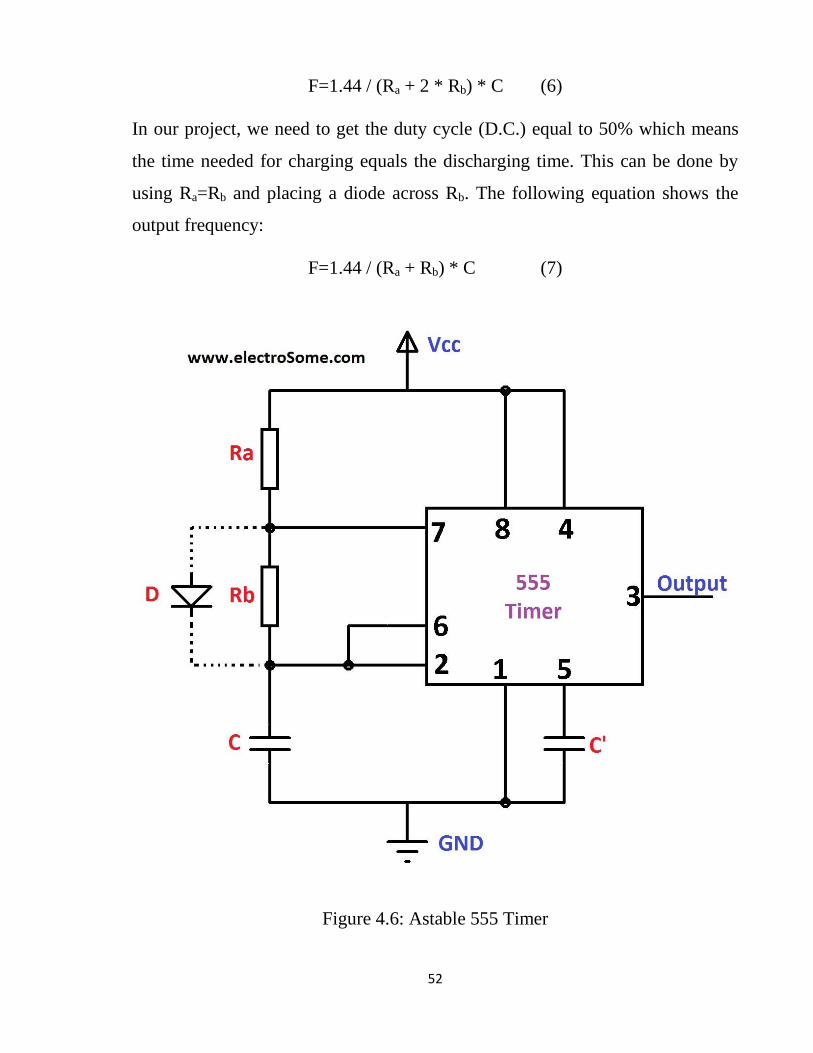
F=1.44 / (Ra + 2 * Rb) * C (6)
In our project, we need to get the duty cycle (D.C.) equal to 50% which means
the time needed for charging equals the discharging time. This can be done by
using Ra=Rb and placing a diode across Rb. The following equation shows the
output frequency:
F=1.44 / (Ra + Rb) * C (7)
Figure 4.6: Astable 555 Timer

53
In our project, we will use Ra=Rb=750 Ω with C=0.1 µF, then the output
frequency is 10 KHz Since we use +12 V (Vcc), the output signal will be
bounded from 4 V (Vcc/3) to 8 V (2Vcc/3)[4].
- Noise generation
Without noise, the output of the VCO is just an un-modulated sweeping RF
carrier. So, we need to mix the triangular signal with noise (FM modulating the
RF carrier with noise). To generate noise signal, we used the Zener Diode
operated in reverse mode. Operating in the reverse mode causes what is called
avalanche effect, which causes wide band noise. This noise is then amplified and
used in our system. We use two amplification stages: in the first stage, we use
NPN transistor as common emitter, and in the second stage, we use the LM386
IC “Audio amplifier”[4].
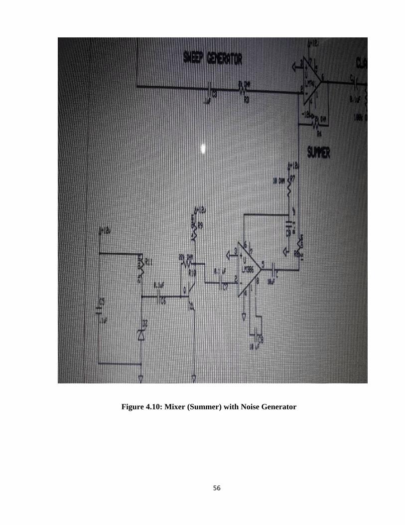
-Mixer
The mixer here is just an amplifier that operates as a summer. So the noise and
triangular wave will add together before entering the VCO. The LM741 IC will
be used to achieve this.
Figure 4.7: Mixer
54
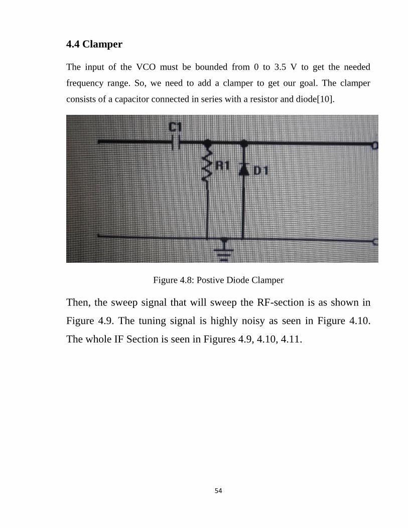
4.4 Clamper
The input of the VCO must be bounded from 0 to 3.5 V to get the needed
frequency range. So, we need to add a clamper to get our goal. The clamper
consists of a capacitor connected in series with a resistor and diode[10].
Figure 4.8: Postive Diode Clamper
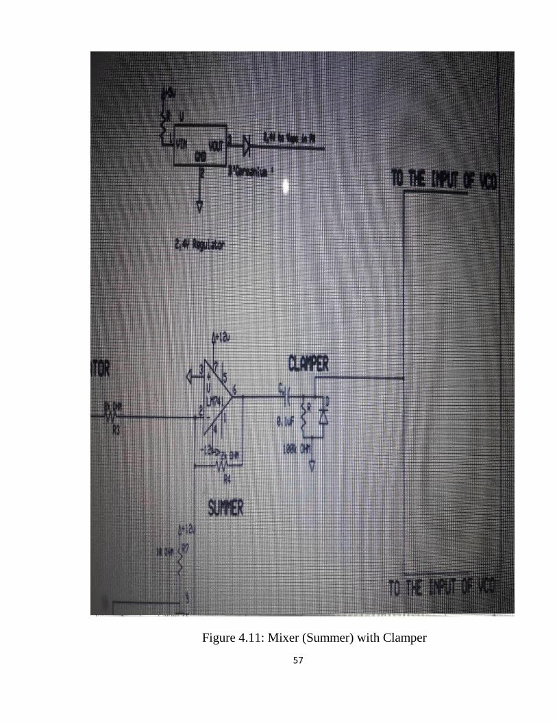
Then, the sweep signal that will sweep the RF-section is as shown in
Figure 4.9. The tuning signal is highly noisy as seen in Figure 4.10.
The whole IF Section is seen in Figures 4.9, 4.10, 4.11.

55
Figure 4.9: Sweep Generator
56
Figure 4.10: Mixer (Summer) with Noise Generator
57
Figure 4.11: Mixer (Summer) with Clamper
58
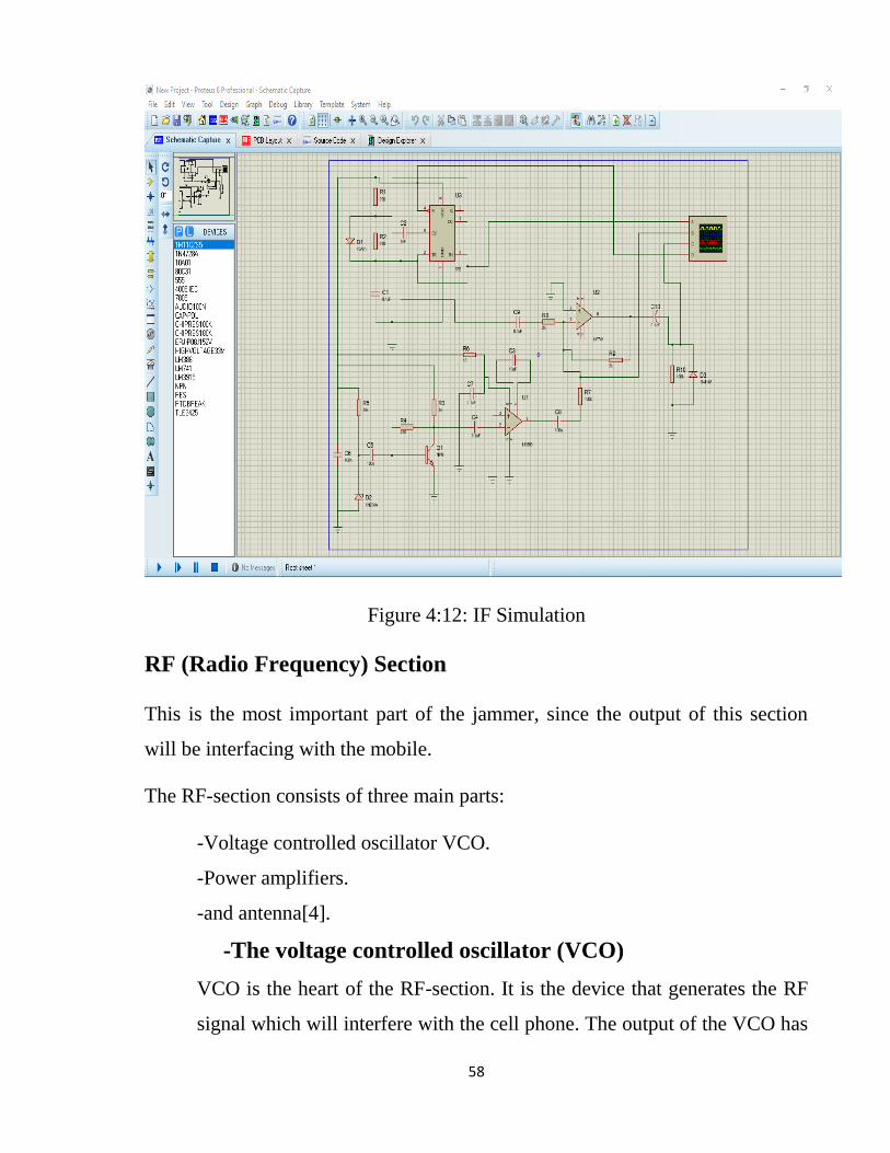
Figure 4:12: IF Simulation
RF (Radio Frequency) Section
This is the most important part of the jammer, since the output of this section
will be interfacing with the mobile.
The RF-section consists of three main parts:
-Voltage controlled oscillator VCO.
-Power amplifiers.
-and antenna[4].
-The voltage controlled oscillator (VCO)
VCO is the heart of the RF-section. It is the device that generates the RF
signal which will interfere with the cell phone. The output of the VCO has

59
a frequency which is proportional to the input voltage, thus, we can
control the output frequency by changing the input voltage. When the
input voltage is DC, the output is a specific frequency, while if the input is
a triangular waveform, the output will span a specific frequency range.
In our design, we need to find a VCO for GSM 900 and GSM 1800. There
are three selection criteria for selecting a VCO for this application. Most
importantly, it should cover the bands that we need, secondly, it should be
readily available at low cost, and finally, it should run at low power
consumption. Moreover, we need to minimize the size of GSM-jammer.
Finally after a lot of search over the internet we found those VCO’s
manufactured by Crystek Microwave[4].
CVCO55CL: this is for 900 GSM, the output frequency is 925 – 970
MHz and the output power is nearly at 8dBm[10].
Figure 4.13: CVCO55CL
CVCO55BE: this is for 1800 GSM, the output frequency is 1785 – 1900
MHz and the output power is nearly at 5dBm[10].
60
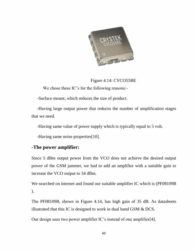
Figure 4.14: CVCO55BE
We chose these IC’s for the following reasons:-
-Surface mount, which reduces the size of product.
-Having large output power that reduces the number of amplification stages
that we need.
-Having same value of power supply which is typically equal to 5 volt.
-Having same noise properties[10].
-The power amplifier:
Since 5 dBm output power from the VCO does not achieve the desired output
power of the GSM jammer, we had to add an amplifier with a suitable gain to
increase the VCO output to 34 dBm.
We searched on internet and found our suitable amplifier IC which is (PF08109B
).
The PF08109B, shown in Figure 4.14, has high gain of 35 dB. As datasheets
illustrated that this IC is designed to work in dual band GSM & DCS.
Our design uses two power amplifier IC’s instead of one amplifier[4].

61
Figure 4.15: IC PF08109B
We found that the PF08109B is the most suitable amplifier due the fact it is
-Illustrated to work in both bands ( 900 and 1800 GSM ).
-It’s a very low power consumption device.
-High gain 3 stages amplifier 35Db.
-High efficiency.
-Antenna:
A proper antenna is necessary to transmit the jamming signal. In order to have
optimal power transfer, the antenna system must be matched to the transmission
system.
We make a move forward by going with a monopole antenna since it’s the
simplest form. It consists of a straight rod –shaped conductor mounted over a
conductive surface.
The length of the antenna is determined by the wave length of the radio waves it
is used with the most common form and it’s the form we will go with the
‘quarter-wave monopole’ with 50 ohm input impedance so that the antennas are
matched to the system.
62
To estimate the lower band-edge frequency of printed monopole antennas:
𝐹𝐿=7.2 / ( (𝐿 + 𝑟 + 𝑝) * 𝑘) * 𝐺𝐻𝑧 (8)
Where:
P: is the length of the 50ohm feed-line in cm.
S: is the side length of the PSMA.
r: is the effective radius of the equivalent cylindrical monopole antenna.
L: height of the planer monopole antenna.
𝐿=𝑆, 𝑟=𝑆 / 2𝜋. (9)

63
Figure 4.16: Antenna calculation laws

64
Figure 4.17: RF-Diagram
65
We couldn’t obtain the VCO’s and the power amplifier required to implement
this section of the device therefore this is the outcome schematic with the
antenna calculation shown.
W=0.81mm to match the input impedance.

66
CHAPTER FIVE
67
CHAPTER FIVE
CONCLUSION AND RECOMMENDATION
5.1 Conclusion
This jammer designed to work at GSM 900 and GSM 1800 in order to disrupt
the signals of the three well-known carries in Sudan (Zain, MTN (Ariba),
Sudani). The design of the research done under certain considerations in order to
fit to the system requirements. When the cellphone be in the area of jammer
device; it is going to be jammed.
Components couldn’t be offered here in Sudan, tried to have them delivered
from USA but Sudan falls under restricted areas and tried to get it from some
neighbor countries ; found that some parts was expensive to be bought. when it
comes to manufacturing IC’s therefore tried to ship them somewhere just to face
the problem that need a clearance from the Telecommunication provider in the
country. Research ended with theoretically developing the intermediate
frequency (IF) and radio frequency (RF) sections of this research. Blocks of
jammer cellphone specified in this research.
Components of this research are; Power supply (PC) which contains transformer,
rectifier, filter, and regulator. Intermediate frequency (IF) section which contains
triangle wave generator, noise wave generator, and mixer, summer. Radio
frequency (RF) which contains two Voltage controlled oscillators (VCOs), two
power amplifiers, and antenna.
Simulation implemented by Proteus software for IF section. In RF section design
implemented only. Antenna measured by its law in order to calculate the length
and width of antenna.
68
5.2 Recommendations
This research is an open-source for anyone who interested about jamming
cellphones’ signals. Anyone who wants to make this research up could be
recommended to level up the jamming distance, jamming 4G and 5G networks,
make more antennas in order to large jamming area, and also make a device that
specify the number of jammed cellphones.
69
REFERENCES
[1] Richard a. Poisel, Artech House, “Modern Communication
Jamming Principles and Techniques” , 2004.
[2] Dr K Ramesh, Mr. Misay. Mangisthu, Mr. Mogos, Birhanu,
Wondosen “Design & Implementation of Mobile Jammer with
Prescheduled Time Duration”, 6 June 2018.
[3] Uno, U. E, Okoye, P. F, and Charles N. V., “ON THE PHYSICS
OF GSM JAMMER AND ITS APPLICATION IN LECTURE
THEATERS” ,2013..
[4] Ahmed Sudqi Hussein Abdul-Rahman and Ahmad Nasr Raja
Mohammad, “Undergraduate project; Dual Band Mobile Jammer for
GSM 900 & GSM 1800”.
[5] Byculla, Mumbai-400008, “DUAL BAND CELL PHONE
JAMMER”, 2013.
[6] GSM.pdf.
[7] Ahmed Jisrawi, “GSM 900 Mobile Jammer”, undergrad project,
JUST, 2006.
[8] AKASH R MANNARI, “ANTI-JAMMING TECHNOLOGY FOR
MOBILE SIGNALS USING EMP JAMMER”.
[9]Ahmed Abdulhadi Ahmed Abdalhadi, “Cell Phone Jammer Circuit
Design and Implementation”,2017 .

70
[10] MOHAMED OMER HASSAN SAEED, “CELLPHONE
JAMMER CIRCUIT”, 2017.