Spin–spin coupling tensors as determined by experiment and computational chemistry
Upload
independentCategory
view
0download
0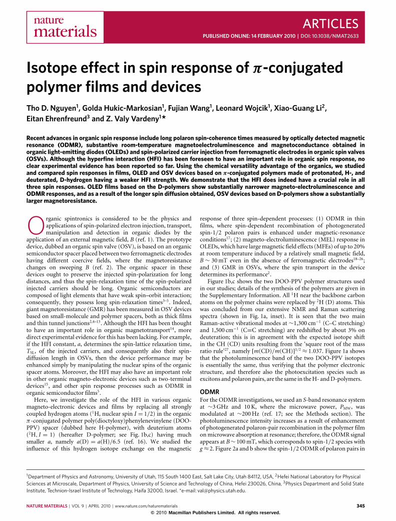
ARTICLESPUBLISHED ONLINE: 14 FEBRUARY 2010 | DOI: 10.1038/NMAT2633
Isotope effect in spin response of π-conjugatedpolymer films and devicesTho D. Nguyen1, Golda Hukic-Markosian1, Fujian Wang1, Leonard Wojcik1, Xiao-Guang Li2,Eitan Ehrenfreund3 and Z. Valy Vardeny1*
Recent advances in organic spin response include long polaron spin-coherence times measured by optically detected magneticresonance (ODMR), substantive room-temperature magnetoelectroluminescence and magnetoconductance obtained inorganic light-emitting diodes (OLEDs) and spin-polarized carrier injection from ferromagnetic electrodes in organic spin valves(OSVs). Although the hyperfine interaction (HFI) has been foreseen to have an important role in organic spin response, noclear experimental evidence has been reported so far. Using the chemical versatility advantage of the organics, we studiedand compared spin responses in films, OLED and OSV devices based on π-conjugated polymers made of protonated, H-, anddeuterated, D-hydrogen having a weaker HFI strength. We demonstrate that the HFI does indeed have a crucial role in allthree spin responses. OLED films based on the D-polymers show substantially narrower magneto-electroluminescence andODMR responses, and as a result of the longer spin diffusion obtained, OSV devices based on D-polymers show a substantiallylarger magnetoresistance.
Organic spintronics is considered to be the physics andapplications of spin-polarized electron injection, transport,manipulation and detection in organic diodes by the
application of an external magnetic field, B (ref. 1). The prototypedevice, dubbed an organic spin valve (OSV), is based on an organicsemiconductor spacer placed between two ferromagnetic electrodeshaving different coercive fields, where the magnetoresistancechanges on sweeping B (ref. 2). The organic spacer in thesedevices ought to preserve the injected spin-polarization for longdistances, and thus the spin-relaxation time of the spin-polarizedinjected carriers should be long. Organic semiconductors arecomposed of light elements that have weak spin–orbit interaction;consequently, they possess long spin-relaxation times3–5. Indeed,giant magnetoresistance (GMR) has been measured in OSV devicesbased on small-molecule and polymer spacers, both as thick filmsand thin tunnel junctions2,4–13. Although the HFI has been thoughtto have an important role in organic magnetotransport14, moredirect experimental evidence for this has been lacking. For example,if the HFI constant, a, determines the spin-lattice relaxation time,TSL, of the injected carriers, and consequently also their spin-diffusion length in OSVs, then the device performance may beenhanced simply by manipulating the nuclear spins of the organicspacer atoms. Moreover, the HFI may also have an important rolein other organic magneto-electronic devices such as two-terminaldevices15, and other spin response processes such as ODMR inorganic semiconductor films5.
Here, we investigate the role of the HFI in various organicmagneto-electronic devices and films by replacing all stronglycoupled hydrogen atoms (1H, nuclear spin I = 1/2) in the organicπ-conjugated polymer poly(dioctyloxy)phenylenevinylene (DOO-PPV) spacer (dubbed here H-polymer), with deuterium atoms(2H, I = 1) (hereafter D-polymer; see Fig. 1b,c) having muchsmaller a, namely a(D) = a(H)/6.5 (ref. 16). We studied theinfluence of this hydrogen isotope exchange on the magnetic
1Department of Physics and Astronomy, University of Utah, 115 South 1400 East, Salt Lake City, Utah 84112, USA, 2Hefei National Laboratory for PhysicalSciences at Microscale, Department of Physics, University of Science and Technology of China, Hefei 230026, China, 3Physics Department and Solid StateInstitute, Technion-Israel Institute of Technology, Haifa 32000, Israel. *e-mail: [email protected].
response of three spin-dependent processes: (1) ODMR in thinfilms, where spin-dependent recombination of photogeneratedspin-1/2 polaron pairs is enhanced under magnetic-resonanceconditions17; (2) magneto-electroluminescence (MEL) response inOLEDs, which have largemagnetic field effects (MFEs) of up to 20%at room temperature induced by a relatively small magnetic field,B ∼ 30mT even in the absence of ferromagnetic electrodes18–26;and (3) GMR in OSVs, where the spin transport in the devicedetermines its performance2.
Figure 1b,c shows the two DOO-PPV polymer structures usedin our studies; details of the synthesis of the polymers are given inthe Supplementary Information. All 1H near the backbone carbonatoms on the polymer chains were replaced by 2H (D) atoms. Thiswas concluded from our extensive NMR and Raman scatteringspectra (shown in Fig. 1a, inset). It is seen that the two mainRaman-active vibrational modes at ∼1,300 cm−1 (C–C stretching)and 1,500 cm−1 (C=C stretching) are redshifted by about 3% ondeuteration; this is in agreement with the expected isotope shiftin the CH (CD) units resulting from the ‘square root of the massratio rule’27, namely [m(CD)/m(CH)]1/2 ≈ 1.037. Figure 1a showsthat the photoluminescence band of the two DOO-PPV isotopesis essentially the same, thus verifying that the polymer electronicstructure, and therefore also the photoexcitation species such asexcitons andpolaron pairs, are the same in theH- andD-polymers.
ODMRFor the ODMR investigations, we used an S-band resonance systemat ∼3GHz and 10K, where the microwave power, PMW, wasmodulated at ∼200Hz (ref. 17; see the Methods section). Thephotoluminescence intensity increases as a result of enhancementof photogenerated polaron-pair recombination in the polymer filmonmicrowave absorption at resonance; therefore, the ODMR signalappears at B∼ 100mT, which corresponds to spin-1/2 species withg ≈2. Figure 2a and b show the spin-1/2 ODMR of polaron pairs in
NATURE MATERIALS | VOL 9 | APRIL 2010 | www.nature.com/naturematerials 345© 2010 Macmillan Publishers Limited. All rights reserved.
ARTICLES NATURE MATERIALS DOI: 10.1038/NMAT2633
R1
R1
R1
R1
O
O
O
O
O
O
O
O
C8H17
C8H17
C8H17
H17C8
H17C8
C8H17
C8H17
C8H17
H H
H H
H
HH
H
n
n
D
D D
D
DD
DD600 700 800 900 1,000
Wavelength (nm)
Phot
olum
ines
cenc
e (a
.u.)
0
1
1,200 1,400 1,600
Raman shift (cm¬1)
Inte
nsity
(a.
u.)
H-DOO-PPV
D-DOO-PPV
a b
c
Figure 1 | D- and H-polymer structures and their basic optical properties. a, The photoluminescence spectra of the D- and H-polymers, which show atwo-phonon replica. The inset shows the resonant Raman spectra of the two polymers, where the vertical lines emphasize the D-polymer frequencyredshift of the C–C (∼1,300 cm−1) and C=C (∼1,500 cm−1) stretching vibrations, respectively. b,c, The basic repeat unit of the synthesized D- andH-DOO-PPV polymers. H- and D- stand for protonated (1H) and deuterated hydrogen (2H), respectively, and R1 is an end-capped molecule used toterminate the polymerization process (see Supplementary Information).
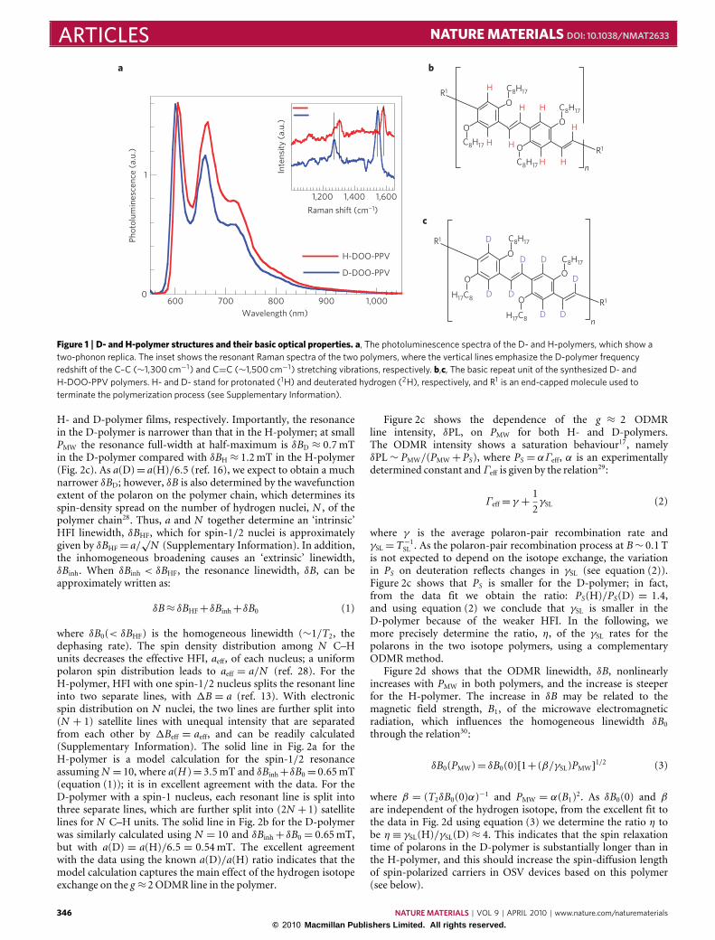
H- and D-polymer films, respectively. Importantly, the resonancein the D-polymer is narrower than that in the H-polymer; at smallPMW the resonance full-width at half-maximum is δBD ≈ 0.7mTin the D-polymer compared with δBH ≈ 1.2mT in the H-polymer(Fig. 2c). As a(D)= a(H)/6.5 (ref. 16), we expect to obtain a muchnarrower δBD; however, δB is also determined by the wavefunctionextent of the polaron on the polymer chain, which determines itsspin-density spread on the number of hydrogen nuclei, N , of thepolymer chain28. Thus, a and N together determine an ‘intrinsic’HFI linewidth, δBHF, which for spin-1/2 nuclei is approximatelygiven by δBHF= a/
√N (Supplementary Information). In addition,
the inhomogeneous broadening causes an ‘extrinsic’ linewidth,δBinh. When δBinh < δBHF, the resonance linewidth, δB, can beapproximately written as:
δB≈ δBHF+δBinh+δB0 (1)
where δB0(< δBHF) is the homogeneous linewidth (∼1/T2, thedephasing rate). The spin density distribution among N C–Hunits decreases the effective HFI, aeff, of each nucleus; a uniformpolaron spin distribution leads to aeff = a/N (ref. 28). For theH-polymer, HFI with one spin-1/2 nucleus splits the resonant lineinto two separate lines, with 1B = a (ref. 13). With electronicspin distribution on N nuclei, the two lines are further split into(N + 1) satellite lines with unequal intensity that are separatedfrom each other by 1Beff = aeff, and can be readily calculated(Supplementary Information). The solid line in Fig. 2a for theH-polymer is a model calculation for the spin-1/2 resonanceassumingN = 10, where a(H )= 3.5mT and δBinh+δB0= 0.65mT(equation (1)); it is in excellent agreement with the data. For theD-polymer with a spin-1 nucleus, each resonant line is split intothree separate lines, which are further split into (2N + 1) satellitelines for N C–H units. The solid line in Fig. 2b for the D-polymerwas similarly calculated using N = 10 and δBinh+ δB0 = 0.65mT,but with a(D) = a(H)/6.5 = 0.54mT. The excellent agreementwith the data using the known a(D)/a(H) ratio indicates that themodel calculation captures the main effect of the hydrogen isotopeexchange on the g ≈2ODMR line in the polymer.
Figure 2c shows the dependence of the g ≈ 2 ODMRline intensity, δPL, on PMW for both H- and D-polymers.The ODMR intensity shows a saturation behaviour17, namelyδPL∼ PMW/(PMW+PS), where PS = αΓeff, α is an experimentallydetermined constant andΓeff is given by the relation29:
Γeff= γ +12γSL (2)
where γ is the average polaron-pair recombination rate andγSL=T−1SL . As the polaron-pair recombination process at B∼ 0.1 Tis not expected to depend on the isotope exchange, the variationin PS on deuteration reflects changes in γSL (see equation (2)).Figure 2c shows that PS is smaller for the D-polymer; in fact,from the data fit we obtain the ratio: PS(H)/PS(D) = 1.4,and using equation (2) we conclude that γSL is smaller in theD-polymer because of the weaker HFI. In the following, wemore precisely determine the ratio, η, of the γSL rates for thepolarons in the two isotope polymers, using a complementaryODMRmethod.
Figure 2d shows that the ODMR linewidth, δB, nonlinearlyincreases with PMW in both polymers, and the increase is steeperfor the H-polymer. The increase in δB may be related to themagnetic field strength, B1, of the microwave electromagneticradiation, which influences the homogeneous linewidth δB0through the relation30:
δB0(PMW)= δB0(0)[1+ (β/γSL)PMW]1/2 (3)
where β = (T2δB0(0)α)−1 and PMW = α(B1)2. As δB0(0) and βare independent of the hydrogen isotope, from the excellent fit tothe data in Fig. 2d using equation (3) we determine the ratio η tobe η ≡ γSL(H)/γSL(D)≈ 4. This indicates that the spin relaxationtime of polarons in the D-polymer is substantially longer than inthe H-polymer, and this should increase the spin-diffusion lengthof spin-polarized carriers in OSV devices based on this polymer(see below).
346 NATURE MATERIALS | VOL 9 | APRIL 2010 | www.nature.com/naturematerials
© 2010 Macmillan Publishers Limited. All rights reserved.
NATURE MATERIALS DOI: 10.1038/NMAT2633 ARTICLES
OD
MR
(a.u
.)O
DM
R (a
.u.)
Full-
wid
th a
t hal
f-m
axim
um (
mT
)
0 1.5 3.0¬3.0 ¬1.5
Data, H
Model
Data, D
Model
0
0.5
1.0
OD
MR
(a.u
.)
0
0.5
1.0
B ¬ B0 (mT)0 1.5 3.0¬3.0 ¬1.5
B ¬ B0 (mT)
0.4
0.8
0 25 50 75 100PMW (mW)
0 25 50 75 100PMW (mW)
D
H
D
H
0.5
1.0
1.5
a b
c d
Figure 2 | Isotope dependence of the spin-1/2 ODMR response in DOO-PPV polymers. a,b, The normalized spin-1/2 ODMR response in the H- andD-polymers; the lines through the data points are based on a model fit taking into account the HFI splitting and the polaron spin density spread on thepolymer chain, as well as inhomogeneous and natural line-broadening contributions to the resonance width (equation (1) and Supplementary Information).c, The microwave power (PMW) dependence of the integrated ODMR signal intensity for the two polymers; the lines through the data points are a model fitusing a saturation equation (see text). d, The microwave power dependence of the ODMR linewidth for the two polymers; the lines through the data pointsare model fits based on equation (3).
MEL in OLEDsFor the MEL investigations, we fabricated OLED devices based onthe two polymers as active layers with various film thicknesses,df. The devices were transferred to an optical cryostat that wasplaced in between the two poles of an electromagnet producinga magnetic field, B, up to 300mT. The devices were drivenat a constant bias voltage, V , using a Keithley 236 apparatus,and the electroluminescence (EL) was measured while sweepingB (see the Methods section). We define MEL by the relation,MEL= [EL(B)−EL(0)]/EL(0). Electroluminescence in the deviceresults from recombination of polaron pairs in the spin singletconfiguration, PPS, which are formed from the carriers injected intothe active layer through the metal electrodes. The polaron pairs inthe two spin configurations, namely PPS and PPT, exchange spinsthrough intersystem crossing (ISC); their steady-state populationsare also determined by their spin exchange interaction, as wellas by the individual recombination and dissociation rates29 (seeSupplementary Information). It is believed that the MEL effect isdue to a field-induced change of the polaron-pair spin sublevelsthat determines the ISC rate22, but the underlying mechanism forthe ISC rate change with B is still under debate31,32.
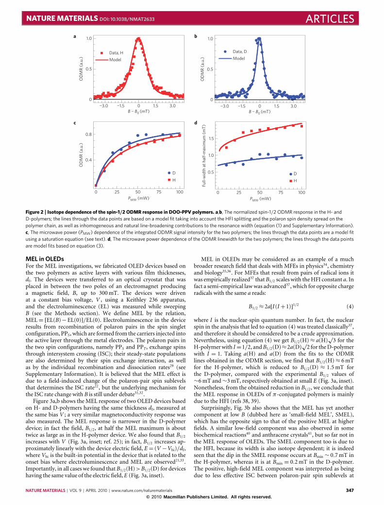
Figure 3a,b shows the MEL response of two OLED devices basedon H- and D-polymers having the same thickness df, measured atthe same bias V ; a very similar magnetoconductivity response wasalso measured. The MEL response is narrower in the D-polymerdevice; in fact the field, B1/2, at half the MEL maximum is abouttwice as large as in the H-polymer device. We also found that B1/2increases with V (Fig. 3a, inset; ref. 25); in fact, B1/2 increases ap-proximately linearly with the device electric field, E= (V −Vbi)/df,where Vbi is the built-in potential in the device that is related to theonset bias where electroluminescence and MEL are observed21,33.Importantly, in all cases we found thatB1/2(H)>B1/2(D) for deviceshaving the same value of the electric field, E (Fig. 3a, inset).
MEL in OLEDs may be considered as an example of a muchbroader research field that deals with MFEs in physics34, chemistryand biology35,36. For MFEs that result from pairs of radical ions itwas empirically realized37 thatB1/2 scales with theHFI constant a. Infact a semi-empirical lawwas advanced37, which for opposite chargeradicals with the same a reads:
B1/2≈ 2a[I (I+1)]1/2 (4)
where I is the nuclear-spin quantum number. In fact, the nuclearspin in the analysis that led to equation (4) was treated classically37,and therefore it should be considered to be a crude approximation.Nevertheless, using equation (4) we get B1/2(H)≈ a(H)
√3 for the
H-polymerwith I=1/2, andB1/2(D)≈2a(D)√2 for theD-polymer
with I = 1. Taking a(H) and a(D) from the fits to the ODMRlines obtained in the ODMR section, we find that B1/2(H)≈ 6mTfor the H-polymer, which is reduced to B1/2(D) ≈ 1.5mT forthe D-polymer, compared with the experimental B1/2 values of∼6mT and∼3mT, respectively obtained at small E (Fig. 3a, inset).Nonetheless, from the obtained reduction in B1/2, we conclude thatthe MEL response in OLEDs of π-conjugated polymers is mainlydue to the HFI (refs 38, 39).
Surprisingly, Fig. 3b also shows that the MEL has yet anothercomponent at low B (dubbed here as ‘small-field MEL’, SMEL),which has the opposite sign to that of the positive MEL at higherfields. A similar low-field component was also observed in somebiochemical reactions40 and anthracene crystals41, but so far not inthe MEL response of OLEDs. The SMEL component too is due tothe HFI, because its width is also isotope dependent; it is indeedseen that the dip in the SMEL response occurs at Bmin ∼ 0.7mT inthe H-polymer, whereas it is at Bmin = 0.2mT in the D-polymer.The positive, high-field MEL component was interpreted as beingdue to less effective ISC between polaron-pair spin sublevels at
NATURE MATERIALS | VOL 9 | APRIL 2010 | www.nature.com/naturematerials 347© 2010 Macmillan Publishers Limited. All rights reserved.
ARTICLES NATURE MATERIALS DOI: 10.1038/NMAT2633
MEL
(%
)M
EL (
%)
E
0
1
2
0 20 40¬40 ¬20B (mT)
B (mT)
0
2
MEL
(%
)
0
2
0 2010 30¬30 ¬10¬20B (mT)
0 21 3¬1¬2¬3
MEL
(%
)
B (mT)
0
0.5
1.0
¬2 ¬1 0 1 2
D-DOO-PPV
H-DOO-PPVD-DOO-PPV
H-DOO-PPV
ProtonsDeuterons
ProtonsDeuterons
¬2
0
2
¬4
4E
¬2
¬4
0
2
4
g BB/a0 01 2 3 1 2 3
1 2
5
1B 1/2
(mT
)V (107 V m¬1)
a b
c d
e f
µ g BB/aµ
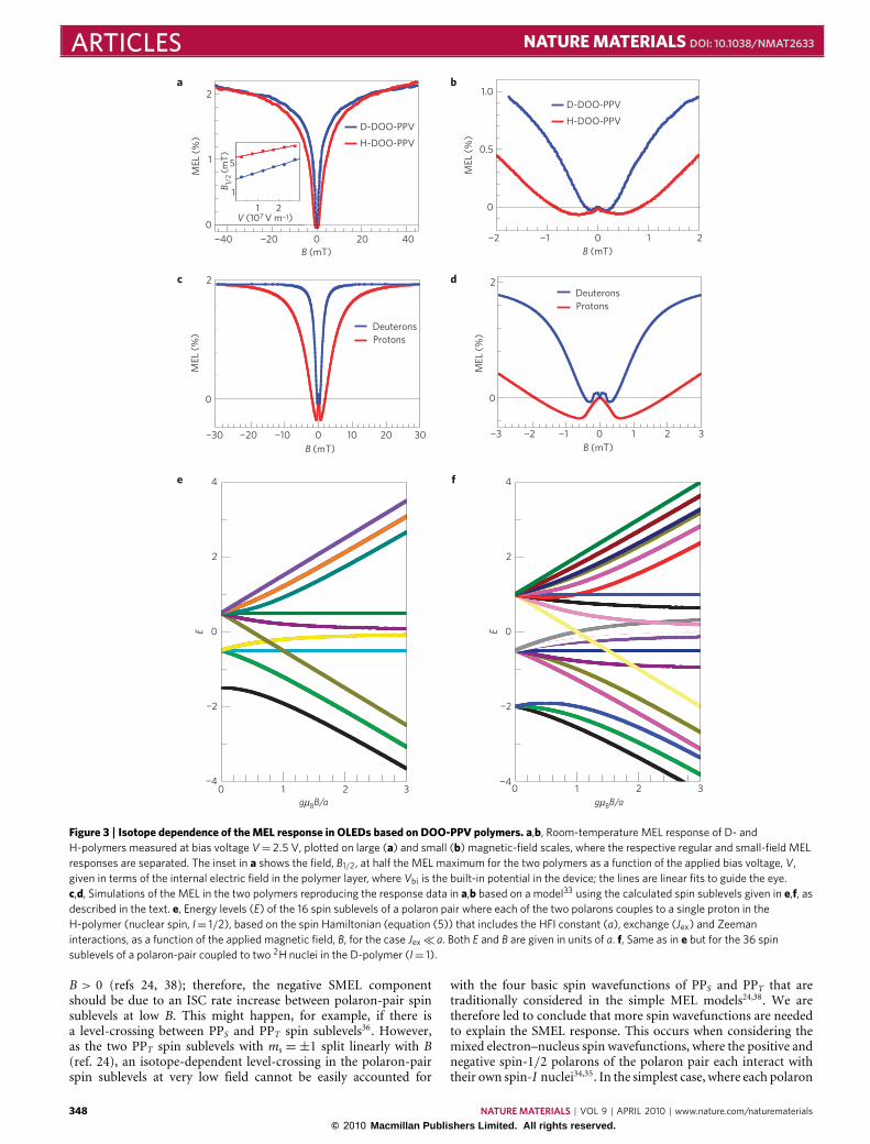
Figure 3 | Isotope dependence of the MEL response in OLEDs based on DOO-PPV polymers. a,b, Room-temperature MEL response of D- andH-polymers measured at bias voltage V= 2.5 V, plotted on large (a) and small (b) magnetic-field scales, where the respective regular and small-field MELresponses are separated. The inset in a shows the field, B1/2, at half the MEL maximum for the two polymers as a function of the applied bias voltage, V,given in terms of the internal electric field in the polymer layer, where Vbi is the built-in potential in the device; the lines are linear fits to guide the eye.c,d, Simulations of the MEL in the two polymers reproducing the response data in a,b based on a model33 using the calculated spin sublevels given in e,f, asdescribed in the text. e, Energy levels (E) of the 16 spin sublevels of a polaron pair where each of the two polarons couples to a single proton in theH-polymer (nuclear spin, I= 1/2), based on the spin Hamiltonian (equation (5)) that includes the HFI constant (a), exchange (Jex) and Zeemaninteractions, as a function of the applied magnetic field, B, for the case Jex� a. Both E and B are given in units of a. f, Same as in e but for the 36 spinsublevels of a polaron-pair coupled to two 2H nuclei in the D-polymer (I= 1).
B > 0 (refs 24, 38); therefore, the negative SMEL componentshould be due to an ISC rate increase between polaron-pair spinsublevels at low B. This might happen, for example, if there isa level-crossing between PPS and PPT spin sublevels36. However,as the two PPT spin sublevels with ms =±1 split linearly with B(ref. 24), an isotope-dependent level-crossing in the polaron-pairspin sublevels at very low field cannot be easily accounted for
with the four basic spin wavefunctions of PPS and PPT that aretraditionally considered in the simple MEL models24,38. We aretherefore led to conclude that more spin wavefunctions are neededto explain the SMEL response. This occurs when considering themixed electron–nucleus spin wavefunctions, where the positive andnegative spin-1/2 polarons of the polaron pair each interact withtheir own spin-I nuclei34,35. In the simplest case, where each polaron
348 NATURE MATERIALS | VOL 9 | APRIL 2010 | www.nature.com/naturematerials
© 2010 Macmillan Publishers Limited. All rights reserved.
NATURE MATERIALS DOI: 10.1038/NMAT2633 ARTICLESinteracts only with a single nucleus, the Heisenberg spin subspace isspread by 24 = 16 wavefunctions for the H-polymer (I = 1/2) and22× 32 = 36wavefunctions for the D-polymer (I = 1). Assumingfor simplicity that the HFI constant, a, and the electronic g -factorare the same for electrons and holes on the polymer chain, the spinHamiltonian,H , can bewritten forB in the z direction as:
H = gµBS1zB+gµBS2zB+aS1 · I1+aS2 · I2+ JexS1 ·S2 (5)
where the indices 1 and 2 refer to the electron- and hole-polaron, respectively; S and I are the spin operators for theelectron and nucleus, respectively, and for simplicity we assumethat each polaron interacts with a single nucleus; Jex is theexchange interaction between the hole- and electron-polaronand µB is the Bohr magneton. We solved the Hamiltonian(5) numerically for the H- and D-polymers using various Jex/avalues (Supplementary Information). We present here results forJex/a � 1, where the isotope effect is more pronounced. It isseen that some of the energy degeneracies that occur at B = 0are lifted at B> 0 (Fig. 3e,f), and several level-crossings occur atBLC < a/gµB. Naturally, the various level-crossings increase theISC process among the polaron-pair spin sublevels, leading to adecrease in the magnetic response, as appropriate for the SMEL. Asa(D)< a(H), the SMEL effect in the D-polymer occurs at a Bminthat is smaller than that in the H-polymer, in agreement with theexperimental results (Fig. 3b).
Further understanding of the MEL response may be gained bymodel calculations based on Hamiltonian (5), where we adopt themodel of Timmel and colleagues35 (Supplementary Information).We assume that the polaron-pair species recombine with a rateconstant, k� a/h̄ (ref. 5). Consequently, ISC among the variousspin eigenstates occurs at a much faster timescale, before polaron-pair recombination sets in. Under these conditions, the PPSpopulation oscillates coherently many times with a frequencydetermined by the energy split between any two non-degenerateeigenenergies of the spin Hamiltonian5,36. This is used here tocalculate the steady-state PPS population yield, ΦS, versus B, asshown in Fig. 3c,d (see also Supplementary Information). Thedominant term at high fields is ΦS ∼ B2/[B2
+ (a/gµB)2], andthis shows that a directly determines B1/2 in the MEL response38,in agreement with our data. Moreover, the model calculationobtained using h̄k/a∼0.002 also nicely reproduces the SMEL effect(Fig. 3d), where the calculated Bmin occurs at ∼0.7 and 0.3mT intheH- andD-polymer, respectively, in excellent agreement with theexperiment (Fig. 3b).
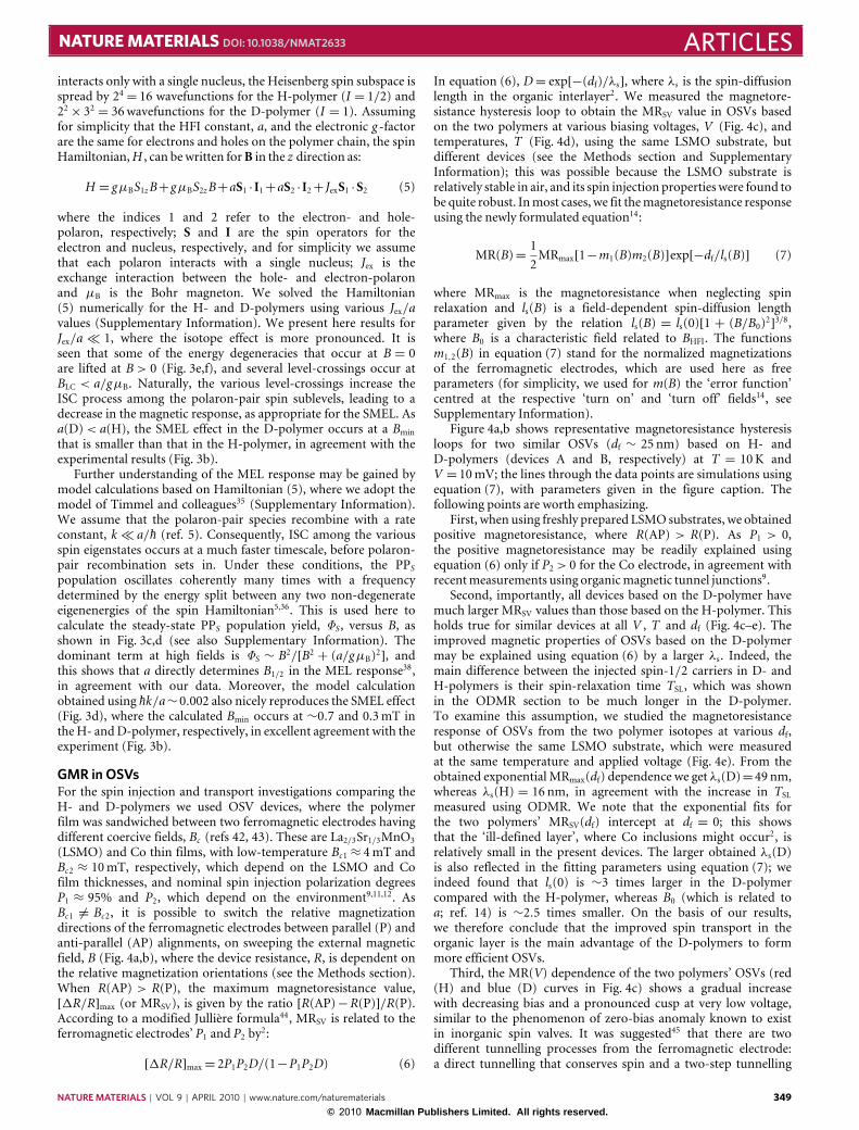
GMR in OSVsFor the spin injection and transport investigations comparing theH- and D-polymers we used OSV devices, where the polymerfilm was sandwiched between two ferromagnetic electrodes havingdifferent coercive fields, Bc (refs 42, 43). These are La2/3Sr1/3MnO3(LSMO) and Co thin films, with low-temperature Bc1 ≈ 4mT andBc2 ≈ 10mT, respectively, which depend on the LSMO and Cofilm thicknesses, and nominal spin injection polarization degreesP1 ≈ 95% and P2, which depend on the environment9,11,12. AsBc1 6= Bc2, it is possible to switch the relative magnetizationdirections of the ferromagnetic electrodes between parallel (P) andanti-parallel (AP) alignments, on sweeping the external magneticfield, B (Fig. 4a,b), where the device resistance, R, is dependent onthe relative magnetization orientations (see the Methods section).When R(AP) > R(P), the maximum magnetoresistance value,[1R/R]max (or MRSV), is given by the ratio [R(AP)−R(P)]/R(P).According to a modified Jullière formula44, MRSV is related to theferromagnetic electrodes’ P1 and P2 by2:
[1R/R]max= 2P1P2D/(1−P1P2D) (6)
In equation (6), D= exp[−(df)/λs], where λs is the spin-diffusionlength in the organic interlayer2. We measured the magnetore-sistance hysteresis loop to obtain the MRSV value in OSVs basedon the two polymers at various biasing voltages, V (Fig. 4c), andtemperatures, T (Fig. 4d), using the same LSMO substrate, butdifferent devices (see the Methods section and SupplementaryInformation); this was possible because the LSMO substrate isrelatively stable in air, and its spin injection properties were found tobe quite robust. Inmost cases, we fit themagnetoresistance responseusing the newly formulated equation14:
MR(B)=12MRmax[1−m1(B)m2(B)]exp[−df/ls(B)] (7)
where MRmax is the magnetoresistance when neglecting spinrelaxation and ls(B) is a field-dependent spin-diffusion lengthparameter given by the relation ls(B) = ls(0)[1 + (B/B0)2]3/8,where B0 is a characteristic field related to BHFI. The functionsm1,2(B) in equation (7) stand for the normalized magnetizationsof the ferromagnetic electrodes, which are used here as freeparameters (for simplicity, we used for m(B) the ‘error function’centred at the respective ‘turn on’ and ‘turn off’ fields14, seeSupplementary Information).
Figure 4a,b shows representative magnetoresistance hysteresisloops for two similar OSVs (df ∼ 25 nm) based on H- andD-polymers (devices A and B, respectively) at T = 10K andV = 10mV; the lines through the data points are simulations usingequation (7), with parameters given in the figure caption. Thefollowing points are worth emphasizing.
First, when using freshly prepared LSMO substrates, we obtainedpositive magnetoresistance, where R(AP) > R(P). As P1 > 0,the positive magnetoresistance may be readily explained usingequation (6) only if P2> 0 for the Co electrode, in agreement withrecentmeasurements using organicmagnetic tunnel junctions9.
Second, importantly, all devices based on the D-polymer havemuch larger MRSV values than those based on the H-polymer. Thisholds true for similar devices at all V , T and df (Fig. 4c–e). Theimproved magnetic properties of OSVs based on the D-polymermay be explained using equation (6) by a larger λs. Indeed, themain difference between the injected spin-1/2 carriers in D- andH-polymers is their spin-relaxation time TSL, which was shownin the ODMR section to be much longer in the D-polymer.To examine this assumption, we studied the magnetoresistanceresponse of OSVs from the two polymer isotopes at various df,but otherwise the same LSMO substrate, which were measuredat the same temperature and applied voltage (Fig. 4e). From theobtained exponential MRmax(df) dependence we get λs(D)=49 nm,whereas λs(H) = 16 nm, in agreement with the increase in TSLmeasured using ODMR. We note that the exponential fits forthe two polymers’ MRSV(df) intercept at df = 0; this showsthat the ‘ill-defined layer’, where Co inclusions might occur2, isrelatively small in the present devices. The larger obtained λs(D)is also reflected in the fitting parameters using equation (7); weindeed found that ls(0) is ∼3 times larger in the D-polymercompared with the H-polymer, whereas B0 (which is related toa; ref. 14) is ∼2.5 times smaller. On the basis of our results,we therefore conclude that the improved spin transport in theorganic layer is the main advantage of the D-polymers to formmore efficient OSVs.
Third, the MR(V) dependence of the two polymers’ OSVs (red(H) and blue (D) curves in Fig. 4c) shows a gradual increasewith decreasing bias and a pronounced cusp at very low voltage,similar to the phenomenon of zero-bias anomaly known to existin inorganic spin valves. It was suggested45 that there are twodifferent tunnelling processes from the ferromagnetic electrode:a direct tunnelling that conserves spin and a two-step tunnelling
NATURE MATERIALS | VOL 9 | APRIL 2010 | www.nature.com/naturematerials 349© 2010 Macmillan Publishers Limited. All rights reserved.
ARTICLES NATURE MATERIALS DOI: 10.1038/NMAT2633
Mag
neto
resi
stan
ce (
%)
Mag
neto
resi
stan
ce (
%)
Mag
neto
resi
stan
ce (
%)
Mag
neto
resi
stan
ce (
%)
Mag
neto
resi
stan
ce (
%)
Mag
neto
resi
stan
ce (
%)
¬100 0 100 200
1
10
100
H
V < 0
|V|¬0.37
|V|¬0.65
D
V > 0
λ
λ
D
D
H
H
0
1
2
40¬40 ¬20 0 20
0
10
20
30
40
B (mT)
40¬40 ¬20 0 20B (mT)
T (K)
0 100 200 300
0
2
4
6
1
10
100
1,000
V (mV)
1
10
d (nm)0 20 40
D = 49 nm
H = 16 nm
|V| (mV)
100101
a c
e
b
d
Figure 4 | Isotope dependence of the magnetoresistance response in OSVs based on DOO-PPV polymers. a,b, Magnetoresistance loop of LSMO(200 nm)/DOO-PPV(25 nm)/Co(15 nm) spin-valve devices measured at T =10 K and V= 10 mV, based on H- (a) and D- (b) polymers, which are devicesA and B, respectively. The blue (red) curve denotes magnetoresistance measurements made while decreasing (increasing) B. The nominal resistance is∼200 k� and∼170 k�, respectively, for devices A and B. The antiparallel and parallel configurations of the ferromagnetic magnetization orientations areshown in the insets at low and high B, respectively. The lines through the data points are simulations using equation (7) with the following parameters forH-polymer (H) and D-polymer (D) OSVs: ls(0)/df= 1 (H), 3 (D); B0= 5 mT (H), 2 mT (D); MRmax= 2% (H), 45% up, 35% down (D); Bc1,2= 3.3 mT and11 mT (H) and 3.6 mT and 8 mT (D). c, The maximum magnetoresistance value (MRSV) of two OSV devices (C and D, respectively) fabricated in a similarway as devices A and B shown in a and b, but having df= 35±5 nm, as a function of the applied bias voltage, V, measured at T= 10 K. Note the logarithmicy scale, and MRSV of∼330% that was obtained at low V for the D-polymer OSV (device D; see Supplementary Information). Inset: The same data plottedon a log–log scale, which show a power-law behaviour, V−p, with the isotope-dependent exponent, p. d, Normalized MRSV of two OSVs (devices E and F)similar to those shown in a–c, as a function of temperature, measured at V=80 mV. e, MRSV of H- and D-polymer OSVs (similar to devices A–F shown ina–d) having various, carefully determined thicknesses, df, measured at T= 10 K and V=80 mV. The lines are fits, where MRSV(df)=6.7%exp(−df/λs),with spin-diffusion lengths, λs(H)= 16 nm and λs(D)=49 nm, respectively, for OSVs based on H- and D-polymers.
(involving hopping) that does not conserve spin. As the latterprocess has a steeper voltage dependence, it dominates at large biasvoltage; this explains the MR(V) decrease at large V , because thedevice magnetoresistance is mainly determined by the two-step,non-spin-conserving tunnelling process. Inelastic tunnelling bymeans of ‘magnetic impurities’ accompanied by phonon emissiongives rise to a power-law dependence46, MRSV(V )∝V −p, where theexponent, p, may be either larger or smaller than 1. The ‘magneticimpurities’ in our case may be ferromagnetic electrode atoms thatdiffuse into the organic barrier, or organic radicals created by thespin injection that are embedded into the organic barrier. Theexponent p was predicted to be isotope dependent46, p ∼M 3/2,where M is the effective isotope mass that determines the phononspectrum that participates in the hopping process. Figure 4c, inset,showsMRSV(V ) for both isotopes on a double logarithmic scale; it isseen that MRSV(V ) indeed obeys a power-law decay with V , havingp < 1 that is isotope dependent. We obtained a larger p for thedeuterated device, as predicted by the model46; we found the ratio
p(D)/p(H)∼ 1.7. This ratio is smaller than [M(D)/M(H)]3/2∼ 2.8expected from the model46, presumably because the phonons thatparticipate in the polaron hopping process in the polymer aredetermined also by theC atoms,which have not been replaced here.
Fourthly, we found that the maximumMRSV value measured inthe D-polymer OSV (device D) at very small V and low T reaches∼330% (Fig. 4c and Supplementary Information). Such a largeMRSV value has never been obtained before in polymer-based OSVs(refs 6, 12), and may be explained by the lack of an ill-defined layerin our OSV devices, and by the standard equation (6) if P2> 66%,which ismuch larger than P2=27%determined before9.
Fifthly, we also note that MRSV strongly decreases at high Tfor both OSV devices, irrespective of the MRSV value at low T(Fig. 4d); thus, it is mainly caused by the spin injection propertiesof the LSMO electrode into the organic layer7,45, rather thanby the organic interlayer. We therefore conclude that differentspin injectors need be found to achieve a significant advance inorganic spintronics. In this regard, the use of deuterated organic
350 NATURE MATERIALS | VOL 9 | APRIL 2010 | www.nature.com/naturematerials
© 2010 Macmillan Publishers Limited. All rights reserved.
NATURE MATERIALS DOI: 10.1038/NMAT2633 ARTICLESsemiconductors as the device interlayer, both as evaporated smallmolecules or spin-cast polymers, should substantially improve theOSV device performance.
Recently, however, it was found that the MEL response inthe Alq3 is not isotope dependent47. The reason for the isotope-independent response is unknown at present, but this mightindicate that not all organic semiconductors would show a strongisotope effect, presumably because interactions other than HFImaydominate the polaron-pair spin Hamiltonian (5) in the specificorganic semiconductor, such as J or/and spin–orbit coupling.
MethodsODMR. The polymer film was placed in an S-band (∼3GHz) microwave cavityin a cryostat at 10 K equipped with microwave throughput cables; the microwaveradiation was provided by a Gunn diode that delivered up to ∼100mW power,PMW (ref. 17). The cryostat was placed inside a liquid-He-cooled superconductingcoil that provided magnetic field, B up to 3 T, applied perpendicular to the film.A 200mW laser beam photogenerated the polymer photoluminescence emissionmeasured by a Si photodetector. PMW was modulated at frequency f ∼ 200Hz,and the changes, δPL, in the photoluminescence intensity were monitored using alock-in amplifier at f . B was swept while monitoring δPL; the resonance conditionfor spin-1/2 occurs when the microwave photon energy is equal to the energydifference between the two Zeeman split spin sublevels at B∼ 0.1 T for g ∼ 2 inan S-band. We obtained δPL> 0 because the polaron-pair recombination rateincreases at resonance conditions as a result of spin mixing in the polaron-pair spinsublevels, which was induced by the microwave absorption. In our investigationswemeasured δPL at resonance as a function of PMW to obtain the ODMR saturationresponse and linewidth broadening contribution.
MEL. The measurements were conducted on OLED devices25, which were5× 2mm2 diodes made from the D- and H-DOO-PPV polymer activelayer; a hole transport layer: poly(3,4-ethylenedioxythiophene)–poly(styrenesulphonate); a transparent anode: indium tin oxide; and a cathode: calcium(protected by an aluminium film). The OLED structure was thus in theform of indium tin oxide/poly(3,4-ethylenedioxythiophene):poly(styrenesulphonate)/DOO-PPV/Ca/Al. The devices showed sizable electroluminescence forV >Vbi (∼2V). The devices were transferred to an optical cryostat with variabletemperature that was placed in between the pole pieces of an electromagnetthat produced B up to 300mT with a 0.1mT resolution. By increasing thedistance between the two magnetic poles, we improved the resolution downto 0.01mT; in all cases B was determined with a calibrated magnetometer.The devices were driven at constant V using a Keithley 236 apparatus, and theelectroluminescence intensity was measured by a Si photodetector, while sweepingB. The MEL is defined as19,25:
1EL/EL=EL(B)−EL(B= 0)
EL(B= 0)
With this definitionMEL> 0 when1EL> 0.
Magnetoresistance in OSVs. The OSVs were fabricated using the D- andH-polymers as spacers in between two ferromagnetic electrodes2; these wereLa0.67Sr0.33MnO3(LSMO) (bottom electrode, FM1) and cobalt (Co) (top electrode,FM2). The LSMO films with a thickness of ∼200 nm and area of 5×5mm2
were grown epitaxially on 〈100〉-oriented SrTiO3 substrates at 735 ◦C using ad.c. magnetron sputtering technique, with Ar and O2 flux in the ratio of 1:1.The films were subsequently annealed at 800 ◦C for ∼10 h before slow cooling toroom temperature. The LSMO films were subsequently patterned using standardphotolithography and chemical etching techniques. Contrary to cobalt, the LSMOfilms are already stable against oxidation; consequently, the LSMO films have beencleaned and re-used multiple times as substrates without serious degradation2.Following the LSMO substrate cleaning using chloroform, we deposited theDOO-PPV polymer layer by spin-casting from a 6mgml−1 1,2-dichlorobenzenesolution. Subsequently the hybrid organic/inorganic junction was introduced intoan evaporation chamber with a base pressure of 5×10⁻⁷ torr, where we deposited athin (10–15 nm) Co film capped by an aluminium (Al) film using a shadow mask.The obtained active device area was typically about 0.2×0.4mm2.
We fabricated several OSV devices having various organic layer thicknesses,df, controlled by the spin angular speed, and calibrated against measurementsusing thickness profilometry methods (KLA Tencor). Films with df > 80 nmappeared segregated, and were subsequently discarded, whereas films having20< df < 80 nm were smooth. D- and H-polymer-based OSVs with various dfwere measured and compared at several bias voltages, V , and temperatures,T . For the df dependence of the magnetoresistance, we used the same LSMOsubstrate and device structure where df was measured using a doctor bladeand a profilometer. The I–V characteristics of the OSV devices were nonlinearwith a weak temperature dependence (see Supplementary Information). Typical
device resistance was in the range of 100–500 k�, and depended on df. Mostdevices showed a ‘metallic’ behaviour, where R increases with T ; however,some devices showed mixed behaviour (Supplementary Information). The OSVmagnetoresistance was measured in a closed-cycle refrigerator with T in the rangefrom 10 to 300K, using the ‘four probe’ method, while varying an external in-planemagnetic field. The magnetization properties of the ferromagnetic electrodes weremeasured by the magneto-optic Kerr effect (see Supplementary Information);from these measurements we determined typical low-temperature coercive fieldsfor the electrodes alone as Bc1 ∼ 4mT and Bc2 ∼ 10mT, for the LSMO andCo films, respectively.
Received 8 June 2009; accepted 12 January 2010; published online14 February 2010
References1. Naber, W. J. M., Faez, S. & van der Wiel, W. G. Organic spintronics. J. Phys. D
40, R205–R228 (2007).2. Xiong, Z. H., Wu, D., Vardeny, Z. V. & Shi, J. Giant magnetoresistance in
organic spin-valves. Nature 427, 821–824 (2004).3. Ruden, P. & Smith, D. L. Theory of spin injection into conjugated organic
semiconductors. J. Appl. Phys. 95, 4898–4904 (2004).4. Pramanik, S. et al. Observation of extremely long spin relaxation times in an
organic nanowire spin valve. Nature Nanotech. 2, 216–219 (2007).5. McCamey, D. R. et al. Spin Rabi flopping in the photocurrent of a polymer
light-emitting diode. Nature Mater. 7, 723–727 (2008).6. Majumdar, S. et al. Application of regioregular polythiophene in spintronic
devices; effect of interface. Appl. Phys. Lett. 89, 122114 (2006).7. Wang, F. J., Yang, C. G., Vardeny, Z. V. & Li, X. Spin response in
organic spin valves based on La2/3Sr1/3MnO3 electrodes. Phys. Rev. B 75,245324 (2007).
8. Hueso, L. E. et al. Multipurpose magnetic organic hybrid devices. Adv. Mater.19, 2639–2642 (2007).
9. Santos, T. S. et al. Room temperature tunnelling magnetoresistance andspin-polarized tunnelling through an organic semiconductor barrier.Phys. Rev. Lett. 98, 016601 (2007).
10. Tombros, N. et al. Electronic spin transport and spin precession in singlegraphene layers at room temperature. Nature 448, 571–575 (2007).
11. Dediu, V. et al. Room-temperature spintronic effects in Alq3-based hybriddevices. Phys. Rev. B 78, 115203 (2008).
12. Vinzelberg, H. et al. Low temperature tunnelling magnetoresistance onLa2/3Sr1/3MnO3/Co junctions with organic spacer layers. J. Appl. Phys. 103,093720 (2008).
13. Drew, A. J. et al. Direct measurement of the electronic spin diffusion lengthin a fully functional organic spin valve by low-energy muon spin rotation.Nature Mater. 8, 109–114 (2009).
14. Bobbert, P. A. et al. Theory for spin diffusion in disordered organicsemiconductors. Phys. Rev. Lett. 102, 156604 (2009).
15. Pulizzi, F. Why going organic is good. Nature Mater. 8, 691 (2009).16. Carrington, A. &McLachlan, A. D. Introduction to Magnetic Resonance (Harper
& Row, 1967).17. Yang, C. G., Ehrenfreund, E. & Vardeny, Z. V. Polaron spin-lattice relaxation
time obtained fromODMRdynamics inπ-conjugated polymers.Phys. Rev. Lett.99, 157401 (2007).
18. Kalinowski, J. et al. Magnetic field effects on emission and current in Alq3-basedelectroluminescent diodes. Chem. Phys. Lett. 380, 710–715 (2003).
19. Mermer, Ö. et al. Large magnetoresistance in nonmagnetic π-conjugatedsemiconductor thin film devices. Phys. Rev. B 72, 205202 (2005).
20. Bobbert, P. A. et al. Bipolaron mechanism for organic magnetoresistance.Phys. Rev. Lett. 99, 216801 (2007).
21. Bloom, F. L., Wagemans, W., Kemerink, M. & Koopmans, B. Separatingpositive and negative magnetoresistance in organic semiconductor devices.Phys. Rev. Lett. 99, 257201 (2007).
22. Hu, B. & Wu, Y. Tuning magnetoresistance between positive and negativevalues in organic semiconductors. Nature Mater. 6, 985–991 (2007).
23. Nguyen, T. D., Sheng, Y., Rybicki, J. & Wohlgenannt, M. Magnetic field-effectsin bipolar, almost hole-only and almost electron-only Alq3 devices. Phys. Rev. B77, 235209 (2008).
24. Bergeson, J. D., Prigodin, V. N., Lincoln, D. M. & Epstein, A. J. Inversionof magnetoresistance in organic semiconductors. Phys. Rev. Lett. 100,067201 (2008).
25. Wang, F., Bässler, H. & Vardeny, Z. V. Studies of magnetoresistance inpolymer/fullerene blends. Phys. Rev. Lett. 101, 236805 (2008).
26. Majumdar, S. et al. Role of electron–hole pair formation in organicmagnetoresistance. Phys. Rev. B 79, 201202(R) (2009).
27. Vardeny, Z. V., Brafman, O. & Ehrenfreund, E. Isotope effect in resonantRaman scattering and induced IR spectra of trans polyacetylene.Solid State Commun. 53, 615–620 (1985).
28. Weinberger, B. R. et al. Electron spin resonance studies of magnetic solitondefects in polyacetylene. J. Chem. Phys. 72, 4749–4755 (1980).
NATURE MATERIALS | VOL 9 | APRIL 2010 | www.nature.com/naturematerials 351© 2010 Macmillan Publishers Limited. All rights reserved.
ARTICLES NATURE MATERIALS DOI: 10.1038/NMAT2633
29. Yang, C. G., Ehrenfreund, E., Wang, F. & Vardeny, Z. V. Spin dependentkinetics of polaron pairs in organic light emitting diodes studied by ELDMRdynamics. Phys. Rev. B 78, 205312 (2008).
30. Abragam, A. The Principles of Nuclear Magnetism (Oxford Univ. Press, 1961).31. Lupton, J. M. & Boehme, Ch. Magnetoresistance in organic semiconductors;
correspondence to the Editor. Nature Mater. 7, 598–599 (2008).32. Hu, B. & Wu, Y. Response to correspondence to the Editor. Nature Mater. 7,
600–601 (2008).33. Bloom, F. L., Kemerink, M., Wagemans, W. & Koopmans, B. Sign inversion of
magnetoresistance in space-charge limited organic devices. Phys. Rev. Lett. 103,066601 (2009).
34. Groff, R. P., Suna, A., Avakian, P. & Merrifield, R. E. Magnetic hyperfinemodulation of dye-sensitized delayed fluorescence in organic crystals.Phys. Rev. B 9, 2655–2660 (1974).
35. Timmel, C. R. et al. Effects of weakmagnetic fields on free radical recombinationreactions.Mol. Phys. 95, 71–89 (1998).
36. Hayashi, H. Introduction to Dynamic Spin Chemistry; Magnetic Field Effectson Chemical and Biochemical Reactions (World Scientific Lecture and CourseNotes in Chemistry Vol. 8, World Scientific Publishing, 2004).
37. Weller, A., Nolting, F. & Staerk, H. A quantitative interpretation of themagnetic field effect on hyperfine-coupling-induced triplet formation fromradical ion pairs. Chem. Phys. Lett. 96, 24–27 (1983).
38. Sheng, Y. et al. Hyperfine interaction and magnetoresistance in organicsemiconductors. Phys. Rev. B 74, 045213 (2006).
39. Desai, P., Shakya, P., Kreouzis, T. & Gillin, W. P. Magnetoresistance inorganic light-emitting diode structures under illumination. Phys. Rev. B 76,235202 (2007).
40. Brocklehurst, B. & McLauchlan, K. A. Free radical mechanism for the effects ofenvironmental electromagnetic fields on biological systems. Int. J. Radiat. Biol.69, 3–24 (1996).
41. Belaid, R. et al. Magnetic field effect on recombination light in anthracenecrystal. Synth. Metals 131, 23–30 (2002).
42. Fert, A. Nobel Lecture: Origin, development, and future of spintronics.Rev. Mod. Phys. 80, 1517–1530 (2008).
43. Dediu, V. A., Hueso, L. E., Bergenti, I. & Taliani, C. Spin routes in organicsemiconductors. Nature Mater. 8, 707–716 (2009).
44. Jullière, M. Tunneling between ferromagnetic films. Phys. Lett. A 54,225–226 (1975).
45. Zhang, J. & White, R. M. Voltage dependence of magnetoresistance in spindependent tunnelling junctions. J. Appl. Phys. 83, 6512–6514 (1998).
46. Sheng, L., Xing, D. Y. & Sheng, D. N. Theory of the zero-bias anomaly inmagnetic tunnel junction. Phys. Rev. B 70, 094416 (2004).
47. Rolfe, N. J. et al. Elucidating the role of HFI on organic MR using deuteratedAlq3. Phys. Rev. B 80, 241201 (2009).
AcknowledgementsWe thank R. Polson for the Raman scattering measurements of the two polymers,and M. Wohlgenannt for useful discussions. This work was supported in part by theDepartment of Energy (Grant No. 04-ER46109; Z.V.V.), the NSFC and National BasicResearch Program of China (Grant 2009CB929502; X-G.L.) and the Israel ScienceFoundation (ISF 745/08; E.E.). Z.V.V. wishes to thank the Lady Davis foundationfor helping his stay at the Technion during spring 2009, where part of the presentwork was conceived.
Author contributionsT.D.N. was responsible for the OLED and OSV device fabrication and measurements;G.H-M. was responsible for the ODMR measurements; F.W. was responsible for theMFE and OSV system apparatus and magneto-optic Kerr effect measurements; L.W.was responsible for the synthesis of the D- and H- polymers; X-G.L. was responsible forgrowing the LSMO substrates; E.E. was responsible for the ODMR and MEL analysisand model fittings; Z.V.V. was responsible for project planning, group managingand first draft writing.
Additional informationThe authors declare no competing financial interests. Supplementary informationaccompanies this paper on www.nature.com/naturematerials. Reprints and permissionsinformation is available online at http://npg.nature.com/reprintsandpermissions.Correspondence and requests formaterials should be addressed to Z.V.V.
352 NATURE MATERIALS | VOL 9 | APRIL 2010 | www.nature.com/naturematerials
© 2010 Macmillan Publishers Limited. All rights reserved.
Copyright © 2022 FDOKUMEN