
IP65 3W 2.5W
18
Body material C37(Brass) • Stainless Steel Body material Aluminum • Resin(PPS) C37 body Stainless steel body One-touch fitting ø3.2, ø4, ø6 Resin body Aluminum body∗ ∗ Only for air. 80 g Aluminum/Resin(PPS) body (Size 2) Conventional C37 body (Size 2) 100 g IP65 Environmental performance (Size 1) (Size 2) 3 W 2.5 W Power consumption Power consumption Lightweight Lightweight Air Air Water Medium vacuum Medium vacuum Water Compact Compact Air Air Medium vacuum Medium vacuum Water RoHS (Compared with Size 1, C37/Stainless steel body) 15 mm 15 mm 17 mm New New New New Conventional model 42.5 mm 42.5 mm 48 mm Series VDW Compact Direct Operated 2 Port Solenoid Valve 371 VCH VQ LVM VDW
-
Upload
khangminh22 -
Category
Documents
-
view
1 -
download
0
Transcript of IP65 3W 2.5W

Body material
C37(Brass) • Stainless Steel
Body material
Aluminum • Resin(PPS)
C37 body
Stainless steel body
One-touch fittingø3.2, ø4, ø6
Resin body
Aluminum body∗∗ Only for air.
80gAluminum/Resin(PPS) body
(Size 2)Conventional C37 body
(Size 2)
100 g
IP65Environmental performance
(Size 1) (Size 2)
3 W2.5 WPower consumptionPower consumption
LightweightLightweight
AirAir Water
MediumvacuumMediumvacuum
Water
CompactCompact
AirAir MediumvacuumMediumvacuum
Water
RoHS
(Compared with Size 1, C37/Stainless steel body)
15 mm15 mm17 mm
NewNew
NewNew
Conventional model
42.5 mm42.5 mm 48 mm
Series VDWCompact Direct Operated 2 Port Solenoid Valve
371
VCH
VDW
VQ
LVM
VDW

Compact Direct Operated 2 Port Solenoid Valve
EnclosureIP65EnclosureIP65
Flame resistanceUL94V-0 conformedFlame resistanceUL94V-0 conformed
Low-noise constructionLow-noise construction
Piping variationsPiping variationsScrew piping, One-touch fitting
Flame resistant mold coil material
Metal noise reduced by the rubber damper
Power consumption
Improved armaturedurabilityImproved armaturedurability
Body materialBody material
Seal materialSeal materialNBR (Air, Water)
FKM (Medium vacuum)
2.5 W (Size 1)
3 W (Size 2)
Series VDW
Direct Operated 2 Port Solenoid Valve
Applicable fluid: Air, Medium vacuum, Water, OilBody material: Aluminum, C37, Stainless steel, Resin
Series VX21/22/23
N.C./N.O. 2, 3, 4, 5, 7, 8, 101/8 to 1/2
One-touch fitting: ø6 to ø12
The materials in ( ) are the seal materials.
· Special voltage48 VAC220 VAC240 VAC24 VAC12 VDC
· G thread, NPT thread
· Oil-free Note 1)
· Low concentration ozone resistant,Deionized water (Seal material: FKM) Note 2)
Note 1) As standard for medium vacuum type.Note 2) For air, water.
Orifice diameterBody material
Port sizeOther special options
1 1.6 2.3 3.2 M5 1/8 ø3.2 ø4 ø6
Valve type Port size Orifice diameter (mmø)
Air Mediumvacuum
Fluid
WaterSize
Aluminum
C37/Stainless steel
(NBR)
(NBR) (NBR)
(NBR)(FKM)
Size 2
Size 1
Size 2
Size 1
Size 2
—
—
—
—
—
—
—
AirAir MediumvacuumMediumvacuum
AirAir MediumvacuumMediumvacuum
Oil SteamWater
IN(1)
OUT(2) Resin(PPS)
Aluminum
Air • Water
Air
C37(Brass), Stainless steelWater • Medium vacuum
Water
Resin(PPS)
CAT.ES70-44
372A

Item
Select the fluid.
Select electric specifications.
Selection item Symbol
Air
Water
Medium vacuum
0
2
4
Symbol
Symbol
A
Page
Page 374
Page 378
Page 376
VDW 0 A A
VDW 1 A A0Size
Body material
Port size
Orifice diameter
1
A
Size 1
Resin
M5
1
AVoltage
Electrical entry Grommet
24 VDC
Select from “Flow rate — Pressure.”• Body material• Port size• Orifice diameter
Item Selection item
Item Selection item
Select the fluid.
Select electric specifications.
For other special options, refer to page 380.
Select “Body material”, “Port size” and “Orifice diameter” from “Flow rate — Pressure” of each fluid.
Step 1
Step 2
Step 3
Step 4
Selection Steps
12
VDW 1 0 A
Standard Specifications
Valvespecifications
Coilspecifications
Valve constructionWithstand pressureMax. system pressureBody materialSeal materialEnclosureEnvironment
MPaMPa
Rated voltage
Allowable voltage fluctuationAllowable leakage voltageCoil insulation type
ACDC
Solenoid Coil Specifications
Size 1Size 2
Size2.53
Power consumption (W) Note 1)
6060
Temperature rise (°C) Note 2)
DC Specification
Note 1) Power consumption, Apparent power: The value at ambient temperature of 20°C and when the rated voltage is applied. (Variation: ±10%)
Note 2) The value at ambient temperature of 20°C and when the rated voltage is applied. The value depends on the ambient environment. This is for reference.
Note 1) Power consumption, Apparent power: The value at ambient temperature of 20°C and when the rated voltage is applied. (Variation: ±10%)
Note 2) There is no difference in the frequency and the inrush and energized apparent power, since a rectifying circuit is used in the AC (with a full wave rectifier).
Note 3) The value at ambient temperature of 20°C and when the rated voltage is applied. The value depends on the ambient environment. This is for reference.
Size 1Size 2
Size2.53
6060
Apparent power (VA) Note 1) 2) Temperature rise (°C) Note 3)
AC Specification (With a full wave rectifier)Normally Closed (N.C.)
Note) Voltage in ( ) indicates special voltage. (Refer to page 380.)
AC (With a full wave rectifier)DC
Direct operated poppet2.0 (resin body type 1.5)
1.0Aluminum, Resin, C37 (Brass), Stainless steel
NBR, FKMDusttight, Low jetproof (IP65)
Location without corrosive or explosive gases100 VAC, 200 VAC, 110 VAC, 230 VAC, (220 VAC, 240 VAC, 48 VAC, 24 VAC) Note)
24 VDC, (12 VDC) Note)
±10% of rated voltage5% or less of rated voltage2% or less of rated voltage
Class B
For Air • Medium Vacuum • Water
Compact Direct Operated 2 Port Solenoid Valve
Series VDW
Be sure to read “Specific Product Precautions” before handling.
373
VCH
VDW
VQ
LVM
VDW
A

Symbol
Port sizeSizeOrifice
diameter(mmø)
Model
Maximum operatingpressure differential (MPa)
0.7
0.4
0.2
80
1.6
2.3
3.2
M5, 1/82
C [dm3/(s·bar)] b
0.07
0.18
0.30
0.45
0.45
0.38
0.30
0.58
1.10
Cv
Flow-rate characteristics
Normally Closed (N.C.)Aluminum Body Type
VDW20
Resin Body Type (Built-in One-touch Fittings)
Model/Valve Specifications
N.C.
Weight(g)
Port sizeSizeOrifice
diameter(mmø)
ModelMaximum operating
pressure differential (MPa)
0.9
0.4
0.7
0.4
0.2
1.0
1.6
1.6
2.3
3.2
M5ø3.2 One-touch fittingø4 One-touch fitting
M5ø4 One-touch fittingø6 One-touch fitting
1
2
C [dm3/(s·bar)] b Pressurized port 1
Pressurized port 1
0.04
0.07
0.07
0.18
0.30
0.40
0.25
0.45
0.45
0.38
0.14
0.30
0.30
0.58
1.10
Cv
Flow-rate characteristics
VDW10
VDW20
Weight(g)
Refer to “Glossary of Terms” on page 384 for details on the maximum operating pressure differential.
Fluid and Ambient Temperature
Note) Dew point temperature: –10°C or less
Note) The symbol shows ports 1 and 2 as blocked, but there is actually a limit to the blocking capability when the pressure of port 2 is greater than the pressure of port 1. Please contact SMC when low leakage performance is required.
−10 to 50
Ambient temperature (°C)Fluid temperature (°C)
−10 Note) to 50
Valve LeakageInternal Leakage
Note) Leakage is the value at ambient temperature 20°C.
External Leakage
NBR
Seal material Leakage rate (Air) Note)
1 cm3/min or less (AIuminum body type)
15 cm3/min or less (Resin body type)
NBR
Seal material Leakage rate (Air) Note)
1 cm3/min or less (AIuminum body type)
15 cm3/min or less (Resin body type)
45
80
21
Single UnitFor Air
374
Series VDW

How to Order (Single Unit)
Size/Valve type
Symbol
1
SizeValvetype
Size 1
2
SingleunitN.C.
Size 2Single
unitN.C.
Body material/Port size/Orifice diameter
Symbol
KLMNPQ
ABCDEFGHJ
ABCDEF
Bodymaterial
Resin(PPS)
Resin(PPS)
Aluminum
Orificediameter
1.0
1.6
1.0
1.6
1.0
1.6
1.6
2.3
3.2
1.6
2.3
3.2
1.6
2.3
3.2
1.6
2.3
3.2
1.6
2.3
3.2
Port size
M5
ø3.2 One-touch fitting
ø4 One-touch fitting
M5
1/8
M5
ø4 One-touch fitting
ø6 One-touch fitting
Voltage/Electrical entry
Symbol
A
B
C
D
E
Z
Electrical entry
Other voltages
Grommet
Voltage
24 VDC
100 VAC
110 VAC
200 VAC
230 VAC
RoHS
Common SpecificationsN.C.
NBR
Class B
Rc
Valve type
Seal material
Coil insulation type
Thread type
For other special options, refer to page 380.
48 VAC
220 VAC
240 VAC
24 VAC
12 VDC
Special voltage
Low concentration ozone resistant (Seal material: FKM)
Oil-free
G thread
NPT thread
VDW 01 A A
Fluid0 For air
Dimensions→Page 381 (Single unit)
375
Compact Direct Operated 2 Port Solenoid Valve Series VDWSingle UnitFor Air
VCH
VDW
VQ
LVM
VDW
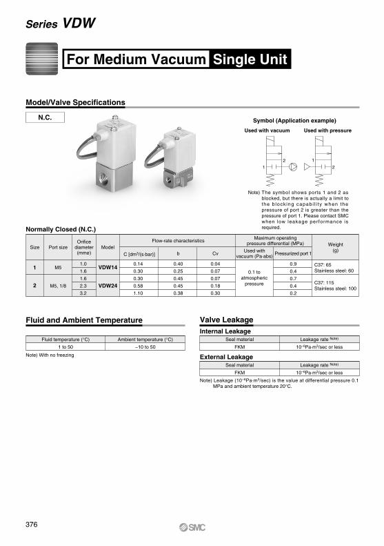
Fluid and Ambient Temperature Valve Leakage
Ambient temperature (°C)
−10 to 50
Fluid temperature (°C)
1 to 50 FKM
Seal material Leakage rate Note)
10−6Pa·m3/sec or less
FKM
Seal material Leakage rate Note)
10−6Pa·m3/sec or less
Symbol (Application example)
Used with vacuum Used with pressure
Model/Valve Specifications
N.C.
Note) With no freezing
Internal Leakage
External Leakage
Note) Leakage (10−6Pa·m3/sec) is the value at differential pressure 0.1 MPa and ambient temperature 20°C.
Normally Closed (N.C.)
Port sizeSizeOrifice
diameter(mmø)
Model
Maximum operatingpressure differential (MPa)
Used withvacuum (Pa·abs) Pressurized port 1
0.1 toatmospheric
pressure
1.0
1.6
1.6
2.3
3.2
M5
M5, 1/8
C [dm3/(s·bar)] b
0.04
0.07
0.07
0.18
0.30
0.40
0.25
0.45
0.45
0.38
0.14
0.30
0.30
0.58
1.10
Cv
Flow-rate characteristics
VDW14
VDW24
Weight(g)
0.9
0.4
0.7
0.4
0.2
C37: 65Stainless steel: 60
C37: 115Stainless steel: 100
1
2
Note) The symbol shows ports 1 and 2 as blocked, but there is actually a limit to the b lock ing capab i l i t y when the pressure of port 2 is greater than the pressure of port 1. Please contact SMC when low leakage performance is required.
2
12
1
Single UnitFor Medium Vacuum
Series VDW
376
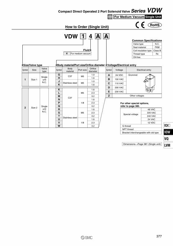
Symbol
1
SizeValvetype
Size 1
2 Size 2
SingleunitN.C.
SingleunitN.C.
Symbol
GHJK
KLMNPQRSTUVW
Bodymaterial
C37
Stainless steel
C37
Stainless steel
Orificediameter
1.6
2.3
3.2
1.6
2.3
3.2
1.6
2.3
3.2
1.6
2.3
3.2
1.0
1.6
1.0
1.6
Port size
M5
1/8
M5
1/8
M5
M5
How to Order (Single Unit)
VDW 4 A A1
Fluid4 For medium vacuum
Size/Valve type Body material/Port size/Orifice diameter Voltage/Electrical entry
Symbol
A
B
C
D
E
Z
Electrical entryVoltage
24 VDC
100 VAC
110 VAC
200 VAC
230 VAC
Grommet
Other voltages
RoHS
For other special options, refer to page 380.
48 VAC
220 VAC
240 VAC
24 VAC
12 VDC
Special voltage
G thread
NPT thread
Bracket interchangeable with old type
Common SpecificationsN.C.
FKM
Class B
Rc
Valve type
Seal material
Coil insulation type
Thread type
Oil-free
Dimensions→Page 381 (Single unit)
377
Single UnitFor Medium Vacuum
Compact Direct Operated 2 Port Solenoid Valve Series VDW
VCH
VDW
VQ
LVM
VDW

Fluid and Ambient Temperature Valve Leakage
Symbol
Ambient temperature (°C)
−10 to 50
Fluid temperature (°C)
1 to 50NBR
Seal material Leakage rate (Water) Note 2)
0.1 cm3/min or less (C37, Stainless steel body type)
1 cm3/min or less (Resin body type)
NBR
Seal material Leakage rate (Water) Note 2)
0.1 cm3/min or less (C37, Stainless steel body type)
1 cm3/min or less (Resin body type)
Model/Valve Specifications
N.C.
Note) With no freezing
Internal Leakage Note 1) Internal leakage when pressure is supplied to Port 1 (IN).
External Leakage
Port sizeSizeOrifice
diameter(mmø)
ModelMaximum operating
pressure differential (MPa)
0.9
0.4
0.7
0.4
0.2
1.0
1.6
1.6
2.3
3.2
M5
M5, 1/8
1
2
AV (x10-6m2)
0.04
0.07
0.07
0.18
0.30
0.96
1.70
1.70
4.30
7.20
Conversion Cv Pressurized port 1
Flow-rate characteristics
VDW12
VDW22
Weight(g)
Single UnitFor Water
Note 2) Leakage is the value at ambient temperature 20°C.
Resin Body Type
Port sizeSizeOrifice
diameter(mmø)
Model
0.9
0.4
0.7
0.4
0.2
1.0
1.6
1.6
2.3
3.2
M5ø3.2 One-touch fittingø4 One-touch fitting
M5ø4 One-touch fittingø6 One-touch fitting
1
2
Pressurized port 1
Flow-rate characteristics
VDW12
VDW22
Weight(g)
Refer to “Glossary of Terms” on page 384 for details on the maximum operating pressure differential.
Normally Closed (N.C.)C37, Stainless Steel Body Type
C37: 65Stainless steel: 60
C37: 115Stainless steel: 100
45
80
Conversion Cv
0.04
0.07
0.07
0.18
0.30
AV
0.96
1.70
1.70
4.30
7.20
Note) The symbol shows ports 1 and 2 as blocked, but there is actually a limit to the blocking capability when the pressure of port 2 is greater than the pressure of port 1. Please contact SMC when low leakage performance is required.
21
Maximum operatingpressure differential (MPa)
378
Series VDW
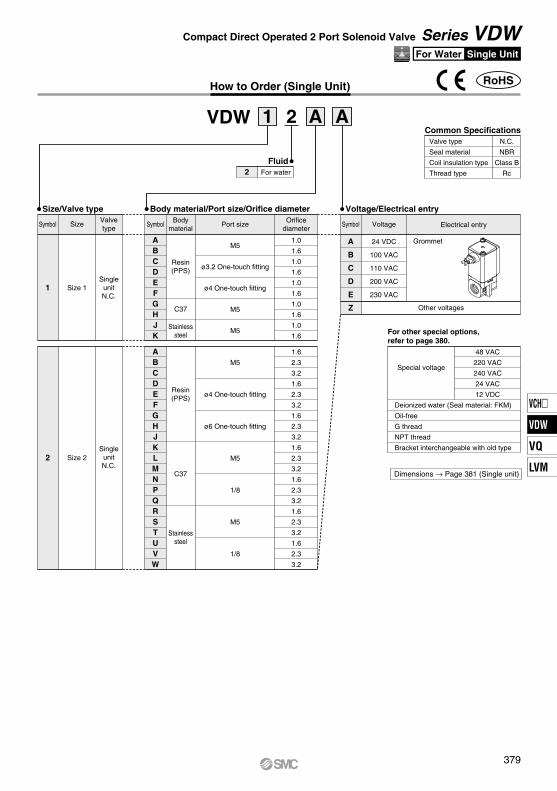
How to Order (Single Unit)
VDW 2 A A1
1 Size 1
2 Size 2
SingleunitN.C.
SingleunitN.C.
KLMNPQRSTUVW
ABCDEFGHJK
ABCDEFGHJ
C37
Stainlesssteel
Resin(PPS)
Resin(PPS)
C37
Stainlesssteel
1.0
1.6
1.0
1.6
1.0
1.6
1.0
1.6
1.0
1.6
1.6
2.3
3.2
1.6
2.3
3.2
1.6
2.3
3.2
1.6
2.3
3.2
M5
ø3.2 One-touch fitting
ø4 One-touch fitting
M5
M5
M5
1/8
M5
1/8
1.6
2.3
3.2
1.6
2.3
3.2
1.6
2.3
3.2
M5
ø4 One-touch fitting
ø6 One-touch fitting
A
B
C
D
E
Z Other voltages
Grommet24 VDC
100 VAC
110 VAC
200 VAC
230 VAC
RoHS
For other special options, refer to page 380.
48 VAC
220 VAC
240 VAC
24 VAC
12 VDC
Special voltage
Oil-free
G thread
NPT thread
Bracket interchangeable with old type
Common SpecificationsN.C.
NBR
Class B
Rc
Valve type
Seal material
Coil insulation type
Thread type
Size/Valve type Body material/Port size/Orifice diameter Voltage/Electrical entry
Symbol SizeValvetype
SymbolBody
materialOrifice
diameterPort size Symbol Electrical entryVoltage
Dimensions → Page 381 (Single unit)
Fluid2 For water
Deionized water (Seal material: FKM)
379
Compact Direct Operated 2 Port Solenoid Valve Series VDWSingle UnitFor Water
VCH
VDW
VQ
LVM
VDW

IN1
IN1
OUT2
OUT2
u
y
t
r
e
w
q
i
u
y
t
r
e
w
q
Construction
Normally closed (N.C.)Body material: Aluminum, PPS resin, C37, Stainless steel Body material: PPS resin (One-touch fitting type)
Component PartsNo. Description
Solenoid coilFixed armatureTubeReturn springArmature assemblySealBody
MaterialCu + Fe + Resin
FeStainless steelStainless steel
NBR, FKM, Stainless steel, PPS resinNBR, FKM
Aluminum, PPS resin, C37, Stainless steel
1234567
Component PartsNo. Description
Solenoid coilFixed armatureTubeReturn springArmature assemblySealBodyBracket
MaterialCu + Fe + Resin
FeStainless steelStainless steel
NBR, FKM, Stainless steel, PPS resinNBR, FKMPPS resin
SPCC
12345678
VDW Z1 0 A AEnter standard
product number.Other option (Low concentration ozone
resistant, Deionized water, oil-free, special thread)
The brackets are interchangeable with brackets of old VDW10/20 series.For details of exterior dimensions, please contact SMC.∗ Only for aluminum and stainless steel
(Select stainless steel when interchangeable product is necessary for water.)
VDW Z1 0 A 1A
1A1B1C1U1D
Grommet
48 VAC220 VAC240 VAC24 VAC12 VDC
VDW XB
Example) VDW Z Z1A XB2 0 A
Electrical option
Other option
Bracket interchangeablewith old type
Series VDWOther Special Options
Other options(Low concentration ozone resistant,
Deionized water, oil-free, special thread)
Bracket interchangeablewith old type
Electrical options(Special voltage)
Enter standardproduct number.
Electrical optionElectrical option(Special voltage)
Electrical entryVoltage
Sym
bol
Spe
cifi-
catio
nS
peci
al v
olta
ge
Enter standardproduct number.
Bracket interchangeablewith old type
∗ Enter symbols in the order to the r ight when ordering a combination of electrical option, other options, and bracket interchangeable with old type.
NilABCZDEFGHJKLMNP
—
—
—
SymbolLow concentration ozone resistant, Deionized water (Seal material: FKM)
—
—
—
Oil-free
— (Standard)G1/8
NPT1/8M6
— (Standard)G1/8
NPT1/8M6
— (Standard)G1/8
NPT1/8M6
— (Standard)G1/8
NPT1/8M6
Specialthread
∗ Applicable for air type (VDW0) and water type (VDW2). ∗ When G or NPT is selected, choose the 1/8 port size standard model. ∗ When M6 is selected, choose the M5 port size standard model.
∗ 1 ∗ 1 ∗ 2, ∗ 3
380

D
CRE
A2 x PPort size
Full wave rectifier(AC type)
≈ 300 Q F
B
B1
M
2 x J thread depth KNote) Bracket interchangeable with old type (VDWXB) only
Dimensions
Grommet
ModelPort size
P
Mounting method
15 22 20 8 13.5 M3
A B D E FB1 C
11 52VDW2 M5, 1/8
(mm)
5 15
J K MGrommet
Electrical entry
17 36.5
Q R
Body material Aluminum
XL1XL2XL3XL4
600 mm1000 mm1500 mm3000 mm
VDW XLLead wire length
Made to Order
<Special lead wire length>Produced upon receipt of order. Please contact SMC for lead times.
381
AirAir MediumvacuumMediumvacuum
Water
Compact Direct Operated 2 Port Solenoid Valve Series VDW
VCH
VDW
VQ
LVM
VDW
A

Y
W
X
X1U1
U
D
CRE
2 x PPort size
Q F
B1
B
Full wave rectifier(AC type)
2 x ø3.4Mountinghole
≈ 300
Y
W
X
X1U1
U
2 x ø3.4Mountinghole
CRE
D
2 x PPort size
Full wave rectifier(AC type)
Q F≈ 300
B
B1
With one-touch fittingsGrommet
Dimensions
For information on handling One-touch fittings and appropriate tubing, refer to page 387 and KQ2 series One-touch fittings in Best Pneumatics No. 6.The KQ2 series information can be downloaded from the following SMC website, http://www.smcworld.com
ModelOne-touch fitting
P
Mounting bracket dimensions
28
33
14
16.5
17
19.5
17
20
U U1 X1 YW X
11
14
34
39
VDW1VDW2
ø3.2, ø4
ø4, ø6
Grommet
Electrical entry
15.5
17
30.5
35
Q R
ModelOne-touch fitting
P
32
36
17
20
9.5
10.5
B B1 EC D
46
53
15
20
VDW1VDW2
ø3.2, ø4
ø4, ø6
11
13.5
F
(mm)
Model Port sizeP
Mounting bracket dimensions
28
33
14
16.5
17
19.5
17
20
U U1 X1 YW X
11
14
34
39
VDW1VDW2
M5(M6)
M5(M6)
Grommet
Electrical entry
15.5
17
30.5
34
Q R
ModelPort size
P
20
22
10
11
9.5
9.5
B B1 EC D
46
51
15
20
VDW1VDW2
M5(M6)
M5(M6)
11
13.5
F
(mm)
Port size M5/M6Grommet
ResinBody material
382
Series VDWAir, Medium Vacuum, Water

D
CRE
2 x PPort size
≈ 300 Q F
B1
B
Full wave rectifier(AC type)
M
2 x J thread depth K
Dimensions
ModelPort size
P
Mounting method
20
22
10
11
6
8
11
13.5
M2.5
M3
B B1 E FC D
42.5
52
15
20
VDW1VDW2
M5
M5, 1/8
4
5
11
15
J K MGrommet
Electrical entry
15.5
17
30
36.5
Q R
(mm)
Grommet
C37
D
CRE
A2 x PPort size
≈ 300 Q F
BB1
Full wave rectifier(AC type)
M
2 x J thread depth K
ModelPort size
P
Mounting method
12
15
20
22
15
20
6
8
11
13.5
M2.5
M3
A B D E FB1 C
10
11
42.5
52
VDW1VDW2
M5
M5, 1/8
(mm)
4
5
11
15
J K MGrommet
Electrical entry
15.5
17
30
36.5
Q R
Grommet
Body material Stainless Steel
Body material
383
AirAir MediumvacuumMediumvacuum
Water
Compact Direct Operated 2 Port Solenoid Valve Series VDW
VCH
VDW
VQ
LVM
VDW

Others
1. MaterialNBR: Nitrile rubberFKM: Fluororubber
2. Oil-free treatmentThe degreasing and washing of wetted parts
3. SymbolSymbol ( ) IN and OUT are in a blocked condition ( ), but actually in the case of reverse pressure (OUT> IN), there is a limit to the blocking.Product with flow direction 2 → 1 with pressure supplied to port 2 and universal specification product are available as specials.
Size 1
Size 2
Sizeø1.0ø1.6ø1.6ø2.3ø3.2
Orifice diameter [mm]0.40.20.20.10.05
Max. operating pressure differential [∆MPa]
Universal specificationA special can be available for Universal Specification, where product operation can be both flow from port 1 to port 2 (1 → 2) and from port 2 to port 1 (2 → 1).
CautionWhen operating the product with flow direction 2 → 1 with pressure supplied to port 2, there is a risk of the valve opening momentarily and fluid leaking to the downstream side due to a rapid increase of the upstream pressure.A special product will be available when holding pressure supplied from port 2 in the flow direction 2 → 1 with low leakage performance is required.
Series VDWGlossary of Terms
Pressure Terminology
1. Maximum operating pressure differentialThe maximum pressure differential (the difference between the inlet and outlet pressure) which is allowed for operation. When the outlet pressure is 0 MPa, this becomes the maximum operating pressure.
2. Minimum operating pressure differentialThe minimum pressure differential (the difference between the inlet pressure and outlet pressure) required to keep the main valve fully opened.
3. Maximum system pressureThe maximum pressure that can be applied inside the pipelines (line pressure).[The pressure differential in the solenoid valve portion must be less than the maximum operating pressure differential.]
4. Withstand pressureThe pressure in which the valve must be withstood without a drop in performance after holding for one minute under prescribed (static) pressure and returning to the operating pressure range. [value under the prescribed conditions]
Electrical Terminology
1. Surge voltageA high voltage which is momentarily generated by shutting off the power in the shut-off area.
2. EnclosureA degree of protection defined in the “JIS C 0920: Waterproof test of electric machinery/appliance and the degree of protec-tion against the intrusion of solid foreign objects”.
Verify the degree of protection for each product.
Example) IP65: Dusttight, Low jetproof type“Low jetproof type” means that no water intrudes inside an equipment that could hinder from operating normally by means of applying water for 3 minutes in the prescribed manner. Take appropriate protection measures, since a device is not usable in an environment where a droplet of water is splashed constantly.
Second characteristic numeralFirst characteristic numeral
IP
First Characteristics: Degrees of protection against solid foreign objects
0123456
Non-protectedProtected against solid foreign objects of ø50 mm and greaterProtected against solid foreign objects of ø12 mm and greaterProtected against solid foreign objects of ø2.5 mm and greaterProtected against solid foreign objects of ø1.0 mm and greaterDust-protectedDusttight
Second Characteristics: Degrees of protection against water
012345678
Non-protectedProtected against vertically falling water dropsProtected against vertically falling water drops when enclosure tilted up to 15°Protected against rainfall when enclosure tilted up to 60°Protected against splashing waterProtected against water jetsProtected against powerful water jetsProtected against the effects of temporary immersion in waterProtected against the effects of continuous immersion in water
Dripproof type 1Dripproof type 2Rainproof typeSplashproof typeLow jetproof typeStrong jetproof typeImmersible typeSubmersible type
—
Product with flow direction 2 → 1 with pressure supplied to port 2When operating the product with pressure supplied to port 2 and pressure in the flow direction from port 2 to 1, the pressure difference between port 2 and port 1 should be according to the values shown in the table below.
384A

Series VDWSpecific Product Precautions 1Be sure to read before handling.Refer to front matter 41 for Safety Instructions, pages 17 to 19and the Operation Manual for 2 Port Solenoid Valves for Fluid Control Precautions. Please download it via our website, http://www.smcworld.com
Design
WarningSelection
Warning1. Cannot be used as an emergency shutoff valve, etc.
The valves presented in this catalog are not designed for safety applications such as an emergency shutoff valve. If the valves are used in this type of system, other reliable safety assurance measures should also be adopted.
2. Extended periods of continuous energizationThe solenoid coil will generate heat when continuously energized. Avoid using in a tightly shut container. Install it in a well-ventilated area. Furthermore, do not touch it while it is being energized or right after it is energized.
3. Liquid ringsIn cases with a flowing liquid, provide a bypass valve in the system to prevent the liquid from entering the liquid seal circuit.
4. Actuator driveWhen an actuator, such as a cylinder, is to be driven using a valve, take appropriate measures to prevent potential danger caused by actuator operation.
5. Pressure (including vacuum) holdingIt is not usable for an application such as holding the pressure (including vacuum) inside of a pressure vessel because air leakage is entailed in a valve.
6. When an impact, such as water hammer, etc., caused by the rapid pressure fluctuation is applied, the solenoid valve may be damaged. Give an atten-tion to it.
Selection
Warning1. Fluid
1) Type of fluidBefore using a fluid, check whether it is compatible with the materials of each model by referring to the fluids listed in this catalog. Use a fluid with a kinematic viscosity of 50 mm2/s or less. If there is something you do not know, please contact SMC.
2) Flammable oil, GasConfirm the specification for leakage in the interior and/or exterior area.
3) Corrosive gasCannot be used since it will lead to cracks by stress corrosion or result in other incidents.
4) Depending on water quality, a brass body can cause corrosion and internal leakage may occur. If such abnor-malities occur, exchange the product for a stainless steel body.
5) Use an oil-free specification when any oily particle must not enter the passage.
6) Applicable fluid on the list may not be used depending on the operating condition. Give adequate confirmation, and then determine a model, just because the compatibility list shows the general case.
2. Fluid qualityThe use of a fluid that contains foreign objects can cause problems such as malfunction and seal failure by promoting wear of the valve seat and armature, and by sticking to the sliding parts of the armature, etc. Install a suitable filter (strainer) immediately upstream from the valve. As a general rule, use 80 to 100 mesh.When using tap water, since substances such as calcium and magnesium which generate hard scale and sludge are included and can cause the valve to malfunction, install water softening equipment and a filter (strainer) right before the valve to remove these substances.
3. Air quality1) Use clean air.
Do not use compressed air that contains chemicals, synthetic oils including organic solvents, salt or corrosive gases, etc., as it can cause damage or malfunction.
2) Install an air filter.Install an air filter close to the valve on the upstream side. A filtration degree of 5 µm or less should be selected.
3) Install an aftercooler or air dryer, etc.Compressed air that contains excessive drainage may cause a malfunction of valves and other pneumatic equip-ment. To prevent this, install an aftercooler or air dryer, etc.
4) If excessive carbon powder is generated, eliminate it by installing a mist separator on the upstream side of valves.If excessive carbon powder is generated by the compres-sor, it may adhere to the inside of the valves and cause a malfunction.
Refer to Best Pneumatics No.5 for further details on compressed air quality.
4. Ambient environmentUse within the operable ambient temperature range. Check the compatibility between the product’s composition materials and the ambient atmosphere. Be certain that the fluid used does not touch the external surface of the product.
5. Countermeasures against static electricityTake measures to prevent static electricity since some fluids can cause static electricity.
6. Low temperature operation1) The valve can be used in an ambient temperature of between
–10 to –20°C. However, take measures to prevent freezing or solidification of impurities, etc.
2) When using valves for water application in cold climates, take appropriate countermeasures to prevent the water from freezing in tubing after cutting the water supply from the pump, by draining the water, etc. When warming by a heater, etc., be careful not to expose the coil portion to a heater. Installation of a dryer, heat retaining of the body is recom-mended to prevent a freezing condition in which the dew point temperature is high and the ambient temperature is low, and the high flow runs.
385
VCH
VDW
VQ
LVM
VDW

Tightening Torque for PipingConnection thread Proper tightening torque (N·m)
M5∗
M6∗
Rc1/8
1 to 1.51 to 1.57 to 9
Series VDWSpecific Product Precautions 2Be sure to read before handling.Refer to front matter 41 for Safety Instructions, pages 17 to 19and the Operation Manual for 2 Port Solenoid Valves for Fluid Control Precautions. Please download it via our website, http://www.smcworld.com
Selection
Warning7. Fluid quality Water
The use of a fluid that contains foreign objects can cause problems such as malfunction and seal failure by promoting wear of the valve seat and armature, and by sticking to the sliding parts of the armature, etc. Install a suitable filter (strainer) immediately upstream from the valve. As a general rule, use 50 to 100 mesh.When using tap water, since substances such as calcium and magnesium which generate hard scale and sludge are included and can cause the valve to malfunction, install water softening equipment and a filter (strainer) right before the valve to remove these substances.
AirUse ordinary compressed air where a filter of 5 µm or less is provided on the inlet side piping. (Except dry air)
Mounting
Warning1. If air leakage increases or equipment does not oper-
ate properly, stop operation.After mounting is completed, confirm that it has been done correctly by performing a suitable function test.
2. Do not apply external force to the coil section.When tightening is performed, apply a wrench or other tool to the outside of the piping connection parts.
3. Mount a valve with its coil position upwards, not downwards.When mounting a valve with its coil positioned downwards, foreign objects in the fluid will adhere to the iron core leading to a malfunction. Especially for strict leakage control, such as with vacuum applications and non-leak specifications, the coil must be positioned upwards.
Mounting
Warning4. Do not warm the coil assembly with a heat insulator, etc.
Use tape, heaters, etc., for freeze prevention on the piping and body only. They can cause the coil to burn out.
5. Secure with brackets, except in the case of steel piping and copper fittings.
6. Avoid sources of vibration, or adjust the arm from the body to the minimum length so that resonance will not occur.
7. Painting and coatingWarnings or specifications printed or labeled on the product should not be erased, removed or covered up.
Piping
Warning1. During use, deterioration of the tube or damage to
the fittings could cause tubes to come loose from their fittings and thrash about.To prevent uncontrolled tube movement, install protective covers or fasten tubes securely in place.
2. For piping the tube, fix the product securely using the mounting holes so that the product is not in the air.
1. Preparation before pipingBefore piping is connected, it should be thoroughly blown out with air (flushing) or washed to remove chips, cutting oil and other debris from inside the pipe.Install piping so that it does not apply pulling, pressing, bending or other forces on the valve body.
2. Avoid connecting ground lines to piping, as this may cause electric corrosion of the system.
3. Tighten threads with the proper tightening torque.When attaching fittings to valves, tighten with the proper tightening torque shown below.
4. Connection of piping to productsWhen connecting piping to a product, refer to its operation manual to avoid mistakes regarding the supply port, etc.
5. In applications such as vacuum and non-leak speci-fications, use caution specifically against the contamination of foreign objects or airtightness of the fittings.
CautionR
SOL.
OFF
Switching element
C
Leakage current
Caution1. Leakage voltage
Particularly when using a resistor in parallel with a switching element and using a C-R element (surge voltage suppressor) to protect the switching element, take note that leakage current will flow through the resistor, C-R element, etc., creating a possible danger that the valve may not turn off.
2. Selecting modelMaterial depends on fluid. Select optimal models for the fluid.
AC/Class B built-in full wave rectifier coil: 5% or less of rated voltageDC coil: 2% or less of rated voltage
Powe
r sup
ply
Leakage voltage
∗ For resin bodies, the proper tightening torque is 0.4 to 0.6 N·m (reference value). After tightening by hand, tighten by an additional 1/6th rotation with a tightening tool.
386A

Caution
Operating Environment
Warning
Straightportion
Mountingpitch A
Recommended Piping Conditions
1. When connecting tubes using one-touch fittings, provide some spare tube length shown in Fig. 1, recommended piping configuration.Also, do not apply external force to the fittings when binding tubes with bands, etc. (see Fig. 2.)
Tubesize
Mounting pitch AUnit: mm
Nylon tube Soft nylon tube Polyurethane tube
44 or more56 or more84 or more
29 or more30 or more39 or more
25 or more26 or more39 or more
Straightportion length
ø3.2ø4ø6
16 or more20 or more30 or more
1. Do not use in an atmosphere having corrosive gases, chemicals, sea water, water, water steam, or where there is direct contact with any of these.
2. Do not use in explosive atmospheres.3. Do not use in locations subject to vibration or
impact. 4. Do not use in locations where radiated heat will be
received from nearby heat sources.5. Employ suitable protective measures in locations
where there is contact with water droplets, oil or welding spatter, etc.
Maintenance
Warning
1. Filters and strainers1) Be careful regarding clogging of filters and strainers.2) Replace filter elements after one year of use, or earlier if the
pressure drop reaches 0.1 MPa.3) Clean strainers when the pressure drop reaches 0.1 MPa.
2. LubricationWhen using after lubricating, never forget to lubricate continu-ously.
3. StorageIn case of long term storage after use with heated water, thoroughly remove all moisture to prevent rust and deteriora-tion of rubber materials, etc.
4. Exhaust the drainage from an air filter periodically.
1. Removing the productThe valve will reach a high temperature when used with high temperature fluids. Confirm that the valve temperature has dropped sufficiently before performing work. If touched inadvertently, there is a danger of being burned.1) Shut off the fluid supply and release the fluid pressure in the
system.2) Shut off the power supply.3) Remove the product.
2. Low frequency operationSwitch valves at least once every 30 days to prevent malfunc-tion. Also, in order to use it under the optimum state, conduct a regular inspection once a half year.
Operating Precautions
Warning1. If there is a possibility of reverse pressure being
applied to the valve, take countermeasures such as mounting a check valve on the downstream side of the valve.
2. When problems are caused by a water hammer, install water hammer relief equipment (accumulator, etc.), or use an SMC water hammer relief valve (Series VXR). For details, please consult with SMC.
Wiring
Caution1. As a rule, use electric wire with a cross sectional
area of 0.5 to 1.25 mm2 for wiring.Furthermore, do not allow excessive force to be applied to the lines.
2. Use electric circuits which do not generate chatter-ing in their contacts.
3. Use voltage which is within ±10% of the rated voltage. In cases with a DC power supply where importance is placed on responsiveness, stay within ±5% of the rated value. The voltage drop is the value in the lead wire section connecting the coil.
4. When a surge from the solenoid affects the electri-cal circuitry, install a surge voltage suppressor, etc., in parallel with the solenoid. Or, adopt an option that comes with the surge voltage protection circuit. (However, a surge voltage occurs even if the surge voltage protection circuit is used. For details, please consult with SMC.)
Recommended Unacceptable
Fig. 2 Binding tubes with bands
Fig. 1 Recommended piping configuration
Series VDWSpecific Product Precautions 3Be sure to read before handling.Refer to front matter 41 for Safety Instructions, pages 17 to 19and the Operation Manual for 2 Port Solenoid Valves for Fluid Control Precautions. Please download it via our website, http://www.smcworld.com
387
VCH
VDW
VQ
LVM
VDW

q
w
Electric Connections
Electric Circuits
One-touch Fitting
2 (–, +)
1 (+, –)
SOL.
Varistor Rectifierelement
2
1
SOL.
Series VDWSpecific Product Precautions 4Be sure to read before handling.Refer to front matter 41 for Safety Instructions, pages 17 to 19and the Operation Manual for 2 Port Solenoid Valves for Fluid Control Precautions. Please download it via our website, http://www.smcworld.com
GrommetClass B coil: AWG20 Outside insulator diameter of 1.8 mm
Caution
Rated voltage
DC100 VAC200 VACOther AC
q
BlackBlueRedGray
w
RedBlueRedGray
Lead wire color
∗ There is no polarity.
Caution
Grommet
[DC circuit]
Grommet
[AC circuit]∗ For AC (Class B), the standard product is equipped with surge voltage suppressor.
CautionFor information on handling One-touch fittings and appropriate tubing, refer to page 387 and the KQ2 series One-touch fittings in Best Pneumatics No. 6.The KQ2 series information can be downloaded from the following SMC website, http://www.smcworld.com
388