Ray Analysis of Acoustic Field in a Fluid Layer - IOSR Journal
Upload
independentCategory
view
0download
0
IOSR Journal of Engineering (IOSRJEN) www.iosrjen.org
ISSN (e): 2250-3021, ISSN (p): 2278-8719
Vol. 05, Issue 01 (January. 2015), ||V1|| PP 44-57
International organization of Scientific Research 44 | P a g e
Optimizing Reception Performance of new UWB Pulse shape
over Multipath Channel using MMSE Adaptive Algorithm
Nadir M. Abd Elaziz, Abdelrasoul Jabar Alzubaidi, Mustafa A. Hassan Al Nilain University – College of Postgraduate Studies - Electronics & Communication Dept.
Sudan University of science and Technology-- Engineering College – Electronics Dept.
Al Nilain University – Electronics & Communication Dept. College of Postgraduate Studies - Al Nilain
University - Sudan, January 2015
Abstract: - this paper examines the performance of Minimum-Mean-Square-Error (MMSE) adaptive algorithm
as a reception algorithm for the 6th derivative Ultra-wideband (UWB) Gaussian pulse shape signals compared
to the performance of conventional Ultra-Wideband (UWB) Rake receiver with different number of Rake
fingers. MMSE adaptive algorithm is more efficient and powerful because of its ability and features of
adaptation to the substantial changes in the UWB multipath wireless communication channel model proposed
by the IEEE 802.15.3a working group based on modified (S-V) channel model because it is the most realistic
and practical channel model due to the nature of multipath wireless environment. The paper demonstrates the
performance of two commonly used transmission schemes in UWB communications which are Direct-
Sequence (DS-UWB) and Time-Hopping (TH-UWB) to compare between their performances over the
previously mentioned UWB multipath channel model using also two reception techniques which are the UWB
Rake receiver (with different number of Rake fingers) and the MMSE adaptive algorithm receiver to show the
latter efficiency due to its distinctive adaptability. Moreover, the performance comparison between the two
reception techniques presented in this paper is assumed to be performed in the presence of both; narrowband
interference coming from other networks (e.g. IEEE 802.11a WLAN), and also the presence of Multiple-
Access-Interference (MAI) coming from other UWB users in the proximity of the desired UWB user.
Index Terms: - Ultra-Wideband (UWB), Multiple-Access-Interference (MAI), Federal-Communication-
Committee (FCC), Bit-Error-Rate (BER), Signal-to-Noise Ratio (SNR), Signal-to-Interference-Noise Ratio
(SINR), Power-Spectral-Density (PSD), Minimum-Mean-Square-Error (MMSE), Channel-Model (CM).
I. INTRODUCTION The field of UWB has drawn a lot of attention and study effort in the last few years as it seems to be a
better candidate compared to most of the existing wireless radio technologies supporting short-range high-
speed (high data rates) communication networks. A substantial change occurred in February 2002; when the
Federal Communication Committee (FCC) has issued ruling report states that UWB signals with its associated
very wide bandwidth (7.5 GHz), and extremely low power-spectral-density (PSD) up to -41.3 dBm could be
used for commercial data communication applications such as wireless Personal Area Networks (WPANs), the
FCC regulation report defines the UWB signal as “ a signal that has a – 10dB bandwidth spectrum greater than
at least 500 MHz, or a signal that has a fractional bandwidth ( BWF ) greater than or equal to 0.20” [1], the
fractional bandwidth is defined by the following equation; whereas Cf represents the central frequency,
Hf and Lf correspond to the high and low frequencies identifying the – 10dB bandwidth respectively [1].
20.02
LH
LH
C
LHBW
ff
ff
f
ffF ……………. (1)
Furthermore, UWB became an emerging solution for the IEEE 802.15a (TG3a) standard; which is to provide
a low complexity, low cost, low power consumption and high data rates among WPANs devices. Since UWB
communications provide several important advantages including; coexistence with other wireless services and
networks without causing any interference, its good performance over low SNR environments, and more
importantly its mitigation of multipath fading propagation effects of the wireless channel due to its great ability
to resolve multipath phenomenon acquired by its extremely narrow pulses (sub-nanoseconds) which makes
UWB systems almost immune to the multipath fading channels. UWB systems are considered more preferable
due to the simple design of the transceiver structure resulting from the fact that; UWB signals are “carrier less”

Optimizing Reception Performance of new UWB Pulse shape over Multipath Channel using MMSE
International organization of Scientific Research 45 | P a g e
(transmitted without any carrier sinusoidal wave); the feature that eliminates the need for modulator,
demodulator, and oscillators circuitries in the transceiver structure. UWB communications utilizes extremely
narrow pulses to convey the carrier less UWB signals over the inherited wide spectrum bandwidth [1] [2].
However, the system model is introduced in section II which characterizes the UWB pulse shapes used in the
paper and the proposed UWB multipath channel models. While the transmission and multiple access schemes
are presented in section III. Section IV demonstrates in details the block diagrams and theory of operation of
the different reception schemes and receiver structures. The simulation and performance comparison results
are illustrated using MATLAB R2013b and Simulink libraries in section V. Finally, section VI concludes the
finishing results of the performance evaluation for the different receiver structures discussed in the paper.
II. SYSTEM MODEL A. UWB Pulse Shape
Since FCC issued a ruling report in February 2002 authorizing that UWB technology is considered an
interesting candidate for indoor wireless communications in the spectrum domain 3.1 – 10.6 GHz for its ability
to convey information with very high data rates inherited from the ultra-wide bandwidth (7.5 GHz). UWB
utilizes extremely narrow pulses (sub-nanosecond) to spread its signal’s power over the wide bandwidth, taking
to consideration that these extremely narrow pulses must fulfill the FCC power spectral density (PSD)
requirements presented in the ruling report as “ UWB systems indoor spectral Mask limits” shown in Fig. (1).
Fig. (1): UWB indoor Radiated power mask regulated by FCC
The narrow UWB pulses are emitted from the transmitter in a unique rhythm called “Pulse Repetition
Rate” associated to each transmitter and it must be known at the receiver to be able to detect the data and
information signal being transmitted. One fundamental challenge is to maximize the radiated UWB pulse
energy; yet to assure that the pulse’s PSD complies with the FCC spectral mask limits. Moreover, since the
extremely narrow pulses are relatively easy to generate with analog components; the Gaussian “monocycle”
pulse and its derivatives are commonly used as basic UWB pulse shapes because their PSD comply with the
FCC mask power limits as demonstrated in Fig. (2) [3] [4]. Hence, the pulse shapes used in the simulation in
the paper are the derivatives of the Gaussian “monocycle” pulse which can be expressed in the following
equation:
2)exp()(
tA
dt
dty
n
n
Gn ……………………….. (2)
Where; A is the normalized Pulse amplitude, and is a time-scaling factor and its relation to the pulse width
PT is that 7PT which contains about 99.98% of the total pulse energy.

Optimizing Reception Performance of new UWB Pulse shape over Multipath Channel using MMSE
International organization of Scientific Research 46 | P a g e
Fig. (2): PSDs of higher order derivatives of UWB Gaussian pulses
It can be seen from Fig. (2) that; PSD of the first derivative of the Gaussian “monocycle” pulse does
not totally fit within the FCC spectral mask. Therefore, another pulse shapes founded from derivatives of the
Gaussian Pulse because the higher-order derivatives increases the number of zero crossings which correspond
to higher “carrier” frequency sinusoid modulated by an equivalent Gaussian envelope. Thus, the Gaussian
Doublet which is the 2nd derivative of the Gaussian Pulse expressed in (3) is the most commonly used UWB
pulse shape in the literature [4]. However, this paper studies and analyzes the performance of the 6th derivative
of the Gaussian Pulse represented in (4) since it satisfies more the power limits of the FCC report and fits
much better into the mask limits as shown in Fig. (2).
22
2 )(2exp)(41)(
tt
tyG………….. (3)
263422
6 )(2exp)(15
64)(16)(121)(
tttttyG
………… (4)
B. UWB Multipath Channel Model
The modified Saleh-Valenzuela (S-V) model is used in the paper since it was adopted as a reference
UWB channel model by the IEEE 802.15.3a working group. The modeling process is based on an indoor
propagation environment practical measurement, and the main distinct features of the UWB propagation
channel are; its extremely rich multipath components profile and the non-Rayleigh fading amplitude
characteristics. In UWB propagation there are much more multipath components than any other wireless
propagation channels. As a result of the wide bandwidth of UWB pulses’ waveforms; the different objects exist
in the indoor environment will give a rise to much several multipath components all of which would be a part
of one “cluster”. Thus, the multipath components arrive at the receiver end in the form of “clusters”, and
within each cluster there will be multiple subsequent arrivals called “rays”. Therefore, Time-Of-Arrival (TOA)
statistics the IEEE 802.15.3a standard model used (S-V) approach which modeled multipath components in
clusters and rays.
Since UWB pulses are extremely narrow; only few multipath components overlap within each resolvable delay
bin. Consequently; the central limit theorem is not applicable and the amplitude fading statistics are not
sufficiently represented by Rayleigh distribution. The IEEE 802.15.3a standard adopted the modified (S-V)
model because its amplitude fading statistics are Log-normally distributed [4]. The impulse response of the
modified (S-V) model is represented in equation (5) [2] [4]:

Optimizing Reception Performance of new UWB Pulse shape over Multipath Channel using MMSE
International organization of Scientific Research 47 | P a g e
1
0
1
0
,, )()(C LCL
l
K
k
i
lk
i
llkii TtXth ……….(5)
Where; i
lk . represents the multipath gain coefficients, i
lT represents the delays of the l th cluster, i
lk ,
represents the delays of the k th multipath component “ray” within the l th cluster arrival time (i
lT ).
Shadowing effect of the total multipath energy is log-normal distributed and is represented by the term iX ,
and i refers to the i th realization.
A calculation of the delay characteristics of the modified (S-V) model impulse response presented in
(5) simulated using MATLAB and the simulation results are shown in Fig. (3). as can be seen in the figure; for
any longer delay in time-domain the amplitudes of UWB signal’s pulses are more decreasing and reduced;
which is expressed as “Fading” due to the multipath delay spread of the different rays within each of the
different clusters.
Fig. (3): Impulse Response and Delay Profile of Modified Saleh-Valenzuela Model
The IEEE 802.15.3a standard multipath channel proposal has defined four different models for different
scenarios based on practical measurements found in the indoor environment which are characterized as:
CM1: Line-Of-Sight (LOS) model for distance 0 – 4 m between XT and XR .
CM2: Non-LOS (NLOS) model for distance 0 – 4 m between XT and XR .
CM3: NLOS model for distance 4 – 10 m between XT and XR .
CM4: NLOS for 4 – 10 m between XT and XR , with extreme (dense) multipath channel condition.
III. TRANSMISSION AND MULTIPLE ACCESS As mentioned in the previous section the UWB pulses must be transmitted as a train of pulses in a
rhythm or a regular time called “pulse repetition rate” to carry the information signal for short range (indoor
environment). However, this regular pulse repetition rate will cause relatively large frequency PSD peaks of
amplitude in the corresponding spectrum at a certain frequencies represent the inverse of the pulse repetition
rate as presented in Fig. (4.a) and (4.b) respectively, the thing that contradicts and breaches the FCC power
mask regulations.
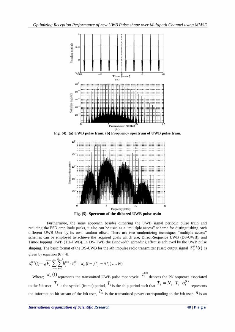
One approach to avoid the regular periodic transmission of UWB pulses is to “dither” the transmitted UWB
pulse train by adding a small random offset to each pulse, either delaying the pulse or transmitting slightly
before its regular time. The resultant spectrum from such a random offset is shown in Fig. (5) which presents
an observable reduction in the PSD amplitude peaks compared to Fig. (4.b).
Optimizing Reception Performance of new UWB Pulse shape over Multipath Channel using MMSE
International organization of Scientific Research 48 | P a g e
Fig. (4): (a) UWB pulse train. (b) Frequency spectrum of UWB pulse train.
Fig. (5): Spectrum of the dithered UWB pulse train
Furthermore, the same approach besides dithering the UWB signal periodic pulse train and
reducing the PSD amplitude peaks, it also can be used as a “multiple access” scheme for distinguishing each
different UWB User by its own random offset. There are two randomizing techniques “multiple access”
schemes can be employed to achieve the required goals which are; Direct-Sequence UWB (DS-UWB), and
Time-Hopping UWB (TH-UWB). In DS-UWB the Bandwidth spreading effect is achieved by the UWB pulse
shaping. The basic format of the DS-UWB for the kth impulse radio transmitter (user) output signal )()( tS k
tr is
given by equation (6) [4]:
j
N
n
cftr
k
n
k
jk
k
tr
C
nTjTtwcbPts1
0
)()()( )()( …. (6)
Where; )(twtr represents the transmitted UWB pulse monocycle,
)(k
ncdenotes the PN sequence associated
to the kth user, fTis the symbol (frame) period, cT
is the chip period such that
)(k
jccf bTNT represents
the information bit stream of the kth user, kP is the transmitted power corresponding to the kth user. n is an
Optimizing Reception Performance of new UWB Pulse shape over Multipath Channel using MMSE
International organization of Scientific Research 49 | P a g e
integer= 0,1,2,.. ,)(k
nc represents the PN sequence associated to the kth user,
1)(k
jb is the BPSK data
(bit) stream of the k th user, fTis the pulse repetition period (frame time), cT
is the chip period. While Time-
Hopping UWB usually utilizes Pulse-Position-Modulation (PPM) as a modulation scheme. In UWB systems
the pulses are assumed to be one of desired UWB pulse shapes mentioned in the previous sub-section. The
basic format of the TH using PPM for the kth user transmitted signal is given by [4]:
j
PPM
k
jc
k
jftr
k
tr TbTcjTtwts )()( )()()(…. (7)
Where; )(k
jc represents the PN Time-Hopping sequence associated to the kth user, PPMT represents the pulse
time-shift for the Pulse-Position-Modulation (PPM). The time-shift element of the TH code word assigned to
the kth user is chosen from the set: j = 0, 1, 2… 1cN ; Where cN is the number of time-delay bins (chips)
in a frame time fT .
IV. RECEPTION SCHEMES AND STRUCTURES The extremely narrow pulses used in UWB systems give a rise to the phenomena of Multipath
characterized by the UWB wireless channel discussed previously in section II due to the mechanisms of
reflection, diffraction, and scattering which cause the transmitted UWB signal to be; diverted into many paths,
and its energy to be dispersed, and also to arrive at the receiver end after some delays according to each path
length and losses. UWB systems utilize spread spectrum techniques as (DS) and (TH) mentioned in section III;
the thing that require great accuracy in signal acquisition, synchronization, and tracking at the receiver end.
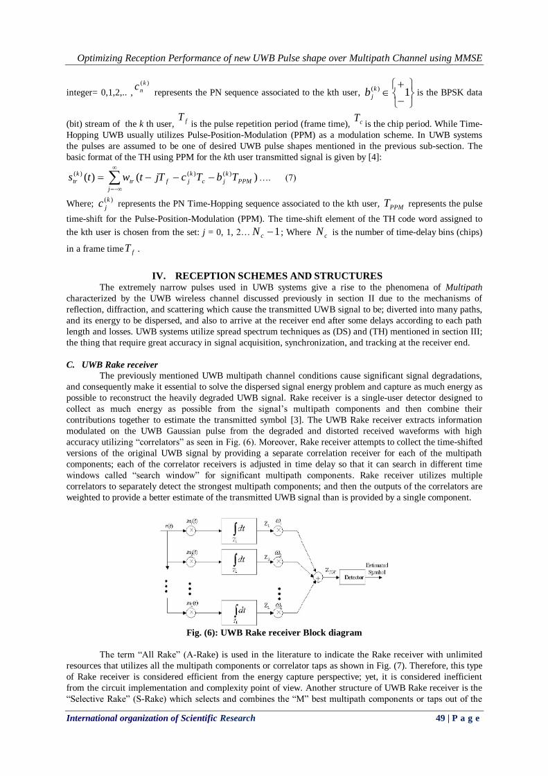
C. UWB Rake receiver
The previously mentioned UWB multipath channel conditions cause significant signal degradations,
and consequently make it essential to solve the dispersed signal energy problem and capture as much energy as
possible to reconstruct the heavily degraded UWB signal. Rake receiver is a single-user detector designed to
collect as much energy as possible from the signal’s multipath components and then combine their
contributions together to estimate the transmitted symbol [3]. The UWB Rake receiver extracts information
modulated on the UWB Gaussian pulse from the degraded and distorted received waveforms with high
accuracy utilizing “correlators” as seen in Fig. (6). Moreover, Rake receiver attempts to collect the time-shifted
versions of the original UWB signal by providing a separate correlation receiver for each of the multipath
components; each of the correlator receivers is adjusted in time delay so that it can search in different time
windows called “search window” for significant multipath components. Rake receiver utilizes multiple
correlators to separately detect the strongest multipath components; and then the outputs of the correlators are
weighted to provide a better estimate of the transmitted UWB signal than is provided by a single component.
Fig. (6): UWB Rake receiver Block diagram
The term “All Rake” (A-Rake) is used in the literature to indicate the Rake receiver with unlimited
resources that utilizes all the multipath components or correlator taps as shown in Fig. (7). Therefore, this type
of Rake receiver is considered efficient from the energy capture perspective; yet, it is considered inefficient
from the circuit implementation and complexity point of view. Another structure of UWB Rake receiver is the
“Selective Rake” (S-Rake) which selects and combines the “M” best multipath components or taps out of the

Optimizing Reception Performance of new UWB Pulse shape over Multipath Channel using MMSE
International organization of Scientific Research 50 | P a g e
total “L” multipath components that is determined by the Rake finger selection algorithm as presented in Fig.
(8) [4] [5].
Furthermore, the “Partial combining Rake” receiver structure (P-Rake) uses “N” multipath components out of
the total “L” available diversity multipath; but it combines the first “N” arriving components which are not
necessarily the strongest nor the best. The P-Rake structure has drastically reduced the complexity compared to
the S-Rake structure due to the absence of the selection mechanism. Thus, the P-Rake mitigates the need to
sort the multipath components by their instantaneous path gain magnitudes which would require a highly
accurate channel estimation process.
Fig. (7): “All Rake” receiver Block diagram
Fig. (8): “Selective Rake” receiver Block diagram
Instead, the P-Rake structure only needs to find the “position” of the first arriving multipath component, which
leads to a substantial circuit complexity reduction.
D. Minimum Mean Square Error (MMSE) algorithm
Significant studies have been made on an adaptive correlator receiver by Pateros and Saulnier in the
field of “Direct-Sequence Spread Spectrum” (DS-SS) systems employing BPSK signaling in a single user,
time-invariant multipath environment; these studies have proven that MMSE algorithm receiver detects the
transmitted data, removes the interference, and coherently combines the multipath components of the signal in
the presence of Narrowband Interference (NBI).
However, this paper demonstrates the performance of the MMSE correlator receiver with its adaptive
algorithm and capabilities for both DS-UWB and TH-UWB transmission schemes discussed previously in
section III. A major advantage of the MMSE scheme relative to other interference suppression reception
schemes is that; explicit knowledge of the interference parameters is not required. Instead, the UWB received
signal (template 6th derivative Gaussian pulses) from the multipath components can be sampled at a rate equal
to the Pulse-Repetition-Frequency after passing through the correlator receivers with their path selection
mechanism, and then the samples are linearly combined using the MMSE algorithm criteria to suppress the
NBI and consequently maximize the SINR as shown in Fig. (9).
Optimizing Reception Performance of new UWB Pulse shape over Multipath Channel using MMSE
International organization of Scientific Research 51 | P a g e
Fig. (9): UWB MMSE receiver Scheme
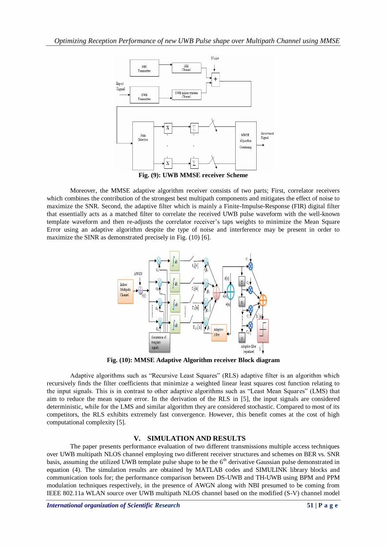
Moreover, the MMSE adaptive algorithm receiver consists of two parts; First, correlator receivers
which combines the contribution of the strongest best multipath components and mitigates the effect of noise to
maximize the SNR. Second, the adaptive filter which is mainly a Finite-Impulse-Response (FIR) digital filter
that essentially acts as a matched filter to correlate the received UWB pulse waveform with the well-known
template waveform and then re-adjusts the correlator receiver’s taps weights to minimize the Mean Square
Error using an adaptive algorithm despite the type of noise and interference may be present in order to
maximize the SINR as demonstrated precisely in Fig. (10) [6].
Fig. (10): MMSE Adaptive Algorithm receiver Block diagram
Adaptive algorithms such as “Recursive Least Squares” (RLS) adaptive filter is an algorithm which
recursively finds the filter coefficients that minimize a weighted linear least squares cost function relating to
the input signals. This is in contrast to other adaptive algorithms such as “Least Mean Squares” (LMS) that
aim to reduce the mean square error. In the derivation of the RLS in [5], the input signals are considered
deterministic, while for the LMS and similar algorithm they are considered stochastic. Compared to most of its
competitors, the RLS exhibits extremely fast convergence. However, this benefit comes at the cost of high
computational complexity [5].
V. SIMULATION AND RESULTS The paper presents performance evaluation of two different transmissions multiple access techniques
over UWB multipath NLOS channel employing two different receiver structures and schemes on BER vs. SNR
basis, assuming the utilized UWB template pulse shape to be the 6th derivative Gaussian pulse demonstrated in
equation (4). The simulation results are obtained by MATLAB codes and SIMULINK library blocks and
communication tools for; the performance comparison between DS-UWB and TH-UWB using BPM and PPM
modulation techniques respectively, in the presence of AWGN along with NBI presumed to be coming from
IEEE 802.11a WLAN source over UWB multipath NLOS channel based on the modified (S-V) channel model

Optimizing Reception Performance of new UWB Pulse shape over Multipath Channel using MMSE
International organization of Scientific Research 52 | P a g e
CM3. Moreover, the simulations present another important performance comparison between two significant
receiver structures schemes; First, Rake receiver with finger selection mechanism and different number of
fingers (4 fingers, 8 fingers, and 128 or an infinite “ ” number of fingers). Second, Minimum Mean Square
Error (MMSE) correlator receiver with LMS, RLS adaptive algorithms to re-adjust the tap weights for noise
and interference suppression to maximize the SINR. The rest of the key simulation parameters are listed in
Table (1).
Table. 1: Simulation Key Parameters
Pulse Shape 6th derivative Gaussian pulse
Pulse Width 0.168 ns
Pulse Amplitude 3 volts
Channel Model S-V channel model (CM 3)
Spreading Techniques
Direct Sequence
Time Hopping
Modulation Techniques Bi-phase Modulation
(BPM)
Pulse-Position-Modulation
(PPM)
Code Length 16cN
Interferences NBI from IEEE 802.11a
WLAN
MUI from 15 UWB users
Receiver Schemes Rake Receiver
MMSE Correlator with
LMS, RLS adaptive
algorithms
Chip Rate 1.6 GHz
Fig. (11): Performance of DS-UWB over Multipath NLOS Channel with AWGN but no Interference

Optimizing Reception Performance of new UWB Pulse shape over Multipath Channel using MMSE
International organization of Scientific Research 53 | P a g e
Fig. (12): Performance of TH-UWB over Multipath NLOS Channel with AWGN but no Interference
Fig. (13): Performance of DS-UWB over Multipath NLOS Channel with One NBI (SIR= -30 dB)
Fig. (14): Performance of TH-UWB over Multipath NLOS Channel with One NBI (SIR= -30 dB)

Optimizing Reception Performance of new UWB Pulse shape over Multipath Channel using MMSE
International organization of Scientific Research 54 | P a g e
Fig. (15): Performance of DS-UWB over Multipath NLOS Channel with One Stronger NBI (SIR= 0 dB)
Fig. (16): Performance of TH-UWB over Multipath NLOS Channel with One Stronger NBI (SIR= 0 dB)
Fig. (17): Performance of DS-UWB over Multipath NLOS Channel with Multiple UWB Interferers
(MUI of 15 UWB users)

Optimizing Reception Performance of new UWB Pulse shape over Multipath Channel using MMSE
International organization of Scientific Research 55 | P a g e
Fig. (18): Performance of TH-UWB over Multipath NLOS Channel with Multiple UWB Interferers
(MUI of 15 UWB users)
Fig. (19): Performance of DS-UWB over Multipath NLOS Channel with combined NBI (SIR = -30 dB)
and Multiple UWB Interferers (MUI)
Fig. (20): Performance of TH-UWB over Multipath NLOS Channel with combined NBI (SIR = -30 dB)
and Multiple UWB Interferers (MUI)
Optimizing Reception Performance of new UWB Pulse shape over Multipath Channel using MMSE
International organization of Scientific Research 56 | P a g e
Fig. (21): Performance of DS-UWB over Multipath NLOS Channel with combined Stronger NBI (SIR =
0 dB) and Multiple UWB Interferers (MUI)
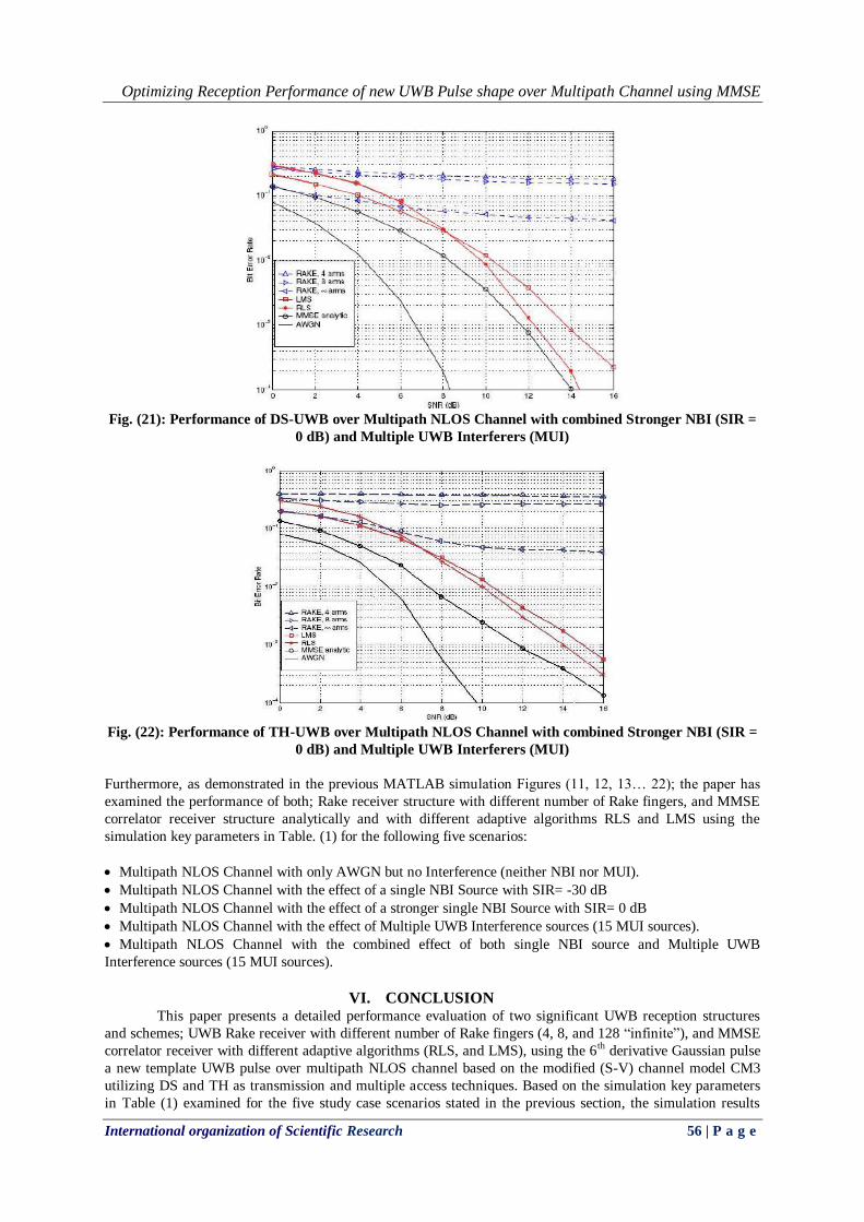
Fig. (22): Performance of TH-UWB over Multipath NLOS Channel with combined Stronger NBI (SIR =
0 dB) and Multiple UWB Interferers (MUI)
Furthermore, as demonstrated in the previous MATLAB simulation Figures (11, 12, 13… 22); the paper has
examined the performance of both; Rake receiver structure with different number of Rake fingers, and MMSE
correlator receiver structure analytically and with different adaptive algorithms RLS and LMS using the
simulation key parameters in Table. (1) for the following five scenarios:
Multipath NLOS Channel with only AWGN but no Interference (neither NBI nor MUI).
Multipath NLOS Channel with the effect of a single NBI Source with SIR= -30 dB
Multipath NLOS Channel with the effect of a stronger single NBI Source with SIR= 0 dB
Multipath NLOS Channel with the effect of Multiple UWB Interference sources (15 MUI sources).
Multipath NLOS Channel with the combined effect of both single NBI source and Multiple UWB
Interference sources (15 MUI sources).
VI. CONCLUSION This paper presents a detailed performance evaluation of two significant UWB reception structures
and schemes; UWB Rake receiver with different number of Rake fingers (4, 8, and 128 “infinite”), and MMSE
correlator receiver with different adaptive algorithms (RLS, and LMS), using the 6th derivative Gaussian pulse
a new template UWB pulse over multipath NLOS channel based on the modified (S-V) channel model CM3
utilizing DS and TH as transmission and multiple access techniques. Based on the simulation key parameters
in Table (1) examined for the five study case scenarios stated in the previous section, the simulation results

Optimizing Reception Performance of new UWB Pulse shape over Multipath Channel using MMSE
International organization of Scientific Research 57 | P a g e
show that; performance of DS-UWB as a transmission and multiple access technique is slightly better than TH-
UWB technique specially in the presence of either Narrowband Interference (NBI) or Multiple User
Interference (MUI) in addition to the AWGN. Furthermore, as the Narrowband Interference grow stronger
(poorer SIR); the performance of Rake receiver with more Rake fingers is proven to be more efficient than the
one with less Rake fingers. However, the reception performance has obviously improved and extensively
developed when employing the Minimum Mean Square Error (MMSE) correlator receiver whether analytically
or utilizing adaptive filter algorithms such as RLS and LMS especially in case of MUI caused by other UWB
users in the proximity of the main desired UWB source.
REFERENCES [1] Ian Oppermann, Matti Hamalainen “UWB Theory and Applications,” Book, pp. 15–80.
[2] M.Ghavami, L.B.Michael “Ultra-Wideband Signals and Systems in Communication Engineering,”
Book, pp. 26–113.
[3] B. M.Mezzour, “Direct Sequence UWB performance over STDL ” paper Journal, vol.3.
[4] Nadir. Abd Elaziz, Abdelrasoul. Alzubaidi, “Performance of the 6th derivative Gaussian Pulse Shape in
IEEE 802.15.3a Multipath Fading Channel” IOSR journal of Engineering, Vol3, Issue December 2014.
[5] Rashid A. Fayyadh, F. Malik “Adaptive Rake receiver using Matched Filter with Three Combining
Techniques” Australian Journal of Basic and Applied Sciences, 7(5): 26-33, 2013 ISSN 1991-8178.
[6] Rashid A. Fayyadh, “Improved Rake Receiver Based On the Signal Sign Separation in Maximal Ratio
Combining Technique for Ultra-Wideband Wireless Communication” World Academy of Science,
Engineering and Technology, International Journal of Electrical, Robotics, Electronics and
Communications Engineering Vol:7 No:12, 2013
Copyright © 2022 FDOKUMEN