INTERNATIONAL STANDARD ISO 21903 - SIS
11
© ISO 2020 Refrigerated hydrocarbon fluids — Dynamic measurement — Requirements and guidelines for the calibration and installation of flowmeters used for liquefied natural gas (LNG) and other refrigerated hydrocarbon fluids Hydrocarbures liquides réfrigérés — Mesurage dynamique — Exigences et lignes directrices pour l’étalonnage et l’installation de débitmètres utilisés pour le gaz naturel liquéfié (GNL) et autres hydrocarbures liquides réfrigérés INTERNATIONAL STANDARD ISO 21903 First edition 2020-02 Reference number ISO 21903:2020(E) This preview is downloaded from www.sis.se. Buy the entire standard via https://www.sis.se/std-80019635
-
Upload
khangminh22 -
Category
Documents
-
view
0 -
download
0
Transcript of INTERNATIONAL STANDARD ISO 21903 - SIS
© ISO 2020
Refrigerated hydrocarbon fluids — Dynamic measurement — Requirements and guidelines for the calibration and installation of flowmeters used for liquefied natural gas (LNG) and other refrigerated hydrocarbon fluidsHydrocarbures liquides réfrigérés — Mesurage dynamique — Exigences et lignes directrices pour l’étalonnage et l’installation de débitmètres utilisés pour le gaz naturel liquéfié (GNL) et autres hydrocarbures liquides réfrigérés
INTERNATIONAL STANDARD
ISO21903
First edition2020-02
Reference numberISO 21903:2020(E)
This preview is downloaded from www.sis.se. Buy the entire standard via https://www.sis.se/std-80019635

ISO 21903:2020(E)
ii © ISO 2020 – All rights reserved
COPYRIGHT PROTECTED DOCUMENT
© ISO 2020All rights reserved. Unless otherwise specified, or required in the context of its implementation, no part of this publication may be reproduced or utilized otherwise in any form or by any means, electronic or mechanical, including photocopying, or posting on the internet or an intranet, without prior written permission. Permission can be requested from either ISO at the address below or ISO’s member body in the country of the requester.
ISO copyright officeCP 401 • Ch. de Blandonnet 8CH-1214 Vernier, GenevaPhone: +41 22 749 01 11Fax: +41 22 749 09 47Email: [email protected]: www.iso.org
Published in Switzerland
This preview is downloaded from www.sis.se. Buy the entire standard via https://www.sis.se/std-80019635
ISO 21903:2020(E)
Foreword ..........................................................................................................................................................................................................................................vIntroduction ................................................................................................................................................................................................................................vi1 Scope ................................................................................................................................................................................................................................. 12 Normative references ...................................................................................................................................................................................... 13 Terms, definitions and abbreviated terms ................................................................................................................................ 1
3.1 Terms and definitions ....................................................................................................................................................................... 13.2 Abbreviated terms ............................................................................................................................................................................... 3
4 Flowmeter selection ......................................................................................................................................................................................... 34.1 Considerations of meters specific to LNG metering................................................................................................ 34.2 Coriolis flowmeter ............................................................................................................................................................................... 44.3 Ultrasonic flowmeter ......................................................................................................................................................................... 4
5 Process conditions .............................................................................................................................................................................................. 55.1 Temperature effects ............................................................................................................................................................................ 5
5.1.1 Loading procedures....................................................................................................................................................... 55.1.2 Temperature effects on CMF measurements ........................................................................................... 55.1.3 Temperature effects on USM measurements........................................................................................... 6
5.2 Pressure effects ...................................................................................................................................................................................... 65.2.1 Coriolis flowmeter .......................................................................................................................................................... 65.2.2 Ultrasonic flowmeter ................................................................................................................................................... 7
5.3 Mechanical vibrations ....................................................................................................................................................................... 75.3.1 Coriolis flowmeter .......................................................................................................................................................... 75.3.2 Ultrasonic flowmeter ................................................................................................................................................... 8
5.4 Cavitation ..................................................................................................................................................................................................... 85.4.1 Coriolis flowmeter .......................................................................................................................................................... 85.4.2 Ultrasonic flowmeter ................................................................................................................................................... 9
5.5 Thermodynamic properties of LNG ...................................................................................................................................... 96 Installation ................................................................................................................................................................................................................. 9
6.1 Valves ............................................................................................................................................................................................................... 96.2 Swirl and non-uniform profiles ................................................................................................................................................ 9
6.2.1 Coriolis flowmeter .......................................................................................................................................................... 96.2.2 Ultrasonic flowmeter ................................................................................................................................................10
6.3 Flow conditioners .............................................................................................................................................................................. 106.4 Pipe stress and torsion .................................................................................................................................................................. 10
6.4.1 Coriolis flowmeter .......................................................................................................................................................106.4.2 Ultrasonic flowmeter ................................................................................................................................................11
6.5 Flowmeter installation recommendations .................................................................................................................. 116.5.1 Coriolis flowmeter .......................................................................................................................................................116.5.2 Ultrasonic flowmeter ................................................................................................................................................12
6.6 Crosstalk and sensitivity to noise ........................................................................................................................................ 126.6.1 Coriolis flowmeter .......................................................................................................................................................126.6.2 Ultrasonic flowmeter ................................................................................................................................................12
6.7 Zero offset — Verification and adjustment procedures ...................................................................................136.7.1 Coriolis flowmeter .......................................................................................................................................................136.7.2 Ultrasonic flowmeter ................................................................................................................................................15
6.8 Temperature management ........................................................................................................................................................ 156.8.1 Thermal insulation ......................................................................................................................................................156.8.2 Cooling procedure .......................................................................................................................................................166.8.3 Warming procedure ...................................................................................................................................................17
7 Calibration ...............................................................................................................................................................................................................187.1 General considerations ................................................................................................................................................................. 187.2 Calibration in a laboratory ......................................................................................................................................................... 18
7.2.1 Gravimetric method ...................................................................................................................................................18
© ISO 2020 – All rights reserved iii
Contents Page
This preview is downloaded from www.sis.se. Buy the entire standard via https://www.sis.se/std-80019635
ISO 21903:2020(E)
7.2.2 Master meter method ...............................................................................................................................................207.3 Calibration in situ .............................................................................................................................................................................. 22
7.3.1 Gravimetric method using a weighbridge .............................................................................................227.3.2 Road tanker temporarily on weighbridge ...............................................................................................237.3.3 Measurement uncertainty .................................................................................................................................... 23
7.4 Interconnected pipe volume .................................................................................................................................................... 23Annex A (informative) Working principle Coriolis flowmeter ...............................................................................................27Annex B (informative) Working principle of the ultrasonic flowmeter ........................................................................30Annex C (normative) Hardware for an LNG calibration facility ............................................................................................33Annex D (informative) Examples of calibration data .......................................................................................................................36Annex E (normative) Alternative calibration procedure based on alternative liquids ................................39Annex F (informative) Thermodynamic properties of LNG .......................................................................................................41Bibliography .............................................................................................................................................................................................................................47
iv © ISO 2020 – All rights reserved
This preview is downloaded from www.sis.se. Buy the entire standard via https://www.sis.se/std-80019635
ISO 21903:2020(E)
Foreword
ISO (the International Organization for Standardization) is a worldwide federation of national standards bodies (ISO member bodies). The work of preparing International Standards is normally carried out through ISO technical committees. Each member body interested in a subject for which a technical committee has been established has the right to be represented on that committee. International organizations, governmental and non-governmental, in liaison with ISO, also take part in the work. ISO collaborates closely with the International Electrotechnical Commission (IEC) on all matters of electrotechnical standardization.
The procedures used to develop this document and those intended for its further maintenance are described in the ISO/IEC Directives, Part 1. In particular, the different approval criteria needed for the different types of ISO documents should be noted. This document was drafted in accordance with the editorial rules of the ISO/IEC Directives, Part 2 (see www .iso .org/ directives).
Attention is drawn to the possibility that some of the elements of this document may be the subject of patent rights. ISO shall not be held responsible for identifying any or all such patent rights. Details of any patent rights identified during the development of the document will be in the Introduction and/or on the ISO list of patent declarations received (see www .iso .org/ patents).
Any trade name used in this document is information given for the convenience of users and does not constitute an endorsement.
For an explanation of the voluntary nature of standards, the meaning of ISO specific terms and expressions related to conformity assessment, as well as information about ISO’s adherence to the World Trade Organization (WTO) principles in the Technical Barriers to Trade (TBT) see www .iso .org/ iso/ foreword .html.
This document was prepared by Technical Committee ISO/TC 28, Petroleum and related products, fuels and lubricants from natural or synthetic sources.
Any feedback or questions on this document should be directed to the user’s national standards body. A complete listing of these bodies can be found at www .iso .org/ members .html.
© ISO 2020 – All rights reserved v
This preview is downloaded from www.sis.se. Buy the entire standard via https://www.sis.se/std-80019635
ISO 21903:2020(E)
Introduction
Reliable, accurate and commonly agreed measurement methods are a first requirement for the trade of goods. In the LNG distribution chain, there is a commonly agreed measurement practice, as described in various International Standards and in the GIIGNL Custody transfer handbook[10]. The LNG industry is committed to improve measurement accuracy to reduce financial risks and to optimize mass and energy balances throughout the LNG measurement chain. Dynamic measurement technologies have the potential to reduce measurement uncertainty. As an extension of the traditional distribution chain for LNG, a new market of professional consumers for LNG is developing related to transport fuel and metrological infrastructure. In this respect, the availability of the following tools for dynamic flow measurement is essential:
— primary standards for the determination of the amount of an LNG substance and calibration of working standards;
— LNG test and calibration facilities (for volume and mass flow) for the calibration of equipment for custody transfer, allocation or process control under operational conditions;
— stable meters for the determination of volume and mass flow under cryogenic conditions;
— guidelines for the selection and installation of cryogenic flowmeters;
— guidelines for zeroing and adjusting cryogenic flowmeters, including tips and traps;
— guidelines for the further dissemination of traceability by (master meter) calibration techniques, including correction methods for parasitic metrological effects;
— guidelines for the calibration of volume and mass flowmeters with alternative fluids such as water.
This document provides designers of metering stations and end-users with a set of valuable guidelines to enable a better performance of liquid flowmeters under cryogenic operating conditions. The document focuses on LNG as a medium, however, it is assumed that much of the information is also directly applicable to other cryogenic fluids.
vi © ISO 2020 – All rights reserved
This preview is downloaded from www.sis.se. Buy the entire standard via https://www.sis.se/std-80019635
Refrigerated hydrocarbon fluids — Dynamic measurement — Requirements and guidelines for the calibration and installation of flowmeters used for liquefied natural gas (LNG) and other refrigerated hydrocarbon fluids
1 Scope
This document specifies the metrological and technical requirements for flowmeters intended to be used for the dynamic measurement of liquefied natural gas (LNG) and other refrigerated hydrocarbon fluids. For LNG static volume measurement used in custody transfer, see ISO 10976.
This document sets the best practice for the proper selection and installation of flowmeters in cryogenic applications and identifies the specific issues that can affect the performance of the flowmeter in use.
Moreover, it offers a calibration guideline for laboratory and on-site conditions (mass or volume) by either using LNG or other reference fluids. The choice of calibration fluid will depend on the capabilities of the available flow calibration facilities and the ability to achieve the required overall measurement uncertainty demanded by the intended application.
This document is applicable, but is not limited, to the use of Coriolis and ultrasonic flowmeters for dynamic measurements of LNG.
In principle, LNG and other refrigerated liquid hydrocarbons are considered in this document. Recommendations in this document are based on the available test results with LNG. These results are probably applicable to other cryogenic fluids.
2 Normative references
The following documents are referred to in the text in such a way that some or all of their content constitutes requirements of this document. For dated references, only the edition cited applies. For undated references, the latest edition of the referenced document (including any amendments) applies.
ISO 10790, Measurement of fluid flow in closed conduits — Guidance to the selection, installation and use of Coriolis flowmeters (mass flow, density and volume flow measurements)
ISO 12242, Measurement of fluid flow in closed conduits — Ultrasonic transit-time meters for liquid
3 Terms, definitions and abbreviated terms
3.1 Terms and definitions
For the purposes of this document, the following terms and definitions apply.
ISO and IEC maintain terminological databases for use in standardization at the following addresses:
— ISO Online browsing platform: available at https:// www .iso .org/ obp
— IEC Electropedia: available at http:// www .electropedia .org/
INTERNATIONAL STANDARD ISO 21903:2020(E)
© ISO 2020 – All rights reserved 1
This preview is downloaded from www.sis.se. Buy the entire standard via https://www.sis.se/std-80019635
ISO 21903:2020(E)
3.1.1master meterMMflowmeter calibrated against a primary standard with sufficiently low uncertainty and used to calibrate the meter under test
3.1.2measurement errormeasured quantity value (3.1.3) minus a reference quantity value
3.1.3measured quantity valuequantity value representing a measurement result
3.1.4measurement uncertaintynon-negative parameter characterizing the dispersion of the quantity values being attributed to a measurand, based on the information used
Note 1 to entry: A list of metrological definitions can be found in ISO/IEC Guide 99.
3.1.5stored zero valueSZVvalue stored in the flowmeter transmitter representing a meter reading at a no flow condition
3.1.6turndown ratioratio of maximum and minimum flow rates
3.1.7zero adjustmentdedicated procedure to set a new stored zero value (3.1.5), with the aim to keep the flowmeter within its zero offset limit (3.1.9)
3.1.8zero offsetZOaverage mass or volume flow rate reading observed under zero (no) flow conditions
Note 1 to entry: In this instance, the (Coriolis) flowmeter’s low flow cut-off filter is disabled, and the flow direction in the electronics is set to bi-directional.
3.1.9zero offset limitZOLmaximum permissible zero offset (3.1.8) specified by the manufacturer
Note 1 to entry: Some Coriolis mass flowmeter manufacturers also state a specific zero offset for verification and adjustment.
3.1.10zero verificationprocedure to check that the actual zero offset (3.1.8) of the flowmeter has not exceeded the zero offset limit (3.1.9)
2 © ISO 2020 – All rights reserved
This preview is downloaded from www.sis.se. Buy the entire standard via https://www.sis.se/std-80019635
ISO 21903:2020(E)
3.2 Abbreviated terms
CMF Coriolis mass flowmeter
LNG liquefied natural gas
MM master meter
MUT meter under test
USM ultrasonic flowmeter
4 Flowmeter selection
4.1 Considerations of meters specific to LNG metering
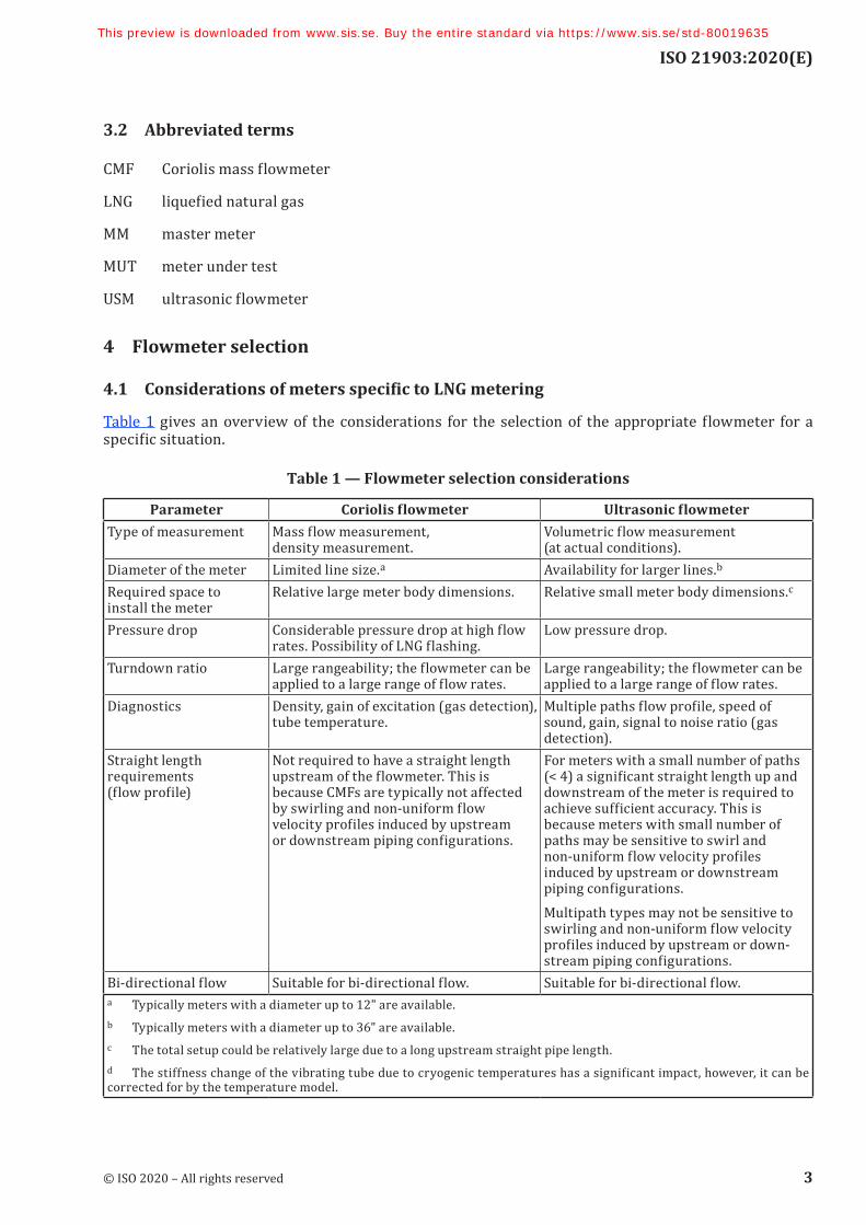
Table 1 gives an overview of the considerations for the selection of the appropriate flowmeter for a specific situation.
Table 1 — Flowmeter selection considerations
Parameter Coriolis flowmeter Ultrasonic flowmeterType of measurement Mass flow measurement,
density measurement.Volumetric flow measurement (at actual conditions).
Diameter of the meter Limited line size.a Availability for larger lines.b
Required space to install the meter
Relative large meter body dimensions. Relative small meter body dimensions.c
Pressure drop Considerable pressure drop at high flow rates. Possibility of LNG flashing.
Low pressure drop.
Turndown ratio Large rangeability; the flowmeter can be applied to a large range of flow rates.
Large rangeability; the flowmeter can be applied to a large range of flow rates.
Diagnostics Density, gain of excitation (gas detection), tube temperature.
Multiple paths flow profile, speed of sound, gain, signal to noise ratio (gas detection).
Straight length requirements (flow profile)
Not required to have a straight length upstream of the flowmeter. This is because CMFs are typically not affected by swirling and non-uniform flow velocity profiles induced by upstream or downstream piping configurations.
For meters with a small number of paths (< 4) a significant straight length up and downstream of the meter is required to achieve sufficient accuracy. This is because meters with small number of paths may be sensitive to swirl and non-uniform flow velocity profiles induced by upstream or downstream piping configurations.Multipath types may not be sensitive to swirling and non-uniform flow velocity profiles induced by upstream or down-stream piping configurations.
Bi-directional flow Suitable for bi-directional flow. Suitable for bi-directional flow.a Typically meters with a diameter up to 12" are available.b Typically meters with a diameter up to 36" are available.c The total setup could be relatively large due to a long upstream straight pipe length.d The stiffness change of the vibrating tube due to cryogenic temperatures has a significant impact, however, it can be corrected for by the temperature model.
© ISO 2020 – All rights reserved 3
This preview is downloaded from www.sis.se. Buy the entire standard via https://www.sis.se/std-80019635
ISO 21903:2020(E)
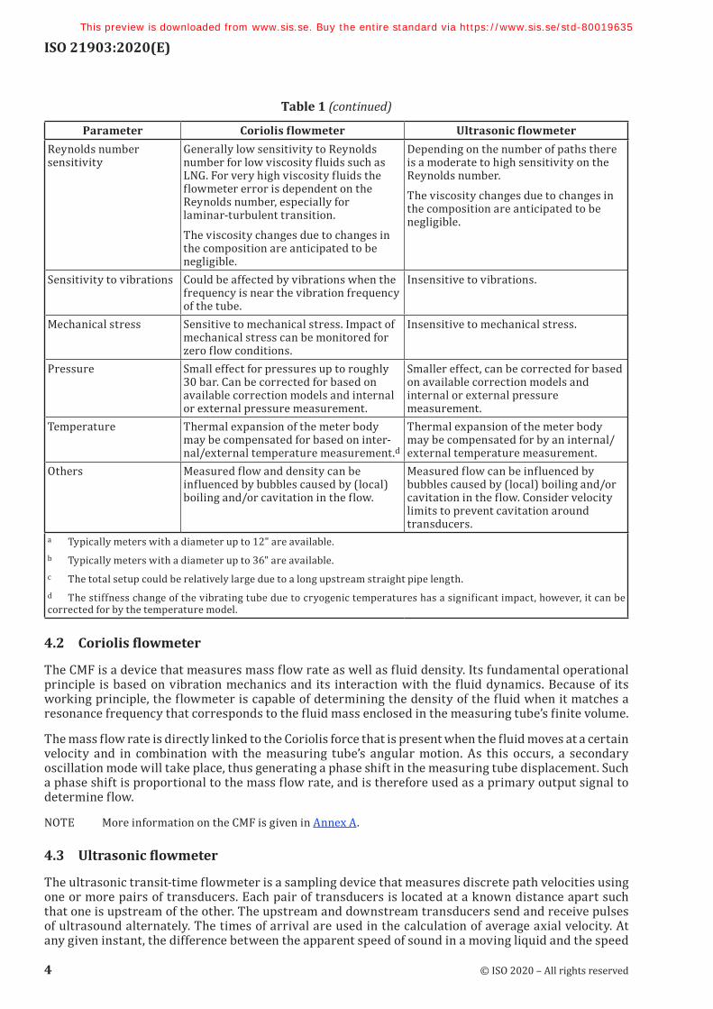
Parameter Coriolis flowmeter Ultrasonic flowmeterReynolds number sensitivity
Generally low sensitivity to Reynolds number for low viscosity fluids such as LNG. For very high viscosity fluids the flowmeter error is dependent on the Reynolds number, especially for laminar-turbulent transition.The viscosity changes due to changes in the composition are anticipated to be negligible.
Depending on the number of paths there is a moderate to high sensitivity on the Reynolds number.The viscosity changes due to changes in the composition are anticipated to be negligible.
Sensitivity to vibrations Could be affected by vibrations when the frequency is near the vibration frequency of the tube.
Insensitive to vibrations.
Mechanical stress Sensitive to mechanical stress. Impact of mechanical stress can be monitored for zero flow conditions.
Insensitive to mechanical stress.
Pressure Small effect for pressures up to roughly 30 bar. Can be corrected for based on available correction models and internal or external pressure measurement.
Smaller effect, can be corrected for based on available correction models and internal or external pressure measurement.
Temperature Thermal expansion of the meter body may be compensated for based on inter-nal/external temperature measurement.d
Thermal expansion of the meter body may be compensated for by an internal/external temperature measurement.
Others Measured flow and density can be influenced by bubbles caused by (local) boiling and/or cavitation in the flow.
Measured flow can be influenced by bubbles caused by (local) boiling and/or cavitation in the flow. Consider velocity limits to prevent cavitation around transducers.
a Typically meters with a diameter up to 12" are available.b Typically meters with a diameter up to 36" are available.c The total setup could be relatively large due to a long upstream straight pipe length.d The stiffness change of the vibrating tube due to cryogenic temperatures has a significant impact, however, it can be corrected for by the temperature model.
4.2 Coriolis flowmeter
The CMF is a device that measures mass flow rate as well as fluid density. Its fundamental operational principle is based on vibration mechanics and its interaction with the fluid dynamics. Because of its working principle, the flowmeter is capable of determining the density of the fluid when it matches a resonance frequency that corresponds to the fluid mass enclosed in the measuring tube’s finite volume.
The mass flow rate is directly linked to the Coriolis force that is present when the fluid moves at a certain velocity and in combination with the measuring tube’s angular motion. As this occurs, a secondary oscillation mode will take place, thus generating a phase shift in the measuring tube displacement. Such a phase shift is proportional to the mass flow rate, and is therefore used as a primary output signal to determine flow.
NOTE More information on the CMF is given in Annex A.
4.3 Ultrasonic flowmeter
The ultrasonic transit-time flowmeter is a sampling device that measures discrete path velocities using one or more pairs of transducers. Each pair of transducers is located at a known distance apart such that one is upstream of the other. The upstream and downstream transducers send and receive pulses of ultrasound alternately. The times of arrival are used in the calculation of average axial velocity. At any given instant, the difference between the apparent speed of sound in a moving liquid and the speed
Table 1 (continued)
4 © ISO 2020 – All rights reserved
This preview is downloaded from www.sis.se. Buy the entire standard via https://www.sis.se/std-80019635

ISO 21903:2020(E)
of sound in that same liquid at rest is directly proportional to the liquid’s instantaneous velocity. As a consequence, a measure of the average axial velocity of the liquid along a path can be obtained by transmitting an ultrasonic signal along the path in both directions and subsequently measuring the transit-time difference.
The volumetric flow rate of a liquid flowing in a completely filled closed conduit is defined as the average velocity of the liquid over a cross section multiplied by the area of the cross section. Thus, by measuring the average velocity of a liquid along one or more ultrasonic paths (i.e. lines, not the area) and combining the measurements with knowledge of the cross-sectional area and the velocity profile over the cross section, it is possible to obtain an estimate of the volumetric flow rate of the liquid in the conduit.
NOTE More information on the ultrasonic flowmeter is given in Annex B.
5 Process conditions
5.1 Temperature effects
5.1.1 Loading procedures
Both CMF and USM applications require a stable and consistent single-phase flowing medium in order to correctly measure the flow. It is particularly important to consider this requirement when loading at cryogenic temperatures as potentially large temperature variations and heat gain increase the likelihood of a two-phase flow. This will at least be the case if the meter/pipes connecting the meter are at ambient temperature prior to loading.
Several mitigating actions may be employed to increase the likelihood of maintaining a cryogenic single-phase liquid flow. One effective way to accomplish this is by keeping the meter cooled down, not only during loading operations, but at all times, e.g. by using a proper circulating loop. A disadvantage is the increased cost of cooling the cryogenic medium as the circulation will increase the heat gain. In general, a low-flow velocity, large pipe diameter, and poorly insulated meter and flow lines should be avoided as this will add to the probability of boiling and two-phase flow.
Maintaining the temperature of the meter at cryogenic conditions will minimize stresses on the pipe material, which is desirable.
Depending on the loading product, it is common practice to cool down the meter and pipes from ambient to cryogenic conditions prior to transfer. For LNG application, gas and liquid nitrogen are often used for this purpose. Starting from an ambient temperature, cold nitrogen gas can be introduced to gradually lower the temperature and avoid stress from temperature shock. Small amounts of liquid nitrogen are then injected to boil off and further cool down the system.
For some applications (e.g. in a small-scale LNG transfer), it is not possible to cool the meter and pipes with liquid nitrogen because it is not accessible at the location. In this case, purging the system with cold natural gas is allowed.
After loading, the temperature will have to change from cryogenic to ambient conditions. It is common to let the remaining liquid boil off from meter/pipes and this can cause a two-phase metering condition.
Depending on the conditions, at loading, both the CMF and USM can apply compensation to account for changes in process conditions such as temperature. Any such compensation can increase the measurement uncertainty and shall be considered specifically for the actual application. Therefore, it is advisable to consult the flowmeter manufacturer.
5.1.2 Temperature effects on CMF measurements
One fundamental design parameter for CMFs at cryogenic temperatures is the consideration of the measuring tube’s material properties and its behaviour at very low temperatures. This is quite relevant, since the Young’s modulus of elasticity of tube material at standard conditions (e.g. water at laboratory
© ISO 2020 – All rights reserved 5
This preview is downloaded from www.sis.se. Buy the entire standard via https://www.sis.se/std-80019635