Intercell Dual-Carrier TDD Enterprise Small Cell Configuration ...
54
Intercell Dual-Carrier TDD Enterprise Small Cell Configuraon Guide Platform FSM
-
Upload
khangminh22 -
Category
Documents
-
view
5 -
download
0
Transcript of Intercell Dual-Carrier TDD Enterprise Small Cell Configuration ...

Intercell Dual-Carrier TDD Enterprise Small Cell
Configuration Guide
Platform FSM
directory1. The initial configuration........................................................................3
1.1 Confi gurati on overview......................................................................3
1.1.1 The confi gurati on process............................................................3
1.1.2 Network port connecti on instructi ons...........................................3
1.1.3 Data preparati on.........................................................................3
1.2 Log in to the Web client.....................................................................4
1.2.1 Web client environment requirements..........................................4
1.2.2 Set the client computer................................................................4
1.2.3 Log into the Web maintenance page.............................................5
1.3 Quick initi al confi gurati on..................................................................5
2. Transport network configuration..........................................................10
2.1 Confi gure the network interface.......................................................10
2.1.1 Confi gure WAN interface............................................................10
2.1.2 Confi gure LAN interface.............................................................11
2.1.3 Confi gure IPv4 routi ng................................................................12
2.1.4 Confi gure multi ple vlans.............................................................14
2.2 Confi gure the NTP service.................................................................18
2.3 Confi gure base stati on X2 functi on....................................................19
2.4 Confi gure network management connecti on......................................20
3. Configure base station parameters......................................................21
3.1 Set up encrypti on and integrity protecti on algorithms........................21
3.2 Confi gure base stati on mobility parameters .......................................21
3.2.1 Neighbor cell is found by air port listening mode ................ . . . . . . . . .21
3.2.2 Manually confi gure adjacent cells ...............................................29
3.2.3 Mobility parameters confi gurati on..............................................33
3.3 Confi gure base stati on synchronizati on parameters ............................43

3.3.1 Overview...................................................................................43
3.3.2 GPS synchronizati on...................................................................45
3.3.3 IEEE1588v2 synchronizati on........................................................46
3.3.4 Sniff er synchronizati on...............................................................48
3.3.5 The free mode...........................................................................50
4. Configure system parameters.............................................................50
4.1.1 Soft ware version upgrade...........................................................50
4.1.2 System fi le backup.....................................................................52
4.1.3 Restart the base stati on.............................................................53
5. Common debugging function...............................................................54
5.1 The Trace log functi on......................................................................54
5.1.1 Capture base stati on logs using a dedicated logviewer
tool 54
5.1.2 Upload the logviewer log automati cally.......................................54
5.2 Other Trace logs are automati cally uploaded.....................................56
5.3 TCP Dump functi on..........................................................................56
5.4 TB Dump functi on............................................................................58
5.5 Telnet functi on................................................................................59
1.The initial configuration
1.1 Configuration overview
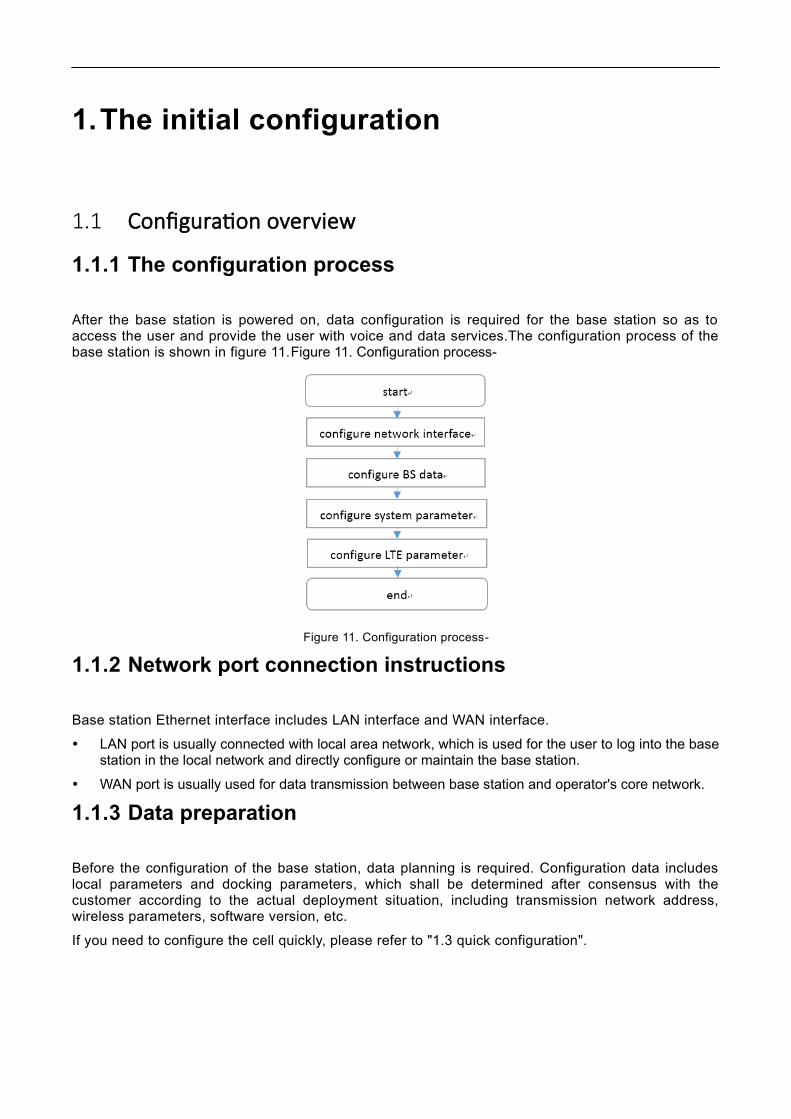
1.1.1 The configuration process
After the base station is powered on, data configuration is required for the base station so as toaccess the user and provide the user with voice and data services.The configuration process of thebase station is shown in figure 11.Figure 11. Configuration process-
Figure 11. Configuration process-
1.1.2 Network port connection instructions
Base station Ethernet interface includes LAN interface and WAN interface.
LAN port is usually connected with local area network, which is used for the user to log into the basestation in the local network and directly configure or maintain the base station.
WAN port is usually used for data transmission between base station and operator's core network.
1.1.3 Data preparation
Before the configuration of the base station, data planning is required. Configuration data includeslocal parameters and docking parameters, which shall be determined after consensus with thecustomer according to the actual deployment situation, including transmission network address,wireless parameters, software version, etc.
If you need to configure the cell quickly, please refer to "1.3 quick configuration".

1.2 Log in to the Web client
1.2.1 Web client environment requirements
The client computer requirements are shown in table 11.Table 11 client environment requirements-1
Table 11 client environment requirements-1
project requirementsThe CPU Intel Core above 2GHzmemory More than 2 g RAM The hard disk Not less than 100 MB of available spaceThe operating system
Microsoft: Windows XP, Windows Vista, or Windows7 Mac: MacOS x 10.5 or above
Display resolution Above 1024*768 pixelsThe browser Chrome 6 or later
1.2.2 Set the client computer
Before logging into the Web client, firstly set the IP address of the client computer and ensure thatthe client computer is connected to the base station.Take Windows 7 as an example.
1. Click start > control panel, and in the pop-up window click network and Internet.
2. Click view network status and tasks, and in the window that pops up, click local connections.
3. In the pop-up local connection status dialog box, click properties to pop up local connection properties.
4. Select Internet protocol version (TCP/IPV4), click properties, and the pop-up window looks like figure12.Figure 12 sets the client IP address-1
Figure 12 sets the client IP address-1
5. Select the IP address below.
6. Enter the IP address, subnet mask, and default gateway, and click ok.
IP address: 192.168.200. XXX: (the recommended value of XXX is 100~199)

Note: since the IP address of the base station LAN port has been preset as"192.168.200.200", other addresses need to be used.
Subnet mask: 255.255.255.0
Default gateway: not required
7. Perform ping 192.168.200.200 in the command line window to check whether the network is connectedbetween the client computer and the device.
1.2.3 Log into the Web maintenance page
1. Enter https://192.168.200.200 in the browser address bar and click "sing in" to open the Web client loginpage, as shown in figure 14.Figure 14 login base station Web page-
User name: admin
Password: MikroTik
192.168.200.200 is the initial IP address of the LAN interface.
Figure 14 login base station Web page-
1.3 Quick initial configurationRapid configuration is to configure the cell parameters of the base station, including the workingmode of the base station, cell identification, working frequency band, frequency point, etc., whichneeds to be set according to network planning data.
1. Select "management-> Cell" in the navigation bar to set basic parameters of the base station, as shown infigure 15 16 17.

FIG. 15 quick setting of base station basic parameters-cell1

FIG. 16 quick setting of base station basic parameters-cell2
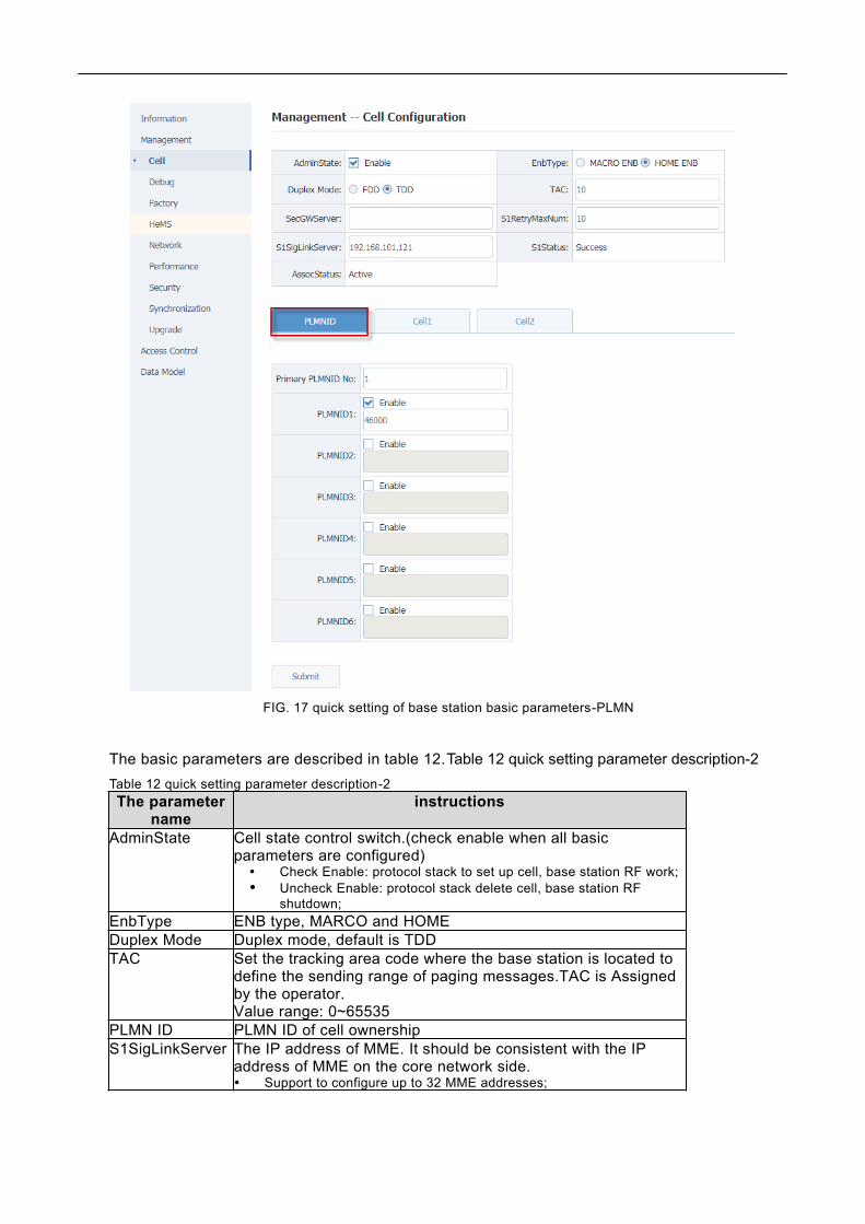
FIG. 17 quick setting of base station basic parameters-PLMN
The basic parameters are described in table 12.Table 12 quick setting parameter description-2
Table 12 quick setting parameter description-2The parameter
nameinstructions
AdminState Cell state control switch.(check enable when all basic parameters are configured)
Check Enable: protocol stack to set up cell, base station RF work; Uncheck Enable: protocol stack delete cell, base station RF
shutdown;EnbType ENB type, MARCO and HOMEDuplex Mode Duplex mode, default is TDDTAC Set the tracking area code where the base station is located to
define the sending range of paging messages.TAC is Assigned by the operator.Value range: 0~65535
PLMN ID PLMN ID of cell ownershipS1SigLinkServer The IP address of MME. It should be consistent with the IP
address of MME on the core network side. Support to configure up to 32 MME addresses;

The parametername
instructions
Multiple MME addresses are separated by English commas
CellIdentity The Cell ID. When the eNB type is MARCO, it is the same as the eNB ID (20bits); When the eNB type is HOME, it is the value of eNB ID moved 8bits
to the left and Cell ID and operation, that is, eNB ID*256+Cell ID (28bits);
OpState Cell working status. When the cell is successfully established and the RF works, the state
is "true"; The Opstate is False when Adminstate is not enabled or the cell is
not successfully established.CandidateARFCNList
Absolute frequency point list.(multiple frequency points are separated by English commas) If only one frequency point is configured, the base station use this
frequency point to establish the cell; If multiple frequency points are configured, the base station selects
frequency points according to SON's self-configuration function and establishes the cell.
CandidatePCIListPCI list.(multiple PCI is separated by English commas) If only one PCI is configured, the base station will use this PCI to
establish cell. If multiple PCI is configured, the base station selects PCI according
to SON's PCI self-configuration function and establishes the cellEARFCNDLInUse/EARFCNULInUse
The actual uplink and downlink absolute frequency points used by the base station
FreqBandIndicator
The frequency band in which the base station operates
PhyCellIDInuse The PCI that Base station actually uses DL Bandwidth /UL Bandwidth
The number of PRBS of the bandwidth (the uplink and downlink bandwidth should be the same) The 5MHz bandwidth is 25 The 10MHz bandwidth is 50 The 15MHz bandwidth is 75 The 20MHz bandwidth is 100
ReferenceSignalPower
Reference signal power.(maximum value is 9) For a single rf port, the actual output power is
ReferenceSignalPower+31 with dBm unit, such as -10+31=21dBmPAGain PA gain value, the integrated base station is set to "0"AntennaPortsCount
Number of base station antennas, usually configured as "2" (MIMO)
RxAntennaPortsCount
The number of antennas a base station USES for receiving, usually configured as "2" (MIMO)
SubFrameAssignment
SubFrame configuration,refer to 3GPP TS36.211.Support configuration: 1/2/3/4/5/6
SpecialSubframePatterns
Special Subframe configuration, refer to 3GPP TS36.211Support configuration: 1/2/3/4/5/6/7/8/9
2. After setting basic base station parameters in table 1-2, click "Submit" to Submit.
Note: some parameter changes (such as bandwidth, etc.) will cause the base station to restart, just wait for therestart to complete.
3. After basic parameter configuration is submitted, check "Enable" of "AdminState"

2.Transport network configuration
2.1 Configure the network interface
2.1.1 Configure WAN interface
WAN interface is the external communication interface of base station, which is mainly used to connectbase station with external devices, such as OMC, MME, gateway and other devices. It supports theconfiguration of multiple vlans to dock with different devices.
Select "management-> Network"->IP in the navigation bar and WAN interface configuration is shown infigure 21Figure 21 configuring the WAN interface address-
Figure 21 configuring the WAN interface address-
Table 21 parameters description of WAN interface IPv4-The parameter
nameinstructions
The Address Type
The mode for WAN interface to obtain IPv4 address.Support: DHCP: dynamically obtaining IP address, no other
parameters need to be configured; Static: IP address and mask need to be configured; Disabled: closes the function of WAN port IPv4 protocol. It
is not recommended to select.IPv4 address The IPv4 address of the WAN interface.
In DHCP mode, it is allocated by DHCP server. Static mode requires manual configuration;
Mask IPv4 subnet mask for the WAN interface. In DHCP mode, it is allocated by DHCP server. Static mode requires manual configuration;
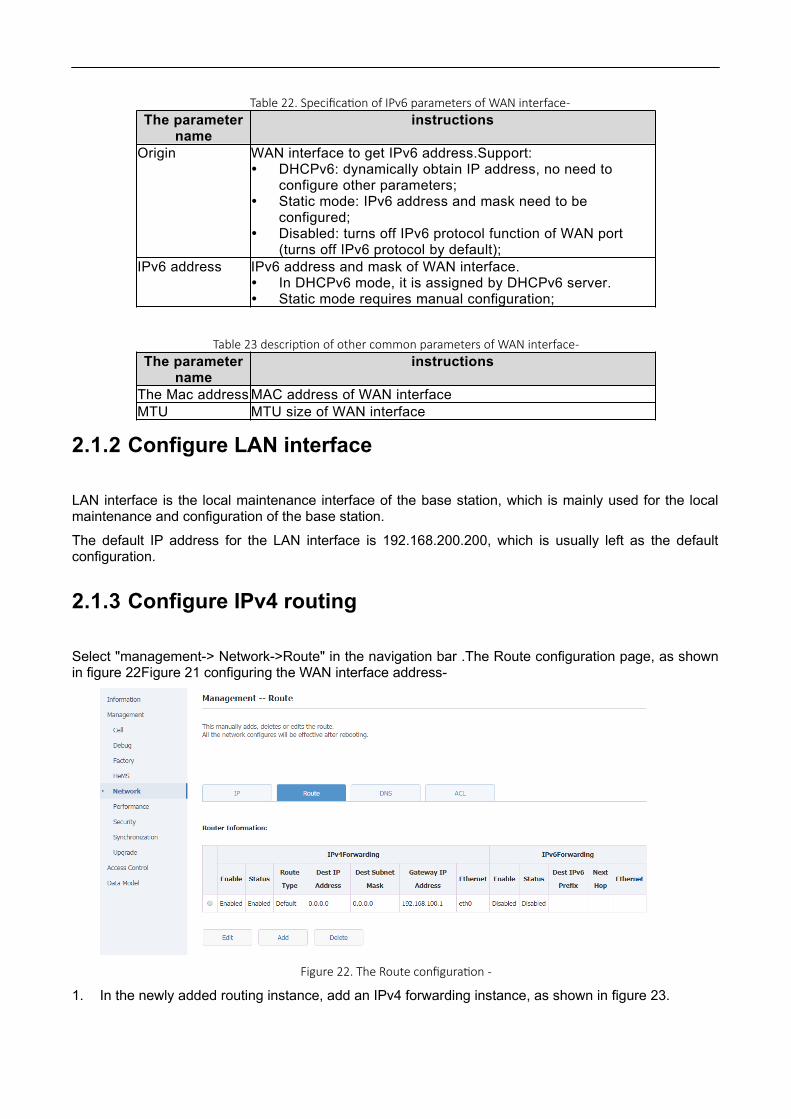
Table 22. Specification of IPv6 parameters of WAN interface-
Table 23 description of other common parameters of WAN interface-
2.1.2 Configure LAN interface
LAN interface is the local maintenance interface of the base station, which is mainly used for the localmaintenance and configuration of the base station.
The default IP address for the LAN interface is 192.168.200.200, which is usually left as the defaultconfiguration.
2.1.3 Configure IPv4 routing
Select "management-> Network->Route" in the navigation bar .The Route configuration page, as shownin figure 22Figure 21 configuring the WAN interface address-
Figure 22. The Route configuration -
1. In the newly added routing instance, add an IPv4 forwarding instance, as shown in figure 23.
The parametername
instructions
Origin WAN interface to get IPv6 address.Support: DHCPv6: dynamically obtain IP address, no need to
configure other parameters; Static mode: IPv6 address and mask need to be
configured; Disabled: turns off IPv6 protocol function of WAN port
(turns off IPv6 protocol by default);IPv6 address IPv6 address and mask of WAN interface.
In DHCPv6 mode, it is assigned by DHCPv6 server. Static mode requires manual configuration;
The parametername
instructions
The Mac address MAC address of WAN interfaceMTU MTU size of WAN interface

Figure 23. Add an IPv4 forwarding instance-
2. Configure route items1) Add the default route, as shown in the figure.
Figure 24. Add a default route-2) Add segment routing, as shown in the figure.

Figure 25 add segment routing-
Table 25 main route configuration parameters-3The parameter name instructions
The Enable Route item switches.Check to enable, check to not enable.
The StaticRoute Check this if the configured route is network segment route;If the configured route is the default route, this item is not checked;
DestIPAddress Destination IP address.DestSubnetMask The subnet mask for the destination IP address.GatewayIPAddress Gateway IP address to destination IP address.Ethernet Select “eth0”
2.2 Configure the NTP serviceSelect "management-> Synchronization" in the navigation bar and enter the NTP/Time Settings page, asshown in the figure below.

Figure 26 NTP configuration-
Configure the NTP server parameters as shown in the following table.Table 39 NTP server parameters-
Table 39 NTP server parameters-The parameter
nameinstructions
The NTP Server The domain name or IP address of the NTP server.(multiple configurations are available)
2.3 Configure base station X2 functionData model path: Device. Services. FAPService. 1. X_OUI_X2.
Figure 27 configures the X2 functionality-

Table 311 X2 functional parameters-The parameter
nameinstructions
X2Enable X2 function switch, on by default.X2SigLinkPort X2 connection port, default 36422.
2.4 Configure network management connectionSelect "management-> HeMS" in the navigation bar, as shown in the figure.
Figure 28 configuration of network administrator-
Table 312 network management parameters-The parameter name instructionsThe HeMS address Network addressThe HeMS username Network administrator user nameThe HeMS password Administrator password
3.Configure base station parameters
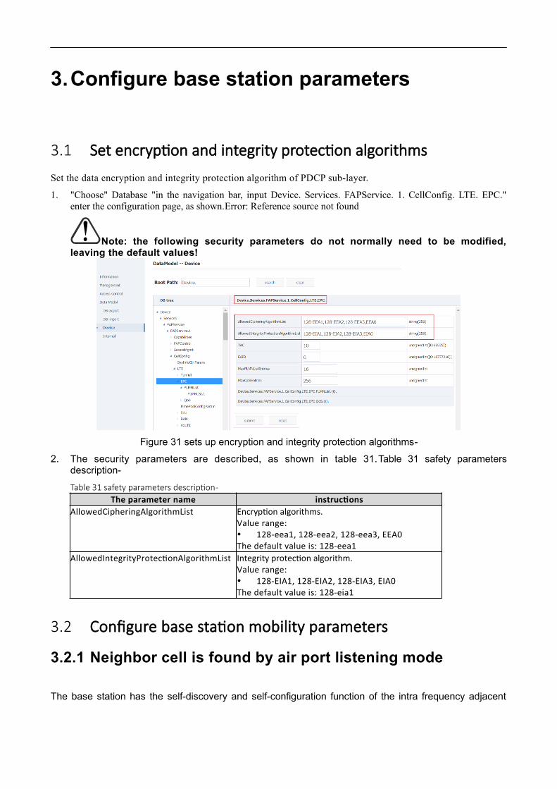
3.1 Set encryption and integrity protection algorithmsSet the data encryption and integrity protection algorithm of PDCP sub-layer.
1. "Choose" Database "in the navigation bar, input Device. Services. FAPService. 1. CellConfig. LTE. EPC."enter the configuration page, as shown.Error: Reference source not found
Note: the following security parameters do not normally need to be modified,leaving the default values!
Figure 31 sets up encryption and integrity protection algorithms-
2. The security parameters are described, as shown in table 31.Table 31 safety parametersdescription-
Table 31 safety parameters description-The parameter name instructions
AllowedCipheringAlgorithmList Encryption algorithms.Value range: 128-eea1, 128-eea2, 128-eea3, EEA0The default value is: 128-eea1
AllowedIntegrityProtectionAlgorithmList Integrity protection algorithm.Value range: 128-EIA1, 128-EIA2, 128-EIA3, EIA0The default value is: 128-eia1
3.2 Configure base station mobility parameters
3.2.1 Neighbor cell is found by air port listening mode
The base station has the self-discovery and self-configuration function of the intra frequency adjacent

cell, inter frequency adjacent cell and inter system adjacent cell based on air port interception.It needs tobe used in combination with 3.2.1.1 or 3.2.1.2.Everytime when the base station reboot it will exeute theinterception process to add neighbor cells.
1. Enable neighborhood self-discovery and frequency point self-measurement functions based on airport interception, as shown in figure 32.Error: Reference source not found
Data model path:
Device. Services. FAPService. 1. FAPControl. LTE. SelfConfig. SONConfigParam.SnifferForANREnable
Device.Services.FAPService.1.FAPControl.LTE.SelfConfig.SONConfigParam.SnifferForMeasurementEnable
Device. Services. FAPService. 1. FAPControl. LTE. SelfConfig. SONConfigParam.GERANSnifferEnable
FIG. 33 enables neighborhood self-discovery and frequency point self-measurement function switchbased on air port interception-
Table 32 parameter description-
The parameter name instructions
SnifferForANREnable Neighborhood self-discovery function switch based on air port interception. (default enable)
SnifferForMeasurementEnable Frequency point self-measurement function switch based on air port interception. (default enable)
GERANSnifferEnable GSM neighborhood self - discovery function switch based on air - port interception.
Default is off

3.2.1.1 Air - port interception for LTE adjacent cell
1. Set the LTE band or frequency point to listen for.
Data model path:
Device. Services. FAPService. 1. REM. LTE. REMPLMNList
Device. Services. FAPService. 1. REM. LTE. EUTRACarrierARFCNDLList
Device. Services. FAPService. 1. REM. LTE. ScanOnBoot (note that if you want to scan frequency points orPLMN this switch to turn on)
Figure 33 sets the listening LTE frequency point-

Figure 34 sets up listening for PLMN-
Table 34 configuration description of LTE neighborhood scan parameters-
The parameter name instructions
EUTRACarrierARFCNDLList Scanning frequency points, commonly used frequency points include: 100,1825
REMPLMNList Add the PLMN ID of the scan
2. Listen for scan results, as shown in the figure below.
Data model path: Device. Services. FAPService. 1. REM. LTE. The Cell
Figure 35 shows the results of the air port listening scan-
3. The adjacent cell added by an air port listener is shown in the figure.

Adjacent cell discovered by air port listening method are added to the relational table of the base station.
Data model path: Device. Services. FAPService. 1. CellConfig. LTE. RAN. NeighborListInUse.
Note: Some scanned LTE cells are not added to the neighbor relationship table of the basestation, which is because the RSRP of the scanned LTE cells is too weak. You can add these cellsto the neighbor relationship table by properly adjusting the threshold value(LTESnifferRSRPThresholdForANR), see table 3.5..Table 35 whether the LTE adjacent area listened to isused as the judgment statement of base station adjacent area-
Data model path:
Device.Services.FAPService.1.FAPControl.LTE.SelfConfig.SONConfigParam.LTESnifferRSRPThresholdForANR
Table 35 whether the LTE adjacent area listened to is used as the judgment statement of base station adjacent area -
The parameter name Value range instructions
LTESnifferRSRPThresholdForANR 44] [- 140: -
This is the RSRP threshold that LTE adjacent cell scanned can be used as a relation. The default value is -95, which can be adjusted according to the actual situation
3.2.1.2 Air port interception for WCDMA adjacent cell (limited qualcomm
platform products)
1. Enable WCDMA air port listening function
Data model path:
Device. Services. FAPService. 1. REM. UMTS. WCDMA. ScanOnBoot
2. Set the WCDMA parameters to listen for
Data model path:
Device. Services. FAPService. 1. REM. UMTS. WCDMA. REMPLMNList
Device. Services. FAPService. 1. REM. UMTS. WCDMA. REMBandList
Device. Services. FAPService. 1. REM. UMTS. WCDMA. UARFCNDLList

Table 36 WCDMA neighborhood scanning parameter configuration-
The parameter name instructions
Device. Services. FAPService. 1. REM. UMTS. WCDMA. ScanOnBoot
WCDMA air port listening switch.Zero: disable;1: enabled
Device. Services. FAPService. 1. REM. UMTS. WCDMA. REMPLMNList
Input the operator's PLMN, the base station will screen the adjacent areas scanned, and only retain theadjacent areas in the REMPLMNList.
Device. Services. FAPService. 1. REM. UMTS. WCDMA. REMBandList
Scan the WCDMA frequency band, generally do not need to scan the frequency band, put this empty.
Device. Services. FAPService. 1. REM. UMTS. WCDMA. UARFCNDLList
Scan the WCDMA frequency point.
3. Listen for scan results, as shown in the figure below.
Data model path: Device. Services. FAPService. 1. REM. UMTS. WCDMA. Cell

4. WCDMA adjacent region added by air port listening mode is shown in the figure.
Adjacent areas discovered by air port listening method are added to the adjacent area relational table ofthe base station.
Data model path:
Device. Services. FAPService. 1. CellConfig. LTE. RAN. NeighborListInUse. InterRATCell. UMTS. {I}.
Note: Some scanned 3G cells are not added to the neighbor relationship table of the basestation, which is because the RSCP of the scanned 3G cells is too weak. You can add these cellsto the neighbor relationship table by properly adjusting the threshold value.
(LTESnifferRSRPThresholdForANR) see table 35.Table 35 whether the LTE adjacent area listened to isused as the judgment statement of base station adjacent area-
Data model path:
Device.Services.FAPService.1.FAPControl.LTE.SelfConfig.SONConfigParam.UTRANSnifferRSCPThresholdForANR.
Table 35 whether WCDMA adjacent region listened to is used as base station adjacent region judgment statement-
The parameter name Value range instructions
Device. Services. FAPService. 1. FAPControl.LTE. SelfConfig. SONConfigParam. UTRANSnifferRSCPThresholdForANR. 44] [- 140: -
This is the RSCP threshold that 3G adjacent cell scanned can be used as a relation. The default value is -95, which can be adjusted according to the actual situation
3.2.1.3 Air port interception for GSM adjacent cell
4. Enable GSM air port listening function

Data model path:
Device. Services. FAPService. 1. REM. UMTS. GSM. ScanOnBoot
5. Set the listening GSM parameter
Data model path:
Device. Services. FAPService. 1. REM. UMTS. GSM. REMPLMNList
Device. Services. FAPService. 1. REM. UMTS. GSM. REMBandList
Device. Services. FAPService. 1. REM. UMTS. GSM. ARFCNList
Figure 37 sets the listening GSM band or frequency point-
Table 36 GSM neighboring area scanning parameter configuration instructions-
The parameter name instructions
Device. Services. FAPService. 1. REM. UMTS. GSM. ScanOnBoot
GSM air port listening switch.Zero: disable;1: enabled
Device. Services. FAPService. 1. REM. UMTS. GSM. REMPLMNList
Input the operator's PLMN, the base station will screen the adjacent areas scanned, and only retain theadjacent areas in the REMPLMNList.
Device. Services. FAPService. 1. REM. UMTS. GSM. REMBandList
The GSM band is scanned. In general, there is no need to scan the band.
Device. Services. FAPService. 1. REM. UMTS. GSM. ARFCNList
Scan the GSM frequency point.
6. GSM cell scan results, as shown in the figure.Error: Reference source not found
Data model path: Device. Services. FAPService. 1. REM. UMTS. GSM. The Cell.
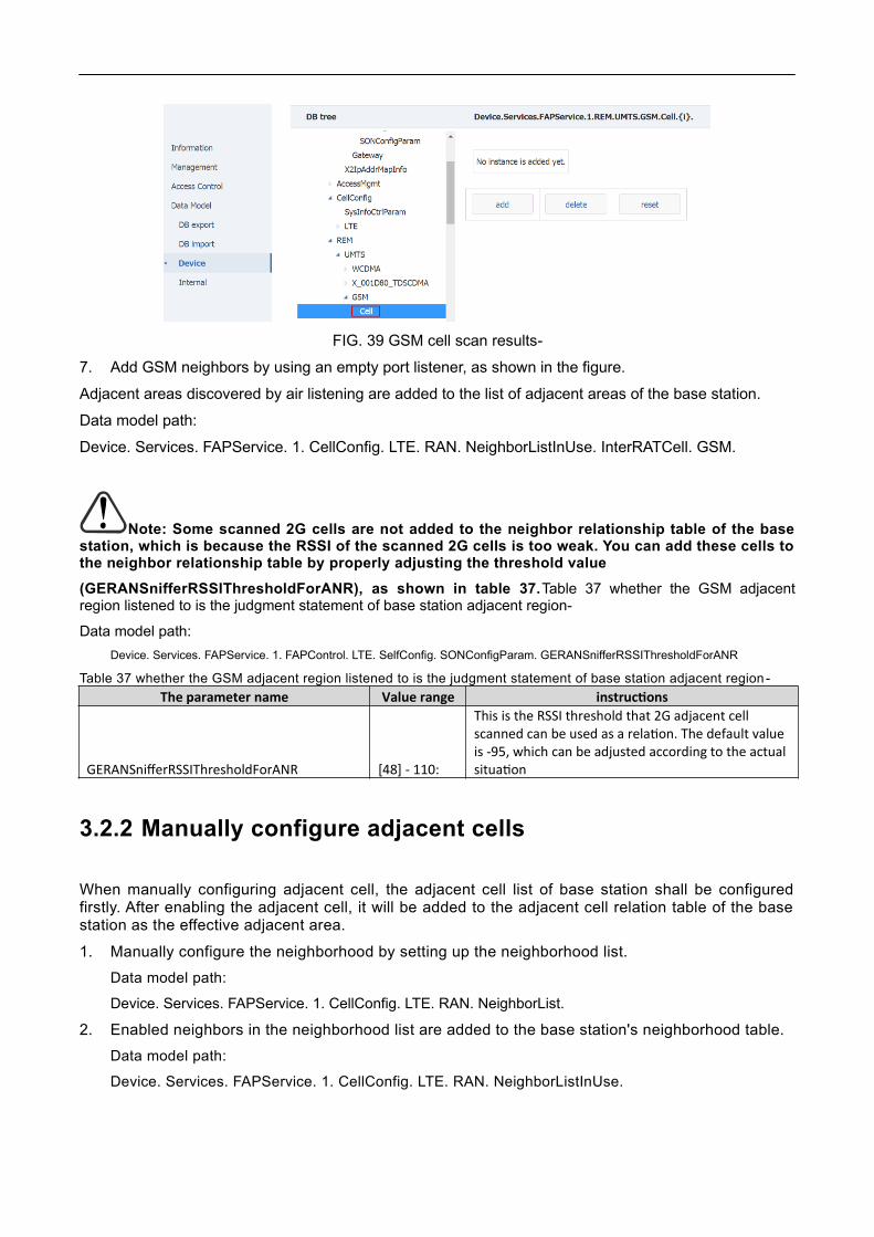
FIG. 39 GSM cell scan results-
7. Add GSM neighbors by using an empty port listener, as shown in the figure.
Adjacent areas discovered by air listening are added to the list of adjacent areas of the base station.
Data model path:
Device. Services. FAPService. 1. CellConfig. LTE. RAN. NeighborListInUse. InterRATCell. GSM.
Note: Some scanned 2G cells are not added to the neighbor relationship table of the basestation, which is because the RSSI of the scanned 2G cells is too weak. You can add these cells tothe neighbor relationship table by properly adjusting the threshold value
(GERANSnifferRSSIThresholdForANR), as shown in table 37.Table 37 whether the GSM adjacentregion listened to is the judgment statement of base station adjacent region-
Data model path:
Device. Services. FAPService. 1. FAPControl. LTE. SelfConfig. SONConfigParam. GERANSnifferRSSIThresholdForANR
Table 37 whether the GSM adjacent region listened to is the judgment statement of base station adjacent region -
The parameter name Value range instructions
GERANSnifferRSSIThresholdForANR [48] - 110:
This is the RSSI threshold that 2G adjacent cell scanned can be used as a relation. The default value is -95, which can be adjusted according to the actual situation
3.2.2 Manually configure adjacent cells
When manually configuring adjacent cell, the adjacent cell list of base station shall be configuredfirstly. After enabling the adjacent cell, it will be added to the adjacent cell relation table of the basestation as the effective adjacent area.
1. Manually configure the neighborhood by setting up the neighborhood list.
Data model path:
Device. Services. FAPService. 1. CellConfig. LTE. RAN. NeighborList.
2. Enabled neighbors in the neighborhood list are added to the base station's neighborhood table.
Data model path:
Device. Services. FAPService. 1. CellConfig. LTE. RAN. NeighborListInUse.

3.2.2.1 Manually configure LTE neighbors
1. Manually configure the neighborhood list
Data model path:
Device. Services. FAPService. 1. CellConfig. LTE. RAN. NeighborList.
Figure 310 manually add LTE adjacent area-
2. After setting LTE neighborhood information, select "submit" to submit;
3. Main parameters are described in the following table.
Table 38 specification of LTE neighborhood parameter configuration-
The parameter name instructions
The EnableAdjacent enable switch0: invalid neighborhood;1: effective neighborhood
Alias Keep the default
MustInclude
Whether to include the neighbor table switch0: not added to neighborhood relational table;1: is added to the neighborhood relationship table
PLMNID Adjacent regions PLMN ID
CID
Neighborhood community ID,
When the neighborhood type is Home, the length is 28 bits
When the neighborhood type is Marco, the length is 20 bits (that is, eNodeB ID)
EUTRACarrierARFCN Neighborhood absolute frequencyPhyCellID Adjacent regions PCI
QOffsetNeighborhood migration, Idle mode cell re - selection, the larger the easier to re - selection to this cell
The CIONeighborhood offset, connection mode cell switching, the larger the easier to switch to this cell
RSTxPower Reference signal power of adjacent region
BlacklistedTurns off by default. If enabled, this neighborhood will not be a switching target for UE
TAC Adjacent regions TAC

EnbType 0: hong station, 1: small station
X_18396E_NoRemoveDisabled by default. If enabled, this neighborhood will not be automatically removed from the InUse list
X_18396E_NoX2
Default off.
If enabled, the base station will not establish an X2 connection with this neighborhood
X_18396E_NoX2HO
Default off.
If enabled, the base station will not be switched with the adjacent area via the X2 interface
X_18396E_AccessMode Neighborhood Access mode, default is Open Access
X_18396E_CSGIDCSG ID of adjacent area, default does not need to be filled in
X_18396E_BlacklistedSIBThis is turned off by default, corresponding to BlackCellList in SIB4 or 5
X_18396E_AntennaPortsCount Number of adjacent antenna portsX_18396E_DLBandwidth Adjacent downlink bandwidthX_18396E_SubFrameAssignment Neighborhood sub-frame ratioX_18396E_SpecialSubframePatterns Neighborhood special subframe mode
3.2.2.2 Manually configure 3G neighbors
1. Manually configure the 3G neighborhood list
Data model path:
Device. Services. FAPService. 1. CellConfig. LTE. RAN. NeighborList. InterRATCell. UMTS.
Figure 311 manually add 3G neighborhood-
2. After setting 3G neighborhood information, select "submit" to submit;

3. Main parameters are described in the following table.
Table 39 UMTS neighborhood parameter configuration description-
The parameter name instructionsThe Enable Entry enable switch, need enableAlias Keep the defaultMustInclude Mandatory include switch, need enablePLMNID Adjacent regions PLMN IDRNCID Adjacent regions RNC IDCID Adjacent regions C - IDLAC Adjacent regions LACThe RAC Adjacent regions RACURA Adjacent regions URAUARFCNUL Line frequency points onUARFCNDL The line frequency pointPCPICHScramblingCode scrambler
PCPICHTxPowerPCPICH transmitting power, multiplied by 0.1 is the actual value, in dBm
3.2.2.3 Configure GSM neighborhood
1. Manually configure the GSM neighborhood list
Data model path:
Device. Services. FAPService. 1. CellConfig. LTE. RAN. NeighborList. InterRATCell. GSM.
Figure 312 add GSM neighborhood manually-
2. After setting the GSM neighborhood information, select "submit" to submit;
3. Main parameters are described in table 310.Table 310 GSM neighborhood parameter configurationinstructions-4
Table 310 GSM neighborhood parameter configuration instructions-4
The parameter name instructionsThe Enable Entry enable switch, need enableAlias MustInclude Mandatory include switch, need enablePLMNID Adjacent regions PLMN IDLAC Adjacent regions LAC
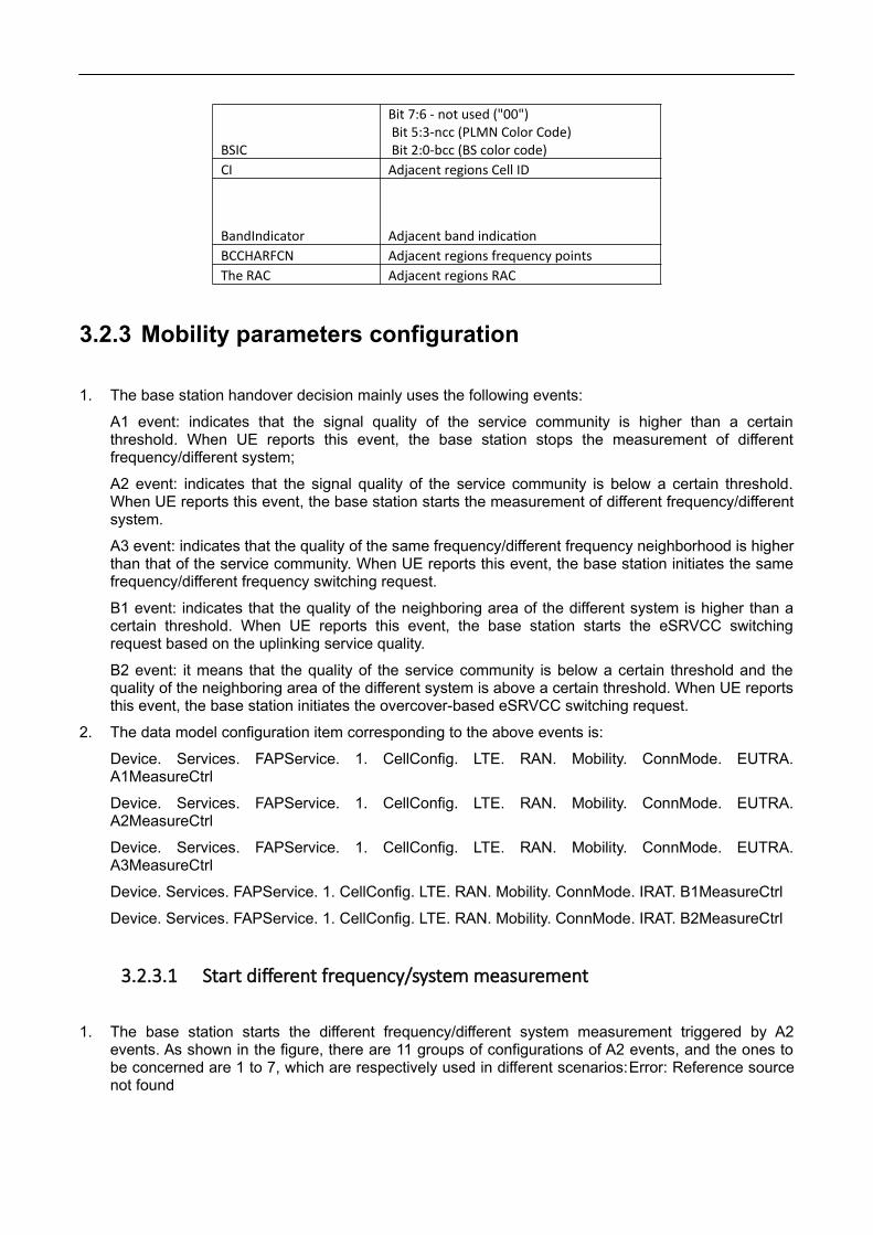
BSIC
Bit 7:6 - not used ("00") Bit 5:3-ncc (PLMN Color Code) Bit 2:0-bcc (BS color code)
CI Adjacent regions Cell ID
BandIndicator Adjacent band indicationBCCHARFCN Adjacent regions frequency pointsThe RAC Adjacent regions RAC
3.2.3 Mobility parameters configuration
1. The base station handover decision mainly uses the following events:
A1 event: indicates that the signal quality of the service community is higher than a certainthreshold. When UE reports this event, the base station stops the measurement of differentfrequency/different system;
A2 event: indicates that the signal quality of the service community is below a certain threshold.When UE reports this event, the base station starts the measurement of different frequency/differentsystem.
A3 event: indicates that the quality of the same frequency/different frequency neighborhood is higherthan that of the service community. When UE reports this event, the base station initiates the samefrequency/different frequency switching request.
B1 event: indicates that the quality of the neighboring area of the different system is higher than acertain threshold. When UE reports this event, the base station starts the eSRVCC switchingrequest based on the uplinking service quality.
B2 event: it means that the quality of the service community is below a certain threshold and thequality of the neighboring area of the different system is above a certain threshold. When UE reportsthis event, the base station initiates the overcover-based eSRVCC switching request.
2. The data model configuration item corresponding to the above events is:
Device. Services. FAPService. 1. CellConfig. LTE. RAN. Mobility. ConnMode. EUTRA.A1MeasureCtrl
Device. Services. FAPService. 1. CellConfig. LTE. RAN. Mobility. ConnMode. EUTRA.A2MeasureCtrl
Device. Services. FAPService. 1. CellConfig. LTE. RAN. Mobility. ConnMode. EUTRA.A3MeasureCtrl
Device. Services. FAPService. 1. CellConfig. LTE. RAN. Mobility. ConnMode. IRAT. B1MeasureCtrl
Device. Services. FAPService. 1. CellConfig. LTE. RAN. Mobility. ConnMode. IRAT. B2MeasureCtrl
3.2.3.1 Start different frequency/system measurement
1. The base station starts the different frequency/different system measurement triggered by A2events. As shown in the figure, there are 11 groups of configurations of A2 events, and the ones tobe concerned are 1 to 7, which are respectively used in different scenarios:Error: Reference sourcenot found

A2MeasureCtrl.1: measurement of different frequencies
A2MeasureCtrl.2: 3G measurement (with LTE data service)
A2MeasureCtrl 3: 2G measurement (with LTE data service)
Blind A2MeasureCtrl. 4:3 g
Blind A2MeasureCtrl. 5:2 g
A2MeasureCtrl 6: 3G measurement (with LTE voice service)
A2MeasureCtrl 7: 2G measurement (with LTE voice service)
Figure 313 A2 event-
2. Regarding the parameter configuration of A2 event, take the common different frequencymeasurement scenario as an example.
A2 event will be triggered when UE's measurement results of primary plot are less thana2thresholdrsrp-hysteresis (both are actual converted values, as shown in figure 314, 45-140-2*0.5=-96 dBm) and are maintained longer than TimeToTrigger, and report continuously withReportInterval.Error: Reference source not foundSee table 311 for parameter description.Table 311A2 event configuration instructions-5
Figure 314 A2 event parameters-
Table 311 A2 event configuration instructions-5
The parameter name instructions

The Enable
A2ThresholdRSRPA2 RSRP trigger threshold, after subtracting 140, is the actual value (in dBm)
A2ThresholdRSRQ
HysteresisTrigger hysteresis, multiplied by 0.5, is the actual value (in unit dB)
MaxReportCells MeasurePurpose ReportAmount Number of reports, 0 is infiniteReportInterval Report interval, in msReportQuantity Report the amountTimeToTrigger Trigger time in ms
TriggerQuantity Trigger, default to RSRP
3.2.3.2 Stop different frequency/system measurement
1. The measurement of base station stopping different frequency/different system is triggered by A1events, as shown in figure 248. A1 events have a total of 11 configurations, and the ones to beconcerned are 1 to 5, which are respectively used in different scenarios:Figure 248 A1 event -2
A1MeasureCtrl.1: measurement of different frequencies
A1MeasureCtrl.2: 3G measurement (with LTE data service)
A1MeasureCtrl.3: 2G measurement (with LTE data service)
A1MeasureCtrl.4: 3G measurement (with LTE voice service)
A1MeasureCtrl.5: 2G measurement (LTE voice service exists)
Figure 248 A1 event-2
Figure 315 A1 event-
2. The parameter configuration of A1 event is taken as an example.
A1 event will be triggered when UE measurement results of primary plot are larger thanA1ThresholdRSRP+ Hysteresis (both are actual values after conversion, as shown in FIG. 249, 55-140+2*0.5=-84 dBm) and maintain time greater than TimeToTrigger, and report continuously with

ReportInterval.Error: Reference source not foundSee table 318 for parameter description.Table 312A1 event configuration notes-6
Figure 316 A1 event parameters-
Table 312 A1 event configuration notes-6
The parameter name instructionsThe Enable
A1ThresholdRSRPA1 RSRP trigger threshold, which is the actual value (in dBm) after subtraction of 140
A1ThresholdRSRQ
HysteresisTrigger hysteresis, multiplied by 0.5, is the actual value (in unit dB)
MaxReportCells MeasurePurpose ReportAmount Number of reports, 0 is infiniteReportInterval Report interval, in msReportQuantity Report the amountTimeToTrigger Trigger time in ms
TriggerQuantity Trigger, default to RSRP
Note: a2thresholdrsrp-hysteresis should be lower than a1thresholdrsrp-hysteresis,otherwise UE will repeatedly report A1, A2 events.
3.2.3.3 LTE same/different frequency handover
1. LTE same-frequency/different-frequency switching is triggered by A3 events. As shown in figure 317,there are two groups of configurations of A3 events, which are used in different scenarios:Error:Reference source not found
A3MeasureCtrl.1: measurement of same frequency
A3MeasureCtrl.2: measurement of different frequencies

Figure 317 A3 events-
2. The trigger condition of A3 is: where Mn and Mp are the measurement results of UE on adjacentarea and main area respectively, Ofn and Ofp are frequency offset of adjacent area and main arearespectively (default is 0), Ocn and Ocp are offset of adjacent area and main area respectively(default is 0), Off is A3Offset, Hys is Hysteresis.Mn+Ofn+Ocn−Hys>Mp+Ofp+Ocp+OffTherefore, when the measurement results of UE on the adjacent area are larger than A3Offset +Hysteresis when compared with the main plot (both are actual values after conversion, as shown inFIG. 251, 4*0.5+2*0.5=3dB) and the maintenance time is longer than TimeToTrigger, A3 events willbe triggered and report continuously with ReportInterval as interval.Error: Reference source notfoundSee table 313 for parameter description.Table 313 A3 event configuration notes-7
Figure 318 A3 event parameters-
Table 313 A3 event configuration notes-7
The parameter name instructionsThe Enable
A3OffsetA3 offset, multiplied by 0.5, is the actual value (in dB).
HysteresisTrigger hysteresis, multiplied by 0.5, is the actual value (in unit dB)
MaxReportCells MeasurePurpose ReportAmount Number of reports, 0 is infiniteReportOnLeaveReportInterval Report interval, in ms
ReportQuantity Report the amount

TimeToTrigger Trigger time in ms
TriggerQuantity Trigger, default to RSRP
3.2.3.4 Overlay based eSRVCC
1. Overlay based eSRVCC switch is triggered by event B2, as shown in figure 252. There are 4 sets ofconfigurations of B2 event for different purposes. The overlay based eSRVCC switch is triggered byB2MeasureCtrl.Error: Reference source not found
B2MeasureCtrl.1 :3G measurement (LTE data service exists)
B2MeasureCtrl.2 :2G measurement (LTE data service exists)
B2MeasureCtrl 3 :3G measurement (LTE voice service exists)
B2MeasureCtrl.4 :2G measurement (LTE voice service exists)
Figure 319 B2 event-
2. B2 indicates that the quality of service community is below a certain threshold and the quality ofneighboring areas of different systems is above a certain threshold. When UE reportsB2MeasureCtrl.4 event, the base station initiates the overlay based eSRVCC switching request.
3. After receiving the measurement report of A2MeasureCtrl 7, the base station starts themeasurement corresponding to B2MeasureCtrl 4.
4. When the measurement result of UE on the main plot was less than b2threshold1eutrarsrp-hysteresis (both were actual values after conversion, as shown below, 42-140-2*0.5=-99 dBm), andthe measurement result of UE on the GSM neighborhood was larger than B2Threshold2GERAN+hysteresis-ofn (both were actual values after conversion, Ofn default was 0, as shown in figure 253,20-110+2*0.5= -89dbm).Error: Reference source not foundAnd if it stays longer than TimeToTrigger,B2 events will be triggered and reported continuously at ReportInterval.Error: Reference source notfound

Figure 320 B2 event parameter configuration-
Table 314 B2 event configuration instructions-The parameter name instructions
The Enable Enable switch, on by default
B2Threshold1EutraRSRPB2 EUTRA RSRP trigger threshold, after subtraction of 140, is the actual value (in dBm)
B2Threshold1EutraRSRQ B2Threshold2UTRARSCP B2Threshold2UTRAEcN0
B2Threshold2GERANB2 GERAN triggers the threshold. After subtracted by 110, it is the actual value (in dBm).
B2Threshold2CDMA2000
HysteresisTrigger hysteresis, multiplied by 0.5, is the actual value(in unit dB)
MaxReportCells MeasurePurpose ReportAmount Number of reports, 0 is infiniteReportInterval Report interval, in msTimeToTrigger Trigger time in ms
3.2.3.5 ESRVCC based on uplink service quality
1. The eSRVCC switch based on upline service quality is triggered by event B1, as shown in figure321. There are 4 sets of B1 configurations for different purposes. The eSRVCC switch based onupline service quality is triggered by B1MeasureCtrl.Error: Reference source not found
B1MeasureCtrl.1 :3G measurement (with LTE data service)
B1MeasureCtrl.2 :2G measurement (with LTE data service)
B1MeasureCtrl.3 :3G measurement (with LTE voice service)
B1MeasureCtrl.4 :2G measurement (LTE voice service exists)
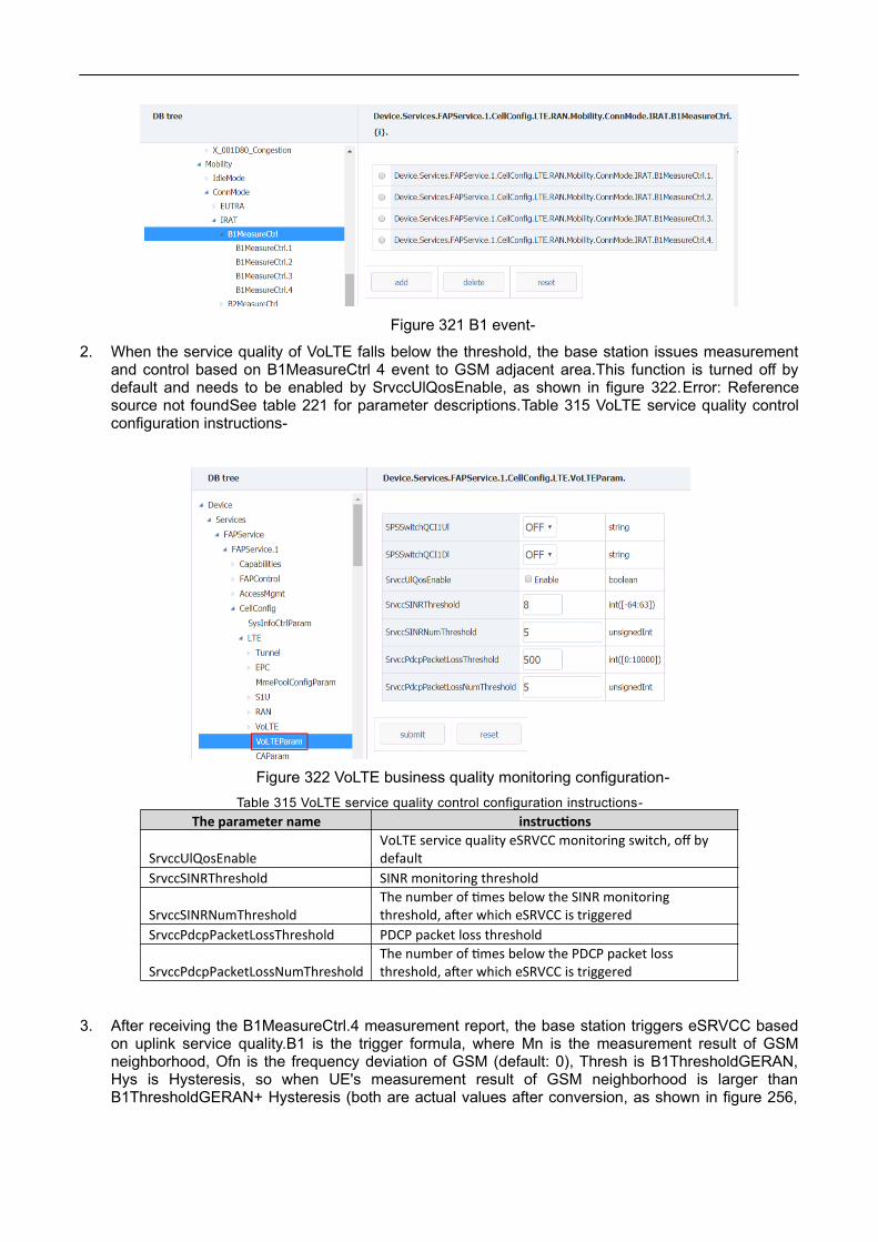
Figure 321 B1 event-
2. When the service quality of VoLTE falls below the threshold, the base station issues measurementand control based on B1MeasureCtrl 4 event to GSM adjacent area.This function is turned off bydefault and needs to be enabled by SrvccUlQosEnable, as shown in figure 322.Error: Referencesource not foundSee table 221 for parameter descriptions.Table 315 VoLTE service quality controlconfiguration instructions-
Figure 322 VoLTE business quality monitoring configuration-
Table 315 VoLTE service quality control configuration instructions-
The parameter name instructions
SrvccUlQosEnableVoLTE service quality eSRVCC monitoring switch, off by default
SrvccSINRThreshold SINR monitoring threshold
SrvccSINRNumThresholdThe number of times below the SINR monitoring threshold, after which eSRVCC is triggered
SrvccPdcpPacketLossThreshold PDCP packet loss threshold
SrvccPdcpPacketLossNumThresholdThe number of times below the PDCP packet loss threshold, after which eSRVCC is triggered
3. After receiving the B1MeasureCtrl.4 measurement report, the base station triggers eSRVCC basedon uplink service quality.B1 is the trigger formula, where Mn is the measurement result of GSMneighborhood, Ofn is the frequency deviation of GSM (default: 0), Thresh is B1ThresholdGERAN,Hys is Hysteresis, so when UE's measurement result of GSM neighborhood is larger thanB1ThresholdGERAN+ Hysteresis (both are actual values after conversion, as shown in figure 256,

20-110+2*0.5= -89dbm), and the retention time is greater than TimeToTrigger.Mn+Ofn−Hys>ThreshError: Reference source not foundThe B1 event will be triggered and willbe reported continuously at ReportInterval.Table 316 B1 event configuration instructions-
Figure 323 B1 event parameters-
Table 316 B1 event configuration instructions-
The parameter name Value range instructionsThe Enable B1ThresholdCDMA2000 [- 1] goes
B1ThresholdGERAN [3] 0-6B1 GERAN trigger threshold, after subtracted by 110, is the actual value (in dBm)
B1ThresholdUTRAEcN0 [0:49] B1ThresholdUTRARSCP [- 1] goes
Hysteresis [0:30]Trigger hysteresis, multiplied by 0.5, is the actual value (in unit dB)
MaxReportCells [8] MeasurePurpose [1:100] ReportAmount Number of reports, 0 is infiniteReportInterval Report interval, in msTimeToTrigger Trigger time in ms
Note: eNB shall correctly configure the measurement of A2 with different systems forUE (when the RSRP of the terminal downlink is at a good level, the reporting of A2 withdifferent systems will not be triggered, but at this time, the service quality of VoLTE is belowthe threshold, and the measurement and control of B1 events will be triggered).
3.2.3.6 CSFB configuration
If UE does not support VoLTE, or USIM does not turn on VoLTE function, or LTE cell signal is very poor,then it will fall back to 2G when receiving calls.In this case, the base station releases the phone andcarries redirectedCarrierInfo on the RRCConnectionRelease to indicate UE back down to 2G.There aretwo sources of GSM frequency points configured when falling back:

1. Device. Services. FAPService. 1. CellConfig. LTE. RAN. Mobility. ConnMode. IRAT. GERAN.GERANFreqGroup., as shown in figure 324.Error: Reference source not foundPlease refer to thefollowing table for parameter description.
FIG. 324 CSFB frequency points-
Table 317 GERANFreqGroup configuration instructions-
The parameter name instructionsThe Enable Can make the switchAlias
The Type Default to BOTH, CSFB and SRVCC
BandIndicator Band indicatesBCCHARFCN Frequency point
SpecifiedReportConfigEnable
Special configuration enables each frequency point to configure different B1 and B2 event threshold, and this function is turned off by default
B1ThresholdGERANB1 GERAN trigger threshold, after subtracted by 110, is the actual value (in dBm)
B2Threshold2GERANB2 GERAN triggers the threshold. After subtracted by 110, it is the actual value (in dBm).
HysteresisTrigger hysteresis, multiplied by 0.5, is the actual value (in unit dB)
TimeToTrigger Trigger time in ms
2. Device. Services. FAPService. 1. CellConfig. LTE. RAN. NeighborListInUse. InterRATCell. GSM.
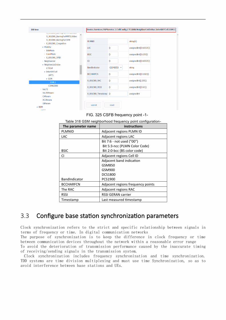
FIG. 325 CSFB frequency point -1-
Table 318 GSM neighborhood frequency point configuration-
The parameter name instructionsPLMNID Adjacent regions PLMN IDLAC Adjacent regions LAC
BSIC
Bit 7:6 - not used ("00") Bit 5:3-ncc (PLMN Color Code) Bit 2:0-bcc (BS color code)
CI Adjacent regions Cell ID
BandIndicator
Adjacent band indicationGSM850GSM900DCS1800PCS1900
BCCHARFCN Adjacent regions frequency pointsThe RAC Adjacent regions RACRSSI RSSI GERAN carrierTimestamp Last measured timestamp
3.3 Configure base station synchronization parameters
Clock synchronization refers to the strict and specific relationship between signals interms of frequency or time. In digital communication networksThe purpose of synchronization is to keep the difference in clock frequency or timebetween communication devices throughout the network within a reasonable error rangeTo avoid the deterioration of transmission performance caused by the inaccurate timingof receiving/sending signals in the transmission system. Clock synchronization includes frequency synchronization and time synchronization.TDD systems are time division multiplexing and must use time Synchronization, so as toavoid interference between base stations and UEs.

3.3.1 Overview
1. The base station supports three synchronization modes. When the synchronization mode switchingfunction is turned on, the base station can switch among the three synchronization modes.
Figure 326 synchronization mode-
Synchronoustechnology
Frequencysynchronization
Timesynchronization
advantages disadvantages
GPS/RGPS Each small base station is equipped with GPS/RGPS independently, without network support.
Need to increaseGPS/RGPShardware, as well asinstallation andmaintenance costs,high cost.
The IEEE 1588v2
1. If frequencysynchronization isonly implemented, itcan supporttransmission acrossdata network andhas lowrequirements forintermediateequipment.
2. Can realizefrequencysynchronization andtimesynchronization,and can support theclock requirementsof LTE TDD.
3. Standard
1. If timesynchronization is tobe achieved, allintermediate networkequipment shall beupgraded to supportIEEE1588 protocol.
2. Clock recoveryquality is susceptibleto data networkdelay, jitter andpacket loss.

protocol, which cansupportinterconnectionbetweenmanufacturersthrough differentprofiles.
Lip sync X No additionalhardware, nonetwork support
Only synchronizingfrequency
Note:
SyncMode1, SyncMode2 and SyncMode3 are not used at present.
Air port synchronization can only synchronize the frequency, generally need tocooperate with the NTP function.
2. The synchronization mode corresponds to parameters, as shown in the table.Table 319synchronization mode-
Table 319 synchronization mode-
synchronously instructions
Freedom Free mode, which means no synchronization
IEEE1588V21588 clock synchronization, need to configure frameoffset
Sniffer
Sniffer synchronization, which synchronizes directly withmacro stations, does not require configuration of frameoffsets
GPS GPS synchronization, need to configure frame offset
3. Synchronize configuration parameters, as shown in the table.
Table 320 synchronization mode parameters-
parameter instructions
SyncSwitchEnable Sync source toggle.Default off.
SyncFailureHandling
How the base station handles synchronizationfailures
Default: Ignore: Ignore synchronizationfailure;
Restart: failure of synchronization willdelete cell retry;
Reboot: failure of synchronization willrestart the base station to retry;

3.3.2 GPS synchronization
1. The base station needs external GPS antenna.
2. Set the synchronization mode to "GPS";
3. Configure frame migration according the operter plan, as shown in figure 327, and thecalculation method of frame migration is shown in table 321.Error: Reference source notfoundTable 321 frame migration parameter description-
Figure 327 GPS synchronization configuration-
Table 321 frame migration parameter description-
The parameter name instructions
TimingCorrectionOffset Time synchronization frame offset, Chip(1/30.72us), valid for GNSS and IEEE1588V2.If the macro station is 700us ahead of the GPS frame header, then the frame offset should be 700*30.72=21504.(the macro station here is of the same frequency band)
4. After parameter configuration is completed, click "Submit";
5. Restart base station and perform GPS synchronization.
6. After the base station restarts, query the GPS synchronization status, as shown in the figurebelow.

Figure 328 GPS synchronization status-
3.3.3 IEEE1588v2 synchronization
1. There are 1588 clock synchronization signals in the network environment of the base station.
2. 1588 PTPv2 is divided into two modes: multicast and unicast. The configuration of multicastmode is shown in figure 3-30.
Select "Ethernet" for Transport;
Role select "Slave";
FIG. 329 1588 PTPv2 multicast mode-
3. The 1588 PTPv2 unicast mode configuration is shown in figure 3-31.

Select "Ethernet" for Transport;
Role select "Slave";
MasterAddr fill in the IP address of the master clock;
In the PTP over IPsec scenario, you need to specify the security gatewayaddress.SecGWServer fill in the security gateway IP address.
Figure 330 1588 PTPv2 unicast mode-
4. For configuring frame offset, see the frame offset configuration instructions in table 3-21
5. After setting the above synchronization parameters, set the synchronization mode to "PTP1588";
Note: after modifying the synchronization mode, the base station takes effect byrestarting and performs the synchronization.
Figure 331 1588 PTPv2 synchronization configuration-

6. Restart the base station and perform 1588PTP synchronization;
7. After the base station restarts, check the synchronization status, as shown in the figure below.
Figure 332 1588 PTPv2 synchronization status-
3.3.4 Sniffer synchronization
1. Configure the frequency points for Sniffer, as shown in the figure.
Figure 333 setting of the same step frequency of Sniffer-
2. Set the synchronization mode to "Sniffer";

Figure 334. Sniffer synchronization configuration-
3. After the configuration of synchronization parameters is completed, restart the base station andperform synchronization;
4. After the base station restarts, check the air port synchronization status, as shown in the figurebelow.
3.3.5 The free mode
1. Set synchronization mode to "Freedom";
2. In free mode, the base station will not synchronize with any synchronous source, relying only on

its own crystal oscillator to ensure frequency deviation.
4.Configure system parameters
4.1.1 Software version upgrade
Select "management-> Upgrade" in the navigation bar to enter the version Upgrade page, as shown in thefigure.Figure 41 version upgrade-
Figure 41 version upgrade-
4.1.1.1 Software upgrade
1. Click "Browser file", select the upgrade file and upload it to the base station.
2. Click Submit to upgrade.
3. The base station restarts and performs the audit, waiting for approximately 3-5min.Aftersuccessful upgrade, the page will be prompted accordingly.
4. The updated version can be confirmed through the "Information" page of the base station.

Figure 42 confirms the updated version-
4.1.1.2 Version back
1. In the event that the base station firmware upgrade fails, the base station will automaticallyrevert back to the available version prior to the upgrade.
2. It is also possible to upgrade back to the previous version through the normal version upgradeoperation.
4.1.2 System file backup
4.1.2.1 Import/export configuration files
1. Select "Data Model" in the navigation bar and enter the DB import/export page, as shown in thefigure.Error: Reference source not found
Figure 43 DB export import-
2. Export/Import to Export and Import data files.
4.1.2.2 Export log file
1. Select "management-> Debug" in the navigation bar to enter the log operation interface, as shown inthe figure.

Figure 44 exports the log file-
2. Select the log you want to Export, and click "Export".
3. Save the log file locally by selecting the save path in the download dialog box thatpops up.
4.1.3 Restart the base station
1. Select "management-> Factory" in the navigation bar.
2. Click "Reboot" to restart the base station.
3. Base station restarts usually take 3 to 5 minutes.
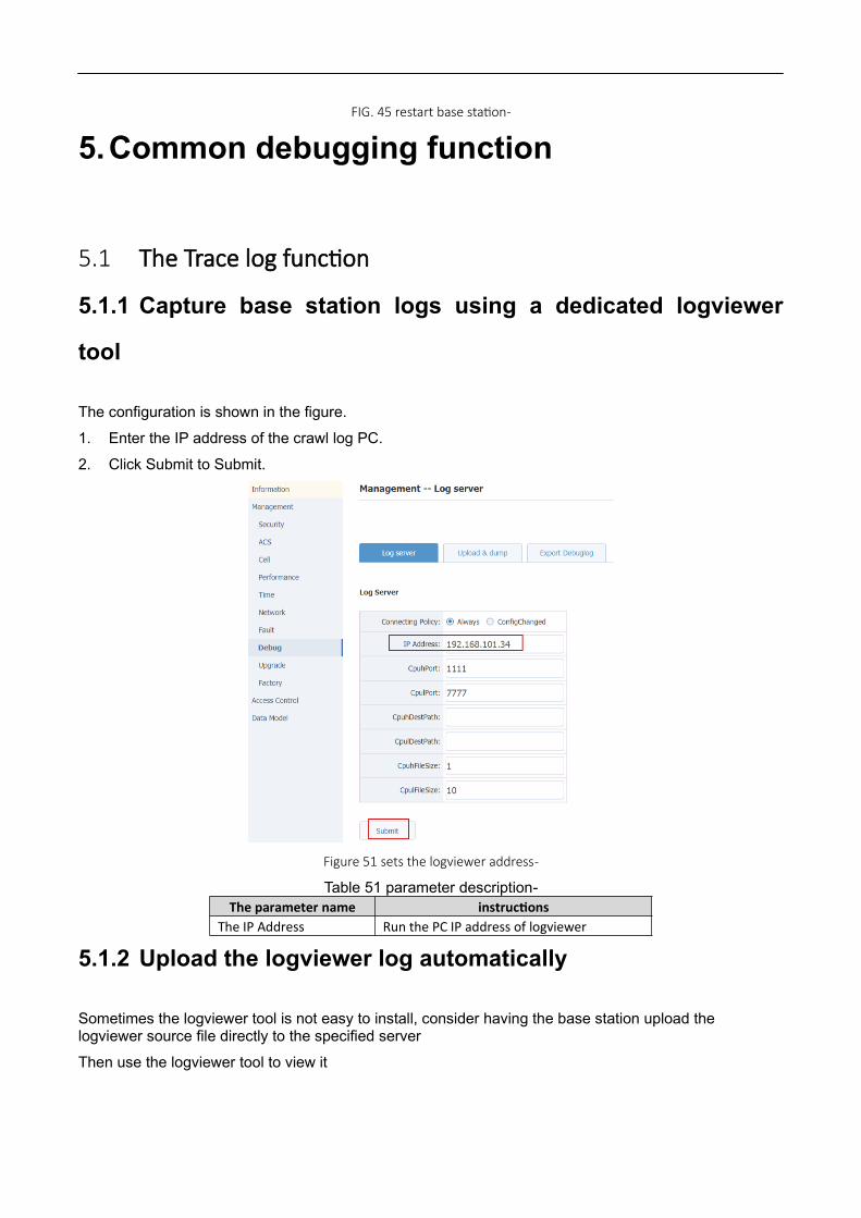
FIG. 45 restart base station-
5.Common debugging function
5.1 The Trace log function
5.1.1 Capture base station logs using a dedicated logviewer
tool
The configuration is shown in the figure.
1. Enter the IP address of the crawl log PC.
2. Click Submit to Submit.
Figure 51 sets the logviewer address-
Table 51 parameter description-The parameter name instructions
The IP Address Run the PC IP address of logviewer
5.1.2 Upload the logviewer log automatically
Sometimes the logviewer tool is not easy to install, consider having the base station upload the logviewer source file directly to the specified server
Then use the logviewer tool to view it

1. Turn on automatic upload
Device. X_D837BE_DebugMgmt. Upload. Enable = 1
2. Set the automatic upload cycle
Device. X_D837BE_DebugMgmt. Upload. PeriodicTraceUploadInterval
3. Choose "VendorTraces" for cyclical upload strategy
Device. X_D837BE_DebugMgmt. Upload. PeriodicUploadPolicy = VendorTraces
Figure 52 turn on the automatic upload log function-
4. Set upload server address and authentication information.
Figure 53 sets upload server parameters-
Table 53 parameter description-The parameter name instructions
The URL
Log automatic upload path.Such as: ftp://10.98.100.80/log/
The Username Server usernameThe Password Server passwordPeriodicUploadEnable Cycle automatically upload enable switch

5.2 Other Trace logs are automatically uploadedBase station supports the function of automatic log uploading, which can upload log files to FTP server.As shown in the figure.
Figure 54 automatically uploads Trace log Settings-
Table 54 parameter description-The parameter name instructions
The Enable Can make the switchThe Upload URL FTP server addressUpload the Username FTP server user nameUpload the Password FTP server passwordUpload the Policy Log upload policy, by default
5.3 TCP Dump functionBase station supports opening TCP Dump function to grab base station network interface messages.Thisis shown below.
1. Choose Interface;
2. Select the corresponding protocol in Filter Type. If other types of packets (such as icmp) are to becaptured, select OTHERS and Expression to fill in icmp.
3. Check the Enable;
4. After configuration, click Submit, as shown in figure 6-3.
5. Export the tcpdump file through the Web interface, as shown in figure 6-4;
6. Wireshark looks at tcpdump, as shown in figure 6-5.
Open tcpdump.rar. Open the tcpdump.log file with wireshark.

Figure 54 TCP Dump Settings-
Figure 56 exports the tcpdump file-
Export tcpdump.log file to desktop and open with Wireshark.
Figure 55 shows the tcpdump file-
Table 55 parameter description-The parameter name instructions
The Enable Can make the switch
InterfaceBase station network interface, through the drop-down selection
The Filter Type Common catch types

Check "OTHERS" when filtering other types of messages
A Filter ExpressionWhen fetching messages other than the usual type, fill in, such as icmp.
5.4 Telnet functionFor security reasons, the Telnet function of the base station is turned off by default.The Telnet function ofthe power base station can be configured by modifying the data model configuration, as shown in figure5-8.
1. Check the "TelnetEnable" Enable identification;
2. Click submit for the configuration to take effect.
3. After the configuration is committed, the Telnet function is enabled.The base station can beaccessed by Telnet.
User name: root
Password: MikroTik
Note: the Telnet function fails after the base station is restarted and needs to be reenabled.
Figure 56enable base station Telnet function-