Instruction Manual - Massio ControlPads and Keypads - AMX
43
INSTRUCTION MANUAL MASSIO CONTROLPADS AND KEYPADS MCP-106, MCP-108, MKP-106, MKP-108
-
Upload
khangminh22 -
Category
Documents
-
view
3 -
download
0
Transcript of Instruction Manual - Massio ControlPads and Keypads - AMX
INSTRUCTION MANUAL
MASSIO CONTROLPADS AND KEYPADS
MCP-106 , MCP-108, MKP-106 , MKP-108
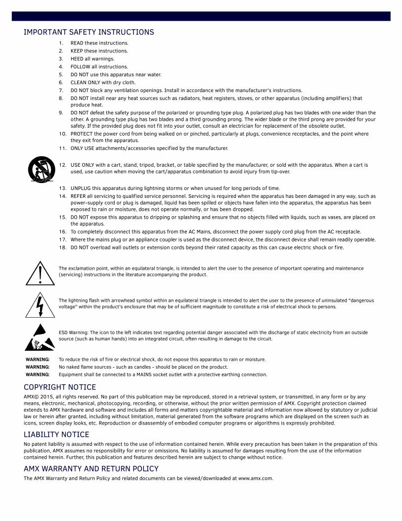
IMPORTANT SAFETY INSTRUCTIONS
COPYRIGHT NOTICEAMX© 2015, all rights reserved. No part of this publication may be reproduced, stored in a retrieval system, or transmitted, in any form or by any means, electronic, mechanical, photocopying, recording, or otherwise, without the prior written permission of AMX. Copyright protection claimed extends to AMX hardware and software and includes all forms and matters copyrightable material and information now allowed by statutory or judicial law or herein after granted, including without limitation, material generated from the software programs which are displayed on the screen such as icons, screen display looks, etc. Reproduction or disassembly of embodied computer programs or algorithms is expressly prohibited.
LIABILITY NOTICENo patent liability is assumed with respect to the use of information contained herein. While every precaution has been taken in the preparation of this publication, AMX assumes no responsibility for error or omissions. No liability is assumed for damages resulting from the use of the information contained herein. Further, this publication and features described herein are subject to change without notice.
AMX WARRANTY AND RETURN POLICYThe AMX Warranty and Return Policy and related documents can be viewed/downloaded at www.amx.com.
1. READ these instructions.2. KEEP these instructions.3. HEED all warnings.4. FOLLOW all instructions.5. DO NOT use this apparatus near water.6. CLEAN ONLY with dry cloth.7. DO NOT block any ventilation openings. Install in accordance with the manufacturer's instructions.8. DO NOT install near any heat sources such as radiators, heat registers, stoves, or other apparatus (including amplifiers) that
produce heat.9. DO NOT defeat the safety purpose of the polarized or grounding type plug. A polarized plug has two blades with one wider than the
other. A grounding type plug has two blades and a third grounding prong. The wider blade or the third prong are provided for your safety. If the provided plug does not fit into your outlet, consult an electrician for replacement of the obsolete outlet.
10. PROTECT the power cord from being walked on or pinched, particularly at plugs, convenience receptacles, and the point where they exit from the apparatus.
11. ONLY USE attachments/accessories specified by the manufacturer.
12. USE ONLY with a cart, stand, tripod, bracket, or table specified by the manufacturer, or sold with the apparatus. When a cart is used, use caution when moving the cart/apparatus combination to avoid injury from tip-over.
13. UNPLUG this apparatus during lightning storms or when unused for long periods of time.14. REFER all servicing to qualified service personnel. Servicing is required when the apparatus has been damaged in any way, such as
power-supply cord or plug is damaged, liquid has been spilled or objects have fallen into the apparatus, the apparatus has been exposed to rain or moisture, does not operate normally, or has been dropped.
15. DO NOT expose this apparatus to dripping or splashing and ensure that no objects filled with liquids, such as vases, are placed on the apparatus.
16. To completely disconnect this apparatus from the AC Mains, disconnect the power supply cord plug from the AC receptacle.17. Where the mains plug or an appliance coupler is used as the disconnect device, the disconnect device shall remain readily operable. 18. DO NOT overload wall outlets or extension cords beyond their rated capacity as this can cause electric shock or fire.
The exclamation point, within an equilateral triangle, is intended to alert the user to the presence of important operating and maintenance (servicing) instructions in the literature accompanying the product.
The lightning flash with arrowhead symbol within an equilateral triangle is intended to alert the user to the presence of uninsulated "dangerous voltage" within the product's enclosure that may be of sufficient magnitude to constitute a risk of electrical shock to persons.
ESD Warning: The icon to the left indicates text regarding potential danger associated with the discharge of static electricity from an outside source (such as human hands) into an integrated circuit, often resulting in damage to the circuit.
WARNING: To reduce the risk of fire or electrical shock, do not expose this apparatus to rain or moisture.WARNING: No naked flame sources - such as candles - should be placed on the product.WARNING: Equipment shall be connected to a MAINS socket outlet with a protective earthing connection.
3Instruction Manual - Massio ControlPads and Keypads
ESD WARNING
WARNING: This product is intended to be operated ONLY from the voltages listed on the back panel or the recommended, orincluded, power supply of the product. Operation from other voltages other than those indicated may cause irreversibledamage to the product and void the products warranty. The use of AC Plug Adapters is cautioned because it can allow theproduct to be plugged into voltages in which the product was not designed to operate. If the product is equipped with adetachable power cord, use only the type provided with your product or by your local distributor and/or retailer. If you areunsure of the correct operational voltage, please contact your local distributor and/or retailer.
FCC AND CANADA EMC COMPLIANCE INFORMATION:This device complies with part 15 of the FCC Rules. Operation is subject to the following two conditions:
(1) This device may not cause harmful interference, and (2) this device must accept any interference received, includinginterference that may cause undesired operation.
NOTE: This equipment has been tested and found to comply with the limits for a Class B digital device, pursuant to part 15 ofthe FCC Rules. These limits are designed to provide reasonable protection against harmful interference in a residentialinstallation. This equipment generates, uses and can radiate radio frequency energy and, if not installed and used inaccordance with the instructions, may cause harmful interference to radio communications. However, there is no guaranteethat interference will not occur in a particular installation. If this equipment does cause harmful interference to radio ortelevision reception, which can be determined by turning the equipment off and on, the user is encouraged to try to correctthe interference by one or more of the following measures:
•Reorient or relocate the receiving antenna.•Increase the separation between the equipment and receiver.•Connect the equipment into an outlet on a circuit different from that to which the receiver is connected.•Consult the dealer or an experienced radio/TV technician for help.
Approved under the verification provision of FCC Part 15 as a Class B Digital Device.Caution: Changes or modifications not expressly approved by the manufacturer could void the user's authority to operate thisdevice.CAN ICES-3 (B)/NMB-3(B)
EU COMPLIANCE INFORMATION:Eligible to bear the CE mark; Conforms to European Union Low Voltage Directive 2006/95/EC; European Union EMC Directive 2004/108/EC; European Union Restriction of Hazardous Substances Recast (RoHS2) Directive 2011/65/EU; European Union WEEE (recast) Directive 2012/19/EU.You may obtain a free copy of the Declaration of Conformity by visiting http://www.amx.com/techcenter/certifications.asp.
WEEE NOTICE:
To avoid ESD (Electrostatic Discharge) damage to sensitive components, make sure you are properly grounded beforetouching any internal materials. When working with any equipment manufactured with electronic devices, proper ESD grounding procedures must befollowed to make sure people, products, and tools are as free of static charges as possible. Grounding straps, conductivesmocks, and conductive work mats are specifically designed for this purpose. These items should not be manufacturedlocally, since they are generally composed of highly resistive conductive materials to safely drain static discharges, withoutincreasing an electrocution risk in the event of an accident. Anyone performing field maintenance on AMX equipment should use an appropriate ESD field service kit complete with atleast a dissipative work mat with a ground cord and a UL listed adjustable wrist strap with another ground cord
WARNING: Do Not Open! Risk of Electrical Shock. Voltages in this equipment arehazardous to life. No user-serviceable parts inside. Refer all servicing to qualifiedservice personnel. Place the equipment near a main power supply outlet and make sure that you caneasily access the power breaker switch.
This appliance is labeled in accordance with European Directive 2012/19/EU concerning waste of electrical and electronicequipment (WEEE). This label indicates that this product should not be disposed of with household waste. It should bedeposited at an appropriate facility to enable recovery and recycling.
Table of Contents
Table of ContentsOverview - Massio ControlPads .........................................................................7
Features .................................................................................................................................................. 7Port Assignments by Massio ControlPad ............................................................................................... 7
Specifications .................................................................................................................... 8MCP-106 ................................................................................................................................................. 8MCP-108 ................................................................................................................................................. 9
Overview - Massio Keypads .............................................................................10Specifications ................................................................................................................. 10
MKP-106 ............................................................................................................................................... 10MKP-108 ............................................................................................................................................... 11
Wiring and Device Connections ......................................................................12Overview ......................................................................................................................... 12Control Ports and Indicators.......................................................................................... 13
RS-232 .................................................................................................................................................. 13RELAYS.................................................................................................................................................. 13I/O......................................................................................................................................................... 14IR/Serial ............................................................................................................................................... 14LAN (RJ-45)........................................................................................................................................... 15
Applying Power................................................................................................................................................... 15
ID Pushbutton....................................................................................................................................... 16
Installation ......................................................................................................18Overview ......................................................................................................................... 18Mounting Procedures ..................................................................................................... 18
Wallbox Mounting ................................................................................................................................. 18
Button Labeling ...............................................................................................20Overview ......................................................................................................................... 20Installing Acetate Button Labels .................................................................................... 20Disassembling the Massio Device................................................................................... 21Re-Assembling the Massio Device................................................................................... 22
Initial Configuration ........................................................................................23Massio ControlPads......................................................................................................... 23
Before You Start.................................................................................................................................... 23Obtaining the ControlPad’s IP Address................................................................................................ 23Changing the ControlPad’s Network Address Information.................................................................. 24Connecting to the ControlPad via USB ................................................................................................. 25Toggling Between IP Addressing Modes: DHCP and Static IP ............................................................. 26Configuration and Programming.......................................................................................................... 26
Programming...................................................................................................................................................... 26
4 Instruction Manual - Massio ControlPads and Keypads
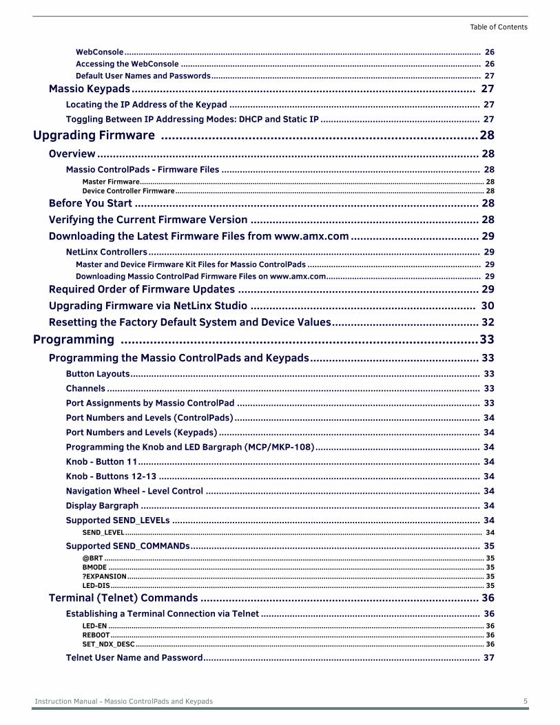
Table of Contents
WebConsole........................................................................................................................................................ 26Accessing the WebConsole ................................................................................................................................ 26Default User Names and Passwords................................................................................................................... 27
Massio Keypads.............................................................................................................. 27Locating the IP Address of the Keypad ................................................................................................ 27Toggling Between IP Addressing Modes: DHCP and Static IP ............................................................. 27
Upgrading Firmware .......................................................................................28Overview .......................................................................................................................... 28
Massio ControlPads - Firmware Files ................................................................................................... 28Master Firmware..................................................................................................................................................................... 28Device Controller Firmware.................................................................................................................................................... 28
Before You Start .............................................................................................................. 28Verifying the Current Firmware Version ......................................................................... 28Downloading the Latest Firmware Files from www.amx.com ......................................... 29
NetLinx Controllers ............................................................................................................................... 29Master and Device Firmware Kit Files for Massio ControlPads .......................................................................... 29Downloading Massio ControlPad Firmware Files on www.amx.com.................................................................. 29
Required Order of Firmware Updates ............................................................................. 29Upgrading Firmware via NetLinx Studio ........................................................................ 30Resetting the Factory Default System and Device Values............................................... 32
Programming ..................................................................................................33Programming the Massio ControlPads and Keypads...................................................... 33
Button Layouts...................................................................................................................................... 33Channels ............................................................................................................................................... 33Port Assignments by Massio ControlPad ............................................................................................. 33Port Numbers and Levels (ControlPads) .............................................................................................. 34Port Numbers and Levels (Keypads) .................................................................................................... 34Programming the Knob and LED Bargraph (MCP/MKP-108)............................................................... 34Knob - Button 11................................................................................................................................... 34Knob - Buttons 12-13 ........................................................................................................................... 34Navigation Wheel - Level Control ......................................................................................................... 34Display Bargraph .................................................................................................................................. 34Supported SEND_LEVELs ...................................................................................................................... 34
SEND_LEVEL........................................................................................................................................................................... 34
Supported SEND_COMMANDs............................................................................................................... 35@BRT ...................................................................................................................................................................................... 35BMODE .................................................................................................................................................................................... 35?EXPANSION........................................................................................................................................................................... 35LED-DIS................................................................................................................................................................................... 35
Terminal (Telnet) Commands ......................................................................................... 36Establishing a Terminal Connection via Telnet .................................................................................... 36
LED-EN .................................................................................................................................................................................... 36REBOOT................................................................................................................................................................................... 36SET_NDX_DESC....................................................................................................................................................................... 36
Telnet User Name and Password.......................................................................................................... 37
5 Instruction Manual - Massio ControlPads and Keypads
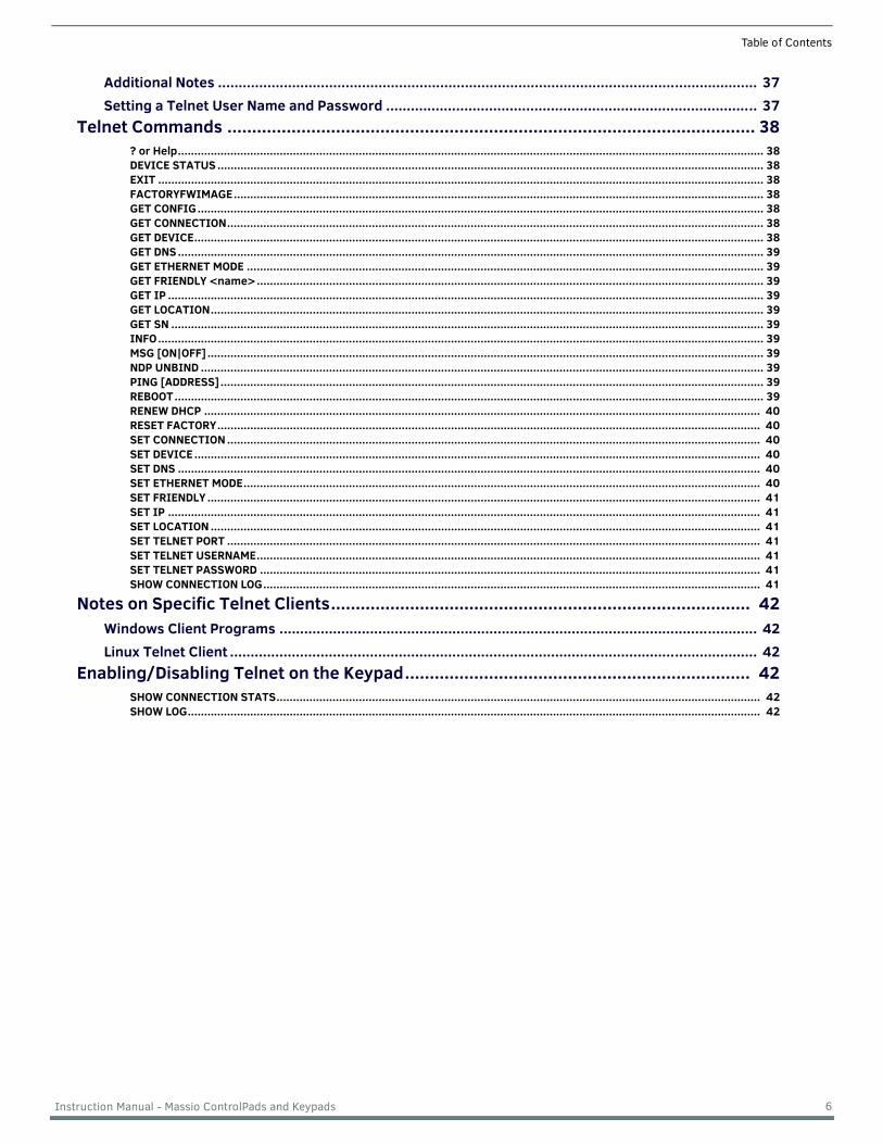
Table of Contents
Additional Notes ................................................................................................................................... 37Setting a Telnet User Name and Password .......................................................................................... 37
Telnet Commands ........................................................................................................... 38? or Help.................................................................................................................................................................................. 38DEVICE STATUS ...................................................................................................................................................................... 38EXIT ........................................................................................................................................................................................ 38FACTORYFWIMAGE................................................................................................................................................................. 38GET CONFIG............................................................................................................................................................................ 38GET CONNECTION................................................................................................................................................................... 38GET DEVICE............................................................................................................................................................................. 38GET DNS .................................................................................................................................................................................. 39GET ETHERNET MODE ............................................................................................................................................................. 39GET FRIENDLY <name>.......................................................................................................................................................... 39GET IP ..................................................................................................................................................................................... 39GET LOCATION........................................................................................................................................................................ 39GET SN .................................................................................................................................................................................... 39INFO........................................................................................................................................................................................ 39MSG [ON|OFF] ......................................................................................................................................................................... 39NDP UNBIND ........................................................................................................................................................................... 39PING [ADDRESS] ..................................................................................................................................................................... 39REBOOT................................................................................................................................................................................... 39RENEW DHCP ......................................................................................................................................................................... 40RESET FACTORY..................................................................................................................................................................... 40SET CONNECTION .................................................................................................................................................................. 40SET DEVICE ............................................................................................................................................................................ 40SET DNS ................................................................................................................................................................................. 40SET ETHERNET MODE............................................................................................................................................................. 40SET FRIENDLY ........................................................................................................................................................................ 41SET IP .................................................................................................................................................................................... 41SET LOCATION ....................................................................................................................................................................... 41SET TELNET PORT .................................................................................................................................................................. 41SET TELNET USERNAME......................................................................................................................................................... 41SET TELNET PASSWORD ........................................................................................................................................................ 41SHOW CONNECTION LOG....................................................................................................................................................... 41
Notes on Specific Telnet Clients..................................................................................... 42Windows Client Programs .................................................................................................................... 42Linux Telnet Client ................................................................................................................................ 42
Enabling/Disabling Telnet on the Keypad...................................................................... 42SHOW CONNECTION STATS................................................................................................................................................... 42SHOW LOG.............................................................................................................................................................................. 42
6 Instruction Manual - Massio ControlPads and Keypads
Overview - Massio ControlPads
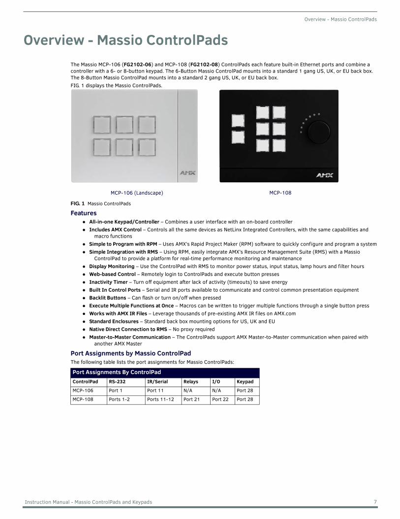
Overview - Massio ControlPadsThe Massio MCP-106 (FG2102-06) and MCP-108 (FG2102-08) ControlPads each feature built-in Ethernet ports and combine a controller with a 6- or 8-button keypad. The 6-Button Massio ControlPad mounts into a standard 1 gang US, UK, or EU back box. The 8-Button Massio ControlPad mounts into a standard 2 gang US, UK, or EU back box.FIG. 1 displays the Massio ControlPads.
FIG. 1 Massio ControlPads
FeaturesAll-in-one Keypad/Controller – Combines a user interface with an on-board controllerIncludes AMX Control – Controls all the same devices as NetLinx Integrated Controllers, with the same capabilities and
macro functionsSimple to Program with RPM – Uses AMX’s Rapid Project Maker (RPM) software to quickly configure and program a systemSimple Integration with RMS – Using RPM, easily integrate AMX’s Resource Management Suite (RMS) with a Massio
ControlPad to provide a platform for real-time performance monitoring and maintenanceDisplay Monitoring – Use the ControlPad with RMS to monitor power status, input status, lamp hours and filter hoursWeb-based Control – Remotely login to ControlPads and execute button pressesInactivity Timer – Turn off equipment after lack of activity (timeouts) to save energyBuilt In Control Ports – Serial and IR ports available to communicate and control common presentation equipmentBacklit Buttons – Can flash or turn on/off when pressedExecute Multiple Functions at Once – Macros can be written to trigger multiple functions through a single button pressWorks with AMX IR Files – Leverage thousands of pre-existing AMX IR files on AMX.comStandard Enclosures – Standard back box mounting options for US, UK and EUNative Direct Connection to RMS – No proxy requiredMaster-to-Master Communication – The ControlPads support AMX Master-to-Master communication when paired with
another AMX Master
Port Assignments by Massio ControlPadThe following table lists the port assignments for Massio ControlPads:
Port Assignments By ControlPadControlPad RS-232 IR/Serial Relays I/O Keypad
MCP-106 Port 1 Port 11 N/A N/A Port 28
MCP-108 Ports 1-2 Ports 11-12 Port 21 Port 22 Port 28
MCP-108MCP-106 (Landscape)
7 Instruction Manual - Massio ControlPads and Keypads
Overview - Massio ControlPads
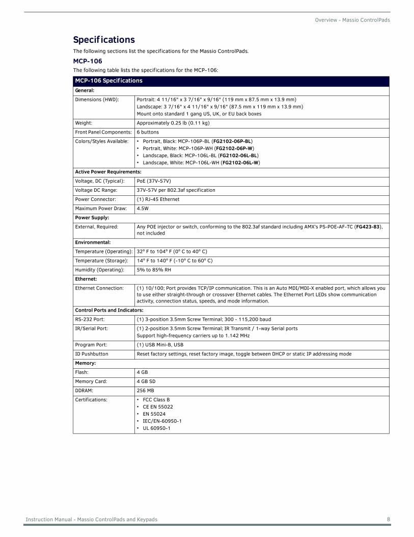
Specif icationsThe following sections list the specifications for the Massio ControlPads.
MCP-106The following table lists the specifications for the MCP-106:
MCP-106 Specif icationsGeneral:
Dimensions (HWD): Portrait: 4 11/16" x 3 7/16" x 9/16" (119 mm x 87.5 mm x 13.9 mm)Landscape: 3 7/16" x 4 11/16" x 9/16" (87.5 mm x 119 mm x 13.9 mm)Mount onto standard 1 gang US, UK, or EU back boxes
Weight: Approximately 0.25 lb (0.11 kg)
Front Panel Components: 6 buttons
Colors/Styles Available: • Portrait, Black: MCP-106P-BL (FG2102-06P-BL)• Portrait, White: MCP-106P-WH (FG2102-06P-W)• Landscape, Black: MCP-106L-BL (FG2102-06L-BL)• Landscape, White: MCP-106L-WH (FG2102-06L-W)
Active Power Requirements:
Voltage, DC (Typical): PoE (37V-57V)
Voltage DC Range: 37V-57V per 802.3af specification
Power Connector: (1) RJ-45 Ethernet
Maximum Power Draw: 4.5W
Power Supply:
External, Required: Any POE injector or switch, conforming to the 802.3af standard including AMX’s PS-POE-AF-TC (FG423-83), not included
Environmental:
Temperature (Operating): 32º F to 104º F (0º C to 40º C)
Temperature (Storage): 14º F to 140º F (-10º C to 60º C)
Humidity (Operating): 5% to 85% RH
Ethernet:
Ethernet Connection: (1) 10/100; Port provides TCP/IP communication. This is an Auto MDI/MDI-X enabled port, which allows you to use either straight-through or crossover Ethernet cables. The Ethernet Port LEDs show communication activity, connection status, speeds, and mode information.
Control Ports and Indicators:
RS-232 Port: (1) 3-position 3.5mm Screw Terminal; 300 - 115,200 baud
IR/Serial Port: (1) 2-position 3.5mm Screw Terminal; IR Transmit / 1-way Serial portsSupport high-frequency carriers up to 1.142 MHz
Program Port: (1) USB Mini-B, USB
ID Pushbutton Reset factory settings, reset factory image, toggle between DHCP or static IP addressing mode
Memory:
Flash: 4 GB
Memory Card: 4 GB SD
DDRAM: 256 MB
Certifications: • FCC Class B• CE EN 55022• EN 55024• IEC/EN-60950-1• UL 60950-1
8 Instruction Manual - Massio ControlPads and Keypads
Overview - Massio ControlPads
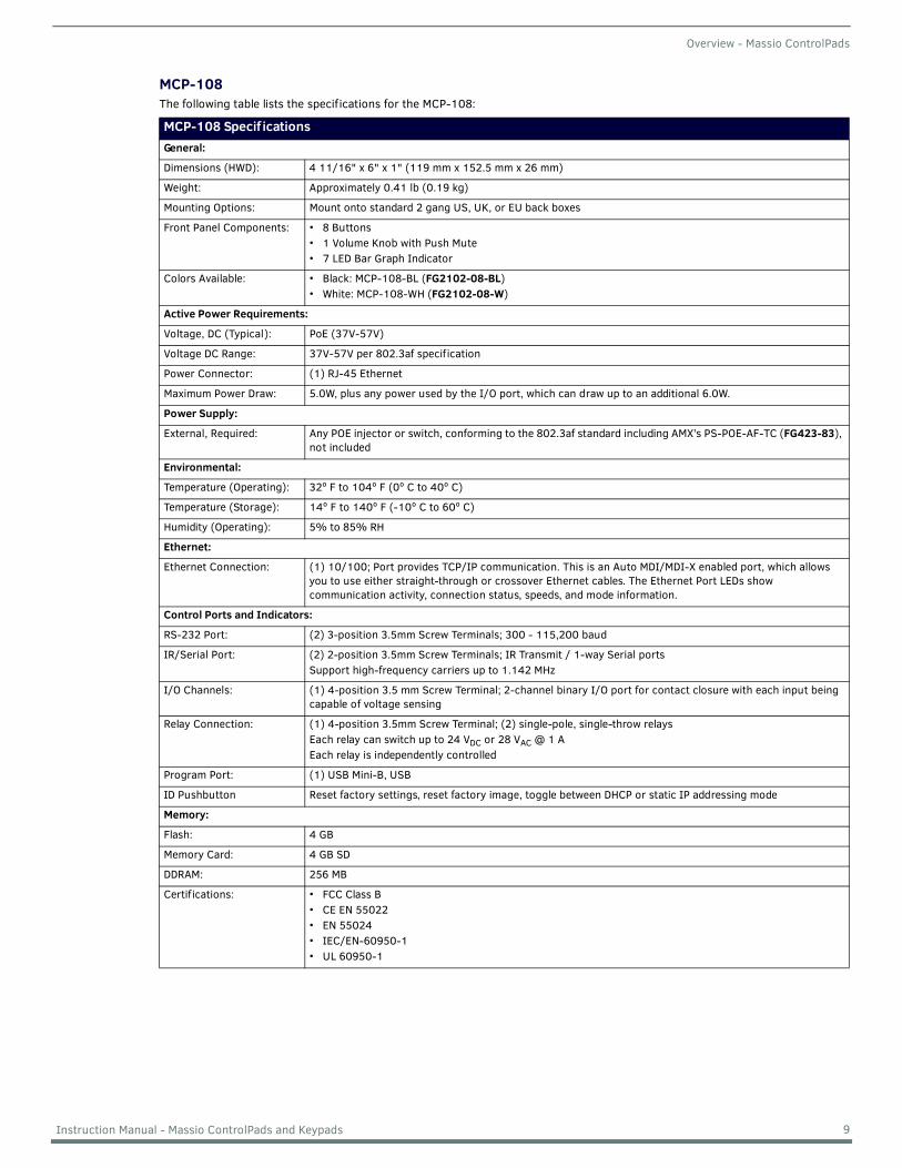
MCP-108The following table lists the specifications for the MCP-108:
MCP-108 Specif icationsGeneral:
Dimensions (HWD): 4 11/16" x 6" x 1" (119 mm x 152.5 mm x 26 mm)
Weight: Approximately 0.41 lb (0.19 kg)
Mounting Options: Mount onto standard 2 gang US, UK, or EU back boxes
Front Panel Components: • 8 Buttons• 1 Volume Knob with Push Mute• 7 LED Bar Graph Indicator
Colors Available: • Black: MCP-108-BL (FG2102-08-BL)• White: MCP-108-WH (FG2102-08-W)
Active Power Requirements:
Voltage, DC (Typical): PoE (37V-57V)
Voltage DC Range: 37V-57V per 802.3af specification
Power Connector: (1) RJ-45 Ethernet
Maximum Power Draw: 5.0W, plus any power used by the I/O port, which can draw up to an additional 6.0W.
Power Supply:
External, Required: Any POE injector or switch, conforming to the 802.3af standard including AMX’s PS-POE-AF-TC (FG423-83), not included
Environmental:
Temperature (Operating): 32º F to 104º F (0º C to 40º C)
Temperature (Storage): 14º F to 140º F (-10º C to 60º C)
Humidity (Operating): 5% to 85% RH
Ethernet:
Ethernet Connection: (1) 10/100; Port provides TCP/IP communication. This is an Auto MDI/MDI-X enabled port, which allows you to use either straight-through or crossover Ethernet cables. The Ethernet Port LEDs show communication activity, connection status, speeds, and mode information.
Control Ports and Indicators:
RS-232 Port: (2) 3-position 3.5mm Screw Terminals; 300 - 115,200 baud
IR/Serial Port: (2) 2-position 3.5mm Screw Terminals; IR Transmit / 1-way Serial portsSupport high-frequency carriers up to 1.142 MHz
I/O Channels: (1) 4-position 3.5 mm Screw Terminal; 2-channel binary I/O port for contact closure with each input being capable of voltage sensing
Relay Connection: (1) 4-position 3.5mm Screw Terminal; (2) single-pole, single-throw relaysEach relay can switch up to 24 VDC or 28 VAC @ 1 AEach relay is independently controlled
Program Port: (1) USB Mini-B, USB
ID Pushbutton Reset factory settings, reset factory image, toggle between DHCP or static IP addressing mode
Memory:
Flash: 4 GB
Memory Card: 4 GB SD
DDRAM: 256 MB
Certifications: • FCC Class B• CE EN 55022• EN 55024• IEC/EN-60950-1• UL 60950-1
9 Instruction Manual - Massio ControlPads and Keypads
Overview - Massio Keypads
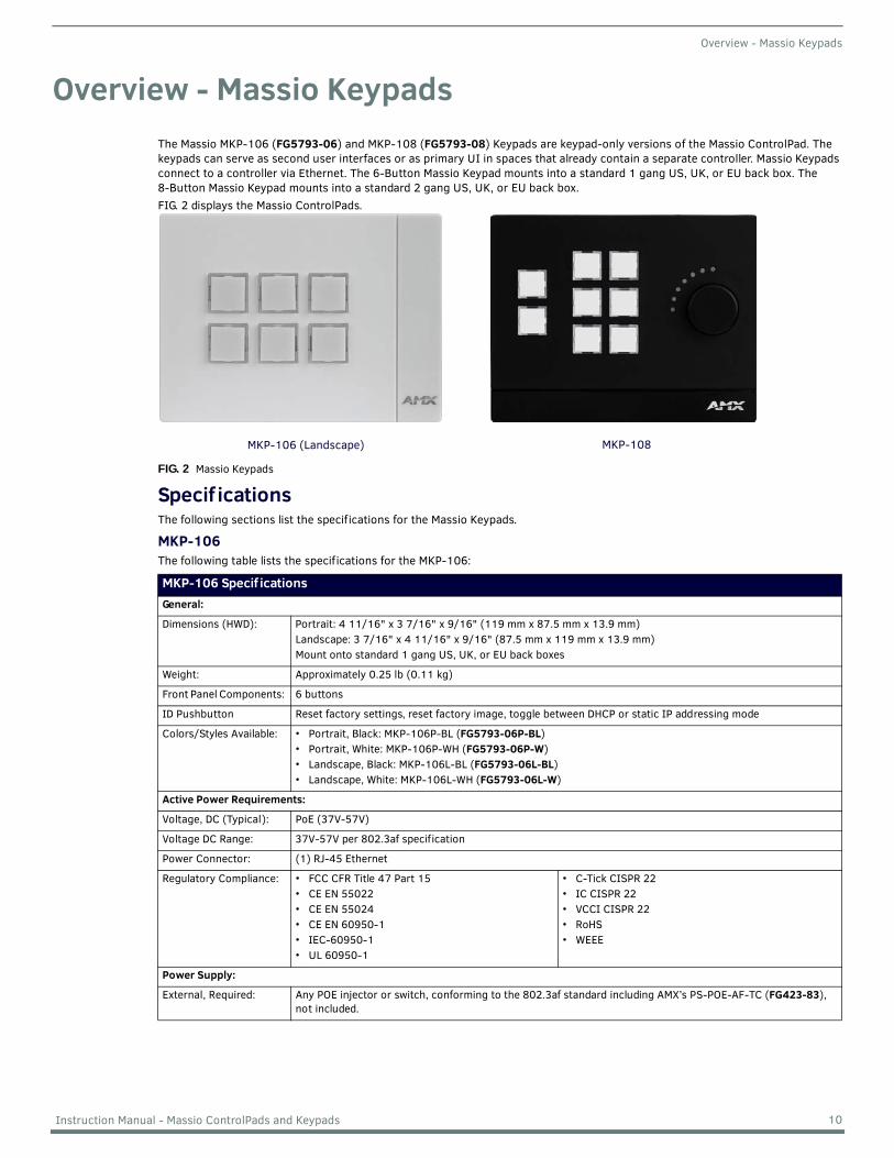
Overview - Massio KeypadsThe Massio MKP-106 (FG5793-06) and MKP-108 (FG5793-08) Keypads are keypad-only versions of the Massio ControlPad. The keypads can serve as second user interfaces or as primary UI in spaces that already contain a separate controller. Massio Keypads connect to a controller via Ethernet. The 6-Button Massio Keypad mounts into a standard 1 gang US, UK, or EU back box. The 8-Button Massio Keypad mounts into a standard 2 gang US, UK, or EU back box.FIG. 2 displays the Massio ControlPads.
FIG. 2 Massio Keypads
Specif icationsThe following sections list the specifications for the Massio Keypads.
MKP-106The following table lists the specifications for the MKP-106:
MKP-106 Specif icationsGeneral:
Dimensions (HWD): Portrait: 4 11/16" x 3 7/16" x 9/16" (119 mm x 87.5 mm x 13.9 mm)Landscape: 3 7/16" x 4 11/16" x 9/16" (87.5 mm x 119 mm x 13.9 mm)Mount onto standard 1 gang US, UK, or EU back boxes
Weight: Approximately 0.25 lb (0.11 kg)
Front Panel Components: 6 buttons
ID Pushbutton Reset factory settings, reset factory image, toggle between DHCP or static IP addressing mode
Colors/Styles Available: • Portrait, Black: MKP-106P-BL (FG5793-06P-BL)• Portrait, White: MKP-106P-WH (FG5793-06P-W)• Landscape, Black: MKP-106L-BL (FG5793-06L-BL)• Landscape, White: MKP-106L-WH (FG5793-06L-W)
Active Power Requirements:
Voltage, DC (Typical): PoE (37V-57V)
Voltage DC Range: 37V-57V per 802.3af specification
Power Connector: (1) RJ-45 Ethernet
Regulatory Compliance: • FCC CFR Title 47 Part 15• CE EN 55022• CE EN 55024• CE EN 60950-1• IEC-60950-1• UL 60950-1
• C-Tick CISPR 22• IC CISPR 22• VCCI CISPR 22• RoHS• WEEE
Power Supply:
External, Required: Any POE injector or switch, conforming to the 802.3af standard including AMX’s PS-POE-AF-TC (FG423-83), not included.
MKP-108MKP-106 (Landscape)
10 Instruction Manual - Massio ControlPads and Keypads
Overview - Massio Keypads
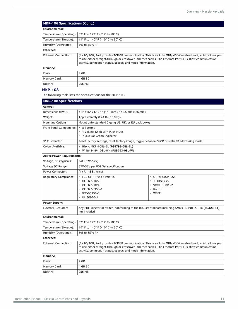
MKP-108The following table lists the specifications for the MKP-108:
MKP-106 Specif ications (Cont.)Environmental:
Temperature (Operating): 32º F to 122º F (0º C to 50º C)
Temperature (Storage): 14º F to 140º F (-10º C to 60º C)
Humidity (Operating): 5% to 85% RH
Ethernet:
Ethernet Connection: (1) 10/100; Port provides TCP/IP communication. This is an Auto MDI/MDI-X enabled port, which allows you to use either straight-through or crossover Ethernet cables. The Ethernet Port LEDs show communication activity, connection status, speeds, and mode information.
Memory:
Flash: 4 GB
Memory Card: 4 GB SD
DDRAM: 256 MB
MKP-108 Specif icationsGeneral:
Dimensions (HWD): 4 11/16" x 6" x 1" (119 mm x 152.5 mm x 26 mm)
Weight: Approximately 0.41 lb (0.19 kg)
Mounting Options: Mount onto standard 2 gang US, UK, or EU back boxes
Front Panel Components: • 8 Buttons• 1 Volume Knob with Push Mute• 7 LED Bar Graph Indicator
ID Pushbutton Reset factory settings, reset factory image, toggle between DHCP or static IP addressing mode
Colors Available: • Black: MKP-108L-BL (FG5793-08L-BL)• White: MKP-108L-WH (FG5793-08L-W)
Active Power Requirements:
Voltage, DC (Typical): PoE (37V-57V)
Voltage DC Range: 37V-57V per 802.3af specification
Power Connector: (1) RJ-45 Ethernet
Regulatory Compliance: • FCC CFR Title 47 Part 15• CE EN 55022• CE EN 55024• CE EN 60950-1• IEC-60950-1• UL 60950-1
• C-Tick CISPR 22• IC CISPR 22• VCCI CISPR 22• RoHS• WEEE
Power Supply:
External, Required: Any POE injector or switch, conforming to the 802.3af standard including AMX’s PS-POE-AF-TC (FG423-83), not included
Environmental:
Temperature (Operating): 32º F to 122º F (0º C to 50º C)
Temperature (Storage): 14º F to 140º F (-10º C to 60º C)
Humidity (Operating): 5% to 85% RH
Ethernet:
Ethernet Connection: (1) 10/100; Port provides TCP/IP communication. This is an Auto MDI/MDI-X enabled port, which allows you to use either straight-through or crossover Ethernet cables. The Ethernet Port LEDs show communication activity, connection status, speeds, and mode information.
Memory:
Flash: 4 GB
Memory Card: 4 GB SD
DDRAM: 256 MB
11 Instruction Manual - Massio ControlPads and Keypads
Wiring and Device Connections
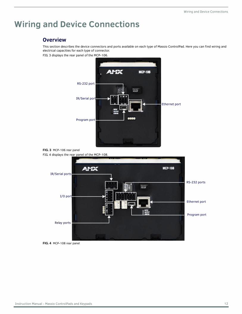
Wiring and Device ConnectionsOverviewThis section describes the device connectors and ports available on each type of Massio ControlPad. Here you can find wiring and electrical capacities for each type of connector.FIG. 3 displays the rear panel of the MCP-106.
FIG. 3 MCP-106 rear panelFIG. 4 displays the rear panel of the MCP-108.
FIG. 4 MCP-108 rear panel
Ethernet port
Program port
RS-232 port
IR/Serial port
RS-232 ports
Ethernet port
Program port
IR/Serial ports
I/O port
Relay ports
12 Instruction Manual - Massio ControlPads and Keypads
Wiring and Device Connections
Control Ports and IndicatorsThe following sub-sections describe each control port on the Massio ControlPads. Refer to Overview section on page 12 for the component layout of the rear panels of each type of Massio ControlPad.
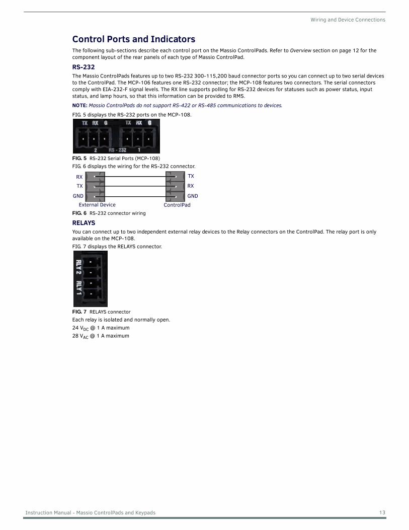
RS-232The Massio ControlPads features up to two RS-232 300-115,200 baud connector ports so you can connect up to two serial devices to the ControlPad. The MCP-106 features one RS-232 connector; the MCP-108 features two connectors. The serial connectors comply with EIA-232-F signal levels. The RX line supports polling for RS-232 devices for statuses such as power status, input status, and lamp hours, so that this information can be provided to RMS.
NOTE: Massio ControlPads do not support RS-422 or RS-485 communications to devices.
FIG. 5 displays the RS-232 ports on the MCP-108.
FIG. 5 RS-232 Serial Ports (MCP-108)FIG. 6 displays the wiring for the RS-232 connector.
FIG. 6 RS-232 connector wiring
RELAYSYou can connect up to two independent external relay devices to the Relay connectors on the ControlPad. The relay port is only available on the MCP-108. FIG. 7 displays the RELAYS connector.
FIG. 7 RELAYS connectorEach relay is isolated and normally open.24 VDC @ 1 A maximum28 VAC @ 1 A maximum
RX
ControlPad
TX
GNDGND
RX
TX
External Device
13 Instruction Manual - Massio ControlPads and Keypads
Wiring and Device Connections
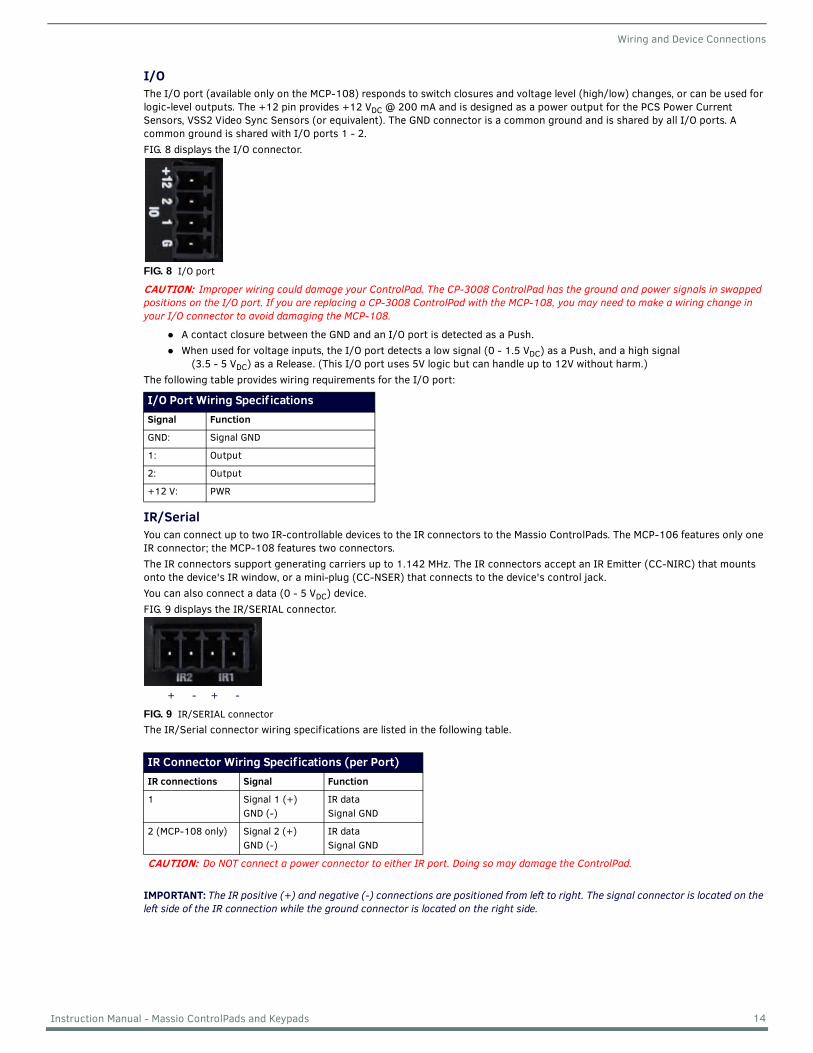
I/OThe I/O port (available only on the MCP-108) responds to switch closures and voltage level (high/low) changes, or can be used for logic-level outputs. The +12 pin provides +12 VDC @ 200 mA and is designed as a power output for the PCS Power Current Sensors, VSS2 Video Sync Sensors (or equivalent). The GND connector is a common ground and is shared by all I/O ports. A common ground is shared with I/O ports 1 - 2.FIG. 8 displays the I/O connector.
FIG. 8 I/O port
CAUTION: Improper wiring could damage your ControlPad. The CP-3008 ControlPad has the ground and power signals in swapped positions on the I/O port. If you are replacing a CP-3008 ControlPad with the MCP-108, you may need to make a wiring change in your I/O connector to avoid damaging the MCP-108.
A contact closure between the GND and an I/O port is detected as a Push.When used for voltage inputs, the I/O port detects a low signal (0 - 1.5 VDC) as a Push, and a high signal
(3.5 - 5 VDC) as a Release. (This I/O port uses 5V logic but can handle up to 12V without harm.)The following table provides wiring requirements for the I/O port:
IR/SerialYou can connect up to two IR-controllable devices to the IR connectors to the Massio ControlPads. The MCP-106 features only one IR connector; the MCP-108 features two connectors.The IR connectors support generating carriers up to 1.142 MHz. The IR connectors accept an IR Emitter (CC-NIRC) that mounts onto the device's IR window, or a mini-plug (CC-NSER) that connects to the device's control jack. You can also connect a data (0 - 5 VDC) device.FIG. 9 displays the IR/SERIAL connector.
FIG. 9 IR/SERIAL connectorThe IR/Serial connector wiring specifications are listed in the following table.
IMPORTANT: The IR positive (+) and negative (-) connections are positioned from left to right. The signal connector is located on the left side of the IR connection while the ground connector is located on the right side.
I/O Port Wiring Specif icationsSignal Function
GND: Signal GND
1: Output
2: Output
+12 V: PWR
IR Connector Wiring Specif ications (per Port)IR connections Signal Function
1 Signal 1 (+)GND (-)
IR dataSignal GND
2 (MCP-108 only) Signal 2 (+)GND (-)
IR dataSignal GND
CAUTION: Do NOT connect a power connector to either IR port. Doing so may damage the ControlPad.
+ - + -
14 Instruction Manual - Massio ControlPads and Keypads
Wiring and Device Connections
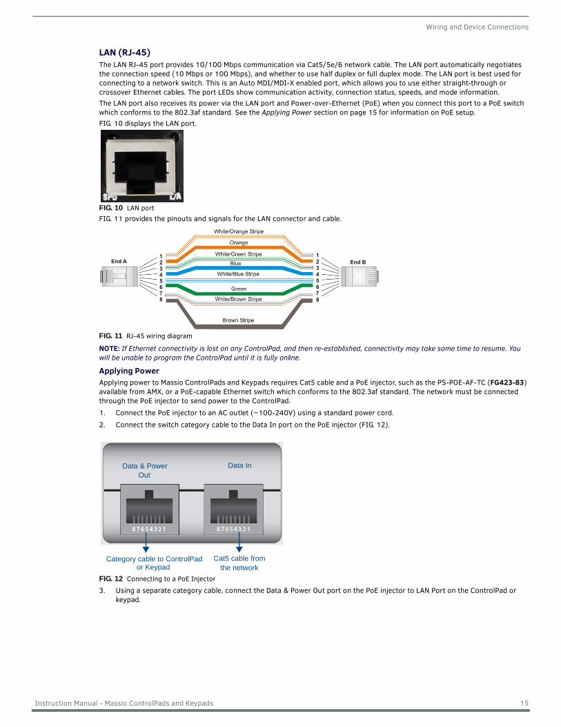
LAN (RJ-45)The LAN RJ-45 port provides 10/100 Mbps communication via Cat5/5e/6 network cable. The LAN port automatically negotiates the connection speed (10 Mbps or 100 Mbps), and whether to use half duplex or full duplex mode. The LAN port is best used for connecting to a network switch. This is an Auto MDI/MDI-X enabled port, which allows you to use either straight-through or crossover Ethernet cables. The port LEDs show communication activity, connection status, speeds, and mode information.The LAN port also receives its power via the LAN port and Power-over-Ethernet (PoE) when you connect this port to a PoE switch which conforms to the 802.3af standard. See the Applying Power section on page 15 for information on PoE setup.FIG. 10 displays the LAN port.
FIG. 10 LAN portFIG. 11 provides the pinouts and signals for the LAN connector and cable.
FIG. 11 RJ-45 wiring diagram
NOTE: If Ethernet connectivity is lost on any ControlPad, and then re-established, connectivity may take some time to resume. You will be unable to program the ControlPad until it is fully online.
Applying PowerApplying power to Massio ControlPads and Keypads requires Cat5 cable and a PoE injector, such as the PS-POE-AF-TC (FG423-83) available from AMX, or a PoE-capable Ethernet switch which conforms to the 802.3af standard. The network must be connected through the PoE injector to send power to the ControlPad.1. Connect the PoE injector to an AC outlet (~100-240V) using a standard power cord.2. Connect the switch category cable to the Data In port on the PoE injector (FIG. 12).
FIG. 12 Connecting to a PoE Injector
3. Using a separate category cable, connect the Data & Power Out port on the PoE injector to LAN Port on the ControlPad or keypad.
Data & PowerOut
Data In
Category cable to ControlPad Cat5 cable fromthe networkor Keypad
15 Instruction Manual - Massio ControlPads and Keypads
Wiring and Device Connections
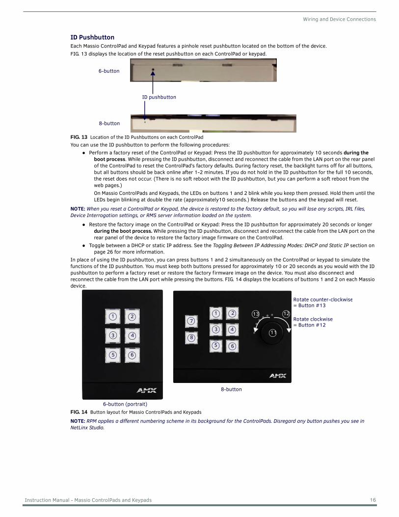
ID PushbuttonEach Massio ControlPad and Keypad features a pinhole reset pushbutton located on the bottom of the device.FIG. 13 displays the location of the reset pushbutton on each ControlPad or keypad.
FIG. 13 Location of the ID Pushbuttons on each ControlPadYou can use the ID pushbutton to perform the following procedures:
Perform a factory reset of the ControlPad or Keypad: Press the ID pushbutton for approximately 10 seconds during the boot process. While pressing the ID pushbutton, disconnect and reconnect the cable from the LAN port on the rear panel of the ControlPad to reset the ControlPad’s factory defaults. During factory reset, the backlight turns off for all buttons, but all buttons should be back online after 1-2 minutes. If you do not hold in the ID pushbutton for the full 10 seconds, the reset does not occur. (There is no soft reboot with the ID pushbutton, but you can perform a soft reboot from the web pages.)On Massio ControlPads and Keypads, the LEDs on buttons 1 and 2 blink while you keep them pressed. Hold them until the LEDs begin blinking at double the rate (approximately10 seconds.) Release the buttons and the keypad will reset.
NOTE: When you reset a ControlPad or Keypad, the device is restored to the factory default, so you will lose any scripts, IRL f iles, Device Interrogation settings, or RMS server information loaded on the system.
Restore the factory image on the ControlPad or Keypad: Press the ID pushbutton for approximately 20 seconds or longer during the boot process. While pressing the ID pushbutton, disconnect and reconnect the cable from the LAN port on the rear panel of the device to restore the factory image firmware on the ControlPad.
Toggle between a DHCP or static IP address. See the Toggling Between IP Addressing Modes: DHCP and Static IP section on page 26 for more information.
In place of using the ID pushbutton, you can press buttons 1 and 2 simultaneously on the ControlPad or keypad to simulate the functions of the ID pushbutton. You must keep both buttons pressed for approximately 10 or 20 seconds as you would with the ID pushbutton to perform a factory reset or restore the factory firmware image on the device. You must also disconnect and reconnect the cable from the LAN port while pressing the buttons. FIG. 14 displays the locations of buttons 1 and 2 on each Massio device.
FIG. 14 Button layout for Massio ControlPads and Keypads
NOTE: RPM applies a different numbering scheme in its background for the ControlPads. Disregard any button pushes you see in NetLinx Studio.
6-button
ID pushbutton
8-button
6-button (portrait)
8-button
1 2 1 2
3 4
5 6
3 4
5 6
7
811
13 12
Rotate counter-clockwise= Button #13
Rotate clockwise= Button #12
16 Instruction Manual - Massio ControlPads and Keypads
Wiring and Device Connections
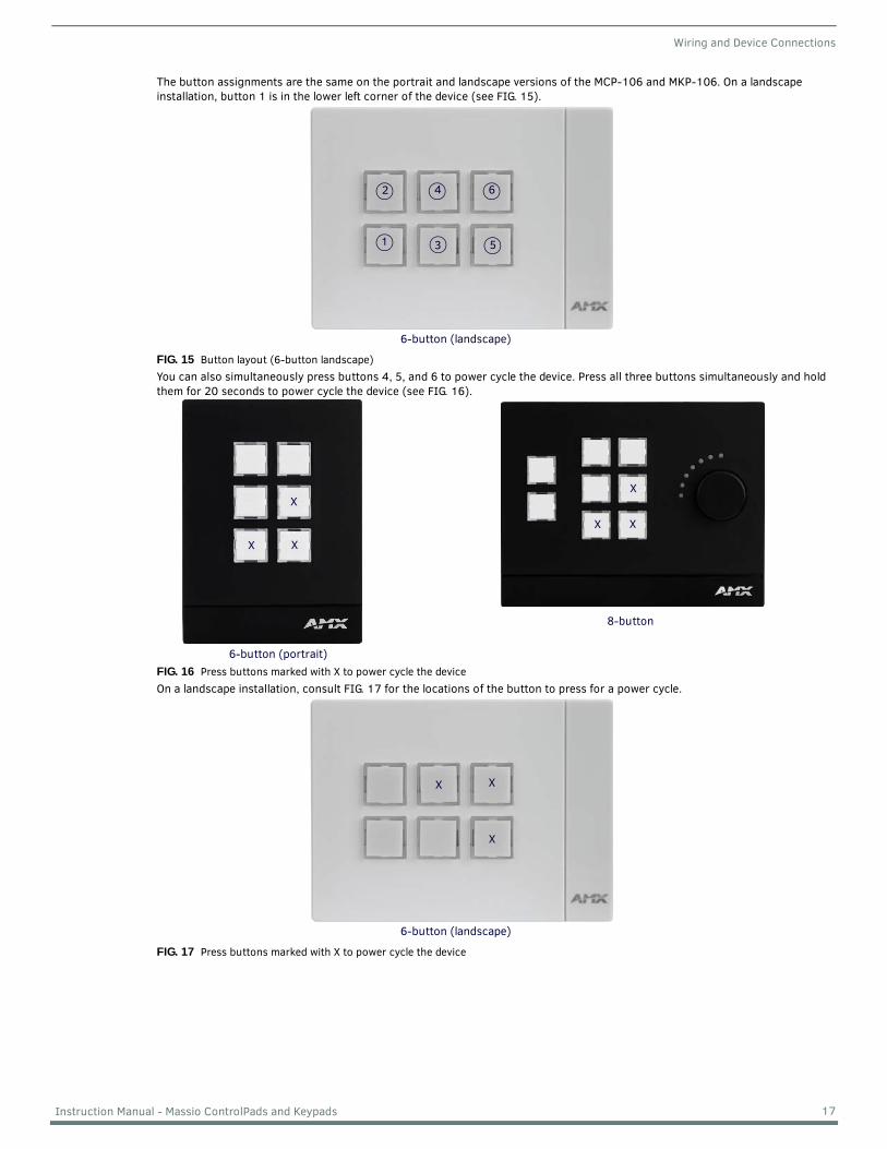
The button assignments are the same on the portrait and landscape versions of the MCP-106 and MKP-106. On a landscape installation, button 1 is in the lower left corner of the device (see FIG. 15).
FIG. 15 Button layout (6-button landscape)You can also simultaneously press buttons 4, 5, and 6 to power cycle the device. Press all three buttons simultaneously and hold them for 20 seconds to power cycle the device (see FIG. 16).
FIG. 16 Press buttons marked with X to power cycle the deviceOn a landscape installation, consult FIG. 17 for the locations of the button to press for a power cycle.
FIG. 17 Press buttons marked with X to power cycle the device
6-button (landscape)
642
531
6-button (portrait)
8-button
X
X
X X
X
X
6-button (landscape)
X
X
X
17 Instruction Manual - Massio ControlPads and Keypads
Installation
InstallationOverviewThis chapter describes installing Massio ControlPads and Keypads. The MCP-106 and MKP-106 mount onto standard 1 gang US, UK, or EU back boxes. The MCP-108 and MKP-108 mount onto standard 2 gang US, UK, or EU back boxes.
NOTE: Before touching the device, discharge the static electricity from your body by touching a grounded metal object.
NOTE: It is best to install button labels before mounting the device. Doing so keeps you from disassembling the ControlPad after mounting it. For instructions on installing button labels, see the Button Labeling section on page 20.
Mounting ProceduresAMX recommends mounting each type of ControlPad or Keypad in standard a conduit box per NEC specs section 370. You can mount the MCP-108 and MKP-108 to a podium using the provided metal mounting bracket.
NOTE: Before installing and mounting the device, you should test it to see that it can receive power. See the Applying Power section on page 15 for more information.
Wallbox MountingPerform these steps to mount the device into a back box:1. Install the back box into the surface of the desired location for the device. Be sure to thread any appropriate wiring through
the back box.
IMPORTANT: Leave 3/8" (9.52mm) of space between the top of the mounting bracket and any overhanging or otherwise obstructing surface. The extra space is required for attaching the device frame to the mounting bracket.
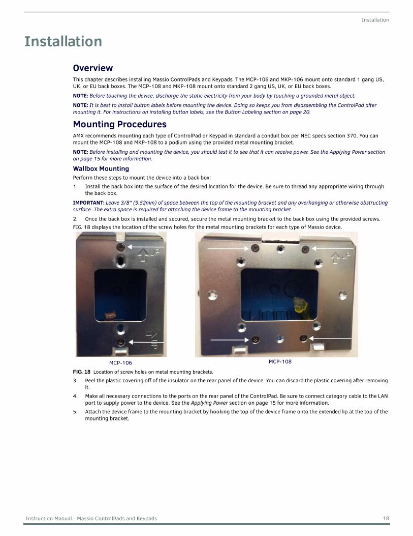
2. Once the back box is installed and secured, secure the metal mounting bracket to the back box using the provided screws.FIG. 18 displays the location of the screw holes for the metal mounting brackets for each type of Massio device.
FIG. 18 Location of screw holes on metal mounting brackets.
3. Peel the plastic covering off of the insulator on the rear panel of the device. You can discard the plastic covering after removing it.
4. Make all necessary connections to the ports on the rear panel of the ControlPad. Be sure to connect category cable to the LAN port to supply power to the device. See the Applying Power section on page 15 for more information.
5. Attach the device frame to the mounting bracket by hooking the top of the device frame onto the extended lip at the top of the mounting bracket.
MCP-106 MCP-108
18 Instruction Manual - Massio ControlPads and Keypads
Installation
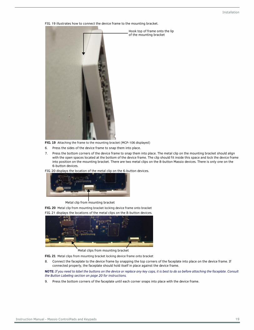
FIG. 19 illustrates how to connect the device frame to the mounting bracket.
FIG. 19 Attaching the frame to the mounting bracket (MCP-106 displayed)
6. Press the sides of the device frame to snap them into place.7. Press the bottom corners of the device frame to snap them into place. The metal clip on the mounting bracket should align
with the open spaces located at the bottom of the device frame. The clip should fit inside this space and lock the device frame into position on the mounting bracket. There are two metal clips on the 8-button Massio devices. There is only one on the 6-button devices.
FIG. 20 displays the location of the metal clip on the 6-button devices.
FIG. 20 Metal clip from mounting bracket locking device frame onto bracketFIG. 21 displays the locations of the metal clips on the 8-button devices.
FIG. 21 Metal clips from mounting bracket locking device frame onto bracket
8. Connect the faceplate to the device frame by snapping the top corners of the faceplate into place on the device frame. If connected properly, the faceplate should hold itself in place against the device frame.
NOTE: If you need to label the buttons on the device or replace any key caps, it is best to do so before attaching the faceplate. Consult the Button Labeling section on page 20 for instructions.
9. Press the bottom corners of the faceplate until each corner snaps into place with the device frame.
Hook top of frame onto the lipof the mounting bracket
Metal clip from mounting bracket
Metal clips from mounting bracket
19 Instruction Manual - Massio ControlPads and Keypads
Button Labeling
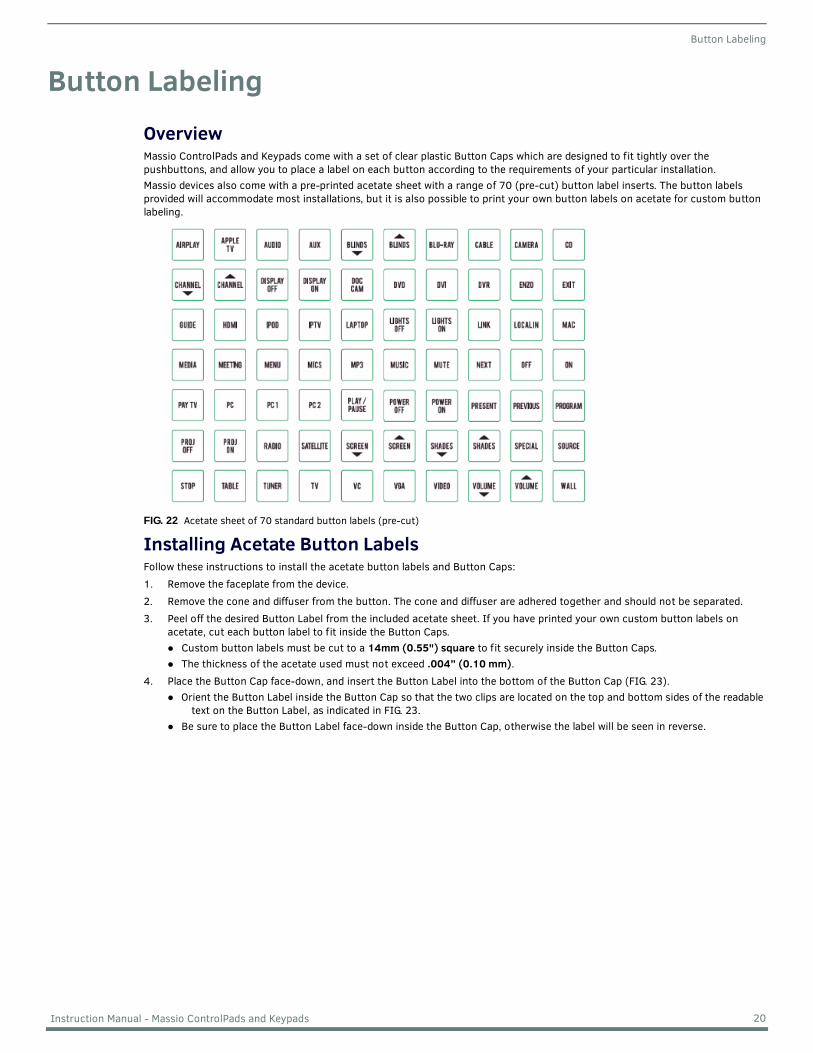
Button LabelingOverviewMassio ControlPads and Keypads come with a set of clear plastic Button Caps which are designed to fit tightly over the pushbuttons, and allow you to place a label on each button according to the requirements of your particular installation.Massio devices also come with a pre-printed acetate sheet with a range of 70 (pre-cut) button label inserts. The button labels provided will accommodate most installations, but it is also possible to print your own button labels on acetate for custom button labeling.
FIG. 22 Acetate sheet of 70 standard button labels (pre-cut)
Installing Acetate Button LabelsFollow these instructions to install the acetate button labels and Button Caps:1. Remove the faceplate from the device.2. Remove the cone and diffuser from the button. The cone and diffuser are adhered together and should not be separated.3. Peel off the desired Button Label from the included acetate sheet. If you have printed your own custom button labels on
acetate, cut each button label to fit inside the Button Caps.Custom button labels must be cut to a 14mm (0.55") square to fit securely inside the Button Caps.The thickness of the acetate used must not exceed .004” (0.10 mm).
4. Place the Button Cap face-down, and insert the Button Label into the bottom of the Button Cap (FIG. 23). Orient the Button Label inside the Button Cap so that the two clips are located on the top and bottom sides of the readable
text on the Button Label, as indicated in FIG. 23.Be sure to place the Button Label face-down inside the Button Cap, otherwise the label will be seen in reverse.
20 Instruction Manual - Massio ControlPads and Keypads
Button Labeling
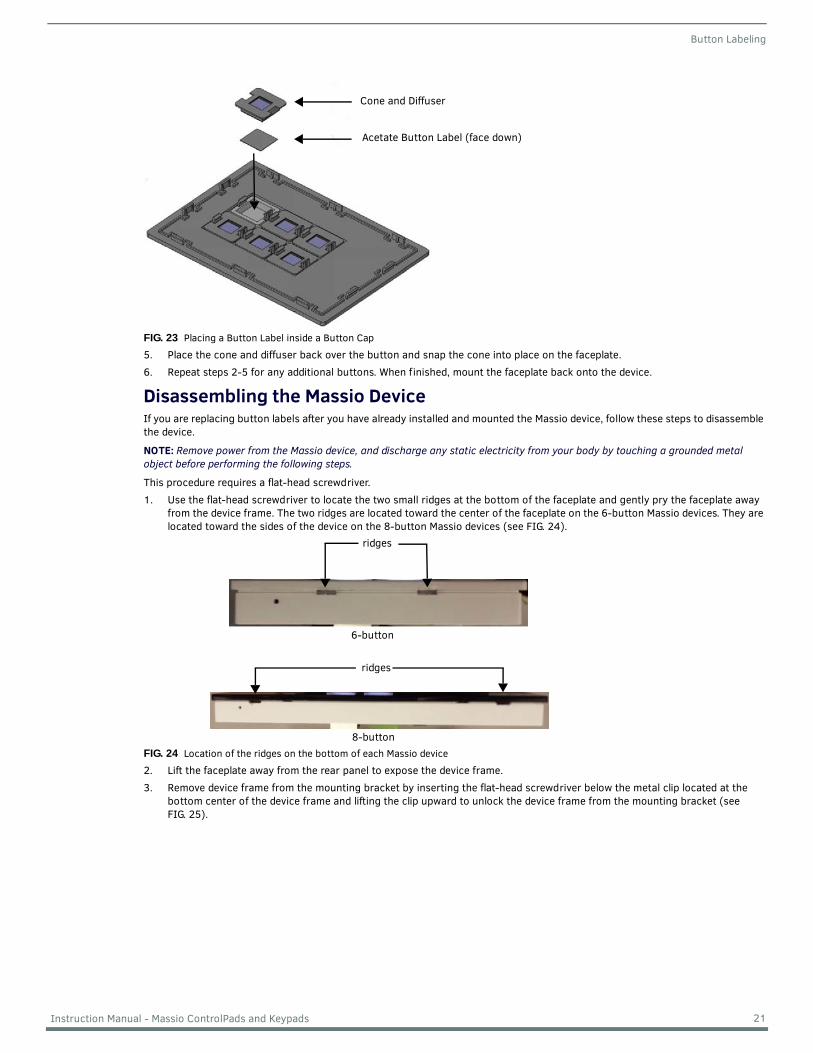
FIG. 23 Placing a Button Label inside a Button Cap
5. Place the cone and diffuser back over the button and snap the cone into place on the faceplate.6. Repeat steps 2-5 for any additional buttons. When finished, mount the faceplate back onto the device.
Disassembling the Massio DeviceIf you are replacing button labels after you have already installed and mounted the Massio device, follow these steps to disassemble the device.
NOTE: Remove power from the Massio device, and discharge any static electricity from your body by touching a grounded metal object before performing the following steps.
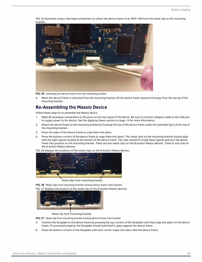
This procedure requires a flat-head screwdriver.1. Use the flat-head screwdriver to locate the two small ridges at the bottom of the faceplate and gently pry the faceplate away
from the device frame. The two ridges are located toward the center of the faceplate on the 6-button Massio devices. They are located toward the sides of the device on the 8-button Massio devices (see FIG. 24).
FIG. 24 Location of the ridges on the bottom of each Massio device
2. Lift the faceplate away from the rear panel to expose the device frame.3. Remove device frame from the mounting bracket by inserting the flat-head screwdriver below the metal clip located at the
bottom center of the device frame and lifting the clip upward to unlock the device frame from the mounting bracket (see FIG. 25).
Cone and Diffuser
Acetate Button Label (face down)
ridges
6-button
ridges
8-button
21 Instruction Manual - Massio ControlPads and Keypads
Button Labeling
FIG. 25 illustrates using a flat-head screwdriver to unlock the device frame of an MCP-106 from the metal clip on the mounting bracket.
FIG. 25 Unlocking the device frame from the mounting bracket
4. When the device frame is unlocked from the mounting bracket, lift the device frame upward and away from the top lip of the mounting bracket.
Re-Assembling the Massio DeviceFollow these steps to re-assemble the Massio device.1. Make all necessary connections to the ports on the rear panel of the device. Be sure to connect category cable to the LAN port
to supply power to the device. See the Applying Power section on page 15 for more information.2. Attach the device frame to the mounting bracket by hooking the top of the device frame under the extended lip(s) at the top of
the mounting bracket.3. Press the sides of the device frame to snap them into place.4. Press the bottom corners of the device frame to snap them into place. The metal clips on the mounting bracket should align
with the open spaces located at the bottom of the device frame. The clips should fit inside these spaces and lock the device frame into position on the mounting bracket. There are two metal clips on the 8-button Massio devices. There is only one on the 6-button Massio devices.
FIG. 26 displays the locations of the metal clips on the 8-button Massio devices.
FIG. 26 Metal clips from mounting bracket locking device frame onto bracketFIG. 27 displays the location of the metal clip on the 6-button Massio devices.
FIG. 27 Metal clip from mounting bracket locking device frame onto bracket
5. Connect the faceplate to the device frame by pressing the top corners of the faceplate until they snap into place on the device frame. If connected properly, the faceplate should hold itself in place against the device frame.
6. Press the bottom corners of the faceplate until each corner snaps into place with the device frame.
Metal clips from mounting bracket
Metal clip from mounting bracket
22 Instruction Manual - Massio ControlPads and Keypads
Initial Configuration
Initial Conf igurationMassio ControlPadsThis section describes using the NetLinx Studio software application to perform the initial configuration of the Massio ControlPad. You can use NetLinx Studio to perform the following configuration options on a Massio ControlPad:
Set up a System numberObtain/assign the IP/URL for the ControlPadTransfer firmware Kit files to the ControlPad - see the Upgrading Firmware section on page 28
You can perform other configuration and programming options on Massio ControlPads by using Rapid Project Maker (RPM) available at www.amx.com.For information on configuring the Massio Keypad, see the Massio Keypads section on page 27.
NOTE: You can also conf igure the ControlPad using the NetLinx Diagnostics 3 application, which is a companion application for RPM for conf iguration and management of Massio ControlPads. It is a lightweight application that does not include the integrated development environment for NetLinx code. It may be a more suitable and recommended application, although in larger sites where both NX controllers and Massio ControlPads are being installed, NetLinx Studio is the preferable application.
Before You Start1. Verify you have the latest version of the NetLinx Studio application version 4.0 installed on your PC.
NetLinx Studio is available to download from www.amx.com. Login to download the latest version. Alternatively, if it is already installed, use the Web Update option in NetLinx Studio’s Help menu to obtain the latest version.The default location for the NetLinx Studio application is Start > Programs > AMX Control Disc > NetLinx Studio > NetLinx Studio.
2. Verify that a LAN cable is connected from the ControlPad to a PoE injector or a PoE-capable Ethernet switch, and the PoE switch is connected to the LAN Hub. If connected correctly, the ControlPad should receive power.
Obtaining the ControlPad’s IP AddressRapid Project Maker (RPM) requires the IP address of the ControlPad for configuration. Perform the following steps to retrieve the IP address of the ControlPad. To assign a static IP address to the ControlPad, see the Changing the ControlPad’s Network Address Information section on page 24 for more information.
NOTE: Massio ControlPads use DHCP addressing by default.
NOTE: Verify there is an active LAN connection on the ControlPad’s LAN port before beginning these procedures.
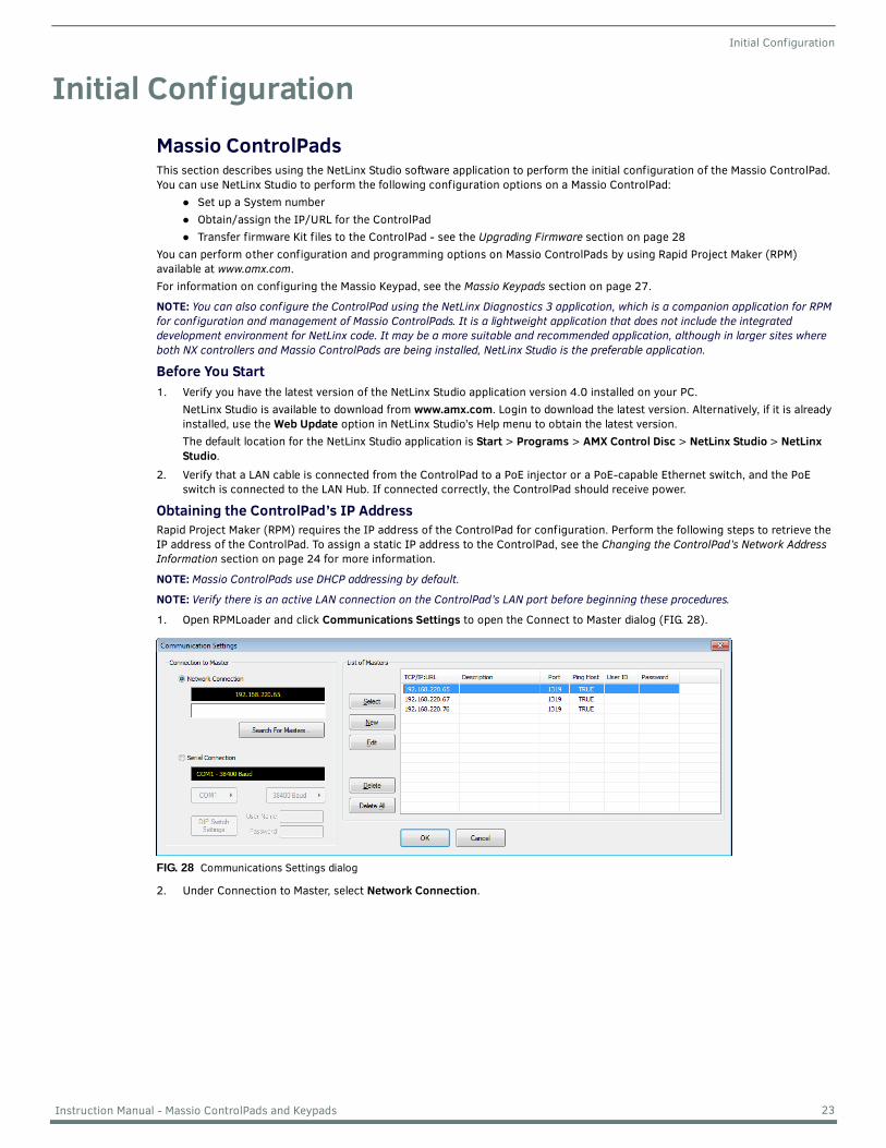
1. Open RPMLoader and click Communications Settings to open the Connect to Master dialog (FIG. 28).
2. Under Connection to Master, select Network Connection.
FIG. 28 Communications Settings dialog
23 Instruction Manual - Massio ControlPads and Keypads
Initial Configuration
3. Click Search For Masters to search the network for online Masters in the Search for Masters dialog (FIG. 29).
4. Click Start Searching to begin listening for "blink" (UDP) messages from NetLinx Masters on the subnet. 5. When you see the IP Address for the ControlPad in the List of Active NetLinx Master Controllers, click Stop Listening. The IP
address of the ControlPad is listed in the TCP/IP column of the dialog.
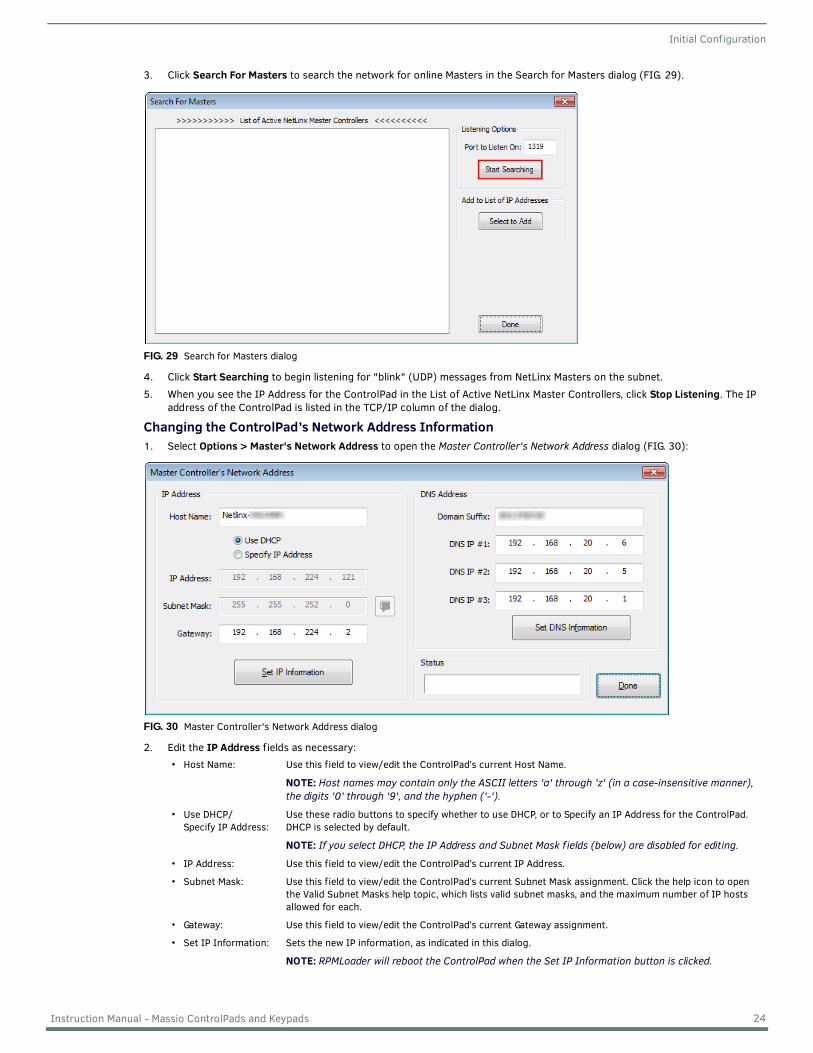
Changing the ControlPad’s Network Address Information1. Select Options > Master's Network Address to open the Master Controller's Network Address dialog (FIG. 30):
2. Edit the IP Address f ields as necessary:
FIG. 29 Search for Masters dialog
FIG. 30 Master Controller's Network Address dialog
• Host Name: Use this field to view/edit the ControlPad’s current Host Name.
NOTE: Host names may contain only the ASCII letters 'a' through 'z' (in a case-insensitive manner), the digits '0' through '9', and the hyphen ('-').
• Use DHCP/Specify IP Address:
Use these radio buttons to specify whether to use DHCP, or to Specify an IP Address for the ControlPad. DHCP is selected by default.
NOTE: If you select DHCP, the IP Address and Subnet Mask f ields (below) are disabled for editing.
• IP Address: Use this field to view/edit the ControlPad’s current IP Address.
• Subnet Mask: Use this field to view/edit the ControlPad’s current Subnet Mask assignment. Click the help icon to open the Valid Subnet Masks help topic, which lists valid subnet masks, and the maximum number of IP hosts allowed for each.
• Gateway: Use this field to view/edit the ControlPad’s current Gateway assignment.
• Set IP Information: Sets the new IP information, as indicated in this dialog.
NOTE: RPMLoader will reboot the ControlPad when the Set IP Information button is clicked.
24 Instruction Manual - Massio ControlPads and Keypads
Initial Configuration
3. Click the Set IP Information button to set the new IP address information on the ControlPad. The program will prompt you that the Master Controller will be rebooted when this button is pressed (click OK to proceed).
4. Edit the DNS Address f ields as necessary:
5. Click the Set DNS Information button to set the new IP address information on the ControlPad. It is not necessary to reboot the ControlPad if only the DNS Address information is changed.
6. Click Done to close this dialog.
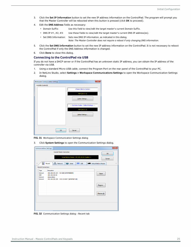
Connecting to the ControlPad via USBIf you do not have a DHCP server or if the ControlPad has an unknown static IP address, you can obtain the IP address of the controller via USB.1. Using a standard Micro-USB cable, connect the Program Port on the rear panel of the ControlPad to your PC.2. In NetLinx Studio, select Settings > Workspace Communications Settings to open the Workspace Communication Settings
dialog.
3. Click System Settings to open the Communication Settings dialog.
• Domain Suffix: Use this field to view/edit the target master's current Domain Suffix.
• DNS IP #1, #2, #3: Use these fields to view/edit the target master's current DNS IP address(es).
• Set DNS Information: Sets new DNS IP information, as indicated in this dialog.Note: The Master Controller does not require a reboot if only changing DNS information.
FIG. 31 Workspace Communication Settings dialog
FIG. 32 Communication Settings dialog - Recent tab
25 Instruction Manual - Massio ControlPads and Keypads
Initial Configuration
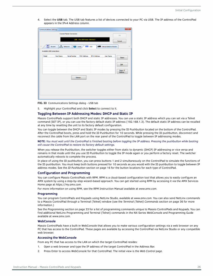
4. Select the USB tab. The USB tab features a list of devices connected to your PC via USB. The IP address of the ControlPad appears in the IPv4 Address column.
5. Highlight your ControlPad and click Select to connect to it.
Toggling Between IP Addressing Modes: DHCP and Static IPMassio ControlPads support both DHCP and static IP addresses. You can use a static IP address which you can set via a Telnet command (SET IP), or you can use the factory default static IP address (192.168.1.3). The default static IP address can be recalled at any time by resetting the unit to its factory default configuration.You can toggle between the DHCP and Static IP modes by pressing the ID Pushbutton located on the bottom of the ControlPad. After the ControlPad boots, press and hold the ID Pushbutton for 10 seconds. While pressing the ID pushbutton, disconnect and reconnect the cable from the LAN port on the rear panel of the ControlPad to toggle between IP addressing modes.
NOTE: You must wait until the ControlPad is f inished booting before toggling the IP address. Pressing the pushbutton while booting will cause the ControlPad to restore its factory default settings.
When you release the Pushbutton, the switcher toggles either from static to dynamic (DHCP) IP addressing or vice versa and remains in that mode until the you use ID Pushbutton to toggle the IP mode again or you perform a factory reset. The switcher automatically reboots to complete the process.In place of using the ID pushbutton, you can press buttons 1 and 2 simultaneously on the ControlPad to simulate the functions of the ID pushbutton. You must keep both buttons pressed for 10 seconds as you would with the ID pushbutton to toggle between IP address modes. See the ID Pushbutton section on page 16 for the button locations for each type of ControlPad.
Conf iguration and ProgrammingYou can configure Massio ControlPads with RPM. RPM is a cloud-based configuration tool that allows you to easily configure an AMX system by using a step-by-step wizard-based approach. You can get started using RPM by accessing it via the AMX Services Home page at https://my.amx.com.For more information on using RPM, see the RPM Instruction Manual available at www.amx.com.
ProgrammingYou can program ControlPads and Keypads using NetLinx Studio, available at www.amx.com. You can also send NetLinx commands to a Massio ControlPad through a Terminal (Telnet) window (see the Terminal (Telnet) Commands section on page 36 for more information.)See the Programming section on page 33 for a list of programming commands unique to Massio ControlPads and Keypads. You can find additional NetLinx Programming and Terminal (Telnet) commands in the NX-Series WebConsole and Programming Guide available at www.amx.com.
WebConsoleMassio ControlPads have a built-in WebConsole that allows you to make various configuration settings via a web browser on any PC that has access to the ControlPad. These pages are available by accessing the ControlPad via NetLinx Studio or any compatible web browser.
Accessing the WebConsoleFrom any PC that has access to the LAN on which the target ControlPad resides:1. Open a web browser and type the IP address of the target ControlPad in the Address Bar. 2. Press Enter to access WebConsole for that ControlPad. The initial view is the Web Control page.
FIG. 33 Communications Settings dialog - USB tab
26 Instruction Manual - Massio ControlPads and Keypads
Initial Configuration
Default User Names and PasswordsThe following table lists the default user names and passwords for accessing the Massio ControlPads through NetLinx Studio or the WebConsole.
For more information about navigating and the features of the WebConsole, see the NX-Series WebConsole and Programming Guide available at www.amx.com.
Massio KeypadsThe following sections provide instructions on accessing and configuring the keypad.
Locating the IP Address of the KeypadThe MKP-106 is configured for DHCP addressing by default. The keypad uses link local addressing as a backup in case the DHCP server is inaccessible. See the Toggling Between IP Addressing Modes: DHCP and Static IP section for information on setting a static IP address. Verify there is an active LAN connection on the controller’s LAN port before beginning this procedure.1. Using category cable, connect the LAN port on the keypad to your external network.2. In NetLinx Studio, select the OnLine Tree tab. You should see the Keypad listed among the Unbound Devices.3. Right-click the Keypad and select Network Bind/Unbind Device from the menu that appears. The Bind/Unbind Device dialog
opens.4. By default, the selected keypad appears in the Device to Bind/Unbind menu at the top of the dialog. If there is more than one
Unbound device in the system, click the down arrow to select which device you want to bind.5. Select the check box next to the Master to which you want to bind the keypad. If there is more than one Master in the system,
check the specific Master to which you want to bind the keypad.6. Click OK to save changes and close this dialog.7. Select Refresh System (in the Online Tree context menu). The device should now appear in the Bound Devices folder.
Toggling Between IP Addressing Modes: DHCP and Static IPMassio Keypads support both DHCP and static IP addresses. You can use a static IP address which you can set via a Telnet command (SET IP), or you can use the factory default static IP address (192.168.1.2).With the keypad powered and booted up (or in ID Mode), you can toggle between the DHCP and Static IP modes by pressing and holding buttons 1 and 2. The LEDs on buttons 1 and 2 blink while you keep them pressed. Hold them until the LEDs begin blinking at double the rate (approximately10 seconds), then release the buttons.When you release the buttons, the keypad toggles either from static to dynamic (DHCP) IP addressing or vice versa and remains in that mode until the you use the buttons to toggle the IP mode again or you perform a factory reset. The keypad automatically reboots to complete the process.
NOTE: You must wait until the keypad is f inished booting before toggling the IP address. Pressing the buttons while booting will cause the keypad to restore its factory default settings.
Default User Names and PasswordsUser Name Password
NetLinx Studio netlinx password
WebConsole administrator password
27 Instruction Manual - Massio ControlPads and Keypads
Upgrading Firmware
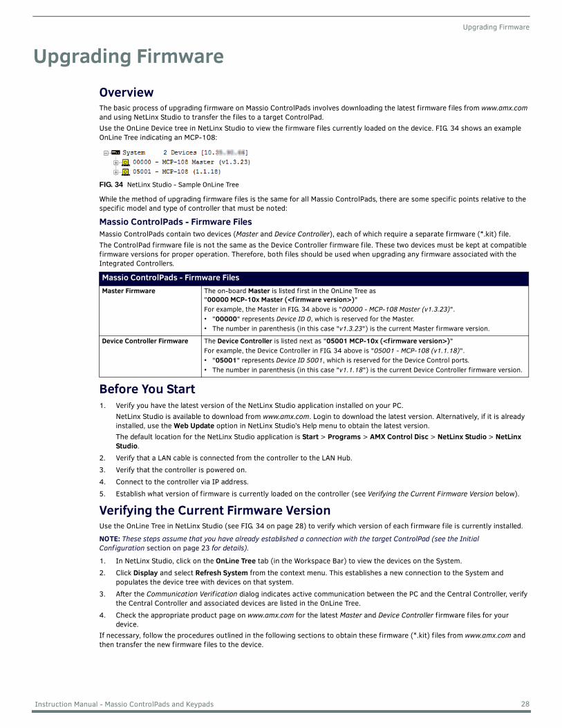
Upgrading FirmwareOverviewThe basic process of upgrading firmware on Massio ControlPads involves downloading the latest firmware files from www.amx.com and using NetLinx Studio to transfer the files to a target ControlPad. Use the OnLine Device tree in NetLinx Studio to view the firmware files currently loaded on the device. FIG. 34 shows an example OnLine Tree indicating an MCP-108:
While the method of upgrading firmware files is the same for all Massio ControlPads, there are some specific points relative to the specific model and type of controller that must be noted:
Massio ControlPads - Firmware FilesMassio ControlPads contain two devices (Master and Device Controller), each of which require a separate firmware (*.kit) file. The ControlPad firmware file is not the same as the Device Controller firmware file. These two devices must be kept at compatible firmware versions for proper operation. Therefore, both files should be used when upgrading any firmware associated with the Integrated Controllers.
Before You Start1. Verify you have the latest version of the NetLinx Studio application installed on your PC.
NetLinx Studio is available to download from www.amx.com. Login to download the latest version. Alternatively, if it is already installed, use the Web Update option in NetLinx Studio’s Help menu to obtain the latest version.The default location for the NetLinx Studio application is Start > Programs > AMX Control Disc > NetLinx Studio > NetLinx Studio.
2. Verify that a LAN cable is connected from the controller to the LAN Hub.3. Verify that the controller is powered on.4. Connect to the controller via IP address.5. Establish what version of firmware is currently loaded on the controller (see Verifying the Current Firmware Version below).
Verifying the Current Firmware VersionUse the OnLine Tree in NetLinx Studio (see FIG. 34 on page 28) to verify which version of each firmware file is currently installed.
NOTE: These steps assume that you have already established a connection with the target ControlPad (see the Initial Conf iguration section on page 23 for details).
1. In NetLinx Studio, click on the OnLine Tree tab (in the Workspace Bar) to view the devices on the System.2. Click Display and select Refresh System from the context menu. This establishes a new connection to the System and
populates the device tree with devices on that system.3. After the Communication Verif ication dialog indicates active communication between the PC and the Central Controller, verify
the Central Controller and associated devices are listed in the OnLine Tree.4. Check the appropriate product page on www.amx.com for the latest Master and Device Controller f irmware files for your
device.If necessary, follow the procedures outlined in the following sections to obtain these firmware (*.kit) files from www.amx.com and then transfer the new firmware files to the device.
FIG. 34 NetLinx Studio - Sample OnLine Tree
Massio ControlPads - Firmware FilesMaster Firmware The on-board Master is listed first in the OnLine Tree as
"00000 MCP-10x Master (<f irmware version>)"For example, the Master in FIG. 34 above is "00000 - MCP-108 Master (v1.3.23)".• "00000" represents Device ID 0, which is reserved for the Master.• The number in parenthesis (in this case "v1.3.23") is the current Master firmware version.
Device Controller Firmware The Device Controller is listed next as "05001 MCP-10x (<f irmware version>)"For example, the Device Controller in FIG. 34 above is "05001 - MCP-108 (v1.1.18)". • "05001" represents Device ID 5001, which is reserved for the Device Control ports. • The number in parenthesis (in this case "v1.1.18") is the current Device Controller firmware version.
28 Instruction Manual - Massio ControlPads and Keypads
Upgrading Firmware
Downloading the Latest Firmware Files from www.amx.comNetLinx ControllersMassio ControlPads require two firmware (*.kit) files: Master firmware and Device firmware. The Master firmware file is not the same as the Device firmware file. Both files should be used when upgrading any firmware associated with the Integrated Controllers.
NOTE: The process of downloading and transferring f irmware f iles is the same for all types of f irmware. However, it is important that the f irmware f iles are upgraded in specif ic following order for Massio ControlPads (see the Required Order of Firmware Updates section on page 29).
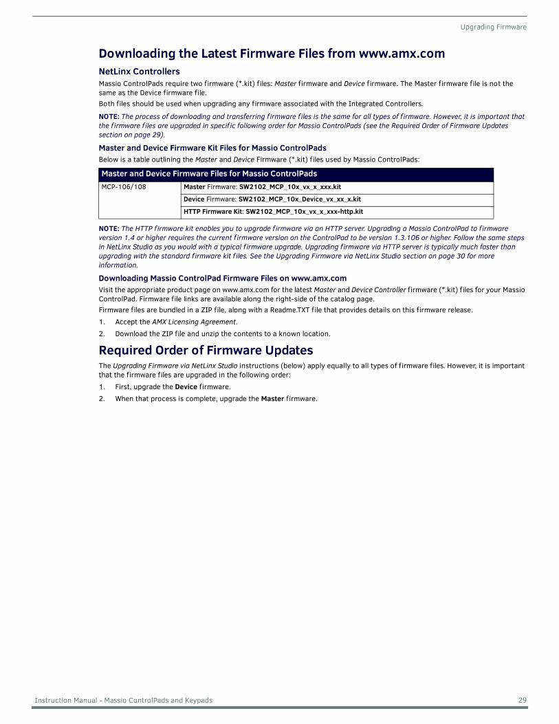
Master and Device Firmware Kit Files for Massio ControlPadsBelow is a table outlining the Master and Device Firmware (*.kit) files used by Massio ControlPads:
NOTE: The HTTP f irmware kit enables you to upgrade f irmware via an HTTP server. Upgrading a Massio ControlPad to f irmware version 1.4 or higher requires the current f irmware version on the ControlPad to be version 1.3.106 or higher. Follow the same steps in NetLinx Studio as you would with a typical f irmware upgrade. Upgrading f irmware via HTTP server is typically much faster than upgrading with the standard f irmware kit f iles. See the Upgrading Firmware via NetLinx Studio section on page 30 for more information.
Downloading Massio ControlPad Firmware Files on www.amx.comVisit the appropriate product page on www.amx.com for the latest Master and Device Controller f irmware (*.kit) files for your Massio ControlPad. Firmware file links are available along the right-side of the catalog page.Firmware files are bundled in a ZIP file, along with a Readme.TXT file that provides details on this firmware release.1. Accept the AMX Licensing Agreement.2. Download the ZIP file and unzip the contents to a known location.
Required Order of Firmware UpdatesThe Upgrading Firmware via NetLinx Studio instructions (below) apply equally to all types of firmware files. However, it is important that the firmware files are upgraded in the following order:1. First, upgrade the Device f irmware.2. When that process is complete, upgrade the Master f irmware.
Master and Device Firmware Files for Massio ControlPadsMCP-106/108 Master Firmware: SW2102_MCP_10x_vx_x_xxx.kit
Device Firmware: SW2102_MCP_10x_Device_vx_xx_x.kit
HTTP Firmware Kit: SW2102_MCP_10x_vx_x_xxx-http.kit
29 Instruction Manual - Massio ControlPads and Keypads
Upgrading Firmware
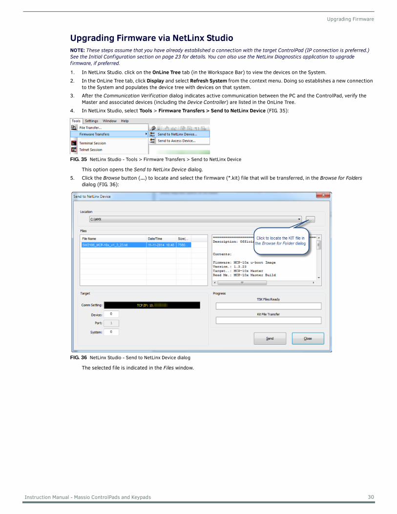
Upgrading Firmware via NetLinx StudioNOTE: These steps assume that you have already established a connection with the target ControlPad (IP connection is preferred.) See the Initial Conf iguration section on page 23 for details. You can also use the NetLinx Diagnostics application to upgrade f irmware, if preferred.
1. In NetLinx Studio. click on the OnLine Tree tab (in the Workspace Bar) to view the devices on the System.2. In the OnLine Tree tab, click Display and select Refresh System from the context menu. Doing so establishes a new connection
to the System and populates the device tree with devices on that system.3. After the Communication Verif ication dialog indicates active communication between the PC and the ControlPad, verify the
Master and associated devices (including the Device Controller) are listed in the OnLine Tree.4. In NetLinx Studio, select Tools > Firmware Transfers > Send to NetLinx Device (FIG. 35):
This option opens the Send to NetLinx Device dialog.5. Click the Browse button (...) to locate and select the firmware (*.kit) file that will be transferred, in the Browse for Folders
dialog (FIG. 36):
The selected file is indicated in the Files window.
FIG. 35 NetLinx Studio - Tools > Firmware Transfers > Send to NetLinx Device
FIG. 36 NetLinx Studio - Send to NetLinx Device dialog
30 Instruction Manual - Massio ControlPads and Keypads
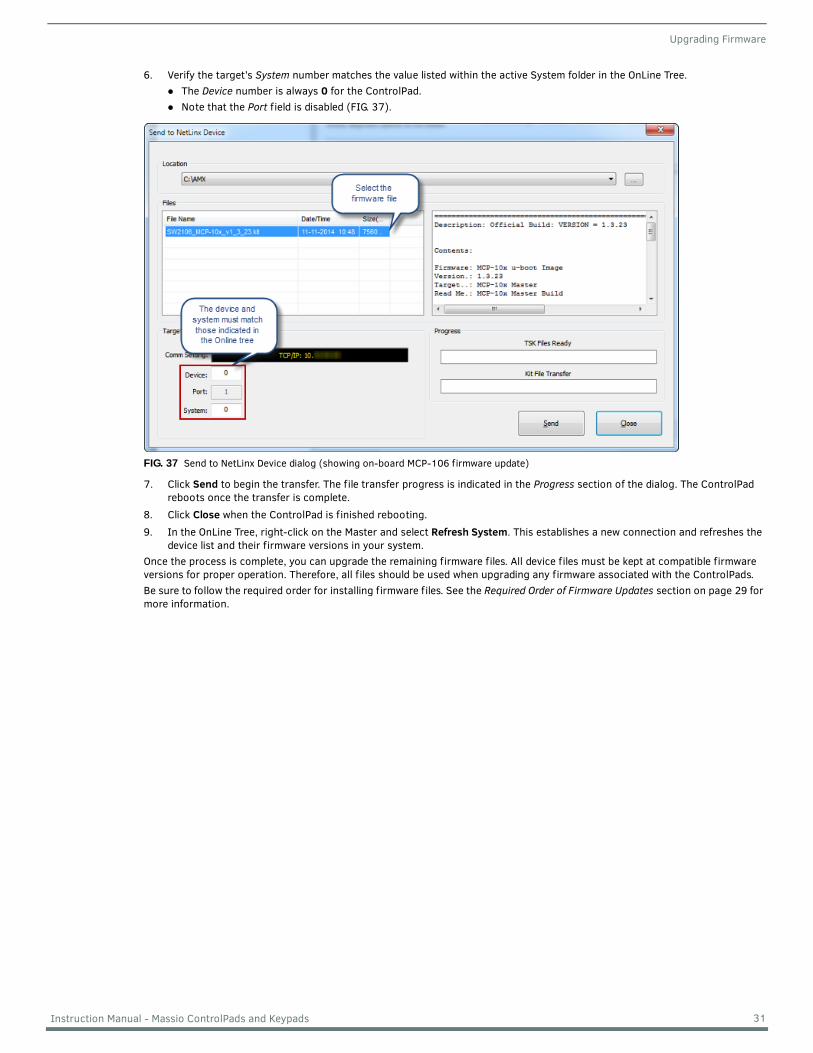
Upgrading Firmware
6. Verify the target’s System number matches the value listed within the active System folder in the OnLine Tree. The Device number is always 0 for the ControlPad.Note that the Port f ield is disabled (FIG. 37).
7. Click Send to begin the transfer. The file transfer progress is indicated in the Progress section of the dialog. The ControlPad reboots once the transfer is complete.
8. Click Close when the ControlPad is finished rebooting. 9. In the OnLine Tree, right-click on the Master and select Refresh System. This establishes a new connection and refreshes the
device list and their firmware versions in your system.Once the process is complete, you can upgrade the remaining firmware files. All device files must be kept at compatible firmware versions for proper operation. Therefore, all files should be used when upgrading any firmware associated with the ControlPads. Be sure to follow the required order for installing firmware files. See the Required Order of Firmware Updates section on page 29 for more information.
FIG. 37 Send to NetLinx Device dialog (showing on-board MCP-106 firmware update)
31 Instruction Manual - Massio ControlPads and Keypads
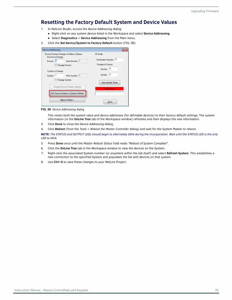
Upgrading Firmware
Resetting the Factory Default System and Device Values1. In NetLinx Studio, access the Device Addressing dialog:
Right-click on any system device listed in the Workspace and select Device Addressing.Select Diagnostics > Device Addressing from the Main menu.
2. Click the Set Device/System to Factory Default button (FIG. 38):
This resets both the system value and device addresses (for definable devices) to their factory default settings. The system information (in the OnLine Tree tab of the Workspace window) refreshes and then displays the new information.
3. Click Done to close the Device Addressing dialog.4. Click Reboot (from the Tools > Reboot the Master Controller dialog) and wait for the System Master to reboot.
NOTE: The STATUS and OUTPUT LEDs should begin to alternately blink during the incorporation. Wait until the STATUS LED is the only LED to blink.
5. Press Done once until the Master Reboot Status field reads *Reboot of System Complete*.6. Click the OnLine Tree tab in the Workspace window to view the devices on the System.7. Right-click the associated System number (or anywhere within the tab itself) and select Refresh System. This establishes a
new connection to the specified System and populates the list with devices on that system.8. Use Ctrl+S to save these changes to your NetLinx Project.
FIG. 38 Device Addressing dialog
32 Instruction Manual - Massio ControlPads and Keypads
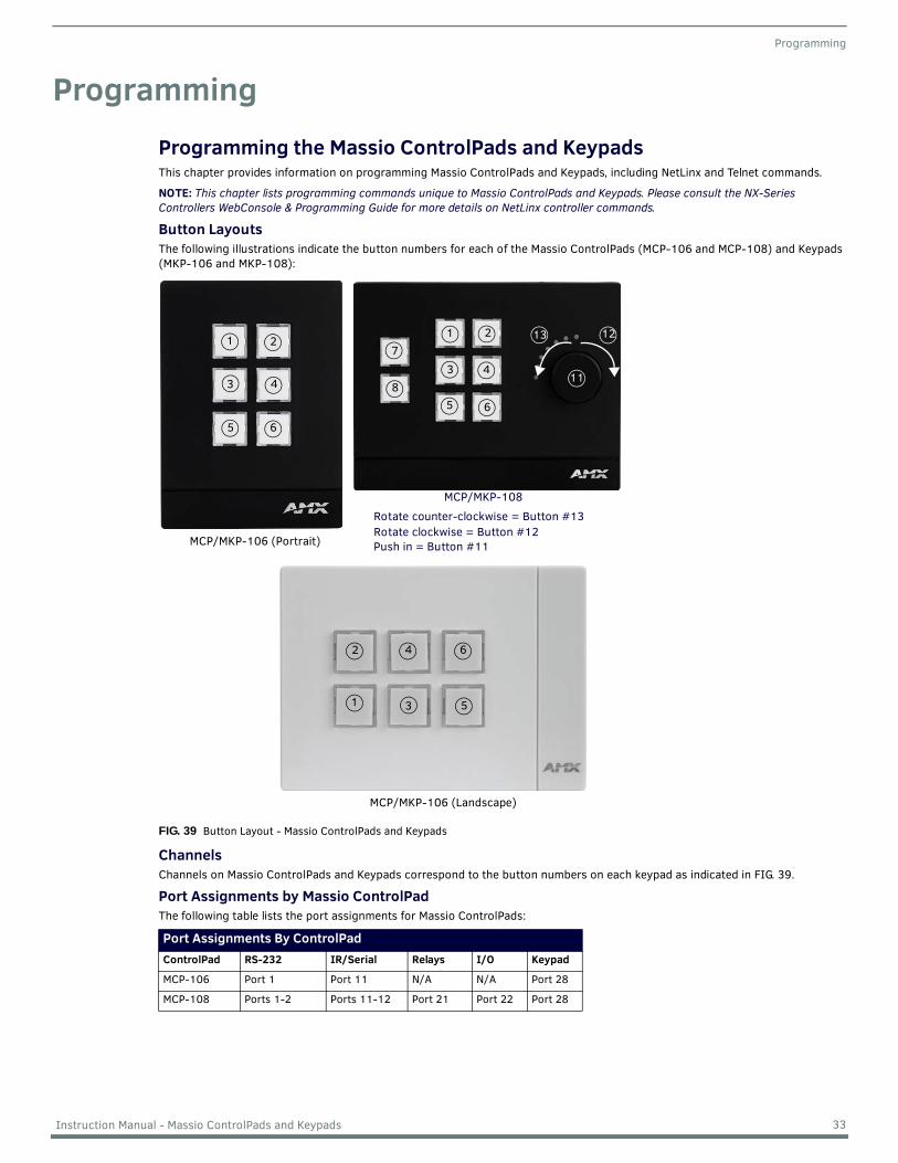
Programming
ProgrammingProgramming the Massio ControlPads and KeypadsThis chapter provides information on programming Massio ControlPads and Keypads, including NetLinx and Telnet commands.
NOTE: This chapter lists programming commands unique to Massio ControlPads and Keypads. Please consult the NX-Series Controllers WebConsole & Programming Guide for more details on NetLinx controller commands.
Button LayoutsThe following illustrations indicate the button numbers for each of the Massio ControlPads (MCP-106 and MCP-108) and Keypads (MKP-106 and MKP-108):
ChannelsChannels on Massio ControlPads and Keypads correspond to the button numbers on each keypad as indicated in FIG. 39.
Port Assignments by Massio ControlPadThe following table lists the port assignments for Massio ControlPads:
FIG. 39 Button Layout - Massio ControlPads and Keypads
Port Assignments By ControlPadControlPad RS-232 IR/Serial Relays I/O Keypad
MCP-106 Port 1 Port 11 N/A N/A Port 28
MCP-108 Ports 1-2 Ports 11-12 Port 21 Port 22 Port 28
1 21 2
3 4
5 6
3 4
5 6
7
811
13 12
Rotate clockwise = Button #12Rotate counter-clockwise = Button #13
MCP/MKP-108
Push in = Button #11MCP/MKP-106 (Portrait)
642
531
MCP/MKP-106 (Landscape)
33 Instruction Manual - Massio ControlPads and Keypads
Programming
Port Numbers and Levels (ControlPads)Massio ControlPads support the following port numbers and levels:
Port Numbers and Levels (Keypads)Massio Keypads support the following port numbers and levels:
Programming the Knob and LED Bargraph (MCP/MKP-108)The knob on the MCP/MKP-108 has multiple programming functions and can be treated from a NetLinx programming perspective as 1 pushbutton plus Channel up and down. The button layout for the knob is indicated in FIG. 39.
Knob - Button 11The knob is a pushbutton that provide an event on Channel #11, and can be programmed like any other button.
Knob - Buttons 12-13The knob itself can be rotated clockwise and counterclockwise, and is intended to provide level control (for example volume or lighting levels).
When rotated clockwise, the knob provides events on Channel #12.When rotated counter-clockwise, the knob provides events on Channel #13.When rotated (clockwise/counter-clockwise), the knob provides level events on Level #2.
Navigation Wheel - Level ControlIn addition to generating button events, a rotation of the knob causes a level change on Level #2:
Clockwise rotations increase the level Counter-clockwise rotations decrease the level.
Example code is provided below:LEVEL_EVENT[dvMassio,2]
{
volume = level.value
SEND_STRING 0, “’Volume is now: ‘, ITOA(volume)”
}
Display BargraphThe display bargraph consists of 7 LEDs and is controlled via Level #1. Sending a level will update the LEDs on the display bargraph. Example code is provided below:
SEND_LEVEL dvMassio,1,200
Supported SEND_LEVELsMKP-108 keypads support a SEND_LEVEL on Level #1. This level is used to adjust the LED bargraph display on the keypad.
Port Numbers and LevelsControlPad/Keypad Part Port Level
Buttons 28 None
Knob (MCP-108 only) 28 2, range is 0-255
LED Bargraph (MCP-108 only)
28 1, levels indicate 0-255
Port Numbers and LevelsControlPad/Keypad Part Port Level
Buttons 1 None
Knob (MKP-108 only) 1 2, range is 0-255
LED Bargraph (MKP-108 only)
1 1, levels indicate 0-255
SEND_LEVELsSEND_LEVEL Adjusts the LED bargraph display on the keypad.
Syntax:SEND_LEVEL <device address>,1,<level>
Variables:level = LED bargraph display (range = 0 - 255).
34 Instruction Manual - Massio ControlPads and Keypads
Programming
Supported SEND_COMMANDsMassio Keypads support a number of NetLinx SEND_COMMANDs, described in the following section. To use these commands, establish a Telnet session from the PC to the NetLinx master (see the Establishing a Terminal Connection via Telnet section on page 36 for more information.)
NOTE: All text is based on a Unicode index.
SEND_COMMANDsCommand Description
@BRT Set Brightness level for all LEDs (pushbuttons and levels indicator bar) for both On and Off states.Syntax:@BRT-<on brightness (0-32)>,<off brightness (0-32)>
Variables:on brightness = LED On brightness; ranges from 0 (off) to 32 (max).off brightness = LED Off level brightness; ranges from 0 (off) to 32 (max).
Example:SEND_COMMAND keypad,'@BRT-32,0'
Sets the LEDs to max brightness in the On state (32), and minimum brightness (no illumination) in the Off state (0).
BMODE Sets the bargraph mode.
NOTE: This command is only valid on the MKP-108 keypad.
Syntax:'BMODE-<bargraph mode 0-9>'
Sets the specified bargraph to operate in one of the following modes:0 = (default) normal bar mode2 = special bar mode (A level of 1-32 turns on the first LED. Each successive LED that lights represents an increment of 32 steps.)
NOTE: Modes 0 and 2 operate identically. Mode 2 is available for backward compatibility with existing NetLinx code for previous keypad models.
8 = individual element, discrete mode9 = inverse individual element, discrete mode
Example: SEND_COMMAND keypad,'BMODE-0'
?EXPANSION Allows NetLinx code to query the keypad to determine whether any expansion keypads are attached to it.Syntax:?EXPANSION
Example:SEND_COMMAND DEVICE_1,"'?EXPANSION'"
Response Syntax:"Expansion-<index>,<count>,<port>,<type>,<description>"
Variables:Index - response index, starting with 1Count - total number of response strings (i.e. max # of expansion keypads allowed, currently 2)Port - Port associated with the expansion keypadType - Expansion keypad type (either MET-7X or MET-13X)Description - Product description
Example Response Strings when a single expansion keypad is present:"Expansion.Device-1,2,2,MET-7X,Metreau 7-Button Expansion Keypad""Expansion.Device-2,2,3,NONE,NONE"
LED-DIS Disable LEDs on the keypad.Syntax:LED-DIS
Example:SEND_COMMAND DEVICE_1,"'LED-DIS'"
Disables LEDs on DEVICE_1.
NOTE: This parameter does not get stored in non-volatile memory. LEDs are enabled by default at each power-up.
35 Instruction Manual - Massio ControlPads and Keypads
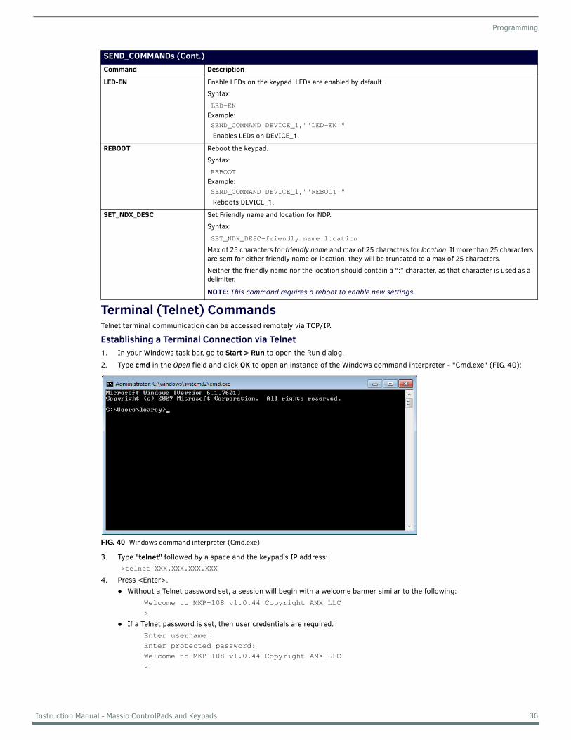
Programming
Terminal (Telnet) CommandsTelnet terminal communication can be accessed remotely via TCP/IP.
Establishing a Terminal Connection via Telnet1. In your Windows task bar, go to Start > Run to open the Run dialog.2. Type cmd in the Open field and click OK to open an instance of the Windows command interpreter - "Cmd.exe" (FIG. 40):
3. Type "telnet" followed by a space and the keypad’s IP address: >telnet XXX.XXX.XXX.XXX
4. Press <Enter>.Without a Telnet password set, a session will begin with a welcome banner similar to the following:
Welcome to MKP-108 v1.0.44 Copyright AMX LLC>
If a Telnet password is set, then user credentials are required:Enter username:Enter protected password:Welcome to MKP-108 v1.0.44 Copyright AMX LLC>
SEND_COMMANDs (Cont.)Command Description
LED-EN Enable LEDs on the keypad. LEDs are enabled by default.
Syntax:
LED-ENExample:SEND_COMMAND DEVICE_1,"'LED-EN'"
Enables LEDs on DEVICE_1.
REBOOT Reboot the keypad.
Syntax:
REBOOTExample:SEND_COMMAND DEVICE_1,"'REBOOT'"
Reboots DEVICE_1.
SET_NDX_DESC Set Friendly name and location for NDP.
Syntax:
SET_NDX_DESC-friendly name:location
Max of 25 characters for friendly name and max of 25 characters for location. If more than 25 characters are sent for either friendly name or location, they will be truncated to a max of 25 characters.
Neither the friendly name nor the location should contain a “:” character, as that character is used as a delimiter.
NOTE: This command requires a reboot to enable new settings.
FIG. 40 Windows command interpreter (Cmd.exe)
36 Instruction Manual - Massio ControlPads and Keypads
Programming
Telnet User Name and PasswordThere are two Telnet commands that set the Telnet user name and password:
Set Telnet Username (see page 41)Set Telnet Password (see page 41)
By default, both the user name and password are blank (empty string). Performing a factory reset on the device will return these values to that default. See the ID Pushbutton section on page 16 for details.
Setting the User Name will have no effect if the password remains blank (empty string). That is, defining the user name alone will not result in Telnet prompting for user login.
Setting the Password will cause Telnet to prompt for user login, whether the user name has been defined or not. If the user name has been defined, this value must be entered. However, since the password can be set independently of the user name, it's possible to have a password defined, but the user name still at its default (blank, empty string). In this case, do not enter anything for the user name when prompted. Simply press <Enter>, which will then present the password prompt. Here, the defined password must be entered, in order to successfully open the Telnet session.
Additional NotesBoth the Telnet user name and password are case-sensitive.Three consecutive, unsuccessful attempts to log in to Telnet will cause the Telnet window to close. Re-launching Telnet will
again present the login prompt, with a fresh "batch" of login attempts.If Telnet login fails because of an incorrect user name, you will receive the "Invalid Password" message (as opposed to an
"Invalid Username" message).
Setting a Telnet User Name and PasswordTo set a Telnet user name and password:1. Establish a terminal connection via Telnet.2. Type Set Telnet Username, and press <Enter>. The program will prompt you to enter a new Telnet user name. 3. Enter a user name and press <Enter>. The program will indicate that the user name is being stored.4. Type Set Telnet Password, and press <Enter>.
NOTE: Press <Enter> twice when asked to enter the password to clear both the telnet user name and password.
5. The program will prompt you to enter a password. Enter a password and press <Enter>. 6. The program will prompt you to re-enter the Telnet password. Re-enter the password and press <Enter>. The program will
indicate that the password is being stored.
37 Instruction Manual - Massio ControlPads and Keypads
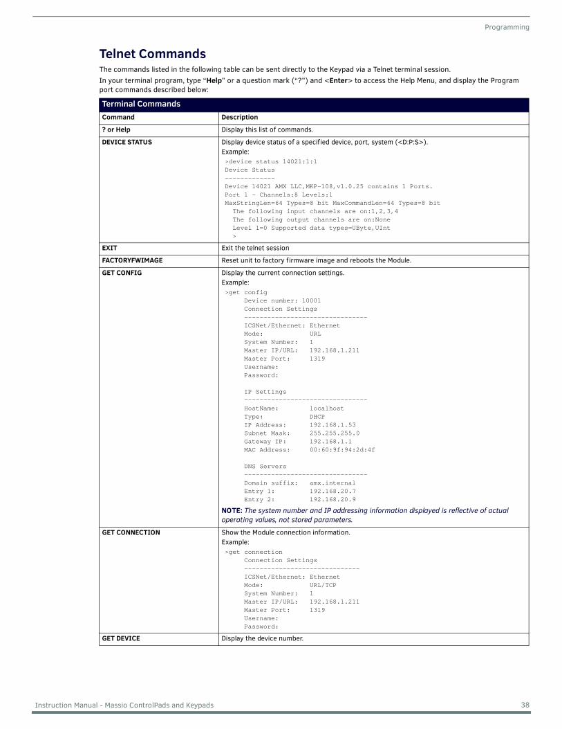
Programming
Telnet CommandsThe commands listed in the following table can be sent directly to the Keypad via a Telnet terminal session.In your terminal program, type “Help” or a question mark (“?”) and <Enter> to access the Help Menu, and display the Program port commands described below:
Terminal CommandsCommand Description
? or Help Display this list of commands.
DEVICE STATUS Display device status of a specified device, port, system (<D:P:S>). Example:>device status 14021:1:1Device Status-------------Device 14021 AMX LLC,MKP-108,v1.0.25 contains 1 Ports.Port 1 - Channels:8 Levels:1MaxStringLen=64 Types=8 bit MaxCommandLen=64 Types=8 bit The following input channels are on:1,2,3,4 The following output channels are on:None Level 1=0 Supported data types=UByte,UInt >
EXIT Exit the telnet session
FACTORYFWIMAGE Reset unit to factory firmware image and reboots the Module.
GET CONFIG Display the current connection settings.Example: >get config Device number: 10001 Connection Settings -------------------------------- ICSNet/Ethernet: Ethernet Mode: URL System Number: 1 Master IP/URL: 192.168.1.211 Master Port: 1319 Username: Password:
IP Settings -------------------------------- HostName: localhost Type: DHCP IP Address: 192.168.1.53 Subnet Mask: 255.255.255.0 Gateway IP: 192.168.1.1 MAC Address: 00:60:9f:94:2d:4f
DNS Servers -------------------------------- Domain suffix: amx.internal Entry 1: 192.168.20.7 Entry 2: 192.168.20.9
NOTE: The system number and IP addressing information displayed is reflective of actual operating values, not stored parameters.
GET CONNECTION Show the Module connection information.Example: >get connection Connection Settings ------------------------------ ICSNet/Ethernet: Ethernet Mode: URL/TCP System Number: 1 Master IP/URL: 192.168.1.211 Master Port: 1319 Username: Password:
GET DEVICE Display the device number.
38 Instruction Manual - Massio ControlPads and Keypads
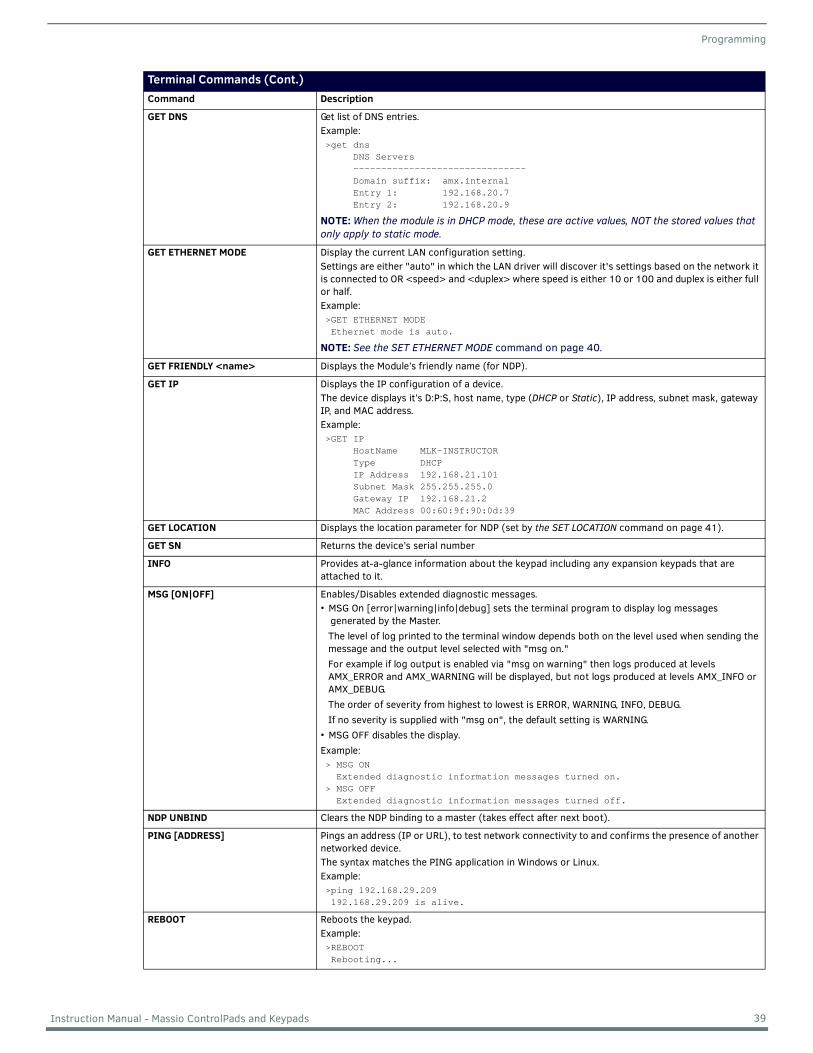
Programming
Terminal Commands (Cont.)Command Description
GET DNS Get list of DNS entries. Example: >get dns DNS Servers ------------------------------- Domain suffix: amx.internal Entry 1: 192.168.20.7 Entry 2: 192.168.20.9
NOTE: When the module is in DHCP mode, these are active values, NOT the stored values that only apply to static mode.
GET ETHERNET MODE Display the current LAN configuration setting. Settings are either "auto" in which the LAN driver will discover it's settings based on the network it is connected to OR <speed> and <duplex> where speed is either 10 or 100 and duplex is either full or half.Example: >GET ETHERNET MODE Ethernet mode is auto.
NOTE: See the SET ETHERNET MODE command on page 40.
GET FRIENDLY <name> Displays the Module’s friendly name (for NDP).
GET IP Displays the IP configuration of a device.The device displays it’s D:P:S, host name, type (DHCP or Static), IP address, subnet mask, gateway IP, and MAC address.Example:>GET IP HostName MLK-INSTRUCTOR Type DHCP IP Address 192.168.21.101 Subnet Mask 255.255.255.0 Gateway IP 192.168.21.2 MAC Address 00:60:9f:90:0d:39
GET LOCATION Displays the location parameter for NDP (set by the SET LOCATION command on page 41).
GET SN Returns the device’s serial number
INFO Provides at-a-glance information about the keypad including any expansion keypads that are attached to it.
MSG [ON|OFF] Enables/Disables extended diagnostic messages.• MSG On [error|warning|info|debug] sets the terminal program to display log messages
generated by the Master.The level of log printed to the terminal window depends both on the level used when sending the message and the output level selected with "msg on." For example if log output is enabled via "msg on warning" then logs produced at levels AMX_ERROR and AMX_WARNING will be displayed, but not logs produced at levels AMX_INFO or AMX_DEBUG. The order of severity from highest to lowest is ERROR, WARNING, INFO, DEBUG. If no severity is supplied with "msg on", the default setting is WARNING.
• MSG OFF disables the display.Example:> MSG ON Extended diagnostic information messages turned on.> MSG OFF Extended diagnostic information messages turned off.
NDP UNBIND Clears the NDP binding to a master (takes effect after next boot).
PING [ADDRESS] Pings an address (IP or URL), to test network connectivity to and confirms the presence of another networked device. The syntax matches the PING application in Windows or Linux.Example:>ping 192.168.29.209 192.168.29.209 is alive.
REBOOT Reboots the keypad.Example:>REBOOT Rebooting...
39 Instruction Manual - Massio ControlPads and Keypads
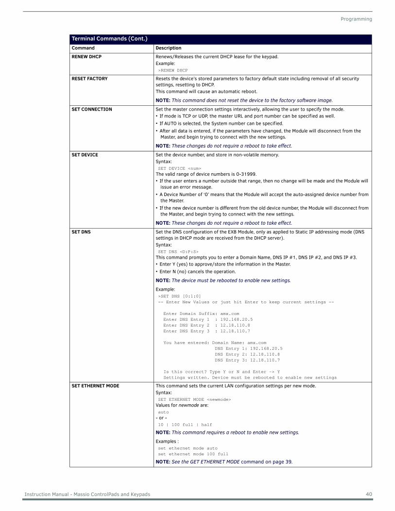
Programming
Terminal Commands (Cont.)Command Description
RENEW DHCP Renews/Releases the current DHCP lease for the keypad.Example:>RENEW DHCP
RESET FACTORY Resets the device’s stored parameters to factory default state including removal of all security settings, resetting to DHCP. This command will cause an automatic reboot.
NOTE: This command does not reset the device to the factory software image.
SET CONNECTION Set the master connection settings interactively, allowing the user to specify the mode. • If mode is TCP or UDP, the master URL and port number can be specified as well.• If AUTO is selected, the System number can be specified.• After all data is entered, if the parameters have changed, the Module will disconnect from the
Master, and begin trying to connect with the new settings.
NOTE: These changes do not require a reboot to take effect.
SET DEVICE Set the device number, and store in non-volatile memory.Syntax:SET DEVICE <num>
The valid range of device numbers is 0-31999.• If the user enters a number outside that range, then no change will be made and the Module will
issue an error message.• A Device Number of ‘0’ means that the Module will accept the auto-assigned device number from
the Master.• If the new device number is different from the old device number, the Module will disconnect from
the Master, and begin trying to connect with the new settings.
NOTE: These changes do not require a reboot to take effect.
SET DNS Set the DNS configuration of the EXB Module, only as applied to Static IP addressing mode (DNS settings in DHCP mode are received from the DHCP server).Syntax: SET DNS <D:P:S>
This command prompts you to enter a Domain Name, DNS IP #1, DNS IP #2, and DNS IP #3. • Enter Y (yes) to approve/store the information in the Master.• Enter N (no) cancels the operation.
NOTE: The device must be rebooted to enable new settings.
Example:>SET DNS [0:1:0]-- Enter New Values or just hit Enter to keep current settings --
Enter Domain Suffix: amx.com Enter DNS Entry 1 : 192.168.20.5 Enter DNS Entry 2 : 12.18.110.8 Enter DNS Entry 3 : 12.18.110.7 You have entered: Domain Name: amx.com DNS Entry 1: 192.168.20.5 DNS Entry 2: 12.18.110.8 DNS Entry 3: 12.18.110.7
Is this correct? Type Y or N and Enter -> Y Settings written. Device must be rebooted to enable new settings
SET ETHERNET MODE This command sets the current LAN configuration settings per new mode.Syntax:SET ETHERNET MODE <newmode>
Values for newmode are:auto
- or -10 | 100 full | half
NOTE: This command requires a reboot to enable new settings.
Examples :set ethernet mode autoset ethernet mode 100 full
NOTE: See the GET ETHERNET MODE command on page 39.
40 Instruction Manual - Massio ControlPads and Keypads
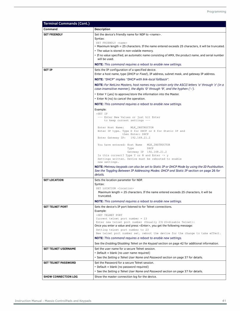
Programming
Terminal Commands (Cont.)Command Description
SET FRIENDLY Set the device’s friendly name for NDP to <name>.Syntax:SET FRIENDLY <name>
• Maximum length = 25 characters. If the name entered exceeds 25 characters, it will be truncated.• The value is stored in non-volatile memory.• If no value specified, an automatic name consisting of AMX, the product name, and serial number
will be used.
NOTE: This command requires a reboot to enable new settings.
SET IP Sets the IP configuration of a specified device.Enter a host name, type (DHCP or Fixed), IP address, subnet mask, and gateway IP address.
NOTE: “DHCP” implies “DHCP with link-local fallback".
NOTE: For NetLinx Masters, host names may contain only the ASCII letters 'a' through 'z' (in a case-insensitive manner), the digits '0' through '9', and the hyphen ('-').
• Enter Y (yes) to approve/store the information into the Master. • Enter N (no) to cancel the operation.
NOTE: This command requires a reboot to enable new settings.
Example:>SET IP --- Enter New Values or just hit Enter to keep current settings ---
Enter Host Name: MLK_INSTRUCTOR Enter IP type. Type D for DHCP or S for Static IP and then Enter: DHCP Enter Gateway IP: 192.168.21.2
You have entered: Host Name MLK_INSTRUCTOR Type DHCP Gateway IP 192.168.21.2 Is this correct? Type Y or N and Enter -> y Settings written. Device must be rebooted to enable new settings.
NOTE: Metreau keypads can also be set to Static IP or DHCP Mode by using the ID Pushbutton. See the Toggling Between IP Addressing Modes: DHCP and Static IP section on page 26 for details.
SET LOCATION Sets the location parameter for NDP.Syntax: SET LOCATION <location>
Maximum length = 25 characters. If the name entered exceeds 25 characters, it will be truncated.
NOTE: This command requires a reboot to enable new settings.
SET TELNET PORT Sets the device’s IP port listened to for Telnet connections.Example:>SET TELNET PORTCurrent telnet port number = 23Enter new telnet port number (Usually 23)(0=disable Telnet):
Once you enter a value and press <Enter>, you get the following message:Setting telnet port number to 23New telnet port number set, reboot the device for the change to take effect.
NOTE: This command requires a reboot to enable new settings.
See the Enabling/Disabling Telnet on the Keypad section on page 42 for additional information.
SET TELNET USERNAME Set the user name for a secure Telnet session.• Default = blank (no user name required)• See the Setting a Telnet User Name and Password section on page 37 for details.
SET TELNET PASSWORD Set the Password for a secure Telnet session.• Default = blank (no password required)• See the Setting a Telnet User Name and Password section on page 37 for details.
SHOW CONNECTION LOG Show the master connection log for the device.
41 Instruction Manual - Massio ControlPads and Keypads
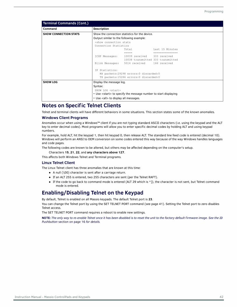
Programming
Notes on Specif ic Telnet ClientsTelnet and terminal clients will have different behaviors in some situations. This section states some of the known anomalies.
Windows Client ProgramsAnomalies occur when using a Windows™ client if you are not typing standard ASCII characters (i.e. using the keypad and the ALT key to enter decimal codes). Most programs will allow you to enter specific decimal codes by holding ALT and using keypad numbers. For example, hold ALT, hit the keypad 1, then hit keypad 0, then release ALT. The standard line feed code is entered (decimal 10). Windows will perform an ANSI to OEM conversion on some codes entered this way because of the way Windows handles languages and code pages. The following codes are known to be altered, but others may be affected depending on the computer's setup.
Characters 15, 21, 22, and any characters above 127.This affects both Windows Telnet and Terminal programs.
Linux Telnet ClientThe Linux Telnet client has three anomalies that are known at this time:
A null (\00) character is sent after a carriage return.If an ALT 255 is entered, two 255 characters are sent (per the Telnet RAFT).If the code to go back to command mode is entered (ALT 29 which is ^]), the character is not sent, but Telnet command
mode is entered.
Enabling/Disabling Telnet on the KeypadBy default, Telnet is enabled on all Massio keypads. The default Telnet port is 23.You can change the Telnet port by using the SET TELNET PORT command (see page 41). Setting the Telnet port to zero disables Telnet access.The SET TELNET PORT command requires a reboot to enable new settings.
NOTE: The only way to re-enable Telnet once it has been disabled is to reset the unit to the factory default f irmware image. See the ID Pushbutton section on page 16 for details.
Terminal Commands (Cont.)Command Description
SHOW CONNECTION STATS Show the connection statistics for the device. Output similar to the following example: >show connection stats Connection Statistics Total Last 15 Minutes ===== =============== ICSP Messages: 10039 received 333 received 10038 transmitted 333 transmitted Blink Messages: 5014 received 166 received
IP Statistics: RX packets:29298 errors:0 discarded:0 TX packets:15286 errors:0 discarded:0
SHOW LOG Display the message log.Syntax:SHOW LOG <start>
• Use <start> to specify the message number to start displaying• Use <all> to display all messages.
42 Instruction Manual - Massio ControlPads and Keypads

© 2017 Harman. All rights reserved. NetLinx, AMX, AV FOR AN IT WORLD, and HARMAN, and their respective logos are registered trademarks of HARMAN. Oracle, Java and any other company or brand name referenced may be trademarks/registered trademarks of their respective companies.AMX does not assume responsibility for errors or omissions. AMX also reserves the right to alter specifications without prior notice at any time.The AMX Warranty and Return Policy and related documents can be viewed/downloaded at www.amx.com.3000 RESEARCH DRIVE, RICHARDSON, TX 75082 AMX.com | 800.222.0193 | 469.624.8000 | +1.469.624.7400 | fax 469.624.7153AMX (UK) LTD, AMX by HARMAN - Unit C, Auster Road, Clifton Moor, York, YO30 4GD United Kingdom • +44 1904-343-100 • www.amx.com/eu/
Last Revised:07/17/2017