INSTRUCTION MANUAL FOR GAS COOKTOPS - ILVE
16
INSTRUCTION MANUAL FOR GAS COOKTOPS
-
Upload
khangminh22 -
Category
Documents
-
view
0 -
download
0
Transcript of INSTRUCTION MANUAL FOR GAS COOKTOPS - ILVE

INSTRUCTION MANUAL FOR GAS COOKTOPS

OPEN 24/7ILVE ACCESSORIES ONLINE SHOP
-VY�H�^PKL�YHUNL�VM�JVɈLL�THJOPULZ��WVKZ��HUK�V[OLY�03=,�HJJLZZVYPLZ�H[�[OL�JSPJR�VM�H�I\[[VU�ZOVW�PS]L�JVT�H\
16 17
GB
Installation
All the operations concerned with the installation (electrical and gas connections, adaptation to type of gas, necessary adjustments, etc.) must be carried out by qualified technicians, in terms with the standards in force. For specific instructions, kindly read the part reserved for the installation technician.
Use
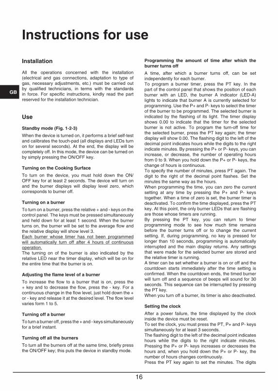
Standby mode (Fig. 1-2-3)
When the device is turned on, it performs a brief self-test and calibrates the touch-pad (all displays and LEDs turn on for several seconds). At the end, the display will be completely off. In this mode, the device can be turned on by simply pressing the ON/OFF key.
Turning on the Cooking Surface
To turn on the device, you must hold down the ON/OFF key for at least 2 seconds. The device will turn on and the burner displays will display level zero, which corresponds to burner off.
Turning on a burner
To turn on a burner, press the relative + and - keys on the control panel. The keys must be pressed simultaneously and held down for at least 1 second. When the burner turns on, the burner will be set to the average flow and the relative display will show level 3.Each burner whose timer has not been programmed will automatically turn off after 4 hours of continuous operation.The turning on of the burner is also indicated by the relative LED near the timer display, which will be on for the entire time that the burner is on.
Adjusting the flame level of a burner
To increase the flow to a burner that is on, press the + key and to decrease the flow, press the - key. For a continuous change in the flow level, just hold down the + or - key and release it at the desired level. The flow level varies form 1 to 5.
Turning off a burner
To turn a burner off, press the + and - keys simultaneously for a brief instant.
Turning off all the burners
To turn all the burners off at the same time, briefly press the ON/OFF key; this puts the device in standby mode.
Programming the amount of time after which the burner turns off
A time, after which a burner turns off, can be set independently for each burner.To program a burner timer, press the PT key. In the part of the control panel that shows the position of each burner with an LED, the burner A indicator (LED-A) lights to indicate that burner A is currently selected for programming. Use the P+ and P- keys to select the timer of the burner to be programmed. The selected burner is indicated by the flashing of its light. The timer display shows 0.00 to indicate that the timer for the selected burner is not active. To program the turn-off time for the selected burner, press the PT key again; the timer display will show 0.00. The flashing digit to the left of the decimal point indicates hours while the digits to the right indicate minutes. By pressing the P+ or P- keys, you can increase, or decrease, the number of operating hours from 0 to 9. When you hold down the P+ or P- keys, the change of hours is continuous.To specify the number of minutes, press PT again. The digit to the right of the decimal point flashes. Set the minutes the same way as the hours. When programming the time, you can zero the current setting at any time by pressing the P+ and P- keys together. When a time of zero is set, the burner timer is deactivated. To confirm the time displayed, press the PT key. At this point, the only burner LEDs that are flashing are those whose timers are running.By pressing the PT key, you can return to timer programming mode to see how much time remains before the burner turns off or to change the current setting. If, during programming, no key is pressed for longer than 10 seconds, programming is automatically interrupted and the main display returns. Any settings that were made for the selected burner are stored and the relative timer is running.A timer can be set whether a burner is on or off and the countdown starts immediately after the time setting is confirmed. When the countdown ends, the timed burner will turn off and a sequence of beeps will sound for 30 seconds. This sequence can be interrupted by pressing the PT key.When you turn off a burner, its timer is also deactivated.
Setting the clock
After a power failure, the time displayed by the clock inside the device must be reset.To set the clock, you must press the PT, P+ and P- keys simultaneously for at least 3 seconds.The flashing digit to the left of the decimal point indicates hours while the digits to the right indicate minutes. Pressing the P+ or P- keys increases or decreases the hours and, when you hold down the P+ or P- key, the number of hours changes continuously.Press the PT key again to set the minutes. The digits
Instructions for use
16 17
GB
to the right of the decimal point will flash and you can change the minutes in the same way described for the hours. When you press PT, the time setting will be saved.
Unlocking the burners
When a burner is locked, the relative display shows the letter “b”. To unlock, hold down the burner A key and the KL key for at least 2 seconds. After being unlocked, the burners will be reset to level 0, ready to be turned on again. Note: If you have to repeat the unlock procedure 5 consecutive times in a period of 15 minutes, the device will display FT06 and will not allow any more unlocks for another 15 minutes.
Locking the keypad
This is activated by pressing just the KL key for at least 2 seconds. All the burners will remain at the current level. The status of the keypad is indicated by the lighting of the decimal points in the flow level displays for each burner. When the keypad is locked, it is not possible to change the levels of the burners or change the timer settings but it is possible to turn off the surface by pressing the ON/OFF key.It is not possible to unlock a locked burner while the keypad is locked. For this reason, you must unlock the keypad before unlocking the burners.
Unlocking the keypad
To unlock the keypad, press the KL key and the + key of burner A for at least 2 seconds. When the keypad is unlocked, the decimal points in the level displays turn off.
Residual Heat
When a burner goes out, the relative display shows an "H" to indicate that the temperature of that burner is still high and the relative LED near the timer display remains on.The "H" symbol and the LED turn off when the temperature of the relative burner is cool.
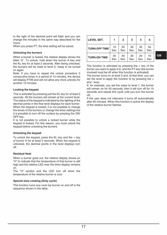
Special slow cooking (Duty cycle)
This function turns any cook top burner on and off is the sequence shown in the table.
LEVEL SET. 1 2 3 4 5
TURN-OFF TIME 10 Sec.
20 Sec.
30 Sec.
40 Sec.
50 Sec.
TURN-ON TIME 50 Sec.
40 Sec.
30 Sec.
20 Sec.
10 Sec.
The function is activated by pressing the + key of the burner you want to apply it to, and the PT key (the burner involved must be off when this function is activated).The burner turns on at level 3 and, at that time, you can set the level to apply the function to by pressing the + and - keys.If, for example, you set the value to level 1, the burner will remain on for 50 seconds, then it will turn off for 10 seconds and repeat this cycle until you turn the burner off.If the user does not intervene it turns off automatically after 60 minutes. When this function is active the display of the relative burner flashes.
18 19
GB
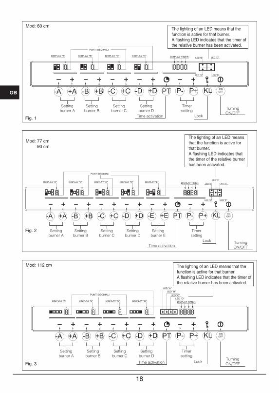
TurningON/OFF
LockTime activation
The lighting of an LED means that the function is active for that burner.A flashing LED indicates that the timer of the relative burner has been activated.
Setting burner A
Setting burner B
Setting burner C
Setting burner D
Setting burner E
Timer setting
Fig. 1
Fig. 2
Fig. 3
Mod: 60 cm
Mod: 77 cm 90 cm
Mod: 112 cm
Setting burner A
Setting burner B
Setting burner C
Setting burner D
Timer setting
TurningON/OFFLockTime activation
Setting burner A
Setting burner B
Setting burner C
Setting burner D
Timer setting Turning
ON/OFFLockTime activation
The lighting of an LED means that the function is active for that burner.A flashing LED indicates that the timer of the relative burner has been activated.
The lighting of an LED means that the function is active for that burner.A flashing LED indicates that the timer of the relative burner has been activated.

18 19
GB
N.B- We recommend the use of pots and pans with a
diameter matching that of the burner, thus preventing the flame from escaping from the bottom part and surrounding the pot (Fig. 4);
- do not leave any empty pots or pans on the fire;When cooking is finished, it is also a good norm to close the main gas pipe tap and/or cylinder.
fish 20x32fast Ø 20-26semifast Ø 14-20auxiliary* Ø 10-14
GAS
Fig. 4
Maintenance
Prior to any operation, disconnect the appliance from the electrical system. For long-life to the equipment, a general cleaning operation must take place periodically, bearing in mind the following:
suitable non-abrasive or corrosive products (found on the market). Avoid chlorine-base products (bleach, etc.);
working area (vinegar, salt, lemonjuice, etc.);
the burner) must be washed frequently with boiling water and detergent, taking care to remove every possible encrustation. Dry carefully and check that none of the burner holes is fully or partially clogged;
heck periodically the state of conservation of the flexible gas feed pipe. In case of leakage, call immediately the qualified technicians for its replacement.
DO NOT USE STEAM CLEANERS
20 21
GB
Instructions for the installer
Installation
This appliance is not provided with a combustion product discharge. It is recommended that it be installed insufficiently aerated places, in terms of the laws in force. The quantity of air which is necessary for combustion must not be below 2.0 m3/h for each kW of installed power. See table of burner power.
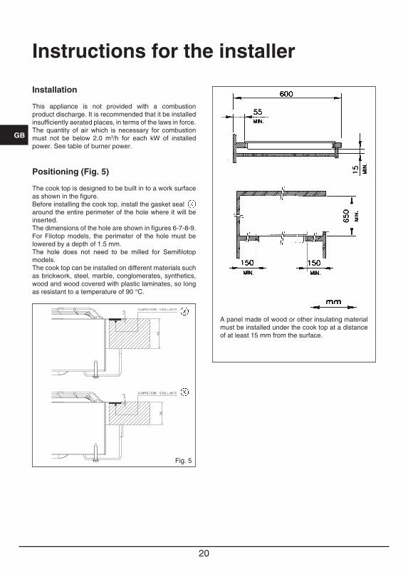
Positioning (Fig. 5)
The cook top is designed to be built in to a work surface as shown in the figure.Before installing the cook top, install the gasket sealaround the entire perimeter of the hole where it will be inserted.The dimensions of the hole are shown in figures 6-7-8-9.For Filotop models, the perimeter of the hole must be lowered by a depth of 1.5 mm.The hole does not need to be milled for Semifilotop models.The cook top can be installed on different materials such as brickwork, steel, marble, conglomerates, synthetics, wood and wood covered with plastic laminates, so long as resistant to a temperature of 90 °C.
Fig. 5
A panel made of wood or other insulating material must be installed under the cook top at a distance of at least 15 mm from the surface.
20 21
GB
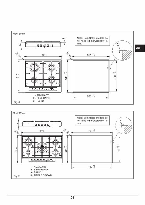
Fig. 6
591+10
511+1 0
560+10
490+1 0
R12
1.5
590
510
R11
74
1
1
3
2
2
Note: Semifilotop models do not need to be lowered by 1.5 mm.
1 - AUXILIARY2 - SEMI-RAPID3 - RAPID
74
770
510
R 11 771+10
511+1 0
490+1 0
750+10
1.5
R 12
1
3 2
42
1 - AUXILIARY2 - SEMI-RAPID3 - RAPID4 - TRIPLE CROWN
Note: Semifilotop models do not need to be lowered by 1.5 mm.
Fig. 7
Mod: 60 cm
Mod: 77 cm
22 23
GB 860
510
R 11 861+10
511+1 0
490+1 0
840+10
1.5
R 12
74
1
3 2
42
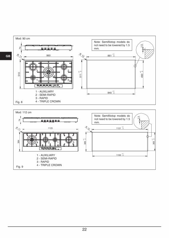
1 - AUXILIARY2 - SEMI-RAPID3 - RAPID4 - TRIPLE CROWN
Note: Semifilotop models do not need to be lowered by 1.5 mm.
Fig. 8
1120R 11 1121+10
385+1 0
365+1 0
1100+10
1.5
R 12
74384
1 34 2
1 - AUXILIARY2 - SEMI-RAPID3 - RAPID4 - TRIPLE CROWN
Note: Semifilotop models do not need to be lowered by 1.5 mm.
Fig. 9
Mod: 90 cm
Mod: 112 cm
22 23
GB
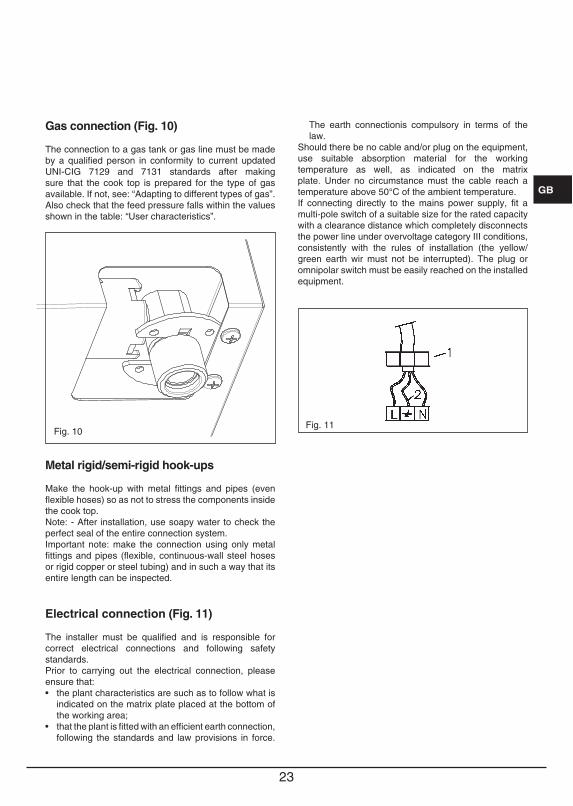
Gas connection (Fig. 10)
The connection to a gas tank or gas line must be made by a qualified person in conformity to current updated UNI-CIG 7129 and 7131 standards after making sure that the cook top is prepared for the type of gas available. If not, see: “Adapting to different types of gas”. Also check that the feed pressure falls within the values shown in the table: “User characteristics”.
Fig. 10
Metal rigid/semi-rigid hook-ups
Make the hook-up with metal fittings and pipes (even flexible hoses) so as not to stress the components inside the cook top.Note: - After installation, use soapy water to check the perfect seal of the entire connection system. Important note: make the connection using only metal fittings and pipes (flexible, continuous-wall steel hoses or rigid copper or steel tubing) and in such a way that its entire length can be inspected.
Electrical connection (Fig. 11)
The installer must be qualified and is responsible for correct electrical connections and following safety standards.Prior to carrying out the electrical connection, please ensure that:
indicated on the matrix plate placed at the bottom of the working area;
following the standards and law provisions in force.
The earth connectionis compulsory in terms of the law.
Should there be no cable and/or plug on the equipment, use suitable absorption material for the working temperature as well, as indicated on the matrix plate. Under no circumstance must the cable reach a temperature above 50°C of the ambient temperature.If connecting directly to the mains power supply, fit a multi-pole switch of a suitable size for the rated capacity with a clearance distance which completely disconnects the power line under overvoltage category III conditions, consistently with the rules of installation (the yellow/green earth wir must not be interrupted). The plug or omnipolar switch must be easily reached on the installed equipment.
Fig. 11
24 25
GB
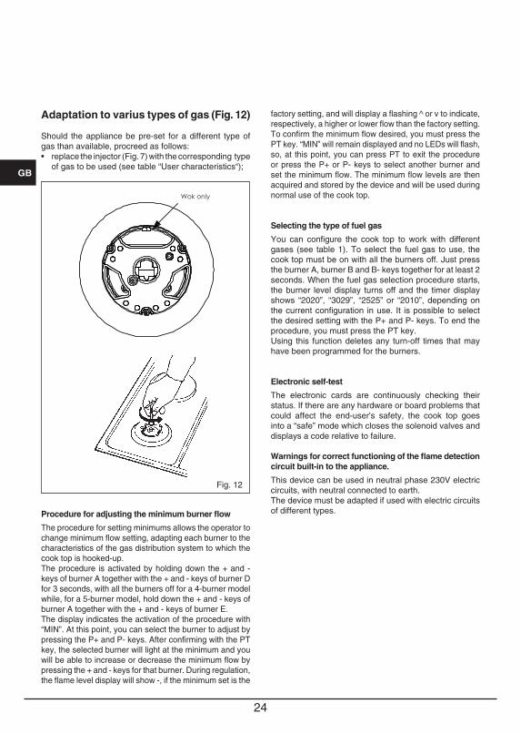
Adaptation to varius types of gas (Fig. 12)
Should the appliance be pre-set for a different type of gas than available, procreed as follows:
of gas to be used (see table “User characteristics“);
Wok only
Fig. 12
Procedure for adjusting the minimum burner flow
The procedure for setting minimums allows the operator to change minimum flow setting, adapting each burner to the characteristics of the gas distribution system to which the cook top is hooked-up. The procedure is activated by holding down the + and - keys of burner A together with the + and - keys of burner D for 3 seconds, with all the burners off for a 4-burner model while, for a 5-burner model, hold down the + and - keys of burner A together with the + and - keys of burner E. The display indicates the activation of the procedure with “MIN”. At this point, you can select the burner to adjust by pressing the P+ and P- keys. After confirming with the PT key, the selected burner will light at the minimum and you will be able to increase or decrease the minimum flow by pressing the + and - keys for that burner. During regulation, the flame level display will show -, if the minimum set is the
factory setting, and will display a flashing ^ or v to indicate, respectively, a higher or lower flow than the factory setting. To confirm the minimum flow desired, you must press the PT key. “MIN” will remain displayed and no LEDs will flash, so, at this point, you can press PT to exit the procedure or press the P+ or P- keys to select another burner and set the minimum flow. The minimum flow levels are then acquired and stored by the device and will be used during normal use of the cook top.
Selecting the type of fuel gas
You can configure the cook top to work with different gases (see table 1). To select the fuel gas to use, the cook top must be on with all the burners off. Just press the burner A, burner B and B- keys together for at least 2 seconds. When the fuel gas selection procedure starts, the burner level display turns off and the timer display shows “2020”, “3029”, “2525” or “2010”, depending on the current configuration in use. It is possible to select the desired setting with the P+ and P- keys. To end the procedure, you must press the PT key.Using this function deletes any turn-off times that may have been programmed for the burners.
Electronic self-test
The electronic cards are continuously checking their status. If there are any hardware or board problems that could affect the end-user's safety, the cook top goes into a “safe” mode which closes the solenoid valves and displays a code relative to failure.
Warnings for correct functioning of the flame detection circuit built-in to the appliance.
This device can be used in neutral phase 230V electric circuits, with neutral connected to earth.The device must be adapted if used with electric circuits of different types.
24 25
GB
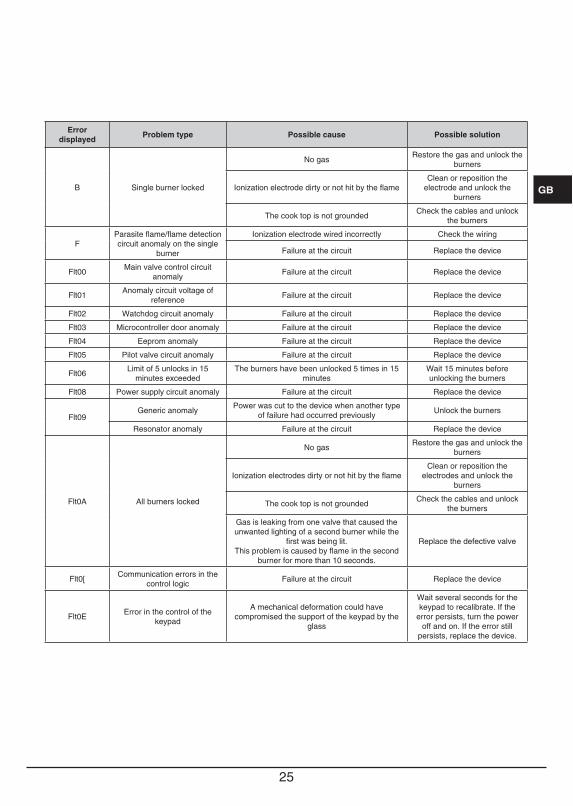
Error displayed Problem type Possible cause Possible solution
B Single burner locked
No gas Restore the gas and unlock the burners
Ionization electrode dirty or not hit by the flameClean or reposition the
electrode and unlock the burners
The cook top is not grounded Check the cables and unlock the burners
FParasite flame/flame detection circuit anomaly on the single
burner
Ionization electrode wired incorrectly Check the wiring
Failure at the circuit Replace the device
Flt00 Main valve control circuit anomaly Failure at the circuit Replace the device
Flt01 Anomaly circuit voltage of reference Failure at the circuit Replace the device
Flt02 Watchdog circuit anomaly Failure at the circuit Replace the device
Flt03 Microcontroller door anomaly Failure at the circuit Replace the device
Flt04 Eeprom anomaly Failure at the circuit Replace the device
Flt05 Pilot valve circuit anomaly Failure at the circuit Replace the device
Flt06 Limit of 5 unlocks in 15 minutes exceeded
The burners have been unlocked 5 times in 15 minutes
Wait 15 minutes before unlocking the burners
Flt08 Power supply circuit anomaly Failure at the circuit Replace the device
Flt09Generic anomaly Power was cut to the device when another type
of failure had occurred previously Unlock the burners
Resonator anomaly Failure at the circuit Replace the device
Flt0A All burners locked
No gas Restore the gas and unlock the burners
Ionization electrodes dirty or not hit by the flameClean or reposition the
electrodes and unlock the burners
The cook top is not grounded Check the cables and unlock the burners
Gas is leaking from one valve that caused the unwanted lighting of a second burner while the
first was being lit.This problem is caused by flame in the second
burner for more than 10 seconds.
Replace the defective valve
Flt0[ Communication errors in the control logic Failure at the circuit Replace the device
Flt0E Error in the control of the keypad
A mechanical deformation could have compromised the support of the keypad by the
glass
Wait several seconds for the keypad to recalibrate. If the
error persists, turn the power off and on. If the error still
persists, replace the device.
2726
GB
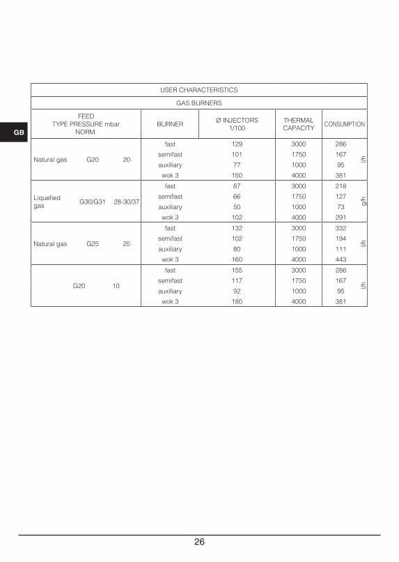
USER CHARACTERISTICS
GAS BURNERS
FEEDTYPE PRESSURE mbar
NORM.BURNER Ø INJECTORS
1/100THERMAL CAPACITY CONSUMPTION
Natural gas G20 20
fast 129 3000 286
l/h
semifast 101 1750 167
auxiliary 77 1000 95
wok 3 150 4000 381
Liquefied gas G30/G31 28-30/37
fast 87 3000 218
g/hsemifast 66 1750 127
auxiliary 50 1000 73
wok 3 102 4000 291
Natural gas G25 25
fast 132 3000 332
l/h
semifast 102 1750 194
auxiliary 80 1000 111
wok 3 160 4000 443
G20 10
fast 155 3000 286
l/h
semifast 117 1750 167
auxiliary 92 1000 95
wok 3 180 4000 381
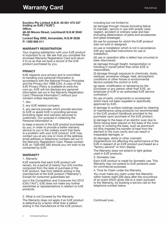
Warranty Card
Eurolinx Pty Limited A.B.N. 50 001 473 347 trading as ILVE (“ILVE”)6ɉJL!������4VVYL�:[YLL[��3LPJOOHYK[�5�:�>������7VZ[!3VJRLK�)HN�������(UUHUKHSL��5�:�>������7!�������������
WARRANTY REGISTRATION@V\Y�VUNVPUN�ZH[PZMHJ[PVU�^P[O�`V\Y�03=,�WYVK\J[�PZ�PTWVY[HU[�[V�\Z��>L�HZR�[OH[�`V\�JVTWSL[L�[OL�LUJSVZLK�>HYYHU[`�9LNPZ[YH[PVU�*HYK�HUK�YL[\YU�P[�[V�\Z�ZV�[OH[�^L�OH]L�H�YLJVYK�VM�[OL�03=,�WYVK\J[�W\YJOHZLK�I`�`V\�
PRIVACY03=,�YLZWLJ[Z�`V\Y�WYP]HJ`�HUK�PZ�JVTTP[[LK�[V�OHUKSPUN�`V\Y�WLYZVUHS�PUMVYTH[PVU�PU�HJJVYKHUJL�^P[O�[OL�5H[PVUHS�7YP]HJ`�7YPUJPWSLZ�HUK�[OL�7YP]HJ`�(J[�� ����*[O���(�JVW`�VM�[OL�03=,�7YP]HJ`�7VSPJ`�PZ�H]HPSHISL�H[�^^ �̂PS]L�JVT�H\��03=,�^PSS�UV[�KPZJSVZL�HU`�WLYZVUHS�PUMVYTH[PVU�ZL[�V\[�PU�[OL�>HYYHU[`�9LNPZ[YH[PVU�*HYK��¸7LYZVUHS�0UMVYTH[PVU¹��^P[OV\[�`V\Y�JVUZLU[�\USLZZ�YLX\PYLK�I`!���SH^"���HU`�03=,�YLSH[LK�JVTWHU`"���HU`�ZLY]PJL�WYV]PKLY�^OPJO�WYV]PKL�ZLY]PJLZ�[V�03=,�VY�HZZPZ[�03=,�PU�WYV]PKPUN�ZLY]PJLZ��PUJS\KPUN�YLWHPY�HUK�^HYYHU[`�ZLY]PJLZ��[V�J\Z[VTLYZ��6\Y�W\YWVZL�PU�JVSSLJ[PUN�[OL�7LYZVUHS�0UMVYTH[PVU�PZ[V�RLLW�H�YLJVYK�VM�[OL�03=,�WYVK\J[�W\YJOHZLK�I`�`V\��PU�VYKLY�[V�WYV]PKL�H�IL[[LY�^HYYHU[`�ZLY]PJL�[V�`V\�PU�[OL�\USPRLS`�L]LU[�[OH[�[OLYL�PZ�H�WYVISLT�^P[O�`V\Y�03=,�WYVK\J[��03=,�TH`�JVU[HJ[�`V\�H[�HU`�VUL�VY�TVYL�VM�[OL�HKKYLZZ��LTHPS�HKKYLZZ�VY�[LSLWOVUL�U\TILYZ�ZL[�V\[�PU�[OL�>HYYHU[`�9LNPZ[YH[PVU�*HYK��7SLHZL�JVU[HJ[�03=,�VU������� ������ZOV\SK�`V\�UV[�^PZO�[V�IL�JVU[HJ[LK�I`�03=,�
WARRANTY���>HYYHU[`03=,�^HYYHU[Z�[OH[�LHJO�03=,�WYVK\J[�^PSS�YLTHPU��MVY�H�WLYPVK�VM�[^LU[`�MV\Y������TVU[OZ�JVTW\[LK�MYVT�[OL�KH[L�VM�W\YJOHZL�VM�[OL�03=,�WYVK\J[��MYLL�MYVT�KLMLJ[Z�HYPZPUN�PU�[OL�THU\MHJ[\YL�VM�[OL�03=,�WYVK\J[��¸>HYYHU[`¹���,_JLW[�MVY�JVUZ\TLY�N\HYHU[LLZ�ZL[V\[�PU�[OL�*VTWL[P[PVU�HUK�*VUZ\TLY�(J[�������*[O���¸(J[¹���03=,�KVLZ�UV[�THRL�HU`�M\Y[OLY�^HYYHU[PLZ�VY�YLWYLZLU[H[PVUZ�PU�YLSH[PVU�[V�03=,�WYVK\J[Z�
���>OH[�PZ�UV[�*V]LYLK�I`�[OL�>HYYHU[ �̀;OL�>HYYHU[`�KVLZ�UV[�HWWS`�PM�HU�03=,�WYVK\J[�PZ�KLMLJ[P]L�I`�H�MHJ[VY�V[OLY�[OHU�H�KLMLJ[�HYPZPUN�PU�[OL�THU\MHJ[\YL�VM�[OL�03=,�WYVK\J[��
PS]L�JVT�H\
PUJS\KPUN�I\[�UV[�SPTP[LK�[V!�H��KHTHNL�[OYV\NO�TPZ\ZL��PUJS\KPUN�MHPS\YL�[V�THPU[HPU��ZLY]PJL�VY�\ZL�^P[O�WYVWLY�JHYL���ULNSLJ[��HJJPKLU[�VY�VYKPUHY`�^LHY�HUK�[LHY��PUJS\KPUN�KL[LYPVYH[PVU�VM�WHY[Z�HUK�HJJLZZVYPLZ�HUK�NSHZZ�IYLHRHNL�"�I��\ZL�MVY�W\YWVZL�MVY�^OPJO�[OL�03=,�WYVK\J[�^HZ�UV[�ZVSK�VY�KLZPNULK"�J��\ZL�VY�PUZ[HSSH[PVU�^OPJO�PZ�UV[�PU�HJJVYKHUJL�^P[O�HU`�ZWLJPÄLK�PUZ[Y\J[PVUZ�MVY�\ZL�VY�PUZ[HSSH[PVU"�K��\ZL�VY�VWLYH[PVU�HM[LY�H�KLMLJ[�OHZ�VJJ\YYLK�VY�ILLU�KPZJV]LYLK"�L��KHTHNL�[OYV\NO�MYLPNO[��[YHUZWVY[H[PVU�VY�OHUKSPUN�PU�[YHUZP[��V[OLY�[OHU�^OLU�03=,�PZ�YLZWVUZPISL�"�M��KHTHNL�[OYV\NO�L_WVZ\YL�[V�JOLTPJHSZ��K\Z[Z��YLZPK\LZ��L_JLZZP]L�]VS[HNL��OLH[��H[TVZWOLYPJ�JVUKP[PVUZ�VY�V[OLY�MVYJLZ�VY�LU]PYVUTLU[HS�MHJ[VYZ�V\[ZPKL�[OL�JVU[YVS�VY�03=,"�N��YLWHPY��TVKPÄJH[PVU�VY�[HTWLYPUN�I`�[OL�W\YJOHZLY�VY�HU`�WLYZVU�V[OLY�[OHU�03=,��HU�LTWSV`LL�VM�03=,�VY�HU�H\[OVYPZLK�03=,�ZLY]PJL�JVU[YHJ[VY�"�O��\ZL�VM�WHY[Z��JVTWVULU[Z�VY�HJJLZZVYPLZ�^OPJO�OH]L�UV[�ILLU�Z\WWSPLK�VY�ZWLJPÄJHSS`�HWWYV]LK�I`�03=,��P��KHTHNL�[V�Z\YMHJL�JVH[PUNZ�JH\ZLK�I`�JSLHUPUN�VY�THPU[LUHUJL�\ZPUN�WYVK\J[Z�UV[�YLJVTTLUKLK�PU�[OL�03=,�WYVK\J[�OHUKIVVR�WYV]PKLK�[V�[OL�W\YJOHZLY�\WVU�W\YJOHZL�VM�[OL�03=,�WYVK\J["�Q��KHTHNL�[V�[OL�IHZL�VM�HU�LSLJ[YPJ�V]LU�K\L�[V�P[LTZ�OH]PUN�ILLU�WSHJLK�VU�[OL�IHZL�VM�[OL�V]LU�JH]P[`�VY�JV]LYPUN�[OL�IHZL��Z\JO�HZ�HS\TPUP\T�MVPS��[OPZ�PTWLKLZ�[OL�[YHUZMLY�VM�OLH[�MYVT�[OL�LSLTLU[�[V�[OL�V]LU�JH]P[`�HUK�JHU�YLZ\S[�PU�PYYLWHYHISL�KHTHNL�"�VY�R��KHTHNLZ��KLU[Z�VY�V[OLY�JVZTL[PJ�PTWLYMLJ[PVUZ�UV[�HɈLJ[PUN�[OL�WLYMVYTHUJL�VM�[OL�03=,�PU�YLZWLJ[�VM�HU�03=,�WYVK\J[�W\YJOHZLK�HZ�H�¸MHJ[VY`�ZLJVUK¹�VY�MYVT�KPZWSH`;OL�>HYYHU[`�KVLZ�UV[�L_[LUK�[V�SPNO[�NSVILZ�\ZLK�PU�03=,�WYVK\J[Z����+VTLZ[PJ�<ZL,HJO�03=,�WYVK\J[�PZ�THKL�MVY�KVTLZ[PJ�\ZL��;OPZ�>HYYHU[`�TH`�UV[�L_[LUK�[V�03=,�WYVK\J[Z�\ZLK�MVY�JVTTLYJPHS�W\YWVZLZ����;PTL�MVY�*SHPT�\UKLY�[OL�>HYYHU[`@V\�T\Z[�THRL�HU`�JSHPT�\UKLY�[OPZ�>HYYHU[`�^P[OPU�[^LU[`�LPNO[������KH`Z�HM[LY�[OL�VJJ\YYLUJL�VM�HU�L]LU[�^OPJO�NP]LZ�YPZL�[V�H�JSHPT�W\YZ\HU[�[V�[OL�>HYYHU[ �̀�I`�IVVRPUN�H�ZLY]PJL�JHSS�VU�[OL�[LSLWOVUL�U\TILY�ILSV �̂
*VU[PU\LK�V]LY���
3 ILVE Operating Manual
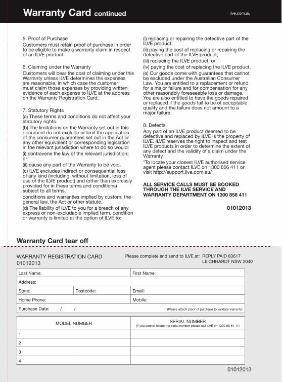
���7YVVM�VM�7\YJOHZL*\Z[VTLYZ�T\Z[�YL[HPU�WYVVM�VM�W\YJOHZL�PU�VYKLY�[V�IL�LSPNPISL�[V�THRL�H�^HYYHU[`�JSHPT�PU�YLZWLJ[�VM�HU�03=,�WYVK\J[�
���*SHPTPUN�\UKLY�[OL�>HYYHU[`*\Z[VTLYZ�^PSS�ILHY�[OL�JVZ[�VM�JSHPTPUN�\UKLY�[OPZ�>HYYHU[`�\USLZZ�03=,�KL[LYTPULZ�[OL�L_WLUZLZ�HYL�YLHZVUHISL��PU�^OPJO�JHZL�[OL�J\Z[VTLY�T\Z[�JSHPT�[OVZL�L_WLUZLZ�I`�WYV]PKPUN�^YP[[LU�L]PKLUJL�VM�LHJO�L_WLUZL�[V�03=,�H[�[OL�HKKYLZZ�VU�[OL�>HYYHU[`�9LNPZ[YH[PVU�*HYK�
���:[H[\[VY`�9PNO[Z�H��;OLZL�[LYTZ�HUK�JVUKP[PVUZ�KV�UV[�HɈLJ[�`V\Y�Z[H[\[VY`�YPNO[Z��I��;OL�SPTP[H[PVUZ�VU�[OL�>HYYHU[`�ZL[�V\[�PU�[OPZ�KVJ\TLU[�KV�UV[�L_JS\KL�VY�SPTP[�[OL�HWWSPJH[PVU�VM�[OL�JVUZ\TLY�N\HYHU[LLZ�ZL[�V\[�PU�[OL�(J[�VY�HU`�V[OLY�LX\P]HSLU[�VY�JVYYLZWVUKPUN�SLNPZSH[PVU�PU�[OL�YLSL]HU[�Q\YPZKPJ[PVU�^OLYL�[V�KV�ZV�^V\SK!�P��JVU[YH]LUL�[OL�SH^�VM�[OL�YLSL]HU[�Q\YPZKPJ[PVU"�or �PP��JH\ZL�HU`�WHY[�VM�[OL�>HYYHU[`�[V�IL�]VPK��J��03=,�L_JS\KLZ�PUKPYLJ[�VY�JVUZLX\LU[PHS�SVZZ�VM�HU`�RPUK��PUJS\KPUN��^P[OV\[�SPTP[H[PVU��SVZZ�VM�\ZL�VM�[OL�03=,�WYVK\J[��HUK��V[OLY�[OHU�L_WYLZZS`�WYV]PKLK�MVY�PU�[OLZL�[LYTZ�HUK�JVUKP[PVUZ��Z\IQLJ[�[V�HSS�[LYTZ�JVUKP[PVUZ�HUK�^HYYHU[PLZ�PTWSPLK�I`�J\Z[VT��[OL�NLULYHS�SH �̂�[OL�(J[�VY�V[OLY�Z[H[\[L��K��;OL�SPHIPSP[`�VM�03=,�[V�`V\�MVY�H�IYLHJO�VM�HU`�L_WYLZZ�VY�UVU�L_JS\KHISL�PTWSPLK�[LYT��JVUKP[PVU�VY�^HYYHU[`�PZ�SPTP[LK�H[�[OL�VW[PVU�VM�03=,�[V!
�P��YLWSHJPUN�VY�YLWHPYPUN�[OL�KLMLJ[P]L�WHY[�VM�[OL�03=,�WYVK\J["�PP��WH`PUN�[OL�JVZ[�VM�YLWSHJPUN�VY�YLWHPYPUN�[OL�KLMLJ[P]L�WHY[�VM�[OL�03=,�WYVK\J["�PPP��YLWSHJPUN�[OL�03=,�WYVK\J["�VY�P]��WH`PUN�[OL�JVZ[�VM�YLWSHJPUN�[OL�03=,�WYVK\J[��L��6\Y�NVVKZ�JVTL�^P[O�N\HYHU[LLZ�[OH[�JHUUV[�IL�L_JS\KLK�\UKLY�[OL�(\Z[YHSPHU�*VUZ\TLY�3H �̂�@V\�HYL�LU[P[SLK�[V�H�YLWSHJLTLU[�VY�YLM\UK�MVY�H�THQVY�MHPS\YL�HUK�MVY�JVTWLUZH[PVU�MVY�HU`�V[OLY�YLHZVUHIS`�MVYLZLLHISL�SVZZ�VY�KHTHNL��@V\�HYL�HSZV�LU[P[SLK�[V�OH]L�[OL�NVVKZ�YLWHPYLK�VY�YLWSHJLK�PM�[OL�NVVKZ�MHPS�[V�IL�VM�HJJLW[HISL�X\HSP[`�HUK�[OL�MHPS\YL�KVLZ�UV[�HTV\U[�[V�H�THQVY�MHPS\YL�
���+LMLJ[Z(U`�WHY[�VM�HU�03=,�WYVK\J[�KLLTLK�[V�IL�KLMLJ[P]L�HUK�YLWSHJLK�I`�03=,�PZ�[OL�WYVWLY[`�VM�03=,��03=,�YLZLY]LZ�[OL�YPNO[�[V�PUZWLJ[�HUK�[LZ[�03=,�WYVK\J[Z�PU�VYKLY�[V�KL[LYTPUL�[OL�L_[LU[�VM�HU`�KLMLJ[�HUK�[OL�]HSPKP[`�VM�H�JSHPT�\UKLY�[OL�>HYYHU[ �̀�;V�SVJH[L�`V\Y�JSVZLZ[�03=,�H\[OVYPZLK�ZLY]PJL�HNLU[�WSLHZL�JVU[HJ[�03=,�VU��������������VY�]PZP[�O[[W!��Z\WWVY[�PS]L�JVT�H\�
ALL SERVICE CALLS MUST BE BOOKED THROUGH THE ILVE SERVICE AND >(99(5;@�+,7(9;4,5;�65�������������
��������
Warranty Card JVU[PU\LK PS]L�JVT�H\
4ILVE Operating Manual
7SLHZL�JVTWSL[L�HUK�ZLUK�[V�03=,�H[!���9,73@�7(0+������ 3,0*//(9+;�5:>�����
3HZ[�5HTL! -PYZ[�5HTL!
(KKYLZZ!
:[H[L! 7VZ[JVKL! ,THPS!
/VTL�7OVUL! 4VIPSL!
7\YJOHZL�+H[L!���������������������������������������������������������������������������������������7SLHZL�H[[HJO�WYVVM�VM�W\YJOHZL�[V�]HSPKH[L�^HYYHU[`�
46+,3�5<4),9 :,90(3�5<4),9� �PM�`V\�JHUUV[�SVJH[L�[OL�ZLYPHS�U\TILY�WSLHZL�JHSS�03=,�VU���������������
�
2
3
�
>(99(5;@�9,.0:;9(;065�*(9+��������
��������
Warranty Card tear off

(\Z[YHSPH�5H[PVUHS�;LSLWOVUL�5\TILY������4@03=,��� ������5L^�ALHSHUK�;LSLWOVUL�5\TILY������������
03=,�ZOV^YVVTZ�HYL�VWLU�KHPS`�MYVT� HT��WT�HUK�:H[\YKH`Z���HT��WT �>(�I`�HWWVPU[TLU[�VUS`�VU�:H[\YKH`Z� PS]L�JVT�H\
5:>� �(*;��/LHK�6ɉJL�������4VVYL�:[YLL[� 3LPJOOHYK[-������� ���
=0*��;(:� �:(�����;VVYHR�9VHK� *HTILY^LSS-���� �� �����
83+�����*H]LUKPZO�9VHK�*VVYWHYVV�-������ ������
>(� �5;<UP[�������/V^L�:[YLL[6ZIVYUL�7HYR�-���� ���� ���
5L^�ALHSHUK76�)V_�������:VJRI\YU�*OYPZ[JO\YJO-��������� ��