INSTRUCTION MANUAL - CIRCUTOR
108
INSTRUCTION MANUAL Power analyser line-CVM-D32 (M237B01-03-19A)
-
Upload
khangminh22 -
Category
Documents
-
view
0 -
download
0
Transcript of INSTRUCTION MANUAL - CIRCUTOR

INSTRUCTION MANUAL
Power analyser
line-CVM-D32
(M237B01-03-19A)

2
line-CVM-D32
Instruction Manual

3Instruction Manual
line-CVM-D32
SAFETY PRECAUTIONS
DANGERWarns of a risk, which could result in personal injury or material damage.
ATTENTIONIndicatesthatspecialattentionshouldbepaidtoaspecificpoint.
Follow the warnings described in this manual with the symbols shown below.
If you must handle the unit for its installation, start-up or maintenance, the following should be taken into consideration:
Incorrect handling or installation of the unit may result in injury to personnel as well as damage to the unit. In particular, handling with voltages applied may result in electric shock, which may cause death or serious injury to personnel. Defective installation or maintenance may also leadtotheriskoffire.Read the manual carefully prior to connecting the unit. Follow all installation and maintenance instructions throughout the unit’s working life. Pay special attention to the installation stan-dards of the National Electrical Code.
Refer to the instruction manual before using the unit
In this manual, if the instructions marked with this symbol are not respected or carried out correctly, it can result in injury or damage to the unit and /or installations.
CIRCUTOR,SAreservestherighttomodifyfeaturesortheproductmanualwithoutpriornotification.
DISCLAIMER
CIRCUTOR, SAreservestherighttomakemodificationstothedeviceortheunitspecifica-tions set out in this instruction manual without prior notice.
CIRCUTOR, SA on its web site, supplies its customers with the latest versions of the device specificationsandthemostupdatedmanuals.
www.circutor.com
CIRCUTOR, recommends using the original cables and accessories that are supplied with the device.
4
line-CVM-D32
Instruction Manual
CONTENTS
SAFETY PRECAUTIONS ��������������������������������������������������������������������������������������������������������������������������������������� 3DISCLAIMER ���������������������������������������������������������������������������������������������������������������������������������������������������������� 3CONTENTS ������������������������������������������������������������������������������������������������������������������������������������������������������������� 4REVISION LOG ������������������������������������������������������������������������������������������������������������������������������������������������������� 6SYMBOLS ��������������������������������������������������������������������������������������������������������������������������������������������������������������� 61�- VERIFICATION UPON RECEPTION ����������������������������������������������������������������������������������������������������������������� 72�- PRODUCT DESCRIPTION �������������������������������������������������������������������������������������������������������������������������������� 73�- INSTALLATION OF THE DEVICE ��������������������������������������������������������������������������������������������������������������������� 9
3�1�- PRELIMINARY RECOMMENDATIONS ���������������������������������������������������������������������������������������������������� 9 3�2�- INSTALLATION ��������������������������������������������������������������������������������������������������������������������������������������� 10 3�3�- 72 x 72 mm PANEL ADAPTER ��������������������������������������������������������������������������������������������������������������� 10 3�4�- DEVICE TERMINALS ������������������������������������������������������������������������������������������������������������������������������ 11 3�5�- EXPANSION WITH OTHER DEVICES ���������������������������������������������������������������������������������������������������� 12
3�5�1�- Line-M-EXT-PS POWER ADAPTER ������������������������������������������������������������������������������������������������ 123�5�2�- INSTALLATION ��������������������������������������������������������������������������������������������������������������������������������� 13
3�6�- CONNECTION DIAGRAMS �������������������������������������������������������������������������������������������������������������������� 153�6�1�- 3-PHASE MAINS MEASUREMENT WITH 4-WIRE CONNECTION ������������������������������������������������ 153�6�2�- 3-PHASE MAINS MEASUREMENT WITH 3-WIRE CONNECTION ������������������������������������������������ 173�6�3�- 3-PHASE MAINS MEASUREMENT WITH 3-WIRE CONNECTION AND TRANSFORMERS WITH ARON CONNECTION���������������������������������������������������������������������������������������������������������������������������������� 193�6�4�- 2-PHASE MAINS MEASUREMENT WITH 3-WIRE CONNECTION ������������������������������������������������ 203�6�5�- SINGLE PHASE MAINS MEASUREMENT WITH 2-WIRE PHASE-TO-PHASE CONNECTION ��� 213�6�6�- SINGLE PHASE MAINS MEASUREMENT WITH 2-WIRE PHASE-TO-NEUTRAL CONNECTION ��������������������������������������������������������������������������������������������������������������������������������������������� 22
4�- OPERATION ��������������������������������������������������������������������������������������������������������������������������������������������������� 23 4�1�- MEASUREMENT PARAMETERS ����������������������������������������������������������������������������������������������������������� 24
4�1�1�- QUALITY PARAMETERS ����������������������������������������������������������������������������������������������������������������� 26 4�2� - LED INDICATORS ���������������������������������������������������������������������������������������������������������������������������������� 27 4�3�- DISPLAY �������������������������������������������������������������������������������������������������������������������������������������������������� 28 4�4�- KEYBOARD FUNCTIONS ����������������������������������������������������������������������������������������������������������������������� 28 4�5�- DIGITAL OUTPUTS �������������������������������������������������������������������������������������������������������������������������������� 29
5�- DISPLAY ���������������������������������������������������������������������������������������������������������������������������������������������������������� 30 5�1�- INSTANTANEOUS VALUE MENU ���������������������������������������������������������������������������������������������������������� 31
5�1�1�- MAXIMUM AND MINIMUM VALUES ������������������������������������������������������������������������������������������������ 32 5�2�- ENERGY MENU��������������������������������������������������������������������������������������������������������������������������������������� 33 5�3�- MAXIMUM DEMAND MENU ������������������������������������������������������������������������������������������������������������������� 35
5�3�1�- MAXIMUM VALUES �������������������������������������������������������������������������������������������������������������������������� 36 5�4�- QUALITY PARAMETERS MENU ������������������������������������������������������������������������������������������������������������ 37 5�5�- VOLTAGE HARMONIC MENU ���������������������������������������������������������������������������������������������������������������� 38 5�6�- CURRENT HARMONIC DISPLAY ����������������������������������������������������������������������������������������������������������� 38 5�7�- METER MENU ����������������������������������������������������������������������������������������������������������������������������������������� 39 5�8�- INFORMATION MENU����������������������������������������������������������������������������������������������������������������������������� 41 5�9�- INPUT / OUTPUT MENU ������������������������������������������������������������������������������������������������������������������������� 42
6�- CONFIGURATION ������������������������������������������������������������������������������������������������������������������������������������������� 43 6�1�- MEASUREMENT CONFIGURATION ������������������������������������������������������������������������������������������������������ 44
6�1�1�- PRIMARY AND SECONDARY VOLTAGE ���������������������������������������������������������������������������������������� 446�1�2�- PRIMARY AND SECONDARY CURRENT ���������������������������������������������������������������������������������������� 456�1�3�- QUADRANTS AND MEASUREMENT CONVENTION ��������������������������������������������������������������������� 466�1�4�- INSTALLATION TYPE ����������������������������������������������������������������������������������������������������������������������� 466�1�5�- CALCULATION PERIODS ���������������������������������������������������������������������������������������������������������������� 476�1�6�- CLEAR MAXIMUMS, MINIMUMS AND MAXIMUM DEMAND ��������������������������������������������������������� 486�1�7�- CLEAR ENERGIES AND DELETE ALL�������������������������������������������������������������������������������������������� 486�1�8�- HARMONICS AND CURRENCY DISPLAY ��������������������������������������������������������������������������������������� 496�1�9�- DISPLAY BACKLIGHT AND PASSWORD ��������������������������������������������������������������������������������������� 49
6�2�- QUALITY PARAMETER CONFIGURATION ������������������������������������������������������������������������������������������� 506�2�1�- NOMINAL VOLTAGE AND FREQUENCY ���������������������������������������������������������������������������������������� 506�2�2�- OVERVOLTAGE AND GAPS ������������������������������������������������������������������������������������������������������������ 516�2�3�- INTERRUPTION AND HYSTERESIS VALUE ���������������������������������������������������������������������������������� 516�2�4�- CLEAR QUALITY PARAMETERS ���������������������������������������������������������������������������������������������������� 52

5Instruction Manual
line-CVM-D32
6�3�- DEVICE CLOCK SETTING ���������������������������������������������������������������������������������������������������������������������536�3�1�- DATE FORMAT����������������������������������������������������������������������������������������������������������������������������������536�3�2�- DATE AND TIME �������������������������������������������������������������������������������������������������������������������������������53
6�4�- COMMUNICATIONS CONFIGURATION �������������������������������������������������������������������������������������������������546�4�1�- PERIPHERAL NUMBER AND TRANSMISSION SPEED �����������������������������������������������������������������546�4�2�- DATA FORMAT AND MEASURE TIME ��������������������������������������������������������������������������������������������54
6�5�- RATIO CONFIGURATION �����������������������������������������������������������������������������������������������������������������������556�5�1�- CO2 EMISSIONS IN CONSUMPTION, TARIFFS 1 AND 2 ���������������������������������������������������������������556�5�2�- CO2 EMISSIONS IN CONSUMPTION, TARIFFS 3 AND 4 ���������������������������������������������������������������566�5�3�- COST OF CONSUMED ENERGY IN CONSUMPTION, TARIFFS 1 AND 2 �������������������������������������576�5�4�- ENERGY COST IN CONSUMPTION, TARIFFS 3 AND 4 �����������������������������������������������������������������576�5�5�- CO2 EMISSIONS IN GENERATION, TARIFFS 1 AND 2 �������������������������������������������������������������������586�5�6�- CO2 EMISSIONS IN GENERATION, TARIFFS 3 AND 4 �������������������������������������������������������������������586�5�7�- ENERGY COST IN GENERATION, TARIFFS 1 AND 2 ��������������������������������������������������������������������596�5�8�- ENERGY COST IN GENERATION, TARIFFS 3 AND 4 ��������������������������������������������������������������������60
6�6�- CONFIGURATION OF DIGITAL OUTPUTS 1 AND 2 �����������������������������������������������������������������������������616�6�1�- VARIABLE �����������������������������������������������������������������������������������������������������������������������������������������616�6�2�- MAXIMUM AND MINIMUM VALUE����������������������������������������������������������������������������������������������������656�6�3�- CONNECTION AND DISCONNECTION DELAY ������������������������������������������������������������������������������656�6�4�- HYSTERESIS AND STATUS OF CONTACTS ����������������������������������������������������������������������������������666�6�5�- LATCH �����������������������������������������������������������������������������������������������������������������������������������������������666�6�6�- ENERGY PER PULSE AND CONTACT STATUS �����������������������������������������������������������������������������676�6�7�- PULSE �����������������������������������������������������������������������������������������������������������������������������������������������686�6�8�- DIGITAL OUTPUT MANUAL OPERATION ���������������������������������������������������������������������������������������69
7�- RS-485 COMMUNICATIONS ���������������������������������������������������������������������������������������������������������������������������70 7�1�- CONNECTIONS ���������������������������������������������������������������������������������������������������������������������������������������70 7�2�- MODBUS PROTOCOL ����������������������������������������������������������������������������������������������������������������������������71
7�2�1�- MODBUS QUERY EXAMPLE �����������������������������������������������������������������������������������������������������������71 7�3�- MODBUS MEMORY MAP �����������������������������������������������������������������������������������������������������������������������72
7�3�1�- MEASUREMENT VARIABLES ���������������������������������������������������������������������������������������������������������727�3�2 �- ENERGY VARIABLES����������������������������������������������������������������������������������������������������������������������797�3�3�- MAXIMUM DEMAND VARIABLES ���������������������������������������������������������������������������������������������������837�3�4�- VOLTAGE AND CURRENT HARMONICS� ���������������������������������������������������������������������������������������877�3�5�- COST VARIABLES ����������������������������������������������������������������������������������������������������������������������������897�3�6�- ANGLE VARIABLES �������������������������������������������������������������������������������������������������������������������������907�3�7�- QUALITY EVENT AND DISTURBANCE COUNTERS ���������������������������������������������������������������������907�3�8�- OTHER DEVICE PARAMETERS ������������������������������������������������������������������������������������������������������907�3�9�- DIGITAL OUTPUTS ��������������������������������������������������������������������������������������������������������������������������917�3�10�- DEVICE CONFIGURATION VARIABLES ���������������������������������������������������������������������������������������917�3�11�- CLEAR PARAMETERS �������������������������������������������������������������������������������������������������������������������95
8�- TECHNICAL FEATURES ��������������������������������������������������������������������������������������������������������������������������������969�- MAINTENANCE AND TECHNICAL SERVICE ������������������������������������������������������������������������������������������������9910 �- GUARANTEE ������������������������������������������������������������������������������������������������������������������������������������������������9911�- CE CERTIFICATE ����������������������������������������������������������������������������������������������������������������������������������������100ANNEX A�- CONFIGURATION MENU ����������������������������������������������������������������������������������������������������������������103
6
line-CVM-D32
Instruction Manual
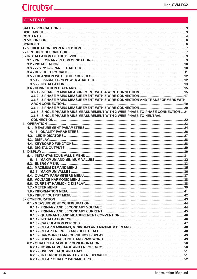
REVISION LOG
Table 1: Revision log�Date Revision Description03/20 M237B01-03-19A First Version
Note: The images on the devices are for illustrative use only and may differ from the original device.
SYMBOLS
Table 2: Symbols�Symbol Description
In accordance with the relevant European directive.
In accordance with the CMiM directive.
Device covered by European Directive 2012/19/EC. At the end of its useful life, do not leave the device in a household refuse bin. Follow local regulations on electronic equip-ment recycling.
Direct current.
~ Alternating current.

7Instruction Manual
line-CVM-D32
1�- VERIFICATION UPON RECEPTION
Upon reception of the device check the following points:
a)Thedevicemeetsthespecificationsdescribedinyourorder. b) The device has not suffered any damage during transport. c) Perform an external visual inspection of the device prior to switching it on. d) Check that it has been delivered with the following:
- An installation guide
If any problem is noticed upon reception, immediately contact the transport company and/or CIRCUTOR's after-sales service�
2�- PRODUCT DESCRIPTION
The line-CVM-D32 is a device that measures, calculates and displays the main electrical parameters in single-phase mains, two-phase mains with and without neutral, and balanced three-phase mains with ARON measurement or unbalanced. Measurement is performed at true RMS value, using three AC voltage inputs and three current inputs.
Currentmeasurement isperformed indirectly through /5A, /1A transformersorefficientMC1and MC3 series transformers (/0.250A).
The device features:
- Display to display parameters. - 3 keys to browse through the different screens and program the equipment.
- 2 digital transistor outputs. - RS-485 communications, with MODBUS RTU© protocol.

8
line-CVM-D32
Instruction Manual
The line-CVM-D32 can be expanded with the following expansion modules:
line-M-4IO-R, expansion module with 4 digital inputs and 4 relay outputs. line-M-4IO-T expansion module with 4 digital inputs and 4 transistor outputs. line-M-4IO-A, expansion module with 4 analogue inputs and outputs. line-M-4IO-RV, expansion module with 4 digital inputs (230 V~) and 4 relay outputs. line-M-EXT-PS, power adapter module.
9Instruction Manual
line-CVM-D32
3�- INSTALLATION OF THE DEVICE
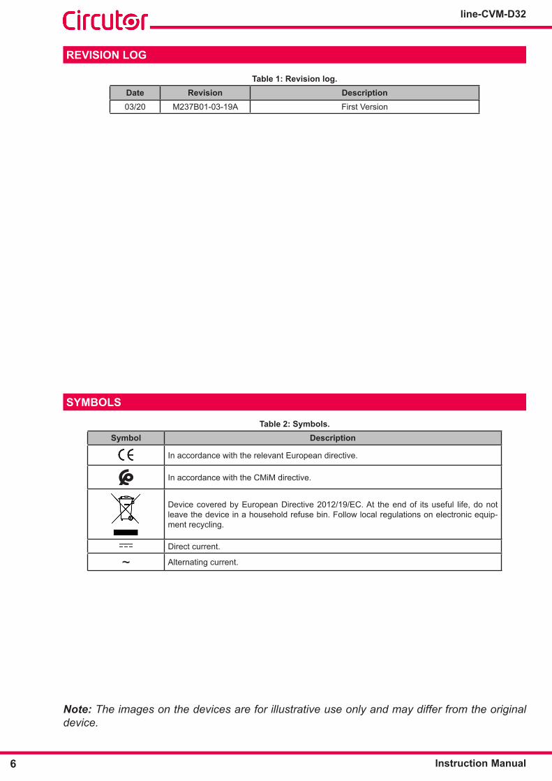
3.1.- PRELIMINARY RECOMMENDATIONS
In order to use the device safely, personnel operating it must follow the safety measures that comply with the standards of the country where it is to be installed; operators must wear the required personal protective equipment (rubber gloves, approvedfacialprotectionandflame-resistantclothing)topreventinjuriesfromelectric shock or arcs caused by exposure to current-carrying conductors, and they must heed the various warnings indicated in this instruction manual.
The line-CVM-D32 devicemustbeinstalledbyauthorised,qualifiedpersonnel.
The power supply plug must be disconnected and measurement systems switched off before handling, altering the connections or replacing the device. It is dangerous to handle the device while it is powered.
Cables must always be kept in perfect condition to avoid accidents or injury to personnel or installations.
Restricttheoperationofthedevicetothespecifiedmeasurementcategory,voltageorcurrentvalues.
The manufacturer of the device is not responsible for any damage resulting from failure by the user or installer to heed the warnings and/or recommendations set out in this manual, nor for damage resulting from the use of non-original products or accessories or those made by other manufacturers.
Do not use the device to take any measurements if an anomaly or malfunction is detected.
Check the surrounding environment before starting to take measurements. Do not take any measurements in hazardous or explosive environments.
Before carrying out maintenance, repair or handling of any of the device's con-nections, the device must be disconnected from all power sources, both from the device's own power supply and the measurement's. Contact the after-sales service if you detect that the device is not working prop-erly.

10
line-CVM-D32
Instruction Manual
3.2.- INSTALLATION
When the device is on, its terminals, opening covers or removing elements may expose the user to parts that are hazardous to touch. Do not use the device until it is fully installed.
The device must be installed inside a medium or low voltage electric panel or enclosure, with DIN rail mounting (IEC 60715).
The minimum recommended distance between rails to install the line-CVM-D32 devices is 150 mm.
The device must be connected to a power supply circuit protected by gl type (IEC 269) or M typefuses,between0.5and2A.Itmustbefittedwithacircuit-breakerorequivalentdevicetodisconnect the device from the mains supply.
The power supply and voltage measurement circuits must be connected with a 1mm² minimum cross-section cable.
The current transformer's secondary line must have a 2.5 mm2 minimum cross-section.
The insulation temperature of the cables connected to the device must be at least 62°C.
3.3.- 72 x 72 mm PANEL ADAPTER
Note: The 72 x 72 mm panel adapter is a separately sold accessory.
CIRCUTOR has a panel adapter for the line-CVM-D32 devices and their expansion modules for their installation in 72 x 72 mm panels.
Figure 1 illustrates how the panel adapter connects to a line-CVM-D32.
Before installing the adapter, the device must be disconnected from all power and measurement supplies.
Figure 1: Installation of the panel adapter�

11Instruction Manual
line-CVM-D32
Table 3: Technical characteristics of the Panel Adapter�
Technical SpecificationsProtection degree IP40Casing Self-extinguishing V0 plastic
68 mm
68 mm
Figure 2: Cut in the panel�
3.4.- DEVICE TERMINALS
3
5
6
111
9 15
16
17
18
13
14
22
21
20
19
24
23
Figure 3: Line-CVM-D32 terminals: Upper - Lower�
Table 4: List of line-CVM-D32 terminals�
Device terminals1: U1, voltage input L1 16: s2, current input L23: U2, voltage input L2 17: s1, current input L35: U3, voltage input L3 18: s2, current input L36: N, neutral input 19: C, common digital outputs9: A1 ~/+, Auxiliary power supply 20: 2, digital output 211: A2 ~/-, Auxiliary power supply 21: 1, digital output 113: s1, current input L1 22: B-, RS-48514: s2, current input L1 23: S, GND for RS-48515: s1, current input L2 24: A+, RS-485

12
line-CVM-D32
Instruction Manual
3.5.- EXPANSION WITH OTHER DEVICES The line-CVM-D32 devices can be expanded with other devices in the Line range, and with the line-EDS and line-M expansion modules .
The line-EDS and line-CVM devices enable up to 2 expansion modules to be directly connect-ed to their right-hand side(1).
line-EDS line-M line-M line-M line-M line-CVM
Figure 4: Line-EDS and line CVM expansion module connection�
(1) Expansion module types: line-M-4IO-R, line-M-4IO-T, line-M-4IO-RV and line-M-4IO-A�
In installations with line-EDS devices, a total of up to seven devices may be connected to their right-hand side.
line-EDS line-M line-M line-CVM line-M line-M line-CVM line-CVM
Figure 5: Typical installation of a line-EDS with 7 devices�
Note: An installation may only be fitted with one line-EDS device.Note: In installations without line-EDS devices, only one line-CVM device may ne installed.Note: All line-EDS and line-CVM devices must be connected to the auxiliary power supply.
3�5�1�- Line-M-EXT-PS POWER ADAPTER
Line-M-EXT-PS is a power adapter belonging to the Line family of devices. The module con-nects to the left-hand side of the devices to be fed. It can supply up to 10 VA, allowing it to power a limited number of devices.
The maximum set it can supply is: 1 line-EDS + 1 line-CVM + 1 line-M (Figure 6).
line-EDS line-M line-M-EXT-PS line-CVM
Figure 6: Maximum set a line-M-EXT-PS can supply�

13Instruction Manual
line-CVM-D32
Multiple line-M-EXT-PS devices can be connected to supply sets with power above 10VA. Each line-M-EXT-PS will power the devices connected to its right-hand side (Figure 7).
line-EDS line-M line-M line-CVM line-M line-M line-CVM line-CVM line-M-EXT-PS line-M-EXT-PS line-M-EXT-PS
Figure 7: Multiple line-M-EXT-PS connection�
Note: None of the line-EDS or line-CVM devices should be connected to the auxiliary power supply.
3�5�2�- INSTALLATION
Before installing a new device, it must be disconnected from all power supplies.
The correct steps to connect the devices are:
1�-Usingaflatheadscrewdriver,removetheexpansionconnector'sprotectivecoverslocatedon the side of the devices, (Figure 8).
line-CVM-D32
Figure 8: Installation step 1�
2�- Insert the expansion connector and fastening clips into one of the devices (Figure 9).

14
line-CVM-D32
Instruction Manual
line-CVM-D32
Figure 9: Installation step 2�
3 �- Connect both devices and fasten them by pushing the front clips down (Figure 10).
line-CVM-D32
Figure 10: Installation step 3�
For correct installation of all devices, please refer to the instruction manual for the different models:M231B01-03-xxx : Instruction Manual for line-EDS devices.M239B01-03-xxx : Instruction Manual for line-M expansion modules.
15Instruction Manual
line-CVM-D32
3.6.- CONNECTION DIAGRAMS
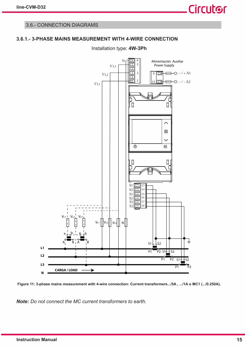
3�6�1�- 3-PHASE MAINS MEASUREMENT WITH 4-WIRE CONNECTION
Installation type: 4W-3Ph
VL1 VL2 VL3 N
L1
L2
L3
N
NV L3
L2V
L1V
VL1 VL2 VL3
a b
A B
a b
A B
CARGA / LOAD
65
3
Alimentación AuxiliarPower Supply
S1S2S1
S2S1S2
S1 S2
P1 P2 S1 S2
P1 P2 S1 S2
P1 P2
131415161718
1 11
9
~ / - A2
~ / + A1
Figure 11: 3-phase mains measurement with 4-wire connection: Current transformers���/5A , ���/1A o MC1 (���/0�250A)�
Note: Do not connect the MC current transformers to earth.

16
line-CVM-D32
Instruction Manual
VL1 VL2 VL3 N
L1
L2
L3
N
NV L3
L2V
L1V
VL1 VL2 VL3
a b
A B
a b
A B
CARGA / LOAD
65
3
Alimentación AuxiliarPower Supply
1 A2
A1
~ / -
~ / +
S1S2S1
S2S1S2
13
15
1718
3P1
2P1
1P1
3P2
2P2
1P2
9
11
14
16
Brown/Green
Grey/Pink
Green/White
Red/Blue
Figure 12: 3-phase mains measurement with 4-wire connection: MC3 series current transformers (���/0�250A)�

17Instruction Manual
line-CVM-D32
3�6�2�- 3-PHASE MAINS MEASUREMENT WITH 3-WIRE CONNECTION
Installation type: 3W-3Ph
VL1 VL2 VL3
L1
L2
L3
VL3
L2V
L1V
VL1 VL2 VL3
a b
A B
a b
A B
CARGA / LOAD
5
3
1
S1S2S1
S2S1S2
S1 S2
P1 P2 S1 S2
P1 P2 S1 S2
P1 P2
131415161718
Alimentación AuxiliarPower Supply
A1
A2~ / -
~ / +9
11
Figure 13: 3-phase mains measurement with 3-wire connection: Current transformers���/5A , ���/1A o MC1 (���/0�250A)�
Note: Do not connect the MC current transformers to earth.

18
line-CVM-D32
Instruction Manual
VL1 VL2 VL3
L1
L2
L3
VL3
L2V
L1V
VL1 VL2 VL3
a b
A B
a b
A B
CARGA / LOAD
5
3
1
Alimentación AuxiliarPower Supply
A1
A2~ / -
~ / +
S1S2S1
S2S1S2
13
15
1718
3P1
2P1
1P1
3P2
2P2
1P2
9
11
14
16
Brown/Green
Grey/Pink
Green/White
Red/Blue
Figure 14: 3-phase mains measurement with 3-wire connection: MC3 series current transformers (���/0�250A)�

19Instruction Manual
line-CVM-D32
3�6�3�- 3-PHASE MAINS MEASUREMENT WITH 3-WIRE CONNECTION AND TRANSFORM-ERS WITH ARON CONNECTION
Installation type: ARON
VL1 VL2 VL3
L1
L2
L3
VL3
L2V
L1V
VL1 VL2 VL3
a b
A B
a b
A B
CARGA / LOAD
5
3
1
Alimentación AuxiliarPower Supply
S1S2S1
S2S1S2
S1 S2
P1 P2
S1 S2
P1 P2
131415161718
A1
A2~ / -
~ / +9
11
Figure 15: 3-phase mains measurement with 3-wire connection and transformers with ARON connection
Note: Do not connect the MC current transformers to earth.

20
line-CVM-D32
Instruction Manual
3�6�4�- 2-PHASE MAINS MEASUREMENT WITH 3-WIRE CONNECTION
Installation type: 3W-2Ph
VL1 VL2 N
L1
L2
N
N
L2V
L1V
VL1 N VL2
a b
A B
a b
A B
CARGA / LOAD
6
3
Alimentación AuxiliarPower Supply
S1S2S1
S2S1S2
S1 S2
P1 P2 S1 S2
P1 P2
13141516
A1
A2~ / -
~ / +
1 11
9
Figure 16: 2-phase mains measurement with 3-wire connection
Note: Do not connect the MC current transformers to earth.
21Instruction Manual
line-CVM-D32
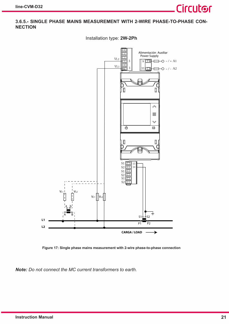
3�6�5�- SINGLE PHASE MAINS MEASUREMENT WITH 2-WIRE PHASE-TO-PHASE CON-NECTION
Installation type: 2W-2Ph
VL1 VL2
L1
L2
L2V
L1V
VL1 VL2
a b
A B
CARGA / LOAD
3
1
Alimentación AuxiliarPower Supply
S1S2S1
S2S1S2
S1 S2
P1 P2
1314
A1
A2~ / -
~ / +9
11
Figure 17: Single phase mains measurement with 2-wire phase-to-phase connection
Note: Do not connect the MC current transformers to earth.

22
line-CVM-D32
Instruction Manual
3�6�6�- SINGLE PHASE MAINS MEASUREMENT WITH 2-WIRE PHASE-TO-NEUTRAL CONNECTION
Installation type: 2W-1Ph
VL1 N
L1
N
N
L1V
VL1 N
a b
A B
CARGA / LOAD
6
1
Alimentación AuxiliarPower Supply
S1S2S1
S2S1S2
S1 S2
P1 P2
1314
9
A2~ / -
~ / + A1
11
Figure 18: Single phase mains measurement with 2-wire phase-to-neutral connection
Note: Do not connect the MC current transformers to earth.

23Instruction Manual
line-CVM-D32
4�- OPERATION
The line-CVM-D32 device is a power analyser for all four quadrants (consumption and gener-ation).The device can operate under three different measurement conventions:
Measurement convention CIRCUTOR. Measurement convention IEC. Measurement convention IEEE.
Themeasurementconventionisconfiguredusingtheconfigurationmenu, see “6.1.3.- QUAD-RANTS AND MEASUREMENT CONVENTION"�
Measurement convention CIRCUTOR :
0º
90º
180º
-90º
Capacitive
Capacitive Inductive
Inductive
GenerationPower
ConsumptionPower
Single-phaseThree-phase
Single-phase
Single-phase
Single-phase Three-phase Three-phase
Three-phase
kk
kkk
kk
kkk
kk
kkk k
kkkk
Figure 19: Measurement convention CIRCUTOR�
Measurement convention IEC:
Q
P
Q1Q2
Q3 Q4
P < 0 Q > 0 PF < 0
Capacitive
CapacitiveInductive
Inductive
P < 0 Q < 0 PF < 0 P > 0 Q < 0 PF > 0
P > 0 Q > 0 PF > 0
Operation in the 4 quadrants (Q1, Q2, Q3, Q4)
0 +
0 +
cos φ > 0
cos φ > 0
Q1
Q4
+ 1+ 1
cos φ values in the receiver operating mode (Q1,Q4)
Figure 20: Measurement convention IEC�
24
line-CVM-D32
Instruction Manual
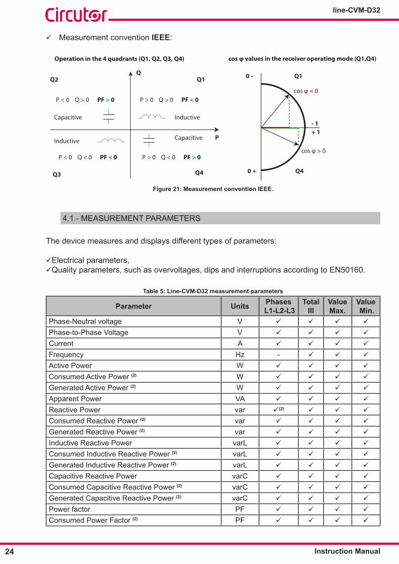
Measurement convention IEEE:
Q
P
Q1Q2
Q3 Q4
P < 0 Q > 0 PF > 0
Capacitive
CapacitiveInductive
Inductive
P < 0 Q < 0 PF < 0 P > 0 Q < 0 PF > 0
P > 0 Q > 0 PF < 0
Operation in the 4 quadrants (Q1, Q2, Q3, Q4)
0 -
0 +
cos φ < 0
cos φ > 0
Q1
Q4
- 1+ 1
cos φ values in the receiver operating mode (Q1,Q4)
Figure 21: Measurement convention IEEE�
4.1.- MEASUREMENT PARAMETERS
The device measures and displays different types of parameters:
Electrical parameters, Quality parameters, such as overvoltages, dips and interruptions according to EN50160.
Table 5: Line-CVM-D32 measurement parameters
Parameter Units Phases L1-L2-L3
TotalIII
ValueMax�
Value Min�
Phase-Neutral voltage V
Phase-to-Phase Voltage V
Current A
Frequency Hz -
Active Power W
Consumed Active Power (2) W
Generated Active Power (2) W
Apparent Power VA
Reactive Power var (2)
Consumed Reactive Power (2) var
Generated Reactive Power (2) var
Inductive Reactive Power varL
Consumed Inductive Reactive Power (2) varL
Generated Inductive Reactive Power (2) varL
Capacitive Reactive Power varC
Consumed Capacitive Reactive Power (2) varC
Generated Capacitive Reactive Power (2) varC
Power factor PF
Consumed Power Factor (2) PF

25Instruction Manual
line-CVM-D32
Table 5 (Continued): Line-CVM-D32 measurement parameters�
Parameter Units Phases L1-L2-L3
TotalIII
ValueMax�
Value Mini�
Generated Power Factor (2) PF
Cosφ φ
CosφConsumed(2) φ
CosφGenerated(2) φ
Voltage THD % - (2) (2)
Current THD % - (2) (2)
Harmonic Voltage Decomposition (2) (up to 40th harmonic) V - % - - -
Harmonic Current Decomposition (2)
(up to 40th harmonic) A - % - - -
Consumed Active Energy kWh (2) - -Generated Active Energy kWh (2) - -Consumed Active Energy Tariffs 1-2-3-4 kWh - -Generated Active Energy Tariffs 1-2-3-4 kWh - -Consumed Inductive Reactive Energy kvarLh (2) - -Generated Inductive Reactive Energy kvarLh (2) - -Consumed Inductive Reactive Energy Tariffs 1-2-3-4 kvarLh - -Generated Inductive Reactive Energy Tariffs 1-2-3-4 kvarLh - -Consumed Capacitive Reactive Energy kvarCh (2) - -Generated Capacitive Reactive Energy kvarCh (2) - -Consumed Capacitive Reactive Energy Tariffs 1-2-3-4 kvarCh - -
Generated Capacitive Reactive Energy Tariffs 1-2-3-4 kvarCh - -
Consumed Reactive Energy (2) kvarh - -Generated Reactive Energy (2) kvarh - -Consumed Reactive Energy Tariffs 1-2-3-4 (2) kvarh - -Generated Reactive Energy Tariffs 1-2-3-4 (2) kvarh - -Consumed Apparent Energy kVAh (2) - -Generated Apparent energy kVAh (2) - -Consumed Apparent Energy Tariffs 1-2-3-4 kVAh - -Generated Apparent Energy Tariffs 1-2-3-4 kVAh - -Maximum Current Demand Tariffs 1-2-3-4 A -Maximum Active Power Demand Tariffs 1-2-3-4 W -Maximum Apparent Power Demand Tariffs 1-2-3-4 VA -Maximum Inductive Reactive Power Demand Tariffs 1-2-3-4 (2)
varL -
Maximum Capacitive Reactive Power Demand Ta-riffs 1-2-3-4 (2)
varC -
Maximum Reactive Power Demand Tariffs 1-2-3-4 (2) var -Angleθ(2) º - - -AngleθV-I(2) º - - -Overvoltage meter (2) - - -

26
line-CVM-D32
Instruction Manual
Table 5 (Continued): Line-CVM-D32 measurement parameters�
Parameter Units Phases L1-L2-L3
TotalIII
ValueMax�
Value Mini�
Gap meter (2) - - -Voltage interruption meter (2) - - -
Parameter Units T1-T2-T3-T4 TotalNº of hours of active energy consumed hours
Nº of hours of Active Energy generated hours
Cost of consumed Active Energy EUR
Cost of generated Active Energy EUR
CO2 emissions from consumed Active Energy kgCO2
CO2 emissions from generated Active Energy kgCO2 (2) Variables only displayed via communications, see "7.3.- MODBUS MEMORY MAP"�
4�1�1�- QUALITY PARAMETERS
For power supply quality control, the voltage levels to be used by the device to log an event mustbedefinedattrueRMSvalue.AccordingtotheEN-61000-4-30 Standard, the RMS value for all AC magnitudes must be calculated in each cycle, being refreshed every ½ cycle. If the RMS value exceeds certain programmed thresholds, an event is said to have occurred.
The device detects quality events such as overvoltages, gaps and voltage interruptions. Figure 22 shows an example of these events.
Figure 22: Example of Quality Events�
Overvoltage
In the time interval t0 in Figure 22 an overvoltage event is illustrated. The duration of the event matches the time the signal is above the set threshold value (“6.2.2.- OVERVOLTAGES AND GAPS"), in this example it is 110% of the nominal voltage, plus the time it takes for the signal to decrease from the value, including a 2% hysteresis.

27Instruction Manual
line-CVM-D32
Voltage gap
In time intervals t1 and t3 in Figure 22, two voltage gaps are illustrated. The duration of the event matches the time the signal is below the set threshold value (“6.2.2.- OVERVOLTAGES AND GAPS"), in this example it is 90% of the nominal voltage.
Voltage interruption
In the time interval t2 in Figure 22 , an outage or interruption event is shown. The duration of the event matches the time the signal is below the set threshold value (“6.2.3.- INTERRUPTION AND HYSTERESIS VALUE”), in this example it is 10% of the nominal voltage, plus the time it takes for the signal to increase from the value, including a 2% hysteresis.
4.2. - LED INDICATORS
CPUALARMAALARM
line-CVM-D32
Figure 23: LEDs: Line-CVM-D32 device
The line-CVM-D32 devices have 2 indicating LEDs:
CPU, Indicates device status:Table 6: CPU LED�
LED Description
CPUFlashing:White: Indicates that the device is powered.
ALARM, Indicates whether an alarm has been activated:Table 7: ALARM LED�
LED Description
ALARMOn:Red: Indicates that an alarm has been activated.
28
line-CVM-D32
Instruction Manual
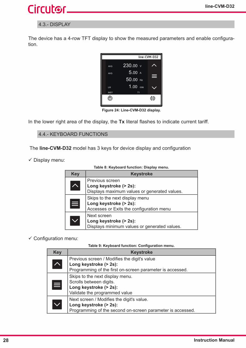
4.3.- DISPLAY
Thedevicehasa4-rowTFTdisplaytoshowthemeasuredparametersandenableconfigura-tion.
AVG 230.00 V
5.00
50.00
1.00
AVG
LIII
INST
A
Hz
cos
T1
line-CVM-D32
Figure 24: Line-CVM-D32 display�
In the lower right area of the display, the Tx literalflashestoindicatecurrenttariff.
4.4.- KEYBOARD FUNCTIONS
The line-CVM-D32 modelhas3keysfordevicedisplayandconfiguration
Display menu:Table 8: Keyboard function: Display menu�
Key Keystroke Previous screenLong keystroke (> 2s): Displays maximum values or generated values.Skips to the next display menuLong keystroke (> 2s):AccessesorExitstheconfigurationmenuNext screenLong keystroke (> 2s): Displays minimum values or generated values.
Configurationmenu:Table 9: Keyboard function: Configuration menu.
Key Keystroke Previousscreen/Modifiesthedigit'svalueLong keystroke (> 2s):Programmingofthefirston-screenparameterisaccessed.Skips to the next display menu.Scrolls between digits.Long keystroke (> 2s):Validate the programmed valueNextscreen/Modifiesthedigit'svalue.Long keystroke (> 2s):Programming of the second on-screen parameter is accessed.

29Instruction Manual
line-CVM-D32
4.5.- DIGITAL OUTPUTS
The device has two digital transistor outputs (terminals 19, 20 and 21 in Table 4). The digital outputscanbeconfiguredasalarms,pulseoutputsorcanbemanuallyactivatedviatheconfig-uration menu, see "6.6.- CONFIGURATION OF DIGITAL OUTPUTS 1 and 2".
19
CargaLoad
Fuente externaExternal load
Salidas de transistor Transistor outputs
21
12
C
Figure 25: Digital transistor outputs�

30
line-CVM-D32
Instruction Manual
5�- DISPLAY
The line-CVM-D32 device arranges all display screens in 8 menus, Figure 26�
INFO
AVG 230.00 V
5.00
50.00
1.00
AVG
LIII
INST
A
Hz
cos
T1
20.00 kWh
4.20
5.00
17.00ENER
Ch
Lh
kVAh
T1
L1 5.00 A
2.50
3.00
5.00
L2
AVG
DEM
A
A
A
T1
L1 0.00 %
0.00
0.00
L2
THDV
%
%
T1
L1 0.00 %
0.00
0.00
L2
THDA
%
%
T1
3 h
2514
TOT+
EUR
kgCO2
T1
10/07/201908:56:55
DATE
TOT+
kvar
kvar
L3
T1
L3
L3
OUT1 MAN.OFFOUT1
OUT2 MAN.OFF
CVMIO
ENER
L1 105
L2
EVQ T1
L3
ALL
INST, Instantaneos value menu
ENER, Energy menu
DEM, Maximum demand menu
EVQ, Quality parameters menu
THDV, Voltage harmonic menu
THDA, Current harmonic menu
ENER, Meter menu
INFO, Information menu
IO, Input / Output menu
Figure 26: Display menu�

31Instruction Manual
line-CVM-D32
5.1.- INSTANTANEOUS VALUE MENU
ThemenushowinginstantvaluesisidentifiedbytheliteralINST in the bottom left area of the display.
Use keys and to browse through the different screens.
AVG 230.00 V
5.00
50.00
1.00
AVG
LIII
INST
A
Hz
cos
T1
Average Phase-Neutral Voltage (V)Average current (A)Frequency (Hz)Cos φ three-phase
∑ 0000.00 w
0000.00
0000.00
1.00LIII
INST
var
VA
PF
T1
∑
∑
Total active power (W)Total reactive power (var)Total apparent power (VA)Three-phase power factor
L1 0000.00 V
0000.00
0000.00
0000.00
L2
AVG
INST
V
V
V
T1
L3
Phase-Neutral Voltage L1 (V)Phase-Neutral Voltage L2 (V)Phase-Neutral Voltage L3 (V)Average Phase-Neutral Voltage (V)
L12 0000.00 V
0000.00
0000.00
0000.00
L23
AVG
INST
V
V
V
T1
L31
Phase L1 - Phase L2 Voltage (V)Phase L2 - Phase L3 Voltage (V)Phase L3 - Phase L1 Voltage (V)Average Phase-Phase Voltage (V)
L1 0000.00 A
0000.00
0000.00
0000.00
L2
AVG
INST
A
A
A
T1
L3
Current L1 (A)Current L2 (A)Current L3 (A)Average current (A)
L1 0000.00 w
0000.00
0000.00
0000.00
L2
INST
w
w
w
T1
L3
∑
Active Power L1 (W)Active Power L2 (W)Active Power L3 (W)Total Active Power (W)
32
line-CVM-D32
Instruction Manual
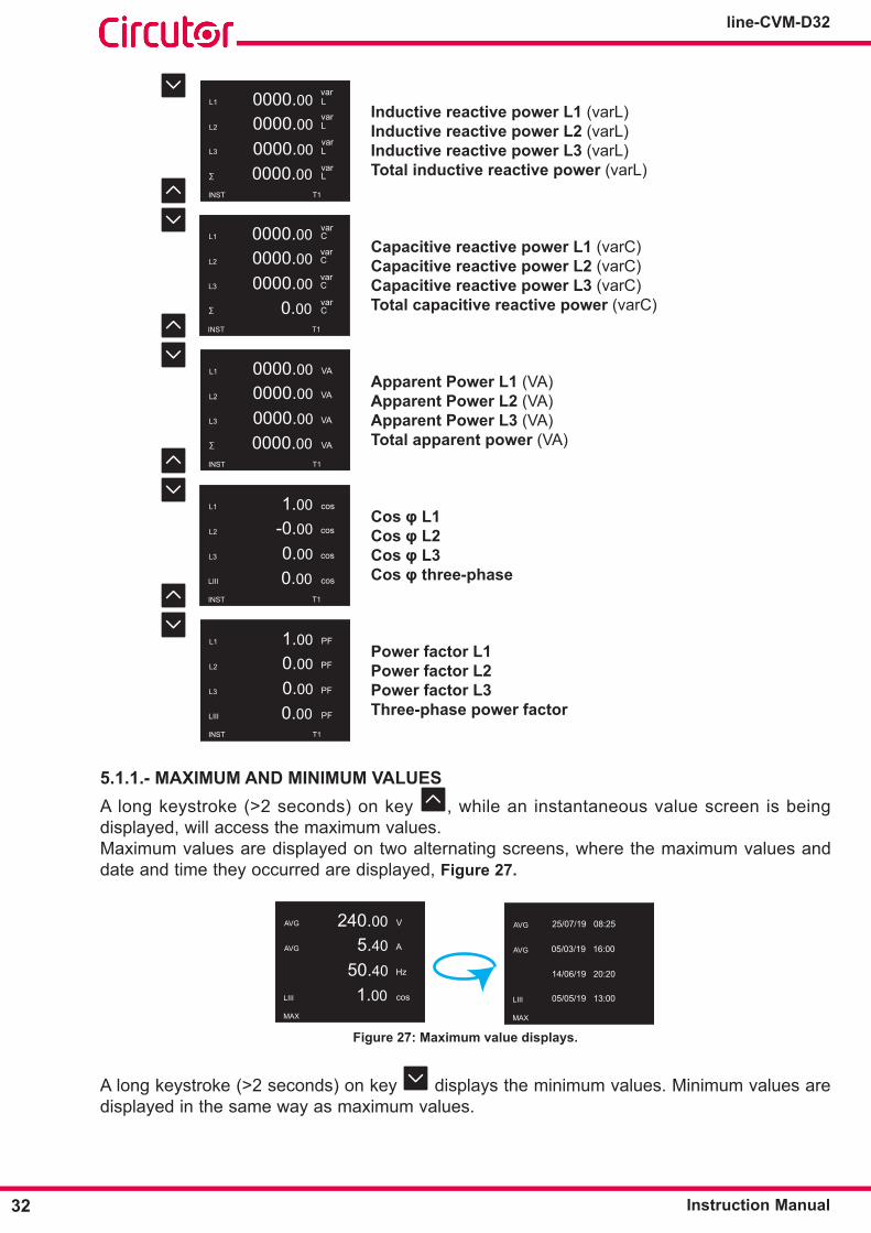
L1 0000.00 L
0000.00
0000.00
0000.00
L2
L3
INST
L
L
L
T1
∑
var
var
var
var
Inductive reactive power L1 (varL)Inductive reactive power L2 (varL)Inductive reactive power L3 (varL)Total inductive reactive power (varL)
L1 0000.00 C
0000.00
0000.00
0.00
L2
INST
C
C
C
T1
L3
∑
var
var
var
var
Capacitive reactive power L1 (varC)Capacitive reactive power L2 (varC)Capacitive reactive power L3 (varC)Total capacitive reactive power (varC)
L1 0000.00 VA
0000.00
0000.00
0000.00
L2
L3
INST
VA
VA
VA
T1
∑
Apparent Power L1 (VA)Apparent Power L2 (VA)Apparent Power L3 (VA)Total apparent power (VA)
L1 1.00 cos
-0.00
0.00
0.00
L2
LIII
INST
cos
cos
cos
T1
L3
Cos φ L1Cos φ L2Cos φ L3Cos φ three-phase
L1 1.00 PF
0.00
0.00
0.00
L2
LIII
INST
PF
PF
PF
T1
L3
Power factor L1Power factor L2Power factor L3Three-phase power factor
5�1�1�- MAXIMUM AND MINIMUM VALUESA long keystroke (>2 seconds) on key , while an instantaneous value screen is being displayed, will access the maximum values.Maximum values are displayed on two alternating screens, where the maximum values and date and time they occurred are displayed, Figure 27�
AVG 240.00 V
5.40
50.40
1.00
AVG
LIII
MAX
A
Hz
cos
AVG 25/07/19 08:25
AVG
LIII
MAX
05/03/19 16:00
14/06/19 20:20
05/05/19 13:00
Figure 27: Maximum value displays�
A long keystroke (>2 seconds) on key displays the minimum values. Minimum values are displayed in the same way as maximum values.
33Instruction Manual
line-CVM-D32
Maximumandminimumvaluescanbedeleted in theconfigurationmenu("6.1.6.- CLEAR MAXIMUMS, MINIMUMS AND MAXIMUM DEMAND") or via communications.
5.2.- ENERGY MENU
Theenergyparametermenuis identifiedbythe literalENER in the bottom left area of the display.
Use keys and to browse through the different screens:
kWh
ENER
Ch
Lh
kVAh
T1TOT+
kvar
kvar
000000.00
000000.00
000000.00
000000.00
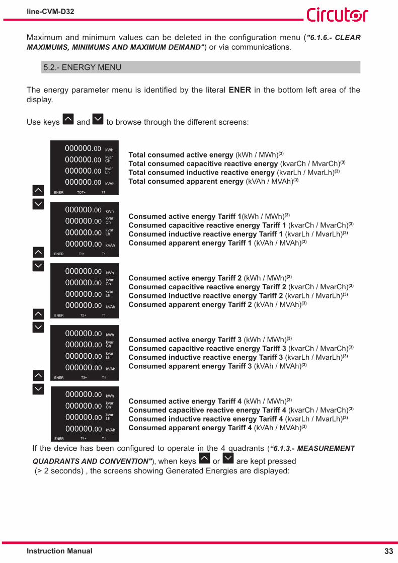
Total consumed active energy (kWh / MWh)(3)
Total consumed capacitive reactive energy (kvarCh / MvarCh)(3)
Total consumed inductive reactive energy (kvarLh / MvarLh)(3)
Total consumed apparent energy (kVAh / MVAh)(3)
T1+
kWh
ENER
Ch
Lh
kVAh
T1
kvar
kvar
000000.00
000000.00
000000.00
000000.00
Consumed active energy Tariff 1(kWh / MWh)(3)
Consumed capacitive reactive energy Tariff 1 (kvarCh / MvarCh)(3)
Consumed inductive reactive energy Tariff 1 (kvarLh / MvarLh)(3)
Consumed apparent energy Tariff 1 (kVAh / MVAh)(3)
kWh
T2+ENER
Ch
Lh
kVAh
T1
kvar
kvar
000000.00
000000.00
000000.00
000000.00
Consumed active energy Tariff 2 (kWh / MWh)(3)
Consumed capacitive reactive energy Tariff 2 (kvarCh / MvarCh)(3)
Consumed inductive reactive energy Tariff 2 (kvarLh / MvarLh)(3)
Consumed apparent energy Tariff 2 (kVAh / MVAh)(3)
kWh
T3+ENER
Ch
Lh
kVAh
T1
kvar
kvar
000000.00000000.00
000000.00
000000.00
Consumed active energy Tariff 3 (kWh / MWh)(3)
Consumed capacitive reactive energy Tariff 3 (kvarCh / MvarCh)(3)
Consumed inductive reactive energy Tariff 3 (kvarLh / MvarLh)(3)
Consumed apparent energy Tariff 3 (kVAh / MVAh)(3)
kWh
ENER
Ch
Lh
kVAh
T1T4+
kvar
kvar
000000.00
000000.00
000000.00
000000.00
Consumed active energy Tariff 4 (kWh / MWh)(3)
Consumed capacitive reactive energy Tariff 4 (kvarCh / MvarCh)(3)
Consumed inductive reactive energy Tariff 4 (kvarLh / MvarLh)(3)
Consumed apparent energy Tariff 4 (kVAh / MVAh)(3)
If thedevicehasbeenconfiguredtooperate in the4quadrants (“6.1.3.- MEASUREMENT
QUADRANTS AND CONVENTION"), when keys or are kept pressed (> 2 seconds) , the screens showing Generated Energies are displayed:

34
line-CVM-D32
Instruction Manual
kWh
ENER
Ch
Lh
kVAh
T1TOT-
kvar
kvar
000000.00
000000.00
000000.00
000000.00
Total generated active energy (kWh / MWh)(3)
Total generated capacitive reactive energy (kvarCh / MvarCh)(3)
Total generated inductive reactive energy (kvarLh / MvarLh)(3)
Total generated apparent energy (kVAh / MVAh)(3)
T1-
kWh
ENER
Ch
Lh
kVAh
T1
kvar
kvar
000000.00
000000.00
000000.00
000000.00
Generated active energy Tariff 1 (kWh / MWh)(3)
Generated capacitive reactive energy Tariff 1 (kvarCh / MvarCh)(3)
Generated inductive reactive energy Tariff 1 (kvarLh / MvarLh)(3)
Generated apparent energy Tariff 1 (kVAh / MVAh)(3)
kWh
T2-ENER
Ch
Lh
kVAh
T1
kvar
kvar
000000.00
000000.00
000000.00
000000.00
Generated active energy Tariff 2 (kWh / MWh)(3)
Generated capacitive reactive energy Tariff 2 (kvarCh / MvarCh)(3)
Generated inductive reactive energy Tariff 2 (kvarLh / MvarLh)(3)
Generated apparent energy Tariff 2 (kVAh / MVAh)(3)
kWh
T3-ENER
Ch
Lh
kVAh
T1
kvar
kvar
000000.00000000.00
000000.00
000000.00
Generated active energy Tariff 3 (kWh / MWh)(3)
Generated capacitive reactive energy Tariff 3 (kvarCh / MvarCh)(3)
Generated inductive reactive energy Tariff 3 (kvarLh / MvarLh)(3)
Generated apparent energy Tariff 3 (kVAh / MVAh)(3)
kWh
ENER
Ch
Lh
kVAh
T1T4-
kvar
kvar
000000.00
000000.00
000000.00
000000.00
Generated active energy Tariff 4 (kWh / MWh)(3)
Generated capacitive reactive energy Tariff 4 (kvarCh / MvarCh)(3)
Generated inductive reactive energy Tariff 4 (kvarLh / MvarLh)(3)
Generated apparent energy Tariff 4 (kVAh / MVAh)(3)
(3) The displayed energy unit depends on the programmed transformation ratios: (Primary Voltage x Primary Current) / (Secondary Voltage x Secondary Current)<1000→k(Primary Voltage x Primary Current) / (Secondary Voltage x Secondary Current) ≥1000→M
If the energy value exceeds the displayed digits, an arrow appears on the left side of the value to indicate so. Total value may be displayed via communications.
kWh
ENER
Ch
Lh
kVAh
T1TOT+
kvar
kvar
587595.15
4555.25
915285.00
2525.99
Figure 28: Energy values higher than the displayed digits�
Keep keys or pressed to display Consumed Energies again.

35Instruction Manual
line-CVM-D32
5.3.- MAXIMUM DEMAND MENU
ThemaximumdemandparametermenuisidentifiedbytheliteralDEM in the bottom left area of the display.
Themaximumdemandcalculationperiodcanbeconfiguredinsection"6.1.5.- CALCULATION PERIODS” or via communications.
Use keys and to browse through the different screens:
L1 5.00 A
2.50
3.00
5.00
L2
AVG
DEM
A
A
A
T1
L3
T1
Maximum L1 Current Demand, Tariff 1 (A)Maximum L2 Current Demand, Tariff 1 (A)Maximum L3 Current Demand, Tariff 1 (A)Total Maximum Current Demand, Tariff 1 (A)
L1 0000.00 W
0000.00
0000.00
0000.00
L2
DEM
W
W
W
T1
L3
∑
T1
Maximum L1 Active Power Demand, Tariff 1 (W)Maximum L2 Active Power Demand, Tariff 1 (W)Maximum L3 Active Power Demand, Tariff 1 (W)Maximum Total Active Power Demand, Tariff 1 (W)
L1 0000.00 VA
0000.00
0000.00
0000.00
L2
DEM
VA
VA
VA
T1
L3
∑
T1
Maximum L1 Apparent Power Demand, Tariff 1 (VA)Maximum L2 Apparent Power Demand, Tariff 1 (VA)Maximum L3 Apparent Power Demand, Tariff 1 (VA)Total Maximum Apparent Power Demand, Tariff 1 (VA)
L1 0000.00 A
0000.00
0000.00
5.00
L2
AVG
DEM
A
A
A
T1
L3
T2
Maximum L1 Current Demand, Tariff 2 (A)Maximum L2 Current Demand, Tariff 2 (A)Maximum L3 Current Demand, Tariff 2 (A)Total Maximum Current Demand, Tariff 2 (A)
L1 0000.00 W
0000.00
0000.00
0000.00
L2
DEM
W
W
W
T1
L3
∑
T2
Maximum L1 Active Power Demand, Tariff 2 (W)Maximum L2 Active Power Demand, Tariff 2 (W)Maximum L3 Active Power Demand, Tariff 2 (W)Total Maximum Active Power Demand, Tariff 2 (W)
L1 0000.00 VA
0000.00
0000.00
0000.00
L2
DEM
VA
VA
VA
T1
L3
∑
T2
Maximum L1 Apparent Power Demand, Tariff 2 (VA)Maximum L2 Apparent Power Demand, Tariff 2 (VA)Maximum L3 Apparent Power Demand, Tariff 2 (VA)Total Maximum Apparent Power Demand, Tariff 2 (VA)
36
line-CVM-D32
Instruction Manual
L1 5.00 A
2.50
3.00
5.00
L2
AVG
DEM
A
A
A
T1
L3
T3
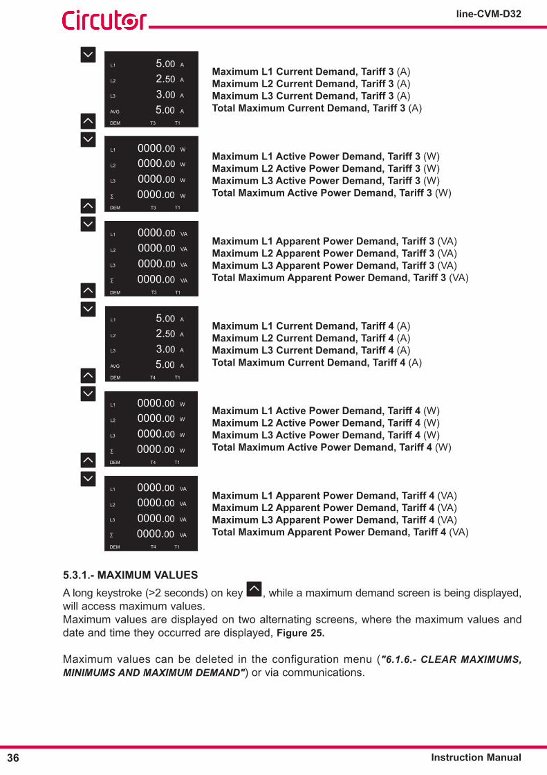
Maximum L1 Current Demand, Tariff 3 (A)Maximum L2 Current Demand, Tariff 3 (A)Maximum L3 Current Demand, Tariff 3 (A)Total Maximum Current Demand, Tariff 3 (A)
L1 0000.00 W
0000.00
0000.00
0000.00
L2
DEM
W
W
W
T1
L3
∑
T3
Maximum L1 Active Power Demand, Tariff 3 (W)Maximum L2 Active Power Demand, Tariff 3 (W)Maximum L3 Active Power Demand, Tariff 3 (W)Total Maximum Active Power Demand, Tariff 3 (W)
L1 0000.00 VA
0000.00
0000.00
0000.00
L2
DEM
VA
VA
VA
T1
L3
∑
T3
Maximum L1 Apparent Power Demand, Tariff 3 (VA)Maximum L2 Apparent Power Demand, Tariff 3 (VA)Maximum L3 Apparent Power Demand, Tariff 3 (VA)Total Maximum Apparent Power Demand, Tariff 3 (VA)
L1 5.00 A
2.50
3.00
5.00
L2
AVG
DEM
A
A
A
T1
L3
T4
Maximum L1 Current Demand, Tariff 4 (A)Maximum L2 Current Demand, Tariff 4 (A)Maximum L3 Current Demand, Tariff 4 (A)Total Maximum Current Demand, Tariff 4 (A)
L1 0000.00 W
0000.00
0000.00
0000.00
L2
DEM
W
W
W
T1
L3
∑
T4
Maximum L1 Active Power Demand, Tariff 4 (W)Maximum L2 Active Power Demand, Tariff 4 (W)Maximum L3 Active Power Demand, Tariff 4 (W)Total Maximum Active Power Demand, Tariff 4 (W)
L1 0000.00 VA
0000.00
0000.00
0000.00
L2
DEM
VA
VA
VA
T1
L3
∑
T4
Maximum L1 Apparent Power Demand, Tariff 4 (VA)Maximum L2 Apparent Power Demand, Tariff 4 (VA)Maximum L3 Apparent Power Demand, Tariff 4 (VA)Total Maximum Apparent Power Demand, Tariff 4 (VA)
5�3�1�- MAXIMUM VALUESA long keystroke (>2 seconds) on key , while a maximum demand screen is being displayed, will access maximum values.Maximum values are displayed on two alternating screens, where the maximum values and date and time they occurred are displayed, Figure 25�
Maximum values can be deleted in the configuration menu ("6.1.6.- CLEAR MAXIMUMS, MINIMUMS AND MAXIMUM DEMAND") or via communications.

37Instruction Manual
line-CVM-D32
5.4.- QUALITY PARAMETERS MENU
ThequalityparametermenuisidentifiedbytheliteralEVQ in the bottom left area of the display.Use keys and to browse through the different screens:
L1 105
L2
EVQ T1
L3
ALL
No� of quality events detected in L1No� of quality events detected in L2No� of quality events detected in L3
L1 001
L2
EVQ T1
L3
SWELL
No� of overvoltages (SWELL) detected in L1No� of overvoltages (SWELL) detected in L2No� of overvoltages (SWELL) detected in L3
L1 001
L2
EVQ T1
L3
DIP
No� of voltage gaps (DIP) detected in L1No� of voltage gaps (DIP) detected in L2No� of voltage gaps (DIP) detected in L3
L1 111
L2
EVQ T1
L3
INT
No� of outages (INTERRUPTION) detected in L1No� of outages (INTERRUPTION) detected in L2No� of outages (INTERRUPTION) detected in L3
The quality parameter meters can be deleted in the configuration menu ("6.1.6.- CLEAR QUALITY PARAMETERS”) or via communications.
38
line-CVM-D32
Instruction Manual
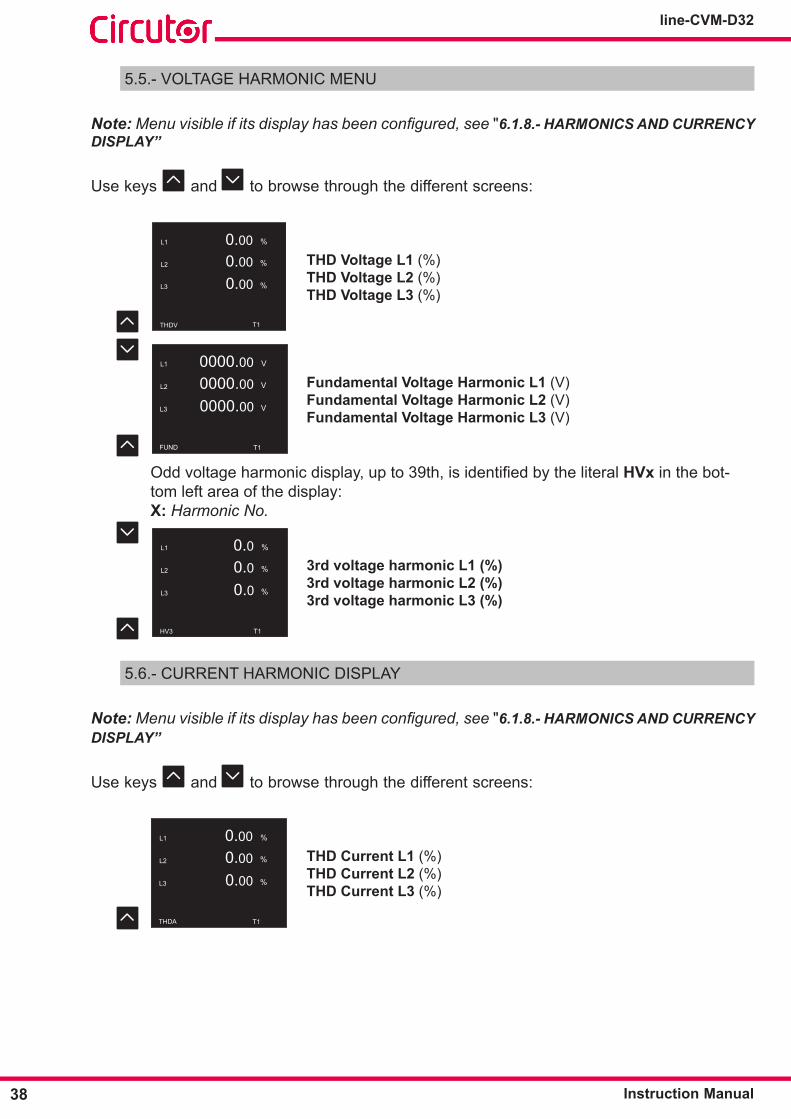
5.5.- VOLTAGE HARMONIC MENU
Note: Menu visible if its display has been configured, see "6.1.8.- HARMONICS AND CURRENCY DISPLAY”
Use keys and to browse through the different screens:
L1 0.00 %
0.00
0.00
L2
THDV
%
%
T1
L3
THD Voltage L1 (%)THD Voltage L2 (%)THD Voltage L3 (%)
L1 0000.00 V
0000.00
0000.00
L2
L3
FUND
V
V
T1
Fundamental Voltage Harmonic L1 (V)Fundamental Voltage Harmonic L2 (V)Fundamental Voltage Harmonic L3 (V)
Oddvoltageharmonicdisplay,upto39th,isidentifiedbytheliteralHVx in the bot-tom left area of the display:X: Harmonic No.
L1 0.0 %
0.00.0
L2
L3
HV3
%
%
T1
3rd voltage harmonic L1 (%)3rd voltage harmonic L2 (%)3rd voltage harmonic L3 (%)
5.6.- CURRENT HARMONIC DISPLAY
Note: Menu visible if its display has been configured, see "6.1.8.- HARMONICS AND CURRENCY DISPLAY”
Use keys and to browse through the different screens:
L1 0.00 %
0.00
0.00
L2
THDA
%
%
T1
L3
THD Current L1 (%)THD Current L2 (%)THD Current L3 (%)

39Instruction Manual
line-CVM-D32
L1 0000.00 A
0000.00
0000.00
L2
L3
FUND
A
A
T1
Fundamental Current Harmonic L1 (A)Fundamental Current Harmonic L2 (A)Fundamental Current Harmonic L3 (A)
Oddcurrentharmonicdisplay,upto39th,isidentifiedbytheliteralHAx in the bot-tom left area of the display:x: Harmonic No.
L1 0.0 %
0.00.0
L2
L3
HA3
%
%
T1
3rd current harmonic L1 (%)3rd current harmonic L2 (%)3rd current harmonic L3 (%)
5.7.- METER MENU
Themenudisplayingmetersis identifiedbytheliteralCOUNT in the bottom left area of the display.
Use keys and to browse through the different screens:
3 h
2514
TOT+
EUR
kgCO2
T1COUNT
Nº of hours of total active energy consumed (h)Cost of total active energy consumed (EUR)CO2 emissions from total active energy consumed (kgCO2)
0000000 h
T1+
EUR
kgCO2
T1
00000000000000
COUNT
Nº of hours of active energy consumed, Tariff 1 (h)Cost of active energy consumed, Tariff 1 (EUR)CO2 emissions from active energy consumed, Tariff 1 (kgCO2)
h
T2+
EUR
T1
0000000
kgCO2
00000000000000
COUNT
Nº of hours of active energy consumed, Tariff 2 (h)Cost of active energy consumed, Tariff 2 (EUR)CO2 emissions from active energy consumed, Tariff 2 (kgCO2)
h
T3+
EUR
T1
000000000000000000000 kgCO2
COUNT
Nº of hours of active energy consumed, Tariff 3 (h)Cost of active energy consumed, Tariff 3 (EUR)CO2 emissions from active energy consumed, Tariff 3 (kgCO2)

40
line-CVM-D32
Instruction Manual
h
T4+
EUR
kgCO2
T1
000000000000000000000
COUNT
Nº of hours of active energy consumed, Tariff 4 (h)Cost of active energy consumed, Tariff 4 (EUR)CO2 emissions from active energy consumed, Tariff 4 (kgCO2)
Ifthedevicehasbeenconfiguredtooperateinthe4quadrants (“6.1.3.- QUADRANTS AND
MEASUREMENT CONVENTION"), if keys or are kept pressed (> 2 seconds), the screens showing generated consumption are displayed:
h
TOT-
EUR
kgCO2
T1
000000000000000000000
COUNT
Nº of hours of total active energy generated (h)Cost of total generated active energy (EUR)CO2 emissions from total generated active energy (kgCO2)
0000000 h
T1-
EUR
kgCO2
T1
00000000000000
COUNT
Nº of hours of active energy generated, Tariff 1 (h)Cost of active energy generated, Tariff 1 (EUR)CO2 emissions from active energy generated, Tariff 1 (kgCO2)
h
T2-
EUR
T1
0000000
kgCO2
00000000000000
COUNT
Nº of hours of active energy generated, Tariff 2 (h)Cost of active energy generated, Tariff 2 (EUR)CO2 emissions from active energy generated, Tariff 2 (kgCO2)
h
T3-
EUR
T1
000000000000000000000 kgCO2
COUNT
Nº of hours of active energy generated, Tariff 3 (h)Cost of active energy generated, Tariff 3 (EUR)CO2 emissions from active energy generated, Tariff 3 (kgCO2)
h
T4-
EUR
kgCO2
T1
000000000000000000000
COUNT
Nº of hours of active energy generated, Tariff 4 (h)Cost of active energy generated, Tariff 4 (EUR)CO2 emissions from active energy generated, Tariff 4 (kgCO2)
Meterscanbedeletedintheconfigurationmenu("6.1.7.- CLEAR ENERGIES AND DELETE ALL") or via communications.

41Instruction Manual
line-CVM-D32
5.8.- INFORMATION MENU
TheinformationmenuisidentifiedbytheliteralINFO in the bottom left area of the display.
Use keys and to browse through the different screens:
10/07/201908:56:55
DATEINFO
Current Date and Time
MODEL
S/N
CVM
line-CVM-D32
FW
123123123412
0.0.4
INFO
Device ModelSerial numberFirmware version of the device
MODEL
S/N
SLOT1
line-M-4IO-T
FW
123222123412
0.0.3
INFO
Note: Displayed if an expansion module is connected. Expansion module model connected to line-CVM-D32 in SLOT1(4)
Serial number of the expansion moduleFirmware version of the expansion module
MODEL
S/N
line-M-4IO-R
FW
12355523412
0.1.4
SLOT2INFO
Note: Displayed if an expansion module is connected. Expansion module model connected to line-CVM-D32 in SLOT2(5)
Serial number of the expansion moduleFirmware version of the expansion module
(4)SLOT1correspondstothefirstdeviceconnectedtotheright-handsideofthe line-CVM-D32 device.(5) SLOT2 corresponds to the second device connected to the right-hand side of the line-CVM-D32 device.
Note: If a line-EDS has been connected to the left-hand side of the line-CVM-D32 device, the information screens for the connected expansion modules will not be displayed on the line-CVM-D32 device.
42
line-CVM-D32
Instruction Manual
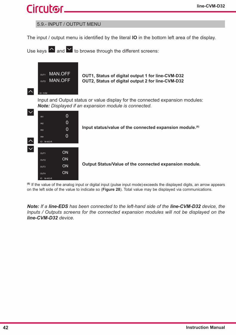
5.9.- INPUT / OUTPUT MENU
Theinput/outputmenuisidentifiedbytheliteralIO in the bottom left area of the display.
Use keys and to browse through the different screens:
OUT1 MAN.OFFOUT1
CVM
OUT2 MAN.OFF
IO
OUT1, Status of digital output 1 for line-CVM-D32 OUT2, Status of digital output 2 for line-CVM-D32
Input and Output status or value display for the connected expansion modules:Note: Displayed if an expansion module is connected.
IN1 0000
IN2
M-4IO-R
IN3
IN4
IO
Input status/value of the connected expansion module�(6)
OUT1 ON
M-4IO-R
OUT2
OUT3
OUT4
ON
ON
ONIO
Output Status/Value of the connected expansion module�
(6) If the value of the analog input or digital input (pulse input mode) exceeds the displayed digits, an arrow appears on the left side of the value to indicate so (Figure 28). Total value may be displayed via communications.
Note: If a line-EDS has been connected to the left-hand side of the line-CVM-D32 device, the Inputs / Outputs screens for the connected expansion modules will not be displayed on the line-CVM-D32 device.
43Instruction Manual
line-CVM-D32
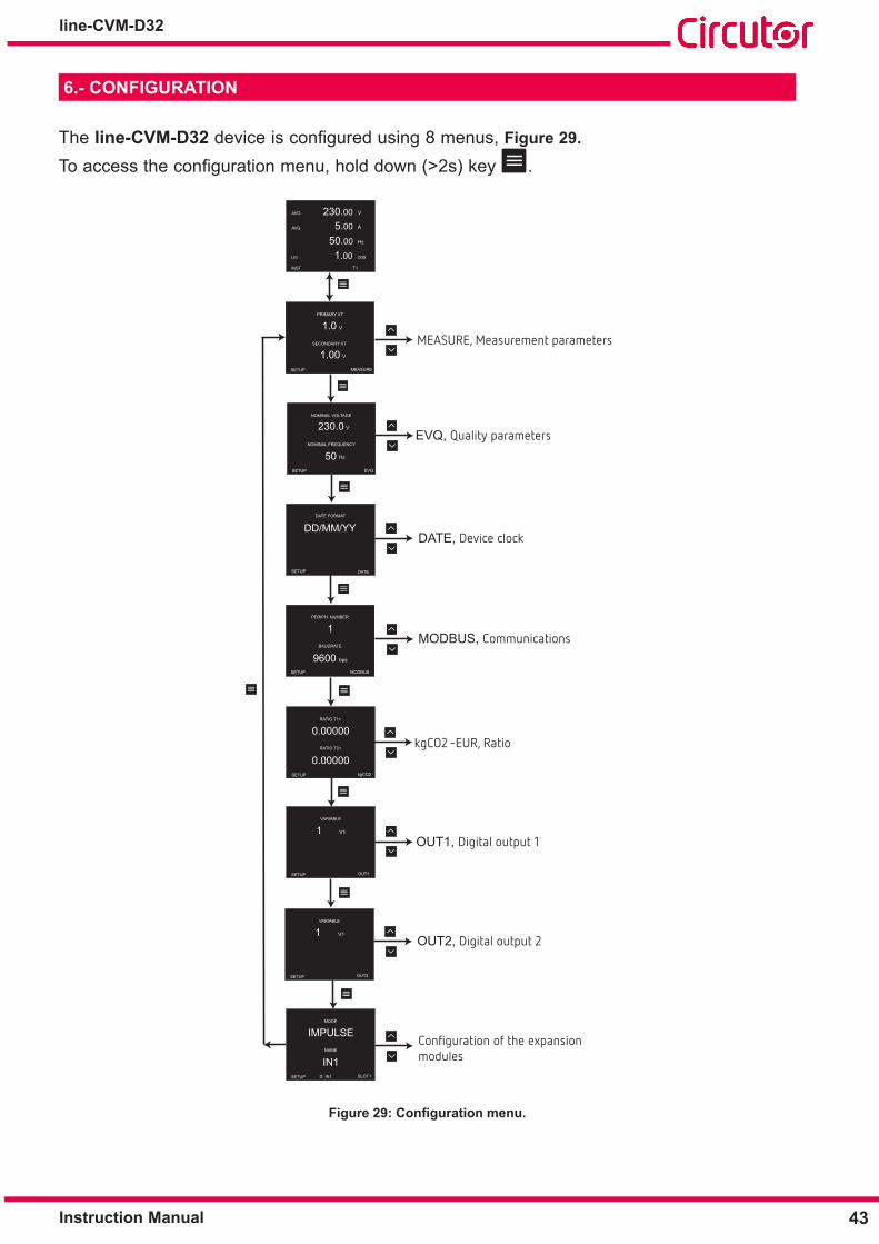
6�- CONFIGURATION
The line-CVM-D32 deviceisconfiguredusing 8 menus, Figure 29�
Toaccesstheconfigurationmenu,holddown(>2s)key .
AVG 230.00 V
5.00
50.00
1.00
AVG
LIII
INST
A
Hz
cos
T1
PRIMARY VT
V1.0
1.00SECONDARY VT
SETUP
V
SETUP
PERIPH. NUMBER
1
9600 bps BAUDRATE
MODBUS
SETUP
VARIABLE
1 V1
OUT1
SETUP
VARIABLE
1 V1
OUT2
SETUP SLOT1
MODE
IMPULSE
IN1NAME
D IN1
MEASURE
SETUP
230.0
50EVQ
NOMINAL VOLTAGE
NOMINAL FREQUENCY
V
Hz
DATE FORMAT
DATE
DD/MM/YY
SETUP
RATIO T1+
0.00000
0.00000 RATIO T2+
kgCO2SETUP
MEASURE, Measurement parameters
EVQ, Quality parameters
DATE, Device clock
MODBUS, Communications
kgCO2 -EUR, Ratio
OUT1, Digital output 1
OUT2, Digital output 2
Configuration of the expansion modules
Figure 29: Configuration menu.

44
line-CVM-D32
Instruction Manual
Ifexpansionmodulesareconnectedtothedevice,afterconfiguringdigitaloutput2,moduleconfigurationisaccessed,seetheExpansionModuleInstructionManualforcorrectmoduleconfiguration(M239B01-03-xxx).
Thedeviceconfigurationmenuisprotectedbypassword;whenaccessingconfigurationofoneofthedevice'sparametersforthefirsttime,thepasswordscreenisdisplayed,Figure 30.
ENTER PASSWORD:
*****
SETUP
Figure 30: Configuration password.
Use keys and to modify the digit's value.Press key to skip through the digits.Hold down key to validate the value.
Default password: 97531.
Note: The password can be modified, see “6.1.9.- DISPLAY BACKLIGHT AND PASSWORD".
Note: In "ANNEX A.- CONFIGURATION MENU" , the entire configuration tree is displayed.
6.1.- MEASUREMENT CONFIGURATION
6�1�1�- PRIMARY AND SECONDARY VOLTAGE
ThisscreenenablesPrimaryandSecondaryVoltagevalueconfiguration.
PRIMARY VT
V1.0
1.00SECONDARY VT
SETUP
V
MEASURE
Hold down key to set the Primary Voltage (PRIMARY VT).
Hold down key to set the Secondary Voltage (SECONDARY VT).
Use keys and to modify the digit's value.Press key to skip through the digits.Hold down key to validate the value.

45Instruction Manual
line-CVM-D32
Primary voltage:
Minimum value: 1.0 VMaximum value: 2000000.0 V
Secondary voltage:
Minimum value: 1.00 VMaximum value: 2000000.00 V
Use key to skip to the next programming point.
6�1�2�- PRIMARY AND SECONDARY CURRENT
ThisscreenenablesPrimaryandSecondaryCurrentvalueconfiguration.
SETUP
PRIMARY CT
A5.0
5.000SECONDARY CT
A
MEASURE
Hold down key to set the Primary Current (PRIMARY CT).Hold down key to set the Secondary Current (SECONDARY CT).
Use keys and to modify the digit's value.Press key to skip through the digits.Hold down key to validate the value.
Primary current:
Minimum value: 1.0 AMaximum value: 2000000.0 A
Secondary current:
Minimum value: 0.25 AMaximum value: 5.00 A
Use key to skip to the next programming point.

46
line-CVM-D32
Instruction Manual
6�1�3�- QUADRANTS AND MEASUREMENT CONVENTION
Thisscreenenablesconfigurationofthedevice'sworkingquadrantsandmeasurementcon-vention.
SETUP
QUADRANTS
4Q
IECSIGN CONVENTION
MEASURE
Hold down key to set the quadrant (QUADRANTS).Hold down key to set the measurement convention (SIGN CONVENTION).
Use keys and to skip through the different options:
Quadrants:
2Q, The device operates in 2 quadrants. 4Q, The device operates in all 4 quadrants.
Measurement convention:
IEC, Measurement convention IEC. CIRC, Measurement convention Circutor. IEEE, Measurement convention IEEE.
To validate the option, hold down key .Use key to skip to the next programming point.
6�1�4�- INSTALLATION TYPE
Thisscreenenablestypeofinstallationtobeconfigured(CIRCUIT TYPE).
SETUP
CIRCUIT TYPE
4W-3Ph
MEASURE
Hold down key to enter programming mode.Use keys and to skip through the different options:
4W-3Ph, Three-phase mains measuring with 4-wire connection. 3W-3Ph, Three-phase mains measuring with 3-wire connection 3W-2Ph, Two-phase mains measuring with 3-wire connection 2W-1Ph, Single-phase mains measuring with 2-wire phase-to-phase connection

47Instruction Manual
line-CVM-D32
2W-1Ph, Single-phase mains measuring with 2-wire phase-to-neutral connection ARON, Three-phase mains measuring with 3-wire connection and transformers with ARON connection.
To validate the option, hold down key .Use key to skip to the next programming point.
6�1�5�- CALCULATION PERIODS
Thisscreenenablesconfigurationofdevicecalculationperiods.
SETUP
AGGREGATION PERIOD
15PD PERIOD
min
15 min
MEASURE
Hold down key to set the aggregation period, i.e. measurement integration period (AGGRE-GATION PERIOD).Hold down key to set the integration period for maximum demand calculation (PD PE-RIOD).
Use keys and to modify the digit's value.Press key to skip through the digits.
Hold down key to validate the value.
Aggregation period:
Minimum value: 1 minute.Maximum value: 60 minutes.
Note: The programmed value must be divisible by 60, i.e. the division 60 / Aggregation period must be exact.
Maximum demand integration period:
Minimum value: 1 minute.Maximum value: 60 minutes.
Use key to skip to the next programming point.
48
line-CVM-D32
Instruction Manual
6�1�6�- CLEAR MAXIMUMS, MINIMUMS AND MAXIMUM DEMAND
This screen enables the maximum demand's maximum, minimum and calculation values to be cleared.
SETUP
CLEAR MAX / MIN
YES/NO ?
YES/NO ?CLEAR PD
Hold down key to clear the maximum and minimum values for all measurement varia-bles (CLEAR MAX/MIN).Hold down key to clear the maximum calculation and value of the maximum demand (CLEAR PD).Use keys and to skip through the different options:
YES, values are cleared.NO, values are not cleared.
To validate the option, hold down key .Use key to skip to the next programming point.
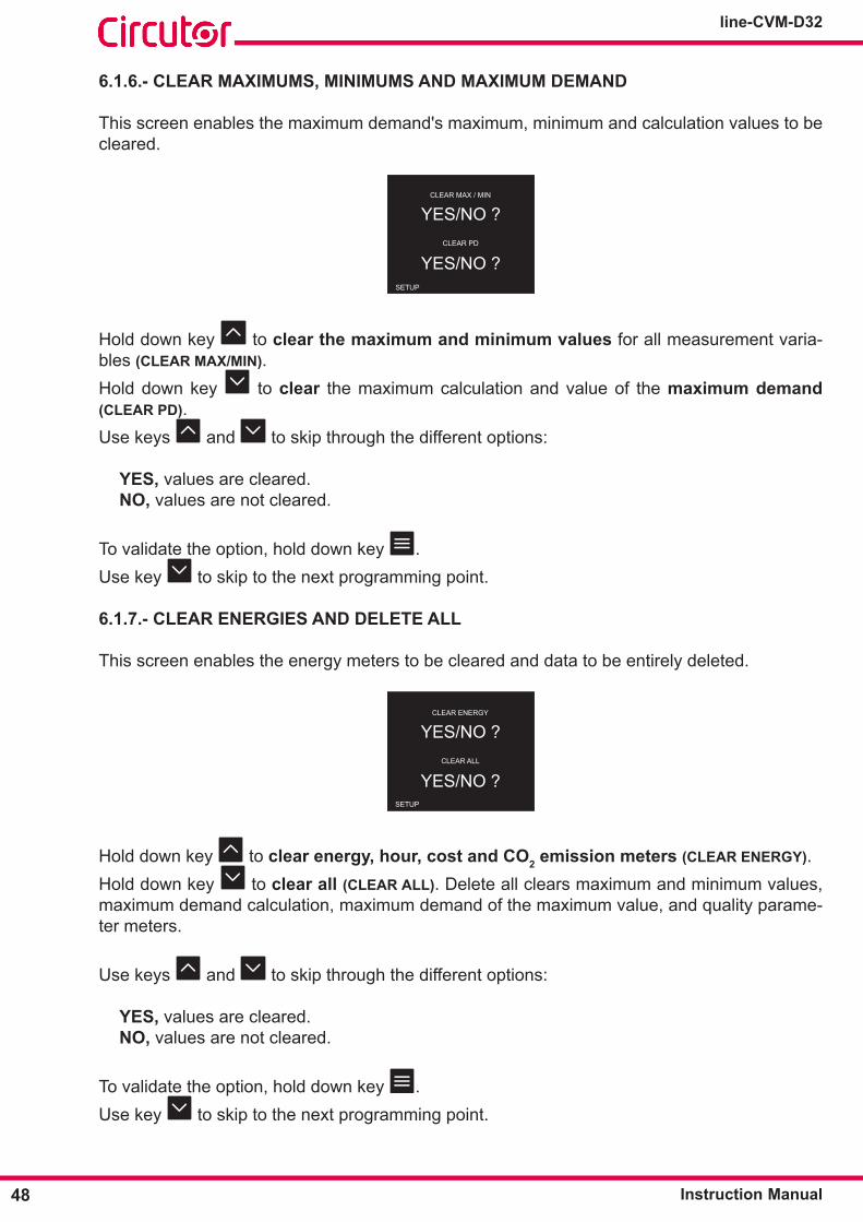
6�1�7�- CLEAR ENERGIES AND DELETE ALL
This screen enables the energy meters to be cleared and data to be entirely deleted.
SETUP
CLEAR ENERGY
YES/NO ?
YES/NO ?CLEAR ALL
Hold down key to clear energy, hour, cost and CO2 emission meters (CLEAR ENERGY).Hold down key to clear all (CLEAR ALL). Delete all clears maximum and minimum values, maximum demand calculation, maximum demand of the maximum value, and quality parame-ter meters.
Use keys and to skip through the different options:
YES, values are cleared.NO, values are not cleared.
To validate the option, hold down key .Use key to skip to the next programming point.

49Instruction Manual
line-CVM-D32
6�1�8�- HARMONICS AND CURRENCY DISPLAY
This screen enables harmonics and calculation currency to be displayed or not.
SETUP
SHOW HARMONICS
YES
EURCOIN
Hold down key to set the harmonics display (SHOW HARMONICS)�Use keys and to skip through the different options:
YES, Voltage and current harmonics are displayed. NO, Harmonics are not displayed.
Hold down key to set the currency (COIN).
Use keys and to modify the digit's value.Press key to skip through the digits.
To validate the option, hold down key .Use key to skip to the next programming point.
6�1�9�- DISPLAY BACKLIGHT AND PASSWORD
Thisscreenenablesconfigurationofthedisplay'smaximumbrightnesstimefromthelasttimethe device was operated using the keypad. After the set time, display dims. Theparameterconfigurationaccesspasswordisalsodisplayed.
SETUP
DISPLAY DIMMING
15 min
*****PASSWORD
Hold down key to set display backlight (DISPLAY DIMMING).Hold down key to set the password (PASSWORD).
Use keys and to modify the digit's value.Press key to skip through the digits.
50
line-CVM-D32
Instruction Manual
Display backlight:
Minimum value: 1 minute.Maximum value: 99 minutes.
Password:
Minimum value: 00000.Maximum value: 99999.
Note: If value 0000 is set, the password is disabled.
Hold down key to validate the value.Use key to skip to the next programming point.
6.2.- QUALITY PARAMETER CONFIGURATION
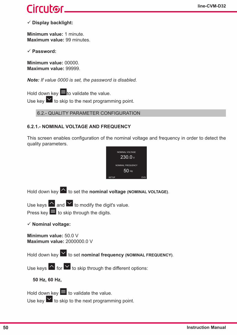
6�2�1�- NOMINAL VOLTAGE AND FREQUENCY
Thisscreenenablesconfigurationofthenominalvoltageandfrequencyinordertodetectthequality parameters.
SETUP
230.0
50EVQ
NOMINAL VOLTAGE
NOMINAL FREQUENCY
V
Hz
Hold down key to set the nominal voltage (NOMINAL VOLTAGE).
Use keys and to modify the digit's value.Press key to skip through the digits.
Nominal voltage:
Minimum value: 50.0 VMaximum value: 2000000.0 V
Hold down key to set nominal frequency (NOMINAL FREQUENCY).
Use keys for to skip through the different options:
50 Hz, 60 Hz,
Hold down key to validate the value.Use key to skip to the next programming point.
51Instruction Manual
line-CVM-D32
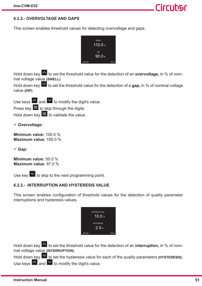
6�2�2�- OVERVOLTAGE AND GAPS
This screen enables threshold values for detecting overvoltage and gaps.
SWELL
DIP
110.0
90.0
%
%
SETUP EVQ
Hold down key to set the threshold value for the detection of an overvoltage, in % of nom-inal voltage value (SWELL).
Hold down key to set the threshold value for the detection of a gap, in % of nominal voltage value (DIP).
Use keys and to modify the digit's value.Press key to skip through the digits.Hold down key to validate the value.
Overvoltage:
Minimum value: 100.0 %Maximum value: 150.0 %
Gap:
Minimum value: 50.0 %Maximum value: 97.0 %
Use key to skip to the next programming point.
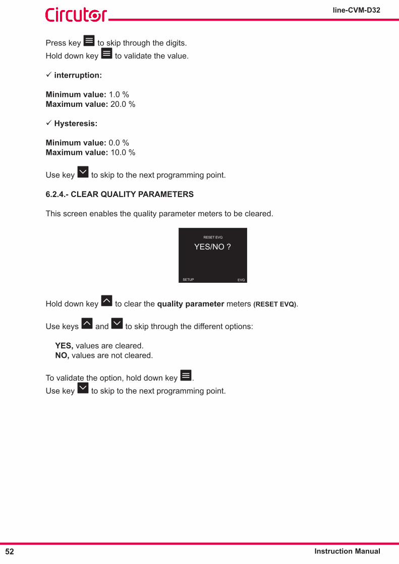
6�2�3�- INTERRUPTION AND HYSTERESIS VALUE
Thisscreenenablesconfigurationof thresholdvalues for thedetectionofqualityparameterinterruptions and hysteresis values.
INTERRUPTION
HISTERESIS
SETUP EVQ
10.0
2.0
%
%
Hold down key to set the threshold value for the detection of an interruption, in % of nom-inal voltage value (INTERRUPTION).
Hold down key to set the hysteresis value for each of the quality parameters (HYSTERESIS).
Use keys and to modify the digit's value.
52
line-CVM-D32
Instruction Manual
Press key to skip through the digits.Hold down key to validate the value.
interruption:
Minimum value: 1.0 %Maximum value: 20.0 %
Hysteresis:
Minimum value: 0.0 %Maximum value: 10.0 %
Use key to skip to the next programming point.
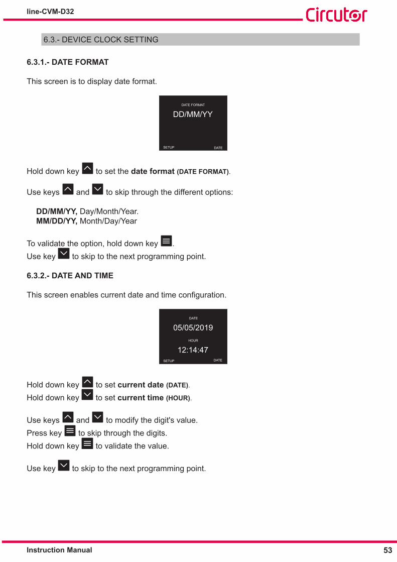
6�2�4�- CLEAR QUALITY PARAMETERS
This screen enables the quality parameter meters to be cleared.
RESET EVQ
SETUP EVQ
YES/NO ?
Hold down key to clear the quality parameter meters (RESET EVQ).
Use keys and to skip through the different options:
YES, values are cleared.NO, values are not cleared.
To validate the option, hold down key .Use key to skip to the next programming point.
53Instruction Manual
line-CVM-D32
6.3.- DEVICE CLOCK SETTING
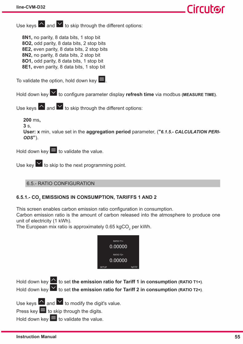
6�3�1�- DATE FORMAT
This screen is to display date format.
DATE FORMAT
DATE
DD/MM/YY
SETUP
Hold down key to set the date format (DATE FORMAT).
Use keys and to skip through the different options:
DD/MM/YY, Day/Month/Year.MM/DD/YY, Month/Day/Year
To validate the option, hold down key .Use key to skip to the next programming point.
6�3�2�- DATE AND TIME
Thisscreenenablescurrentdateandtimeconfiguration.
SETUP DATE
DATE
05/05/2019 HOUR
12:14:47
Hold down key to set current date (DATE).
Hold down key to set current time (HOUR).
Use keys and to modify the digit's value.Press key to skip through the digits.Hold down key to validate the value.
Use key to skip to the next programming point.

54
line-CVM-D32
Instruction Manual
6.4.- COMMUNICATIONS CONFIGURATION
6�4�1�- PERIPHERAL NUMBER AND TRANSMISSION SPEED
ThisscreenenablesconfigurationoftheperipheralnumberandtransmissionspeedforRS-485communications.
SETUP
PERIPH. NUMBER
1
9600 bps BAUDRATE
MODBUS
Hold down key to set the peripheral number (PERIPH� NUMBER).Use keys and to modify the digit's value.Press key to skip through the digits.
Peripheral number:
Minimum value: 1.Maximum value: 255.
Hold down key to validate the value.
Hold down key to set the transmission speed (BAUDRATE).
Use keys and to skip through the different options:
4800, 9600, 19200, 38400, 57600, 115200 bps
Hold down key to validate the value.Use key to skip to the next programming point.
6�4�2�- DATA FORMAT AND MEASURE TIME
Thisscreenenablesdataformatandcalculationtimeconfiguration.
SETUP
DATA SETTINGS
8N1MEASURE TIME
3 s MODBUS
Hold down key toconfiguredata format (DATA SETTINGS) for RS-485 Communications.
55Instruction Manual
line-CVM-D32
Use keys and to skip through the different options:
8N1, no parity, 8 data bits, 1 stop bit 8O2, odd parity, 8 data bits, 2 stop bits8E2, even parity, 8 data bits, 2 stop bits8N2, no parity, 8 data bits, 2 stop bit8O1, odd parity, 8 data bits, 1 stop bit8E1, even parity, 8 data bits, 1 stop bit
To validate the option, hold down key .
Hold down key toconfigure parameter display refresh time via modbus (MEASURE TIME).
Use keys and to skip through the different options:
200 ms, 3 s, User: x min, value set in the aggregation period parameter, ("6.1.5.- CALCULATION PERI-ODS”).
Hold down key to validate the value.
Use key to skip to the next programming point.
6.5.- RATIO CONFIGURATION
6�5�1�- CO2 EMISSIONS IN CONSUMPTION, TARIFFS 1 AND 2
Thisscreenenablescarbonemissionratioconfigurationinconsumption.Carbon emission ratio is the amount of carbon released into the atmosphere to produce one unit of electricity (1 kWh).The European mix ratio is approximately 0.65 kgCO2 per kWh.
RATIO T1+
0.00000
0.00000 RATIO T2+
kgCO2SETUP
Hold down key to set the emission ratio for Tariff 1 in consumption (RATIO T1+).
Hold down key to set the emission ratio for Tariff 2 in consumption (RATIO T2+).
Use keys and to modify the digit's value.Press key to skip through the digits.Hold down key to validate the value.

56
line-CVM-D32
Instruction Manual
Tariff 1 and 2 emission ratio in consumption:
Minimum value: 0.00000 kgCO2Maximum value: 99.99999 kgCO2
Use key to skip to the next programming point.
6�5�2�- CO2 EMISSIONS IN CONSUMPTION, TARIFFS 3 AND 4
Thisscreenenablescarbonemissionratioconfigurationinconsumption.Carbon emission ratio is the amount of carbon released into the atmosphere to produce one unit of electricity (1 kWh).The European mix ratio is approximately 0.65 kgCo2 per kWh.
RATIO T3+
0.00000
0.00000 RATIO T4+
SETUP kgCO2
Hold down key to set the emission ratio for Tariff 3 in consumption (RATIO T3+).
Hold down key to set emission ratio for Tariff 4 in consumption (RATIO T4+).
Use keys and to modify the digit's value.Press key to skip through the digits.Hold down key to validate the value.
Tariff 3 and 4 emission ratio in consumption:
Minimum value: 0.00000 kgCO2Maximum value: 99.99999 kgCO2
Use key to skip to the next programming point.
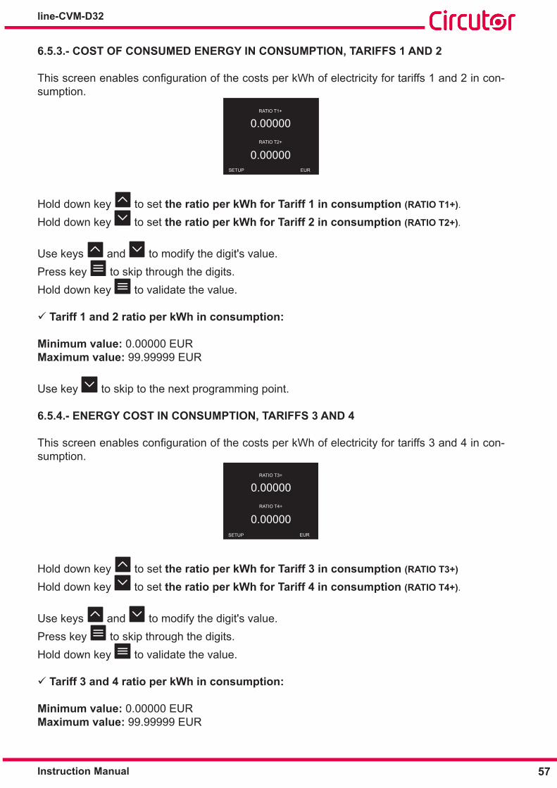
57Instruction Manual
line-CVM-D32
6�5�3�- COST OF CONSUMED ENERGY IN CONSUMPTION, TARIFFS 1 AND 2
ThisscreenenablesconfigurationofthecostsperkWhofelectricityfortariffs1and2incon-sumption.
EURSETUP
RATIO T1+
0.00000
0.00000 RATIO T2+
Hold down key to set the ratio per kWh for Tariff 1 in consumption (RATIO T1+).
Hold down key to set the ratio per kWh for Tariff 2 in consumption (RATIO T2+).
Use keys and to modify the digit's value.Press key to skip through the digits.Hold down key to validate the value.
Tariff 1 and 2 ratio per kWh in consumption:
Minimum value: 0.00000 EURMaximum value: 99.99999 EUR
Use key to skip to the next programming point.
6�5�4�- ENERGY COST IN CONSUMPTION, TARIFFS 3 AND 4
ThisscreenenablesconfigurationofthecostsperkWhofelectricityfortariffs3and4incon-sumption.
EURSETUP
RATIO T3+
0.00000
0.00000 RATIO T4+
Hold down key to set the ratio per kWh for Tariff 3 in consumption (RATIO T3+)
Hold down key to set the ratio per kWh for Tariff 4 in consumption (RATIO T4+).
Use keys and to modify the digit's value.Press key to skip through the digits.Hold down key to validate the value.
Tariff 3 and 4 ratio per kWh in consumption:
Minimum value: 0.00000 EURMaximum value: 99.99999 EUR

58
line-CVM-D32
Instruction Manual
Use key to skip to the next programming point.
6�5�5�- CO2 EMISSIONS IN GENERATION, TARIFFS 1 AND 2
Note: Display visible if the device has been configured to operate in all 4 quadrants (“6.1.3.- QUADRANTS AND MEASUREMENT CONVENTION")
Thisscreenenablescarbonemissionratioconfigurationingeneration.Carbon emission ratio is the amount of carbon released into the atmosphere to produce one unit of electricity (1 kWh).The European mix ratio is approximately 0.65 kgCO2 per kWh.
RATIO T1-
0.00000
0.00000 RATIO T2-
kgCO2SETUP
Hold down key to set the emission ratio for Tariff 1 in generation (RATIO T1-).
Hold down key to set the emission ratio for Tariff 2 in generation (RATIO T2-).
Use keys and to modify the digit's value.Press key to skip through the digits.Hold down key to validate the value.
Tariff 1 and 2 emission ratio in generation:
Minimum value: 0.00000 kgCO2Maximum value: 99.99999 kgCO2
Use key to skip to the next programming point.
6�5�6�- CO2 EMISSIONS IN GENERATION, TARIFFS 3 AND 4
Note: Screen displayed if the device has been configured to operate in all 4 quadrants (“6.1.3.- QUADRANTS AND MEASUREMENT CONVENTION").
Thisscreenenablescarbonemissionratioconfigurationingeneration.Carbon emission ratio is the amount of carbon released into the atmosphere to produce one unit of electricity (1 kWh).The European mix ratio is approximately 0.65 kgCO2 per kWh.
RATIO T3-
0.00000
0.00000 RATIO T4-
SETUP kgCO2

59Instruction Manual
line-CVM-D32
Hold down key to set the emission ratio for Tariff 3 in generation (RATIO T3-).
Hold down key to set emission ratio for Tariff 4 in generation (RATIO T4-).
Use keys and to modify the digit's value.Press key to skip through the digits.Hold down key to validate the value.
Tariff 3 and 4 emission ratio in generation:
Minimum value: 0.00000 kgCO2Maximum value: 99.99999 kgCO2
Use key to skip to the next programming point.
6�5�7�- ENERGY COST IN GENERATION, TARIFFS 1 AND 2
Note: Display visible if the device has been configured to operate in all 4 quadrants (“6.1.3.- QUADRANTS AND MEASUREMENT CONVENTION").
ThisscreenenablesconfigurationofthecostsperkWhofelectricityfortariffs1and2ingen-eration.
EURSETUP
RATIO T1-
0.00000
0.00000 RATIO T2-
Hold down key to set the ratio per kWh for Tariff 1 in generation (RATIO T1-)
Hold down key to set the ratio per kWh for Tariff 2 in generation (RATIO T2-).
Use keys and to modify the digit's value.Press key to skip through the digits.Hold down key to validate the value.
Tariff 1 and 2 ratio per kWh in generation:
Minimum value: 0.00000 EURMaximum value: 99.99999 EUR
Use key to skip to the next programming point.
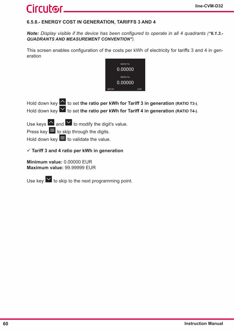
60
line-CVM-D32
Instruction Manual
6�5�8�- ENERGY COST IN GENERATION, TARIFFS 3 AND 4
Note: Display visible if the device has been configured to operate in all 4 quadrants (“6.1.3.- QUADRANTS AND MEASUREMENT CONVENTION").
ThisscreenenablesconfigurationofthecostsperkWhofelectricityfortariffs3and4ingen-eration
EURSETUP
RATIO T3-
0.00000
0.00000 RATIO T4-
Hold down key to set the ratio per kWh for Tariff 3 in generation (RATIO T3-).
Hold down key to set the ratio per kWh for Tariff 4 in generation (RATIO T4-).
Use keys and to modify the digit's value.Press key to skip through the digits.Hold down key to validate the value.
Tariff 3 and 4 ratio per kWh in generation
Minimum value: 0.00000 EURMaximum value: 99.99999 EUR
Use key to skip to the next programming point.
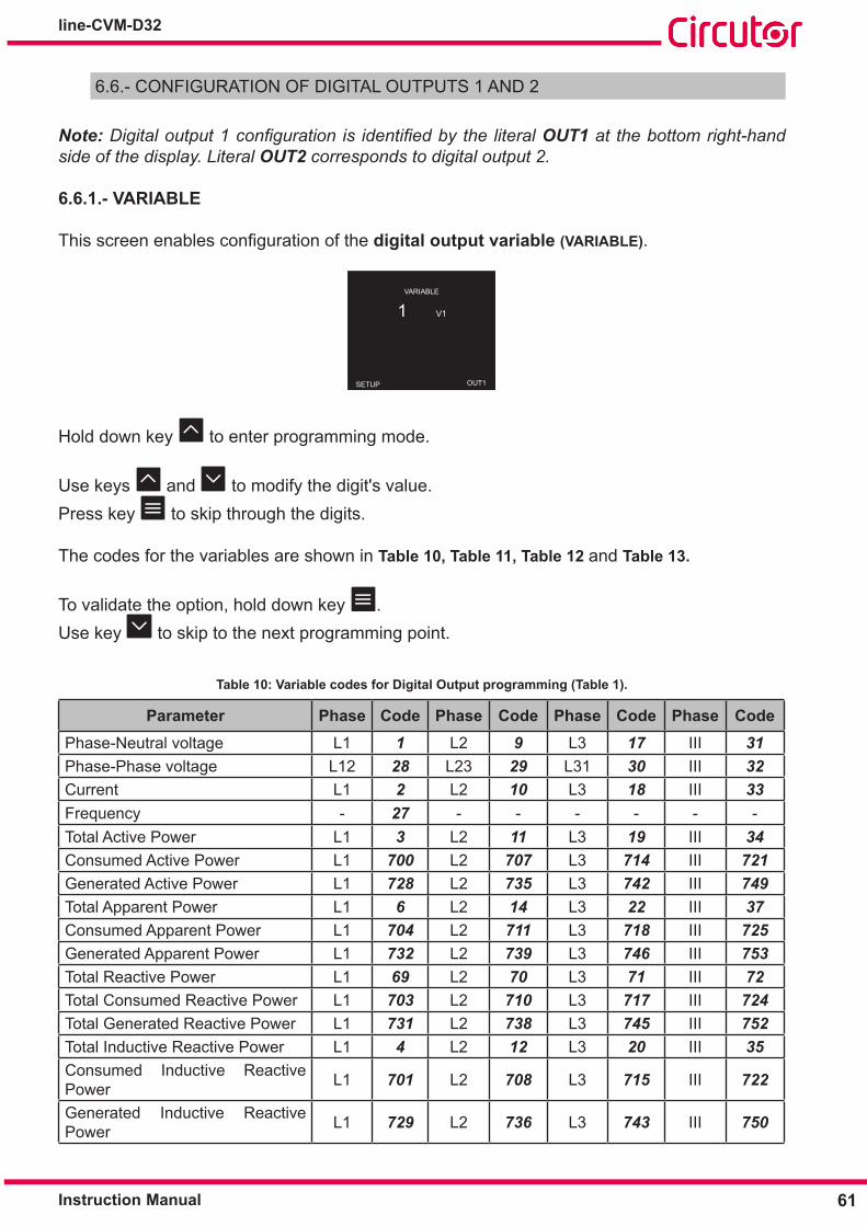
61Instruction Manual
line-CVM-D32
6.6.- CONFIGURATION OF DIGITAL OUTPUTS 1 AND 2
Note: Digital output 1 configuration is identified by the literal OUT1 at the bottom right-hand side of the display. Literal OUT2 corresponds to digital output 2.
6�6�1�- VARIABLE
Thisscreenenablesconfigurationofthe digital output variable (VARIABLE).
SETUP
VARIABLE
1 V1
OUT1
Hold down key to enter programming mode.
Use keys and to modify the digit's value.Press key to skip through the digits.
The codes for the variables are shown in Table 10, Table 11, Table 12 and Table 13�
To validate the option, hold down key .Use key to skip to the next programming point.
Table 10: Variable codes for Digital Output programming (Table 1)�
Parameter Phase Code Phase Code Phase Code Phase CodePhase-Neutral voltage L1 1 L2 9 L3 17 III 31Phase-Phase voltage L12 28 L23 29 L31 30 III 32Current L1 2 L2 10 L3 18 III 33Frequency - 27 - - - - - -Total Active Power L1 3 L2 11 L3 19 III 34Consumed Active Power L1 700 L2 707 L3 714 III 721Generated Active Power L1 728 L2 735 L3 742 III 749Total Apparent Power L1 6 L2 14 L3 22 III 37Consumed Apparent Power L1 704 L2 711 L3 718 III 725Generated Apparent Power L1 732 L2 739 L3 746 III 753Total Reactive Power L1 69 L2 70 L3 71 III 72Total Consumed Reactive Power L1 703 L2 710 L3 717 III 724Total Generated Reactive Power L1 731 L2 738 L3 745 III 752Total Inductive Reactive Power L1 4 L2 12 L3 20 III 35Consumed Inductive Reactive Power L1 701 L2 708 L3 715 III 722
Generated Inductive Reactive Power L1 729 L2 736 L3 743 III 750
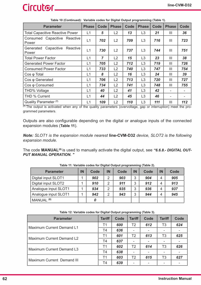
62
line-CVM-D32
Instruction Manual
Table 10 (Continued): Variable codes for Digital Output programming (Table 1)�
Parameter Phase Code Phase Code Phase Code Phase CodeTotal Capacitive Reactive Power L1 5 L2 13 L3 21 III 36Consumed Capacitive Reactive Power L1 702 L2 709 L3 716 III 723
Generated Capacitive Reactive Power L1 730 L2 737 L3 744 III 751
Total Power Factor L1 7 L2 15 L3 23 III 38Generated Power Factor L1 705 L2 712 L3 719 III 726Consumed Power Factor L1 733 L2 740 L3 747 III 754CosφTotal L1 8 L2 16 L3 24 III 39CosφGenerated L1 706 L2 713 L3 720 III 727CosφConsumed L1 734 L2 741 L3 748 III 755THD% Voltage L1 40 L2 41 L3 42 - -THD % Current L1 44 L2 45 L3 46 - -Quality Parameter (7) L1 109 L2 110 L3 111 III 112
(7) The output is activated when any of the quality parameters (overvoltage, gap or interruption) meet the pro-grammed parameters.
Outputsarealsoconfigurabledependingon thedigitaloranalogue inputsof theconnectedexpansion modules (Table 11).
Note: SLOT1 is the expansion module nearest line-CVM-D32 device, SLOT2 is the following expansion module.
The code MANUAL(8) is used to manually activate the digital output, see “6.6.8.- DIGITAL OUT-PUT MANUAL OPERATION. "
Table 11: Variable codes for Digital Output programming (Table 2)�
Parameter IN Code IN Code IN Code IN CodeDigital input SLOT1 1 902 2 903 3 904 4 905 Digital input SLOT2 1 910 2 911 3 912 4 913 Analogue input SLOT1 1 934 2 935 3 936 4 937 Analogue input SLOT1 1 942 2 943 3 944 4 945 MANUAL (8) 0
Table 12: Variable codes for Digital Output programming (Table 3)�
Parameter Tariff Code Tariff Code Tariff Code
Maximum Current Demand L1T1 600 T2 612 T3 624T4 636 - - - -
Maximum Current Demand L2T1 601 T2 613 T3 625T4 637 - - - -
Maximum Current Demand L3T1 602 T2 614 T3 626T4 638 - - - -
Maximum Current Demand IIIT1 603 T2 615 T3 627T4 639 - - - -

63Instruction Manual
line-CVM-D32
Table 12 (Continued): Variable codes for Digital Output programming (Table 3)�
Parameter Tariff Code Tariff Code Tariff Code
Maximum Active Power Demand L1T1 604 T2 616 T3 628T4 640 - - - -
Maximum Active Power Demand L2T1 605 T2 617 T3 629T4 641 - - - -
Maximum Active Power Demand L3T1 606 T2 618 T3 630T4 642 - - - -
Maximum Active Power Demand IIIT1 607 T2 619 T3 631T4 643 - - - -
Maximum Apparent Power Demand L1 T1 608 T2 620 T3 632T4 644 - - - -
Maximum Apparent Power Demand L2 T1 609 T2 621 T3 633T4 645 - - - -
Maximum Apparent Power Demand L3 T1 610 T2 622 T3 634T4 646 - - - -
Maximum Apparent Power Demand III T1 611 T2 623 T3 635T4 647 - - - -
Consumption hour no.T1 531 T2 537 T3 543T4 549 Total 585 - -
Generation hour no.T1 534 T2 540 T3 546T4 552 Total 588 - -
Consumption costT1 529 T2 535 T3 541T4 547 Total 583 - -
Generation costT1 532 T2 538 T3 544T4 550 Total 586 - -
CO2 emissions from consumptionT1 530 T2 536 T3 542T4 548 Total 584 - -
CO2 emissions from generationT1 533 T2 539 T3 545T4 551 Total 587 - -
Table 13: Variable codes for Digital Output programming (Energy pulses)�
ParameterL1 L2 L3 III
Tariff Code Tariff Code Tariff Code Tariff Code
Consumed Active Energy
T1 129 T1 134 T1 139 T1 144T2 169 T2 174 T2 179 T2 184T3 209 T3 214 T3 219 T3 224T4 249 T4 254 T4 259 T4 264
Total 489 Total 494 Total 499 Total 504
Generated Active Energy
T1 149 T1 154 T1 159 T1 164T2 189 T2 194 T2 199 T2 204T3 229 T3 234 T3 239 T3 244T4 269 T4 274 T4 279 T4 284
Total 509 Total 514 Total 519 Total 524

64
line-CVM-D32
Instruction Manual
Table 13 (Continued): Variable codes for Digital Output programming (Energy pulses)�
ParameterL1 L2 L3 III
Tariff Code Tariff Code Tariff Code Tariff Code
Consumed ReactiveEnergy
T1 132 T1 137 T1 142 T1 147T2 172 T2 177 T2 182 T2 187T3 212 T3 217 T3 222 T3 227T4 252 T4 257 T4 262 T4 267
Total 492 Total 497 Total 502 Total 507
Generated Reactive Energy
T1 152 T1 157 T1 162 T1 167T2 192 T2 197 T2 202 T2 207T3 232 T3 237 T3 242 T3 247T4 272 T4 277 T4 282 T4 287
Total 512 Total 517 Total 522 Total 527
Consumed Inductive Reactive Energy
T1 130 T1 135 T1 140 T1 145T2 170 T2 175 T2 180 T2 185T3 210 T3 215 T3 220 T3 225T4 250 T4 255 T4 260 T4 265
Total 490 Total 495 Total 500 Total 505
Generated Inductive Reactive Energy
T1 150 T1 155 T1 160 T1 165T2 190 T2 195 T2 200 T2 205T3 230 T3 235 T3 240 T3 245T4 270 T4 275 T4 280 T4 285
Total 510 Total 515 Total 520 Total 525
Consumed Capacitive Reactive Energy
T1 131 T1 136 T1 141 T1 146T2 171 T2 176 T2 181 T2 186T3 211 T3 216 T3 221 T3 226T4 251 T4 256 T4 261 T4 266
Total 491 Total 496 Total 501 Total 506
Generated Capacitive Reactive Energy
T1 151 T1 156 T1 161 T1 166T2 191 T2 196 T2 201 T2 206T3 231 T3 236 T3 241 T3 246T4 271 T4 276 T4 281 T4 286
Total 511 Total 516 Total 521 Total 526
Consumed Apparent Energy
T1 133 T1 138 T1 143 T1 148T2 173 T2 178 T2 183 T2 188T3 213 T3 218 T3 223 T3 228T4 253 T4 258 T4 263 T4 268
Total 493 Total 498 Total 503 Total 508
Generated Apparent Energy
T1 153 T1 158 T1 163 T1 168T2 193 T2 198 T2 203 T2 208T3 233 T3 238 T3 243 T3 248T4 273 T4 278 T4 283 T4 288
Total 513 Total 518 Total 523 Total 528
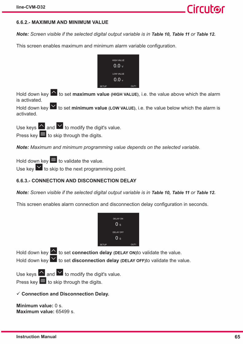
65Instruction Manual
line-CVM-D32
6�6�2�- MAXIMUM AND MINIMUM VALUE
Note: Screen visible if the selected digital output variable is in Table 10, Table 11 or Table 12.
Thisscreenenablesmaximumandminimumalarmvariableconfiguration.
HIGH VALUE
0.0 V
0.0 v LOW VALUE
OUT1SETUP
Hold down key to set maximum value (HIGH VALUE), i.e. the value above which the alarm is activated.Hold down key to set minimum value (LOW VALUE), i.e. the value below which the alarm is activated.
Use keys and to modify the digit's value.Press key to skip through the digits.
Note: Maximum and minimum programming value depends on the selected variable.
Hold down key to validate the value.Use key to skip to the next programming point.
6�6�3�- CONNECTION AND DISCONNECTION DELAY
Note: Screen visible if the selected digital output variable is in Table 10, Table 11 or Table 12.
Thisscreenenablesalarmconnectionanddisconnectiondelayconfigurationinseconds.
DELAY ON
0 S
0 S DELAY OFF
OUT1SETUP
Hold down key to set connection delay (DELAY ON)to validate the value.Hold down key to set disconnection delay (DELAY OFF)to validate the value.
Use keys and to modify the digit's value.Press key to skip through the digits.
Connection and Disconnection Delay�
Minimum value: 0 s.Maximum value: 65499 s.

66
line-CVM-D32
Instruction Manual
Hold down key to validate the value.Use key to skip to the next programming point.
6�6�4�- HYSTERESIS AND STATUS OF CONTACTS
Note: Screen visible if the selected digital output variable is in Table 10, Table 11 or Table 12.
Thisscreenenableshysteresisvalueandcontactstatusconfiguration.
HYSTERESIS
0 %
NO CONTACT TYPE
OUT1SETUP
Hold down key to set hysteresis value (HYSTERESIS), the difference between the alarm on and off value in %.Use keys and to modify the digit's value.Press key to skip through the digits.
Hysteresis:
Minimum value: 0%.Maximum value: 99%.
Hold down key to set contact status (CONTACT TYPE).
Use keys and to skip through the different options:
NC, Contact normally closed. NO, Contact normally open.
Hold down key to validate the value.Use key to skip to the next programming point.
6�6�5�- LATCH
Note: Screen visible if the selected digital output variable is in Table 10, Table 11 or Table 12.
Thisscreenenablesalarmlatchingconfiguration.
LATCH
NO
0 S TIME ON
OUT1SETUP

67Instruction Manual
line-CVM-D32
Hold down key to set latching (LATCH), i.e. if it remains interlocked after the alarm is trig-gered, even if the event that triggered it disappears.
Use keys and to skip through the different options:
NO, Latching is not activated. YES, Latching is activated.TIME, Alarm latching is activated for a set time, Latching time.
Hold down key to set Latching time (TIME ON). The time in seconds that the alarm is inter-locked is displayed. After such time, if the alarm status no longer applies, disconnection delay is activated.
Use keys and to modify the digit's value.Press key to skip through the digits.
Latching time:
Minimum value: 0 s.Maximum value: 65499 s.
Hold down key to validate the value.Use key to skip to the next programming point.
6�6�6�- ENERGY PER PULSE AND CONTACT STATUS
Note: Screen visible if the selected digital output variable is an energy, see Table 13.
Thisscreenenablesenergyperpulseandcontactstatusconfiguration.
WEIGHT
1Wh
NO CONTACT TYPE
OUT1SETUP
Hold down key to set the energy per pulse (WEIGHT)�
Use keys and to modify the digit's value.Press key to skip through the digits.
Energy per pulse:
Minimum value: 1 wh / varLh / varCh / varh / VAh. Maximum value: 1999999 wh / varLh / varCh / varh / VAh.

68
line-CVM-D32
Instruction Manual
Hold down key to set contact status (CONTACT TYPE).
Use keys and to skip through the different options:
NC, Contact normally closed. NO, Contact normally open.
Hold down key to validate the value.Use key to skip to the next programming point.
6�6�7�- PULSE
Note: Screen visible if the selected digital output variable is an energy, see Table 13.
Thisscreenenablespulsewidthconfiguration
HIGH PERIOD
0
0 LOW PERIOD
msx10
OUT1
msx10
SETUP
Hold down key to set pulse width to a high level (HIGH PERIOD).Hold down key to set pulse width to a low level (LOW PERIOD).
Use keys and to modify the digit's value.Press key to skip through the digits.
Pulse width:
Minimum value: 0 x10 ms.Maximum value: 999 x10 ms.
Hold down key to validate the value.Use key to skip to the next programming point.
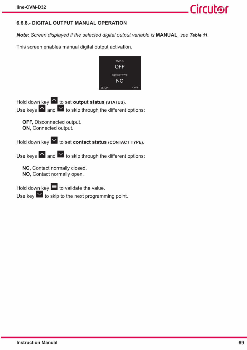
69Instruction Manual
line-CVM-D32
6�6�8�- DIGITAL OUTPUT MANUAL OPERATION
Note: Screen displayed if the selected digital output variable is MANUAL, see Table 11.
This screen enables manual digital output activation.
RATIOSSETUP OUT1
STATUS
OFF
NOCONTACT TYPE
Hold down key to set output status (STATUS)�
Use keys and to skip through the different options:
OFF, Disconnected output. ON, Connected output.
Hold down key to set contact status (CONTACT TYPE).
Use keys and to skip through the different options:
NC, Contact normally closed. NO, Contact normally open.
Hold down key to validate the value.Use key to skip to the next programming point.
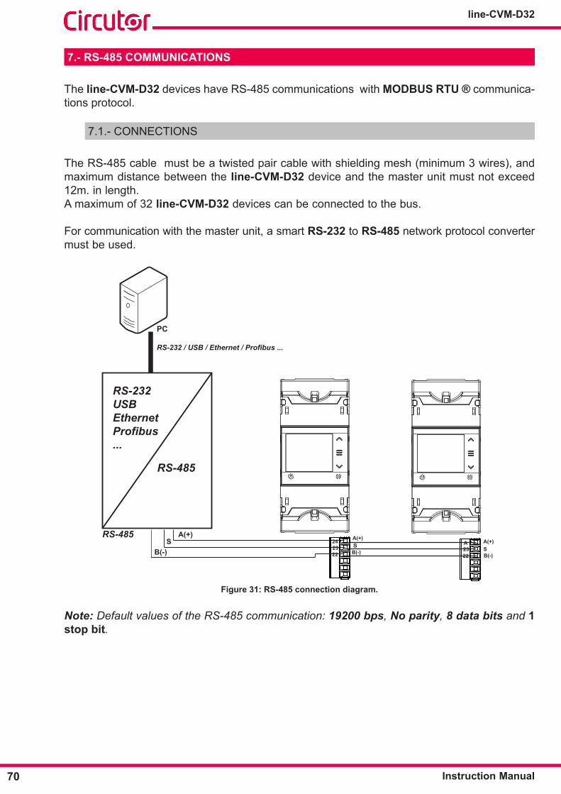
70
line-CVM-D32
Instruction Manual
7�- RS-485 COMMUNICATIONS
The line-CVM-D32 devices have RS-485 communications with MODBUS RTU ® communica-tions protocol.
7.1.- CONNECTIONS
The RS-485 cable must be a twisted pair cable with shielding mesh (minimum 3 wires), and maximum distance between the line-CVM-D32 device and the master unit must not exceed 12m. in length.A maximum of 32 line-CVM-D32 devices can be connected to the bus.
For communication with the master unit, a smart RS-232 to RS-485 network protocol converter must be used.
B(-)
A(+)S
RS-232 / USB / Ethernet / Profibus ...
PC
RS-485
RS-485
RS-232USBEthernetProfibus...
A(+)
B(-)S
A(+)
B(-)S
242322
A2322
Figure 31: RS-485 connection diagram� Note: Default values of the RS-485 communication: 19200 bps, No parity, 8 data bits and 1 stop bit.
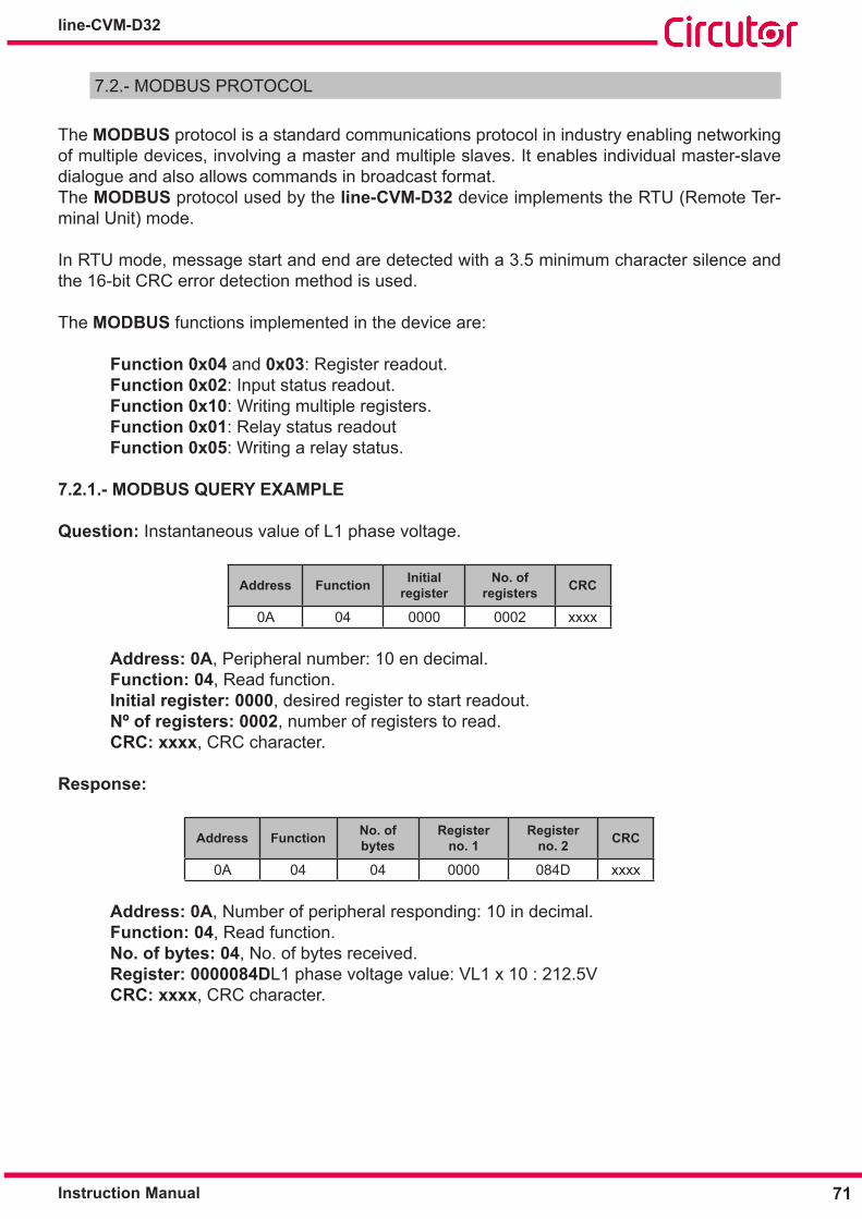
71Instruction Manual
line-CVM-D32
7.2.- MODBUS PROTOCOL
The MODBUS protocol is a standard communications protocol in industry enabling networking of multiple devices, involving a master and multiple slaves. It enables individual master-slave dialogue and also allows commands in broadcast format. The MODBUS protocol used by the line-CVM-D32 device implements the RTU (Remote Ter-minal Unit) mode. In RTU mode, message start and end are detected with a 3.5 minimum character silence and the 16-bit CRC error detection method is used.
The MODBUS functions implemented in the device are:
Function 0x04 and 0x03: Register readout. Function 0x02: Input status readout. Function 0x10: Writing multiple registers. Function 0x01: Relay status readout Function 0x05: Writing a relay status.
7�2�1�- MODBUS QUERY EXAMPLE
Question: Instantaneous value of L1 phase voltage.
Address Function Initial register
No� of registers CRC
0A 04 0000 0002 xxxx
Address: 0A, Peripheral number: 10 en decimal. Function: 04, Read function. Initial register: 0000, desired register to start readout. Nº of registers: 0002, number of registers to read. CRC: xxxx, CRC character.
Response:
Address Function No� of bytes
Register no� 1
Register no� 2 CRC
0A 04 04 0000 084D xxxx
Address: 0A, Number of peripheral responding: 10 in decimal. Function: 04, Read function. No� of bytes: 04, No. of bytes received. Register: 0000084DL1 phase voltage value: VL1 x 10 : 212.5V CRC: xxxx, CRC character.

72
line-CVM-D32
Instruction Manual
7.3.- MODBUS MEMORY MAP
All MODBUS map addresses are in Hexadecimal.
7�3�1�- MEASUREMENT VARIABLES
The Function 0x04: register readout, is implemented for these variables.
Table 14: Modbus Memory Map: Measurement variables (Table 1)�
Instantaneous ValueParameter Format Address UnitsVoltage phase L1 Float [32] 00-01 VCurrent L1 Float [32] 02-03 AActive Power L1 Float [32] 04-05 WInductive reactive power L1 Float [32] 06-07 varLCapacitive reactive power L1 Float [32] 08-09 varCApparent Power L1 Float [32] 0A-0B VAPower factor L1 Float [32] 0C-0D -CosφL1 Float [32] 0E-0F -Voltage phase L2 Float [32] 10-11 VCurrent L2 Float [32] 12-13 AActive Power L2 Float [32] 14-15 WInductive reactive power L2 Float [32] 16-17 varLCapacitive reactive power L2 Float [32] 18-19 varCApparent Power L2 Float [32] 1A-1B VAPower factor L2 Float [32] 1C-1D -CosφL2 Float [32] 1E-1F -Voltage phase L3 Float [32] 20-21 VCurrent L3 Float [32] 22-23 AActive Power L3 Float [32] 24-25 WInductive reactive power L3 Float [32] 26-27 varLCapacitive reactive power L3 Float [32] 28-29 varCApparent Power L3 Float [32] 2A-2B VAPower factor L3 Float [32] 2C-2D -CosφL3 Float [32] 2E-2F -Frequency Float [32] 34-35 HzVoltage L1-L2 Float [32] 36-37 VVoltage L2-L3 Float [32] 38-39 VVoltage L3-L1 Float [32] 3A-3B VAverage phase-phase voltage Float [32] 3C-3D VAverage phase-neutral voltage Float [32] 3E-3F VAverage current Float [32] 40-41 ATotal Active Power Float [32] 42-43 WTotal inductive reactive power Float [32] 44-45 varLTotal capacitive reactive power Float [32] 46-47 varCTotal apparent power Float [32] 48-49 VAThree-phase power factor Float [32] 4A-4B -Cosφthree-phase Float [32] 4C-4D -

73Instruction Manual
line-CVM-D32
Table 14 (Continued): Modbus Memory Map: Measurement variables (Table 1)�Instantaneous Value
Parameter Format Address UnitsTHD % voltage L1 Float [32] 4E-4F %THD % voltage L2 Float [32] 50-51 %THD % voltage L3 Float [32] 52-53 %THD % Current L1 Float [32] 56-57 %THD % Current L2 Float [32] 58-59 %THD % Current L3 Float [32] 5A-5B %Reactive Power L1 Float [32] 5E-5F varReactive Power L2 Float [32] 60-61 varReactive Power L3 Float [32] 62-63 varTotal Reactive Power Float [32] 64-65 varConsumed Reactive Power L1 Float [32] 66-67 varConsumed Reactive Power L2 Float [32] 68-69 varConsumed Reactive Power L3 Float [32] 6A-6B varTotal consumed reactive power Float [32] 6C-6D varGenerated Reactive Power L1 Float [32] 6E-6F varGenerated Reactive Power L2 Float [32] 70-71 varGenerated Reactive Power L3 Float [32] 72-73 varTotal generated reactive power Float [32] 74-75 varQuadrant L1 Uint [16] 76 -Quadrant L2 Uint [16] 77 -Quadrant L3 Uint [16] 78 -Three-phase quadrant Uint [16] 79 -Consumed Active Power L1 Float [32] 7A - 7B WConsumed Active Power L2 Float [32] 7C - 7D WConsumed Active Power L3 Float [32] 7E - 7F WTotal Active Power Consumed Float [32] 80 - 81 WGenerated Active Power L1 Float [32] 82 - 83 WGenerated Active Power L2 Float [32] 84-85 WGenerated Active Power L3 Float [32] 86-87 WTotal Active Power Generated Float [32] 88-89 WConsumed Inductive Reactive Power L1 Float [32] 8A-8B varLConsumed Inductive Reactive Power L2 Float [32] 8C-8D varLConsumed Inductive Reactive Power L3 Float [32] 8E-8F varLTotal Inductive Reactive Power Consumed Float [32] 90-91 varLGenerated Inductive Reactive Power L1 Float [32] 92-93 varLGenerated Inductive Reactive Power L2 Float [32] 94-95 varLGenerated Inductive Reactive Power L3 Float [32] 96-97 varLTotal Inductive Reactive Power Generated Float [32] 98-99 varLConsumed Capacitive Reactive Power L1 Float [32] 9A-9B varCConsumed Capacitive Reactive Power L2 Float [32] 9C-9D varCConsumed Capacitive Reactive Power L3 Float [32] 9E - 9F varCTotal Capacitive Reactive Power Consumed Float [32] A0-A1 varCGenerated Capacitive Reactive Power L1 Float [32] A2-A3 varCGenerated Capacitive Reactive Power L2 Float [32] A4-A5 varCGenerated Capacitive Reactive Power L3 Float [32] A6-A7 varC
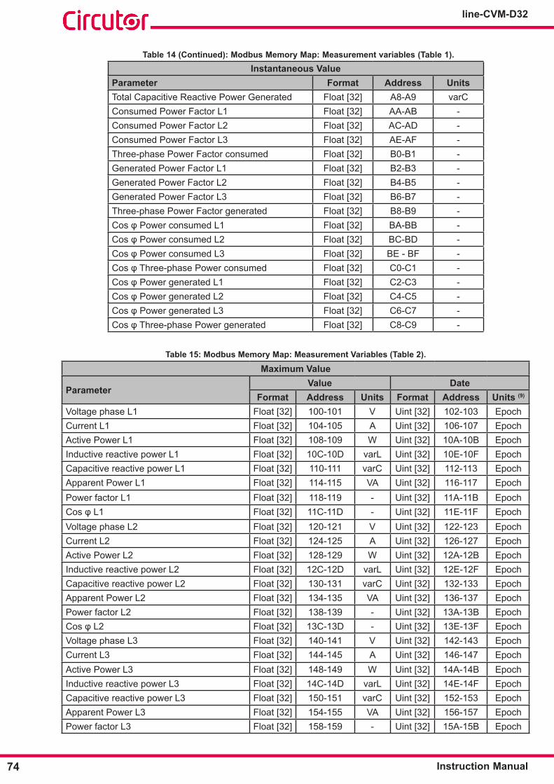
74
line-CVM-D32
Instruction Manual
Table 14 (Continued): Modbus Memory Map: Measurement variables (Table 1)�Instantaneous Value
Parameter Format Address UnitsTotal Capacitive Reactive Power Generated Float [32] A8-A9 varCConsumed Power Factor L1 Float [32] AA-AB -Consumed Power Factor L2 Float [32] AC-AD -Consumed Power Factor L3 Float [32] AE-AF -Three-phase Power Factor consumed Float [32] B0-B1 -Generated Power Factor L1 Float [32] B2-B3 -Generated Power Factor L2 Float [32] B4-B5 -Generated Power Factor L3 Float [32] B6-B7 -Three-phase Power Factor generated Float [32] B8-B9 -CosφPowerconsumedL1 Float [32] BA-BB -CosφPowerconsumedL2 Float [32] BC-BD -CosφPowerconsumedL3 Float [32] BE - BF -CosφThree-phasePowerconsumed Float [32] C0-C1 -CosφPowergeneratedL1 Float [32] C2-C3 -CosφPowergeneratedL2 Float [32] C4-C5 -CosφPowergeneratedL3 Float [32] C6-C7 -CosφThree-phasePowergenerated Float [32] C8-C9 -
Table 15: Modbus Memory Map: Measurement Variables (Table 2)�
Maximum Value
ParameterValue Date
Format Address Units Format Address Units (9)
Voltage phase L1 Float [32] 100-101 V Uint [32] 102-103 EpochCurrent L1 Float [32] 104-105 A Uint [32] 106-107 EpochActive Power L1 Float [32] 108-109 W Uint [32] 10A-10B EpochInductive reactive power L1 Float [32] 10C-10D varL Uint [32] 10E-10F EpochCapacitive reactive power L1 Float [32] 110-111 varC Uint [32] 112-113 EpochApparent Power L1 Float [32] 114-115 VA Uint [32] 116-117 EpochPower factor L1 Float [32] 118-119 - Uint [32] 11A-11B EpochCosφL1 Float [32] 11C-11D - Uint [32] 11E-11F EpochVoltage phase L2 Float [32] 120-121 V Uint [32] 122-123 EpochCurrent L2 Float [32] 124-125 A Uint [32] 126-127 EpochActive Power L2 Float [32] 128-129 W Uint [32] 12A-12B EpochInductive reactive power L2 Float [32] 12C-12D varL Uint [32] 12E-12F EpochCapacitive reactive power L2 Float [32] 130-131 varC Uint [32] 132-133 EpochApparent Power L2 Float [32] 134-135 VA Uint [32] 136-137 EpochPower factor L2 Float [32] 138-139 - Uint [32] 13A-13B EpochCosφL2 Float [32] 13C-13D - Uint [32] 13E-13F EpochVoltage phase L3 Float [32] 140-141 V Uint [32] 142-143 EpochCurrent L3 Float [32] 144-145 A Uint [32] 146-147 EpochActive Power L3 Float [32] 148-149 W Uint [32] 14A-14B EpochInductive reactive power L3 Float [32] 14C-14D varL Uint [32] 14E-14F EpochCapacitive reactive power L3 Float [32] 150-151 varC Uint [32] 152-153 EpochApparent Power L3 Float [32] 154-155 VA Uint [32] 156-157 EpochPower factor L3 Float [32] 158-159 - Uint [32] 15A-15B Epoch

75Instruction Manual
line-CVM-D32
Table 15 (Continued): Modbus Memory Map: Measurement variables (Table 2)�Maximum Value
ParameterValue Date
Format Address Units Format Address Units (9)
CosφL3 Float [32] 15C-15D - Uint [32] 15E-15F EpochFrequency Float [32] 168-169 Hz Uint [32] 16A-16B EpochVoltage L1-L2 Float [32] 16C-16D V Uint [32] 16E-16F EpochVoltage L2-L3 Float [32] 170-171 V Uint [32] 172-173 EpochVoltage L3-L1 Float [32] 174-175 V Uint [32] 176-177 EpochAverage phase-phase voltage Float [32] 178-179 V Uint [32] 17A-17B EpochAverage phase-neutral voltage Float [32] 17C-17D V Uint [32] 17E-17F EpochAverage current Float [32] 180-181 A Uint [32] 182-183 EpochTotal Active Power Float [32] 184-185 W Uint [32] 186-187 EpochTotal inductive reactive power Float [32] 188-189 varL Uint [32] 18A-18B EpochTotal capacitive reactive power Float [32] 18C-18D varC Uint [32] 18E-18F EpochTotal apparent power Float [32] 190-191 VA Uint [32] 192-193 EpochThree-phase power factor Float [32] 194-195 - Uint [32] 196-197 EpochCosφthree-phase Float [32] 198-199 - Uint [32] 19A-19B EpochTHD % voltage L1 Float [32] 19C-19D % Uint [32] 19E-19F EpochTHD % voltage L2 Float [32] 1A0-1A1 % Uint [32] 1A2-1A3 EpochTHD % voltage L3 Float [32] 1A4-1A5 % Uint [32] 1A6-1A7 EpochTHD % Current L1 Float [32] 1AC-1AD % Uint [32] 1AE-1AF EpochTHD % Current L2 Float [32] 1B0-1B1 % Uint [32] 1B2-1B3 EpochTHD % Current L3 Float [32] 1B4-1B5 % Uint [32] 1B6-1B6 EpochReactive Power L1 Float [32] 1BC-1BD var Uint [32] 1BE-1BF EpochReactive Power L2 Float [32] 1C0-1C1 var Uint [32] 1C2-1C3 EpochReactive Power L3 Float [32] 1C4-1C5 var Uint [32] 1C6-1C7 EpochTotal Reactive Power Float [32] 1C8-1C9 var Uint [32] 1CA-1CB EpochConsumed Reactive Power L1 Float [32] 1CC-1CD var Uint [32] 1CE-1CF EpochConsumed Reactive Power L2 Float [32] 1D0-1D1 var Uint [32] 1D2-1D3 EpochConsumed Reactive Power L3 Float [32] 1D4-1D5 var Uint [32] 1D6-1D7 EpochTotal consumed reactive power Float [32] 1D8-1D9 var Uint [32] 1DA-1DB EpochGenerated Reactive Power L1 Float [32] 1DC-1DD var Uint [32] 1DE-1DF EpochGenerated Reactive Power L2 Float [32] 1E0-1E1 var Uint [32] 1E2-1E3 EpochGenerated Reactive Power L3 Float [32] 1E4-1E5 var Uint [32] 1E6-1E7 EpochTotal generated reactive power Float [32] 1E8-1E9 var Uint [32] 1EA-1EB EpochConsumed Active Power L1 Float [32] 1EC-1ED W Uint [32] 1EE-1EF EpochConsumed Active Power L2 Float [32] 1F0-1F1 W Uint [32] 1F2-1F3 EpochConsumed Active Power L3 Float [32] 1F4-1F5 W Uint [32] 1F6-1F7 EpochTotal Active Power Consumed Float [32] 1F8-1F9 W Uint [32] 1FA-1FB EpochGenerated Active Power L1 Float [32] 1FC-1FD W Uint [32] 1FE-1FF EpochGenerated Active Power L2 Float [32] 200-201 W Uint [32] 202-203 EpochGenerated Active Power L3 Float [32] 204-205 W Uint [32] 206-207 EpochTotal Active Power Generated Float [32] 208-209 W Uint [32] 20A-20B EpochInductive Reactive Power consumed L1 Float [32] 20C-20D varL Uint [32] 20E-20F EpochInductive Reactive Power consumed L2 Float [32] 210-211 varL Uint [32] 212-213 EpochInductive Reactive Power consumed L3 Float [32] 214-215 varL Uint [32] 216-217 EpochTotal Inductive Reactive Power consumed Float [32] 218-219 varL Uint [32] 21A-21B Epoch
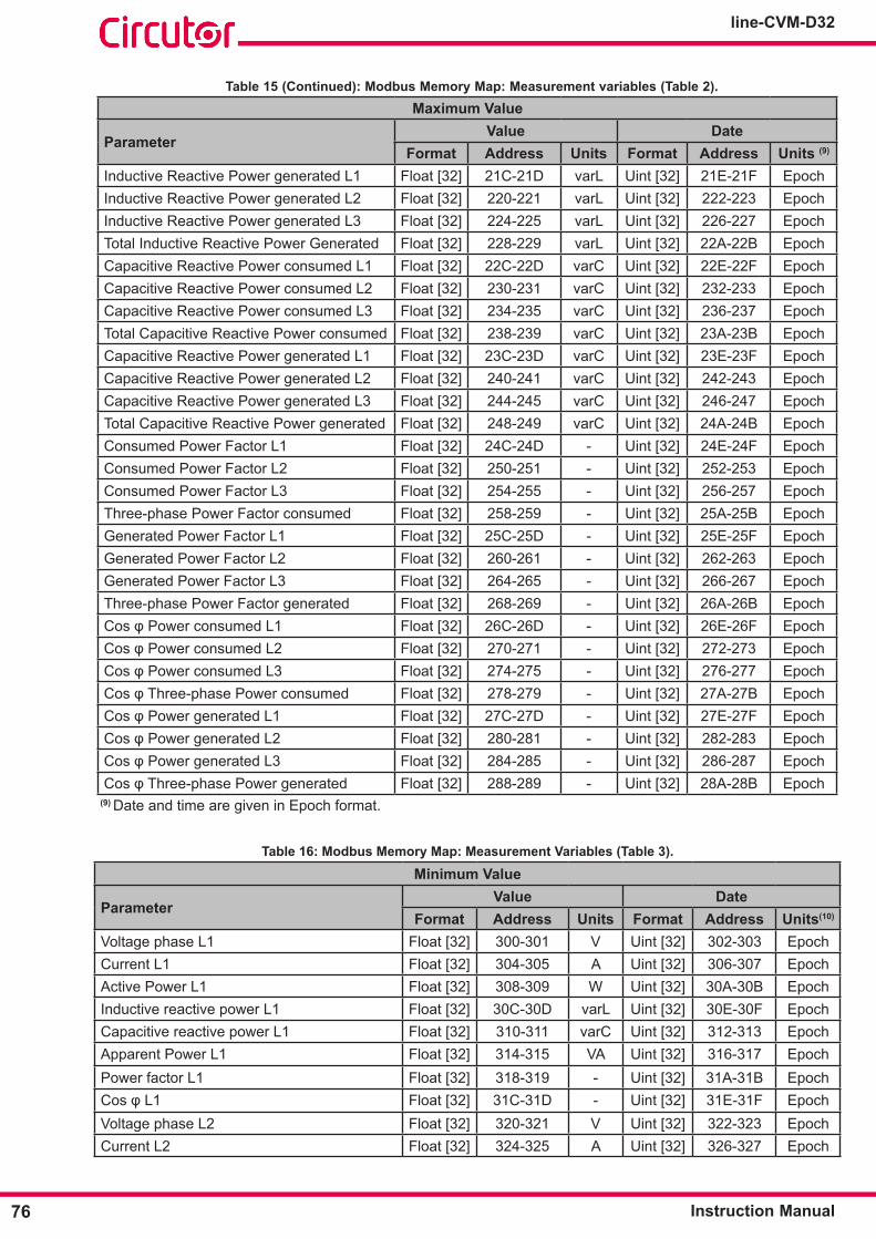
76
line-CVM-D32
Instruction Manual
Table 15 (Continued): Modbus Memory Map: Measurement variables (Table 2)�Maximum Value
ParameterValue Date
Format Address Units Format Address Units (9)
Inductive Reactive Power generated L1 Float [32] 21C-21D varL Uint [32] 21E-21F EpochInductive Reactive Power generated L2 Float [32] 220-221 varL Uint [32] 222-223 EpochInductive Reactive Power generated L3 Float [32] 224-225 varL Uint [32] 226-227 EpochTotal Inductive Reactive Power Generated Float [32] 228-229 varL Uint [32] 22A-22B EpochCapacitive Reactive Power consumed L1 Float [32] 22C-22D varC Uint [32] 22E-22F EpochCapacitive Reactive Power consumed L2 Float [32] 230-231 varC Uint [32] 232-233 EpochCapacitive Reactive Power consumed L3 Float [32] 234-235 varC Uint [32] 236-237 EpochTotal Capacitive Reactive Power consumed Float [32] 238-239 varC Uint [32] 23A-23B EpochCapacitive Reactive Power generated L1 Float [32] 23C-23D varC Uint [32] 23E-23F EpochCapacitive Reactive Power generated L2 Float [32] 240-241 varC Uint [32] 242-243 EpochCapacitive Reactive Power generated L3 Float [32] 244-245 varC Uint [32] 246-247 EpochTotal Capacitive Reactive Power generated Float [32] 248-249 varC Uint [32] 24A-24B EpochConsumed Power Factor L1 Float [32] 24C-24D - Uint [32] 24E-24F EpochConsumed Power Factor L2 Float [32] 250-251 - Uint [32] 252-253 EpochConsumed Power Factor L3 Float [32] 254-255 - Uint [32] 256-257 EpochThree-phase Power Factor consumed Float [32] 258-259 - Uint [32] 25A-25B EpochGenerated Power Factor L1 Float [32] 25C-25D - Uint [32] 25E-25F EpochGenerated Power Factor L2 Float [32] 260-261 - Uint [32] 262-263 EpochGenerated Power Factor L3 Float [32] 264-265 - Uint [32] 266-267 EpochThree-phase Power Factor generated Float [32] 268-269 - Uint [32] 26A-26B EpochCosφPowerconsumedL1 Float [32] 26C-26D - Uint [32] 26E-26F EpochCosφPowerconsumedL2 Float [32] 270-271 - Uint [32] 272-273 EpochCosφPowerconsumedL3 Float [32] 274-275 - Uint [32] 276-277 EpochCosφThree-phasePowerconsumed Float [32] 278-279 - Uint [32] 27A-27B EpochCosφPowergeneratedL1 Float [32] 27C-27D - Uint [32] 27E-27F EpochCosφPowergeneratedL2 Float [32] 280-281 - Uint [32] 282-283 EpochCosφPowergeneratedL3 Float [32] 284-285 - Uint [32] 286-287 EpochCosφThree-phasePowergenerated Float [32] 288-289 - Uint [32] 28A-28B Epoch
(9) Date and time are given in Epoch format.
Table 16: Modbus Memory Map: Measurement Variables (Table 3)�
Minimum Value
ParameterValue Date
Format Address Units Format Address Units(10)
Voltage phase L1 Float [32] 300-301 V Uint [32] 302-303 EpochCurrent L1 Float [32] 304-305 A Uint [32] 306-307 EpochActive Power L1 Float [32] 308-309 W Uint [32] 30A-30B EpochInductive reactive power L1 Float [32] 30C-30D varL Uint [32] 30E-30F EpochCapacitive reactive power L1 Float [32] 310-311 varC Uint [32] 312-313 EpochApparent Power L1 Float [32] 314-315 VA Uint [32] 316-317 EpochPower factor L1 Float [32] 318-319 - Uint [32] 31A-31B EpochCosφL1 Float [32] 31C-31D - Uint [32] 31E-31F EpochVoltage phase L2 Float [32] 320-321 V Uint [32] 322-323 EpochCurrent L2 Float [32] 324-325 A Uint [32] 326-327 Epoch
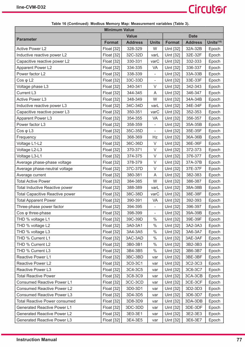
77Instruction Manual
line-CVM-D32
Table 16 (Continued): Modbus Memory Map: Measurement variables (Table 3)�Minimum Value
ParameterValue Date
Format Address Units Format Address Units(10)
Active Power L2 Float [32] 328-329 W Uint [32] 32A-32B EpochInductive reactive power L2 Float [32] 32C-32D varL Uint [32] 32E-32F EpochCapacitive reactive power L2 Float [32] 330-331 varC Uint [32] 332-333 EpochApparent Power L2 Float [32] 334-335 VA Uint [32] 336-337 EpochPower factor L2 Float [32] 338-339 - Uint [32] 33A-33B EpochCosφL2 Float [32] 33C-33D - Uint [32] 33E-33F EpochVoltage phase L3 Float [32] 340-341 V Uint [32] 342-343 EpochCurrent L3 Float [32] 344-345 A Uint [32] 346-347 EpochActive Power L3 Float [32] 348-349 W Uint [32] 34A-34B EpochInductive reactive power L3 Float [32] 34C-34D varL Uint [32] 34E-34F EpochCapacitive reactive power L3 Float [32] 350-351 varC Uint [32] 352-353 EpochApparent Power L3 Float [32] 354-355 VA Uint [32] 356-357 EpochPower factor L3 Float [32] 358-359 - Uint [32] 35A-35B EpochCosφL3 Float [32] 35C-35D - Uint [32] 35E-35F EpochFrequency Float [32] 368-369 Hz Uint [32] 36A-36B EpochVoltage L1-L2 Float [32] 36C-36D V Uint [32] 36E-36F EpochVoltage L2-L3 Float [32] 370-371 V Uint [32] 372-373 EpochVoltage L3-L1 Float [32] 374-375 V Uint [32] 376-377 EpochAverage phase-phase voltage Float [32] 378-379 V Uint [32] 37A-37B EpochAverage phase-neutral voltage Float [32] 37C-37D V Uint [32] 37E-37F EpochAverage current Float [32] 380-381 A Uint [32] 382-383 EpochTotal Active Power Float [32] 384-385 W Uint [32] 386-387 EpochTotal Inductive Reactive power Float [32] 388-389 varL Uint [32] 38A-38B EpochTotal Capacitive Reactive power Float [32] 38C-38D varC Uint [32] 38E-38F EpochTotal Apparent Power Float [32] 390-391 VA Uint [32] 392-393 EpochThree-phase power factor Float [32] 394-395 - Uint [32] 396-397 EpochCosφthree-phase Float [32] 398-399 - Uint [32] 39A-39B EpochTHD % voltage L1 Float [32] 39C-39D % Uint [32] 39E-39F EpochTHD % voltage L2 Float [32] 3A0-3A1 % Uint [32] 3A2-3A3 EpochTHD % voltage L3 Float [32] 3A4-3A5 % Uint [32] 3A6-3A7 EpochTHD % Current L1 Float [32] 3AC-3AD % Uint [32] 3AE-3AF EpochTHD % Current L2 Float [32] 3B0-3B1 % Uint [32] 3B2-3B3 EpochTHD % Current L3 Float [32] 3B4-3B5 % Uint [32] 3B6-3B7 EpochReactive Power L1 Float [32] 3BC-3BD var Uint [32] 3BE-3BF EpochReactive Power L2 Float [32] 3C0-3C1 var Uint [32] 3C2-3C3 EpochReactive Power L3 Float [32] 3C4-3C5 var Uint [32] 3C6-3C7 EpochTotal Reactive Power Float [32] 3C8-3C9 var Uint [32] 3CA-3CB EpochConsumed Reactive Power L1 Float [32] 3CC-3CD var Uint [32] 3CE-3CF EpochConsumed Reactive Power L2 Float [32] 3D0-3D1 var Uint [32] 3D2-3D3 EpochConsumed Reactive Power L3 Float [32] 3D4-3D5 var Uint [32] 3D6-3D7 EpochTotal Reactive Power consumed Float [32] 3D8-3D9 var Uint [32] 3DA-3DB EpochGenerated Reactive Power L1 Float [32] 3DC-3DD var Uint [32] 3DE-3DF EpochGenerated Reactive Power L2 Float [32] 3E0-3E1 var Uint [32] 3E2-3E3 EpochGenerated Reactive Power L3 Float [32] 3E4-3E5 var Uint [32] 3E6-3E7 Epoch

78
line-CVM-D32
Instruction Manual
Table 16 (Continued): Modbus Memory Map: Measurement variables (Table 3)�Minimum Value
ParameterValue Date
Format Address Units Format Address Units(10)
Total Reactive Power generated Float [32] 3E8-3E9 var Uint [32] 3EA-3EB EpochConsumed Active Power L1 Float [32] 3EC-3ED W Uint [32] 3EE-3EF EpochConsumed Active Power L2 Float [32] 3F0-3F1 W Uint [32] 3F2-3F3 EpochConsumed Active Power L3 Float [32] 3F4-3F5 W Uint [32] 3F6-3F7 EpochTotal Active Power consumed Float [32] 3F8-3F9 W Uint [32] 3FA-3FB EpochGenerated Active Power L1 Float [32] 3FC-3FD W Uint [32] 3FE-3FF EpochGenerated Active Power L2 Float [32] 400-401 W Uint [32] 402-403 EpochGenerated Active Power L3 Float [32] 404-405 W Uint [32] 406-407 EpochTotal Active Power generated Float [32] 408-409 W Uint [32] 40A-40B EpochInductive Reactive Power consumed L1 Float [32] 40C-40D varL Uint [32] 40E-40F EpochInductive Reactive Power consumed L2 Float [32] 410-411 varL Uint [32] 412-413 EpochInductive Reactive Power consumed L3 Float [32] 414-415 varL Uint [32] 416-417 EpochTotal Inductive Reactive Power consumed Float [32] 418-419 varL Uint [32] 41A-41B EpochInductive Reactive Power generated L1 Float [32] 41C-41D varL Uint [32] 41E-41F EpochInductive Reactive Power generated L2 Float [32] 420-421 varL Uint [32] 422-423 EpochInductive Reactive Power generated L3 Float [32] 424-425 varL Uint [32] 426-427 EpochTotal Inductive Reactive Power generated Float [32] 428-429 varL Uint [32] 42A-42B EpochCapacitive Reactive Power consumed L1 Float [32] 42C-42D varC Uint [32] 42E-42F EpochCapacitive Reactive Power consumed L2 Float [32] 430-431 varC Uint [32] 432-433 EpochCapacitive Reactive Power consumed L3 Float [32] 434-435 varC Uint [32] 436-437 EpochTotal Capacitive Reactive Power consumed Float [32] 438-439 varC Uint [32] 43A-43B EpochCapacitive Reactive Power generated L1 Float [32] 43C-43D varC Uint [32] 43E-43F EpochCapacitive Reactive Power generated L2 Float [32] 440-441 varC Uint [32] 442-443 EpochCapacitive Reactive Power generated L3 Float [32] 444-445 varC Uint [32] 446-447 EpochTotal Capacitive Reactive Power generated Float [32] 448-449 varC Uint [32] 44A-44B EpochConsumed Power Factor L1 Float [32] 44C-44D - Uint [32] 44E-44F EpochConsumed Power Factor L2 Float [32] 450-451 - Uint [32] 452-453 EpochConsumed Power Factor L3 Float [32] 454-455 - Uint [32] 456-457 EpochThree-phase Power Factor consumed Float [32] 458-459 - Uint [32] 45A-45B EpochGenerated Power Factor L1 Float [32] 45C-45D - Uint [32] 45E-45F EpochGenerated Power Factor L2 Float [32] 460-461 - Uint [32] 462-463 EpochGenerated Power Factor L3 Float [32] 464-465 - Uint [32] 466-467 EpochThree-phase Power Factor generated Float [32] 468-469 - Uint [32] 46A-46B EpochCosφPowerconsumedL1 Float [32] 46C-46D - Uint [32] 46E-46F EpochCosφPowerconsumedL2 Float [32] 470-471 - Uint [32] 472-473 EpochCosφPowerconsumedL3 Float [32] 474-475 - Uint [32] 476 - 477 EpochCosφThree-phasePowerconsumed Float [32] 478-479 - Uint [32] 47A-47B EpochCosφPowergeneratedL1 Float [32] 47C-47D - Uint [32] 47E-47F EpochCosφPowergeneratedL2 Float [32] 480-481 - Uint [32] 482-483 EpochCosφPowergeneratedL3 Float [32] 484-485 - Uint [32] 486-487 EpochCosφThree-phasePowergenerated Float [32] 488-489 - Uint [32] 48A-48B Epoch(10) Date and time are given in Epoch format.
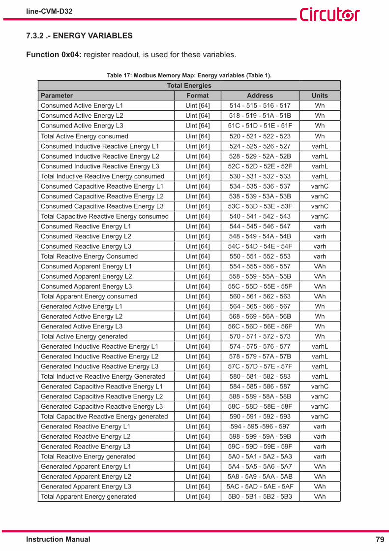
79Instruction Manual
line-CVM-D32
7�3�2 �- ENERGY VARIABLES
Function 0x04: register readout, is used for these variables.
Table 17: Modbus Memory Map: Energy variables (Table 1)�
Total EnergiesParameter Format Address UnitsConsumed Active Energy L1 Uint [64] 514 - 515 - 516 - 517 WhConsumed Active Energy L2 Uint [64] 518 - 519 - 51A - 51B WhConsumed Active Energy L3 Uint [64] 51C - 51D - 51E - 51F WhTotal Active Energy consumed Uint [64] 520 - 521 - 522 - 523 WhConsumed Inductive Reactive Energy L1 Uint [64] 524 - 525 - 526 - 527 varhLConsumed Inductive Reactive Energy L2 Uint [64] 528 - 529 - 52A - 52B varhLConsumed Inductive Reactive Energy L3 Uint [64] 52C - 52D - 52E - 52F varhLTotal Inductive Reactive Energy consumed Uint [64] 530 - 531 - 532 - 533 varhLConsumed Capacitive Reactive Energy L1 Uint [64] 534 - 535 - 536 - 537 varhCConsumed Capacitive Reactive Energy L2 Uint [64] 538 - 539 - 53A - 53B varhCConsumed Capacitive Reactive Energy L3 Uint [64] 53C - 53D - 53E - 53F varhCTotal Capacitive Reactive Energy consumed Uint [64] 540 - 541 - 542 - 543 varhCConsumed Reactive Energy L1 Uint [64] 544 - 545 - 546 - 547 varhConsumed Reactive Energy L2 Uint [64] 548 - 549 - 54A - 54B varhConsumed Reactive Energy L3 Uint [64] 54C - 54D - 54E - 54F varhTotal Reactive Energy Consumed Uint [64] 550 - 551 - 552 - 553 varhConsumed Apparent Energy L1 Uint [64] 554 - 555 - 556 - 557 VAhConsumed Apparent Energy L2 Uint [64] 558 - 559 - 55A - 55B VAhConsumed Apparent Energy L3 Uint [64] 55C - 55D - 55E - 55F VAhTotal Apparent Energy consumed Uint [64] 560 - 561 - 562 - 563 VAhGenerated Active Energy L1 Uint [64] 564 - 565 - 566 - 567 WhGenerated Active Energy L2 Uint [64] 568 - 569 - 56A - 56B WhGenerated Active Energy L3 Uint [64] 56C - 56D - 56E - 56F WhTotal Active Energy generated Uint [64] 570 - 571 - 572 - 573 WhGenerated Inductive Reactive Energy L1 Uint [64] 574 - 575 - 576 - 577 varhLGenerated Inductive Reactive Energy L2 Uint [64] 578 - 579 - 57A - 57B varhLGenerated Inductive Reactive Energy L3 Uint [64] 57C - 57D - 57E - 57F varhLTotal Inductive Reactive Energy Generated Uint [64] 580 - 581 - 582 - 583 varhLGenerated Capacitive Reactive Energy L1 Uint [64] 584 - 585 - 586 - 587 varhCGenerated Capacitive Reactive Energy L2 Uint [64] 588 - 589 - 58A - 58B varhCGenerated Capacitive Reactive Energy L3 Uint [64] 58C - 58D - 58E - 58F varhCTotal Capacitive Reactive Energy generated Uint [64] 590 - 591 - 592 - 593 varhCGenerated Reactive Energy L1 Uint [64] 594 - 595 -596 - 597 varhGenerated Reactive Energy L2 Uint [64] 598 - 599 - 59A - 59B varhGenerated Reactive Energy L3 Uint [64] 59C - 59D - 59E - 59F varhTotal Reactive Energy generated Uint [64] 5A0 - 5A1 - 5A2 - 5A3 varhGenerated Apparent Energy L1 Uint [64] 5A4 - 5A5 - 5A6 - 5A7 VAhGenerated Apparent Energy L2 Uint [64] 5A8 - 5A9 - 5AA - 5AB VAhGenerated Apparent Energy L3 Uint [64] 5AC - 5AD - 5AE - 5AF VAhTotal Apparent Energy generated Uint [64] 5B0 - 5B1 - 5B2 - 5B3 VAh

80
line-CVM-D32
Instruction Manual
Table 18: Modbus Memory Map: Energy variables (Table 2)�
Energies per TariffsTariff 1
Parameter Format Address UnitsConsumed Active Energy L1 Uint [64] 5B4 - 5B5 - 5B6 - 5B7 WhConsumed Active Energy L2 Uint [64] 5B8 - 5B9 - 5BA - 5BB WhConsumed Active Energy L3 Uint [64] 5BC - 5BD - 5BE - 5BF WhTotal Active Energy Consumed Uint [64] 5C0 - 5C1 - 5C2 - 5C3 WhConsumed Inductive Reactive Energy L1 Uint [64] 5C4 - 5C5 - 5C6 - 5C7 varhLConsumed Inductive Reactive Energy L2 Uint [64] 5C8 - 5C9 - 5CA - 5CB varhLConsumed Inductive Reactive Energy L3 Uint [64] 5CC - 5CD - 5CE - 5CF varhLTotal Inductive Reactive Energy consumed Uint [64] 5D0 - 5D1 - 5D2 - 5D3 varhLConsumed Capacitive Reactive Energy L1 Uint [64] 5D4 - 5D5 - 5D6 - 5D7 varhCConsumed Capacitive Reactive Energy L2 Uint [64] 5D8 - 5D9 - 5DA - 5DB varhCConsumed Capacitive Reactive Energy L3 Uint [64] 5DC - 5DD - 5DE - 5DF varhCTotal Capacitive Reactive Energy consumed Uint [64] 5E0 - 5E1 - 5E2 - 5E3 varhCConsumed Reactive Energy L1 Uint [64] 5E4 - 5E5 - 5E6 - 5E7 varhConsumed Reactive Energy L2 Uint [64] 5E8 - 5E9 - 5EA - 5EB varhConsumed Reactive Energy L3 Uint [64] 5EC - 5ED - 5EE - 5EF varhTotal Reactive Energy consumed Uint [64] 5F0 - 5F1 - 5F2 - 5F3 varhConsumed Apparent Energy L1 Uint [64] 5F4 - 5F5 - 5F6 - 5F7 VAhConsumed Apparent Energy L2 Uint [64] 5F8 - 5F9 - 5FA - 5FB VAhConsumed Apparent Energy L3 Uint [64] 5FC - 5FD - 5FE - 5FF VAhTotal Apparent Energy consumed Uint [64] 600 - 601 - 602 - 603 VAhGenerated Active Energy L1 Uint [64] 604 - 605 - 606 - 607 WhGenerated Active Energy L2 Uint [64] 608 - 609 - 60A - 60B WhGenerated Active Energy L3 Uint [64] 60C - 60D - 60E - 60F WhTotal Active Energy generated Uint [64] 610 - 611 - 612 - 613 WhGenerated Inductive Reactive Energy L1 Uint [64] 614 - 615 - 616 - 617 varhLGenerated Inductive Reactive Energy L2 Uint [64] 618 - 619 - 61A - 61B varhLGenerated Inductive Reactive Energy L3 Uint [64] 61C - 61D - 61E - 61F varhLTotal Inductive Reactive Energy generated Uint [64] 620 - 621 - 622 - 623 varhLGenerated Capacitive Reactive Energy L1 Uint [64] 624 - 625 - 626 - 627 varhCGenerated Capacitive Reactive Energy L2 Uint [64] 628 - 629 - 62A - 62B varhCGenerated Capacitive Reactive Energy L3 Uint [64] 62C - 62D - 62E - 62F varhCTotal Capacitive Reactive Energy generated Uint [64] 630 - 631 - 632 - 633 varhCGenerated Reactive Energy L1 Uint [64] 634 - 635 - 636 - 637 varhGenerated Reactive Energy L2 Uint [64] 638 - 639 - 63A - 63B varhGenerated Reactive Energy L3 Uint [64] 63C - 63D -63E - 63F varhTotal Reactive Energy generated Uint [64] 640 - 641 - 642 - 643 varhGenerated Apparent Energy L1 Uint [64] 644 - 645 - 646 - 647 VAhGenerated Apparent Energy L2 Uint [64] 648 - 649 - 64A - 64B VAhGenerated Apparent Energy L3 Uint [64] 64C - 64D - 64E - 64F VAhTotal Apparent Energy generated Uint [64] 650 - 651 - 652 - 653 VAh
Tariff 2Parameter Format Address UnitsConsumed Active Energy L1 Uint [64] 654 - 655 - 656 - 657 WhConsumed Active Energy L2 Uint [64] 658 - 659 - 65A - 65B Wh

81Instruction Manual
line-CVM-D32
Table 18 (Continued): Modbus Memory Map: Energy variables (Table 2)�Energies per Tariffs
Parameter Format Address UnitsConsumed Active Energy L3 Uint [64] 65C - 65D - 65E - 65F WhTotal Active Energy consumed Uint [64] 660 - 661 - 662 - 663 WhConsumed Inductive Reactive Energy L1 Uint [64] 664 - 665 - 666 - 667 varhLConsumed Inductive Reactive Energy L2 Uint [64] 668 - 669 - 66A - 66B varhLConsumed Inductive Reactive Energy L3 Uint [64] 66C - 66D - 66E - 66F varhLTotal Inductive Reactive Energy consumed Uint [64] 670 - 671 - 672 - 673 varhLConsumed Capacitive Reactive Energy L1 Uint [64] 674 - 675 - 676 - 677 varhCConsumed Capacitive Reactive Energy L2 Uint [64] 678 - 679 - 67A - 67B varhCConsumed Capacitive Reactive Energy L3 Uint [64] 67C - 67D - 67E - 67F varhCTotal Capacitive Reactive Energy consumed Uint [64] 680 - 681 - 682 - 683 varhCConsumed Reactive Energy L1 Uint [64] 684 - 685 - 686 - 687 varhConsumed Reactive Energy L2 Uint [64] 688 - 689 - 68A - 68B varhConsumed Reactive Energy L3 Uint [64] 68C - 68D - 68E - 68F varhTotal Reactive Energy consumed Uint [64] 690 - 691 - 692 - 693 varhConsumed Apparent Energy L1 Uint [64] 694 - 695 - 696 - 697 VAhConsumed Apparent Energy L2 Uint [64] 698 - 699 - 69A - 69B VAhConsumed Apparent Energy L3 Uint [64] 69C - 69D - 69E - 69F VAhTotal Apparent Energy consumed Uint [64] 6A0 - 6A1 - 6A2 - 6A3 VAhGenerated Active Energy L1 Uint [64] 6A4 - 6A5 - 6A6 - 6A7 WhGenerated Active Energy L2 Uint [64] 6A8 - 6A9 - 6AA - 6AB WhGenerated Active Energy L3 Uint [64] 6AC - 6AD - 6AE -6AF WhTotal Active Energy generated Uint [64] 6B0 - 6B1 - 6B2 - 6B3 WhGenerated Inductive Reactive Energy L1 Uint [64] 6B4 - 6B5 - 6B6 - 6B7 varhLGenerated Inductive Reactive Energy L2 Uint [64] 6B8 - 6B9 - 6BA - 6BB varhLGenerated Inductive Reactive Energy L3 Uint [64] 6BC - 6BD - 6BE - 6BF varhLTotal Inductive Reactive Energy generated Uint [64] 6C0 - 6C1 - 6C2 - 6C3 varhLGenerated Capacitive Reactive Energy L1 Uint [64] 6C4 - 6C5 - 6C6 - 6C7 varhCGenerated Capacitive Reactive Energy L2 Uint [64] 6C8 - 6C9 - 6CA - 6CB varhCGenerated Capacitive Reactive Energy L3 Uint [64] 6CC - 6CD - 6CE - 6CF varhCTotal Capacitive Reactive Energy generated Uint [64] 6D0 - 6D1 - 6D2 - 6D3 varhCGenerated Reactive Energy L1 Uint [64] 6D4 - 6D5 - 6D6 - 6D7 varhGenerated Reactive Energy L2 Uint [64] 6D8 - 6D9 - 6DA - 6DB varhGenerated Reactive Energy L3 Uint [64] 6DC - 6DD - 6DE - 6DF varhTotal Reactive Energy generated Uint [64] 6E0 - 6E1 - 6E2 - 6E3 varhGenerated Apparent Energy L1 Uint [64] 6E4 - 6E5 - 6E6 - 6E7 VAhGenerated Apparent Energy L2 Uint [64] 6E8 - 6E9 - 6EA - 6EB VAhGenerated Apparent Energy L3 Uint [64] 6EC - 6ED - 6EE - 6EF VAhTotal Apparent Energy Generated Uint [64] 6F0 - 6F1 - 6F2 - 6F3 VAh
Tariff 3Parameter Format Address UnitsConsumed Active Energy L1 Uint [64] 6F4 - 6F5 - 6F6 - 6F7 WhConsumed Active Energy L2 Uint [64] 6F8 - 6F9 - 6FA - 6FB WhConsumed Active Energy L3 Uint [64] 6FC - 6FD - 6FE - 6FF WhTotal Active Energy consumed Uint [64] 700 - 701 - 702 - 703 WhConsumed Inductive Reactive Energy L1 Uint [64] 704 - 705 - 706 - 707 varhL

82
line-CVM-D32
Instruction Manual
Table 18 (Continued): Modbus Memory Map: Energy variables (Table 2)�Energies per Tariffs
Parameter Format Address UnitsConsumed Inductive Reactive Energy L2 Uint [64] 708 - 709 - 70A - 70B varhLConsumed Inductive Reactive Energy L3 Uint [64] 70C - 70D - 70E - 70F varhLTotal Inductive Reactive Energy consumed Uint [64] 710 - 711 - 712 - 713 varhLConsumed Capacitive Reactive Energy L1 Uint [64] 714 - 715 - 716 - 717 varhCConsumed Capacitive Reactive Energy L2 Uint [64] 718 - 719 - 71A - 71B varhCConsumed Capacitive Reactive Energy L3 Uint [64] 71C - 71D - 71E - 71F varhCTotal Capacitive Reactive Energy consumed Uint [64] 720 - 721 - 722 - 723 varhCConsumed Reactive Energy L1 Uint [64] 724 - 725 - 726 - 727 varhConsumed Reactive Energy L2 Uint [64] 728 - 729 - 72A - 72B varhConsumed Reactive Energy L3 Uint [64] 72C - 72D - 72E - 72F varhTotal Reactive Energy consumed Uint [64] 730 - 731 - 732 - 733 varhConsumed Apparent Energy L1 Uint [64] 734-735-736-737 VAhConsumed Apparent Energy L2 Uint [64] 738 - 739 - 73A - 73B VAhConsumed Apparent Energy L3 Uint [64] 73C - 73D - 73E - 73F VAhTotal Apparent Energy consumed Uint [64] 740 - 741 - 742 - 743 VAhGenerated Active Energy L1 Uint [64] 744 - 745 - 746 - 747 WhGenerated Active Energy L2 Uint [64] 748 - 749 - 74A - 74B WhGenerated Active Energy L3 Uint [64] 74C - 74D - 74E - 74F WhTotal Active Energy generated Uint [64] 750 - 751 - 752 - 753 WhGenerated Inductive Reactive Energy L1 Uint [64] 754 - 755 - 756 - 757 varhLGenerated Inductive Reactive Energy L2 Uint [64] 758 - 759 - 75A - 75B varhLGenerated Inductive Reactive Energy L3 Uint [64] 75C - 75D - 75E - 75F varhLTotal Inductive Reactive Energy generated Uint [64] 760 - 761 - 762 - 763 varhLGenerated Capacitive Reactive Energy L1 Uint [64] 764 - 765 - 766 - 767 varhCGenerated Capacitive Reactive Energy L2 Uint [64] 768 - 769 - 76A - 76B varhCGenerated Capacitive Reactive Energy L3 Uint [64] 76C - 76D - 76E - 76F varhCTotal Capacitive Reactive Energy generated Uint [64] 770 - 771 - 772 - 773 varhCGenerated Reactive Energy L1 Uint [64] 774 - 775 - 776 - 777 varhGenerated Reactive Energy L2 Uint [64] 778 - 779 - 77A - 77B varhGenerated Reactive Energy L3 Uint [64] 77C - 77D - 77E - 77F varhTotal Reactive Energy generated Uint [64] 780 - 781 - 782 - 783 varhGenerated Apparent Energy L1 Uint [64] 784 - 785 - 786 - 787 VAhGenerated Apparent Energy L2 Uint [64] 788 - 789 - 78A - 78B VAhGenerated Apparent Energy L3 Uint [64] 78C - 78D - 78E - 78F VAhTotal Apparent Energy generated Uint [64] 790 - 791 - 792 - 793 VAh
Tariff 4Parameter Format Address UnitsConsumed Active Energy L1 Uint [64] 794 - 795 - 796 - 797 WhConsumed Active Energy L2 Uint [64] 798 - 799 - 79A - 79B WhConsumed Active Energy L3 Uint [64] 79C - 79D - 79E - 79F WhTotal Active Energy consumed Uint [64] 7A0 - 7A1 - 7A2 - 7A3 WhConsumed Inductive Reactive Energy L1 Uint [64] 7A4 - 7A5 - 7A6 - 7A7 varhLConsumed Inductive Reactive Energy L2 Uint [64] 7A8 - 7A9 - 7AA - 7AB varhLConsumed Inductive Reactive Energy L3 Uint [64] 7AC - 7AD - 7AE - 7AE varhLTotal Inductive Reactive Energy consumed Uint [64] 7B0 -7B1 - 7B2 - 7B3 varhL

83Instruction Manual
line-CVM-D32
Table 18 (Continued): Modbus Memory Map: Energy variables (Table 2)�Energies per Tariffs
Parameter Format Address UnitsConsumed Capacitive Reactive Energy L1 Uint [64] 7B4 - 7B5 - 7B6 - 7B7 varhCConsumed Capacitive Reactive Energy L2 Uint [64] 7B8 - 7B9 - 7BA - 7BB varhCConsumed Capacitive Reactive Energy L3 Uint [64] 7BC - 7BD - 7BE - 7BF varhCTotal Capacitive Reactive Energy consumed Uint [64] 7C0 - 7C1 - 7C2 - 7C3 varhCConsumed Reactive Energy L1 Uint [64] 7C4 - 7C5 - 7C6 - 7C7 varhConsumed Reactive Energy L2 Uint [64] 7C8 - 7C9 - 7CA - 7CB varhConsumed Reactive Energy L3 Uint [64] 7CC - 7CD - 7CE - 7CF varhTotal Reactive Energy consumed Uint [64] 7D0 - 7D1 - 7D2 - 7D3 varhConsumed Apparent Energy L1 Uint [64] 7D4 - 7D5 - 7D6 - 7D7 VAhConsumed Apparent Energy L2 Uint [64] 7D8 - 7D9 - 7DA - 7DB VAhConsumed Apparent Energy L3 Uint [64] 7DC - 7DD - 7DE - 7DF VAhTotal Apparent Energy consumed Uint [64] 7E0 - 7E1 - 7E2 - 7E3 VAhGenerated Active Energy L1 Uint [64] 7E4 - 7E5 - 7E6 - 7E7 WhGenerated Active Energy L2 Uint [64] 7E8 - 7E9 - 7EA - 7EB WhGenerated Active Energy L3 Uint [64] 7EC - 7ED - 7EE - 7EF WhTotal Active Energy generated Uint [64] 7F0 - 7F1 - 7F2 - 7F3 WhGenerated Inductive Reactive Energy L1 Uint [64] 7F4 - 7F5 - 7F6 - 7F7 varhLGenerated Inductive Reactive Energy L2 Uint [64] 7F8 - 7F9 - 7FA - 7FB varhLGenerated Inductive Reactive Energy L3 Uint [64] 7FC - 7FD - 7FE -7FF varhLTotal Inductive Reactive Energy generated Uint [64] 800-801-802-803 varhLGenerated Capacitive Reactive Energy L1 Uint [64] 804-805-806-807 varhCGenerated Capacitive Reactive Energy L2 Uint [64] 808 - 809 - 80A - 80B varhCGenerated Capacitive Reactive Energy L3 Uint [64] 80C - 80D - 80E - 80F varhCTotal Capacitive Reactive Energy generated Uint [64] 810 - 811 - 812 - 813 varhCGenerated Reactive Energy L1 Uint [64] 814 - 815 - 816 - 817 varhGenerated Reactive Energy L2 Uint [64] 818 - 819 - 81A - 81B varhGenerated Reactive Energy L3 Uint [64] 81C - 81D - 81E - 81F varhTotal Reactive Energy generated Uint [64] 820 - 821 - 822 - 823 varhGenerated Apparent Energy L1 Uint [64] 824 - 825 - 826 - 827 VAhGenerated Apparent Energy L2 Uint [64] 828 - 829 - 82A - 82B VAhGenerated Apparent Energy L3 Uint [64] 82C - 82D - 82E - 82F VAhTotal Apparent Energy Generated Uint [64] 830 - 831 - 832 - 833 VAh
7�3�3�- MAXIMUM DEMAND VARIABLES
Function 0x04: register readout, is used for these variables.
Table 19: Modbus Memory Map: Maximum Demand Variables (Table 1)�
Parameter Format Tariff 1 Tariff 2 Tariff 3 Tariff 4 UnitsCurrent L1 Float [32] B54-B55 B84-B85 BB4-BB5 BE4-BE5 ACurrent L2 Float [32] B56-B57 B86-B87 BB6-BB7 BE6-BE7 ACurrent L3 Float [32] B58-B59 B88-B89 BB8-BB9 BE8-BE9 ATotal Current Float [32] B5A-B5B B8A-B8B BBA-BBB BEA -BEB AActive Power L1 Float [32] B5C-B5D B8C-B8D BBC-BBD BEC-BED W
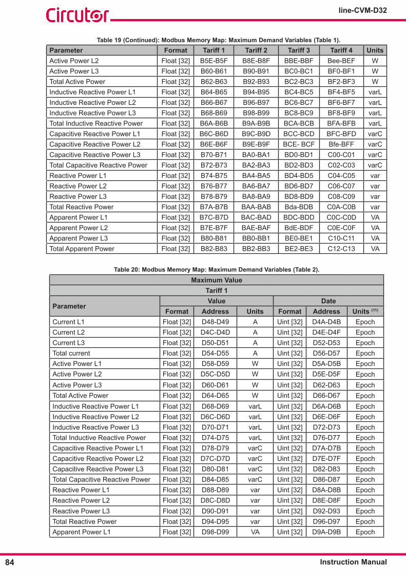
84
line-CVM-D32
Instruction Manual
Table 19 (Continued): Modbus Memory Map: Maximum Demand Variables (Table 1)�Parameter Format Tariff 1 Tariff 2 Tariff 3 Tariff 4 UnitsActive Power L2 Float [32] B5E-B5F B8E-B8F BBE-BBF Bee-BEF WActive Power L3 Float [32] B60-B61 B90-B91 BC0-BC1 BF0-BF1 WTotal Active Power Float [32] B62-B63 B92-B93 BC2-BC3 BF2-BF3 WInductive Reactive Power L1 Float [32] B64-B65 B94-B95 BC4-BC5 BF4-BF5 varLInductive Reactive Power L2 Float [32] B66-B67 B96-B97 BC6-BC7 BF6-BF7 varLInductive Reactive Power L3 Float [32] B68-B69 B98-B99 BC8-BC9 BF8-BF9 varLTotal Inductive Reactive Power Float [32] B6A-B6B B9A-B9B BCA-BCB BFA-BFB varLCapacitive Reactive Power L1 Float [32] B6C-B6D B9C-B9D BCC-BCD BFC-BFD varCCapacitive Reactive Power L2 Float [32] B6E-B6F B9E-B9F BCE- BCF Bfe-BFF varCCapacitive Reactive Power L3 Float [32] B70-B71 BA0-BA1 BD0-BD1 C00-C01 varCTotal Capacitive Reactive Power Float [32] B72-B73 BA2-BA3 BD2-BD3 C02-C03 varCReactive Power L1 Float [32] B74-B75 BA4-BA5 BD4-BD5 C04-C05 varReactive Power L2 Float [32] B76-B77 BA6-BA7 BD6-BD7 C06-C07 varReactive Power L3 Float [32] B78-B79 BA8-BA9 BD8-BD9 C08-C09 varTotal Reactive Power Float [32] B7A-B7B BAA-BAB Bda-BDB C0A-C0B varApparent Power L1 Float [32] B7C-B7D BAC-BAD BDC-BDD C0C-C0D VAApparent Power L2 Float [32] B7E-B7F BAE-BAF BdE-BDF C0E-C0F VAApparent Power L3 Float [32] B80-B81 BB0-BB1 BE0-BE1 C10-C11 VATotal Apparent Power Float [32] B82-B83 BB2-BB3 BE2-BE3 C12-C13 VA
Table 20: Modbus Memory Map: Maximum Demand Variables (Table 2)�
Maximum ValueTariff 1
ParameterValue Date
Format Address Units Format Address Units (11)
Current L1 Float [32] D48-D49 A Uint [32] D4A-D4B EpochCurrent L2 Float [32] D4C-D4D A Uint [32] D4E-D4F EpochCurrent L3 Float [32] D50-D51 A Uint [32] D52-D53 EpochTotal current Float [32] D54-D55 A Uint [32] D56-D57 EpochActive Power L1 Float [32] D58-D59 W Uint [32] D5A-D5B EpochActive Power L2 Float [32] D5C-D5D W Uint [32] D5E-D5F EpochActive Power L3 Float [32] D60-D61 W Uint [32] D62-D63 EpochTotal Active Power Float [32] D64-D65 W Uint [32] D66-D67 EpochInductive Reactive Power L1 Float [32] D68-D69 varL Uint [32] D6A-D6B EpochInductive Reactive Power L2 Float [32] D6C-D6D varL Uint [32] D6E-D6F EpochInductive Reactive Power L3 Float [32] D70-D71 varL Uint [32] D72-D73 EpochTotal Inductive Reactive Power Float [32] D74-D75 varL Uint [32] D76-D77 EpochCapacitive Reactive Power L1 Float [32] D78-D79 varC Uint [32] D7A-D7B EpochCapacitive Reactive Power L2 Float [32] D7C-D7D varC Uint [32] D7E-D7F EpochCapacitive Reactive Power L3 Float [32] D80-D81 varC Uint [32] D82-D83 EpochTotal Capacitive Reactive Power Float [32] D84-D85 varC Uint [32] D86-D87 EpochReactive Power L1 Float [32] D88-D89 var Uint [32] D8A-D8B EpochReactive Power L2 Float [32] D8C-D8D var Uint [32] D8E-D8F EpochReactive Power L3 Float [32] D90-D91 var Uint [32] D92-D93 EpochTotal Reactive Power Float [32] D94-D95 var Uint [32] D96-D97 EpochApparent Power L1 Float [32] D98-D99 VA Uint [32] D9A-D9B Epoch

85Instruction Manual
line-CVM-D32
Table 20 (Continued): Modbus Memory Map: Maximum Demand Variables (Table 2)�Maximum Value
ParameterValue Date
Format Address Units Format Address Units (11)
Apparent Power L2 Float [32] D9C-D9D VA Uint [32] D9E-D9F EpochApparent Power L3 Float [32] DA0-DA1 VA Uint [32] DA2-DA3 EpochTotal Apparent Power Float [32] DA4-DA5 VA Uint [32] DA6-DA7 Epoch
Tariff 2Current L1 Float [32] DA8-DA9 A Uint [32] DAA-DAB EpochCurrent L2 Float [32] DAC-DAD A Uint [32] DAE-DAF EpochCurrent L3 Float [32] DB0-DB1 A Uint [32] DB2-DB3 EpochTotal Current Float [32] DB4-DB5 A Uint [32] DB6-DB7 EpochActive Power L1 Float [32] DB8-DB9 W Uint [32] DBA-DBB EpochActive Power L2 Float [32] DBC-DBD W Uint [32] DBE-DBF EpochActive Power L3 Float [32] DC0-DC1 W Uint [32] DC2-DC3 EpochTotal Active Power Float [32] DC4-DC5 W Uint [32] DC6-DC7 EpochInductive Reactive Power L1 Float [32] DC8-DC9 varL Uint [32] DCA-DCB EpochInductive Reactive Power L2 Float [32] DCC-DCD varL Uint [32] DCE-DCF EpochInductive Reactive Power L3 Float [32] DD0-DD1 varL Uint [32] DD2-DD3 EpochTotal Inductive Reactive Power Float [32] DD4-DD5 varL Uint [32] DD6-DD7 EpochCapacitive Reactive Power L1 Float [32] DD8-DD9 varC Uint [32] DDA-DDB EpochCapacitive Reactive Power L2 Float [32] DDC-DDD varC Uint [32] DDE-DDF EpochCapacitive Reactive Power L3 Float [32] DE0-DE1 varC Uint [32] DE2-DE3 EpochTotal Capacitive Reactive Power Float [32] DE4-DE5 varC Uint [32] DE6-DE7 EpochReactive Power L1 Float [32] DE8-DE9 var Uint [32] DEA-DEB EpochReactive Power L2 Float [32] DEC-DED var Uint [32] DEE - DEF EpochReactive Power L3 Float [32] DF0-DF1 var Uint [32] DF2-DF3 EpochTotal Reactive Power Float [32] DF4-DF5 var Uint [32] DF6-DF7 EpochApparent Power L1 Float [32] DF8-DF9 VA Uint [32] DFA - DFB EpochApparent Power L2 Float [32] DFC - DFD VA Uint [32] DFE-DFF EpochApparent Power L3 Float [32] E00-E01 VA Uint [32] E02-E03 EpochTotal Apparent Power Float [32] E04-E05 VA Uint [32] E06-E07 Epoch
Tariff 3Current L1 Float [32] E08-E09 A Uint [32] E0A-E0B EpochCurrent L2 Float [32] E0C-E0D A Uint [32] E0E-E0F EpochCurrent L3 Float [32] E10-E11 A Uint [32] E12-E13 EpochTotal current Float [32] E14-E15 A Uint [32] E16-E17 EpochActive Power L1 Float [32] E18-E19 W Uint [32] E1A-E1B EpochActive Power L2 Float [32] E1C-E1D W Uint [32] E1E-E1F EpochActive Power L3 Float [32] E20-E21 W Uint [32] E22-E23 EpochTotal Active Power Float [32] E24-E25 W Uint [32] E26-E27 EpochInductive Reactive Power L1 Float [32] E28-E29 varL Uint [32] E2A-E2B EpochInductive Reactive Power L2 Float [32] E2C-E2D varL Uint [32] E2E-E2F EpochInductive Reactive Power L3 Float [32] E30-E31 varL Uint [32] E32-E33 EpochTotal Inductive Reactive Power Float [32] E34-E35 varL Uint [32] E36-E37 EpochCapacitive Reactive Power L1 Float [32] E38-E39 varC Uint [32] E3A-E3B EpochCapacitive Reactive Power L2 Float [32] E3C-E3D varC Uint [32] E3E-E3F EpochCapacitive Reactive Power L3 Float [32] E40-E41 varC Uint [32] E42-E43 Epoch

86
line-CVM-D32
Instruction Manual
Table 20 (Continued): Modbus Memory Map: Maximum Demand Variables (Table 2)�Maximum Value
ParameterValue Date
Format Address Units Format Address Units (11)
Total Capacitive Reactive Power Float [32] E44-E45 varC Uint [32] E46-E47 EpochReactive Power L1 Float [32] E48-E49 var Uint [32] E4A-E4B EpochReactive Power L2 Float [32] E4C-E4D var Uint [32] E4E-E4F EpochReactive Power L3 Float [32] E50-E51 var Uint [32] E52-E53 EpochTotal Reactive Power Float [32] E54-E55 var Uint [32] E56-E57 EpochApparent Power L1 Float [32] E58-E59 VA Uint [32] E5A-E5B EpochApparent Power L2 Float [32] E5C-E5D VA Uint [32] E5E-E5F EpochApparent Power L3 Float [32] E60-E61 VA Uint [32] E62-E63 EpochTotal Apparent Power Float [32] E64-E65 VA Uint [32] E66-E67 Epoch
Tariff 4Current L1 Float [32] E68-E69 A Uint [32] E6A-E6B EpochCurrent L2 Float [32] E6C-E6D A Uint [32] E6E-E6F EpochCurrent L3 Float [32] E70-E71 A Uint [32] E72-E73 EpochTotal current Float [32] E74-E75 A Uint [32] E76-E77 EpochActive Power L1 Float [32] E78-E79 W Uint [32] E7A-E7B EpochActive Power L2 Float [32] E7C-E7D W Uint [32] E7E-E7F EpochActive Power L3 Float [32] E80-E81 W Uint [32] E82-E83 EpochTotal Active Power Float [32] E84-E85 W Uint [32] E86-E87 EpochInductive Reactive Power L1 Float [32] E88-E89 varL Uint [32] E8A-E8B EpochInductive Reactive Power L2 Float [32] E8C-E8D varL Uint [32] E8E-E8F EpochInductive Reactive Power L3 Float [32] E90-E91 varL Uint [32] E92-E93 EpochTotal Inductive Reactive Power Float [32] E94-E95 varL Uint [32] E96-E97 EpochCapacitive Reactive Power L1 Float [32] E98-E99 varC Uint [32] E9A-E9B EpochCapacitive Reactive Power L2 Float [32] E9C-E9D varC Uint [32] E9E-E9F EpochCapacitive Reactive Power L3 Float [32] EA0-EA1 varC Uint [32] EA2-EA3 EpochTotal Capacitive Reactive Power Float [32] EA4-EA5 varC Uint [32] EA6-EA7 EpochReactive Power L1 Float [32] EA8-EA9 var Uint [32] EAA-EAB EpochReactive Power L2 Float [32] EAC-EAD var Uint [32] EAE-EAF EpochReactive Power L3 Float [32] EB0-EB1 var Uint [32] EB2-EB3 EpochTotal Reactive Power Float [32] EB4-EB5 var Uint [32] EB6-EB7 EpochApparent Power L1 Float [32] EB8-EB9 VA Uint [32] EBA-EBB EpochApparent Power L2 Float [32] EBC-EBD VA Uint [32] EBE-EBF EpochApparent Power L3 Float [32] EC0-EC1 VA Uint [32] EC2-EC3 EpochTotal Apparent Power Float [32] EC4-EC5 VA Uint [32] EC6-EC7 Epoch
(11) Date and time are given in Epoch format.

87Instruction Manual
line-CVM-D32
7�3�4�- VOLTAGE AND CURRENT HARMONICS�
Function 0x04: register readout, is used for these variables.
Table 21: Modbus Memory Map: Voltage and current harmonics�
Parameter Format Voltage L1 Voltage L2 Voltage L3 UnitsFundamental Harmonic Float [32] 1B58-1B59 1BEE-1BEF 1C84-1C85 V2nd Harmonic Float [32] 1B5A-1B5B 1BF0-1BF1 1C86-1C87 %3rd Harmonic Float [32] 1B5C-1B5D 1BF2-1BF3 1C88-1C89 %4th Harmonic Float [32] 1B5E-1B5F 1BF4-1BF5 1C8A-1C8B %5th Harmonic Float [32] 1B60-1B61 1BF6-1BF7 1C8C-1C8D %6th Harmonic Float [32] 1B62-1B63 1BF8-1BF9 1C8E-1C8F %7th Harmonic Float [32] 1B64-1B65 1BFA-1BFB 1C90-1C91 %8th Harmonic Float [32] 1B66-1B67 1BFC-1BFD 1C92-1C93 %9th Harmonic Float [32] 1B68-1B69 1BFE-1BFF 1C94-1C95 %10th Harmonic Float [32] 1B6A-1B6B 1C00-1C01 1C96-1C97 %11th Harmonic Float [32] 1B6C-1B6D 1C02-1C03 1C98-1C99 %12th Harmonic Float [32] 1B6E-1B6F 1C04-1C05 1C9A-1C9B %13th Harmonic Float [32] 1B70-1B71 1C06-1C07 1C9C-1C9D %14th Harmonic Float [32] 1B72-1B73 1C08-1C09 1C9E-1C9F %15th Harmonic Float [32] 1B74-1B75 1C0A-1C0B 1CA0-1CA1 %16th Harmonic Float [32] 1B76-1B77 1C0C-1C0D 1CA2-1CA3 %17th Harmonic Float [32] 1B78-1B79 1C0E-1C0F 1CA4-1CA5 %18th Harmonic Float [32] 1B7A-1B7B 1C10-1C11 1CA6-1CA7 %19th Harmonic Float [32] 1B7C-1B7D 1C12-1C13 1CA8-1CA9 %20th Harmonic Float [32] 1B7E-1B7F 1C14-1C15 1CAA-1CAB %21st Harmonic Float [32] 1B80-1B81 1C16-1C17 1CAC-1CAD %22nd Harmonic Float [32] 1B82-1B83 1C18-1C19 1CAE-1CAF %23rd Harmonic Float [32] 1B84-1B85 1C1A-1C1B 1CB0-1CB1 %24th Harmonic Float [32] 1B86-1B87 1C1C-1C1D 1CB2-1CB3 %25th Harmonic Float [32] 1B88-1B89 1C1E-1C1F 1CB4-1CB5 %26th Harmonic Float [32] 1B8A-1B8B 1C20-1C21 1CB6-1CB7 %27th Harmonic Float [32] 1B8C-1B8D 1C22-1C23 1CB8-1CB9 %28th Harmonic Float [32] 1B8E-1B8F 1C24-1C25 1CBA-1CBB %29th Harmonic Float [32] 1B90-1B91 1C26-1C27 1CBC-1CBD %30th Harmonic Float [32] 1B92-1B93 1C28-1C29 1CBE-1CBF %31st Harmonic Float [32] 1B94-1B95 1C2A-1C2B 1CC0-1CC1 %32nd Harmonic Float [32] 1B96-1B97 1C2C-1C2D 1CC2-1CC3 %33rd Harmonic Float [32] 1B98-1B99 1C2E-1C2F 1CC4-1CC5 %34th Harmonic Float [32] 1B9A-1B9B 1C30-1C31 1CC6-1CC7 %35th Harmonic Float [32] 1B9C-1B9D 1C32-1C33 1CC8-1CC9 %36th Harmonic Float [32] 1B9E-1B9F 1C34-1C35 1CCA-1CCB %37th Harmonic Float [32] 1BA0-1BA1 1C36-1C37 1CCC-1CCD %38th Harmonic Float [32] 1BA2-1BA3 1C38-1C39 1CCE-1CCF %39th Harmonic Float [32] 1BA4-1BA5 1C3A-1C3B 1CD0-1CD1 %40th Harmonic Float [32] 1BA6-1BA7 1C3C-1C3D 1CD2-1CD3 %Parameter Format Current L1 Current L2 Current L3 unitsFundamental Harmonic Float [32] 1DB0-1DB1 1E46-1E47 1EDC-1EDD A

88
line-CVM-D32
Instruction Manual
Table 21 (Continued): Modbus Memory Map: Voltage and current harmonics�
Parameter Format Current L1 Current L2 Current L3 units2nd Harmonic Float [32] 1DB2-1DB3 1E48-1E49 1EDE-1EDF %3rd Harmonic Float [32] 1DB4-1DB5 1E4A-1E4B 1EE0-1EE1 %4th Harmonic Float [32] 1DB6-1DB7 1E4C-1E4D 1EE2-1EE3 %5th Harmonic Float [32] 1DB8-1DB9 1E4E-1E4F 1EE4-1EE5 %6th Harmonic Float [32] 1DBA-1DBB 1E50-1E51 1EE6-1EE7 %7th Harmonic Float [32] 1DBC-1DBD 1E52-1E53 1EE8-1EE9 %8th Harmonic Float [32] 1DBE-1DBF 1E54-1E55 1EEA-1EEB %9th Harmonic Float [32] 1DC0-1DC1 1E56-1E57 1EEC-1EED %10th Harmonic Float [32] 1DC2-1DC3 1E58-1E59 1EEE-1EEF %11th Harmonic Float [32] 1DC4-1DC5 1E5A-1E5B 1EF0-1EF1 %12th Harmonic Float [32] 1DC6-1DC7 1E5C-1E5D 1EF2-1EF3 %13th Harmonic Float [32] 1DC8-1DC9 1E5E-1E5F 1EF4-1EF5 %14th Harmonic Float [32] 1DCA-1DCB 1E60-1E61 1EF6-1EF7 %15th Harmonic Float [32] 1DCC-1DCD 1E62-1E63 1EF8-1EF9 %16th Harmonic Float [32] 1DCE-1DCF 1E64-1E65 1EFA-1EFB %17th Harmonic Float [32] 1DD0-1DD1 1E66-1E67 1EFC-1EFD %18th Harmonic Float [32] 1DD2-1DD3 1E68-1E69 1EFE-1EFF %19th Harmonic Float [32] 1DD4-1DD5 1E6A-1E6B 1F00-1F01 %20th Harmonic Float [32] 1DD6-1DD7 1E6C-1E6D 1F02-1F03 %21st Harmonic Float [32] 1DD8-1DD9 1E6E-1E6F 1F04-1F05 %22nd Harmonic Float [32] 1DDA-1DDB 1E70-1E71 1F06-1F07 %23rd Harmonic Float [32] 1DDC-1DDD 1E72-1E73 1F08-1F09 %24th Harmonic Float [32] 1DDE-1DDF 1E74-1E75 1F0A-1F0B %25th Harmonic Float [32] 1DE0-1DE1 1E76-1E77 1F0C-1F0D %26th Harmonic Float [32] 1DE2-1DE3 1E78-1E79 1F0E-1F0F %27th Harmonic Float [32] 1DE4-1DE5 1E7A-1E7B 1F10-1F11 %28th Harmonic Float [32] 1DE6-1DE7 1E7C-1E7D 1F12-1F13 %29th Harmonic Float [32] 1DE8-1DE9 1E7E-1E7F 1F14-1F15 %30th Harmonic Float [32] 1DEA-1DEB 1E80-1E81 1F16-1F17 %31st Harmonic Float [32] 1DEC-1DED 1E82-1E83 1F18-1F19 %32nd Harmonic Float [32] 1DEE-1DEF 1E84-1E85 1F1A-1F1B %33rd Harmonic Float [32] 1DF0-1DF1 1E86-1E87 1F1C-1F1D %34th Harmonic Float [32] 1DF2-1DF3 1E88-1E89 1F1E-1F1F %35th Harmonic Float [32] 1DF4-1DF5 1E8A-1E8B 1F20-1F21 %36th Harmonic Float [32] 1DF6-1DF7 1E8C-1E8D 1F22-1F23 %37th Harmonic Float [32] 1DF8-1DF9 1E8E-1E8F 1F24-1F25 %38th Harmonic Float [32] 1DFA-1DFB 1E90-1E91 1F26-1F27 %39th Harmonic Float [32] 1DFC-1DFD 1E92-1E93 1F28-1F29 %40th Harmonic Float [32] 1DFE-1DFF 1E94-1E95 1F2A-1F2B %

89Instruction Manual
line-CVM-D32
7�3�5�- COST VARIABLES
Function 0x04: register readout, is used for these variables.
Table 22: Modbus Memory Map: Cost variables
TotalParameter Format Address UnitsNº of hours of total active energy consumed Uint [32] 15E0-15E1 hoursCost of total active energy consumed Float [32] 15E2-15E3 -CO2 emissions from total active energy consumed Float [32] 15E4-15E5 kgCO2
Nº of hours of total active energy generated Uint [32] 15E6-15E7 hoursCost of total generated active energy Float [32] 15E8-15E9 -CO2 emissions from total generated active energy Float [32] 15EA-15EB KgCO2
Tariff 1Nº of hours of active energy consumed, Tariff 1 Uint [32] 15EC-15ED hoursCost of active energy consumed, Tariff 1 Float [32] 15EE-15EF -CO2 emissions from active energy consumed, Tariff 1 Float [32] 15F0-15F1 kgCO2
Nº of hours of active energy generated, Tariff 1 Uint [32] 15F2-15F3 hoursCost of generated Active Energy Float [32] 15F4-15F5 -CO2 emissions from active energy generated, Tariff 1 Float [32] 15F6-15F7 kgCO2
Tariff 2Nº of hours of active energy consumed, Tariff 2 Uint [32] 15F8-15F9 hoursCost of active energy consumed, Tariff 2 Float [32] 15FA-15FB -CO2 emissions from active energy consumed, Tariff 2 Float [32] 15FC-15FD kgCO2
Nº of hours of active energy generated, Tariff 2 Uint [32] 15FE-15FF hoursCost of active energy generated, Tariff 2 Float [32] 1600-1601 -CO2 emissions from active energy generated, Tariff 2 Float [32] 1602-1603 kgCO2
Tariff 3Nº of hours of active energy consumed, Tariff 3 Uint [32] 1604-1605 hoursCost of active energy consumed, Tariff 3 Float [32] 1606-1607 -CO2 emissions from active energy consumed, Tariff 3 Float [32] 1608-1609 kgCO2
Nº of hours of active energy generated, Tariff 3 Uint [32] 160A-160B hoursCost of active energy generated, Tariff 3 Float [32] 160C-160D -CO2 emissions from active energy generated, Tariff 3 Float [32] 160E-160F kgCO2
Tariff 4Nº of hours of active energy consumed, Tariff 4 Uint [32] 1610-1611 hoursCost of active energy consumed, Tariff 4 Float [32] 1612-1613 -CO2 emissions from active energy consumed, Tariff 4 Float [32] 1614-1615 kgCO2
Nº of hours of active energy generated, Tariff 4 Uint [32] 1616-1617 hoursCost of active energy generated, Tariff 4 Float [32] 1618-1619 -CO2 emissions from active energy generated, Tariff 4 Float [32] 161A-161B kgCO2

90
line-CVM-D32
Instruction Manual
7�3�6�- ANGLE VARIABLES
Function 0x04: register readout, is used for these variables.Table 23: Modbus Memory Map: Angle variables�
Parameter Format Address UnitsAngleθL1 Float [32] 1770-1771 DegreesAngleθL2 Float [32] 1772-1773 DegreesAngleθL3 Float [32] 1774-1775 DegreesAngleφV-IL1 Float [32] 1776-1777 DegreesAngleφV-IL2 Float [32] 1778-1779 DegreesAngleφV-IL3 Float [32] 177A-177B Degrees
7�3�7�- QUALITY EVENT AND DISTURBANCE COUNTERS
Function 0x04: register readout, is used for these variables.Table 24: Modbus Memory Map: Quality event and disturbance counter�
Parameter Format Address UnitsOvervoltage meter L1 Uint [16] 11C6 -Overvoltage meter L2 Uint [16] 11C7 -Overvoltage meter L3 Uint [16] 11C8 -Gap meter L1 Uint [16] 11CB -Gap meter L2 Uint [16] 11CC -Gap meter L3 Uint [16] 11CD -Voltage interruption meter L1 Uint [16] 11D0 -Voltage interruption meter L2 Uint [16] 11D1 -Voltage interruption meter L3 Uint [16] 11D2 -
7�3�8�- OTHER DEVICE PARAMETERS
Function 0x04: register readout, is used for these variables.
Table 25: Modbus Memory Map: Other device parameters�
Parameter Format AddressDevice ID number Uint [32] 35E8-35E9ID number of Slot 1 expansion module Uint [32] 35EA-35EBID number of Slot 2 expansion module Uint [32] 35EC-35ED
Device serial number String 364C - 364D -364E -364F -3650 -3651 -3652
Serial number of Slot 1 expansion module String 3653 - 3654 -3655 -3656 -3657 -3658 -3659
Serial number of Slot 2 expansion module String 365A - 365B -365C -365D -365E -365F -3660
Current tariff Uint [16] 59ECFirmware version (part 1) Uint [16] C288Firmware version (part 2) Uint [16] C289Firmware version revision Uint [16] C28ADevice Model String C28C-C28DFirmware version (part 1) of Slot 1 expansion module Uint [16] C292
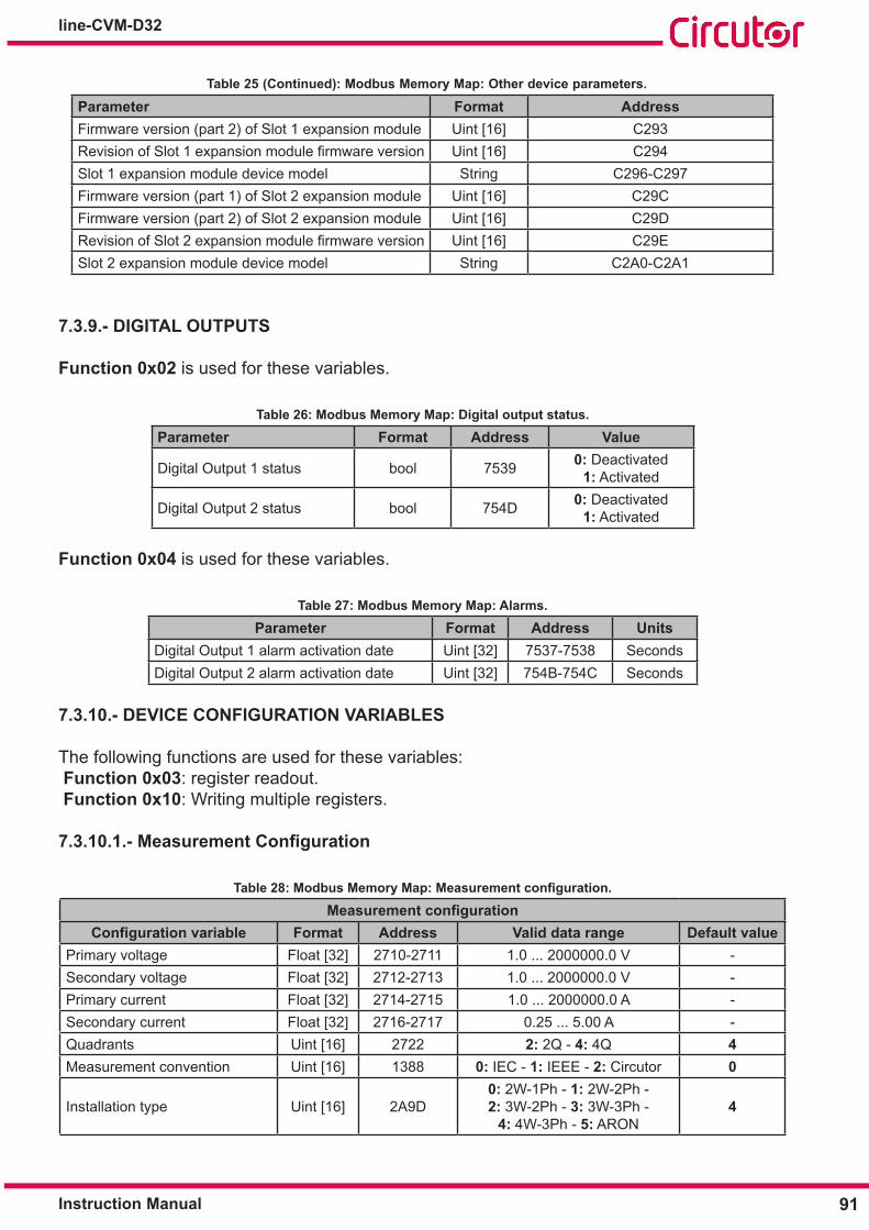
91Instruction Manual
line-CVM-D32
Table 25 (Continued): Modbus Memory Map: Other device parameters�
Parameter Format AddressFirmware version (part 2) of Slot 1 expansion module Uint [16] C293RevisionofSlot1expansionmodulefirmwareversion Uint [16] C294Slot 1 expansion module device model String C296-C297Firmware version (part 1) of Slot 2 expansion module Uint [16] C29CFirmware version (part 2) of Slot 2 expansion module Uint [16] C29DRevisionofSlot2expansionmodulefirmwareversion Uint [16] C29ESlot 2 expansion module device model String C2A0-C2A1
7�3�9�- DIGITAL OUTPUTS
Function 0x02 is used for these variables.
Table 26: Modbus Memory Map: Digital output status�
Parameter Format Address Value
Digital Output 1 status bool 7539 0: Deactivated1: Activated
Digital Output 2 status bool 754D 0: Deactivated1: Activated
Function 0x04 is used for these variables.
Table 27: Modbus Memory Map: Alarms�
Parameter Format Address UnitsDigital Output 1 alarm activation date Uint [32] 7537-7538 SecondsDigital Output 2 alarm activation date Uint [32] 754B-754C Seconds
7�3�10�- DEVICE CONFIGURATION VARIABLES
The following functions are used for these variables: Function 0x03: register readout. Function 0x10: Writing multiple registers.
7.3.10.1.- Measurement Configuration
Table 28: Modbus Memory Map: Measurement configuration.
Measurement configurationConfiguration variable Format Address Valid data range Default value
Primary voltage Float [32] 2710-2711 1.0 ... 2000000.0 V -Secondary voltage Float [32] 2712-2713 1.0 ... 2000000.0 V -Primary current Float [32] 2714-2715 1.0 ... 2000000.0 A -Secondary current Float [32] 2716-2717 0.25 ... 5.00 A -Quadrants Uint [16] 2722 2: 2Q - 4: 4Q 4Measurement convention Uint [16] 1388 0: IEC - 1: IEEE - 2: Circutor 0
Installation type Uint [16] 2A9D0: 2W-1Ph - 1: 2W-2Ph - 2: 3W-2Ph - 3: 3W-3Ph -
4: 4W-3Ph - 5: ARON 4

92
line-CVM-D32
Instruction Manual
Table 28 (Continued): Modbus Memory Map: Measurement configuration.
Measurement configurationConfiguration variable Format Address Valid data range Default value
Aggregation period (12) Uint [16] 2ACB 60... 3600 s 600 sMaximum demand integration period Uint [16] 274C 60... 3600 s 900 s
Maximum demand calculation type (7) Uint [16] 274D 0: Sliding window
1:Fixed 0
Currency String 27FC-27FD EURDisplay backlight Uint [16] 280D 1... 99 min 15 minPassword Uint [32] 2A97-2A98 00000... 99999 97531
Current tariff (13) Uint [16] 59DC 1: Tariff 1 - 2: Tariff 2 - 3: Tariff 3 - 4: Tariff 4 1
Harmonics display (14) Bool 1782 0: Not displayedFF00: Display 0
(12) The programmed value must be divisible by 60, i.e. the 3660 / Aggregation period division must be exact. It must also be a multiple of 60, i.e. if the programmed value contains the number 60, an integer of the number. (13) Parameternotconfigurableviadisplay.(14) Functions 0x01 and 0x05 are used for this variable.
7�3�10�2�- Quality parameters
Table 29: Modbus Memory Map: Quality parameters�
Quality parametersConfiguration variable Format Address Valid data range Default value
Nominal voltage Float [32] 271C-271D 50.0 .... 2000000.0 V 230.00 VNominal frequency Uint [16] 2720 50-60Hz; 50 HzOvervoltage (swell) Float [32] 2ABC-2ABD 100.0 ... 150.0 % 110.0 %Gap (Dip) Float [32] 2ABE-2ABF 50.0 ... 97.0 % 90.0 %Outage (Interruption) Float [32] 2AC0-2AC1 1.0 ... 20.0 % 10.0%Overvoltage hysteresis Float [32] 2AC4-2AC5 0.0 ... 100.0 % 2.0 %Gap hysteresis Float [32] 2AC6-2AC7 0.0 ... 100.0 % 2.0 %Interruption hysteresis Float [32] 2AC8-2AC9 0.0 ... 100.0 % 2.0 %
7�3�10�3�- Device clock
Table 30: Modbus Memory Map: Device clock�
Device clockConfiguration variable Format Address Valid data range Default value
Date format Uint [16] 280F 0: mm/dd/yy1: dd/mm/yy 1
Date and Time Uint [32] 283C Date and time are given in Epoch format
7�3�10�4�- Communications
Table 31: Modbus Memory Map: Communications�
CommunicationsConfiguration variable Format Address Valid data range Default value
Peripheral number Uint [16] 2739 1... 255 1
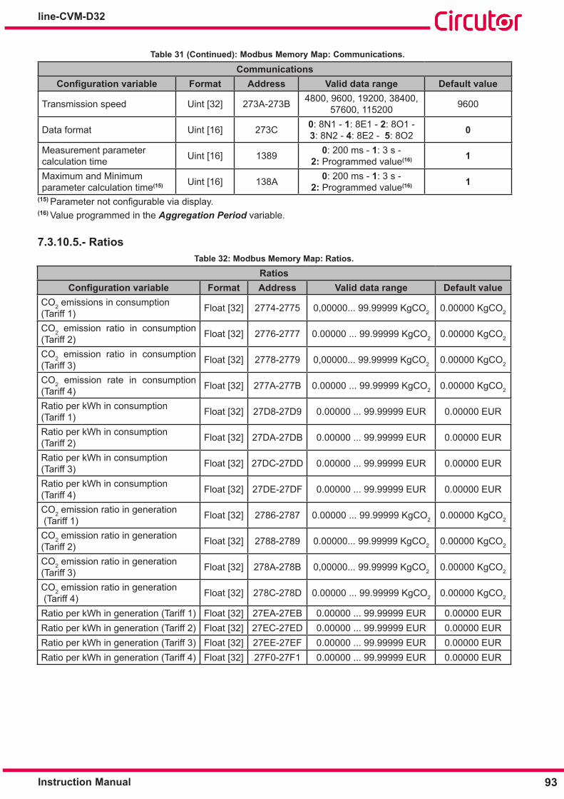
93Instruction Manual
line-CVM-D32
Table 31 (Continued): Modbus Memory Map: Communications�
CommunicationsConfiguration variable Format Address Valid data range Default value
Transmission speed Uint [32] 273A-273B 4800, 9600, 19200, 38400, 57600, 115200 9600
Data format Uint [16] 273C 0: 8N1 - 1: 8E1 - 2: 8O1 - 3: 8N2 - 4: 8E2 - 5: 8O2 0
Measurement parameter calculation time Uint [16] 1389 0: 200 ms - 1: 3 s -
2: Programmed value(16) 1
Maximum and Minimum parameter calculation time(15) Uint [16] 138A 0: 200 ms - 1: 3 s -
2: Programmed value(16) 1(15) Parameternotconfigurableviadisplay.(16) Value programmed in the Aggregation Period variable.
7�3�10�5�- RatiosTable 32: Modbus Memory Map: Ratios�
RatiosConfiguration variable Format Address Valid data range Default value
CO2 emissions in consumption (Tariff 1) Float [32] 2774-2775 0,00000... 99.99999 KgCO2 0.00000 KgCO2
CO2 emission ratio in consumption (Tariff 2) Float [32] 2776-2777 0.00000 ... 99.99999 KgCO2 0.00000 KgCO2
CO2 emission ratio in consumption (Tariff 3) Float [32] 2778-2779 0,00000... 99.99999 KgCO2 0.00000 KgCO2
CO2 emission rate in consumption (Tariff 4) Float [32] 277A-277B 0.00000 ... 99.99999 KgCO2 0.00000 KgCO2
Ratio per kWh in consumption (Tariff 1) Float [32] 27D8-27D9 0.00000 ... 99.99999 EUR 0.00000 EUR
Ratio per kWh in consumption (Tariff 2) Float [32] 27DA-27DB 0.00000 ... 99.99999 EUR 0.00000 EUR
Ratio per kWh in consumption (Tariff 3) Float [32] 27DC-27DD 0.00000 ... 99.99999 EUR 0.00000 EUR
Ratio per kWh in consumption (Tariff 4) Float [32] 27DE-27DF 0.00000 ... 99.99999 EUR 0.00000 EUR
CO2 emission ratio in generation (Tariff 1) Float [32] 2786-2787 0.00000 ... 99.99999 KgCO2 0.00000 KgCO2
CO2 emission ratio in generation (Tariff 2) Float [32] 2788-2789 0.00000... 99.99999 KgCO2 0.00000 KgCO2
CO2 emission ratio in generation (Tariff 3) Float [32] 278A-278B 0,00000... 99.99999 KgCO2 0.00000 KgCO2
CO2 emission ratio in generation (Tariff 4) Float [32] 278C-278D 0.00000 ... 99.99999 KgCO2 0.00000 KgCO2
Ratio per kWh in generation (Tariff 1) Float [32] 27EA-27EB 0.00000 ... 99.99999 EUR 0.00000 EURRatio per kWh in generation (Tariff 2) Float [32] 27EC-27ED 0.00000 ... 99.99999 EUR 0.00000 EURRatio per kWh in generation (Tariff 3) Float [32] 27EE-27EF 0.00000 ... 99.99999 EUR 0.00000 EURRatio per kWh in generation (Tariff 4) Float [32] 27F0-27F1 0.00000 ... 99.99999 EUR 0.00000 EUR

94
line-CVM-D32
Instruction Manual
7�3�10�6�- Digital Output 1
Table 33: Modbus Memory Map: Digital Output 1�
Digital Output 1Configuration variable Format Address Valid data range Default value
Variable Uint [16] 4E20 Table 10 - Table 11 - Table 12 - Table 13 0
Maximum value / Energy per pulse Float [32] 4E22-4E23 Depends on the selected variable -
Minimum value Float [32] 4E24-4E25 Depends on the selected variable -Connection delay
Uint [16] 4E26 0... 65499 s 0 s
High level pulse width 0... 999 ms (x10)Disconnection delay
Uint [16] 4E270... 65499 s 0 s
Low level pulse width 0... 999 ms (x10)Hysteresis Uint [16] 4E28 0... 99% 0%
Contact status Uint [16] 4E21 0: Normally open - 1: Normally closed 0
Latch Bool 4E29 0: No - 1: YesLatching time Uint [16] 4E2A 0... 65499 s 0 sUnlatch the output (17) Bool 7530 0 0Manual Operation: Output status (17) Bool 7539 ON(connected output): FF00
OFF (disconnected output): 0000 0
(17) Functions 0x01 and 0x05 are used for this variable.
7�3�10�7�- Digital Output 2
Table 34: Modbus Memory Map: Digital Output 2�
Digital Output 2Configuration variable Format Address Valid data range Default value
Variable Uint [16] 4E34 Table 10 - Table 11 - Table 12 - Table 13 0
Maximum value / Energy per pulse Float [32] 4E36-4E37 Depends on the selected variable -
Minimum value Float [32] 4E38-4E39 Depends on the selected variable -Connection delay
Uint [16] 4E3A0... 65499 s 0 s
High level pulse width 0... 999 ms (x10)Disconnection delay
Uint [16] 4E3B0... 65499 s 0 s
Low level pulse width 0... 999 ms (x10)Hysteresis Uint [16] 4E3C 0... 99% 0%
Contact status Uint [16] 4E35 0: Normally open - 1: Normally closed 0
Latch Bool 4E3D 0: No - 1: YesLatching time Uint [16] 4E3E 0... 65499 s 0 sUnlatch the output (18) Bool 7544 0 0Manual Operation:Output status (18) Bool 754D ON(connected output): FF00
OFF (disconnected output): 0000 0
(18) Functions 0x01 and 0x05 are used for this variable.
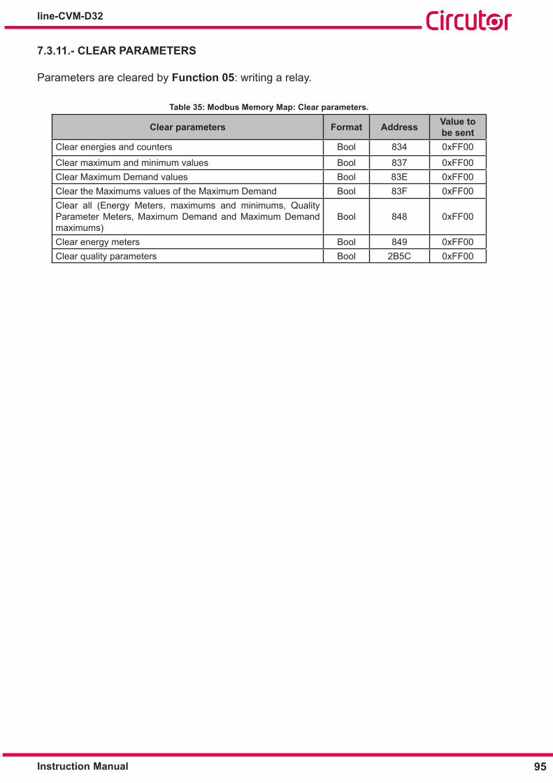
95Instruction Manual
line-CVM-D32
7�3�11�- CLEAR PARAMETERS
Parameters are cleared by Function 05: writing a relay.
Table 35: Modbus Memory Map: Clear parameters�
Clear parameters Format Address Value to be sent
Clear energies and counters Bool 834 0xFF00
Clear maximum and minimum values Bool 837 0xFF00Clear Maximum Demand values Bool 83E 0xFF00Clear the Maximums values of the Maximum Demand Bool 83F 0xFF00Clear all (Energy Meters, maximums and minimums, Quality Parameter Meters, Maximum Demand and Maximum Demand maximums)
Bool 848 0xFF00
Clear energy meters Bool 849 0xFF00Clear quality parameters Bool 2B5C 0xFF00

96
line-CVM-D32
Instruction Manual
8�- TECHNICAL FEATURESAC Power supply
Rated voltage 80... 264 V ~ Frequency 50... 60 HzConsumption 3... 8 VA
Installation category CAT III 300V
DC Power supply Rated voltage 100 ...300 V
Consumption 2... 3 WInstallation category CAT III 300V
Voltage measurement circuit Rated voltage (Un) 300 VPh-N , 520 VPh-Ph Voltage measuring margin 20... 300 V ~ Frequency measuring margin 47... 63 HzInput impedance 1MΩMinimum measurement voltage (Vstart) 10 V~Installation category CAT III 300V
Current measurement circuit Rated current (In) ... / 5A,... / 1A or.../0.250 A (MC type transformers)
Current measurement marginIn: ���/5A In: ���/1A In: ���/0�250A
0.01 ... 10 A 0.01 ... 2 A 0.01 ... 0.5 AMaximum current, impulse < 1s 100 AMinimum current measurement (Istart) 0.01 AMax� consumption of the current input 0.9 VAInstallation category CAT III 300V
Measurement accuracyClass (��� / 5A) Class (��� / 1A) Class (��� / 0�250A)
Voltage measurement 0.2 % (19) 0.2 % (19) 0.2 % (19)
Current measurement 0.2 % (19) 0.2 % (19) 1 % for I >=20% In (19)
Active power measurement 0.5 % (19) 0.5 % 1 %Reactive power measurement 1 % (19) 1 % 2 %Apparent power measurement 0.5 % (19) 1 % for I >=5% In 1 % for I >=20% InActive energy measurement 0.5s 1 1Reactive energy measurement 1 2 2Frequency measurement 0.1 % (19) 0.1 % 0.1 %Power Factor measurement 0.5 % (19) 0.5 % 0.5 %
(19) For three-phase and phase values.Digital transistor outputs
Quantity 2Type Optocoupled (Open-collector)Maximum voltage 48 V Maximum current 120 mAMaximum frequency 500 HzPulse width 1 ms

97Instruction Manual
line-CVM-D32
RS-485 CommunicationsCommunications protocol Modbus RTUBaud rate 9600 - 19200 - 34800 - 57600 - 76800 - 115200 bpsData bits 8Stop bits 1 - 2Parity without - even - odd
User interfaceDisplay TFT RGB 1.77" 160x128 pixelsKeyboard 3 keysLED 2 LEDs
Environmental featuresOperating temperature -10ºC ... + 50ºCStorage temperature -20ºC ... +70ºCRelative humidity (non-condensation) 5... 95%Maximum altitude 2000 mProtection degree IP30, Front: IP40,
Mechanical features
Terminals
1... 24 2.5 mm2 ≤ 0.4 Nm, M2.5 FlatDimensions Figure 32 (mm)Weight 350 g.Enclosure Self-extinguishing V0 plasticAttachment DIN rail (20)
(20) Recommended minimum distance between DIN rails: 150 mm.Standards
Safety requirements for electrical equipment for measurement, control, and labo-ratory use Part 1: General requirements� EN 61010-1
Safety requirements for electrical equipment for measurement, control, and la-boratory use Part 2-030: Specific requirements for test and measuring circuits. EN 61010-2-030
Electrical material for measurement, control and laboratory use Electromagnetic compatibility (EMC) requirements Part 1: General requirements EN 61326-1

98
line-CVM-D32
Instruction Manual
118
52.5
9035
.7
45
4470
Figure 32: Line-CVM-D32 Dimensions

99Instruction Manual
line-CVM-D32
9�- MAINTENANCE AND TECHNICAL SERVICE
10 �- GUARANTEE
• No returns will be accepted and no unit will be repaired or replaced if it is not ac-companied by a report indicating the defect detected or the reason for the return.•The guarantee will be void if the units has been improperly used or the stora-ge, installation and maintenance instructions listed in this manual have not been followed.“Improperusage”isdefinedasanyoperatingorstorageconditioncon-trary to the national electrical code or that surpasses the limits indicated in the technical and environmental features of this manual.• CIRCUTOR accepts no liability due to the possible damage to the unit or other parts of the installation, nor will it cover any possible sanctions derived from a pos-sible failure, improper installation or “improper usage” of the unit. Consequently, this guarantee does not apply to failures occurring in the following cases:- Overvoltages and/or electrical disturbances in the supply;-Water,iftheproductdoesnothavetheappropriateIPclassification;- Poor ventilation and/or excessive temperatures;- Improper installation and/or lack of maintenance;-Buyerrepairsormodificationswithoutthemanufacturer’sauthorisation.
CIRCUTOR guarantees its products against any manufacturing defect for two years after the delivery of the units.
CIRCUTOR will repair or replace any defective factory product returned during the guarantee period.
In the case of any query in relation to device operation or malfunction, please contact the CIRCUTOR, SA Technical Support Service.
Technical Assistance ServiceVial Sant Jordi, s/n, 08232 - Viladecavalls (Barcelona)Tel: 902 449 459 ( España) / +34 937 452 919 (outside of Spain)email: [email protected]

100
line-CVM-D32
Instruction Manual
11�- CE CERTIFICATE

101Instruction Manual
line-CVM-D32
102
line-CVM-D32
Instruction Manual

103Instruction Manual
line-CVM-D32
ANNEX A�- CONFIGURATION MENU
AVG 230.00 V
5.00
50.00
1.00
AVG
LIII
INST
A
Hz
cos
T1
PRIMARY VT
V1.0
1.00SECONDARY VT
SETUP
V
MEASURE
PRIMARY VT
V1.0
1.00SECONDARY VT
EDIT
V
MEASURE
SETUP
PRIMARY CT
A5.0
5.000SECONDARY CT
A
MEASURE EDIT
PRIMARY CT
A5.0
5.000SECONDARY CT
A
MEASURE
> 2s
> 2s
> 2s
> 2s
> 2s
> 2s
> 2s
SETUP
QUADRANTS
4Q
IECSIGN CONVENTION
MEASURE EDIT
QUADRANTS
4Q
IECSIGN CONVENTION
MEASURE
> 2s
> 2s
> 2s 4Q 2Q
IEC IEEE
SETUP
CIRCUIT TYPE
4W-3Ph
MEASURE EDIT
CIRCUIT TYPE
4W-3Ph
MEASURE
> 2s
> 2s4W-3Ph
CIRC
3W-3Ph 3W-2Ph
2W-2Ph
2W-1PhARON
SETUP
AGGREGATION PERIOD
15PD PERIOD
min
15 min
MEASURE EDIT
AGGREGATION PERIOD
15PD PERIOD
min
15 min
MEASURE
> 2s
> 2s
> 2s
SETUP
CLEAR MAX / MIN
YES/NO ?
YES/NO ?CLEAR PD
EDIT
CLEAR MAX / MIN
YES/NO ?
YES/NO ?CLEAR PD
> 2s
> 2s
> 2s
YES NO
EDIT
EDIT
EDIT
CLEAR ENERGY
YES/NO ?
YES/NO ?CLEAR ALL
DISPLAY DIMMING
15 min
*****PASSWORD
SHOW HARMONICS
YES
EURCOIN
SETUP
CLEAR ENERGY
YES/NO ?
YES/NO ?CLEAR ALL
SETUP
SHOW HARMONICS
YES
EURCOIN
SETUP
DISPLAY DIMMING
15 min
*****PASSWORD
> 2s
> 2s
> 2s
> 2s
> 2s
> 2s
> 2s
> 2s
> 2s
YES NO
YES NO
SETUP
230.0
50EVQ
NOMINAL VOLTAGE
NOMINAL FREQUENCY
V
Hz
0
900 00
0
900 00
0
900 00
0
900 00
0
900 00
Primary voltage
Secondary voltage
Primary current
Secondary current
Quadrants
Measurement convention
Installation type
Aggregation period
Integration period for maximum demand calculation
Clear the maximum and minimum values
Clear the maximum demand
Clear energy
Clear all
Harmonics display
Coin
Display backlight
Password
EVQ
MEA
SURE

104
line-CVM-D32
Instruction Manual
PROG
> 2s
> 2s
> 2s
> 2s
> 2s
> 2s
> 2s
> 2s
> 2s
> 2s
> 2sYES NO
0
900 00
0
900 00
EDIT
230.0
50EVQ
NOMINAL VOLTAGE
NOMINAL FREQUENCY
V
Hz
SETUP
230.0
50EVQ
NOMINAL VOLTAGE
NOMINAL FREQUENCY
V
Hz
50 60
SWELL
DIP
INTERRUPTION
HISTERESIS
RESET EVQ
110.0
90.0
%
%
EDIT EVQ
EDIT
EDIT
EVQ
EVQ
10.0
2.0
%
%
YES/NO ?
SWELL
DIP
110.0
90.0
%
%
SETUP EVQ
INTERRUPTION
HISTERESIS
SETUP EVQ
10.0
2.0
%
% 0
900 00
RESET EVQ
SETUP EVQ
YES/NO ?
PROG
> 2s
> 2s
> 2s
> 2s
> 2s
0
900 00
DD/MM/YY
EVQ
DATE FORMAT
DATE
DD/MM/YY DATE FORMAT
DATE
DD/MM/YY
EDIT
EDIT DATE
DATE
05/05/2019 HOUR
12:14:47 SETUP DATE
DATE
05/05/2019 HOUR
12:14:47
MM/DD/YY
SETUP
SETUP
PERIPH. NUMBER
1
9600 bps BAUDRATE
MODBUS
DATA SETTINGS
8N1MEASURE TIME
3 s MODBUS
> 2s
> 2s
> 2s
EDIT
PERIPH. NUMBER
1
9600 bps BAUDRATE
MODBUS
EDIT
DATA SETTINGS
8N1MEASURE TIME
3 s MODBUS
> 2s
> 2s
> 2s
RATIO T1+
0.00000
0.00000 RATIO T2+
kgCO2SETUP
0
900 00
9600
19200 38400
57600
1152004800
8N1
8E1 8O1
8N2
8E28O2
User: xx min
3s
200 ms
SETUP
Nominal voltage
Nominal frequency
Overvoltage
Gap
Interruption
Hysteresis value
EVQ
Clear quality parameters
Date format
Current date
Current time
DATE
Peripheral number
Baud rate
Data format
Refresh time
kgCO2 - EUR
MOD
BUS

105Instruction Manual
line-CVM-D32
RATIO T1+
0.00000
0.00000 RATIO T2+
kgCO2EDIT
> 2s
> 2s
> 2s
> 2s
> 2s
> 2s
> 2s
> 2s
> 2s
PROG
CIRCUIT TYPE
MEASURE
CIRCUIT TYPE
PROG MEASURE PROG
15PD PERIOD
min
15 min
MEASURE
> 2s
> 2s
> 2s
PROG MEASURE PROG
> 2s
> 2s
> 2s
PROG MEASURE
PROG MEASURE
PROG
> 2s
> 2s
> 2s
> 2s
> 2s
> 2s
0
900 00
0
900 00
RATIO T1+
0.00000
0.00000 RATIO T2+
kgCO2SETUP
RATIO T3+
0.00000
0.00000 RATIO T4+
EDIT
EUREDIT
EURSETUP
kgCO2
RATIO T1+
0.00000
0.00000 RATIO T2+
RATIO T3+
0.00000
0.00000 RATIO T4+
RATIO T1-
0.00000
0.00000 RATIO T2-
kgCO2EDIT
RATIO T3-
0.00000
0.00000 RATIO T4-
EDIT
EUREDIT
EUREDIT
kgCO2
RATIO T1-
0.00000
0.00000 RATIO T2-
RATIO T3-
0.00000
0.00000 RATIO T4-
RATIO T3+
0.00000
0.00000 RATIO T4+
SETUP kgCO2
EURSETUP
RATIO T1+
0.00000
0.00000 RATIO T2+
> 2s
> 2s
> 2s
PROG
CIRCUIT TYPE
MEASUREEUREDIT
RATIO T3+
0.00000
0.00000 RATIO T4+
RATIO T1-
0.00000
0.00000 RATIO T2-
kgCO2SETUP
RATIO T3-
0.00000
0.00000 RATIO T4-
SETUP kgCO2
EURSETUP
RATIO T1-
0.00000
0.00000 RATIO T2-
EURSETUP
RATIO T3-
0.00000
0.00000 RATIO T4-
0
900 00
0
900 00
0
900 00
0
900 00
0
900 00
0
900 00
SETUP
VARIABLE
1 V1
OUT1
Emission ratio, tariff 1, consumption
Emission ratio, tariff 2, consumption
Emission ratio, tariff 3, consumption
Emission ratio, tariff 4, consumption
Ratio per kWh, tariff 1, consumption
Ratio per kWh, tariff 2, consumption
Ratio per kWh, tariff 3, consumption
Ratio per kWh, tariff 4, consumption
Emission ratio, tariff 1, generation
Emission ratio, tariff 2, generation
kgCO
2 -
EUR
Emission ratio, tariff 3, generation
Emission ratio, tariff 4, generation
Ratio per kWh, tariff 1, generation
Ratio per kWh, tariff 2, generation
Ratio per kWh, tariff 3, generation
Ratio per kWh, tariff 4, generation
OUT1 - OUT2

106
line-CVM-D32
Instruction Manual
PROG
> 2s
> 2s
> 2s
> 2s
> 2s
> 2s
> 2s
> 2s
PROG MEASURE PROG MEASURE
PROG
> 2s
> 2s
> 2s
PROG MEASURE
> 2s
> 2s
> 2s
PROG
> 2s
> 2s
> 2s
> 2s
> 2s
> 2s
0
900 00
0
900 00
0
900 00
EDIT
VARIABLE
1 V1
HIGH VALUE
0.0 V
0.0 v LOW VALUE
DELAY ON
0 S
0 S DELAY OFF
HYSTERESIS
0 %
NO CONTACT TYPE
LATCH
NO
0 S TIME ON
WEIGHT
1Wh
NO CONTACT TYPE
HIGH PERIOD
0
0 LOW PERIOD
OUT1
OUT1EDIT
OUT1EDIT
OUT1EDIT
OUT1EDIT
OUT1
msx10
OUT1
msx10
EDIT OUT1
STATUS
OFF
NOCONTACT TYPE
EDIT
EDIT
SETUP
VARIABLE
1 V1
OUT1
HIGH VALUE
0.0 V
0.0 v LOW VALUE
OUT1SETUP
DELAY ON
0 S
0 S DELAY OFF
OUT1SETUP
HYSTERESIS
0 %
NO CONTACT TYPE
OUT1SETUP
LATCH
NO
0 S TIME ON
OUT1SETUP
0
900 00
> 2s
> 2s
> 2s
NO NC
0
900 00
NO TIME
YES
WEIGHT
1Wh
NO CONTACT TYPE
OUT1SETUP
HIGH PERIOD
0
0 LOW PERIOD
msx10
OUT1
msx10
SETUP
SETUP OUT1
STATUS
OFF
NOCONTACT TYPE
NO NC
0
900 00
0
900 00
NO NC
OFF NO
SETUP SLOT1
MODE
IMPULSE
IN1NAME
D IN1
VariableManual operationEnergy
Maximum value
Minimum value
Connection delay
Disconnection delay
Hysteresis
Contact status
OUT1
- OU
T2
Latch
Latching time
Energy per pulse
Contact status
Pulse width, high level
Pulse width, low level
Output status
Contact status
Configuration of the expansion modules

107Instruction Manual
line-CVM-D32

CIRCUTOR, SA Vial Sant Jordi, s/n08232 - Viladecavalls (Barcelona)Tel: (+34) 93 745 29 00 - Fax: (+34) 93 745 29 14 www.circutor.es [email protected]