Institute of the Environmental Sciences / Group of Energy / PVsyst Modeling Systems Losses in PVsyst
15
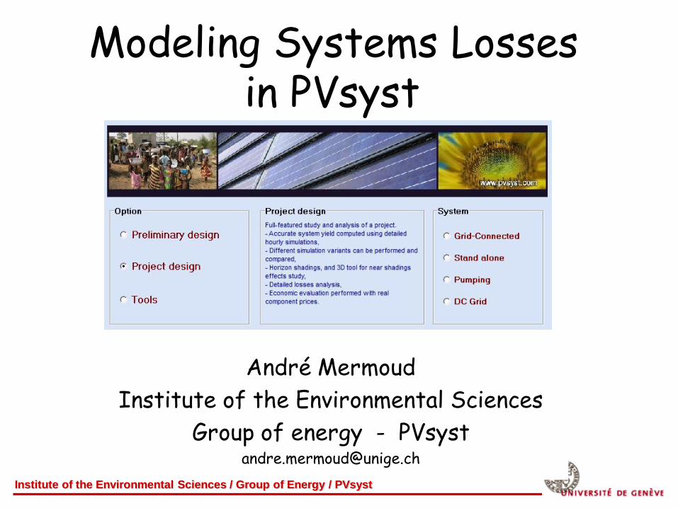
Institute of the Environmental Sciences / Group of Energy / PVsyst Modeling Systems Losses in PVsyst André Mermoud Institute of the Environmental Sciences Group of energy - PVsyst [email protected]
Transcript of Institute of the Environmental Sciences / Group of Energy / PVsyst Modeling Systems Losses in PVsyst
Institute of the Environmental Sciences / Group of Energy / PVsyst
Modeling Systems Losses in PVsyst
André Mermoud
Institute of the Environmental Sciences
Group of energy - PVsyst [email protected]
Institute of the Environmental Sciences / Group of Energy / PVsyst
Summary
Losses in a PV system simulation may be:
- Determined by specific models (shadings)
- Interpretations of models (PV module behaviour)
- User's parameter specifications (soiling, wiring, etc).
PVsyst provides a detailed analysis of all losses with each simulation
This is a valuable tool for
checking the pertinence of the input parameters,
comparing several simulation runs.
Institute of the Environmental Sciences / Group of Energy / PVsyst
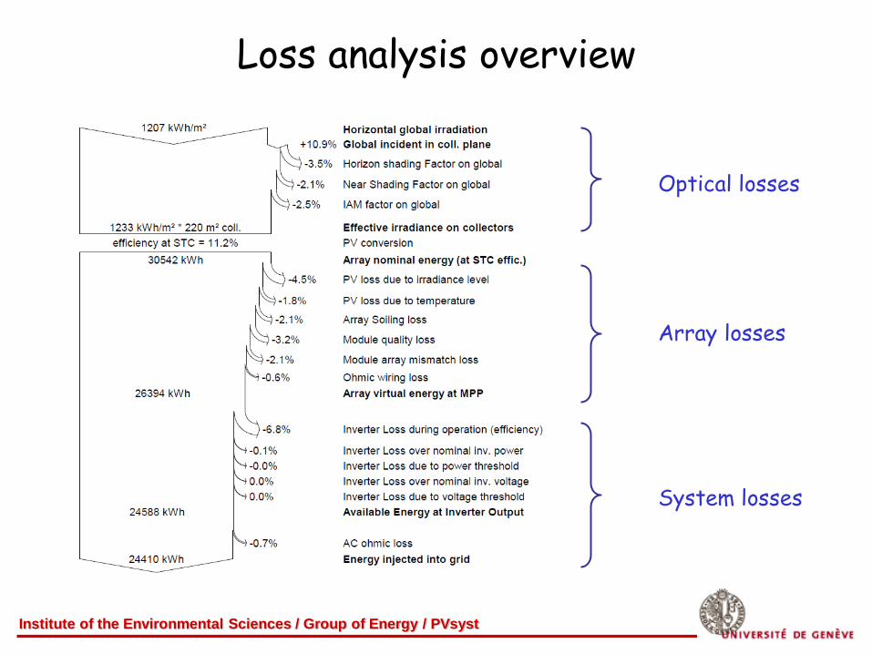
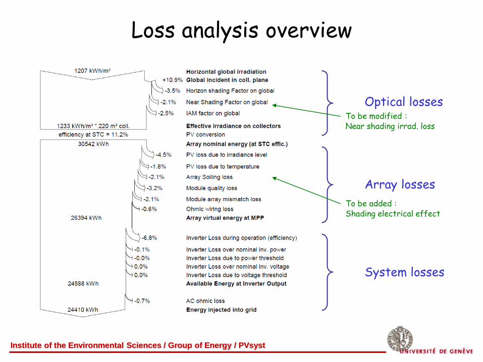
Loss analysis overview
Optical losses
Array losses
System losses
Institute of the Environmental Sciences / Group of Energy / PVsyst
Shading losses
2 kinds of shading losses:
Far shadings :
Obstacles sufficiently far for considering the sun over or under
the horizon line at a given time (typically: distance > 10 x array size).
Treatment: ON/OFF of beam component (fractions of hours)
Near shadings:
Shades "drawn" on the array
Requires a full 3D construction
Treatment: define a "shading factor" = shaded area/total area
Involves additional electrical losses
Institute of the Environmental Sciences / Group of Energy / PVsyst
Far shadings
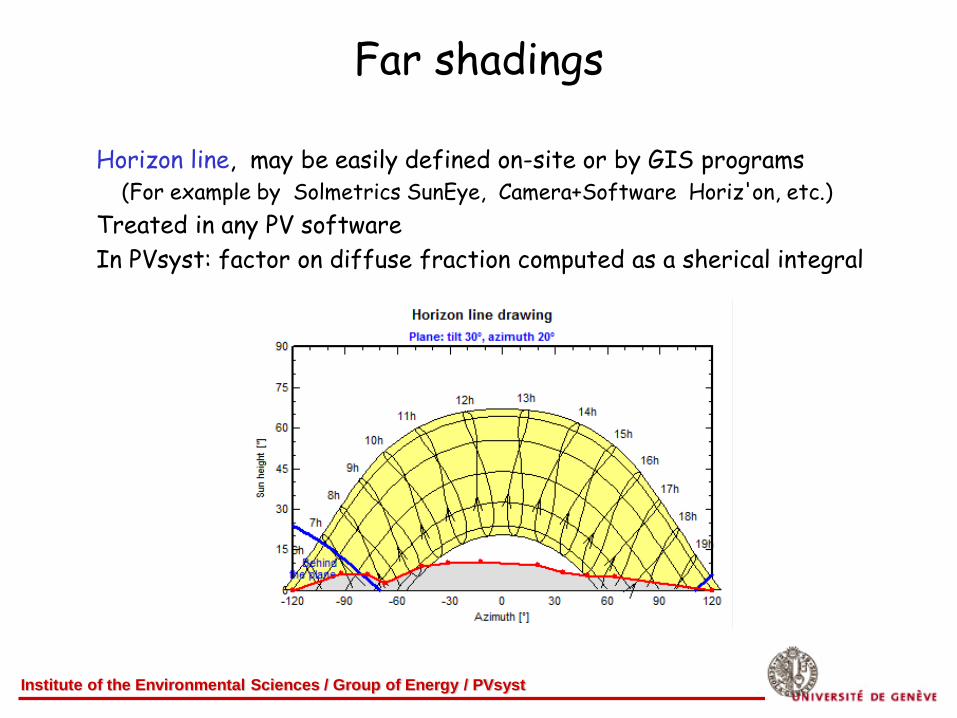
Horizon line, may be easily defined on-site or by GIS programs (For example by Solmetrics SunEye, Camera+Software Horiz'on, etc.)
Treated in any PV software
In PVsyst: factor on diffuse fraction computed as a sherical integral
Institute of the Environmental Sciences / Group of Energy / PVsyst
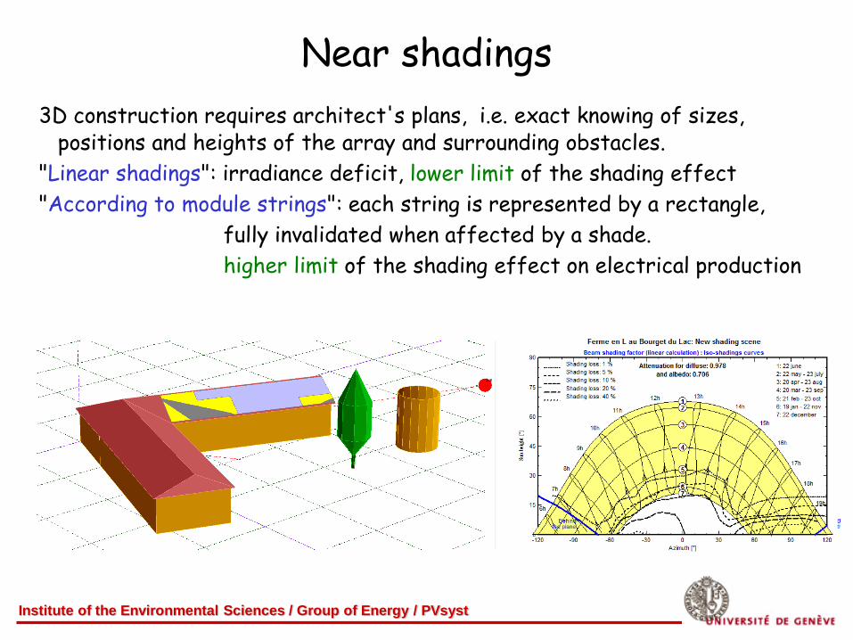
Near shadings
3D construction requires architect's plans, i.e. exact knowing of sizes, positions and heights of the array and surrounding obstacles.
"Linear shadings": irradiance deficit, lower limit of the shading effect
"According to module strings": each string is represented by a rectangle,
fully invalidated when affected by a shade.
higher limit of the shading effect on electrical production
Institute of the Environmental Sciences / Group of Energy / PVsyst
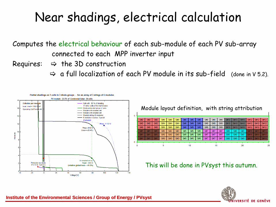
Near shadings, electrical calculation
Computes the electrical behaviour of each sub-module of each PV sub-array
connected to each MPP inverter input
Requires: the 3D construction
a full localization of each PV module in its sub-field (done in V 5.2).
Module layout definition, with string attribution
This will be done in PVsyst this autumn.
Institute of the Environmental Sciences / Group of Energy / PVsyst
Loss analysis overview
Optical losses
Array losses
System losses
To be added : Shading electrical effect
To be modified : Near shading irrad. loss
Institute of the Environmental Sciences / Group of Energy / PVsyst
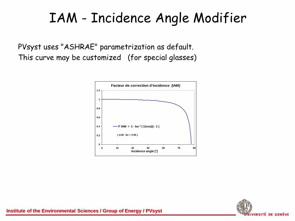
IAM - Incidence Angle Modifier
PVsyst uses "ASHRAE" parametrization as default.
This curve may be customized (for special glasses)
Facteur de correction d'incidence (IAM)
0
0.2
0.4
0.6
0.8
1
1.2
0 15 30 45 60 75 90
Incidence angle [°]
F IAM = 1 - bo * ( 1/cos(i) - 1 )
( with bo = 0.05 )
Institute of the Environmental Sciences / Group of Energy / PVsyst
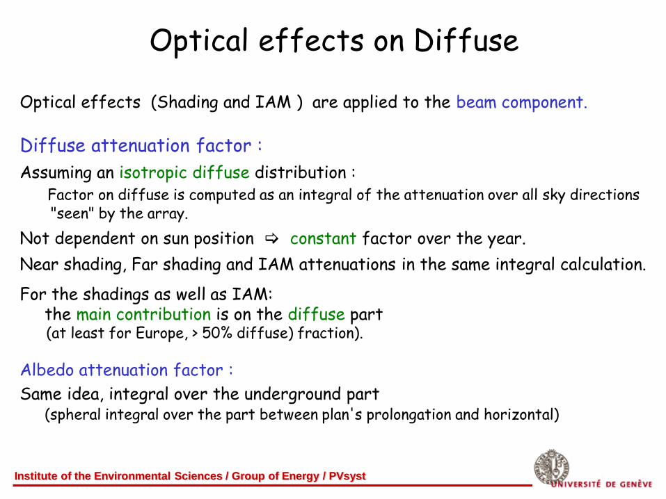
Optical effects on Diffuse
Optical effects (Shading and IAM ) are applied to the beam component. Diffuse attenuation factor :
Assuming an isotropic diffuse distribution : Factor on diffuse is computed as an integral of the attenuation over all sky directions "seen" by the array.
Not dependent on sun position constant factor over the year.
Near shading, Far shading and IAM attenuations in the same integral calculation.
For the shadings as well as IAM: the main contribution is on the diffuse part (at least for Europe, > 50% diffuse) fraction).
Albedo attenuation factor :
Same idea, integral over the underground part (spheral integral over the part between plan's prolongation and horizontal)
Institute of the Environmental Sciences / Group of Energy / PVsyst
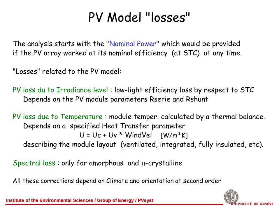
PV Model "losses"
The analysis starts with the "Nominal Power" which would be provided if the PV array worked at its nominal efficiency (at STC) at any time. "Losses" related to the PV model: PV loss du to Irradiance level : low-light efficiency loss by respect to STC Depends on the PV module parameters Rserie and Rshunt
PV loss due to Temperature : module temper. calculated by a thermal balance. Depends on a specified Heat Transfer parameter U = Uc + Uv * WindVel [W/m²K]
describing the module layout (ventilated, integrated, fully insulated, etc). Spectral loss : only for amorphous and -crystalline All these corrections depend on Climate and orientation at second order
Institute of the Environmental Sciences / Group of Energy / PVsyst
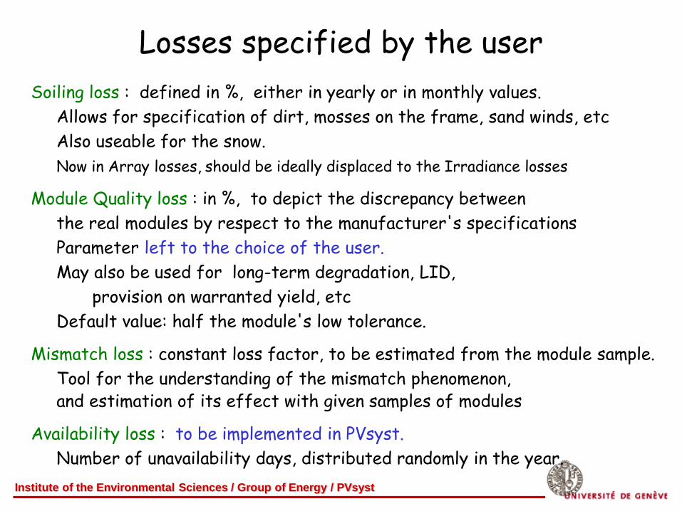
Losses specified by the user
Soiling loss : defined in %, either in yearly or in monthly values.
Allows for specification of dirt, mosses on the frame, sand winds, etc
Also useable for the snow.
Now in Array losses, should be ideally displaced to the Irradiance losses
Module Quality loss : in %, to depict the discrepancy between
the real modules by respect to the manufacturer's specifications
Parameter left to the choice of the user.
May also be used for long-term degradation, LID,
provision on warranted yield, etc
Default value: half the module's low tolerance.
Mismatch loss : constant loss factor, to be estimated from the module sample.
Tool for the understanding of the mismatch phenomenon, and estimation of its effect with given samples of modules
Availability loss : to be implemented in PVsyst.
Number of unavailability days, distributed randomly in the year.
Institute of the Environmental Sciences / Group of Energy / PVsyst
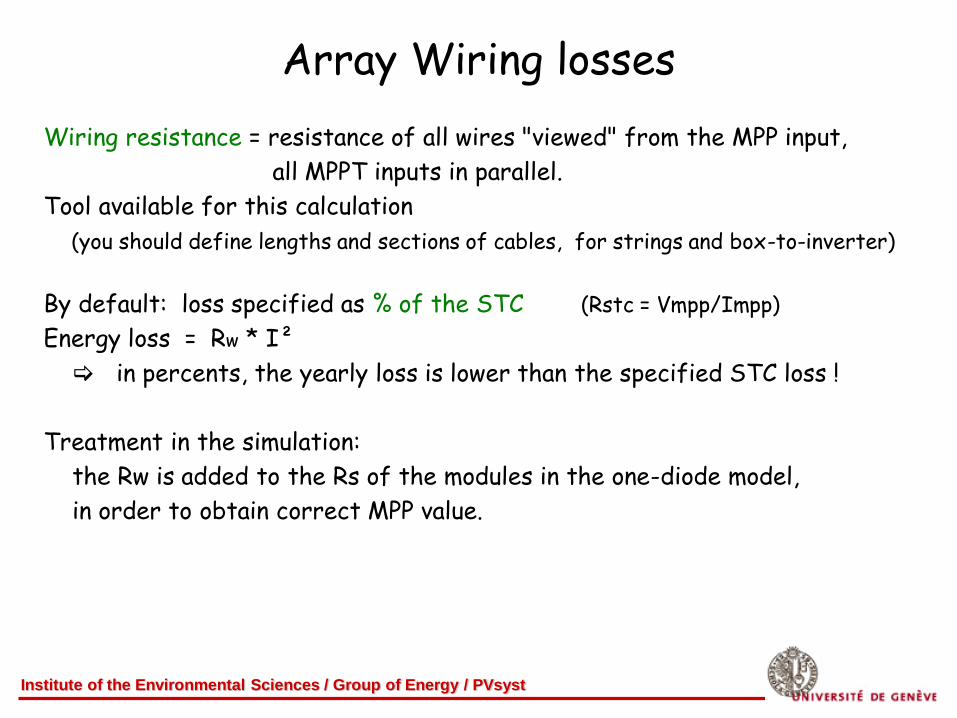
Array Wiring losses
Wiring resistance = resistance of all wires "viewed" from the MPP input,
all MPPT inputs in parallel.
Tool available for this calculation
(you should define lengths and sections of cables, for strings and box-to-inverter)
By default: loss specified as % of the STC (Rstc = Vmpp/Impp)
Energy loss = Rw * I²
in percents, the yearly loss is lower than the specified STC loss !
Treatment in the simulation:
the Rw is added to the Rs of the modules in the one-diode model,
in order to obtain correct MPP value.
Institute of the Environmental Sciences / Group of Energy / PVsyst
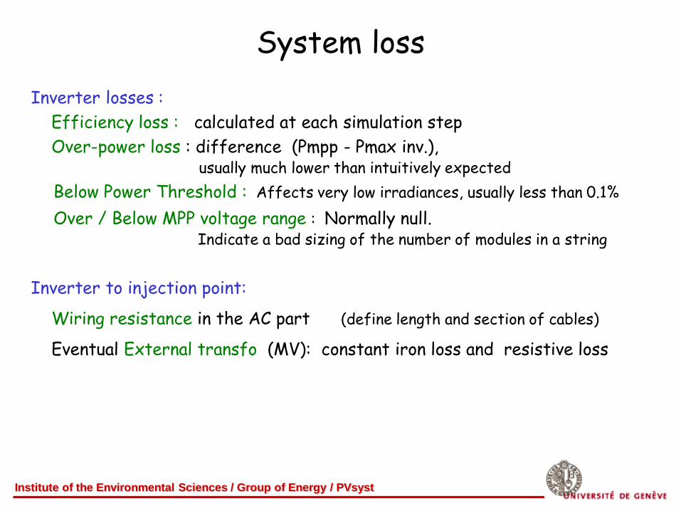
System loss
Inverter losses :
Efficiency loss : calculated at each simulation step
Over-power loss : difference (Pmpp - Pmax inv.), usually much lower than intuitively expected
Below Power Threshold : Affects very low irradiances, usually less than 0.1%
Over / Below MPP voltage range : Normally null. Indicate a bad sizing of the number of modules in a string
Inverter to injection point:
Wiring resistance in the AC part (define length and section of cables)
Eventual External transfo (MV): constant iron loss and resistive loss
Institute of the Environmental Sciences / Group of Energy / PVsyst
Conclusions
PVsyst tries to use suited models for all parts of the PV system,
including all identified sources of losses.
It provides a detailed and quantified analysis of each loss
giving a one-sight evaluation of the sizing and system-comparison tool.
Some losses due to the models
Other ones explicitely specified by the user (initially with default values)
final results of the simulation cannot be warranted !
The main uncertainties of the PV production remain: The meteo data (source, and annual variability)
The PV module model, and the validity of the manufacturer's specifications
More and more requests for P50/P90 warranties : any suggestion ???