Installation Manual 100L Hotflo Direct AN V3 Final 29102014
17
1 The instruction to installers for a Satchwell HOTFLO cistern type thermo-siphon system As local manufacturer, we would like to thank you for choosing our Product! We hope that it gives you many years of hot water. IMPORTANT: Please take time to read this instruction manual to ensure that the installation is according to SABS safety standards and to achieve optimal efficiency. Failure to observe safety practices may result in scalding / burning, electrical shock, falling, which can cause injury or death. Hot water carries a burning risk; please take care when utilizing hot water from this appliance, installing and or maintaining it, as discussed later. It is also important to peruse the terms and conditionsthe Warrantee document at the end of the manual INSTALLER Don’t deviate and follow the instructions described in the manual carefully. There are many tips to help you as an installer to install the product in accordance with the relevant SABS standards and to help ensure that the product operates at maximum ability. OWNER As an owner it is equally as important to read the manual and become familiar with the operation of your new geyser. Please ensure that your installer fills in the details on the cover of this booklet. Please contact the installer if there are any problems in the future.
-
Upload
khangminh22 -
Category
Documents
-
view
1 -
download
0
Transcript of Installation Manual 100L Hotflo Direct AN V3 Final 29102014

1
The instruction to installers for a
Satchwell HOTFLO cistern type thermo-siphon system
As local manufacturer, we would like to thank you for choosing our Product! We hope that it gives you many years of hot water.
IMPORTANT: Please take time to read this instruction manual to ensure that the installation is according to SABS safety standards and to achieve optimal efficiency. Failure to observe safety practices may result in scalding / burning, electrical shock, falling, which can cause injury or death. Hot water carries a burning risk; please take care when utilizing hot water from this appliance, installing and or maintaining it, as discussed later. It is also important to peruse the terms and conditionsthe Warrantee document at the end of the manual
INSTALLER Don’t deviate and follow the instructions described in the manual carefully. There are many tips to help you as an installer to install the product in accordance with the relevant SABS standards and to help ensure that the product operates at maximum ability. OWNER As an owner it is equally as important to read the manual and become familiar with the operation of your new geyser. Please ensure that your installer fills in the details on the cover of this booklet. Please contact the installer if there are any problems in the future.
2
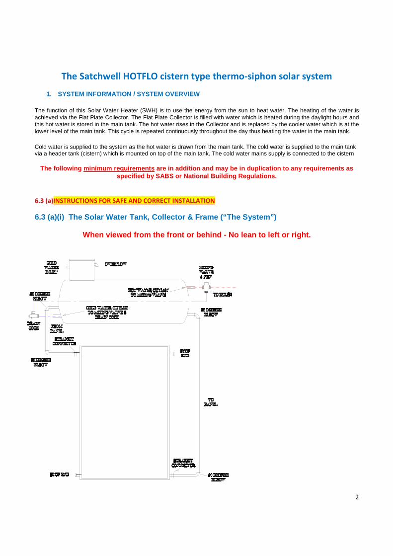
The Satchwell HOTFLO cistern type thermo-siphon solar system
1. SYSTEM INFORMATION / SYSTEM OVERVIEW The function of this Solar Water Heater (SWH) is to use the energy from the sun to heat water. The heating of the water is achieved via the Flat Plate Collector. The Flat Plate Collector is filled with water which is heated during the daylight hours and this hot water is stored in the main tank. The hot water rises in the Collector and is replaced by the cooler water which is at the lower level of the main tank. This cycle is repeated continuously throughout the day thus heating the water in the main tank. Cold water is supplied to the system as the hot water is drawn from the main tank. The cold water is supplied to the main tank via a header tank (cistern) which is mounted on top of the main tank. The cold water mains supply is connected to the cistern
The following minimum requirements are in addition and may be in duplication to any requirements as
specified by SABS or National Building Regulations.
6.3 (a)INSTRUCTIONS FOR SAFE AND CORRECT INSTALLATION
6.3 (a)(i) The Solar Water Tank, Collector & Frame (“The System”)
When viewed from the front or behind - No lean to left or right.

3
1. The Tank is a 100 liter vented cistern type and the system is classified as a split direct thermosiphon type
and is only to be used in coastal areas where no freezing is likely to occur
2. The flat plate must also not be used in water conditions where the dissolved solids / minerals are more
than 1000ppm (“hard water areas”) that can cause blockage in the panel (because of scale). As a
general rule, it is recommended, regarding the prevailing water conditions, that a inline water filter is
fitted during installation. This will ensure that the inlet valve does not become clogged.
3. Systems should be located as low as possible on roofs to reduce exposure to wind and/or a storm.
4. Systems must not be mounted with tanks on the lower inclination of the roof (where the weight of the
tank could cause The System to fall over backwards).
5. Wherever possible The System should sit on a single face of the roof rather than over the roof ridge.
6. Whenever possible The System should not straddle the roof ridge.
7. The System should be orientated as close due North as possible but must be between North East and
North West
8. The inclination of the Collector is 37° angular plus or minus 5° (32° to 42°).
9. The frame and system when viewed from the front or back, left or right must be vertical with no lean to
right or left. Check that the tank is horizontal, using a level. (Adjust the frame and mountings) Cross
braces supplied in the frame kit must be installed.
10. Frames of systems should be securely fastened to roof trusses with the weight of the tank evenly
distributed over a truss, and the front of the frame as close as possible to other roof trusses.
11. A load bearing beam/strap across the back and front legs of the system frame must be installed
protruding 300mm beyond each foot (ref: SANS1307:2012 Clause 4.5.5.1 a).
12. No sharp edges should ever rest against the roof materials and a foot or bearing plate should be utilized.
13. All frame connections into roof must be properly waterproofed.
14. Any adjustment to the legs beyond the pre-made adjustment holes must be made corrosion proof.
Where frames have been cut, (for example to accommodate inclination) the bare cut must be treated
with anti rust / corrosion paint.
15. The cold water cistern should lie as close to vertical as possible, but must not be off vertical by more
than 5˚.
16. Lids of cistern must be securely fastened to avoid blowing off in a wind, with the self threading screws
provided.
17. The overflow must be unobstructed and allow a safe discharge of water in the event of a failure.
18. The cistern valve float level is set in the factory and must not be altered.

4
19. All external pipe work must be copper or stainless steel, including cold water feeds to cisterns or header
tanks.
20. No plastic pipe to or from the system is allowed on the system, unless it is inside the building.
21. Isolating valves of the cold water feed to the SWH system must be a lever type, easily accessible and
below shoulder height.
22. Taps must be properly secured to the wall and suitable for the use of hot water.
23. Tempering valves must be fitted to comply with required maximum heat into the home (normally 60°
Celsius) and must be suitable for low pressure installation.
24. Cold and hot water to the mixing valves must be balanced pressure. High pressure one side (cold water)
/ low pressure (hot from the tank) do not work.
25. Where pipes go through roofs all holes must be properly waterproofed to avoid leaks.
26. All plumbing connections/fittings must comply with SABS requirements.
27. The inlet pipe must be supported correctly so as not to create a load on the cistern tank inlet.
6.3(a)(ii) Assembly Manual:Adjustable incline roof stand
Adjustable Incline and Flat roof stand:
5
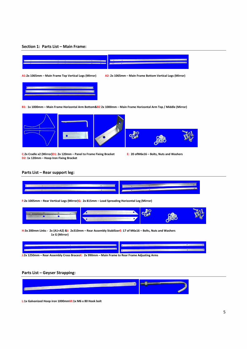
Section 1: Parts List – Main Frame:
A1:2x 1065mm – Main Frame Top Vertical Legs (Mirror) A2: 2x 1065mm – Main Frame Bottom Vertical Legs (Mirror)
B1: 1x 1000mm – Main Frame Horizontal Arm Bottom&B2 2x 1000mm – Main Frame Horizontal Arm Top / Middle (Mirror)
C:2x Cradle x2 (Mirror)D1: 2x 120mm – Panel to Frame Fixing Bracket E: 20 ofM6x16 – Bolts, Nuts and Washers
D2: 1x 120mm – Hoop Iron Fixing Bracket
Parts List – Rear support leg:
F:2x 1005mm – Rear Vertical Legs (Mirror)G: 2x 815mm – Load Spreading Horizontal Leg (Mirror)
H:3x 200mm Links - 2x (A1+A2) &I: 2x310mm – Rear Assembly StabilizerE: 17 of M6x16 – Bolts, Nuts and Washers
1x G (Mirror)
J:2x 1250mm – Rear Assembly Cross BracesK: 2x 990mm – Main Frame to Rear Frame Adjusting Arms
Parts List – Geyser Strapping:
L:1x Galvanized Hoop iron 1000mmM:1x M6 x 80 Hook bolt

6
Section 2: Assembly – Main Frame:
NB: Assess the angle of the roof & determine which of the below assemblies will be suitable.
Step 1:
Step 2:
Step 3:
Step 4:
Step 5:
Cradle assembly – bolt inside, washer and nut outside Assembled Main Frame
Start by laying out the components:
• A to D of the main frame, and
• 2 x component H on a flat surface as indicated
left.
Use a tape measure to determine the component length.
Using the M6 x 16 mm Bolts, nuts and washers, assemble
A2 to A1, using component H – bolt inside, washer and
nut outside. Only finger tighten the bolts, nuts and
washers. Repeat the process for the other vertical leg.
Assemble B1 onto A2 using the M6 x 16mm bolts, nuts and washers supplied–
bolt inside, washer and nut outside. Only finger tighten the bolts, nuts and
washers.
Repeat the process for the other side.
Assemble B2 x2 onto A1 using the M6 x 16mm bolts, nuts and washers
supplied. – Mirror assembly – bolt inside, washer and nut outside. (Angles
facing each other)
Only finger tighten the bolts, nuts and washers
Assemble C onto A1 using the M6 x 16mm bolts, nuts and washers
supplied – cradle longest arm facing towards panel / bottom of main
frame. These bolts, nuts and washers can be fastened properly and in the
correct manner.
Repeat the process for the other side

7
Section 3: Assembly – Rear Support leg:
Step 6: Step 7:
Start by laying out the components F to K of the rear Support leg on a flat surface as indicated above.
Step 8: Step 9:
NB: The bolts, nuts and washers on this assembly can be fastened properly and in the correct manner.
Step 10:
NB: Tighten all bolts and nuts on the Main Frame properly and in the correct manner.
Assemble load spreading
horizontal legs (H onto G x2)
mirror assembly - using the M6 x
16mm bolts, nuts and washers -
bolt outside, washer and nut
inside. Only finger tighten the
bolts, nuts and washers.
Assemble F and I onto G
using the M6 x 16mm
bolts, nuts and washers
supplied.
Only finger tighten the
bolts, nuts and washers.
Assembled parts F to J with Rear
Support Braces in place – bolts
outside, washers and nuts
inside.
Using 2x Part K and the M6 x
16mm bolts, nuts and washers
supplied assemble the Main
Frame and Rear Support Leg as
indicated left. Only finger
tighten the bolts, nuts and
washers.
Then insert Collector to square
Main Frame (indicate right)
8
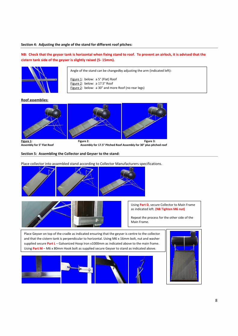
Section 4: Adjusting the angle of the stand for different roof pitches:
NB: Check that the geyser tank is horizontal when fixing stand to roof. To prevent an airlock, it is advised that the
cistern tank side of the geyser is slightly raised (5- 15mm).
Roof assemblies:
Figure 1: Figure 2: Figure 3:
Assembly for 5° Flat Roof Assembly for 17.5° Pitched Roof Assembly for 30° plus pitched roof
Section 5: Assembling the Collector and Geyser to the stand:
Place collector into assembled stand according to Collector Manufacturers specifications.
Angle of the stand can be changedby adjusting the arm (indicated left):
Figure 1: below: a 5° (Flat) Roof
Figure 2: below: a 17.5° Roof
Figure 2: below: a 30° and more Roof (no rear legs)
Using Part D, secure Collector to Main Frame
as indicated left. (NB Tighten M6 nut)
Repeat the process for the other side of the
Main Frame.
Place Geyser on top of the cradle as indicated ensuring that the geyser is centre to the collector
and that the cistern tank is perpendicular to horizontal. Using M6 x 16mm bolt, nut and washer
supplied secure Part L – Galvanized Hoop Iron x1000mm as indicated above to the main frame.
Using Part M – M6 x 80mm Hook bolt as supplied secure Geyser to stand as indicated above.

9
6.3 (b)INSTRUCTIONS FOR SAFE AND CORRECT OPERATION OF COMPLETE SYSTEM
Once the Safety Precaution list below ((6.3 (d)) has been checked proceed with the following steps:
1. Connect the closed-loop connections between the collector and the geyser according to the installation
schematic.
2. Connect the cold water supply line and hot water to user line as marked on the schematic.
3. Make sure that all systems’ connections are fastened.
4. Fill the geyser with potable water ensuring that there are no airlocks.
5. Check carefully for leaks and fix if any.
6. Make sure the pipes going out of the collector to the geyser are on a constant slope upwards.
7. Uncover the panel.
8. Best performance achieved with well insulated pipes. The hot line from the collector must be insulated
to reduce heat losses.
9. The geyser is designed to be installed in a horizontal position only - a vertical installation must not be
attempted and will also invalidate the warranty.
10. The geyser must not be wall mounted—a wall mounting is unsafe and will also invalidate the warranty.
6.3 (c) INSTRUCTIONS FOR REGULAR MAINTENANCE
(Please read and note a safety instruction that follows)
• Regularly inspect the solar system for any leaks or damages
• Turn off main water supply and open Drain cock to flush tank with fresh water once a year to flush any
settled scales.
• Turn off main water supply and carefully loosen stop-end at the bottom of the panel to flush out
collector, using clean, fresh water (at least once a year)DANGER: Water can be extremely hot!
• Clean or replace additional inline water filter, recommended during installation.
• For optimum performance clean and wipe glass on panel every 3 months, removing dust, bird
droppings, leaves ect. Use a soft cloth or mop.
Problem Possible Cause Corrective Action
1 Constant water over flow from header tank.
Float valve does not shut off water when the header tank is full.
Check float valve is operating correctly.
Check for debris in the float valve that might be preventing the float valve from shutting off.
2 No hot water although the weather has been sunny.
No mains water supply. Check and restore mains water supply.
Check that the inline filter and strainer (in inlet of valve) are clean and free of debris.
• In case of emergency, like broken panel or leaking tank, close cold water supply to system immediately
and call the authorised service provider for rectification of the problem.

10
6.3 (d) SAFETY PRECAUTIONS
Safety Installation Requirements For Cistern Type H ot Water System:
• Factory labels and markings may not be altered or rendered unreadable.
• All safety regulations apply when installing a system and all installations are to be done in accordance with
the Occupational Health & Safety Act and Regulations 85 of 1993 requirements and any relevant local
authority bylaws.
• Assess the risks specific to the area of installation and eliminate or reduce to an acceptable level to fall
within the H&S requirements, before starting with the installation.
• Assess weather circumstances to determine if safe installation will be possible e.g. high winds, rain, lighting,
etc.
• Inform home owners or building occupants of the time and place of work to be carried out as well as risks
involved. Ensure occupants are aware of access constraints and safety implications to them. Cordon off area
and ensure pets are secured.
• Beware of overhead power lines coming through the roof, crossing the roof overhead, or wiring running
through the ceiling, in the area where the installation need to take place.
• Ensure persons doing an installation are competent and in suitable physical condition. All personnel working
on an installation of a solar hot water system must be issued with the appropriate safety equipment e.g.
goggles, hard hats, gloves, safety wear, etc. and trained in their use. Be sure to comply with the specified
degree of protection.
• Working at heights should only be undertaken by suitable qualified personnel, using the proper safety
equipment. Installers must be trained and conversant with the assessment of height hazards, working at
heights safety procedures and assessment of safety equipment e.g. scaffolding, ladders, harness, etc.
• Scaffolding and safety equipment must be installed by certified personnel and be signed off accordingly.
• Water temperature can reach boiling point and the collector can reach stagnation temperatures of over
70°C. Shade collector during installation to prevent heating.
• Care should be taken not to touch the pipe work connecting the solar storage tank and the solar collector,
very high temperature hot water can be generated by the solar collector under certain conditions and will
flow through the pipe work from the solar collector to the solar tank.
• Take care when handling collector during installation to prevent breakage to glass and injury. Safety goggles,
work wear and gloves must be used to reduce the risk of injury.
Also, ensure to: • check that all bolts and nuts are tight on the Support Stand.
• check that all anchor points to the roof are secure and tight.
• check that all plumbing connections have been tightened.
• check that the Drain Cock on the Main Tank is closed.
11
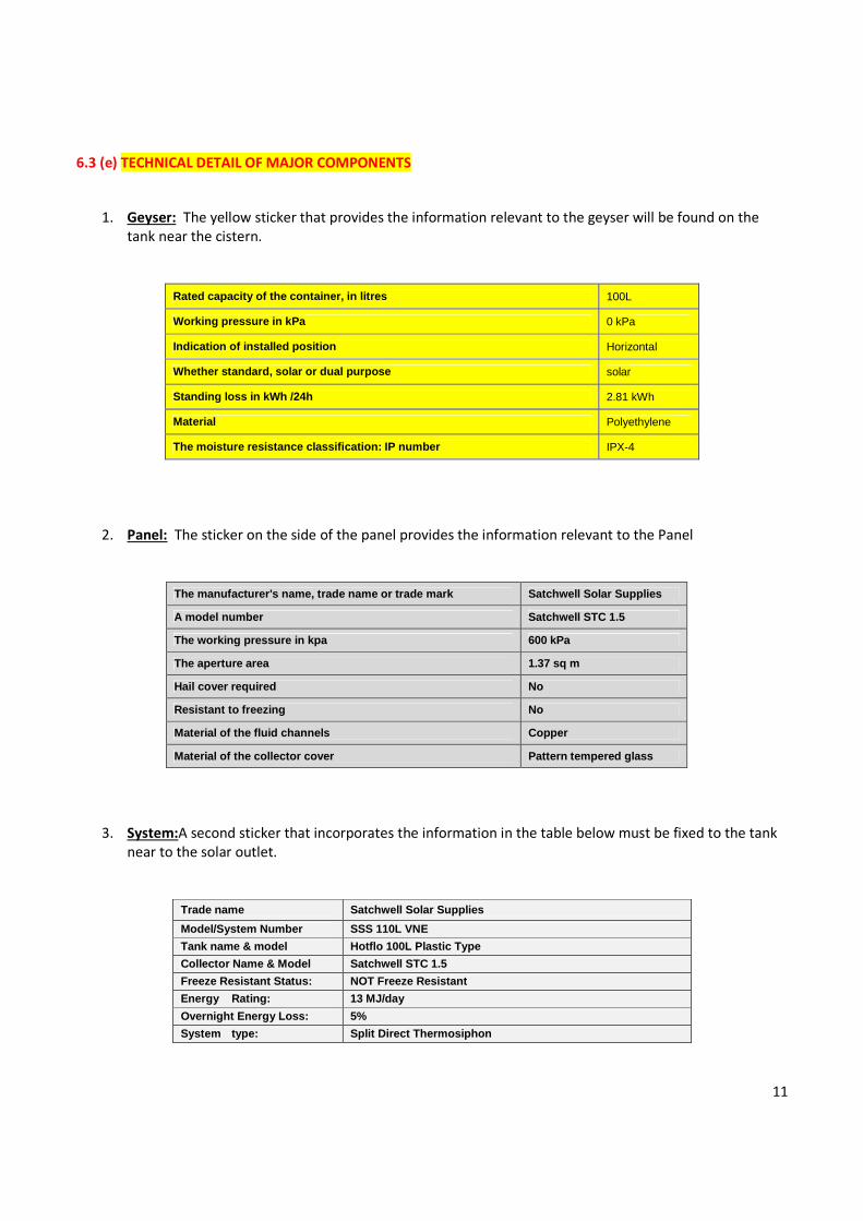
6.3 (e) TECHNICAL DETAIL OF MAJOR COMPONENTS
1. Geyser: The yellow sticker that provides the information relevant to the geyser will be found on the
tank near the cistern.
Rated capacity of the container, in litres 100L
Working pressure in kPa 0 kPa
Indication of installed position Horizontal
Whether standard, solar or dual purpose solar
Standing loss in kWh /24h 2.81 kWh
Material Polyethylene
The moisture resistance classification: IP number IPX-4
2. Panel: The sticker on the side of the panel provides the information relevant to the Panel
The manufacturer's name, trade name or trade mark Satchwell Solar Supplies
A model number Satchwell STC 1.5
The working pressure in kpa 600 kPa
The aperture area 1.37 sq m
Hail cover required No
Resistant to freezing No
Material of the fluid channels Copper
Material of the collector cover Pattern tempered glass
3. System:A second sticker that incorporates the information in the table below must be fixed to the tank
near to the solar outlet.
Trade name Satchwell Solar Supplies
Model/System Number SSS 110L VNE
Tank name & model Hotflo 100L Plastic Type
Collector Name & Model Satchwell STC 1.5
Freeze Resistant Status: NOT Freeze Resistant
Energy Rating: 13 MJ/day
Overnight Energy Loss: 5%
System type: Split Direct Thermosiphon

12
4. Float valve:(See below)
Please note that the float valve is already set by the factory and must NOT be adjusted. It must at all time be
secured vertical to function correctly.
6.3 (f)INCLINATION ANGLE (RANGE OF ANGELS) AT WHICH SYSTEM SHALL BE INSTALLED:
Type of installation on different roofs (using a Satchwell Stand & Cradle designed according to SANS 1307 of
2012):
o Pitched roof houses (roof pitch around 37°): No back legs required. Only cradle and frame
connected to the trusses as described above, according to SANS specifications.
o RDP type houses (roof pitch ± 17.5°):The short back legs of the frame enable an inclination of
20° before mounting on an RDP roof of 17.5°, providing a final inclination to horizontal of
around 37°.
o Flat roofs (roof pitch ± 5°): The long back legs of the frame enable an inclination of 30° before
mounting on an flat roof of 5°, providing a final inclination to horizontal of around 35°.
General :
1. All holes in walls, ceilings must be made good, as if they had not been made.
2. All installations must be tidy.
3. Customer Information and User Manual
4. The customer / homeowner / user of the system must be supplied with the user manual for the SWH
system, including the telephone numbers for contacting the installer, for ongoing maintenance or
emergencies.
5. The installer needs to explain to the customer the important and safety aspects operating the system.
Operating range:
From 0.1 to 16 bars
(can resist 20 bars)
Filling flow:
20L/min at 2 bar main pressure

13
SATCHWELL CONTROLS 100L Cistern Type
LIMITED PRODUCT WARRANTY
Satchwell Controls, a division of ACTOM (Pty) Ltd (“Supplier”), hereby provides the following product
warranty in relation to its Satchwell 100L Cistern Type Water Storage Unit and Solar Plate (“the Product”).
1. LIMITED FIVE (5) YEAR WARRANTY
Subject to the limitations and exceptions set out herein, the Supplier hereby represents and warrants to
purchasers of the Product (“the Buyer”) that the Product shall be free from material defects for a period of
five (5) years from the date of Supplier’s invoice (“the Limited Warranty”).
2. EXCEPTIONS TO LIMITED WARRANTY
2.1 The Limited Warranty does not cover or relate to defects, damage or failure to the Product caused by:
• a defect or failure in any component of the Product not supplied by Supplier;
• failure to comply with the manufacturing guidelines, or instructions regarding installation, operating,
maintenance and use;
• abuse, abnormal use or accidental damage;
• use in a manner for which the Product was not designed or intended;
• inadequate water quality;
• natural non-controllable forces of any description, i.e. hail, frost, fire, etc.;
• excess loads placed on the Product’s frame ;
• improper site design by other parties;
• improper storage, installation, maintenance or repair by other parties;
• improper handling by the Buyer or other third parties.
2.2 The Limited Warranty shall irrevocably be rendered null and void if:
• the Product is used improperly;
• the Product is not registered by the Buyer with the Supplier;
• any materials or components not provided or authorized by the Supplier are used with or connected to
the Products;
• the Supplier does not receive timely notice of alleged defects in accordance with clause 5.

14
2.3 Any materials or components not manufactured by the Supplier and forming part of the Product shall
be warranted by the manufacturers thereof. The Supplier shall, to the maximum extent practicable, and as a
matter of courtesy, act as intermediary to facilitate Buyer claims arising from defects, damage or failure
arising therefrom.
3. EXCLUSIVE REMEDY
3.1 the Supplier shall, at its sole discretion, either
(a) repair or replace the whole Product or the component thereof found to be defective, or
(b) refund to the Buyer the purchase price paid by it for the Product.
3.2 In no event shall any claim arising out of the Limited Warranty exceed the sale price received by the
Supplier for the relevant Product. The value of any warranty refund made in terms of clause 3.1(b) shall be
calculated with reference to original Product purchase price, reduced pro rata in relation to the expired
period of the warranty period referred to in clause 1.
3.3 The Limited Warranty is given by the Supplier in lieu of all other warranties, expressed or implied in
law, including any implied warrant of merchantability or fitness for a particular purpose.
3.4 No amendments or additions to this Limited Warranty shall be binding on the Supplier, unless recoded
in writing and signed by a duly authorised company official.
4. EXCLUSION OF CONSEQUENTIAL AND INCIDENTAL DAMAGES
The Supplier shall in no event be liable to the Buyer for indirect, incidental or consequential damages,
including but not limited to:
• loss of profit;
• cost of removal, disassembly and shipment of defective Products or parts thereof;
• damage to other property;
• injury or death;
• loss of use or commercial losses;
• installation of any replacement Product or components thereof.
5. NOTICE TO THE SUPPLIER
5.1 Any claims brought by the Buyer in relation to the Limited Warranty must be reported to the Supplier
in writing in the prescribed format within seven (7) days of manifesting itself.
5.2 The notice in clause 5.1 must be sent to:
Satchwell Controls
Private Bag X 6002
SUIDER PAARL,
7620
Telephone: 021 – 863 2035
Facsimile: 021 – 863 0235
E-mail: [email protected]
Website: www.satchwell.co.za
15
5.3 The notice in clause 5.1 must include:
• the Buyer’s name, address, contact details;
• location of the installed Products;
• proof of Product purchase;
• brief description of the defect(s).
5.4 The Buyer shall authorise the return of the defective Product or components thereof for replacement or
repair, or arrange at the Supplier’s sole discretion the inspection of the defective Product at place of
installation.
5.5 Defective Products or parts thereof authorised for return must be suitably packaged, freight and
transportation prepaid. All risk associated with the Product return to and from the Supplier shall be the
sole responsibility of the Buyer.
5.6 Should the Supplier elect to inspect the defective Products or components thereof at installation in
accordance with clause 5.4, such inspection shall take place within normal working hours unless otherwise
agreed to by both the Supplier and the Buyer.
5.7 In the event that any inspection carried out by the Supplier pursuant to clause 5.4 results in the
Supplier determining that the Buyer has no valid Limited Warranty claim, the Buyer shall be liable for, and
shall on written demand from the Supplier, pay, the cost of the associated inspection fee.
6. CHOICE OF LAW
Any warranty claim by a Buyer against the Supplier in relation to the Product shall be governed by, and
construed in accordance with South African laws. In the event of any dispute the Buyer consents to the
jurisdiction of the High Court of South Africa, Western Cape Division.
7. SEVERABILITY
In the event any portion of this Limited Warranty is determined to be invalid under any applicable law,
such provision shall be deemed null and void and the remainder of the Limited Warranty shall continue in
full force and effect.

16

17
Satchwell Solar Supplies
Contactor Road
Private Bag X6002
Suider-Paarl
7624
Telephone: 021 – 863 2035
Facsimile: 021 – 863 0235
E-mail: [email protected]
Website: www.satchwell.co.za
SANS 1307