Initial Configuration Parameter Manual (2019, UAE, Apollo-II)
35
FusionModule1000A40 Prefabricated All-in-One Data Center Initial Configuration Parameter Manual (2019, UAE, Apollo-II) Issue 01 Date 2019-04-29 HUAWEI TECHNOLOGIES CO., LTD.
-
Upload
khangminh22 -
Category
Documents
-
view
0 -
download
0
Transcript of Initial Configuration Parameter Manual (2019, UAE, Apollo-II)

FusionModule1000A40 Prefabricated All-in-One Data Center
Initial Configuration Parameter Manual
(2019, UAE, Apollo-II)
Issue 01
Date 2019-04-29
HUAWEI TECHNOLOGIES CO., LTD.

Issue 01 (2019-04-29) Copyright © Huawei Technologies Co., Ltd. i
Copyright © Huawei Technologies Co., Ltd. 2019. All rights reserved.
No part of this document may be reproduced or transmitted in any form or by any means without prior
written consent of Huawei Technologies Co., Ltd.
Trademarks and Permissions
and other Huawei trademarks are trademarks of Huawei Technologies Co., Ltd.
All other trademarks and trade names mentioned in this document are the property of their respective
holders.
Notice
The purchased products, services and features are stipulated by the contract made between Huawei and
the customer. All or part of the products, services and features described in this document may not be
within the purchase scope or the usage scope. Unless otherwise specified in the contract, all statements,
information, and recommendations in this document are provided "AS IS" without warranties, guarantees or
representations of any kind, either express or implied.
The information in this document is subject to change without notice. Every effort has been made in the
preparation of this document to ensure accuracy of the contents, but all statements, information, and
recommendations in this document do not constitute a warranty of any kind, express or implied.
Huawei Technologies Co., Ltd.
Address: Huawei Industrial Base
Bantian, Longgang
Shenzhen 518129
People's Republic of China
Website: http://e.huawei.com

FusionModule1000A40 Prefabricated All-in-One Data
Center
Initial Configuration Parameter Manual (2019, UAE,
Apollo-II) About This Document
Issue 01 (2019-04-29) Copyright © Huawei Technologies Co., Ltd. ii
About This Document
Purpose
This document describes the precautions and system parameters involved in the initial
configuration of data center. It helps customers quickly get familiar with product
configurations.
Intended Audience
This document is intended for:
Maintenance engineers
Technical support engineers
System engineers
Commissioning engineers
Data configuration engineers
Symbol Conventions
The symbols that may be found in this document are defined as follows.
Symbol Remarks
Indicates an imminently hazardous situation which, if
not avoided, will result in serious injury or death.
Indicates a potentially hazardous situation which, if not
avoided, could result in serious injury or death.
Indicates a potentially hazardous situation which, if not
avoided, may result in minor or moderate injury.
Indicates a potentially hazardous situation which, if not
avoided, could result in equipment damage, data loss,
performance deterioration, or unanticipated results.
NOTICE is used to address practices not related to
personal injury.

FusionModule1000A40 Prefabricated All-in-One Data
Center
Initial Configuration Parameter Manual (2019, UAE,
Apollo-II) About This Document
Issue 01 (2019-04-29) Copyright © Huawei Technologies Co., Ltd. iii
Symbol Remarks
Calls attention to important information, best practices
and tips.
NOTE is used to address information not related to
personal injury, equipment damage, and environment
deterioration.
Change History
Changes between document issues are cumulative. The latest document issue contains all the
changes made in earlier issues.
Issue 01 (2019-04-29)
This issue is the first official release.
FusionModule1000A40 Prefabricated All-in-One Data
Center
Initial Configuration Parameter Manual (2019, UAE,
Apollo-II) Contents
Issue 01 (2019-04-29) Copyright © Huawei Technologies Co., Ltd. iv
Contents
About This Document .................................................................................................................... ii
1 Initial Configuration Parameter Manual Usage...................................................................... 1
2 Initial Configuration Parameters ............................................................................................... 2

FusionModule1000A40 Prefabricated All-in-One Data
Center
Initial Configuration Parameter Manual (2019, UAE,
Apollo-II) 1 Initial Configuration Parameter Manual Usage
Issue 01 (2019-04-29) Copyright © Huawei Technologies Co., Ltd. 1
1 Initial Configuration Parameter Manual Usage
This chapter describes the notes for using the initial configuration parameter manual.
This document only describes initial configuration parameters involved in the
commissioning, operation, and maintenance (O&M) of a data center.
The system configuration parameters are essential to reliable running of the system.
Improper modifications of parameters may easily cause abnormal running status, or even
damage to the system. You are not allowed to modify configuration parameters without
permission when using a data center. If a modification is necessary, contact Huawei
technical support. Huawei shall not be responsible for any loss caused by unauthorized
configuration modification.
You can modify initial configurations under the guidance of Huawei engineers. Huawei
assumes no liability for any loss caused by unauthorized changes to the initial
configurations.
Some parameters mentioned in this document should be provided and configured by
onsite technical support engineers based on the actual application of the data center.
If parameters need to be modified during the running of systems, the operator should be
a professional in this field and familiar with each system and its working principles.
Before performing an operation, ensure that the prerequisites are met. Otherwise, the
expected result may not be achieved. More seriously, equipment damage and personal
injury may occur.
Before using this document, read through and keep in mind the safety precautions in this
document, the precautions in each chapter or section, and the cautions and notes for
operations.
Precautions provided in this document are only supplementary to the local laws and
regulations governing the data center.

FusionModule1000A40 Prefabricated All-in-One Data
Center
Initial Configuration Parameter Manual (2019, UAE,
Apollo-II) 2 Initial Configuration Parameters
Issue 01 (2019-04-29) Copyright © Huawei Technologies Co., Ltd. 2
2 Initial Configuration Parameters
This chapter describes the initial configuration parameters for the systems of a Data Center
solution.

Category Diagram ID Diagram Name Detailed Initial Configuration Parameters
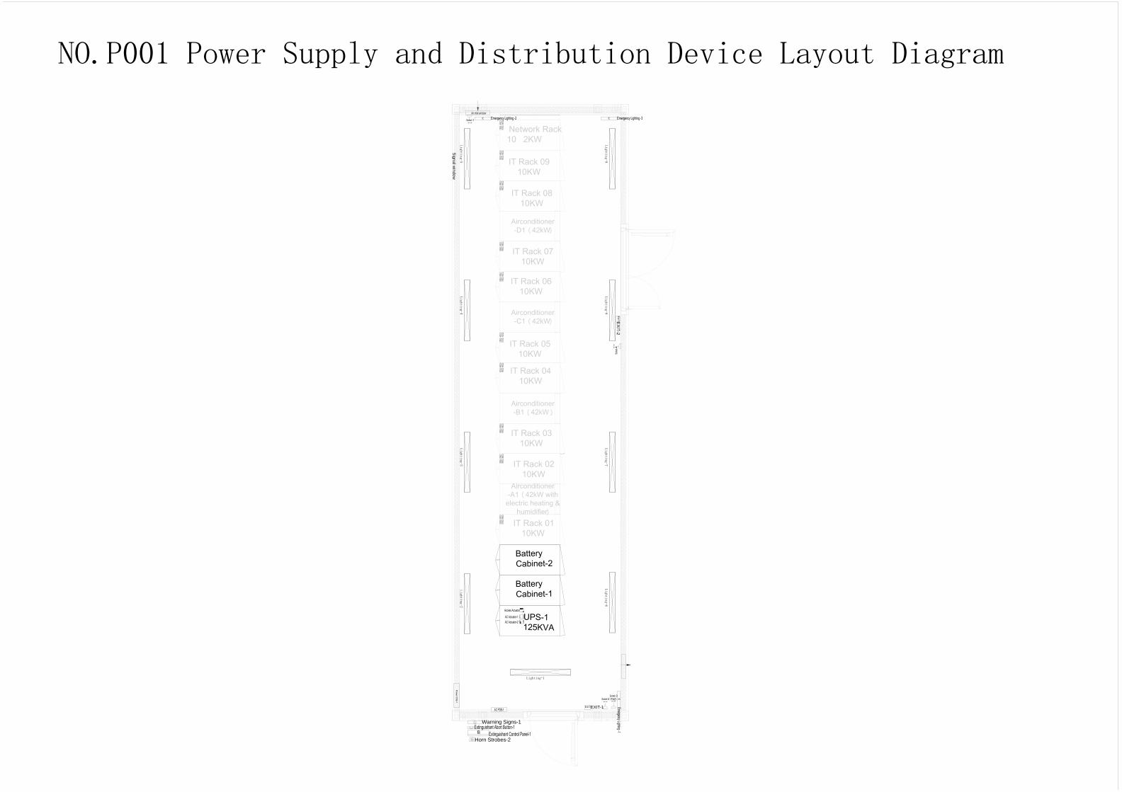
NO.P001 Power Supply and Distribution Device Layout Diagram N/A
NO.P002 Power Supply and Distribution System Diagram N/A
Initial Configuration Parameters for 8D ATS
Initial Configuration Parameters for an Integrated UPS
NO.C001 Cooling Device Layout Diagram N/A
NO.C002 Air Conditioner Teamwork Relationship Diagram N/A
NO.C003 Indoor and Outdoor Unit Signal Cable Wiring Diagram N/A
Initial Configuration Parameters of Remote Temperature and Humidity
Sensor DIP Switches for 42 kW Air Cooled Precision Air Conditioners
Initial Configuration Parameters of Main Control Board DIP Switches for
42 kW Air Cooled Precision Air Conditioners
Initial Teamwork Configuration Parameters for 42 kW Air Cooled
Precision Air Conditioners
Initial Temperature and Humidity Configuration Parameters for 42 kW
Air Cooled Precision Air Conditioners
NO.M001 Monitoring Device Layout Diagram N/A
NO.M002 Monitoring System Network Diagram N/A
Table 3 Initial Configuration Parameters for the Management System N/A
Initial Configurations for the Fire Extinguishing
SystemNO.F001 Fire Extinguishing Device Layout Diagram (CE) N/A
Initial Configurations for the Cooling System
Initial Configurations for the Management System
List of Initial Configuration Parameters
Initial Configuration Parameters for Cooling DevicesTable 2
Initial Configuration Parameters for Power Supply and Distribution
DevicesTable 1
Initial Configurations for the Power Supply and
Distribution System
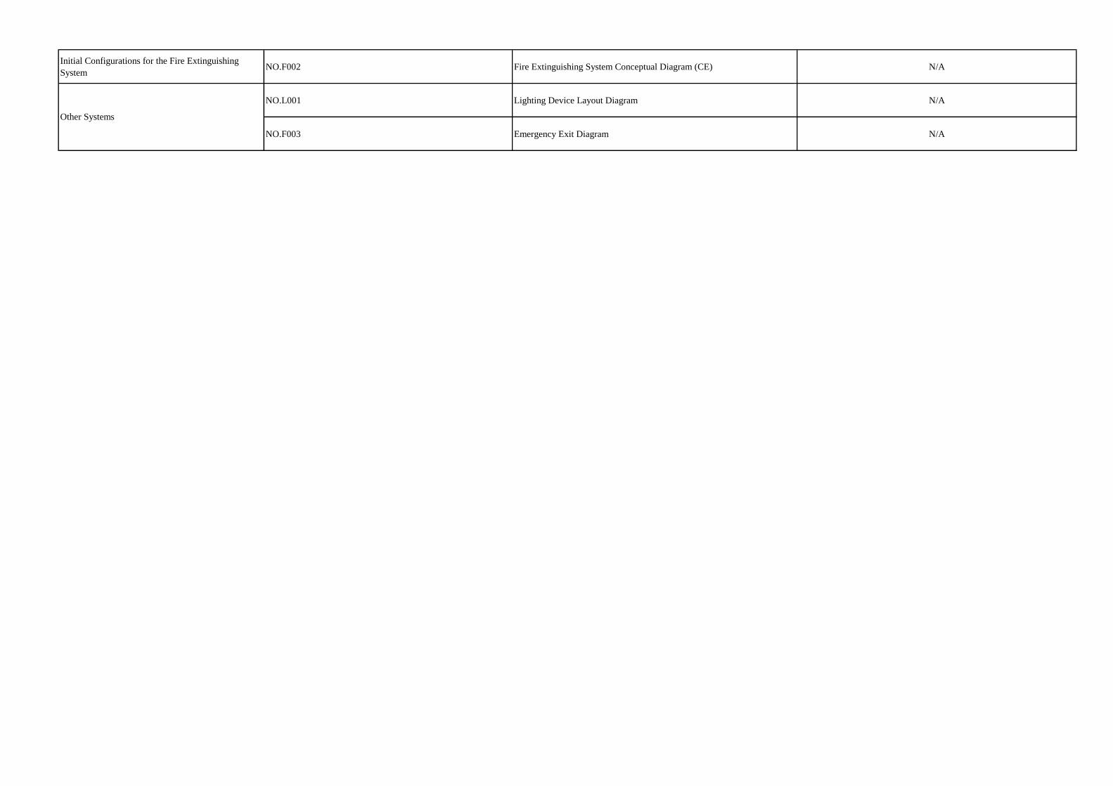
Initial Configurations for the Fire Extinguishing
SystemNO.F002 Fire Extinguishing System Conceptual Diagram (CE) N/A
NO.L001 Lighting Device Layout Diagram N/A
NO.F003 Emergency Exit Diagram N/A
Other Systems
Signal w
indow
Lighting-1
Lighting-2
Lighting-3
Lighting-4
Lighting-5
Lighting-6
Lighting-7
Lighting-8
Lighting-9
B
Abort
Horn Strobes-2
Warning Signs-1
EXIT
EXIT-1
NO.P001 Power Supply and Distribution Device Layout Diagram

Q2
MCCB 250A/3P
Q1
MCCB 250A/3P
120kVA STS
25kVA
25kVA
25kVA
Q3
MCCB 250A/3P
11
12
14
11
12
14
11
12
14
25kVA
Battery
ATS
/400
A/4
P
1HG
QFS
MCB C32A/4P
Main1
ATSE
11
12
14
In=20kA,
Imax=40kA
1FU
SPD
Main2 or
Genset
COM
OFF
ON
2FU
400/5
QFL3
MCB C10/1P
QFL2
MCB C10/1P
QFL1
MCB C10/1P
2HG
1L1/1L2/1L3/1N
2L1/2L2/2L3/2N
L1/L2/L3/N
L11/L12/L13/N
U/V/W/N
L31/L32/L33/N
25kVA
25kVA
1QF4
MCB C40/1PL1
L2
L1
1QF5
MCB C40/1P
L3
1QF6
MCB C40/1P
1QF7
MCB C40/1P
L21/L22/L23/N
IT Load PDU
3QF4
MCB C63/3PCooling PDU
3QF5
MCB C63/3P
3QF7
MCB C63/3P
3QF8
MCB C63/3P
AC PDB-1
3QF1
MCB C63/3P
3QF2
MCB C63/3P
3QF3
MCB C63/3P
2QF13
MCB C40/1PL1
L2
L1
L1
2QF14
MCB C40/1P
2QF19
MCB C40/1P
L3
2QF15
MCB C40/1P
2QF16
MCB C40/1P
2QF20
MCB C40/1PL2
L3
2QF24
MCB C40/1P
IT Load PDU
AC Actuator-2
AC Actuator-1
Air Conditioner-A1 AC1
Air Conditioner-B1 AC1
Air Conditioner-C1 AC1
Air Conditioner-D1 AC1
2QFS
MCB C63A/4P11
12
14
2FS
In=30kA,
Imax=60kA
COM
OFF
ON
Power PDB-1
1QFS
MCB C63A/4P
11
12
14
1FS
In=30kA,
Imax=60kA
COM
OFF
ON
Copper bar1
Copper bar2
Spare
Fan-1/2
Socket-1/2/3/4
Emergency Lighting-1/2/3
Extinguishant Control Panel-1
EXIT-1/2
Spare
Spare
Spare
1QF1
MCB C40/1PL1
L2
1QF2
MCB C40/1P
L3
1QF3
MCB C40/1P
L3
1QF24
MCB C40/1P
1QF11
MCB C40/1P
L3
1QF12
MCB C40/1P
L1
1QF13
MCB C40/1P
1QF14
MCB C40/1P
1QF8
MCB C40/1P
L3
1QF9
MCB C40/1P
L1
1QF10
MCB C40/1P
L2
L2
L2
L1
1QF19
MCB C40/1P
1QF20
MCB C40/1PL2
1QF18
MCB C40/1PL3
1QF15
MCB C40/1PL3
L1
1QF16
MCB C40/1P
L2
1QF17
MCB C40/1P
2QF1
MCB C40/1PL1
L2
L1
2QF2
MCB C40/1P
L3
2QF3
MCB C40/1P
2QF4
MCB C40/1P
2QF5
MCB C40/1PL2
L3
L2
2QF6
MCB C40/1P
L1
2QF7
MCB C40/1P
2QF8
MCB C40/1P
2QF9
MCB C40/1PL3
L1
L3
2QF10
MCB C40/1P
L2
2QF11
MCB C40/1P
2QF12
MCB C40/1P
L3
L2
2QF17
MCB C40/1P
2QF18
MCB C40/1P
NO.P002 Power Supply and Distribution System Diagram

Quantity Power Distribution Device Name
1 UPS-1
1 UPS-1
Table 1 Initial Configuration Parameters for Power Supply and Distribution Devices
If voltage/frequency settings for power distribution devices are involved, adjust the voltage and frequency settings based on the local voltage system and check whether the voltage thresholds and frequency hysteresis meet
setting requirements before first operation.
Note: The following device parameters are not all parameters of the devices. Only the parameters that need to be set for the project are listed. Default values will be used for the other parameters so they do not need to be set.
To view other device parameters, see the user manual for the corresponding device.
Integrated UPS ■Involved □Not involved
8D ATS ■Involved □Not involved
Device Name Project Configuration

Default Value Value Range Setting
0001 N/A 1
Rated Voltage 400/230 V
100/57 V-115/66 V-120/70 V-208/120 V-220/127
V-230/132 V-240/138 V-277/160 V-347/200 V-
380/220 V-400/230 V-415/240 V-440/254 V-
480/277 V
400
Rated Frequency 50 Hz 50 Hz, 60 Hz 50 Hz
Number of Phases LN1 3 phases with N 3 phases with N/3 phases without N/1 phase 3 phases with N
Number of Phases LN2 3 phases with N 3 phases with N/3 phases without N/1 phase 3 phases with N
Secondary Load Not Used Not Used/Opening Only/Opening And Closing Default Value
Generator Usage No Generator No Generator, Generator In Use Generator In Use
Line priority Line 1–Switch ILine 1 – Switch I/Line 2 – Switch II/No Line
PriorityLine 1 – Switch
Volt Threshold Min LN1 -20% -30% to -5% -10%
Volt Threshold Min LN2 -20% -30% to -5% -10%
Volt Threshold Max LN1 +20% +5% to +30% +10%
Volt Threshold Max LN2 +20% +5% to +30% +10%
Volt Hysteresis Min LN1 -8% -29% to -4%, step 1% -8%
Volt Hysteresis Min LN2 -8% -29% to -4%, step 1% -8%
Voltage Hysteresis
Device Confi guration
Category Parameter
Component
ABB 8D ATS Initial Configuration Parameters
Main PDF-1
System Configuration
Password
Configuration attributes
Voltage Thresholds

Volt Hysteresis Max LN1 +8% +4% to +29%, step 1% +8%
Volt Hysteresis Max LN2 +8% +4% to +29%, step 1% +8%
Freq Threshold Min LN1 -1% -10% to -1% -5%
Freq Threshold Min LN2 -1% -10% to -1% -5%
Freq Threshold Max LN1 +1% +1% to +10% +5%
Freq Threshold Max LN2 +1% +1% to +10% +5%
Freq Hysteresis Min LN1 -3.0% -9.8% to -0.8% -3.0%
Freq Hysteresis Min LN2 -3.0% -9.8% to -0.8% -3.0%
Freq Hysteresis Max LN1 +3.0% +0.8% to +9.8% +3.0%
Freq Hysteresis Max LN2 +3.0% +0.8% to +9.8% +3.0%
Switching 0s 0–60s 0s
Dead Band I to II 0s 0–60s 5s
Back Switching 0s 0s, 1s...59s, 1 min, 2 min…90 min 0s
Dead Band II to I 0s 0–60s 5s
Delay on Transfer 0s 0s, 1s...59s, 1 min, 2 min…10 min 30s
Generator Stop 5s 0s, 1s...59s, 1 min, 2 min...30 min 10s
ChineseEnglish, French, Italian, Spanish,
Finnish, German, Russian and ChineseEnglish
Voltage Hysteresis
Device Confi guration
Frequency Hysteresis
Delay Times
Language Selection
Frequency Thresholds
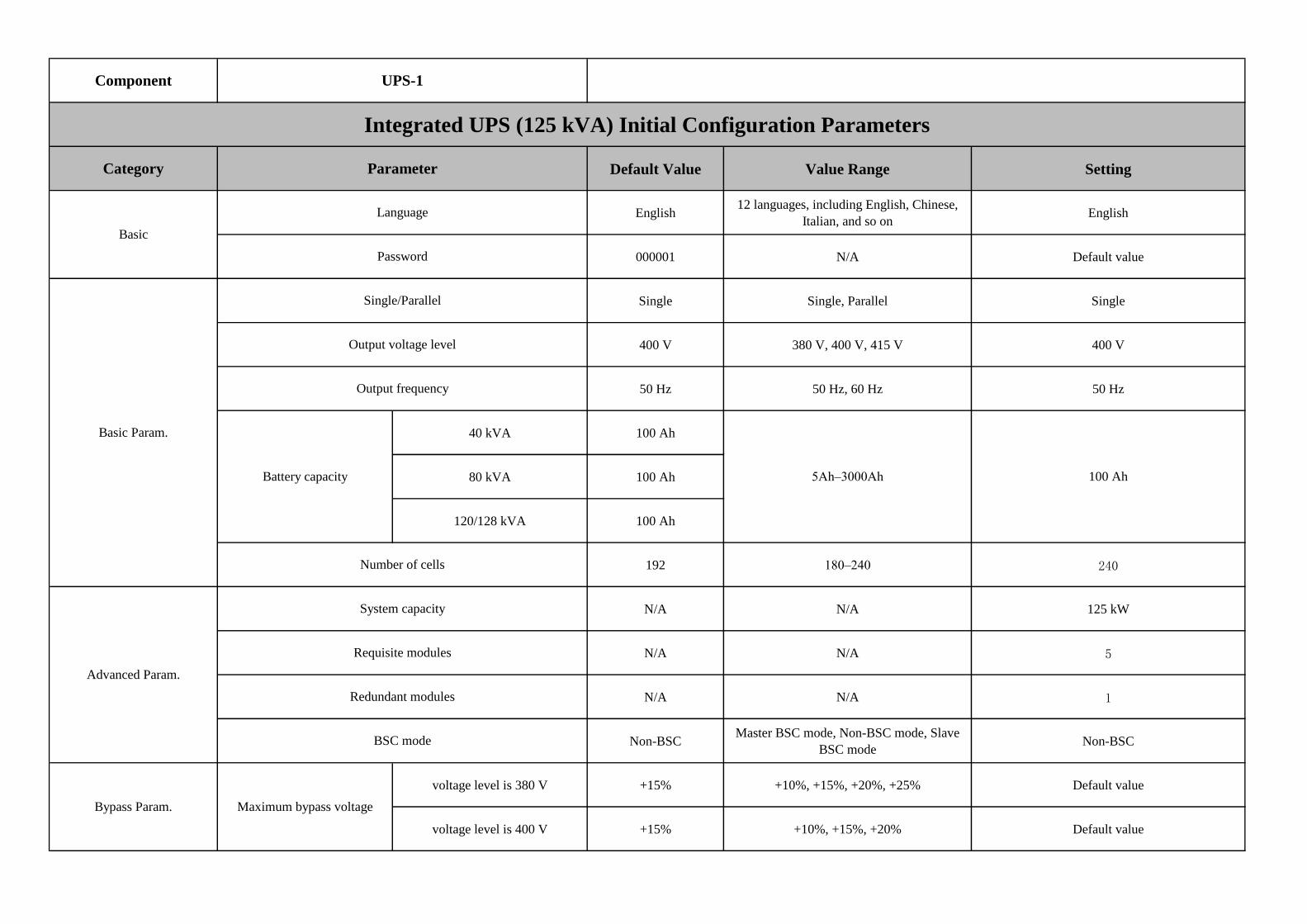
Default Value Value Range Setting
English12 languages, including English, Chinese,
Italian, and so onEnglish
000001 N/A Default value
Single Single, Parallel Single
400 V 380 V, 400 V, 415 V 400 V
50 Hz 50 Hz, 60 Hz 50 Hz
40 kVA 100 Ah
80 kVA 100 Ah
120/128 kVA 100 Ah
192 180–240 240
N/A N/A 125 kW
N/A N/A 5
N/A N/A 1
Non-BSCMaster BSC mode, Non-BSC mode, Slave
BSC modeNon-BSC
voltage level is 380 V +15% +10%, +15%, +20%, +25% Default value
voltage level is 400 V +15% +10%, +15%, +20% Default value
Maximum bypass voltageBypass Param.
Category Parameter
Component UPS-1
Integrated UPS (125 kVA) Initial Configuration Parameters
Basic
Output voltage level
Output frequency
Language
Password
Single/Parallel
Basic Param.
Battery capacity
Number of cells
5Ah–3000Ah 100 Ah
System capacity
Requisite modules
Redundant modules
Advanced Param.
BSC mode

Bypass Param. Maximum bypass voltage voltage level is 415 V +10% +10%, +15% Default value
Disable Disable/Enable Disable
Disable Disable/Enable Disable
N/A N/A Set by service personnel
Enable Disable/Enable/User-defined
User-defined (After setting the parameter to User-
defined, disable the spare branch circuit breaker in
the Installation time PDU > Branch Battery
conceptual diagram and enable the branch circuit
breaker that connects to a load.)
Enable Disable/Enable/User-defined
User-defined (After setting the parameter to User-
defined, disable the spare branch circuit breaker in
the Installation time PDU > Branch Battery
conceptual diagram and enable the branch circuit
breaker that connects to a load.)
Enable Disable/Enable/User-defined
User-defined (After setting the parameter to User-
defined, disable the spare branch circuit breaker in
the Installation time PDU > Branch Battery
conceptual diagram and enable the branch circuit
breaker that connects to a load.)
Enable Disable/Enable/User-defined Disable
Settings
PDU Parameters-Branch breaker open alarm enable
PDU Parameters-Branch breaker open alarm enable
PDU Parameters-Branch breaker open alarm enable
PDU Parameters-Main input 3-phase cur. Imb
Battery Param. Installation time
Dry Contacts
BCB connection
Batter breaker

1200
Po
we
r P
DB
-1
T&H-A1_1
T&H-A1_2
T&H-B1_1
T&H-B1_2
T&H-C1_1
T&H-C1_2
T&H-D1_1
T&H-D1_2
100
NO.C001 Cooling Device Layout Diagram

1200
Po
we
r P
DB
-1
T&H-A1_1
T&H-A1_2
T&H-B1_1
T&H-B1_2
T&H-C1_1
T&H-C1_2
T&H-D1_1
T&H-D1_2
100
CAN_OUT
CAN_OUT
CAN_OUT
CAN_IN
CAN_IN
CAN_IN
NO.C002 Air Conditioner Teamwork Relationship Diagram

1200
Po
we
r P
DB
-1
T&H-A1_1
T&H-A1_2
T&H-B1_1
T&H-B1_2
T&H-C1_1
T&H-C1_2
T&H-D1_1
T&H-D1_2
100
NO.C003 Indoor and Outdoor Unit Signal Cable Wiring Diagram

1 2 3 4 5 6
11 ON ON OFF ON OFF OFF
12 OFF OFF ON ON OFF OFF
Table 2 Initial Configuration Parameters for CoolingDevices
Initial Configuration Parameters of Remote Temperature and Humidity Sensor DIP Switches for Air Cooled Precision
Air Conditioners
DIP Switch Sequence No.
AddressSensor Name and No.
Remote humidity and temperature sensor 1
Remote humidity and temperature sensor 2

A1
B1
C1
D1
ON ON ON OFF
Initial Configuration Parameters of Main Control Board DIP Switches for Air Cooled Precision Air Conditioners
OFF
ON ON ON OFF
OFF
Air Conditioner
DIP Switch Sequence No.
1 2 3 4
ON ON OFF
OFF ON ON
Air
Conditioner
Teamwork
No.
Teamwork Unit
Address
Teamwork
FunctionNetwork
Total Number of
Units
Number of Running
UnitsRotation
Rotation
Period
Rotation
Time
Forced
Rotation
Requirement
ControlCascade
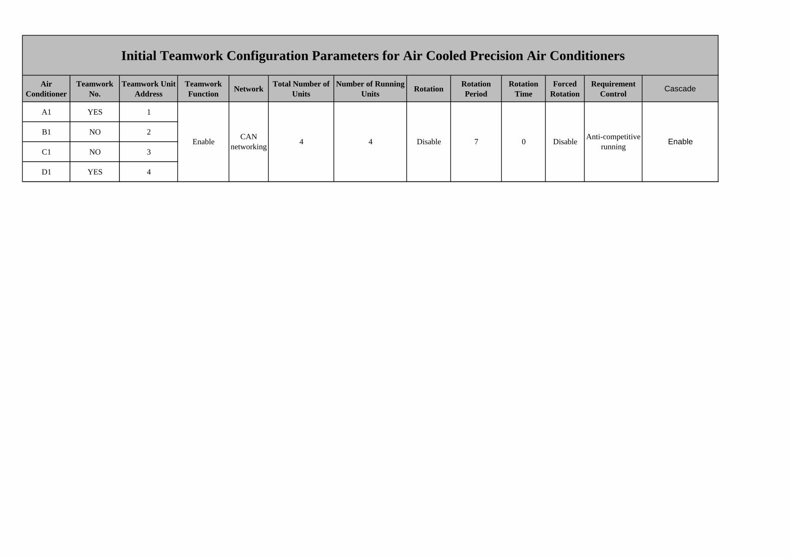
A1 YES 1
B1 NO 2
C1 NO 3
D1 YES 4
Anti-competitive
runningEnable
Initial Teamwork Configuration Parameters for Air Cooled Precision Air Conditioners
0 Disable4 Disable 7CAN
networking4Enable

Air Conditioner Cold aisle sensor 1 Cold aisle sensor 2 Cold aisle sensor 3Temp control
mode
A1
B1
C1
A1
23
Cold-aisle Humid Set Point
Initial Temperature and Humidity Configuration Parameters for Air Cooled Precision Air Conditioners
50Cold-aisle AverageEnable Enable
T/H Control TypeCold-aisle temp set
point/Return-air temp set point
Enable

1200
Signal window
100
DOOR
DO
OR
EX
IT
BR
EA
K G
LA
SS
DO
OR
PA
DP
AD
DO
OR
N0.M001 Monitoring Device Layout Diagram

Power PDB-1 SPD-1
Power PDB-1 SPD-2
AI/DI_2 AI/DI_4 AI/DI_6 DO_2
AI/DI_1 AI/DI_3 AI/DI_5 DO_1
COM2/12V COM4/12V
COM1/12V COM3/12V
WAN_2 LAN_2
WAN_1 LAN_1
HUAWEI
MMU02B
53.5VDC_OUT1 53.5VDC_OUT2
Collector_ECC800-1
BACK
Reserved
Collector_ECC800
Air Conditioner-C1
POE_2 POE_3 POE_4POE_1 48V_OUT1 48V_OUT2
PWR_IN
FE_1 FE_2
PWR_OUT
UT-H606
POE_2 POE_3 POE_4POE_1 48V_OUT1 48V_OUT2
PWR_IN
FE_1 FE_2
PWR_OUT
UT-H606
POE_2 POE_3 POE_4POE_1 48V_OUT1 48V_OUT2
PWR_IN
FE_1 FE_2
PWR_OUT
UT-H606
Smart ETH Gateway-3Smart ETH Gateway-2Smart ETH Gateway-1
Access Actuator-1
Air Conditioner-D1
Air Conditioner-A1
Air Conditioner-B1
IP Camera-2
IP Camera-3
ReservedWiFi Converter-1
AI/DI Module-1
Reserved
Reserved
Reserved
UPS-1
Reserved
LOCAL FIRE
FIRE RELAY
FAULT RELAY
DDF-1
Reserved
Reserved
Extinguishant Control Panel(CE)
Scenario without a VCN: Connect the signal cables of the indoor and outdoor cameras to the PoE ports on the smart ETH gateway.
Scenario with a VCN: Connect the signal cables of the indoor and outdoor cameras to the LAN switch.
IP Camera-1
Reserved
AC PDB-1 SPD
Reserved
Reserved
Reserved
Reserved
NO.M002 Monitoring Device Layout Diagram

Monitoring
Device
Data
TypeDevice Code
Device
Name
Device
Model
Device IP
Address
Device
Address
Alarm
Threshold
WebUI User Name
and Password
LCD User
Name and
Password
Port to
Upper-
Level
Device
DDF
Transfe
r Port
Upper-
Level
Device
Upper-
Level
Device
Port
Remarks
Collector_ECC
800-1FE 02311JEX
Collector_ECC
800-1
ECC800
C
IP:
192.168.9.150 N/A
Username:admin
Password:ChangemeN/A WAN_1 N/A DDF-1 DDF-1
WAN_1:
192.168.1.10
WAN_2:
192.168.0.10
LAN_1、
LAN_2:
192.168.248.10
WiFi default IP
address:
192.168.245.10
Collector_ECC
800-1FE 50100886
Smart ETH
Gateway-1
UT-
H606N/A 0 N/A N/A N/A FE_1 N/A
Collector_
ECC800-1LAN_1 N/A
Collector_ECC
800-1FE 50100886
Smart ETH
Gateway-2
UT-
H606N/A 1 N/A N/A N/A FE_1 N/A
Smart
ETH
Gateway-1
FE_2 N/A
Collector_ECC
800-1FE 50100886
Smart ETH
Gateway-3
UT-
H606N/A 1 N/A N/A N/A FE_1 N/A
Smart
ETH
Gateway-2
FE_2 N/A
Collector_ECC
800-1FE 2411335 IP Camera-1
IPC6325
-WD-VR
External
Network
ip:192.168.9.16
intranet
ip:192.168.248.5
1
1 N/AUsername:admin
Password:HuaWei123N/A LAN N/A
Smart
ETH
Gateway-3
POE_2 N/A
Table 3 Initial Configuration Parameters for the Management System

Collector_ECC
800-1FE 2411335 IP Camera-2
IPC6325
-WD-VR
External
Network
ip:192.168.9.16
intranet
ip:192.168.248.5
1
1 N/AUsername:admin
Password:HuaWei123N/A LAN N/A
Smart
ETH
Gateway-1
POE_1 N/A
Collector_ECC
800-1FE 02411335 IP Camera-3
IPC6325
-WD-VR
External
Network
ip:192.168.9.16
intranet
ip:192.168.248.5
1
1 N/AUsername:admin
Password:HuaWei123N/A LAN N/A
Smart
ETH
Gateway-1
POE_2 N/A
Collector_ECC
800-1FE 52271874
Access
Actuator-1
UT-
H101N/A 1 N/A N/A N/A POE N/A
Smart
ETH
Gateway-1
POE_3 N/A
Collector_ECC
800-1FE 50100888
WiFi
Converter-1
ECC5E
MSWF0
0
N/A 1 N/A N/A N/A LAN N/A
Smart
ETH
Gateway-1
POE_4
WiFi Username:
appwifi Password:
Huawei123
Collector_ECC
800-1FE 52272360
Air
Conditioner-A1
NetCol5
000-
A021HN
12D2002
0E1
N/A 1 N/A N/A
Username:
admin Initial
password:
000001
FE N/A
Smart
ETH
Gateway-2
POE_1
"Set >
communication
settings" IP
allocation method,
select "Automatic
(DHCP)"
Collector_ECC
800-1FE 52272361
Air
Conditioner-B1
NetCol5
000-
A021HN
12D2E1
20E1
N/A 1 N/A N/A
Username:
admin Initial
password:
000001
FE N/A
Smart
ETH
Gateway-2
POE_2
"Set >
communication
settings" IP
allocation method,
select "Automatic
(DHCP)"
Collector_ECC
800-1FE 52272360
Air
Conditioner-C1
NetCol5
000-
A021HN
12D2002
0E1
N/A 1 N/A N/A
Username:
admin Initial
password:
000001
FE N/A
Smart
ETH
Gateway-2
POE_3
"Set >
communication
settings" IP
allocation method,
select "Automatic
(DHCP)"

Collector_ECC
800-1FE 52272361
Air
Conditioner-D1
NetCol5
000-
A021HN
12D2E1
20E1
N/A 2 N/A N/A
Username:
admin Initial
password:
000001
FE N/A
Smart
ETH
Gateway-2
POE_4
"Set >
communication
settings" IP
allocation method,
select "Automatic
(DHCP)"
Collector_ECC
800-1FE 02290925 UPS-1
UPS500
0-E-60K-
LABBS
N/A N/A N/AUsername:admin
Password:Changeme
Username:
admin Initial
password:
000001
FE N/A
Smart
ETH
Gateway-3
POE_1
"Set >
communication
settings" IP
allocation method,
select "Automatic
(DHCP)"
Collector_ECC
500-XXXRS485 N/A LCU-XXX N/A N/A 1 N/A N/A
User name:
Admin
Initial
password:
000001
COM_IN N/ALCU-
XXXCOM
Baud rate: 9600
data bits: 8 parity
bit: None stop bit:
1
Collector_ECC
800-1Dry contact 52250103
FAULT
RELAY
SIGMA
XT/K11
031M2
N/A N/A
Normal:
closed
Alarm: open
N/A N/ACrimping
TerminalsN/A
Collector_
ECC800AI/DI_2
Collector_ECC
800-1Dry contact 52250103 LOCAL FIRE
SIGMA
XT/K11
031M2
N/A N/A
Normal: open
Alarm:
closed
N/A N/ACrimping
TerminalsN/A
Collector_
ECC800AI/DI_4
Collector_ECC
800-1Dry contact 52250103 FIRE RELAY
SIGMA
XT/K11
031M2
N/A N/A
Normal: open
Alarm:
closed
N/A N/ACrimping
TerminalsN/A
Collector_
ECC800AI/DI_6
Collector_ECC
800-1Dry contact 33010007
Door Status
Sensor-1~2
Lippo
Ma
m520/Gr
eystone
GS-06
N/A N/A
Normal:
closed
Alarm: open
N/A N/ACrimping
TerminalsN/A
Collector_
ECC800AI/DI_1
Door Status
Sensor-1And Door
Status Sensor-
2Serial connection
Extinguishant
Control Panel

Collector_ECC
800-1Dry contact 33010007
Door Status
Sensor-3~4
Lippo
Ma
m520/Gr
eystone
GS-06
N/A N/A
Normal:
closed
Alarm: open
N/A N/ACrimping
TerminalsN/A
Collector_
ECC800AI/DI_3 N/A
Collector_ECC
800-1Dry contact 33010347 Water Sensor
Greyston
e WD-
900D/Li
ppo Ma
mYW51
7K/
N/A N/A
Normal:
closed
Alarm: open
N/A N/A RJ45 N/AAI/DI
Module-1AI/DI_1 N/A
Collector_ECC
800-1Dry contact N/A
AC PDB-1
SPDN/A N/A N/A
Normal:
closed
Alarm: open
N/A N/ACrimping
TerminalsN/A
AI/DI
Module-1AI/DI_2
Fire cutting non-
state
Collector_ECC
800-1Dry contact N/A
Power PDB-1
SPD-1N/A N/A N/A
Normal:
closed
Alarm: open
N/A N/ACrimping
TerminalsN/A
AI/DI
Module-1AI/DI_3 N/A
Collector_ECC
800-1Dry contact N/A
Power PDB-1
SPD-2N/A N/A N/A
Normal:
closed
Alarm: open
N/A N/ACrimping
TerminalsN/A
AI/DI
Module-1AI/DI_4 N/A

Address SW1 SW2
0 ON ON
1 OFF ON
2 ON OFF
Remarks:
Remarks:
Remarks:
No. Yes/No
1 No
2 No
3 No
4 No
5 No
6 No
7 No
8 No
The AC actuator connects to the ECC800 controller in wireless mode.
After a camera is commissioned, label the camera with its name and IP address.
DIP Switch Settings for the AI/DI Module
SW3
ON
ON
ON
Remarks:
Camera commissioning: Obtain the IP address automatically allocated by the ECC800 to the camera through Huawei IPC TOOL. Then access the camera on the WebUI over
the IP address to configure the internal IP address.
Northbound SNMP interface for performance data
Capacity management
Mobile APP O&M
Optional Functions of the NetEco
Function
Fire alarm linkage air conditioner
Client authorization
Work order management
Energy efficiency management
Northbound SNMP interface for alarms

Air C
on
ditio
ne
r
-C
1(4
2kW
)
Air C
on
ditio
ne
r
-B
1(4
2kW
)
NO.F001 Fire Extinguishing Device Layout Diagram (CE)
-
+ +
-
+ +
1 3
2
4
COMM+LEV1 LEV2
2WIRE
I/P
SILENCE
STATUS UNITS
10K
10K 6.8K
6.8K 6.8K
6.8K6.8K
COMM+
LEV1 LEV2 2WIRE
I/P
SILENCE
6.8K
1 2
6.8K
470Ω
10K
+
-E
ROV
AUX
+SIL AL
FLT RST
REMOTE
CONTROL
+ - + -
DATA POWER
+ - + - + - + -
ZONE 1 ZONE 2
+ -
ZONE 3S1 S2
NCC NO
+ -
1ST
STAGE
NCC NO
2ND
STAGE
2ND
SOUNDER
+ -
MODE
SELECT
+ -
MAN
RELEASE
+ -
HOLD
C+ -
REL
PRESS
SWITCH
+ -
EXTING
+ -
LOW
PRESS
SWITCH
EXTRACT
NONC C
NO NC C NO NC C NO
FIRE
RELAY
LOCAL
FIRE
FAULT
RELAY
C
NC
NO
6.8K
470Ω
Fire Alarm Bell-1
To Monitoring system
brown & white
green
Terminal Resistor
redblack
redblack
red
black
red
black
black
red
Connect the fault signal
output (NO) to the collector
of the monitoring system.
Connect the gas release signal
output (NO) to the collector of
the monitoring system.
Connect the fire alarm signal
output (NO) to the collector
of the monitoring system.
Connect smoke
detector in
detection zone 1
Connect heat
detector in
detection zone 2
Data cablePower cable
Connect the first
stage alarm to the
fire alarm bell.
Connect the second stage alarm
to the horn strobes and warning
signs .
Connect the
emergency
abort port to
the extinguishant
abort button .
Connect the pressure
signal to the pneumatic
switch.
Connect the electrical
actuator drive signal to the
electrical actuator.
Horn Strobes -2 Horn Strobes -1
Terminal Resistor
Terminal Resistor
停止按钮-1
brown & whitegreen
brown & white
green
red
black
redblack
Warning Signs-1
pneumatic switch-1
Extinguishant Abort Button -1
Electrical Actuator-1
Terminal Resistor
消防警铃-1
至监控系统
棕白绿
棕白
绿 棕白绿
故障信号输出
(常开)
接监控系统采
集器
放气信号输出
(常开)
接监控系统采
集器
火警信号输出
(常开)
接监控系统采
集器
探测区域1
接感烟探
测器
探测区域2
接感温探测
器
数据线 电源线 第一阶段告警
接消防警铃
第二阶段告警
接声光报警+放
气指示灯
紧急停止
接紧急停
止按钮
压力信号
接压力开关
电磁阀
驱动信
号接电磁阀
终端电阻
红 黑红 黑 红 黑
红 黑
红 黑 红 黑 黑红
声光报警器-2
终端电阻终端电阻
终端电阻
声光报警器-1
放气指示灯-1
压力开关-1
电磁阀-1
技术要求:
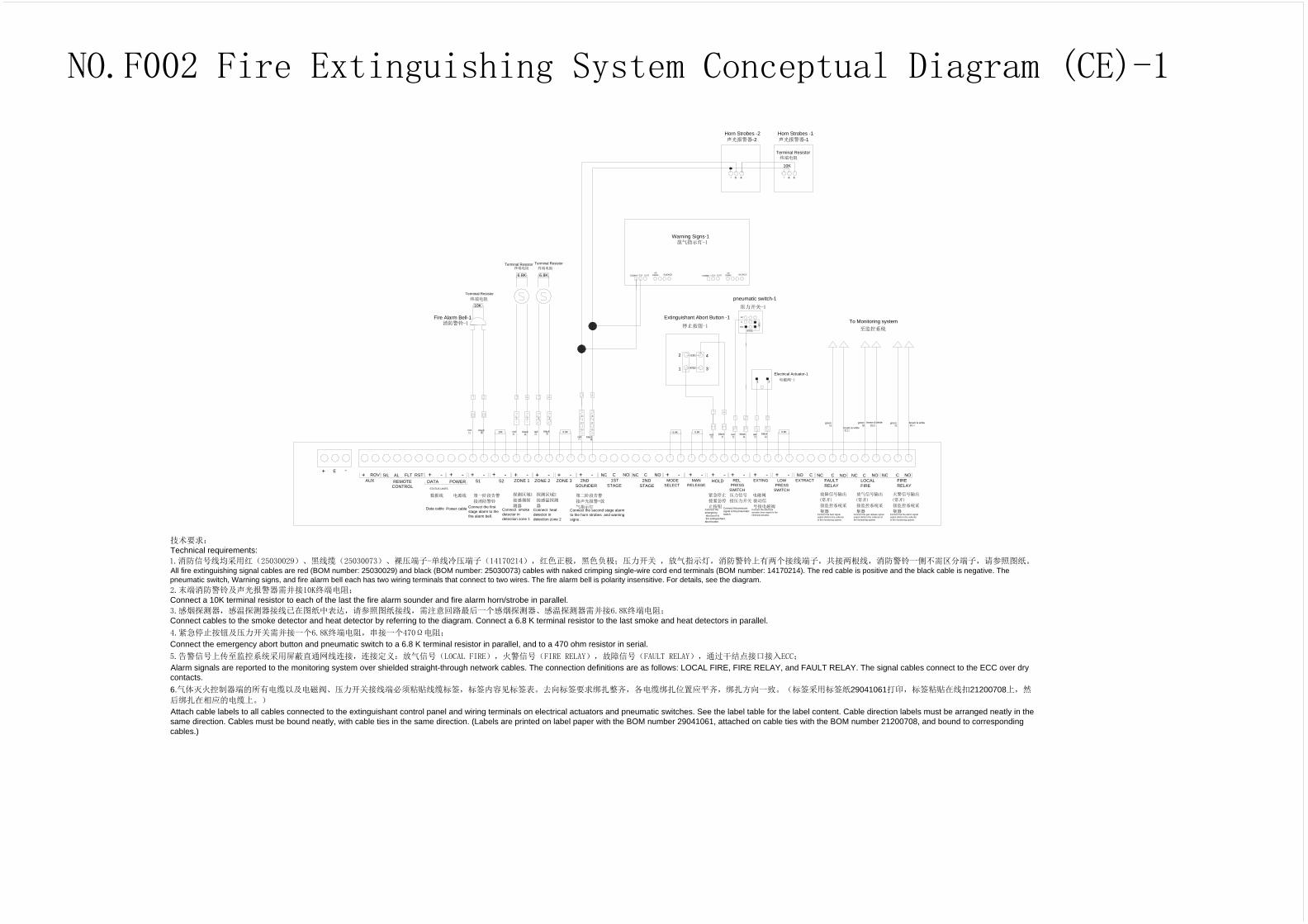
Technical requirements:
1.消防信号线均采用红(25030029)、黑线缆(25030073)、裸压端子-单线冷压端子(14170214),红色正极,黑色负极;压力开关 ,放气指示灯,消防警铃上有两个接线端子,共接两根线,消防警铃一侧不需区分端子,请参照图纸。
All fire extinguishing signal cables are red (BOM number: 25030029) and black (BOM number: 25030073) cables with naked crimping single-wire cord end terminals (BOM number: 14170214). The red cable is positive and the black cable is negative. The
pneumatic switch, Warning signs, and fire alarm bell each has two wiring terminals that connect to two wires. The fire alarm bell is polarity insensitive. For details, see the diagram.
2.末端消防警铃及声光报警器需并接10K终端电阻;
Connect a 10K terminal resistor to each of the last the fire alarm sounder and fire alarm horn/strobe in parallel.
3.感烟探测器,感温探测器接线已在图纸中表达,请参照图纸接线,需注意回路最后一个感烟探测器、感温探测器需并接6.8K终端电阻;
Connect cables to the smoke detector and heat detector by referring to the diagram. Connect a 6.8 K terminal resistor to the last smoke and heat detectors in parallel.
4.紧急停止按钮及压力开关需并接一个6.8K终端电阻,串接一个470Ω电阻;
Connect the emergency abort button and pneumatic switch to a 6.8 K terminal resistor in parallel, and to a 470 ohm resistor in serial.
5.告警信号上传至监控系统采用屏蔽直通网线连接,连接定义:放气信号(LOCAL FIRE),火警信号(FIRE RELAY),故障信号(FAULT RELAY),通过干结点接口接入ECC;
Alarm signals are reported to the monitoring system over shielded straight-through network cables. The connection definitions are as follows: LOCAL FIRE, FIRE RELAY, and FAULT RELAY. The signal cables connect to the ECC over dry
contacts.
6.气体灭火控制器端的所有电缆以及电磁阀、压力开关接线端必须粘贴线缆标签,标签内容见标签表。去向标签要求绑扎整齐,各电缆绑扎位置应平齐,绑扎方向一致。(标签采用标签纸29041061打印,标签粘贴在线扣21200708上,然
后绑扎在相应的电缆上。)
Attach cable labels to all cables connected to the extinguishant control panel and wiring terminals on electrical actuators and pneumatic switches. See the label table for the label content. Cable direction labels must be arranged neatly in the
same direction. Cables must be bound neatly, with cable ties in the same direction. (Labels are printed on label paper with the BOM number 29041061, attached on cable ties with the BOM number 21200708, and bound to corresponding
cables.)
NO.F002 Fire Extinguishing System Conceptual Diagram (CE)-1

ROV SIL AL FLT RST
+ -
NC C NO C
AUX
24V
+ -
DATA POWER
STATUS UNITS
+ - + - + - + -
ZONE 1 ZONE 2
+ -
ZONE 3
+ -
1ST
STAGE
NC C NO
2ND
STAGE
+ -
MODE
SELECT
+ -
MAN
RELEASE
+ - + - + -
EXTING
+ -
EXTRACT
NC C NO NC C NO NC C NO
FIRE
RELAY
L1 OUT
L1 IN
L2
-R
L1 OUT
L1 IN
L2
-R
L1 OUT
L1 IN
L2
-R
L1 OUT
L1 IN
L2
-R
L1 OUT
L1 IN
L2
-R
L1 OUT
L1 IN
L2
-R
L1 OUT
L1 IN
L2
-R
L1 OUT
L1 IN
L2
-R
L1 OUT
L1 IN
L2
-R
L1 OUT
L1 IN
L2
-R
L1 OUT
L1 OUT
NO
2ND
SOUNDER
REMOTE
CONTROL
S1 S2 HOLD
LOCAL
FIRE
FAULT
RELAY
++
-E
brown & white
green
Connect the fault signal
output (NO) to the collector
of the monitoring system.
Connect the gas release signal
output (NO) to the collector of
the monitoring system.
Connect the fire alarm signal
output (NO) to the collector
of the monitoring system.
Connect smoke
detector in detection
zone 1
Connect heat
detector in detection
zone 2
Data cable
Power cable
Connect the pressure
signal to the pneumatic
switch.
red
red blackred black
Connect the first stage
alarm to the fire alarm
bell.
Connect the second stage alarm to the
horn strobes and warning signs .
Connect the
emergency
abort port to
the Extinguishant
abort button .
Connect the electrical
actuator drive signal to the
electrical actuator.
brown & white
greenbrown & white
green
red
red
red
black
black
black black
REL
PRESS
SWITCH
LOW
PRESS
SWITCH
探测区域1
接感烟探
测器
探测区域2
接感温探测
器
数据线 电源线 第一阶段告警
接消防警铃
第二阶段告警
接声光报警+放
气指示灯
紧急停止
接紧急停
止按钮
压力信号
接压力开关
电磁阀驱动信
号接电磁阀
故障信号输出
(常开)
接监控系统采
集器
放气信号输出
(常开)
接监控系统采
集器
火警信号输出
(常开)
接监控系统采
集器
棕白绿棕白绿 棕白绿
红
红
黑 黑
红
红
黑 黑
红 黑 红 黑
终端电阻(6.8K)
终端电阻(6.8K)
技术要求:
Technical requirements:
1.消防信号线均采用红(25030029)、黑线缆(25030073)、裸压端子-单线冷压端子(14170214),红色正极,黑色负极;压力开关 ,放气指示灯,消防警铃上有两个接线端子,共接两根线,消防警铃一侧不需区分端子,请参照图纸。
All fire extinguishing signal cables are red (BOM number: 25030029) and black (BOM number: 25030073) cables with naked crimping single-wire cord end terminals (BOM number: 14170214). The red cable is positive and the black cable is negative. The
pneumatic switch, Warning signs, and fire alarm bell each has two wiring terminals that connect to two wires. The fire alarm bell is polarity insensitive. For details, see the diagram.
2.末端消防警铃及声光报警器需并接10K终端电阻;
Connect a 10K terminal resistor to each of the last the fire alarm sounder and fire alarm horn/strobe in parallel.
3.感烟探测器,感温探测器接线已在图纸中表达,请参照图纸接线,需注意回路最后一个感烟探测器、感温探测器需并接6.8K终端电阻;
Connect cables to the smoke detector and heat detector by referring to the diagram. Connect a 6.8 K terminal resistor to the last smoke and heat detectors in parallel.
4.紧急停止按钮及压力开关需并接一个6.8K终端电阻,串接一个470Ω电阻;
Connect the emergency abort button and pneumatic switch to a 6.8 K terminal resistor in parallel, and to a 470 ohm resistor in serial.
5.告警信号上传至监控系统采用屏蔽直通网线连接,连接定义:放气信号(LOCAL FIRE),火警信号(FIRE RELAY),故障信号(FAULT RELAY),通过干结点接口接入ECC;
Alarm signals are reported to the monitoring system over shielded straight-through network cables. The connection definitions are as follows: LOCAL FIRE, FIRE RELAY, and FAULT RELAY. The signal cables connect to the ECC over dry
contacts.
6.气体灭火控制器端的所有电缆以及电磁阀、压力开关接线端必须粘贴线缆标签,标签内容见标签表。去向标签要求绑扎整齐,各电缆绑扎位置应平齐,绑扎方向一致。(标签采用标签纸29041061打印,标签粘贴在线扣21200708上,然
后绑扎在相应的电缆上。)
Attach cable labels to all cables connected to the extinguishant control panel and wiring terminals on electrical actuators and pneumatic switches. See the label table for the label content. Cable direction labels must be arranged neatly in the
same direction. Cables must be bound neatly, with cable ties in the same direction. (Labels are printed on label paper with the BOM number 29041061, attached on cable ties with the BOM number 21200708, and bound to corresponding
cables.)
L1 OUT
L1 IN
L2
-R
L1 OUT
L1 IN
L2
-R
NO.F002 Fire Extinguishing System Conceptual Diagram (CE)-2

Signal w
indow
Lighting-1
Lighting-2
Lighting-3
Lighting-4
Lighting-5
Lighting-6
Lighting-7
Lighting-8
Lighting-9
NO.L001 Lighting Device Layout Diagram

Air C
on
ditio
ne
r
-C
1(4
2kW
)
Air C
on
ditio
ne
r
-B
1(4
2kW
)
NO.F003 Emergency Exit Diagram