Includes US and Canadian Models
143
Includes US and Canadian Models
-
Upload
khangminh22 -
Category
Documents
-
view
1 -
download
0
Transcript of Includes US and Canadian Models

PANTONE 288 CVC DIC F101 BLACK BF40D50D_AH-OM表紙31ZZ4620BF40D50D_AH-OM表紙31ZZ4620BF40D50D_AH-OM表紙31ZZ4620背幅4mm背幅4mm背幅4mm
Includes US and Canadian Models英 N HCAHEM331ZZ4620
00X31-ZZ4-62001000.2011.04
Printed in China

-
The engine exhaust from thisproduct contains chemicals
known to the State of California tocause cancer, birth defects, or
other reproductive harm.
Keep this Owner’s Manual handy, so you can refer to it at any time. This Owner’sManual is considered a permanent part of the outboard motor and should remain withthe outboard motor if resold.
The information and specifications included in this publication were in effect at thetime of approval for printing. Honda Motor Co., Ltd. reserves the right, however, todiscontinue or change specifications or design at any time without notice and withoutincurring any obligation whatever. No part of this publication may be reproducedwithout written permission.
2011 Honda Motor Co., Ltd. All Rights Reserved
11/03/10 14:15:35 31ZZ4620_001

1
INTRODUCTION
Congratulations on your selection ofa Honda outboard motor. We arecertain you will be pleased with yourpurchase of one of the finestoutboard motors on the market.
We want to help you get the bestresults from your new outboardmotor and to operate it safely. Thismanual contains information on howto do that; please read it carefully.
As you read this manual you willfind information preceded by a
symbol. That informationis intended to help you avoid damageto your outboard motor, otherproperty, or the environment.
We suggest you read the warrantypolicy to fully understand itscoverage and your responsibilities ofownership.
When your outboard motor needsscheduled maintenance, keep in mindthat your Honda Marine dealer isspecially trained in servicing Hondaoutboard motors. Your HondaMarine dealer is dedicated to yoursatisfaction and will be pleased toanswer your questions and concerns.
Best Wishes,Honda Motor Co., Ltd.
11/03/10 14:15:42 31ZZ4620_002
-
-
-
-
-
-
2
A FEW WORDS ABOUTSAFETY
INTRODUCTION
Safety Messages
Safety Headings
Safety Labels
Safety Section
Instructions
IMPORTANT SAFETY INFORMATION.
OUTBOARD MOTOR SAFETY.
Your safety and the safety of othersare very important. And using thisoutboard motor safely is an importantresponsibility.
To help you make informeddecisions about safety, we haveprovided operating procedures andother information on labels and inthis manual. This information alertsyou to potential hazards that couldhurt you or others.
Of course, it is not practical orpossible to warn you about all thehazards associated with operating ormaintaining an outboard motor. Youmust use your own good judgment.
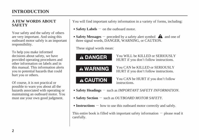
You will find important safety information in a variety of forms, including:
This entire book is filled with important safety information please read itcarefully.
preceded by a safety alert symbol and one ofthree signal words, DANGER, WARNING, or CAUTION.
These signal words mean:
such as
on the outboard motor.
such as
how to use this outboard motor correctly and safely.
You WILL be KILLED or SERIOUSLYHURT if you don’t follow instructions.
You CAN be KILLED or SERIOUSLYHURT if you don’t follow instructions.
You CAN be HURT if you don’t followinstructions.
11/03/10 14:15:56 31ZZ4620_003

3
CONTENTS
...................................OUTBOARD MOTOR SAFETY . 7................IMPORTANT SAFETY INFORMATION . 7
................................SAFETY LABEL LOCATIONS . 9
..................................CONTROLS AND FEATURES . 13CONTROL AND FEATURE
................................IDENTIFICATION CODES . 13....COMPONENT AND CONTROL LOCATIONS . 14
..............................................................CONTROLS . 20LH and LHT Types (tiller handle)
......................................................Ignition Switch . 20Emergency Stop Switch Clip and Emergency
.......................................................Stop Switch . 20..........................................................Throttle Grip . 21
.....................................Throttle Friction Adjuster . 22.....................................................Gearshift Lever . 22
.....................................Steering Friction Adjuster . 22.............................Transom Angle Adjusting Rod . 23
...............................................................Tilt Lever . 23LRT and XRT Types (remote control/
side-mount control type) [standard equipment(LRTC type)], [optional equipment (LRTA and
................................................XRTA types)] . 24......................................................Ignition Switch . 24
Emergency Stop Switch Clip and Emergency.......................................................Stop Switch . 25
..........................Gearshift/Throttle Control Lever . 26.......................................................Fast Idle Lever . 27
LHT, LRT and XRT Types (power trim/tilt)........................................Power Trim/Tilt Switch . 28
............................Power Tilt Switch (engine pan) . 28.............................................Manual Relief Valve . 29
.....................................................Common Controls . 30
.....................................................Tilt Lock Lever . 30...........................................Engine Cover Latches . 30
................................................................Trim Tab . 30.......................................................INSTRUMENTS . 31
Trim Meter [standard equipment (Canadiantypes)], [optional equipment (LRTA
.........................................and XRTA types)] . 31Tachometer [standard equipment (Canadian
types)], [optional equipment (LRTA.........................................and XRTA types)] . 31
Digital Tachometer [optional equipment (LRT................................................and XRT types)] . 31
Digital Speedometer [optional equipment (LRT................................................and XRT types)] . 32
Fuel Gauge [standard equipment (Canadiantypes)], [optional equipment
.........................................(American types)] . 32
11/03/16 10:38:34 31ZZ4620_004
4
CONTENTS
...........................................................INDICATORS . 33...................................Alternator (ACG) Indicator . 33
...........................................Malfunction Indicator . 33............................................Oil Pressure Indicator . 34
.................................................Overheat Indicator . 35.....................................Cooling System Indicator . 35
................................................OTHER FEATURES . 36.....................................................Overrev Limiter . 36
Portable Fuel Tank[standard equipment (Canadian types)],
........[optional equipment (American types)] . 36....................................Fuel Filler Cap Vent Knob . 37
.................................................Fuel Priming Bulb . 37......................................NMEA Interface Coupler . 37
...................................................................Anodes . 38
................................................BEFORE OPERATION . 39........ARE YOU READY TO GET UNDER WAY? . 39
IS YOUR OUTBOARD MOTOR..............................................READY TO GO? . 39
Tiller Handle Height/Angle Adjustment........................................(LH and LHT Types) . 41
................................................................OPERATION . 42....................SAFE OPERATING PRECAUTIONS . 42
.......................................BREAK-IN PROCEDURE . 42...TRANSOM ANGLE ADJUSTMENT (LH Type) . 43
PORTABLE FUEL TANK[standard equipment (Canadian types)],
............[optional equipment (American types)] . 44................................FUEL HOSE CONNECTIONS . 44
.......................................................FUEL PRIMING . 45...............INFREQUENT OR OCCASIONAL USE . 46
......................................STARTING THE ENGINE . 46........................LH and LHT Types (tiller handle) . 46
LRT and XRT Types (remote control).................................Side-Mount Control Type . 49
.....................................EMERGENCY STARTING . 52.......................................STOPPING THE ENGINE . 55
................................Emergency Engine Stopping . 55.......................................Normal Engine Stopping . 56
GEARSHIFT AND..............................THROTTLE OPERATION . 58
........................LH and LHT Types (tiller handle) . 58.................LRT and XRT Types (remote control) . 59
...............................................................STEERING . 60........................LH and LHT Types (tiller handle) . 60
.....................................Steering Friction Adjuster . 60.................LRT and XRT Types (remote control) . 60
11/03/16 10:38:37 31ZZ4620_005

5
CONTENTS
................................................................CRUISING . 61
................................................................TRIM TAB . 63........................SHALLOW WATER OPERATION . 63
...............MOORING, BEACHING, LAUNCHING . 65
..............SERVICING YOUR OUTBOARD MOTOR . 67...........THE IMPORTANCE OF MAINTENANCE . 67
.....................................MAINTENANCE SAFETY . 68SPARE SWITCH CLIP AND EMERGENCY
..................................................STARTER ROPE . 69...................TOOL KIT and OWNER’S MANUAL . 69
...............................MAINTENANCE SCHEDULE . 70....................................TRIM TAB ADJUSTMENT . 72....................................MANUAL RELIEF VALVE . 73
ENGINE COVER REMOVAL AND.............................................INSTALLATION . 73
........................................Engine Oil Level Check . 74................................................Engine Oil Change . 75
..............................Engine Oil Recommendations . 77................................................Spark Plug Service . 77.................................................Lubrication Points . 79
.............................................................REFUELING . 80...............................FUEL RECOMMENDATIONS . 82
Fuel Filter/Water Separator Inspection and...............................................................Service . 83
Portable Fuel Tank and Tank Filter Cleaning[standard equipment (Canadian types)],
........[optional equipment (American types)] . 86..............................................Anode Replacement . 87
..........................................Propeller Replacement . 88
....................................CLEANING AND FLUSHING . 90..........................................Cleaning and Flushing . 90
....................................................................STORAGE . 93........................................................................Fuel . 93
.............................................................Engine Oil . 96................HOISTING THE OUTBOARD MOTOR . 96
...................................STORAGE PRECAUTIONS . 96...............................REMOVAL FROM STORAGE . 97
........................................................TRANSPORTING . 98WITH OUTBOARD MOTOR INSTALLED
.............................................................ON BOAT . 98WITH OUTBOARD MOTOR REMOVED
.......................................................FROM BOAT . 98
11/03/10 14:16:08 31ZZ4620_006

6
CONTENTS
TAKING CARE OF UNEXPECTED..........................................................PROBLEMS . 99
..................................ENGINE WILL NOT START . 99HARD STARTING OR STALLS AFTER
.........................................................STARTING . 102.........................................ENGINE OVERHEATS . 103
.....................................................................FUSES . 104........................Electric Starter Will Not Operate . 104
.....................................Battery Will Not Charge . 104.................................................Fuse Replacment . 105
OIL PRESSURE INDICATOR GOES OFF AND..........................ENGINE SPEED IS LIMITED . 106
OVERHEAT INDICATOR COMES ON AND..........................ENGINE SPEED IS LIMITED . 107
.................SUBMERGED OUTBOARD MOTOR . 109
.................................TECHNICAL INFORMATION . 111........................................Serial Number Locations . 111
.....................................................................Battery . 112...................Emission Control System Information . 112
................................................................Star Label . 115..........................................................Specifications . 117
.................................CONSUMER INFORMATION . 120.................................................Honda publications . 120
................................Customer Service Information . 120...............................................Warranty Statements . 123
..............................Distributor’s Limited Warranty . 123........................Emission Control System Warranty . 128
............................................Distributor’s Warranty . 132
.........................................................................INDEX . 135
11/09/14 10:56:03 31ZZ4620_007
7
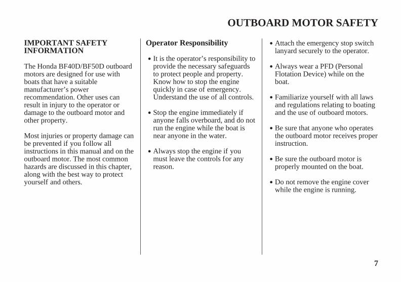
IMPORTANT SAFETYINFORMATION
Operator Responsibility
OUTBOARD MOTOR SAFETY
It is the operator’s responsibility toprovide the necessary safeguardsto protect people and property.Know how to stop the enginequickly in case of emergency.Understand the use of all controls.
Attach the emergency stop switchlanyard securely to the operator.
Stop the engine immediately ifanyone falls overboard, and do notrun the engine while the boat isnear anyone in the water.
Always stop the engine if youmust leave the controls for anyreason.
Always wear a PFD (PersonalFlotation Device) while on theboat.
Familiarize yourself with all lawsand regulations relating to boatingand the use of outboard motors.
Be sure that anyone who operatesthe outboard motor receives properinstruction.
Be sure the outboard motor isproperly mounted on the boat.
Do not remove the engine coverwhile the engine is running.
The Honda BF40D/BF50D outboardmotors are designed for use withboats that have a suitablemanufacturer’s powerrecommendation. Other uses canresult in injury to the operator ordamage to the outboard motor andother property.
Most injuries or property damage canbe prevented if you follow allinstructions in this manual and on theoutboard motor. The most commonhazards are discussed in this chapter,along with the best way to protectyourself and others.
11/03/10 14:16:24 31ZZ4620_008

8
Carbon Monoxide HazardRefuel With Care
OUTBOARD MOTOR SAFETY
Gasoline is extremely flammable,and gasoline vapor can explode.Refuel outdoors, in a well-ventilated area, with the enginestopped. Never smoke neargasoline, and keep other flamesand sparks away.
Refuel carefully to avoid spillingfuel. Avoid overfilling the fueltank.
After refueling, tighten the fillercap securely. If any fuel is spilled,make sure the area is dry beforestarting the engine.
Exhaust contains poisonous carbonmonoxide, a colorless, odorless gas.Breathing carbon monoxide cancause loss of consciousness and maylead to death.
If you run the engine in an area thatis confined, or even partly enclosed,the air you breathe could contain adangerous amount of exhaust gas.
Never run your outboard inside agarage or other enclosure.
11/03/10 14:16:32 31ZZ4620_009

*
9
SAFETY LABEL LOCATIONSUS, Puerto Rico, and US Virgin Islands Types
OUTBOARD MOTOR SAFETY
These labels come with the outboard motor.
READ OWNER’S MANUALEMERGENCY ENGINE STARTING
(LHA type)
The label shown here contains important safety information. Please read it carefully. This label is considered apermanent part of your outboard motor. If the label comes off or becomes hard to read, contact an authorized HondaMarine dealer for a replacement.
11/09/14 10:56:38 31ZZ4620_010

*
10
SAFETY LABEL LOCATIONSCanadian Types
OUTBOARD MOTOR SAFETY
READ OWNER’S MANUALEMERGENCY ENGINE STARTING
These labels come with the outboard motor.
READ OWNER’S MANUAL
The label shown here contains important safety information. Please read it carefully. This label is considered apermanent part of your outboard motor. If the label comes off or becomes hard to read, contact an authorized HondaMarine dealer for a replacement.
11/03/10 14:17:03 31ZZ4620_011
11
OUTBOARD MOTOR SAFETY
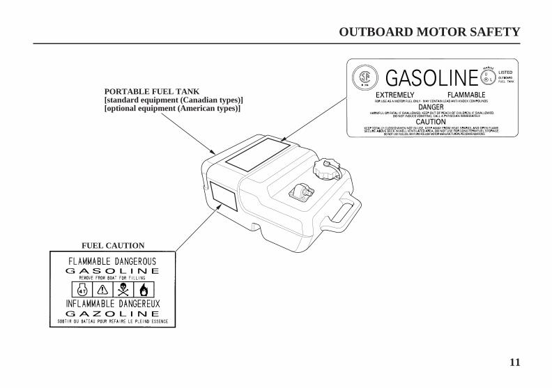
FUEL CAUTION
PORTABLE FUEL TANK[standard equipment (Canadian types)][optional equipment (American types)]
11/03/10 14:17:15 31ZZ4620_012

Gasoline is harmful or fatalif swallowed. Keep the fueltank out of reach ofchildren.Gasoline is extremelyflammable and is explosiveunder certain conditions.Refuel in a well-ventilatedarea with the enginestopped.Do not smoke or allowflames or sparks where theengine is refueled or wheregasoline is stored.Do not overfill the fuel tank.After refueling make surethat the fuel tank cap isclosed properly andsecurely.
Be careful not to spill anyfuel while refueling. Spilledfuel or fuel vapor mayignite. If any fuel is spilled,make sure that the area isdry before starting theengine.Honda outboard motor is
designed to give safe anddependable service ifoperated according toinstructions.Read and understand theOwner’s Manual beforeoperating the outboardmotor. Failure to do socould result in personalinjury or equipmentdamage.
12
OUTBOARD MOTOR SAFETY
Canadian Types
11/03/10 14:17:24 31ZZ4620_013

*
*
*
*
*
*
*
13
CONTROL AND FEATURE IDENTIFICATION CODES
CONTROLS AND FEATURES
Remote Control
Model
Type
Power Trim/Tilt
Shaft Length
Gas Assist Tilt
Tiller Handle
Tachometer
Trim Meter
Optional equipment
LHA LRTA LRTC
BF40D
LHTC LRTA LRTC XRTA
BF50D
L
X
Refer to this chart for an explanation of the Type Codes used in this manual to identify control and feature applications.:
L R T ATYPE CODE (Example)
None=Gas Assist TiltH=Tiller Handle
L=20.5 in (521 mm) (Long Shaft)X=24.5 in (622 mm) (Extra Long Shaft)
T=Power Trim/Tilt
R=Remote Control
Destination: A=American, C=Canadian
11/03/10 14:17:43 31ZZ4620_014

14
COMPONENT AND CONTROL LOCATIONS
CONTROLS AND FEATURES
LH and LHT Types(tiller handle)
ENGINE COVERLATCH (front)
TILLERHANDLE
FUEL LINECONNECTOR
STERN BRACKET
TRANSOM ANGLEADJUSTING ROD
ANODE METAL
GEAR OIL CHECKSCREW
WASH SCREW
GEAR OIL DRAIN/FILLSCREW
EXHAUST PORT/WATER OUTLETPORT
TRIM TAB
ANODEMETAL(each side)
IDLE PORT
ENGINE COVERLATCH (rear)
ENGINE COVER
SPARK PLUG(inside the cover)
ENGINE OILFILLER CAP
OIL LEVELDIPSTICK
COOLINGSYSTEMINDICATOR
ENGINE OILDRAIN BOLTCOVER
ANTIVENTILATIONPLATE
TILT LOCKLEVER
POWER TILTSWITCH(LHT type only)
MANUAL RELIEFVALVE(LHT type only)
TILT LEVER(LH type only)
POWER TRIM/TILT SWITCH(LHT type only)
PROPELLER[standard equipment (Canadian types)][optional equipment (American types)]
COOLING WATERINTAKE PORT
11/03/10 14:17:52 31ZZ4620_015

15
CONTROLS AND FEATURES
GEARSHIFT LEVER
IGNITION SWITCH KEY
IGNITION SWITCH
EMERGENCY STOPSWITCH LANYARD
THROTTLEGRIP
THROTTLE FRICTIONADJUSTER
EMERGENCY STOP SWITCH
STEERING FRICTIONADJUSTER
EMERGENCY STOPSWITCH CLIP
INDICATORS(Oil pressure, Overheat,Alternator, Malfunction)
POWER TRIM/TILT SWITCH(LHT type only)
11/03/10 14:17:58 31ZZ4620_016

16
CONTROLS AND FEATURES
LRT and XRT Types (remote control)
TILT LOCKLEVER
ENGINE COVERLATCH (front)
FUEL LINECONNECTOR
STERN BRACKET
GEAR OIL CHECKSCREW
WASH SCREW
GEAR OIL DRAIN/FILLSCREW
SPARK PLUG(inside the cover)
ENGINE COVER
ENGINE COVERLATCH (rear)
POWERTILTSWITCH
IDLE PORT
TRIM TAB
EXHAUST PORT/WATER OUTLETPORT
ENGINE OILFILLER CAP
OIL LEVELDIPSTICK
COOLINGSYSTEMINDICATOR
ENGINE OILDRAIN BOLTCOVER
ANTIVENTILATIONPLATE
COOLING WATERINTAKE PORT
ANODEMETAL(each side)
ANODE METAL
MANUAL RELIEFVALVE
PROPELLER[standard equipment (Canadian types)][optional equipment (American types)]
11/03/10 14:18:06 31ZZ4620_017

17
Remote Control BoxSide-Mount Control Type[standard equipment (LRTC type)] [optional equipment (LRTA and XRTA types)],
CONTROLS AND FEATURES
GEARSHIFT/THROTTLECONTROL LEVER
POWER TRIM/TILTSWITCH
SPARE EMERGENCYSTOP SWITCH CLIP
BUZZER(inside)
CONTROL LEVERFRICTION ADJUSTER
EMERGENCY STOPSWITCH LANYARD
EMERGENCY STOPSWITCH CLIP
EMERGENCY STOPSWITCH
IGNITION SWITCHKEY
IGNITION SWITCH
FAST IDLE LEVER
INDICATORS(Oil pressure, Overheat,Alternator, Malfunction)
NEUTRAL RELEASE LEVER
11/03/10 14:18:13 31ZZ4620_018

18
Portable Fuel Tank
[optional equipment (American types)][standard equipment (Canadian types)]
CONTROLS AND FEATURES
FUEL HOSE CONNECTOR(female)
FUEL GAUGE
VENT KNOB
PRIMING BULB
FUEL HOSE(standard equipment)
PORTABLE FUEL TANK
FUEL FILLER CAP
11/03/10 14:18:21 31ZZ4620_019

19
Trim Meter Tachometer Digital Speedometer[standard equipment (Canadiantypes)][optional equipment (LRTA andXRTA types)]
[standard equipment (Canadiantypes)][optional equipment (LRTA andXRTA types)]
[optional equipment (LRT andXRT types)]
Digital Tachometer[optional equipment (LRT andXRT types)]
CONTROLS AND FEATURES
11/03/10 14:18:32 31ZZ4620_020

20
CONTROLS
LH and LHT Types(tiller handle)
CONTROLS AND FEATURES
OOFFFF
OONN START
IGNITIONSWITCHKEYIGNITION SWITCH
EMERGENCYSTOP SWITCHLANYARD
EMERGENCY STOP SWITCH
EMERGENCY STOPSWITCH CLIP
EMERGENCY STOP SWITCH CLIP
EMERGENCY STOPSWITCH LANYARD
Emergency Stop Switch Clip andEmergency Stop Switch
Ignition Switch
Turning the ignition switch key to theSTART position operates the startermotor. The key automatically returnsto the ON position when releasedfrom the START position.
Turning the ignition switch to theOFF position stops the engine.
The engine will not start unless thegearshift lever is in the N (neutral)position (p. ) and the emergencystop switch clip is in the emergencystop switch.
The ignition switch controls theignition system and the starter motor.
46
11/03/10 14:18:42 31ZZ4620_021

21
CONTROLS AND FEATURES
THROTTLE GRIP
INCREASE
THROTTLE INDEX MARK
Throttle Grip The throttle grip controls enginespeed.
The emergency stop switch clip mustbe inserted in the emergency stopswitch in order for the engine to startand run. The emergency stop switchlanyard must be attached securely tothe operator or to the operator’s PFD(Personal Flotation Device).
When used as described, theemergency stop switch andemergency stop switch lanyardsystem stops the engine if theoperator falls away from the controls.
A spare switch clip is provided in thetool bag (p. ).
The throttle index mark showsthrottle position and is helpful forsetting the throttle correctly whenstarting (p. ).
69
47
11/03/10 14:18:50 31ZZ4620_022

22
CONTROLS AND FEATURES
THROTTLE GRIP
RELEASE
FIX
THROTTLE FRICTIONADJUSTER R (reverse)
GEARSHIFT LEVER
N (neutral)F(forward)
TTOO IINNCCRREEAASSEEFFRRIICCTTIIOONN((LLOOCCKK))
STEERING FRICTION ADJUSTER
TTOO DDEECCRREEAASSEEFFRRIICCTTIIOONN((FFRREEEE ))
Gearshif t LeverThrottle Friction Adjuster Steering Friction Adjuster
The gearshift lever is used to select F(forward), N (neutral), or R (reverse)gears.
The engine can be started with thegearshift lever in the N (neutral)position only.
The throttle friction adjuster adjustsresistance to throttle grip rotation.
Turn the adjuster clockwise toincrease friction for holding a throttlesetting while cruising.
Turn the adjuster counterclockwise todecrease friction for easy throttle griprotation.
Less friction allows the outboardmotor to turn more easily. Morefriction helps to hold a steady coursewhile cruising or to prevent theoutboard motor from swinging whiletrailering the boat.
The steering friction adjuster adjustssteering resistance.
11/03/10 14:19:04 31ZZ4620_023

23
CONTROLS AND FEATURES
FFRREEEE((TTIILLTT))
STERN BRACKET
TO LOCK
PPUUSSHH
TO CHANGE
LOCKED POSITION
UNLOCKED POSITION
TTUURRNN UUPP
TRANSOM ANGLE ADJUSTING ROD(storage position)
TRANSOM ANGLE ADJUSTING ROD
TILT LEVER
LLOOCCKK((RRUUNN))
Tilt Lever (LH type)Transom Angle Adjusting Rod(LH type)
The transom angle adjusting rodlimits the tilt angle of the outboardmotor when fully lowered.
Proper adjustment prevents theoutboard motor from being trimmedtoo low (p. ).
Moving the tilt lever to the FREE(TILT) position allows the outboardmotor to be tilted and moving the tiltlever to the LOCK (RUN) positionlocks the outboard motor in thedesired position. Use the tilt lever totemporarily tilt the outboard motorwhen the boat is operating in shallowwater, or mooring in shallow water.The tilt lever must be in the LOCK(RUN) position before operating theoutboard motor or the outboardmotor could tilt up when operating inreverse.
There are five transom angleadjustment positions. Four arecontrolled by the adjusting rod andthe fifth is controlled by the sternbracket. In order to use the fifthposition, remove the adjusting rodand store it in the storage location,then lower the outboard motor downto the stern bracket stop position.
61
11/03/10 14:19:15 31ZZ4620_024

24
LRT and XRT Types(remote control/side-mountcontrol type)[standard equipment (LRTCtype)][optional equipment (LRTA andXRTA types)]
CONTROLS AND FEATURES
EMERGENCY STOPSWITCH
OOFFFF
IGNITIONSWITCH
SWITCH CLIP
ON START
Ignition Switch Turning the ignition switch key to theSTART position operates the startermotor. The key automatically returnsto the ON position when releasedfrom the START position.
The ignition switch can be used tostart the engine only when the controllever is in the N (neutral) position (p.
) and the emergency stop switchclip is in the emergency stop switch.
Turning the ignition switch to theOFF position stops the engine.
For panel-mount or top-mountremote control information, refer tothe instructions provided with theremote control equipment.
The ignition switch controls theignition system and the starter motor.
49
11/03/10 14:19:26 31ZZ4620_025

25
CONTROLS AND FEATURES
EMERGENCY STOP SWITCH
EMERGENCY STOPSWITCH CLIP
EMERGENCY STOPSWITCH CLIP
EMERGENCYSTOPSWITCHLANYARD
EMERGENCYSTOP SWITCHLANYARD
SPARE SWITCH CLIP
Emergency Stop Switch Clip andEmergency Stop Switch
The emergency stop switch clip mustbe inserted in the emergency stopswitch in order for the engine to startand run. The emergency stop switchlanyard must be attached to theoperator’s PFD (Personal FlotationDevice) or to the operator securely.
When used as described, theemergency stop switch clip andemergency stop switch lanyardsystem stops the engine if theoperator falls away from the controls.
A spare switch clip is stored in a slotin the control housing.
11/03/10 14:19:33 31ZZ4620_026

26
CONTROLS AND FEATURES
NEUTRALRELEASE LEVER
GEARSHIFT/THROTTLECONTROL LEVER
N (NEUTRAL)30° 30°
F (FORWARD) R (REVERSE)SHIFT SHIFT
MMIINNIIMMUUMM MMIINNIIMMUUMM
TTHHRROOTTTTLLEE OOPPEENNIINNGG
MAXIMUM
GEARSHIFT/THROTTLECONTROL LEVER
TTHHRROOTTTTLLEE OOPPEENNIINNGG
MAXIMUM
Gearshif t/Throttle ControlLever
Less friction allows easier controllever movement. More friction helpsto hold a steady throttle setting whilecruising.
Moving the control lever 30° from N(neutral) selects the gear, and furthermovement increases engine speed.
The control lever automatically locksitself in the N (neutral) position. Tomove the lever out of the N (neutral)position, you must squeeze theneutral release lever on the undersideof the lever handle.
The gearshift/throttle control levercontrols engine speed and selects F(forward), N (neutral), or R (reverse)gears.
A friction adjuster near the base ofthe control lever adjusts the operatingresistance of the control lever. Referto p. .59
11/03/10 14:19:43 31ZZ4620_027

27
CONTROLS AND FEATURES
FAST IDLE LEVER
N (neutral)
MAXIMUM FAST IDLE
START(LOWESTPOSITION)
Fast Idle Lever
Use the fast idle lever to accelerateengine warm-up after starting theengine. Do not use the fast idle leverwhen starting the engine.
See page for engine warm-upinstructions.
The fast idle lever allows you toincrease the idle speed only when thecontrol lever is in the N (neutral)position. Place the fast idle lever inits START (fully lowered) positionto cancel the fast idle and return thecontrol lever to normal operation.
51
11/03/10 14:19:50 31ZZ4620_028

28
LHT, LRT and XRT Types(power trim/tilt)
CONTROLS AND FEATURES
POWER TILT SWITCH
TILLER HANDLE
CONTROL LEVER
POWER TRIM/TILT SWITCH
POWER TRIM/TILT SWITCH
PPrreessss UUPP ttoo ttrriimm oorrttiilltt tthhee oouuttbbooaarrddmmoottoorr uupp..
PPrreessss DDNN ttoo ttrriimm oorr ttiilltt tthheeoouuttbbooaarrdd mmoottoorr ddoowwnn..
Press UP to trim ortilt the outboardmotor up.
Press DN to trimor tilt the outboardmotor down.
Power Tilt Switch (engine pan)
Power Trim/Tilt Switch
LHT Type
LRT and XRT Types
The power trim/tilt switch is locatedon the control lever. It is a rockerswitch with UP and DN (down)positions for changing the angle ofthe outboard motor.
The power tilt switch is located onthe engine pan. It is a rocker switchwith UP and DN (down) positionsfor changing the angle of theoutboard motor.
The power tilt switch will operatewithout turning the ignition switchON.
This switch is used with the enginestopped to raise the outboard motorfor mooring, trailering, ormaintenance.
You can use the power trim/tiltswitch anytime whether the boat isunderway, stopped, or the ignitionswitch is in the OFF position. It isnecessary for the ignition switch tobe in the ON position for the trimmeter to indicate the outboard motorangle.Trim the outboard motor to obtainthe best performance and stability(p. ).
Tilt the outboard motor for shallowwater operation, beaching, launching,or mooring.
61
11/03/10 14:20:05 31ZZ4620_029

29
CONTROLS AND FEATURES
MANUAL(To release)
POWER(To fix)
RIGHT STERN BRACKET
MANUAL RELIEF VALVE
Manual Relief Valve The outboard motor can be tiltedmanually after opening the manualrelief valve. This allows the outboardmotor to be tilted up or down whenno battery is connected.
Check that nobody is under theoutboard motor before opening themanual relief valve. If the manualrelief valve is loosened (turnedcounterclockwise) when the outboardmotor is tilted up, the outboard motorwill suddenly tilt down.
11/03/10 14:20:12 31ZZ4620_030

30
Common Controls
CONTROLS AND FEATURES
FFRREEEE
UNLATCH
(front)
(rear)
TRIM TAB BOLT
TRIM TAB
PROPELLER
TTIILLTT LLOOCCKK LLEEVVEERR
LLOOCCKK
ENGINECOVERLATCH
UNLATCH FIX
ENGINECOVERLATCH
FIX
Tilt Lock Lever
Engine Cover Latches Trim Tab
The tilt lock lever is used to supportthe outboard motor in the fully-raisedposition.
When the boat is to be moored for along time, tilt the outboard motor upas far as it will go. Then move the tiltlock lever to the LOCK position, andgently lower the outboard motor untilthe lever contacts the stern bracket.
The trim tab compensates for‘‘torque steer,’’ which is a reaction ofthe outboard motor to propellerrotation.
If uncompensated, torque steer wouldmake the outboard motor tend to turnto one side.
When the trim tab is correctlyadjusted (p. ), steering effort isequal in either direction.
The engine cover latches fasten theengine cover to the outboard motor.
72
11/03/10 14:20:26 31ZZ4620_031
31
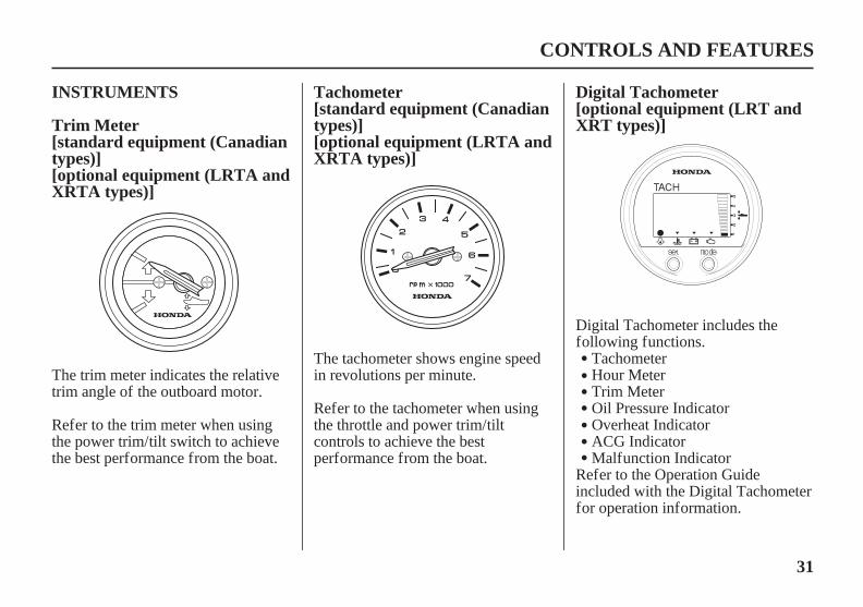
Digital TachometerTachometerINSTRUMENTS
Trim Meter[optional equipment (LRT andXRT types)]
[standard equipment (Canadiantypes)][optional equipment (LRTA andXRTA types)]
[standard equipment (Canadiantypes)][optional equipment (LRTA andXRTA types)]
CONTROLS AND FEATURES
Digital Tachometer includes thefollowing functions.
TachometerHour MeterTrim MeterOil Pressure IndicatorOverheat IndicatorACG Indicator
Refer to the Operation Guideincluded with the Digital Tachometerfor operation information.
The trim meter indicates the relativetrim angle of the outboard motor.
Refer to the trim meter when usingthe power trim/tilt switch to achievethe best performance from the boat. Malfunction Indicator
Refer to the tachometer when usingthe throttle and power trim/tiltcontrols to achieve the bestperformance from the boat.
The tachometer shows engine speedin revolutions per minute.
11/03/10 14:20:44 31ZZ4620_032

32
Digital Speedometer Fuel Gauge[optional equipment (LRT andXRT types)]
[standard equipment (Canadiantypes)][optional equipment (Americantypes)]
CONTROLS AND FEATURES
FUEL GAUGE
Digital Speedometer includes thefollowing functions.
SpeedometerFuel Level MeterVoltmeterTripmeterFuel Integration MeterFuel Economy MeterFuel Flow Meter
Refer to the Operation Guideincluded with the DigitalSpeedometer for operationinformation.
A fuel gauge is built into the fueltank connector of the portable fueltank.
11/03/10 14:20:58 31ZZ4620_033

33
INDICATORS Alternator (ACG) Indicator Malfunction Indicator
CONTROLS AND FEATURES
BUZZER
(RED)
(side-mount control)
(RED)
ACG INDICATOR
(internal buzzer)
(side-mount control)
BUZZER
(RED)
(RED)
MALFUNCTIONINDICATOR
MALFUNCTIONINDICATOR
ACG INDICATOR
(internal buzzer)
LH and LHT Types
LRT and XRT Types
LH and LHT Types
LRT and XRT Types
The ACG indicator turns on and thebuzzer sounds in one-secondintervals when the charging system isfaulty.
The indicator lights come on and thebuzzer sounds when you turn theignition switch ON, allowing you tosee that they are working. If anindicator does not light during thistest, it cannot alert you if that systemdevelops a problem. Have yourHonda Marine dealer check forburned-out bulbs or other problems.Under normal conditions, thefollowing occur when the ignitionswitch is turned ON:
The ACG, Malfunction, OilPressure, and Overheat indicatorslight.The buzzer will beep twice.The Malfunction, Oil Pressure,and Overheat indicators will go outafter the second beep.The ACG indicator will go outafter the engine starts.The Oil Pressure indicator willlight again after the engine startsand will stay lit to indicate the oilpressure is normal.
1.
2.3.
4.
5.
11/03/10 14:21:17 31ZZ4620_034

34
Oil Pressure Indicator
CONTROLS AND FEATURES
BUZZER
(GREEN)
OIL PRESSUREINDICATOR
(internal buzzer)
(side-mount control)
OIL PRESSUREINDICATOR
(GREEN)
LRT and XRT Types
LH and LHT Types
TAKING CARE OFUNEXPECTED PROBLEMS,
When the oil pressure indicator is lit,oil pressure is OK.
If oil pressure becomes low, theindicator will go off, and the engineprotection system will limit enginespeed. Refer to
on p. .
All models are equipped with abuzzer that sounds continuouslywhen the oil pressure indicator goesoff.
Low oil pressure indicates that theengine oil level is low or that there isa problem with the engine lubricationsystem.
When the engine control systemdetects an engine control systemmalfunction, the malfunctionindicator turns on and the buzzersounds at one-second intervals.
106
11/03/10 14:21:27 31ZZ4620_035
35
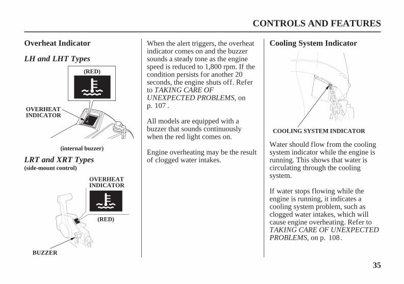
Overheat Indicator Cooling System Indicator
CONTROLS AND FEATURES
(RED)
OVERHEATINDICATOR
(internal buzzer)
OVERHEATINDICATOR
(side-mount control)
COOLING SYSTEM INDICATOR
BUZZER
(RED)
LRT and XRT Types
LH and LHT Types
TAKING CARE OFUNEXPECTED PROBLEMS
TAKING CARE OF UNEXPECTEDPROBLEMS
When the alert triggers, the overheatindicator comes on and the buzzersounds a steady tone as the enginespeed is reduced to 1,800 rpm. If thecondition persists for another 20seconds, the engine shuts off. Referto
, onp. .
All models are equipped with abuzzer that sounds continuouslywhen the red light comes on.
Engine overheating may be the resultof clogged water intakes.
Water should flow from the coolingsystem indicator while the engine isrunning. This shows that water iscirculating through the coolingsystem.
If water stops flowing while theengine is running, it indicates acooling system problem, such asclogged water intakes, which willcause engine overheating. Refer to
, on p. .
107
108
11/03/10 14:21:39 31ZZ4620_036

36
Portable Fuel Tank
Overrev Limiter
OTHER FEATURES[standard equipment (Canadiantypes)][optional equipment (Americantypes)]
CONTROLS AND FEATURES
The overrev limiter may be activatedduring operation, limiting enginespeed, if the outboard motor istrimmed or tilted up excessively, orwhen propeller ventilation occursduring a sharp turn.
The engine is equipped with anoverrev limiter to prevent thepossibility of mechanical damagefrom excessive engine speed.
The cooling system indicatordischarge port can also becomeplugged.
If the overrev limiter is activated,check the trim angle of the outboardmotor.
Check to see if the correct propelleris installed.
The portable fuel tank has a capacityof US gal ( L) and has a fuelgauge built into the fuel tankconnector.
256.6
11/03/10 14:21:50 31ZZ4620_037

37
Fuel Priming Bulb NMEA Interface Coupler
CONTROLS AND FEATURES
CCLLOOSSEE
OOPPEENN
VENT KNOB
FUEL FILLER CAP
UP
PRIMING BULB
INLET END(fuel tank side)
NMEA INTERFACE COUPLER
OUTLET END(outboard motor side)
Fuel Filler Cap Vent Knob
A priming bulb is built into the fuelhose that connects the fuel tank to theoutboard motor.
Before starting the engine, hold thepriming bulb up in the direction ofthe arrow; then squeeze the primingbulb until it feels firm. This willensure that fuel is supplied to theengine (p. ).
NMEA2000 based information onengine speed, fuel consumption, andvarious warnings can be read byconnecting to the outboard motorwith the interface cable (optionalequipment).Contact your dealer for moreinformation.
The fuel filler cap is provided with avent knob to seal the portable fueltank for carrying it to and from theboat. Open the vent by turning thevent knob counterclockwise all theway before starting the engine.
45
11/03/17 11:05:09 31ZZ4620_038

38
Anodes
CONTROLS AND FEATURES
ANODE(stern bracket) ANODE
(each side)
The anodes are made of a sacrificialmaterial that helps to protect theoutboard motor from corrosion.
There are two anodes on the gearcase, one on the stern bracket andtwo small anodes in the waterpassages of the engine block.
11/03/10 14:22:07 31ZZ4620_039

Improperly maintainingthis outboard motor orfailing to correct a problembefore operation can causea malfunction in which youcould be seriously hurt orkilled.
Always perform a pre-operation inspection beforeeach operation, and correctany problem.
39
ARE YOU READY TO GETUNDERWAY?
Safety
Knowledge
IS YOUR OUTBOARDMOTOR READY TO GO?
BEFORE OPERATION
Your safety is your responsibility. Alittle time spent in preparation willsignificantly reduce your risk ofinjury.
Read and understand this manual.Know what the controls do and howto operate them.
Familiarize yourself with theoutboard motor and its operationbefore you get underway. Knowwhat to do in case of an emergency.
Familiarize yourself with all lawsand regulations relating to boatingand the use of outboard motors.
Always wear a PFD (PersonalFlotation Device) while on the boat.
Before beginning your pre-operationchecks, be sure the ignition switch isin the OFF position.
Attach the emergency stop switchclip securely to the operator or to theoperator’s PFD (Personal FlotationDevice).
For your safety, and to maximize theservice life of your equipment, it isvery important to take a fewmoments before you operate theoutboard motor to check its condition.Be sure to take care of any problemyou find, or have your authorizedHonda Marine dealer correct it,before you operate the outboardmotor.
11/03/10 14:22:20 31ZZ4620_040

40
Safety Inspection
Maintenance Inspection
BEFORE OPERATION
Look around the outboard motorfor signs of oil or gasoline leaks.
Check that all fasteners are inplace and securely tightened.
Check that the fuel hose isundamaged and properlyconnected.
Wipe up any spills before startingthe engine.
Check the stern bracket to be surethe outboard motor is securelyinstalled.
Check that all controls areoperating properly.
Replace any damaged parts.
Check that the battery fluid isbetween the upper and lower levels,and the battery leads are connectedsecurely.
Make sure a tool kit and theemergency starter rope areonboard (p. ). Replace anymissing items.
Check the fuel level in the fueltank (p. ).
Check that the anodes are securelyattached to the stern bracket andthe gear case (p. ) and are notexcessively worn. The anodes helpprotect the outboard motor fromcorrosion.
Check to be sure the propeller isundamaged and the castle nut issecured with the cotter pin(p. ).
Check the engine oil level (p. ).Running the engine with a low oillevel can cause engine damage.
Check the fuel filter for watercontamination (p. ).
Check the emergency stop switchfor proper operation (p. , ).Start the engine. Make sure theengine stops by pulling theemergency stop switch clip fromthe emergency stop switch (p.
).
If you are using the portable fueltank (standard or optionalequipment), make sure it is in goodcondition and properly secured inthe boat (p. ).
2520
74
69
80
55
88
87
83
44
11/03/10 14:22:35 31ZZ4620_041

×
×
×
41
Tiller Handle Height/AngleAdjustment (LH and LHTtypes)
BEFORE OPERATION
HANDLE ANGLE: 13°
Reference point
HEIGHT
HEIGHT ADJUSTMENTBLOCK
HANDLE ANGLE: 13°
HANDLE ANGLE: 21°
HANDLE ANGLE: 7°
Install the height adjustment blockso that the selected angle of thetiller handle is in this position.
HANDLE ANGLE: 7°
HANDLE ANGLE:21°
8 28 mmFLANGE BOLT
10.8 in(275 mm)
13.2 in(336 mm)
15.7 in(399 mm)
Pull down the tiller handle.Determine the height adjustmentblock installation direction andsecure the block with the 8 28mm flange bolt.
Raise the tiller handle and removethe 8 28 mm flange bolt and theheight adjustment block.
The tiller handle height and angle canbe adjusted to three positions bychanging the installation direction ofthe height adjustment block. Select asuitable height and angle for theoperator and secure the block.
2.
1.
11/03/10 14:22:47 31ZZ4620_042

~
~
42
SAFE OPERATINGPRECAUTIONS
BREAK-IN PROCEDURE
Break-in period: 10 hours
Next 60 minutes:
Next 8 hours:Next 45 minutes:
First 15 minutes:
OPERATION
IMPORTANT SAFETYINFORMATION
BEFORE OPERATION.
To safely realize the full potential ofthis outboard motor, you need acomplete understanding of itsoperation and a certain amount ofpractice with its controls.
Before operating the outboard motorfor the first time, please review the
on page and thechapter titled
Proper break-in operation allows themoving parts to wear in smoothly forbest performance and long servicelife. Avoid continuous operation at asteady speed.
Run the engine up to a maximum of4,000 to 5,000 rpm, which is about50% to 80% of maximum throttleopening. Operating at maximum4,000 5,000 rpm should be limitedto 50% of the 60 minutes.
For your safety, do not start or runthe engine in a confined or partlyenclosed area. Your engine’s exhaustcontains poisonous carbon monoxide,a colorless, odorless gas that cancollect rapidly. Breathing carbonmonoxide can cause loss ofconsciousness and may lead to death.
Do not run the engine at full throttlefor more than 5 minutes at a time.
For boats that plane easily, bring theboat up on plane, and then reduce thethrottle opening to the recommendedrpm range.
30-second full-throttle bursts are OK,but do not operate the enginecontinuously at full throttle.
Run the engine up to a maximum of2,000 to 3,000 rpm, which is about10% to 30% of maximum throttleopening. Operating at maximum2,000 3,000 rpm should be limitedto 50% of the 45 minutes.
Run the engine at trolling speed. Usethe minimum throttle openingnecessary to operate the boat at a safetrolling speed.
7
11/03/10 14:23:01 31ZZ4620_043

43
TRANSOM ANGLEADJUSTMENT (LH Type)
OPERATION
TO LOCK LOCKED POSITION
TRANSOM ANGLE ADJUSTING ROD
TRANSOM ANGLE ADJUSTING ROD
TO CHANGE
STERN BRACKET
UNLOCKEDPOSITION IDLE EXHAUST PORT
TTUURRNN UUPP
PPUUSSHH
Do not allow water to enter the idleexhaust port or the engine can bedamaged.
The transom angle adjusting rodlimits the tilt angle of the outboardmotor when fully lowered.
To adjust, first tilt the outboardmotor so it is not resting on the rod.
Proper adjustment prevents theoutboard motor from being trimmedtoo low (p. ).
Push the rod in and turn the end ofthe rod up, so the latch will fall intoline with the rod.
Remove the rod and reinsert it in thedesired position.
Push the rod in and turn the end ofthe rod down, so the latch will fall tothe locked position. Then release therod.
61
11/03/10 14:23:10 31ZZ4620_044

Gasoline is highlyflammable and explosive.
You can be burned orseriously injured whenhandling fuel.
Stop the engine and keepheat, sparks, and flameaway.Handle fuel onlyoutdoors.Wipe up spillsimmediately.
44
PORTABLE FUEL TANK FUEL HOSE CONNECTIONS[standard equipment (Canadiantypes)][optional equipment (Americantypes)]
OPERATION
FUEL HOSE CONNECTOR
FUEL HOSE CONNECTOR
PORTABLE FUEL TANK
(fuel tank side)
(outboard motor side)
FUEL HOSE(standard equipment)
Secure the portable fuel tank in theboat so that it won’t move aroundand become damaged. Turn the portable fuel tank vent knob
counterclockwise to the openposition.
To ensure that the outboard motorwill be able to draw fuel from thetank, place the tank within 6 feet(2 m) of the outboard motor and notmore than 3 feet (1 m) below the fuelconnector on the outboard motor.
Place the portable fuel tank in a well-ventilated location, away from directsunlight, to reduce the possibility of agasoline vapor explosion.
11/03/10 14:23:25 31ZZ4620_045

Stop the engine and keepheat, sparks, and flameaway.Handle fuel onlyoutdoors.Wipe up spillsimmediately.
You can be burned orseriously injured whenhandling fuel.
Gasoline is highlyflammable and explosive.
45
FUEL PRIMING
OPERATION
OUTLET END(outboard motor side)
UP
PRIMING BULB
INLET END (fuel tank side)
Connect the fuel hose to the tank andthe outboard motor, as shown. Besure both connectors snap securelyinto place. Always disconnect thefuel hose when storing ortransporting the outboard motor.
Do not touch the priming bulb withthe engine running or when tilting upthe outboard motor. The vaporseparator could overflow.
Check to be sure there are no fuelleaks before starting the engine.
Hold the priming bulb up in thedirection of the arrow; then squeezethe priming bulb several times until itfeels firm, indicating that fuel hasreached the engine.
If you are using a portable fuel tank,turn the portable fuel tank vent knobcounterclockwise to the openposition.
11/03/10 14:23:36 31ZZ4620_046

46
STARTING THE ENGINEINFREQUENT OROCCASIONAL USE
OPERATION
EMERGENCY STOPSWITCH LANYARD
EMERGENCY STOP SWITCH
EMERGENCY STOPSWITCH CLIP
LH and LHT Types(tiller handle)
Put the emergency stop switch clipin the emergency stop switch, andattach the emergency stop switchlanyard securely to the operator orto the operator’s PFD (PersonalFlotation Device).
The engine will not start or rununless the emergency stop switchclip is in the emergency stopswitch.
The emergency stop switch clipand emergency stop switch lanyardsystem is a safety device that willstop the engine if you fall awayfrom the controls while operatingthe boat.
Always attach the emergency stopswitch lanyard securely to theoperator or to the operator’s PFDbefore starting the engine.
Control Page..........Side-Mount Control Type . 49If your outboard motor will be used
on an infrequent or intermittent basis,please refer to the fuel section of theSTORAGE chapter (p. ) foradditional information regarding fueldeterioration.
1.
93
11/03/10 14:23:46 31ZZ4620_047

47
OPERATION
STARTPOSITION
POINTER
THROTTLE GRIP
OOFFFF
OONN SSTTAARRTT
IGNITION SWITCH KEY
N (neutral)
GEARSHIFTLEVER
Turn the ignition switch key to theSTART position and hold it thereuntil the engine starts.When the engine starts, release thekey, allowing it to return to the ONposition.
Align the engine start symbol‘‘ ’’ on the tiller handle with thepointer ‘‘ ’’ on the throttle grip.
Turn the ignition switch key to theON position; the buzzer will soundtwice.
Check the position of the gearshiftlever. It must be in the N (neutral)position for starting.
The engine will not start if thegearshift lever is in the F (forward)or R (reverse) position.
3. 4.
5.
2.
11/03/10 14:23:56 31ZZ4620_048
-
48
OPERATION
TAKING CARE OFUNEXPECTED PROBLEMS
If the engine is not properlywarmed up bef ore raising theengine speed, the buzzer andoverheat indicator may activateand the engine speed will beautomatically reduced.The cooling system may f reeze inareas where the temperaturereaches 32°F (0°C) or below.Cruising at high speed withoutwarming the engine up may causeengine damage.
Using the electric starter f or morethan 5 seconds at a time willoverheat the starter motor and candamage it.
Turning the ignition switch key tothe START position while theengine is running can damage thestarter motor and f lywheel.
If the indicators show anyabnormal condition, immediatelystop the engine and determine thecause of the problem. Refer to
onp. .
Before getting underway, allowthe engine to warm-up sufficientlyto ensure good performance.
Above 41°F (5°C), warm-up theengine for at least 3 minutes.
Below 41°F (5°C), warm-up theengine for at least 5 minutes at2,000 rpm.
During the warm-up period, checkthe oil pressure indicator (p. ),overheat indicator (p. ), andcooling system indicator (p. ).
If the engine fails to start within 5seconds, release the key and waitat least 10 seconds beforeoperating the starter again.
Also, as the engine warms up, thethrottle grip can be turned to theSLOW position without stalling.
6.
106
3435
35
108
11/03/10 14:24:08 31ZZ4620_049

49
Side-Mount Control Type[standard equipment (LRTCtype)][optional equipment (LRTA andXRTA types)]
OPERATION
EMERGENCY STOPSWITCH
EMERGENCY STOPSWITCH CLIP EMERGENCY STOP
SWITCH LANYARD
N (neutral)
CONTROL LEVER
LRT and XRT Types(remote control)
The engine will not start or rununless the emergency stop switchclip is in the emergency stopswitch.
Set the control lever in the N(neutral) position.
The engine will not start if the F(forward) or R (reverse) gears areengaged.
The emergency stop switch clipand emergency stop switch lanyardsystem is a safety device that willstop the engine if you fall awayfrom the controls while operatingthe boat.
Always attach the emergency stopswitch lanyard securely to theoperator or to the operator’s PFDbefore starting the engine.
Put the emergency stop switch clipin the emergency stop switch, andsecurely to the operator or to theoperator’s PFD (Personal FlotationDevice).
1.
2.
11/03/10 14:24:19 31ZZ4620_050

50
OPERATION
OOFFFFON
START
IGNITION SWITCH KEY
FAST IDLERANGE
START(fully lowered)
FAST IDLE LEVER
Using the electric starter f or morethan 5 seconds at a time willoverheat the starter motor and candamage it.
Turning the ignition switch key tothe START position while theengine is running can damage thestarter motor and f lywheel.
The fast idle lever cannot be raisedunless the control lever is in the N(neutral) position.
The control lever cannot be movedaway from the N (neutral) positionunless the fast idle lever is lowered.
Leave the fast idle lever in theSTART (fully lowered) position.
If the engine fails to start within 5seconds, release the key and waitat least 10 seconds beforeoperating the starter again.
Turn the ignition switch key to theON position; the buzzer will soundtwice.
Turn the ignition switch key to theSTART position and hold it thereuntil the engine starts.
When the engine starts, release thekey, allowing it to return to the ONposition.
3. 4.
5.
11/03/10 14:24:30 31ZZ4620_051

-
51
OPERATION
FAST IDLERANGE
MAXIMUM FAST IDLE
TAKING CARE OFUNEXPECTED PROBLEMS
If the engine is not properlywarmed up bef ore raising theengine speed, the buzzer andoverheat indicator may activateand the engine speed will beautomatically reduced.The cooling system may f reeze inareas where the temperaturereaches 32°F (0°C) or below.Cruising at high speed withoutwarming the engine up may causeengine damage.
Before getting underway, allowthe engine to warm-up sufficientlyto ensure good performance.
Above 41°F (5°C), warm-up theengine for at least 3 minutes.
Below 41°F (5°C), warm-up theengine for at least 5 minutes at2,000 rpm. Raise the fast idle leverto achieve approximately 2,000rpm.
If the fast idle lever was used towarm-up the engine, graduallylower the lever as the enginewarms up.
When the fast idle lever is fullylowered, the control lever can bemoved away from the N (neutral)position.
During the warm-up period, checkthe oil pressure indicator (p. ),overheat indicator (p. ), andcooling system indicator (p. ).
If the indicators show anyabnormal condition, immediatelystop the engine and determine thecause of the problem. Refer to
onp. .
6.7.
3535
34
106 108
11/03/10 14:24:40 31ZZ4620_052

×
×
×
52
EMERGENCY STARTING
OPERATION
NOTE:
Releasethe harness.
Removethe bandclamp.
UNLOCK
ENGINE COVERLATCH
ENGINE COVERLATCH
UNLOCK
6 25 mm BOLTS
CLAMPBRACKET
ALTERNATOR COVER
(front)
(rear)If the battery is discharged or thestarter motor is inoperative, you canstart the engine manually using theemergency starter rope supplied withthe outboard motor.
Remove the four 6 25 mm boltsand clamp bracket, release theharness from the clamper, thenremove the alternator cover.
Install the clamp bracket with the 625 mm bolt.
Take care not to lose the bolts.
Turn the ignition switch key to theOFF position (p. ).
Unlatch the engine cover latchesand remove the engine cover.
1.
2.
3.
4.57
11/03/10 14:24:50 31ZZ4620_053

--
-
Exposed moving parts cancause injury.
Do not operate theoutboard motor withoutthe engine cover.Use extreme care wheninstalling the enginecover.
53
OPERATION
KNOT
EMERGENCYSTARTER ROPE
ALTERNATORPULLEY
EMERGENCY STARTER ROPE
Direction to pullTAKING CARE OFUNEXPECTED PROBLEMSTurn the ignition switch key to the
ON position.
Set the controls the same as fornormal starting (p. ,
).
Set the alternator pulley so thecutouts are on the right and leftsides of the alternator pulley asshown. Hook the knot at the end ofthe starter rope (accessory) againsta cutout in the alternator pulley,and wind the starter rope one andhalf turns counterclockwise alongthe groove in the alternator pulley.
Pull the emergency starter ropeslowly until resistance is felt, thenpull briskly.
Keep away from moving partswhile pulling the rope.
If necessary, rewind the rope andpull again. If the engine does notstart after several attempts, refer to
on p..
5.
7.
6.
46 4749 50
99 101
11/03/10 14:25:03 31ZZ4620_054

54
OPERATION
If the fast idle control(s) was usedto start the engine, return thecontrol(s) to the normal operatingposition as the engine warms up.
During the warm-up period, checkthe oil pressure indicator (p. ),overheat indicator (p. ), andcooling system indicator (p. ).
If it was necessary to remove theemergency stop switch lanyardfrom you to perform theemergency starting procedure, besure the lanyard is attachedsecurely to operator beforeoperating the outboard motor.
Have your closest authorizedHonda Marine dealer check yourelectrical system and correct theproblem so that you can use theelectric starter.
Leave the alternator cover off, butinstall the engine cover (p. )and lock it in place by latching theengine cover latches.
8.
9.
10.
11.
3435
35
73
11/03/10 14:25:09 31ZZ4620_055

55
STOPPING THE ENGINE
Emergency Engine Stopping
OPERATION
EMERGENCY STOPSWITCH LANYARD
EMERGENCY STOP SWITCH
PPUULLLL
EMERGENCY STOPSWITCH CLIP
EMERGENCY STOP SWITCH
PULL
EMERGENCY STOPSWITCH CLIP
EMERGENCY STOPSWITCH LANYARD
LRT and XRT Types(remote control)
LH and LHT Types(tiller handle)
To stop the engine in an emergency,pull the emergency stop switch clipout of the emergency stop switch bypulling the emergency stop switchlanyard.
Turn the ignition switch key to theOFF position after verifying theemergency stop switch operation.
We suggest that you stop the enginethis way occasionally to verify thatthe emergency stop switch isoperating properly.
11/03/10 14:25:20 31ZZ4620_056
56
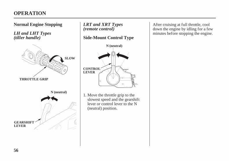
Normal Engine Stopping
Side-Mount Control Type
OPERATION
SLOW
THROTTLE GRIP
N (neutral)
GEARSHIFTLEVER
N (neutral)
CONTROLLEVER
LRT and XRT Types(remote control)
LH and LHT Types(tiller handle)
Move the throttle grip to theslowest speed and the gearshiftlever or control lever to the N(neutral) position.
After cruising at full throttle, cooldown the engine by idling for a fewminutes before stopping the engine.
1.
11/03/10 14:25:29 31ZZ4620_057

57
OPERATION
OOFFFF
OOFFFF
IGNITIONSWITCH KEY
IGNITION SWITCH KEY
LH and LHT Types(tiller handle)
LRT and XRT Types(remote control)
Turn the ignition switch key to theOFF position to stop the engine.In the event that the engine doesnot stop when the ignition switchkey is turned to the OFF position,pull the emergency stop switchclip out of the emergency stopswitch by pulling the emergencystop switch lanyard (p. ).
When the boat is not in use,remove and store the ignitionswitch key and the emergency stopswitch clip and lanyard. If you areusing a portable fuel tank,disconnect the fuel hose if youwill be storing or transporting theoutboard motor.
2.
3.
55
11/03/10 14:25:37 31ZZ4620_058

58
GEARSHIFT ANDTHROTTLE OPERATION
OPERATION
POINTER
THROTTLEGRIP
SLOW
FAST
GEARSHIFTLEVER
F(forward)
N(neutral)
R(reverse)
THROTTLE FRICTION ADJUSTER
THROTTLEGRIP
FIX
RELEASE
LH and LHT Types(tiller handle)
To shift gears, turn the throttle grip tothe SLOW position; then move thegearshift lever to select the F(forward), N (neutral), or R (reverse)gears.
Use the throttle friction adjuster tohelp hold a constant throttle settingwhile cruising.
Turn the adjuster clockwise toincrease throttle grip friction forholding a constant speed.
Turn the adjuster counterclockwise todecrease friction for easy griprotation.
The engine can be started with thegearshift lever in the N (neutral)position only.
The throttle grip can be turned to theFAST position only when thegearshift lever is in the F (forward)position.
11/03/10 14:25:48 31ZZ4620_059

59
OPERATION
TO INCREASEFRICTION
TO DECREASEFRICTION
CONTROL LEVER
N (neutral)
F (forward)R (reverse)
CONTROLLEVERFRICTIONADJUSTERNEUTRAL
RELEASELEVER
LRT and XRT Types(remote control)
To shift gears, move the control leverto select the F (forward), N (neutral),or R (reverse) gear.
The control lever cannot be movedfrom the N (neutral) position unlessthe neutral release lever is squeezed.
Moving the control lever beyond thegear selection range increases enginespeed.
Adjust the control lever frictionadjuster so the control lever will holda constant throttle setting whilecruising.
11/03/10 14:25:58 31ZZ4620_060

60
STEERING
OPERATION
RIGHT TURN LEFT TURN
Move the tillerhandle to the left.
Move the tillerhandle to the right.
STEERING FRICTIONADJUSTER
FRICTIONPLATE
TTOO IINNCCRREEAASSEEFFRRIICCTTIIOONN((LLOOCCKK))
TO DECREASEFRICTION(FREE)
LRT and XRT Types(remote control)
Steering Friction Adjuster
LH and LHT Types(tiller handle)
Do not apply grease or oil on thef riction plate. Grease or oil willreduce the f riction of the adjuster.
Steer the boat in the same manner asan automobile.
Move the adjuster to the LOCKdirection to increase steering frictionfor holding a steady course.
Move the adjuster to the FREEdirection to decrease friction for easyturning.
Steer by moving the tiller handleopposite the direction you want theboat to turn.
Use the steering friction adjuster tohelp hold a steady course whilecruising.
11/03/10 14:26:10 31ZZ4620_061

61
CRUISING
Engine Speed
Trim
OPERATION
LH TypeLHT, LRT and XRT Types
If, for example, the outboard motoris tilted excessively or propellerventilation occurs during a sharp turn,the engine may overrev, activatingthe overrev limiter.
The engine is equipped with anoverrev limiter to prevent thepossibility of mechanical damagefrom excessive engine speed.
For rough water conditions or largewaves, slow down to prevent thepropeller from rising out of the water.
If engine speed becomes unstable athigh speed due to activation of theoverrev limiter, reduce speed andcheck the trim angle of the outboardmotor.
Use the power trim/tilt switch to trimthe outboard motor for the bestperformance and stability.
You can use the power trim/tiltswitch at any time, whether the boatis underway or stopped.
Press the UP or DN (down) side ofthe switch to adjust the angle of theoutboard motor.
Refer to the trim meter (p. ) for anindication of whether the outboardmotor is trimmed high or low.
Install the outboard motor at the besttrim angle for stable cruising andmaximum power.
Trim angle too large: Causes boat to‘‘squat.’’
Trim angle too small: Causes boat to‘‘bow steer.’’
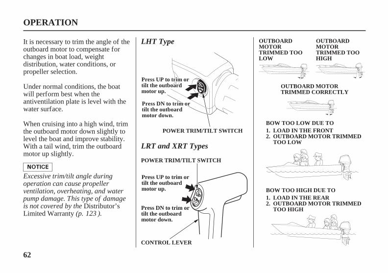
It is necessary to trim the angle of theoutboard motor to compensate forchanges in boat load, weightdistribution, water conditions, orpropeller selection.
Under normal conditions, the boatwill perform best when the
antiventilation plate is level with thewater surface.
When cruising into a high wind, trimthe outboard motor down slightly tolevel the boat and improve stability.With a tail wind, trim the outboardmotor up slightly.
For best fuel economy, limit thethrottle opening to 80%. Use thethrottle friction control (p. , )to help you hold a steady speed.
58
31
59
11/03/10 14:26:28 31ZZ4620_062
62
OPERATION
BOW TOO LOW DUE TO
BOW TOO HIGH DUE TO
POWER TRIM/TILT SWITCH 1.2.
1.2.
POWER TRIM/TILT SWITCH
CONTROL LEVER
PPrreessss UUPP ttoo ttrriimm oorrttiilltt tthhee oouuttbbooaarrddmmoottoorr uupp..
Press DN to trim ortilt the outboardmotor down.
Press UP to trim ortilt the outboardmotor up.
PPrreessss DDNN ttoo ttrriimm oorrttiilltt tthhee oouuttbbooaarrddmmoottoorr ddoowwnn..
OUTBOARDMOTORTRIMMED TOOHIGH
LOAD IN THE FRONTOUTBOARD MOTOR TRIMMEDTOO LOW
LOAD IN THE REAROUTBOARD MOTOR TRIMMEDTOO HIGH
OUTBOARDMOTORTRIMMED TOOLOW
OUTBOARD MOTORTRIMMED CORRECTLY
LHT Type
LRT and XRT Types
Excessive trim/tilt angle duringoperation can cause propellerventilation, overheating, and waterpump damage. This type of damageis not covered by the
(p. ).123
It is necessary to trim the angle of theoutboard motor to compensate forchanges in boat load, weightdistribution, water conditions, orpropeller selection.
Under normal conditions, the boatwill perform best when theantiventilation plate is level with thewater surface.
Distributor’sLimited Warranty
When cruising into a high wind, trimthe outboard motor down slightly tolevel the boat and improve stability.With a tail wind, trim the outboardmotor up slightly.
11/03/10 14:26:42 31ZZ4620_063

-
63
TRIM TAB
SHALLOW WATEROPERATION
OPERATION
TRIM TAB BOLT
TRIM TAB
PROPELLER
12°
4°
TRIM ANGLE0°(VERTICAL LINE)
TILT ANGLE16°
63°
(when transom angle is 12°)
LHT, LRT and XRT Types
LH TypeTRIM TAB ADJUSTMENT
An excessive trim/tilt angle duringoperation can cause propellerventilation, overheating, and waterpump damage. This type of damageis not covered by the
(p. ).123
When operating in shallow water, tiltthe outboard motor, using the tiltlever, so the propeller and gear casewon’t hit the bottom.
When the trim tab is correctlyadjusted, steering effort will be equalin both directions.
If steering effort is not equal in bothdirections, adjust the trim tab tocompensate for ‘‘torque steer,’’which is the reaction of the outboardmotor to propeller rotation.
Proceed at low speed, and monitorwater flow from the cooling systemindicator (p. ) to be sure theoutboard motor is not tilted so highthat the water intakes are out of thewater.
When operating in shallow water, usethe power trim/tilt switch (p. ) totilt the outboard motor so that thepropeller and gear case won’t hit thebottom.
Refer toon p. .
Adjust the trim tab with the enginestopped. Loosen the trim tab boltabove the trim tab, turn the trim tab,and then tighten the bolt securely.
Distributor’sLimited Warranty
72
62
35
11/03/10 14:26:56 31ZZ4620_064

64
OPERATION
ENGINE COVER GRIP
LLOOCCKK((RRUUNN))
FFRREEEE((TTIILLTT))
TILT LEVER
Do not use the tiller handle as alever to raise the outboard motor.Applying excessive f orce to the tillerhandle can damage it.
An excessive tilt angle duringoperation can cause propellerventilation, overheating, and waterpump damage. This type of damageis not covered by the
(p. ).123
Monitor water flow from the coolingsystem indicator (p. ) to be surethe outboard motor is not tilted sohigh that the water intake is out ofthe water.
While the outboard motor is tilted,proceed at a low speed, and do notoperate the outboard motor in reverse.The outboard motor will risesuddenly if operated in reverse.
Distributor’sLimited Warranty
To return the outboard motor to thenormal operating position, move thetilt lever to the LOCK (RUN)position. You may need to raise theoutboard motor slightly to disengagethe tilt mechanism, and then slowlylower the outboard motor.
To tilt the outboard motor, move thetilt lever to the FREE (TILT) position,then raise the outboard motor to thedesired position by pulling on theengine cover grip.
35
11/03/10 14:27:04 31ZZ4620_065

65
MOORING, BEACHING,LAUNCHING
OPERATION
POWER TILT SWITCH(LHT, LRT and XRT Types)
TILT LOCK LEVER(lock position)
FFRREEEE
LLOOCCKK
STERN BRACKETLH Type
LHT, LRT and XRT Types
Do not attempt to use the power tiltswitch to tilt the outboard motordown while the tilt lock lever is in theLOCK position. Damage to thepower tilt system may occur.
Before tilting up, leave the outboardmotor in the running position for oneminute after stopping the engine todrain the water from inside theengine.
Stop the engine and disconnect thefuel hose from the outboard motorbefore tilting the outboard motor.
Use the tilt lever to raise and lowerthe outboard motor as described onp. .
To raise the outboard motor out ofthe water while the engine is stoppedand the boat is moored, or formaximum clearance when beachingor launching, use the power tiltswitch on the engine pan to tilt theoutboard motor up as far as it will go.Move the tilt lock lever to the LOCKposition, and then gently lower the
outboard motor until the levercontacts the stern bracket.
To lower the outboard motor, tilt up,move the tilt lock lever to the FREEposition, and then lower the outboardmotor to the desired position.
If more clearance is needed to swingthe tilt lock lever into the LOCKposition, rock the outboard motorforward slightly by pulling on theengine cover grip.
64
11/03/10 14:27:15 31ZZ4620_066

66
OPERATION
RIGHT STERNBRACKET
MANUAL RELIEFVALVE
POWER(To fix)
MANUAL(To release)
For manual tilting, use a flat bladescrewdriver to turn the valvecounterclockwise 2 and a half turns.Close the valve firmly afterpositioning the engine.
The outboard motor can also be tiltedmanually after opening the manualrelief valve. This feature enables theoutboard motor to be tilted up ordown when no battery is connected.
Be sure the valve is closed beforeoperating the outboard motor. If thevalve is not closed, the outboardmotor will tilt up when operated inreverse.
Check that nobody is under theoutboard motor before opening themanual relief valve. If the manualrelief valve is loosened (turnedcounterclockwise) when the outboardmotor is tilted up, the outboard motorwill suddenly tilt down.
11/03/10 14:27:24 31ZZ4620_067
Improperly maintainingthis outboard motor orfailure to correct a problembefore operation can causea malfunction in which youcould be seriously hurt orkilled.
Always follow theinspection andmaintenancerecommendations andschedules in this Owner’sManual.
67
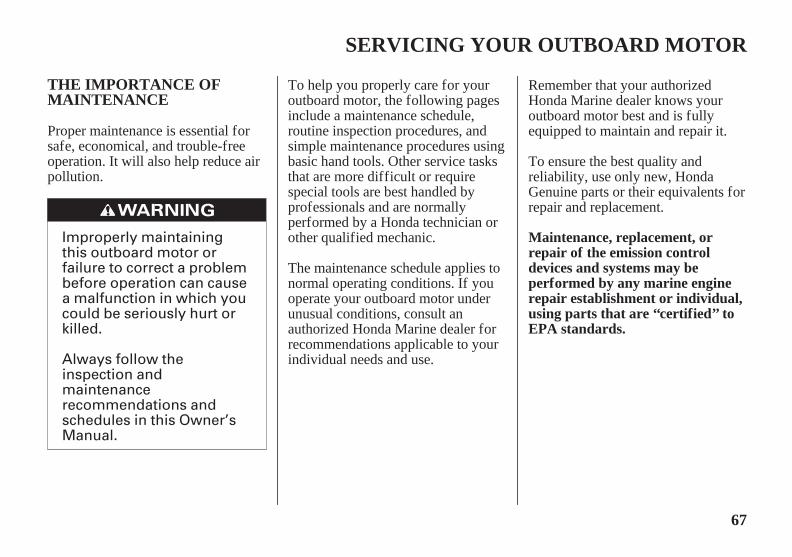
THE IMPORTANCE OFMAINTENANCE
Maintenance, replacement, orrepair of the emission controldevices and systems may beperformed by any marine enginerepair establishment or individual,using parts that are ‘‘certified’’ toEPA standards.
SERVICING YOUR OUTBOARD MOTOR
Proper maintenance is essential forsafe, economical, and trouble-freeoperation. It will also help reduce airpollution.
To help you properly care for youroutboard motor, the following pagesinclude a maintenance schedule,routine inspection procedures, andsimple maintenance procedures usingbasic hand tools. Other service tasksthat are more difficult or requirespecial tools are best handled byprofessionals and are normallyperformed by a Honda technician orother qualified mechanic.
The maintenance schedule applies tonormal operating conditions. If youoperate your outboard motor underunusual conditions, consult anauthorized Honda Marine dealer forrecommendations applicable to yourindividual needs and use.
Remember that your authorizedHonda Marine dealer knows youroutboard motor best and is fullyequipped to maintain and repair it.
To ensure the best quality andreliability, use only new, HondaGenuine parts or their equivalents forrepair and replacement.
11/03/10 14:27:32 31ZZ4620_068

-
-
-
Failure to properly followmaintenance instructionsand precautions can causeyou to be seriously hurt orkilled.
Always follow theprocedures andprecautions in the Owner’sManual.
68
MAINTENANCE SAFETY Safety Precautions
Burns from hot parts.
Injury from moving parts.
Carbon monoxide poisoningfrom engine exhaust.
SERVICING YOUR OUTBOARD MOTOR
Some of the most important safetyprecautions follow. However, wecannot warn you of everyconceivable hazard that can arise inperforming maintenance. Only youcan decide whether or not you shouldperform a given task.
Make sure the engine is off beforeyou begin any maintenance orrepairs. This will eliminate severalpotential hazards:
Read the instructions before youbegin, and make sure you have thetools and skills required.
To reduce the possibility of fire orexplosion, be careful whenworking around gasoline. Use onlya nonflammable solvent, notgasoline, to clean parts. Keepcigarettes, sparks, and flames awayfrom all fuel-related parts.
Wear gloves when handling thepropeller to protect your handsfrom sharp edges.Let the engine and exhaust
system cool before touching.
Do not run the engine unlessinstructed to do so.
Do not start or run the engine ina confined or partly enclosedarea.
11/03/10 14:27:43 31ZZ4620_069

×
×
69
TOOL KIT and OWNER’S MANUALSPARE SWITCH CLIP (LHand LHT Types) ANDEMERGENCY STARTERROPE
SERVICING YOUR OUTBOARD MOTOR
SPARE SWITCH CLIP(LH and LHT Types)
EMERGENCY STARTER ROPE
8 mm WRENCH
10 12 mm WRENCH
OIL CHECK SCREWDRIVER
PHILLIPS/FLATSCREWDRIVER
SCREWDRIVER HANDLE
PLIERS
18 19 mm SOCKET WRENCH
FUSE PULLERTOOL BAG
OWNER’S MANUAL
If your tool kit needs replacement, it is not available as a kit and each itemmust be ordered individually.
Always carry the spare switch clipand the emergency starter ropeonboard. The spare clip may either bestored in the tool bag or in an easilyaccessible location on the boat alongwith the emergency starter rope.
The owner’s manual and tool kit can be used to perform simple maintenanceprocedures and emergency repairs. Keep these items on the boat so that theywill always be available if you need them.
11/03/10 14:27:54 31ZZ4620_070

○
○○
○○
○○
○
○○
○
○○
-
○○
○○
○
○○
70
MAINTENANCE SCHEDULE
SERVICING YOUR OUTBOARD MOTOR
Distributor’s Limited Warranty
Follow the MAINTENANCE SCHEDULE table and service your outboard motor accordingly. Please note, a claim forwarranty coverage will not be denied simply because the maintenance schedule for your outboard motor was notfollowed. However, any part(s) that fails specifically due to lack of maintenance, or improperly performed maintenance,would not be covered under the .
ITEM
Perform at every indicated month or operatinghour interval, whichever comes first.
REGULAR SERVICE PERIOD
After use
Engine oil
Gear case oilEngine oil filterTiming beltThrottle linkageIdle speedValve clearanceSpark plugPropeller and cotter pinAnode metal (Outside engine)Anode metal (Inside engine)LubricationFuel tank and tank filterThermostat
Each useFirst month
or20 hrs.
(2)
(2)(2)
(1)
Every yearor
200 hrs.
(2)(2)
(2)
(2)
Referto page
7475
77 788887
7986
Every6 months
or100 hrs.
(2)
(2)(2)
(1)
Every2 years
or400 hrs.
(2)
Check levelChangeChangeReplaceCheck-adjustCheck-adjustCheck-adjustCheck-adjustCheck-adjust/ReplaceCheckCheckCheckGreaseCleanCheck
(3)
Lubricate more frequently when used in salt water.
For professional commercial use, log hours of operation to determine proper maintenance intervals.
These items should be serviced by your servicing dealer, unless you have the proper tools and are mechanically proficient. Refer to theHonda shop manual for service procedures.
(1)(2)
(3)
11/03/10 14:28:08 31ZZ4620_071

○
○○
○
○
○
-○
○
○
○○○○
○
○
○
○○
71
SERVICING YOUR OUTBOARD MOTOR
Perform at every indicated month or operatinghour interval, whichever comes first. Each use After use
First monthor
20 hrs.
Every6 months
or100 hrs.
Every yearor
200 hrs.
Every2 years
or400 hrs.
Referto page
REGULAR SERVICE PERIOD
ITEMFuel filter(Low pressure side)Fuel filter(High pressure side)Fuel line
Battery and cableconnectionBolts and nutsCrankcase breather tubeCooling water passagesWater pumpEmergency stop switchEngine oil leakEach operation partEngine condition (6)Power Trim/TiltShift Cable
CheckReplaceCheckReplaceCheckReplaceCheck level-tightness
Check-tightnessCheckCleanCheckCheckCheckCheckCheckCheckCheck-adjust
Every 2 years (If necessary) (2) (8)
(4)
(2)(2)
(2)
(2)
83 86
40
(3)
(5)
(7)
(2)
(2)
(2)(2)
Lubricate more frequently when used in salt water.These items should be serviced by your servicing dealer, unless you have the proper tools and are mechanically proficient. Refer to theHonda shop manual for service procedures.For professional commercial use, log hours of operation to determine proper maintenance intervals.When operating in salt water, turbid or muddy water, the engine should be flushed with clean water after each use.Check for water and/or contamination.Upon starting, check for unusual engine sounds and cooling water flowing freely from the check hole.Check the fuel line for leaks, cracks or damage. If it is leaking, cracked or damaged, take it to your servicing dealer for replacement beforeusing your outboard.Check the fuel line for leaks, cracks, or damage. Replace the fuel line if there are signs of leaks, cracks or damage.
(1)(2)
(3)(4)(5)(6)(7)
(8)
11/03/10 14:28:25 31ZZ4620_072

72
TRIM TAB ADJUSTMENT
SERVICING YOUR OUTBOARD MOTOR
TRIM TAB BOLT
LEFT
RIGHT
TRIM TAB
LLEEFFTT
TRIM TAB BOLT
TRIM TAB
RRIIGGHHTT
The trim tab compensates for‘‘torque steer,’’ which is a reaction ofthe outboard motor to propellerrotation.
If uncompensated, torque steer wouldmake the outboard motor tend to turnto one side.
When the trim tab is correctlyadjusted, steering effort is equal ineither direction.
If steering effort is unequal, loosenthe trim tab bolt and adjust the angleof the trim tab. Retighten the trim tabbolt securely. If less effort is required to make left
turns, move the back of the trim tableft.
Adjust the trim tab in smallincrements, and retest steering effortwith the boat evenly loaded andrunning at cruising speed.
If less effort is required to make rightturns, move the back of the trim tabright.
11/03/10 14:28:37 31ZZ4620_073

73
MANUAL RELIEF VALVE
ENGINE COVER REMOVALAND INSTALLATION
SERVICING YOUR OUTBOARD MOTOR
RIGHT STERNBRACKET
MANUALRELIEF VALVE
MANUAL(To release)
POWER(To fix)
(front)
ENGINE COVERLATCH
UNLATCH FIX
(rear)
ENGINE COVERLATCH
UNLATCHFIX
LHT, LRT and XRT Types
Check that nobody is under theoutboard motor before opening themanual relief valve. If the manualrelief valve is loosened (turnedcounterclockwise) when the outboardmotor is tilted up, the outboard motorwill suddenly tilt down.
Be sure the valve is closed beforeoperating the outboard motor. If thevalve is not closed, the outboardmotor will tilt up when operated inreverse.
The engine cover latches fasten theengine cover to the outboard motor.
To remove the engine cover, unlatchboth front and rear latches, then liftthe engine cover off the outboardmotor.
To install the engine cover, place thecover on the outboard motor, thenlatch both front and rear latchessecurely.
The outboard motor can be tiltedmanually after opening the manualrelief valve. This feature enables theoutboard motor to be tilted up ordown when no battery is connected.
For manual tilting, use a flat bladescrewdriver to turn the valvecounterclockwise 2 and a half turns.Close the valve firmly afterpositioning the engine.
11/03/10 14:28:50 31ZZ4620_074

74
Engine Oil Level Check
SERVICING YOUR OUTBOARD MOTOR
OIL LEVEL DIPSTICK
UPPERLIMIT
LOWERLIMIT
OIL FILLER CAP
Running the engine with a low oillevel can cause engine damage.
Check the engine oil level with theengine stopped and the outboardmotor in the vertical position.
Insert the dipstick all the way in,then remove it and check the oillevel shown on the dipstick.
If the oil level is low, remove theoil filler cap, and add oil to reachthe upper limit mark shown on thedipstick. Use the oil recommendedon p. .
Install the oil filler cap and tightenit securely.
Install and lock the engine cover.
Unlatch and remove the enginecover (p. ).
Remove the oil level dipstick andwipe it clean.
1.
2.
3.
4.
5.
6.73
77
11/03/10 14:29:04 31ZZ4620_075

75
Engine Oil Change
SERVICING YOUR OUTBOARD MOTOR
DRAIN BOLTCOVER
DRAIN BOLT COVER(oil drain guide)
DRAIN BOLTCOVER SCREW
An engine oil evacuation device maybe used to remove the engine oil.
Drain the used oil while the engine iswarm. Warm oil drains quickly andcompletely.
Loosen the drain bolt cover screwusing a flat blade screwdriver andremove the drain bolt cover.
Place the drain bolt cover asshown to use it as an oil drainguide. Place a suitable containerunder the guide.
Unlatch and remove the enginecover (p. ). Remove the oilfiller cap (p. ).
1.
2. 3.
7374
11/03/10 14:29:14 31ZZ4620_076

2.1 US qt (2.0 L)
2.2 US qt (2.1 L)
76
SERVICING YOUR OUTBOARD MOTOR
SEALINGWASHER
ENGINE OILDRAIN BOLT
Improper disposal of engine oil canbe harmf ul to the environment. Ifyou change your own oil, pleasedispose of the used oil properly. Putit in a sealed container, and take it toa recycling center. Do not discard itin a trash bin, dump it on the ground,or pour it down a drain.
With the outboard motor in avertical position, fill to the upperlimit mark on the dipstick (p. )with the recommended oil.
Engine oil refill capacity:Without oil filter change:
With oil filter change:
Install the oil filler cap and tightenit securely.
Install and lock the engine cover.
Reinstall the drain bolt cover.
Remove the engine oil drain boltand sealing washer.
Allow the used oil to draincompletely, then install a newsealing washer on the engine oildrain bolt, and tighten it securely.
4.
5.
6.
7.
8.
9.
74
11/03/10 14:29:26 31ZZ4620_077

X22ESR-UB (DENSO)DR7EB (NGK)
77
Engine Oil Recommendations Spark Plug Service
SERVICING YOUR OUTBOARD MOTOR
SPARK PLUG CAPS
SPARK PLUG WRENCH
Incorrect spark plugs can causeengine damage.
Oil is a major factor affectingperformance and service life. Use4-stroke detergent oil.
SAE 5W-30 is recommended forgeneral use.
RECOMMENDED SPARK PLUGS:
Unlatch and remove the enginecover (p. ).
Disconnect the spark plug capsfrom the spark plugs.
Honda recommends that you use APIservice category SG, SH or SJ oil.The SAE oil viscosity and servicecategory are in the API label on theoil container.
Remove the spark plugs with aspark plug wrench.
2.
3.
2.73
11/03/10 14:29:37 31ZZ4620_078
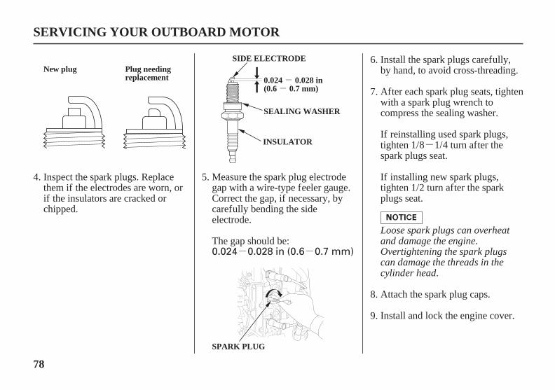
-
- -
--
0.024 0.028 in (0.6 0.7 mm)
78
SERVICING YOUR OUTBOARD MOTOR
SPARK PLUG
SIDE ELECTRODE
0.024 0.028 in(0.6 0.7 mm)
New plug Plug needingreplacement
SEALING WASHER
INSULATOR
Loose spark plugs can overheatand damage the engine.Overtightening the spark plugscan damage the threads in thecylinder head.
Install and lock the engine cover.
Attach the spark plug caps.
If installing new spark plugs,tighten 1/2 turn after the sparkplugs seat.
If reinstalling used spark plugs,tighten 1/8 1/4 turn after thespark plugs seat.
After each spark plug seats, tightenwith a spark plug wrench tocompress the sealing washer.
Install the spark plugs carefully,by hand, to avoid cross-threading.
Measure the spark plug electrodegap with a wire-type feeler gauge.Correct the gap, if necessary, bycarefully bending the sideelectrode.
The gap should be:
Inspect the spark plugs. Replacethem if the electrodes are worn, orif the insulators are cracked orchipped.
5.
6.
7.
8.
9.
4.
11/03/10 14:29:52 31ZZ4620_079

79
Lubrication Points
SERVICING YOUR OUTBOARD MOTOR
TILLER HANDLE(LH and LHT types)
TILT SHAFT
UPPER SWIVEL CASE/MOUNT FRAME
PROPELLER SHAFT LOWER SWIVELCASE
To prevent corrosion, apply anticorrosion oil to pivotsurf aces where grease cannot penetrate.
Apply Honda Marine Corrosion Inhibitor (or equivalent) to all areas under the engine cover and any exposed metalsurfaces except the belts.
Apply Honda Marine waterproof grease to the partsshown below:
After the first 20 hours or 1 month, then every 100 hoursor 6 months (refer to the maintenance schedule on page
).
Lubrication interval:
70
11/03/10 14:30:05 31ZZ4620_080
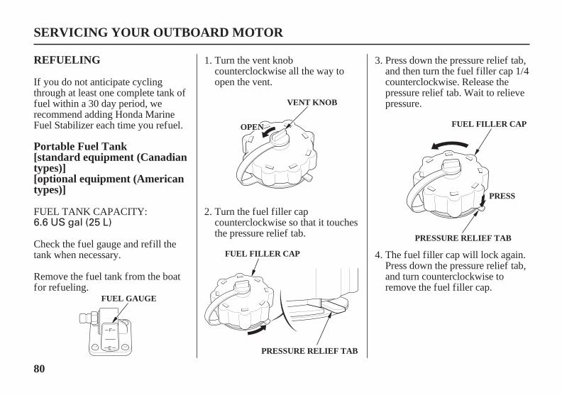
6.6 US gal (25 L)
80
REFUELING
Portable Fuel Tank[standard equipment (Canadiantypes)][optional equipment (Americantypes)]
SERVICING YOUR OUTBOARD MOTOR
VENT KNOB
FUEL FILLER CAP
OOPPEENN
PRESSURE RELIEF TAB
FUEL FILLER CAP
PRESS
PRESSURE RELIEF TAB
FUEL GAUGE
Turn the vent knobcounterclockwise all the way toopen the vent.
Press down the pressure relief tab,and then turn the fuel filler cap 1/4counterclockwise. Release thepressure relief tab. Wait to relievepressure.
Turn the fuel filler capcounterclockwise so that it touchesthe pressure relief tab.
The fuel filler cap will lock again.Press down the pressure relief tab,and turn counterclockwise toremove the fuel filler cap.
If you do not anticipate cyclingthrough at least one complete tank offuel within a 30 day period, werecommend adding Honda MarineFuel Stabilizer each time you refuel.
Remove the fuel tank from the boatfor refueling.
Check the fuel gauge and refill thetank when necessary.
FUEL TANK CAPACITY:
1.
2.
3.
4.
11/03/17 14:42:14 31ZZ4620_081

Gasoline is highlyflammable and explosive.
You can be burned orseriously injured whenhandling fuel.
Stop the engine and keepheat, sparks, and flameaway.Handle fuel onlyoutdoors.Wipe up spillsimmediately.
81
Using the fuel tank mounted inthe boat.
SERVICING YOUR OUTBOARD MOTOR
VENT KNOB
CCLLOOSSEE
FUEL FILLER CAP
SAFE FILL LEVEL
Fuel can damage paint and plastic.Be caref ul not to spill f uel whenf illing your f uel tank. Damagecaused by spilled f uel is not coveredunder warranty.
Refuel in a well-ventilated area. Fillthe tank to the SAFE FILL LEVELline.
After refueling, install the cap andtighten it until you hear it click. Closethe vent by turning the vent knobclockwise all the way, and return thefuel tank to the boat.
Check the fuel level and refill ifnecessary. Do not fill the fuel tankabove the UPPER LIMIT. Refer tothe boat manufacturer’s instructions.
Never refill the fuel tank inside abuilding where gasoline fumes mayreach flames or sparks. Keepgasoline away from appliance pilotlights, barbecues, electric appliances,power tools, etc.
Spilled fuel is not only a fire hazard,it causes environmental damage.Wipe up spills immediately.
11/03/17 11:05:31 31ZZ4620_082

82
FUEL RECOMMENDATIONS
SERVICING YOUR OUTBOARD MOTOR
Use unleaded gasoline with a pumpoctane rating of 86 or higher.
Your outboard motor is certified tooperate on unleaded gasoline.Unleaded gasoline produces fewerengine and spark plug deposits andextends exhaust system life.
Never use stale or contaminatedgasoline or an oil/gasoline mixture.Avoid getting dirt or water in the fueltank.
You may use unleaded gasolinecontaining no more than 10% ethanol(E10) or 5% methanol by volume. Inaddition, methanol must containcosolvents and corrosion inhibitors.
Use of fuels with content of ethanolor methanol greater than shownabove may cause starting and/orperformance problems. It may alsodamage metal, rubber, and plasticparts of the fuel system.
Engine damage or performanceproblems that result from using a fuelwith percentages of ethanol ormethanol greater than shown aboveare not covered under warranty.
If your outboard motor will be usedon an infrequent or intermittent basis,please refer to the fuel section of theSTORAGE chapter (p. ) foradditional information regarding fueldeterioration.
93
11/03/10 14:30:42 31ZZ4620_083

Gasoline is highlyflammable and explosive.
You can be burned orseriously injured whenhandling fuel.
Stop the engine and keepheat, sparks, and flameaway.Handle fuel onlyoutdoors.Wipe up spillsimmediately.
83
Fuel Filter/Water SeparatorInspection and Service
SERVICING YOUR OUTBOARD MOTOR
PPUULLLL
PPUUSSHH
FUEL HOSE CONNECTOR
Water or sediment accumulation inthe filter can cause loss of power orhard starting. To prevent enginemalfunction, inspect the filter andreplace when necessary.
Remove the engine cover (p. )and disconnect the fuel hoseconnector from the outboard motor.
The fuel filter is located under theengine cover between the fuelcoupling and the fuel pump.
A red ring float is located inside thestrainer cup. It floats on top of thewater and indicates how much waterhas accumulated in the strainer cup.
1. 73
11/03/10 14:30:53 31ZZ4620_084
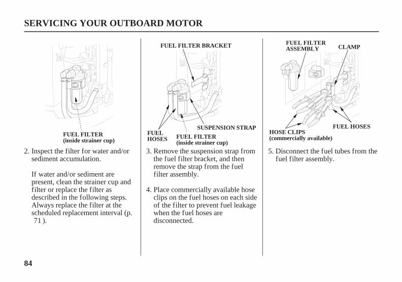
84
SERVICING YOUR OUTBOARD MOTOR
FUEL FILTER(inside strainer cup)
FUEL FILTER BRACKET
FUELHOSES FUEL FILTER
(inside strainer cup)
SUSPENSION STRAPHOSE CLIPS(commercially available)
FUEL HOSES
FUEL FILTERASSEMBLY CLAMP
Inspect the filter for water and/orsediment accumulation.
If water and/or sediment arepresent, clean the strainer cup andfilter or replace the filter asdescribed in the following steps.Always replace the filter at thescheduled replacement interval (p.
).
Remove the suspension strap fromthe fuel filter bracket, and thenremove the strap from the fuelfilter assembly.
Place commercially available hoseclips on the fuel hoses on each sideof the filter to prevent fuel leakagewhen the fuel hoses aredisconnected.
Disconnect the fuel tubes from thefuel filter assembly.
2. 3.
4.
5.
71
11/03/10 14:31:03 31ZZ4620_085
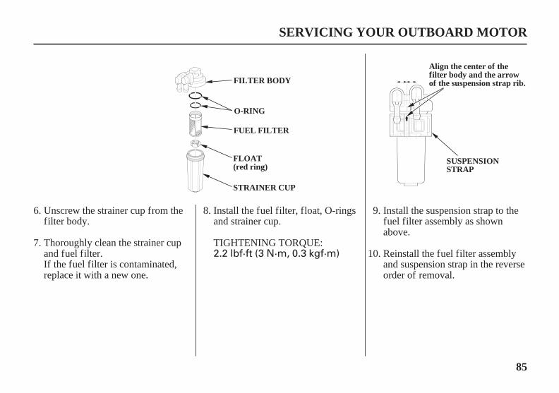
2.2 lbf·ft (3 N·m, 0.3 kgf·m)
85
SERVICING YOUR OUTBOARD MOTOR
FILTER BODY
O-RING
FUEL FILTER
STRAINER CUP
FLOAT(red ring)
SUSPENSIONSTRAP
Align the center of thefilter body and the arrowof the suspension strap rib.
Unscrew the strainer cup from thefilter body.
Thoroughly clean the strainer cupand fuel filter.
Install the fuel filter, float, O-ringsand strainer cup.
If the fuel filter is contaminated,replace it with a new one.
Install the suspension strap to thefuel filter assembly as shownabove.
Reinstall the fuel filter assemblyand suspension strap in the reverseorder of removal.
6.
7.
8. 9.
10.TIGHTENING TORQUE:
11/03/10 14:31:11 31ZZ4620_086

Wipe up spillsimmediately.
Handle fuel onlyoutdoors.
Stop the engine and keepheat, sparks, and flameaway.
You can be burned orseriously injured whenhandling fuel.
Gasoline is highlyflammable and explosive.
86
Portable Fuel Tank and TankFilter Cleaning[standard equipment (Canadiantypes)][optional equipment (Americantypes)]
SERVICING YOUR OUTBOARD MOTOR
FUEL HOSE(standard equipment)
Fuel Tank
Empty the portable fuel tank into anapproved gasoline container. Use afunnel to avoid spilling fuel. Rinsethe fuel tank with nonflammablesolvent to remove any accumulatedsediment.
Connect the fuel hoses to the fuelfilter securely with the hoseclamps. Remove the fuel hoseclips used to close the fuel hoses.
Install and lock the engine cover.
If loss of power or hard starting arefound to be caused by excessivewater or sediment accumulation inthe fuel filter, inspect the fuel tank.
Clean the fuel tank and tank filter ifnecessary. It may be necessary todrain the fuel tank completely andrefill with fresh gasoline.
Securely connect the fuel hoseconnector to the outboard motor(refer to page ).
Prime the engine using the primingbulb (p. ). Check for fuel leaks.Repair any fuel leaks if necessary.
11.
12.
13.
14.
44
45
11/03/10 14:31:25 31ZZ4620_087
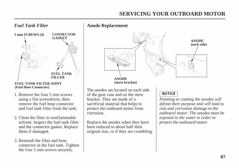
87
Anode Replacement
SERVICING YOUR OUTBOARD MOTOR
FUEL TANKFILLER ANODE
(stern bracket)
ANODE(each side)
5 mm SCREWS (4) CONNECTORGASKET
FUEL TANK FILTER JOINT(Fuel Hose Connector)
Fuel Tank Filter
Painting or coating the anodes willdef eat their purpose and will lead torust and corrosion damage to theoutboard motor. The anodes must beexposed to the water in order toprotect the outboard motor.
The anodes are located on each sideof the gear case and on the sternbracket. They are made of asacrificial material that helps toprotect the outboard motor fromcorrosion.
Replace the anodes when they havebeen reduced to about half theiroriginal size, or if they are crumbling.
Reinstall the filter and hoseconnector in the fuel tank. Tightenthe four 5 mm screws securely.
Remove the four 5 mm screwsusing a flat screwdriver, thenremove the fuel hose connectorand fuel tank filter from the tank.
Clean the filter in nonflammablesolvent. Inspect the fuel tank filterand the connector gasket. Replacethem if damaged.
1.
2.
3.
11/03/10 14:31:36 31ZZ4620_088

88
Propeller Replacement[standard equipment (Canadiantypes)][optional equipment (Americantypes)]
SERVICING YOUR OUTBOARD MOTOR
THRUST WASHERCASTLE NUT
COTTER PIN
PLAIN WASHER
SPECIAL SPLINEWASHER
MARINE GREASE
COTTER PIN(stainless)
PROPELLER
Installation
Removal
Apply marine grade grease to thepropeller shaft.
Install the thrust washer with thegrooved side toward the gear case.
Inspect the propeller shaft for anyfishing line or debris.
Remove the cotter pin, unscrewthe castle nut, remove the washer,and then remove the propeller andthrust washer.
Operating the outboard motor athigher altitudes will reduceavailable power. This may requiredecreasing the propeller pitch tomaintain correct engine RPM.
The propeller blades may have sharpedges, so wear heavy gloves toprotect your hands.
Before replacing the propeller,remove the emergency stop switchclip from the emergency stop switchto prevent any possibility of theengine being started while you areworking with the propeller.
1.
2.
1.
2.
11/03/10 14:31:48 31ZZ4620_089

0.7 lbf·ft (1 N·m, 0.1 kgf·m)
25 lbf·ft (35 N·m, 3.5 kgf·m)
89
SERVICING YOUR OUTBOARD MOTOR
Do not tighten the castle nut abovethe TIGHTENING TORQUE LIMIT,or the propeller and shaf t may bedamaged.
TIGHTENING TORQUE LIMIT:
Be sure to replace the cotter pinwith a new one.
Use a Honda Genuine stainlesssteel cotter pin or equivalentcotter pin and bend the pin endsas shown.
Note that these wrenches are notincluded with the tool set that comeswith the outboard motor. Contactyour authorized Honda Marine dealerfor additional tool information.
Install the propeller, the specialspline washer and the plain washer.
Lightly tighten the castle nut byhand or wrench until the propellerhas no free play.
Then, using a torque wrench,tighten the castle nut until the firstavailable groove in the castle nutaligns with the cotter pin hole. Donot tighten past the first alignmentof the castle nut groove and thecotter pin hole.
Tighten the castle nut using atorque wrench.
5.
6.
CASTLE NUTTIGHTENING TORQUE:
7.3.
4.
11/03/10 14:31:57 31ZZ4620_090

90
Cleaning and Flushing
CLEANING AND FLUSHING
WASH SCREW(flush screw)
Cleaning
Flushing With a Garden HoseGarden Hose Adapter (optionalequipment)Do not apply water or corrosion
inhibitor directly to the electricalcomponents under the engine cover,such as the HO2 sensor and timingbelt. If water or corrosion inhibitorpenetrates these components, theymay be damaged. Bef ore applying acorrosion inhibitor, cover the HO2sensor and timing belt with aprotective material to preventdamage.
It is necessary to run the engineduring the flushing procedure. Forsafety, remove the propeller from theoutboard motor (p. ).
After each use in salt water or dirtywater, thoroughly clean and flush theoutboard motor with fresh water.
Touch up any damaged paint, andcoat areas that may rust with HondaCorrosion Inhibitor, or equivalent.Lubricate controls with a siliconespray lubricant.
Wash the outside of the outboardmotor with clean, fresh water, andflush the cooling system as follows.
Tilt down the outboard motor.
Remove the wash screw andsealing washer from the WASHscrew hole in the gear case. Besure not to remove the oil levelscrew from the OIL LEVEL screwhole in the gear case.
88
2.
1.
11/09/14 11:10:47 31ZZ4620_091

91
CLEANING AND FLUSHING
GARDEN HOSE ADAPTER(FLUSH KIT COUPLER)
WATER INTAKES(each side)
WATER INTAKE
Running the engine without goodwater circulation can causeoverheating and water pump damage.
Distributor’s Limited Warranty
Move the gearshift lever or controllever to the N (neutral) position.Flush the outboard motor in theneutral position only.
Turn on the fresh water supply tothe flush kit coupler.
Damage caused by running theoutboard motor without sufficientcooling water is not covered by the
(p. ).
Remove the sealing washer fromthe wash screw and install thesealing washer on the flush kitcoupler.
Install the flush kit coupler into theWASH screw hole and connect afresh water hose to the gardenhose adapter.
Cover the three water intakes withduct tape as shown above.
4.
5.
3.
6.
7.
123
11/03/10 14:32:18 31ZZ4620_092

92
CLEANING AND FLUSHING
COOLING SYSTEM INDICATOR
Allow the engine to run at idle forat least 5 minutes to clean theinside of the outboard motor.
Stop the engine, and disconnectthe fuel hose from the outboardmotor. Remove the garden hoseadapter.
Remove the sealing washer fromthe garden hose adapter and installthe sealing washer on the washscrew.
If tape was used to cover the threewater intakes in step 6, remove thetape now.
Install the wash screw into the gearcase securely.
Start the engine. Monitor thecooling system indicator. Stop theengine if water does not come outof the cooling system indicator andcheck the fresh water supply.
Tilt up the outboard motor andmove the tilt lock lever to theLOCK position.
9.
8.
11.
10.
12.
13.
11/03/10 14:32:27 31ZZ4620_093

93
Fuel
STORAGE
Adding a Fuel Stabilizer
Depending on the region where youoperate your outboard, f uelf ormulations may deteriorate andoxidize rapidly. Fuel deteriorationand oxidation can occur in as littleas 15 days and may cause damage tothe f uel system. Please check withyour servicing dealer f or localstorage recommendations.
Distributor’s Limited Warranty
When adding a fuel stabilizer, fill thefuel tank with fresh gasoline. If onlypartially filled, air in the tank willpromote fuel deterioration duringstorage. If you keep an additionalcontainer of gasoline for refueling,be sure that it contains only freshgasoline.
Drain the vapor separator beforeadding fuel stabilizer.
Gasoline will oxidize and deterioratein storage. Old gasoline will causehard starting, and it leaves gumdeposits that clog the fuel system. Ifthe gasoline in your fuel tank andvapor separator deteriorates duringstorage, you may need to have thevapor separator and other fuel systemcomponents serviced or replaced.
The length of time that gasoline canbe left in your fuel tank and vaporseparator without causing functionalproblems will vary with such factorsas gasoline blend, your storage
temperatures, and whether the fueltank is partially or completely filled.The air in a partially filled fuel tankpromotes fuel deterioration. Verywarm storage temperatures acceleratefuel deterioration. Fuel deteriorationproblems may occur in less than 15days, if the gasoline was not freshwhen you filled the fuel tank.
You can extend fuel storage life byadding a gasoline stabilizer that isformulated for that purpose, or youcan avoid fuel deterioration problemsby draining all the fuel from the fueltank and vapor separator.
Thedoes not cover fuel system damageor engine performance problemsresulting from neglected storagepreparation.
Add Honda Marine fuel stabilizerfollowing the instructions on thelabel.
Turn the engine OFF.
After adding a fuel stabilizer, runthe engine in water for 10 minutesto be sure that the treated gasolinehas replaced the untreated gasolinein the vapor separator.
1.
2.
3.
4.
11/03/10 14:32:39 31ZZ4620_094
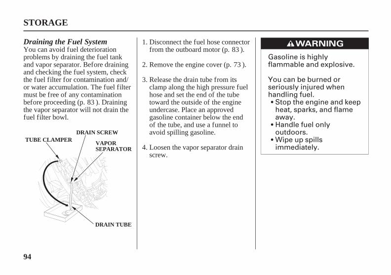
Gasoline is highlyflammable and explosive.
You can be burned orseriously injured whenhandling fuel.
Stop the engine and keepheat, sparks, and flameaway.Handle fuel onlyoutdoors.Wipe up spillsimmediately.
94
STORAGE
DRAIN TUBE
VAPORSEPARATOR
TUBE CLAMPERDRAIN SCREW
Draining the Fuel SystemYou can avoid fuel deteriorationproblems by draining the fuel tankand vapor separator. Before drainingand checking the fuel system, checkthe fuel filter for contamination and/or water accumulation. The fuel filtermust be free of any contaminationbefore proceeding (p. ). Drainingthe vapor separator will not drain thefuel filter bowl.
Disconnect the fuel hose connectorfrom the outboard motor (p. ).
Release the drain tube from itsclamp along the high pressure fuelhose and set the end of the tubetoward the outside of the engineundercase. Place an approvedgasoline container below the endof the tube, and use a funnel toavoid spilling gasoline.
Remove the engine cover (p. ).
Loosen the vapor separator drainscrew.
2.
1.
3.
4.
73
83
83
11/03/10 14:32:51 31ZZ4620_095

95
STORAGE
Tilt the outboard motor up untilgasoline flows out of the draintube.
Leave it in that position until thegasoline stops flowing.
After thoroughly draining, tightenthe drain screw securely.
Check the drained gasoline for thepresence of water orcontamination. If either is present,you will have to reassemble andrun the outboard to refill the vaporseparator with gasoline and thendrain it again. Repeat thefollowing procedure until no wateror contamination is present in theremoved gasoline.
Make sure the gasoline supply isnot contaminated.
Reassemble the outboard andreconnect the fuel lineconnector.
Place the outboard in water. Usethe priming bulb to refill thefuel system and run theoutboard at idle for 3 minutes.
Stop the outboard and followthe procedure beginning withstep 1 above.
Secure the drain tube to the clampalong the high pressure fuel hose.
Install the engine cover.
Drain the fuel tank into anapproved gasoline container, or ifyou need to store fuel in the fueltank, you can extend fuel storagelife by filling the fuel tank withfresh gasoline and adding HondaMarine fuel stabilizer followingthe directions on the container.Close the fuel cap vent.
If using the portable fuel tank,close the fuel filler cap vent knob.Store the portable fuel tank in acool dry place out of directsunlight.
5.
6.
7.
8.
a.
b.
c.
d.
9.
10.
11.
11/03/10 14:33:02 31ZZ4620_096

- -
96
STORAGE PRECAUTIONS
HOISTING THE OUTBOARDMOTOR
Engine Oil
STORAGE
LIFTINGEYE
HOISTHOOK
After the outboard motor is placedin storage and disconnected fromthe hoist, install the engine cover.
Select a well-ventilated storage area.If possible, avoid storage areas withhigh humidity.
Disconnect the outboard motorfrom the boat, hoist the outboardmotor, and move it to the storagearea.
Remove the spark plugs (p. ),and remove the emergency stopswitch clip from the emergencystop switch.
Unlatch and remove the enginecover (p. ).
Attach the hoist hook to the liftingeye.
Change the engine oil (p. ).
Pour 1 2 teaspoons (5 10 cm )(p. ) of clean engine oil intoeach cylinder.
If storing a container of gasoline,such as the portable fuel tank(standard or optional equipment),store it away from any appliance thatoperates with a flame, such as afurnace, water heater, or clothesdryer. Also avoid any area with aspark producing electric motor, orwhere power tools are operated.
Using the emergency starter rope(p. ), rotate the flywheel a fewrevolutions to distribute the oil inthe cylinders.
Reinstall the spark plugs (p. ).
2.
3.
4.
1.
2.
3.
1.
4.
5.
75
77
53
7378
110
3
11/03/10 14:33:16 31ZZ4620_097
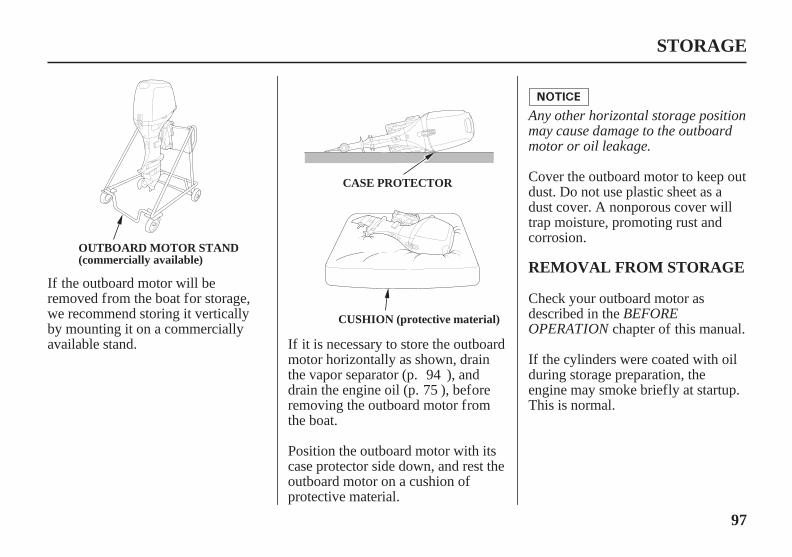
97
REMOVAL FROM STORAGE
STORAGE
OUTBOARD MOTOR STAND(commercially available)
CASE PROTECTOR
CUSHION (protective material) BEFOREOPERATION
Any other horizontal storage positionmay cause damage to the outboardmotor or oil leakage.
If the outboard motor will beremoved from the boat for storage,we recommend storing it verticallyby mounting it on a commerciallyavailable stand.
If the cylinders were coated with oilduring storage preparation, theengine may smoke briefly at startup.This is normal.
Check your outboard motor asdescribed in the
chapter of this manual.
Cover the outboard motor to keep outdust. Do not use plastic sheet as adust cover. A nonporous cover willtrap moisture, promoting rust andcorrosion.
If it is necessary to store the outboardmotor horizontally as shown, drainthe vapor separator (p. ), anddrain the engine oil (p. ), beforeremoving the outboard motor fromthe boat.
Position the outboard motor with itscase protector side down, and rest theoutboard motor on a cushion ofprotective material.
7594
11/03/10 14:33:26 31ZZ4620_098

98
WITH OUTBOARD MOTORINSTALLED ON BOAT
WITH OUTBOARD MOTORREMOVED FROM BOAT
TRANSPORTING
STEERING FRICTION ADJUSTER
TTOO IINNCCRREEAASSEEFFRRIICCTTIIOONN((LLOOCCKK))
TO DECREASEFRICTION(FREE)
OUTBOARD MOTOR SUPPORT BAR(commercially available)
LH and LHT Types(tiller handle)
LRT and XRT Types (remotecontrol)
All Types
Secure the outboard motor in eitherthe vertical or horizontal positionshown on p. .
Tighten the steering friction adjusterto prevent the outboard motor frommoving while trailering the boat.
Use an outboard motor support bar toprevent the outboard motor frommoving while trailering the boat.Refer to the manufacturer’sinstructions for using an outboardmotor support bar.
When trailering a boat with theoutboard motor attached, alwaysdisconnect the fuel line from theportable fuel tank.
The preferred method is to leave theengine in the normal running position,but if there is insufficient roadclearance, you can tilt the outboardmotor using a commercially availableoutboard motor support bar availablethrough your dealer. Refer to themanufacturer’s instructions for usingan outboard motor support bar.
97
11/03/10 14:33:37 31ZZ4620_099

99
TAKING CARE OF UNEXPECTED PROBLEMS
ENGINE WILL NOT START
Possible Cause
Insert clip in emergency stop switch.
Correction
Clip not inserted in emergency stop switch.
Gearshift lever or control lever not in neutral position. Shift to neutral (p. or ).
Throttle grip not in START position (tiller handle type). Turn throttle lever or grip to START position (p. ).
Fast idle lever raised (remote control/side-mount type). Leave fast idle lever in the START position (p. ).
46 49
47
50
11/09/14 11:12:33 31ZZ4620_100

100
TAKING CARE OF UNEXPECTED PROBLEMS
Possible Cause Correction
Out of fuel.
ENGINE WILL NOT START
Refuel (p. ).
Fuel vent closed (portable fuel tank). Open fuel filler cap vent (p. ).
Fuel hose not primed. Squeeze priming bulb (p. ).
Fuel filter or fuel tank filter clogged.
Bad fuel; outboard motor stored without treating ordraining gasoline, or refueled with bad gasoline.
Drain fuel tank and vapor separator (p. ). Refillwith fresh gasoline (p. ).
Replace fuel filters (p. ).
94
80
44
45
83 and 87
80
11/09/14 11:12:46 31ZZ4620_101

101
TAKING CARE OF UNEXPECTED PROBLEMS
ENGINE WILL NOT START
Possible Cause Correction
Battery connections loose or corroded. Clean and tighten battery connections.
Battery discharged. Recharge battery.
Fuse(s) blown. Replace fuse(s) (p. ).
Spark plugs faulty, fouled, or improperly gapped. Gap or replace spark plugs (p. ).
Spark plugs wet with fuel (flooded engine). Dry and reinstall spark plugs. Start engine with thethrottle open.
Fuel system malfunction, fuel pump failure, ignitionmalfunction, stuck valves, starter malfunction, switchmalfunction, or electrical problem in the startingcircuit, etc.
Use starting procedure (p. , ); if engine still willnot start, then take outboard motor to an authorizedHonda Marine dealer, or refer to the shop manual.
104
77
46 49
11/09/14 11:13:01 31ZZ4620_102

102
TAKING CARE OF UNEXPECTED PROBLEMS
HARD STARTING OR STALLS AFTER STARTING
Possible Cause Correction
Throttle grip not in START position(tiller handle type).
Turn throttle grip to START position (p. ).
Fast idle lever raised (remote control/side-mount type). Leave fast idle lever in the START position (p. ).
Fuel vent closed (portable fuel tank). Open fuel filler cap vent (p. ).
Fuel hose not primed. Squeeze priming bulb (p. ).
Fuel filter or fuel tank filter clogged. Replace fuel filters (p. and ).
Bad fuel; outboard motor stored without treating ordraining gasoline, or refueled with bad fuel.
Drain fuel tank and vapor separator (p. ). Refillwith fresh gasoline (p. ).
47
50
44
45
83 87
9480
11/09/14 11:13:16 31ZZ4620_103
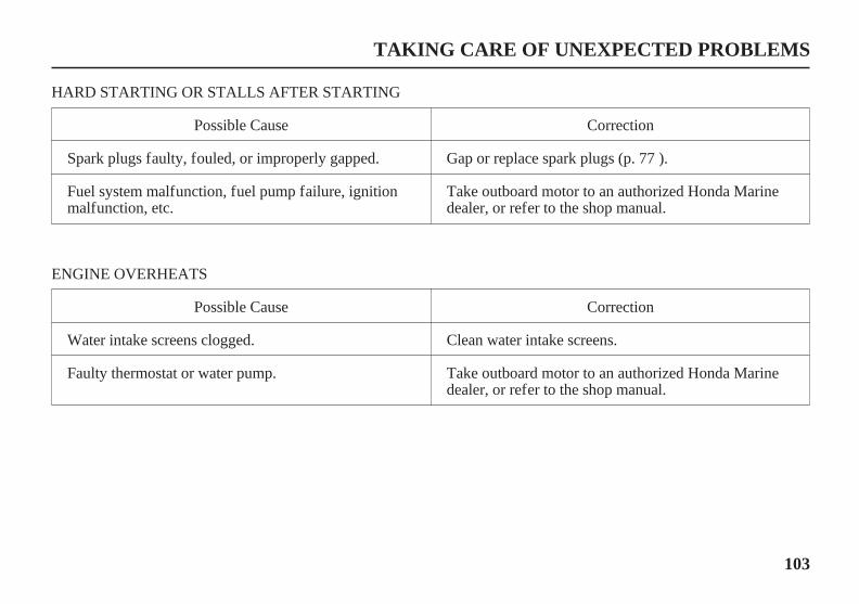
103
TAKING CARE OF UNEXPECTED PROBLEMS
HARD STARTING OR STALLS AFTER STARTING
Possible Cause Correction
Spark plugs faulty, fouled, or improperly gapped. Gap or replace spark plugs (p. ).
Fuel system malfunction, fuel pump failure, ignitionmalfunction, etc.
Take outboard motor to an authorized Honda Marinedealer, or refer to the shop manual.
Possible Cause
ENGINE OVERHEATS
Correction
Water intake screens clogged.
Faulty thermostat or water pump.
Clean water intake screens.
Take outboard motor to an authorized Honda Marinedealer, or refer to the shop manual.
77
11/09/18 15:45:00 31ZZ4620_104
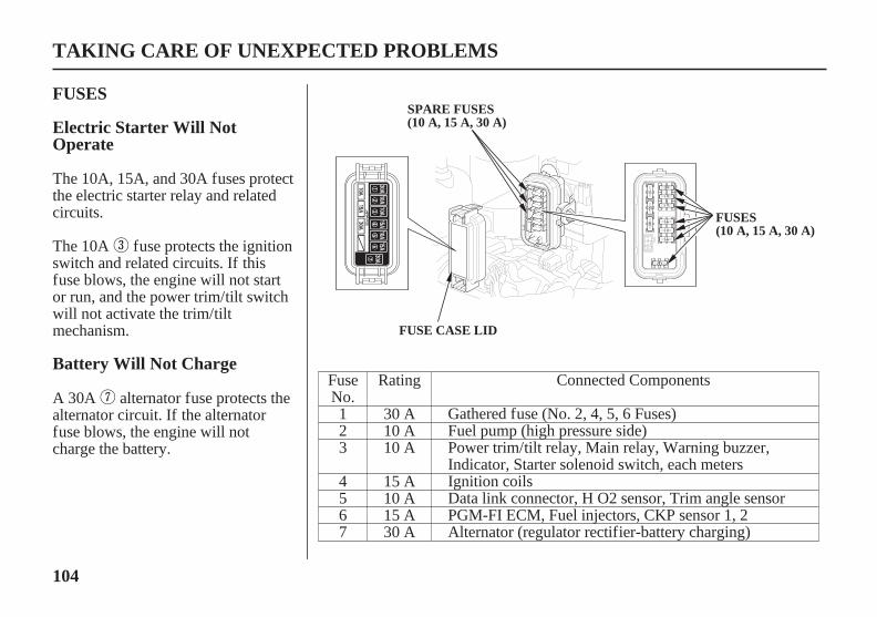
104
Electric Starter Will NotOperate
FUSES
Battery Will Not Charge
TAKING CARE OF UNEXPECTED PROBLEMS
FUSE CASE LID
FUSES(10 A, 15 A, 30 A)
SPARE FUSES(10 A, 15 A, 30 A)
The 10A, 15A, and 30A fuses protectthe electric starter relay and relatedcircuits.
The 10A fuse protects the ignitionswitch and related circuits. If thisfuse blows, the engine will not startor run, and the power trim/tilt switchwill not activate the trim/tiltmechanism.
A 30A alternator fuse protects thealternator circuit. If the alternatorfuse blows, the engine will notcharge the battery.
Connected Components
Gathered fuse (No. 2, 4, 5, 6 Fuses)Fuel pump (high pressure side)Power trim/tilt relay, Main relay, Warning buzzer,Indicator, Starter solenoid switch, each metersIgnition coilsData link connector, H O2 sensor, Trim angle sensorPGM-FI ECM, Fuel injectors, CKP sensor 1, 2Alternator (regulator rectifier-battery charging)
FuseNo.123
4567
Rating
30 A10 A10 A
15 A10 A15 A30 A
11/03/10 14:34:54 31ZZ4620_105

-
10 A, 15 A, 30 A
105
Fuse Replacement
TAKING CARE OF UNEXPECTED PROBLEMS
BLOWN FUSE
FUSE PULLER(supplied in the tool bag)
Main Fuse
Never use a f use with a ratinggreater than specif ied. Seriousdamage to the electrical system couldresult.
Disconnect the battery cable at thebattery negative ( ) terminal bef orereplacing the f use.Failure to do so may cause a shortcircuit.
Reconnect the battery.
If a blown fuse is found, try todetermine and correct the electricalproblem that caused the blown fuse.An uncorrected electrical problemmay cause the fuse to blow again.
If fuses continue to blow, take theoutboard motor to an authorizedHonda Marine dealer for inspectionand service, or refer to the shopmanual.
Use the fuse puller from the toolkit to remove the fuses. If a fuse isblown, install a replacement fuseof the same specified rating. Theoutboard motor is supplied withspare fuses in the fuse holder.
MAIN FUSE RATINGS:
Stop the engine and disconnect thebattery cable.
Remove the fuse case lid.
Reinstall the fuse case lid, and theengine cover.
Remove the engine cover.
1.
2.
3.
4.
5.
6.
11/03/10 14:35:06 31ZZ4620_106

106
Digital TachometerOIL PRESSURE INDICATORGOES OFF AND ENGINESPEED IS LIMITED
TAKING CARE OF UNEXPECTED PROBLEMS
(GREEN)
(internal buzzer)
(GREEN)
BUZZER
Normal
Abnormal
LRT and XRT Types(remote control)
LH and LHT Types(tiller handle)
If oil pressure becomes low, the oilpressure indicator will go off, and theengine protection system limitsengine speed. If you are at cruisingspeed, engine speed will decreaseautomatically.
The oil pressure indicator is alsoequipped with a buzzer that soundswhen the oil pressure indicator goesoff.
Low oil pressure may be the result ofa low engine oil level, or there maybe a problem with the enginelubrication system.
11/03/10 14:35:17 31ZZ4620_107

107
OVERHEAT INDICATORCOMES ON AND ENGINESPEED IS LIMITED
TAKING CARE OF UNEXPECTED PROBLEMS
(RED)
(internal buzzer)
BUZZER
(RED)
LRT and XRT Types(remote control)
LH and LHT Types(tiller handle)
If the throttle is closed suddenly afterfull throttle operation, engine speedmay drop below the specified idlerpm, and that could activate theengine protection systemmomentarily.
If low oil pressure activates theengine protection system, stop theengine, check the engine oil level(p. ), and add oil if needed.
With the engine oil at therecommended level, restart theengine. If the lubrication system isOK, the oil pressure indicator shouldcome on within 30 seconds, and theengine will respond normally tothrottle control lever operation.
If the engine protection systemremains activated after 30 seconds,return to the nearest boat landing, andhave the outboard motor inspected byan authorized Honda Marine dealer.
74
11/03/10 14:35:26 31ZZ4620_108
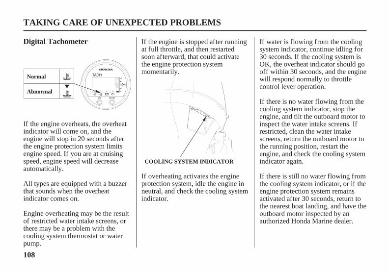
108
Digital Tachometer
TAKING CARE OF UNEXPECTED PROBLEMS
COOLING SYSTEM INDICATOR
Normal
Abnormal
If the engine overheats, the overheatindicator will come on, and theengine will stop in 20 seconds afterthe engine protection system limitsengine speed. If you are at cruisingspeed, engine speed will decreaseautomatically.
All types are equipped with a buzzerthat sounds when the overheatindicator comes on.
Engine overheating may be the resultof restricted water intake screens, orthere may be a problem with thecooling system thermostat or waterpump.
If the engine is stopped after runningat full throttle, and then restartedsoon afterward, that could activatethe engine protection systemmomentarily.
If overheating activates the engineprotection system, idle the engine inneutral, and check the cooling systemindicator.
If water is flowing from the coolingsystem indicator, continue idling for30 seconds. If the cooling system isOK, the overheat indicator should gooff within 30 seconds, and the enginewill respond normally to throttlecontrol lever operation.
If there is no water flowing from thecooling system indicator, stop theengine, and tilt the outboard motor toinspect the water intake screens. Ifrestricted, clean the water intakescreens, return the outboard motor tothe running position, restart theengine, and check the cooling systemindicator again.
If there is still no water flowing fromthe cooling system indicator, or if theengine protection system remainsactivated after 30 seconds, return tothe nearest boat landing, and have theoutboard motor inspected by anauthorized Honda Marine dealer.
11/03/10 14:35:37 31ZZ4620_109

-
109
SUBMERGED OUTBOARDMOTOR
TAKING CARE OF UNEXPECTED PROBLEMS
EMERGENCY STARTER ROPEWhen cranking the engine with anopen ignition circuit (spark plugsremoved f rom the ignition circuit),remove the clip f rom theemergency stop switch to preventpossible damage to the ignitionsystem.
Change the engine oil as describedon p. . If there was waterin the engine crankcase, or if theused engine oil showed signs ofwater contamination, then a secondengine oil change should beperformed after running the enginefor half an hour.
Remove the spark plugs (p. ),and remove the emergency stopswitch clip from the emergencystop switch. Pull the emergencystarter rope, rotate the flywheel afew revolutions to completelyexpel any water from the engine’scylinders.
If the engine was running when itsubmerged, there may bemechanical damage, such as bentconnecting rods. If the enginebinds when cranked, do notattempt to run the engine until ithas been repaired.
Remove the alternator cover (p.).
Drain the vapor separator asdescribed on p. .
Remove the engine cover, andrinse the outboard motor withfresh water to remove salt water,sand, mud, etc.
If there is a Honda Marine dealershipnearby, take the outboard motor tothe dealer immediately. If you are farfrom a dealer, proceed as follows:
A submerged outboard motor mustbe serviced immediately after it isrecovered from the water in order tominimize corrosion.
3.
4.
5.
1.
2.
75 77
52
77
94
11/03/10 14:35:50 31ZZ4620_110

- -
110
TAKING CARE OF UNEXPECTED PROBLEMS
Running the outboard motor withoutsuf f icient cooling water will damagethe water pump and overheat theengine.
As soon as possible, take theoutboard motor to an authorizedHonda Marine dealer forinspection and service.
Reinstall the spark plugs andalternator cover, and put theemergency stop switch clip intothe emergency stop switch.
Pour 1 2 teaspoons (5 10 cm )of engine oil into each spark plughole, and then pull the emergencystarter rope several times tolubricate the inside of the cylinders.
If the engine starts, and nomechanical damage is evident,continue to run the engine for ahalf hour or longer. Be sure thewater level is at least 2 inches (5cm) above the antiventilation plateto avoid overheating and waterpump damage.
If the engine fails to start, removethe spark plugs and dry them, thenreinstall the spark plugs andattempt to start the engine again.
Attempt to start the engine. Besure the water level is at least 2inches (5 cm) above theantiventilation plate.
7.
6.
8. 9.
3
11/03/10 14:36:00 31ZZ4620_111

111
Serial Number Locations
TECHNICAL INFORMATION
LEFTSTERNBRACKET
PRODUCT IDENTIFICATIONNUMBER
ENGINE SERIAL NUMBER
STARTER MOTOR
Engine serial number:Product identification number:
Date of purchase:
The product identification number isstamped on a plate attached on theleft stern bracket.
The engine serial number is stampedon the cylinder block under thestarter motor which is located in thefront of the engine.
Record the product identificationnumber, the engine serial number,and the date of purchase in the spaceprovided on this page. You will needthese numbers when ordering parts,and when making technical orwarranty inquiries (p. ).120
11/09/14 11:15:03 31ZZ4620_112
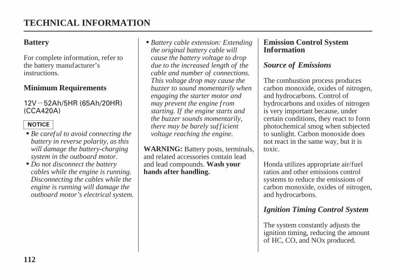
-12V 52Ah/5HR (65Ah/20HR)(CCA420A)
112
Battery
Minimum Requirements
Emission Control SystemInformation
WARNING:
Wash yourhands after handling.
TECHNICAL INFORMATION
Source of Emissions
Ignition Timing Control System
Be caref ul to avoid connecting thebattery in reverse polarity, as thiswill damage the battery-chargingsystem in the outboard motor.Do not disconnect the batterycables while the engine is running.Disconnecting the cables while theengine is running will damage theoutboard motor’s electrical system.
Battery cable extension: Extendingthe original battery cable willcause the battery voltage to dropdue to the increased length of thecable and number of connections.This voltage drop may cause thebuzzer to sound momentarily whenengaging the starter motor andmay prevent the engine f romstarting. If the engine starts andthe buzzer sounds momentarily,there may be barely suf f icientvoltage reaching the engine.
For complete information, refer tothe battery manufacturer’sinstructions.
The combustion process producescarbon monoxide, oxides of nitrogen,and hydrocarbons. Control ofhydrocarbons and oxides of nitrogenis very important because, undercertain conditions, they react to formphotochemical smog when subjectedto sunlight. Carbon monoxide doesnot react in the same way, but it istoxic.
Honda utilizes appropriate air/fuelratios and other emissions controlsystems to reduce the emissions ofcarbon monoxide, oxides of nitrogen,and hydrocarbons.
The system constantly adjusts theignition timing, reducing the amountof HC, CO, and NOx produced.
Battery posts, terminals,and related accessories contain leadand lead compounds.
11/09/14 11:15:15 31ZZ4620_113

113
TECHNICAL INFORMATION
Tampering and AlteringPGM-FI System The U.S., Calif ornia Clean AirActs, and Environment Canada
Tampering is a violation of Federaland Calif ornia law.
EPA, California, and Canadianregulations require all manufacturersto furnish written instructionsdescribing the operation andmaintenance of emission controlsystems.
The PGM-FI system uses sequentialmultiport fuel injection. It has twosubsystems: Engine Control, andFuel Control. The Engine ControlModule (ECM) uses various sensorsto determine how much air is goinginto the engine. It then controls howmuch fuel to inject under alloperating conditions. The following instructions and
procedures must be followed in orderto keep the emissions from yourHonda engine within the emissionstandards.
Alterations that would cause theengine to operate outside its designparameters.
Removal or alteration of any partof the intake, fuel, or exhaustsystems.
Tampering with or altering theemission control system may increaseemissions beyond the legal limit.Among those acts that constitutetampering are:
11/09/14 11:15:26 31ZZ4620_114

114
TECHNICAL INFORMATION
Replacement PartsProblems That May Af f ectEmissions
Maintenance
If you are aware of any of thefollowing symptoms, have yourengine inspected and repaired byyour servicing dealer.
Hard starting or stalling afterstarting.
Rough idle.
Misfiring or backfiring under load.
Afterburning (backfiring).
Black exhaust smoke or high fuelconsumption.
The emission control systems onyour Honda engine were designed,built, and certified to conform withEPA and California emissionregulations. We recommend the useof Honda Genuine parts wheneveryou have maintenance done. Theseoriginal-design replacement parts aremanufactured to the same standardsas the original parts, so you can beconfident of their performance. Theuse of replacement parts that are notof the original design and qualitymay impair the effectiveness of youremission control system.
A manufacturer of an aftermarketpart assumes the responsibility thatthe part will not adversely affectemission performance. Themanufacturer or rebuilder of the partmust certify that use of the part willnot result in a failure of the engine tocomply with emission regulations.
Follow the maintenance schedule onp. . Remember that this scheduleis based on the assumption that yourmachine will be used for its designedpurpose. Sustained high-loadoperation, or use in unusualconditions, will require morefrequent service.
70
11/09/14 11:15:39 31ZZ4620_115
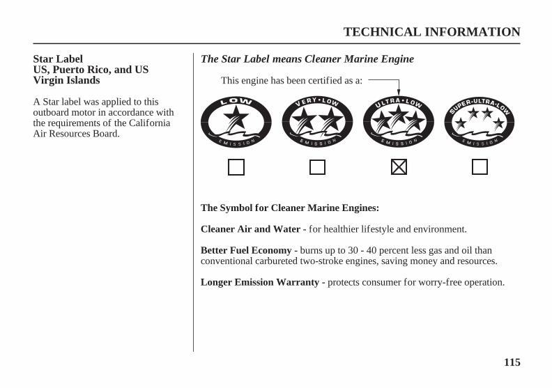
115
Star LabelUS, Puerto Rico, and USVirgin Islands
The Symbol for Cleaner Marine Engines:
Cleaner Air and Water -
Better Fuel Economy -
Longer Emission Warranty -
TECHNICAL INFORMATION
The Star Label means Cleaner Marine Engine
for healthier lifestyle and environment.
burns up to 30 - 40 percent less gas and oil thanconventional carbureted two-stroke engines, saving money and resources.
protects consumer for worry-free operation.
This engine has been certified as a:
A Star label was applied to thisoutboard motor in accordance withthe requirements of the CaliforniaAir Resources Board.
11/09/14 11:15:52 31ZZ4620_116

116
One StarLowEmission
Two StarsVery LowEmission
Three StarsUltra LowEmission
Four StarsSuper UltraLow Emission
TECHNICAL INFORMATION
The one-star label identifies engines that meet the Air Resources Board’sPersonal Watercraft and Outboard marine engine 2001 exhaust emissionstandards. Engines meeting these standards have 75% lower emissions thanconventional carbureted two-stroke engines. These engines are equivalentto the U.S. EPA’s 2006 standards for marine engines.
The two-star label identifies engines that meet the Air Resources Board’sPersonal Watercraft and Outboard marine engine 2004 exhaust emissionstandards. Engines meeting these standards have 20% lower emissions thanOne Star-Low Emission engines.
The three-star label identifies engines that meet the Air Resources Board’sPersonal Watercraft and Outboard marine engine 2008 exhaust emissionstandards or the Sterndrive and Inboard marine engine 2003-2008 exhaustemission standards. Engines meeting these standards have 65% loweremissions than One Star-Low Emission engines.
The four-star label identifies engines that meet the Air Resources Board’sSterndrive and Inboard marine engine 2009 exhaust emission standards.Personal Watercraft and Outboard marine engines may also comply withthese standards. Engines meeting these standards have 90% loweremissions than One Star-Low Emission engines.
Cleaner Watercraft - Get the Facts1-800-END-SMOG
www.arb.ca.gov
11/09/14 11:16:04 31ZZ4620_117

-
-
- -
-
*
*
BBDJBF40D
8°, 12°, 16°, 20°, 24°
4° to 12° (when Transom angle is 12°)35° right and left
Dog type (Forward-Neutral-Reverse)
mechanical type
Water exhaustWater cooling with thermostat
12V 17AULTRA · LOW EMISSION
API standard (GL-4) SAE 90Hypoid gear oil
27.3 in (694 mm)31.3 in (794 mm)
216 lbs (98 kg)
electrical type
53.7 in (1,364 mm)20.5 in (521 mm)
14.6 in (372 mm)
API standard (SG, SH, SJ)SAE/FC-W 5W-30
Unleaded gasoline(86 pump octane or higher)
63° (when Transom angle is 12°)
Trochoid pump pressure lubricationFull transistor battery
Electric starter
0.024 0.028 in (0.6 0.7 mm)49.3 cu-in (808 cm )
4 stroke OHC in-line 3 cylinder
5,000 6,000 rpm29.8 kW (40 HP)/5,500 rpm
2.1 US qt (2.0 L)
2.2 US qt (2.1 L)
0.43 US qt (0.41 L)
DR7EB (NGK) X22ESR-UB (DENSO)
220 lbs (100 kg)
LH LRT
Tiller handle Outboard motor-mounted, remote
control
Gear case:
Engine:
Engine:
Gear case:
without oil filter change
with oil filter change
Low pressure side:High pressure side:
,
117
Specifications
TECHNICAL INFORMATION
MODEL
Type
Descriptioncode
Overall lengthOverall widthOverall height
Transom angle
Steering angleGear change
Fuel
Fuel pumpSpark plugsExhaust systemCooling systemD.C. outputCARB star label
Oil capacity
Specified oil
Transom height(when transomangle is 12°)
Trim angleTilt up angle
Lubricationsystem
Ignition systemStarter system
DisplacementEngine type
Full throttlerange
Rated power
Dry mass[weight]
Steering controlsystem
Spark plug gap
With propeller
Honda outboard motors are power rated in accordance with NMMA procedures and using the ICOMIA standard 28/23.
11/09/19 14:21:24 31ZZ4620_118

-
-
- -
-
*
*
Water cooling with thermostat
ULTRA · LOW EMISSION
BF50DBBEJ
14.6 in (372 mm)
API standard (GL-4) SAE 90Hypoid gear oil
12V 17A
Water exhaust
mechanical typeelectrical type
Unleaded gasoline(86 pump octane or higher)
Dog type (Forward-Neutral-Reverse)35° right and left
4° to 12° (when Transom angle is 12°)
8°, 12°, 16°, 20°, 24°
API standard (SG, SH, SJ)SAE/FC-W 5W-30
63° (when Transom angle is 12°)
Trochoid pump pressure lubricationFull transistor battery
Electric starter
0.024 0.028 in (0.6 0.7 mm)49.3 cu-in (808 cm )
4 stroke OHC in-line 3 cylinder
5,500 6,000 rpm37.3 kW (50 HP)/5,750 rpm
225 lbs (102 kg)
57.7 in (1,465 mm)
31.3 in (794 mm) 27.3 in (694 mm)
53.7 in (1,364 mm)
225 lbs (102 kg) 216 lbs (98 kg)
53.7 in (1,364 mm)
2.1 US qt (2.0 L)
2.2 US qt (2.1 L)
0.43 US qt (0.41 L)20.5 in (521 mm) 24.5 in (622 mm)
DR7EB (NGK) X22ESR-UB (DENSO)
LHT LRT, XRT
Tiller handle Outboard motor-mounted, remote
control
Gear case:
Engine:
Engine:
Gear case:
without oil filter change
with oil filter change
Low pressure side:High pressure side:
LRT:XRT:
LRT:XRT:
,
118
Specifications
TECHNICAL INFORMATION
MODEL
Type
Descriptioncode
Overall lengthOverall widthOverall height
Transom angle
Steering angleGear change
Fuel
Fuel pumpSpark plugsExhaust systemCooling systemD.C. outputCARB star label
Oil capacity
Specified oil
Trim angleTilt up angle
Lubricationsystem
Ignition systemStarter system
DisplacementEngine type
Full throttlerange
Rated power
Dry mass[weight]
Transom height(when transomangle is 12°)
Steering controlsystem
Spark plug gap
With propeller
Honda outboard motors are power rated in accordance with NMMA procedures and using the ICOMIA standard 28/23.
11/09/19 14:22:03 31ZZ4620_119

±±
- -±
No other adjustment is needed
0.15 0.02 mm0.23 0.02 mm
0.024 0.028 in (0.6 0.7 mm)850 50 rpm
See page 78See shop manualSee shop manual
Exhaust:Intake:
119
TECHNICAL INFORMATION
BF40D/BF50D Tune up
Spark plug gapIdle speed
Other specifications
Valve clearance
11/09/14 11:17:30 31ZZ4620_120

-
120
Honda Publications
Customer Service Information
CONSUMER INFORMATION
American Honda Motor Co., Inc.
Honda Canada Inc.
(United States, Puerto Rico, andU.S. Virgin Islands)
Shop Manual
Parts Catalog
Accessory Catalog
Contacting Honda
If you need to contact Hondaregarding your experiences with yourHonda product or with your dealer,please contact the Honda office inyour region:
These publications will give youadditional information formaintaining and repairing youroutboard motor.
This manual covers completemaintenance and overhaul procedures.It is intended to be used by a skilledtechnician.Available through your HondaMarine dealer or through Helm Inc.at1 888-292-5395 orvisit www.Honda-marine.comand click on OWNERS’RESOURCES.
This manual provides complete,illustrated parts lists.The catalog is available through yourHonda Marine dealer.
Your authorized Honda Marinedealer offers a wide selection ofaccessories (optional equipment, oils,and lubricants) to enhance yourboating experience.Visit www.honda-marine.com andclick on PARTS & ACCESSORIESto see the entire catalog ofaccessories.
Your Owner’s Manual was written tocover most of the questions youmight ask about your Honda. Anyquestions not answered in the Owner’sManual can be answered by yourHonda dealer. If your dealer doesn’thave an immediate answer, theyshould be able to get it for you.
If you have a difference of opinionwith your dealer, please rememberthat each dealership is independentlyowned and operated. That’s why it’simportant to work to resolve any
differences at the dealership level. Ifthe service personnel are unable toassist you, please discuss yourconcerns with the dealer managementsuch as the Service Manager or thedealership’s owner.
Marine DivisionCustomer Relations Office4900 Marconi DriveAlpharetta, GA 30005-8847Telephone (770) 497 6400M-F 8:30 am-7:00 pm (Eastern TimeZone)
Customer Relations Office180 Honda BoulevardMarkham, Ontario L6 0H9Tel: 1-888-946-6329 (Toll free)Fax: 1-877-939-0909 (Toll free)
11/09/14 11:17:45 31ZZ4620_121
121
CONSUMER INFORMATION
Warranty CoveragePlease include the followinginformation in your communication:
Model and complete serial number
Date of purchase
Name and location of sellingdealer
Name and location of servicingdealer (if different)
A detailed description of yourconcerns
Your new Honda is covered by thefollowing warranties:
Distributor’s Limited WarrantyEmission Control SystemWarranty
Your name, address and telephonenumber (complete with area code)
To obtain warranty service you musttake your Honda outboard motor,together with proof of original retailpurchase date, at your expense, to aHonda engine dealer or distributorauthorized to sell that product in theUnited States, Puerto Rico, the U.S.Virgin Islands or Canada.
Please read the warranty statementscontained in this manual. There areresponsibilities, restrictions, andexclusions that apply to thesewarranties.
It is important to realize that yourwarranty applies to defects inmaterial or workmanship of yourHonda. Your warranty coverage doesnot apply to normal wear ordeterioration associated with usingyour Honda outboard motor.
Your warranty coverage will not bevoided if you choose to perform yourown maintenance. However, youshould have the proper tools andservice information and bemechanically qualified. Failures thatoccur due to modifications, impropermaintenance, or service are notcovered.
11/09/14 11:18:00 31ZZ4620_122

122
CONSUMER INFORMATION
Warranty Service
As the owner of a Honda product,your servicing dealer may ask you toauthorize an inspection. If theproblem is covered under warranty,your dealer will perform anywarranty repairs for you at no cost.However, you may be responsible foradditional non-warranty charges.
If you have questions about warrantycoverage or the nature of the repair, itis best to talk to the service managerof your Honda dealer.
Sometimes, in spite of the bestintentions of all concerned, amisunderstanding may occur. If youaren’t satisfied with your dealer’s
handling of the situation, we suggestyou discuss your problem with theappropriate member of thedealership’s management team. If theproblem has already been reviewedwith the appropriate manager of theService, Parts, or Sales department,contact the owner of the dealership ortheir designated representative.
Please remember that recommendedmaintenance interval servicing is notincluded in your warranty coverage.Additionally, your warranty does notapply to the normal wear of items(such as spark plug(s), water pump,etc.).
11/09/14 11:18:07 31ZZ4620_123

123
United states, Puerto Rico and Virgin Islands
Warranty Statements
Distributor’s Limited Warranty
CONSUMER INFORMATION
The American Honda Distributor’s Limited Warranty applies to outboards purchased in the United States, Puerto Rico,or the U.S. Virgin Islands. The Honda Canada Distributor’s Warranty applies to outboards purchased in Canada.The product warranty is only valid in the country where the product was purchased.
This warranty is limited to Honda Outboard Motors and related original equipment distributed by American HondaMotor Co., Inc., Power Equipment Division, 4900 Marconi Drive, Alpharetta, Georgia 30005-8847.
Products Covered by Warranty: Length of Warranty: (from date of original retail purchase)NONCOMMERCIAL/
NONRENTALCOMMERCIAL/RENTAL STATE/LOCAL/FEDERAL
GOVERNMENT
The same duration as the outboard with which they were purchased.
36 months 12 months12 months
24 months24 months60 months
All models purchased before July 1, 2008
All Models purchased on or after July 1, 2008
Related original equipment items:
BF2 through BF30 models: Portable fuel tank
and original propeller.
All models: Primer bulb/fuel line assembly and
tiller handle.
Models purchased prior to July 1, 2008 (unless previously purchased with True-5 warranty from a participating dealer).
35, 65, & 105 Jet models: Jet pump assembly is a dealer installed option. Jet pump warranty is provided by Specialty Manufacturing Co. (Outboard Jets).
(1)
(2)
(1) (2)
(2)
11/09/14 11:18:22 31ZZ4620_124

124
To Qualify for This Warranty:
What American Honda Will Repair or Replace UnderWarranty:
To Obtain Warranty Service:
CONSUMER INFORMATION
Contacting Honda
The Honda Outboard Motor must be purchased fromAmerican Honda or a dealer authorized by AmericanHonda to sell Honda Outboard Motors in the UnitedStates, Puerto Rico, or the U.S. Virgin Islands. Thislimited warranty applies to the first retail purchaser andeach subsequent owner during the applicable warrantytime period.
American Honda will repair or replace, at its option, anypart that is proven to be defective in material orworkmanship under normal use during the applicablewarranty time period. Warranty repairs and replacementswill be made without charge for parts or labor. Anythingreplaced under warranty becomes the property ofAmerican Honda Motor Company, Inc.
All parts replaced under warranty will be considered aspart of the original product and any warranty on thoseparts will expire coincidentally with the original productwarranty.
You must, at your expense, take your Honda OutboardMotor and proof of the original purchase date to anydealer who is authorized to service Honda OutboardMotors in the United States, Puerto Rico, or the U.S.Virgin Islands, during the dealer’s normal business hours.If you are unable to obtain warranty service, or aredissatisfied with the warranty service you receive, takethe following steps: First, contact the owner of thedealership involved; normally this should resolve theproblem. However, if you should require furtherassistance, write or call the Honda Marine CustomerRelations. Please see page 120 .
11/09/14 11:18:31 31ZZ4620_125
‘‘ ’’’
125
Exclusions:
Disclaimer of consequential damage and limitation ofimplied warranties:
CONSUMER INFORMATION
This warranty does not extend to the following:Conditions caused by lack of routine maintenance orimproper storage (as outlined in the Owner’s Manual)Conditions caused by the use of propeller (s) that donot allow the outboard motor to run in itsrecommended full throttle rpm rangeOperation inconsistent with the recommendedoperation/duty cycle (as outlined in the Owner’sManual)Parts affected or damaged by an abuse, submersionand/or collisionNormal wear and tearFuel contamination and water entering engine throughthe fuel intake, air intake or exhaust systemOperation with fuels, oils, additives and lubricantswhich are not suitable for use in the productUse in an application for which the outboard motorwas not designed, such as racing or competitive use orany other misuse or neglect
The unauthorized alteration, improper installation and/or rigging, or any causes other than defects in materialor workmanship
Incorporation of unsuitable attachments or parts
Corrosion to steering system or electrical components,corrosion due to electrolysis, water born foreignchemicals, improper service or corrosion caused bydamage or abuse
Reimbursement for towing charges, in and out ofwater charges, or technician travel timeGrowth of marine organisms on outboard motorsurfaces, external or internalAny product that has ever been declared a total loss orsold for salvage by a financial institution or insurer, orthat has been issued a salvage or similar title underany state s law.
American Honda disclaims any responsibility for loss oftime or use of the outboard, revenue, or the equipment inwhich the outboard is installed, transportation,commercial loss, or any other incidental or consequentialdamage. Any implied warranties are limited to theduration of this written limited warranty.Some states do not allow limitations on how long animplied warranty lasts and/or do not allow the exclusionor limitation of incidental or consequential damages, sothe above exclusions and limitations may not apply toyou. This warranty gives you specific legal rights, andyou may also have other rights which vary from state tostate.
11/09/14 11:18:48 31ZZ4620_126

126
To Qualify for This Warranty:
What American Honda Will Repair or Replace UnderWarranty:
Accessories and Replacement Parts
CONSUMER INFORMATION
The accessories or replacement parts must bepurchased from American Honda or a dealer,distributor, or distributor’s dealer authorized byAmerican Honda to sell those products in the UnitedStates, Puerto Rico, and the U.S. Virgin Islands. Partsand Accessories must be purchased for installation onoriginal Honda equipment or engines to be eligible forwarranty coverage. Installing parts and accessories onnon-Honda products or engines voids this warranty.You must be the first retail purchaser. This warranty isnot transferable to subsequent owners.
American Honda will repair or replace, at its option, any
marine product accessories or replacement parts that areproven to be defective in material or workmanship undernormal use during the applicable warranty time period.Anything replaced under warranty becomes the propertyof American Honda Motor Company, Inc. All partsreplaced under warranty will be considered as part of theoriginal product and any warranty on those parts willexpire coincidentally with the original product warranty.
Accessories and replacement parts, installed by a dealerwho is authorized by American Honda to sell them, willbe repaired or replaced under warranty without charge forparts or labor. If installed by anyone else, accessories andreplacement parts will be repaired or replaced underwarranty without charge for parts, but any labor chargeswill be the responsibility of the purchaser.
1.
2.
This warranty is limited to Honda Marine parts, accessories and apparel when distributed by American Honda Motor Co.,Inc., 1919 Torrance Blvd., Torrance, California 90501-2746.
Products Covered by Warranty:
12 months 3 months 3 months
Non Commercial Commercial/Rental Local/State/FederalGovernment
Length of Warranty: (from date of original retail purchase)
6 months 3 months 3 months
24 months24 months24 months
Accessories other than noted below
Emission related accessories:
Portable fuel tanks, fuel line assemblies, and
water/fuel separators
Replacement Parts
11/09/14 11:18:58 31ZZ4620_127

127
Disclaimer of consequential damage and limitation ofimplied warranties:
Exclusions:
To Obtain Warranty Service:
CONSUMER INFORMATION
You must, at your expense, take the Honda OutboardMotor product accessory or replacement part or theoutboard motor or boat on which the accessory orreplacement part is installed, and proof of purchase toany Honda Marine authorized service facility or dealer inthe United States, Puerto Rico, or the U.S. Virgin Islands,during normal business hours.
This warranty does not extend to accessories or partsaffected or damaged by collision, normal wear, use in anapplication for which the product was not designed orany other misuse, neglect, incorporation or use ofunsuitable attachments or parts, unauthorized alteration,improper installation, or any causes other than defects inmaterial or workmanship of the product.Installing parts and accessories on non-Honda products orengines voids this warranty.
American Honda disclaims any responsibility for loss oftime or use of the outboard motor, or the boat on whichthe product is installed, transportation, commercial loss,or any other incidental or consequential damage. Anyimplied warranties are limited to the duration of thiswritten warranty. Some states do not allow limitations on
how long an implied warranty lasts and/or do not allowthe exclusion or limitation of incidental or consequentialdamages, so the above exclusions and limitations may notapply to you. This warranty gives you specific legalrights, and you may also have other rights which varyfrom state to state.
11/09/14 11:19:06 31ZZ4620_128
128
Emission Control System Warranty
YOUR WARRANTY RIGHTS AND OBLIGATION
CaliforniaMANUFACTURER’S EMISSION CONTROLSYSTEM WARRANTY COVERAGE:
All States
CONSUMER INFORMATION
Your new Honda outboard engine complies with both theU.S. EPA and State of California emission regulations.American Honda provides the same emission warrantycoverage for outboard engines sold in all 50 states.
The California Air Resources Board and AmericanHonda Motor Co., Inc. are pleased to explain theemission control system warranty on your 2001 and laterHonda outboard engine. In California, new outboardengines must be designed, built, and equipped to meetCalifornia’s stringent anti-smog emission standards inaddition to the U.S. EPA emissions standards.
In all areas of the United States your outboard enginemust be designed, built, and equipped to meet the U.S.EPA Emission Standard for spark ignited marine engines.American Honda Motor Co., Inc. must warranty theemission control system on your outboard engine for theperiod of time listed below provided there has been noabuse, neglect, or improper maintenance of youroutboard engine. Where a warranty condition exists,American Honda Motor Co., Inc. will repair your
outboard engine at no cost to you including diagnosis,parts and labor.
Your emission control system may include such parts asthe carburetor or fuel injection system and catalyticconverter. Also included may be hoses, connectors andother emission-related assemblies.
Your 2010 and later outboard engine is warranted for aminimum of five years or 250 hours of operation,whichever comes first, or the length of Honda MarineDistributor’s Limited warranty, whichever is longer.However, warranty coverage based on the hourly periodis only permitted for outboard engines equipped withappropriate hour meters. If any emission-related part onyour outboard engine is defective under warranty, thepart will be repaired or replaced by American HondaMotor Co., Inc.
11/09/14 11:19:16 31ZZ4620_129

129
WARRANTY COVERAGE:OWNER’S WARRANTY RESPONSIBILITY:
CONSUMER INFORMATION
Contacting Honda
As the outboard engine owner, you are responsible forthe performance of the required maintenance listed inyour owner’s manual. American Honda Motor Co., Inc.recommends that you retain all receipts coveringmaintenance on your outboard engine, but AmericanHonda Motor Co., Inc. cannot deny warranty solely forthe lack of receipts or for your failure to ensure theperformance of all scheduled maintenance.As the outboard engine owner, you should, however, beaware that American Honda Motor Co., Inc. may denyyou warranty coverage if your outboard engine or a parthas failed due to abuse, neglect, improper maintenance,or unapproved modifications.You are responsible for presenting your outboard engineto a Honda Marine dealer as soon as a problem exists.The warranty repair should be completed in a reasonableamount of time, not to exceed 30 days.If you have any questions regarding your warranty rightsand responsibilities, you should contact American HondaMotor Co., Inc., Marine Division Customer RelationsOffice. Please see page 120 .
Honda outboard engines certified to the CARB and EPA2010 regulations are covered by this warranty for aminimum of five years or 250 hours of operation,whichever comes first, or the length of the Honda MarineDistributor’s Limited warranty, whichever is longer fromthe date of delivery to the retail purchaser. This warrantyis transferred to each subsequent purchaser for theduration of the warranty period.Warranty repairs will be made without charge fordiagnosis, parts and labor. All defective parts replacedunder this warranty become the property of AmericanHonda Motor Co., Inc. A list of warranty parts is on page131 . Normal maintenance items, such as spark plugs andfilters, that are on the warranted parts list are warrantedup to their required replacement interval only.American Honda Motor Co., Inc. is also liable fordamages to other engine components caused by a failureof any warranted part during the warranty period.Only Honda approved replacement parts will be used inthe performance of any warranty repairs and they will beprovided without charge to the owner. The use ofreplacement parts not equivalent to the original parts mayimpair the effectiveness of your engine’s emissioncontrol system. If such a replacement part is used in therepair or maintenance of your engine, and an authorizedHonda Marine dealer determines it is defective or causesa failure of a warranted part, your claim for your engine
11/09/14 11:19:23 31ZZ4620_130

130
TO OBTAIN WARRANTY SERVICE:
EXCLUSIONS:
DISCLAIMER OF CONSEQUENTIAL DAMAGEAND LIMITATION OF IMPLIED WARRANTIES:
CONSUMER INFORMATION
may be denied. If the part in question is not related to thereason that your engine requires repair, your claim willnot be denied.
You must take your Honda outboard engine, along withyour sales registration card or other proof of originalpurchase date, at your expense, to any Honda Marinedealer who is authorized by American Honda Motor Co.,Inc. to sell and service that Honda Marine product duringhis normal business hours. Claims for repair oradjustment found to be caused solely by defects inmaterial or workmanship will not be denied because theengine was not properly maintained and used.If you are unable to obtain warranty service, or aredissatisfied with the warranty service you received,contact the owner of the dealership involved. Normallythis should resolve your problem. However, if yourequire further assistance, write or call the Honda MarineCustomer Relations Office of American Honda MotorCo., Inc.
Failures other than those resulting from defects inmaterial or workmanship are not covered by this warranty.This warranty does not extend to emission controlsystems or parts which are affected or damaged by ownerabuse, neglect, improper maintenance, misuse, misfueling,improper storage, and/or collision, the incorporation of,or use of, unsuitable attachments, or the unauthorizedalteration of any part.This warranty does not cover replacement of expendablemaintenance items made in connection with requiredmaintenance service after the item’s first scheduledreplacement as listed in the maintenance section of theproduct owner’s manual, such as: spark plugs and filters.
American Honda Motor Co., Inc. disclaims anyresponsibility for incidental or consequential damagessuch as loss of time or the use of outboard engine, or anycommercial loss due to the failure of the equipment; andany implied warranties are limited to the duration of thiswritten warranty. This warranty is applicable only wherethe California or U.S. EPA emission control systemwarranty regulation is in effect.
11/09/14 11:19:32 31ZZ4620_131

*
*
131
EMISSION CONTROL SYSTEM WARRANTY PARTS:
CONSUMER INFORMATION
SYSTEMS COVERED BY THISWARRANTY:Fuel Metering
EvaporativeAir Induction
Ignition
Lubrication systemCrankcase Emission Control
ExhaustValve Control System
Miscellaneous Parts
PARTS DESCRIPTION
Carburetor assembly, Throttle body, Fuel injector, Fuel pump, Fuel pressureregulator, Throttle position sensor, Intake air temperature sensor, Engine temperaturesensor, Manifold absolute pressure sensor, Idle air control valve, Barometric pressuresensor, Fuel line solenoid valve, Intake manifold, Intake valves, and Oxygen sensoror Air fuel ratio sensorPortable fuel tank, Fuel cap, Fuel hoses, Primer bulb, Fuel hose joint
Flywheel magneto, Ignition pulse generator, Ignition coil assembly, Ignition controlmodule, Engine control module, Crankshaft position sensor, Spark plug cap,Spark plug , Knock sensor, and Camshaft position sensorOil pump and internal parts
Exhaust manifold and Exhaust valvesRocker arm oil control valveTubing, fittings, seals, gaskets, and clamps associated with these listed systems.
Air intake duct, Vapor separator, Intake manifold tuning valve (Intake air bypasscontrol valve)
Crankcase breather tube, Positive crankcase ventilation valve, Oil filler cap
Covered up to the first required replacement only. See the Maintenance Schedule on pages 70 and 71.
11/09/14 11:19:44 31ZZ4620_132
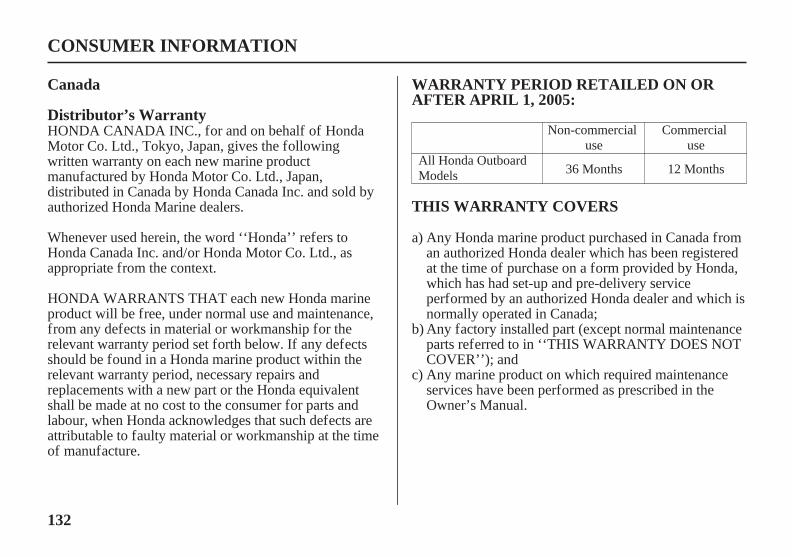
132
WARRANTY PERIOD RETAILED ON ORAFTER APRIL 1, 2005:
THIS WARRANTY COVERS
Distributor’s Warranty
Canada
CONSUMER INFORMATION
HONDA CANADA INC., for and on behalf of HondaMotor Co. Ltd., Tokyo, Japan, gives the followingwritten warranty on each new marine productmanufactured by Honda Motor Co. Ltd., Japan,distributed in Canada by Honda Canada Inc. and sold byauthorized Honda Marine dealers.
Whenever used herein, the word ‘‘Honda’’ refers toHonda Canada Inc. and/or Honda Motor Co. Ltd., asappropriate from the context.
HONDA WARRANTS THAT each new Honda marineproduct will be free, under normal use and maintenance,from any defects in material or workmanship for therelevant warranty period set forth below. If any defectsshould be found in a Honda marine product within therelevant warranty period, necessary repairs andreplacements with a new part or the Honda equivalentshall be made at no cost to the consumer for parts andlabour, when Honda acknowledges that such defects areattributable to faulty material or workmanship at the timeof manufacture.
Any marine product on which required maintenanceservices have been performed as prescribed in theOwner’s Manual.
Any factory installed part (except normal maintenanceparts referred to in ‘‘THIS WARRANTY DOES NOTCOVER’’); and
Any Honda marine product purchased in Canada froman authorized Honda dealer which has been registeredat the time of purchase on a form provided by Honda,which has had set-up and pre-delivery serviceperformed by an authorized Honda dealer and which isnormally operated in Canada;
a)
b)
c)
Non-commercialuse
Commercialuse
All Honda OutboardModels 36 Months 12 Months
11/09/14 11:19:58 31ZZ4620_133
133
THIS WARRANTY DOES NOT COVER THE OWNER’S OBLIGATION
TO OBTAIN WARRANTY SERVICE
CONSUMER INFORMATION
Any repairs required as a result of collision, accident,striking any object, misuse or lack of requiredmaintenance;Any repairs required as a result of any attachments,parts or devices installed by or repairs done by a partyother than an authorized Honda dealer;Any outboard that has been operated out of water,(Run Dry) damaging the water pump and or enginecomponents due to insufficient cooling water.Any marine products modified, altered, disassembledor remodelled;Normal maintenance services, including tightening ofnuts, bolts and fittings and engine tune-up and thereplacement of parts made in connection with normalmaintenance services including filters, spark plugs andwires, fuses, belts, lubricants and other expendablessusceptible to natural wear;Outboard propeller or shear pin.All accessories or attachments.
In order to maintain the validity of this DISTRIBUTORSWARRANTY, the required maintenance services as setforth in the Owner’s Manual must be performed at theproper intervals and detailed receipts and records retainedas proof.
You must take your Honda marine product, at yourexpense, during normal service hours, to any authorizedHonda Marine dealership. If you are unable to obtain orare dissatisfied with the warranty service you receive,first contact the owner of the dealership involved; thisshould resolve the problem. If you require furtherassistance, contact Honda Canada’s Customer RelationsDepartment at:
HONDA CANADA INC.Customer Relations Office180 Honda BoulevardMarkham, Ontario L6 0H9
TELEPHONE: 1-888-946-6329 TOLL FREEFAX : 1-877-939-0909 TOLL FREE
a)
b)
c)
d)
e)
f)g)
11/09/14 11:20:12 31ZZ4620_134

134
REPLACEMENT PARTS AND ACCESSORYWARRANTY
ENTIRE WRITTEN WARRANTY
DISCLAIMER
NOTICE TO CONSUMER
CONSUMER INFORMATION
New genuine Honda replacement parts or accessoriessold to a consumer or installed by an authorized HondaMarine dealer which are not covered by theDISTRIBUTORS WARRANTY are warranted for aperiod of one year from date of purchase, provided,however, that this Replacement Parts and AccessoryWarranty does not apply to any replacement partsmodified, used with, or installed on a marine product forwhich the replacement parts were not intended. Electricalcomponents that are not installed by the dealer (sold overthe counter) are not covered by warranty.
This DISTRIBUTORS WARRANTY and theREPLACEMENT PARTS AND ACCESSORYWARRANTY are the only and the entire writtenwarranties given by Honda for Marine engines. No dealeror his agent or employee is authorized to extend orenlarge on these warranties on behalf of Honda by anywritten or verbal statement or advertisement.
To the extent the law permits, Honda disclaims anyresponsibility for loss of time or use of the product,transportation or towing costs or any other indirect,incidental or consequential damage, inconvenience orcommercial loss.
The provisions contained in these written warranties arenot intended to limit, modify, take away from, disclaimor exclude any warranties set forth in or the operation ofThe Consumer Products Warranties Act, 1977(Saskatchewan), The Consumer Product Warranty andLiability Act (New Brunswick), The ConsumerProtection Act (Quebec), or any other similar provincialor federal legislation.
11/09/14 11:20:21 31ZZ4620_135
135
INDEX
...........................................Alternator (ACG) Indicator . 33...........................................................................Anodes . 38
..............................................................Replacement . 87.............ARE YOU READY TO GET UNDERWAY? . 39
.........................................................................Battery . 112......................................................Will Not Charge . 104
................................................BEFORE OPERATION . 39...........................................BREAK-IN PROCEDURE . 42
....................................CLEANING AND FLUSHING . 90.........................................................Common Controls . 30
........COMPONENT AND CONTROL LOCATIONS . 14.................................CONSUMER INFORMATION . 120
CONTROL AND FEATURE IDENTIFICATION......................................................................CODES . 13
..................................................................CONTROLS . 20..................................CONTROLS AND FEATURES . 13
..............................................Cooling System Indicator . 35....................................................................CRUISING . 61
....................................Customer Service Information . 120
Digital Speedometer............[optional equipment (LRT and XRT types)] . 32
Digital Tachometer............[optional equipment (LRT and XRT types)] . 31
...................................Distributor’s Limited Warranty . 123................................................Distributor’s Warranty . 132
................................Electric Starter Will Not Operate . 104EMERGENCY
......................................................STARTER ROPE . 69...............................................................STARTING . 52
Emergency Stop Switch Clip and Emergency StopSwitch
...................................................LH and LHT Types . 20.........................................Side-Mount Control Type . 25
.......................Emission Control System Information . 112............................Emission Control System Warranty . 128
EngineCover
...............................................Latches (front/rear) . 30...................REMOVAL AND INSTALLATION . 73
Oil...................................................................Change . 75
..........................................................Level Check . 74.................................................Recommendations . 77
.........................................................OVERHEATS . 103..................................................WILL NOT START . 99
11/03/10 14:41:09 31ZZ4620_136
136
INDEX
Ignition Switch...................................................LH and LHT Types . 20.................................................LRT and XRT Types . 24
....................IMPORTANT SAFETY INFORMATION . 7...............................................................INDICATORS . 33
...................INFREQUENT OR OCCASIONAL USE . 46...........................................................INSTRUMENTS . 31
IS YOUR OUTBOARD MOTOR......................................................READY TO GO? . 39
................................NMEA INTERFACE COUPLER . 37
.........................................MAINTENANCE SAFETY . 68...................................MAINTENANCE SCHEDULE . 70
..................................MANUAL RELIEF VALVE . 29, 73...................................................Malfunction Indicator . 33
...................MOORING, BEACHING, LAUNCHING . 65
.........................................................Lubrication Points . 79
..........................Gearshift Lever (LH and LHT Types) . 22Gearshift/Throttle Control Lever
..............................................(LRT and XRT Types) . 26.........GEARSHIFT AND THROTTLE OPERATION . 58
HARD STARTING OR STALLS AFTER.............................................................STARTING . 102
....................HOISTING THE OUTBOARD MOTOR . 96.....................................................Honda Publications . 120
...............................................................Fast Idle Lever . 27Fuel
Filler Cap Vent Knob[standard equipment (Canadian types)],
............[optional equipment (American types)] . 37.........Filter/Water Separator Inspection and Service . 83
Gauge [standard equipment (Canadian types)],................[optional equipment (American types)] . 32
...........................................HOSE CONNECTIONS . 44..................................................................PRIMING . 45
.............................................................Priming Bulb . 37..........................................RECOMMENDATIONS . 82
.......................................................Fuse Replacement . 105.........................................................................FUSES . 104
11/03/10 14:41:17 31ZZ4620_137

137
INDEX
....................................................Oil Pressure Indicator . 34OIL PRESSURE INDICATOR GOES OFF AND
..............................ENGINE SPEED IS LIMITED . 106................................................................OPERATION . 42
....................................................OTHER FEATURES . 36...................................OUTBOARD MOTOR SAFETY . 7
.........................................................Overheat Indicator . 35OVERHEAT INDICATOR COMES ON AND
..............................ENGINE SPEED IS LIMITED . 107.............................................................Overrev Limiter . 36
........................SAFE OPERATING PRECAUTIONS . 42....................................SAFETY LABEL LOCATIONS . 9
.............................................Serial Number Locations . 111..............SERVICING YOUR OUTBOARD MOTOR . 67
............................SHALLOW WATER OPERATION . 63
........................................................Spark Plug Service . 77..............................................................Specifications . 117
....................................................................Star Label . 115..........................................STARTING THE ENGINE . 46
...................................................LH and LHT Types . 46LRT and XRT Types
.....................................Side-Mount Control Type . 49.........Steering Friction Adjuster (LH and LHT Types) . 22
....................................................................STEERING . 60...........................................STOPPING THE ENGINE . 55
.....................................Emergency Engine Stopping . 55...........................................Normal Engine Stopping . 56
....................................................................STORAGE . 93..................................................................Engine oil . 96
............................................................................Fuel . 93........................................STORAGE PRECAUTIONS . 96
.....................SUBMERGED OUTBOARD MOTOR . 109
.................................................................REFUELING . 80...................................REMOVAL FROM STORAGE . 97
PORTABLE FUEL TANK[standard equipment (Canadian types)],
..........[optional equipment (American types)] . 36, 44...........................................and Tank Filter Cleaning . 86
....................................Power Tilt Switch (engine pan) . 28................................................Power Trim/Tilt Switch . 28
..................................................Propeller Replacement . 88
11/03/10 14:41:23 31ZZ4620_138

138
INDEX
Tachometer [standard equipment (Canadian types)],......[optional equipment (LRTA and XRTA types)] . 31....TAKING CARE OF UNEXPECTED PROBLEMS . 99
.................................TECHNICAL INFORMATION . 111...............THE IMPORTANCE OF MAINTENANCE . 67
Throttle....................Friction Adjuster (LH and LHT Types) . 22
........................................Grip (LH and LHT Types) . 21Tiller Handle Height/Angle Adjustment
................................................(LH and LHT Types) . 41..............................................................Tilt Lock Lever . 30
........................TOOL KIT and OWNER’S MANUAL . 69........................................................TRANSPORTING . 98
WITH OUTBOARD MOTOR INSTALLED.............................................................ON BOAT . 98
WITH OUTBOARD MOTOR REMOVED.......................................................FROM BOAT . 98
Trim Meter [standard equipment (Canadian types)],......[optional equipment (LRTA and XRTA types)] . 31
........................................................................Trim Tab . 30........................................TRIM TAB ADJUSTMENT . 72
...................................................Warranty Statements . 123
11/09/14 11:20:46 31ZZ4620_139

139
MEMO
11/03/10 14:41:29 31ZZ4620_140

140
MEMO
11/03/10 14:41:31 31ZZ4620_141

PANTONE 288 CVC DIC F101 BLACK BF40D-50D_AH-OM表紙31ZZ4621BF40D-50D_AH-OM表紙31ZZ4621BF40D-50D_AH-OM表紙31ZZ4621背幅4mm背幅4mm背幅4mm
Includes US and Canadian ModelsUS:K2
C:K3英 N HCAHEM331ZZ4621
00X31-ZZ4-62101000.2011.10
Printed in China