
IITRI Project J6324 Final Technical Report IITRI J-TR-74-6324 ...
402
IITRI Project J6324 Final Technical Report IITRI J-TR-74-6324 THERMAL MODEL OF LASER-INDUCED EYE DAMAGE Contract F41609-74-C-0005 October 8, 1974 Approved for public release; distribution unlimited.
-
Upload
khangminh22 -
Category
Documents
-
view
5 -
download
0
Transcript of IITRI Project J6324 Final Technical Report IITRI J-TR-74-6324 ...

IITRI Project J6324
Final Technical ReportIITRI J-TR-74-6324THERMAL MODEL OF LASER-INDUCEDEYE DAMAGE
Contract F41609-74-C-0005
October 8, 1974
Approved for public release; distribution unlimited.

*11
dvanced concepts are being used by UIT Research Institute tosolve research, development, and design problems for industry andgovernment through contract research. Our services encompass
- . • virtually all of the physical and biological sciences. Principal areas: are: chemistry, computer sciences, electronics, engineering me-
chanics, life sciences, mechanics of materials, medical engineering,* . metals, and management and social science research.
The interdisciplinary approach at IITRI brings the latest technologyto bear upon the problem-solving process.
Principal office:10 West 35th StreetChicago, Illinois 60616

Engineering Mechanics DivisionlIT Research Institute10 West 35th StreetChiqfo, Illinois 60616
IITRI Project J6324
Final Technical ReportIITRI J-TR-74-6324THERMAL MODEL OF LASER-INDUCEDEYE DAMAGE
Contract F41609-74-C-0005
October 8, 1974
Approved for public release; distribution unlimited.
Prepared by
A. N. TakataL. GoldfinchJ. K. HindsL. P. Kuan 9A viThN. Thomopoulis .
A. Weigandt
for
Aerospace Medical Division (AFSC)Brooks AFB, Texas 78235

UNCLASSIFIEDSECURITY CLASSIFICATICN Or T1 5 PAGE 'Who-, neit. 1.-'1..dl
READ INSTRUCTIONSREPORT DOCUMENTATION PAGE BEFOREt COPLETNUC FORM
I. REPORT NUMBER . GOVT ACCESSION, --. ,ý A
IITRI-J--TR-74-6324) ______
i, " 't."iT L Ct' .d S .,b,,lU•... ..)- :.. . . . ,r,•o €o •• .
-..... .........-... ... .. ....... . Final flep~ t-THERMAL-MODEL OF LASER-INDUCED EYE DA14AGE. Octr'9 7 3 - Sept 74,
- j ,r~ 4~~ ~ ING '3AG. REPORT MUMOCR
IITRI-J63249. COI.TACT OR GRANT %IMSER(.J
A. N. Takata. L. P. 'uan
L. 'Goldfinch, N./Thomopoulis F416d974C-lc05J. K./Hinds. A," Weigandt
9,-'ERXPOIkew -OOIRGANIZATION NAME AND AOORESS 10. PROGRAM ELEMENT. PROJECT. TASK
Engineering Mechanics Division AIREA A WORK UpNIT UMsErS
liT Research Institute 62202F60 West 35th Street
Chicago, Illinois 60616 6301-00-48ti. CONTROL.LLNG OFFICE NAME ANDI ADDRESS I.. HEPOlqT OATE
USAF School of Aerospace Medicine (RAL) September 197T'Aerospace Medical Division (AFSC) rt. e o, psES
Brooks Air Force Base, Texas 78235 398
14 Unclassified
Co~,i'.'U16.. SECURT LASS . (AIO 'ol thi RA.p N G
~.- .~SCHEDULE, -ig75YNI3.1 W1AYEME. .-"- / t•" ,- S/ |. OI L ASSFIlC ATI ON OOWN GRNADi NG•CI~
Approved for Public-_r-elease; distribution unlimited.
.' /II~t-DIST*I6U1Th 1W'1fTfTA MEN T (of the .baI,.et .. ,t...d #A Stock 20. It ElflIrv.A, I, 00-0916ft j- .
IS. SUPPLEMENTARY NOTES
IS. KEY WOROS (ConiImue on fevcrso side if nII , .fry and Identify by. block ntber)
Ocular DamageLaser Effect3Thermal ModelTemperature Rise PredictionRetinal, Corneal, Lenticular Damage
20. ABSTR ACT (CoIfn. on ,.",so aide II necem-y amd Identify by block number).
-& This report describes the development of computerized mcdels forpredicting the temperatures and thermal damage (protein denaturation)caused by the exposure of eyes to laser beams. The extent of thermaldamage or the threshold level for thermal damage may be predictedeither for the. cornea, lens or retina of the eye -- wherever theenergy deposition is greatest. Included- n the report,>is (continued)`
DD I ro.-.,.. 1473k• EOITO, Or I NOV 65 IS OBSOLETE,.CASE SUNCLASSIFIED•I[CUiRITY CL.ASSIFIlCATION 0 y THIS PAGE r74.nDlat Fn..nIerl • e
I ,1 / '-, '"-. • .... ,-

UNCLASSIFIEDSECURITY CLASSIFICATION OF TmIb PAGEOw(hn Data Fnferd)
Item 20. continued r
'-•a description of the models and data for predicting the ithermaldamage to monkey and human eyes for known laser exposures.
Model predictions were found to be in reasonably good agreementwith experimental results for pulse durations ranging from about-10-J see to- -•-•Hwever, major discrepancies arise with pulsesess than-abo 7 ;sec. With such short pulses, the predicted
temperature rises are much too small to cause thermal damage.Therefore, some other damage mechanismppears responsible for thedamage caused by the very short pulse. At present, the mechanismof damage has not been id(,Tified. A
c • / Jt T•
UNCLASSIFIEDSECURITY CLASSIrICATION OF YWIS PAGEIW en Date Fm,-ýd)

PREFACE
This report describes the development of the Corneal and
Retinal models for predicting the temperature rises and thermal
damage produced in the eye by laser exposures. IIT Research
Institute personnel involved in the program were A. N. Takata, iL. Goldfinch, J. K. Hinds, L. P. Kuan, Y. Shikari and A. Weigandt.
The project monitor was Capt. D. Egbert of the AMD School of
Aerospace Medicine's Radiobiology Division, Laser Effects Branch
(SA14/RAL) at Brooks AFB, San Antonio, Texas.
Work presented in this report represents the combined efforts
of IITRI with various Brooks AFB personnel. Particularly notable
is the excellent guidance and support efforts provided by Dr. Ralph
Allen and Capt. David Egbert of Brooks AFB.
I
£.

TABLE OF CONTENTS
Pa ge
I 1. INTRODUCTION 1
2. LITERATURE 6
1 3. OPTICAL STUDIES 7
3.1 Irradiance Profiles Produced byRefraction of Laser Beam by Cornea 8
3.2 Retinal Image 10
13.3 Check of Optical Analysis 12
4. THERMAL STUDIES 15
j4.1 Grid System 15
4.2 Energy Deposition 17
* 4.3 Use of Implicit Explicit Alternating DirectionTechnique for Predicting Transieuit Temperatures 17
4.4 Blood Flow 19
4.5 Melanin Granules 20
4.6 Typical Temperature Rises
i 5. DAMAGE CRITERIA 25
5.1 Thermal Damage 25
5.2 Mechanical Damage 26
6. OPTICAL, TFHERMAL, AND LESION DATA 27
6.1 Optical Properties Associated with the Eyes"of Man and the Rhesus Monkey 27
4 6.1.1 Absorption and Reflection Coefficients 27I 6.1.2 Index of Reflection 33
6.2 Thermal Property Data 33
6.3 Thicknesses of Eye Media 34L
6.4 Experimental Ocular Threshold Data 5
7 COMPUTER CODES 407.1 Retinal Model 41
* 7.1.1 Main Program for Retinal Model 41 !
"* 7.1.2 Subroutine Grid for Retinal Model 55
7.1.3 Subroutine Image of Retinal Model 57
1i:i i

TABLE OF CONTENTS (contd)
7.1.4 Subroutine HTXDEP of Retinal Model 60
7.1.5 Subroutine MXGRAN of Retinal Model- 63
7.1.6 Subroutine BLOOD of Retinal Model 667ý2 Corneal Model 68
7.2.1 Main Program for Corneal Model 68
7.2.2 Subroutine GRID for Corneal Model 82
7.2.3 Subroutine IMAGE of Corneal Model 33
7.2.4 Subroutine HTXDEP of Corneal Model 86
7.2.5 Subroutine MXGRAN for Corneal Model 88
7.3 Description of Code for Preparing2D and 3D Illustrations 88
8. MODEL PREDICTIONS, AND SENSITIVITY AND ERROR ANALYSES 89
8.1 Model Predictions of Laser PowerNecessary to Cause Given Lesion Sizes 89
8.1.1 Predictions of Corneal Damage 89
8.1.2 Predictions of Retinal Damage 93
8.2 Sensitivity Runs 94
8.2.1 Corneal Model 95
8.2.2 Retinal Model 100
8.3 Assessment of Frequency Distributionof Errors Associated with Predicted Laser Power 101
9. SUMMARY AND CONCLUSIONS 108
9,1 Consequence of Parametric Errors 108
9.2 Comparison of Model Predictionswith Experimental Data 109
9.3 Problem Areas 110
REFERENCE S il
APPENDIX A - Computational Scheme for Predicting Eye Temperatures
APPENDIX B - Thermal Effects Caused by Blood FlowAPPENDIX C - Decay of Normalized Temperature Rises
of Melanin Granules with Time
APPENDIX D - Assessment of Temperatures Caused by Multiple Pulses"Using Single-Pulse Temperaturc Predictions
"APPENDIX E - Choice of Time Intervals
iv

I
TABLE OF CONTENTS (concl)IAPPENDIX F - Heat Deposition Analyses
1APPENDIX G - Optical Properties of Eyes of Man and Rhesus Monkey
APPENDIX H - Retinal Irradiance Profile
APPENDIX I - Grid System
APPENDIX J - Measuring Uncertainties in Predicted Laser Powersto Cause Damage
APPENDIX K - Nomenclature, Sample Data, Code Listing,- and Sample Run for Retinal Model
APPENDIX L - Nomenclature, Sample Data, Code Listing,and Sample Run for Corneal Model
4 APPENDIX N - User Manual for Preparing 20 and 3D Illustrations
of Temperature Rise Profiles
APPENDIX N - Literature Bibliography
vm
* i ,
* I
1~1
-- I

LIST OF FIGURES
Figure Page
I Schematic Illustration of PrincipalComponents of Eye 5
2 Nomenclature for Determining Laser Profileafter Corneal Refraction 9
3 Schematic for Evaluating W 13
4 Grid System Used by Corneal and Retinal Models 16
5 Decay of Normalized Temperature Rises of MelaninGranules Following an Instantaneous Deposition ofEnergy 21
6 Axial Temperature Profiles at End of Single Pulses 23
7 Radial Temperature Profiles at End of Single Pulses 24
8 Schematic Illustration of Principal Routinesof Retinal Model 42
9 Flow Diagram of Main Program of Retinal Model 43
10 Schematic Illustration of Principal Routinesof Corneal Model 69
11 Flow Diagram of Main Program of Corneal Model 70
12 Frequency Distribution of Errors in Predicted Powerfor Cornmeal Model for Beam Size of 0.0350 cm 103
13 Frequency Distribution of Errors in Predicted Powerfor Corneal Model for Beam Size of 0.0250 cm 104
14 Frequency Distribution of Errors in Predicted Powerfor Retinal Model for Beam S,.e of 0.0300 cm 105
15 Frequen-.y Distribution of Errors in Predicted Powero-or Retinal Model for Beam Size of 0.0025 cm 106
Vi]44
" ~~vi •

I
> LIST OF TABLES
STable Page
I Physiological Parameters Requiredfor Optical Analysis 14
2 Comparison of Predicted and ExperimentalRetinal Image Radii for Gaussian Laser Profiles 14
S3 Summ-iry of Optical Data for Retinal Model(Rhesus Monkey) 28
4 Summary of Optical Data for Retinal Model(Caucasian) 29
5 Summary of Optical Data for Retinal Model(Negro) 30
6 Absorption Constants for Water 31
7 Index of Refraction Versus Wavelength for Water 33
8 Thickness of Eye Media 34
9 Experimental Data for Retinal Damagej in Rhesus Monkey Eyes 36
10 Experimental Data for Corneal Damagein Rhesus Monkey Eyes 39
1. 11 Comparison Between Computer and ExperimentalLasur Powers (Total) and Lesion Sizes
SPAssociated with Corneal Damage 90
12 Comparison Between Predicted and ExperimentalLaser Powers (Total) to Cause Specified Lesionson Retina 91
13 Effect of Varying Individual Parameters on TotalLaser Power to Initiate Corneal Damage for Four
* Different Laser Exposures (X 2727 nm) 96
14 Effect of Varying Individual Parameters on TotalLaser Power to Initiate Retinal Damage for FourDifferent Laser Expnstxrei 0 = 1060 nm) 97
1 15 Rates of Thermal Damage Vorsus Temperature 99
16 Confidence Intervals Associated with PredictedLaser Power 102
I L
vi L

THERMAL MODEL OF LASER-INDUCED EYE DAMAGE
1. INTRODUCTION
This is the final report of the contract entitled "Thermal
Model of Laser-Induced Eye Damage" and covers the work performed
by lIT Research Institute (TITRI) from October 1973 through qep-
tember 1974. The principal objective of the program was to select
and develop mathematical models for predicting eye damage caused
by exposure to lasers. The laser exposures of concern involve
various wavelengths, beam geometries and intensities, as well as
pulse lengths, number of pulses, and repetition rates. Predlic-
tions of eye damage involve either threshold lesions or the extentof damage. These capabilities were achieved by
e Reviewing the literature for pertinent
- thermal and optical analytical techniques- optical and thermal property data- experimental temperature and damage data
e Developing a model (Retinal model) for pre-dicting temperatures and damage in and aboutthe retina
a Developing a model (Corneal model) for pre-dicting the temperatures and damage to thecornea and lens
e Checking models by comparing predictionsagainst experimental data.
* Assessing sensitivity of predictions to inputvariables
a Evaluating consequences of estimated errorsin input variable-S on total laser power nec-essary to cause eye damage
These models allow for variations in laser exposures described
in terms of
* wavelength
* pulse durationa repetition rate
@ number of pulses
-~ I I

Ait
e beam profile
a laser power on the cornea
* beam divergence
Major assumptions used to develop the models are:
9 simulation of eye geometriesby polar coordinates
* use of retinal image at all depthsof the eye in the Retinal model
o all reflected radiation consideredto move along axial directions
* use of rates of damage pertainingto skin for retinal, corneal andlens damage
* radiation is coheient and defocuscan be calculated via geometric optics
A summary of the model capabilities is presented below:
Input
1. User inputs thermal, optical, and physiologi.calproperties of desired layers for human or monkey
2. User specifies beam characteristics, at the cornea(or at the retina if desired): total power, beamdiameter, divergence (or the distance from thenearest beam waist)
3. User specifies the range of spatial coordinatesfor damage calculations, printouts of temperaturerise histories arid/or 3D plotting of temperature rises
Output
1. Damage thresholds at specified spatial coordinates
2. Prediction of the extent of damage for input poweras a function of depth and radius
. 3. Prediction of temperature-rise time histories as a*F.. function of depth and radial position
4. Prediction nf thresholds For preselected peaktemperature rises in the pigment granules
5. 3D or 2D plots of temperature rises
- 6. Retinal image distribution calculated by opticalroutine
2

Innovations Compared co Original Tech. Inc. Model
(Refs. 1, 52) . .
1. Damage is predicted by integrating a damage ratefunction over the time history of the temperaturerises of selected points to determine their thresholdlevels and then the extent of damage
2. Possible to validate model predictions with thres-hold, extent of lesion and temperature measurements
3. Automated optimum selection of temporal and spatialgrid elements, their extent and configuration forinput physiological and beam parameters, to includeautomated handling of repetitive pulse exposures
4. Optical routine available to predict retinal orlenticular beam characteristics based on beam de-scripton at the cornea and distance of the lastbeam waist
5. Blood flow in chorio-capillary and surroundingtissue incorporated into heat flow - temperaturerise calculations
6. Granular structure provided in pigment epitheliallayer to simulate the melanin granule absorption.The same structure is available but not used forthe cornea
7. Able to adjust the position and thickness of themelanin granule structures within the PE to accom-modate simulation of both human and monkey retina
8. Simple selection of spatial coordinates for tem-perature rise history and threshold predictionsoutput
9. Documented collection of appropriate thermal, optical,and physiological parameter values necessary todetermine damage to human aid monkey eyes.
10. Calculated predictions comparable with representativethreshold data for retina and cornea
.- 11. Can run a number of test exposures at once where pulserepetition rate and numbers of pulses (or train length)can be varied
"In the remainder (ýf this report all aspects of the develop-
ment of computer codes for the thermal models are discussed and acomparision is made between predictions with experimental results.
Detailed analytical studies and information are included in appen-
dices as well as documentation of a code developed by IITRI for
preparing 2D and 3D illustrations of the temperature rise profiles.
3
Figure 1 illustrates principal components of the eye. Except
I for the pigment epithelium and the underlying chorio-capillaris,
all components have relatively subtantial thicknesses. Periodi-
cally within this report, we shall refer to these eye media.
4
, Ji

A
I
. ~ Z.9 . ',04•
I 0
E.-4
0
I ""P4
"°' Q
a14
1 -4
I "
-,4 ,
44
* 'Oh. (5

2. LITERATURE
I Before formalizing the computer codes, the literature was
searched for means and information with which to base the models.
SI This literature search pertained to
e Schemes for predicting laser deposition ofenergy within eye
• Schemes for predicting the transfer of heatwithin the eye by heat conduction or the
j flow of blood
* Thermal and optical property data for humanand animal eyes
a Experimental laser-induced temperature andthreshold damage data -Wiith which to checkand refine predictions
The literature study involved searching for recent articles
of interest and using the resultant lists of references to identify
earlier articles. All reference titles have been placed on compu-
ter cards to speed revision and listing of articles pertaining to
important subject areas. The result is the list of references
shown in Appendix N, arranged according to the following subjects:
* thermal models
* optical models
* thermal. properties
e optical properties
e blood effects
a threshld damage criteria* experimental temperature data
* experimental damage data
e melanin granules
e miscellaneous
A very significant portion of the models is based on informa-
tion found in the literature as well as that provided by SAM/RAL of
Brooks Air Force Base.
6

£ 3. OPTICAL STUDIES
I Due to differences in the absorption constants of the various
media of the eye with wavelength, there are considerable differences
in the location3 at which the lasers deposit their energy withinthe eye. Peak depositions may occur either in the cornea, lens or
retina. For this reason, two models were developed -- one for
retina damage (Retinal model), and one for cornea and lens damage
(Corneal model).
In each model, the optical calculations are initiated by a
determination of the refraction of the laser beam by the cornea.The result is a description of the irradiance as a function of
radius and depth from the anterior surface of the cornea to the
i I pupil and beyond. The resultant irradiance profile is thenused directly by the Corneal model with appropriate provisions
"for absorption and reflection to assess the rate of energy depo-
"sition in the cornea, aqueous humor, lens and vitreous humor.
On the other hand the Retinal model utilizes the above analy-
"sis to assess the irradiance profile at the pupil of the eye.
This profile is then used by the optical analysis described in
-" Section 3.2 to determine the retinal profile. The resultant ir-
radiance distribution of the retinal image is preserved at all
depths of the eye and tissues analyzed by the Retinal model. Each
model will accept any symmetric laser profile at the cornea. This
includes uniform, gaussian or irregular profiles.
In the Retinal model, the usur has two options for the irradi-
ance profile at the retina. The first is to calculate the irradi-
ance profile using parameters describing the incident laser beam
and the eye; while the second is to use experimental measurements
of the profiles. Similarly, two options are provided in the Corneal-
model, depending on whether one wishes to assess cornea or lens
damage. In order to ensure accurate burn predictions, each
model concentrates the finer mesh grid in the region of the eye at
which the greatest temperatures and temperature gradients are anti-
cipated.
7I'-_ _ _ _ _ _ _ _ _

.1 iIn the remainder of this section we shall discuss means for
calculating irradiance profiles from the cornea to the lens. Then Iwe shall discuss imaging the laser beam onto the retina accounting
for spherical and chromatic aberrations.
3.1 Irradiance Profiles Produced by
Refraction of Laser Beam byCornea
Laser beams can be reduced in diameter by as much as a factor
of 1.2 in traveling from the cornea to the lens due to refraction
by the cornea. This can cause an appreciable increase in the peakirradiance incident upon the lens and thereby increase the possi-
bility for lens burns. Also,if the beam is appreciably reduced in
size at the pupil, significant changes can occur in the retinal
image.
The first step in analyzing the effect of the cornea on the
beam is to determine the imaginary depth at which the beam would
be focused solely by cornea. This depth exceeds the depth of the
retina as illustrated by Fig. 2. The depth z, shown in this figure
is given by
zf = n-z.'f /(n'zo "fc)i•
subject to the condition that n.zo>fc, where
f = focal length of cornea
n index of refraction of ocular media
z. distance between laser's waist and pupil
Here zo mny be. approximated hy dividing thL beam diameter at the
cornea by the total beam divergence expressed in radians. More
accurate determinations of z. require measuiements of the width
* ~of the bea,, at 2 or more axial locations. The above condition has
been found to hold for all AFSC experiments to date.
-- To determine the irradiance profiles between the ,ornea and
lens, we shall neglect the curvature of the cornea and utilize
linear interpolation based on the triangle formed by the two en-
trance points and the imaginary focal point. Here it is readily
8

0U p.4
UU '-4
U
.rJ.4 0I HI QI'
I'I'
4-� H4mI
0
II
H�L4
I4-.'
0
4 p.4
Q
I HIzHI
0
1* z
4
1 (NJ
1..0
U s-I0) Ia)I U) Cd,
2 CuI9
(�. -

I seen that incident rays at a radial distance r are displaced toradial distances C-r upon entering the eye where P, depends on
the depth z as follows1= - z/zf (2)
I This means that a laser profile of P (r) at the surface of thecornea will assume a shape P c(r/•) upon entering the eye, where
C>0. Moreover, conservation of energy for the case of no absorp-
tion requires that the total power in the incident beam equals
j that of the refracted beam. Thus, if the refracted beam is des-
cribed by C' • P (r/ý), thenC
c(r)' 2 .w.r dr C'. PC (r/C).2.i.r dr (3)
. c'.ý 2 P,(r').2.fr.r' dr'
so that the constant C' is given by
C' = I/2 (4)
Based on the above, the irradiance P(rz) at points r,z is given
by
P(rz) = Pc(r/O)/M2 (5)
Thus to determine the profile at a depth z, one first evaluates
zf and • using Eqs. 1 and 2, and then substitutes the resulting
value for - into Eq. 5.
3.2 Retinal Image
The first step in computing the distribution of the irradiance11(r) at the retina is the determination of the profile Pp(r) at the
ppupil plane given by
I Pp( r) P Pc(r/•)/•2 (6)
where
I. p= distance of pupil from cornea (see Fig. 2)
1 10

The normalized irradiance at the retina is then given by (Appendix H)
H dpfI f iPP
where °a - pupil radius, cm
f' - fo - p
f. - second principal focal length at areference wavelength of -A
F1 (p) - function accovnting for defocusing (chromaticand geometric)
F 2 (p) - function accounting for spherical aberration
J. - zero order Bessel function of first kind
p - distance of pupil from second principal plane, cm
r - radial distance in retinal plane, cm
' - wavelength, run
p - radial distance in pupil plane, cm
In Eq. 7 the functions FI(p) and F2(p) are given by:
F l (p) - exp (i'C 0.p 2 ) (8)
F 2 (p) - exp (L'C 2 "p4 ) (9)
while the constants C. and C2 are given by
= 2Ln 2-n [-f' - •z.(l-cosa) + (f,) (10) s a
c2 -3-06/x
wherea = angle between the refracted beam at the
cornea and the axis of the eye
n - index of refraction at wavelength A
p - distance of pupil from second principal plane
z0 - distance of pupil from waist of laser beam, cm
The incremental distances W and Az, the angle c%, and the focal
length f are illustrated in Fig. 3. The distance W is expressed
I by Eq. 10 while cx, Az and f may be obtained from the followingequa tions:
Sf =f." n(n,,'l)/no(n-l) (11)
1 tan cI = a/(f' + Az) (12)
z n .z0 .f /f- -fo f- (13)
t.• whe ref = focal length at laser's wavelength, cm
n = index of refraction at a reference wave-" 0 ° length K0, cm
Constants required for the optical analyses are presented
in Tables 1 and 7.
3.3 Check of Optical Analysis
To ensure a comprehensive check of the optical analysis,
eight experiments were chosen representing a wide variety of con-
ditions. Experimental, and predicted results for the :image radius
(i/e2 point) are given in Table 2.
,C.
Ii
112iN

F-
I4~ý
I4 CA
II b H
-in1 <x
OU'dTdplpa

TAB U, I.
PHYSIOLOGICAL PARAMETERS
REQUIRED FOR OPTICAL ANALYSES (derived from Ref. 17)
IPa rame te r Values of Parameters, cmaHuman Eye Monkey Eye
I -a 0.35 0.35
fo at ?~500 11m) 2.24 1.68
p 0.135 0.12f3.12 2.43
PC 0.31 0.29
TABLE 2
COMP~ARISON OF PREDICTED AND EXPER1hIINALIRETINAL IM4AGE RADII FOR GAUSSTAN LASER PROFILES
Iryi~ RadisRun Beam Radius at z0 .1cm ?ý,m le Radits,cmNumber* cornea (lie2
Points) , cm Exp. Calc.
11 0.135 270. 530.0 .0025 .0013
*51 0.075 118. 514.5 .0025 .0009
52 0.380 600. 514.5 .0025 .0009
59 0.144 533. 520.8 .0025 .0009
*60 0.124 310. 647.1 .0025 .0024
61 0.125 12.8 647.1 .0140 .0179
K64 0.125 7.50 647.1 .0225 .0288
66 0. 125 3.17 647.1 .0525 .0523
*See Table 9 for a descriptioni of experiments.
From a comnparisoii of the experimental nnd calculated image
I radii, one can see that all five predictions of the radii of: the
smialler experimntcnal image~s arc less than their experinental counter-
I parts of 25 pmn. The source of this discrepancy is not known. Veryappreciable changes in the constant C 2 (which could be in error by
j as mauch as 50 percent) had a negligible effect on thc small images.
1 14

4. THERMAL STUDIES
In this section we shall review means for calculating the
deposition ana transport of heat starting with a knowledge of the
laser's profile within the eye which has been covered in Section 3
and Appendix H. Each model
* selects the grid network for predicting thedeposition and transport of heat which con-sists of a network of points located at vari-ous radii and depths,
e computes the deposition rates of energy perunit volume at each of the grid points,
* computes the transport of heat by thermalconduction.
In addition the Retinal model
* computes the absorption and transport ofheat by blood flow
* computes the temperature rises of melaningranules in the pigment epithelium (PE)
4.1 Grad System
The grid system chosen for performing the temperature calcula-
tion is shown in Fig. 4. Here the front of the eye is located
at the left-hand side of the network while the axis of the eye
is located at R(1=0. In each model, the fine portions of the
' grid are located at regions of greatest temperature rise. In the
* •Retinal model this region would be at the retina while in the
Corneal model the region would either be in the cornea or lens
depending on where the temperatures are greatest. Within the
finer grid, each of the spacial steps DR and DZ are uniform.
Beyond this region the spacial increments are sequentially in-
Screased by the constant factors RI and R2 as illustrated belowZ (i+l)-Z (i) F • (71(i)-Z(i-l)) ( 4
R(j+l)-R(j) = R2 (R(j)-R(j-I))
The choice of a constantly expanding network away from theregion of hi.ghest temperature was made to conserve on computational
time. Ln addition the size of the smallest elements was varied
according to the magnitude of the anticipated temperature gradients.i1

~Lr4+ 4
I" w -
4r-
U)iii
t_
9 ->4
________________________ - ____ - ______-
- -.-rI
A'
IP4IS~
V~~jI Sj,-o LTq T T U
__H
10 __o
16_ __
-

I F3 In this regard the spacial increments are increased in size with
the pulse duration. Moreover, in the Corneal model the increments
1 are decreased w4th increased absorption coefficients. A detailed
description of ":•e means used to arrive at tl-e grid system is given
j in Appendix I.
4.2 Energy Deposition
I Having established che shape of the laser beam within the eye,the next problem is to del.eri:Lne where the laser's energy is de-
Sposited within the eve. With this purpose in mind six differenteye media are provided in each madel. These eye media are distin-
guished according to:
* thicknesses
* absorption coefficients
o total reflections at the various interfaces IAll reflected radiation is considered to move in axial direc-
tions. Multiple reflections are considered of secondary importanceand neglected. Energy deposition is computed using Lamberts Law at
"the various grid points described in the previous section. The de-"position of energy is considered to be uniformly dispersed throughout
-- each spaclal increment. A description of the means used to calculatethe rates of energy deposition is presented in Appendix F.
"- 4.3 Use of Implicit Explicit Alternating Direction Techniquefor Predicting Transient Temperatures
I'. Temperature predictions for single pulses are made using the
scheme developed by Technology, Inc. (Refs. 1,52). This scheme isbased on the work of Peac,.man (Ref. 9) and evaluates the consequence
of heat conduction using finite-difference solutions of parabolicequations. This is accomplished by solving the finite-difference
equation explicitly in z (axial direction) and implicitly in r"(radial direction) for odd time steps; and implicitly in z and
"explicitly in r for even time steps. The implicit representation
of the thermal gradients involves using future temperatures while
the explicit representation of the thermal gradients involves using
existing temperatures. The result is two sets of equations which
I are solved using ordinary matrix algebra.
S. 17

The primary advantage of this method is that the time steps
may be one or more orders of magnitude larger than those required
3 by standard explicit methods. Solutions are stable provided the
time steps are not excessively large during periods of sudden
changes in the deposition of energy, such as at the start and endof a pulse. To ensure accurate temperature predictions, the time
steps and spacial steps must be chosen consistent with the thermal
I gradients (See Appendix E). This finite-difference technique is
used to predict temperature rises at specific locations of the eye
I during and following a single pulse.
In order to minimize the execution times of the computer codes,
Sit is important to use the largest time intervals possible consist-
ent with accurate temperature predictions. For this reason an anal-
ysis was conducted to establish how these time intervals should be
chosen. This analysis is described in Appendix E and indicates
S] that progressively larger time intervals may be used as the tempera-
ture gradients diminish with time. As shown in Appendix E these
time intervals may be increased sequentia.ly by a factor XC as
.• illustrated below:
• Atk+I XC.Atk (15)
where the first time interval AtI should be chosen such that it
is of the order of the times required by purely explicit finite-difference s01ut-ions and the-factor XC may assume values from 1
to 1.4 (See Appendix E).
The above technique for computing the time intervals guards
T against excessively large errors that may not be obvious to the4. user in that the .9iternating-direction, implicit, explicit tech-
T nique is usually stable even for excessively large time steps.
A major limitation of using constantly expanding time stepsi o occurs when one considers multiple pulses. Direct alplication of
the method to multiple pulses would require regular time steps
during each pulse. Use of regular time steps throughout the expo-sure will cause enormous computational times because of the rel-
atively large times between pulses. Thus, the finite-difference
predictions of the temperature rtse are confined to single pulse
exposures.1. 13

Instead, a more efficient method was developed for comput-
ing the temperature rises from multiple pulses. This method is
I described in Appendix D and involves Pdding the temperature con-
tributions from each pulse provided by the finite-difference
computations. Here, of course, it is necessary to account for
the differences in elapsed time. To illustrate the method usedfor multiple pulses, let us represent the temperature rise pre-
I diction from a single pulse at a particular point by T(t). Then
the temperature rise following a second pulse is given by
1T(t) + T(t--) (16)
where i- represents th,, time period from the start of the first
pulse to the start of the second pulse. Temperature rises fromthe various pulses can be added because all the terms in the heat
* conduction and its subsidiary equa'-ions are linear in T (See
Appendix D)
- When the times t are less than the interval T, the second
term of Eq. 16 is zero and the temperature is T(t). For excep-
tionally large time intervals T wherein T(T),O, the temperaturesduring the second pulse are essentially the same as those during
the first pulse.
4.4 Blood Flow
.. In the Retinal nmodel account is also made for the transportof heat by blood flow. Two regions of blood flow are considered. I
The first is the chorio-capillaris layer beneath the pigment epi-thelium, while the second is the blood flow through tissues sur-
rounding the eye.
Blood is considered to enter the chorio-capillaris layer
through major blood vessels at the ambient temperatures of the eye.
Once blood enters the chorio-capillaris it is diverted into numer-
ous small blood vessels of various sizes and paths. Thereafter,
thermal equilibrium is considered to exist between the blood andtissues through which it flows. The immediate effect of the blood
Sflow is to abstract sufficient h'eat to raise its temperature to
that of the spacial increment within which it enters- Additionally,
19
Iwm

(Iradial blood flows can transport heat as they move through regions
of differing temperatures. The resultant radial transport of heat
depends upon the flow of blood, the temperature gradients and the
specific heat of blood. Radial flows are controlled through
values assigned the artificial blood flows eutering and leaving the
chorio-capillaris at variou,; radial distances.
Consideration is also given to the thermal effects of blood
flow within tissues surrounding the eye. In this case tht Ibloodis assumed to enter the tissues at the ambient temperatures of
the tissue and leave at the temperature of the tissue. Here the
transport of heat between grid elements by blood flow is of second-
ary importance and therefore is neglected.
4.5 IMelanin Granules
To estimate the temperatures of the melanin granules within
the pigment epithelium (PE), it is necessary to take advantage ofthe fact that the granules lose their temperature much more rapidly
than the PE grid increments within which they lie. This allows one
to treat the granules separately from the PE grid increments. To
predict the granule temperatures, calculations are made describing
how an increment's heat is partioned between the granules and its
surroundings with respect to time.
To provide such determinations, two sets of calculations
must be made. The first is to subdivide the pulse into a number
of incremental pulses short enough so that essential ly no heat
is transferred from the granule to its surroundings during the
incremental pulse. For this purpose we have chosen a time ofV
0.3.1O-8 see for the incremental pulses. If no further heat weredeposited into the granules, then their normalized temperature rise
would decay in time as shown in Fig. 5. After a relatively
short time of about 5-10- sec there would be essentially no dif-
ference between the temperatures of the granules and their ima-
mediate surroundings.
To account for additional heat deposition from several incre-
mental puLses, it is necessary to add the temperature contributions
20
.1

~- w---.----.'. - ____
IL
Iz C.,- 0
cL4- U)4
C~I0 Hx2
U) 4
1>
4--- ;-1C) F-
4>
SOTIIUU-0 0 ST1) ., Z)IL~U.L~dU~j9ý3JOV _0 (T~lLH
21

i I from each incremental pulse allowing for differences of elapsed
time. These time-dependent results are then divided by the number
of incremental pulses and multiplied by the temperature rise of
the spacial increment to arrive at the actual temperature rise of
the granules.
4.6 Typical Temperature Rises
I To acquaint the reader with the magnitude of the temperaturerises needed to thermally damage the eye, we have chosen three
I widely different pulse durations. The temperature rises at theend of the pulses are shown in Figs. 6 and 7. Figure 6 shows the
temperature profiles in the axial direction at the end of pulsesof duration .5 , 4." and 1000 see. Figure 7 shows the
corresponding temperature profiles in the radial direaction.
-2 2
I:
II
, i
: 221 I

4 00
I ~LZ (C) q) J1(o)
--4 Lr) C) (
U -I
II II~-4 -4
_4J
-U) bo
pl 4U-) c1o. W-1
0 0
Lý.4
U )
114
*H r-4
uVXxq >oL
23;

C-)D
C.)C)
-u C.r-
M U) r-4
0 CC)
C.) 01
I ai C ,~ U
'-U. r4
0
~~1-4
U)) Cl
(V CJd4 @j
24U

I
5. DAMAGE CRITERIA
There are at least two modes by which lasers can cause eyedamage. These are
e thermal damage causing protein denaturationo mechanical damage caused by acoustic and/or
shock waves
Thermal damage is produced by pulses in excess of roughly 10-7 to
10-8 sec while pressure waves may be a primary cause of damage byshorter pulses. Here we shall briefly review each damage mechanism.
5.1 Thermal Damage
Thermal damage is an accumulative process which depends bothon the temperatures and their duration (Ref. 3). Damage commences
at a temperature of 43 C. To compute the damage Q, one must firstconvert the predicted temperature rises VC(zr,t) at the pointsr,z into absolute temperature VC(z,r,t) in degrees Kelvin and usethe following e:npressiou
$I(z,r) - A2(z,r,t) - C1 exp(-C2 /VC(z,rt))At (17)
time time
For skin, the constants C1 and C2 are as follows (Ref. 3)
C 1 4.322"I064/sec for tissue temperatures (18)C2 i. 50,0000 K I •(50 + 273)OK
C1 9.389-"0 104 /se&'ý"1 for tissue temperatures (19)
C2 = 80,000 0 K (50 + 273)K
Here At represents the time interval in seccnds over which the
damage is being sunned. Once the accumulated damage Q(z,r) achieves
a value of 1 the tissue is irreversibly damaged. These damage
determinations are made for all ocular media except for the 6pm
thick tear layer on the cornea.
251
Because of the large magnitude of CI and the small magnitude
of the exponentials, it is most efficient to use logarithms to
a evaluate the incremental damage AQ. Thus
A)(zr,rt) = exp( in CI-C 2 /VC(z,r,t)-ln Atk) (20)
SIn the two codes the values for In CI and C 2 are stored in the
array DAMAGE.
5.2 Mechanical Damage
I With the shorter pulses appreciable pressures can result due
to the lack of time for energy losses either by thermal conduction,
wave propagation, or media displacement.
Studies covering the generation of acoustic waves by the uni-
form radiant exposure of a semi-infinite body are presented
in Ref. 4. This study shows that pressure of the order of a hun-
dred psi can cause damage. Unfortunately, much has to be learned
regarding the
* generation of acoustic waves by non-uniformheat deposition,
• shock waves caused by extremely short pulses, and
e criteria of mechanical damage.
Until such knowledge is available, damage predictions can only
be made for pulses in excess of roughly 10-7 to 10-8 sec wherein
"the damage is primarily thermal in origin.
2
1
S1" 26
S .1.

16. OPTICAL, THERMAL, AND LESION DATA
In this section we shall present input data required by the
Icodes, experimental data acquired from corneal and
retinal burns of the rhesus monkey.
I6.1 Optical Properties Associated with the Eyes of Manand the Rhesus Monkey[
Amongst the more important data needed to predict damage tothe eye by laser exposures are the optical properties of the vari-
ous eye media. Optical data for man and the rhesus monkey are
presented in Appendix G.
- In this section, we shall discuss the optical data and pre- ,
sent our best estimates of the absorptance, reflectance and trans-
- mission data for use in che models. Before presenting these data,
it should be emphasized that the published data are incomplete and ia number of inconsistencies have been found in examining the data.
The reasons for the discrepancies are apparently due to
* differences in experimental technique
a differences in terminology
* specimen variations
* limited number of experiments
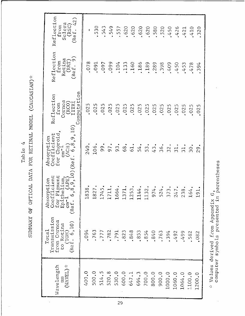
6.1.1 Absorption and Reflection Coefficients IOptical data, derived primarily from the work of Coogan
(Ref. 5), Boettner (Refs. 6,10), Geeraets (Refs. 7,8,9,11), and
Smith (Ref. 42) are presented for the rhesus monkey, caucasian,
and negro in Tables 3 through 5 respectively at several selectedS~wavelengths.
weFor the Corneal model one should use the values of the absorp-
tion coefficients for water shown in Table 6. These values were
derived from transmission measurements of Hale (Ref. 1-2).'11
- 27
L .... .. . . ..... .. . .- - -

(3) u 0 Ur) co u-i LjrCN c-)0 LJ' 0C c,4c 0 Ur)
H'-I- (U) _ Q . . . . . . . . . . .
o4 c
C) (U C~ 0r 04 00 r_ il -1 r- in I f__ 00 0,- -i n U- 0
a) w 1 4 =)C)(: 0 0 0 C) 0 4"C N"C
0/
(VZ 4P )c )C)C 4-J0 CD c z0 C Co t0 r
LP u
0) 0Y '-'00
r4 r4ý4rý --
C i F-i CL-r A- -!Uo. , ..D)DLn , t - - r _ :
-ii 0 0))0)
C)4I-i U)
QtJ-4 U-3r In Hý Hý Hý Hý co
o4r 'r U 4%' n ) CL.
I i ~ U *(A)~ N- H, 1--N P& N-ý o ~ ~ n 4 -r
p ýc1~t 0 C)cooP4 r_ '-J
CI) L.J 4J0
FY4 co r--
va Q)0
T__ * . CL) (U..
CLI 1 ' q - , r-.0 0 - CO 0 0 00 -0 N0 f-O 40~i C H~~ ' 00DD0~JW
0)r4CR C Cý0 4ý ininin C% Cý TO)X 0,0HM>r: H_. Hý 1_ H - >
wý4 ý4W ý23
0C) 'ý r-~O 0 0 00D0k0 C)C ýo-4 C00CQC() VI -,I LftN U) CJO U1 q C\ 0 ý (N NI r-4 C
C)
00
r-4 0 4 Q) Q -H . . . . . . .41-4 i
U) U0 C)H4 UN N1 N-jCj N N' Nj N N, N NA N' Nq N N Nq
LL4 u aQ) 0
CD
0 Q)0
H- rq-ýu01 --- '0 .4-J C) Or2 IC)Cý Cý1ý C4
0(t44 C)<
<C)L4 ~ L44
Q)-C) P-Hr- . 4-
4-ij C0 , ' ^ cý rý4ccr- r- -r- -I (n c ' -t N4 \i- ----u-) c- r---ci- r-, t .)\c -
-4L4 1 \o 0 00 ccD nccr--r--ý ON rH 4Gn( c~j Nq -4 -IH L4-4 4-Wr--i -4 ~-4 rH r - r -4 r- r- r--4.
0 0 0 Cq L4U t44 C-) Q)~
CIL
.r-4 Q C)
M U ý4 .- r4 -- , - " r~--N - Cý)cc 00-c-)c- OCn '-j 0C)acz r4 C 4-) '-o (0) Nof- 00 c C IAN -,J- fLr n -<-'j- \,D 0~' CO k- c 41 1
-iE D)C C-) 0 0D tr- ccr r 0 00 o'--4c CL 0 0 0 0 0 0 0 0)
0 ~ ~ 0 r-4 N: .' I~ .Q . . 0 0 .>0 . . . .IZ F Z -ci- 10r 0.4r -- c 0 ~ 0 ,.
N-- ,4 >- - r -c-i-r
I-,-O
294

o- 4r) C Y Nr Ct) o o-h 0 C 0 0 0 0 C 00
0 0)OW f V) m t I r - l 1 N 0 C1L)C C4J4 - IN
(3 ~44I -
U C~- ON 00 'r m% O't 0 ( '.0 0'% ON 0O0 L(N 0 fI" cnCO
rbL 4 W'- 0)I- C
(A)4 LW Q)
0 00
C)0 0 )Cý0 C 0 C - )C
DE W O . . .N J N N (. 1 N N N ' . N N.. . .N
P- 0
w 1 0U)1)0p
1-- Lx, 00 0 a)
E-E4
r-)4 rd'ý Co Lfl r4 Cý 00 4' C41 NI CCý i- ) . C4111 ~ ~ 0f r-4 N -CO MIn ,O C .ý .) -, Cr) M . 0- CD N C-4 - N-
PH P-4 r-4 r-4 t--4 r-4 r-i a
04-4 4Lj-4 La~
C) V) ) ý4
40 0 44

I Tab le 6
ABSORPTION CONSTANTS OF WATERt (Ref. 12)
N (ýLmn) a(cm -i) - - - (ým ) a c --A-I (ý-m ) - 1cm
0.200 6.9115.10-2 0.900 6.7858.10- 2 3.400 7.2072.102
0.225 2.7367-10-2 0.925 1.4400-10-I 3.450 4.8080.102
0.250 1.6839"102 0.S711 3.875710 3.500 3,3750.102
j 0.275 1.0739-.10-2 0.975 4.4852.10 1 3.600 1.7977.102
0.300 6.7021-10 -3 1.000 3.6317-10-1 3.700 1.2227.102
0.325 4.1759"10-3 1.200 1.0357 3.800 1.1244.102
0.350 2.3338"10-3 1.400 1.2387-.10+1 3.900 1.2244.102
0.375 1.1729'10-3 1.600 6;7152 4.000 1.4451.102
0.400 5.8434"10-4 1.800 8.0285 4.100 1.7225"102
S0.425 3.8438"10- 4 2.000 6.9115.1 0+1 4.200 2.0585"102
0.450 2.8484 .10-4 2.200 1.6508.10+1 4.300 2.4694"102
0.475 2.4736-10- 2.400 5.0056.10±1 4.400 2.9417-102
0.500 2.5133-10- 2.600 1.5321"10 2 4.500 3.7420"102
0.525 3.1595"10-4 2.650 3.1772-102 4.600 4.0158.102
"0.550 4.4782"10-4 2.700 8.8430-102 4.700 4.1977-102
"0.575 7.8676"10-* 2.750 2.6961'103 4.800 3.9270.102
"0.600 2.2829.10-3 2.800 5.1612-103 4.900 3.5135.102
"0.625 2.7948"10-3 2.850 8.1571"103 5.000 3.1165.102
0.650 3.1706.10-3 2.900 1.1613.104 5.100 2.7350.102
0.675 4.1516.10-3 2.950 1.2694-104 5.200 2.4408-102
0.700 6.0139-10-3 3.000 1.1394"104 5.300 2.3236-102
0.725 1.5860.10-2 3.050 9.8883 .103 5.400 2.3969.102
0.750 2.6138-102 3.100 7.7830 .103 5.500 2.6504.102
0.775 2.3998.10-2 3.150 5.3856.10 3 5.600 3.1865.102
0.800 1.9635-10-2 3.200 3.6285-103 5.700 4.4754-102
0.825 2.7722'10-2 3.250 2.3586-1i03 5.800 7.1498."102
0.850 4.3317.10-2 3.300 1.4013 "103 5.900 1.3248-103
0.875 5.6154-10-2 3.350 9.7905 "102 6.000 2.2410-10 3
I!3

Table 6
ABSORPTION CONSTANTS OF WATER (Concl)
ccm (cm _ < cm .-1 )
6.100 2.6987"103 9.800 6.1421.102 27.000 1.6011-103
6.200 1.7836.103 10.000 6.3837-102 28.000 1.5169.103
6.300 1.1370l103 10.500 7.9228-102 29.000 1.4430-103
6.400 8.8161-102 11.000 1.O1l0!0 3 30.000 1.3739.103
6.500 7.5785102 11.500 1.55i7*103 32.000 1.2724-10
1 6.600 6.7782.102 12.000 2.0839103 34.000 1.2160-103
E.6.700 6.3207.102 12.500 2.6038 103 36.000 1.1973.103
6.800 6.0430-102 13.000 2.9483.103 38.000 Lo193810 3
6.900 5.8643.102 13.500 3.1928"103 40.000 1.2095.103
7.000 5.7446.102 14.000 3.3211l103 42.000 1.2237-10 3
7.100 5.6637.102 14.500 3.3626-103 44.000 1.2452-103
"7.200 5.6025"102 15.000 3.3678"103 46.000 1.2621I103
"7.300 5.5430"102 15.500 3.3564.103 48.000 1.2776-103
7.400 5.5020-102 16.000 3,3144-103 50.000 1.2918-10o3
7.500 5.4622,102 16.500 3.2596 -03 60.000 1.2294-103
7.600 5.4234.102 17.000 3.1712-103 70.000 1.0340-103
7.700 5.4019 102 17,500 3.0806 "103 80.000 8.5923"102
7.800 5.3971.102 18.000 2.9740 -103 90.000 7.4•,-40 102
S7.900 5.3924.102 18.500 2.8597.10 3 100.000 6.6853.102
8.000 5.3878,102 19.000 2.7382.103 110.000 6.0661.102
8.200 5.3790.102 19.500 2.6035.103 120.000 5.5083-102
8.400 5.4006"102 20.000 2.4693 "103 130.000 4,9686.102
8.600 5.4357-102 21.000 2.2859"103 140.000 4.4880.102
" " 8.800 5.4978"102 22.000 2.1306 .i03 i0.000 4.1469.102
9.000 5.5711.102 23.000 2.0052"103 160.000 3.8956.102
9.200 5.6685"102 24.000 1.8902 -103 180.000 3.4837"102
- 9.400 5.7886-102 25.000 1.7895 -103 190.000 3.3136-10299.600 5.9429 i0- 26.000 1.6916-10 200.000 3.1667.102
ST
S1
S. " 321

6.1.2 Index of RefractionFor computing the laser profiles, the indexes of refraction
are taken equivalent to those of water as shown below. The index
of refraction for water for wavelengths greater than 1.4pm can be
obtained from Ref. 12.
Table 7
INDEX OF REFRACTION VERSUSWAVELENGTH FOR WATER
(Re~s. 48 and 49)
Index of Index ofWavelength, nm Refraction Wavelength, nm Refraction
350 1.357 900 1.328400 1.346 950 1.327
. 450 1.341 1000 1.326500 1.336 1050 1.325550 1.334 1100 1.324600 1.332 1150 1.3235
-' 650 1.331 1200 1.323700 1.330 1250 1.322
-. 750 1.329 1300 1.321800 1.328 1350 1.220850 1.327 1400 1.320
The only exceptions are for wavelergths 390, 400, and 450 nmi
where the index of refraction is taken as 1.357, 1.346, and 1.341,
* respectively (see Appendix H). - h6.2 Thermal Property Data IA
Property data associated with the conduction and storage of
heat are taken as: H
Density = 1.0 gm/cm3
Specific Heat = 1.0 cal/gnm-°C
Thermal Conductivity = 0.0012 cal/cm-sec-°C
The above value of thermal conductivity was estimated based onvalues associated with organic media such as (Ref. 13)
I
De rmis .00088 cal/cm-sec-oC
Blood .0012
Egg white .0013
Beef vitreous humor .0014
Beef aqueous humor .0014 if1 1.-- - -

Different values of blood flow were used for the chorio-
capillaris, and for tissues surrounding the eye. Total blood
flow to the chorio-capillaris was taken as 0.024 ml/sec (Ref. 14)
and was distributed uniformly throughout the chorio-capillaris.
The result is a flow of 0.016 gm/sec per unit radial area of the
chorio-capillaris. Blood flow to tissues surrounding the eye was
assumed as 0.001gm/cm -sec. In both cases, the specific heat
of blood was taken 0.9? cal/gm-°C Ref (15).
6.3 Thicknesses of Eye Media
Thicknesses of various eye media for rhesus monkeys and humans
I are presented in Table 8.
1 •able 8
THICKNESSES OF EYE MEDIA*
S~Thicknesses in cm
. Mon ke yMan
Tear Layer 610Cornea 5.16"10-2 2
Aqueous Humor 2.9.10 3.1.0
Lens 3.5-10- 3.610
Vitreous Humor 1.157 1.697
Pigment Epithelium 1.2.10- 1.4-10
Chorio-Capillaris 1.0-0 3 1.210 3
Choroid 1.68"10-2 1.42.10-2
Sclera 1.0"10 1 010i
1 Corneal Surface toSecond Principal -lPlane 1.70.10 1.75'10"1Corneal Surface to -1[
Pupil Surface 2.9.-10 3.1-10-
II*Refs. 5, 16, 17, and 18
34
LI -

f6.4 Experimental Ocular Threshold DaTTo ensure a comprehensive check of the two models, experi-
jmental. data were acquired by Brooks Air Force Base. These data
are associated with retinal and corneal damage and are presented
in Tables 9 and 10, respectively. Later, in Section 8 we shall
use selected experiments to verify the two models.3
:1
J...
~1
1.
1 35
I

- 4 4 4 4 - 4 4 4ý jý 4ý ,4 .ý -4H r4H 4
04 -0 C D : 0 0) 0: 0
a w- or-' S 4 -
4j m~ a H ow Ln CD n00 000 00 0 00 00 00 00 0 000 000C
-a.-
0r
I 0.-4 H C'4 N H .Q Q Cj -4 -4 v- r4 r4 N- I'. 0 04 ' 0 ' a- u4000C4 -
L4CO4
CA UC LA r-j r4 IA IA 4A r4 4A r r-j r-4 CA LA r4 rq r-j 0 LA Lj IA
>~00 w 0040 0 0C)0 000 00 0 0 00006 66w4 C'C!2N9 lz C
-4 WD -L -4 -
-'-4 U." r, Wj 0 C4 t H 4 4 M. n M CCj CCO'n
"'4
IJ0
r- CC' - Ln t n L n L n w ' n t - r n L n L 0 i n a -
C4I N a V N I 1 I N N N C 1 1 I t M T C4 <t
0-)
ý4CI~ ca~W, ( ,~ 0 0~ C ~ 0
U..4.O 'n 'J O 0.L L O O AC r 0sL 4lO.L'
0-" '-4 N 4NNNNNN NNNN 'j
toc .4
I0-0o.O- ~ O'O.,4
- -
C0 M I 4 !

Z008 00008800 8000000000000 8a 00*.0 4 00 00C%0 0 ~0 a 0 0
44- 4 -4 r444~
4.,
jj Cf
o4 A 10 o Uc 10 10 a 10 S0 a 6 40 S) 1 0 4) 0 0- 6 I 0 01 0 0
ul 4) 0C 0 8 00000008000 08)aQ0000000000
Ij M c n M M M M r -- 1 -4~I ' . ý4
go 4 '.4 C-4 C4 H- e~4
ý3 00M -00c)00W0 0 0m0 00 a00
'ON
iiViP4Ibu -0
Uw 1
kna C) 4- 0 0 e
C.. C) ýNI
sc ON 0%C. o*' Nr 40 ) m c' m 1 0 0% - 4:3 %D. 'D %0 0o % n L n 0 a C>q n L n i

C).-~ 00 ~0 c0 000 '0 0 0 0 N4 f L~n 0O~0 v 4.-i.4 ý4 -4 "~ ý4 ~-4 .ý4 -' 4 4 - 4 %t C'iO, ý
o i'Qi 00 o )0 00Cý0 0 0000000r)j0
-U
0 4)-, 4 V~). I- 4 Ci cJ c '
'Ij M v) 00000 0 0
'444
a]on
J: 3Ll. .- 4 Ln %Ci 0 L
Il W I 4 4 n
0 ý4 0,0 00,0,0 '0 '0 0 0a 0 to 0 '0u ý~~,4 ý4 4-4 -4 -4 -4 -4 -4 -4 -4 -I-4-ý4
inr (nL Q00
13W i4-J
0 I ,- 1 In 10 10 In 0 I a I,- a I = 10 10 I a Ic lc
(r) -~4 %Vl 0 a00)0 0 0 0 0 10\0Or C n LnQUn- M 0.4 C -4 r~4 ý4 uj C44ý -I rM 1-. C ' C-4~
I+
C ) C -0 C) , 4 - ,4t-4 4 v0 D , Coiu in Q0 00
i....... ...... ........ ... ... ...... ........ . . . (U
...w to w
~co f A ~in J'41) u~O -.- I O -~-4 .4 I v.
0- P ai
E-44- j .
14 0 0 0 0 0 0 0010 10 01
1- ________0 33

r~ 0
o0)V4 C%~
oJ 4) CO.E-4,oA 4JU
4. cc 4
4)10~r4,w4~.
$4)4
A4 v-4z H-
0-A 00 0CD0 0 0 D0 0 0 0 00 00ý14:: c4ii 44 r-4 v- - - rir - -4 -r4 -I s-r- 4
r r-Ir- -
oe 0-0~ 0.2 'r.'0 0 CD 0 0'. Ln 0 -I f4 0 0 u0 CO 0-
41.ca4 CF. ~ c~r ~ C ~- 4 .-4 f-4 f-4 c 'Cq C%4 r-4 v' -4 0
adaS44 1 C. (L ) rsI 1'0 atcv -- % 0 0 %0C)% C40 ' r4I- '0 M 0 r- a- U-0 ca -J e 0 ~ ,4 r- 0'00 rý(%c nL n0r n0r- 0 CP0r-4VI-- 01 4
0)-
41-
:3: "4_ _M o I
(U~ -r

l 7. COMPUTER CODES
In this sectiO n we shall describe the Retinal and Corneal
models used t:o predict thermal damage to the retina, cornea and
lens. Listings, nomenclature, and sample data for the two codes
are presented in Appendices K and L. Basic analytical studies
used to develop the codes are presented in Appendices A, B, C,
D, E, F, H, and I. In this section we shall describe the twocodes with particular emphasis being given to the users needs.First, we shall cover the major aspects of the codes, and then
examine each code in detail.
Each code starts with a description of the laser exposure
as presented below
* wavelength
o total power in the laser beam on the cornea
e shape of laser beam profile
* distance of laser's waist from pupil
* pulse duration
* number of pulses
e repetition rate
Then these input data are used to establish how the laser's beam
is refracted into the eye (See Section 3 ). Next, the resultant
laser profile and power are- used in conjunction with the thick-
nesses and absorption coefficients of the various eye media, 'to
determine the deposition of energy into t:he eye (See Appendix F)
at select points in the grid system indicated by Fig. 4. Here we
have chosen polar coordinates in r and z (See Appendix A) to
identify the various locations of the eye.
To calculate the transient temperatures within the eye result-
ing from a single laser pulse, we have used a finite-difference
method formulated by Tech. Inc. (Refs. 1,52) using the work of
Peaceman (Ref. 2). This method represents an alternating explicit
A.' "implicit technique for computing the temperature rises that allows
use of constantly expanding time steps.
40
Sj ___

4arc Temperature predictions for multiple pulses (See Appendi)t D)
are made using the resultant temperature predictions for a single
pulse. Total damage is predicted by integrating the rates of dam-
age over the times at which the rates of damage are significant.
Based on the damage criterion of Ref. 3, the codes compute
the total laser powers required to damage each of the specified
locations within the eye. After r'he threshold powers are found
for the specified points, the codes predict the region damaged by
the particular laser power specified by the user. The damagedregion is found by interpolating the radial extent of damage at
various depths, as well as the axial extent of damage along the
axis of the eye.
Having briefly reviewed the principal features of the two
models, let us now examine qach code in detail.
7.1 Retinal Model
The Retinal model consists of a main program plus five sub-
routines. Principal features of the code are illustrated in Fig.
8. Here we shall describe each part of the Retinal model using
the listing presented in Appendix K. Throughout this discussion
we shall refer to the sequence numbers at the left-hand side of
the listing. Included in Appendix K is a description of the vari-
ables, sample data, and output results.
All input data required by the code are read in the main pro-
grain and subroutine IMAGE. The order in which the data are read
in is indicated by the numbers at the right-hand side of the list-
ing. Read statements with asterisks are executed only for irregu-
lar laser profiles.
7.1.1 Main Program for Retinal Model
Figure 9 illustrates key portions of the Main Program.
Numbers in the boxes refer to the sequence numbers of the listing.The symbols i, j, k refer to the grid positions Z(i), R(j) and
timies XT(k) , respectively.
4ll

0 .j 4J -rý
1 V -1 0 tko
4 0) ~J 4-4 4)
o nC ~0 -c o:n Qjic~ >. -,J *r4 ZJ14
0 w ~-f-4 0W U 4~-40 W0-r4C 4-4J ý4Q0 4 ~CU 0WJ- ~
.r4 :) 4-J 4J
wU CLJ C00040> FE ' -4.4
H C W w 00 r
W CW Pz
(D 0 r
Q) (.4 *H H4
41- pl (
o a)4 a o j
H. 00 > gQ U)H)C
(U) Cl) QP..
~~r~CU C.) r ý
4-d '41)0~41 -4
*HF 0
o iwc4-4 W
L42I

t' T li -A-.-
CA-44 ItO ~
C) )LnJ) C
4)4J A C"C C 0i '
~~23
Ug -fj .4L
A)WA J)A.0A'
In j UC. C
-4.2 /, -
001-~A' Iý noHV : ID
A.Z -- .1 0) H .0. ). ) 6J
oC 4)4- NVAL
(C) I A s:0
10~~ 10 0 In 1 C.
A-. D 00 .s1:1-13tI
I. IW 0-,
0V
'u Q InAC). luE 1V-
HA 710""') 4 t.
H11 V)
43:

Retinal Main: Sequence Numbers 1-52
Sequence numbers 25 through 27 define the number NI of uni-
Sform grid increments, and the tot-l number N3 of grid points inLithe radial grid. Here NI must V ss than N3. The size of the
smallest radial grid increments D, is established at sequence
numbers 30 and 31. For gaussian or irregular laser profiles, DR
is found by subdividing the lesion radius LESION into an integer
number LIM of increments. For uniform profiles, DR is found by
subdividing the profile radius RIM into (LIM-.5) increments. At
. present, all values of DR should be larger than about 0.0003 cm
to avoid temperature instability. To use smaller DR values, the
*1 size of the initial time steps DT must be decreased and the dimen-sion KT increased in the appropriate arrays (see Appendix K).
If one wishes to reduce DR by a factor t,, then DT should be de-
creased by the factor P
At sequence numbers 37 and 38, the index LPX is set equal to
0 or 1 according to whether the laser exposure involves single or
multiple pulses, respectively. This index is used to control the
course of the computations. At sequence numbers 42 and 43, the
laser power and pulse duration are altered when the pulse duration
is less than 0.3"10-8 sec. In these alterations, the total energy
is preserved. These changes save on computational time and re-
flect the fact that the conduction of heat is insignificant during
times less than 0.3"10"8 sec.
Retinal Main: Sequence Numbers 54-63
At sequence numbers 54 through 63, the time step DT and the
total time TIME are couiputed using the arrays XCT, NPT, and KTT.
Specific values for XC, NP and KT are selected from these arrays
as a function of the pulse duration DPULSE. The array XCT presents
values for the expansion factor XC by which successive time steps
are increased; NPT the number of time steps NP contained within
DPULSE; and KTT the total number of time steps KT. The values
assigned these arrays are given in the ample data cards 18, 17
and 19 presented in Appendix K. The result of these computations
is time steps DT, XC'DT, XC2. DT ... .xc(KT- 1 ).DT, where the total
time TIME is given by
41I

i II KT- I
IME (Xc)nDT DT - - XT(KT) (21)
The elapsed time from the start of a pulse to the K-th time step
is represented by XT(K+I). Here XT(1)=O. At the end of a pulse
of duration DPULSE,
XT(KM) = DPULSE (22)
Retinal Main: Sequence Numbers 66-77
I I At sequence numbers 66 through 77, the code computes TIME,
DT, KT and KM for multiple-pulsed exposures. Here the expansion
I lfactor XC is set equal to the relatively large value of 1.4 so thatthe total time TIME brackets all the pulses without resorting to
1 large numbers of time steps. The total time TIME is determinedby first evaluating the train length, and then multiplying the
1 result by the value selected from the array FTIME. To provide
maximum flexibility the array FTIIME is described by input data
as a function of pulse duration. Elements of FTIME should always
] be great'-r than 1.
If the temperature rises from a pulse do not approach zero
J in the allotted time, then one should increase the particular
element of the array FTIME corresponding to DPULSE.
I. To integrate damage over each pulse, DPULSE is subdivided
into NP uniform time steps of magnitude PTIME (See Appendix D).
For more refined damage calculations, one can increase the number
of intervals bearing in mind that it will require increases in the
I dimensions of arrays with arguments KT and KX (See Appendix K).
Here KX equals the total number of time intervals used to evaluate
damage from pulse to pulse and presently equals NP+3 (see sequence
ntunber 331).Retinal. Main: Sequcnce Numbers 82-89
At sequence numbers 82 through 89, the indices for grid pointsSI along the Z axis, i, are chosen along with the size of the smallest
increwent DZ along the z axis. To conserve on computational time,
DZ is increased with the pulse duration DPULSE.
45

* •At sequence number 87, the first grid point in the pigment
epithelium designated by IPE is located at the second uniform grid
I point shown in Fig. 4. Also, the first grid point in the cornea
designated by IPA is located at the second grid point.
IRetinal Main: Sequence Numbers 91-100
"From sequence numbers 91 through 98, the distances ZD of the
"various interfaces from the cornea are computed using the assigned
thicknesses for the various media. Here ZD(8) is set equal to an
exceptionally large value to ensure it contains Z(M3), the last
grid point on the Z axis.
At sequence number 99, subroutine GRID is called to compute
e the locations of all grid points Z(i), R(j),
e the indices for the various eye media, and
* other spacially-dependent thermal properties.A discussion of this subroutine is given in Section 7.1.2.
At sequence number 100, the number of grid points NVL in the
chorio-capillaris for any specified value of J is calculated using
I the first grid point IPV and last point LPV in the layer.
Retinal Main: Sequence Numbers 102-106
Here the i,j indices, at which temperature print outs are
desired, are computed. These points are chosen according to the
I values assigned ID1, ID2, JDl and JD2 on data card no. il.
Retinal Main: Sequence Numbers 113-114
I Here the i indices associated with points in the vascular
layer are computed and stored in the array IBLOOD.
I Retinal Main: Sequence Numbers 116-121
In this section the normalized irradiance profile HR is set
to zero and subroutine IMAGE called to evaluate HR at the retina.In this regard, two options are available to the user. Either
one can input the retinal image directly by setting IFIL-0, orcompute the image as described in Section 3 and Appendix if by s•r.-
I ting IFIL=I.
( :L46

When IFIL equals zero, the program sets the image equal tothe profile described by input data on cards 4 and 6 of the main
program (for gaussian and uniform profiles), or cards 19A*, 19A**
and 19A*** of subroutine IMAGE (for irregular profiles). Other-wise these profiles are considered to be at the cornea and the
I retinal images are calculated in subroutine IMAGE.
u Retinal Main: Sequence Numbers 131-139Here* the blood flows entering (IFLOWI) and leaving (XFLOWO)
the chorio-capillaris are specified at various radial distancesIDFLOW. These blood flows are all on a unit area basis and are
distributed uniformly over a circular area of radius RVL such
Sthat the total flow equals CFLOW. Presently the incoming andexiting flows are set equal. This means that there is no net
I radial flow. However, the code is structured so that one caneasily vary the inccaing and exiting flows with radius as more
S | detailed information is acquired.
Retinal Main: Sequence Numbers 144-146• In this section the initial temperature rises are set to an
insignificantly nonzero value (10-10), to prevent underf low. Computer
installations without library routines to handle underflow will4 not tolerate temperature rises of the order of l'10-.37 that are
other than zero.
Retinal Main: Sequence Numbers 172-257This part of the code assesses temperature rises caused by
a single pulse as described by Appendix A. Here heat is depositedat a rate of S(i,j) per unit volume at each point Z(i),R(j) during.the pulse, i.e. at times of XT(l), XT(2.- . XT(K4). After the
pulse, S(i,j) is set equal to zero by suDroutine HTXDEP.
S .1 Two provisions are left to the discretion of the user. Thefirst is that one can subdivide the time inte rals used to compute"the temperature rises without changing the tiie steps XT(K) -XT(K-I).This involves changing the integer IKX which provides for 2.IKXtime intervals of size (XT(K)-XT(K-l)/(2-1KX). For this purpost,
IKX may be altered by adjusting the vaiues of EDTI and EDT2 assigned
" 1i 47

i IS I as input data on card no. 12. This provision is included so that
one can improve accuracy or eliminate instability without having
to increase the number of time steps KT. Except for long pulse
times, a value of 1 for IKX is usually adequate. To reflect the
j fact that IKX should be greater than I for pulse widths of the
order of 1000 see or more, DPULSE has been included in the evalu-
* ation of IKX.
The second option is the times at which temperature print-
outs are desired. This option is provided by the value assigned
ITYPE in the input data. If one wishes print outs at each time
XT., then one merely sets ITYPE =1. If one wishes ririntouts at
every n-th XT, then ITYPE should be set equal to n. Print outswill always be provided at the conclusion of the pulse as well as
at the list time XT(KT).
Retinal Main: Sequence Numbers 263-268
Here we complete the evaluation of the array XPD(K) describ-ing the ratio of the average temperature of the granules to the
average temperature of the region of the pigment epithelium in
which they lie. The values for XPD(K) are given at times of XT(K)- and approach 1 after the conclusion of a pulse. This reflects the
fact that the excess heat in the granules is dissi.pated to its immedi-ate surroundings following a pulse.
"Retinal Main: Sequence Numbers 275-294
Here we select the points ID(L),JD(L) at which damage cal-
culations are to be made. Two input parameters are required to
.. specify the points. The first is the radial distance RHAX over
which damage assessments are desired. Here the code assesses
damage for all grid points starting at R(1) and ending at the
first point beyond RMAX, namely R(JM).
The second control one has in selecting the points is in
the value assigned LIMAX. Knowing this variable, the code estab-
lishes the depth Z(IMAX) of greatest temperature rise, and then
assess the damage from Z(IMAX-LIMAX) to Z(IMAX+LIMAX). Thus when
LIMAX is set equal to zero, damage is only evaluated at the deptnl
1 of highest temperature.
- 48

Ilk
The number of points at which damage is to be evaluated isgiven by L1J. If LIJ is larger than the allotted dimension for
the arrays associated with LIJ then the computations will stop.
Moreover, care should be exercised not to designate more points
than needed -- first, because points remote from the region of
greatest temperature require considerable time to heat and cool,
and secondly because of the appreciable increase of storage required
when LIJ is increased.
Retinal Main: Sequence Numbers 299-403
"J In this section the temperature rises caused by multiple
pulses are computed using the temperature predictions for a single
I pulse. Also, the array M is evaluated for subsequent computa-
tions of the damage.
* First, the temperature rises at the points, at which damage
calculations are desired, are stored in the array VE(L,K,n). Inthe array VE the point is at ID(L), JD(L), the time is XT(K), and
"n=l when VL represents the temperature rise of the region around
"the point while n-2 when VE. represents the average temperature rise
"of the granules. When the point is not in the pigment epithelium,
the two temperatures VE for n=l and 2 are the same.
As may be noted at sequence number 315, provisions have been* - made to evaluate NTEST exposures during a single computer run.
These exposures may differ only in their repetition rate or
number of pulses.
The basis for the multiple-pulse computations is presented
in Appendix D. First the temperatures are interpolated at select•. interpulse times during and between pulses. The interpulse times
differ from the times XT(K). The total number of interpulse times
from one pulse to the next, is given by KX -- where NP interpulse
times are uniformly spaced across each pulse and three are uni-
T formly spaced across the interval between pulses. Measured from
the beginning of each pulse, the interpulse times for the thermal
damage calculations are stored in ZTX(L3) while the interpulse
times for predicting the granule temperatures are stored in ZT(L3).
Then the temperatures VE for a single pulse are used to compute
the temperature rises VZ from multiple pulses.
49
' " .. ....•;•-• - • r i• • I I I I I • I II

!I
S1 Temperatures arc stored in VZ for each pulse only when the
number of pulses is less than 20. Othcrwise the code groups the
pulses into an odd number of IN pulses, and stores the temperatures
associated with the middle pulse of each groups of pulses. Later
Sthese temperatures will be used to assess the damage caused by each
group, The number of groups of pulses during the exposure is INX,
while the number of groups in the time TIME is represented by INXX.
Generally, TIME exceeds the train length so more pulses are con-
sidered than actually exist. Thi reason for using more pulses
than exist is •o provide for temperature prcdicti(''IL" following the
exposure (see Appendix D). This point will be returned to later
in this section.
In order to relate the interpulse times to the times XT, it
is first necessary to add the interpulse times ZTX and ZT to the
product of the number of prior pulses and the time interval TC
from pulse to pulse. These times are designated by X3 and are
calculated at sequence numbers 367 and 371, where L7 equals the
number of pulses started during the times of interest.
From sequence numbers 363 Lo 3/8, the temperatures during
the middle pulse of the first group of pulses are evaluated and
stored in VZ(L,L6,L3,n) where L indicates the point ID(L) , JD(L)
at which the temperatures are calculated; L6 labels the groupsof pulses concerned; L3 designates particular interpul.se times,
and n indicates whether t:he temperatures are for t:he media orgranules.
To interpolate the temnperatuures at time X3, it is first: nec-
essary to determine which pair of XT(K) bracket X3. To this end
it should be remembered that the times XT are given by
XT(l) = 0XC -I_
XT(K) = DT.-1--_l , K>2
To find the time XT(K) just prior to X3, one merely substitutes
X3 for XT(K) and solves for the integer value of K. In this man-
ner X3 is located between XT(K) nnd XT(K+I). Linear interpolation
is then IUsed to find the temperature at time X3.
j, 50
I T / ' , ,, - - , -- - " '-'I • ••" ,r,,,7rr,, ,, •,rn r -n n rn u •

IlIiFrom sequence numbers 379 through 397, the computations are
continued for the 2nd, 3rd.. .INXX group of pulses (L6=2,3...).
In each case the computations start with the pulse following the
last pulse considered and end with the middle pulse of the suc-
ceeding group. In the process the temperature contributions are
added sequentially for all pulses. The result is a description
VZ of the temperature rises during and immediately following se-
lected pulses for a total of IN-INXX pulses.
As mentioned previously the number of pulses IN.INXX consid-
ered exceeds the number of pulses IN.INX in the exposure. There-
fore, for times exceeding the total exposure time, one must subtract
3 the temperature contributions from the last: IN.(INXX-INX) pulses.
This operations is performed at sequence numbers 398 through 402.
I Retinal Main: Sequence Numbers 404-462
Here we compute the damage caused by temperatures from multi-
jple pulses. Damage is evaluated at the points with indices ID(L),
JD(L). For each point, an initial estimate is made of the factor
CQ by which the input laser power POW must be multiplied to cause
irreversible damage. This operation is conducted from sequence
Snumbers 413 through 416. This estimate of CQ is purely empirical
based on the pulse duration DPULSE and the peak temperature rise
at the conclusion of the last pulse. The computations are aborted
if the temperature rise is below 0.0010 C. This provision is in-
cluded to prevent examination of remote points wherein there is
jno temperature rise. In such situations an arbitrary threshold20power of 10 is printed for the points ID(L) , JD(L)
I Having made an initial estimate of the laser power, the next
step iu to set the control indices LLT and LGT to 0. These indices
1become I when the assumed laser power is below or above the pre-
dicted chreslmid value, respectively. We will return to this
point later.
The damage calculations are made from sequence numbers 1,21
jthrough A32. Two criteria are used to assess damage. The first
51

3 is the use of an arbitrary temperature TSTEAM of the melanin gran-
ules. If the temperature rise of the granules VZ(LL6,L3,2) exceedsI, TSTEAM-TO, where TO represents the initial temperature, then ir-
reversible damage is assumed. For the computer runs considered,
the granule temperatures are high enough to cause damage. However,
the fact that the experimental damage results are more in linewith the thermal denaturation criteria suggests that any damage
I caused by steam is too localized to be observable. Within a timeincrement of say At, the incremental damage AQ caused by ther-mal
j denaturation is (see Section 5)
AQ = C1 exp(-C2 /Ta (t))At (24)
where C, and C2 are constants and T (t) is the absolute temperature.
Irreversible damage occurs if and when.rt
JAQ-d-c d,, 1 (25)
Being that C1 is a very large number and the exponential is a very
small number, it is advisable to evaluate the damage using logari-
thms. Therefore, taking the log of Eq. 24 yields
"In (AP) = in C; - C2/Ta(t) + In At (26)
To assess the incremental damage one merely sums the exponentials of
the logarithm of N1. The accumulated damage DAMC is therefore
given by
DAMC exp(X i) (27)
where Xl in CI - C2 /Ta(t) + in At. When groups of pulses are
considered, At is multiplied by the number of pulses IN per group.
After the damage has been evaluated for the assumed laser
power, C() is either increased or decreased by 4% according to
whether DAMC is less than or greater than I, respectively. In
the pro-ess LL is set equal to one if DAMC <- I or LCT is set equal
to oue if DAMC 1 1. Once both LLT and LGT are equal to 1, the
i*.52

dam calculations are completed in that one has crossed over
the threshold value. One half of the last 4% correction is then
returned to CQ so that one can be assured that the predicted value
is accurate to within 2%. To separate the predictions of laser
power caused by the two criteria, TSTEAAM is progressively increased
until the last two sets of power predictions are the same. To
determine when this occ,,rs one of the predicted laser powers is
I stored in XQ so it can be compared with its subsequent prediction.
As a result, the last two sets of power predictions are
associated with thermal damage while earlier predictions indicate
the laser power necessary to raise the granule temperaturL above
TSTEAM. One word of caution is needed at this point. Damage
assessments are onl.- made over the time TIME. At regions far re-
"moved from the region of greatest energy deposition, the assigned
TIME may not be adequate. The adequacy of the time may be judged
'by examining the temperature print-outs. If the temperature peaks,
"and then drops by more than roughly 5°C, then the predicted power
is satisfactory. Otherwise, one should increase TIME through the
array FTIME and increase dimensions of arrays containing the time
index KT.
Retinal Main: Sequence Numbers 463-508
This section provides data cards for plotting the temperatures
at times specified by the user. Here the temperature rises from
multiple pulses are calculated at points with indices i ranging
from Ill through 112 and j indices ranging from JJl through JJ2.
The times at which the temperatures are desired are inputed by
the user in the array TIMEX. These times are measured from the
start of the first pulse and may assume any value from 0 to TIME."These calculations are essentially the same as those of sequence
numbers 361 through 403.
In addiLion to the temperature rises, the plotting routine
"must know the range of the points over which plots are desired
as well as the peak temperature rise RGV of the profile. Also
to aid in identifying the curves, a provision has been included
to label a particular curve. The curve to bi labeled will
have an i index corresponding to the assigned value for 113.
•, 53

In addition to providing data cards for plotting, provisions
are also made for print-outs of the data. Three options are avail-
j able in this regard. 'f KTYPE is assigned a value of 0, then no
cards or print-outs will be provided. If KTYPE=n and KTYPEO=l the
j code will only print the temperature rises at n times TIMEX(n),
Values of KTYPE=n and KTYPEO=0 will provide both cards as well
j as print-outs.
Retinal Main: Sequence Numbers 523-56 4
This portion of the code computes the damage from single
pulses. The basic difference from the damage calculations for
multiple pulses is the use of the temperatures at the times XT(K).
Here the code assesses the damage from the KM time intervals, i.e.
XT(2)-XT(l), XT(3)-XT(2), etc., during the pulse as well as an
additional (KT-KM) time intervals following the pulse. As with
multiple pulses, damage is evaluated by using the temperatures
at the mid-points of the above time intervals. Other than the.
difference in time intervals the computations are identical to
those for multiple pulse and the same observations apply.
Retinal Main: Sequence Numbers 578-603
1 Here provisions are made for prcparing drita carus for con-
structing 3-D and 2-D profiles of the temperature at selected
locations and times. Except for the use of a single pulse, the
computations are identical to those used for multiple pulses.
SRetinal Main: Sequence Numbers 605-653
In the final portion of the main program, the predicted thres-
1 hold powers QD for specified poilrs are used to assess the regionL - damaged by the particular laser power specified by the user.
To assess the axial extent of the damage, the computer first
scans the predicted powers to find the i indices at which the
1predicLed powers bracket the specified power POX=:l0W. For minimum i
depths of damage the i indices are 15 and 16 while for maximum
depths of damage the i indices -ire 17 and KS. TIT POW is lower
I than all the QD (i, 1) , then 16 assumes the value 0 and all remaining
computations are aborted.
,1 54

If POW exceeds all the QD(I,1), then the computer prints a message
I indicating this fact and all future axial computations are aborted.
To interpolate the depths where QD=POW, the following equa-
tion is used
QD = Xlbexp(X2-z) (28)
I where QD represents the power, z represents the axial distance
and X1 and X2 are constants to be evaluated. By substituting
Sthe two laser powers, say QD 1 and QD 2 , that bracket POW into
Eq. 28 along with their axial distances, say zI and z 2' one can
]solve the resultant equations for Xl and X2. The result is
Xl = QD 1 /exp(X2"z 1 ) (29)
X2 = log(QD 9 /QDl)/(z 2 -zl) (30)
Thus, substituting Xl and X2 back into Eq. 28, replacing QD by
PeW, and solving for the threshold depth z yields
z = log(POW/X1)/X2 (31)
By using the pair of laser powers found for small i values and
for large i values, one arrives at the minimum and maximum depths
of damage along the eye's axis.
Starting at sequence number 632, a similar set of computations
is made to assess the radial extent of damage for the depths at
I which the predicted power exceeds POX or POW. Except. for the use
of r instead of z, the same analysis is used as exemplified by
Eqs. 28 through 31. This then completes the description of the
main program.
1 7.1.2 Subroutine Grid for Retinal Model
Subroutine grid establishes the values for Z(i) and R(j)
subject to the values assigned N, Ni, N3, DR, RVL, M, Ml, M2, M3,
TAV, and DZ in the main program. Also the subroutine eval.uates
the matrix elements A and B for the finite-difference solution |
of the heat conduction equation. Moreover, the subroutine determines
I
• I ' I I I I I IiI II 55

I
I the location of the i indices associated with the first and lastpoints of each eye media. Finally, the subrbutine stores the
assigned thermal conductivities CON(i) and heat capacities VSH(i)
at the appropriate depths Z(i).
ii Appendix I describes the techniques used to develop the grid
ne two r k.
I Rtinal Grid: Sequence Numbers 15-21.Here the subroutine evaluates the expansion factor by which
the radial grid steps are sequentially increased starting at j=Nl.
The grid is selected so that the radial extent: RVL of the eye isS~located. at
RVL = (R(N-l)+R(N))/2 (32)
3 For more details the reader is referred to Appendix I.
Retinal Grid: Sequence Numbers 27-32
In this section the radial distances of the radial pointsR(j) are evaluated and assigned.
Retinal Grid: Sequence Numbers 34-52
Hlere the matrix elements B(jl), B(j,2) and B(j,3) are eval-
uated for the finite-difference solution of the heat conduction
equation. A description of this evaluation is presented in Appendix A.
Retinal Grid: Sequence Numbers 54-61
This portion of the code computpes the expansion factor R11"for the z grid. The surface of the cornea is located halfway
"between Z(l) and Z(2), while the surface of the pigment epithelium
- is located 'hlalfiway within the first uniform element. This element-. Ls bounded by the points Z(M2-Ml+l) an i Z(M2-Ml+2).
Retinal Grid: Sequence Numbers 64-76
-•Here the subroutine computes and assigns the values for the
various Z(i) using the expansion factor R1.
Retinal Grid: Sequence Numbers 80-100
Here the subroutine uses the depths of the various interfacesto locate the initial and last grid points in each media. T'he re-
sulting i values are stored in the arrays IX and LX and then assigned
to IPV, [PC LPS, LPT.
K N
Retinal Grid: Sequence Numbers 102-118
To provide for the possibility that the various eye media
may have different thermal conductivities CONX and heat capacities
VSHX, provisions are made for such variations. To this end, the
assigned thermal properties are stored with depth in the arrays
I CON(i) and VSH(i).
Retinal Grid: Sequence Numbers 121-126
.5 Here the matrix elements A(i,l), A(i,2) and A(i,3) are eval-
uated for use in the finite-difference equations of the neat con-y .I duction equation discussed in Appendix A. These elements we:e
chosen so that there is no heat flow from the cornea to the environ-
S mental air. In this regard, no consideration was given to the
effects of blinking.
1 7.1.3 Subroutine Image of Retinal Model
This subroutine performs two major funct.•ons. These are to
determine the
e normalized image profile HR at the retina(no.malized profiles have a value of 1 atthe eye's axis)
* irradiance QP on the eye's axis by whichthe normalized profile HR must be multi-! -" plied to obtain the irradiance across the
image prior to any internal reflections orabsorption. The latter is accounted forin subroutine IITXDEP.
Retinal Image: Sequence Numbers 16-1L7
Here the number of radial increments for the spread function
(see Appendix H) integration is specified. The integration is
made across the entire laser beam or pupil radius -- whichever is
the smaller. In situations in which the beam is smaller than the
I pupil, LII becomes less than LI.
For most exposures, 500 increments are adequate. The one
S I exception is when much of the laser's energy is beyond about 0.1 cm
from thu center of the pupil. In such situations, it is advisable
to increase the number of increments. A very crude rule of thumb
is to use an LI value of 5000 times the radius wherein most of the
1l 57, 4

energy is contained. This is necessary to decrease the intervals
of the argument of the Bessel Function at larger radial distances r.
I Retinal Image: Sequence Numbers 25-26
Any shape of laser profile may be accommodated by the code.
The most obvious profiles are the gaussian (IPROF-l) and the uni-
form (IKROF=O). Other profile shapes may be handled by assigning
a value of 2 for IPROF on data card 6 of the main program.
Retinal Image: Sequence Numbers 29-48
1 For irregular profiles (other than gaussian or uniform), the
.1 user must specify the profile's shape on a point by point basis.
This is accomplished by first assigning the number of points LR
on data card 19A. Then the profile values PX and associated radial
distances PRX are read on data cards 19A** and 19A*-'d,-. The numbers
for the profile values need only be relative.
From sequence numbers 35 through "8 the code normalizes the
profile w'alues PX and then integrates the profile over it's radial
area. The normalized power incident on the pupil is represented
by X5 and the normalized power beyond the pupil is represented by
"* X6. In order to account for th.ý possibility that only a portion
"of the laser's energy may enter the eye, we have used XX to repre-o *. sent the fraction of the laser's power entering the eye.
"ATo additional determinations are made. The first is the
"-' determination of the irradiance QP entering the eye on the eye's
axis. This value of irradiance is only used when one wishes to
imzge tHie profile directly onto the retina. This is accomplished1) t V ,s J i , i iti.- i vwlle of 0 to IFIL on data card 4 of the main program.
T"01- ý'ucih cabUs the entire energy in the profile is used. When the
I fIX(L}) of tLhe profile is less than the pupil radius, the
nurnt)r of radial increments LII is reduced accordingly.
Retinal Image: Sequence Numbers 49-59
Here the magnitudus of the irregular profile are evaluated
at rqdial increments of RINT and stored in the array for future
use.
_ • * 58
I 1 . .k IIi

(-
S I Retinal Image: Sequence Numbers 61-80
In this part of the subroutine, the code evaluates QP and XX
for gaussian profiles. When the user indicates a desire to place
the profile directly onto the retina, the computer evaluates the
normalized image i;'•ofile and stores the results in PR(j) for future
use. On the other hand, if the profile represents the beam profile
(signified by setting IFIL=l), then the code evaluates the normal-
ized profile at radial increments of RINT and stores the results
in the array FX.
.1 Retinal Image: Sequence Numbers 82-93
Here the subroutine treats uniform profiles in a similar
.4 fashion as the gaussian profiles are handled at sequence num~bers
61-80.
- Retinal Image: Sequence Numbers 98-119
This section images irregular profiles directly onto the
retina. Here the array PR is determined by first evaluating the
accumulated radial area and associated power between r=0 and L.RINT.
The accumulated area is stored in the array FA(L), while the accum-
ulated power is stored in the array FP(L). These arrays are then
* used to establish the laser's intensity at the points R(j).
Retinal Image: Sequence Numbers 122-210
Here the beam profile is optically imaged onto the retina."* The method used to determine the image is described in Section 3
"and Appendix H. The spread function calculations apply to all
profiles. Wherever different symbols are used in the code from
those of the text we shall inject an or between symbols. The
first symbol is used in the code.
The first portion of this section evaluates the index of
* refraction NC or n, the second principal focal length FL or f and
the incremental distance XO or Az. Then the beam profile (described
S1 by the array FX) is refracted onto the pupil yielding a profile FY.
From sequence number 148 through 158 the real and imaginary
I parts of the integrand of Eq. 7 are evaluated exclusive of the Bessel
Function. The real. part of the integrand is stored in XFI(L) at
!~ L..~ .59

"radial distances of (L-l)-RINT while the imaginary part is stored
in XF2(L). From sequence numbers 167 through 190, the Bessel
Function is evaluated and stored in X7. Then the integrals of
the real and imaginary parts are determined using the radial incre-
ments RINT. The two integrals are represented by X2 and X3.
Finally at sequence number 191, the resultant integrals are squared
and added together to yield the shape of the image profile HR.
j Before using HR, it is normalized so that is has a value of 1 at
r=0.
From sequence numbers 195 through 210 the normalized image
profile HR is integrated over the radial. area. The result is
represented by X4. Then the total laser power POX is used in
conjunction with X4 to arrive at the irradiance QP on the retina
at r=0 presuming no internal reflections or absorption. Reflections
and absorption are considered in subroutine HTXDEP.
Retinal Image: Sequence Numbers 217-218
In cases in which the specified profile is to be projected
directly onto the retina (by setting IFIL=0), HR(j) is set equal
to the specified profile PR(j). After the above computations are
completed, subroutine IMAGE is never reentered.
7.1.4 Subroutine HTXDEP of Retinal Model
This subroutine assesses the rate of energy deposition into
the various regions of the eye on a per unit v:oll=ui basis. A dis-
cussion of the techniques used is given in Appendix F. The primary
advantage of this analysis is that die eye's interfaces need not
coincide with the boundaries betmeen grid increments.
To determine the rates of energy deposition, the subroutine
starts with the image profile and assumes that it exists at all
- depths of the eye. This assumption is reasonable in the vicinity
.. of the retina where much of the heat is conceritrated. Discrepaiicies
will increase with distance from the retina. However, at depths
far removed from the retina, errors are of secondary importance
* . because of the relatively low rates of energy dcposition.
61 , 60
S ' .. ...

(-
3" 1 l Retinal HTXDEP: Sequence Numbers 13-15
These statements control the course of the calculations.
Initially, the control index TIhT is set equal to two in the main
program while QP has a value exceeding 1.10-10 Therefore, the
heat deposition rates S(ij) are evaluated following the first
entry of the subroutine. After these computations are completed,IHT is set equal to 1 so that the same S(i,j) values are used
throughout the pulse. This means, of course, that the laser power
is constant during the pulse. Once the pulse is over, QP is set
I equal to 0 in the main program causing the subroutine to set IHT
and all the S(i,j) equal to zero. Once IHT assumes a value of
"zero, all future entries are aborted.
Retinal HTXDEP: Sequence Numbers 16-32
Here the subroutine sets 12 equal to the number eye media + 1.
Moreover, LZO is set equal to the number of eye media. LZ1 is set
equal. to the number of interfaces in the eye and underlying tissue.
"Then the boundarys ZH(i) of the z increments are evaluated, and
the arrays II, IZ, AB, REF and REFL are initialized to zero. These
-. arrays will be discussed as they are evaluated. Finally, the
reflection coefficients REF are assigned values at the retina and
sclera. Here REF(l) has been set to 0 since corneal reflection
is accounted for in the irradiance QP.
Retinal HTXDEP: Sequence Numbers 37-47
Then the code uses the known ab.;orption coefficients APE and
ACH for the pigment epithelium and choroid, respectively, to assess
the absorption coefficient for the portion of the PE containing
"grn..ules . thc p,,rtion void of granules. To distinguish beLweeu
the two portions of the FE, the user must assign a value for the
... fractional distance RPE of their interface from the front of the
SPE. This datum is read in on data card 13 of the main program.
The coefficient for the front portion of the ]PE is represented by
APEI while the coefficient for the rear portion of the PL is repre-
sented by APE2. In monkeys, the granules ax"e at the front of the
PE while in humans the granules are at the rear. To accommudaiL
this difference, IGX should be assigned a value of 0 when considering
1..61
_ii n-..-*.

I
monkeys, and P. value of 1 when considering humans. This index
is read in on data card 4 of the main program.
I To evaluate the coefficients APE1 and APE2, the portion of
the PE void of granules is assumed to have an absorption coeffi-cient equal to that of the choroid. The absorption coefficientof the remaining portion of the PE is then selected consistent
with the absorption of energy by the entire PE. This condition
requires that the sum of the products of the absorption coeffi-
cients and PE thicknesses are equal for the two cases.
Next, a determination is made of the fraction AP of the
Sgranulated PE's energy absorbed by the granules. This evaluation
is made by first computing the energies absorbed by granulated PI,.
and by an equivalent thickness of choroid. Then the fraction AP
is found by dividing the difference by the energy absorbed by the
granulated PE. The fraction AP is later combined with computations
of subroutine MXGRAN to predict how the average temperature ofthe granules decay in time. Finally, ihe i index IG 0f the first
point in the granulated PL is assigned.
Retinal HTXDEP: Sequence Numbers 50-102
After assigning the absorption coefficients to the array ABS,the subroutine evaluates the arrays AB, II, 1Z and ABR. For details
of this analysis the reader is referred to Appendix F. Here AB(i,L)
represents the product of the absorption coefficient and thickness
of each eye media in the increment containing Z(i). The index L
- ranges from 1 to the total number of media contained within the
element. To identify which media interfaces are located within
j. the increments, the array 11(i) is used to represent the number of
interfaces within the i-th increment plus 1, while IZ(L) repre-
Ssents the argument of the first interface ZD within the increment.
The array AB1{(i,LI) represents the sum of the AB(i,I), AB(i,2).
I associated with each media between Z.1(i-l) and ZD(LI).
In order to prevent the possibility of underflow due to
j excessively large values of AB or ABR, thi•y were limited to a
value of 10. This value was chos;en ince it means that practically
all the energy will be absorbed within the particular element.
62
Retinal HTXDEP: Sequence Numbers 104-122
In this portion of the subroutine, the incoming irradiance
is followed through each media to find rates at which energy is
being deposited into each increment. Here X3 represents the ir-
j radiance entering an increment; X2 represents irradiance entering
the nexL increment; and X4 represents the irradiance reflected
away. To account for irradiance changes with radius, the resultant
values are multiplied by the normalized image profile. To arrive
at the rates of energy deposition S(i~j) per unit volume, the
Sabove product is divided by the increment's depth, i.e. ZH(i)-Z1I(i-l).
To guard against the possibility of underflow, S(ij) is set
equal to zero when it becomes excessively small (10- 1 0 /DPULSE).
Retinal IITXDEP: Sequence Numbers 125-145
: From sequence number 125 through 1-31, the reflected intensities
REFL are evaluated for each of the interfaces. Immediately there-
after, each of the reflected irradiances are followed through the
eye to arrive at the rates of energy deposition into each increment.
Here we have assumed the rays move in an axial direction, and have
neglected multiple reflections.
Retinal IiTXDEP: Sequence Numbers 151-154
As mentioned earlier, after the pulse is over, S(i,j) and IHTSare set to zero. Thereafter, all subsequent calculations by this
subroutine are aborted.
7.1.5 Subroutine MXGRAN of Retinal Model
In this subroutine the granule temperatures are calculated
neg lect ing
e heat absorbed by changes of state
i a energy losses due to pressure wavesand mechanical displacements
SThus all granule temperature predictions represent upper bounds.
The subroutine starts with a description of how the average tem-
* perature rise of the granules decays with time following the in-
stantaneous deposition of heat. These results were obtained from
63

(I
the analysis of Appendix C and are placed on data cards at time
intervals of 3.0.10-8 sec. During intervals of 0.3.10- 8 sec,
heat conduction from the granules is insignificant. These tem-
perature rises are represented by TS, and were computed by plac-
j ing a given quantity of heat in the granules and using the finite-
difference equatiots of Appendix C to determine the transient
temperatures. The quantity of heat was chosen so that the aver-
4 age temperature rise of the granules and their immediate environ-
ment is 1%C.
Most laser pulses are sufficiently long (i.e.> 10-8 sec) to
allow significant heat conduction from the granules to their im-
I mediate surroundings during the pulse. Such cases may be treated
by subdividing the pulse into LPT incremental pulses of 0.3-10' seC
1duration, and adding the temperature contributions from each in-
cremental pulse. The incremental pulse duration of 0.3.10-8 sec
is represented by BT. If the normalized tumperature rise from
a single incremental pulse is TS(t), then the normalized tempera-
"ture rise T(t) produced by LPT incremental pulses is.'""LPT
T(t) TS(t-(n-l)BT)/LPT (32)
n=l
With time, both TS and T approach I°C. When T equals one there
is no temperature difference between the granules and their
1 immediate environment.
To relate the above results to the temperature rises of the
y PE, one must account for the fact that only a portion of the PE s
energy is deposited into the granules. This fact is accounted
for in the main program by use of the factor AP. To arrive at
the actual granule temperature rises, the normalized temperature
rises are multiplied by the temperature rise of the PE volume
within which they lie.
Here the temperature rises are evaluated at the times XT(K),
.-nd the results stored in XPD(K). To conservw on computational
time the summation is made only when the contributions from TS
1

are significantly greater than IC. In this regard, the incre-
mental pulses cease to be important after a time LTMAX.BT.
j Retinal MXGRAN: Sequence Numbers 12-30
If the pulse duration DPULSE is greater than 1.10 sec, the
peak temperature achieved by the granules will not exceed that
of its in-mediate surroundings. Therefore, for such exposures the
transient temperature calculations are aborted. In addition this
section assigns values to BT and LPT, and evaluates TS at eachBT interval using the data provided TS at intervals of 10-BT.
1Retinal 1*4XGRAN: Sequence Numbers 33-62
In order to conserve on computational. time, the subroutine
j distinguishes between short pulses in which the pulse duration
LrI:.BT is less than the time for heat dissipation following
the first incremental- pulse, namely LTMAX BT.
In this portion of the code LPT is less than LTMAX so that
all LPT temperature contributions are significant during the pulse.
After the pulse, an increasing number PO of the incremental pulses
cease to be important while (LPT-PO) are significant.
Therefore, at sequence numbers 57 through 59 the sum of the
temperature contribution X2 is fj-'st set equal to PO. Then the
remaining contributions are added to X2 on a one by one basis.
Finally the sum X2 is divided by the total number of contributions
considered.
Retinal MXGRAN: Sequence Number,; 65-87
In this section, the subroutine performs the calculations
"k for cases in which the pulse duration LPT'BT exceeds LTMAX.BT.
- Here the only difference fi m the earlier case is the manner bywhich the significant cont- butions are identified. Otherwise,
the determinations of XPD(K) are the same.
1 Retinal XGCRAN: Sequence Numbers 90-92
When the granule temperatures do not differ from those of
their surroundings, all subsequent values of XPD(K) are set equal
to 1. After printing the values for XPD, the subroutine calcula-
tions are completUd and nevc- repeated therafter.
I65| 65

(!
7.1.6 Subroutine BLOOD of Retinal Model
Subroutine BLOOD considers blood flow both in the chorio-
* capillaris and in tissues surrounding the eye. To this end we
have used the analysis described in Appendix B to determine ti.
Schanes needed in the matrix elements A(i,2), B(j,l), B(j,2) and
B(j,3) to account for blood flow. The elements A and B represent
btthe factors by which various differences of temperature rises mustbe multiplied to account for heat conduction. The coefficients B
1 are associated with heat conduction along radial directions while
the coefficients A are associated with heat conduction in the axial
direction.
Retinal BLOOD: Sequence Numbers 19-21
Here we determine the interfaces between the radial points
R(j) needed to assess the rates of blood flow entering and leaving
each radial increment of the chorio-capillaris.
Retinal BLOOD: Sequence Numbers 22-31.
Here determinations are wade of the bloud flows, entering
XI(j) and leaving XO(j) the chorio-capillaris at points R(j) These
flows are on a per unit area basis and are interpolated using the
S flows X.FLOWl(L2) and XFLOWO(L2) specified at radial distances of
OFLOW (L2).
I Retinal BLOOD: Sequence Numbers 32-46
Next the arrays XFLOWX(j), FLOWI(j) and RD(j) are evaluated.
For a description of these arrays see Appendix B.
Retinal BLOOD: Sequence Numbers 54-77
At sequence numbers 54-61 the necessary changes BV and BB
of the matrix elements A and B are evaluated using Eq. B-17.
1 Following these computations, the arrays TV(i) and IAB(i,j) de-
signating the locations of the two blood flows are specified.
1 The array IV(i) is set to i for all i values corresponding to
points in the chorio-capillaris and 0 otherwise; the array IAB(Q,j)is set to 1 for all i,j values corresponding to points in the
L tissues suirrounding the eye and 0 otherwise. Blood flow is not
166

II~ I considered at a particular location ij of the eye when both
arrays are zero.
I Because of the possibility for rapidly changing temperatures,
this subroutine is reentered at each time step used in the single
I pulse calculations of the main program.
[ I
SII
167
.
I
67Li : ""-.~- - - - -- - - - --

3 7.2 Corneal Model.
The Corneal model computes damage either on the cornea or
lens and consists of a main program plus four subroutines. Prin-
cipal features of the code are illustrated in Fig. 10. Here weshall describe each part of the Corneal model using the listing
, • presented in Appendix L. Throughout this discussion we shall re-
fer to the sequence numbers at the left-hand side of the listing.* 1 Included in Appendix L is a description of the variables and sample
data used in the code.[ .1 All input data required by the code are read in the main
program. The order in which the data are read in is indicated by
the numbers at the right-hand side of the li~ti-ng. Read statements
with asterisks are executed only for irregular laser profiles.
Some of this discussion is a repeat of that for the Retinal
.I model due to the many similarities between the two models.
7.2.1 Main Program for Corneal Model
"Figure 11 illustrates key portions of the main program. Num-* bers in the boxes refer to the sequence numbers of the listing.
Corneal Main: Sequence Numbers 1-52
"" Sequence numbers 24 through 26 define the number NI of uni-
* - form grid increments, ai1 the total number N3 of grid points in
the radial grid. Here NI must be less than N3. The size of the
smallest radial grid increments DR is established at sequence num-bers 29 and 30. For gaussian or irregular laser profiles, DR is
found by subdividing the lesion radius LESION into an integer
Snumber LIM of increments. For uniform profiles, DR is found bysubdividing the profile radius RIM into (LIM-.5) increments. The
"latter choice was made so that the boundary of the radial incre-
"ments would coincide with RIM. At present all values of DR should
-I be larger than about 0.0003 cm to avoid temperature instability.
STo use smaller DR values, the size of the initial time steps DTmust be decreased and the dimension KT increased in the appropriate
arrays (see Appendix L). If one wishes to reduce DR by a factor •,
then DT should be decreased by the ictor
i68II[
kK,.

4-- () 0 * >- r4 A~5 Co -4 4Jl~r
1 .4-
0 4 C) p
* H W) -,-~4 -, 04J P. 4-J U-40 (U CL
So w to0:4-1 cl 0)U i co i U)
U)>H00UL) L) 0) 4'.4~ ic 0)14-,V
:3 0 0rI0 rC-,
4-J
W 0 O.H
r-I. 0 U
- ý-4
U)0 In. IU)0 r-I
$4J010 V) w M
to $4 ( ) 04WCL
in CU'-4
4-J c 4- .-ý M t
1.4 Ckl 0 r ,'
L ) af flU)la ý:ý C-- C)to 4-
Ji~~ ~ ~ to* )4Ja D.)-j A >10:J -0 ($4 1)-
ý44 U)104 44[-4
C)4-4 -4 0
1 69r
M 4 1)i
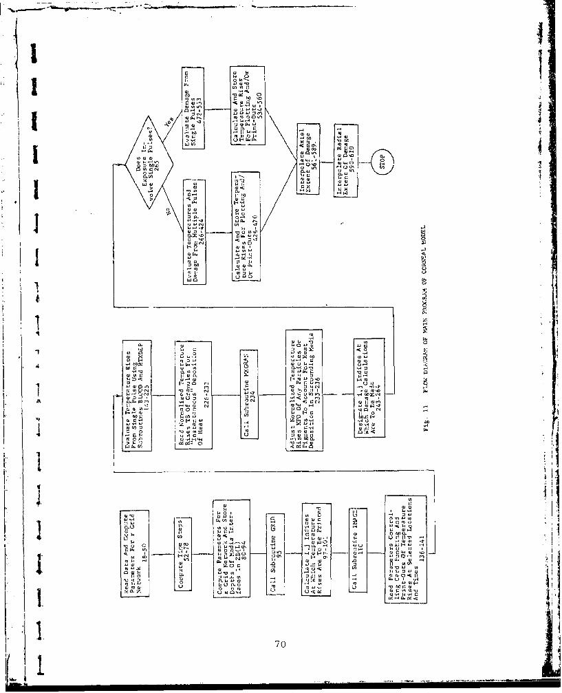
In M
414
bA A 03 a)J
GI W IAýmc
io) a,0 r
'14
w r
0 ho
I, r 0
I! A A0
1- IQ, 0 to
70nC.1

.. • • - "•-• --m . -•-•-- -. " J - • u- -. , _- _ .. .. ... ..... --.
At sequence numbers 36 and 37, the index LPX is set equal
to 0 or I according to whether the laser exposure involves single
or multiple pulses, respectively. This index is used to control
the course of the computations. At sequence numbers 41 and 42,
the laser power and pulse duration zre altered when the pulse dur-
ation is less than 0.3.108 se. In these alteratiousthe total
energy is preserved. These changes save on computational time and
reflect the fact that the conduction of heat over dimensions of
0.0001 cm is insignificant during times less than 0.3-10-8 Sec.
Corneal Main: Sequence Numbers 57-61
At sequence numbers 57 through 61, the time step DT and the
total time TIME are computed for single-pulse exposures using the
arrays XCT, NPT, and KTT as a function of the pulse dur:ition D1PULSE.
The expansion factor XC by which successive time steps are in-
creased is selected from the values of the array XCT. The number
of time st-eps NIP within DPULSE i s selected from values in the array
NPT; and the total number of time steps KT is selected from the
values in the array NPF. The values a;;signed these arrays ore given
on data cards 18, 17, and 19, respectively. The result of these
computations is time steps, DT, XC.DT, XC 2 .D.,.X*(KT-I).DT, where
the total time TIME is given by
I ( 1i ' x c K T -
TIME = (xc)n.DT = DT.--X_•Z1 XT(KT) (34)
The elapsed time from the start of a pulse to the K-th time step
is represented by XT(K+l). Here XT(1)=0. At the end of a pulse
of duration DPULSE,
I..XT(KM) = DPULS, (35)
[ I) C ]orneail . Nin: Seqen•e ( NumbI)rs 64-75
At sequence numbers 64 through 73, the code computes TIM"1,
and DT for multiple-pulsed exposures. Also the expansion factor
XC is set equal to the relatively large value of 1.4 so thait the
total time TIME brackets all the pulses without resorting to large
number s of time steps. The total time TIME' is determined by firstevaluating tie trlin length and then multiplying the rcsult by1
71

the value found in the array FTIME for the pulse width. To provide
maximum flexibility the array FTIME is described by input data as a
F function of pulse duration. Elements of FTIME should always be
' greater than 1.
If the temperature rises from a pulse do not approach zero
iin the alotted Lime, then one should increase the particular ele-
•• I ment of the arLay FTIME corresponding to DPULSE.
At sequence number 73, DPULSE is subdivided into NP uniformtime steps of magnitude PTIME (see Appendix D) for subsequent
damage evalu-Lions. For more refined damage calculations, one can
. increase the number of intervals bearing in mind that it will re-
quire increases in the dimensions of arrays with arguments KT and
"KX (see Appendix L).. Here KX equals the total number of time in-
tervals used to evaluate damage from pulse to pulse and presently
equals NP+3 (see sequence number 294).
At sequence numbers 74 and 75 the final values for KT and KM
- •re specified for single or multiple-pulsed exposures.
Cortviai Main: Sequence Numbers 80-85
At ;,equence nwumbers 80 through 85, the i indices foc the
axial grid points are chosen alo-g with the size of the smallestV "*incremenr- DZ on t:Va z axis. Hero DM 4s chosen according to the
Z puise duration DPUjSE, absorption coefficient (ABS(l) for corneal
I . damage (r M"S(4) for lens damage) and the constants DZI and DZ2
assigý,ud )n card no. 1. To erisule DZ is not too large, the user
"shiould ex a•; '.o the temperature results for excessive temperature
changes. Such co-,•- may be remedied by altering th.e values as-
signnd DZl and DZ2.
Col .al M3in; Setuence Numbers 87-95K From sr.ikjencc numbers 87 through 94, the distances ZD of-- th. 'ai>..:uc IriLterfaces from t', cornea are computed using the
the v ¶ , . r s f o ' c
assagyied thicknesses TH for tk. various media. Here ZI)(8) is
.•et equal to an exceptioo:i , large value to ensure it contains
"1M3), the last: grid "0 icr oa the Z a.s.
At seic:encc number 95, subroutine GRID is called to compute
< * the locations of all grid pojirýs Z(i), R(j),
72-

- ---
& the indices for the various eye media, and.
A *o other spacially-dependent thermal properties.
A discussion of this subroutine is given in Section 7.2.2.
Corneal Main: Sequence Numbers 97-1.01
Here the i,j indices, at which temperature print-outs aredesired, are computed. These points are chosen according to
the values assigned IDI, ID2, JDl and JD2 on data card no. 11.J Temperature print-outs are provided for i indices ranging from
IPl+ID1 (input) to IP1+iD2 (input), where IPI refers to first
point in the coraiea regardless of the value assigned ILENS.
Corneal Main: Sequence Number 110
In this section subroutine IMAGE is called to store the nor-
malized irradiance profile (corneal) in the array HR(j) and toassess how the profile is altered in depth by corneal refraction.This subject will be returned Lo in Sections 7.2.2 and 7.2.3.
Input data describing gaussian and uniform profiles are to be
placed on data cards 4 and 6, while other profiles may be desig-
nated by using data cards 12.,', l9; and 19A*** of subroutine IMAGE.
Corneal Main: Sequence Numbers 113-123
In this section the initial temperature rises are set to an
insignificantly smrnli non-zero (10-li) value. This provision is
provided to prevent subsequent underflow. Computer installations
without library routines to handle underflow will not tolerate
temperature rises of the order of 1.-10-37 that are other than zero.
Corneal Main: Sequence Numbers 145-225
This part of the code assesses temperature rises caused by
a single pulse as described by Appendix A. Here heat is deposited
at a rate of S(i,j) per unit volume at each point Z(i), R(j) duringS the pulse, i.e. at times of XT(1), XT(2)...XT(KM). umie d ia telIy
after che pulse, S(i,j) is set equal to zero by subroutine 1TXDEP.
S | Two p1rov::sions are left to the discretion of the user. The
first is that one can reduce the time intervals used to compute
the temperature rises without changing the time steps XT(K)-XT(K-l).
1 73

This involves changing the integer IKX which provides for 2.1KX
time intervals of size (XT(K)-XT(K-l))/(2-IKX).
IMX may be altered by adjusting the values assigned EDTI and
EDT2 on data card no. 12. This provision is included so thaL one
can improve accuracy or eliminate instability without having to
increase the number of time steps KT and storage. Except for longpulse times, a value of 1 for IKX is usually adequate. To reflect
J the fact that IKX should be greater than I for pulse widths of theorder of 1000 sec or more, DPULSE has been included in the evalua-
tion of IKX.
The second option is thi times at which temperature print-
outs are desired. This option is provided by the value assigned
ITYPE in the input data. If one wishes print-outs at each of
the times XT(K), then one merely sets ITYPE =1. If one wishes jprint-outs at every n-th XT(K) then ITYPE should be set equal
to n. Print-outs will always be provided at the conclusion of
the pulse as well as at the last time XT(KT).
Corneal Main: Sequence Numbers 231-236
This part of the code is provisional in that it *ipplies only
if there are any particles in the eye. At present, no particles
are considered so that subroutine MXGRAN sets both XPD and AP
equal to one. The above discussion also applies to the ay-rays
VE(L,K,2) and VZ(L,L6,L3,2) which will be discussed later in thissection.
Corneal Main: Sequence Numbers 243-262Here we select the points ID(L), JD(L) at which damage cal-
culations are to be made. Two input parameters are required to
specify the points. The iirst is the radial distance RMAX over
j which damage assessments are desired. Damage is evaluated for
all grid points starting at R(1) and ending at the first point
beyond RMAX, namely R(JM).
rhe second control one has in selecting the points is in the
value assigned LIMAX. Knowing this variable, the code establishes
the depth Z(IMAX) of greatest temperature rise beyond the tear layer
71

K Iand the assesses the damage from Z(tMAX-LIMAX) to Z(IMAX+LIMAX).
Thus when LIMAX is set equal 1o zero, damage is evaluated only at
the depth of highest temperature.
J Tha number of points at which damage is to be evaluated is
given by LIJ. If LIJ is larger than the alloted dimension for
3 the arrays associated with LIJ, then the computations are halted.
Moreover, care should be exercised to limit the number of points
I -- fir-st, because points remote from the region of greatest tem-
peratufe require considerable time to heat and cool, and secondly
-, becau,-e of the appreciable increase of storage required when LIJ
is increased.
Corneal Main: Sequence Numbers 269-366In this section the temperature rises caused by multiple
pulses are computed using the temperature predictions for a single
pulse. Also, the array ZTT is evaluated for subsequent computa-
tions of the damage.
-- First, the temperature rises at the grid points, ID(L) and
JD(L) at which damage calculations are desired at times XT(K) are
stored in the array VE(L,K,n). The index n is provided to distin-
guish between any particles and their immediate surroundings. At
present this provision of the code is not used so that the temper-
atures VE for nýl and n=2 are identical. As may be noted at se-
quence number 283, provisions have been made to evaluate NTEST
exposures during a single computer run. These exposures may
"differ only in their repetition rate or number of pulses.
The basis for the multiple-pulse computations is presented
"in Appendix D. First temperatures are interpolated at a nuri-
I, ber ol select interpulse times during and between successive pulses
- since the interpulse times differ from the times XT(K). The total
number of interpulse times from one pulse to the next, is given
by KX -- where NP interpulse times are uniformly spaced across
each pulse and three are uniformly spaced across the interval be-
tween pulses. Measured from the beginning of each pulse, the inter-
pulse times for the thermal damage calculations are represented by
ZTX(L3) while the interpulse times associated with any parti.le
" -.-- "--- - -- -- mI I-- - I i-i-. i i I

~- -- - _ __.•.. ....
fi
temperaturea; are represented by ZT(L3). For a description of these
times the reader is referred to Appendix D.
• |Temperatures are stored in VZ for each pulse only when the
number of pulses is less than 20. Otherwise the code groups
the pulses into an odd number of IN pulses, and stores the temper-
I atures associated with the middle pulse of each group of pulses.
Later these temperatures are used to assess the damage caused by
each group. The number of groups of pulses during the exposure
is INX, while the number of groups of pulses contained intime TIME is represented by INXX. In order to account for the
fact that the time TIME exceeds the train length, more pulses areSconsidered than actually exist. The reason for using more pulses
than exist is to provide for temperature predictions following
"- the exposure (see Appendix D). This point will, be returncd to
later in this section.
In order to relate the interpulse times to the times XT, it
"is first necessary to add the interpulsc times ZTX and ZT to the
product of the number of prior pulses and the timc interval TCfrom pulse to pulse. These times are designated by X3 and arecalculated zit sequence numbers 331 and 335, where L7 equals the
number of pulses started during the times of interest.
From sequence number:: 326-341, the temperatLures during
I the middle pulse of the first group of pulses are evaluated anid
stored in VZ(L,L6,L3,n), where L indicates the point ID(L), JD(L)
I at which the temperatures are calculated; LG equals une for the
K. first group of pulses; L3 designates particular interpulse times
and n indicates whether the temperatures are for the media or any
particles.
I To interpolate the temperatures at time X3, it is firstnecessary to determine which pair of XT(K) bracket X3. To this
j end it should be remembered thot the times XT are given by
"76
,_•i i I i I IIL

I5 xTcl) .--0
XT() CK-i1- (36)XT(K) = DT- XC-- (36)I "XC-.I , K>.2
To find the time XT(K) just prior to X3, one merely substitutesX3 for XT(K) and solves for the integer value of K. In thisIlmanner X3 is located between XT(K) and XT(K+l). Linear inter-polation is then used to find the temperature at tire X3.
From sequence numbers 342 through 360, the computations are
continued for subsequent groups of pulses i.e. L6=2,3.. .INXX.
In each case the computations start with the pulse following thelast pulse considered, and end with the middle pulse of the
succeeding group. These temperature contributions are then summed
for each of the previous pulses. The result is a description VZ
of the temperature rises during and following selected pulses for
a total of IN.INXX pulses.
As mentioned previously the number of pulses IN•INXX consid-
erably exceeds the number of pulses IN-INX in the exposure. There-
fore, for times exceeding the total exposure time, one must subtract
the temperature contributions from the last IN-(INXX-INX) pulses.
This operation is performed at sequence numbers 361 through 366.
Corneal Main: Secouence Numbers 368-424
Here we compute the damage caused by temperatures from multi-
ple pulses. Damage is evaluated at the points with indices ID(L),
JD(L). For each point, an initial estimate is made of the factor. CQ by which the input laser power POW is to be multiplied to arrive
at the threshold power. This operation is conducted from sequence
numbers 376 through 379. The relationships used to estimate CQ are
peak temperature rise achieved at the point in question. Damagecomputation! for points having a negligible temperature rise of
0.001 C are aborted and tha threshold power QD(ij) set to the
j I arbitrary value of 10 Without this provision the computer
could run without end in attempting to find the threshold laser
power.
77fit

I Having made an initial estimate of the laser power, thenext step is to set the control indices LLT and LGT to 0. Later
the index LLT is assigned the value I when the assumed laser poweris. less than the threshold value, while LGT is assigned the value I
when the assumed laser power exceeds the threshold value. We will
return to this subject.
The damage calculations are made from sequence numbers 384
through 395. Two criteria are used to assess damage. The first
is the use of an arbitrary temperature TSTEAM. If the temperature
7 . rise VZ exceeds TSTUFAM-TO, where TO represents the initial temper-
ature, then irreversible damage is assumed. For the computer runs
considered, peak eye temperature is a poor criteria of damage. The
second arid more meaningful damage criteria is thermal denaturation.
The latter criterion is the one used in this report. Over a time
increment of say At, this criterion predicts incremental damage A,2
(see page 152) of"exp [ iln Ci-C 2/Ta(t)+in Atj (37)
where C1 and C2 are constants and Ta(t) is the absolute temperature.To assess the incremental damage one merely sums the exponentials
of thce logarithm of AQ. The accumulated damage DAMC is therefore
given by
DAMC exp(XI) (38)
"where X! = In CI-C 2 /Ta (t)+ln At. When groups of pulses are con-
-. sidered, At is multiplied by the nunber of pulses IN per group asmay be seen by rxamining the array ZTT back at sequence numbers309, 31-6 and 319.
178
! !

' |I
These damage calculations involve all ocular media other
than the 61im tear layer over the cornea. This layer is not
considered since it consists essentially of water.
After the damage has been evaluated for the assumed laser
power, CQ is either increased or decreased by 4% according to
whether DAMC is less than or greater than 1, respectively. Inthe process LLT is set equal to one if DAMC <1 while LGT is set
equal to one if DAMC > 1. Once both LLT and LGT equal 1, the dam-
age calculations are completed since the assumed power has crossed
over the threshold value. Then one-half of the last 4% correction
is returned to CQ so that one can be assured that the predicted
value is accurate to within 2%.
To separate the predictions of laser power caused by the two
criteria, TSTEAM is progressively increased until the last two
"sets of power predictions are the same. To determine when this
"occurs, one of the predicted laser powers is selected ;ind stored
"1in XQ so it may be compared with its subsequent v•iiue.
Thus, the last two sets of power predictions are associated
with thermal damage while earlier prcdictions indicate the laserpowers necessary to produce temperature in excess of TSTEAM. One
word of caution is needed at this point. Damage assessments ireonly made over tho time TIDE. At; regions far removed from the
-region of greatest energy deposition considerablu time is required
to heat and cool such regions and the assigned time TIME may noLbe adequate. The adequa'zy of the time may be judged by exariminingg
the temperature print-outs. If the temperature peaks and then
drops by more than about 5'C. then thL predicted power is satis.-
factory. Otherwise-, one should incr$-nse TI.YE through the array
FTTIMI anid increase dimensions of arrays containinig the time index KT.
Cornea t. Maini: Sequence Numbers 426-4 70
This section provides data cards Cor plotting the temiperatures
at time specified by the user. Here the temperature rises from
multiple pulses are calculated at point•s with axial iiidiceS i rangLnm,,
I1

from III through 112 and radial indices j ranging from JJ1 through
JJ2. The times at which the temperatures are desired are inputed
by the user in the array TIMEX. These times are measured from the.
start of the first pulse and may assume any value from 0 to TIME.
In addition to being provided with the temperature rises,
the plotting routine must know the range of the points over which
plots are desired as well as the peak temperature rise RGV of
the profile. Also to aid in identifying the curves a provision
has been included to label one of the curves. In this regard the
plotting routine will index the curve having an assigned value
113 for i.
In addition to providing data cards for plotting, provisions
are also made for print-outs of the data. Three options are avail-
"" able to the user. If KTYPE is assigned a value of 0, then no cards
"or print-outs will be provided. If LTYPE=n and KTYPEO=l the code
will only print the temperature rises at n times TIMEX(n) . Values
of KTYPE=n and KTYPEO=O will provide cards as well as print-outs.
Corneal Main: Sequence Numbers 482-533
This portion of the code computes the damage from single
-. pulses. The basic difference from the daitmage calculations for
,. multiple pulses is the use of the temperatures at the Lime XT(K)
Here the code assesses the damage from the KM time intervals, i.e.
XT(2)--XT(1) ., XT(3)-XT(2) , etc., during the pulse as well as an
additional (KT-KM) timi! intervals following the pulse. As with
•multiple pulses., damage i•s evaluated by using the temperatures
at: the mid-points of the Lime interval.s. Other Than the difference
- in vime interva].3 the cnomputations are identical to those for
multiule pulse and the same observations apply.
I Corneal Ma ui Sequeuc.e Numbetrs 536-560
'ere provisi.or's are mnade for prepidrini, dat: cnrds fUor con-
sL-ru c L ing 3-1) and 2-D pro01ile:.; If he L: 11)t . Iic ted
1 0 CL ti 'III and tAIII , 1. 's x :e.'pL: fo,' l''e use ( of a s.1.ngle pils , Ihe
Conl)ULal Lons are identical to those u.ed fur: mu: ipeIC pulses.
'.. 0I •

'II
j Corneal Main: Sequence Numbers 561-610In the final portion of the main program, the predicted laser
power QD for the specified points are used to assess the region
damaged by the particular laser power specified by the user.
To assess the axial extent of the damage, the computer first
scans the predicted power to find the i indices at which the pre-
dicted powers bracket the specified power POX=POW. For minimum
Sdepth of damage (low i values) the indices are 15 and 16 while
for maximum depth of damage (high i values) the indices are 17
and 18. If POW is lower than all the QD(i,l), then 16 assumes
the value 0 and all remaining computations are aborted. If POW
1 exceeds all the QD(il), then the computer prints out a message
indicating this fact and all future axial computations are aborted.
To interpolate the depths where QD=POW, the following equa-
tion is used
QD = Xl'exp(X2-z) (39)
where QD represents the power, z represents the axial distance
and Xl and X2 are constants to be evaluated. By substituting the
",two laser powers, say QD1 and QD2 , that bracket POW into Eq. 39
* along with their axial distances, say z1 and z 2 , one can solve the
resultant equations for X1 and X2. The result is
Xl QDl/exp(X2.z) (40)
X2 log(QD2 /QD1 )/(z 2 -z 1 )
Thus, substituting X1 and X2 back into Eq. 39, replacing QD by POW,
T• • and solving for the threshold depLh z yields
z = Iog(POW/Xl)/X2 (41)
L By using the pair of laser powers found for small i values and
for large i values, one arrivcs at the minimum and maximum depths
I of damage along the eye's axis.
Starting at sequence number 590 a similar set of computations
j is made to assess the radial extent of damage for the depths at
which the predicted power exceeds POX or POW. Except for tle use
881

of r instead of z, the same analysis is used as exemplified by
Eqs. 39 through 41. This then completes the description of the
main program of the Corneal model.
7.2.2 Subroutine GRID for Corneal Model
Subroutine GRID establishes the values for Z(i) and R(j)
subject to the values assigned N, NI, N3, Di, RVL, M, ML, M2,
M3, TH, and DZ in the main program. Also the subroutine evaluates
the matrix elements A and B for the finite-difference solution of
the heat conduction equation. Moreover, the subroutine determines
the location of the i indices associated with the first and last
points of eac i eye media. Finally, the subroutine stores the
assigned thermal. conductivities CON(i) and heat capacities VSH(i)
at the appropriate depths Z(i).
Appendix I describes the techniqnes used to develop the
grid ne twork.
Corneal GRiD: Sequence Numbers 1-3-1.9
Here fhe subroutine evaluates the expansion factor R2 by
which the radial grid steps are sequentially increased starting
at j=Nl. The grid is selected such that the radial extent RVL
"of the eye is located at
RVL = (R(N-l)+R(N))/2 (4Z)
For more details the reader is referred to Appendix I.
Corneal GRID: Sequence Numbers 27-32
In this section the radial distances of the radial points
R(j) are evaluated and assigned.
Cornenl GRID: Sequence Numbers 34-52
Here the matrix eloimlnts B(.,1), B(0,2) and B(j,3) are oval-
uatod for the finite-diffurenee solution of the heat conduction
equat:ion. A dIscription of these elements aind their use is given
S iin Appendix A.
Cornea• I GRID: Scouence Numbers 54-6'3
This portion of. the code assesses the expansion factor R1
for them z grid. Two different grids are chosen depending on
82
-iM.. - 1w - 1 -

J 1
whether damage occurs at the cornea or lens. For the corneal
case the anterior tear surface is located midway between the
first uniform increment at (Z(IPI-l.)+Z(IPI))/2 while the sixth
eye media extends to a depth of Z(M3)..
7- To assess lens damage the fine grid work starts at the depth
ZD(4) of the anterior surface of the lens. This means this sur-
face is midway between the first uniform increment located at
(Z(M2+l-MI)+Z(M2+2-MI))/2 while the anterior surface of the tear
layer is raidway between Z(3) and Z(4).
Corneal GRID: Sequence Numbers 71-83
Here the subroutine computes and assigns the values for the
various Z(i) using the expansion factor RI.
Corneal GRID: Sequence Numbers 84-108
tlHere the subroutine uses the depths of the various interfaces
to locate the initial and last grid points in each media. The* resulting i values are stored in the arrays IX and LX and then
assigned to IP2, IP3... IP6, LPl, LP2...LP6.
Corneal GRID: Sequence Numbers 11.0-127
Here provisions are made for the eye media having different
thermal conductivities CONX and heat capacities VSHX. To accomo-
date any differences, the assigned thermal properties are stored
with depth in the arrays CON(i) and VSH(i).
Corneal GRID: Sequence Numbers 129-136
Here the matrix elements A(i,l), A(i,2) and A(i,3) are eval-
uated for use in the finite-,differunce equations of the heat con-
duection equation discussed in Appendix A. These elements were
chosen so that there is no heat flow from the cornea to the envi- 4
ronmental air. In thLs regaird, the effects of blinking have been
lneglected. This effect could be important for pulses inl Uxcuss
of0.1 sec.
7.2.3 Subroutine IMAGE of Corneal Model
Chis subroutine performs two major functions. These are to
deteUrminej the
• * - - - --..-

0 normalized laser profile at various depthsof the eye (normalized means profiles havea value of I at the eye's axis).
j • irradiance QP on the eye's axis by which thenormalized profile HR must be multiplied toobtain the irradiance across the beam priorto any internal reflections ot" absorptiion.The latter are accounted for in subroutineHTXDEP.
4 Corical IMAGE: Sequence Numbers 10-20
Here the number of radial increments is specified for deter-mining how the profile is altered in depth by corneal refraction.
The increments have a radius RINT and extend across the pupil or
beam radius, whichever is smaller. The number of increments across
the pupil radius PUPIL is (LI-I). The radial increments RINT are
chosen accordingly. Later if the beam proves smaller than the
pupil, the number of increments is reduced and stored in LII.
Corneal IMAGE: Sequence Numbers 21-22
Any symmetric laser profilc may be accomodated by the code.
The most obvious profiles are the gaussian (II'ROF=l) and the uni-
form (IPROF=0). Other profile shapes may be handled by assigning
a value of 2 for IPROF on data card 6 of the mlin programi.
Corn-Lal IMAGE: Sequence Numbers 25-4.1
For irregulair profiles (other than gaussian or uniform), theuser must specify the profile's shape on a point by point basis.
This is accomplished by first assigning the number of points LRI
on data card 19A. Then the profile values PX and associated radialdistances RX are read on data cards 19A and 19A***. The numbers
used to describe the profile intensities need o'ly be reli tive.
From sequence numbers 30 through 39 the code normalizes the
profile villues PX and then integraItes the profile over it's radial
airea. The intcgral of the normalized profile is represe.nted by X5.
Two additional. determinations are made in this portion of
the subrouLine. The first is the du termina Lion of the irr-adiance
QP Cntering the eye on the eye's zixis. The second is to determine
b 4

whether or not the profile extends beyond the pupil. When the
radius RX(LRý) of the profile is less thani the radius of the pupil,
the number of radial increments 1,11 is redUCed accordingly.
Corneal1 IMAGE': Sequence Numbers 42-5 1
Here the magnitudes of the irregular profile are evaluated
at radial increments of RINT and stored in the array FX for future
USe-,.
Corneal1 IMAGE: Sequence Numbers 57-62
In this part of thec subroutine, thle code evaliut~es galussianl
profile13 at the points R(j) as well as the irradiance Qi'.
Corneal IMACE: Sequence. Numbers 65-67
Here the subroutine stores thie values of uniform profiles at
R(j) In addition the~irradiance QP is evaluated.
Corneal IMAGE: Sequence Numbers 71-95
This seccioni is resurved for irregular profiles. Here we
have avoided interpolat~ion of the intensities at R(j) in- that it
could cause appreciable errors inl the energy de~positioni. In ste ad
an evaluation is first: wide of the, radial aroa and laser power
l)eCtwc20f r=O and the radial clisuLnices (L-5) RlNT. Thei ore-as arc
*stored in the array FA(L), WhiLl theI accuinulL1tCi I)L)WCrS are Stored
*in the arr-ay FP?(L), Thecse arrays aire then used to find the. average.
intensity of the laerbam from (R,(j -l)-R(j )) /2 to (R(j )±R(j+l)) /2
an~d stored in IIR(j). Then the profile is normalized at sequence
-numbers 93 through 95.
Coreua 1 IMAGE: Sequenice Numbers 96-116
In all the previous M)L cuptO L~iDIS theC irra -ianc C )rOf Ii I
.. has the same shape as that of the laser beami at, the cornea. T1lissection com1putes the. al teration of- 'the profile IIR by cornlea Ire.-
f rac Lionl. A discussion of the means by which Lthis is accomplishe~d
is pr.:suntcd in Section- 3. liero we haive eva itia ted thec array
/CON(ij) by which I[]-(j ) is to be, multiplied Lu arrive at thie
the 'rOSLII Lan1-t pr-oft le OS a func tion of d cpth. The resul .tan t pro -
fil~e bucomes, miore com~pact withi depth due to conivergence of'L Lhe

I
In the next section we shall discuss how subroutine HTXDEP utilizes
the arrays HR and ZCON to compute the rates of energy deposition
per unit volumen :it each of the grid points, For this purpose, one
must know the absorption and reflection coefficients of the vari-
ous eye media.
7.2.4 Subroutine HTXDEP of Corneal Model
This subroutine assesses the rate of energy deposition into
the various regions of the eye on a per unit volume basis. A dis-
cussion of the techniques used is given in Appendix F. 1he pri-
mary advantage of this analysis is that the eye's interfaces need
not coincide with the boundaries between grid increments.
To determine the rates of energy deposition, the subroutine
projects the beam rays refracted at the cornea to all depths of
the eye. Refraction by the lens is not considered since it has a
negligibly small effect on corneal or lens burns. Due to corneal
refraction the beam converges with depth as may be seen by examin-
ing Fig. 2.
Corneal HTXDEP: Sequence Numbers 10-12
These statements control the course of the calculations.
Initially, the control index IHT is set equal to two in the main
program while QP has a value exceeding 1.10-10
The heat deposition rates S(i,j) are evaluated following the
first entry of the subroutine. After these computations are com-
pleted, IHT is set equal to 1 so that the same S(i,j) values are
used throughout the pulse. This means, of course, that the laser
power is constant during the pulse. Once the pulse is over, QP
is set equal to 0 in the main program causing i subroutine to
set I1T and all the S(i,j) equal to zero. Once IHT assumes a value
of zero, all future entries are aborted.
Corneal I-TXDEP: Sequence Numbers 14-26
Here the subroutine sets LZ equal to the number eye media + 1.
Moreover, LZO is set equal to the number of eye media while LZl is
set equal to the number of interfaces in the eye and uiiderlyiug tissue.
86

I:
3 Then the boundaries Zl-(i) of the z increments are evaluated, and
the arrays II, IZ, AB, REF and REFL are initialized to zero. These
arrays will be discussed as they are evaluated.
Corneal HTXDEP: Sequence Numbers 29-74
i Next the subroutine evaluates the arrays AB, II, IZ and ABR.
For details of this analysis the reader is referred to Appendix F.
Here AB(i,L) represents the product of the absorption coefficient
and thickness of each eye media in the increment containing Z(i).
The index L ranges from I to the total number of media contained
within the element. To identify which media interfaces are locat2d
L within the increments, the array 11(i) is used Lo ezopresent the
Snumber of interfaces within the i-th increment plus 1, while 17(i)
is used to represent the argument of the first interface ZD within
the increment. The array ABR(iLI) represeuts the sum of the
AB(i,l), AB(i,2)... associated with each media between ZH1(i-l)
and ZD(Ll).
In order to prevent the possibility of underf•Low due to
excessively large values of Ali or ABR, they were limited to a
I value of 10. This value was chosen since it means that practicallyall the energy will be absorbed within the particular element.
" I Corneal HTXDEP: Sequence Numbers 75-94
In this portion of the subroutine, the incoming irradiance
Sis followed through each media to find rates of energy deposition
in each increment. Here X3 represents the irradiance entering an
3 increment; X2 represents irradiance entering the next increment;
and X4 represents the irradiance reflected away. To account for
irradiance changes with radius, the resultant values ar- multiplied
by the profile shape 11R(i,j)>ZCON(i,j). To arrive at the rates of
1 energy deposition S(ij) per unit volume, the above product is
divided by the increment's depth, i.e. ZIi(i)-Zi(i-I).
I To guard against the possibility of underfiow, S(ij) is set
equal to zero whenever the rates of energy deposition become ex-
Scessively small (10-1 0 /DPULSE cal/cm3 -sec)-
187
I I I I I I I I I I I I II i ' -i

!1
Corneal HTXDEP: Sequence Numbers 97-120
j From sequence number 97 through 103, the reflected intensities
REFL are evaluated for each of the interfaces. Itmmediately there-
j, after, each of the reflected irradiances are followed through the
eye to arrive at the rates of energy deposition per unic volume
3 at each of the grid points Z(i), R(j). The results are then added
to the deposition rates from the incoming beam to arrive at the
total rates of energy deposition.
Corneal HTXDEP: Sequence Numbers 123-126
- As mentioned earlier, after the pulse is over, S(i,j) and
- IHT are set to zero. Thereafter, all subsequent calculations by
this subroutine are aborted.
7.2.5 Subroutine MXGIAN for Corneal Model
This subroutine is a remnant from the Retinal model for asses-sing temperature rises of PE granules. Since no particles are
presently considered in the Corneal model, the normalized particle
temperature rises XPD(K) have been set to one. If at some future
date, one wishes to examine the effect ot any particles, one
merely substitutes a modified version of the subroutine used in
the Retinal model.
7.3 Description of Code for Preparing, 2D and 3D Illustrations
* This code utilizes the temperature rise predictions from the
models to display two and three dimensional temperature rise pro-
files as a function of the radial and axial coordinates, and of
the times from the start of the laser exposure. Provisions are
made in the code for varying the angles from which the profiles
"are viewed as well as the dimensions of the profiles. Appendix F1
"presents a user manual for the code along with its listing.
88'I-
<I
8. MODEL PREDICTIONS, AND SENSITIVITY AND ERROR ANALYSES
8.1 Model Predictions of Laser PowJerNecessary to Cause Given Lesion Sizes
A total of 18 cases were run covering corneal damage, and a
total of 32 cases were run covering retinal damage. In the corneal
calculations, the laser beam was refracted at the cornea so thatthe beam radius decreases progressively with depth. In the retinalstudies, the image was identical -o that estimated experimentally.
Results of the two sets of computer runs are given in Tables 11 and12 for the Corneal and Retinal models, respectively.
In both tables, the experiments are referred to by run numbers
and ordered in terms of increasing pulse widths. Experimental dataassociated with the run numbers are presented in Tables 9 and 10of Section 6.
8.1.1 Predictions of Corneal Damage
Two criteria were used to assess the accuracy of the Corneal
model -- one involving predictions of the laser power necessary to
cause the given experimental lesion, and one involving predictions
of the size of lesion for the given experimental laser power. Froman examination of the rorneal results shown in Table 11, it may beobserved that with one exception, the predicted laser power always
exceeds the experimental values. This discrepancy is particularlypronounced with the short pulse times of 10-7 to 10-8 sec. The
fact that the discrepancy is much greater than can be attributed to
errors in the prediction of thermal damage suggests the damage is
caused by some other mechanism other than thermal or that the es-
timated lesion size is in error.
One likely candidate for causing the damage is the generation
of compressive and tensile waves due to thermal expansion. This
hypothesis is based on the fact that the energy is delivered in
sufficiently small times to produce presure waves of the orderof 100 psi. The fact that the anomoly arises with short pulses
probably reflects the fact that when similar quantities of energy
Ij 89a

.0
UdU
"I W
I 0o :x~
XE-4
-.1 L" - t- -t I 4 4L
E-f 0 r4-4 r-4 r- _ -4C -a C) C) a1
a 4 C 0'0 0'0 D6 0' 0 0'00'C, 0*CDQQ0 00
4-4t- 04,it4,)
rA~
Iz wU CE-41- W ___4v4r4r C _r- -
4) :0 t13) 00000000000D ý , -r- , C400 000004Ltý nr4 ý- 9. . . . . . .
(A r40000000U3V r4r I l.I v.I 4.I'
4.'.I I I
I '-4
0~~~~~ V)C C - . )ý . 1 )r4L)CNC r 0rIw r_ _ _ nL -M ON 0c)r0~~r iC
zi -- 34 1 ýr ý1 ýC - r - r
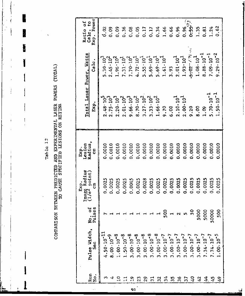
0 0 C. ON C % o ,. ,. ., n rý r. .4 %, v. ,4. S-4 C°°C; 000r-C0 HOHO
U3, r-4- 4 r a
•, , • . •. * _ • o• . , . *. . •.
0.) 0 01 D0,1
--4 "4 r- -I I r- -4 -4 -4 4 r- r4 r- r- t- i I
I c
E-3
00
H
R.'.4 000000 0000 00 z D0000000
w~u to ~ uL;jiac t ~U r~I A L)I AU
c-40 0 0 0 0 0 , r
E* C C -4 I Y l nI "-0,D " c4 0%(0 0u
m 0.
C4 H
WCA)
L0 In aI

-,H
m0 P-1 -:,U) c n c , , - D ON ýo 0* r4 .
4j- .- H 00 0 0 0 0 0 C
CU) Y Y q ( Cq r- 4 r-4 r--i cY0-) -1 O1 1 1 1 ~ 10 H cm 1- 1c1
Hl D0 o 0 C )C
00
Cl)
U) N N C4 N C4C 4 C r-4H r-- H H -4 H H- Y
-4
cu >1 0000 o.~ L0 6-0 6I~C) l-4 4j 0 r- r- G- QLn 0 C coZr- c-4 N N q
H0
u") Cq L -
04 ~ Pý-.H r-IE 00 0 00 0 0 0 0 r-An OJ00
H3 Cr- 4 ;C;/ C ; ;C
o 4 - u)Ln~J Lr)Ll) LCn Ln~ 00 irn Vr Lrm 0 ~ q ,-jeq NI N, N, -zt -ýt Cpj LC N N- Nj
C) C)0 0 )0 4- 0W N)C
00 ) 0ý 0ýC,0 cu --
rio LC) C) H Hý Hr U- -4 -4 H 4 -1 -4 r- 4-I-
'Li Or )ol M C)CI N -4r)L lO O O
(3) 4* 0A
0 CC Hn LnONO 0~ CD N 4C)\ C-
4ZZL )Un ~LC Ln ) "D ýD "D "0
92

are delivered over longer times, the pressure waves are of reduced
intensity. Much, however, remains to be learned about the inter-
action of pressure waves with eye media. ln this regard, it is
I suspected that to irreversibly damage a particular region of the
eye, one need only damage some of the critical components within
j the region -- not necessarily all components in the region. Identi-
fication zand modeling of the critical components is no simple task.
I NeL let us explore the fact that most of the power predictions
are higher than their experimental counterparts. The immediate
thought which comes to mind is whether or not the depths at which
damage are predicted are consistent with the minimum depth at which
I damage must occur in order to be observable. Unfortunately, this
argument is not very convincing in that the predicted depths of
damage vary considerably -- ranging from a few microns to tens of
-microns in going from short to long pulses. A more likely possi-
bility is that thermal damage proceeds more rapidly in the corneaSth n n t e etn a, po s b l t
teinterf'I This psiltyshould be explored experi-
mentally.Finally, let us compare the size of the experimentally deter-
mined lesion with the lesion size predicted using the experimental
Slaser power. As may be anticipated from the above discussion, the
predicted Lesion sizes are, with one exception, all smaller than
I the experimentally determined lesion sizes. While this discrepancy
is not large, it is consistent enough to be of concern. The cause
of the excessively small predicted lesion sizes is probably the
I same as the cause of the excessively large predicted laser power.
In this regard, it is suspected that tLe rates of thermal damage
1. for the cornea are somewhat larger than- those developed for skin.
8.1.2 Predi-ctionl-; of Retinal Damage
Resu.Lts of the computer runs corresponding t:o experiments
involving retinal damage are presented in Table 12. NotLice that
for pulses exceeding 1"10 sec, that the predicted laser powcrs
necessary to cause the specified lesions fluctiumte above and
S1)e].ow their experimental counterparts. Slightily better agree-
ment is h'ad ý,;Ji-, the c(XI)0surce s involving- the I ,gest ima gesI, i.

U namely run numbers 61, 62, 64, 65, and 66. Over this range ofpulse durations, the errors appear random and therefore not sug-
gestive of any particular source of error.
The next observation is the fact that the predicted powerfor the short duration pulses (1"10- 1 sec or less) are with one
exception very low. Here we refer to run numbers 3, 4, 10, 19, 23,29, 31, and 32. In these computer runs the image radius ranged
.from 0.0025 to 0.0045 cm at the l/e 2 point of a gaussian profile.
Much of the above discrepancy is believed due to errors in theexperimentally determined image size. For example, when the
image size was calculated for run number 23, the i/e 2 image radius
was predicted to be 0.0075 cm rather than the estimated value of
0.0025 cm used in Table 12. Using the 0.0075 cm image size, the
laser power was computed to be 1.12"103 watl:s which compares quite4. favorably with the experimental value of 0.87'103 watts found
experimentally. This, of course, raises the possibility that the
. discrepancies for the shorter pulses may in large part be attribut." Iý
to errors in the estimated image size. Unfortunately, time did-not allow this question to be explored further. The fact that the
major discrepancies occur primarily with exposures having short
pulses is consistent with the observation that errors in the image
"size have their greatest effect on predictions involving short
pulses.
8.2 Sensitivity Ruiis
In order to better appreciate the consequence of parametricerrors on the predictions of total laser power, four representative
"single-pulse exposures were first selected for the Corneal model"and four representative exposures were selected for the Retinal
model. Next, a set of key parameter; was selected for study for
each model, and estimates made of the limiting errors associated
with each parameter. Finally, the computer codes were uised toassess the effect of the errors on the predicted laser powernecessary to initiate irreversible damage at the ;,xis of the eye.
; I.
94
LkJ,

SI
In these studies, all parameters were held at their nominal values
except for the particular parameter being considered. Results of
the sensitivity analyses are shown in Tables 13 and 14 for the
Corneal and Retinal models, respectively.
"- 8.2.1 Corneal Model
Parameters varied in Lhe Corneal model were the absorption
coefficient, thermal conductivity and heat capacity plus the size
of the incident laser beam, and the rates at which thermal damage
occurs. A description of the nominal and limiting values chosen
for each parameter is presented at the bottom of Table 13.
Four exposures were used to assess the effect of the limitingerrors. These exposures involved combinations of small and largebeam size, and small and large pulse durations. To better appreciatethe consequence of the errors, the predicted laser powers were
divided by the predicted laser power for the case when all param-eters are held at their nominal values.
Examination of Table13 shows that errors in the absorption coeffi-cient have their greatest effect on short duration exposures, and
are of minor or negligible importance for long duration exposures.This result is for the most part independent of beam size, andindicates that during extended pulses the differences in heat
deposition tend to be negated by thermal cnnduction. In fact over
extended exposures, the temperatures are most s(',sitive to the
thermal conductivity as may be seen by examination of Table 13.
Errors in the heat capacity have their largest effect forexposures involving short pulses and small beams. This result is
a consequence !)f the very steep and transient temperature profilesproduced by the above exposures. In such exposures, the temperatures
associated with threshold damage are higher than those required by
longer pulses and/or larger beams. As a result, errors in the heat
capacity produce greater changes in the predicted temperatures
as well as thermal d&,mae for exposures involving short iDuses
?-
95

c. 0~U.> ~ ~ ~ ~ I 0 0~~:3 S 0 m0 N
"N00
~U43 N
N a' 0 ,' a ' a a 0 N
I.D 00 ___ _- c) Q c
s-. (-'
S.. ID 0lC,
-~~ ~ ~~~ 8 ~ "~0.0 0 0 0 0 0
c- L,
* CO .3 43s'3 "
cfE- C) c Uit
43- . 3 -- 01 01 j Q 1
oC' 0) CL-' 0- C
f -4. 'o In
I Ij
~ ~ -' ~;wCD . U4
*..4LCC. . . . . . . . . . . . . .D
0~~ ~ CD o ' ' 1 ' . (300(411U U14
U 0.~ - 4-
:3 4 4L '0 0 u( l(

C.) A-i3. Ctn C 0 0 It a 0 CD -n i\ c- 0
co- 0 f n -3 0 0 a C 0 ' -
OAA'- 00 C 3 ' 00 -
AjuC
mC ci-A .i 0 O0-iA 0- -
-o
L -AF3b
"~ f 2 A" '"a 'L 0- A' - -CD.2 AU -1 )n C
CA Ctc CD C D c) 0 0CA) oi Ii *A - - m
In' -Q3 0 :u , u1n IA s ' t A 4 i 3 i t n Ai n
i~¼o 0 ' An 0 C in 0 0 33 a' i a -J n 0
I- U_ C l I L IC'
H~io 00ýi
C) ~ ~ ~ ~ ~ C WAi. Uý 4
Ci)
F-AC I C 0 C
C) C -
K gu 'U 4 :
I- u wl A) C) C))

iiand small beams. ThIs explains why errors in the heat capacity
have their greatest effect on predictions involving exposures with
short pulses and small beams.
I Beam size is controlled by the parameter CUT which describes
the magnitude of the normalized gaussian beam at r=RIM. Beam size
increases with the value of CUT. Errors in the beam size have their
greatest effect on predictions for exposures involving the shorter
j laser pulses. Thiis result can be explained by the fact that in
such exposures the temperatures are highly transient. In such cases,
1 damage is more dependent on the deposition of energy than on itsdissipation by thermal conduction.
Perhaps the most important parameters studied is the rale at
which thermal damage proceeds with temperature. Here the rates
were increased or decreased by a factor of 100 over the entire range
Sof temperatures. At first glance, one would suspect that such a
factor is excessively large. This is in part true at temperatures
up to 60'C wherein the rates were deternined. Over this range of
temperatures, the factor should be closer to 10 rather than 100.
On the other hand, above 60'C the factor of 100 is probably unduely
conservative. To appreciate the significance of using a factor of
"100 one should examine how rapidly the rates of damage change as
"shown in Table 15.
From an examination of Table 13, it may be observed that the
predicted laser power is very sensitive to errors in the rate of
thermal damage. This is true for all four cases considered.
If one were to rate the parameters in need of more refined
I measurement one would rank them in priority as follows:
* Rate of thermal damage
Se Absorption coefficient and beam size
a Heat capacity
* Thermal conductivity
I,
IIl
I: t
I

4.. I Table 15
RATES OF THERMAL DAIIAGE VERSUS TEMiPE-ATURL
Temperature, Rate of Damage, Temperature, Rate of Damage,Tm]a°C Resec C 1/sec
44 1.62"10 4 82 1.70.107
46 4.35- 10-4 84 6.00"107
48 1.16.10- 86 2.09-l08
50 3.03.10-3 88 7.19.108
( 52 1.5710-2 90 2.44-l10954 7.08-10-2 92 8.1.6"109
56 3.13-101 94 2.69"1010
58 1.36 96 8.78"1010
60 5.81 98 2.82.1011
62 2.44"101 100 8.97-1011
64 1% 01"102 102 2.82.1012
66 4.08"10 0 104 8.74.1012
68 1.63-103 106 2.68"101370 6.40' 10 1-08 8.1.1"104
72 2.47-10 4 110 2.43"1014
74 9.4] 104 112 7.].8.1014S76 3.53- 105 114 2.10" 101
"78 1.30-106 116 6.08.1015
80 4.74"106 118 1.74.1016
I-
1~1o0
(4-m.

8.2.2 11ctinai Miodel
As with the Corneal model, four laser exposures were chosen
to study the effect of the limiting parametric errors oin the pre-
dicted laser power necessary to initiate retinal damage. The
exposures chosen involve combinations of image radii of 0.0025 and
0.0300 cm, and pulse durations of 10"8 and 1-00 sec. Parameters
chosen for this study were identical to those chosen for the Corneal
model except for the use of the image rather than the beam
profile; and the added consideration of blood flow CFLOW in the
"chorio-capillaris, and the fraction RPIE of the pigment epithhelium
containing the melanin granules.
As with the Corneal model, errors in the absorption coefficient
and heat capacity have their greatest impact on exýposures involving
short pulses. These results can be explained by the fact that the
temperatures necessary to cause damage are higher with the shorter
pulses. In such situations, errors in the absorption coefficient
and/or heat capacity result in greater changcs in the predicted
temperature than achieved with long duration pulses. The result
is greater changes in the rate of damage with shorter pulses, and
hence in predictions of the total laser power.
The effects of errors in tile blood flow are most apparent. for
exposures involving large images and long pulses. Here, long
exposures provide greater time for the transport of heat by che
blood. On the other hand, large images create less transient
temperatures which in turn extend the period over which damage
occurs as well as the period over which blood can remove critical
heat from those portions of the eye being damaged.SErr'ors iln tile fractLion IRPH' of tile pigineiir-~ e])ithe ].iuhi] col1tai nitl •
melanin granules are most important with short pulses. The realson
for this behavior is the same as advanced for errors in the absorp-
tion coefficient and heat capacity -- niamely that such errors
÷ bring about greater temperature changes with the shorter pulses.
1JII. :

SIImage size was varied by varying the parameter CUT which
describes the magnitude of the gaussian profile at r=RIM. In this
study the limiting errors were chosen considering that large imagesIIare more precisely known percentage-wise than small images. Exam-
ination of Table 1 shows that errors in the image size are signi-
ficant in all four cases considered, and are most important with
exposures involving small images and short pulses. With such
exposures, changes in the image size have their greatest effect
on the predicted peak temperatures, rates of thermal damage, and
total laser power. From an examination of Table 14, it may be ob-
served that errors in the rate of damage have the greatest effect
"* on the predicted laser power -- assuming the estimated limiting
errors are accurate. This result is true for all four cases considered.
According to the need for more accurate measurements, the
parameters are ranked as follows:
* Rates of thermal damage
a Image sizee Absorption coefficients
a Fraction of PE con ;aining granules
* Thermal conductivity
e Blood flow
• Heat capacity
. 8.3 Assessment of Frequency Distributionof Errors Associated with Predicted Laser Power
Having gained an appreciation of how individual errors affect
the predir'.ted laser power, let us now examine the effect of all the
errors on the predicted power. Here we have used Beta functions
along with the limiting values of the errors to arrive at the
frequency distribution of the errors for each parameter. Then
these results wcre used along with the power predictions from the
sensitivity analysis to arrive at the frequency distributions
associated with the predicted laser power. This exercise was per-
formed for each of the four cases for each of the two models.
101
III

The results are illustrated by Figs. 12 and 13 for the Corneal
model, and by Figs. 14 and 15 for the Retinal model. Confidence
intervals for the four cases of each model are presented below'
Table 16
CONFIDENCE INTERVALSASSOCIATED WITH PREDICTED LASER POWER
Confidence interva is
Exposure 50% 75% 90%o 99%
"Case 1, Cornea .89-1.13 .81-1.21 .75-1.27 .64-1.43
Case 2, .84-1.14 .74-1.23 .65-1.31 .56-1.44
Case 3, .88-1.10 .81-1.16 .75-1.24 .64-1.37
Case 4, "80-1l17 .68-1.27 .61-1.36 .50-1.47
Case 1, Retina .86-1.12 .75-1.23 .66-1.31 .53-1.48
"Case 2, .91-1.14 .83-1.22 .76-1.30 .62-1.44
"Case 3, .86-1.20 .72-1.33 .62-1.45 .45-1.69
Case 4, .92-1.13 .84-1.20 .78-1.28 .65-1.40
Here cases 1 through 4 refer to the exposures of Tables 13 and 14,reading from left to right.
The first observation to be noted from the figures is that
the power prediccions are slightly more accurate with the shorter
pulses for the cornea and with the longer pulses for the retina.
One possible cause for this difference is uncertainties in the
beam profile at the retina. This source of error would have its
greatest effect on retinal burns produced by short pulses, and
"would be of negligible importance for corneal burns. When thiserror is small, one would expect the damage predictions to be
more accurate for the shorter pulses. The second observation is
that the power predictions are slightly more accurate with ex-
posures involving large irradiated areas for both models. One
imay anticilate this result in that, when the laser's energy is
deposited over larger areas, errors in The optical data and thermal
conduction are of lesser importance.
102!

\10
_ 4W4
r-4~- CAcU
I-
III
FC Fi-40
0)0
0 N
r--4 0 ý F-4
- •- i i 2r-4 LH
co
4-1 0
.4 0 - ,-
o Q4 n-
0N 0
'•* (I)
1~ I
-u
I- a)
Hi
00
103
U- ý111 I-
C1 L

I U-)0)
(L)
0)Y
-~ -4 inWC
~CD
~5C)ý,(
CD- 0W ý. ~-4
fl-0
41 F-4 z)
-r- E- CO
L (*O IiD0
P1
.tCD C)) 0 )
*1U~z)-,ao)j 'uotpilqTU~jstQ~ X-u;nbi-axLj
I q 104

44 2 YC-))
r~~ -~ - -- C
r) -- -C 4 E
4-4 0,
(U ~
W4 F-
co w
'- N
ý4 24c I-4-
0)O
0 *4 ýt
r-4
C~l -4
4ou0i-ibo
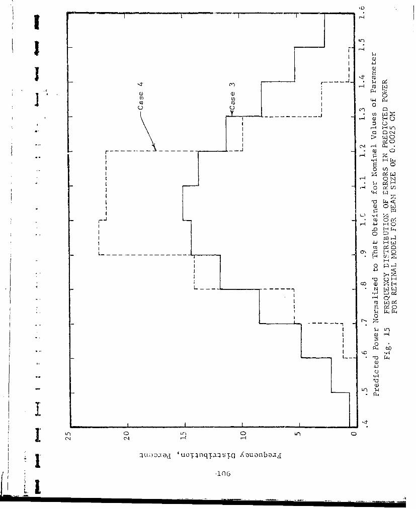
1:4
' 4 - nCID m
> C)
.--4 (14
-J-
r-4 0) N
C0 [N
r4
m o
0)
00j
00
LLr)
-r4
$.)P0
Lir) CD
Li. ~ ~ ~ ~ ~ ~ ~ ~ ~ L' I- ) d u pnqTa- Ec zuon a

* (-
As would be expected the Corneal model provides more
accurate power prediction's than the Retinal model. This is
attributable to the fact that there are fewer variables in
the Corneal model.
I.
107
L 1I

9. SUMMARY AND CONCLUSIONS
During the course of this program two codes, namely the
Corneal and Retinal models, were developed to assess the tempera-
tures and thermal damage produced in eyes by exposure to lasers.
These models differ according to where one wishes to examine damage.
Corneal or lens burns are treated by the Corneal model while ret-
inal lArns are treated by the Retinal model. Computer times for
the models range from about: 10 to 20 sec on the UNIVAC 1103 computer.
Predictions of thermal damage were made using the damage
criterion presented in Ref. 3 for skin tissues. Two means were
used to assess the capabilities of the models for providing ac-
curate predictions. These were to
a assess the error in the predicted laser power"due to estimated uncertainties in the inputdata
. compare model predictions with experimental results
9.1 Consequence of Parametric Errors
To assess the effect of parametric errors on the predicted
laser powers, seven key parameters were chosen. Most sensitive
and those requiring additional accuracy are in order of priority,
for the cornea:
- Rates of thermal dawage
e Absorption coefficient and beam size
* Heat capacity
. Thermal conductivity
and for the retina:
"* Rates of thermal damage
* Image size !a Absorption coefficients
a Fraction ol IP containing granules
* Thermal conductivity
* Blood flow
* Heat capacity
108
i0• U
j Based on estimated errors associated with each parameter two con-
clusions were drawn. These are that the accuracy of the predicted
Sllaser powers is approximately ±14 percent for a 50 percent confi-
dence interval. Of all the parameters, estimated errors for the
rate of thermal damage has the greatest impact on the predictions.
9.2 Comparison of Model Predictions with Experimental Data
Two additional means were used to assess the capabilities of
"the models for providing accurate burn predictions. These involved
1) comparing predicted and experimental laserpower for the given lesion size.
2) comparing predicted and experimental lesionsize for the given experimental laser power.
For the retina, the agreement between predictions and experimental
determinations is reasonably good for pulse durations of the order
0-of 06 sec or greater. Poorer agreement is had for pulses of 10-8to 10- 7 sec. The latter may be caused by errors in the image size.
Of greatest concern is that with picosecond pulses (run 1 of Table 10),damage is inflicted with extremely low energies. In fact the experi-
mental laser energies will only produce temperature rises of the
order of 10- C in the retina. Hlence thermal damage may be dis-
carded as a credible cause of damage for picosecond pulses. Themost likely cause of damage is shocks produced within the melanin
granules due to the very rapid deposition of energy. During such
short depositiDn times the energies cannot escape either by thermal
or mechanical means. The result is very pronounced concentrations
of energy that lead to very steep fronted pressure waves. Whether
or not such waves represent a primary cause of damage remains to
"be seen.
For the cornea, the predicted laser power.-, were almost always
"higlicr than their experimental counterparts. This discrepancy is
particularly pronounced for pulses of the order of 10- sec or less.
S Here the predicted laser powers were some 40 to 90 times larger thanthe experimental values ... 1"his discrepancy sugygests that some other
damage mechanism other than thermal is involved, such as acoustic
10 9
I _

pressure waves. Literature studies (Ref. 4) suggest that the
latter is a credible mechanism of damage. On the other hand, the
discrepancy at the longer pulses suggests that the rates of thermal
damage for the cornea are higher than those of the skin.
9.3 Problem Areas
From the above results it should be apparent that there is a
serious need for information regarding the
1) rates at which the cornea is thermally damaged,
2) generation, movement and damage capabilities ofslhocl< waves,
3) generation, movement and damage capabilities ofacoustic waves.
Measurements of the rates of thermal damage in the cornea should
':ery suibstantially improve the accuracy of the predictions of cor-
neal burns. Such studies would require a combined experimental
and analytical effort -- the experiments I:o establish the damage
and associated temperatures in the corneal and the analytical work
to establish the rates of thermal damage from the experimental results.
Items 2 and 3 appear to be a likely cause of damage at the
"shorter pulses. To resolve this question feasibility studies areI needed. Such studies should not only establish whether the above
rdiscrepancies can be attributed to pressure waves, but also identify
situations in which pressure waves could cause extensive damage.
Only by knowing the extent of damage caused by various phenomena
can one identify the prime cause of damage.
ii0I J
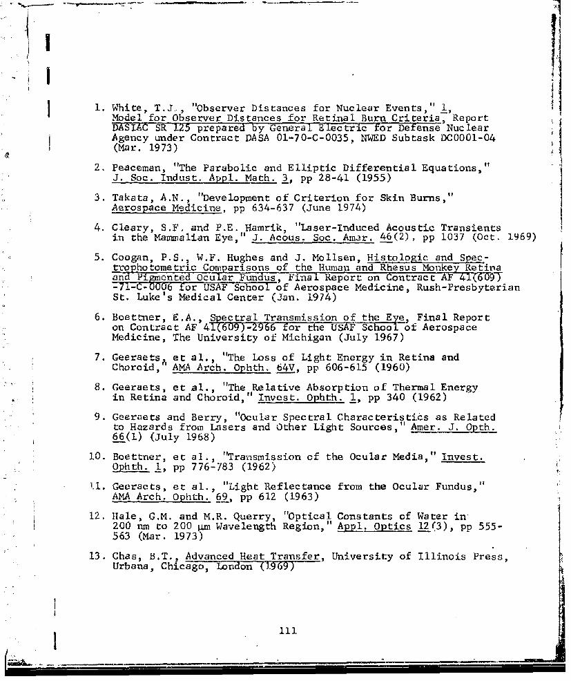
1. White, T .J.., "Observer Distances for Nuclear Events,Model for Observer Distances for Retinal Burn Criteria, ReportDASIAC SR 125 prepared by General Electric for Defense Nuclear.Agency under Contract DASA 01-70-C-0035, NWED Subtask DC0001-04(Mar. 1973)
2. Peaceman, "The Parabolic and Elliptic Differential Equations,"J. Soc. Indust. Appl. Math. 3, pp 28-41 (1955)
3. Takata, A.N., "Development of Criterion for Skin Burns,"Aerospace Medicine, pp 634-637 (June 1974)
4. Cleary, S.F. and P.E. Hamrik, "Laser-Induced Acoustic Transientsin the Mammalian Eye," J. Acous. Soc. Ainer. 46(2), pp 1037 (Oct. 1969)
5. Coogan, P.S., W.F. Hughes and J. Mollsen, Histologic and Spec-trophotometric Comparisons of the Human and Rhesus Monkey Retinaand Pimented OculIar Fundus, Final Report on Contract AF 41(609)-7C-CU0006 for USAF School of Aerospace Medicine, Rush-PresbyterianSt. Luke's Medical Center (Jan. 1974)
6. Boettner, E . A., Spectral Transmission of the Eye, Final Reporton Contract AF 41(609)-2966 for the USAF School of AerospaceMedicine, The University of Michigan (July 1967)
7. Geeraetsh et al., "The Loss of Light Energy in Retina andChoroid, AMA Arch. Ophth. 64V, pp 606-615 (1960)
8. Geeraets, et al., "The Relative Absorption of Thermal Energyin Retina and Choroid," Invest. Ophth. 1, pp 340 (1962)
9. Geeraets and Berry, "Ocular Spectral Characteristics as Relatedto Hazards from Lasers and Other Light Sources," Amer. J. Opth.66(1) (July 1968)
10. Boettner, et al., "Transmission of the Ocular Media," Invest.Ophth. 1, pp 776-783 (1962)
11. Geeraets, et al., "Light Reflectance from the Ocular Fundus,v?AMA Arch. Ophth. 69, pp 612 (1963)
12. Hale, G.M. and M.R. Querry, "Optical Constants of Water in200 nm to 200 pm Wavelength Region," Appl. Optics 12(3), pp 555-563 (Mar. 1973)
13. Chas, B.T., Advanced Heat Transfer, University of Illinois Press,Urbana, Chicago, London -(1969)
11

I
14. Wilson, T.M., et al., "The Measurement of the Choroidal Bloodj Flow in the Rabbit Using 85-Krpton," Exp. Eye Res._ 16, pp 421-
425 (1973)
15. "Thermal Problems in Biotechnology," American Society of AmericanEngineers, New York, N.Y. (Dec. 3, 1968)
16. Maurice, D.M. "The Cornea and Sclera," The Eye 1) Davson Academic
Press, New York, N.Y. (1919)
17. Gallagher, J.T., personal communication to Brooks AFB (July 1974)
18. Bruce, R., personal communication to Brooks AFB (3973)
19. Taboada, J. and R.W. Ebbers, "Ocular Tissue Damage Study for1060 nm Ultrashort Laser Pulse Train" Post Deadline Paper OSAmeeting (Apr. 24, 1974)
20. Vassiliadis, A. et al., "Investigations of Laser Damage toOcular Tissues, AFAL TR-67-170, AFA Lab WPAFB (Mar. 1967)
21. Zweng, H.C., et al., "Experimental Q-Switched Ruby Laser RetinalDamage," Arch. Ophth. 78 (Nov. 1967)
22. Ebburs, R.W. and i.L. Dunsky, "Retinal Damage Thresholds forMultiple Pulse Lasers," Aerospace Medicine 44(3) pp 317 (Mar. 1973)
23. Gibbons, W.D., "Retinal Burn Thresholds for Exposure t. aFrequency-Doubled Neodyinium Laser," SAM-TR-73-45, School ofAerospace Medicine, Brooks AFB (Nov. 1973)
24. Beatrice, E.S. and P.D. Shawaluk, "Q-Switched Neodymium LaserRetinal Damage in Rhesus Monkey, Memo Report M73-9-1, FrankfordArsenal, Philadelphia, Pa. (Mar. 1967)
25. Vassiliadis, A., et al., Research on Ocular Laser Thresholds,SRI Report on contract for F41609-68-C-0041--(Aug. 1969)
S26. Vassiliadis, A., et al., Investiga tion of Laser Damage toOcular Tissues, SRI Report on contract F33615-67-C-1752 (Mar. 1968)
27. Beatrice, E.S., et al., Retinnl Darmape Thresholds Comparisonof 3mrm and 8mm D1iameter (7qw-ItScT Ruby Laser, Report i-1956iirankford Arsenial, Ph--ladelphia, Pa. (Apr. 1970)
* 28. Beatrice, E.S. an-' C.S. Steinke, •-Switched Ruby Retinal Danmaein Rhesus Monke., Report: R-2051, Frankford Arsenal, Phildelphia,Pa. (Sept. 1972j
29. Frisch, G.D., et al., "Comparative Study of Argon ind Ruby RetinalDamage Thresholds, Memo Repot M71-9-1, Frankfoid Arsenal,Philadelphia, Pa. (Apr. 1971)
112

ri,I
30. Vassiliadis, A., Ocular Laser Threshold Investigation, SRI Report
i on contract F4l60-U-C7---',( ZJan. 1971)
31. Dunsky, I.L. and D.E. - "Corneal Dauiage Thresholds forHydrogen Fluoride and Deuterixmn Fluoride Chemicals " USAF Schoolof Aerospace Medicine, Bzooks AFB, Texas, SAM-TR-71-51 (Dec. 1973)
32. Stuck, "Corneal Damage Thresholds for Carbon Dioxide LaserIrradiation, Ottawa, Canada, pp 19-23 (!une 1972)
33. Vassiliadis, A., Investigations of l.<ser Dama e to OcularTissues., SRI Report , Contract No•.-F3!5"o0-75 r/'- . 1966)M_34. Cooper, et al., "The Yellow Coulour of t,,e Lens of Man and
Other Primates, Jour. Physiol. 2::;0 pp 414-417 (1969)
35. Said, F., et al., "The Variation with Age Jf the SpectralTransmissivity of the Living Human Crystalline Lens,"Gerontolcgia 3, pp 2-3 (1939)
36. Ludvigh, et al., "Absorption of the Visible Light by theRefractive Media of the Human Eye," Arch. Ophth., pp 20-37 (1937)
37. Alpern, et al., "Spectral Transmittance of Visible Light byIluman Eye, Jour. Opt. Soc. Am. 55, pp 723-727 (1965)
38. Ruddock, R.H., "The Effect of Age Upon Colour Vision II.
Changes with Age in Light Transmission of the Ocular Media,"Vision Res. 5, pp 47-55 (1964)
39. Sliney, et al "Evaluation of Optical Radiation Hazards,"Appl. Optics 21(l) (Jan. 1973)
40. Norren, D., "Literature Review of Human Ocular Absorption inthe Visible, Institute for Perception RVO-TVO, Report IZF-1972-S.
41. Coogan, et al.- "A Histological Comparison of the Human and
Rhesus Monkey Retinas and its Rela- ion to Laser Photocoagulation,"USAF School of Aerospace Medicine, Aerospace Medical Divisionof Brooks Air Force Base, SAM-TR.
42. Smith, et al., "Ocular Hazards of Transseleral Laser Radiation,"Amer. Jour. Ophthal. 66, pp 21 (1968)
43. Goodman, Z.W., Introduction to Fourier Optics, McGraw-Hill,pp 60 (1968)
44. Born, M. and E. Wolf, Principles of Optics, third ed., PergamonF Press (1965)
U m113U

45. Lotmar, W., Jour. Opt. Soc. Am. 61, pp 1522 (1971)
46. Van Meeteven, A., Optica Acta 21, pp 395 (1974)
47. el Hage, S.G. and F. Berny, Jour. Opt. Soc. Am. 63, pp 205 (1973)
"48. Irvine, W.H. and J.B. Pollack, Icarus 8, pp 324 (1968)
49. Palmer, K.F. and D. Williams, Jour. Opt. Soc. Am. 64, pp 1107 (1974)
50. Wald, G. and D.R. Griffin, Jour. Opt. Soc. Am. 37, pp 321 (1-947)
51. Douglas, Jr., and T.M. C;allie, Jr., "Variable Time Steps in theSolution of the Heat Flow Equation by a Difference Equation,"J. Soc. Indust. Appl. Math. 3 (1955)
52. Mainster, M.A., T.S. White, J,11. Tips and P.W. Wilson, "Transient
Thermal Behavior in Biological Systems," Bull. of Math. Biophysics32(303) (1970)
114
lI.
S ; 1.14
'_ I•

/ In
I i
• I
' APPENDIX A
I COMAPkIJATIONAL SCHEME FOR PREDICTING EYE TEb'IIERATURES
.4,
I
1qL
• 1 -

APPENDIX A
COMPUTATIONAL SCHEME FOR PREDICTING EYE TEMPERATURES
1. INTRODUCTION
I' In this appendix we shall describe the method used to compute
temperatures within the eye as developed by Technology, Inc. (1,52)
and modified by liT Research Institute. In essence the methodinvolves the use of finite-difference equations to assess the tran-
sient temperature,; within the eye produced by exposures to alaser beam. Because the usual explicit techniques require a minimum
size of time element for stable solutions, an explicit-implicit
alternating direction technique was used. Herc. we shall briefly
discuss the disadvantages of standard explicit techniques for the
problem at hand and then develop the equations associated with the
explicit- implicit alternating-direction method.
2. DISADVANTAGES 0O' STANDARD EXPLICIT TECHINIQUESFOR SOLVING FINITE-DIFFERENCE EQUATIONS
Explicit Lechniques involve using existing temperatures to
..alculate future temperatures. While the equations are relatively
simple, it is necessary to use a minimum size of time increment to
prevent the fluxes and temperatures from oscillating with progres-
"sively increasing magnitudes. These oscillations arc caused by the
"temperature differences and fluxes being maintained for longer times
than is possible, causing exceptionally large or small temmerature
rises. At the next time interval, the process will be reversed andexceptionally large temperature rises will become exceptionally sifl,
or vice versa.
Pure explicit techniques require very small time intervals
and relatively large computational times to prevent such tempera-
ture fluctuations. The method described in this appendix circum-
vents the need for using very smwll time intervals by the simu].taueous
use of implicit and explicit techniques.
A| Al

3. EXPLICIT-IMPLICIT ALTERNATING DIRECTION TECHNIQUEFOR SOLVING FINITE-DIFFERENCE EQUATIONS
One method by which stable solutions may be achieved by use
of large time intervals is the explicit-implicit alternating-
direction technique. This method is based on the work of Peaceman
(2) and involves the simultaneous use of present and future temper-
ature uses to assess future fluxes and temperature rises. This is
accomplished by treating the fluxes explicitly in one direction
while the fluxes are being treated implicitly in the other direc-
tion. At succeeding time steps the process is reverscd.
3.1 Formulation of Equations for Explicit-ImplicitAlternating-Direction Technique
Here we shall develop the equations for the explicit-implicit
alternating-direction techniques for polar coordinates, where r
"represents radial displacements and z represents axial displace-
ments. Differences in the composition of the eye are accounted for
by varying the thermal conductivities and heat capacities with depth
in each model. In order to account for blood flow in the Retinal
-. model, provisions have been made for adjusting the matrix elements
derived from this analysis. This subject is covered in Appendix B.
Within each eye media, heat conduction can be described using
the standard heat-conduction equation
(.)dv [ V 1] (K. V21 t) )(A).
(..C) = q(z,r,t) + K " + + (V-(A-•)
where
C - speci.fic huat
K thermal. conductivity
Sq rate of heat deposition from laser
r = radial distance
1t timetv temperature rise above initial temperature
z = axial distance
S= density
[' A2iI• . . .. .. .. .'.. .... .... ...... i . ... . . .. . .i . . .. . ... i ... , ' --j

SThis equation provides for variations of thermal conductivity
with depth.
I Just prior to exposure to the laser beam,
v(z,r,0) 0 (A-2)
Beyond some radial and axial disl ance away from the region at whichappreciable energy is deposited, the temperature rises will remain
insignificant over the times in which damage is inflicted. Moreover,
because the temperatures are symmetric about the z axis, there is no
heat transfer across the z axis. Mathematically these facts may be
expressed by:
0) = 0 at r O; and
v = 0 at r = RN, z 0 and z = 2-ZM (A3)
where z is measured from the outer surface of the cornea; and RN
and 2-ZM represent radial and axial distances, respectively, beyond
which there is no temperature rise during the times at which damage
is being inflicted.
To achieve stable solutions two sets of finite-difference
equations are employed to represent the heat fluxes. The first involves
treating the fluxes explicitly in z and implicitly in rwhich is
termed COLUMN; and the second involves treating the fluxes implicitly in
z and explicitly in r,which is termed ROW. For reasons which will.
be evident later in this section each set of calculations involve[ - the use of two time steps each of size At/2, where At represents
the time increment for one complete cycle.
-• Increments of z, r and t are represented by z i+l-'i, rAj+-rj• . and tk l-tl, respectively, where i, j, k = 1,2,3..., and whcrc
LI t 0. To conserve on computational time the size of the spacial
elements is progressively increased with distance from the region
of appreciable energy deposition while the time intervals are
progressively increased with time.
A 3K, .

"Using time steps of At k/2, the finite-difference approxi-
mations of the heat fluxes of Eq. A-I are as follows:
__ (P-C) 1PC it nr - Vjj,.+14 v ~ij ,k+k-3 (A-4)
q(z,r,t) = qijk~l/ 2 (A-5)
K ov K vivj+1,1kk+kl v Vjjl ,jklllk (A-6)7 LF _17 loj+1 - J7-K. v. v ±il. vi , j -V- k+kl
'-I -r" rj+l-:j-i r j+). - j -rj - rj_1
(A-7)
K. V - virj,k2
• ... ) Z, ,i+l - z I- L i+1 - ziJ , i (A•- 8 )
i.j,]+k2 ,k+.2l1 3__l___z.-z i I +z I v~jkZ. -1 zi+ i-1 ' i-1,jk+k23
Equations A-4 through A-8 hold at all points within the eye
except on the z axis and at the, outer surface of the cornea at z=O
I wherein the radial heat flux is zero. At r=0
K~X2 K1 A9Sr -K K .-(--A-9) ,v" V k~k
2At z=O, the following condition holds
-r 0 (A-10)
KI A4
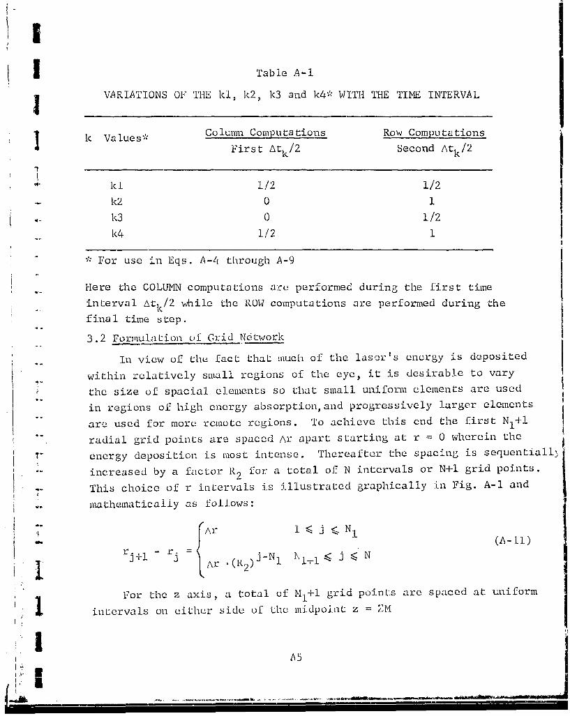
Table A-I
VARIATIONS OF THE kl, k2, k3 and k4* WITH THE TIME INTERVAL
Sk Values* Column Computatioons Row Computations
First Atk/2 Second Atk/2
1kl 1/2 1/2
Sk2 0 1
k3 ) 1/2
k4 1/2 1
For use in Eqs. A-4i through A-9
Here the COLUMN computations are. performed during the first time
interval Atk/2 while the ROW computations are performed during thefinal time step.
3.2 Formulation of Grid Network
In view of the fact that much of the laser's energy is deposited
within relatively small regions of the eye, it is desirable to vary
the size of spacial elements so that small uniform elements are used
in regions of high energy absorption, and progressively larger elements
"arc used for more remote regions. To achieve this end the first NI+1
radial grid points are spaced Ar apart starting at r = 0 wherein the
energy deposition is most intense. Thereafter the spacing is sequentialld
increased by a factor R2 for a total of N intervals or N+1 grid points.
r- This choice of r intervals is illustrated graphically in Fig. A-1 and
niathematicaliy as follows:
tAr I <, j ;N 1l rj.;_rl - rj= . jN ll j<N
r Ar ( 2)J*N 1 '\i.+1 j < N
For the z axis, a total of MI+l grid points are spaced at uniform
1 intervals on either side of the midpoint z ZM
A5

WOc 'S~jI;UIOzxTdST(I TVTP1Jll~
'-4
-"4
NN
4J(I
r-4 0 z
_ _ _ _ _ _ _ _ _ -4
0 -4
4-<)
bI j )
FX4
C~~1" wTo- HI-r l

At shallower and deeper depths the spacing is progressively in-
j creased by a factor R to yield a total of M+1 grid points or M
intervals along the z axis. This choice of z intervals is illus-
"1' trated graphically in Fig. A-I and represented mathematically by
M- -Mr- i+lIr Azl{1)1 • i •<•- N1
I lM
i i z D" M + I < + M1 (A-12)
/-z .-(R I) , Mt I1 + I • i •< M
"To determine the various grid points it is first necessary to
specify the maximun values of z and r represented by 2-ZM and RN,
respectively, along with the number of uniformly spaced grid points
M1 and N1 and the total number of grid spaces M and N. Values of
the ratios R1 and R. are then determined such that the proper number
of increments are provided wiLhin the distances 2.ZM and RN. Here
we shall illustrate the method for assessing the ratios for the cas3e
of R.
Given the designated values for ZN, MI, M,and Az, it is necessary
that
M/2-MI
AZMl MI+i= R RAM+
A--fz "-- RI -
I~l•' 0
11RIILi -

Setting n + equal to c mnd M/2 - MI+1 equal to c and
simplifying Eq. A-13 yields
' cp'R! Cp + 1 = RI1 (A-14)
Taking logarithms of both sides of Eq. A-14 yieldsI 'log(cpRI - cp + 1) = ck'log R1 (A-15)
Finally rearrangement of Eq. A-15 yields
"eRxp -1- cP 1) (A-16) "
"In view of the fact that factor R1 is present on both sides of
"Eq. A-16 it is necessary to determine R1 by successive approximations.This is accomplished by first setting X1 equal to an iinitial
value of say 2,and then evaluating the right-hand side of Eq. A-16
for the first trial value for RI. If with this RI, Eq. A-16 is not
satisfied, thun RI is set equal to the value found for the right-hand
side of the equation and the process repeated until Eq. A-16 is
satisfied.
To evaluate the ratio R2 for the r coordinate one merely replaces
ZM, i, MI, M/2 and Az by RN, j, NJ, N and Ar, respectively. With these
chang becomes RN N+ and c becomes N - NI1-.ch n e p A'I k"
"3.3 Matrix Representation of Finite-Difference Equations
Generally the most efficient method for solving simultaneous
finite-difference equations involves the use of matrix representation
"of the appropriate equations. In this regard we are concerned with
" solutions for two problems -- the first for COLUMN in which the heat
transfer in the z direction is treated explicitly while the heat-- transfer in the r direction is treated implicitly; and thie second
for ROW in which the heat transfer in the z directiol is treated
Simplicitly while the heat transfer in the r direction is treated
explicitly.
I' A .8 1

To determine the finite-dij'ference equations appropriate for
each set of computations one must first substitute the finite-difference expressions given by Eqs. A-4 through A-9 for the variouspartial derivatives of temperature rise v presented by Eq. A-i.The result is two sets of finite-difference equations -- one for
COLUMN and one for ROW.
After collecting like terms in v 1j. k one arrives at thefollowing equations.
• , •)LUMN:
X iB +Vi i(K-./ 3 + 2p iC"-o ,l * -V3,j.lI+./2 + j 2 \tk )vij ,k+1/2 - K. Bj 3vi,j+l,k+1/2
2.fp..C.-A2. (A y +I av .A +Si.
- Ai, " j ,i,2 Atk i,j,k i,3"vi4l,j,k ajk+l/2
(A-17)
ROW:
* A~ v + (A~ A2+-~-~vA~i,1 i-l,j,k+"l+ (i22 + t k vij'k4l- Ai'3"vi+l'j'kil
1 " 2 .*i. Ci..= Ki.B. ,Vvi,j-l,k+1/2 (Ki. Bj,2 - t )v i'j k+,/jKiLBj'3. vi,j+l,k+1/:
+*i,j ,k+i/2 (A-18)
where ALt difference in elapsed times given by XT(k4-1)-XT(k)(1,l
i 2,3.. .M; j = 2,3... N; and where at the boundaries
V2 ,j,~m+ , j ,k I, ,
vb~,jk=o (A- 19)
I<.,N+. Ik(
A9'I' I I I I I I I I I I I I I

j For the case of COLUMN, the index i is held constant while
the index j is varied to yield the matrix presented in Fig. A-2.I For the initial time interval Ltk/2, i i s first set equal to 2
while the temperature rises v2jk+i/2 are being evaluated. Then
i is set equal to 3 to determine the temperature rises v 3 , +j/ 2 +l c.
Finally, i is set equal to M to yield vm j)k+I/2
For the case of ROW, the index j is held constant while theindex i is varied to yield the matrix presented in Fig. A-3. Forthe second time interval Atk/2, j is first set equal to I while-
the temperature rises vik+l arc being evaluated. Then j is- increased to 2 while v is being evaluated, etc.S• ,~i2, k~l' "
Values for the coeffiLcients A A 2,i3 BjiBj 9 and Bj3
arc given in Table A-2.
3.4 Solution of Matrix Representation of Finite-Difference Eiuatiuns
Having established the matrices for performing the COLUMN and
ROW calculations, the next step is the evaluation of the teiiperature
rises v . In this regard it is important Lo observe that the
coefficient matrices shown in Figs. A-2 and A-3 are tridiagonal in
L-that all elements are zero except for those on the main diagonal andon either side of the diagonal. To solve these equations, a very
efficient algorithm is available which involves an elimination
procedure.
To illustrate this procedure consider the simplified versionof the equations presented bI.nw:
b-- o ... 0 0-
a 2 b2 C2 0 0 v2 x2
0 a 3 b3 c 3 0 - (A-20)
i0 0 a4 b
P P P .P
JLI!,

'-4
4 14
-4 C*d I4 a~~4 1--44
+j r - *4 '1--- ~:4 + CN ~ '-
r- N-
%-111 -H N-1
I,,,i
Kr-
r- 4 r4 a H4 1 * T- 4 ý 4x- H ' - 114. .a
14 1 r )
r'--I
+- ++-
H) C4
r-44-4-
a +N'1 L L. '(-
All

.144___
r5 '
-.4 .,4 -€ -
"1" 0 0 0 .i.
I - t
t "4
44Si ,A1
S• .• ,. a , -- 4. .. , .... "• -•JL. . T_ - ••

CIN en-> >o .
-4 4 4LZ
C) C) I2~ 0
*4 0
r4 A
A HHAtfl ri
..DC
r4. -
N a.cq 0
> e Cli
*-1r'A
A *f
* A C ii
KrA13

The procedure is as follows. The first equation, namely (
b l.V1 + c 1,V9 =ý Xl (I2) -
is solved for v, which is then employed to eliminate v 1 from thej• second equation, namely
a2.v + b 2' 2 .v = x2 (A-22)
The resulting equation is then solved for v 2 and u.,ed to eliminate
v2 from the third equation, namely
a 3 .v 2 + b 3 .v 3 + c 3 .v 4 (A-23)
This process is repeated for all of the equations and results in the
following set of simultaneous equations
"1 F v2
p 2v2 F 72 3 = 22 (A- 24)
:. c3
v 3 + I c ' v 4 = D
Fp1 Vp=D_
wherexl
F 1 = bl, D1 7, and
[. IIFF1m
F ~b - a ,C (A-25)
"" - ill 11-i1
in F2
for m 1,2,3...p
A14

!ITo solve for v one first evaluates Cm, D and Fm and then
evaluates the vII sequentially starting with vp. The result is as
I follows:
v =D-p P
V Vp-i = 1 p-I p-
C"v 2 f- v (A-26)p-2 p- -2 2pi
c2
S2 = "�2 D v3V2 cI
v =l 1 v2V
To use the above set of equations, one must first evaluate theexpressions tor am) b1n, and cm for the COLUMN computations presented
by Fig. A-2 and for the ROWq computations by Fig. A-3 using the resu].tsof Table A--2. Then the resultant values for a, bII and cU are used tocvaluhate Lhe parameters Cm, D and F given by Eq. A-2j.
IL
IIA 15

H'I(
APPENDIX B
i"- THERMAL EFFECTS CAUSED BY BLOOD FLOW"WITHIN CHORIO-CAPILIARIS
AND TISSUES SURROUNDING EUE
I:
LK

APPENDIX B
THERMAL EFFECTS CAUSED BY BLOOD FLOWS~WITHIIN CHORIO-CAPI LLARIS
AND TISSUES SURROUNDING EYE
1. INTRODUCTION
Blood flowq occurs in a diffuse and pulsating fashion through
many sizes of blood vessels within the chorio-capillaris of the
eye as well as within tissues surrounding the eye. During and
after exposure to a laser beam the flow of blood shall act to dis-
sipate heat from surrounding tissue and thereby moderate thermal
damage. Such heat dissipation occurs as a result of two effects.
The initial effect of the blood is to act as a heat sink, while
the second effect is to ..transport heat from regions of high tempera-
ture to regions of low temperature. Both effects are considered
-iu asscssing the consequence of blood flow in the chorio-capillaris.
On thie other hand blood Elow within tissues surrounding the eye is
treated purely as n heat 2in1.
Recognizing that the problem is inherently complex because of
the multitude of blood vessels, some assumptions must he made to
achieve tractable solutions. To this end we shall assume that
* thu blood reaches the chorio-capillaris or tissuesthrough the tiain blood vessels at its normal temperature
e the teoperature of blood within the smaller bloodvessels of the vascular layer equals Lhat of sur-rounding tissue
* the flow of blood is not altered by temperature changes
Moreover, we shall consider the transport of heat by the blood in
the chorio-capillaris only along directions of changing radii.
Axial heat transport is neglected in view of the shallow depth
of the chorio-capillaris.
B1
-.- - -- -*-*. - -

2. CIIORIO-CAPILLARIS
2.1 Radial Griu Coordinates tar Analyzing Blood Flow in Chorio-Cpilris s
To remain consistent with the scheme for predicting eye ter-
peratures described in Appendix A,we shall use the same grid system
shown in Fig. A-I. In this scheme, temperatures are specifiod atradial distances r. starting with r 1 =0 at the axis of the eye. To
minimize the number of radial elements, the first NI spacings are
kept uniform and then allowed to progressively increase in size
by a factor R2 . A similar scheme is used for the axial elements Zz.
SThi vascular layer is considered to lie within the r,'gion of uniform
spacing between one or more of the incrementfl depths; Az.
.- Due to the fact that only a smLll number of volume elements are
in the vascular layer,we shall utilize explicit finite-difference
equations to predict the transport and loss of heat caused by bloodflow. These heat transfer predictions shall be made for each time
interval Atk=XT(k+l)-XT(k) considered in the Technology, Inc. scheme-
for predicting temperatures. The result of this analysis shall be
predictions of the incremental changes of heat to each of the elements,of the vascular layer during each of the intervals of time.
'2.,.2 Representation of Blood Flows in Chorio-Capillaris
In order to describe the flow of blood into and out of various
elements of the vascular layer, the flows to and from unit areas ofthe two bounL~ary surfaces of the vascular layer will be represented
by XIj and XOj , respectively. variations ot the flows XIj and
XOj with radial distance r will be accounted for by delineatingthe flows at several select radial distances. An illustration of
K these flows is shown below.
-1-0
rA2Q
* r 1 2 3
R9

Differences in the quantities of blood entering and leaving
various radial sections of the vascular layer will move either
inward or outward in the radial direction. If the radial flows
at rj arc designated by FRj, then the radial flows are given by
I FR 1 = 0
FR 2 = (x13/ 2 -XO3/2).Or /r22_ 2
FR3 = FR2+(X1 5/2-X0 5/2) .(r 3-r 2 )/2 (B-2)
or in general. ~2 2
FR. = (XI l/2 XO -/ (r nr 2_1)/2 (B-3)Ll-1/2- O -1/ 2nn
Since these flows pass through crossectional areas of
ZAO~r. ((B-4)
it is necessary to divide each flow FR. by the area through which
it flows to assess the rates per unit area. The resultant radial
flows per unit area at N. arc given by
FLOWE.Rj = FR./(Z.AO .r )
j-1x X r n-)/(2.Z (B-5)
=n 1 / X2nl/ -X 1~/ 2 ) ( r n - .rj )(
for j , 2, These flows will transport heat along radial lines.
To assess the cooling effects of the ii,:oming blood,one must
first determine the blood flows entering unit volumes of the chorio-
capillaris. This is accomplished by dividing the flows X1 by the
thickness Z of the vascular layer to yield
SFLOWI xi/ (B-)
i? I.

2.3 Analysis of Thermal Effects Caused by Blood Flowin Chorio-Capillaris
In this section we shall consider the thermal effects of
blood apart from the effects of heat conduction treated in
Appendix A. The results shall be a description of the tern-
perature charnges caused by blood flow during the given time
interval Atk=XT (k+l) -XT (k).
The differential equation requiring solution is
PICv I (r-FLOWR-v) - FLOWI.v.Cb
If r.FLOWR is represented by FLOWX then Eq. B-7 becomUs
C v Cb•
P.C.'T- = - T- (FLOWX'v) - FLOWI .V.Cb (B-)
In terms of the indices i, j, k for z, r and time t, respectively,
the finite-difference solution of Eq. B-8 isc
viij ki+/2vi'j k+ j- I FLOWX(v-V,jl,k)
(13-9)
-V . , " ( OWXj _ -FLOWXj+ -c.FLOWI•v ,j, k+ ik- (vjw-1- jl i, ,
where c At.Cb/(2.p.C)
The term involving the bracket reflects temperature changes of
the tissue caused by the radial flow of blood while the last term
reflects temperature changes of the tissue caused by instantaneous
heating of the blood as it enters the chorio-capillaris through
small cipillaries.
Using the following substitution
j•RD (j)r= (B-1O)
1B4
I I

lI,KI Eq. B-9 becomes
} I (v7T i'j'k+i/2-vi'j'k) Cb'R )FO~ (vijI - ijl)
+ Cb'RD(j)(FLOWX j-FLOwxj+I " Cb'FLOWIj vijk
Within the Retinal Model the coefficients on the right-hand
Sside of Eq. B-Il are represented by
3BV(j,1) Cb*RD(j).FLOWX. (B-12)
The2"BV(j,2) = Cb.RD(j)(FLOWX.FLOWX j+l)-Cb'FLOWI" (B-13), BV(j,3) = -CB. RD(j).FLOWXj (B-14)
'. ,•The terms on the left-hand side of the above eqUuatons are to-- be added or subtracted from the corresponding matrix elemients
B(j,l), B(j,2), B(j,3) and A(i,2) used to compute the temperatures
(see Appendix A). In other words
B(j,l) ÷ B(j,l)+BV(j,i)'IV(i)
B(j,2) - B(j,2)-BV(j,2).IV(i)
B(j,3) 4 B(j,3)+BV(j,3),IV(i) (B-15)I A(i,2) - A(i,2)-BV(j,2)'IV(i)
Here IV equals one when the point is in the chorio-capillaris and, equals zero otherwise. Here the contribution from 2'BV(j,2) has been
partitioned equally between B(j,2) and A(i,2) for purposes of
temperature stability.
2.4 Blood Flow in Tissues
In tissues surrounding the eye, blood is considered only asa heat sink. If XFLOW represents the rate of blood flow per unit
[ volume, then the rate of heat loss from tissues having a tempera-
ture rise v. is[-~i ,j ,k
" Cb*XFLOW'vi.j1 , (B-16)
In the Retinal model the coefficient of v is represented by -'BB.
-T.

To include these heat losses as well as the effects of blood flow
in the chorio-capillaris, the matrix elements A and B musL be
j. changed as follows:
B(j,l) -B B(j,l)+BV(j,l)'IV(i)
1 B(j,2) B B(j,2)-BV(j,2)'IV(i)-BB.IAB(i,j) (B-17)B(j,3) -> B(j,3)+BV(j,3)1IV(i)
A(i,2) -> A(i,2)-BV(j ,2).IV(i)-BB.I*AB(ij)
where IAB equals one when the point is in the tissues surrounding
the eye and equals zero otherwise. As with the BV(j,2) contribu-
"tions, 2"BB has been partitioned equally between B(j,2) and A(i,2)
-- to improve the stability of the temperature calculations. Otherwise,one could have placed the contributions for A(i,2) into B(j,2).
IB6
LL
K' ±i

(1
.t.
APPENDIX C
DECAY OF NORMALIZED TEMPEIRATURE RISESOF MELANIN GRANULES WITH TIME
I
I

I
APPENDIX C
DECAY OF NORMALIZED TE4PERIAI. RISES•,:OF MELANIN GRANU-UE•ý WITH TIME
1. INTRODUCTION
Melanin granules are better absorbers of radiation than
other media within the pigment epithelium within which they are
situated. As a result considerable temperature differences can be
produced bet-een the granules and the intervening tissue especially
by short duration, high-intensiLy pulses. With very short exposures,
steam could be produced within jth granules, and the resultan.t pres-
sures cause damage. 4Here of course one must recognize that temperature differences
between the granules and intervening media persist only for rela-
tively short times. To -identify the laser exposures in which theI
temperature differences arc appreciable, it is necessary to predict
the temperature rises, at: and between grannles. In this endeavor,
we shall restrict the. analysis to very small volumes of the pigment
epithelium across which the transmitted radiaition is essentially
constant. Also we shall neglect energy losses due to
0 changes o0 state
a development and transmission of pressure waves
As a result, all temperature predictions represent upper bounds
and should be i,'eated accordingly.
I!:• ~~2. FINITLd-DIFFLREMLC EQUATIONS .:
"To predict the temperature rises we will assume that the
granules are cubes which are located at the intersect-ion-s of a
three dimensional cartesian grid of equal linear dimensions. An
illustration of a cross section through the center of Lho granules
is shown in Fig. C-I. Here the spacing between granules is taken
equal to the diameter of the granules. This spacing is minimal
in that the diameter of the granules is about I micron while the
. spacing ranges from 1. micron to 1.5 micron (Ref, 1).
C1

ZZII
K4
-- Granules Representative Region
SLBoundary of Zero H-eat Transfer
6•
IIFigure C-1 SCHEMATIC OF CROSS SECTION OF GRANULES ND REPRESENTATIVE
REGION FOR ANALYSIS
G2

For the case of maximurn spacin8 one must add two additional elements
between the granules.
Due to symmetry one needs to consider only those elements en-
closed by the heavy lines. Because of their relatively small dimen-
sions, the surrounding groups of elements will be at essentially the
same temperatures.
"To perform the iieccssary calculations we shall employ an explicit
finite-difference analysis since the computational times are relatively
small. To this end we shall consider a 4.4"4 cube of elements for' the
case of minimum spacing or a 5-5"5 cube of elements for the case of
maximum spacing. In addiLion, volume elements immediately surrounding
the cubes will be included as a convenient means for ensuring that
no heat is lost from the cubes.
In the analysis we shall consider the worst case in which all the
absorbed energy is deposited within the melanin granules. Moreover
we shall normalize the results by depositing just enough heat so thatif it were uniformly absorbed without the granules a unit temperaturc
rise would result. This, of course, simplifies the interpretation and
ultimate use of the normalized temperatures. To achieve this end, it"is necessary that the total quantity of hcat deposition be
.C.((n-2) Ax) 3 1 (c-l)
where:
C specific heat of tissue
n = number of elements
Ax = linear dimension of elements
p = density of tissue
"and where the number 2 accounts for the fact that the heat is deposited
only within elements beneath the outer ring of elements and the nunmber 1
represents the uniL temperature rise. For the case of minimum spacing
ný6,and for the case of maximum spacing n=7.
--This hat will be deposited within a total of 2 elements corre-
sponding to the portion of the melanin granule under consideration
C3St

S I•.
(see Fig. C-1). If this heat is deposited in an increment of
t ic At, then deposition q, per unit granule volume is
3 3q l =f,.C, ((n-2) Ax)- 11/(8.(Ax) .At) = p'C(n-2) 3 /(8"At) (C-2)
implicit in this analysis is that there is negligible heat
transfer during the incremental time At'. In the remainder of thisanalysis we shall discuss how the resultant temperatures dJicay with
time at intervals At.
"For central differences the appropriate finite-difference
•- equation is
v t+At t. f~~oC. vil j l'kl-Vil j l'kl -
, At
"t t + t tF -Vil-.lilkl + ,jl-l,kl 3 Vil,jl,kl-i iI,ji,kl il+l,jl,kl
t Lvil, j1+1, k1 + Vi Ijl kl+l /(Ax)2(-3
where ' -i
il,jl,kl ý indices describing the location of the elementK = thermal conductivity of tissue
t = time
v = temperature rises at locations and timesindicated by subscripts and superscripts,respectively.
Prior to exposure all the temperature rises v are zero. The condition
of zero heat loss is accounted for by maintaining a zero tcLiyj:ature
gradient between the outermost elements and corresponding adjacent
elements by use of the following equations:-. - Vt t|
L t
V1 i 1 1( v, (C-4)
V, 1j, 1 Vi,jl,2
C4*1 C-
L o 1 •....

vt v-njlkl n-l,jl,kl
t tV il~n,Rl V iln-l,kl (C-4)
t til,jl,n il,jl,n-1
-- where n represents the maximum index of the elements and equals 6 for
the case of mininum spacing and 7 for the case of maximum spacing.
"To ensure computational stability, At_ should additionally
satisfy the following condition
2At '(&xx)2 p.C/(6.K) (C-5)
Predictions of the temperature rises consists of first setting the
vijlk to zero. Then Eq. C-3 is used to evaluate the ilii~jl~klil,jl,kl
for il,jl, and kl = 2,3,...N-2 using the previous temperature rises.
Then Fqs. C-4 are applied to ensure no heat loss and the process
repeated with the new temperature rises to compute the next set of
temperature rises.
The result of this anal-;is is normalizprl temnPrature rise
histories of the granules assuming all the energy is deposited with-
in an incremental time interval of At. When the actual deposition
period exceeds At, then one must
* divide each cf the above temperature rises by theratio of the Jeposition time/At to ensure the finaltemperature rises are normalized (i.e. ultimate tem-perature rises of 1'C)
e s',oer;i).jose the resultant temperature rises allowingU r differences in elavsed time
The above steps arc mathematically illustrated by Eq. 32.
C5

HI
I -
APPENDIX D
ASSESSMENT OF TEMPERATURIES CAUSED BY MULTIPLE PULSESUSING SINGLE-PULSE TEMPERATURE PREDICTIONS
T
ii
I"
LIEl-' I II I II I II I I

7- 7APPENDIX D
ASSESSMENT OF TEMPNRATURES CAUSED BY MULTIPLE PULSES. USING SINGLE-PULSE TEMPERATURE PREDICTIONS
1. INTRODUCTION
i There are two ways to compute the transient temperatures
caused by multiple pulses. The first is to deposit the energies
from each pulse at the appropriate times using the scheme for
Computing temperatures discussed in Appendix A. Unfortunately,
this is not practical since the number of pulses could be in the
thousands. Moreover, the time intervals would have to be chosen
so they would correspond to the beginning and end of each pulse.
Regular intervals would, of course, preempt the use of constantly
expanding time intervals.
2. ANALfTICAL MEANS IOR PREDICTING TEMPERATURESCAUSED BY MULTIPLE PULSES
A more practical approach may be arrived at by examining
the heat conduction equation for the temperature rise V given
below.
2 I•VKV 2 V + q(t) + qb jwC YC (D-1)
where V=0, at t=0
=0, at z=O for all r, t
V-? O, as r, z -• ± .. for all tfq (r), 0 t •to
q (t) = q o
0 , t>to
qb CV + C2 Vrfor z values corresponding tob Ivascular layer. CI,C 2 = constants
depending on the heat capacity andflow of blood.
and where r = radial distance
"t = time
to p=].se duration
q - rate of energy deposition from laser perunit volume
q b= rate of heat exchang;e per unit volume dueto blood flow
_ l Dl

p = density
C specific heat
K = thermal conductivity
z = axial distance
SIn order to examine the possibilities of making use of'the computing temperatures caused by single pulses, let us consider
that Vl(r,z,t) represents the solution of Eq. 1 for a single pulse
of duration t.. If there are two such pulses, with TC representing
the tijme from the start of the first pulse to the start of the second
pulse, then the solution for times t less than TC is obviously the
same as that of a single pulse.
Once t>TC, the solution becomes
Vl(t) + VI(t-TC) (D-2)
To validate this solution, let us replace V of Eq. D-1 by the
,above expression. The result is
KV2VI(t) + q(t) + CIVI(t) + CVI(t) K 4-2V1 (t-TC) + q(t-TC)i •6r
+ CIVI(t-TC) + C2 VI(tTC)r =[ dV(t) + )Vl(t-TC)] • (D-3)
Since Vl(t) is a solution of Eq. D-l, the first four terms on the
left-hand side of Eq. D-3 equal the first term on the right-hand
side. Therefore, eliminating these terms and replacing the argument
t - TC by t' results in
"KV" V(t') + q(t') + CIVI(t') + C2V-(t= b•--t- (D-4)
To prove that this equation holds, it is first necessary to
b. .. 'lish that q(t') satisfies the heat deposition condition forEq, D-1. This means that the following equation should ho].d:
, qo(r), 0,< t'4ý Lq(t') = (D-5)f 0 (r, Ot '>to
"At t'=O, t equals TC which corresponds to the start of the second
pulse; while at t'=t0 , t equals TC+to which corresponds to the end
of the second pulse. Thus, the heat deposition condition is satisfied.
D2
.jI
Let us now examine the initial and boundary conditions asso-
ciated with Eq. D-1. Since both conditions hold for the first
I pulse, it is only necessary to examine whether or not the condi-tions hold for the second pulse which starts at t'=O or t=TC. At
t=TC
VI(t-TC) = VI(O) = 0 (D-6)
so that the initial condition holds. Also shifting the time scaledoes not alter either boundary condition, namely V-÷0 as r,z++ozand
dV/oz = 0 at z=0. Thus, the expression given by Eq. D-2 satisfies
"the hect conduction equation, and its initial and boundary conditions.
An illustration of the above technique for evaluating the
"temperature rises caused by two pulses is illustrated in Fig. D-1.
Here the temperature rises produced by the pulses are identical
-.... where the first pulse is represented by the solid curve and
the second pulse by the dashed curve. The temperature rise produced
by both pulses is represented by the heavy curve, and from Eq. D-2
equals the sum of the contributions from each pulse at the appro-
priate times.
.. By extending the argument to additional pulses, it is obvious
that the temperature rise V(t) produced by N'epulses is given by
N'
V(t) = VL(t-(n-1)TC) (D-7)
where N' equals the number of pulses started prior to time t. At
the culmination of all pulses N '=N.
3. COMPUTERIZED MEANS FOR. PIP•DICTING TEMPERATUIURES- - CAUSED BY MULTl, PULSES
"Having established a rather simple technique for assessing
the temperature rises caused by multiple pulses, the next step is
the selection of the times between pu'lses at which temperatures
Gare to be calculated to ensure accurate damage assessments. In
this regard it is desirable that the times be sufficiently close
to ensure accurate, integration of the damage over time.
I" D3

C))
± w
I U.)
I L4
4.
-~ \ 4
I-L
ýlq
'0 -ý

"For this purpose, five values of the temperature rise (as"calculated for the single pulse described in Appendix A) at reg-
ularly-spaced time intervals are used to cover the period duringeach pulse, and three values of the temperature rise at regularly-spaced time steps are u's~d to cover the period from the end ofone pulse and the start of the next. An illustration of the timesteps is shown by Fig. D-2. Integration of the thermal damageis accomplished using the temperatures at the midpoints of the
intervals. On the other hand, the average granule temperatures
are calculated at the end of the time intervals to arrive at thepeak temperatures.
In the computer codes, the times from the start of each pulse
to the midpoints of the intervals are designated by ZT(L); whilethe times to the end of the intervals ardesignated by ZTX(l0).
As may be observed from Fig. D-2 the index L ranges from I to 8.
In the remainder of this section we shall elaborate on the
technique using the time intervals ZT(L). Measured from the start
of the first pulse, the times of concern are
t = (N'-1).TC + ZT(L) (D-8)
where N' = number of pulses started prior to time t. Substitutionof this expression into Eq. D-7 yields
V(t) VI((N'-I.)-TC + ZT(L) - (n-I)TC) (D-9)
which simplifiPs tn
V(t) Vi((n-I)TC - ZT(L)) (D-10)
This expression describes temperature rises at times ZT(L) follow- X
ing the start of the N'-th pulse. Here, of course, N' may range
over the number of pulses N used.4?-1
To evaluate the temperatures following the exposure at timesof say (M-I)TC + ZT(L) where MNN, it is necessary to consider the
effect of M hypothetical pulses given by
-- -- D5

�4 -
*1 C)B I-IIf. U)
j1�
TI
0 /C-)a) / /Li-)
/
* 4-
'0* 0)
.tJLU
r� �
:1 wCi .1..) �i)
ri LuCO -4
C) HO
cC-[Ur2Cn
J Cl) 03u LUH
03 LU
C?) (V iiC) 03 Oi--4�.4 -I-A
n ;-i I.-U LzJZ 1*
I-i $-�03 0 ¶n* 4-' CflR4U Cu -�03 I-i •0U 03w El)1 �0
- �jj
:1 2Z-n�CU 03 AW3-U) W A-LU-z Z HU U LUH r4 p0
Z':' '�
U J-�.-. -'t-t* IiCV CO
C)
co tfl 1-44 Ii>1 41 C) CI) H-cEl Elri vi
/1 H HN II
-. - . S0)U) C)
* -- - �-r�' 'I/
U "-4
U);/
r4
--
'S
DO

!MVl ( (in-l)'TC + ZT(L) (D-1l)
In-ere only the firstN of the 14 pulses are real. In the
above summation, these pulses correspond to n-M-N+l to M. The
M-N hypothetical pulses correspond to n=l to M-N. Eliminating the
non-existant contributions from the M-N hypothetical pulses yields
M-N
V(t) Vi((n-l).TC + ZT(L)) - V1 ((n-l)TC + ZT(L))n~l
Z VI((n-l)'TC + ZT(L)) (D-12)
n=M-N+l
In summary, Eqns. D-10 and D-12 describe the temperatures
at the intervals ZT(L) shown in Fig. D-2 during and following
exposure to the laser, respectively. The temperature rises V1 are
linearly interpolated using the computer predictions for a single
"pulse represented by \VC(i:j,k) at the times XT(k) at the desiredpoints Z(i), R(j).
As long as the number of pulses is minimal, the execution times
are reasonably rapid. However, for exposures involving many pulsesthe execution time's can become. excessive. Excessive computer execu-.
tion timcs are avoided by evaluating the temperatures and damage
"only at select regularly-spoced pulse-s when the number of pulses
is 20 or more. For example, for exposures of 57 pulses the pulses
are subdivided into 29 groups of 3 pulses,with iLe temperature au-d
damage evaluations made during each of the middle pulses -- i.e.
pulses 2,5,8...56. Total damage is arrived at by sunruing the
"- damage produced during each of the select pulses, and multiplyingSthe- result by 1,hre to account for the remaining pulses.
In this analysis the number of pulses per group is always set
equal to an odd nurnlber so that the damage occurring during the
middle pulse of each group is representative of the average damage
of all pulses in the group.
D7

The number of pulses/group is given below.
Total. Number of Pulses Number of Pulses/GrouC
i Ito 19 1
20 to 59 3
60 to 99 5100 to 139 7"140 to 179 9"180 to 219 11
N to N+39 integer value of (N/20)+2
A
iJ
41081i

!1~1
I
2.
°..
-'- API-'ENDIX E
.. Cl-I"CE OF TlIME INTERVALS
IIA
1

APPENDIX E
CHOICE OF TIME INTERVALS
1. INTRODUCTION
The principal advantage of the Technology, Inc. scheme is
that it produces stable temperature solutions for large time
intervals. However it does not address itself to the problem
of choosing time-intervals so that errors are consistently small.
Choice of time intervals is complicated by the fact thau excessively
"small time intervals will cause unnecessarily long computer times
* while excessively large time intervals will produce excessive
errors. As with all finite-difference schemes some compromise
. must be made between accuracy and execution times. Specifically,
we are concerned with selecting the sizes of progressively larger
time intervals such that errors are maintained at some consistently
small value.
To V-sess how the error. depend on the time increment and on
the dimensions of the spacial elements we shall examine the residues
that were neglected in approximating the heat conduction equation
by means of the finite-difference equations described in Appendix A.
This means assessing how well the heat conduction equation
-ju K 6u 3ju U luSC E7• - r + K-=7 + 7o7 (K -- ) (E-l
is satisfied by use of finite-difference approximations of Appendix A
where C = specific heat
K = thermal conductivity
r = radial distance
z = axial distance
u = temperature rise
Sp = density
t = timeIn Eq. E-I the temperature rise is represented by u to distinguish
it from the temperature rise v obtained from the finite-difference
solution. Errors in the finite-difference predictions will, of
course., be(E2S= v-u (E-2)
El

2. ANALYSIS OF RESIDUALS NEGLECTED BY FINITE-DIFFERENCE APPROXIMATIONS(In this analysis we shall consider the first and last pair of
the two time steps Atk/2 used in the computational scheme described
I in Appendix A. The result is two time steps each of duration Atk/ 2 --
in which the COLUMN computations are used for the firsu time step Atk 2
while the ROW computations are used for the second time step Atk/2, n
each case it is necessary to -::pand each of the partial derivatives
uf Eq. E-1 where the first t.iiae step Atk/ 2 corresponding to k - k+1/2
will be designated by A'k. Similarly the second time step At k/ 2
corresponding to k+l/2-+ k+l will also be of duration ATk.
For the first time step A½k the differential equation requiring
solution is
= o2u 2P- (u + Ku + K. )U
._r p.Cl/2 -r i,j,k+i/2 i,j,k+1/2
(E-3)
Since the COLUMN computations involve using existing temperatures
for the term in z and future temperatures for terms in r,it is
necessary to replace the last term of Eq. E-3 by
"..- -- +K. AK (E-4)K'z• i~j,k -ý Iij,k
The result of the above substitution is2.r 2u1 K CS + K. 72u + K -7-7i
Si,j ,k+1/2-J i,j ,k+l/2 Or Iij ,kul 12
K)C t 3U 'ac!..k] (E-5)
Reversing the time steps for the ROW computations for the second time
step Am in which k~ii/2 k+l yields
E'1
1J I E

-[,- -. 7(-.
TE j1,+ ]-j k+1L/2 + 'r j k.+l/2 k~l~
2 u~i + 3 u ZATk +K. 2u
Next it is necessary to replace the terms of Eqs. E-5 and E-6 bythe following series expansions:
Ui~jk+/iiI j 1-,A1/
(A3tk 2 (E.-7)
ij ,k-i-/2
C) u Uijk±I-u i~j,k+1/2 1 2
li,j ,k+l A)k + l i~j ýk+l/2 k
uj (A¶r) 2(E-8)
or i~~k +/2 *r Lj jkjk±1/
-3-9
i-j+u.kl/ ij,k+1//2 i,j-l,k±1/2 1.-2i~j~~l/ (Ar)
(Ar) 2 ... (E-9o)
u i~~l~k 1 /2 - 2.u jk+l/2 'ij-lJ,k+1/2 -
c5Ilijc±1/2 (Z
1 2 (A().r) _-0TZ ui A(
j ]ý+1/

2 k-2 .+UUi+l, j k "u- i ji, k-41 - 1, J k+
-7 ( • A4) (Az)2-... (E-12)
6• i,,j ,k+l
Substituting Eqs. E-7 through E-12 into Eq. E-3 along with
3 3 4K- . 2 Ark - K.73 ~~ -- ) t ij jki1/2 i,j k+1/2
(E- 3)
yields
Cui - k - C iu A~k 3 k
P-C 12 u(A' k )
"3" t , i,j ,k+ -/2
K.~~i j±Lk1,,+1/ 2k1/2 k)
:." .r ' .j i,j ,k+I/2
K. Ui,j_+l,k_ _/2-2"ui, __k+I/2uK_3_111 K T 2rki/ (Ar) + )-i~j-j k+1/2
(Ar) 72 i,j ,k+1/2
- ij 1- (Ak)
jK.~~'~1'( Ik-lu~~J - I.4 t
(A(AZ)
It ~A 3" k j - 1 1,-- for the COLUMN computations. The correspondinig equatLion for theS~ROW coirputatiorns is obtained by substituting Eqs E-7 through E-12
,#. into Eq. E-4 to yield,.
E4
LL' _ ~/L

P- k~' + 24 1p•C AAk A'rkj
03 J u . -u i~-.. +,1".r C r i 2 K kjj+,k+1/2
-~Ak 7T r ArK i,jk+1/2
K (Ar) 2 -+ +i k 2LJ k j k+l-/2..
UK ijj~l k-/-2ui + 2+u j-111, ]A+Llc+ K. 4L-. (A2 +(Ar) f r iij,k+1/2
°" j ({\z)
S; 4 u 2 (+-l 5)
(A\z)li,j,k+l
The result of one set of COLUMN and ROW computations would be
the suin of Eqs. E-14 and E-15. Therefore, summing the two equations
and replacing the terms u with v-g from Eq. E-2 results in
! A2 (p,+ (z\(ij -ij) 22 2 2ij ,k+l- A'rlk r, r z k(Aýk) :
*.- (E--16)
where the terms in the braces and brackets cancel and where
Z"Li,j_+Ilk+l/2-P i,j-l,].+1/2 + :,
j A2 2 -iIj,k+l2. 2, Ar
,-2K[i, j+l,l<•i/-Z2- 2"-,Pi~j Il+i/2+P i, j-l1, 1+l/ 2]+ .
(A1)( )K iTj ,,+I/ 2-2 fijj-,+1/2+ i- lj. ,1ki-1/2. (E-17)
-34
! K,Cr1 I I II Ir
E5U'

G K u (E- 19)z~k •- i~jk+1/2
"[5Q (p.C) );u 2 u(2 Ul (E-20)C, K
Now it has been shown (Ref. 51) that if
A2 y-Ck'Yk= gk ir k=l,2 ... K-1 with yo=YK=0, (E-21)
then
max Y~j~flU .~S(E.. 22)
Applying Eq. E-22 to Eq. E-15 yield&,+ •; (/r A) 2+Cz. (Az) 2._+Ck(Ak
ma i~max a .- K 1J"r -I-C ~(A) t,kJA½)2 (L-23)
Since YEiPj o=, Eq. E,-23 becomes
K-I
max 3ik IK r,k(Ar)2 4-CiAz) 2±tk(A-rk)2 (1.-24'
Equation E-24 shows that errors shall accumulate with time
depending on the size of .Au, Az and A".k as well as the various
derivatives of tcmperature rise with respect Vo r, z and t. During
the early times while the eye is being exposed to the laser,thederivatives associated with Crk Czk and Ctk will be most pro-
nounced. Therefore,it is obvious Lhat initially k must be rela-
tively small. Subsequently, Lhe time intervals '-L-k=Atk/ 2 "may be
progressively increased with time.
in order to keep the errors small,the first time intervalshould be such that it satisfies the stability condition for standard
explicit fini ce-diCfcfreiice equations, namely
A t:- 4ý f) C- . (E;-25)
S |

To better appreciate how rapidly to increase subsequent
intervals,let us examine the last term of Eq. E-24, namely (6
2S5 (P'C .• ) - K - ") 1 (E-26)
•'!t: ý Z-Z z- ij , i/2-- -
Along the axis of the eye,wherein the most pronounced tem-
peratures occur, the heat flow approximates one-dimensional flow.
Therefore, to gain an appreciation of the above term we will take
the second deivative of the one-dimensional heat conduction
equation with respect to time. Holding the thermal properties
constant, the result is
K p4u 7 (E-27) 3
Using this relationship, the expression given by Eq. E-26 becomes
_ lf 3 u (/\t,) 2
- 3"-6 ~~)M I ij k+l/2 ( (L-28)
iFor Lriv worst, condition,in which heat is supplied at a si1ngie. depth
at a cons ta..t rate, th. temperature rises at the griven depth willapproximate
I = clV L (E-29)
where cI is a constant. Differentiating this equation three times
with respect to time yields
-- 1 - 3ci/(8ýt 53L
Substituting Eq, E-30 into the expression given by Eq. 7-28 along
with the subscript k- and dropping all the constants yieldsI'
(xt 2(,k)l, (L-31)
t
L7
-----------

In order to keep this expression consistently small,it is necessary
that
SAt < c .t5/4 (E-32)k k
where c is a constant. This result indicates that one can expand
the Lime intervals very rapidly with respect to time. However,in
view of the various assumptions made in this analysis,it is wisc
to select tirae intervals appreciably smaller than indicated by the
above condition. One choice which has proven satisfactory is as
follows
SAk+1 CAtk (E-33)
where the first time interval AtI is given by Eq. E-25. Values for
the constant C used in this study ranged from 1.1 to 1.4.
* IE
* I.
ft I

I -.
[
[Ii
APPENDIX F
HIEAT DEPOSITION ANALYSES *"
F C y
I-.I
I. III
I --
I-,

I
* APPENDIX F
HEAT DEPOSITION ANALYSES
1. INTRODUCTION
In order to calculate the deposition of energy within the
eye, it is first necessary to determine the laser profile within
the eye. To this cnd each model starts with a determination of the
refraction of the laser beam by -the cornea as described in Section
3. The result is a description of the normalized profile as a
function of radius and depth from the anterior surfacc of the
cornea to the anterior surface of the lens. The resultant irradi-
ance profile is then used directly by the Corneal Model with
appropriate provisions for absorptim-)i. ;nrd reflection to assess
the rate of energy deposition into various regions of the eye.
On the other hand the Retinal Model utilizes the normalized pro-
file at the lens to assess the irradiance profile at tha retina
as described in Section 3 and Appendix H. The resulta-nt irradi-
ance distribution of the retinal image is preserved at all depths
of the eye. This assumpuion is considered reasonable in that the
profile varies only slightly in and about the retina wherein most
of the energy is deposited.
In this appendix we shall illustrate the procedures used to
compute the deposition of energy from these irradiance profiles
at various depths of the eye. Key parameters in this analysis
are the absorption and reflection coefficients for the various
•.. medli.-, and intrflces, respectively-
First, it is important to recognize that it is not possible
to locate all interfaces (between eye media) at the boundaries
,, ZI{(i) if the z increments are given by
i ?-Zl{(i) = (Z(i-1) + Z(i))12 F'(i)
Only the more important interfaces are located at the above
boundaries. These include the front of the eye medium for which
damage is being evaluated (see Appendix I for a description of
the grid network).
- Fl

Ii
Thus, most of the iOnterfaces do not coincide with the bound-aries ZH(i). Moreover,in someý situations there can be more than
one interface within a given increment. To provide for such even-
tualities we have used the array ZD(LI) to represent the depths z
associated with the various interfaces between eye media. The
absorption coefficients associated with eye medium between ZD(LI-L)
and ZD(LI) are represented by ABS(LI-1). The above coordinatesand nomenclature are depicted by Fig. F-i for a given z increment,
starting at ZH(i-l) and ending at ZH(i). Included are the products
AB(i,L) of the absorption coefficients and thicknesses of various
"" eye media within the given z increment. The products AB(iL) are
given by
AB(i,1) = ABS(LI-1)'(ZD(LI)-ZH(i-1)) P(2)AB(i,2) ABS(LI),(Z11(i)-ZD(LI))
If there is one eye medium between Z1I(i-l) and ZH(i), thenAB(il) = ABS(LI-l)'(ZII(i)-ZH(i-l)) F(3)
AB(i,2) - 0
2. ENERGY DEPOSITION FROM INCOMING BEAM
To compute the total energy deposition within an increment,
it is first necessary to determine the irradiance 11(r) at the
front of the increment. At the antcrior surface of the cornea,
the entering irradiance is represented by
11(r) = QP HR (r) F(4)
Here r equals the radial distance R(j) of the radial grid points,
"where j=1,2 ".N3 and QP represents the irradiance at r=O.
To arrive at the rate of energy depol.tion into a given in-"crement z, it is first necessary to determine how the irradiance
"changes on passing through the increment allowing for absorption
and reflections. For purposes of simplicity, we shall follow the
irradiance (at a given radial disLance R(j)) through each of the
media contained in the increment illustrated by Fig. F-I. Here
X3 shall represent the incoming irradiance; X2 shall representthe irradiance at various depths, and X4 shall represent the sum
of the reflected irradiances.
1F2V

v______S
Z3D3�X�UI
1� N
I. II
N
VC'-,II
1. IIOQ�Cl) (�)
CN
wg �N
h-I N <1�U)
'-.-'
U)
-� I..4 -'4�
0'di k4�a, '-
- - -- �-J �O�UJZiJ1U1 U N
iier-A N 1
NW-4
I. -�' I H E-'r-4 I a,
I �' --2
-� V 5 UN
2 -. ----- II I
-. I N [i�
U)
'-I
-�
I-__________________N
I' III N
14
P3

J After passage through the first zone shown in Fig. F-1, the
irradiance is
X2 = X3.exp(-1\B(i,l)) F(5)
At the interface at ZD(LI), a portion of the radiation is
reflected away given by
X4 = REF(LI)-X2 (6)
After passage through the second zone shown in Fig. F-I, the
irradiance becomes
X2' = (-EL))X.x-A(i2 1.(7)
The net rate of energy deposition per unit volume surrounding the
point 7,(i), R(j) is therefore given by
(X3-X2'-X4).HI(r)/(ZII(i)-ZII(i-1)) F(8)
The above result includes only the absorption from the in-
coming beam. In the next section wc s;hall. assess absorption from
radiation reflected at the several interfaces.
3. ENERGY DEIPOSITION FROM REFLECTED RADIATION
In this analysis we1 shall consider the radiation to be re-
flected parallel to the axis of the eye. The neglect of diffuse
reflections is considered of secondary importance in view of the
fact that reflected radiation is of secondary importance. Calcu-
lations arc also simplified by the i ,glect of multiple reflections1
To determine thL deposition of energy from the reflected
radiation, it is first necessary to assess the sums ABR(iLI) of
""the nrocdticv- of the absorption coefficients anid thicknesses of
each eye media within each increment z prior to the depths at
which the reflections occur, namely ZD(LI). For the situation
illustrated in Fig. F-l, these sums are given by
AB R1(i,LI) = Ali(i, 1) 11(9)ABR(i,LI4-)l AB(i,1) 4- i (i,2)
To compute the ratio of absorption of the reflected radiation, it
is first necessary to determine the intensities of the reflected
radiation at each of the interfaces ZD(LI). At the first interface,
F 4

(1
SZD(i) belneoth the anterior surface of the cornea, the intensity
of the reflected radiation IEFL(2) is
SREFL(2) ý H(r)' (-exp-ABS(L)) 'REF(2) F(10)
At the third interface ZD(3), the reflected irradiance REFL(3) is
Rl EFL(3) = 11(r). (l-exp-ABS(1)).(I-REF(2))"
(l-exp-.ABS (2)) REF (3)
By continuing this process, each of the reflected intensities
RLFL(LI) may be determined for each of the interfaces.
To deternine the rates of energy deposition, it is necessary
to consider the rcflected radiation from each interface separately.
For example, at the interface ZD(LI) shown in Fig. F-I the reflect-
cd irradiance at Z1U(i-l) from the ZD(LI) interface is
REFL(LI) .cxp -ABR(i,LI) F(12)
and the rate of energy deposition into the z increment is
REFL(LI)(1-exp -ABR(i,Ll))/(ZII(i)-ZII(i-1)) F(13)
Similarly, the rate of energy deposition into the next increment
between ZlI(i-2) and ZII(i-l) is
I•E;LLIcxp -A R~,L )) I-xpAZI{i-,L ))(ZH i-)-H~ -2)) I(4)
Bjy continuing the process for decreasing i, one arrives at the
rates of energy deposition into each increment due to reflection
at ZD(LI).
To arrive at the total deposition, one merely performs the
compltations for all interfaces and sums the results for each
4n-r-ment. Then by dividing the sums by the depths ZIl(i)-ZI(i-l)
of each increment, one arrives at the rates of energy deposition
" per unit volume at each of the grid poilnts Z(i),, R(j). The total
"deposition, of COLUSe , is the sum of the encergy depositions frow
"the incoming and reflected beamls.
.1'
II i !5

I
APPENDIX G
OPTICAl, PROPERTIES CF EYES OF MAN A•ND RHESUS MONK~EY
IL
Ii ° -
ii-
It --- - - -

1. OPTICAL PROPERTIES OF THE RHESUS MONKEY
1. CORME
i' 1 The rhesus cornea has a refractive index of 1.376 so the
calculated reflection coefficient for light incident along the
normal is approximately 2.5% for visible wavelengths.
Boettner (6) measured the transmittances of the corneas ofyoung adult rhesus as shown below. The total transmittanceincludes both the direct beam and forward scattered radiation.
tGI
.1 S' .1 '
lie GI

0
C,- <
100
Li LI~1-
o a 00 0 0 C) 0"Q~
3:)NVI.LlJSNV8J. IN3:)3d
G2

1.2 AQUEOUS HUMAOR
I Since the refractive indices of the cornea and aqueous humorare very similar (1.376 and 1.336) the rL.lection coefficient for
I normal incidence can be calculated as approximately 0.02% for visible
wavelengths.
"Boettner's (6) measuremenrs of the transmission of the rhesus
aqueous humor are shown in Figure G-2. There is no forward scat-
*, tering, nor is the transmission age dependent.
F: 100
90 /--
I: 80-_ _-
-DIRECT T"RAHJ''j'3iTTAN'CE 0!-fiTH AOUE:OUG IMFS01OF THE RHESUS MONKEY
Go
I~5 -- -- -- _ _ - - -
4 0z
Li .30 - •
K A0
I0 ---
-. 200 '100 50 00 0 800 1500 ... 2000
"" Wave length (nm)
•- Figur-e G-2 TRANSMITTANCE OF THE AQUEOUS HUMOIR OF THE
.•.. RHESUS MONKE'Y
K..
WGliU:IIU3
- IL
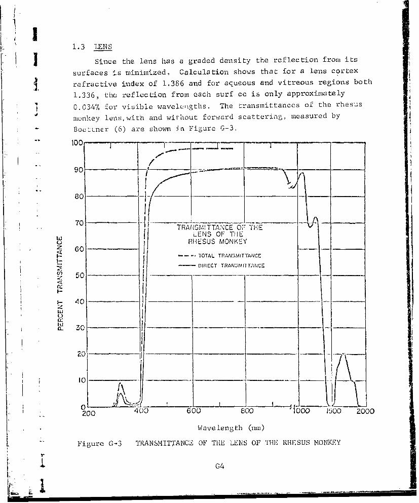
Ik 1.3 LENS
S I Since the lens has a graded density the reflection from its
surfaces is minimized, Calculation shows that for a lens cortex
refractive index of 1.386 and for aqueous and vitreous regions both
1.336, the reflection from each surf ce is only approximately
41I 0.034% for visible wavelcngths. The transmittances of the rhesus
monkey lens,with and without forward scattering, measured by
Bocttner (6) are shown in Figure G-3.
-- "100 -'_.1'_ •-I-
90 1 "-
80 .... . .
70 TRA-,SMITTANCE O;: TH-E
U LENS OF THEo RHESUS MONKEY
z 60
-.... * TOTAL TRANSMITTANCr
I - - L~DIRECT TRANZ;IAITAtNCZ
150
S0
r200 __00__ 6_6__8__100_00
- Wavelength (I-111)
Figure G-3 TRANSMITTANCE OF THE LENS OF THE, RHESUS MONKEY
G4

L -LI ..4 VITREOIUS IODY
L The transmission. of the rhesus vitreous body shown in Figure
G-4 is due to Boettner (6).
100 -- l T -- 2 -- - --
890 --
70--
""RA.ISMrITANCE OF THE-VITREOUS I IUMOR OF
w THE RHESUS MONKEY
_---IOTAL IRANSMITTANCE
I 50- - - -'-- -- DIRECT TRANSAIT-ANCE
: <l(
4-1- 40 -- - -- _____-___
z
- ~ti-i
20 -- l01 I
2"1 1 ... L_ i_'-__ o
V.. 014 4o0 L .oo I• oL200 40020 050 1500
Wavelength (unm)
"Figure C-4 TRANSMITTANCE OF THE VITREOUS HUMOROF THE RHESUS MONKEY
1 0G5iI

1.5 OCUlAR MEDIA
The foregoing measurements by Boettner (6) on the I.ndividal
components of the ocular media are summarized in Table G-1.
Table G-1
TRANSMITTANCES OF TIHE INDIVIDUAL OCULAR MEDIA OF R}IEStI MONKEY (%)Wavelength Cor:nea Aqueous Lens Vitreous
(nvn) Direzt Total Direct Direct Total Direct Total 7
200 <0.220 .2240 2.5260 1.5280 < 0.1 < 0.1 2.0 < 0.1 < 0.1300 10, 16. 40. < 0.1 0.5 15. 15.320 34. 54. 70. 5. 9. k1. 90.34o 45. 67.5 80. 1. 3. 88.5 93.
360 51.5 74. 84. .5 1. 90.5 94.5•380 54, 80. 87.5 .5 1. 9"2.5 96.4oo 67.5 85.5 89.5 2. 10. 93.5 97.420 6o.5 96. 91.5 55. 62. 94. 97.5440 63. 88. 93. 71. 90.5 95. 97.5460 65. 90. 93.5 82. 93. 95.5 98.480 67. 91. 94.5 81;.5 95.5 96. 98.500 69. 91.5 95. 86.5 96.5 96.5 98.550 73.5 92.5 96.5 87.5 97.5 97. 98.6oo 77. 94. 97.5 89. 97 5 97.5 98.650 79. 94.5 97.5 89.5 98. 97.5 93.700 81. 95. 97.5 9o. 98. 9. 98.750 82.5 95. 98. 90.5 97. 98.800 84. 98. 90.5 96.5850 85. 97.5 91. 97.900 86. 97. 91. 96.5950 86. 95. 89. 80.980 85.5 90.5 8ý. 57.
1OO 85.5 88. 85.5 "3.51100 87. 90.5 88. 77-1200 86. 70-5 68.5 22.51500 8.5.5 65. 70. 23.14oo 38.0 0.5 5. < 0.1
S144.5 20. 0. ]. 0.1ir•
1500 58. 0.5 0.5,-1600 66.5 3 '.5 16.5
* 1700 66.5 19. 18.51800 58. 7. 9.5.1900 0.5 < 0.1 < 0.1
1950 0.5 I-2000 2.0
2100 22.52200 32.2500 23.2400 16.25'-00 0.5
'f'I .,o

Table G-2 shows the percentage of the light incident on thecornea which penetrates through the rhesus monkey's eye to theanterior surface of each component of the ocular media. These arevalues computed using Table G-l. The column headed "retina" showsthe pe~l:ntage transmission of the whole ocular media.
Table G-2
TRANSMISSION THROUGH THE OCULAR MEDIA OF THE RHESUS MONKEY_(%)Wavelenzth AcuiouG Lens 'itreous R'2tirI_..irlrn) Direct To tal D re•,c Total Di p-ct T. ' T r Drz TotaI
2sO < 0,1 < 0.1 0.0300 10. 16. 4. 6.5 0.0 < 0.1 0.0 0.0
5 33. 53. 23. 38. 1.0 3.5 0.8 3.0340 44. 66. 35. 53. 0.4 1.5 0.5 1.5360 50. 72. 42. 6o.5 0.2 0.6 0.2 0.6380 52 .5 78. 46. 68. 0.2 0.7 0.2 0.7400 66. 81.5 59. 73. 1.0 7.5 1.0 7.5
1 420 59. 94. 54. 86. 19. 53.5 18. 52.464. 86. 57r 80. 1o.5 72.5 38.5 70.5'wo, 65.5 88. 59.5 82.5 49. 7G.5 47. 75.485 65.5 89. 62. CA. 52.5 80. 50.5 78.5
S!0 67.5 89.5 64. 85. 55.5 82. 53.5 80.5550 71.5 90.5 69. 87.5 Co.5 85.5 58.5 8L.6oo 75. 9?- 73. 89.5 65. 87. 63.5 .5(6o 77. 92.5 75. 90. 67. 88. 65.5 86).S700 79. 93. 77. 90.5 69.5 88.5 67.5 F6,)750 80.5 93. 79. 91. 71.5 69.5
o80o 8e. eo.s 73. 70.5850 83. 81. 735.5 7.5900 84. 81.5 74. 71.5930 (91. 80. 75. 58.,930 63-5 75.5 62.5 5.51. 000 83.5 73.5 65. Lo.
S1100 85. 77. 68. 52.5
"10oo 84. 59. 4o.5 9.1. •o 1,5 53. 57.. 8,51400 57. IM. 5.5 0.0
•"11,115 19.5 < 0.1 0 .0
2 00 37. 0.2 0.0" , . 1 . 5
.160o 65. 8.-1700 65. 22.5 2.01800 56.5 4. 0.4
1900 0.5 < 0.0 < 0.01950 0.520C0 2.10 0 22.
2200 31.2>0 0 22.5
"4co 16.- '-oo 0.5
_ 7

IThe data shown graphically in Figs G-6 and G-7 are tabulated
below in Table G-3.
Table G-3
TRANSMITTANCE OF THE FUNDUS OF RHESUS MONKEY (%)
Wavelength Nervous Retina P.E. & Choroid-_m) Direct Total Direct Total
"300 < 0.1 45.325 < 0.1 59.
350 0.1 63.* 375 0.2 63.
400 O.i 62.425 0.1 65.5 < 0.145o 0.2 72. 0.1475 0.2 77 0.5500 0.2 80.5 1.0550 0.5 83. 1.06oo o.4 84.5 1.565o 0.5 83. 2.0
700 o.6 85. 2.5750 0.7 85. 4.o8o0 0.8 84.5 5.5
850 i.o 85. 8.00oo 1.1 84. 11.
- 950 1.3 84.5 14.1i000 1. 6 85. 17.
1100 2.3 81. 21.51200 3.3 83. 26.
1- 2300 4.8 71. 30.14oo 3.7 4o. 31.1 1445 2.0 27. 0.00 27.51500 3.7 2- .- 0.03i6oo 8.0 66. o.14 3351700 10.9 69.5 0.23 35.51800 10.5 62. 0.22 36.
1900 < 0.1 23. 0.02 34.1950 < 0.1 < 0.1 0.00 18.2000 2.0 5. < 0.01 23.
K 2100 7.4 32.5 0.09 30.5j 2200 10.9 46. O.20 34.5
2300 8.0 0.11 22.5
£ 2400 3.5 0.03 11.5
2500 < 0.1 < 0.01 7.26o0 0.0
G8

IFigure G-5, due to Geeracts and B3erry (9) show.q their
measurements on the transmission of the whole ocular media of
the rhesus monkey with a comparison with the rabbit and man.
PERCENT TRANSMISSION THROUGH OCULAR MCDIA
w*0 go-TVJ2' -ioI I , L _1
40 -T
400 1 500 OC 700 000 900) 1000 I100 1200 I100 1400 15,)0
W/AVE UNI3TH (nm)
*. Figure C-5 TRANSMISSION THROUGH THE OCULAR MEDIA"FOR RHESUS MONKEY, MAN, AND RAB1IT
I"
I
I -- G9 i i • •

1.6 FUNDUS
S I Figure G-6, due to Boettner (6), shows the transmission of
the nervous retina of the rhesus monkey, without the pigment
I epithelium.
20%
o i
OF rHE• ....... -SI• VC. KE
60 -,__ ___
""_ __ _ _ / 1'-- ~/
II____ _ _ - ---.- -
,•. -- TRANSMITTANCE OF: 'fl' RETINAI° OF THE RHESUS MON,,EY' ' I
* f TI O A 40TOTAL IRANSMITTANCC, LFT ORDIfNATE40 -10% ---- DI1{CCT TIZANS itIT-A;NCZ, RIGIHT ORIDINI./.47C- -
U3j
0- z
* .cjI ____ ______ m1
S8% -Ji--.- ,_ _ _ _
20ur C-6W --NS1TAC OF ___ TH-NEVU-RT
-a.)
I 1.I
""200 400 600 800 %000 2000
Wa.ve length (urn)
OF THE RIIESUS MONKEY
IJ
I,
(•-.E

Boettner s measurements of the transmitLtnce of the rhesusS•" monkey pigment epit•helium plus choroid are shown in Figure G-7.
I0
Q
0
0 0
; 011 •
(lua~~~a~d) ;aM.:ITS~j
Gil--

In Figure G-8 below, Boettner (6) shows the spectral reflectance
of the rhesus monkey fundus. The. curve labeled fundus was takenon specimens consisting cf the whole fundus plus sclera. The curve
T labeled sclera was taken on sclera alone.
CAI
0
CrCO
"L ! -"r;--0N 0,, C) O
p
00I ._ _,._
! ~>
00
L $4
(/) Z
/G 12j./! H
0
.H
I
S 1C J..2

j IT The rieflectancc of the sclera of the rhesus monkey is shown
in Figure G-8 and Table G-4. Thcsc measurements are due to
SBoettner (6). No other scleral measurements on the rhesus monkey
"have been found in the open literature.
Table G-4
REFLECTANGE 07 SCLERA AND FUNDUS PLUS SCLERA FOR RHESUS MONKEY (7)
Fundus Scler.
400 0.8 36.
45o 0.5 - 34.500 0.5 52.5550 0.3 30.6oo 0.4 26.565o 0.8 24.700 1.5 25.750 2.3 24.8oo 3.1 25.850 4.3 25.
o900 .8 24.5950 8. 23.5
1000 10.5 24L1100 22.5 26.1200 20.5 21.51300 20.5 21.51400 5. 7.5"1445 2. 2.51500 3. 4.10oo 6. 10.1700. 7. 10.1800 4.5 5.19w0 1.5 1.52000 1. I"2" 00 1. .
G1
I •V" ---------------------

ijIFigure G-9 due to Ceeraets and Berry (9) shows the spectral
reflection from the rhesus monkey fundus, with data on the rabbit
and man shown for comparison.
PERCENT SPECTRAL REFLECTIO'l FROM RETINAL PIGMENT EPITHELI'JA28 IHUMIAN rEyg ANC) Cii . .O: - 1 I
'"' '; ' ' '/ ; '~ 'l"ii
00 EY ES" I , CLO100 0 0 I " '
1, 4Q>, 0 50, I 03
WAVt L•IGfl:•(Mf)
Figure 0-9 PERCE.'-T REFLECTION FROM P.E. PLUS COR0 OIDFOR MAN, RABBIT AND RHESUS MONKEY
Figure G-10, from the same source, shows the absorption in the
complete fundus.
PERCENT A OZFlPICR4 IN RETINA AND CHORO:D
f-iT
0 . . . .--. ..T- ..-7 1V•eo v- ....: .. L I i l -;°•
0 .. L_ Ah T _I ... •- I '... - LL ,I ,. m400 50,0 £00 700 800 5CC 0 00 lIl 17.,O I00 IS0) 1400 150.0O .
W.AVE: LENIh0lI.I, m
Figure G-10 ABSOR{PTION IN THI•E COMPLETE< FUNDUS.- ~OF RHESUS MONKEY "
014V '$
i i i .. 1 .. . .. .. . ... ..1 .... . ....... . .. f ..... i . . . . .. ... .... .... i

The total transmission data of Tables G-3 and G-4 have beenused to compute the absorption coefficients of the nervous retina
and of the combined P.E. and choroid, as shown in Table G-5. It
is truncated at 1500 nm since the transmission of the 0.'. hasfallen to zero by then. The computation is based upon a thickness
of 190 wa for the P.E. + ChCp + Ch and 300 .im for the nervous
retina, the latter being an arbitrary choice.
In Table G-3 the transmission of the choroid at 500 jm isshown as 11%. This is assumed to be an error and a figure of 1%
has been abstracted from Figure 0-7. The reflection of the inter-
face between the vitreous bcdy and norvous retina was assumed to
be zero.
Table G-5
ABSORPTION COEFFICIENTS DERiVED FROM BOETTNER'SDATA FOR THE RtESUS MONKEY
Wavelength Ab~orptio-n Coefficients (cm- -
(nm) N.R. P1.E'. & Ch.
0.4 15.9 Above 26.20.45 11.0 2420.5 7.2 2420.6 5.6 2210.7 5.4 -193
0.8 5.6 1510.9 5.8 1131.0 5.4 87
1.1 7.0 681.2 6.2 591.3 11.4 511.4 31.0 591.445 - 671.5 35.0 64
G15
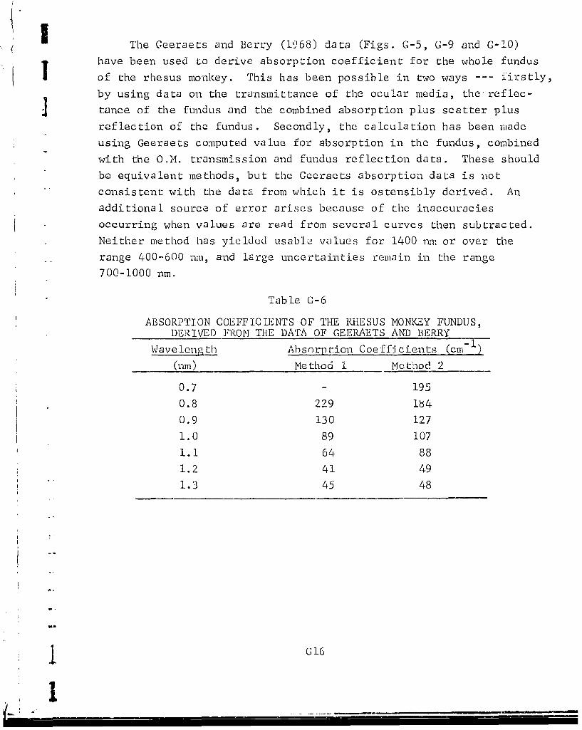
IThe Geeraets and Berry (1968) data (Figs. G-5, G-9 and G-10)
have been used to derive absorption coefficient for the whole fundus
of the rhesus monkey. This has been possible in two ways --- firstly,
by using data on the transmittance of the ocular media, the reflec-
j tance of the fundus and the combined absorption plus scatter plus
reflection of the fundus. Secondly, the calculation has been made
using Geeraets computed value for absorption in the fundus, combined
with the O.M. transmission and fundus reflection data. These should
be equivalent methods, but the Geeraets absorption data is not
consistent with the data from which it is ostensibly derived. An
additional source of error arises because of the inaccuracies
occurring when values are rend from several curves then subtracted.
Neither method has yielded usable values for 1400 nm or over the
range 400-600 nm, and large uncertainties remain in the range
700-1000 nm.
Table 0-6
ABSORPTION COEFFICIENTS OF THE RHESUS MONKEY FUNDUS,DERIVED FROM THE DATA OF GEERAETS AND BERRY
Wavelength Absorption Coefficients (cm-)
(nm) Method 1 Method 2
0.7 - 195
0.8 229 184
0.9 130 127
1.0 89 107
1.1 64 88
1.2 41 49
"1.3 45 48
G16
I
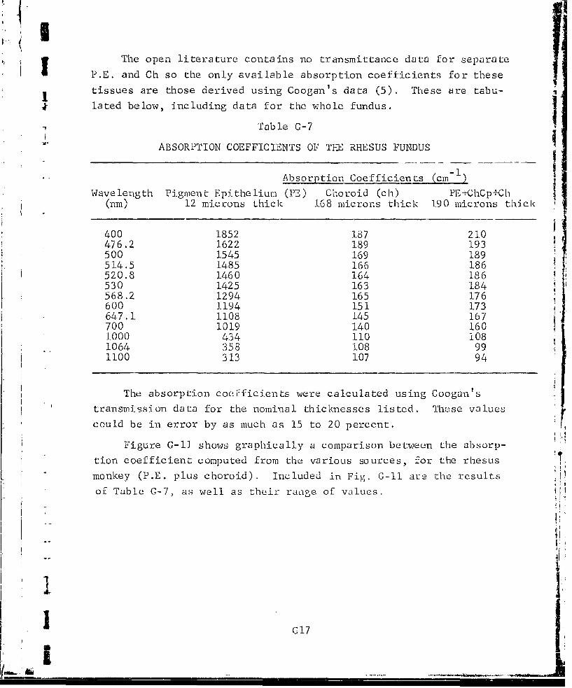
IThe open literature contains no transmittance data for separate
P.E. and Ch so the only available absorption coefficients for these
tissues are those derived using Coogan's data (5). These are tabu-
lated below, including data for the whole fundus.
Table G-7
ABSORPTION COEFFICIENTS OF TE RHESUS FUNDUS
Absorption Coefficients (cm1)
Wavelength Pignient Epithelium (PE) Choroid (ch) PE,+ChCp±Ch(nm) 12 microns thick 168 microns thick 190 microns thick
400 1852 187 210476.2 1622 189 193500 1545 169 189514.5 1485 166 186520.8 1.460 164 186530 1425 163 184568.2 1294 165 176600 1-194 151 173647.1 1108 145 167700 1019 140 1601000 434 110 1081064 358 108 991100 313 107 94
The absorption coefficients were calculated using Coogan's
transmission data for the nominal thicknesses listed. These valuescould be in error by as much as 15 to 20 percent.
Figure G-11 shows graphically a comparison between the absorp-
tion coefficient computed from the various sources, for the rhesusmonkey (P.E. plus choroid). Included in Fig. 0-11 are the results
of Table G-7, as well as their range of values.
C17

30
S -j
25 2otre -1 eeraets
44J
4- 150U Co ga
~z100
-o
Wavelenigth, Rtm
Figure C-11 COMPUTED SPECTRAL DEPENDENCE OF TRlE A13SORPTIONCOEFFICIENTS (see text)
jc G18

( 2.0 OPTICAL PROPERTIES OF MAN
2.1 CORNEA
Since the cornea has a refractive index of 1.376 its reflectioncoefficient for light incident along the normal can be calculatedas approximately 2.5% for visible wavelengths.
Measurements of the human corneal transmission, made byBoettner (6) are shown below. The total transmission includesforward scattered radiation, which is age dependent.
100
00-00I
I-- DIR. ...-.- I
20 ' 2 /. T 14--
.1 I - 1 /" II0- 0 / " G;I1- I, //'I
g-:DIEC, 11. S.bYW- t /I-~~C,~3YS/i /
SWAVELENGTH (umn)
I -Figure G-12 TRANSMITTANCE OF THE HUMAN CORNEA
CI 9
" I /

2.2 AQUEOUS HUMOR
The aqueous humor shows no age effect and no forward scattering.The spectral transmittance of the human aqueous humor as measured
by Boettner (6) is shown in Figure G-13.
-i ili HT
80-
60
- AQUEO*US HUMOR -
-DIRECT TRANSMITTANCE
<402-
2.020 [.0-
300 400 500 600 800 1000 1200 1600 2000
WAVELENGTH (nrm)
"Figure G-13 TRANSMITTANCE OF THE AQUEOUS HUMOR OF MAN
2
1 o
G2

2.3 LENS
The human lens increases in optical density with age,particularly at the shorter wavelength. This appears to be
due to yellowing of the lens with age due to increasing pigmenta-
tion. The density plot below is due to Cooper and Robson (34).
It is plotted to emphasize the density in the UV.
10
5-
i .....-.
°0, • o -! '.-\
0
I I I I 1 II I I I I300 400 W50 600
Wave.length (nrn)
Figure G-14 DENSITY SPECTRA OF INTACT HUMAN LENSES OFVARIOUS AGES. TIHE AGE IN YEARS IS SHOWNAGAINST THE CURVES.
ILj
I G21I
, I

r4 ' Said and Weale (35) shows an optical density plot shown in
I Figure G-15 scaled to show the effect of age upon transmission inthe visible. The crosses on this plot show the mean of ,cilsuro-
ments on two lenses, 48 and 53 years old.
'4i 'C'
37 63
3' x
xxo5o
03 '
¢ -__._...• J _ _ A
40'0 5 0600 600
Figure G-15 SPECTRAL DENSITY CURVES OF SOME ENGLISH LENSESOF DIFFERENT AGES
L
-
1fIG22

2.4 VITREOUS BODYBoettner's (6,10) data shown in Figure G-17 show the trans-
mittances of the human vitreous body, both witn and without the
forward scattered light. Boettner reported the possibility that
the vitreous humor may have been contaminated with pigment, lower-
"ing the values obtained for direct transmission.
I:I
100
tu 60
SI vIT'REous HUMAOR
F- p
-- I --- TOTAL 'TRANSMITTANCE
V)'w I
Iz I -- DIRECT TRAN SNIITTANCE
< 40--SI
LU
C _20
300 400 500 GOO 800 1000 1200 1600 2000
.. YWAVELENGTH ('nni)
Figure G-17 TRANSMITTANCE OF TilE VITREOUS HUMOR OF MAN
GC23

Using the data of Table G-8, Boettner has computed the percentage
of the light incident on the human cornea which was transmitted
through to the anterior surfaces of the aqueous, lens, vitreous
and retina. The results are shown in Figure G-18 for direct
transmittance, excluding forward scattering, for a young eye.
DIRECT TRA/S!'417TANCE AT ThE
VARIOUS ANTERIOR " SURFACES
60 I AQUEOUSR L LEhI'S
I L_ 3 VITREOUS --
S4 RETINAk
GO
is,
3 4
-.,
WAVEL-Ek 5ITH (nin)
Figure G-18 CALCULATED DIRECT TRANSMITTANCE OF 'rilE ENTiRE HUMAN EYE
G-
Id
I G24I ...!I~
K' J

Here the totLJ transmitta~nce for a young hlumanl eye is show-n
Jin Figure C-19 i-ncludinig the- forw~ard scattered radiationi. The
results were computed rather tha.1n measured. Tim &ata illow for
Ithe reflectiOnl 10-;CS atL the ajr-corflc1 illterface.
Th-e data of Figures C-18 and C-19 are piesenited in tabulnr
f orm in Tabic G-9.
C, 0
Q TOTAkL TRANSMITTANCE AT- THEw VARZIOUS ANTERIOR SUPFACES
300 el00 C) O 5000 GOOoo 1000 1200 1600 2000VWAVELEfIO'-lH (nmn)
IFigure G-19 CALCUIATBI) TOTAL TRANSM.1ITAN~CE OF. ?111 E'NTIRE IiUmAN tEYE'
025

Table G-9
PROGRESSIVE TRANSMISSION OF LIGHT THROUGH THE HIrMAN OCULAR MEDIA (%)
(percentage of light incident on the cornea which roaches theanterior surfaces of the components named)
Wavelength Aoueous Lens Vitreous Retina.
(rim) Direct Total Direct Total Direct Total Direct Total
280 < 0.1 < 0.1 < 0.1 < 0.1300 2. 8.5 0.3 1.5 0.0 0.0 0.0 0.0320 26.5 59. 20.5 46. 1.5 4. 0.9 3.340 34.5 66.5 28.5 55. 0.5 1. 0.3 1.0360, 42. 71.5 36. 61.5 0.1 0.4 < 0.1 0.4
380 47. 76.5 41.5 67.5 0.4 I. 0.5 0.9400 51. 80.5 46. 72.5 5.5 10. 4.o 9.420 54. 82. 49. 74.5 27-5 47.5 20.5 44.440 57. 83.5 53. 77. 37.5 69.5 28.7 65.5460 60. 89. 56. 79.5 41.5 74. 32. 70.0
480 62. 86.5 58.5 81.5 41-.5 76. 35. 72.5500 63. 88. 59.5 83. 46.5 78. 37. 75.55o 66. 90. 63.5 86.5 52. 82. 41.5 79.6co 69.5 91. 67. 88. 57. 83.c 46. 80.565o 71.5 92. 69.5 89.5 60.5 85.5 49. 82.5
700 74. 93. 72. 90.5 63.5 87. 51.5 83.5750 76. 93. 74. 90.5 65.5 87. 53.5 83.800 77.5 93. 75. 90. 66.5 86.5 54. 82.85o 79. 93.5 76. 9o. 68. 86.5 53.5 81.5900 80. 93.5 75.5 88.5 68. 84.5 51.5 75.
950 79.5 93. 71.5 83.5 60.5 75. 36. 49.5980 79. 91.5 66.5 77.5 52.5 64.5 21.5 32.
1000 Bo. 92. 69.5 80. 56. 69. 25. 38.51100 83.5 92.5 75.5 81.5 63. 75. 41. 55.1200 78.5 89.5 51. 4 58.5 33. 39. 4. 8.
1300 80.5 88.5 54.5 59.5 36.5 41.5 4.5 6.51400 39. 58. 0.2 0.3 < 0.1 < 0.1 0.0 0.01445 18.5 24. 0.0 0.0 0.0 0.01500 27. 32.5 < 0.1 < 0.1 < 0.1 0.01600 57. 66.5 5. 6. 0.5 0.91700 62.5 69.5 9.5 10.5 1.0 1.51800 54.5 6o.5 3. ).5 0.2 0.2
1900 3. 5. 0.0 0.0 0.0 0.01950 0.0 0.5 0.0 0.02000 1. 3. 0,0 0.02100 16.5 21.5 < 0.1 < 0.12200 26. 30.5 < 0.1 < 0.12300 17.5 20°5 < 0.1 < 0.12400 5.s 8. 0.0 0.0
S2500 0.0 0.5
GG2 6
( !

Boettner (6) made some transmission measurements on complete
J human eyes from which the sclera and fundus had been removed. The
results for the 7 year eye are in reasonable agreement with the
I computed values. Also shown are the percentage of 566 nrm radiation
scattered outside a cone of 1° total angle. The scatter profile
for the 7 year human eye is shown on the next page.
Table G-10 at
SUMMARY OF TOTAL PERCENT TRANSMITTANCE MEA";URENENTS
__ _ __ _ Scatter* h66 (nm) 566 (rim) 666 (nm) £00 (nm)
Augu3t 1.4, 1963"7-year raile 29 79.0 82.5
(600 nm)April 27, 196451-year female 40 56.5 79.0 81.0
June 18, 196453-year female 39 38.0 65.0 71.0 71.0
October 22, 196445-year male 37 46.0 69.o 84.0 64.0
February 19, 196552-year male 30 41.0 69.0 79.0 67.0
Calculated TrarsAission
68 78 82 81
*Percent of 566 nm scattered outside of a 1 degree cone, except7-year male, which was measured at 600 urn.
1l G272a. .

t I *0 ---
s 0II
60 Hua Eye
C .|
80-
I I ... "Perfeat" Lens
I ---- Glass Lens6O I
Si ! - Human Eye,:-• ! • 7yr. Mole
Ui)
° ~I
ft
20- lU !
S"" 0 • / 1 : ! : ,!l
S.. 0 -60' -30' 0 30' 60' 901
I ~~Figure G-0 SCATTER PR{OFILEO AUhNEYGSLN,
-- AND 1tPEREECT" LENS
1 •028

I'
Earlier measurements on the transmission of the ocular media
jof the human eye were made by Ludvigh and McCarthy (36)measure-
ments were made by Alpern et at (37) in vivo. A comparison of these
two sets of measurements with those of Boettner is given below.
(-)
o 2.0
0
c• .°_
LOa• i.4 /o
1.2S5 00 500 50 C, GLO
VIAVULENGTH nm
Figure C-21 The mean spectral transmittance curve forthe three eyes (solid line) compared toin vitro measurements of Boettner andWolter (10) (dotted line) and of Ludvighand McCarthy (filled circles) (36)
I

!
I Ruddock (38) has examined the effect of age upon the trans-
mission of the human ocular media, the curve below showing the1: ratio of transmissions of 63 year old versus 21 year old eyes.
The results are shown in Figure G-22.
nm
Figure G-22 The transmission of the ocular mediaas a function of wavelength. Thevalues of tA represent the trans-mission of the media in a 63-year-o1I observer relative to a 21-year-old observer (for whom tA is unityat each wavelength)
I
I G

The ocular media transmissions reported by Boettner (6) and
Geeraets and Berry (9) are compared by Sliney and Freasier (39) as
shown in the curves of Figure G-23. He claims that much of the
discrepancy could be explained by differences in the size of the
image upon the retina.
- N..' !:
N \
4o -¢'h i l£O lW. __--.J---__
W•AVL L, -G T H (
Figure G-23 Spectral transmission of the ocular media
of the human eye. Upper curve wzis totaltransmission obtained by Ceeraets and Berryusing twenty-eight enucieated eyes. Lower
two curves by Boettner and Wolter were ob-tained by combining separately measuredtransmission factors for the cornea, aqueous,lens, and vitreous for nine human eyes. Lowestcurve is direct transmission obtained byeliminating forward scattered light, whereasmiddle curve was obtained by collectingtotal light transmitted.
G31
I - -

Norren (40), in comparing all available sources of data forhuman eyes, arrived at the curve of Figure G-24 as a best estimateof the transmission of the ocular media between 400 and 700 nm.This appears to be a curve for direct transmission.
I .
2 obsorplion of all oculor media-
2.n
"" I _
-400 500 00 700wavelength (nrm)
"Figure G-24 PROPOSED COURSE OF THE SPECTRAL ABSORPTION OF ALLOCULAR MEDIA FOR AN AVERAGE 30 YEARS OLD OBSERVER
j G32

4 2.5 TRANSMISSION THROUGH THE OCULAR MEDIA
( The data of Boettner (6,1U)shown graphically in Figs. G-12,
G-13, G-16 and G-17 are presented here in tabular form.
Table G-8
3 TRANSMISSION OF THE INDIVIDUAL OCULAR MEDIA
WayelenP'th Cornea Aqueous Lens Vitreous(rim) Direct Total Direct Direct Total Direct Total
0.0 0.0 < 0.1280 < 0.1 < 0.1 0.1 0.0 0.0
1 300 2.0 8.5 17.5 0.0 0.0 1.0 1.5J 320 27. 6o.5 78. 6.5 9. 57. 74.
340 35. 68. 83. 2. 2. 64. 79.
1 360 43. 73. 86. 0.5 0.5 68. 83.380 48. 78.5 88.5 1.0 1.5 71. 87.4o00 52. 82.5 90. 12, 14. 73. 9o.
1420 55. 84. 91. 56. 63.5 74.5 92.5440 58.5 85.5 92. 71. 90. 76. 94.460 61.5 87. 93.5 74. 93. 77. 94.5
148 5 588. 93.5 76. 93.5 78.5 95.5500 64.5 90. 94. 78.5 94. 79.5 96.
- 550 67.5 92. 96. 82. 95. 80. 96.56o0 70.5 93. 96.5 85. 95, 80,5 96.5650 73. 94. 97.5 87. 95.5 81. 97.700 76. 95. 97.5 88. 96. 81. 96.750 78. 95. 97.5 88. 96. 81.5 95.5800 79.5 95. 97. 88.5 96. 81.5 95.850 81. 95.5 96.5 89.5 96. 79. 94.
900 82. 95.5 94.5 90. 95.5 75.5 &C,
950 81.5 95. 90. 84.5 90. 59.5 u6.980 81. 93.5 84.5 79. 83. 41. 149.5
11000 82. 94. 87. 80.5 86. 44.5 56.
1100 b5.5 94.5 88. 86. 92. 65. 73.511200 80.5 91.5 65.5 64.5 66.5 12. 20.5
1300 82.5 90.5 67. 67. 69.5 12.5 16.1400 40. 59.5 0.5 1.5 4. < 0.1 2.5
I 144! 19. 25. 0.0 0.0 0.01500 27.5 33. 0.1 0.2 0.516o0 58.5 68. 9.0 9.5 14.5
j1700 64. 71, 15. 2.1.5 25.5
1800 56. 62. 6. 5.5 6.51900 3. 5. 0. 0.0 0.0
j1950 0.0 0.5 0.
2000 1. 3. < 0.172100 17. 22. < 0.1
2200 26.5 31. 0.22300 18. 21. < 0.1
1 2400 5.5 8. 0.02500 0.0 o. _
, .. • l[G33

Boettner (6,10)/measured the total transmission and the
transmission with scattering excluded for human lenses of various
ages. The results are shown in Figure G-16.
I00
I I80e
=0 r -'O.
LENS TRANSMITTANCE"" u 60 !
(U . u ,,--=TOTAL , 4 1/2 YRS. |
- I -- DIRECT, 4 1/2 YRS.
"U - I • 2--DIRECT, 53 YRS. -
1. I 3---DIRECT, 75 YRS.
". 40
-J-
"20t I'
300 400 500 600 800 1000 1200 1600 2000
WAVELENGTH (ru)
Figure G-16 TRANSMITTANCE OF THE HUMAN LENS
Ii
G34
--= A--i• ,--

2.6 FUNDUS
i[ Geeraets and Berry (9) made a series of measurements on
the fundus tissues of man, rhesus monkey and rabbit. The spectral
I reflectances for each are shown in Figure G-25. Note that for
man because the eyes had aged 24-28 hours post mortem the nervous
T retina had swollen and clouded and had to be excised. Even so the"data for man show considerable scatter.
PE.RCENT 5FT.CTRAL RE'FLECTIN F-RQY RETINAL PIGMENT EPITHFILIUM14AND~ CHcOiCID
28 IAUU14 EYES 56 EL>ýJLI. EYES 14 1IC,•EY EYES ,
T0 1I •I I f t j
ii i ! 9, 1101 300 50
I::~ ~ WV LENGT (mAi~X I j>J.7 1 - ,H .I- _ ,,. .iu I
00 9(00 1300 500 9"-30 I200 500 500 1300)
70{)T0 I 00 I200 700 I100 1500 700• II00 150Q
WAVC" LENSTII {InI I
Figure G-25 REFLECTION COEFFICIENTS FOR THE HUMAN P.E. & CHOROID,:. WITH COMPARISONS WITH THE COMPLETE FUNDI OF THE RABBIT
AND RHESUS MONKE-Y
G.
::I
it 1
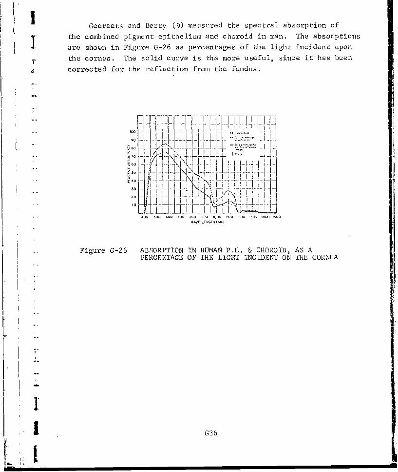
rGeeraets and Berry (9) measured the spectral absorption of
the combined pigment epithelium and choroid in man. The absorptions
are shown in Figure G-26 as percentages of the light incident upon
T the cornea. The solid curve is the more useful, since it has been
4• corrected for the reflection from the fundus.
I,
"I " -F- I
-• ,,400 ~l 5 000 - 0- . O •I I0 l I I?.0 10 40 10
WAVE LE NGTh ( nm )
.. Figure G-26 ABSORPTION TN HUMAN P.E. & CHOROID, AS APERCENTAGE OIF THE LIGHT INCIDENT ON THlE CORNEA
LL
o .
]~ t.
G36Li!

The earlier work of Geeraots et al (8) does not appear to be
j corrected for reflection from the fundus, but is included here
because of the dearth of data for man. Figure G-27 shows, for the
human eye, the range in value of the absorptions of the pigment
epithelium and the choroid. Figure 0-28 shows the absorption in the
lightest pigment epithelium as a percentage of the light incident
on the cornea.
100 124 HUHAN EYES
CHORO IDm. I--
CL RETINAL PIGMENT EPITHELIUM
40)
'- 40 __ -__ __-_
C-)
20
350 450 550 650 750 850 950 1050 1150 1.r0 1350 1450
WAVE LENGT!I (nm)
Figure G-27 Range of absorption in human retinal
Ti gment epithelium (area Letw,•.r solidlines) and choroid
100 -- - -I -.. ... ...... -- _ -.- 80 - _IL__
S6 0 . . . . . . . . . . ..
U)
20•= 40 I _
20
350 450 5'O GýO 750 850 950 1050 I 1O 1250 1350 I 11M
WAVF LENG3II (nnm)
Figure G-28 Curves showing absorption ii lightest"humana retinal pigmenL epithelium forlight incident on the cornea
j 037
I,F I.

Figures G-29, C-30 and 0-31 show the Geeraets measurements of
the absorption of the darkest human pigment epithelium, the lightest
human choroid and the darkest human choroid, in each case as per-
centages of the light incident on the cornea.
100
DARKEST PIGMIENT EPITHELIUM¶" 0 60 -...... __ ___ _ _ __ _ ___ _
.U4 0
"20
350 450 550 650 750 860 950 1050 1150 1250 1350 1450
WAVE LENGTH (nm)
Figure G-29 Curve showing absorption in darkesthuman retinal pigment epitholium forlight incident on the cornea
100
80
"- •LIGHTEST HUMAN CHOROIDS60
.1 ~ ~ ~ so---.---___0
CL 2020 ---• -----. __ •-_ ___--___ -
0350 450 550 550 750 850 950 1050 1150 1250 1350 1450
WAVE LENGTH (rim)
F ligue G-30 Curve showing, absorption in lightesthuman choroid for light incidcnt onthe cornea
1 -1 38 •
L±J _ _ _ ___ I

100 _ |I
I ~~80 __I'ý CD DARKEST HUMAN CH0R0• 0
40
20 -T7 __ __
350 4,50 550 650 750 850 C50 1050 1150 1250 1350 1450
WAVE LENGTH (nm)
Figure G-31 Curve showing absorption in darkesthuman choroid for light incidentotn ahe cornea
Sliney and Freasier (39) used the Geeracts spectral absorptionmeasurements for man and multiplied them by the ocular wedia transmit-
tances due to Geeraets, and Boettners lowest curve to show the range
in values for the absorbed dose in the retina plus choroid as a per-
centage of the light incident on the cornea. These results are shown
in Fig. G-32.
"V- 60 4
"1 VIAVI { ,I•{L.
Figure G-32 Spectral absorbed dose in retinaand choroid relative to spectral
I corneal exposure as a function ofwavelength. Retina and choroidspectral absorption values correctedfor fundus reflection obtained byGeeracts and Berry were multipliedby corresponding transmission spec-tral factors of the ocular media
i from Geeracts (upper) and Boettnor(lower)
G39
I*, : .-

t hCoogan et al (41) claims that the rhesus monkey is a poor
surrogate for man in terms of laser damage to the fundus, because
the human pigment epithelium Js much more heavily pigmented which
"•renders it more prone to damage. However, human pigment is located
towards the rear of the PE rather than at the front as with monkeys.
Also threshold data available indicate the monkey retina is more
sensitive to laser radiation than that of humans. The rhesus choroid
is the more heavily pigmented, but this is not thr. primary site
"6of laser-induced damage. 1lowever, the spectral absorption ch--;-ac-
te-istics of t.he two fundi may differ slightly, since man hafuscin mixed with his melanin, the rhesus monkey does not.
The rabbit is a good surrogate, as demonstrated by Geeru.-,+ts
et al (7) who showed via the curves below that the fundal absorp-
tions of man and the rabbit are similar if the pigmentation density
can be matched.
I° :- ... .. . ... 0 ~' , ' 1-~~I Il .. ' ' '' : ' , .-
100IJII
1 \ .I I • . I < .. J
Figure G-33 Percentage of the energy incident onthe fundus which is absorbed, for one
-- ~human individual and for rabbits of4different pigmenta tion classes. The
"" ~human fungus here lacked the nervous. re tina
Ij
304I _35 11 5
I0 o 1 ý) D 00' 010 01 0201ý1 C: W

2.7 Sc lera
Smith and Stein (42) have made measurements on the human sclera
over the range 0.5 to 2.5 nm. Their interest was in laser damagevia transsc .liz beams so their measurements were made on anterior
portion, oDf the sclera, viewed from outside. Figure G-34 shows -the
"spectral ri"flection from the sclera alone, while Fig. G-35 shows
the spect.:ai ,rans-nis.iion. The spectral absorption, derived for
.each wavelength b,- subtracting the reflectance plus transmission
from 100%, is shown in Fig. G-36.
,, \.
o 4 -'2w '
•:4 .5.
U. I O
Wavelength (nm)
Figure G-34 SPECTRAL REFLECTION FROM THE HUMAN SCLERA
r 1 G41IL )....-.i

, 0 /' -'I,-_~~ ~ ............ A
F-'
"/ ',-7 i , ,
"900 '
• 7 7(2
• 60-
50
.,20 !"
10
G.5 1 1.5 2 2.5 3.0Wavelcngth (nrn )
Figure G-35 TRASMS2TAOT IN THE HUMAN SCLERA
lG42

IAlpern et al (37)measured the reflectance from the outside of
-the slera of living human eyes, as shown in Fig. G-37. They covered
only 0.4 to 0.65 ILm. These reflectances are all below 40%, thus
considerably below Smith and Stein's measurements.
4.~i
40 .... Q0 Gtoit
"W Figure G-37 Spectral rcflectance of the sclera.Open circles arc measurements madeby reflecting light from the outside
-. of a living human eye. Filled circlesare the measurements made by reflectinglight from the inside of an enucleatedmonkey eye which has been carefullydeniuded of pigm-enat epithelium and under-lying choroid.
G
.ii
I
I
SG43
i1

APPENDIX It
RE T INIA L 11WDIANCE PROFILE

APPENDIX H
RETINAL IRRADIANCE PROFILE
3 1. INTRODUCTION
The determination of retinal irradiance for axial plane or
J spherical beams can be performed using the Fourier transform' prop-
erties of imaging systems. Accordingly, the Fourier transform of
the image distribution is given by the product of the Fourier trans-
"forms of the object distribution and of the point spread function
(impulse response) of the eye.
l(fx fy 11(f 'E.y)'O(fx)fy(-I
An inverse transformation of I then provides the desired image
distribution H(x,y). In the case of laser sources the radiation
is coherent. The physical quantities are the (complex) amplitudes,
and the coherent transfer function. The retinal intensity distribu-
tion is obtained by squaring the absolute values of the calculated
amplitude distribution obtained from the Fourier transform of I(fxfy).
Appropriate scaling of the object amplitude is required and the
transfer function must include the effucts of aberration and pupil
size as well as the effects of the retina not being conjugate to the
object plane.
An equivalent and, in the case of this program, preferable
"procedure is to view the problem in terms of scalar diffraction
theory, in particular the Fresnel approximation. An excellent dis-
cussion of this topic can be found in the book by Goodman (43)
Taking the appropriate result from this we can express the amplitude
in the retinal plane as
U(xR,IYR) JJ h(Y,1sYR; xy) U(x,y)dx dy (11-2)
"where U(x,y) is the amplitude at the exit pupil and
Li h(x RYRx =xP iexp ikz kp ik X)2 + (yR-y)2 (1-3)iNZ 2z
HI

We can therefore write
eU(xR'YR) exp ikz exp [i k 2 +ljx'R iý,z 2z (R2 + yR2)]
"ff{U(x'Y) exp[ik (x 2 + Y2)}] exp[-ik (xRx + yRy)]dx dy
(H-4)
Aside from phase factors and constants, the retinal amplitude is
the Fourier transfprm of the pupil amplitude multiplied by a quadratic
phase term. The radiant: intensity is then
"".(xRYR) U(xR,YR)1 2 (H-5)
"Thus the problem becomes one of specifying U(x,y). We can separate
this into two parts, one part determined by the experimental param-
eters, the others by the properties of the eye which are most con-
veniently described by the aberration function.
%;I
I"
, H2S... i ii i i ..... .... iJ

2. ABERRATION FUNCTION
The aberration function for the eye includes a number of
contributions from different terms. In order to simplify the compu-
tation of this we shall use only the radially symmetric terms. The
justification of this is two-fold. First, in experiments we assume
that the subjects used are selected for minimal aberrations of the
astigmatic kind and that coma is negligible because of nearly axial
"illumination. Secondly, the thermal calculations are based on
radial symmetry. This reasoning leads us to characterization ofthe eye in terms of spherical aberration alone via an aberration
function
CI p + C2 p4 (H-6)
where p f radius in pupil plane. 4
The spherical aberration term C2 p4 is of the formP
The coefficient C2 for the human eye can be estimated ii the
following way. From Born and Wolf (Ref. 44) the longitudinal spher.cal
aberration Az is related to C' by
' AZ (H-7)C2 4a 2 f2
"According to Lotmar(Ref. 45) Az -.1 cm (.35 cm pupil radius) giving
S2r 4 - 42N , = -1.0"10 cm (H-8)
Lotmar's v-alue corresponds to a longitudinal aberration of 3 diopters.
L Van Meeteren (Ref. 46) gyiveS value of i diopter which leads to
2 7-- c; = -3.0.103 cm" 4 (H-9)
* We have used X = 500.0 nm for these calculations. Considering the
range of variation found in human eyes we can choose the mean,
where X is in nanometers. El Hage and Berny (Ref. 47) have pub-
lished aberration prt les wbich give values quite consistent
with this choice. In the Retina), code C2 CABER2 while 2wC' 2 -- CA3EP
S -3.0-106 cm- 4 nm.
H3
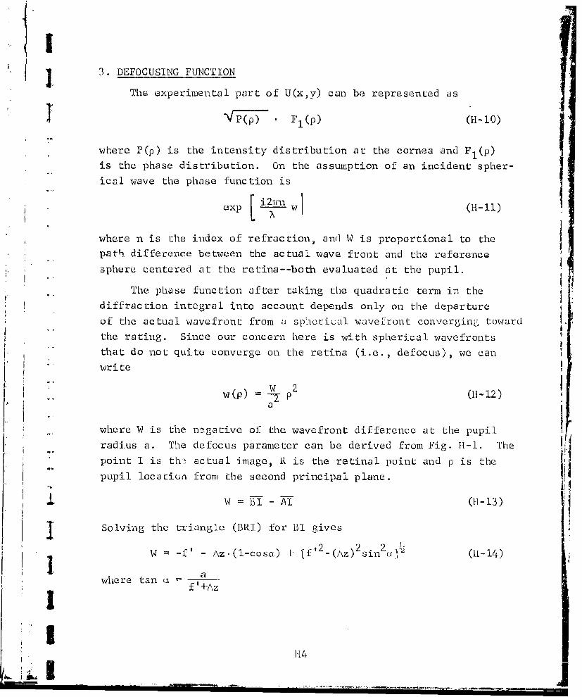
J 3. DEFOCUSING FUNCTION
The experimental part of U(x,y) can be represented as
]1 */(• F11(p) (H-t0)
where P(p) is the intensity distribution at the cornea and F 1 (p)
is the phase distribution. On the assumption of an incident spher-
ical wave the phase function is
exp W Ll (-l
where n is the index of refraction, and W is proportional to the
path difference between the actual wave front and the reference
sphere centered at the retina--both evaluated at the pupil.
The phase function after taking the quadratic term in the
diffraction integral into account depends only on the departure
of the actual wavefront from a sphcrical wavefront converging toward
the rating. Since our concern here is with spherical wavefronts
that do not quite converge on the retina (i.e., defocus), we canwr ite
W 0wiew(p) P (H-12)
a
where W is the negative of the wavefront difference at the pupil
radius a. The defocus parameter can be derived from Fig. 11-1. The
point I is the actual image, R is the retinal point and p is the
pupil location from the second principal plane.
W -
I ]Solving the triangle (BRI) for BI gives
-f' - Az.(l-cosa) + [f, 2 ([\z) 2 sinU-. (11-14)
where tan af '+Az
H4- -- I14

HI N
T I __ _ *1
K ___
(2) �1
H
C)
I C-,1�H
C-)
2. 4-1
bOI *r-I
- rt4
ii
TIdtXT - 9 -*�-- .1. _____
OUL'�j TI�dTou.T�a 1)UOZ�OS
1 115
�iI�I

IAz~ nz f (H- 15)nz.-f. a =pupil radius
f-back focal 'Length (measured from second principal 4)
fn mdx frercto
p =distance between pupil and second principal 1-~t Z
z,, distance of pupil from the wvaist of the las.er beam
I.JI
116

<I4. CHROMATICABERRATION
Considering that fixed experimental geometries are used even
through the wavelength changes we need to include the effect of
the "chromatic aberrations" of the eye. In the application at" hand
this is the change in focal length with wavelength and if we include
this in the defocus term we have accomplished our purpose.
The dependence of focal length is given by (Ref. 15)
where n = n(\)
no= n(-/.) and -A is the wavelength at which the focallength of the eye is f,.
The dependence of refractive index of water on wavelength can
be obtained in tabular form from Irvine and Pollack (Ref. 48).
Recent measurements (Ref. 4.9) have shown good agreemenL with the
Irvine and Pollack compilation.
We have used the refractive index of water siiice the eye media !consists mainly of water. As has been shown (Ref. 50) the calcul-
ated eye behaviour agrees with that determiined experimentally atwavelengths above about 430 nm. The use of the water index at the
short wavelengths results in an excessive focal length and is
apparently due to the nonaqueous constituenits particularly the lens.
Using the Wald and Griffin data we can calculate the corresponding
effective refractive index for use as the tabulated values below
500 rim.
The results are
350 1.357
400 1. 346
450 1.341
11I
117
i=l'Ii i " i i i ii i-

I.
5. RETINAL IRRADIANCE'
With the above functions the diffraction integral becomes
. a 2wr
H(r,G) = - f VTTT) exp i Co 2 + C2 p4]
0 0 2 (H1-17)• exp -- •P.r.cos(0-O) -d]d•h
where we have taken advantage of the syxmmetry and converted to
cylindrical coordinates. Recognizing that21T
i 27!- i 2rexp p.r.cos(O-O) d o] -- 1
the normalized profile becomes
a a
, I _____( ..-19)
jII I I, I ICp 2 + cuo4] pdp
II

I
I'I
q.2
I-,t1
-I - .... . . ..• • - , . .. .. . .. ... . . . _I I •i .. . I I I . . . -- -

APPENDIX I
GRID SYSTEM
1. INTRODUCTION
SIn both models, polar coordinates r and z were chosen to
assess the transport of heat within the eye. To conserve on
computational. times, the points at which temperature, are calcu-
lated are closely spaced in regions of greatest energy deposition.
The mid-point of the grid shown in Fig. 1-1 is located at i=M2+l,
j=1 where i represents the index for points on the z axis while
j represents the index for points on the r axis.
On the z axis, there are M1 uniform increments on each side
of the mid-point, while on the r axis there are a total of NI
uniform increments starting at j=l. Beyond the uniform portion
.. of the grid, it commences to expand so that each succeeding incre-
ment is a constant factor larger than the previous increment.
Choice of the grid network is based on the surface
of the cornea being at z=O and the edge of the eye at r=RVL.
Consideration is also given to the interfaces betwee eye media.
For the Retinal model the thicknesses of the eye media are repre-
sented by TAV, TPE, TVL, TCH, TSC and TTS, where
TAV = thickness of all eye media from corneato pigment epithelium, cm
TPE = thickness of the pigment epithelium, cm
TVL = thickness of the chorio-capillaris, cm
TCH = thickness of the choroid, cm
TSC = thickness of sclera, cm
TTS = thickness of tissues beneath eye, cm
- Distanccs of the interfaces from the !;ur 4Uace of thc cornea, wherein
z=O, are given by ZD(LI) stirting with ZD(l)=O.
Ir In the Corneal model the thicknesses of the various eye media
are represented by TH(l), TH(2) .... TH(6). Distances of the inter-
] faces from the surface of the cornea are represented by ZD(LI)again starting with ZD( 1)=O at the anterior surface of the cornea.
I1

I 4
-4r
-rl
4- 4- 4 -
"".. .- )
I+ +
' 'H
,-4 •
-- 40-
iri
""_ _ _ _ _ I _ 12------ : -•-4--•- • - - G-j NI I - - l)•i
- ---- .
I II.-)
•1 12

Next we shall discuss how the grid nEtwurk was related to
the various interfaces. In this regard, tha only liberty one has
once the number of grid points are selected, is the choice of two
I points with which to fix the grid.
2. RADIAL M TWORK
In both models, the first radial grid point was located on
-. the axis of the eye (wherein j=l) so that
R(l) =0 (1-1)
The edge of the eye at r=RVL is located halfway between
"R(N-l) and R(N). Thus, there are two radial points, namely R(N)
and R(N3) beyond eye. This situation prevails regardless of how
"many grid points are chosen.
3. AXIAL NETWORK
Choice of the axial grid work differs in the two models
since the finer grid is always located in and about the region
"* of greatest energy deposition.
3.3. Retinal Model
In the Retinal model, the anterior surface of the COLnL'A is
. located halfway between Z(l) and Z(2). On the other hand, the
anterior surface of the pigment epithelium is located halfway
* between Z(M2-MI+1) and Z(M2-Ml+2). The first grid point- in the
"-• pigment epithelium is at Z(M2-MI+2).
K i 3.2 Corneal Model
'. In the Corneal mou'l, L•e grid work for z differs according
to whether one wishes to assess corneal or ienas damage. For the
case of corneal damage, the finer grid is located at the front of
j the eye so that the corneal surface lies halfway between Z(M2-MI+I)
and Z(M2-MI+2). The last grid point Z(M3) is located so it coin-
cides with ZD(7).
For the case of lens damage, the fine grid is located in and
about the lens. The surface of the tear layer is located halfway
between Z(3) and Z(4), while the anterior surface of the lens
(at z=ZD(5)) is located halfway between Z(M2-M1+l) and Z(M2-Ml+2).I ~13 ,

4. DETERMINATION OF EXPANSION FACTOR
Once one has chosen the number of nonuniform grid points
1 with which to cover a given distance, the next problem is to assess
the expansion factor by which the increments must be sequentially
Sincreased to arrive at the given distance. To illustrate the
-• method, we will develop the expansion factor for the radial grid.
-- The method is an extension of the technique used by Tech. Inc.(Refs. 1,52).
-. First, consider that one wishes to locate the edge of the
eye (r=RVL) halfway between R(N-l) and R(N). Moreover, consider
that there are NI uniform increments of size DR included within
a total of N+1 points. If we represent the expansion factor by
R, then the distances P1 and P2 from the start of the last uniform
increment at R(Nl) to R(N-1) and R(N), respectively, are given by
:. ~'l = =1 + R (-2
I -l- - 1 + R + R 2 ... Rj- (1-3)2 R--
where j=N-Nl. If we ',w add these two equations, and represent
(PI+P2)/2 by P, then
"P.2_(R-I)+2 = RJ-I (1-4)R+1
Taking the logs of both sides and solving for the R on the right-
hand side of Eq. 1-4 yields
1R = exp(log(2 P(R+1)+I)/(j-l)) (1-5)
This equation can be solved for R by successive approximations.
j First one evaluates the right-hand side using an estimated value
for R. The result represents the first approximation of R. The
Snext approximation is made by substituting the newly .found valuefor R back into the right-hand side of l-,q. 1-5. This process is[ ij continued until R ceases to change. Usually, about LO approxima-
tionb are required.
l.1ii~l• l14

I.
.. APPENDIX J
I ~MEASURING UNCERTAIN;TIES IN PREDICTED LASER POWERS
TO CAUSE DAMAGE
I ! .
,I.
a.
I

A PPE'ND IX J
MASURNG UNCERTAINTIES IN PREDICTED LASER POWERSTO CAUSE DAMAGE
In this appendix a methodology is described which measures
Sthe variability in the predic tions of the laser of the Corneal and
Retinal models caused by uncertainties in the input parameters.
A computer program has been developed for this purpose. This ap-
pendix describes the problem, the methodology, and an example.
1. THE PROBLEM
Consider a mathematical model with n input parameters labeled• as X1 , X2 ,... X and an output result Y. Hence, Y is related to the
nparameters X in some functional fonr as
"Y = f(Xl, X2 ,..., Xn) (J-l)
1.1 Parameter Nominal Values
To use the mathematical model, one must specify values for tho
input parameters: these may be denoted as X 10 ,..., Xn0 Upon exer-
cising the program a particular output result is obtained, say Y0 ,
In functional form
Y = f(Xl 0 ',..' Xn 0 ) (J-2)
"1.2 Uncertainty in Nominal Values
As a result of the fact that the nominal values X1 0 ,..., Xno
probably deviate from their true values, the nominal values are in
reality "most-likely" values of the parameters. To appreciate the
consequence of uncertainties in the parameters, the limits over which
each parameter may range must be ý;pecified.
1.3 Uncertainty in Output Result
j Because of uncertainties in the input parameters, a corres-
ponding uncertainty exists in the output results. The purpose ofthis appendix is to measure this uncertainty.
J 11

!I2. THE METHOD
To measure the variability in output results, therc are threebasic steps as follows:
* define the uncertainty in input parameter values,
* determine the variability in output resultsassociated with each parameter's variability,
9 combine all the uncertainties so that the outputvariability can be measured.
2.1 Variability in Input Parameter Values
In addition to the assigned nominal value for each parameter,
the user must specify a pair of minimum and maximum values within
"which the time parameter value lies, The nominal value is assumed
to be the most likely value for the parameter. With these three
values the probability distribution produced by each parameter's
variability can be estimated by use of the Beta probability distribution.
The Beta probability distribution takes on many shapes depend-
ing on two coefficients, namely a and b. In this application 19
possible combinations of a and b have been selected. These are
(a=l,2,...,10 with b=10) and (a=10 with b=1,2,...,l0). Some examples
are cited in Fig. J-1. The case in which both a and b equal 10 is
very near a normal distribution.
In a standardized Beta distribution, the variable range is
from zero to one. The most likely value, which is hereafter called
the mode, becomes
Mode - (j-3)Node =a+b-2
It is the mode which is used to determine the coefficients for a
particular parameter.
The corresponding standardized mode of the i-th parameter is
found fromXiO-x 1 (min)
Mode - 7 (max)-X (min-Y )4)
j 2
Lt .1x

b= U b=i
L a L3 a = 10
b 10 b =3
I .: I • a= 5 a 10io
b 10 b =5
If
a = 9 a 10b =1.0 b9
a 10
I.,.
)= 10
* - 'ig. J-1 SOMEI ]EXAMPLES OF TIlE PlETA PROBIABII.ITV DEINSITY
1 3
, -' • - -. - I -- - I--

I whereXi. = nominal value for parameter
I X (min) = minimum possible value for parameter
YX(max) = maximum possible value for parameter
jGiven the estimate of the mode in Eq. J-4, a search is conducted
to find the closest of the 19 combinations of a and b which corres-
ponds to Eq. J-3. Once found, the shape of the distribution for
"the i-th parameter is obtained.
"Now with the shape of the i-th parameter value established,
"five representative values of X. are selected. These are denoted
as X.(p) for p=0.1,0.3,0.5,0.7,0.9. Here p represents the 100 p-' -percentiles as shown in Figure J-2. The figure shows that the
VU.
I . .l ,1 1 ... i
Xi(.l) Xi(.3) Xi(.5) Xi(.7) Xi(.9)
7 Fig. J-2 FIVE REPRESENTATIVE VALUESOF 'ITHE i-th PARAMETER VALUES
probability distribution for X. is separated into jive equal areas,
each with a probability value of 0.2. The center point of X. for
the left-most such area becomes Xi(.l). Next is Xi(. 3 ), and so forth.
111 this fashion, five repre.3entative values for each of the n
parameterý: are obtained. These now become(X i(.1), xi(.3), Xi(.51), Xi(.7), Xi(.9)), ... J 5
£ (X (.1), X11 (.3), Xn( (.5), X11(.7), Xn(.9))
AJ4
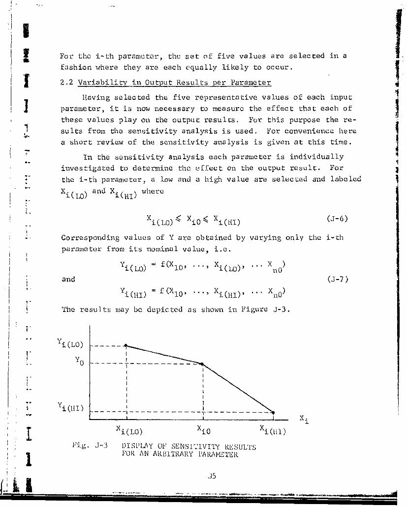
For the i-th parameter, the set of five values are selected in a
fashion where they are each equally likely to occur.
5 2.2 Variability in Output Results per Parameter
Having selected the five representative values of each input
parameter, it is now necessary to measure the effect that each of
these values play on the output results. For this purpose the re-suits from the sensitivity analysis is used. For convenience here
a short review of the sensitivity analysis is given at this time.
In the sensitivity analysis each parameter is individually
investigated to determine the effect on the output result. For
the i-th parameter, a low and a high value are selecLed and labeled
Xi(l.,) and Xi(.I) where
2-LO 2( i) L)K o<x(I J6
and (J-7)
Y 1-11,f(X 0) X0 Xi(Hi) . -0?-)
The results may be depicted as shown in Figure J-3.
"Yi(LO) k-•~YO
I.I
K " I• IXiL0 X0 iM)l
Fig. J-3 DISPLAY OF SENSITIVITY RESULTSFOR AN ARBITRARY PARAMI'TER
J5
......... . . ................. .ON

Now it is possible to estimate the sensitivity associated withthe five values of parameter i by simple interpolation or extra-
polation, whichever pertains. The results yield(Yi(.l), Yi(.3), Yi(.5), Yi(.7), Yi(.9))
and are obtained as depicted in Figure J-4. Note that Xi(LO) and
Y (.1) -) --- Y i(LO)Yi .i
. Yi(.3)(
- Yi(.5) Y_
10"" Yi(.'7/
-Yi(.9) __ ______
+
Fig. J-4 SEUL&fING Y! 1')
X. are not necessarily outside of the range containing X (.I)
With the values of Y i (p) now available, it is possible to
calculate five deviates for each i, i.e.,
Ai(p) = (Yijp) -YO) i1 2 .n(J-8)p ... .... 9
Iit
INo Le tha_ L for the i- Lh p1ra1I~tO, tlizi t tile five. issoc'!IaLUCd devitcV lLs
are equally likely to occur.
2.3 Applying All Combination-s
Now variables to Y=Y0 can be obtaiined by selecting nll comn-
binations of the deviates and applying them to the expression
J6
.. !-@,I ,1X

• Y =-0 + AI(pl) + A2(P2) + " + An(Pn) (J-9)
where P. .i,.3,.5,.7,.9 for i=.2...n. The frequency distribution
4. of Y from all of the combinations yields the estimate of the uncer-
tainty in the output result.
IJ7
i J7
K'

APPENDIX K
NOMENCLATURE, SAMPLE DATA, CODE LISTING, ANDSAMPLE RUN FOR RETINAL MODEL
*1
1.
I: 3

C *** NOMENCLATUhL FOR RETIJAL MODEL
CI A1Iol),A(I,2)9
__c.. AI.3 OEFFICIE.N.S . FINITEDIFFERENCt •UATIONSZ ELEMNT.R
CC RETI F' F CM .S--LC AAV ABSORPTION COEFFICIENT FUR EYE MEDIA FROM CORNEA TO
.C . A. . PRODVCTS .F_ ABSORPTION COEFFICIFNTS AND THJCKNE sS . ...
C ABCIt2)9.,, SUCCESSIVE EYE MEDIA BETWEEN ZH(I-1) AND ZH(I)
C ASR(IoLL) bUM OF Ab(I,1)tAB(I,2)... CF MEDIA BETwEEN ZH('-li_ _ _ N . Z D .( l. .1L . .. . . . ... . . . .
c AsS(L) ABSORPTION COEFFICIENTS ASSOCIATED WITH L-TH EYE
• C MEDIA BETWEEN ZD(L) AND ZD(,L+÷),PER CM
_C---_-- ACH ABSORPTIUN CUEFFFCIENT FQRjkQOIvPER CM"C AP FRACTIUN OF HEAT DEPOSITED IN GRANULATED PE THAT IS
" C ABSORBED BY GRANULESC AtE A.FOR PIG EPITM•LIUM.Pj._M R
C AsC ABSORPTION CUEFFICIENT FOR SCLERAPER CM
C AVL ABSORPTION COEFFICIENT FOR CHORIU-CAPILLAR1S,PER CM
- _C_ -AT _A88ORPLIO COEFFICIENT FOR TISSUES BENEATH FYEPPER CM
," C 2(Jvs) COEFFICIENTS OF FINITE DIFFERENCE EQUATIONSR ELEMEI'TS
,,• C BT TIME INTERVALSECC Ma CHANGES IN A AND-B-MATRTX EL-EMENTS DUE TO BL.O 0D FL 0
:.' C IN TISSUES SURROUNUING EYE
C BV(J,1).., CHANGES IN A AND b MATRIX ELEMENTS DUE TO t3LOOD FLOW---------
C BV(J,3) IN CHORIO-CAPILLARISC CA8ER CONSTANT USED TO EVAL.UATE SPHERICAL ABERRATION
. C CONSTANT CABERL = CZ ?C CABER2 SPHERICAL--AHERRATIUN-CONSTANTl/CML .
C CFLOW TOTAL 6LOOD FLOW TO CHORIu-CAPILLARISGM/SEC
*... C CON(I) THERMALCONDUCIIVITY AT DEPTH Z(I),CAL/CM-SEC-C
. C CONX(L) THERMAL CONDUCTIVITIES FOw L-TM EYE MEUIACAL/CM-SECC-C
C CQ RATIO OF PREDICTED TO ACTUAL LASER POWERt
C INITIALLY ESTIMATE0 AND THEN REFINED BY OAH!GE CALC,.,-C....Cxc .. .UTED-TOEVALUATE--TEFPRATURES USING MATRIX
C CXR(U) ELEMENTS, CUT NORMALIZED INTENSITY OF LASER BEAM AT R=RIMC DAMAGE(Li. COEFFICIENTS FUR RATE OF THERMAL DAMASE.-RATFzC L) LXPCDAMAGE(CI)-L)AMAGE(1,2}/(VC(273÷TO)) FOR TEMPERAw
C TURES BELOW 50 C, ANO RATFzEXP(DAMAGE(2,1)-DAMAGE(2,2)/' C (VC+273+TO)) FUR TEMPERATURES ABOVE 50 C
, C DFLOW(Ll) RADIAL DISTANCES AT vHICH BLOOD FLOW I DEBrRIBEO,CM
"C DIM MAX* NUMBER OF ELEMENTS USED TO COMPUTE I'HERMAl. EFFFCTS
, C OF GRANULES"i C DpULS. DURATION OF INDIVIDUAL PULSES,SEC. ALWAYS HELD FIXED
C DR H INCREMENT IN UNIFORM PART OF GRID, Cr.
C OT FIRST TIME INTERVAL FOR'SINGLE-PULSE TEMPEKATURE CALCO
C SUCCESSIVE INTERVALS INCREASED BY FACTOR XC,SEC
.,C . TS.M TEMPERATURE INCREMENT TO HE ADDED TO TSTEAM CONSIdERING
C AvER GRANULE TEMPERATURE AS HYPOTHETICAL DAMAGE
, C CRITeRIONC ox SIZE OF GRID USED TO CALC. GRANULE TEMPERAIIJRE RISESCM
C DxC(J) ARRAYS USED-TO EVALUATE TEMPERATURES RISES
C DXR(I(I'IC DZ Z INCREMENT IN UNIFORM PART OF GRID, CM
C EDTI POoqER TO WHICH TIME 1I RAISED TO SPECIFY NUMBER OF CYCL.FS
C TO WHICH BASIC TEMPERATURE CALCULATIONS ARE REPFATEn
C TO ENSURE STABILITY
' C EoDTý ... ADDITIVE FACTOR 10 SPECIFY NUMBER OF CYCLES TO WHICH
iC SINGLE-PULSE TEMPERATURE CALC, ARE REPEATED TO ENSURE
l K

C STABILITY¶C FA(L) AREA FROM Rmo TO R3(Lu.,5)*RINTvCM'2-w-FOR CALC. IRIRLGULAPJC PROF ILES
C F~... __ Y~CA~ .LNGT 0J Or~NA,~ 1 1~~ONHUMANS :~ a~CM -
FOR MONK~EYSC FL FOCAL LENGTH OF LENS AT WAVELEN(GIH WJAVELvCmc' C FLOSCO' PRI-NC.IPALFOCAL L~NTHAT WVELENGTH OF --
C N~m*4 Cm FUR HUMANS*=1,684. FOR~ MONKEYS
1C FLONI(J)v FLOW OF BLOOD INTO UNIT VOLUME OF VASCULAR LAYER Ar R(J~q__ C ___G/M-EIC FLOINX(J) PRODUCT OF RAV: . AND FLOW OF BLOOD PER UNIT AREA IN P
C DIRECTION AT R-. ,Om.CMwSECC___ F(L~ I___ fOTAj,_LASER POv,"Eri EETWEFNP=Q AND R=(L-o5)*P ---
C FOR CALC. IRREGULAR PROFILESc FTIME(L) FACTORS 8Y WHICH EXPOSURE TIME 15 MULTIPLIED TO YIELD
c ____________ C I ECIET _TIM 0R DA M AýT Q OC CU H9G- IVEN AS FN C.TINC OF PULSE NIDT~bC FXC(J) ARRAYS USED TO EVALUATE TEMPERATURES
*C HR(J) NORMALIZED RETINAL IRRADIANCE AT R(J)9CAL/CM2-SECC I INOEX OF AXIAL GRID POINTS ZCI)C 9kj)J _INDICES CONTROLLING WHICH I.3 ELEMENTS To INCORPORATE_$8C CHANGES TO A AND 8 MATRIX ELEHENTSC ISLOCO(Lfl INDICE8 DESIGNATING DZ ELEMENTS A550CIATED WITH CHORIO
._CA.I LLAR I StL1-c.112vm .*.NVL.C~ ID1IfDu I INUILES FOR PRINTING AT DEPTHS Z(I) W4HERE I=IPL+IDI TnC IPE+!D2
___FI INDEX CONTROLLING USE OFSPREAD ,UNCTIONISLT~t TO USE
C IGI INDEX INDICATING LOCATION OF GRANULESC _ IG( _ INDEX INDICATINGwHETHER HUMAN OR MONKEYtIF MONKEY SET:O.C IF HUMAN SLT21__
c II(I)NUMBER OF INTERFACESCZD) RET-,EEN ZHCI-1) AND 7.F(I)oC PLUS I
c UN 3-P PLOTSC IKX NUMFRER OF TIMES TEMPERATURE CALC,_ARL REPEATED FOR
C -P ~ u R F E S OF- ST-AB 1-1 TY-C Ir'AX I INUFX AT WHICH PtAK TEMPERATURES OCCURC I N NUMBER OF PULSES GROUPED TOGETHER FOR DAMAGE CAL CUILATTo~mS
TIC__ INX _N U-M ER -OF G*ROUJPS -OFPULSES CONSIDERED DURING EXPOSURE...C TO LASERC INXX -- WAUBER OFGROUPS OF PULSES CON5IDFRED DURING AND
if.IP FOLLOWING EXPOSURE TO LASER.1IRC INITIAL GRID POINT IN CORNEASC___ IpC -- INITIAL GPID POINT IN CHOROID_
SC IRE INITIAL GRID PUINT IN PIGMENT EPITHELIUM------ - -
*jC IPROF -INITEX GESRIDIN LASER PROFILEtUNIFORM IP=OtGAUSSIAN Iý: 1
c C PT INITIAL GRID POINT IN TISSUES BENFATH EYE.~C I P INITIAL GRID POINT TM CHORIO-CAPILLAkIS
IC ITYPE__ 'K INTERVAL ATAHICHMVC(IJvK) IS PRINTEDc C V(I) INDICES CONTROLLING I VALUES A7 MHICH TO INCORPORATE RVC LHANCES TO A AND B MA' 7x ELEMENTS
x (L)INDICES ASSOCIATED w'ýTM INITIAL GRID POINT (Z) IN L-TR
c E YE MEDIA,.f IzIINDEX L OF FIRST lINTERFACF ZD(L) BEYOND ZH(I-1)1' JINDEX FOR RADIAL GRID POINTS R(J) -
C JD19,.D2 J INDICES FOR PRINTING, WILL PRINT J:30 TO 302
1 K2

"• C Jm MAXIMUM J INUýX AT WHICH DAMAGE ASSESSMENTS ARE Tn RE maDF*C 9DEPENDS ON VALUE CHOSEN FOR RMAX
c.. . JvL _J IN.LeX FOR IHC-_R(J.VL)_APPRO-X.fA1•.RV. .." JO(L) SESSEL FUNCTION OF 0 ORDER
SC K INDEX FOR TIMES XT(K)_ITE;ESUH THATXT(KM=OPlj.L F E
"4 C KT MAXIMUM NUMBER OF EXPANDING TIME8 XT(K)IC KTT(L) NUMBER OF TIME STEPS WITH WHICH TO REACH TOTAL TIME
_____ KTYPE NUMBER OFTIME._.- AT _WHICH 3D ThMPtPATURE DRAWINGS ARE DESIPED'j C --- FOR NO DRAWINGS SET KTYPE=O
SC KTYPEO CONTROL INDEX WHICH WHEN SET =I AILL PkEEMPT CARD_ .UNCHING WHILE MAINTAINING PRINT nUTs OF TEMPFR&TUREsSC .................- ATSELZCTED--TINES-ANc-P- OINTS,.-S T W.O- OR CARD PUNCHING.
": C KX TOTAL NUMRER OF TIME INTERVALS FHOM PULSE To PULSE'-, C LESION LESION RADIUSCM0,LI,II NU-MER -F-RADIAL INTERVALS LISED TO INTEGRATF SPREAD1-1ý C FUNCTION'.C LM . _NUMBER OF RADIAL INTERVALS FROM R=O TO R=RIM OR LFSION
C LIMAX I INDEX t)ESCRHIING RANGE OF I OVER WHICH TO ASSESS OAMAGE,"I C RANGE=IMAX-LIMAX TO IMAX+LIMAX'p c L .T.LLG INOICES USED TO CONTROL CALC, OF 1HRESHOLD POWER
"C J.pA LAST GRID POINT IN VITREOUS HUMORC LpC LAST GRID POINT IN CliOROID
•. LPE LAST GRID POINT IN PIGMENT EPITHELIUMC LPS LAST PUINT IN SCLERA ... .. ...... .. . . .. ..C LPT NUMBER OF INCREMENTAL PULSES BT IN OPULSE
• C L. V LV LAST POINT IN CHORIO-CAP.LLARTSC LR NUMBER OF POINTS OESCRIBING IRREGULAR LASER PROFILE
•..C Ly INDEX OF NUMBER OF TIME INTERVALS BTC LTMAX TIME INDEX(TIME=LTMAX*BT) bEYOND WHICH EXCESS
"-c TEMPERATURE RISE OF GRANULES IS DISSIPATEDC LTT TIME INDEX USED FOR K IN SU8ROUTI7E MXGRAN
".'CW LX(L) I INDICES ASSOCIATED WITH LAST GRID POINT (Z) IN L-TH,,•_• ... .... ...... ... YL -MEDIA .. . . . ..... . . . .. . . . . . . . . .. ....... .
C LtL2,L3,.. DUMMY VARIABLES USED IN COMPUTATIONS'..C M NO, OF GRID SPACES IN Z DIRECTIONCEVEN)C .. T HALF-OF NLIMLH-O0-UNIFURMLY THICK Z INCREMENTS(LESS THAN •I/2)C M2 HALF THE NO, OF GRID SPACES IN Z DIRECTION
" C M3 NO. OF GRID POINTS IN Z DTRFCTIOIJ (M+1)
C N NO. OF GRID SPACES IN-R DIRECTION .C NA(L) REFRACTIVE INDEX Ab FUNCTTON OF WAVELENGTH
, C (350÷50,¢L-1).) NH... N N3 REFRACTIVE INI)•X-AT OiAVFýENGTH'OF 500'NM=NA(4)
,C NC REFRACTIVE INDEX AT WAVELFNGTH WAVEL,NUM,,E OF TIE INITLVAL,, WI THIN OPULSEVULSED FOR DAVAGE
C CALCULATIONS,I C NPL TOTAL NU.MBER OF PULSES IN EXPOSURE.JC NPT(L) NUMBER OF INCREMENTAL TIMES USED TO SUBDIVIDE OPULSE
C NPULSE(L) NUMBER OF PULSES ASSOCIATED WITH L-TH TEST EXPOSUREI" C NTEST NUMBER OF TEST EXPOSURES WHICH CAN DIFFER IN REPETITION
. C -HRATES OR NUMýEH OF PULSESC NI NUMBER OF UNIFORMLY THICK Iq INCREMENTS(LESS THAN N).c N3 NO, OF GRID POINTS IN R DIRECTION (N÷j)
- N . . NO. OF GRID POINTS IN UNIFORM PANT OF 6RID IN R DIRFCTIONC PC DISTANCE OF PUPIL-FROM .40NEA,'. OCM ORHUMANS,C =,36 CM FOR MONKEYSC Po NUMBER OF INCREMENTAL.PULSES CAUSING NEGLIG9LE TEMPER-i! • ATURE 141SES IN-GRANULE CALC.C PowoPOX LASER POWER ON CORNEAL PLANEWATTSC Pp DISTANCE BETWEEN PUPIL AND SECOND PRINCIPAL PLANECM
SK3

C PR(j) CALCULATED OR MEASURED' RETINAL IRRADIANCE PROFILEc NONMALIZED TO UNITY AT k(l)=0s
_ __ _ .T _____TC.TAL N-UMHME04OF ELEMENTS USFD TO CALC, GRANULE TEMPFRA1IJRFbC PTIME UNIFORM~ TIME INTERVAL USED TO SUBI)IVIDL O)PULSE FOR MULTIPLE
PULSES1c PUPIL PUPIL RAI)IUS9CM
tLC Px(L IREGULAR LASEK' PRUFILE AT PUIiNTS R'X(L) -__
c GO(Iqj) LASER POWER RE(QUIRLD TO CAUSE IRREVERSIBLE DAMAGE AT_____ Z.CI) R(J) ,wATTS __
C R(J) RADIUS AT CO-ORDINATE Jv CM _j=9A/M8E
C _____ RCO_ REFLECTIONs FROM_ CORNEA___C RE F( FR'A'CT I UN O-'F-R RADI'TATIO-N -R--E--L-E IE 0-A T Z =ZD (L-)
IC REFL(L) HEFýEClEU RADIATION FROM INTERFACE AT :Z=O0L)C__ ~L T(L) REPETITIUN RATES ASSOCIATED WITH L-TH TEST_ FXPOSUPEoPULSES/C SEC ___ _
1,jC RGV RANGE 0?. TEMPERATURE RISE.CC) FOR 3-0 AND 2-D PLOTSC R()RADIAL DISTANCE HALFWAY BFTWEEN R(J) AND R(J+-13 _
C RIM I MAGE U' HL4ýkAMRAIUS, 9FflR -AUSS-IAN' PROF I ES L(4L'ALS --- '
C kADIUS AT WHICH NORMALIZED PROFILE EQUALS CUITt FOR
-C- -RN T -UNI FOR M- RADIfA-L INTLR-V-ALS,C RmAX MAXIMUM RAUIAL DISTANCE AT WHICH DAMAGE ASSESSMENTS AREC ___-_TO Be MADE___C RN MXMMfAILITNECC NPE FRACTION OF FRONT OIF PL CONTAINING ALL GRANULES OR NONEC -~RRT ____ REFLECTION OFF OF kETINA
C --RsC ELCIN¼OSC.A ----- ___
C RVL RADIAL EXTENT OF EYE9CMC Rx(L) HA DIAL DISTANCES ASSOCIATEDWITH_ IRREG'ULAR LASER PROFILE
PXLCYMTI N)CC Rl STHETCHING FACTOR IN Z DIRECTTON
I[C R.2 _ ________STkETCHI -NG FACTOR IN R DIPECTION'IC 8(19j) RATE OF HEAT DELPUSlTlIOýPE---UNIT--VOLUMEV-AT Z(I1,R9Jk
C CAL/Cm'3-SECC S8M _ SPECIFIC HEAT OF 8LOUDvCAL/GM-C
C -S IGMA- --RADIUS AT -WHI CH NOHMLI'ZFD GAUSS IAN PROF ILE EQUALSC 1 /E.C TAV _ THICKNESS OF MEDIA FROM CORNEA TO VITREO0US HUMORCMC TC - TIME FHOM START OF PULSE TO START OF NeXT PULSE9SEC-c TCH THICKNESS OF CHOHOIDqCMC TIME ___MAXIMUM TIME. LIMIT SET9 SEC:4C T I mE X(CL TIMES AT WHILH 3rnD PLOTS- ARE OESSIRLIDSE.CC TOM TRANSMITTANCE LiE MEDIA FROM CORNEA THROUGH VITREOUS FilJmnqC TP k THICKNESS OF PIGMENT EPITHF~lUM.tCm
STS ( L) -NOkMALI ZED -TE.NPEfHAlURE RI SLS FOR rGNANtJLESiC- --
C TsC THICKNESS OF SCLtRACWC TSTEAM GRANULE TEMPERATURE USED AS HYPOTHETICAL DAMAGE
C CaTRO,
C TvL THICKNE.SS OF CHORIO.cAPrLLARISC ToINITAL TMPEATUR OF YI.C VcIJ) TEMPERATURE RISES-AT Z(I)pR(J) 'AT GIVEN TIME9C-C VcC(IvjK) TEMPERATURE. R:SES AT Z(I)oR(J) AT TIME XT(KjqC *
C ELKJ TEMPERATURE RISES AT Z(Ifl(L)),R(,JDCL)) AT TIME XTCR)vL¶II--C FOR .-EYE MED-IA,*AND)-LI-=FjR-GRAN1JLES5
C px TEMPERATURE RISESC3C --- -- TEMPE.RATURE RIiSE. CAUSED 63Y ENERGY D)EPOSITION WITHINc 6RANULE DURING TIME. INTERVAL PT9C
C VSH(I) VOLUJMETRIC SPECIFIC HEAT AT Z(I)pC'L/CM3-C~ C VSHX(L) HEAT CAPACITY OL-TH EYE MEDIACAL/CM3-C
III K4

I . c VZ(L L69L39 TEMPERATURE RISE AT TIME INTEkVAL ZT(L3) AFTERC Li (L6-eS)*INm.5 INCREMENTAL PUJLSES AT POINT Z(TD(L~),P(JD(Lfl
C -_9E0 N.L1- FOR --E YE -MEDIA A.NDL-LA.,i FOR .GRANULLES--- J( WArE WAVELENGTHoNN
C xC STRETCHING FACTOR FOR TIMIF INTERVALS AbSOl.IATED AITHSC SINGLE PULSE TEMPE11ATURE CALCULATIONS ---.
C XC T CL ~ V ALUES F RO0M W HI CH EXP A NSION FA C TOR XC IS 3E LE C IE U AS EC UPON PULSE V41DTH
._____XFLtOW ______HATE OF BLOOD FLOW TO TISSUES SURROUNDING LYEsGM/CM3-SLCC XFLOWI(J) FLOW OF BLOOD INTO VASCULAR LAYER AT RZDELOW(J)o
C ýfOOC) ILOW OF BLOOD OUT OF VASCULAR LAYFRAT R=DFLOw(J)p- GM/CM? -SE C
C X1(J) FLUW OF t3LOOLO INTO UNIT AREA OF VASCULAR LAYFP HALF-M VAY bETWEEN ( NDRjUM/WSC
C XOCj) FLOW OF f3LOOD OUT OF UNIT ARt.A OF VASCULAR LAYEP HALF-<C WAY bFTwEEN R(J) AND R(J~l)mGM/CM?-SECC _XPD(K)_ NORMALIZED TEMPERATURE PISFS OF GRANU.LES_AT _TIME XTC(K IC X T C K -TIMES -FOLL-OwINI- START -UP E-XPOSURE.1NDICAIED BY - INDEX K
"c #SECIKc X FRACTIUN OF LAbERS ENERGY ENTFERING EYE4
C I,~q3.. UMYV-A-R-IABLES -U-St.O -IN CO-MPUT AT IONS -_
C Z(l) DISTANCE ALONG Z AXIS AT GRID POINT ICMC ZD(I)___ QEPTHS OFINTERFACES BETWEEN VARIOUS EYE MEDIAiCM
*C ZsI) - _AXIAL- (ITNE I~F~ BEENC)-AND --Z (I+ I)-CtC zMHALF LENGTH OF Z AXTS9 CM
L-(L3 DISU1TANCE OF PUPIL FROM LASERS WAISTvCMC IT(L-ý------TIME FROM STA-RT OF PUL:SE TO CE-NTE-R _OF _T IME_ I1NTER VACS_
C USED TO PREDICT THERMAL DAMAGE FOP MULTIPLE PULSESIC Z T T(L3)....0 G OP PRODUCT OF NUMBER OF PUILSES/GROUP TIMES TIME ---
C ~~~INTRVALS'AIW--vHICH-D-AMAGLECALC."-APE-MAL)E*C ZTX(L3) TIME INTERVAL FROM START nF EACH PULSE AT WNHICH
C ___GRANULE TEMPERATURES ARE TO BE CALCUiLATEDii C - - -- - - - . . . -. - - - - -.- . .
C #*DIMENSIONS UF VARIOUS ARRAYS USED IN PROGRAMC
C HRCN3).IAO(M3,N3),IliLOODCN'VL) ,IVCM3) ,PP(N3) ,R(N3).S(M3vN1,),TS(LTMAY),
_C XT(KTN) 9 z(M3) N3,KT(),VH~)VHM~LWN)XL~C3,~DK
~.C M* AIN PROGRAM .C DIMENSION CXC(N6)CXR( -M3)#DA.MA -GL(2o2)DXC(N3),DXR(M3,F>XC(N3)yFXP(M13),
C ID)(LIJL)CJLIj),IKT(38,NPTJNPUNPLSE(NTEAT~1J UN(NTEST~,UDCm3,N3, 4C REPET(NTEST).Tlr4EX(KTYPE),XCT(38),VE(LIJKT,2).VXX(M3qN3),VZ(LIJq
C INXXKX92) .ZT(KX~ ,ZTT(I<X) ,ZTX(KX)r 2 C* UubU~OuTti NL GrID - ----...-------.--
C IX(7)oLX(7)4C * SUBROUTINE IMAGE
C FA(LI+I.oFP(LI+l),FX(LlIlj)JUC32)9PXCLR~.RX(LK),XF'I(LI41~,XF?(Ll+flpC * SU8ROLJTINE HTXDEP
C ABCW3,3),AtdN(M3,7),il(M3),1ZUM3),REF(8) ,REFLt ,,jZHC+M3)C UbROUTINL MXGRAN(ORIGINAL)__c Tt77v7,) ,TT(V7977)C SUEPROUTINE BLOOD
K5

I.SAMPLE DATA FOR RETINAL MODEL USING EXPERIMENTALLY
S T OBSERVED LASER PROFILE AT RETINA
------------ ------------------- w -----------------
---------- DATA CAPUS .--------1.3 1.3 1.3 1.3 1.3 1.3 ,1.3 173 ¶.' 1.31.3 1.3 1.3 1.3 1.3 1.3 ".3 1.3 1.• 1.31,3 1.3 1.3 113 1.3 1.3 1.3 1.31.3 1.3 i.3 1.3 1.3 1.3 . 1.3
--- -- -- L)ATA CARO 4 --....
---------- DATA CARD 5 ............0010 .0010
------- -L)DAIA CARD) b -- ------
-------.... DAA CAPU 7 -----------
----------------------------------------- DATA CARD 8 ------
--------- DATA CARD 0 .......
----------- DATA CAPD t ...........1,
17 1 5
---- 04 .AT CAPD 11 -----------
.::; i::5 ~ .ij .72Ti .070 W 33 00
b4 ... ..6 0 L- . 1ATA C D 1 ...........
--------.. DATA. CARPD il ...........1 7.6 .001 i.0 0 .0 6 1i.
----------- -I- A --ARD 1 ..-----------SOU-eO .00120 .00120 .uOl?u .00120 .00120
------------- ATA CAPD 16a1 1, 1. 1.
----------- DATA CARDS 17 -----------1 3 7 n 14 18 PI 2 28
30 31 32 33 34 '5 b j7 3A •,)L4 0 i 42 3 411 115 117 A 41950 S? 55 3 5 7,
-; .--------- A] 'A CARDS I L9 ----------al• l. , .. 2 1 .2 I,.P 1.2 .;) 1 .2
1.2 1.- }.2 1,2 1i 1 .,1 5 1 . IL; , 5 1. • 11.115 1~ b l i .15 I.Ili 1.15 1.ib 1 .15 1.1 ,1
1.1 1.1 1.1 1.1 1.1 1.1 1.1----------- .AIA CARDS 19 -----------
35 35 35 35 35 *5 3f 16 37 738 18 3t .q 39 40 40 41 i 1 i 4p ?3
411 /15 b b ij7 41 49 50 ni SP 2b; 3q 94 S ,6 57 S;7 5.& * ;8
-DA.......... TA CARO 19A --------------.35+u
K6

"I
I
------ ...- DAIA CAPI) 20 ......92 ,001 ,OLJ
----------- ATA CADIU 20fA- - - - - - -
* 1S- ------- - ATA CAPD 21 -----------
2
--- ------ DATA CARD 2? --- -- .5,,7 .5-b,
-- - D A f A C AR D) 2 3 . . .. .. . . . . .10 11 10 1 2
------ DATA CAPU 24 ---6, 2191
. . .. .OATA CAPI)S P5 ----------
8.00 . 'q 0,,341 0.*4 L q 27 7 4.0 Li 7 410 4 ;4 J.31 Q .132 31960 3. '12 1 56 3,520 U ,90 3.276 1.16i 3.01I22.9o5 2.874 P.7-7 e.706 ?.k29 2.5q7 ?.488 2.4'3 7.161 2.30322,•47 2. 101 P . 1 41 .0 96 P . 0 51 t U 07 1 Qbt6 I1. 9;7 1.9kFi 1 . 89
- 1.819 1.7F~b 1.759 1.17' I .A97 1.670 1,6 aL4 i. . 1C 1 9 1.5721.5O0 1.5?'f 1.50b9 110 i1172 1.,r 1 4 ,ý7 1.141 1,no0 1.3001.31b 1 1.34Q 1.336 I .3 24 .3 12 i.3 01 1.2?0 1. P A 1.270
1.26(0 1.251 1.24 ? ,213 1 . 229 1 .7 1 .PO q 1.202 1.1'I 11IA1,Ii. 1.17 L) 1 .1 1.163 1 . I• . I .? I1 147 I.Il1 1 .137 1.17321.127 1.1?3 1 .1 4 1.115 1 1 11 1 .107 1 .103 1.100 1 .() 1.0I Q31.090 1.OF/ I .,00 l , .OP.I 1.078 i.075 1.073 1.070 1,0bA I.OAb1.0 b 3 1.01 .l 1, 1 0 Q 7 1.051 1.0I0 I b Ll 1.0 71.045 1.0'3 1. 0,4P i.t) 0 ,l l3 1, . A 1 .037 1 0" 5 1 .0314 1.0"3t.032 1.u01 1.0.() o .vY 1.n2B 1.0;7 1. 0ni• 1.0'S 1.0211 1.0)L
I 1.0e3 1.0F2 1 .0 c I uR1 1 .02C 11019 1.019 1.018 1 .017 1.017.01 1.Oi 1.015 .01 1 .IA14 1.a 1 013 1.013 t .01 O 1.012
1,012 1.uvI 10 11 1 .u10 1.010 1,0.0 1 .000 1.009 10)0 1i.0n8
I,0U 1 .08 1 , 0U 1..007 1 .0O7 1.007 1 .)07 1.0fl6 1 1)OA 1.006
I.00" 1.o.e 01uoI, 1.005 1)n05 1.005 1.009 1.on5 1.n00 1.O001.0U4 1.(4 1.004 1.004 1 .004 1 .0O4 1 .0%3 1.()Oo 1.003
1.00?2 1.0Olc 1.o0 1.00z 1.00? 2 1.0,) 00?o2 1.02 l.nO 1.0O21.002 1.001 1.0O, 0 .uOl 1.o f1 1.001 1O.01 ,1. m01 1.0• . 01
--- ------- DATA rAR) ?I- . ........"10"9. 50000. 22., 6OO000, *IvU , 1'vO,
i
' 1
0 .0~ 0 0 ,
I K7

I SAMPLE RUN OF RETINAL MODEL
Ri 301452 Zfi; ge.80boa
101% 9 1u~xla 401u I JL)~m 5
2 00 09113 .0007 '0010 60013 .00 3 . 0109 ,04,46 o.?3k87 1 flol
108523 198529 105~49 lobbl li,b807 1,9'423 2.13Sti ?,7144 4,b597
PUPILig .35U
UPS5 *47b+07 PKC3.100+01 o9bb+Qo 86b7+00 .726+00 obtb+00 o60'a-01 se9,1.£f 4000 *000 *Ouv
6100#01 *9bb#U0 80+0~0 *726+00 .mbbb*0(J604*01 od97-1b %000 ()U000
9100+04
NPULSL%
AAVs 41 Achm 163, APEM 1~4L5, ASCm ib~a. A15= 1b3.AVL19 1b3, CFLUmNU 0240 DPUL5Er .150w07 DRm 330Ulm~ 20e~-U8 tUZ= 4.00w03 IFILmnf IPA;: 2 IPC:-21 Wl~10 lpb=?bIP1027 1PV~1b JVLS 9 K~m 6 KI m3b LIM= '3 LPAM 9 FCLLPEXP1', LfPSr-4 LIPVri MSý8 t4j;, 6 N=10 NI;z 4 NPx SNTLST= 1 NVL= b PUNNd e.UI+03 PTIML= *000 UP= 9 1J7+0 RCOz of,)bo
2 lir sIM; b RP c P3330 NRHT s0700 RVL-- %701+00 '8HtLZ .9TAVm @165+01 ILHu slb~w0l TIMm .9594-05 T0Mx sb~rio IPL= Ieo"-02TSCm .1U0+00 TVLz .100-02 'TO= 51,0 XCr. 102 XFLUiibr *uVilU
* .1a5h+02 *15h+oe .156+0? .156U2 ..15b+02? 151,E+0ý IS6h*02 vl. +15 6+02.bb(2FLOwxm
5000 0000 . 000 1000 .000 . 000 .00o *W)00 .0)o
*ZH:
.126+01
.179)+01
' 1K8

165t+01
0.185+01
I t3,5+0oI
.185+01
*i1b5P01.11375+01
.218+01
. 4187+0
.191g+01
p370+01
APms OZ06 APý.JQ 3952,79 APE2z 163.00 I(; IoSr o428+06 a4l3+Ub @371+06 •311+0 b o40• 0 59 000 U0 o0O0 ,000
sm 6401+06b ,387+06 .348+06 l•9i+Ob e,*7+0h 6 '42+O0 ,uOU ,uo0 ,000 ,ourSt ,3q2+06 ,379+0b 03÷0+06b .285+0b se2se06 *237+0ý ,000 .8000 ,0O( o000
59 .390+06 s376eub n338+06 4283+06 a221+06 ,30 ,00 2350 .000 ,0n *o000
so •389406 ,37b50b 9337+06 ,c'b2e06 ,e'0+0b o23b+0b ,OuO Ou00 40)00 QkUj)
"So o389÷Ub ,375+0U o337+06 o262•÷06 a2O+0b ,2354+05 ,000 .OOo ,000 OUO
rm .389.06 t.37590b *337+Ub *282+Ub 2eO+Ob ,23S+05 .00 ,OU 00 (ut '000
@3b ..89+06 9375Ob *337+Ub *26beOb f220+0b 235m+0S UO00 9000 6 0.
a 91,03+. ,994g+1•÷ sb91+10 ,74'6+10 .582+10 ,621+09 .000 000 ,0V0) ,U0o4 *sb66+10 .1450+10 404.+10 ,338+IU i.b4+10 o281+09 OUO .•000 .00 •iIU0
I = .124+09 .120+09 alOS+(J9 g903+U8 *7014408 ,7$1+07 UO0 u000 ,0 OUO ,(U
-8 .120+09 .116+09 si04+09 a 8875408 , b82+08 '7 2 7+07 ,000 0 (0)(10 10 0 .0 =Ovt)
So c117+09 ,l)3+09 .101+09 e847+06 ,b60+08 ,704+0i ,000 .000 '00o .UU)
S..i113+09 @109+U9.0979+08 ,819+'8•, 6394Ob 60)2+07 .Uu0 ,000 ,u100
SIR *109+09 *105+09 ,9948+08 #793+08 .61P+08 6b6U+07 ,000 ,00(0 .*of ,oUt
v. ; 16Ob+0Q e102+09 .917+06 .7bP+V8 .598+0 8 0,39+07 au00 .Oh k) .n.usic. s ,1021÷09 ,988*Ub ,b6'I+u8 , 7 43+08 k ,57q+ g01 , 6 1 s÷07 ,0()0} 4900 , W( k) LiU
s9 @,91+08 .957+08 .860+08 ,719+08 o561+08 s59F*u7 ouo ,On '(1w .00)O
09..--÷ U8 ,9-6+08 b3A8.9+08 "-543+08 6519+07 ouu .(1o0 U ( 0()oSot 6191+08 4881+0" ,792+08 ,663+Ud , bIb +U 8 551+0'1 00)0 ,00 U ,n( 0 0 k)8a o79S+06 m'6(74O08 490+08 ,577+UB *450+08 o80+07 00 ,000l ,OoO ,OuO01(So o522+08 ,504+o8 4•53+08 .379+08 .295+08 .315+07 ,OUO ,)0o) 6O00 ,UUo
So q 158'l u• 6 15 +0bt s 13 7 + Ub vi • O I 4 o9t 9 1+ 0 7 951+06b . 0() () ,000 §m.()O0 ,()(U jL
$8 46b+06b 4.449+06 .403+Ob .338+06 ,263+06 ,21+Ob ,OO0 ,UO0 (0()0 ,001,
5" a 1993• L) 3a 192+03 a173+03 @1145'03 .I13+03 O)(00 *(.00 0 .o 0 0 () * 0
Si .000 4000 '000 .0(0 000 ,o00 ,0(0 6000 , 00 ,1000
5s .00 .0000 .000 ,030 ,.0000 '00o 9000 ,000 ,000 ,O00
TIM~u .202-08 K~ 2 PQWEFRu 201+03iqATTSI; Q u ,OO00 ,OU033 ,00067 ,0010. o00133
"5m Zu .,0(010 '0 .0 10 .U0
zi .,00O0 ?017 e0,0 18.0 i5.u 11,7Za .00030 q,14 9.1 8.1 ,8 53
Za .00050 .3 2 12 .2 . 1
T TIME: .4•3-Ub K- 3 PUWLR=: el+03WA)T5

TIM~w .734.0t8 K;; 4. UA~3,?10~AT
TIME= *106w0i Ka. 5 PUJWNIz 4UI0*3WATTS
f= N 00000 .00U33 .00067 .00100 Q00133Za 4,00010 so .0 .0 s0
za 000010 111.2 10703 96,5 80,7 b2mg
Vu 9~00030 50.4S 4i80 LU.7 36.6 2b~bZu .00050 1 o4 10 1,2 1.
1 LTIMLm .15U-07 Kr. b PUW~k *J4Q3ANATTSN'r su0000 OvO033 *000b7 sUO0i0 ,00133
ZR u.00010u .0 .0 o0 .0 .
Za .00010 1124o2 1'46.$ 1133.7 111.9 67.2
zm_ .00030 6909 67,5 6U06 500 39'
za .4)0050 ley I'd3 lob 1,4 l.i
VTIMLN *200-U7 Ka 7 Pu~%jN3 9201+03iNAT7S
TIMtLm o2b0-07 Ka 8 POWERUz g201+O3WAITS
TIME= 433-0Y Ka, 9 PUWdERn .2UI+03WATTSNA *00000 '0u033 OUUU67 .00100 S00133
28 WOU010 0
2U .UUQIQ .541 1b7 .1336 11,0 8s
Za O00030 b~gq 07.5 60,6 5007 39.6
za .00050 1,9 1:(? 1,7 1.'4 1.1
TIML ,419eUY K=10 PoiqLH seQ1403ViATTS
TIMED .523-07 Knit PU0E.R& ,201+03WAIT5
Tj'Q.x o64dw07 Km12 POWERN .201+0310ATT5
Nz Q0000U .00033 .00067 .0010) .00133
zr. *00010 153.8 1'4864 133,4~ 111,7 /,
ZX 000030 bq.9 67o5 60.6 50.8 ,,
KTIhErE e978-07 Ku1'4 P0wtRu .t01+03ýsATT$
TIME.U 11~9OU6 K315 PQIMENN 0201+03WATTSHs *00000 .00033 &O~Ubl ,0UIU0 Q013-i
za .. 00010 .3 02 .2 92 *1
za .00010 153.04 1'4801 133.1 1It1. bf20!
z .0()030 69,9 b7 5 60U, 7 kOO 39 0b
za .00050 aol 2.0O 1,8 lob Is
TIMER 1,$5-06 Kalb POHEWS .2Ul03hArTS
-TIME= ,176-Ub K;;17 PUVMEkv 02014-O3WATTS
Tlm~g214wb Kate P0i4EkaoUlUAATRz U00VO 00U33 m00067 .00100 .001U3*
TIM .214wul Is. .29O33 .3
Za 200010 152.8 174 13215 109 b,

ZQ $0003V 7040 67.5 bfQ.7 50.8 399
TIVEU 42563.Ub K81'Y p~wER3 *201+03JAA173
2TIME* .312-00 KC20 PUNERM a21l+03VNA1TT
TIMEm *376-06 KM21 pUHEn~ .2u14O~vjAT1S .03HO *ijOOO O *o33 S00067 .00100 6513
Zz u*0001o .8 18 o7 b 8106
zu a 000U. 7 v 00 b7oh ~0 ,7 'Su a 394b
za .00050 20 a5 2,3 1.9 Its
TIM~a o454-Qb KZ24 POIAER 20+03wA1'T$
T1M~.Z ,b5lb.Ob Kr?3 pUW'EN 201+3ýNATT5
TIMEx ~bbbm.b KZ24I pUvqNR eol03"0AfTS
~~R U O O O VO UUU .000)33 uuutb7 .()0100 . 0li
iN .oO03Q o. 67.0 bo'ki -5 0 @'4 ý9,7
zN ,000ýu 3.1 2*7 2.3 15
*TIMELN .791-06 po3wlRz .2UJ+03ký40TS
TIMEZ ,j114-b Ki2 pudq.N .eo1+J3WAr1S
Hr. %UO000 100033 4OU067 .00100 *u0O133
0 .0001 u 1'46,3 1 (41aI I 1b ,8 1 U6.,2 Lib
i *'O0030 7U.1 07.tb t)(,9 5160 3'v.8
n*~ i1~U 137-U5, IKa8 P.Uv'IER0 evj+OSWlATTS
TLM~,1~.0'~~;2 F.UVERC IRUJ+03WAITS
TIME* 4196005 K=30 ~ 2ui+03WjATISkXf o0i0ou oo 0oo33 QU0067 .00)100 *0013+6
Z4 W,Qou1J '4.1 14,0 3.6 3.00
Zz .00010 1'40,(1 135.7 12?.0 102,2 794t3
z .o3 0 7 U0.4 137,9 6 1 a 51.1 39
z x 0 0 '10 1ý e7 5.5 4'.9 4,1 3.2
1MEm .236u00h K"Sl PIWLRX .2Uj+U3ATTS
.?86-*obmb KZ2 POvE~x *~u1*03WATIS
11MEn 93'43,*05 K(:33 PUAý= U+UWAT
HOu "V0000 100033 .00067 .00t0() a0u133
Zm .,OO3UI bob b78 5,9 boo1 39.9
oLtu b0~ b2 '119 1 .1 6,0 4,
1(11
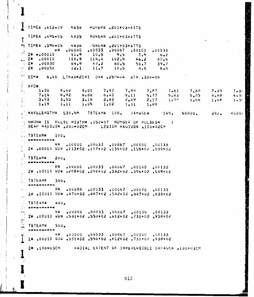
~~!K 90OU s0003 sOU07 .010A100 .0O133 .l 7b 7J9 .3
za v,00O010 10.9C 10,5 9,5 7,9 0Zu 1000 19 114 1)2.9 62 70
Ix 103 60 Zn 60,5 5,7 3,zu *0 0 u 50 117 1uIz 8*6
DIMA b.00 LTMAX02191 092 ac~hO-u' 61= 0300..(T
0 Ou 6,10u0 8.00 7.,9'1 7,914 7 A7 7ab 7.8 09
-03 ' .55 3. 18 2 , 2 2,49 2,17 1.q 1.b (?nA o
W' AVLLLNGTHx 530,Nm TS7LAMM 100, nAMAGE2 149s. b0000, 2l4ý. ~'
1NHUNm 11 PULSt. 'IUTHA *lbOmO7 NUM6EFR UF PULSE.SmBE~A11 K(ALUUS& ,2SUO02CM LE51[ON RAUIUSM sl1o00.2cm
TSTEAMS 1o,00
kc 400000 @0Ov3S .00067 ,00100 uuts33Z: .00010 0Lý 11113+Ca .117+02 o130*02 .155+0, .199+02
TSTEAMV 200.u
- ~RZ .00000 U(3033 .00007 400100 4001133*Z13o01 vU OlO U~m *26+02 v298+02 a332+02 *396+02 .509+02
ISTEAM; 30o,
R:; s00000 .00033 .00067 .00100 400133zo 800010 Wut) .4~7u+02 4S87+02 o5i42+Ue t347+U2 6830+02
-- ~ Hr u00o00 ,ou033 ooo067 Uo0l00 .00133ZOn s00010 UW: 561+02 550O+02 *612+01 '731+02 .93k+?
.. TSITAMn 5U0,
R. .00000 o0U033 UOO067 .001vO .00133j a gooU .001 L)= .531+02 e550+02 61l2+0ie .731+0? .938402
Zx .100-03cm NADIAL tXrEN7 UF IHRVL.W51BLE DAhA6(Th- .100+o3ct
K 12

¾7MAIN PROGRA~M OF RETINAL MODEL
CUfMHONI . iC U NX Cb) [U~'(j N ,ItC uT #r)IMfHL0n W 1(~) w C )PULSF#rkDTnTYf .W
;00 13 a 5,~R~8?~j#HvT~oCtOePtV~SM~ TSCtTT.RV(?9911)
*7. b vV C C 2 9 v1 1 v6Q j) V S H L 2 9) 9V H ~ ~ W V ~ X t F n v F n T 6 g F n 4 (~
1 1u 0 FAC(11 ) FXR129) i i)c5o *jr)(90) ,KTiT(3e1 ,NIPT(3b) o'PIILSE(7) ,N~tuN(7)t
12. 3VZ(20,?et.at2),ZTU6),7TT(8).ZTX(8)1 .6 H.AL LF6~TUN'1'40 2 FORMAT(10F7.3)IS. 3 FuRmAT (F7 . Qt3 17)I b " 4 FORmAT'(11R7.2)17. , FURMAJ(10.j7)16, 6 FURMATU(7.PY1792P7.d)19. 7 VuRPIAT(OL.7.2)Ru. 8 FLPRMAT(170ý7.?)
23. RLAQC~qb.rýMAXvLlMAX,LESlnN2'4, f 4 StT VALU~b FU Nw~N1lvN3.rNf. AND UFR
2b. N IN=+4
26. N4zNl±1
29, KLAU(5#b)fPR0Fh,Hfli..CUT30. D;' =L E 6T uNLI
32. k )C S, vi)U P U 1 5F3. RAUC5.5NTý,ST,(NkUivC(L)9,I:1NTFST) A34 RLAD(So~ 7) (h'EI I lCL~q It~TPST)
3S~ ~~ PaA)5 X ;; I
39. 1ý C itLbF L 10a u *4A UJUST PUOV4FH \NJLI 'ULSE '- IDTH Fr)R EXyFl$i)RNb NTTH PUL' bFS LFSe THAN
PD Ll W = b P T F.l I JL t.H TC 3 VL
I U '4/ A UV S# 4T I F u) 1 1E 1V1
a LAL)CS, 4)lA(C(ýTVXLv ,L,: H TISCR
T / A IUC: )5 Q~ RLAU(5t5)(N1TCL.)#L=1-3A) 197
*R L3 A~ L) Yl C T ( t .t -1 r, IM 3 N8)
I kL u 5 5 C l (-9= 9853. IcLumPurýP I v K.flC 1v K I pPITVTIEANf
5 14, L = AL Cjr ( ) F"l L. 5 E11(1 +I5

J ~MAIN (RETINAL)
58. ** *--SINr~LF PULSED FXPOS'JRFS59. XC:XCTCLI)60. NP:NPT(L1)
1 62. DT=DPUL8*(CXC-1.)/CXC**NP-j.)63. TIME:DT* CXC**KT-1 * /(XC-1 *)64o G *10 1365. *** -M-ULTIPLE PULSED LYPOSHRIES
67m.P268a X1--0.69. Du 12 L=1,N1ES7
71. 12 CuJNTINUE
73. DT=0PULSE~tXC-1.V/CXC**NP-1.)74~. KT:ALor-(1.+TTMF*(XC-1.)/flT)/ALOG(XC)+1.5s. PTIME=DPUL5E/NP
7b. 13 K T =KT+ I* - 77. KM NNPF+ I* 78, IF(KT.IPT.5Q)WRTTE(h.IL4)1T
79. 14~ FCRMAT(jH~i3HK7=vj392X92PT1TIE DTMFNSION Tn0 Lnw90. IE.(KT.CZT,59)STCP81.. ** CALC* 02Z AND I INDICES
82. MIF7.H6.*(0ULS)**.
*84J, M=?)ýM1+1685. M22MI286. M3=M+1
87. IPE~m2-ml+2
90 * 5 SORE AXTAL DISTANCE.S TO IN~TFRF:ACES OF EYE
92. Z U 2) =TA V93. ZU(3)=7D(2)+PPE#TPF
94. ZU(t4)=7t)C3)+(1.-RPF)*TPE95. ZD(5)r.ZD(4)+TVI.96a Z0(6)=7D(5)+TCH97. Z0C7)=ZD(6)+T8CC; Q. Z0(8)=7DC73t10.
W Q9, CALL GPID C AL LF100. NVL=LPV-IPV+l
'01 C A* AL CU LA 1 F A ND0 ST r)R I ,J T N ICI S A T W H ICH T F PPFRA T UR F" ~RF P R IN T E1
103. ID2=IU2+TPE1014. 1F (1n1 *LT * PA ) ID1IPA
108. 15 FUPMAT(1H0,UHID1l, 12.3X 4HID .12. vH~~t23~HJP92
12, 19 FURMAT(1H0-2H7=/('1X10F8.4))
114. d0 I~LL0OD(Ll)=1PV+Ll-1 1(14
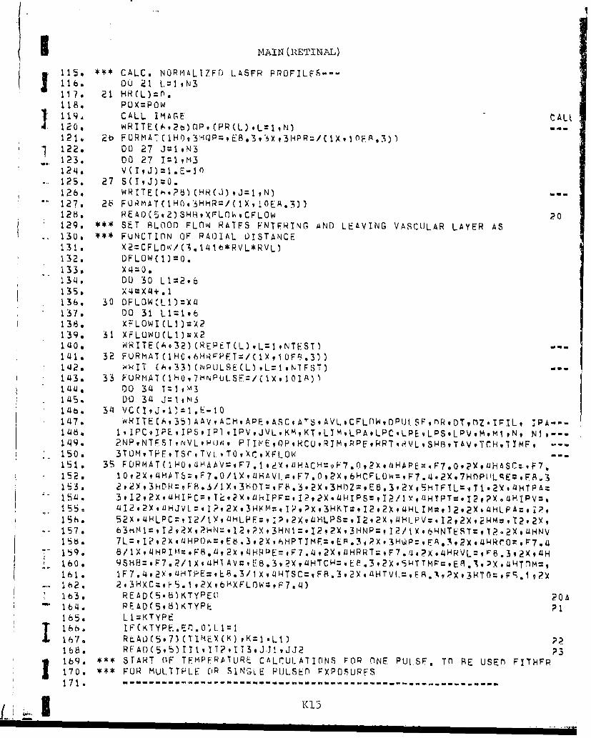
MAIN (RETINAL)
115a *** CALC. NORMALIZ.FfJ L.ASFP PPOFILFS---
118. DU 21LPO 9N
119, CALL. IMAGE C AL t120. wITEU.,2onP, (PP(L).L=1 ,N) Ul-121, 2t' FURMAT I03Q=9~3' .3P=(J90A3)
122. 00 27 J= I, N3123. 00 27 1:1 m3
125. 27 S(I,J)=O.126. WRlTEC~.?P.3CHR(J)9J~1,N.3Oan127. 28 FL>RMAT(1HO.3ýHHR=/C1X,l0EA.3))1280 PEAQC~v2) SHl~XF'L(ThCFLOW 20129. * SE.T IHLOOr) FL0O RATFS FN.TFRING AND LEAVING VASCULAR LAYER AS130. e FUNCTION OF RAOIAL UISTANCE131.. X2=CFL.0W3/V.1i4lb*RVL*RVL)132. DFLOwC1)=o.133.134. DO 30 L1=296
136. 30 DFLOWL~L):zLJ1.37. DO 31 L1z1qb138. XFLOWICL1)=X2139. 31 XFL0W0(LU)=X2140. vqlRITECA,32) (REPET(L) .L=1 NTEST.3141. 32 FURl'ATC1H0,6HRFýFT=/ClX,¶OFI..3))1.4?. wkIT (A933)(lvPLJLSE(L.3,L=19N1FsT)l143. 33 FU~A(H9HPUS=C~II)14a. DO 34 T~Im.3145. DO 34 Jiz.11 m
147. 'wNITECA,35) AAV,ACHA'FASC;AT~,AVLCFLfWDPlJl.SF',flRDTtrMZ.IFIL, 'PA---1464, 1.IPCIPEIPS.IP1 .IPV,JVL.KMKTLTMLPALPC.LPELPS.LPVM.m¶ ,N, N1,--149. ?NPvNTEST iNVLSHIWJvi PTIti-E9oPXcORTMPPERRTi.vLSI.BTAV,YCH,TTMF, - - -
150. 3T0HvTPFFTsrTV[ vT0,XC9XFlOW- -
151 . 3S FCJRMAT( 1HOL1H4AAV~F7.1 YLAH9709X4A~w7O9Y46C97152. lOt2X, 4HATS=,F7.0/lXq 4HAVI. :,F7.0,2X,bkCF;-LOw=,F74 -7fPILq~F.
155. 4I22X.4 HLPC:,I ?/l , 2Xi4HLPE:,HK = I~ 2 t HL M v] @ yiH PA o
157. 63i1:I=92,tX,?N.il2,?Xt3HN¶:.I?,2X,3HNP:, I2/.X6H-NTEST:,T?.2XouHNVjS6. 7L=9229H~%tb.9X HTM~EP*,XIW~E,32eHrrP.1590 8/1XLIHPliM:F8.LI,2X94REt".9YDPT*7/4PoHv~ 8.9X160. 9SHB:,F7.2/1~aIV~E.9X,4HTC~E.9X9 TPoPl.''tHn~161. IF . 9y UH P = . /l,?S'FS 3 2 qiH V-:E .A P tH O162. 2#3HXCz9F.j,2XbHXFL0W=,F7.tj)Fl.1
2(
1b3, READ(S-8.3KTYPECl 20 A164. PEAD(598)KTYPE165. LI =K T yP E16 b. IF CKTYPF..Er.0 tL 1l
168, RFAr)CS,5) 111w 1T2.113.J.J'.,J~J? 2316b9. *~STAR~T (IF TFHPFR.ATURE CALCUL.ATICINS FOR flNE Put SF. Tfl BE USEFD FITHFR170. FU ~R MULITPTF~ OP SINGLE PUtLSED) FXP0SUPFS
171. ------- .----- -"-------------
fi~~K 3 5

J ~MAIN (RET'.INAL)
17?. XTCI):O.- 173. Dr~TXFI
174. KTX=KT41175. DU 3k K=2#KIX
* 176. X(K=TK-)D177. 36 DT=XC*DT178. IKX(=TIME**FCDTI+LrT2
180. X2*K161. KkTEC6937)JKX182. 37 FURMATROjiHI~~KX~tI2)183. =
185. ITYPEX=ITYPF186. CALL BLOOD CALL187. 38 DT=XTCK)-XTCK-1)
189, CALL HTXf)LP CALL19u I IFCK.GT.2)r0O TO -41
1930 39 FURHATrIH 92HS~t1UEb.3)
15 41 WkITE(S#'2)XTCK)*KqPo41966 4 ý FURMAT~ iH0,5HTIME~oE.lA3.,3o2HK~le3:, CWP&E.9HWTA197,~ CALCULATE TEMPEiýATURE PISEe.MATRIX PEDUCTIOMI ALrCOPITHM)198. 1K 1199. *4'ICULUMThNF(NOPMAL)........................- -- -200. 4~3 DO '45 TZIPAtM
*201 . l9 * S ( /D202. 0)0 4 4 .203. FXCCJ):i~+CONC I)*RCJ,?)-BIV(J4?)*IV(T)-BP*IARCT !J)204o I Jf ) + SV CJ 911)*V(T lC( J..I205. CX C ) - C N I* ( t ) B ( t ) I C ) /FXC(C,T)200. SUm=(~(A-(I ,2)-IBV(J,?J*IV( I).BP*IAP(IgJ) 3)*VCIj3+A(T. I)*V(Ij.Jj),
0 8 0XC(J)=SIJm/FXC(J)
210. 11 )211. 44 CONTINUE~212. V X:=O.213. DO0U Lzlq
215. VX=DXC(J)-CXCCJ)*VY2 1 b. 45 VXX(To,I)=VY(
217. 0 '46 T=7Pht,t,
220 . *** HOWSCNOxMAJ) ------- -- -- -- -- -- -- -- -- ---221. CXW(IPA-I)=O.2?2. 00 bo T= I~223. DO 48 I=IPAqmýe4. v X X* V Sd I) /OT1*225. FXR(I)=+A(I,?)-BVCJ,2)*TV(I3-RB*ItpCI,J).A(T,1 )*CYR(-1)1226. CXP(I)=-A(Tvl,/FYRCI)
227 S M= ýN-CU'( )* (Jo )- VC 92 *TV I) RB IAH I, )) *V Tý1(16N Y)

I MAIN (RETINAL)
I F CJ. GT ),SuM=SRUM+ CCON 1) C(J, I)*8V CJ I )I V (T))V(! I230. X R (I) =SUJM / V Y RCI
232. 48 CON T INUE233. VX=0.234a DO 50 L=I'JAm235. I=M+IPA-L236. VXDXRcI)-cr.pCI)*Vx237a VC(IJvjo)TVX
*238. 5O vxg(IJ)=Vx*239. DU 51 zT!PAtm
2140. DO 51 J=1 tNI
2142. IN=IK+l2'43. ***' NECYCLF TEMPFRAIUHE CALCULATIONSZ'14 4. l~(IKLE.IKX)Gfl TO ~412145. IF(K.E9,KMl)60 TO 62246, IF(1TYPEX.LI.ITYPE.AND.k.LT.KflGO TO 6A2t47, h,2 WRITFCh.63)URCJ)vJ=JD1,Jr)2)2148. 63 F UR MATc I H , 10 Y tER-?9F Jý. 9/1 3 Y,3O0H---- -- -- -- -- -- -- -- -- -- -- -- -- ----2149. DO 65 I~IFri,102250. X1l=ZCI)-7(TPE)4d)Z/?.251. WkITE(b,9'4)Xi, CVC(It,JK) .J:JO1qJD23252. 614 FUPmAT(1H výZv8tqY9Al
*253. 65 CONTINUEce54. ITYPFX=0
255. 66 K =K+ I2sb, ITYPFX=ITYPEX+le 7 . IF(K.LF.KT)c.I TO 38
256 kEA CALCULtt7ED TEMPFRATUHE RISES TS OF GRANULFS FnR .3L-8 PULSE259 AN CA.CILýT NUMALTZED rP7SFS XPD ~FOR ACTUAL PULSE
26U5bD~9TA 21426 , 70 FORMA7(IH0,e6tHDJMEN.IoNJ OF ARRAYS ASSOtcaATED ViTTH ARG~UMENT LIJ IS
263 262. ITOO SMALL)263. DO 71 L.1=19LTMA~k
if2614. 71 Ts fL )1 1
266. CALL HYGRAKI CAL267. DO 72 i-=1.Kl[268. 72 XPD(L)=AP*YPDCL)41.-AP
271. 1DAMAGE(-92)...272. 73 FIJRMAT( 1H0 9 llwVLNT=F.9HM3tHTT~4O60lq7ýAAF273. 1 4F9,u)2714. * 4,* CAI.CULArF I 9J TNOH½.S AT v-HTCH DAMAG2F CALCULATIONS ARE Tfl RE M1ADF275. JM=Q2 76. DO 714 TzlQN277. IF(R(J).LT.kIMAX+.000OO1)JYM:J+I
S278. 714 CONTINUE279. XI=O.280. D0 71h T=TPAtm281. IFCVC'TfIqKM).(V,T.XI2TMAX=T
283. 75 CONTINUEL
285. 1O1:IMAX-LIMAX K1

MAIN (RETINAL)
eboo I U2= IMA X+L I WNAXadt.DU) 76 IIL)1,IilG2ý8kA 1 DU '16 Jzlt,lm
e.9. L=L+ I
29~1 . 76 JU(Li=J
293. IF(LITJ.,T.2Ž0hjw1Tt Co./2944, IFCLIJ.i;T.?uli)TUPe-'41b. lCLPX.LQ.')c)t TO i2q
ekib. k* TL.MPEr<tL'r<F~ ANP DAMAGE tVALUATIU"JS FOR MIJLTIPLF £'ULSFS297. -- - - - - - - - - - - - - - - - - --- - - - - - - -
*.2. ct,ýt FVALUATt. TLMPEIA iUIýF RiStS VlJTH AMI) 6ITHOU.T GPANIULEA299.. DO 77 L=19LIJ
-- 300. 1=10(0)101. J ZJUCL)(L
3044. DU 77 <:29WT
-30b. VE(LqKq2)=VC( Isjvh)0 7. 1F ( i. NI aT G) (,(7, Til 7 7
* . .3080. VE(LqK*2)=XPP(K)*VC(I ,JK)
31I11 77 CUN TI NUt
* 31S. Xc,1=AL0G(XC)3140 XbTLAM=JSrýAt'3 1b . V U 10 6 L 13 =I,14jTL -ST31t. X3:UPULSF+NPUt6F'(L13-1)/PEPET(L13)S 17.
31. 1T2 F.3 LX XP 7~lMVROF: PUILS=p~ T'oY916RPFT OIP
620 eTE=YEb3,31HPUL.8F*1JSFC)ý521 lF~iFL.F(..2'G( TU bO322- WTlF(,Eq7LflRTM9LFSIUN3."1FURMAT(IH .H-AWHAI)IUF=:, .3,2HCM~bYv1L~HL.FSTON RAflhIlS~vF8.3q2WC
GO TO Aý3 Pb. bU IA~TE(&.,bl)HTr',LEST0Njl~2 7 b I FuHM AI'C I H q 13 H T 0A bE R A PI1S6 E6. 3 2 HC Mv X 1 i~ltt-I n N R ;oEAIPý
3;? 9. d 1CM l/k.P.(L 3
S30. NPL=NPUILStjLl3)331 .. KA Iq332. 1N I
(] 333. b3 IýAL /l IDN LJlS. 2 G /.Q10 42
33o. 6 XI=NL.11L:
3 'Au 0 INXX=M11ýELl)*INXI 343. **4 SlORF Tirmh JNTEýVALS AND LOGS r)F INTFRVALS Fflk DAMAGF C41 CIlLhTTONIS342 l~X(l):RPTllM
*~ K1

MAIN (RETINAL)
344. ZT T (I )=A (GIN* HTI mý)345. DO 65 L3:29NP34(o. ZTTCL3)ALt0GCIW*JPTTMF)
3148 . 85 ZT(L3)=ZT(L3-1)+PT~lME34~91 LI:NP+1390. X3=(TC-DPULSE)/(KX-NP)351. ZTX CL I) DPlJLSE+X3352, ZTCLI)::L)PLJL SL7+)3/2.
353. ZTT(LI2)=AL0G(IN*Y3)
355. DO 66 L3=LI.KX356. ZTTCL.3)ZALOG(.IN*X3)
V357. ZTX(L3)=ZTY(l.3-1)*X3358. 86 Zf(L3)=ZT(i 31)+X3359. , CALCULATE TEMPERATUJRE RISES 45SUCIATFD WITT L3-TH TIME IN~TFRVAL
360. F~ ULLOw4TNC CLb-o5)#TN-o5 PULSE361.a DU 95 L1-=iLIJ362. DO 95 L-3=19KX
*363.
366. L7=1367. 87 X3=(L7-1)4*TC+ZTCL3)368. K:AL0G(X3*ýb0+1.)/Xb1+1.3690. S >5V E(R_<p 1 + ( X3- XT (K*C V FC ,K + I, lV E (L K,1/X T C K+tmX T(CK)
370. yI=X1:I1+ y371. X3::(L7-1)*TC+2LTXCL3)372, KmAL.OG(X3*Xb0+1.)/Yb111.
V3714. IF(X'b.LT..0OU1*XI)CW(, 10l 9375 L7 =L 7 +1376, IFCL7.LE.LI1ý;O TO 87
¶-377. 88 VZCLvltL39I)=Xl378. VZ(Li1.L3s2)=X2379m DU 93 Lb=2*INXY380m IF(X5.LTo..OOO1X1)GU TO1191
3b2. XdVZ(LqL6-!vL3lP)383, L 2L I+ I
S3814. L I LI+ I N38b. L7L.2366bv 90 X3=(L7-1)*TC+ZTCL.ý)387. KALOG(X3*Y6O+l.')/Xblt1.388. X5=E(LvV,1)+(ý3-XTC(<))CVF(LK+1 ,l)VE(L.K,1))/rXTCK41)-XTCK))389. x1~xl+x5390. X(S-CL7- I) +~' " +Z T X CLA
39'. X2=X2+Va(LvK,2)+3Xi-TW )*(VFCL.K+1 )V(qK2)(TK+)XC)
393. IFCx5.LT..o0oo*XI)GO inl Q13914. L7 %L 7+ I
S95, IF(L7.I E.Ll)GO TO 90396. 91 V(L4L69LSql11X
3 q8. L I =IN X+ I399. DO 9~4 Lb=LI*TN4'X
K(19
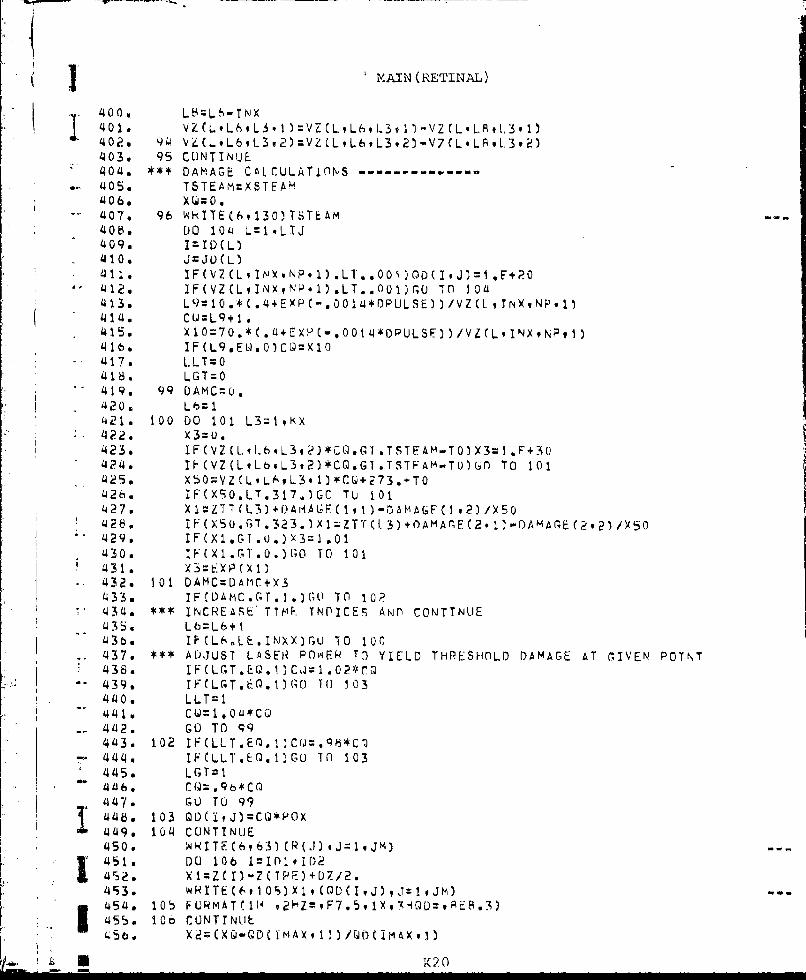
I MAIN (RETINAL)
40 e VZ(?: W,1=VCL L6 L3fl1V2CLL. 1.3 1)'402. 94 VLCL.9L6q-3,2)=VZ CLL6,L3.2)-V7(L.LPL.3.2)'403. 95 CONTINUE404. *** DAHIAG CALCULATIONS ------ - - ----
.. 405. TSTEAM=XBTEA'ý'406o. ~ o'407. 96 WIE610TTA408. DO 104i L=1*LIJ
'410. a j=JU(L)*411. IF(V2CLIN~.NP,1) .LT..001 )OD(IJ)=1 .E+?0
'412. IF(VZ(LINXNI'.1).LT..0U1)r0 TO 10a'413. L9=10.*C.~4+EXP(-s0014*DPULSE~))VZ(LIT NPI
- 414. CU=Lq+I a415, X10=70.*(.aEXP.(-.001iJ*iPULS~Fl/Vi(LINX9NP,1)'4 b s IF(L9vEL4.O)CQ=X10
-'417. L. L T =
'418. LGT=0
- 420. Lbz1* 421. 100 DiO 101 L3zlKX
'422o X3:0.'423. IF(VZ(L4I.bL3,?)*CQ.GT.TSTEAM-T0)X3=1 *F+30
- 4240 IHVZ(LLb.L3,2)*CQ.GT.TSTFAM-TuliGn To 101'425. X50=VZfLqL6,9L3, 1)*C+273.+T0'4260 IFCX90*LT.317.)GO TU 101
428. IF(X50.GT.3232)x1.ZTT(L )+.OAMAr(~E2. 1)-rAMA(,ýE(2,2)/X50
'430, IF(X1.GT.0.)GO0 TO 101'431 . X3=E I)4 A '42. 101 DAMC=t)AHC+X3'433. 1 FC DA MC. r. GT I, TO 1024 3 4 **1 INCR~EASE' TIF. TNIPICE5S AN~n CONTTNUJE'435. Lb=L6+1
* 43t). IFCL6.LE.INXX)rlU 10 100'437o *** ADJUST LASER~ POwE'4 To YIELD THRESHOLD DAMAGE AT rIVEN' POTNT'436. IFCLC-T.L.1)CJ1.024r@
'440, LLT~l
'442. GO TO 99'443. 102 IF(LLT.E0,l1CQ.q8*C0
* ' 444, IFCLLIT.EQ.I)GU TO 103'445. LGT;:11.-4146.1 cQ=.qb*ctnI'4147. GU TO 994i48. 103 QD(ltJ)=CQ*POX
449o104CU)NTINLJE1450 . 'ANlTFC6963)CR()j).Jq1jH)I '451 . DO 106 IlIr'~1.ID2
£452. )(l=ZCl-ZCTPF)+D7/2.49i3 W ~TE(6v10S,)Xlq(0D(IJ~v~~M454. 10 b FCONTC1INUEv75plvAQ~vE.;455. 105b CUNMTCI T NLJ,1,3Qý,iA3
456.* X2=(XQ-QDC TMA'A, ! )/0(jD mAXv )
kT (20C

j MAIN (RETINAL)
457s.3x2XI 58 1 I&X3.LT..o00j1GO TO 1084590 T8TEAM:rTsTEAM+DTsTM4b0. YQ=O0(TMAX91)'4610 GO TO 96462. 108 CON T INUE4463 . IF(KTYPlK.E.Q.fl)CG TO 174
~ 464, *** CALCULATF ANnl STORE TEMPFRATUFRES FOR PLUTTING TjMPFERATURF PROFTLFS465. "i/RPT14~66 NF'LZNPULSE(1)
-467 . DO 123 L15=1,KTYPE466, IFfcMmFXC~5).CG1.XTi<T))Go TO 123
'1470.o L2=TIMFXCLI5) /ICQ47 1. 0TIME=T1mEX(L15)-L2*7C1472.* L2=L2+1473. 00 116 1=111,112
-4174 , DO 116 J=Jj,J1J~d
Q 7 t) DO 113 Lhz:I9L2477. K=ALOGC (OTliME+(L6-1)*TC)*X60+1 .)/Xt'1+1.478a X2=(DTTMFCL6-1)*TC-T(K)),(xT(K.1,-Y (i,2'479o 113 X1=X1+VC(I.J9K)+X2#(VCCIJK+!)-VC(IJ.K))480, VCIJ)=X1
'.181. L3=L2-NPL.-'482. lFCL3.Lt.O)GO TU 115
* 484. 00 1144 L 9 1-L'485. a KrALoI;C D (I MF+ CLbaA)*TC)*XbO0i .)/X461+1.
-- 487. 114 X1=Xl+VC(1,JK)+X2*(VC(IJK4.1).VC(Ij*<))*488a V(IJ)=VcIJ)-Y1- 4890 115 IFCV(IvJ . ýV)R'V-
Uqo0 a2116 CONT I NUE401I. 1FUKTYPLiO.FQ.1)GO Tu 121492. wRITE(1 ,117)NIRUNC1) ,NPUL5E(1),PEPET(1)i493, 117 FORMAT(2T7*F;7.1)'494o WRITECI .1 1)fl)PtJL5E,ýAVFLvRIM'495. 118 FORMATC1OEB.3)
'497k 1110 FORMATrbT7)4 '498 W WRI TE ( I q 19) N3 o P13
500, 120 FURMAT(1OF7.L9)
50121 ýqRI TE C I v20(Z ( II I qM3~
503. 11DU 122 1=1119112I5014. WITL CA, 12Il VC19J) qJ:.JJ1 i JJ2)505. IF(KTYPL0,F.Ec )1G0 TO 12?5 0 b. WHIlFC * 12U) CV(lsJ)i,TJ~JlTJ1JJ2)507, 12~ 2 ONT INUES 08. 123 CONT INUE509, 12 4 F ORlA T I F7 . I510. G 0 10 I7 liI 511, *** DAMAGE CALU.UL-AlIONS FOR SINGLE PULSE
b513 . 125 VdIHITE C 6 12(,) NUNC II) fPUiLSE P PULSE ( I
V221.

NAIN (RETINAL)
5141,126 FRM AT( JH0v SHNRUNZ *I I#2X 12HPULSE W I DTH ER~. It?X9 I7HNUHfHFR OF PLJLS
51b. lF(IFll..EIQ.O)G0 TO 127517. WHITE(A979) NIM.LESION
5 18- GO TO IaBff1b9v 127 WRITE(6*81)91HvLESl0N520.. 128 XU=O.521.a 129 wIRTECU,913C)TSTEAH
*522. 130 FORMAT(lH~O7HiTS1EAIM:eF7.O/1 X, OH -----------5?P3. 00 138 IZID19ID2
S214. DO 138 J=19JM
b26. IF(VC(1j,JKM).Ll..OQl)GO Tfl 13A527. L9=10.*( .~4.XP(.C00144DPIJLSE))/VC(IJKM)528. CQ=L9+1 .ti2q. X1O:7U.*(.L1+RXP(-.00111*oPUL-SE) )/VC(IqjKM)5300 * IF (L9 * * 0) CQ:)105311, L LT:O
*533. 131 D A MC:
534. K=2535. 132 ý13=ALflG(XT(K)-XT(K-1))536, VPXZ(VCCIv3,K2+VC(ItjvK-1 ))/2.537. X3z0.538. IF(j.NE.IG)GC' TO 133539. IF (VPX*XPDCK*CCUIGT.TST~EAM-TO)Y3=1.E+30
5140.IF(VPX*XPD(K)*CU.GT.TSTEAM-TO)GC) If0 1311*. 111. 133 X50=Vc'e*C0+273.+To
5'[2. lF(X50.LT.317.3Gfl TO 13u
54.6. 1FCX1.nT.0.)Go 10 13054~7. X3=LXPCXl)54.8. 134. OAMC=DAMC+)(35149. 1FCD6MC.SE.1.)GO 7n 13S550. Zl5510 IF(K.LT.KT)Gfl TO 132552. *4* AUJUST t-ASFP POW~ER 10 YIFLr) THPESHOL1D DAMAGE A~T rIVEN POINT553. lFCLGT.E(Q.l)CO:1.0?A*C@5514. IFCLGT.Er,'.i)Go TO 136555. LLT:1b~b. CW=1 .o1*cL557. GU ILI 131558. 135 IFCLLT.EQ.l)C0=.98*CrQ559. IF(L-LT.ErC,1)GO TO 1365bO. L.LT:1561. CQ=.qb*rCn
~' 5629 GO TO 131
b4 . l3 d CU'qTINUJF565Sh. WklTF(6v63j)UUJ).J:1,JM)
* 56h, DO 1'43 I:11I)19102Sb 7 . X1:Z( I)-7(CIPE ) LU7/?.
b69 . j14. CONT IN.UE --
( ~E ___VK22

I ~MAIN (RETINAL)
*571. x3=>2x?,25D e. FX;.T.ool~ TU 150
b74. XT=" IMISAM fI~T
I 7ý GO) Tn 12Q57o. Iýo XF( TYPt.L(.'))(U Tn 174577e 1*4 CALCLILAIh AN'D SlOHE TLMHEHATURFS nHPLUTTIkrn PRCIFILF'57b. DU 17U 1o 19TP)79, .;;
581 KZALO~CD(TIML*()(L-1.)/DT>+1.)/,ýLCG(XC)+1.
jeb. ou 16'b J'JJIOJie-560 V(IvJ)=VCCT ,JvK)+X1(VC(TJK+1>-VCLTJK) 3587. * f(V~ttpj) .CT .GV)HGV~v~lsJ)bbd~. lbt CONTINUE
569* F-(NTYPE1!.Ftw.1)ul, TO 1674 0 . *14* CALCUL.AIF Ai\'O SJORF TE~mPFRATUNRFS FOR HL.UTTTw- PpOFll.
b9. I E T( IvIIP ) DPI'L. K4vFL - %'lM
b96. 10 DO ibb I=IT1.1T~lb 99 0 'mITE(6t24') (`vU 9 J)qJ=,JJ¶ p~JbO. rýT~YPLCI L' 1. 1 '1 GO u 1bt6
j:1 c ")*E1 ~ (V(lf.0)?yi=JJl v.1j jb b0 2 168 CUNI INLIL AiLE~N FDYG
603. I70Cifi..)NU TT i.U
bQM DO51 175= u~~Ii
oL 1. iF CI f I.E '.1v1) 2L) CU T L?
6 0A- U7 L17N 51IN I-I)I - D
b IC u I F t~ 00 C L I 4 Il G-~ 1 0 b X 9
17 .jb FORMA T CI HO. L5HI)LP 1 H UW PArAGE HFY ON!n ROITH Sr)F-:I FIED LpFPTHq)617. 1 F(15 0..OWf TO U 18
t)1 .b1,FIb..I1.J (.II-O 10 1 q
b2O . Xe=ALO(qCP(I~ '~1j/UhTv1) ((b)l.S
tb?2 . X.5=AL~r-(POX/!)/X~1)ZIE+Z2
6P,17F T23 ~ H1C 1 014HyI Il 1 ~ E PH 0 F A M G F;s&.F.3,HCMI
625. 178 I(1i8 .GL 17)' 10ýL In I b* 2b. X e=ALO L 06( (8,I~ r/' CT/ I L )2(T8 -C7
627. X1:UDTI/fl)j('I 3

MAIN (RLTINZAL)
b3. b1 uRMAT(1HO,2lIHhiA)(ImUM nEPTH OF DAAE S 3 hM
631 o *** INTLRIHQLATF PAD1AL LXTF.NT OE IPF<EVFRSIfILE DAAG AT SPFCTFTEfl rEPTH$
3 XS=LC1.-7(IPEJ+DZ/?.b~s. DO 18~3 J"1vJm
[ 3 37 . 1ML43 CUNTINUE
-- 390 IF(J1.rXk..U)GC) TO 187
b ~ 1. I ý FURMATC1HO,9?HL~vF.3.2NCM,9X,36HPArýAL. EYTFNT ('F L'AMAGF r~RMATEP THb 1 i!0 4NtL8.392rmcm)
I "~~s IFCJl.FiU.JtA)CLi 10 ¶jq
I bL ) b. X -: J )
bi4J. 167 DT,1
648~ 166 FUNIAr'(1Ho,2HLZ=,F6.ý,2HcMq5X937HRArI'AL EYTFINT OFl IRR VFR.RIRLF Iý4MA
6S&3. 113 CUNT iNL't
b510 5 1*0P
b53, 191 FUPH'A1 ~1Huq31hL,u IAMAGF----LAqEP POWE.R Tun tLLIA)
OS5. sl Op
K.2.

ji ~SUBROUTINE GRID (R1ETINAL)
1~. SU~c4OUTP'JE GRP~2 . *41- G)RIL) L;OMPIJIhS THE CUEFFI(-IFNT5 IN' PAPTIAL flIFrPFPcNTIAL EOUAT!OkIS A AND F
3m~ RADIAL AM) AXIAL CnOOQ0TNATFS.P P ANr 7, AND AR'STGNS CONMUflTTVTTY AND~
4o * VULUMLTHTC 5PECIFIC HEAT TO' GRID
be CUMMON AC,,l~APAAV,4CH9¾M EASCAT5,AVLR(1 1,3',RkBVC11o3)v
b0 ICONXCo) ,CUN(29 ,CuTqf~lIMlr)FLOWCif2 ,DPULSEDk.OTnTymZ*FI.,'JPr1 )o
Ib. 3IP'VIV(dQ) .JVL*LIM9L.PAqLPG.LPELPbSLPVLPXLTM4X9KqKMKT9~Mil P~2.
~13. DO1M.NbTUN Tx(7)9,LXC7)
-- lo. C'=-N-1Ni
170 CP=HVL/UP-mJ1+l*
22. GU 10 IoO21.163WKITE(6*1641)Re
2 ?4. 1 d FURMAT(IH ,3HR2zvF. 4.t)
20 a *** CALCULATE PAr)IbL SPArFh STEPS k(J)
-27 . DU 18t J=29NU-28. id's PLJ)ZOR+(Ji)29. Xl=2*DPý30. DU 18b J=NNJN
32. 16 b X I R2 4 W33. *** CALCULATE: ICLJFFIjCjEi\Tb t OF FINITE DIFFERENCF F0'KIS.
ý 40. X I= 2 ./ )R )N'ib1. Ou 187 J=2N'4,
31 ýi( J, 3v 2 i X I 2~- .38. 16 i j9-4 1- s.
41, U 188 X1r449ýL
(4 ~4. b8(1 , (2)./(W4't RJ))(ykx2
415. Y2=182J*x2
465. 189 CNIN=R2*yIJ
54 d
50. Du189 =19
5I o. 190 P.TV Z+.X *1)-. (Y .
57s
K2 5

GRID (RETINAL)
IýCH1/Y1.GT..99999.ANuL.w¶/)(1.LT.1.000o1o)O Tn iqý
6u. Ou 10 190
63. 19~4 FURMAT1H ,3H~lqF.AqPX.3HZM:,F8.bi)
bb. DO i9'j 1=29m2b7. Z C A + 1 7 il 4X 2
70. 1.95 X ~+X 171 . Z 1 0 .72. Md+=Z73. Z mtI)= .47r
75. DL) 19t, 1=19m3
77. L 3 =IP Alb. DL 00 L= 197
7'9. L1= 080. DO 1q7 I =I P A 9 m381 * Ii-:(L( 1) .LT.Zf)(L4t))L'3rI
8iIF Z(i ).I.L()u.WG.DL~1) TO 19783. L 2 1
dtb) 197 CUNTIN1II1
87o IF(LI,1:EuJ:U-DC)=L3
90. 2010 CLJNTINL*L91.
92. Ipczlxcý)9S, IPS=IX(6)
Q4. IPT=IX (7)
9b. LPF=L.X(3)97, LHV:LX(")
qbo LHC-=LXCS)T- 99.1 LPSZL.X(b)
1 u . LHT:-MS.10 I o. *~SLT CONDUCTIViTY CON AND HEAT CAPACITY VSH FrOR VARTOLIS EVE MFDTA&
102. DO 203 I1=1LPA103. CON(T)=cflNX(1)
105. DO (?04 1I=I'tL0LLj 10. CONC I2C0NX (2)10 7. 204 VSH(I)=V,1rIY(2)lud. DU d0 11IPV*LPV109. CJNCI)=CL)NXt3)
4110. 205 VSH(I)=VSHY(3)
112. CONCI)=cor1-V(L1)
-12 2u6DO) 207 i=IP69LPSX.2 6

I GRID (RETINAL)
118 CON(I)=CONY(6)
lPO. **7 CALCUATE OFFFIxENT A OF FINITE DIFFERENCF: F(NNS.I
121. DO 210 I=IPAM
I 126. IFCI.ErQ.IPA)ACI,1)=0."1279 ACI,3)=-X2+X3/(Z(1+1A-ZCI))128. 210 ACI,2)=A~jI.+ACTv3)
*129. RETURN130. E N(
IK27

SUBROUTINE IMGE (RETINAL)
1, SUBROUTINE IH~A(-E2.** IMAGE CUMPUTý5 1HE RFTTNAL IPRADIAMNLF P~flOTLP' 0~ CUMMON A(2q,3).AP,AAVACHLPF9 ASCATSAVL.,H(11.3jI9hBtV(1 1.3)
a CC)NX(b) ,CCJN(?q9 ,CUTP,")lývr')POW(6) YDPLLSFy), ,D~qflTyo',FZ.PtRNf1)t5. 21AB(29911 ).VILOUDC(6) , FIL.,TGIf'X.IHTIPA.IpC.IPE.1PRnF.IpS.IPr.
7. '4M3,NNI ,NI3.N4¼NVLqPLJ~,Pt.C1¶) PTIME.(4PgR(1l1,vCfel.lIMPN.RPE.RPT,I. -8. bkVLNSCqS(29.11 ~ Tý#CtO~TET~oSPO) o T~trTT~.\'cpq.1 )
9. bVC(29. 11 ,AO) ,VH(29g VSHX(6) ',AELt~XLO .F~A()XFLflM0ZA~1 u. 7XHD((bul ,Y (60) ,LC2q) ZD(A) .Zm1- 11. L)IMENSTUN A01F iX51FY51 J()wkC?,'3)
13. RLAL Jo0,NA.iNjlNC14, 00 200 J= I
16. L: =b
Z u . RADU(,'02)PLIPIL a21. 202 FUkMAT(1OE8.3)22. NRITEC6,203)PUPIL23. 203 FURMAT(1H0,tHHUFIL:,F7.3)
25b. I im( IPk nF. E .I )GU 10 P 14
27. *, IiTLRPOL A IF Tý4NaJULAR L A SP PROF ILF( SYMMFTRlr, TN R) AT I1N'TFRVALS2t.*4*O~ ITSTkRTjMG AT R=O
219. RLAVC5t205)LR 1430. 2u5 FURMAT(17)31. RLAL)(5q20b)(NX(Lq1-zlvLk) q*
32. ý06 FURMATC2.OE7.3)
.3c4 YI:PX ( I
3tP0 7 PXCL)=P)(CL)/Xl
37. x 0.36. Zb 0.
39. 00 20d L=2oLR
,Ii. XIFPXLL)JX?*RxCL.) I44o F0 UPIL S 23 X 3 LII
3 1 a2 21lF(HX(L2).GJ.PF~l)Ll0 k Tn 21?IT+5 9. Le2~U~
13 4 . I1(L2oLý.LP)G0 10 21055. GU TO 213
K2 8

*1 IMAGE (RETiNAL)
So 213 X1=XltRliNT
b* * IF *4' CALCUL4~TE rcAtJSSIbN LA$6FR PROFILE AT INTERVALS OF HINT qTARTING AT P~fl
620 WNITE(6v?19) SlGMARIM
634. 215 PUR .2390liu b*(1 *rA~t; /(3,5 1~u6*pIGM4SI'Th
-- b's XAX1 .- FXP(-2.*PtjA1L4PUPIL,/(STGMA*SIGM4))bb., IF(IFIL.FQ.1)G0 TO 217
(ob8. X3=2.*R(J) *k(J) /(SIGmA*SlGM.A)699 IF(X3.r~T.ýA.)G! TO 216
-- 7o. CKj)=WXp(-x3)71. 2 1b CUNT INIUh72. GO TO ;)7S
714a DO 218 Lz1.LII- 7S. X3=2.*X 1*X /(SI'.?AI(ASTfGMýA)
77. IF(x3.C1 *bO.)G0 TO 216
7 d FX(L)=EXP(-)(3)
0 GU TO 2~761. *** SPF.CIFY U4TFným i-Astp P~nfFTLE FPflm H(1) TU H(LTMI62. 219 O~*26(.RO/314~RMRM
~s. IF(IFIL.Ew.1)G0 Tu 2218 6. DO d20 J=19LIm87 . 2a0 P ý( J ) I.
t~b a GU TO ?7h
90. RNT=1RTM/Ll
q- ~e. DO 222 L=191-11Q 3. 222 F X( L ) =I.9'40 (;UO P10 ?795. *** CALCULAfE TOTAL AREA FA(L) AND PONT ION OF LASEPS PnWFR BF71'EFN R=O9b. ** ANqD (L-.S)*NT.NT147. 223 Ih1I.F~ILnTO 2?7
190. DO ý2?4 L=29 I I1 C1I. X I IL -.5) 4- PINIT102. Xd2L-1 .5)rýTNT
104. 22d4 FA(L)=FA(L-¶ ý14t-XIX-X*P
10t). * CALCLILAIF PHUFTLF Pli(J)10o x I=107. Xe 25 u. .
1109. X3=CP<(JJ+I-(J+1)J/(?.*RTNT)4.9Q0000G1S110. I i C ,LT.*1.) X3= 1 * cOQOOC
111. L2=X3
2,le IF'L2.C-t.LTI)Gc! lu &c?ý
513. X'4=x3-I-2
3IL-- 11(29

J IMAGE (RETlNAL)
115. XbFA(L2)+4>8*(FA(L2+!)-FA(L.2) )
116: X1 PC)(5-X ,~A2
11i8. X2=X6119,225 CONTIN~jE
4 .s120. GU TO 276121,*** SPREAD FUNCTT~r4 CALCULATIOHJS
122. 2,-7 READC5vP02)ZOiFLO.FCN~,CAPERPPPC 19P.*
1,23. CAFERR=CAthFR/WAVEL
124 0 READ(59,Ž28)(JUCiL=,1,3?1,25,.228 FLJRMATCO08,5)
128, L 12X I
130. NC:NA(11)+X(2*(NA(L141)-NACil1))129. ~2Xj='N-L.t N/N-t(C1
F L= LO* X
135, X3=1.-PC*CNC*!O-FC)/CNC*ZO*FC)
136. DO 230 L~iLT137. IF(L*GT.LII)GU TO 230
K14s3a I'L~T JUC TO 230
3 30 CUNTINLJEDO 231 L-=@L~II
XI=5JNCX';)*bjN (X5)
16152. Of Zý 1.=19LII
-
1Sc. 1PUPIL*PLPIL)
137b.~ (P1I ýSQT(FX (L) )*COS C X+X2) I158,: 23'C 2 -NT(FX(L)*STN(W1+X2j'
160, 235 FU)RMAT l,9HTV'og3loHOqP.v~iHLO9633tHAE=161.
lh2. ;XZHINC;;,F7.3,3Xp6HMAVF*L= l.3HFC=06.3i)
j ~6. DO. 260 J=19N
X2=0.
TFLEQ~4.XLI.-(*.?5*RINT
1~70 Do TO' 25A
171 a )XZ=X'l/.1+i.000O01T25
K30

¶ I IMAGE (RETINAL)
172. LI=XS173. Xt.=X5-L I
175. GO rO P51
176. 250 Xb=3./YL4
178a 1,0173*6X X*6.0785YbX*6X*6,0146X;Y*6179. 2Xb*X6*Yb180. Y9XU:i-.7853982.6- .CL16b397ýI6-.o003954*X4*Yb4 O657*XW6*181.* x.OO'J1824. 2Xb*Xb'*X6183., Xt=X8*r1ThCX9)/SQPTCXI4)I
1849. 251 IFCL.GT,1)rC' T(' 252
187. GO TO 255188. 252 X2:X2*X7*XF1 (L)*CL-¶.)*RINT*RlkvT
* -I69. X3=X3+X7*XF2CL)*(L-1 ).iPNT*RTNT190. 255 CONTINUE191. 260 HkN(j)=X2*X2+Xý*X3;
193. DO 270 J=1,tNI* 14 . 270 Hi4 J ) =H R Cj)/X 1195. x I .000 2
197. J2
199. LIM?~00 . 271 1 F( I. L l.W(J)..000000l)G TO 272-
102. GU TO 271
203. 272 X:~-C-liWJ.C~f
jr205. X7=do*(LI-i)*X22 06. 9 xamx1+Yb$>X7
208. X1=XI+.0nf022090. I( X I tE . I) GO T 0 27 12100 G P=.?3906*XX*Pr'X*1 .-RC0l /X'21 1 a * JI TF( 6 .?7c) CHP(,TJ =I *1N)212v 2751 FURPMAT(1H~v3HHK?/(1X,1OEA.~3))2 13. IkLTURN
*214o 276 00 2A0 J=Y215. P8 0 HRCJ)=PRCJ)426 RENTUPN217.
K3

~~ SUBROUTINE HTXDEP (RETINAL)
, 1. s u ji.< UTINIE HiTXD-P2, ;4*4 iHTX)L.EP CflMPUTES PATt OF HEAT L)FPOSTTnN AT VMPIflUe, PO!N7'S IVJ
CUMIM0N A(2Q,3) .AP¼AVACI-¼APFASFý,hTSAVLPC¶ j.3) ,13BV(1 1.3)
; be .,1PVIVCý9) ,JVLLTMLPALPC,LPE.LPSLPVLPXLTtAAX.K.KMKTM.MI .M2#
130 '. SWVLPSCS(2'ýt it) S~T~grtnqTET .SP1)TS(rTT~iV?9.11)91
* 10.
12. 1ztr(89)
15. TF(lH-T .tQ(,lPuRlb. LZ=?17. LZO=LZ-118. til=LL+1
* 20o I(I C I
21.
24 3 7.
26 kr- F(1I~.r<=O.1G 0~
i3ý. Wt4 Ar)1KRf-
32b. ktFLEXPC-CH C .R.
35LL. * If.EVAL)AT AHOKl-)*IPFN CCAFTi)+. IPIADAE)FRFkN N ERO ~£.lie *** WLL rEASQ &P.Pu ,APF2,T~r T ' TN)L .1~ý RA(L$AP
37. 10 76)4
38. ArojS(2)APFAH%1-P))Q
'39 AbSU,)=4VL
I 3 2d SREI=
9b. A2 S7)AT
147. 2 b 14 1(32Tl~ 3 A'PF .4"'9'A~ w,#P P 3 o H P P OF . 94(3~ r* A

HTXDEP (RETINAL)
58. DO3061:IZPA,:
61. GO TO 29562. 296 IF(ZH(I).CF.ZD(L13)6O TO 299
IL 63. *** NO ZD PETýNFFN ZH(1-11 AN ZH(I)
65. II(I)-:I
67. IF(Ll.CjT.LZ)G~O TO 306
68. DL0 297 L2=LiiLZ69. 297 A6RC1,L2)=A8(I,1)
-- 70, co ro 3ob
71. 2'Q9 1(ZH(1).GFZD(L.I+1))GO0 TO 30372. **ý O-NLY ZD(Ll) RETAEEN 2PHCI-11 AND ZH(I)
* 714. (I,12)AbSCIL11)*CZHCL13.7.C13)
76. 1 ICI1 =277. Z(I)Ll76. L3=L1+i79. IF(L-3.GT.LZ)GO TO 3U680. DO 300 L2=L3,LZF)I 300 AbR (I v 12) =AE C.1 41) +ABC 192)62 GO TO 30t,83t. -4** ZDCLI) AND ZD0I1+1) ;;TKFEW 7H(1-13 AND ZHUI)
Ab C5 A~It 2 AB ( L 1)CZDC(L1+ 1 -ZD (LI)
8 7a AbjR(IvLllwAH(I91)
IFCL3,(GI.LZ)rO 10 30693. DL) 3041 L2=1-39LZ
q5, 306 C:OrT!NUE96. 1)0 314 Im1PAom
100. Du 3144 L=29LIZ
102m 31.4 CONTINUE103. *** DEPOSITION bY INCOMING 8FAM
10 U X =Q103. L !:-.lobe DO 317 I=IPAvM
-- 107. L 2=I I C
109. X2cX2*FXPt-AR(Tvl))
I I I I F L.? , Q. IGn TO 315
i(.3 39L4

II HTXDEP (RETINAL)
125. IýCL2,EU.2)GO TO 31b
118- 315 !F(X2.LT.1.E-1O)X2=0.I1190 DO 317 .J=19JVL412101 s(IJ)=CY3-X2-Y4n*HRCJ /(ZH()-ZH(T-i))
S122. 317 CON T INUE123.a CALCULATION OF HEFLECTED INTFNSITIFS BY VAPIOUS TNTEPFACFS STAPTINr,1?4.** 'AITH FIRSI INTFHNhI. INTERFACF125. X2=QP126. DO 3?? L1mlLZO127. X3=ARS(Ll)*(7DCLl+1)-Z0t'L1))128. IF(X3.GT. i0.'x3=10.129. X2=X2*EXP(-X3)130. REFLCLl+l)rx2*PEF(L1+l)131. 322 X2:X2*(1.-PEF(L141))132. DO 327 LI:?9LZ
*134. 324 IF(ZHCI).GT.ZDCLfl))G Tri 325135. I+136. IF(I.LF.M)GO TO 324137m GO TO 327138. 325 X2=REFL(I1)13q. DO 326 L3=IPAi140a.39141. L4%I+IPA-L3
-1'421, X2=X2*FXP(-AFSR(L4,v.1~)114:5 DO 32b~ J=1.JVL
145. IF(S(L.49jI).LT.1.E-I0/UPULSF)S(LtAJýO.146. 326 C 0N T INU E147. 327 CONTINUE
149. RETURN150. * NO HEAT rPCnSIT1ON.bEAM O1FF151. 3,40 00 342 I1=1M3152. DO 342 Jx1.N3
*153. 342 S(ItJ)=0.
I r,41 IrHTM0L 155. R~ETURN7156. END

SURUTN MXM2 STIAL
3IPVuIV(?)JULMLALPPPP.PLtXKRTMM MX2PATHIS29 ROUIN CiLfOMPTRCNFOEC FGRNLPAqDPINO,)EPR~
3,*FT-VARIACS(?1 IN. Pt(SHSn~ ',~,TC.Y fMT~r VLT(?ON TrCT 4 V?,~,C(29,1 A(,9O) ,V$H(29) bcgTVAI-RiI3.PBB~~i*IC N ( ) C N( 9 p U o)19) L '( ) D U S 9)i t T 9 Z F v R l )
* ~ ~ i.4 5 =
16 LPTZD~lJLSE/.3t.-819. L'ILTmkx-10?0. DLi ~410 L=1,L7,1U
21. L 1=L+ I22. L?-L+ 9
24o. xe=TS(I-+10)-Xl
2b. DU '410 L3=Ll@L?27. X3=x3+.
t T, 1 16L3)=Xl+Y3*x2pg. L ITz;2
3 u . XpD(l)-j.031. IF(LPT.GF.LlmAX)(0 TO '47?732. **$ CASE FOR LPil LFSS THAN~ LTMAX -- -- --
13. L94.0 IF(XT(LTT).GE..3F-ý5)fl,O in 4434m XPD(LTT).=TsC1)
35 LIT=LTTt1360 GU rO 440o37. U42 TIMtX=T(LTT)
38 Xx~rlxEx/dT+.00000139. L X::X Ya 110 PT=L.XI41. 1 F(L X G TLPIIP lT:: L PT142. P u= 0'43,. i-L~e LTN) m XFl0=L X- L T mAX
gi4. IF(LXG1.LPl)G0 To '443
40. Le=LX
147 s GO TO tljý6
I * 149. LI=LX+¶-LPT-. 50. Le=LX
51. GO To 41461
5s GOJ TO lqi~l55,445 L1=LX-LfT+1
Ld=L Tm A x57.'44h Xe=PO K(35

1 MXGRAN (RETIlNAL)
158. OUI J448 L37-LlqL?59. 414 b X2=X~2,TbCL3)60. XPD(LTT)=X2/PTb1. LfTT:LTTtl
S62. IF(LTT.LE.Kr)GO TO 44263m GO TO IJ6
6**## CASE FO~R LTM'A~X LESS THAN LPT- ---
h6, XXcTIMIýX/ST+.OOUOO1
69. IF(LX.G1 .LPT)FT=LPT* 10. PU =0 .
71.o IF(Ly~rZ1 LTMAXfPO=LX-LTMAX7 72. IF(LX.GlT.LPT)G0 TO 473
73. L 1 =74. L2:LX
-. 75. IF(LX.GT.LTNAX)L.2LTMAX7 bGO TO 475iT77. 47?ý IF(LX.L-i.LTMAK4l.PT);O T 778. L5=LTT79. GO TO 494~e80~. 474 LI=LX-LPT'~1big. L2=LTMAX
83. DO 476 L3=LI.L284. '47b X2=X2+TS(L3)85. XPfl(LlT)=X2/PT
86. LrTTL'IT+ I87. IFCL¶T.LE.I<T)GO TO 47288. GO TO 4q6
89 * lo* END CALCULATION IF TEMPERATURES VERY UINIFORM
Q4 Li97 FQRMAT(1HO,4HXPD=/(lXqloF8.2))105 RE.TURN96. END
K-3

i~jSUBROUTINE BLOOD (RETlNPJ,)
1. SUbHCUTINE BLOVCUI SIJ6ROUTINE C']r'IPuTS CrHANr-E3 OF -A-IPIY ELF ýFNfF A AND R. DIJE T~ ~Lf3, CLJMMON A(.8g.3),APAAVACHAPFASCqATSAu-LqR(11, ql2.B','(' j,3)
1 CUNX (b) 9C 0NIC 29) 9C UT ý ) i v fFl OwU~ *DO'LLSF )k vUT rT Y ? 1ZoF.l- QHR ( 1I
b 0 3IFPVIVC~9) 9JVL.LIM.L.PALPCLPE.LP3,LPV.LPXsLTý'lxKvX)~KO',9<T.MM1 M2q
12,~* INI IIAL Ev LUA IflN UF PA HktETEQ AKIO AQFPAyS
1 3. DU 600 J~l sN 3
Li17. FLOwI(J=0 .I do 800 FLOWX CJ) =0 .19. hl:R21.21U DU 813 JZ2 IV L
23 U 1 Jr-1 JVL.TlF0
25, L e=L 2+ I2 b. GJ TO Po',2 7. 806 Xl=0L)PL'.CL?)-LUFLfA(L2-1)
ba Xe~H(j) -CfLOa% CL21)
31.,610 xku(j) XFLrN( L2- 1 ) 1 ( XFL.OWO L2)-XFLciw(i.2-1 1
I. 33. DO 812 J = 9J VLF34. 812 FLO~iN( CJ FLOjwX ( - I) +(I (J-I1 -x - R * )-
- 5. 1(.TLj 3b. FLlwX CJV L+ I ).F L010 C JVL)37.
!9 . UU 820 J=ý24JVLa u. LIa1 q IF (t)FLCN 'L?) GT R(J) )U0~ Tu bib
L2=L2+1
4 J3 8 1b roUFnv (L?
(i-'I W X CA2 )FLU W I(L-t A Cd X' FTL nX
1 ''. I~".iP)ULWX~) Jzlg TVL"5 Eu .82 FURMAI'i(11- 96HýLulWx/( 1X,10F8.3))51. Du e23 1=2*2JVL
I 3 41 CACLf C HANGE.S IN MATRIX ELEMENT", A AND b [UWE TO mLnOfl FL11W
5s I o: 2(3 H _05o, SB~LOJ?

[ 13BLOOD (RIrTINAL)
00 82S J=29JVL59,, RV(Jvl.=SHBRDCJ)*FLc0w)(J,,,
I61, R 2 5 ý;CJ93 -SH4R0 (J)*FLOWX(.J)
63. 835 1Iv C 106S4. Li' 81 L3=lt,NVL65. L-4=18LOODCL3)
66. 640 !V(Li4)=I67. 00 6415 I=IPAoLP-68. DO 84~2 Izi*JVL
70 IF(JVL..QN)GO TO H'r
71. L J VL+ I72. 00 843 J=LltN
7 [A U45 C ONT INU E
78. RE TUf0'J
79 END
i(3

II
III I
3: 1
T APPENDIX L
NOMENCLATURE, SAMPLE DATA, CODE LISTING, AND1 ~ SAMPLE RUN FOR CORNEAL MODELr ,
aid
I
< I
.................-

IC **S NOMENCLATURE FOR CORNEAL MODELC
! A(I,3) COEFFICIENTS OF FINITE DIFFERENCE EGUATIONSZ ELEMENTSc ABC1) PRODUCTS OF ABSORPTION COEFFICIENTS AND THICKNESSES OFA ,IS2),LUCCESSIVE EYE MEDIA HETMEEN ZH(I-15 AND ZH(I_
C ~(i'Ll) SU m OF AB(Ij)vA8(I,2)*.. OF MEDIA BETwEEN Z(lAND ZDCLI)
IC AS(SL) ABSORPTION COEFFICIENTS ASSOCATL.D WITH L-TH EYEC MEDIA BETWEEN ZD(L) AND ZD(L*19PER CMC AP FRACTION OF HEAT ABSORBED By MEDIA THAT IS ABSORBED
[Fc BY PARTICLES ON PIGMENTS0o, C e(Jqi)obcJ,2)9
,C B(J3) COEFFICIENTS OF FINITE DIFFERENCE EQUATIONSR ELEMENTS'-~CCONCI)THERMAL CONDUCTIVITY Ar DEPTH Z(I)#CAL/CM-SEC-C__
C CONX(L) THERMAL CONDUCTIVITIES FOR L-TH LYE MEDIACAL/CM-SEC-CC Cg RATIO OF PREDICTEO TO ACTUAL LASER POwER,C INITIALLY ESTIMATED AND THEN REFINED BY DAMAGE CALC.
,siC CXC(J) ARRAYS USED TO EVALUATE TEtPLRATUR-E-S:-C CuT NORMALIZED INTENSITY OF LASER BEAM AT R=RIM11 C DAMAGE(CLi COEFFICIENTS FOR RATE OF THERMAL DAMAGERATE= _KC¢ L•) E XP (DAM AGEC-1,1)-}-DA-MAGE-(1 32Y / CvcC27 3+T 0 )--FOR -T EM-PRA-
, ..C TURES BELOW 50 C, AND RATE.zEXPCDAMAGE(Ci)-DAMAGE(292)/2 C (VC*273+TO)) FOR TEMPERATURES ABOVE 50 C
C DIM MAX. NUMdER OF ELEMENT• SED-T -COMPUTIE TERMAL EFF CTSF24C PARTICLES OR PIGMENTS2';C DPULSE DURATION OF INDIVIDUAL PULSESoSEC, ALWAYS HELD FIYED _..DR R-INCREMENT IN UNIFORM PART OF GRIU, CMz'j C DY FIRST TIME INTERVAL FOR SINGLE-PULSE TEMPERATURE CALC,2.:C SUCCESSIVE INTERVALS INCREASED BY FACTOR XCSEC
'C . TTM TEMPERAUPE I NCREMEN TO -BE ADDEDTO -TSTEAM- CONSIDERING -
--,C PEAK RARTICLE rEMPERATURE AS HYPOTHETICAL DAMAGE"i _. c CRITERIONS C •Xc-TJ AR RA YSU SED TO-•VA L-UT-E-T EM P-R AT URE RSE S
',C DXR(I)I C DZ Z INCREMENT IN UNIFORM PART OF GRIDo CM•'C EDIT POMER--TO-WH-IC-H-YI-M-IS--RI-SED TO SPECIFWNUMIE-R--F-CYCLES ... :
C TO WHICH BASIC TEMPEHATUHE CALCULATIONS ARE REPEATEDml C TO ENSURE STABILITY,- C-- T=ADI-TIVE FA-tTDH TO- PECIFY--N BEF-OF CYCLeS--TOwhICH i
C SINGLE-PULSE TEMPERATURE CALC, ARE REPEATED TO ENSUPE__C _TABILITY
.FA() AREAFROM6 R o TO R:=CL- 5 ,S* RINT•CN i-m- FoP CALC, I RREGU LA A, ¢ PROFILES
C FCF FOCAL LENGTH OF CONNEA,:3.12 CM FOR HUMANS,=2.*3 CM
4-C FP(L) TOTAL LASER PONER 8ETejEEN R=O AND R:(L-,5)*RINT---".C FOR CALC, IRREGULAR PROFILES
.'K __F- FI M EL~ _ýifA TOS BY VIHICH 'EXPOSURE_ TImE 01 0 ULi-P CI Co TOb Y IEL D4--C SUFFICIENT TIME FOR DAMAGE TO OCCURGIVEN AS FUNCTION
C OF PULSE WIDTH4,, C FXCC J) ARRAYS USED -TO -EvALUATE --TEMPERATURE -S .... . . . . ..
"C FxN(I)C HR(J) NORMALIZED IRRADIANCE ENTERING EYE AT R(J)vCAL/Cm2-SEC =
INDEX -UF- AXIAL GRI POINTS Z(I.)c IDIVID2 I INDICES FOR PRINTING AT DEPTmS Z(I) VwHERE I=IPI+InI T•l
I -c _ _.- ._ _ P14 +_D,2 _ _ , - - . .. _ _ - _&--C . IG I INDEX INDICATING LOCATION OF PARTICLES
C 11(1) NUMBER OF INTEkFACES(ZD) BETAEEN ZH(I-1) AND ZH(I),•C PLUS I
L..... Li

. 113 1 INDEX OF V(I139J) TEfPlRATflL CURVEN VAKYING) TO MARK
cUN 3-D PLOTSC I•X NUMBER OF TIMES TEMPERATURE_ CAC•.ARE..PTEDFOR . ...
Kc PURPOSES OF STABILITYc ILENS INDEX INDICATING WHETHER TO CONSIDER CORNEAL KUPNS OR
_LENS __RNSFR CORNEA 8F1 ILENS:OoPOR LENS SET ILENS= _
- JM'x I INDEX AT WHICH PEAK TEMPERATURES OCCUR
SC IN NUMBER OF PULSES GROUPED TOGETHEk FOR DAMAGE CALCULATIONS
c INX NUMSER OF GROUPS OF PULSES CONSIDERED DURING EXPOSURE-_TO L S _ R ....
INXX NUMbER OF GROUPS OF PULSES CONSIDERED) DURING ANDc FOLLOWING EXPOSURE TO LASER .... ...
""C _I INDEX-OF-IRST Z(T) IN CORNEA LIP LENS" C IPROF INDEX DESCRIBING LASER PROFILEUNIFORM IF=O,GAUSbIAN IF=l
C ___RREGULAR IF:=C IPl9IP2,@,, I INDICES ASSOCIATED KITH INITIAL 6RID POINTS ALONG Z
C AXIS IN SUCCESSIVE EYE MEDIA STARTING WITH I:IPI TNC .. . .CORNEA, OUTER bOUNUARY OFCORNEA•AT (Z(IPl-l)+Z(IPl))/2C ITYPE K INTERVAL AT WHICh VCCI,JK) IS PRINTED
I C IX(L) I INDICES ASSOCIATED WITH INITI4L GRIO POINT (ZQ IN L-TH- C EYE MEDIA
C IZ(I) INDEX- LOF-FIR-T--NTERFACE-ZO(L)-REYONU ZHCI-1)All Jc _ INDEX FOR RADIAL GRID POINTS R(J)
..- VJ_2 J INDICES FOR PRINTING, WILL PRINT JJD I TO J2 r].-- C ... . M .. MAX-I-MUM-J--NDEX-T�T-HICH-DAMAGE ASSESSMENTS ARE TO RE MADEOF
C tOEPLNDS ON VALUE CHOSEN FOR RMAX
.IC JVL J INDEX FOR WHICH R(JVL) APPROXIMATFS RVL
C K INDEX FOR TIMES XT(K) . ........* C KM INTEGER SUCH THAT XT(KM)ZDPULSE
C _ KT MAXIMUM NUMBER OF EXPANDING TIMES XT(K) V. C- ----- KTT(L)• ......... N-UMBER-OF-T-IME-STEPS--WITH WHICH-TO PEACH- TOTAL7TIME
Ci KTYPL NUMBER UF TIMES AT WHICH 30 TEMPERATUHE DRAWINGS ARE DESIRED
SC =--- FOR NO DRAvINiGS SET KTYP.=0O'-C KTYPEu CONTROL, INDEX- HICH-WH-NSET =j-wILL.' PREEMPT CARD----i
C PUNCHING WHILE MAINTAINING PRINT OUTS OF TEMPERATURESC AT SELECTED TIMES AND POINTS---SET =0 FOR CARD PUNCHING,C KX . . 101 AL NUMBER OF -TIME INTeRVALS FROM PULSE 10 PULSE ...
C LESION LESION HADIU8,CM
C C LI NUMBER OF RADIAL INTERVALS USED Tn INTEGRAIE PROFILE"C . .LiM NUMBER OF---RADIAL INTERVALS FHOM k=O TO R:RIM-ORLESION------
C LIMAX I INDEX DESCHIbING RANGE OF I OVER WHICH TO ASSESS DAMAGE,C RANGE=IMAX TO IMAX+LJMAXC LLTvLLG ------ INUICES-USED TO-CONTROL CALC, OF THRESHOLD PUWERC LPIPLP2.,, I INDICES ASSOEIATLD 14ITH LAST LiRlD POINTS(Z) IN
C SUCCESSiVE EYE HEOIA(SEE iPi,iP2.,)...
C" NUMBER OF POINIS DESCRIBING IRREGULAR LASER PROFILE
C LT INDEX OF NUMBER OF TIME INTERVALS BT
,, C LTMAX TIME INDEX(TIME:LTMAX*bT) BEYOND 6HICH EXCESS
C . TEMPERATURE RISE OF PARTICLES IS DLSSIPATELir C Lx(L) I INDICES ASSOCIATLU WITH LAST GRID POINT (Z) IN L-TH
C EYE MEDIAc LZ NUMBEi OF DIFFERENT EYE LAYERS ON MEDIA
-C LIL2,L3,,, UUMMY VAHTABLES USED IN COMPUTATIONSC M NO. OF GRID SPACES IN Z DIRECTION(EVEN)•C Ml ... HALF -OF NUMBER OF UNIFORMLY THICM Z INCREMLNTS(LESS THAN M/?)
A C M2 HALF THE NO. OF GRID SPACES IN Z DIRECTION
"C M3 NO, OF GkID POINTS IN Z DIRECTION, (M•l)
C N NO, OF GRID SPACES IN R DIRECTIONS C NB REFRACTIVE IND, X AT IAVELENGTH OF 5Ou NM
. NC REFRACTIVE INDEX AT hAVELFNGTH WAVEL
L2 Jk . . . ---- - _ _

C NP ~~NUMHLR OF TIME INTLRVA'S WITHIN DPULSEqUSEU O DMG
C CALCURLATIOGSNp -----TOTAL NUMýýR -OF PUIqS IN~ EXPOSURF
jC- NPT(L) NUMBER Oý INCREMENTAL _TIMES USED TO SUBDIVIDE DPUiLSE
c NPULSE(L) NUM[3ER OF PULSES ASSOCIATED WITH L-TH TEST EXPOSURE
MES HATES OR NUMBER OF PULSESCADFERNPTI nIC N1 NUMBER OF UNIFURIIrLY THICK R INCRIEMENTS(LESS THAN N)
C_ NO,_OFCHIDPOINTS TN RODIRFCTION (N+W _
N' C N1 NO. OF _G R I D 6INT SI IN UNIFORM PART OF*GRID'T NR DIRF.CTION
C PC DISTANCE OF PUPIL FROM CORNEAt.mfl CM FOR HUMANS,
-C Z,36 CM FOR MONKEYS
* ~ C Pow vPQX_ LAE OvER-ON4-CORNEA-LP-LaNEWATTS9-'-"il C PR(J) CALCULATED OR MEASURED RETINAL IRRADIANCE. PROFIL.E,
'C _____NORMALIZED TO UNITY AT R(j):O._C ATM UIOMTM INRVL US ED TO SUbUIV I D EPUL SE FOR HUL TIPL E
H~C PULSESC PUPIL PUPIL RADIUSvCM
c Rx(L) IRREGULAR LASER PRUFILE AT PU1NTS kX(L)* "C. QD(IIJ) LASER POWER REUUIRED TO CAUSE IRREVERSIBLE oAMAGE. AT
C __L(I),R(J),bidATTSC op LAS E' I NT ENSITY YENTIERNING EYE AT N (1 )=vC AL /CM2-S ECC R~j) RADIUS AT CO-OHOINATE J9 CM
R E.F (.L) FRACTION OF WAUIATION REFLECTED AT Z=.ZDCL)
- WEFL -(L) ---- REFLEC.TED RADIATION -FROM -INTERFACE- AT-L=ZD(L)
C REPET(L) REPETITION HATES A5SUClIAED NITH L-TH TEST EXPOSURE9PULSES/
C SANEC O EPRTR IEC)FR3OAD2'PAC__RGV SE-_ RNCOFTMEHTUE S -O -;DAL - LT
C RHCJ) RADIAL DISTANCE HALFkAY BETWEEN R(J) AND R(J+1)
C RIM IMAGE OR BEAM RADIUS9 FOR GAUSSIAJ PROFILES EOUALS
,J C AUIUS AT I vHI .Ch NORM .AL-I ZE -D -_PROFILE EQUALS CUT, FUR
Ct UNIFORM PROFILES E'UUALS EXTENiT OF PROFILECM
-,C RINT UNIFURM RADIAL INTLRVALSgCm
c RmAx- MAXIMUM 'RADIAL-L)1STANCLEAl wMICH LIAIMAGEC ASbFSSMENTS ARE
C TO HE MAUEC RN -mAXIHUM RADIAL DlSTAr'CEqCM
AC RI 5TkE'TCMIN(,FAcTOH-N1NZ DIRECTIO)N-
~tC R2tTRETCHING FACTOR IN R DIRECTION
c XCL) RADIAL DISTANCES ASSUCIATE[) WITH IRREGULAR LASER PROFILF
c PX(L)(SYMMETHIC IN R)qCM
:iC SCI'j) RATE OF HEAT DEPOSITION PER UNIT VOLUME AT ZCI)vH(J),
C CAL/Cm3-SECC SIGMA kAUIUS AT VHICH NORýMLIZEO GAUSSIAN PROFILE FILJUALS
-C T c -TIME FROM START OF PULSE TO START Uý NEXT PUILSE.SFC_
C TiHCL) - THICKNLSb OF EYE M~r)IA IN~OICATL.D BY -LCM
C TIME MAXIMUM TIME LIMIT SET9 SEC
*C TSTLAm GRANULE TEMPERATURt. USED AS HYPOTHETICAL OAMAGE
SC CRITERIONC
SC TO .INITIAL TEMP 'ERATUR ' OF FYEqr.
1 VCI.j2 TEMPERATURt RISES AT Z(I)vR(J) AT GIVEN TIMEC
C VC(ItJtK) TEMPERATURE kISES AT Z(IJR(J) AT TIME XTCK)tC
¼C~ VE(LgKvLl) TEHPERATURE RISES AT Z(I0(L))vR(JD(L)) AT TIME XTCK).Llt=
_ FOR EYL MECIIAPAND L1=2 FOR PARTIULLS OR RIGMENTS
c C VPX TEM-PERAT-URE HISE.$vC
SC VSH(J) VOLUMETRIC SPECIFIC MEAT AT Z ( I CAL/CM3-CC VSHX(L) HEAT CAPACITY OF L-TH EYE MEDIAoCAL/CM3-C
C VZ(LpLb9L39 TEMPERATURE RISE AT TIME INTERVAL ZT(I-3) AFTER
C L I. (Lb-.5)I1N-,'5 INCREMENTAL PULSLS AT POINT ZCIO(L))9R(JD(L))
L3

* ?L1=1 FOR EYE MEDIA AND L1=2 FUR PARTICLES5C WAVEL NA VEL E NGT HNMC_ X STRETCHING FACTOR FOR TIMF INTERVALS AbSUCIATED OT
'i C TECH' IN CORP' TEM'PLRATURE CALCULATIONSC XcT(L) VALUES FROM WHICH EXPANSION FACTOR YC IS SELcCTED B3AsEi)
ICUN - - - -PULS E W IDITH1C XPD(K) NORMALIZEDTEMPEATURERSES OFGRANULES AT TItlE XT(K)- XTU() TImES FOLLOWING START OF F~XPOSUREtINDICAIEv) tV -INDEY K
41 S E SCC Xx FRACTION OF LAbERS ENERGY ENTERING E.YE
C X1sX~,2X3,,, DUMMY VAHIAULE5 USED IN COMPUTATIOiNSC Z(I DISTANCE ALONG Z AXIS AT G'RID P.OINT IqLm
c ZCUN (ij I ) FA O YV IHL Eý5. IN TEN .I .Tj FS( NORMAL .SEA M) -A .RE*C dULTIPLIED TO ACCOUNT FOR REFRACTIONvUSED F~k LFNS BRUNS
_.,ZPo(.I_) DEPTHS. OiF I1.NTE kFAC-ESB ETKFEN. _V.AR IOUS _.E.Y E~ EI A,9CH* '.C ZH(1) AXIAL U! JANCES HALF~NAY bETHLEN4(1) AND Z(I+1),CM-
*jC Zm HALF LENGTH OF Z AXI$. CM<C Zo DISTANCE OF PUPIL FROm LASERS 1NAISTvCM
C lIM FHM__TAR1' g-PULSE TO CENTk-R OF TI-ME TNTERVALSiIC USEU TU PRE'DICT THERMAL DAMAGE FUR MULTIPLE PULSESC __ ZTTCL3) LOU~ OF PRODUCT OF NUMBER OF PULSES/GROUP TIMES T1IMLC INTERVALS AT WHICH DAMAGE CALC * ARE MADE-
* ~ C ZTX(L3) TIME INTERVAL FROM START OF EACH PULSE AT WHICHC PARTICLE TEmPEHATURE5 ARL CALC..
SC1C 41 DIMENSIONS OF VARIOUS AR *RAYSU -SEr -IN .PROGRAm.__.J C
* ~ .; C OMN DIMLNSIONS ACM,),~ Z ,(NJ3 ,CNX (6) ,CUN(M3) ,HR(N3J9*MC _ R(N3),REF~(Lil,),rI1(LZ),TS(M3,N3, ,SCLTMAX),VC(Ml3,Nl3KT),VSHi-iX(),VSH~ii<4).'!C XPU ( KT) 9_)T ( KT ),IZ M3) qZ0 (LZ + I)Ct*** MAIN PRUGRAMC DIMLNSION LXC(N3) ,CXR(Mi3) ,UAMAGr.(ý92) ,DXC(N3) ,oxKRCt;3) ,FXC(N3) ,FxR(Mi)v
C TIMEX(KTYME),XCT(383.VCM3,N.ý),VECLIJKT,2) ,VX(m3,N3),VZ(LIJINX~,KX9.3)C ZT(KX)tZTTCKX)
'~C * SUBROUTINE GRID'-c 1x~. Cx lb
C SUBROUTINE IMAGLC FA(LI+1)'.FF(LI+ ,PXCLI4'1),JO(32),PX(LR),NIXCLH),t(FýICLt4I) ,)(l-(Li+fl
C * SUBROUTINE HTXOEP{C o)~b(~L)1IM)ICM~RF(Z+)Z~3
-Vo
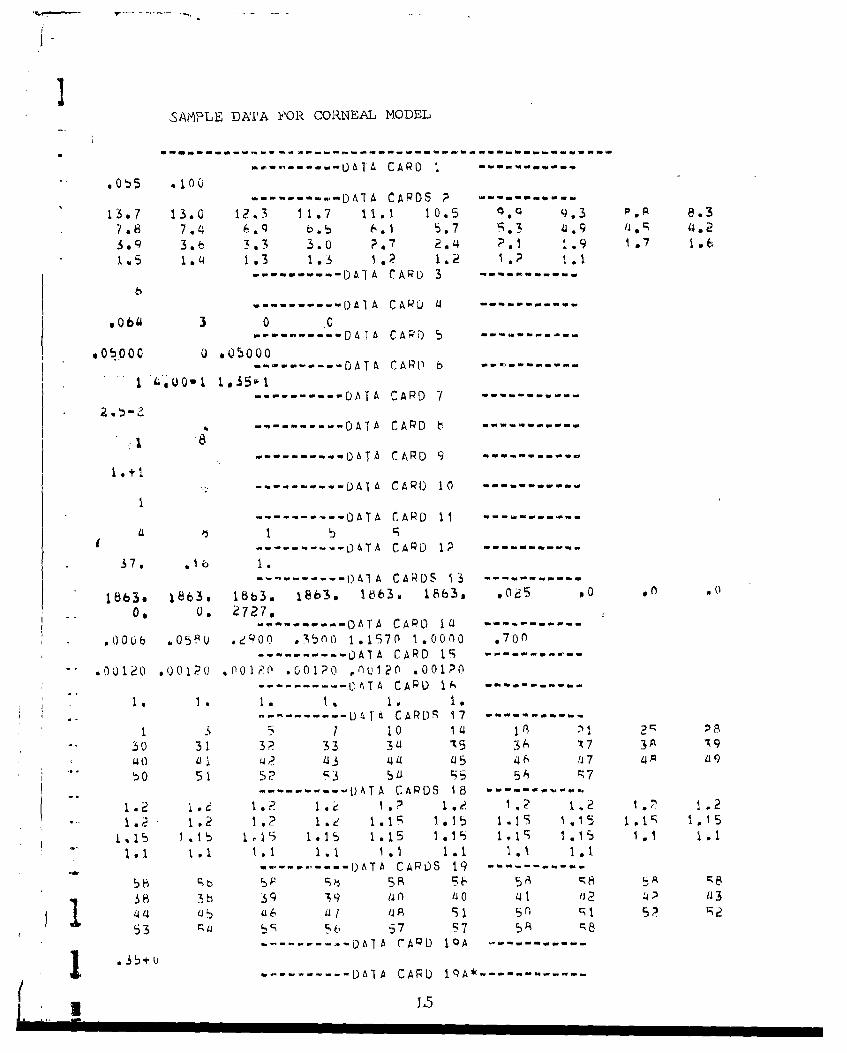
Io
SAMPLE DATA FOR CORNEAL MODEL
-- - --------------------------------- -------
........... 06-IA CARD 1 ...........
" .0'•5 .100
---------- DA TA CARDS P ...-------.13.7 13.0 12 3 11.7 11.1 10.5 . 9.3 8, .3
7.8 7.4 6.Q b.5 6.1 5.7 3 1.9 4.23.9 3.c 3.3 3.0 ?.7 2.'4 ;>1 1.9 ,1.6
105 1.14 1.3 1.3 l.p 1.2 1.? 1.1------- DATA CARD 3 -----------
---------.. D)A IA C A• R ..........
,0bi 3 0 .0...-------. DATA CARD 5 -----------
.05000 U ,05000
-- - - - - - - - ------------ DATýCAPb----- -- --------- DATA CARD 7 ----.........
--------- DATA CARD b .----
---------- 0ATA CARD 9 ..........
..... DAIA CARD 10 ...........
-------------------------- DATA rARD 11 --
S..... .. . ATA CARD 9 ----
-........ . DATA CAPO 1l1 ----------
0006 ..05, . . .eqT300 1.1570 1,0000 .07.0S--------- OATA CARD 1S --------
.001, .001?, 1.001?() Gol0o r0u.po .00150------ ---.. DATA CAPO IA -----------
* . 1. 1. 1, 1.. 1.
S..D T CARDR 17 -..........
1 1 1 10 14 1 A A30 31 3P 33 3 4 t5 34 X7 3 •9
0 51 5? p3 5a1 5 56 r7-.-.-.---- -^ TA CARDS 18 -.----.....
1.1 11 ,1.1 1.1 1.1 1.1 . 1.15 ," i~~i I~l 1. 1,15 ! 1 i I . ~
-.---.-- --- ----- -I)ATA CARDS 19 -.-------.--. -
58 51 5 A 5& 5A 5• A8
38 3b 3q 39 a n 40 41 12 ?3 a314 b u6 1 /4A 91 5n r, 5 Pt53 i6 C, c 57 57 5R 8
---------- Ohlb CAPD IQA -----------
--- -- -- DATA CARD IqA* --------
L5

II3
----------D A I A C A R D I q A * * * ----------
1.+0 i35+U .0÷0w --------- A CARD 06 "-- -
"3.u÷d ?,'43U+0 ,36+0 1.3-b÷u-......... DATA CARP 20 ......-.
. .... DATA CARD 21 ...........
2----------.. DATA CARD 22 ........
---------- D &TA CARD 2 " - - --
-. ....- DATA CARD 24 ...........
1--------- DAIA CARO 2 q ....
-.. - -- -- DAT % CARD 26 ..........
r149, 50000, 2LJý, 80ou. 100. iuO.
L6
A-

SAMPLE RUN OF CORNEAL MIODEL
$ 39u00+0? o60Uouq+01 '4 10 .616667-Q01 Ie4+j
0 3 q00040i sbuoov+o1 4 10 bb7.W01 *19u99+ol
439000+~02 6Ouo+01 4 10) @16667001 .19048+01
0390004-02 obooo0+o ~ 4 10 .i~b6bbl- e19034+014 *590uu4-0, 6b000u+u1 4 10 *1b66b7-uj si~o3u+ol
4 .390uoio~o .00o0Q+01 4 10 *l6bbl"01 019029+01
- *390004-02 .600o~olt '4 10 albbo7-Ui sl9u2Ti+01
834000+02 *60Quo+o1 '4 1u0 16b61u.Ul 619024+01
$39000+02 *0600oul01 4 10 *1bbb7-0l1 *9()ag+uR~m 1,9029
a 11959+04 *Ioouu+02 It 2 936000a01 *10560+01 obblit5-03 *2u~l5+ul
111959+04 .1oooou+oa 11 .o 3b000-01 .10b60+Vl *Le8115wU3 .20390+01
I -. q+0 .lou0 UQU+2 11 e , *3 0 t 0. 0 1m1 *l~bbQ+ 0 ~1 15 - Q aa 3'439? + i
.11959+0'4 110o00+02 11 2-06b000-01 .105bu+01 668115-o3 .2(1393t0l
*11959+ou .100u0uo2 11 a 6ýb000-01 *10560+01 c,6611bo03 .20393+01-~RIM 2.0393 Zm I 10 5 47
iuizil 102214 JOI: I J02= b
o-o .000 *lt)7 00333 .0500 @Ubo7 I0984 0158'1 60J36 94921 *9U7'1.b992
01,053'4 -m5159 -m2ý23 *1231 *.0597 -,02mý --so013'4 ... 0 9 -,o2 0('0004 .001k 6UQ22 O0Q31 .0049 'O0O35 o*01-o fi. ,obe '125t.2bb0 s5idb) 1.0560
- URIL2 .350
SIG.MA= *b'40"U0 FIMm .b6S0u01
1lJPu~u .083+02 2581+00 295+00 m114+QO Aaj1-02 .447--o5 ooo~1 .00 ,oio
* .vovl 8(+0
L7

IAH3n ld~ 1b63. 1863.s 1bb3,3 163. 186S0 AI.m UOOOPULbEaE a250-01 DR= .161-01 VT9 IU6'-0'4 Dzz ;81-03 1 p I11 IPm 17
IP3xl7 1Pusib I P',1b IP6919 JVLZ 9 KM= 413 KTZ '7 LAS,: 3 ý.PJ1:i
LP2=17 LP3:.18 LP4X18 LPS:.19 LP6223 M222 Plz ;j NZ1O NJ=: ' NP:'42NIESTm 1 PO~m 4~ou+oo PT1MEM .000 UPX a145+02
.000 0 000 0 000 6 000 0 u,Ou H1112 964u001i vLa *700 Th4 .900-02 .900-02- 6900--02 .i00 ~ 00.100+01 TINtc; .438w01 10:. 37.0 YC: 1.15
l~mI
e88lwO3 s176m,02 e~bgm,02 *398,*02 .67lwO2j 123-01 e23b-l.416g8..01 gq40-01 $190+00.1 3e7+0o o1b7+OUI2 1;133+05 * 116+05 .1/1+04 .391+04 P151040. .117+03 5t#4-'01 9 O _,(00 .000
So *257+04 922S+104 si49+04 .758+03 *293+03 ,227+U2 .115-01 .000 .000 O00u
8: s499+0S #45+3 a290+03 1147403 .567+02 .439+01 US3-02 .000 000 *Ooo
I 8: g724+02 s032+02 @420+U8 .213+o2 .622+oi *637+00 ,330 00o _ 000 '000
bx v318+01 *277+01 .1kb4+01 #933+00 4360+00 .279-0l *O(u SU0() M*00 6000
v I: W.S 971m,02 .607m02 .562.,02 .264-02 .110-02 .851-U4 .00G .000 alo0 .000)
__1 000 6000 .1000 ,0 0000 .000 1000 suoo .000 .00()
-L 03 .00 .00 0 400000 0000 6 000 .000 ())0 u00 '000 .00 fA so 00 .000 .000 su 000 s000 10000 O00 So00 .000 '000
so. 8:000 .000 .000 .000 .000 .000 1000 ()0() ooo .00()
4 000 .00 .01 000u .000 %)()0 ()00 6100 1000 .000
TIME= .1()b04 Kr. 2 POiNEK3 ./J00+OuNA7TSRZ UOOO *oo 01667 .03333 .05000 Qb6b7
Zu .000134 to so0.0.
zm 60012e .0 .0 10 .0 .0
Z= t '00308 .0 '0 00of
*TIME: .2?8-04 Ka 3 PULtH .400+U0~wATTS
TIME= ,3h9-04 K: 4 PU'WEH& .400+OOwATiS
'vvmt z530ý0~4 K a 5 POW ER2 ;46C0+fiOW~ATT$
TlIFE: 4716-.04 P, a 6 P 0 r- L R *Sm 400+OATIS
ST1ME3 .9290/4 K x 7 PU# Rm 4004M0,,ATTSlqm .0000 0 .01667 .03333 *o~o~o .0 66 ti7
Z: a 00044 1 .&e 10 q7 .3 .1SZ:4 .00132 .30 2 .1 so
Z~ a 022 a1 UU s0 00 .a0,X 00308 .0 00 to .0 .0
ITIMEm .117-03 is; 8 IPUVMý.H 4~00+u00ýATTS
*TIMEN .146-03 rx 9 PUWFEHx .'A00+00iATTS
TINEw ,178-03 ismIG PUWER= .I4UQ+U0hATTS
4 L8

ITImLm .elb"QS ?S11 PoN~r 400o+OCIWATIS
ItR2 oou o000 0b67 m03333 u0500 *06667
I z U 3 0u ?*6 1:7'94
Do OU220 s2JQ *00. .0 .0 b o.o00.
TIME= 30A-03 K;913 PUAERX .40U+UUNATTS
- I *' 305-3 ý,l pU.Jsf~E ,j040()UWATTS
''TIMEM 430-U4Q K915b PUWERX *400I+00WATTS
gbqi~.5-("3 K C17 pov.ýr 4UU0+UW4ATTb.
NZ *00QO0 .01667 .03333 *U50(ý ()6667
Z *0 414 b 00 3.3 1 .8 o7
800132 is .6 . ~
Z 6 0o02 .7 It
TIMES bM .(3 ,1 P(hEIH B4UU+QQWAITS
TIME 8*LQ5.0 3 K219 PU8~itk .804U+00JAITS
TIF *930'-03 K~a0 pUjvLR= 4~UO+Q0wAJT'
T E rIM. g.lb.Q? Kr2 P.u puEE ku,4 00 + 00yA.T T S.
H~ uouo00 s01667 .03333 s.obuO Ubbt,-/
zo U0uU44 10lb iS.3 oo2 3.*i 14
2Z *QO132 -- b. 9 -. -- ..-. 1...
l Z2 OU?~20 2861.5 ob .3
-rZa .00308 , ~ CO5 03
TII~v *146.02 Kz:23 POWER=f~ q~uU+UvArTS
TIML2 ttb~2 K=2 P8ij~wi .4U0400UNATj5
TIME2 *196-U2 Kz:b pu~ 4I0o*uuwATTS
I.TIML2 226b-U2 KI .LJ~w~z.EN2oiNTT
TI e; *lb-0? K=27 PflAEWm *400+00wATTS
RZ l00000 sQlbb7 003333 9050"2 006667
7*: 40044 7 15.2 10.1 501 2.0
joo TIM4 23009 2.ud P1.0
TIMO 47Ud KC29 powE.Rc .040()QwAT1S
L9
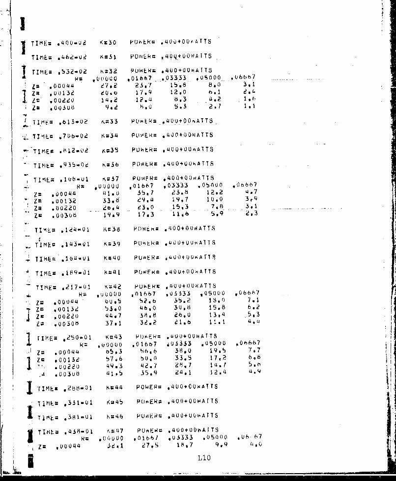
TIE 0-4 K3IPOEZ4I+U4T
Z;% voI3 Ke3i4 P179Q .IO-10 0 0*AT2,
z'IMu s8o.ub 90,2S PWiAo ,'.3000 21T
IT I mE. .'33 ~36 PQAER -#40UO..+0U.0ATTS
TXL 2ibU ~34 P Uv, k *~o40Ov11A~TTS
-11: Lc 0 SU ,711)oll 3,
*TIME= oluboul ,(=37 PUWF= 400LU+OOWAITS
'rze u o Q 4 14 1 P(.wFN 1200t2Ar7
TIME= 01247w01 tK'42 pbN K;% 40+0UWATTS
i..gJI c 14 -0 K0039' PC)7 E k f 4 0 5.3 UwA
T - .00w 37. 32.2 IA~ 11.1+06AT,
TIME=~ *21701 K=~42 P'J"-Fc 40U+00WATTSUU0 ~ 1~(( 01667 0(~333 .050001 VOL667
la 6:000114 bb. u 2 a6 38,0 18 00 7 a7
-T ZG 1; 001 3d b ,6 460. 33.56 58 0
1 IME 2003-06 7 1;U 320WE a*1 1 6 11 AT4,
T1MF 50-01m1 K='43 PljiE3 sLAUQ+Q0w~AtTS
k= *0oou0 *01667 *QS333 .05000 Oh66b7
u u 2 .3-01 49@3i 421Ei7 ? ý "1 0 , Ar5
4 1 0 5 35,9 2401 7.2.14 74 9
TIMEM2b~oo Kr.4 POWE= 4 LQOUAT
lV ~ I3-l K4 OER 0+0~T

Zm 400220 30*4 q. 1.8 9, 3 kiZZ 7- 0 6 2&7 5,I 170 9 3*
T AVELýWNrIIa 2772.-UNM Tbl LAMM I1U00 0AHAGtm 1449* 5booQo - 14 - MOt.
NRUNM 8 PULSE.N 1U IH a ebS0Ow NUH~biR OF PULSES= I
bEAM RADIUS; 04()woUjCtA LESIO)N RA01u$m *0O0m.01cm
TSTEAMC 100.
H .6Qu000 s0166i7 0Q5333 Q05000 0. 6Za .0004" iUL)z .173+'00 s,199+00 .a97+ou b~7.9+~00 .1447+01
-T.4 E.A M,;I,~HaUAM .ou 016 003 UU0 066
-ZZ 4~41003CHi HAU;AL LXEJ O IRkEVEHSIBLE DMACLa .s4uUlw0Cm

(I MAIN PROGRAM OF CORNEAL MOD)EL
I is COMMON A(213 3;)A~iS(b) ,AP.B(l11,,CflN(23),CON)(U%)oCUJT.DTMDPULSF,28 1DNoOTYIDTX.DZHkC1W flGIHT.ILENS@IPROF91P1,IP2YT03,Ip£4,Ip5'lpb3. 2JVLLImyLPi ,L.P?,.P3,LP'4,LP5,LPý,qLP~ILTMAXLZ.KKTM.Mj ~o-'9N£4. 3NlN3,N14,PDXWTIMEDP.R(11),REF(7) ,RIMRNRVL,91(?31l IT(.)
5.~ 4TS(22OO0 *V(23,li) ,VCC23,11,60).VSH(23),VSHXC6).XCWAVELVPInC60)96. SXTC6O) qZC23) ,ZCONC23,11).ZDC8).ZM
7. DIMENSIUN CXCCI 1),CXRC23),DAMrE(2.2).DXC(11),nPC?3).FTTMF(381#8. IFXCCl1),FXR(23)vD5)J)5)WTC8tP 5)NPIS()NU()
90 2@DC23, U) ,REPET(7) ,TTMEXCS) ,XCT(38) ,VE(20.60.2) ,VXXC?3.11) 9t0. 3VZ(20,?b.S,2) .7T(8) 9ZTTC9) .ZTX(8)lit REAL LFSION12. 3 FOR'1AT(F7.SI,3i7)
-- 13, ~4 FORMAT(10F7.2)14, 5 FORMATC1017)15. 6 FORMAT(F7.2#1792F7.2)1b. 7 FORMAT(1OE7.2)17. 8 FUPNATCI7,3E7,2)18. REAUC5vLD?1,[)7219, RE.AC(5,'4) (FTlMF(L) ,L=1q38)p20. REAU(~59)L72j.* READ(5. 3)RT~M9LIM, IG, LENS422. READ(5t6)HMAXvLIMAX9LESIONS
-~23.*#* SET VALUES FOR N9NIN3eN4, AND DR
24. N1=1425. N =N I+ 626. N 3 =N+ 127, N 4 =N I+ I
12, Rb.AD.I8)PRnFvpnwvCUT 6
.2 9 a DF=LEST0W/LIM
30. l F C PROF.E9.0)DR=FlM/(LIM-%5)31a READ(597)DPULSE 7
32. READ(5,5)NTEST, CNHUN(L) .L=1 NTFST) P.
I 3. READC59 7)(REPET(L~vL~tvKNTEST)34. REAUCýiq 5)(NPULbE(L),L=19NTEST) to
V 35. REA0C5.SI'3)1q)IflD2JDlJD2,1TYPE 1.1
-. 36. LPY~1
38. lF(0PUL8F.GT..31'-8)C,0 TO 10
39,**4 ADIJUST POW~ER AND PULSE 4IVTH FOR ElYPOSURFES ýYTTH PULSES LESS THAN
14 1 . P Uw =P 0 " *DP UL'LSj.a '2. DPULSE ..;E-8 1£43. 10 READ(5,i4210,FI)T1EDT? 1
J44. READCSLL) (kES(L) tL1.LZ) (PEF(LI) iL=19L7) .MAVEL 13
*-145. RLAD(5,'4)(TH(L)vL=1qLZ)*RVL 14
46a READ(5. i4)(CONX(L).LmlvLZ) 1
47. READ(5oa')(V5HX(L)9LlqLZ) 1b
148e READ(5i,5)(NIPT(L.).L=193) 17
49, READ(5,14)(XCT(L),L~lo3A) 18
~' 50. REAUC5o5)(KTTCL).L.=1q38) 19
51.**COMPUTE DTKMKToNPvPTIMETIME, AND XC
52a LlZALOr-(DPULSE)/.b9315+2Q.53. IP (LI .LT . I1 L I= 1541,IF(Ll .GI.3F4)L1=38I 5 IF(LPX.EQ~.l)GO 10oi1
56. *4' --- SING~LE PULSED ExPflsuRFS57, XCXC T (L 1 1,12

MAIN (CORNEAL)
58. NP=NPT(LI)
60. fTDT~PUI.SE*(XC-1.)/(XC4*NP-i.)61bI TIME=DT*(XC**KT-1.)/CXC-¶ *)62. GO TO 1363.*4c --- MULTIPLE PULSED EYPOSURFS
654 NP=5I 6 bb I= 0.67. DO 12 L:19NTESTI 68. IF(X1IIT.NPULSFCL)/REPET(L) )X1=NPUJLSECL1/REPETCL)69. 12? CONTINUE70, TlME:FTImEL~L1)*XI
* 71. DT=DPUl-SF*('XC>1 ./(X**NP..1.)72. KTzALOC,(l.+T'IME*(XC-1.)/DT)/ALOG(XC2*1.73. PTIMEMOPULSE/NP74. 13 XT=KT+i
*75. KM=NPtl* 76. IF(KT.t9T.59)wRT1EU(,1li)KT*77. 14 FQRmAT~1HO.3HKT:,I3i2Xs22HTIME: DINFNSION TOO Lnw)* * 78. IPfKT.GT.59)STOH*79.*** CALC. DZ AND I INDICES
F' 0 . H 1 =2*81. M=24cm1418* 32. M2=M/2
-. 3. M.5=M+1614. Z D 1* PI SE * 2 /S R ( C ))~85, IF(IL-ENS.E(Q.1,DZ--OZl*CDPLJLSE**D'Z2)/SCqRT(ABS(iJ) )86.*** STORE AXIAi- PISIANJCLý TO INTERFACES OF LYE
-. 88. ZU(2)=70(1)+TH(1)89. ZD(3)z7O)(2)+TH(2)go. ZD(4)=ZD(3)+TH(3)
92. ZD(b) :ZOC5)+TH(5j9. 3. ZO(7):7D(6)+TH(6)94t ZD(8)=7D(7)*1 U.
95. CALL.G~ A.q~.;CALCULATE AN() SIORF TvJ TNDICES AT WHICH TEMPERATUPES ARF PRINTED
97. ID1=I~i+lPl*98 . I D2 = ID2+ IP 1
*100. IF C 102. GT em)I D2M101 * IF(JTD2.G;T.N)JD2=N100 l JI TE (6 -p I b I N #, D02 tJO1 'J02 ...103. 15b FORMA T ( HO (4HI 0 1 = T 2 934,3 ilHj0? I P 3X 44HJD1, T? 3y 4HTD=sI)?P)
11 , 8 FORMAT I HO., 2"H:I (I X I I 8 4 ))
1106. ARITFc&.19) (7(1). 1=vMi3)..107, 19 FUMTl~2Z/jq0(.)108..'** CAI.C. N4uRmALIZEu LASEFP PROFILES ---109. p=PcX:POI 110. CALL IMAGE CALL
112 26FORMAT(l1H0,3H(WP=I8.3,3X,3HHR=/C lXIOEP.3))1 13. D2 L 2 7 -1 114, DU 27 T~l,M3 TL13

I MAIN (CO)RNEAL)
~ 11. 'S(1.J)=1 .E-i 0jib. 27 8S(19J)=O.117. wý(ITE(6.,32) (REPEr(L) ,L=1,NTESTý118, 32 FOMTIH HEFT/ltiE-ý
119, WNIITE(6933) (NPUILSE(L) ,L:1.NTEST)-S120, 33 FURMATC1H0*7HNPýL5LE=/(1Xl108))
121. DO 34 7=19V-3122, DO 34 J=10,N3
125. 1I,6JVLKM.IKTqLImLPILPtLP3,LP4.LPSLP6.mqm1t,N$i,NlPNTESI.PflW. -
12,b. 2PTlIHEQP, CPEF(I 1~ L11 'L?7 ,PIM.RVLe CTH(L2) .L?=,LZ) ,TImETOXC --
-~127,* 35 FORMAT (1Ho, 4H13 Zb~q *0, 2X. 3HAP=,F6.*3/i X .7HDPULS$; * Ep *l * ,3HnP~.
1- 29. 241-1P3:, t21?X,4HIP4=,!2.2y('4HIPS= I2.2X.4HI0b6, I2,2X.4HJVL=.IP,2X9
1lls 4HLP3=vd2,2Xt.HLP4, I2,2Xq4HLP5:.I?,2X,4HLPdnT?,2Y,
133. b,12,2X,4POýQ.Eb.3,2X,6HPIIFo~.9~ HPgA11qURF9F.;
* 134. 72X ,4HRTM ,F8.3/IX ,4HRVL:.F7,3,?X, 3HTH:.5F1 0.3,tX.EIO.3.2Y.qHTIME0,
135. 8E8.3.2Y,3HT0=,F6. I 2Y,3HYC:.F6.2) 2
*136. RýAO(59b)KTYPEO 2
137. PLAU(598)KTYP'E Pi138. L1=KTYPE139. IF (KTYPE.EIP.0)L1zl
-142,*** STAR~T OF TEMPERATURL CALCULATIONS FOP ONE PULSE, TO RE UREn ETTHER1ý43.0'** FUR MULTIPLE OR SINGLE PULSED EXPOSURES
144, -- -- - - -- -- -- -- -- -- -- -- -- -- -- -------------
145. XT 11 ) m0
~.147. K T X KT +148. OU 36 I<=2oKTX1(19. XT(Is)=zT(K-t)+DT
1)50. 36 D T =XC I151. IKX=TIME**FDT14EDT2
153. xFCIX .LT*IIKX
-15 4 . tNR1TE(693f1)KX---
U156, K=2157. I HT =21158. J.TYPEX=IfyplE159. 38 DT=XT(I<)-XT("-1)16o. IF(K.GT.KM)QP=0.~16 CALL HTX(DEP CALL162. 1 F( K. GT,Ž2GU TO 4 1163. f00 40 TL=Ipllm
1b5. 39 FURMAT~1H 92HS291OF8.3)1 h66. 40 CONT I WIL
J167. Ui 1 WTTE(6,42)XT(KY,)KqPOW168, 42 F0)RMATC H~HTE9gl3Y2Ko23tHOWPoA1SWTSl b9.*c** CALCULATF TEm;PE.RATW(E PISE(MATPIX REDUCTION ALIORITH1A)
---------------------------------------------------
(I L14

N'AIN (CO)RNEAL)
173. ýsXX*VSH(I)/PT1714. DO 44 J:1,N175. FXC(j2.WCON(I)*8(J, 2)
S177. CXC(J)=-CON(I)*b(jt3)/FXC(J)l7b. SUm:(w~-ACI .2))*VC1wJ)+ACT * )*,V(I-Ij ,)+A(I,3)*V(I+1,J)+SC(TJ)179. DXC(J)=S'J)M/FXC(J)180. IF ( J.GT . I)DX C (J:S U M+ C 0 NJC T)*6J.1 o IX C J- 13 F)
181. '44 CONTINUE182, V X =0183. 00 45 L::IN1 840 J:=N + I-L
185. VX=DY.CCJ);CXC(J)*VX
187. DO 46~ TZIP1, M188. DO~ 46 J=IvN
193. DO £48 1lP1,m* 1q4. L'=XX*VSH(l)/Dl
197m UFXRWCI)N+C1,2*+(J,2))*VcxN)CONI*Rt3*1)JI+STJ
1~9. DXW ()=SL'MA/F)R I)
201. 48 CONTINUE202. VX.O.203. 0o 5 0 -= TP 1 9M204. 1=M41PI-L205. VX=DXR'CI).CXR(I)*VX20b. YCCIqJPK)=VX207. 50 VXXCIJ)=VX208s DO 51 I=IPI1 *1
209. DO 51 J~l N
212,~ RECYCLE TEMPERATURE CALCULATION'S
2 13 . IFCIK.LE.IKX)GO TO L41
*214. IF(IK.E0.KM)GO T0 6?
215. IF(ITYPEX.LT.ITYPL..AK'D.K.LT.KT)GO TO 66
217.6b3 FORMAT(1H sl0Y92HRi,9F9.5/13X3OH --- -- -- -- -- -- -- -- -- -- --
218. Do b5 I=ID1,Ifl2
22.0,644 FORMATC1H v,2HZc*F8.592XvQFP.l)-- 221, b65 COUN T IN II222. ITYPEX=O
'2?j3 bb K = K+ I224. ITYPEX=ITYPEX+1225c IFC:K.LF.K1)(O0 TO 3A226.v** READ I4ORMALIZEfl TFMFFRATIIRE RISES TS OF GRANIJLFS FOR I~E-8 PULSE
2 2 7.4* AND CALLULATE NORMALTZED RISES XPD FOR ACTUAL- PtiSF
228. 70 FORMAT(1HO,61HDItIENSION OF ARRAYS ASSOCIATED W'ITH AR(rUMENIT LTJ IS
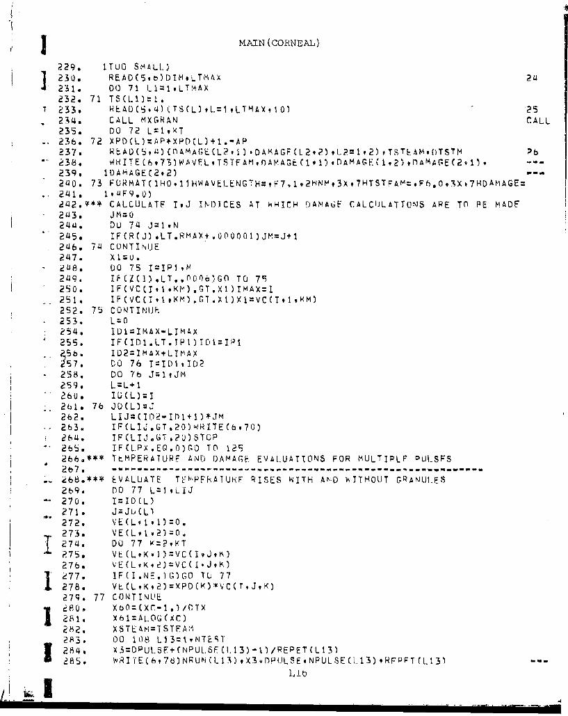
3 MAIN (CORNEAL)
229. ITUO SMALL)
12 0: READ(#t~)DTM9LTMAX 2232o 71 TSCL.1)='t.
T233. HEDS4(SL9~v~*Aq0 -25
234.. CALL MXGRAN rALL235. DO 72 L=t,9(T
-- 23b, 72 XPDCL)=AP+XPDCL)+1.-AP237. RýA0C5(Mt)At;E(L2,1).D4MAGP(L2,?),L?~l,2) ,TSTh&Mor)TSTM b238. WHT(93)A *STA9AAG(9)DAMAGE(192),OAMA(GE(2,1)9--
239, IDAMAGEC292)- -
2'uo. 73 FURMATC iHO. 1iHWAVEL-ENGTH=,F7,1 ,2HNH,3X,7HTSTFAm~.F6.,0,ýX,7HDAMiAGE:
a142~**CALCULATF IJ IIND1CES AT NHICH FDAiNAGF CALCIJLATTONS ARE TO RE M.ADEF*2413. Jm=0
24j4. Du 714 J=19N
2415a IF(R(J) .LT.RmAY+.Q0O001)JM=J+l2146. 714 CONTINUE2147. xI zu .
2149. IFCZ(I)*LT..00O')oGO TO 79250. IFCVC(I,1,KM).GT.Xl)IMAX=I
252. 75 C Q ' T I N 1.F*253. L=O
254,4 ID1=IMAX-LIMAX
- 5b. ID2=lMAX(*LImAxi57. ýO 76 T=I10ivD2
*258. DO 76 JzltJM259. L=L+l2 26 u. IU (L ) =I261. 76 JD(L)=J
263. IFCLIJGT*2O)ý-RITE(b,70)26140 IFCLIJ.GTo?0)STOP26b5 IF(L.PX.E0.O)GO TO 129266.*** TEMPERATURF AND DAMAGE. EVALUATIONS FOR MULTIPLF PULSFS2 7. ------- ------ ------ ------ ------ -- ---------------- "- - -
2b9. DO 77 L=19LIJ
-- 270. 1=I ID CL.
271. VEJ(Lll)0
I273. VE(Lol.2)zO.2714. DU 77 K=?.KT
2 77. lF (I .NF .I G ,)G 0 T L 7 7
279. 77 CONTINUE.* 800 XbO=CXr1.-)/DTX'2614 Xbl=ALOG(XC)
R82. X8TE'mT~ASTFAMl283. D0 108 L13=1.NTEcT
12814s x3zDPULSF+CNPUL.SF CI.13)-t)/REPETCL13)*285 , MRI'rE(6,7e)NRUN(-13) ,X39IDPlJLSE.NPULSE(L13) ,HFPFTflI13' )
Lit)

1*1AIN (CORNEA L)
I cbo. 78 UMT11sH ,IA1TR IW NT=F'.twF6YlHi~s I LeIh, '7 . IvuTm:,rFo. 3 ,es**lSEC/lx17hiNUMbFR OF P~-5'=T@xlwPFTTNP
d 9v. 79 ý uRm Af (1 H *1 2"ihL A L ;, EAT A P.39 ?HM 4 t 1 4HLFSTON P A r)IUS:!-qFb .392HC
-214 KX:NPt3
c!97. I-=I +
d~o. tILU TO 63
3o4.~.V4 STOxE Til1E INlFmVALS ANMC LOlGS OlF INTFHVALS FrR DAMAGF (A.CtILkTTOC'JS
S±07. T T (I )L (,r, (J NrT½I* 308L. 1) U oc5 I 3 eI
309 71 7 L 3 = IL r- GC I t- +1 I FE3 1 u ZTXCL3)=7TX(L.5-1 +PrfTr-F31 1. b 5 ZU(L3):ýT(L3-1)+PlltAF
31 3. x3 T L -u PL S L /K X- NFP
31b. ZrTLLi1ALrG(INy3)3517. LI-L I+ I316 L)UJ 8A L 3=L1I
3 ?' 2 -C AL C U L A f E T L F HA I IJ F R 1S F S A SS C rJ TF D IT TH 1 3 T~ T IE I M TFR V AL.
.523. PL1SF
L) L. X~15 . S
Y X3%(L7-1 14tC4'~TTL3)'<=AL0G(X3+Vn0+1.)/Xb!+1.
X. z' (L 7. - I1 J ;u T C C M7TA
Do v 3 1 1 '4NX X
I ~L17 -

MAIN (CORNE~AL)
3413 IF(X5.LT..00O1*X1)GU Tn 91
3447 . L1:L1+TN3S480 L7=L23419. 90 X3(71*CZ(3
3509 K=AL0(Cx3*XbG+l.)/Xb14.¶
3132. X I =X I+x 5*353, X3=(L.7-1)*TC+ZTXCL3)
3S4.~ KZALnGCA3*X6O+I .VXbI+1.355. )(= 2 V ( 9 9 ) C 3 XT K CE L K 1 2 - E Lo 9 ) ? X C+ ) Y ( )356, IFCX5.LT..0001.'Xl)G0 TO 91357. L 7=L 7+ I
*358, IF(L.7,LE.Ll)G0 TO 9035.e 91 VZCLL69L3,1)=Xl360. 93 VZCLvL6iL3,2)=Y2
362o DO 'g'J Lb=L1,TNJXX3b3. L b=L 6- IN Y
3b5a 9~4 VZ(LLb,L3,2)=VL (LL6,L3,2)-VZ(L,Lt~L3,?)366. 95 CONfIlNUE367e *#* DAM~AGE CALCULATIONS -- -- -- --------
368. TSTEAH=XSTEAM369a XQ 0.A7O0. 96 mRITE(6912Q)TSTEAM
371a DO 104 L=1.LIJ
373, J=JD(L)
175. IF(VZ(L.T~Ný#NP.1).LT.*QO12rO0 TO 104.1376. L9=1O.*C.41FPC-.00141DPUILSE) )/VZCLINXNP. 1)377o CQ=L9Q I
37()o IF(L9,EU.0)CO:XlO
383. L 6=1384.10000 101 L3=1,KX
385, X3=0.385* 1 L93?*QG.qFMT)*;IE1387, IF¼VZ(LtL6.L3,2)*CQ.GT.TSTFAM-TO)GO TO 101388. X50=VZ(L0-6,13v1)*CG+273.4T0389. IF(X50.LT.317.)GO TO 101
90, X I-Z T T (L 3 + 0Af4 AG E 91,)D A MA G E C 1?)X ,0391 * FxOG.2.X=T(3+AAF21-AAE22/5
-'392. IFCX1.r.T.0.)X3=i.O1393. IF(XI.LGT.O.)GO 70 101
394, X 3=E 'P (X II'* .395. 101 DAtmc~oAmc4x3.39be IFCDAMC1~rr.1 .)CO TO t023Q7. * 1ý* IN~CREASE TTME INDICES ANDl CONTINUE
398. L b =L 6* +I399, IF(L6.LE.INIXX)GO TO 100
L 16

I MAIN (CORNEAL)
4U0. *** AD'JUST LASFR P~P TO YI~ THR~ESHOLD DAMAGE AT n'IVEN POTNT
40o2, 1JF(LGT.EQ.1)(;Q TO 1.03'403. LLT~1I 4014. Q1.4'405. GO TO 991406. 1.02 IFCLLr.E.lJCQ=.983*CQ'407. IfCL.LT.Efl.1)GO TO 103
408. LLGT=1
a 10.0 GO TO 09'41.1.103 QD(1,jy;CGo*Pox'412. 104 CONTINUE'413, WNITF(6q631(FR(J)vj~l9VM) -
4 14'I DO 106 I~lir¾lI2
4 41k. 105 F0PMATfjH 92HZ~vF7s'.bqX9,HQDv8Ea'3)4 17. ob10 CUNT I N(E
1420. IF(X3.L.T,..'o01)GC- TO 106421. T6TEAm:1STEA~l+TTSl'M'.22. XQ=QD(rNAX91)1423. Gu TO qb'420.o 108 CUNTINUE
4ý5. IF(KTYPE.bQO~f)C-0 TO 17L~42?b. 1 CALCULATE AND STORE TEMPER~ATURES FfnH PLOTlIN(' TEMPFRATtiRF PROFILES
14.27. TCm1./PLEPET0)U28. NPL=NPULSE(l)1429. DO 123 L15=1.KTYPE'.430 . IFCTTNEX(LI5).Cl.XT(KT)) GO TO 123
- '43 . Ld:=TIMEXCLI5)/TC'433.* DTImE=TImEX (L15)-L2$TC4314, LC'=L 2+ 1Q 035. DO ilb ImITlItIl
* 436. DO 116~ =JTjvj1 J21437. X I 0.IJ38, . 0 113 L6=1,Ld
442 "3. V J
'403. L3=L2-NPL14 44 , IF(L3.L.E.u)G0. TO 115ý14i5. X
.L. '4 b 00D 110 L6=1,1-3~4979 K';ALCJG( DTTmE. CLh-1 2*TC) *x,,Q+1 .) /)U1+1.
S451 . 115 4'FCVCIqJ) .rT.PGV)H4GV=VCI*J)452o 11b CONTINUE053. IF'(KTyp~fn(.1¶~lGf TO 121
I .45I.11I FORMATr2T7,F7.1)145(# WHIqTEC 1,1 1)DPOL8Ev'qAVEL@PIM
LU1.19

I MAIN (CORNEAL)
~ 457.116 FOIRMAT(10EA.3)
460. WRITE~lvIlq)N3sHM3~ 461, w -fITE( 19120) (R(J) 9 Jz1 9 N3)
1462, 120 FOHMA)C1OF7.u)
46A. VvITE(IP12O)TzDI:E(151)
lot 1659 12~1 DO 122 1111'112?46b: w~lTE(6v12P) tV(1JvJ=JJlqjjp)4- 7 IF(0TYPEO.Fra.l)G0 TO 122
'4b'9 122 CONTINUE'470, 123 CONTINUE
7 71. GO TO 17L£472. ** DAMAGE CALCULATIONS FU SINGLE PULSE47 s------- ane wn s e - -------
475, 126 &L)RMAT(1H0.5HN4RUN=,13,2X,1?HPULSE WIDTH~oE8,3,2X#17HNUm8FR OF PULS'476, 1ES=9151'477a Nd~ITE(6v79)RIMvLF5ION
'478. XU=O0.S479. 127 tqITE(6q12Q)TSTt.AM480o 128 FORPIAT(1flF7,1)4 481.a 129 FORMAAT (lHO,7HTSTEAM~,F7,0/l~t10H ----- 1
-482, DO 138 I;Ir1,10f2483o DO) 13h J=1,JM
-- ~ C84 I (VCTJKM) .lT..001)(~tOC1,J):1.E±?0485. IF(VCCIJ.Km).Ll..0012G0 TO 138
4F II6. L9:=10.*C .'±+E)XC-.o1i11*fOPtLSE))/VC(IjKM)
14688 X10=70.*(.L+FXP(-,0014*r)PULS') )/VCCIyjKM)
'490. LLTzO
491: G=
-L L9 4 131 X13=&L0GXl'K)-'XT(K-1))
~ 496. XiO li 3AI
I 4989 IFVý*PDK ,GTTTA-T)31E+30499. IF(VPX*XPD(K)*Cc.GT.TSTEAmCT0)ro T0 134500. 133 XbQ=VPY4#CQ+273.+Tu501 IF(X50.LT.317.)GO TO 134
+ 502s Xl=X13.U)AMAGF (1 1 -DAMAGF( I ?) /X50503. 1I (x50.GT.3Ž.ý.)XIZX13+DAMAGE (2. 1)-OAMAnE(292)/ýc50
505. IFCXl.c-l.0.)G0 10 13a506. X3 =E xP ( I) V507, 134 DAmC=DAMC+Y3508. IF(0AMC.GE.1.)C-U TO 135I509, K =K + Is50 I Fr(K.LlT.KT)GO TO 131
511 ,*4* ADJUST LASFk '~~~ IL THE~ DL AMAGE AT rZIVEN POTNT 1513 lF(LGT:E0.Dl)C,0 70 136
L20

j ~MAIN (CORNEAL~)
5114. L.LT=
I516. GO 10 130517, 135 jF(LLT.EQ.1)CLq=.Qb*CQ
516. IF([email protected])G0 TO 136519. LGT:1S20. Cu= b*cfý
-r521. GO TO 130522, 136 QU(I.J)=CLU*P0X
5 ; . 1 3 8 C O N T I N U
S25. DO 14~3 IcI.M.10I2
b27. 1143 CUNTIrd4JE528m X2=(XW-.fD(IMAX, 1)) /Q(IMhXsl)S29. X=2Y530. IF(x3,LT.o0o0l)b.0 TO 150531. TSTEAm=TSTEAtM+0TSWH
*532. XwalLDOCMAX91)533. GO TO 1275314. * CALCULATE ANO STOR~E TEMPEHATURES FOR PLOTTINC PRC1FILF535. 150 IF(KTYPE,6Qr).0G TO 1714
-. 36. DU 170 LIS=1.i<TYPE
537. DTIMEzTIMX(LIS)538. K=AL0G(DTIME'ýCXC-1.)/DTX+1.)/AL-OG(XC)+t.539. IPCK+1.GTKlMGO TU 170
*5/41. jV0ý42. DO 166 1=IT1I@Il',143. 9 D 166 J~J 19J,3J2
Lý aa ,V(IJ)ZVCC T ,j,)+X1*CVC CI ,JK+1)-VC(T,3,K) )5145. IF(V(I'J) ,CT.kGV)RGV=V(IPJ)
5146. 166 CUNTIN.\UE5417. IFC(KTYPE0.FI0.1)GO TO 1675148. Y4HITEC 1 9117l'N4UN(1)qKNPULSEC1)qREPETC1)
S4. RI TE 1 9llý)DPl.jLSLNAVE-LvRTM
-~552a WRITE(19120)(R(J)vd~i9 M3)
556. W W TTEFC I 120)(V(l,),Jl=lJ1,JJ2
551. IF(KTYPbo.FD3.1)G0 TO JhB7'598- WRITE(¶ .12M) V(1vJ) ,JzJJ1qJJ?2
559. 168 CUMrINuE560. 170 CONTINIIE561. * * ** INTERpnLAIE AxIAL EXTENT OF D)AmAGE562, 1714 Iib~M2$?M15b3. lF(I.ENS.EQ.C)IlP~lPl5614o 15:0
566. lF1101.EQ.ID?)CO 10 18?567o DO 175 1=I0X1902568.* Ll=1D1+Iln2-I
5690 IF(UO(LI,1).GT.P0X)15=Ll570. IF( f LI91).- pn 6 l

I MAIN (CORýNEAL)
b71. * tý UD CIq1).0T.PLA) I7=
b72. 1FCUDCIvl) .LT.PUX)(TbZ1573,175CONTINUE~
b74, IF (15.Fu.0~vPITtib,17b)---t~t).176 FRUMAj(lHQ."5H)tPlHS OF DAMAGE bEYnND ROTH SPECIFIFD DFPTHR)
1;76 . 1C(5.Eu.u'JLO Tu 182
577, 1 C 16 .FU .U) i,U TU 190
S 7: 6X 1 C~ 15 C h.I f, ri 1 101
ID82 w5NITECE'. 77)X)356.177 FURMAT'jUh0,2lmW.N±MUM DEPTH OF DAMAGF=9E8.3vPHrmj
'14 17*/8 IFC18.rL.17)(GU in lb2
566. X1xALCI7i10Yxl)XL I7)-ZCIP )tDrZ/2.
586. 1 b0 qHI T E YC~)3
5ýQ Ie ti -ATIU IM~.U DFLPTH OF UAA;~CA3Pr,
'ý90, *4*. INqthfpnfLATF PADIAL c2&TENT nDF 1RHEVFN.~IPLY nAMA(GE AT RP;7CTFTE0 DEPTHS
t) Q4 0 Uo 183 J=jjm
5'b. 183 CUNT I PLIE.b~ 597 X 0 =0.
Dqb I F j IFw..0 ) GO TU 18 1
t. U0c. 165 FUJHMiAT(lHU,)2HL=9,E3.3.2HC~iS9,361ýRAD)IAL LYTFNT nF DAMAGF CRFATEP TH
b 0 1 . 1.Allq8.3v2HCvl)102. IF C I. E(;. Jm) GufU 169
C)t059 X20:ALOLCP0X/x 1 J/x2+RCJj)IbOb. 187 WlT~IFC&,18R)Y3sxU607. 6 F~ A 18 ( ~ H=1F8 2U'tr 7PD LYTF \T lF. I RRFV~rRS;IRLF DAMA
008. 1 CL= ,b .- *2hrm)
609. 189 C UN T I N\UE~b1 I * 10 s~T 10 ' 191
b 12 . 191 P URMA I IHo .3 1 Ntdu lAMhuF---L-ASE.R POWER TUO Luw)
T j I N KH1 1
L2 2
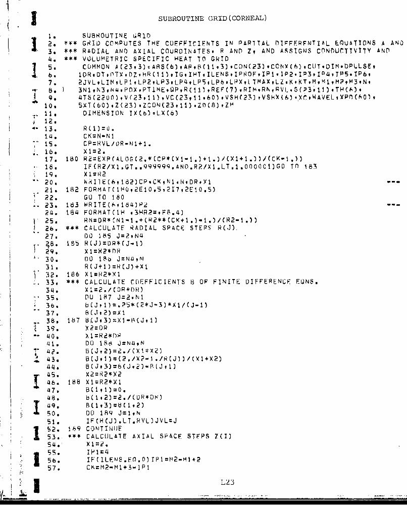
j SUBROUTINE G3RID (CORNEAL)
is. SUBROUTINE GRID
I2: *4* GR~ID COMPUTES THE CUFFPIC"IFNTS INJ PAPITAL OIPFFPFNF'TIAL E3OUATIDNS A AND3o ~ RADIAL ANO AXIAL COURDINATESp P AND Zt AND ASSIGNS CONDUCTIVITY AND14a*~ VOLUMETRIC SPECIFIC HEAT Tf0 GRID
7.2JVLLIMLPI ,LPRLP3,LPiJLP9,LP6.LPX,1 TMAXLZKKTMMlM?d43,N,B. ) 3N1,N3,N4.PflXPTlME.QP,RC(fl ,REF(7),RIMgRN.RVIL,S(P3,11),TH(Af)*
S9. 4T5(2200) ,V(23, 11) ,VC(23, 11.60) VSH(23) ,VSHY(6) . ,WAVEL,XPDC601,10. 5XT(bC) .Z(23) .ZCON(23,11) .ZD(8) ,ZM
* DIMENSION IX(b)*LX(6)
13. R (1):O14. CK;N-Nl
18. IF(R2/Xl.GT..99999Q.AND.R?/Xl.LT.1.OOOCOI2GO Tfl 18319. X 1 R2
21.s 182 FORMAr(lHQ,2E10,5,217,2El0.5)22. GO TO 18023. 163 WRITEC(',914)P2 -24. 1834 FORMATCIH. f3HR2=.FF~.4)25. RN:DR*N1-1.+(fR2**(CK~+1.)-1.)/CR2-1.))26. *** C-ALCULATE RADIAL SPACE STEPS RCJ).27. 00 165 J=2,N4
29. X K 2* D R"30 o. DO 186 J=NiJ,K
31. RCJ+1)=R(J)+Xl32.* 186 X I--2*X 133, ** CALCULATE COEFFICIENTS 6 OF FIN4ITE DIFPERENUF FONS,34o Xl=2./CDR*DR)
-. 35. DU 18J7 J=2vNl
37. B (J ,2)=X I-. 38. 1i7 8.(Jt3)=X1-B(J.1)
41. DO 188~ J=N49N
~ 43.
45, X2=R2*X2
1k46. 188 XI=P,2*)X1
48 . b(1,2)=2./CDR*Dk)419. B(1q3)zb(1,2)50 . DOI 189 J=1,N51. IFCH(J).LTRVL)JVL=JI52. 169 CONT INIJE53., ** CALCULATE AXIAL SPACF STFPS 7(I)
57, CK=M2"Ml+3-lPl

3 ~GRID (CORNEAL)
* 9~. IFC LENS.En.O)CK~f0?-M1+j
1 59- 190CP2*C~/Z1-X*(1)1/Cil.- s 0. IF CILEMS E() ,0 )C'=LDC 7) /DZ- .*M 1+1 c;61a* R1=EXP(ALOG(CP*X1-CP+1.) /CK)
S62.1 IF(R1/Yl.G;T..999999.AND.Rl/X1.LT.1.o0o0012c-O TO 19363. xI:N1641, WRITE(6'.191 )CP.CKM2.M1,ZDCLJ) ZD(7) .DZ.X'IbS. 191 FORMAT( 1H0,2E10.5,217,SE1O.'3)66. G~O TO 190
69b. ZMIT((6#1**CK~v
70. 194 FORMATC1H v3HR1:,F8.a92X*3HZM=,98.s,471. a X:DZ
-72. X2=Xl73. DU) 19S 1=29M27u,. Z(m2+IJ=2M+X2
*75. Z(M2+2.I=7m-XP*76. IF(I.GT.M1)X1uR1*X1
77. 195 X2=X2+X178. Z ( I =0 .79. Z(MR+1)=ZM
-~80. ZM1=.Z
82. DO 1%6 I1z.KM*83. 196 C~i~X
8ti. L3=IPI-85. DO 200 L = tbt6. L1=087. DO 1Q7 I:IP1iqý3
890 IF(2(I).LT:Z(L1).O.L3 )G.7CLITG TO 19790. L2=1
-. 97. 197 CONTINUE98. 1F:I(L1l`.) 'U)=
I9. I . F 0 ) LXCI
96, ~IF(4L.J0)XL)L
101. 1 P 1X r u
1014, LP2=LX(2)
108. LP6=M3
'109. ~ StT CONDUCTIVITY CON AND HPAT CAPAZITY VSH FOR VAR IOUJS EYE MEDYA
110l. DO) 203 I=1.LP1
114 a0 VUN(I)=CSHX(? L24

GRID (CORNEAL)
115. 204. VSHCI)=VSHX(2)31164 DO 20O5 zP93
117, CON(ý)=CnNXC3)118o 205 V6H,'.)=VSHX(3)
3119. D)O 206 I=IP149LP'4~120. CON(I)=C0DNXU4)121m 206 V6H(I)=VSHY(U.)1122. DO 207 l=IPS9LP5123, CON(I)=CfNY(S)124~. 207 VSHCl)=VSHX(5)125. DO 208 I=IFpb.M3I 26. CONCI)=CONY(b)127.v 208 VSHCI)=VSHýCb)128, *** CALCULATE COEFOICIE'NTS A OP FINITE DIFrERENCF FQNS.129. DO 210 I=IP1.M
1312* X32: CCDN( 1T) -CNC
135 4 k(I,3)Q-Y+x3/C(I+1)= ZC)
.137. RLTUlRN
-- E N D
aL2

SUJBROUTINE IMAGE (CORNEAL)
19~ SUBROUTINE IMAGE26 COMMON A(23.3),AFRS(.)ApB(1, ý),CflN(?3).CONYC6).CtIT.D!M.[OPULSF,11 3, lDN.DTvrnT~.rDZ#H.RC~flvltHILM*PCvItP2P3P415P
'4a 2JVL.,LlILPI ,LP?,1.P3,LP'4,LP5,LP6',LP~,LTMAXLZ.KKrMM1,M?,M3.N,
* 7. SXT(b0) .ZC23) .ZCON(?3.11) qZDC8) ZM61~ DIME.NSION A51FP51FX51PX0)R()
99 REAL NC10. LI=SOO
*11. 00 200 j:1,N312a 200 HR(J)=O,13, L II .L I1'4. D0 201 L=IvLlI5, 201 FX(L)=0.16. READ(59202)PUPIL 917. 202 FORMAT(10E8.3)185. iyRlE(6q?2o3)Pl.lPIL19. 203 F0RMAT(IH0o6HPUPIL:,P7.3)20 a RINT=PLJP'1L,(LI-1)21. IFCIPROF.E0,I)GO TO 21'422. IFCIPRciF.Er'.0)GC TO 21Q23. INTERPOLATE THRREULAP LASER PROFILE(SYMMETRIC T!N R) AT IN'TFRVAI-S2'4o OF NINT STARTI'NIG AT R;-.9 O25. READCSZ051LR26, 20'3 FORMAT(17)
ý68. 206 FORMAT(IOE7.3)j-29. RED52b(X~-t=qP30. x1P
32. 207 PX(L)=PX(L)/Y133. x 5 =03'43 DO 208 L=2,LR
~.36. Y1:PXCL-)-X?*RX(L)
* 37s X3=Xl*(RX(L)*NX(L)-H.X(L.-1)*RX(t -1) )/2-
j 39. 208 X5=X5+6,?832*Cx3+x~4)40. PPX.3~*(.PFl)X41.0 IF(NXCL.R) .LT.PUPIL)LII:RX(L.RVRINIT+I(4 L 2
1414 D0; 2 13 L= I, L.I I
I 5: 210 IF(RX(L2).G-T.XI)GO TO 212/47, IF(L2.LE.LR)CO TO 210
AW 50. F'XCL)=PXCL2-l)+X24*(PX(L2)-PXCL2.-1))51. 213 X1=X14RINI
.I 3 CALCULTO CAUSSIAN LASER PROFILE AT FACH VALUE OF R(J)
* 55. WRlTE6,y216)SIGMA#PIm3 156, 216 F'ORMAT( 1HO.ilHSIGMAcoE.34,5b.4HRlM~vEE43)57. DO 217 J=19r!
L26

~i'I IMAC-E (CORNEAL)
I . IF(X3.('F1.60.)LO TU 217bu HR(J)=ExPC-x3)
6~1a 217 CUNTINUiE62, @P2.*U( 30) - 1 ~/3,1L41 o*STGmA*STtMA~I b., GO TO 250b14, *** SPECIFY tJNT&OiýM LAStR P1ROFTLE FROM N~l) To IR(LTIK)65v 219 Do 220 J~liLIMhb . 2i0 HlNCJ)=i
68. GU TO 250
69.* CALCULATE TOTAL AREA FA(L AND POPTItIN OF L.AREPS PnNFR EFTWErN R=O
7Ž FA(i)=3.1~41o*K1NNT+P1T/L4,73. DU ?214 LN2*L71I
7b. Fk=(L-.SzPL1)xCj+.1lb(1*1,2*?
-. 7/. ?Ž4 FACL)=FA(L-1)+3.1!4Ib*(XI*XI-X2*XP)7b. *4*' CALCIJLATF NORM~ALTZEL) PROFILE HP(J) ... HP=1 AT H~o
*79. xi~uq.F u . Xe-= v.
* -- 1. DO 225 J:1,
83. 1(X3,L`T.1.)ý3i.U0OOO1~.814. LdzX3
85. IFCL2,GL.LI1)GO To 2?5V 8c~. x1~:x3-1I Ž
9 u. Xb~AL)~k(AL+)F(Ž I )
Q ~I. Xe=Xb
141 I ZILON(I'J)N 093.~~~ x qZR
D50O 3017 I.-±P19H
S1004. Zl:2CZ*F/N*7-1015. DO 301 1=Pc1020 xzi.ZMCJJ/XU
j103. ?98 iq Ix1 0Lr.N L)GU 0 O 1
104. LL=+2
109. IF(L*Lr.N)GO TO 298
I ~~~ F(HPCJ) .LT 1 ,F-?0) CGf To 301
115. 301 CUN1 INUJE
116, RtTURiNI L2i
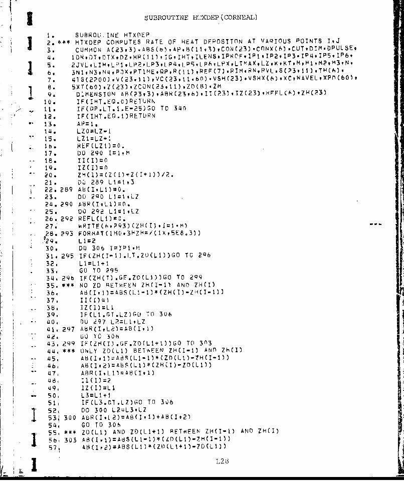
I SUBROUTINE HTXDEP (CORNEAL)
I. SUBROU-INE HTXDEP12. *** HTXDEP COMPUTES RATE OF HEAT DFPOSITTON AT VAPIOUS POINTS ItJ
3. COMMON A(23,3),A8S~b),4PB11,l),CON'4(3)9cnNyc6)CUTDTM.DPULSE,401DR.DTDTXDZ.HPC11)l~ ItIHTILENS.IPROF9IP19IP29IP3.IP'49IPS9IP
6'IS. 2jVLLIML.P1 -~--~lP41P;L~L~tTAt.o#T9olMv~be 3N1,N3,Nq49POXPT1IAEQpRC1 ~ijREF(7) .RIM.RNRVL,*SC?3 1.1) ,TH4h) .
7. 41S(2?OO),gJ(23911)#C2ol6)V C3*SX6oC#AEt~)6)
94 DIMENSION] AR29)AR29)I(3)1(3oFIC)Z(10. a IF( HT.E@&.O) PElTUHNI1I. IF(tOP.LT.I.Ei-25)GO TO 340i12. IF( IHT.E0.1)RETUlRN13. AP= I ,1/4. LZO=L-Z.-I
I h's LZ1(LZl+10
17. DU 290 1= 1 ,M
19. 1 Z Ci)-20. ZH
21. DL 289 L1=1 9322. 289 Ah(I.Ll)=0.
-23. DO 2QO L 1=1 #L2/4. 290 ARI1)O25m 00 292 LlclPLZ26. 292 R E L (L 1:0.
-. 28,.293 FORMAT(lHO.3HZH=/(lX,5E8o3))..29. L I c230. 0 U 306 1=1P1,M31. 295 IFCZH(I-1).I.T.ZU)(LI))GO TO 2Q632, LI =L I+ I
- 33. GO TO 293/4. 29b IF(ZH(Tl.GF.ZD(LW)Go To 2q935. *** NO ZD RTv;FLhN /H(I'-1l AND) ZHCI)
37, 11 C I)~-3b, I ZCI) L I39. iFCL1.rT.LZ)GCJ TO 306
-. 0. rOU 297 L=LltLZ41 -297 A6(IvL,LJ=AB(I I~42, GO TO '30h
/44, **ONLY ZD(LI) BEI'v.EEN ZH(I-1) ANfl) ZH(iI)- 45, Ab(I #1A8ACL I - IC ZD C t- I-H I-1 I
49, IZ(I-5~ 0 L3=L1*151. IF (L 3 ,G .LZ1GO0 TO0 30ý6
52. D0 300 L2=L39LZ5 3 i30O AbR(I#L2)=A83(I1)*kB(j92)54, GO TO 30655( *** Z1)C L i) A N D Z D (LI + I) ;E T NE E N ZH I - I A N D ZH I1; b 1 303 AB I I= tS L - )* L)L ) Z ( - )
L 26

I HTXDEP (CORNEAL)
I 60,12, II(I)=:3
63, L3=Ll+?64, IFCL3.GT.LZ)GU* TO 3U665. IDO 304J L2=L39LZ
68, 00 314 IP,
71, IF(A8(I,3) *Gr.10.)A8(I,3)=10*72. DO 314 L=29L.Z
74, 314 CONTINHE75. *+# DEPOSITION BY INCOMING; BFAM7b.77. L1=2
-~78. DO 317 I:IP1,tm
80, X3=x2-~81. X~mX2*EXP(-AI3(I, ))
82. X w = 083. hL.u-)OT 31'384, L 3 =I ZC(I85. X4X*RE ~l-3)
b, 87. IýCL2.EU.2)GO TO 315
-- 89. X)2X4X2*C.REF(L3+1 )*p(kC3)
90. 315 lF(X2.LT.l.E-10)X2=0.91. D0 317 J3:IOJVL92. S( t ) C 3 X2 X H (T*Z D ( 9 ) C PC ) Z ( - )93, IFCSCI9,J),LT.I.E-6/OPULSE)SCI,J)0O.9 U 9'. 317 CONTINUE
P '~ *~* C.LCULATION OF kFLECTED INTENSITIFS By VARIOUJ TNTEPFACFS STARTTNcG- 96b. 41 WiTH FIRST 1NYERNAL INTEPFACE
';7 - X2=QP48. DO 322 L1l.-ILZO
99, X3mA8SCLl)*yH(Ll)
F 102. REFL(Ll+li=X2*PEFCLl*1)
105. ~P 1106- b3 2 IF(ZHIJ).GT.7DCLm)Go To 325
108. IF(I.LE.M)GO TO 32/J'109. GO TO W7I 032S NexREFLCL1
L29

(I HTXDEP (CORNEAL)
115. D0 326 J=1.JVL
118*. 326 CONTINUE
N19 D327TIN A CONINU1231. 1O HT= I:1
121. RETURN
125. 34 SCIN J1 H=
12s RTR
L30

.14 COMO 5XAO, 23o).ZCUNC631) ,ZD*ClllqD(2.ZNM4*UoT~DILý
10. 00 DO 95 LI:1.KTI 1. 495~ XP0(Ll)=l.I 12. RETURN
13. END
IL3

'I!i
I'
II
I.APNDX1!.
USRMNA!O RPRN - N - LUTAINOFTMEAUE!IEPOIE
I!__' i "
I " -

1. INTRODUCTION
The computer program documented herein was developed by IIT
Research L-istitute to display two and three dimensional temperature
rise profile surfaces as a function of radial and axial coodinates.
1 The methodology chosen was to start with temperature data for
'selected points from either the Corneal or Retinal Models. This
information was then used to build a general three dimensional
point array of plotting information. Finally, a generalized pack-
age is used to yield any desired view of this three dimensional
data. This documentation pertains mainly to the use of this sys-
tem and in less detail, to the documentation of the system itself.
2. EXAMPLE OF THE USE OF THE SYSTEM
-o A sample input deck to this system is shown in Table 1 with
each data card preceded by annotated comments. The deck shown
consists of two separate decks. Cards 1 through 14 contain infor-
mation defining the data supplied by the Corneal or Retinal Models.
Cards 15 through 35 contain individual plot commands. In partic-
* ular, cards numbered 23, 25, 31 and 34 contain specific commands
to plot while other cards provide auxiliary information concerning
the screen size and cesired view of the object. The last card
(card 35) is necessary to properly close the plot file. The four
- plots generated by these coumiands are shown in Figs. M-1 through 14-4.
3. SYSTEM DESCRIPTION
The entire program consists of approximately 1500 cards ofFORTRAN source divided into a main program and twelve subroutines.
It is assumed that -his package is also supported by the subset
of CALCOMP software consisting of the subroutines PLOTS, PLOT,
NLTIBER and SYMBOL. The FORTRAN is ANSI FORTRAN, and should be
directly portable between computers. The package was developed
on a UVIVAC 1108 and tested on an IBM 370 computer.
1IS~Mi,
I

N OD
00~
r-i C) 0ON 03 j)r-
-ItI
z r-. -41
C4 03 r
cq -It -0 Q)
H0 03 LC)
003 CD 11 ~Ln C) )LPmcC1) w -d-
0 - M.0t r--4 uý
0 a
0 00' NMMMcC,4~
.C) (3) C.
Cl) 0-I Lrj-..() (r-q 0 .'o 03lD. C o c 40) cq' N 'zt l-) I 0ý a) 0 rI 0
cC) ..H ' Ir-I - ýi a)0 "~ .~- H44U- ~ bi) (1)
F4 a-1 Hr-I C) V)O C a) ý
-l 0 0 O)N m O~' a%00U Or )r-4 r 0) 1 C) -4 0i-1 CN r_41N . -.u . o cu 4-4 Ir- 4-1 a)
0 r-A M CC)LC00 LnC)N P.4 0.0 0 100 C) 0 C/ o - ) 0 4-
N -r~0'0 t41I u 0r±-q 8 >-. W4-4 ,
+ H .. 1) CO --r r r, 0 3N 0 c,) En cy rIý -
-.I-I r -NO C .-J0' ;a Hu NO .-Z w * 0 3 C) -)u0 00%.D t CV PI.c) p 0 0 r Cf~I- 0r C) 00 00 -4) *CL) *rý o 4 'n I
Lf:J ' -.4 - 3 '
-4 - I () S--I QI
L jj-4- -4--U_____ __U)____

IWIpIu
U)I40
4.J 4-)Uj 0 0 0
-4- p
jJ- CU U0-w 0-
U)cd
3> > r) 4
1 0r -4 H
1-4 4 ; s4 N Wa)l
X 10 0 0DH (aH a) 4.4 r-4*,4
44 a) r-l a) 0-00 -H4 .4 ( P
r4 0 0 (UJ'-44 4-))0 4-W 44 -
>2 H)4-1 '4-4 g
C)4 4-) U) '-U 04.1 A a~C) 0 )0 ~~
H 1. a4% ) cl ma Ha4) 0 * -
V C) 04 .1-4 4J~. *d 'ý
'd r4 C. -I C) Hl a) U)r-4 r
4 d) r4 ,iý 0) r-H H r'r) 44. . 04P, 41 m' p 4-
Q '-1 4)- 10 40) "04I4 4-) 0 0 N0 4-i ~ 4-j 4ci - r:.H *-4 u C)0 Q Oa4L) V) ON 04C ) C4 r) r- 0)O'\ W~- ý -0 0*-,-n C 4 (1) '0 (N WH r) i *d-r . W a r-4 -4,a H- 4-) -0 41i u) Hr , p- H4
W Q ) -,1 0 4-3(40
r" C4 r-4 0.4()-
gr4U W ) c 0) PiU 1 4 -4 U Q 1 U -00
dL) U) 0H (:1 M ) 0 U )H& - 4[ a,'x -rH0 VU) U 0OI~ P-A Hl v l 0 I- I' 0 -Cl -4 H 1-4 Cl L ) fr --Ia P-H0 0 P4 H P4 H 0 P40 nA -
C1 04 (N (1 C14 m~ M '
M43J

((
C-)44
Cd)
0
E-4H
-4d
r4 -
00
f:-44 r4
:: D -A.
z
ul Q)
,.C r4
-4 -
Cfl t4 r-4 44- 4 04
0V r r4 r
(2N 0: 'C) C
I r4
cli u 'E-4 E-4
en mf cfl mf
M44

//
" r.-.
-0M
rz., ] -l •''••---t-~-','-•--•-*~-• o40
•*.. i"/ ,• r'TI
s 'd '•' • -' ' '
-.
-

'II
I vl "
//
4 -', /1'
] II
N m
K U __ _ _ _ __ _ _ _ _

CU
I ,
1P14I
* I "---
M7
"Vl.
-. "|Li --
,,- -I------
I . /1L // --"
I,0 -'U C

I ~ ~ ~ - 1 4 4--
*11
mil

The processing flow and subroutine structure of the system
are shown in Fig. H-5. The processing is divided into three
parts. The first part of the main program (called COLUMN) readse data generated by the Corneal or Retinal Models and
prints a summary of this data. The second part of the program
builds a consolidated array of three-dimensional point data.This array is arranged in the specific format for subsequent
plotting and contains not oniy the criss-cross gridwork of sci-
entific data, but all axial and labelling data as well. The sub-
routine POLSUR and its subsidiaries PCROSS and EQUIV are used to
build the mesh points into a criss-cross pattern of plotting
strokes with embedded normlals to be used in hidden line views.
The routines SYMCON (for symbol control) and AXES (for generated
3D axial information) are used to generate axial stroke lines and
symbol and numeric size and positioning information.
At this point the main program relinquishes control to
the subroutine 'READIN'. This subroutine is structured to
read general plot information and to plot current views of the
three-dimensional object. The READIN routine can be used to
"generate as many plots of the data as desired. In the particular
example documented in Section 2, two general perspective
space-views and two isometric plane views were all obtained
from the same user input deck.
The Subroutine 'RE-ADIN' calls the principal plotting
routine - namely 'SSPLOT'. The 'SSPLOT' routine in turn calls
CALCOMP software and four other subroutines - namely, the
'WINDOW' routine to zoom in on a localized area of a plot, the
'MMULT' routine to multiply 4x4 matrices to pr'oduce a consoli-
"dated matrix containing all the scaling and positioning data
"relating to the current view of the object; the 'PEAUSPIT,
routine to generate a 4x4 matrix in response to a user's
request for translation, rotation or scaling and a duimmy
'OFFSET' routine. The 'OFFSET' routine has no function in
the CALCOMP version of this system. However, at IITRI a real'OFFSET' routine is used to control a Tektronix Craphics
terminal. in a CALCOMP interface mode.
iM

I4 0Q) $4.UI I .I
P4-
-4 9 0 ýL
cu <
-- 0
-. 2 m
4P
;u L)
r.4
:41 cu U'rr4 >4
1-4~1 Li C4I
0 P-4 tuC.) 4-i
14104
H ~ Li

As shown in Fig. M-5 all phases of this program yield summary
print data to aid the user in verifying not only his input, butalso the results of intermediate processing. A listing of theentire code is at the rear ot this appendix.
4. DETAILED USER INPUT TO THE PLOT PROGRAM
The user's interface with the plotting portion of this
I program is controlled by the subroutine 'READIN'. This programis designed to read and list cards under a uniform format and
to immediately execute the user's command indicated. The
-- uniform format for all cards is shown below.
Columns Columns Columns Columns Columns
1 - 4 11 - 20 21- 30 31- 40 41- 50
Key word First Second Third Fourth etc.
left-justified Parameter Parameter Parameter Parameter
* A keyword in alphanumeric format is entered in Columns 1 - 4.
Parameters - as applicable - are entered as floating point
numbers in fields 10 characters wide starting with column 11.
Of course, a blank entry is always read as a floating number
with value zero. A user's card is always printed as read and
if the keyword does not match the dictionary of keywords a
clear diagnostic is produced and processing terminates.
Certain conventions should be described relative to the* philosophy for viewing the object. A single matrix stores all
of the user's consolidated requests for rotations,scaling and
translation of the object. At program start this matrix,
•. without any other information, would plot an isometric x-y view
of the object where the user's numbers (x, y and z) are all
interpreted as real inches. Of course, if x and y coordinates
are in hundreths of a centimeter and temperature rise is in full
degrees, such a view, if there is space on the plotter, would
j be little more than a vertical line because of disparity between
coordinate magnitudes. Accordingly, the data can be scaled
1 to fill a desired viewing area and to allow for proportional
!Ii 1I11

3 scaling of axes. Rotated spatial views of the object are
obtained by successive simple commands to roll, pitch or yaw
the object from the initial viewing position. These commands
are usually employed only after the 'BOX' command which centers
-the object on the origin and allows more reasonable application
of successive rotational commands.
The viewer considers that the permanent x-axis lies to a
horizontal right direction, the y-axis is vertical and up and
the permanent z-axis is coming out toward him. If the viewer
enters a command to roll 45', the object will perform a 45'
movement clockwise in the viewing plane. If he commands it to
pitch 45' the objecL will rotate around the x-axis so that the
"top part of the screen will come toward him. If the viewer
commands the object to yaw 450 the object will rotate around
the permanent y-axis so that right most portion of the screen
will move away from him. All of these commands are based on a
right hand rule to determine orientation. Good three-dimensional
views are usually built-up by a succession of three-rotational
commands (such as in example 2).
The above gives some insight into the positioning philosophy
"of this model. What follows ib a detailed description of each
input conmmand for the plotting system.
Keyword
1 11 21 31 41 51"P a x y z w
The symbol 'P' denotes that a point or vector is being added to"the data base of point P. Here P consists of a two digit real
"number of the form AB. The tens digit 'A' defines the mode in
which the vector stroke to the current point should be plotted
* as follows:
SA = 0 maintain current modeA = 1 plot solid lines through succeeding points
A = 2 plot dashed lines through succeeding pointsA 3 plot only the points themselves
A 4 plot a string of dashed points through succeeding points
In case A = 5, the entry is not a point, but a vector attached !.,
the previous point (this is used in hidden line views)
3 M.12

!The units digit B carries the following interpretations:
I B = 0 plot no special symbol at the point
B = I plot a Calcomp centered symbol at the point -I the value of the symbol is held in w.
B = 2 plot a floating number at the point -
the value of the number is in w.
SB = 3 plot an alphanumeric label at the point. Thelabel is held in the word w.(note: since the card parameters are all readunder a floating point format, this option cannotbe obtained through an input card).
SThe second, third and fourth parameters are x, y, z coordinatesof a point and the w-coordinate carries the meaning as indicated
in the explanation of the 'B' digit value.
In the present application of the model, this point array
is built-up automatically in the COLUMN program and the user
is not required to input data under this format.
INIT
The 'INIT' command initializes all plot data including
zeroing out all point arrays). It also initializes the plot
buffer. Plotting cannot occur until the INIT routine is called,
either directly or indirectly. (Please note that in the
'COLUMN' molel this command is called automatically at the
beginning of the run).
ROLL A
The 'ROLL' command indicates that the object should move
counterclockwise in the viewing plane by an angle A.
PITC A
*. The pitch command indicates that the object should
'pitch' by A degrees around the horizontal axis
YAW A
1 This command indicates that the object should 'yaw' byA degrees (i.e., rotate around the fixed y-axis).
1413
I... z I I I I I I l .. . ... ..... ..... i.. ...[ ' i. .. ' = •i

I I
S CAL A B C
This command rescales the current object. If the1 factors B and C are both zero, then all three dimensions are
rescaled uniformly by the factor A. Otherwise, the x, y, and
z coordinates are independently scaled by the factors A, B,3 and C respectively.
TRAN A B C
The command 'TRAN' effects a translation of the current
objert position through a sector (A,B,C). It should be notedthat all of the previous commands are cumulative - that is, they
operate on the current transformed position and scale of the
object.
DIST A B x y
The distance command adjusts the distance of the observerfrom the object. If no parameters or else zero parameters areinput, the projection will simply be parallel. If only onenon-zero parameter A is input, then the distance of the observerfrom the origin of coordinates and of the projection plane
I . from the viewer are both interpb.eted as A units. Otherwise A
is the distance of the viewer from the origin and B is thedistance of the paper (on which the object is projected) from
the viewer. Optionally third and fourth parameters (x and y,may be added to allow the viewer to shift his viewing position.
"REIN
This command, mnemonic for re-initialize, is entered torestart the transformation matrix from the position of anidentity transformation. All of the previously built: up results
from roll, pitch, yaw, scale, box and translation coimmandsare lost.
I MI

HIDE A
i The 'HIDE' command is used to turn the hidden line calcule-
tion on or off. If parameter A is zero, the hidden line calcula-
I tion is turned off. If A is 1.0, hidden lines are removed andif A is 2.0 hidden lines are dashed. The hidden line calculation
can only be effected where normal vectors have been entered anddepends simply on whether the normal is leaning away from or
toward the observer.
SIGN A
The SIGN command can be used to reverse the sense of
surface normals entered in the data base.
WIND A B C D
The 'WINDOW' command is used to turn the window option onor off and to set the parameters for windowing. A and B are
lower left hand coordinates of the windowed area and C and D
are width and height of the window area in terms of display
coordinates. In particular, if a SCREEN option is in effect,
then the origin of coordinates is at the center of the screen.
The Window option is not modal - it is only in effect for the
plot command immediately following. However, it can be reactivated
by entering a 'WIND' card with no parameters. In this case,* 'WINDOW' will be switched on again and the old window parameters
will be used. The window option does result in a permanent
change of the display matrix whenever the 'Screen' option is
in effect. In this case, the windowed area is automatically
blown up to fill the Screen area. Otherwise "Window" merelyacts to scissor unwanted parts of a plot.
SCRN A B C D E
The 'Screen' command sets up the physical size of the
"-- display area and draws a border around that area for every plot.
j The screen command is modal, and remains in effect until it is
1M15
L b I-- - -- - -- - -- - -- - -- - -- - -- - n-- - -

turned off. The parameters A and B describ. the coordinates
3 of the lower left corner of the screen and C and D describe
the width and height. These units are all. in inches. If no
Swindow command is in effect, then the screen acts as an
automatic window area for scissoring the plot lines. A
I fifth parameter E may also be entered. In this case, the user
defines a three-dimensiorial geometric box so that the object
can subsequently be rescaled to fill that box.
BOX A B C
The 'BOX' command causes the object to fill a fraction of
*-the screen area. The object is first centered on its centerof gravity and then rescaled from there to fill a proportion
of the available viewing area. In case only one parameter, A,is entered, a single scale is applied to all three axes. Ifall three parameters are entered, then the object is scaled
to fill the specified x, y, z scre-n width. The BOX
command is used frequently to attain 'full' views of an object
after rotation.
FACT A
The factor command simply blows up or shrinks all plotting
"by the factor A.
PLOT A B C
The plot command causes the current view of the object tobe actually plotted. Parameters A and B define the relative x
and y-advance on the Calcomp for a new origin of coordinates.
If the parameter C is entered with a negative value the plot
file is terminated. The plot file must always be explicitly
terminated.
USER
The user command is simply designed to allow a user to
branch to his owi, input routine. Of course the user would have3 to supply the coding to effect such input. In its present fori,,,
the 'USER' subroutine is a dummy subroutine.
L I Li' 1.6

IPRIN
I This is presently a dumnmy statement - eventually it may
be used to control the level and amount of print information.
END
1 This word terminates the READIN program and allows
-. control to pass to a higher level routine.
DUM
'This word requests a summary of the current number of
points in the data base and of the x-y-z range of the data.
iM
|
• .1
mi

iWI
I
LISTING OF CODE FOR 3D PLOTS
I
I i MI8

, DIOATA(0 SAMPLE INPUT DATA
1. 3 7 1.02a1,.s3 5.15+2 2'b-33. *8 12 1;5 1 6
4, 11 175, .0000 90010 .0020 .0030 .0040 .0078 .0224 .0783 .2918 1.106r'6. 4.22877e -. 8862 o8862 1,5110 1.7313 1.8090 1.8363 1.8460 1.8494 1.8506 I.b51H8. 1,8522 1.8649 1.8922 1.9699 2e190? 2,8150 4.5874
i 4 9. 1.0"1
10. 4.8 4.0 3.3 2.8 2,t 1.6110 84.5 7e3 5.9 4.5 3.4 1.512. 16.7 13.3 8.9 5.6 3*7 1.5
" 13. 8.4 7.3 5,8 4s4 3.4 1.514. 2.8 2,7 2.5 2o3 2.0 1.3
S 15. DUM16. DIST 3n.
17, SCRN -4.1 -3.1 8. 6. 6.18. BOX 1. 1. 0.19. PITC -q0.20, YAW -65.
21. P!TC 25.22. BOX .923, PLOT 10. 6.24, HIDE 2,25e PLOT 10. 6,
26. HIDE279 REIN28. PITC -90.
29, DIST30. BOX 0.9 0.931. PLOT log 6.32, YAW -90.33* BOX 0,9 0,934v PLOT 10. 6.35. PLOT -1.
.931
iMl
~ i MI9.. -. - -_

1OUH C 11h112 I VALULS DESIGNATING RANGE OF Z(I) V4LUES FOR PLOTTING9
cm C RANGr=Z(I11) TO '(112)
3. C JJ19JJ2 JVALUES DESINATING RANGE OF R(J) VALUESi FOR PLOTTING94, C RANGE=R(JJI) 10 R(JJ2)5.~ C R(J) RIAqM
-6. RGRRANGE OF R VALUES 10 BE PLOTTE09CM7.-'C RGV RANGE OF TEMPERATURE VALUES TO BE PLOTTEDqC
Bec RGZ RANGE OF Z VALUES TO BE PLOTTEO.CM1.9. C TIMEX TIME AT WHICH TEMPERATURE RISE. VALUES ARE PLOTTED9SEC10. C V(IqJ) TEMPERATURE RISE AT TIME TIMLK(K)tC1ll C Z(I) ABSISSACM
1-12. REAL L A13. COMMON/PLBAS1/ P(4,3001)o.iCON(3001),NUMNUMAX14, COMMON/PLBAS2/AP(16),AV(16ý,CP(16),DAT(8)15.DIMENSION LAW4
16, DIMENSION RR(100,),PT(3),RPCIOO)17. DIMENSION R(11)pV(23911)*Z(23)18. DATA LA/4HZ9CMv4HR#CM#4H TtC,4HRUN=/-190 DAT ( 1)=1*
L20o CALL SSPLOT-- 21o READ(599)NRUNoNPULSEPREP'TI
22s 9 FORMAT(217,F7,1)23. READ(SvI0)OPULSEsWAVELRIM24.- 10 FORMA'U3E8,3)25. RLAD(5t11)IIl9II2vII3vJJl,)JýJ2 326, 11 FORMAT(517)
I27. READ(5911)N3oM3 42.REA0(5#12)(R(J)9J=1,N3)
29. 12 FORMAT(10F7,4)
32. 00 15 I=I11.11233s HEAD(5v14)(V(I9J)qJ=JJ1,JJ2)34. 14 FORMAT(10F7s2)
S35a 15 CONTINUE36. C ** START OF PROGRAM FOH PLOTTING
j39. R~vmO,40o DO 20 Izl11.112
410 DO 20 J=JU19JJ2
-42. IF(V(19J) .GToRGV)RGV=V(IJ)A.43o dO CONTINUE
1 6 DO 23 1111.11I2
48, 2 F0RMAT(1H0v2HI,9I2/(lXq10F7.2))49 2 3 CONTINUE50o C ** PLOT ROUTINESim 30 CONT 1 wUE
t52. C153. C ----------- SET UP FOR PLOT54. C
56. JDIF=JJ2-JJ11l57. NM1l
M20

COL.UMNCO)
58.o DOoioo N=1,IDIF569. DO 100 M=1,JDIF
61,, J1=JJ1.m-1
63. - P(2tNM)=Z(I1) .
64, P (39NM) =V(II ,1)
.659 ICON(NM)=1066.,- IF(MNEa.1 ICON(NM)=067. NM=NM.168. 100 CONTINUE69#.-~ DO 200 M=1,JDIF70. DO 200 N=1,IUIF71s JI=JJI+M-1
* T 72. I1=Ill+N-1
74, P(29NM)=Z(Il)
76, ICON(NM)=10*77. IF(NoNE01) ICON(Nm)=O78o NM=NM.179. 200 CONTINUE80. NUMAX=3000
829. CALL POLSUR(JOIFtIDIF)83. D0 150 MM=1,JDIF84. M=JJ1+MM-185o NUM=NUM+l86o P(1,NuM)=R(M)87*-. PC29NUM)=Z(III)*880 P (3 9N UM)= 0. 089. ICON(NUM)=1090. NUM=NuM. 191. PNUM) =R (M)92. P(29NUM)=Z(111)
.93.P(3,NUM)=V(II19M~)94*ICON (NUM) =0
95o 150 CONTINUE96. DO 160 MM=1,JDIF97o M=JJ1,MM-198. NUM=NUM.1909. PC2,NUM)=Z(11)I
4 109. P(1,NUM)=R(II)1010 P(39NUM)=0.0102a ICON(NUM)=10103. NUM=NUM+ 1104a P(lNUM)=R(M)105. P(2tNkJM)=Z(II2)
S106. P(39NUM)=V(II2vM)S107. ICON (NUM) =0108. 160 CONTINUE109. 0O 170 NN=19IOIF
1106 NUM=NtJM+l111. N=NN*II1-l
j113. P (2,9NUM) =Z (N)114a P(3#NUM)0.0O
M21

ICOLUMN (0)115. ICON(NUM)=10116. NUM=NUM.1
1179 Pi (,9NUM) 2R (JJ2)
I119. P (39NUM)=V CN*JJ2)120a ICON(NUM)=O121. 170 CONTINUE122. NUM:NUM,1123. P(1,NUM)=H(JJ2)
125s P(3tNUM)=V(II3,vJJ2)
127* CON(NUM)'=31128. NUM=NUM*l
130. P(29NUM)=Z(II1)-RG* 00.25
131. P(39NUM)=RGV*oo5
i 133o ICON(NUM)=32*134, NUM=NUM.1*135.9 P(lNUM=R(~JJ2)+RGR*0.i136. P(29NUN¶)=Z(Il1)*RGZ*0.5137. P(3,NUM)=0.0
P(4,NtJM)=LA(l)1394 ICON(NUM)=32140a NUM=NUM+1141. P(1,NUM)=R(JJ1)+RGR*0.5142a P(2#NUM)=Z(Ill)-RGZ*O.11439 P(39NLIM).O*
*144. P(49NUM)=LA(2)1~5. ICON(NUI)=32
F 146. CALL SYMCON C 07949,19*1 -1 .2)147. NUIM=NUM41148. P(1,NUM)=R(JJ2)149o P(29NUM)7Z(II1,)150o P(3,NU.M)=0&0151. P(49NUMF=R(Jd2)
-- 152s ICON(NUM)=33153. C ---------- X-AXIS AT Y=Z(II1)154, RP(1)=JDIF155. DO 300 KK:;',Jr)IF
r156. IJ=KK*2r-p ~, IIIj i kK-1
158. R (IJ)=R(K
T159a IJ=IJ.1T160. 0 RP(Ij)=1
162s PRINT 398I163. 398 FORMAT(1OX,' X-AXISI)164o PRINT 399,(RPCLL)4LL1,#IJ)165: 399 FORMAT(5X91OF10*4)
I167, PT(2)=Z(III)168. PT(3)=0I169. LAB~1170. CALL AXLS(RP9PT9LAB,291)171. C ---------- X-AXIS AT Y=Z(112)
2 M2 2
Kt_

!COL.UMN (0)
172. PT((JJ1WA
174o PT (3) =0175a LAL3=1176o CALL AXLS(RPPTtLAB9292)
S1.77. a CALL.SYMCON(0a07,491.l,-l.2)-178. C --------- YAXIS AT X=R(JJI)
-179. RP(1)=IDIF.180. DO 301 KK=19IDIF181. lj=KK*2
-.183*..-RP(IJ)=Z(JK)
185. RP(IJ)=-1-1136@ 301 CONTINUE187. PRINT 297188. 397 FORMAT'lOX,' Y-AX151)189. PRINT 399,(RP(LL)tLL~l*IJ)190. PT(1)=R(JJI)1910 PT(2)=Z(II1)192a PT(3)=0193. LAB=2194. CALL AXES(RPvPT9LABt2v2]195*--. C --------.- V-AXIS.AT.TOPI OF V196, PT(1)=R(JJI)
1980 PT(3)=RGV1990 LAB=2200o CALL AXES(RP#PTYLAB92,1)201. C ----------Y-AXIS AT X=R(JJ2)202, PT(1)=R(JJ2)203. PT (2)=Z (Ill)204a PT (3) =0205. RP(3)=i206. RP(IJ)=l
*207o LAB62-. 2086 CALL s4XES(RP9PT9LAB92ol)209. C ---------- 7-AXIS AT X=R(JJ1)o Y=Z(III)210. CALL SYMCON(O.07919,1*191.2)211o RP(1)=RGV.1.
2'~- RR(!)=ROV.1
~214, D0 302 KK=19II2154 IJ=KK*2216e RP(IJ)=KK-1
217,RR IJ) =KK-1218o IJ=IJ.1
1220. RP(IJ)=-1.1221. 302 CONTINUE222. PRINT 396223. 396 FORMATC1OX, Z-AXISI)
1224. PRINT 3999(RRCLL),LL!2lIJ)225o PT(1)=R(JJ1I226o PT(2)=ZeUI1)227. PT(3)=0
.-..228o LAB=3M23

ICOLUMN(0)
229. CALL AXES(RRPTfLA892*1)I230. PTCI)=R(JJI)231. PT(2)=Z(II2)2324 PT(3)=0.,
2339 LAB=3234. CALL AXES(RPoPTLAB9291)I235o DO 299 LL=19NUM236. PRINT 199,LLICON(LL),Pý(1,LL),P(2,LL),P(3,LL)
237, 199 FORMAT (5X*15t5XI5,5X93Fl5.4)
239v C
241. C
242. WR11'E(6935)WAVELoNPULSE243. 35 FORMAT(1HO,11HWAVELENGiTH=,E8.3,2HCM,1OX,17HNUMB3ER OF PULSLI91)244. WRITE(6936)DPULSEPRIM245. 36 FORMAT(1H0912HPULSE WlDTH=qE,E83voXv13fllMAGE RADIUSgEB#3)246,. WRITEC6*37)REPET247. 37 FORMAT(IHO,16HREPETITION RAIE=tE6.391OHPULSES/SEC)248. C249o WWITE(6940)250. 40 FORMAT(IHO,17HAXIAL DISTANCECMj)2519 WRITE (6941)252. 41.FORMAT(1HO,18HRADIAL DISTANCE.CM)
-~253o WRITE(6942)2549 42 FORMATClHO925HTEN1PERATURE RISE9OEGREE C)255, WRITE(6,p43) TIMEt~.xNRUN256. 43 FORMAT(IHO*27HTEMPERATURE RISE PROFILE ATE8.3t8HSEC(HUN=.l3,1H))257. CALL PLOT(0..0.,-3).~258, HT=*07259. A=TIMFX7260o B=NRUN4.261. CALL SYI*SOL(O,t1.gHT,29h TEMPERATUJRE RISE PROFILE A7 vO.,29)262. XX=29*HT263, CALL NUMEIER(XX,1. ,HT9AO0o,7)264, XX=XX+ 12*HT265. CALL 5YMHOL(XXv1.,HTI2HSEC -- RUN= 90.0012)266, XX=XX+12*HT
1267. CALL NUMHERCXX91.,HT9B90,0,O)268. CALL PEADIN(lRR)2699 STOP
-w' .270, END
M24

3PcROSS(0)
1. SUBROUTINE PCROSS(PAPR9PC9VIS)2, DIMENSION PAC3)tPB(3)vPC(3),V(3)39 DIMENSION VX(3)oVY(3)
7. 10 CONTINUEI 8. V (1)=VX(2)OVY(3)-VX(3)*VY(2)
10. V (3) =VX (1) *VY (2) -VX (2) *VY (I)11.0 sum~0.0
S12. DO 20 I=1#313. 20 SUM=SUM*V(I)*V(I)14. SUM=5QRT(SUM).1.0E-2O15. DO 30 I1=1316. 30 V(I)zlS*V(I)/SUM176 RETURN18. ENU
-M2

*EQUIV(O)
1, SUBROUTINE
EQUIV(PAtPb)
2, DIMENSION PA(3)vPB(3)
4a 10 PA(I)-PBCl)5, RETURN6. .... .... END,.
..
M26
' -.. ..€M2!6

IPOLSUR(O)1. SUBROUTINE POLSUR (M.gN)
4. NCT=OSo5 DO 10 1ml.N6. DO 10 J=19M7. NCT=NCT.18. DO 10 L=19390 ~ W (L9NCT)=P (L vNCT)10. 10 CONTINUEl1e NUN¶=01 -13 DO 20 N=913. NLO=Ni14. MM=M-1
-~15. DO 20 Ml=lMM16. MLO=m111. NUM=NLJM.118. NA=M1,Nl*M-M19. CALL EQUIV(P(1,NUM)qW(1,NA))
-. 20. ICON(NUM)=021. IF(M1.EQ*1) ICON(NUMv)=1022. NUM=NuM.123, NAvM1,1.%Nl-l)*M
~24, -- CALL EQUIV(P(1,qNUM),qW_(1vNA)) .-.
25. ICON(NUM)=O26. NUM=NuM.127o ISIGN~l28. IFCN1.NE*l) ISIGN=-129. NA=MLO+(NLO-1)*M,1302 NB=NA-131. NC=NA+ISIGN*M32o IS1IGN=-ISIGN33. CALL PCIRQSS(W(1,NA),W(vNL3),W(INC),P(1,NUJM),IS16N)34c ICON(NUM)=5O
35a 20 CONTINUE
*37, MLO=M138. NN=N-139. DO 30 N1=1,NN
I.,-. 40., NLO=Ni41: NUM=NUM.1
43. CALL EQUIV(P(1,NUM),W(1,NA))44o ICON(NUM)=045. IF(N1.EUel) ICON(NUM)=10
146, NUM=NUM+l
48, CALL EQUIV(P(1,NUM)qWC1,NA))I * ,49, ICON (NUM)=O
1.50. NUM=NUMe 1Q5I. ISIGN~l
53o NA=MLO. (NLO0-1) *M*M54, NB=NA+ISIGN55. NC=NA-M
56* ISIGN=-ISIGN57, CALL PCROSS(WC1,NAhtW(1,NBhPW(1,NC),P(1,NUM),ISIciN)
M2 7

3POLSUR(o)
~' 580 ICON(NUM)=5059. 30 CONTINUE
bl. END
K: M28

' ,, 3OFFSET(O)
1. SUBROUTINE OFFSET(XDUMYDUM)S 20 C--- DUMMY OFFSET ROUTINE FOR CALCOMP
. 3RETURN4f, END
I . . .
.9,9
.4
.1
I
£42
1 1. SUBROUTINE SYMCON(HHvNN#XXvYY)
J 20 COMMON/PLBAS1/ PC4v30014,1C0N(3001),NUMNUMAX3. -NUM=NUNI.1
4a DO 10 I1=13
56 10 P(I9NUM)=0.0
8. NUM=NUM419. 00 20 I1=13
10. 20 P(ItNuM)=0.011. PC4,NUM)=NN
.12.. ICON(NUM)=7213. NUM=NUM+l14. DO 30 I=19315a 30 P(IiNUM)=O,0'16. P(49NUM)=XX17. ICON(NUM4)=73
__18.. NUM=NUM.119. DO 40 I=19320. 40 P(I9NLlM)=O0,
j ~.21......P (49NUM) =YY22s ICONCNUM)=7423. RETURN
S249 END -. . . . ...
V,3

IXES (0)
I, SUBROUTINE AXES(R,PTLAB,MODENCON)
2. COMMON/PLBAS1/ P(4,3001)9ICON(3OO1),NUM9N0MAX
3_ DIMENSION R(I),T.(102)4, DATA NT/100/S5, DIMENSION PT(3).6. - DATA BIG/IOE*20/7. C--- OBJECTIVE OF ROUTINE IS TO GENERATE AXIS DATA IN THE THREE
as8 C--- DIMENSIONAL POINT DATA BASE9,... .. C--- INPUT IS THRU CALLING ARGUMENTS AS FOLLOWS
10. C--- LAB SHOULD BE I 2 OR 3 DENOTING X, Y OR Z AXIS INFORMATION
,. 11, C--- IF MODE IS 1 THEN R(1v2,3 AND 4) DENOTE RESPECTIVELY THE START,
.12s .... C--.-. INCREMENTNUMBER OF INCREMENTS AND INCREMENT FOR NUMBERINGS13. C--- MODE=2 MEANS THAT THE TICK DATA IS STORED IN THE ARRAY R SO THAT
14. C--- R(1) IS THE NUMBER OF POINTS9 R(2) IS THE VALUE FOR THE FIRST 9
--.. I _C---_ MARKv R(3) IS POSITIVE IF A NUMBER SHOULD BE PLOTTED' AND NEGATI"
16, C--- OTHERWISE AND SO ON
17. C--- IN THE CASE OF EACH MODE, TICK DATA IS BUILT INTO THi LOCAL ARRA'
18. C---.. T AS A BUFFER, AND THEN TRANSFERRED TO THE POINT ARRAY
19. GO TO (10,20),MODE20. 10 CONTINUE
- 21,.... START=R(1)22. AINC=R(2)
- 23o NO=R(3)24,.- . . .... IVINC=R(4)
25, IRR=l26. IF(NOLEO) GO TO 99827. IRR=2
- 28o IF(NOGTNT/2) GO TO 99829, T(1)=NO30-9.. .... SMIN=RIG31, SMAX=-BlG32, DO 11 I=1,NO
- .33s .. T(2*1)=START+(I'I)*AINC34, T(2*I+I)=-lS35, SMIN=AMINI(T(2*I)9SMIN).36. . SMAX=AMAXl(T(2*I),SMAX)379 IF(IVINCLE,0) GO TO 10
- 389 IFtMOD(IIVINC),EQI) T(2*I+1}=lO
39,. 11 CONTINUE40s GO TO 100
41. 20 CONTINUE. 42, NO=R(1)
43, IRR=344. IF(NO.LE.0) GO TO 998
45, IRR=446. IF(NOGT,NT/2) GO TO 99847s SMIN=RIG48s SMAX=-BIG
149s DO 21 I=1,NO50, T(2*I)=R(2*I)51, T(2*I,1)=R(2*I1I)52* 21 CONTINUE53s 100 CONTINUE54. _. JTEM:NUM
I55 DO 110 I=1,NO56o JTEM=JTEM.157, DO 120 J=193
" I M 31
L_ I. .....,. .. . . . .. . . ..

L ES (0)
*58a 120 P(jqjTEM)=PT(J)59 PC4,JTEM)=LAB-60o. P(LAB*JTEM)=T(2*1)61. IF(I.FQ.1) XCONCJTEM)=NCON*10*1
663o 110. CONTINUE64o NUM=NUNINO65, JTEM=NUM
J66s........00 130 I=1,NO67o IF(T(2*I*1).LTe0.0) GO TO 13068, NUM=NU?441
70. - JTEM:JTEM.170.D 00 40 J=1*3
*71. 140 P(~JtJTEM):PT(J)* 72. P(LAB*JTE.M)=T(2*I)
S73. ICON (jTEM) =33,74, P(49JTEM)=T(2*Il75. 130 CONTINUE76s 999 IRR=077. RETURN78, 998 WRITE(69997) IRR79a 997 FORMAT(/#I ERROR IN AXES ROUrINE9 IRR= 99169/)
-80. RETURN810 END
1432

1 )ECOD (0)
1 * SUBROUTINE DEC00 (PP,VV,AAJCON. ISYMIVECOI)
2* COMMON/PLBASI/ P(4 93 001),ICUN(30O1)9NUMjNUmAX
-39.COMMON/PLB3AS2/ AP(16)9AV(jb)sCP(16)qDAT(7)4. CO'MMON/PLBAS3/ WINXLWINYLWINXW9WINYWI IWIN
1 5a COMMON/PLBAS4/ SCPNXLoSCRNYLiSCRNXWSC RNYW91SCRN
*~. 6. _COMMON/PLBAS5/ sIGjNORSNPLoTqItis.- COMMON/PLBaAS7/H1 ,NDECFXXLATEYLATE
~8. DIMENSION PP(3)oVV(3)
39. IVEC=O10. IF(I.GE.NUMAX) Go TO 999
11. IF(I.GT.NUM) GO TO 99911?.DO 10 L=193
@13. 10 PP(L)cP(LtI)14. AAMP(491)
115.- JCON=ICON(I) /10Y 16. ISym=ICON(l) -lo*JCON
17. IF(JCON.GEob) GO TO 997
17 IF(ISyM*GT.3) 00 TO. 999
.21o IF(INEX.NE.5) GO TO 99B
22. 11*1d23. DO Z0 L=193
24. ..20 VV (L)=P (L 1)125a IVEC~l4,26. 998 CONTINUE27o RETURN
128, 999 CONTINUE
30w- . RETURN31. 997 CONTINlUE32a IVEC=9991 3 IFiJCON.NE.7) RETURN34. IF(ISyM.EQ.1) HT=P(491)135o.IF(ISYM.EQ.2) NDECF~X=P(491)-36. IF(ISyM*EQ*3) XLATE=P(4#I)
37 IF(ISYM*EQ*4) YLATE:=P(49I
39a END
rI
- m3 3

,3SPLOT (0)
j 1SUBROUTINE SSPLOTS2s COMMON/PLBASI/ P(4,3001),ICON(3001),NUMNUMAX3, COMMON/PLBAS2/ AP(16),AV(16),CP(16),DAT(7)4. COMMON/PLBAS3/ WINXLWINYL#WINXWWINYwIWIN5, COMMON/PLBAS4/ SCRNXLSCRNYLSCRNXWSCRNYWSCRNZWISCHN
( 1 .6e .. COMMON/PLBAS5/ SIGNORSNPLOT,IH7. COMMON/PLBASbDIMAGEDORIGDOBXDOBY8 . COMMON/PLBAS7/HTNDECFXXLATEYLATE9. C--- APAV ARE PROJECTIVE NON SINGULAR MATRICES WHICH RECORO THE10. C--- CURRENT POSITION OF THE POINT SETII. C--- IH THE HIDDEN LINE FLAG12s. C--- ZVIEW IS DISTANCE OF VIEWERS EYE FROM PROJECTION(XY) PLANE13. C--- DAT CONTAINS THE COMMAND DATA FOR EXECUTING PIECES OF THIS ROUTI14. C,--- SIGNOR THE SIGN APPLIED TO THE SURFACE NORMALS
* 15. C--- P CONTAINS XYZ DATA OF POINTS,VLCTORS AND SYMBOL DATA IN 4TH PLC16o C--- ICON CONTAINS TWO PACKED DIGITS AB WITH THE FOLLOWINO MEANING17. C--- A=O, CONTINUE PRESENT MODE OF PLOTTING, A=I START CONNECTING POIN
-" 18 .. C--- BY STRAIGHT LINES, A=2 CONNECT PTS BY DASHED LINES, A=4 PLOT PU119. C--- S ONLY, A=4 PLOT DASHED POINTS20. C--- b=U PLOT NO SYMBOL, 8=1 PLOT CENTERED SYMBOL WHOSE VALUE 15 P(49)21. C--- PLOT LITERAL STRING IN FIELD P(4,) 6=3 PLOT NUMBER IN FIELD P(4922. C--- SET UP WINDOW PARAMETERS"23, DATA SMALL/I.OE-lO/qSMAL/I.OE-8/
.. 24•, ....... DIMENSION AID(16),TP(1b)9,P(I6)"25. DIMENSION RWID(3),RCEN(3),RMIN(3),RMAX(3)26. DIMENSION IBUF(1000)27. DIMENSION PP(3),VV(3'28. DATA AID/1O,,4*G.Q,1.,4*OO,,1O,44•OO,1.O/29* IT=DAT(1)".30a GO TO (lO,20,30v40,50,60,708O,9olOOllO,120,130,14Ut150),IT31. C--- IT=l INITIALIZE KEY VARIABLES WITH DEFAULT VALUES32. 10 SIGNOR=IO
-- .33, NUM=O34a IPRIN=O"359 HT=O,.436, HT=O.o737s SWIDTH=825
-- 38, SHEIGT=6*539. ISCRN=-1[ 40. IWIN=-I41o SCRNXL=0*,42, SCRNYL=00
.- 43, SCRNXW=6,544e SCRNYw=6,25
-- 45. SCRNZII=SCRNXW46. SXUNIT=1024,47. SYUNIT=760.048o IH=O49, ZVIEW:O=050o NERASE=O51, HT:O.0752. NDECFX=-l53, XLATE=-ll54s YLATE=-Il55o NUM=O56., CALL PLOTS(IBUF,1000,10)57. IPRIN:O
' g [134

tSPLOT (0)
3 58, 1O 11 1=1916£ 59. BP(I)=AIOC()
60 . ..AP(l)zAIO(I)p61o 11 AV(I)=AID(I)
62a BP(11)=.OV-63s .-------- C---_REPLACE INCREMENTAL VALUES.wITH ABSOLUTE VALUES64, NUMAX=300065a DO 13 L=1,NUMAX
.66, DO 14 K=1,467, 14 P(KL)=O,OI 68. ICON(L)=O
.-69, 13 CONTINUE70. DORX=OO71. DOBY=OO
* 72a GO TO 99973. C--- 20,30 AND 40 ARE ROTATION COMMANDS74. C--- IT=2 XYRO" OR ROLL75. 20 DAT(1)=1.0
- 76, CALL PERSPT(DATTP)77, CALL MMULT(APtTPtCP91)
.T 78. - CALL MMULT(AVTP9CPm)79. GO TO 99980. C--- IT=3 YZROT OR PITCHB g. . 30-DAT(1}=2,082. CALL PERSPT(DATsTP)
"" 83. CALL MMULTC&PTPCPl)... 8 . CALL MMULT(AVTPCPl)
"" 85, GO TO 99986. C--- IT=4 ZXROT OR YAW
- ...-- 87. 40O.DAT(1)=3- 88. CALL PERSPT(DATTP)
89. CALL MMULT(AP#TPCP9l)90, CALL MMULT(AVTPCP,1)91. GO TO 99992. C--- IT=5 SCALE
4 ..93. - --50 DAT(1)=494. CALL PERSPT(DATTP)95. CALL MMULT(APTPtCP,1)96o GO TO 99997s C--- IT=6 TRANSLATION
98, 60 DAT(L)=599 ... CALL PENSPT(DATTP)100, CALL MMULT(APsTPtCPl)
101. GO TO 999I 102. C--- IT=7 SETUP PROJECTION ONTO XYPLAN FROM VIEWERS POSITION103. 70 DAT(I)=6104s ZVIEW=DAT(?)1050 DIMAGE=DAT(2)106o DORIG=DAT(3)107a DOBXzi)AT(4)108. DOBY=DAT(5)1090. CALL PERSPT(DAT*BP)
-110. GO TO 999II. .C--- REIDENIIFY THE TRANSFORMATION MATRICES
3112. 80 DO 81 1=1,16113, APCI)=AID(I)114o 81 AV{I)=AID(1)
V 14M35

LSPLOT (0)
115. GO TO 9991116. C--- SETUP THE HIDDEN LINE FLAG117, 90 IH=OAT(2)118. GO TO 999
1196 100 SIGNOR=DAT(?J11209.Go To 999
121. 110 CONTINUE
123s IFDT2*2DT3-**A(4*2LA()ý2LTSA' GO To ~999124. IWINmj
I.125. WINXL=DAT (2)126. .WINYL=DAT(3)
127. WINXW=DATC4)128. WINYW=DAT(S)129o GO TO 999
Q-~ 130. C--- SCREEN PARAMETERS INTRODUCEU131. 120 CONTINUE
'132o .ISCRN=-ISCRN*4133s IF(O)AT(2)**2*DAT(3)**2eDAT(4)**2?4DAT(5)**2.LT.SMAL) GO TO 999
134, SCRNXL=DAT(2)135. SCRNYL=DAT(3)
1 136.SCRNXW=DAI (4)- 137: SCRNYW=DAT(5-138. SCRNZW=DAT(b)[139,.SR~140. Go To 9991419 C--- BOX COMMAND, SCALE THE OBJECT TO FILL THE SCREEN142. 130 CONTINUE143. IF(ISCRN.LT.0) GO TO 999144 PROAcDAT (2)145a PROB=DAT(3)
1 146, PROC=DAT(4)-,-147& C--- DETrERMINE THE XYZ EXTENT OF THE. TRANSFORMED OBJECT
4-148s DO 131 L=193149. RMIN(L=1.oE+20
150. 131 RMAX(L)=-l.0E+2O151. 1=0
152, 137 1=1*1
1:3 IF(Ic,GT.NkUM) GO TO 1381549 CALL DECOD(PP,VVAAJCON, ISYM, IVEC, I)155. IF(IVEC*EQ.999) GO TO 137156. IF(I*LTo0) GO TO 999157, WW=PP(1)*AP(13)+PP(2)*AP(14),PP(3)*AP(15)+AP(16),SMALL158. DO 132 L=1*3
'~159. L4=L*4160. PP=P()A(43+P2*P(42 P3*PL-)A(4)/ww161. kMIN(L)=AMINO(PPPRMlN(L))
~.162. RMAX(L):AMAX0(PP0%RMAX(L))163, 132 CONTINUE164a GO TO 137165s 138 CONTINUE166, DO 133 L=1*31167o.CNL=RI(L+M)()/o
170a 133 CONTINUE171. C--- CENTERISE THE OBJECT AROUND THE ORIGIN
M1 6

ISSPLOT (0)
172.DAT (1 ) =5T 173oCALL PERSPT(DA~vTP)
174. CALL MMULT(APtTPCP*I)-175. C--- SCALE THE OBJECT INTO THE SCR~EEN AREA OR WINDOW AREA IF RE~QUESTED31769 IF(ISC~RNtLE*,0 GO TO 999177a___. .. A=.I*OE20
* 178. SX=SCRNXW/RWID(1)*PHOA179, IF(PROBoGT*Oo0) GO TO 135ISO, A=SCRNYW/RWID(2)*PROA181. SX=AMIN1(SXoA)
* -182. DAT(2)=SX_183o. DAT(3)=S)(184. OAT(4)=Sx185o GO TO 136186. 135 CONTINUE187o SY=SCRNYW/RWIO (2) *PROB188. DAT(2):SX189. DAT(3)=SY190. DAT(4)=1.o191. IF(PROCeGToO*0) DAT(4)zSClqNZW/RWID(3)*PROC1929 136 CONTINUE.193. DAT(1)=4194. CALL PERSPT(DATvTP)195s CALL. MMULT(APsTPCP,1)196. CALL MMULT(AVTPgCP,1)197o IF(IWINoLE,0) GO TO 999* 198. C--- APPLY A FURTHER TRANSLATION AND SCALF IF WINDOW IS IN EFFECT
200. DAT(2)=-(WINXL4'WINXW/2.0)201a *DAT(3)=-(WINYL+WINYW/2.Q)202o DAT(4)=O,0203. CALL PERSPT(DATvTP)204. CALMMULT(APTPvCP,1)205. DAT(2)=SCHNXW/WINXW206w DATC3)=SCRNYW/WINYW207. DAT(2)=AMIN1(DAT(2)90AT(3))208a. N'T (3)=OAT(2)209a DAT(4)=DAT(2)
210. OAT (4 1.0~-211. DAT(1)=4*0212. CALL PERSPT(DATiTP)213a C4LL.MMULT(AP'*TPCP9I)214o CALL MMULTCAVtTPCP,1)215s WINXW=SCRNXW
-~216. WINYW=5CRNYW217. WIN)(L=SCHNAL218. WINYL=SCRNYL219. GO TO 999420 C--- APPLY A STRAIGHT FACTOR TO ALL SUB-SEQUENT PLTS
221s 140 CONTINUE
222. -- IF(DAT(2).LE*SMAL) GO TO 999
2259 .-C-- MAN POT POCESINGIS HERE226o 150 CONTINUE227,IF(DAT(4)oLTo0.0) CALL PLOT(0.,O..-3)
228, IF(U)AT(4).LTb0.0) CALL PLOT(DAT(2),UAT(3)#999)
rL~ 31437

L SPLOT (0)I229. IFCDAT(4).LT..0O) Go To 999230: CALL PL0T(DATC2).DAT(3)q-3)231. C--- OFFSET COMM4AND FOR THE TEKTRONIX VER5ION ONLY232, CALL OFFSET(4.1259,325)
J233o 151 CONTINUE1234, CALL MMULT(APBPgCP,3)235. C--- SETUP THE WINDOWSCREEN AND PLOT BOUNDARIES
1236s lF(IWIN.LE.0-AND.ISCRN*LE.0) GO TO 154? 379 IF(ISCRN*GT.O) GO TO 153238m IF(IWiNoLE.O) GO TO 154
* ?39. XL=WINXL* *240, YL=WINYL
241, XW=WINXW
I243. . GO TO 152.244. 153 XLZSCRNXL245. YL=SCRNYL
I 246s - _ X~aSCPNXW
248o 152 CONTINUE
-.249, IF(DAI(2)**2'DAT(3)**2.GT.5MAL) CALL PLOT(XL#Xw/2,0oYL,+YW/2.O,3)I250. CALL PLOT(XLgYL93)251. CALL PLOT iXL+XwtYL92)252.a. CALL PLOT (XL+XWYL.YW,2)253. CALL PLQT(XLoYL+YW*2)
..254. CALL PLOT(XLvYL92)255a 154 CONT!NUE256. MOVNOw=O
257s IF(CISrRNGT.0.OR. IWIN.3T.O) CALL WINDOW(XL,YL,XWvYWMOVNUW)258, /XLAS=0.0
260., IPERM=O
261, NPLTho262s 1=0
-. 263. 301 I=I~1"k. 264. IFiI0 GT.NUM) GO TO 302
265a C--- MAIN PLOTTING LOOP266. X1I=XLAS
j267a Y1=YLAS268I C--- DECODE THE NECESSARY POINT AND AUXILIARY DATA
269. IA=II270. CALL DEC01)(PPVV.AAJCON, ISYM. IVEC, IA)271. IF(IVECEQ.999) GO TO 301272o IF(IA.LE.O) GO TO 300273. I=IA274. IF(JCON*(5-JCON) .NE*O) IPERM=JCQN;-75o IF(IPFRMwEU.O) GO TO 300276, WNOW=PP(1)*CP(13) ,PP(2)*CP(14)*PP(3)*CP(1.5)+CP(16) 4$)MALL277o XNOW=(PP(1)*CP(1),PP(2)*CP(?-),PP(3)*CP(3)+CP(4) )/WNOW
278, YNOW=(PP(1)*CP(5b)bPP(2)*CP(b),PP(3)*CP(7)4CP(B) )/WNOW
*279. X2zXNOW2609 Y2=YNOWI281. MOVNOW=2282a -- IFCIWINLT.O) GO TO CHEC
3284. MOVNOw1l285. CALL WINDOWCX1,Y1,X&2s29MOVN0W)
Lit3

ISPLCTCO)
2 86. 310 CONTINUEI 87. IFItIOVN0W*LT*O) GO TO 600-288. IF(IH.EQ*O.OR*IVEC*LT*1) GO To 320289. C--- MAKE THE HIDDEN LINE/SURFACE NORMAL CHECKI290. VXNOW=VV (I) UAV (1) VV (2) 0AV (2) +VV (3) *AV (3)
-------------.----.VYNOW=VV(1)*AV(5),VV(2)*AV(b).VV(3)*AV(7)292s VZNOW=VV(1)*AV(9) ,VV(2)*AV(10) .VV(3)*AV(11)
j293a PXNOW=PP(1)*AP(1),PP(2)*AP(2).PP(3)*AP(3),Ap(4),2c)4. PYNOW=PP(1)*AP(5)+PP(2)*AP(6)4PP(3)*AP(7),AP(B)295a P7NOW=PP(1)*AP(9),PP(2)*AP(10) .PP(3)*AP(11),AP.(12)
296a F(ABS8P(1)),T0001) GO TO 3302.97. -Z IW -P 1 )B (5
299. D=D#SIGNOR1300.s IHCUR=0~301 PRINT 311302. 311 FORMAT(' PXNOWPYNOWPZNOWVXNIOWVYNOWVZNOWDOB3XDO)'YZVIEWD')~303a WRlTE(6.12) It304a x PXNOWPYNOWPZNOW, VXN0~,VYNOWVZN0WDOBXDOOBYZVIEWoD305. 312 FORMAT(lXoI4,3(3(lXF9,3)),2XF9,3)
-306o IF(DoGT*0.0) IHCUR4l307. GO TO 340308. 33`0 IHCUR=O309a D=VZNOW*SIGNOR310. IF(O.LT.0.0) IHCUR~1
-311. 340 CONTINUE312. 320 CONTINUE
-313. IPERMN zIPERM*314. IF(IH.EQ,0ON.RIVEC*LT.1) 6O TO 350*315 s.-. - IF(1IHCUREQe0) GO TO 350316. IF(IH.EQ*2) GO TO 360317., C--- TOTALLY HIDDEN LINE318a -IPERMN=0319. GO TO 350S320. 360 CONTINUE
a& 321.a- IF(IPERM*EQo1) IPERMN =2322. IF(IPERMsEQ,2) IPERMN :,,4323s 350 CONTINUE324s IF(IPFRMN 6EQ.O) G0 TO 600325o IF((IPERMN-2)*(IPERMN-4).EQ.O.ANU.JCON.EQ~o) 6U TO 370
¶326. NDASH~1327, UX=XZ-Xi
1328. U Y 'r-Y 1329. Go TO 380I330m 370 'ONTINUE331. D=SQRT((X2-Xl)**2.(Y2-Yl)**2)332m NOASH=0/0.25I 3* N0A5H=MAX0(3tNDASH)334. Dl=D/NDASiH
335a~ UX(X2-Xl)/(U*SmALL)'kB4336. UY=(Y2-Yl)/(DSMALL)*OD
j337. C--- POSITION POINT AT START OF SEGMENTa338. IF (MOvNOW.EQ*3.OR.MOVNOW.EQ,5) CALL PLOT (XlY1013)-3399 IF(MOVNOW.EQ.3.ORMOVNOW,EQ.5) NPLT=.NPLT.1
3340. 380 CONTINUE1341. IF(IPERMN .GT.2) GO TO 420
3 42.a MODO=-1
M3

5sSPLOT(0)
343o DO 410 I=ITNDASH
346.9 MODO=-fAODuj3474 I PLT w2348. IF(MO(0OLT,43) 1;)(T=3349. iF(JCoNsNEvO) IPYLT-3
350aNPLT=NPLT$1j 5 41 CALL PLOT(,XXvYIPLT)3524 410CONTINUE
353. GO TO 500I354* 4ZO DO -30 j=;iNDASH
355. xxu;x1 + uxoj35be yy~zy1,*uyj
357aCALL PLOT(X)1tYYv3)~3584 CALL 'o;LOT(XXoYYv2)359. NPLT=NPLT'-P13 60. 430 CONYINUE361. GO TO $00362. 500 CONTINUE
Z639 FHVNWEia4*0N.9Q GO TO b90364* IF(ISYM*EQo0) GO TO 590
365~. 0O TO (51O,52Ov530),ISYMI-366s. 510) CONTINUE
i ~ INT=AA4268. CAL.L SYM3OOX2,Y29HT9INT90*092)
1.1690GO TO 590370, 520 CONTINUE
3716NCtIAR=4 *0XLE F7 T =F'TXL.- TE-1,0)~005*NCHAR,ýHT
.372a ~ YLE:FT=(YLjtiE1.0l,)*0.5*NCHAR*HI
374. CALL SYMBOL( A2+XLEFToY2+YLEF~oHrAA90.0v4).375. 00 TO 590376,, i30 CONTINUE
-?377.o SZ=2
378. S51=ABS(AA)379. IF(51.GTý,SMAL) SZ=ALOGiO(51)
~l381. 57=ALOGl0 (51)
A382o IF(SZ.GE.oo0) NOEC~l3830 IF(SZ.Lyo0s0) NN=SZI384a IF(SZ.LT*0.0) NUEC=NN#2385. IF(NDECFX.GEcO) NDEC=NDE-CFX
386s IF' SZ.GE..0.) NSIG=SZ.1,0+2-0
,.387. IF(SZ.LTo0.0) NtilG=NDEC+R.O4388.p GO TO 592
=389. 591 CONTINUE390e NSIG=3I391s NUEC~1392. 592 CONTINUE
393a IF(AA.LT*0*0) NSIG6fN5IG+l
S394a XLEFT=HT*~NSIG*(XLATE>1 .0) *0.5
£395o YLEFT=HT*N5IG*CYLATE1,O0)*0*396, CALL NUMBER (X2,XLEFTY2,YL.EFTHTAAO.ONDEC)397c 590 CONTINUE398m XLAS=XNUW399s YLAS~yNOW
M440

jSSPLOT(0)
400o GO TO 3004010 600 CONTINUE
402. 300 CONTINUE403. GO TO 301
* 404. 3U2 CONTINUE405s . WRITE(69390) NPLT406._ 390 FORMAT(6X,$PLOT COMPLETED9 TOTAL POINTS PLOTTED= lIb)407. GO TO 999
* 408. 999 RETURN409a END
M4I
I*I
II
* . M4 1

j1MULT (0~
~ 1. SUBROUTINE MMULT(AtBCqM)j 2. C--- CONSTRUCT C=A6g AND STORE THE RESUl.T IN A OR 8
3. DIMENSION A(16)#B(16)oC(16)4. DIMENSION ITEMP(4)5. DATA ITEMP/1,5,9913/
.& 6. 00 10 IROWwI,47. 0O 10 ICOL=1948. KK=ITEMP(ICOL)99 ~ SUM=0.*0
loo DO 11 K=194lie SLJM=SLJM.ACIROWý.ý4-4)*B(KK+K-1)129......11 CONTINUE13. C(4*ICQL-4+IR0W)=SUM14o 10 CONTINUE.15. IDEBUG=U16a IF(IDEBUG.EQ-0) Go TO 2017c WRITE (6950)
-- .189 50 FORMAT(//)19, Do 30 I11.420. IL:li.2
* 21. WRITE(6940)(A(L)tL=IIL,4),(B(L)oL=1,IL,4),(C(L),L=1IIL,4)229 40 FORMAT(t MMULT'94(lXF8.3),3X,4(1XwF8.3),3X,4(1XFý3.3))23. 30 CONTINUE
S244...-. 20-CONTINLIE25s IF(M.FQ.3) RETURN26. DO 12 1=1.16.27s IF(M*FQ*1) A(I)=C(I)28. IF'MoF~o2) B(I)=C(I)29, 12 CONTINUE30. RETURN31. END
m4

IERSPT(0)
1. SURROUjTINE PERSPT(DAT*B)1 o C--- GENERATE A PRUJECTIVE MATRIX B FROM A SIMPLE COMMAND VAT
4. DATA AID/i .0,4*0.0,1.0,4*0.0,1.0,4*0.0,1.0/5a OATA CDR/0.01745329251994/
1-6 ..-C---. DAT(l) CONTAINS THE COMMAND FLAG =1=XYROT, 27-YROTP,.7. C--- 3=ZXROT9 4rnVARIAE3LE SCALE, 5=TRAN5, 6=CENTER
a, DO 10 1=1,16
10. IFLAG=DAT(l)lit IF(IFL-AG.GT.3) GO TO 50I12. A=DAT(2)*COR1-3. C=COScA)146 S=SINCA)I15, GO TO (20,30940)91FLAG16. 20 8(1)=C17o 8(2)=-S18, 8(5)=s119. B (6) =C
S20. GO TO 10021. 30 E3(6)=C
122. 7=S423. 8(10) =S.24, 8(11)=C25. GO TO 100
j26. 40 8(1)=C27o B(3)=S
1 8* B(9)=-S29o B(i1)=C
S30..- GO TO 10031. 50 IFLAG=IFLAG-3132. GO TO (60970980)9 IFLAG339. 60 W=OAT(3)**2+DAT(4)**2
34a IF(W.LT90*000001) GO TO 6S
.36,~~ 8(6)=nT3
389 GO TO 100
40a B(6)4)AT(3)
46. Go TO 100
43 70. IF(O.T..00)B(5-1AT(2)
475. 80D1ABS(DAT(3))
519 IF(D1.GT.0.O001.eAND.D.GT,0.*U00i) B(16)= DAT(3)/DAT(2)g52. 8(4)=-DAT(4)* 53o B(8)=-DAT(5)
54. 100 CONTINUE55a IOEBkJG=OI 56, IF(IDEBUGoEQOo) RETURN57s WP'XTF(69140)
M43

( ERSPT 0)
58. 140 FORMAT(/)159m 00 110 1=114
62s 120 FORMAT(I0X,'PERSPT' .4(2X.F12.S))
-64. 110 CONTINUE64* RETURN
65, END
M 4

jID-le SURROUTINE WINDOW(XAYAXBYBMOL)
"I 2 C--- ROUTINE TO EXAMINE THE CURRENT SEGMENT RELATIVE TO THE CURRENT30 C- -...WINDOW.
4, C--- INPUT IF MOD IS 0 THEN XAYA ARE LOWER LEFT CORNER OF NEW WINDOWC--- AND XB AND YB ARE THE WIDTH AND HEIGHT OF THE WINDOW
-6 . C--- OTHER PARAMETERS ARE ALSO INITIALIZED IN THIS CASE79 C--- THE RETURN VALUE OF MOD IS -1: C--- IF MOD IS I THEN XAYA AND XBYB REPRESENT END POINTS OF A LINE
.9, C--- SEGMENT WHICH SHOULD BE WINDOWED. IF MOG)-1 ON RETURN THE SEGMENT10. C--- DOES NOT INTERSECT THE WINDOW. IF MOD=2 THE INTERSECIION OCCURS11. C--- AND THE FIRST POINT DOES NOT CHANGE, WHILE IF MOD=3 THE FIRSI P129 C---. HAS CHANGED, XAtYAgXBYB MAY BE MODIFIED ON OUTPUT TO HOLD13. C--- CHANGED VALUES OF THE END POINTS14. C--- IF MOD IS LESS THAN -1? AN ERROR HAS OCCURRED.15s DIMENSION PX(2),PY(2)gPD(5)tX(5),Y(5),IND(2,2)16. DATA IND/1,2,4,3/17, DATA SMAL/IUE-20/
--. 18..I .. LOGICAL AINBIN19, BET(AB9C}=(8-A)*(C-H)
20. IF(MON)20,1O,2021, C--- INITIALIZATION OF WINDOW PARAMETERS22a 10 CONTINUE23. XL=XA.24s YL=YA-25. XW=XB26, YW=YB
27. XU=XL+XW28, YU=YL+YW29, X(1)=)L"30.- X(2)=XL+XW31, X(3}zX(2)32o X(4)=XL33o X(5):xL34, Y(1)=YL35, Y(2)=YL-36s Y(3)=YL+YW37a Y(4)=Y(3)38. Y(5)=YL39, HXW=XW/2,040. HYW=YW/2,041. XC:XL+HXW42.. YC=YL+HYW43. DC=HXW*HXW*HYW*HYW[4. MOD=-l""45o 0O TO 99946. C--- BEGIN WINDOW CUTTING ACTION ON SEGMENI"47. 20 CONTINUE48, AX=BET(XLXAXU)49. AY=BET(YLvYAtYU)50, AIN:,TRUE.51. IF(AXLT.O0,oORAY.LT*.0Q) AIN=,FALSE,
' 52. BX:BET(X'..X89XU)53, BY=BET(YLYBYU)54v BIN=,TRUE.55o IF(BXLTO.O#ORbY*LT0,%0) BIN=,FAL5E.56v IF(AIN.AND.BIN) GO TO 10057. IF(AINORBIN) GO TO 200
SP145

~I INDOW (0)
~I 58. GO TO 30059. C,--- 80TH INSIDE.60s 10.0 CONTINUE61.a MOD=2J 62. GO TO 999
- 63s. C--- ONE INSIDE/ ONE OU'TSIDE64. 200 CONTINUEJ65. IF(AIN) GO TO 21066, XX=XA67. YY=YA68. GO TO 220~69, 210 XX=XB~70. YY=YB71, 220 CONTINUE
..72a.- . .C--- CHOOSE THE MAIN CORNER REFERENCE POINT%~73a SK:XX-XC74a SY=YY-YC
,.75a 1=2S76. J=2
78. IF(SY,LT*0.0) J~l79 IS=INO(19J)80. C--- SET UP THE EQN OF THE LINE SEGME:NT
- .1. A=YB-YA82. B=XA-XB
*83. C=XB*YA-XAOYB64. ISA=IS-185., IF(ISALT9I) ISA=486, D1=A*X(IS)4E3*Y(1S)+C87..- D2=A*X(ISA).8*Y(ISA)+C88. IF(D1*D2.GT*0,O) ISA=IS~i89, IFCISA*GT.4) ISA=190. ICUM=ISA+IS91. lF'(ICUM*NE*5) GO TO 240
-92, XX=X(IS).-.93o YY=-(CCA*X(1S))/(8.SM4AL)94s GO TO 25095. 240 XX=-(C*B*Y(15))/(ASMAL)I 96. YY=Y(TS)97. 250 CONTINUE98, IF(AIN) GO TO 260
1 990 XA=)XX1.1000 Y A=Y V101. MOD=31102o . GO TO 999103. 260 CONTINUE104. XB=XX105. YB=YYI106. MOD=4107. GO TO 999.108. C--- 'THE CASE OF TWO POINTS OUTSIDE 'THE:. WINDOW109. 300 CONTINUE
5110. IF(XA-XL.LT.O.0.ANDeXB-XL.LTs0.0) GO TO 390111.IF(XA4-XU.GT.O.0.AND*X8-XU.Gr.O.O) GO TO 390
112. IF(YA-Y~..LTiO.OAND.Y8-YL.LT.(o.) GO TO 390I113. IFCYA-YU.GT.0.0.AND.YB-YU~cfl.0.O) GO 10 390114* A=YB-VA
U 1446

jJI NDOJW/ýo)
115.7/ B=XA-XB1i6,, C=XB * yA -XA*Y0
1170 ICUM=O
I119, DO 310 I=2$5
121. IF(PD(I)*PD(-1),LT.O.0) TCUM=ICUM1l
122o 310 CONTINUEj123s IF(ICUJMeEQ*0) GO To 390
124. NUM=0
125a. Do 340 1=194 0T 4T 16.IF(P[)(I)*P)D(141)*GT,0&) (3 O 4
.127, NUM=NUM+l
128. IF(NUM*GT*2) GO TO 340
* 2.ICUM=I+I*1 OT35130. IF(ICL+M.EQ.3.DR*IcUM@E-o
7 ) (0T 5
~131. PY(NUM)=(C4A*X(I))/(H+SMAL)F ..132, PX (NUM)=X (1)
133, GO TO 340
..134, 350 PX(NUM)=-(C*(3*Y(I))/(A+SMAL)
*135. PYCNUM)=YCI)7136* 340 CONTINUE
137.IF(NUJM.LT.?) GO TO 998
138a D1=(PX(l)-Q(A)**2*(PY(l)-YA)**2D2=(PX(2)-XA)*02+(PY(2)-YA)**
2
140, NUM1=1
-142. XA=PX(NUMI)S143. YA=PY(NUMI)S144.
NUM2=2145, lF(NUml*EQ,.-) NUM2=1
1146o XB=PX(NUM2)~147,. YB=PYCNUM2)148. MOD=5S149. GO TO 999
150, 390 CONTINUE
**151. MO0M-l2.999 CONTINUE
154 998 MOD=-215.GO ltO( 999l
1 7
M47

11 SUBROUTINE USER2: COMMON/PLBASI/ PC4v3O01),ICON(3001)tNUM*NUMAX3 ..COMMON/PL.BAS2/ AP(16),AV(16)*CP(16),DAT(7)
1 5, COMMON/PLBAS4/ SCRN)XLSCRNYLSCRNXWoSCRNYWI5CRN6,J .6. _ COMMON/PLBAS5/ SIGNORSNPLOTtIH7. RETURN
8E EN D
m

SE A I 1N (0)
* 1. SUBROUTINE READIN(IRR)~: COMMON/PLBASl/ PC49300l),ICONq(3001),NUMNUMAX
3a ---.CMMN/PBA2/AP C 6) ,AV(I6) .CP( 16) ,DAT (7)"4, COMMON/PLRAS3/ WINXL9WINYL9WINXWvWINYW, IWIN
~: COMMON/PLBAS4/ SCRNXLSCRNYLSCRNXW.SCRNYWISCRN-60 - COMMON/PL6AS5/ SIGNORSNPLOTIbi
7e DIMENSION NAM(21)BeDATA NAM/ 4HP t4HINIT,4HRULL,4HPITC,4HYAW99,X 4HSCAL,4HITRANv4HDIST,4HREIN,4HHIOE.
ie x: 4HPLOT,4HUSER,4HPRIN,4HEND *4HDUM 9
12.. . 4HAXIS/13. DATA NONAM/21/14. EQUIVALENCE (OAT(l),RDAR(I))15. DIMENSION RDAR(8)16. DIMENSION R(4),RMN(3)9RMX(3)9PT(3)17. 1 READ(5ol0,END=999) NAMM,(RDAR(L)vL=2*8)
-- 189 10 FORMAT(A4,6X,7F1.O.')19. IF(IPRIN.GT.s0) GO TO 4120. WRITE(6940) NAMM,(RDAR(L),L=298)21. 40 F'ORMAT(lXA4,6X,7F10*4)22. 41 CONTINUE
-- 23. C--- COMPARE TO PRESTORED NAMES IN ORDER 10 DETERMINE THE ACTION CODE24. DO 20 I=19NONAM
P254, IF(NAMM#EQeNAM(l)) GO TO 3026. 20 CONTINUE27. C--- ERROR PATH -- INPUT WORD WAS NOT VALID
.30a.50FORAT(91 RRO -- THECODE NAME ',A5,1X9' WAS NOT VALIU, VALID
32 GO TO 999339 30CONTINUE
34. IF(I.FrD.1) GO TO 10035. IF(I.GTolsAN0*X.LT,17) GO TO 12036. IK=1-1637a GO TO (1709180919092009210)91K38, 100 CONT INUE39@ IF(RDAR(?).LT.-0.,JOR.RDAR(2).GT.99.) GO TO 11040, NUM=NUM+141. DO III L=19442. Ill P(L9NtUM)=RDAR(L*2)
4.43o ICON(NUM)=RDAR(2)44* GO TO I
S45, 110 CONTINUE46. NUM=ROAR (3)47o GO TO 1
-48v 120 CONTINUE49, RDAR C;-l) I1
50 CALL SSPLOT51, GO TO 1
152. 170 CONTINUE
5i4, CALL USER55s GO TO 1
* 56. 180 CONTINUE
57o IPRIN=RDAR (2) 14
1.149
-L - -------
tADIN (0)
58. GO TO 1159: 190 CONTINUE4 00 GO TO 99961. 200 CONTINUEI62. WRITE(69201) NUMiNUMAX.63. 201 FORMAT(5xWCURRENT NUMBER OF POINTS= 19160' AND MAXIMUM ALLOWEU=64. X916)65o NUM1=MINO (NUMAX9NUm)
*66, IF(NUM1.LF.0) GO TO 167, WRITEC69205)68, 205 FORMAT( 1X,10HCOORDINATE910H LOW VAL 910H HI VAL
*69.o X 10H MEAN VAL 910H WIDTH-70. -DO 202 J=19371. RMIN=1.OE+20
-. 72, -RMAX=-1 .OE+?073o DO 203 L=19NUM74. IF(ICON(L),GE*49) GO TO 203-75& RMINxAMIN1(RMIN9P(JvL))76, RMAX=AMAX1(RMAX#PkJ9L))77. 203 CONTINUE78. RMEAN=(RMAX*RMIN) /2.079. DIF=RMAX-RMIN800 O.wNiTE(6,204) ~JoRMINgRMAXRMEANYDIF*~.81.204 FORMAr(1XtICOORL) '19291X94F10.3)
T82. 202 CONTINUE83s GO TO I84. Z10 CONTINUE85, IF(NUM.LE.0) GO TO 999
86: DO 211 J=193
88. RMAX=-RMIN1. 89. DO 212 1=19NUM
90. IF(ICON(I).GT.49) 6O TO 212
92. RMAX=AMAXl(RMAX9P(J9I))93. 212 CONTINUE949 RMX(J)=RMAX
Ie 95, RMN(.J)=RMINj96o PT(J)=(RMIN+RMAX)/2,097 IF(ROAR(2),GT,0.1) PTtJ)=RMAXQ8, 1F(ROAR(2).LT.-0.1) PT(J)=RMIN'99. 211 CONTINUL
100. DO 213 J=1*3101. lF(RMX(J)-RMN(J)*LT.O.0001) GO TO 213102s IF(RMX(J)-RMN(J)9GTe1.0E*2O) GO ro 213103a R(3)=RMN(J)104o R(2)=lRMX(J)-RMN(J))/5e01054 R(3)=6*01060.()1*K I107. LAf3=J108. CALL AXES(RePTLA8,1)
S109. 213 CONTINUE5110. GO TO- 1111. 999 CONTINUE
-112. RETURN3113o END
atb

$!-I
(I
a -
APPENDIX N
"I LITERATURE BIBLIOGRAPHY
* Thermal Models
S1a Optical Models
e Thermal Properties* Blood Effects
"* Burn Griteria
* ExpCrimental Temperature Data
* Experimental Burn Data
* Melanin Granules
* Miscellaneous
2.
III
I.[•I

I CATE.GURY I HE1 HN.At- I-UD L
I. ALLL, ET AL. OC.A LCIJLAI I uc, UF HE T I .iA L B~LINN IhNJ F Lhqf-IkIN~r,'E SSSAFE SEPARATIfnw [ISlANCESit I).LHNOLOGY, INC.9 SA,-I AýlOUNIuq TEXAS LI&F.SCILNCES hIv. I`4lbu-o,7mCwo()t40I 5P . J AN I 96h
1-2, ALLý,N t.1 AL kLbE.AkL1 Mo OBI AIN P YF LFýLU1 IS ATA ANU OUVEL'h' AthA1ALI-IATICAL. MODbEL FPk EYE Fk~tCTS 4E~r-ICT11'haz.
FINAL- IhEHkT Q OEL 11470. USA~bAf CuNIRACI 1318ois-,970-C-00079 TIC1.,9 1Nc.
1* 3. ASChIIF F LI AL HLA T TRANSFER 1HROUGH1 lPF blAIN ANOU 11SCHANGE.
1- 4,~ QHAIu J C sAVA'CEI) HEAT 1RAN,5FLP IN~ C;HACt H, Is * Uis)# *UNiV. 01' ILI,
PKI:660 39b PP., 19694
*C H- A~ C U J C a THLR'IAL VkLIALEMS IhH]u CNLYASM I
1" 6, LLAkKE L T AL A AN E U 111L I (IR I UM% T H E RMAL ý-ClDL L 1' L) R RF. T JI NA L. I NJ ~Q'ýY
'3.
C L AU * Lb I Nki A P, . NUAiLH I (-AL mEj h015 I N HE AT 1 N ANSFL H,9 h1f~ r ~i .L c TI..F'CNlk
I1- 8j 0)(I.JG.LAb J 011- 1HE NU1JFRICAL iNTELiRA fO lOf)1F HEAT cLNI(UCLr InN
-~EhUATIUN HY ThP I II ME-TtiO y,5 J, 'c ~ rU,
I - 9. OOIJ(GLAý El AL A GLNFRAL FOI-hWMi-ATIUN LUF ALIElIýNA1IN(; 0IHýCTIU:r4
I o1 1 I , Hb j il *A moUELL FI~ T14F STOQ'Y Clh KEI INAL DAIiAGE illE TInLASiLR HAOIlATIONP(, US, AI`;V' II-ChNICAL REPORI 3h7i'.
I: 11: - .- YLS LT AL 1hRML (WL U ýý INAL 1,AAL,-E rNDUCF IY PhOLSi
le? NLDL6AND F P 196ho 1F1NIT~wrJIhFte-NCE ýWUITTO.'S AP411 S1~tf-
1- 13a MA IN61 EN EI AL ,Fiý I INAL fEPh.N A TL'HE I PCNI ASES PRuI)MJrý 1) HiY I N IFISLIG~HT OUURC-St 6JiIJPNA1 (hIF TliE OPT ICAL 50C@ OPAMh.N. VOL. 60D LI. Po, (FER 1970).
S 1- 144 mA11\461ht. E.T ALt * ItRANSiLN1j IHE-MAL HEmAVIt'IR IN bTO)LL1jC4L SYSTý-r',
I I - I ¶, MAYLH- LT AL E YE.. )iLwii~ LUArAr;L C ALCIJI. ATI PO~ N AN FOAIi'~hNULAN hVl',J PT*~L'a. A'tEN.,*5t('7b.683, 19hw~~~~~ U .1 i

I- 10s MiIL.LE Er AL KL I INIAL KUtN$ AND F-LA.bHbj-j14ijk~SS F' I I AI, ROH 1
CONTNAC T I )609-6ti-C0?3, V11L. N. JOV o9q, TýCnIrLUL,,Y M' C~ 1) .)(.C AL) t e9 7 we 1
4 1- 17. WJCr~L J A EVALUA t1IW OF EYE HALARH05 P0k NUCLEAR UTONA IOUNSF INAL REPQRT HF I 9-(ýPU---0014'9 St P 1970,~ TLCH.
III- 16m 0 UH It LEt" El A L * A 5Ti~jOy nF- THE NIJmE HI U AL 50iOL 1 011h OFP PAINT I AL
()I F Ftkt i T IAL EWJA I IONS 9 A'~ M A T[14MA I tCA L soc ILTIY
1- 19, PEALEIMAN ET AL hE N U N ýK UA L S UIAI- JTh 10N0 PA ýA b 0L IC A N 0 fLL I P IICbI F F LK-t N T lA1,Li JU A T 111NS, J N 11~C ViU13T. .PP L
1" ?U. PENF-\,P h H 94NAL.YSJS IF' IlISSUE ANLi AWI L kAL ýALLUU TMPER~A IlI',FIN TDlt REST ING; HjiPAN FOR~i'u1, JOURINAL. OF~ APPL 1 1F)
-PHYS I QLIGY s V0L. 1. 9 NU. e A1.6L#.I9i4A 9PH .9 3- 1P?c
I- els R UJLIEW A LCALLULATJW I "*O TENPý.HA ILIPL I'LES N 1l! E YVPHUL)UCLtD LY INTF.N8E 1.I(zH~i Wi hLL, 1*'A IH* FHUPHý .32v 411SC1970)
I- 22oS bAIl LT AL 9111L VARI1ATION Wiliq 4CF f OF- liE SPE-( 'TuPAL TWANSt16SS]VI TY OF THE Liv 1NvC i~tAN HY ST ALL INE L.FNIS9 G.IM~
TLILGLA,39213o 195
1- e3, 8 AOLI 'tV V K 1 NTL.GRA TION OF E(UALJA ONS LIt FANAiOL IC 1 YP&. HAy I HF'ME1AFUO OF NF15 F-, VOkK, MACI-'lLLAtf,@,IYf 194.
I- 5'~*~ C~u(I T 0I AL SO(M.L C ALC LJLAI I (INS OF 1 E 1-4 E 1' A IJ~ UEI r*. P E 11 \ ~AL L,.URI-
PfUtiLENS,5 LAIHiOIkA'TONY kFFPONT, F. IPA' l~itNI tF F.lti"
1~~b SIIN ET Al *ANALYTICAL G(JLtT.IO'IS TO THE PR'UHQEM OF i RA N S[FMl
ZLL.. ASMFE, AiJG, 1971.
I- ?b" SKt EN LIT A I- slCULAfR EFFECTS OF ME Ak INFkA4NEO L AbEN. RAnlIAT 1I)?,j
FUR~ SAFý1 V Ck~ITEFU A, T1 CHNUL'LGY9 INC., tAF Lill'oTRACI
F 416 D 9 v-7 1 0 1 f iPk UJ b 3 01 91 A 5K05b 0 RK 1) N I10el 2ed
JUNE 19~72,
?7 c ýK(b-ENt~ L~T AL S C ULA R F ;F F C IS 0OF k EP FIIir IV F L A S~ F. PU L 8tS 9 F lC iNULO(Y9 INC., AF CONIF"ACI FQ1609-71wC."lOu1M, Ph'(jJ
I TASK 05 t F I NAL Rý POR*T ý%UKK tmi r o2iojt,.v>1 309 1972,2.TAKATA ET AL *IIVESIIGATION 9IF Mi-AIS AND MATERIALS TLI C(OU'lAT
I- c?. r ENMIAL RADIATI JUN F LASH OMkI'J8 59AIWMOOI kF SEARCH F NON
41P~qUJECT flU46, JAN., 19'37.
I- eq Y s 1~*) 16 11A L C 0 1P IJiT AT I nN S OiF I R A T LFýF I N Tj I 14A LW13.I1i PW(I.IILE-Mii INST ITLOH FO PL '~RCEPT TO!.NV-THI
1: ~- d9. VS J j PiyUT NO, IZLF 9 1911,-169S~~lFR~L~ TliF WETHF.ý

L-ANUS,9 19 5.
1-3U. Vus J J iLhPOHUARY ANil P MhANhiqT LUS6 Uý V±SLJAL FwjcIdTV4l,BY FLASHF.S AT NUCLFAR' EXPL0SUil'J'54, A 1 HEkLUk~ CM.APPRLiALHs KLPORT NU, 1 9590, I.N5T Ilit IL FOR PLtw
CE.PTIUJN RVO.INU (AV) ý32?-b55. l 9t9. SU(LSTPERHiwC,NET HWLkAND5
1- 31 a )4EAVE'k LT AL thAIMLOMAT I AL Mo)ULi Uý SK~I N P.XtUSE-L, 1 0 1 l-P iAtA.RADIATION, Lu,S, MAVAL ALW PýhYLLUPIIEf4I ChNihwo
JOHINSVILLE, V~ANMT(NbltA,h PEL'-1.. 189711 Iro9oAh-,?.,I
SPACL ,,EL ,,#4o(i)v, l,-3u#
1- 32, VN r j *UBSERVER UISTANCF.S FOh' NUCLL.AR EVI:-NTit Vill-, It
(MUDFL FOR 0' SEjRVER 1)151 'NLI-.S FOR 0S IEI1Nhl. SlIN',
CRIILHIA)i Df.FENSE Iq.,CLEAW Ai'LNCý CUNTHACT RrPC0NT
- DASIAC Shi-1259 1913a
1- 33 * 'JHilT rL Ti. AL *CHUlR1()khTI ? Ti AL THER ý;AL 'kL -AV 1 Hq HIJLL, h AT H
Hj0PiiYSICS,5 329315 (1470~).
*1- 34,* WHI Tt L AL gEV/AL.UAiION (IF'EYE hAZAkD Fi)SMUNILCA -~N~u
SCHUOL UF AýK06PACF. hLDIC .L, AEL-j~jPACý ý'I) ICALDVq(AFSC)qliOUIS AIR FlIkCL BA~ 1I-XAat'*1~
I-~. 3be AH II L L-T AL. THL FEASIOIL.1TY OF ANALOG(IfCLILAPI? EfRNL 5YWJL~lY-
3(iI' 19689 INTERIM't REPLUNI 19It O~-E--I?~
1- 3b. IsRAI J L MOUEL POP Hd:FDIC'rION OIF MU IINAL M)Pr~bq IJASA
-. 1262* UEFENSE ATUMIC SUP(P0N1 AGE-kry, WASHlNGICIll
I: 1- 37a YOUNG D THE~ NLJMF.XC AL SOL Llil W- k~U ~LL IPT IC AMU'i PARAIgi IC* PAhlIAL i)IFFERý14TTAL EWqJAT1(Jijb, IN SUk\LY tiF
4 NUMENILAL. ANALYSIStN J, TuIoh. NFW Yt')HK
1- 36. LARE.T M M A14ALY618 O F F-ACIURFS (IF LAZS I kANAT I (I Pikf)(BjiC I L,
[. NET I ~~kL7 .AL CHANGE, F- U. '-' ri*S ,'~ LIPP. * 1
39 ol. iC~hnAL PWL'HLFANS IN HMfl.FChr-ULULGYo A4'Af,, Kj~lI% VUt~
I N,

-. CATEGUNY -e - OPTICAL MODUELS
2 .Ai LLN LT AL. *CALCULAT ION OF NET INAL. HUNN~ AND FLASHbL1NUNEk.SSbANTOiO SPRT ON STANCESt TEEHNOLIUfY, NC SAN
AN~o~lutIF.XAS LIFtbC]Ptj~ Div,~ J ý,*416b10;t17-C-0094oe156P. JAN 1Y68.
4%~LLýýN LT AL. RESEARCH Toi O6TAIN EYE. LEIC S DAIA AN' I)EVELI)P At4ATHEMATICAL MODEL FOR EYE EFFE!CTS fND1TI.rS
FiNAL REPORT 9 DEC 1970e USAFSAM CONTRACT 6J146(9-I 70-C-0007, TLCH.. INiC.
1, 4-. 3v HiArýAKg ET Al. I MA GE 0F AMt rINCL)h E RE NT LY i LLiM I N AT E 11) ISK, J3. Q291.
Ž'4. I`WPýN E.1 AL PRkItN C. IPLPS O F IJHPICI CP5ENRU1AUN P VttS. Nb13 YM.;4K,Y I7O) 0 rH 1),. P , Ii~3 8-19.
be- I) UY 1-T UN A AL SOURCE$ OF PFyIUPIC SCAT I EH Ini THE- HUMiArN E iJ' s. OP 1 s 60C . AME., Mhk v IIL , J4w PP,¶jo(wl q (j19no)*[ b F iH-5 4 e*A MO1DEL F OR THE 5100DY OF ici INAL O4MIAGLt DTh IlfLASER RAD)IATiO)N, U,5. ARMiY 1ECHNICAL RE-PORT 3h~tb,
2 7. LE-I~k Y ET AL T1U31 E8 0 i4 HUM NA N U LLJ L AP P I r,1L N r ,I1N - E YE S T II t LJNF
11 AULrýsVLRLAu,,1965.
2- , FL~ 1, 1L) T A L A NJA L LG 9O Ll k," 014F I A b R N61 NAL C 11A GULL AT 10 N e. 1).U
920 '!P1%1' VAL PF.kFUNMAr.4CE UF HLIAN' EYE, 3 . UP T SO17, AM,1$ Lj, 40 (1967h
2' IJ riAN¼UN, L.T AL C A~f CAF A N AL YSI OF6 C I) N Inuu fjU0VSAVE H E --'F.LA I A1l*T IH Y . P La - , 14 3
19iL,4AA~ V TEEE PL ui*o 9
H' V OHKIrINS h H 1tEI Y A -'lI.l -h AJ L I LF P E. .ý C
SPON5Ep PROC. p~iV3 1 SOC.. v O, 11tcii)
2- 1?. lOPK INS m HI o I HE IP ICAT 11ON OF F , (4 UtNL Y RE b591'SL TE.CHP, I I4iIFSi S.I OFNI AL CHI '4L-N OF SCIEC AM !; TE Cfw
-:LGL(JN[UUN $,t,7, P6 1
?.W13 tJP K I'SHH TH NU M FR ý C AL t V A~ L, V Ni 0F THE IRE 'JIJNCY PES~f'.SE,DEPT * OF PHYSICSý 1: :r IAL CltLE~t. LONhDON,4 j JUNE, 1957,
r,5 1I)I HE: PO1NT7 AN C LI1NE P-R EAD I. FL)NG T jI ll;S OIFP ll 0ur-GNfAPH1C IMA(VFS, JOURN"AL ()F T:L 'rI('AL SOCIETY CF:
A -afEikI CAq V OL * q Ia, i)LC.

a:.ýA LINLOu¶ NFI YHN(19
2-? 17, MAYLR LT AL. rtE. k15K UV EYFti4UL4 Fk m A 1INI.1WL.F4 F VEN1 I-IUIS I.UE
ASbOCIATh-Sq Na LUS ANGVLES¼ CAI-IFORNIA c1qIS2)(SLcRE1-RESTRICTEL) DATA),
2- 18. 14ILKLEL J A rIVALIAT IoN flF EYE HAZANL.S F(Ji NHdCLý AR 1ET0PhATI("'JStFINAL REPORT F41609-(,9-C---U0(j , SEP 1970 rFCHI-~
2- 19 Y IOUL. 6 * ESF('N1Sj-F ý 'C TION UO F TH IC~ Ye. J.* APPL. . PHYS *
JAHAN9 28v 531-534.9 1959.
21v e~0 POLYAes S L TH fRt L1I NA9 0, OF CHICA(;C) Pf b-5, CHICUAGO' ILLhr OlS(1 94 11
2- 21. kAn ET AL ,C,ALjSSIA,% ANDi EAP(!ý,IENIAL -%PIIAIIIATIW'NS I.-( Te-mOI0ULAT ftN TRA.NSF-E1 rUNLT.L('1,1 J, UPT, SUC. AM,v
2- 22. r-RK N*IhLAH~UNG, 1,~ SFiSCHA4ý W-) Utk D~~ST~l' LFIJI-' KLfAIC\L 1ijjjEVi'- AUS IbLI"l Ut$T&'5Cf1&: , 'HL U'
(196,))v (CALCULATING, LIGHIT I%1fEUS1;lY IN RNFIJNAL
I V(~.~OR H.UmAN LYE~ FK.t Tr'L kXPLKJM-NTAL C~i'1 AS IIkANSMJSSION FLINCTILjPS)v
2- ?. 3, kUuLIE.ý A C.AL.L~uLATIJIjP, uF T~mAPNi#Uqk I.AkrASE IN THE 0E~PquUIUCLLO tA 1k1T FNiSE LI U;hTo H oLl., H A TH I*- IUWI-HY S*
- ~329 'CUS(1'97())
I2- 2'4, SKEE14 E~T AL .CICULAR EFP'FCIS OF 1NEAw lojFhAkif-) LA.;f' RiAUIAV1r.',
ýU SAFEIY C141TERTA9 TýCH','aLlijys iýýC. AI 0')1kA(T
I JU-Nf. 1971.
2- ?5v 6KhLr LT AL UCLULAr( EI-FECTS OiF r'EPFTITIVE. LASEPý PUL3ES9 T E' CNfLUy Iit Al 1; L 1T1H 6CY T f 1 6 09 7i C-o1)~ 1 PvV j.
b3U1 v I ASKS oSt tJNAL PEPLl .I 'K lit. IT 112ti v .11~. )3 09 19 Y 72.
2- 26, S11L .S L.T A L *I h L U `-IMINO1)b F F F I t I C i1 NAY b ET1;k I>.-,G Ttl t LY t£ ~PUPIL AT DIFFE0F.NT P~lIr,.T~,6 PkuIC, k0Y, SUC v h I- leg2
2 - 27. VAN NLt ti AL .5PAT I AL ~;01oj L AT I UN TrkA f,*S P I 41N T 1 fI. ( I Y. qh, t0J
uPT SLC , AM6 5 7,1 U I ( 19b7).
2- L2,5 \WS E-1 QLL CfU'-jItIbUTIUN4 (H- rim CC(*rFA To ENTIIPIC -SCAYTI-ýh.
J. UPI, 80iC. AM~E.N. VOL,. 53v PM-/3(~h)

2- e~avs H I I QObEVEk~ OlbTANCES FO1R m)(,-Lt Ak ~VE 1rTS VO'L 1,IT 2 ~~9. (PIUW-.L FU.H UHSiE R~i L I SrANCLS FOR RET INIA1. IUKN
CNI TEN1A) , jFFENSF ?IUCLEAI. A(ftNCY COINTRACT HE-POKI'DASIAC SON-12bo 1973.
2-3u, ý4ij iý.T A.. F-VAiLUATIL)j' OF E~YE HAZAW[dS IROH NtiCLFAR [ThFIONA1ILH'Ilas SAFE SEPARATION UISTAN'Lk~ PFlEl)1CiIDjN5. USAý
SCbOWIL OF AFROSPACE ME-L4C1INLP. AERO-5PACE VILD) CALf) V.( AýSC),9 kk)OKS A 1 U'lýCI;. BAS E, TEX AS# NOJV l9 19..
2- 31. v&il]E ET AL THý f-EASIBI1ITN OF ANIALL'L~p jLiJLAkT'lE~t-'AL SPItULAI.ION, 19~ INtTFRIM RLPLIRT It Al~(6fl9)b.-6PA.QO()03.
2- 32o* wWAY J L MUI)EL FOR PREL)ICTIC1N OF~ NW.1IPAL OUt3Ui89 UASA
12.829 ULFLNSFK ATOMIC SVPPUKT AUFjJCYi v4A3HIfr'l7TOr
2- 33. ZARLT M M AN~ALYSIS JU' IAC1I~kS UF LASER RADIATION &'k0DuCl;,4Gw(.TINAL Cohimi(E, FOI), Pk0LC. ,i4*SbnP)(4* SUPP.'P 149
(Jb')

ICAILGUkY IHNA.ltOETE
3m' lo. 60E4 ET AL *E(;I1KCLNING R~ADIATIOJN HEAT TkANSFLk PiflPENTIES OFH fUMAN SK INs UNIV, OF U1 AH9 6ALT LAKE Cl TY~ 9 W 4t~
3- 2, BU I r'Nt.wf K. si.Fý. Qý ý: T XlR HkA r ANO CUL.D UN HUHAN 5K 1N1.I AtNAL~bI.S OF TLmPERA1 -~k CHANGE6~ cA'lJ)EfU iy I)TFVPKIkNUS UF _AT APPLN,, JOWKNAL PA'LE HSL
VUL., .4b9I-7u~v NO, 12, JUNi:, 19b1,
L .3- 3. CHAN LT AL *ALTERATION~S UF S00HRLrI R 4JAL PRO'TEINS ULC ITO11 4LRtMAL lNJthRY AC TA OPHITHAUMULOGICA , SUPPL 71.o
S3- 4. CHA6 T VAUVANCLE) HLAT TRANSFER,, UNI Vt'I17 V OF lLLIr4I1lS
PkS* l kBAtNA.L~j.AL&JwL0NU~li# 196
3- $a CH&JU J C .AUVAeYLED VILAT TRANSF-F? 11-BlIUENGIiNEt.NING, CHAU, H I. %. C(U). UrilV. OF ILL*pk~bbv 3(95 PP., 19b96
.5- b. HdAI "I J c A 51IRVEY UF HlrkfrAL COiNDtUC lV IlY QAT'A L11 61IU-LULyI7CAL MAIFkJALSo U. OF 1. URBAHAg ILL.
3-. 79 CHA I U J c ,fnlLkr.AL P'fl,;LEMS IN 81(OTt-ChN'(LUr4YA~rltl96Ni
So- 83, CLINNINUHAM 1) SAN EVALUAT ION OF HLAI TkAhbPFEN NlWIGH 1 HF SKJl~IN Tr-L HUMJ-AN EXIREM1T'Y9 Che ?2o, PhYbj1OLOrGlCAtAND) TEMPFRATURE, P.FUULA I[)N, JAr'ES 0. HAW0Y , CHA.S.
- C * I~~L flhUI"A P1,6LI~SHERV H~I'i~ ~L ILL,
3m- 9, IIA1I ILLU HI S '-ASUHLM1ENT (IF ThE THEKMAL LUIN1,11CI IVITY OFAN'IMAL T7bS5i0z. PHYSIOLOGICAL SoCjiýTY PRnCFE!)1NG~sP, 3 L)Pq .IAPJCH ?m~'j~
3- lue '11KLAr ,ND 4 IN VIJVO T1ENRýAL c,;OUuCT lVilY VALUE) F-UR 611ViNF
A-,') CAPPJRNý' 05SEOUS 1I LSSL'L -H0C.EEuiNNS,~ AN--ýAL
- ~CQNFtNE.NCK rIN ENC-INLE-W i G IN MEOIC INE 011) :31OLolh6 999 AUSJONo MASS,, 20O4 PP, (P~tLIM~i'AkY DAIA)fl.4b7.
3- 1 1. LE N I *cp104t.NiAL CONOUCTIVIlY OF M- ¶Ars, FAIS,. GF.LAt~l. G-L.SsAND ICE,9 FDU~l TEC'INOL)GY s 159'. 1 9ti1, v' Pe ?13.
3- leo LIP'N4N ET AL *MI:AbQLNr1LNl UF SOME JH~kMAL ýIHQPEkT Iý.S UF HLPIANITlbsutbf J. APPL, PHYSIOLLUUYv 7v Pic! PP.9 19514s
1 3, 1*m U1JU K L T HE c nL F r-1C IE N T OF T HENMAL COhnOjC.T I V II Y UP LLUUU.ANLO VAMHIQUS I ISS]E.S, JOUNR U LN. * HY5 ICLUM"Yo 4S
3'14o PoP.Pi-NrIEK' M I- #TtiEýi.AL ANlr ELLCT NICAL. Ct'iLlUi.L-ViiY (hB IIJLULICAL F'LUILIS ANvO 1156~L'I-bv 1 !)N. AD)~

0(04-7b8, 013-560# b~tgn6WJ, o,30-30396,30.7129 19(ý4-
3'. 15, ----.-- " 1 HL~fl A PtN.JbLErMS I N 13i101ECHNOLLWY AS M~E~ vjj Nt Yk
L)LLLM~3R 196b

II CAlLGIJY - ' - HICAL I'OPER TILS
4- 1 ALPLNN El AL .SPECIHAL TRANSMITIfANCE OF VlS1r6LE LIGHT 93Y HUhiANLYE., 9 s 011T. SOC . AM.955 e/3-727 1961),
.40- 2s ANIOLRSUN' LT AL .L I tyHT- A L URFAQINL; ;,NI SC AT rLH Ii,ýL Pi-dWFkT I P S (Jý N0ri A LMLYSEL) -iLOLII) 1),qHYSVS.MLLICI))L . 9c2? t 73-1 YA1 4;7,
4- So ANUD SUN ET AL *HLPLEQ1'10N AN'1F) 114ANSMISCSXUN OF LIGHT QIY rL\FlLi,1OF NJUNHAt.i-OLYSED19h7,
4- 44. EOEITNL.N L A ,SPLCIRAL IRANSMISSION OF h iL t.yEv FINAL Rt.PkRf UNCUL.-IkACT 0-14j~(b09)9w29tb FOR USAý SCHUJOLALHUSPACE MEAtJLCIN~, 196'7,
t4-5 hQL1 rNti~ F- A TH - ff A8LJHFM*4tNl OF OCUlAR ALSORPIn.Tfi UFr LAStH HAU)-lAf IOUN FOR CALCULAI ING( PjNSUI))NEL iiAZAN~HD,(QLUkTLNqLYNEPONT 4 19CLINTRACT F(41b09t-l4mCwos0(6 THL. AtHUSPAGý.11LOICAL. tLUVjISINq!l3RUUP AIK' FUKCI HASETXAS9 19~74.
14-6 bUL[I1NE F_. AL v HANSM11 68 ON [.F THL OCULAk F HLA. v VE I @ UPH'f AL,19776b%7639 1962,
4- 7. b(IVNIUO ý-T Al- PhYSICAL ME45URE: UF 31IHAY LIGH1It LXIE E YES'J* UPB1FIAL, 5OC, AfitNXCIAN ~44, 079t 19511.
14sm 8s CAMPULLL L.T AL OPTITCAL AND HETINAL FACT0145 A týEC1JNG V1501AL
'-9, LAm'PýLl. b.T AL OPTIC~AL UUALITY OF IHE HUiMAbi Eývp J, PHYS~IQLwo18b, 558 (1966).
40 10s CASI-LEPAN ET AL oFtATUNt LXTRACTILN IN VISOAL EVflKLI- POIENI1IALANALY616, TECH, kLPURJ Nt), 1,i [BTUj-;nF1), FNIv,N
RESEAHCH LAH.9(A1IG 19hq).
44 sL.IN INhANL kEWAPIE TNUI-J.OPT.LUC.?IN.,3 vi~ ?"51N9'L-,NFA
4 i'I i! . CUOh)AN L.T AL *A HISIULLJL;JC C(MPARIýW4t OF- lh ti. ijIIANj AND I HES!,.h'
p 1u70C AIIUND uS U C16LA I 0T FkU L PA CF14E 0 1CIIN E vA E H0SP AC L M E DIfA L U I Vo ( A FSC DNii 0()K A Ii
PUHJCL. IASLv TEXAS# SAMIN.)1
14- 13. CULIPER ET AL a 'hL YLLLUI VITLOUH OF 7HF, LE,'iý OF MAN ANI) nTHEW
PHINATLS, is HHYbIUL~oe3Ot 411-t,1916qe
440i114, CLIUPXF- E I AL *USt OF UP l'CAL F N~iES FO F UE1hfrINAT ION (INAULANICE, Ar THlE RL 1,NAL PLANE., ACTA OPTHA.L-MUL01J;ICA9 q SPPLL~NtKTum 7hp DEP 1`1 OF RESELAkCIH fvY ,g~
N9

u- 15, CUR&N hT AL )EfqS LIY OF HU'MAN LE Nb PIGM'.i A I list) £ N VI~VO
HtASLINý.! (iE EXTENI)LU. 4,E. týAksLý V IS IUN RES.v~~
S4- the C#AisUkD bi H .IHL SCUTUPIL. VISIfBLfly ýLINCI1I'~t PHUjC. PHYS. :SUL,,*62 Hv 321-334 #19491
S4- 17 to AR INALL H J A THE PHUJT0ej01 QGY (11 VISUAL PýUF6E IN IHý LY,(EDO H6. JAYSON) ALAL)L;1C PkL S~vhEI YOi,%N i'U'2*
i'f 16 0 DARNVALL V~ AL 9CLj'T()PiC LUMIN05ITY QUNýL. ANI.) The ABOk~IPON 6PLC"*TkUM OF VI.SUAL PU PFq4`LK (W I) 3 t ,49 9 7
4- Y' a ENIUN L J Lli~Hr AUSURPT10vi bY ]IiH ]N1AC.T NIMIoAt ýýYMPOSJUMFIkum VISUAL PRQULEMS jF* CULLuH4 ()vCHLthILAL P~JoLI.5H~I'U GU, ;NFe.( YOF9Kt19b1.
'4- euss FEE1'EY t.T AL 81 ItuiS ON HUMi'AN IJCbLu'H f)16L,N4'rvlij w &.YL- SVKUC.TULt
I IAUEN-VFRLA~io 965,,
Lie 21. GAMIIK2 El AL ssbTii&ULgfAO BRILLOIJIN SCAT11LNINI 3 IN LIU4UJD5 APLfPHY6, LETIERS 5984-bs'~ 19b4,
Uo 22, LE~.AE.T5 ET AL .[-IGHT HEýLECIANCE EFL~h 1IHE OUCLJAii HJ-.N(kJSv Assm.,AAHNCH, UF UIPH1H,9 *9901~21 1963.
'4 ~, GELtKALIý> Ll AL )ICULAR SPLCTRAL )i[CEN~I~ SNLAiIFU TOhAslAi.)O) Fkjil LASEH6 AM,) iii it- LIGr1 60PRCIE.So All.
4w. 24, GEEHAkTS ETi Al- .Trlt LUbS UIý LIGH1 INE(, Pt4 tIENA ANI) C110ROILi'
1 4" 2t- (ILLRAF-TS ý.T AL oTH-E KLLA1 IVE L1iSC'HP IION rfi Tf(EHMAL 1',L~IRGY IN,RNI1IliA AN'O ChUmiR010 IiNVE57o UP?1THi 19 314Q 19?
I 4- 26. LUL)UMAN L W'). 1w NOLUCTI oN TO FuqlJNiE. UPIucS , r-1C (3NAl HILL, Wts.,
~ ~7 L~h.LbH NYUihK* 1 906
4- e m 60 I b M R v, 0P II L AL P ýH .F C kM AN L F U F HI I 1AN kýYE.'[ (i~ P I (C'' C. A Mbj7v '40?1 Cq90)
4w 26, G;UNNEL El AL tjMAN(ES Iy L:CuTUPlC vIS5IBIL~11 fI,1R.SHouIS ý-JI-i A1W-I HLLAiNH. CIPHIHAL,. 69v 419,1963.5
/I. ýLi HAt U f Ej A L. OIPI ILAL CUN~l ANTS UI v-':AlF EN IN L ?0(1 ir 10" (II s200 PW A V L L h GT H kEt;10NI NA P P L I I.L srT S1 3 5 bb ( 19 13~S 4- 30, JUMiNSUI4L ss 0 *PII ±A L U D ';UýIU N IN HiL UO 91 WE E TRAMS1)N I"F1
'4- .51, KINýLY V & SFLC 1 HAL TRA'Jbf,15ION OF~ (Ii- IU Lyf I U IJLTI<AV 1JLL IAkc H . UP, H1 q M 9 3 ýi 1) C 19 0 B
4-~ 3d. NAMtk L.T AL *ilqFLUEN'CE OF~ (iXYCl-i4 bA1UFA11iJ'w'E.PY1!iRNCYTL-. CLINt1Cj-'

TRAl UUN, AND) OhPTICAL DLJTtl PIM UPU THE 'NELI NEH1N
I -RARLD LIGHT THAN~ml IT ANC.[- LIP v-HLE [kUUUDv AMiERTCANJUURNIAL OTh PflYSIOLUciYvVUL. 1y9"v24w46,APHIL, i9bi.
i 33,* KRALJ6rUPF J *LI(;H' k-ISTRIOUTICIN jIN HUMAN RýTINAL INAGES, Js
*(Pi. SLUC, Aho, 52 10,4b (190b39
4-~ 34. LUUVIGri ET AL sAbbL0fr1 ION OF Tli VISIBLE LIGM1 by IHE- HEFRACT1vF.
MEDUiA UF THE HUMAN EYL, AKCH..0PHTH,,2ut-37, 193/,
u- 3b mtLLERI.O J L IGHT A~jSUHJP1 jfiN ANLi 5CAI t.H If, .1; H HUhAN LL.I'IS
4- SC MOH(AN J ~ I NT ULUCT ýON 10U GEOMETRICAL. AtWL PrIYS CAL OPT I C-5
NIC 6H AýN H ILLr NEVN YORK 9 ,3 t9b P ,29
ý1 371, 1N0HEN L) sLITLHAIlid.L REVIEWi OF HUMAN~ UCULAS' Alý,50kHTtUN I'
7''H L v ISbHL E. N S II TU I EFut(Pt L ~E PI 11)N R V II -IV Llt
li Sli pU li (IF1 I .HE L)CUL AN uLJT RAV I (JLET AC I ULN SPk L T RH AxiL)
PýLiT ýC 11UN G kI TLt4ION, 0HLAL TiifiyI PSC~s 9 WG AMU NPkb~ VOL, c5 CDEW') H'P, 5b9.'5bb,-ARCH, 1973.
4- 3Y. f;ll 111 9 THANSHISSIGN OF fHh V1ISIHLL WEcit~ IMNOUlGt THLOiCULA[R HiUIA OF TH* S3OVIN1ý LYE-v AM-. J., OPIC(.Mo K(AFIUH, AM, ACAD. Ok[UM., 3btceb9, 1959.
4- UM PLYA 8 114LHE I&INA9 U. OF CHICAGO FRES5, CHILAi4U, 1ýLLNU1,'
4 4 Mi. 1 PFIII'CL J H SPLCINAL AHSuRPTIO61 (i THL KOlINA 41\1 CH)N4)II' 3LJU-
1700 ML), HEPUHl RF PNOJECl l0b9HHNOOKS AIH hUHCE
6A,ý7LXAbMAFICHo19b2.
04 142, 1* NLMEýrfi14 FrT AL L 0MIAER T AbiSUkP7IO~N COL.FF IC 1E"J OF V'' AT Ek IN I hL
1 ]N 'A RU9J . 0PTSO. 0CoA M t R t) I 13 1b- 13 2Q 919 7 1
4- 43, NOr-,L1Th R sE ' NLARUNCG [MF SEHSLHAkFt UNDL L)EN KONIRA5TSCHNEbL LE1-iF F PUR KLLINL UiijEKI E AUS Uý UPT15CHEN' AhUILrIJ,UI..I E-N bIIi AF TLN Lir. A U r" I- 1- L " I . t P I 7 ¶ 9, b 'I-i
k19be),(CALCULATING LI(;hT 1NTNfEC'S IN Hr Y INs-TALH '1 IlAGE F OR HUMAN E.YE F- Uh i ElMH LXP.Rl-,N1AL C0H4TRAS 1INAN6MISS1ION FUNCTIUNIS),
4- 14. i4J FiWHLLk hl AL HESI1I' LM CE LiL(HT ýE HI I ILU(NU AUF DEN- N5-r ZiAýIT
1'~~ ( 59(5)v(MLAS9UkEMENlb U1F flL N'UU~ULA T (iIf THANbSth .I U FUNG LONS UP HUMAN EYL5)
u.- 45, RUOL~uCK K H .1 Mt EFFECT (IF AGE LJFijN (ULLJUN V IONS *,Mf
~v ilh AGE IN L.IGHIT RANSn I SbiIU 11V TriE OCUL AN
fADL~lA ViSION RES,#' 590Jw5b 1414
n j b L6AI Ati)E AL 2iHE VAHTAfIO14N I Mh A(;ý-O r)H'-E. SPECYNAL IRANSý--JSI
U~VLIiY OF TilE L IVINY, HtfliSAb UHYb 1ALLlrjL LL'VS1 6ýL)Cuu0
TUL.Mý~IAI s13# 19 9

41 -4- 1 . SL.INILY ET AL OF VU.LOA IJONLl.DP kADI AIIO H A LAHO I, vO:L. ? I ,
I 40 98, SM11H LT AL *ffcULAR HAZANLOS LF THAN'8(CLh.RAL L.AiF.R HADIAIIUoleI3AMEk. JULJN. UPIHALit 66 Pe ?19 1968m,
4- 49 8 STIL~b 0. AL TIHL LUrMINUUS EFF1CIENCY OiF HAYS ENT~kINL, HE. kybPOPIL Al DIFFERENT POINTb, PRUC, ROY. 80C.9 bill?,
4-1~j 5U. VAN C)EN ?JINK G E5RLEI OF Tri f;F(Jtlt<1CAL Ab HHAATýONS ufr I HL
*4- 51. o EALE. R A LIGHT AB~SORPTION HY 1biE LENS UF he. HUMAN LYE.v
4-' 52a * EALF. R A N I Lb UN 1 HE PHUTUMLII j 1S N 1F ICAiaI;e. OF~ 1'; MhiANCNY37ALLl'-' LfENS9 VISiON RES,, I?1-911~
4- 53, Wý-S IHIC IIL t6 ()P11CJAL ANDJI iUTLIK F ACI Uký .11 THE P ONNAl ION (4-
Q- bgs 514. 1hiMe. t.T AL 6LIGH1 UIS1NItBUT104 IN WE 'L; I-UR11LU biY THlLL1lVli,4; HUmArN EYE, Js UPI , 51JC. AM-N.f 52v 1014 it
* - 55a V-K.lblIN('EN ET A), a lilt TWANS1118S O GFs~o~c L I GM I 1 1,L)(JrH T Ht UCIIL AN M~ U IA
* ~OF THL WAk3filT EYE9 AM'. J. (KioIH,. '.iý0~UI (1956).
4~L- Sb. ZoUJrxU~vbKIElAL 11iCLTASISO N Hý.CI~ Y"O01L
I 12en128APdTL, 1970.
-- ~CHUHL)IAI IN4VLSTo UPHTHALev I@ (3)v 314Om347, 196?ike~

5- 1. i3UTTNLH H 1 ~i I NPLULNCL j 81- LU11. CI R~LULA 11U ON THl:flRANSPU~R QF HEAT IN THL SbSIIJ, 8TNAHLLNTHLRAPj.E9I~b (1 936)v Pe 333,
5~- 2, LArMPkUlLL Li At- H-LULMU VE56FL FLUNFAlIIN IN~ lh CUkNNA~cP.UTJ.OPhli6.
5a 3, LthA IU J C a IHERMAL PRHOLEMS IN ~il 1 VCHNULLUGY ASflE., 1 Q)64.
5- '4 LOUuP~i L AL . Tý: 1,kLUOU FLok% IN SK IN AND MliJCLE (IF 1I hL HUM~AN
5- 5v CLINNILNGHAM G @AN LvALUATIUN OF titAl TIRANbHK rtjKDD(;ý flni SKI,,In 1vi HUMAN4 EXTRý1-IIY, C~tiq f~J PHY8IULUGItCALANt) TEMPErW.AURE N4LUPULA T 1PNI J)Mhi.b 1), HAkLDYv CIA.S.C, THOIMA5 PUt3LI3Hf:-R SPR1-d;Gl`LLUv iILL.
5- 6, LV'Il:-ALT& ET AL PRAIL OF 61L001) FLOW~ ANt.' 116 tFFLCT ON CHUIURL11'4ALBUirqSt DEP1. OF LIT.1HA"-OUG.Y AvW) MI1PHYb1(,Sv 1 mE.rE.DICAL CULLEGE OiF VA,, i)E.Cq 191
5- 1 a tUURPY 6 UKAFE-.jt' vlLTELNH1NAT IoN OF I Hk L1xYNH~\ b 1 UNAjji ' OF KLLt.'L) BYA 610PI-L IF I ý0 TE~kN (WUe. , (dPL 1C Alitl,. Ti S TAIUAKtL'AU1PMLN1 ,jouRtAL OF- tijU1.uk~J.UAL Cr'ýM16TiYvvUL.2eei
b5 b HA,-l ET AL THE. RAIE Ui; HLOULO FL-Uv, AND 115ý 1-.1F~FLCT Of-CAUHIONE-TINAL j)UkýN89 AkCI-i UPtiltAL., 68v bb-6l.
-. I 9bc2F-5
5- 9. IiENI&dLAN Er AL. qRLL.IONAL t)IFFF&NLNCk.S IN' THE. bAbAL. ANLJ MAX.IMALRATE ~S UF 6'LiOUL FL()v" Il', 1 HL b5 iý14 J*AP'PL,
Ih Tht 'LS1 I .G HL MA N F UHF AitAM. J 0 U N h kL I j F A PP L I )
5- 11# PO~eLNOILK H P- vTMENMAL AND F-LLCTNIICAL LULNU1ULTVjIY OF-H'IULUGICAL F LLU I LS A N L I j S 5 L' E 11)Uc tU r\L08'
Obs
5 - 12,. 5ENAY L G .CLJI ANEOOUS fALULD FLLJI~b IN CALF,9P011 FOLARM (, tt1EK 9AND EAR L)UkING CHA.'lGING AMU IF NT JEMPERA1 UH~LLUN i AC T Nij, AF t31 (61b) -707/ 9 ST , L)UIS5 U.41 V,
'S- 13o blql:KWOU0 K J 19b'ý# I.RANS. ASSOC. IMM)SIK.1. uFF-1CIEk~ ~ i, 'Nt..* 1,~I Is US. AIR FOKC0h JULY I19519 S'TAN.IARD' VALUF.b- IN BLUUD9 El. L.C. ALHN1TION, 1ECHI. khPORI NU.

.3 � UAY1OIJ, OhIU..1 14. � K �. .THE 1HF-�kMAL CIJNDULTIV1IL�.S LU SUAL
fLUIt.)Sw IN rA�OXCINL-. Akt) I�IULL�GY, �,
U* 5 ',- 1�. �JIL�LIN LT AL *THL � OF- [HL CHUI�UII)AL rILUUi) �LU�' jN
f�A1�I3IT U&]�NG KN�PIUNyLXP.�YI: �ES. ,
1 1973.
I(1
II]
IIi.1
�1ii
III
N14

ICATEGORY CHIIL'R'A
6-1 Abh HL L AL ,TIME-ILMPLRATURE RELgi 1ON5H1lf' 6,ILH PInW)UCES ruO1
AIR iuKN,5 OiF IHUMtN SK' IN, AfIiJCiN~f) 11I)u, RlE 5AIHCHJ ~LAtUS, PoRT KNOX.IKYO JULY# 194J4.
6~ 2, Ou.IlNLRI K .FFFECTS O(W kXTREMF HEAT AND COLL) ON HUMAN SPýTNj ~I, ANALYSIS OF 1tcl-PkA fORL CHAt,,E5 CAUSLI) hVy~l
KNU~S OF HEiAl APPLN, t JUILIR'NAL L' IAPPL11:1) PflVSL.VOL. 3tb9lm70c!@ yOs 129 J~L"1,19 1951.
J 6 3a LIAVIS I P THL HEATING OF $KIN RY RA~LANT41 ENAEP.;Y- IN lIPF(ATQKt* ITS fESUREMF:NI ANI CUO H(Il_ liq 5CIE.NCL Afdo3NUUSI(Y (C ,M.HF NI EL; iL1.) , 91'J 9 rAVU)L. S.HI iiHUll-PUtiLISMING C(JkP0RAIIjI,NI0Av YORKq, '46_A.
6- 4s LH~i'.uHA"JL LIMt, IIAZAHI) F XOm MASENS * LOb ALAI`tIJ. SLIIF.NT IF-ICLALIU.'AIDRY, LAfDC"57/0P9 1962o
b- t) FUUI TI C H A HAlt PRUCLSS IFIEURY LIF Ir'LwIAL iNJLURY,HLAO(UUAJq1 ~hS ARMEO PHIKLES SPLLCIAL FA`rR. PNJLC I
b- 66 HAii L f Ai, SLILULAR HAZAHR)S F RON ý; iLICUSfE 01% PUbk-6 (IF Nhl V A",
LASER HADI)AT IUN,9 SC ILNUE 9 0_v I 8b t JULY 174 x P .3ti
b 7 p HAHL)Y 4,El AL. oSh 1N T LNPE.RA I Ukh AN L' CUT A NtLUS P A If- I) iUH I N-;v ,1
oiATEH Il¶MERSIJUN, J.H.PIHICL Pf`IUN, L,.rl. Aht) OP T.CIF PHYbIjL.UGYv YALF- kNIIV,o NLYY HvLN9 CU"Jý'js 9
b~ , ht:1IOUL5 F - .51IUL)IF. (IF TtlERNAL. IfJIJI<Yt AkLII, PATIH. 144, -My
h- 9. q NN1IIJES ET AL .*STUUII:S THERMAL YNJi'hY, lip- 'k td;' im; IAjTU ANIL) I HHh L)IJ (4 18 SNi AN I Ik 1L A T .) r4 .i A T I A
T Il'~ IN E 0 H Eu0 I I C A L AU k iX PL H I rE it11 A L I 1\1 V E1SGATIuINg AL.J, HAT H.9 230331-550 (I'941)0
6- 10. KUHIIAO LT AL tiALARL)S A141) PHYsIULOGICAL E1-1-LrS OF LAb1-. RADT-*ATIU14, IDL LASER, v'EIN YUk'K AL.ALI 6, S.v1?~,277q
I t 5
13- 11 * NAR5HALL J I MERMAL At-if) MECHANICAL 1-.~ ~-sILAhEP UOANA.EI~J 'IO JJ~NiINAINVLSr.UPMHhAL. ,99,4-fl5,197t;.
6- 12a MUF I? I Z T A L 5 1Ur)I LS U1F THERM~AL INJUHY. 11.9THL RLLAI IVL I N-I* PPITANCE OF TP-SE ANU SUkFALL TLmPLWATUNE- I N ru
L AUS A TI1N (IF C UT7A N L US btIR" '\ 6 AUI1-. R J a P AIMH, 9 269t,95-7efl (194?),
I6- 134 '-uRITL LT AL .STL~IDIS OF' THIýMAL il)JUHY Ill I ,WvTL PAT HOLIG(Y AivUHAI HOGLNE 5 IS UF CUT AWEOUL1S OIWP-JS - AUj LXPE& HI MiF N I AL
*N 1i5

S rUU 9 m*JWkN A H -PA rlUL,ýY v V~l-. X xI11,i.h
I L NC,1 194J7,
6- 1l'. MUJRI'Z LT AL oSluL)Eb O& THLNMAL 1NJURY V.,qAN txP.LURArp)N OF~
3 ~HIL CASUALTY IJRUUU(~lNkv ATiHL1UU1~ GPE CUNFLAI~kA-
TIuNS;LUCAl AND SYbTEMIC LP-FFCTS O~F G.INRAL CUTO"-uyLUUS EXJL)SaJNE. jLi EXClýSSJVt CINCUMA?1UIýNT (AIR)i
1 ~ANt) CIKCUMPfAOIENT H-EA) UF VARYiNG iHjJIiAT1UN ANd)INILNSITYv ARCHO UF PATHOL06tY b,$~ ~'I
b- 15, PE.AGI)Cr G; N bUR&ACL TLb'PkAlLJR Ab A PAWAIIFIER It: Lý3110~AI)J[Jj LA5CH 1N-JL'kY THr-E SHULU69,US ARMY t~it.~ 11145LAO,.HtO~i I
7.StFLUHT KNjX ,KEN1UCIKY91i9b7.
16- Th H11 15 u G 1luit OCULAK ULTRAVIOLLhT flClIL'[ bpFCIRLM ArjL)IPNUIhC1 ION CRITHJlUN, Hý.ALJr PHiYSIC.S, PEGAolut,
fPNLSS, VOL. 25 (0EL..)q fPP. 'b9-5bomARCII, 1973.
6- i 7, 51UL.L. hT AL. .ktL AT 1UUJSHt I P AEY 1. t N kA IN A~j '41 1su 1 .U1)AMA(; Gf rU -IU 1 MLk'MAL RAL)IAT 1,I',@ *1)UUI' ArPPL. PHySI ULuGY q 114*
6- bu 8,~ TAKI\AA L~T AL. *IQVFfG114J MtAr'S ANU SiAILRJALS To)(jW.
IHLN(MAL fRA)I AT IUN F LASH hWN bvANqPU~i1JR5I C'
PRUJLLI LDU4jb JAtN.. 1957.
6- 19, VLJS J j ,A I rit-IJY DI- RETINAL HUýd'49 ,IJULL. MIATH'. (J'YS..
hs, 20. V 0 S j J- * A f1 UA M A 6E. 'i 0 111 h KF I INA CIO L A S E ,S A N I P HU I L--Q U AG , L A T 0 S, IN ST.s U F PL P NLH 11 P LIN HV -I f',u (SULýE 1 Lx
60 I1 k-H I L I .1 sUuISURVLk)I~ uST ANCe S ILIlK NUL.Le.AR LVLNT ., VO'LS .I(MIO~-L UN i~S- v~. ~ijSl ANLI5 b I-UP kýi ,~At-PLh)IJ~i
Ch TEI IL A) 9 UE f - J ,I J1CLf- AR Auti. wC Y C ON I tiA C k NL PIpH TIUASlAC Sk"125t 1973a
16. e2 .... .... .~- - - . lHL. P4110L'LYION OF HAI,)1AI JUN oUkN6 ON I hE IRL I INAAT 1 HE I HI(ESHOLD Lý VLL OP UA it A 1-1 ItRATLIktS'Jý;VEY AND) TEN.TATIVE PlAliHti-4CAL T~LjiY N*AfPq
INSTITU7E Oif- AVIATIOn.\ IiULe IlLPIkT f~ -PRC/
N~N 16

ICAriL;uxY -/ EXP-K I M N f AL T t-PER AU~ FLJ 0A I A
70 1. HU~lrNEN. K EýFECTS OF EXIRE,'.F MLAI ANt) COLD Ui-4 tWI~AN bl'\1N3 I, ANALYSIS OF TEMPEA1I)H LHAUJG~. CAUSEL..' OY NIFF.
KINDJS Uj- hEAT AtPPLN,q JOUUrJAl- OF Af*½LiLU) Pf"YSL*
I7- 2. CAINP ANDL vdhLCH OMLA6U.RLI) ANlj) ýLLI1CIL to LAiL H-i'I)UCLL, F~lkii~Al.10'kW1SL5 IN JHL H.ABH11 FrUNL'LI~t INVL5I, UPH1HAI.,ovuL.13t Noe It p. 6U.-/Ov JANUA1hY9 1974~,
7 - 3. GAMPl3LLL ET AL .1INKAUCULAI< MIt/EHAlui-(L Cr1Ar4GE!3 PRNUOUCLU OY LAb~iý
7w 4, CtR(bULH J oMt.ASLUNLEM,"Jb OF THE VII HEOUS lt- MPLkA tUiL WUHI-N-;PHUl UCUACULA1IJON IN Thý RAlioI 1 Y&. ACTA kti-'hThfýLv
S7- 5. UAVI 15 P 11 V -,~~ j4 tAýJEPýh AC IA
7w b.v UERASL.N LH AL TLhPtR W~t lJVrb MLAb'Jh±!r-rN I ANU C0,' I KUL I " SC lNE:
LUNL.IkH AT ILINt NENl Y(Jr4KI Llt).S) 4,V Q.. . 3fH P / I-f
_7a 7~ INELMAiq AND FI- A ENV I kUNMEN4 AL I NFLLU&-'CI. 1)1% LCUL AK I Ent~jHA T Lu4ýi-
7- h, KUHTJ.A(1 ET AL ILhMPtHATUýQJ kISL AN:U PnriO!U(AGLILA1IUN 0I- HAOt)2IRL IJNAS EXPc~b~t) 1U Itik Ll! LASLfP, Ar.Er.. Jv COiThlHUI.
I 1 HE SKIN1)ik'N DI ING U1 jHRA IIjj výll Vl H "i~ Lt LIUHI1
STkAHLE-N1eif AP1E9 Pis 3c"AJ ý'~ 1'93o,
! w IV, l.i~AJAL H El. AL *I) IHLCT T HU OmCuuw'LE ' L~H.-Nf ' ~~NA '~klbL 'ANt) HF.Al CONUbUC1ItO 11, liiý RAM-diT kf- 1 INA,
7- 1.. 'NLIYUH ET AL .UCLILAR I HENMAL E FELlý 14.LuLly Pk-U iLC0Akl,1
7 - 12. SCHolAkii LT AL T~rPtKATUR~E ('HAt)IEN'i114J IMEi RAhtill tYFj~ vtSLuPH-TH-AL,t ,V0L.1 (flw AlJGlJ'.) I 1'ib2 P'qb
17- 1. is HIlL tEf AL CHUI. IIJII<TLK'AL TtfPý.kjijhkL. IrcRAt. #'h SOLkk
£ HlbERVAI UN., tULL * fAAThq 0I0P HhfS, 33.vI 1 19 1('b
I ~i117

CAILI$URY - 0 4Iq 'IF-1A L LAU FNI f+QM VIH
8- 1. ALLLN ET AL LCL1PSt bNUkNS IN h'UMANS AN)LAf5,)kATORPY
mL AS LIE MLNT IN H A fif.1 $* S A M-1.L 01 (Ay Y
6w 2a ALLLN LT AL HUL'm CT Iij Uý CHLiN I lkE TI 1NAL ,Ut4.S Py NlI'CL F-ANfUt LUNAT It) 1S AND JLS IS ('1- PWO IF.C IL V l Df-V rI vCi:SA-D) PHOT01KUP IC MAT Hc ALS (u), iU ,-IIl 1t(% I-eOl 4),I)Pi- kAT I tjý Ii,kNN1141C * Pii~jF C 1 4. %1, NA <l 19 h5
( SLLK~L -FH L))
S~ ALLEN L.T AL RESE.ARLH Or, OCULAR EFFEFCTS PkOOki)ULf ir' THF~HNALkAI)IAiI1Nv FINAL IHLPol [tIN CUiiiN1RCI AF-'41.UU t )-
3U99 FUR USAý- SH(JI. (T ALK1.15ACE FAEI)CINý., 9h
6 'I.ALLXANOUH 0 AL )lLbEAiRCH UN' JCULAR &Th r-CTS PiWUDIjC'Fll HYTHRAkAL)I Al I ION, I FNAL H E POR 1 )N 1, 0 H N A A F - 14 1C (6091)
29Ut6 FuR USAF SCHU''L OF AH.1.1iP$ACL MFOIC Irhl * 19n()
bf So bEAINIl. H AL Q -b ,1 1C H F.) rN LU0DY hILUN L A bLh EL kIIIN AL 1)AA A G I N K
SUtS frUNKEYtME.MU RLPOUNT M7 3-4- ItFkANKF(i4L) APSIJ AL,
P H iLA UELLPHIAq'P A.~sI` AkhC ~v97 3.
Sw * SATIN'lE LI AL 0-5tiITC"OiED RURY RETINAL I)ArMAb IN R'HLS05 MUNiYFY9k _P Q IR - 1 P.~ ýi ~A f KFO () A 11b EN AL , 'I LA 1)L LP mI A ,-A .
6 F Prt h 6E H 19 If 2.
8- 7 s HtEA I N±E LT AL RETfINAL DAMAGE B3Y (.wSI 11 CHELJ R(Jti LASER F OR LAIHUE.kE IINAL SPOT DI AmETERb #MEMU) ixEFUNkT m ii 2 .1 9FRANK-
FUkO ARSENALPHILAIDLLPH1AHA.WvJUNL, 197(1.
8-1 be UL5AiNICL LT AL i? II N AL D AM1ýA GE T H k hS HU L 1) C 01"P ANfP R ur NL 3 #4M AW
h3~M OIJAMLIEH wSviiTCHEL) k'ji3Y LASt ,NtLPUNI ri19ttb.
-' I kANtKFURDL ARSF.N-AL.PtIILAUEIYHIAPA,IAHNlL. 19(0t.
*5 9. bEH[L,WViS F l AL *A bF k i R ýAU J A NC F. L 1.V ELLS FOF 0 PP I jNI NAL S I oS Al C
UPHI HAL9113v33I-3I499 t9b$.
10e oU * ILuVi5T LT AL iqE: I. I LrSjiUNS fji,.LIiCLL) tY ~J-8i4I CHEDi LASFRSv
AClA QPHTrIAL94'49eit', 3Hb3,
I- 1 LLKEL H R .CUNIIAb I T HKESHOL.IDS DýI- 1E AHUMAN~ FiYL, J , OpI . SOC.,
AM. 36 (1946) b24jmb43.
13 12, * IukLANU) ET Alt rhi,(ESHLILO LEVELS FURF UAMA6,1 'I (I? '"L u' FULLI1" I-
-NG~ iRNAQI)IAIT ION t5y A LUN I IINUIO'L WAVe. CA1,16ON flux i)X l)
A- 13o LiNL.LMLYE.R Ei AL HNAOIAT ON IhHE5HULI)S FUNC~k1FLTik bUOiNS ALLilb l.) 6¶P AT* 1LEC. 1NFLiPNATIUIN ,ukvjC.f,
h- 1 bH* iF NiCK G~ I1CUILAN LASER? I H~bfOLI)LS I- RItl AN Ak',iON LASER:N

UEP A P I ME.NT OF THP A HWY v FANIý P- OR(I A iýb.N A L9
Pri I L A 0E.LPHI IA P A, PERSONA AL (.AjiMMlU N1I C A I I' U, 19'i~
11- IS. akRý(4~ J L EXPERIMENrAL INVýSTIGA110N Uk r- KA-511LDNI'ULS50
3:HUMAN FACTORS, 503-5169 OCIUOEN ý'h
Boo Th BRUvýNLLL C-T AL cui LASEk INLLJCP.0 5KIl. Ltý10i'NtUS', ARM!Y HLJ)okN.5t.A1U
j HLPONI 7b99,FOT KlJUX, ~f~lUL'KYlQb83,
6i- 17. t'YRlqLb Ll AL uHORIOIRETINAL LESIONS DUE 1'. TdEtk-IkL RAUIATIONFRUN THE ATOMIC H4jMb, A, M, A, ARLHi. OPH'rN,,
80 18e CA~ldL LL LT AL .oCULAR EFFE.CTS PRUDUCLO0 tY LXPERIMENTAL LA$EkS?
8.. 19., LA'IPbLL ET AL oTHE THNESH(,LI OIF THE RLTINh TU I)AMAfGh 1ýy LASf-H
bw iCu CHIýUfl G 1 TN~ 1kAUUULAW t;.FPLCl ON Uxf*L A5Hl!LI~l;t 6 AEN'jCSbtl_
e I1 o LHLS1UM LT AL *FL A SiH HL 4rNLrNESS'L I HE !. C-. f b (i F PRL FL A%'oHAUAPI AI~' 11 ANO PUP IL SIZEv AF.HUSPACFJ MED)1LINjF,
8-w 2?o * IJ(JOAN Hl AL 9 A lit STLLOGIC COMPAR I.SN OF itl 11011-li~i ANO) .HESISIS
mutNKLY RET1;,44S iHJ( 11$ RELA1ITU( TO LASi~kPHUTOCUA6ULA( ION, USAF SChUI'L U,- AEýI<VSPACý'
FORCL LIASE9 TEXASt SAM-TN,)
60 e3, L'ODAN ET AL AN 1MPNUiVLD HISTOLOGIC lkECiINIC FUN SlUOYINUPRIMA1E WE.T1NA9 SAM-lN-b9-D3,S ~uk0S AIR F'UNCL-,jiASEf IFX, USAF SChOOIL, OF AtHUSHAf2Ii 111-UCINC,
8. 24s. CUOLUAN EL AL sHISTOLUGIC AIW 5PF-CTi~oPHHi~lUVhTHIC CO"PAIý1SLUNSý (d-THE HUMIANI AND) kEISus MONKEY kE !NA AN[) PjG~thN1 lOCULAk FUNDUSYFINAL Nf.PW<Tv CONhTRACT ý41t.97 1-L-
0O069RUSH-PRSBlYTERIAN Sr. LUKES MIEDILAL C:L~Nft
CHlCA(,Uv ILLINQISW JANUAkY, 197"~,
6w. 25a DLMLmwf ET AL AN LXPLRIMENTAL SIUDY OF HETINAL HORNS, ujR-15'4iv~kULHESIEP,10,NY W41V.,AT011. -NIFRGY, Pi4OJECT CUNik.
- ~w 74019 '499 1959A9 MIAY lie
81w 2b. JLOT I LT A L 6IRNALDIANCE 1HRkSH-ULL)b I-OH 1UN1OIU~TIN:AL L-tSTLli'di,
As Mi, A, ARCH, OPHTHAL,, b~, 143/653f 1959 o.
0- 27o OFLRKSEN El AL hHONS Tu SKIN bY HILLIý.,tCUN4 LIG111 PULSE59fDASA HL.
K 1329US NAVAL APPL.SC1,L h,vHH UfkLYjqNNL YUNH~,1~t,14
8- li.l~~b~y T AL .Lu-NLAL DAMALL 1HRESHOLUfI w Y Ch)FOH "ULUTtHILIH I-LUUýKlf)t. LHEMiCAL LAbHSAlTIW-73-5lvO6AF}. IS~hULOL OF AEROSiPACE fiLUllC I , ENukl.S A IR FORCE LIASP.
rT lXAb9,DkfCEmBER9 1973.

to 29. ULINSKY ET AL I)FTE~Rt-1NATTON OF VIL AKFRCEPHvlbhF
USAF 5CHOUL OF A~kUSPACE, IILJUI.NF9 6UOOS AIR3 ~FUICE bASE, TFXASt 1972,
6w. S~(I DU~UPT LT AL E.FPEC~b UF LASE.R HADIAT1UN UN THiE MAPALIAN ýYýI ~TtýAilb N,Y, ACAD. SClot S. I$ 2,19 5. 7-5Php
6- 3~1 *EbLHUS k 4R INAL EFFE.E1' OFD MuL. If;LL PULSE i7ALLIU'4Akl~ I
LAbSki6ATw7~2-2,L'SAF SCHOUL LIF ALr0.1PACE 'MtICI- 3NI bH UK AIR F0(WCL
8- 32. LBBENS ET A L. Rb.lNAL DAM~AGE T~4kLSh'ULU)S FUK MIJLfIPLL PUL5t LA5FH
A K K 0 8PA C E !iL ) JI iN F 9 ' ,3, 317 lA RCLMH 19 13.1
8- 33, FINL El AL .C U R dj A L 11,4jU kY T m KF 6m ULL Dr1 C A k li 014U IUX 10 F L.A 5 F
IRF(AUIArION9 ANEH J L)H~T AL, ~b.oI Im1l SJUL f l9 19fk
8- 34v F I 1ýiL L. T AL rHLL IMINAHY ObSERV0YT L'' UF liLLILAH E.`T0 O F~ HIGH
Pu'.NCý@uNl1NUL)US C02i LAbEI<IAikli~,.JUl
6- 35, frR1LUMAIA ET AL olt iL lEINAL PIcIMENTEPi'THEýLIur--IV.,HIE I)A440,iNL,
EF~CT oF WAUI)AIN LNEtKGY9 ARCH, LIP-ITHAL., 8O,
8- 8 0 Rb EI SCH .tI AL COMPARA1IVE STUDY UF AR6ULN ArL' HLJUY 'ýtTlrAL iIM'AI~L
THHESHUlLOSqMM t %ý 719-, UrI U AWSENAL,,
PHlLAL)LLPtlIA, PA A'k1L, 19 11.L
8- 37, FR14CH ET AL REIINAL INJUIRY THlRESHUJLD Fl~RA. AHMGf'\. LASý.R RAL)IAllI
* UNq MLPIOHAruL)LM NFýUN I Mlo-el ,tJLINT LAbER SAF-i.IYTý-AM,ENANKFOI.Li) APbhI'iAL. 9 Pm1L.AuLLP1I Am P~A , ,JUi"E 9 Ito 7
6-. 36, 6LLH.ALj 5 J *PR.I I'AL INJUPY bY RIJMY ANU IlEUlUYMIlklf LAbF k , ACT A
UPr11HALMOLU(6ICA VOL, W) 196/i.
b- 6'9@ 6ý-(t S 4tý AL E XPI)UHE UA TA hASFD 1) O MI N1 "AL LE ST L)Ii,5 AF' i EN N
IRH ALD JA TIiON jF* U) IF FEkFN1. -) ~I I Ij3 Ti HFi riUkaI kETj *1,rO A A~HITL- LIGHT SL)URCEA F11'4AL RliTDA 49' 1 Q 6J ~XZ 44i6v NL[)-'ICAL LOLL'L.(.,t OF VItl1.\1A t',O)
hm 14u U * .EKALTS LT AL i. A'ýLH VESSL1~1CI ~iA1t'~A F'I\xL-UbGOP C A.'J)
MIST uLOcIG STUDY OF CHORIU~t.111NAL u~qjUH AS A
ýUNG1IUON OF EXPUSURE TlfrEv FLO, PHP[G. SL'PPL, Iile
8- ('41. bk.,NAýTS ET AL R E IINAL UAhAGE FkUM HIG'H INIL.N-51TY LIGHT, AL TA* UPhThALMWl.UGlCAq SUPPLEMENlLUhý 769 109-112,
j80 02 (JIL'OtN~a 0 RIE INAL HUPN THRE SHLID FOR' LXPOUuRE TO A Fkt0LiF rCY
£ I)OUUILEO) tit.00 M bR LASE N, AtH Ike-/ 3-I.I5 .IAE ZSCHIlL (I
AkEkU.SPACE MEUICINE9,hHuUL)KS AIR FokR(E tiASý , I XASi~iiv
aw 143. G;Itbu,, ET AL oIICULAR 0A-iAGtL THhESIIULUS FuiN iEPI TI~tIV PO'LSED
N 20
i6 _0
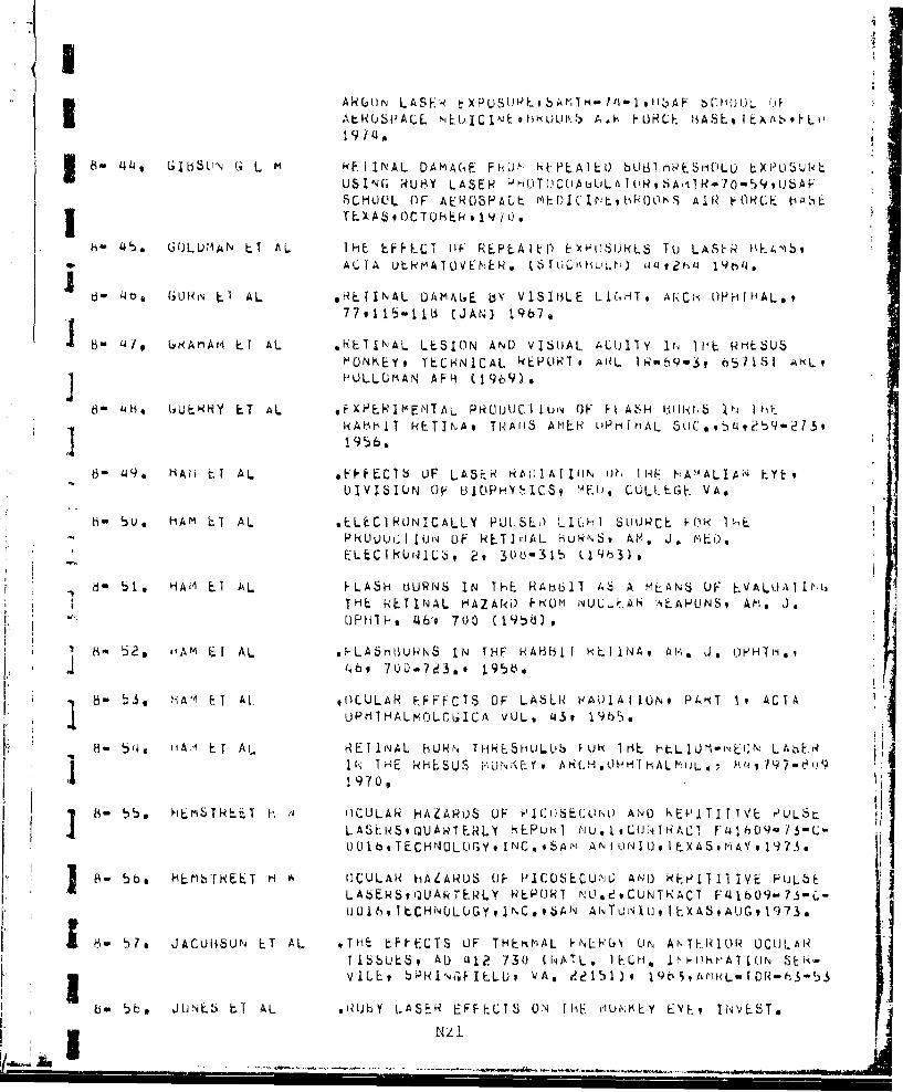
*AkG'11IN LASE F ~ XPUSUPE i b A r. - t I ' I I ',A F Z)Ch(UL)L fJ&3At.NUSvACL MEL,; I C INE flIA I Ai% ý1~C HJL. AS L I t,\ A,, L~ 0
U8- '44, 6105LIN 6. L m kI INAL DAAC4,E: Fk(ý NEPEAlELD bU[3lrlPESM(IlLL LXIL)5SUTLUSIN(, RUýY LASEN fP T)(~~'AI N ~lN7~,JA.SCHUL'L OF AEROSPACE Mý_D)ICIrlt, hPBOLIS AIR F0KCF. hg'ltzI ~~TEXA~SOCT0HEkN, 1'.ii
8- 45. GCJLUMAN Ll AL THE EF&ECT vP REPLA Iýf F~wýSUKLS Tko LASHR HEA'AblA IA UtH M AT 0VF :E kN (ki LKhU L. t;) a 4 9?4, id4 19014.
8- d 4ba 1.7UHN LA AL H L rINAL UAMALE biy V1SIOLE L1(,HTI AfACii OPH[HAL.,
6- 3 4 lo 68ArArl Ll AL *HLIINAL LESION AND VISUAL AClillY 1t IfE priESU.5MONKEY, TECHNICAL kEPUR'T. AL 1N-bqw3? 657181 AKLIJ HOLLUrIAN AF~l (1%969)
8" 46 G3ULHHY F-T AL F~XPERIMENITAL PkfUULJC IIUii OF Fi AS~H 1FA11iriHb 1ý 1RAHhIT kETINA, TRA'iS AMLH L'PrifMAL St]C..4. b9?3
1956.
6- 49* N Aii tI A L *Fý'EClb OF~ LASEN kAIt!ATJIIJN W, 114 F:A'AALlAi\J 0EPUlVISI1UN OF LlJPMFiS JME, COLLEGE. VA,
* 6- 5U, HAM 0l AL .LLECIRUNICALLY PUT SLO LIUmil StUUWCL HýR It-'EPRULU:I jUI~j OF NET] JAL HuWNSf, AM. J. V EO,
* ELLCflRUNIL, 29 300-31b tlj%3),
*8- t)I HAMl Ll AL FLASH OURNS IN THE. RAiohi AS A MLAN5 OF _V A LUATI 1 LTHE k-ET INAL HAZAki) PhUm i'ULLIF.Ak SE.APUNS, Amt J.OPHIHe '46'9 700 (19~58),
ý ' 2,, fI-.[ AL sýLA5HIIUHWS IN rHF HABBiI I HEI NA, AH. js QHHT~i,q
8-ý3 HAM Al. At CULAR EFFFC1S OF LAbLH HAt)1AI ON9 PfNT 19 ACTA
UPMTHALVMOL.OGICA VOL, 4131 I.Th$.
8-H 54, IAl ErT A L RETINAL hURN TiHRE5MULLIS ýUk 1ri ýtIEhL1Url'LjN' LASiERI 1~~~N THE RHEGSUS HiUNKECY 7HHI~H HA 60Q ~77-u
8-. y,, HLEiSTREET H OCULAR HAZARi)S UF PIC06ECOUMw AND) KEPUTIf t IVL PLLSL Utj ANSLR(aUANTFRLY 6%EPUK1 M'U.IvLUNM1NACI FL~hO9-7S3C(J01bvTECHNULUGYINC,,S~IIA~iUNOIXAA,17
Pk- 50m HL'brNEET H IOCULAR IIALARUS OF P.ICo~bCUNU AND4 REt'1II IVE FULbE.LAbE.Sqr~lAkTERLY REPORT NU.sdvCUNTKACI F'4 109- 73"C,-
Ho 5w7a JACOBSON ET AL ITHt ECtETS OF THEtd4AL FNLFIý'G UNt ANTERIOR OCUJLARTIbbUES, AU U12 730 (NATL. IELM, If"I-0hr~A7i(JN
I bm ~~~~VILE, bPRNICFIELUv V'AI e?~15flw CI)I93.
bwýeJUNLbi LT AL .1Ib .ASER EFFECTS ON THE clUi.-KEY EYE, INVEbT.
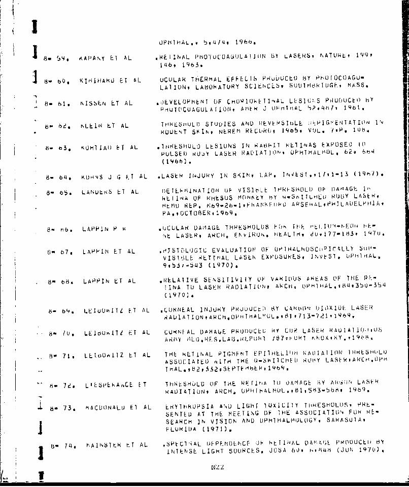
8-B 54, KAPANI' El AL HNEIINAL fPhO1UC0UUAL;JtIAjN BY LASEI.b, rATUkLt 199 9
14b, 1963,
8-boo K!IMHAkLJ ET AL UCULAR Tt1ERMAL EFFELIS PHUDOCLD Biy PMOO
LAlIUNq LABONATuRY SCjtlINCE5, 8UU1THt~kltUG~ MASS*
8- 610 KISLN ET AL 0.OVELUPMtNT OF CU~1U1-~ I lAL LI:SIUr--S PNUUUCt') hy
PUIOCUAGULAfIONt AMtk U~rithiAL .i?4ýi/v 19bi,
6- oc2, NLEIN4 hýT AL THýhL STuIJOES AND I PVý.RblbLE I;FHIGr-EN1 ATIO'jI%RUL)LNT 561NO NEREM REGURL, 1905# VOL., 70P, 106.
8- 133, KUH1 LAU I T AL .1 MqSHULD LES IUNS IN )gAt~l-I.T ýcAlINAS EXPOSEU 1 0P~ULSE1) kL~b' LASER qAi.IJAT I ON OPHMIALiAOL t 629 6b4'(1966)
8- b'4* KUHNS J G 0l AL .LASER 114JURY IN SKIN# LAP.,rEll11 1M)
a- 5 LANULr<b LT AL 1)ý,TENLklNAl r.ON OF 1I SIt-,L E ~1HRI-SiAOLI OF OI)IA'4GE. I-
kE. I j'4A OF RNt-jSUS MOrmEY hY Ww'wri ~t r ELu Rl(3y LASE lq
MtMU REP, ~;92- FA~uUAP5FhJAL.,PHjLALELPHH1AqPA, ,UCTOFRE~,19b9,
8- hb. LAPPIN P w sUCL'LAR V)AiIAGL THI4ESHOLUS FO ThF. HF-LM~'L)Nik
Nt LASER, ARCH. FNvjiNU'N HLALlriq eU,177-Ifi3t i'lu.e
8- 67. LAPHIN ET AL 'rq15T[.LUJGT.U LVALUATION" (F 0PlHALN05CtiPIC~LLY blit-
VISI.ýjLE RLTt"'AL LkSER EXPJUbKL~i , DVý51 UP11imAL,
99ý)ýi-543 (1970).
8- 68aH LAPPIN ET AL vNELAIIVE 5EN61TIV41Y OF VANIOUS 6HAS OF THE PE.-
IINA TO LASER RA01ATIU'Nt AIkCtio ('M1HAL.,493bQ-354
(1970)
8- b64 LEIltUvllTZ E.l AL .LUNN~EAL JNJUN(Y PNWUUUtl) OY LAR~L'LN b1.LXIUE: LASER
6- ?us LE100AITZ ET 4L LUIýNF AL. OAMAUjR PNUI)L'CLU iHA ClI) LAS~i? RAUI A]U!(,' .jb
ARMY IL E LA M.U1/7 UNK JOXIK Y * , I 9.
8- 7 1. LLIoU~~11Z ET AL Tt-U kLTINAL PIrGhFNT EFI~ftELllti-l RAL~lA1It(N lHNESHI'LO)
ASSL]CIA YEt 'i1 re- THE ts'J11CiI) UY LASE NARCriok)Pfl
64- '7ee L1 ESP~kAlCE. [ET TMhNE8JLU OF THE WFrir.~A !O LWMAGE IiY Aki~fl LASFR
RADIA11UN9 ARCH,~ UPflIhALMOLasb1 ,5H3-5689 14b').
8- 13, t1,ACUONALU ET AL tk`YlhkUPSIA ANLJ LIGhr IUXIL;IIY THRESMULI)S, PHL-5ENTE U AT THE MEET ING OF 1 HE ASSOCIAT1ION FUH PE"SEAIHCH IN VISION AND UPHIHALIIULOGY4 SARASUIA,
FLUHIL)A (1971),
8_ 14 ý S T AL ,SPýCl'iAL DF PFI'DLt\CF LiE H Ti NAL L4'ýArr;L PWODUCLI' HY
£ NTEKSE LIGHT SOUNOLES. JObA 6'Jv tii (JUN 1970),
lit,2

8 ~- 75a mAH~iANALL ti AL Hi S TULOGY (1F REI INAL LEST ueq,6b HOiR0iCP IJ ~Iri I-* ~~~~CHEL) LASEWE~vt;XP.EYE 5,,Q,(bj
he 7b MILE Ll AL .vVALUATIONl UP EYE HAZAHUS FkJlm NUCLEAk L)FTUNATOIONS, 1, * (.TIAL i;Ow- TL. (U) IE-CM. INCs SAN
ANTNJ~t~:O 1E.XA89 LIFE. SLIt NLLES 1)IV* 9 OV 1q969.
6 t- 77, MILLEN~ ET AL kFTINAL IýURFNS A~f) FLASHHL1N4L)'vi:ES, ýINAL HLPOR79IU 1,'T ACT F'41b09" b-(.2B39 VUL. , It NuV 64t fECHNU-
LO(Y INC.9 OUC AD 6971u?5.
6-~ 7tis ,,ILLLk E.1 AL NEIINAL BLJPN ThHLbflULQS fiN ?Jt"AhS.t INIýRImKEJH VON, CONTRAC r AF 4j (bOY)-b8-3-CoO23 V'ThUSAF SCHOOL OF AEROSPACE. Mt~)IC1NE# 19b~io
I 8 79s N~l:LL LT AL 'K.I IWvAL L'AIAAG;E B3Y L.IGHT LN RA ISINVEST *UPHThAL.1UL&&5(5)*450"q472, 1966.
I8- bO* NJ)UkUN E.T AL ,THL C;HARACILRISTICS Ul3 LXP1rilfEý'TAL L.ASLR CUAL4GU~LAIjok OF THL RETINA, ARCHl. LUH~hIH. 7e(L_4 ¶Y4'j'
13 01 kýI * ý-AU')Y L1 AL THkESHULU oAt;AGE FtcLM, CI.&3 LASEL~b5, A'.CH.UHOHTHlALM1L.L
ti 62s. HOb h IN RE5ARCH S TIJOY Ofr ThL Pk01U(C1 IUN UF RLTImAl. RUNNS.TECH, HLP, OASA-109. OFFE'%bE ATU'11C bSUPPORT
8o tb3o hUSt E I AL HLW-At ~-l C0IOKE.I IJNAL HkURF. ýh lrl AT 0.110 F.JH~riALLSv
lie 13 NULJ. IEN A IPHUTUCUAGUL A I ION THH('U(,H THE (~DAJjCON, rACT1GLAS6 I I * 9A'j APPAAI AUS US INC, A cýUASJ -CONT INU(JU6LASLN SoUNCE 9 ARCH ,(JPHTHAL.s, 79,9 b7ilwlbd33, v19~68
6-n 85@ rqL)UNI.)b 0 t. CFFLCTS OF LASEH RAUIAT IO(N ON (.ELL CIJLTUPFESt Fu.,PtNuc'92408116..1214 SUPPe 1iJ (19b5).
6-e~ 430a E kvL t 4L. INVEST IGA rrt1O'S OIF ()CIJLAR viALAHO) VIU,'i LASErýS If,HUMAN\ bU[AJbCTS. DEPT, OF O'tiriALMUOLUIY ANI) LAS~kLAHiUWAIDR1ES. UNIV. OF CTi\,LI\[4ATI, CIN.9 UH1ti,
8-s 61. 5A-NUL~b V E fPEbEA RUH N1 I HE: FYE EF. FE CT 6 (jF L. -t N41) 1 A 11 W14UANiENLY REPUHT W1,0 eqCOirNTRCI F~41jbO-73-C-('L'.7,
1ELHNULOGYvjNC.iSAN ANTUIKIU, EX459 ALJGU3TqI 97.i,.
8-~,~~ SET AL C HOHI OhýET I NA L L.ES IONSQ PH01) LICý ) IJY i-A,5 k ON 1iL1NKEYVAND mAr~bITSv AMEN. Ja UPHTHAL91 619230-24U (1966).
a- 96 SHELINE ET AL EF P CTS (I5 F H I ;H I 1qT NS IT NAD I ANT ENERY ON St\11"i.1..TVPE OF TNJURY AND 11S RUtATION tW Ei-4Ek('v )L-
LIVE.RY, KAIL, ARCH, PATH. (CH)AGO) ob,?b65-219
Ie 9() bO*STUCK Bi F CURNNýAL DAM'AUE THRESHOL05 '-.Ik LARii(VJ LJU)U.I1)L LAbEIK1RNOIAIOPNSENh)AT Itit Tt-iIHU MLE11N4; OF TILP
V~ ).('13

19-23 JUNvfl91729
i-9,ruiIfNL5 ET AL XLNUrN PHOIOC(AGLJLA10 (I 111 ý'P1LLUMACULAR
6U9. hNDL L ~I A EXPLH I ME 1-4 L $1I ')Y 9 ARCH. UP HfI HAL S 7,
I679-603 (`7)83- 92e VAS51IAU)ISETAL OCULAR( LASERF T4ESH('LL It'J\/L6TI(jATILIN3vF1NAL. kPUNI
ON CON I RACT Fa b09.70O-C-'1Wi( It 3~TANP C.;R() ESLAIRLH 11S1 ITuTE 01ENL0 P ARK 9 CALIF 0KN IA #JANO A Y 19q71.
83- 93a '/Ab.ILIADISEA AL R.St. AN LH 0h I CULA R L ASER I r~lit bLUS,5 CL"'T HA rT NO
F41hO9-bb-Cw')O41.*iAN'dLk0. KLStýARCH JN6TI TU1EvLNL.L
~1 PARK, CALIFOFNN3AgAUGUST91'9bY.
B- 9~4o AATLKE ET AL. okUby LASER PhiO7OCUAGUL.AI U1U LJF ThL rPAPILLUhIACLJLAHt1UNULt., AN EX~hfEILS1LJLJ' ARCH, OPHIHALM?,
8 t- 93. el 11L.L At, 6 L A L ,EXAMINATIONr. UF TI-E CUKPJbKA PuLLLUA.jIju.; t`XPUh~ký TOM I LHi: AAV L R AD IAT II)JNoA I IUbP ALE MEI) IC IINE pA PH IL. v 1)I1'J.
t3- 9b, 60LUAkSH'T E!T aL I4F I 1'qA*PA rh0L.UGY1 OF NEýi)YI-IUM Am~) kUL-'y LA$F-t oUki-4
6-" 97, ZAia h 11 OC UCLAR EXPOSUJRE 1U *S;11 CPLO LASLi RP~l'AFAL-Trb-6w-2779, AP 1966.
h_ -ý6 ZAWLýIi N UPHTHALMOLOGIZCAL EFFECrb kJ ITj-1EfNi Ll(;rif DýA-',bAL~1wbI.2j,~R~h~rATb~tS~iAIR FUhCF.' BASE,
Q)HlUf AVIONICS Lfw(JkAiURY, 196'4,
do 149, LANLJ k.1 AL. LASENR Pt0T0CU)AGULAT'I~i, UF THiE LYb., AM*A* AriL¶.
uPrlIHov 69997 (Jiv 19h3).
1 0 ZUmr I I-. r AL UGUL4H LEbli)O PHL)UUC[I) HY AN LIPTICAL Ak
8-0i /výEN LT' AL F-PHIE1LW~NIGt)P~YLAS~h KE~IIIAL. UAALGEq
6-u~s ZAN LT AL HJ.STOLL)LY L). HUMAN ULULAK LIJQt;L'LA IOJýNt AHcCH. I
--,13 .~- -- - -- -- ----- HEAT UAl1AGE TO THE HETINA IhY LA5Lt?<$ ANl)£ PHUTOCUAGULAT(1hS9 19Lt)tu OPIALMOLUGIZAI 151,
Am U1U4 T~ THE PNO1DUCI ION UF K AD IA II ON l' UkNS O1N I HE Hh I1i',AF -Ar IfHE THRE.SHULD LEVEL UF I)AMAG.ýý A LI 1EPAI Ukt
6SRLJVY ANDL TENTATIVE MATHEMATICAL TriHjIYs k,A.olI NbTI TLTE OF A V I AT IUN rlý1)IC INE t ilkPOP1 NO . F Hl'C/
1424
CATEGLuNY -9 - MELANIN (6kANULE PFC
9- 1~ CLJI.)LAN 0. AL. A HISTUL.UGI.c COPIPAR150hi UP Tn rl.iiUMM.l ANIL) RtiLýUSNOfNKEY kETINAS ANA) I 1ý [6ýELA I UN TU LASEHi'HU FICUA6.UL Al Ii)N9 USAF SCHOOL LIF iCFdSPACEMEDLBAN~tAEHUSPACE I-',ELJILAL U)IY. CAFC kkOUK8 AI~q?-KLtrI 6AS~ TEXAS* bAfi-Tk.)
9in ea UAkIN"ALL. H J A VI-5UAL PI(U-1ENTS 11i' PHOTflRECV'p7Us . iti ihE. Ey.(tt)AVS)Nt E'J.),)vO)L.2,bLý-5t3.SALALýhiJC P~io*65,NjEv VoRKANU LLUNDUN,1q9b2@
9- 3. I)IUCHMANS P tIE.LANIIN 6,NANULES* HIMF-l &IN 3 tiUGTlJkEt FGjkPAt ri NAND) I)EGfRAOATiON IN (-,IiIktiAL 4NI) P4~1OULO0,1CAL I9ji
9- ~4 t0U,Hr01ANS P TmE P- Ig- SlkUCTUjRL UI- rsLANjI 4 GkA.1'1ES, 1 -t1)c
I(UfqE ANO CO'.)TrdJL UP ) HE tMkLAt,[CY TLUG.I)LLA POK(ANLJ.MUHLE.NBRIOCK, ELtS,) SIXTH IflEikNATILUNAL. PIG'Th'N1CELLCNF .NE95 LN lLrGN yr,
9- ' O.i)NLHOAN$ PJ LLI NASIRiC1 URE OF MLLAhi±q ,~sNULLS ' IN - 40AiV4NCL3
IN is11.LOGY LIP [email protected]~,,t. PT;h.TtYSY1s-MUNTAL;NA 6 F, HO U. ,K-7,)XN)H-jI(Au
9- ba FEE.NLY ET AL S1uL)IFS ON~ HUMAN OCULAR Plý,1EflTIN a EYE STRICICLNk..
fTAULR-VPENLAG, 1965,
9- 7m FR~AN'C01b ET AL ELECi kUN M11CRUSCUP I" imSEkVAT 11NS ilm CHUOtJIIU Pli,-
'E-N i LPI1 ?ELIU?1 AND) PECJF0~ Ut' YHE oEvELtiP11i LHICr6IN tiE LAT I N TO ME LAN 1 N SY,, rhE-6I S uP~iH IHJLiHLuO I CA
9- be rlANýr'N ý-T AL OMELAbliN G'kANULE 'ML)LEL6 F014 HUL3iH-f I ASF-k 1I'4fUC~ju,t'JJINAL l"IJUIkYv VOL. 7v NO,* 19APPLliI) OPIVIC. 1,~51z
9.' Y 9, IU' ENk LT AL M*ELANUL;ENESIS* L'LTRA6 TJLCT NL,.. rilýT(OCnEMICAL D(, F-VAT IONS ON JL TRAV IHL.F JRRNAOIATF~j HIJr-AAJ r4;ýLA\NSUCY li:IN VL.Sl) ENN . 51,13we2j 1, 1970.,
= 9- 10. tl(yt F il EVELOPMý.141 9 STRUC I u'iL A r O Fl mL Tc I L)N L h~ )E K NLILm I.N[ P II H EL I iM t I N [1EHE. TINA(C;TRAATSMA FET ALt
EL)5s)t1s3ONLtGENTS UP UCtLO0i AAýGELESCAL,v,1%9.
9.m 11 M 0Y L V F H ELECTNON fIICROSCLPIC W3it SE VATIU'4m- Li- THE. N~.,0.VLlUtMENIj & GEIE I IC CUNIHI~)L (JF MFL AIJIN G'''LIN THE mOUtSE EYE. hI t, 'O ~ F1 ~EF S
LSER't t1, b9-'486j,ACAOE-';lC rSE';YH1b.
9- 12 Pt)IILR Ef AL SfUD1L$ ON THE E.NOUPLAbfijC ý-TiCULLri* V. ITS Fllkw
W' 25

A;iJLiJ )I FF L R f:,- 4 T I N 11f k rIv;F ,j I EPM-Ti.L1AL CFL.5L
L)F THEL FRU(., iE f INA, t j H10ý'flYZb Pi(rr Y 1 'iL.
1 3* ýEi~kUYNS M STUM) UF THE. ULTRASTI'uCl Uk1. (IF 1 ? Nf. 1 !I W tL E PIIl b ~1-LiUM bY NL.ANS OF THE. ELECI-rUPIL tUbPA~.J
.19v 1'4, SLIJI &T AL. CmLMXCAL CUMI0L)SI1 lN & TEXý,INCLOLGY C'1 SPEI'~ALl t.-UkjAiELLLS(MFLANCJbUý"ý5 A1,1j MELAN IN (vA%01-L5J I"
mMAMALIAIN EAUY~,N!~L~)
9- 15. 5LIJZ t.T AL. SU15CLLLULAR LOCALIZAlIUN OF MELAlN~r MlCSYN'IHLS516ANqN.NY *AC A), SCI. * 10 # 49 /-b33. l9t),.
9- leis bPl 11Z,4AS M .rH ULNbS& NATURý (F 1i. P IGMENT GRANU LES iN
TriL ADULT HU~iAN RETIPJAL PIGMEN.T ITEUI,.Lt
9- 17 1 A AKLU ChI h iiUKH1ULUGICAL STUDL)- . $ (IF I -tL P I Gr'tiT GIRANOL LS (IF-1Ht IRETImA HY THE t.LLCMiNU\'11CWUSLOPý9,JAH. J, *~
4- 1b., rANIGULF1 Y OIJLIRA81RUCTURE UF PIL;mEh~T (jAf4UL.tb UF R&.TINAL
ýiPITFILJLWM * 109CO0' 15 *v Ai!Lk J, * UPhjHILMUL. AIjv
9- 199 L~1~~ LI AL r.LkC1l?UN' 'I1CROSCOPIL; 3TU1fl1.S QN TriF 5Ul<CELLIJLAHWR.jNIL4' AN~D ULTRA5TkUCtLPL~. O'F '1H1..AMjN t~,ANULtb IN
M.AMMALIAN MLELAN4UHASAIý.i-ieY.ALAU.ý3C~I,Y.)()95i4H.ýbbU
9-2 , i.ýLLL1NLS P-1 AL F LLCT KQN MIC:RLSC0IV (IF HW'lIAN MAI- IGNANT #J ,NAT.
q- 2?1 a AL~LLIN~iS F-T AL ivf)LE OF 601LGi APPARAT Uo 1, IN FH ORm AT IQN LUý MLL11.NIN LPkANLI.F 5 IN HUMAN M 1L I UNA,1 rLAI'JUMA Jý,JAL I RA-
N2 6

CA1LtLJIY I U r1CALL ANL 0LIS
0- 1 o ALPtI4. Ul AL. f LC Tb U rij; I G 14tLJS I I Y R A I IA1AN7 ý-rWF.NiY 0 NJ SKII'klit UIJANT ITATIVE UE-PkiL,,LE uFW TiSSuE ir':Juky (Jrj
UIJNA11UN QII EXPU$UPI~E9 A PCh AliH (CriLCAGOfl 'S5i
0- 2, DAF)N El1 AL LIbfliT býf4~ J J1 IN r4ILJL.0I,.IC bY.51-,ýb
PHUTIOTUXICI.TY ANLI eHuT('ALlLE'i;y WILLATEL) Iu V151t~ll-ý
0- 'S tLANCt-iANU ET AL, A LAbL CIF ACC IOLNTAI AL MAULAkN FHOTUCL1A6LJLA1(ION tA IOW 4i* OLUm H~ F. * lU I('YN4V11C ACTION' AlNuU ubt'%t~i CAJSLU) vY LIl''1,l
0- 5 ORCt~i'4' AL pXE.LAT IUiI OF I HRE.SHOLI) Ck I I L q I (), TU T 'iý FUi,4, I LINAl.H~E LLPI 0S uF I HE. EYE J .OPT. blIC . AI,'Lfq, I Lf 9 %-
0- h, t4RUMA M 3 MLLIANlSrl Fo,4 E1\'EkG.Y IkAi4SI-te~r hEl vý(-IN A ýHCLIS5kA)LASER 1AM ANI) A lKI`,A8PAkLNl NI ~LUI` 1NVJLV ING
LLLC[RI)4AbtjL~TlC FI]ELL) GRuLqb(~iEL!E AT T I i.
Ar'LR1LAt KASHINGTU~, O.C,)APIkIL I-it VIt0 (v-Fp IS).
0- i. tUETTNLR r, skFW- OF ExTRLME HEAT 00-) CULJUi U'r- 1iiJfiAN- SK -!
11 l, -1ILt N.iEI GAL AN ALYSI 5~ 18; 1FIL.07 (. XPER I tlý,'I S U!ýPLvImRNAri4G FL-ASH RAI)1A1IIs,;, LFf FCfý99 Js AP~Fh1YS1UL % 'j207U2t (1'nS).
0-m 8A b sL t-I I N E F. T A~ E YE. h a ZLA m ) F H 0JM A N A r 0 fL I~dh C Sý N ri i5 A V 1 '6 k~ t V
239 1.
-~L ~ATI~~EuEA ij k) 3-~49. LAUKIiALIE1 J H PAIlrNIAL LFFI-CTS GI LSE r<4A I Iu"A~j l jrSC
0w O~LUiNIET I 6N L A .iit( tY A/. A R ) E VA L.UA T IUd .AN I)I A L A ri IRk1(1HIN LK.
Jiw11 LAMPHLLL F Il THE. Ur.PT h OF F IFL 1) (F I hE h0U"'Av CY ý., UPT ICA AC I A,
0- Ids. CAIMlH6LL LT AL THE. OPTICAL HAE A5 A 1,hE.INIAL Ct)AGUIATuN4i Ai'i4 ~~tV AL.UAfONt TRNANJS AMER AC Al UPH TH ioL )T LILArkYl1 l;
671$8-67 (JAN-FEB~) 19t63.
0- 13, LA~i~iL ET AL_ G6EI'4EHiqAl0, 01- ACLUU I IC SlujALýS I L jtAJID~i IN KkWY..
3 FlNYS, L~fTTEqS9M ow, 95*9/U )'- lAt<LH
ow 1'!, H HAIN L.T AL I. 1(iH I C(JALLLAT JUN ANIU IN fIP 'A UCLIL A k MAtA. 161\1A N T3 N 27

11 MO 8I 4 F AN Ep1ý"JI IA L 5 ftuLGý y ALIA i)P I HLil1~E 0 1 C AL CU0LýL. OF V A R NC i1 OuU 14 t~AKCMt , q
I0- 15, CLAkNE LT AL *L4SEN t.FFECTS ON rtit F~h AtýLhs ENvIRNur, Mt-ALIHI189 424-oe7
0- 10a G004~AN ET AL LA5S.RS ThElk TLCMNILAL, IltuLU'ý1C AwJ Alk FUWCLIj ~IMPLICAT IONS, SAr'wAMR3-1,d.
0- 1lit CQLh'KIVLY L. S o.CL)I'tRWS i OUI1 F.U TO~A~\ 1. ACtULIS) C LNL-kL iYj n~Y SUHFACE HEATING, J, AfC1UO O. 6 ,q VUL./40 9 11460
() 186 Cj;Ilvq LIi T AL 1%EFLtLIED LASER. I3LAM LALUS1itý A(.C11UP:NIAL t6URN Uý
IU- 19. UANIELS F J IN~ TORi~APLUTIC bLECT-LC11Y A'JL) ULLINAVIOLETtRA01ATt.,NF S,H, LICril, LO. CrAYý-HLY PN~t,5SjJ dALI 1M1JkE, 196b7)o Hid, 3s7?4u~,t
o- 2o, UAVIE6 ET1 AL PRUCLtlNU. 5 OF T~t- U.,'), ANIIY NATILK LAH FLAS.%HHLINMI)UEs SymiPOSjUl,v ARMEDýUNLS.j UAPESEARLH COUJNCIL CU,-1 ý LIN V13SQ)'q, AU o91793( NATL, TELH, INFOHMAI ION SýRv ICE# * HI'GF LLU,
I - e 1 A V bULN H I h L t.YH h 92 i ) E D, 9V L, 1, A 4i~C A U .S
YjH K IH 8Y. 1 '19 69.)
0 - ;)AV5iIJN Hi TFIL tYtC,~i"u Ff. VJLI.,S, ALApj',IN1. i ERSS, i*Ok yop,
0-o e3s Q~kk iý f AL P qL Ai)ILAL 0CC0iRWFqUE i f14 611EL. A!bER- I RAL)A f EU
t-AIULUw;iCAL M1AT ý. IALS, 9 P .) HHUC , 2'.4,S 99- 1U:.1 s UH-P.
0- (ig40 UUr(L-ýLGjEP S T.xTbiooK UF UPHIHALMOLOUYIY VOL. Tv19S i 'O~l * '41
VUL.6hi 19499 ST. LUIJJSt li' C,,v, MO)$HY COMPHANY,
I0- 2a. 0outm F 4PHYS1CAL rIFCHANISmS OF I Hý AC rilj 1W' IN.1JENhEI.111 R A,5LJr'NU ON TI9SSUE, At~I , O, F PHriYItAL flt1). 9
10- 2osECCLE6 ET AL ýXPHIIENTAL PHUIU-HEI.1k il.'j ý11) J, AUSTNM14.A t
) 0- P?17 EL r'A($E ET A6. .J, UP'T6 30C, AMS, VU)Lsh~t P,PU59 1473
w0- 2o. ENUCH ET AL lPhYtijCAL ANDJ UPTICAkL LHANUFS~ 11\ iLXC1SE') RLT1,'ALI ~~IlbSUEi INLs. PH~mtr' VULm 5) P, F½' 0 -U21
J2y. ELvNEI 1 0 NýiCHE THIWSHULD DISI 7ANCE S ~UH RLTIJNAL ij1-RN,9 J-Koii U'
YTIELI) l4LCLE: AN I'L i 1 ONS#* SCHHIIL HF 4L OSI- ' ALEME-)1CIrj~, AEiý[)SPACL 11lh)ICAL. UiVISIUrNA dC3 dIULiK8 AIR F-jriCL bASEv , 1XA,'i.
own 30, FVAK1HAUiF.iH E. AL rmE i HuUb OF PHflT (ICOA(;ULA I 1W\4~ I ?HOLu1,ri I IiL (WLI)mAfNl,
14 28

jCON TAC I GLASS,9 M 0U %11, ' IrAL A, L t dor!7? ,1 9 o
0- 310 FAtU<EN ET AL THE ýEýECT OF THRkESHOLDj MACULAN LLS1ANllS AND 5011T HIRN briO()L D 1,A LU LAKH EXAP (1S8E Li lNý V1 S'1)A L A C I I INyI-
T I- HE. H h ESUS6 MO0N KE Y, bOOllim 1 T I ý i L) F i LN Iu CA IO0N I rlfl-L JOURNAL oF AMERICAN I'OýUSTRIAL HY(;IENF.AS6LUCLAIIUN, 1969,
0- 34!, FANNERý L f AL v ISUAL ACUIIT Y iN MOINKEYS,6 VjbjiJHr KLES., 79,1 (AS
0- 33. F INt. Lt AL tHI UL UG I CAL EF F EC1S OF L ASýtK k A UI AI IU0vI\ N A1) V ARI,:,LLS5IN bIOLOGICAL AND) 14EICAL PHYI~bCS, VOL0 30, PP,1'4Y-eab, NFW YORK; ACAD)EMIC PxLESS, 1~cSý.
Q- 3M. PINt. tl AL hIAZAhUSb ý PROTECTIVE UtVLtCES AbsUCIAIlI) ',-l TriI vu. hp-U N A U A 1 0N P R QC . 2) Q Tw ANU A L C ()f EN E UF- N U j' N FP4u
TN MtEOJCINE ANI) uILS,(INMSAIU~ISJLiv.
0 - 35, k INt. ET AL li1NTLRALflu"'l 1-w LASEN RAOjA1li- lt11 h FAIULMIULALSYSTEMS. it ' SfIUt.S ONIIrtU[uN L41H SSUES.FEO PROC. ?119 ~35wi45y SOH, 1L4 (19t)5),
0Q 3f), F I ',- E I A L, LASER IRNA I ATIL 1 OP '' IO-LO(I4IALSYT'S IFLt-
U- £7, I- Nt Er AL ANDC HUMO1 UP 819Ur .ýZ~
;-'ANA6EMEN I OF ACCIt)L'fl S Pk.J(' &ýO U.k N' 'L
LASER [fECHNULUNY , ILL. INST1l DIE OF I ECh. Gh] CAWi1,ILL.' APR,, 1965,
Ow 300 rI'L E. I A L "lULLLN00 I E-LL AND 1 rt (-1l'AILE upllIIU H-fNAr'FK LYMN :~~~~ AL THE kIOM kFINA* AN tLLL 1U: IGUCUI SLYI
J, A'JSTNALTA, ?,UUO.
0 R Et_,4At', T AL AN LVALOAlIIDN OF THE kRubY LASE'A5AREIA
o- "I * AYt)ON A C; CLOURLj SEI\4SAlIONS P<OUIJUCLI' IoY ULIdAyIOLET u.Jrwht
us- U /J2. ILENHALTS W .1 IN LAtLL< EYE- EFFECTS, ýi'4 . bPL?'uI'-i;9 Lost A)ýYI'F ONCES - ýA TIWUMAL RESE ANCrI CuLr-C IL. CUr`,`ii FEUVISj()oN Al) 667-i494 (NAIL, IlLM4nr, 1NFMA1IL)NjSEltVICE, SPHINGFIELL~t VA, ?2s515) 1968.
0- 14. U 2EEKLNATS LT AL .ENLYM-L ACTIVITY IN Itr, CtI1GUOLAlE-O HKlI1qAV A MEANSIOF STUDY IN TU7HEHPAIL (11 D iUC I [U(iN AS A f UNC IO I 1 jF
E AxPusN U j 5Ui IIm E A C I A (PHIT HA L,. K(Ih t MriA Vi N Pt~' *.7btU11 1493 (I9bA)
3 01- 44, O,(LL;MArI t- HJENA TI-IL D I'; IC [' ANIF LbJ A I I UN,\S uF ASF~r N A' IjIA r IOU,FED PRO 0C ,* / ?"S 9?- b L) PUP. 14 1
Lw. hslN29

10- Qb, GOUpAN El At. LAhS14 RADIATION Uý NALIG'1&CY IN ihgCtCFk
0 - 4 m (jlj ')LV ýf AL H E P MUT Q6LEN IT IV jTY OF VISUAL P HIJ PLtE SUL W IONLIS k.0- ~ GUU~LV F AL IkE. CUTOP IC SENSI T lViiY Uý lhE. ýYti I' TiQF IJL f-4-
1 - 47, *lukUU, F.1 AL I 1i. I`Aý)ElýNNtl TYPE. UF AfPLIF lLhi FV4ENUENCY
bTAN~UAfRL, A'I1) 5PELikUWETE1(f PHfl34 ktV.#YCJIP2&-7d4.
0J O"6 Llt, UHNAY L b sCOrVERSI:.A OFý ECECI 7kJNhGNFEI i TO ACijUb I ii
HiY WhLtýACL. hEAT IN69 TH t JULikN'AL QF I HF ACOUb IL CAL
SOCIETY UF AMERICAVUL..1Oo A0U.69 .313~1b
0 - 49, (,NAtAM ET AL VI510O" AND VISUAL F'LKCEF`Tu1u4 VlLtY AiND SU'%S.
0- bO, * ~LrF ~ I L T A L LIG~HT AN() E LE.C I RN Ml IJ\U8L(>1( IC Ill5E.,VA1 IOWS Ili~ A
bU1tqld CIAL CORNEAL j)Ybl[RLJýhHY* H.'iAA13LE FAH RiLY 6I
0- b~ 1 , LGULI'r<Y Ef AL v~rU70C0( 9'JC L&T ION OF) riý k 1t]I jA* klE.fi14 jR ý.U ASUCCE5SFULLY INE ATL FL' ASF OF ANLiIW&'A VOS I 6 kETjf\-AEoAils J, OPrITh,, 469,i4b3*9 19bls
u- bee rMAMv E AL oFLA8Ht6URNS IN~ THEI kAOFA1 ?ýTNhT ~ oim , J. ndrliH*,
0- 5.~. -,Am L A L w0LULAR EFlFLC IS OFr L4bLR k AlL A I 10',4 PA~il It, OA5
b- 50 HA V f AL. ouULfiHAARS kW L AiFN týAt.l Al 11.lI~~o SYMPOS1L)H UjiT ht PHYSI)LI)GICAL Ai\[1 11 IIOLJ' L AL A,`Pl)ETS 0; LASLtR
NAL)IATIL10:,1 1 APRIL 1'1ýds9 (J'I ICAL SOC A *,",
j~r I~ iiA Lr AL U N ICLHAEN (Lh 10 1ý AC l' Ll UHT ) )A NlULU 1.
SI.P P L. 7 h ok c 19 h 3
j0- 5L. LA Ii AL T1lmLt4 T HýF OR t SP-F C:I AL bUOLsUvMI I I F. E Li
JHAI)IAT1 ' NI ,JUINT C01-1- IIFE 0j', ATONIC ENEW;Y9C~~k'GkLSSob UPTH NI [LLO 8`1 ATI'S GMI1 , -'W1N I I~i'
1f4CE~PH, ?u6w24J99 l\ASHINLVl W-09 0~.(:,
0u- 5 7. V~.~. T AL THE. bYNEGSI ;isiic L+c O LA,;tA HAOIA1 IONAND) IUNIZ~i\,G kAD1AiI 111' N I.ALIG;MAb411 I U-".kS INiVIV AND 1N VITHNO. AMEP. J, rU.tuizlqT6l'. 9cfot4f4l)-iiI9
0- ýdp MI-.LAI E AL AýNA IWICAL AN)) H16IUCmEM ILAL CHAV6E INS 5 K11` AFf k
j IG F ~~LA6L-R IRWAL)IATIIJn. FE1'. PrCySl39i lPlP 14.
3 - b~ vE) 'ESlI AL * ".k--bF NIF 11N'j IFkSLCI1UNLItN tL U 11- U II H~I)L.~ tjSCH ICENL,1 ""b A'WLJIE U10% i JIEi t:.INFLL1SS
NL 3 0

AUý 1; 4 G S rie-M ARCH, f- * AII(dLrI'riL1L tr, 63, 1 IS 41~ J
j19 u ýj
006d hit C L El AL I riL 1 HU.RMAL-CLHMI CAL b)AfrAAL 111 ~IJGC AL iA IL IALJ L~t LAbES IRRAI)IAT1UNg lEtE- fkANS, (3i-vILU, .N179 3#220 (1970)
Jo- 61. 1kVINI. LT AL *1.CAHQ2Sq VUL,'it P.324t 196A.
0-. h?, J ACu63SJN Hi bIF I-O L4. l EiiERAL ELNGNV OJil, idti J AL F1r' tLTOIN *tQ.Tt~~b?'~6h'~3THAHRUS['AUL rltDCAL. H1 .F.Ak.CH LOAUN.
*1 i~~~~~~UhiILSVALtHUSPACL hiL-UJAL UVSrN1~T1l~IAIK K.JCL 6A6EvOH1(JtAtI(;U~fI'40,?
J -O. s t JAKUS M A FUIHERl~ 06SFIVATIGNS UN 1 HL S IIR I NCTUkNE OF~ 1 -
0- 0 * JUNe. H C ON 1 HL Tm~LORY OF TriE 0IREL,1 IUNAL, PAlTTLFN-S iWýCON Ili lJOUS SIJUILF. I) S~kBINIhi'fNS (11 A PLAflL
Ow ý* JULS~ LTI AL, LAbERN 'A)I A I UN Eý) - t C IS I w\ 1HE "O PHOL(H." A'l()ýUNC1IJON Uý t3CULAK I ISbilEv bLC0NU) 4.i"o'UL rNLP,
u- 006 JU'\4L5 ETI AL ON I HL 1NFLULNCE. OF I HE RU10' i kj ~fl ktuE- Nt.1 0NA \
ilIL VISUAL. ACUITY9 J. QPT. SOL;, Af. 37t ell/(149 14 7 ).
0- b7 .JU~i]L. Hl AL *Pt) J, PHICLANULAý II Y AIXO) L1(A I jv4I') SoMUECHAHACIRUISIICS CmF IHý VjbUAl, SYSlET W iU~A>CIr-i IrE EVALUAT1uN UF L ?AIN±I4ý6, ANI) GNANU1_AH1T~~t
JULIHNAI. OF OPTICAL. ýUCil-iY UF jamFICA, VOL, 379Nut 4U9 t APRIL, 194~7,
U- ~ K [i, H-UhAI, L I AL LASEN hAOI)ATION AS A CL U'LLAL. khJL IN LANCENkIIILNAPY, FEi), PH .9L~t4tbI.)91bU, 6L)Pt's 141 19(,5)
b 9 KsI'WtSLAKL R APHLI-kO 0PTICS ANO U),'[CAL kiN IjVOL. IvoPAKI It CHAP, 13 (KAt)Uh _RY ty F. E-, NIC(.VhIdi)fACAULMiC PNR.S57 NEq YUHI\ (19h7),
- -70*iLLIN Li1 AL j N eNALl biN UF LASER~ KAUAI)IAT vk)4 iii 0 IfOLoC;I
SYTm$ 1U.,-1.'.I9, SUPP. 1WSJH~ (19tPý(Le).
0- 11 . K'Ll. J1i El AL. q IN I EACT I N OF L-ASEN RAL) j fA I iw (4 10OL G IC3Y51ýiS.Ib, 1* ,5tUDIL-5 ON ojIJ1.kJUICAL- SY',jjF~iS I Nv'ilhUt FLU, PROC. 2418wIU(-11ul 19660
0 - '12. -UkA13AA ET AL HRA 1NAL T)AHL6E BY VSIsHLr: L ~1;1i* A,' tLt:C1IILI M 1-
1CNU5LUPIC STUI)Y9 ARCH UPIITHAL '79,b94-713 WA!,4) 19(iji.
0- 13a LAOPN Y ElI AL THL PAI HOL.OGY IJF LASkrH HAIIA I JON OF: Tý-t S, LN ANROHOU7v .A4LL UP 11E MWtJbLo AfMltH* J. PATH., 947v 643-boll
j ( lbb)* N3 31
La ýi-

0. /14 LE:ACH vA pi tjI UlLLIG1CA L ASP LCTS VFr I'LIP l~AV ILILET I-.A UI)A I I ON A i(L-
Nj '41 1' HF /A L)f) p /o E ji-. 0 U o * V W H L. I C I, A L I H
I* 1: 0 1i.,'k1:A U OF KAUI) ILOUL, AL I'L:AL I H, W1CK`V ILL-EvM-A?,YLAN09 SEPT. 1970.)
0-~ 75* LENGYLL 0 A Jr ItsltUOUL [IUoi TO LASLH PhiYbILSi NFvN YONK9 JOtW'
NILEY AND 8UNS, 19 6 Y.
01 '1n the 1_1 MAN W .. Ja OP I . SLOr AM, VUL (-,I 5i',d 297 1
Io-' 7/"1. t.ACrLE'N 0 AL LASLH F'.'CLJ) 7(4I) &9 (1971)9
o - 78. AArINAN T H STINMLILATEI) hPTICAL HAUlATIOUN t'N JUlY . ATUI<E J~ii
0-. 79. HAUNSTEK N~ A I)EbTiIUCfIVF L.iGHT ALUAPTA1IIN9 Ahl'O. UPHTr1AL.929Q4'
1 (197 U).
0 -* 0 U a MAKAL.IjU El AL LýI' F C S OF LASERS ON lobE HWIhAI EYF , JUok. JLv t s
40- b 1 MAOuELOAUNm F kL. PLKIPrft-AL VISUAL ACUITY, A". J, 3~itA..~i 0q,
581 (1947),
0 - 62. MCGUFF P E C()rH~ARA lVE '-FFELrS OF LASý?4 A'O1j/ui,, J1U.1/1" R'L.AI.'j-
.4A I IO U N 114L X P N I ML NTI AL M A L I I.NAT -\ ~I'.I(I %. J 1h Ný PU'ý 7
Ul S6 N~LP G 1ST 11 C I U rth iýC I L) AL E.Fý t C T 0 C LW I4 -F) L A
IAINL' IONIZING kAVIAT1ON1,@ Alm,%, t',IOt -)TCAL L -15tlC~ ~~5 0O ER.cIIS Is U N rAS, ' Iju'* I hr
U-. 63,~ NICNELLN K LT AL vt-.LLCIKIUK1IiiI)GIAPfiY AF1tH 1Lildil LUAt;LILAUUJUN, A0.c
oIPo fHAL,v CKOhENhA VI) S'JPPL * 7b, 91001l (1 9b&)o
00 oi b'I. LNIOLLSON FT Al- 3TUD~l OF BI(JLL1(UCALL YII'* I \I ,I F I C A"I FUNCES FUJLLU,"
IN6U L.AbEk 1W,4AUI)A1tjIO'j FI. PIHUC. , 511 5
IIH.1J (1965),
1 - bse ý-LYLk ET AL WIUT CUA(.jIJLAT iu(. t r * LQUUIb THE ;V , itflSIAY r_01`-3 IAlsY, 1960.
0- ob' 5~.[ MLI-EM N U 1,os 111YvF AFT EHI 1AI;E AS A t3 ACI'. ,HUL1NI LNIJ!NAi"C1`
J, OFT * SUC, AM,99 bo !bbtlb6-Ut 1966.
0- 67. o IMLLEk N ý P051TITVE AFTERIMA FGE FI- LLLI~h. Ir.,3kjlE F IiI.im 1"! nS iTY
J FLA~~~~flL~~, 1 OPT * SL)(,AN, 01sp MS-8u,9b'
0- 3L a IILE N 0V IZ)IAL NH COVFRIY FRUNOM Il-h1t EýIPSUKIF S OF HIG;H Ult!--
3IrNANCLe J. (WI. SLIC. AlMt ýý* ~1.61-60t 1961
U- 69. rILLEiH N' U VISUAL_ KLCOVENY F:l" H I H I NTIENS I IY F LASiIF ')
ANNUAL PHASEý REt'UH 1,9 USAF LUkjf I RA C I Af U~ I ( W9) -,ueb9
I .JuLY 1465.
*ý MI I TN A AL k) N LUL Y Sý 1S N 1 H1 L ASE h I? NýiYC ri E i) [IT m (3 ~TI:bYt m 41t4kL_ (LCJNI0)IW)q,;)V791 i4k ( 19f5) *
I- 9 1 f ilfitL$ ý. AL POU.ER AND EFFJCINC FNlY OF A t..uj' II Njt1US1 I-F LIlEM IrAL
16

L A 5L14 1 FEF J(IIUN A L LiF I) A N Ij.)' F-LELLT ON I C WE -7 v "
um 9t?. 1NL.VqLL F wN 11NiUUýTHIAL A~if) TRAlUhAfC U~r11hAL`-WLL)6Y, A,rlKrEI\YLT AL,q F-05. (CVg MUS11Y C.UnFANY9 SAlIqT 1.0UU89
Ow 93m. 1 NU R Tut E.T A L F L U W tiC I N ý L UN DU 5 Pt HI I L fc'w!,P HY 4: k\ AIL) 1tv I hFUIFFLRENE 417AL DI ACGN~bl5 OF PW.~i ERU OCu~UCLAR LEýS-
1LJI'.q hIANS ANER. ACAL'. U~hHIlHAL 011 ULAHY 0,,U90V055-
00O 914 PALNLHI LI AL a*J OPT. SOC. AH~,v VUL~on'4 V*I107s 11?471
0- 5, A~~f~ J1 ')lt)$.ASES UP THE EVE.. 11ACMILLAN C0'.9 10TH~ Elu.
u- 9Jt, PhE AULK G, W SPOT SIZE ANDt BjEAM PAivAhIEK1ES Li IN hliNUItr - IAL (hfuliLAb~k bEAPIS, 08 ARIY 'EUy L .L5NEN1 774 FL'tx
KNU~qKENTLlCI4Y919Ibk.
u- 97, PUNI)EH E MLOI) C L PIIY SICSt \((L. I * 391. L0. (, G l-Ab3EN 194S
- ~~~~(LhICAGiO, THE VE.ARBOU(K ~'HIMNINC.
0- 146 R8 A I HK LY A b ALC1IVENTAL LASEK 6(ikN OF Tlk- 'AClJLAA8HCH,()PHTl,AL.,9
ow 99, rl TE Y F. U 1-HLUICiIH' 1 ( i, F E'rF SAFFE SVPArIAI Y(. l tl t) i9 AN~LE-, fhL-SE: rTt L) AT tA(;AD Syt PU0510(1 UNý L''65 OF V lb] (IN INUA-
HIGH IN'f NS [I L]GthI t PAPI.?I IhALEv MARCHi 196t..
0-1kioll11E t U L I hL b$Ufq 5 RE 1 lejA4-hNRNI Nk VOIAL IN SPACE. e PRE 1 ED
AT THE~ SPACE Hml)1CAL SYriiF'Oblb-i OF I H F L L F. v h\1 'III
SNI ENMAT TONAL ASl)I HUliAt) I IF L C.LjtIGkE5SvSl LjC~lHULMv
AUG.o 15.20. 1960.
I ki I RUS'iN H JC ET At.. CUNNE NI PROHLEMS IN, LASýR ll1CliC.PHUflF- ANALY51ýb.FLU, :u.~S2-ih Uh 14 (lqlt~)v
* .O lU,) litJULNI)b ET AL L AStk h'AL)iA~j OF IJH T ISbL'r. C'JL iLjRL , ANNJ, N.*Y * [email protected]?19 AkTo j?
0-1 03o 140LNL) E.7 AL THE F'UIENTTATION OF 1.AMIIA kHAUIATI(U,\ "1 IH bhiFriGYFIRUM A RUBY LASER, S5AM-TR-tb~-iil JUNlk 19fY3.
00 101 04, SALLMANN 11 T HE ANATOMY AND H j I o. LUY I.Q- THE liU-1AN LYP.IALLO
(UNIV. OF CHICAGO PRE5S, CF'lLAb,)q 1912)9 ~~1b?
OmAU'J. 5C;HA-1LOý ET AL INFRAHEI) AND OPTIL'AL MA5Ei-(b PlIY,, NEýV.yl2q 19140-49 (l%6b).
0 10 b a6EH El A- THE APPLICATION OF LAStk FLHR THE. SPEC1NUChFMICALSH~NMAN AL ANIALY 315 OF C AL.C EIP~Iti TIh(l'E~,' ANN, N ,Y, ACAUB,
SCIn91.22,7b7-772i AR.T. 2(16)
0w 1 UI S.IPNLY U h IN LA'SLH APPLICATILINS IN blý[.ICINE ANIJ HIOLOGY,H.*L, * 6LLBAkSrHT EU * (P'LLt'U PkE 553, Ný YL'IHK
N31

I~ 9-f1) PPa.1 h3w23:.LAE
I~14 OlO SLUb I U (10 NUV. 96)
0-1v9" SPEo4CEH El AL L(.UN1IIU0US NJAVL CHENILAL LA6E,51NT.J*CHF;1oKr\NFT w
0 - 11 Q bPL;-dLEH 0 AL PlILL1MIN~ARY PLRFL)HNAN\Ct U'- A Iý.UNl L!'IoIUS WJAvL Cv'l-vf CAL L A SEkvAPP PnYS.LEI IEr~bp o h 2.35-4e3It 1970 .
O-111al. 5PIILNAS El AL OTHLR bELtIENTS Uý ;M()iUmFLPTLJ#%.c AN-o THE kETINALPIWI1ENr EPITlIELIUt.;*. JNTRRtLUATjI \bHJP 114 HUMAN E-Yt
0- 12 5TE1'N Li AL VLAbSLJItMENT uF lHL 1INAL It-,46Lt Vok LASI-N k&IA1I I( i'
J.N k1h~LIUS ri(!KE Y F INAL k'ýPUI~ 9 F.L I609in'55-C-UU309* eYt Nk-bEAtýCH F(JUrNUA1j- Iut - bF- IfiL3SAb bE ThES*-)AqM3 ~(191u).
0-.113a 61kEHLER ti L c,1 TtL H1SOt)HEMIbTRý ANL) LJLrrqASf'LJL1UHt& UP At,0.IP16M.LI-4 I* IN AUVANCE'b IN 6EHoIvOLUGICAL RLSEIARChtIV0Ln1I,.L.S1REhLELIN t~) 93113-564ACAUEMIC Pi~Ebbg
NLh- YOr4K AND LONOUN1~1964..
I -114elI, flA K h '. 1 .Vjbjlf% IN THE LjLTkAVj0L.FTVi)uMswiJj LLIl',KW1J1%-UTh.-LC r, 1971.
j - I$*5 IE\'kTtRiH ET tL LA,5th ACT 1ON ON TmL HLUNAN 0t: ACIA OPHI IAL., '8.1
j0-1 Tb. I LHHUNE k V, NUN-11L NE OP T I C59buLJL1) S 1 A I E Nv4 A4 93
0-1 17, UNrACH F I HE HI QLUrGIC EFF FCT 5 W; uLL HA V1 OLETI HAf)I ATIOUN( PLRGAMOJN PRE.SS oftY YORK ' 1v<h j'i) ~PP, 8.3-8'Y v 32 1-
143b, b~jobSLi,
Q'111!i. VAN h'EtLmEN'P A L)PIICA ALIA, V1lL.c?1i P@395v 197Q
f- 0-1 19. VA861IiA015 A Ili LASER A~PL1CAT IONS IN MLUICINE AND 1'S4)Lllf,Yrý'.La NULBARSHT, FD, (PLENUO PHESS9 NFA Y014K
0o.lc~i. VAS61LIAU)1SEIAL 1INVESrIGAl.(UN OF HET~IfAL UAMAGE 0,bING A (J-b1%1TCHLUNLJ0iY LASER oI tCHNICAL 1,EFPAliq ýORhC& AV1Or'IC6 I A0.9AF33(b±53060), v-RIGIhT PArlLi-S(1N Alk FORCE riAiLciHjlo AU(u,0SF 1966,
0 -1'1, VA~blLlA1A5~ElAL IISVE5T1c6A1IUN OF HE11tNAL HIAZARD Ijw. 1U PULSF-1X ENUN LAMP RADIATION9 (STAN.FflKf RSF.AIRH IPNMII-lUILi MF.NL.0 PARK, LALIF,9 1970.)
0 -1224 VERWUEPý El AL .iHL PAimtULOGICAL EF~Ft[:l OIF WADIAthI1 ýNEN(;Y ()N hhYtvP8NUC. Am, ACAI). AlNTS & S-Ivv51i tl07'9.9191t,.
3 01 e3 , V05 Er AL SU ý HEF LE.C TIONS UN# 1HE f nl'J;ER flý A I\4f 1'11 u 1r iCJOUN AciAINST NUCLF.AR FL.A~tIMLiP.Ur.ESb AN HET INAL

($1 b~ 9 ?F ii I N*O lj 1 iN, T UI jt. Fiý-H PlFtp'.3 Ll-TIU,'q~Vu.1'4I (AU '"b6-1t)t Qtb .
0- 1 '4. s ALU) ANU. GklfrýI pJ a UP 1 * bUG, A l-1 VOL $, P9v. 32 i I 4t4 I'
o-i. v~ALK6tH A M Itil PAIHOL(MGJCAL EFfElCib UIý IAUiAN1 El'4Ek(ZY Uw TH 1,EYt4 A :jYST r-AT I C m~l 1 E: U, OF T riL 1-1i E r AI Uý4 t-)
0~- 1 d~j9 EYIUIJh E.T AL V IbL A L A CU IIY 1 illh14 1iHE A ItA F(,r;I k AL 1S ~if,(;Sd L L AI I O.N 1 L E Y H( \ I ' I I N S AI'YI A 1X 11 rq, AM V-1
3 ew 79 a WLPF~ E ANAII1L4,iAL IOuý TH EYELI LAND uio r LVt3 'bi ,UNiiA ACU
0I 1w30, * LýNGEtT AL CLINICAL LXPF Rj~NC.L5 ol~r I In th P HU rULOAt;LAT11,1149,HR, UC.,249565'-7''0 SUW4'. 114 (19ih,).
* Oa131. -amo- *p ---- MERJCAtN LoNýEFRLNCL UF 1,'I ''iýN1 AL INOUSIRIAL3 1Y(,1EN18154 THREShULL' LIr.I 1 V AILLb kuý PltYSJCAL
A(;LN l ADUPT E.D f5Y AL-61H F ~ ' 1971 ( AC l-1 jH B UX 1 ';-S /CINCIf'INAl11 LhIMIO 1971)o
I u-3c e LA5EI4 lHALIH HAZARDUS CUNTINLIL,9 APIA 1bI!ho U~obs uL-
PAH lF-Tfr jT OF THE AI Fd'HCE I ',AbH Ir,(iT(JN, U.Cov AP?, IL
I 1'9b' AN[) SFPI, I()'II.
0 -13's%.-- - .L~bLHS* f HF IR TECIINILAL9 b~lL)LULCv AND AIH FLtL
1IvFLICA I UN59 AtMkiE D3 CAL kLvI 1q5, 9 -b~ii LJAF
'I SCI-UL- OF AEK(JSPACI- NED IC It-L.L 9 AFH# I EXAS v 1966
0064 PAPER.S NLAD TAfQf IiL SLL(.U'Ji) INTF-NA (IUI~bl LP StR
SAP E T Y Co-N-FEkErqCF AND) vUkr-tLHU), L r4C INN A 7 I 1 AK,h
U 3 6 , PRUCtLUINtGs OF TtA F I HST LUrFýHnC(N LASERISA L IY, 9mAk T IN COMPANY,9OR ANIMU e F I-.A MAY cfta
00 137 , rwm- A LibF OF L ASE.P5 tx~UPLISE I) b I ANUA') RD - I-;( ( AN~k-
I C.AN NlAT JON AL. r TANJ)ARLUS i,\ I IA I l E NL4t y I)RN. 19 le
aiL~3