IEEE 1588 Precision Time Protocol (PTP) in ITU-T Standards
16
SiT-AN10052 Rev. 1.0 Page 1 of 16 www.sitime.com IEEE 1588 Precision Time Protocol (PTP) in ITU-T Standards Contents 1 Introduction ............................................................................................................................................. 1 2 ITU-T SG15/Q13 and its Application to IEEE 1588 ................................................................................... 2 3 Time Error Network Budget and Metrics for Phase/Time Synchronization ............................................ 6 3.1 Time and phase requirement classes .............................................................................................. 6 3.2 Network reference model and limits ............................................................................................... 7 3.3 Time error network budget ............................................................................................................. 9 4 Requirements to Telecom Boundary Clocks (T-BC) and Telecom Time Slave Clocks (T-TSC) ................ 10 4.1 Noise generation............................................................................................................................ 11 4.2 Noise tolerance .............................................................................................................................. 11 4.3 Noise transfer ................................................................................................................................ 12 4.3.1 PTP to PTP /1 PPS noise transfer ......................................................................................... 12 4.3.2 Physical layer frequency to PTP/1 PPS noise transfer ......................................................... 12 4.4 Transient response and holdover performance ............................................................................ 12 4.4.1 Transient response .............................................................................................................. 12 4.4.2 Holdover performance ........................................................................................................ 13 5 PTP Profiles in ITU-T Standards .............................................................................................................. 15 1 Introduction Wireless telecommunication technologies have completely transformed over the past two decades. Voice traffic is no longer dominating bandwidth demand. Data now vastly dominates the traffic. More- over, speed requirements are rapidly growing to support faster content download with video streaming at increasing resolutions (HD, 4K, 8K, and growing). Packet networks are ideal for carrying data at high speed, but they are also asynchronous by nature, and many services require synchronization. For example to interwork with SDH and SONET, data rate synchronization is required, and LTE base stations which use time division duplexing (TDD) require accurate time synchronization because the carrier radio frequency for the base station must be within the allocated spectrum and remote control services require low latency. With the emerging 5G standard, available bandwidth is increasing, latency is going down, and new services are being introduced that are driving tighter synchronization requirements. New protocols, such as PTP, and other standards have been developed to support time and frequency synchronization and these protocols are constantly evolving. Precision Time Protocol (PTP) is a two-way time transfer protocol that was introduced in the IEEE 1588- 2002 standard. Since then a new version of PTP has evolved called PTPv2 that is addressed in IEEE 1588- 2008. The IEEE 1588 standard defines the protocol for time and frequency synchronization in packet networks and it provides a flexible framework. It doesn’t provide use cases, target any specific applications, or give timing requirements. Application of the protocol for specific use cases is within the domain of corresponding standard bodies such as the International Telecommunication Union
-
Upload
khangminh22 -
Category
Documents
-
view
4 -
download
0
Transcript of IEEE 1588 Precision Time Protocol (PTP) in ITU-T Standards
SiT-AN10052 Rev. 1.0 Page 1 of 16 www.sitime.com
IEEE 1588 Precision Time Protocol (PTP) in ITU-T Standards
Contents 1 Introduction ............................................................................................................................................. 1 2 ITU-T SG15/Q13 and its Application to IEEE 1588 ................................................................................... 2 3 Time Error Network Budget and Metrics for Phase/Time Synchronization ............................................ 6
3.1 Time and phase requirement classes .............................................................................................. 6 3.2 Network reference model and limits ............................................................................................... 7 3.3 Time error network budget ............................................................................................................. 9
4 Requirements to Telecom Boundary Clocks (T-BC) and Telecom Time Slave Clocks (T-TSC) ................ 10 4.1 Noise generation ............................................................................................................................ 11 4.2 Noise tolerance .............................................................................................................................. 11 4.3 Noise transfer ................................................................................................................................ 12
4.3.1 PTP to PTP /1 PPS noise transfer ......................................................................................... 12 4.3.2 Physical layer frequency to PTP/1 PPS noise transfer ......................................................... 12
4.4 Transient response and holdover performance ............................................................................ 12 4.4.1 Transient response .............................................................................................................. 12 4.4.2 Holdover performance ........................................................................................................ 13
5 PTP Profiles in ITU-T Standards .............................................................................................................. 15
1 Introduction
Wireless telecommunication technologies have completely transformed over the past two decades. Voice traffic is no longer dominating bandwidth demand. Data now vastly dominates the traffic. More-over, speed requirements are rapidly growing to support faster content download with video streaming at increasing resolutions (HD, 4K, 8K, and growing). Packet networks are ideal for carrying data at high speed, but they are also asynchronous by nature, and many services require synchronization. For example to interwork with SDH and SONET, data rate synchronization is required, and LTE base stations which use time division duplexing (TDD) require accurate time synchronization because the carrier radio frequency for the base station must be within the allocated spectrum and remote control services require low latency. With the emerging 5G standard, available bandwidth is increasing, latency is going down, and new services are being introduced that are driving tighter synchronization requirements. New protocols, such as PTP, and other standards have been developed to support time and frequency synchronization and these protocols are constantly evolving.
Precision Time Protocol (PTP) is a two-way time transfer protocol that was introduced in the IEEE 1588-2002 standard. Since then a new version of PTP has evolved called PTPv2 that is addressed in IEEE 1588-2008. The IEEE 1588 standard defines the protocol for time and frequency synchronization in packet networks and it provides a flexible framework. It doesn’t provide use cases, target any specific applications, or give timing requirements. Application of the protocol for specific use cases is within the domain of corresponding standard bodies such as the International Telecommunication Union

SiT-AN10052 Rev. 1.0 Page 2 of 16 www.sitime.com
IEEE 1588 Precision Time Protocol (PTP) in ITU-T Standards
Telecommunication Standardization Sector. To facilitate enforcing network architecture and limitations, and in order to achieve performance targets, PTPv2 introduces PTP profiles that are intended to either allow or forbid a number of PTP features. For example, a profile can define whether a multicast or unicast mode of operation is used, can define synchronization message rate, and can enforce using only boundary clocks in a chain between a grand master and a slave clock.
The International Telecommunication Union (ITU) is an agency of the United Nations (UN) that is responsible for information and communication technologies and ITU-T is the ITU Telecommunication Standardization Sector that coordinates standards for telecommunications. The ITU-T body is split into a number of study groups based on various topics. Study Group 15 (SG15) is the group that develops transport standardization. ITU’s work plan is based on 4-year study periods. Synchronous Ethernet was standardized in the 2005 to 2008 period, IEEE 1588 carrying frequency in the 2009 to 2012 period, and phase and time transport in the 2013 to 2016 study period. ITU-T sets up a number of working groups called “Questions” that study different topics. Question 13 (Q13), “the timing question”, is the expert group that is responsible for the development of standards covering all aspects of frequency, phase, and time synchronization. It includes the clocks, network architecture and limits, metrics, and measurement techniques.
2 ITU-T SG15/Q13 and its Application to IEEE 1588
Figure 2-1 provides a summary of the standards studied within ITU-T SG15/Q13 that are related to frequency, phase, and time delivery using PTP. All the standards can be divided into two major groups: 1) solutions for frequency synchronization, and 2) solutions for time/phase synchronization. ITU-T G.8260 is applicable to both groups and provides the background and definitions for all underlying standards. Table 2-1 is an overview of the ITU-T standards related to PTP.
The ITU-T 8271 standard currently focuses on cases when timing is carried with support from the network. In the case of PTP hardware and software, timing functions should implement either T-BC (boundary clock) or T-TC (transparent clock). The boundary clock terminates timing messages, filters network noise, and regenerates the messages. A transparent clock provides a way to measure the residence time of timing packets in the network node and includes that information in PTP messages.
This document will focus on the requirements to telecom boundary clocks (T-BC) and telecom time slave clocks (T-TSC) in a network with full timing support.

SiT-AN10052 Rev. 1.0 Page 3 of 16 www.sitime.com
IEEE 1588 Precision Time Protocol (PTP) in ITU-T Standards
G.8260Definitions
Basics
Clocks
Methods and Architecture
Profiles
Network Requirements
G.8261
G.8261.1
G.8262
G.8262.1
G.8266
G.8264
G.8265
G.8265.1
G.8271
G.8271.1
G.8271.2
G.8272
G.8273
G.8273.1
G.8273.2
G.8273.3
G.8273.4
G.8275
G.8275.1
G.8275.2
Frequency Phase/Time
Figure 2-1: Summary of standards studied within Q13 related to PTP
Table 2-1: Scope of ITU-T standards relevant to IEEE 1588
Standard Number Standard Name Scope
G.8260
Definitions and terminology for synchronization in packet networks
Provides definitions and terminology for frequency, phase, and time synchronization in packet networks, including mathematical definitions for stability and quality metrics. Provides basic background information about packet timing systems and the impairments associated with them.
G.8261
Timing and synchronization aspects in packet networks
Defines frequency synchronization aspects in packet networks such as the network limits of jitter and wander, equipment tolerance to jitter and wander, and requirements for the synchronization function of network elements.

SiT-AN10052 Rev. 1.0 Page 4 of 16 www.sitime.com
IEEE 1588 Precision Time Protocol (PTP) in ITU-T Standards
G.8261.1
Packet delay variation network limits applicable to packet-based methods (frequency synchronization)
Covers frequency synchronization aspects in packet networks: hypothetical reference model (HRM) and the packet delay variation (PDV) network limits related to frequency synchronization with clock recovery method covered by G.8261 and G.8260. Specifies the minimum equipment tolerance to PDV.
G.8262 Timing characteristics of synchronous Ethernet equipment slave clocks
Provides requirements for timing devices used in network equipment that supports synchronous Ethernet (SyncE).
G.8263 Timing characteristics of packet-based equipment clocks
Provides requirements for the packet slave clocks for frequency synchronization distribution using packet-based methods. The main focus is on delivery of frequency synchronization for mobile applications such as mobile base stations. Recommendations include clock accuracy, PDV noise tolerance, holdover performance, and noise generation.
G.8264 Distribution of timing information through packet networks
Provides the requirements, including architecture, to Ethernet networks (IEEE 802.3) for frequency transfer: synchronization status message (SSM) transport channel, protocol behavior, and message format.
G.8265 Architecture and requirements for packet-based frequency delivery
Covers general architecture of frequency distribution using packet based methods with the help of either NTP or PTP.
G.8265.1 Precision time protocol telecom profile for frequency synchronization
Provides the PTP frequency delivery profile for telecommunication applications. Specifies the application of features defined in IEEE 1588 to ensure network element interoperability.
G.8266 Timing characteristics of telecom grandmaster clocks for frequency synchronization
Defines the minimum requirements for the timing functions of the telecom grandmaster clocks. Supports frequency synchronization distribution with packet-based methods.
G.8271 Time and phase synchronization aspects of packet networks
Defines time and phase synchronization aspects in packet networks.
G.8271.1 Network limits for time synchronization in packet networks
Specifies network limits of phase/time error, equipment tolerance to phase/time error, and requirements for the synchronization function of network elements. Applies to packet-based phase and time distribution for the networks with full timing support from the network.
SiT-AN10052 Rev. 1.0 Page 5 of 16 www.sitime.com
IEEE 1588 Precision Time Protocol (PTP) in ITU-T Standards
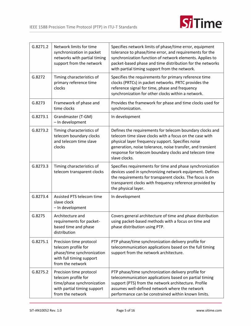
G.8271.2 Network limits for time synchronization in packet networks with partial timing support from the network
Specifies network limits of phase/time error, equipment tolerance to phase/time error, and requirements for the synchronization function of network elements. Applies to packet-based phase and time distribution for the networks with partial timing support from the network.
G.8272 Timing characteristics of primary reference time clocks
Specifies the requirements for primary reference time clocks (PRTCs) in packet networks. PRTC provides the reference signal for time, phase and frequency synchronization for other clocks within a network.
G.8273 Framework of phase and time clocks
Provides the framework for phase and time clocks used for synchronization.
G.8273.1 Grandmaster (T-GM) – In development
In development
G.8273.2 Timing characteristics of telecom boundary clocks and telecom time slave clocks
Defines the requirements for telecom boundary clocks and telecom time slave clocks with a focus on the case with physical layer frequency support. Specifies noise generation, noise tolerance, noise transfer, and transient response for telecom boundary clocks and telecom time slave clocks.
G.8273.3 Timing characteristics of telecom transparent clocks
Specifies requirements for time and phase synchronization devices used in synchronizing network equipment. Defines the requirements for transparent clocks. The focus is on transparent clocks with frequency reference provided by the physical layer.
G.8273.4 Assisted PTS telecom time slave clock – In development
In development
G.8275 Architecture and requirements for packet-based time and phase distribution
Covers general architecture of time and phase distribution using packet-based methods with a focus on time and phase distribution using PTP.
G.8275.1 Precision time protocol telecom profile for phase/time synchronization with full timing support from the network
PTP phase/time synchronization delivery profile for telecommunication applications based on the full timing support from the network architecture.
G.8275.2 Precision time protocol telecom profile for time/phase synchronization with partial timing support from the network
PTP phase/time synchronization delivery profile for telecommunication applications based on partial timing support (PTS) from the network architecture. Profile assumes well-defined network where the network performance can be constrained within known limits.

SiT-AN10052 Rev. 1.0 Page 6 of 16 www.sitime.com
IEEE 1588 Precision Time Protocol (PTP) in ITU-T Standards
3 Time Error Network Budget and Metrics for Phase/Time Synchronization
3.1 Time and phase requirement classes
ITU-T G.8271 lists time and phase requirement classes as summarized in Table 3-1. Appendix II of the ITU-T G.8271 provides values for a variety of applications corresponding to the level of accuracy 6. The latest standard version as of the date of this publication (Rec. ITU-T G.8271/Y.1366 (2017)/Amd.1 (03/2018)) covers some aspects of LTE-A applications governed by 3GPP TS 36, but does not include 5G requirements that are studied in 3GPP TS 38. Refer to Table II.2 in Appendix II of ITU-T G.8271 for more details on phase and time requirements related to 3GPP TS 36.104.
Table 3-1: Time and phase requirement classes
Level of Accuracy
Time Error Requirements (error with respect to a
common reference) Typical Applications
1 500 ms Billing, alarms
2 100 µs IP delay monitoring, Asynchronous Dual Connectivity
3 5 µs LTE TDD (large cell), Synchronous Dual Connectivity (for up to 7 km propagation difference between eNodeBs)
4 1.5 µs UTRA-TDD, LTE-TDD (small cell), WiMAX-TDD (some configurations), Synchronous Dual Connectivity (for up to 9 km propagation difference between eNodeBs)
5 1 µs WiMAX-TDD (some configurations)
Level of Accuracy
Maximum Relative Time Error Requirements (pk-pk between
elements in a cluster) Typical Applications
6A 260 ns Intra-band non-contiguous carrier aggregation with or without MIMO or TX diversity, and inter-band carrier aggregation with or without MIMO or TX diversity
6B 130 ns Intra-band contiguous carrier aggregation with or without MIMO or TX diversity
6C 65 ns MIMO or TX diversity transmissions at each carrier frequency
SiT-AN10052 Rev. 1.0 Page 7 of 16 www.sitime.com
IEEE 1588 Precision Time Protocol (PTP) in ITU-T Standards
3.2 Network reference model and limits
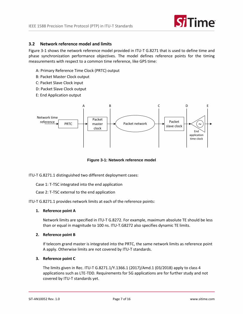
Figure 3-1 shows the network reference model provided in ITU-T G.8271 that is used to define time and phase synchronization performance objectives. The model defines reference points for the timing measurements with respect to a common time reference, like GPS time:
A: Primary Reference Time Clock (PRTC) output
B: Packet Master Clock output
C: Packet Slave Clock input
D: Packet Slave Clock output
E: End Application output
PRTCPacket master clock
Packet networkPacket
slave clock ~End
application time clock
Network time reference
A B C D E
Figure 3-1: Network reference model
ITU-T G.8271.1 distinguished two different deployment cases:
Case 1: T-TSC integrated into the end application
Case 2: T-TSC external to the end application
ITU-T G.8271.1 provides network limits at each of the reference points:
1. Reference point A
Network limits are specified in ITU-T G.8272. For example, maximum absolute TE should be less than or equal in magnitude to 100 ns. ITU-T.G8272 also specifies dynamic TE limits.
2. Reference point B
If telecom grand master is integrated into the PRTC, the same network limits as reference point A apply. Otherwise limits are not covered by ITU-T standards.
3. Reference point C
The limits given in Rec. ITU-T G.8271.1/Y.1366.1 (2017)/Amd.1 (03/2018) apply to class 4 applications such as LTE-TDD. Requirements for 5G applications are for further study and not covered by ITU-T standards yet.

SiT-AN10052 Rev. 1.0 Page 8 of 16 www.sitime.com
IEEE 1588 Precision Time Protocol (PTP) in ITU-T Standards
In the case of full timing support from the network covered by ITU-T G.8271.1, the packet network between points B and C (Figure 3-1) consists of a chain of T-BC or T-TC. The noise generated by this chain can be divided into two different categories that are different in nature:
o Constant TE (cTE) produced by the chain. The common cause is fixed asymmetries that have not been compensated.
o Dynamic TE (dTE) produced by the chain, which in terms is split into low frequency noise dLTE (components are < 0.1 Hz) or high frequency noise dHTE (components are > 0.1 Hz). The local oscillator plays an important role in the dynamic performance of the clock. SiTime SiT5356 Precision Super-TCXO was designed to minimize Frequency versus Temperature Slope to reduce sensitivity to the environment temperature as well as to have superior resistance to dynamic external stressors such as airflow, shock, vibration, and power supply noise.
To quantify constant and dynamic TE the following metrics are used:
o Maximum absolute TE includes constant TE and low frequency components of the dy-namic TE
o Maximum Time Interval Error (MTIE) and Time Deviation (TDEV) are used to measure low frequency noise components of the dynamic TE with frequencies below 0.1 Hz
o Peak-to-peak TE is used to measure high frequency noise components of the dynamic TE with frequencies above 0.1 Hz
The network limits at reference point C for deployment case 1 are:
o Maximum absolute TE ≤ 1100 ns (first order low pass filter with 0.1 Hz bandwidth has to be applied to the measured TE samples prior to calculating maximum absolute TE).
o MTIE limits to quantify low frequency dynamic TE specified in Table 3-2 Figure 3-2and Figure 3-2. TDEV limit is not defined in the standard (first order low pass filter with 0.1 Hz bandwidth has to be applied to the measured TE samples pri-or to calculating MTIE and TDEV).
o Peak-to-peak TE amplitude < 200 ns as measured over a 10,000 s interval (first order high pass filter with 0.1 Hz bandwidth has to be applied to the measured TE samples prior to calculating peak-to-peak TE).
The network limits at reference point C are not defined for deployment case 2.
Table 3-2: Dynamic time error network limit expressed in MTIE
MTIE limit (ns) Observation interval, τ (s)
100 + 75τ 1.3 < τ ≤ 2.4
277 + 1.1τ 2.4 < τ ≤ 275
580 275 < τ ≤ 10 000

SiT-AN10052 Rev. 1.0 Page 9 of 16 www.sitime.com
IEEE 1588 Precision Time Protocol (PTP) in ITU-T Standards
Figure 3-2: Dynamic time error network limit expressed in MTIE
4. Reference point D
For deployment case 1, the network limits at point D are not defined in the standard.
For deployment case 2, the network limits at point D are the same as the network limits at point C for deployment case 1.
3.3 Time error network budget
Appendix V of ITU-T G.8271.1 provides an example of network budget allocation. An example of full time error network budget for an LTE-TDD system is illustrated in Figure 3-3. There are 4 sections that are considered separately:
1. Time error generation of the reference clock, which is a combination of PRTC and T-GM.
According to ITU-T G.8272, the maximum allowed time error of PRTC and T-GM combination is
±100 ns
2. Time error generation of the network, which consists of:
a. Constant time error generated by the chain of T-BCs. cTE adds up linearly, so for the
chain of 10 T-BCs assuming up to 50 ns per T-BC, it adds up to ±500 ns. Sometimes cTE
of the slave is also included in this budget resulting in ±550 ns budget for cTE.
b. Dynamic time error generated by the chain of T-BCs. dTE is less than ±200 ns for the
chain of T-BSs up to 20 nodes
c. Constant time error due to the link asymmetry ±250 ns
3. Holdover budget due to failure scenarios described in ITU-T G.8275 (±250 ns)
4. Noise generation of end application ±150 ns
100
1000
1 10 100 1000 10000
MTI
E (n
s)
Observation interval τ (s)

SiT-AN10052 Rev. 1.0 Page 10 of 16 www.sitime.com
IEEE 1588 Precision Time Protocol (PTP) in ITU-T Standards
The overall budget should meet the ±1.5 µs requirement for the end application.
PRTCPacket master clock
Packet networkPacket slave clock
~
End application time clock
Network time reference (e.g., GPS)
A, B C D E
PRTC
BC dTE Assym
holdover
End Eq
PRTC dTE Assym End Eq
BC
BC
BC
BC
BC
BC
BC
BC
BC
BC
BC
BC
BC
BC
BC
BC
BC
BC
BC holdover
±100 ns PRTC
±550 ns cTE ±200 ns ±250 ns
±250 ns
±150 ns
±1.1 µs network budget
±1.5 µs end-to-end budget
Figure 3-3: Time error network budget
4 Requirements to Telecom Boundary Clocks (T-BC) and Telecom Time Slave Clocks (T-TSC)
ITU-T G.8273.2 defines the requirements for T-BC and T-TSC. It addresses the case of phase/time synchronization with the full timing support from the network with the architecture defined in ITU-T G.8275 and the phase/time synchronization profile defined in ITU-T G.8275.1. The ITU G.8273.2 assumes physical layer frequency support such as SyncE.
Performance requirements to T-BC and T-TSC consist of:
1. Noise generation (cTE and dTE)
2. Noise tolerance
3. Noise transfer
4. Transient response and holdover performance
This chapter focuses on the requirements for T-BC. The requirements for T-TSC are almost identical and can be found in ITU-T G.8273.1 Annex C.

SiT-AN10052 Rev. 1.0 Page 11 of 16 www.sitime.com
IEEE 1588 Precision Time Protocol (PTP) in ITU-T Standards
4.1 Noise generation
Noise generation of T-BC is an amount of noise (time error) produced at the output of the T-BC assuming the ideal input reference signal. The T-BCs are divided into two classes based on maximum absolute time error:
T-BC Class A: Maximum absolute time error of 100 ns
T-BC Class B: Maximum absolute time error of 70 ns
There are separate requirements for constant time error generation and dynamic time error generation.
Constant time error requirements are (ITU-T G.8273.2 Clause 7.1.1):
T-BC Class A: Maximum cTE ±50 ns
T-BC Class B: Maximum cTE ±20 ns
Dynamic time error is specified in terms of low pass filtered noise generation dLTE (ITU-T G.8273.2 Clause 7.1.2) and high pass filtered noise generation dHTE (ITU-T G.8273.2 Clause 7.1.3). Dynamic time error generation is defined for the case of T-BC operating in a locked mode and containing EEC-Option 1 clock assuming ideal references: wander-free PTP reference and wander-free frequency reference delivered via the physical layer. SiTime Precision Super-TCXOs can help achieve tighter spec limits for both frequency recovery from the physical layer (SyncE EEC) and phase/time recovery from PTP. Performance of the local oscillator and it’s resistance to changing environmental conditions is an important factor for achieving frequency, phase, and time synchronization performance goals.
Specification Spec Limit Observation Interval, τ (s)
dLTE under constant temperature MTIE ≤ 40 ns m < τ ≤ 1000
dLTE under variable temperature MTIE ≤ 40 ns m < τ ≤ 10 000
dLTE under constant temperature TDEV ≤ 4 ns m < τ ≤ 1000
dHTE under constant temperature Pk-pk time error < 70 ns τ = 1000
Note: Minimum τ value m is determined by the packet rate of 16 pps, m = 1/16 s or m = 1 when 1 PPS signal is measured.
4.2 Noise tolerance
T-BC should tolerate the minimum dynamic time error at the input while not causing any alarms, switching of clock reference, or going into holdover mode.
The levels of dTE that should be tolerated are defined in:
ITU-T G.8271.1, clause 7.3 at the PTP input
ITU-T G.813, clause 8.1 at the SDH input
ITU-T G.8262, clause 9.1 at the SyncE input
All the above conditions can occur simultaneously.

SiT-AN10052 Rev. 1.0 Page 12 of 16 www.sitime.com
IEEE 1588 Precision Time Protocol (PTP) in ITU-T Standards
4.3 Noise transfer
Noise transfer is determining the filtering capabilities of T-BC. Two paths of noise transfer are considered: PTP to PTP or 1 PPS, and Physical layer frequency to PTP or 1 PPS. Noise transfer requirement is applicable to dynamic time error only; there is no requirement to constant time error transfer.
4.3.1 PTP to PTP /1 PPS noise transfer
The bandwidth of T-BC should be within a 0.05 Hz to 0.1 Hz range. Phase gain of the T-BC should be < 0.1 dB in the passband.
4.3.2 Physical layer frequency to PTP/1 PPS noise transfer
Band-pass filter with 0.05 Hz to 0.1 Hz lower corner and 1 Hz to 10 Hz higher corner frequencies. Phase gain of the EEC should be < 0.2 dB in the passband.
4.4 Transient response and holdover performance
4.4.1 Transient response
The transient conditions that are specified in ITU-T G.8273.2 refer to a transient response of PTP output and 1 PPS output due to:
1. Rearrangement of physical layer frequency transport and PTP network – limit is not defined
2. Rearrangement of PTP network – limit is not defined
3. Rearrangement of physical layer frequency transport – limit provided in Annex B of ITU-T
G.8273.2 (refer to
Table 4-1 and Figure 4-1)
4. Long term rearrangement of physical layer frequency transport – limit not clearly defined
Table 4-1: Output phase transient mask in case of physical layer frequency rearrangement
Time S after the start of physical layer frequency transport rearrangement(s)
Absolute output phase error of T-BC (ns)
0 < S ≤ 2.4 200 + 50S
2.4 < S ≤ 14.25 50 + 270e-2π(0.05)(S-2.4)
14.25 < S ≤ 15.5 180
15.5 < S ≤ 25.5 115
25.5 < S ≤ 50 50 + 65e-2π(0.05)(S-25.5)

SiT-AN10052 Rev. 1.0 Page 13 of 16 www.sitime.com
IEEE 1588 Precision Time Protocol (PTP) in ITU-T Standards
Figure 4-1: Absolute time error mask for the case of physical layer frequency transport rearrangement
4.4.2 Holdover performance
Holdover performance defines maximum error in the PTP or 1 PPS signal when either PTP input or both physical layer frequency input and PTP input are lost:
1. Loss of both physical layer frequency input and PTP input. In this holdover state, T-BC relies
entirely on the performance of a local oscillator. A stable local oscillator can ensure longer
holdover times. The slope of frequency change in response to a temperature change (ΔF/ΔT) of
a local oscillator is very important to minimize frequency error due to small temperature
variations and therefore time error accumulation. SiTime has introduced Precision Super-TCXO
products with ±100 ppb frequency stability spec (SiT535x), that due to their unique temperature
compensation scheme compete in performance with ±20 ppb and ±50 ppb OCXO devices.
The standard does not define time error limit for this case.
2. Loss of PTP input only. In this case, the T-BC relies on physical layer frequency assistance that
provides a frequency reference traceable to PRC. This holdover state can be called assisted
holdover. ITU-T G.8273 defines assisted holdover specs for the case with constant temperature
(Table 4-2 and Figure 4-2) and variable temperature (Table 4-3 and Figure 4-2).
0
50
100
150
200
250
300
350
0 10 20 30 40 50 60
Ab
solu
te p
has
e e
rro
r (n
s)
Time after the beginning of rearrangement (s)

SiT-AN10052 Rev. 1.0 Page 14 of 16 www.sitime.com
IEEE 1588 Precision Time Protocol (PTP) in ITU-T Standards
Table 4-2: Holdover performance limit in constant temperature environment
MTIE Limit (ns) Observation Interval, τ (s)
22 + 40τ0.1 1 < τ ≤ 100
22 + 25.25τ0.2 100 < τ ≤ 1000
Table 4-3: Holdover performance limit in variable temperature environment
MTIE Limit (ns) Observation Interval, τ (s)
22 + 40τ0.1 + 0.5τ 1 < τ ≤ 100
72 + 25.25τ0.2 100 < τ ≤ 1000
Not defined 1000 < τ ≤ 10 000
Figure 4-2: Holdover performance limit
10
100
1000
1 10 100 1000
MTI
E (n
s)
Observation interval τ (s)
Constant temperature Variable temperature

SiT-AN10052 Rev. 1.0 Page 15 of 16 www.sitime.com
IEEE 1588 Precision Time Protocol (PTP) in ITU-T Standards
5 PTP Profiles in ITU-T Standards
IEEE 1588 defines all the features and options of a PTP, and it also defines PTP profiles that specify which IEEE 1588 features should be used and what options are available to a certain application to ensure interoperability and performance targets. The PTP profile does not set any performance limits itself.
ITU-T G.8275.1 is a telecommunication profile for phase/time synchronization with full timing support from the network. The profile ensures compatibility with the network architecture as described in ITU-T G.8275. Table 5-1: ITU-T G.8275.1 Annex A Telecom Profile Features lists some of the key features of this telecom profile. The complete lists can be found in Annex A of ITU-T G.8275.1.
Table 5-1: ITU-T G.8275.1 Annex A Telecom Profile Features
Feature/Option Value
profileName ITU-T PTP profile for phase/time distribution with full timing support from the network
profileVersion 2.1
profileIdentifier 00-19-A7-01-02-01
Required, permitted, or prohibited node types
Permitted: ordinary clocks, boundary clocks, end-to-end transparent clocks
Prohibited: peer-to-peer transparent clocks
One-step versus two-step clock mode Both
Multicast or unicast Multicast; unicast is not permitted
Best master clock algorithm (BMCA) Alternate BMCA described in clause 6.3 of ITU-T G.8275.1
Sync message rate 16 per second
Announce message rate 8 per second
SiT-AN10052 Rev. 1.0 Page 16 of 16 www.sitime.com
IEEE 1588 Precision Time Protocol (PTP) in ITU-T Standards
Table 5-2: Revision History
Version Release Date Change Summary
1.0 06/29/2018 Original doc
SiTime Corporation, 5451 Patrick Henry Drive, Santa Clara, CA 95054, USA | Phone: +1-408-328-4400 | Fax: +1-408-328-4439
© SiTime Corporation, June 2018. The information contained herein is subject to change at any time without notice. SiTime assumes no responsibility or liability for any loss, damage or defect of a Product which is caused in whole or in part by (i) use of any circuitry other than circuitry embodied in a SiTime product, (ii) misuse or abuse including static discharge, neglect or accident, (iii) unauthorized modification or repairs which have been soldered or altered during assembly and are not capable of being tested by SiTime under its normal test conditions, or (iv) improper installation, storage, handling, warehousing or transportation, or (v) being subjected to unusual physical, thermal, or electrical stress.
Disclaimer: SiTime makes no warranty of any kind, express or implied, with regard to this material, and specifically disclaims any and all express or implied warranties, either in
fact or by operation of law, statutory or otherwise, including the implied warranties of merchantability and fitness for use or a particular purpose, and any implied warranty arising from course of dealing or usage of trade, as well as any common-law duties relating to accuracy or lack of negligence, with respect to this material, any SiTime product and any
product documentation. Products sold by SiTime are not suitable or intended to be used in a life support application or component, to operate nuclear facilities, or in other mission critical applications where human life may be involved or at stake. All sales are made conditioned upon compliance with the critical uses policy set forth below.
CRITICAL USE EXCLUSION POLICY
BUYER AGREES NOT TO USE SITIME'S PRODUCTS FOR ANY APPLICATION OR IN ANY COMPONENTS USED IN LIFE SUPPORT DEVICES OR TO OPERATE
NUCLEAR FACILITIES OR FOR USE IN OTHER MISSION-CRITICAL APPLICATIONS OR COMPONENTS WHERE HUMAN LIFE OR PROPERTY MAY BE AT STAKE. SiTime owns all rights, title and interest to the intellectual property related to SiTime's products, including any software, firmware, copyright, patent, or trademark. The sale of SiTime products does not convey or imply any license under patent or other rights. SiTime retains the copyright and trademark rights in all documents, catalogs and plans supplied pursuant to or ancillary to the sale of products or services by SiTime. Unless otherwise agreed to in writing by SiTime, any reproduction, modification, translation, compilation, or representation of this material shall be strictly prohibited.