- «•„f. * ¿ t" •. • ir .¿v -^ w .> * : ¿ -. * *.?• -4 * i ; •••» "i %>v .i - CORE
Upload
khangminh22Category
view
0download
0
/ NASA TBCUNzCaL MBM0Dwa/N-Du-N
NASA TZ-1-77292
CLBARtaNCB FLOW-GENER21TIBD TRDYNSVERSE FORCES
AT TUB ROTORS OF THERMAL TURDOMACHINES
nl^^
Karl Urlichs
MSA-TU-77292)ULOSVE3 1111SE? 71120ECKI S 82 EDE ECTCES OF ^!OBDOZL
univ. 8 1975 iliationa' I Lazamunutj 'co lad space101 P tic 8C9/ j-j'y' 80^ U --al C2 a a
G3/37 13672
Translation of "Durch Spaltstroemungen hervorgerufene Quer-I=aefte an den Laufern Thermischer Turbomaschinen". Muenchen,Technische Universitaet, Fachbereich Maschinenwesen, DoctoralDissertation, 1975, pp. 1-159.
NATIONAL AERONAUTICS AND SPACE ADMINISTRATIONWASHINGTON, D.C., 20546 OCTOBER 1983
https://ntrs.nasa.gov/search.jsp?R=19850007871 2020-03-20T19:44:11+00:00Z

STA30AND ToTLE P.M9
0 R 5 0 7712921 ^1'7 G.
19P
I N D OR-7MVE RVOKICBS AT TUB ROTORS OF TIMBIM-ML TURBO-
arm iMa 0J'A"', 2,21
16A^' N,
It. rottem nt 81408181 Wef2^ _t' orbMC_rIZ_NBIS
1. Awhostel
r-arll Urlichs,
0, Peorsom'"S 08,14"8tsvion NOMO and Ail0*98SCITRANBox 5456
M W*116 Unit Fic
11. Contract *0 Grant me.NASA -4 93 42 d
136 T1100 of 14POOt and Psfiod Covotot
Trsmalation2. Sjen
'* ' A None end Addres:V4tESnarnMeroa&ut:Lc* and Sp&r.4k AdainistrStion
'Wasnington, D,C® 40546 Spe"W" Ai"vey We
%3. SwFPCOMralffy Hof*$
Translation of "Durch Spaltstroemungen hervorgerufeneQuerkraefte an den Laufern TI-nrmischer Turbomaschinen",-Muenchen, Technische Universitaet, Fachbereich Maschinenwesen,Doctoral Dissertation, 1975, -pp. 1-1!59. . (A76-43249)
Self-excited rotor whirl represents a serious hazard in theoperation of turbomachines. The reported investigation has,',therefore, the objective to measure the lateral forces actingon the rotor and to determine the characteristic pressuredistribution in the rotor clearance area. A description ispresented of an approach for calculating the leakage flow inthe case of an eccentric rotor position on the basis of ampiricaloss coefficients. The results are reported of an experimentalinvestigation with a turbine stage, taking into account a varia-tion of the clearance characteristics.
IV- 1961 W*V#Q (SM46144 &I ASUWWf46 1 1f1. Visartknon $Weawd
ii

I -WEIFT6 to G,-^-IOZKGGS R'ry speciml gzati`^^Ude to LOE000"mor Dr. rmg.N.-J. Thomase who as discoverer of cleamilea Q.-mitation providGd
tho otlyaulms ®r th- As wo= and I-Tho, always Oncouraged its
pz-OgEoso with his interest.
I mye a debt of gratitude to all my colleagues at the Institutepespecially enginsor R. Wohlxabp for stimulating discussions andvaluable ouggGsti ciao . I also want to thank the l not Laura lsmachine-shops, uhich contributed substantially to the
accomplishing of ^;his effort. The test -r-urb-I ne manuffactuxe was
undGrtrakan in part by AEG-Kanio. The measurements ware perforabid
w iithin the zrasearch project "Rotor lnstabil)ity due to clearance02 " c -1. ta' 'C' i on " .
The nurtlerical calculations Ware parfo-R-mad at the Laibniz
Computer Cea;;Gr 00 the Bavarian Academy of Sciences o whose
collaborators I would like to thank for their friendlyassistance.
Munichp Ju-11 1975
Xaxl Urlichs
iii

TM-77292
CLBOARZIF- NCBR FLO-V'I-G*-PN*:I Z27VID'^P-D TRN^NSVBRSB FORCBS AT THE
ROTORS OF THERM2AL TURI BOMACHINES
(Durch Spaltstroswungen herforgerufane Quay kr-nezte and den
Laeufarn thermischer Turbomachineal
Dissertation
authori2ed by theProfessional area Mechanical Engineering
of the
Technical University of Munich
to obtain the degree of
Doctor in Engineering
Submitted byEng. Karl Urlithe
1st Reporter: Pro --F . Dr. Eng. H.-J. Thomas2nd Reporters PZ0f. Dr. Eng. J. Raabe
Submission dates 07-03 1975Acceptance dates 09-25-1975
Graduation dates 09-29-1975
1

^, n-I DLB OV CQMT3MTS
Pzncjo
Io Introduction 5
2. Fundamental considerations and current
status oO raooagch 72.1. General definition based oy. a rotor mod(A. 7
2.2. Simple rotor stability bo-havior 102.3 Flo "generated forces - status oZ research 132.3.1. Forces from ahe variablo z tangential ZorcG at
the rotor grid 132.3.1 . 1. Eccentr ic rotor position 132.3.1.2. Rot-or-to-housing inclination
2.3.2. Forces from the pressure distribution at thesealing clearance 21
2.3.3. Processes at Ih-he meridian channel and theclearance entrance 25
3. Calculation procedure for the transverse forcesat the turbine blades caused by the clearance -flow 29
3.1. Definition of the control spaces at the sealingclearance 30
3.1.1. Location of the support points 313.1.2. Calculation of the control surfaces 373.2. Basic stream tube equations 393.2,1. Boundary conditions at the clearance entry
and exit 40302.2. Momentum equation 423.2.3. Energy equation 423.2.4. lywpulse equation 473.2.5. Throughput calculation 533.2.6. Discussion of the basic equations using a
simple clearance form 563.3. Coe
fficients to describe flow processes at the
clearance 62
2
Pia CT, Q
61 03.14 Dires=a loss 63
3 0 3. I . I . ST1106th clearance 63
InIDYviW;h- alearmace 67
Bea,,4-ranao f bond and e2lzit 100000 69
3.3.2. Mcmentum coe ggicients as a function ofPressure 1003 72ZtllalOgy With E Straight OtreMrd tube 72
3.3.2.2. Considora obi ons based on the energy equation 743.3.2.3. Cons ideLatilons oxx n -1-.)-by-riaI;h clearance 753.3.3. klized ft"Ictionall force at "dw channel GI-Eit 81
3.3.4. Determination of
ckr=-Z-17ic?-Ifiats froyiti 'ameasured pressure 82
4 CnIcul'ation 00- L II..", ins. acting O8.
a rotor 83
304*010 Transverse forcez 4((, dietribiltion 833.4.2. Transverse forca2 10,9 8 85
3.4.3. Forces due to surface 873.5. Iterative solu %ion to th f;-^ , 883.6. Tasting the calculation procedure using
Simple clearance forms 91
41. M,,pe-r-imental of the transverse
forces acting (on the rotor 1154019 Test assei i0bly 1154.1.1. installation construction 1154.1.2. InS01--allation operation 1194.1.3. Miacasuremewa instruments and test Met'hod 1204. 2 ® Test program 1244.3. lylsasureraan^ evaluation 1264o3.1. Turbine data and fo-rce measurent ants 1264.3.2. Relationship between e ,Kciting force and efficiency
rile asurewents 1314.3.3. Pressure distribution at the shroud band 1344 040 Transverse forces from an eccentric rotor position and
parison to efficiency distribixUoncoyff 13611*0vockets" wit- shroud band 137
3

Pago
1-40
5. P-7-a"coure distrL"bluVgion O"TO-9 1;110 Eotor Ohrocid, band
and -Vmw t! I e 0 -7r- y 142
Shroud band wi3 th c-mmth clenzance 143
4.5.2. Labyvinlk;h with Irm gll cm-nds 150
4eSe3. Off-oot shroud band 'ai lt;h g1cmada, 155
4 .6 11 Forces due ;o i^he rotor-to -IIOUS-I ng I' ac-UnnUou 159
51 Suriffilwey 161-21
6. Designations used 166
7. RGOGrences 169
8. Appendixl-. Tables o--'%-- measuresd -values 174
4
i :0TRODUCTION /I
In mn engineering offort to ,-Agnlflcamtly raloo the Output of
turbomachino unli;mq IR high pro oore tu--v 't,horo apl,'3car, to an
avo moveaoing oz-4tonto fla--Imral vibrationo unrelated to the
610-nal speed, placing severe operating ros trictiono 0"n rot'oro'
that are thoz'mod^ ?namlcally properly doolfpiod. This oil t-put -dependent
o' PAJ tation ®' vilb:,,ations is notul caused by bearing
inotabilityq but by forces produced as a consequence of the
cloaranee flow generated between rotor and housing [1-4]. Thedevelopment o? these forces is generally su-mmarised under, the
co-neopt of clearance ozeitation.
A theoretical description of the vibrational systom is already
available [9, 101, for multi-supported shafts of
any form. Howeverg
the troatment assumes Imowledge of the support characteristics and
the clearance ozeitation forces. Recently, several important papers
have been published (for instance, [61) in the area of frictionbearing i-Gsoarcho with their help , bearing instability (oil whip)can
be substantially avoided by means of constructive measures. In
addition, it
is possible to determine systam daymp-11' which in a
vibrating turbine shaft is predominantly caused by the bearings. Inpublications to date on rotor instability due to clearance92:01tationg the eInKciting forces are determined almost a2zelusively
via theoretical statements based on Thomas' [I] fundamental
cmas! do rat ions. Only recently have morasuraftionts become available
[51 that allow a reliable astimation- of the limiting output.
The clearance amcfktation forces, originate i.vi the peal -ing -1aazra--'Ica
- variable around the perimeter - that ovamrm -%ar -.1 deflou-tiMn
ozzists between turbine rotor and oar.-Ing,, . rue to the ehanging
clearance loss, the rotor blade@ ars oubjected to d-.4'-f-faring,
peripheral forcesq the reoultant of which has an 62-M hill cf
Numbers, in the mar in indical to fox-oijy-4 pagination

Woetv for a shaft viboating An Cho samo sense as the direction
of notation. Since 1'rn tuvbLao Coccics the rotor's peripheral
velocity is very lavge ' the flow
%hpough the scaling clearanceis of spiral typo, For CM occontric rotor position, the
consequence is a pressure distribution that varies along the
Perimeter - duo to the different flow which in
tho case of banded "buchoto" considerably magnifies the orciting
forces.
The goal of this study is the measurement of the transverse
forces acting on the rotor, as well as the determination of the
characteristic pressure distribution in the rotor clearance. Inaddition, a procedure is provided with which the clearance flowlaffected by torsional forces, can be calculated for eccentric
rotor positioning, by means of empirical loss coefficients. Theresult contains the variable clearance throughput and thepressure distribution at the coaling clearance under
consideration. This provides the two characteristics of the
clearance flow through whichtransverse forces proportional to
the lateral deflection act on the rotor.
6
2 KPUNDAH0,335^1_85# CONSIDUPIATZI Otis AND ISTIATUS, OV RU919MARICH /D
2.1. Gonoml doAnitimn bnood mn a _-Ootoz, -modol
TV0%C 3 - rz
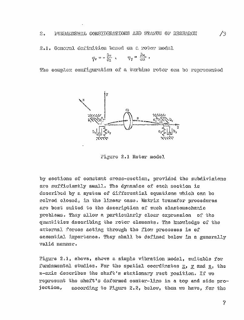
The cmqploz confiauvation of
a lmrbino rotozo can bo roIxii.,a, ontod
'Sb
b y Cy by
Fia'IrG 2.1 Rotor model
by sections of constont cross-sections provided the subdivisions
are sufficiently small. The dynamics of each section is
described by a system of differential equations which can besolved closed, in the linear case. -Mat riz transfer procedures
are best suited to the description of such elastortischanic
problems. They allow a particularly clear e,mpresslon of the
quantities describing the rotor elements. The knowledge of the
eX,te:r-nal forces acting through the flow processes is of
essential importance. They shall be defined below in a generallyvalid manner.
Figure 2eIq above shcum a simple Vi bra tion modele suitable x-oVfundaimen"bal studies. For the s- s 14E Y 't, Z' 9 thepatial coordinate q end h
F,-auzis describes the shaft's, stationary rest position® 1^ vie
represent the shaft's deformed center-sine in a top and side pro-jection, according to Figure 2.2 9 belows then we have, for the
7
boz:)LOO-ing
o
n L
pAS
i s^ LF
N
L*
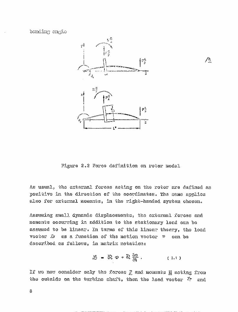
Figure 2.2 Force definition on rotor model
As usual, the azte-nnall forces acting on the rotor are do:-Unod as
positive in the direction of the coordinates. The same appliesalso for azte-nnal mortientso in the right-handed syst-sai chosen.
Assuming small dynamic displacements, the forces and
moment s occurring in addition to the stationary load can beassumed to be linear. In terms of this linear theory, the loadvector Is as a function of the motion victor' w can bedescribed -as follows, in matriz notations
a
If via now consider only the -fo rces F and momento M acting from
the outside on the turbine Shax"t, then the load vector X." Kid
a

'Oho 1-ilotim"I vao'^Oz^ V are doZinod by
Yly
V1
( 2.2 3
Considering the symnio- try conaltions - a 13-^Z) pplicable bocamso of
the problaw's iso lb-zoopy- the forceo cmd mowont-o, cenmoed by the
.i.low mill in gene vcal be deowell-bed by the coot-Uclen's of the
deflection- ytiet-1,tv-312, r 9^. , ^5 amnd the velocity 'As . The
coefficients of thla- Ymatridz: have the di amens ions of a spring or
veopoctively, daikping, const eant. For a, sh,,aft rotating clockwis s e.L
their oign will be given by the coordinate system to be
introduced latov, which rot ,,-1,tes with the vibrational mol'-p-lon.
q, -q ?, 9zaz
q? 9 1 -q (' qz
' ,% C .
OZ
.3pq - P2 P3- Ri. b, -ba b.y ors
P2. P1 -P,;- P3 b2. bi - 6^^
The bearings' dynamic restoring forces can be represented in the
spatial coordinate system xpy in a simil aer m-anner. In genera
the sy-mmetry conditions expressed above ara not s.,-1,til sfied here.
On the other hand, assu ► ing point-bearingss, the e ,Zte-mal woments
vanish. In adds bong forces due -1-Ao the bearings,' -Gilt as a rule
can be negglected. The deflection mat LE RL and the velocity
matri z, N for the bearing forces then are
- C;; I, - C-,%y 0 0 ' -JRY IdNIV 0 0
- CVA -CYV 0 0 . dy, -d a 0YV
C 2.40 0 0 6I 0 a 0 a
0 0 0 0 0 0 0 0
The bearings' characteristic WK.! TO COMPOCK Of AM'spring and dauping constantop whose ALY is ootablishoo by thecoordinate system abovo. For the usual friction Wrings a largevolume of toots results is already available Zoom Glionicho [6].It should be pointed out that in those papers the direction ofnotation is defined Avorsolyo with the consoquOnao that thesigns must be changed during the transfer to the coordinateoyotee chosen here.
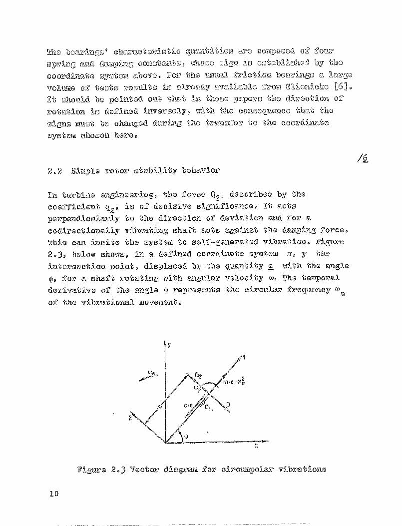
2.2 Simplo rotor stability behavior
In WNW engineering, the force Q2 described by the
coefficient q29 is of decisive significance. It acto
perpendicularly to the direction of deviation and for a
codirectionally vibrating shaft sets against the damping force.
This can incite the system to self-generated vibration. Filmrs
20), below shows in a defined coordinate system to y theintersection point, displaced by the quantity a with the angle
1 9 for a shaft rotating with angular velocity w © The temporal
derivative of the angle Q reprosento the circular frequency ws
of the vibrational movement.
/A
Figure 2.3 Vector diagram for circumpolar vibrations
10

^ii:n the
00ntr!2UCpI
2o,E,0(,,
balanced at0 06 0 Z, mlrn 0 a
,';he limitf
QzmLyna the ot at lonalr.-y DoS I U4 mn, the
a 0 , [ 3 11 n 010 v - I n , ma (114 L, -, 0 t I o a Tmd
govp,o -coo toGmth02,- wf%th roo"Go-VILng
by the Zlow. The aaMpInG 20:000 Do
)2 otab-71-I ty by tho, _-"02^co 0,0 C -",qP aeto
o v:, , onq 1 0 i q,I yijot^^_on. `L; i t no oot r n - force can bo
noGlloctod p In UimrbI ego o - bocamso oi Its, SMICIII MaGd-VitUdO - in
Coilroarlson to Ulc 0-pring, 002Coo ' tho of the
thC 'CO,Zclt-at lon :--'ozC(D Q2 1 P, -) K1,2-i 2l Goa Of 1 1110 -It
U (I Y
BmIldisly; on Thomas' fund,",EIG ntal Worh I D eveZ-0,11 -0,2-
-
POVS
Contain tile orot ical cono-I dorat Ions on the effect of 0_,Izt0rn,,A
,?o2r?C0G On t1la behavior' o:? sl*plo rotor 1110doAs- 121
asialoG!y to Thom m e Gensch 171 jnvGstigatos - for rigid boar -i ng--o -
the offoot of only the Q'Zo-I tatioil conot"ant q2 for 'a Contz"n'll
aa t Iz [)-) tahes, into em, 00-mm;' C,--)I-1rr&^,-n(Somont of t-ho m-c- 1,00, 1,111:1-1 10 P-11
the coofficiGnto, of 'she YmntrUeoland
k,^, i n en --m-3yFIT1110tricall
-ootor. Me- stability
11FAto for the slykply G,_,IGma zod Lava l shaft e
tile effect of friction boaring-o into accotnt through
conoldoration 02 the clearance force 0,29 was
calculated by Kraemer [2], Pollytiaman [31 and Vogel [91.
le of such calculati ons is shown In Figure 2.4, below. A
stability value was fomad with the shaft rigid-I ty a and the
ozoitation constant q. which is plotted against the shaft's
ajustment w/w,, ® Besides the bearing type, the relative shaft
nq 4C .
?_ [r -11
elasticity was va led q which 1-adicalies the ratio of static di lemm-re
Under its own
weight, to tha friction bear ing ,'o diamstGr play. The
it

P^
C'm
^s«1^ C,
splieric I beacingI r
Double jqedg0
e be fg,,a^inK_
iM D1 GV beari"
J ^ u
n mi 1-
0,2
Figure 2.4 Stability chart for the symysie"t-Prilcal unit -mas s
vibrator with friction bearings. So k
® 0 - 2 1-) b/d = 0-5
c mad the bearingl s width ratio b/d is kept constrant. Below thecharacteristic limiting curve 61he shaft is strableg while above it
instability beg,-1 --eis. The steep drop of the rotat i onal rate - Which in-
Greases with w/wk - characterises instability due the frictionbearing,'s so-called of whip.
Essent i al information regarding the construction of a turbine shaftc,-r):n be do-rived from stability charts of th i s k1nd. However, a
quantitatively accurate vibration calculation is possible only When
the rotor's goometry has been defined more accuraitftaly, by
subdivision into indiviftoA fields $ and once the shaftingls
d
0,1
Oj0
4J.rjr-1
ri
4J
W
0,0 1,0 1,4 1,6 2,0
Adjustment W /W It
12

sou-oport can be to'l-m-n I'A nto accozmt. Thio was oolvod, for
'"'^mmipOor jxr000claroop by Sohux-Tkcm,aeo, by -tiiccit2^14-"- 6 112'moz [101 and VoGol
[91, no well no by Gaoch with finite
olemon`ro [0).
2.3 Flow-genorated forcon - Rooearch statutj
/i
Mien -'U-urbino rotors are mounted in casingps ,-,),t the non-contactSealing cloa-vancoo
of the stator and the -roto3?, of necessity
cloa anco vilidtho will diffor along the circumforenco. Thio leads
to cleaaram-CG los's and teangpi-it-lial force differences at the rotorand -!,n turns to a resulting transverse force at the shaft. Inadditions an asymmetrical preesurs distribution appears at theoealing cleare-noess which gene -r yes @ force that acts on tile
rotor. For a vibration calculations both components - thetvansveroe force from clearance 'Loss QS and that from thewassure d i stribution QD - must be added.
0 a QS + Q C) , (2.S )
To the extent that those forces Q are linear and a fir-act'-pion of
the deflection e, the constants q ® Q-/e of the deflection matrix
of equation (203) are eas i ly determined.
The flow velocity caused by these forces in the usual turbinesare two orders of magnitude higher than the rotor's vibration
velocity. It is for this reason that forces frora the ntatri ,X inequation (2-3) that are proportional to the velocity, can aS
usually be neglected.
2 -3. 1 Forces frond the variable tangential force at the -rotorgrid
2.3.1.1. Eccentric rotor position
13
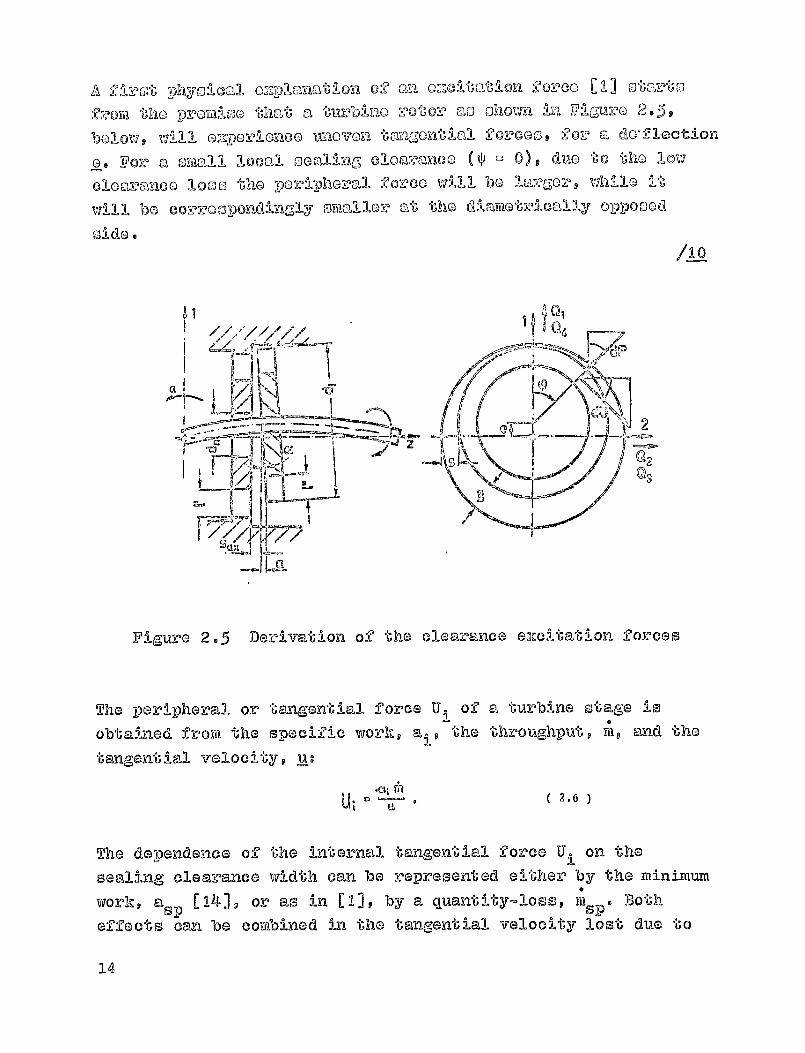
A 0-11-zOt phyOt'W"Al 02:701anat-I on Of "n"I Ozoltat-O" oil Ooreo [1] sta%*6""
2:,,,Oyjj the p--wcm-loo that a '^uz^blno rotor ao o howa in Viguz,-O 2.5,
below, wlill l o,,IPZI o-_e, :'A_OkIOO MOvOYI 1-mvigont-O "DA 20r000 l 20z' 'a do, flection
0 ' Yor a Small 106".1 'sonllung, 010 ri),:'mROO OP L; 0), duo to t1flo low
1000 the fozco will be
largor t while it
will be EYEII-cello at the 0-od
Side
/LO
A n.
Fi,g,ure 2-5 Derivation
The peripheral or tangentLobtained froYd the specific
tangential velocity, Re.
of the clearance 02'401tatioll forces
Dl force U i
of a turbine stage is0work, e i , the throughput, mv @;ad the
The dependence of the internal tangential force Ui on the
sealing clearance width can be represented either by the minimumwork # asp [ 141, or as in [I], by a quantity-loss, w sp . Both
effects can be combined in the tangential velocity lost due to
14
the 010mm-nool
^tl? " U "', - 11-, ( 2.7 )
Vilm"ro U 11 is the ta'agon' tial forGG without clo 'c"mme, looses. If via
dozin-c the isoatm ' 9 t would bepic taklomatlal force, U 0 thatattal"nod with a 1000-froo flow l then the 5-Late"mil 'al and the
Ipo'riphoral o2floloncyq as well as the clearanco can be
represented as gorce ratios
4UU %p ( z..
U.S
For the local tangential force via thereby obtain the simpleOquat lon
dA, = ! I, ( t, d'p ( 2.92 tr 2-1 -
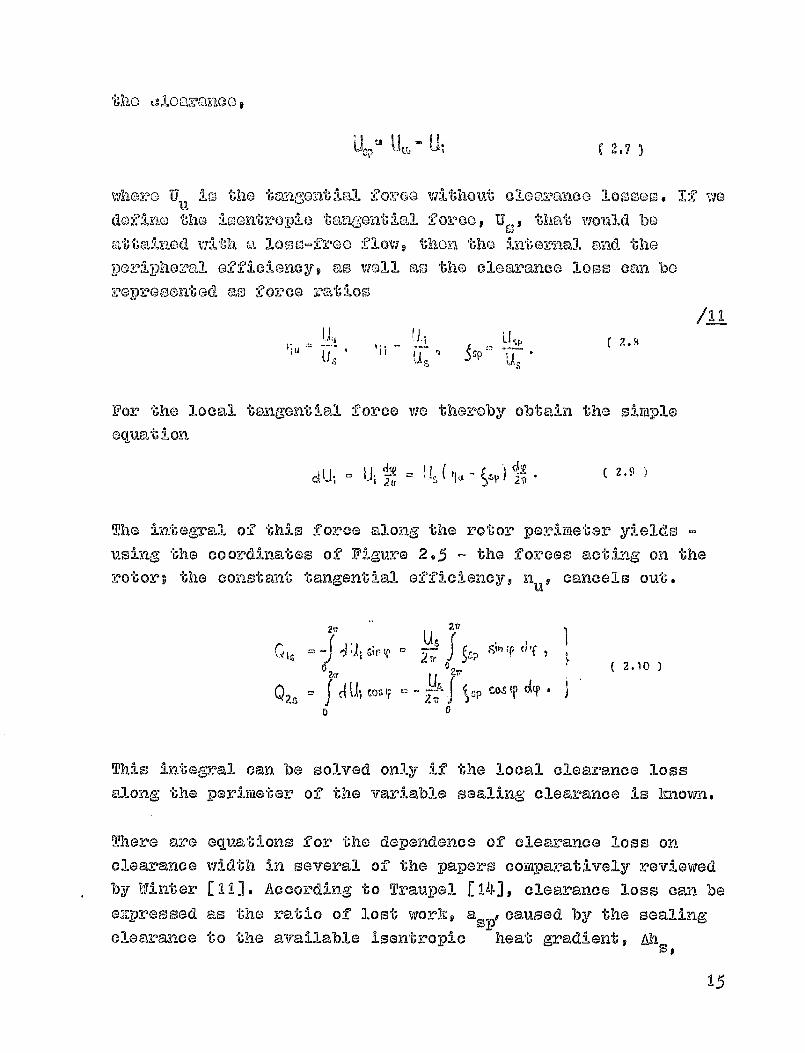
The integral of this force along the rotor perimeter yields -
using, the coordinates of Figure 2 .5 - the forces acting on therotor; the constant tangential efficiency, n u 9 cancels out.
2r
tb 1 ^^ ^^ s,^ 'S J 4^
0
J1!1{ Cos Coz!0
This integral can be solved only if the local clearance lossalong the perimeter
of the variable sealing clearance is Imowin.
There are equations for the dependence of clearance loss onclearance width in several
of the papers coyk-paratively reviewed
by Winter [111. According to Traupal [14], clearance loss can bee2j"Pressed as the ratio of lost work, a s., caused by the sealing
clearance to the available isentropic heat gradient, Ah so
15
if tile loontroplo tmigential force is dofiaod by
/.L?--then the clearance loss, asp , is identical to aqmtion (2.8)1where the to-agential 2orcoy reduced by the clearance affect
takes the value of
equation (2.6).
The stage clearance loss is composed of
a loss at
the sra'4;or
blades, C and a loss at
the rotor blades,
As'j^ ' 1<+ S^ - — :7le . ;^W- T'2
Kn
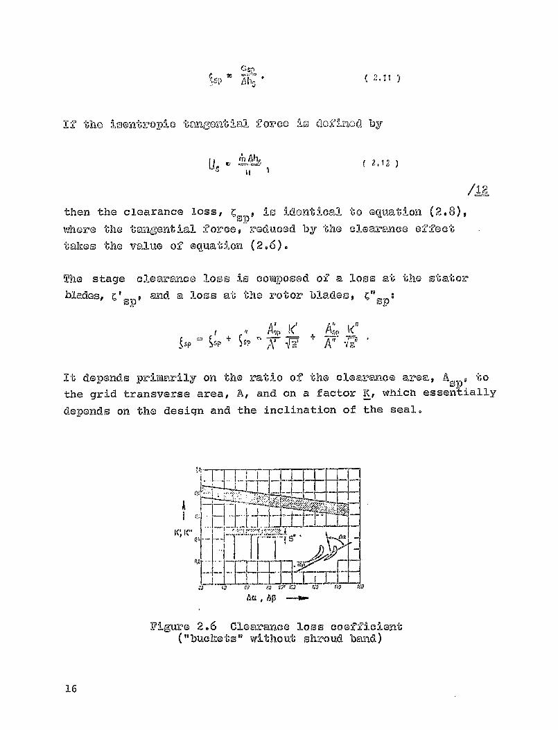
^Sp §sp - N7, .
It depends primarily on the ratio of the clearance area., A s , torthe grid transverse area, A, and on a facto K, which essentially
depends on the design and the inclination of the seal.
4a
I FITI'j 43 CO 60 119, 1:3 DO reo
40L , 6P ---awo
Figure 2.6 Clearance loss coefficient("buchets" without shroud band)
16
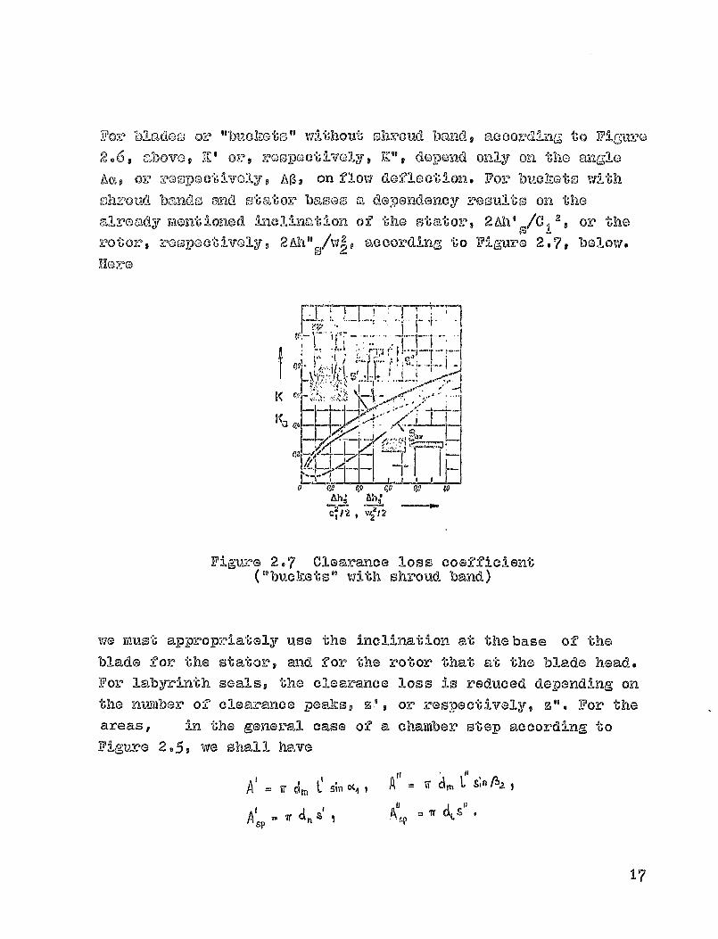
For Un do' s. or "buchots" without shroud band, accordln^; to Vignro2.6. above, N' or, roOpocti col y, TZ_", dopond mily on the angloAa,p Or rGsjpoctkfolyp AO, on flow defloc"U'lon. For buotchs ,V ill:- t holizaoud bands omd otatozr baseE., a dependency veoulto on thealready vmositio-ned inclination of the stators 2AW
0 /C 1 2 , or the
rotor, rospectively V 2Ah" A, P_ according to Figure 2.7, bolow.19 2PI-lore
I
Cpl
}•i..,'L,^ ^ 11 •^^ff ^,{^ ^.^^^_
4:
K
1^
7121-2 1 2Is,
Figure 2.7 Clearance loss coefficient("buckets" with shroud band)
we must appropriately use the inclination at the base of the
blade for the stator, and for the rotor that at the blade head.For 1,al-byrinth seals the clearance loss i s reduced depending onthe nwaber of clearance peaks, S', or respectively, z". For theareas, in the general case of a chamber stop according toFigure 2 -5, vie shall have
Ad C44
7r a, Aa L
sp
17

We thus obtaKl ap for the clearanco loss#
1111 11
kpK'
F31
Consequently, the clearance loss at the s if;,ator and at the rotor
depend linearly on the clearance width. If vie asstnio -
neglecting compensating flows ® that the dopondoncG is
applicable also to local clearance widths
0-1 = S - C COS
V
according to Figwre 2-5, then we obtain, from e quation (2.10)
Qzs
04, . 0,
n [ k , & C k, A 1 .1 (4 U^ N7—,^jqrxl
Because of the direct proportionality between clearance loss madclearance width, the force vanishes in the direction ofdeflection.
The clearance eXcitation forces Q 2s' depends linearly on theeccentricity G/1 11 the li sent topic tangential forces U
mad the coefficient K 2s p which basically describes theconstruction forra of the seal.
Ut2.16
KzS z I &111OC4 dm C fe—if."A4 dill
In the dimensionless representation of equation (2.16). X 2Sindicates the slope of the e_xcitation force mentioned, Q 2 slu Sover the relative eccentricity e/1" -and is therefore referred toas clearance excitation coefficient K2,s'
18
In DmAnolplo ' Ron-1-1 -mar cloa vmnco 100s, oauationo could also bo
usod 202? "U'llo :1ntograt-11 on 0Z tho 100c,"11 -F'02?000 'such as
'rho , 2t '9 0t' 0 Contal"220d Im tho 2nd 0d-"0 t:1-O-V1 0---' WILL for 1-no me • ThisOffoct is disjouGood in soctlo -a 4*4.2, in connoction with ca
moaouved aZAIcloncy dictri but ion. It io shoma thore that even
with a non-linmar 'approach for Cs 1)
(O d , forces can de v pelo -1a t
do-pond lii:-Locnrly on the occontric`1ty a, just as, here.
Iq
inclination
Forces acting on the rotor can also be caused by an inclinationof the rotor with respect to the housAngo if the aMiall so,90-Ing,
effect of the clearance is signific ant. In general, according to
Figure 2 -59 the of the rotor along the r3ha-ft's,
bonding line is coupled to a certain eccentricity. If we ostart
froya the premioe that the radial clearance width is largo !n
coi-tipar-ison to the aXiall sealing clearance, then the cloe-lo-i-ance
loss will be de tax-minedonly by the alcial clearance. For thistype of construction clearance loss equations exist, as in [141,conforming to Figure 2 -7 that make it possible to calculato the
forces acting on the rotor, which in this case will be due only
to the inclinat-ion. The local arial clearance of the rotor
with
shrov.d band towards the housing changes along the perimeters'according to Figure 2-59 for an inclination 0--l' the disc equal to - no.
banding angle a. The magni tude of the non-um"R Ze'-'^"-'k2i'lty 'En C010-U po-nc^ -0
on the angle of inclination a., and on the di o 2 "69 h o
seal. The clearance loss is again tal-mn as non--,,to the ratio of the seal area and the rotor area
^ 9,
AD vkmms "Gho on for the d•'U'A Coalp t 610,').Llanao loso,
-2o tho "I"ILI rotoz oo"A 00 ^ponols On tho- al'z-oady, z,
Mill/VY 2 n) ,nd can bo tqhm-i -!"romSO 2Agnpo 2.V,,
W "Tn)''orgy "00 'am eccontric rotor Pool"621"On, an loe"a)l
'^Oz -'0 'he clodn:maco-'00- oaa Do 1 rrslod "C'h'at downdr. on t 1000,
"and `rho 1,1 1,O)Ontropic teama-enti 32l foce U5
(equation (2.12)).amlong
the Porimoter yields the tranoveroe -?o-room
aot-ing on -'b,ho- rotozeq
2.20
U"
116
In accordance with its definition in the deflection matrix, theforce Q
3s has a. destabilizing effect on the rotor. It depends
linearly on relative deflection -qand on the i-sentropic
trangential force, and it can be represented by the
NP 3S 9 as the slope of the dimensionless G2z e-ittnG2 :?orcz, ovar lb-he
relative deflection.
5 5 - K ,. Rr-^ I ( 2.31 )
s a
n i Jia— 4L 2.22 •K3 2. sjn62. d,
The exciting., force due to the inclination of the rotor 61 -'doc can
be calculateLl, only for a purely a2dal seal effoot, with
tlho
clearance loss equations given. However, it would bo on -vhG 02 fa
side to consider this effects in addition to the cloa-mmoo
e2mitati on coefficient for a radial seal. For a clearance
shows both a radial and an amial seal effectq a rotor
position as shown in Figure 2 -5, due to the inclination a
non-uniform cleareaace loss will occur alo-ng the perimetez. Foy
20

Ste di
thlo z:lomm tlio inlet turbine stageo will beZ7 booau
f "'hoto Zf1b j 0 Ot t 0 gro "I't Ozz, 0 tat 1 01-2 _2 Oz, go s m o
Lac lian t 1 On.
2.).2 Yorcor. C1.11.0 0-0 le"ho prossure dio otvibutlors ale, the ooallong0 la 'a vamn 0 0
TzrutnowshY 1 1 51 provides a comproliencivo review of the
calculations for non-Oontact seals. Mil-lo i-tiost of -'(-)he procedures
described there determino only the throughput of
a clearance
that is uniform alon;^ the entire porimotoxr, vie are interested
here Drimarily in the effects by means of which transverse
forces act on 'U"ho rotor duo to cle , -.ranee flow.
Voz' an eccentric pool ibion of the rotor with respect 'to the
housinga not only the throughput but also the pressure gradient
along the direction of flow changes mi-th the local clearanceIwlldth. Assuming- lb-hat at the emit the flow will be subject to
atimoophazAc pressures a characteristic pressure distributionwillill develop along the perimeters whose ma-MiRium value will
colacide with the narrowest clear^nce. This affect was firstdGscribe,q by Loyiiakin [ 171 using a smooth clearance with purely
a,-'Uiall A Similar derivation can be found in [181. Because
of the aoeumption of a purely axial flow without compensation at
the per imet-or l the pressure drop is linear •: If we apply thi s tothe shroud band of a turb ine rotor, as in Figure 2.8 9 below, we
Figure 2.8 Rotor clearance
21

ob'r'aLln - for tho Syntom o--n 000-odlnatos 00, 2.5 - `0-ho
pvov-)Suzo vcm^-Iatlo-n Kn cq -la""'A mvm"
Pz
+
2.23
b;L
Tho coo-fficli ont X Xft'ori !ADD hydraul:100 io asommod
constant, here. In
addition, Gntrmance 102soo and a poosiblo
proosure rocovery at tho oz ii; hunve been nogloctod.
The Integra'Oplon of a Vq-x^
the forces acting on the
6 2v
QID -Jjdp COST0 0b 2
e "d P $In tf
0 0
U-)IAG pressure Variation y1oldso firotq
rotor in genovalob 2tr
J j us T r dy d?0
b 0 27r 2.24
If pfuq) d JO
00
AL8-Using equation (2.23), we obtain the forces
Qqp P, -
+
P2 2 d 6 t- 7
zs
The force Q ID 9 because of its negative sign, acts against thedeflection .a and at larg.,or pressure differences
P I - P2 - as theyoccur, for instance, with bollor- feed purips - have an essentialeffect on the system'-s vibration behavior. Because of asimplified k-ategration of the pressure variation, this force
depends linearly on the eccentricity, while the dirionsions ofclearance d,V h and s occur
in sortie non-linear torms. Since the
pressure variation is symmetrical with respect to the
deviation,, the force Q 2Ds
perpendicular to it vanishes.
22
DIZO t0 'U""a)o tcmasn'e6lal V0100:1-Ity Llo f'30noz"atod
C't "6110 011 0 'mmmoop vfhloh -I n C tjboaz^:%-EiC , ftz- i-astan-oo
thoz^ou,Zhily iavoOtigatod by Stinsoll"n [271 - Com patoo a pre couvo
1-il,c.--millml Cho")d 0-? the
clo"mINnunco. Here, too, 0,2D -?Oz co lo
n VU-dovoloDod that could initi gto a vibrational aystome Howova%
they bocoictio mly -Vor o"I'l-T210:14.01Itly lonc, Cloaralloo 's- with
a'D Tory radial wildtho 'VAII-4011 in amno-rall can no
Imager be implemented inthablade chcmne ll of a turbomach:1--ne,
In turbine stages a larsa volocity co ytiponmx4 ka a tangential
CIL?oCt IO-onoccurs, 02pocically -.-Am d of
the z°otor l s Cocal clloox-anco,
with the conco quonco that the clearance flow is no longer axialbut develops a diagonal flow. With eccentric rotor
p Io-ol"IJ-1 0-nimr" thlis loads to v@xieablo cross-sectIto-no ealong a otvoam
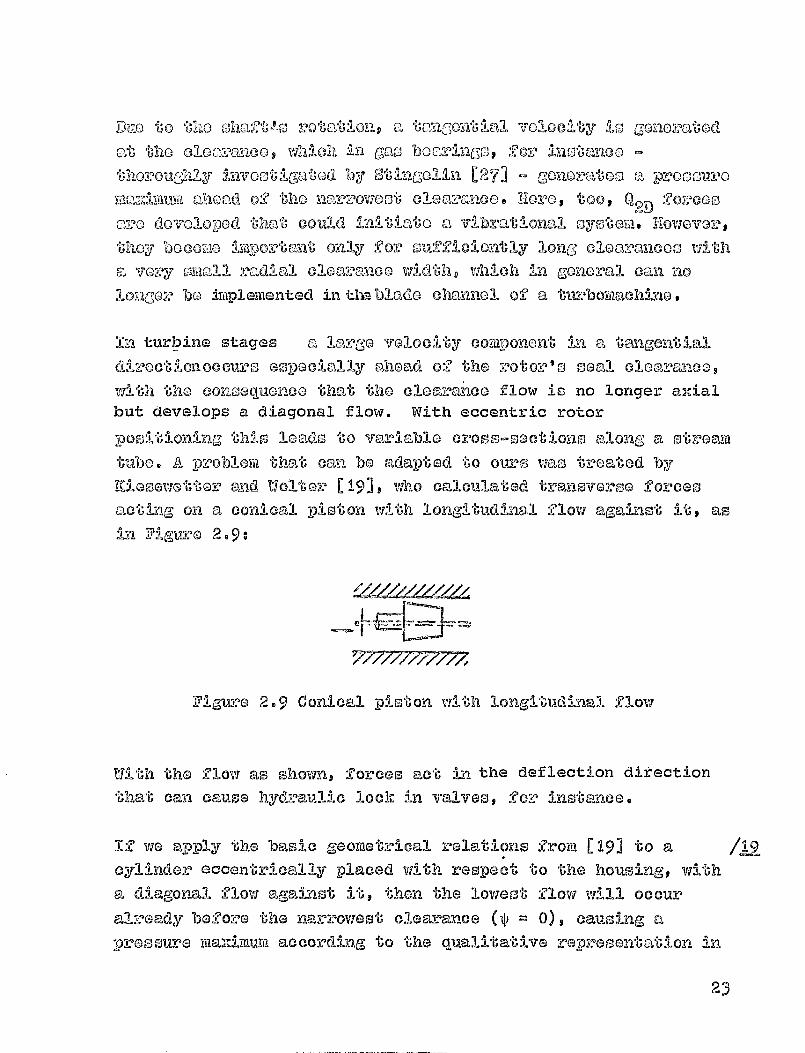
tube. A problem that can be adapted to ours was treated by
'nand Wolter [19] 9 whoc,,:-Aculated tra-Emoverse foreets
acting on a conical piston with longitudinal flow against it, as
in Figure 2.9:
CIL
771-71-17--1777,
Figure 2.9 Conical piston with longitudinal flow
With the flow as shown, forces act kp the deflection directionthat can cause hydraulic lock in valves, for instmee.
1-f we apply the basic geome"tzricall relations from [19] to a /12cylinder eccentrically placed with respect to the housingp witha diagonal flow against it, then the lowest flow will occur
already before the narrowest clearance (^ ® 0), Causi-L-I"m a
pre ssu itative representation inre ma,.Umum according to the quall
23
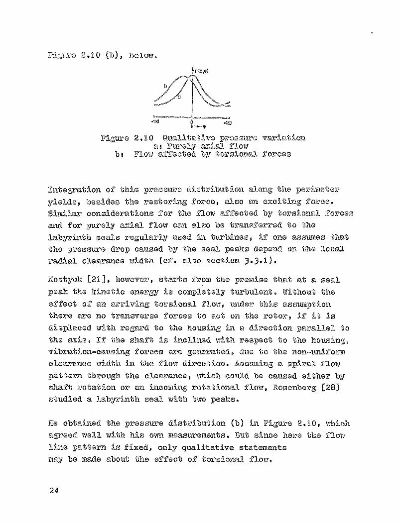
V:1.,Suro 2.10 (b), below.
I P I Z.,P)
Vigure 2.10 Qt1alita-t-1 vo Pro m variation.a: PCB anleal -fow
b.- Flow affected by "Oporolon- l"Al forcos,
n' t:' of this pressure distribution alonr ,61; 1C., porimoter
yields besides the motoring force, also on e2zeiting force.
Similar considerations for the flow affected by torsional forcos
and for purely ay.,-ial flow can also be transferred to the
labyrinth seals regularly used In turbines, if one assn-meo that
the pressure drop caused by the seal peaks depend on the local
oadial clearance width (cf. also section 3.3.1).
Kostyuk [211 t however, starts frora the premise that at a sealpeak the k i netic energy i s coraplotely turbulent. Without theeffect of an arriving torsional flow, wader this assumption
there are no transverse forces to @et on the ro-'t-tor,, ix i t is
displaced with regard to the housing in a. direction to
the arls. If the shaft is inclined with respect to the houm-a",
vibrat- ion-cati sing forces are generated & due to the non-uni-for-m
clearance width in the flow direction. Assuming a, spiral flow
pattern through the clearance, which cc^-Ad be caused either byshaft rotation or an incoming, rotational flow, Rosenberg [28]
studied a labyrinth seal with 'two peaks.
lie obtained the pressure distribution (b) in Figure 2.10 9 whichagreed well with his own measurements. BWu- since here the flow
line pattern is fixed, only qualitative statements
way be made about the effect of torsional flow.
24
to M'", 0z"d [201 9 Oo:i^ 010al lun vfhflah -^ho
oil me o 310m,"moo ml dl'U'12 lo, "'mm"1110:'? *61',L)cnan th"),t "It "KIO 04'a"Its
t:,',-nzsvo-,,'00 1002?eos dovolo-p, Cleo to rah oZ'E'Oet of
tho
:,r.-Otozw q VAI-I 01:1 Can bzna:% ,^O tho Dy"AC'mvil to paloratod
Uns 21 V7 in t 0MAI O a dhA to n0 OOKY00 on ', 0 hlabyz,'LT h ehrayifbo ,-,,'aq znldo^' thoso SpuOz and por
21 E 0b' Gr 1. 1 Z--L 'U'll 0 0:9 10 o o o r oo u b y n C,; i , lo, o2 2 o o 1; I --,,i o
00Y-40" dq o.-^'atl on.
N7 Y a 0-1,rc lie 0joehLpouthor (291 porfo:i^mod a 93-1-ndamon"bo.1 Stud 0 01 , a:i'llowl V111:11 311 starto by soli v."Img tho d000r-IbIng 0-0-forontial
oquation at a pinAn cloavanco, noing al d-UPEox-onco Y,10-b"hod. Under
tho o0gacts of vot'antionp boundary conditionto) can bo satiSfiod
o-v both la-YAnar and turbuloiY6 Olory o accordinc.,; to Ijoyimahln. The
p --v,ocodure mas thon widened to include labyrinth cl oar ances;
hore, coyiVicle"U'o turbulenco o -," the 151-notic energy vieno esmtvtied at
tho soml J-50aks.
2.).3. Procoomo at the merldian channel and the clearance
entrance
Mf the cloarance width is variable along the perimeters thelocal
efficlethroz.,Ig 111 V
-,,^),ryq as wi l l the t 'ange ntl ea xicy at§Iput w:*
the rotor blades of a turbine st age. This iwas, taken into
considerst-lor. in equat i on (2.7), in section 2-3-1- For constantprosssm-a bias w ng without shroud band, Pit tz [12] investigated
both offoctog by determining pressure changes in the bladesq inaddilt,Aon to changeo, in the local triang-le of velocities. Here -
at least for bladinp, without shroud band - presure-cawed
forcom can act on the rotor. With mi occasionally severe
oiftiplifica ,ion of the three-dimensional flow, PlItz calculated
all the coefficients f or the defiection mid velocity Diatrices in
equat-ion (2-3). However, he showed by means of vibration
calculations that at least for a central rotor arrangement
botwoon, the beaflngsp the additional offects determined by him
25
moo sz,2,0111 9 Lj-n oCAm1O,--),r-! oon to conoldoz,1,6 -ily the oze:11-atlion
foz'co Q2 aecordla,? to [ I ] .
If wo otcart from the pL,,omloo I;hat doopito local velocity
v Iariun-10-:1-io.nS tho porco-nt gGp roaction is eon eta --at nlong- the
periphery, even for amnecc Ent r:ic rotor - UU -00,m1t :*O-on, then - in
contract to (121 - by introducing omplorrical clodrance 1000
coolilfici oat og all effects that can canioc, local variations of the
poriphorall force have been teahon into consideration.
Diorega'ding balancing flows, th: *A-o is vealid especially qzlso for
an efficiency distribution meamured as a function of the
clearamco width, which was used to calculate local clearance
losses.
At constant pressure ahead of and behind the turbine step, a
variation in the percent reaction along the periphery -
according to section 1' e lf•a1s - cauwed by the local cleaz-cmco-
loss, is conceivable. Here the turbine stage, percent reaction
is calculated from theI pressure gradient and the turbine's
throughput. The only quantity variable along the paraphery t o be
considered here is the stator's cledsxsmce throughput according
to equation (•.13). It turns out that i tLp can very substantially
affect the -results if one d i sregards balancing flows ahead of
the stator. Thus, for a large local stator clearance, a larger
pressure gradient should be observed at the rotor. This would
displace the local stator to rotor clearance loos ratlo, which
could affect the forces from the variable tangential or
peripheral force to very differing derg-rees. The pressure
distribution in the sealing clearances could be affected also.
However, a variable percent reaction in the blad-i ng's flow
channel does not necessarily have to cause compressive forces,
since -varying pressure distributions could cancel each other, in
the case of banded "bucket,11-chmmels.
Since the effect of a percent reaction varying along the
periphery a not yet sufficiently established theoretically, nor
26

doolmi ,ion"t;od by momou:i-omantog V10 011co'll 11"I'Vo to Tnogloct lltq at
- I oo I?goronoot-sZt o m in "Id'(11,^:7-i on bo CLICEM-mlod that pltszn,-a d:U
in the channol Ill onacol 0-Lzt much more readily duo to
91OV70 Al -n 'fan gontlal diroctiong than in radial /g2
00 cloyom-ncos, s:Ince the rolatlivo Gecontri0ty - rox-orrod
L' o oha-n-nol tae.?c;h` - viII II be omealll oxr . Only in aztmiio care,-,, with
high tangom.1,92 ve'locit:1-000 in the r13o r _5 d'a an eham,101 9 Compro-001vo
J"orco-o vAll bo ozortod on long, cyMou'10:01110'al rotor pmoto l such ast,hooa obsox-fod during glow control in test turbines 151 withstanding bladinp (i.o.j largo flow-off velocities).
The lnflt= conditions at the clearance entrance are of great
importance to the davelo _vmont of
-a pressure distribut i on in a
radicall clearance. Do, Roche [23] Investig, t d the effect o af.,a a -0 -1
point of
irrogularity in the side-viall of
the bladed flow
channel, betweema the stator and the rotor, both theoretically
and G^Uperimsntallly. TG begin with, he showed that the off-set
height f! (see Vigmre 2.8) is of oubstantial significance to the
initial pressuzPa at the clearance and hence also to its
throtighput o
The calculations and basic 0-M.Perimentation were performed by La
Roche f or a bidimensional model In which the flow was
perpendicular to the off-set. Apparently all optimum off-set
hei,g?ht could be found., he-re, for which the losses would be
minimioad. In contrast to the usual construction. it was
characterized by a negative value for the off-set and aweld.-rounded entrance edgge. However, transfer to an. with
an oblique influx still appears to be somewhat of a problem,
oven thouggh La Roche obtained ggood agreement with the
bid-1 -men-sional model, with
a waif orya-pres sure turbine.
Since the overlapping a of the rotor "btic-het" height, ascompa-red to the stator bladling, -varies as the local radial
clearmce width, for an eccentric rotor position. La Roche's
equations should be included in the calculations of local
27

cloavanco losses. It turns outostrongly dopende& on 00condarythe rotor blades, wall boundaryshroud band edge) I which maho aWhile the off-oot certainly hasLa Roche 's rose to can not be a
however, that Ohio loco 10 voryeffects (displacemQU WAS Klayer at the otator, form of thereliable application Wpoo o'er ble.an effect, for the above rem oono,lied to this Audy.
28

/?_ 3
CA-LOMUTI)ION PROCEDIURB FOR TH13 TRANSV B" PUSE FORC_BiS AT
TUR3'jj'Q]J MaMj CAUS-03D BY TIE CLEARANCE FLOW
By introducing the tapjpeoprlaa ibo control surfaces, it? is possibleto ro-rosont a soan-I clearance of arbitrary geometry as a seriesof contiguous ^a'tvecqmi tubes with variable cross-sect-i ons. If weconsider average velocities, at certain reference points in theclea:rancoq then they can be described by the continuity
equations as a function of the local cross-section. Thethvoughput and the pressure drop along a stream tube can be
calculated by means of
the energy equation, using empirical loss
coefficients; the flow directions are determined with the aid of
the theorem of momentum, under special consideration for the
torsional effect at the entrance. The application of energy andmomentum equations to such stream tubes thus does not require a
knowledge of the processes inside the flow domain under
consideration. I t does, however, assume loss coefficients $ to bedetermined from Imown empirical laws.
From this views the separation of clearance flow from the :#',Iov,
along, the meridian channel must be possible- this will occuronly if the blade ands are fitted with shroud bands or similarfeatures. Free-stan-ding "buckets" or blades, coupled to the lossof volume, also show losses at the blade ends, caused by theenergy exchange between the clearance flow and the main flow.
For this reason, such constructions shall be precluded, here.For the same reasons we must establish restrictions for bladingwith discontinuous shroud bands, or for stator bottoms withbalance holes, since the continuity equation of a stream tube
can not be applied in, the manner describeds due to a pressureequalizing flow.
In the calculation method below, we study the clearance flow fora stationary displacement
of the rotor with respect to the
29

a
housing, which would allow the do'^Oxrip.lnatlon of
all the
Coefficients for the 0.0vio!"'(A-10-el matrizz, (2.3). However, because ofthoi%, much great-or significance to the vibration boh vvior, weshall only determine here the ZOfficeo relevant to an eccentric /911rotor Dosition. Since the ra"610 of the clearance flow to the
main flow in the xtieridian channol is always smalIq vie shall
consider the latter independent of the ro"Gor l o eccentricity, asa Most approximation. In add ionsthe calculation Ttie"L.Fhod 's'-diall
be limited to cases in which the clearance flow may be
considered incoitiDressible.
3 .1. Definition of the control spaces at the seal clearance
The non-contact seals predominantly used for turbines are shown
Figure 3.1 Seal clearance at a turbine step
in Figure 3- 1 , above. For reasons of operating safety theclearance at the -radial entrance E and exit A is usually much
larger than the radial clearnee S, which in the newer machines
is fashioned in labyrinth form.
Sortie Constructions show a plain clearance at the rotor, in which
30
case the soallng effect can also be accomplished by 'q;:n entrance
cadger tic Shail consider, as
a general ca se, the -rotor
011eare.-noo Ira Ff"Llauro ),I t vAloro either a plain or a labyrinth
clea:oance can be used at section S,, However, the calculation
procedure ch000n will also be applicable to the seal clearance
at the stator, if the correoponding,, radii area By /.&5
appropriate modifications to the boundary conditions, it is readily
possible to eliminate the radial entrance or axit, which allows -(-or
other areas of application t such as shaft seals of the housing.
The flow processes at a sea l clearance may be consideredunidimensional, provided the control spaces can be var i ed accordingto the course of the flow lines. These are described by supportreference points which in the entrance and exit lie on con)stantradii; in the radial clearance they lie on planes perpendicular tothe axis of rotation. In the tangential direction the suppor"t,points are variable and are determined by the local an-
of -"h@
flow-line tangent to the reference line. The variablecross-sections of a stream tube are then g iven by the d!stqi--iae '-jbetween neighboring support points on the perimeter and by tholocal clearance width. In this procedure, the flow anZlco) 2^?s
obtained by iteration of the basic equations for ,-1, 'rUbep
they are assumed known, in the following sections.
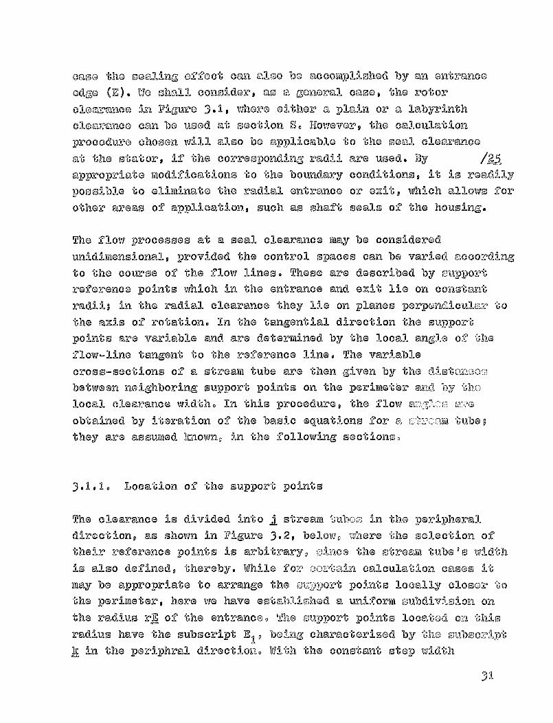
3.1-1. Location of the support points
The clearance is divided -*-into j stream tuboto in the peripheral
direction, as shown in Figure 3.2, belowo vfhexre the selection of
their reference points is arbitrary, olnes the stream tube's width
is also defined, thereby. While for eoz^tain calculation cases 111,-may be appropriate to arrange the oiz-pport points locally closor to
the perimeter, here we have established a uniform subdivision on
the radius rE of the entrance. The support points located on this
radius have the subscript E10 being., characterized by the oubscriptk La the periphral direction. With the constant step width
31
Ab
APIAE
Figure 3.2 Stream tube stibdivision along the poiAphery
S1 ... Si ... sn
......... 0 ^x
CE ME PE
CA CCA PA
Figvu?e 3 . 3 Location of wippoz•U points in the flow
I.?-_6
32

(k
tl- - r-of-'I-Ls a-C' the oatranoc dctorwi no() by "Oho, anglo cat
(20161 M 01
^E I 1k a. TNIk-1 ,e A k I (k - 2-)
/17-
with th000 support point locations the re7aaining points
thc:,,) flow direction are determined us i ng only the local flowanglo,-.. Vor thisa -reason, together with the "an-gle at the centergi!jo in the flow direction the corresponding distances, more
pzoecisely determined in section 3- 1 * 2e © also changes
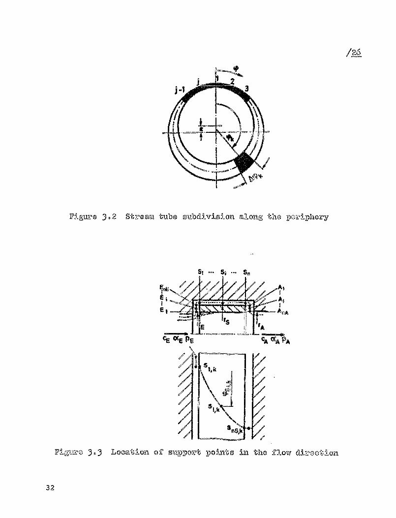
The clearance (B 9 S and A) is divided respectively into nE, nS
and nA support pointso in the flow direction, as shown in Figure
3.3. above, characterized by the subscript i. Using theperipheral angle ^ as an exartiple, the complete indexing is shown
'-^ or the radial clearance S. We have left; out whenever there.L
is no possibility of confusion. 12 we require the support pointsto lie on a flow line, the tangents to the flow lines are given
together with the corresponding flow angles. These can beappro]Zimated by straight line segments, if appropriate
assumptions are made regarding the intersection of two
consecutive tangents.
If we subdivide the radial entrance E of radius r E to r S into n"S,support points, as in Figure 3.4, below, then at constant step
width,
/.2.8-the radii
33
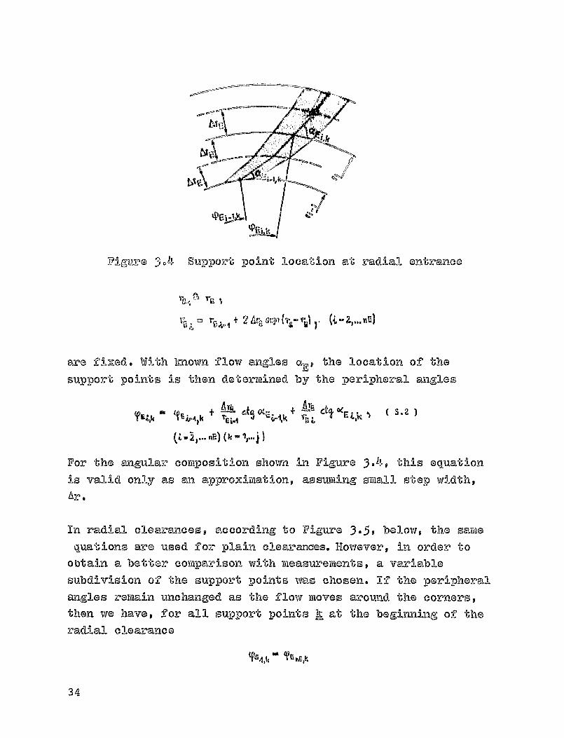
Fig-uve 3.4 Support point location at radial entrance
2 Arp avin ILI ), (t 21 ... nt)
are fi ,lzed. With Imown flow angles aE j the location of thesupport points is then determined by the peripheral angles
^E;" k + arm -4I
(Z - 2 ' .. nB) (k -1r... i )
For the angular composition shown in Figure 3 . 49 this equation
is valid only as an approximation, assuming small step width,Or.
In radial clearances, according to Figure 3.5, below, the samequations are used for plain clear ances. However, in order toObtain a better comparison with measurements, a variable
subdivision of the support points was chosen. If the peripheralangles remain unchanged as the flow moves around the corners,
then we have, for all support points k at the beginning of theradial clearance
T-S4.1, ' TE'Elk
34

q),nE,k Q Ik -01,0 if
amc, I /M41.1
Yskk014-11!, + G dre V-8L,k
Il
( 3.3 )
Figure 3.5 Location of support points for a smoothradial clearance
I
Figure 3.6 Location of support points for alabyrinth
35

Fop a labyripth, snDDovt points can be QoKno? only immediatelyat the PoQtv SACO no U002ul a0malwyon ions a velocity
distribution can bo DaGo in the chambers. Bocause of thi s factsthe volatioY'AD bo%woon the suplort point location and the flowangloo at the TVIN aoquivo particular significance. Startingwith the last YVAM RnBek of the ontrancog it is assumed,according to ZZiso ).6, above, that the flow in the firstchamber boaoE:- Onvbulont, following a path at the perimotov ofthe labyrWl aLsmbov that i s proportional to the height h ofthe chamber vnd to Cho flow angles at the end of the radialentrance.
t4F Mi ctj,,,S1'^v W F- F4 at, Ok % lk
/ noAccording to this, as in the case of the mxKth clearance, theflow line lo composed of straightof interooction of the flow linesthe weighting factor 0 <gs <1, wh99 = 0-5.
line segments, where the pointcan be changed by means of the
1ch in Figure 3.6 is drawn for
%T` O'D ) Ott ast-, ct-qhy
In the radial exitv the peripheral angles can be calculated inthe same manner as in the entrance. If a musth radial clearance
precedes the emit, than as a first appromimation there will beno change in the peripheral angle at the cornet to the ezit
Won
shile in a labyrinth the width of the last chamber must still betaken into Ansi cue ration:
q xt (A is
A, Na,k'
36
'O' `k'ho pho'?all , Oleo wo oh,,--011- hava, :1n) q-n,9loC,,:y to
VIGtIvo
TAHk + &q'XAZ-jIh + -A--'V6 e-to 'Y-Atik14-1 "A L
Thu S, lb-ho path followed by the fluid from the clearance entrance
to its o2zit is detormined only by local flow angloo and the
distancoo to the reference lines. Obviously, complicated
clGareqYneG forms can also be studied in this manner, provided 'an
-adequate relationship can be found between the flow angles at
the support points and the peripheral a:nglez, More precise
prodictions - especially in the case of labyrinth seals - can be
maac3o only iAien it becomes to obtaln em-p-Irical
information from flow lines -rendered visible.
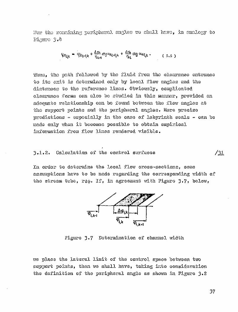
3.1.2. Calculation of the control surfaces
/al
In. order to determine the local flow Oros S-secij lons 9 soma
as SwIti-Pt ions have to be made regarding the Corresponding width of
the stream tube, rA . Ifv in agreement with Figure 3.79 below,
Figure 3 . 7 Determination of channel width
we place the lateral limit ox" the control space between two
sujo- -rt points, then we shall have, taking into considerationpo
the definition of the peripheral angle as shown in Figure 3.2
37

AY ff 2-r
A(?
( 3.6 )
+ Y4,V4 I
Assuming a rotor displacement with ragaird to the ho"sAnig,
poo-eleallel to 'rho a--.Us, according "'0 Fl aure 3.1 the
local
clearance widths remain constant in the radial entrance z
13 and
exit- '-'A p while the radial cloarance lo dependent on both the
peripheral angle ^ -and the eccentricity, a. To reduce the fe-orma-,
otructureq we desisted at this point from also including cau
inclination o-'O" the rotor with respect to the housing. Because of
the banding line of the vibrating turbine shaft, theiclinations in the domain of the steps are small, in any event.
For this reason we may neglect the affect, at this -point.
The local radial cloarance width according to Figure 3- 2 can besatisfactorily approximated by
t - r. --e COS T
/32where it is assumed that at a support point iP i9k that width willCorrespond 'to the average value of # i9k' For a sufficientlynarrow subdivision at the perimeter, this approllimation has no
effect On the final result, comparison to an exact
integration. Thus we have, for the local surfaces of all streaftitubes,
A 4,k ATFXk ^s I
ASj,kAyqtk (s —a Cos (?,S k) 3.7
AA4 'k Ati,k 'AM ATAkk 5A
38

^! \°
41
Tilo eoyz) zxaa !on p lntroOmood hoN°o mcaho It of 31-A:)l 0,^o ^ram :Innz6o OOnm"WI5Qmt1' o&2 Oonstrio 'c":1-01-10 th'at
003tu? duo to doacl) viatoz- oz, otoocnyf2 7^"6) -'6110 j,)Oaj7_c. :t?O%I
I'Al 'ain 0-I 04:,,-"71n0o0 cemid tm'bulo^-Y6 glow w1ith I! m I # wo shall bog :11-i
by coon um1mg "ohc)'I" tho ro:?Oz4onco 01,0 'so-Sootlioaf 14o cox-f plo-UNOIY
yM A -110cl by 'rho ntzlo(am; Toz' labyploath Wonl lc, Nod. mcma0c, [24]
moactnood valuoo can be umd. At cons taxit coal Doak w-I &I'L 'a, 9 tho
o '-POOCtIvo glow
doo-vo-at-jo-' wilth 11-noro-aOing madluq:--1
clo'c":i-mico width o f 'em" ohown In Figllro 3.8.
Relat3-ve"A rid3e thickness ,-/A
Figure 3- 8 Coy tra,,Cti on co efficients (from [241)
Ac cording to 1 t9 teak I ngp the
st-ream contraction into ac Oomt , a
clearanco that is variable along 'he per mebecomes somewhat., U 6
more mniforw. It
reirialnis to be established, howeverg whether
this contrection coefficient is i Wires tricredly applicable alsoto a seal peak
with a diagonal flow thz^ough it.
3. 2 Basic strearii tube equations
,fti essential advantage of
the decorkposition into individual
otroam tubes is
th,,:-Lt the basic equations of fluid flow mochanics
can be satisfied unidimensionally for every control space.
39
This mahoo it possible to apply loco 0002fiolonts Zoom the
labyrinth thooryq as veil a the laws of Qbo hydrarlico. In
principle, one could also calculate comprosoibly along the
stream tube, using procedures already hnova [15]. Howavor, the
contort of
this study aoonmos incomprosoiblo fluidop which seems
particularly permissible, conoidoving the relatively low
pr000ure drop and Mach numbers NA 0 0-5 at the clearancesconoldorodp especially that of the rotor.
3- 2 - 1 - Boundary conditions at cloarance entry and exit
The pressuroo and velocities caused in the blade otream must be
known immodiatoly at the clearance entrance and exit. Stprting,
from these conditions, the throughput of each stream tube will
result from the losses in the clearanco. Once the average
cross-section calculations have been performad for a turbine
stop (cf. section 40A.), it can be generally assumed that theflow will obey the potential vortex law. Through it we obtain,
from a tangential component 0 um
at velocity cm at a radius r mithe tangential component c
u at radius R.
UC
LA Vn
rM -
If we further assume that the axial velocity c sin a is constant,
along the ra thus o then we have
C el" at - C n, sin mm .
Lot the density be uniform throughout the channel; we can then
apply the energy equation
+
It is thus possible to calculate the velocity g, the pressure
and the angle of flow a at a radius 1.
15-L,
40
Z7
^t a 2
Cm [ ( , Cog CAM 2.
52" 0cm ^ $
P PW il P
Ct 0;,,,
As "), fit of appro ,=Imat ion this yl, oldo the promomras, and
velocities before the clearance, at
the read r. of the entranceand r
l^ of the o--I
We Ray now assume that at the clearance entrance, according toFigure 3 - 3, a glow line azzists that sam@xates the mass, streamflowing through the stream tube from the Main flow. Thereby the
clearance throughput is no longer determined only by the static
pressure drop, but also by the energy of
the incoming
velocities, whose impulse determined the flow direction inside
the clearance. By the same token, shearing forces due to mixed
friction at the separating flow line could act on the clearanceflowq which can be neglected here, however, in comparison to the
incoming impulse. The effect of an overlapping in La Roche'ssense W. section 2.3-3.) shall be neglected, at this point.
But it could be described generally by me-ns of
the losscoefficients to be introduced later.
At the exitq the clearance flow becomes mi ,Krid with the meridian
channel flow; here, because of the differences in velocity,rdZed friction forces front the main flow will act on theclearance's stream tubes. It is conceivable that during thisprocess part of the kinetic energy of either the clearance flowor main flow is converted into pressure. Howevers according tothe transverse pressure equation of flow mechanics (cf. [161)p
it can be assumed - for most seal constructions - that the
el-Ating clearance flow will be subject to the static pressure
behind the clearance.
41
Tho pzrocoosoo Ede ocribod abovo Zor the 0102Y'G)2200 Ontz?@,noo Q-ad_ 12Aozbit qaro oz,z^plre000d bolow in onorgy impulso oquations. Tothils, 0'ad we y1mot flor"t Introduco for-ml-al 6000010-0yee' s, 90%a thoproo'suro los"o' and luncoyAng wh000 mca,"nfl-tudo w-02.11 boO'ZIM"mined more closely only In sect on 3.3.
3.2.2. continuity OQU."'tion
For each support poij-_i t :1 the continuil ty equ Iation cam besatisfied with the throughput
of stream tube h. it i-my be
assumed that i n the cross-section, perpendicularly to the flowdirection Ai 9
k sinai'k there is I:lm o-vez-agm velocity, since !-.,I
equation (3.7) we already introduced contraction coefficientsIAi_ k that take into account a variable velocity disIc-ributionwithin the effective flow cross-section. Therefore the
velocities
W^)k 9 A b 1k
can be calculated for all support points in the clearances E, Sand A: from -the throughput 1. of the stream tube and at constant
density.
3.2.3. Energy equation
In each stream tube, the energy equations can be set up from oneswpport point to the next. According to section 3.2. we mustdistinguish here between three basic types of control spaces,
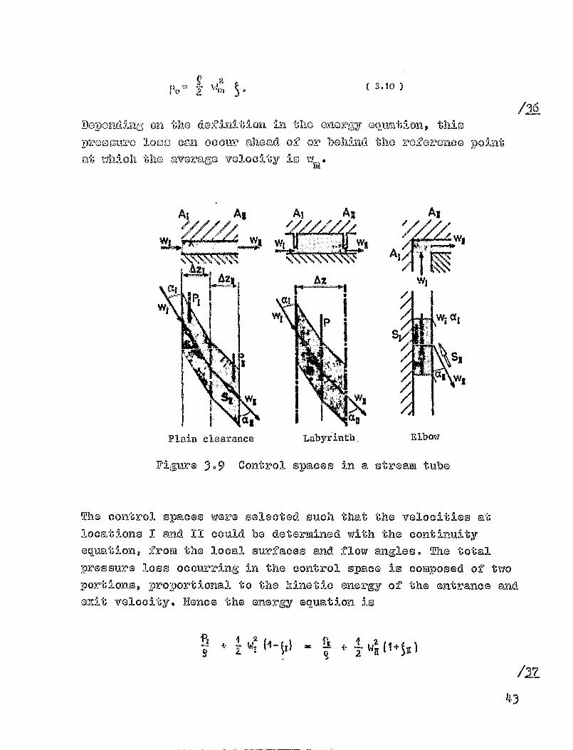
which are surm►rized in Figure 3.9, below. The pressure lossescaused by friction against the channel walls or by velocityvorteming can be assirmed to be proportional to the kinetic
energy of the flow, with a loss coefficient ^,
42
i
N
Ai Al
Plain clearance,
As Al
I W,
ElbowLabyrinth,
( 3.10 )
Do- 0 -poi-Lld JIxig On :J--&L -Le
, on
"ho do-I'LL-AJ6 2I tl eno'916-y GOV.,ations this
pz,00nu%^o loss can occur whoad of or behind the 2-Oforonca point
at VfMch tile avaro-GO velocity is VYF11
/26
Figure 3.9 Conti®l s-Paces in a stream tube
The control spaces were selected such that the velocities at
locations I and 11 could be determined with the continuityequation, frora the local surfaces and flow angles. The totalpressure loss occurring in the control space is composed of two
portions, proportional to the kinetic energy of the entrance and@-xit velocity. Plane the energy equation is
+ W' (4 - WZ
/27-
43
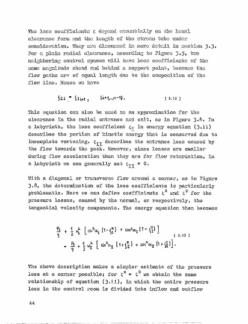
The loo r., GOOZZ11 01012to C depond. oos'OntLj'.,nl-1 y oi-^i the looeal
cloaranco forKii and 'shelonGth, of tho st:i2oayiI tubo trador
con-Oldoratiun. Thoy a--i-o di sous ced in Filoro dotall in soctio-n
For "'. plal in radliall clearance, according- 'to KP I G-, ire e 3 . 5 9 t vio
neighboring control spaces vAll have loom coot ficiento of tho
same wagni iu'ude ahead and behind a support point, because the
flow paths aro° of equal langth due to the coyiiposit- Ion of the
flow line. Henc e we have
^nl .- ^ I w ; ( ^- °1), ( 3.12 )
This equation can also be used am an approziyiiatlon for the
clearance in the radial entrance and ezit, as in F-Igure 3.4. in
a labyrinths the loss coefficient c, in enerrt.-;y equation (3.11)
describes the portion of kinetic energy that is conserved due toincortiplete vortexing. C TLI describes the entrance loom caused by
the flow towards the Dealt. However, since losses are swaller
during flow acceleration than they are for flovi retardation, -1-a
a labyrinth we can generally set X11 = 0.
With a diagonal or transverse flow around a corner, as in Figure
3 .8 9 the de terrAnation of the loss coefficients is particularlyprobleyaatic. Here we can define coefficients 0 and C 1' for thepressure losses, caused by the norraal, or respectively, thetangential velocity cohTonents. The energy equation then becopies
11Z + C0820( , Tj. C'isl ^11W, S1
WZ
( 3.13
.SLI2,R'a ( I i, t, ) +
4- ^ 1 ^II' ^ .
2 3
The above descrip tion raakes a sirtapler estiwate of the pressureloss at a corner possible- for ^ 2 = ^^ via obtain the saytierelationship of equation i3.11), in which the entire pressureloss in the control roorti is divided -i-.,Ito inflow and outflow
44
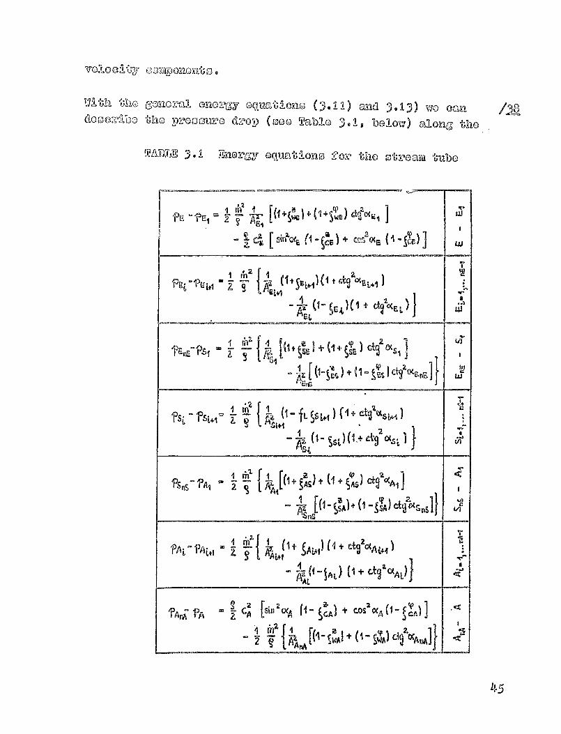
dO Oo ''S%bc thc -9-,i'c0 surd d:'®p (coo Tablo 3.1 a bo ovi) al onc, ',cllc
TABLE 3.1 E'Rcz-GY OQU t ®mss v or tho O t-Malil tube
" C;q
e^
g{^ + ^wE) $ { 1 swe ^t`a( 1 ta!
i
'Pat - 'p- t; Lt1 w
A2 (fi+ ^ Ltd) l 1 t etc c>s i^1
E`tiqi
I- 10 SCE ) j^ ^ al2oca L ) ^
u!!dAcv J
ui
1
6 `'art
`Psi - fs L+1
tilt
^ 0 — ^ i,tq } (1 + ^t^^ocs^+aSi
p^e
+q
J
s t^5 0 ^A1
z
gAAiL(1
+ AS + (1 a SAS) G+22(fAq
^°
t
w z [0- ^sA) + 0 - kA) ^$
® Tz (1 ®lAt{ 1 + Gtj$ 6tAL )
v¢
AL
4"A[0 WA^+^1—SWAa
dI CCAMJ
1.1 5
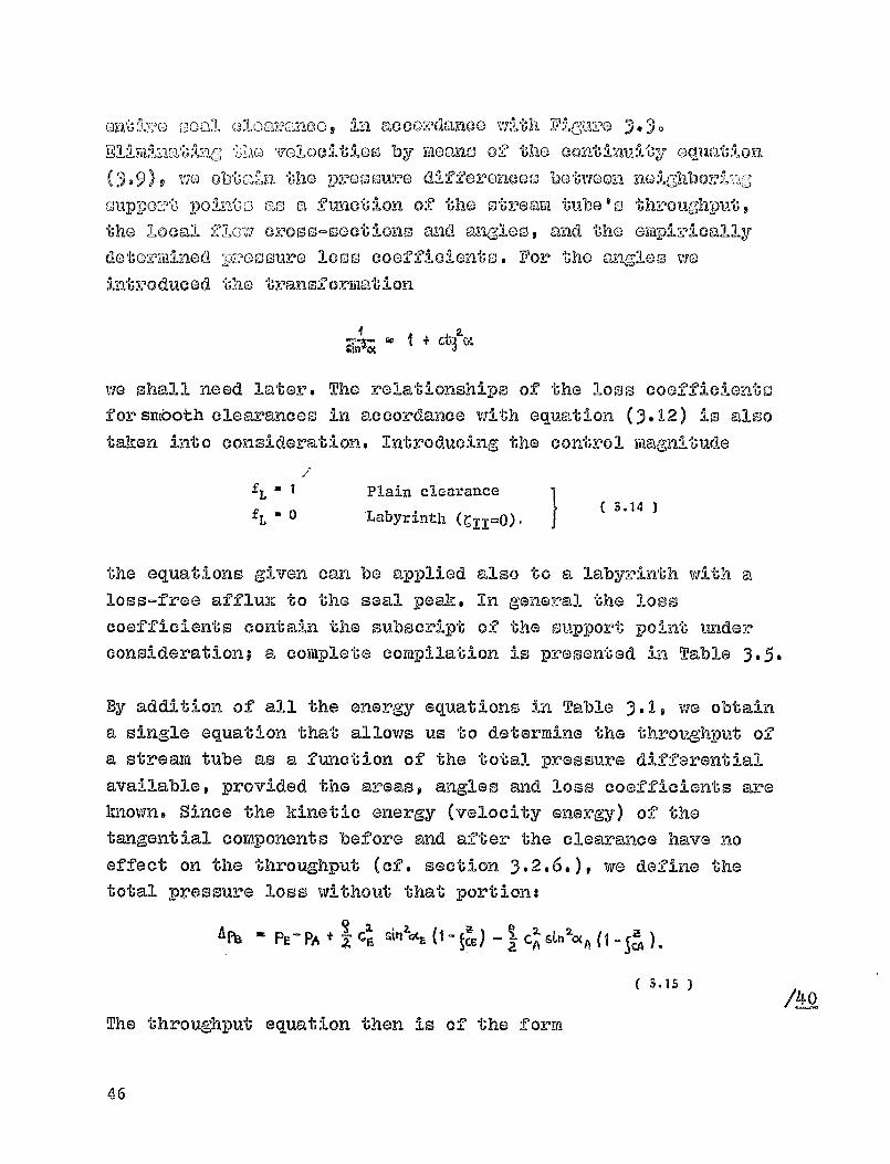
-Oal 010Q'_,,'an00, in
aCCOE-danOO With FIN 'Dvolocitloo by meano, o_'O" tho co t:lunulty oqi-^_D_O ua.^Ion
wo obtc0l.'n oho p-recoure differoncolo botwoon noiGhboring
X 4 1 p - tass a fu-,nctl on
of the otream ttibo I o thvoug!-hput
the local flow evoss-soctions amiad anrgloo, and the oytypizoioally
dotoz'TtiLiod ip ,@osuro loss coefficients. For
the anglos we
int:ooduced the transformation
iw'-x a I + ctl 0^
we shall need later. The relationships of the loss coefficientsfor sniboth clearances in accordance with equatlon (3.12) is also
taken into consideration. Introducing the control magnitude
fL
* I Plain clearancefL
" 0 labyrinth (^=O).3.14
the equations given can be applied also to a labyrinth with an
loss-free of lux to the seal peak. In general the losscoefficients contain the subscript of the support point underconsideration; a complete compilation is presented in Table 3-5-
By addition of all the energy equations in Table 3- 1 , we obtain• single equation that allows us to determine the throughput of• stream tube as a function of the total pressure differentialavailable, provided the areas, angles and loss coefficients areknown. Since the kinetic energy (velocity energy) of thetangential components before and after the clearance have noeffect on the throughput ( of - section 3 * 2@6 * ) t we define thetotal pressure loss without that portion:
AN " Z - ' 2 A - CA- )tL — 1 C2* 'Stn 20( AP -Z C
PF A
( 3.15 )
The throughput equation then is of the formO0
46

Apa zt C ' e (I - S^^" 5^+ dA
'2 5(Xk
+ +
X
Hovxovor, sinco tho analos are also a function of the throughput
© as via shall see in the followkag. section - some specialconsiderat-ions (000 section 3-2-5-)
must still be applied to
these calculat i ons. According-lye Table 3.1 provides the entirepressure distribution through all support points is in the
seal clearance.
3.2.4. Momentum equation
The change in a nment= entering and leaving a control surface
is equal to the smi of all erternal forces acting on the control
space. If the irmentum change is to be calculated in this manner,
the a%tarnal l forces have to be sufficiently known. On a control
space as shown in Figure 3-9 there act ® disregarding
gravitat i onal and centrifugal forces - compressive forces at theliTait's as well as supporting forces due to friction against
channel walls. Applying the momentum theore yii per- pand-i cula"rly to
the entrance and exit surfaces is unfavorable for the controlspace selected, since it requires knowledge of the pressuresacting on the end planes AI and A,,, from the ene
rgy equation.
If the moment= theora ya is applied in the tangential direction,
then these compressive forces are slim!--nated. Then only the muchsmaller forces acting on the lateral limits of the stream tube
must be determined by iteration from a pressure distributionalong the perimeter.
If we take into consideration variable radii at the entrance and
amit of a Control Space , as in Figure 3-9, then the momentum
47
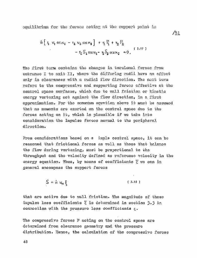
IOqui 131britail 'for tho -Oovcos' o` `an alt; tho ouppozl^ - in0 -po ., t `Ag
iYl V, W COS ME - Ya t-jq COS Vx ] + ti' R. + P"
Cos IM ID;(KrI - 'rk S
C,
The first -'U- Orril cont, al I ns 'b,he chan-ges in t ors 1 ona) f or Go 0 froyll
entreance I to exulit 11 9 whe^@ the differing radii h@ve an offoct
only in clearances with an. redliall flow direction. The nort term
refers to the compressive nf.:nd supporting forces effective at the
control space surfaces, which due to wall friction or hinetic
energy vortexing, act against the flow direction, in a flirst
ap - Vproximat-Jon. For the mo-mentm aqvP t ion above it must be assumed
that no moments are e ,Kerted on the control space due to the
forces acting on it, which is dal-nusible if we take into
consideration the impulse forces normal to the peripheral
direction.
From considerations based on a imple control space, it can be
reasoned that frictional forces as well as those that balance
the flow dying vortaxing, must be proportional to the
throughput and the velocity defined as reference velocity in theenerg.,,y equation. Thus, by means of coefficients Z we can ingeneral encompass the support forces
. S ( 3.18 )
that are active due to wall friction. The magnitude of these
impulse loss coefficients Z is determined in section 3-3 inconnection with the pressure loss coefficients C.
The compressive forces P acting on the control space aredetermined from clearance georaetry and the pressuredistribution. Hence, the calculation of the compressive forces
Aul
48

p.
ou2,?o distvibutian in all stroamt-d 30o, o' lb-10 OnIj whon tho pro- -"
t-M)O-() Iias, boon dctoz-idnod, Tho varlation of tho a)-Iong,
tho por:Lmoter cz la ba roprosentod at locationo i by moans of the
Fouror 00:0100
OU 4 04 Q& T -"^ a2' cgs 2CP + + o " Cos M T
4. b4 vnT + b.&In2y +— + b l,, sinmy
Froxii j Imown pro o-surer 'Pi 1, in a support plane 1 and the
co o perreopnding ri-0
0 f Y(l( j/2) -1phe-ral a ngloo u M^:L,k l a ma-""T"
coefficients can be determined for the function p i ( *) 9 for
insta.-nco by a least squares fit method. However, since due t o
their iterative determination ( section 3.5. ) the pressures are
not given exactly,, a curve-fitting with Wewer coefficients can
lead to bettor convergence of the calculation procedure,especially for labyrinths.
According to Figure 3- 10 9 the resulting tangential compressive
ILT2
T
Figure 3. 10 Compressive forces acting on the control space
49

force P is composed of the forces P-10, -Inlicl Pb o
aotl y,LC,; 2rom both
sides on the free porwtions of the otroam tube , TIO tWi-S bo-
addod the supporting -'1 0:000 St , oaorted on the fluid as a
consequence of
the channel ou"evatu-ro. For "), 05-FlIpla oealculatlo-n
of those forces it Is, asstniod that the pr000ure distribution and
the vc):rien-ble width of a oup-gort le, 1 -a o coi a9 no — r -10 t nic,
over the width As i s For a siftooth clearainco, it is -possible to
attain an (DaUr).ct solution with suff-leflently narrow spacing of
the
support points ka the flow d i rection; for a labyri nth, instead,
because of the unknown pressure distribution inside the chaxAbor,
no more precise considerations are possible. With a variable
clearance width
5 t - 11 + S° e Cos (P
which takes into consideration tho height of the labyrinth
chamber, the individual forces can be determined across the
width AF,.
Pa 9.401) P(Ta)
F114b)
9b
p((e) dy - as e PP((q) szinT d
1h
By introducing the coefficients % I
and by,, of the pressure
distribution (3.19), these forces can be calculated within the
prescribed interval % to *b in the control space. The
doteriTO-ned integrals occurring for the support force S t are ofthe f orya
/L2
50

with the ummally tabulatedits and shall be assumed
cowpressivo force acting
CFb
fx. (V ran (f4n
i
b., sLvi x
IC
Tlioir oolution is generally P0001blosi- ovyimlaa, for any ntymbev of coofficiei
known, here. The re sultan OU'angential
on the control space now is
Pilk - A 2^ t (11 + S I [ F,( CVQ I - F[Tb) I
I COS To P (qQ) T b P (T bl 3.21
dy
CFO
It can be shown that if we asewme p(t) = constant, the -resulting
compressive force vanishes. In a labyrinth the effect of
the
compressive forces increases with increasing chamber height and
for variable radial clearance widths is dependent on the local
gradient ds/d^. However, the sum of all the compressive forces
along the perimeter must be zero. For the radial entrance E and
exit A the calculation performed above for the compressive
forces acting on the free portion of the control space is rauch
simplar, since the supportive forces St (3.20) vanish, becauseof the constant clearance width.
Once all e.,.rtemal forces in the impulse moment equation (3.16)
have been calculated, that equation can be used to calculate theflow anglas at a support point 11, if that angle is Immm for
the imidediately -preceding support point 1. Since at the entrance
the flow angle is given by the main flow in the raeridian-
channel s in conformance to Figure 3.3 9 the angles at all other
51
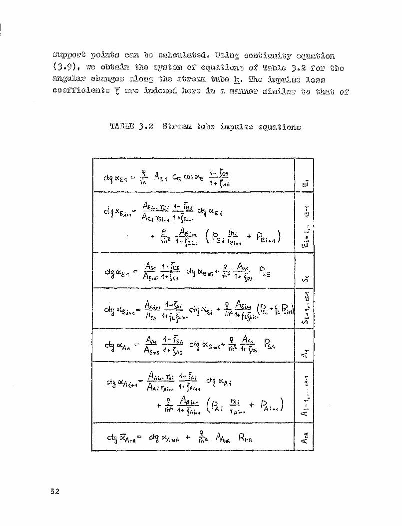
su-Ppovt pointo Can be caulcullau -U`Od. Usln, eon'Unul-ty oQu.'atlion
(3-9) t wo obtain the 0yotem of oquations of Tcl IkAo 3.2 tho
ulmgulav chemiges along t-ho otzc.,a-m tvibo h. Tho luitypulon loco
0002-P-110-10--ill';s 'C incle2zed hcz^o In M 8C3a5A ,10:0 ollmilor to that of
TABLE 3.2 Stro'elml tube impulse equations
Ckq 9 F-4 AE I 's COS 04F
4-
1 -4
pe + P- . 011+ 4ai4q LU
A,s, qA psr+ -5—Ac.E 14-
Sic
ps i + it psitilAs., I+ fL 41
C(I V-A4A4AA,, 4 - TsA Cpl C,(S
i^ss 44- ^AG ^ASPSA
kiss ZA; 4 °
1+ JA44
C'f A 4
AA4A-^- + PA
4+ TA
r-'5 6FA tA Of^ O^A,,A + 1^1 AAjA RMA
52
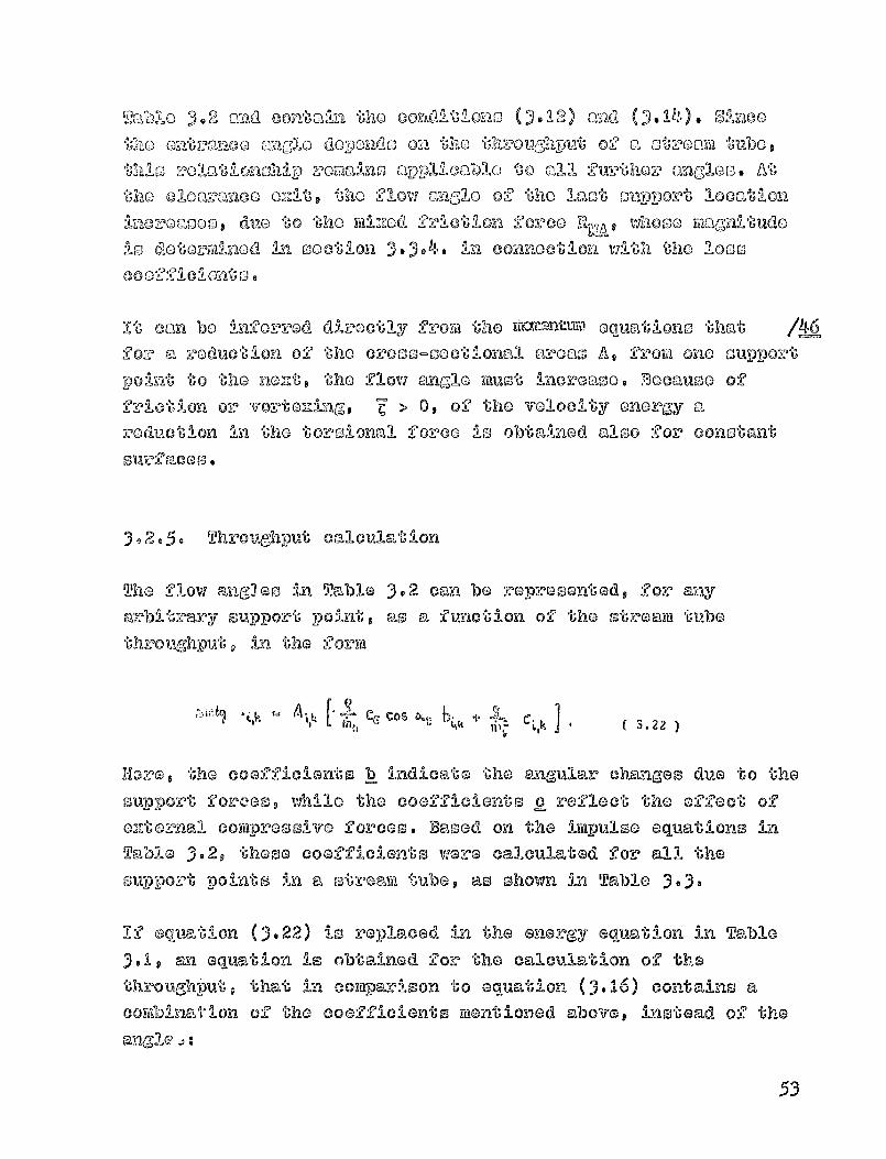
Table 5.2 and contain the oolditiono (1012) and SWOOCho onbranoo anolo Upon& on Cho Chroughput 02 a otsoam tubesthis rolaWaSip romaAno Qpplieablo to all furthow angles. AtCho cloarance OM P the flow Engle 00 the last Oupport locationWononoon, due to the Used friction forco %ap whose ma3pitudois determined An section ).J.4. in connection with the loco0002ficianjo.
It can be Qforvod directly from the fLMMI•UAW Oquationo that /06for a reduction of the cr000-ooctional avoao A t from one Oupportpoint to the noutp the flow angle Must increase. Because offriction or vortoning, Z > 0, of the velocity energy areduction in the torsional foveo is obtained also for constantsurfaces.
3.2-5. Throughput calculation
The flow angles in Tabl e 3- 2 can be represented, for anyarbitrary support point, as a function of the stream tubethroughput, in the form
acscc Cos a., 6
3.22
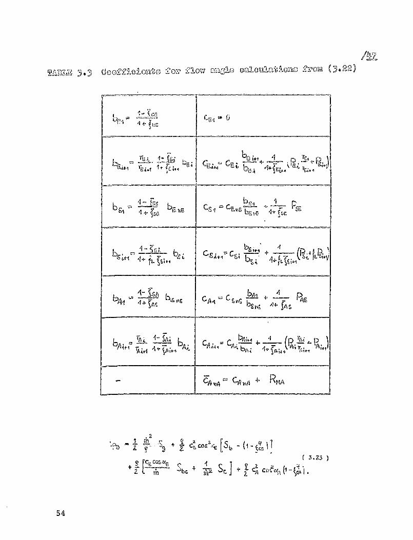
Hare, the coefficients h indicate the angular changes due to thesupport Forces, while the coefficients I reflect the effect ofMernal compressive forces. Based on the impulse equations inTable 3.2, these coefficients were calculated for all thesupport pointo in a stream tube, as shown in Table 3-3-
If equation (3.22) is replaced in the energy equation in Table3- 1 , an equation is nbtained for the calculation of the%hrouZhPV • that in comparison to equation ().16) contains acombination of the coefficients mentioned above,instead of theangle 0:
53
AqI
TAK3 I ^ 5 - am""'Ol-oll or5y6n, :Olow ")z"231c) ('3,91-oulo-i6lo ono 2zoy!2 0.22)
cul
ba 41 bta 4.r.-
^C_Jl 11 4- `c, c, - Pab3A
1 4- brHJ
+
b
c-! S-1
4+
ft.
bA 4 4. be h5Re
Aa fA
t>E! 4^CA CA - — p4;—
bA,
.4 vA cA vA R^IA
2
+ CosTB 'Y q [51,
+
CA
54
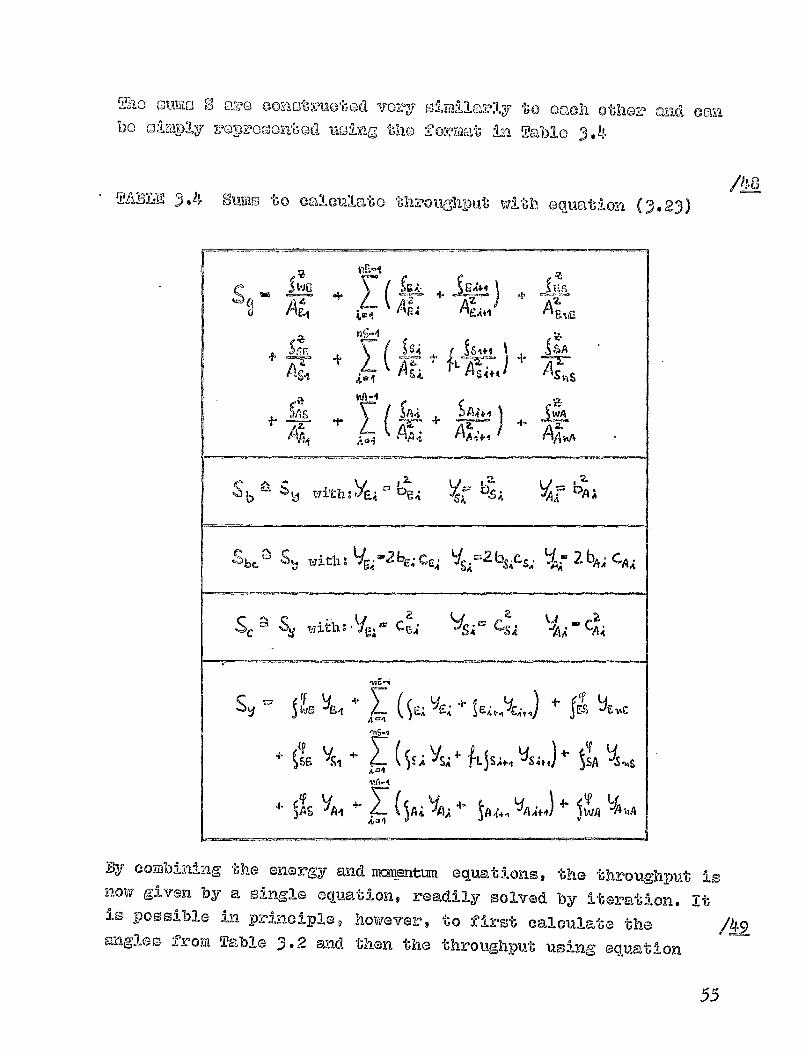
Tho conctime"620d vozy 01m:1-1 -l arly to Oach Othoz, and Canbe a
!!'-'IPlY :POP-'00G0ff6Od 111C,, the
OOM-Rat L2 Table 3.11
TABLE minis to OcA cul ato through- /^
put with eq-Lj,,-),t-*jon
Az
Z
A&4 64 AzeA41
As p Asi+, Asks
IA r,
4A- A AzA,4-1 2'AA,,A
S b De"S ? Tq t h 2 VA bAl
nS Id with: V
c:A -2 bE; cc^ VS 2- bs c 2 bA; CAR
Sc S.V • ith Ife., - c E; cs! IjAu - C•
SV(^F-A ^ eAFA^`A4 A^ ^4r5 ® 41^^
dd
+GF,
4°4
VSI + E R YSa 4- ^LJ
S A,, 'JS + SA
4- S qAS
%iA-4
^A4 (^AiJAA4,
' ^A4.•, LJA.i+J)
WA AIA
--------------
By combining the energy andmomentun equat i ons, the throughput isas®W glmen by a single eqUatio-q$ readily solved by iteration. itis possible in Principle, however, to first calculate thea-`ngles f-ro-va Table 3- 2 and then the throughput using equatican
55
( 3.16). Of cou%,00, La ghat 0,9_00 'rho calloullationo
ijacroa-'moo con sidor,bly, do'pozldin^s oil tho 1-ilagnitudo Of 'Gho
torsional fovooa at the ontveanco. Howovor, t'he undo:plyinrg
assivimtion in throughput calculat-l oiao acewodinr, to tho- aboveO uat on is "-) hnowlodao of the local flow and
loss coefficients, which can be obtained by 1toration f:Pom thecouroG of the flow lines.
3.2.6. Discussion of the basic equations using a sl ►rpleclearance shape
A dimensionless description of the basic equations for a streamtube is possible only if the boundary condi t i ons ahead of andbehind the clearance are eliFainateds while retaa ning the effect
of the seal geometry. Since as will be shovrn later, the loss
coefficients introduced depend on the local flow angle andReynold ' s number, a comple te similarity can not be attained for
different init ial pressures and velocities.
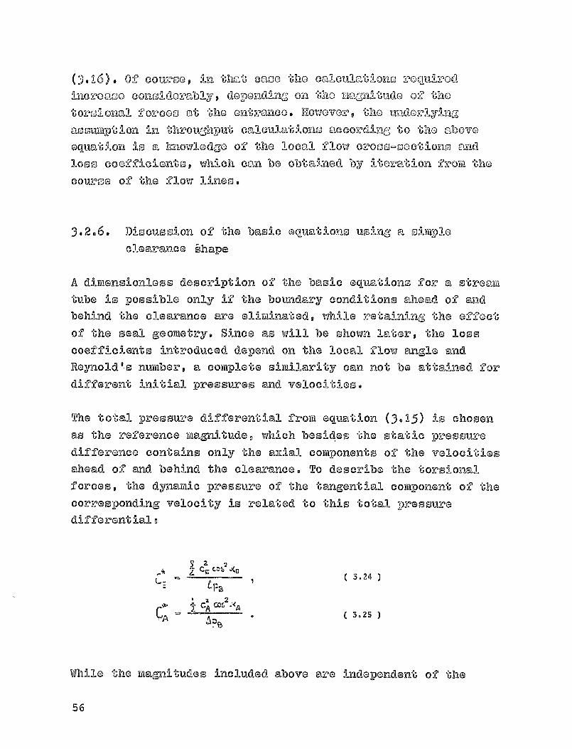
The total pressure differential from equation (3-15) is chosenas the reference magni tudev which besides the static pressure
difference contains only the ax al components of the velocities
ahead of and behind the clearance. To describe the torsionalforces, the dynamic pressure of the tangential component of t hecorresponding velocity is re a ged to this total pressuredifferential o
22Cc casa AC
3.24z
2eA Cos "<A3.25
While the magnitudes included above are independen t of the
56
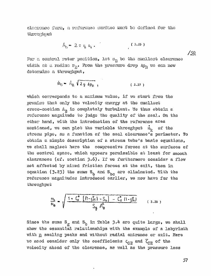
a ro2o-ronoo ouv2aoo muct bo 61.Wr,57med Oo-j' the
3.26
For 'a cmutral rotor positions lot t-z' D- be tho omealloot cloaramoo
VIV1,411 at 'a "radi'Llo ApB vie canZ "i -pr 000ure drop nowD e From t(10toz?ii,lim a th-roughput"'s
61 r3 . A--- -,—
B. C2 9Q A PB 1 3.27
which corresponds to a vague, if vie start from the
promiso that only the velocity onergy at the smallest
cross-section AD is completely turbulent. We thus obtain areference magmitudo to judge the quality
of the seal. On the
other hand, with the introduction of the reference area
mentionedg we can plot the variable throughput Yak of
the
stream pipeg as a function of the seal clearance's perimeter. To
obtain a simple deoeviption of a stream tube's basic equations,
we shall neglect here the compressive forces at the surfaces ofthe control space, which appears permissible at least for smoothclearances (of. section 3.6). If we fvrtharraore consider a flow
not affected by mixed friction forces at the ex t, then in
equation (3.23) the Sums S b andd S bc are elimin-ated. With thereference raag-aitudes introduced earlier, we now have for -the
throughput
+A^"_k (I - 'S C* ( I -
2.3.28
Since the sums S and Sb
in Table 3.4 are quite large, we shall
show the essenti.al relationships with the example of a labyrinth
with n sealing peaks and without radial entrance or exit. Here
we need consider only the coefficients c CE and -Cc E of the
velocity ahead of the clearance, as well as the pressure loss
57

PW imoulso 1001--i 60022W.Onto 6 1 or rOSPOOtIAVOIY O =CS tat t'ho
vocalm. WO thus have tllo, :,r '011owins Conditions:
nE - 0,
a C? US,^Wc.9WC- iwp-
nA 0
A A„
wASWA - S' 2 (WA
,z YSCA . SCA
For the coefficients of Table 3.3 we now have
6s, - ( I - JCL, ) , .
b.SL ., - ( I - -Cn I N ( i - ^•) t ( ^ - 2,... n).Voi
From this we obtain the sums of Table 3.4v
Se0-_ ^Cs)" T^^
Vol
where for I the product above takes the value
Val
If we take the dependence on the peripheral angle into account,described by the subscript of the stream tube k, then we have,using equation (3-28)t the referred throughput
( S ilk!
2.1 + C* ye) 0 KC)
m6
9.29 9.29.k X^.
LOT L-k ^A^'4^,,k
58

The Otrue1jure of the equation is Maintainad even 11 we tclhc into
Cons idoration all the loss coefficients do rood in "the provious,
sections or mono Gnonoral cloarancG forms. In this cases just
the Mum-tary,10 in the nuifflor"l tor and the donowinator will becomelargar.
If for a central rotor position via a2OIX510 equally sized flow
cross-sections at
all peaks, than the throughput - fox , completevortaming of the velocity energy - All be pro-&. portionaal to I/Ah
in the Imown iiiannerg where n is the number of seal peaks.Assirming equal pressure differentialso a decrease in
throughput could occur due to an affluxt affected by torsional
orces, if the expression in the rounded bracket of equation
(3- 29) becomes less than zero. For this, the relationshipbetween the coefficients ^ and -C - which will be discussed in
more detail in section 3-3.2. ® is of primary importance.
The local flow angles can be deterrainedo in the example chosen,
at an arbitrary sup-port po -int > x > n in stream tube It, from
Table 3.2
X-4
Ct'j C cos M A F (I
- ^,,) .k ( 3.30 )
In a similar manner it is possible to calculate local pressures
in the clearance from the differences for location x,k inTable 3.1
- 2. ti
^^^
!.!,L j4
t%%^b ) I t Ct 2
N +
Lax
k
With the throughput (3.29) and the flow angles above it is now
possible 'to describe the pressure distribution only in terms of
59

loss coofficionto and the local lou:0fa.000. As- an, opocia-1 cases qndas
shall be shown yet (of. equation (3.49) ), we can assulme a
dependence of the nmentun loss coefficients 'C on the prossu-z-o
loss coefficients ^, of the form
and -j&p 2.
T
In this manner the throughput would be Inde-pendent of the
magnitude of the relative affluiz energy C Y, 9 and via obtain, from
equation (3.29)t
IMk 3.32
A 2.
B4
Ik "Y
/0-Under these assumptions, the flow angles calculated above (3.30)can be described very simply as a function of the face areas A
of the control spaces and the loss coefficients, for a -ocat-Jon
2 2Y-1 11
C DL A F1 (I -x^k
According to this equation, for equal surfaces, with increasinguorsional effects at the entrance and larger pressure loss
coefficients, there will be smaller flow angles in theclearance. Along the clearanv -- (x > I), however, with complete
4. Cm n -1voru X"I-1'/'7 (^=I) a purely al-ial flow will be achieved, withotga =0. Pressure at the support points can be rendered in adimensionless manner with equatLons (3-31) to (3-33)
60
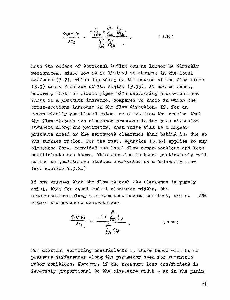
Vx'k - PA ( 3.34 )Apj3
L.k
Homo the effect of torsional influx can no longer be directlyrecognised, once now It is lim-11tad to chanizem in the localsurfaces (3.7) 9 whic -Iti depending on the course of the flow lines(3.3) are a, function of the angloo (3-33)- It can be shown,however, that for stream pi-pas with decreasing cross-@actionsthere is a, pressure increase, compared to those in which thecross-sections increase in the flow direction. If, for aneccentrically positioned rotor, we start from the promise- thatthe flow through the clearance proceeds in the same directionanywhere along the parimoterg then there will be a higherpressure ahead of the narrowest clearance than behind it, due tothe surface ratios. For the rest, equation (3-34) applies to any
clearance form, provided the local flow cross-sections and losscoefficients are Imown. This equation is he-nee particularly wellsuited to qualitative studies unaffected by a balancing flow(cf. section 2-3-2-)
If one assumes that the flow throug-h the clearance is purelyaxial, then for equal radial clearance widths, thecross-sections alon-P a stream tube become constant, and weobtain the pressure distribution
h
PXA_ PA +Ez ; Lk_
APB3.35
L-1
For constant vortaxing coefficients C, there hence will be no
pressure differences along the perimeter even f or eccentric
rotor positions. However, if the pressure loss coefficient is
inversely proportional to the clearance width - as in the plain
61
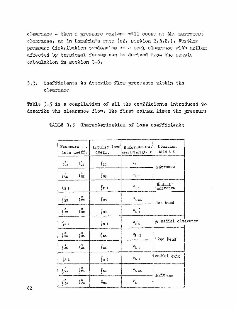
clearanco - then a z,-O0Ou:OO Ma-Zimum V7:7-111 ocolu'.- 'at, '96110 kl'arrowost
clongranco, ao in LowaMn's co'00 (0-0 . 000tion 2.3.2., . Y11--othor
pressure distribution tendencies in a mall cloavanco vrla-th a-Ulu:-.
affected by torsional forces can be
derived grow the uayikplo
calculation ka section 3.6.
3.3. Coefficients to describe flow processes within the
cleareanco
Table 3.5 is a compillatio-n of all the coefficients introduced to
describe the clearance flovi. The first colon lists the pressure
TABLE, 3-5 Characterization of loss coefficients
62
Pressure Impulse losS Refer.tjelra. Locationloss coeffe coeff. geschwindigkL^ A Dild 3 3
tcr l XE gCEC
Entrance
ZWE 14D w E I
E iwEi
'Radial'entrance
ES L'S PC; E ns1st bend
SE Sr j .SE w S I
S i s i w i8 Radial cle,
SA SA SA N nn2nd bend
AS ( ASSw A
w radial exitA
WA WA willw A MA
CA CAP.$tA C
A
irance

10-0 coofficlonti- I VAIII-a the ox-)CO110. disn - b"'he yarag'afl-tudo to,
"ponolblo for angull ,'%r eheangoo 'according" to the lit,aantmi-a
thooroya. F-row the coz-roapondlin"o 1'020ronco velocities it is
poosiblo to roadily rocogpiso the significamoo of
the Individua-A
solfbo'cripts" In Conjunction with the location dasiggiations shown
in Flr-al
Below vie shall determine the pressure loss coefficients ^ along
the otreaqra tube with equations fro ya the literature j while the
momentap loss coefficients Z can be determined only by means of
analogy cons-5 derations. Since the relation between these two
magnitudes is very essential to the throughput of the strealwi
tube, dan additional condition at the clearance entrance Faust besatisfied, which establishes the relation between the incoming
velocity energy and the entrance moment= (cf. section 3.3.2.3.)
3.3-1 Pressure loss coefficients
3.3-1-1. Pl"a n clearance
136
The loss coefficient ^, already intr,
equation (cf. equation 3-10)v can be
a plain clearance - according to thethe; length I o the htdraul ic a' Jiameter
friction coefficient X. According todiameter
Dduced for the energydetermined ® in the case oflaws of hydraulics g fromdhydr and the tube's[161 9 the hydraulic
!LA
Uban
is defined as the ratio of four times the flow cross-section tothe wetted perimeter, and corresponds here to twice theclearance width. The tube's friction coefficient depends on thetube wall roughness and on lReynold ® s number
Re W25V,
63

Vo^o hydra-ulioally omoo-16h vja!121 9 mocnomroc3 va-llms cas th000 in
3.11 (o-f. Truchonbrod ic, [16]) P,,r-m bo usocl. At' tho oour^,l
w2sV
Figure 3.11 Tube friction coefficients forhydraulically smooth walls
clearances in turbine stators, via shall assume here, without
rest-rictins, the calculation procedure for turbulent /Rflow. Thus we have, for the friction coeffic i ent? La v®n Ida rman 's
O
1 .(RAK) — I'a
IT
Since the flow lines in the clearance can be representedsectionally by straight lines t the flow paths I can berepresented (see Figure 3. 12 , below) as a func'^-Jon
of the flow
angle and the distance a to the reference line. We thenobtains for the loss coefficients in the case of -lainclearances
Ent rame e
64

mRad-l'all '01-0 avcanco COOV^""; *' -11 ^ 6zi
6rAA3 SA a
Figure 3-1 2 17o-r the calculation of loss coefficientsin a plain clearance
/51_8In the considerations above it was assumed that both channel
were at rest. In order to take into consideration the
modified -pre^sure loss for rotating channel wall, we start frorathe premise - as vie did before - that the velocities w and their
directions a represent average values across the clearance.Thusj the relative motion will then affoct only the direction of
the stream tube and the pressure drop. The resistance forces -which in a friction bearing, for instance, pause the
characteristic pressure build-up ahead of the narrowestclearance - are disregarded here, because of "ie considerationsin section 2.3..", .
According t o Figure 3. 1 3, below, at
the wall rotckting with a
tangential velocity R, the relative velocity v will e pis t- q Cas
oppe,sed to the absolute velocity at a fixed wall, H. If weconsider only a we tted surface of the clearances then the
65

itU I
F 3.13 Ve1® c- r!. eig channel weall rotation
hydraulic diameter becomes dhyd-r = 4 s,. Accordingly, the
friction coefficient moving along the fixed wall from I to 11
will be only half that of equation (3-36). At the rotatingsurface, the fluid traverses the path from I to IV at relativevelocity X and suffers the pressure drop
^ X L.Y V 747^ =^tn&
In the process, as a first approximation.
If we assume an average friction coefficient X for the pressureloss of both cleantance surfaces, then the total pressure loss -
using the definition in equation (3-1 0 ) - vill -I be 12-
P. + 5.37
The coefficient C to be used for the pressure loss at a 2ixedchannel wrall is that
of equation (3.36). The local -relative
velocities v -and their anggles 0 are easily calculated, from thegeometry -*Ln Figi-we 3- 1 31, as a fvLnct -i can of the absclute vel-ce- 4-ty L,,,
its angle a and the tangential velocity a. At least for flows with
a strong torsional effects the eqtiatio-, above will px°ovidz al.'I
estimate of the modified pressure loss.
66
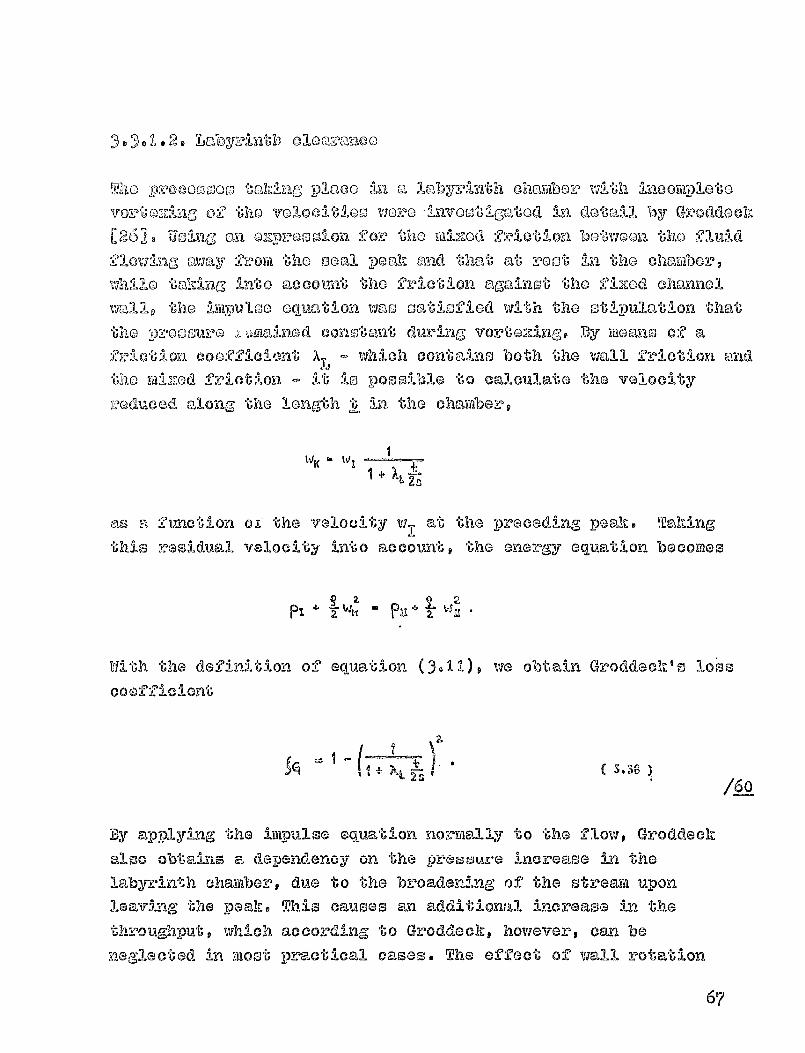
o o .10 2 0 Labyzlj nt I-,, oloac :,anoo
TI-7,10 oz000s-oo, t 'alJoLng 4 2-pl,"'Co LI&cortrploto
VD-_"-t^oZzLaG^ 02 tho VOIOCI` Ios woro linvost:%gatod 21a dot,110_1 by Groddoch
[261. Uoina an o2zpv'000lon for
the YA-zod friotlo ozi botwoon `0-ho OlivId
'110wing-, 'awal 'ho Boat po"f)'h and the,"e, at root -in tho chambor,
V711-110 i;")hIng into acconlx' tho friction agpd-not tho fixod channol
w 19 "6111" ocivatio-n vias toatisgied vAth the stipulation that
tho pz-00 'ouro a, :a no 'no-no d const 'ant du r` FIF" vo-vtozin a. BOY mo 'anss of @
friction coofAci^,bnt of - which conta-I Rs both the wall friction and
tho mizzod friotion - it
10 Possible to calculate the Valod-Ity
^,^oduood along the longth J; an the chamber,
+
as s function of the -veloc i ty w-
at the preceding peak. TakingI
this residual velocity into account, the energy GqVatIon b0corflos
2.
PI Pa
With the definition of equation (3.11). we obtain Groddeck's los's
coefficient
(GJtJ %
/§-0
By applying the impulse equation normally to the flow, Groddeck'-'-a ox^eosuru increase in theobtains a 1 aps- enoy o-.(-.L L^^Ww U a LV. UIL
labyrinth chamber, due to the broadening of the stream uponI a av in F_ al i ncrease in the, the Doak. This causes an addit lon-'Uhroutg1hputp which a.-cording to Groddeck, however, can be
n egglGcted in most practical cases. The effect of waill rotation
67
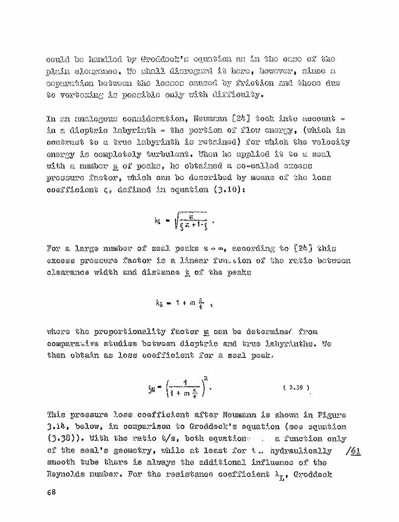
could bo homdlOff? b,,,x GroOdoolz.ls Oquatilon 00-ho ocaso 02 t.120
Pla-1,Y2 cloavanao. WO shall dlsroga"'d i ,6 hozzo l howovozo t sineo a
SoDm,,ation botwoon tho loosoci Calasod by friction aild thom (Imo
to vortozino; is only with 0:10NO"I'loulty.
In on 'analogom, conm1dozimatig one Notimelmn. [24] ooh into Liucoun-^ -in a d1optric labyrinth - the orb ion
of flow onorgy, (which In
contrast to a true labyrinth is rotaiaod) for which the velocity
energy' is complotaly turbul en" . When ho applied it to a seal
with a number s ®f peakoe he obtai-nod a so-called ozeess
proosure f-,-1,ctor j which can be described by mcans of
the loss
coefficient ^, defined i n equation, (3-10):
For a large nvitiber of seall - itPeaks s according, to [24) thloexcess pressure factor is a linear IN-a-- tAlon
of the ratio between
clearance width and distance t of the peaks
+
where the proportionality factor III can be determinee. from
couparaAve studies between dioptric and true labyrinths. Wethen obtain as loss coefficient for a seal peak,
This pressure loss coefficient after Neumann is shown in Figure3.14, below, in comparison to Groddeck's equal- (see equation
(3-38 ))- With the ratio t1sq both equat-J on c - a funct i on onlyof the seal's geometry, While at least for t... hydraulically
smooth tube there is always the additional influence of the
Reynolds number. For the resistance coefficient X L , Groddeck
68
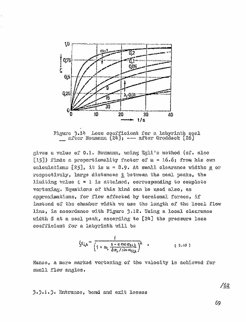
.n
- 0 10 20 30 40t S
Figure 3.14 Loss coefficient for a labyrin-th seal
after Neumann [241; --- after Groddock [261
gives a value of 0.1. Neu rtiann, using Egli's mothod (of. also[151) finds a pro port ionality factor of Fii = 16.6; from his own
calculations 12519 it is w ® 8.9. At small clean:zranco widths s or
respactivsly, large distmnsnces t between he p-aakso tull-M
limiGrog Value m I is attained, corresponding t® complete
vortexing. Eq b^uationo ®f this kind can be used alsop as
approximations, for flow affected by torsional Forces, if
instead ®f the chamber width we use the length ®f the local flow
line, in accordance with Figure 3.12. Using a local clearance
width 9 at a seal peak, according to [241 the pressure losscoefficient for a labyrinth will be
+ ln ^ s - e ca tpst 4. 5.40
H12.8noe, a mo:re markad vortaxin g of the velocity is achloved forsmall f low angles.
3-3. 1 -3- Entzla^nce t bond and exit losses/62
69
According to ViGuro 3.) t the flow changes ooui:,so fotzz t-L.,iospperpendicularly to tho zoofoa?oneo odoos. Millo at tho oix^2'anco
,aO -'-ho ezl.t the flow ?Uh:oough the turblao otato-ro lo ofIIrlipo-&-teance to "C,110 ll,o,-, do!"i"nod, ho ,'Q t 'at tho Zlow
arotrild) edge in the radial cleEr ae-noo (bond l000) only the local-goomotz?y can be of significance.
If vie asouY►io that at the cloa&,a :nea Qixtr,,--Ince tho navallablevelocity energy is fully usodv
then the 1000 coefficients 1,7111
be to-kon as ^&j,,, m d ® 0 (cf. oqu@tlon (3-50) 1n addit-l on I woOB
must talk-o an entrance loss int o account relative to the
velocity at the fi rst support plane . Since the
t-aing-ent-Lill
component does net chango direction in space # we can set the
loss coefficient ^ & = 0 9 while the loss coofficient for the
normal component is assumed to be appro..Pirtia"Goly ^2 0.29VIE
although much largos values are al so -possible. In principlegloss co efficients could occur here tha t are dependent one sayvcle-an:z-arneG through-put ors according to se ction 2 -3-3-1 on localOverlapping.
If two plain clearances follow one another, then vie can start byapplying the bond looses from tube hydraulics. It must be
remembered though that the fl ow around such a bond is diagonal
and additionally, that it can show very variable entrance andexit surfaces. However, with the onorg.,y equation given in(3 . 15). the po ssibility exists to consider separately the lossesin tangential and in -normal directi on; here the total pressureloss at a bend can be expressed as a functi on of influz and
outflow velocities. The pressure losses caused by the peripheralor tangential component of the velocity can be disregarded as
0 8 ollowing the same considerati ons as earlier. This mew-as
that if the control space ' s entrance and exit surfaces areequal, the peripheral velocity is fully maintained. Consideringonly the normal c omponent, we can use convent ional bend losses,
although accordi ng to [161 these strongly depend on the
70

Const-PuOtIO'n Oorm. vow'
U00 Valnoo r, z
the offoct of varicblo
at
ful2luz and outflow vol^
application to coal cloaranceog wo couldr^: 0.2 to 1.01 at the poriphoz-yq whom
ourgaco charactovioties can be do0cribed
by a corrooponding subdivision into local
)Oitloo.
If a laby:PL-Lth coal ±ollowo eq-
radial entrance, then tho volocity
vortozzing at Support locatilon E an be o4zpxresood in a mannerolmilar to that used for a soal poa)h. If wo asommo the pessuz-e
lo 's'^ coaffiellont"s to b7 e the oaviie forthetangential andthe
a i lac-1 components of tat volocityl
ES - SETS -
then, in analogy to equation (3, 40 ), we should have
le CDs
In addition, it would be possible here to provide losscoefficients for the antreance loss at the first peak.However, with SE S
= ^^ = 0 we shall have to assume that theEpressure loss occurring here is negligible compared to thevortezing of the flow-off velocity at sup-port location E . Ann Ileanalogous procedure is possible if a plain seal (outlet) followsa, labyrinth seal. In this case we describe the vortexing at the
last peak by
SSA- ^$('A - ^&%
where the coefficient SA is to be calculated using equation(3.40). With c2 AS = 0, any loss a-lb the entrance to the
-As
radial oxit can be neglected, once again.
71
Dchind the seal cloavance, the 91OV7 in
the rilaz-idiml 011-a-SYK101
tranofevs no velocity Oneray (CC ,1 m 0) 00 'the' flow.
Hance the static pressure of
the main stream will be im-poSad on
the O-ziting flow. under certain condit'lono t which depond, very
Strongly on the goometry of the clearance o-ZAt-, portion of
the exiting flow energy can bo transformed into proosure. This istaken into accomt by meam of Gmit losses
A.
CUMIAA < I t which
TP7
very significantly affect the pressure distribution with i n theclearance. In the normal case, however, with ^ I'M = It we have toassume that the velocity is completely turbulent, at the oZit.
3.3.2. 1111-pulse-loss coefficients as a function of
pressure loss
3-3.2. 1 Analogy with a straight stroara tube
The coefficients Z ( equation ( 3, 18 )) introduced in the impulseequation for the support forces S o irehich act on the control spacedue to friction, can be determined - in a stra- 1 -11 --k m l-rears tube -
ivith the length 1, frond Figure 3- 12 , From the impulse equation for
the direction of flow
m t W, - WU ) + P, Al - P31 An - S
end the energy equation
+
we obtain, considering a constaxi!G flow cross-section AT = A yn
A sin a, the frictional force
-PVCs
72
cao a Otrneil;ion of theP!,?0G0,UT20 100
k
A difforont derivation is possible, using the 1002-011orgy BVIobtainocl
from the docroase 10 11 the 0-9001210 hinetic energy P v(I/P)multiplied by the rtiaoo inside tki).a stream tube under consideration,
L
Since this loss-worlz Diustq in turno be eq ual to tho -product
bo ,6wean the frictional force and Iiha friction path length we
obtain the same result above. Uoina the continuity Oqualtion
(3-9) and the pressure loss from equatlon (3.10), we now obtain
the frictional force
3.42
at any arbitrary support point. A comparison with the ezz^ression
chosen for equation (3- 18 ) provides a simple r3latiOnshiPbetween the impulse loss coefficient ^ and the frictioncoefficient C al'tar equation (3-36)
- = 1
TES -2 3.43
it is assumed hare, howeverg that both channel walls are at-
rest. The support-force generated by the frict i on against therotat-i lla wall is determined similarly to the previous
derivation s from a stream tube with an inc: _JoA a-i-A- 1gle 'AV
A . S. IV' --I -' ASlat RW10ir z 4 -.- stn f3
/0-
73
whore the rolativa valocity Y 10 calculated fz. om Figure ). 13.
The' forces against the diroction of flow - doocribod
by the a'nGlo c4 - described by mocano of Ocimm lb-lon (3.100 ), 1-2a
the impuloo oquations off'' the tangeat:Ial dlz-,oction. The above,
friction,al force on the
rotating part, however, accordinC- ,; to
Figure 3.13 acts at the oupport point at an ang-lo ^. In order to
determine an imptilso loss coafficient Z PL which coy' rom)ondo to
definition (3.18) at both channoll walls, via must honcG introduce
a correction factor. As a function of the prosouro loss
coefficient ^ for two walls at
root (equation (3.36)) via then
obtain
^R + V2 .0sesW I COS OL ^ ° (3.45
For large tangential velocities and srmalll torsion,-:1.1 effect, the
iterative consideration of any rotation, using the im-pulse losscoe-ficient above, can fail for numerical reasons. In
calculations for such cases, the frictional force from equation(3.44) would have to be introduced directly in the impulse
equation.
3.3.2.2. Considerations based on the energy equation
Especially in the application to flow around bonds, we may
assume - certainly for a central rotor position ® that in thetangential direction there is no pressure loss, but merely adecrease in that velocity component. Consequently, the energyequat i on (3.16) can be divided into two partial equations, forthe Dressure loss in normal direction and the velocity decreasein tan-gential direct-ion..-
(PI.. pt) SLn2tX + W, aitn'-'Xt
2 2s.46
COS&2Wi Cos UT.
/66
74

T 000011d equation Yields sx-)-1,10 rooulltthe
iyll^?-)11100
equation .17) if OZ-bern"ll, cortroro 0- 'M! V(" zorco'co are negloctod
isoa l if V70 Oct
I +g rjT3.47
These -relationship s can also be applied to a plain clearance,and for small clearance widths - i . e., large pressure losscoefficients - yields more precise results, there. Increasing
the number of support locat ions, for the same clearance length,the flow paths in a control space will be shorter, and hence thepressure loss coefficients will be smaller. Test calculations
show that using equati on (3-47), the number of support loca tions
has no noticeable affect provided ^ < I is maintained. In
contrast, this le, not valid for equation (3.43)9 obtained from a
simplified description, on a straight stream tube. Nevertheless,
it will lead to the same result , provided the pressure losscoefficients are sufficiently small.
3-3 .2 -3- Considerations on a labyrinth clearance
The support forces that cause a decrease in the torsional effect ina labyrinth have already been taken into consideration by impulseequation 3.17). Since the affluX from the labyrinth chamber to an
immediately subsequent seal peak was assumed to occur without
losses, the support force acting on the entire control space (cf.Figure 3-9) can be determined by a consideration of only theprocesses of velocity energy vort-exing inside the chamber. If it is^ -1re—A -'UM- 4 - I^ IL * alyr:lnth chamber as that in Ngurs 3- 1 5 there iswlr.^O ad In a -f W L U
no pressure change due to the turbulence of velocity w-It then the
75

?a
XX
,Y). I
Figure 3. 15 Direction change inthe labyrinth chaartiber
residual velocity wi, can be detemained by the energy aqua t-ion
W2 o - S 1) -
independently of the pressure loss coefficient Co Eliminating the
chamber velocity, the impulse equations in the tangential direction
and perpendicularly to it will be - provided that for a concentric
rotor position and constant chamber pressure we disrageard the
compressive forces on the control space's surfaces -
1i W, C* 0C, - Cos L% O th W, S4i ott - Sin cz,, V1 --gl 0 .
The angle m. depends on the processes in the labyrinth chardber and
can be determined precisely only from measured flow U-ne courses
It is possible to determine - depending on this angle - the
76
f0voo 9 "1 ":10 ito nnolo as$ ING
cc5 rat - co; c9K y.1 W r
Sill (XZ - 4"K4 3.48
+ (4
Since- iikpulss equation ( 3-17) already inclides the assumption
that the support force works agnainst the velocity w i at the seal
peak, it is necessary to introduce a correction factor y that
will take into account the redirection of flow inside the
labyrinth chamber. With the de•iW.tion of
the support force by
equat i on (3.18) and the direction established in equation(3- 1 7). using the impulse equation for the tangential direction,
we obtain the impulse loss coefficients
3.4941
whereS Co"I V.T
According to Figure 3, 14, for y >I the stream tube would be
redirected in a peripheral direction, for instance, throughrotation
of the channel wall; for -y < 1 9 larger ax' flux angles to
the naixt seal peak would be attained. The latter is conceivable
if the vortexing of the tangential co ytzponent were enhanced, forinstance
by building special devices, such as crossbars, into
the labyrinth chambers. On the one hand, this would improve
turbulence within the labyrinth chamber. On the other hand, in
this manner the velocity becomes only -partially turbulent, whichcorresponds to redirection without pressure loss. This affect is
StUudi o-' 4 ra sacti on ". z - L -1 L blon11^ ^ "-I U -- asing a ea' 00a'AIS% *
example.
For a total loss of the velocity enorgy ^ = Ip equation (3.49)aiwa^,-,L provides, with impulse squatio--wa, (3- 1 7) - independently ofU
77

yc9
C9
Ux=38®
V
the 11"actov y - u xUow thn:t :,-J s nozmeal 6o 1,he no.zt joal
peak; in contract, without and wit,110 -at Vet 00:1-ity
turbulence (y 0) the myn Zlow mZlo as th-c),t at 16ho
Iprevious Peal: will be ropoatod. ^'huoq the of'-sr'Oet ..f the
redirection factor introduced increases with lower tmrbulenco
coefficients ^. For the usual soil constructions, however-,
should be y = I g then the oama irm,pulso loss coofficlont isobtained as mo found from energy in the
previous sect ion.
Figure
3. 16 , below, shows the effect of
the redirection factor
on a strearti tube. For the oame angle and the saytis
velocities at the SGal peakso We Calculated the outflow eangles
and the magnitude and direction of support force 279 froya the
Figure 3.16 Stre-am tube changes due to theconstant, y U=0 .3; 0,, =20 o ; A
I =A II)
above relationships. Due to redirection Athin the chamber, the
stream tube is changed co-sisiderably. Hovever, as a firsilb,approxime.tion we shall assume that the -flow-line course -
78

-00al'-Ing valld only -fory y E; -I - can be caloulatod acotVMnod in coctioxi 3.1.1. Duo to the partial velocity
turbulonco, 1oho outflow anlgllo alvxays, bocomao larger cciiad do-pondo
on '61-10 rod-.1 --motion Y. Through the Lmpuloe aquationg an, angular011"I"ago :3-10 ccuplod to the o roam lmxbo throughput which, on the
othor hand, doDondn substantially on the flow angle within the
clearance. This relationship is described by too discharge
oQuat ion (3-29)-
/Z A
For a relative afflur. energy C the round brackets contain acombin-ation of the pressure and i-mpulse loss coefficients, Which
we simplified here for the case of two seal peaks (n = 2,
A
Dn + (4
Using the impulse lo s s coeffi cient of equation (3.49). via obtainfor the case, for instance, that the afflux energy and the'A.Iy
—orsiu-nal force can be used completely, for 'CE ^ SCE = 09
I - rpD m I L
Since C11 < I
I must- beg a redirection to the tangential direction
y > I with D < 0 would bring a throughput decrease, as a
consequence, according to equation (3.29)v and viceversa. The
cause for this lies in the modification of the outflow anglewhich occurs
( se e Figure 3- 1 5)) due to the throughput-related
redirection. For y = 1, with D = 0 we obtain the special case
alreadv mentioned in section 3.2.6. Phvsicallv. an affect of the
afflux torsion on the throughput is not meaningful, since it
muss, be asavamed that an additional support force, geting on the
stream tube due to the is balanced by
correspondingly changed boundary conditions at-the clearance
79
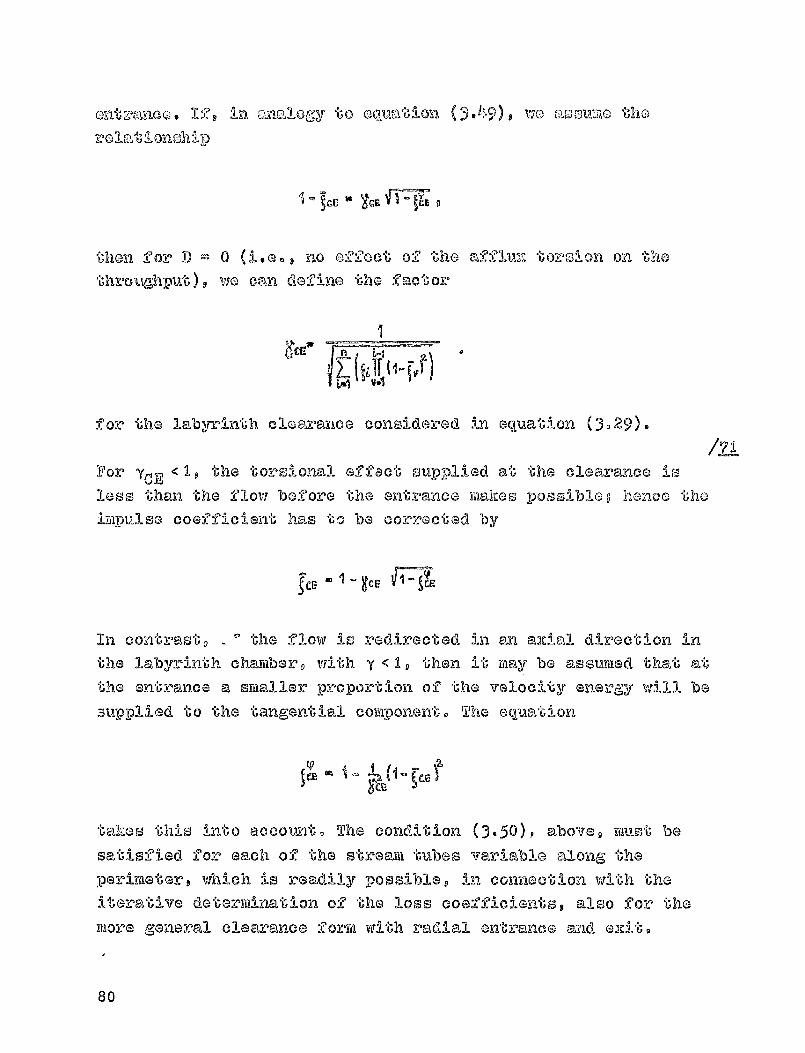
Onto:'p,anco . log L-1 ma"I'logy to ouilIC-Ition ( ^.49) 0 wo acommo the0llat:7- Tnsh i 1)
then for D ® 0 U.e. a no effect of the
afflll— tWoolion on iu-ho
throughput)v wo ca-n defino the factorg-
6ce
for the labyrinth clearance considered i n equat -l on (3.29).
/Z IFor yCE <11, the torsional- effact supplied at the clearance isless than the flow before the makes - Ipossibleg hence theimpulse coefficient has to be corrected by
9CE gee F —7CE
In cont-res"G, .. c' the flow is -redirected in Lrsi axial direction in
the labyrinth charifoar, with y < 1, then it may be assumed that at
the entrance a smaller proportion o'-F the velocity energy ,,All be
supplied to the tangential component. The equation
2.
takes this into accottmt,, The condition (3.50)p above, must be
san-tisfied for each of the st-re le,111 tubes variable along the
perimeter, which i s readily possible, in connection with the
iterative determination of
the loss coefficients, -also for themore general clearance form with radial ent-rance and el,it.
80

E'1212'od Olore"O 'r1 *6 the oh"-"nnol 04zlt
Pact 'rho no al clommnco) 'KIC) tom"[3ontiall V02.03'11ty t- 11 C-)
O' he'-.-mol 140, rollal;lvoly It :10 Concolv'nblo th'rat
ho:V-0 a mkmd 9:010t5-0--no-1 '-?oroo r.),ets, on the
cloaranoo flow. Using
Vlnogol l o' ecoula"U'lon-,c-,),lso [26)) th l o foz^c p', Oom be
doocribod
by a miz-ad friction GOOZACiont rg V,znotlon of the o.-i't;
suv-'O^'ace an &^Qa- amnd the
hinet-lic onorgy of
tho difference between
the locall tcomgont^'O-aq l vo 110 0 -" 0 so ,
21
VIA " ;VAPA ^z ( CA CC'5 RA- VJArA V-9a VAnA ) . (
The difformacoo between the tangon"Goial valocitios is datez'minad
itGrena"Givoly for ocach sltzmayii tube t eaccordiong to section 3949
simultamously with the loss coefficients. To begin witho the
Ooveo obove only ac is to modify the outflow zang-le of the last
control spa cov since due to the fluid's viscosity 611E) friction-all
forces were disveC?:arded in the remalAning control s paces. With 2
a 'b-orsion-froc affluz and accent ric rotor -position, an
equalising flow occurso which along the perimeter is oyi-imietrical
to the position of the narrowest clearance width. Taldn '-ij., this
modified outflow angle into cons ider'al t I O,9 I-r-nraer F11:12:'Ge.
frictional forces in tl!^ tangen tial direction are generated in
front of the narrowest clearance than behind it. Due to the
outflow angles corrected by these additional forces, tJ.G-
Drensure losses at the ezit now change, as does the pressuredistribution within the radial clearance. Due to this, in spiteof a tors-i o -sq.-free afflum and without considering rotation, a
transverse for-rm now also acts parpendicularli to the deviation
(cf. secti®n 3.6.)
This simplified description at least permits a qualitative
evaluati on of the rdLced friction beyond the clearance; according
to [26 -1, for the mij-Eed fricti on coefficient we coan use A
0.11
According to Table 3.2 9 the outflow angle caused by the mixed
82
friction Oren 10 a -unction 02 "6110 thronghplai6. S"Ineo .1tq :111
tuzmq do-pond Ot-roingly On "6110 02:1416 loss (and hone'o ' also on tho
'aklglo)p at tho ezzit a slyulllaz 00-ndition OuGht to bo
So"UOL 's,210d th")"Ij f or t-ho ntra"'noo, :1-1-n the provil om" oo-ot:10no by
mo,"'nD of washich it i s am"mmoOd tho 1'hz^oucU Y -';hput Z^Om'qj no
constant undoxv- the effect of TA2".0d frIctim:1.
3.3 -4 - Dotorminatio-n of
loss cooffic-11 Gnto fmill a masurod
pre ssure distribution
If the pressure distributions are h--sown from file a'smremeat's' , for a
few essential reference planosq then it should be -oosslblG to
determine thG loss coofficientsfro yll those in such a manner thatthere is agreement between memmuremento and theory. Howavor,
hnowlodg,ga of
the course of the flow lines is assumedo hereg
s iince so-mal".w changes in the torsio-nal forces can decisivelyaffect the pressure drop in the stream tube. If- one makes
as sum-ptions regarding the im-pulse loss coefficients or theirrelationship to the pressure loss coefficients, than it must be
possible to latex-mine them from the measured pressure
distributions, by mems of the existing 10-heory. To this and vie
can apply the same iterative calculation procedure we use in
se ction 3-5, in which vie calculate the loss coefficients from
Table 3-19 by means of the pressure differences obtained from
measurements. In this manners we obtain the pressure loss
coefficients for each measurement plane or, in conjunction withTable 3-2, also the impulse loss coefficients. The two
can be determined simUtameously only if, for
instance, the flow ,are rendared visible so that the ax1gle
change become] knovin, mad the losses become known by pressure
measurements. In a, labyrinth, however, the assiniptions made on
the composition of the flow lines froya flow angles are
addi-itlion.ally of inportance, as are tasose nmde about streara
contraction.
82
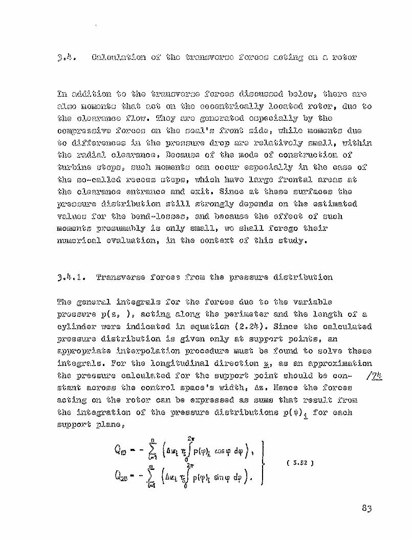
calcvll nt •don ®2 t-ho tromovoVE-)o 00.%-Coo actiung On r). 2?ot- or
In add.-I tlo wn to tho t:,?,nnovarso forcoo d1scumood. bolow, thoro amoG-
al so -, tzJ faloylont 's, than', 'c"Ot, 0-n the 00contrI1.0,911y locatoid rotor duo totho olommylwo flow. They are Gonorated oopocially by thecol-lurm?G -so- A vo zorcoo on the 0021 1 0 front side, VAAIQ m%,lonto dueto differoncoo in the proo cur o drop aro rolatilvoly symalls wit'hinthe radial cloaremmee.. Because of *(;he mode 0 ,_? const-ruction. of
turbine otepog such mmitionts can occur eopocially in tho c. -,-f, aGo o
the so-called recess stops, which have la rare front,',,),l areem atthe cloarance entrance emd Gx,it. Since at theme surfaces thopressure distribution st i ll otrongly depends on the estimatedvalue@ for the bend losses, and because the effect of suchmomonto presumably is only small, we shall forego theirnumerical evaluation, in the context of this study.
3- 4 - 1. Transverse force ,3 from the pressure distribution
The general integrals for the forces due to the va-r-Jablepressure p(z, ), acting along the perimeter and the length of acylinder ivere indicated in equation (2.24). Since the calculatedpressure distribution is given only at support points, anappropriate interpolation procedure must be found to solve theseintegrals. For the longitudinal direction z, as an approxi-mation
the pre3sure calculated for the support point should be con- /_74start across the control space's Adth, Az. Hence the forces
acting on the rotor can be expressed as sums that result froya
the integration of the pressure distributions D(^ ), for eachs u-pport plane,
( mtL P (Y)j Cos
Ii (4n 2tr
3.52
7L (Aw L r^;j p (^V)L tP d'ftal
83
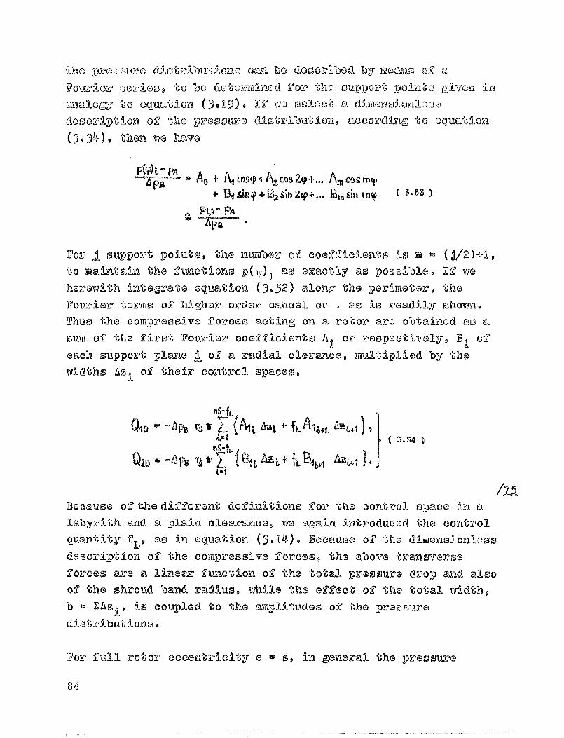
Tho pro o" ouro dlotz^ibutlons can bo do)OAbed by mo roms) of a
Vov--oio norlos, to be dotoz-1-flinod f0:0 the OuDr poz°t poil n'^,o g:1von in
angloGy to equation (3.19). 12 wo tooloot a dimanoiOnlossof
tho pretsmoo Olstzljbution, n-ccoz-61:1-mg, to GQ'acat'loon
(3.34), then VIG havo
0A - PAZ—Ca AG + Aj co,,-ip+AZ mztp+... A.cnamy
4. Di sin + B2 sin 2(P+... gm sin m Y 3-53
N ot- PA
For i support points, the number of coefficients is its ® (j/2)+I,to maintaill the functions
PWI as a2zactly as possible. If vie
heremi th integrate e quation (3-52) alone the perime"Uaro she
Fourier to rotas of
higher order cancel oi • - as is readily shown.
Thus the compressive forces acting on a rotor are obtained as a
sum of the first Fourier coefficients A I
or respectivelyv B1
0-)
each support plane i of a radial clerance, multiplied by thewidths Az i of their control spaces,
flS-fL
0jrj - —Ap. rs Ir Z (Aij A-. t +kwl 3-S4
A-zQZD
Because of the d-IJI-Cferent def in-it:11-ons f or the control space ill a
labyrith and a - troduced the cont colto plain clearance we again inquantity f L' as
in equation (3,14). Because of the dirtiensiolllr:ss
descri-Ption of the com pressive forces, the above trannsverse
forces are a linear function of
the tot-al pressure drop and also
of the shroud band radius, while the effect of the total width,b = ZAz,, is coixpled to the amplitudes of the pressuredistributions.
For full
rotor eccentricity a ® S, in general
the pressure

dif-20:00RCOS at "she CIOCIMROO OsltrancO can MIOMRt Only to APB,
making a doublo aruip-1 -I tudo 2A < I ^posl o,-ible. AummAo-ag ll-noa-!^
-p:OOkz)Su.rG C3.0croaso -anlj-al diroctil on wo thon obtanin :?orco
jr h e2 V
Th-l o manrd-Ulum a1itall ylable compressive force - in which the
II '10ar in 0relative ecoGntz-11 city has been asssurtied to be IJU, - can btaken as a r'ever'ence maGnitude for the above transverse forces,
fro-m the pressure distribution.
3-4-2. Transverse forces from the clearance loss
The local tangential force changes with the variable rlearance
throughput at the entrance to the rotor blading. The integral ofthe components of this force along t-he perimeter yields the
transverse forces acting on the rotor, as indicated in generalin ecivatiors (2.10). This requires a knowledge of the localclearance loss, which can also be calculated from the ratio
!A `_ ^ ^-'tbo (
of the clearance throughput to the total mass flow, if we
introduce a corrp- ,--tion factor
The fumcion Z(^) takes into account that the decrease in thetangential force included in asp is not directly proportionalto the throug,hput ratio =lo. Any indication onavailable in [141 - can be made only based o',measurements
or the entire turb i ne ste-3 It
however, that the function is different
rotor clearance losses, since the tangential
35

blading is
affoctod In ono otaoo by the -,inpip.-s-oaching maSo Olow cnnd
I n r,ho other, by the outg. one
With the above defin1c'U11-on
of the clear@--noc loo s,
we obtain for
the integral of equation (2.10), boarin^,- in
TAnd the quantities
that are constemnt along the
orsQ
^ +)rin
sin Y dmgp 1,
Q29 Cos (P d tk? -0 t11PO
The local throughput per arc length can be described by means ofa Fourier series
t C, co; u, + Q9 mz2 ip + Cm co r. m q
- s1 01 -iv i t?' - + UZ Own 29 + m CP
!k4 t
- Px
whoBe coefficients are determined by the calculated throughputs
11K/A^IE per arc length of the stream tubes. While at the rotor
clearance we must use the channel widths Aip and the tangential
angles ^ of the first support location, E19 k
, at the stator it
is appropriate to use values for the last support location,'nA 11 If in equation (3-58) as a first approZimation we set
g(_^ ^ 1, then its integration will yield the transverse forcesacting on the rotor, with the higher-order Fourier coefficientsCanceling out, again:
QjS = us 01MO3.60
Q25 m LS Ceno
86
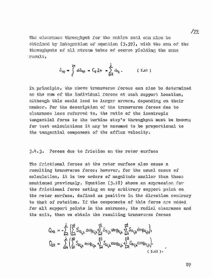
/-10Tho elca mmco throughput for tho on• ire oocal ca-&-i also be
obtmLiaad by of oquaUon ( 3.59 9 with the ouiii of the
thvougdiputs of
all otromm tubes of couroo yielding the same
rooult 9
2* 1
CO ZT, - , ( ^.61 )f^h k
0 k•l
in principle, the above transverse forces can also be determined
as the sirm of the individual forces at each support location,al
though thio could lead to larger errors, depending on their
number. For the description of the transverse forces due to
clearance loss referred to, the ratio of the isentropictangential force to the turbine step's throughput imust be known;
for test calculations it
rimay be assumed to be proportional to
the tangential component of the afflux velocity.
3- 4 -3. Forces due to friction on the rotor surface
The fr i ctional forces at the rotor surface also cause aresulting transverse fonce however, for the usual cases of
calculation, it
is two orders of
magnitude smaller than those
mentioned previously. Equation (3- 18 ) shows an e"-press on for
the frictional force acting on any arbitrary support -point onthe rotor surface, defined as positive in the direct on co-atralry
to that of rotation. If the components of this force are added
for all support points in the entrance, the radial clearance and
the exit, then we obtain the resulting transverse forces
t
hE nS nA
QAR ^1— R
61 ^1-1 r aril i r 4.1 I
n^ VIS nA
kt W
87
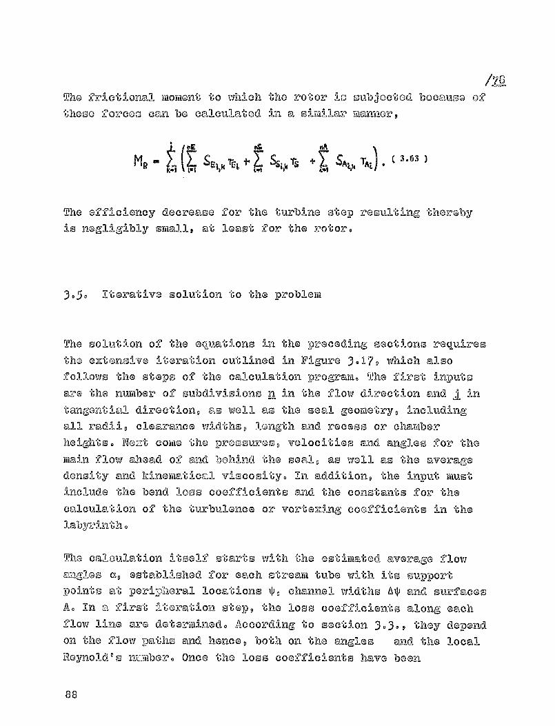
/-7G(1The frict:1- one I mo ytiont to which the 1otor Is oubjoctod bocce uso of
these 'fo-vIcGo acan be calculated in a Simil-ar Ytloxrner,
"A
T4MRLai
S"' + 1, S"" T
The efficiency decrease for the turbine stop resulting therebyis negligibly s ► all, at least for the rotor.
3.5. Iterative solution to the problem
The solution of
the equations in the q^eceding sections requires
the eztansive iteration outlined in FitSure 3 .1 7, which also
follows the steps of the calculation program. The first inputsare the number of subdivisions n in the flow direction and I in
tangenti&,l direction, as well as the seal geometry, including
all radU D clearance widths length and recess or chamberheights. We::t coi-tie the pressures, velocities and angles for the
main flow ahead of
and boh-ind the seal as well as the average
density and kinematical viscosit-y. In addition, the input must
include the bend loss coefficients and the constraints for the
calculation ol? the turbulence or vorte ,Ang coo fficierrs s in the3.,-:tby--o:#-nth.
►ho calaulentio-n itself starts with the estimated average flowangles aq established for each stream tube with its support
points at- periyheral locations ^, channel widths A^ and surfaces
A. in a first iteration step, the loss coefficients along eachflow line are determined. According, to section
3-3-9 they depend
on the flow pa1.hs and hence, both on the angles and the local
Reynold's nz_-fiiber. Once the loss coefficients have been
8 0U

/7-2
^ t"si ^ II
I"
AOY
0.8
WNW."..stream tube'
throughput,
I.P I P, 0. "S
eccentricity]
Figure 3. 1 7 Iteration Plan
89
dotorminod - :'ual ti' llly -for Co-nst 'ant th-z'o-or"I'l-put - With OM "'r'`? 010i'l'"
Iprocloion, tho through-put of
the o"U':r0 falil tuboo io ce.110tilotad
iteratively iY,-ip:Povod beyond the defined lovol D21, al zoo ,')Aly
I ni6o account tho cheangeo in the flow anglo, w'1-thsection 3-2-5- This Proce Ss is performod lado- -itly oz'Z' aMpande^^
stream tubes h, as indicated in F i gure 3017 9 above, by the
subscri pt field.
In a -Zuriher block, the geometry of
the stroa-m tube to
calculated in accordance with section 30 1 and subsequently the
throughput is corrected ('to level M2). Since through the channel
width the stream tubes affect each others the calculation must
be performed each tifile for all stream tubes® If the difference
between the new throughput m b and old throughput ma of "_" otre";-"Yli
-tube is too large, then the loss coefficients must be
recalculated, beyond level id,
Once the throughputs, angles, loss coefficients and surfaces ofall stream tubes are precisely known, the pressure distribution
is calculated® Once the Fourier coefficients have been obtained,
this allows the determination of the compressive forces actingat each support location on the control space surfaces. Theseprimarily change the geometry of the stream tubes; for -this
reason the iteration need not start from the beginning, but from
index P. Subdividing throughput calculations into two partial
iterations, starting at indelx MI or respectively, M2, was chosen
only to save calculation time, since the loss coefficientsappparently only change very little.
For normal application cases the convergence is very good.
However, for large torsional effects at the entrance and large
accentricitiesp the flovi angles vary cons i derably along the
perimeter, causing, significant c`.,anges in the channel widths. It
is recommended not to perform Iftirther itera"Gions directly with
the new value, but with, a weigh-ted aTerage of the old and the
90

now values. Mile the
Ond result will be
attainod
Ooy:.Iovfhat -."110-v'o slowly, a divo:O:Gonco call god by 02mossive chmoo's,in ^ ho individual vglucs will be avoided "o-hoz-oby. A similar
procodure may also be nocosseary in the itareative calcOlatIon o f
the comprosolva forces, especially for large labyrinth chambers.
At the and
of the
acting on the rot
distribution, and
tm- gent ial forcog
overall iteration, the compr000-1ve forces Q D
Dr can be calculated from the pressurethe forces QS caused by the variablefrom the variations
in the clearance
thz^oug,-hyat. Wo new initial valves need be set to calculate
further eccentricities./9-1
Based on the similarity of conditions, favorable initial valuesare obtained rather by increasing the eccentricity gradually.Since the course of the forces in general is only weaklynon-linear, a few individual forces can cause an increase beyondthe deviation as required for the vibration calculations insection 2.1.
3.6. Testing the calculation procedure using si-iKple clearance
f ox-Ins
The essential parameters describing the clearance flow affectedby torsional forces can be studied in Figure 3 ,18 , using sixupleclearance forras. The clearance's diameter and length were chosen
fo:. P their similarity to aa test turbine, but without radian
entrance or exit. Besides the radial clearance width and thechamber height h 9 the geometry of the -seal remains unchanged end
is suP pleydent ed 0111Y in
Figure 3-37 with a radial entrance and
exit.
Table 3.6 clarifies the most li mpox-tall'u- equationts for the
92

%
CC IOUXIE PE _PA
re
Plain clearance(nS=13 , j:=20)
Labyrinth clearanceI (nSm2. j=20)
Fidure 3. 18 Calculation e^,Mwples of cleavance formo
TABI X, 3.6 Loss coefficientso affluAll conditions and dimen-sionless quantities for calculation exarapleo
z
IVIS
SNA
vSWF, SR
S A
.,clearance: r (x) from eq. (3-36)from eq. (3-43),,
CS (r. s'3.
Labyrinth' (m) from. eq. (3.40)
clear-.: CS (r,, y) from . e - q .(3-49)
ii (M from Fig. 3.3
1, 2. 46-1
r- 44T C FJ,
C 00F_ ii
C Mw - CA Cri,
I
ApaIN -M
VA
LI Alla
4cL%
Vii 1iâ
Avg
R (Q) -PA
Apa T WS by Are
ft)AWRVAL
PR POOR
7)
92
oaloulaion of loss eooMclontop and Cho borudary conditions
given by a main flow unnOfovtod by Cho cloaraaoo flow. A
Constant velocity component on is assumed ahead of
the
clonvanoo, in normal direction, which is fully used with the
acoused 0002210ionto T CB, Whind the clearance, only a normalvelocity ozists; however, because 4 CA ® 1, it has no effect on
the clonvanca flow. By changing the affluz analoo it is now
possible to doscribo conditions such ao they may occur ahead of
the rotor clearance of a turbine step. Under these conditions,
for a con otant static proosuvo drop, the available total
pressure drop Ap. according to equat ion (3- 1 5) also remainsconstant. To calculate the transverse forces that act on the
turbine rotor due to the clearance l oss, we oet the ratiobetween the - Isentropic tangential force in equation (2-12) /98-3
and the throughput equal to the velocity diff erence A& Itcorresponds to the tangontial component of the afflux velocity,since too tangential or pokforal velocity disappearsp beyond
the clearance. The relative afflux energy A can be modified byEeither the angles a B or the pressure decrease IPBO
For dimensionless descriptions Q" D the transverse forces actingon the intor are ezpressed in terms of the force Q D as the unW9
according to equat ion (3055). This also reflicts in aqualitativa1y correct wannor the ratio between the compressiveforces QD and the forceF 0S from the clearance lose. To clarifythe results D we have in part also provided ?to dimensionleospressure distributions pf along the Perim el y r, at anyyoO
I
locations 1, according to Figure 3- 18 - Next to these prbosuy',diotributionso the throughput of the stream tubso, M"has also been recorded, here raMred to the total throughputaccording to equation (3- 27) -
The azamploo of calculations, belowp are intended to illustratethe effect of the afflux conditions a well as that of theproosure and impulse loss coefficients on the transverse forcesacting on the rotor. Initi ally p in a dimensioned description, WO
93

Occentricity (Mm)
RS
QJ
invesUGM Cho Qpondonoo A Cho Asson on Cho P7;oQY!QQy auaCho prosoure di2faroneop sinco Qhoy ara HAVAN in Cho,0001anne quantity. For a puroly Mal MI lea Agurc 3.19 OhOWD
MOVIVINAL 1"AGB IS
Figure 3019 Plain cleaoanceDSOMMO an" 9 W= 50mbarq q=0
A= 1
from eq.0.35)
AN0.4 0.6 0.
Eccentricity (am)
Figure 3.20 .!,a byrinth, o=lmm,HOw as=90 o Apn= 50 Mang go=
=00 100 41MI"WO AT =1
Ithe variation of the restoring force -QjD cf. definition !inFigure 2 05) across the eccentricity. Since the compressive force
Q2D vanishes perpendicularly to the deviation due to asymmatrical pressure distributiong the forces Q S caused by thevariable tangential force at the turbine blading must beanulled, because of the assumption regarding the velocityincrease Acu in Table 3.6. The approximate integration of theprassure variation in equation (2-25) yields a linear dependencean the acnentricity, which in =Dparison to nompletecalc !Ions is valid only for small deviatione. Due to ther0n^i4^1, w" al! clearance length the effect of a balancing 2lov-1
94

0
02D,
is net ligibIG, in compairicon to the calculation of the Dresourevariation f2?om equation (3-35)o for which 9? purely axial flowwas assumed. Taking into account a variable 1j"be friction
,00fficient X(Ro), larLer restoring forces are obtained, whose
dependence on the eccentricity is also non-linear. The same
calculations were performed for the labyrinth clearance, in
FiZura 3.20, above. Due to the incomplete velocity vort-GiUng in
the labyrinth chamber, a restoring force -Q ID acts on t1_10 rotor'which varies nearly linearly across the eccentricity. Here ton,
the affect of the equalizing flow is only slightly larger than
for the plain clearance. In accordance with equation (3-35),taking into consideration a contraction coefficient 11 that
varies with the local clearance width does have en effect, for apurely axial flow, since the surfaces at all seal peaks are
reduced in the same manner.
1^
E/S-O. 0
dye
0.5
0-1
C/0-0.3 1.0
I r
5
J,
'00
24
L1---j0.®
Eccentricity (mm)
Figure 3.21 Plain clearance, s = I mm
ct, - C 2 ^, 95

For a flow affected by torsional forces, Figure 3.21, above,shows that there are transverse forces acting on the rotor, inthe direction of the deviation, Q 1 and perpendicularly to it,
Q20 The cause for these forces can be seen from the pressurevariations, neiEt to the figure. For a, central positioning, e/s0 and the throughput and the pressure along the perimeter areconstant. The strongest pressure decrease occurs between theconditions ahead
of the clearance, p" = 1, and the first support
location, P) (cf- also Figure 3- 18 ), whil3 pressure losses along
the clearance and to the end state, p' = 0, are relativelysmall. For an eccentric rotor position, this pressure decreasevaries in an inversely proportional manner with the localclearance width, which is smallest for ^ = 0. Due 'L-. o thetorsional effect, there is a spiral flow in the clearance, whichresults in variable cross-sections along the stream tubes, andcauses the characteristic pressure maximum ahead of thenarrowest clearance, as seen in the direction of torsion. As a /86consequence, compressive forces arise, Q 2D' perpendicular to thedeviation, which for a plain clearance are of the same magnitudeas the restoring forces -Q ID' The local throughput (broken line)modifies the tangential forces at the rotor blading, whoseresultant generates a force Q 2s' perpendicular to thedeviation, and the much smaller force Q 11s, which acts in thedirect-ion of the deviation. If the variations in the throughputwere symmetrical around ^ = 0, then according to equation (2.15)that force would have to vanish. Across the eccentricity, thetransverse forces are linear, with a small departure at QThis is also true of the flow with torsional effect, in alabyrinth clearance. Because cf this it is possible to builddimensionless increases Q x of the forces across *U'- he deviaition.t, using the reference quantity of equation (3-55), and inaccordance with Table 3.6. In all further calculations, thisincrease is determined from this force only for a relativeeccentricity els = 0.5. We thereby also obtain an approximately
96

900. 5 N"
P*
/IX-180 6
`0.1.0
E/S-D.
^1. 0
P
0-1.5 MG/9-o.5
average value for a minimally linea:oiz'ed increase.
The effect of the radial clearance width i s shown - with a viewtowards a vibration calculat i on - on the basis of an increaseMe of the force Q, assumed linear across the deviation e,,
Qualitatively this also corresponds to the representation oftransverse forces for equal rotor eccentricity. As Figure 3022
Radial clear.width (mm)
Figure 3022 Plain clearance
shows, for a plain clearance the forces from the pressuredistribution increase steeply for smaller radial clearancewidths. The amplitudes of the pressure variations depicted areapproximately equal, since they are valid, in each case, forhalf the maximum eccentricity, e/s = 0 -5 . For smaller clearancewidths, the pressure loss increases along the clearance, thus
xincreasing the pressure level at the entrance, p i '
97

As already explained in sect i on 303020200 in a plain clearanceand with decreases in the radial clearance width, under sortiecircumstances inadmissibly large values can arise -for thepressure loss coefficient ^ in a control space. S i nce thepressure losses depend on the flow paths within the controlspace, if necessary the number of support locations in the flowdirection may have to be increased. Using equation (3047), thecalculations here were performed for all clearance widths withnS = 11 support point s . However, no deviations worth mentioningwere observed for radial clearance widths s > 00 5 mm , even for nS= 3. The determination of impulse loss coefficients fromsectionally straight stream tubes in accordance with equation(3 04 3) is also valid only for correspondingly short flow paths.However, the use of this relationship yields the same result -for a sufficiently large number of support locations - and wasapplicable, in particular and without restrictions, to nS = 3and s = I mra.
For labyrinth clearances the number of support locations isdetermined by the number of seal peaks. In addition, onlypressure loss coefficients c <1 can occur. As Figure 3 .2 3 shows,the increase in the forces due to the pressure distribution,with small radial clearance widths is very much less than with a
- plain clearance. While the exciting force Q2s is independent of the /88radial clearance width, in accordance with equation 2.15, this resultsin a change based on the variable pressure loss coefficient. By disregardingthe flow contraction P = 1, the exciting force Q 2s is proportionally increasedto the throughput. However, the pressure distribution forces are notsimilarly altered, as the cross -sections along the flow tube become moreequal because of the flow contraction p (s), which is dependent on Vielocal clearance width (c.p. fig. 3.8). A flow contraction which is constantalong the perimeter would therefore cause an increase in the exciting forcefrom the pressure distributor.
98
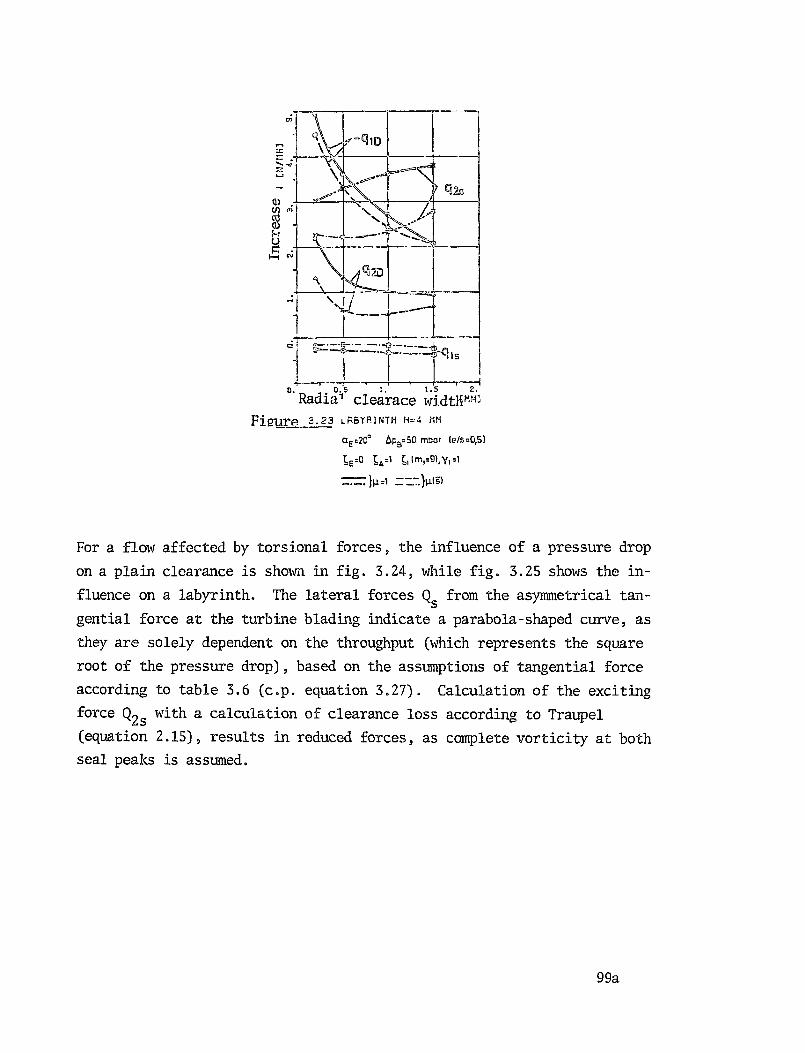
0)U^c^
U^ N
iQ
0. 0.5 1. 1.5 2.
Radia' clearace widtNHH3
FlgurP 3.23 LRBYRIMTH H=4 NM
aE =20° a,,=50 mbar ( e /s=q5)
^E =0 4=1 ^"MI=9)'YI='
}µ=, }µ1s)
For a flow affected by torsional forces, the influence of a pressure drop
on a plain clearance is shown in fig. 3.24, while fig. 3.25 shows the in-
fluence on a labyrinth. The lateral forces Q s from the asymmetrical tan-
gential force at the turbine blading indicate a parabola-shaped curve, as
they are solely dependent on the throughput (which represents the square
root of the pressure drop), based on the assumptions of tangential force
according to table 3.6 (c.p. equation 3.27). Calculation of the exciting
force Q2s with a calculation of clearance loss according to Traupel
(equation 2.15), results in reduced forces, as complete vorticity at both
seal peaks is assumed.
99a
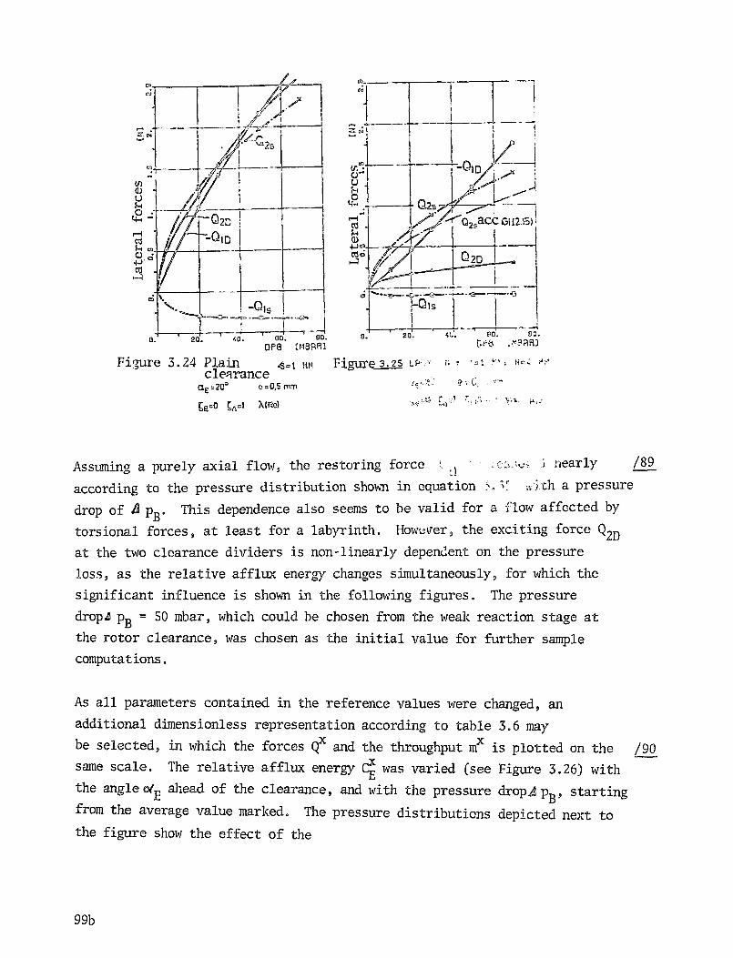
B_
J , 2s
1 a-^i
u
m
821 i
N—010
O ,
ipP8 CHBRRJ
---
i1`
I
i^7s
020
1
^ \.^. Jew.
1s
./a•-^.ro..{j
Q • LU. 9^.. ^,u uu.
rS-I
WCd
Ud
04,,)k_4
tlC,
c
Figure 3.24 Plain 4.1 rasaclearance
CXE =20° a= C's MM
5E=0 S'zl 7,IRe1
Figure ^. 2S t_w;-y ,; , ^ i Paz 4 ^"
Assuming a purely axial flow, the restoring force vg nearly /89
according to the pressure distribution shown in equation .` .6 'ch a pressure
drop of A pB . This dependence also seems to be valid for a glow affected by
torsional forces, at least for a labyrinth. However, the exciting force Q2D
at the two clearance dividers is non-linearly dependent on the pressure
loss, as the relative afflux energy changes simultaneously, for which the
significant influence is shown in the following figures. The pressure
droph pB = 50 mbar, which could be chosen from the weak reaction stage at
the rotor clearance, was chosen as the initial value for further sample
computations.
As all parameters contained in the reference values were changed, an
additional dimensionless representation according to table 3.6 may
be selected, in which the forces Qx and the throughput m is plotted on the /90
same scale. The relative afflux energyCE was varied (see Figure 3.26) with
the angle o(E ahead of the clearance, and with the pressure drop, p B , starting
from the average value marked. The pressure distributions depicted next to
the figure show the effect of the
99b

i
Rel. afflux energy, CE N. 2?1`Ea.-S0'
Variation of-.9EaE 5 16
PY9
.,Variation of ApR
AL-So 9.0CE'-o.o
P°
0.9
•1©0 0
AL- 20 1.0P.
1
AL-15 11.0CE
. .2.1)
F
s
-100
Figure 3026 Plain clearance, s = 1 mm
afflux angle, due to which the location of the pressure maximum
is displaced towards the direction of torsion, with a
simultaneous increase in amplitude.
The local throughput changes in the same manner, with increasing
torsional effects at the entranceo Because of the spiral flow
within the clearance, the flow paths become longer, which leads
to a slight decrease in the throughput of reference, X11, as a
function of the relative afflux energy, Cx. Variations in the 19-1angle or the pressure gradient do not yield the same results
here either, for the transverse forces, since Reynold°s number
and hence the friction coefficient a changes somewhat with the
throughput's absolute quantity. However, within the range
99c
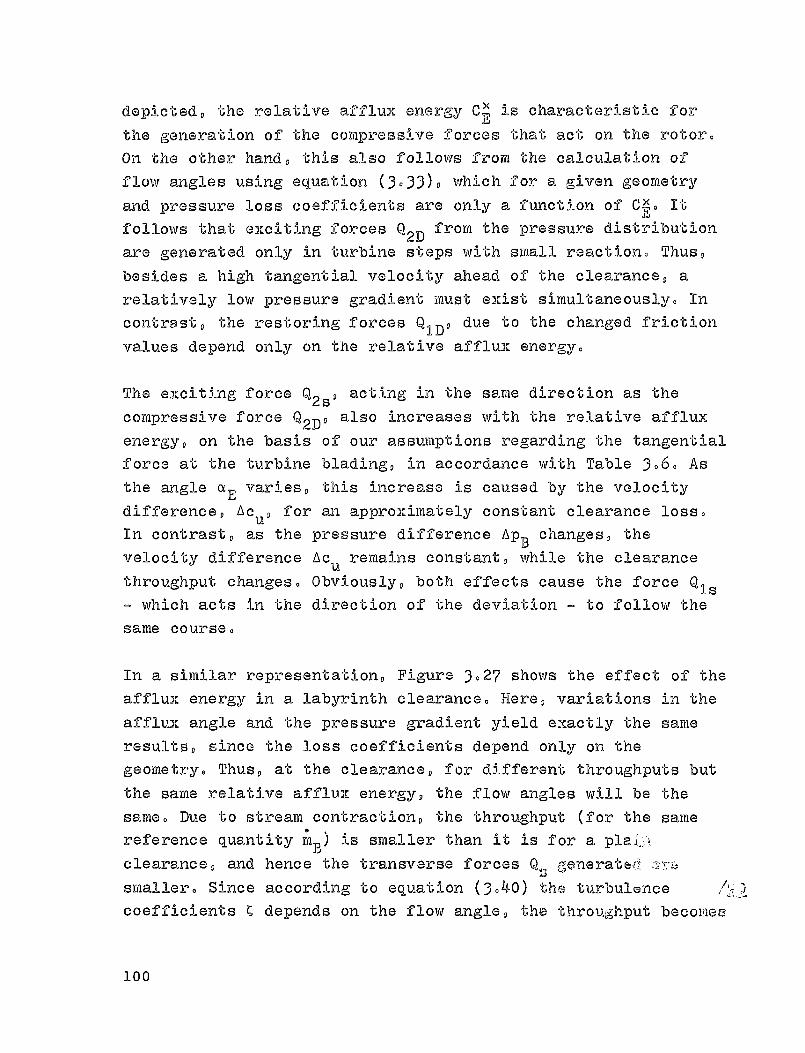
depicted, the relative afflux energy Cx is characteristic for
the generation of the compressive forces that act on the rotor.
On the other hand, this also follows front the calculation offlow angles using equation (3.33), which for a given geometryand pressure loss coefficients are only a function of Cx. It
follows that exciting forces Q 2 from the pressure distribution
are generated only in turbine steps with small reaction. Thus,
besides a high tangential velocity ahead of the clearance, a
relatively low pressure gradient must exist simultaneously. In
contrast, the restoring forces Q 1D , due to the changed friction
values depend only on the relative afflux energy.
The exciting force Q 2s , acting in the same direction as the
compressive force Q 2D , also increases with the relative afflux
energy, on the basis of our assumptions regarding the tangential
force at the turbine blading, in accordance with Table 3.6. Asthe angle a varies, this increase is caused by the velocity
difference, Aeu , for an approximately constant clearance loss.
In contrast, as the pressure difference AP B changes, the
velocity difference Ac remains constant, while the clearance
throughput changes. Obviously, both effects cause the force QIs
which acts in the direction of the deviation ® to follow the
same course.
In a similar representation, Figure 3.27 shows the effect of the
afflux energy in a labyrinth clearance. Here, variations in the
afflux angle and 'the pressure gradient yield exactly the same
results, since the loss coefficients depend only on the
geometry. Thus, at the clearance, for different throughputs but
the same relative afflux energy, the flow angles will be the
same. Due to stream contraction, the throughput (for the same
reference quantity n ) is smaller than it is for a plan';.
clearance, and hence the transverse forces Q UA generates" a:r6
smaller. Since according to equation (3.40) the turbulence p ,i
coefficients C depends on the flow angle, that throughput beeomea
100
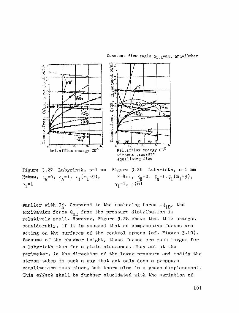
CY
CY
U
Cd
V. a. L.x
Rel.afflux energy CE'
0. a. X. J. V.
Rel.afflux energy CE xwithout pressureequalizing flow
Constant flow angle Oi,k=UE, 4PB=50mbar
Figure 3.27 Labyrinth, s=1 mm Figure 3.28 Labyrinth, s=1 min
H=4mm, C E=OD v 1 C I (M
I = 9), H=4mmD C
E= 0,
CA=' D C I (MI=9),
Y1 =1 Y1 =1 D P(—S)
smaller with C 11 . Compared to the restoring force -QID' theE excitation force Q 2D
from the pressure distribution is
relatively small. However, Figure 3.28 shows that this changes
considerably, if it
is assumed that no compressive forces are
acting on the surfaces of the control spaces (cf. Figure 3010)0Because of the chamber height, these forces are much larger for
a labyrinth than for a plain clearance. They act at the
perimeter, in the direct i on of the lower pressure and modify the
stream tubes in such a way that not only does a pressure
equalization take place, but there also is a phase displacement.
This affect shall be further elucidated with the variation of
101
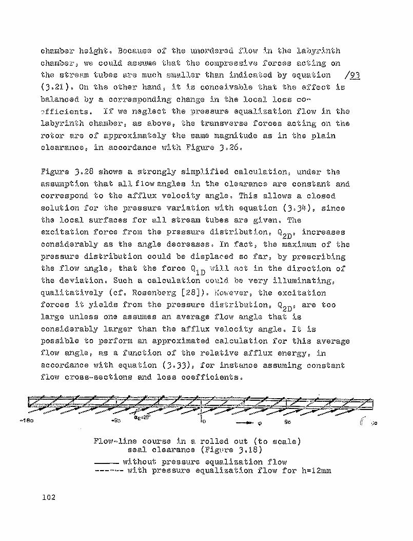
-11 to
chamber height. Because of the unordered flow in the labyrinth
chamber, we could assume that the compressive forces acting onthe stream tubes are much smaller than indicated by equation 19-3(3021). On the other hand,
it is conceivable that the effect is
balanced by a corresponding change in the local loss co-^fficients. If we neglect the pressure equalization flow in thelabyrinth chamber, as above, the transverse forces acting on therotor are of approXimately the same magnitude as in the plainclearance, in accordance with Figure 3.26.
Figure 3.28 shows a strongly simplified calculation, under theassumption that all f low angles in the clearance are constant and
correspond to the afflux velocity angle. This allows a closedsolution for the pressure variation with equation (3-34), sincethe local surfaces for all stream tubes are given,, Theexcitation force from the pressure distribution, Q 2D' increasesconsiderably as the angle decreases. In fact, the maximum of thepressure distribution could be displaced so far, by prescribingthe flow angle, that the force
Q ID ', 'All act in the direction of
the deviation. Such a calculation could 'bP very illuminating,qualitatively (cf. Rosenberg [28]). Koi, 'ever, the excitation
forces it yields from the pressure dirtribution, Q 2D , are toolarge unless one assumes an average flow angle that isconsiderably larger than the afflux velocity angle. It ispossible to perform an approximated calculation for this averageflow angle, as a function of the relative afflux energy, inaccordance with equation (3.33), for instance assuming constantflow cross-sections and loss coefficients.
Flow-line course in a rolled out (to scale)seal clearance (Figure 3-18)
without pressure equalization flow------ with pressure equalization flow for h=12mm.
102

Ha 2 nd 1. o 11®12 ii(1 11- 0
Pe PO
0.5 a. S
a
O aP. o40D
O
2 © ..®. ..Hi
n
. 2s
CY
without pressure
>;% equalizing f low
C13
0CU o . ^•
^4 °®osH
Chamber hght H (mm)Figure 3.29 Labyrinth, s=1 mm, H=4 mm
In Figure 3029, above, the height of the labyrinth chamber was
varied (cf(, Figure 3018)o While the Forces related to the
clearance loss, Q s , were only marginally affected, especially
the excitation force, Q 2D , related to the pressure distribution,
decreased very markedly with increasing chamber height,, An
explanation for this arises out of the course of the flow-lines
in a rolled-out, true to scale representation of the clearance
103
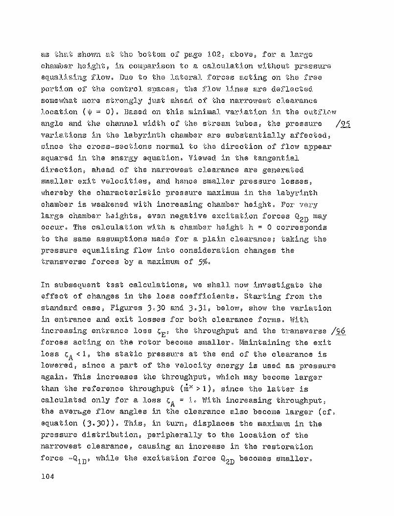
as that shown at the bottom of page 102, above, for a large
chamber height, in comparison to a calculation without pressure
equalizing flow. Due to the lateral forces acting on the free
portion of the control spaces, the flow lines are deflected
somewhat more strongly just ahead of the narrowest clearance
location (^ = 0). Based on this minimal variation in the outflow
angle and the channel width of the stream tubes, the pressure /91-5variations in the labyrinth chamber are substantially affected,
since the cross-sections normal to *the direction of flow appear
squared in the energy equation. Viewed in the tangential
direction, ahead of the narrowest clearance are generated
smaller emit velocities, and hence smaller pressure losses,
whereby the characteristic pressure maximum in the labyrinth
chamber is weakened with increasing chamber height. For verylarge chamber heights, even negative excitation Forces Q 2 may
occur. The calculation with a chamber height h = 0 corresponds
to the same assumptions made for a plain clearance,, taking the
pressure equalizing flow into consideration changes the
transverse forces by a maamimum of 5/.
In subsequent test calculations, we shall now investigate the
effect of changes in the loss coefficients. Starting from the
standard case, Figures 3.30 and 3 . 31, below, show the variation
in entrance and exit losses for both clearance forms. Withincreasing entrance loss CE, the throughput and the transverse 1566
forces acting on the rotor become smaller. Maintaining the exit
loss CA <1, the static pressure at the end of the clearance is
lowered, since a part of the velocity energy is used as pressure
again. This increases the throughput, which may become larger
than the reference throughput ( m' >1), since the latter iscalculated only for a loss CA = 1. With increasing throughput,the aver4ge flow angles in the clearance also become larger (cf.
equation (3.30)). This, in turn, displaces the maximt,.m in the
pressure distribution, peripherally to the location of the
narrowest clearance, causing an increase in the restoration
force -QID, while the excitation force Q2D becomes smaller.
104
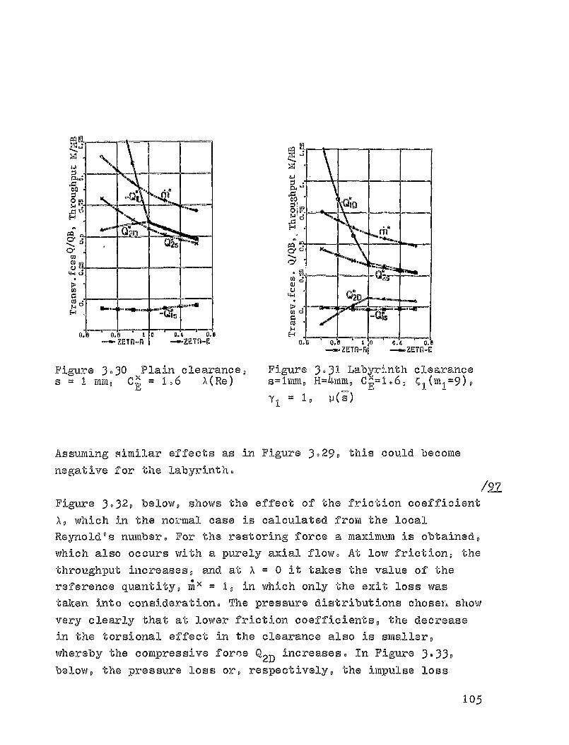
\p i-^1
F%1 ^
Pp4
D0
H ^o H
O' [i nC
vjv in o'Uo
m^ vfA U
0+ ^^a
?a0.0 8 0 D.6 0.00. H
ZETR-A —ZETA—F,
Figure 3030 plain clearance, Figure 3.31 LabF.,.nth clearances = 1 mm, C" = 1.6 a(Re) s=lmm, M=4^mm, CF =1.6, cl(m1=9)9
Y1 = 1, u(s)
Assuming similar effects as in Figure 3.29, this could become
negative for the labyrinth.
/aFigure 3.32, below, shows the effect of the friction coefficient
X, which in the nob ,mal case is calculated from the local
Reynold°s number, For the restoring force a maximum is obtained,
which also occurs with a purely axial flow. At low friction, the
throughput increases, and at X = 0 it takes the value of the
reference quantity, m l = 1, in which only the exit loss was
taken into consideration. The pressure distributions chose7b show
very clearly that at lower friction coefficients, the decrease
in the torsional effect in the clearance also is smaller,
whereby the compressive force Q 2 increases. In Figure 3 .33,
below, the pressure loss or, respectively, the impulse loss
10 ,E
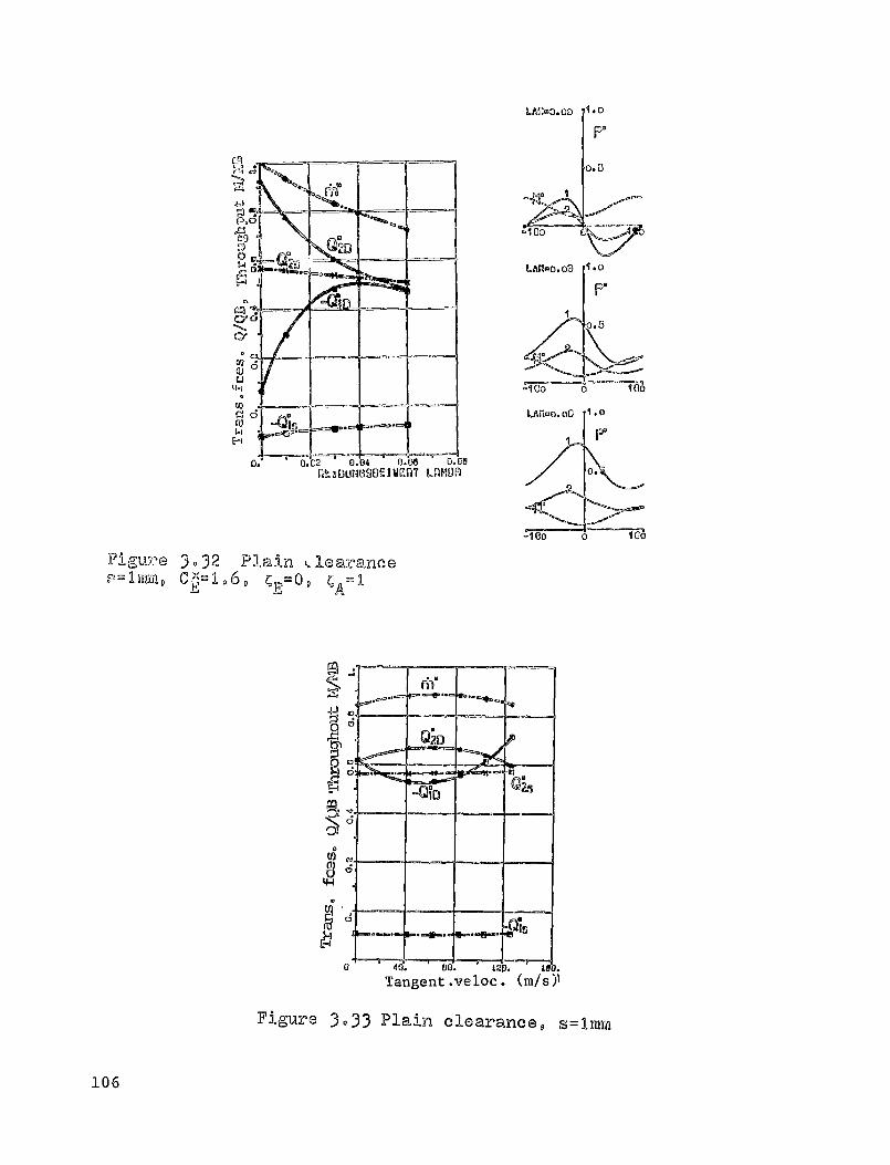
6AU-o .o3 1.0
Ip'
LAU-0.00
w
ruwE-4
WHY LAMOnU. LI;
MA
Figure 3-3 2 Plain LlearanceC I-1.6,=09 C IE a A =
m
3I
J^E-1
M
Figure 3033 Plain clearance, s=Imm
106
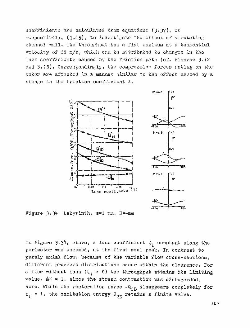
Loss coeff.zeta (1)
21-0.3 1.0
IP"
.601
U
rn
M
cooffic-lento aro Cal culatod frow equations (3.37), or
:000poctivoly, ().45), to investigate mho effect of a rotatingchannel wall. The throughput has a flat ma2Eivtium at a tangential
valoci'L"'y of 60 w/o, which can be
attributed to chalk-,goo in the
loss coofficionto caused by the friction path (cf. Figures 3.12
and 3013)- Correspondingly, the compressive forces acting on the
rotor are affect-od In a manner sirAllar to the effect caused 'by a
change in the friction coefficient X.
Figure 3.34 Labyrinth, s=1 mm, H=4mm
In Figure 3034 , above, a loss coefficient ^ ,
constant along theperimeter was assumed, at the first seal peak. In contrast topurely axial flow, because of the variable flow cross-sections,different pressure distributions occur within the clearance. Fora flow without loss (C
1 = 0) the throughput attains its limiting
value, ^ ll = 1, since the stream contraction was disregarded,here. While the restoration force -Q
ID disappears completely for
1, the excitation energy Q 2D
retains a finite value.107
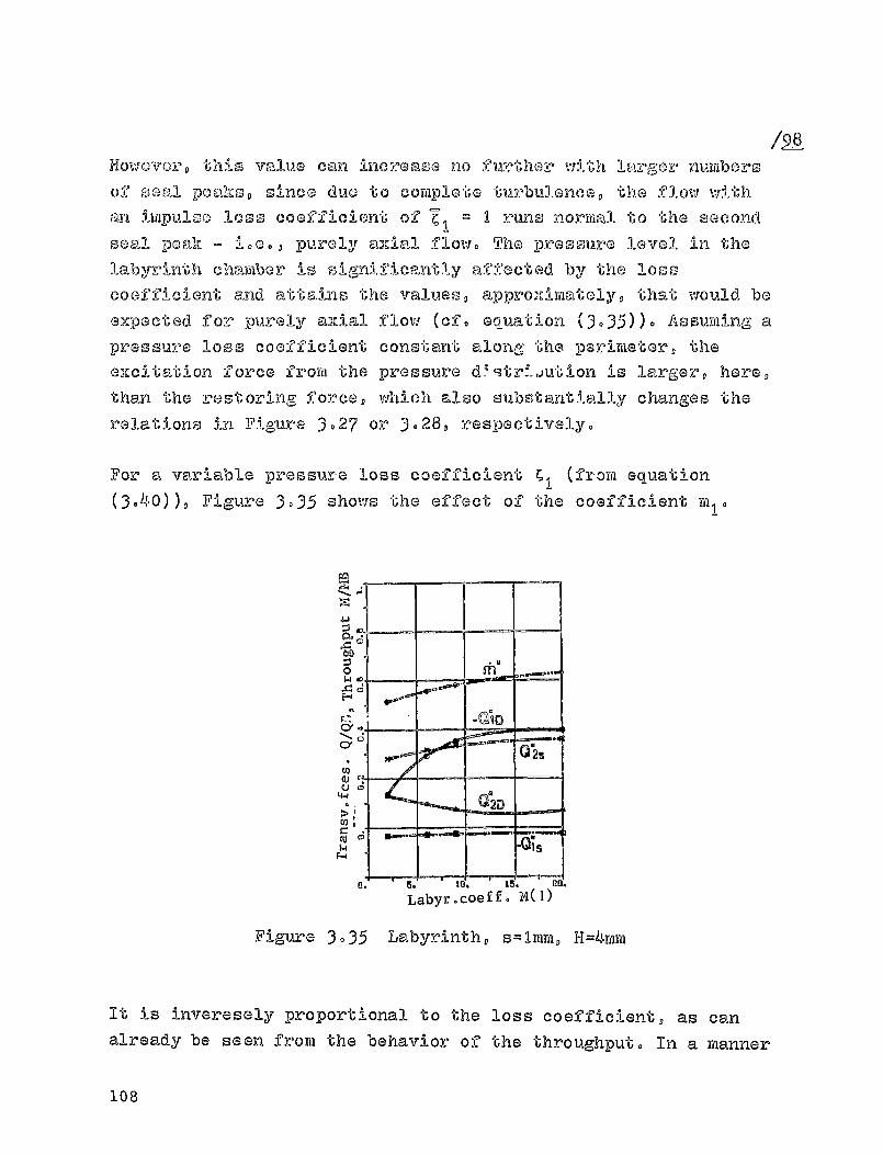
0w4
E-4
r_,
a
4-i
CO
/98Howaverp this value can increase no further with larger numbersof seal peak so since due to com plete turbulence, the flow withan impulse loss coefficient of C o I runs normal to "Ghe secondseal peak - i.00 D purely axial flow. The pressure level i n the
labyrinth chamber is significantly afifocted by the losscoefficient and attains the values, approximately, that would be
expected for purely axial flow (cf. equation (3-35)). Assuming a
pressure loss coefficient constant along the perimeter, theexcitation force from the pressure d 1 9tr__ jution is larger, here,then 'the restoring force, which also substantially changes the
relations in Figure 3. 2 7 or 3.28, respectively.
For a variable pressure loss coeffic i ent C II (from equation
(3040)), Figure 3.35 shows the effect of the coefficient mio
Labyr.coeff. MM
Figure 3-35 Labyrinth, s=1mm, 11=4mm
It is inveresely proportional to the loss coefficient, as can
already be seen from the behavior of the throughput. In a manner
108
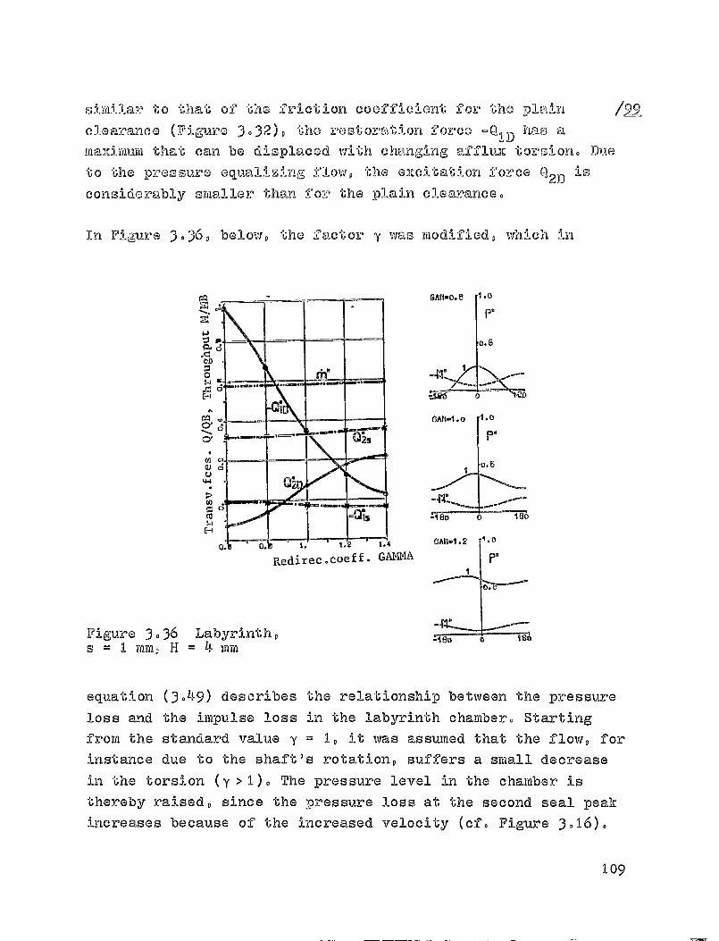
ro0
CY
Cx
ro
Redirec.coeff. GAMMA
similar to that of the friction coefficient for the plain /22
clearance ( F igure 3-32), the restoration force -Q ID has a
maidimum that can be displaced with changing af*Cluiz torsion. Due
to the pressure equali%ing flow, the e2Lcitation force 02D is
considerably smaller than for the plain clearance.
In Figure 3.36 , below, the factor y was modified, which in
GAR-0.0 1.0
Pa
—4
0
GAn-1.0 1.0
P,
-1 80
CAH-1.2
P,
m.
Figure 3 . 36 Labyrinth,s = I mm, H = 4 min
equation (3.49) describes the relationship between the pressure
loss and the impulse loss in the labyrinth chamber. Starting
From the standard value y = 1, it was assumed that the flow, for
instance due to the shaft's rotation, suffers a small decrease
in the torsion (y>2). The pressure level in the chamber is
thereby raised, since the pressure loss at the second seal peak
increases because of the increased velocity (cf. Figure 3o16).
log

0 V/
Docaus,e of the changed pressure distribution, somewhat larger
oizeitation forces Q 2D are generated. If the velocity is
redirected, in the labyrinth chamber, without further pressure
lo.ssas, (y <1), then only a little of
the velocity energy can be
destroyed at the clearance skit. This causes a lowering of
the
pressure level in the labyrinth chamber, with a simultaneous
displacerfient in the location of
the pressure mcximurti. A strong
reduction in the torsional effect on the flow, caused for
instance by crosl-bars within the labyrinth chamber, leads to a
considerable reduction in the siccitation force Q 2D' taking into
consideration the lateral compressive forces acting on the free
portions of
the control spaces. This force can even adoptnegative values, as has been observed during tests with these
Fittings 1301. The calculations above were performed, as a first
approximation, with the compositlon of flow-linos from the /LO—Otangents to the flow angles, with a weighting factor g z = 005,
described in equation (3.4). Changes in this factor, even in
extreme cases, caused no deviation worth mentioning in the
remaining calculation examples. Taking into account the pressure
equalizing flow in the application case described (y <1) is also
only approximately valid, since by adding features in the
chamber, additional compressive forces act on the stream tube.
\RFYI
nSG3nA-0
riE.2 ISANDno.3M-3
Figure 3 . 37 Plain clearance with radialentrance and exit (cf.Figure 3,18)
110

Figure 3.37, above, shows two further clearance forms, in whichthe flow's radius rewained as in Figure 3- 18 -
Form A
appro3i_i wately corresponds to the shroud band on a rotor, while /.LO_Iform B could be used as the stator clearance of a turbine stop inchamber construction. The effect
of the radial entrance in form
A is shown in Figure 3-3 8 , below. With a modification to theentrance clearance - to correspond to the axial clearance
between stator and rotor blading - the forces due to the
pressure distribution, Q D'
remain nearly constant, even thoughvery large pressure differences occur in the entrance clearance,due to the higher velocities. In contrast, the forces Qsdecrease, due to the lower clearance loss in a smaller axial
clearance, something confirmed also by measurements to bediscussed later.
e2
°®1D
2D
^
-----------
Is
U. 1. W. S. 4.
Entrance clear.SE (mm)
bA
0$4
MMAIii
CYMQj
UU
Cd
Figure 3.3 8 Clearance as in Fig- 3-37(A)
111
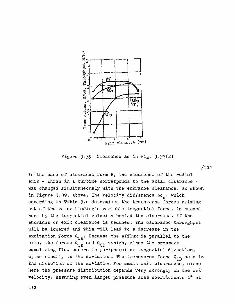
a^0
0a^
F+
a
o'
0U
4-i
NGcaP
E-+
4
^ y Exit clear.SA (mm)
Figure 3039 Clearance as in Figa 3.37(B)
/102
In the case of clearance forth B D the clearance of the radialexit m which in a turbine corresponds to the axial clearance
was changed simultaneously with the entrance clearance, as shown
in Figure 3.39, above. The velocity difference Ac uD whichaccording to sable 3.6 determines the transverse forces arising
out of the rotor blading e s variable tangential force, is causedhere by the tangential velocity behind the clearance. If theentrance or emit clearance is reduced, the clearance throughput
will be lowered and this will lead to a decrease in the
excitation force Q2s o Because the afflux is parallel to theaxis, the forces Q ls and Q 2 vanish, since the pressureequalizing flow occurs in peripheral or tangential direction,
symmetrically to the deviation® The transverse force Q ID acts inthe direction of the deviation for small exit clearances, since
here the pressure distribution depends very strongly on the exit
velocity. Assuming even larger pressure loss coef'f'icients C O at
112
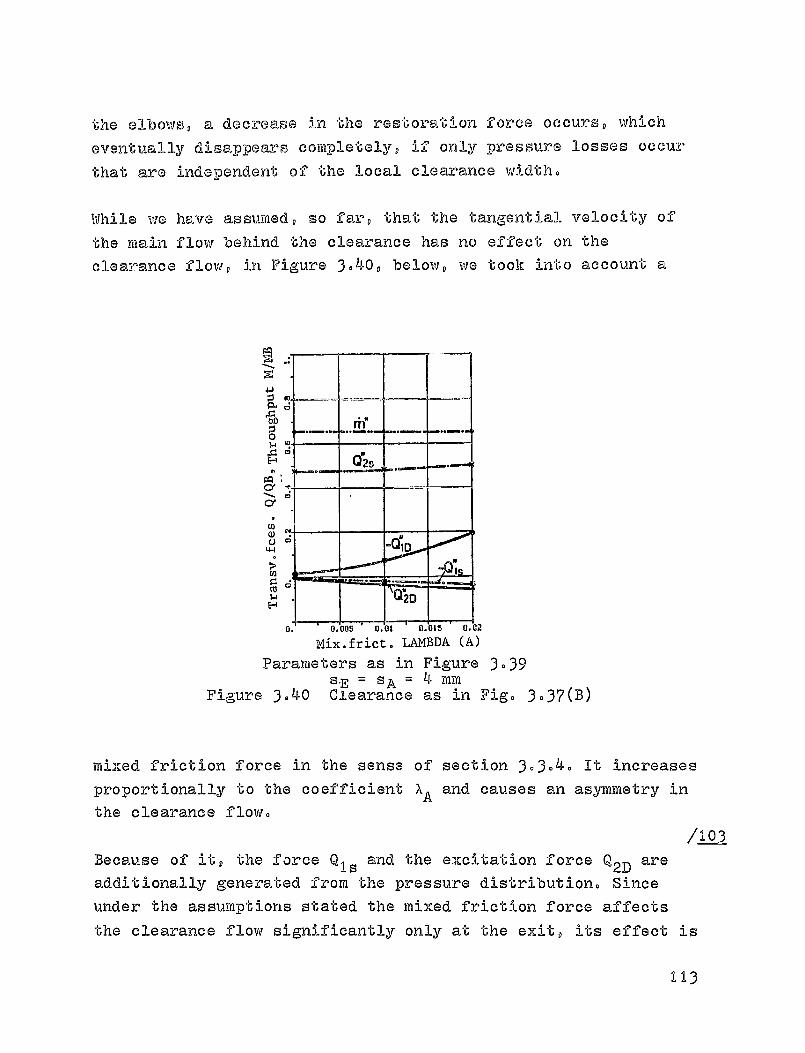
-5'00
FACeCe
ro
the elbows, a decrease in the restoration force occurs, which
eventually disappears completely, if only pressure losses occurthat are independent
of the local clearance width.
While we have assumed, so far, that the tangential velocity of
the main flow behind the clearance has no effect on the
clearance flow, in Figure 3.40, below, vie took into account a
Mix. frict. LAMBDA (A)
Parameters as in Figure 3-39S -E = SA
= 4 mm
Figure 3040 Ciearance as in Fig. 3.37(B)
mixed friction force in the sense of section 30304. It increases
proportionally to the coefficient X A and causes an asymmetry in
the clearance flow.
A-03-
Because of it, the force Q 1. and the excitation force Q 2D are
additionally generated from the pressure distribution. Since
under the assumptions stated the mixed friction force affects
the clearance flow significantly only at the exit, its effect is
113

relatively small. From this we may conclude that the Gimitation
forces related to the pressure distribution are mainly generated
at the rotor clearance of a turb i ne steps At the stator
clearance, besides the excit-ation forces caused by the clsarance
loss, transverse forces are generated by the pressuredistribution that may act against or even in the direction ofthe deviation, if we take a radial entrance or extit intoaccount .
114
1/1044 DE-TE-IffiI-)( NPT ITON Or, THE TRANSVERSE FORCES ACTING ON
THE ROTOR
In ag-Poortiant w i th -their definition, the individual coefficients
of the ma'(-Irii: c. ^6 proportional to 'the deviation (see equation
2.3) (3u-n be doterminod by means of the measurement of the
forcoo acting,- at the turbine rotor, as a function of
-i ,-o t tic displacement. In contrast, the forces proportional to
the velocity, in matrix Wzs can be determineu only from apredetermined vibratory rotor movement. Kinetic tests (of.
Wohlrab, 1301) make it possible to study the simultaneous effectof all the coefficients
of the matrices proportional to the
deviation and to the velocity, from the fading of the aisturbingvibration for known system damping. This study focuses only onthe static method, which has the advantage - besides theseparate determination of the forces proportional to thedeviation - that the effect of a pressure distribution insidethe seal clearance is relatively easy to investigate.
4.1. Test assembly
4.1.1. Installation construction
The transverse forces caused by the flow medium at a turbinestop are many times smaller than the rotor's inertia,representing at most 10% of the tangential force acting on therotor. Since the clearances between rotor and housing are verysmall, special problems arise in the exact positioning of therotor. The force measuring apparatus is arranged around therotor in its stationary positionD an eccentric positioning canbe simulated by moving the housing.
115
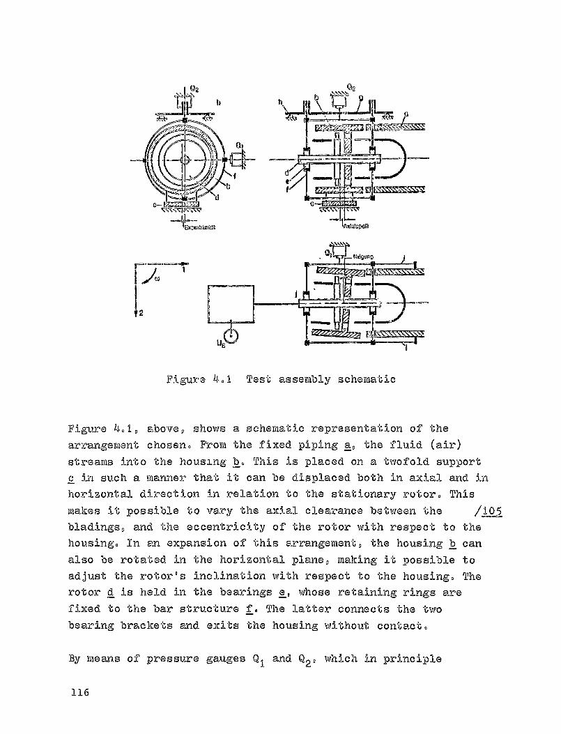
an)
---I"iMCMIOZIU1
12
Figure 4.1 Test assembly schematic
Figure 4.1, above, shows a schematic representation of the
arrangement chosen. From the fixed piping a, the fluid (air)
streams into the housing 11,, This is placed on a twofold support
c in such a manner that it can be displaced both in axial and in
horizontal direction in relation to the stationary rotor. This
makes it possible to vary the axial clearance between the ILO-5-bladings, and the eccentricity of the rotor with respect to the
housing. In an expansion of this arrangement, the housing ]I can
also be rotated in the horizontal plane, making it possible to
adjust the rotor's inclination with respect to the housing. The
rotor d is held in the bearings e, whose retaining rings are
fixed to the bar structure f. The latter connects the two
bearing brackets and exits the housing without contact.
By means of pressure gauges Q 1 and Q29 which in principle
116
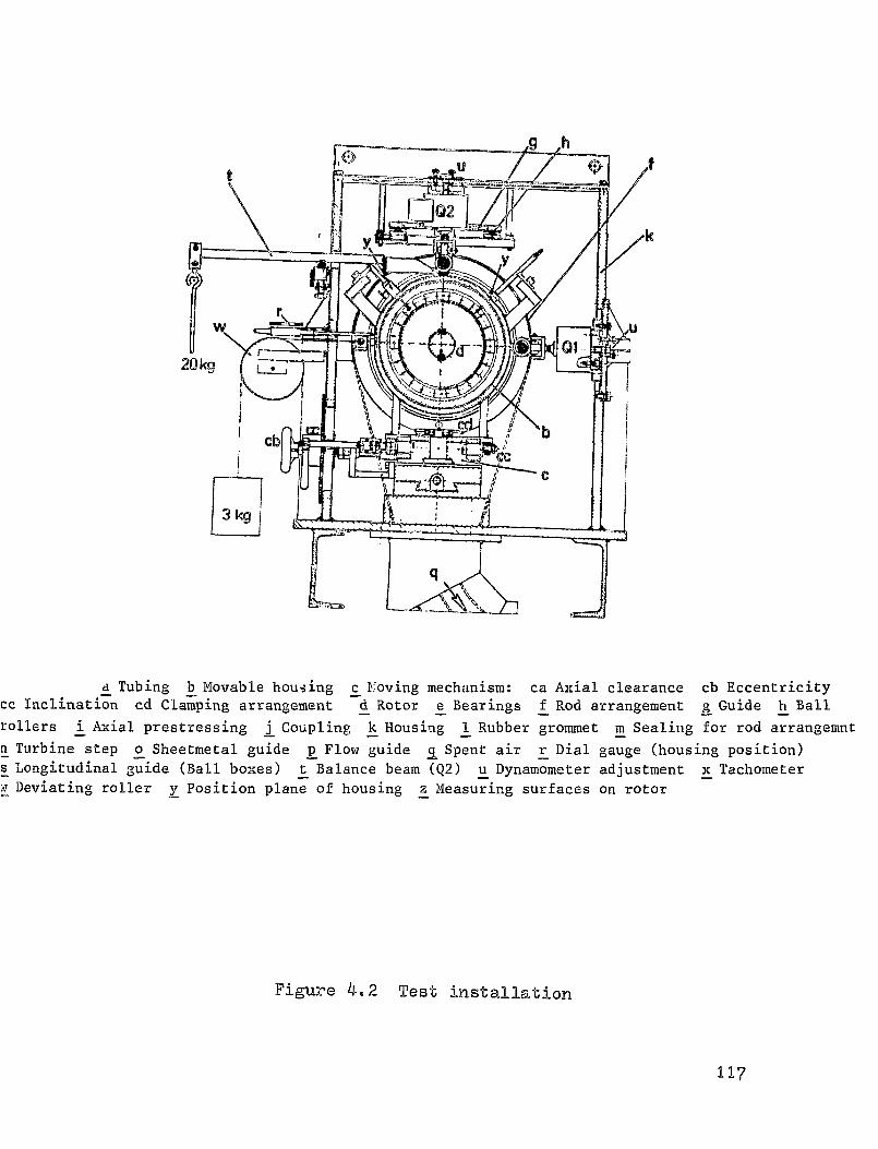
a Tubing b Movable housing c Proving mechanism: ca Axial clearance cb Eccentricitycc Inclination cd Clamping arrangement d Rotor a Bearings f Rod arrangement g Guide h Ball
rollers i Axial prestressing j Coupling k Housing 1 Rubber grommet m Sealing for rod arrangemnt
n_ Turbine step o Sheetmetal guide p Flow guide q Spent air r Dial gauge (housing position)
s Longitudinal guide (Ball boxes) t Balance beam (Q2) u Dynamometer adjustment x Tachometer
:a Deviating roller y Position plane of housing z Measuring surfaces on rotor
Figure 4.2 Test installation
117
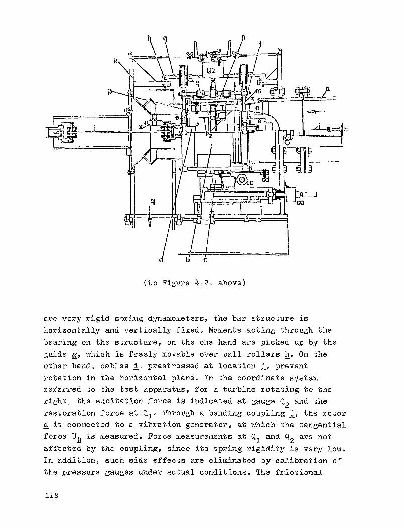
(to Figure 4.2, above)
are very rigid spring dynamometers, the bar structure ishorizontally and vertically fixed. Moments acting through the
bearing on the structure, on the one hand are picked up by the
guide gg, which is freely movable over ball rollers h. On the
other hand, cables iq prestressed at
location I*, prevent
rotation in the horizontal plane. In the coordinate system
referred to the test apparatus, for a turbine rotating to theright, the excitation force is indicated at gauge Q 2 and the
restoration force at Q, 0 Through a bending coupling _j, the rotor
d is connected to a vibration generator, at which the tangential
force U B is measured. Force measurements at Q I and Q2 are not
affected by the coupling, since its spring rigidity is very low.In addition, such side effects are eliminated by calibration of
the pressure gauges under actual conditions. The frictional
118
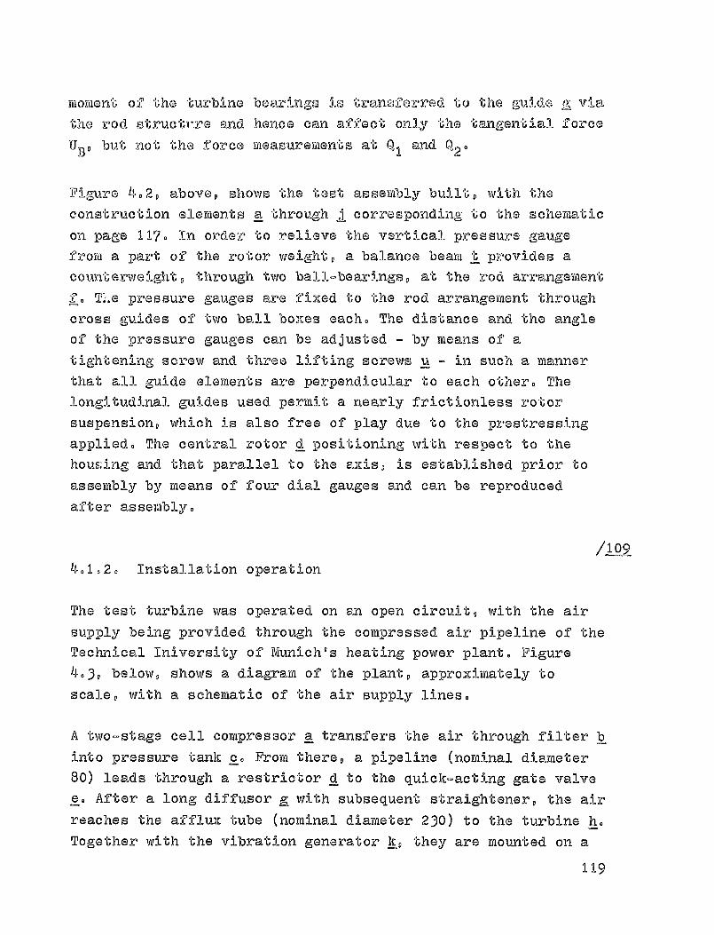
moment of the turbine bearings is transferred to the gu i de r-, via
the -rod structrre and hence can affect only the tangential force
U., but not the force measurements at Q, and Q2'
Figure 4.2, above, shows the test assembly built, with the
construction elements a through 11 corresponding to the schematic
on page 117. In order to relieve the vertical pressure gaugefrom a part of the rotor weight, a balance beam t provides a
counterweight, through two ball-bearings, at the rod arrangementf.T:.e pressure gauges are fixed to the rod arrangement through
cross guides of two ball boxes each. The distance and the angleof the pressure gauges can be adjusted ® by means of a
tightening screw and three lifting screws u - in such a mannerthat all guide elements are perpendicular to each other. The
longitudinal guides used permit a nearly frictionless rotor
suspension, which is also free of play due to the prestressing
applied. The central rotor d positioning with respect to the
houk;i-ng and that parallel to the axis, is established prior to
assembly by means of four dial gauges and can be reproduced
after assembly.
/Lon4.1.2. Installation operation
The test turbine was operated on an open circuit, with the air
supply being provided through the compressed air pipeline of the
Technical Iniversity of Munich's heating power plant. Figure
4 -3, below, shows a diagram of the plant, approXimately toscale, with a schematic of the air supply lines.
A two-stage cell compressor a transfers the air through filter b
into pressure tank c. From there, a pipeline (nominal diameter
80) leads through a restrictor d to the quick-acting gate valve
e. After a long diffusor g with subsequent straightener, the air
reaches the afflux tube (nominal diameter 230) to the turbine h.
Together with the vibration generator k, they are mounted on a
119

I k
-M-7-1 rm- 9 f
P•
91
I ^^
Figure 4. 3 Arrangement of the installation
base plate. The spent air is blown into the machine rooiii via a /1-10silencer. On one side of the control panel m are mounted theessential control elements for the 'best turbine h. The pressuresare recorded at a U-tube wall no and can be fotographed with acamera p I, from the measuring site. The measurement amplifyingand indicating instruments are located approximately at6 _q.
Shielded cables lead from there to a recording facility requipped w i th selector switch, digital voltmeter and printer.
4 - 1 -3- Measurement instruments and test method
The forces were determined by mea:ns.of Hottinger pressuregauges, whose spring elements are outfitted with wire straingauges. The table below provid-e s a review of the gauges used andtheir spring rigidity, the possible measurement ranges - whichare much larger than the forces actually measured at thefacility. The precision is not affected hereby, since a
120
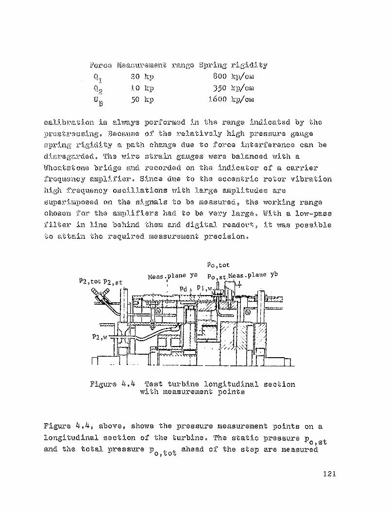
P2,
PorcG Measuroment range Spring rigidity
0, 1 20 kP 800 kplem
X12 10 I:p 350 hp/cm
U B 50 II:P 1600 hp/cril
calibration is always performed in the range indicated by the
pros y essingo Because of the relatively high pressure gaugespring rigidity a path change due to force interference can be
disregardedo The wire strain gauges were balanced with aWhoel,totone bridge and recorded on the ind i cator of a carrierfrequency amplifier. Since due to the eccentric rotor vibrationhigh frequency oscillations with large amplitudes are
superirtiposed on the signals to be measured, the working rangechosen for the amplifiers had to be very large. With a low-pass
filter in line behind them and digital readout, it was possibleto attain the required measurement precision.
PO'tot
MPAA.Dlane Y8 P. rMeas.plane yb
Figure 4.4 Test turbine longitudinal sectionwith measurement points
Figure 4.4, above, shows the pressure measurement points on alongitudinal section of the turbiineo The static pressure
1°o a stand the total pressure p
O'tot ahead of the step are measured
121
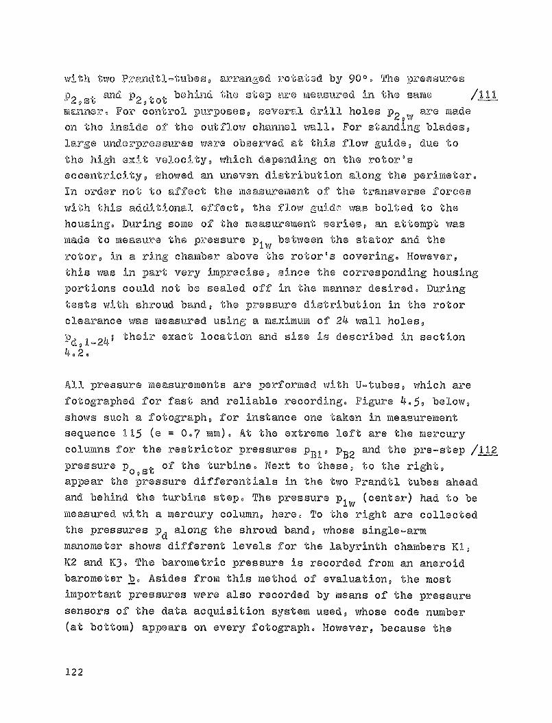
with two Prandtl 'Gubes, arranged rotated by 90 0 . The pressures
92,st and P2 'tot behind the step are measured in the same ILUmanner. For control purposes, several drill holes P2 ^ w are madeon the inside of the outflow channel wall. For standing blades,
large underprGosures were observed at this flow guide, due tothe high aNit velocity, which depending on the rotor'seccentricity, showed an uneven distribution along the perimeter.In order not to affect the measurement
of the transverse forceswith this additional effect, the flow guide was bolted to thehousing. During sortie
of the measurement series, an attempt was
made to measure the pressure p, , between the stator and therotor, in a ring chariber above the rotor's covering. However,this was in Dart very imprecise, since the corresponding housingportions could not be sealed off in the manner desired. Duringtests wi th shroud band, the pressure distribution in the rotorclearance was measured using a maximuri of 24 wall holes,
Pd,1-24; their exact location and size is described in section4.2.
All pressure measurements are performed with U-tubes, which arefotographed for fast and reliable recording. Figure 4.5, below,shows such a fotograph, for instance one taken in measurementsequence 11 5 (e = 0.7 ram). At the extreme left are the mercurycolumns for the restrictor pressures p,,, PB2 and the pre-step I112pressure post of the turbine. Next to these, to the right,appear the pressure differentials in the two Prandtl tubes aheadand behind the turbine step. The pressure p 1w (center) had to bemeasured with a mercury column, here. To the right are collectedthe pressures pd
along the shroud band, whose single-armmanometer shows different levels for the labyrinth chambers K1,K2 and K3. The barometric pressure is recorded frori an aneroidbarometer b. Asides from this method of evaluation, the mostimportant pressures were also recorded by means of the pressuresensors of the data acquisition system used, whose code number(at bottom) appears on every fotograph. However, because the
122

AP P,1W 'f "4 ^'" ^n A,.
4z4clr 4PV
OK^'Z"-'
A,r6 4 .5 Fraware
;vnissronent ringn of the preosure mon gors ni q unA uited to
toot facility, the Pvaluation ww pRrformcd primarily with th
photn^raphla Awti,
At the beginning of a test sequence, the static rotor was placed
in the desired position with -respect to the fixed housing parts,and the arrangement checked for freedom from friction. For aprecise adjustment- of the central position with respect to themovable housing, airflow was established across the step withoutrotation,- hereby it was possible to reduce measurement errorscaused by arrangement elast i city to a minimum. Once the dial
gauges were removed, the rotor was brought to operating speedand the pressure gauges were calibrated using weights. It was
then possible to change the housing position without modifying
the operating conditions and record all forces, temperatures and,ressures for each position. Thus a measurement sequence yields
the variations in the transverse forces across the deviation and
on the basis of repetitive measurements provides relatively
precise average values for all turbine data. Within the
precision of the measurements, these were independent of the
eccentricity - or respectively, inclination - of the rotor.
4.2 Test program
The constant-pressure step represented in Figure 4.6, below, was
used primarily to investigate the effect of the seal form on the
clearance excitation forces. With the rotor suspension chosen,
it was possible to measure simultaneously the forces acting in
the direction of the deviation and perpendicularly to it,-
because of the test arrangement, the moments acting on the rotor
were not included. Because of the non-variable compressor, the
turbine throughput was fixed at approximately 0.4 k9/s. For an
operating speed of 8,000 rpm, the pressure coefficient * was 5.2
to 6.2. The Reyncld's numbers calculated from the afflux
velocity and the blades' chord length was approximately 89 104.
From measurements performed with standing blades - listed
completely in one report 151 - it was possible to derive
124

ORIGINAL: PAGE
BLACK AND WHITE PHOTOGRAPH
A
E2
8 meas..drill-holesalong
xP ime rer' te
D V//"
8 drill-holes,wise 2 dr.hls.,s
ng perimeter.I ^Ks
8 drill-holesotherwise 4
periimete.rN
Figure 4.6 Constant pressurestep geometry
Figure 407 Variations in theForm of the seal
essential trends in the clearance excitation forces, which alsoserved as orientation for the remainder of the test program.Because they are more applicable, we shall mention here onlytests with rotating blading, which are in agreement with the /icemeasurements above, once differences in operating conditions aretaken into account.
The seal geometry was varied by placing certain inserts in theturbine housing, shown in Figure 407, above, for blading withshroud band. Table 4.1, below, provides an overview of thesequentially numbered insert conditions, indicating thecharacteristic magnitudes. The variations in the radial
225

TABLE 4.1 Test program
Insertion condition Geometry
EB s' Sol Forme
21 1,1 1,0 A
22 w/o shroud-band 1,55 I's A
231
0,55 O's A
24, 25 plainshroud 1,1 1,0 Al
20-band— B2
26, 27 twoseal peaks
1,1 1,0 C
29threeseal peaks
1,1 1,0 D
clearance widths were performed only for blading without shroud
band (form A); for reasons of tolerances, the stator clearance
was slightly larger than that for the rotor. Since distinct
pressure differences could already be observed along the rotor
shroud band for standing blading, special attention was paid to
banded bladingo First, the plain clearance was investigated with
a simple gauge ring B1, for different operating speeds. However,
the pressure drop in axial direction could be measured more
accurately only after adding a second gauge ring, B2. To
conclude the test program, two labyrinth seals commonly used
with turbines (C and D) were installed at the rotor. In
addition, this made it possible to study the effect of rotor
inclination with respect to the housing.
/116
4.3- Measurement evaluation
4-3- 1 . Turbine data and force measurements
The turbine's mass flow is determined from the temperature at
126

tA ® - L'-'dra 12,
U ,( 4.3 )
the measurement orifice, t,,, and the Pressures PBI and PB2'
according to DIN"** 1952
4.1
The pipe diameter is given as D = 80 mm and the opening ratio ofthe orif i ce as m = d 2/D 2 = 0 -366. The density p can becalculated from the gas equation, as a function of temperatureat the orifice. The expansion coefficient E(PB2/PB10 m) and thethroughput coefficient a(Re, m) were determined from DIN 1952,taking into consideration the temperature dependence of thekinematical viscosity for Reynold 's number. Because of thedependence of Reynold's number on the mass flow, iteration isnecessary.
The turbine's isentropic gradient is obtained from the pressuresoo,W P2 A ,, and the temperature T o , by
Ails C: Ce 2 ( 4.2T,O -(Lf-b P^ I
The force NB at the brake's lever arm lb is first recalculated
using the calibration factor of the gauge, then the turbinestop's tangential force
is determined. With the angular velocity w at the rotor, we
obtain the effective efficiency
IP-. ( 4.4
'd V,.3 rh
DIN = Deutsche Industrie-Norm. = German Industrial Standards
127
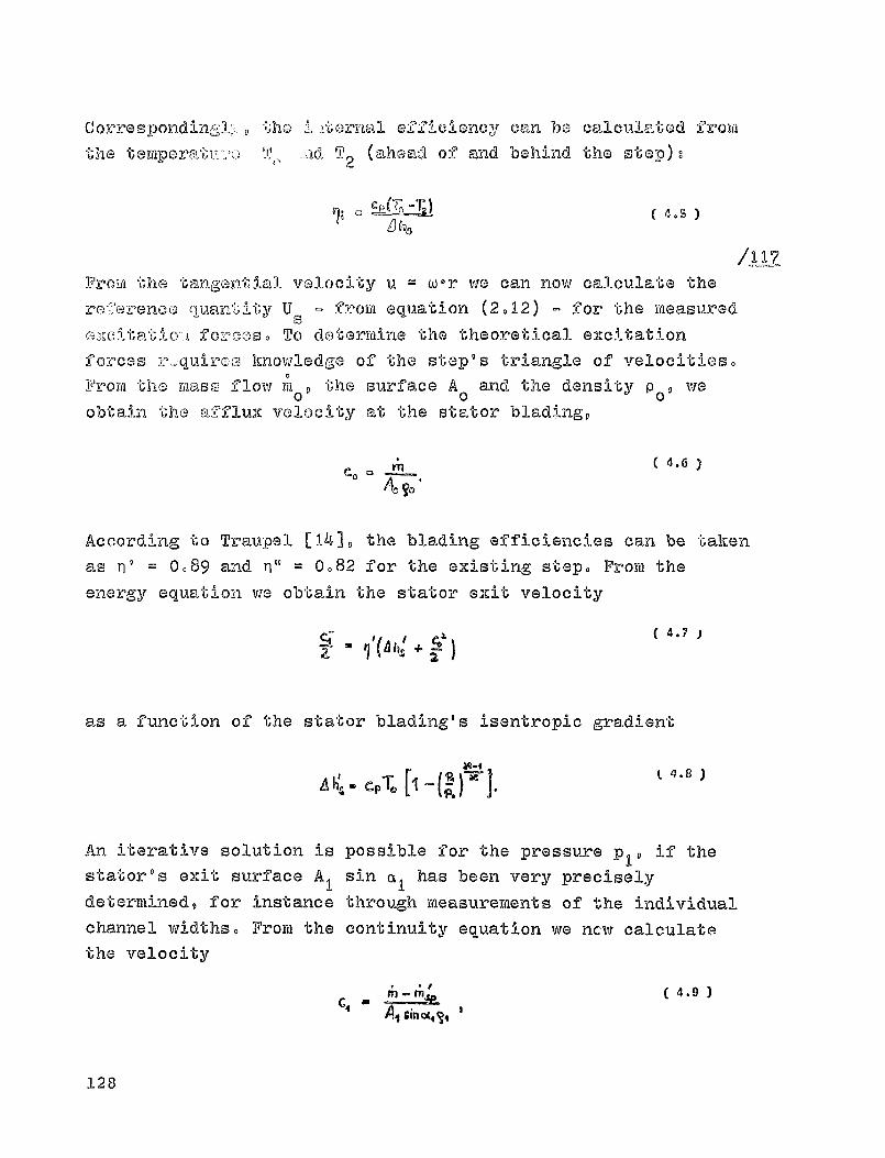
0, -T
Q Ear( 4.S )
C orre s pond `.ho ^, ternal efficiency can be
cq,.Icula- -'U-Gd from
the TO -Ad "2 (ahead of and behind the otep)-.
Frow the tanzGn-U,--),I velocity u = w-r we can now calculate the
r "arenco q uantity Us- - ^J- s - from equation (2012) - for the measuredfo-z-oos. To determine the theoretical excitation
forces z, .;quirco knowledge of the step's triangle of velocities.0
From the Tualso flow m0, the surface A 0 and the density p 0 , weobtain the a-fflux velocity at the stator blading,
CO^n
A, T.'
According to Traupel [141, the blading efficiencies can be takenas W = 0.89 and Ti" = 0.82 for the existing step. From the
energy equat i on we obtain the stator exit velocity
I CO4.7
4 h^ 4-
as a function of the stator blading's isentropic gradient
cp% 11 ® (S 4.8 ^• l
'P.
An iterative solution isstator's exit surface Aldetermined, for instancechannel widths. From the
the velocity
possible for the pressure p,, if thesin a1 has been very preciselythrough measurements of IV-he individualcontinuity equation we new calculate
M 4.9
A, Sin CA444
128
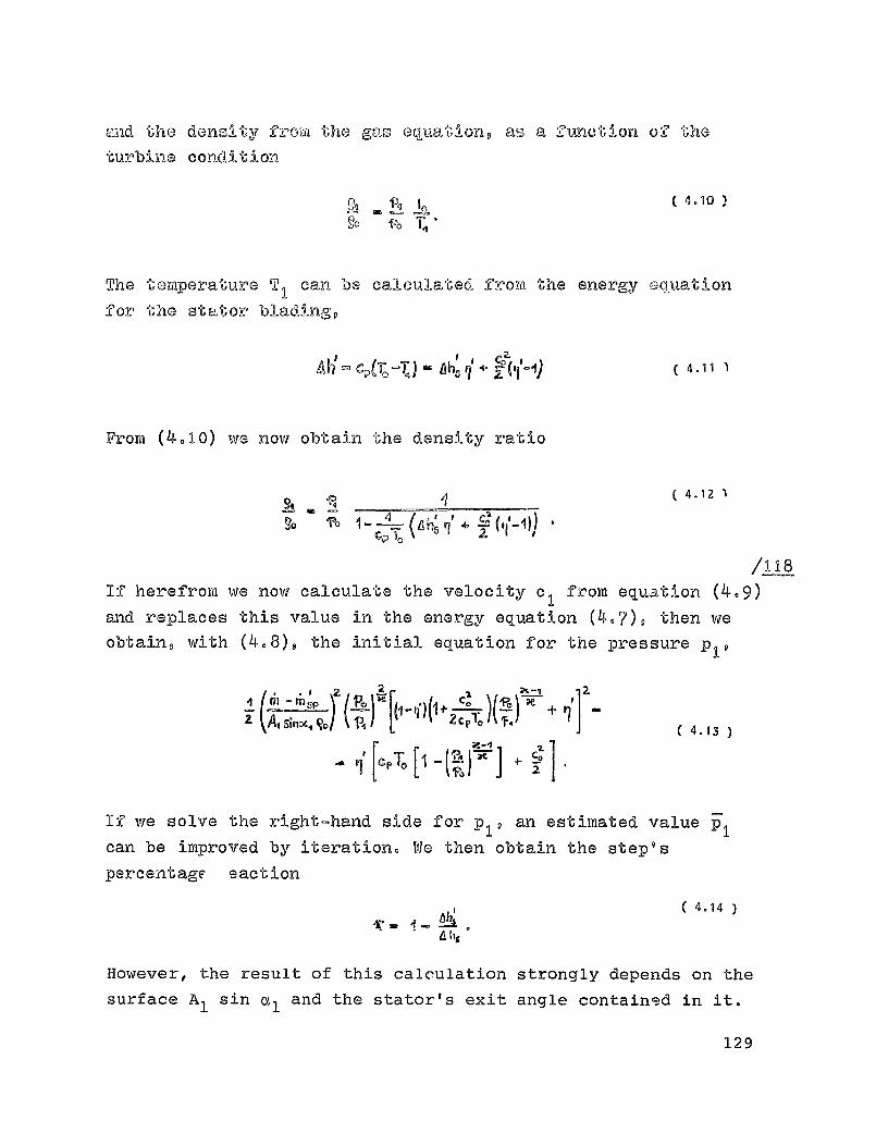
I
T_ 7.0 A b4-4N( 4.14 )
and the density from the gas equation, as a function of theturbine condition
( 4.10 )4
The temperature T 1 can be calculated frow the energy equationfor the stator blading,
A TJCp(T. - - Ahz# q►1 4.11 1
From (4010) we now obtain the density ratio
4.12
4, cj (
t
X I
/.L1_8If herefrom we now calculate the velocity c I from equatiors. (4.9)and replaces this value in the energy equation (4-7), then weobtain, with (408), the initial equation for the pressure P,,
► 2 124 io V
++
4.13r(—A,
Ct Ia Va I ^P^m ^'^ ®^^ I K
J +
If we solve the right-hand side for p,, an estimated value pcan be improved by iteration. We then obtain the step'spercentage saction
However, the result of this calculation strongly depends on thesurface Al sin a 1 and the stator's exit angle contained in it.
129
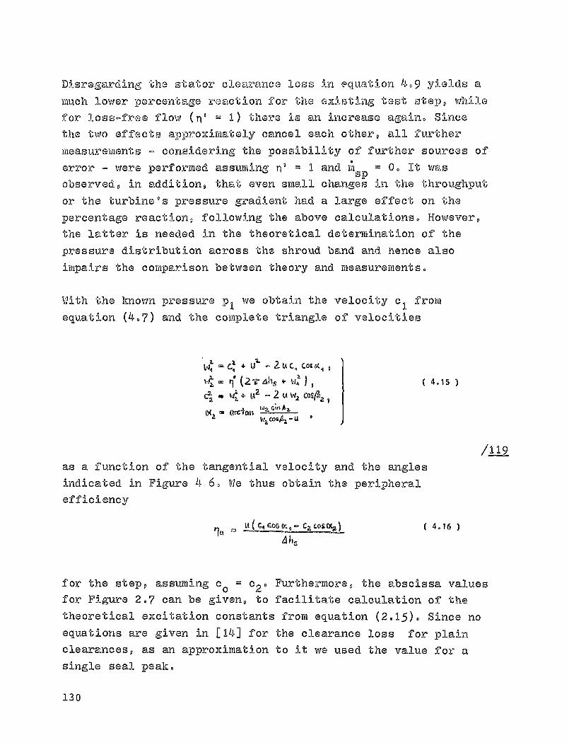
Disregarding the stator clearance loss in equation 409 yields a
much lower percentage reaction for the eXisting test step, while
for loss-free flow (n' = 1) there is an increase again. Since
the two effects approximately cancel each other, all further
measurements o considering the possibility of further sources of
error m were performed assuming n' = 1 and :lisp
= 0. It wasobserved, in addition, that even small changes in the throughput
or the turbine's pressure gradient had a lame effect on thepercentage reaction, following the above calculations. However,
the latter is needed in the theoretical determination of the
pressure distribution across the shroud band and. hence also
impairs the comparison between theory and measurements.
With the known pressure p 1 we obtain the velocity c, from
equation (4.7) and the complete triangle of velocities
Wq ° Gq 4 U2' a U Cq C©c Dc q y
a 6 n (2 v ail, * V1q J , ( 4.15 )tL2 . V41 + L42U W2 CoSAa
9
D(2.
Q^C$Qp i^G ^'" bb
2 WaC0a4aoU
/12as a function of the tangential velocity and the angles
indicated in Figure 6. We thus obtain the peripheral
efficiency
U(6,goyM,®C2 Col ®c,^ ( 4.16 )
4 hs
for the step, assuming c o = c20
for Figure 207 can be given, to
theoretical excitation constant
equations are given in [ 14] for
clearances, as an approximation
single seal peals
Furthermore, the abscissa values
facilitate calculation of the
s from equation (2m15)m Since no
the clearance loss for plain
to it we used the value for a
130
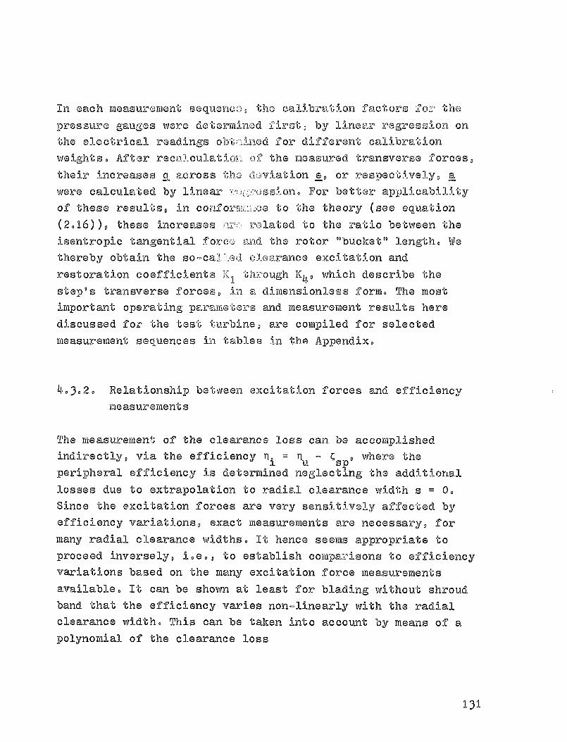
In each measurement sequence, the calibration factors foz , the
pressure gauges were determined by linear regression on
the electrical readings o lb ," Aned for different, calibration
weights. After recalculatio2l of the measured transverse forces,
their increases a across the cl oviation e, or respectively, a
were calculated by linear For better applicability
of these results, in to the theory (see equation
(2016)), these increases related to the ratio between the
isentropic tangential fora; Lind the rotor "bucket." length. We
thereby obtain the so-ca]."i.ed clearance excitation and
restoration coefficients uh--oough K4' which describe the
step's transverse forces, in a dimensionless form. The most
important operating parameters and measurement results here
discussed for the test turbine, are compiled for selected
measurement sequences in tables in the Appendix.
•-3.2. Relationship between excitation forces and efficiency
measurements
The measurement of the clearance loss can be accomplished
indirectly, via the efficiency n i = nu - C sp , where the
peripheral efficiency is determined neglecting the additional
losses due to extrapolation to radial clearance width s = 0.
Since the excitation forces are very sensitively affected by
efficiency variations, exact measurements are necessary, for
many radial clearance widths. It hence seems appro priate to
proceed inversely, i.e., to establish comparisons to efficiency
variations based on the many excitation force measurements
available. It can be shown at least for blading without shroud
band that the efficiency varies non-linearly with the radial
clearance width. This can be taken into account by means of a
polynomial of the clearance loss
131

fQP M CA O S + C12
.2 2 + C-t ,3 e ( 4.17 )
as a function of the clearance width. If we assume, disregarding
equalizing flows, that this clearance loss is valid also for
local radial clearance widths 6 according to equation (2.1•),then the integration of equation (2010) yields the transverseforces acting on the rotor,
01 ( 4.18)
I
2. + ^^
cap e
Z ^.2.6 - [( " 4 +2az s +' 3C1 3 S
4.
Since the clearance loss was assumed proportional to the localclearance width, the force in the direction of deviationvanishes. While for a linear equation a2 = a 3
= 0 - as we
already established - the force is independent of the radialclearance width S, this effect can already be noticed for aparabolic equation a3
= 0. However, it is only for higher-order
clearance loss equations that an "s"-shaped course of theexcitation force across the eccentricity is obtained.
If we assume that the excitation forces Q 2D caused by pressuredistributions can be disregarded for bladings without shroudband, then the coefficients of equation (4018) can be determinedby the least squares method applied to the measured excitationforces Q 2 =Q2so Here we obtain a family of curves of theexcitation forces as a function of radial clearance width s,across the eccentricity, whose coefficients determine the courseCO of the clearance loss that would result as a consequence ofsp
the excitation forces. By further adapting this course to themeasured efficiency
q ( 4.19q;
044 sp TQ
132

we can determine the peripheral efficiency nu and a factor y by
which the clearance loss fop
from the excitation forcemeasurements would have to be corrected. For Y Q1, there would
be complete agreement ( see Figure 403, below) between excitation
1,
71u
GPQP
e ®® y®>1
Y0
Yo<^^°m
S
Figure 4®S Variation of the effciency acrossthe radial clearance width
force and efficiency measurements. For y Q < 1, the measuredexcitation forces are larger than the forces that can be
explained based on the clearance loss, which leads to the
conclusion that there are additional effects, for instance due
to the pressure distribution, at work. In general the factor
will be yQ >1, since the local clearance loss can be reduced by
means of equalizing flows along the perimeter ® In this case the
measured excitation forces are smaller than those one would
calculate from a precise course of the efficiency ni(s)®
It was assumed., in the evaluation of the results, that the
effective efficiency determined from output measurements at the
electric dynamometer are to be set equal to the internal
133

Rotor
Stator
off -I'locioncy, r) i Q q 0 0 The monouromont WK the' efficiency
from the toyi-iporaturos ahead oZ t--iyid behind the turbine is
sf, -0, ^octod by monouromont orvoro that are teo largo, 'or theseconoldovationo. But it is to be ozpoctod .dI-at the friction at
the toot turbine's ball bearings will affect the efficiency rt ein the saute manner for all paramotor changes.
Especially important to the above correlati on is the assumption
that viewed across the parimater, the smallest clearance 1. SSwill also occur at the narrowest clearance width. Because of thetorsional affect on the flow, according to section 306 this willnot always be true. As Figure 4.9 9 below, shows, a small phasedisplacement- occurs also because the clearance loss :ccurring /1-22-
Figure 409 Flow-line course
at the stator reduces the tangential force only after an arclength b. 0 Because of this, in contrast to equation (4018) thereare transverse forces Q
Is active here that must be taken into
account, in the correlation with the efficiency variations. Themeasured restoration forces Q 11 however point towards the factthat in spite of the relatively large flow line advance2b
b /d
M = 17 0 ) this effect is small.
403030 Pressure distribution at the shroud band
The purpose of the pressure measurements at the rotor seal
134
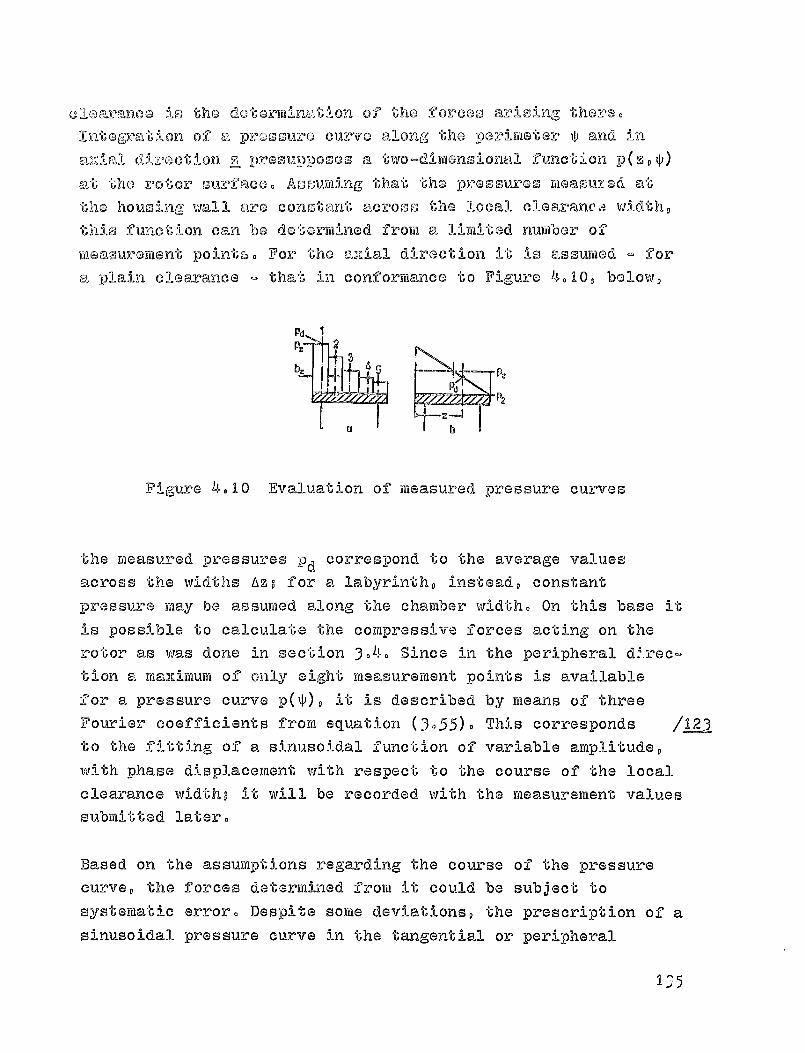
Pd
P
2
b, ®®
P2Pd F PC
b
clearance is the dotormination o-J- the forces arising there.Integration of a p:oossuro curve along,
perimeter s and in
am-zial direction s presupposes a two-dimensional function -r)(sDO
--)t the rotor surface. Assuming that the pressures- atthe housing wall are constant across the local clearanca width,this function can be determined from a limited number of
measurement points. For the axial direction it
is assumed - for
-a plain clearance - that in conformance to Figure 4.10, below,
Figure 4.10 Evaluation of measured pressure curves
the measured pressures Dd correspond to the average valuesacross the widths ^z,- for a labyrintho instead, constantpressure may be assumed along the chamber width. On this base itis possible to calculate the compressive forces acting on therotor as was done in section 3.4. Since in the peripheral V.rec-tion a mai-Umum of only eight measurement points is availablefor a 'pressure curve pM, it is described by means of threeFourier coefficients from equation (3-55). This corresponds /.L22to the fitting of a sinusoidal function of variable amplitude,with phase displacement with respect to the course of the localclearance widthD it will be recorded with the measurement valuessubmitted later.
Based on the assumptions regarding the course of the pressurecurve, the forces determined from it could be subject tosystematic error. Despite some deviations, the prescription of asinusoidal pressure curve in the tangential or peripheral
I -o^ 5
direction appears to lead to only small errors, since higher
order Fourier coefficients (e quation 0.54 )) drop out during,integration. In contrast, the result
is severely affected by how
the widths As in Figure 4.10 are established, since the pressure
curve is non-linear in axial direction. It would be possible in
principle to fit a two-dimensional function p(z,f) to the
measurement points, but it would lead to substantial calculation
efforts, since the parameters would no longer be independent of
each other. This would make restrictions necessary such that no
increased precision in the results could be expected, in
comparison to the above evaluation. Qualitatively, moreover,
measurements with only one measurement plane perpendicular to
the carrying axis (cf. Figure 4.10b) yield useful results.
Within a measurement sequence, the pressure variations are
recorded for each eccentricity and the forces Q D
are computed,
from whose course across the eccentricity the increases q D are
calculated by linear regression. Whether the rotor is displaced
in a positive or a negative direction (cf. Figure 2 -5), for a
corresponding definition of the tangential angles the samepressure curves should be obtained. However, due to minute
differences in the seal's microgeometry, in part substantial
deviations can occur. Therefore, in order to obtain
representative descriptions of the pressure course, pr(-suresfor equally large positive and negative eccentricities re
averaged.
/1 244
4.4. Transverse forces from an eccentric rotor position andcomparison to the efficiency curve
Starting from the central position of the turbine step within
the housing, the eccentricity could be adjusted to UP to 75% ofthe radial clearance width, in both directions. The transverse
136
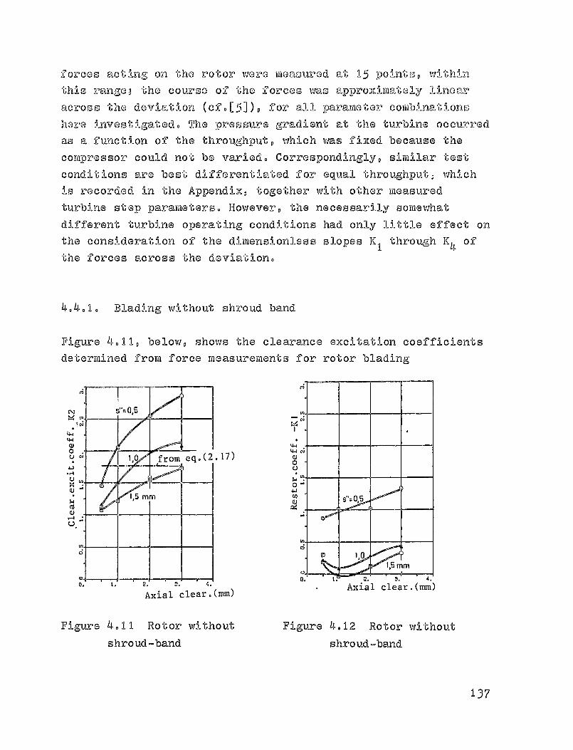
forces acting on the rotor were measured at 1 5 -point s, withinthis rangeB the course of the forces was approximately linear
across the deviation for all parameter combinations
here investigated. The pressure gradient at the turbine occurredas a function
of the throughput, which was fined because the
compressor could not be varied. Correspond i ngly, similar testconditions are best differentiated for equal throughput, whichis recorded in the Appendix, together with other measured
turbine step parameters. However, the necessarily somewhat
different turbine operating cond i tions had only little effect onthe consideration of the dimensionless slopes K 1 through K4 ofthe forces across the deviation.
4.4.1. Blading without shroud band
Figure 4.11, below, shows the clearance excitation coefficientsdetermined from force measurements for rotor blading
F)
4-4
4-4 CU
1 ' 0 from eq (2-17) W .0U
0-
1,5 mrn
r=0
1^51
1,0
MM
a. 4.
Axial clear.(mm) Axial clear.(mm)
Figure 4.11 Rotor without
Figure 4.12 Rotor withoutshroud-band shroud-band
4qLHN0
-W•4U
XQ)
COQ)-4
137
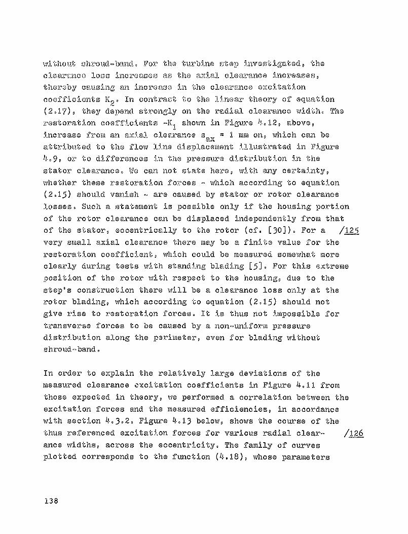
without shroud-band, For the turbine stop investigated, the
clearance loos increases as the amiJ, clearance increases,
thereby causing an increase in the clearance e2zeltation
coefficients K2 0 In contrast to the linear theory of equation
(2017), they depend strongly on the radial clearance width. The
restoration coefficients -K I
shown in Figure 4.12, above,
increase from an axial clearance saX ® I mm on, which can be
attributed to the flow line displacertient illustrated in Figure
409, or to differences in the pressure distribution in the
stator clearance. We ca7.2 not state here, with any certainty,
whether these restoration forces - which according to equation
(20 1 5) should vanish - are caused by stator or rotor clearancelosses. Such a statement is possible only if the housing portionof the rotor clearance can be displaced independently from that
of the stator, eccentrically to the rotor (cf. 1301)0 For a 111_5
very small axial clearance there may be a finite value for therestoration coefficient, which could be measured somewhat more
clearly during tests with standing blading 153. For this extreme
position of the rotor with respect to the housing, due to the
step's construction there will be a clearance loss only at the
rotor blading, which according to equation (2015) should not
give rise to restoration forces. It is thus not impossible for
transverse forces to be caused by a non-uniform pressure
distribution along the perimeter, even for blading without
shroud-band.
In order to explain the relatively large deviations of the
measured clearance excitation coefficients in Figure 4011 from
those expected in theory, we performed a correlation between the
excitation forces and the measured efficiencies, in accordance
with section 4-302. Figure 4o13 below, shows the course of the
thus referenced excitation forces for various radial clear- /126
ance widths, across the eccentricity® The family of curves
plotted corresponds to the function (4.18), whose parameters
138

^\I^I
ua^0
4-i.r4
UW
CU
CJ
O
SOO
0
/AntlQ
O
1
O Alf
0
0. 0.'.S 0.5 0.95
Eccentricity .(mm)
Figure 4.13 Blading without shroud —bandCurve fitted w/2ndorder polynomial for clearance loss
from clearance loss,[14],ego(2.15)were determined from the measurement points, by linear
regression, as a function of the two variables e and s. Since
the course of the excitation Forces is linear across the
eccentricity, a second order polinomial (4.17) will be
sufficient for the clearance loss. However, a higher-order
polinomial was able to explain measurements for a standing rotor
C51 very well, even though there the course of the excitation
Forces is non-linear across the eccentricity, characterized by a
steeper slope for increasing eccentricity.
It is possible to establish a comparison between the parameters
of the functions (4.18), determined frora excitation Force
measurements, and the measured efficiencies, for all axial
clearances investigated. Starting from the calculated peripheral
efficiency (for s = 0), the broken straight line records the
course or the clearance losses from [14], which for this turbine
139

0
r4 q ^^
0 a
0
Q-4 CD
^1x
44W
1,0
2,03,0 mm
d0
Radial clear. (nun)
o SOV-O .S Uri OOn®1.00 :.10• SAX-1.0 HU OPM-1.10 $.06M S61Vo2.0 H4 ON-1.17 e.02X SAU.B.0 KM GM-1.18 1.08
Eff.curve from excit.fce.measurement,
2nd order polynomial fit
—•-From clearance loss, [14)
Figure 4014 Blading without shroud-band
step agree only very little with the measurements. The slope and
curvature of the curves plotted were determined for each axial /127
clearance from the measured excitation forces. If together with
equation (4019) we were to introduce a correction factor y =1.2,
the agreement between these curves and the treasured efficiency
would improve. In other words, the excitation forces are only
83% of the forces one should calculate, from the actual course
of the efficiencies. Faking into consideration the certainty
required for vibration calculations, the excitation forces in
bladings without shroud-band can be calculated from a known
efficiency curve, using equations (2016) or (4.18).
404020 Blading with shroud-band
In order to reduce clearance losses, the blading is fitted with
140
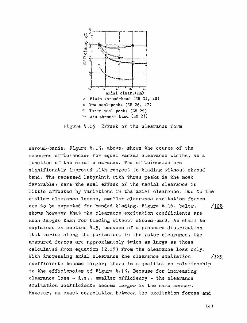
ca
4_1
4.4
W
31
r^
U. 9. X. Z. 4.
Axial clear.(mm)o Plain shroud-band (EB 25, 28)• Two seal-peaks (EB 26, 27)
Three seal-peaks (EB 29)w/o shroud- band (EB 21)
Figure 4.15 Effect of the clearance form
shroud-bands. Figure 4.15, above, shows the course of themeasured efficiencies for equal radial clearance widths, as afunction of the axial clearance. The efficiencies aresignificantly improved with respect to blading without shroudband. The recessed labyrinth with three peaks is the mostfavorable3 here the seal effect of the radial clearance islittle affected by variations in the axial clearance. Due to thesmaller clearance losses, smaller clearance excitation forcesare to be expected for banded blading. Figure 4.16, below, /128shows however that the clearance excitation coefficients aremuch larger than for blading without shroud-band. As shall beexplained in section 4-5, because of a pressure distributionthat varies along the perimeter, in the rotor clearance, themeasured forces are approximately twice as large as thosecalculated from equation (2.17) from the clearance loss only.With increasing axial clearance the clearance excitation / L-2 9
coefficients become larger; there is a qualitative relationshipto the efficiencies of Figure 4.15. Because for increasingclearance loss - i.e., smaller efficiency - the clearanceexcitation coefficients become larger in the same manner.However, an exact correlation between the excitation forces and
141
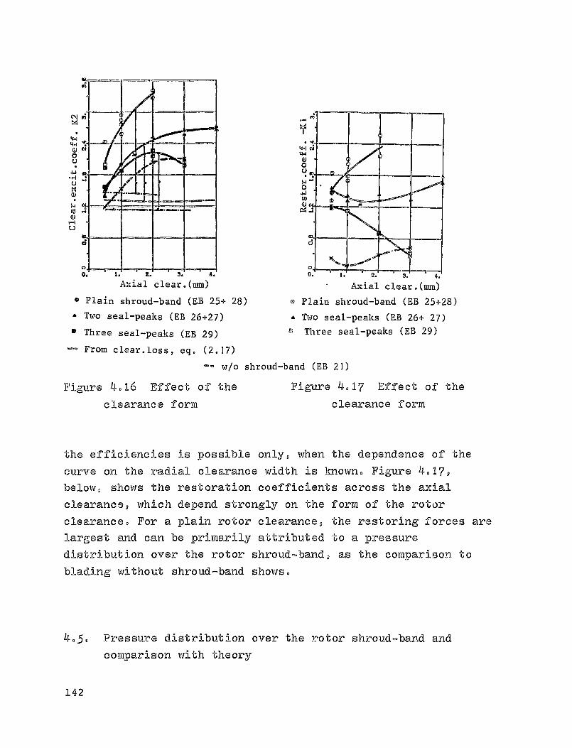
4-a4-INOu
UvQ1
roro
Vd
tll0U
O.WCn
04
Axial clear.(mm) Axial clear.(mm)
m Plain shroud-band (EB 25+ 28) o Plain shroud-band (EB 25+28)
• Two seal-peaks (EB 26+27) • Two seal-peaks (EB 26+ 27)
Three seal-peaks (EB 29) ° Three seal-peaks (EB 29)
From clear.loss, eq. (2.17)
-- w/o shroud-band (EB 21)
Figure 4.16 Effect of the Figure 4.17 Effect of the
clearance form clearance form
the efficiencies is possible only, when the dependence of the
curve on the radial clearance width is Known.. Figure 4.17,
below, shows the restoration coefficients across the axial
clearance, which depend strongly on the form of the rotor
clearance,, For a plain rotor clearance, the restoring forces are
largest and can be primarily attributed to a pressure
distribution over the rotor shroud-band, as the comparison to
blading without shroud-band shows.
4,,5,, Pressure distribution over the rotor shroud-band and
comparison with theory
142

IN
4 -5- 1 - Shroud-band with plain clearance
Figure 4018 shows a two-dimensional representat i on of the
Figure 4.18 Pressure distribution across a plainshroud-band, e = 0.7 mm
pressure course, measured for an eccentricity of 007 mra at a
plain rotor clearance, both along the perimeter and in axialdirection. The static pressure drop at the rotor blading'sexternal section was approximately 60 mbar, in this measurement
sequence (cf. Appendix), with an of lux velocity of 140 m/s.Starting from the entrance edge (z = OD cf. Figure 208), thepressure courses for five measurement planes normal to the axis,in accordance with Figure 407 (B2), are shown along the shroudband; the axial direction was considerably magnified incomparison to the perimeter. The clearance at the entrance sideof the shroud-band here is only half as large as the averageradial clearance width. In agreement with the definition inFigure 2.5, the smallest local radial clearance width is found
at the tangential angle ^ = 0. Because the flow is subjected to
143

torsional effects, there is a pressure mtesudUmum just before the
narrowest clearance, which for individual measurement planes
along the shroud-band travels, almost 80 0 against the direction
of rotation. Due to the characteristic pr- sure maximum in DAFront
of the narrowest clearance, a force; acts on the rotor that
has a component in the direction of the &eviation, and another
one perpendicular to i t. In tangential direction the pressure
curve does not correspond to a pure sine function, since the
maXima are steeper than the minima.
Figure 4.19, below shows, for three selected measurement
sequences, the effect of the axial clearance on the measured
pressure courses, with the fitted sine function plotted in each
case. Measurement sequences 90 and 93 are only qualitatively
comparable to sequence 89, already in axonometric
representat i on. Because of a defective seal, the turbine's
throughput and hence also the pressure and the velocity in front
of the clearance were much smaller, as can be seen from the
recorded pressure PI of the central section.
ID2To calculate the theoret i cal pressure courses - also plotted on
Figure 4.19 - the pressure and the velocity were recalculated,
from the turbine step's central section to the entrance radius,
using the potential vortex law (cf. section 3.2.1.). The loss
coefficients introduced in section 3 to describe the clearance
flow affected by torsional forces, were usedD their effect has
already been thoroughly investigated by means of test
calculations. The radial clearance was subdivided in the flow
direction in such a manner that the pressure courses represented
are valid for the position of the measurement planes. In
addition, we plotted the course of the throughput ® variable
along the perimeter - and for small axial clearances, the course
of the pressure at the end of the radial entrance. Due to the
manner of construction of the seals studied, the radial exit.can
be ignored.
144

CO
q
ajVu^ y
WN
n PaV
NAV
0
V
MEASUREMENT: For housing insert B2, fitted to sine function
m
v
N
QJS4Pa
W
4J
vaU!^.a
04
S
a
OCIO
V Pd
7
^-1®0 -oo o Do 9®^
Ca
V _
v
P
Z.d
P2 Ql
yT7°log -go 0 00 1eo
v
4on _Pn n nn It
.Verimeter Perimeter Perimeter
CALCULATION: OCE - 9 64 4IS 451=0(2 r,w1' 1 X(Re)
5ce no ^Kr za5== ;13e 0 ^w„et
Cd
vs^
ChCav
a
0nU
^7 4 1 i
-2n n Pn 98e
Perimeter Perimeter Perimeter
Uaa =0,5 MM S" =1 1?1M S"= 4 f8iM
a 1. 0 2. n 3. G. + 5. Meas . plane
® radial entrance (calculation)-- local throughput (calculation)
Figure 4.19 Pressure distribution for a plain rotor
clearance, for various axial clearances
When the axial, clearance is changed, it must be remembered that
From Figure 4.7, simultaneously the position of the measurement
drill-holes with respect to the shroud-band is displaced. For
the gauge ring B2 considered here, with five holes perpendicular
to the axis, one can obtain for s ax = 4 mm, for instance, the
interesting special case in which the drill-holes of the first
vW
U)CO
r NN♦ Pa
V
nc^U
i
1
i
a
7f
0
145
plane are already over the radial entrance. In agreement with
theory, we obtain here a nearly constant pressure course along
the perimeter. By decreasing the aidal clearances, the
velocities at the shroud-band's .front side increase and cause
very large pressure differences along the perimeter, as shown by
the calculations for s ail = 0.5 mm, for instance. A direct
comparison with meas Lire rfients is not possible, since thedrill holes for the first measurement plane are already over the
shroud-band (cf. Figure 4.7). This measurement plane's low
pressure must be attributed, at the tangential angle ^ = 1800,
for instance, to a flow separation due to cross-section
enlargement, which passes from a clearance width s =ax 0.5 mm
for the radial entrance, to the locally large radial clearance 9
= 107 mm. During calculations, this would be taken into account
by means of contraction coefficients. In addition, the bend-loss
coefficients could not be considered constant, as here, but
dependent on the local geometry.
/?-3
Experiments with modified afflux conditions are particularly
suited to test the calculations procedure. In a turbine, these
conditions can be affected by the percentage reaction, which
essentially can be modified with the rate of rotation and the
pressure differential for the entire step. Starting from a
central operating condition, the pressure curves for both
possibilities of variation are shown in Figure 4.20D the simple
gauge ring B1 (see Figure 4.7) was used. It has only two
drill-holes in the frontal and bads measurement planes, which
however are so arranged along the perimeter that the course of
the curve can be determined from positive and negative
eccentricity. With increasing pressure differentials the
amplitudes of the pressure curves become larger and at lower
rotation rates the position of the pressure madlima shifts.
Figure 4.21, below, shows the slopes of the transverse forces
acting on the rotor, as a function of its pressure differential.
Due to the reduced number of measurement points, these forces /
146

F3LIZra
F4
P,
tiR r9
nfJ
L7 -
_o _-- _..- P9
Ow ^
N P2
O-180 -2n 0 80 1413
circu=erencenp z 4000 1/min
p 1 -p2 ` 13 mbar
n(j}
ryW,W
-1@0 -00 0 . go 11410
njrCLV6Lf-C_5 vv L^^ C1 rCLl111^erPncr
no a 0000 1 /lain n®: B@b0 11traitsp1 -p2 s 19mbar PI -p2 -- 31 mbar
Figure 4020 Pressure distribution for a plain rotor
clearance, e = 006 mm, sac = 100 mm-r^easuranent: for housing insert Bl with
matched sine function
v6Er
0® Q 21)
0-q10
I
Ej ^, CO4 d V tr1 Ln
u
0. t0. E0. S0. 40.
pressure Cdrrrerence VI-rc uanrena
Figure 4021 Plain shroud-band (P1)measurement calculaticn
linear course for ©o00
were determined based only on the pressure curves of the central
measurement plane, Since according to Figure 4018 the course of
the pressure is non-linear in axial direction, the transverse
14.7
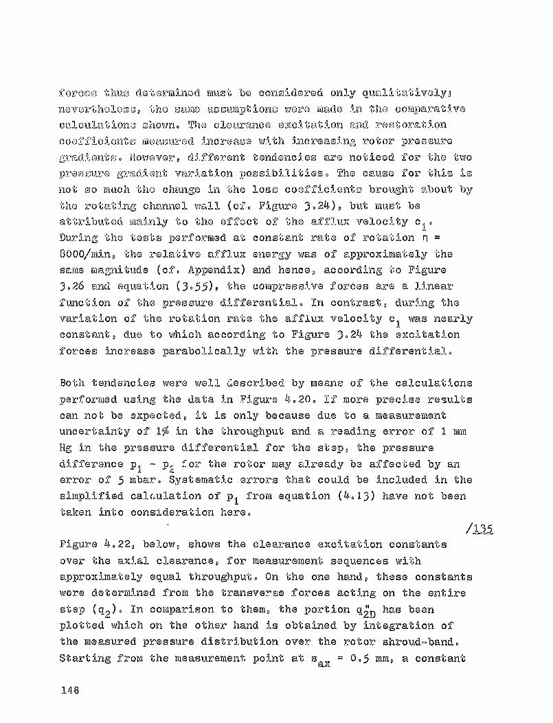
f orcoo till-is detorminod muo`60 be considered only ql,,1E1Mtat)_vQly,-
ROVOrthO3.000, the SEDILIG ERSSUMptiOnS were made in the Comparativecalculations ohown. The clearance excit-atIon and restoration
coefficients measured increase w i th increasing rotor prssourogradiantoo flowovor, different tendencies are noticed for the twopressure gradient variation possibilities. The cause for this isnot so much the change in the loss coefficients brought about by
the rotating channel wall (cf. Figure 3024), but must be
attributed wainly to the effect of the afflux velocity clo
Dur i ng the tests performed at constant rate of rotation Tj
8000/rAn, the relative afflux energy was of approximately the
same magnitude (cf. Appendix) and hence, according to Figure
3026 and equation (3055), the compressive forces are a linearfunction of the pressure differential. In contrast, during the
variation of the rotation rate the afflux velocity c l was nearly
constant, due to which according to Figure 3024 the elicitation
forces increase parabolically with the pressure differential.
Both tendencies were well described by meano of the calculationsperformed using the data in Figure 4.20. If more precise results
can not be expected, it is only because due to a measurement
uncertainty of 1% in the throughput and a reading error of I mm
Hg in the pr9ssure differential for the step, the pressure
difference p, - p,4 for the rotor may already be affected by an
error of 5 mbar. Systematic errors that could be included in thesimplified cal(;ulation of p, from equation (4013) have not been
taken into consideration here.I
IDIAFigure 4.22, below, shows the clearance excitation constants
over the axial clearance, for measurement sequences withapproximately equal throughput. On the one hand, these constants
were determined from the transverse forces acting on the entire
step (q2)' In comparison to them, the portion q2"D has beenplotted which on the other hand is obtained by integration of
the measured pressure distribution over the rotor shroud-band.
Starting from the measurement point at sax = 0. 5 Dim , a constant
148

qI
q10
W1,
es
O
0
0
axial gap
ql'
qID
I
cA0M0j 0. 1. 2. 9. 4.
axial gap IMMI
force moaOuroment on entire Otago
from pr000ure distribution (COVOP band)
theory forz'OtOr 9MP
q 2
Figure 4022 Plain shroud-band Figure 4023 Plain shroud-band(B2) (B2)
course across the axial clearance may be assumed for the slopeof these forces, which is qualitatively confirmed by
measurements with the housing insert BI (cf. Appendix, MR 62 to64). These slopes q
2D are also confirmed very clearly by
calculation. Besides the compressive forces, the calculatedslope q2 contains the portion q 2 s ,
caused by the variable rotorclearance loss. The transverse forces arising from the statorclearance loss, -represented by the difference
q^ = Q2 ® q2' were
not calculated here (however, see Q2s" in Figure 3039 for aqualitative comparison).
IL3_6
Figure 4. 23, above, shows the restoration coefficients on asimilar plot; the portion due to the pressure distribution wasagain plotted as a qualitative course from comparablemeasurements. The restoration coefficients calculated from the
149
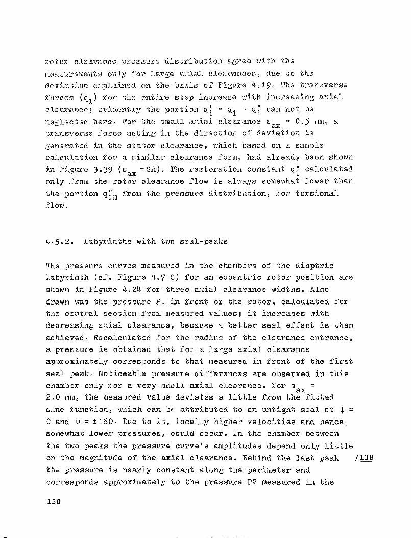
rotor clearance pressure distribution agree with themonsurGmGnts only for large aizial clearances, due to thedeviation onplained on the basis of Figure 4019. The transverse
forces (q j ) for the entire stop increase with increasing axialclearance; evidently the portion qj = q, - q can not )eneglected here. For the small axial clearance s a), = 0 0 5 111m0 en,
transverse force acting in the direction of
deviation isgenerated in the stator clearance, which based on a samplecalculation for a similar clearance form, had already been shownin Figure 3.39 ( s all
t,: SA). The restoration constant q"I calculatedonly from the rotor clearance flow le always somewhat lower than
the portion q 1" D
from the pressure distribution, for torsionalflow.
40502. Labyrinths with two seal -peaks
The pressure curves measured in the chambers of the dioptriclabyrinth ( cf. Figure 4.7 C) for an eccentric rotor position areshown in Figure 4024 for three axial clearance widths. A lsodrawn was the pressure PI in front of the rotor, calculated forthe central section from measured valuesB it increases withdecreasing axial clearance, because a better seal effect is thenachieved. Recalculated for the radius of the clearance entrance,a pressure is obtained that for a large axial clearanceapproximately corresponds to that measured in front of the firstseal peak. Noticeable pressure differences are observed in thischamber only for a very small axial clearance. Fors ax
=
2.0 mm, the measured value deviates a little from the fittedsane function, which can bp attributed to an untight seal at0 and ^ = ±1800 Due to it, locally higher velocities and hence,somewhat lower pressures, could occur. In the chamber betweenthe two peaks the pressure curve ' s amplitudes depend only littleon the magnitude of the axial clearance. Behind the last peak /138tha pressure is nearly constant along the perimeter andcorresponds approximately to the pressure P2 measured in the
150

R.Q)
04
ro
P4
MEASUREMENT: for housing insert C with fitted sine function
1-114
W
?IP4
Perimeter
QR 78
Pi
o P2
1 4-- -^160 -'go 0 go ISO
Perimeter PerimeterSax JQ6 1 2 3 4
CALCULATION: t',czt - -.0 E,'v-tC_ W
40 - q - 0
ECE EWE- E""Zl
0
co
IID
CI
Q)
0
C4Bpd
P4
04
-180 -go 0
00
looPerimeter
SOX A5 MM
p-0,7 tEs(mrj
V C 1 tJI(MJ1)
N co
P4
e t1
t3 E
- go 0 00 16c)Perimeter
s.=2mm
MC,'I.Q 2,0 3,S 4,0 4.0
riRry 30 30 30 30 30
13 0 Do lao
Perimeter
s.=4 rim
before first peak, 0 labyrinth chamber, a after last peaklocal throughput (calculated)
Figure 4.24 Pressure distribution for a rotorclearance with two seal peaks, e = 0 .7 mm
central section, behind the rotor©
For the labyrinth, avery much - as shown
for the pressure andseal-peaks. Assuming
the calculations were
calculation of the pressure curves dependsin section 306 - on the assumptions madeimpulse loss coefficients at thea constant contraction coefficient 0-7,
D performed with the pressure loss
151

coefficients from equations (3- 40 ) and ( 3JAI-). Through tho
constants applicable to the seal geometry, those coefficientsdepend on the local clearance widths and flow angles. The
impulse loss coefficient was determined as a factor y = I from
equation (4.49), as a function of the corresponding pressureloss coefficients. Based on the considerations in relation to
Figure 3.29, a pressure equalizing flow was not taken into
consideration. In addition, the channel widths for the
individual stream tubes were assumed to be constant, based on
the same assumption, i.e., that th i s effect, balanced by
corresponding local var i ations in the loss coefficients.
In agreement with the measurements, a relatively low pressure
level is observed in the central chamber, caused by the first
peaks's low loss coefficient and the changes in the flow angles
wi thin the clearance. The amplitudes for these pressure curves
are approximately as high as those measured. The very smaii
axial clearance s ax 0.5 mm caused considerable pressure
differences in front of the first peak (cf. Figure 4.19) 9 due to
the variable velocities in the radial entrance. With the
existing empirical loss coefficients, no better agreement
between measurement and theory can be attained in this chamber.
It remains unclear, in addition, whether the assumption is
warranted that the pressure in the chamber before the first
seal-peak remains constant, with turbulence and simultaneous
redirection of the velocity. It would be conceivable that due to
cross-currents within the chamber, the pressures determined
through existing measurement drill-holes (cf. Figure 4-7) are
not representative for the entire chamber.
ID-9-By means of section 3.3.4., the loss coefficients can be
determined in such a way from the available measurements, that
complete agreement exists between the measured and the
calculated pressure curves. But this approach also depends on
assumptions that limit the general validity of the result.
Agreement will especially not be achieved, with the contraction
152
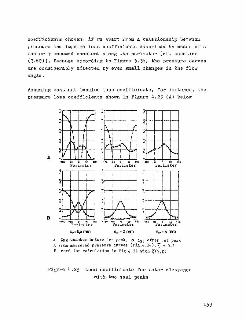
O
C4 __zJ
AISO -90 0 Go ISO
Perimeter
B
Perimeter Perimeter
coefficients chosen, if we start from a relationship between
pressure and impulse loss coefficients described by means of afactor y assumed constant along t! ,Le perimeter (cf. equation
(3 049)). Because according to Figure 3 0 36 , the pressure curvesare considerably affected by even small changes in the flowangle.
Assuming constant impulse loss coefficients, for instance, thepressure loss coefficients shown in Figure 4.25 (A) below
-M -an 0 Do 160 -180 -go 0 Go IGO
Perimeter Perimeter Perimeters..4,5 mm %^,n 2 mm s.= 4 mm
® CES chamber before Ist peak, 0 C S I after Ist peakA from measured pressure curves (Fig.4.24), T = 0.2B used for calculation in Fig.4.24 with T(Y,0
Figure 4025 Loss coefficients for rotor clearancewith two seal peaks
-ISO
153
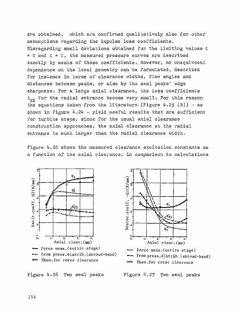
are obtained, which are confirmed qualitatively also for other
assumptions regarding the impulse loss coefficients.
Disregarding small deviations obtained for the limiting values
= 0 and C = 1, the measured pressure curves are described
exactly by means of these coefficients. However, no unequivocal
dependence on the local geometry can be formulated, described
for instance in terms of clearance widths, flow angles and
distances between peaks, or also by the seal peaks' edge
sharpness. For a lame axial clearance, the loss coefficients
CES for the radial entrance become very small. For this reason
the equations taken from the literature (Figure 4.25 (B)) - as
shown in Figure 4.24 - yield useful results that are sufficient
for turbine steps, since for the usual axial clearance
construction approaches, the axial clearance at the radial
entrance is much larger than the radial clearance width.
Figure 4.26 shows the measured clearance excitation constants as
a function of the axial clearance, in comparison to calculations
eo, (^2
N
N a
wW qzD0 m .^ ...
u
w m
U. e. u. Z. e.
Axial clear.(mm)
Force meas.(entire stage)
-- from press.distrib.(shroud-band)
Theo.for rotor clearance
\
®o \ q,
qj
0
.Axial clear.(mm)
® Force meas.(entire stage)
from press. distrib.(shroud-band)
Theo.for rotor clearance
i
Cei
wL64Q)0u
0
vx
Figure 4.26 Two seal peaks
Figure 4.27 Two seal peaks
154

perforriied with the data from Figure 4024. While the transverse
force out of
the pressure distribution is nearly constant, the
total force increases, because the clearance loss increases with
increasing axial clearance width. This course is confirmed also
by calculations containing only the portion of clearance flow
coming From the rotor. The excitation force from the stator seal
' Ican be determined as the difference (q 2 - q2) between the /1 0
measured total force and the forces determined from the rotor's
clearance flow. While the stator clearance loss of the turbine
steps studied is just as large as the rotor's (cf. Appendix),
due to the equalizing flows only weak excitation forces are
generated here,
/141The restoration constants are shown over the axial clearance, in
Figure 4027, above. The transverse force out of the rotorclearance's pressure distribution is larger, at saX 00 5 mm,than the total force measured at the runner, since the stator
clearance has the same effect as in Figure 4023. The
theoretically determined restoration force increases very
steeply at small axial clearance widths, which may be attributed
to the course of the pressure ahead of the first seal peak (see
Figure 4.24). Disregarding a small axial clearance, thecalculation procedure provides good agreement with measurements,
despite the uncertain loss coefficients for the transverse
Forces (q 1D,ID' C12D) out of the rotor clearance's pressure
distribution, Taking into consideration the transverse forces
generated in the stator clearance (cf. qualitatively Q' and Q'1 2
in Figure )039), the forces measured for the entire turbine step
(ql' q2) can also be completely explained.
/14240 50 3- Off-set shroud band with three seF,. Peaks
While the dioptric labyrinth was somewhat more favorable as to
its seal affect than the plain shroud band, it was possible to
considerably increase the step's effiency by means of the
off-set labyrinth common in turbine construction (cf,, Figure
155

is 0 ^
C9 J
0
coPI
0
0C
I j
io q 90 IgoPerimeter
p 0,7 CES(MEJ
-YC51 (M51)
Ez2 Irnsz)
-iso -go 0 go 160
Perimeters,,, 0,5 1 2 3
MES 1 ,0 2 ,0 3 -5 4-0
ms, 12 15 30 40
Ms2 40 30 19 0
Qj
10" ca
O
O
14 O
RO agoIgo -160 -go a go lao
Perimeter Perimeter
so,% I Mfn S." = 3 MM
Ca
-0
Cf.
13-4
CALCULATION: KC'E4w'E30 CLO
I IF
UE CUM 00 C0A_-'
ca
Ia
W
Qd
Perimeter
San a0,5 mm
Cq
^I Go -go o Do 100
4,15)- The pressure distributions along the perimeter, shown inFizurs 4.28, below, were measured in the chambers before the
MEASUREMENT: for housing insert D with fitted sine function
PA
0
0
O
P1
ro
P2
-160 -Go q 90 ISOPerimeter
® before Ist peak 0 Ist a 2nd labyrinth chamber---local throughput (calculated)
Figure 4.28 Pressure distribution for a rotor clearancewith three seal peaks, e = 007 mm
first seal peak and between the first and second peaks (seeFigure 4.7 (D)). From the results obtained for the dioptric
156
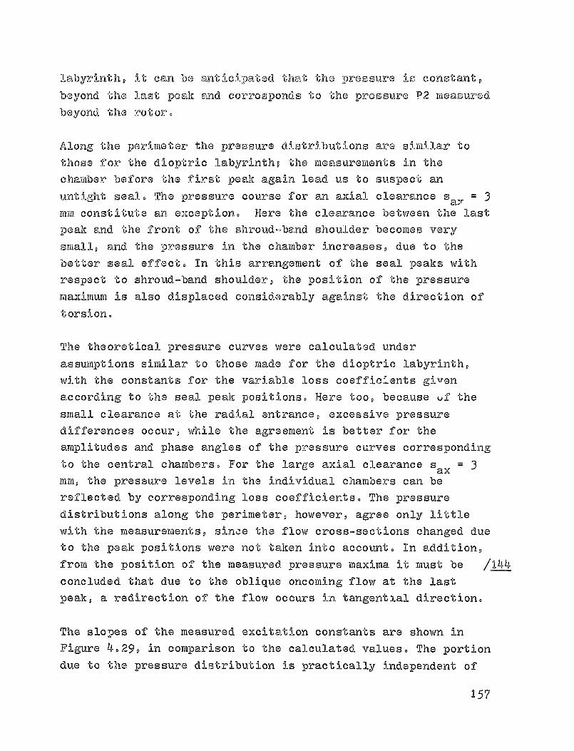
labyrinth, it can be anticipated that the pressure is constant,
beyond the last peak and corresponds to the pressure P2 measured
beyond the rotor.
Along the perimeter the pressure distributions are similar to
those for the dioptric labyrintho the measurements in the
chamber before the f i rst peak again lead us to suspect an
uptight seal. The pressure course for an axial clearance s 3a,myti constitute an exception. Here the clearance between the last
peak and the front of the shroud-band shoulder becomes -very
small, and the pressure in the chamber increases, due to the
better seal effect. In this arrangement of the seal peaks with
respect to shroud-band shoulder, the position of the pressure
maximum is also displaced considerably against the direction of
torsion.
The theoretical pressure curves were calculated under
assumptions similar to those made for the dioptric labyrinth,
with the constants for the variable loss coefficients given
according to the seal peak positions. Here too, because Qf the
small clearance at the radial entrance, excessive pressure
differences occur, while the agreement is better for the
amplitudes and phase angles of the pressure curves corresponding
to the central chambers. For the large axial clearance sax = 3
mm, the pressure levels in the individual chambers can be
reflected by corresponding loss coefficients. The pressure
d i stributions along the perimeter, however, agree only little
with the measurements, since the flow cross-sections changed due
to the peak positions were not taken into account. In addition,
from the position of the measured pressure maxima it must be /144
concluded that due to the oblique oncoming flow at the last
peak., a redirection of the flow occurs in tangential direction.
The slopes of the measured excitation constants are shown in
Figure 4. 29, in comparison to the calculated values. The portion
due to the pressure distribution is practically independent of
157

42
NCy
4-41U0U
• r1UryW^
4
Aa1
C7I
1-4-1vOU
!•aO1W
0
CS
CD aa
a^
am rr410
Q^ qri
® °ei0
0
Axial clear,(mm)
Force meas.(entire stage)®= from press.distrib.(shroud-band)
Theo. for rotor clearance
Figure 4.29 Three seal peaks
Axial clear.(mm)
Force meas.(entire stage)
from press, distrib.(shroud-band)
Theo.for rotor clear.
Figure 4030 Three seal pears
the axial clearance, as was true of other clearance forms. The
slope of the excitation force at the stator - formed as the
difference q2 - q2 between the measured value for the entire
step and the value calculated for the rotor - agrees with the
results for plain rotor clearances and for the dioptric
labyrinth.
The restoration constants decrease with increasing axial
clearance, under the effects of compressive forces, as shown in
Figure 4-30. The restoration constants calculated from the rotor
pressure distributions agree only qualitatively with the
measured values, due to deviations in the pressure curves
already explained in connection with Figure 4028. The difference
q 1 q", between the measured total force and and the 1IL5—
compressive force, corresponds to the compressive forces
generated in the stator clearance, if we disregard the small
restoration forces out of the rotor clearance loss. This course,
which can also be recognized in Figure 4. 27, is qualitatively
158

confirmed by the complete calculation in accordance with Figure
3.39 for a stator clearance with radial entrance and exit,,
It was also possible for the set-off shroud band to determine
the loss coefficients in such a Manner that the measurements are
reproduced exactly. However, it is not possible to provide a
generally valid dependence on the local seal geometry, which is
here expanded with the shroud-band shoulder. It should
nevertheless be expected for the calculated transverse forces to
provide better agreement, for t.e axial clearances that are
usually much larger than the radial clearance widths. Special
cases, though, resulting from the position of the seal peaks
with respect to the shroud band shoulder - as occur in Figure
4.28 for sax= 3 ream - are excepted
4.6. Forces due to a rotor-to-housing inclination
Normally, according to Figure 205, an inclination of the rotor
with respect to the housing occurs only coupled to rotor
eccentricity, with the ratio of the axial clearance change a to
the eccentricity e being a function of the deflection bending
line, the rotor diameter and the arrangement of the turbine step
between the bearings. In order to test whether the forces due to
both kinds of deviation are additive, a separate and a common
displacement were performed on the test turbine. Figure 4.31,
below, shows a plot of the relative excitation force Q 2/Us over
the eccentricity e (MR 76) and the Force Q 3/Us over the
inclination a = 0-535e (MR 80). Furthermore, the displacement
was performed in such a manner that under the action of both
effects the forces became larger in one case (MIS 84), but
smaller in the other (MR 83)o Within the measurement precision,
they can be readily composed from individual measurements, with
the same conclusions also being applicable to the restoration
159

(222)1
MMINAE PAGri, is
DF POOR QUALITY
Install'n BRotorS t a t o
008-^aid7t—hcle a r
Axial 'cl-ea'*r—'--D Lnn-
s
Rot rate u=80001,i-ir
MR Usk))
76 913 6 24 0,111_ _ ^^+
80 9 75 62383 _ ^980 6.27
OA eEMMI 0,0
^MR 80
0,535
Figure 4.31 Relative excitation forces over theeccentricity and the inclination of the rotor with
respect to the housing
4-4LH
(3)
0
04JCO(1)
Cn
O
44
4-1
0)0
DCcll
cb
U U. 1.
2' 4Axial clear. (mm^
Force meas.(entire stage)from press.distrib.(shroudband)
U. L. L.
3'
4^
Axial clear.( nun
Force meas.(entire stage)
from press.distrib.(shroufta,nd)
Figure 4032 Two seal peaks Figure 4033 Two seal peaks
160
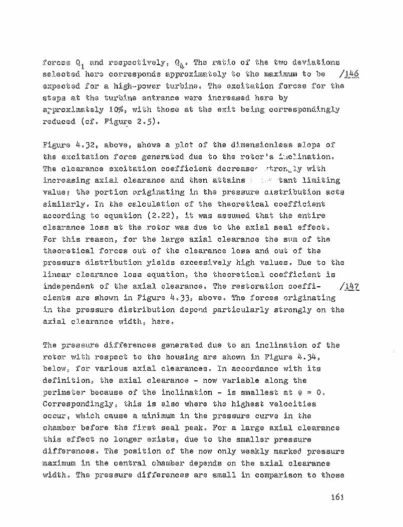
Forces Q 1 and respectively, Q,,. The ratio of t tihe two deviationsselected here corresponds approximately to the maximum to be
expected for a high-power turbine. The excitation forces for the
steps at the turbine entrance were increased here by
aFproximately 10%, with those at the exit being correspondingly
reduced (cf. Figure 205)0
Figure 4032, above, shows a plot of the dimensionless slope of
the excitation force generated due to the rotor's i-AclinationoThe clearance excitation coefficient decrease- .-tron,,,Jy withincreasing axial clearance and then attains : tant limiting
value? the portion originating in the pressure aistribution acts
similarly. In the calculation of the theoretical coefficient
according to equation (2.22), it was assumed that the entire
clearance loss at the rotor was due to the axial seal effect.
For this reason, for the large axial clearance the stem of the
theoretical forces out of the clearance loss and out of the
pressure distribution yields excessively high values, Due to the
linear clearance loss equation, the theoretical coefficient is
independent of the axial clearance. The restoration coeffi- /147
cients are shown in Figure 4033, above. The forces originating
in the pressure distribution depord particularly strongly on the
axial clearance width, here.
The pressure differences generated due to an inclination of the
rotor with respect to the housing are shown in Figure 4034,
below, for various axial clearances. In accordance with its
definition, the axial clearance ® now variable along the
perimeter because of the inclination m is smallest at ^ = 0.
Correspondingly, this is also where the highest velocities
occur, which cause a minimum in the pressure curve in the
chamber before the first seal peak. For a large axial clearancethis effect no longer exists, due to the smaller pressure
differences® The position of the now only weakly marred pressure
maximum in the central chamber depends on the axial clearance
width. The pressure differences are small in comparison to those
161

uj
P-A
'14-
V0
MEASUREMENT: for housing insert C, x-jith fitted sine functionU
ro
j.,
1 1-4110 -10 i ro ISO
Perimeter Perimeter Perimeterc m 0,52 mm (3 r 0,69 no M 6 n 0,60 MM
SGX so MM s,, • 2 mm S., r 4 min
& before 1st peak, 0 Labyrinth chamber, U after last peak
Figuva 4-34 Pressure distribution for a rotorclearance with two seal peaks
generated for an eccentric ro, r position, even though verylarge axial clearance changes were tested, such as would hardlybe possible with a vibrating turbine shaft.
1/148
Assuming a linear clearance excitation theory, it is possible toformulate a relationship between the excitation force caused by
the inclination. of the rotor, and efficiency curve. From
equations (2019) to (2022) we obtain the slope of the localclearance loss over the axial clearance,
, Sp'a. 2 '3s = 2S an us/C
as a function of the clearance excitatiGn coefficient K 3s
D
caused by the changes in the local tangentiv.1 force. It can bedetermined as the difference K
3s = K3 = K
3D between the total
clearance excitaticiL coefficient and the portion due to thepressure distribution, front available measurements. Figure
14r^4
162

P
N
Q)
U. L . N. J. q
Axial clear.(mm)
Measured (MR 67 to 84)
from (ax.) clear.loss (from [14])
slope from excit.force meas.
Figure 4.35 Two seal peaks
4 .35, above, shows the efficiency curve, as a function of theaXial clearance. Starting from the calculated tangent..La.l.
efficiency for the step, the linear efficiency decrease which
results from the clearance loss due to the shroud-band entrance
shoulder, is plotted, according to equation (2.19). The slopes /149
determined from the excitation force measurements are
qualitatively in agreement with the non-linear efficiency curve.
However, there are deviations for large aXial clearances, caused
either by compressive forces at
the stator clearance, or due to
the fact that an inclination of the rotor can also cause small
radial clearance changes. If we take these side effects into
consideration, the relationship between the excitation forces
and the efficiency course seems sufficiently confirmed also for
the case of an inclination between rotor and housing.
163
/D-0
5 SUMMARY
The rotor-- of thermal turbomachines can become endangered by
self-excited vibrat i ons that may impose severe output
restrictions on the affected power -plants, if these vibrations
are caused by clearance excitation. For a theoretical
description of the system, it is necessary to know the
transverse forces that act in dependance on a deviation of the
rotor from its centered position with respect to the housing.
The component -perpendicular to the direction of deviation
acquires special significance, since in circumpolar vibrational
movement it act by setting., up vibrations in the turbine shaft.
The excitation force can be described as the resultant of the
turbine stage's tangential force, which becomes variable for an
eccentric rotor position. Therefore, for a given rotation rate,
it is a function of the stage's output and of the course of the
clearance loss over the radial clearance width. In the case of
blading with shroud-band, the excitation forces can be
considerably enhanced due to a variable pressure distribution in
the rotor's sea! clearance. This effect was studied in detail by
means of a calculation procedure in which the torsionally
affected flow at the clearance ® caused by the main flow, in
turbine stages - was especially taken into account.
Sample calculations show that the excitation forces due to a
pressure distribution in the seal clearance increase with
increasing pressure gradient and especially, with increases in
the tangential velocity before the clearance. However, the
characteristic quantity is the relative afflux energy, to be
obtained from the dynamic pressure of the tangential velocity
before the clearance, related to the pressure gradient operating
at the seal clearance. Correspondingly, because of the large
relative afflux energy at turbine stages in impulse
164
construction, larger ancitation forces become active due to the
pressure 1-15-11-essure distribution over the rotor's shroud-band, than in
reaction stages. However, the form of the seal clearance and the
empirical loss coefficients, which describe the clearance flow
as a function of the geometry, also have a significant effect on
the magnitude of the excitation forces.
The e2merimental studies were performed on an impulse turbine
stage, varying the rotor's clearance form. The rotor was mounted
in a kind of two-component balance, connected to a
dynamometrical brake,- the transverse forces were measured as a
,unction of its deviation with respect to the housing. By means
of efficiency measurements at various radial clearance widths,
it was possible to show that for blading without shroud-band the
excitation forces could be calculated from the clearance loss
alone. In contrast, for the bladings with shruud-bard
investigated, in spite of lower clearance losses, larger
excitation forces were observed,- these could be explained by
means of measurements of the pressure distribution at
the rotor
clearance.
Considering the compleXity of the flow processes in a seal
clearance, the agreement between the measured pressure curves
and the theory is relatively good y minor deviations ® especially
for small axial clearance widths, can be explained in terms of
the simplifying assumptions made regarding the loss
coefficients. For the usual constructions, the transverse forces
acting on a turbine stage - caused by the clearance loss, on the
one hand, and the pressure distribution along the rotor
perimeter, on the other - can be determined with sufficient
accuracy.
165
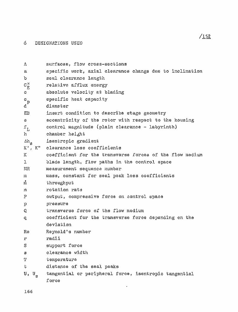
1/152
DESIGNATIONS USED
A surfaces, flow cross-sections
a specific work, ancial clearance change due to inclination
b seal clearance lengthC EX -relative affluX energy
0 absolute velocity at blading
c P
specific heat capacity
d diameter
EB insert condition to describe stage geometry
a eccentricity of the rotor with respect to the housing
f L
control magnitude (plain clearance - labyrinth)
h chamber height
Ah s isentropic gradient
K 1 , K 11 clearance loss coefficients
K coefficient for the transverse forces of the flow medium
1 blade length, flow paths in the control space
MR measurement sequence number
ra mass, constant for seal peak loss coefficients
n1 throughput
n rotation rate
P output, compressive force on control space
P pressure
Q transverse force of the flow medium
coefficient for the transverse force depending on the
deviation
Re Reynold's number
r radii
S support force
S clearance width
T temperature
distance of the seal peaks
U, Us tangential or peripheral force, isentropic tangential
force
166

u tangential or peripheral velocity
vp w velocities within the clearancew relative velocity at the blading^^ V y p z spatial coordinates
.r° D z°° number of seal peaks
/1-02
(Y flow angle, angle of rotor inclination
U P R flow angles at turbine blading
C ' pressure loss and impulse loss coefficientsTI efficiency
isentropy exponentfriction coefficient
iu contraction coefficientP density
tangential or peripheral angle, bending anglepressure coefficient of the turbine stage
W angular velocity
Z ' 40 load vectorload matrix proportional to the deviationload matrix proportional to the velocitypercentage reaction
Subscript and superscripts-aX dimensionless representation
clearance width variable along perimeterstatorrotor
I in the direction of deviation2 perpendicular to direction of deviation (precedingthe direction of rotation)A radial exit
B reference magnitudeD from pressure distributionE radial entrance
i,n support point in flow directionk,j support point in tangential direction
167

radial clearanceoriginating in clearance loss
Stage control surfacessbefore the statorbetween bladingsbehind rotor
168
/154
7 REFERENCES
1 Thomas, H.-J., Instabile Eigenschwingungen von
Turbinenlaeufcrn, angefacht durch die Spaltstroemung in
Stopfbuchsen and Beschauflung [Unstable natural vibration of
turbine rotors induced by the clearance flow in glands and
blading], Bull. de 1°A.I-M- _Z1, No-11112, 10391063 (1958)-
2 Klraemer,E-, Selbsterregte Sehwingung von Wellen infolge von
Querkraften [Self-excited vibration of shafts due to
transverse forces], BWK 20 8 No-7, 307®312 (1968)-
Gleitlagern rotierenden
of a shaft rotating in
excitation] ,t Reihe 1 [Progress
Engineers) Journal Series
3 Pollmanne E-, Stabilitaet einer in
Welle mit Spalterregung [Stability
friction bearings, under clearance
Fortschrittsbericht VUI®Zeitschrif
Report, VUI (Association of German
11, No- 15 (1969)-
4 Thomas, H.-J., Grenzleistungsprobleme bei thermischen
Turbomaschinen [Limiting output problems in thermal
turbo-machines], Mitt- VGB 3, No- 4, 286-293 (1971)
5 Thomas, H-mJ-, Urlichs, K. and Wohlrab, R-,
Laeuferinstabilitatet infolge Spalterregung [Rotor
instability due to self-excitation], Forschungsvereiningung
Verbrennungskraftmaschinen [Research Association for
Internal Combustion Engines], Frankfurt, Issue 167 (1974)
6 Glienicke, J-, Experimentelle Ermittlung der statischen and
dynaTrz? schen Eigenschaften von Gleitlagern fuer, ch-e llaufende Wellen- Einfluss der Schmierspaltgeometrieund der L agGcbreite [Experimental determination of thestatic and dynamic characteristics of friction bearing for
169
high speed shafts. Effect of the lubrication clearance
geometry and of the bearing width], Progress Report, VDI
Journal Series 1, No. 22 (1970)0
7 Gasch, R., Stabiler Lauf von Turbinenrotoren [Stable running
of turbine rotors], Konstruktion 1 7, No. 11, 447-452 (1965)0
8 Gasch, R., Unwucht-erzwungene Schwingungen and Stabilitaet
von Turbinenlaeufern [Unbalance-forced vibrations and
stability of turbine rotors], Konstruktion ^_5, No - 5,161®168 (1973)
9 Vogel, Dm Ha, Die Stabilitatet gleitgelagerter Rotoren von
Turbomaschinen unter besondere Beruecksichtigung einer
Erregung dureh Spaltstroeme [The stability of friction
bearing-supported turbo-machine rotors with special
consideration to clearance flow excitation], Dissertation,
Munich Institute of Technology, 19690
10 Schirmer, Go Fa, Zur Stabilitaet der Schwingungen von
Turbinenwellen [On the stability of turbine shaft
vibrations], Dissertation, Darmstadt Institute of
Technology, 19690
11 Winter, C.-J., Lastabhaengige instabile Bewegung von
Turbinenlaeufern [Load dependent, unstable motion of turbine
rotors], Dissertation, Darmstadt Institute of Technology,
1968a
12 Piltz, Ea, Belastungon von Dampfturbinenlaufraedern bei
Auslenkung der Welle [Stress on steam turbine rotors under
shaft deviation], Konstruktion 24, No. 4, 141-148 (1972)0
13 Piltz, E., Einfluss von Dampfbelastung auf die
Stabilitaetsgrenze einer einstufigen Model lturbine [Effect
of steam charge on the limit of stability of a single-stage
170

model turbine], Konstruktion ^, svoa 4, 1 30 ° 1 35 (1973).
14 Traupel, W. , "T'her-mische Turbo yyiaschinen" [Thermal
Tubo°machines] Volo1, (1st Ed.), Springer (Berlin,
Goettingen, Heidelberg) 1958. (2nd. iEdoa 1.967).
15 Trutnowsky, K., "Beruehrungsfreie Dlchtungen" [No-contact
seals], VDT Publishers, Duesseldorf 1973.
16 Truckenbrodt,Ee, "Stroemungs yryechanik" [Flow Mechanics],Springer (Berlin, Heidelberg, New York) 19680
17 Lomakin, A. A., Die Berechnung der kritischen Drehzahl and
der Bedingungen fuer Sicherung der dynamischen Stabilitatet
des Laeufers von hydra.ulischen Hochdruck-Maschinen unter
Beruecksichtigung der Kraefte, die in den Dichtungen
entstehen [Calculation of the critical speed and the
conditions to insure the dynamic stability of hydraulic
high-pressure machine rotors, taking into consideration the
forces generated in the seals] , Energomasinostroenie 4, No4, 1°5 (1958)-
18 Domm, U., Dernedde, R. and Handwerker, Tho, Der Einfluss der
Stufenabdichtung auf die kritische Drehzahl von
Kesselspeisepumpen [The effect of stage sealing on the
critical speed of boiler feeders], VDT Report No. 113
(1967)°
19 Kiesewetter, Ha and Wolter, W., Einige Bemerkungen ueber die
dezentrierende Kraft auf umstroemten Kolben [Some remarks on
the decentering force on pistons immersed in flow],
Maschinenbautechnik 12, No. 2, 69 0 73 (1963)-
20 Alford, J. So, Protecting turbomachinery from self-excited
rotor whirl, Transactions ASME, J. of Engof.Power ^Z, No.
10 9 333-344 (1965)
171

21 Spurk, J. H. and Keiper, Ro, Selbsterregto Schwingungen beiTurbortiaschinen infolge der Labyrinthstroomung [Self-excitedvibration in turbo-machines due to the labyrinth flow],Ingenieur-Archiv es, No. 2/3, 127-135 (1974).
22 Kostyuk, A. G., A theoretical analysis of the aerodynamic
forces in the labyrinth glands of Turbomachines,Teploenergetika (Thermal Engineering) L_g, No. 11, 29-33(1972).
23 La Roche, U., Untersuchung der Stroemung ueber einen Absatzim Zusammenhang mit den Injektionsverlusten bei Dampf andGasturbinen [Study of the flow across a set-off in relationto the injection losses in steam and gas tu7bines],Communication from the Institute for Thermal Turbomachines,Swiss Institute of Technology at Zurich, No. 10 (1965)
24 Neumann, K., Zur Frage der Verwendung vonDurchblickdichtungen im Dampfturbinenbau [On the question ofusing dioptric seals in steam turbine construction],lilaschinenbautechnik 13, No. 4, 188-195 (1964).
25 Neumann, K., Untersuchungen von Wellendichtungen fuerDampfturbinen bei hohen Dampfparametern [Study of shaftseals for steam turbines under high steam parameters],Maschinenbautechnik L5, 27-31 (1966)0
26 Groddeck, K.-H., Probleme der beruehrungsfreienHochdruckstopfbuchsen [The problems of non-contacthigh-pressure glands], Forschung Ing.-Wesen ^, No - 5,183-195 (1957)
115_6
27 Stingelin, V., Theoretische and experimentelleUntersuchungen an Gaslagern [Theoretical and experimental
172

studies on gas bearings], Comm uni cat from the Institute
for Aerodyna-mics, Swiss Institute of Technology at
Zurich,
No- 32 (1963)0
28 Rosenberg, S. Sch., Orlik, W,, G. and Marcenko, U. A.,
Untersuchung aerodynamischer Querkrael-te bei einerWellenex.zentrizitaet [Study of aerodynamic transverse forces
in thecase of shaft eccentricity], Energo,iiasinostroenie 8,
15-17 (1974).
29 Hochreuther, W., Kraefte bei axial durchstroerfiten Spal ten
[Forces in clearances with axial flow], Dissertation,
Stuttgart University 1975-
3 0 Wohlrab, R., Spalterregung bei thermischen Turbomaschinen
[Clearance excitation inthermal turbo-machines],
Dissertation, Munich Institute of Technology (1975).
173
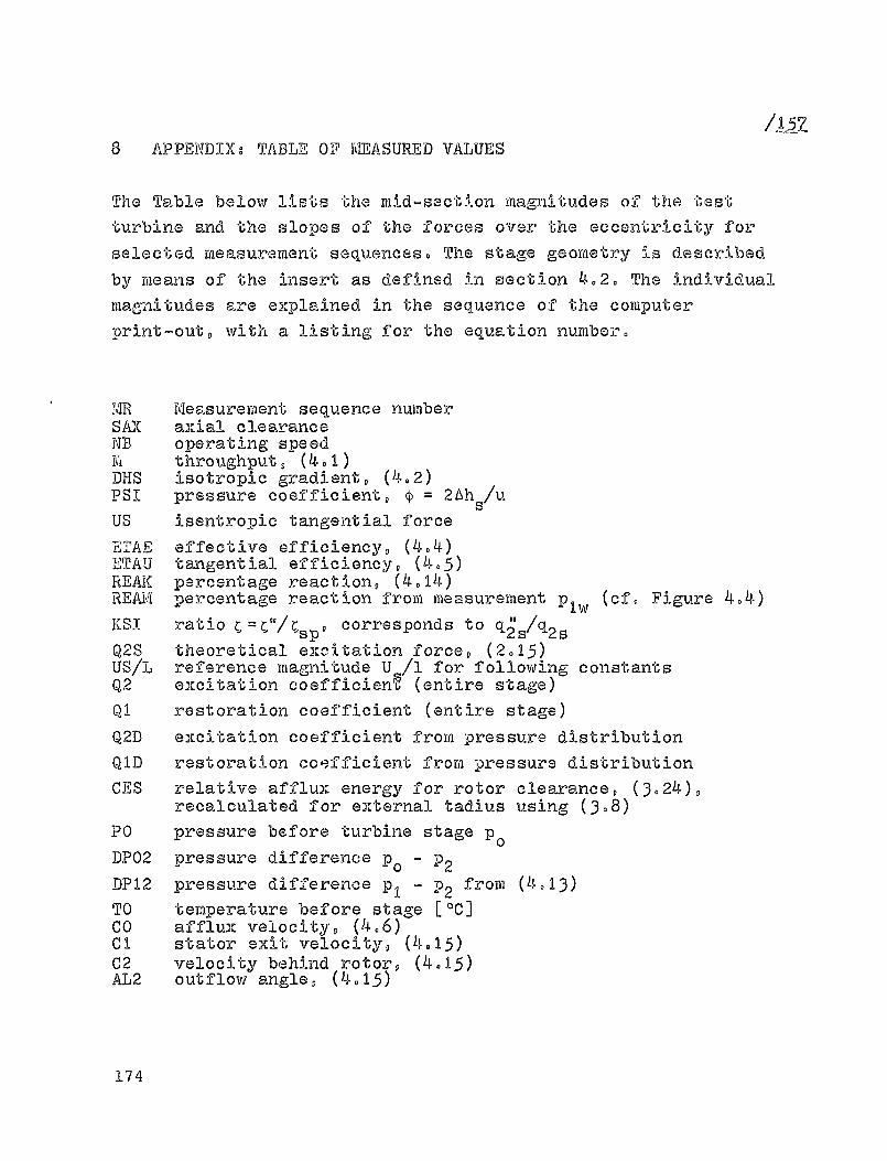
IL518 APPENDI)Cs TABLE OF MEASURED VALUES
The Table below lists the raid-section magnitudes of the test
turbine and the slopes of the forces over the eccentricity forselected measurement sequences. The stage geometry is described
by means of the insert as defined in section 4,,2. The individualmagnitudes are explained in the sequence of the computerprint-out, with a listing for the equation number.
MR Measurement sequence numberSAX axial clearanceNB operating speedM throughput, (401)DHS isotropic gradient, (402)PSI pressure coefficient, ^ = M
s /u
US isentropic tangential force
ETAE effective efficiency, (404)ETAU tangential efficiency, (405)REAK percentage reaction, (4014)REAki percentage reaction from measurement p 1w (cf. Figure 4.4)KISI ratio C = C"/C
sp , corresponds to q 2s/q2s
Q2S theoretical excitation force, (2015)US/1, reference magnitude U /1 for following constantsQ2 excitation coefficien ,9L, (entire stage)Q1 restoration coefficient (entire stage)Q2D excitation coefficient from pressure distributionQID restoration coefficient frora pressure distributionCES relative afflux energy for rotor clearance, (3.24),
recalculated for external tadius using (308)PO pressure before turbine stage p 0DP02 pressure difference p 0 ® P2DP12 pressure difference p, ® P2 from (4013)TO temperature before stage [IC]CO afflux velocity, (4.6)C1 stator exit velocity, (4.15)C2 velocity behind rotor, (4.15)AL2 outflow angle, (4,15)
174

MR SAX fib H OHS P51 05 ETAS 4TAg ETAU BEAK REAM KS1 ®25®a MM YPM KG/5 KJ/KO — N ---- .--- a-=® ---- —a en N/nM
Insert cond. 231 w/o shroud band (s=0.5 mm) IForm A39 0 @ 5 0000 .389 34 0 4 5@50 78 0 5 0 720 e704 @ 708 X 222 0 068 0 57 70240 100 0000 0809 14 0 7 5 0 48 78 0 2 0 721 0 694 @750 0213 0 068 0 57 7@2q 200 8000 .309 1 4 0 0 5051 7x1,7 :710 0 7 15 9 749 021 9 0 068 0 57 70242 3 0 0 0000 0 389 14 0 7 5 0 46 78 02 0716 0 720 0750 1212 0 068 0 57 7.2
Insert cond. 211 w/o shroud-band (s=1.0 mm), Form A
17 0 0 5 6000 0393 1 4 0 4 5937 77 0 3 0020 0 666 0 764 1 145 00 0 57 70116 100 8000 0393 14 0 1 5,26 75 0 8 0 594 0631 0769 :121 a .57 70014 2@® 8000 0392 14 0 0 '3 0 20 74o 7 0579 0 644 077 1 011 7 0 9 57 6091D 3 90 a4D00 039k 14 0 1 5 0 25 75 0 6 078 :639 0 769 9121 ^ 057 700
Insert cond. 221 w/o shroud —band,(s=1.5 mm), Form A
30 100 8000 0 398 14 0 0 5922 76 @ 3 0521 @ 357 o772 @ 105 0 071 0 57 70034 890 8000 .390 14 0 0 5,22 76@2 @ 459 0 357 0 772 e105 0 071 9 57 70027 2,0 8000 0 399 14 , 0 5,21 76@1 0 456 @ 331 0 772 X 105 0 072 057 Too32 3 @ ® N000 0990 14 9 0 5022 76 @ 3 0440 0 357 .772 X 105 0 071 0 57 700
Insert cond. 251 Plain shrou —band, Form B1
59 100 4000 0366 12 @ 318@30122 @ 8 0 495 9 456 @ 56' @ 091 A 0 34 70960 1@49 6000 9360 12@6 8 0 34 84 9 5 0 617 @ 6 1 7 0 709 e1b7 n 047 6,B66 100 8000 0385 13 9 6 5006 7105 9 677 e323 @ 769 0 145 " 0 49 5056D 1:0 6000 9422 15 0 9 5,93 91, 7 0 659 e540 0 753 11^9 n 0 50 70364 0 0 5 8000 0 429 16 0 7 6 0 22 97 0 7 @ 707 9 599 @ 742 X 169 n 0 49 70669 1 0 0 5000 @429 16 9 4 6o12 96 01 0666 ,535 9 747 @1D 7 w 50 70763 '400 6000 ,429 16 0 2 6 9 02 94 0 5 9 059 @522 o7P3 9132 a
o@5® 794
Insert cond. 281 Plain shroud-,band, Form B2
39 0 0 5 8000 9423 16 9 9 6,29 97 0 7 0 707 0 770 0 741 :171 @04 1 0 49 lob--Throughput corrected MR 90 to 93--90 100 13000 9326 10 @ 0 3072 44 9 4 0 671 048 9 708 0 098 0 046 0 50 3,D91 200 8000 0322 10 0 0 9,74 46,1 ,060 0 722 9 706 01.1 9 054 0 50 30592 3 9 0 8000 o520 10 0 1 ':, 7 0 45 0 4 @ 650 9 744 .708 0 100 e0°7 9 50 30693 4 9 0 0000 @331 10 @ 3 3 @ ne 4605 9649 9 740 0 709 e091 0 059 0 49 3.0
Insert cond. 271 Two seal-peaks, Fore C
68 Oo5 8800 0400 16 0 2 6,03 60o4 •6©O o731 9729 oZ44 o1 76 @ 45 60475 1 0 0 8000 ,416 16 0 8 6024 9503 0664 0 727 .734 9 217 9 100 0 43 6.676 2 0 0 6000 0 4 17 16oB 6024 94 0 4 @ 652 @ 706 .739 0210 01 90 0 42 60677 3 0 0 8000 0410 1 6 o 7 6021 9 5 91 0 64 2 0 701 .737 0201 0193 0 42 6.578 4 0 0 8000 9 418 16 9 7 6 9 20 93.0 9 635 9 704 0 737 0 200 91 95 9 4 2 605
Insert cond. 291 Three seal-peaks, Form D
113 005 8000 0400 1408 5 0 52 02.3 .700 0 774 0 756 @ 175 p 9 37 5.2114 190 8000 0407 14 9 8 3 0 52 82,4 @ 606 @762 9756 01 9937 502115 2 9 0 5000 0 407 14 9 9 5o54 8296 06 6 7 0 764 9 756 91'i ^ 037 502116 3 9 0 80V0 .407 1409 5,56 82, 8 •696 0 756 ,754 91 0 ' oB7 5.2
175

MR 0500 Qz -Qj QZD Qj U C os PO OPOL On g T O co cl cz 462NAIM NI M P N/MM N/Mm NIHN - MDAR MBAR NEAR C MIS 14 /5 NIS GRO
Insert cond. 231 w/o shroud-band ( S ^0.5 mm), Form A
39 491 641 0:7 lo4 1140 187 39,3 G3 g4 W 41 0440 4ol 0 9 0 460 194 1146 105 37 0 4 Z4 94 145 41 0541 4ol toO 41 . 0 of 1 9 4 1143 18b 38,U 24 4 145 4t 0442 401 Poo DO - 104 1146 101 37o3 94 k4 145 41 65
Insert cond. 211 w/o shroud-band (s=].O mm), Form A
17 4 9 1 4 9 @ o f ? 108 1129 179 2995 95 25 150 27 7116 4 9 0 O t
t 0 9 3 n RoO 112; 175 20,0 25 ?5 151 35 74
14 3 0 9 BoC 194 291 1125 173 19,2 24 g5 150 34 75l5 4 9 0 .8 9 A le'f a Roo I120 175 %?*? ?4 ^5 17o 55 74
Insert cond. 221 w/o shroud-band, (s=1.5 mm), Form ADO 4 0 0 Poo -0 0 4 - 202 1137 175 17 0 3 Z5 {b 151 $4 76DI 490 M 00 - a 292 1135 179 17 9 4 g5 95 151 Z4 7627 400 0 00 OOP - 4 Rol 1134 175 17 0 4 93 k5 %% 34 7602 490 7 ol 10 - 902 1135 175 17 0 5 Z5 45 151 Z4 76
Insert cond. 251 P^.ain shroud-band, Form BI59 6 0 5 ?,D Bo§ 4,D 2,4 2 0 6 1092 149 130 Z4 Z4 143 72 DBbO 4,4 JO * l Deg 4,8 Rol 9 9 % 1100 154 17,Z 24 k4 142 47 4066 398 49,7 7,^ 5,0 3 0 6 1 0 8 1117. 170 230 ki u4 146 34 7565 4o0. 420 Ogg 5 9 9 4 9 2 %o 9 1150 202 ROO 21 26 156 41 6464 p ot 095 6 :9 5 0 1 3,3 1 0 7 1161 214 33 9 V 21 f6 159 45 5969 5 :2 4,6 1 9 8 1158 211 54:t t9 {0 159 44 0105 s:Q bob 10 9 6 6 # 2 4 9 1 1 9 9 1154 207 U 0 ;6 160 42 0
Insert cond. 281 Plain shroud-band, Form B2
09 P o t 909 7 9 P 795 99Q 10 7 1160 213 3402 25 3 140 46 58
---Throughput correcteMR 90 to 93---90 ?vS 7 0 6o g 4,6 bol 2oZ 1067 119 IZO 25 Z2 128 27 114`)j 2 o 3 0 9 7 7,8 3,9 3 8 0 to n 1067 120 1P,O 26 22 126 27 10992 2 0 4 9 07 8,t 3,9 5,4 2 9 E 1069 121 J;og Z6 ZZ 129 27 1129D 2 0 4 90 9 0 t 3,6 4,5 2,3 1070 123 1Qv7 Z6 k2 131 27 112
Insert cond. 271 Two seal-peaks i Form C
60 t.7 7 oC 7 ,Z Sob 9,7 1.1 1175 208 5092 94 94 145 49 567D P00 4 0 0 c bob 6 0 3 ago 194 1167 213 43.0 95 k6 155 40 5770 5 0 0 JZ,D O,f 5,0 4 9 4 194 1160 213 4Z,l 25 46 155 40 5777 543 4Z qo Ot t 5 9 4 3,0 105 1169 21Z 400 Z5 zb 156 47 587d 5,0 1392 8o9 5 9 3 4 9 1 10 1165 211 39,§ 25 kb 156 47 58
Insert- cond. 291 Three seal-peaks, Form D
113 403 697 Ded 4,0 0 # 2 1 0 6 1164 1 9 1 3405 Z3 95 149 39 66114 4 9 3 0.1 4,^ 3.7 4,4 1 0 7 1164 191 340 Z3 95 150 39 66W 493 9 94 3.6 Be D 0 9 5 job 1164 191 51 0 6 23 25 UO 39 60Ito 4 # 4 6 0 lob Bel -3ol l06 tlbP 192 3997 23 ^§ 149 40 06
176
Copyright © 2022 FDOKUMEN