Hybrid Voice Controller for Intelligent Wheelchair ... - J-Stage
8
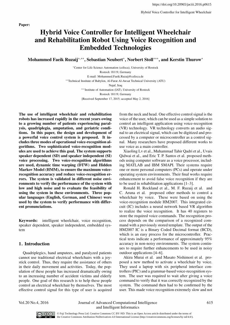
Hybrid Voice Controller for Intelligent Wheelchair Paper: Hybrid Voice Controller for Intelligent Wheelchair and Rehabilitation Robot Using Voice Recognition and Embedded Technologies Mohammed Faeik Ruzaij ∗,∗∗ , Sebastian Neubert ∗ , Norbert Stoll ∗∗∗ , and Kerstin Thurow ∗ ∗ Center for Life Science Automation (celisca), University of Rostock Rostock 18119, Germany E-mail: [email protected] ∗∗ Technical Institute ofBabylon, Al-Furat Al-Awsat Technical University (ATU) Najaf, Iraq ∗∗∗ Institute of Automation (IAT), University of Rostock Rostock 18119, Germany [Received September 17, 2015; accepted May 2, 2016] The use of intelligent wheelchair and rehabilitation robots has increased rapidly in the recent years owing to a growing number of patients experiencing paral- ysis, quadriplegia, amputation, and geriatric condi- tions. In this paper, the design and development of a powerful voice control system is proposed. It in- cludes three modes of operational voice-recognition al- gorithms. Two sophisticated voice-recognition mod- ules are used to achieve this goal. The system supports speaker dependent (SD) and speaker independent (SI) voice processing. Two voice-recognition algorithms are used, dynamic time warping (DTW) and Hidden Markov Model (HMM), to ensure the maximum voice- recognition accuracy and reduce voice-recognition er- rors. The system is validated in different noise envi- ronments to verify the performance of the system with low and high noise and to evaluate the feasibility of using the system in these environments. Three pop- ular languages (English, German, and Chinese) were used by the system to verify performance with differ- ent pronunciations. Keywords: intelligent wheelchair, voice recognition, speaker dependent, speaker independent, embedded sys- tem 1. Introduction Quadriplegics, hand amputees, and paralyzed patients cannot use traditional electrical wheelchairs with a joy- stick control. Thus, they require the assistance of others in their daily movement and activities. Today, the pop- ulation of these people has increased dramatically owing to an increasing number of accident victims and elderly people. One goal of this research is to help these people control an electrical wheelchair by themselves. The most effective control signal for this type of user is acquired from the neck and head. One effective control signal is the voice of the user, which can be used as a simple solution to control an intelligent application using voice-recognition (VR) technology. VR technology converts an audio sig- nal to an electrical signal, which can be digitized and pro- cessed by a computer or microcontroller as a control sig- nal. Many researchers have proposed different works to use voice as a main controller. Xiaoling Lv et al., Muhammad Tahir Qadri et al., Uvais Qidwai et al., and Eric T. P. Santos et al. proposedmeth- ods using computer software as a voice processor, includ- ing MATLAB and IBM SMAPI. Their systems require one or more personal computers (PCs) and operate under operating system environments. Their final works require enhancement to avoid false voice recognition if they are to be used in rehabilitation applications [1–3]. Ronald H. Rockland et al., M. F. Ruzaij et al. and C. Aruna et al. proposed other methods to control a wheelchair by voice. These were based on using the voice-recognition module HM2007. This integrated cir- cuit (IC) includes a neural network based VR algorithm to realize the voice recognition. It has 40 registers to store the required voice commands. The recognition pro- cess depends on the comparison of a recognized com- mand with a previously stored template. The output of the HM2007 IC is a Binary Coded Decimal format (BCD), which is an easy process for the microcontroller. Prac- tical tests indicate a performance of approximately 95% accuracy in non-noisy environments. The system contin- ues to require further enhancements to be used in noisy outdoor applications [4–6]. Akira Murai et al. and Masato Nishimori et al. pro- posed a new method to activate a wheelchair by voice. They used a laptop with six peripheral interface con- trollers (PIC) and a grammar-based voice-recognition sys- tem. The user was required to wait after giving a voice command to verify that it was correctly recognized by the system. The command then had to be confirmed by the user. This made voice recognition extremely slow and not Vol.20 No.4, 2016 Journal of Advanced Computational Intelligence 615 and Intelligent Informatics https://doi.org/10.20965/jaciii.2016.p0615 © Fuji Technology Press Ltd. Creative Commons CC BY-ND: This is an Open Access article distributed under the terms of the Creative Commons Attribution-NoDerivatives 4.0 International License (http://creativecommons.org/licenses/by-nd/4.0/).
-
Upload
khangminh22 -
Category
Documents
-
view
4 -
download
0
Transcript of Hybrid Voice Controller for Intelligent Wheelchair ... - J-Stage
Hybrid Voice Controller for Intelligent Wheelchair
Paper:
Hybrid Voice Controller for Intelligent Wheelchairand Rehabilitation Robot Using Voice Recognition and
Embedded TechnologiesMohammed Faeik Ruzaij∗,∗∗, Sebastian Neubert∗, Norbert Stoll∗∗∗, and Kerstin Thurow∗
∗Center for Life Science Automation (celisca), University of RostockRostock 18119, Germany
E-mail: [email protected]∗∗Technical Institute of Babylon, Al-Furat Al-Awsat Technical University (ATU)
Najaf, Iraq∗∗∗Institute of Automation (IAT), University of Rostock
Rostock 18119, Germany[Received September 17, 2015; accepted May 2, 2016]
The use of intelligent wheelchair and rehabilitationrobots has increased rapidly in the recent years owingto a growing number of patients experiencing paral-ysis, quadriplegia, amputation, and geriatric condi-tions. In this paper, the design and development ofa powerful voice control system is proposed. It in-cludes three modes of operational voice-recognition al-gorithms. Two sophisticated voice-recognition mod-ules are used to achieve this goal. The system supportsspeaker dependent (SD) and speaker independent (SI)voice processing. Two voice-recognition algorithmsare used, dynamic time warping (DTW) and HiddenMarkov Model (HMM), to ensure the maximum voice-recognition accuracy and reduce voice-recognition er-rors. The system is validated in different noise envi-ronments to verify the performance of the system withlow and high noise and to evaluate the feasibility ofusing the system in these environments. Three pop-ular languages (English, German, and Chinese) wereused by the system to verify performance with differ-ent pronunciations.
Keywords: intelligent wheelchair, voice recognition,speaker dependent, speaker independent, embedded sys-tem
1. Introduction
Quadriplegics, hand amputees, and paralyzed patientscannot use traditional electrical wheelchairs with a joy-stick control. Thus, they require the assistance of othersin their daily movement and activities. Today, the pop-ulation of these people has increased dramatically owingto an increasing number of accident victims and elderlypeople. One goal of this research is to help these peoplecontrol an electrical wheelchair by themselves. The mosteffective control signal for this type of user is acquired
from the neck and head. One effective control signal is thevoice of the user, which can be used as a simple solution tocontrol an intelligent application using voice-recognition(VR) technology. VR technology converts an audio sig-nal to an electrical signal, which can be digitized and pro-cessed by a computer or microcontroller as a control sig-nal. Many researchers have proposed different works touse voice as a main controller.
Xiaoling Lv et al., Muhammad Tahir Qadri et al., UvaisQidwai et al., and Eric T. P. Santos et al. proposed meth-ods using computer software as a voice processor, includ-ing MATLAB and IBM SMAPI. Their systems requireone or more personal computers (PCs) and operate underoperating system environments. Their final works requireenhancement to avoid false voice recognition if they areto be used in rehabilitation applications [1–3].
Ronald H. Rockland et al., M. F. Ruzaij et al. andC. Aruna et al. proposed other methods to control awheelchair by voice. These were based on using thevoice-recognition module HM2007. This integrated cir-cuit (IC) includes a neural network based VR algorithmto realize the voice recognition. It has 40 registers tostore the required voice commands. The recognition pro-cess depends on the comparison of a recognized com-mand with a previously stored template. The output of theHM2007 IC is a Binary Coded Decimal format (BCD),which is an easy process for the microcontroller. Prac-tical tests indicate a performance of approximately 95%accuracy in non-noisy environments. The system contin-ues to require further enhancements to be used in noisyoutdoor applications [4–6].
Akira Murai et al. and Masato Nishimori et al. pro-posed a new method to activate a wheelchair by voice.They used a laptop with six peripheral interface con-trollers (PIC) and a grammar-based voice-recognition sys-tem. The user was required to wait after giving a voicecommand to verify that it was correctly recognized by thesystem. The command then had to be confirmed by theuser. This made voice recognition extremely slow and not
Vol.20 No.4, 2016 Journal of Advanced Computational Intelligence 615and Intelligent Informatics
https://doi.org/10.20965/jaciii.2016.p0615
© Fuji Technology Press Ltd. Creative Commons CC BY-ND: This is an Open Access article distributed under the terms of the Creative Commons Attribution-NoDerivatives 4.0 International License (http://creativecommons.org/licenses/by-nd/4.0/).
Ruzaij, M. F. et al.
applicable to real time applications [7, 8].A control signal can also be acquired from a user head
movement to enable a simple solution to control an in-telligent application using an Orientation Detection (OD)unit. OD units can sense any change in the head po-sition with reference to the three main axis (x, y, andz), which are referred to the vertical, horizontal, anddepth. Researchers also used other body signals suchas electroencephalogram (EEG) [9, 10], electromyogram(EMG) [11, 12], electrooculogram (EOG) [13], and bodyorientation [14–16] as a controller for a wheelchair orrobotic application.
The majority of the previous works uses one or morecomputers to process and classify the acquired signal.This adds high cost and additional complexity to the sys-tem. Further, the majority of body signals such as EEG,EMG, and EOG are highly affected by electrical inter-ference from the user’s body and power source. Specialelectrodes in contact with the body are required to capturethe signal and thus, make this approach uncomfortable.Moreover, the small value of this signal makes the pro-cessing and using of these body signals more complex touse as a main controller for wheelchairs and rehabilitationsystems.
In this paper, a two-mode of operation voice controlleris designed and tested in two different noise level envi-ronments (celisca labs, University of Rostock, Germany).The presented work is a part of a multi-input control sys-tem that will include a voice and head orientation con-troller to support the use of the system for indoor and out-door applications.
Compared to previous research, this work is innovativein the sense that it employs a two-mode of operation voicecontroller (DTW and HMM) as the hybrid main voicecontroller. It can function in speaker dependent (SD) andspeaker independent (SI) modes. The use of these twopowerful VR algorithms in one unit enhances the VR ac-curacy by selecting the most accurate recognition and re-duces VR errors. The program includes a false positive(FP) error cancelation algorithm to cancel the false posi-tive (FP) VR errors. It works standalone, without the re-quirement to use a computer for the data processing anddoes not require the attaching of complex sensitive elec-trodes to the user’s body. The proposed system can op-erate with any language in SD mode and functions witheight global languages in SI mode.
2. System Construction
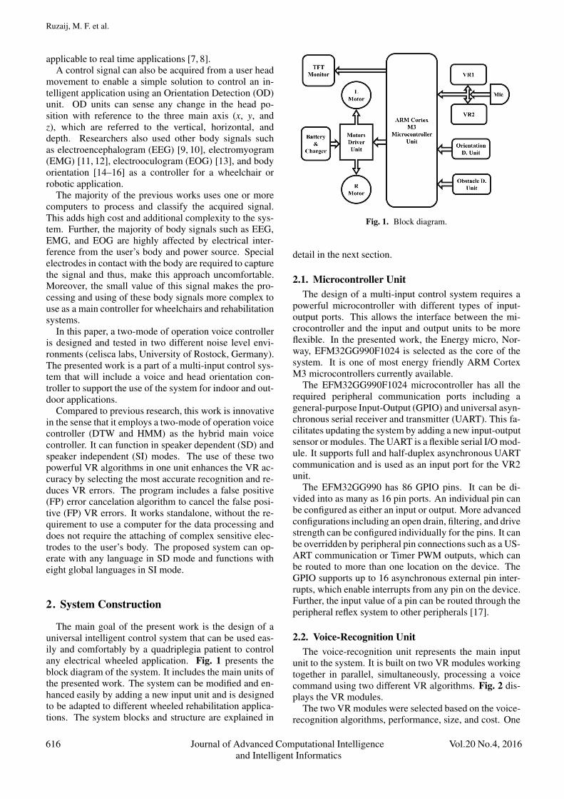
The main goal of the present work is the design of auniversal intelligent control system that can be used eas-ily and comfortably by a quadriplegia patient to controlany electrical wheeled application. Fig. 1 presents theblock diagram of the system. It includes the main units ofthe presented work. The system can be modified and en-hanced easily by adding a new input unit and is designedto be adapted to different wheeled rehabilitation applica-tions. The system blocks and structure are explained in
Fig. 1. Block diagram.
detail in the next section.
2.1. Microcontroller UnitThe design of a multi-input control system requires a
powerful microcontroller with different types of input-output ports. This allows the interface between the mi-crocontroller and the input and output units to be moreflexible. In the presented work, the Energy micro, Nor-way, EFM32GG990F1024 is selected as the core of thesystem. It is one of most energy friendly ARM CortexM3 microcontrollers currently available.
The EFM32GG990F1024 microcontroller has all therequired peripheral communication ports including ageneral-purpose Input-Output (GPIO) and universal asyn-chronous serial receiver and transmitter (UART). This fa-cilitates updating the system by adding a new input-outputsensor or modules. The UART is a flexible serial I/O mod-ule. It supports full and half-duplex asynchronous UARTcommunication and is used as an input port for the VR2unit.
The EFM32GG990 has 86 GPIO pins. It can be di-vided into as many as 16 pin ports. An individual pin canbe configured as either an input or output. More advancedconfigurations including an open drain, filtering, and drivestrength can be configured individually for the pins. It canbe overridden by peripheral pin connections such as a US-ART communication or Timer PWM outputs, which canbe routed to more than one location on the device. TheGPIO supports up to 16 asynchronous external pin inter-rupts, which enable interrupts from any pin on the device.Further, the input value of a pin can be routed through theperipheral reflex system to other peripherals [17].
2.2. Voice-Recognition UnitThe voice-recognition unit represents the main input
unit to the system. It is built on two VR modules workingtogether in parallel, simultaneously, processing a voicecommand using two different VR algorithms. Fig. 2 dis-plays the VR modules.
The two VR modules were selected based on the voice-recognition algorithms, performance, size, and cost. One
616 Journal of Advanced Computational Intelligence Vol.20 No.4, 2016and Intelligent Informatics

Hybrid Voice Controller for Intelligent Wheelchair
(a) VR1 module (b) VR2 module
Fig. 2. Voice-recognition modules implemented.
of the goals is to use two different voice-recognition al-gorithms in one voice controller. This goal can be alter-natively achieved using a computer or a signal processingkit; however, this choice would be more costly and con-sume additional time.
2.2.1. SpeakUp Click Module (VR1)The first VR module is a SpeakUp click module
(MikroElektronika, Serbia). It functions only in SDmode. In SD mode, the VR process functions based on thesound characteristic of the user; hence, the system will re-spond only to the user who trained the system previously.VR execution in this module is realized using DTW. DTWis a signal processing technique used to detect and mea-sure the similarity between two information sequences.It calculates the optimal warping path between two timeseries of different lengths. One represents the trainingreference sample; the other is the test sample. This unitcan be trained with up to 200 voice commands and canbe adapted to the external host by 12 GPIO pins and theUART communication port [18].
2.2.2. Easy VR Module (VR2)The second VR module is the EasyVR module (Veear,
Italy). This unit can operate in two modes of voice recog-nition, SD and SI. The SD mode is the same as in the firstmodule and can be used with any available language. Inthe SI mode, the system will respond to any user articu-lating a command that is included in the system library.This mode depends on converting the text command to areference voice sample and performs a comparison withlive voice commands from the user. The EasyVR modulefunctions with only eight global languages (US English,UK English, German, French, Italian, Spanish, Korean,and Japanese), owing to the availability of the commandvocabulary libraries for these languages supported by themanufacturer. It can support a maximum of 28 SD com-mands and up to 32 SI commands, which is sufficient forthe presented work requirements. The voice processingin this module is performed using an HMM algorithm.HMM is a stochastic discrete-time process, a type of sig-nal processing technique, used successfully in VR and inhandwriting recognition [19].
Fig. 3. Jaguar lite robot.
The input of the VR unit originates at the microphoneand is transferred to both VR modules. The output ofthe VR unit is interfaced with the EFM32GG990F1024microcontroller, which is the core of the system that se-lects the correct VR command. The microcontroller im-plements the control action depending on the use of threedeveloped algorithms; the (“AND,” “OR,” and “AND –OR”). The three algorithms consider both VR modules asone VR unit.
2.3. Motors Driver UnitThe output of the system interfaces with a Dr. Robot
Jaguar Lite robot (Dr. Robot Inc., Canada; see Fig. 3).The connection between the ARM microcontroller andthe robot is realized using UART communication ports.
The Jaguar Lite robot has two DC motors connected tothe robot controller PMS5005 through a Sabertooth 2X25motor driver unit. The rating operation voltage for themotors is 24 V and the rated current is 7.5 A. The max-imum weight that can be held by this type of DC motoris not sufficient for wheelchair real time applications andwill be replaced in a future work.
2.4. LCD DisplayA small TFT LCD display with 320×240 pixels is used
to display the given control command from the user andreturn the response of the intelligent control system. Itcan be fixed in any place in the wheelchair in front ofthe user’s view. Fig. 4 illustrates a sample command andfunction of the LCD display.
3. Experimental Description
The VR unit consists of the two modules, VR1 andVR2, connected to the ARM microcontroller through theGPIO and UART ports. The VR unit captures the voicecommand with a sensitive microphone that is feeding thetwo VR modules in parallel. The microcontroller receivesthe VR result from the VR unit and processes the VR in-formation to select the best VR accuracy based on a pro-gram that has been uploaded previously. The results of
Vol.20 No.4, 2016 Journal of Advanced Computational Intelligence 617and Intelligent Informatics

Ruzaij, M. F. et al.
Fig. 4. TFT display.
Table 1. Command control action.
Command DefinitionForward Both motors rotate forwardLeft Right motor rotates forward and the left ro-
tates backwardRight Left motor rotates forward and the right ro-
tates backwardBackward Both motors rotate backwardStop Both motors stopSpeed one Increase the speed or decrease from speed
twoSpeed two Increase the speed
the VR processing are converted to a control command tothe motor driver unit of the Jaguar Lite robot.
The interface between the ARM microcontroller andthe Jaguar Lite robot is realized using UART communi-cation ports on the two sides (Microcontroller and Robot)with the following setting: 115,200 kbps, N, 8, 1.
The system was tested with three global languages (En-glish, German, and Chinese). The test was performed intwo different noise level laboratories in the Center for LifeScience Automation (celisca, University of Rostock, Ger-many). The test used seven popular motion commandsin the three languages and each command had a differentcontrol action as indicated in Table 1.
There were two VR algorithms, DTW and HMM, builtinto the two VR modules, VR1 and VR2. The moduleswere tested at two different noise levels, ≈42 dB and≈72 dB. The algorithms were tested with 1,260 voicesamples from seven persons for English and German andfour persons for Chinese for each noise level. Before thetest, each algorithm was trained by the user by captur-ing an appropriate sound sample. The VR1 module mustbe trained in the presence of the environment noise. TheVR2 module must be trained with a minimum noise leveland then tested with any noise level in any environment.In the 42 dB noise level training, the user’s voice level
Table 2. SD tests for VR1.
CommandEnglish VR Acc. German VR Acc. Chinese VR Acc.P 42 dB 72 dB P 42 dB 72 dB P 42 dB 72 dB
Forward 7 91.4% 95.7% 7 91.4% 95.7% 4 100% 95.0%Left 7 98.5% 94.2% 7 91.4% 90.0% 4 100% 85.0%Right 7 97.2% 92.8% 7 97.2% 94.2% 4 90.0% 85.0%Backward 7 94.2% 95.7% 7 87.1% 87.1% 4 97.5% 100%Stop 7 98.5% 97.2% 7 91.4% 91.4% 4 97.5% 90.0%Speed one 7 97.2% 88.5% 7 88.5% 87.1% 4 82.5% 95.0%Speed two 7 94.2% 90.0% 7 94.2% 94.2% 4 85.0% 92.5%
Table 3. SD tests for VR2.
CommandEnglish VR Acc. German VR Acc. Chinese VR Acc.P 42 dB 72 dB P 42 dB 72 dB P 42 dB 72 dB
Forward 7 90% 91.4% 7 94.2% 91.4% 4 95% 97.5%Left 7 95.7% 78.5% 7 98.5% 80.0% 4 92.5% 80.0%Right 7 98.5% 90.0% 7 100% 90.0% 4 100% 87.5%Backward 7 98.5% 91.4% 7 97.2% 74.2% 4 100% 95.0%Stop 7 100% 87.1% 7 100% 84.2% 4 100% 67.5%Speed one 7 94.2% 85.7% 7 91.4% 82.8% 4 100% 80.0%Speed two 7 97.2% 77.1% 7 87.1% 72.8% 4 92.5% 90.0%
Table 4. OR tests for VR1 and VR2.
CommandEnglish VR Acc. German VR Acc. Chinese VR Acc.P 42 dB 72 dB P 42 dB 72 dB P 42 dB 72 dB
Forward 7 95.7% 92.8% 7 92.8% 95.7% 4 87.5% 97.5%Left 7 100% 95.7% 7 98.5% 97.2% 4 100% 100%Right 7 100% 100% 7 100% 100% 4 100% 95.0%Backward 7 100% 97.2% 7 98.5% 84.2% 4 100% 97.5%Stop 7 100% 97.2% 7 100% 92.8% 4 100% 77.5%Speed one 7 97.2% 98.5% 7 94.2% 98.5% 4 100% 77.5%Speed two 7 100% 100% 7 98.5% 90.0% 4 100% 100%
must be greater than 70 dB; in the 72 dB noise level, theuser’s voice level must be greater than 80 dB.
In the test, there were two types of VR errors to be ad-dressed by the algorithms: 1) false negative (FN) errors,which means the algorithms could not recognize the voicecommand; 2) false positive (FP) errors, which means thatthe algorithms recognized the incorrect command (e.g.,the spoken command “forward” and the recognized com-mand “stop”). FP errors are more harmful than FN er-rors in rehabilitation systems because they issue incorrectcommands compared with no command detection.
4. Experimental Results
Tables 2–5 present the experimental results of the sys-tem test. The symbol P refers to the number of personstested. The symbol Acc. represent the VR accuracy in thetesting environment.
The test results indicate that the SD-VR2 had the high-est VR accuracy in a low noise environment; however, theperformance decreased with increasing noise. The SD-VR1 algorithms demonstrated performance above 90% inboth noise levels.
618 Journal of Advanced Computational Intelligence Vol.20 No.4, 2016and Intelligent Informatics

Hybrid Voice Controller for Intelligent Wheelchair
Table 5. AND tests for VR1 and VR2.
CommandEnglish VR Acc. German VR Acc. Chinese VR Acc.P 42 dB 72 dB P 42 dB 72 dB P 42 dB 72 dB
Forward 7 85.7% 84.2% 7 90.0% 90.0% 4 75.0% 70.0%Left 7 94.2% 84.2% 7 92.8% 81.4% 4 100% 57.5%Right 7 94.2% 87.1% 7 94.2% 87.1% 4 92.5% 75.0%Backward 7 97.2% 87.1% 7 88.5% 61.4% 4 97.5% 95.0%Stop 7 97.2% 72.8% 7 82.8% 74.2% 4 100% 57.5%Speed one 7 71.5% 75.7% 7 75.7% 67.1% 4 70.0% 55.0%Speed two 7 91.4% 65.7% 7 75.7% 57.1% 4 70.0% 72.5%
Fig. 5. VR accuracy average in two noise levels.
The VR errors for the tested algorithms indicate thatthe SD-VR1 algorithm had the highest FP error rate com-pared to a nearly zero FP error rate for SD-VR2. SD-VR2 had the highest FN error rate in the high noise level.Fig. 5 displays the VR accuracy test of the VR1 and VR2modules and Fig. 6 presents the VR errors for the testedmodules using three different languages.
One of the primary goals of this work is the enhance-ment of the voice-recognition unit performance. Increas-ing the VR accuracy and reducing the VR errors canachieve this goal. FP error has higher priority for avoid-ance than FN because it sends incorrect control com-mands to the rehabilitation application, which can createunwanted situations for the user. The “AND” microcon-troller program was written to avoid this type of error. The“AND” program uses the logical AND condition to makecontrol decisions. When the user issues a voice command,the system will respond only if both algorithms recog-nized the command correctly. This condition reduces theFP errors effectively; however, it increases the possibil-ity of FN errors because it cancels all single recognitionresults (when only one module recognizes the voice com-mand).
Another microcontroller program was written andtested using the OR logical condition in the VR unit. Inthis program, the microcontroller applied the control ac-tion when either of the VR modules or both recognized thevoice command. The program demonstrated acceptableperformance in the two tested environments. The “OR”
Fig. 6. VR errors in two noise levels.
(a) “AND” program (b) “OR” program
Fig. 7. Flowcharts for “AND” and “OR” programs.
program had one unwanted drawback, which is the possi-bility of FP errors when only one module recognized thevoice command incorrectly. Fig. 7 displays the flowchartof the “AND” and “OR” algorithms.
The VR accuracy and VR error rate of the two pro-grams at the two noise levels is indicated in Fig. 8 andFig. 9, respectively.
Adding and testing the important FP error cancelationfunction feature improved the OR algorithm. It is used toavoid the FP errors. This function is performed at eachnew voice command trigger and compares the VR resultsof the two VR modules. When the function recognizesdifferent voice commands by the two modules, it cancelsthe recognition result. This means it converts the FP errorto an FN error, which is less harmful to the system. Theuse of this function reduces the possibility of FP errorseffectively.
Although no FP errors occurred during the test of the
Vol.20 No.4, 2016 Journal of Advanced Computational Intelligence 619and Intelligent Informatics

Ruzaij, M. F. et al.
Fig. 8. VR accuracy of “OR – AND” programs.
Fig. 9. Error rate of “OR – AND” programs.
FP cancellation function in the current system, the possi-bility of FP errors continues to exist when only one mod-ule detects the voice command incorrectly and the othermodule does not detect any voice command. In this case,the system cannot avoid FP errors. Fig. 10 presents theflowchart of the new modified OR program.
Another voice-recognition module will be added in afuture work. The new module will exploit the “AND –OR” programs more actively and will reduce the VR errorrate to a minimum level.
5. Conclusions and Future Work
In this paper, a multi-mode voice controller for reha-bilitation purposes was presented. The system aimed toassist the quadriplegic, handicapped, elderly, and para-lyzed patient to control a robotic wheelchair using voicecommands rather than a traditional joystick controller.The system design considered the future requirement tomodify or expand functionality by adding a new controlunit using the GPIO, I2C, and UARTs ports of the ARMEFM32GG990F1024 Microcontroller. The results con-firm the accepted improvement in the VR accuracy usingOR – AND algorithms compared to the use of an indi-
Fig. 10. Modified OR program with FP error cancelation.
vidual algorithm (SD-VR1, SD-VR2) with approximately5% improvement in low-level noise (42 dB) and approx-imately 3% in high-level noise (72 dB). The AND pro-gram can be used effectively in a low noise environmentwith FP error rates ≈0%, which is safer for rehabilitationapplications.
The VR accuracy of the OR program reached more than98% in non-noisy environments using English language.Compared to [1–8], this outcome has the following ad-vantages:
• Maximum percentage accuracy of VR in noisy andnon-noisy environments up to 72 dB of noise
• System tested with three different languages andhaving flexibility of using any language in SD voicecontrol and eight global languages in SI voice con-trol
• System tested by more than ten people with differentaccents
• Work standalone without requirement of a PC
• Can avoid FP errors, which are more harmful in arehabilitation application
The system was tested successfully with a JaguarLite robot and designed to function with any robot orwheelchair after modifying the motor driver parameter.
620 Journal of Advanced Computational Intelligence Vol.20 No.4, 2016and Intelligent Informatics

Hybrid Voice Controller for Intelligent Wheelchair
As the system is designed for use in wheelchairs andrehabilitation robotics, it should include an obstacle de-tection unit to protect the quadriplegic, handicapped, orelderly user in case of any unexpected situations.
AcknowledgementsThe authors would like to thank the German Academic ExchangeService (DAAD, Germany) and Al-Furat Al-Awsat Technical Uni-versity (ATU, Iraq) for scholar funding.
References:[1] X. Lv, M. Zhang, and H. Li, “Robot Control Based on Voice Com-
mand,” Proc. IEEE Int. Conf. on Automation and Logistics, Qing-dao, pp. 2490-2494, September 2008.
[2] M. T. Qadri and S. A. Ahmed, “Voice Controlled Wheelchair UsingDSK TMS320C6711,” Proc. of Int. Conf. on Signal Acquisition andProcessing 2009, Kuala Lumpur, pp. 217-221, 2009.
[3] U. Qidwai and F. Ibrahim, “Arabic Speech-Controlled Wheelchair:a Fuzzy Scenario,” Proc. of 10th Int. Conf. on Information Science,Signal Processing and their Applications, Kuala Lumpur, pp. 153-156, 2010.
[4] Ronald H. Rockland Reisman S., “Voice Activated WheelchairController,” Proc. IEEE 24th Annual Northeast BioengineeringConf., Hershey, PA, pp. 128-129, 1998.
[5] M. F. Ruzaij and S. Poonguzhali, “Design and Implementation ofLow Cost Intelligent Wheelchair,” Proc. 2nd Int. Conf. on RecentTrends in Information Technology, Chennai, pp. 468-471, 19-21April, 2012.
[6] C. Aruna, A. Dhivya Parameswari, M. Malini, and G. Gopu, “VoiceRecognition and Touch Screen Control Based Wheelchair for Para-plegic Persons,” Proc. Green Computing, Communication and Elec-trical Engineering, Coimbatore, pp. 1-5, 2014.
[7] A. Murai, M. Mizuguchi, T. Saitoh, T. Osaki, and R. Konishi, “El-evator Available Voice Activated Wheelchair,” Proc. 18th IEEE Int.Symp. on Robot and Human Interactive Communication, Toyama,Japan, pp. 730-735, Sept. 27-Oct. 2, 2009.
[8] M. Nishimori, T. Saitoh, and R. Konishi, “Voice Controlled Intelli-gent Wheelchair,” Proc. SICE Annual Conf. 2007, Kagawa Univer-sity, Japan, pp. 336-340, Sept. 17-20, 2007.
[9] K. Tanaka, K. Matsunaga, and H. O. Wang,“Electroencephalogram-Based Control of an Electric Wheelchair,”IEEE Trans. on Robotics, Vol.21, No.4, August 2005.
[10] I. Iturrate, J. Antelis, and J. Minguez, “Synchronous EEG Brain-Actuated Wheelchair with Automated Navigation,” Proc. 2009IEEE Int. Conf. on Robotics and Automation, Int. Conf. Center,Kobe, Japan, May Vol.12-17, pp. 2318-2327, 2009.
[11] I. Moon, M. Lee, J. Ryu, and M. Mun, “Intelligent RoboticWheelchair with EMG-, Gesture-, and Voice-based Interfaces,”Proc. IEEE/RSJ Int. Conf. on Intelligent Robots and Systems, LasVegas, Nevada, Vol.4, pp. 3453-3458, 2003.
[12] S. Ohishi and T. Kondo, “A Proposal of EMG-based Wheelchair forPreventing Disuse of Lower Motor Function,” Proc. Annual Conf.of Society of Instrument and Control Engineers (SICE), Akita Uni-versity, Akita, Japan, pp. 236-239, August 20-23, 2012.
[13] B. Champaty, J. Jose, H. Pal, and A. Thirugnanam, “Developmentof EOG Based Human Machine Interface control System for Mo-torized Wheelchair,” Proc. Int. Conf. on Magnetics, Machines &Drives (AICERA-2014 iCMMD), Kottayam, Vol.24-26, pp. 1-7,July 2014.
[14] O. Partaatmadja, B. Benhabib, A. Sun, and A. A. Goldenberg,“An Electrooptical Orientation Sensor for Robotics,” IEEE Trans.On Robotics And Automation, Vol.8, No.1, pp. 111-119, February1992.
[15] Z. Aiyun, Y. Kui, Y. Zhigang, and Z. Haibing, “Research andApplication of a Robot Orientation Sensor,” Proc. Int. Conf. onRobotics Intelligent Systems and Signal Processing, Changsha,China, pp. 1069-1074, October 2003.
[16] S. Manogna, S. Vaishnavi, and B. Geethanjali, “Head MovementBased Assist System For Physically Challenged,” Proc. 4th Int.Conf. on Bioinformatics and Biomedical Engineering (iCBBE),Chengdu, China, pp. 1-4, 2010.
[17] EFM32GG990 DATASHEET, [Online]. Available:http://www.silabs.com. [Accessed December 20, 2014]
[18] Speak Up Click User Manual Ver.101, MikroElektronika, Belgrade,Serbia, 2014.
[19] EasyVR 2.0 User Manual R.3.6.6., TIGAL KG, Vienna, Austria,2014.
Name:Mohammed Faeik Ruzaij
Affiliation:Center for Life Science Automation (celisca),University of Rostock
Address:Friedrich-Barnewitz-Str. 8, D-18119 Rostock, GermanyBrief Biographical History:1998- Received the B.E. in Medical Instrumentation Engineering,Technical College of Mosul2012- Received the M.E. in Medical Electronics Engineering, AnnaUniversity2014- Pursuing Ph.D. at celisca, University of RostockMain Works:• Biomedical instrumentation• Rehabilitation application
Name:Sebastian Neubert
Affiliation:Center for Life Science Automation (celisca),University of Rostock
Address:Friedrich-Barnewitz-Str. 8, D-18119 Rostock, GermanyBrief Biographical History:2007- Receive Dipl.-Ing. in Electronical Engineering, University ofRostock2010- Receive Dr.-Ing. in electrical engineering from University ofRostock2014- Head of Research Group LSA-Information Technologies, celiscaMain Works:• “Mobile real-time data acquisition system for application in preventivemedicine,” Telemed J e-Health, Vol.16, No.4, pp. 504-509, 2010.
Vol.20 No.4, 2016 Journal of Advanced Computational Intelligence 621and Intelligent Informatics

Ruzaij, M. F. et al.
Name:Norbert Stoll
Affiliation:Professor of Process Measurement, Institute ofAutomation (IAT), University of Rostock
Address:Richard-Wagner-Str. 31 / Building 8, D-18119 Rostock, GermanyBrief Biographical History:1979- Diploma degree (Dipl-Ing.) in Automation1985- Ph.D. (Dr.-Ing.) in Measurement Technologies at the University ofRostock1985-1991 Research Group Leader in Mass Spectrometry / Head ofSection Analytical Chemistry - Academy of Sciences of GDR, CentralInstitute for Organic Chemistry1992-1994 Associate Director of Institute for Organic Catalysis Rostock1994-present Univ.-Professor for Process Measurement Technologies1994-2000 Director of the Institute of Automation, University of Rostock2000-2002 Dean of the College of Engineering, University of Rostock1994-present Board of Directors of the Technology Park Warnemunde1997-present CEO of Analytical Instrument GmbH2003-present Vice President of the Center of Life Science Automation(celisca), University of RostockMain Works:• M. Kumar, R. Stoll, and N. Stoll, “A min-max approach to fuzzyclustering, estimation, and identification,” IEEE Trans. on Fuzzy Systems,Vol.14, No.2, pp. 248-262, 2006.• K. Thurow, B. Gode, U. Dingerdissen, and N. Stoll, “Laboratoryinformation management systems for life science applications,” OrganicProcess Research and Development, Vol.8, No.6, pp. 970-982, 2004.• M. Kumar, R. Stoll, and N. Stoll, “A robust design criterion forinterpretable fuzzy models with uncertain data,” IEEE Trans. on FuzzySystems, Vol.14, No.2, pp. 314-328, 2006.Membership in Academic Societies:• Medicalautomation.org• AHMT e.V.
Name:Kerstin Thurow
Affiliation:Professor of Automation Technology / Life Sci-ence Automation, Center for Life Science Au-tomation (celisca), University of Rostock
Address:Friedrich-Barnewitz-Str. 8, D-18119 Rostock, GermanyBrief Biographical History:1995- Dissertation in organometallic chemistry,Ludwig-Maximilians-University Munich1999- Habilitation in Measurement and Control, University of Rostock1999-2004 Full Professor Laboratory Automation2004- Full Professor Automation Technology / Life Science Automation,University of RostockMain Works:• Life science automation, automated analytical measurement• Automation technology, mobile roboticsMembership in Academic Societies:• Gesellschaft fur Chemische Technik und Biotechnologie• Academy of Sciences Hamburg• National Academy of Science and Engineering
622 Journal of Advanced Computational Intelligence Vol.20 No.4, 2016and Intelligent Informatics
Powered by TCPDF (www.tcpdf.org)