
HOW TO TEACH 3D CAD TO PRODUCT DESIGN ...
12
INTERN Dubrovni HOW STUD EXPE K. M. K Keywor 1. Intro 3D CAD developm manufac there hav designer backgrou designer designer educatio suggestio courses i with CA and engi Thus CA Then, ho related to students power us and has industria is now r design m design el This arti course c time imp results o develope educatio 2. CAD Educatio schools NATIONAL D ik - Croatia, M TO TEA DENTS PR ERIENCE Kim rds: CAD ed oduction D has been e ment process cturing comp ve been con r and enginee und in indu rs and engin r’s return to a on didn’t app ons and rec in higher edu AD tools. Th ineers who c AD training c ow can futur o CAD train has been de ser of CAD been taught al design maj running. It h majors from 2 lements and icle aims to content and s plementation or quantitativ ed and taugh on, reflecting D; Trends, on for CAD h emphasize s DESIGN CONF May 19 - 22, 2 ACH 3D C ROVIDIN E ducation, pr essential in d s [Hoffmann panies. Indus nflicts and in ering design ustrial/produc neering desi academia sh propriately r commendatio ucation spen he ultimate g can improve courses need re product de ning be solve esigned, refle tools in prod t for 1 st sem jor. It has be has been an 2014. Before principles su introduce a structure, as w n with achiev ve evidence ht, by which d g actual desig , problems has followed shape and a FERENCE - D 2014. CAD TO P NG INTEG roduct desig designing, m n 1989], [Del strial designe nefficiency in ner, with 13 ct design, o igners becau howed that th reflect the ac ons for creat nd too much goal of CAD e efficiency i to be connec esigners be tr ed? With the ecting the ex duct design mester studen een implemen elective cou e taking this uch as form g newly deve well as some vements thro e on CAD e design educa gn practice. s and critic d the discipli appearance w DESIGN 2014 PRODUC GRATED gn, industria modelling, sim lchambre 199 ers and engin n design pro years of ind observed freq use of diffe he CAD train ctual industr ting a bette time on how D training cou in product d cted with the rained throug ese questions xperience of practice. The nts of 2 nd y nted four tim urse and will course, mos giving and v eloped CAD e pedagogica oughout the c education. In ators and rese cism inary-oriente with produc 4 CT DESIG D DESIGN al design mulating and 96]. It is eve neers use it e ocesses relat dustry experi quent time erent CAD ning courses ry situation. er CAD train w to use CAD urses should design and d e design proc gh CAD cou s, a CAD cou the product e course was year or 3 rd q mes so far sin l be changed st students tak visual design training cou al methods, a course. It doe nstead, it re earchers cou ed developme ction of aest GN N d tooling thr erywhere in i every day in t ted to CAD ience using 3 consumption tools and w for industria Although th ning course, D tools rathe d be to raise development cess. urses? How c urse for indu t/engineering s titled ‘3D quarter stude nce 2011 and d to a requir ke basic desi language. urse, includi and report th esn’t aim to s eports how t uld have insig ment of CAD thetic and p roughout the industry, espe their work. H works. An i 3D CAD too n between i working styl al designers here have be , it seems th er than how t competent d utilizing CA can existing p ustrial/produ g designer w CAD & Pro ents of 1 st ye d the fifth tim red one for i ign courses r ing design ra he results of show any ex this course h ght into a bet technologies photorealistic e product ecially in However, industrial ols, and a industrial les. This in higher een good hat these to design designers AD tools. problems uct design who was a ototyping’ ear in an me course industrial related to ationales, the four- xperiment has been tter CAD s. Design c images, DESIGN EDUCATION 1399
-
Upload
khangminh22 -
Category
Documents
-
view
1 -
download
0
Transcript of HOW TO TEACH 3D CAD TO PRODUCT DESIGN ...
INTERNATIONALDubrovnik
HOW TO TEACH 3D CAD STUDENTS PROVIDING IEXPERIENCE
K. M. Kim
Keywords:
1. Introduction3D CADdevelopment process manufacturing companies. Industrial designers and engineers use it there have been conflicts and designer and engineering designer, with 13 years of indubackground in industrial/product design,designers and engineering designers because of different CAD tools and working styles. designer’s return toeducation didnsuggestions and recommendations for courses in higher education spend too much time on how to use CAD tools rather than how to design with CAD tools. The ultimate goal of CAD training courses and engineersThus CAD training courses need to be connected with Then, how can future product designers related to CAD students power user of CAD tools in product design practice. The course was titled and has been taught for 1industrial design major. It has been is now running. It has been an electivedesign majordesign elements and principles such as formThis article course content and structuretime implementation with achievementresults or quantitative evidence on CAD education. Instead, developed and taughteducation
2. CAD; Trends, problems and criticismEducation for CAD has schools emphasize shape and appearance with production of
INTERNATIONAL DESIGN CONFERENCE Dubrovnik - Croatia, May
HOW TO TEACH 3D CAD STUDENTS PROVIDING IEXPERIENCE
Kim
Keywords: CAD education, product design, industrial design
Introduction 3D CAD has been essential in designing, modelling, simulating and tooling throughout development process manufacturing companies. Industrial designers and engineers use it there have been conflicts and designer and engineering designer, with 13 years of indubackground in industrial/product design,designers and engineering designers because of different CAD tools and working styles. designer’s return to academeducation didn’t appropriately reflect the actual industry situation. suggestions and recommendations for courses in higher education spend too much time on how to use CAD tools rather than how to design with CAD tools. The ultimate goal of CAD training courses
engineers who can improve efficiency in proThus CAD training courses need to be connected with Then, how can future product designers related to CAD training
has been designed, power user of CAD tools in product design practice. The course was titled and has been taught for 1industrial design major. It has been
running. It has been an electivedesign majors from 2014. Before taking this course, most students take basic design courses related to design elements and principles such as form
his article aims to introduce a newly developed CAD training coursecourse content and structuretime implementation with achievementresults or quantitative evidence on CAD education. Instead, developed and taughteducation, reflecting actual design
CAD; Trends, problems and criticismEducation for CAD has schools emphasize shape and appearance with production of
DESIGN CONFERENCE May 19 - 22, 20
HOW TO TEACH 3D CAD STUDENTS PROVIDING IEXPERIENCE
CAD education, product design, industrial design
essential in designing, modelling, simulating and tooling throughout
development process [Hoffmann 1989]manufacturing companies. Industrial designers and engineers use it there have been conflicts and inefficiencydesigner and engineering designer, with 13 years of indubackground in industrial/product design,designers and engineering designers because of different CAD tools and working styles.
academia showedt appropriately reflect the actual industry situation.
suggestions and recommendations for courses in higher education spend too much time on how to use CAD tools rather than how to design with CAD tools. The ultimate goal of CAD training courses
who can improve efficiency in proThus CAD training courses need to be connected with Then, how can future product designers
training be solvehas been designed, reflecting
power user of CAD tools in product design practice. The course was titled and has been taught for 1st semesterindustrial design major. It has been
running. It has been an electivefrom 2014. Before taking this course, most students take basic design courses related to
design elements and principles such as formaims to introduce a newly developed CAD training course
course content and structure, as well as some time implementation with achievementresults or quantitative evidence on CAD education. Instead, developed and taught, by which design educators and researchers could have insight into a better CAD
reflecting actual design
CAD; Trends, problems and criticismEducation for CAD has followed the disciplinaryschools emphasize shape and appearance with production of
DESIGN CONFERENCE - DESIGN 20, 2014.
HOW TO TEACH 3D CAD TO PRODUCT DESIGN STUDENTS PROVIDING INTEGRATED DESIGN
CAD education, product design, industrial design
essential in designing, modelling, simulating and tooling throughout Hoffmann 1989], [Delchambre 1996
manufacturing companies. Industrial designers and engineers use it inefficiency in design process
designer and engineering designer, with 13 years of indubackground in industrial/product design, observed fdesigners and engineering designers because of different CAD tools and working styles.
showed that the CAD t appropriately reflect the actual industry situation.
suggestions and recommendations for creating acourses in higher education spend too much time on how to use CAD tools rather than how to design with CAD tools. The ultimate goal of CAD training courses
who can improve efficiency in proThus CAD training courses need to be connected with Then, how can future product designers be trained
e solved? With these questions, a CAD course for industrial/product design reflecting the experience
power user of CAD tools in product design practice. The course was titled semester students of 2
industrial design major. It has been implementedrunning. It has been an elective course and will be changed to a required one for industrial
from 2014. Before taking this course, most students take basic design courses related to design elements and principles such as form giving and visual design language.
aims to introduce a newly developed CAD training courseas well as some
time implementation with achievements throughout the course.results or quantitative evidence on CAD education. Instead,
by which design educators and researchers could have insight into a better CAD reflecting actual design practice.
CAD; Trends, problems and criticismfollowed the disciplinary
schools emphasize shape and appearance with production of
DESIGN 2014
TO PRODUCT DESIGN NTEGRATED DESIGN
CAD education, product design, industrial design
essential in designing, modelling, simulating and tooling throughout [Delchambre 1996
manufacturing companies. Industrial designers and engineers use it in design process
designer and engineering designer, with 13 years of induobserved frequent time consum
designers and engineering designers because of different CAD tools and working styles. that the CAD training
t appropriately reflect the actual industry situation. creating a better
courses in higher education spend too much time on how to use CAD tools rather than how to design with CAD tools. The ultimate goal of CAD training courses
who can improve efficiency in product designThus CAD training courses need to be connected with the
be trained through CAD courses? How can existing problems h these questions, a CAD course for industrial/product design
experience of power user of CAD tools in product design practice. The course was titled
students of 2nd year or 3implemented four times so far since 2011 and the fifth time course
course and will be changed to a required one for industrial from 2014. Before taking this course, most students take basic design courses related to
giving and visual design language.aims to introduce a newly developed CAD training course
as well as some pedagogicalthroughout the course.
results or quantitative evidence on CAD education. Instead, by which design educators and researchers could have insight into a better CAD
CAD; Trends, problems and criticism followed the disciplinary-oriented development of CAD technologies
schools emphasize shape and appearance with production of
4
TO PRODUCT DESIGN NTEGRATED DESIGN
CAD education, product design, industrial design
essential in designing, modelling, simulating and tooling throughout [Delchambre 1996]. It is everywhere in industry, especially
manufacturing companies. Industrial designers and engineers use it every dayin design processes related to CAD works.
designer and engineering designer, with 13 years of industry experience using 3D CAD tools, and a requent time consum
designers and engineering designers because of different CAD tools and working styles. training courses for industrial designers in higher
t appropriately reflect the actual industry situation. better CAD training course, it see
courses in higher education spend too much time on how to use CAD tools rather than how to design with CAD tools. The ultimate goal of CAD training courses should
design and development utilizing CAD tools. the design process.
through CAD courses? How can existing problems h these questions, a CAD course for industrial/product design
of the product/engineering designerpower user of CAD tools in product design practice. The course was titled
year or 3rd quarter students of 1four times so far since 2011 and the fifth time course
course and will be changed to a required one for industrial from 2014. Before taking this course, most students take basic design courses related to
giving and visual design language.aims to introduce a newly developed CAD training course
pedagogical methods, and report the results of throughout the course. It does
results or quantitative evidence on CAD education. Instead, it reportby which design educators and researchers could have insight into a better CAD
oriented development of CAD technologiesschools emphasize shape and appearance with production of aesthetic
TO PRODUCT DESIGN NTEGRATED DESIGN
essential in designing, modelling, simulating and tooling throughout It is everywhere in industry, especially
every day in their work. Howeverrelated to CAD works.
stry experience using 3D CAD tools, and a requent time consumption
designers and engineering designers because of different CAD tools and working styles. courses for industrial designers in higher
t appropriately reflect the actual industry situation. Although there have been good CAD training course, it see
courses in higher education spend too much time on how to use CAD tools rather than how to design should be to raise competent designers and development utilizing CAD tools.
design process. through CAD courses? How can existing problems
h these questions, a CAD course for industrial/product design product/engineering designer
power user of CAD tools in product design practice. The course was titled ‘3D CAD & quarter students of 1
four times so far since 2011 and the fifth time course course and will be changed to a required one for industrial
from 2014. Before taking this course, most students take basic design courses related to giving and visual design language.
aims to introduce a newly developed CAD training course, including design rationales, , and report the results of
It doesn’t aim to show any experiment reports how th
by which design educators and researchers could have insight into a better CAD
oriented development of CAD technologiesaesthetic and photorealist
essential in designing, modelling, simulating and tooling throughout the It is everywhere in industry, especially
in their work. Howeverrelated to CAD works. An industrial
stry experience using 3D CAD tools, and a ption between industrial
designers and engineering designers because of different CAD tools and working styles. courses for industrial designers in higher
lthough there have been good CAD training course, it seems that
courses in higher education spend too much time on how to use CAD tools rather than how to design be to raise competent designers
and development utilizing CAD tools.
through CAD courses? How can existing problems h these questions, a CAD course for industrial/product design
product/engineering designer who was a3D CAD & Prototyping
quarter students of 1st year in four times so far since 2011 and the fifth time course
course and will be changed to a required one for industrial from 2014. Before taking this course, most students take basic design courses related to
including design rationales, , and report the results of
t aim to show any experiment how this course has been
by which design educators and researchers could have insight into a better CAD
oriented development of CAD technologiesphotorealistic
the product It is everywhere in industry, especially in
in their work. However, An industrial
stry experience using 3D CAD tools, and a between industrial
designers and engineering designers because of different CAD tools and working styles. This courses for industrial designers in higher
lthough there have been good ms that these
courses in higher education spend too much time on how to use CAD tools rather than how to design be to raise competent designers
and development utilizing CAD tools.
through CAD courses? How can existing problems h these questions, a CAD course for industrial/product design
who was a Prototyping’
year in an four times so far since 2011 and the fifth time course
course and will be changed to a required one for industrial from 2014. Before taking this course, most students take basic design courses related to
including design rationales, , and report the results of the four-
t aim to show any experiment has been
by which design educators and researchers could have insight into a better CAD
oriented development of CAD technologies. Design ic images,
DESIGN EDUCATION 1399
whereas engineering schools focus more on mathematical principle, FEM and simulation [Ye et al. 2004]. These differences have caused problems because there has been little sharing between the disciplines, even though they have to share their data and tasks in actual product design practice. This section briefly reviews the developmental trends of 3D CAD tools and their characteristics, CAD-related problems in industry, and the educational situation of CAD.
2.1 CAID vs. CAD; industrial designers’ tool vs. engineering designers’ tool The development of commercial 3D CAD tools mirrors the product development process, in which different tools are used for different design stages. With a simple categorization, there are 3D CAD tools for industrial design work, usually called CAID tools (e.g. [Associates 2012], [Autodesk 2013], [Autodesk 2013]), and tools for engineering or engineering design work (e.g. [PTC 2013], [Siemens 2013], [Systems 2013]). The characteristics of CAID tools can be explained with surface modelling and photorealistic rendering functions. Designers have freedom to handle surface features, and can produce flashy images of 3D CAD models. However, CAID generally doesn’t have functions for dimensioning, tolerance control, assembling and imposing physical parameters, as industrial designers focus on the aesthetics and rarely pay attention to dimension and scale. When they create a 3D CAD model, they pay more attention to creating detailed surfaces for certain features than figuring out relationships between volumes. That seems to happen due to the limited choices that designers must take within surface modelling. This doesn’t accord with the designerly way of form giving in the physical world. In industrial design school, students usually study form giving in their first year. Its essence is on building relationships among dominant, subdominant, and subordinate forms [Hannah 2002]. They are trained to handle forms as connections of volumes with forces rather than surfaces that compose a volume. However, commercial CAID tools don’t appropriately adopt this kind of concept, because of the surface modelling method. This forces industrial designers to adapt themselves to a different way of the form giving process from what they do in the physical world. Thus, CAID doesn’t do well at supporting tasks in product development, except presenting visual images of design concepts. 3D CAD tools for engineering designers have different aspects. Contrasting to CAID tools, they are solid modellers. They have been developed to support detail design and manufacturing in product development. They are necessary for simulation. Interference checks, mechanical motion studies, stress analyses, and so on, can be performed. Comparing the material properties of a CAID tool that only provides visual appearance of a specific material, a CAD tool provides physical properties such as weight, density and etc. The tools have two different modes. Part modelling constructs pieces which can then be used in the assembly model to build a complete product or system. This can go on to be tested in terms of assembling, disassembling, kinematic study, and so on. Engineering drawing functions for communication and manufacturing processes after detail design are also provided. To sum up, CAID tools have been developed to represent the industrial designer’s visual concept of a product effectively, with freeform building and photorealistic functions, whereas CAD tools equipped with solid modelling and simulation functions have been developed for supporting product development, including the detail design, testing and manufacturing phases. While the data compatibility between the two has increased, in many cases, their working flows are not well lined-up in industry, when industrial designers and engineering designers use different tools. As CAID tools focus on visualization of design concept, industrial designers’ work frequently loses the sense of reality, and rarely considers the components structural relationships. The models produced have a lack of information related to tolerance, dimensions, assembling and manufacturing, and don’t much consider the following design engineering phases. Because of this, most surface modelling data that industrial designers produced cannot be directly used by engineering designers in a detail design phase. They regenerate the outside shape with their own tools, causing extra time consumption and conflicts between the two groups. These conflicts happen frequently, as during the design phase there can be modifications to the outside shape due to the rearrangement of inside components. The solid model data that engineering designers generate should be sent back to the industrial designers for modifications, who often cannot handle it. The resending of surface and solid model data happens repetitively through common exchange file format such as IGES [Smith and Wellington 1986], and
1400 DESIGN EDUCATION

Step [ISO 2012]. Even though they can share the data, this process itself causes conflicts and inefficiency.
2.2 Educational issues on CAD training 3D CAD training programs in higher education cannot avoid the responsibility in this current situation. Most art-based design schools instruct the surface modelling techniques [Unver 2006], although some design schools have started to teach solid modelling [Aldoy and Evans 2011] The fact that one is very knowledgeable on a CAD tool and its commands doesn’t mean that one knows how to design or do design engineering with it. Most CAD reference books contain how to use the tools and commands rather than touch on the strategies for designing or doing design engineering with them. To look at the cause from another perspective; education with lack of practical experience limits the utilization of computer technology [Coyne et al. 2002]. CAD instructors who have less experience in actual product design practice with CAD tools could hardly teach highly procedural knowledge on the design practices supported by these tools. They could not help teaching more declarative knowledge such as mathematic principles on CAD. The procedural knowledge they could teach would be limited to how to use commands, rather than strategies and approaches to designing with them. As a result, students in higher education could not utilize enough the possibilities of 3D digital tools [Aldoy and Evans 2011].
2.3 Criticism to new approaches Some proposed ideas by researchers also seem to be lacking the holistic view of product design and product development procedures. Reverse engineering attempts to have precise modelling data by digitizing an original physical model have been made [Lee and Woo 2000], [Benko wt al. 2002], [Fisher 2004]. However, adopting reverse engineering technology in the industrial design phase is time consuming, especially when a new design project is undergoing, thus a new shape needs to be created. Reverse engineering technology is mostly useful in the industrial design phase when they want to replicate existing products, such as competitors’ products whose data is not affordable, and to regenerate 3D data from existing products when they lost the original data or the original data is 2D. Thus, the idea of adopting reverse engineering technology in the concept design phase fails to reflect the actual design process in practice. While it has been sometimes needed in the automotive industry, rarely does a product design process require an accurate physical model in the concept design phase. The initial form created by industrial designers undergoes iterative change through later procedures. As most industrial designers are trained to differentiate aesthetic shape, either of physical or digital model making, they directly generate a digital form with 3D CAD tools at first, and then fabricate a physical model utilizing digitalized machining tools to review their design concept with a tangible object. This is an opposite procedure to what reverse engineering advocates propose.
2.4 CAD in industry Product design cannot be explained with either industrial design or engineering design, but needs a holistic and integrated approach of both [Roozenburg and Eekels 1995], [Cross 2008]. Engineering designers sometime view industrial design as artistic design [Pahl et al. 2007], [Eder 2012], as industrial designers in the automotive industry, called ‘car stylists’, focus much on aesthetic value. However, most mid-complex engineered consumer product domains, where the majority of industrial designers engage, require their contribution throughout the product development process [Ulrich and Eppinger 2012]. This implies the overlapping and sharing of tasks and data between industrial designers and engineering designers. Leading companies in this field have started to use the same tool for the concept design and detail design phases. According to a recent study on the actual design process, and the interaction between industrial designers and engineering designers, three out of six leading companies in consumer electronic products in Korea have adopted the same 3D CAD tool policy between the two groups [Kim and Lee 2014]. All tools are feature-based parametric solid modellers. This change is attributed to the
DESIGN EDUCATION 1401

companies’and workinConsidering the old concurrent engineering principle, ithe common CAD platform policy. It has been more or less believed that industrial design is not topic formodellingadapt themselves [Systems 2013]tools [Luxion 2013]
3. Course design and executionThe course is named integrated knocompleted thesemester students in five times so far, through which the contents and course structure have been gradually this section, the principles and rationales of schedule
3.1 Course design directionThe course design direction experience in product development, 2) adopting employing
3.1.1 Providing Industrial designers need to understand basic engineering design concepts in order to avoid problems[Field 2004]designing both experience ofmultiple components, generate assemblemodels utilizing CAD tools understand how their designing acmanufacturing phases. Therefore[Asperl 2005]Figure 1through from concept design to testing and prototyping throughout the course.
companies’ endeavourand working styles that they experienced.Considering the old concurrent engineering principle, ithe common CAD platform policy. It has been more or less believed that industrial design is not
for concurrent engineering. Nowadays statmodelling functions,adapt themselves from[Systems 2013] and independent rendering software ha
[Luxion 2013]. This makes industrial desig
Course design and executionThe course is named
grated knowledge on product design and development. The completed the entry semester students in five times so far, through which the contents and course structure have been gradually this section, the principles and rationales of schedule, and the execution results
ourse design directionThe course design direction experience in product development, 2) adopting mploying top-down & bottom
Providing a holistic and integrated CAD experience in product development processndustrial designers need to understand basic engineering design concepts in order to avoid problems
2004]. A CAD training course should provide industrial design students with the experience of designing both the experience of the product development process, in which students multiple components, generate assemblemodels utilizing CAD tools understand how their designing acmanufacturing phases. Therefore[Asperl 2005] of product developmentFigure 1. shows the product development process framework used to design the course. Students go through from concept design to testing and prototyping throughout the course.
Figure 1.
endeavour to overcome the conflicts and time g styles that they experienced.
Considering the old concurrent engineering principle, ithe common CAD platform policy. It has been more or less believed that industrial design is not
concurrent engineering. Nowadays stats, and the interface ha
from CAID tools. Moreoverand independent rendering software ha
. This makes industrial desig
Course design and executionThe course is named ‘3D CAD and
wledge on product design and development. The entry level of an
semester students in 2nd year or 3five times so far, through which the contents and course structure have been gradually this section, the principles and rationales of
execution results
ourse design direction The course design direction canexperience in product development, 2) adopting
down & bottom-up modelling strategies.
holistic and integrated CAD experience in product development processndustrial designers need to understand basic engineering design concepts in order to avoid problems
AD training course should provide industrial design students with the experience of the outside form and inside structure. In other word
product development process, in which students multiple components, generate assemblemodels utilizing CAD tools [Yeunderstand how their designing acmanufacturing phases. Therefore
of product developmentshows the product development process framework used to design the course. Students go
through from concept design to testing and prototyping throughout the course.
Figure 1. Integrated produce development process framework
to overcome the conflicts and time g styles that they experienced.
Considering the old concurrent engineering principle, ithe common CAD platform policy. It has been more or less believed that industrial design is not
concurrent engineering. Nowadays statand the interface has been enhanced to the extent that industrial designers easily
CAID tools. Moreoverand independent rendering software ha
. This makes industrial desig
Course design and execution 3D CAD and Prototyping’
wledge on product design and development. The an industrial design major. Thus
year or 3rd quarter students in five times so far, through which the contents and course structure have been gradually this section, the principles and rationales of
execution results are presented
be summarized experience in product development, 2) adopting
up modelling strategies.
holistic and integrated CAD experience in product development processndustrial designers need to understand basic engineering design concepts in order to avoid problems
AD training course should provide industrial design students with the experience of outside form and inside structure. In other word
product development process, in which students multiple components, generate assembled models and engineering drawings
[Ye et al. 2004]understand how their designing activity is connected and influenced to manufacturing phases. Therefore, this course was designed to provide a process
of product development, starting from outside design, shows the product development process framework used to design the course. Students go
through from concept design to testing and prototyping throughout the course.
Integrated produce development process framework
to overcome the conflicts and time
Considering the old concurrent engineering principle, it is very natural that companies start to adopt the common CAD platform policy. It has been more or less believed that industrial design is not
concurrent engineering. Nowadays state-of-the-art solid been enhanced to the extent that industrial designers easily
CAID tools. Moreover a rendering engine is also provided as addand independent rendering software ha
. This makes industrial designers free to select a modeller.
Prototyping’ and is wledge on product design and development. The
industrial design major. Thusquarter students in the
five times so far, through which the contents and course structure have been gradually this section, the principles and rationales of the course design, the course content, structure and
are presented.
be summarized in threeexperience in product development, 2) adopting a designerly
up modelling strategies.
holistic and integrated CAD experience in product development processndustrial designers need to understand basic engineering design concepts in order to avoid problems
AD training course should provide industrial design students with the experience of outside form and inside structure. In other word
product development process, in which students models and engineering drawings
2004]. Through this experience, industrial designers can tivity is connected and influenced to this course was designed to provide a process
starting from outside design, shows the product development process framework used to design the course. Students go
through from concept design to testing and prototyping throughout the course.
Integrated produce development process framework
to overcome the conflicts and time consumption caused by different CAD tools
t is very natural that companies start to adopt the common CAD platform policy. It has been more or less believed that industrial design is not
art solid modellingbeen enhanced to the extent that industrial designers easily
rendering engine is also provided as addand independent rendering software has high compatibility
ners free to select a modeller.
is designed to teach industrial design students wledge on product design and development. The intended
industrial design major. Thus, it is designed to the1st year in t
five times so far, through which the contents and course structure have been gradually course design, the course content, structure and
three parts; 1) providing designerly way of
holistic and integrated CAD experience in product development processndustrial designers need to understand basic engineering design concepts in order to avoid problems
AD training course should provide industrial design students with the experience of outside form and inside structure. In other word
product development process, in which students can design products composed of models and engineering drawings
hrough this experience, industrial designers can tivity is connected and influenced to this course was designed to provide a process
starting from outside design, shows the product development process framework used to design the course. Students go
through from concept design to testing and prototyping throughout the course.
Integrated produce development process framework
ption caused by different CAD tools
t is very natural that companies start to adopt the common CAD platform policy. It has been more or less believed that industrial design is not
modelling CAD software habeen enhanced to the extent that industrial designers easily
rendering engine is also provided as addcompatibility with various 3D CAD
ners free to select a modeller.
designed to teach industrial design students intended students are those
it is designed to year in their major. It has been offered
five times so far, through which the contents and course structure have been gradually course design, the course content, structure and
; 1) providing a holistic and integrated way of the form giving principle a
holistic and integrated CAD experience in product development processndustrial designers need to understand basic engineering design concepts in order to avoid problems
AD training course should provide industrial design students with the experience of outside form and inside structure. In other words, a provision of
can design products composed of models and engineering drawings, and fabricate physical
hrough this experience, industrial designers can tivity is connected and influenced to the design engineering and this course was designed to provide a process
starting from outside design, and ending shows the product development process framework used to design the course. Students go
through from concept design to testing and prototyping throughout the course.
Integrated produce development process framework
ption caused by different CAD tools
t is very natural that companies start to adopt the common CAD platform policy. It has been more or less believed that industrial design is not
CAD software habeen enhanced to the extent that industrial designers easily
rendering engine is also provided as add-in softwarewith various 3D CAD
designed to teach industrial design students students are those who
it is designed to be offeredheir major. It has been offered
five times so far, through which the contents and course structure have been gradually improvedcourse design, the course content, structure and
holistic and integrated giving principle a
holistic and integrated CAD experience in product development process ndustrial designers need to understand basic engineering design concepts in order to avoid problems
AD training course should provide industrial design students with the experience of , a provision of the
can design products composed of and fabricate physical
hrough this experience, industrial designers can design engineering and
this course was designed to provide a process-oriented sequence ending with prototypin
shows the product development process framework used to design the course. Students go
Integrated produce development process framework
ption caused by different CAD tools
t is very natural that companies start to adopt the common CAD platform policy. It has been more or less believed that industrial design is not a
CAD software has surface been enhanced to the extent that industrial designers easily
in software with various 3D CAD
designed to teach industrial design students who have ed for 1st
heir major. It has been offered improved. It
course design, the course content, structure and
holistic and integrated giving principle and 3)
ndustrial designers need to understand basic engineering design concepts in order to avoid problems AD training course should provide industrial design students with the experience of
the overall can design products composed of
and fabricate physical hrough this experience, industrial designers can
design engineering and oriented sequence
prototyping. shows the product development process framework used to design the course. Students go
1402 DESIGN EDUCATION

3.1.2 Adopting a As already mentioned, current CAID giving foranother course Thus, when students start to build a form, they need to identify positive and negative volumestheir connection and transformation. This is the first stag
3.1.3 EmployingThe product design process can be viewed as a developmental process of outside form and inside layout [Hubka and Eder 1996]When the outside shape is defined, the betweenthe two parts and their roles, students need to experience the development of form and layout together. A top-down divided into small papproach, students can determine the overall shape firstnext. As the detail parts are or discrepancy model composed of all necrole as a basic definition of a productbuilding an assembly model. The assembly model can be easily generated from the mastewith a bottomindependently,can be used for
3.2 Teaching approach and course schedulingSolidWorks has been used for this course because it provides enough necessary functions for running the course effectively;
Adopting a designerlyAs already mentioned, current CAID
for the physical world. If students can adopt the formnother course on basic principle
when students start to build a form, they need to identify positive and negative volumestheir connection and transformation. This is the first stag
Employing Topproduct design process can be viewed as a developmental process of outside form and inside
Hubka and Eder 1996]When the outside shape is defined, the between them should be determined under careful consideration of both. Regarding the importance of the two parts and their roles, students need to experience the development of form and layout together.
down modellingdivided into small papproach, students can determine the overall shape firstnext. As the detail parts are or discrepancy amongmodel composed of all necrole as a basic definition of a productbuilding an assembly model. The assembly model can be easily generated from the maste
bottom-up modellingindependently, and assembled again in an assembly modelling mode. Then, the final can be used for simulation
3.2 Teaching approach and course schedulingSolidWorks has been used for this course because it provides enough necessary functions for running the course effectively;
designerly way of the formAs already mentioned, current CAID
physical world. If students can adopt the formbasic principle
when students start to build a form, they need to identify positive and negative volumestheir connection and transformation. This is the first stag
Figure 2. Top
Top-down & Bottomproduct design process can be viewed as a developmental process of outside form and inside
Hubka and Eder 1996], [Pahl et al.When the outside shape is defined, the
them should be determined under careful consideration of both. Regarding the importance of the two parts and their roles, students need to experience the development of form and layout together.
modelling strategy is employed, divided into small parts to be elaborated as functional componentsapproach, students can determine the overall shape firstnext. As the detail parts are driven
among components. model composed of all necessary components. This model is called role as a basic definition of a productbuilding an assembly model. The assembly model can be easily generated from the maste
modelling approach. All components are extracted from the master model and saved and assembled again in an assembly modelling mode. Then, the final simulation such as interference che
3.2 Teaching approach and course schedulingSolidWorks has been used for this course because it provides enough necessary functions for running the course effectively; a user-friendly interface, part
way of the form giving principlesAs already mentioned, current CAID use is not well matched with
physical world. If students can adopt the formbasic principles of design
when students start to build a form, they need to identify positive and negative volumestheir connection and transformation. This is the first stag
Top-down and bottom
down & Bottom-up modelling strategiesproduct design process can be viewed as a developmental process of outside form and inside
[Pahl et al. 2007When the outside shape is defined, the layout
them should be determined under careful consideration of both. Regarding the importance of the two parts and their roles, students need to experience the development of form and layout together.
is employed, ts to be elaborated as functional components
approach, students can determine the overall shape firstdriven from the overall or bigger shape, there is little risk of overlapping
components. The final outcome of topessary components. This model is called
role as a basic definition of a product, and will be usedbuilding an assembly model. The assembly model can be easily generated from the maste
approach. All components are extracted from the master model and saved and assembled again in an assembly modelling mode. Then, the final
such as interference che
3.2 Teaching approach and course schedulingSolidWorks has been used for this course because it provides enough necessary functions for running
friendly interface, part
giving principlesis not well matched with
physical world. If students can adopt the forms of design, they can more easily adapt themselves to CAD tools.
when students start to build a form, they need to identify positive and negative volumestheir connection and transformation. This is the first stage to define an overall shape of a product.
down and bottom-up modelling approach
up modelling strategiesproduct design process can be viewed as a developmental process of outside form and inside
2007], whichlayout should be
them should be determined under careful consideration of both. Regarding the importance of the two parts and their roles, students need to experience the development of form and layout together.
is employed, where designers create a big volume firstts to be elaborated as functional components
approach, students can determine the overall shape firstfrom the overall or bigger shape, there is little risk of overlapping
final outcome of topessary components. This model is called
and will be usedbuilding an assembly model. The assembly model can be easily generated from the maste
approach. All components are extracted from the master model and saved and assembled again in an assembly modelling mode. Then, the final
such as interference check, assembling check, motion study, etc
3.2 Teaching approach and course scheduling SolidWorks has been used for this course because it provides enough necessary functions for running
friendly interface, part modelling, assembly modelling,
giving principles is not well matched with ind
physical world. If students can adopt the form giving principles that they learn from , they can more easily adapt themselves to CAD tools.
when students start to build a form, they need to identify positive and negative volumese to define an overall shape of a product.
up modelling approach
up modelling strategies product design process can be viewed as a developmental process of outside form and inside
which are closely linked and influence each other. should be considered
them should be determined under careful consideration of both. Regarding the importance of the two parts and their roles, students need to experience the development of form and layout together.
where designers create a big volume firstts to be elaborated as functional components
approach, students can determine the overall shape first, and the cofrom the overall or bigger shape, there is little risk of overlapping
final outcome of top-down modelling is a complete part essary components. This model is called
and will be used in further operation for modification and building an assembly model. The assembly model can be easily generated from the maste
approach. All components are extracted from the master model and saved and assembled again in an assembly modelling mode. Then, the final
ck, assembling check, motion study, etc
SolidWorks has been used for this course because it provides enough necessary functions for running modelling, assembly modelling,
industrial designersgiving principles that they learn from
, they can more easily adapt themselves to CAD tools. when students start to build a form, they need to identify positive and negative volumes
e to define an overall shape of a product.
up modelling approach
product design process can be viewed as a developmental process of outside form and inside are closely linked and influence each other.
ed, and the connection structure them should be determined under careful consideration of both. Regarding the importance of
the two parts and their roles, students need to experience the development of form and layout together. where designers create a big volume first
ts to be elaborated as functional components [Ye et al. connection of compositional parts
from the overall or bigger shape, there is little risk of overlapping down modelling is a complete part
essary components. This model is called a ‘master modelfurther operation for modification and
building an assembly model. The assembly model can be easily generated from the masteapproach. All components are extracted from the master model and saved
and assembled again in an assembly modelling mode. Then, the final ck, assembling check, motion study, etc
SolidWorks has been used for this course because it provides enough necessary functions for running modelling, assembly modelling,
ustrial designers’ way of formgiving principles that they learn from
, they can more easily adapt themselves to CAD tools. when students start to build a form, they need to identify positive and negative volumes
e to define an overall shape of a product.
product design process can be viewed as a developmental process of outside form and inside are closely linked and influence each other.
, and the connection structure them should be determined under careful consideration of both. Regarding the importance of
the two parts and their roles, students need to experience the development of form and layout together. where designers create a big volume first, which is again
2004]. Through this nnection of compositional parts
from the overall or bigger shape, there is little risk of overlapping down modelling is a complete part
master model’ which plays a further operation for modification and
building an assembly model. The assembly model can be easily generated from the masteapproach. All components are extracted from the master model and saved
and assembled again in an assembly modelling mode. Then, the final assembled model ck, assembling check, motion study, etc. (F
SolidWorks has been used for this course because it provides enough necessary functions for running modelling, assembly modelling, engineering
way of form giving principles that they learn from
, they can more easily adapt themselves to CAD tools. when students start to build a form, they need to identify positive and negative volumes, and
e to define an overall shape of a product.
product design process can be viewed as a developmental process of outside form and inside are closely linked and influence each other.
, and the connection structure them should be determined under careful consideration of both. Regarding the importance of
the two parts and their roles, students need to experience the development of form and layout together. which is again . Through this
nnection of compositional parts from the overall or bigger shape, there is little risk of overlapping
down modelling is a complete part which plays a
further operation for modification and building an assembly model. The assembly model can be easily generated from the master models
approach. All components are extracted from the master model and saved ed model
Figure 2).
SolidWorks has been used for this course because it provides enough necessary functions for running engineering.
DESIGN EDUCATION 1403
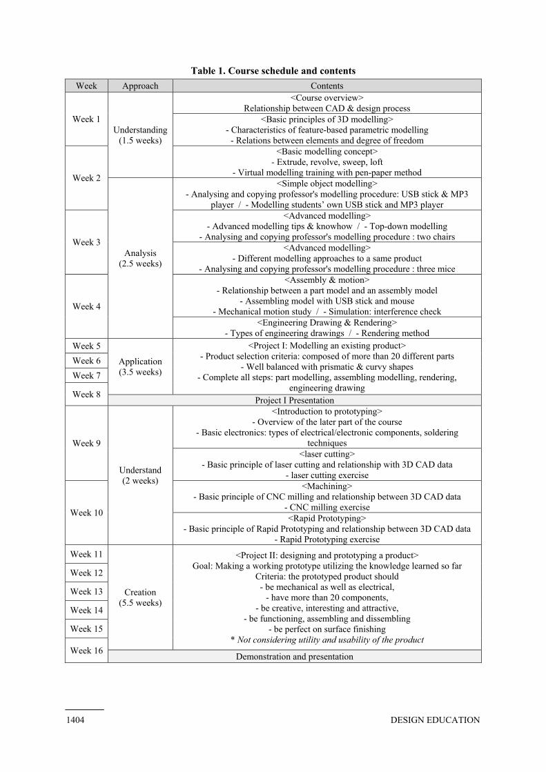
Table 1. Course schedule and contents Week Approach Contents
Week 1 Understanding
(1.5 weeks)
<Course overview> Relationship between CAD & design process
<Basic principles of 3D modelling> - Characteristics of feature-based parametric modelling
- Relations between elements and degree of freedom
Week 2
<Basic modelling concept> - Extrude, revolve, sweep, loft
- Virtual modelling training with pen-paper method
Analysis (2.5 weeks)
<Simple object modelling> - Analysing and copying professor's modelling procedure: USB stick & MP3
player / - Modelling students’ own USB stick and MP3 player
Week 3
<Advanced modelling> - Advanced modelling tips & knowhow / - Top-down modelling
- Analysing and copying professor's modelling procedure : two chairs <Advanced modelling>
- Different modelling approaches to a same product - Analysing and copying professor's modelling procedure : three mice
Week 4
<Assembly & motion> - Relationship between a part model and an assembly model
- Assembling model with USB stick and mouse - Mechanical motion study / - Simulation: interference check
<Engineering Drawing & Rendering> - Types of engineering drawings / - Rendering method
Week 5
Application (3.5 weeks)
<Project I: Modelling an existing product> - Product selection criteria: composed of more than 20 different parts
- Well balanced with prismatic & curvy shapes - Complete all steps: part modelling, assembling modelling, rendering,
engineering drawing
Week 6 Week 7
Week 8 Project I Presentation
Week 9
Understand (2 weeks)
<Introduction to prototyping> - Overview of the later part of the course
- Basic electronics: types of electrical/electronic components, soldering techniques
<laser cutting> - Basic principle of laser cutting and relationship with 3D CAD data
- laser cutting exercise
Week 10
<Machining> - Basic principle of CNC milling and relationship between 3D CAD data
- CNC milling exercise <Rapid Prototyping>
- Basic principle of Rapid Prototyping and relationship between 3D CAD data - Rapid Prototyping exercise
Week 11
Creation (5.5 weeks)
<Project II: designing and prototyping a product> Goal: Making a working prototype utilizing the knowledge learned so far
Criteria: the prototyped product should - be mechanical as well as electrical,
- have more than 20 components, - be creative, interesting and attractive,
- be functioning, assembling and dissembling - be perfect on surface finishing
* Not considering utility and usability of the product
Week 12
Week 13
Week 14
Week 15
Week 16 Demonstration and presentation
1404 DESIGN EDUCATION

drawing, simulation, and rendering functions. To train students effectively, two strategies have beenemployedlecture was which students models through a form rather than command knowledge. The other strategy is to have them apply what they learned to create their own models2008]. Thuswith CAD, and 2) developing a working prototype utilizing design and design engineering knowledge. Eight weeks,minutes per class.
3.2.1 Design and design engineering training with 3D CADThe first eight weeks are composed of three learning stages: learning through uthrough aLearning through understanding (1.5 weeks):how CAD works in procedures are needed for CAD knowledge about CAD, parametricfreedomCAD andbasic modelling procedures for simple objects are taught. method’ combination of the procedures on papers instead of utilizing a computer (
Figure
As most featurevirtual modelling training without an actual CAD tool is useful to teach students procedural knowledge on modelling itself.Learning through analysis (2.5 weeks):their knowledge. It
drawing, simulation, and rendering functions. To train students effectively, two strategies have beenemployed. The one is to teach procedural knowledge by
was deliveredwhich students analysemodels through copying a form rather than command knowledge. The other strategy is to have them apply what they learned to create their own models
. Thus, the whole course is divided into two phases; 1) design and design engineering training with CAD, and 2) developing a working prototype utilizing design and design engineering knowledge. Eight weeks, or a half minutes per class.
Design and design engineering training with 3D CADThe first eight weeks are composed of three learning stages: learning through uthrough analysis, and learning through application (Learning through understanding (1.5 weeks):how CAD works in procedures are needed for CAD knowledge about CAD, parametric modellingfreedom’ of elements and imposing relations onto elements. After understanding the basic CAD and the design process, four basic basic modelling procedures for simple objects are taught.
is adopted, combination of the modelliprocedures on papers instead of utilizing a computer (
Figure 3. Virtual
As most feature-based virtual modelling training without an actual CAD tool is useful to teach students procedural knowledge on modelling itself.Learning through analysis (2.5 weeks):their knowledge. It
drawing, simulation, and rendering functions. To train students effectively, two strategies have been. The one is to teach procedural knowledge by
ed in each class, sample 3D model data related to the teachinganalysed procedural copying the instructor’s
a form rather than command knowledge. The other strategy is to have them apply what they learned to create their own models, once independently
the whole course is divided into two phases; 1) design and design engineering training with CAD, and 2) developing a working prototype utilizing design and design engineering knowledge.
half semester
Design and design engineering training with 3D CADThe first eight weeks are composed of three learning stages: learning through u
nalysis, and learning through application (Learning through understanding (1.5 weeks):how CAD works in the design processprocedures are needed for CAD knowledge about CAD, the design process and their relationship are firstly dealt with. Then, how
modelling works is taughtof elements and imposing relations onto elements. After understanding the basic
design process, four basic basic modelling procedures for simple objects are taught.
is adopted, with which modelling concepts and procedures
procedures on papers instead of utilizing a computer (
Virtual modelling
based parametric modellers have similar modelling concepts and procedurevirtual modelling training without an actual CAD tool is useful to teach students procedural knowledge on modelling itself. Learning through analysis (2.5 weeks):their knowledge. It is composed
drawing, simulation, and rendering functions. To train students effectively, two strategies have been. The one is to teach procedural knowledge by
each class, sample 3D model data related to the teachingd procedural sequencethe instructor’s strategies. In this way, they learn
a form rather than command knowledge. The other strategy is to have them apply what they learned to independently
the whole course is divided into two phases; 1) design and design engineering training with CAD, and 2) developing a working prototype utilizing design and design engineering knowledge.
ester, are assigned to each phase. One week has two
Design and design engineering training with 3D CADThe first eight weeks are composed of three learning stages: learning through u
nalysis, and learning through application (Learning through understanding (1.5 weeks):
design process, and to teach them what concepts are applied and what procedures are needed for CAD modelling
design process and their relationship are firstly dealt with. Then, how taught, and related ex
of elements and imposing relations onto elements. After understanding the basic design process, four basic modelling
basic modelling procedures for simple objects are taught. with which students think out how objects
concepts and proceduresprocedures on papers instead of utilizing a computer (
modelling training with pen
parametric modellers have similar modelling concepts and procedurevirtual modelling training without an actual CAD tool is useful to teach students procedural
Learning through analysis (2.5 weeks): From this stage, stuis composed of four sections; simple object modelling, advanced modelling,
drawing, simulation, and rendering functions. To train students effectively, two strategies have been. The one is to teach procedural knowledge by a
each class, sample 3D model data related to the teachingsequences taken by the instructor
strategies. In this way, they learn a form rather than command knowledge. The other strategy is to have them apply what they learned to
independently and the next time collthe whole course is divided into two phases; 1) design and design engineering training
with CAD, and 2) developing a working prototype utilizing design and design engineering knowledge. , are assigned to each phase. One week has two
Design and design engineering training with 3D CADThe first eight weeks are composed of three learning stages: learning through u
nalysis, and learning through application (see Table 1)Learning through understanding (1.5 weeks): The purpose of this stage is to make students understand
and to teach them what concepts are applied and what before starting with a real CAD tool. Therefore
design process and their relationship are firstly dealt with. Then, how and related exercises are
of elements and imposing relations onto elements. After understanding the basic modelling concepts
basic modelling procedures for simple objects are taught. think out how objects
concepts and procedures, and then draw out the sequence of procedures on papers instead of utilizing a computer (see Figure 3.)
training with pen-paper method: a student work in 2012
parametric modellers have similar modelling concepts and procedurevirtual modelling training without an actual CAD tool is useful to teach students procedural
From this stage, stuof four sections; simple object modelling, advanced modelling,
drawing, simulation, and rendering functions. To train students effectively, two strategies have beena ‘strategy-copying approach.
each class, sample 3D model data related to the teachingtaken by the instructor
strategies. In this way, they learn a form rather than command knowledge. The other strategy is to have them apply what they learned to
next time collthe whole course is divided into two phases; 1) design and design engineering training
with CAD, and 2) developing a working prototype utilizing design and design engineering knowledge. , are assigned to each phase. One week has two
Design and design engineering training with 3D CAD The first eight weeks are composed of three learning stages: learning through u
ee Table 1). The detailed descriptions are below.The purpose of this stage is to make students understand
and to teach them what concepts are applied and what before starting with a real CAD tool. Therefore
design process and their relationship are firstly dealt with. Then, how cises are executed
of elements and imposing relations onto elements. After understanding the basic concepts – extrud
basic modelling procedures for simple objects are taught. A ‘virtual modellingthink out how objects around
and then draw out the sequence of ee Figure 3.).
paper method: a student work in 2012
parametric modellers have similar modelling concepts and procedurevirtual modelling training without an actual CAD tool is useful to teach students procedural
From this stage, students startof four sections; simple object modelling, advanced modelling,
drawing, simulation, and rendering functions. To train students effectively, two strategies have beencopying approach.
each class, sample 3D model data related to the teachingtaken by the instructor, and regenerated the same
strategies. In this way, they learn procedurala form rather than command knowledge. The other strategy is to have them apply what they learned to
next time collaboratively in a team the whole course is divided into two phases; 1) design and design engineering training
with CAD, and 2) developing a working prototype utilizing design and design engineering knowledge. , are assigned to each phase. One week has two
The first eight weeks are composed of three learning stages: learning through understandThe detailed descriptions are below.
The purpose of this stage is to make students understand and to teach them what concepts are applied and what
before starting with a real CAD tool. Thereforedesign process and their relationship are firstly dealt with. Then, how
executed. These include of elements and imposing relations onto elements. After understanding the basic
extrude, revolve, sweep and loft modelling training with penaround them
and then draw out the sequence of
paper method: a student work in 2012
parametric modellers have similar modelling concepts and procedurevirtual modelling training without an actual CAD tool is useful to teach students procedural
start to use aof four sections; simple object modelling, advanced modelling,
drawing, simulation, and rendering functions. To train students effectively, two strategies have beencopying approach.’ After
each class, sample 3D model data related to the teaching was providedand regenerated the same
procedural strategy to builda form rather than command knowledge. The other strategy is to have them apply what they learned to
aboratively in a team the whole course is divided into two phases; 1) design and design engineering training
with CAD, and 2) developing a working prototype utilizing design and design engineering knowledge. , are assigned to each phase. One week has two classes with 100
nderstanding, learning The detailed descriptions are below.
The purpose of this stage is to make students understand and to teach them what concepts are applied and what
before starting with a real CAD tool. Thereforedesign process and their relationship are firstly dealt with. Then, how
. These include ‘degree of of elements and imposing relations onto elements. After understanding the basic elements
e, revolve, sweep and loft training with pen
can be built with a and then draw out the sequence of modelling
paper method: a student work in 2012
parametric modellers have similar modelling concepts and procedurevirtual modelling training without an actual CAD tool is useful to teach students procedural
a computer to extend of four sections; simple object modelling, advanced modelling,
drawing, simulation, and rendering functions. To train students effectively, two strategies have been After a related
was provided, with and regenerated the same
strategy to build a form rather than command knowledge. The other strategy is to have them apply what they learned to
aboratively in a team [Chester the whole course is divided into two phases; 1) design and design engineering training
with CAD, and 2) developing a working prototype utilizing design and design engineering knowledge. with 100
ing, learning The detailed descriptions are below.
The purpose of this stage is to make students understand and to teach them what concepts are applied and what
before starting with a real CAD tool. Therefore, basic design process and their relationship are firstly dealt with. Then, how
degree of elements of
e, revolve, sweep and loft – and training with pen-paper
can be built with a modelling
paper method: a student work in 2012
parametric modellers have similar modelling concepts and procedures, the virtual modelling training without an actual CAD tool is useful to teach students procedural
computer to extend of four sections; simple object modelling, advanced modelling,
DESIGN EDUCATION 1405

assembly & motion, and engineering drawing & rendering. Each section introduces related commands briefly, and then teachelecture and half exercise are the main teaching format. Also, delivered by showing that objects around us can be expressed with negative volumes. Instead of attention on teaching how to use commands, modelling sequences with one or two example modelsbuilding 3D models, how to start with scale and dicovered. For the exercise and home assignment, are askedto quickly acquire knowledge developed by an expert. The models provided USB memory stick than thirtyprovidedTwo very similar solid micethe other with mainly surface modelling commands. They Analysingthere are various approaches to building modelling is
The other master modelconstructed from it. Thus, the model data are used to explain mouse assembly models. How to draw out different types of engineering drawings; part, assembly, and exploded drawings, is also engineering drawings as assigof motionsusing Photoview360 Learning through application (4 weeks):course continuessection is themselves. They are asked to select a real product composed of more than 20 componentsneither too simple nor too complex, but includes balanced prismatic and curvy shapes. Most select consumer products around us. The final outcomes are a master part model, assembly model, engineering drawings, and rendering images.
assembly & motion, and engineering drawing & rendering. Each section introduces related commands and then teache
lecture and half exercise are the main teaching format. Also, delivered by showing that objects around us can be expressed with negative volumes. Instead of attention on teaching how to use commands, modelling sequences with one or two example modelsbuilding 3D models, how to start with scale and dicovered. For the exercise and home assignment,
ed to analyse to quickly acquire knowledge developed by an expert. The models provided
memory stick thirty steps in the
provided; two chairswo very similar solid mice
ther with mainly surface modelling commands. They Analysing and copying the modelling procedures of the two, students there are various approaches to building modelling is a home assignment.
The other two sections are assembly and motion, and engineering drawmaster model’ is completeconstructed from it. Thus, the model data are used to explain mouse assembly models. How to draw out different types of engineering drawings; part, assembly, and exploded drawings, is also engineering drawings as assigof motions are shown
Photoview360 Learning through application (4 weeks):course continues on asection is for studentsthemselves. They are asked to select a real product composed of more than 20 componentsneither too simple nor too complex, but includes balanced prismatic and curvy shapes. Most select consumer products around us. The final outcomes are a master part model, assembly model, engineering drawings, and rendering images.
assembly & motion, and engineering drawing & rendering. Each section introduces related commands and then teaches procedural
lecture and half exercise are the main teaching format. Also, delivered by showing that objects around us can be expressed with negative volumes. Instead of attention on teaching how to use commands, modelling sequences with one or two example models are demonstratedbuilding 3D models, how to start with scale and dicovered. For the exercise and home assignment,
the modelling strategies and copy them. This to quickly acquire knowledge developed by an expert. The models provided
memory stick and an MP3 playersteps in the history list.
s and three micewo very similar solid mice are provided
ther with mainly surface modelling commands. They and copying the modelling procedures of the two, students
there are various approaches to building home assignment.
Figure 4
Figure 5.
two sections are assembly and motion, and engineering drawcompleted, assembly modelling and engineering drawing data can be easily
constructed from it. Thus, the relationshipmodel data are used to explain thismouse assembly models. How to draw out different types of engineering drawings; part, assembly, and exploded drawings, is also engineering drawings as assignments. A
are shown with five mechanical modelsPhotoview360 [Systems 2013]
Learning through application (4 weeks):a tutorial basis
students to apply anthemselves. They are asked to select a real product composed of more than 20 componentsneither too simple nor too complex, but includes balanced prismatic and curvy shapes. Most select consumer products around us. The final outcomes are a master part model, assembly model, engineering drawings, and rendering images.
assembly & motion, and engineering drawing & rendering. Each section introduces related commands procedural sequences
lecture and half exercise are the main teaching format. Also, delivered by showing that objects around us can be expressed with negative volumes. Instead of attention on teaching how to use commands, modelling sequences with
are demonstratedbuilding 3D models, how to start with scale and dicovered. For the exercise and home assignment,
the modelling strategies and copy them. This to quickly acquire knowledge developed by an expert. The models provided
MP3 player (Figure 4). They are simplehistory list. In the adva
and three mice. They include curvy shapeare provided, one generated mainly with solid modelling commands and
ther with mainly surface modelling commands. They and copying the modelling procedures of the two, students
there are various approaches to building thehome assignment.
4. Sample models for simple part modelling
. Sample models for advanced part modelling
two sections are assembly and motion, and engineering draw, assembly modelling and engineering drawing data can be easily relationship among themthis. An interference check is also
mouse assembly models. How to draw out different types of engineering drawings; part, assembly, and exploded drawings, is also demonstrated
nments. As part of a simulation, motion study is taught. with five mechanical models
[Systems 2013], a SolidWorksLearning through application (4 weeks): No more
tutorial basis, while each student apply and utilize the knowledge they learned to generate a 3D CAD model by
themselves. They are asked to select a real product composed of more than 20 componentsneither too simple nor too complex, but includes balanced prismatic and curvy shapes. Most select consumer products around us. The final outcomes are a master part model, assembly model, engineering drawings, and rendering images.
assembly & motion, and engineering drawing & rendering. Each section introduces related commands sequences, utilizing them to generate particular models
lecture and half exercise are the main teaching format. Also, delivered by showing that objects around us can be expressed with negative volumes. Instead of attention on teaching how to use commands, modelling sequences with
are demonstrated. The method using 2D sketches as references for building 3D models, how to start with scale and dimension, and covered. For the exercise and home assignment, teacher-
the modelling strategies and copy them. This to quickly acquire knowledge developed by an expert. The models provided
(Figure 4). They are simplethe advanced modelling section, five complex 3D models are
. They include curvy shape, one generated mainly with solid modelling commands and
ther with mainly surface modelling commands. They and copying the modelling procedures of the two, students
the same model. At each section,
Sample models for simple part modelling
Sample models for advanced part modelling
two sections are assembly and motion, and engineering draw, assembly modelling and engineering drawing data can be easily
among them is emphasizednterference check is also
mouse assembly models. How to draw out different types of engineering drawings; part, assembly, demonstrated. Students are asked to produce
part of a simulation, motion study is taught. with five mechanical models (Figure 6).
, a SolidWorks’ add-No more lecturesach student carries
d utilize the knowledge they learned to generate a 3D CAD model by themselves. They are asked to select a real product composed of more than 20 componentsneither too simple nor too complex, but includes balanced prismatic and curvy shapes. Most select consumer products around us. The final outcomes are a master part model, assembly model, engineering drawings, and rendering images. Every class
assembly & motion, and engineering drawing & rendering. Each section introduces related commands utilizing them to generate particular models
lecture and half exercise are the main teaching format. Also, the delivered by showing that objects around us can be expressed with negative volumes. Instead of attention on teaching how to use commands, modelling sequences with
. The method using 2D sketches as references for mension, and the
-generated models the modelling strategies and copy them. This analysing
to quickly acquire knowledge developed by an expert. The models provided (Figure 4). They are simple
nced modelling section, five complex 3D models are . They include curvy shapes and have long history lists
, one generated mainly with solid modelling commands and ther with mainly surface modelling commands. They both
and copying the modelling procedures of the two, students same model. At each section,
Sample models for simple part modelling
Sample models for advanced part modelling
two sections are assembly and motion, and engineering draw, assembly modelling and engineering drawing data can be easily
is emphasizednterference check is also demonstrated with the USB
mouse assembly models. How to draw out different types of engineering drawings; part, assembly, . Students are asked to produce
part of a simulation, motion study is taught. (Figure 6). Finally
-in software, lectures are delivered in this stage. Instead,
carries out his/her own project. The goal of this d utilize the knowledge they learned to generate a 3D CAD model by
themselves. They are asked to select a real product composed of more than 20 componentsneither too simple nor too complex, but includes balanced prismatic and curvy shapes. Most select consumer products around us. The final outcomes are a master part model, assembly model,
very class, tutorials
assembly & motion, and engineering drawing & rendering. Each section introduces related commands utilizing them to generate particular models
the top-down modelling concept is delivered by showing that objects around us can be expressed with a manipulationegative volumes. Instead of attention on teaching how to use commands, modelling sequences with
. The method using 2D sketches as references for the top-down modelling process are
models are providedanalysing process helps t
to quickly acquire knowledge developed by an expert. The models provided in the first section are (Figure 4). They are simple, as they can be built with fewer
nced modelling section, five complex 3D models are and have long history lists
, one generated mainly with solid modelling commands and have a few inside
and copying the modelling procedures of the two, students can naturally understand that same model. At each section, complet
Sample models for simple part modelling
Sample models for advanced part modelling
two sections are assembly and motion, and engineering drawing and rendering. When , assembly modelling and engineering drawing data can be easily
is emphasized. The USB stickdemonstrated with the USB
mouse assembly models. How to draw out different types of engineering drawings; part, assembly, . Students are asked to produce assembly
part of a simulation, motion study is taught. inally, rendering techniques are taught
and Keyshot are delivered in this stage. Instead, out his/her own project. The goal of this
d utilize the knowledge they learned to generate a 3D CAD model by themselves. They are asked to select a real product composed of more than 20 componentsneither too simple nor too complex, but includes balanced prismatic and curvy shapes. Most select consumer products around us. The final outcomes are a master part model, assembly model,
tutorials are given
assembly & motion, and engineering drawing & rendering. Each section introduces related commands utilizing them to generate particular models. Thus, half
down modelling concept is a manipulation of positive and
negative volumes. Instead of attention on teaching how to use commands, modelling sequences with . The method using 2D sketches as references for
down modelling process are are provided, and process helps the
the first section are can be built with fewer
nced modelling section, five complex 3D models are and have long history lists (Figure 5).
, one generated mainly with solid modelling commands and have a few inside components
naturally understand that completing the
ing and rendering. When , assembly modelling and engineering drawing data can be easily
stick and mouse partdemonstrated with the USB
mouse assembly models. How to draw out different types of engineering drawings; part, assembly, assembly models and
part of a simulation, motion study is taught. Different types rendering techniques are taught
and Keyshot [Luxion 2013]are delivered in this stage. Instead, out his/her own project. The goal of this
d utilize the knowledge they learned to generate a 3D CAD model by themselves. They are asked to select a real product composed of more than 20 components, neither too simple nor too complex, but includes balanced prismatic and curvy shapes. Most select consumer products around us. The final outcomes are a master part model, assembly model,
are given according to
assembly & motion, and engineering drawing & rendering. Each section introduces related commands . Thus, half
down modelling concept is of positive and
negative volumes. Instead of attention on teaching how to use commands, modelling sequences with . The method using 2D sketches as references for
down modelling process are and students
he students the first section are a
can be built with fewer nced modelling section, five complex 3D models are
(Figure 5). , one generated mainly with solid modelling commands and
components. naturally understand that
ing the copy
ing and rendering. When ‘a , assembly modelling and engineering drawing data can be easily
and mouse part- stick and
mouse assembly models. How to draw out different types of engineering drawings; part, assembly, models and
ifferent types rendering techniques are taught
[Luxion 2013]. are delivered in this stage. Instead, the out his/her own project. The goal of this
d utilize the knowledge they learned to generate a 3D CAD model by which is
neither too simple nor too complex, but includes balanced prismatic and curvy shapes. Most of them select consumer products around us. The final outcomes are a master part model, assembly model,
according to student
1406 DESIGN EDUCATION
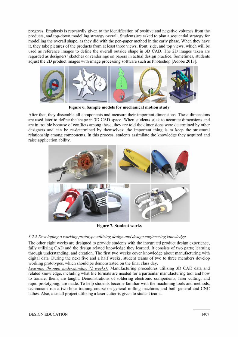
progress. productsmodelling the overall shapeit, they take pictures of the products from at least three views; front, side, and topused as reference images to define the overall outside shape in 3D CAregarded as designersadjust the 2D product images with image processing software such as Photoshop
After that, they dissemble all components and measureare used later to define the shape in 3D CAD space. are in troubledesignerrelationship among components. In this processraise application ability.
3.2.2 Developing a working prototype utilizing design and design engineering knowledgeThe other eight weeks are designed to provide students with the integrated product design experiencefully utilizing CAD and through understandingdigital data. During the next five and working prototypes, which shouLearning through understanding (2 weeks):related knowledgeto transfer themrapid prototypingtechnicianslathes. Also
progress. Emphasis isproducts, and top-down modelling strategy overall. Students are asked to plan a sequential strategy for modelling the overall shapeit, they take pictures of the products from at least three views; front, side, and topused as reference images to define the overall outside shape in 3D CAregarded as designersadjust the 2D product images with image processing software such as Photoshop
After that, they dissemble all components and measureare used later to define the shape in 3D CAD space.
trouble because of conflicts among designers and can be rerelationship among components. In this processraise application ability.
Developing a working prototype utilizing design and design engineering knowledgeThe other eight weeks are designed to provide students with the integrated product design experiencefully utilizing CAD and through understandingdigital data. During the next five and working prototypes, which shouLearning through understanding (2 weeks):related knowledge, including what file formats are needed for a to transfer them, are taught. Demonstrations of soldering electronic rapid prototyping, are made. To technicians run a twolathes. Also, a small project utilizing a laser cutter
s is repeatedlydown modelling strategy overall. Students are asked to plan a sequential strategy for
modelling the overall shape, as they did with it, they take pictures of the products from at least three views; front, side, and topused as reference images to define the overall outside shape in 3D CAregarded as designers’ sketches or renderings on papadjust the 2D product images with image processing software such as Photoshop
Figure 6.
After that, they dissemble all components and measureare used later to define the shape in 3D CAD space.
because of conflicts among s and can be re-determined by themselves
relationship among components. In this processraise application ability.
Developing a working prototype utilizing design and design engineering knowledgeThe other eight weeks are designed to provide students with the integrated product design experiencefully utilizing CAD and the design related knowledge they learned. It conthrough understanding, and creation. digital data. During the next five and working prototypes, which should be demonstrated Learning through understanding (2 weeks):
including what file formats are needed for a are taught. Demonstrations of soldering electronic are made. To two-hour training
small project utilizing a laser cutter
repeatedly given to the down modelling strategy overall. Students are asked to plan a sequential strategy for
as they did with it, they take pictures of the products from at least three views; front, side, and topused as reference images to define the overall outside shape in 3D CA
sketches or renderings on papadjust the 2D product images with image processing software such as Photoshop
. Sample models for mechanical motion study
After that, they dissemble all components and measureare used later to define the shape in 3D CAD space.
because of conflicts among thesedetermined by themselves
relationship among components. In this process
Figure
Developing a working prototype utilizing design and design engineering knowledgeThe other eight weeks are designed to provide students with the integrated product design experience
design related knowledge they learned. It conand creation. The first two weeks cover knowledge about manufacturing with
digital data. During the next five and a half weekld be demonstrated
Learning through understanding (2 weeks):including what file formats are needed for a
are taught. Demonstrations of soldering electronic are made. To help students
hour training course osmall project utilizing a laser cutter
the identificationdown modelling strategy overall. Students are asked to plan a sequential strategy for
as they did with the pen-paper method in the early phase. When they have it, they take pictures of the products from at least three views; front, side, and topused as reference images to define the overall outside shape in 3D CA
sketches or renderings on papers in actual design practice. Sometimeadjust the 2D product images with image processing software such as Photoshop
Sample models for mechanical motion study
After that, they dissemble all components and measure theirare used later to define the shape in 3D CAD space. When students stick to
these, they are tolddetermined by themselves; the important thing is to keep the structural
relationship among components. In this process, students
Figure 7. Student works
Developing a working prototype utilizing design and design engineering knowledgeThe other eight weeks are designed to provide students with the integrated product design experience
design related knowledge they learned. It conhe first two weeks cover knowledge about manufacturing with
half weeks, student teams ld be demonstrated on the final
Learning through understanding (2 weeks): Manufacturing procedures utilizing 3D CAD data and including what file formats are needed for a
are taught. Demonstrations of soldering electronic students become familiar
on general milling machines and small project utilizing a laser cutter is given to student teams.
cation of positive and negative volumes from the down modelling strategy overall. Students are asked to plan a sequential strategy for
paper method in the early phase. When they have it, they take pictures of the products from at least three views; front, side, and topused as reference images to define the overall outside shape in 3D CA
ers in actual design practice. Sometimeadjust the 2D product images with image processing software such as Photoshop
Sample models for mechanical motion study
their importanthen students stick to
they are told the dimensions were determined by other the important thing is to keep the structural
students assimilate the knowledge
Student works
Developing a working prototype utilizing design and design engineering knowledgeThe other eight weeks are designed to provide students with the integrated product design experience
design related knowledge they learned. It conhe first two weeks cover knowledge about manufacturing with
, student teams ofthe final class day.
Manufacturing procedures utilizing 3D CAD data and including what file formats are needed for a particular
are taught. Demonstrations of soldering electronic familiar with the machining tools and methods,
general milling machines and given to student teams.
of positive and negative volumes from the down modelling strategy overall. Students are asked to plan a sequential strategy for
paper method in the early phase. When they have it, they take pictures of the products from at least three views; front, side, and topused as reference images to define the overall outside shape in 3D CAD. The 2D images taken are
ers in actual design practice. Sometimeadjust the 2D product images with image processing software such as Photoshop [Adobe 2013]
Sample models for mechanical motion study
important dimensions. These dimensions hen students stick to accurate
the dimensions were determined by other the important thing is to keep the structural
assimilate the knowledge
Developing a working prototype utilizing design and design engineering knowledgeThe other eight weeks are designed to provide students with the integrated product design experience
design related knowledge they learned. It consists of two parts; learning he first two weeks cover knowledge about manufacturing with
of two to three members develop day.
Manufacturing procedures utilizing 3D CAD data and particular manufacturing tool and how
are taught. Demonstrations of soldering electronic componentswith the machining tools and methods,
general milling machines and both general and CNC given to student teams.
of positive and negative volumes from the down modelling strategy overall. Students are asked to plan a sequential strategy for
paper method in the early phase. When they have it, they take pictures of the products from at least three views; front, side, and top views, which will be
The 2D images taken are ers in actual design practice. Sometimes,
[Adobe 2013]
dimensions. These dimensions accurate dimensions and
the dimensions were determined by other the important thing is to keep the structural
assimilate the knowledge they acquir
Developing a working prototype utilizing design and design engineering knowledge The other eight weeks are designed to provide students with the integrated product design experience
sists of two parts; learning he first two weeks cover knowledge about manufacturing with
two to three members develop
Manufacturing procedures utilizing 3D CAD data and manufacturing tool and how
components, laser cutting, with the machining tools and methods,
both general and CNC
of positive and negative volumes from the down modelling strategy overall. Students are asked to plan a sequential strategy for
paper method in the early phase. When they have views, which will be
The 2D images taken are s, students
[Adobe 2013].
dimensions. These dimensions dimensions and
the dimensions were determined by other the important thing is to keep the structural
acquired and
The other eight weeks are designed to provide students with the integrated product design experience, sists of two parts; learning
he first two weeks cover knowledge about manufacturing with two to three members develop
Manufacturing procedures utilizing 3D CAD data and manufacturing tool and how
, laser cutting, and with the machining tools and methods,
both general and CNC
DESIGN EDUCATION 1407

Learning through creation (5.5 weeks):member prototype passingprocesses. To this end, they should fully utilize the knowledge that they have learnedown approaches and strategies. Furthermore, teamwork is emphasized actual design process in
Goals
Criteria for the p
The class runs ontheir progress, each teamdemonstration of the prototype
Learning through creation (5.5 weeks):member student teamprototype passing through theprocesses. To this end, they should fully utilize the knowledge that they have learnedown approaches and strategies. Furthermore, teamwork is emphasized actual design process in
Goals o To develop a o To learn teamwork in product development
Criteria for the po To be both mo To be composed of o To be co To be fo To be po Not to
he class runs on a tutorial basis. Even though every class requires their progress, each teamdemonstration of the prototype
Figure
Learning through creation (5.5 weeks):student team carries out a product development project. They should build a
through the idea generation, 3D CAD processes. To this end, they should fully utilize the knowledge that they have learnedown approaches and strategies. Furthermore, teamwork is emphasized actual design process in industry
To develop a creative To learn teamwork in product development
Criteria for the product be both mechanical and electrical
o be composed of o be creative, interesting and attractiveo be functioning, assembling and do be perfect on the surface finishingot to consider utility and usability
tutorial basis. Even though every class requires their progress, each team’s work demonstration of the prototype’s functionali
Figure 8. ‘Toy car
Figure 9.
Learning through creation (5.5 weeks): This is the final stage of the course out a product development project. They should build a
idea generation, 3D CAD processes. To this end, they should fully utilize the knowledge that they have learnedown approaches and strategies. Furthermore, teamwork is emphasized
is always collaborative.
creative product To learn teamwork in product development
echanical and electrical o be composed of more than 20 components
reative, interesting and attractiveunctioning, assembling and derfect on the surface finishing
consider utility and usabilitytutorial basis. Even though every class requires
s work is self-regulats functionality, assembling and dissembling.
Toy car’ in 2011: from concept design to working prototype
. A working prototype
This is the final stage of the course out a product development project. They should build a
idea generation, 3D CAD processes. To this end, they should fully utilize the knowledge that they have learnedown approaches and strategies. Furthermore, teamwork is emphasized
collaborative.
product from idea generation to prototypingTo learn teamwork in product development
echanical and electrical more than 20 components
reative, interesting and attractive unctioning, assembling and dissemblingerfect on the surface finishing
consider utility and usability tutorial basis. Even though every class requires
regulated. On the final dty, assembling and dissembling.
: from concept design to working prototype
prototype of
This is the final stage of the course out a product development project. They should build a
idea generation, 3D CAD modeling, processes. To this end, they should fully utilize the knowledge that they have learnedown approaches and strategies. Furthermore, teamwork is emphasized
The project brief is
idea generation to prototypingTo learn teamwork in product development
more than 20 components
issembling
tutorial basis. Even though every class requires givingthe final day, each team is asked to make
ty, assembling and dissembling.
: from concept design to working prototype
of ‘Lotus light
This is the final stage of the course in whichout a product development project. They should build a
detail design andprocesses. To this end, they should fully utilize the knowledge that they have learnedown approaches and strategies. Furthermore, teamwork is emphasized [Chester 2008]
The project brief is as follows
idea generation to prototyping
giving student teams feedback ay, each team is asked to make
ty, assembling and dissembling.
: from concept design to working prototype
Lotus light’ in 2012
in which each two to three out a product development project. They should build a
detail design and manufacturing processes. To this end, they should fully utilize the knowledge that they have learned, and devise their
[Chester 2008] because the follows:
idea generation to prototyping
student teams feedback ay, each team is asked to make
: from concept design to working prototype
two to three out a product development project. They should build a working
manufacturing and devise their
because the
student teams feedback on ay, each team is asked to make a
1408 DESIGN EDUCATION

4. Reflection and discussion A newly developed CAD training course has been introduced at the author’s institution. During the four times it has been implemented, the contents and teaching methods have been elaborated. One very noticeable phenomenon is that enrolment has increased, from six in the first two courses, to thirteen, twenty six and then now to thirty eight. Some students have personally asked the instructor if they could take this course. Some students who took this course have made remarkable achievements. One student won the first prize and another placed third at the 13th National CAD Modelling Competition in 2012, as a maiden entry from this institution. Another student placed first again in 2013. Some other students from this course have also won awards in other competitions. Some students taking this course have had remarkable performances in other design studio and project-oriented courses. They have played a key role in team projects. In addition to academic achievement, a few students have been involved in actual product development projects. Since the fourth implementation of this course, students have been surveyed on their first and last day for their reasons for taking it, and on what they achieved throughout the course, respectively. Most mentioned that they wanted to be competent on CAD and product design, and that they had heard this course was tough but rewarding. Their responses to the achievement throughout this course were positive. Most of them mentioned that they have learned how to implement the design idea in their mind. So far, CAD tools have been developed in a task-based and disciplinary-oriented direction. Many thought that one type of tools were good for industrial designers and the other for engineering designers. Most CAD training courses in higher education have also not considered the integrated approach. Design schools emphasized on the production of photorealistic images, whereas engineering focused more on mathematical principles and simulation, but both have somehow failed to reflect the actual CAD related design practice. With the awareness of these problems a new CAD training course for product design students, has been developed and implemented, based on industry experience and researchers’ recommendations. Three principles were applied as follows; 1) providing a holistic and integrated experience in product development, 2) adopting a designerly way of using the form giving principle and 3) employing top-down & bottom-up modelling strategies. It seems that CAD related courses are not easy to teach because the contents require highly procedural knowledge from product design and development practice. Without practical experience, the teaching would rely on the command knowledge or mathematical principles behind the operation, as these can be acquired without practical experience. Designers often use CAD tools in limited ways in practice, and have to relearn practical knowledge on CAD again for their first and second year in companies. The dichotomized CAD education between industrial design and mechanical engineering is problematic. We rarely see industrial design departments teach how to construct inside components and build functional prototypes, or see mechanical engineering departments educate on how to design and determine overall shape, and produce rendering images. Considering product design and development proceed under the interaction between and contribution by both industrial designers and engineering designers, CAD education should provide the holistic and integrated experience of product design. This article will give meaningful insight into the direction to CAD instructors and design researchers.
Acknowledgement This work was supported by the National Research Foundation of Korea Grant funded by the Korean Government (NRF-2012S1A5A8024274).
References 3DS MAX, http://www.autodesk.com/products/autodesk-3ds-max/overview, accessed at Dec. 4, 2013. Aldoy, N., Evans, M., "A Review of Digital Industrial and Product Design Methods in UK Higher Education", The Design Journal, Vol. 14, No. 3, 2011, pp. 343-368. Alias, http://www.autodesk.com/products/autodesk-alias-products/overview, accessed at Dec. 4, 2013. Asperl, A., "How to teach CAD", Computer-Aided Design and Applications, Vol. 2, No. 1, 2005, pp. 459-468.
DESIGN EDUCATION 1409

Benko, P., Kós, G., Várady, T., Andor, L., Martin, R., "Constrained fitting in reverse engineering", Computer Aided Geometric Design, Vol. 19, No. 3, 2002, pp. 173-205. Coyne, R., Park, H., Wiszniewski, D., "Design devices: digital drawing and the pursuit of difference", Design studies, Vol.23, No. 3, 2002, pp. 263-286. Cross, N., "Engineering design methods: strategies for product design", 2008. Delchambre, A., "CAD Method for Industrial Assembly: Concurrent Design of Products, Equipments, and Control Systems", John Wiley & Sons, Inc., 1996. Eder, W. E., "Engineering Design Vs. Artistic Design–A Discussion", Proceedings of the Canadian Engineering Education Association, 2012, pp. 1-7. Field, D. A., "Education and training for CAD in the auto industry", Computer-Aided Design, Vol. 36, No. 14. 2004, pp. 1431-1437. Fisher, R. B., "Applying knowledge to reverse engineering problems", Computer-Aided Design, Vol. 36, No. 6. 2004, pp. 501-510. Hannah, G. G., "Elements of design: Rowena Reed Kostellow and the structure of visual relationships", Princeton Architectural Press, 2002. Hoffmann, C. M., "Geometric and solid modeling: an introduction", Morgan Kaufmann Publishers Inc., 1989. Hubka, V. and Eder, W. E., "Design science: introduction to needs, scope and organization of engineering design knowledge", 1996. ISO 10303-233:2012 Industrial automation systems and integration - Product data representation and exchange - Part 233: Application protocol: Systems engineering, International Organization for Standardization, 2012. Kim, K. and Lee, K.-p., "Don't Make Art, Do Industrial Design: A Voice from Industry", DMI Review, (in press), 2014. Lee, K. and Woo, H., "Development of an efficient method for interfacing reverse engineering and rapid prototyping", 2000, pp. 62-7. Luxion, I., "KeyShot", 2013. NX, http://www.plm.automation.siemens.com/en_us/products/nx/, accessed at Dec. 4, 2013. Pahl, G., Wallace, K., Blessing, L., "Engineering design: a systematic approach", Springer, 2007. Photoshop, http://www.adobe.com/, accessed at December 8, 2013. PhotoView 360, http://www.solidworks.com/sw/products/3d-cad/photoview-360.htm accessed at Pro/Engineer, http://www.ptc.com/products/proe/wildfire4/, accessed at Dec. 4, 2013. Rhinoceros, http://www.rhino3d.com/, accessed at Dec. 4, 2013. Roozenburg, N. F., Eekels, J., "Product design: fundamentals and methods", Wiley Chichester, 1995. Smith, B., Wellington, J., "Initial graphics exchange specification (IGES), version 3.0", Society of Automotive Engineers, 1986. SolidWorks, http://www.solidworks.com/, accessed at Dec. 4, 2013. Ulrich, K. T., Eppinger, S. D., "Product design and development", McGraw-Hill/Irwin, 2012. Unver, E., "Strategies for the transition to CAD based 3D design education", Computer-Aided Design and Applications, Vol. 3, No. 1-4. 2006, pp. 323-330. Ye, X., Liu, H., Chen, L., Chen, Z., Pan, X., Zhang, S., "Reverse innovative design—an integrated product design methodology", Computer-Aided Design, Vol. 40, No. 7. 2008, pp. 812-827. Ye, X., Peng, W., Chen, Z., Cai, Y.-Y., "Today's students, tomorrow's engineers: an industrial perspective on CAD education", Computer-Aided Design, Vol. 36, No. 14. 2004, pp. 1451-1460. KwanMyung Kim, Assistant Professor Ulsan National Institute of Science and Technology UNIST-gil 50, Banyeon, Yeonyang, Ulju, Ulsan 689-798, Republic of Korea Telephone: +82-52-217-2714 Telefax: +82-52-217-2708 Email: [email protected]. URL: http:// [email protected]
http://youtube.com/user/kwanmyungkim
1410 DESIGN EDUCATION