How the body contributes to the wake in undulatory fish swimming: flow fields of a swimming eel...
12
Many fish pass a transverse wave down their body to produce thrust. Undulatory swimming comprises a continuum of swimming styles from curvilinearly increasing body waves running down fusiform bodies and generating thrust mainly at the tail to rectilinearly increasing body waves along elongate bodies generating thrust along the whole body. At one end of the spectrum are fish such as mullet Chelon labrosus (Müller et al., 1997) and danio Danio malabaricus (Wolfgang et al., 1999), both with a curvilinearly increasing amplitude envelope and thrust production dominated by the contribution of the tail. Two mechanisms have been proposed to explain how the body contributes to the thrust generated at the tail. First, the body undulations create circular flow patterns that travel posteriorly along with the body wave and ultimately modify the flow around the tail to increase swimming performance (Müller et al., 1997). The second mechanism is based on shedding vorticity off the body’s trailing edge in the peduncle region, which again modifies the tail flow to increase swimming efficiency (Wolfgang et al., 1999). Eels (Anguilla anguilla), with their elongate bodies and rectilinearly increasing body wave, represent an extreme case of undulatory swimming and generate thrust along their whole body rather than at the tail. A snapshot of the flow around and behind their body has been published (Gray, 1968) and resembles the flow patterns observed in mullet and danio. But, without a description of the eel’s swimming kinematics, no link between body movement and flow can be established. It is, however, unlikely that the trailing edge shedding mechanism contributes to thrust since eels do not have a peduncle region and body vorticity cannot be shed in this way to interact with the tail flow. Simple analytical models predict that undulatory swimmers shed a reverse von Kármán vortex street when optimising swimming performance (Lighthill, 1969). This wake consists of a double row of single vortices and is generated if the fish swims at a slip (the ratio of swimming speed U to body wave speed V) of less than 1. Typically, slip is in the region of 0.6–0.8 (for a review, see Videler, 1993). Computational simulations of the flow around an undulatory swimmer exist for a danio (Wolfgang et al., 1999) and eel (Carling et al., 1998; Pedley and Hill, 1999). Two of the three models predict a wake resembling the prediction of Lighthill (Lighthill, 1969) with 2751 The Journal of Experimental Biology 204, 2751–2762 (2001) Printed in Great Britain © The Company of Biologists Limited 2001 JEB3238 Undulatory swimmers generate thrust by passing a transverse wave down their body. Thrust is generated not just at the tail, but also to a varying degree by the body, depending on the fish’s morphology and swimming movements. To examine the mechanisms by which the body in particular contributes to thrust production, we chose eels, which have no pronounced tail fin and hence are thought to generate all their thrust with their body. We investigated the interaction between body movements and the flow around swimming eels using two-dimensional particle image velocimetry. Maximum flow velocities adjacent to the eel’s body increase almost linearly from head to tail, suggesting that eels generate thrust continuously along their body. The wake behind eels swimming at 1.5 L s -1 , where L is body length, consisted of a double row of double vortices with little backward momentum. The eel sheds two vortices per half tail-beat, which can be identified by their shedding dynamics as a start–stop vortex of the tail and a vortex shed when the body-generated flows reach the ‘trailing edge’ and cause separation. Two consecutively shed ipsilateral body and tail vortices combine to form a vortex pair that moves away from the mean path of motion. This wake shape resembles flow patterns described previously for a propulsive mode in which neither swimming efficiency nor thrust is maximised but sideways forces are high. This swimming mode is suited to high manoeuvrability. Earlier recordings show that eels also generate a wake reflective of maximum swimming efficiency. The combined findings suggest that eels can modify their body wave to generate wakes that reflect their propulsive mode. Key words: fish, swimming, undulatory swimming, eel, Anguilla anguilla, flow visualisation, particle image velocimetry. Summary Introduction HOW THE BODY CONTRIBUTES TO THE WAKE IN UNDULATORY FISH SWIMMING: FLOW FIELDS OF A SWIMMING EEL (ANGUILLA ANGUILLA) ULRIKE K. MÜLLER*, JORIS SMIT, EIZE J. STAMHUIS AND JOHN J. VIDELER Department of Marine Biology, University of Groningen, PO Box 14, 9750 AA Haren (Gn), The Netherlands *Present address and address for correspondence: Department of Zoology, University of Cambridge, Downing Street, Cambridge CB2 3EJ, UK (e-mail: [email protected]) Accepted 31 May 2001
Transcript of How the body contributes to the wake in undulatory fish swimming: flow fields of a swimming eel...

Many fish pass a transverse wave down their body toproduce thrust. Undulatory swimming comprises a continuumof swimming styles from curvilinearly increasing body wavesrunning down fusiform bodies and generating thrust mainly atthe tail to rectilinearly increasing body waves along elongatebodies generating thrust along the whole body. At one end ofthe spectrum are fish such as mullet Chelon labrosus(Mülleret al., 1997) and danio Danio malabaricus(Wolfgang etal., 1999), both with a curvilinearly increasing amplitudeenvelope and thrust production dominated by the contributionof the tail. Two mechanisms have been proposed to explainhow the body contributes to the thrust generated at the tail.First, the body undulations create circular flow patterns thattravel posteriorly along with the body wave and ultimatelymodify the flow around the tail to increase swimmingperformance (Müller et al., 1997). The second mechanism isbased on shedding vorticity off the body’s trailing edge in thepeduncle region, which again modifies the tail flow to increaseswimming efficiency (Wolfgang et al., 1999). Eels (Anguillaanguilla), with their elongate bodies and rectilinearlyincreasing body wave, represent an extreme case of
undulatory swimming and generate thrust along their wholebody rather than at the tail. A snapshot of the flow around andbehind their body has been published (Gray, 1968) andresembles the flow patterns observed in mullet and danio. But,without a description of the eel’s swimming kinematics, nolink between body movement and flow can be established.It is, however, unlikely that the trailing edge sheddingmechanism contributes to thrust since eels do not have apeduncle region and body vorticity cannot be shed in this wayto interact with the tail flow.
Simple analytical models predict that undulatory swimmersshed a reverse von Kármán vortex street when optimisingswimming performance (Lighthill, 1969). This wake consistsof a double row of single vortices and is generated if the fishswims at a slip (the ratio of swimming speed U to body wavespeed V) of less than 1. Typically, slip is in the region of0.6–0.8 (for a review, see Videler, 1993). Computationalsimulations of the flow around an undulatory swimmer existfor a danio (Wolfgang et al., 1999) and eel (Carling et al., 1998;Pedley and Hill, 1999). Two of the three models predict a wakeresembling the prediction of Lighthill (Lighthill, 1969) with
2751The Journal of Experimental Biology 204, 2751–2762 (2001)Printed in Great Britain © The Company of Biologists Limited 2001JEB3238
Undulatory swimmers generate thrust by passing atransverse wave down their body. Thrust is generated notjust at the tail, but also to a varying degree by the body,depending on the fish’s morphology and swimmingmovements. To examine the mechanisms by which thebody in particular contributes to thrust production, wechose eels, which have no pronounced tail fin and henceare thought to generate all their thrust with their body.We investigated the interaction between body movementsand the flow around swimming eels using two-dimensionalparticle image velocimetry. Maximum flow velocitiesadjacent to the eel’s body increase almost linearly fromhead to tail, suggesting that eels generate thrustcontinuously along their body. The wake behind eelsswimming at 1.5L s−1, where L is body length, consisted ofa double row of double vortices with little backwardmomentum. The eel sheds two vortices per half tail-beat,
which can be identified by their shedding dynamics as astart–stop vortex of the tail and a vortex shed when thebody-generated flows reach the ‘trailing edge’ and causeseparation. Two consecutively shed ipsilateral body andtail vortices combine to form a vortex pair that movesaway from the mean path of motion. This wake shaperesembles flow patterns described previously for apropulsive mode in which neither swimming efficiency northrust is maximised but sideways forces are high. Thisswimming mode is suited to high manoeuvrability. Earlierrecordings show that eels also generate a wake reflective ofmaximum swimming efficiency. The combined findingssuggest that eels can modify their body wave to generatewakes that reflect their propulsive mode.
Key words: fish, swimming, undulatory swimming, eel, Anguillaanguilla, flow visualisation, particle image velocimetry.
Summary
Introduction
HOW THE BODY CONTRIBUTES TO THE WAKE IN UNDULATORY FISHSWIMMING: FLOW FIELDS OF A SWIMMING EEL ( ANGUILLA ANGUILLA )
ULRIKE K. MÜLLER*, JORIS SMIT, EIZE J. STAMHUIS AND JOHN J. VIDELERDepartment of Marine Biology, University of Groningen, PO Box 14, 9750 AA Haren (Gn), The Netherlands
*Present address and address for correspondence: Department of Zoology, University of Cambridge, Downing Street, Cambridge CB2 3EJ, UK(e-mail: [email protected])
Accepted 31 May 2001

2752
one vortex shed per half tail-beat. Carling et al. (Carling et al.,1998) predict a wake consisting of two counter-rotatingvortices on either side of the mean path of motion, into whichall shed vortices merge. However, model studies on wavingplates have shown that the wake changes significantly with slip(Hertel, 1966) and the phase between interacting waving plates(Gopalkrishnan et al., 1994; Streitlien et al., 1996).
The experimental flow fields published so far haveconcentrated on the wake rather than on wake generation. Twomain wake patterns have been observed behind undulatoryswimmers (Fig. 1). The reverse von Kármán vortex street,indicative of high efficiency, has been observed in eel (Gray,1968), bream Diplodus annularis (Aleyev, 1977), troutOncorhynchus mykiss(Blickhan et al., 1992) and mullet(Müller et al., 1997). A different vortex pattern resemblinga double row of double vortices has been reported forzebra danio Brachydanio albolineatus(Rosen, 1959), watersnake Natrix natrix (Hertel, 1966) and Kuhli leachAcanthophthalmus kuhli(Rayner, 1995). All these wakepatterns were generated during steady undulatory swimming atspeeds between 1 and 7L s−1, where L is body length. Thevalues for slip were 0.6–0.7 where mentioned.
In the present study, we address the question of how a wakeis generated by the interaction between fish and water.Quantitative mapping of the flow, from its generation on thebody to the shedding of the wake, will provide a time courseof wake development. If thrust is generated along the wholebody, flow speeds adjacent to the body should increasecontinuously from head to tail, rather than increase sharplytowards the tail as observed in carangiform swimmers (Mülleret al., 1997; Wolfgang et al., 1999). Mapping swimmingmovements and flow simultaneously will suggest the relevantkinematic parameters for thrust production. Key waveparameters such as maximum lateral displacement and lateralvelocity will be mapped relative to the flow to establishcorrelations between body wave and flow. Previous work has
shown that eels generate flow fields around their body and intheir wake that are qualitatively equivalent to the flow fields ofcarangiform swimmers such as mullet and danio. The eel isalso the most extreme case of body-generated thrust: withouta pronounced tail, an eel generates thrust along the whole ofits body. Hence, eels provide the ideal showcase for thrust-generating mechanisms of the body during steady undulatoryswimming.
Materials and methodsExperimental animals
The experiments were performed on juvenile eels Anguillaanguilla L. caught as glass-eels during the winters of 1995/96and 1996/97 off the Portuguese coast and kept for 3 months atan eel farm in the Netherlands. They were reared to the elverstage in a 30 l aquarium containing artificial sea water (salinity30 ‰) at 22±1 °C. At the time of the experiments, the eels wereapproximately 0.10 m in body length L and less than 5 mmhigh.
Flow visualisation
The experiments were performed in still-standing water.This allows the eel to display its preferred swimmingbehaviours spontaneously. In still-standing water, the signal-to-noise ratio in the flow visualisation is maximal in theabsence of turbulence induced by the flow tank. The eels swamin a 0.2 m×0.3 m×0.3 m tank filled to a depth of at least 50 mmwith artificial sea water (salinity 30 ‰, temperature 22 °C). Thewater was seeded with unexpanded polystyrene particles (VF654, BASF, diameter 0.2–0.4 mm). The particles were slightlydenser (1.026 kg m−3) than sea water, so their response tochanges in the flow velocity was delayed (Merzkirch, 1987)and they sank slowly. Both effects were insignificant comparedwith the fish-generated flows and were therefore neglected.The particles were illuminated in a horizontal plane by a 1 mmthin laser light sheet (krypton ion laser, wavelength λ=647 nm,maximum power 0.8 W). A horizontal light sheet waspositioned in the middle of the water column. The watersurface was covered with a Plexiglas raft to prevent surfacewaves from distorting the images when the fish was swimmingtoo close to the water surface. We recorded sequences onlywhen the fish was swimming in the middle of the tank to avoidwall and surface effects. Only spontaneous swimmingbehaviour was recorded; we did not stimulate the fish in anyway.
All experiments were performed with a single fish in the testtank. The fish avoided looking into the light sheet by keepingits eyes above or below the level of the light sheet. Otherwise,swimming behaviour seemed to be unaffected by the lightsheet. A CCD camera (Adimec MX-12, with 50 mm lens and5 mm extension ring) was mounted perpendicular to the lightsheet to record top-view images of 1024×1024 pixels ata frequency of 25 images s−1 (integration time 10 ms).Recordings of the flow fields were made using a purpose-designed recording system (Dutch Vision Systems) (Müller et
U. K. MÜLLER AND OTHERS
A
B
Fig. 1. Sketch of a cross section in the medio-frontal plane of thewake behind a steady undulatory swimmer. (A) Double row ofsingle vortices as observed in eel, bream, trout and mullet, which inthree dimensions constitute a chain of vortex rings (Blickhan et al.,1992). (B) Double row of double vortices as observed in zebradanio, water snake and Kuhli leach. The circles indicate shedvortices, with arrowheads indicating the rotational sense. Thearrows indicate the jet flows.

2753Wake of a swimming eel
al., 1997). The recorded images were checked immediately,and sequences in which the eel and the wake were in the lightsheet in the centre of the field of view were storeduncompressed as 512×512 pixel images for later analysis. Wefilmed in the centre of the tank to avoid recordings impairedby wall effects. We recorded up to five sequences from 11 eels.
Kinematic analysis
In the selected sequences, the eel was swimminghorizontally through the light sheet along a straight paththrough the centre of the field of view, i.e. with its body at least25 mm away from the water surface and the bottom of the tank.We obtained the midlines of the swimming eel from thedigitised images (TIM, Dutch Vision Systems) (Müller et al.,1997). The body length was assumed to be equivalent to thenumber of pixels representing the midline of the fish. Theinstantaneous swimming speed was obtained from the headposition in sequential images and the frame rate. It wasaveraged over complete tail-beat cycles to obtain the meanswimming speed U. The mean path of motion was calculatedfrom the head position in consecutive images using standardlinear regression over complete tail-beat cycles.
In an earth-bound frame of reference, we calculated thefollowing kinematic parameters. The amplitude A of the bodywave at each point along the body was defined as half thetransverse distance between the points of maximum lateralexcursion of a particular body segment. The stride length λs ofthe fish was calculated as twice the distance between twoconsecutive points where the path of the tail crosses the meanpath of motion. We also determined the lateral velocity V(t,x)of the body relative to the fluid and the points on the midlinewhere this lateral velocity is zero [for a definition of V(t,x), seeAppendix].
The following kinematic parameters were obtained in a fish-bound frame of reference. The body wave length λb wasconsidered to be twice the distance between two consecutivepoints where the body midline crosses the mean path ofmotion. The speed V of wave propagation was calculated fromthe displacement of these crossings and the frame rate (25 Hz).We further determined the position of the nodes, maxima andinflection points of the midline. The nodes were defined as thepoints where the midline crosses the mean path of motion. Theinflection points were defined as the points where the curvatureof the midline changes direction. Nodes, maxima and inflectionpoints of the midline were derived numerically by searchingfor zero positions and extremes in the lateral displacementfunction and its derivatives (Müller et al., 1997).
Hydrodynamic analysis
Particle image velocimetry
The flow generated by the swimming fish was visualisedusing two-dimensional particle image velocimetry (PIV). Theexact algorithms employed to derive the flow fields from ourrecordings are described elsewhere (Stamhuis and Videler,1995).
We conducted subimage cross-correlations on pairs of
consecutive images to obtain a velocity vector field from theparticle displacements (Chen et al., 1993; Stamhuis andVideler, 1995). We used a subimage size of 33×33 pixels with50 % overlap. The choice of the subimage size was determinedby the seeding density of the polystyrene particles and the peakvelocities in the flow fields (Keane and Adrian, 1991): therewere more than 10 particles in each subimage; the particledisplacement in the flow was less than 25 % of the subimagediameter between consecutive frames. The cross-correlationresulted in vector fields of, at best, 30×30 equally spacedvectors if all subimages contained sufficient information forcross-correlation. A comparison of particle tracking resultswith PIV flow velocity data for the same area in the flow fieldrevealed no significant underestimation of the peak flowvelocities due to the spatial averaging of the cross-correlation.Regions in which PIV was not possible or was unreliable wereaugmented by particle tracking velocimetry (as described inMüller et al., 1997).
Post-processing
The flow velocity vectors resulting from PIV were fitted intoa grid of 30×30 cells. Gaps in the resulting vector field werefilled using a two-dimensional spline to interpolate vectors(Stamhuis and Videler, 1995). The following flow parameterswere derived from the flow field: vorticity ω, which isproportional to the angular velocity at a point in the fluid, andthe discriminant for complex eigenvalues d, which was usedto locate the centre of vortices in the wake (Vollmers et al.,1983; Stamhuis and Videler, 1995).
The wake was characterised by the position of the vortexcentres and the direction of the jet. From the position of thevortex centres in the flow field, we calculated the distancebetween vortices along and perpendicular to the mean path ofmotion. Consecutive vortices were considered to be a pair and,hence, were assumed to form a vortex ring in the three-dimensional wake if they were separated by a distinct jet flowand moved away from the mean path of motion together. Wealso confirmed that their respective circulations were equal inmagnitude and of opposite sense after shedding. The forwardmomentum that the fish is able to gain from such a vortex ringdepends on the momentum angle ϕ between the ring and themean path of motion. The angle between the ring and the meanpath of motion and the flow speed of the jet through the ringwere obtained directly from the velocity vector field.
All mean values in the text are given ± 1 S.D.
ResultsWe recorded 30 sequences, each of approximately three tail-
beats, in which the eel was swimming in the field of view atswimming speeds between 0.10 and 0.15 m s−1. In half of these,the eel shed a structured wake always consisting of one vortexpair per tail-beat. We did not succeed in recording a singlesequence in which the eel reproduced the wake patternphotographed by Gray (Gray, 1968). Of the recordedsequences, three were selected for further analysis on the basis
2754
of their high and even seeding with the eel swimminghorizontally in the light sheet without noticeable changes indirection or speed. Their wakes consisted of a double row ofdouble vortices. The fish swam in the centre of the field of viewin only one of the chosen sequences. All but two flow fieldspresented stem from this one sequence to facilitate comparisonamongst the figures.
Swimming kinematics
In the selected three sequences (Fig. 2), the eels have similartail-beat frequencies, amplitudes and body wave lengths (Table1). They cross the field of view within three tail-beat cycles.Their slip U/V ranges from 0.6 to 0.7 at swimming speeds of0.10–0.14 m s−1 (1.0–1.5L s−1). Within one tail-beat cycle, theswimming speed varies between 0.9 and 1.1U. Swimmingspeed exhibits a total of two peaks per half tail-beat cycle, withboth peaks clustering around the moment of stroke reversal ofthe tail. The kinematic characteristics of the undulating bodymovements agree with earlier findings (Hess, 1983; Videler,1993). The amplitude envelope of the body wave shows aminimum at a distance 0.1L from the snout tip and increasesfrom there almost linearly to a maximum amplitude ofapproximately 0.1L at the tail tip. The body wave lengthdecreases along the body by 20–30 % from above 1.0L in thefirst third of the body to 0.8L at the tail. The stride length λs
is approximately 0.5L.
U. K. MÜLLER AND OTHERS
t=1.20 s
B
C
A
50 mm s-1
Vorticity
-4 +4 s-10
Fig. 2. The wake behind a steadily swimming eel. The short blackarrows indicate the flow velocity. The meandering grey arrowindicates the path of the tail tip and the swimming direction. All eelsare swimming from right to left and have just left the field of view.The colour tiles indicate the level of vorticity in the flow, blue forclockwise vorticity, red for counterclockwise vorticity. Darkershades indicate higher levels of vorticity. The field of view is108 mm×108 mm. (A) Eel (body length L=0.08 m) swimming atspeed U=0.12 m s−1. Sequence 1, see Table 1. Tail and body vorticeshave moved away from their initial shedding position (filled andopen circles, respectively) close to the tail path (grey line). The shedvortices are visible in the flow field as areas of elevated vorticity. (B)Eel (L=0.10 m) swimming at U=0.14 m s−1. Sequence 2, see Table 1.(C) Eel (L=0.10 m) swimming at U=0.12 m s−1. Sequence 3, seeTable 1.
Table 1.Morphological and kinematic parameters for thethree swimming sequences selected for analysis
Sequence
1 (Fig. 2A) 2 (Fig. 2B) 3 (Fig. 2C)
Body length, L m 0.08 0.10 0.10Swimming speed, U m s−1 0.12 0.14 0.10Wave speed, V m s−1 0.21 0.20 0.15Tail-beat frequency, f s−1 2.6 2.3 2.8Tail-beat amplitude, A m 0.09 0.10 0.10Stride length, λs L 0.5 0.6 0.4Body wave length, λb L 0.87 0.69 0.85Slip, U/V 0.6 0.7 0.7

2755Wake of a swimming eel
Flow in the vicinity of the fish body
Flow generated by the body
A swimming eel generates substantial flows from the creststo the troughs of the body wave along the full length of its body(Fig. 3). In the medio-frontal plane of the body, these flowsform semicircles that travel posteriorly with the body wave. Ina fluid-based reference system, the flows from crests toposterior troughs are strong, unlike the flows from crests toanterior troughs. As the body wave amplitude increasesposteriorly, so do the flows. The peak flow speeds in the crestsincrease almost linearly from values close to 0 directly behindthe head to 0.014 m s−1 (0.12U) at the tail (Fig. 4). In thetroughs, the flow speeds increase to values of up to 0.023 m s−1
(0.19U) at the tail. Contralateral semicircular flows have thesame sense of rotation. Combined, they resemble the potentialregion of a vortex that has its centre within the eel’s body, theirflow driven by the pressure difference between crests andtroughs. With each high-pressure flow off a crest beingfollowed by a low-pressure flow into the neighbouring trough,the maximum size of this vortical structure is limited to aquarter of the body wave length. The ‘vortex’ centre is located
t=0 s
50 mm s-1
Vorticity
−5 +5 s-1
t=0.08 s
t=0.12 st=0.04 s
0
Fig. 3. Flow field adjacent to an eel(body length L=0.079 m) swimmingsteadily at speed U=0.121 m s−1 fromthe lower right to the upper left of thefield of view (sequence 1, seeTable 1). The black arrows indicatethe flow velocity. Blue shadesindicate clockwise vorticity, redshades indicate counterclockwisevorticity. Darker shades indicatehigher levels of vorticity. The flowfields are continued in Fig. 6. Thetime t is arbitrarily set to t=0 s for thefirst frame shown in Fig. 3. The fieldof view is 108 mm×108 mm.
Fig. 4. Variation in the flow speeds adjacent to the eel’s body overone tail-beat cycle. The values at a particular position along the bodycan range from close to zero when the body segment is close to aninflection point of the midline to maximum values when the segmentis in the low- or high-pressure zone. The maximum flow speeds,indicative of the transferred momentum, increase almost linearlyfrom head to tail.
0
0.5
1
1.5
2
2.5
0 0.2 0.4 0.6 0.8 1.0Position (L)
Flo
w s
peed
(U
)
0
0.01
0.02
0.03
Flo
w s
peed
(m
s-1
)
Trough of the body wave
Crest of the body wave

2756
between the crest and the trough of the body wave in theregions of elevated vorticity adjacent to the eel’s body. Thisvortical flow travels down the body along with the body waveand is ultimately shed in the wake as a vortex. While stilltravelling along the body, we call this structure a ‘proto-vortex’. Once it has been shed, it is called a ‘body vortex’. Theterm ‘bound vortex’ is avoided because our experimentalevidence does not show conclusively that the observedphenomenon is a vortex or that it is in any way equivalent toa ‘bound vortex’, which is a free vortex core ‘buried’ inside alift-generating aerofoil to satisfy the Kutta–Joukowskytheorem.
Blickhan et al. (Blickhan et al., 1992) and Videler et al.(Videler et al., 1999) suggest that the undulatory pump
mechanism is driven by a combination of a travelling wavewith a posteriorly increasing amplitude envelope. The centreof the ‘proto-vortex’ is therefore correlated with the transitionpoint between concave and convex body curvature.Triantafyllou et al. (Triantafyllou et al., 2000) find in theircomputational flow fields that local peaks in the boundary layervorticity occur near the nodes of the body wave. To test theseproposed links between body kinematics and flow, the positionof the vortex centre was tested against the position of thefollowing three body wave parameters: (i) the node, where thebody midline crosses the mean path of motion; (ii) themaximum, where the body wave reaches local extremes oflateral excursion; and (iii) the inflection points, where thedirection of the body curvature changes. The centre of the
U. K. MÜLLER AND OTHERS
*
Body midline NodeInflection point Maximum lateral excursion Local vorticity maximum Minimum body curvature Zero lateral body displacement
Edg
e of
fie
ld o
f vi
ew
Swimming direction
Time
Edg
e of
fie
ld o
f vi
ew
Fig. 5. Midlines of a steadily swimming eelover approximately two tail-beat cycles in anearth-bound frame of reference (swimmingspeed U=0.121 m s−1, sequence 1, see Table 1;see also Fig. 2A, Fig. 3 and Fig. 6 for flowfields). Also shown are the positions of severalbody wave parameters and the location ofmaximum vorticity in the flow field. The timeinterval between consecutive midlines is 0.04 s.The vertical lines at either side of the graphindicate the edge of the recorded images. Theasterisk indicates t=0 s (cf. Fig. 3 and Fig. 6).The purple boxes indicate the grid cells with alocal maximum in vorticity, sized to scale.Their arrowheads indicate the sense of rotationof the shed vortex. The area of minimumcurvature (brown bar) indicates the confidenceinterval of the location of the inflection point.
2757Wake of a swimming eel
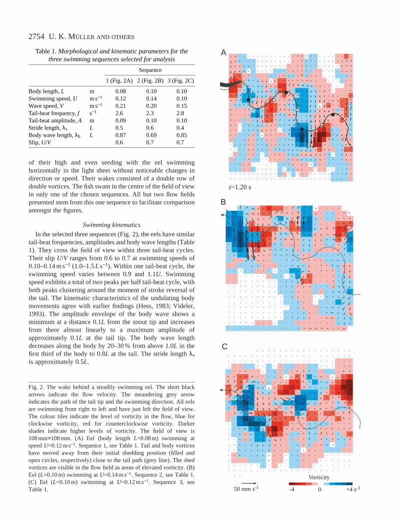
‘proto-vortex’ was assumed to be at the local vorticity peak.We found that, within the limited spatial resolution of our flowfields (3 mm), none of the above body wave parameterscorrelates tightly with the position of the vortex centre. Instead,the vortex centre shifts from a position close to the lateralmaximum when near the head until it almost coincides withthe position of the node and inflection point when it is shed off
the tail (Fig. 5, Fig. 6). The phase between node and vortexcentre induces a lateral offset that decreases with decreasingphase. Ultimately, the ‘proto-vortex’ crosses the mean path ofmotion together with the inflection point and is shed off the tailon the opposite side (Fig. 6, t=0.48 s; t=0 s is defined in Fig. 3)from where the vortex was first observed at approximately 0.3Lbehind the head (Fig. 3, t=0.04 s).
t=0.20 s
50 mm s-1
Vorticity
-5 +5 s-1
t=0.44 s
t=0.36 st=0.24 s
0
t=0.16 s t=0.28 s
t=0.32 s
t=0.40 s
t=0.48 s
Fig. 6. Instances during the time course of wake generation behind a steadily swimming eel (speed U=0.121 m s−1, sequence 1, see Table 1).The black arrows indicate the flow velocity, and the colour code indicates vorticity. Blue shades indicate clockwise vorticity, red shadesindicate counterclockwise vorticity. Darker shades indicate higher levels of vorticity. The flow fields are a continuation of the swimmingsequence in Fig. 3. The time t is arbitrarily set to t=0 s for the first frame shown in Fig. 3. The field of view is 108 mm×108 mm.

2758
To test whether the observed vorticity distribution isconsistent with a simple lift generation model (Lighthill’sslender body model: Lighthill, 1960), we also calculated thelateral velocity V(t,x) of the body relative to the fluid. A bodyof constant cross-sectional area A swimming in water ofdensity ρ creates instantaneous lift forces FL at each bodysegment according to:
FL = −ρAV(t,x) . (1)
At the centre of the ‘proto-vortex’, V(t,x) should be zero.The precision of zero positions of V(t,x) decreases anteriorlyfrom less than 1 mm at the tail to 10 mm near the head. Withinthese limits, the points along the midline where V(t,x) is zerocoincide with the positions of local vorticity maxima only forthe counterclockwise vortices. For the clockwise vortices,there is a variable phase shift between the two. These tentativeresults, together with predictions of an analytical body wavemodel (see Appendix), suggest that body wave parameters arenot suitable for predicting the body flows directly. In thepresent study, a simple two-dimensional pressure-based modelyields more reliable predictions, but its power is limitedbecause it ignores three-dimensional effects and wakeinteraction.
Flow generated at the tail
The flow at the tail results from the interaction between thebody flow reaching the tail and the flow generated by theoscillating movement of the tail. Over most of the tail-beatcycle, it has a strong lateral component. This is mainly a resultof the body-generated low-pressure flows periodically enteringthe tail region. Averaged over one tail excursion from right toleft, flow velocities are 0.019±0.004 m s−1 (0.16±0.03U) (N=23velocity vectors from t=0.08 s in Fig. 3 to t=0.24 s in Fig. 6).Flow velocities in the grid cells adjacent to the tail vary overhalf a tail-beat cycle from 0.014±0.006 m s−1 (0.12±0.05U)(N=27 velocity vectors from three tail-beats from t=0 s inFig. 3 to t=0.64 s in Fig. 6) when the tail crosses the mean pathof motion to 0.021±0.008 m s−1 (0.18±0.07U) (N=14 velocityvectors from three tail-beats) near the stroke reversal. The peakvelocities coincide with the body flows entering the tail region.At this moment, the mean angle of attack of the tail (the anglebetween the flow and the tail fin) is approximately 50 ° (49±5 °,N=3 tail-beats), and a vortex is shed off the tail (Fig. 3,t=0.12 s; Fig. 6, t=0.32 s). Body vortices shed to the right ofthe animal just before stroke reversal rotate clockwise; bodyvortices shed to the left rotate counterclockwise.
Each time the tail reaches a lateral extreme and changesdirection, a start–stop vortex is shed at the tip of the tail. Thisvortex is visible in the wake as a circulating flow around anarea of elevated vorticity (e.g. Fig. 6, t=0.24 s and 0.44 s). Tailvortices shed to the right of the animal rotate counterclockwise(Fig. 6, t=0.44 s); vortices shed to the left of the animal rotatein a clockwise direction (Fig. 6, t=0.24 s). In the following,start–stop vortices shed at stroke-reversal from the trailingedge of the tail will be called tail vortices. Because of thelimited spatial resolution of our flow fields, a body vortex is
not always distinguishable from the previously shed tail vortexduring and immediately after shedding (Fig. 6, t=0.24–0.36 s).However, both emerge as separate and individuallyrecognisable body and tail vortices in the wake by the time thenext body vortex is shed (Fig. 6, t=0.40 s).
Flow in the wake
Wake morphology and wake generation
In all sequences with a clearly visible wake, the flow fieldin the medio-frontal plane behind a swimming eel consists offour vortices per tail-beat cycle (Fig. 5, Fig. 6). Consecutivelyshed ipsilateral vortices have an opposite sense of rotation.This induces a strong jet flow between them. The jet has onlya small component in the direction opposite to the swimmingdirection, but is directed away from the mean path of motionat almost a right angle (ϕ=70±10 °, N=3 tail-beats from t=0 sin Fig. 3 to t=0.64 s in Fig. 6). This suggests that the eel isgenerating considerable side forces and little thrust. The flowspeeds of the jet are 0.016±0.005 m s−1 (0.13±0.05U; N=3 tail-beats). The vortices move away from the mean path of motion,and the distance between the contralateral vortices roughlydoubles within 0.5 s.
A pattern of double vortices in a double row could be a crosssection through either of the proposed wakes (Fig. 1). First, ifthe wake behind the fish is a single chain of vortex rings(Fig. 1A, Fig. 7A), a frontal cross section of such a vortexchain off the medial plane would consist of two rows of vortexpairs. Two consecutive ipsilateral vortices would have thesame rotational sense. The jet through the centre of the vortexrings would appear to meander between consecutive counter-
U. K. MÜLLER AND OTHERS
Fig. 7. Hypothetical three-dimensional wakes of an eel. (A) In across-sectional view above or below the medio-frontal plane, a singlevortex chain would appear as pairs of same-sense vortex pairs toeither side of the mean path of motion. A strong jet flow meanderingaround the mean path of motion would be visible betweenconsecutive contralateral vortices. (B) A double vortex ring wakeviewed in the mediofrontal plane would appear as pairs of counter-rotating vortices to either side of the mean path of motion. A jet flowwould form between the vortices of a pair. Our two-dimensional flowfields are consistent with scenario B rather than A.
B

2759Wake of a swimming eel
rotating vortices on opposite sides of the mean path of motion.Second, two ipsilateral counter-rotating vortices could be amediofrontal cross section through a vortex ring with a jetthrough the centre of the ring. The three-dimensionalimpression of such a wake would be a double row of vortexrings (Fig. 1B, Fig. 7B). These individual vortex rings wouldmove away from the mean path of motion at their self-inducedvelocity.
In our flow fields, consecutive ipsilateral vortices arecounter-rotating. The distance between contralateral vorticesperpendicular to the mean path of motion increases over time,while the distance along the mean path of motion remainsconstant. On the basis of these observations, we assume thatconsecutive ipsilateral vortices represent cross sectionsthrough a vortex ring with a diameter that can be approximatedby the distance between the two vortices (Fig. 7B).
One vortex ring comprises consecutively shed ipsilateralbody and tail vortices. A clockwise tail vortex combines withthe previously shed counterclockwise body vortex to form avortex ring to the left of the mean path of motion, and viceversafor vortex rings to the right of the mean path of motion.Body and tail vortices can be distinguished by their positionrelative to the path of the tail tip (Fig. 2A). Tail vortices areshed just after the point of maximum lateral displacement ofthe tail, and body vortices are shed before this point close tothe mean path of motion. The positions of the vortices reflectthe swimming kinematics. The distance between the centresof consecutive tail vortices and between consecutive bodyvortices along the mean path of motion is 22±4 mm (N=3 tail-beats from t=0 s in Fig. 3 to t=0.64 s in Fig. 6), whichmatches half the stride length λs (λs=46±5 mm, N=3 tail-beats). Vortices of the same type do not move apart along themean path of motion during the observation period of 1 s. Theinitial distance between shedding positions of consecutive tailvortices perpendicular to the path of motion is 20.1±4.3 mm(N=3 tail-beats). This corresponds to twice the tail-beatamplitude A (A=9.3±1.0 mm, N=3 tail-beats). The distancebetween consecutive contralateral tail vortices almostdoubles during the first second after shedding. The bodyvortices move apart perpendicular to the mean path of motionat the same rate. However, at 2.6±2.1 mm (N=3 tail-beats),the initial distance between consecutive contralateral bodyvortices is considerably smaller than twice the tail-beatamplitude and is closer to the distance between consecutiveinflection points as they reach the tail tip (4.4±3.2 mm, N=3tail-beats).
If the circulation G and radius R of a circular vortex ring areknown, the vortex ring impulse I can be computed accordingto (Spedding et al., 1984):
I = ρΓπR2 . (2)
Immediately after shedding, body and tail vortices have asimilar strength, which varies between rings from 0.0003 to0.0007 m2s−1. This circulation is equivalent to a vortex forceof 0.4–1 mN. At a momentum angle of 70 °, this correspondsto a net thrust of 0.1–0.3 mN.
DiscussionContribution of the body to the wake in undulatory swimmers
Lighthill (Lighthill, 1969) predicted that the body wouldgenerate thrust at slips smaller than unity by imparting rearwardmomentum to the fluid. On the basis of their own flowvisualisations, Rayner (Rayner, 1985) and Blickhan et al.(Blickhan et al., 1992) also proposed that the body wouldcontribute to thrust production. Rayner called the flow patternsgenerated on the body ‘trapped vortices’ (Rayner, 1985).Blickhan et al. (Blickhan et al., 1992) coined the phrase‘undulatory pump’ to describe thrust production by bodyundulation. Both base their concepts on observations ofundulatory swimmers generating considerable potential flowsalong their body. Lighthill’s (Lighthill, 1969) analyticalmodel predicts that fish will shed only a single vortex street,whereas in our study body and tail flows are shed at separateinstances into a double vortex street. This wake pattern wasanticipated in model experiments and computational studies(Gopalkrishnan et al., 1994; Streitlien et al., 1996). Accordingto their findings, at least three types of vortex interaction canbe anticipated. One possible scenario maximises thrust andresults in the shedding of a single reverse von Kármán vortexstreet, because body and tail vortices of the same rotationalsense are shed together and merge. Another scenario maximisesefficiency, and a single weak von Kármán vortex street resultsfrom the merging of counter-rotating tail and body vortices intoone shed vortex per half tail-beat. A third scenario emergesfrom counter-rotating body and tail vortices being shed atdiscrete instances. The resulting wake behind the fish containstwo vortex pairs per tail-beat cycle. While Triantafyllou et al.(Triantafyllou et al., 2000) emphasise the role of body vorticityshed at the caudal peduncle in modifying the propulsiveperformance of the tail, we would like to propose a modifiedmodel of wake generation for undulatory swimmers. Thismodel does not require trailing-edge shedding off the body andis, therefore, also applicable to elongate swimmers such as theeel without a peduncle region or discrete dorsal fins.
At slips smaller than unity, the swimmer transfers momentumwhen the lateral movements of its body accelerate the adjacentwater. This generates longitudinal flows that are driven by thepressure gradient between ipsilateral troughs and crests of thebody wave. With the body wave amplitude increasing towardsthe tail, this momentum transfer takes place along the entirebody; as the body wave amplitude increases, so do thelongitudinal flows. The localised pressure gradients not onlycause flows from body wave crests to posterior troughs, but alsocause a backflow from high-pressure to anterior low-pressurezones. This backflow, in turn, causes a thickening of theboundary layer in a region along the body approximately at thecore of the ‘proto-vortex’. This thickening effect becomesvisible only in slender swimmers, for which the flows arestronger than in fusiform swimmers; in these areas of backflow,the boundary layer occupies a large enough proportion of a gridcell to elevate its average vorticity significantly.
Computational studies on fusiform swimmers (Triantafyllou

2760
et al., 2000) predict strong transverse flows out of themediofrontal plane near the nodes of the body wave andpredominantly longitudinal flows where the body wave reachesa lateral maximum. From our two-dimensional flow fields, wecan calculate divergence (Stamhuis and Videler, 1995) toestimate the absence or presence of out-of-plane flows inincompressible fluids. We observe weak divergence at the headand slightly higher values in the tail region. The caudal out-of-plane flows concentrate in the areas of high flow velocitybetween the node and the lateral extreme of the body wave.
Eels generate more pronounced longitudinal flows than thepreviously studied fusiform swimmers for several reasons.First, they have a larger body wave amplitude and a shorterbody wave length. Both aspects can contribute to higher lateralbody velocities. Second, bodies of almost uniform widthdisplace water in a different way from strongly taperedfusiform bodies. In a fusiform body, the lateral excursion ofthe body at the crest of a body wave does not significantlyexceed the initial displacement of water at the head. Noticeablecrests develop only in the peduncle region (Fig. 8A). Hence,for fusiform undulating bodies, the water displacement and themomentum transfer are largest at the troughs and only weak atthe crests (Müller et al., 1997; Wolfgang et al., 1999). Slenderfish such as eels generate substantial lateral movement beyondthe initial head displacement along the entire body (Fig. 8B).Hence, significant pressure gradients build up in the crests aswell as the troughs of the body wave.
These flows along the body contain the momentumtransferred to the water by the body, but they cannot be equatedwith the body’s contribution to thrust production and simplybe added to the tail’s thrust output: the body flows interact withthe tail flows and modify the tail’s performance.
Wake generation in undulatory swimmers
As the body flows reach the tail, they cause the shedding of
a body vortex off the trailing edge of the tail tip. Independentlyfrom the shedding of this body-generated vortex, start–stopvortices are shed off the tail every time the tail reaches a lateralextreme and changes direction. The phase between body andtail movements determines whether consecutive body and tailvortices are shed separately, as in our eel, or merge into onevortex, as in our previous experiments with mullet (Müller etal., 1997). This sensitivity of the wake shape to the phaserelationship between two vortex generators was established byGopalkrishnan et al. (Gopalkrishnan et al., 1994) and Streitlienet al. (Streitlien et al., 1996), including its relevance formaximising thrust or efficiency.
In the case of our eel, the ‘proto-vortex’ travels down thebody. It crosses the mean path of motion before it is shed as abody vortex off the tail tip on the contralateral side of whereit was first observed. We observe the following sheddingpattern in the mediofrontal cross section of the wake. The bodysheds a single row of alternating vortices close to the meanpath of motion. These lie inside a reverse von Kármán vortexstreet shed by the tail. Consecutive body and tail vorticescounter-rotate and form one vortex pair per half tail-beat cycle.The circulations of the body and the tail vortex are similarimmediately after shedding, indicating that body vorticescontribute equally to the wake and probably to thrust. Inprevious studies on mullet (Müller et al., 1997) and danios(Wolfgang et al., 1999), the body vortex is shed together witha tail vortex of the same rotational sense. Body and tail vorticescombine into a single vortex. The resulting cross sectionthrough the wake consists of a reverse von Kármán vortexstreet with two single rows of counter-rotating vortices.
Wake morphology is the result of the interaction betweenthe circulation building up around the tail and the momentumgenerated by the undulatory pump action of the body. Thisinteraction depends on the phase relationship between the tail-beat cycle and the body wave travelling down the body. It canbe shown analytically (see Appendix) that a non-uniformamplitude envelope causes a phase shift between the lateraldisplacement function of the body and the pressure differenceacross the midplane of the fish. Assuming a constant bodywave length, the phase shift causes the ‘proto-vortex’ to beshed off the tail not on the mean path of motion, but offsetlaterally. A phase shift can be the result either solely of a non-uniform amplitude envelope or of the interaction between theformer and a changing body wave length along the body. Thesensitivity of the phase relationship to slight changes in theamplitude envelope and the wave length might explain howundulatory swimmers can produce wakes with single vorticesand vortex pairs at similar U/V ratios. Eel-type swimmers canadapt their kinematics to produce a double (Hertel, 1966;Rayner, 1995; present study) or single (Gray, 1968) vortexwake. Saithe-type swimmers have been reported to producevortex-pair wakes (Rosen, 1959) as well as single-vortexwakes (Aleyev, 1977; Blickhan et al., 1992; Müller et al., 1997;Wolfgang et al., 1999).
Some data exist in the literature mapping the phase betweenlateral displacement function and body curvature, and several
U. K. MÜLLER AND OTHERS
CrestTrough
CrestTrough
B
A
Fig. 8. Body contours over one tail-beat of (A) an eel and (B) amullet swimming steadily at 1.4L s−1 (slip 0.6–0.7, where L is bodylength). The time between contours is 0.04 s. The light-shaded areaindicates the initial water displacement by the head. The maximumcrests (thick black line) of the body wave extend considerablybeyond this initial displacement only in the eel (grey triangles). Thismeans that only the eel generates strong high-pressure flows. Thetroughs (thick black line) recess significantly beyond the initialdisplacement of the head in both fish (grey triangles). This causesstrong low-pressure flows in both species.

2761Wake of a swimming eel
studies did indeed find a variety of phase relationships inseveral undulatory swimmers (Gillis, 1997; Jayne and Lauder,1995; Katz and Shadwick, 1998; Müller et al., 1997; Videlerand Hess, 1984). These experimental data on the variable phasewithin body wave parameters – such as node and inflectionpoint – make it likely that a similar variability exists betweenthese body wave parameters and the body-generated flowpatterns. However, the experimental evidence for a correlationbetween body wave parameters and body vortex shedding isfar from conclusive. Data on the relationship between vortexshedding and body kinematics are still very sparse (Müller etal., 1997; Wolfgang et al., 1999).
Experimental and theoretical approaches alike suggest thatfish might change their body wave to cause changes in the phaserelationship between body and tail movements, which in turnaffect the phase between body and tail flow. The result is a finecontrol over the interaction between body and tail vortices andthe vortex shedding pattern that reflects the optimisation criteriaemployed by the fish at each moment. The range of flowpatterns observed behind undulatory swimmers to date can beexplained in terms of the proposed control over body and tailvorticity. The wake of an undulatory swimmer will be a strongreverse von Kármán vortex street only if the fish is maximisingthrust. When maximising efficiency, the resulting wake is aweak reverse von Kármán vortex street, which can verge on adrag wake depending on the relative strength of the mergingcounter-rotating body and tail vortices. Maximising thrust orefficiency requires a specific phase relationship between bodyand tail vortex shedding. For a phase relationship midwaybetween the two optima, yet another wake pattern is generated.This is the vortex-pair wake observed in the present study.
Concluding remarks
The morphology of the wake and the flow adjacent to theeel’s body support the hypothesis that the eel employs itswhole body to generate thrust. The maximum flow velocitiesadjacent to the body increase approximately linearly from headto tail. The tail-beat kinematics is only one factor besides thebody wave that determines the shape of the wake. The shapeof the wake deviates strongly from an optimised wake formaximising hydrodynamic efficiency or thrust, as suggested byTriantafyllou et al. (Triantafyllou et al., 1991; Triantafyllou etal., 1993) and observed in mullet (Müller et al., 1997) and trout(Blickhan et al., 1992). Instead, it resembles the flow patterndescribed by Gopalkrishnan et al. (Gopalkrishnan et al.1994)for a phase relationship between maximum thrust andefficiency, where neither is particularly high.
AppendixLighthill’s small-amplitude slender body theory (Lighthill,
1960) can be used to derive a qualitative estimate for the phaserelationship between ‘proto-vortex’ and body wave parameters.Lighthill’s model describes the pressure distribution across thebody. We assume that the centre of a ‘proto-vortex’ lies at thepoint where the pressure difference DW across the fish is zero.
This approach neglects the effects of the wake on the pressuredistribution on the body, the details of the shedding process andadded-mass effects. We compare pressure distribution and bodywave, in particular the positions of nodes and inflection points,for two simple amplitude envelopes. The analysed body wavegeometries neglect the existence of a pivot point and assume aconstant body wave length. We also assume that the cross-sectional area A of the eel’s body is constant. The mainobjective of this comparison is to see whether the ‘proto-vortex’will be shed on the mean path of motion (node and vortex centrecoincide at the tail tip) and whether it coincides with theinflection point at the moment of shedding.
Let the midline displacement, relative to the mean path ofmotion x, be h(t,x) and the lateral velocity of the midlineV(t,x) be:
where U is the swimming speed. Then, according to Lighthill(Lighthill, 1960), the instantaneous lift per unit length of fishFL(t,x) is:
With A and the density of water ρ being constant along thebody, the pressure difference DW across the body isproportional to:
The centre of the ‘proto-vortex’ should be at DW=0. Theinflection point is where ∂2h/∂x2=0 and the node is at h=0. Nowconsider two cases.
Uniform amplitude envelope
h=Acosk(x−Vt), where V is the wave speed and k is the wavenumber. Then
where θ=k(x−Vt) and DW=−k2A(V−U)2cosθ. In this case,DW=0, and node and inflection point coincide. All reach thetail when h=0.
Linearly increasing amplitude envelope
h=A(x/L)cosk(x−Vt), where L is the body length of the fish.Then:
while
(A6)DW = − Ak2 (V − U)2cosθ + 2A U(V − U)sinθ .x
L
k
L
(A5)= − A k2cosθ − 2A sinθ ,∂2h
∂x2
x
L
k
L
(A4)= − k2Acosθ ,∂2h
∂x2
(A3)DW~ + U .
∂h
∂t
∂h
∂x+ U
∂∂t
∂∂x
(A2)FL = − ρ + U A .
∂h
∂t
∂h
∂x+ U
∂∂t
∂∂x
(A1)V(t,x) = + U ,
∂h
∂t
∂h
∂x

2762
Therefore, ∂2h/∂x2=0 where tanθ=−kx/2, while DW=0 wheretanθ=+kx/2(V/U−1). Note that, in this case, ∂2h/∂x2=0 at x=L=0when tanθ=1/kL, and h=0 at x=L when cosθ=0, which is notnecessarily at the same time as the ‘proto-vortex’ reaches thetail tip, depending on the values of kL and V/U. Hence, node,inflection point and vortex centre do not necessarily coincide,and the vortex is shed at the tail tip not on the mean path ofmotion but offset laterally.
We would like to thank The Eelfarm in Bedum, theNetherlands, for providing the eels and BASF for providingthe polystyrene particles. Tim Pedley helped iron outinconsistencies in the hydrodynamic interpretation of thedata, in particular in the Appendix. Michael Dickinson andan anonymous referee are gratefully acknowledged for theirhelpful suggestions. This research was conducted by U.K.M.as part of a PhD under the supervision of J.J.V. and fundedby the University of Groningen. J.S. and Maaike Binnerrecorded the flow fields presented here as part of MScprojects under the supervision of U.K.M.. E.J.S. wrote mostof the flow-analysis software and designed the image-recording system.
ReferencesAleyev, Y. G. (1977). Nekton. The Hague: Dr. W. Junk. 435pp.Blickhan, R., Krick, C., Zehren, D. and Nachtigall, W.(1992). Generation
of a vortex chain in the wake of a subundulatory swimmer.Naturwissenschaften79, 220–221.
Carling, J., Williams, T. L. and Bowtell, G. (1998). Self-propelledanguilliform swimming: simultaneous solution of the two-dimensionalNavier–Stokes equations and Newton’s laws of motion. J. Exp. Biol. 201,3143–3166.
Chen, C. J., Kim, Y. G. and Walter, J. A.(1993). Progress in quantitativeflow visualisation and imaging process. In Atlas of Visualisation(ed. TheVisualization Society of Japan), pp. 279–296. Oxford: Pergamon Press.
Gillis, G. B. (1997). Anguilliform locomotion in an elongate salamander(Siren intermedia): effects of speed on axial undulatory movements. J. Exp.Biol. 200, 767–784.
Gopalkrishnan, R., Triantafyllou, M. S., Triantafyllou, G. S. and Barrett,D. S. (1994). Active vorticity control in a shear flow using a flapping foil.J. Fluid Mech. 274, 1–21.
Gray, J. (1968). Animal Locomotion. London: Weidenfeld & Nicolson. 479pp.Hertel, H. (1966). Structure, Form, Movement. New York: Reinhold
Publishing Corp. 251pp.Hess, F.(1983). Bending movements and muscle power in swimming fish.
Proceedings of the Australian Fluid Mechanics Conference, vol. 2, pp.12A1–12A3. University of Newcastle, New South Wales.
Jayne, B. C. and Lauder, G. V.(1995). Speed effects on midline kinematicsduring steady undulatory swimming of largemouth bass, Micropterussalmoides. J. Exp. Biol.198, 585–602.
Katz, S. L. and Shadwick, R. E.(1998). Curvature of swimming fish midlinesas an index of muscle strain suggests swimming muscle produces netpositive work. J. Theor. Biol.193, 243–256.
Keane, R. D. and Adrian, R. J.(1991). Optimization of particle imagevelocimeters. Part II. Multiple pulsed systems. Measurement Sci. Tech.2,963–974.
Lighthill, M. J. (1960). Note on the swimming of slender fish. J. Fluid Mech.9, 305–317.
Lighthill, M. J. (1969). Hydrodynamics of aquatic animal propulsion. Annu.Rev. Fluid Mech.1, 413–446.
Merzkirch, W. (1987). Flow Visualisation. Second edition. Orlando:Academic Press. 260pp.
Müller, U. K., van den Heuvel, B. L. E., Stamhuis, E. J. and Videler, J. J.(1997). Fish foot prints: morphology and energetics of the wake behind acontinuously swimming mullet (Chelon labrosus). J. Exp. Biol. 200,2893–2906.
Pedley, T. J. and Hill, S. J. (1999). Large-amplitude undulatory fishswimming: fluid mechanics coupled to internal mechanics. J. Exp. Biol.202,3431–3438.
Rayner, J. M. V. (1985). Vorticity and propulsion mechanics in swimmingand flying vertebrates. In Konstruktionsprinzipien Lebender undAusgestorbener Reptilien(ed. J. Riess and E. Frey), pp. 89–118. Universitiesof Stuttgart and Tübingen: Konzepte SFB 230, 4.
Rayner, J. M. V. (1995). Dynamics of the vortex wakes of flying andswimming vertebrates. In Biological Fluid Dynamics(ed. C. P. Ellingtonand T. J. Pedley), pp. 131–155. Cambridge: Company of Biologist Ltd.
Rosen, M. W.(1959). Water Flow about a Swimming Fish. China Lake, CA:U.S. Naval Ordnance Test Station TP 2298. 96pp.
Spedding, G. R., Rayner, J. M. V. and Pennycuick, C. J.(1984).Momentum and energy in the wake of a pigeon (Columbia livia) in slowflight. J. Exp. Biol.111, 81–102.
Stamhuis, E. J. and Videler, J. J.(1995). Quantitative flow analysis aroundaquatic animals using laser sheet particle image velocimetry. J. Exp. Biol.198, 283–294.
Streitlien, K., Triantafyllou, G. S. and Triantafyllou, M. S. (1996). Efficientfoil propulsion through vortex control. AIAA J.34, 2315–2319.
Triantafyllou, M. S., Triantafyllou, G. S. and Gopalkrishnan, R. (1991).Wake mechanics for thrust generation in oscillating foils. Phys. Fluids A 3,2835–2837.
Triantafyllou, M. S., Triantafyllou, G. S. and Grosenbaugh, M. A.(1993).Optimal thrust development in oscillating foils with application to fishpropulsion. J. Fluid Struct.7, 205–224.
Triantafyllou, M. S., Triantafyllou, G. S. and Yue, D. K. P. (2000).Hydrodynamics of fishlike swimming. Annu. Rev. Fluid Mech.32, 33–53.
Videler, J. J. (1993). Fish Swimming. London: Chapman & Hall, 260pp.Videler, J. J. and Hess, F.(1984). Fast continuous swimming of two pelagic
predators, saithe (Pollachius virens) and mackerel (Scomber scombrus): akinematic analysis. J. Exp. Biol.109, 209–228.
Videler, J. J., Müller, U. K. and Stamhuis, E. J. (1999). Aquaticvertebrate locomotion: wakes from body waves. J. Exp. Biol. 202,3423–3430.
Vollmers, H., Kreplin, H.-P. and Meier, H. U. (1983). Separation andvortical-type flow around a prolate spheroid− evaluation of relevantparameters. NATO AGARD Conference Proceedings No.342, pp.14/1–14/14.
Wolfgang, M. J., Anderson, J. M., Grosenbaugh, M. A., Yue, D. K. P. andTriantafyllou, M. S. (1999). Near-body flow dynamics in swimming fish.J. Exp. Biol.202, 2303–2327.
U. K. MÜLLER AND OTHERS