Historical Reconstruction Drawings of the Copper Coast Mines, Co. Waterford
18
1. INTRODUCTION The coast of Co. Waterford west of Tramore is an area of great scenic beauty, characterised by small bays between stretches of high cliffs below which a multitude of small rocky islands pockmark the sea. Travelling west on the R675 coast-road, after you pass Dunabrattin Head and Kilmurrin Cove, your horizon is interrupted by the 19th century pumping engine-house and chimney of Tankardstown copper mines, which you pass on the landward side of the road (Figure 1). Less than a kilometre fur- ther on you pass on your left the wall of the old copper yard that tops the cliff above where copper ore was shipped to, and coal imported from South Wales. Finally you come down to Knockmahon, where you pass the junction with the R681 Waterford road. Above a rock cutting on the left side of the road stands the fine 19th century three-storey house built for the mine managers (Figure 2). Across the stream on the other side of the road are the remains of the dressing floors where the copper was concentrated by a small army of men, women and boys (Figure 3). Today, the only substantial evidence of these dressing operations is the walled yard of the mine count-house on the slope above the valley floor, a cobbled dressing floor and a stone façade beside the course of the old mineral tramway. 29 HISTORICAL RECONSTRUCTION DRAWINGS OF THE COPPER COAST MINES, CO. WATERFORD By Dr Daniel Tietzsch-Tyler Author's address: 3 Glenview Drive, Shelbourne Park, Limerick, Ireland. E-mail: [email protected] Abstract: . Journal of the Mining Heritage Trust of Ireland, 5, 2005, 29-46. Figure 1. Tankardstown pumping engine-house (right), winding engine-house and chimney (looking towards the sea). Figure 2. The mine manager's house. Figure 3. Dressing floors at Knockmahon, with the mine count-house at the centre.
-
Upload
independent -
Category
Documents
-
view
0 -
download
0
Transcript of Historical Reconstruction Drawings of the Copper Coast Mines, Co. Waterford

1. INTRODUCTIONThe coast of Co. Waterford west of Tramore is an area of greatscenic beauty, characterised by small bays between stretches ofhigh cliffs below which a multitude of small rocky islandspockmark the sea. Travelling west on the R675 coast-road, afteryou pass Dunabrattin Head and Kilmurrin Cove, your horizonis interrupted by the 19th century pumping engine-house andchimney of Tankardstown copper mines, which you pass on thelandward side of the road (Figure 1). Less than a kilometre fur-ther on you pass on your left the wall of the old copper yard thattops the cliff above where copper ore was shipped to, and coalimported from South Wales.
Finally you come down to Knockmahon, where you pass thejunction with the R681 Waterford road. Above a rock cutting onthe left side of the road stands the fine 19th century three-storeyhouse built for the mine managers (Figure 2). Across the streamon the other side of the road are the remains of the dressingfloors where the copper was concentrated by a small army ofmen, women and boys (Figure 3). Today, the only substantialevidence of these dressing operations is the walled yard of themine count-house on the slope above the valley floor, a cobbleddressing floor and a stone façade beside the course of the oldmineral tramway.
29
HISTORICAL RECONSTRUCTION DRAWINGS OF THE COPPER COAST
MINES, CO. WATERFORD
By Dr Daniel Tietzsch-Tyler
Author's address: 3 Glenview Drive, Shelbourne Park, Limerick, Ireland. E-mail: [email protected]: . Journal of the Mining Heritage Trust of Ireland, 5, 2005, 29-46.
Figure 1. Tankardstown pumping engine-house (right),winding engine-house and chimney (looking towards thesea).
Figure 2. The mine manager's house.
Figure 3. Dressing floors at Knockmahon, with the minecount-house at the centre.

As part of the development of the INTERREG IIIB (NWEurope Region) funded Copper Coast Global and EuropeanGeopark, two drawings were commissioned to interpret howthe principal sites of mine-related operations may haveappeared in their heyday. This commentary is intended to pro-vide an explanation to accompany an exploration of those draw-ings: of the mines at Tankardstown as they might have appearedin about 1870 (Figure 6), and of the dressing floors besideKnockmahon village as they might have appeared in about1860 (Figure 7). Both drawings are based on various combina-tions of extant remains, old Ordnance Survey and mine maps(some illustrated with sketches of the mines), some archaeolo-gy at Tankardstown, reference to a rich treasure of late 19th andearly 20th century photographs of very similar Cornish mines,and general research on 19th century mining methods. This arti-cle explains some of the reasoning and assumptions that wentinto their making.
1.1. A BRIEF HISTORYThe mines reconstructed in these drawings were operated in the19th century by the Mining Company of Ireland (MCI), whichwas established by Act of Parliament in 1824. After four yearsof exploration on lands they had leased east of the RiverMahon, MCI was able to announce on July 12th 1828 the eco-
30
Figure 4. Thecopper veinsbetween StageCove andKnockmahon(from W.W.Smyth's map,drawn in 1845).
Figure 5. The extended MCI area of operations includingthe Tankardstown mines. The former dressing floors werejust below the road east of Osborne Terrace (A). Stage Coveis at the bottom in the centre (B). The mineral tramway thatformerly served the mines is highlighted in red.Tankardstown is near the right edge of the map, where thetramway turns north (C). (Geological Survey of Ireland fieldsheet showing the principal ore veins, based on the 1922 edi-tion of the Ordnance Survey 6" scale map.)

nomic viability of a mineral vein system extending north-west from the cliffs at Stage Cove, past Knockmahon vil-lage (Figure 4). Mining by MCI continued from this dateuntil 1878 - 50 years later - when the mines were finallyabandoned.
The rocks here are hard Ordovician volcanic and sedimen-tary rocks (about 460 million years old) - seen in the promi-nent cliffs at Stage Cove - and, locally inland, a thin cap ofslightly younger Old Red Sandstone. The veins of interestto the mining company comprise mainly copper ore withsubsidiary lead ore in veins chiefly of quartz (Cole 1998).In profitable years (1834-46 and 1851-68) annual outputreached as high as 7000 tons of 10-13% copper ore. Inunprofitable years (1828-33, 1847-50 and 1869-78) pro-duction fell as low as 100-270 tons of 4-5% copper oreeach year. Total profits from the good years were £331,126(averaging £11,000 per annum), far exceeding total lossesof £47,757 from the bad years (averaging £1,447 perannum).
Mining operations began on the valley floor beside the dressingfloors, with water-powered pumping and ore dressing. Fourwaterwheels with diameters ranging from 12 feet (3.7 metres)to 40 feet (12.2 metres) had been erected by 1831 for theseoperations. During the 1830s and 1840s the focus of miningmoved to the cliff top above Stage Cove, where five steamengines were erected for pumping and winding. Mine workingsextended under the sea from there but began to flood with sea-water, causing the abandonment of these mines in 1852.
However, already by this time the focus of attention had shift-ed again, this time 0.8 kilometres east to Tankardstown where agood copper vein system had been discovered and was beingworked by 1850 (Figure 5). With the closure of the mines atKnockmahon, the engine-houses there fell into disuse. Theirsteam engines were dismantled and moved to Tankardstownwhere they were re-erected in three new engine-houses, one topump water from the mines, another for winding - both fromHeron's Shaft, and a third to operate a mineral tramway that wasused to haul ore and coal between Tankardstown, Stage Coveand the dressing floors at Knockmahon (Figure 5; see alsoMorris et al., 2005, for a detailed description and interpretationof the tramway system).
1.2. TANKARDSTOWN REMAINSThe most impressive mining remains are at Tankardstown(Figure 8). Still standing in a walled yard are a partially restoredpumping engine-house (Figure 1), the ruins of a windingengine-house and a restored chimney (Figure 16). The founda-tions of the boiler-houses serving both engine-houses also sur-vive. The main shaft, Heron's Shaft, was still open until 1970,when it was blocked and partially filled in during the making ofthe film The McKenzie Break. You can see the shaft in the filmwhen a group of escaped prisoners-of-war roll a truck into theshaft, where it explodes!
A small quarry northeast of the engine-houses was the site ofanother shaft, Pope's Shaft. There was also a trial shaft betweenHeron's Shaft and Pope's Shaft that was sunk too close to the
vein of ore and was abandoned. A fourth shaft, Boundary Shaft,is still open close to the edge of the cliff about 175 metres westof the engine-houses. Almost nothing now remains of theengine-house, boiler-house and winding apparatus that alsostood on the cliff-top to operate the mineral tramway. All thatremains is a wall on one side of a reverse incline that was usedto counterbalance the wagons carrying coal and copper ore toand from the mines here.
1.3. STAGE COVE REMAINSThe walled copper yard on the cliff-top above the cove is onlyone of severalremains at StageCove. The copperyard itself wasextended at somepoint after 1840 andconsequently hasevidence of cobbledsurfaces at two dif-ferent levels - that inthe extended areabeing about a metreabove that in theoriginal yard(Figure 9). East ofthe copper yard, alsoon the seaward sideof the road, are sec-tions of wall and theshell of a smallbuilding corre-sponding to anotherramp on the mineraltramway.
31
Figure 8. Tankardstown Mine Remains (based on the 1905edition of the Ordnance Survey 6" scale map). Inset: twostills from the film The McKenzie Break (1970), showing atruck being driven into Heron's shaft, then still open, whereit subsequently exploded.
Figure 9. The cobbled copper yard.

32
Figure 6. The mines at Tankardstown as they might have appeared in about 1870. (© Daniel Tietzsch-Tyler, February 2006)

33
Figure 7. The dressing floors beside Knockmahon village as they might have appeared in about 1860. (© Daniel Tietzsch-Tyler, February 2006)
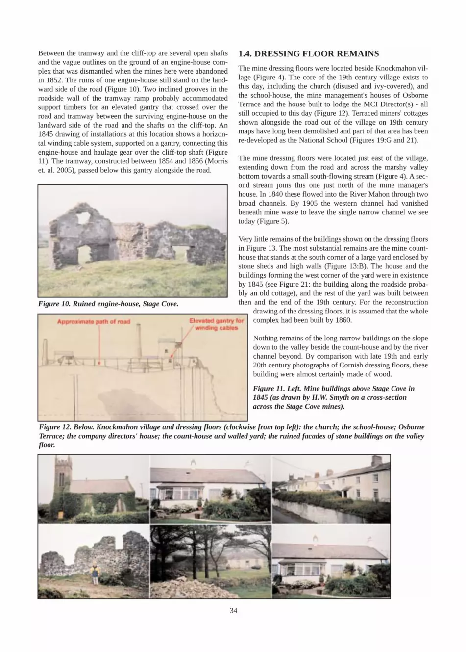
Between the tramway and the cliff-top are several open shaftsand the vague outlines on the ground of an engine-house com-plex that was dismantled when the mines here were abandonedin 1852. The ruins of one engine-house still stand on the land-ward side of the road (Figure 10). Two inclined grooves in theroadside wall of the tramway ramp probably accommodatedsupport timbers for an elevated gantry that crossed over theroad and tramway between the surviving engine-house on thelandward side of the road and the shafts on the cliff-top. An1845 drawing of installations at this location shows a horizon-tal winding cable system, supported on a gantry, connecting thisengine-house and haulage gear over the cliff-top shaft (Figure11). The tramway, constructed between 1854 and 1856 (Morriset. al. 2005), passed below this gantry alongside the road.
1.4. DRESSING FLOOR REMAINSThe mine dressing floors were located beside Knockmahon vil-lage (Figure 4). The core of the 19th century village exists tothis day, including the church (disused and ivy-covered), andthe school-house, the mine management's houses of OsborneTerrace and the house built to lodge the MCI Director(s) - allstill occupied to this day (Figure 12). Terraced miners' cottagesshown alongside the road out of the village on 19th centurymaps have long been demolished and part of that area has beenre-developed as the National School (Figures 19:G and 21).
The mine dressing floors were located just east of the village,extending down from the road and across the marshy valleybottom towards a small south-flowing stream (Figure 4). A sec-ond stream joins this one just north of the mine manager'shouse. In 1840 these flowed into the River Mahon through twobroad channels. By 1905 the western channel had vanishedbeneath mine waste to leave the single narrow channel we seetoday (Figure 5).
Very little remains of the buildings shown on the dressing floorsin Figure 13. The most substantial remains are the mine count-house that stands at the south corner of a large yard enclosed bystone sheds and high walls (Figure 13:B). The house and thebuildings forming the west corner of the yard were in existenceby 1845 (see Figure 21: the building along the roadside proba-bly an old cottage), and the rest of the yard was built betweenthen and the end of the 19th century. For the reconstruction
drawing of the dressing floors, it is assumed that the wholecomplex had been built by 1860.
Nothing remains of the long narrow buildings on the slopedown to the valley beside the count-house and by the riverchannel beyond. By comparison with late 19th and early20th century photographs of Cornish dressing floors, thesebuilding were almost certainly made of wood.
34
Figure 10. Ruined engine-house, Stage Cove.
Figure 11. Left. Mine buildings above Stage Cove in1845 (as drawn by H.W. Smyth on a cross-sectionacross the Stage Cove mines).
Figure 12. Below. Knockmahon village and dressing floors (clockwise from top left): the church; the school-house; OsborneTerrace; the company directors' house; the count-house and walled yard; the ruined facades of stone buildings on the valleyfloor.

The rest of the dressing floor buildings were probably a mix oftimber and stone-built structures. Certainly the Crusher identi-fied on the Smyth's map of 1845 would have been built in stoneand any engine-house powering the crusher would also havebeen stone-built. A stone façade still survives alongside the path
of the mineral tramway -still clearly visible(Figures 12 and 13:G) -and the foundation for astone building is also pre-served in the wall of asmall, more modern quarrybeneath the count-houseyard (Figure 13: F).
2. TANKARD-STOWN MINES INABOUT 1870The reconstruction draw-ing of the mines atTankardstown attempts toshow the complex ofbuildings and associatedmining paraphernalia asthey might have appearedin about 1870, just beforeore production began tofall away irrevocably.Three main elements of themine are illustrated in thedrawing (Figure 14):· Heron's Shaft and associ-ated engine-houses andboiler-houses (Figure14:A)
· the Tankardstown terminus of the mineral tramway and itsengine-house (Figure 14:B)· the minor Boundary Shaft and its associated winding gear(Figure 14:C)
35
Figure 13. Composite map showing the mine dressing floors sometime after 1840 (based on the1840 and 1922 Ordnance Survey maps). The MCI directors' house in the village is on theextreme left (A) and the count-house is in the upper centre (B: the only element of the 1922 edi-tion of the Ordnance Survey map to be superimposed here onto the 1840 edition). Timber build-ings would have dominated west and southwest of the count-house (C), but a few stone buildingswere dotted around the remainder of the dressing floors: the crusher (D) and probable engine-house and boiler-house complex (E); part of the foundation of a stone building preserved in asmall quarry (F); a surviving stone façade (G). Also shown are the shed for the jigging machines(H) and the site on the lower leat of the forty-foot water wheel (J). (For an explanation of leats,see text.)
Figure 14.The mines atTankardstownas they mighthave appearedin about 1870:Heron's Shaftand engine-house complex(A);Tankardstowntramway ter-minus (B);BoundaryShaft work-ings (C); trialshaft (D).

2.1. Heron's Shaft andEngine-Houses ComplexHeron's Shaft lay just north of thecoast road through Tankardstown(Figure 8). In 1870 it was at thecentre of mining operations andwould have stood within a walledyard. The shaft appears to havebeen very broad in the 1970 filmThe McKenzie Break (Figure8:inset). This is because it servedthree purposes: for the miners todescend to and ascend from theunderground workings, to raise oreto the surface and to pump waterout of the mines. A timber partitionprobably divided the shaft into twounequal parts, the larger one forpumping. The smaller sectionwould have been fitted with laddersfor the miners (the uppermost lad-der can be seen emerging from theshaft in the drawing) and providedthe space for raising the ore.
An earlier trial shaft excavatednearby was probably abandonedwhen it was found to intersect theore-body too close to the surface(Des Cowman, personal communi-cation). It is shown fenced off out-side the walled enclosure in thedrawing (Figure 14:D). Just off theleft side of the drawing, beyond the puddles and at the end of abranch of the tramway, was Pope's Shaft - now the site of asmall quarry (Figure 8).
To pump the mines dry, a large rectangular engine-house wasbuilt beside the shaft (Figures 1 and 15:G). The engine-housestands almost complete today, with the damage seen in TheMcKenzie Break now restored. The building has an entrance inboth of its shorter walls. One overlooks Heron's Shaft and theother, which has a fine restored semi-circular brick arch, facesthe road below windows on two levels. Several windows punc-tuate the longer walls to light the three floors inside that werereached by stairs - the lines of which are still visible on theinside walls.
The wall overlooking the shaft stops at the second level to sup-port a massive iron beam, called the main beam or bob (Figure15:H), which oscillated up and down to work an undergroundpump (Drew and Connell 1993). Half the beam was inside theengine-house and the other half extended out over the shaftbelow. A steam engine bolted to the ground floor of the build-ing drove the stroke of the bob by pushing and pulling a pistonrod attached to the indoor end of the bob. A heavy timber beam,the 'main girder', spanned the width of the building just belowthe inside end of the bob. This acted as a buffer and shock
absorber should the indoor end of the bob drop too low, withpotentially catastrophic results. Its location is seen in thebricked-up rectangular openings just over half way up thelonger walls of the engine-house (Figure 15:G).
A long timber beam called the pump rod (actually severalbeams held together by iron bands and bolts) hung from theouter end of the bob and extended down to a pump at the bot-tom of the shaft. The stroke of the bob moved the pump rod upand down to work the pump. No pipes or wooden troughs (laun-ders) are shown expelling water from the shaft in the recon-struction drawing because it was probably expelled throughadits (horizontal mine-workings) emerging in the cliff facebelow here. To reduce the strain on the steam engine of thepump rod's weight, it was finely counter-balanced by a timberconstruction called a balance bob (Figure 15:E). A steel rodconnected one end of the balance bob to the pump rod so that itoscillated about an axle with each stroke of the pump rod. Thislifted a large box filled with rocks at the opposite end of the bal-ance bob, the weight of which more-or-less equalled and thuscancelled out the weight of the pump rod (Drew and Connell1993).
To emplace and maintain the pump rod, a tall timber frame - theshear legs (Figure 15:D) - was erected over the shaft and con-nected to a windlass. To lift the pump rod, a cable connected it
36
Figure 15. Heron's Shaft (A) with winding head-frame (B), ore-bins (C), shear legs (D),balance bob (E) and windlass (F); the pumping engine-house (G) with its iron beam (H)and adjacent boiler-house (J); the winding engine-house (K), adjacent boiler-house (L),external winding drum and plinth (M) and the chimney shared by both boiler-houses (N).

to the windlass via a pulley-wheel at the top of the shear legsand a second pulley near the bottom of one of the legs (Figure15:F). When maintenance was required, mining came to a tem-porary stop, as all miners were required to work the windlass(Drew and Connell 1993). Commonly, shear legs were erectedparallel to the engine-house, but here it appears they had to beerected at a slightly oblique angle to make room for the wind-ing gear (Figure 15:B) that had also to be positioned over theshaft. This arrangement closely resembles that of the famousLevant Mine in Cornwall (Corin 1992).
The house for the coal-fired boiler that fed steam to the pump-ing-engine was a stone lean-to structure on the side of theengine-house (Figure 15:J). This arrangement was typical andcan again be seen at Levant Mine (Corin 1992).
The location of the winding gear is dictated by the orientationof the winding drum (Figure 15:M) on the side of the windingengine-house (Figure 15:K). The winding drum is shown parti-tioned to wind two cables, one winding over the drum and theother under it. These extended over two pulley wheels on thewinding gear so that as the drum turned, one cable dropped anempty kibble (ore-bucket) down the shaft while the otherhauled up a full kibble. Once a kibble reached the surface it wasemptied into a timber ore-bin erected beneath the winding gear(Figure 15:C). The rotation of the drum was then reversed tosend the empty kibble back down again while hauling up anoth-er full one. The ore in the bin was unloaded into wagons andtransported on the mineral tramway to Knockmahon.
One end wall of the winding engine-house (Figure 15:K) stillstands close to its full height (Figure 16). Only the lower levelsof the rest of the building's walls remain. Vertical grooves forthe long bolts that secured the timber mounting for the windingdrum can seen in the outer face of one wall (Figure 16). Mostof the long wall of the lean-to boiler-house (Figure 15:L) also
survives to its full height. A cobbled yard has also been exposedbetween the two boiler-houses and was probably the coal yardfor both.
The winding engine-house was smaller - both narrower andlower - than the pumping engine-house because it housed asmaller steam engine. It also differed from the pumping engine-house in that a smaller bob was enclosed entirely within theengine-house. The winding engine-house at Tankardstown isvery similar to the winding engine-house at Levant Mine (Corin1992).
Several men are shown working in the yard around the engine-houses in the reconstruction drawing. One stands on a platformon top of the ore-bin, emptying a kibble. Another is emptyingore from the bin into a wagon on the tramlines. The 'surfacecaptain' in his white coat stands at the foot of the winding gear,shouting up to the man emptying the kibble. Finally, a shift ofminers can be seen walking home on the road to Knockmahon,Bunmahon and beyond. Scattered around the yard in the draw-ing are the typical paraphernalia of 19th century mining opera-tions. Much of it is waste (or perhaps spare parts), for example:old cogwheels (leaning against the winding plinth); sparepumping pipes (in front of the winding-house); pulley-wheelsand pieces of timber (in front of the fence around the balancebob pit); spare tramway rails (inside the rear gate of the yard);and an old, partially dismembered Cornish boiler (in the near-corner of the yard).
Also seen in the yard are: wagons filledwith ore waiting on the tramlines totravel down to the dressing floors atKnockmahon; the branching tramlinesextending to Pope's Shaft and across theroad to the cliff top; an unhitched horsecart; materials for patching up the ren-dering on the pumping engine-house;barrels, crates and timber stackedagainst one wall of the yard and one ofthe stone sheds that are preserved onlyin foundation on the site; and a night-watchman's hut inside the main gate.
2.2. Tankardstown TramwayTerminusCoal for the boilers was brought up tothe mines on a single-track tramway
from the copper yard at Stage Cove. Byreturn, copper ore was taken from themines down to the dressing floors, pass-ing the copper yard at the halfway point.The tram wagons were pulled up to
Tankardstown by a cable that wound on and off one end of apartitioned winding drum (Figure 17:G) situated a little dis-tance away from an engine-house, at the foot of a short rampinclined in reverse to the tramline (Figure 17:H). The cable ranon rollers set between the tramway tracks (Figure 17:D).
37
Figure 16. The winding engine-house at Tankardstown. The vertical grooves in thewall in the foreground are for the long retaining bolts that secured the windingdrum. The higher wall between the engine-house and the chimney beyond it is thelong wall of the adjoining boiler-house.

The other end of the winding drum wound a cable that pulled arock-filled wagon (Figure 17:J) up the reverse-ramp. This cableused a system of multiple-pulleys at each end of the ramp toenable the wagon, in one length of the ramp, to counter-balancethe laden wagons being pulled up all the way from Stage Cove.The winding drum was probably housed in a shed of some sortto protect it from bad weather, as shown in the drawing (Morriset al. 2005).
Because nothing now remains of the engine-house, boiler-house or chimney (Figure 17:A, B and C) that powered thewinding drum, it would be reasonable to assume that horse-power pulled the wagons up from Stage Cove - either directlyor using a horse-whim (see below) to turn the winding drum.However, the footprint of a building on several 19th centurymaps (e.g. Figure 8) - actually described as a "whim" (winding)engine on one - confirms that an engine-house existed here, asshown in the reconstruction drawing. From the shape of thefootprint and the space available between the ramp and the roadit appears that this was a small engine-house, perhaps similar toor smaller than the winding engine-house across the road. Likethat engine-house, this one is depicted enclosing fully itsbob. Because of the distance between the engine-houseand the winding drum, a drive-belt (shown in the draw-ing) or a sweep rod must have connected the windingdrum to a flywheel inside the engine-house that turnedwith the sweep of the beam (Morris et al. 2005).
When coal-filled wagons reached the junction at the topof the inclined tramway (Figure 17:E), it is presumed thatthey were disconnected from the cable and then drawn byhorse the rest of the way to Heron's Shaft or Pope's Shaft.In the drawing, a man is shown leading a horse from apaddock and shed between the engine-house and the edgeof the cliff towards a waiting train of coal-filled wagons.
2.3. Boundary Shaft WorkingsThe third feature of interest in the reconstruction drawing is theBoundary Shaft, excavated in the cliff-top a couple of hundredmetres east of the tramway terminus. Both this shaft and Pope'sShaft were relatively shallow shafts, which didn't require thepower of a steam engine to lift ore or equipment. Consequentlythey were most probably worked using a horse-whim, a wood-en winding drum that was turned on a vertical axis by a horse(Figure 18). In the early days of mining operations, this type ofequipment would have been used throughout the mines.
As with the larger winding gear at Heron's Shaft, cables extend-ed from either side of the winding drum to two pulley-wheelson top of a low head-frame over the shaft. A horse was har-nessed to a horizontal beam that extended out on either side ofthe drum. As the horse turned the drum, one of the ropes woundonto the drum, pulling a bucketful of ore up the shaft, while theother unwound from the drum, allowing an emptied bucket todescend again.
38
Figure 17. The winding engine-house (A)on the cliffs at the Tankardstown tramwayterminus, its lean-to boiler-house (B) andchimney (C). Wagons were pulled up thetramway by a cable running on pulleys(D), but were disconnected from the cableat the top of the incline (E) and pulled byhorse into the yard across the road (F).The cable wound onto a winding drum(G) situated at the foot of a reverseincline (H), on which a heavily-ladenwagon (J) moved up and down tocounter-balance the weight of the ore orcoal-laden wagons on the tramway.
Figure 18. Boundary Shaft with small winding head-frame and a horse-whim used to wind the kibbles upand down the shaft.
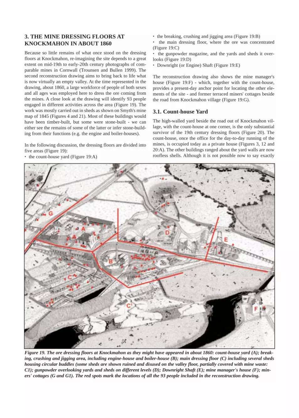
3. THE MINE DRESSING FLOORS ATKNOCKMAHON IN ABOUT 1860Because so little remains of what once stood on the dressingfloors at Knockmahon, re-imagining the site depends to a greatextent on mid-19th to early-20th century photographs of com-parable mines in Cornwall (Trounsen and Bullen 1999). Thesecond reconstruction drawing aims to bring back to life whatis now virtually an empty valley. At the time represented in thedrawing, about 1860, a large workforce of people of both sexesand all ages was employed here to dress the ore coming fromthe mines. A close look at the drawing will identify 93 peopleengaged in different activities across the area (Figure 19). Thework was mostly carried out in sheds as shown on Smyth's minemap of 1845 (Figures 4 and 21). Most of these buildings wouldhave been timber-built, but some were stone-built - we caneither see the remains of some of the latter or infer stone-build-ing from their functions (e.g. the engine and boiler-houses).
In the following discussion, the dressing floors are divided intofive areas (Figure 19):· the count-house yard (Figure 19:A)
· the breaking, crushing and jigging area (Figure 19:B)· the main dressing floor, where the ore was concentrated(Figure 19:C)· the gunpowder magazine, and the yards and sheds it over-looks (Figure 19:D)· Downright (or Engine) Shaft (Figure 19:E)
The reconstruction drawing also shows the mine manager'shouse (Figure 19:F) - which, together with the count-house,provides a present-day anchor point for locating the other ele-ments of the site - and former terraced miners' cottages besidethe road from Knockmahon village (Figure 19:G).
3.1. Count-house YardThe high-walled yard beside the road out of Knockmahon vil-lage, with the count-house at one corner, is the only substantialsurvivor of the 19th century dressing floors (Figure 20). Thecount-house, once the office for the day-to-day running of themines, is occupied today as a private house (Figures 3, 12 and20:A). The other buildings ranged about the yard walls are nowroofless shells. Although it is not possible now to say exactly
Figure 19. The ore dressing floors at Knockmahon as they might have appeared in about 1860: count-house yard (A); break-ing, crushing and jigging area, including engine-house and boiler-house (B); main dressing floor (C) including several shedshousing circular buddles (some sheds are shown ruined and disused on the valley floor, partially covered with mine waste:C1); gunpowder overlooking yards and sheds on different levels (D); Downright Shaft (E); mine manager's house (F); min-ers' cottages (G and G1). The red spots mark the locations of all the 93 people included in the reconstruction drawing.

what these buildings were used for, it is possible to make someinferences based on 1846 valuations for the townland ofBallinagigla (Des Cowman, personal communication). Thesestate that areas of human activity here at that time includedoffices, two stables, two tool houses, a forge (perhaps the one afew hundred metres further along the road past the count-houseyard), an open-fronted timber store measuring 19.2 metres by4.42 metres (including a cart-maker's, wheelwright's and coop-er's workshop), a large carpenter's shop measuring 15.24 metresby 8.53 metres, a 34.4 metre-long saw-house, a tar and rope-house, a powder and candle-house (presumably the magazinediscussed below) and two privies (toilets).
A number of these buildings were obviously outside the count-house yard, for example the magazine. Others were also proba-bly outside the yard, corresponding perhaps to buildings in theyards below the magazine that are not identified on Smyth'smap (Figure 21). Some of the very long buildings describedabove, measuring between 15 and 35 metres long, perhapscould correspond to the longer sheds on the main dressing floor,except that Smyth labels these as ore-dressing [sheds] andstamps, not workshops. Also, workshops, offices and storesneeded to be secure from pilfering. Consequently, many of thebuildings described in the account are taken to correspond tothe - often very long - buildings ranged around the count-house
yard. In the drawing, these include: the long tim-ber store (Figure 20:B) and, adjacent to it, the(combined) cart-maker's, cooper's and wheel-wright's shop (Figure 20:C); the long saw-house,which had a 'five-foot (1.53 metres) deep by five-foot wide pit along its full length' (Figure 20:D);the assay office where ore samples were valued(Figure 20:E); an open-topped privy (Figure20:F).
40
Figure 20. The count-house yard with the count-house at one corner (A). Selected buildings have been interpreted as: a long,open-fronted timber store (B); a combined cart-maker's, cooper's and wheelwright's workshop (C); a long saw-house (D); anassay office (E); and an open-roofed outside privy (F).
Figure 21. Detail from W.W. Smyth's 1845 mapshowing the mine dressing floors. The labels onselected features are: office (the count-house);stamps (probably the two north-south orientatedbuildings west of the office); ore-dressing floors(the long east-west orientated sheds generally);crusher; jigging machines; wheel of 40' [12.2-metre] diam[eter]; Downright Shaft. The rec-tangular black building in the rectangularframe in the top left corner of the map is themagazine (M).

A number of activities are depicted in the yard, including a mansawing at the entrance of the cart-maker's shop and two pairs ofmen moving timber planks from the store to the side gate of theyard. At the front entrance of the yard, a timber gantry is beingused to lift a large timber beam into the saw-house - while threemanagers look on! The head of a man can also be seen in theprivy! Note also the elevated wooden launder that carries theupper leat (a Cornish term for a channel excavated to supplywater to mine workings) across the road in front of the count-house yard.
3.2. Breaking, Crushing and Jigging AreaHand-drilling, picking and hammering, and also gunpowderwere used to extract copper ore from the mines. The ore wasraised to the surface, deposited in wagons and sent to the dress-ing floors at Knockmahon. On arrival the ore was dumped fromthe wagons into large ore-hoppers (Figure 22:A) below thetramline (implying the presence of a ramp bringing the tramlineup above the hoppers - see below). From there it was shovelledinto barrows and dumped on a coarsely cobbled dressing floor(Figure 22:B) for the first in a series of dressing and separationoperations. Dressing removed as much waste as possible tomaximise the percentage of copper that was transported toSouth Wales for refining. The range of dressing operations thatthe ore went through is illustrated in Figure 23.
In the reconstruction drawing, women called 'bal maidens' or'bal girls' (Cornish terms) do the ragging, spalling and cobbingof the ore using large hammers and smaller picks (Figure 22:B).Contemporary accounts state that these women worked in theopen (Des Cowman, personal communication). The broken orewas taken to the crusher (Figure 22:C) to be reduced mechani-cally to about pea-size. The crushed ore then went on to the jig-gers beside the crusher (Figure 22:F).
Jigging involved vigorously shaking the crushed ore in mesh-bottomed boxes suspended in water. Light waste accumulatingat the top of the water was skimmed off and discarded. Thefinest ore passed through the mesh to be collected and sent tothe main dressing floor for buddling (see below). The richest ofthe remaining ore settled on the mesh at the bottom of the box,from where it was removed for valuing and shipping. Themixed ore above it was sent up to the stamps beside the count-house for further crushing. The first MCI shareholders' report of1847 states that a ramp and an extra waterwheel had been erect-ed in the previous six months to move this ore up to the stamps(Des Cowman, personal communication). In the reconstructiondrawing, it is assumed that the ramp is the one that climbs fromthe cobbled yard over the ore-hoppers and past the count-house.The 30-foot (9.3-metre) waterwheel driving the stamps (Figure25:B) may also have been used to wind the wagons of ore up tothe stamps.
41
Figure 22. Breaking, crushing and jigging area. Ore from the mines was emptied into large ore-hoppers below thetramway (A). The ore was moved to the cobbled breaking floor (B), where it was hand-broken by women. The brokenore was then taken to the crusher (C) close beside a steam-powered engine-house (D) and boiler-house (E). From thecrusher, the ore went to the jigging sheds (F) for separation. The separated ore then went either to the stamps for fur-ther crushing or to the buddles (in the lower left corner) for concentration - both on the main dressing floors (Figure25). Note here also the 40-foot (12.2-metre) waterwheel (G) that drives pumping in Downright Shaft (see Figure 28)via a system of flat-rods (H), and the lower leat that carries water to and from the wheel (J and J1).

In the drawing, the crusher is shown powered by a steam engineand boiler similar to those described at Tankardstown (Figure22:D and E). Though none of the old maps identifies an engine-house, a sketch from the 1840s shows smoke spewing from achimney on the dressing floors. Only two groups of buildingson Smyth's map (Figure 21) could be an engine-house and boil-er-house grouping. One was near the top of the ramp from thecobbled dressing floor (Figure 13:F) and the other was besidethe crusher (Figure 13:E). Contemporary accounts state thatpumping of the mines was water-powered so the engine-houseprobably powered crushing, making the latter location mostlikely.
3.3. Main Dressing FloorOn maps from about 1840 and 1845 (Figures 13 and 21), themain dressing floor is shown cluttered with long narrow build-ings. Nothing remains of these and it is hard to imagine themtoday on the scrubby slope below the road. They were certain-ly no more than simple timber sheds to provide some shelter fordressing operations, as seen in contemporary photographs ofCornish mines (Trounsen and Bullen 1999).
Of the buildings on the main dressing floor, only the stamps arelabelled on Smyth's map (Figure 21). The functions of the otherbuildings are not identified. In comparison with the size andlayout of stamps at many Cornish mines - in two long shedsaligned on either side of a driving mechanism - it is probablethat the two long north-south aligned sheds west of the count-house were for the stamps. In the reconstruction drawing, thesouthern shed is shown still under construction even though thestamps are in use - a frequent sight in photographs of Cornishmines (Trounsen and Bullen 1999).
Dressing operations at Knockmahon were water-powered fromthe beginning, with a 40-foot waterwheel erected and opera-tional by 1829 (Figure 22:G). The location of this wheel, usedfor pumping the nearby Downright Shaft (Figure 28), is knownfrom Smyth's map (Figure 21). Another three waterwheels wereoperational by 1831: a 30-foot (9.3-metre) wheel, a 15-foot(4.6-metre) wheel and a 12-foot (3.7-metre) wheel. They arenot shown on Smyth's map, but are interpreted to lie in linealong a cross-leat connecting the upper leat and the lower leaton Smyth's map (Figure 21; see also Figure 25:H and J respec-tively) and on the 1840 O.S. map (Figure 13). The ground drops
42
Figure 23. The sequence of oper-ations commonly used to dressand separate copper ore in the19th century.
Figure 24. The relative elevations of the 30-foot (9.3-metre), 15-foot (4.6-metre) and 12-foot (3.7-metre) waterwheels as inter-preted for the reconstruction drawing. Ground level (green) rises from the valley floor on the right and continues up to thelevel of the upper leat, which was at the same elevation as the top of the 30-foot wheel. (Modified from a 3-dimensional plan-ning drawing of the dressing floors.)

about 15 metres from the road to the valley floor along this line,so the leat shown on the maps must in fact have been a steppedseries of launders (wooden troughs) that supplied water to eachwaterwheel in turn (Figure 24). These launders probably alsosupplied water to the ore-dressing sheds on the main dressingfloor via a series of subsidiary launders (Figure 25:G).
While we cannot say with certainty what occurred in the longore-dressing sheds, buddling was probably the main operationhere. A buddle was a circular pit with its floor sloping gentlyaway from the centre to the edge. Brushes suspended from aframe over the pit rotated about the pit's axis to sweep the floor.Fine-grained ore was fed by water into the centre of the pit andgravity concentrated the copper near the inlet. The rotatingbrushes smoothed the ore to prevent channels forming in thesediment. The copper was then removed from the centre of thepit for valuing and shipping, and the waste was shovelled outfrom a slightly deeper trough just inside the edge of the pit. This
waste was either reprocessed back through the dressing cycle,or discarded if it was the final residue at the end of such a cycle.
Four sheds have been interpreted as housing buddles in thereconstruction drawing. Because the sheds are quite narrow andbuddles usually have a diameter of up to 4 metres, the sheds areshown as being open-sided with awnings extending their roofs(Figure 25:C) (cf. Trounsen and Bullen 1999). The buddles liemore-or-less in two lines and it is inferred that they were pow-ered by the 15-foot (4.6-metre) and 12-foot (3.7-metre) water-wheels (Figure 25:D and E), enclosed at the eastern end of theeasternmost shed in each row. (Mostly hidden in the drawing bythe shed roofs, the wheels can be located by the launders enter-ing the sheds above them and exiting below them). Mine work-ers with barrows can be seen dumping the waste in pilesbetween the sheds and close scrutiny of the drawing reveals thefeet of several men shovelling waste from the buddles.
43
Figure 25. The main dressing floor. The layout of these timber sheds is taken from mine-maps dating from about 1845. Thefunctions of several sheds are interpreted (partly based on the same maps) as: unfinished but fully operational stamp sheds(A and A1) powered by a 30-foot waterwheel (B); sheds extended by awnings (C) to provide shelter for circular buddles pow-ered by enclosed 15-foot (4.6-metre) and 12-foot (3.7-metre) waterwheels (D and E respectively); and a tailings pond forwaste (F). Water is supplied to the different dressing operations by elevated wooden launders (G), which are themselves sup-plied from an upper leat or canal (H). Note also a lower leat (J) that supplies water to power the 40-foot (12.2-metre) water-wheel (Figure 22).

Two other features are of interest in Figure 25. The lower leat isshown elevated on a steep embankment (Figure 25:J) to enableit to supply water to drive the overshot 40-foot (12.2-metre)wheel (overshot means the water was supplied to the top of thewheel to turn it). In the extreme lower left corner of the recon-struction drawing, this embankment merges into higher ground.An 1831 section sketched across the Knockmahon dressingfloors (Figure 26) shows the top of the 40-foot (12.2-metre)wheel standing about eight metres above the valley floor, witha stepped (presumably stone-built) platform supporting thelaunder, on wooden trestles, that supplied water to the wheel.Moving west from the wheel (not included in Figure 26), theground appears to rise to meet the lower leat - to become theembankment in Figure 25. (The stepped stone platform and 40-foot wheel can be seen in Figure 22.)
The final feature of interest is the suggestion of a tailings pondfor waste from the dressing process (Figure 25:F). In the recon-struction drawing the pond is the first stage in waste dispersal,draining through the embankment supporting the lower leat andthe 40-foot (12.2-metre) wheel platform to form two deltas ofmine waste. These are depicted gradually covering derelictsheds on the valley floor (Figure 19:C1). The evidence for thiscomes from a comparison of Smyth's mine map and the 1840and 1905 O.S. maps. In 1840 the stream flows into the RiverMahon through two broad channels and three sheds stand closeto the western channel. By 1905 the western channel had com-pletely disappeared beneath a blanket of mine waste and todayappears as the level, bulldozed area between the Bunmahon'Geological Garden' and the visible remnants of the dressingfloors further up the valley.
3.4. Gunpowder Magazine and adjacent Yardsand ShedsThe gunpowder magazine for the mines was sited on top of asmall hill that projects onto the valley floor above the dressingfloors (Figure 27:A). All that remains of it today is one cornerof high windowless wall with two shallow buttresses on itsinner side. Looking at Smyth's map (Figure 21), this appears to
be part of a rectangular wall enclosing a small building. This isa classic example of magazine architecture, in which explosivesand related material were secured in a small roofed buildinginside a strong wall. The outer wall provided additional securi-ty and would also direct the force of any accidental explosionupwards rather than outwards. The high wall extending fromthe magazine down the hill towards the dressing floors today isinterpreted as the surviving stretch of the wall that onceenclosed the whole site. In the reconstruction drawing, a coupleof workers are shown gingerly carrying a box of gunpowderdown the steps from the magazine to a cart waiting below.
The dressing floors below the magazine were on different lev-els, presumably with low ramps connecting them (Figure 27). Anumber of wooden sheds are shown scattered about them, butthere is evidence also for stone buildings at two locations.Nothing survives of a group of buildings that existed below thecount-house (Figure 27:B) except for a fragment of wall builtonto the rock below in a small modern quarry. This was part ofthe westernmost of three connected buildings shown on the1840 O.S. map (Figure 13:F) and on Smyth's map (Figure 21).In the reconstruction drawing they are all interpreted to bestone-built.
The second group of stone buildings survives as a façade besidethe former tramway, halfway between the stream and the count-house (Figure 27:C). Facing it from the tramway track, thefaçade comprises a high gabled end-wall in the centre with anintegrated lean-to extension to the right and a flat-topped wallextending to the left. The latter wall turns twice through 45°into a short left-facing end-wall, with brickwork defining the
bevel corners. On Smyth's and the 1840 O.S.maps, the gable end appears to belong to a longbuilding extending back from the tramway, witha small extension parallel to the tramway.
3.5. Downright ShaftOf the shafts sunk in the 1830s and 1840sbetween Knockmahon and Stage Cove, mosthad been abandoned by the early 1850s. Onlyone shaft is shown on the dressing floors onSmyth's map (Figure 21). Called Downright
Shaft, this probably corresponds to Engine Shaft on the 1831sketch (Figure 26:F), though a second shaft appears there too,called Highbarrow Shaft. The name 'Downright Shaft' is usedhere because it is the more evocative name.
The 1831 sketch shows a counter-balanced main beam (or bob)pumping water from Downright Shaft. It is shown positionedmostly below ground (Figure 26:E) and this is recaptured in thereconstruction drawing, where the bob (Figure 28:B) is sunkinto a timber-lined pit, from which the shaft (Figure 28:A) issunk. A man is shown carrying a plank down the ramp from theground surface to the floor of the pit.
The bob oscillated about its axle to work a pump rod attachedto one end, while a weighted box at the other end balanced theweight of the pump rod - just like the balance bob atTankardstown (Figure 15:E). As reported in 1835 (Des
44
Figure 26. Sketch taken from an 1831 mine section, whichis annotated to show: the 40-foot waterwheel (A); the count-house (B); a pitman's house (C); a smith's shop (D); themain beam (E) for pumping from Engine Shaft (DownrightShaft?); shear legs standing over Engine Shaft (F); horsewhims (G, I); and a capstan (H). (The shaft on the extremeright is Highbarrow Shaft.)

Cowman, personal communication), thebeam is shown driven by flat-rods (Figures22:H and 28:C) - linked timber beams thatpushed a vertical post projecting up fromthe bob (Figure 28:B) forward and back.The flat-rods ran on rollers through a cul-vert beneath the tramway (Figure 28:D) andacross the dressing floors (Figure 22:H) to acrankshaft attached to the 40-foot water-wheel (Figure 22:G). In the reconstructiondrawing, the water is shown being pumpedup a pipe into an elevated wooden launder(Figure 28:E and F) and discharging into thenearby stream (Figures 7 and 19). Sparepipe segments can be seen lying nearby. Asat Heron's Shaft in Tankardstown, shearlegs were erected over the shaft (Figure28:G; compare with 26:F), attached to anearby windlass (Figure 28:H).
45
Figure 27. The gunpowder magazine overlooking various yards and sheds. The magazine, a small stone building surroundedby a strong outer wall (A) stands isolated on a hill in the valley. Below it are several yards with sheds scattered about them ondifferent levels. The stone foundation of one of a group of three connected buildings (B), shown on the 1845 maps, can stillbe seen in a small modern quarry, and the stone façade of another group also survives alongside the former tramway (C).
Figure 28. Downright Shaft (A) is shown at the bottom of a timber-lined pit thatalso accommodates the main beam or bob (B) attached to a pump rod in theshaft. The 40-foot waterwheel drives the bob via flat-rods (C) that pass under thetramway at (D). A metal pipe (E) brings pumped water from underground to awooden launder (F), which discharges into the nearby stream. The usualarrangement of shear legs (G) and windlass (H) is also depicted.

3.6. Mine Manager's HouseIn the reconstruction drawing, the minemanager's house, known locally as'Petherick's House' after one of its occu-pants, is depicted just as it appears today(Figure 29; compare with Figure 2), butwith an open-topped carriage waiting atthe front door. The road that now runsalongside the stream below the housewas constructed since the date of thedrawing. From his elevated vantagepoint, the mine manager was kept awareof all the activity on the dressing floorsacross the valley, not least from therhythmic din of noise that emanatedfrom there day and night - from thebackground squelch of the waterwheelsto the thump and rending of the stamps,as recorded in an 1840s report (DesCowman, personal communication).
Presumably the mine manager was ableto access the complex either via a com-bined tramway and access bridge over the stream, as shownnear the extreme left hand edge of Figures 7 and 19, or by trav-elling the short loop of road inland that crossed the stream northof the magazine and past the front of the count-house yard onits way into Knockmahon village.
4. REFERENCESCole, G.A.J., 1998. Memoirs of Localities of Minerals of
Economic Importance and Metalliferous Mines in Ireland:A facsimile of the Geological Survey of Ireland Memoir of1922. The Mining Heritage Society of Ireland, Dublin.155pp.
Corin, J., 1992. Levant: a Champion Cornish Mine. TheTrevithic Society, Camborne, Cornwall. 84pp.
Drew, G.J. and Connell, J.E., 1993. Cornish beam engines inSouth Australian mines. Special Publication No. 9,Department of Mines and Energy, South Australia. 191pp.
Morris J.H., Scanlon, R. and Tietzsch-Tyler, D., 2005. TheKnockmahon - Tankardstown Mineral Tramway,Bunmahon, Co. Waterford. Journal of the Mining HeritageTrust of Ireland, 5, XX-XX.
Trounson, J.H. and Bullen, L.J., 1999. Mining in Cornwall,Volume One: The Central District. Tempus PublishingLimited, Stroud, Gloucestershire. 128pp.
© All drawings copyright of Daniel Tietzsch-Tyler, April 2006
46
Figure 29. The mine manager's house stood above the river with no road betweenthem in the mid-19th century.