
Hierarchical peer-to-peer look-up service Prototype ... - CIn UFPE
59
Hierarchical peer-to-peer look-up service Prototype implementation (Master Thesis) Francisco Javier Garcia Romero Tutor in Institut Eurecom: Prof. Dr. Ernst Biersack March 28, 2003
-
Upload
khangminh22 -
Category
Documents
-
view
3 -
download
0
Transcript of Hierarchical peer-to-peer look-up service Prototype ... - CIn UFPE

Hierarchical peer-to-peer look-up service
Prototype implementation
(Master Thesis)
Francisco Javier Garcia Romero
Tutor in Institut Eurecom:Prof. Dr. Ernst Biersack
March 28, 2003

Acknowledges
I first of all wish to thank Mr. Dr. Ernst Biersack, my master thesis supervisor, for supportingand advising me and for doing this work possible. I also want to thank Mr. Luis Garcés whohas been my principal advisor during this master thesis and my personal friend during my stayat Institut Eurecom.
I specially thank Mr. Dr. Javier Aracil for his comprehension and for doing possible thisproject at Institut Eurecom. I also want to thank Mr. Dr. Pascal Felber for his help and veryinteresting contributions to this work.
Last but not least, I would like to thank Christian Schleippmann, my office colleague for allthe joyful moments that we have passed together.

Abstract
This work describes the design and implementation of a prototype of a distributedstorage system over a hierarchical organized peer-to-peer network. This system uses emptydisk space on Internet hosts for reliable storage of data objects. To increase the reliability ofthe system, the objects are replicated and distributed to peer-nodes of a two-level hierarchicalpeer-to-peer system. The peers are organized into groups. The groups are organized in a top-level Chord overlay network that is spanned over the participating groups. The Chord top-level overlay network provides a robust and well scaling binding of objects to groups. Fororganizing the peers inside each group, a CARP lower-level overlay network is used. Thisdistributed storage system provides high reliable content location in an environment ofunreliable hosts when nodes and groups join or leave the system. It is robust against hostfailures and the binding is resolved by a two-step look-up operation. The downloading ofcontents has been improved by a parallel data access. The major part of the prototypeimplemented in Java is versatile object oriented framework architecture. A hierarchy offramework layers provides generalized solutions to problems in peer-to-peer networking. Thefile storage application itself is a thin layer on top of this framework.

Francisco Javier García Romero March 28, 2003
1
Table of Contents
1. Introduction ................................................................................................................... 41.1. A reliable storage network over a hierarchical peer-to-peer system........................ 61.2. Organization of this work......................................................................................... 7
2. Related Work................................................................................................................. 82.1. Usenet....................................................................................................................... 82.2. DNS.......................................................................................................................... 82.3. Some recent peer-to-peer applications. .................................................................... 9
2.3.1. First generation P2P routing and location schemes .......................................... 92.3.1.1. Napster ....................................................................................................... 92.3.1.2. Gnutella .................................................................................................... 102.3.1.3. FastTrack.................................................................................................. 10
2.3.2. Second generation P2P systems ...................................................................... 112.3.2.1. Pastry........................................................................................................ 112.3.2.2. Tapestry.................................................................................................... 122.3.2.3. CAN ......................................................................................................... 122.3.2.5. CARP ....................................................................................................... 12
2.3.3. Distributed Storage Applications .................................................................... 122.3.3.1. Freenet...................................................................................................... 132.3.3.2. PAST........................................................................................................ 132.3.3.3. Cooperative File System (CFS) ............................................................... 14
3. Problem analysis......................................................................................................... 153.1. Overlay Routing Networks .................................................................................... 15
3.1.1. Chord............................................................................................................... 163.1.2. CARP .............................................................................................................. 20
3.2. A hierarchical look-up service ............................................................................... 203.3. Proposed solution ................................................................................................... 21
3.3.1. A two-step look-up service ............................................................................. 223.3.2. Metadata structure ........................................................................................... 233.3.3. Intended use of this system ............................................................................. 23
4. Overview of the framework layer.............................................................................. 244.1 Object oriented programming languages concepts ................................................. 24
4.1.1. Classes and objects.......................................................................................... 244.1.2. Inheritance....................................................................................................... 244.1.3. Polymorphism ................................................................................................. 254.1.4. Java.................................................................................................................. 25
4.2. Framework layer design......................................................................................... 264.2.1. Message layer.................................................................................................. 274.2.2. Look-up and Routing layer ............................................................................. 274.2.3. Block Storage layer ......................................................................................... 284.2.4. Application layer ............................................................................................. 29
Francisco Javier García Romero March 28, 2003
2
5. Message Layer Implementation................................................................................. 315.1. A pool of threads for managing messages reception ............................................. 315.2. Node-to-node communication method................................................................... 31
6. Look-up and Routing layer implementation ............................................................ 336.1. Node identifiers ...................................................................................................... 336.2. Top-level overlay network ..................................................................................... 34
6.2.1. Successors and predecessors ........................................................................... 346.2.2. Fingers............................................................................................................. 356.2.3. Inter-group look-up ......................................................................................... 366.2.4. Join and leave of groups.................................................................................. 36
6.2.4.1. Stabilization process................................................................................. 376.2.4.2. Notification .............................................................................................. 386.2.4.3. Group join ................................................................................................ 38
6.3. Lower-level overlay network ................................................................................. 396.3.1. Node group information.................................................................................. 396.3.2. A node joins the group .................................................................................... 406.3.3. A node leaves the group.................................................................................. 41
6.4. Hierarchical look-up service .................................................................................. 42
7. Block storage layer implementation .......................................................................... 447.1. Basic Elements ....................................................................................................... 44
7.1.1. Metadata Hash................................................................................................. 447.1.2. Paraloader........................................................................................................ 45
7.2. Storing a block data................................................................................................ 467.3. Fetching a block ..................................................................................................... 477.4. Reorganization of data block due a overlay network changes ............................... 48
7.4.1. A node leaves the group.................................................................................. 487.4.2. A node joins the group .................................................................................... 49
8. Application layer implementation ............................................................................. 508.1. Batch nodes file...................................................................................................... 508.2. Graphical user interface (GUI)............................................................................... 518.3. Storing and fetching a file ...................................................................................... 528.4. Block event methods .............................................................................................. 53
9. Conclusion and Future Work .................................................................................... 54
10. Bibliography .............................................................................................................. 54

Francisco Javier García Romero March 28, 2003
3
List of Figures
Figure 1.1– A client/server architecture ............................................................................ 5
Figure 1.2- A peer-to-peer architecture..............................................................................6
Figure 3.1- A key is stored at its successor: node with next higher ID............................ 17
Figure 3.2- The basic look-up .......................................................................................... 18
Figure 3.3- An example of a finger interval with the finger pointer ................................ 18
Figure 3.4- Chord routing look-up example..................................................................... 19
Figure 3.5- Implemented system overview ....................................................................... 21
Figure 3.6- Two-step look-up service............................................................................... 22
Figure 4.1- Framework Layer design and classes hierarchy........................................... 26
Figure 4.2- Interaction of Look-up and routing layer with the other layers.................... 28
Figure 4.3- Communication between the Storage layer and the others layers ................ 29
Figure 4.4- Communication between the Application layer and the Storages layer........ 30
Figure 5.1- Basic communication method among nodes.................................................. 32
Figure 6.1- An example of the top-level Chord overlay network ..................................... 35
Figure 6.2- An inter-group look-up example.................................................................... 37
Figure 6.3- A CARP group example................................................................................. 40
Figure 7.1- Parallel download process ............................................................................ 46
Figure 7.2- Storing a data block....................................................................................... 47
Figure 7.3- Fetching a data block .................................................................................... 48
Figure 8.1- A batch nodes file example ............................................................................ 50
Figure 8.2- Graphical user interface (GUI) appearance................................................. 52
Figure 8.3- Files Splitting into Blocks.............................................................................. 53

Francisco Javier García Romero March 28, 2003
4
1. Introduction
Peer-to-peer computing can be described as a class of applications that takes advantageof resources available at the edges of the Internet. Peer-to-peer (P2P) systems are distributedsystems without any centralized control or hierarchical organization, where the softwarerunning at each node is equivalent in functionality. These systems have recently receivedsignificant attention in both, academic and industry environment for a number of reasons. Thelack of a central server means that individuals can cooperate to form a P2P network withoutany investment in additional high-performance hardware to coordinate it. Furthermore, P2Pnetworks suggest a way to aggregate and make use of the tremendous computation and storageresources that remain unused on idle individual computers. Finally, the decentralized,distributed nature of P2P systems makes them robust against certain kinds of faults, makingthem potentially well-suited for long-term storage or lengthy computations.
In the last years, new peer-to-peer applications have been introduced and they havebecome a lot of public attention. A new type of peer-to-peer based file sharing applications,like Napster[1] or GNutella[2], have re-invented the history of the music industry and theybecame a strong polemic a cause of legal issues concerning the content downloading. Thepeer-to-peer paradigm seems to be something really new. This is not truth. In fact, the earlyInternet was designed like this. We can take the Usenet, which appeared in 1979 and which isstill used, like a clear example of this. The properties that characterize P2P applications are[3]:
• They are distributed systems, so they improve the scalability.• They take advantage of distributed, shared resources such as storage, CPU cycles, and
content on peer-nodes• Peer-nodes have identical capabilities and responsibilities• Symmetrical communication between peer-nodes• Significant autonomy from central servers for fault tolerance• Operate in dynamic environment where frequent join and leave is the norm
The reason why most people consider peer-to-peer applications as something radicalnew is that in the last decade, the paradigm of Internet applications changed fromdecentralized applications, like the Usenet, to the server centric World Wide Web. In fact, theInternet as originally conceived in the late 1960s was a peer-to-peer system. The goal of theoriginal ARPANET was to share computing resources around the U.S. The first few hosts onthe ARPANET, UCLA, SRI, UCSB, and the University of Utah, were already independentcomputing sites with equal status. The ARPANET connected them together not in amaster/slave or client/server relationship, but rather as equal computing peers. For example,the early "killer apps" of the Internet, FTP and Telnet, were themselves client/serverapplications. A Telnet client logged into a compute server, and an FTP client sent and receivedfiles from a file server. But while a single application was client/server, the usage patterns as awhole were symmetric. Every host on the Net could FTP or Telnet to any other host, and inthe early days of minicomputers and mainframes, the servers usually acted as clients as well.Between 1995 and 1999 the Internet became a mass medium driven by the ”killer”applications World Wide Web (WWW). The World Wide Web is a typical client/serverapplication. The change of the Internet to a mass cultural phenomenon caused by the WWW,

Francisco Javier García Romero March 28, 2003
5
has had a far-reaching impact on the network architecture, an impact that directly affects ourability to create peer-to-peer applications in today's Internet, because the networks switched tothe client\server paradigm. These changes are seen in the way we use the network and are theorigin of the breakdown of cooperation on the Net and of the increasing deployment offirewalls on it. Because of the asymmetry in the WWW service, page requests are muchsmaller than the page reply, the dial-up technologies were developed considering thatasymmetry. ADSL and V.90 modems have three to eight time higher downstream bandwidthsthan upstream bandwidth. This growth of asymmetric networks caused a lot of problems topeer-to-peer applications because the P2P applications have symmetrical bandwidthcharacteristics.
-Figure 1.1– A client/server architecture
The P2P paradigm has many advantages, among which we can enumerate:• Good harnesses of client resources.• Provides robustness under failures.• Redundancy and high fault-tolerance.• Immunity to DoS attacks.• Load balance among the clients.
But not everything is advantages. Among the disadvantages, we can enumerate:• A tough design problem.• How do you handle a dynamic network (nodes join and leave frequently)• A number of constrains and uncontrolled variables:
o No central serverso Clients are unreliableo Client vary widely in the resources they provideo Heterogeneous network (different platforms)
In resume, we can say that the Internet started out as a fully symmetric, peer-to-peernetwork of cooperating users. As the Net has grown to accommodate the millions of peopleflocking online, technologies have been put in place that have split the Net up into a system

Francisco Javier García Romero March 28, 2003
6
with relatively few servers and many clients. At the same time, some of the basic expectationsof cooperation are showing the risk of breaking down, threatening the structure of the Net.These phenomena pose challenges and obstacles to peer-to-peer applications: both the networkand the applications have to be designed together to work in tandem. Application authors mustdesign robust applications that can function in the complex Internet environment, and networkdesigners must build in capabilities to handle new peer-to-peer applications. Fortunately,many of these issues are familiar from the experience of the early Internet; the lessons learnedthere can be brought forward to design tomorrow's systems.
-Figure 1.2- A peer-to-peer network
1.1. A reliable storage network over a hierarchical peer-to-peer system
The Java based prototype presented in this work uses empty disk space available onInternet hosts to build a reliable storage system. By April 2002, a typical workstation PC isshipped with a hard disk of about 60 GB storage capacities. After the operating system andsome other applications are installed, most of the capacity on the hard disk is still unused. Forexample, the software takes 10 GB and the remaining free disk space is 50GB. For anorganization with 100 such workstations, the total amount of unused disk space is 5 TB.Nowadays, most workstations in an organization are connected together with a local areanetwork (LAN) that uses the Internet protocol (IP). This work describes the design of such asystem and explains the implementation of a simple file storage application, which uses anunderlying framework architecture developed as a mayor part of this work.
The goal is to achieve a maximum of reliability and fault tolerance for the storage service builtout of Internet hosts, called nodes in this context. These nodes are organized in a hierarchicalpeer-to-peer system. Nodes are organized into groups. We use overlay networks for organizingboth nodes into groups (in a lower-level overlay network) and groups (in a top-level overlaynetwork). Each group has one or more superpeers for inter-group communication. Theseoverlay networks use distribute hash functions to map keys identifiers of the stored contents tospecific nodes.

Francisco Javier García Romero March 28, 2003
7
The storage network must be reliable while the nodes themselves are not. Unlikededicated file servers, the nodes are workstations generally not shipped with redundant powersupplies or RAID (Redundant Array of Inexpensive Disks) systems. Since the workstationsare under control of their users, their system availability is not predictable. Users may shutdown their workstations or a network link may temporarily fail.
Assuming a heterogeneous and dynamic environment of hosts connected together by ahigh bandwidth and low latency IP network this work has focuses on:
• reliability of data storage.• scalability in terms of the number of hosts and content requests.• efficient usage of the available resources
Further, it is assumed that there are no restrictions concerning firewalls and NetworkAddress Translation (NAT) issues. All hosts are willing to cooperate by relaying messages andthey store data if their storage quotas have not been exceeded.
1.2. Organization of this work
This work is organized as follows: in the chapter ”Related Work”, existing applicationswith their solutions to P2P specific problems are analyzed. Immediately after, the chapter“Problem analysis” introduces the problem and presents the general solution proposed.Immediately after, the solution design is presented. The solution proposed a framework layerdesign, so the more important implementation aspects of every layer are presented in separatedchapters. This work closes with the chapter ”Conclusion and Future Work”, where the resultsof this work are summarized and an outlook for future improvements are given. In thisdocument important terms are emphasized with italic font, when first introduced. Class andmethod names are always emphasized with italic.

Francisco Javier García Romero March 28, 2003
8
2. Related Work
The Internet as originally conceived in the late 1960s as a peer-to-peer system. Theearly Internet was also much more open and free than today's network. For example, firewallswere unknown until the late 1980s. Generally, any two machines on the Internet could sendpackets to each other. The Net was the playground of cooperative researchers who generallydid not need protection from each other. The protocols and systems were obscure andspecialized enough that security break-ins were rare and generally harmless. Let's look first attwo long-established fixtures of computer networking that include important peer-to-peercomponents: Usenet and DNS. Immediately after, we are going to present some new peer-to-peer applications more recently appeared.
2.1. Usenet
Usenet news implements a decentralized model of control that in some ways is thegrandfather of today's new peer-to-peer applications such as Napster, Gnutella and Freenet[4].Fundamentally, Usenet is a system that, using no central control, copies files betweencomputers. Since Usenet has been around since 1979, it offers a number of lessons and isworth considering for contemporary file-sharing applications.
The Usenet system was originally based on a facility called the Unix-to-Unix-copyprotocol, or UUCP. UUCP was a mechanism by which one UNIX machine wouldautomatically dial another, exchange files with it, and disconnect. This mechanism allowedUNIX sites to exchange email, files, system patches, or other messages. The Usenet usedUUCP to exchange messages within a set of topics, so that students at the University of NorthCarolina and Duke University could each "post" messages to a topic, read messages fromothers on the same topic, and trade messages between the two schools. The Usenet grew fromthese original two hosts to hundreds of thousands of sites. As the network grew, so did thenumber and structure of the topics in which a message could be posted. Usenet today uses aTCP/IP-based protocol known as the Network News Transport Protocol (NNTP), whichallows two machines on the Usenet network to discover new newsgroups efficiently andexchange new messages in each group.
Usenet has been enormously successful as a system in the sense that it has survivedsince 1979 and continues to be home to thriving communities of experts. Usenet has evolvedsome of the best examples of decentralized control structures on the Net. There is no centralauthority that controls the news system. The addition of new newsgroups to the main topichierarchy is controlled by a rigorous democratic process. Still, Usenet's systems fordecentralized control, its methods of avoiding a network flood, and other characteristics makeit an excellent object lesson for designers of peer-to-peer systems.
2.2. DNS
The Domain Name System (DNS) is an example of a system that blends peer-to-peernetworking with a hierarchical model of information ownership. DNS was established as a

Francisco Javier García Romero March 28, 2003
9
solution to a file-sharing problem. In the early days of the Internet, the way to map a human-friendly name like bbn to an IP address like 4.2.49.2 was through a single flat file, hosts.txt,which was copied around the Internet periodically. As the Net grew to thousands of hosts andmanaging that file became impossible, DNS was developed as a way to distribute the datasharing across the peer-to-peer Internet.
The remarkable thing about DNS is how well it has scaled, from the few thousandhosts it was originally designed to support in 1983 to the hundreds of millions of hostscurrently on the Internet. The lessons from DNS are directly applicable to contemporary peer-to-peer data sharing and distribute storage applications.
The namespace of DNS names is naturally hierarchical. This built-in hierarchy yields asimple, natural way to delegate responsibility for serving part of the DNS database. Eachdomain has an authority, the name server of record for hosts in that domain. When a host onthe Internet wants to know the address of a given name, it queries its nearest name server toask for the address. If that server does not know the name, it delegates the query to theauthority for that namespace. That query, in turn, may be delegated to a higher authority, allthe way up to the root name servers for the Internet as a whole. As the answer propagates backdown to the requestor, the result is cached along the way to the name servers so the next fetchcan be more efficient. Name servers operate both as clients and as servers.
2.3. Some recent peer-to-peer applications.
So from its earliest stages, the Internet was built out of peer-to-peer communicationpatterns. One advantage of this history is that we have experience to draw from in how todesign new peer-to-peer systems. The problems faced today by new peer-to-peer applicationssystems such as file sharing are quite similar to the problems that Usenet and DNS addressed10 or 15 years ago. This applications are presented because they deal with the kind ofproblems with are we going to deal in this work.
2.3.1. First generation P2P routing and location schemes
The first generation of new P2P applications, like Napster or Gnutella, were speciallyintended for large scale sharing of data files. Because of their big success, the peer-to-peerparadigm has become very popular. Such applications are very valid to solve the objectives forwhich they were designed. However, there were a set of issues for which they didn’t give anice solution, like for example self-organization of the peers that make up the system or thescalability of the P2P system with the number of peers. Moreover, a reliable content locationwas not guaranteed.
2.3.1.1. Napster
Napster is a file sharing application. Napster not follows a true P2P concept. Napstercan be characterized as a client/server system for centralized content metadata look-upcombined with direct client-to-client connections for content delivery. At startup the Napsterclient software connects to a central Napster server, authenticates itself with login and

Francisco Javier García Romero March 28, 2003
10
password and registers its shared content’s metadata to a central index database. A contentquery is sent to the central index server, which processes the query by an index database look-up, and returns to the client a list of matching content metadata records containing the networklocation of the client sharing the content item, its exact filename and some bandwidth andlatency information. From this list the user has to choose a client from whom to download thecontent file. The download reliability is low, because only a single unreliable source is usedand a broken download is not automatically continued from a different source. Afterconnecting to one of the central servers, the client stays connected to its server for the wholesession. Since each server maintains its own index database, a user will only see a restrictedview of the total content available. The handicap of Napster is the centralized index, whichsimplifies the system but results in a single point of failure and a performance bottleneck.
2.3.1.2. Gnutella
Gnutella is another file sharing application. To avoid the disadvantages of Napster, theGnutella network is decentralized. The only central component is the host cache service,which is used by the servants, a Gnutella specific term of combined client and server, to find abootstrap node. The Gnutella protocol uses a time-to-live (TTL) scoped flooding for servantand content discovery. A servant is permanently connected to a small number of neighbors.When a servant receives a request from one of his neighbors, it decreases the TTL counter ofthe request and forwards it to all its neighbors if the TTL is greater than zero. The reply isrouted back along the reverse path. There are two important request/reply pairs. A Pingrequest for discovering new servants is replied with a Pong response message containing theIP address, TCP port and some status information. The other pair is the Query request whichcontains query keywords and is answered with a QueryHit if the Query matches some filesshared by the servant. The QueryHit is routed back along the reverse path to the servant thatinitiated the Query and contains the necessary information to start a direct download of thefile, which is done similar to the HTTP get command.
The main disadvantage of Gnutella is the distributed search based on scoped flooding,which does not scale in terms of the number of servants[5], because the number of messagesgrows exponentially and uses much of the servant’s bandwidth. To reduce the number ofservants the next generation of the Gnutella protocol will introduce supernodes which will actas a message routing proxies for clients with limited bandwidth. These clients, called shieldednodes, have only a single connection to one supernode, which shields them from routingGnutella messages. The supernode concept is a result of the nodes heterogeneity observed inthe real world. Not all nodes are really equal concerning their resources and by far not all userswant to share them.
2.3.1.3. FastTrack
The FastTrack protocol, used in the KaZaa[6] and Morpheus[7] application, is a hybridand two layered architecture of peers connect to supernodes, which themselves are connectedtogether. A supernode acts like a local search hub that maintains the index of the media filesbeing shared by each peer connected to it and proxies search requests on behalf of its local
Francisco Javier García Romero March 28, 2003
11
peers. FastTrack elects peers with sufficient bandwidth and processing power to become asupernode if its user has allowed it in the configuration. A search results in FastTrack containsa list of files that match the search criteria. FastTrack uses parallel download and client sidecaching for file transfers. A file is logically split into segments and these segments aredownloaded from other peers that share the same file or, in the case of client side caching, dodownload this file and share the segments downloaded so far until the download is completed.This can increase the download speed significantly, especially for asymmetric dial-upconnections, because the limited upstream bandwidths add up together. As FastTrack is aproprietary protocol, it is so far difficult to evaluate which scaling properties the supernodenetwork has.
2.3.2. Second generation P2P systems
This second generation of P2P applications, like Pastry[8], Tapestry[9], CAN[10] orChord[11], were intended to resolve the problems than the first generation of P2P applicationsdoesn’t give a solution. They form a self-organizing overlay network. In addition, they providea load balanced, fault-tolerant distributed hash table, in which items can be inserted andlooked up in a bounded number of forwarding hops, so they guarantee a definite answer to aquery in a bounded number of network hops. They use hash identifiers for both, nodes andcontents. In fact, all of these systems provide the same unique service: for a key k whichidentifies any content, any node A can determine the current live node B responsible for thekey k. These systems could be used in a variety of distributed applications, includingdistributed stores, event notification, and content distribution It is critical for overlay routingto be aware of the network topology. Otherwise, each routing hop takes a message to a nodewith a random location in the Internet, which results in high look-up delays and unnecessarywide-area network . While there are algorithmic similarities among each of these systems, animportant distinction lies in the approach they take to topology-aware routing. We present abrief comparison of the different approaches that propose each system.
2.3.2.1. Pastry
In Pastry, keys and idNodes are 128 bits in length and can be thought of as a sequenceof digits in base 16. A node's routing table has about log(16N) rows and 16 columns (N is thenumber of nodes in the overlay). The entries in row n of the routing table refer to nodes whoseidNodes share the rst n digits with the present node's idNode. The (n + 1)th idNodes digit of anode in column m of row n equals m. The column in row n corresponding to the value of the(n+1)th digit of the local node's idNodes remains empty. At each routing step in Pastry, a nodenormally forwards the message to a node whose idNodes shares with the key a prex that is atleast one digit longer than the prex that the key shares with the present node's id. If no suchnode is known, the message is forwarded to a node whose idNode shares a prex with the keyas long as the current node but is numerically closer to the key than the present node's id. EachPastry node maintains a set of neighboring nodes in the idNode space (leaf set), both to locatethe destination in the internal routing hop, and to store replicas of data items for faulttolerance. The expected number of routing hops is less than log(16N).

Francisco Javier García Romero March 28, 2003
12
2.3.2.2. Tapestry
Tapestry is very similar to Pastry but differs in its approach to mapping keys to nodesin the sparsely populated id space, and in how it manages replication. In Tapestry, there is noleaf set and neighboring nodes in the namespace are not aware of each other. When a node'srouting table does not have an entry for a node that matches a key's nth digit, the message isforwarded to the node in the routing table with the next higher value in the nth digitmodulo(2b). This procedure, called surrogate routing, maps keys to a unique live node if thenode routing tables are consistent. For fault tolerance, Tapestry inserts replicas of data itemsusing different keys. The expected number of routing hops is log(16N).
2.3.2.3. CAN
CAN routes messages in a d-dimensional space, where each node maintains a routingtable with O(d) entries and any node can be reached in O(dN 1=d ) routing hops. The entriesin a node's routing table refer to its neighbors in the d-dimensional space. Unlike Pastry,Tapestry and Chord, CAN's routing table does not grow with the network size but the numberof routing hops grows faster than logN in this case, namely O(dN 1=d ).
2.3.2.4. Chord
Chord uses a circular 160 bit id space. Unlike Pastry, Chord forwards messages onlyclockwise in the circular id space. Instead of the prex-based routing table in Pastry, Chordnodes maintain an n finger table, consisting of idNodes and IP addresses of up to 160 otherlive nodes. The ith entry in the finger table of the node with idNode n refers to the live nodewith the smallest idNode clockwise from n2i+1. Each node also maintains pointers to itspredecessor and to its k successors in the id space (the successor list). Similar to Pastry's leafset, this successor list is used to replicate objects for fault tolerance. The expected number ofrouting hops in Chord is log(N), where N is the number of nodes of the system.
2.3.2.5. CARP
Another example of overlay networks is CARP[12]. When using CARP, each peer hasa list with the identities pi of all other peers in the network. In order to find a key k, a peerperforms a hash function hi, h(pi; k) over all peers pi. The peer pi with the highest hi is the onethat stores key k. Thus, a peer in a CARP-organized network is able to find the peer where akey is stored with exactly one hop. However, each peer must know the identities and IPaddresses of all the others.
2.3.3. Distributed Storage Applications
Because in this work we are going to implement the prototype of such an application,we are going to present some applications existing nowadays. Distributed storage applicationsmust have an active replication strategy to increase reliability as compared to file sharing andcontent distribution application, which more rely the fact that with a large number of userssharing content, the probability of content being available can be quite high, however without

Francisco Javier García Romero March 28, 2003
13
determination. An important difference to file sharing applications is that distributed storageapplications in general have a publish process, which adds content items to the system. Thelocation of the content items is not predefined like it is for file sharing applications.
2.3.3.1. Freenet
Freenet is a distributed publishing system, which provides anonymity to publishers andconsumers of content. An adaptive network is used to locate content by forwarding requests tonodes that are closer to the key that identifies a content item. On each hop informationwhether the item was found on this path or not travels in backward direction and istemporarily stored on the nodes. The next request for the same key takes advantage of thisinformation and gets routed directly to the content source. When the query reaches the contentsource, the content is propagated along the query’s reverse path and cached in the intermediatenodes. Freenet uses an intelligent flooding search, where the routing information and cachedcopies are stored along the path. The more requests for a content item, the more cached copiesand routing information are available. If there has been no request in a period of time for acontent item, the nodes discard the content items, because all routing information about thisitem on the other nodes has already timed out and the item is not referenced anymore. As aconsequence, published content is stored persistent only as long as there is enough demand forkeeping routing information alive. The content objects are floating around in the network andthere is only temporal and local knowledge about where the content is actually located. Toprovide anonymity to the publishers and consumers, there is no direct peer-to-peer datatransfer. Instead, the content data is routed through the network. Nodes with low bandwidthmay become a bottleneck to the system and the flooding based content look-up causes scalesbadly.
2.3.3.2. PAST
PAST [13] is a persistent peer-to-peer storage utility, which replicates complete fileson multiple nodes. Pastry is used for message routing and content location. PAST stores acontent item on the node whose node identifier idNode is closest to the file identifier idFile.Routing a message to the closest node is done by choosing the next hop node whose idNodeshares with the idFile a prefix that is at least one digit longer than the prefix that the idFileshares with the present node’s idNode. The idFile is generated by hashing the filename and theidNode is assigned randomly when a node joins the network. The routing path length scaleslogarithmic in terms of the overall number of nodes in the network. For each file an individualreplication factor k can be chosen and replicas are stored on the k nodes that are closest to theidFile. Maintaining the k replicas in the case of a node failure is detected by the Pastrybackground process of exchanging messages with neighbors. When a node detects a neighbornode’s failure, the replica is automatically replaced on another neighbor. Free storage space isused to cache files along the routing path, while approaching the closest node during thepublish or retrieval process. This can only be done if the file data is routed along the reversequery path. Thus there is no direct peer-to-peer file transfer. Similar to the Freenet system,nodes with low bandwidth may become a bottleneck.

Francisco Javier García Romero March 28, 2003
14
2.3.3.3. Cooperative File System (CFS)
CFS[14] is a read only file system built on top of Chord, which is used for contentlocation. Chord belongs to the same family of second generation peer-to-peer resourcelocation services like Pastry and Tapestry, which use routing for content location. On eachhop, the closest routing alternative is chosen to approach the closest node defined by a metricof the identifiers generated by a hash function. Since Chord was used for the inter-groupslook-up in this work, it is described in detail in Section 3.1.1. Right now, it’s enough to knowthat the hashed identifiers are interpreted as n-bit numbers, which are arranged in a circle bythe natural integer order. A file is split into blocks identified by idBlocks. Similar to PAST andSilverback, cache replicas are stored along the reverse look-up path when the requested blockdata is returned to reduce latency and to balance the load.

Francisco Javier García Romero March 28, 2003
15
3. Problem analysis
Peer-to-Peer applications aim to take advantage of shared resources in a dynamicenvironment where fluctuating participants are the norm. In this work, the resource of interestis free disk space available on Internet hosts. Each host is identified by a unique InternetProtocols (IP) host address used for packet routing to this host. To establish a communicationto a host, an additional port number is necessary to identify the software that handles thecommunication process on that host. The IP address together with the port number is thenetwork location which is necessary to communicate with the software on a host managing itsstorage resources. Moreover, a content item needs a content name that identifies it among allthe other content items.
In this work, we proposed a storage file system application. In this kind of application,the content is already stored on hosts and there must be mechanisms to discover the contentstored on the hosts. The system itself decides where the content items are stored during thepublish process and therefore, an addressing scheme based on an overlay network can be used,which resolves bindings by routing. The addressing scheme maps content items to nodes andthis mapping is used to store and retrieve the content items.
3.1. Overlay Routing Networks
Every application in a P2P environment must handle an important problem: the look-up problem. For example, for the special case of a P2P storage file system, this problemconsists in how do we find the data or how do we store the data. There are a lot ofapproximations to resolve this problem. For example, a centralized look-up scheme can beused as Napster does or a flooded query look-up scheme can be used as Gnutella does. In thecase where the peer-to-peer system has n nodes, the centralized look-up scheme uses a table ofa size O(n) and it achieves the look-up in O(1) hops. This method has scalability problems innumber of nodes (because of the centralized approximation) and has also a great dependencyof a central point. The flooded queries method uses a table size of O(1) and achieves the look-up in O(n) hops. This method has also problems of scalability when the number of nodes goesup (considerably increase of number of messages to be sent). Moreover, these two methods arenot absolutely reliable in terms of existing data discover.
In order to improve the scalability of the system with the number of nodes, overlaynetworks were introduced. The look-ups are done by routing messages through the overlaynetwork. To achieve a look-up cost of O(log(#nodes)), we should do a binary search, so weneed to have an ordered array. With the objective of ordering both, the nodes and the dataitems, hash functions are used. Using a hash function like SHA-1, each object (nodes, dataitems) are identified by a unique id which is a fixed length bit string. In this way, all theobjects are ordered and look-ups can be done in O(log(#nodes)) hops.
Francisco Javier García Romero March 28, 2003
16
An overlay routing network is built of nodes connected together by a network ofdistinct topology. This network is a logical overlay network because the nodes communicateover an underlying communication network. But the logical network topology determines howthe routing is done. To resolve a binding for a content name, a message is routed to a nodewhich is ”closest” to the content name according to a metric of the node identifiers and thecontent names. The network location of this ”closest” node is the result of the look-upoperation. The routing algorithm on each node exploits local routing knowledge to route themessage to the ”closest” local routing alternative.
To define the closeness, there must be a metric that applies to both, the node identifierand content name space. A hash function is used to map node identifiers and content namesinto a hash space and a metric is chosen to define the closeness. Pastry, Tapestry and Chordare based on this idea and therefore, share the same average look-up path length ofO(log(#nodes)) hops, but they use different metrics and overlay network topologies. All ofthem use flat overlay networks. In this work we have interest in Chord, which we introduce itnext.
3.1.1. Chord
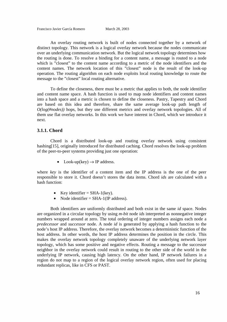
Chord is a distributed look-up and routing overlay network using consistenthashing[15], originally introduced for distributed caching. Chord resolves the look-up problemof the peer-to-peer systems providing just one operation:
• Look-up(key) → IP address.
where key is the identifier of a content item and the IP address is the one of the peerresponsible to store it. Chord doesn’t stores the data items. Chord ids are calculated with ahash function:
• Key identifier = SHA-1(key).• Node identifier = SHA-1(IP address).
Both identifiers are uniformly distributed and both exist in the same id space. Nodesare organized in a circular topology by using m-bit node ids interpreted as nonnegative integernumbers wrapped around at zero. The total ordering of integer numbers assigns each node apredecessor and successor node. A node id is generated by applying a hash function to thenode’s host IP address. Therefore, the overlay network becomes a deterministic function of thehost address. In other words, the host IP address determines the position in the circle. Thismakes the overlay network topology completely unaware of the underlying network layertopology, which has some positive and negative effects. Routing a message to the successorneighbor in the overlay network could result in routing to the other side of the world in theunderlying IP network, causing high latency. On the other hand, IP network failures in aregion do not map to a region of the logical overlay network region, often used for placingredundant replicas, like in CFS or PAST.

Francisco Javier García Romero March 28, 2003
17
A content item is also identified by an m-bit content key, and the binding from keys(hashed content name) to node ids (hashed host address) is defined by the successor function.A key k is located at the node n with the same or the next higher id than the key k written asn=successor(k) (see figure 3.1). The content item associated with the key k is not stored inChord itself. Chord just assigns a responsible node whose network location is used to accessthe content item.
-Figure 3.1- A key is stored at its successor: node with next higher ID
Using the same identifiers for nodes and keys leads to a combined look-up and routing.A look-up is resolved by routing a message to the node that is the successor of the key. Everynode knows at least two other nodes, its successor and its predecessor. The “simple look-up”algorithm routes a messages around the circle by following the successor pointers until a nodewith the same id or the next higher id than the key is found (see figure 3.2). As one node isonly aware of its successor and its predecessor as available routing alternatives, a look-upmessage is always traversing the circle in direction of the successor pointers, because only thisreduces the distance. In the worst case, a message has to complete a full circle turn, before thenode that is successor to the key is found. Resolving a look-up with the simple algorithm takesO(#nodes) hops. As long as every node has a working pointer to the immediate successor inthe circle, a successful successor look-up is guaranteed. In a real application with frequentnode join and leave, a single successor pointer is not sufficient enough to guarantee asuccessful look-up. A single node failure would break the circle and result in look-up failures.Therefore, redundant successor pointers are used. As long as one working successor pointer isfound, the look-up routing can proceed and a successful look-up is guaranteed.
N32
N90
N105
K80
K20
K5
Circular 7-bitID space
Key 5Node 105
N32
N90
N105
K80
K20
K5
Circular 7-bitID space
Key 5Node 105

Francisco Javier García Romero March 28, 2003
18
-Figure 3.2- The basic look-up
To reduce the average look-up path length to a practical number, a finger table withadditional routing information is introduced (see figure 3.3). Fingers are like shortcuts, usedinstead of going around the circle from node to node following the successor pointers. Everynode divides the circle into m finger intervals with exponentially growing size in power of 2.A finger points to the successor of the interval start, which could result in finger pointers beingoutside their corresponding finger interval. The finger nodes are resolved by the Chord look-up function, which returns the successor node of the interval start id. Using the finger table,adds O(m) additional routing alternatives and the one is chosen that leads closest to thesuccessor of the key. The higher the finger index, the farer away the finger points. Therefore,the finger table is searched in reverse order, starting at the finger[m]. If a finger i points to anode preceding the key, this hop reduces the distance to the key by 2i-1. With a few hops, thedistance to the key is quickly reduced, which results in an average look-up path length ofO(log(#nodes)) This bound was proven theoretically and verified by controlled experiments ina the Chord paper[].
80 start end length node1 81 82 1 992 82 84 2 993 84 88 4 994 88 96 8 995 96 112 16 996 112 16 32 1207 16 80 64 20
Finger Table
-Figure 3.3- An example of a finger interval with the finger pointer
N32
N90
N105
N60
N10N120
K80
“N90 has K80” N32
N90
N105
N60
N10N120
K80
“N90 has K80”
N32
N10
N5
N20N110
N99
N80
N60
Lookup(K19)
K19
80 + 20
80 + 2180 + 22
80 + 23
80 + 24
N120
80 + 25
80 + 26
N32
N10
N5
N20N110
N99
N80
N60
Lookup(K19)
K19
80 + 20
80 + 2180 + 22
80 + 23
80 + 24
N120
80 + 25
80 + 26

Francisco Javier García Romero March 28, 2003
19
Figure 3.4 shows a detailed Chord routing example using finger tables in a m=7 bitcircular hash space. Starting at node N32, which wants to resolve the successor of the keyK19, N32 looks in its finger routing table for the node that closest precedes K19. The fingertable is searched in reverse order, starting at the finger with higher index. This finger matchesthe criteria and therefore, the look-up continues at N99. On N99, the finger table is searchedagain. The 7th finger N60 does not precede K19, therefore the 6th finger is tested. This one,pointing to N5, precedes K19, hence the look-up continues on N5. N5 finds N10 as its closestpreceding finger. N10 now terminates the look-up, because it can make out that its successorN20 is the successor node of K19.
-Figure 3.4- Chord routing look-up example
Chord provides a peer-to-peer hash look-up service. Chord offers a scalable, robust,and balanced mapping of hashed content names to host network locations (IP address and anode D) with a minimal join/leave disruption. The Chord overlay network delegatesresponsibility for content items to nodes. Chord does not store the data itself. The participatinghosts are organized in an overlay network that establishes neighbor relations amongparticipating hosts based on numerical proximity of their ids in a virtual coordinate space. Thelook-up time of Chord in terms of the number of peer hops is O(logN), where N is the numberof peers in the overlay network.
In spite of good characteristics that Chord presents, Chord has also some problems.The main problem in Chord is that the overlay network doesn’t care about the underlyingInternet. The look-up time can be high because two neighbor peers in the overlay network canbe physically very far in terms of communication latency. Another thing that Chord doesn’tconsider is the fact that there are hosts which have much better characteristics than others(transmission bandwidth, CPU power or up-time). It seems a good idea to take advantage ofthese node with good characteristics in order to give them more responsibilities so that the
32 start end node1 33 34 602 34 36 603 36 40 604 40 48 605 48 64 606 64 96 807 96 32 99
Finger Table
99 start end node1 100 101 1102 101 103 1103 103 107 1104 107 115 1105 115 3 56 3 35 57 35 99 60
Finger Table
N32
N10
N5
N20
N110
N99
N80
N60
Lookup(K19)
K19
N32
N10
N5
N20
N110
N99
N80
N60
Lookup(K19)
K19
5 start end node1 6 7 102 7 9 103 9 13 104 13 21 205 21 37 326 37 69 607 69 5 80
Finger Table

Francisco Javier García Romero March 28, 2003
20
reliability of the peer-to-peer system is improved. It’s also demonstrated that in a Chordsystem, look-ups can be achieved with a cost of O(logN) hops only when the overlay networkis stable, when there aren’t a lot of node joins and leaves. These problems can be solvedintroducing a hierarchy of nodes in the overlay network as is explained in [16].
3.1.2. CARP
When using CARP, each peer has a list with the identities Pi of all other peers in thegroup. In order to find a key k, a peer performs a hash function h, hi=h(Pi; k) over all peers Pi
of the group. The peer Pi with the highest hi is the one that stores the key k. Thus, every peer ina CARP-organized network is able to find the peer where a key is stored with exactly one hop.However, each peer must know the identities and IP addresses of all the others peers in thegroup. This does not scale well with the number of peers into a group.
3.2. A hierarchical look-up service
To solve the sort of problems than flats overlays show, the [16] paper propose toorganize the participating peers into groups. The peers of each group form a separate overlaynetwork (lower-level overlay). Another overlay network will be established among all groups(top-level overlay). The top-level overlay “interconnects” the lower-level overlays to ensurethat there exists a routing path among peers in different groups. With this scheme:
• It’s possible to implement a two-step hierarchical look-up P2P system. A look-upprocess requires finding first the group which a key is mapped to, and immediatelyafter the peer in that group where the key is actually stored.
• We can improve the overall reliability and performance of the P2P system by choosingpeers with the highest reliability and processing power inside each group to be part ofthe top-level overlay network. Those kind of peers are the super peers.
• We can put peers into the same group that are close in terms of communicationlatency across the Internet, thereby achieving shorter inter-peer delays and fasterreaction to failures.
• We improve the scalability of existing solutions to overlay networks as each overlayonly comprises a subset of all peers.
In this work the peers are organized into groups in a two level hierarchy. The groupsare chosen so that the peers in the same group are “close” to each other in the sense thatcommunication delays (latency and/or file transfer delays) between peers in the same groupare relatively small. Each group is required to have one or more super peers. The super peersare gateways between the groups: they are used for inter-group query propagation. To this end,it’s required that if Si is a super peer in a group, then it musts know the identifier and the IPaddress of at least one super peer Sj of another group. With this knowledge, Si can send querymessages to Sj. On the other hand, if p is a “normal” peer in the group, then p must first sendintra-group query messages to a super peer in its group, which can then forward the querymessage to another group. Within each group there is also an overlay network that is used for

Francisco Javier García Romero March 28, 2003
21
query communication among the peers in the group. When a group is designed to beresponsible of storing a key by the top-level overlay network, the key is stored within thegroup according to the organization of the group overlay network (lower-level overlay). Eachof the groups operates autonomously from the other groups.
3.3. Proposed solution
In this work we are going to implement the prototype of a two-level hierarchical peer-to-peer look-up system. Peers are organized into groups. The groups are organized in anoverlay network. For this top-level overlay network, we have chosen Chord. In fact, thesystem is a set of peer groups organized in a Chord ring (top-level overlay network). Insidegroups, the peers are also organized in an overlay network. This system assumes that thenumber of peers into each group is small, in the order of hundred. CARP is used to organizethe peers in a lower-level overlay network into the groups. Figure 3.5 shows an overview ofthe system.
At each group, there are a set of special peers, called super peers, which are the onlypeers that are able to execute inter-group look-ups. The rest of the peers of the group, called“normal” peers, are able to perform look-ups in other groups through any super peer of thegroup. Every peer can become a super peer at every moment. The super peers are intended tobe the peers of the group with better characteristics and are chosen according a “merit” metric.Only the super peers have the routing information of the Chord ring: list of network locationsof other super peers in successor groups, the super peers in the predecessor group, table offingers. In the standard Chord system, at any “hop” of the Chord overlay network there is justa single node. In this scenario, at any “hop” of the Chord overlay network there is the set ofsuper peers of a group.
-Figure 3.5- Implemented system overview
Chord ringS 1
P 1
P 2
P 3
C ARP Group
List of nodesIn the G roup
C ARP G roup
CARP GroupS1P1P2P3
Chord ringS 1
P 1
P 2
P 3
C ARP Group
List of nodesIn the G roup
C ARP G roup
CARP GroupS1P1P2P3

Francisco Javier García Romero March 28, 2003
22
3.3.1. A two-step look-up service
Our system provides a look-up service to find the peer that is responsible for a key.The key is under the responsibility of a peer, and CARP is used for assigning theresponsibilities into the groups. The system first finds the group that is responsible for the key.This responsibility is assigned by the Chord top-level overlay network: the group responsibleof storing a key k is the idGroup=successor(k). Immediately after, the responsible peer withinthe responsible group is looked up. This responsibility is assigned by the CARP lower-leveloverlay network. Every peer at every group is able to perform a look-up in the system. Onlythe super nodes are able to perform an inter-level look-up. An intra-group look-up can beachieved by every node. We present the functions implemented that allow a node pi,integrated in the group Gi, to locate the peer pj, integrated in the group Gj, which isresponsible for key k. The node pi has an IP address @pi, and the node pj has an IP address@pj. We assume that pi knows at least a super peer Si of this group and the IP address @si ofthis super peer.
@sj = getSuperpeerForKey(@si ,k): The node pi calls this function to obtain from Si the IPaddress @sj of the super node Sj managing the group responsible for key k.
@sj = findKeyInOverlayNetwork(k): To answer the call getSuperpeerForKey, the super peer Siuses findKeyInOverlayNetwork to obtain the IP address @sj of the super node Sj of the groupresponsible for key k. This function implements the inter-group Chord look-up and only canbe called by a super peer.
@pj = getNodeForKey(@sj, k): A “normal” node pi calls this function to obtain from thesuper peer Sj of the group Gj responsible for key k, the IP address @pj of the node pjresponsible for k.
@pj = findKeyInGroup(k): To answer the call getNodeForKey, a super peer Sj uses thisfunction to obtain the IP address @pj of the node pj responsible for k. This functionimplements the CARP look-up and can be called by any the node.
-Figure 3.6- Two-step look-up service
2.2.
S1 S3S2
P1
P2
P3
P1P2P1 P2
Overlay Network
3.
4.S1S1 S3S3S2S2
11
22
33
112211
22
Overlay Network
3.
4.getSuperPeerForKey( key)
1.
findKeyInOverlayNetwork ( key)
findKeyInGroup ( key)
getNodeForKey(S3, key)

Francisco Javier García Romero March 28, 2003
23
3.3.2. Metadata structure
In order to increase the reliability of the storing system, several replicas of every datablocks are stored in different nodes into the responsible group for the data unit and insuccessors groups of the responsible group. A metadata structure for a content item trackspointers to nodes, where replicas for reliability are located. Every node which stores a dataunit stores also this metadata structure. This metadata structure is then used for paralleldownload[18]. When a node requests a content item, it first looks-up a responsible node ineach of the responsible groups for storing a data unit. It sends a message to a responsible nodein each group to get the metadata pointers necessary for the parallel download. This paralleldownload scheme, accessing multiple replicas in parallel, will be used to increase downloadperformance: instead of trying to select a fast node, connections to multiple nodes providing areplica of the desired content item are established and different blocks of the replica aretransferred in parallel. In this case, the fastest node will be among the set of opened parallelconnections. The aggregation of the individual connections bandwidths will potentiallyincrease overall throughput, especially for asymmetric connections, because the limitedupstream channels are aggregated to match with the higher bandwidth downstream channel ofthe receiving node. As an additional improvement, the intelligent paraloader performs adynamic load balancing by choosing to download more block of a replica across the fasterconnections or drop connections that have become heavily congested during a downloadsession. Due to paraloading, the download is more resilient to route or link failures and trafficfluctuations. More details about parallel access are found in the Section 7.1.2.
3.3.3. Intended use of this system
This system assumes that groups are quite stables. There are not frequent group joinsand leaves. Chord is quite efficient in such high-availability environments. We also assumethat the number of peers into each group is small, around a hundred. This is because in CARP,every peer knows the IP address and node identifier of all the others peers in the group, so thisamount of information increases with the number of peers. Such a design has severaladvantages comparing to flat architecture designs:
• Faster look-up time: Because the number of groups will be typically orders of magnitudesmaller than the total number of peers, queries travel over fewer hops. A cause that thenumber of groups is smaller than the number of peers, the number of hops in the Chordlook-up algorithm is reduced. Into the groups, the look-up is done in only a hop. Thegroups could be formed by peers with small network latency communication.
• The top-overlay network is formed by the super-peers, which are the nodes with betterreliability properties, so the reliability of the Chord ring is improved

Francisco Javier García Romero March 28, 2003
24
4. Overview of the framework layer
A multi-layer design framework has been used to implements this system. Each layerprovides some functionalities which can be used by the other layers. Obviously, the upperlayers use the functionalities or services offered by the lower layers. The lower layers don’tknow anything about the upper layers. The communication between layers is achieved by twodifferent means. The lower layers pass events to the upper layers when an one occurs. Theupper layers use the methods or functions that the lower layers provide.
Object orientated (OO) programming languages and their concepts turned out to bevery useful to design such a multi-layer framework. These concepts are used in this Javaprototype, since Java is the model of an object orientated programming language. Beforeintroducing the solution proposed to implement this prototype, it is desirable to introducequickly the theoretical concepts of the OO programming languages.
4.1 Object oriented programming languages concepts
OO is organized around classes and objects, which are the instances of the classes.Thinking of analysis and design objects is very important because humans think in terms ofobjects[17].
4.1.1. Classes and objects
We can define a class like a blueprint, or prototype, which defines the variables andthe methods common to all objects of a certain kind. An object is just a real instance of aspecific class. The class is defined by the class’s code in a programming language, while anobject is the code’s representation in the computer’s physical memory. Different objectsinteract and communicate with each other by sending messages to each other. In OOprogramming a message is sent from one object to another by calling the others object’smethods. The information is passed along with the message as parameters. Messages providetwo important benefits:
• An object's behavior is expressed through its methods, so (aside from direct variableaccess) message passing supports all possible interactions between objects.
• Objects don't need to be in the same process or even on the same machine to send andreceive messages back and forth to each other.
4.1.2. Inheritance
The concept of a class makes it possible to define subclasses that share some or all ofthe main class characteristics. This is called inheritance. A class inherits state and behaviorfrom its superclass. Inheritance provides a powerful and natural mechanism for organizingand structuring software programs. However, subclasses are not limited to the state andbehaviors provided to them by their superclass. Subclasses can add variables and methods to

Francisco Javier García Romero March 28, 2003
25
the ones they inherit from the superclass. You are not limited to just one layer of inheritance.The inheritance tree, or class hierarchy can be as deep as needed. In general, the farther downin the hierarchy a class appears, the more specialized its behavior. Inheritance offers thefollowing benefits:
• Subclasses provide specialized behaviors from the basis of common elements provided bythe superclass. Through the use of inheritance, programmers can reuse the code in thesuperclass many times.
• Programmers can implement superclasses called abstract classes that define "generic"behaviors. The abstract superclass defines and may partially implement the behavior, butmuch of the class is undefined and unimplemented. Other programmers fill in the detailswith specialized subclasses.
4.1.3. Polymorphism
The polymorphism concept results of the combination of inheritance and objectcommunication via messages. Any descendant class is allowed to overwrite any methodinherited from its parent class with its own implementation. When another object calls such aninherited and overwritten method, the specific implementation is called. This allows defining astandard way to communicate with classes based on the same ancestor class without knowingabout their specific internal details.
4.1.4. Java
Java is a platform independent OO programming language with a C-like syntax andstrict object orientation. Compared with C++ it lacks some advanced features like templateclasses and multiple class inheritance, but it is shipped with a fairly complete set of librariescovering most of the standard programming problems and data structures. The platformindependence is achieved by using intermediate byte-code which is interpreted by a platformdependent Java Virtual Machines (JVM). For most systems a JVM implementation isavailable. Therefore Java is the optimal programming language for a distributed networkoperated in a heterogenic environment with multiple platforms. Developing and especiallymaintaining code versions for different platforms is hard. Either the code is separated from thebeginning and therefore too many versions have to be synchronized, or compiling directivestaking into account the individual platform’s behaviors will result in fragmented, hardlyunderstandable code. Java’s ”write once, run everywhere” paradigm helps out of this trouble.In real life, this is not always completely true, but in general the platform differences areminor. For applications with a graphical user interface (GUI), there is so far no real alternativeto Java with its Swing library, which is available on all Java platforms. Swing offers a highlevel of abstraction and offers most standard widgets, elementary GUI items like lists, buttonand edit fields. Java offers a quite complete solution well adapted to distributed computingwith many advantages to fast prototyping, but performance is still far away from nativeimplementations and should be considered in the design concept.

Francisco Javier García Romero March 28, 2003
26
4.2. Framework layer design
The solutions components are integrated into an object oriented frameworkarchitecture using Java’s object oriented concepts. A framework in software design is areusable class hierarchy that depends only on the abstract interfaces of various components[].Another useful concept in software and network design is layering. Layers are defined by theirservices and interfaces to these services. Each layer uses services of the underlying layers toprovide its own service and therefore hides underlying details. This super imposition leads tothe desired abstraction necessary for a reusable framework design. Abstraction reduces thedependence from implementation details, because general mechanism are specified, notimplementations.
The layer hierarchy is described by a hierarchy of classes. The service of theunderlying layer is used by calling its methods. Sometimes it is necessary to inform a layerusing a deeper layer’s service about specific events in that layer. The events are signaled bypolymorphic method calls. A layer signaling an event calls its abstract event method, which isoverwritten by higher layers interested in processing that event. The polymorphic mechanismcalls the top overwritten method first. This layer processes the event and calls the eventmethod of the next deeper layer. The event soaks through the layers.
The notion of node is the basic element, out of which the storage network is built. In apure P2P storage network, all nodes are equal and have the same functionality, even if in ourcase, all functionalities are not always used by all nodes at same moment. Hence, each node isan object instance of the same node class, implementing the node functionality. Thefunctionality of the node is provided by the class hierarchy of superimposed layers. In orderto collaborate with each other, the nodes need to communicate. The node to node messageservice is provided by the Message Layer, which itself uses a communication service of theunderlying IP network layer. The overlay network which provides a look-up and routingservice is maintained by the Look-up and Routing Layer. Reliable content block storage ishandled by the Block Storage Layer. And finally, the Application Layer is storing files usingthe block storage service of the underlying layer.
-Figure 4.1- Framework Layer design and classes hierarchy
Transport Layer (TCP)
Message Transport Layer(Node)
Look-up and Routing Layer(LNode)
Block Storage Layer(SNode)
Application P2P(Anode)
Events
MethodCalls
Node
ANode
SNode
LNode
Inherits
Inherits
Inherits

Francisco Javier García Romero March 28, 2003
27
4.2.1. Message layer
The Message layer defines the basic behavior of a node, which is the capability ofcommunicating with other nodes. The functionality of a node in this layer is provided by theNode class. Communication is based on two primitives, messages and responses. Thecommunication initiator sends a message to another node, which receives the message,processes the message and returns a response according to the message. Each node has aunique address in the Message layer represented by a Location object which contains its IPaddress and a port number listening for incoming messages. The basic message object isimplemented by the Message class and the basic response object is implemented by theResponse class. By extending the Message base class, semantic meaning is added andspecified by additional attributes. The base class only encapsulates the message originator’slocation. The Response class object has a boolean success field indicating if the processingwas successful or not. If processing was not successful, the reason field should contain astring explaining the reason why the message processing failed.
For simple node-to-node communication the sendMsg method is used. It waits until thedestination node has processed the message and returned a response. For recursive messageprocessing, where several nodes are involved, the sendRecursiveMsg method must be called,with a RecursiveMessage object. This object extends the Message object with the setResponsemethod, which is called by the node that terminates the recursive message processing andsupplies a processing response. The sendRecursiveMsg method waits until this method iscalled returning the response or a waiting response timeout has occurred. The processing itselfis done by the layers on top of this one, which use the Message layer service. A layer usingthis service should overwrite the processMsgEvent method and handle processing of ownmessages by returning a response. Polymorphic method invocation results in calling theprocessMsgEvent method of the top-most layer class. Unknown messages, which cannot beprocessed are passed to the next deeper layer for further processing by calling the inheritedprocessMsgEvent method of the deeper layer. If all layers above cannot process a message, itends at the Message layer’s processMsgEvent method, which provides a default messageprocessing by setting the result to false.
4.2.2. Look-up and Routing layer
This layer provides the hierarchical look-up and routing service. The nodes arearranged in groups which are organized in a Chord ring. The functionality of a node in thislayer is provided by the LNode class, which inherits directly from the Node class. Every nodehas two identifiers: an idGroup identifier, which is common to all the nodes in a group and anidNode identifier, which is unique for every node in a group. Since keys and node identifiersare generated by the same hash function, they are represented as instances of the LHashIDclass. Every node has in the Look-up and Routing layer a unique LLocation object, whichextends the Location object of the Message layer with both node identifiers.
The look-up operation resolves the responsible node for a key. Firstly, for a given key,the look-up service find the responsible group to store the key using Chord rules: theresponsible group is the idGroup=successor(key). Immediately after, the responsible group for

Francisco Javier García Romero March 28, 2003
28
a key has been found, the look-up process searches for the node in the group which isresponsible for storing the key using CARP rules (see section 3.1.2).
There are some special nodes that are called super peers. There are aNUMBER_SUPER_NODES maximum number of super peers at each group. These nodes arechosen considering the bandwidth and CPU of the node. It is desirable to choose like superpeers the nodes with better characteristics. These super peers are integrated in the top overlaynetwork, that is to say, they build the Chord ring. The other nodes of the group don’t knowanything about the Chord ring. All nodes in a group know the list of super peers of the group.Every node can become a super peer at any moment. In fact, this is not a pure peer-to-peersystem since there are peers that have more importance than the others. However, all the peerscan perform both as super peer and “normal” peer.
The Look-up and Routing layer use the sendMsg and sendRecursiveMsg methods ofthe Message layer for node communication. The processMsgEvent method is overwritten andit is the way used by the deepest layer to pass events. The look-up method is calledfindNodesResponsibles. The look-up result is an array of Successor objects of each group. TheSuccessor object contains the idGroup identifier of a group and a list of LLocations objects ofthe super peers in the group. In order to communicate node joins or leaves in a group to theupper layer, the Look-up and Routing layer provides the nodeChangedEvent method whichmust be overwritten by the upper layer.
-Figure 4.2- Interaction of Look-up and routing layer with the other layers
4.2.3. Block Storage layer
The data storage is handled by the Block Storage layer. This layer offers a reliableblock storage facility for storing, fetching and removing blocks using distributed redundantreplicas for reliability. The basic storage unit is the data block, any kind of binary datarepresented by variable length byte sequence. Each block is identified by a unique LHashIDobject. The functionality of a node in this layer is implemented by the SNode class.
To achieve a more versatile approach, the layer itself does not read, write or deleteblock data. It logically manages the blocks and calls the readBlockDataEvent,testBlockDataEvent, writeBlockDataEvent and removeBlockDataEvent methods to let the
Look-up and Routing Layer(LNode)
Message Transport Layer(Node)
Block Storage Layer(SNode)
processMsgEvent()
processMsgEvent()sendMsg()
nodeChangedEvent()
sendRecursiveMsg()

Francisco Javier García Romero March 28, 2003
29
Application layer do the physical changes. It’s up to the P2P application defined in theApplication layer which storage devices are used for block storage and which block size isreasonable. The size should be chosen carefully considering that fine granularity helps to usethe available storage resources more efficiently and balances the storage load among thenodes. On the other hand, the paraloader is less effective for smaller blocks due to the smallernumber of block pieces downloaded in parallel. This layer uses the Look-up service offer bythe Look-up and Routing layer to resolve the binding between keys and nodes and theMessage layer for exchanging messages with other nodes. The Look-up and Routing layerreport this layer about node leaves and joins into a group through the nodeChangedEvent. Thiskind of event causes a reorganization of the data blocks between the nodes that form thegroup. Each data block is stored in the node responsible to store the data unit in the group andin a set of other nodes.
-Figure 4.3- Communication between the Storage layer and the others layers
4.2.4. Application layer
The Application layer is the topmost layer interfacing with the user. In this prototypeimplementation, the application offers a simple file storage interface to demonstrate the use ofthe underlying layers. The user can choose a file from his hard disk and file will be stored bysplitting it into blocks and spreading them among the storage network’s nodes. The file can beretrieved from the storage network and saved on the local hard disk by specifying a directoryto write the file and the files original filename. The file’s consistency is verified by comparingit with a stored hash fingerprint.
The framework is fully parameterizable by the Application Layer’s Parameter class. Inthis class all parameters used for the different layers can be configured and adjusted to theneeds of the application using the framework. The Application layer provides a simple graphicuser interface (GUI) which is implemented by the JFNodes class. The NodeTest classimplements the main method which runs the application. The user can create several nodesover the same machine. The nodes to be created are rode from a batch file which must bepassed to the program as input.
Look-up and Routing Layer(LNode)
Block Storage Layer(SNode)
Application P2P(Anode) readBlockDataEvent()
findNodesResponsibles()
writeBlockDataEvent()
Message Transport Layer(Node)
sendMsg()
testBlockDataEvent()
removeBlockDataEvent()
nodeChangedEvent()
processMsgEvent()
processMsgEvent()

Francisco Javier García Romero March 28, 2003
30
The functionality of a node in this layer is implemented by the ANode class, whichinherits directly from the SNode class. The ANode class uses the storeBlockData andfetchBlockData methods provides by the SNode class for storing and fetching a data blockrespectively. The ANode class overwrites the readBlockDataEvent, testBlockDataEvent,writeBlockDataEvent and removeBlockDataEvent methods. In this way, the Block Storagelayer can pass events to the Application layer.
-Figure 4.4- Communication between the Application layer and the Storages layer
Block Storage Layer(SNode)
Application P2P(Anode)
removeBlockDataEvent()
testBlockDataEvent()writeBlockDataEvent()readBlockDataEvent()
storeBlockData()fetchBlockData()

Francisco Javier García Romero March 28, 2003
31
5. Message Layer Implementation
The Message Layer is designed as a general purpose node-to-node communicationservice based on Message and Response objects. Since this layer Node class is the base classfor all other layers, it defines the basic properties and behavior of a node. The Message andResponse objects are Java classes and the Java serialization is the mechanism used to sendthem between nodes. In this layer, a node is an instance of the Node class. A node is identifiedby the Location object’s host IP address and the port number where the node is listening forpossible incoming messages. After the node object is created, the startup method needs to becalled for installing a specified number of pool threads waiting for incoming messages toprocess. The shutdown method should be called to properly shutdown a node by terminatingthe installed threads and remove their binding to the node’s port. All classes based on theNode must call the startup and shutdown methods.
5.1. A pool of threads for managing messages reception
A node is listening for continuous incoming messages. To manage this, it would bepossible to use the remote method invocation (RMI) to implement a node-to-nodecommunication. But the standard remote method invocation frameworks like Java-RMI orCORBA create at least one thread per remote method call. For the Java-RMI, part of thestandard Java distribution, it is reported that even three threads are created for each call[].Since creating threads is an expensive operation for operating systems and a P2P applicationbased on an overlay network will cause constant message traffic in order to maintain andstabilize its overlay network structure, using the standard solutions would cause a massivethread creation overhead. A Java specific mechanism, the garbage collector, makes thingseven worse. For convenience, Java objects do not need to be destroyed manually after usage.The garbage collector detects objects which are not referenced anymore and discards them.Therefore, they will stay in memory for an unspecified time until they are removed. Thiswould also happen to the thread objects created for each incoming message call and occupymain memory. The key to avoid this overhead is thread re-use[]. A pool of threads is installedat startup, waiting for incoming messages. One of the waiting threads gets activated, handlesthe message processing and starts waiting again.
5.2. Node-to-node communication method
The node-to-node communication is done by using TCP connections over theunderlying IP network. The Message/Response semantic is easier to implement with thebidirectional TCP protocol than using the unidirectional and unreliable UDP service, forwhich additional mechanisms for mapping responses to messages, fragmentation and errorhandling would be necessary to implement. It turned out that the Java socket implementation,when used together with multiple threads waiting at the same port, buffers incoming TCP

Francisco Javier García Romero March 28, 2003
32
connections even if all pool threads are active. The next free thread handles the bufferedconnection, if a TCP connection timeout does not occur first. This buffering effect maysmooth short load peeks. Figure 5.1 shows how the TCP-based Message/Response processingworks. The sendMsg method tries to establish a TCP connection to the node’s location. If athread on node B is waiting, it gets activated and a connection is established. Otherwise aLocationException is thrown. After the connection is established, the correspondingObjectInputStreams (OIS) and ObjectOuputStreams (OOS) get connected together by each ofthe unidirectional TCP data pipes. Node A sends a Message object serialized by the OOS andde-serialized by the OIS. Then Node B calls the processing method processMsg and returnsthe Response object in the same way. The default serialization methods of each individualMessage derived class can be overwritten to pack the data more efficiently than the standardserialization implementation does.
The sendRecursiveMsg method is used to start a recursive message processing. Themessage object based on the RecursiveMessage class is sent to the node given by thedestination location. On the other node, the implementation will recognize a recursive messageby class introspection and return an acknowledgement Response object. Then, thesendRecursiveMsg starts waiting until the response for this message arrives or the timeoutoccurs. Each RecursiveMessage is identified by an eight byte message id randomly generatedwhen its constructor is called. A node that terminates a recursive message processing calls therecursive message’s setResponse method and sets the message’s processing response attributewith a Response object. The RecursiveMessage object and the processing response are sentback to the message’s originator node stored in its org attribute. The originator node receivesthe recursive message and recognizes from the non empty response attribute that a response toone of its recursive messages has arrived. Then it tries to identify the waiting thread from theunique message id and activates it. The thread calling the sendRecursiveMsg method iswaiting at an emphSemaphore. A semaphore is a thread synchronization mechanism that wasintroduced by Dijkstra to solve the ”lost signal” problem[]. When a thread wants to enter asynchronized area it has to wait at the semaphore’s pass p() method until another thread callsthe free v() method signaling that the area is now free.
-Figure 5.1- Basic communication method among nodes
Lookup and Routing Layer
Block Storage Layer
Message Transport Layer
Lookup and Routing Layer
Block Storage Layer
Message Transport Layer
sendMsg()
TCP ConnectionMessage
Response Response
Messageoos
oos
ois
ois
Node A Node B
processMsgEvent()
Pool thread 1
Pool thread n
Lookup and Routing Layer
Block Storage Layer
Message Transport Layer
Lookup and Routing Layer
Block Storage Layer
Message Transport Layer
Lookup and Routing Layer
Block Storage Layer
Message Transport Layer
Lookup and Routing Layer
Block Storage Layer
Message Transport Layer
sendMsg()
TCP ConnectionMessageMessage
ResponseResponse ResponseResponse
Messageoos
oos
ois
ois
Node A Node B
processMsgEvent()
Pool thread 1
Pool thread n

Francisco Javier García Romero March 28, 2003
33
6. Look-up and Routing layer implementation
In this chapter we explain the implementation details of the Look-up and Routinglayer. This layer provides the hierarchical look-up and routing service. The nodes are arrangedin groups which are organized in a Chord ring. The functionality of a node in this layer isprovided by the LNode class, which inherits directly from the Node class. All the nodes areinstances of this class. The Look-up and Routing layer use the sendMsg andsendRecursiveMsg methods of the Message layer for node communication. TheprocessMsgEvent method is overwritten and it is used by the deeper layer to pass events. Inorder to communicate node joins or leaves in a group to the upper layer, the Look-up andRouting layer provides the nodeChangedEvent method which must be overwritten by theupper layers.
There is a flag isSuperNode to distinguish a super peer from a “normal” peer. At everymoment, any “normal” peer can become a super peer. In fact, this is not a pure peer-to-peersystem since there are peers that have more importance like the others in a specific moment,but in fact, all the peers can perform as super peer or as “normal” peer at any moment. Thereare NUMBER_SUPER_NODES super peers at each group. Each node has two identifiers, theidGroup identifier, which is unique for all the nodes in the same group and the idNodeidentifier, which is unique for each node in the group. Both of these identifiers are representedby LHashID objects. Every node has in the Look-up and Routing layer a unique LLocationobject, which extends the Location object of the Message layer with both node identifiers. Wegive more details about these identifiers below.
6.1. Node identifiers
Node identifiers are m-bit long and interpreted as non-negative integers. They aregenerated by a hash function. A hash function maps any variable length input data (an array ofbytes) to a fixed m-bit length hash value. Hash functions are often used in cryptography,especially for integrity checking. The most used cryptographic hash functions are MD5 andSHA-1. The length of the MD5 hash values is 128 bit compared to 160 bit for SHA-1. Sincethe number of bits directly determines the number of addressable content items, the SHA-1algorithm with its higher length of 160 bit and a resulting number of 2160 different possiblecontent items was chosen for this implementation.
Using cryptographic functions in Java is standardized by the Java CryptographicExtension (JCE) framework, which defines basic interfaces and classes implemented by acryptographic provider, like the freely available Cryptix library used for this project. Theidentifiers are encapsulated in the LHashID class. The static getLHashKey method of theLHashID class, called with an input byte array as parameter, uses the SHA-1 function togenerate the 20 byte (160 bit) hash value from the input data. From these 20 bytes, a positiveBigInteger object is created and encapsulated in the LHashID object. For working with these

Francisco Javier García Romero March 28, 2003
34
identifiers, a LOpenHashIDIntervall class is used for testing if an identifier is inside this openinterval defined by two LHashIDs.
6.2. Top-level overlay network
The peers are organized in groups. These groups are organized in a top-level overlaynetwork. In this work, we have chosen Chord for the implementation of this top-level network.There is a limited number Parameter.NUMBER_SUPER_NODES of super peers at eachgroup. These special peers are supposed to be the best nodes of the group in accordance with ametric. This metric is called the merit factor. This merit factor must take account of propertiesof node (CPU power, bandwidth of the node and time-up). The merit of a node is obtained bythe getMerit method. All the nodes in a group have at every moment the list of the super peersof the group. This list is called superNodesList. In this work, the implementation of the Chordsystem has been modified to support the hierarchical look-up service. Now, there is a Chordring of groups instead of a Chord ring of nodes. Every group is represented by a Successorobject. This object contains the LHashID idGroup parameter, which is the identifier of thegroup and the LinkedList nodesGroup parameter, which is the list of super peers of this group.Therefore, we have a Chord ring of Successor objects. All super peers are able to do look-upsthrough the Chord ring. This is achieved by the findKeyOverlayNetwork method. This methodperforms the Chord inter-group look-up. All the other “normal” nodes of the group can look-up in other groups through any of the super peers of the group. This is done through themethod getSuperpeerForKey. Only the super peers are integrated in the Chord ring. For thispurpose, every super peer has a list of the Successor objects of its next groups in the Chordring. This list is named successors list. All super peers have another list with all the superpeers in its predecessor group. This list is named predecessors list.
6.2.1. Successors and predecessors
Each super peer must have a pointer to its immediate successor group, that is, it mustknow the Successor object of the next group in the top-level overlay network. This is requiredfor a successful look-up. A single successor pointer is not reliable in a dynamic scenario withfrequent joining and leaving groups. If a group fails, the successor pointer is not working untilthe stabilization process has assigned the new successor group. In the worst case, this couldcause a look-up to fail. Therefore, redundant successor pointers are used. They areimplemented by a linked list of Successor objects, the successors list. The list is kept inascending group ids order by inserting new groups at the position according to their group ids.The list has a maximal size specified by the Parameter.SUCCESSOR_LIST_SIZE constant,which should be set to 2log2(N), where N is the number of maximal expected groups. Whenthe list has reached its maximal size, the entries at the end of the list are removed to get spacefor new entries with smaller ids. To find the successor, the list is searched from the beginning.We try to contact each of the super peers of this group until the first working super peer isfound. If nono of them answer, this group is not working and is removed from the list. Thesuccessor list is constantly filled when the stabilization process is executed. This is how newsuccessor groups are discovered. More details about this method in subsection 6.2.4.1. The

Francisco Javier García Romero March 28, 2003
35
access to the successors list is controlled by a flag blockSuccessorsList to avoidsynchronization problems caused by of multiple threads accessing to the list at the same time.New Successor objects are introduced in the succccessors list through the addSuccessor oraddSuccessorGroup methods and they are removed by the removeSuccessor method. Sincepredecessors are not necessary for the look-up, only the list of the immediate predecessorgroup is used.
6.2.2. Fingers
Correct finger table entries are necessary for a fast look-up while the successors arenecessary for a reliable look-up. For the m-bit identifiers used in this implementation, thenumber of finger intervals is m. The finger table is implemented by an array of m Fingerobjects. A Finger object contains the finger interval start as LHashID object calculated when anode startups, because it does not change after the group id is set. This is done through theinitFingers method. The finger pointers themselves do change due to joining and leavinggroups or changing of super peers in the groups. Any entry in the finger table points to aSuccessor object of the group which has the next idGroup identifier bigger than the beginningof the interval of this table entry. The finger table entries are updated that is, they areperiodically refreshed each Parameter.FIXFINGER_INTERVAL_MS (ms) by a thread whichexecutes the method refreshFingers as it’s described in the Chord paper.
-Figure 6.1- An example of the top-level Chord overlay network
Predecessors
List
135/1135/2135/3
430/1 430/235/170/1135/1 135/2 135/3
Successors List
Group 35
Group 70
Group 135
Group 255
Group 430
N1
255 start end Group1 256 257 430/1, 430/22 257 259 430/1, 430/23 259 263 430/1, 430/24 263 271 430/1, 430/25 271 287 430/1, 430/26 287 319 430/1, 430/27 319 383 430/1, 430/28 383 511 430/1, 430/29 511 255 35/1
Finger Table
N1 N2 N3 N1
N1 N2
N1
ChordRing

Francisco Javier García Romero March 28, 2003
36
6.2.3. Inter-group look-up
The top-level overlay network as we have already said is a Chord ring. The inter-grouplook-up operation resolves the responsible group for a key: the responsible group is the groupwhose idGroup identifier is idGroup=successor(k), where k is the searched key. The look-upis resolved using a recursive method. In the Chord paper is explained how to do an iterativelook-up, but the recursive method is better because the number of messages sent is smaller andprivacy of the sender is preserved. Only the super peers are able to achieve inter-group look-ups. This is done by the findKeyOverlayNetwork method. The node that wants to do the look-up, tries to contact a super peer of the first group in the look-up path. If this super peer doesn’tanswer, it tries to contact another in the same group. Each node receiving a query routes it tothe next hop of the look-up path and the node that finally can resolve the successor of thelook-up id has to return the Successor object of the responsible group to the node that initiatedthe look-up. Therefore the initiating node has to wait passively until it receives a result or atimeout occurs.
The recursive look-up is started by calling its findKeyOverlayNetwork method, whichlocally calls the recursiveFindSuccessorList method, which locally calls therouteRecursiveFindSuccessor method. This method routes the recursive look-up query byrecursively calling the routeRecursiveFindSuccessor method on a super peer of the nextclosest preceding group until the successor group is resolved and the recursion stops. On thefirst local invocation of the routeRecursiveFindSuccessor method, anLFindSuccessorRecursiveMessage object is sent to a super peer on a preceding group with arecursiveSendMsg call. This super peer is determined by the finger table. If the finger tablecan’t do the look-up, the successors list is used for routing this message to a super peer in agroup “close” to the searched group. After sending the message to a super peer of thecomputed destination group and receiving an acknowledging Response object, the thread startswaiting until the result arrives or the timeout occurs. On the destination super peer, therouteRecursiveFindSuccessor method is called forwarding the message in the same fashionuntil the setResponse method is called and the result is returned to the super peer that initiatedthe look-up. The super peer that had iniatited the look-up receives as response aLlocationListResponse with the Successor object of the responsible group for the searchedkey. The number of message pairs used for a recursive look-up is l+1, where l is the numberof hops. At figure 6.2 we can observe an example of this look-up.
6.2.4. Join and leave of groups
In order to maintain the Chord circle topology new groups and new super peers mustbe integrated and groups and super peers that leave, fail or change must be detected andremoved. In Chord there is no explicit mechanism for a node to leave. This case is treated likea node failure.
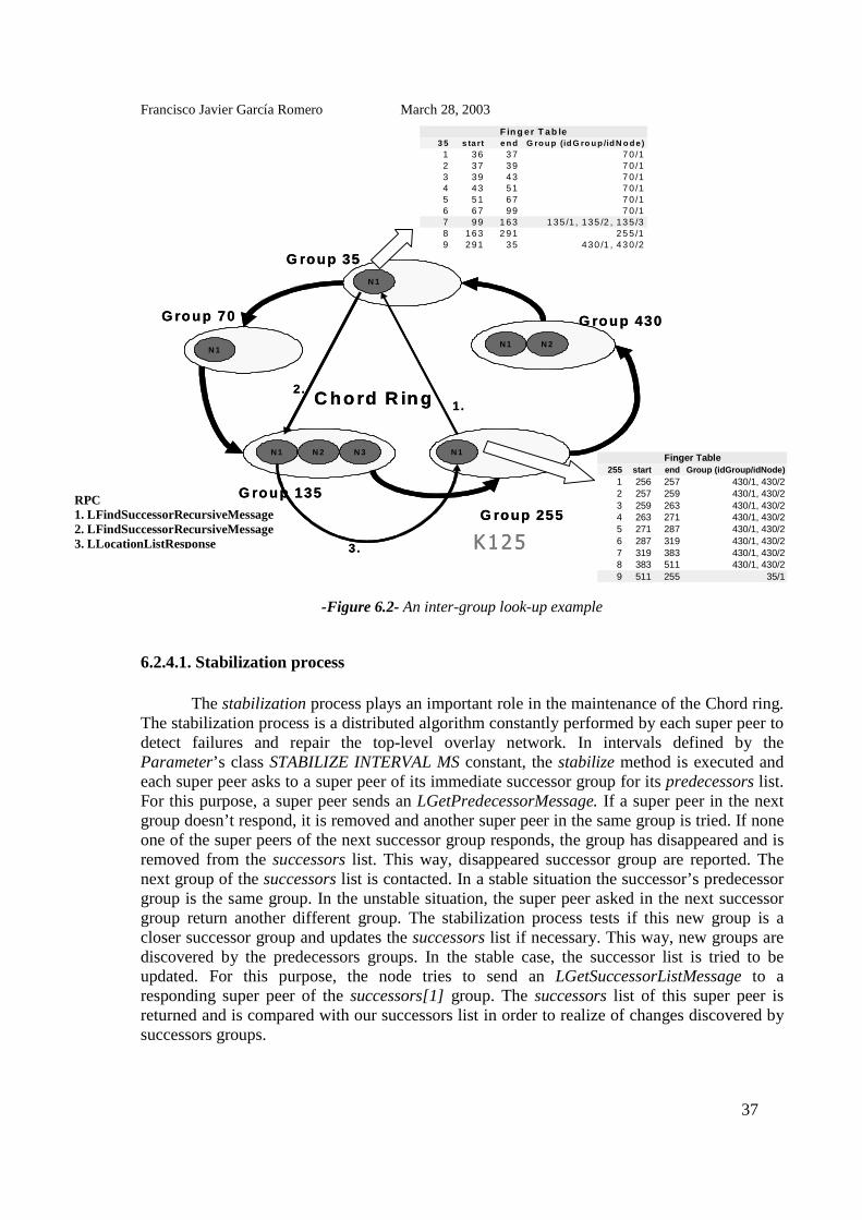
Francisco Javier García Romero March 28, 2003
37
-Figure 6.2- An inter-group look-up example
6.2.4.1. Stabilization process
The stabilization process plays an important role in the maintenance of the Chord ring.The stabilization process is a distributed algorithm constantly performed by each super peer todetect failures and repair the top-level overlay network. In intervals defined by theParameter’s class STABILIZE INTERVAL MS constant, the stabilize method is executed andeach super peer asks to a super peer of its immediate successor group for its predecessors list.For this purpose, a super peer sends an LGetPredecessorMessage. If a super peer in the nextgroup doesn’t respond, it is removed and another super peer in the same group is tried. If noneone of the super peers of the next successor group responds, the group has disappeared and isremoved from the successors list. This way, disappeared successor group are reported. Thenext group of the successors list is contacted. In a stable situation the successor’s predecessorgroup is the same group. In the unstable situation, the super peer asked in the next successorgroup return another different group. The stabilization process tests if this new group is acloser successor group and updates the successors list if necessary. This way, new groups arediscovered by the predecessors groups. In the stable case, the successor list is tried to beupdated. For this purpose, the node tries to send an LGetSuccessorListMessage to aresponding super peer of the successors[1] group. The successors list of this super peer isreturned and is compared with our successors list in order to realize of changes discovered bysuccessors groups.
255 start end Group (idGroup/idNode)1 256 257 430/1, 430/22 257 259 430/1, 430/23 259 263 430/1, 430/24 263 271 430/1, 430/25 271 287 430/1, 430/26 287 319 430/1, 430/27 319 383 430/1, 430/28 383 511 430/1, 430/29 511 255 35/1
Finger Table
3 5 s ta rt e n d G ro u p (id G ro u p /id N o d e )1 36 37 7 0 /12 37 39 7 0 /13 39 43 7 0 /14 43 51 7 0 /15 51 67 7 0 /16 67 99 7 0 /17 99 1 63 1 35 /1 , 135 /2 , 13 5 /38 163 2 91 25 5 /19 291 35 430 /1 , 43 0 /2
F in g er T ab le
G roup 35
G roup 70
G roup 135
G roup 255
G roup 430
N 1
N 1 N 2 N 3 N 1
N 1 N 2
N 1
C ho rd R in g
K125
1.2 .
3 .
G roup 35
G roup 70
G roup 135
G roup 255
G roup 430
N 1
N 1 N 2 N 3 N 1
N 1 N 2
N 1
C ho rd R in g
K125
1.2 .
3 .
RPC1. LFindSuccessorRecursiveMessage2. LFindSuccessorRecursiveMessage3. LLocationListResponse

Francisco Javier García Romero March 28, 2003
38
6.2.4.2. Notification
A super peer of a predecessor group calls its successors notify function to inform asuper peer in the successor group about its presence. The predecessor super peer sends anLNotifyMessage message to its successor super peer who tests if the node that sent themessage was not stored in this predecessors list or if it belongs to a new group. If the idGroupof the sender node is “closer” (it’s between its idGroup and the idGroup of its old predecessorgroup) or the predecessors list is empty, the new predecessor super peer is stored in thepredecessors list which is updated with the new group. This way, successor groups discovernew predecessor groups. If the super peer belongs to the same group than the super peer storedin the predecessors list, is the case where a super peer in the predecessor group has changed.All of the old predecessor super peers are pinged by the verifyPredecessors method to see ifthey are still up. Not responding predecessor super peers are removed from the predecessors.The new predecessors list is sent to the other super peers of the group with anLsendPredecessorsListMessage. By this way, successors super peers discover super peerchanges in its predecessor group.
6.2.4.3. Group join
Any node that wants to join an overlay network needs to know at least one bootstrapnode which is already part of the system. This node could belong to any group and it may beany peer, since every “normal” node can do look-ups in other groups through the super peersof its group. This bootstrap node is given as an argument to the join function. In a first step,the new node sends the idGroup identifier of the group that it wants to join to the bootstrapnode. To do so, the node sends an LFindRemoteSuperNodeMessage. The bootstrap nodereturns a LlocationResponse with an array of Successor objects. If the first Successor object ofthis array is not a Successor object representative of the group which the node wanted to join,the group doesn’t exist. This way, the new node knows that it must create a new group and itexecutes the createGroup method. The array returned by the bootstrap node is the newsuccessors list for the new node. Therefore, the new node knows the position of its new groupin the circle and informs a super peer in its immediate successor group about its presence bysending a LNotifyMessage. The super peer in the next group discovers the new predecessorgroup and reports to the other super peer of its group. By the execution of the stabilizationprocess, the super peers in nearby groups discover the new group.

Francisco Javier García Romero March 28, 2003
39
6.3. Lower-level overlay network
The nodes are organized in CARP groups. At each group there is a number ofParameter.NUMBER_SUPER_NODES super peers. The other peers are called “normal”peers. The super peers are gateways between the groups: they are used for inter-group querypropagation. Only the super-peers are integrated in the Chord ring and therefore, only them areable to do look-ups in other groups. The super peers are intended to be the best nodes of thegroup in terms of bandwidth, CPU power or up-time. In this work, the merit factor is just theproduct of a bandwidth quantification factor with a CPU process quantification factor of thenodes. The method getUpTime returns the up-time of a node.
6.3.1. Node group information
In this section, we are going to enumerate the information that every node has aboutthe group. There are two types of nodes: the super peers and the “normal” peers. All the nodeshave a boolean flag, called isSuperNode. If true, this node is a super peer. Every node canbecome a super peer at every moment executing the becomeSuperNode method. This methodsends an LNotifyMessage to a super peer in the next group to warn the super peers of thesuccessor group about the new predecessor super peer. The best “normal” nodes of the group,the nodes which have the best merit factor to become a super peer, are called “firstcandidates” nodes. All the nodes have a boolean flag isFirstCandidate. If true, this node is a“first candidate” node. These nodes act like a normal peer but they have all the Chord ringinformation like a super peer, in order to become a super peer immediately after a super peerfailure. The super peers inform to the normal nodes if they are a “first candidate” node by thenotifyFirstCandidates method. A super peer sends an LNotifyFirstCandidate message to the“normal” nodes for this purpose.
All the nodes in the group know all the other nodes. Every node has a list, callednodesList, with all the other nodes of its group. This list stores NodeGroup objects which juststore the LLocation identifier object of a node. All the nodes know which nodes are the currentsuper peers of the group. For this purpose, all the nodes have a list, called superNodesList,which contains the LLocation identifier objects of the super peers of the group. This list isused for doing look-ups in others groups. Only the super peers and the “first candidate” nodeshave another list, called candidatesList, where all the “normal” nodes of the group are orderedby its merit factor. This list contains NodeCandidate objects. These objects contain theLLocation identifier object of a node and its merit factor. In order to report to upper layerswhen a node has failed without sending a notify message, at section 6.3.3 there are explainedthe several surveillance mechanisms implemented. By one of these mechanisms, everyParameter.WATCH_INTERVAL_MS (ms), a node makes a ping to the node contained in thisvariable watchedNode to verify if it is still up. This variable stores the LLocation object of thecurrent watched node. This watching node is always the node of the group with next loweridentifier to a node. This node is obtained by the getNextNode method. At figure 6.3 we canobserve a simple example of a group with the group information that has every type of node.

Francisco Javier García Romero March 28, 2003
40
-Figure 6.3- A CARP group example
6.3.2. A node joins the group
A node, in order to join the system, musts know the LLocation object of a current nodein any group. The new node knows the idGroup identifier of the group that it wants to join.The new node also knows its idNode identifier in this group and the quantification factors ofits bandwidth and CPU power. First, the new node sends an LFindRemoteSuperNodeMessageto the bootstrap node. This message contains the idGroup identifier of the group that it wantsto join. The bootstrap node looks up in the system if this group already exists. If it’s this case,it returns to the new node an LFindRemoteSuperNodeResponse with the Successor object ofthis group. The new node integrates an existing group through the integrateGroup method. Ifthe group didn’t exist, the new node must create a new group. In this case, the new nodeexecutes the createGroup method. When a node integrates a group, it knows the Successorobject that identifies the group. This object contains the LLocation objects of all the currentsuper peers of this group. It sends to the first responding super peer anLRemotePresentationMessage with its “credentials”, CPU, bandwidth quantification factors.The super peer decides if the new node musts be a super peer if there aren’t enough superpeers. The super peer returns to the new peer all the lists that it needs:
• If the new node is a new super peer, the bootstrap super peer gives to the new super peerthe list of nodes of the group (nodesList), the list of super peers of the group(superNodesList), the list of the “normal” nodes of the group ordered by the merit factor(candidatesList), the list of Successor objects of the next groups in the top-overlaynetwork (successors), and the list with the LLocation objects of the super peers of thepredecessor top-level overlay network’s group (predecessors).
List of nodes
in the Group
N15N14N13N12N11N10
List of
SuperNodes
N10N11N12
node merit
N15 30N14 25N13 20
Candidates List
IsSuperNode: true
isFirstCandidate: FalseWatchedNode: N11
(SuperNode)
List of
SuperNodes
N10N11N12
List of nodes
in the Group
N15N14N13N12N11N10
IsSuperNode: FalseisFirstCandidate: FalseWatchedNode: N12
(“Normal” Node)
N10 N11 N12
N13
N14
N15List of nodes
in the Group
N15N14N13N12N11N10
List of
SuperNodes
N10N11N12
node merit
N15 30N14 25N13 20
Candidates List
IsSuperNode: FalseisFirstCandidate: trueWatchedNode: N14
(firstCandidateNode)
Parameters:1. NUMBER_SUPER_NODES = 3;2. CANDIDATES_SUPERNODE_SIZE: 1

Francisco Javier García Romero March 28, 2003
41
• If the new node is a new “normal” peer, the bootstrap super peer gives back to the new“normal” peer just the list of nodes of the group (nodesList), the list of super peers of thegroup (superNodesList).
The new node fits it isSuperNode variable and its watchedNode variable. Immediatelyafter, the new node sends a sends an LNotifyArrivalMessage to all the others nodes of thegroup. When a node receives this message, it executes the nodeChangedEvent method toprevent the upper layers about the new node join in the group.
6.3.3. A node leaves the group
There are two possible situations: when a node leaves the group in a “friendly” wayand when it fails suddenly. In both cases, when a node leaves the group, anLNotifyLeaveMessage must be sent to all the other nodes of the group. This message containsthe LLocation identifier objects of the leave node. If the node leaves the group in a “friendly”way, the leaving node sends this message by the leaveGroup method. On the other hand, if anode falls down and it can’t send this warn message to the other nodes of the group, it isanother node which sends this message. This LNotifyLeaveMessage message contains:
• The LLocation object of the failing node.• If the failed node was a super peer, it sends the updated superNodes and candidatesList.
In this case, the leaving node warns the new “first candidates” nodes too.
When a node receives this message, it updates their nodesList and superNodesList. Itexecutes also the nodeChangedEvent method to warn the upper layers about the node leave.For looking after sudden node failures, there are a number of control mechanisms ofsurveillance among the nodes:
1. The super peers make a ping every PINGSUPERNODES_INTERVAL_MS (ms) to the othersuper peers of the group. This constant time is specified at the Parameter class. If a super peerdiscovers than another super peer is no more up, it sends an LNotifyLeaveMessage from theleaving node executing the changeSuperNode method.
2. The “first candidate” nodes make a ping every PINGSUPERNODESFIRSTCANDIDATEINTERVAL MS (ms) to all the super peers of the group. This constant time is specified in theParameter class. Only if all the super peers have suddenly failed, the “first candidate” nodesends an LNotifyLeaveMessage for all of them.
3. All the nodes watch another node of the group. Every WATCH_INTERVAL_MS (ms),every node makes a ping to its watched node to verify if it is still up. This constant time isspecified at the Parameter class. If it has failed, it sends an LNotifyLeaveMessage for thefailed node only if it wasn’t a failed super peer, since in this case another super peer will do it.

Francisco Javier García Romero March 28, 2003
42
6.4. Hierarchical look-up service
The Look-up and Routing service offers to the upper layers just one service: it resolvesthe look-up problem of the peer-to-peer systems and provides just one operation:
• Look-up(key) → IP address.
where key is the identifier of a content item and the IP address is that of the peer responsible ofits storage. This layer doesn’t store the data items. The ids are calculated with a hash function:
• Key identifier = SHA-1(key).• Node identifier = SHA-1(IP address).
This look-up can be achieved by any node of the group. The node that executes thelook-up can contacts directly the responsible node for the searched key and can directlyretrieve the data associated with this key.
As we have seen in this chapter, the peers are organized in a hierarchical two-levelpeer-to-peer system, so the look-ups are done in two steps. First, the responsible group for akey must be found. Immediately after, the responsible peer of storing this key in the groupmust be looked up. As we have also seen, the groups are organized in a Chord top-leveloverlay network and the peers are organized into the groups in CARP’s lower-level overlaynetworks.
Only the super peers are able to perform a Chord look-up (an inter-group look-up). ACarp search (an intra-group look-up) can be done by every peer. We present the functionswhich allow a peer pi, to locate the peer pj which is responsible for key k The peer pi is in thegroup Gi and has an IP address @pi, and the peer pj is in a different group Gj and has an IPaddress @pj.
@sj = getSuperpeerForKey(@si ,k): The peer pi calls this function to obtain from any superpeer of its group Si the IP address @sj of a super peer Sj in the responsible group for key k.
@sj = findKeyInOverlayNetwork(k): To answer the call getSuperpeerForKey, the super peerSi uses findKeyInOverlayNetwork to obtain the IP address @sj of the super peer Sj of thegroup responsible for key k. This function implements inter-group Chord look up.
@pj = getNodeForKey(@sj ,k): A regular peer pi calls this function to obtain from the superpeer Sj of the group Gj responsible for key k the IP address @pj of the peer pj responsible fork.
@pj = findKeyInGroup(k): To answer the call getNodeForKey, a super peer Sj uses thisfunction to obtain the IP address @pj of the node pj responsible for k. This functionimplements the CARP intra-group look-up.

Francisco Javier García Romero March 28, 2003
43
The two step look-up is observed at figure 3.6. In this work we are using this look-upservice to implement a reliable block storage service over it. These functions have beenmodified a bit. The reliability of blocks storage is achieved storing each block in a set of nodesin the responsible group. In addition, a block can be stored in a number of successor groups ofthe responsible group. For this purpose, in order to give a more efficient service to the upperblock storage layer, the findNodesResponsibles method has been implemented. This functionreturns a list of StorageNode objects for each responsible group storing a block identified bythe key k. This StorageNode object contains the LLocation identifier object of a node and theCARP hash value of this node for the specific key k. This way, the upper layer makes a call tothe Look-up and Routing layer through the findNodesResponsibles method to find the set ofnodes where a given data block must be stored.

Francisco Javier García Romero March 28, 2003
44
7. Block storage layer implementation
This layer aims to implement a reliable distribute storage functionality over the Look-up and Routing layer. The functionality implemented by the Block Storage layer consists inthree main tasks: storing a data block, fetching a data block and the automatic reorganizationof the data blocks between the peers due to overlay network changes. The specific behavior ofa node in this layer is implemented by the SNode class. It uses the Message layer forcommunication among nodes and the Look-up and Routing layer to map responsibility fordata blocks to nodes and resolve their network addresses. The Message layer communicatesthe new messages to the Storage layer through the processMsgEvent method and the Look-upand Routing layer, communicates the changes in the overlay networks through thenodeChangedEvent.
The basic storage unit is the data block, any kind of binary data represented by variablelength byte sequence. Each block is identified by a unique LHashID object. This layer offers areliable block storage service using distributed redundant replicas for reliability. Each datablock is stored in the node responsible to store the data unit in the responsible group and in aset of Parameter.REPLICATION_FACTOR-1 other nodes in the responsible group. In orderto increase the reliability, each data block could be stored in the same way by a number ofParameter.REPLICATION_GROUP_FACTOR-1 successor groups to the responsible group.This layer itself does not read, write or delete block data. It logically manages the blocks andcalls the readBlockDataEvent, testBlockDataEvent, writeBlockDataEvent andremoveBlockDataEvent methods to let the Application layer do the physical changes.
7.1. Basic Elements
Firstly, some basic elements of the Reliable Storage layer are introduced because oftheir importance in the implementation of this layer.
7.1.1. Metadata Hash
For any data block, there is a set of responsible nodes charged of storing it. A hashidentifier is calculated for each data block. If key k is the hash value identifier for any datablock, the responsible group of storing this data block is the group with the same or the nexthigher group hash identifier than the key k. In order to increase the reliability, the block data isalso stored in the successors groups of the responsible group in number ofParameter.REPLICATION_GROUP_FACTOR–1. Into a group, there areParameter.REPLICATION_FACTOR node responsibles of storing the data block. This set ofnodes are chosen to be the nodes which maximize the value h(k,Pi) ∀ Pi P, where P={P1,P2,…, Pr} is the set of nodes of the group and h is the hash function .
A node stores a SKeyMetaData object for each data block stored. This object containsa LHashID key identifier of the data block. The keyDataBytes attribute defines the number of

Francisco Javier García Romero March 28, 2003
45
bytes of this data block. The storageNodes attribute is the list of nodes where this block data isstored in this group.
A stored file is composed by a set of block data everyone stored in their responsiblenodes in the responsible groups. There is a special object called FileMetaData which containsthe set of blocks identifiers of all the data blocks that make up the stored file. ThisFileMetaData is managed like another data block and its hash identifier is calculated from thefile name.
Of corse, a node can be responsible for different data blocks. Each node has a hashdata structure for uniquely mapping block data keys to KeyMetaData objects for which thisnode is responsible. This hash will be referred as RNMetaData and is implemented using theJava HashMap class which provides constant time performance for the basic operations putand get.
7.1.2. Paraloader
The parallel download mechanism, short paraloader[18], is implemented in the SNodeclass method downloadBlockData. This method takes an array of SKeyMetaData objects andperforms a parallel download from the locations of the nodes contained in these objects. Sinceit is a parallel process, a multi-threaded implementation is necessary. We can observe thisprocess at figure 7.1. For each download node location a client thread is created. First, a clientthread sends a SGetKeyDataMessage to its download node. The receiver node checks if thedesired data block is really available by a call to the testBlockDataEvent method. Since it is anevent, the Application layer’s implementation is called and it verifies if the data is physicallyavailable on the storage device. If the data is available, a server thread is installed waiting on afree TCP port between the MIN DATA PORT and MAX DATA PORT constants of theParameter class. After the server thread was successfully installed, the port number and IPaddress is returned by a LocationResponse object. Otherwise the failure flag of the responseobject is set and the client thread gets to know that a download from this location is notpossible. The client thread establishes a TCP connection to the given IP and port address andthe two JVMs connect their streams. For the upstream direction, seen from the client thread,an ObjectOutputStream (oos) and an ObjectInputStream (ois) are connected together whichallows to send serialized DataRequest objects to the server thread. This DataRequest objectcontains the offset position and the length of the block segment requested by the client thread.Serialization is used here, because it handles the difficulties with ”big indian” and ”littleindian” integer conventions on different platforms. The server thread waits for an incomingDataRequest object, calls its abstract readBlockDataEvent method to get the requested datafrom Application layer and writes it to the binary OutpuStream (os). Then it starts waiting forthe next DataRequest object. On the client thread’s side, the data is read from the InputStreamand the segments are reassembled to reconstruct the block data.
The block to download is split into segments of length given by the BLOCKSEGMENT SIZE constant set in the Parameter class. All segments of a block that have to bedownloaded are put into a Workpile object which represents a kind of job stack. A free clientthread takes the next segment download job from the Workpile and tries to download it. Ifdownloading fails because a connection cannot be established or the connection was closed bythe server thread, the job is put back into Workpile and another client thread has to download

Francisco Javier García Romero March 28, 2003
46
the segment. A client thread with a fast connection will download his first segment fast andtake the next job from the Workpile. Therefore more segments will be downloaded from thefast connections and efficiency increases. It is important that there are be more segments thendownload connections, because otherwise the time until the slowest connection has finished isnot used by the other client threads to download the remaining segments. The segment numbershould be a multiple of the number of download locations. For each segment that wassuccessfully downloaded the synchronized counter BlockDone gets incremented by one.Synchronization is necessary to be sure that the number of downloaded segments is notcounted incorrectly due to unlucky timing of two threads that want to increment the counter atthe same time. Each client thread runs a main loop fetching download jobs from the Workpileuntil the BlockDone counter has reached the total number of segments of block. Afterterminating the main loop each thread waits at a Barrier class object. The Barrier object isnecessary to synchronize the thread that called the paraloader and the parallel client threads.The calling thread must wait until all client threads have terminated because only then theblock is completely downloaded. A Barrier object is initialized with an initial value i. ThisBarrier object blocks i-1 threads calling its check method and releases them when the ith
thread calls its check method. Here in this case, the Barrier object gets initialized with i=l+1where l is the number of different node locations used for the download. The thread that callsthe downloadBlockData method waits at the check method and is released when all l clientthreads have terminated.
-Figure 7.1 – Parallel download process
7.2. Storing a block data
In this section we describe how a data block is stored. This functionality isimplemented by the storeBlockData method of the Store Block layer. The Application layergives to the Storage layer an array of bytes to store with the hash key identifier of this datablock. According to this key, the set of nodes where the data block musts be stored is searchedby the findNodesResponsibles function provides by the Look-up and Routing layer. ThefindNodesResponsibles method of the Look-up and Routing layer, returns a number ofREPLICATION_FACTOR*REPLICATION_GROUP_FACTOR nodes to store every datablock. An SSendBlockToStoreMessage message is send to every node responsible and whenevery one of these nodes receives this message, they download the block data from the node
TCP Connection
1) SGetKeyMetaDataMessage 2) installGetKeyDataThread
3) LocationResponseClient Thread 1
Client Thread n
Server Thread
node A node B
oos
osis
ois4) Send DataRequest
6) receive data5) readKeyDataEventTCP ConnectionTCP Connection
1) SGetKeyMetaDataMessage 2) installGetKeyDataThread
3) LocationResponseClient Thread 1
Client Thread n
Server Thread
node A node B
oos
osis
ois4) Send DataRequest
6) receive data5) readKeyDataEvent

Francisco Javier García Romero March 28, 2003
47
that is storing the block data. This download is done by the downloadBlockData method. Thenodes use the paraloader to download the data block, even if in this case, the data block isdownloaded from only a node. Figure 7.2 shows the steps to be performed to store a block inthe Block Storage layer. The method writeBlockDataEvent physically stores the block on thestorage device. The SSendBlockToStoreMessage also contains the rest of responsible nodes inthe group to store the block data, so each responsible node creates a SkeyMetaData for theblock and they add it to their RNKeyMetaData.
-Figure 7.2- Storing a data block
7.3. Fetching a block
Due to the separation of block data and metadata, a node n that wants to fetch a blockfrom the network has to execute two steps: gets the FileMetaData object for this data block,containing the download locations of the responsible nodes that contains this data block andperform a parallel download from these locations. This functionality is implemented by thefecthBlockData function of the Storage Block layer. In order to find the responsible nodeswhere the data block is stored, the findNodesResponsibles function is used. Immediately after,the fecthBlockData function tries to send a SGetKeyMetaDataMessage to one responding nodein each one of the different groups in order to recover the SKeyMetaData object whichcontains the LLocation objects of the responsible nodes in this group where the data block isstored. In this manner, we do a parallel download of the data block from all the responsiblenodes in all responsible groups where block data is stored. A data block can be recoveredalways that it exists in at least one node. An example can be observed at figure 7.3.
N2
N7 N75
N100 N10
N25
Group 5
Group 80 N15
Chord Ring
G100 G5
G20
G50
G80
1. 2. 1.
2.
1.
2.
RPC:1. Send of a SSendBlockToStoreMessage.2. Parallel download.
Example: N15 of G80 stores block data with id 3
Parameters:1. NUMBER_SUPER_NODES = 3;2. REPLICATION_GROUP_FACTOR = 1;3. REPLICATION_ FACTOR = 3;
findNodesResponsibles( key=3)=Node 1: idGroup: 5, idNode:7;Node 2: idGroup: 5, idNode: 75;Node 3: idGroup:5, idNode:100;

Francisco Javier García Romero March 28, 2003
48
-Figure 7.3- Fetching a data block
7.4. Reorganization of data block due a overlay network changes
When a node joins or leaves a group, all the others nodes of the group receive anLNotifyArrivalMessage or an LNotifyLeaveMessage. The Look-up and Routing layer notifiesthis event to the Storage Block layer through the nodeChangedEvent method. This methodmanages the changes. Always a data block must be replicate into a responsible group in anumber of Parameter.REPLICATION_FACTOR responsible nodes. We have to distinguishbetween the cases when a new node leaves the group and when a node joins the group.
7.4.1. A node leaves the group
All the nodes have to check theirs RNKeyMetaData hash. This hash maps theSKeyMetaData objects to the keys for which this node is responsible. For every key this nodeis responsible for, this last has to check if the node which has left the group was a responsiblenode. If it was, the node eliminates the node which leaves the group from the storageNodeslist attribute of the SKeyMetaData object for the data block and executes the findKeyInGroupmethod of the Look-up and Routing layer in order to find the new responsible node to storethe data unit. When the new node is found, it sends to it an SStoreBlockMessage. The new
Chord Ring
G100 G5
G20
G50
G80
Example: N15 of G80 fetches block data with id 3
N2
N7N75
N100 N10
N25
N15
Group 5
Group 80
1.
RPC:1. Send of a SGetKeyMetaDataMessage.2. Parallel download.
2.2.
2.
Parameters:1. NUMBER_SUPER_NODES = 3;2. REPLICATION_GROUP_FACTOR = 1;3. REPLICATION_ FACTOR = 3;
findNodesResponsibles( key=3)=Node 1: idGroup: 5, idNode:7;Node 2: idGroup: 5, idNode: 75;Node 3: idGroup:5, idNode:100;

Francisco Javier García Romero March 28, 2003
49
responsible node makes a parallel download from the rest of nodes that contains the data in thegroup. After, it creates a new SKeyMetaData object for this data block and stores it in itsRNKeyMetaData hash structure.
7.4.2. A node joins the group
All the nodes have to calculate the hash value of the new node with every one of thekeys for which it is a responsible node. This is done by the Block Storage layer methodgetHashForThisKey. If the new node has a hash value bigger than an old responsible node, itbecomes responsible to store this key. Every responsible node updates their SKeyMetaDataobject for this data block and sends an SStoreBlockMessage to the new node. When the newnode receives this message, it makes the parallel download of the block data from the othersresponsible nodes for the data block in the group and creates an SKeyMetaData object for thisdata block, which is stored it in its RNKeyMetaData hash structure. There is a node that is nomore responsible for this data block. This node deletes this data block throughremoveBlockDataEvent method and deletes the SKeyMetaData object for this data unit fromits RNKeyMetaData hash structure.

Francisco Javier García Romero March 28, 2003
50
8. Application layer implementation
The Application layer is the topmost layer interfacing with the user. This layerimplements the P2P application. A node in this layer offers specially two possibilities: store afile or retrieve a file. The functionalities of a node in this layer are implemented by the ANodeclass which inherits from the SNode class. The method that implements the main method isnamed NodeTest. The framework is fully parameterizable by the Application layer’sParameter class. In this class all parameters used for the different layers can be configured andadjusted to the needs of the application using the framework. This layer offers also a graphicaluser interface (GUI) that is implemented by a unique Java class JFNodes. The user can createseveral nodes over the same machine. This GUI gives the functionality of creating anddeleting several nodes on the machine where it is running. The nodes are created from a textfile that must be passed to the application as input. It gives also the functionality of storing andretrieving a file by the selected local node and it has to provide the overwrittenimplementations for the block events methods of the Storing Block layer.
8.1. Batch nodes file
The P2P storing application needs a text file with the list of nodes to be created asinput. Each line of this file corresponds to a single node. An example of this file can beobserved at figure 7.4. It is very important to separate each one of the parameters by a semi-colon character. The parameters of any of the lines of this file are:
• IDGroup: This is the identifier of the group the node belongs to.• IDNode: This is the node identifier of this node into the group.• BW: This is the bandwidth quantification factor of the node.• CPU: This is the CPU process quantification factor of this node.
-Figure 8.1 – A batch nodes file example
IDGroup=10;IDNode=10;BW=5;CPU=1;IDGroup=10;IDNode=11;BW=5;CPU=2;IDGroup=10;IDNode=12;BW=5;CPU=3;IDGroup=10;IDNode=13;BW=5;CPU=4;IDGroup=10;IDNode=14;BW=5;CPU=5;IDGroup=10;IDNode=15;BW=5;CPU=6;
NodesFileIDGroup=10;IDNode=10;BW=5;CPU=1;IDGroup=10;IDNode=11;BW=5;CPU=2;IDGroup=10;IDNode=12;BW=5;CPU=3;IDGroup=10;IDNode=13;BW=5;CPU=4;IDGroup=10;IDNode=14;BW=5;CPU=5;IDGroup=10;IDNode=15;BW=5;CPU=6;
NodesFile

Francisco Javier García Romero March 28, 2003
51
8.2. Graphical user interface (GUI)
We can observe the GUI appearance at figure 7.5. We have to specify the batch nodesfile at the command line. The user interface of this prototype consists on a list with all thenodes running on the local host and some buttons which perform operations on the selectedvirtual node when the application starts, the first node of the batch nodes file is created. Theavailable options are:
• Create new Node: This button creates the next node of the batch nodes file. Every nodeneeds know an existing node to join the system, so we have to select an existing node from thelist as join system node.
• Create All Nodes From File: This button creates automatically all the nodes specified inthe batch nodes file. The nodes are created every 2*Parameter. STABILIZE_INTERVAL_MS(ms).
• Delete Selected: This button eliminates the selected node from the list of existing nodes.• Send Leave Message: When this option is selected, the delete node sends an
LNotifyLeaveMesage to all the other nodes of its group to warn them of its leave. If it is notselected, this message is not send. This situation recreates the sudden failure of a node.
• Read new Nodes File: This button permits to read another batch nodes file. All thecurrent nodes are eliminated automatically. This button allows reset the program withoutstopping it.
• Chord Info: This button shows the Chord ring information of the selected node. Onlythe super peers have this information.
• Group Info: This button shows the intra-group information of the selected node.• Show Storage Layer Info: This button shows the data blocks stored at this moment for
the selected node.• Write File: The user can select a file from a file dialog which gets stored on the network
using the selected node.• Read File: The user has to select a node which is used to retrieve the requested file and
then an “open file” dialog appears where the directory and the requested filename can bespecified.
• Quit Program: This button stops the application execution and removes from the harddisk all the directories created by the nodes.

Francisco Javier García Romero March 28, 2003
52
-Figure 8.2 – Graphical user interface (GUI) appearance
8.3. Storing and fetching a file
The Application layer uses the underlying Block Storage layer to store and retrievefiles. The ANode class offers the writeFile which stores the selected file in the system. Filesare split into blocks. The block size is defined by the FILE BLOCK SIZE constant of theParameter class. First, a FileMetaData class object is created, shown in figure 7.6. This objectcontains the file’s size, a fingerprint of the file content computed using the code snippet fromSection 6.1 and an array of the block’s LHashID keys generated by hashing the block binarydata. Then each file block is stored with the storeBlockData method offers by the BlockStorage layer. After all file blocks are successfully stored, the FileMetaData object itself isserialized and stored as a block with the hashed filename as block key.
A file is fetched by the inverse process implemented in the readFile method. First, theFileMetaData object is retrieved by hashing the filename provided by the user and the objectis de-serialized. With the help of the FileMetaData object the blocks are fetched using thefetchBlockData method offers by the Block Storage layer and reassembled in the right order.Finally, a fingerprint of the reassembled file is compared to the fingerprint stored in theFileMetaData object. If they are not exactly the same, an exception is raised.

Francisco Javier García Romero March 28, 2003
53
-Figure 8.3- Files Splitting into Blocks
8.4. Block event methods
The ANode class overwrites the readBlockDataEvent, testBlockDataEvent,writeBlockDataEvent and removeBlockDataEvent methods. These methods permit doingphysical changes over the physical file system of the machine where the P2P application isrunning. The block event methods provide an interface to the physical storage device for thelogical block management of the Block Storage layer. For this prototype, the hard disks onInternet hosts are used as storage devices. When a ANode class object is created, a disk quotadataDirQuota for that node and a data directory is specified. Each group creates its owndirectory in the data directory path named by its group id and each one of the nodes of thisgroup, creates its own directory into the group directory named by its own node id. Thesedirectories are created under a temporal directory passed to the program as input at thecommand line. Blocks are stored in this directory named by their block id and the ”.data”extension. In this way, nobody can know which files are stored at each physical machine.Every time a block is written or deleted he node increases or decreases its dataDirUsedvariable by the block’s size to keep track f the disk space used. If the block size plus thedataDirUsed exceeds the dataDirQuota limit, the writeBlockEvent method returns a failure.
K i = S H A -1 (file N a m e )
F ileM etaD ata D a ta b lo c k 1 D a ta b lo c k 2 D a ta b lo c k n…
K e yn
S H A -1D a ta b lo c k n
K i = S H A -1 (file N a m e )
F ileM etaD ataF ileM etaD ata D a ta b lo c k 1D a ta b lo c k 1 D a ta b lo c k 2D a ta b lo c k 2 D a ta b lo c k nD a ta b lo c k n……
K e yn
S H A -1D a ta b lo c k n K e yn
S H A -1D a ta b lo c k nD a ta b lo c k n

Francisco Javier García Romero March 28, 2003
54
9. Conclusion and Future Work
A prototype of a reliable storage system based on peer nodes has been designed andimplemented in Java. The peers are organized in a two-level hierarchical peer-to-peer system.The peers are arranged in groups. The groups are organized in a top-level Chord overlaynetwork. Inside each group, a CARP overlay network is used for arranging the peers in alower-level overlay network. This peer-to-peer system provides a two-step look-up androuting service to the storage system. The goal of scalability in term of the number of nodeswas achieved by implementing this hierarchical peer-to-peer system. Reliable storage isachieved by content replication managed by a Block Storage layer which uses the nativeevents of the overlay network for the reattribution of dependencies among the peers. A paralleldownload content mechanism has been implemented in order to improve the download rate.The application itself is a thin layer on top of a powerful and versatile framework architecture.This framework could be the base for many other Java P2P applications, not only reliabledistributed storage applications, because our framework provides solutions to many standarddesign problems in the field of P2P.
The framework nature of the implementation makes future improvements easy,because mechanisms and not implementations are specified by the framework layers andtherefore implementations are exchangeable. It should be interesting to provide a Messagelayer’s method to send messages by UDP to avoid the overhead of short lived TCPconnections.
It should also be interesting that the Look-up and routing layer provides a methodintended to be overwritten by the upper layers in order to pass them events about group leavesand joins. In this particular application, such a method could be useful to reorganize the datablocks among groups.
Caching mechanism inside the groups could be implemented. When a peer of thegroup recovers any block data, it could redistribute this block data among the groupresponsible peers to take advantage of low intra-group latency. Another improvement could beto consider up-time in the merit factor to promote a peer to super peer. The paraloader’sefficiency could be further increased by dynamically adjusting the segment size to the blocksize and the number of download locations.
It could be very useful to implement an Application layer protocol to interact with theapplication through this protocol commands. Actually, it’s just possible to interact with theprogram through the GUI. The last area of study could be the definition of a “physicalproximity” metric among nodes in order to arrange them into groups. Security mechanisms tobe aware from malicious participants have not been treated in this work.

Francisco Javier García Romero March 28, 2003
55
10. Bibliography
[1] Napsterhttp://www.napster.com/
[2] Gnutellahttp://www.gnutella.com/
[3] C. Shirky, “What is P2P And What Isnt!”, Nov 2000.
[4] Freenethttp://freenetproject.org/cgi-bin/twiki/view/Main/WebHome
[5] J. Ritter, “Why Gnutella Can’t Scale”, unknown, Mar 2000.
[6] Kazaahttp://www.kazaa.com/us/index.php
[7] S. Han, B. Hore, I. Issenin, S. McCarthy, and S. Tauro, “HollyShare: Peer-to-Peer FileSharing Application”, , Information and Computer Science, University of California, Irvine,2001.
[8] A. Rowstron and P. Druschel, "Pastry: Scalable, distributed object location and routingfor large-scale peer-to-peer systems". IFIP/ACM International Conference on DistributedSystems Platforms (Middleware), Heidelberg, Germany, pages 329-350, November, 2001.
[9] B. Y. Zhao, J. Kubiatowicz, and A. D. Joseph, “Tapestry: An infrastructure for fault-tolerant wide-area location and routing,” Tech. Rep. UCB/CSD-01-1141, Computer ScienceDivision, University of California, Berkeley, Apr 2001.
[10] S. Ratnasamy, M. Handley, R. Karp, and S. Shenker, “A scalable content-addressablenetwork,” in Proc. ACM SIGCOMM, 2001.
[11] I. Stoica, R. Morris, D. Karger, M. Kaashoek, and H. Balakrishnan, “Chord: A scalablepeer-to-peer lookup service for internet applications,” in Proc. ACM SIGCOMM, 2001.
[12] K. W. Ross, “Hash-routing for collections of shared web caches,” IEEE NetworkMagazine, vol. 11, 7, pp. 37–44, Nov-Dec 1997.
[13] P. Druschel and A. Rowstron, “PAST: A large-scale, persistent peer-to-peer storageutility”, In Proc. HotOS VIII, may 2001.
[14] F. Dabek, “A Cooperative File System”, M.S. Thesis, Sep 2001.

Francisco Javier García Romero March 28, 2003
56
[15] Consistent Hashing and Random Trees: Distributed Caching Protocols for Relieving HotSpots on the World Wide Web, El Paso, Texas, May 1997, ACM Symposium on Theory ofComputing.
[16] L. Garces-Erice, K. W. Ross, G. Urvoy-Keller, and E. W. Biersack, “Hierarchical P2Plook-up services,” tech. rep., Institut Eurecom, July 2002.
[17] M. Prestwood, “An Introduction to Object Orientation”, Jan 2002.
[18] P. Rodriguez, A. Kirpal, and E. W. Biersack, “Parallel Access for Mirror Sites in theInternet”, Infocom. Tel-Aviv, Israel, March 2000.