Henry Cadell's Experimental Researches in Mountain Building
45
Revised Cadell ms 1 Henry Cadell’s Experimental Researches in Mountain Building: their 1 lessons for interpreting thrust systems and fold-thrust structures 2 3 Robert W.H. Butler, Clare E. Bond & Mark A. Cooper 4 5 Fold-Thrust Research Group, School of Geosciences, University of Aberdeen, Aberdeen 6 AB24 3UE, United Kingdom. E-mail: [email protected] 7 ORCID: R.W.H.B., 0000-0002-7732-9686 8 9 Abstract 10 In 1888, inspired by fieldwork in what has become known as the Moine Thrust Belt, NW 11 Scotland, Henry Cadell conducted a pioneering series of analogue deformation experiments 12 to investigate structural evolution of fold and thrust belts. Some experiments showed that 13 imbricate thrusts build up thrust wedges of variable form, without requiring precursor 14 folding. Others demonstrated a variety of fold-thrust structures and how heterogeneities in 15 basement can localise thrust structures. These experiments are described here and used to 16 draw lessons in how analogue deformation experiments are used to inform the interpretation 17 of fold-thrust structures. Early adopters used Cadell’s results as guides to structural styles 18 when constructing cross-sections in thrust belts. His models and the host of others created 19 since, serve to illustrate part of the range of structural geometries in thrust belts. But, as with 20 much subsequent work, Cadell’s use of a deformation apparatus, with a fixed basal slip 21 surface, biases perceptions of fold-thrust belts to be necessarily “thin-skinned” (experimental 22 design bias) and can simply reinforce established interpretations of natural systems 23 (confirmation bias). So analogue deformation experiments may be unreliable guides to the 24 deterministic interpretations of specific fold-thrust structures in the sub-surface of the real- 25 world. 26 27 Key-words: Moine Thrust belt, analogue experiments, interpretation uncertainty, cognitive 28 bias 29 30 31 Deformation experiments using rheologically-contrasting materials as analogues for rock are 32 widely used and cited to illustrate the evolution of large-scale geological structures. Their 33 text file Click here to access/download;text file;Cadell revised 2a.docx
-
Upload
khangminh22 -
Category
Documents
-
view
1 -
download
0
Transcript of Henry Cadell's Experimental Researches in Mountain Building

Revised Cadell ms 1
Henry Cadell’s Experimental Researches in Mountain Building: their 1
lessons for interpreting thrust systems and fold-thrust structures 2
3
Robert W.H. Butler, Clare E. Bond & Mark A. Cooper 4
5
Fold-Thrust Research Group, School of Geosciences, University of Aberdeen, Aberdeen 6
AB24 3UE, United Kingdom. E-mail: [email protected] 7
ORCID: R.W.H.B., 0000-0002-7732-9686 8
9
Abstract 10
In 1888, inspired by fieldwork in what has become known as the Moine Thrust Belt, NW 11
Scotland, Henry Cadell conducted a pioneering series of analogue deformation experiments 12
to investigate structural evolution of fold and thrust belts. Some experiments showed that 13
imbricate thrusts build up thrust wedges of variable form, without requiring precursor 14
folding. Others demonstrated a variety of fold-thrust structures and how heterogeneities in 15
basement can localise thrust structures. These experiments are described here and used to 16
draw lessons in how analogue deformation experiments are used to inform the interpretation 17
of fold-thrust structures. Early adopters used Cadell’s results as guides to structural styles 18
when constructing cross-sections in thrust belts. His models and the host of others created 19
since, serve to illustrate part of the range of structural geometries in thrust belts. But, as with 20
much subsequent work, Cadell’s use of a deformation apparatus, with a fixed basal slip 21
surface, biases perceptions of fold-thrust belts to be necessarily “thin-skinned” (experimental 22
design bias) and can simply reinforce established interpretations of natural systems 23
(confirmation bias). So analogue deformation experiments may be unreliable guides to the 24
deterministic interpretations of specific fold-thrust structures in the sub-surface of the real-25
world. 26
27
Key-words: Moine Thrust belt, analogue experiments, interpretation uncertainty, cognitive 28
bias 29
30
31
Deformation experiments using rheologically-contrasting materials as analogues for rock are 32
widely used and cited to illustrate the evolution of large-scale geological structures. Their 33
text file Click here to access/download;text file;Cadell revised 2a.docx

Revised Cadell ms 2
results are used to confirm the viability of interpreted structural geometries illustrated on 34
cross-sections – especially in contractional tectonic regimes. This approach has a long 35
history. An important early pioneer was Henry Moubray Cadell (1860-1934; Fig. 1) and his 36
results were reported in his influential paper on “Experimental researches in Mountain 37
Building” (Cadell 1889). He was motivated to explain structures that he had mapped out as 38
part of the team from the Geological Survey of Scotland working in what came to be known 39
as the Moine Thrust Belt. One of his experiments, the sequential development of imbricate 40
thrusts, is well known (e.g. Graveleau et al. 2012) and his illustrations were reproduced in 41
some influential publications of the early 20th century (e.g. Peach et al. 1907; Chamberlin & 42
Miller 1918). Consequently, it might be assumed that he was only concerned with the 43
formation of imbricate thrust systems. However, Cadell conducted a broader array of 44
experiments in contractional tectonics deliberately designed to explore the origins of different 45
structural styles, especially the relationships between folding and thrusting. Although some of 46
his motivations, experimental designs and results are reported in Graveleau et al.’s (2012) 47
excellent review of the development of analogue modelling, and the historical context 48
reported by Oldroyd (1990), it is timely to look more broadly at Cadell’s work. The aim of 49
this paper is to share more fully Cadell’s results and motivations. In doing so, we explore 50
how analogue experiments are used to assist structural interpretation of the real-world and 51
how restrictive modelling approaches may introduce bias to these endeavours. 52
53
Cadell’s field investigations 54
55
Inspection of his notebooks reveals that Cadell was inspired to conduct his deformation 56
experiments by his own fieldwork in NW Scotland (Butler 2004a). In the early 1880s, he was 57
a member of the Geological Survey of Scotland, having joined in 1883. In the early summer 58
of 1884, Cadell was sent north to assist Ben Peach and John Horne in the NW corner of the 59
country. As Oldroyd (1990) extensively documents, Peach and Horne had been sent to 60
Durness and Loch Eriboll districts (Fig. 2) to challenge the validity of the contentions 61
proposed by Callaway (1883) and Lapworth (1883) that the geological structure was 62
dominated by major low-angle tectonic contacts. Peach and Horne’s director, Archibald 63
Geikie, had held that the region largely consisted of a regular stratigraphic order. Faced with 64
his colleagues’ findings, that confirmed and greatly elaborated upon Callaway and 65
Lapworth’s results, Geikie famously recanted his earlier hypothesis and went on to coin the 66
term “thrust” for the low-angle tectonic contacts (Geikie 1884). He then directed a substantial 67

Revised Cadell ms 3
cohort of his survey colleagues to map out the region. The Survey team referred to this 68
system, with characteristic understatement, as the “zone of complication” (Oldroyd 1990). 69
We now know it as the Moine Thrust Belt. Accounts of the Survey’s mapping approaches are 70
provided by Butler (2010) and the regional geology is extensively described, including 71
detailed site descriptions, by Mendum et al. (2009). 72
Even recognising the talent and numbers that Geikie directed to the mapping, the 73
team made remarkable progress. The northern area, from Eriboll to south of Ullapool (Fig. 2) 74
was largely mapped by the end of 1887. Geikie presented the preliminary results on behalf of 75
the Survey team to a meeting of the Geological Society on 25th April 1888. The written 76
report (Peach et al. 1888) included 15 cross-sections, strongly concentrated on the Assynt 77
district (Fig. 2). The complete report on the NW Highlands had to wait for a further two 78
decades (Peach et al. 1907), although the mapping (and indeed the publication of many of the 79
geological maps) was completed significantly earlier. 80
A range of structural styles was interpreted by the team and documented in their 81
preliminary account (Peach et al. 1888; Fig. 3). The rock units of NW Scotland are 82
particularly distinctive (Fig. 4) so that the Survey team were readily able to recognise 83
stratigraphic repetitions between which they inferred the presence of steeply-dipping reverse 84
faults (“minor faults” as designated “t” on Fig. 3a). Along with these steep faults, the team 85
also recognised low-angle thrusts which they generally inferred to have significant sub-86
horizontal displacements (“major thrusts”, designated “T” on Fig. 3). The “minor thrusts” 87
would, in more modern accounts (e.g. Elliott & Johnson 1980), be termed imbricate thrusts 88
with the “major thrusts” forming the roof and floor thrusts to duplexes. The lowest 89
recognised low-angle thrust was generally designated as the “Sole thrust” (Fig. 4). Some of 90
the structurally higher “major thrusts” carry Lewisian basement (e.g. the Glencoul Thrust, 91
T2; and the Ben More Thrust, T3 on Fig. 3). The basement sheets contain major, broadly 92
westward-facing folds that deform the original basement-cover unconformities. 93
It is generally assumed that Ben Peach was the chief innovator of structural 94
interpretation (e.g. Oldroyd 1990; Mendum & Burgess 2015). His field notebooks from the 95
time show repeated sketches of a theoretical nature illustrating his ideas on the formation of 96
imbricate thrusts (Fig. 5). These have the appearance of communication tools, perhaps drawn 97
to share knowledge with Cadell and other members of the Survey team (Butler 2010). In 98
these sketches, imbricate thrusts are considered to be arrays of reverse faults that acted upon 99
originally horizontally-bedded strata. The effect is that the cross-sectional representations of 100

Revised Cadell ms 4
thrust structures produced by the Survey team, not only in the preliminary report (Peach et al. 101
1888) but also in the main memoir (Peach et al. 1907), have a remarkably uniform quality. 102
It was into this team that Cadell was embedded. Geological investigations were 103
facilitated by the newly-available topographic survey of Scotland so that the Survey team had 104
access to state-of-the-art maps, at a scale of 1:10,560. The geologists did however draft their 105
own topographic contours (see Butler 2010, for more details on the mapping strategies and 106
approaches of the Survey team). 107
Cadell was allocated the mountain wilderness immediately south of Loch Eriboll (Fig. 108
4). A discussion of his fieldwork is provided in more depth elsewhere (Butler 2004a). The 109
area has over 900m of relief and is cut by deep valleys. One of these, Strath Dionard (Fig. 4), 110
runs nearly parallel to the regional dip direction of strata and the valley sides provide two 111
natural cross-sections. The deeper parts of these sections, towards the NW, contain 112
metamorphic basement (the Lewisian), overlain unconformably by quartz sandstones of 113
Lower Cambrian age (Eriboll Quartzite Formation). These strata are stacked and repeated by 114
thrusts – especially evident on the mountain ridges of Conamheall and Foinaven (Fig. 6a). 115
Cadell recognised these thrust repetitions, though he termed the structures “slide planes” 116
(abbreviated “SP” on Fig. 6b). He also noted that the top of the Lewisian basement passed 117
beneath the repeated Cambrian strata without being offset by faults. He was able to map out 118
the base of the deformed quartz sandstones – later designated as the Sole Thrust (Peach et al. 119
1907; Fig. 4). He also mapped out the “slide planes”. 120
Throughout in his study area, Cadell recognised various thrust geometries (Fig. 6). In 121
many cases these were developed in a single formation, the Pipe Rock Member (Fig. 4), and 122
developed on scales that were too small to be represented on his maps. Where the structures 123
involved more diverse parts of the Cambrian stratigraphy, their internal bed geometries were 124
shown in more detail (Fig. 6f). These representations clearly conform to Peach’s view of 125
imbricate structure (Fig. 5). 126
The eastern side of Cadell’s study area comprises the “Moine Schists”, carried on 127
their eponymous thrust (Fig. 4). Cadell refers to this major structure as “the Great Slide 128
Plane” (“GSP” in his notebooks). The Moine Thrust is simply the highest of a series of 129
dislocations, characterised in Cadell’s interpretations (e.g. Fig. 7) as dipping at a low angle, 130
relative to the smaller thrusts he mapped within the Cambrian strata. 131
Cadell’s perception of the characteristic structure of his study area is shown in Fig. 132
7b, a diagram from his notebook that is a proof copy destined for his book on Sutherland’s 133
geology (Cadell 1896). It shows the structure created by thrusts of different displacement and 134

Revised Cadell ms 5
dip, all repeating stratigraphic units. And so, it was this understanding, built from fieldwork, 135
that would inspire Cadell to recreate experimentally the deformation structures that he 136
mapped. 137
138
Cadell’s experiments 139
140
“When discoveries are made in various departments of physical science, it is usual, if 141
possible to try how theories squares with facts, and in such branches as electricity and 142
chemistry, the experimental method has produced the most important results.” Cadell 1896, 143
p. 68) 144
145
In January 1887, Cadell conducted a series of experiments in the courtyard of his home in 146
Grange, West Lothian. He was not walking untrodden ground. Deformation experiments on 147
analogue materials had been carried out at various times in the 19th century. Of these, Cadell 148
was certainly aware of those by Hall (1815) and Favre (1878) who were especially concerned 149
with the origin and tectonic significance of folding. Daubrée (1879) had created reverse faults 150
by lateral compression of a model of layered wax. So, it was not the experimental concept 151
that was original. The importance of Cadell’s work lay in his desire to develop a range of 152
different structures and to investigate some possible explanations for these differences. 153
A key issue facing the Geological Survey in their work in the “zone of complication” was the 154
origin of the thrust faults. Existing theoretical understanding of the process largely came from 155
the Swiss Alps, especially through the influential works of Albert Heim (1879). In this, thrust 156
faults were considered to evolve from the progressive development of overfolds through the 157
attenuation and shearing of the overturning limbs. Thus, rocks adjacent to the thrust faults 158
should include strongly sheared and locally overturned strata. It was an inference that was at 159
odds with the observations and interpretations that the Geological Survey team, including 160
Cadell, were making in the NW Highlands, where thrusts separated panels of tilted but 161
otherwise largely undisrupted strata (e.g. Figs 3, 6, 7). As he subsequently noted: “it occurred 162
to my colleagues of the Geological Survey and myself, that our discoveries and theorising 163
might, perhaps, be substantiated or at least illustrated on a small scale by a few simple 164
experiments at home” (Cadell 1896, p. 69). 165
The deformation apparatus (Fig. 1) consisted of an open-topped rectangular wooden 166
box some six feet (1.9 m) long into which one end could be driven in via a hand-turned 167
screw. Thus, the two ends of the box converged – subjecting any material caught between 168

Revised Cadell ms 6
these ends to horizontal contraction. Cadell pressed down on the movable end-wall to keep it 169
in contact with the base of the deformation box. One of the long sidewalls could be removed 170
during and after each experiment run so that the structure could be observed and 171
photographed. These photographs are the primary records of the experiments, from which 172
Cadell made careful drawings and other synoptic diagrams. In the course of the experiments 173
he produced over 60 photographs and associated sketches, 32 of which he reproduced in his 174
paper (Cadell 1889). In the account below, some of the original images, as preserved in his 175
laboratory book, are reproduced. As he states (Cadell 1889, p. 339), these “images tell their 176
own tale, and require but little description”. …” 177
178
Imbricate thrusting 179
As Cadell (1896) noted – in order to recreate the types of imbricate thrusts as interpreted in 180
the NW Highlands, he needed a deformation medium that was less prone to buckling than 181
those deployed by Hall (1815) and Favre (1878). He achieved this by entombing layers of dry 182
plaster of Paris within damp sand. By using different colours of sand he created a 183
recognisable stratigraphy for tracking deformation. And after a few minutes the plaster had 184
absorbed some water and begun to set: Cadell had created a rheological brittle-ductile 185
multilayer. In other experiments, he found that foundry loam (a paste made of moistened clay 186
and fine sand, primarily used to create moulds for casting iron), could achieve similar results 187
without using plaster of Paris as a brittle layer. 188
As Cadell pushed the end-wall into his multilayer he noted that the surface of the 189
model bulged up. He opened the sidewall to reveal arrays of imbricate thrusts (Fig. 8). 190
“Eureka! said I to myself, not loud but deep. Here was a mountain in embryo newly 191
upheaved, before denudation had ever scratched its brow, full of neat little thrust-planes, a 192
perfect model of some of the heaped-up quartzite bens* of Sutherland “ (Cadell 1896, p 71). 193
Critically for the interpretation of the structure deduced in the NW Highlands, 194
Cadell’s experiments showed that thrusting could occur in a stratigraphic and rheological 195
multilayer without any precursor folding. He further noted that the thrusts all dipped back 196
towards the converging end wall of his deformation apparatus. However, many of Peach et 197
al.’s (1888) cross sections (e.g. Fig. 3b, c) showed complex thrusting. Cadell went on to 198
create further experiments where he relaxed his downward pressure on the movable end-wall 199
so that it rode up across the partly deformed model. In this way he created low-angle thrusts: 200
Local term for hills or mountains.*

Revised Cadell ms 7
“Hey, Presto I The whole mountain jumped up and slid forwards in a lump, thrust-planes and 201
all, along the top of the strata below, which were also beginning to show distinct signs of 202
thrusting “ (Cadell 1896, p. 72). 203
The differences in thrust geometry were summarized by Cadell in a series of sketches, 204
clearly derived from photographs of various experimental runs (Fig. 9). In this he describes 205
the stack of imbricate thrusts as “wedge structure”, as developed in Fig. 8. The other sketches 206
show the variations in the “wedge structure” created in the various experimental runs. He 207
notes that changing the spacing of thrusts and their displacement creates different wedge 208
forms. The lower two diagrams show the results of allowing the end-wall to ride up onto the 209
trailing edge of the model – showing how imbricate stacks may be carried forward on 210
underlying structures. In his discussions Cadell clearly recognizes that early-formed thrusts 211
can be folded and, as in the third diagram, become down-ward facing (Fig. 9). But, as the 212
quote above indicates, he was most struck by the creation of thrusts of different sizes as 213
interpreted in the NW Highlands (Fig. 3) – small-displacement imbricate thrusts (which he 214
equates to the “minor thrusts”) and larger, low-angle thrusts (that he equates with the “major 215
thrusts”). 216
217
Fold-thrust structures 218
In a further experiment, again using encased embrittled layers of plaster of Paris, 219
Cadell created a fold-thrust structure (Fig. 10). From this he deduced that, by changing the 220
layer structure and rheology, folding and thrusting could develop in the same model. The 221
model, in its partly-developed form (Fig. 10, upper), has a thrust at depth passing up into an 222
antiform. The forelimb of the fold contains smaller reverse faults, and the back-limb has 223
developed shears. As Cadell (1889, p. 343) notes: “Towards the surface this line of shear [the 224
deeper thrust within the model] is seen to split up, till the movement, which was confined to 225
one plane below, has become so distributed through the mass that the underlying thrust plane 226
is lost in a great fold above, and never appears at the surface.” In this fashion Cadell became 227
aware that thrusts, as localized brittle structures, can change structural style up-section. In 228
this case the upward change from thrusting into folding is represented not simply as a fault 229
tip but by a zone of distributed minor thrusting. 230
After imposing further contraction, in the final state (Fig. 10, bottom), the earlier-231
formed antiform has elongated upwards, tightening and stretching the limbs. The effect is to 232
largely overprint the back-limb shears. Collectively these deformations record vertical 233
stretching. However, in parallel, a new thrust has developed, ahead of the vertically-stretched 234

Revised Cadell ms 8
antiform. This thrust has cut cleanly through the multilayer. Thus, the same multilayer can 235
show different structural styles in the same experiment. 236
237
The continuity of thrusts to depth 238
Cadell speculated that brittle thrust structures are unlikely to continue deep in the Earth, 239
arguing that with increased temperatures with depth “rocks must begin to soften, and in such 240
cases rock masses cannot well be expected to behave like rigid bodies” (Cadell 1896, p. 75). 241
Therefore, he constructed an experiment where the deeper layers were forced to fold rather 242
than fault. To do this he laid the base of his experimental rig with waxed cloth and upon the 243
layer he laid down his rheological multilayer of sand with embrittled plaster of Paris. The 244
expectation was to demonstrate that thrusting in shallow levels could pass downwards into 245
folding. In order to investigate the progressive development of the structure, Cadell removed 246
the side panel of the deformation at various stages of his experiment. These “time-lapse” 247
images are reproduced in Fig. 11a. He noted that the deeper layer of waxed cloth buckled as 248
expected but the shallow levels did indeed fault. The thrust passed downwards so that, with 249
progressive deformation, they became difficult to identify. 250
Cadell also used this experiment to discuss the symmetry of thrusting relative to the 251
fold – terming the end-product a “fan structure” (Fig. 11b). He noted that the thrusts 252
developed progressively as the anticline tightened. The model is interesting because it shows 253
that Cadell was not fixed on simply reproducing Peach’s (Fig. 5) representations of imbricate 254
structures or to restrict thrusts to necessarily pass downwards onto a basal detachment or Sole 255
Thrust. Rather, he was exploring alternative scenarios, forecasting the deep structure of thrust 256
systems in nature that, at the time, lay outside his experience. 257
258
Basement involvement 259
Up to this point, Cadell’s experiments, in common with those conducted by previous 260
researchers, used laterally continuous layers of material (sand, clay, foundry loam, plaster of 261
Paris and waxed cloth). This arrangement was appropriate for models that might inform 262
understanding of thrust structures developed in the Cambro-Ordovician strata of NW 263
Scotland – stratigraphy that is remarkably layer-cake over tens of km. However, the 264
arrangement of the main rock sequences in the NW Highlands, especially in the Assynt 265
district, was not that simple. The Torridonian strata that underlay the Cambrian rocks formed 266
a wedge shape, tapering eastwards – and this was known to Cadell (see Butler 2010). And the 267

Revised Cadell ms 9
gneissic structure of the Lewisian basement that underlaid both the Torridonian and Cambro-268
Ordovician strata was highly inclined. 269
To explore the consequences of deformation in a complex, layered system, Cadell 270
constructed a further model that was substantially more elaborate than his other fold-thrust 271
experiments (Fig. 12). The model set-up was sketched out in his laboratory notebook (Fig. 272
12a) and consists of three key layer components. The lowest portion of the model, 273
representing Lewisian basement, was constructed in panels of inclined layers. These are not 274
explicitly described in his notebooks but presumably largely comprise foundry loam and 275
damp sand-clay mixes that were cohesive enough to be built up with significant slopes. In 276
one part of the model Cadell cut in a near-vertical strip of sand, representing a dyke. Above 277
the composite basement layer Cadell created a rightward-tapering wedge (i.e., thinning 278
towards the mobile end-wall of the experimental rig) of sand and loam (sequence 1 on Fig. 279
12b). He then overlaid this wedge with a rightward-dipping sequence of sand, filling the low 280
part of this with a further sand-clay mix (sequence 2 in Fig. 12b). Apparently two thin layers 281
of plaster of Paris are included, one in each of the labelled sequences. Finally, Cadell added a 282
vertical cut in the model, apparently to examine the role of inherited flaws in the layering in 283
localising subsequent deformation. 284
Deformation in this model appears to have localized along the layering within the 285
“basement” unit, developing spaced thrusts that cut up into the overlying layers. As with his 286
fold-thrust models, the trailing edge of this experiment experienced vertical stretching, 287
strongly modifying not only the trajectory of the thrusts but also the thicknesses of layers. 288
The deformation also propagated outwards, away from the moving end-wall and into the 289
previously unformed parts of the layers. Regardless of these deformations, angular 290
discordances between the sequences of layers that were built before the experiment ran were 291
still recognisable, although deformed, in the final state. 292
The “basement model’ (Fig. 12) illustrates Cadell’s broader interest in deformation. In 293
their discussion of the structures within the Lewisian gneisses of NW Scotland, Peach et al. 294
(1888) describe localised shear zones – features that they explicitly interpreted as “thrusts”. 295
Thus, for these workers, the term “thrust” embraced a range of localised deformation 296
structures. In this sense it is interesting that Cadell included a “dyke” in his model. He noted 297
that the “dyke” was sheared into the thrust – essentially demonstrating the behaviour deduced 298
from outcrop (e.g. Peach et al. 1888, p 394). 299
300
General results 301

Revised Cadell ms 10
It is evident from the array of experiments that he performed that Cadell was intent not just 302
on recreating simple thrust structures. He deliberately wanted to show how minor thrusts and 303
major thrusts were essentially formed in the same way and that, when acting together, could 304
create a wide variety of thrust belt (“wedge”) structures. However, he went much further, 305
examining the possible relationships between folding and thrusts, relating these to distinct 306
rheological properties and the propensity for brittle failure of layers. And he was intent on 307
upscaling these models to understand orogenic process, examining how shearing and 308
associated foliations might relate to localized slip. He drew the following conclusions (as a 309
“general summary of results”: Cadell 1889, p.356-7): 310
1 – horizontal pressure applied at one point is not propagated far forward into a mass 311
of strata; 312
2 – the compressed mass tends to find relief along a series of gently-inclined thrust-313
planes, which dip towards the side from which pressure is exerted; 314
3 – after a certain amount of heaping-up along a series of minor thrust-planes, the 315
heaped-up mass tends to rise and ride forward bodily along major thrust-planes; 316
4 – thrust-planes and reversed faults are not necessarily developed from split 317
overfolds, but often originate at once on application of horizontal pressure; 318
5 – a thrust-plane below may pass into an anticline above, and never reach the 319
surface; 320
6 – a major thrust-plane above may, and probably always does, originate in a fold 321
below; 322
7 – a thrust-plane may branch into smaller thrust-planes, or pass into an overfold 323
along the strike; 324
8 – the front portion of a mass of rock being pushed along a thrust-plane tends to bow 325
forward and roll under the back portion; 326
9 – the more rigid the rock, the better will the phenomenon of thrusting be exhibited; 327
10 – fan-structure may be produced by the continued compression of a single 328
anticline; 329
11 – thrust-planes have a strong tendency to originate at the sides of the fan; 330
12 – the same movement which produces the fan renders its core schistose; 331
13 – the theory of uniformly contracting substratum explains the cleavage often found 332
in the deeper parts of a mountain system, the upper portion of which is simply plicated; 333
14 – this theory may also explain the origin of fan-structure, thrusting, and its 334
accompanying phenomena, including wedge structure. 335

Revised Cadell ms 11
336
Cadell had successfully demonstrated his first hypothesis - that thrusts need not form 337
in a layer that had first to experience over-folding, as envisaged by Heim (1879). He had 338
achieved this by creating a rheological layering that incorporated deliberately embrittled 339
plaster of Paris that would break rather than buckle. In this he confirmed Peach’s (Fig. 5) 340
representation of imbricate thrusts. 341
Cadell’s experimental apparatus required deformation to be detached from the rigid 342
base. Consequently, the concept of a basal detachment beneath the imbricate thrusts in NW 343
Scotland was reinforced. However, he did consider that this type of thrusting was a relatively 344
shallow phenomenon in the Earth and that, on some larger scale, the deformation passed 345
downwards into folding. In more modern language we might now call this depth-dependent 346
deformation. Cadell illustrated this with watercolour sketches (Fig. 13), possibly used to 347
support his address to the Royal Society of Edinburgh the year after his experiments. 348
It is evident from the array of experiments that he conducted, Cadell was interested in more 349
than simply establishing that thrusts can form in a layer that had not previously been folded. 350
In doing so he showed that Heim’s (1879) view that thrusts formed rather late in the 351
progressive deformation of strata undergoing contraction was not of universal application. He 352
explored other relationships between thrusting and folding, designing experiments to form 353
structural relationships that, at that time, had not been recognised in the NW Highlands by the 354
geological Survey team. He documented that thrusts can terminate upwards into folds and 355
pass back downdip into folds and more distributed deformation. Consequently, he envisaged 356
that deformation can change style, with contrasting behaviours of strain localisation, through 357
multilayers and with depth in the Earth. And even though his deformation apparatus was 358
narrow and therefore designed to understand structural evolution in the two-dimensional 359
planes of cross-sections, Cadell was aware that thrusts can pass laterally into folds – and 360
therefore that multilayers can show lateral variations in the ways in which they localise 361
deformation. By creating a “fan structure” he showed that thrusts can form with opposed 362
dips. Less relevant to the discussions here, Cadell also performed experiments to investigate 363
the relationship between the development of schistosity and deformation kinematics. So, in 364
the space of just a few days, he had greatly expanded knowledge of the structural evolution of 365
fold-thrust systems and raised issues that continue to challenge the community today. 366
367
Cadell’s legacy 368
369

Revised Cadell ms 12
Cadell presented his experimental results to the Royal Society of Edinburgh on 20th February 370
1888, using his photographs as illustrations. The written publication appeared in the Society’s 371
Transactions in January of the following year (Cadell 1889). A less formal account is given 372
in his Geology and Scenery of Sutherland (Cadell 1896). Cadell’s father died in January 1888 373
and that year he resigned from his position in the Geological Survey to managed the family’s 374
extensive business interests (Oldroyd 1990; Mendum 2010). And so, it was for his colleagues 375
in the Geological Survey and others to make use of the experimental results. 376
The imbrication results (Fig. 9) were used extensively to inspire interpretations in the 377
northern part of the Moine Thrust Belt, so that cross-sections in the NW Highlands memoir 378
(Peach et al. 1907) are broadly similar to those in the preliminary paper (Peach et al. 1888). 379
However, as the Geological Survey team interpreted further south in the thrust belt (Fig. 14), 380
they applied more complex fold-thrust relationships, just as Cadell created in his later 381
experiments (e.g. Figs 11, 13). In these sectors of the thrust belt the Cambrian quartzites are 382
underlain by thick sandstones of the Torridon Group. Compared with elsewhere in the thrust 383
belt, structures in the south are generally more widely spaced so that thrust sheets incorporate 384
thicker stratigraphic sections. Thrusts are associated with significant folding, especially 385
within Torridon Group rocks. Thus, Cadell’s contention that thrusts can pass downwards into 386
strata that have a greater propensity for folding, is developed by the interpretations of Peach 387
et al. (1907). This willingness to adopt variations in structural style in interpretations along 388
the Moine Thrust Belt has been reflected in subsequent syntheses (e.g. Mendum et al. 2009, 389
fig. 5.2). 390
The imbrication results were reproduced and discussed by Peach et al. (1907) 391
alongside Cadell’s list of conclusions. The sequence of thrusting in the NW Highlands was a 392
key concern for the Survey team and the issue was fully discussed by John Horne (in Peach et 393
al. 1907). Cadell’s experiments generally showed a forward migration of thrusting. Of 394
course, it is this behaviour that has been assumed to dominate thrust systems, since workers 395
in the foothills of the Canadian cordillera termed the sequence as piggy-back (e.g. Dahlstrom 396
1970). However, Horne was strongly influenced by the field relationships in the NW 397
Highlands and considered higher thrusts to truncate imbricates that lay in their footwalls 398
(Peach et al. 1907; see discussion in Butler 2010). Horne likened the behaviour to 399
stratigraphic overstep, though in modern parlance the behaviour he invoked might be termed 400
break-back (Butler 1987) or “out-of-sequence” thrusting. Consequently, Horne concluded 401
that interpretations of the real-world trumped inferences made from analogue models. Much 402
later, in re-interpreting the Geological Survey’s fieldwork, Elliott & Johnson (1980) proposed 403

Revised Cadell ms 13
that the Moine Thrust Belt behaved exclusively in piggy-back fashion. Subsequent fieldwork 404
has established significantly more complexity in the sequence of thrusts in the NW Highlands 405
(e.g. Coward 1980, 1983, 1988; Butler 1987, 2004b; Holdsworth et al. 2006; Watkins et al. 406
2014), indeed much of this is presaged by Cadell’s experiments and their inferences. There 407
are generalities concerning the confrontation between model results and the interpretation of 408
real-world structures that are discussed below. 409
As for the rest of Cadell’s experiments, most of his conclusions are far less well-410
known. Debates as to the downward continuity of thrust structures and changes of structural 411
style are recurrent themes in tectonic research (e.g. Ramsay 1980, fig. 22, and many others 412
since). Cadell recognised these issues yet it is his demonstration of “thin-skinned” thrusting 413
that dominates studies of thrust systems today. 414
Cadell’s fieldwork in the ground south of Loch Eriboll (Fig. 4) was as influential as 415
his experiments. A combination of his experiments and fieldwork feature strongly in 416
Seyfert’s (1987, p 334-5) encyclopaedia entry on imbricate structure. His cross-section 417
through the Foinaven ridge was reproduced in Read & Watson’s (1962) influential geology 418
primer and again was referenced in Elliott & Johnson’s (1980) reappraisal of the Moine 419
Thrust Belt. It went on to become Boyer & Elliott’s (1982) type example of a hinterland-420
dipping duplex. Subsequently work has suggested that the duplex model as propounded by 421
Boyer & Elliott is not applicable to the Foinaven sector. The relationships described by 422
Cadell, showing truncation of the imbricate slices by the over-riding Moine Thrust sheet are 423
correct and the sequential development of thrusting is not simple (Butler 2004b). 424
425
426
Validation, confirmation and structural interpretation 427
428
The foundations laid by Cadell experiments in the late 19th century have been built upon 429
extensively in the intervening 130 years, as exhaustively documented by Graveleau et al. 430
(2012, see Lacombe et al. 2019 for further references). Many recent studies have used 431
analogue experiments to examine the dynamics of entire thrust wedges, for example the 432
sensitivity of the shape of the overall thrust belt to changes in the strength of the basal 433
detachment, or to patterns of erosion and deposition on the wedge-top. As Graveleau et al. 434
(2012) conclude, analogue modelling has “to be an indispensable tool for investigating 435
tectonics and relief dynamics” – that is for investigating the large-scale evolution of thrust 436
systems. Other groups of researchers have sought to use geometric models to limit the range 437

Revised Cadell ms 14
of structural styles they apply to interpretations of real-world examples. The issues that arise 438
from the use of geometric and numerical models in fold-thrust belt interpretations are 439
discussed elsewhere (e.g. Groshong et al. 2012; Butler et al. 2018); here we concentrate on 440
the utility of analogue deformation models in reducing interpretation uncertainty. 441
Deliberate attempts to mimic individual structures to reduce uncertainty in subsurface 442
interpretation of thrust belts that are prospective for oil and gas were arguably pioneered by 443
Theodore “Ted” Link (1897-1980) in the 1920s and 1930s. Ted Link was an innovative and 444
pioneering exploration geologist who worked in many parts of the world but was a 445
particularly important figure in the discovery of many large hydrocarbon fields in Canada 446
(e.g. Mackenzie 1981; Sikstrom 1995). He started working for Imperial Oil (Exxon) in 1919 447
but after a few years took leave of absence to complete a PhD at the University of Chicago. 448
There he worked with Rollin Thomas Chamberlin, who’s own work cited Cadell’s 449
experiments (Chamberlin & Miller 1918). Link developed a series of analogue model 450
experiments designed to study thrust structures and orogenic evolution and compared his 451
results to well-documented natural examples of deformed strata (e.g. Link 1928, 1931). On 452
return to Imperial Oil in 1927, Link worked in the foothills of the Canadian Cordillera, 453
including on the rapidly developing Turner Valley Field (Link & Moore 1934). Later, he 454
used a series of analogue deformation experiments based on his cross-sections through the 455
Alberta foothills (Link 1949). In his words: ‘The logical question for the reader is to ask is: 456
“How does the writer [i.e. Link] know that this is the correct interpretation?” The answer is, 457
the writer made the structure in the laboratory…’. Link’s use of analogue modelling in this 458
way was deterministic - the ability to mimic experimentally a particular structural 459
interpretation, even in the poorly, or unconstrained subsurface, confirms the veracity of this 460
interpretation – and therefore that other interpretations are falsified. 461
The use of analogue models to validate interpretations of subsurface structure in the 462
deterministic manner proposed by Link is increasing. Recent examples include the Dabashan 463
and the eastern Sichuan-Xuefeng fold-thrust belts in South China (Wang et al. 2013; He et al. 464
2018) and the Wupoer fold belt in the NE Pamirs (Wang et al. 2016). These generally impose 465
a structural or stratigraphic template derived from the specific geological case study. 466
Consider the example of the Subandean ranges of southern Bolivia (Moretti et al. 2002 and 467
references therein). The pre-kinematic strata comprise a 10 km succession of siliciclastic 468
units, including significant shaley units (Baby et al. 1989 and others since). The Los Monos 469
Formation (top Devonian) is generally considered to separate two composite packages of 470
siliciclastics. Regional cross-sections (e.g. Moretti et al. 2002; Rocha & Cristallini 2015; 471

Revised Cadell ms 15
Heidmann et al. 2017) all imply that the upper and lower competent units deformed semi-472
independently, decoupled along the Los Monos Formation. Three different series of analogue 473
experiments have been performed (Pichot & Nalpas 2009; Driehaus et al. 2014; Darnault et 474
al. 2016), each using sand (as a proxy for competent units) and silicone (as an incompetent 475
proxy). The array of models is far more elaborate than those conducted by Cadell in the 19th 476
century. All pay particular attention to rheology and scaling factors. When applied to the 477
Subandean fold and thrust belt of southern Bolivia, collectively they might appear to provide 478
a good range of scenarios and thus reflect the diversity of viable structural interpretations. 479
Disharmonic deformation with depth is a well-established expectation for mechanical 480
multilayers where competent layers are separated by thick incompetent horizons, as we 481
discuss elsewhere (Butler et al. 2019). As Darnault et al. (2016) conclude, multiple 482
detachment horizons within the pre-kinematic succession is why the structure within 483
anticlines of the Subandean fold-thrust belt is complex. Yet collectively, the analogue 484
deformations experiments did not lead to better drilling outcomes. The pre- and syn-drill 485
structural models, based on the results of the analogue models, did not survive well-486
penetrations. In order to reach the reservoir, repeated side-tracks were required (Heidmann et 487
al. 2017). The analogue deformation experiments did not reduce uncertainty in forecasting 488
the probability of specific structural geometries at depth. 489
Published interpretations of the structure of fold and thrust belts, including the 490
Subandean ranges of southern Bolivia, generally show the fold belt as “thin-skinned” 491
detached upon a basal slip surface. In fact, this is far from certain, lying well below the reach 492
of drilling campaigns. The top of crystalline basement, imaging of which in the foothills of 493
the Canadian Rocky Mountains in the 1960s (e.g. Bally et al. 1966) is commonly seen as the 494
first prima facie evidence of thin-skinned thrusting as a tectonic process (e.g. Hatcher 2007), 495
is very poorly constrained by geophysics in southern Bolivia. Could the anticlines at the 496
surface be “thick-skinned” and root down onto reactivated basement structures? Such a 497
paradigm has not been investigated for southern Bolivia, either through structural 498
interpretation or analogue modelling. Creating an appropriate deformation apparatus to model 499
these “thick-skinned” scenarios is far more complex than for the “thin-skinned” ones. 500
There have been other attempts to model specific structures using analogue 501
experiments: some have reported a diversity of structural geometries resulting from different 502
experimental set-ups that explore the impact of inherited structures. For example, Granado et 503
al. (2017) use three different initial model configurations to explore structural evolution in 504
the Höflein high in the western Carpathian fold-thrust belt. Their models incorporate complex 505

Revised Cadell ms 16
half-graben geometries that are deformed above a deep-seated detachment. Note however, the 506
complexity of this structure and uncertainty in the pre-tectonic configuration of basins and 507
stratigraphy suggests that significantly more than three different initial configurations would 508
be needed to capture appropriately the range of possible geological interpretations. The work 509
nevertheless illustrates the importance of pre-existing structures in controlling the final 510
structure, just as Link (1931) did some 86 years earlier. 511
Notwithstanding the work of Granado et al. (2017) and several others (e.g. Ventisette 512
et al. 2006 and discussions thereof; Yagupsky et al. 2006; Bonini et al. 2012) to investigate 513
structural inheritance in thrust systems, the array of published analogue models for thrust 514
systems are strongly weighted to “thin-skinned” systems (Graveleau et al. 2012). But is this 515
array representative of the diversity of natural thrust systems? Or do the limitations of 516
experimental design bias interpretations of natural thrust belts to conform with those 517
portrayed on analogue models? There is a danger that analogue experiments can anchor 518
structural interpretations of real-world examples in specific sub-surface scenarios. 519
Limitations in the design of experiments is one of several forms of bias that influence the 520
creation and use of analogue models in interpreting the sub-surface. We use the work of 521
Cadell and others to illustrate some of these biases using the narrative to inform commentary 522
on how analogue models of fold-thrust belts may best be used to inform sub-surface 523
interpretation. 524
525
Experimental Biases 526
During the Vietnam War, Robert McNamara (US Secretary of Defense, 1961-1968) 527
used known casualty figures of enemy combatants as a quantitative measure of military 528
success. Other parameters were unmeasurable and thus relegated to have no importance in 529
tracking success – yet ultimately the USA lost the war, while still apparently winning using 530
McNamara’s measure. This is the McNamara Fallacy, also known as the quantitative fallacy 531
(Fischer 1970), in which only information that is readily quantifiable is used to make 532
decisions, or inform understanding (Bass 1995). Increasingly it is recognised as a source of 533
cognitive bias across a wide range of disciplines. The deterministic use of analogue 534
deformation experiments risks similar fallacious reasoning. Consider experiments configured 535
to be thin-skinned and scaled using carefully quantified rheological layering (e.g. Schreurs et 536
al. 2006). These may yield structural geometries that can be related explicitly to model input 537
parameters. But there may be many other combinations of rheology, geometry and 538
deformation set-up that can create structural geometries that satisfy observations of real-539

Revised Cadell ms 17
world examples. The ease of running specific types of experiments, especially for ‘thin-540
skinned’ models, can influence subsurface interpretation and our perceptions of uncertainties 541
in these interpretations. We term this experimental design bias. This design bias is limited not 542
only by difficulties in engineering deformation rigs but also by our perceptions of the 543
possible structural geometries and evolution. 544
Confirmation bias (e.g. Nickerson 1998) arises from over-reliance on observations 545
and experimental results that confirm an existing hypothesis or belief. Link’s (1949) words 546
reproduced above, are an excellent illustration of unwittingly falling for this. He concluded 547
that being able to mimic in an analogue experiment, his prior interpretation of foothills 548
structures, demonstrated that his interpretation was correct. The fallacy arises because Link 549
did not attempt to create other subsurface interpretations so did not try to evaluate the size of 550
the solution space (in the sense of attempting to recognise all possible solutions to the 551
problem, and representing that breadth). The same limitations exist in the studies of the fold 552
thrust belts in south China, Pamirs, Carpathians and Bolivian Subandean chains referenced 553
above. Without assessing the range of possible structures, it is not possible to evaluate the 554
probability of any one interpretation being correct. 555
Confirming structural geometries, through analogue model re-creation, falsely gives 556
confidence to a single deterministic model, or narrow range of model realisations. Graveleau 557
et al. (2012) hint at the dangers of this. Experimental design, real-world heterogeneities and 558
the fact that nucleation of structures, in both the real-world and analogue models, often arise 559
from minor asperities or heterogeneities, single analogue models are just one realisation of 560
many possible geometries (see also Schreurs et al. 2006). This leads to the question as to 561
whether re-creation of known structures in analogue models helps us to predict structural 562
geometries in the unknown subsurface? 563
564
Reflections on biases inherent in Cadell’s work 565
Cadell (1889) adopted a distinctly different philosophy to that of Link (1949) and others. The 566
range of different experiments Cadell ran was limited by the design of his deformation 567
apparatus. His choice of deformable materials and their pre-deformational architectures were 568
also limited. Notwithstanding these limitations, Cadell strove to create a diversity of fold-569
thrust structures. In modern parlance, he appears intent to limit experimental design bias. But, 570
in comparing experimental results with interpretations of the real-world, was he and his 571
colleagues in the Geological Survey prone to confirmation bias? 572

Revised Cadell ms 18
For Cadell’s (1889) imbrication models (Figs. 8 and 9), thrusts climb from a basal 573
detachment and cut simply through the stratigraphy. The design of the apparatus with its 574
basal detachment was consistent with Cadell’s direct observations that, in the South Eriboll 575
district, deformed Cambrian strata overlay a top-basement surface that retained a simple, 576
gently-dipping planar geometry (e.g. Fig. 6b). Thus, his interpretations of a basal detachment 577
beneath imbricate structures were consistent with field observations and not simply anchored 578
by limitations of his experimental set-up or narrowness of thought. But Peach et al. (1907) 579
tended to draw imbricate thrusts as sub-planar, steeply-inclined faults in their various cross-580
sections. This representation can be traced back to Peach’s early investigations in NW 581
Scotland (Fig. 5) and, as we have seen, were adopted by Cadell in his field interpretations 582
(Figs. 6f, 7). Subsequent remapping in the 1980s established that that imbricate thrusts are 583
folded and have a range of complex dips (e.g. Coward 1988, Mendum et al. 2009). This 584
suggests that Peach et al. (1907) were anchored on Cadell’s imbrication experiments and had 585
used these results to confirm their original interpretations (Peach et al. 1888). Peach et al. 586
(1907) explicitly report Cadell’s (1889) imbrication experiments as confirmation of the 587
structural styles they adopted on their cross-sections for the northern Moine Thrust Belt. The 588
diversity of fold-thrust structures that Cadell (1889) created (Figs, 10, 13) were sparingly 589
adopted by Peach et al. (1907) in their construction of cross-sections. 590
A basal thrust detachment to arrays of imbricate thrusts is a near-ubiquitous 591
component of cross-sections drawn by Peach et al. (1907) for much of the Moine Thrust Belt. 592
It might therefore seem that the Geological Survey were prone to experimental design bias – 593
as a basal detachment was inherent in Cadell’s experimental apparatus. However, Cadell did 594
attempt to modify his experimental design, by including deep layers where faulting was 595
inhibited in favour of buckling. Of course, these deeper folds detached along the base of his 596
apparatus but the thrusts in the shallower part of the model did not. Perhaps this gave Peach 597
et al. (1907) confidence to interpret thrusts in the southern part of the Moine Thrust Belt as 598
passing down into folds (Fig. 14). 599
600
Lessons from Cadell 601
It was not Cadell’s (1889) intention to mimic directly any specific structure in the NW 602
Highlands. He was interested in demonstrating that particular types of structural geometry 603
could be formed. This began with showing that, given the right conditions and materials, 604
thrusts could form in layers that had not previously undergone folding. These thrusts formed 605
arrays and tended to dip in a single direction, except when associated with folds (his fan 606

Revised Cadell ms 19
structure). Neither Cadell nor his colleagues in the Geological Survey (Peach et al. 1888, 607
1907) used his experimental geometries to illustrate specific structures in the NW Highlands. 608
Rather, they used the structural style evident in the experiments to draw cross-sections, with 609
imbricate thrusts dipping towards the orogenic interior without any associated folding. But in 610
order to be consistent with field observations, these sections are considerably more complex 611
than those produced experimentally, by invoking multiple, stacked detachment levels for 612
example. Note, as discussed above, Peach et al. (1907) chose to prefer deductions from field 613
observations rather than adopting Cadell’s experimental results when inferring the general 614
sequence of thrusting. Overall then, Cadell (1889) and the early adopters (Peach et al. 1907) 615
were less prone to the risks of over-confidence in their structural interpretations than Link 616
(1949) and others. 617
Rather than be satisfied with creating a close approximation to a particular geometric 618
interpretation, Peach et al. (1907) embraced a diversity of distinct geometric outputs from 619
array of different experiments. This diversity may begin to illustrate the extent of the solution 620
space and therefore show at least part of the uncertainties in the subsurface interpretations. 621
Opting for a single experimental output or outputs based on a single experimental 622
configuration and deformable material is unlikely to limit uncertainty assessment in 623
subsurface interpretation. 624
Cadell’s (1889) experiments show the virtue of striving for diversity. As such 625
they illustrate a variety of fold-thrust behaviours that can inform subsurface interpretation 626
today - endeavours that are inherently uncertain. Striving for single deterministic solutions 627
without eliminating other alternatives, be these solutions derived from theoretical models or 628
experiments, can engender over-optimistic faith in forecasts of sub-surface structure. 629
Deformation apparatuses are much easier to design with simple basal detachments than 630
mimic basement-coupled inversion tectonics. Consequently, simple thrust wedges dominate 631
the literature (Graveleau et al. 2012) as they do for interpretations of fold—thrust belts. 632
Similarly, imbricate thrusting is generally inferred to be the dominant structural style in thin-633
skinned systems while buckle folding is neglected (see Butler et al. 2019 for discussion). 634
Cadell showed that deformation can localize in different ways through a multilayer. It is 635
hoped that these and other structural styles, under-represented in both the interpretation and 636
modelling literature, are investigated more fully in the future. 637
638
Discussion 639
640

Revised Cadell ms 20
Cadell (1889) pioneered the use of analogue deformation models to understand structural 641
evolution in thrust belts. It is an endeavour that continues apace today, with much discussion 642
in the opportunities for technical developments in analogue (and indeed) numerical modelling 643
(see Lacombe et al. 2019, for example). However, there is little discussion of how these 644
insights should be integrated into a workflow to reduce uncertainty in the interpretation of 645
structural geometry in the natural World. The tendency to recreate arrays of imbricates to 646
form thrust wedges, which dominate the modern literature in analogue deformation 647
experiments, may introduce bias by confirming existing subsurface interpretations rather than 648
challenging them. 649
Cadell was interested in building a range of models, to explore what we would now 650
call the “solution space”. He created a series of experiments of imbricate thrusting that 651
demonstrated that thrusts could form without precursor folding and that imbricate thrusts 652
could develop in various patterns. Additionally, he investigated how folds and thrusts can 653
form together. Thrusts can lose displacement up-dip into folds and pass down dip into folding 654
and more distributed strain. He illustrated that basement heterogeneities can localise thrusts. 655
It is unfortunate that, apart from those that produced imbricate thrust arrays, (e.g. Graveleau 656
et al. 2012) Cadell’s (1889) results are largely forgotten. His insights on how folding and 657
thrusting can interact during progressive deformation can inform structural interpretation in 658
fold-thrust belts at large. 659
The selective use of Cadell’s experiments and others since is an illustration of the 660
dangers of cognitive bias inherent in interpretation. Fold-thrust belts need not simply be 661
arrays of imbricate thrusts: they can show a wide range of structural styles (e.g. Butler et al. 662
2018, 2019 and references therein). Cadell recognised that the localization of deformation, 663
both in his experiments and in nature, can be complex, and that this generates structural 664
variability. We argue that there is more to be learnt from those analogue modelling studies 665
that produce diverse results than those that are concerned with reproducing special structures. 666
Cadell was definitely in the diversity camp. Indeed, it would have been exceptionally difficult 667
to generate identical rheological multilayers for an array of models given his method for 668
generating embrittlement of plaster of Paris. Rather he wanted to explore diversity in the 669
structures that could be produced in his simple deformation apparatus. So, collectively 670
Cadell’s diversity of experiments meant that Peach et al. (1907), as they went on to develop 671
interpretations along the Moine Thrust Belt, were not anchored on one specific structural 672
style. Cadell made no claims of quantification of his models and made only general 673
comparisons between the structures formed in his experiments and those interpreted in 674

Revised Cadell ms 21
nature. This is useful for it shows some of the possible solutions available for structural 675
interpretation in thrust belts. 676
Expecting analogue modelling to yield single deterministic solutions, and therefore to 677
entirely constrain interpretations of structural geometry is, in our view, over-optimistic. For 678
analogue modelling to achieve this level of utility requires complete understanding of all 679
possible interpretations. Simply being able to mimic in an analogue model, the structural 680
geometry displayed on an interpreted cross-section does not demonstrate the veracity of this 681
interpretation, even if it may be reproduced in multiple experiments. Such approaches risk 682
introducing confirmation bias into structural interpretation with the concomitant ignorance of 683
the real uncertainties. There’s a thin line between confirmation bias, validation and a void of 684
possible interpretations that reflect our true understanding of sub surface structures in fold 685
thrust belts. Striving for diversity in analogue models, like those that Cadell created, based on 686
thoughtful experimental design to create a diversity of structures, can help minimise 687
confirmation bias and help to fill the interpretation void of possibilities. 688
689
Funding 690
The Fold-Thrust Research Group has been funded by InterOil, Santos, OilSearch and 691
NAGRA. The original compilation of Cadell’s researches was part of an outreach programme 692
funded by BP. 693
694
Acknowledgements 695
RWHB is indebted to the late John Mendum for arranging access to Cadell’s notebooks and 696
his field maps that were lodged in the then offices of the British Geological Survey in 697
Murchison House, Edinburgh. This formed part of a collaboration with BGS and the 698
development of the “Assynt’s Geology” website in the early 2000s. Many of the images from 699
Cadell’s notebooks, including his experimental results, were part of this site. Regrettably it 700
has not been maintained and is no longer accessible. Rectifying this loss of resource forms 701
the motivation for this contribution. We thank Juergen Adam and an anonymous referee for 702
construct reviews, together with James Hammerstein for shepherding the manuscript through 703
the editing process, although of course the views expressed in this paper remain the 704
responsibility of the authors alone. 705
706
References 707
708

Revised Cadell ms 22
Baby, P., Hérail, G., Lopez, J.M., Lopez, O., Oller, J., Pareja, J., Sempere, T., Tufiño, D. 709
1989. Structure de la Zone Subandine de Bolivie: infuence de la géométrie des séries 710
sédimentaires antéorogéniques sur la propagation des chevauchements. Comptes Rendus 711
l’Académie Sci., 309, 1717-1722. 712
Bally, A.W., Gordy, P.L. & Stewart, G.A. 1966. Structure, seismic data, and orogenic 713
evolution of southern Canadian Rocky Mountains. Bulletin of Canadian Petroleum 714
Geology, 14, 337-381. 715
Bass, B.M. 1995. Comment: transformational leadership. Looking at other possible 716
antecedents and consequences. Journal of Management Enquiry, 4, 293-297. 717
Bonini, M., Sani, F. & Antonielli, B. 2012. Basin inversion and contractional reactivation of 718
inherited normal faults: A review based on previous and new experimental models. 719
Tectonophysics, 522, 55-88. 720
Boyer, S.E. and Elliott, D. 1982. Thrust systems. Bulletin of the American Association of 721
Petroleum Geologists, 66, 1196-1230. 722
Butler, R.W.H. 1987. Thrust sequences. Journal of the Geological Society, London, 144, 619-723
634. 724
Butler, R.W.H. 2004a. Mountain Building with Henry Cadell. Geoscientist 14 (6), 4-7. 725
Butler, R.W.H. 2004b. The nature of ‘roof thrusts” in the Moine Thrust Belt, NW Scotland: 726
implications for the structural evolution of thrust belts. Journal of the Geological 727
Society, London, 161, 849-859. 728
Butler R.W.H. 2010. The Geological Structure of the North-West Highlands of Scotland – 729
revisited: Peach et al. one hundred years on. In: Continental Tectonics and Mountain 730
Building: The Legacy of Peach and Horne. (eds R.D. Law, R.W.H. Butler, R.E. 731
Holdsworth, M. Krabbendam & R. Strachan), Special Publication of the Geological 732
Society, 335, 7-27. 733
Butler, R.W.H., Bond, C.E., Cooper, M.A. & Watkins, H.M. 2018. Interpreting structural 734
geometry in fold–thrust belts: why style matters. Journal of Structural Geology, 114, 735
251–273. 736
Butler, R.W.H., Bond, C.E., Cooper, M.A. & Watkins, H.M. 2019. Fold-thrust structures – 737
where have all the buckles gone? In: Bond, C.E. & Lebit, H. (eds) Folding and 738
Fracturing of Rocks: 50 Years of Research since the Seminal Text Book of J. G. Ramsay. 739
Special Publications of the Geological Society, London, 487, in press. 740
Cadell, H. M. 1889. Experimental researches in mountain building. Transactions of the Royal 741
Society of Edinburgh, 35, 337–357. 742

Revised Cadell ms 23
Cadell, H M. 1896. The Geology and Scenery of Sutherland. D Douglas, Edinburgh. 2nd 743
edition. 108pp. 744
Callaway, C. 1883. The age of the newer gneissose rocks of the northern Highlands. 745
Quarterly Journal of the Geological Society, London, 39, 355–422. 746
Chamberlin, R.T. & Miller, W.Z. 1918. Low-angle faulting. Journal of Geology, 26, 1-44. 747
Coward, M.P. 1980. The Caledonian thrust and shear zones of NW Scotland. Journal of 748
Structural Geology, 2, 11-17. 749
Coward, M.P. 1983. The thrust and shear zones of the Moine thrust zone and the NW 750
Scottish Caledonides. Journal of the Geological Society, 140, 795-811. 751
Coward, M.P. 1988. The Moine Thrust and the Scottish Caledonides. In: Mitra, G. & Wojtal, 752
S. (eds) Geometries and Mechanics of Thrusting, with Special Reference to the 753
Appalachians. Geological Society of America, Special Papers, 222, 1–16. 754
Dahlstrom, C.D. 1970. Structural geology in the eastern margin of the Canadian Rocky 755
Mountains. Bulletin of Canadian Petroleum Geology, 18, 332-406. 756
Darnault, R., Callot, J-P., Ballard, J-F., Fraisse, G., Mengus, J-M. & Ringenbach, J-C. 2016. 757
Control of syntectonic erosion and sedimentation on kinematic evolution of a 758
multidecollement fold and thrust zone: Analogue modeling of folding in the southern 759
subandean of Bolivia. Journal of Structural Geology, 89, 30-43. 760
Daubrée, G.A. 1879. Etudes synthétiques de Géologie Expérimentale. Dunot, Paris. Part 1, 761
478 pp., Part 472, 350 pp. 762
Driehaus, L., Nalpas, T. & Ballard, J.F. 2014. Interaction between deformation and 763
sedimentation in a multidecollement thrust zone: Analogue modelling and application to 764
the Sub-Andean thrust belt of Bolivia. Journal of Structural Geology, 65, 59-68. 765
Elliott, D. and Johnson, M.R.W. 1980. Structural evolution in the northern part of the Moine 766
Thrust Zone, NW Scotland. Transactions of the Royal Society of Edinburgh: Earth 767
Sciences, 71, 69-96. 768
Favre, A. 1878. Expériences sur les effets des refoulements ou écrasements latéraux 769
engéologie. La Nature: Archives des sciences physiques et naturelles, 246, 278–283. 770
Fischer, D.H. 1970. Historians' fallacies. Harper and Row, New York. 147pp. 771
Geikie, A. 1884. The crystalline schists of the Scottish Highlands. Nature, 31, 29–31. 772
Granado, P., Ferrer, O., Muñoz, J. A., Thöny, W. & Strauss, P. 2017. Basin inversion in 773
tectonic wedges: Insights from analogue modelling and the Alpine-Carpathian fold-and-774
thrust belt. Tectonophysics, 703, 50-68. 775

Revised Cadell ms 24
Graveleau, F., Malavieille, J. & Dominguez, S. 2012. Experimental modelling of orogenic 776
wedges: a review. Tectonophysics, 538-540, 1-66. 777
Groshong Jr, R., Bond, C., Gibbs, A., Ratcliff, R. & Wiltschko, D. 2012. Preface: Structural 778
balancing at the start of the 21st century: 100 years since Chamberlin. Journal of 779
Structural Geology, 41, 1-5. 780
Hall, J. 1815. On the vertical position and convolutions of certain strata and their relation 781
with granite. Transactions of the Royal Society of Edinburgh, 7, 79–108. 782
Hatcher Jr, R.D. 2007. Confirmation of thin-skinned thrust faulting in foreland fold-thrust 783
belts and its impact on hydrocarbon exploration: Bally, Gordy, and Stewart, Bulletin of 784
Canadian Petroleum Geology, 1966. American Association of Petroleum Geologists 785
article, 70034(4). 786
He, W., Zhou, J. & Yuan, K. 2018. Deformation evolution of Eastern Sichuan–Xuefeng fold-787
thrust belt in South China: Insights from analogue modelling. Journal of Structural 788
Geology, 109, 74-85. 789
Heidmann, J-C., Durand, J., Mallard, P., Ballard, J-F. and Moron, J-M. 2017. Discovery of a 790
Bolivian Foothills giant gas field: Incahausi. Memoir of the American Association of 791
Petroleum Geologists, 113, 153-164. 792
Heim, A. 1879. Untersuchungen über den mechanismus der gebirgsbildung, im anschluss an 793
die geologische monographie der Tödi-Windgällen-gruppe (2 volumes with atlas). B. 794
Schwabe, Basel. 795
Holdsworth, R.E., Strachan, R.A., Alsop, G.I., Grant, C.J. & Wilson, R.W. 2006. Thrust 796
sequences and the significance of low-angle, out-of-sequence faults in the northernmost 797
Moine Nappe and Moine Thrust Zone, NW Scotland. Journal of the Geological Society, 798
163, 801-814. 799
Jamison, W.R. 1987. Geometric analysis of fold development in overthrust terranes. Journal 800
of Structural Geology, 9, 207-219. 801
Lacombe, O., Mazzoli, S., von Hagke, C., Rosenau, M., Fillon, C., & Granado, P. 2019. Style 802
of deformation and tectono-sedimentary evolution of fold-and-thrust belts and foreland 803
basins: From nature to models. Tectonophyscs, 767, 1-11. 804
Lapworth, C. 1883. On the structure and metamorphism of the rocks of the Durness-Eriboll 805
district. Proceedings of the Geological Association, 8, 438–442. 806
Link, T.A. 1928. Relationship between over-and under-thrusting as revealed by experiments. 807
Bulletin of the American Association of Petroleum Geologists, 12, 825-854. 808

Revised Cadell ms 25
Link, T.A. 1931. Individualism of orogenies suggested by experimental data. Bulletin of the 809
American Association of Petroleum Geologists, 15, 385-403. 810
Link, T.A. 1949. Interpretations of foothills structures, Alberta, Canada. Bulletin of the 811
American Association of Petroleum Geologists, 33, 1475- 1501. 812
Link, T.A. & Moore, P.D. 1934. Structure of Turner Valley gas and oil field, Alberta. 813
Bulletin of the American Association of Petroleum Geologists, 18, 1417-1453. 814
Mackenzie, W.D.C. 1981. Memorial: Theodore August Link (1897–1980). Bulletin of the 815
American Association of Petroleum Geologists, 65, 1486-1488. 816
Mendum, J.E. 2010. Henry Moubray Cadell: a geological and industrial innovator. 817
Edinburgh Geologist, 48, 5-14. 818
Mendum, J.E. & Burgess, A. 2015. Benjamin Neeve Peach (1842-1926). Edinburgh 819
Geologist, 57, 19-25. 820
Mendum, J. R, Barber, A. J., Butler, R.W.H., Flinn, D., Goodenough, K. M., Krabbendam, 821
M., Park, R. G. and Stewart, A. D.(eds) 2009. Lewisian, Torridonian and Moine rocks of 822
Scotland. Geological Conservation Review Series, Joint Nature Conservation 823
Committee, Peterborough, 721pp. 824
Moretti, I., Labaume, P., Sheppard, S.M.F. & Boulègue, J. 2002. Compartmentalisation of 825
fluid migration pathways in the sub-Andean Zone, Bolivia. Tectonophysics, 348, 5-24. 826
Nickerson, R. S. 1998. Confirmation bias: A ubiquitous phenomenon in many guises. Review 827
of General Psychology, 2, 175–220. 828
Oldroyd, D. R. 1990. The Highlands Controversy. Chicago University Press, Chicago. 438 829
pp. 830
Peach, B. N., Horne, J., Gunn, W., Clough, C. T., Hinxman, L. W. & Cadell, H. M. 1888. 831
Report on the recent work of the Geological Survey in the North-west Highlands of 832
Scotland, based on the field notes and maps. Quarterly Journal of the Geological 833
Society, London, 44, 378–441. 834
Peach, B. N., Horne, J., Gunn, W., Clough, C. T., Hinxman, L. W. & Teall, J. J. H. 1907. The 835
Geological Structure of the North-West Highlands of Scotland. Memoirs of the 836
Geological Survey of Great Britain. 837
Pichot, T. & Nalpas, T. 2009. Influence of synkinematic sedimentation in a thrust system 838
with two decollement levels; analogue modelling. Tectonophysics, 473, 466-475. 839
Ramsay, J.G. 1980. Shear zone geometry: a review. Journal of Structural Geology, 2, 83-99. 840
Read, H.H. & Watson, J. 1962. Introduction to geology, vol. 1. MacMillan & Co., London. 841

Revised Cadell ms 26
Rocha, E. & Cristallini, E.O. 2015. Controls on structural styles along the deformation front 842
of the Subandean zone of southern Bolivia. Journal of Structural Geology, 73, 83-96. 843
Schreurs, G., Buiter, S.J., Boutelier, D., Corti, G., Costa, E., Cruden, A.R., Daniel, J., Hoth, 844
S., Koyi, H.A., Kukowski, N. and Lohrmann, J. 2006. Analogue benchmarks of 845
shortening and extension experiments. In: Buiter, S.J. & Schreurs, G. (eds) Analogue and 846
Numerical Modelling of Crustal-Scale Processes. Special Publications of the Geological 847
Society, London, 253, 1-27. 848
Seyfert, C.K. (ed) (1989). The encyclopaedia of structural geology and plate tectonics. Van 849
Nostrand Reinhold Co., New York, pp. 875. 850
Sikstrom, C.B. 1996. Theodore August Link (1897–1980). Arctic, 48, 96-98. 851
Wang, C., Cheng, X., Chen, H., Ding, W., Lin, X., Wu, L., Li, K., Shi, J. & Li, Y. 2016. The 852
effect of foreland palaeo-uplift on deformation mechanism in the Wupoer fold-and-thrust 853
belt, NE Pamir: Constraints from analogue modelling. Journal of Geodynamics, 100, 854
115-129. 855
Wang, R, Zhang, Y & Xi, G. 2013. Physical modeling of fold‐and‐thrust belt evolution and 856
triangle zone development: Dabashan Foreland Belt (Northeast Sichuan basin, China) as 857
an example. Acta Geologica Sinica‐English Edition, 87, 59-72. 858
Watkins, H., Bond, C.E. & Butler, R.W.H. 2014. Identifying multiple detachments and an 859
evolving thrust history through cross-section restoration and appraisal in the Moine 860
Thrust Belt, NW Scotland. Journal of Structural Geology, 66, 1-10. 861
Yagupsky, D.L., Cristallini, E.O., Fantín, J., Valcarce, G.Z., Bottesi, G. & Varade, R. 2008. 862
Oblique half-graben inversion of the Mesozoic Neuquén Rift in the Malargüe Fold and 863
Thrust Belt, Mendoza, Argentina: New insights from analogue models. Journal of 864
Structural Geology, 30, 839-853. 865
Yan, D.P., Xu, Y.B., Dong, Z.B., Qiu, L., Zhang, S. & Wells, M. 2016. Fault‐related fold 866
styles and progressions in fold‐thrust belts: Insights from sandbox modeling. Journal of 867
Geophysical Research: Solid Earth, 121, 2087-2111. 868
869
870
871

Revised Cadell ms 27
Figure captions 872
873
Figure 1. a) Henry Cadell posing with his deformation apparatus, surrounded by the materials 874
he used to conduct the experiments. Note the sieve for ensuring equality of sand grade. 875
b) sketch from Cadell’s field notebook in which he lays out the design for his 876
experiments. Images courtesy of BGS. 877
878
Figure 2. Simplified geological map of the northern Moine Thrust Belt, showing localities 879
discussed in the text. The selected section lines from Peach et al. (1888) reproduced in 880
Fig. 3 are indicated a-c. The boxed area locates Fig. 4. The inset shows the location of 881
Fig. 3 in NW Scotland and the cross-sections of Fig 14 (x, y). 882
883
Figure 3. Selected cross-sections through the Assynt district as published by Peach et al. 884
(1888), and located on Fig. 2. Precise localities were not provided in the original 885
publication. The numbers on the sections identify the various stratigraphic units (see Fig. 886
4): 1 – Lewisian basement; 2 – Torridonian; 3- Lower Quartzite; 4 – Pipe Rock; 5 – 887
Fucoid Beds; 6 – Saltarella Grit; 7 – Durness Group carbonates. Section a – 888
approximately 1.2 km across; section b – 2.4 km across; section c – 3.2 km across. 889
890
Figure 4. Simplified geological map of the Loch Eriboll district of the Moine Thrust Belt 891
(located on Fig. 2). X – viewpoint for Fig. 6a; Y – viewpoint for Fig. 6c; Z – viewpoint 892
for Fig. 6e; v – section location for Fig. 6f; w – section-line for Fig. 7. The inset shows 893
the stratigraphic units involved in this part of the thrust belt (note that Torridonian rocks 894
are not present here). The numbers on the column relate to the numerals on the sections 895
of Fig. 3. 896
897
Figure 5. A scene from Ben Peach’s field notebook apparently showing his interpretation of 898
imbricate thrusting. The colours represent stratigraphic units. Note the schematic 899
restored section, showing these units are unbroken and sub-horizontal – with the future 900
thrust trajectories penciled in. In the faulted section pencil lines indicate different 901
exposure levels through the structure. Image courtesy of BGS 902
903
Figure 6. Cadell country – the ground south of Loch Eriboll with some of his field sketches 904
portraying the structure. Images are located on Fig. 4. a) shows the Conamheall ridge, 905

Revised Cadell ms 28
viewed from the eastern slopes of Srath Beag, with the Foinaven ridge in the 906
background. Conamheall comprises imbricated Cambrian quartzites (almost exclusively 907
the Pipe Rock Member of the Eriboll Sandstone Formation, with an original stratigraphic 908
thickness of c 75m). The thrusting direction is inferred to be to the WNW (i.e. from L to 909
R). b) Cadell’s field sketch (dated 8th July 1885) showing his interpretation of imbricated 910
Pipe Rock on Conamheall, viewed from the slopes of the Foinaven ridge (spelled 911
“Foinnebheinn” here) , looking broadly NE-wards. SP = slide plane. c) view onto the 912
Conamheall ridge from the summit area of Foinaven (near point 914m), giving a broadly 913
equivalent perspective as for Fig. 6b. These structures were illustrated by Peach et al. 914
(1907) and used by Boyer & Elliott (1982) as their type-example of a hinterland-dipping 915
duplex. d) Cadell’s field sketch looking northward down Srath Beag from the 916
Conamheall ridge towards Loch Eriboll. The foreground captures part of the imbricated 917
Pipe Rock that lies adjacent to Creag Shomhairle (called Creag Choral by Cadell). e) 918
shows this structure more clearly, with increasing eastward dip in bedding in more 919
eastern (internal) thrust slices. This structure is illustrated by Butler 1987 as a clear 920
example of an antiformal stack duplex. f) Cadell’s field interpretation of imbrication of 921
Cambrian strata on the northern cliffs of Creagan Meall Horn. Images (b, d, f) courtesy 922
of BGS 923
924
Figure 7. Cadell’s interpretation of the structure at Creag na Faolinn (located on Fig 4) from 925
diagrams in his field notebook. The profile of the section can be seen in Fig. 6 d. a) 926
shows his interpreted profile with thicknesses of structures (in feet). b) is an etching 927
(subsequently published in Cadell 1896) glued into his field notebook, with additional 928
annotation. The section is oriented WNW-ESE (left to right). The WNW side identifies 929
Cambrian quartzite unconformably overlying “undisturbed Archaean (sic) gneiss”. On 930
the ESE side Moine Schist (sic) overlies a thrust contact (GSP = Great Slide Plane on Fig 931
7a, now termed the Moine Thrust) above Archaean (sic) gneiss. A further thrust plane 932
separates this sheet from “Cambrian beds”. Image courtesy of BGS. 933
934
Figure 8. Cadell’s classic and oft-reproduced record of his imbricate thrusting experiment. He 935
termed this style as “wedge structure”. The photographs apparently record two attempts 936
to create imbricate thrusts together with a watercolour painting of the summary structural 937
style. Images courtesy of BGS. 938
939

Revised Cadell ms 29
Figure 9. Cadell’s summary diagrams that illustrate four contrasting experimental results to 940
create thrusts. Images courtesy of BGS. 941
942
Figure 10. Progressive formation of a fold-thrust structure developed in Cadell’s rheological 943
multilayer. In modern terminology this structure might be termed a “fault-propagation 944
fold” (e.g. Jamison 1987). The bright white layer is embrittled plaster of Paris. This 945
experiment has been photographed twice. The top image shows an intermediate 946
deformation state. After acquiring the photograph Cadell will have replaced the side 947
panel of the deformation rig, continued pushing in the end-wall. After a further 948
contraction (estimated here to be about 5 cm), the side-wall was removed and the model 949
re-photographed (lower image) to reveal that a new thrust has formed below the former 950
fold-thrust structure. Note that the tape measure (graded in inches) is repositioned 951
between photographs and is designed simply to provide a scale rather than a reference 952
frame for tracking displacements. Images courtesy of BGS. 953
954
Figure 11. a) Progressive formation of a fold-thrust structure. In modern terminology the 955
structure might be termed a “detachment fold” (e.g. Jamison 1987). Here the lower part 956
of the model is formed by waxed cloth upon which sand and plaster of Paris multilayer 957
has been laid. The images are displayed in deformation sequence (earliest at the top, 958
latest at the bottom). The waxed cloth and lower sand layer has buckled. However, the 959
shallower layers, within which there are thin seams of embrittled plaster of Paris, 960
develops thrusts. b) Cadell’s designation of the fold-thrust structure in (a) as “fan 961
structure”. These sketches illustrate the evolution of the structure with thrusts developed 962
as the antiform is progressively tightened. Images courtesy of BGS. 963
964
Figure 12. Basement structure. a) is his design of the experimental set up, based on the 965
“double unconformity” that characterizes the stratigraphic arrangement in the NW 966
Highlands. b) traces the early stages of deformation (XXVII in c), annotating the various 967
model components. c) shows the progressive deformation of model (XXVII – XXIX). 968
Images courtesy of BGS. 969
970
Figure 13. Cadell’s watercolour illustrations summarising the evolution (top to bottom) of 971
thrust structures and their downward passage into folds. Images courtesy of BGS. 972
973

Revised Cadell ms 30
Figure 14. Peach et al.’s (1907) sections through part of the southern Moine Thrust Belt. 974
Vertical and horizontal scales are equal and each profile is shown in two parts. a) Beinn 975
Eighe (x on Fig. 2); b) Beinn Liath Mhor (y on Fig. 2). These illustrate the notion that 976
thrusts (t) in the Cambrian strata (Ca, Cb = Eriboll Sandstone Formation) passing down 977
into folds within the Torridonian (Bb), so that later in their investigations the Geological 978
Survey adopted more diverse structural styles than the thin-skinned imbricate model. 979
980
981
982
983
984

Fig 1 Click here to access/download;figure;Fig 1_Cadelllo.jpg

10 km
05 W
05 W
58 N
Lewisian basementBorrolan suite
Torridonian Cambro-Ordovician
Moine
Moine Thrust
N
A S S Y N T
Loch More
Glencoul
Loch Eriboll
Arkle
Foinaven
KnockanCrag
Fig. 4
Durness
Ullapool
Lochinver A
B
C
Inverness
Moi
neTh
rust
Nave
rTh
rust
Sgurr
Bea
g Thrust
50 km
06 W
05 W
58 N
NW Scotland
x
y
Fig 2 Click here to access/download;figure;Fig 2_map.pdf

figure 3 Click here to access/download;figure;Fig 3_sections.jpg

Foinaven
Conamheall Creag Shomhairle
Cambro-Ordovician Foreland
Lewisian
Thrust belt
Cambro-Ordovician (imbricated etc.)
Lewisian thrust sheets
Moine thrust sheet
40
50 50
60
773
801
914
731
60
520
40
Strath Dionard
5 km
N
Moine Thrust
Salteralla GritFucoid Beds
Pipe Rock
Basal Quartzite
Lewisian Complex
Durness Group (up to 1500m, but
generally only a few 10s m)
An t-Sron Fm
EribollSandstoneFormation
100 m
Loch
Erib
oll
Ben Arnaboll
Srath
B
eag
Moine Thr
ust
Sole
Thrust Faollinn
X
YZ
w
v
A838
A838
1
3
4567
Fig 4 Click here to access/download;figure;Fig 4Eriboll map.pdf

figure 5 Click here to access/download;figure;Fig 5 Peach imbs.jpg

Fig 6A Click here to access/download;figure;Fig 6alo.jpg

figure 6b Click here to access/download;figure;Fig 6blo.jpg

figure 7 Click here to access/download;figure;Fig 7 Faolinnlo.jpg

Fig 8 Click here to access/download;figure;Fig 8 imbricateslo.jpg

figure 9 Click here to access/download;figure;Fig 9 thrust resultslo.jpg
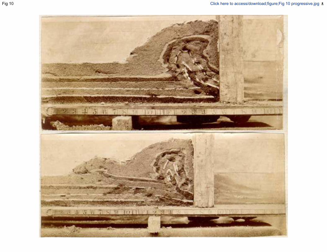
Fig 10 Click here to access/download;figure;Fig 10 progressive.jpg

figure 11 Click here to access/download;figure;Fig 11 fanlo.jpg

figure 12 Click here to access/download;figure;Fig 12 basementmodello.jpg

figure 13 Click here to access/download;figure;Fig 13 foldthrustlo.jpg

a)
b)
figure 14 Click here to access/download;figure;Fig 14 Southern.pdf