
HemaTek 2000 Book.book - LabWrench
98
-
Upload
khangminh22 -
Category
Documents
-
view
2 -
download
0
Transcript of HemaTek 2000 Book.book - LabWrench
© 2008 Siemens Healthcare Diagnostics Inc. All rights reserved.
No part of this manual or the products it describes may be reproduced by any means in any form without prior consent in writing from Siemens.
Hematek is a trademark of Siemens Healthcare Diagnostics.
Origin: United States
The information in this manual was correct at the time of printing. However, Siemens continues to improve products and reserves the right to change specifications, equipment, and maintenance procedures at any time without notice.
If the Hematek system is used in a manner not specified by Siemens, the protection provided by the equipment may be impaired. See warning and hazard statements.
Contents
Contents
Section 1: Introduction............................................................................................ 1-3General Description and Intended Use...........................................................................................1-3
Theory of Operation .................................................................................................................1-4Physical Characteristics....................................................................................................................1-5
Circular Bubble Level ...............................................................................................................1-5Levelers ..................................................................................................................................1-5
Slide Transport System.....................................................................................................................1-6Conveyor Spirals .....................................................................................................................1-6Platen .....................................................................................................................................1-6Slide Drying System .................................................................................................................1-7Slide Drawer ...........................................................................................................................1-7Waste Tank .............................................................................................................................1-7
Staining System .................................................................................................................................1-8Volume Control Panel ..............................................................................................................1-8Solution Pumps .......................................................................................................................1-8Pump Tubing and Cannulas ......................................................................................................1-9Sensing Switches ....................................................................................................................1-10
Electrical System ...............................................................................................................................1-11Operating Lever .......................................................................................................................1-11POWER Light ..........................................................................................................................1-12LOW STAIN Light ....................................................................................................................1-12Power Module .........................................................................................................................1-12Line Cord Receptacle ...............................................................................................................1-12Fuse Holder ............................................................................................................................1-13ON / OFF Switch .....................................................................................................................1-13
Specifications .....................................................................................................................................1-13Disposal of System Waste and Supplies ..................................................................................1-14
Section 2: Installation............................................................................................... 2-3Overview .............................................................................................................................................2-3Environmental Factors ......................................................................................................................2-3Unpacking...........................................................................................................................................2-4Instrument Setup ...............................................................................................................................2-4
Level the Instrument ................................................................................................................2-4Plug the Line Cord into an Outlet ...............................................................................................2-5Performance Check (Prior to Installing Tubing) ...........................................................................2-5Install the Pump Tubing ............................................................................................................2-6Install the Stain Pak .................................................................................................................2-9Inspect Waste Tank and Slide Drawer .......................................................................................2-10Familiarize Yourself with the Instrument .....................................................................................2-10Check Pump Volumes ..............................................................................................................2-10
Section 3: Operating Instructions ........................................................................... 3-3
Contents
General Guidelines for Optimal Staining ........................................................................................3-3Operating Procedures .......................................................................................................................3-3
Start the Instrument .................................................................................................................3-3Prime the Tubing .....................................................................................................................3-4Load the Blood Smear Slides ....................................................................................................3-5Stain the Smears .....................................................................................................................3-6Clean the Tubing after Use .......................................................................................................3-7Turn the Instrument Off at the End of the Day .............................................................................3-7
Stain Pak Replacement ....................................................................................................................3-7
Section 4: Specimens............................................................................................... 4-3Overview .............................................................................................................................................4-3Peripheral Blood Smears..................................................................................................................4-3Bone Marrow Smears .......................................................................................................................4-5
Section 5: Maintenance ............................................................................................. 5-3General Cleaning...............................................................................................................................5-3Daily Cleaning ....................................................................................................................................5-3
Cleaning the Platen ..................................................................................................................5-3Cleaning the Stain Tubing and Cannula .....................................................................................5-4Emptying the Waste Tank .........................................................................................................5-6
Weekly Cleaning................................................................................................................................5-6Cleaning Drain Troughs and Rear Guide Rail .............................................................................5-6
Decontamination and Removal from Operation ............................................................................5-9
Section 6: Minor Replacements and Adjustments ................................................. 6-3Fuse Replacement ............................................................................................................................6-3Replacement of Light Assemblies ...................................................................................................6-4Replacement of the Pump Tubing...................................................................................................6-7Replacement of the Underplaten Tubing........................................................................................6-11Pump Volume Adjustment ................................................................................................................6-14
Check and Correct Instrument Operation Prior to Pump Volume Adjustment .................................6-15Adjust the Stain, Buffer, and Rinse Volumes ..............................................................................6-15
Volume and Ratio Determination.....................................................................................................6-17Sensing Switch Fingers Adjustment................................................................................................6-18
Section 7: Troubleshooting ..................................................................................... 7-3Checklist for Quality of Stained Blood Smears ..............................................................................7-3Troubleshooting Chart.......................................................................................................................7-4
Section 8: Service, Supplies, and Replacement Parts .......................................... 8-3
Contents
When to Call for Service ...................................................................................................................8-3For Service .........................................................................................................................................8-3
Siemens Authorized Representative ..........................................................................................8-3Siemens Offices Worldwide .....................................................................................................8-4
Returning the Instrument for Repair, Exchange, Replacement, or Loaner................................8-7Supplies and Replacement Parts ....................................................................................................8-8
Hematek Stain Pak – Modified Wright’s Stain .............................................................................8-8Hematek Stain Pak – Modified Wright-Giemsa Stain ...................................................................8-8Hematek Cannula Set ..............................................................................................................8-8Hematek Pump Tube Set .........................................................................................................8-9Hematek Underplaten Tubing ...................................................................................................8-9Ordering Information for Supplies and Replacement Parts ...........................................................8-10
Appendix A: List of Symbols ................................................................................... A-1Symbols Used With This System ....................................................................................................A-1
Appendix B: Hematek Preservice Checklist........................................................... B-1

Contents

Section 1: Introduction, Page 1—1
Section 1: Introduction............................................................................................ 1-3General Description and Intended Use...........................................................................................1-3
Theory of Operation .................................................................................................................1-4Physical Characteristics....................................................................................................................1-5
Circular Bubble Level ...............................................................................................................1-5Levelers ..................................................................................................................................1-5
Slide Transport System.....................................................................................................................1-6Conveyor Spirals .....................................................................................................................1-6Platen .....................................................................................................................................1-6Slide Drying System .................................................................................................................1-7Slide Drawer ...........................................................................................................................1-7Waste Tank .............................................................................................................................1-7
Staining System .................................................................................................................................1-8Volume Control Panel ..............................................................................................................1-8Solution Pumps .......................................................................................................................1-8Pump Tubing and Cannulas ......................................................................................................1-9Sensing Switches ....................................................................................................................1-10
Electrical System ...............................................................................................................................1-11Operating Lever .......................................................................................................................1-11POWER Light ..........................................................................................................................1-12LOW STAIN Light ....................................................................................................................1-12Power Module .........................................................................................................................1-12Line Cord Receptacle ...............................................................................................................1-12Fuse Holder ............................................................................................................................1-13ON / OFF Switch .....................................................................................................................1-13
Specifications .....................................................................................................................................1-13Disposal of System Waste and Supplies ..................................................................................1-14

Page 1—2, Section 1: Introduction
Section 1: Introduction, Page 1—3
Section 1: Introduction
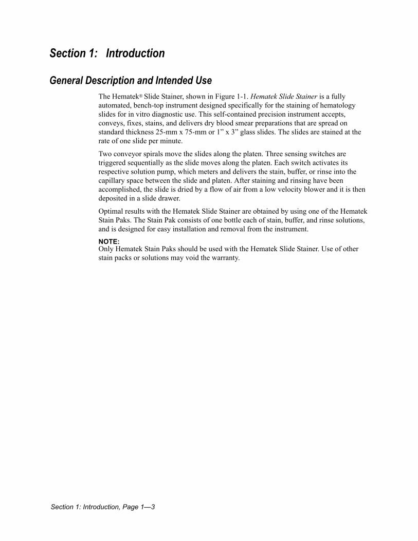
General Description and Intended UseThe Hematek® Slide Stainer, shown in Figure 1-1. Hematek Slide Stainer is a fully automated, bench-top instrument designed specifically for the staining of hematology slides for in vitro diagnostic use. This self-contained precision instrument accepts, conveys, fixes, stains, and delivers dry blood smear preparations that are spread on standard thickness 25-mm x 75-mm or 1” x 3” glass slides. The slides are stained at the rate of one slide per minute.
Two conveyor spirals move the slides along the platen. Three sensing switches are triggered sequentially as the slide moves along the platen. Each switch activates its respective solution pump, which meters and delivers the stain, buffer, or rinse into the capillary space between the slide and platen. After staining and rinsing have been accomplished, the slide is dried by a flow of air from a low velocity blower and it is then deposited in a slide drawer.
Optimal results with the Hematek Slide Stainer are obtained by using one of the Hematek Stain Paks. The Stain Pak consists of one bottle each of stain, buffer, and rinse solutions, and is designed for easy installation and removal from the instrument.
NOTE: Only Hematek Stain Paks should be used with the Hematek Slide Stainer. Use of other stain packs or solutions may void the warranty.

Page 1—4, Section 1: Introduction
Theory of OperationThe Hematek Slide Stainer is designed to produce stained slides of consistent quality in a continuous process. This is accomplished by having a fixed length of time in each of the three phases of stain, buffer, and rinse, as well as a predetermined ratio of stain-to-buffer volumes in the buffer phase.
A properly stained slide is the result of an interactive process involving the pump volumes, the mixing process, and the stain-to-buffer ratio. A minimum ratio of 1:2 is recommended; however, if the platen is filling properly, good mixing is occurring, and the stained slides are acceptable under the microscope, the stain-to-buffer ratio should not be adjusted.
Figure 1-1. Hematek Slide Stainer
Section 1: Introduction, Page 1—5
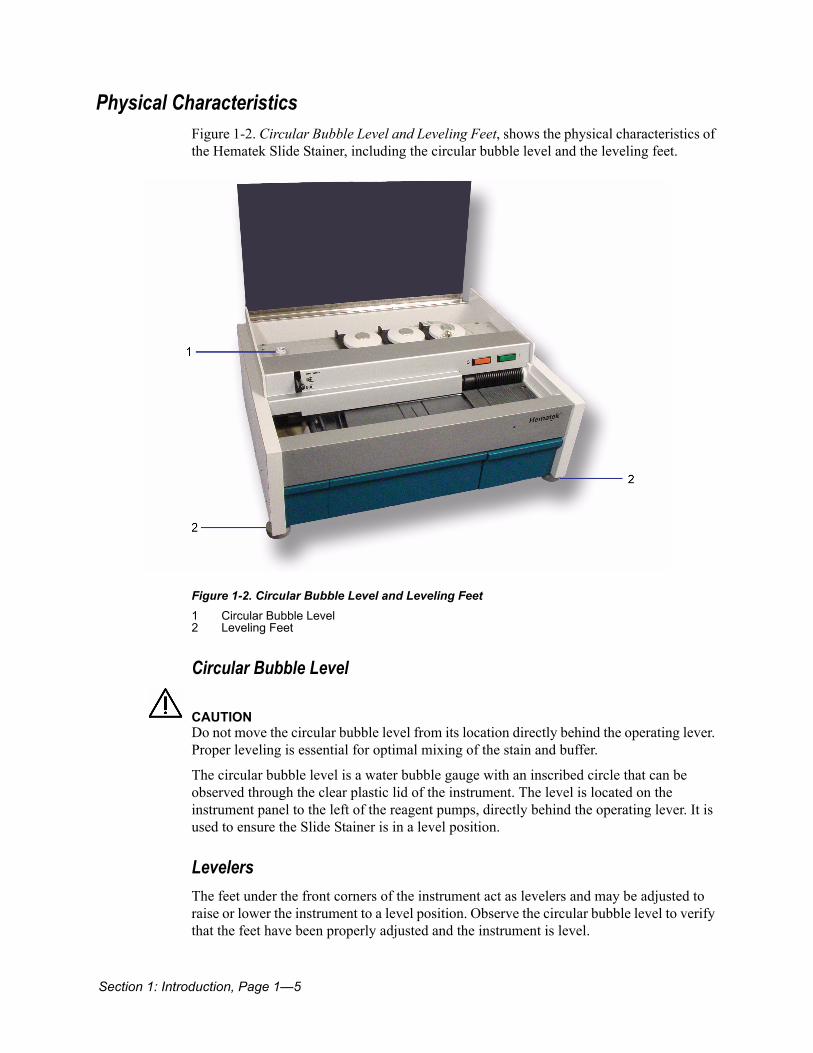
Physical CharacteristicsFigure 1-2. Circular Bubble Level and Leveling Feet, shows the physical characteristics of the Hematek Slide Stainer, including the circular bubble level and the leveling feet.
Figure 1-2. Circular Bubble Level and Leveling Feet
Circular Bubble Level
CAUTIONDo not move the circular bubble level from its location directly behind the operating lever. Proper leveling is essential for optimal mixing of the stain and buffer.
The circular bubble level is a water bubble gauge with an inscribed circle that can be observed through the clear plastic lid of the instrument. The level is located on the instrument panel to the left of the reagent pumps, directly behind the operating lever. It is used to ensure the Slide Stainer is in a level position.
LevelersThe feet under the front corners of the instrument act as levelers and may be adjusted to raise or lower the instrument to a level position. Observe the circular bubble level to verify that the feet have been properly adjusted and the instrument is level.
1 Circular Bubble Level2 Leveling Feet
Page 1—6, Section 1: Introduction
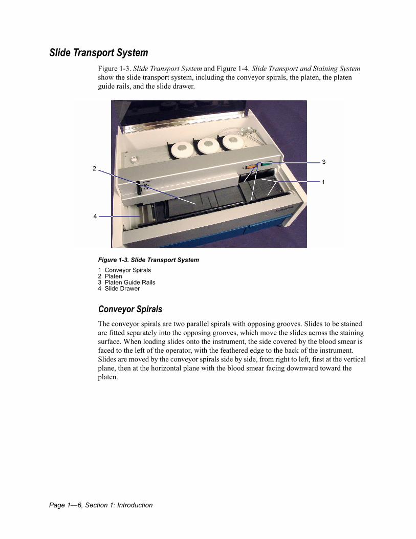
Slide Transport SystemFigure 1-3. Slide Transport System and Figure 1-4. Slide Transport and Staining System show the slide transport system, including the conveyor spirals, the platen, the platen guide rails, and the slide drawer.
Figure 1-3. Slide Transport System
Conveyor SpiralsThe conveyor spirals are two parallel spirals with opposing grooves. Slides to be stained are fitted separately into the opposing grooves, which move the slides across the staining surface. When loading slides onto the instrument, the side covered by the blood smear is faced to the left of the operator, with the feathered edge to the back of the instrument. Slides are moved by the conveyor spirals side by side, from right to left, first at the vertical plane, then at the horizontal plane with the blood smear facing downward toward the platen.
1 Conveyor Spirals2 Platen3 Platen Guide Rails4 Slide Drawer
Section 1: Introduction, Page 1—7
PlatenThe platen spans the entire front of the instrument, between the conveyor spirals. The outside ridges of the platen are elevated guide rails, which give support to the slides as they are moved along the platen. It is a precision-machined component made from a high-performance plastic polymer material and is designed specifically for two main functions:
1. It maintains the exact volumes of the required solutions within a capillary space between the platen and the slide.
2. It provides a mixing system for the stain and buffer.
The platen also provides the necessary time interval after the rinsing step for proper drying of the slides before they are deposited in the slide drawer. A trough around the perimeter of the platen allows for drainage of used solutions into the waste tank below.
Slide Drying SystemThe dryer is a blower type fan that runs continuously when the instrument is in operation. The airflow serves to cool the mechanical components inside the Slide Stainer, as well as to dry the slides.
Slide DrawerThe slide drawer is located below the left end of the platen. It receives the slides as they drop from the platen after being stained, rinsed, and dried. The drawer will hold 100 slides. See Figure 1-4. Slide Transport and Staining System .
Waste TankThe waste tank is located underneath the platen and collects used and overflow staining solutions. The waste tank should be emptied and rinsed once each day and whenever a new Stain Pak is installed. Refer to Section 5: Maintenance for more information.
Page 1—8, Section 1: Introduction
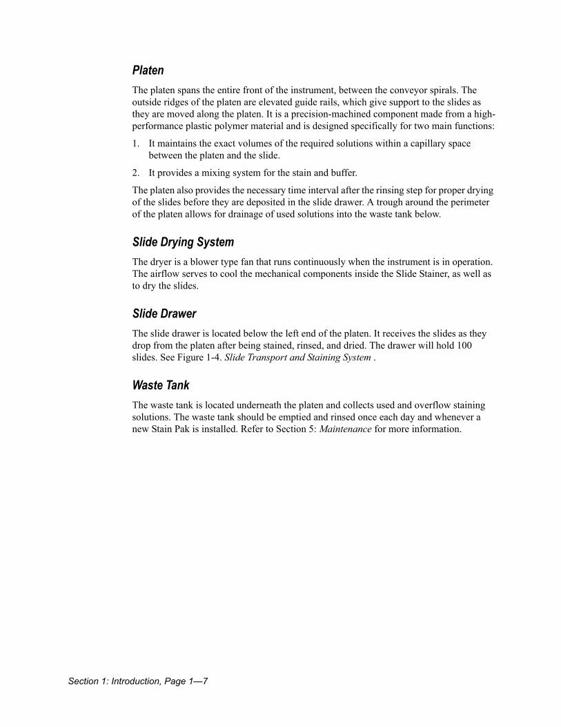
Staining SystemFigure 1-4. Slide Transport and Staining System , Figure 1-5. Staining Systems, and Figure 1-6. Sensing Switches, illustrate the staining system, including the volume control panel, pump assemblies, pump cap, pump arm, pump tubing, and cannula.
Figure 1-4. Slide Transport and Staining System
Volume Control PanelThe volume control panel tips out from the right front corner of the instrument and contains three graduated adjustment knobs. The volume of reagent being delivered can be adjusted by rotating the respective control dial clockwise to increase the volume or counterclockwise to decrease the volume.
Solution PumpsThe instrument has three pump assemblies, one for each solution. Each assembly consists of a pump motor, four rollers that are attached to the underside of a pump cap, and a pump arm. All work together to maintain a constant metering speed to provide consistent volumes of stain, buffer, and rinse, even though the line voltage may fluctuate. The amount of solution pumped is electronically adjusted through the use of the volume control knobs.
1 Slide Drawer2 Waste Tank3 Volume Control Panel
Section 1: Introduction, Page 1—9
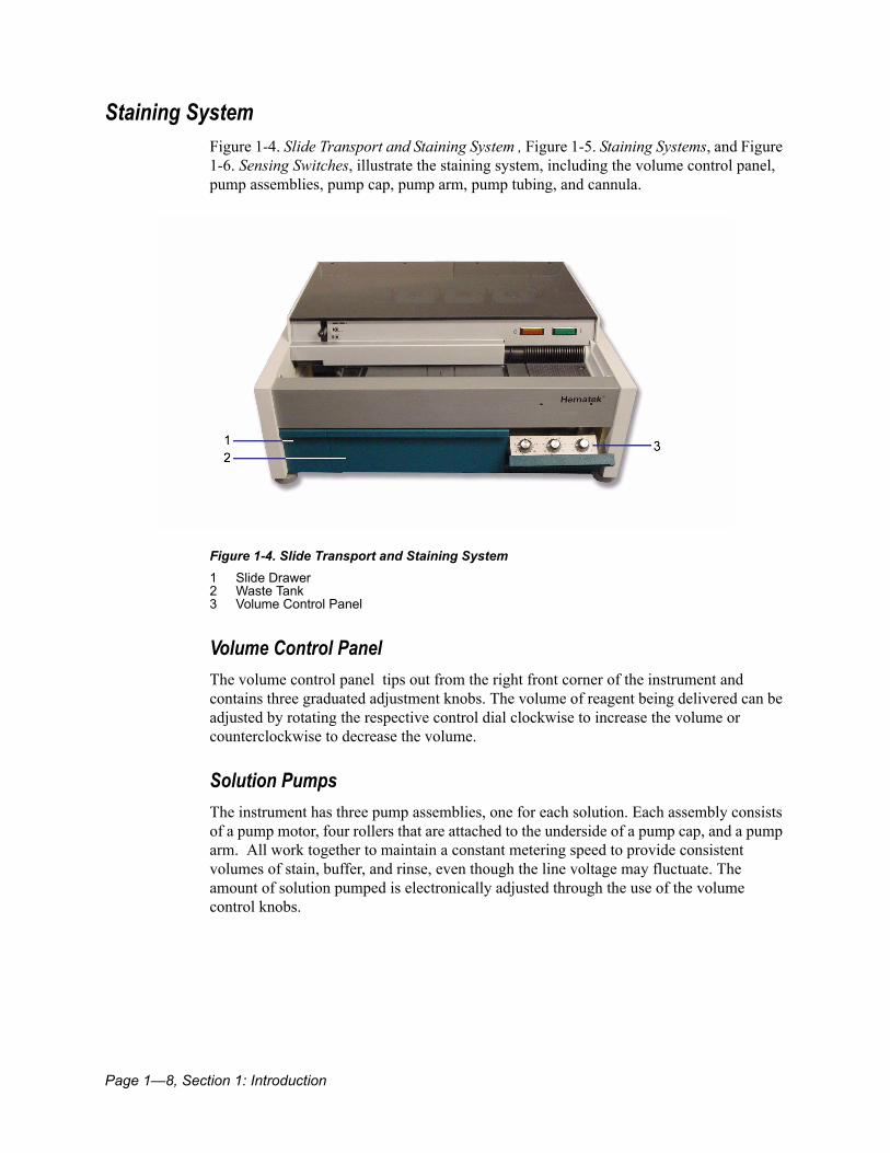
Figure 1-5. Staining Systems
Pump Tubing and Cannulas
CAUTIONUse only the Hematek Pump Tube Set with the Hematek Slide Stainer. Use of other tubing may result in incorrect measurement and improper staining, buffering, and rinsing.
The pump tubing is provided as a set of three separate pieces of tubing. Notice that each pump tube is identified with a number and symbol, which corresponds to the reagent carried by the tubing:
• 1 for stain• 2 for buffer• 3 for rinse
Each tube has a clear plastic cuff that fits snugly up to the pump arm and holds the tube in position without slippage. The tubing is a special type of rubber that is resistant to leaching and brittleness. The special diameters and lengths of the tubing assure precise measurement of solutions. Each pump tube is connected to a cannula that is inserted into the appropriate bottle in the Stain Pak. Three cannulas are provided with the Hematek Slide Stainer. With proper routine cleaning, the cannulas can be used for an extended period of time.
1 Pump Assemblies2 Pump Cap3 Pump Arm4 Pump Tubing5 Cannula

Page 1—10, Section 1: Introduction
Sensing SwitchesThe sensing switches are three finger-like devices located just above the back edge of the platen. When contacted, the respective sensing switch is activated, which tells the instrument that a slide is in position for the pump to run. After a specific time delay, the pumping motor for the specific reagent is activated. The solution pumps are set so that precise volumes of stain, buffer, and rinse are delivered to their respective areas on the platen. Each reagent is delivered through its respective cannula and tubing network to the platen orifice. The capillary space between the slide and the platen is then filled with the measured volume of reagent.
Figure 1-6. Sensing Switches 1 Sensing Switches
Section 1: Introduction, Page 1—11
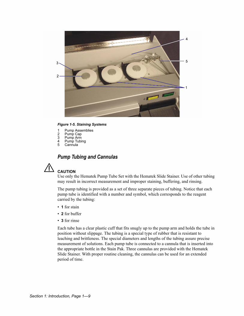
Electrical SystemFigure 1-7. Electrical System and Figure 1-8. Electrical System–Rear of Instrument illustrate the components of the electrical system.
Figure 1-7. Electrical System
Operating LeverThe operating lever is a multiple function, bar-shaped lever located at the front left side of the instrument, near the top. The three positions of the lever are labeled and their related functions are as follows:
• UNLOCK releases the pressure of the reagent pump arms against the pump tubing.• LOCK locks the reagent pump arms into their proper position against the pump tubing.• PRIME provides an override control to allow the pumps to run continuously so the tubes
can be primed with solutions and cleared of air bubbles. The lever must be held continuously in the PRIME position. When released, it returns automatically to the LOCK position.
1 Operating Lever2 Power Light3 Low Stain Light

Page 1—12, Section 1: Introduction
POWER LightThe green POWER light is located at the right side of the instrument near the top. When the instrument is turned on, the light illuminates.
LOW STAIN LightThe yellow LOW STAIN light is to the left of the POWER light. It is off under usual operating conditions; however, when the Hematek Stain Pak contains sufficient reagents to stain only about 20 slides, a weight-sensing device activates the circuit and illuminates the light. The Stain Pak should be replaced at this time.
Power ModuleThe power module is located on the rear of the instrument; on one side of the module is the panel that contains the line cord receptacle, fuse, and power switch. The power module converts the line current coming into the instrument to 12 volts DC, which is the voltage within the instrument.
Figure 1-8. Electrical System–Rear of Instrument
Line Cord ReceptacleThe line cord connects into the line cord receptacle, which is located at the top of the panel on the power module.
1 Power Module2 ON / OFF Switch3 Fuse Holder4 Line Cord Receptacle

Section 1: Introduction, Page 1—13
Fuse HolderThe fuse holder, in the center of the panel, holds the fuse that protects against serious electrical overload. A spare fuse is also located in the fuse holder.
ON / OFF SwitchThe ON / OFF Switch is located at the bottom of the panel and controls all power to the instrument.
Specifications
Power Requirements 100 - 230 VAC + 10%, 50/60 Hz, 0.75 Amps
Fuse Rating 250 Volt, 1.0 Amps, 5mm x 20mm, Type T
Line Leakage Current <5 milliamperesTesting protocol and allowable limits as specified by the safety standards for laboratory equipment outlined in UL 1262 and CSA 22.2 No. 151.
Dimensions Depth - 43.4 cm (17.1 in)Width - 47.0 cm (18.5 in)Height - 19.0 cm (7.5 in)
Weight 17.7 kg (39 lbs)
Throughput Stains 1 slide per minute
Page 1—14, Section 1: Introduction
Disposal of System Waste and Supplies Laws and regulations enacted to protect the environment and to encourage resource conservation require the disposal of hazardous and biohazardous wastes in a specified manner. Some of the wastes from the Hematek Slide Stainer can be classified as hazardous or biohazardous wastes. It is essential that the laboratory take appropriate steps to determine the laws and regulations applicable to their disposal and to effect compliance. If it is necessary to sample instrument wastes and effluent in order to evaluate compliance with applicable regulations, the laboratory should contact a local licensed biohazardous waste disposal firm for assistance.
The principal wastes associated with the use of the Hematek Slide Stainer are pump and underplaten tubing, effluents from the staining operation, and the container for stain, buffer, and rinse.
Slides with human specimens, control materials, and all reagents, should also be handled and disposed of in accordance with the prevailing regulations and guidelines of agencies with jurisdiction over the laboratory. Refer to the product label and to Material Safety Data Sheets for details concerning any special precautions related to the handling of Hematek Stain Pak containers. Material Safety Data Sheets are available from Siemens.
BIOHAZARD Wear personal protective equipment. Use universal precautions. Refer to Appendix A, page A-1 for recommended precautions when working with biohazardous materials.
Section 2: Installation, Page 2—1
Section 2: Installation............................................................................................... 2-3Overview .............................................................................................................................................2-3Environmental Factors ......................................................................................................................2-3Unpacking...........................................................................................................................................2-4Instrument Setup ...............................................................................................................................2-4
Level the Instrument ................................................................................................................2-4Plug the Line Cord into an Outlet ...............................................................................................2-5Performance Check (Prior to Installing Tubing) ...........................................................................2-5Install the Pump Tubing ............................................................................................................2-6Install the Stain Pak .................................................................................................................2-9Inspect Waste Tank and Slide Drawer .......................................................................................2-10Familiarize Yourself with the Instrument .....................................................................................2-10Check Pump Volumes ..............................................................................................................2-10

Page 2—2, Section 2: Installation

Section 2: Installation, Page 2—3
Section 2: Installation
OverviewThis section provides detailed installation and setup instructions for the Hematek Slide Stainer. The installation steps must be followed correctly to ensure proper installation, operation, and service. Read this Operator’s Guide carefully before attempting to operate the instrument. Follow all instructions carefully.
The Hematek Slide Stainer is a precision instrument and must be handled accordingly. Rough handling or dropping of the instrument will disturb or damage internal components. Always handle the instrument with care.
Environmental FactorsAs with all sensitive electronic instruments, prolonged exposure to excessive humidity and temperature should be avoided. Temperature should be held relatively constant to obtain the highest degree of operating stability. The ambient temperature range for operating the instrument is 18ºC to 30ºC (64ºF to 86ºF). The ambient operating humidity range is 20% to 85% relative humidity.
Place the instrument in a well-ventilated area, avoiding exposure to corrosive vapors or temperature extremes. Be sure it is near a power source that meets the electrical requirements (voltage) specified on the rating label located on the rear of the instrument. Avoid proximity to open windows, sinks, ovens, hot plates, open burners, radiators, and dry ice baths. The instrument should not be used in an explosive atmosphere.

Page 2—4, Section 2: Installation
Unpacking Before opening the shipping carton, inspect it for visible signs of damage. Use the following steps to unpack the instrument.
1. Carefully remove the Hematek instrument and supplies from the shipping carton.The following items are provided with the instrument:
• Hematek pump tube set
• Hematek cannula set
• operating manual
• line cord
• warranty card - for use by US customers only
• FedEx PRP label - for use by US customers only
2. If the instrument shows any visible signs of damage, immediately file a complaint with the carrier.
3. Retain the shipping carton for further use. If the instrument ever needs to be shipped, the shipping carton will afford the best protection.
4. After the instrument has been unpacked, place it on a firm, level work surface in the designated work are by lifting the instrument by its frame.
Instrument SetupComplete the following procedures to ensure proper installation and performance of your Slide Stainer.
Level the Instrument
CAUTIONDo not move the circular bubble level from its location directly behind the operating lever. Proper leveling is essential for optimal mixing of the stain and buffer.
1. Raise the hinged lid of the instrument and locate the circular bubble level.The circular bubble level is located on the instrument panel to the left of the reagent pumps, directly behind the operating lever.

Section 2: Installation, Page 2—5
2. Adjust the two feet located under the front corners of the instrument to raise or lower the instrument to a level position.
Figure 2-1. Leveling the Instrument
3. Observe the circular bubble level to indicate when the feet have been properly adjusted and the instrument is level. The bubble in the level should be centered within the inscribed circle.
NOTE: If necessary, make a final leveling check and adjustment by watching the flow of the waste fluids during staining. Fluids should flow evenly to the drain hole at the left-front corner of the waste trough.
Plug the Line Cord into an Outlet
CAUTIONBe sure the outlet supplies the proper voltage for your instrument. Refer to the rating label located on the rear of the instrument to determine the proper voltage ratingPlug the appropriate end of the line cord into the instrument and the other end into an appropriately grounded AC electrical outlet.
Performance Check (Prior to Installing Tubing)1. Turn the instrument on by pressing the ON / OFF switch, located on the left side of the
power module at the rear of the instrument, to the ON position.
The green POWER light illuminates, the fan starts, and the conveyor spirals slowly revolves.
2. Inspect the slide dryer area for noticeable airflow.
3. Place five blank slides into the grooves on the right side of the conveyor spirals.
Page 2—6, Section 2: Installation
Be sure the slides are positioned in opposing slots, parallel to the inscribed lines on the platen.
4. Allow the slides to automatically feed onto the platen.
5. As the slides move down the platen, make sure the leading edge of the slides contact and activate each of the three sensing switch fingers, located along the back wall of the platen above the platen trough.As each switch is activated, the appropriate pump activates and you are able to observe the pump cap rotating.
6. If the instrument functions properly in these steps, continue with the instrument setup procedures.
7. If a problem occurred, contact the your local technical support provider or distributor. Refer to Section 8: Service, Supplies, and Replacement Parts for more information.
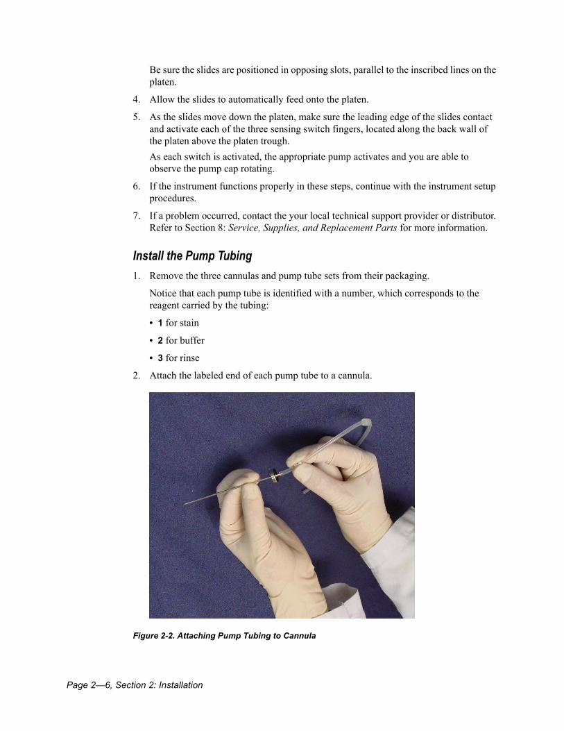
Install the Pump Tubing1. Remove the three cannulas and pump tube sets from their packaging.
Notice that each pump tube is identified with a number, which corresponds to the reagent carried by the tubing:
• 1 for stain
• 2 for buffer
• 3 for rinse
2. Attach the labeled end of each pump tube to a cannula.
Figure 2-2. Attaching Pump Tubing to Cannula
99E44889 Rev. D Section 2: Installation, Page 2—7
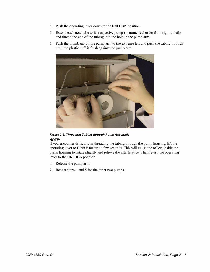
3. Push the operating lever down to the UNLOCK position.
4. Extend each new tube to its respective pump (in numerical order from right to left) and thread the end of the tubing into the hole in the pump arm.
5. Push the thumb tab on the pump arm to the extreme left and push the tubing through until the plastic cuff is flush against the pump arm.
Figure 2-3. Threading Tubing through Pump Assembly
NOTE: If you encounter difficulty in threading the tubing through the pump housing, lift the operating lever to PRIME for just a few seconds. This will cause the rollers inside the pump housing to rotate slightly and relieve the interference. Then return the operating lever to the UNLOCK position.
6. Release the pump arm.
7. Repeat steps 4 and 5 for the other two pumps.
Page 2—8, Section 2: Installation
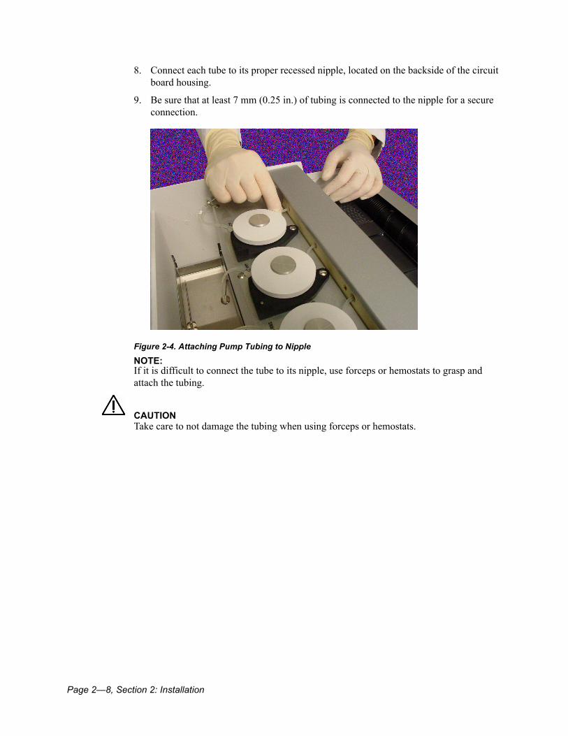
8. Connect each tube to its proper recessed nipple, located on the backside of the circuit board housing.
9. Be sure that at least 7 mm (0.25 in.) of tubing is connected to the nipple for a secure connection.
Figure 2-4. Attaching Pump Tubing to Nipple
NOTE: If it is difficult to connect the tube to its nipple, use forceps or hemostats to grasp and attach the tubing.
CAUTIONTake care to not damage the tubing when using forceps or hemostats.

Section 2: Installation, Page 2—9
Install the Stain Pak1. Remove the perforated tabs from the Hematek Stain Pak. Insert the carton, with the
STAIN bottle to the right, into the well at the rear of the instrument.
2. Make sure the carton is all the way down and resting on the tray at the bottom of the well. The carton should be level when properly installed.
Figure 2-5. Installing the Stain Pak
3. Insert the appropriate cannula into its respective bottle by puncturing the center of the indentation on the bottle.
Figure 2-6. Installing Cannula into Stain Pak Bottle
Page 2—10, Section 2: Installation
4. Remove the cannula, turn it 1/4 turn, and insert it again into the same puncture.
The double puncture creates a slightly larger hole for venting.NOTE: If additional venting is desired, a second hole can be made in the top of the bottle, near the indentation. A 20-gauge needle can be placed into the hole, if needed.
5. Push the cannula down until the guard at the top touches the plastic container.
6. Repeat steps 3 through 5 for each bottle.
Inspect Waste Tank and Slide DrawerInspect the waste tank and slide drawer for proper positioning below the platen. Each should be pushed completely into its respective cavity in the front of the instrument so it is flush with the control panel on the right front corner.
Familiarize Yourself with the InstrumentBefore beginning normal instrument use, carefully review Section 3: Operating Instructions, and Section 5: Maintenance, to become familiar with operating techniques and instrument cleaning requirements.
Check Pump VolumesCheck the pump volumes and adjust them if necessary by following the procedures in Pump Volume Adjustment on page 6-14 and Volume and Ratio Determination on page 6-17. Do this before staining any patient slides for clinical evaluations.
Section 3: Operating Instructions, Page 3—1
Section 3: Operating Instructions ........................................................................... 3-3General Guidelines for Optimal Staining ........................................................................................3-3Operating Procedures .......................................................................................................................3-3
Start the Instrument .................................................................................................................3-3Prime the Tubing .....................................................................................................................3-4Load the Blood Smear Slides ....................................................................................................3-5Stain the Smears .....................................................................................................................3-6Clean the Tubing after Use .......................................................................................................3-7Turn the Instrument Off at the End of the Day .............................................................................3-7
Stain Pak Replacement ....................................................................................................................3-7

Page 3—2, Section 3: Operating Instructions
Section 3: Operating Instructions, Page 3—3
Section 3: Operating InstructionsFollowing initial installation (see Section 2: Installation), the Hematek Slide Stainer is ready for routine operation. Carefully read this section before beginning any slide staining.
General Guidelines for Optimal Staining• Use high quality slides. Do not use slides of variable thickness. Bevel-edged slides
should not be used, as they may break in the instrument.• Make sure the blood smears are thoroughly dry before placing on the instrument for
staining.• Clean the stain tubing with methanol after each run, especially if the Slide Stainer is not
to be used for one hour or more.• Keep the staining grooves and guide rails clean, as instructed in Cleaning the Platen on
page 5-3. Use only methanol to clean.• Change the pump tubing and underplaten tubing on a routine basis. Refer to
Replacement of the Pump Tubing on page 6-7 and Replacement of the Underplaten Tubing on page 6-11 for recommended frequency.
• Check the alignment of the sensing switch fingers, as instructed in step 5 of Check and Correct Instrument Operation Prior to Pump Volume Adjustment on page 6-15.
Operating Procedures
CAUTIONUse Hematek Stain Paks only. Other solutions may contain non-dissolved or particulate materials.
Start the Instrument1. Turn the instrument on by pressing the ON / OFF switch, located on the left side of the
power module at the rear of the instrument, to the ON position.The green POWER light will illuminate, the fan will start, and the conveyor spirals will begin to slowly revolve.
NOTE: When the Hematek Stain Pak contains sufficient reagents to stain only about 20 slides, the yellow LOW STAIN light will illuminate to indicate the need for replacement of the Stain Pak. Refer to Stain Pak Replacement on page 3-7.
Page 3—4, Section 3: Operating Instructions
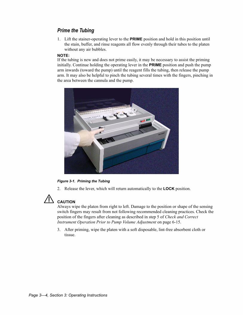
Prime the Tubing1. Lift the stainer-operating lever to the PRIME position and hold in this position until
the stain, buffer, and rinse reagents all flow evenly through their tubes to the platen without any air bubbles.
NOTE: If the tubing is new and does not prime easily, it may be necessary to assist the priming initially. Continue holding the operating lever in the PRIME position and push the pump arm inwards (toward the pump) until the reagent fills the tubing, then release the pump arm. It may also be helpful to pinch the tubing several times with the fingers, pinching in the area between the cannula and the pump.
Figure 3-1. Priming the Tubing
2. Release the lever, which will return automatically to the LOCK position.
CAUTIONAlways wipe the platen from right to left. Damage to the position or shape of the sensing switch fingers may result from not following recommended cleaning practices. Check the position of the fingers after cleaning as described in step 5 of Check and Correct Instrument Operation Prior to Pump Volume Adjustment on page 6-15.
3. After priming, wipe the platen with a soft disposable, lint-free absorbent cloth or tissue.

Section 3: Operating Instructions, Page 3—5
Load the Blood Smear Slides
BIOHAZARDWear personal protective equipment. Use universal precautions. Refer to Appendix A, page A-1 for recommended precautions when working with biohazardous materials.
1. Prime the platen.The platen should be primed and wetted with reagents in order to ensure optimal results on the specimen slides.
2. Mark blank or old blood smear slides as priming slides (for example, label them with the name PRIME).You can reuse these priming slides
CAUTIONSlides must be inserted into the spiral grooves so they are parallel to the slide loading lines inscribed on the platen. If slides are not placed correctly in the spiral grooves, breakage can occur.
3. Load two to four priming slides and allow them to be transported across the platen ahead of the patient slides.
Figure 3-2. Priming the Platen
Page 3—6, Section 3: Operating Instructions
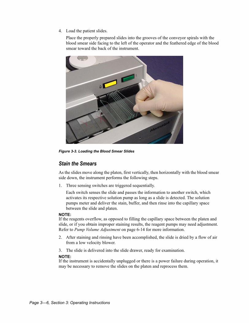
4. Load the patient slides.Place the properly prepared slides into the grooves of the conveyor spirals with the blood smear side facing to the left of the operator and the feathered edge of the blood smear toward the back of the instrument.
Figure 3-3. Loading the Blood Smear Slides
Stain the SmearsAs the slides move along the platen, first vertically, then horizontally with the blood smear side down, the instrument performs the following steps.
1. Three sensing switches are triggered sequentially.Each switch senses the slide and passes the information to another switch, which activates its respective solution pump as long as a slide is detected. The solution pumps meter and deliver the stain, buffer, and then rinse into the capillary space between the slide and platen.
NOTE: If the reagents overflow, as opposed to filling the capillary space between the platen and slide, or if you obtain improper staining results, the reagent pumps may need adjustment. Refer to Pump Volume Adjustment on page 6-14 for more information.
2. After staining and rinsing have been accomplished, the slide is dried by a flow of air from a low velocity blower.
3. The slide is delivered into the slide drawer, ready for examination.NOTE: If the instrument is accidentally unplugged or there is a power failure during operation, it may be necessary to remove the slides on the platen and reprocess them.
Section 3: Operating Instructions, Page 3—7
Clean the Tubing after UseIf no slides are to be processed for an extended period (one hour or more), it is recommended that the stain tubing be cleaned with methanol as described in Cleaning the Stain Tubing and Cannula on page 5-4. Push the operating lever down to the UNLOCK position to relieve the pressure against the pump tubing. You must re-prime the tubing and the platen before processing any more slides.
Turn the Instrument Off at the End of the Day
CAUTIONAlways clean the instrument after daily use. See Daily Cleaning on page 5-3. If using frosted-end slides, it is especially important to clean the front guide rail on a regular and frequent basis. This is because the stain may spread across the frosted portion of the slide to the front rail. If allowed to accumulate, slide breakage may occur.
1. At the end of the day, clean the platen and stain tubing, and empty the waste tank.
2. Push the operating lever to the UNLOCK position.
3. Turn the instrument off.
Stain Pak ReplacementIf the LOW STAIN light illuminates when the instrument is first turned on or while slides are being processed, a new Hematek Stain Pak is needed. Follow these steps to replace the Stain Pak.
CAUTIONAfter replacement of the Stain Pak, the instrument must always be primed to remove any air bubbles that may be present.
1. Remove the three cannulas from the used Stain Pak and lift the empty carton out of the well at the rear of the instrument.
2. Remove the perforated tabs from the new Stain Pak carton.
3. Insert the carton with the STAIN bottle to the right into the well at the rear of the instrument.Make sure the carton is all the way down and resting on the tray at the bottom of the well. The carton should be level when properly installed.
4. Vent each bottle and insert the cannulas as described in Install the Stain Pak on page 2-9.
NOTE: Check the cannulas with each new Stain Pak and replace them if they appear bent or damaged.
5. Empty the waste tank into an appropriate receptacle and rinse it with water after each Stain Pak replacement. See Emptying the Waste Tank on page 5-6.

Page 3—8, Section 3: Operating Instructions

Section 4: Specimens, Page 4—1
Section 4: Specimens............................................................................................... 4-3Overview .............................................................................................................................................4-3Peripheral Blood Smears..................................................................................................................4-3Bone Marrow Smears .......................................................................................................................4-5

Page 4—2, Section 4: Specimens
Section 4: Specimens, Page 4—3
Section 4: Specimens
OverviewThe Hematek Slide Stainer is designed specifically for the automatic staining of peripheral blood smears that have been prepared on standard 25 mm x 75 mm or 1” x 3” glass slides. Blood smears that are stained according to instructions will provide the examiner with high quality differential staining characteristics for all cytologic blood components. See Section 3: Operating Instructions for staining instructions.
Peripheral Blood Smears
BIOHAZARDWear personal protective equipment. Use universal precautions. Refer to Appendix A, page A-1 for recommended precautions when working with biohazardous materials.
It is crucial to start with a properly prepared blood smear in order to obtain the best results on the stained slide. The following suggestions are recommended:
• Use high quality slides that are new and thoroughly cleaned.• Slides must be free of oil and grease.• Do not touch the slide surfaces with the fingers or against the skin of the patient.• Protect blank slides from moisture and high humidity, as well as contamination by
dust, flies, and other insects.• Store the slides covered in a cool, dry place.• Never use oxalated or heparinized blood for making blood smears.• EDTA is the anticoagulant of choice.• Protect blood smears from excessive heat (such as radiators and ovens), water
splatters, and high humidity.
Use the following procedure to prepare a blood smear.
1. Remove the cap from a tube of well-mixed anticoagulated whole blood. EDTA is the anticoagulant of choice.
NOTE: Blood should be kept at room temperature prior to preparing the smear. Adaquate mixing requires approximately 20 inversions prior to blood film preparation.
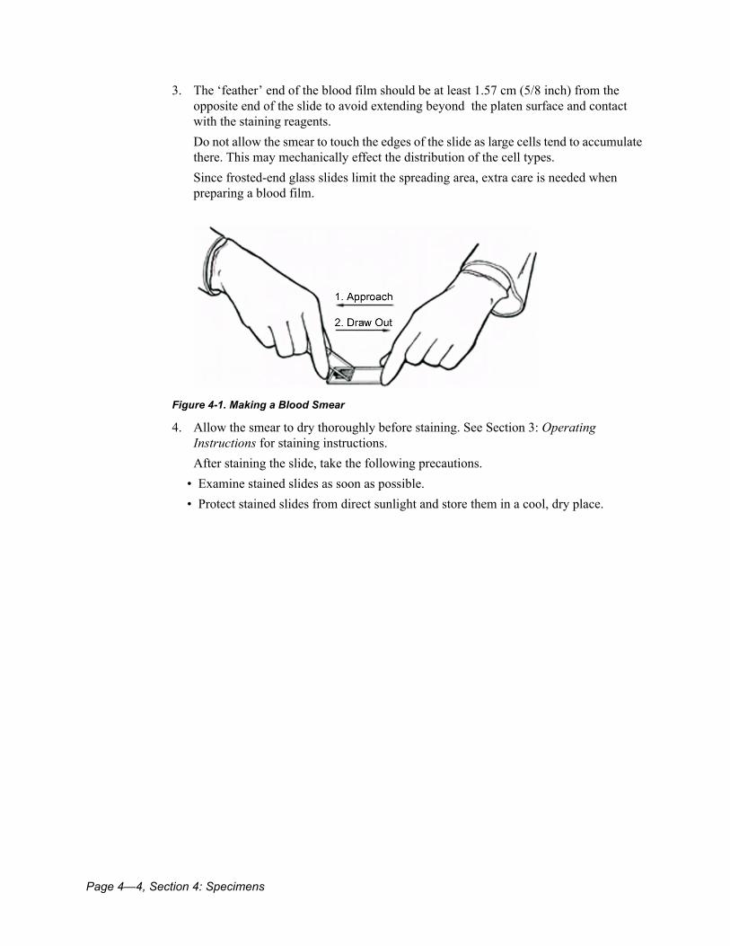
2. Place a drop of well-mixed blood near one end of a high quality slide. Hold a second spreader slide at about a 45 degree angle and approach the drop of blood. Allow the blood to spread almost to the width of of the slide edge. Then rapidly and smoothly push the spreader slide to the opposite end of the slide, pulling the blood behind it.
NOTE: The angle and speed at which the blood drop is spread determines the thickness or thiness, and length of the blood film.
Page 4—4, Section 4: Specimens
3. The ‘feather’ end of the blood film should be at least 1.57 cm (5/8 inch) from the opposite end of the slide to avoid extending beyond the platen surface and contact with the staining reagents.Do not allow the smear to touch the edges of the slide as large cells tend to accumulate there. This may mechanically effect the distribution of the cell types.Since frosted-end glass slides limit the spreading area, extra care is needed when preparing a blood film.
Figure 4-1. Making a Blood Smear
4. Allow the smear to dry thoroughly before staining. See Section 3: Operating Instructions for staining instructions.After staining the slide, take the following precautions.
• Examine stained slides as soon as possible.• Protect stained slides from direct sunlight and store them in a cool, dry place.
Section 4: Specimens, Page 4—5
Bone Marrow Smears
BIOHAZARDWear personal protective equipment. Use universal precautions. Refer to Appendix A, page A-1 for recommended precautions when working with biohazardous materials.
Many laboratories stain bone marrow smears with the same stain as is used for blood smears. The procedure involves using the “squash” technique for smear preparation and staining the slide once or twice on the Hematek Slide Stainer. The following procedure has been verified as giving clinically useful staining results on bone marrow slides; however, the stain quality is dependent upon the thickness and evenness of the bone marrow smear. A thick smear is more likely to require a second pass through the instrument than a thinner smear; an uneven smear will not stain uniformly.
1. Use bone marrow smears that have been prepared using the “squash” technique.Be sure the smear is thoroughly dry before staining.
2. Place the slide onto the Hematek Slide Stainer and stain according to instructions in Section 3: Operating Instructions.
3. Remove the slide after it has been stained and examine it under high power (dry) for the staining quality.Do not use any oil on the slide for this examination.
4. If the slide is under-stained, place it on the slide stainer again and stain it a second time. In rare instances, a third staining may be necessary.When using the Hematek Modified Wright Stain Pak (#4481), the bone marrow smears must be stained twice; one pass through the instrument is generally insufficient to produce distinct nuclear intensity. A third pass generally does not increase or decrease the quality of the staining.When using the Hematek Modified Wright-Giemsa Stain Pak (#4405), a single staining is generally sufficient for most bone marrow smears. The smear may become over stained, with the appearance of precipitate and nuclear artifacts, on slides stained two or more times.
5. Thoroughly clean the platen after staining bone marrow slides to remove the greasy residue that can be left on the platen by the fat droplets in the marrow

Page 4—6, Section 4: Specimens
Section 5: Maintenance, Page 5—1
Section 5: Maintenance ............................................................................................. 5-3General Cleaning...............................................................................................................................5-3Daily Cleaning ....................................................................................................................................5-3
Cleaning the Platen ..................................................................................................................5-3Cleaning the Stain Tubing and Cannula .....................................................................................5-4Emptying the Waste Tank .........................................................................................................5-6
Weekly Cleaning................................................................................................................................5-6Cleaning Drain Troughs and Rear Guide Rail .............................................................................5-6
Decontamination and Removal from Operation ............................................................................5-9

Page 5—2, Section 5: Maintenance
Section 5: Maintenance, Page 5—3
Section 5: MaintenanceThe Hematek Slide Stainer is a precision instrument, designed to provide trouble-free operation with a minimum of maintenance.
BIOHAZARDWear personal protective equipment. Use universal precautions. Refer to Appendix A, page A-1 for recommended precautions when working with biohazardous materials.
General CleaningKeep the exterior surfaces of the instrument free of dust at all times. If needed, the exterior may be cleaned using a damp cloth and mild detergent. A small amount of methanol may be used to clean stain from the instrument.
Daily CleaningIt is vitally important to clean the platen and tubing at least once each day in order to maintain consistently high quality staining results. It is also important to empty the waste tank at the end of each day.
Cleaning the PlatenAfter staining a large number of blood smears, precipitated stain solution tends to accumulate in the mixing grooves of the platen. This precipitate must be removed at regular intervals. Daily cleaning of the platen is imperative; after each run is optimal. Cleaning is especially important if bone marrow slides have been stained because the fat droplets can leave a greasy residue on the platen. Use the following procedure to clean the platen:
1. Turn the instrument off.
2. Carefully flood the working area of the platen with methanol.Avoid splashing the methanol.
CAUTIONAlways wipe the platen from right to left. Damage to the position or shape of the sensing switch fingers may result from not following recommended cleaning practices. Check the position of the fingers after cleaning as described in step 5 of Check and Correct Instrument Operation Prior to Pump Volume Adjustment on page 6-15.

Page 5—4, Section 5: Maintenance
3. After priming, wipe the platen with a soft, disposable, lint-free absorbent cloth or tissue.Wipe from right to left only.
Figure 5-1. Cleaning the Platen
CAUTIONIf using frosted-end slides, it is especially important that the front guide rail be cleaned on a regular and frequent basis. This is because the stain may spread across the frosted portion of the slide to the front rail. If allowed to accumulate, slide breakage may occur.
4. Thoroughly clean the mixing grooves and the front guide rail.
Cleaning the Stain Tubing and CannulaThe tubing carrying the stain should be cleaned at least once daily (or after each run), as described in the following procedure:
1. Remove the stain, buffer, and rinse cannulas from the Stain Pak bottles.NOTE: The buffer and rinse cannulas and tubing do not require cleaning. These cannulas are removed so the buffer and rinse solutions are not wasted while the stain tubing is being cleaned.
Section 5: Maintenance, Page 5—5
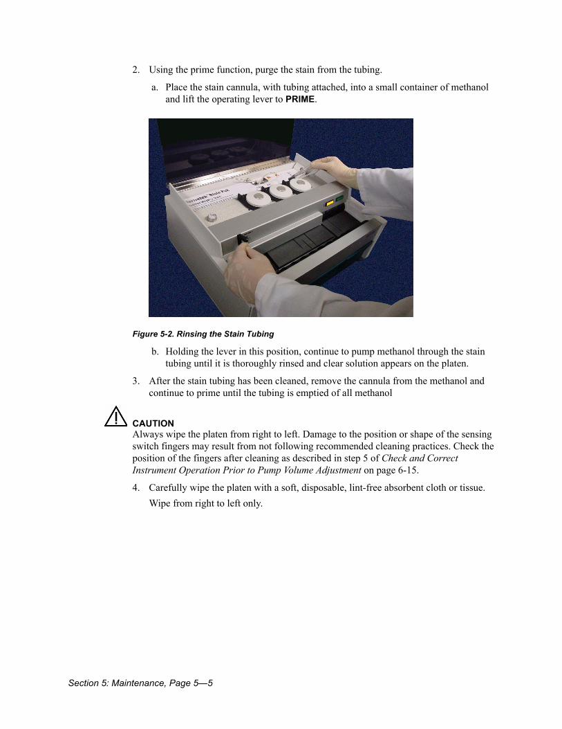
2. Using the prime function, purge the stain from the tubing.
a. Place the stain cannula, with tubing attached, into a small container of methanol and lift the operating lever to PRIME.
Figure 5-2. Rinsing the Stain Tubing
b. Holding the lever in this position, continue to pump methanol through the stain tubing until it is thoroughly rinsed and clear solution appears on the platen.
3. After the stain tubing has been cleaned, remove the cannula from the methanol and continue to prime until the tubing is emptied of all methanol
CAUTIONAlways wipe the platen from right to left. Damage to the position or shape of the sensing switch fingers may result from not following recommended cleaning practices. Check the position of the fingers after cleaning as described in step 5 of Check and Correct Instrument Operation Prior to Pump Volume Adjustment on page 6-15.
4. Carefully wipe the platen with a soft, disposable, lint-free absorbent cloth or tissue.Wipe from right to left only.
Page 5—6, Section 5: Maintenance
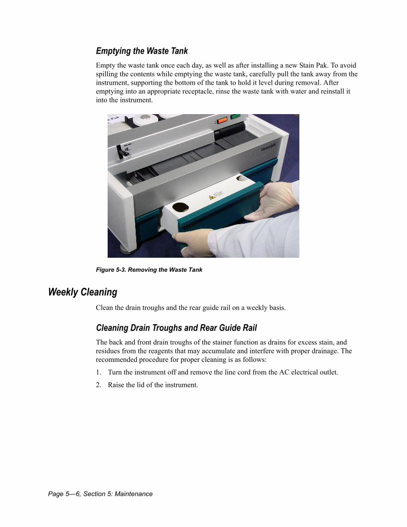
Emptying the Waste TankEmpty the waste tank once each day, as well as after installing a new Stain Pak. To avoid spilling the contents while emptying the waste tank, carefully pull the tank away from the instrument, supporting the bottom of the tank to hold it level during removal. After emptying into an appropriate receptacle, rinse the waste tank with water and reinstall it into the instrument.
Figure 5-3. Removing the Waste Tank
Weekly CleaningClean the drain troughs and the rear guide rail on a weekly basis.
Cleaning Drain Troughs and Rear Guide RailThe back and front drain troughs of the stainer function as drains for excess stain, and residues from the reagents that may accumulate and interfere with proper drainage. The recommended procedure for proper cleaning is as follows:
1. Turn the instrument off and remove the line cord from the AC electrical outlet.
2. Raise the lid of the instrument.

Section 5: Maintenance, Page 5—7
3. Loosen the two thumbscrews that are inserted through the notches in the back of the circuit board cover.
Figure 5-4. Location of Thumbscrews
4. Carefully raise the circuit board cover so the back trough is completely exposed and easily accessible.
Figure 5-5. Raising the Circuit Board Cover
5. Move the panel up and back, out of the way.The circuit board cover is connected to the instrument by the two connectors of the LOW STAIN and POWER lights. Rotate the panel carefully so the connectors are not pulled loose.

Page 5—8, Section 5: Maintenance
6. Flood both the front and back troughs with methanol to loosen any precipitated stain that may be present. Take care not to splash methanol onto the circuit board.
7. Using an applicator stick with a cotton swab attached, wipe from right to left along the length of the back and front troughs to remove the entire excess residue.
Figure 5-6. Cleaning the Back Trough
8. Clean other exposed areas that might be accidentally stained, including the rear guide rail, in the same careful manner.
NOTE: Ensure that you do not scratch the platen.
9. Return the circuit board cover to its normal position, between the circuit board panel and the back edge of the screws, and tighten the two thumbscrews.Be sure the panel is not resting on top of the screw heads before tightening.
Section 5: Maintenance, Page 5—9
Decontamination and Removal from Operation
BIOHAZARDWear personal protective equipment. Use universal precautions. Refer to Appendix A, page A-1 for recommended precautions when working with biohazardous materials.
Use this procedure to remove the Hematek system from operation for extended periods and prior to packing and shipping the system to another location or to an off-site service facility.
1. Remove and dispose of all slides in the appropriate receptacle.
2. Follow the first five steps of the Replacement of the Pump Tubing on page 6-7, procedure to empty and remove the pump tubing and discard it in an appropriate waste container.
3. Lift the used Hematek Stain Pak carton out of the well at the rear of the instrument.
4. Follow steps 3 through 8 of the Replacement of the Underplaten Tubing on page 6-11 to turn off the instrument and remove the underplaten tubing. Discard it in an appropriate waste container
5. Clean the platen with methanol, always wiping from right to left.
6. Empty the waste tank, fill with 10% solution of household bleach and water, empty the solution, and then rinse the tank with regular water.
7. Clean the exterior surfaces of the instrument with a damp cloth and mild detergent. A small amount of methanol may be used to clean stain from the instrument.
8. Screw the front feet all the way up.
The instrument is now ready for storage or for packing and shipping.

Page 5—10, Section 5: Maintenance
Minor Replacements and Adjustments, Page 6—1
Section 6: Minor Replacements and Adjustments ................................................. 6-3Fuse Replacement ............................................................................................................................6-3Replacement of Light Assemblies ...................................................................................................6-4Replacement of the Pump Tubing...................................................................................................6-7Replacement of the Underplaten Tubing........................................................................................6-11Pump Volume Adjustment ................................................................................................................6-14
Check and Correct Instrument Operation Prior to Pump Volume Adjustment .................................6-15Adjust the Stain, Buffer, and Rinse Volumes ..............................................................................6-15
Volume and Ratio Determination.....................................................................................................6-17Sensing Switch Fingers Adjustment................................................................................................6-18

Page 6—2, Section 6: Minor Replacements and Adjustments
Section 6: Minor Replacements and Adjustments, Page 6—3
Section 6: Minor Replacements and AdjustmentsThis section is provided as an aid for performing minor replacements and adjustments on the Hematek Slide Stainer. Fully review and understand the procedures before attempting them, and they must be performed with care. For any adjustments or replacements other than those given in this section, or if any procedure appears to be too complex, refer to Supplies and Replacement Parts on page 8-6, for instructions on service for your instrument.
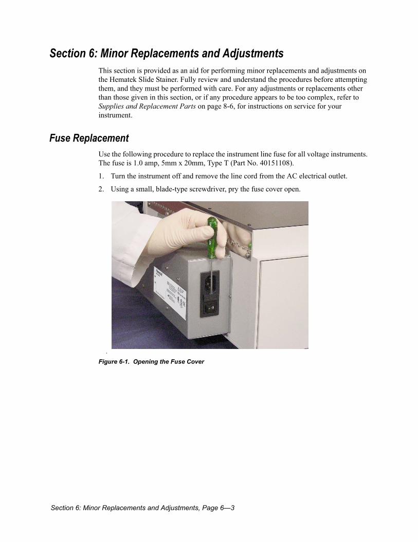
Fuse ReplacementUse the following procedure to replace the instrument line fuse for all voltage instruments. The fuse is 1.0 amp, 5mm x 20mm, Type T (Part No. 40151108).
1. Turn the instrument off and remove the line cord from the AC electrical outlet.
2. Using a small, blade-type screwdriver, pry the fuse cover open.
.
Figure 6-1. Opening the Fuse Cover

Page 6—4, Section 6: Minor Replacements and Adjustments
3. Pull the fuse holder out of the instrument.
4. Remove the fuse from the holder and discard it into an appropriate waste container.
Figure 6-2. Replacing the Fuse
CAUTIONUse only the specified fuse to avoid damage to the instrument.
5. Replace the defective fuse with an identical fuse, snapping it into place. Fuse specifications are in Section 1: Introduction, while ordering information is in Section 8: Service, Supplies, and Replacement Parts.A spare fuse, located in the small, enclosed compartment in the fuse holder, is shipped with the instrument. Push the fuse out of the compartment using a small screwdriver.
6. With the flat side up, return the fuse holder to its position in the instrument.
7. Firmly press the fuse cover until it snaps into place and is flush with the power module plate.
Replacement of Light AssembliesUse the following procedure to replace the Power Light Assembly (PN 94000787) or Low Stain Light Assembly (PN 94001073).
1. Turn the instrument off and remove the line cord from the AC electrical outlet.
2. Raise the lid of the instrument.

Section 6: Minor Replacements and Adjustments, Page 6—5
3. Loosen the two thumbscrews that are inserted through the notches in the back of the circuit board cover.
Figure 6-3. Location of Thumbscrews
4. Lift the panel from the front wall, exposing the printed circuit board and the connectors for the LOW STAIN and POWER lights.
Figure 6-4. Raising the Circuit Board Cover

Page 6—6, Section 6: Minor Replacements and Adjustments
5. Disconnect the wires from the circuit board for the light that is to be replaced.Using a small, blade-type screwdriver, loosen the two small screws located on the top of the connector (the screws will not come out completely), then pull on the connector wires to remove them from the connector.
Figure 6-5. Removing the Connector Wires
6. Unsnap the burned-out light assembly from the circuit board cover by pinching together the two plastic retaining tabs on the light assembly.If the tabs are too stiff, use a screwdriver to press against one side, then push that edge partially through the opening. Repeat with the other side.
Figure 6-6. Unsnapping the Light Assembly
Section 6: Minor Replacements and Adjustments, Page 6—7
7. Discard the burned-out light assembly into an appropriate waste container.
8. Insert the new light assembly into the circuit board cover, threading the wires through the opening from the front of the cover and pressing firmly on the light until it snaps into place.
9. Insert the connector wires into the holes on the connector on the printed circuit board.Each wire can go into either hole.
10. Tighten the small screws to just past finger tight.
11. Return the circuit board cover to its normal position, between the circuit board panel and the back edge of the screws, and tighten the two thumbscrews.Be sure the panel is not resting on top of the screw heads before tightening.
12. Replace the line cord into the AC electrical outlet and turn the instrument on to check the light operation.
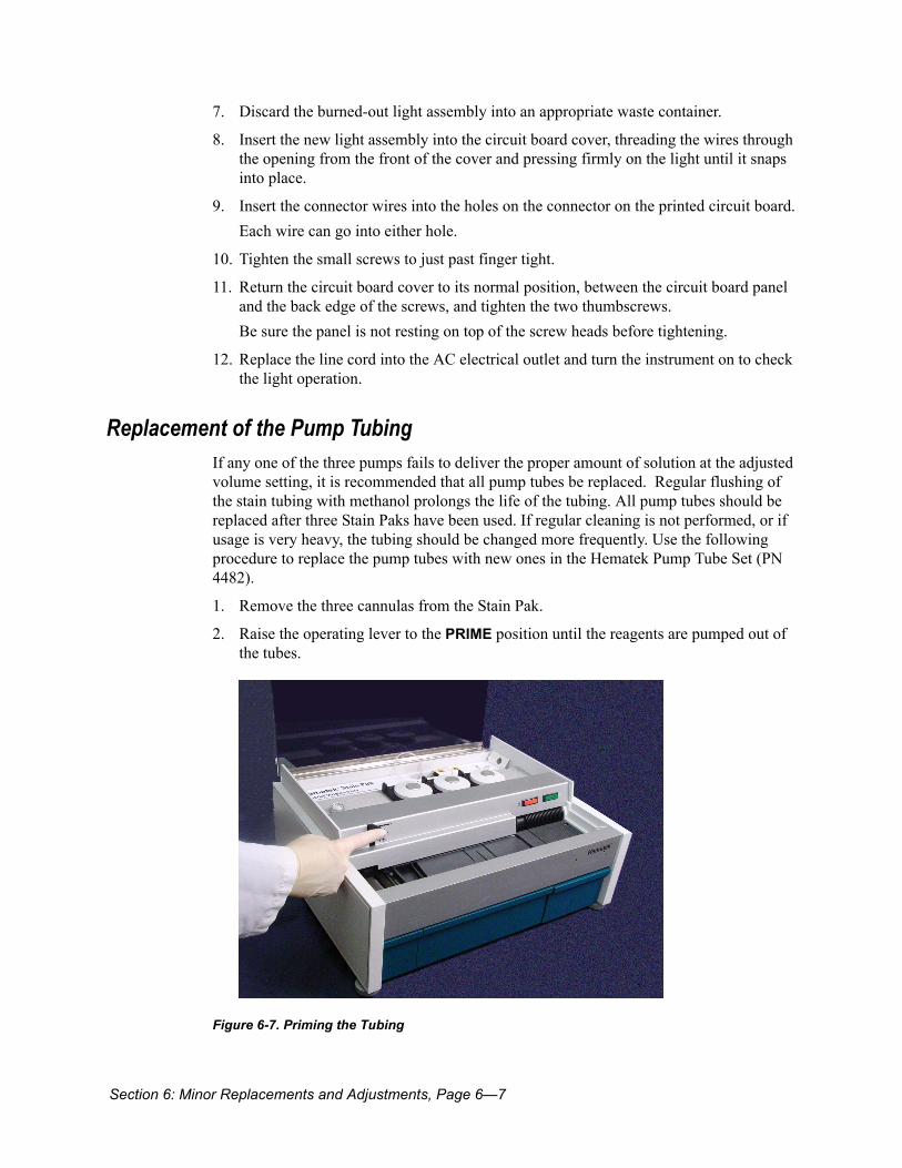
Replacement of the Pump TubingIf any one of the three pumps fails to deliver the proper amount of solution at the adjusted volume setting, it is recommended that all pump tubes be replaced. Regular flushing of the stain tubing with methanol prolongs the life of the tubing. All pump tubes should be replaced after three Stain Paks have been used. If regular cleaning is not performed, or if usage is very heavy, the tubing should be changed more frequently. Use the following procedure to replace the pump tubes with new ones in the Hematek Pump Tube Set (PN 4482).
1. Remove the three cannulas from the Stain Pak.
2. Raise the operating lever to the PRIME position until the reagents are pumped out of the tubes.
Figure 6-7. Priming the Tubing
Page 6—8, Section 6: Minor Replacements and Adjustments
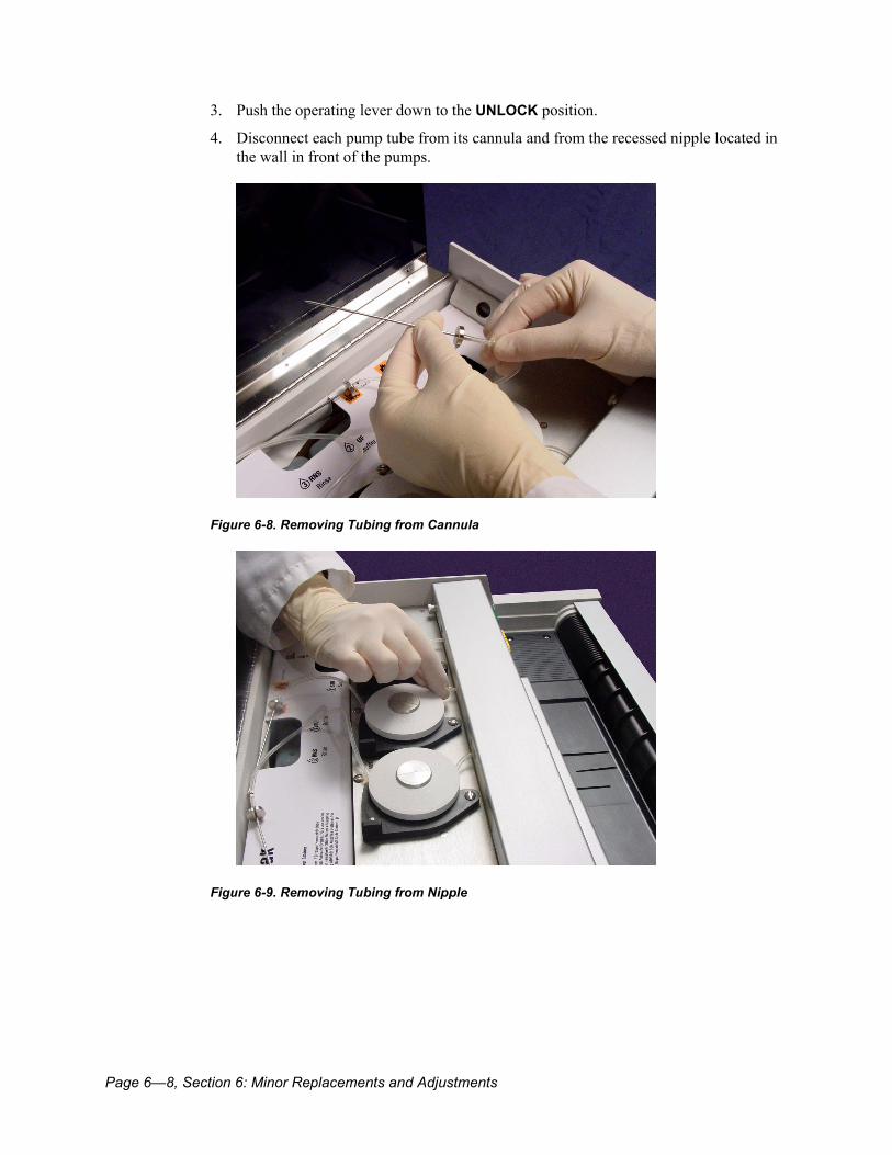
3. Push the operating lever down to the UNLOCK position.
4. Disconnect each pump tube from its cannula and from the recessed nipple located in the wall in front of the pumps.
Figure 6-8. Removing Tubing from Cannula
Figure 6-9. Removing Tubing from Nipple
Section 6: Minor Replacements and Adjustments, Page 6—9
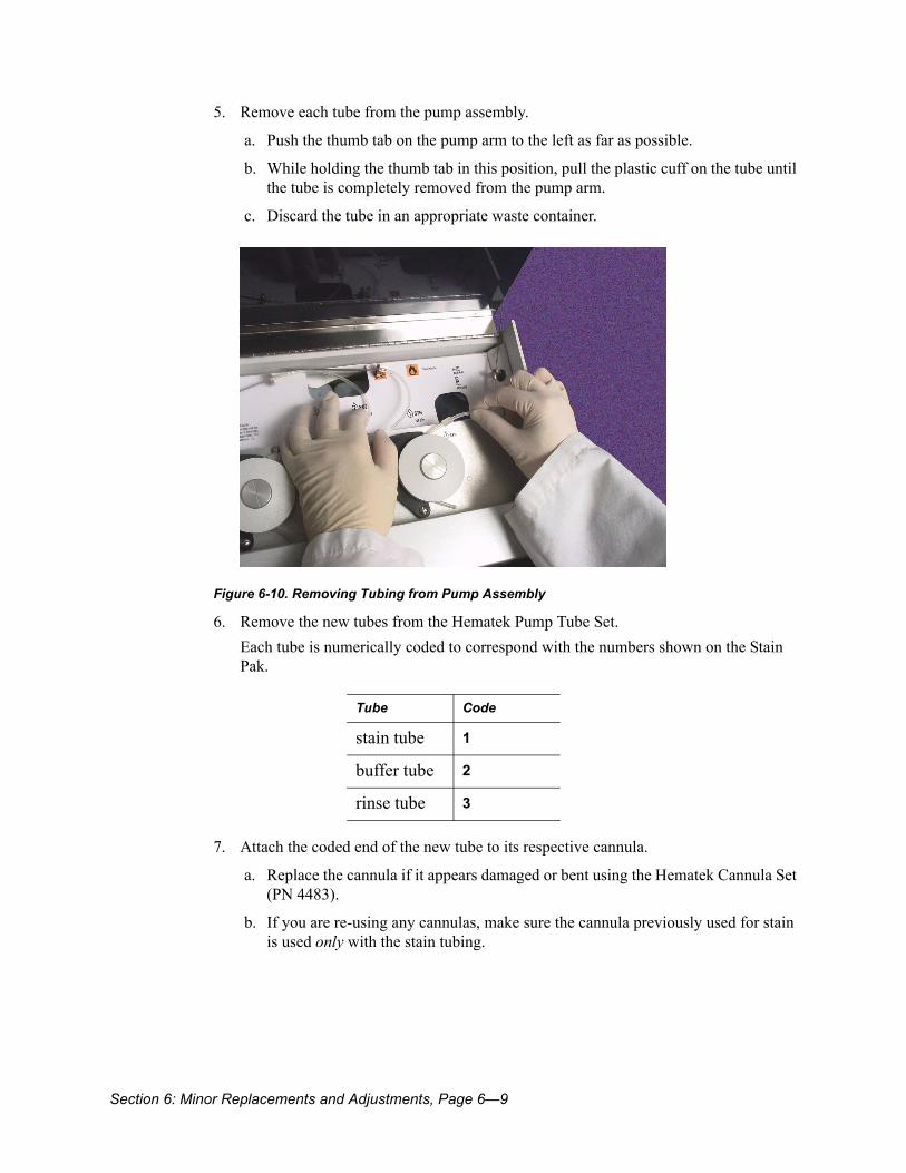
5. Remove each tube from the pump assembly.
a. Push the thumb tab on the pump arm to the left as far as possible.
b. While holding the thumb tab in this position, pull the plastic cuff on the tube until the tube is completely removed from the pump arm.
c. Discard the tube in an appropriate waste container.
Figure 6-10. Removing Tubing from Pump Assembly
6. Remove the new tubes from the Hematek Pump Tube Set.Each tube is numerically coded to correspond with the numbers shown on the Stain Pak.
7. Attach the coded end of the new tube to its respective cannula.
a. Replace the cannula if it appears damaged or bent using the Hematek Cannula Set (PN 4483).
b. If you are re-using any cannulas, make sure the cannula previously used for stain is used only with the stain tubing.
Tube Code
stain tube 1
buffer tube 2
rinse tube 3
Page 6—10, Section 6: Minor Replacements and Adjustments
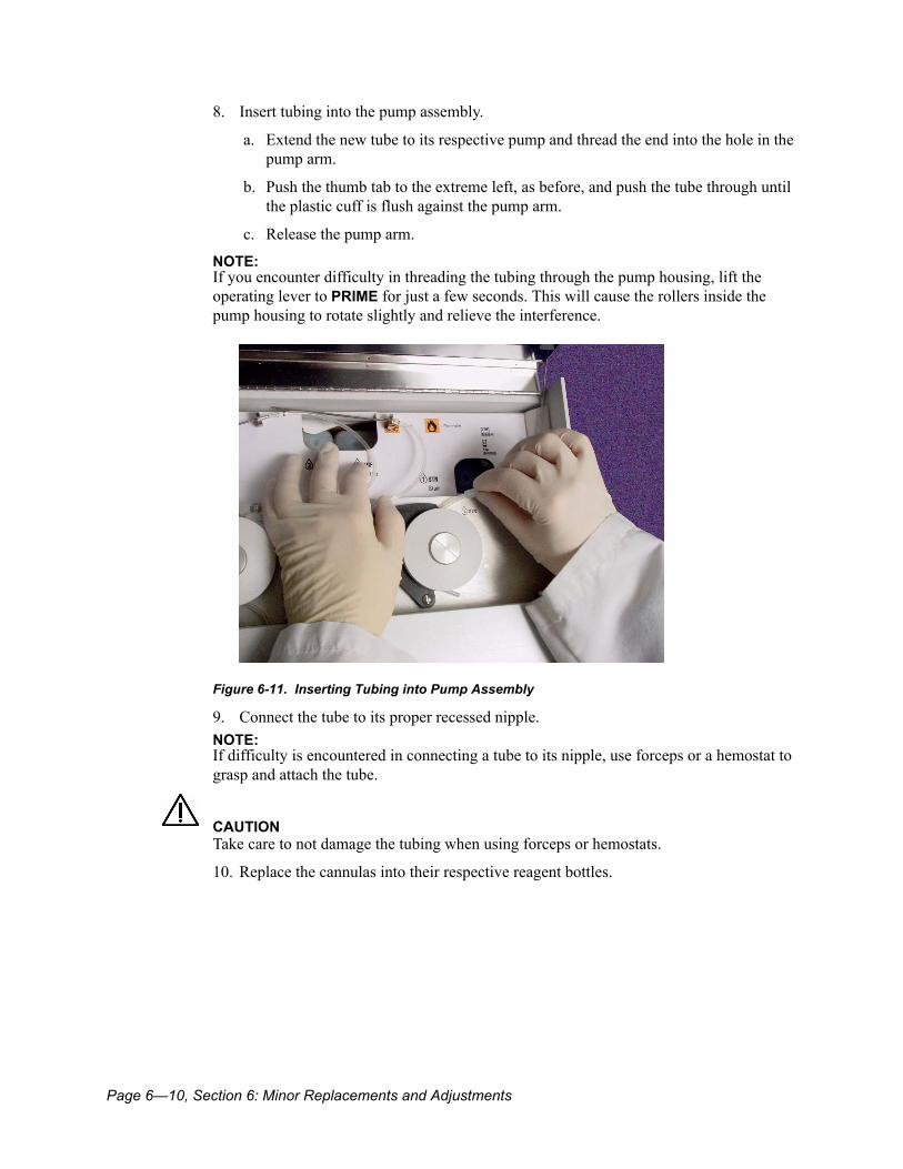
8. Insert tubing into the pump assembly.
a. Extend the new tube to its respective pump and thread the end into the hole in the pump arm.
b. Push the thumb tab to the extreme left, as before, and push the tube through until the plastic cuff is flush against the pump arm.
c. Release the pump arm.
NOTE: If you encounter difficulty in threading the tubing through the pump housing, lift the operating lever to PRIME for just a few seconds. This will cause the rollers inside the pump housing to rotate slightly and relieve the interference.
Figure 6-11. Inserting Tubing into Pump Assembly
9. Connect the tube to its proper recessed nipple.NOTE: If difficulty is encountered in connecting a tube to its nipple, use forceps or a hemostat to grasp and attach the tube.
CAUTIONTake care to not damage the tubing when using forceps or hemostats.
10. Replace the cannulas into their respective reagent bottles.
Section 6: Minor Replacements and Adjustments, Page 6—11
11. Prime the pumps until the solution in each tube is clear of all air bubbles.NOTE: New tubing is sometimes difficult to prime the first time and may need assistance. While holding the operating lever in the PRIME position, push the pump arm inwards (toward the pump) until the reagent fills the tubing, then release the pump arm. It may also be helpful for you to pinch the tubing several times with your fingers, pinching in the area between the cannula and the pump arm.
12. Verify the pump timings and reset the volume controls if necessary. See Pump Volume Adjustment on page 6-14.
Replacement of the Underplaten TubingThe underplaten tubing is the tubing between the spout under the platen and the nipple behind the circuit board. The buffer and rinse tubing should be replaced after approximately ten Stain Paks have been used. The stain tubing needs to be changed more frequently, especially if it is not regularly flushed with methanol. Depending on usage and cleaning patterns, the stain tubing may need to be changed as often as after every four Stain Paks. Use the following procedure to replace the underplaten tubing with new tubing in the Hematek Underplaten Tubing pack (Product No. 4484).
1. Remove the three cannulas from the Stain Pak.
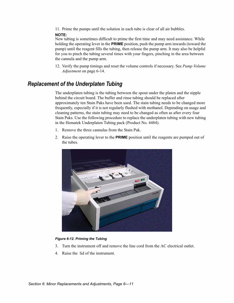
2. Raise the operating lever to the PRIME position until the reagents are pumped out of the tubes.
Figure 6-12. Priming the Tubing
3. Turn the instrument off and remove the line cord from the AC electrical outlet.
4. Raise the lid of the instrument.
Page 6—12, Section 6: Minor Replacements and Adjustments
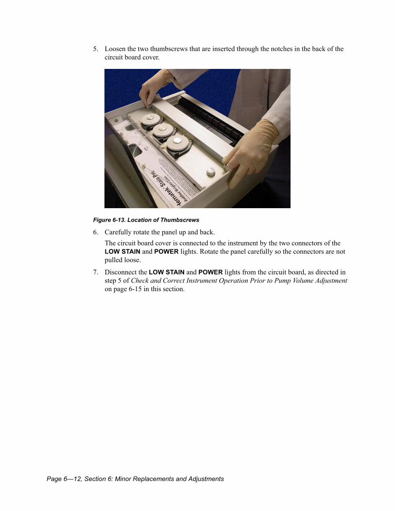
5. Loosen the two thumbscrews that are inserted through the notches in the back of the circuit board cover.
Figure 6-13. Location of Thumbscrews
6. Carefully rotate the panel up and back.The circuit board cover is connected to the instrument by the two connectors of the LOW STAIN and POWER lights. Rotate the panel carefully so the connectors are not pulled loose.
7. Disconnect the LOW STAIN and POWER lights from the circuit board, as directed in step 5 of Check and Correct Instrument Operation Prior to Pump Volume Adjustment on page 6-15 in this section.

Section 6: Minor Replacements and Adjustments, Page 6—13
8. Disconnect the stain tubing from the nipple that is located behind the circuit board.
Figure 6-14. Disconnecting Underplaten Tubing from Nipple
9. Remove the waste tank and reach underneath the platen through the waste tank area.
10. Disconnect the stain tubing from the platen by pulling the tubing free from behind the circuit board, and then disconnect it from the spout under the platen.
Figure 6-15. Removing the Underplaten Tubing
11. Select one of the new sections of underplaten tubing and connect it to the stain-tubing nipple behind the circuit board.Make sure at least 7 mm (¼ inch) of tubing is connected onto the nipple.
12. Thread the tubing behind the circuit board through the channels provided until it extends under the platen.
Page 6—14, Section 6: Minor Replacements and Adjustments
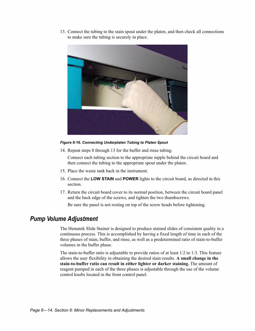
13. Connect the tubing to the stain spout under the platen, and then check all connections to make sure the tubing is securely in place.
Figure 6-16. Connecting Underplaten Tubing to Platen Spout
14. Repeat steps 8 through 13 for the buffer and rinse tubing.Connect each tubing section to the appropriate nipple behind the circuit board and then connect the tubing to the appropriate spout under the platen.
15. Place the waste tank back in the instrument.
16. Connect the LOW STAIN and POWER lights to the circuit board, as directed in this section.
17. Return the circuit board cover to its normal position, between the circuit board panel and the back edge of the screws, and tighten the two thumbscrews.Be sure the panel is not resting on top of the screw heads before tightening.
Pump Volume AdjustmentThe Hematek Slide Stainer is designed to produce stained slides of consistent quality in a continuous process. This is accomplished by having a fixed length of time in each of the three phases of stain, buffer, and rinse, as well as a predetermined ratio of stain-to-buffer volumes in the buffer phase.
The stain-to-buffer ratio is adjustable to provide ratios of at least 1:2 to 1:3. This feature allows the user flexibility in obtaining the desired stain results. A small change in the stain-to-buffer ratio can result in either lighter or darker staining. The amount of reagent pumped in each of the three phases is adjustable through the use of the volume control knobs located in the front control panel.

Section 6: Minor Replacements and Adjustments, Page 6—15
Check and Correct Instrument Operation Prior to Pump Volume AdjustmentFollow these steps to check and correct instrument operation when slides are not satisfactory or pump volumes do not appear to be optimum. If any of these steps correct the situation, you do not need to adjust the pump volumes.
1. Replace both sets of tubing.Refer to Replacement of the Pump Tubing on page 6-7 and Replacement of the Underplaten Tubing on page 6-11.
2. Clean the platen, including the front and back drain troughs, and make sure that there is no residue in any mixing groove.Refer to Cleaning the Platen on page 5-3 for instructions to clean the platen and the drain troughs.
3. Observe the circular bubble level to make sure the instrument is level to provide optimal buffer mixing.If leveling is required, follow the Level the Instrument on page 2-4.
4. Make sure the Stain Pak has been vented.Refer to Install the Stain Pak on page 2-9.
5. Check the adjustment of the sensing switch fingers.
6. Observe several slides as they move across the platen and visually ensure all of the following events occur and they are activating the pumps at the proper time.
• The stain pump should be activated after approximately ½ of the slide width has passed over the stain orifice.
• The buffer pump should be activated after about 1/8 inch of the slide has crossed over the buffer orifice.
• The rinse pump should be activated just as the leading edge of the slide crosses over the rinse orifice.
7. If the starting times for each phase are not correct, follow the procedure in this section.
Adjust the Stain, Buffer, and Rinse VolumesOptimal staining results are achieved when the Hematek Slide Stainer is properly adjusted. Normally, proper adjustment of the instrument can be determined by observation of the amount of stain and buffer required to fill the capillary gap between the slide and the surface of the platen. If the proper amounts of stain and buffer are being pumped, proper mixing of the reagents will occur, resulting in uniform staining of blood smears. Use the following procedure to adjust the pump volumes.
1. Locate the pump volume control knobs, which are located in the control panel on the front-right corner of the instrument.Each knob contains a centering catch on, which provides a central reference point.The instrument is manufactured to give a stain-to-buffer ratio of approximately 1:2.5 and a rinse volume of approximately 1.0 mL/slide when each knob is at the centering catch.
Page 6—16, Section 6: Minor Replacements and Adjustments
Volume is lowest when a knob is turned fully counterclockwise and highest when turned fully clockwise.Volume increments are marked on each knob:
• Stain and buffer knobs: Each evenly labeled increment changes the volume by approximately 0.1 mL per 10 slides (0.01 mL/slide).
• Rinse knob: Each evenly labeled increment changes the volume by approximately 0.5 mL per 10 slides (0.05 mL/slide).
2. Prime the instrument by placing the operating lever in the PRIME position and holding it there until solution is being pumped at all three stations (stain, buffer, and rinse).
3. Wipe the platen after priming, wiping from right to left only.
4. Prime the platen by loading five priming slides and allowing them to be transported across the platen.This procedure primes and wets the platen to achieve proper surface tension characteristics.
5. Adjust the stain volume as follows:
a. Run five blood smear slides across the platen immediately following the priming slides.
b. Adjust the stain control knob so the stain just fills, but does not overfill, the capillary space between the platen and the slide.
c. If the slide is receiving an inadequate amount of stain, adjust the control knob clockwise.
d. If overflow of solution is visible on either side of the slide or an excess of stain is visible hanging over the front beveled edge of the platen, adjust the stain control knob counterclockwise.
The adjustment is correct when proper fill has been achieved on two consecutive slides.
6. Adjust the buffer volume as follows:
a. If there has been a gap of more than two consecutive slides across the platen since the stain volume adjustment, re-prime the platen with three priming slides.
b. Run five blood smear slides across the platen immediately following the priming slides.
When the slide passes the buffer section of the platen, mixing of the stain and buffer occurs because of the mixing grooves. This is where the proper stain-to- buffer ratio is most important. The slide looks under filled as it travels over the mixing grooves because the capillary gap is slightly greater.
7. Adjust the buffer control knob so the stain-buffer mixture just fills the capillary space under the slide when the slide is past the mixing grooves and onto the smooth portion of the platen, just before the rinse area.Ensure that the stain-buffer mix does not extend out from either side of the slide.
Section 6: Minor Replacements and Adjustments, Page 6—17
NOTE: As the slide moves along, the buffer should pulse from the buffer orifice and move around the two mixing grooves for complete mixing of the stain and buffer. Too much stain and/or buffer will reduce the pulsing action, causing inconsistent staining across the slide. If partial flooding occurs, it should quickly re-drain as the slide continues to move across the grooves. Complete flooding of the second groove may indicate an excessive volume of either the stain or buffer.
8. Adjust the rinse volume as follows:
a. Examine the slides under a microscope.
b. If adjustment is necessary, use the rinse control knob to make the correction.
c. If excess stain is left on the slide appearing as precipitation under the microscope, increase the rinse volume.
d. If the staining is pale due to over washing, reduce the rinse volume.
NOTE: Any change in the rinse setting may cause a slight color change due to the small amount of methanol in the rinse.
9. Recheck the adjusted pump volumes:
a. Prime the platen with three priming slides.
b. Run at least three blood smears to ensure that the capillary spaces between the platen and slide fill completely with stain at the stain area and with stain-buffer mixture just before the rinse area.
NOTE: Occasional small voids may occur on the slide after proper filling. These voids are acceptable and will not adversely affect stain quality. Do not try to compensate for small voids by increasing the stain volume. Doing so may upset the optimum stain-to-buffer ratio and may affect the stain intensity.
Volume and Ratio DeterminationOnce adjustments have been made that appear visually to be giving appropriate slide results, the pump volumes and stain-to-buffer ratio can be measured as follows:
1. Remove the waste tank and disconnect the underplaten tubing leading to the stain, buffer, and rinse spouts on the platen.
2. Place the tubing ends into a beaker or other small container, and prime by using the operating lever.
3. As soon as all three-pump tubes have been primed and are free of air, place the free end of the stain and buffer tubes into separate 10 mL graduated cylinders. Place the free end of the rinse tube into a 25 mL graduated cylinder.
4. Process 10 blank slides and record the volume of stain, buffer, and rinse solution pumped into each cylinder. The following should be noted:
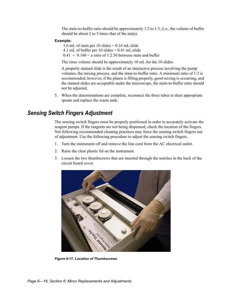
Page 6—18, Section 6: Minor Replacements and Adjustments
The stain-to-buffer ratio should be approximately 1:2 to 1:3, (i.e., the volume of buffer should be about 2 to 3 times that of the stain).
The rinse volume should be approximately 10 mL for the 10 slides.A properly stained slide is the result of an interactive process involving the pump volumes, the mixing process, and the stain-to-buffer ratio. A minimum ratio of 1:2 is recommended; however, if the platen is filling properly, good mixing is occurring, and the stained slides are acceptable under the microscope, the stain-to-buffer ratio should not be adjusted.
5. When the determinations are complete, reconnect the three tubes to their appropriate spouts and replace the waste tank.
Sensing Switch Fingers AdjustmentThe sensing switch fingers must be properly positioned in order to accurately activate the reagent pumps. If the reagents are not being dispensed, check the location of the fingers. Not following recommended cleaning practices may force the sensing switch fingers out of adjustment. Use the following procedure to adjust the sensing switch fingers.
1. Turn the instrument off and remove the line cord from the AC electrical outlet.
2. Raise the clear plastic lid on the instrument.
3. Loosen the two thumbscrews that are inserted through the notches in the back of the circuit board cover.
Figure 6-17. Location of Thumbscrews
Example:1.6 mL of stain per 10 slides = 0.16 mL/slide4.1 mL of buffer per 10 slides = 0.41 mL/slide0.41 ÷ 0.160 = a ratio of 1:2.56 between stain and buffer
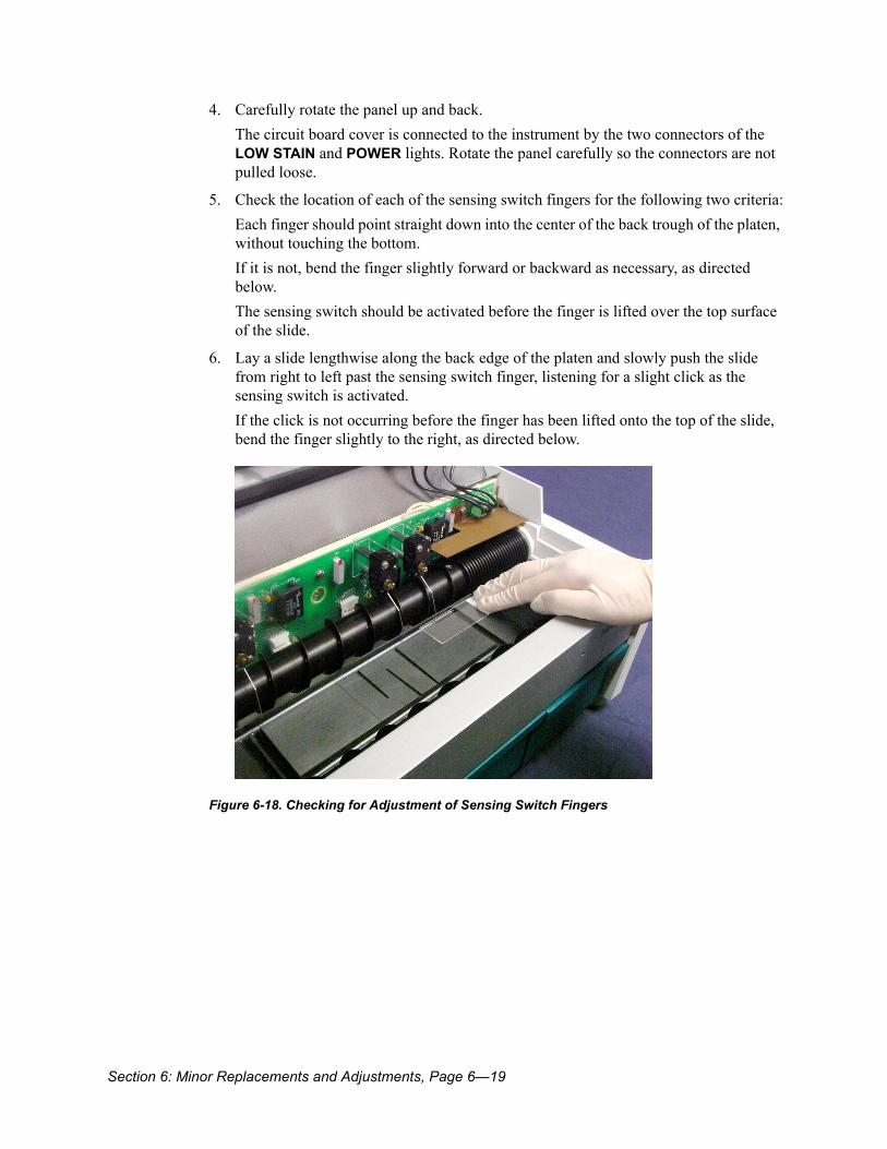
Section 6: Minor Replacements and Adjustments, Page 6—19
4. Carefully rotate the panel up and back.The circuit board cover is connected to the instrument by the two connectors of the LOW STAIN and POWER lights. Rotate the panel carefully so the connectors are not pulled loose.
5. Check the location of each of the sensing switch fingers for the following two criteria:Each finger should point straight down into the center of the back trough of the platen, without touching the bottom.If it is not, bend the finger slightly forward or backward as necessary, as directed below.The sensing switch should be activated before the finger is lifted over the top surface of the slide.
6. Lay a slide lengthwise along the back edge of the platen and slowly push the slide from right to left past the sensing switch finger, listening for a slight click as the sensing switch is activated.If the click is not occurring before the finger has been lifted onto the top of the slide, bend the finger slightly to the right, as directed below.
Figure 6-18. Checking for Adjustment of Sensing Switch Fingers
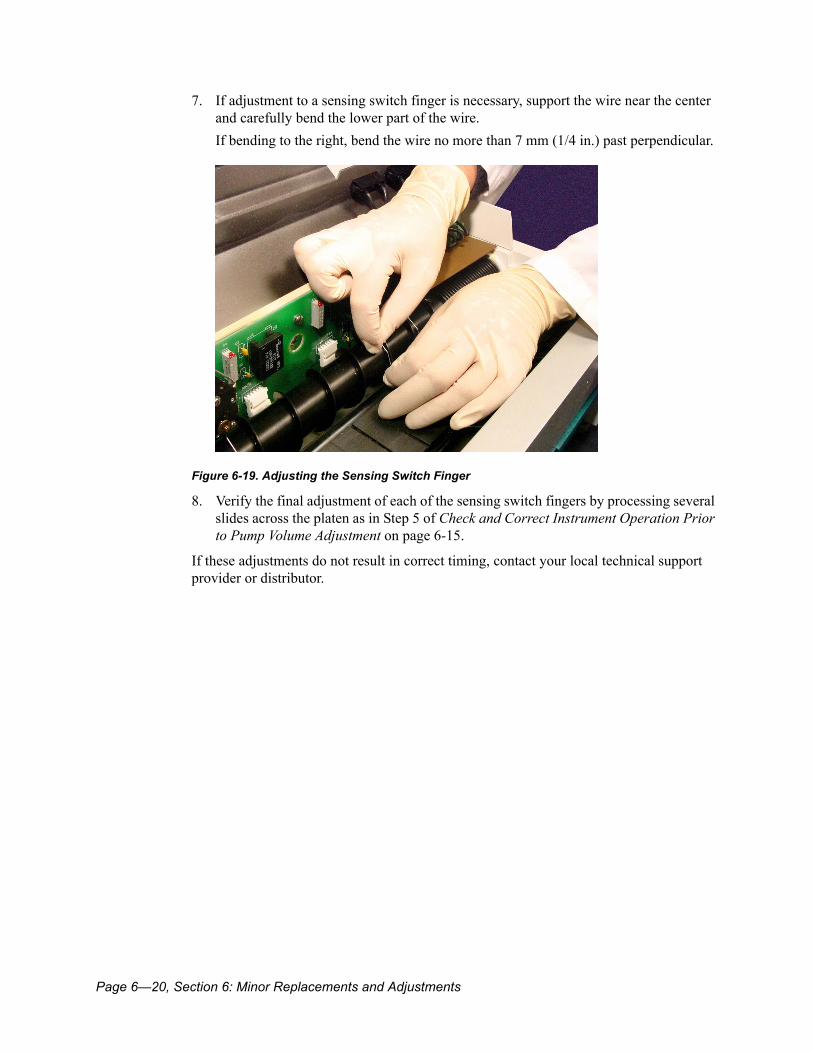
Page 6—20, Section 6: Minor Replacements and Adjustments
7. If adjustment to a sensing switch finger is necessary, support the wire near the center and carefully bend the lower part of the wire.If bending to the right, bend the wire no more than 7 mm (1/4 in.) past perpendicular.
Figure 6-19. Adjusting the Sensing Switch Finger
8. Verify the final adjustment of each of the sensing switch fingers by processing several slides across the platen as in Step 5 of Check and Correct Instrument Operation Prior to Pump Volume Adjustment on page 6-15.
If these adjustments do not result in correct timing, contact your local technical support provider or distributor.

Troubleshooting, Page 7—1
Section 7: Troubleshooting ..................................................................................... 7-3Checklist for Quality of Stained Blood Smears ..............................................................................7-3Troubleshooting Chart.......................................................................................................................7-4

Page 7—2, Section 7: Troubleshooting
Section 7: Troubleshooting, Page 7—3
Section 7: TroubleshootingThe Hematek Slide Stainer is designed to give trouble-free operation when the directions for operating and cleaning the instrument are followed. If a problem occurs, refer to troubleshooting pointers in this section for help in solving the problem.
Checklist for Quality of Stained Blood SmearsWhen stained blood smears do not have the desired quality, the first tendency is to assume the staining reagents or the stainer is at fault. Frequently, however, other factors are the cause of the poorly stained blood smears. The following checklist can help isolate the problem when you question the quality of stained blood smears.
Are the pump volumes properly adjusted? Improper settings may lead to poorly stained blood smears.Is the blood old or does it contain an incorrect anticoagulant? Use fresh blood (less than 8 hours old), EDTA is the anticoagulant of choice.Was the blood thoroughly mixed before making the smear?Is the blood smear too thick, too thin, or spread unevenly?Does the feathered edge of the smear end at least 1/8 inch from the end of the slide?Was the blood smear thoroughly dry before staining?Are the slides clean? Even new slides are not necessarily clean.Are the slides flat? Variable thickness of a given slide may cause uneven staining.Have the Hematek Stain Pak containers been vented? Venting is necessary for even delivery of the stain, buffer, and rinse reagents.
Has the reagent tubing on the Hematek Slide Stainer been primed before staining the slides? Air bubbles in the tubing will cause poorly stained smears.Has the platen been primed and wetted before running blood smears? Process two to four blank slides across the platen to wet the platen surface before each run of blood smears.Is the stain tubing, cannula, nipples, or orifice plugged? Daily cleaning of the stain tubing is recommended to prevent plugging.Are the platen and grooves clean and free of residue? A dirty platen or grooves will result in uneven, low-quality staining.Is the microscope clean and adequately illuminated? A dirty microscope or inadequate lighting may give the impression of a poorly stained blood smear.

Page 7—4, Section 7: Troubleshooting
Troubleshooting ChartThe following instrument troubleshooting chart lists possible problems relating to electrical and mechanical operations that could occur during instrument operation. Probable causes and recommended corrective actions are also included, so that many isolated problems can be quickly corrected. When dealing with any problem with the Hematek Slide Stainer, it is essential to determine which portion of the system is the source of the trouble. A systematic approach should be employed to isolate the problem.
If additional assistance is required concerning an instrument problem, copy and complete the Hematek Preservice Checklist in Appendix A, and contact your local technical support provider or distributor.
Only Hematek Stain Paks should be used with the Hematek Slide Stainer. Do not use any other stain solution. For problems or questions concerning the Stain Paks, contact your local technical support provider or distributor.
Symptom Possible Cause Corrective Action
Unit fails to turn on when the main instrument power switch is turned ON
Instrument not plugged into wall outlet or instrument
Ensure line cord is plugged into outlet and instrument
Line fuse is blown Unplug the unit and replace the fuse. Refer to Fuse Replacement on page 6-3.
Circuit breaker tripped in electrical circuit of building
Reset the circuit breaker
Instrument electrical failure
Contact your local technical support provider or distributor
Green POWER light fails to illuminate but drive, pump, and fan motors operate
Light is burned out Replace light assembly. Refer to Replacement of Light Assemblies on page 6-4.
Open circuit in associated wiring
Contact your local technical support provider or distributor
Pumps run but do not deliver solution during or after priming
Stain Pak is empty or near empty
Replace with a new Hematek Stain Pak. Refer to Install the Stain Pak on page 2-9.
Tubing has accidentally been pulled off platen nipple
Place tubing back on the nipple

Section 7: Troubleshooting, Page 7—5
Cannula openings are clogged
Remove cannulas from solution bottles and clean away debris with cloth and alcohol
Pump tubing is collapsed from use, or is perforated
Replace pump tubing. Refer to Replacement of the Pump Tubing on page 6-7.
Underplaten tubing (from the circuit board area to the platen) is clogged with foreign matter
Replace with new tubing. Refer to Replacement of the Underplaten Tubing on page 6-11.
Yellow LOW STAIN light is not functioning properly
Stain Pak is not properly positioned in the well
Reposition the Stain Pak so it moves freely up and down on the right end
Light is burned out Replace light assembly. Refer to Replacement of Light Assemblies on page 6-4.
Light switch is not operating correctly
Contact your local technical support provider or distributor for information on adjusting the switch
Switch or associated circuit is defective
Contact your local technical support provider or distributor
Improper mixing action between stain and buffer on platen
Instrument is not properly leveled
Adjust the front feet of the instrument so the bubble is centered in the circular bubble level. Refer to Level the Instrument on page 2-4.
Inadequate pump volume setting
Refer to Pump Volume Adjustment on page 6-14. Contact your local technical support provider or distributor if unable to adjust properly.
Uneven staining Mixing grooves on the platen are dirty
Clean mixing grooves. Refer to Cleaning the Platen on page 5-3.
Too much stain or buffer solution is being pumped causing poor mixing of stain and buffer
Refer to Pump Volume Adjustment on page 6-14
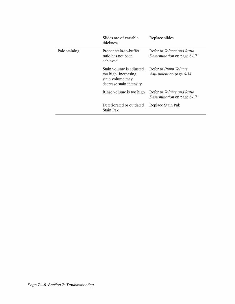
Page 7—6, Section 7: Troubleshooting
Slides are of variable thickness
Replace slides
Pale staining Proper stain-to-buffer ratio has not been achieved
Refer to Volume and Ratio Determination on page 6-17
Stain volume is adjusted too high. Increasing stain volume may decrease stain intensity
Refer to Pump Volume Adjustment on page 6-14
Rinse volume is too high Refer to Volume and Ratio Determination on page 6-17
Deteriorated or outdated Stain Pak
Replace Stain Pak

Service, Supplies and Replacement Parts, Page 8—1
Section 8: Service, Supplies, and Replacement Parts .......................................... 8-3When to Call for Service ...................................................................................................................8-3For Service .........................................................................................................................................8-3
Siemens Authorized Representative .........................................................................................8-3Siemens Offices Worldwide ....................................................................................................8-4
Returning the Instrument for Repair, Exchange, Replacement, or Loaner................................8-7Supplies and Replacement Parts ....................................................................................................8-8
Hematek Stain Pak – Modified Wright’s Stain .............................................................................8-8Hematek Stain Pak – Modified Wright-Giemsa Stain ...................................................................8-8Hematek Cannula Set ..............................................................................................................8-8Hematek Pump Tube Set .........................................................................................................8-9Hematek Underplaten Tubing ...................................................................................................8-9Ordering Information for Supplies and Replacement Parts ...........................................................8-10

Page 8—2, Section 8: Service, Supplies and Replacement Parts
Section 8: Service, Supplies, and Replacement Parts, Page 8—3
Section 8: Service, Supplies, and Replacement PartsWhen problems arise during operation of the Hematek Slide Stainer, refer first to Section 7: Troubleshooting. Avoid problems by carefully following proper operating and cleaning procedures.
When to Call for ServiceA call for assistance is appropriate under the following circumstances:
• If the problem cannot be solved by performing the steps described in the Troubleshooting Chart on page 7-4.
• If additional assistance is required concerning an instrument or reagent problem.• If the problem is beyond the scope of this manual.
Before calling for service, copy and complete the Hematek Preservice Checklist in Appendix A.
For ServiceTo contact the legal representative for Siemens within the European community, contact the Siemens Authorized Representative. For service, contact your local technical support provider or distributor.
Siemens Authorized Representative
Page 8—4, Section 8: Service, Supplies, and Replacement Parts
Siemens Offices Worldwide
www.siemens.com/diagnostics Siemens Healthcare Diagnostics Pty Ltd 885 Mountain Highway Bayswater Victoria 3153 Australia
Section 8: Service, Supplies, and Replacement Parts, Page 8—5
Returning the Instrument for Repair, Exchange, Replacement, or LoanerWhen instructed to return the instrument to Siemens for repair, exchange, replacement or the return of a loaner, follow these steps:
1. Move the ON / OFF switch to the OFF position.
2. Follow all steps in Decontamination and Removal from Operation on page 5-9.
3. Pack the instrument in the original bag and container, or as instructed by your local technical support provider or distributor.
4. Seal the container securely.
5. Return the container to your local technical support provider or distributor.NOTE: If Siemens does not receive your defective instrument within 15 days, you will be billed for the replacement.

Page 8—6, Section 8: Service, Supplies, and Replacement Parts
Supplies and Replacement PartsTo obtain the best results with the Hematek Slide Stainer, use only Hematek brand supplies.
Hematek Stain Pak – Modified Wright’s StainThe Stain Pak contains a polychrome methylene blue-eosin stain and specially prepared buffer and rinse solutions. The Stain Pak is contained in a single carton that fits easily into the well inside the Slide Stainer. Also supplied are buffer and rinse solutions that have been optimally designed for use on the Hematek system. Each Stain Pak contains sufficient solutions to stain approximately 1000 slides.
WARNINGHighly Flammable! Toxic! Contains Methanol. Toxic by inhalation, in contact with skin and if swallowed. Danger of very serious irreversible effects through inhalation, in contact with skin and if swallowed. Keep container tightly closed. Keep away from sources of ignition. Avoid contact with skin. Wear suitable protective clothing and gloves. In case of accident or if you feel unwell, seek medical advice immediately (show the label where possible).
Hematek Stain Pak – Modified Wright-Giemsa StainThis is a modified Wright-Giemsa stain for laboratories that prefer a Giemsa stain component for preparation of their blood smears. This Stain Pak contains a modified polychrome methylene blue-eosin stain based on the original stain proposed by Romanowsky. Also supplied are buffer and rinse solutions that have been optimally designed for use on the Hematek system. Each Stain Pak contains sufficient solutions to stain approximately 1000 slides.
WARNINGHighly Flammable! Toxic! Contains Methanol. Toxic by inhalation, in contact with skin and if swallowed. Danger of very serious irreversible effects through inhalation, in contact with skin and if swallowed. Keep container tightly closed. Keep away from sources of ignition. Avoid contact with skin. Wear suitable protective clothing and gloves. In case of accident or if you feel unwell, seek medical advice immediately (show the label where possible).
Hematek Cannula SetThe Cannula Set is available as a replacement item. The cannulas are positioned in the Stain Pak bottles and connected to the pump tubing.
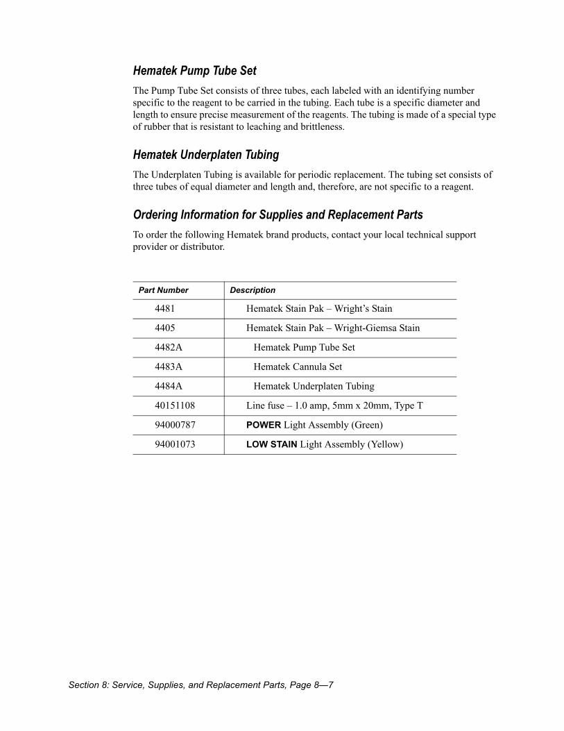
Section 8: Service, Supplies, and Replacement Parts, Page 8—7
Hematek Pump Tube SetThe Pump Tube Set consists of three tubes, each labeled with an identifying number specific to the reagent to be carried in the tubing. Each tube is a specific diameter and length to ensure precise measurement of the reagents. The tubing is made of a special type of rubber that is resistant to leaching and brittleness.
Hematek Underplaten TubingThe Underplaten Tubing is available for periodic replacement. The tubing set consists of three tubes of equal diameter and length and, therefore, are not specific to a reagent.
Ordering Information for Supplies and Replacement PartsTo order the following Hematek brand products, contact your local technical support provider or distributor.
Part Number Description
4481 Hematek Stain Pak – Wright’s Stain
4405 Hematek Stain Pak – Wright-Giemsa Stain
4482A Hematek Pump Tube Set
4483A Hematek Cannula Set
4484A Hematek Underplaten Tubing
40151108 Line fuse – 1.0 amp, 5mm x 20mm, Type T
94000787 POWER Light Assembly (Green)
94001073 LOW STAIN Light Assembly (Yellow)

Page 8—8, Section 8: Service, Supplies, and Replacement Parts
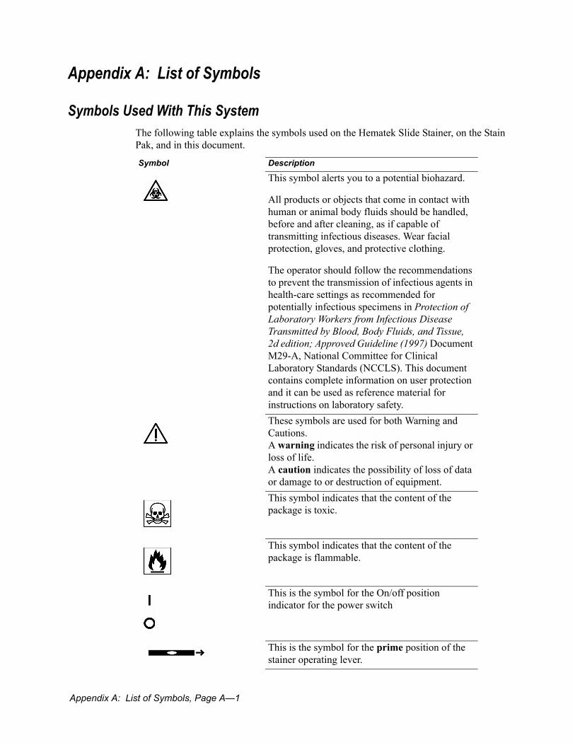
Appendix A: List of Symbols, Page A—1
Appendix A: List of Symbols
Symbols Used With This SystemThe following table explains the symbols used on the Hematek Slide Stainer, on the Stain Pak, and in this document.
Symbol Description
This symbol alerts you to a potential biohazard.
All products or objects that come in contact with human or animal body fluids should be handled, before and after cleaning, as if capable of transmitting infectious diseases. Wear facial protection, gloves, and protective clothing.
The operator should follow the recommendations to prevent the transmission of infectious agents in health-care settings as recommended for potentially infectious specimens in Protection of Laboratory Workers from Infectious Disease Transmitted by Blood, Body Fluids, and Tissue, 2d edition; Approved Guideline (1997) Document M29-A, National Committee for Clinical Laboratory Standards (NCCLS). This document contains complete information on user protection and it can be used as reference material for instructions on laboratory safety. These symbols are used for both Warning and Cautions.A warning indicates the risk of personal injury or loss of life. A caution indicates the possibility of loss of data or damage to or destruction of equipment.This symbol indicates that the content of the package is toxic.
This symbol indicates that the content of the package is flammable.
This is the symbol for the On/off position indicator for the power switch
This is the symbol for the prime position of the stainer operating lever.

Page A—2, Appendix A: List of Symbols
This is the symbol for the unlock position of the stainer operating lever
This is the symbol for the lock position of the stainer operating lever
This symbol indicates that the product has a temperature limitation. In this example, you need to store the product between 15 and 30 °C.
Identifies Hematek stain.
Identifies Hematek buffer.
Identifies Hematek rinse.
Indicates that there is power to the instrument.
Indicates low stain.
This symbol indicates that you should consult the instructions for use.
This is the fuse symbol.
This symbol indicates that the product is UL approved for safety (United States and Canada).
This symbol indicates that the product is CSA approved for safety (Canada).
This symbol indicates that the product complies with the applicable directives of the European Union.
This symbol indicates the serial number of a part or product.
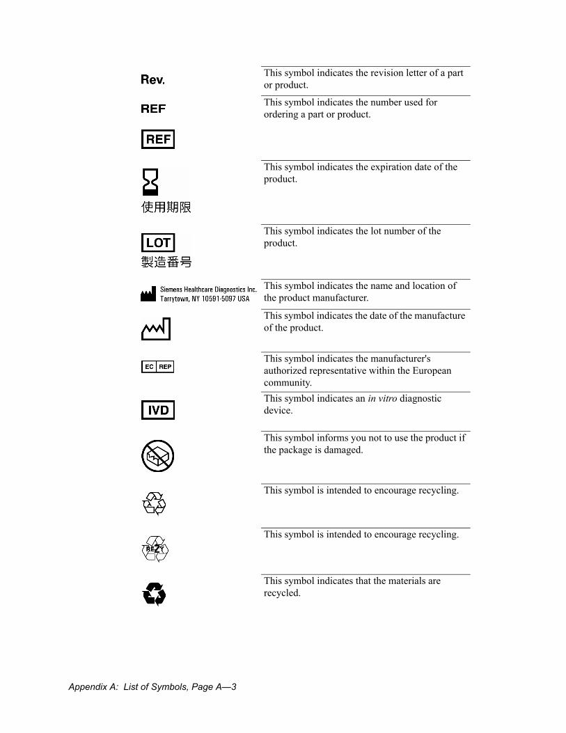
Appendix A: List of Symbols, Page A—3
This symbol indicates the revision letter of a part or product.
This symbol indicates the number used for ordering a part or product.
This symbol indicates the expiration date of the product.
This symbol indicates the lot number of the product.
This symbol indicates the name and location of the product manufacturer.
This symbol indicates the date of the manufacture of the product.
This symbol indicates the manufacturer's authorized representative within the European community.This symbol indicates an in vitro diagnostic device.
This symbol informs you not to use the product if the package is damaged.
This symbol is intended to encourage recycling.
This symbol is intended to encourage recycling.
This symbol indicates that the materials are recycled.
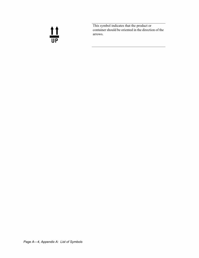
Page A—4, Appendix A: List of Symbols
This symbol indicates that the product or container should be oriented in the direction of the arrows.
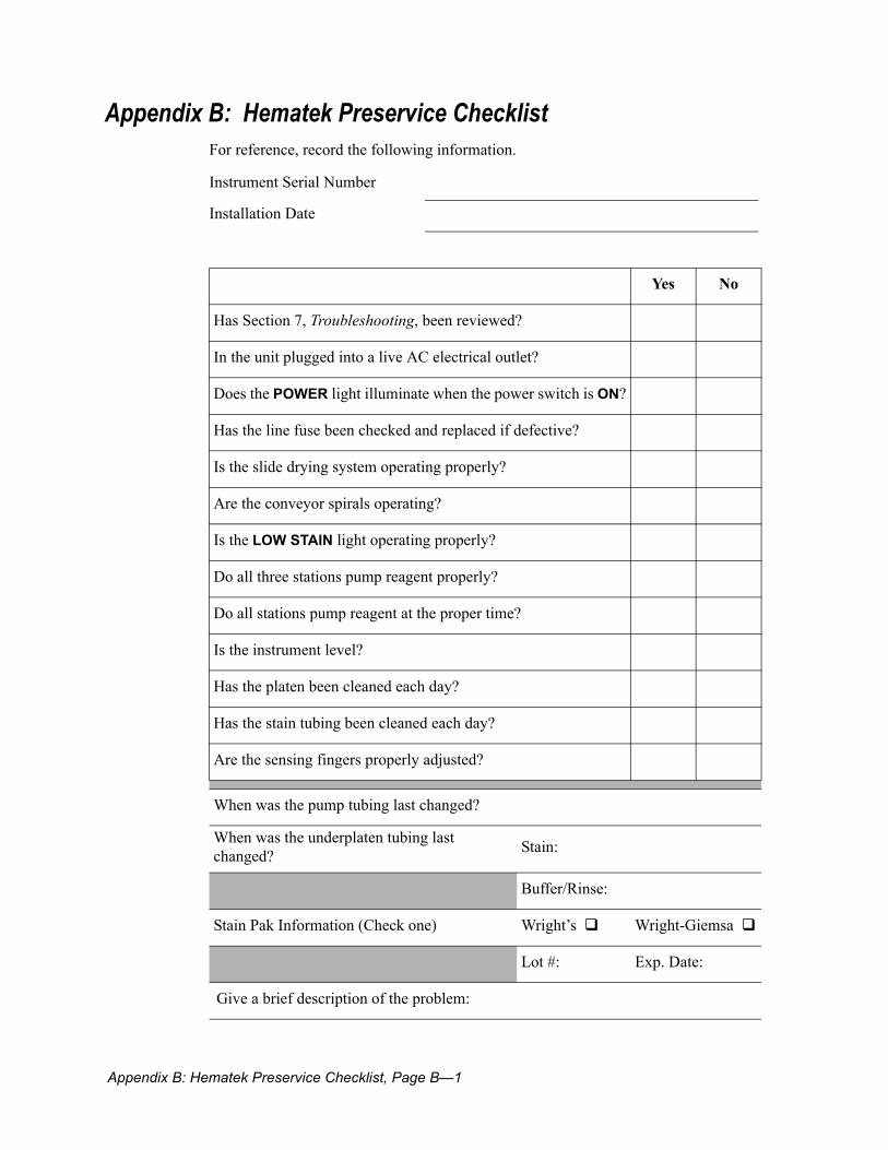
Appendix B: Hematek Preservice Checklist, Page B—1
Appendix B: Hematek Preservice ChecklistFor reference, record the following information.
Instrument Serial Number
Installation Date
Yes No
Has Section 7, Troubleshooting, been reviewed?
In the unit plugged into a live AC electrical outlet?
Does the POWER light illuminate when the power switch is ON?
Has the line fuse been checked and replaced if defective?
Is the slide drying system operating properly?
Are the conveyor spirals operating?
Is the LOW STAIN light operating properly?
Do all three stations pump reagent properly?
Do all stations pump reagent at the proper time?
Is the instrument level?
Has the platen been cleaned each day?
Has the stain tubing been cleaned each day?
Are the sensing fingers properly adjusted?
When was the pump tubing last changed?
When was the underplaten tubing last changed? Stain:
Buffer/Rinse:
Stain Pak Information (Check one) Wright’s Wright-Giemsa
Lot #: Exp. Date:
Give a brief description of the problem:

Page B—2, Appendix B: Hematek Preservice Checklist

Index-1
IndexNumerics12 volts DC, line current converted 1- 12
Aadjust reagent 1- 8adjustments
buffer volume 6- 15pump volume 6- 14rinse volumen 6- 15sensing switch fingers 6- 18stain volume 6- 15
Assemblies, pump 1- 9authorized service representative 8- 3
Bblood smears
loading the blood smear slides 3- 5positioning smears 1- 6procedure 4- 3quality checklist 7- 3staining the smears 3- 6
blood stainsmaking quality stains 4- 3
bone marrow smearsmaking quality smears 4- 5procedure 4- 5
Ccalling for service 8- 3cannulas
cleaning 5- 4cannulas 1- 9characteristics
physical 1- 5checklist for quality of stained blood smears 7-3circular level 1- 5cleaning
emptying the waste tank 5- 6platen 5- 3stain tubing and cannula 5- 4tubing after use 3- 7
conveyor spiralsloading slides 1- 6
Ddaily cleaning
platen 5- 3stain tubing and cannula 5- 4waste tank 5- 6
decontamination 5- 9drain trough
cleaning 5- 6drawer, slide
description 1- 7
Eenvironmental factors
humidity range 2- 3temperature range 2- 3
Ffeet, levelers 1- 5fuse
replacement procedure 6- 3fuse holder, power module 1- 13
Ggeneral cleaning 5- 3grooves, opposing (conveyor spiral) 1- 6guidelines for optimal staining 3- 3
HHematek
Pump Tube Set, description 1- 9underplaten tubing 8- 9
Hematek cannula set 8- 8Hematek pump tube set 8- 9Hematek Stain Pak
Modified Wright’s Stain 8- 8Modified Wright-Giemsa stain 8- 8
humidity range 2- 3
Iinstrument
location 2- 3return procedure 8- 7
intended use 1- 3
Kknobs
volume control 1- 8

Index-2
Llevelers
circular 1- 5feet 1- 5
leveroperating, in electrical system 1- 11
light 1- 11light assemblies
replacement procedure 6- 4line cord receptacle, power module 1- 12line voltage 1- 8loading the blood smear slides 3- 5location of instrument 2- 3Low Stain light 3- 7
Mmaintenance
cleaning drain troughs/rear guide rail 5- 6cleaning the tubing after use 3- 7daily cleaning
cleaning the platen 5- 3cleaning the stain tubing/cannula 5- 4emptying the waste tank 5- 6
general cleaning 5- 3Stain Pak replacing 3- 7
Modified Wright’s Stain 8- 8Modified Wright-Giemsa stain 8- 8
Nnumbering
on pump tubes 1- 9
Ooffices, Siemens 8- 4operating lever
electrical system 1- 11operating procedures
clean the tubing after user 3- 7load the blood smear slides 3- 5prime the tubing 3- 4stain the smears 3- 6start the instrument 3- 3turn the instrument off 3- 7
operationtheory of 1- 4
opposing grooves 1- 6
ordering supplies and replacement parts 8- 10
Pparallel spirals, conveyor 1- 6peripheral blood smears 4- 3physical characteristics 1- 5platen
cleaning procedure 5- 3description 1- 6main functions 1- 6
position of blood smear 1- 6power light
electrical system 1- 12power module
description 1- 12priming the tubing
first time priming 6- 11procedure 3- 4when to 3- 4
PumpAssemblies 1- 9
pump assembliesdescription 1- 8four rollers 1- 8pump arm -1 8pump cap 1- 8pump motor 1- 8
Pump Tube Set 1- 9pump tubing
numbering 1- 9replacement procedure 6- 7
pump volumeadjustment 6- 14
pump volume adjustmentadjust stain, buffer, and rinse volumes 6- 15correct instrument operation 6- 15
Rration determination 6- 17reagents
adjusting 1- 8rear guide rail
cleaning 5- 6removal from operation 5- 9replacement parts
ordering information 8- 10

Index-3
replacements and adjustmentsfuse replacement 6- 3light assemblies 6- 4pump tubing 6- 7underplaten tubing 6- 11volume and ration determination 6- 17
replacing the Stain Pak 3- 7returning the instrument to Siemens 8- 7
Ssensing switch fingers adjustment 6- 18sensing switches
description 1- 10illustration 10
servicewhen to call 8- 3
service calls 8- 3service representative 8- 3Siemens offices
authorized representatives 8- 3 worldwide offices listing 8- 4slide drawer
description 1- 7slide drying system, description 1- 7slide transport 1- 6slide transport system 1- 6slides
loading 1- 6Specifications
dimensions 1- 13fuse ratings 1- 13line leakage current 1- 13power requirements 1- 13throughput 1- 13weight 1- 13
specimensoverview 4- 3
spirals, conveyor 1- 6Stain Pak
replacement 3- 7stain tubing
cleaning 5- 4
staining the smears 3- 6stain-to-buffer ratio 6- 18starting the instrument 3- 3supplies
Hematek cannula set 8- 8Hematek pump tube set 8- 9Hematek Stain Pak
Modified Wright’s Stain 8- 8Modified Wright-Giemsa stain 8- 8
Hematek underplaten tubing 8- 9ordering information 8- 10
symbolsused with system 1- 1
system waste 1- 14
Ttemperature range 2- 3theory of operation 1- 4transport system 1- 6troubleshooting
chart 7- 4checklist for blood smear quality 7- 3
troubleshooting chart 7- 4turning the instrument off 3- 7
Uunderplaten tubing
replacement procedure 6- 11
Vvolume control knobs 1- 8volume control panel 1- 8volume determination 6- 17
Wwaste disposal 1- 14waste tank
description 1- 7emptying procedure 5- 6when to empty and rinse 1- 7
weekly cleaningdrain troughs 5- 6rear guide rail 5- 6

Index-4


![Studer v Boettcher [2000] NSWCA 263 (24 November 2000)](https://static.fdokumen.com/doc/165x107/633372df3108fad7760f0e34/studer-v-boettcher-2000-nswca-263-24-november-2000.jpg)