Heinemann Physics 12 Workbook - Pearson Australia
19
UNIT How do fields explain motion and electricity? AREA OF STUDY 2 How are fields used to move electrical energy? Outcome 2 Analyse and evaluate an electricity generation and distribution system. Key knowledge Generation of electricity • calculate magnetic flux when the magnetic field is perpendicular to the area, and describe the qualitative effect of differing angles between the area and the field: Φ B = B ⊥ A • investigate and analyse theoretically and practically the generation of electromotive force (emf) including AC voltage and calculations using induced emf: ε =- Φ Δ Δ N t B , with reference to: – rate of change of magnetic flux – number of loops through which the flux passes – direction of induced emf in a coil • explain the production of DC voltage in DC generators and AC voltage in alternators, including the use of split ring commutators and slip rings respectively. Transmission of electricity • compare sinusoidal AC voltages produced as a result of the uniform rotation of a loop in a constant magnetic field with reference to frequency, period, amplitude, peak-to- peak voltage (V p−p ) and peak-to-peak current (I p−p ) • compare alternating voltage expressed as the root mean square (rms) to a constant DC voltage developing the same power in a resistive component • convert between rms, peak and peak- to-peak values of voltage and current • analyse transformer action with reference to electromagnetic induction for an ideal transformer: = = N N V V I I 1 2 1 2 2 1 • analyse the supply of power by considering transmission losses across transmission lines • identify the advantage of the use of AC power as a domestic power supply. VCE Physics Study Design extracts © VCAA (2015); reproduced by permission. Sample pages
-
Upload
khangminh22 -
Category
Documents
-
view
4 -
download
0
Transcript of Heinemann Physics 12 Workbook - Pearson Australia

UNIT
How do fields explain motion and electricity?
AREA OF STUDY 2
How are fields used to move electrical energy?
Outcome 2Analyse and evaluate an electricity generation and distribution system.
Key knowledgeGeneration of electricity• calculate magnetic flux when the
magnetic field is perpendicular to the area, and describe the qualitative effect of differing angles between the area and the field: ΦB = B⊥A
• investigate and analyse theoretically and practically the generation of electromotive force (emf) including AC voltage and calculations using induced emf: ε = − Φ∆
∆N
tB, with reference to:
– rate of change of magnetic flux
– number of loops through which the flux passes
– direction of induced emf in a coil
• explain the production of DC voltage in DC generators and AC voltage in alternators, including the use of split ring commutators and slip rings respectively.
Transmission of electricity• compare sinusoidal AC voltages
produced as a result of the uniform rotation of a loop in a constant magnetic field with reference to frequency, period, amplitude, peak-to-peak voltage (Vp−p) and peak-to-peak current (Ip−p)
• compare alternating voltage expressed as the root mean square (rms) to a constant DC voltage developing the same power in a resistive component
• convert between rms, peak and peak-to-peak values of voltage and current
• analyse transformer action with reference to electromagnetic induction for an ideal transformer: = =N
NVV
II
1
2
1
2
2
1
• analyse the supply of power by considering transmission losses across transmission lines
• identify the advantage of the use of AC power as a domestic power supply.
VCE Physics Study Design extracts © VCAA (2015); reproduced by permission.
Sample
page
s

50 HEINEMANN PHYSICS 12 Workbook 1st edition Copyright © Pearson Australia 2019 ISBN 978 1 4886 2391 2
Electromagnetic induction and transmission of electricity
INDUCING AN EMF IN A MAGNETIC FIELDIn the 19th century, scientists studying the relatively new field of electrical currents discovered that moving charges produce magnetic effects. After this, Michael Faraday, an English scientist, was convinced that the reverse should also be true—a magnetic field should be able to produce an electric current. It was discovered that a change in a magnetic field, when a magnet is moved closer to a conductor, leads to an induced emf (electromotive force) that in turn produces a current. A way to induce an emf is by moving a magnet in and out of a coil or moving a straight conductor in a magnetic field.
The production of an induced emf, ε, by a changing magnetic flux is called electromagnetic induction. Magnetic flux is essentially the total number of magnetic field lines passing through any given area. Figure 3.2.1a represents a strong magnetic field acting over a small area that has the same magnetic flux as a weaker magnetic field acting over a larger area (Figure 3.2.1b).
BB
(a) (b)
Figure 3.2.1 The magnetic flux is the same in (a) and (b).
Magnetic flux is defined as the product of the strength of the magnetic field, B, and the area of the field perpendicular to the field lines, A. It is given by the formula:
ΦB = BAwhere ΦB is the magnetic flux in weber (Wb, where 1 Wb = 1 T m2)
B is the magnetic field (T) A is the area perpendicular to the magnetic
field (m2). A subscript ⊥ can be included in the formula to
indicate that the area referred to is that perpendicular to the magnetic field (ΦB = BA⊥), or the component of the magnetic field is that perpendicular to the area (ΦB = B⊥A).
The amount of magnetic flux varies with the angle of the field to the area under investigation. It is a maximum when the area is perpendicular (at 90°) to the field and zero when the area is parallel to the field. This can be represented by the following formula:
ΦB = BA cos θIn Figure 3.2.2, the charges in the wire are moving
apart due to the force they are experiencing from the magnetic field. One end of the conductor will become more positively charged, the other more negatively charged and a potential difference, ΔV, or emf will be induced between the ends of the conductor. This can be represented by the formula:
ε = lvBwhere ε is the induced emf (V)
l is the length of the conductor (m) v is the speed of the conductor perpendicular to the magnetic field (m s−1)B is the strength of the magnetic field (T).
S
ν+++
+++ +
_ ______
N
ΔV
Figure 3.2.2 A potential difference, ΔV, will be produced across a straight wire moving to the left in a downwards-pointing magnetic field.
INDUCED EMF FROM A CHANGING MAGNETIC FLUXFaraday’s investigations led him to conclude that the average emf induced in a conducting loop in which there is a changing magnetic flux is proportional to the negative rate of change of flux. This is now known as Faraday’s law of induction and is one of the basic laws of electromagnetism. If the flux through N turns (or loops) of a coil changes from Φ1 to Φ2 (ΔΦ) during a time Δt, then the average induced emf during this time will be:
ε Φ= −
∆∆
NtB
The negative sign in Faraday’s law indicates direction. For questions involving only magnitudes, you should not use the negative sign or any negative quantities.
LENZ’S LAW AND ITS APPLICATIONSThe Russian physicist Henrich Lenz developed a law to explain how electromagnetic induction obeys the principles of conservation of energy and which explains the direction of the induced emf. This is known as Lenz’s law. Lenz used the idea of nature trying to
Sample
page
s

51Copyright © Pearson Australia 2019 ISBN 978 1 4886 2391 2 Unit 3 Area of Study 2: How are fields used to move electrical energy?
oppose any applied force. Lenz’s law states that when an emf is generated by a change in magnetic flux (Faraday’s law), the induced emf produces a current that, in turn, produces a magnetic field that opposes the original change in flux. For example, when an induced current flows through a coil and a galvanometer, the magnetic field produced by the coil has a direction that repels the incoming pole of a permanent magnet. The same happens if the permanent magnet is pulled out of the coil; however, the magnetic field produced tries to attract the withdrawing permanent magnet back inside the coil again.
A galvanometer is a type of sensitive ammeter; it is an instrument for detecting small electric current.
In Figure 3.2.3a, the north end of a magnet is brought towards a coil from right to left, inducing a magnetic field in which the current flows anticlockwise.
N N SS
(a)
– +
v
(b)
B
I
– +
v
B
I
S SN N
Figure 3.2.3 (a) The north end of a magnet is brought towards a coil from right to left, inducing a current that flows anticlockwise. (b) Pulling the north end of the magnet away from the coil from left to right induces a current in a clockwise direction.
There are three distinct steps to determine the induced current direction according to Lenz’s law:1 What is the change that is happening?2 What will oppose the change and/or restore the
original conditions?3 What must be the current direction to match this
opposition?For example, consider Figure 3.2.4, in which the
arrow indicates the direction the magnet is moving. In this figure, the south pole of a magnet is moved towards the horizontal coil held above it.
S
Figure 3.2.4 The south end of a magnet is brought towards a coil.
In order to find the direction of the induced current, the three distinct steps will be followed.
1 What is the change that is happening?The magnetic field direction in the coil will be downwards towards the south pole of the magnet. As the magnet is brought closer to the coil, the downwards flux in the coil from the magnet will increase (the coil initially had zero magnetic field, hence zero magnetic flux). So the change in flux is increasing downwards.
2 What will oppose this change?The magnetic flux is increasing downwards as the magnet moves towards the coil, so this means the induced magnetic field that opposes the change would act upwards.
3 What is the current direction?In order to oppose the change, the current direction would be anticlockwise when viewed from above (using the right-hand grip rule).
It is important to note it is the flux, not the field, and the rate of change of flux, not the absolute size of the flux, that matters.
INDUCED CURRENT DIRECTION BY CHANGING AREAAs magnetic flux ΦB = B⊥A, a change can be created by any method that causes a change to either of the variables B or A. So an induced emf can be created in three ways:1 by changing the strength of the magnetic field2 by changing the area of the coil within the magnetic
field3 by changing the orientation of the coil with respect
to the direction of the magnetic field.Figure 3.2.5 illustrates an example of the direction
of an induced current that results during a decrease in the area of a coil.
B(inward)
/
B(inward)
/
Figure 3.2.5 Inducing a current by changing the area of a coil.
Sample
page
s

52 HEINEMANN PHYSICS 12 Workbook 1st edition Copyright © Pearson Australia 2019 ISBN 978 1 4886 2391 2
(a) coil rotated
carbonbrushes
sliprings
SN
coilaxle
commutator carbon brush
(b)
Figure 3.2.7 The main features of (a) an AC alternator and (b) a DC generator.
An AC generator produces an alternating current that varies sinusoidally over time with the change in magnetic flux. The alternating current produced by power stations and supplied to cities varies sinusoidally at a frequency of 50 Hz. The peak value of the voltage of domestic power (Vp) is ±340 V, and the peak-to-peak voltage (Vp−p) is 680 V. This is shown in Figure 3.2.8.
10 20
+240
–340
–240
0
peak forward emf +340 V
peak reverse emf –340 V
peak-to-peak emf 680 V
Time (ms)
+340
emf (V)
Figure 3.2.8 The voltage from Australian power points oscillates between +340 V and −340 V, 50 times each second. The value of a DC supply that would supply the same average power is 240 V.
As the area of the coil decreases due to its changing shape, the flux through the coil (which is directed into the page) also decreases. Applying Lenz’s law, the direction of the induced current would oppose this change and will be such that it acts to increase the magnetic flux through the coil into the page. Using the right-hand grip rule, a current would therefore flow in a clockwise direction while the area is changing.
In Figure 3.2.6, the coil is being rotated within the magnetic field. The effect is the same as reducing the area. The amount of flux flowing through the coil is reduced as the coil changes from being perpendicular to the field to being parallel to the field. An induced emf would be created while the coil is being rotated. This becomes particularly important in determining the current direction in a generator.
B(inward)
fluxdecreasing
Figure 3.2.6 An emf is induced when the orientation of a coil within a magnetic field is changed by rotating the coil, reducing the amount of flux through the coil.
GeneratorsA machine that converts mechanical energy into electrical energy is called a generator or alternator. The electric generator is probably the most important practical application of Faraday’s discovery of electromagnetic induction. This machine relies on the induction principle between a coil and a magnetic field. The principle of electric power generators is the same whether the result is alternating current or direct current. Relative motion between a coil and a magnetic field induces an emf in the coil.
The construction of a generator or alternator is very similar to that of an electric motor. A coil is rotated in a magnetic field, which will induce an alternating current in the coil. How that current is harnessed will determine whether the device is an AC alternator or a DC generator.
An AC alternator has slip rings that transfer the alternating nature of the current in the coil to the output (Figure 3.2.7a). A DC generator has a split ring commutator to reverse the current direction every half turn so that the output current is always in the same direction (Figure 3.2.7b).Sam
ple pa
ges
53Copyright © Pearson Australia 2019 ISBN 978 1 4886 2391 2 Unit 3 Area of Study 2: How are fields used to move electrical energy?
Ideal transformers are 100% efficient; real transformers are often over 99% efficient, and for this reason power losses within the transformer can be ignored in calculations.
The transformer equation can be written in different ways but is based on:
=VV
NN
1
2
1
2
where V1 is the primary voltage (V)V2 is the secondary voltage (V)N1 is the number of turns in the primary coilN2 is the number of turns in the secondary coil.
A step-up transformer increases the secondary voltage compared with the primary voltage. A step-down transformer decreases the secondary voltage compared with the primary voltage.
The transformer equation can also be written in terms of current:
=II
NN
1
2
2
1
Power outputTransformers will not work with DC voltage since it has a constant, unchanging current that creates no change in magnetic flux. A transformer works on the basis of a changing current (AC voltage) in the primary coil inducing a changing magnetic flux, which therefore induces a current in the secondary coil. The AC electrical supply from a generator is easily stepped up or down by transformers, so AC is the preferred form of electrical energy in large-scale transmission systems.
Large-scale transmission systems involve current travelling large distances and so even relatively good electrical conductors such as copper have a significant resistance. The efficient transmission of the electrical energy with the least amount of power loss over that distance is therefore important to consider.
Electrical power loss is proportional to the square of the current:
P = I2R
where P is the power (W) I is the current (A)R is the resistance (Ω).
Using this equation, it can be recognised that electrical engineers use very high voltages (P = VI) in order to keep the currents small and the loss of power as heat to a minimum.
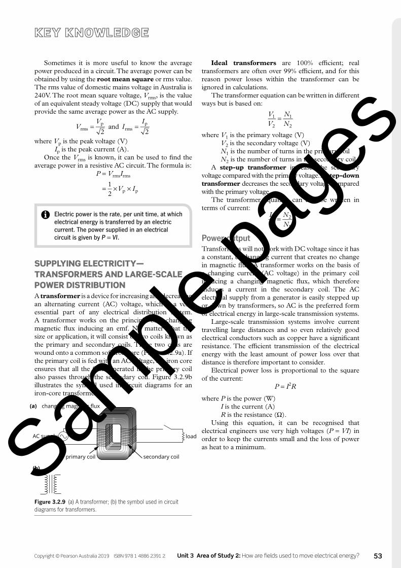
Sometimes it is more useful to know the average power produced in a circuit. The average power can be obtained by using the root mean square or rms value. The rms value of domestic mains voltage in Australia is 240 V. The root mean square voltage, Vrms, is the value of an equivalent steady voltage (DC) supply that would provide the same average power as the AC supply.
= =VV
II
2and
2rmsp
rmsp
where Vp is the peak voltage (V) Ip is the peak current (A).
Once the Vrms is known, it can be used to find the average power in a resistive AC circuit. The formula is:
P = VrmsIrms
= × ×V I12 p p
Electric power is the rate, per unit time, at which electrical energy is transferred by an electric current. The power supplied in an electrical circuit is given by P = VI.
SUPPLYING ELECTRICITY—TRANSFORMERS AND LARGE-SCALE POWER DISTRIBUTIONA transformer is a device for increasing and decreasing an alternating current (AC) voltage, which is a very essential part of any electrical distribution system. A transformer works on the principle of a changing magnetic flux inducing an emf. No matter what the size or application, it will consist of two coils known as the primary and secondary coils. These two coils are wound onto a common soft iron core (Figure 3.2.9a). If the primary coil is fed with an AC voltage, the iron core ensures that all the flux generated in the primary coil also passes through the secondary coil. Figure 3.2.9b illustrates the symbol used in circuit diagrams for an iron-core transformer.
AC supply
primary coil secondary coil
changing magnetic flux(a)
load
(b)
Figure 3.2.9 (a) A transformer; (b) the symbol used in circuit diagrams for transformers.
Sample
page
s

54 HEINEMANN PHYSICS 12 Workbook 1st edition Copyright © Pearson Australia 2019 ISBN 978 1 4886 2391 2
Checking up on charges1 A wire has a current vertically upwards through a hole (i.e. out of the page in the diagram below) in a
horizontal platform in a region where Earth’s magnetic field is horizontal and has a strength of 5.0 × 10⁻⁵ T.
B
N
W E
S
A I
D12 cm
C
a Points A–D are each 12.0 cm from the wire. A compass is placed in turn at each of the points. At one point the compass points directly north, at another exactly north-east and at another the compass keeps moving around without settling down in any one direction. Identify each of these three points.
Compass points directly north ________________________________________________________________
Compass points north-east ___________________________________________________________________
Compass keeps moving _______________________________________________________________________
b What is the size of the net field at each of these three points?
2 A 12.0 V DC power supply is attached to a 56.0 Ω resistor.
a What current does the power supply carry?
b How much power is being expended in the circuit by the power supply?
c A 33.0 Ω resistor is now connected in series with the first resistor. Calculate the values for parts a and b for this new circuit.
Sample
page
s

55Copyright © Pearson Australia 2019 ISBN 978 1 4886 2391 2 Unit 3 Area of Study 2: How are fields used to move electrical energy?
3 A 14.0 cm long coil around a cardboard tube has 600 turns and carries a current of 1.20 A.
X
What is the direction of the magnetic field in the middle of the coil?
At a certain point in a circuit, 4.5 × 10¹⁷ electrons per second are recorded moving from left to right through a 25 cm length of wire.
a What is the direction of the conventional current?
b What is its size?
c If every electron has 8.0 × 10⁻¹⁸ J of work done on it, find the potential difference across the length of wire.
d What is the size of the electric field in the wire?
Sample
page
s
56 HEINEMANN PHYSICS 12 Workbook 1st edition Copyright © Pearson Australia 2019 ISBN 978 1 4886 2391 2
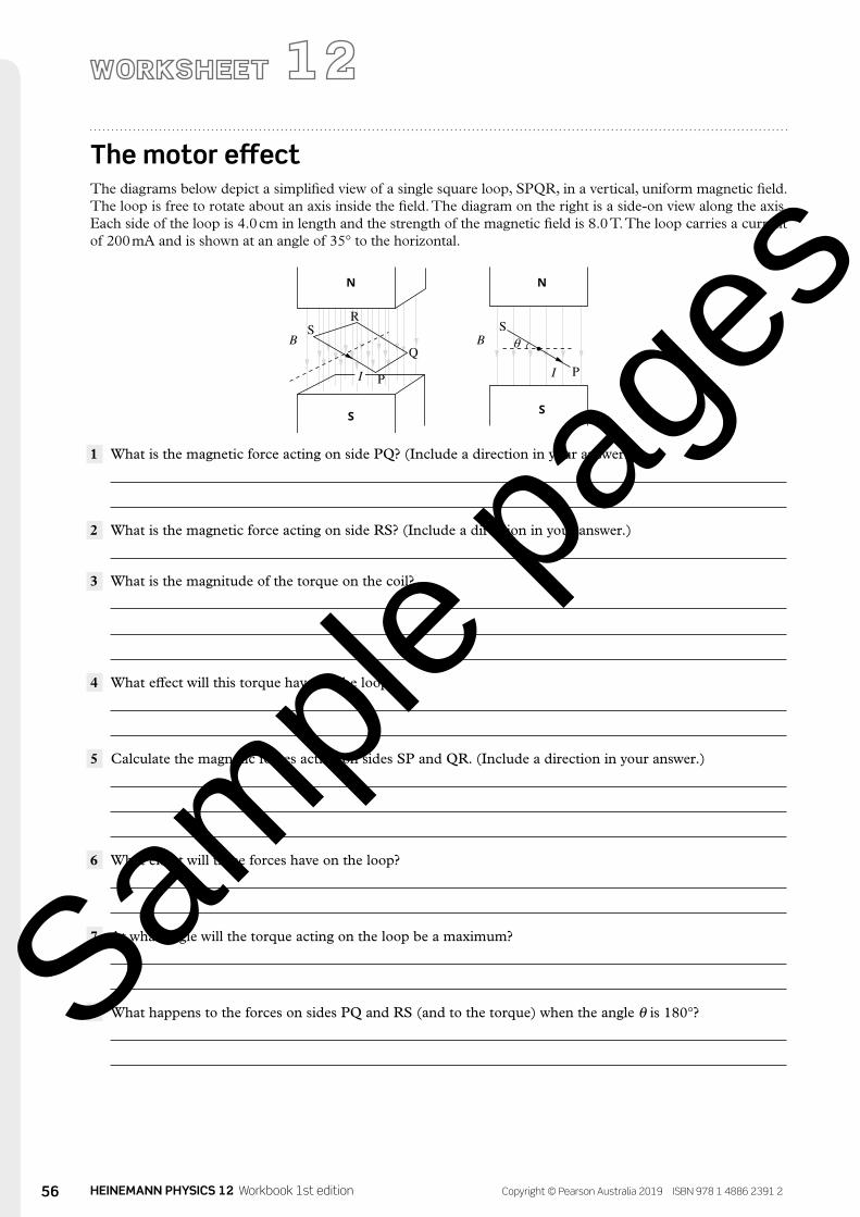
The motor effectThe diagrams below depict a simplified view of a single square loop, SPQR, in a vertical, uniform magnetic field. The loop is free to rotate about an axis inside the field. The diagram on the right is a side-on view along the axis. Each side of the loop is 4.0 cm in length and the strength of the magnetic field is 8.0 T. The loop carries a current of 200 mA and is shown at an angle of 35° to the horizontal.
N
I I
θ
N
S
P PQ
RS S
S
B B
1 What is the magnetic force acting on side PQ? (Include a direction in your answer.)
2 What is the magnetic force acting on side RS? (Include a direction in your answer.)
3 What is the magnitude of the torque on the coil?
4 What effect will this torque have on the loop?
5 Calculate the magnetic forces acting on sides SP and QR. (Include a direction in your answer.)
6 What effect will these forces have on the loop?
7 At what angle will the torque acting on the loop be a maximum?
8 What happens to the forces on sides PQ and RS (and to the torque) when the angle θ is 180°?
Sample
page
s

57Copyright © Pearson Australia 2019 ISBN 978 1 4886 2391 2 Unit 3 Area of Study 2: How are fields used to move electrical energy?
9 Describe what happens to the forces on PQ and RS (and to the torque) when the angle θ exceeds 180°.
10 If this loop is to continue to be rotated by the magnetic forces, what needs to happen to the current? Describe how this action can be applied to the loop. What mechanism can you use to achieve this?
11 Explain three further modifications or additions that could be made to this arrangement to turn it into a practical electric motor.
Sample
page
s

58 HEINEMANN PHYSICS 12 Workbook 1st edition Copyright © Pearson Australia 2019 ISBN 978 1 4886 2391 2
Inducing an emf1 A magnet is dropped, with the north end facing down, through a conducting coil, inducing a current. Which
of the options in the table describes the direction of the current when viewed from above the coil?
Magnet entering the coil Magnet exiting the coil
A clockwise anticlockwise
B anticlockwise clockwise
C clockwise clockwise
D anticlockwise anticlockwise
2 On the diagrams below, draw the direction of the induced current in a coil as it enters or exits a magnetic field.
(b)
(c)
×
× ×
×
×
×
(a)
(d)
×
× ×
× ×
×
3 A square coil of 50 turns and with a side length of 3.0 cm long is moving at 12 cm s−1 into a uniform magnetic field of 4.0 × 10⁻⁴ T. The coil has a resistance of 6.0 Ω (represented by a single resistor symbol). At the instant shown it is halfway into the field.
3 cm B = 4.0 × 10⁻⁴ T
12 cm s–1
× × × × × ×
× × × × × ×
×
×× × × × ×
××××
× ××××
× ××××
6.0 Ω
a How much flux is threading the coil at the instant shown?
b What is size of the emf generated in the coil?
c Describe and calculate the forces, if any, acting on the coil.
Sample
page
s

64 HEINEMANN PHYSICS 12 Workbook 1st edition Copyright © Pearson Australia 2019 ISBN 978 1 4886 2391 2
PROCEDURE
1 Connect a long copper wire to a galvanometer or current sensor using two leads with alligator clips. If using a current sensor, follow the directions of the manufacturer to set up an analogue display of current. Set a sample rate of 20–50 Hz.
2 Hold a part of the wire horizontally between the two poles of a horseshoe magnet as shown in the diagram.
A
B alligator clip
alligator clip
galvanometer or current sensor
long copper wire (straight)
horseshoe magnet
wire lead
N S
0
10
20
3040 50
60
70
80
90
– +
3 Keeping the wire horizontal and parallel to the line AB, move it vertically up and down within the magnetic field of the magnet. Observe and record the direction of the current induced in the wire as it is moved in each direction. Note the direction in the table in the Results section.
4 Keeping the wire horizontal and parallel to the line AB, move it horizontally from one pole of the magnet to the other. Observe and record the direction of the current induced in the wire as it is moved in each direction.
5 Finally, move the wire backwards and forwards along the line A–B, keeping it horizontal. Once again, observe and record the direction of the current induced in the wire as it is moved in each direction.
INTRODUCTION
Just three years after Faraday’s discovery of electromagnetic induction, German physicist Heinrich Lenz discovered a simple principle by which the direction of the induced emf could be found. Lenz’s law states that a current that is induced in a loop will create a flux that will oppose the change in flux that created the current.
The right-hand rule can be used to visualise the direction of the induced current. In this activity the direction of the current induced in a wire by a magnetic field is investigated.
PURPOSE
To investigate the direction of the current induced in a wire by a magnetic field.
Electromagnetic induction—the direction of the induced current in a wire
MATERIALS
• galvanometer or current sensor
• horseshoe magnet• electrical leads with
alligator clips
DURATION
20 minutes
Sample
page
s
65Copyright © Pearson Australia 2019 ISBN 978 1 4886 2391 2 Unit 3 Area of Study 2: How are fields used to move electrical energy?
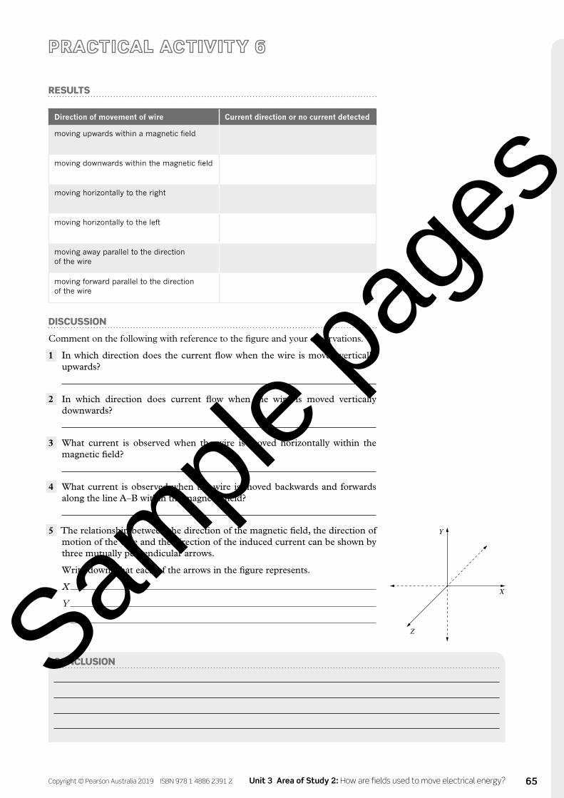
RESULTS
Direction of movement of wire Current direction or no current detected
moving upwards within a magnetic field
moving downwards within the magnetic field
moving horizontally to the right
moving horizontally to the left
moving away parallel to the direction of the wire
moving forward parallel to the direction of the wire
DISCUSSION
Comment on the following with reference to the figure and your observations.
1 In which direction does the current flow when the wire is moved vertically upwards?
2 In which direction does current flow when the wire is moved vertically downwards?
3 What current is observed when the wire is moved horizontally within the magnetic field?
4 What current is observed when the wire is moved backwards and forwards along the line A–B within the magnetic field?
5 The relationship between the direction of the magnetic field, the direction of motion of the wire and the direction of the induced current can be shown by three mutually perpendicular arrows.
Write down what each of the arrows in the figure represents.
X
Y
Z
Y
X
Z
CONCLUSIONSample
page
s

66 HEINEMANN PHYSICS 12 Workbook 1st edition Copyright © Pearson Australia 2019 ISBN 978 1 4886 2391 2
Electricity from a DC motor
INTRODUCTION
In this activity, the basic principle of electric power generation will be investigated. A rotating-coil generator is fundamentally just an electric motor being turned manually to produce a current.
PURPOSE
To investigate the output of a DC motor driven mechanically.
PROCEDURE
1 Connect a small electric motor to a gear system so that the centre shaft of the motor can be turned manually. Connect the leads of the motor to a centre-zero ammeter, or a current sensor. Set up the current sensor following the manufacturer’s instructions.
2 Start turning the motor (and start recording data if using an electronic sensor) as slowly and as smoothly as possible. Observe the output as shown on the galvanometer or the graph of the voltage sensor. Increase the speed of rotation gradually and record your observations of the effect on the output.
3 If you are using an ammeter, stop turning the motor after a little while and replace the ammeter with a CRO. Observe the output from the motor on the oscilloscope screen. Sketch two waveforms corresponding to two different speeds of rotation on the same axes. Label the waveform corresponding to the higher speed of rotation.
RESULTS
Graph of voltage versus time for two speeds of rotation
MATERIALS
• centre-zero ammeter or galvanometer (or current and voltage sensors and data-collection system)
• CRO (cathode ray oscilloscope, if not using an electronic measure)
• electric motor• electrical leads with
alligator clips or banana plugs
• gear system—use gears and a handle to make it easy to turn the shaft of the electric motor
DURATION
20 minutes
Sample
page
s

67Copyright © Pearson Australia 2019 ISBN 978 1 4886 2391 2 Unit 3 Area of Study 2: How are fields used to move electrical energy?
DISCUSSION
1 Is the electric motor an AC or DC generator? Explain with reference to your graph.
2 How does the speed of rotation affect the frequency and amplitude of the output voltage? Why is this the case?
CONCLUSION
Sample
page
s

68 HEINEMANN PHYSICS 12 Workbook 1st edition Copyright © Pearson Australia 2019 ISBN 978 1 4886 2391 2
Faraday’s law of electromagnetic induction
MATERIALS
• data-collection system• voltage sensor (if not
available, a CRO or galvanometer can be used for a qualitative investigation)
• 200-, 400- and 800-turn coils (or other coils of known number of turns as available)
• neodymium magnets• plastic tubes with lids
(empty blood-test tubes from a pathology lab are ideal)
• retort stand and clamp• paper and tape• no-bounce or foam pad
(optional)
DURATION
50 minutes
PROCEDURE
Neodymium magnets can severely pinch skin and are very fragile. Prior to starting the experiment, place the magnets in the plastic tubes—one magnet in one tube, two in the next and so on. Seal the tubes to prevent the magnets falling out.
PART A: VARYING THE NUMBER OF TURNS1 Connect the voltage sensor to the data-analysis system following the manufacturer’s
guidelines and start a new experiment in the relevant software. Set the sample rate to at least 200 Hz and display a graph of voltage versus time.
2 Mount the 200-turn coil to the retort stand using the clamp, so that it is approximately 40 cm above the bench top. If a no-bounce pad is available, place it under the coil to soften the fall of the magnet/s.
3 Connect the voltage sensor to the coil.4 What do you expect the voltage–time graph to look like when the magnet is dropped
through the coil? Before continuing, sketch your prediction in the grid supplied in the Results section.
5 Hold the magnet just above the opening of the coil, start the data-collection system and then drop the magnet through the coil. Stop collecting immediately after.
6 Replace the coil with the 400-turn coil (or the coil with the next most turns) and then repeat the data collection. Do the same for each coil.
7 Display the data on one graph, annotating each curve to identify the number of turns. Print out and paste the graph in the Results section or sketch the graphs in the space
provided.
PART B: VARYING THE NUMBER OF MAGNETSUse the same set-up for this part as in Part A, but use only the 200-turn coil (or the smallest number of turns available).
1 Hold the tube containing one magnet just above the coil opening. Start the data-collection system and then drop the magnet through the coil. Stop collecting immediately after.
2 Repeat with tubes containing two, three, four and five magnets as available.3 Display the data runs on the one graph, annotating each to identify the number of
magnets. Print out and paste the graph in the Results section or sketch the graphs in the space provided.
INTRODUCTION
Michael Faraday (1791–1867) discovered a relationship between a changing magnetic flux, ΦB, and the induced emf within a conductor, ε. Known as Faraday’s law, this relationship is defined by two key elements: the number of turns in a coil, N, and the change in magnetic flux, ΔΦB. In this activity, Faraday’s law will be investigated by using magnets of different strength and increasing the rate at which the magnet passes through the coil.
PURPOSE
To investigate quantitatively the relationship between induced voltage and magnetic flux, time and the number of turns in a coil of wire.
Safety warning
Be careful with magnets. Strong magnets can disrupt electronic devices and severely pinch any skin that comes between them. Keep magnets away from computer hard drives, USB drives and phones.
Sample
page
s

69Copyright © Pearson Australia 2019 ISBN 978 1 4886 2391 2 Unit 3 Area of Study 2: How are fields used to move electrical energy?
PART C: VARYING THE RATE OF CHANGE OF FLUXUse the same set-up for this part as in Part A, but using only the 200-turn coil (or the smallest number of turns available) and a tube with a single magnet.
1 Roll up a piece of paper into a tube, and tape it securely. The tube should be wide enough to allow your magnet to pass through freely, but narrow enough to guide the magnet through the coil.
2 Mark four equally spaced positions on the tube and slide the tube into the coil so that the first mark is showing just above the coil opening.
3 Hold the magnet just above the tube opening. Start the data-collection system and then drop the magnet through the coil. Stop collecting immediately after.
4 Slide the paper tube down into the coil until the next mark on the tube is just above the opening of the coil and repeat the data collection. Repeat the process for the remaining positions marked on the paper tube.
5 Display the data on one graph, annotating each to identify the height from which the magnets were dropped. Print out and paste the graph in the Results section or sketch the graphs in the space provided.
RESULTS
PART A: VARYING THE NUMBER OF TURNS1 Sketch your prediction of the voltage versus time graph.
Sample
page
s

70 HEINEMANN PHYSICS 12 Workbook 1st edition Copyright © Pearson Australia 2019 ISBN 978 1 4886 2391 2
continued
2 If a changing magnetic field causes charges to move in a conductor, and charges moving in a conductor give rise to a magnetic field, what will be the orientation of the induced magnetic field relative to the original changing magnetic field?
3 Sketch or paste your graph of the induced voltage versus time for the different number of turns in the coils.
PART B: VARYING THE NUMBER OF MAGNETS1 Sketch or paste your graph of the induced voltage versus time for a different number of
magnets.
Sample
page
s

71Copyright © Pearson Australia 2019 ISBN 978 1 4886 2391 2 Unit 3 Area of Study 2: How are fields used to move electrical energy?
PART C: VARYING THE RATE OF CHANGE OF FLUX1 Sketch or paste your graph of the induced voltage versus time for each of the different
drop heights.
DISCUSSION
1 How did your prediction compare to the actual voltage versus time graphs?
2 Describe the relationship between the number of turns in the coils and the peak voltages observed.
3 Describe the relationship between the strength of the magnets used and the peak voltages observed. What could be measured to give a more precise relationship?
4 Describe the relationship between the height above the coil from which the magnet fell and the peak voltages observed. What could be measured to give a more precise relationship?Sam
ple pa
ges

72 HEINEMANN PHYSICS 12 Workbook 1st edition Copyright © Pearson Australia 2019 ISBN 978 1 4886 2391 2
continued
CONCLUSION
5 The second peak of the voltage curve is always in the opposite direction to the first peak and is also a slightly larger peak. Describe why this is the case.
Sample
page
s