
Hardware-Assisted Visibility Sorting for ... - Lume - UFRGS
11
Hardware-Assisted Visibility Sorting for Unstructured Volume Rendering Steven P. Callahan, Milan Ikits, Student Member, IEEE, Joa ˜o L.D. Comba, and Cla ´udio T. Silva, Member, IEEE Abstract—Harvesting the power of modern graphics hardware to solve the complex problem of real-time rendering of large unstructured meshes is a major research goal in the volume visualization community. While, for regular grids, texture-based techniques are well-suited for current GPUs, the steps necessary for rendering unstructured meshes are not so easily mapped to current hardware. We propose a novel volume rendering technique that simplifies the CPU-based processing and shifts much of the sorting burden to the GPU, where it can be performed more efficiently. Our hardware-assisted visibility sorting algorithm is a hybrid technique that operates in both object-space and image-space. In object-space, the algorithm performs a partial sort of the 3D primitives in preparation for rasterization. The goal of the partial sort is to create a list of primitives that generate fragments in nearly sorted order. In image-space, the fragment stream is incrementally sorted using a fixed-depth sorting network. In our algorithm, the object-space work is performed by the CPU and the fragment-level sorting is done completely on the GPU. A prototype implementation of the algorithm demonstrates that the fragment-level sorting achieves rendering rates of between one and six million tetrahedral cells per second on an ATI Radeon 9800. Index Terms—Volume visualization, graphics processors, visibility sorting. æ 1 INTRODUCTION G IVEN a general scalar field in IR 3 , a regular grid of samples can be used to represent the field at grid points ð! i ;! j ;! k Þ, for integers i; j; k and some scale factor ! 2 IR. One serious drawback of this approach is that, when the scalar field has highly nonuniform variation—a situa- tion that often arises in computational fluid dynamics and partial differential equation solvers—the voxel size must be small enough to represent the smallest features in the field. Unstructured grids with cells that are not necessarily uniform in size have been proposed as an effective means for representing disparate field data. In this paper, we are primarily interested in volume rendering unstructured scalar data sets. In volume render- ing, the scalar field is modeled as a cloud-like material that both emits and attenuates light along the viewing direction [1]. To create an image, the equations for the optical model must be integrated along the viewing ray for each pixel (see Fig. 1). For unstructured meshes, this requires computing a separate integral for the contribution of the ray segment inside each cell. If the order of these segments is known, the individual contributions can be accumulated using front-to- back or back-to-front compositing. On a practical level, the whole computation amounts to sampling the volume along the viewing rays, determining the contribution of each sample point, and accumulating the contributions in proper order. Given the increasing size of volume data sets, performing these operations in real-time requires the use of specialized hardware. Modern GPUs [2] are quite effective at performing most of these tasks. By coupling the rasterization engine with texture-based frag- ment processing, it is possible to perform very efficient volume sampling [3], [4]. However, generating the frag- ments in visibility order is still necessary. For regular grids, generating the fragments in visibility order is straightforward. This is often accomplished by rendering polygons p 1 ;p 2 ; ... ;p n perpendicular to the view direction at different depths. The polygons are used to slice the volume and generate the samples for the cells that intersect them. The fact that the polygons are rendered in sorted order and are parallel with each other guarantees that all the fragments generated by rasterizing polygon p i come before those for p iþ1 . In this case, compositing can be accomplished by blending the fragments into the frame- buffer in the order in which they are generated. For details on performing these computations, see [5]. The sampling and compositing procedure for unstruc- tured grids is considerably more complicated. Although the intrinsic volume rendering computations are similar, the requirement of generating fragments in visibility order makes the computations more expensive and difficult to implement. The Projected Tetrahedra (PT) algorithm [6] was the first to show how to render tetrahedral cells using the traditional 3D polygon-rendering pipeline. Given tetrahedra T and a viewing direction v, the technique first classifies the faces of T into front and back faces with respect to v. Next, for correct fragment generation, the faces are subdivided into regions of equal visibility. Note that the PT algorithm can properly handle only a single tetrahedral IEEE TRANSACTIONS ON VISUALIZATION AND COMPUTER GRAPHICS, VOL. 11, NO. 3, MAY/JUNE 2005 1 . S.P. Callahan, M. Ikits, and C.T. Silva are with the Scientific Computing and Imaging Institute, School of Computing, University of Utah, 50 S. Central Campus Dr., Salt Lake City, UT 84112. E-mail: {stevec, ikits}@sci.utah.edu, [email protected]. . J.L.D. Comba is with the Universidade Federal do Rio Grande do Sul, Instituto de Informatica, Av. Bento Goncalves, 9500, Campus do Vale- Bloco IV-Pre´dio 43425, Porto Alegre RS 91501-970, Brazil. E-mail: [email protected]. Manuscript received 18 Oct. 2004; revised 27 Dec. 2004; accepted 5 Jan. 2005; published online 10 Mar. 2005. For information on obtaining reprints of this article, please send e-mail to: [email protected], and reference IEEECS Log Number TVCG-0131-1004. 1077-2626/05/$20.00 ß 2005 IEEE Published by the IEEE Computer Society
-
Upload
khangminh22 -
Category
Documents
-
view
4 -
download
0
Transcript of Hardware-Assisted Visibility Sorting for ... - Lume - UFRGS
Hardware-Assisted Visibility Sorting forUnstructured Volume Rendering
Steven P. Callahan, Milan Ikits, Student Member, IEEE,
Joao L.D. Comba, and Claudio T. Silva, Member, IEEE
Abstract—Harvesting the power of modern graphics hardware to solve the complex problem of real-time rendering of large
unstructured meshes is a major research goal in the volume visualization community. While, for regular grids, texture-based
techniques are well-suited for current GPUs, the steps necessary for rendering unstructured meshes are not so easily mapped to
current hardware. We propose a novel volume rendering technique that simplifies the CPU-based processing and shifts much of the
sorting burden to the GPU, where it can be performed more efficiently. Our hardware-assisted visibility sorting algorithm is a hybrid
technique that operates in both object-space and image-space. In object-space, the algorithm performs a partial sort of the
3D primitives in preparation for rasterization. The goal of the partial sort is to create a list of primitives that generate fragments in nearly
sorted order. In image-space, the fragment stream is incrementally sorted using a fixed-depth sorting network. In our algorithm, the
object-space work is performed by the CPU and the fragment-level sorting is done completely on the GPU. A prototype implementation
of the algorithm demonstrates that the fragment-level sorting achieves rendering rates of between one and six million tetrahedral cells
per second on an ATI Radeon 9800.
Index Terms—Volume visualization, graphics processors, visibility sorting.
�
1 INTRODUCTION
GIVEN a general scalar field in IR3, a regular grid ofsamples can be used to represent the field at grid
points ð�i; �j; �kÞ, for integers i; j; k and some scale factor� 2 IR. One serious drawback of this approach is that, whenthe scalar field has highly nonuniform variation—a situa-tion that often arises in computational fluid dynamics andpartial differential equation solvers—the voxel size must besmall enough to represent the smallest features in the field.Unstructured grids with cells that are not necessarilyuniform in size have been proposed as an effective meansfor representing disparate field data.
In this paper, we are primarily interested in volume
rendering unstructured scalar data sets. In volume render-
ing, the scalar field is modeled as a cloud-like material that
both emits and attenuates light along the viewing direction
[1]. To create an image, the equations for the optical model
must be integrated along the viewing ray for each pixel (see
Fig. 1). For unstructured meshes, this requires computing a
separate integral for the contribution of the ray segment
inside each cell. If the order of these segments is known, the
individual contributions can be accumulated using front-to-
back or back-to-front compositing.
On a practical level, the whole computation amounts tosampling the volume along the viewing rays, determiningthe contribution of each sample point, and accumulating thecontributions in proper order. Given the increasing size ofvolume data sets, performing these operations in real-timerequires the use of specialized hardware. Modern GPUs [2]are quite effective at performing most of these tasks. Bycoupling the rasterization engine with texture-based frag-ment processing, it is possible to perform very efficientvolume sampling [3], [4]. However, generating the frag-ments in visibility order is still necessary.
For regular grids, generating the fragments in visibilityorder is straightforward. This is often accomplished byrendering polygons p1; p2; . . . ; pn perpendicular to the viewdirection at different depths. The polygons are used to slicethe volume and generate the samples for the cells thatintersect them. The fact that the polygons are rendered insorted order and are parallel with each other guaranteesthat all the fragments generated by rasterizing polygon picome before those for piþ1. In this case, compositing can beaccomplished by blending the fragments into the frame-buffer in the order in which they are generated. For detailson performing these computations, see [5].
The sampling and compositing procedure for unstruc-tured grids is considerably more complicated. Although theintrinsic volume rendering computations are similar, therequirement of generating fragments in visibility ordermakes the computations more expensive and difficult toimplement. The Projected Tetrahedra (PT) algorithm [6]was the first to show how to render tetrahedral cells usingthe traditional 3D polygon-rendering pipeline. Giventetrahedra T and a viewing direction v, the technique firstclassifies the faces of T into front and back faces withrespect to v. Next, for correct fragment generation, the facesare subdivided into regions of equal visibility. Note that thePT algorithm can properly handle only a single tetrahedral
IEEE TRANSACTIONS ON VISUALIZATION AND COMPUTER GRAPHICS, VOL. 11, NO. 3, MAY/JUNE 2005 1
. S.P. Callahan, M. Ikits, and C.T. Silva are with the Scientific Computingand Imaging Institute, School of Computing, University of Utah, 50 S.Central Campus Dr., Salt Lake City, UT 84112.E-mail: {stevec, ikits}@sci.utah.edu, [email protected].
. J.L.D. Comba is with the Universidade Federal do Rio Grande do Sul,Instituto de Informatica, Av. Bento Goncalves, 9500, Campus do Vale-Bloco IV-Predio 43425, Porto Alegre RS 91501-970, Brazil.E-mail: [email protected].
Manuscript received 18 Oct. 2004; revised 27 Dec. 2004; accepted 5 Jan. 2005;published online 10 Mar. 2005.For information on obtaining reprints of this article, please send e-mail to:[email protected], and reference IEEECS Log Number TVCG-0131-1004.
1077-2626/05/$20.00 � 2005 IEEE Published by the IEEE Computer Society
cell. For rendering meshes, cells have to be projected invisibility order, which can be accomplished using techni-ques such as the Meshed Polyhedra Visibility Ordering(MPVO) algorithm [7]. For acyclic convex meshes, this is apowerful combination that leads to a linear-time algorithmthat is provably correct, i.e., it is guaranteed to produce theright picture. When the mesh is not convex or containscycles, MPVO requires modifications that significantlycomplicate the algorithm and its implementation, leadingto slower rendering times [8], [9], [10], [11].
The necessity of explicit fragment sorting for unstruc-tured grids is the main cause of the rendering-speeddichotomy between regular and unstructured grids. Forregular grids, we are exploiting the fact that we can sort inobject space (implicit in the order of the planes beingrendered) and avoid sorting in image space (i.e., sortingfragments). Thus, on modern GPUs, it is possible to renderregular volumes at very high frame rates. Unfortunately,performing visibility ordering for unstructured grids com-pletely in image space has turned out to be quite expensiveand complex [11], [12], [13].
In this paper, we build on the previous work of Fariaset al. [14] and Carpenter [15] and propose a new volumerendering algorithm. Our main contributions are:
. We present a new algorithm for rendering unstruc-tured volumetric data that simplifies the CPU-basedprocessing and shifts much of the sorting burden tothe GPU, where it can be performed more efficiently.The basic idea of our algorithm is to separate visibilitysorting into two phases. First, we perform a partialvisibility ordering of primitives in object-space usingthe CPU. Note that this first phase does not guaranteean exact visibility order of the fragments duringrasterization. In the second phase, we use a modifiedA-buffer of fixed depth (called the k-buffer) to sort thefragments in exact order on the GPU.
. We show how to efficiently implement the k-bufferusing the programmable functionality of existingGPUs.
. We perform a detailed experimental analysis toevaluate the performance of our algorithm usingseveral data sets, the largest of which having over1.4 million cells. The experiments show that ouralgorithm can handle general nonconvex mesheswith very low memory overhead and requires only a
light and completely automatic preprocessing step.Data size limitations are bounded by the availablemain memory on the system. The achieved render-ing rates of over six million cells per second are, toour knowledge, the fastest reported results forvolume rendering of unstructured data sets.
. We provide a detailed comparison of our algorithmwith existing methods for rendering unstructuredvolumetric data. This includes render rates per-formed using optimized implementations of thesealgorithms using uniform test cases on the samemachine.
The remainder of this paper is organized as follows: Wesummarize related work in Section 2. In Section 3, wedescribe our algorithm, define k-nearly sorted sequences,and provide further details on the functionality of thek-buffer. In Section 4, we show how to efficiently implementthe k-buffer using the programmable features of current ATIhardware. Section 5 summarizes our experiments andresults. In Section 6, we discuss different trade-offs of ourapproach. Finally, in Section 7, we provide final remarksand directions for future work.
2 RELATED WORK
The volume rendering literature is vast and we do notattempt a comprehensive review here. Interested readerscan find a more complete discussion of previous work in[5], [11], [16], [17], [18]. We limit our coverage to the mostdirectly related work in the area of visibility ordering usingboth software and hardware techniques.
In computer graphics, work on visibility ordering waspioneered by Schumacker et al. and is later reviewed in [19].An early solution to computing a visibility order was givenby Newell, Newell, and Sancha (NNS) [20], which continuesto be the basis for more recent techniques [21]. The NNSalgorithm starts by partially ordering the primitives accord-ing to their depth. Then, for each primitive, the algorithmimproves the ordering by checking whether other primi-tives precede it or not.
Fuchs et al. [22] developed the Binary Space Partitioningtree (BSP-tree)—adata structure that represents a hierarchicalconvex decomposition of a given space (typically, IR3). Eachnode � of a BSP-tree T corresponds to a convex polyhedralregion, P ð�Þ � IR3 and the root node corresponds to all of
2 IEEE TRANSACTIONS ON VISUALIZATION AND COMPUTER GRAPHICS, VOL. 11, NO. 3, MAY/JUNE 2005
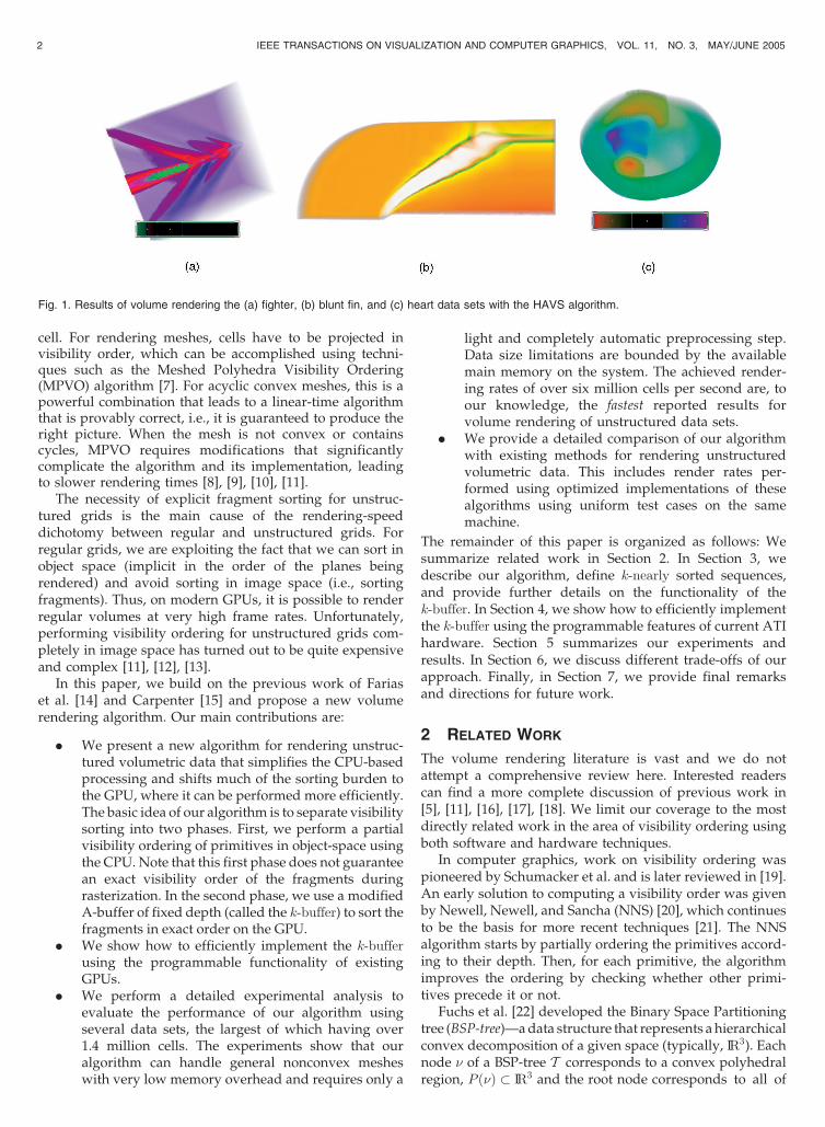
Fig. 1. Results of volume rendering the (a) fighter, (b) blunt fin, and (c) heart data sets with the HAVS algorithm.
IR3. Each nonleaf node � is defined by a hyperplane, hð�Þthat partitions P ð�Þ into two half-spaces, P ð�þÞ ¼ hþð�Þ \P ð�Þ and P ð��Þ ¼ h�ð�Þ \ P ð�Þ, corresponding to the twochildren, �þ and �� of �. Here, hþð�Þ (h�ð�Þ) is the half-space of points above (below) the plane hð�Þ. Fuchs et al.[22] demonstrated that BSP-trees can be used for obtaining avisibility ordering of a set of objects or, more precisely, anordering of the fragments into which the objects are cut bythe partitioning planes. The key observation is that thestructure of the BSP-tree permits a simple recursivealgorithm for rendering the object fragments in back-to-front order. Thus, if the viewpoint lies in the positive half-space hþð�Þ, we can recursively draw the fragments storedin the leaves of the subtree rooted at ��, followed by theobject fragments Sð�Þ � hð�Þ. Finally, we recursively drawthe fragments stored in the leaves of the subtree rooted at�þ. Note that the BSP-tree does not actually generate avisibility order for the original primitives, but for fragmentsof them.
The methods presented above operate in object-space, i.e.,they operate on the primitives before rasterization by thegraphics hardware [2]. Carpenter [15] proposed theA-buffer—a technique that operates on pixel fragmentsinstead of object fragments. The basic idea is to rasterize allthe objects into sets of pixel fragments, then save thosefragments in per-pixel linked lists. Each fragment stores itsdepth, which can be used to sort the lists after all the objectshave been rasterized. A nice property of the A-buffer is thatthe objects can be rasterized in any order and, thus, do notrequire any object-space ordering. A main shortcoming ofthe A-buffer is that the memory requirements are sub-stantial. Recently, there have been proposals for implement-ing the A-buffer in hardware. The R-buffer [23] is apointerless A-buffer hardware architecture that implementsa method similar to a software algorithm described in [24]for sorting transparent fragments in front of the frontmostopaque fragment. Current hardware implementations ofthis technique require multiple passes through the polygonsin the scene [25]. In contrast, the R-buffer works by scan-converting all polygons only once and saving the not yetcomposited or rejected fragments in a large unorderedrecirculating fragment buffer on the graphics card, fromwhich multiple depth comparison passes can be made. TheZ3 hardware [26] is an alternative design which uses sparsesupersampling and screen door transparency with a fixedamount of storage per pixel. When there are morefragments generated for a pixel than what the availablememory can hold, Z3 merges the extra fragments.
Because of recent advances in programmable graphicshardware, techniques have been developed which shiftmuch of the computation to the GPU for increasedperformance. Kipfer et al. [27] introduce a fast sortingnetwork for particles. This algorithm orders the particlesusing a Bitonic sort that is performed entirely on the GPU.Unstructured volume rendering has also seen a number ofrecent advances. Roettger and Ertl [28] demonstrate theefficiency of the GPU for compositing the ray integrals ofarbitrary unstructured polyhedra. Their method uses anemissive optical model which does not require anyordering. Their technique is similar to HAVS without
sorting. Recently, Wylie et al. have shown how toimplement the Shirley-Tuchman tetrahedron projectiondirectly on the GPU [29]. As mentioned before, thePT projection sorts fragments for a single tetrahedron onlyand still requires that the cells be sent to the GPU in sortedorder. An alternative approach is to perform pixel-levelfragment sorting via ray-casting. This has been shownpossible by Weiler et al. for convex meshes [12] and, morerecently, for nonconvex meshes [13].
Roughly speaking, all of the techniques described aboveperform sorting either in object-space or in image-spaceexclusively, where we consider ray casting as sorting inimage-space and cell projection as sorting in object-space.There are also hybrid techniques that sort both in image-space and object-space. For instance, the ZSWEEP [14]algorithm works by performing a partial ordering ofprimitives in object-space followed by an exact pixel-levelordering of the fragments generated by rasterizing theobjects. Depending on several factors, including averageobject size, accuracy and speed of the partial sort, and costof the fragment-level sorting, hybrid techniques can bemore efficient than either pure object-space or image-spacealgorithms. Another hybrid approach is presented in [30],where the authors show how to improve the efficiency ofthe R-buffer by shifting some of the work from image-spaceto object-space.
3 HARDWARE-ASSISTED VISIBILITY SORTING
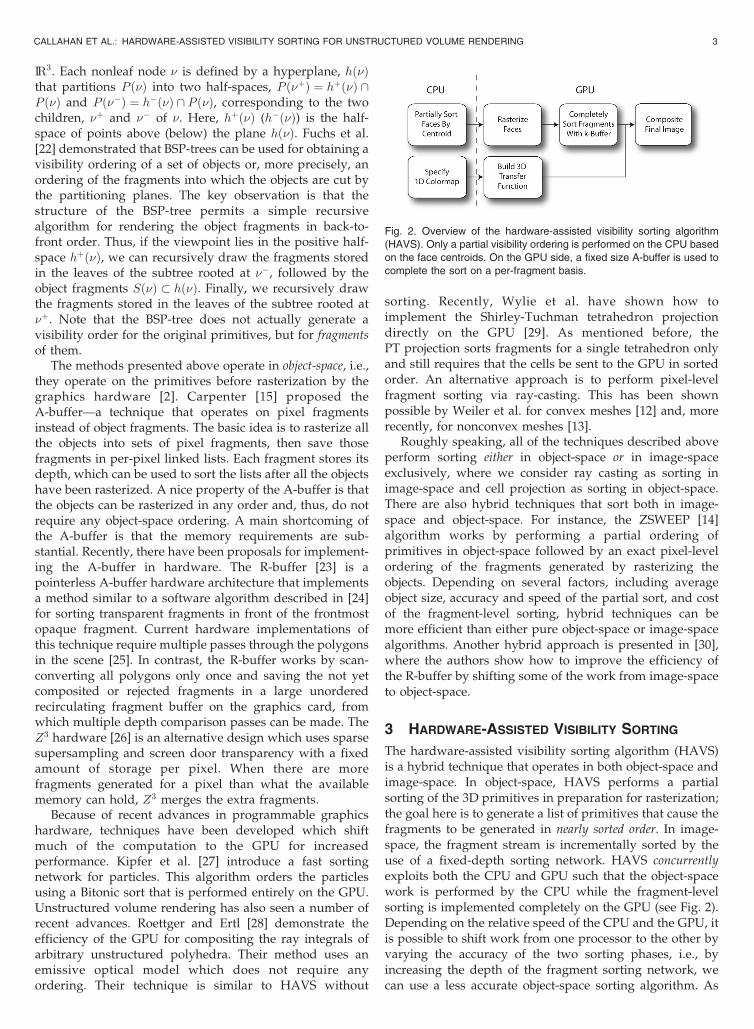
The hardware-assisted visibility sorting algorithm (HAVS)is a hybrid technique that operates in both object-space andimage-space. In object-space, HAVS performs a partialsorting of the 3D primitives in preparation for rasterization;the goal here is to generate a list of primitives that cause thefragments to be generated in nearly sorted order. In image-space, the fragment stream is incrementally sorted by theuse of a fixed-depth sorting network. HAVS concurrentlyexploits both the CPU and GPU such that the object-spacework is performed by the CPU while the fragment-levelsorting is implemented completely on the GPU (see Fig. 2).Depending on the relative speed of the CPU and the GPU, itis possible to shift work from one processor to the other byvarying the accuracy of the two sorting phases, i.e., byincreasing the depth of the fragment sorting network, wecan use a less accurate object-space sorting algorithm. As
CALLAHAN ET AL.: HARDWARE-ASSISTED VISIBILITY SORTING FOR UNSTRUCTURED VOLUME RENDERING 3
Fig. 2. Overview of the hardware-assisted visibility sorting algorithm
(HAVS). Only a partial visibility ordering is performed on the CPU based
on the face centroids. On the GPU side, a fixed size A-buffer is used to
complete the sort on a per-fragment basis.
shown in Section 4, our current implementation uses verysimple data structures that require essentially no topologi-cal information leading to a very low memory overhead. Inthe following sections, we present further details on the twophases of HAVS.
3.1 Nearly Sorted Object-Space Visibility Ordering
Visibility ordering algorithms (e.g., Extended MeshedPolyhedra Visibility Ordering [9]) sort 3D primitives withrespect to a given viewpoint v in exact order, which allowsfor direct compositing of the rasterized fragments. In ourwork, we differentiate between the sorting of the3D primitives and the sorting of the rasterized fragmentsto utilize faster object-space sorting algorithms.
To precisely define what we mean by nearly sortedobject-space visibility ordering, we first introduce somenotation. Given a sequence S of real values fs1; s2; . . . ; sng,we call the tuple of distinct integer values ða1; a2; . . . ; anÞ theExactly Sorted Sequence of S (or ESSðSÞ) if each ai is theposition of si in an ascending or descending order of theelements in S. For instance, for the sequenceS ¼ f0:6; 0:2; 0:3; 0:5; 0:4g, the corresponding exactly sortedsequence is ESSðSÞ ¼ ð5; 1; 2; 4; 3Þ. Extensions to allow forduplicated values in the sequence are easy to incorporateand are not discussed here. Similarly, we call a tupleðb1; b2; . . . ; bnÞ of distinct integer values a k-Nearly SortedSequence of S (or k-NSSðSÞ) if the maximum element of thepairwise absolute difference of elements in ESS(S) andk-NSSðSÞ is k, i.e., maxðja1 � b1j; ja2 � b2j; . . . jan � bnjÞÞ ¼ k.For instance, the tuple ð4; 2; 1; 5; 3Þ is a 1-NSS(S) (i.e.,maxðj5� 4j; j1� 2j; j2� 1j; j4� 5j; j3� 3jÞ ¼ 1), while thetuple ð3; 1; 4; 5; 2Þ is a 2-NSS(S). In this work, we processsequences of fragment distances from the viewpoint. Werelax the requirement of having exactly sorted sequences,which allows for faster object-space sorting, but leads tonearly sorted sequences that need to be sorted exactlyduring the fragment processing stage.
There are many techniques that implicitly generatenearly sorted sequences. For example, several hierarchicalspatial data structures provide mechanisms for simple andefficient back-to-front traversal [31]. A simple way ofgenerating nearly sorted object-space visibility ordering ofa collection of 3D primitives is to use a BSP-tree, which hasbeen shown to cause near-linear primitive growth fromcutting [8]. The goal is to ensure that, after rasterization,pixel fragments are at most k positions out of order. In apreprocessing step, we can hierarchically build a BSP-treesuch that no leaf of the BSP tree has more than k elements.Note that this potentially splits the original primitives intomultiple ones. To generate the actual ordering of theprimitives, we can use the well-known algorithm forback-to-front traversal of a BSP-tree and render the set ofk primitives in the leaf nodes in any order. Since it is notstrictly necessary to implement this approach, simplersorting techniques are used in our work. In practice, mostdata sets are quite well-behaved and even simple techni-ques, such as sorting primitives by their centroid or even bytheir first vertex, are often sufficient to generate nearlysorted geometry. This was previously exploited in theZSWEEP algorithm [14]. In ZSWEEP, primitives are sortedby considering a sweep plane parallel to the viewing plane.
As the sweep plane touches a vertex of a face, the face israsterized and the generated fragments are added to anA-buffer using insertion sort. It was experimentally ob-served that the insertion sort had nearly linear complexitybecause fragments were in almost sorted order. To avoid amemory space explosion in the A-buffer, ZSWEEP uses aconservative technique for compositing samples [14]. In ourapproach, we apply a more aggressive technique formanaging the A-buffer.
3.2 The k-Buffer
The original A-buffer [15] stores all incoming fragments in alist, which requires a potentially unbounded amount ofmemory. Our k-buffer approach stores only a fixed numberof fragments and works by combining the current frag-ments and discarding some of them as new fragmentsarrive. This technique reduces the memory requirement andis simple enough to be implemented on existing graphicsarchitectures (see Section 4).
The k-buffer is a fragment stream sorter that works asfollows. For each pixel, the k-buffer stores a constantk number of entries hf1; f2; . . . ; fki. Each entry contains thedistance of the fragment from the viewpoint, which is usedfor sorting the fragments in increasing order for front-to-back compositing and in decreasing order for back-to-frontcompositing. For front-to-back compositing, each time anew fragment fnew is inserted in the k-buffer, it dislodges thefirst entry (f1). Note that boundary cases need to be handledproperly and that fnew may be inserted at the beginning ofthe buffer if it is closer to the viewpoint than all the otherfragments or at the end if it is further. A key property of thek-buffer is that, given a sequence of fragments such thateach fragment is within k positions from its position in thesorted order, it will output the fragments in the correctorder. Thus, with a small k, the k-buffer can be used to sort ak-nearly sorted sequence of n fragments in OðnÞ time. Notethat, to composite a k-nearly sorted sequence of fragments,kþ 1 entries are required because both the closest andsecond closest fragments must be available for the preinte-grated table lookup. In practice, the hardware implementa-tion is simplified by keeping the k-buffer entries unsorted(see Fig. 3).
Compared to ZSWEEP, the k-buffer offers a less con-servative fragment sorting scheme. Since only k entries areconsidered at a time, if the incoming sequence is highly outof order, the output will be incorrect, which may benoticeable in the images. As shown in Section 5, evensimple and inexpensive object-space ordering leads tofragments that are almost completely sorted.
3.3 Volume Rendering Algorithm
The volume rendering algorithm is built upon themachinerypresented above. First,we sort the faces of the tetrahedral cellsof the unstructured mesh on the CPU based on the facecentroids using the floating-point radix sort algorithm. Toproperly handle boundaries, the vertices aremarkedwhetherthey are internal or boundary vertices of the mesh. Next, thefaces are rasterized by the GPU, which completes the sortusing the k-buffer and composites the accumulated color andopacity into the framebuffer (see Fig. 2). The completepseudocode for our CPU algorithm is given below:
4 IEEE TRANSACTIONS ON VISUALIZATION AND COMPUTER GRAPHICS, VOL. 11, NO. 3, MAY/JUNE 2005
CPU-SORT
Perform sort on face centroids
for each sorted face sf
Send sf to GPU for rasterization
4 K-BUFFER HARDWARE IMPLEMENTATION
The k-buffer can be efficiently implemented using the
multiple render target capability of the latest generation of
ATI graphics cards. Our implementation uses the ATI_
draw_buffers OpenGL extension, which allows writing
into up to four floating-point RGBA buffers in the fragment
shader. One of the buffers is used as the framebuffer and
contains the accumulated color and opacity of the frag-
ments that have already left the k-buffer. The remaining
buffers are used to store the k-buffer entries. In the simplest
case, each entry consists of the scalar data value v and the
distance d of the fragment from the eye. This arrangement
allows us to sort up to seven fragments in a single pass (six
entries from the k-buffer plus the incoming fragment).The fragment program is comprised of three stages (see
Fig. 3 and the source code in the Appendices, which can be
found on the Computer Society Digital Library at http://
computer.org/tvcg/archives/htm). First, the program
reads the accumulated color and opacity from the frame-
buffer. Program execution is terminated if the opacity is
above a given threshold (early ray termination). Next, the
program fetches the current k-buffer entries from the
associated RGBA buffers and finds the two closest frag-
ments to the eye by sorting the entries based on the stored
distance d. For the incoming fragment, d is computed from
its view-space position, which is calculated in a vertex
program and passed to the fragment stage in one of the
texture coordinate registers. The scalar values of the two
closest entries and their distance is used to obtain the color
and opacity of the ray segment defined by the two entries
from the 3D preintegrated texture. Finally, the resulting
color and opacity are composited with the color and opacity
from the framebuffer, the closest fragment is discarded, and
the remaining entries are written back into the k-buffer (see
also Fig. 3). The complete pseudocode for our GPUfragment sorter (k ¼ 3) is given below:
GPU-SORT
for each fragment fnewRead color c1 from framebuffer
if c1 is opaque then
RETURN
Read fragments f1, f2, and f3 from k-buffer
n1 closest fragment fnew, f1, f2, or f3ðr1; r2; r3Þ remaining fragments
n2 closest fragment r1, r2, or r3d1 depth of n1, d2 depth of n2
v1 scalar of n1, v2 scalar of n2
�d d2 � d1Read c2 from preintegrated table
using v1, v2, and �d
Composite c1 and c2 into framebuffer
Write r1, r2, and r3 back into k-buffer
Several important details have to be considered for thehardware implementation of the algorithm. First, to look upvalues in a screen-space buffer, e.g., when compositing aprimitive into a pixel buffer, previous implementations ofvolume rendering algorithms used the technique of project-ing the vertices of the primitive to the screen, from which2D texture coordinates are computed [32], [33]. As illu-strated in Fig. 4, this approach produces incorrect results,unless the primitive is aligned with the screen, whichhappens only when view-aligned slicing is used to samplethe volume. The reason for this problem is that therasterization stage performs perspective-correct texturecoordinate interpolation, which cannot be disabled onATI cards [2]. Even if perspective-correct interpolationcould be disabled, other quantities, e.g., the scalar datavalue, would still need to be interpolated in perspectivespace. Thus, to achieve the desired screen space lookup, onehas to compute the texture coordinates from the fragmentwindow position or use projective texture mapping [34].Since projective texturing requires a division in the texturefetch stage of the pipeline, we decided to use the formersolution in our implementation.
Second, strictly speaking, the result of simultaneouslyreading and writing a buffer is undefined when primitives
CALLAHAN ET AL.: HARDWARE-ASSISTED VISIBILITY SORTING FOR UNSTRUCTURED VOLUME RENDERING 5
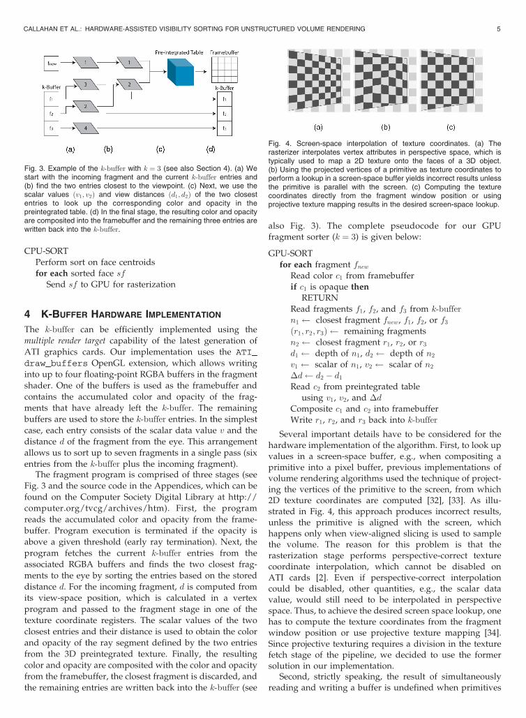
Fig. 3. Example of the k-buffer with k ¼ 3 (see also Section 4). (a) Westart with the incoming fragment and the current k-buffer entries and(b) find the two entries closest to the viewpoint. (c) Next, we use thescalar values ðv1; v2Þ and view distances ðd1; d2Þ of the two closestentries to look up the corresponding color and opacity in thepreintegrated table. (d) In the final stage, the resulting color and opacityare composited into the framebuffer and the remaining three entries arewritten back into the k-buffer.
Fig. 4. Screen-space interpolation of texture coordinates. (a) Therasterizer interpolates vertex attributes in perspective space, which istypically used to map a 2D texture onto the faces of a 3D object.(b) Using the projected vertices of a primitive as texture coordinates toperform a lookup in a screen-space buffer yields incorrect results unlessthe primitive is parallel with the screen. (c) Computing the texturecoordinates directly from the fragment window position or usingprojective texture mapping results in the desired screen-space lookup.
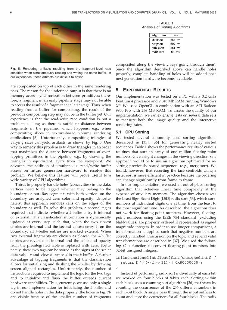
are composited on top of each other in the same renderingpass. The reason for the undefined output is that there is nomemory access synchronization between primitives; there-fore, a fragment in an early pipeline stage may not be ableto access the result of a fragment at a later stage. Thus, whenreading from a buffer for compositing, the result of theprevious compositing step may not be in the buffer yet. Ourexperience is that the read-write race condition is not aproblem as long as there is sufficient distance betweenfragments in the pipeline, which happens, e.g., whencompositing slices in texture-based volume renderingapplications [5]. Unfortunately, compositing triangles ofvarying sizes can yield artifacts, as shown by Fig. 5. Oneway to remedy this problem is to draw triangles in an orderthat maximizes the distance between fragments of over-lapping primitives in the pipeline, e.g., by drawing thetriangles in equidistant layers from the viewpoint. Weadvocate the addition of simultaneous read/write bufferaccess on future generation hardware to resolve thisproblem. We believe this feature will prove useful to awide variety of GPU algorithms.
Third, to properly handle holes (concavities) in the data,vertices need to be tagged whether they belong to theboundary or not. Ray segments with both vertices on theboundary are assigned zero color and opacity. Unfortu-nately, this approach removes cells on the edges of theboundary as well. To solve this problem, a second tag isrequired that indicates whether a k-buffer entry is internalor external. This classification information is dynamicallyupdated at every step such that, when the two closestentries are internal and the second closest entry is on theboundary, all k-buffer entries are marked external. Whentwo external fragments are chosen as closest, the k-bufferentries are reversed to internal and the color and opacityfrom the preintegrated table is replaced with zero. Fortu-nately, these two tags can be stored as the signs of the scalardata value v and view distance d in the k-buffer. A furtheradvantage of tagging fragments is that the classificationallows for initializing and flushing the k-buffer by drawingscreen aligned rectangles. Unfortunately, the number ofinstructions required to implement the logic for the two tagsand to initialize and flush the buffer exceeds currenthardware capabilities. Thus, currently, we use only a singletag in our implementation for initializing the k-buffer anddo not handle holes in the data properly (the holes in Fig. 7bare visible because of the smaller number of fragments
composited along the viewing rays going through them).Since the algorithm described above can handle holesproperly, complete handling of holes will be added oncenext generation hardware becomes available.
5 EXPERIMENTAL RESULTS
Our implementation was tested on a PC with a 3.2 GHzPentium 4 processor and 2,048 MB RAM running WindowsXP. We used OpenGL in combination with an ATI Radeon9800 Pro with 256 MB RAM. To assess the quality of ourimplementation, we ran extensive tests on several data setsto measure both the image quality and the interactiverendering rates.
5.1 CPU Sorting
We tested several commonly used sorting algorithmsdescribed in [35], [36] for generating nearly sortedsequences. Table 1 shows the performance results of variousroutines that sort an array of one million floating-pointnumbers. Given slight changes in the viewing direction, oneapproach would be to use an algorithm optimized for re-sorting previously sorted sequences (e.g., mergesort). Wefound, however, that resorting the face centroids using afaster sort is more efficient in practice because the orderingcan change significantly from frame to frame.
In our implementation, we used an out-of-place sortingalgorithm that achieves linear time complexity at theexpense of auxiliary memory. The algorithm chosen wasthe Least Significant Digit (LSD) radix sort [36], which sortsnumbers at individual digits one at time, from the least tothe most significant one. As described, the algorithm doesnot work for floating-point numbers. However, floating-point numbers using the IEEE 754 standard (excludingNaN-values) are properly ordered if represented as signedmagnitude integers. In order to use integer comparisons, atransformation is applied such that negative numbers arecorrectly handled. Discussion on the topic and several validtransformations are described in [37]. We used the follow-ing C++ function to convert floating-point numbers into32-bit unsigned integers:
inline unsigned int float2fint(unsigned int f) {
return f ^ ((-(f >> 31)) | 0x80000000);
}
Instead of performing radix sort individually at each bit,we worked on four blocks of 8-bits each. Sorting withineach block uses a counting sort algorithm [36] that starts bycounting the occurrences of the 256 different numbers ineach 8-bit block. A single pass through the input suffices tocount and store the ocurrences for all four blocks. The radix
6 IEEE TRANSACTIONS ON VISUALIZATION AND COMPUTER GRAPHICS, VOL. 11, NO. 3, MAY/JUNE 2005
Fig. 5. Rendering artifacts resulting from the fragment-level race
condition when simultaneously reading and writing the same buffer. In
our experience, these artifacts are difficult to notice.
TABLE 1Analysis of Sorting Algorithms
sort performs four passes through the input, each passsorting numbers within a single block. Starting from theLSD block (0-7 bits), the counting results for that block areused to correctly position each number in an auxiliary arraywith the same size as the input. Once this block is sorted, asimilar pass is issued to sort bits 8-15, this time using theauxiliary array as input and the original input array asoutput. Finally, two additional counting sorts are used tosort bits 16-23 and 24-31. Overall, five passes through thearray are necessary to correctly sort the input, establishingthe linear complexity.
Our code was written in C++ without any machine-levelwork, thus improvements can potentially be made toincrease the performance of CPU sorting even further. Inany case, our current sorting technique can sort upward of15 million faces per second.
5.2 k-Buffer Analysis
As a measure of image quality, we implemented a softwareversion of our algorithm that uses an A-buffer to computethe correct visibility order. As incoming fragments areprocessed, we insert them into the ordered A-buffer andrecord how deep the insertion was. This gives us a k sizethat is needed for the data set to produce accurate results.We also gain insight on how well our hardware imple-mentation will behave for given k sizes. This analysis isshown in Table 2. For each data set, we show the number oftotal fragments generated when rendering them at 5122
resolution, the maximum length of any A-buffer pixel list,the maximum k (i.e., the number of positions any fragmenthad to move to its correct position in the sorted order minusone for compositing), and the number of pixels that requirek to be larger than two or six, which are the values currentlysupported by the hardware used. These results representthe maximum values computed from 14 fixed viewpoints oneach data set.
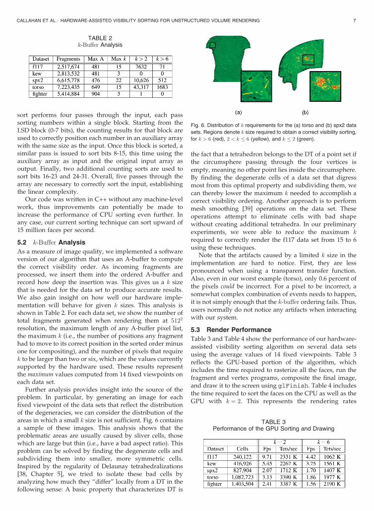
Further analysis provides insight into the source of theproblem. In particular, by generating an image for eachfixed viewpoint of the data sets that reflect the distributionof the degeneracies, we can consider the distribution of theareas in which a small k size is not sufficient. Fig. 6 containsa sample of these images. This analysis shows that theproblematic areas are usually caused by sliver cells, thosewhich are large but thin (i.e., have a bad aspect ratio). Thisproblem can be solved by finding the degenerate cells andsubdividing them into smaller, more symmetric cells.Inspired by the regularity of Delaunay tetrahedralizations[38, Chapter 5], we tried to isolate these bad cells byanalyzing how much they “differ” locally from a DT in thefollowing sense: A basic property that characterizes DT is
the fact that a tetrahedron belongs to the DT of a point set ifthe circumsphere passing through the four vertices isempty, meaning no other point lies inside the circumsphere.By finding the degenerate cells of a data set that digressmost from this optimal property and subdividing them, wecan thereby lower the maximum k needed to accomplish acorrect visibility ordering. Another approach is to performmesh smoothing [39] operations on the data set. Theseoperations attempt to eliminate cells with bad shapewithout creating additional tetrahedra. In our preliminaryexperiments, we were able to reduce the maximum k
required to correctly render the f117 data set from 15 to 6using these techniques.
Note that the artifacts caused by a limited k size in theimplementation are hard to notice. First, they are lesspronounced when using a transparent transfer function.Also, even in our worst example (torso), only 0.6 percent ofthe pixels could be incorrect. For a pixel to be incorrect, asomewhat complex combination of events needs to happen,it is not simply enough that the k-buffer ordering fails. Thus,users normally do not notice any artifacts when interactingwith our system.
5.3 Render Performance
Table 3 and Table 4 show the performance of our hardware-assisted visibility sorting algorithm on several data setsusing the average values of 14 fixed viewpoints. Table 3reflects the GPU-based portion of the algorithm, whichincludes the time required to rasterize all the faces, run thefragment and vertex programs, composite the final image,and draw it to the screen using glFinish. Table 4 includesthe time required to sort the faces on the CPU as well as theGPU with k ¼ 2. This represents the rendering rates
CALLAHAN ET AL.: HARDWARE-ASSISTED VISIBILITY SORTING FOR UNSTRUCTURED VOLUME RENDERING 7
TABLE 2k-Buffer Analysis
Fig. 6. Distribution of k requirements for the (a) torso and (b) spx2 data
sets. Regions denote k size required to obtain a correct visibility sorting,
for k > 6 (red), 2 < k � 6 (yellow), and k � 2 (green).
TABLE 3Performance of the GPU Sorting and Drawing
achieved while interactively rotating and redrawing thedata set. All rendering was done with a 5122 viewport and a
1283 8-bit RGBA preintegrated table. In addition, a lowopacity colormap was used and early ray termination was
disabled, thus every fragment is rasterized to give moreaccurate timings. With early ray termination enabled, we
have been able to achieve over six million cells per second
with the fighter data set using a high opacity colormap dueto the speedup in fragment processing. In addition, we can
improve the performance of our algorithm by exploitingpipeline parallelism between the CPU and GPU, i.e., sorting
is performed on the CPU for the next frame while thecurrent frame is being rendered by the GPU. Through the
use of this parallelism, we have been able to effectivelyremove the CPU time and reduce the total rendering time to
the GPU time.Our technique requires no preprocessing, and it can be
used for handling time-varying data. In addition, ourimplementation allows interactive changes to the transfer
function. These operations are only dependent on the GPUfor sorting and rendering (see Table 3), therefore, the CPU
portion of the algorithm is not performed. The user
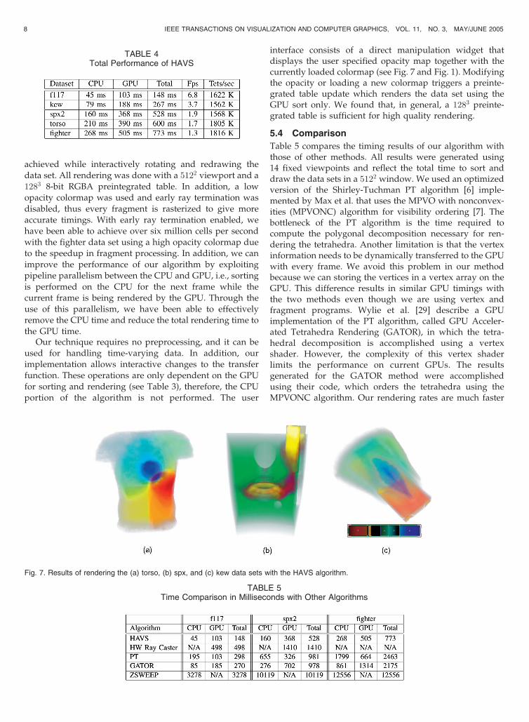
interface consists of a direct manipulation widget thatdisplays the user specified opacity map together with thecurrently loaded colormap (see Fig. 7 and Fig. 1). Modifyingthe opacity or loading a new colormap triggers a preinte-grated table update which renders the data set using theGPU sort only. We found that, in general, a 1283 preinte-grated table is sufficient for high quality rendering.
5.4 Comparison
Table 5 compares the timing results of our algorithm withthose of other methods. All results were generated using14 fixed viewpoints and reflect the total time to sort anddraw the data sets in a 5122 window. We used an optimizedversion of the Shirley-Tuchman PT algorithm [6] imple-mented by Max et al. that uses the MPVO with nonconvex-ities (MPVONC) algorithm for visibility ordering [7]. Thebottleneck of the PT algorithm is the time required tocompute the polygonal decomposition necessary for ren-dering the tetrahedra. Another limitation is that the vertexinformation needs to be dynamically transferred to the GPUwith every frame. We avoid this problem in our methodbecause we can storing the vertices in a vertex array on theGPU. This difference results in similar GPU timings withthe two methods even though we are using vertex andfragment programs. Wylie et al. [29] describe a GPUimplementation of the PT algorithm, called GPU Acceler-ated Tetrahedra Rendering (GATOR), in which the tetra-hedral decomposition is accomplished using a vertexshader. However, the complexity of this vertex shaderlimits the performance on current GPUs. The resultsgenerated for the GATOR method were accomplishedusing their code, which orders the tetrahedra using theMPVONC algorithm. Our rendering rates are much faster
8 IEEE TRANSACTIONS ON VISUALIZATION AND COMPUTER GRAPHICS, VOL. 11, NO. 3, MAY/JUNE 2005
TABLE 4Total Performance of HAVS
TABLE 5Time Comparison in Milliseconds with Other Algorithms
Fig. 7. Results of rendering the (a) torso, (b) spx, and (c) kew data sets with the HAVS algorithm.
then these PT methods, while producing higher qualityimages through the use of a 3D preintegrated table. Anotherrecent technique is the GPU-based ray casting of Weileret al. [13], [40]. The image quality of this technique is similarto that of our work, but the algorithm has certain limitationson the size of the data sets that make it less general thancell-projection techniques. In fact, the fighter data set weused for comparison could not be loaded properly due tohardware memory limitations. The results for this algo-rithm were generated using a DirectX-based ray casterdescribed in Bernardon et al. [41], which is approximatelytwice as fast as the original technique reported by Weileret al.. The ZSWEEP method [14] uses a hybrid image andobject-space sorting approach similar to our sorting net-work, but does not leverage the GPU for better perfor-mance. The code that was used in this portion of our timingresults was provided by Ricardo Farias. All of theseapproaches require a substantial amount of connectivityinformation for rendering, resulting in a higher memoryoverhead than our work. Another advantage of ouralgorithm is the simplicity of implementation in softwareand hardware. The software techniques described above(PT and ZSWEEP) require a substantial amount of code forsorting and cell projection. Implementations of the hard-ware techniques (GATOR and HW Ray Caster) involvedeveloping long and complex fragment and vertex pro-grams which can be difficult to write and debug.
6 DISCUSSION
When we started this work, we were quite skeptical about
the possibility of implementing the k-buffer on current
GPUs. There were several hurdles to overcome. First, given
the potentially unbounded size of pixel lists, it was less than
obvious to us that small values of k would suffice for large
data sets. Another major problem was the fact that reading
and writing to the same texture is not a well-defined
operation on current GPUs. We were pleasantly surprised
to find that, even on current hardware, we get only minor
artifacts.
There are several issues that we have not studied in
depth. The most important goal is to develop techniques
that can refine data sets to respect a given k. Currently, our
experiments show that, when the k-buffer is not large
enough, a few pixels are rendered incorrectly. So far, we
have found that most of our computational data sets are
well-behaved and the wrong pixels have no major effect on
image quality. In a practical implementation, one could
consider raising the value of k or increasing the accuracy of
the object-space visibility sorting algorithm once the user
stops rotating the model. Using the smallest possible k is
required for efficiency.
Some of our speed limitations originate from limitations
of current GPUs. In particular, the lack of real conditionals
forces us to make a large number of texture lookups that we
can potentially avoid when next generation hardware is
released. Furthermore, the limit on the instruction count has
forced us into an incorrect hole handling method. With
more instructions, we could also incorporate shaded
isosurface rendering without much difficulty.Finally, there is plenty of interesting theoretical work
remaining to be done. It would be advantageous to develop
input and output sensitive algorithms for determining theobject-space ordering and estimation of the minimum k size
for a given data set. We have preliminary evidence that, by
making the primitives more uniform in size, k can belowered. We believe it might be possible to formalize these
notions and perform proofs along the lines of the work of
Mitchell et al. [42] and de Berg et al. [43].
7 CONCLUSIONS AND FUTURE WORK
In this paper, we presented a novel algorithm for volume
rendering unstructured data sets. Our algorithm exploits
the CPU and GPU for sorting both in object-space and
image-space. We use the CPU to compute a partial ordering
of the primitives for generating a nearly sorted fragment
stream. We then use the k-buffer, a fragment-stream sorter
of constant depth, on the GPU for complete sorting on a
per-fragment basis. Despite limitations of current GPUs, we
show how to implement the k-buffer efficiently on an ATI
Radeon 9800.
Our technique can handle arbitrary nonconvex meshes
with very low memory overhead. Similarly to the
HW-based ray caster, we use a floating-point-based
framebuffer that minimizes rendering artifacts and we can
easily handle both parallel and perspective projections. But,
unlike those techniques, the maximum data size is bounded
only by the available main memory of the system. In our
paper, we provide a comparison of our technique with
previous algorithms for rendering unstructured volumetric
data and enumerate the advantages in speed, ease of
implementation, and adaptability that our work provides.We would like to reemphasize the simplicity of our
technique. At the same time that our technique is shown to
be faster and more general than others, the implementation
is very compact and easy to code. In fact, the rendering code
in our system consists of less than 200 lines. We believethese qualities are likely to make it the method of choice for
rendering unstructured volumetric data.There are several interesting areas for future work.
Further experiments and code optimization are necessaryfor achieving even faster rendering rates. In particular, we
hope that next-generation hardware will ease some of the
current limitations and will allow us to implement sorting
networks with larger k sizes. Real fragment programconditionals will allow us to reduce the effective number
of texture lookups. On next generation hardware, we will
also be able to implement a more efficient early ray
termination strategy. Another interesting area for futureresearch is rendering dynamic meshes. We intend to
explore techniques that do not require any preprocessing
and can be used for handling dynamic data. Finally, wewould like to devise a theoretical framework for analyzing
the direct trade-off between the amount of time spent
sorting in object-space and image-space.
CALLAHAN ET AL.: HARDWARE-ASSISTED VISIBILITY SORTING FOR UNSTRUCTURED VOLUME RENDERING 9

ACKNOWLEDGMENTS
The authors thank Joe Kniss for suggesting that the k-buffer
could be implemented efficiently on ATI hardware. They
thank Ricardo Farias for the ZSWEEP code and the
insightful discussions that helped shape many ideas
presented in this paper. Carlos Scheidegger and Huy Vo
provided invaluable code contributions. In particular, Vo
wrote the fast radix sort used in their system. They thank
Fabio Bernardon for the use of his HW Ray Caster code. The
Teem toolkit [44] proved very useful for processing the data
sets and results. They thank Mark Segal from ATI for the
donated hardware and his prompt answers to their
questions. They are grateful to Patricia Crossno, Shachar
Fleishman, Nelson Max, and Peter Shirley for helpful
suggestions and criticism. The authors also acknowledge
Bruce Hopenfeld and Robert MacLeod (University of Utah)
for the heart data set, Bruno Notrosso (Electricite de France)
for the spx data set, Hung and Buning (NASA) for the blunt
fin data set, and Neely and Batina (NASA) for the fighter
data set. Steven P. Callahan is supported by the US
Department of Energy (DOE) under the VIEWS program.
Milan Ikits is supported by the US National Science
Foundation (NSF) grant ACI-0078063 and the DOE Ad-
vanced Visualization Technology Center. Claudio T. Silva is
partially supported by the DOE under the VIEWS program
and the MICS office, the NSF under grants CCF-0401498,
EIA-0323604, and OISE-0405402, and a University of Utah
Seed Grant. The work of Joao L.D. Comba is supported by a
CNPq grant 540414/01-8 and FAPERGS grant 01/0547.3.
REFERENCES
[1] N.L. Max, “Optical Models for Direct Volume Rendering,” IEEETrans. Visualization and Computer Graphics, vol. 1, no. 2, pp. 99-108,June 1995.
[2] ATI, “Radeon 9500/9600/9700/9800 OpenGL Programming andOptimization Guide,” 2003, http://www.ati.com.
[3] S. Roettger, M. Kraus, and T. Ertl, “Hardware-AcceleratedVolume and Isosurface Rendering Based on Cell-Projection,”Proc. IEEE Visualization, pp. 109-116, Oct. 2000.
[4] S. Guthe, S. Roettger, A. Schieber, W. Straßer, and T. Ertl, “High-Quality Unstructured Volume Rendering on the PC Platform,”Proc. ACM SIGGRAPH/Eurographics Workshop Graphics Hardware,pp. 119-126, Sept. 2002.
[5] M. Ikits, J. Kniss, A. Lefohn, and C. Hansen, GPU Gems:Programming Techniques, Tips, and Tricks for Real-Time Graphics,pp. 667-692, Addison Wesley, 2004.
[6] P. Shirley and A. Tuchman, “A Polygonal Approximation toDirect Scalar Volume Rendering,” Proc. San Diego WorkshopVolume Visualization, vol. 24, no. 5, pp. 63-70, Nov. 1990.
[7] P.L. Williams, “Visibility-Ordering Meshed Polyhedra,” ACMTrans. Graphics, vol. 11, no. 2, pp. 103-126, Apr. 1992.
[8] J. Comba, J.T. Klosowski, N. Max, J.S.B. Mitchell, C.T. Silva, andP.L. Williams, “Fast Polyhedral Cell Sorting for InteractiveRendering of Unstructured Grids,” Computer Graphics Forum,vol. 18, no. 3, pp. 369-376, Sept. 1999.
[9] C.T. Silva, J.S. Mitchell, and P.L. Williams, “An Exact InteractiveTime Visibility Ordering Algorithm for Polyhedral Cell Com-plexes,” Proc. IEEE Symp. Volume Visualization, pp. 87-94, Oct.1998.
[10] M. Kraus and T. Ertl, “Cell-Projection of Cyclic Meshes,” Proc.IEEE Visualization, pp. 215-222, Oct. 2001.
[11] R. Cook, N. Max, C. Silva, and P. Williams, “Efficient, ExactVisibility Ordering of Unstructured Meshes,” IEEE Trans. Visua-lization and Computer Graphics, vol. 1, no. 6, pp. 695-707, Nov./Dec.2004.
[12] M. Weiler, M. Kraus, M. Merz, and T. Ertl, “Hardware-Based RayCasting for Tetrahedral Meshes,” Proc. IEEE Visualization, pp. 333-340, Oct. 2003.
[13] M. Weiler, P.N. Mallon, M. Kraus, and T. Ertl, “Texture-EncodedTetrahedral Strips,” Proc. Symp. Volume Visualization 2004, pp. 71-78, 2004.
[14] R. Farias, J. Mitchell, and C.T. Silva, “ZSWEEP: An Efficient andExact Projection Algorithm for Unstructured Volume Rendering,”Proc. IEEE Volume Visualization and Graphics Symp., pp. 91-99, 2000.
[15] L. Carpenter, “The A-Buffer, an Antialiased Hidden SurfaceMethod,” Computer Graphics (Proc. SIGGRAPH 84), vol. 18, no. 3,pp. 103-108, July 1984.
[16] L. Guibas, “Computational Geometry and Visualization: Problemsat the Interface,” Scientific Visualization of Physical Phenomena,N.M. Patrikalakis, ed., pp. 45-59, Springer-Verlag, 1991.
[17] N.L. Max, “Sorting for Polyhedron Compositing,” Focus onScientific Visualization, pp. 259-268, Springer-Verlag, 1993.
[18] R. Farias and C.T. Silva, “Out-of-Core Rendering of Large,Unstructured Grids,” IEEE Computer Graphics and Applications,vol. 21, no. 4, pp. 42-51, July/Aug. 2001.
[19] I.E. Sutherland, R.F. Sproull, and R.A. Schumacker, “A Character-ization of Ten Hidden-Surface Algorithms,” ACM ComputingSurveys, vol. 6, no. 1, pp. 1-55, Mar. 1974.
[20] M. Newell, R. Newell, and T. Sancha, “A Solution to the HiddenSurface Problem,” Proc. ACM Ann. Conf., pp. 443-450, 1972.
[21] C. Stein, B. Becker, and N. Max, “Sorting and Hardware AssistedRendering for Volume Visualization,” Proc. IEEE Symp. VolumeVisualization, pp. 83-89, Oct. 1994.
[22] H. Fuchs, Z.M. Kedem, and B.F. Naylor, “On Visible SurfaceGeneration by A Priori Tree Structures,” Computer Graphics (Proc.SIGGRAPH 80), vol. 14, no. 3, pp. 124-133, July 1980.
[23] C. Wittenbrink, “R-Buffer: A Pointerless A-Buffer HardwareArchitecture,” Proc. ACM SIGGRAPH/Eurographics Workshop Gra-phics Hardware, pp. 73-80, 2001.
[24] A. Mammen, “Transparency and Antialiasing Algorithms Im-plemented with the Virtual Pixel Maps Technique,” IEEEComputer Graphics and Applications, vol. 9, pp. 43-55, July 1984.
[25] C. Everitt, “Interactive Order-Independent Transparency,”NVIDIA, technical report, 2001, http://developer.nvidia.com.
[26] N.P. Jouppi and C.-F. Chang, “Z3: An Economical HardwareTechnique for High-Quality Antialiasing and Transparency,” Proc.ACM SIGGRAPH/Eurographics Workshop Graphics Hardware, pp. 85-93, Aug. 1999.
[27] P. Kipfer, M. Segal, and R. Westermann, “Uberflow: A GPU-BasedParticle Engine,” Eurographics Symp. Proc. Graphics Hardware 2004,pp. 115-122, 2004.
[28] S. Roettger and T. Ertl, “Cell Projection of Convex Polyhedra,”Proc. 2003 Eurographics/IEEE TVCG Workshop Volume Graphics,pp. 103-107, 2003.
[29] B. Wylie, K. Moreland, L.A. Fisk, and P. Crossno, “TetrahedralProjection Using Vertex Shaders,” Proc. IEEE/ACM Symp. VolumeGraphics and Visualization, pp. 7-12, 2002.
[30] T. Aila, V. Miettinen, and P. Nordlund, “Delay Streams forGraphics Hardware,” ACM Trans. Graphics, vol. 22, no. 3, pp. 792-800, July 2003.
[31] H. Samet, “The Quadtree and Related Hierarchical Data Struc-tures,” ACM Computing Surveys, vol. 16, no. 2, pp. 187-260, 1984.
[32] J.M. Kniss, S. Premo�zze, C.D. Hansen, P. Shirley, and A.McPherson, “A Model for Volume Lighting and Modeling,” IEEETrans. Visualization and Computer Graphics, vol. 9, no. 2, pp. 150-162, 2003.
[33] J. Kruger and R. Westermann, “Acceleration Techniques for GPU-Based Volume Rendering,” Proc. IEEE Visualization, pp. 287-292,2003.
[34] M. Segal, C. Korobkin, R. van Widenfelt, J. Foran, and P. Haeberli,“Fast Shadows and Lighting Effects Using Texture Mapping,”Proc. ACM SIGGRAPH, pp. 249-252, July 1992.
[35] T.H. Cormen, C.E. Leiserson, R.L. Rivest, and C. Stein, Introductionto Algorithms, second ed., pp. 40, 127-173. McGraw-Hill, 2001.
[36] R. Sedgewick, Algorithms in C, third ed., pp. 298-301, 403-437.Addison-Wesley, 1998.
[37] H. Warren Jr., Hacker’s Delight, pp. 261-265. Addison-Wesley,2002.
[38] H. Edelsbrunner, Geometry and Topology for Mesh Generation.Cambridge Univ. Press, 2001.
10 IEEE TRANSACTIONS ON VISUALIZATION AND COMPUTER GRAPHICS, VOL. 11, NO. 3, MAY/JUNE 2005
[39] L. Freitag, P. Knupp, T. Munson, and S. Shontz, “A Comparison ofOptimization Software for Mesh Shape-Quality ImprovementProblems,” Proc. 11th Int’l Meshing Roundtable, pp. 29-40, 2002.
[40] M. Weiler, M. Kraus, M. Merz, and T. Ertl, “Hardware-BasedView-Independent Cell Projection,” IEEE Trans. Visualization andComputer Graphics, vol. 9, no. 2, pp. 163-175, 2003.
[41] F.F. Bernardon, C.A. Pagot, J.L.D. Comba, and C.T. Silva, “GPU-Based Tile Ray Casting Using Depth Peeling,” Technical ReportUUSCI-2004-006, SCI Inst., 2004.
[42] J.S.B. Mitchell, D.M. Mount, and S. Suri, “Query-Sensitive RayShooting,” Int’l J. Computational Geometry and Applications, vol. 7,no. 4, pp. 317-347, Aug. 1997.
[43] M. de Berg, M.J. Katz, A.F. van der Stappen, and J. Vleugels,“Realistic Input Models for Geometric Algorithms,” Proc. Ann.Symp. Computational Geometry, pp. 294-303, 1997.
[44] G.L. Kindlmann, “The Teem Toolkit,” 2003, http://teem.sourceforge.net.
Steven P. Callahan received the BS degree incomputer science from Utah State University in2002. He is currently pursuing the MS degree incomputational engineering and science at theUniversity of Utah, where he works as aresearch assistant in the Scientific Computingand Imaging Institute. His research interestsinclude graphics, visualization, and large-scalescientific computing.
Milan Ikits is a PhD candidate in the School ofComputing at the University of Utah. Hisresearch interests lie in the areas of computergraphics, scientific visualization, immersive en-vironments, and human-computer interaction.He received the Diploma in computer sciencefrom the Budapest University of Technology andEconomics in 1997. He joined Immersion Med-ical in 2004, where he has been involved withthe company’s research and development ef-
forts toward advancing the state-of-the-art in surgical simulation. He haspublished several papers and book chapters on using immersiveenvironments for scientific visualization. He is also the creator of thepopular OpenGL Extension Wrangler library. He is a student member ofthe IEEE.
Joao L.D. Comba received the Bachelor’sdegree in computer science from the FederalUniversity of Rio Grande do Sul, Brazil, the MSdegree in computer science from the FederalUniversity of Rio de Janeiro, Brazil, and the PhDdegree in computer science from StanfordUniversity. He is an associate professor ofcomputer science at the Federal University ofRio Grande do Sul, Brazil. His main researchinterests are in graphics, visualization, spatial
data structures, and applied computational geometry. His currentprojects include the development of algorithms for large-scale scientificvisualization, data structures for point-based modeling and rendering,and general-purpose computing using graphics hardware. He is amember of the ACM Siggraph.
Claudio T. Silva received the Bachelor’s degreein mathematics from the Federal University ofCeara, Brazil, and the MS and PhD degrees incomputer science from the State University ofNew York at Stony Brook. He is an associateprofessor of computer science at the Universityof Utah and a member of the Scientific Comput-ing and Imaging (SCI) Institute. His mainresearch interests are in graphics, visualization,applied computational geometry, bioinformatics,
and high-performance computing. His current projects include thedevelopment of out-of-core and streaming algorithms for large-scalescientific visualization, techniques for point-based modeling andrendering, and efficient algorithms for modern graphics hardware. Hehas published more than 60 publications in international conferencesand journals, holds five US patents, and presented tutorials at ACMSIGGRAPH, Eurographics, and IEEE Visualization conferences. Heserves on numerous program committees and is papers cochair of theIEEE Visualization 2005 conference. He is a member of the ACM,Eurographics, and IEEE.
. For more information on this or any other computing topic,please visit our Digital Library at www.computer.org/publications/dlib.
CALLAHAN ET AL.: HARDWARE-ASSISTED VISIBILITY SORTING FOR UNSTRUCTURED VOLUME RENDERING 11