HardiePanel® Vertical Siding Product Description
13
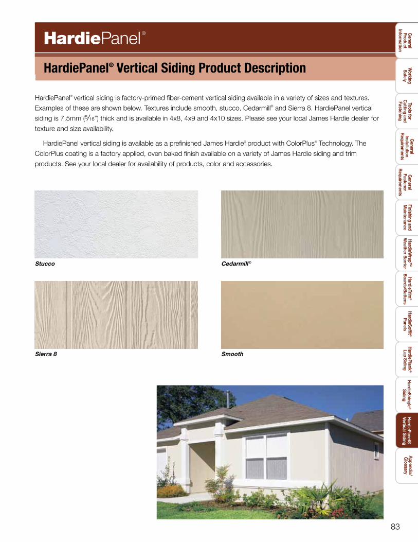
83 HardiePanel ® Vertical Siding Product Description HardiePanel ® vertical siding is factory-primed fiber-cement vertical siding available in a variety of sizes and textures. Examples of these are shown below. Textures include smooth, stucco, Cedarmill © and Sierra 8. HardiePanel vertical siding is 7.5mm ( 5 / 16”) thick and is available in 4x8, 4x9 and 4x10 sizes. Please see your local James Hardie dealer for texture and size availability. HardiePanel vertical siding is available as a prefinished James Hardie ® product with ColorPlus ® Technology. The ColorPlus coating is a factory applied, oven baked finish available on a variety of James Hardie siding and trim products. See your local dealer for availability of products, color and accessories. Stucco Cedarmill © Sierra 8 Smooth general product information working safely Tools for cutting and fastening general installation requirements general fastener requirements finishing and maintenance hardieTrim ® boards/battens hardiewrap™ weather barrier hardiesoffit ® panels hardieplank ® lap siding hardieshingle ® siding hardiepanel® Vertical siding appendix/ glossary
-
Upload
khangminh22 -
Category
Documents
-
view
0 -
download
0
Transcript of HardiePanel® Vertical Siding Product Description
83
HardiePanel® Vertical Siding Product Description
HardiePanel® vertical siding is factory-primed fiber-cement vertical siding available in a variety of sizes and textures.
Examples of these are shown below. Textures include smooth, stucco, Cedarmill© and Sierra 8. HardiePanel vertical
siding is 7.5mm (5/16”) thick and is available in 4x8, 4x9 and 4x10 sizes. Please see your local James Hardie dealer for
texture and size availability.
HardiePanel vertical siding is available as a prefinished James Hardie® product with ColorPlus® Technology. The
ColorPlus coating is a factory applied, oven baked finish available on a variety of James Hardie siding and trim
products. See your local dealer for availability of products, color and accessories.
Stucco Cedarmill©
Sierra 8 Smooth
general
product inform
ation
working
safelyTools for
cutting and
fastening
general
installation r
equirements
general
fastener r
equirements
finishing and m
aintenanceh
ardieTrim®
boards/b
attensh
ardiewrap™
weather b
arrierh
ardiesoffit ®
panelsh
ardieplank®
lap sidingh
ardieshingle®
sidingh
ardiepanel® Vertical siding
appendix/g
lossary
84
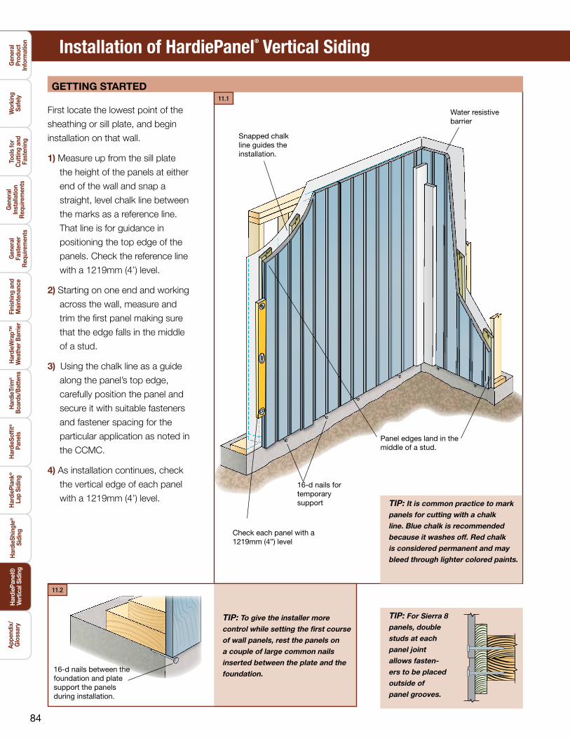
TIP: For Sierra 8panels, doublestuds at eachpanel jointallows fasten-ers to be placedoutside ofpanel grooves.
TIP: It is common practice to mark panels for cutting with a chalk line. Blue chalk is recommended because it washes off. Red chalk is considered permanent and may bleed through lighter colored paints.
TIP: To give the installer more control while setting the first course of wall panels, rest the panels on a couple of large common nails inserted between the plate and the foundation.
Waterresistivebarrier
16-dnailsfortemporarysupport
Snappedchalklineguidestheinstallation.
Paneledgeslandinthemiddleofastud.
16-dnailsbetweenthefoundationandplatesupportthepanelsduringinstallation.
Installation of HardiePanel® Vertical Siding
geTTing sTarTed
First locate the lowest point of the
sheathing or sill plate, and begin
installation on that wall.
1) Measure up from the sill plate
the height of the panels at either
end of the wall and snap a
straight, level chalk line between
the marks as a reference line.
That line is for guidance in
positioning the top edge of the
panels. Check the reference line
with a 1219mm (4’) level.
2) Starting on one end and working
across the wall, measure and
trim the first panel making sure
that the edge falls in the middle
of a stud.
3) Using the chalk line as a guide
along the panel’s top edge,
carefully position the panel and
secure it with suitable fasteners
and fastener spacing for the
particular application as noted in
the CCMC.
4) As installation continues, check
the vertical edge of each panel
with a 1219mm (4’) level.
Checkeachpanelwitha1219mm(4”)level
gen
eral
pr
oduc
t in
form
atio
n
wor
king
sa
fely
Tool
s fo
r c
uttin
g an
dfa
sten
ing
gen
eral
in
stal
latio
n r
equi
rem
ents
gen
eral
fa
sten
er
req
uire
men
ts
fini
shin
g an
d m
aint
enan
ceh
ardi
eTrim
®
boa
rds/
bat
tens
har
diew
rap™
wea
ther
bar
rier
har
dies
offit
®
pan
els
har
diep
lank
®
lap
sid
ing
har
dies
hing
le®
sid
ing
har
diep
anel
® V
ertic
al s
idin
gap
pend
ix/
glo
ssar
y
11.1
11.2

85
VerTical JOinT TreaTmenT
Treat vertical joints in HardiePanel®
vertical siding by using one of the
following four methods:
1) Install the panels in
moderate contact.
2) Leave an appropriate gap
between panels (3mm (1/8”) is
the most common), and caulk
using a high-quality paintable
caulk, that meets part 9.27.4 of
the NBC requirements.
Panels may be installed first
with caulk applied in the joints after
installation; or as an option, after
the first panel is installed, apply a
bead of caulk along the panel edge.
When the next panel is installed
against the first, the edge embeds
in the applied caulk creating a
thorough seal between the edges
of the panels.
3) Vertical joints may be covered
with wood or fiber-cement
batten strips. If James Hardie®
siding or trim products are
ripped and used as batten
strips, paint or prime the cut
edges. Batten strips should
span the vertical joint by at least
19mm (¾”) on each side.
4 Metal or PVC “H” moldings can
be used to join two sections of
HardiePanel siding.
3 battened joint 4 h-channel joint
1 moderate contact joint 2 caulked joint
Panelsarebuttedtogetherlightly. 1/8-in.gapleftbetweenpanelsisfilledwithcaulk.
HardieTrim®battenboardcoversthejointbetweenpanels.
AmanufacturedH-channelcapturestheverticaledgesofthepanels.
TIP: Stainless steel fasteners are recommended when installingJames Hardie products.
6d
screw
2 51 9
hardiepanel siding fasTener specificaTiOns
4d13mm x 6.8mm x 38mm(0.118” x 0.267” x 1.5”)
ring shanksiding nail5
2.3mm x 5.6mm x 38.1mm(0.091” x 0.221” x 1.5”)
roofing nail93.1mm x 9.4mm x 31.8mm[11 GA] (0.121 x 0.371” x 1.25”)
ET&F132.5mm x 6.4mm x 38.1mm[AGS-100] (0.100” x 0.25” x 1.5”)
23mm x 6.8mm x 50.8mm(0.118” x 0.267” x 2”)
6d
FasteningSubstrate
Fastening TypesApproved Fastener
Ribbed Wafer-Head No. 8 9.5mm x 41.3mm (0.375” x 1.625”)
screw
woodstuds
406mm(16”) o.c.
7 13steelstuds
16” o.cor
406mm(16”) o.c. Ribbed Bugle-Head No. 8
8.2mm x 41.3mm (0.323” x 1.625”)
screw7
7/16” OSBor equivalent
2 15 15
The caulk joint method is not recommended for the
ColorPlus® products
!
general
product inform
ation
working
safelyTools for
cutting and
fastening
general
installation r
equirements
general
fastener r
equirements
finishing and m
aintenanceh
ardieTrim®
boards/b
attensh
ardiewrap™
weather b
arrierh
ardiesoffit ®
panelsh
ardieplank®
lap sidingh
ardieshingle®
sidingh
ardiepanel® Vertical siding
appendix/g
lossary
11.3 11.4
11.611.5
86
Water-resistivebarrier
Flashing
Upperpanel
furringstrip
furringstrip
Lowerpanel
Decor-ativebandboard
Water-resistivebarrier
Flashing
Upperpanel
6mm(¼”)Gap
6mm(¼”)Gap
Don’tcaulkgapbetweenflashingandupperpanel.
Don’tcaulkgapbetweenflashingandupperpanel.
Water-resistivebarrier
Upperpanel
Upperpanel
Lowerpanel
Lowerpanel
Decorativebandboard
Installation of HardiePanel® Vertical Siding (continued)
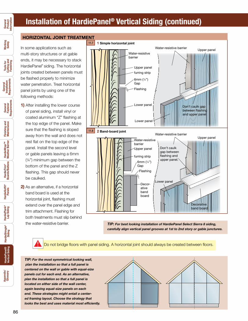
hOriZOnTal JOinT TreaTmenT
In some applications such as
multi-story structures or at gable
ends, it may be necessary to stack
HardiePanel® siding. The horizontal
joints created between panels must
be flashed properly to minimize
water penetration. Treat horizontal
panel joints by using one of the
following methods:
1) After installing the lower course
of panel siding, install vinyl or
coated aluminum “Z” flashing at
the top edge of the panel. Make
sure that the flashing is sloped
away from the wall and does not
rest flat on the top edge of the
panel. Install the second level
or gable panels leaving a 6mm
(¼”) minimum gap between the
bottom of the panel and the Z
flashing. This gap should never
be caulked.
2) As an alternative, if a horizontal
band board is used at the
horizontal joint, flashing must
extend over the panel edge and
trim attachment. Flashing for
both treatments must slip behind
the water-resistive barrier.
1simple horizontal joint
2band-board jointWater-resistivebarrier
TIP: For the most symmetrical looking wall, plan the installation so that a full panel iscentered on the wall or gable with equal-sizepanels cut for each end. As an alternative,plan the installation so that a full panel islocated on either side of the wall center,again leaving equal-size panels on eachend. These strategies might entail a center-ed framing layout. Choose the strategy thatlooks the best and uses material most efficiently.
TIP: For best looking installation of HardiePanel Select Sierra 8 siding, carefully align vertical panel grooves at 1st to 2nd story or gable junctures.
Do not bridge floors with panel siding. A horizontal joint should always be created between floors.!
gen
eral
pr
oduc
t in
form
atio
n
wor
king
sa
fely
Tool
s fo
r c
uttin
g an
dfa
sten
ing
gen
eral
in
stal
latio
n r
equi
rem
ents
gen
eral
fa
sten
er
req
uire
men
ts
fini
shin
g an
d m
aint
enan
ceh
ardi
eTrim
®
boa
rds/
bat
tens
har
diew
rap™
wea
ther
bar
rier
har
dies
offit
®
pan
els
har
diep
lank
®
lap
sid
ing
har
dies
hing
le®
sid
ing
har
diep
anel
® V
ertic
al s
idin
gap
pend
ix/
glo
ssar
y
11.7
11.8

87
In panel installations, trim is typically
overlaid on top of the panel. Special
attention needs
to be paid to trim flashing at the
tops of openings. Below is one
method for properly flashing trim in
a panel application:
1) After installing the window, cut
and install a 6mm (¼”) thick shim
above the window. The shim
should be the same width as the
trim, and it should be as long as
the top or header piece of trim.
2) Over the shim install flashing that
is wide enough to allow for the
thickness of the trim.
3) Install the panel to the window
and around the shim taking care
not to damage the flashing and
leaving a 6mm (¼”) gap between
the panel and the horizontal part
of the flashing.
4) Install the trim around the
window, slipping the head piece
under the installed flashing.
1Install6mm(¼”)thickshimoverthewindow.
2Installflashingovertheshimandunderthewater-resistivebarrier.
3Cutandfitpanelaroundtheshimandflashing,Leave6mm(¼”)gapbetweentheflashingandtheupperpanel.
4Installwindowtrimundertheflashing.
windOws, dOOrs, and OTher wall peneTraTiOns
general
product inform
ation
working
safelyTools for
cutting and
fastening
general
installation r
equirements
general
fastener r
equirements
finishing and m
aintenanceh
ardieTrim®
boards/b
attensh
ardiewrap™
weather b
arrierh
ardiesoffit ®
panelsh
ardieplank®
lap sidingh
ardieshingle®
sidingh
ardiepanel® Vertical siding
appendix/g
lossary
11.9
11.10 11.11
88
Installation of HardiePanel® Vertical Siding (continued)
rain screens
gen
eral
pr
oduc
t in
form
atio
n
wor
king
sa
fely
Tool
s fo
r c
uttin
g an
dfa
sten
ing
gen
eral
in
stal
latio
n r
equi
rem
ents
gen
eral
fa
sten
er
req
uire
men
ts
fini
shin
g an
d m
aint
enan
ceh
ardi
eTrim
®
boa
rds/
bat
tens
har
diew
rap™
wea
ther
bar
rier
har
dies
offit
®
pan
els
har
diep
lank
®
lap
sid
ing
har
dies
hing
le®
sid
ing
har
diep
anel
® V
ertic
al s
idin
gap
pend
ix/
glo
ssar
y
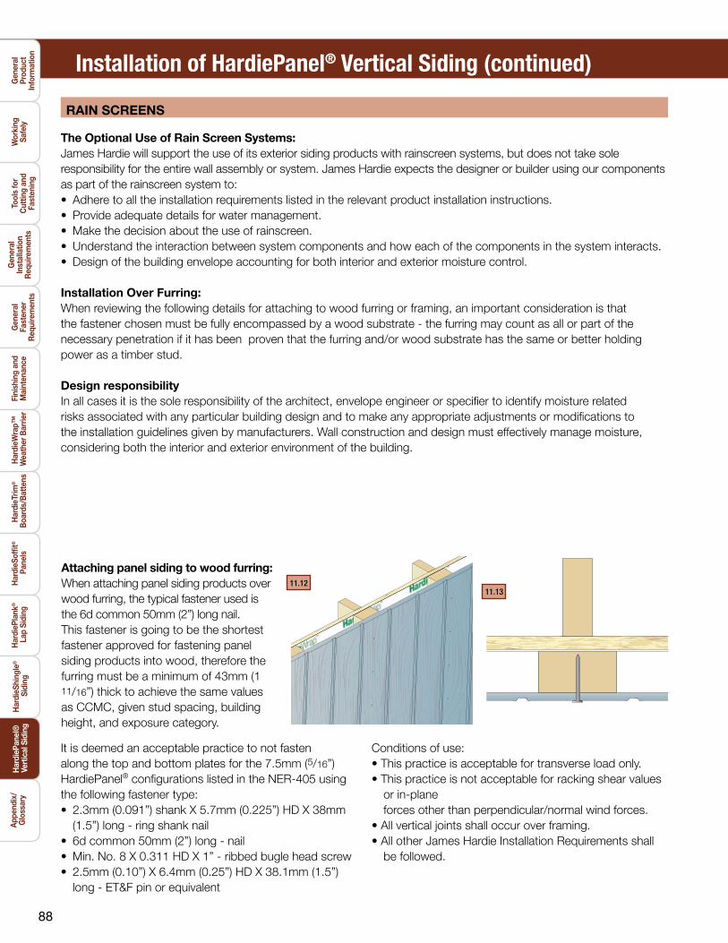
attaching panel siding to wood furring:When attaching panel siding products over wood furring, the typical fastener used is the 6d common 50mm (2”) long nail. This fastener is going to be the shortest fastener approved for fastening panel siding products into wood, therefore the furring must be a minimum of 43mm (1 11/16”) thick to achieve the same values as CCMC, given stud spacing, building height, and exposure category.
11.1311.12
The Optional use of rain screen systems:James Hardie will support the use of its exterior siding products with rainscreen systems, but does not take sole responsibility for the entire wall assembly or system. James Hardie expects the designer or builder using our components as part of the rainscreen system to:• Adhere to all the installation requirements listed in the relevant product installation instructions.• Provide adequate details for water management.• Make the decision about the use of rainscreen.• Understand the interaction between system components and how each of the components in the system interacts.• Design of the building envelope accounting for both interior and exterior moisture control.
installation Over furring:When reviewing the following details for attaching to wood furring or framing, an important consideration is that the fastener chosen must be fully encompassed by a wood substrate - the furring may count as all or part of the necessary penetration if it has been proven that the furring and/or wood substrate has the same or better holding power as a timber stud.
design responsibilityIn all cases it is the sole responsibility of the architect, envelope engineer or specifier to identify moisture related risks associated with any particular building design and to make any appropriate adjustments or modifications to the installation guidelines given by manufacturers. Wall construction and design must effectively manage moisture, considering both the interior and exterior environment of the building.
It is deemed an acceptable practice to not fasten along the top and bottom plates for the 7.5mm (5/16”) HardiePanel® configurations listed in the NER-405 using the following fastener type:• 2.3mm (0.091”) shank X 5.7mm (0.225”) HD X 38mm
(1.5”) long - ring shank nail• 6d common 50mm (2”) long - nail• Min. No. 8 X 0.311 HD X 1” - ribbed bugle head screw• 2.5mm (0.10”) X 6.4mm (0.25”) HD X 38.1mm (1.5”)
long - ET&F pin or equivalent
Conditions of use:• This practice is acceptable for transverse load only.• This practice is not acceptable for racking shear values
or in-plane forces other than perpendicular/normal wind forces.
• All vertical joints shall occur over framing.• All other James Hardie Installation Requirements shall
be followed.
89
general
product inform
ation
working
safelyTools for
cutting and
fastening
general
installation r
equirements
general
fastener r
equirements
finishing and m
aintenanceh
ardieTrim®
boards/b
attensh
ardiewrap™
weather b
arrierh
ardiesoffit ®
panelsh
ardieplank®
lap sidingh
ardieshingle®
sidingh
ardiepanel® Vertical siding
appendix/g
lossary
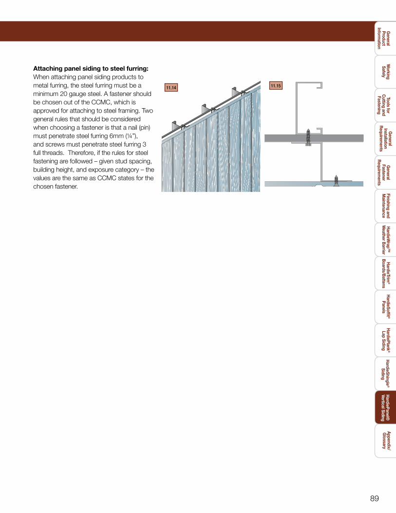
attaching panel siding to steel furring:When attaching panel siding products to metal furring, the steel furring must be a minimum 20 gauge steel. A fastener should be chosen out of the CCMC, which is approved for attaching to steel framing. Two general rules that should be considered when choosing a fastener is that a nail (pin) must penetrate steel furring 6mm (¼”), and screws must penetrate steel furring 3 full threads. Therefore, if the rules for steel fastening are followed – given stud spacing, building height, and exposure category – the values are the same as CCMC states for the chosen fastener.
11.14 11.15
90
HS0916-P1/6 5/10
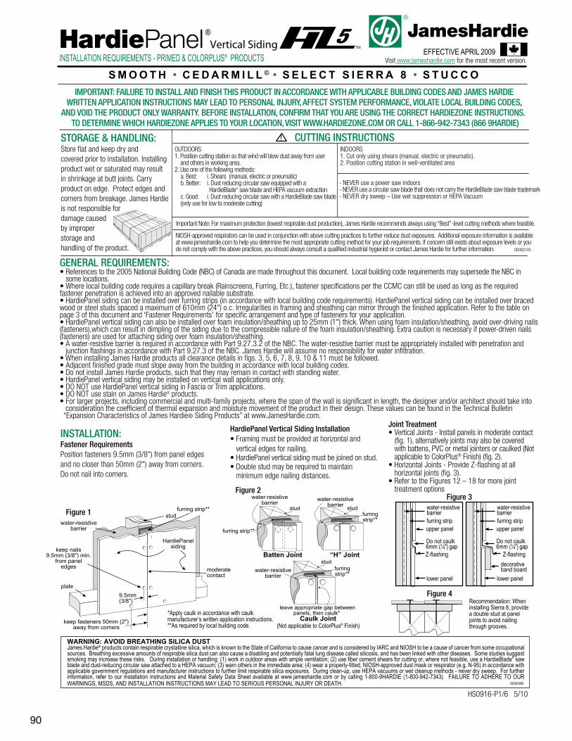
Figure 4Recommendation: When installing Sierra 8, provide a double stud at panel joints to avoid nailing through grooves.
Figure 3
GENERAL REQUIREMENTS:• References to the 2005 National Building Code (NBC) of Canada are made throughout this document. Local building code requirements may supersede the NBC in some locations. • Where local building code requires a capillary break (Rainscreens, Furring, Etc.), fastener specifications per the CCMC can still be used as long as the required fastener penetration is achieved into an approved nailable substrate.• HardiePanel siding can be installed over furring strips (in accordance with local building code requirements). HardiePanel vertical siding can be installed over braced wood or steel studs spaced a maximum of 610mm (24") o.c. Irregularities in framing and sheathing can mirror through the finished application. Refer to the table on page 3 of this document and ‘Fastener Requirements’ for specific arrangement and type of fasteners for your application.• HardiePanel vertical siding can also be installed over foam insulation/sheathing up to 25mm (1") thick. When using foam insulation/sheathing, avoid over-driving nails (fasteners),which can result in dimpling of the siding due to the compressible nature of the foam insulation/sheathing. Extra caution is necessary if power-driven nails (fasteners) are used for attaching siding over foam insulation/sheathing.• A water-resistive barrier is required in accordance with Part 9.27.3.2 of the NBC. The water-resistive barrier must be appropriately installed with penetration and junction flashings in accordance with Part 9.27.3 of the NBC. James Hardie will assume no responsibility for water infiltration.• When installing James Hardie products all clearance details in figs. 3, 5, 6, 7, 8, 9, 10 & 11 must be followed.• Adjacent finished grade must slope away from the building in accordance with local building codes.• Do not install James Hardie products, such that they may remain in contact with standing water.• HardiePanel vertical siding may be installed on vertical wall applications only.• DO NOT use HardiePanel vertical siding in Fascia or Trim applications.• DO NOT use stain on James Hardie® products.• For larger projects, including commercial and multi-family projects, where the span of the wall is significant in length, the designer and/or architect should take into consideration the coefficient of thermal expansion and moisture movement of the product in their design. These values can be found in the Technical Bulletin “Expansion Characteristics of James Hardie® Siding Products” at www.JamesHardie.com.
INSTALLATION:Fastener RequirementsPosition fasteners 9.5mm (3/8") from panel edges and no closer than 50mm (2") away from corners. Do not nail into corners.
Joint Treatment• Vertical Joints - Install panels in moderate contact (fig. 1), alternatively joints may also be covered with battens, PVC or metal jointers or caulked (Not applicable to ColorPlus® Finish) (fig. 2).• Horizontal Joints - Provide Z-flashing at all horizontal joints (fig. 3). • Refer to the Figures 12 – 18 for more joint treatment options
WARNING: AVOID BREATHING SILICA DUSTJames Hardie® products contain respirable crystalline silica, which is known to the State of California to cause cancer and is considered by IARC and NIOSH to be a cause of cancer from some occupational sources. Breathing excessive amounts of respirable silica dust can also cause a disabling and potentially fatal lung disease called silicosis, and has been linked with other diseases. Some studies suggest smoking may increase these risks. During installation or handling: (1) work in outdoor areas with ample ventilation; (2) use fiber cement shears for cutting or, where not feasible, use a HardieBlade® saw blade and dust-reducing circular saw attached to a HEPA vacuum; (3) warn others in the immediate area; (4) wear a properly-fitted, NIOSH-approved dust mask or respirator (e.g. N-95) in accordance with applicable government regulations and manufacturer instructions to further limit respirable silica exposures. During clean-up, use HEPA vacuums or wet cleanup methods - never dry sweep. For further information, refer to our installation instructions and Material Safety Data Sheet available at www.jameshardie.com or by calling 1-800-9HARDIE (1-800-942-7343). FAILURE TO ADHERE TO OUR WARNINGS, MSDS, AND INSTALLATION INSTRUCTIONS MAY LEAD TO SERIOUS PERSONAL INJURY OR DEATH. SD050905
*Apply caulk in accordance with caulk manufacturer’s written application instructions.**As required by local building code.
Batten Joint
Caulk Joint
“H” Joint
leave appropriate gap betweenpanels, then caulk*
water-resistivebarrier water-resistive
barrier
water-resistivebarrier
stud
studstud
furring strip**
furringstrip**
furringstrip**
Figure 1
moderate contact
keep fasteners 50mm (2")away from corners
plate
keep nails9.5mm (3/8") min.
from paneledges
water-resistivebarrier
stud
HardiePanelsiding
9.5mm (3/8")
furring strip**
HardiePanel Vertical Siding Installation• Framing must be provided at horizontal and vertical edges for nailing.• HardiePanel vertical siding must be joined on stud.• Double stud may be required to maintain minimum edge nailing distances.
(Not applicable to ColorPlus® Finish)
Vertical SidingINSTALLATION REQUIREMENTS - PRIMED & COLORPLUS® PRODUCTS
EFFECTIVE APRIL 2009Visit www.jameshardie.com for the most recent version.
Store flat and keep dry andcovered prior to installation. Installing product wet or saturated may result in shrinkage at butt joints. Carry product on edge. Protect edges and corners from breakage. James Hardie is not responsible for damage caused by improper storage and handling of the product.
OUTDOORS1. Position cutting station so that wind will blow dust away from user and others in working area.2. Use one of the following methods: a. Best: i. Shears (manual, electric or pneumatic) b. Better: i. Dust reducing circular saw equipped with a HardieBlade® saw blade and HEPA vacuum extraction c. Good: i. Dust reducing circular saw with a HardieBlade saw blade (only use for low to moderate cutting)
INDOORS 1. Cut only using shears (manual, electric or pneumatic). 2. Position cutting station in well-ventilated area
- NEVER use a power saw indoors - NEVER use a circular saw blade that does not carry the HardieBlade saw blade trademark- NEVER dry sweep – Use wet suppression or HEPA Vacuum
Important Note: For maximum protection (lowest respirable dust production), James Hardie recommends always using “Best”-level cutting methods where feasible.
NIOSH-approved respirators can be used in conjunction with above cutting practices to further reduce dust exposures. Additional exposure information is available at www.jameshardie.com to help you determine the most appropriate cutting method for your job requirements. If concern still exists about exposure levels or you do not comply with the above practices, you should always consult a qualified industrial hygienist or contact James Hardie for further information. SD083105
CUTTING INSTRUCTIONSSTORAGE & HANDLING:
Figure 2
S M O O T H ■ C E D A R M I L L © ■ S E L E C T S I E R R A 8 ■ S T U C C OIMPORTANT: FAILURE TO INSTALL AND FINISH THIS PRODUCT IN ACCORDANCE WITH APPLICABLE BUILDING CODES AND JAMES HARDIE
WRITTEN APPLICATION INSTRUCTIONS MAY LEAD TO PERSONAL INJURY, AFFECT SYSTEM PERFORMANCE, VIOLATE LOCAL BUILDING CODES, AND VOID THE PRODUCT ONLY WARRANTY. BEFORE INSTALLATION, CONFIRM THAT YOU ARE USING THE CORRECT HARDIEZONE INSTRUCTIONS.
TO DETERMINE WHICH HARDIEZONE APPLIES TO YOUR LOCATION, VISIT WWW.HARDIEZONE.COM OR CALL 1-866-942-7343 (866 9HARDIE)
lower panel
Z-flashing
Do not caulk
upper panel
6mm (¼") gap
water-resistive barrierfurring strip
lower panel
Z-flashing
Do not caulk
upper panel
6mm (¼") gap
water-resistive barrierfurring strip
decorative band board
91
siding
6mm (¼") gap
flashing
Do notCaulk
Self-adheringmembrane
Step flashing
Housewrap
Drip edge
Kickoutflashing
Self-adheringeaves membrane
joist
50 mm (2") min.
water resistive barrier
siding
flashingfurring strip
deck material
ledger
50 mm (2") min.
50 mm (2") min.
Figure A Figure B
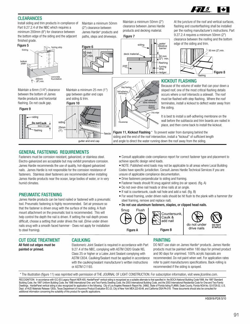
CLEARANCESInstall siding and trim products in compliance of Part 9.27.2.4 of the NBC which requires a minimum 200mm (8") for clearance between the bottom edge of the siding and the adjacent finished grade.
Maintain a minimum 50mm (2") clearance between James Hardie® products and paths, steps and driveways.
Maintain a minimum 50mm (2") clearance between James Hardie products and decking material.
At the juncture of the roof and vertical surfaces, flashing and counterflashing shall be installed per the roofing manufacturer’s instructions. Part 9.27.2.4 requires a minimum 50mm (2") clearance between the roofing and the bottom edge of the siding and trim.
Maintain a 6mm (1/4") clearance between the bottom of James Hardie products and horizontal flashing. Do not caulk gap.
Maintain a minimum 25 mm (1")gap between gutter end caps and siding & trim.
KICKOUT FLASHINGBecause of the volume of water that can pour down a sloped roof, one of the most critical flashing details occurs where a roof intersects a sidewall. The roof must be flashed with step flashing. Where the roof terminates, install a kickout to deflect water away from the siding.
It is best to install a self-adhering membrane on the wall before the subfascia and trim boards are nailed in place, and then come back to install the kickout.
Figure 11, Kickout Flashing * To prevent water from dumping behind thesiding and the end of the roof intersection, install a "kickout" of sufficient lengthand angle to direct the water running down the roof away from the siding.
GENERAL FASTENING REQUIREMENTSFasteners must be corrosion resistant, galvanized, or stainless steel. Electro-galvanized are acceptable but may exhibit premature corrosion. James Hardie recommends the use of quality, hot-dipped galvanized nails. James Hardie is not responsible for the corrosion resistance of fasteners. Stainless steel fasteners are recommended when installing James Hardie products near the ocean, large bodies of water, or in very humid climates.
PNEUMATIC FASTENINGJames Hardie products can be hand nailed or fastened with a pneumatic tool. Pneumatic fastening is highly recommended. Set air pressure so that the fastener is driven snug with the surface of the siding. A flush mount attachment on the pneumatic tool is recommended. This will help control the depth the nail is driven. If setting the nail depth proves difficult, choose a setting that under drives the nail. (Drive under driven nails snug with a smooth faced hammer - Does not apply for installation to steel framing).
• Consult applicable code compliance report for correct fastener type and placement to achieve specific design wind loads.• NOTE: Published wind loads may not be applicable to all areas where Local Building Codes have specific jurisdiction. Consult James Hardie Technical Services if you are unsure of applicable compliance documentation.• Drive fasteners perpendicular to siding and framing.• Fastener heads should fit snug against siding (no air space). (fig. A)• Do not over-drive nail heads or drive nails at an angle.• If nail is countersunk, caulk nail hole and add a nail. (fig. B)• For wood framing, under driven nails should be hit flush to the plank with a hammer (for steel framing, remove and replace nail).• Do not use aluminum fasteners, staples, or clipped head nails.
CUT EDGE TREATMENTAll field cut edges must be painted or primed.
CAULKINGElastomeric Joint Sealant is required in accordance with Part 9.27.4 of the NBC, complying with ASTM C920 Grade NS, Class 25 or higher or a Latex Joint Sealant complying with ASTM C834. Caulking/Sealant must be applied in accordance with the caulking/sealant manufacturer’s written instructions or ASTM C1193.
PAINTINGDO NOT use stain on James Hardie® products. James Hardie products must be painted within 180 days for primed product and 90 days for unprimed. 100% acrylic topcoats are recommended. Do not paint when wet. For application rates refer to paint manufacturers specifications. Back-rolling is recommended if the siding is sprayed.
RECOGNITION: In accordance with ICC-ES Legacy Report NER-405, HardiePanel® vertical siding is recognized as a suitable alternate to that specified in: the BOCA National Building Code/1999, the 1997 StandardBuilding Code, the 1997 Uniform Building Code, the 1998 International One- and Two-Family Dwelling Code, the 2003 International Building Code, and the 2003 International Residential Code for One-and Two-FamilyDwellings. HardiePanel vertical siding is also recognized for application in the following: City of Los Angeles Research Report No. 24862, State of Florida listing FL#889, Dade County, Florida NOA No. 02-0729.02, U.S.Dept. of HUD Materials Release 1263c, Texas Department of Insurance Product Evaluation EC-23, City of New York MEA 223-93-M, and California DSA PA-019. These documents should also be consulted foradditional information concerning the suitability of this product for specific applications.
fascia
siding
gutter and end cap
200mm (8") min.
bottom plate
furring strip
25mm (1")
* The illustration (figure 11) was reprinted with permission of THE JOURNAL OF LIGHT CONSTRUCTION. For subscription information, visit www.jlconline.com.
Figure 5 Figure 6
Figure 7
Figure 8
Figure 9
Figure 10
HS0916-P2/6 5/10

92 HS0916-P3/6 5/10
WIND LOAD TABLE FOOT NOTES:1. Values are for species of wood having a specific gravity of 0.42 or greater.2. Values are for species of wood having a specific gravity of 0.36 or greater.
METRIC TO IMPERIAL CONVERSION TABLEThe following table provides a conversion of the nominal metric measurements presented in these installation instructionsto nominal Imperial fraction measurement valuesmm inches2.3 3/322.5 3/322.8 7/645.7 7/326.2 1/4
mm inches6.7 17/647.5 5/168.2 21/649 23/6412 15/32
mm inches25 138 1-1/250 292 3-5/8102 4
mm inches150 6203 8305 12406 16610 24
2.3mm shank x 5.7mmHD 38mm (1 1/2”)
ring shank nail
102mm (4”) - edge/
203mm (8”) - field
150mm (6”) - edge/
305mm (12”) - field
150mm (6”) - edge/
150mm (6”) - field
102mm (4”) - edge/
102mm (4”) - field
150mm (6”) - edge/
305mm (12”) - field
150mm (6”) - edge/
150mm (6”) - field
102mm (4”) - edge/
102mm (4”) - field
150mm (6”) - edge/
150mm (6”) - field
102mm (4”) - edge/
203mm (8”) - field
102mm (4”) - edge/
203mm (8”) - field
Nominal2 x 4 wood 2 406mm
(16”)
406mm(16”)
406mm(16”)
406mm(16”)
406mm(16”)
406mm(16”)
200
2.8mm shank x 6.7mmHD 50mm (2”) long nail
Nominal2 x 4 wood 1 157
PRODUCTTHICKNESS
FASTENERTYPE
FASTENERSPACING
FRAMETYPES
MAXIMUMSTUD
SPACING
ULTIMATELOAD@FAILURE
2.8mm shank x 6.7mmHD 50mm (2”) long nail
Nominal2 x 4 wood 1 200
2.8mm shank x 6.7mmHD 50mm (2”) long nail
223Nominal2 x 4 wood 1
2.8mm shank x 6.7mmHD 50mm (2”) long nail
146Nominal2 x 4 wood 1
153Nominal2 x 4 wood 1
2.8mm shank x 6.7mmHD 50mm (2”) long nail
Nominal2 x 4 wood 1
2.8mm shank x 6.7mmHD 50mm (2”) long nail
153
160Min No. 8-18 x 8.2mmHD x 25mm (1”) long Hi-Lo S or S-12 ribbed
bugle screws
Min. No 20 ga.x 92 mmx 35 mm
metal C-stud
2.5mm shank x 6.2mmHD x 38mm (1 1/2”) long
ET & F pin fastener
Min. No 20 ga.x 92 mmx 35 mm
metal C-stud
154
ALLOWABLE LOADS FOR STRUCTURAL EXTERIOR HARDIEPANEL® VERTICAL SIDING
610mm(24”)
610mm(24”)
610mm(24”)
610mm(24”)
90
89
149
236
59
94
143
170
170
SHEARVALUE
2.5mm shank x 6.2mmHD x 38mm (1 1/2”) long
ET & F pin fastener
Min. No 20 ga.x 92 mmx 35 mm
metal C-stud
133 101
(plf)(kNm)
2.92
2.29
2.92
3.25
2.12
2.23
2.23
2.33
2.25
1.94
(psf)(kPa)
4.30
4.26
7.13
12.30
2.82
4.5
4.85
8.14
8.14
4.84
7.5mm(5/16”)
7.5mm(5/16”)
7.5mm(5/16”)
7.5mm(5/16”)
7.5mm(5/16”)
7.5mm(5/16”)
7.5mm(5/16”)
7.5mm(5/16”)
7.5mm(5/16”)
7.5mm(5/16”)
COMPLIANCE:HardiePanel® vertical siding complies with ASTMSpecification C1186 (Grade II, Type A) andISO Standard 8336 (Category 3, Type A).
When tested in accordance with CAN/ULC-S102, the product is recognized to have the following properties: Flame Spread Rating: 0, Smoke Developed Classification: 0.
When tested in accordance with CAN/ULC-S114, the product is recognized as noncombustible.
RECOGNITION:HardiePanel vertical siding may be recognized as an alternative to exterior wall cladding in section 9.27 of the NBC. For technical assistance, call 1-800-9-HARDIE.
FIRE-RESISTIVE CONSTRUCTION:HardiePanel vertical siding is recognized as a component in 1-hour fire-related wall construction. Details of this assembly (Design No. JH/WA 60-01,JH/WA 60-09 and JH/WA 60-10) may be found at: www.Intertek-ETLSemko.com
93
HS0916-P4/6 5/10
COLORPLUS® TECHNOLOGY CAULKING, TOUCH-UP & LAMINATETouch up nicks, scrapes and nail heads using the ColorPlus® Technology touch-up applicator. Touch-up paint should be used sparingly.If large areas require touch-up, replace the damaged area with new HardiePanel® siding with ColorPlus Technology.• Laminate sheet must be removed immediately after installation of each course.• Terminate non-factory cut edges into trim where possible, and caulk. Color matched caulks are available from your ColorPlus® product dealer.• Treat all other non-factory cut edges using the ColorPlus Technology edge coaters, available from your ColorPlus product dealer.
PAINTING JAMES HARDIE® SIDING AND TRIM PRODUCTS WITH COLORPLUS® TECHNOLOGYWhen repainting ColorPlus products, James Hardie recommends the following regarding surface preparation and topcoat application:• Ensure the surface is clean, dry, and free of any dust, dirt, or mildew• Repriming is normally not necessary• 100% acrylic topcoats are recommended• DO NOT use stain or oil/alkyd base paints on James Hardie® products• Apply finish coat in accordance with paint manufacturers written instructions regarding coverage, application methods, and application temperature
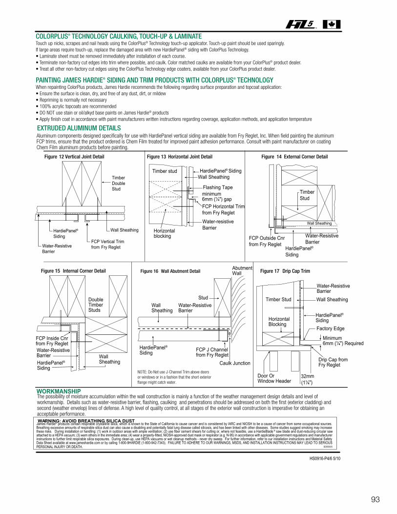
EXTRUDED ALUMINUM DETAILSAluminum components designed specifically for use with HardiePanel vertical siding are available from Fry Reglet, Inc. When field painting the aluminum FCP trims, ensure that the product ordered is Chem Film treated for improved paint adhesion performance. Consult with paint manufacturer on coating Chem Film aluminum products before painting.
Figure 12 Vertical Joint Detail
TimberDoubleStud
Wall Sheathing
FCP Vertical Trim from Fry Reglet
HardiePanel®Siding
Water-ResistiveBarrier
Horizontal Joint DetailFigure 13
Wall SheathingTimber stud
Horizontalblocking
HardiePanel® Siding
FCP Horizontal Trimfrom Fry RegletWater-resistiveBarrier
minimum 6mm (¼") gap
Wall Sheathing
Water-ResistiveBarrier
Figure 14 External Corner Detail
TimberStud
FCP Outside Cnrfrom Fry Reglet
HardiePanel®Siding
Wall Abutment DetailFigure 16
NOTE: Do Not use J-Channel Trim above doors or windows or in a fashion that the short exteriorflange might catch water.
WallSheathing
Stud
AbutmentWall
Caulk Junction
FCP J Channelfrom Fry Reglet
Water-ResistiveBarrier
HardiePanel®Siding
Internal Corner DetailFigure 15
DoubleTimberStuds
HardiePanel®Siding
WallSheathing
Water-ResistiveBarrier
FCP Inside Cnrfrom Fry Reglet
Drip Cap TrimFigure 17
HardiePanel®Siding
Timber Stud
Water-ResistiveBarrierWall Sheathing
Factory Edge
Door OrWindow Header
Drip Cap fromFry Reglet
Minimum6mm (¼") Required
32mm(1¼")
HorizontalBlocking
Flashing Tape
WORKMANSHIPThe possibility of moisture accumulation within the wall construction is mainly a function of the weather management design details and level of workmanship. Details such as water-resistive barrier, flashing, caulking and penetrations should be addressed on both the first (exterior cladding) and second (weather envelop) lines of defense. A high level of quality control, at all stages of the exterior wall construction is imperative for obtaining an acceptable performance.
James Hardie® products contain respirable crystalline silica, which is known to the State of California to cause cancer and is considered by IARC and NIOSH to be a cause of cancer from some occupational sources. Breathing excessive amounts of respirable silica dust can also cause a disabling and potentially fatal lung disease called silicosis, and has been linked with other diseases. Some studies suggest smoking may increase these risks. During installation or handling: (1) work in outdoor areas with ample ventilation; (2) use fiber cement shears for cutting or, where not feasible, use a HardieBlade ® saw blade and dust-reducing circular saw attached to a HEPA vacuum; (3) warn others in the immediate area; (4) wear a properly-fitted, NIOSH-approved dust mask or respirator (e.g. N-95) in accordance with applicable government regulations and manufacturer instructions to further limit respirable silica exposures. During clean-up, use HEPA vacuums or wet cleanup methods - never dry sweep. For further information, refer to our installation instructions and Material Safety Data Sheet available at www.jameshardie.com or by calling 1-800-9HARDIE (1-800-942-7343). FAILURE TO ADHERE TO OUR WARNINGS, MSDS, AND INSTALLATION INSTRUCTIONS MAY LEAD TO SERIOUS PERSONAL INJURY OR DEATH. SD050905
94
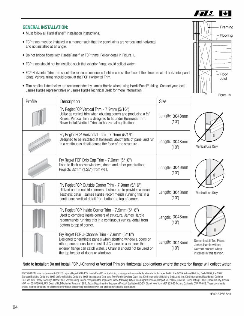
Profile Description Size
Fry Reglet FCP Vertical Trim - 7.9mm (5/16")Utilize as vertical trim when abutting panels and producing a ½” Reveal. Vertical Trim is designed to fit under Horizontal Trim. Never install Vertical Trims in horizontal applications.
Length: 3048mm(10’)
3048mm(10’)
3048mm(10’)
3048mm(10’)
3048mm(10’)
3048mm(10’)
Length:
Length:
Length:
Length:
Fry Reglet FCP Horizontal Trim - 7.9mm (5/16")Designed to be installed at horizontal abutments of panel and run in a continuous detail across the face of the structure.
Fry Reglet FCP Outside Corner Trim - 7.9mm (5/16")Utilized on the outside corners of structure to provides a clean aesthetic detail. James Hardie recommends running this in a continuous vertical detail from bottom to top of corner.
Fry Reglet FCP Inside Corner Trim - 7.9mm (5/16")Used to complete inside corners of structure. James Hardie recommends running this in a continuous vertical detail from bottom to top of corner.
Fry Reglet FCP J-Channel Trim - 7.9mm (5/16")
Note to Installer: Do not install FCP J-Channel or Vertical Trim on Horizontal applications where the exterior flange will collect water.
Designed to terminate panels when abutting windows, doors or other penetrations. Never install J Channel in a manner that exterior flange can catch water. J Channel should not be used on the top header of doors or windows.
Length:
Fry Reglet FCP Drip Cap Trim - 7.9mm (5/16")Used to flash above windows, doors and other penetrationsProjects 32mm (1.25") from wall.
Vertical Use Only.
Vertical Use Only.
Framing
Flooring
FloorJoist
Figure 18
Do not install Tee Piece. James Hardie will not warrant product when installed in this fashion.
RECOGNITION: In accordance with ICC-ES Legacy Report NER-405, HardiePanel® vertical siding is recognized as a suitable alternate to that specified in: the BOCA National Building Code/1999, the 1997 Standard Building Code, the 1997 Uniform Building Code, the 1998 International One- and Two-Family Dwelling Code, the 2003 International Building Code, and the 2003 International Residential Code for One-and Two-Family Dwellings. HardiePanel vertical siding is also recognized for application in the following: City of Los Angeles Research Report No. 24862, State of Florida listing FL#889, Dade County, Florida NOA No. 02-0729.02, U.S. Dept. of HUD Materials Release 1263c, Texas Department of Insurance Product Evaluation EC-23, City of New York MEA 223-93-M, and California DSA PA-019. These documents should also be consulted for additional information concerning the suitability of this product for specific applications.
HS0916-P5/6 5/10
GENERAL INSTALLATION:• Must follow all HardiePanel® installation instructions.
• FCP trims must be installed in a manner such that the panel joints are vertical and horizontal and not installed at an angle.
• Do not bridge floors with HardiePanel® or FCP trims. Follow detail in Figure 1.
• FCP trims should not be installed such that exterior flange could collect water.
• FCP Horizontal Trim trim should be run in a continuous fashion across the face of the structure at all horizontal panel joints. Vertical trims should break at the FCP Horizontal Trim.
• Trim profiles listed below are recommended by James Hardie when using HardiePanel® siding. Contact your local James Hardie representative or James Hardie Technical Desk for more information.

95
© 2010 James Hardie Technology Limited All rights reserved.TM, SM, and ® denote trademarks or registered trademarks of James Hardie Technology Limited. is a registered trademark of James Hardie Technology Limited.
Additional Installation Information, Warranties, and Warnings are available at
www.jameshardie.com
HS0916-P6/6 5/10