H401 & H601 - Hypertherm
62
Power Supplies Instruction Manual 800410 – Revision 5 H401 & H601
-
Upload
khangminh22 -
Category
Documents
-
view
0 -
download
0
Transcript of H401 & H601 - Hypertherm
Power Supplies
Instruction Manual800410 – Revision 5
H401 &H601
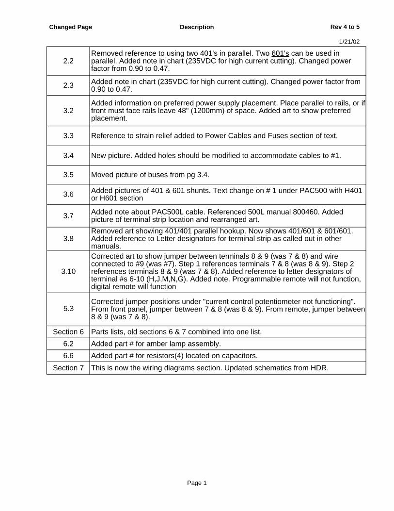
Changed Page Description Rev 4 to 5
1/21/02
2.2Removed reference to using two 401's in parallel. Two 601's can be used in parallel. Added note in chart (235VDC for high current cutting). Changed power factor from 0.90 to 0.47.
2.3 Added note in chart (235VDC for high current cutting). Changed power factor from 0.90 to 0.47.
3.2Added information on preferred power supply placement. Place parallel to rails, or if front must face rails leave 48" (1200mm) of space. Added art to show preferred placement.
3.3 Reference to strain relief added to Power Cables and Fuses section of text.
3.4 New picture. Added holes should be modified to accommodate cables to #1.
3.5 Moved picture of buses from pg 3.4.
3.6 Added pictures of 401 & 601 shunts. Text change on # 1 under PAC500 with H401 or H601 section
3.7 Added note about PAC500L cable. Referenced 500L manual 800460. Added picture of terminal strip location and rearranged art.
3.8Removed art showing 401/401 parallel hookup. Now shows 401/601 & 601/601. Added reference to Letter designators for terminal strip as called out in other manuals.
3.10
Corrected art to show jumper between terminals 8 & 9 (was 7 & 8) and wire connected to #9 (was #7). Step 1 references terminals 7 & 8 (was 8 & 9). Step 2 references terminals 8 & 9 (was 7 & 8). Added reference to letter designators of terminal #s 6-10 (H,J,M,N,G). Added note. Programmable remote will not function, digital remote will function
5.3Corrected jumper positions under "current control potentiometer not functioning". From front panel, jumper between 7 & 8 (was 8 & 9). From remote, jumper between 8 & 9 (was 7 & 8).
Section 6 Parts lists, old sections 6 & 7 combined into one list.
6.2 Added part # for amber lamp assembly.
6.6 Added part # for resistors(4) located on capacitors.
Section 7 This is now the wiring diagrams section. Updated schematics from HDR.
Page 1
H401 & H601
Instruction Manual
(P/N 800410)
Revision 5 – January, 2002
© Copyright 2002 Hypertherm, Inc.All Rights Reserved
Hypertherm, HT, and PAC are trademarks of Hypertherm, Inc. and may be registered in the United States and/or other countries
Hypertherm, Inc.Hanover, NH USA
www.hypertherm.com

Hypertherm, Inc.
Etna Road, P.O. Box 5010Hanover, NH 03755 USA603-643-3441 Tel (Main Office)603-643-5352 Fax (All Departments)800-643-9878 Tel (Technical Service)800-737-2978 Tel (Customer Service)
Hypertherm Automation
5 Technology DriveWest Lebanon, NH 03755 USA603-298-7970 Tel 603-298-7977 Fax
Hypertherm Plasmatechnik GmbH
Technologiepark HanauRodenbacher Chaussee 6 63457 Hanau-Wolfgang, Deutschland49 6181 58 2100 Tel 49 6181 58 2134 Fax49 6181 58 2123 (Technical Service)
Hypertherm Singapore Pte Ltd
No. 19 Kaki Bukit Road 2 K.B. Warehouse Complex Singapore 417847, Republic of Singapore65 841 2489 Tel 65 841 2490 Fax 65 841 2489 (Technical Service)
Japan
1952-14 Yata-NatsumegiMishima City, Shizuoka Pref.411-0801 Japan81 0 559 75 7387 Tel81 0 559 75 7376 Fax
Hypertherm UK Ltd
9 Berkeley Court, Manor Park Runcorn, Cheshire, England WA7 1TQ44 1928 579 074 Tel 44 1928 579 604 Fax
France
15 Impasse des Rosiers95610 Eragny, France0805 050 111 Tel 0805 050 222 Fax
Hypertherm S.r.L.
Via Torino 220123 Milano, Italia39 02 725 46 312 Tel 39 02 725 46 400 Fax39 02 725 46 314 (Technical Service)
Hypertherm B.V.
Burg. Haverkampstraat 13 7091 CN Dinxperlo, Nederland31 315 655866 Tel 31 315 655886 Fax
Hypertherm B.V. (ETSO)
Vaartveld 94704 SE Roosendaal, Nederland00 800 49 73 7843 – toll-free in Europa
31 165 596900 Tel31 165 596901 Fax
Hypertherm Brasil Ltda.
Rua Visconde de Santa Isabel, 20 – Sala 611Vila Isabel, RJ Brasil CEP 20560-12055 21 2278 6162 Tel55 21 2578 0947 Fax
10/30/01
ELECTROMAGNETIC COMPATIBILITY (EMC) AND CE SAFETY
EMC INTRODUCTION
Hypertherm's CE-marked equipment is builtin compliance with standard EN50199. Theequipment should be installed and used inaccordance with the information below toachieve electromagnetic compatibility.
The limits required by EN50199 may not beadequate to completely eliminate interfer-ence when the affected equipment is inclose proximity or has a high degree ofsensitivity. In such cases it may be neces-sary to use other measures to further re-duce interference.
This plasma equipment is designed for useonly in an industrial environment.
INSTALLATION AND USE
The user is responsible for installing andusing the plasma equipment according tothe manufacturer's instructions. If electro-magnetic disturbances are detected then itshall be the responsibility of the user toresolve the situation with the technicalassistance of the manufacturer. In somecases this remedial action may be as simpleas earthing the cutting circuit, see Earthingof Workpiece. In other cases it could involveconstructing an electromagnetic screenenclosing the power source and the workcomplete with associated input filters. In allcases electromagnetic disturbances mustbe reduced to the point where they are nolonger troublesome.
ASSESSMENT OF AREA
Before installing the equipment the usershall make an assessment of potentialelectromagnetic problems in the surround-ing area. The following shall be taken intoaccount:a. Other supply cables, control cables,signalling and telephone cables; above,below and adjacent to the cuttingequipment.b. Radio and television transmitters andreceivers.c. Computer and other control equipment.d. Safety critical equipment, for exampleguarding of industrial equipment.e. Health of the people around, for example the use of pacemakers andhearing aids.f. Equipment used for calibration ormeasurement.g. Immunity of other equipment in theenvironment. User shall ensure that otherequipment being used in the environment iscompatible. This may require additionalprotection measures.h. Time of day that cutting or other activitiesare to be carried out.
Earthing of Workpiece
Where the workpiece is not bonded to earthfor electrical safety, nor connected to earthbecause of its size and position, forexample, ship's hull or building steelwork, aconnection bonding the workpiece to earthmay reduce emissions in some, but not allinstances. Care should be taken to preventthe earthing of the workpiece increasing therisk of injury to users, or damage to otherelectrical equipment. Where necessary, theconnection of the workpiece to earth shouldbe made by a direct connection to theworkpiece, but in some countries wheredirect connection is not permitted, thebonding should be achieved by suitablecapacitances selected according to nationalregulations.
Note. The cutting circuit may or may not beearthed for safety reasons. Changing theearthing arrangements should only beauthorized by a person who is competent toassess whether the changes will increasethe risk of injury, for example, by allowingparallel cutting current return paths whichmay damage the earth circuits of otherequipment. Further guidance is given in IECTC26 (sec)94 and IEC TC26/108A/CD ArcWelding Equipment Installation and Use.
Screening and Shielding
Selective screening and shielding of othercables and equipment in the surroundingarea may alleviate problems of interference.Screening of the entire plasma cuttinginstallation may be considered for specialapplications.
CE Safety
Power supplies are intended for an overvoltage category III power source. SeeSection 6.1 of IEC 60974-1.
Power suplies are intended for environ-mental conditions of pollution degree 3minimum. See Section 6.1 of IEC 60974-1.
Power supplies must not be used for apipe-thawing application. See Section 17N of IEC 60974-1.
The size of the surrounding area to beconsidered will depend on the structure ofthe building and other activities that aretaking place. The surrounding area mayextend beyond the boundaries of thepremises.
METHODS OF REDUCING EMISSIONS
Mains Supply
Cutting equipment must be connected to themains supply according to the manu-facturer's recommendations. If interferenceoccurs, it may be necessary to takeadditional precautions such as filtering ofthe mains supply. Consideration should begiven to shielding the supply cable ofpermanently installed cutting equipment, inmetallic conduit or equivalent. Shieldingshould be electrically continuous throughoutits length. The shielding should be con-nected to the cutting mains supply so thatgood electrical contact is maintained be-tween the conduit and the cutting powersource enclosure
Maintenance of Cutting Equipment
The cutting equipment must be routinelymaintained according to the manufacturer'srecommendations. All access and servicedoors and covers should be closed andproperly fastened when the cutting equip-ment is in operation. The cutting equipmentshould not be modified in any way except forthose changes and adjustments covered inthe manufacturer's instructions. In particu-lar, the spark gaps of arc striking andstabilizing devices should be adjusted andmaintained according to the manufacturer'srecommendations.
Cutting Cables
The cutting cables should be kept as shortas possible and should be positioned closetogether, running at or close to the floorlevel.
Equipotential Bonding
Bonding of all metallic components in thecutting installation and adjacent to it shouldbe considered. However, metallic compo-nents bonded to the workpiece will increasethe risk that the operator could receive ashock by touching these metallic compo-nents and the electrode at the same time.The operator should be insulated from allsuch bonded metallic components.
Hypertherm CE Power Supplies i
WARRANTY
ii Hypertherm Warranty9-01
WARNINGGenuine Hypertherm parts are the factory-recommendedreplacement parts for your Hypertherm system. Any damagecaused by the use of other than genuine Hypertherm partsmay not be covered by the Hypertherm warranty.
WARNINGYou are responsible for the safe use of the Product.Hypertherm does not and cannot make any guarantee orwarranty regarding the safe use of the Product in yourenvironment.
GENERALHypertherm, Inc. warrants that its Products shall be free fromdefects in materials and workmanship, if Hypertherm isnotified of a defect (i) with respect to the power supply withina period of two (2) years from the date of its delivery to you,and (ii) with respect to the torch and leads within a period ofone (1) year from its date of delivery to you. This warrantyshall not apply to any Product which has been incorrectlyinstalled, modified, or otherwise damaged. Hypertherm, at itssole option, shall repair, replace, or adjust, free of charge,any defective Products covered by this warranty which shallbe returned with Hypertherm’s prior authorization (which shall not be unreasonably withheld), properly packed, toHypertherm’s place of business in Hanover, New Hampshire,or to an authorized Hypertherm repair facility, all costs,insurance and freight prepaid. Hypertherm shall not be liablefor any repairs, replacement, or adjustments of Productscovered by this warranty, except those made pursuant to thisparagraph or with Hypertherm’s prior written consent. Thewarranty above is exclusive and is in lieu of all otherwarranties, express, implied, statutory, or otherwise withrespect to the Products or as to the results which may beobtained therefrom, and all implied warranties orconditions of quality or of merchantability or fitness for a particular purpose or against infringement. The foregoing shall constitute the sole and exclusiveremedy for any breach by Hypertherm of its warranty.Distributors/OEMs may offer different or additional warranties,but Distributors/OEMs are not authorized to give anyadditional warranty protection to you or make anyrepresentation to you purporting to be binding uponHypertherm.
PATENT INDEMNITYExcept only in cases of products not manufactured byHypertherm or manufactured by a person other thanHypertherm not in strict conformity with Hypertherm’sspecifications and in cases of designs, processes,
formulae, or combinations not developed or purported to bedeveloped by Hypertherm, Hypertherm will defend or settle,at its own expense, any suit or proceeding brought againstyou alleging that the use of the Hypertherm product, aloneand not in combination with any other product not supplied byHypertherm, infringes any patent of any third party. You shallnotify Hypertherm promptly upon learning of any action orthreatened action in connection with any such allegedinfringement, and Hypertherm’s obligation to indemnify shallbe conditioned upon Hypertherm’s sole control of, and theindemnified party’s cooperation and assistance in, thedefense of the claim.
LIMITATION OF LIABILITYIn no event shall Hypertherm be liable to any person orentity for any incidental, consequential, indirect, orpunitive damages (including but not limited to lostprofits) regardless of whether such liability is based onbreach of contract, tort, strict liability, breach ofwarranties, failure of essential purpose or otherwise andeven if advised of the possibility of such damages.
LIABILITY CAPIn no event shall Hypertherm’s liability, whether suchliability is based on breach of contract, tort, strictliability, breach of warranties, failure of essential purposeor otherwise, for any claim action suit or proceedingarising out of or relating to the use of the Productsexceed in the aggregate the amount paid for theProducts that gave rise to such claim.
INSURANCEAt all times you will have and maintain insurance in suchquantities and types, and with coverage sufficient andappropriate to defend and to hold Hypertherm harmless in theevent of any cause of action arising from the use of theProducts.
NATIONAL AND LOCAL CODESNational and Local codes governing plumbing and electricalinstallation shall take precedent over any instructionscontained in this manual. In no event shall Hypertherm beliable for injury to persons or property damage by reason ofany code violation or poor work practices.
TRANSFER OF RIGHTSYou may transfer any remaining rights you may havehereunder only in connection with the sale of all orsubstantially all of your assets or capital stock to a successorin interest who agrees to be bound by all of the terms andconditions of this Warranty.
TABLE OF CONTENTS
H401 & H601 Instruction Manual iii4
Electromagnetic Compatibility (EMC).......................................................................................................................iWarranty .....................................................................................................................................................................ii
Section 1 SAFETYRecognize Safety Information...................................................................................................................................1-2Follow Safety Instructions.........................................................................................................................................1-2Cutting Can Cause Fire or Explosion .......................................................................................................................1-2Electric Shock Can Kill..............................................................................................................................................1-3Cutting Can Produce Toxic Fumes...........................................................................................................................1-3A Plasma Arc Can Cause Injury and Burns..............................................................................................................1-4Arc Rays Can Burn Eyes and Skin ...........................................................................................................................1-4Grounding Safety......................................................................................................................................................1-4Compressed Gas Equipment Safety ........................................................................................................................1-5Gas Cylinders Can Explode If Damaged ..................................................................................................................1-5Noise Can Damage Hearing.....................................................................................................................................1-5Pacemaker and Hearing Aid Operation ....................................................................................................................1-5A Plasma Arc Can Damage Frozen Pipes................................................................................................................1-5Additional Safety Information....................................................................................................................................1-5Warning Label...........................................................................................................................................................1-6
Section 1a SÉCURITÉIdentifier les consignes de sécurité.........................................................................................................................1a-2Suivre les instructions de sécurité ..........................................................................................................................1a-2Le coupage peut provoquer un incendie ou une explosion ....................................................................................1a-2Les chocs électriques peuvent être fatals...............................................................................................................1a-3Le coupage peut produire des vapeurs toxiques....................................................................................................1a-3L'arc plasma peut provoquer des blessures ou des brûlures .................................................................................1a-4Mise à la masse et à la terre...................................................................................................................................1a-4Les rayons de l'arc peuvent brûler les yeux et la peau...........................................................................................1a-4Sécurité des bouteilles de gaz comprimé ...............................................................................................................1a-5Les bouteilles de gaz comprimé peuvent exploser en cas de dommages .............................................................1a-5Le bruit peut provoquer des problèmes auditifs......................................................................................................1a-5Pacemakers et prothéses auditives........................................................................................................................1a-5Étiquette de sécurité ...............................................................................................................................................1a-6
Section 2 SPECIFICATIONSIntroduction ...............................................................................................................................................................2-2
H401 or H601 with HT4001..............................................................................................................................2-2H401 or H601 with PAC500 .............................................................................................................................2-2
Specifications............................................................................................................................................................2-2H401 Power Supply .........................................................................................................................................2-2H601 Power Supply .........................................................................................................................................2-3H401 & H601 Dimensions................................................................................................................................2-4H401 & H601 Duty Cycle Curves.....................................................................................................................2-4H401 & H601 Volt-Amp Curves .......................................................................................................................2-4
Section 3 INSTALLATIONInstallation Requirements .........................................................................................................................................3-2
Positioning the Power Supply ..........................................................................................................................3-2Grounding Requirements..........................................................................................................................................3-3Noise Levels .............................................................................................................................................................3-3
TABLE OF CONTENTS
iv H401 & H601 Instruction Manual5
Power Requirements ................................................................................................................................................3-3Power Cables and Fuses .................................................................................................................................3-3
Connecting the Primary Power .................................................................................................................................3-4Line Disconnect Switch ....................................................................................................................................3-5
Secondary Connections............................................................................................................................................3-6PAC500 with H401 or H601 .............................................................................................................................3-6PAC500 Control Cable with H401 or H601 ......................................................................................................3-7Parallel Power Supply Connections .................................................................................................................3-8PAC500 Water Muffler and Water Supply System Connections......................................................................3-9Water supply connections ................................................................................................................................3-9Current Control Potentiometer Connections ..................................................................................................3-10HT4001 with H401 or H601............................................................................................................................3-10
Section 4 OPERATIONControls and Indicators.............................................................................................................................................4-2Operation ..................................................................................................................................................................4-3
H401 or H601 with HT4001..............................................................................................................................4-3H401 or H601 with PAC500 .............................................................................................................................4-3Output Current for Power Supply Dial Settings................................................................................................4-4
Section 5 MAINTENANCE AND TROUBLESHOOTINGRoutine Maintenance................................................................................................................................................5-2Power Supply Circuit Description .............................................................................................................................5-2Troubleshooting ........................................................................................................................................................5-3
Section 6 PARTS LIST – H401 AND H601Front Panel Outside .........................................................................................................................................6-2SCR and Shunt Detail ......................................................................................................................................6-3Transformer and Inductor.................................................................................................................................6-4Temperature Switches .....................................................................................................................................6-5Upper Inside.....................................................................................................................................................6-6Fans .................................................................................................................................................................6-7PCB Assemblies ..............................................................................................................................................6-8
Section 7 WIRING DIAGRAMS............................................................................................................................7-1
Appendix A SYSTEM GROUNDING....................................................................................................................a-1System Grounding Requirements.............................................................................................................................a-1Suggested Ground Cable Routing............................................................................................................................a-1
Power Supply ...................................................................................................................................................a-1Equipment Grounding ......................................................................................................................................a-1Work Table Grounding .....................................................................................................................................a-2
Hypertherm Plasma Systems 1-1
Section 1
SAFETY
In this section:
Recognize Safety Information .........................................................................................................................1-2Follow Safety Instructions ...............................................................................................................................1-2Cutting Can Cause Fire or Explosion..............................................................................................................1-2Electric Shock Can Kill ....................................................................................................................................1-3Cutting Can Produce Toxic Fumes..................................................................................................................1-3A Plasma Arc Can Cause Injury and Burns.....................................................................................................1-4Arc Rays Can Burn Eyes and Skin .................................................................................................................1-4Grounding Safety ............................................................................................................................................1-4Compressed Gas Equipment Safety...............................................................................................................1-5Gas Cylinders Can Explode If Damaged ........................................................................................................1-5Noise Can Damage Hearing ...........................................................................................................................1-5Pacemaker and Hearing Aid Operation...........................................................................................................1-5A Plasma Arc Can Damage Frozen Pipes ......................................................................................................1-5Additional Safety Information ..........................................................................................................................1-5Warning Label .................................................................................................................................................1-6
SAFETY
1-2 Hypertherm Plasma Systems11-98
SAFETY
RECOGNIZE SAFETY INFORMATION
The symbols shown in this section are used toidentify potential hazards. When you see a safetysymbol in this manual or on your machine, understandthe potential for personal injury, and follow the relatedinstructions to avoid the hazard.
FOLLOW SAFETY INSTRUCTIONS
Read carefully all safety messages in this manual andsafety labels on your machine.
• Keep the safety labels on your machine in goodcondition. Replace missing or damaged labelsimmediately.
• Learn how to operate the machine and how to use the controls properly. Do not let anyone operate itwithout instruction.
• Keep your machine in proper working condition.Unauthorized modifications to the machine mayaffect safety and machine service life.
DANGER WARNING CAUTION
A signal word DANGER or WARNING is used with asafety symbol. DANGER identifies the most serioushazards.
• DANGER and WARNING safety labels are locatedon your machine near specific hazards.
• WARNING safety messages precede relatedinstructions in this manual that may result in injuryor death if not followed correctly.
• CAUTION safety messages precede relatedinstructions in this manual that may result indamage to equipment if not followed correctly.
Fire Prevention• Be sure the area is safe before doing any cutting.
Keep a fire extinguisher nearby.• Remove all flammables within 35 feet (10 m) of the
cutting area.• Quench hot metal or allow it to cool before handling
or before letting it touch combustible materials.• Never cut containers with potentially flammable
materials inside – they must be emptied andproperly cleaned first.
• Ventilate potentially flammable atmospheres beforecutting.
• When cutting with oxygen as the plasma gas, anexhaust ventilation system is required.
Explosion Prevention• Do not use the plasma system if explosive dust or
vapors may be present.• Do not cut pressurized cylinders, pipes, or any
closed container.• Do not cut containers that have held combustible
materials.
CUTTING CAN CAUSE FIRE OR EXPLOSION
WARNING
Explosion HazardArgon-Hydrogen and Methane
Hydrogen and methane are flammable gases thatpresent an explosion hazard. Keep flames away fromcylinders and hoses that contain methane or hydrogenmixtures. Keep flames and sparks away from the torchwhen using methane or argon-hydrogen plasma.
WARNING
Hydrogen Detonation with Aluminum Cutting
• When cutting aluminum underwater, or with thewater touching the underside of the aluminum, freehydrogen gas may collect under the workpiece anddetonate during plasma cutting operations.
• Install an aeration manifold on the floor of the watertable to eliminate the possibility of hydrogendetonation. Refer to the Appendix section of thismanual for aeration manifold details.
Touching live electrical parts can cause a fatal shockor severe burn.
• Operating the plasma system completes anelectrical circuit between the torch and theworkpiece. The workpiece and anything touchingthe workpiece are part of the electrical circuit.
• Never touch the torch body, workpiece or the waterin a water table when the plasma system isoperating.
Electric Shock Prevention
All Hypertherm plasma systems use high voltagein the cutting process (200 to 400 VDC arecommon). Take the following precautions whenoperating this system:• Wear insulated gloves and boots, and keep your
body and clothing dry.• Do not stand, sit or lie on – or touch – any wet
surface when using the plasma system.• Insulate yourself from work and ground using dry
insulating mats or covers big enough to prevent anyphysical contact with the work or ground. If you mustwork in or near a damp area, use extreme caution.
• Provide a disconnect switch close to the powersupply with properly sized fuses. This switch allowsthe operator to turn off the power supply quickly inan emergency situation.
• When using a water table, be sure that it is correctlyconnected to earth ground.
ELECTRIC SHOCK CAN KILL
• Install and ground this equipment according to theinstruction manual and in accordance with nationaland local codes.
• Inspect the input power cord frequently for damageor cracking of the cover. Replace a damaged powercord immediately. Bare wiring can kill.
• Inspect and replace any worn or damaged torchleads.
• Do not pick up the workpiece, including the wastecutoff, while you cut. Leave the workpiece in placeor on the workbench with the work cable attachedduring the cutting process.
• Before checking, cleaning or changing torch parts,disconnect the main power or unplug the powersupply.
• Never bypass or shortcut the safety interlocks.• Before removing any power supply or system
enclosure cover, disconnect electrical input power.Wait 5 minutes after disconnecting the main powerto allow capacitors to discharge.
• Never operate the plasma system unless the powersupply covers are in place. Exposed power supplyconnections present a severe electrical hazard.
• When making input connections, attach propergrounding conductor first.
• Each Hypertherm plasma system is designed to beused only with specific Hypertherm torches. Do notsubstitute other torches which could overheat andpresent a safety hazard.
Cutting can produce toxic fumes and gases thatdeplete oxygen and cause injury or death.
• Keep the cutting area well ventilated or use anapproved air-supplied respirator.
• Do not cut in locations near degreasing, cleaning orspraying operations. The vapors from certainchlorinated solvents decompose to form phosgenegas when exposed to ultraviolet radiation.
• Do not cut metal coated or containing toxic materi-als, such as zinc (galvanized), lead, cadmium or
CUTTING CAN PRODUCE TOXIC FUMES
beryllium, unless the area is well ventilated and theoperator wears an air-supplied respirator. Thecoatings and any metals containing these elementscan produce toxic fumes when cut.
• Never cut containers with potentially toxic materialsinside – they must be emptied and properly cleanedfirst.
• This product, when used for welding or cutting,produces fumes or gases which contain chemicalsknown to the State of California to cause birthdefects and, in some cases, cancer.
Hypertherm Plasma Systems 1-38-99
SAFETY
SAFETY
1-4 Hypertherm Plasma Systems4-99
SAFETY
Instant-On TorchesPlasma arc comes on immediately when the torchswitch is activated.
A PLASMA ARC CAN CAUSE INJURY AND BURNS
The plasma arc will cut quickly through gloves andskin.• Keep away from the torch tip.• Do not hold metal near the cutting path.• Never point the torch toward yourself or others.
Eye Protection Plasma arc rays produce intensevisible and invisible (ultraviolet and infrared) rays thatcan burn eyes and skin.• Use eye protection in accordance with applicable
national or local codes.• Wear eye protection (safety glasses or goggles with
side shields, or a welding helmet) with appropriatelens shading to protect your eyes from the arc’sultraviolet and infrared rays.
Lens ShadeArc Current AWS (USA) ISO 4850
Up to 100 A No. 8 No. 11100-200 A No. 10 No. 11-12200-400 A No. 12 No. 13Over 400 A No. 14 No. 14
ARC RAYS CAN BURN EYES AND SKIN
Skin Protection Wear protective clothing to protectagainst burns caused by ultraviolet light, sparks andhot metal.• Gauntlet gloves, safety shoes and hat.• Flame-retardant clothing to cover all exposed areas.• Cuffless trousers to prevent entry of sparks and
slag.• Remove any combustibles, such as a butane lighter
or matches, from your pockets before cutting.
Cutting Area Prepare the cutting area to reducereflection and transmission of ultraviolet light:• Paint walls and other surfaces with dark colors to
reduce reflection. • Use protective screens or barriers to protect others
from flash and glare.• Warn others not to watch the arc. Use placards or
signs.
Work Cable Attach the work cable securely to theworkpiece or the work table with good metal-to-metalcontact. Do not connect it to the piece that will fallaway when the cut is complete.
Work Table Connect the work table to an earthground, in accordance with appropriate national orlocal electrical codes.
GROUNDING SAFETY Input Power• Be sure to connect the power cord ground wire to
the ground in the disconnect box.• If installation of the plasma system involves
connecting the power cord to the power supply, besure to connect the power cord ground wireproperly.
• Place the power cord's ground wire on the stud first,then place any other ground wires on top of thepower cord ground. Fasten the retaining nut tightly.
• Tighten all electrical connections to avoid excessiveheating.
SAFETY
Hypertherm Plasma Systems 1-511-98
SAFETY
• Never lubricate cylinder valves or regulators with oilor grease.
• Use only correct gas cylinders, regulators, hosesand fittings designed for the specific application.
• Maintain all compressed gas equipment andassociated parts in good condition.
• Label and color-code all gas hoses to identify thetype of gas in each hose. Consult applicablenational or local codes.
GAS CYLINDERS CANEXPLODE IF DAMAGED
COMPRESSED GAS EQUIPMENT SAFETY
Gas cylinders contain gas under high pressure. Ifdamaged, a cylinder can explode.• Handle and use compressed gas cylinders in
accordance with applicable national or local codes.• Never use a cylinder that is not upright and secured
in place.• Keep the protective cap in place over valve except
when the cylinder is in use or connected for use.• Never allow electrical contact between the plasma
arc and a cylinder.• Never expose cylinders to excessive heat, sparks,
slag or open flame.• Never use a hammer, wrench or other tool to open
a stuck cylinder valve.
Prolonged exposure to noise from cutting or gougingcan damage hearing.• Use approved ear protection when using plasma
system.• Warn others nearby about the noise hazard.
NOISE CAN DAMAGE HEARING
Pacemaker and hearing aid operation can be affectedby magnetic fields from high currents.Pacemaker and hearing aid wearers should consult adoctor before going near any plasma arc cutting andgouging operations.
To reduce magnetic field hazards:• Keep both the work cable and the torch lead to one
side, away from your body.• Route the torch leads as close as possible to the
work cable.• Do not wrap or drape the torch lead or work cable
around your body.• Keep as far away from the power supply as
possible.
PACEMAKER AND HEARINGAID OPERATION
ADDITIONAL SAFETY INFORMATION
1. ANSI Standard Z49.1, Safety in Welding and Cutting, AmericanWelding Society, 550 LeJeune RoadP.O. Box 351020, Miami, FL 33135
2. ANSI Standard Z49.2, Fire Prevention in the Use of Cutting andWelding Processes, American National Standards Institute1430 Broadway, New York, NY 10018
3. ANSI Standard Z87.1, Safe Practices for Occupation andEducational Eye and Face Protection, American NationalStandards Institute, 1430 Broadway, New York, NY 10018
4. AWS F4.1, Recommended Safe Practices for the Preparation forWelding and Cutting of Containers and Piping That Have HeldHazardous Substances, American Welding Society550 LeJeune Road, P.O. Box 351040, Miami, FL 33135
5. AWS F5.2, Recommended Safe Practices for Plasma Arc Cutting, American Welding Society550 LeJeune Road, P.O. Box 351040, Miami, FL 33135
6. CGA Pamphlet P-1, Safe Handling of Compressed Gases inCylinders, Compressed Gas Association1235 Jefferson Davis Highway, Arlington, VA 22202
7. CSA Standard W117.2, Code for Safety in Welding and Cutting,Canadian Standards Association Standard Sales178 Rexdale Boulevard, Rexdale, Ontario M9W 1R3, Canada
8. NFPA Standard 51B, Cutting and Welding Processes, NationalFire Protection Association470 Atlantic Avenue, Boston, MA 02210
9. NFPA Standard 70–1978, National Electrical Code, National FireProtection Association, 470 Atlantic Avenue, Boston, MA 02210
10. OSHA, Safety and Health Standards, 29FR 1910U.S. Government Printing Office, Washington, D.C. 20402
A PLASMA ARC CAN DAMAGE FROZEN PIPES
Frozen pipes may be damaged or can burst if youattempt to thaw them with a plasma torch.
SAFETY
1-6 Hypertherm Plasma Systems8-99
SAFETY
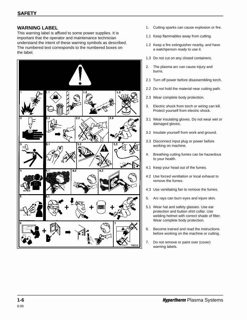
WARNING LABELThis warning label is affixed to some power supplies. It isimportant that the operator and maintenance technicianunderstand the intent of these warning symbols as described.The numbered text corresponds to the numbered boxes onthe label.
1. Cutting sparks can cause explosion or fire.
1.1 Keep flammables away from cutting.
1.2 Keep a fire extinguisher nearby, and havea watchperson ready to use it.
1.3 Do not cut on any closed containers.
2. The plasma arc can cause injury andburns.
2.1 Turn off power before disassembling torch.
2.2 Do not hold the material near cutting path.
2.3 Wear complete body protection.
3. Electric shock from torch or wiring can kill.Protect yourself from electric shock.
3.1 Wear insulating gloves. Do not wear wet ordamaged gloves.
3.2 Insulate yourself from work and ground.
3.3 Disconnect input plug or power beforeworking on machine.
4. Breathing cutting fumes can be hazardousto your health.
4.1 Keep your head out of the fumes.
4.2 Use forced ventilation or local exhaust toremove the fumes.
4.3 Use ventilating fan to remove the fumes.
5. Arc rays can burn eyes and injure skin.
5.1 Wear hat and safety glasses. Use earprotection and button shirt collar. Usewelding helmet with correct shade of filter.Wear complete body protection.
6. Become trained and read the instructionsbefore working on the machine or cutting.
7. Do not remove or paint over (cover)warning labels.
Hypertherm Systèmes plasma 1a-12/12/01
Section 1a
SÉCURITÉ
Dans cette section :
Identifier les consignes de sécurité ...............................................................................................................1a-2Suivre les instructions de sécurité.................................................................................................................1a-2Danger Avertissement Précaution...............................................................................................................1a-2Le coupage peut provoquer un incendie ou une explosion...........................................................................1a-2
Prévention des incendies, Prévention des explosions .........................................................................1a-2Risque d’explosion argon-hydrogène et méthane................................................................................1a-2Détonation de l’hydrogène lors du coupage de l’aluminium.................................................................1a-2
Les chocs électriques peuvent être fatals .....................................................................................................1a-3Prévention des chocs électriques.........................................................................................................1a-3
Le coupage peut produire des vapeurs toxiques ..........................................................................................1a-3L’arc plasma peut provoquer des blessures ou des brûlures........................................................................1a-4
Torches à allumage instantané.............................................................................................................1a-4Les rayons de l’arc peuvent brûler les yeux et la peau.................................................................................1a-4
Protection des yeux, Protection de la peau, Zone de coupage ..........................................................1a-4Mise à la masse et à la terre .........................................................................................................................1a-4
Câble de retour, Table de travail, Alimentation .....................................................................................1a-4Sécurité des bouteilles de gaz comprimé .....................................................................................................1a-5Les bouteilles de gaz comprimé peuvent exploser en cas de dommages....................................................1a-5Le bruit peut provoquer des problèmes auditifs ............................................................................................1a-5Pacemakers et prothèses auditives ..............................................................................................................1a-5Un arc plasma peut endommager les tuyaux gelés ......................................................................................1a-5Étiquette de sécurité .....................................................................................................................................1a-6
SÉCURITÉ
1a-2 Hypertherm Systèmes plasma2/12/01
IDENTIFIER LES CONSIGNES DE SÉCURITÉ
Les symboles indiqués dans cette section sont utilisés pouridentifier les risques éventuels. Si vous trouvez un symbolede sécurité, que ce soit dans ce manuel ou surl’équipement, soyez conscient des risques de blessures etsuivez les instructions correspondantes afin d’éviter cesrisques.
SUIVRE LES INSTRUCTIONS DE SÉCURITÉ
Lire attentivement toutes les consignes de sécurité dans leprésent manuel et sur les étiquettes de sécurité se trouvantsur la machine.
• Les étiquettes de sécurité doivent rester lisibles.Remplacer immédiatement les étiquettes manquantes ouabîmées.
• Apprendre à faire fonctionner la machine et à utilisercorrectement les commandes. Ne laisser personne utiliserla machine sans connaître son fonctionnement.
• Garder la machine en bon état. Des modifications nonautorisées sur la machine peuvent engendrer desproblèmes de sécurité et raccourcir la durée d’utilisationde l’équipement.
DANGER AVERTISSEMENT PRÉCAUTION
Les signaux DANGER ou AVERTISSEMENT sont utilisésavec un symbole de sécurité, DANGER correspondant auxrisques les plus sérieux.
• Les étiquettes de sécurité DANGER et AVERTISSEMENTsont situées sur la machine pour signaler certainsdangers spécifiques.
• Les messages d’AVERTISSEMENT précèdent lesinstructions d’utilisation expliquées dans ce manuel etsignalent les risques de blessures ou de mort au cas oùces instructions ne seraient pas suivies correctement.
• Les messages de PRÉCAUTION précèdent lesinstructions d’utilisation contenues dans ce manuel etsignalent que le matériel risque d’être endommagé si lesinstructions ne sont pas suivies correctement.
Prévention des incendies• Avant de commencer, s’assurer que la zone de coupage
ne présente aucun danger. Conserver un extincteur àproximité.
• Éloigner toute matière inflammable à une distance d’aumoins 10 m du poste de coupage.
• Tremper le métal chaud ou le laisser refroidir avant de le manipuler ou avant de le mettre en contact avec desmatériaux combustibles.
• Ne jamais couper des récipients pouvant contenir desmatières inflammables avant de les avoir vidés etnettoyés correctement.
• Aérer toute atmosphère potentiellement inflammableavant d’utiliser un système plasma.
• Lors de l’utilisation d’oxygène comme gaz plasma, unsystème de ventilation par aspiration est nécessaire.
Prévention des explosions• Ne pas couper en présence de poussière ou de vapeurs.• Ne pas couper de bouteilles, de tuyaux ou autres
récipients fermés et pressurisés.• Ne pas couper de récipients contenant des matières
combustibles.
LE COUPAGE PEUT PROVOQUER UN INCENDIEOU UNE EXPLOSION
AVERTISSEMENTRisque d’explosion
argon-hydrogène et méthane
L’hydrogène et le méthane sont des gaz inflammables etpotentiellement explosifs. Conserver à l’écart de touteflamme les bouteilles et tuyaux contenant des mélanges àbase d’hydrogène ou de méthane. Maintenir toute flammeet étincelle à l’écart de la torche lors de l’utilisation d’unplasma d’argon-hydrogène ou de méthane.
AVERTISSEMENTDétonation de l’hydrogène lors du
coupage de l’aluminium
• Lors du coupage de l’aluminium sous l’eau, ou si l’eautouche la partie inférieure de la pièce d’aluminium, del’hydrogène libre peut s’accumuler sous la pièce à couperet détonner lors du coupage plasma.
• Installer un collecteur d’aération au fond de la table à eauafin d’éliminer les risques de détonation de l’hydrogène.Se référer à l’annexe du manuel pour plus derenseignements sur les collecteurs d’aération.
SÉCURITÉ
Hypertherm Systèmes plasma 1a-32/12/01
Toucher une pièce électrique sous tension peut provoquerun choc électrique fatal ou des brûlures graves.
• La mise en fonctionnement du système plasma ferme uncircuit électrique entre la torche et la pièce à couper. Lapièce à couper et tout autre élément en contact avec cettepièce font partie du circuit électrique.
• Ne jamais toucher le corps de la torche, la pièce à couperou l’eau de la table à eau pendant le fonctionnement dusystème plasma.
Prévention des chocs électriques
Tous les systèmes plasma Hypertherm utilisent des hautestensions pour le coupage (souvent de 200 à 400 V). On doit prendre les précautions suivantes quand on utilise lesystème plasma :• Porter des bottes et des gants isolants et garder le corps
et les vêtements au sec.• Ne pas se tenir, s’asseoir ou se coucher sur une surface
mouillée, ni la toucher quand on utilise le système plasma.• S’isoler de la surface de travail et du sol en utilisant des
tapis isolants secs ou des couvertures assez grandespour éviter tout contact physique avec le travail ou le sol.S’il s’avère nécessaire de travailler dans ou près d’unendroit humide, procéder avec une extrême prudence.
• Installer un sectionneur avec fusibles appropriés, àproximité de la source de courant. Ce dispositif permet àl’opérateur d’arrêter rapidement la source de courant encas d’urgence.
• En cas d’utilisation d’une table à eau, s’assurer que cettedernière est correctement mise à la terre.
LES CHOCS ÉLECTRIQUES PEUVENT ÊTRE FATALS
• Installer et mettre à la terre l’équipement selon lesinstructions du présent manuel et conformément auxcodes électriques locaux et nationaux.
• Inspecter fréquemment le cordon d’alimentation primairepour s’assurer qu’il n’est ni endommagé, ni fendu.Remplacer immédiatement un cordon endommagé. Un câble dénudé peut tuer.
• Inspecter et remplacer les câbles de la torche qui sontusés ou endommagés.
• Ne pas saisir la pièce à couper ni les chutes lors ducoupage. Laisser la pièce à couper en place ou sur latable de travail, le câble de retour connecté lors ducoupage.
• Avant de vérifier, de nettoyer ou de remplacer les piècesde la torche, couper l’alimentation ou débrancher la prisede courant.
• Ne jamais contourner ou court-circuiter les verrouillagesde sécurité.
• Avant d’enlever le capot du système ou de la source decourant, couper l’alimentation électrique. Attendre ensuite5 minutes pour que les condensateurs se déchargent.
• Ne jamais faire fonctionner le système plasma sans queles capots de la source de courant ne soient en place.Les raccords exposés de la source de courant sontextrêmement dangereux.
• Lors de l’installation des connexions, attacher tout d’abordla prise de terre appropriée.
• Chaque système plasma Hypertherm est conçu pour êtreutilisé uniquement avec des torches Hyperthermspécifiques. Ne pas utiliser des torches inappropriées quipourraient surchauffer et présenter des risques pour lasécurité.
Le coupage peut produire des vapeurs et des gaz toxiquesqui réduisent le niveau d’oxygène dans l’air et peuventprovoquer des blessures, voire la mort.• Conserver le poste de coupage bien aéré ou utiliser un
masque respiratoire homologué.• Ne pas procéder au coupage près d’endroits où
s’effectuent le dégraissage, le nettoyage ou la vapori-sation. Certains solvants chlorés se décomposent sousl’effet des rayons ultraviolets et forment du phosgène.
• Ne pas couper des métaux peints ou contenant desmatières toxiques comme le zinc (galvanisé), le plomb, lecadmium ou le béryllium, à moins que la zone de travail
LE COUPAGE PEUT PRODUIRE DES VAPEURS TOXIQUES
soit très bien ventilée et que l’opérateur porte un masquerespiratoire. Les revêtements et métaux contenant cesmatières peuvent produire des vapeurs toxiques lors ducoupage.
• Ne jamais couper de récipients pouvant contenir desmatières inflammables avant de les avoir vidés etnettoyés correctement.
• Quand on utilise ce produit pour le soudage ou lecoupage, il dégage des fumées et des gaz quicontiennent des produits chimiques qui, selon l’État deCalifornie, provoquent des anomalies congénitales et,dans certains cas, le cancer.
SÉCURITÉ
1a-4 Hypertherm Systèmes plasma2/12/01
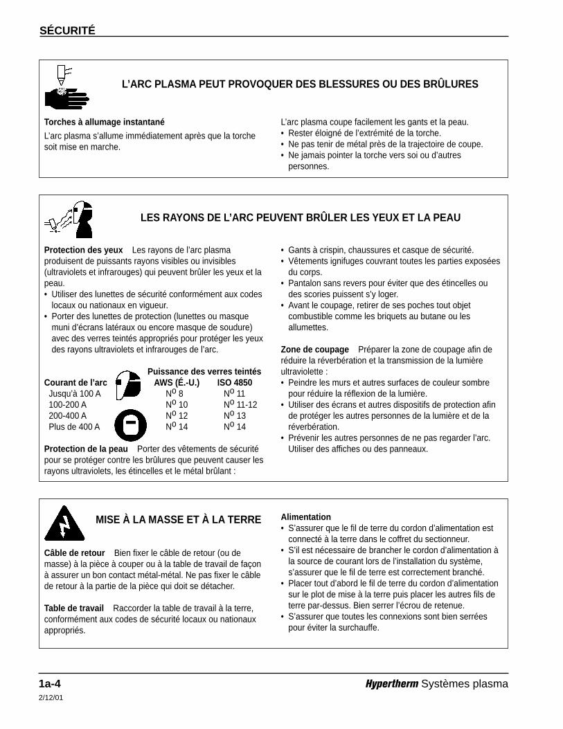
Torches à allumage instantané
L’arc plasma s’allume immédiatement après que la torchesoit mise en marche.
L’ARC PLASMA PEUT PROVOQUER DES BLESSURES OU DES BRÛLURES
L’arc plasma coupe facilement les gants et la peau.• Rester éloigné de l’extrémité de la torche.• Ne pas tenir de métal près de la trajectoire de coupe.• Ne jamais pointer la torche vers soi ou d’autres
personnes.
Protection des yeux Les rayons de l’arc plasmaproduisent de puissants rayons visibles ou invisibles(ultraviolets et infrarouges) qui peuvent brûler les yeux et lapeau.• Utiliser des lunettes de sécurité conformément aux codes
locaux ou nationaux en vigueur.• Porter des lunettes de protection (lunettes ou masque
muni d’écrans latéraux ou encore masque de soudure)avec des verres teintés appropriés pour protéger les yeuxdes rayons ultraviolets et infrarouges de l’arc.
Puissance des verres teintésCourant de l’arc AWS (É.-U.) ISO 4850Jusqu’à 100 A No 8 No 11100-200 A No 10 No 11-12200-400 A No 12 No 13Plus de 400 A No 14 No 14
Protection de la peau Porter des vêtements de sécuritépour se protéger contre les brûlures que peuvent causer lesrayons ultraviolets, les étincelles et le métal brûlant :
LES RAYONS DE L’ARC PEUVENT BRÛLER LES YEUX ET LA PEAU
• Gants à crispin, chaussures et casque de sécurité.• Vêtements ignifuges couvrant toutes les parties exposées
du corps.• Pantalon sans revers pour éviter que des étincelles ou
des scories puissent s’y loger.• Avant le coupage, retirer de ses poches tout objet
combustible comme les briquets au butane ou lesallumettes.
Zone de coupage Préparer la zone de coupage afin deréduire la réverbération et la transmission de la lumièreultraviolette :• Peindre les murs et autres surfaces de couleur sombre
pour réduire la réflexion de la lumière.• Utiliser des écrans et autres dispositifs de protection afin
de protéger les autres personnes de la lumière et de laréverbération.
• Prévenir les autres personnes de ne pas regarder l’arc.Utiliser des affiches ou des panneaux.
Câble de retour Bien fixer le câble de retour (ou demasse) à la pièce à couper ou à la table de travail de façonà assurer un bon contact métal-métal. Ne pas fixer le câblede retour à la partie de la pièce qui doit se détacher.
Table de travail Raccorder la table de travail à la terre,conformément aux codes de sécurité locaux ou nationauxappropriés.
MISE À LA MASSE ET À LA TERRE Alimentation• S’assurer que le fil de terre du cordon d’alimentation est
connecté à la terre dans le coffret du sectionneur.• S’il est nécessaire de brancher le cordon d’alimentation à
la source de courant lors de l’installation du système,s’assurer que le fil de terre est correctement branché.
• Placer tout d’abord le fil de terre du cordon d’alimentationsur le plot de mise à la terre puis placer les autres fils deterre par-dessus. Bien serrer l’écrou de retenue.
• S’assurer que toutes les connexions sont bien serréespour éviter la surchauffe.
SÉCURITÉ
Hypertherm Systèmes plasma 1a-52/12/01
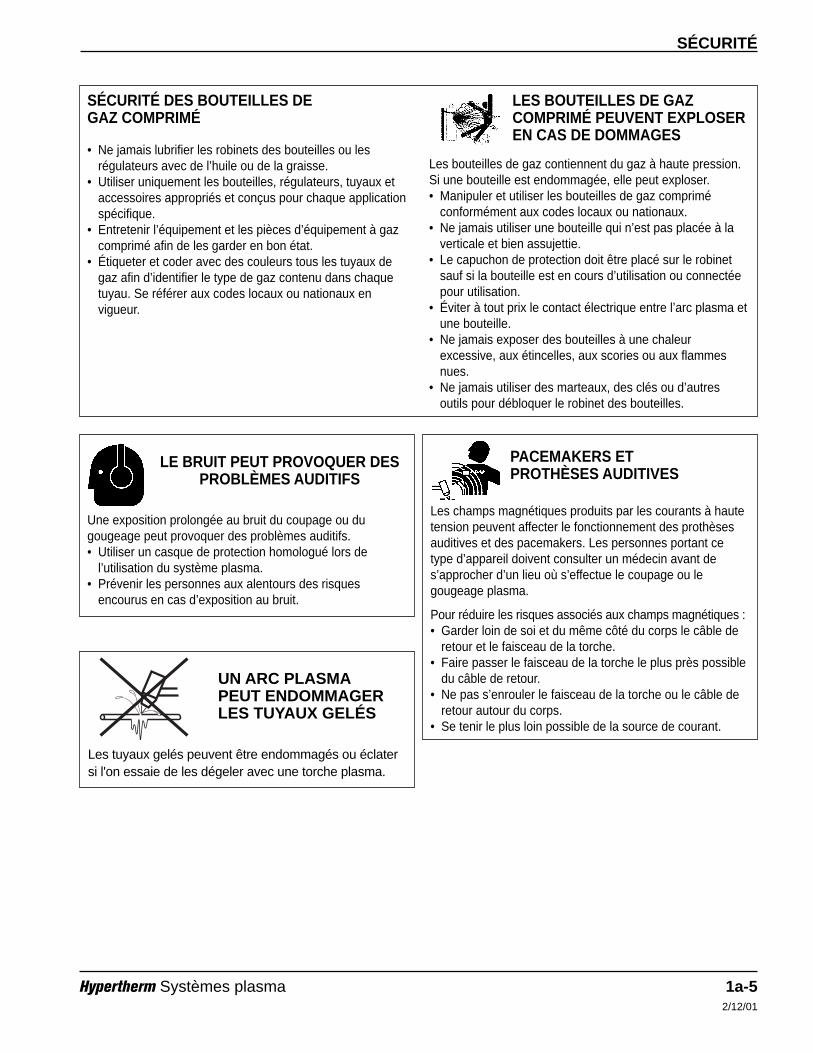
• Ne jamais lubrifier les robinets des bouteilles ou lesrégulateurs avec de l’huile ou de la graisse.
• Utiliser uniquement les bouteilles, régulateurs, tuyaux etaccessoires appropriés et conçus pour chaque applicationspécifique.
• Entretenir l’équipement et les pièces d’équipement à gazcomprimé afin de les garder en bon état.
• Étiqueter et coder avec des couleurs tous les tuyaux degaz afin d’identifier le type de gaz contenu dans chaquetuyau. Se référer aux codes locaux ou nationaux envigueur.
LES BOUTEILLES DE GAZCOMPRIMÉ PEUVENT EXPLOSEREN CAS DE DOMMAGES
SÉCURITÉ DES BOUTEILLES DE GAZ COMPRIMÉ
Les bouteilles de gaz contiennent du gaz à haute pression.Si une bouteille est endommagée, elle peut exploser.• Manipuler et utiliser les bouteilles de gaz comprimé
conformément aux codes locaux ou nationaux.• Ne jamais utiliser une bouteille qui n’est pas placée à la
verticale et bien assujettie.• Le capuchon de protection doit être placé sur le robinet
sauf si la bouteille est en cours d’utilisation ou connectéepour utilisation.
• Éviter à tout prix le contact électrique entre l’arc plasma etune bouteille.
• Ne jamais exposer des bouteilles à une chaleurexcessive, aux étincelles, aux scories ou aux flammesnues.
• Ne jamais utiliser des marteaux, des clés ou d’autresoutils pour débloquer le robinet des bouteilles.
Une exposition prolongée au bruit du coupage ou dugougeage peut provoquer des problèmes auditifs.• Utiliser un casque de protection homologué lors de
l’utilisation du système plasma.• Prévenir les personnes aux alentours des risques
encourus en cas d’exposition au bruit.
LE BRUIT PEUT PROVOQUER DESPROBLÈMES AUDITIFS
Les champs magnétiques produits par les courants à hautetension peuvent affecter le fonctionnement des prothèsesauditives et des pacemakers. Les personnes portant cetype d’appareil doivent consulter un médecin avant des’approcher d’un lieu où s’effectue le coupage ou legougeage plasma.
Pour réduire les risques associés aux champs magnétiques :• Garder loin de soi et du même côté du corps le câble de
retour et le faisceau de la torche.• Faire passer le faisceau de la torche le plus près possible
du câble de retour.• Ne pas s’enrouler le faisceau de la torche ou le câble de
retour autour du corps.• Se tenir le plus loin possible de la source de courant.
PACEMAKERS ET PROTHÈSES AUDITIVES
Les tuyaux gelés peuvent être endommagés ou éclatersi l'on essaie de les dégeler avec une torche plasma.
UN ARC PLASMAPEUT ENDOMMAGERLES TUYAUX GELÉS
SÉCURITÉ
1a-6 Hypertherm Systèmes plasma2/12/01
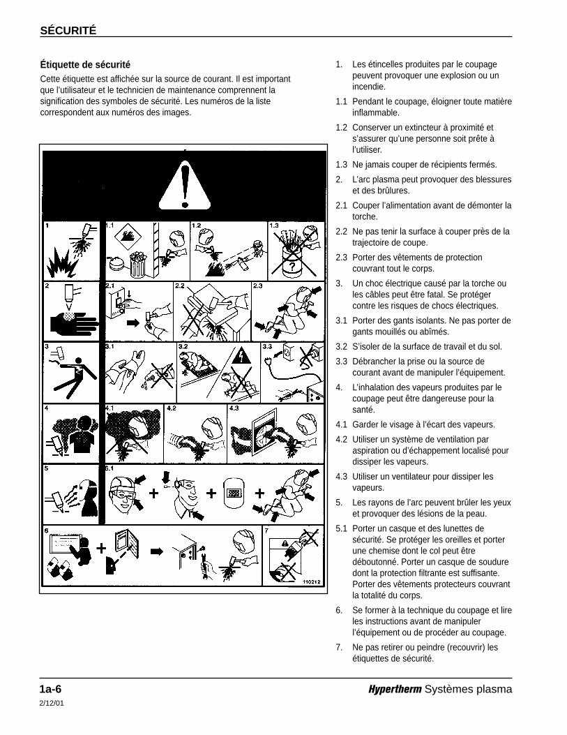
Étiquette de sécuritéCette étiquette est affichée sur la source de courant. Il est importantque l’utilisateur et le technicien de maintenance comprennent lasignification des symboles de sécurité. Les numéros de la listecorrespondent aux numéros des images.
1. Les étincelles produites par le coupagepeuvent provoquer une explosion ou unincendie.
1.1 Pendant le coupage, éloigner toute matièreinflammable.
1.2 Conserver un extincteur à proximité ets’assurer qu’une personne soit prête àl’utiliser.
1.3 Ne jamais couper de récipients fermés.
2. L’arc plasma peut provoquer des blessureset des brûlures.
2.1 Couper l’alimentation avant de démonter latorche.
2.2 Ne pas tenir la surface à couper près de latrajectoire de coupe.
2.3 Porter des vêtements de protectioncouvrant tout le corps.
3. Un choc électrique causé par la torche oules câbles peut être fatal. Se protégercontre les risques de chocs électriques.
3.1 Porter des gants isolants. Ne pas porter degants mouillés ou abîmés.
3.2 S’isoler de la surface de travail et du sol.
3.3 Débrancher la prise ou la source decourant avant de manipuler l’équipement.
4. L’inhalation des vapeurs produites par lecoupage peut être dangereuse pour lasanté.
4.1 Garder le visage à l’écart des vapeurs.
4.2 Utiliser un système de ventilation paraspiration ou d’échappement localisé pourdissiper les vapeurs.
4.3 Utiliser un ventilateur pour dissiper lesvapeurs.
5. Les rayons de l’arc peuvent brûler les yeuxet provoquer des lésions de la peau.
5.1 Porter un casque et des lunettes desécurité. Se protéger les oreilles et porterune chemise dont le col peut êtredéboutonné. Porter un casque de souduredont la protection filtrante est suffisante.Porter des vêtements protecteurs couvrantla totalité du corps.
6. Se former à la technique du coupage et lireles instructions avant de manipulerl’équipement ou de procéder au coupage.
7. Ne pas retirer ou peindre (recouvrir) lesétiquettes de sécurité.
H401 & H601 Instruction Manual 2-14
Section 2
SPECIFICATIONS
In this section:
Introduction ...............................................................................................................................................................2-2H401 or H601 with HT4001..............................................................................................................................2-2H401 or H601 with PAC500 .............................................................................................................................2-2
Specifications............................................................................................................................................................2-2H401 Power Supply .........................................................................................................................................2-2H601 Power Supply .........................................................................................................................................2-3H401 & H601 Dimensions................................................................................................................................2-4H401 & H601 Duty Cycle Curves.....................................................................................................................2-4H401 & H601 Volt-Amp Curves .......................................................................................................................2-4
SPECIFICATIONS
2-2 H401 & H601 Instruction Manual5
Introduction
H401 or H601 with HT4001
Refer to HT4001 instruction manuals 802470 for 200V HT4001 power supplies; or 802000 for all other voltageHT4001 power supplies.
H401 or H601 with PAC500
The H401 provides power to cut stainless steel and non-ferrous metals up to 1-inch thick and mild steel up to 1/2-inch thick. The H601 provides power to cut stainless and non-ferrous metals up to 2-inches thick and mild steelup to 1-inch thick.
One H401 and one H601, or two H601s in parallel can provide the full power capacity of the PAC500 torch and cutat 1000 amps. At 1000 amps, the PAC500 torch can cut stainless steel to 5-inches thick, and aluminum and othernon-ferrous metals to 6-inches thick.
Specifications
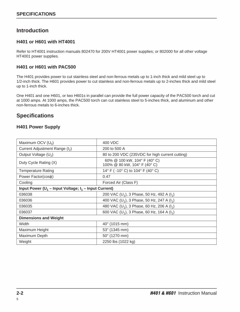
H401 Power Supply
Maximum OCV (U0) 400 VDC
Current Adjustment Range (I2) 200 to 500 A
Output Voltage (U2) 80 to 200 VDC (235VDC for high current cutting)
60% @ 100 kW, 104° F (40° C)Duty Cycle Rating (X) 100% @ 80 kW, 104° F (40° C)
Temperature Rating 14° F ( -10° C) to 104° F (40° C)
Power Factor(cosϕ) 0.47
Cooling Forced Air (Class F)
Input Power (U1 – Input Voltage; I1 – Input Current)
036038 200 VAC (U1), 3 Phase, 50 Hz, 492 A (I1)
036036 400 VAC (U1), 3 Phase, 50 Hz, 247 A (I1)
036035 480 VAC (U1), 3 Phase, 60 Hz, 206 A (I1)
036037 600 VAC (U1), 3 Phase, 60 Hz, 164 A (I1)
Dimensions and Weight
Width 40" (1015 mm)
Maximum Height 53" (1345 mm)
Maximum Depth 50" (1270 mm)
Weight 2250 lbs (1022 kg)
SPECIFICATIONS
H401 & H601 Instruction Manual 2-35
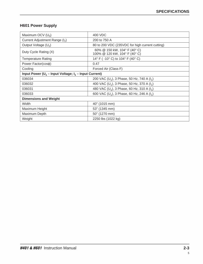
H601 Power Supply
Maximum OCV (U0) 400 VDC
Current Adjustment Range (I2) 200 to 750 A
Output Voltage (U2) 80 to 200 VDC (235VDC for high current cutting)
60% @ 150 kW, 104° F (40° C)Duty Cycle Rating (X) 100% @ 120 kW, 104° F (40° C)
Temperature Rating 14° F ( -10° C) to 104° F (40° C)
Power Factor(cosϕ) 0.47
Cooling Forced Air (Class F)
Input Power (U1 – Input Voltage; I1 – Input Current)
036034 200 VAC (U1), 3 Phase, 50 Hz, 740 A (I1)
036032 400 VAC (U1), 3 Phase, 50 Hz, 370 A (I1)
036031 480 VAC (U1), 3 Phase, 60 Hz, 310 A (I1)
036033 600 VAC (U1), 3 Phase, 60 Hz, 246 A (I1)
Dimensions and Weight
Width 40" (1015 mm)
Maximum Height 53" (1345 mm)
Maximum Depth 50" (1270 mm)
Weight 2250 lbs (1022 kg)
SPECIFICATIONS
2-4 H401 & H601 Instruction Manual4
H401 % Duty Cycle
H401 Volt-ampere Curves
H601 % Duty Cycle
H601 Volt-ampere Curves
Arc
Cu
rren
t
Arc
Cu
rren
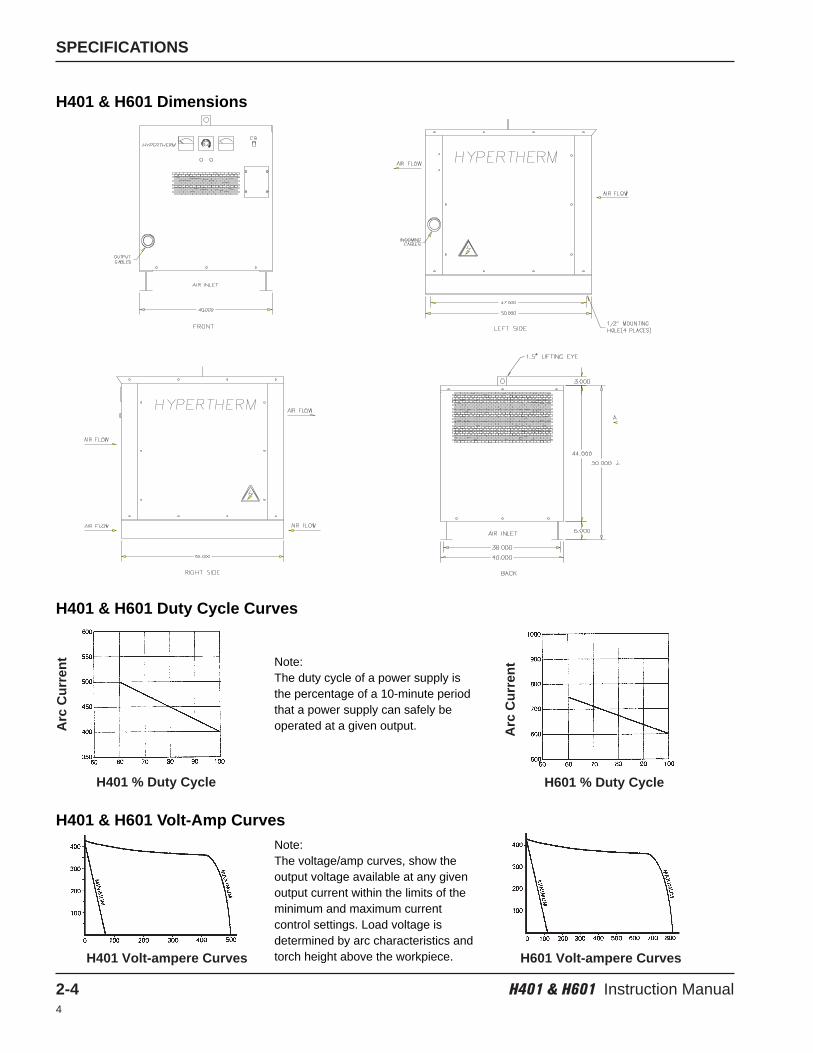
tNote: The duty cycle of a power supply isthe percentage of a 10-minute periodthat a power supply can safely beoperated at a given output.
Note:The voltage/amp curves, show theoutput voltage available at any givenoutput current within the limits of theminimum and maximum currentcontrol settings. Load voltage isdetermined by arc characteristics andtorch height above the workpiece.
H401 & H601 Dimensions
H401 & H601 Duty Cycle Curves
H401 & H601 Volt-Amp Curves
H401 & H601 Instruction Manual 3-14
Section 3
INSTALLATION
In this section:
Installation Requirements .........................................................................................................................................3-2Positioning the Power Supply ..........................................................................................................................3-2
Grounding Requirements..........................................................................................................................................3-3Noise Levels .............................................................................................................................................................3-3Power Requirements ................................................................................................................................................3-3
Power Cables and Fuses .................................................................................................................................3-3Connecting the Primary Power .................................................................................................................................3-4
Line Disconnect Switch ....................................................................................................................................3-5Secondary Connections............................................................................................................................................3-6
PAC500 with H401 or H601 .............................................................................................................................3-6PAC500 Control Cable with H401 or H601 ......................................................................................................3-7Parallel Power Supply Connections .................................................................................................................3-8PAC500 Water Muffler and Water Supply System Connections......................................................................3-9Current Control Potentiometer Connections ..................................................................................................3-10HT4001 with H401 or H601............................................................................................................................3-10
INSTALLATION
3-2 H401 & H601 Instruction Manual5
Installation Requirements
Direct any technical questions to the nearest Hypertherm Technical Service Department listed in the front of thismanual, or your authorized Hypertherm distributor.
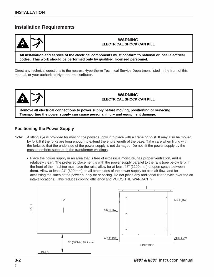
Positioning the Power Supply
Note: A lifting eye is provided for moving the power supply into place with a crane or hoist. It may also be movedby forklift if the forks are long enough to extend the entire length of the base. Take care when lifting withthe forks so that the underside of the power supply is not damaged. Do not lift the power supply by thecross members supporting the transformer windings.
• Place the power supply in an area that is free of excessive moisture, has proper ventilation, and isrelatively clean. The preferred placement is with the power supply parallel to the rails (see below left). Ifthe front of the machine must face the rails, allow for at least 48" (1200 mm) of open space betweenthem. Allow at least 24" (600 mm) on all other sides of the power supply for free air flow, and foraccessing the sides of the power supply for servicing. Do not place any additional filter device over the airintake locations. This reduces cooling efficiency and VOIDS THE WARRANTY.
WARNINGELECTRICAL SHOCK CAN KILL
All installation and service of the electrical components must conform to national or local electricalcodes. This work should be performed only by qualified, licensed personnel.
WARNINGELECTRICAL SHOCK CAN KILL
Remove all electrical connections to power supply before moving, positioning or servicing.Transporting the power supply can cause personal injury and equipment damage.
RIGHT SIDE
AIR FLOW
AIR FLOW
AIR FLOW
AIR FLOW
FR
ON
T
RAILS
24" (600MM) Minimum
TOP

INSTALLATION
H401 & H601 Instruction Manual 3-35
Grounding Requirements
Proper grounding is essential for personal safety and to prevent emission of high-frequency interference. See theAppendix section for system grounding requirements.
Connect the worktable to a high-quality earth ground from within 20 feet (6 m) of the table. A suitable groundconsists of a solid copper rod of at least 3/4-inch (19 mm) diameter driven to a depth of at least 8 feet (2.5 m) intothe earth below the permanent moisture level. Ensure that all grounding connections are tight to avoid excessiveheating. See also Grounding in the Safety section. For additional information consult national or local electriccodes.
Noise Levels
Acceptable noise levels as defined by national or local codes may be exceeded by this plasma system. Alwayswear proper ear protection when cutting or gouging. See also Noise Protection in the Safety section of this manual.
Power Requirements
All switches, slow-blow fuses and power cables are customer supplied and must be chosen as outlined byapplicable national or local electrical codes. Installation must be performed by a licensed electrician. Ifslow-blow fuses are not available or not allowed per applicable codes, use a motor-start circuit breaker.
Power Cables and Fuses
Wire sizes vary based on the distance of the receptacle from the main box. Use a 4-conductor Type SO inputpower cable with a conductor temperature rating of 140°F (60°C). The proper strain relief should be used toprevent damage to input power cables. The cable should be installed only by a licensed electrician. Always connectthe power cable to the power supply before connecting to the line disconnect switch.
Refer to the data tag on the rear of the power supply to verify the correct line voltage requirements and todetermine the continuous current draw for the unit.
Fuse sizes should never exceed the capacity of the power line conductors. Use FRS type fuses.
INSTALLATION
3-4 H401 & H601 Instruction Manual5
Connecting the Primary Power
Power Cable to H401 or H601 Power Supply
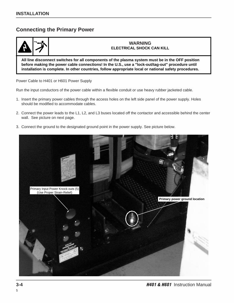
Run the input conductors of the power cable within a flexible conduit or use heavy rubber jacketed cable.
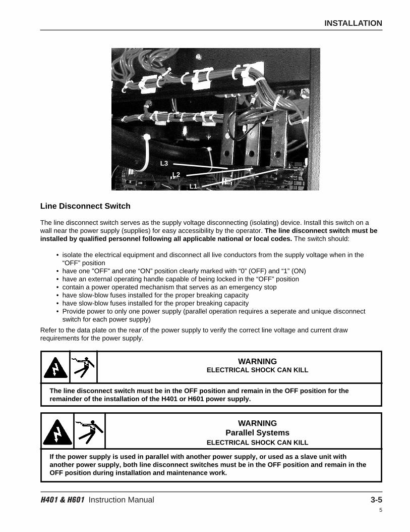
1. Insert the primary power cables through the access holes on the left side panel of the power supply. Holesshould be modified to accommodate cables.
2. Connect the power leads to the L1, L2, and L3 buses located off the contactor and accessible behind the centerwall. See picture on next page.
3. Connect the ground to the designated ground point in the power supply. See picture below.
WARNINGELECTRICAL SHOCK CAN KILL
All line disconnect switches for all components of the plasma system must be in the OFF positionbefore making the power cable connections! In the U.S., use a "lock-out/tag-out" procedure untilinstallation is complete. In other countries, follow appropriate local or national safety procedures.
Primary Input Power Knock-outs (5)(Use Proper Strain-Relief)
Primary power ground location
INSTALLATION
H401 & H601 Instruction Manual 3-55
L1
Line Disconnect Switch
The line disconnect switch serves as the supply voltage disconnecting (isolating) device. Install this switch on awall near the power supply (supplies) for easy accessibility by the operator. The line disconnect switch must beinstalled by qualified personnel following all applicable national or local codes. The switch should:
• isolate the electrical equipment and disconnect all live conductors from the supply voltage when in the“OFF” position
• have one "OFF" and one “ON” position clearly marked with “0” (OFF) and “1” (ON)• have an external operating handle capable of being locked in the “OFF” position• contain a power operated mechanism that serves as an emergency stop• have slow-blow fuses installed for the proper breaking capacity• have slow-blow fuses installed for the proper breaking capacity• Provide power to only one power supply (parallel operation requires a seperate and unique disconnect
switch for each power supply)
Refer to the data plate on the rear of the power supply to verify the correct line voltage and current drawrequirements for the power supply.
L3
L2
WARNINGELECTRICAL SHOCK CAN KILL
The line disconnect switch must be in the OFF position and remain in the OFF position for theremainder of the installation of the H401 or H601 power supply.
WARNINGParallel Systems
ELECTRICAL SHOCK CAN KILL
If the power supply is used in parallel with another power supply, or used as a slave unit withanother power supply, both line disconnect switches must be in the OFF position and remain in theOFF position during installation and maintenance work.
INSTALLATION
3-6 H401 & H601 Instruction Manual5
PAC500 with H401 or H601
1. Connect the negative cables to the electrode at the cathode block in the plumbing compartment of the PAC500plasma console. See instruction manual 800370 Figure 7.
2. Connect the positive cables to the star ground on the water table.
Secondary Connections
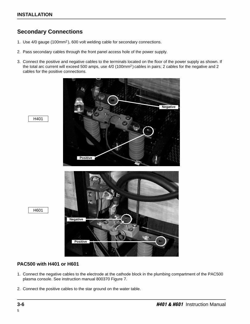
1. Use 4/0 gauge (100mm2 ), 600 volt welding cable for secondary connections.
2. Pass secondary cables through the front panel access hole of the power supply.
3. Connect the positive and negative cables to the terminals located on the floor of the power supply as shown. Ifthe total arc current will exceed 500 amps, use 4/0 (100mm2 ) cables in pairs; 2 cables for the negative and 2cables for the positive connections.
H401
Positive
Negative
Negative
Positive
H601
INSTALLATION
H401 & H601 Instruction Manual 3-75
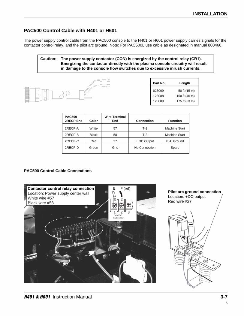
PAC500 Control Cable with H401 or H601
The power supply control cable from the PAC500 console to the H401 or H601 power supply carries signals for thecontactor control relay, and the pilot arc ground. Note: For PAC500L use cable as designated in manual 800460.
Contactor control relay connectionLocation: Power supply center wallWhite wire #57Black wire #58
Pilot arc ground connectionLocation: +DC outputRed wire #27
Caution: The power supply contactor (CON) is energized by the control relay (CR1).Energizing the contactor directly with the plasma console circuitry will resultin damage to the console flow switches due to excessive inrush currents.
PAC500 Control Cable Connections
57
58
Machine Start
1 2 3
E F (ref) 27
Part No. Length
028009 50 ft (15 m)
128088 150 ft (46 m)
128089 175 ft (53 m)
PAC500 Wire Terminal2RECP End Color End Connection Function
2RECP-A White 57 T-1 Machine Start
2RECP-B Black 58 T-2 Machine Start
2RECP-C Red 27 + DC Output P.A. Ground
2RECP-D Green Gnd No Connection Spare
INSTALLATION
3-8 H401 & H601 Instruction Manual5
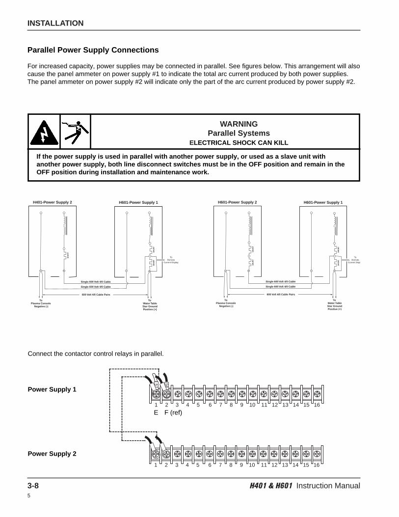
WARNINGParallel Systems
ELECTRICAL SHOCK CAN KILL
If the power supply is used in parallel with another power supply, or used as a slave unit withanother power supply, both line disconnect switches must be in the OFF position and remain in theOFF position during installation and maintenance work.
Parallel Power Supply Connections
For increased capacity, power supplies may be connected in parallel. See figures below. This arrangement will alsocause the panel ammeter on power supply #1 to indicate the total arc current produced by both power supplies.The panel ammeter on power supply #2 will indicate only the part of the arc current produced by power supply #2.
Power Supply 1
Connect the contactor control relays in parallel.
Power Supply 2
57
58
1 2 3 4 5 6 7 8 9 10 11 12 13 14 15 16
1 2 3 4 5 6 7 8 9 10 11 12 13 14 15 16
H401-Power Supply 2 H601-Power Supply 1
Single 600 Volt 4/0 Cable
Single 600 Volt 4/0 Cable
600 Volt 4/0 Cable Pairs
To Plasma Console
Negative (-)
To Water TableStar GroundPositive (+)
SH
UN
T SH
UN
TS
HU
NT
ToRemote
Current Display
H601-Power Supply 2 H601-Power Supply 1
Single 600 Volt 4/0 Cable
Single 600 Volt 4/0 Cable
600 Volt 4/0 Cable Pairs
To Plasma Console
Negative (-)
To Water TableStar GroundPositive (+)
SH
UN
T
ToRemote
Current Displ
SH
UN
T
SH
UN
TS
HU
NT
E F (ref)
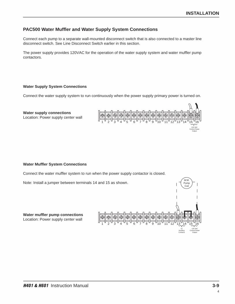
INSTALLATION
H401 & H601 Instruction Manual 3-94
PAC500 Water Muffler and Water Supply System Connections
Connect each pump to a separate wall-mounted disconnect switch that is also connected to a master linedisconnect switch. See Line Disconnect Switch earlier in this section.
The power supply provides 120VAC for the operation of the water supply system and water muffler pumpcontactors.
Water Supply System Connections
Connect the water supply system to run continuously when the power supply primary power is turned on.
Water supply connectionsLocation: Power supply center wall
Water Muffler System Connections
Connect the water muffler system to run when the power supply contactor is closed.
Note: Install a jumper between terminals 14 and 15 as shown.
Water muffler pump connectionsLocation: Power supply center wall
120 VACControl Power
Output
1 2 3 4 5 6 7 8 9 10 11 12 13 14 15 16
W.M.PumpCoil
1CAuxiliaryContacts
120 VACControl Power
Output
1 2 3 4 5 6 7 8 9 10 11 12 13 14 15 16
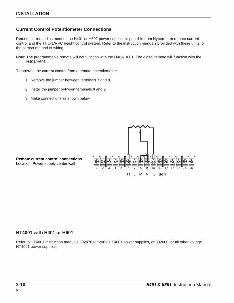
INSTALLATION
3-10 H401 & H601 Instruction Manual5
Current Control Potentiometer Connections
Remote current adjustment of the H401 or H601 power supplies is possible from Hypertherm remote currentcontrol and the THC-1/RVC height control system. Refer to the instruction manuals provided with these units forthe correct method of wiring.
Note: The programmable remote will not function with the H401/H601. The digital remote will function with theH401/H601.
To operate the current control from a remote potentiometer:
1. Remove the jumper between terminals 7 and 8.
2. Install the jumper between terminals 8 and 9.
3. Make connections as shown below.
HT4001 with H401 or H601
Refer to HT4001 instruction manuals 802470 for 200V HT4001 power supplies, or 802000 for all other voltageHT4001 power supplies.
1 2 3 4 5 6 7 8 9 10 11 12 13 14 15 16
Remote current control connectionsLocation: Power supply center wall
H J M N G (ref)
H401 & H601 Instruction Manual 4-15
Section 4
OPERATION
In this section:
Controls and Indicators.............................................................................................................................................4-2Operation ..................................................................................................................................................................4-3
H401 or H601 with HT4001..............................................................................................................................4-3H401 or H601 with PAC500 .............................................................................................................................4-3Output Current for Power Supply Dial Settings................................................................................................4-4
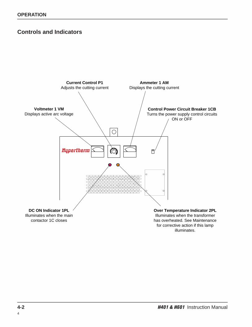
OPERATION
4-2 H401 & H601 Instruction Manual4
Controls and Indicators
Voltmeter 1 VMDisplays active arc voltage
Current Control P1Adjusts the cutting current
Ammeter 1 AMDisplays the cutting current
Control Power Circuit Breaker 1CBTurns the power supply control circuits
ON or OFF
DC ON Indicator 1PLIlluminates when the main
contactor 1C closes
Over Temperature Indicator 2PLIlluminates when the transformer
has overheated. See Maintenancefor corrective action if this lamp
illuminates.
OPERATION
H401 & H601 Instruction Manual 4-34
Operation
H401 or H601 with HT4001
Refer to HT4001 instruction manual 802470 for 200V HT4001 power supplies or 802000 for all other voltageHT4001 power supplies.
H401 or H601 with PAC500
1. Turn the line disconnect switch on. When the primary power is applied, the power supply cooling fan(s) and thewater supply system will turn on immediately. The DC ON indicator will be extinguished and the power supplyvoltmeter will read zero volts.
2. Find the correct current setting from the operating data charts in the PAC500 or PAC500L instruction manuals.
3. Determine the proper power supply dial setting from Figure 4-1. After an arc is established, the setting may bereadjusted to the exact current desired.
4. The start sequence of the plasma arc control in "RUN" mode will close the power supply contactor.See the PAC500 instruction manual 800370 or PAC500L instruction manual 800460 to operate the PAC500system.
When the power supply contactor closes, the red DC ON indicator on the front of the power supply (1PL) willilluminate and the voltmeter will read 400V. After arc ignition, the voltage will drop to 120 – 220 volts, depending onthe operating conditions selected.
Caution: When primary power is applied to the power supply, the water supply system,if connected, will be energized. Always verify that the water supply line is opento avoid damage to the pump.
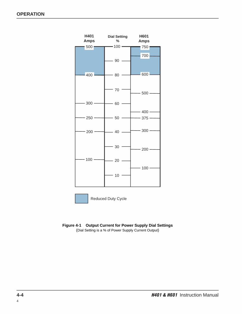
OPERATION
4-4 H401 & H601 Instruction Manual4
Figure 4-1 Output Current for Power Supply Dial Settings(Dial Setting is a % of Power Supply Current Output)
10
20
30
40
50
60
70
80
90
100500
400
300
250
200
100
750
700
600
500
400
375
300
200
100
H401Amps
H601Amps
Dial Setting%
Reduced Duty Cycle
H401 & H601 Instruction Manual 5-14
Section 5
MAINTENANCE AND TROUBLESHOOTING
In this section:
Routine Maintenance................................................................................................................................................5-2Power Supply Circuit Description .............................................................................................................................5-2Troubleshooting ........................................................................................................................................................5-3
MAINTENANCE AND TROUBLESHOOTING
5-2 H401 & H601 Instruction Manual4
Routine Maintenance
Clean, service and inspect the H401 and H601 power supplies at 6-month intervals.
Power Supply Circuit Description
The H401 and H601 power supplies are 3-phase transformer-rectifier type, D.C. power sources using SCRs in afull-wave bridge rectifier circuit. Low rms ripple current is achieved through use of 6 SCRs into an inductor. Filtersare provided to protect the SCRs from high-voltage transients and high-frequency currents from the plasma arcignition circuit. A thermostat protects transformer windings from overload and overheated conditions. Thethermostat resets automatically when the transformers return to safe operating temperatures. Circuit boards controlthe SCRs. The current can be adjusted from the front panel mounted potentiometer or by a remote potentiometer.
• Remove side panels and blow out any dust with a low pressure dry air line.• Clean air passages and cooling fans.• Check for loose wiring and components. Make repairs as necessary.• Lubricate the fan motor(s) every 2 years with SAE 20 weight motor oil.
WARNINGELECTRICAL SHOCK CAN KILL
Shut off all power supplies at their primary disconnect switches. In the U.S., use a “lock-out/tag-out”procedure. In other countries, follow appropriate local or national safety procedures. Shut off allplasma control circuits to prevent control power from entering the power supply. Verify with avoltmeter that no power is present on the power supply primary and control circuit terminals (L1, L2, L3, 1T-1 and 1T-2).
WARNINGParallel Systems
ELECTRICAL SHOCK CAN KILL
If the power supply is used in parallel with another power supply, or used as a slave unit withanother power supply, both line disconnect switches must be in the OFF position and remain in theOFF position during installation and maintenance work.

MAINTENANCE AND TROUBLESHOOTING
H401 & H601 Instruction Manual 5-35
Troubleshooting
Correct malfunctions of the solid-state control circuits by replacing the printed circuit boards.
Current control potentiometer not functioning:
• Jumper is positioned incorrectly. To adjust the current from the front panel potentiometer, place the jumperbetween terminals 7 and 8. A remote potentiometer requires a jumper between terminals 8 and 9.
DC ON indicator (1PL) is illuminated, but there is no voltage:
• Contactor has failed.
DC ON indicator (1PL) is extinguished during the plasma start sequence:
• PAC500 plasma console is in “TEST” mode.
• DC ON lamp is burned out. If output voltage is indicated on the front panel voltmeter, the lamp is probablyburned out.
• Control relay CR1 has failed.
• There is an interface failure. Check the wiring to the PAC500 plasma console and console flow switches.
• The thermal switch is open. If the power supply has been operating above the rated output, the situation willbe corrected when the main transformer cools down.
Over-temperature indicator (2PL) is illuminated.
• A transformer or inductor thermal switch is open. If the power supply has been operating above the ratedoutput, allow the main transformer to cool down by letting the fans run for 5 minutes or longer beforeattempting to cut again.
• Thermal switch failure. Thermal switches are normally closed and open when there is an over temperaturecondition. Check switches and associated wiring.
Open circuit voltage present, but the arc does not start:
• Surge injection circuit has failed. Check resistor R1 and capacitors C13A and C13B. These componentsare located across the power supply output. See the Parts List section to locate components.
• PAC500 plasma console high frequency generator or pilot arc circuits have failed.
Low output current and/or low open circuit voltage:
• A fuse is open in the 3-phase primary voltage supply.
• A transformer winding is open.
• Line voltage is low.
H401 & H601 Instruction Manual 6-15
Section 6
PARTS LIST
In this section:
Front Panel Outside..................................................................................................................................................6-2SCR and Shunt Detail...............................................................................................................................................6-3Transformer and Inductor ........................................................................................................................................6-4Temperature Switches..............................................................................................................................................6-5Upper Inside .............................................................................................................................................................6-6Fans..........................................................................................................................................................................6-7PCB Assemblies .......................................................................................................................................................6-8
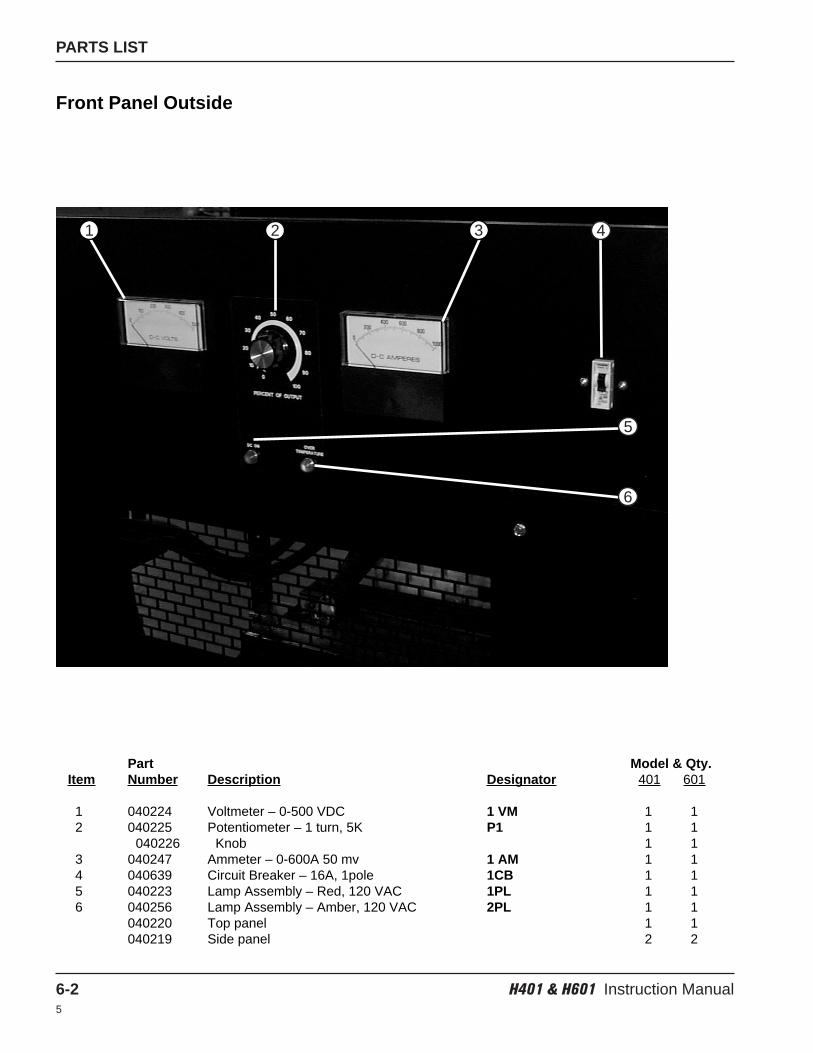
PARTS LIST
6-2 H401 & H601 Instruction Manual5
Front Panel Outside
Part Model & Qty.Item Number Description Designator 401 601
1 040224 Voltmeter – 0-500 VDC 1 VM 1 12 040225 Potentiometer – 1 turn, 5K P1 1 1
040226 Knob 1 13 040247 Ammeter – 0-600A 50 mv 1 AM 1 14 040639 Circuit Breaker – 16A, 1pole 1CB 1 15 040223 Lamp Assembly – Red, 120 VAC 1PL 1 16 040256 Lamp Assembly – Amber, 120 VAC 2PL 1 1
040220 Top panel 1 1040219 Side panel 2 2
1 3 4
5
2
6
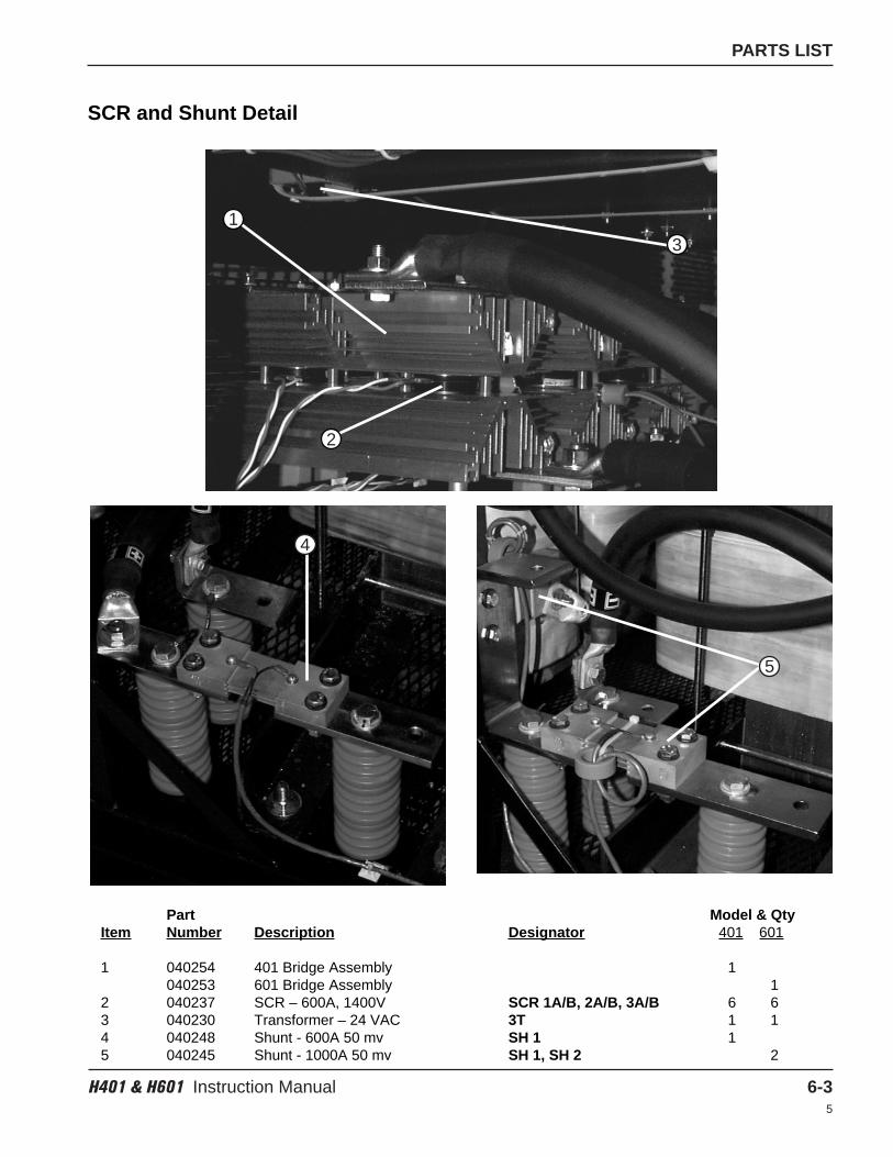
PARTS LIST
H401 & H601 Instruction Manual 6-35
SCR and Shunt Detail
Part Model & QtyItem Number Description Designator 401 601
1 040254 401 Bridge Assembly 1040253 601 Bridge Assembly 1
2 040237 SCR – 600A, 1400V SCR 1A/B, 2A/B, 3A/B 6 63 040230 Transformer – 24 VAC 3T 1 14 040248 Shunt - 600A 50 mv SH 1 15 040245 Shunt - 1000A 50 mv SH 1, SH 2 2
3
1
4
5
2
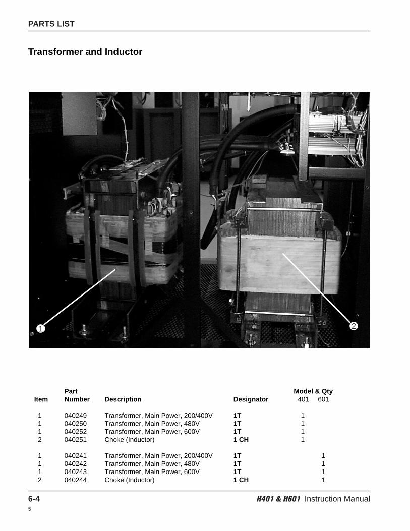
PARTS LIST
6-4 H401 & H601 Instruction Manual5
Transformer and Inductor
Part Model & QtyItem Number Description Designator 401 601
1 040249 Transformer, Main Power, 200/400V 1T 11 040250 Transformer, Main Power, 480V 1T 11 040252 Transformer, Main Power, 600V 1T 12 040251 Choke (Inductor) 1 CH 1
1 040241 Transformer, Main Power, 200/400V 1T 11 040242 Transformer, Main Power, 480V 1T 11 040243 Transformer, Main Power, 600V 1T 12 040244 Choke (Inductor) 1 CH 1
21
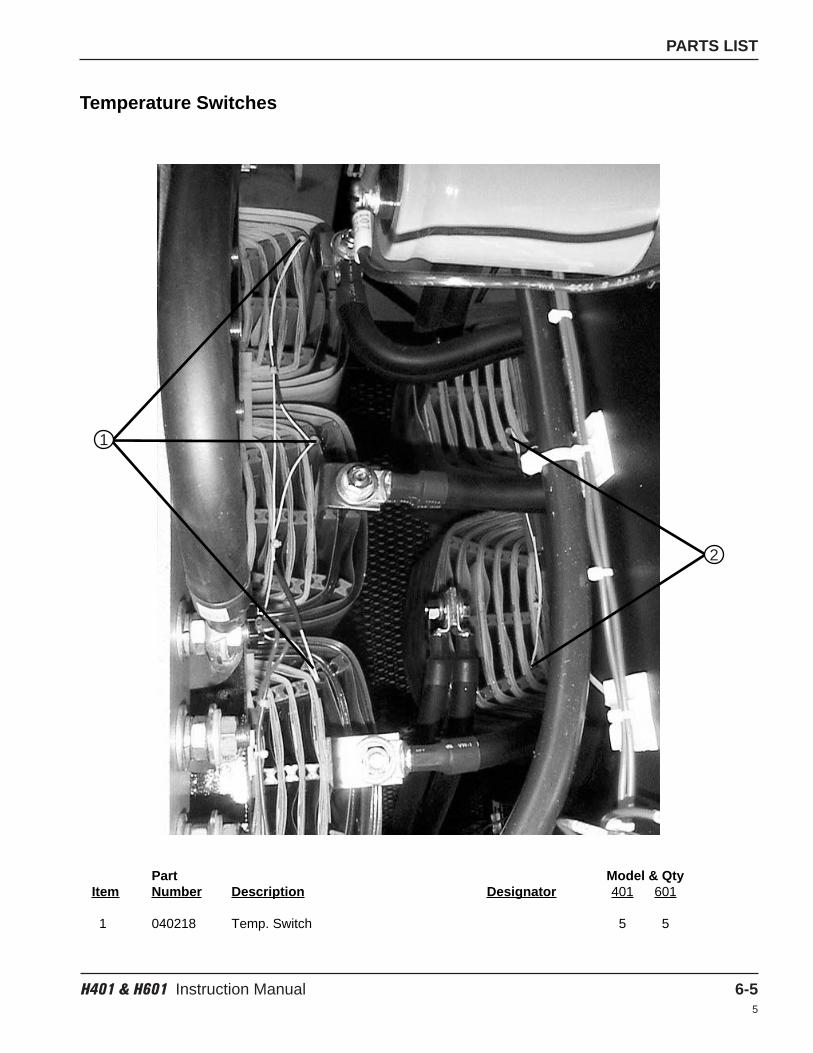
PARTS LIST
H401 & H601 Instruction Manual 6-55
Temperature Switches
Part Model & QtyItem Number Description Designator 401 601
1 040218 Temp. Switch 5 5
1
2
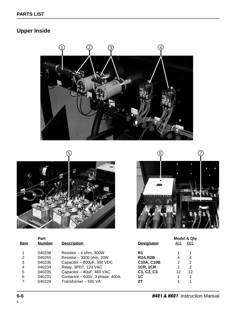
5
PARTS LIST
6-6 H401 & H601 Instruction Manual5
Part Model & QtyItem Number Description Designator 401 601
1 040238 Resistor – 4 ohm, 300W R1 1 12 040255 Resistor – 3000 ohm, 20W R2A,R2B 4 43 040236 Capacitor – 800µF, 350 VDC C10A, C10B 2 24 040234 Relay, 3PDT, 120 VAC 1CR, 2CR 2 25 040235 Capacitor – 40µF, 460 VAC C1, C2, C3 12 126 040231 Contactor – 600V, 3 phase, 400A 1C 1 17 040229 Transformer – 500 VA 2T 1 1
Upper Inside
21
6
43
7
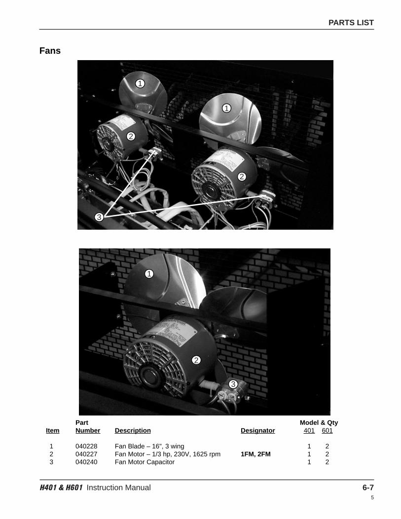
PARTS LIST
H401 & H601 Instruction Manual 6-75
Fans
Part Model & QtyItem Number Description Designator 401 601
1 040228 Fan Blade – 16", 3 wing 1 22 040227 Fan Motor – 1/3 hp, 230V, 1625 rpm 1FM, 2FM 1 23 040240 Fan Motor Capacitor 1 2
1
2
1
2
3
1
2
3
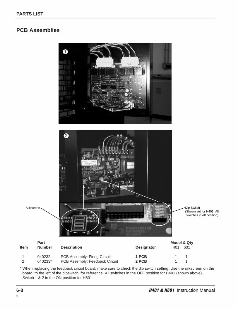
PARTS LIST
6-8 H401 & H601 Instruction Manual5
PCB Assemblies
Part Model & QtyItem Number Description Designator 401 601
1 040232 PCB Assembly: Firing Circuit 1 PCB 1 12 040233* PCB Assembly: Feedback Circuit 2 PCB 1 1
* When replacing the feedback circuit board, make sure to check the dip switch setting. Use the silkscreen on theboard, to the left of the dipswitch, for reference. All switches in the OFF position for H401 (shown above).Switch 1 & 2 in the ON position for H601
1
2
Silkscreen Dip Switch(Shown set for H401: Allswitches in off position)
Section 7
WIRING DIAGRAMS
In this section:
H401-200V................................................................................................................................................................7-3H401-400V................................................................................................................................................................7-5H401-480V................................................................................................................................................................7-7H401-600V................................................................................................................................................................7-9
H601-200V..............................................................................................................................................................7-11H601-400V..............................................................................................................................................................7-13H601-480V..............................................................................................................................................................7-15H601-600V..............................................................................................................................................................7-17
H401 & H601 Instruction Manual 7-14
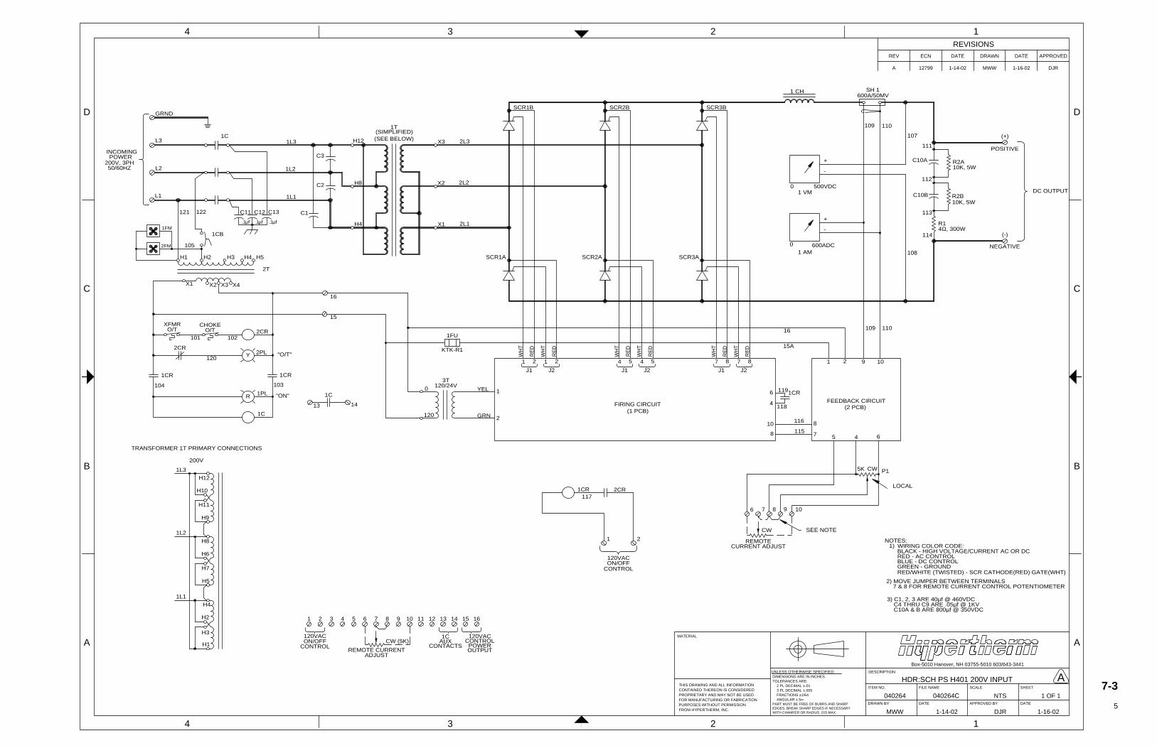
A 12799 1-14-02 MWW 1-16-02 DJR
APPROVEDDATEDRAWNDATEECNREV
REVISIONS
TOLERANCES ARE:
UNLESS OTHERWISE SPECIFIED:
2 PL DECIMAL ±.01
FRACTIONS ±1/64 ANGULAR ±.5∞
DIMENSIONS ARE IN INCHES.
3 PL DECIMAL ±.005
PART MUST BE FREE OF BURRS AND SHARPEDGES. BREAK SHARP EDGES IF NECESSARYWITH CHAMFER OR RADIUS .015 MAX.
PURPOSES WITHOUT PERMISSIONFOR MANUFACTURING OR FABRICATION
FROM HYPERTHERM, INC.
THIS DRAWING AND ALL INFORMATION
PROPRIETARY AND MAY NOT BE USEDCONTAINED THEREON IS CONSIDERED
MATERIAL
040264 040264C
HDR:SCH PS H401 200V INPUT
NTS 1 OF 1
MWW 1-14-02 DJR 1-16-02
SCALE
Box-5010 Hanover, NH 03755-5010 603/643-3441
APPROVED BYDRAWN BY
ITEM NO. FILE NAME
DATE
DESCRIPTION
DATE
SHEET
4 3 2 1
B
C
D
A
4 3 2 1
A
B
C
D GRND
L3
L2
L1
INCOMINGPOWER
1C
H1 H3H2
X1 X4
2T
1CB
H12
H8
H4
X3
X2
X1
1T
SCR1B
SCR1A SCR2A
SCR2B
SCR3A
SCR3B
1 CH
+
-
1 VM
-
1 AM
+
(+)
POSITIVE
(-)
NEGATIVE
DC OUTPUT
1 2
J1
2
J2
1 5
J1
4 5
J2
4 8
J1
7 8
J2
7
FIRING CIRCUIT
1 2 9 10
6
4
1CR
10
8
8
7 5 4 6
FEEDBACK CIRCUIT
5K CW
CW SEE NOTE
LOCAL1CR
1 2
6 7 8 9 10
0
120
YEL
GRN
1
2
3T120/24V
NOTES: 1)
2) MOVE JUMPER BETWEEN TERMINALS 7 & 8 FOR REMOTE CURRENT CONTROL POTENTIOMETER
WIRING COLOR CODE: BLACK - HIGH VOLTAGE/CURRENT AC OR DC
GREEN - GROUND RED/WHITE (TWISTED) - SCR CATHODE(RED) GATE(WHT)
BLUE - DC CONTROL RED - AC CONTROL
1L3
1L2
1L1
1FM
2FM 105
C3
C2
C1
(SIMPLIFIED)
2L3
2L2
2L1
WH
T
RE
D
WH
T
RE
D
WH
T
RE
D
WH
T
RE
D
WH
T
RE
D
WH
T
RE
D
(1 PCB)(2 PCB)
119
116
115
P1
REMOTECURRENT ADJUST
117
SH 1
C10A
C10B
R2A
R2B
R1
H3
H1
H2
1L1
H5
H4
H7
1L2
H6
H8
H9
200V
1L3
H11
H10
H12
TRANSFORMER 1T PRIMARY CONNECTIONS
200V, 3PH50/60HZ
121 122
H4 H5
X3
(SEE BELOW)
120VACON/OFF
118
0 500VDC
0 600ADC
600A/50MV
3) C1, 2, 3 ARE 40µf @ 460VDC C4 THRU C9 ARE .05µf @ 1KV C10A & B ARE 800µf @ 350VDC
Y
XFMRO/T
CHOKEO/T 2CR
2PL "O/T"
101 102
2CR
120
R
104 103
1CR 1CR
1PL
1C
"ON"
13 14
1C
16
15
1 2 3 4 5 6 7 8 9 10 11 12 13 14 15 16
120VACON/OFF
CONTROLCW (5K)
REMOTE CURRENTADJUST
1CAUX
CONTACTS
120VACCONTROLPOWEROUTPUT
107
111
112
113
114
108
109 110
109 11016
15A
2CR
CONTROL
10K, 5W
10K, 5W
4Ω, 300W
X2
C11 C12 C13
.1µf .1µf .1µf
1FU
KTK-R1
A7-3
5
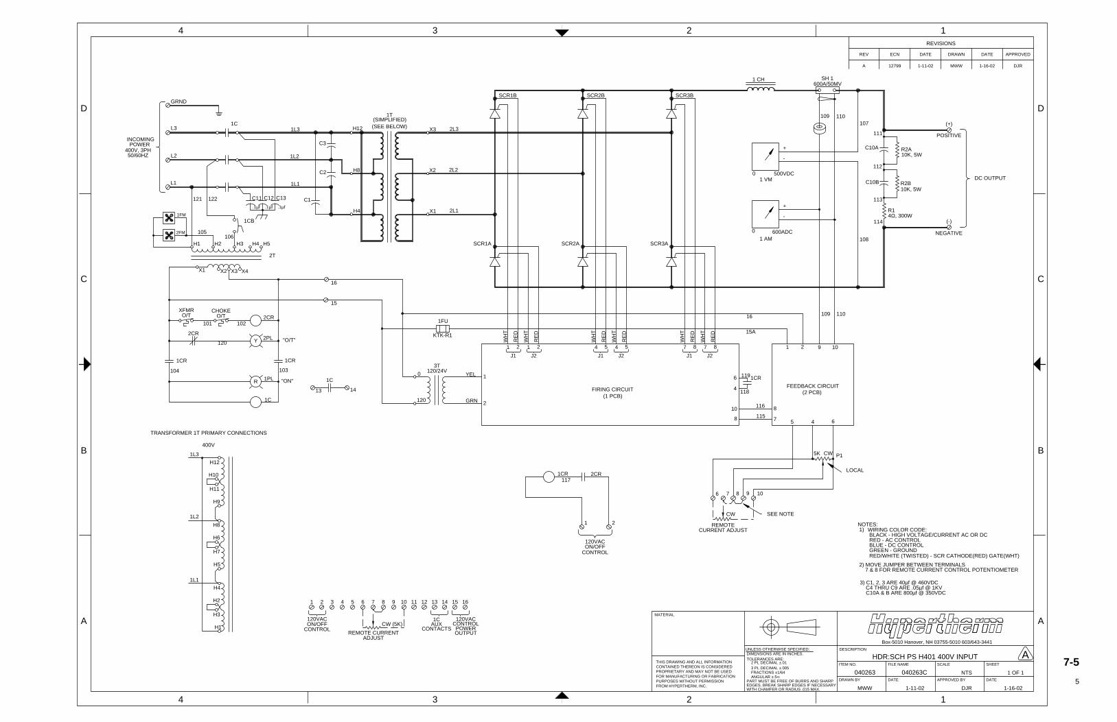
A 12799 1-11-02 MWW 1-16-02 DJR
APPROVEDDATEDRAWNDATEECNREV
REVISIONS
TOLERANCES ARE:
UNLESS OTHERWISE SPECIFIED:
2 PL DECIMAL ±.01
FRACTIONS ±1/64 ANGULAR ±.5∞
DIMENSIONS ARE IN INCHES.
3 PL DECIMAL ±.005
PART MUST BE FREE OF BURRS AND SHARPEDGES. BREAK SHARP EDGES IF NECESSARYWITH CHAMFER OR RADIUS .015 MAX.
PURPOSES WITHOUT PERMISSIONFOR MANUFACTURING OR FABRICATION
FROM HYPERTHERM, INC.
THIS DRAWING AND ALL INFORMATION
PROPRIETARY AND MAY NOT BE USEDCONTAINED THEREON IS CONSIDERED
MATERIAL
040263 040263C
HDR:SCH PS H401 400V INPUT
NTS 1 OF 1
MWW 1-11-02 DJR 1-16-02
SCALE
Box-5010 Hanover, NH 03755-5010 603/643-3441
APPROVED BYDRAWN BY
ITEM NO. FILE NAME
DATE
DESCRIPTION
DATE
SHEET
4 3 2 1
B
C
D
A
4 3 2 1
A
B
C
DGRND
L3
L2
L1
INCOMINGPOWER
1C
H1 H3H2
X1 X4
2T
1CB
H12
H8
H4
X3
X2
X1
1T
SCR1B
SCR1A SCR2A
SCR2B
SCR3A
SCR3B
1 CH
+
-
1 VM
-
1 AM
+
(+)
POSITIVE
(-)
NEGATIVE
DC OUTPUT
1 2
J1
2
J2
1 5
J1
4 5
J2
4 8
J1
7 8
J2
7
FIRING CIRCUIT
1 2 9 10
6
4
1CR
10
8
8
7 5 4 6
FEEDBACK CIRCUIT
5K CW
CW SEE NOTE
LOCAL1CR
1 2
6 7 8 9 10
0
120
YEL
GRN
1
2
3T120/24V
NOTES: 1)
2) MOVE JUMPER BETWEEN TERMINALS 7 & 8 FOR REMOTE CURRENT CONTROL POTENTIOMETER
WIRING COLOR CODE: BLACK - HIGH VOLTAGE/CURRENT AC OR DC
GREEN - GROUND RED/WHITE (TWISTED) - SCR CATHODE(RED) GATE(WHT)
BLUE - DC CONTROL RED - AC CONTROL
1L3
1L2
1L1
1FM
2FM 105
C3
C2
C1
(SIMPLIFIED)
2L3
2L2
2L1
WH
T
RE
D
WH
T
RE
D
WH
T
RE
D
WH
T
RE
D
WH
T
RE
D
WH
T
RE
D
(1 PCB)(2 PCB)
119
116
115
P1
REMOTECURRENT ADJUST
117
SH 1
C10A
C10B
R2A
R2B
R1
H3
H1
H2
1L1
H5
H4
H7
1L2
H6
H8
H9
400V
1L3
H11
H10
H12
TRANSFORMER 1T PRIMARY CONNECTIONS
400V, 3PH50/60HZ
121 122
H4 H5
X3
(SEE BELOW)
120VACON/OFF
118
0 500VDC
0 600ADC
600A/50MV
3) C1, 2, 3 ARE 40µf @ 460VDC C4 THRU C9 ARE .05µf @ 1KV C10A & B ARE 800µf @ 350VDC
Y
XFMRO/T
CHOKEO/T 2CR
2PL "O/T"
101 102
2CR
120
R
104 103
1CR 1CR
1PL
1C
"ON"
13 14
1C
16
15
1 2 3 4 5 6 7 8 9 10 11 12 13 14 15 16
120VACON/OFF
CONTROLCW (5K)
REMOTE CURRENTADJUST
1CAUX
CONTACTS
120VACCONTROLPOWEROUTPUT
107
111
112
113
114
108
109 110
109 11016
15A
2CR
CONTROL
10K, 5W
10K, 5W
4Ω, 300W
X2
106
C11 C12 C13
.1µf .1µf .1µf
1FU
KTK-R1
A7-5
5
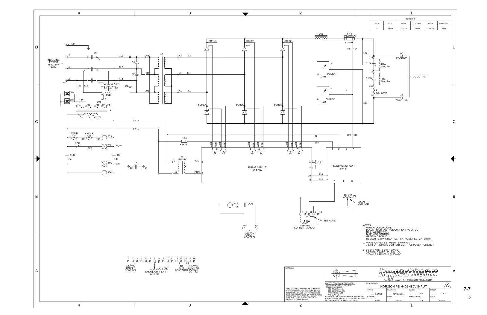
A 12799 1-11-02 MWW 1-16-02 DJR
APPROVEDDATEDRAWNDATEECNREV
REVISIONS
TOLERANCES ARE:
UNLESS OTHERWISE SPECIFIED:
2 PL DECIMAL ±.01
FRACTIONS ±1/64 ANGULAR ±.5∞
DIMENSIONS ARE IN INCHES.
3 PL DECIMAL ±.005
PART MUST BE FREE OF BURRS AND SHARPEDGES. BREAK SHARP EDGES IF NECESSARYWITH CHAMFER OR RADIUS .015 MAX.
PURPOSES WITHOUT PERMISSIONFOR MANUFACTURING OR FABRICATION
FROM HYPERTHERM, INC.
THIS DRAWING AND ALL INFORMATION
PROPRIETARY AND MAY NOT BE USEDCONTAINED THEREON IS CONSIDERED
MATERIAL
040258 040258C
HDR:SCH PS H401 480V INPUT
NTS 1 OF 1
MWW 1-11-02 DJR 1-16-02
SCALE
Box-5010 Hanover, NH 03755-5010 603/643-3441
APPROVED BYDRAWN BY
ITEM NO. FILE NAME
DATE
DESCRIPTION
DATE
SHEET
4 3 2 1
B
C
D
A
4 3 2 1
A
B
C
DGRND
L3
L2
L1
INCOMINGPOWER
1C
H1 H3H2
X1 X4
2T
1CB
H3
H2
H1
X3
X2
X1
1T
SCR1B
SCR1A SCR2A
SCR2B
SCR3A
SCR3B
1 CH
+
-
1 VM
-
1 AM
+
(+)
POSITIVE
(-)
NEGATIVE
DC OUTPUT
1 2
J1
2
J2
1 5
J1
4 5
J2
4 8
J1
7 8
J2
7
FIRING CIRCUIT
1 2 9 10
6
4
1CR
10
8
8
7 5 4 6
FEEDBACK CIRCUIT
5K CW
CW SEE NOTE
LOCALCURRENT 1CR
1 2
6 7 8 9 10
0
120
YEL
GRN
1
2
3T120/24V
NOTES: 1)
2) MOVE JUMPER BETWEEN TERMINALS 7 & 8 FOR REMOTE CURRENT CONTROL POTENTIOMETER
WIRING COLOR CODE:BLACK - HIGH VOLTAGE/CURRENT AC OR DC
GREEN - GROUNDRED/WHITE (TWISTED) - SCR CATHODE(RED) GATE(WHT)
BLUE - DC CONTROLRED - AC CONTROL
1L3
1L2
1L1
1FM
2FM 105
C3
C2
C1
2L3
2L2
2L1
WH
T
RE
D
WH
T
RE
D
WH
T
RE
D
WH
T
RE
D
WH
T
RE
D
WH
T
RE
D
(1 PCB)(2 PCB)
119
116
115
P1
REMOTECURRENT ADJUST
117
SH 1
C10A
C10B
R2A
R2B
R1
480V, 3PH60HZ
121 122
H4 H5
X3
120VACON/OFF
118
0 500VDC
0 600ADC
600A/50MV
3) C1, 2, 3 ARE 40 µf @ 460VDC C4 THRU C9 ARE .05 µf @ 1KV C10A & B ARE 800 µf @ 350VDC
Y
XFMRO/T
CHOKEO/T 2CR
2PL "O/T"
101 102
2CR
120
R
104 103
1CR 1CR
1PL
1C
"ON"
13 14
1C
16
15
1 2 3 4 5 6 7 8 9 10 11 12 13 14 15 16
120VACON/OFF
CONTROLCW (5K)
REMOTE CURRENTADJUST
1CAUX
CONTACTS
120VACCONTROLPOWEROUTPUT
107
111
112
113
114
108
109 110
109 11016
15A
2CR
CONTROL
10K, 5W
10K, 5W
4Ω , 300W
X2
106
C11 C12 C13
.1µf .1µf .1µf
1FU
KTK-R1
A7-7
5
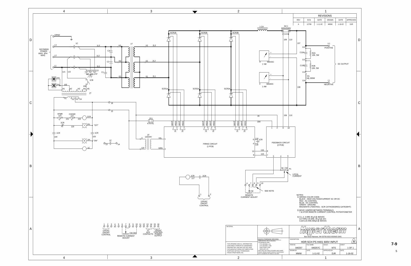
A 12799 1-11-02 MWW 1-16-02 DJR
APPROVEDDATEDRAWNDATEECNREV
REVISIONS
TOLERANCES ARE:
UNLESS OTHERWISE SPECIFIED:
2 PL DECIMAL ±.01
FRACTIONS ±1/64 ANGULAR ±.5∞
DIMENSIONS ARE IN INCHES.
3 PL DECIMAL ±.005
PART MUST BE FREE OF BURRS AND SHARPEDGES. BREAK SHARP EDGES IF NECESSARYWITH CHAMFER OR RADIUS .015 MAX.
PURPOSES WITHOUT PERMISSIONFOR MANUFACTURING OR FABRICATION
FROM HYPERTHERM, INC.
THIS DRAWING AND ALL INFORMATION
PROPRIETARY AND MAY NOT BE USEDCONTAINED THEREON IS CONSIDERED
MATERIAL
040257 040257C
HDR:SCH PS H401 600V INPUT
NTS 1 OF 1
MWW 1-11-02 DJR 1-16-02
SCALE
Box-5010 Hanover, NH 03755-5010 603/643-3441
APPROVED BYDRAWN BY
ITEM NO. FILE NAME
DATE
DESCRIPTION
DATE
SHEET
4 3 2 1
B
C
D
A
4 3 2 1
A
B
C
D
GRND
L3
L2
L1
INCOMINGPOWER
1C
H1 H3H2
X1 X4
2T
1CB
H3
H2
H1
X3
X2
X1
1T
SCR1B
SCR1A SCR2A
SCR2B
SCR3A
SCR3B
1 CH
+
-
1 VM
-
1 AM
+
(+)
POSITIVE
(-)
NEGATIVE
DC OUTPUT
1 2
J1
2
J2
1 5
J1
4 5
J2
4 8
J1
7 8
J2
7
FIRING CIRCUIT
1 2 9 10
6
4
1CR
10
8
8
7 5 4 6
FEEDBACK CIRCUIT
5K CW
CW SEE NOTE
LOCALCURRENT 1CR
1 2
6 7 8 9 10
0
120
YEL
GRN
1
2
3T120/24V
NOTES: 1)
2) MOVE JUMPER BETWEEN TERMINALS 7 & 8 FOR REMOTE CURRENT CONTROL POTENTIOMETER
WIRING COLOR CODE:BLACK - HIGH VOLTAGE/CURRENT AC OR DC
GREEN - GROUNDRED/WHITE (TWISTED) - SCR CATHODE(RED) GATE(WHT)
BLUE - DC CONTROLRED - AC CONTROL
1L3
1L2
1L1
1FM
2FM 105
C3
C2
C1
2L3
2L2
2L1
WH
T
RE
D
WH
T
RE
D
WH
T
RE
D
WH
T
RE
D
WH
T
RE
D
WH
T
RE
D
(1 PCB)(2 PCB)
119
116
115
P1
REMOTECURRENT ADJUST
117
SH 1
C10A
C10B
R2A
R2B
R1
600V, 3PH60HZ
121 122
H4 H5
X3
120VACON/OFF
118
0 500VDC
0 600ADC
600A/50MV
3) C1, 2, 3 ARE 40 µf @ 460VDC C4 THRU C9 ARE .05 µf @ 1KV C10A & B ARE 800µf @ 350VDC
Y
XFMRO/T
CHOKEO/T 2CR
2PL "O/T"
101 102
2CR
120
R
104 103
1CR 1CR
1PL
1C
"ON"
13 14
1C
16
15
1 2 3 4 5 6 7 8 9 10 11 12 13 14 15 16
120VACON/OFF
CONTROLCW (5K)
REMOTE CURRENTADJUST
1CAUX
CONTACTS
120VACCONTROLPOWEROUTPUT
107
111
112
113
114
108
109 11016
15A
2CR
CONTROL
10K, 5W
10K, 5W
4 , 300W
X2
106
109 110
C11 C12 C13
.1µf .1µf .1µf
1FU
KTK-R1
A7-9
5
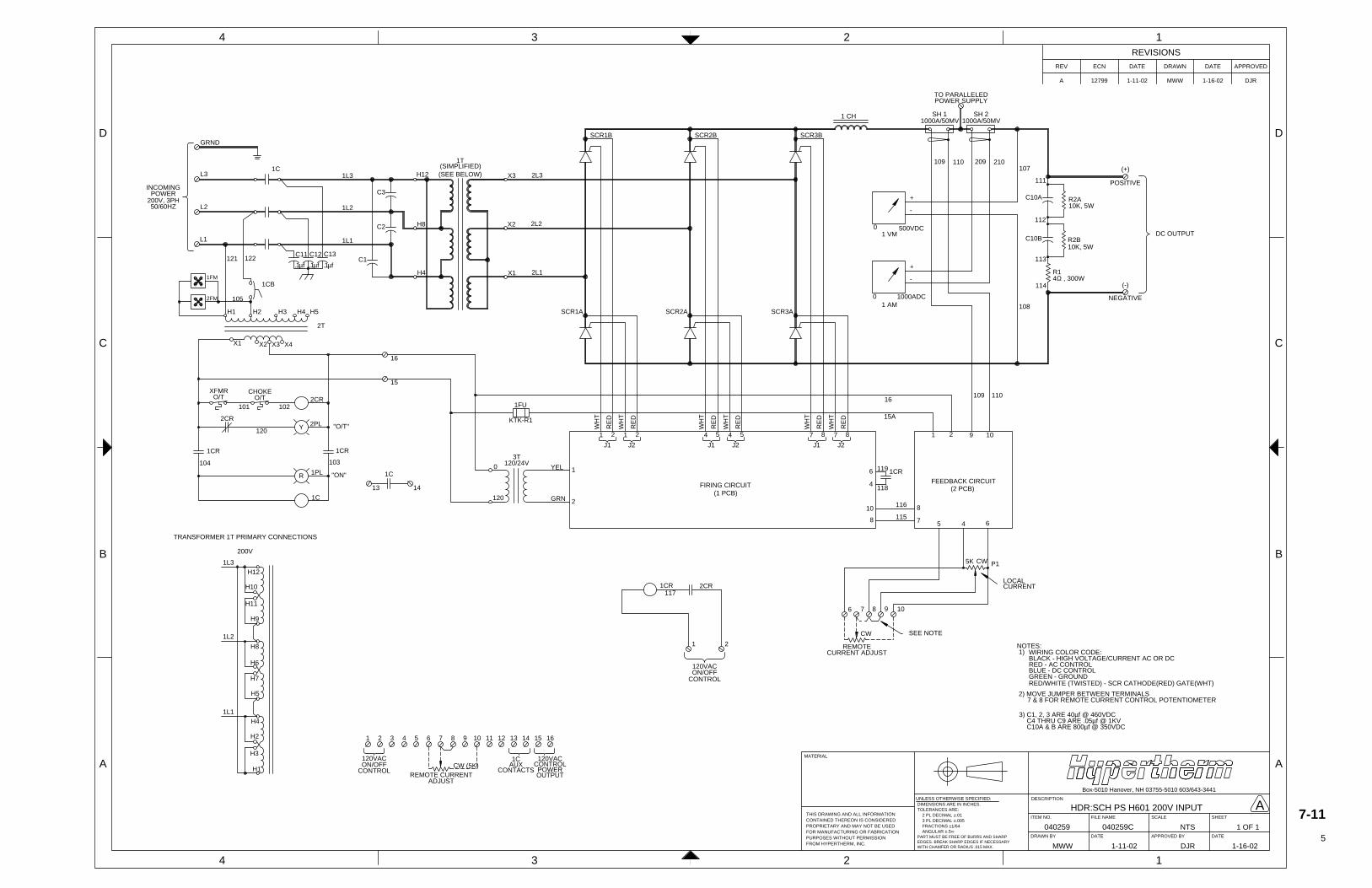
A 12799 1-11-02 MWW 1-16-02 DJR
APPROVEDDATEDRAWNDATEECNREV
REVISIONS
TOLERANCES ARE:
UNLESS OTHERWISE SPECIFIED:
2 PL DECIMAL ±.01
FRACTIONS ±1/64 ANGULAR ±.5∞
DIMENSIONS ARE IN INCHES.
3 PL DECIMAL ±.005
PART MUST BE FREE OF BURRS AND SHARPEDGES. BREAK SHARP EDGES IF NECESSARYWITH CHAMFER OR RADIUS .015 MAX.
PURPOSES WITHOUT PERMISSIONFOR MANUFACTURING OR FABRICATION
FROM HYPERTHERM, INC.
THIS DRAWING AND ALL INFORMATION
PROPRIETARY AND MAY NOT BE USEDCONTAINED THEREON IS CONSIDERED
MATERIAL
040259 040259C
HDR:SCH PS H601 200V INPUT
NTS 1 OF 1
MWW 1-11-02 DJR 1-16-02
SCALE
Box-5010 Hanover, NH 03755-5010 603/643-3441
APPROVED BYDRAWN BY
ITEM NO. FILE NAME
DATE
DESCRIPTION
DATE
SHEET
4 3 2 1
B
C
D
A
4 3 2 1
A
B
C
DGRND
L3
L2
L1
INCOMINGPOWER
1C
H1 H3H2
X1 X4
2T
1CB
H12
H8
H4
X3
X2
X1
1T
SCR1B
SCR1A SCR2A
SCR2B
SCR3A
SCR3B
1 CH
+
-
1 VM
-
1 AM
+
(+)
POSITIVE
(-)
NEGATIVE
DC OUTPUT
1 2
J1
2
J2
1 5
J1
4 5
J2
4 8
J1
7 8
J2
7
FIRING CIRCUIT
1 2 9 10
6
4
1CR
10
8
8
7 5 4 6
FEEDBACK CIRCUIT
5K CW
CW SEE NOTE
LOCALCURRENT 1CR
1 2
6 7 8 9 10
0
120
YEL
GRN
1
2
3T120/24V
NOTES: 1)
2) MOVE JUMPER BETWEEN TERMINALS 7 & 8 FOR REMOTE CURRENT CONTROL POTENTIOMETER
WIRING COLOR CODE:BLACK - HIGH VOLTAGE/CURRENT AC OR DC
GREEN - GROUNDRED/WHITE (TWISTED) - SCR CATHODE(RED) GATE(WHT)
BLUE - DC CONTROLRED - AC CONTROL
1L3
1L2
1L1
1FM
2FM 105
C3
C2
C1
(SIMPLIFIED)2L3
2L2
2L1
WH
T
RE
D
WH
T
RE
D
WH
T
RE
D
WH
T
RE
D
WH
T
RE
D
WH
T
RE
D
(1 PCB)(2 PCB)
119
116
115
P1
REMOTECURRENT ADJUST
117
SH 2
C10A
C10B
R2A
R2B
R1
H3
H1
H2
1L1
H5
H4
H7
1L2
H6
H8
H9
200V
1L3
H11
H10
H12
TRANSFORMER 1T PRIMARY CONNECTIONS
200V, 3PH50/60HZ
121 122
H4 H5
X3
(SEE BELOW)
120VACON/OFF
118
0 500VDC
0 1000ADC
1000A/50MV
3) C1, 2, 3 ARE 40µf @ 460VDC C4 THRU C9 ARE .05µf @ 1KV C10A & B ARE 800µf @ 350VDC
Y
XFMRO/T
CHOKEO/T 2CR
2PL "O/T"
101 102
2CR
120
R
104 103
1CR 1CR
1PL
1C
"ON"
13 14
1C
16
15
1 2 3 4 5 6 7 8 9 10 11 12 13 14 15 16
120VACON/OFF
CONTROLCW (5K)
REMOTE CURRENTADJUST
1CAUX
CONTACTS
120VACCONTROLPOWEROUTPUT
107
111
112
113
114
108
109 110
109 11016
15A
2CR
CONTROL
10K, 5W
10K, 5W
4Ω , 300W
X2
1000A/50MVSH 1
209 210
TO PARALLELEDPOWER SUPPLY
C11 C12 C13
.1µf .1µf .1µf
1FU
KTK-R1
A7-11
5
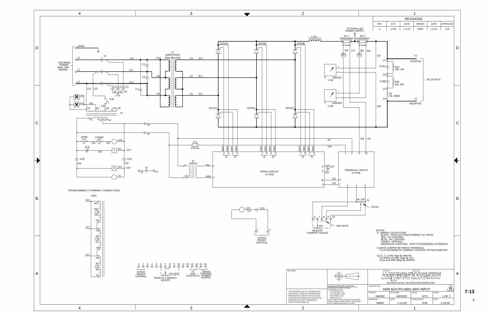
A 12799 1-11-02 MWW 1-16-02 DJR
APPROVEDDATEDRAWNDATEECNREV
REVISIONS
TOLERANCES ARE:
UNLESS OTHERWISE SPECIFIED:
2 PL DECIMAL ±.01
FRACTIONS ±1/64 ANGULAR ±.5∞
DIMENSIONS ARE IN INCHES.
3 PL DECIMAL ±.005
PART MUST BE FREE OF BURRS AND SHARPEDGES. BREAK SHARP EDGES IF NECESSARYWITH CHAMFER OR RADIUS .015 MAX.
PURPOSES WITHOUT PERMISSIONFOR MANUFACTURING OR FABRICATION
FROM HYPERTHERM, INC.
THIS DRAWING AND ALL INFORMATION
PROPRIETARY AND MAY NOT BE USEDCONTAINED THEREON IS CONSIDERED
MATERIAL
040262 040262C
HDR:SCH PS H601 400V INPUT
NTS 1 OF 1
MWW 1-11-02 DJR 1-16-02
SCALE
Box-5010 Hanover, NH 03755-5010 603/643-3441
APPROVED BYDRAWN BY
ITEM NO. FILE NAME
DATE
DESCRIPTION
DATE
SHEET
4 3 2 1
B
C
D
A
4 3 2 1
A
B
C
D GRND
L3
L2
L1
INCOMINGPOWER
1C
H1 H3H2
X1 X4
2T
1CB
H12
H8
H4
X3
X2
X1
1T
SCR1B
SCR1A SCR2A
SCR2B
SCR3A
SCR3B
1 CH
+
-
1 VM
-
1 AM
+
(+)
POSITIVE
(-)
NEGATIVE
DC OUTPUT
1 2
J1
2
J2
1 5
J1
4 5
J2
4 8
J1
7 8
J2
7
FIRING CIRCUIT
1 2 9 10
6
4
1CR
10
8
8
7 5 4 6
FEEDBACK CIRCUIT
5K CW
CW SEE NOTE
LOCAL1CR
1 2
6 7 8 9 10
0
120
YEL
GRN
1
2
3T120/24V
NOTES: 1)
2) MOVE JUMPER BETWEEN TERMINALS 7 & 8 FOR REMOTE CURRENT CONTROL POTENTIOMETER
WIRING COLOR CODE: BLACK - HIGH VOLTAGE/CURRENT AC OR DC
GREEN - GROUND RED/WHITE (TWISTED) - SCR CATHODE(RED) GATE(WHT)
BLUE - DC CONTROL RED - AC CONTROL
1L3
1L2
1L1
1FM
2FM 105106
C3
C2
C1
(SIMPLIFIED)2L3
2L2
2L1
WH
T
RE
D
WH
T
RE
D
WH
T
RE
D
WH
T
RE
D
WH
T
RE
D
WH
T
RE
D
(1 PCB)(2 PCB)
119
116
115
P1
REMOTECURRENT ADJUST
117
SH 2
C10A
C10B
R2A
R2B
R1
H3
H1
H2
1L1
H5
H4
H7
1L2
H6
H8
H9
400V
1L3
H11
H10
H12
TRANSFORMER 1T PRIMARY CONNECTIONS
400V, 3PH50/60HZ
121 122
H4 H5
X3
(SEE BELOW)
120VACON/OFF
118
0 500VDC
0 1000ADC
1000A/50MV
3) C1, 2, 3 ARE 40µf @ 460VDC C4 THRU C9 ARE .05µf @ 1KV C10A & B ARE 800µf @ 350VDC
Y
XFMRO/T
CHOKEO/T 2CR
2PL "O/T"
101 102
2CR
120
R
104 103
1CR 1CR
1PL
1C
"ON"
13 14
1C
16
15
1 2 3 4 5 6 7 8 9 10 11 12 13 14 15 16
120VACON/OFF
CONTROLCW (5K)
REMOTE CURRENTADJUST
1CAUX
CONTACTS
120VACCONTROLPOWEROUTPUT
107
111
112
113
114
108
209 210
109 11016
15A
2CR
CONTROL
10K, 5W
10K, 5W
4Ω, 300W
X2
1000A/50MVSH 1
109 110
TO PARALLEDPOWER SUPPLY
C11 C12 C13
.1µf .1µf .1µf
1FU
KTK-R1
A7-13
5
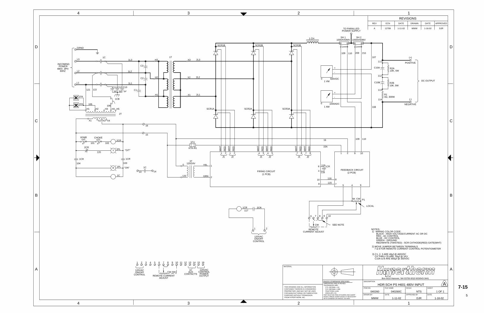
A 12799 1-11-02 MWW 1-16-02 DJR
APPROVEDDATEDRAWNDATEECNREV
REVISIONS
TOLERANCES ARE:
UNLESS OTHERWISE SPECIFIED:
2 PL DECIMAL ±.01
FRACTIONS ±1/64 ANGULAR ±.5∞
DIMENSIONS ARE IN INCHES.
3 PL DECIMAL ±.005
PART MUST BE FREE OF BURRS AND SHARPEDGES. BREAK SHARP EDGES IF NECESSARYWITH CHAMFER OR RADIUS .015 MAX.
PURPOSES WITHOUT PERMISSIONFOR MANUFACTURING OR FABRICATION
FROM HYPERTHERM, INC.
THIS DRAWING AND ALL INFORMATION
PROPRIETARY AND MAY NOT BE USEDCONTAINED THEREON IS CONSIDERED
MATERIAL
040260 040260C
HDR:SCH PS H601 480V INPUT
NTS 1 OF 1
MWW 1-11-02 DJR 1-16-02
SCALE
Box-5010 Hanover, NH 03755-5010 603/643-3441
APPROVED BYDRAWN BY
ITEM NO. FILE NAME
DATE
DESCRIPTION
DATE
SHEET
4 3 2 1
B
C
D
A
4 3 2 1
A
B
C
D GRND
L3
L2
L1
INCOMINGPOWER
1C
H1 H3H2
X1 X4
2T
1CB
H3
H2
H1
X3
X2
X1
1T
SCR1B
SCR1A SCR2A
SCR2B
SCR3A
SCR3B
1 CH
+
-
1 VM
-
1 AM
+
(+)
POSITIVE
(-)
NEGATIVE
DC OUTPUT
1 2
J1
2
J2
1 5
J1
4 5
J2
4 8
J1
7 8
J2
7
FIRING CIRCUIT
1 2 9 10
6
4
1CR
10
8
8
7 5 4 6
FEEDBACK CIRCUIT
5K CW
CW SEE NOTE
LOCAL1CR
1 2
6 7 8 9 10
0
120
YEL
GRN
1
2
3T120/24V
NOTES: 1)
2) MOVE JUMPER BETWEEN TERMINALS 7 & 8 FOR REMOTE CURRENT CONTROL POTENTIOMETER
WIRING COLOR CODE: BLACK - HIGH VOLTAGE/CURRENT AC OR DC
GREEN - GROUND RED/WHITE (TWISTED) - SCR CATHODE(RED) GATE(WHT)
BLUE - DC CONTROL RED - AC CONTROL
1L3
1L2
1L1
1FM
2FM 105
C3
C2
C1
2L3
2L2
2L1
WH
T
RE
D
WH
T
RE
D
WH
T
RE
D
WH
T
RE
D
WH
T
RE
D
WH
T
RE
D
(1 PCB)(2 PCB)
119
116
115
P1
REMOTECURRENT ADJUST
117
SH 2
C10A
C10B
R2A
R2B
R1
480V, 3PH60HZ
121 122
H4 H5
X3
120VACON/OFF
118
0 500VDC
0 1000ADC
1000A/50MV
3) C1, 2, 3 ARE 40µf @ 460VDC C4 THRU C9 ARE .05µf @ 1KV C10A & B ARE 800µf @ 350VDC
Y
XFMRO/T
CHOKEO/T 2CR
2PL "O/T"
101 102
2CR
120
R
104 103
1CR 1CR
1PL
1C
"ON"
13 14
1C
16
15
1 2 3 4 5 6 7 8 9 10 11 12 13 14 15 16
120VACON/OFF
CONTROLCW (5K)
REMOTE CURRENTADJUST
1CAUX
CONTACTS
120VACCONTROLPOWEROUTPUT
107
111
112
113
114
108
209 210
109 11016
15A
2CR
CONTROL
10K, 5W
10K, 5W
4Ω, 300W
X2
106
1000A/50MVSH 1
109 110
TO PARALLEDPOWER SUPPLY
C11 C12 C13
.1µf .1µf.1µf
1FU
KTK-R1
A7-15
5
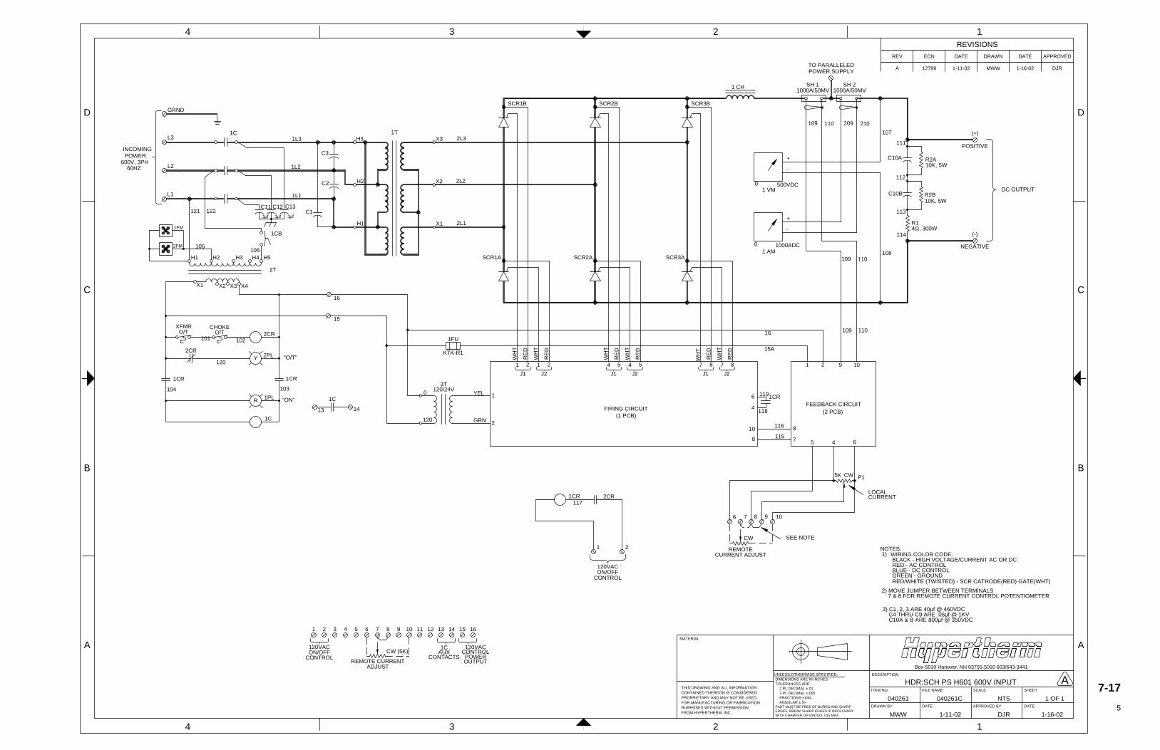
A 12799 1-11-02 MWW 1-16-02 DJR
APPROVEDDATEDRAWNDATEECNREV
REVISIONS
TOLERANCES ARE:
UNLESS OTHERWISE SPECIFIED:
2 PL DECIMAL ±.01
FRACTIONS ±1/64 ANGULAR ±.5∞
DIMENSIONS ARE IN INCHES.
3 PL DECIMAL ±.005
PART MUST BE FREE OF BURRS AND SHARPEDGES. BREAK SHARP EDGES IF NECESSARYWITH CHAMFER OR RADIUS .015 MAX.
PURPOSES WITHOUT PERMISSIONFOR MANUFACTURING OR FABRICATION
FROM HYPERTHERM, INC.
THIS DRAWING AND ALL INFORMATION
PROPRIETARY AND MAY NOT BE USEDCONTAINED THEREON IS CONSIDERED
MATERIAL
040261 040261C
HDR:SCH PS H601 600V INPUT
NTS 1 OF 1
MWW 1-11-02 DJR 1-16-02
SCALE
Box-5010 Hanover, NH 03755-5010 603/643-3441
APPROVED BYDRAWN BY
ITEM NO. FILE NAME
DATE
DESCRIPTION
DATE
SHEET
4 3 2 1
B
C
D
A
4 3 2 1
A
B
C
D GRND
L3
L2
L1
INCOMINGPOWER
1C
H1 H3H2
X1 X4
2T
1CB
H3
H2
H1
X3
X2
X1
1T
SCR1B
SCR1A SCR2A
SCR2B
SCR3A
SCR3B
1 CH
+
-
1 VM
-
1 AM
+
(+)
POSITIVE
(-)
NEGATIVE
DC OUTPUT
1 2
J1
2
J2
1 5
J1
4 5
J2
4 8
J1
7 8
J2
7
FIRING CIRCUIT
1 2 9 10
6
4
1CR
10
8
8
7 5 4 6
FEEDBACK CIRCUIT
5K CW
CW SEE NOTE
LOCALCURRENT 1CR
1 2
6 7 8 9 10
0
120
YEL
GRN
1
2
3T120/24V
NOTES: 1)
2) MOVE JUMPER BETWEEN TERMINALS 7 & 8 FOR REMOTE CURRENT CONTROL POTENTIOMETER
WIRING COLOR CODE: BLACK - HIGH VOLTAGE/CURRENT AC OR DC
GREEN - GROUND RED/WHITE (TWISTED) - SCR CATHODE(RED) GATE(WHT)
BLUE - DC CONTROL RED - AC CONTROL
1L3
1L2
1L1
1FM
2FM 105
C3
C2
C1
2L3
2L2
2L1
WH
T
RE
D
WH
T
RE
D
WH
T
RE
D
WH
T
RE
D
WH
T
RE
D
WH
T
RE
D
(1 PCB)(2 PCB)
119
116
115
P1
REMOTECURRENT ADJUST
117
SH 2
C10A
C10B
R2A
R2B
R1
600V, 3PH60HZ
121 122
H4 H5
X3
120VACON/OFF
118
0 500VDC
0 1000ADC
1000A/50MV
3) C1, 2, 3 ARE 40µf @ 460VDC C4 THRU C9 ARE .05µf @ 1KV C10A & B ARE 800µf @ 350VDC
Y
XFMRO/T
CHOKEO/T 2CR
2PL "O/T"
101 102
2CR
120
R
104 103
1CR 1CR
1PL
1C
"ON"
13 14
1C
16
15
1 2 3 4 5 6 7 8 9 10 11 12 13 14 15 16
120VACON/OFF
CONTROLCW (5K)
REMOTE CURRENTADJUST
1CAUX
CONTACTS
120VACCONTROLPOWEROUTPUT
107
111
112
113
114
108109 110
109 11016
15A
2CR
CONTROL
10K, 5W
10K, 5W
4Ω, 300W
X2
106
SH 11000A/50MV
109 110 209 210
TO PARALLELEDPOWER SUPPLY
C11 C12 C13
.1µf .1µf .1µf
1FU
KTK-R1
A7-17
5
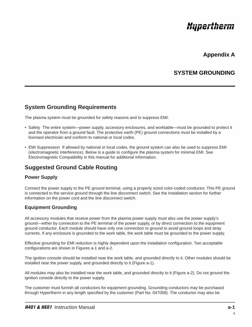
H401 & H601 Instruction Manual a-14
System Grounding Requirements
The plasma system must be grounded for safety reasons and to suppress EMI:
• Safety The entire system—power supply, accessory enclosures, and worktable—must be grounded to protect itand the operator from a ground fault. The protective earth (PE) ground connections must be installed by alicensed electrician and conform to national or local codes.
• EMI Suppression If allowed by national or local codes, the ground system can also be used to suppress EMI(electromagnetic interference). Below is a guide to configure the plasma system for minimal EMI. SeeElectromagnetic Compatibility in this manual for additional information.
Suggested Ground Cable Routing
Power Supply
Connect the power supply to the PE ground terminal, using a properly sized color-coded conductor. This PE groundis connected to the service ground through the line disconnect switch. See the Installation section for furtherinformation on the power cord and the line disconnect switch.
Equipment Grounding
All accessory modules that receive power from the plasma power supply must also use the power supply’sground—either by connection to the PE terminal of the power supply, or by direct connection to the equipmentground conductor. Each module should have only one connection to ground to avoid ground loops and straycurrents. If any enclosure is grounded to the work table, the work table must be grounded to the power supply.
Effective grounding for EMI reduction is highly dependent upon the installation configuration. Two acceptableconfigurations are shown in Figures a-1 and a-2.
The ignition console should be installed near the work table, and grounded directly to it. Other modules should beinstalled near the power supply, and grounded directly to it (Figure a-1).
All modules may also be installed near the work table, and grounded directly to it (Figure a-2). Do not ground theignition console directly to the power supply.
The customer must furnish all conductors for equipment grounding. Grounding conductors may be purchasedthrough Hypertherm in any length specified by the customer (Part No. 047058). The conductor may also be
Appendix A
SYSTEM GROUNDING
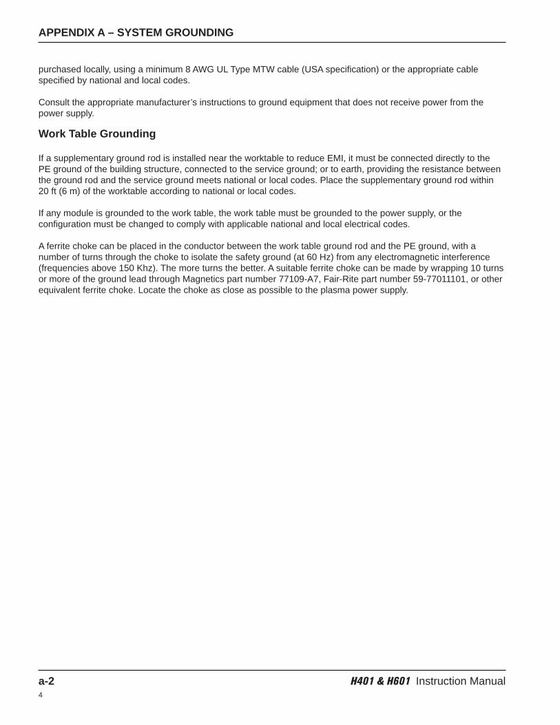
APPENDIX A – SYSTEM GROUNDING
a-2 H401 & H601 Instruction Manual4
purchased locally, using a minimum 8 AWG UL Type MTW cable (USA specification) or the appropriate cablespecified by national and local codes.
Consult the appropriate manufacturer’s instructions to ground equipment that does not receive power from thepower supply.
Work Table Grounding
If a supplementary ground rod is installed near the worktable to reduce EMI, it must be connected directly to the PE ground of the building structure, connected to the service ground; or to earth, providing the resistance betweenthe ground rod and the service ground meets national or local codes. Place the supplementary ground rod within20 ft (6 m) of the worktable according to national or local codes.
If any module is grounded to the work table, the work table must be grounded to the power supply, or theconfiguration must be changed to comply with applicable national and local electrical codes.
A ferrite choke can be placed in the conductor between the work table ground rod and the PE ground, with anumber of turns through the choke to isolate the safety ground (at 60 Hz) from any electromagnetic interference(frequencies above 150 Khz). The more turns the better. A suitable ferrite choke can be made by wrapping 10 turnsor more of the ground lead through Magnetics part number 77109-A7, Fair-Rite part number 59-77011101, or otherequivalent ferrite choke. Locate the choke as close as possible to the plasma power supply.
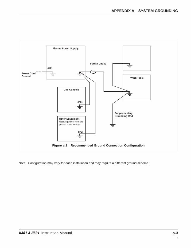
APPENDIX A – SYSTEM GROUNDING
H401 & H601 Instruction Manual a-34
Figure a-1 Recommended Ground Connection Configuration
Note: Configuration may vary for each installation and may require a different ground scheme.
Plasma Power Supply
(PE)
(PE)
(PE)
Power CordGround
Ferrite Choke
SupplementaryGrounding Rod
Gas Console
Other Equipmentreceiving power from theplasma power supply
Work Table
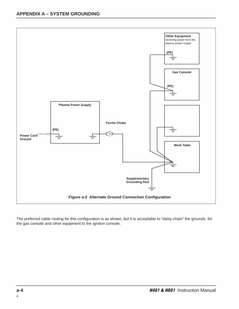
APPENDIX A – SYSTEM GROUNDING
a-4 H401 & H601 Instruction Manual4
Figure a-2 Alternate Ground Connection Configuration
The preferred cable routing for this configuration is as shown, but it is acceptable to “daisy-chain” the grounds forthe gas console and other equipment to the ignition console.
Plasma Power Supply
(PE)
Power CordGround
Ferrite Choke
SupplementaryGrounding Rod
Gas Console
Other Equipmentreceiving power from theplasma power supply
Work Table
(PE)
(PE)