ANALOGY BETWEEN ARCHITECTURAL DESIGN PROCESS AND THE DOCUMENTATION OF ARCHITECTURAL WORKS
Upload
khangminh22Category
view
2download
0
ACI 303R-12
Guide to Cast-in-Place Architectural Concrete Practice
Reported by ACI Committee 303
Copyright American Concrete Institute Provided by IHS under license with ACI Licensee=University of Texas Revised Sub Account/5620001114, User=rtytyui, rtyrt
Not for Resale, 01/26/2015 01:29:40 MSTNo reproduction or networking permitted without license from IHS
--````,`,`,,`,`,``````,,,`,,`,,-`-`,,`,,`,`,,`---
daneshlink.com
Daneshlink.com
First PrintingJune 2012
Guide to Cast-in-Place Architectural Concrete Practice
Copyright by the American Concrete Institute, Farmington Hills, MI. All rights reserved. This material may not be reproduced or copied, in whole or part, in any printed, mechanical, electronic, film, or other distribution and storage media, without the written consent of ACI.
The technical committees responsible for ACI committee reports and standards strive to avoid ambiguities, omissions, and errors in these documents. In spite of these efforts, the users of ACI documents occasionally find information or requirements that may be subject to more than one interpretation or may be incomplete or incorrect. Users who have suggestions for the improvement of ACI documents are requested to contact ACI via the errata website at www.concrete.org/committees/errata.asp. Proper use of this document includes periodically checking for errata for the most up-to-date revisions.
ACI committee documents are intended for the use of individuals who are competent to evaluate the significance and limitations of its content and recommendations and who will accept responsibility for the application of the mate-rial it contains. Individuals who use this publication in any way assume all risk and accept total responsibility for the application and use of this information.
All information in this publication is provided “as is” without warranty of any kind, either express or implied, includ-ing but not limited to, the implied warranties of merchantability, fitness for a particular purpose or non-infringement.
ACI and its members disclaim liability for damages of any kind, including any special, indirect, incidental, or con-sequential damages, including without limitation, lost revenues or lost profits, which may result from the use of this publication.
It is the responsibility of the user of this document to establish health and safety practices appropriate to the specific circumstances involved with its use. ACI does not make any representations with regard to health and safety issues and the use of this document. The user must determine the applicability of all regulatory limitations before applying the document and must comply with all applicable laws and regulations, including but not limited to, United States Occupational Safety and Health Administration (OSHA) health and safety standards.
Participation by governmental representatives in the work of the American Concrete Institute and in the develop-ment of Institute standards does not constitute governmental endorsement of ACI or the standards that it develops.
Order information: ACI documents are available in print, by download, on CD-ROM, through electronic subscription, or reprint and may be obtained by contacting ACI.
Most ACI standards and committee reports are gathered together in the annually revised ACI Manual of Concrete Practice (MCP).
American Concrete Institute38800 Country Club DriveFarmington Hills, MI 48331U.S.A.Phone: 248-848-3700Fax: 248-848-3701
www.concrete.org
ISBN 978-0-87031-771-2
American Concrete Institute®
Advancing concrete knowledge
Copyright American Concrete Institute Provided by IHS under license with ACI Licensee=University of Texas Revised Sub Account/5620001114, User=rtytyui, rtyrt
Not for Resale, 01/26/2015 01:29:40 MSTNo reproduction or networking permitted without license from IHS
--````,`,`,,`,`,``````,,,`,,`,,-`-`,,`,,`,`,,`---
daneshlink.com
Daneshlink.com
This guide presents recommendations for producing cast-in-place architectural concrete. The importance of specified materials, forming, concrete placement, curing, additional treatment, inspec-tion, and their effect on the appearance of the finished product are discussed. Architectural concrete requires special construction techniques, materials, and requirements that are unique to each project. The specific recommendations and information presented in this guide should be used accordingly.
Keywords: admixture; aggregate; architectural concrete; beam; bush-hammer; cement; coating; column; consolidation; cracking; curing; deflec-tion; exposed-aggregate finish; finish; form lining; formwork; joint; joint sealant; mixture proportion; pigment; placing; quality control; release agent; repair; retarder; sealant; texture; wall.
CONTENTSChapter 1—Introduction, p. 2
Chapter 2—Definitions, p. 2
Chapter 3—Architectural considerations, p. 33.1—Architectural features3.2—Architectural design3.3—Coatings and sealers3.4—Joint sealants3.5—Specifications
Chapter 4—Structural considerations, p. 74.1—Spalling4.2—Deflections4.3—Cracking4.4—Joints4.5—Beams and slabs4.6—Columns4.7—Walls
Chapter 5—Forms, p. 105.1—General5.2—Materials
ACI 303R-12
Guide to Cast-in-Place Architectural Concrete Practice
Reported by ACI Committee 303
Chris A. Forster, Chair
Keith Ahal
George F. Baty
Eugene H. Boeke Jr.
Daniel P. Dorfmueller
Thomas J. Grisinger
Gardner P. Horst
James M. Shilstone Jr.
Michael S. Smith
David M. Suchorski
Claude B. Trusty Jr.
Gregory R. Wagner
The committee would like to thank the late Louis Tallarico for his contribution to this guide.
1
ACI Committee Reports, Guides, and Commentaries are intended for guidance in planning, designing, executing, and inspecting construction. This document is intended for the use of individuals who are competent to evaluate the significance and limitations of its content and recommendations and who will accept responsibility for the application of the material it contains. The American Concrete Institute disclaims any and all responsibility for the stated principles. The Institute shall not be liable for any loss or damage arising therefrom.
Reference to this document shall not be made in contract documents. If items found in this document are desired by the Architect/Engineer to be a part of the contract documents, they shall be restated in mandatory language for incorporation by the Architect/Engineer.
ACI 303R-12 supersedes ACI 303R-04 and became effective June 2012..Copyright © 2012, American Concrete InstituteAll rights reserved including rights of reproduction and use in any form or by any
means, including the making of copies by any photo process, or by electronic or mechanical device, printed, written, or oral, or recording for sound or visual repro-duction or for use in any knowledge or retrieval system or device, unless permission in writing is obtained from the copyright proprietors.
Copyright American Concrete Institute Provided by IHS under license with ACI Licensee=University of Texas Revised Sub Account/5620001114, User=rtytyui, rtyrt
Not for Resale, 01/26/2015 01:29:40 MSTNo reproduction or networking permitted without license from IHS
--````,`,`,,`,`,``````,,,`,,`,,-`-`,,`,,`,`,,`---
daneshlink.com
Daneshlink.com
5.3—Economics5.4—Formwork accuracy5.5—Form joints5.6—Textures and patterns5.7—Formwork accessories5.8—Form coatings and sealers5.9—Form release agents5.10—Form removal
Chapter 6—Reinforcement, p. 186.1—General6.2—Clear space6.3—Reinforcement supports and spacers6.4—Tie wire6.5—Zinc-coated (galvanized) steel reinforcement6.6—Epoxy-coated reinforcing bars
Chapter 7—Concrete materials and mixture proportioning, p. 20
7.1—General7.2—Materials7.3—Proportioning, mixing, and temperature control
Chapter 8—Placing and consolidation, p. 228.1—Conveying and placing8.2—Consolidation
Chapter 9—Curing, p. 249.1—General9.2—Curing in forms9.3—Moist curing9.4—Membrane curing9.5—Hot weather curing
Chapter 10—Treated architectural surfaces, p. 2410.1—Surface retarders10.2—High-pressure water jet10.3—Acid wash10.4—Abrasive blasting10.5—Tooling or other mechanical treatments
Chapter 11—Finishing and final cleanup, p. 2611.1—General11.2—Tie holes11.3—Blemish repair11.4—Stain removal11.5—Sealers and coatings
Chapter 12—References, p. 27
Appendix A—Architectural concrete photos, p. 29
CHAPTER 1—INTRODUCTIONThis guide presents recommendations for cast-in-place
architectural concrete that is exposed to view. Architectural concrete requires special care in the selection of concrete materials, forming, placing, and finishing to achieve the desired architectural appearance. Refer to the photos in
Appendix A for examples of architectural cast-in-place concrete. Various procedures are recommended for deter-mining requirements of the architect, contractor, concrete producer, and inspector. Critical areas are indicated for special attention, and means for prevention or correction of defects are discussed. Specific surface treatments and special forming techniques are presented. Applicable codes, specifi-cations, and recommendations are given. A good resource for general information about architectural concrete can be found in several papers published in Concrete International (1984(a) to (i); 1988(a) to (h)), as well as the Concrete Construction Engineering Handbook (Kenny and Freedman 1997).
The information presented in this guide is broad and covers several special conditions for specific architectural concrete. Information that may be applicable for use in producing a specific result may not be applicable to another. The user should also be aware that recommendations in this guide are subjective to the means and methods used for accomplishing a specific task for a specific level of architectural effect, and should be tested before use to ensure it will produce the required result. Further research is needed to provide addi-tional information on surface air voids and other construc-tion problems. This guide does not address all the problems associated with architectural concrete.
CHAPTER 2—DEFINITIONSACI provides a comprehensive list of definitions through
an online resource, “ACI Concrete Terminology,” (http://terminology.concrete.org). Definitions provided herein complement that resource.
blemish—any superficial defect that causes visible varia-tion from a consistently smooth and uniformly colored surface of hardened concrete.
checking—development of shallow cracks at closely spaced but irregular intervals on the surface of plaster, cement paste, mortar, or concrete.
concrete, architectural—concrete that will be perma-nently exposed to view and therefore requires special care in the selection of the concrete materials, forming, placing, and finishing to obtain the desired architectural appearance.
concrete, cast-in-place—concrete that is deposited and allowed to harden in the place where it is required to be in the completed structure, as opposed to precast concrete.
concrete, exposed—concrete surfaces formed so as to yield an acceptable texture and finish for permanent expo-sure to view. (Refer to concrete, architectural.)
finish, exposed-aggregate—a decorative finish for concrete work achieved by removing, generally before the concrete has fully hardened, the outer skin of mortar and exposing the coarse aggregate.
finish, rubbed—a finish obtained by using an abrasive to remove surface irregularities from concrete. (Refer to sack rub.)
mottling—uneven color shading or blotchiness across a surface.
quality control—actions taken by an organization to provide control and documentation over what is being done and what is being provided so that the applicable standard of
American Concrete Institute Copyrighted Material—www.concrete.org
2 GUIDE TO CAST-IN-PLACE ARCHITECTURAL CONCRETE (ACI 303R-12)
Copyright American Concrete Institute Provided by IHS under license with ACI Licensee=University of Texas Revised Sub Account/5620001114, User=rtytyui, rtyrt
Not for Resale, 01/26/2015 01:29:40 MSTNo reproduction or networking permitted without license from IHS
--````,`,`,,`,`,``````,,,`,,`,,-`-`,,`,,`,`,,`---
daneshlink.com
Daneshlink.com
good practice and the contract documents for the work are followed.
sack rub—a finish for formed concrete surfaces, designed to produce even texture and fill pits and air holes; after damp-ening the surface, mortar is rubbed over the surface; then, before the surface dries, a mixture of dry cement and sand is rubbed over it with either a wad of burlap or a sponge-rubber float to remove surplus mortar and fill voids.
sandblast—a system of cutting or abrading a surface such as concrete by a stream of sand ejected from a nozzle at high speed by compressed air; often used for cleanup of horizontal construction joints or for exposure of aggregate in architectural concrete.
snap tie—a proprietary concrete wall-form tie, the end of which can be twisted or snapped off after the forms have been removed.
texture—the pattern or configuration apparent in an exposed surface, as in concrete and mortar, including rough-ness, streaking, striation, or departure from flatness.
CHAPTER 3—ARCHITECTURAL CONSIDERATIONS
3.1—Architectural features3.1.1 General acceptance criteria—Architecturally
acceptable concrete surfaces should be aesthetically compat-ible with minimal color and texture variations and surface defects when viewed at a distance of approximately 20 ft (6 m) or more, as agreed upon by the architect, owner, and contractor, or as otherwise specified.
3.1.2 Measurement—It is beyond the scope of this guide to establish precise or definitive rules of measurement. Within any discrete building element or series of like elements, however, a high degree of visual uniformity is generally expected and required. The preconstruction mockup panel would normally be used to establish acceptance criteria (Section 3.5.4).
3.1.3 Variations in color and shading—Variations in color and shades within a color can be expected due to the many variables encountered with cast-in-place architectural concrete. These are minimized by:• Quality control of ingredients, concrete mixtures, and
consistency (Sections 7.2 and 7.3);• Uniform concrete delivery schedules (Section 8.1.1);• Uniformity of form surface, form release agent, applica-
tion rate, and formwork reusage, erection, and stripping (Sections 5.10.2 to 5.10.4);
• Uniform rates of placement and consistent methods of placement and consolidation of concrete (Chapter 8);
• Placement schedules to minimize extreme variations of ambient conditions (Section 8.1.1);
• Consistent curing procedure and material (Chapter 9); and
• Properly timed or executed finishing operations (Chapter 11).
3.1.4 Finishes—Surface textures are grouped into two general classes:
• Untreated surfaces where the mortar is the principal visible constituent, and the texture is that which is imparted by the formwork sheathing or form liner; and
• Surfaces that are mechanically or chemically treated in place by removal of surface mortar to expose the under-lying aggregate, thus wholly or partially obscuring the texture of the form sheathing or form liner.
High-build polymer coatings and cementitious or polymer-modified coatings that obscure both color and texture are not included in this guide.
3.2—Architectural design3.2.1 General criteria—Architectural design criteria for
readily obtainable and acceptable results should include:• Isolation or division of concrete surfaces to allow reuse
of formwork modules by the incorporation of rustica-tion or joint patterns, or by the employment of a paneled effect;
• Systematic planning of construction joints that allows a reusable formwork module and conforms to structural requirements;
• Use of textured form sheathing (face sheets) or form liners, mechanically or chemically textured concrete finishes, or other relief features; and
• Limitations on the size of panels bounded by rustication or joint patterns; large, smooth, uninterrupted expanses of concrete surfaces should be avoided.
3.2.2 Details of architectural design3.2.2.1 Unchamfered corners—Although acute- and right-
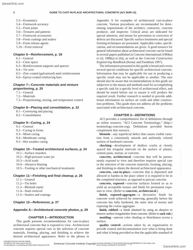
angle corners can be obtained, they are difficult to construct and maintain, especially during construction. Proper consol-idation of the concrete is essential, and self-consolidating concrete (SCC) may be required to achieve a crisp edge (Fig. 3.2.2.1). Forms should be designed and sealed to resist concrete placing pressures, and fabricated such that they can be stripped without damaging the concrete. Extended strip-ping time will probably be necessary to prevent damage to sharp corners that, depending on the size of the project, may require additional forms. Extended stripping time could also affect color because variation in form stripping times will increase the color differential.
Fig. 3.2.2.1—(a) Difficult-to-achieve consolidation at acute corners; and (b) the use of SCC allows for proper consolida-tion at the acute corner.
American Concrete Institute Copyrighted Material—www.concrete.org
GUIDE TO CAST-IN-PLACE ARCHITECTURAL CONCRETE (ACI 303R-12) 3
Copyright American Concrete Institute Provided by IHS under license with ACI Licensee=University of Texas Revised Sub Account/5620001114, User=rtytyui, rtyrt
Not for Resale, 01/26/2015 01:29:40 MSTNo reproduction or networking permitted without license from IHS
--````,`,`,,`,`,``````,,,`,,`,,-`-`,,`,,`,`,,`---
daneshlink.com
Daneshlink.com
3.2.2.2 Chamfered corners—Where chamfers are part of the architectural feature, the chamfer form strip should be continuously tight to all form surfaces they contact. Plastic or metal chamfer strips are available that have integral means of sealing to the form contact surfaces. Wood chamfer strips are difficult to maintain continuously tight, unless a sealant is used when attaching to formwork.
3.2.2.3 Joints—Panel area joints may be recessed into the concrete surface by applying rustication strips on the formed surfaces. These can also be used for construction joints as needed by the contractor. Waterstops, keyways, and joint sealants may be included where required. Refer to Section 4.4 for recommended joint depths.
Formwork rustication strips should have a draft of at least 15 degrees to facilitate removal. Draft is defined as a small angle or taper in the formwork for reentrant formed surface that facilitates release when the form is stripped (Fig. 3.2.2.3). Also, wooden strips should be deeply sawcut or kerfed on the backside to prevent binding due to expansion from absorbed water.
All rustication strips or other inserts should be installed continuously tight to the form contact surface. Back-screwing the strip so it can be released before stripping may help obtain a tight seal. Nailing the strips to the form face for some architectural treatments may be acceptable but will not attain a tight seal. Insufficient nailing of the form strip will usually result in leakage and leave the reveal void ragged and discolored.
Rustication strips should be uniform in dimensions, nonabsorbent, and of sufficient stiffness to maintain align-ment during concrete placement operations. In areas of possible deflection of the sheathing, a method of treatment to prevent mortar leakage should be used.
Metal chamfer or rustication strips and other materials of similar stiffness should have a minimum width of 3/4 in. (20 mm). Widths of wooden rustication strips should be at least equal to their depths. Joints smaller than recommended above can be attained with special form detailing using steel insert strips installed between the forms.
Intersections of chamfer or rustication strips should be mitered or coped to fit snugly. Chamfer, rustication, or isola-tion strips may be placed so as to cover form joints.
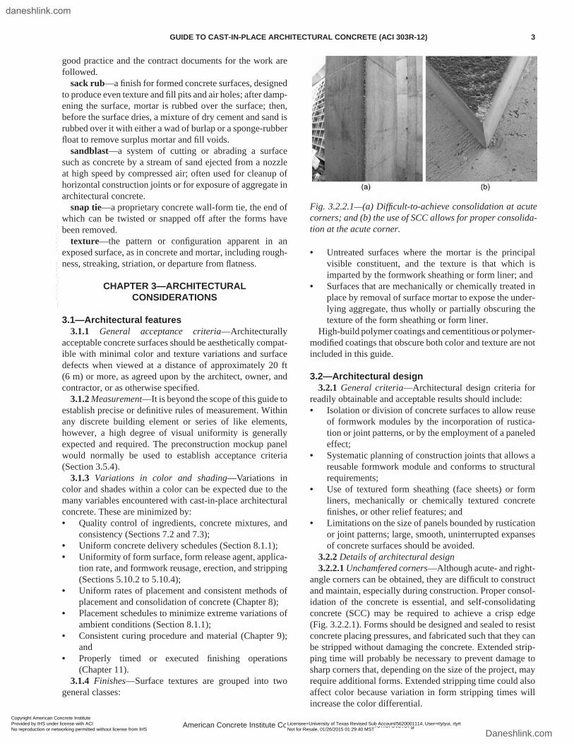
3.2.2.4 Soffits—A drip should be installed in soffits near vertical surfaces where there is a potential for downward movement of rainwater on the vertical concrete face (Fig. 3.2.2.4). The drip molds should be placed as near to the external vertical face as practicable, but not closer than 1 in. (25 mm) from the finished concrete surface. Note that the drip in Fig. 3.2.2.4 is interrupted at either end of the under-side horizontal surface to to help facilitate downward move-ment of water before it reaches the inside vertical face.
3.2.2.5 Sloped surfaces—Accumulation of airborne solids on horizontal surfaces can be minimized by sloping such surfaces. Sills should have a slight downward slope, and the upper surfaces of recesses should have an upward slope from the horizontal, relative to the inside face of the recess. Slopes may vary from 1:12 for smooth surfaces to 1:1 for textured surfaces (Fig. 3.2.2.5(a) and (b)).
Fig. 3.2.2.3—Typical contraction joint detail.
Fig. 3.2.2.4—Drip detail.
Fig. 3.2.2.5(a)—Suggestions for detail that will promote self-cleaning by facilitating the downward flow of water.
American Concrete Institute Copyrighted Material—www.concrete.org
4 GUIDE TO CAST-IN-PLACE ARCHITECTURAL CONCRETE (ACI 303R-12)
Copyright American Concrete Institute Provided by IHS under license with ACI Licensee=University of Texas Revised Sub Account/5620001114, User=rtytyui, rtyrt
Not for Resale, 01/26/2015 01:29:40 MSTNo reproduction or networking permitted without license from IHS
--````,`,`,,`,`,``````,,,`,,`,,-`-`,,`,,`,`,,`---
daneshlink.com
Daneshlink.com
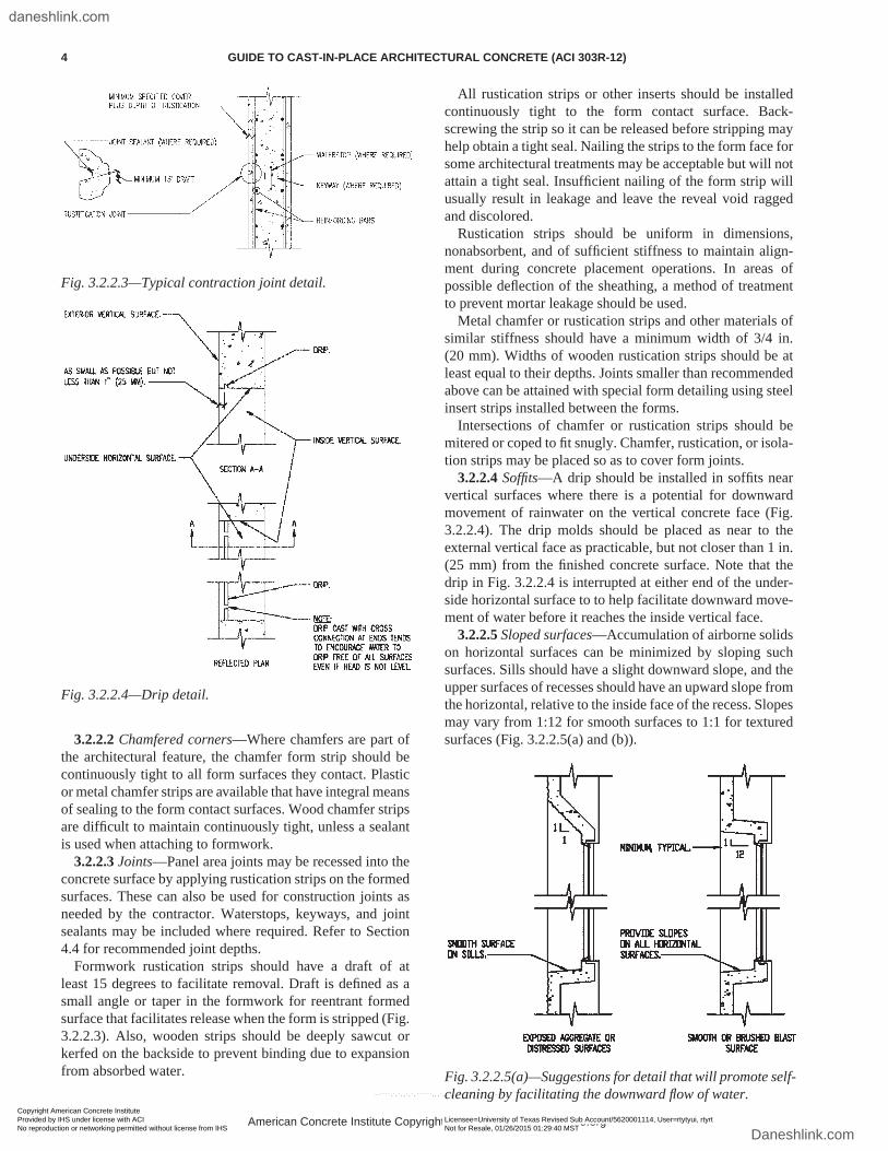
On parapets, the slope should be away from the face. Unsloped horizontal offsets in vertical recesses and the use of textures on horizontal surfaces should be avoided. If a horizontal recess is formed without a drip near the exterior face, a slight upward slope, relative to the exterior face, should be provided (Fig. 3.2.2.5(c)).
Sloped and horizontal surfaces cast against a form will trap air bubbles as the concrete is consolidated. Special tech-niques and materials may be required to reduce trapped air, such as an absorbent form face. Refer to ACI 309R-05 for more information.
3.2.3 Combination with precast concrete—Cast-in-place architectural concrete and precast elements may be success-fully combined using one of two site options:
1. On-site—Color and texture may be reasonably matched by on-site precasting at the same time cast-in-place work is done, using the same concrete mixture, materials, formwork techniques, and curing for both types of concrete; or
2. Off-site—Contrasting colors and textures in the design between off-site precast concrete and cast-in-place archi-tectural elements are provided. In some cases, color and texture can be closely matched using dissimilar materials. A mockup panel can be used to demonstrate the match for approval by the architect.
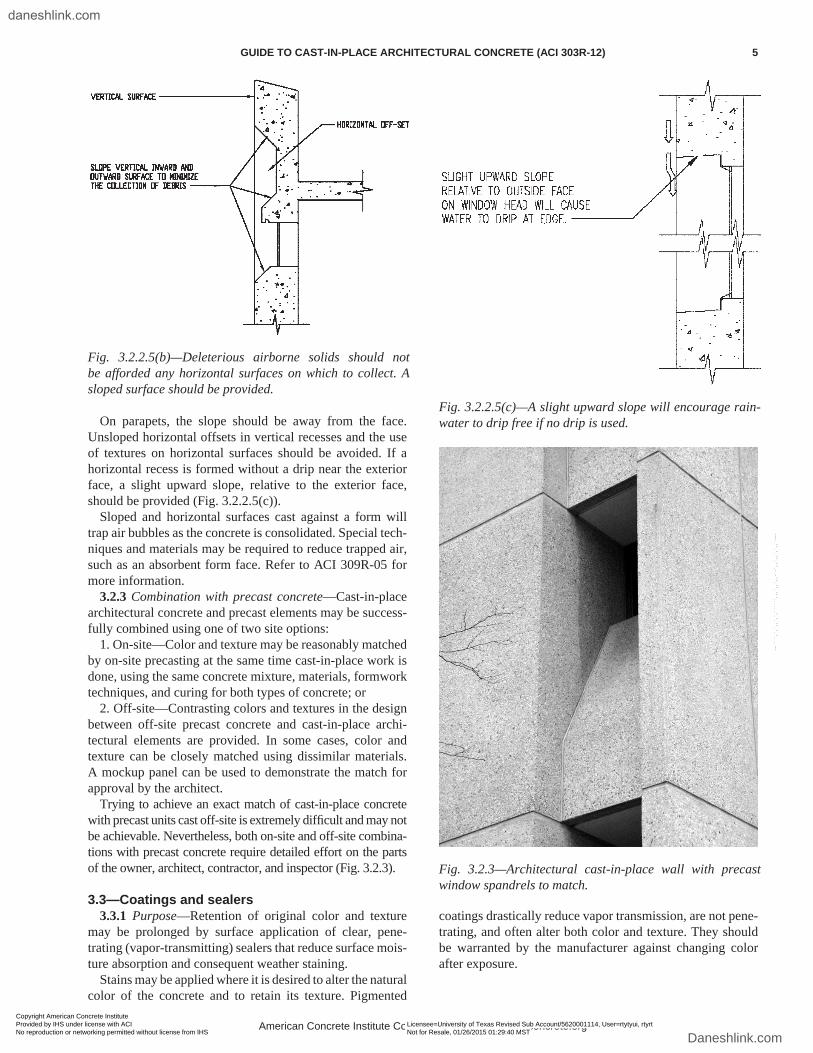
Trying to achieve an exact match of cast-in-place concrete with precast units cast off-site is extremely difficult and may not be achievable. Nevertheless, both on-site and off-site combina-tions with precast concrete require detailed effort on the parts of the owner, architect, contractor, and inspector (Fig. 3.2.3).
3.3—Coatings and sealers3.3.1 Purpose—Retention of original color and texture
may be prolonged by surface application of clear, pene-trating (vapor-transmitting) sealers that reduce surface mois-ture absorption and consequent weather staining.
Stains may be applied where it is desired to alter the natural color of the concrete and to retain its texture. Pigmented
coatings drastically reduce vapor transmission, are not pene-trating, and often alter both color and texture. They should be warranted by the manufacturer against changing color after exposure.
Fig. 3.2.2.5(b)—Deleterious airborne solids should not be afforded any horizontal surfaces on which to collect. A sloped surface should be provided.
Fig. 3.2.2.5(c)—A slight upward slope will encourage rain-water to drip free if no drip is used.
Fig. 3.2.3—Architectural cast-in-place wall with precast window spandrels to match.
American Concrete Institute Copyrighted Material—www.concrete.org
GUIDE TO CAST-IN-PLACE ARCHITECTURAL CONCRETE (ACI 303R-12) 5
Copyright American Concrete Institute Provided by IHS under license with ACI Licensee=University of Texas Revised Sub Account/5620001114, User=rtytyui, rtyrt
Not for Resale, 01/26/2015 01:29:40 MSTNo reproduction or networking permitted without license from IHS
--````,`,`,,`,`,``````,,,`,,`,,-`-`,,`,,`,`,,`---
daneshlink.com
Daneshlink.com
3.4—Joint sealantsPassage of moisture through construction and contraction
joints should be prevented by filling the joints with seal-ants as recommended in ACI 224.3R-95. For architectural reasons, the sealant should be approved by the architect, match well in color and shape with the adjacent concrete surface, be nonstaining, and be chemically compatible with clear penetrating sealers.
3.5—Specifications3.5.1 General—Specifications are customarily prepared
as either performance, prescriptive, or a combination of both (Bell 1996):• Performance specification—The quality of the end
product is specified and, in this case, full responsibility is placed on the contractor. Recommended methods may be suggested.
• Prescriptive specification—Detailed methods, materials, and procedures are specified and, in this case, responsi-bility is shared by the designer and contractor with the purpose of the mockup being to confirm the specified materials and methods and to demonstrate the contrac-tor’s ability to produce the desired architectural finish.
Most exposed aggregate projects use a combination of performance and prescriptive specifications, where aggre-gate proportions, cement source, and minimum vibration frequency are specified to ensure success without specifying actual methods of construction.
3.5.2 Design reference sample—Surface quality and appearance requirements should be referenced for bidding purposes to an actual sample or samples exhibiting the desired surfaces, color, and texture.
The sample should be prepared under the architect’s direction and labeled as the design reference sample (DRS). A minimum size of 18 x 18 x 2 in. (460 x 460 x 50 mm) provides sufficient area for display and thickness for surface tooling and allows for easy handling. The sample should
be cast vertically or horizontally similar to the position in which the final concrete will be cast.
Design reference samples of walls or other representative building elements should be available for inspection and examination by prospective bidders. Mixture proportions, placement method, and sources of materials should also be provided. The samples should be confirmed in writing by both the owner and architect/engineer so as to have equal legal status with the contract documents.
In special cases, such as building additions or additional structures within a pre-existing group or complex, it may be acceptable to use an existing building for reference that contains elements of the desired quality and appearance.
3.5.3 Mandatory prebid conference—A mandatory prebid conference should be held between the architect/engineer and the prospective bidding contractors, where expectations and requirements are explained and clarified. An acceptable architectural finish should be presented as established by the contract documents. At this time, the contractors will have an opportunity to discuss aspects of the specifications that make it difficult or impossible to achieve the desired effect. Minutes of the prebid conference should be issued as part of the bid documents.
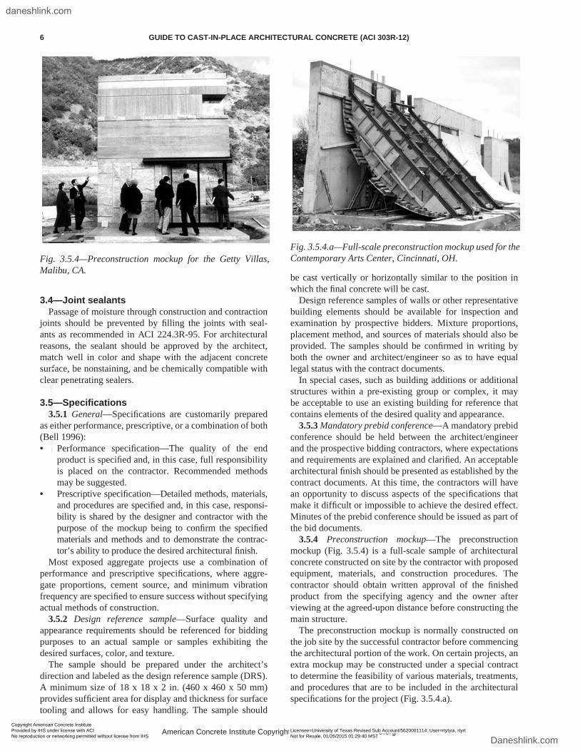
3.5.4 Preconstruction mockup—The preconstruction mockup (Fig. 3.5.4) is a full-scale sample of architectural concrete constructed on site by the contractor with proposed equipment, materials, and construction procedures. The contractor should obtain written approval of the finished product from the specifying agency and the owner after viewing at the agreed-upon distance before constructing the main structure.
The preconstruction mockup is normally constructed on the job site by the successful contractor before commencing the architectural portion of the work. On certain projects, an extra mockup may be constructed under a special contract to determine the feasibility of various materials, treatments, and procedures that are to be included in the architectural specifications for the project (Fig. 3.5.4.a).
Fig. 3.5.4—Preconstruction mockup for the Getty Villas, Malibu, CA.
Fig. 3.5.4.a—Full-scale preconstruction mockup used for the Contemporary Arts Center, Cincinnati, OH.
American Concrete Institute Copyrighted Material—www.concrete.org
6 GUIDE TO CAST-IN-PLACE ARCHITECTURAL CONCRETE (ACI 303R-12)
Copyright American Concrete Institute Provided by IHS under license with ACI Licensee=University of Texas Revised Sub Account/5620001114, User=rtytyui, rtyrt
Not for Resale, 01/26/2015 01:29:40 MSTNo reproduction or networking permitted without license from IHS
--````,`,`,,`,`,``````,,,`,,`,,-`-`,,`,,`,`,,`---
daneshlink.com
Daneshlink.com

The overall height and width of the full-scale mockup should allow the demonstration of floor, column, and wall construction. The mockup should incorporate both horizontal and vertical form or form liner joints, placing method and equipment, and all of the specified reinforcement, accesso-ries, and curing materials and equipment. All construction materials for the mockup should be the same as those used during the actual construction of the project. Ideally, the main vibrator operator for the concrete in the final structure should also operate the vibrator during construction of the mockup.
The mockup should also include a repaired area to deter-mine ahead of time an acceptable color and texture match for use if remedial work is needed. In evaluating this experi-mentally repaired area, the repair should be aged at least 1 month to allow enough time for a true indication of its color. To expedite construction of the project, a minimum of five variations of mixture color should be made for selection of the best match. Perfecting a repair procedure can save both time and money in the final outcome of the project.
Where feasible, architectural concrete placement, treatment, and procedures can be evaluated on portions of the structure eventually hidden from view, such as basement walls.
3.5.5 Shop drawings—Shop-drawing submittals are effec-tive tools for reviewing the contractor’s plans for construc-tion. The shop drawings should include:• Details of the formwork aspects of the project, including
form butt joints, rustications or reveals, and construction joints. They should convey to the architect the means and methods the contractor will be using to fabricate and erect the formwork and show how the forms will be maintained to ensure tightness against leakage and alignment during concrete placement;
• Cover of reinforcing steel; and• Description of the placing operation, including the
method of conveying concrete to the forms, wall place-ment lengths and lift heights, soffit deposit sequences, and vibration techniques.
3.5.6 Inspection and quality control3.5.6.1 General—The architect, contractor, project
inspector, suppliers, and other parties involved with the production of the architectural concrete may interpret the results of the finished product differently. These interpreta-tions may vary during progress of the work, especially in circumstances where expectations of the outcome appear impossible to achieve if maintaining the existing prac-tice of construction and materials. To avoid ambiguities midway through the project, the inspector should review the specifications early on, meeting with the architect/engi-neer and contractor after the mockup has been constructed, and confirming established criteria for evaluating the final product (ACI SP-2 1999). Section 3.5.6 addresses additional concerns not covered in ACI SP-2 (1999).
3.5.6.2 Qualification of the inspector—The inspector should have experience in the inspection of architectural concrete of equivalent complexity and scope. The extent of the inspector’s responsibility is determined by the architect/engineer. Confirmation of this responsibility is developed at
the prebid and postbid conferences with the contractors. The architect and inspector should hold periodic conferences to discuss the progress and quality of the work. On major proj-ects where different operations are proceeding concurrently, more than one inspector may be required to inspect the work.
3.5.6.3 Duties of the inspector—The duties and responsi-bilities of the inspector should include:• Reviewing project documents in advance of the prebid
conference and advising the architect/engineer of changes that may be required to produce the desired results;
• Inspecting and personally observing the manufacture of the prebid samples. This will provide the inspector with invaluable knowledge and experience regarding the mixture, slump, color, and placing characteristics of the concrete. During the contract period that follows, any variation would immediately become apparent;
• Attending the prebid conference to assist the architect/engineer in clarifying the intent of the specifications;
• Being present during construction of the preconstruc-tion mockup to observe and evaluate the materials and techniques used to produce and repair the panel. The inspector, after completion of these efforts, will be ready to assist the architect/engineer in evaluating the quality of the completed architectural concrete work;
• Providing inspection of materials used for concrete mixture, forming or texturing, form release agents and their application, form alignment, tightness of the form joints, rustication fastening, placement of reinforcing steel relative to the exposed face, curing before and subsequent to the form stripping, required repairs, and final clean-down. Each of these contributes to the appearance of the finished surface of the architectural concrete; and
• Observing and recording the condition of the archi-tectural forms after each reuse and consulting with the contractor and architect when the forms need to be replaced or refurbished to achieve uniformity of the architectural surface.
3.5.6.4 Final acceptance—If the procedures determined by the approved on-site mockup are continued throughout the project, final acceptance at the agreed-upon distance should not be a problem. Due to the inevitable nonuniformity of construction practices, some repairs will be required. Their final acceptability will depend on the contractor’s blending technique and skill. Periodic review by the inspector and the architect/engineer to allow partial acceptance creates goodwill and confidence with all concerned. After final acceptance, the inspector’s records should be completed and filed. If later additions are made or adjoining buildings constructed, these records will be helpful for construction.
CHAPTER 4—STRUCTURAL CONSIDERATIONSStructural and architectural design should function together
to produce a structure capable of withstanding service loads and stresses without excessive cracking, spalling, or deflec-tion that may detract from the architectural appearance of the structure.
American Concrete Institute Copyrighted Material—www.concrete.org
GUIDE TO CAST-IN-PLACE ARCHITECTURAL CONCRETE (ACI 303R-12) 7
Copyright American Concrete Institute Provided by IHS under license with ACI Licensee=University of Texas Revised Sub Account/5620001114, User=rtytyui, rtyrt
Not for Resale, 01/26/2015 01:29:40 MSTNo reproduction or networking permitted without license from IHS
--````,`,`,,`,`,``````,,,`,,`,,-`-`,,`,,`,`,,`---
daneshlink.com
Daneshlink.com
4.1—SpallingIn their design, the architect and engineer should pay
special attention to applied loads at joints where movement can occur and cause spalling.
4.2—DeflectionsThe use of strength design requires strict investigation for
undesirable deflections in beams or spandrels exposed as architectural concrete. The desired camber should be speci-fied to compensate for the deflection of the completed struc-tural member. Consideration should also be given to addi-tional long-term deflection due to creep of concrete under permanent loads. Architectural requirements may dictate that the engineer design for deflections less than normally acceptable. They may also require additional camber to avoid the impression of sagging in long spans. Excessive camber can, in some cases, be as objectionable as sag.
4.3—CrackingCracking in architectural concrete can be unsightly.
Practices to reduce and control cracking to minimize the effect on appearance and durability should be used.
Factors that influence concrete cracking are:• Gravity or lateral loads that produce tension, shear, or
torsion in members;• Restraint of drying shrinkage;• Creep;• Abrupt change in geometry, such as concrete thickness;• Axial or bending stresses due to thermal effects; and• Foundation settlement.
Cracking may be reduced by:• Adding reinforcement, closure strips, and other methods
at bearings or slip joints as needed to correct axial short-ening and rotation due to post-tensioning;
• Limiting the flexural tension stress in reinforcement;• Distributing flexural reinforcement when appropriate
(ACI 318-11);• Using special materials, such as shrinkage-reducing
admixtures, shrinkage-compensating cements, and aggregates with low shrinkage characteristics, or selected proportions of these (ACI 223R-10);
• Minimizing the total water content, along with the water-cementitious material ratio (w/cm) of the concrete mixture by optimizing the aggregate grading. Some water-reducing admixtures may increase shrinkage despite a reduction in water;
• Minimizing the change in member-to-member geom-etry or mass;
• Evaluating trial batches with various combinations of aggregates, cements, and admixtures, and checking for shrinkage using ASTM C157/C157M-08;
• Increasing the shrinkage and temperature reinforcement above the minimum requirements in ACI 318-11;
• Minimizing thermal stresses by controlling heat of hydration and cooling; and
• Providing joints or crack-inducing devices to relieve stress.In addition to the aformentioned methods, cracking can
often be minimized by attention to joint placement, which
relieves the shrinkage stresses and directs the cracking to joints that are integral with the designed surface presenta-tion. This is often achieved through rustication or reveals on the concrete surface with internal devices, which weaken the concrete at predetermined lines to induce the concrete to crack at that location. An induced crack should be sealed when exposed to weather to prevent water penetration. This is done by applying sealant in the surface rustication or reveal void or by placing a waterstop-type internal crack-inducing device in the concrete.
4.4—JointsConstruction joints divide the structure into segments that
can be constructed in a logical and efficient manner; contrac-tion joints are used in walls and slabs-on-ground to control cracking; and isolation joints are used in slabs-on-ground to separate them from walls, columns, or other structural elements. Details should be shown in the project drawings.
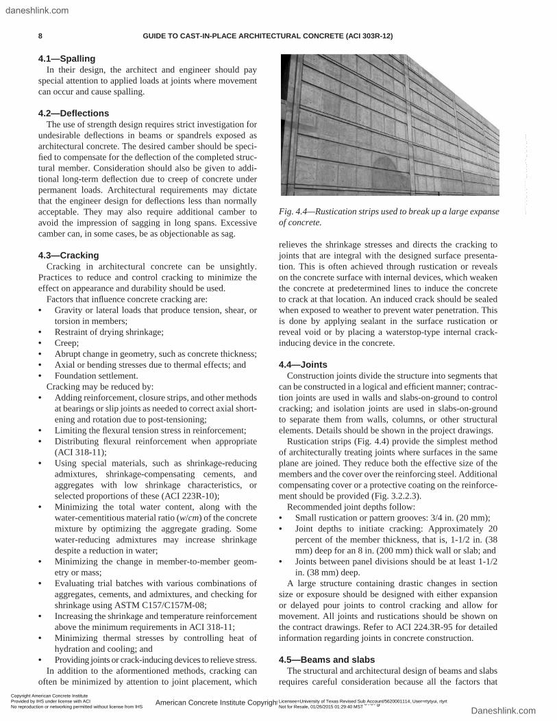
Rustication strips (Fig. 4.4) provide the simplest method of architecturally treating joints where surfaces in the same plane are joined. They reduce both the effective size of the members and the cover over the reinforcing steel. Additional compensating cover or a protective coating on the reinforce-ment should be provided (Fig. 3.2.2.3).
Recommended joint depths follow:• Small rustication or pattern grooves: 3/4 in. (20 mm);• Joint depths to initiate cracking: Approximately 20
percent of the member thickness, that is, 1-1/2 in. (38 mm) deep for an 8 in. (200 mm) thick wall or slab; and
• Joints between panel divisions should be at least 1-1/2 in. (38 mm) deep.
A large structure containing drastic changes in section size or exposure should be designed with either expansion or delayed pour joints to control cracking and allow for movement. All joints and rustications should be shown on the contract drawings. Refer to ACI 224.3R-95 for detailed information regarding joints in concrete construction.
4.5—Beams and slabsThe structural and architectural design of beams and slabs
requires careful consideration because all the factors that
Fig. 4.4—Rustication strips used to break up a large expanse of concrete.
American Concrete Institute Copyrighted Material—www.concrete.org
8 GUIDE TO CAST-IN-PLACE ARCHITECTURAL CONCRETE (ACI 303R-12)
Copyright American Concrete Institute Provided by IHS under license with ACI Licensee=University of Texas Revised Sub Account/5620001114, User=rtytyui, rtyrt
Not for Resale, 01/26/2015 01:29:40 MSTNo reproduction or networking permitted without license from IHS
--````,`,`,,`,`,``````,,,`,,`,,-`-`,,`,,`,`,,`---
daneshlink.com
Daneshlink.com
produce tension in concrete may be present in portions of the member.
Rustication depths should be kept to the minimum recom-mended size at the top and bottom of beams in regions of flexural tension. When the typical concrete cover on the steel is increased excessively by the depth of the rustication strip, any cracks that occur in the flexural tension zone will also be increased in width. Sandblasting accentuates the width of a crack due to rounding of its edge, especially at soffits of beams and slabs. Connections that are intended to allow substantial rotation or displacement should be designed and detailed to prevent spalling and leaking from weather exposure.
Openings in slabs induce cracks from the corners of the openings. Diagonal bars placed in the corners of the slab openings are effective in preventing or minimizing crack width at these locations. The slab should have sufficient thickness to accommodate these bars and the design rein-forcement. The effect of openings on the structural capacity of slabs must be reviewed by the architect/engineer.
4.6—ColumnsTypically, concrete columns do not have the high tensile
stresses present in beams. The lateral dimensions are usually small and there is less tendency for vertical cracking. The small lateral dimensions also allow for rapid concrete place-ment compared to other elements. This tends to eliminate some of the problems associated with slow concrete place-ment such as cold joints and mortar splatter. Columns asso-ciated with long span beams may have a tendency to exhibit horizontal cracking as they become loaded because long span beams will generally induce greater bending moments in columns than comparable shorter span beams. Thermal movements and movement due to concrete shrinkage can also cause horizontal cracking in columns. The engineer should take these added effects into consideration when designing the column reinforcing.
4.7—WallsThe typical wall is relatively long, and may be tall,
compared to its thickness. Normally in compression verti-cally, horizontal cracking is generally not a problem, but horizontal cracks may develop where a wall receives significant lateral loading or supports other elements that produce vertical bending moments. Horizontal cracking can occur when the concrete further consolidates subsequent to vibration of thick walls. These cracks can be prevented by ensuring that each lift is integrated with the previous lift by using a good vibrator spacing and insertion time. The most common cracking in walls is generally vertical or nearly vertical. The primary cause of vertical cracks in walls is axial tension caused by restrained drying shrinkage, temper-ature stresses, or both.
Construction joints are normally provided at the bottom and top of slabs at the intersection of the walls and slabs. Construction joints should also be provided at other loca-tions necessary for construction and to control cracking. These joints should be concealed, rusticated, or empha-
sized. Joints required for construction should be coordinated between the contractor and the architect/engineer.
Vertical construction joints in long walls may be neces-sary at midspan or at some multiple of the bay length. An architectural approach is to provide for vertical rustications at a uniform spacing in all bays. This provides the contractor greater flexibility in planning the construction operation.
Vertical construction joints with rustication strips can be detailed as joints to accommodate volume-change move-ments and to reduce the horizontal extent of the casting operation, or can be detailed as crack-control joints. This permits the acceleration of the vertical rate of casting that, particularly in hot weather, will eliminate or make manage-able the problems associated with surface air voids, form spatter, cold joints, and lift lines. Form spatter is mortar splashed on forms that is allowed to dry before covering with concrete. This creates a nonuniform surface that positively affects the architectural appearance. The architect/engineer should consider the formwork panel size in planning the joint locations; form-facing material joints may be visible on the concrete surface even though subsequent mechanical finishing is performed on the hardened concrete surfaces.
An effective method for controlling vertical cracking is providing contraction joints at a uniform spacing of not more than 20 ft (6 m) on center by placing deep (1.5 times the maximum aggregate size), narrow rustication strips on both wall faces to induce cracking. Any of the contraction joint locations can also be used for construction joints.
Consideration should be given to reducing the reinforce-ment crossing contraction and construction joints that are used for crack control. Suggested reinforcement crossing either type of joint should not exceed 1/2 of the horizontal reinforcement elsewhere in the wall. The minimum hori-zontal reinforcement required in walls by ACI 318-11 may be increased to minimize the widths of cracks that may occur between joints.
Consideration may also be given to the use of fiber rein-forcement as a means of reducing the width of the visible crack. Fibers may be seen at the surface and should be approved in the mockup.
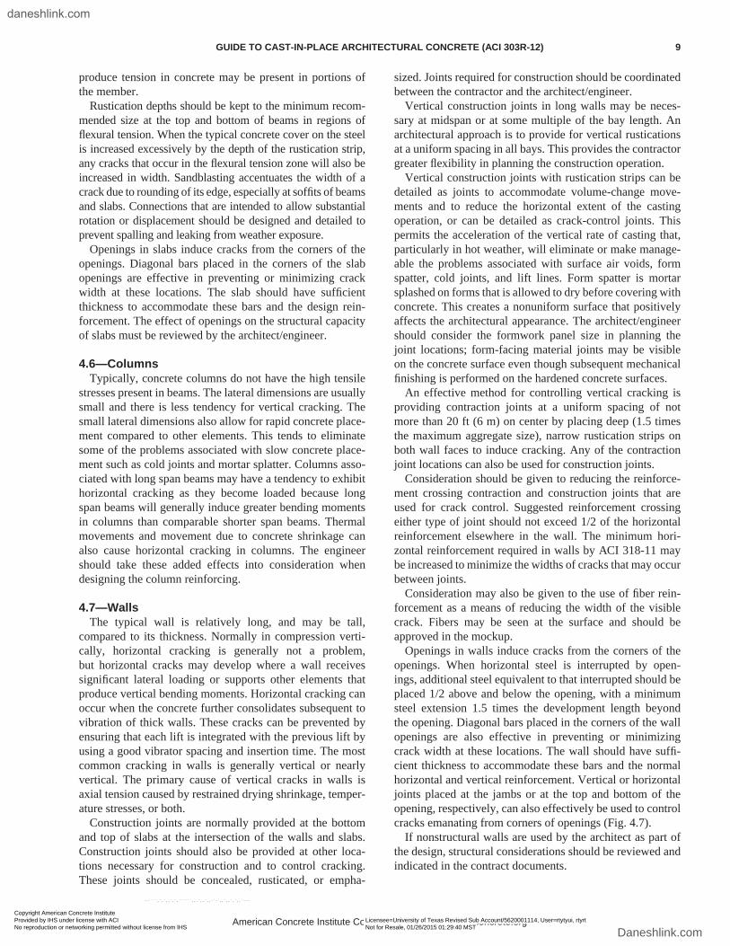
Openings in walls induce cracks from the corners of the openings. When horizontal steel is interrupted by open-ings, additional steel equivalent to that interrupted should be placed 1/2 above and below the opening, with a minimum steel extension 1.5 times the development length beyond the opening. Diagonal bars placed in the corners of the wall openings are also effective in preventing or minimizing crack width at these locations. The wall should have suffi-cient thickness to accommodate these bars and the normal horizontal and vertical reinforcement. Vertical or horizontal joints placed at the jambs or at the top and bottom of the opening, respectively, can also effectively be used to control cracks emanating from corners of openings (Fig. 4.7).
If nonstructural walls are used by the architect as part of the design, structural considerations should be reviewed and indicated in the contract documents.
American Concrete Institute Copyrighted Material—www.concrete.org
GUIDE TO CAST-IN-PLACE ARCHITECTURAL CONCRETE (ACI 303R-12) 9
Copyright American Concrete Institute Provided by IHS under license with ACI Licensee=University of Texas Revised Sub Account/5620001114, User=rtytyui, rtyrt
Not for Resale, 01/26/2015 01:29:40 MSTNo reproduction or networking permitted without license from IHS
--````,`,`,,`,`,``````,,,`,,`,,-`-`,,`,,`,`,,`---
daneshlink.com
Daneshlink.com
CHAPTER 5—FORMS
5.1—GeneralThrough general drawings, specifications, samples, and
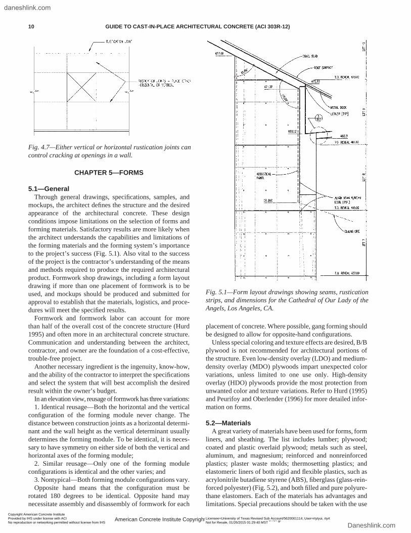
mockups, the architect defines the structure and the desired appearance of the architectural concrete. These design conditions impose limitations on the selection of forms and forming materials. Satisfactory results are more likely when the architect understands the capabilities and limitations of the forming materials and the forming system’s importance to the project’s success (Fig. 5.1). Also vital to the success of the project is the contractor’s understanding of the means and methods required to produce the required architectural product. Formwork shop drawings, including a form layout drawing if more than one placement of formwork is to be used, and mockups should be produced and submitted for approval to establish that the materials, logistics, and proce-dures will meet the specified results.
Formwork and formwork labor can account for more than half of the overall cost of the concrete structure (Hurd 1995) and often more in an architectural concrete structure. Communication and understanding between the architect, contractor, and owner are the foundation of a cost-effective, trouble-free project.
Another necessary ingredient is the ingenuity, know-how, and the ability of the contractor to interpret the specifications and select the system that will best accomplish the desired result within the owner’s budget.
In an elevation view, reusage of formwork has three variations:1. Identical reusage—Both the horizontal and the vertical
configuration of the forming module never change. The distance between construction joints as a horizontal determi-nant and the wall height as the vertical determinant usually determines the forming module. To be identical, it is neces-sary to have symmetry on either side of both the vertical and horizontal axes of the forming module;
2. Similar reusage—Only one of the forming module configurations is identical and the other varies; and
3. Nontypical—Both forming module configurations vary.Opposite hand means that the configuration must be
rotated 180 degrees to be identical. Opposite hand may necessitate assembly and disassembly of formwork for each
placement of concrete. Where possible, gang forming should be designed to allow for opposite-hand configurations.
Unless special coloring and texture effects are desired, B/B plywood is not recommended for architectural portions of the structure. Even low-density overlay (LDO) and medium-density overlay (MDO) plywoods impart unexpected color variations, unless limited to one use only. High-density overlay (HDO) plywoods provide the most protection from unwanted color and texture variations. Refer to Hurd (1995) and Peurifoy and Oberlender (1996) for more detailed infor-mation on forms.
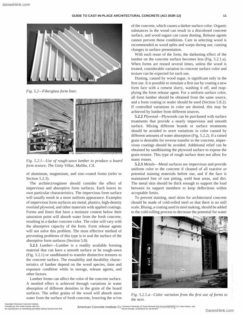
5.2—MaterialsA great variety of materials have been used for forms, form
liners, and sheathing. The list includes lumber; plywood; coated and plastic overlaid plywood; metals such as steel, aluminum, and magnesium; reinforced and nonreinforced plastics; plaster waste molds; thermosetting plastics; and elastomeric liners of both rigid and flexible plastics, such as acrylonitrile butadiene styrene (ABS), fiberglass (glass-rein-forced polyester) (Fig. 5.2), and both filled and pure polyure-thane elastomers. Each of the materials has advantages and limitations. Special precautions should be taken with the use
Fig. 4.7—Either vertical or horizontal rustication joints can control cracking at openings in a wall.
Fig. 5.1—Form layout drawings showing seams, rustication strips, and dimensions for the Cathedral of Our Lady of the Angels, Los Angeles, CA.
American Concrete Institute Copyrighted Material—www.concrete.org
10 GUIDE TO CAST-IN-PLACE ARCHITECTURAL CONCRETE (ACI 303R-12)
Copyright American Concrete Institute Provided by IHS under license with ACI Licensee=University of Texas Revised Sub Account/5620001114, User=rtytyui, rtyrt
Not for Resale, 01/26/2015 01:29:40 MSTNo reproduction or networking permitted without license from IHS
--````,`,`,,`,`,``````,,,`,,`,,-`-`,,`,,`,`,,`---
daneshlink.com
Daneshlink.com
of aluminum, magnesium, and zinc-coated forms (refer to Section 5.2.3).
The architect/engineer should consider the effect of impervious and absorptive form surfaces. Each leaves its own particular characteristics. The impervious form surface will usually result in a more uniform appearance. Examples of impervious form surfaces are metal, plastics, high-density overlaid plywood, and other materials with applied coatings. Forms and liners that have a moisture content below their saturation point will absorb water from the fresh concrete, resulting in a darker concrete color. The color will vary with the absorptive capacity of the form. Form release agents will not solve this problem. The most effective method of preventing problems of this type is to seal the surface of the absorptive form surfaces (Section 5.8).
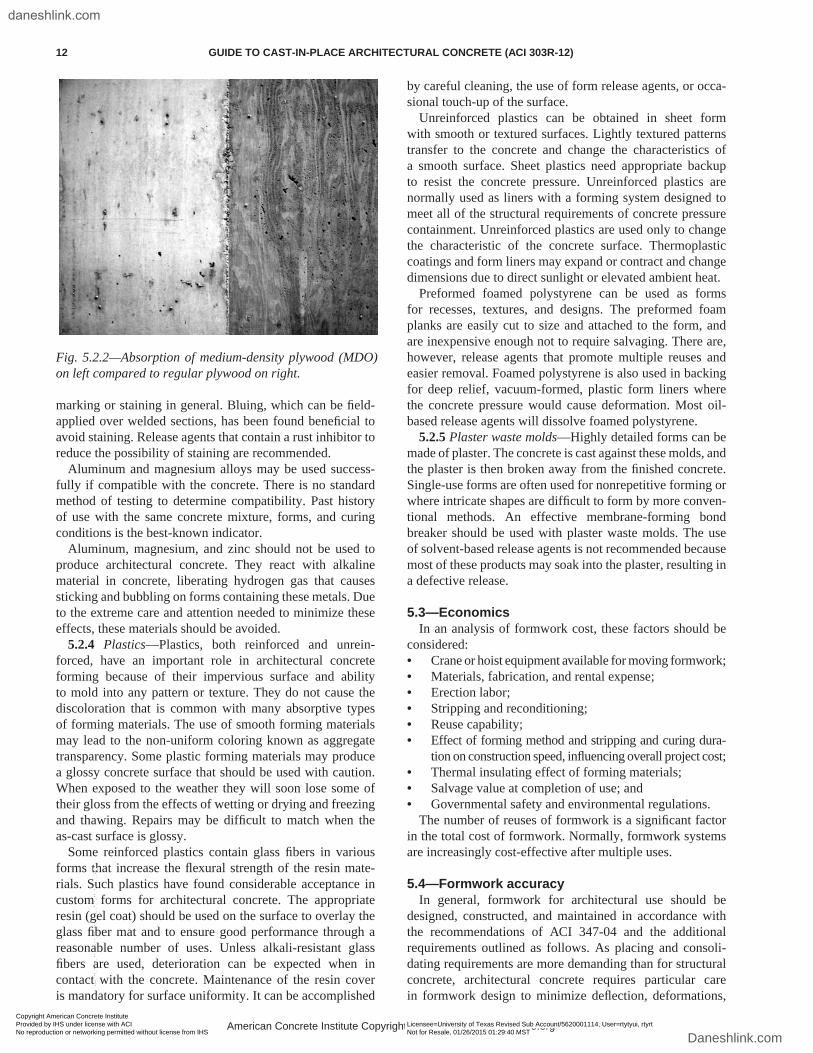
5.2.1 Lumber—Lumber is a readily available forming material that can have a smooth surface or be rough-sawn (Fig. 5.2.1) or sandblasted to transfer distinctive textures to the concrete surface. The reusability and durability charac-teristics of lumber depend on the wood species, time and exposure condition while in storage, release agents, and other factors.
Lumber forms can affect the color of the concrete surface. A mottled effect is achieved through variations in water absorption of different densities in the grain of the board surfaces. The softer grains of the wood will absorb more water from the surface of fresh concrete, lowering the w/cm
of the concrete, which causes a darker surface color. Organic substances in the wood can result in a discolored concrete surface, and wood sugars can cause dusting. Release agents cannot prevent these conditions. Care in selecting wood is recommended as wood splits and warps during use, causing changes in surface presentation.
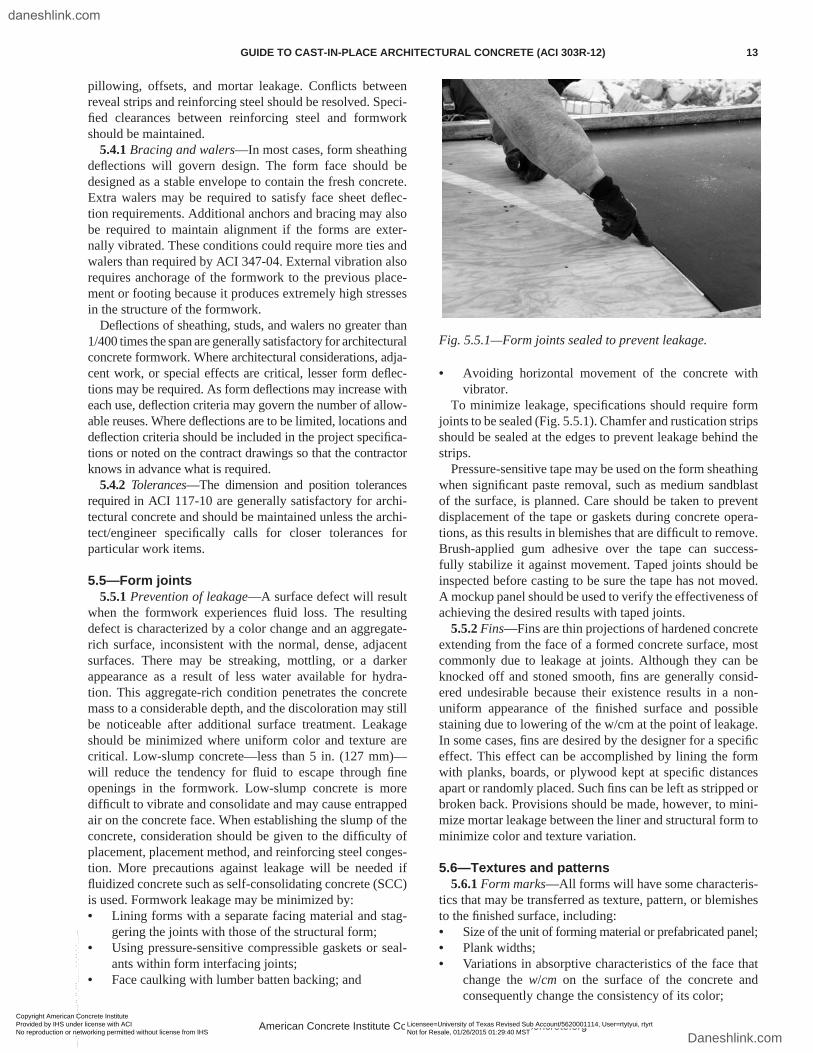
With each reuse of the form, the darkening effect of the lumber on the concrete surface becomes less (Fig. 5.2.1.a). When forms are reused several times, unless the wood is treated, considerable variation in concrete surface color and texture can be expected for each use.
Dusting, caused by wood sugar, is significant only in the first use. It is possible to simulate a first use by coating a new form face with a cement slurry, washing it off, and reap-plying the form release agent. For a uniform surface color, all form lumber should be obtained from the same source, and a form coating or sealer should be used (Section 5.8.2). If controlled variations in color are desired, this may be achieved by lumber from different sources.
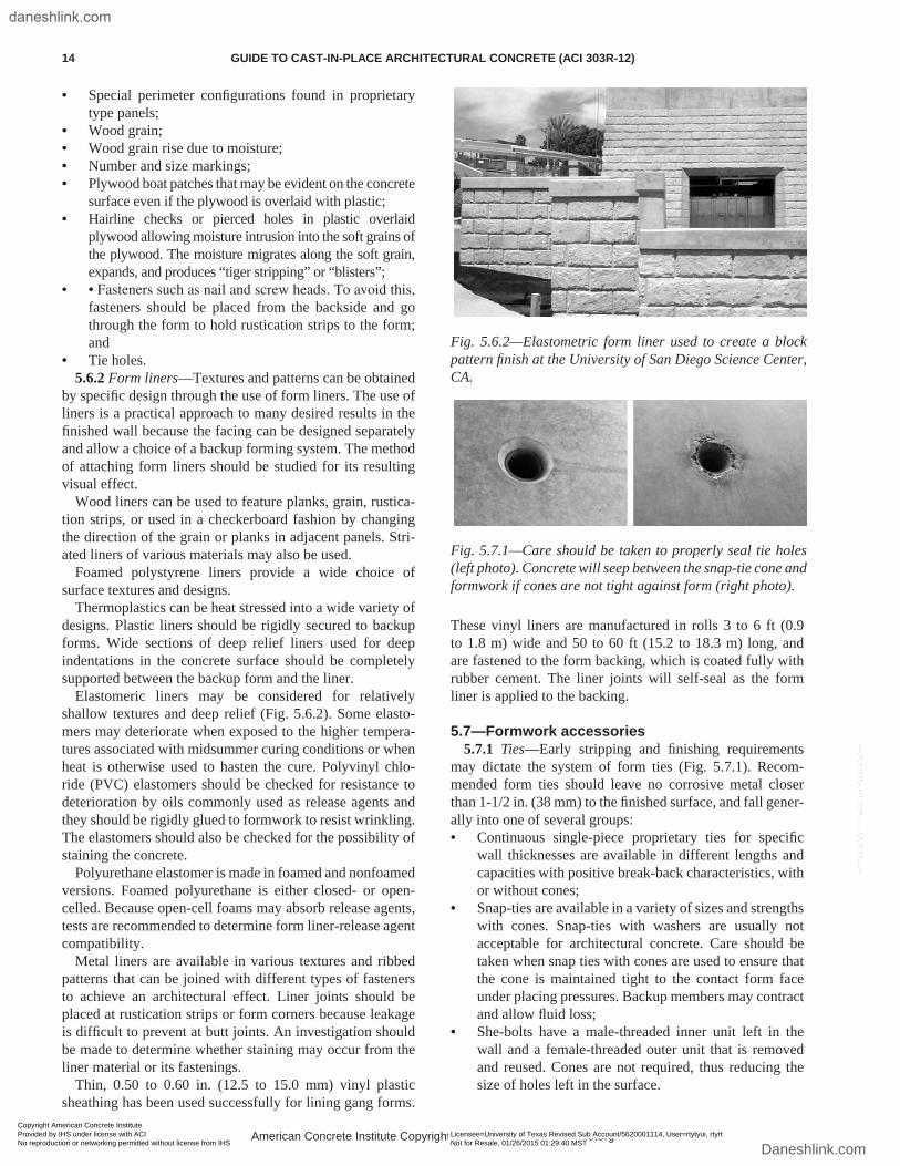
5.2.2 Plywood—Plywoods can be purchased with surface treatments that provide a nearly impervious and smooth surface. Mixing different brands or surface treatments should be avoided to avert variations in color caused by different amounts of water absorption (Fig. 5.2.2). If a raised grain is desirable for reverse transfer to the concrete, imper-vious coatings should be avoided. Additional relief can be obtained by sandblasting the plywood surface to expose the grain texture. This type of rough surface does not allow for many reuses.
5.2.3 Metals—Metal surfaces are impervious and provide uniform color to the concrete if cleaned of all reactive or potential staining materials before use, and if the face is maintained free of rust pitting, weld heat areas, and dirt. The metal skin should be thick enough to support the load between its support members to keep deflections within acceptable limits.
To prevent staining, steel skins for architectural concrete should be made of cold-rolled steel so that there is no mill scale. Bluing, a coating used in steel making, should be added to the cold-rolling process to decrease the potential for water
Fig. 5.2—Fiberglass form liner.
Fig. 5.2.1—Use of rough-sawn lumber to produce a board form texture, The Getty Villas, Malibu, CA.
Fig. 5.2.1.a—Color variation from the first use of forms to the next.
American Concrete Institute Copyrighted Material—www.concrete.org
GUIDE TO CAST-IN-PLACE ARCHITECTURAL CONCRETE (ACI 303R-12) 11
Copyright American Concrete Institute Provided by IHS under license with ACI Licensee=University of Texas Revised Sub Account/5620001114, User=rtytyui, rtyrt
Not for Resale, 01/26/2015 01:29:40 MSTNo reproduction or networking permitted without license from IHS
--````,`,`,,`,`,``````,,,`,,`,,-`-`,,`,,`,`,,`---
daneshlink.com
Daneshlink.com
marking or staining in general. Bluing, which can be field-applied over welded sections, has been found beneficial to avoid staining. Release agents that contain a rust inhibitor to reduce the possibility of staining are recommended.
Aluminum and magnesium alloys may be used success-fully if compatible with the concrete. There is no standard method of testing to determine compatibility. Past history of use with the same concrete mixture, forms, and curing conditions is the best-known indicator.
Aluminum, magnesium, and zinc should not be used to produce architectural concrete. They react with alkaline material in concrete, liberating hydrogen gas that causes sticking and bubbling on forms containing these metals. Due to the extreme care and attention needed to minimize these effects, these materials should be avoided.
5.2.4 Plastics—Plastics, both reinforced and unrein-forced, have an important role in architectural concrete forming because of their impervious surface and ability to mold into any pattern or texture. They do not cause the discoloration that is common with many absorptive types of forming materials. The use of smooth forming materials may lead to the non-uniform coloring known as aggregate transparency. Some plastic forming materials may produce a glossy concrete surface that should be used with caution. When exposed to the weather they will soon lose some of their gloss from the effects of wetting or drying and freezing and thawing. Repairs may be difficult to match when the as-cast surface is glossy.
Some reinforced plastics contain glass fibers in various forms that increase the flexural strength of the resin mate-rials. Such plastics have found considerable acceptance in custom forms for architectural concrete. The appropriate resin (gel coat) should be used on the surface to overlay the glass fiber mat and to ensure good performance through a reasonable number of uses. Unless alkali-resistant glass fibers are used, deterioration can be expected when in contact with the concrete. Maintenance of the resin cover is mandatory for surface uniformity. It can be accomplished
by careful cleaning, the use of form release agents, or occa-sional touch-up of the surface.
Unreinforced plastics can be obtained in sheet form with smooth or textured surfaces. Lightly textured patterns transfer to the concrete and change the characteristics of a smooth surface. Sheet plastics need appropriate backup to resist the concrete pressure. Unreinforced plastics are normally used as liners with a forming system designed to meet all of the structural requirements of concrete pressure containment. Unreinforced plastics are used only to change the characteristic of the concrete surface. Thermoplastic coatings and form liners may expand or contract and change dimensions due to direct sunlight or elevated ambient heat.
Preformed foamed polystyrene can be used as forms for recesses, textures, and designs. The preformed foam planks are easily cut to size and attached to the form, and are inexpensive enough not to require salvaging. There are, however, release agents that promote multiple reuses and easier removal. Foamed polystyrene is also used in backing for deep relief, vacuum-formed, plastic form liners where the concrete pressure would cause deformation. Most oil-based release agents will dissolve foamed polystyrene.
5.2.5 Plaster waste molds—Highly detailed forms can be made of plaster. The concrete is cast against these molds, and the plaster is then broken away from the finished concrete. Single-use forms are often used for nonrepetitive forming or where intricate shapes are difficult to form by more conven-tional methods. An effective membrane-forming bond breaker should be used with plaster waste molds. The use of solvent-based release agents is not recommended because most of these products may soak into the plaster, resulting in a defective release.
5.3—EconomicsIn an analysis of formwork cost, these factors should be
considered:• Crane or hoist equipment available for moving formwork;• Materials, fabrication, and rental expense;• Erection labor;• Stripping and reconditioning;• Reuse capability;• Effect of forming method and stripping and curing dura-
tion on construction speed, influencing overall project cost;• Thermal insulating effect of forming materials;• Salvage value at completion of use; and• Governmental safety and environmental regulations.
The number of reuses of formwork is a significant factor in the total cost of formwork. Normally, formwork systems are increasingly cost-effective after multiple uses.
5.4—Formwork accuracyIn general, formwork for architectural use should be
designed, constructed, and maintained in accordance with the recommendations of ACI 347-04 and the additional requirements outlined as follows. As placing and consoli-dating requirements are more demanding than for structural concrete, architectural concrete requires particular care in formwork design to minimize deflection, deformations,
Fig. 5.2.2—Absorption of medium-density plywood (MDO) on left compared to regular plywood on right.
American Concrete Institute Copyrighted Material—www.concrete.org
12 GUIDE TO CAST-IN-PLACE ARCHITECTURAL CONCRETE (ACI 303R-12)
Copyright American Concrete Institute Provided by IHS under license with ACI Licensee=University of Texas Revised Sub Account/5620001114, User=rtytyui, rtyrt
Not for Resale, 01/26/2015 01:29:40 MSTNo reproduction or networking permitted without license from IHS
--````,`,`,,`,`,``````,,,`,,`,,-`-`,,`,,`,`,,`---
daneshlink.com
Daneshlink.com
pillowing, offsets, and mortar leakage. Conflicts between reveal strips and reinforcing steel should be resolved. Speci-fied clearances between reinforcing steel and formwork should be maintained.
5.4.1 Bracing and walers—In most cases, form sheathing deflections will govern design. The form face should be designed as a stable envelope to contain the fresh concrete. Extra walers may be required to satisfy face sheet deflec-tion requirements. Additional anchors and bracing may also be required to maintain alignment if the forms are exter-nally vibrated. These conditions could require more ties and walers than required by ACI 347-04. External vibration also requires anchorage of the formwork to the previous place-ment or footing because it produces extremely high stresses in the structure of the formwork.
Deflections of sheathing, studs, and walers no greater than 1/400 times the span are generally satisfactory for architectural concrete formwork. Where architectural considerations, adja-cent work, or special effects are critical, lesser form deflec-tions may be required. As form deflections may increase with each use, deflection criteria may govern the number of allow-able reuses. Where deflections are to be limited, locations and deflection criteria should be included in the project specifica-tions or noted on the contract drawings so that the contractor knows in advance what is required.
5.4.2 Tolerances—The dimension and position tolerances required in ACI 117-10 are generally satisfactory for archi-tectural concrete and should be maintained unless the archi-tect/engineer specifically calls for closer tolerances for particular work items.
5.5—Form joints5.5.1 Prevention of leakage—A surface defect will result
when the formwork experiences fluid loss. The resulting defect is characterized by a color change and an aggregate-rich surface, inconsistent with the normal, dense, adjacent surfaces. There may be streaking, mottling, or a darker appearance as a result of less water available for hydra-tion. This aggregate-rich condition penetrates the concrete mass to a considerable depth, and the discoloration may still be noticeable after additional surface treatment. Leakage should be minimized where uniform color and texture are critical. Low-slump concrete—less than 5 in. (127 mm)—will reduce the tendency for fluid to escape through fine openings in the formwork. Low-slump concrete is more difficult to vibrate and consolidate and may cause entrapped air on the concrete face. When establishing the slump of the concrete, consideration should be given to the difficulty of placement, placement method, and reinforcing steel conges-tion. More precautions against leakage will be needed if fluidized concrete such as self-consolidating concrete (SCC) is used. Formwork leakage may be minimized by:• Lining forms with a separate facing material and stag-
gering the joints with those of the structural form;• Using pressure-sensitive compressible gaskets or seal-
ants within form interfacing joints;• Face caulking with lumber batten backing; and
• Avoiding horizontal movement of the concrete with vibrator.
To minimize leakage, specifications should require form joints to be sealed (Fig. 5.5.1). Chamfer and rustication strips should be sealed at the edges to prevent leakage behind the strips.
Pressure-sensitive tape may be used on the form sheathing when significant paste removal, such as medium sandblast of the surface, is planned. Care should be taken to prevent displacement of the tape or gaskets during concrete opera-tions, as this results in blemishes that are difficult to remove. Brush-applied gum adhesive over the tape can success-fully stabilize it against movement. Taped joints should be inspected before casting to be sure the tape has not moved. A mockup panel should be used to verify the effectiveness of achieving the desired results with taped joints.
5.5.2 Fins—Fins are thin projections of hardened concrete extending from the face of a formed concrete surface, most commonly due to leakage at joints. Although they can be knocked off and stoned smooth, fins are generally consid-ered undesirable because their existence results in a non-uniform appearance of the finished surface and possible staining due to lowering of the w/cm at the point of leakage. In some cases, fins are desired by the designer for a specific effect. This effect can be accomplished by lining the form with planks, boards, or plywood kept at specific distances apart or randomly placed. Such fins can be left as stripped or broken back. Provisions should be made, however, to mini-mize mortar leakage between the liner and structural form to minimize color and texture variation.
5.6—Textures and patterns5.6.1 Form marks—All forms will have some characteris-
tics that may be transferred as texture, pattern, or blemishes to the finished surface, including:• Size of the unit of forming material or prefabricated panel;• Plank widths;• Variations in absorptive characteristics of the face that
change the w/cm on the surface of the concrete and consequently change the consistency of its color;
Fig. 5.5.1—Form joints sealed to prevent leakage.
American Concrete Institute Copyrighted Material—www.concrete.org
GUIDE TO CAST-IN-PLACE ARCHITECTURAL CONCRETE (ACI 303R-12) 13
Copyright American Concrete Institute Provided by IHS under license with ACI Licensee=University of Texas Revised Sub Account/5620001114, User=rtytyui, rtyrt
Not for Resale, 01/26/2015 01:29:40 MSTNo reproduction or networking permitted without license from IHS
--````,`,`,,`,`,``````,,,`,,`,,-`-`,,`,,`,`,,`---
daneshlink.com
Daneshlink.com
• Special perimeter configurations found in proprietary type panels;
• Wood grain;• Wood grain rise due to moisture;• Number and size markings;• Plywood boat patches that may be evident on the concrete
surface even if the plywood is overlaid with plastic;• Hairline checks or pierced holes in plastic overlaid
plywood allowing moisture intrusion into the soft grains of the plywood. The moisture migrates along the soft grain, expands, and produces “tiger stripping” or “blisters”;
• •Fastenerssuchasnailandscrewheads.Toavoidthis,fasteners should be placed from the backside and go through the form to hold rustication strips to the form; and
• Tie holes.5.6.2 Form liners—Textures and patterns can be obtained
by specific design through the use of form liners. The use of liners is a practical approach to many desired results in the finished wall because the facing can be designed separately and allow a choice of a backup forming system. The method of attaching form liners should be studied for its resulting visual effect.
Wood liners can be used to feature planks, grain, rustica-tion strips, or used in a checkerboard fashion by changing the direction of the grain or planks in adjacent panels. Stri-ated liners of various materials may also be used.
Foamed polystyrene liners provide a wide choice of surface textures and designs.
Thermoplastics can be heat stressed into a wide variety of designs. Plastic liners should be rigidly secured to backup forms. Wide sections of deep relief liners used for deep indentations in the concrete surface should be completely supported between the backup form and the liner.
Elastomeric liners may be considered for relatively shallow textures and deep relief (Fig. 5.6.2). Some elasto-mers may deteriorate when exposed to the higher tempera-tures associated with midsummer curing conditions or when heat is otherwise used to hasten the cure. Polyvinyl chlo-ride (PVC) elastomers should be checked for resistance to deterioration by oils commonly used as release agents and they should be rigidly glued to formwork to resist wrinkling. The elastomers should also be checked for the possibility of staining the concrete.
Polyurethane elastomer is made in foamed and nonfoamed versions. Foamed polyurethane is either closed- or open-celled. Because open-cell foams may absorb release agents, tests are recommended to determine form liner-release agent compatibility.
Metal liners are available in various textures and ribbed patterns that can be joined with different types of fasteners to achieve an architectural effect. Liner joints should be placed at rustication strips or form corners because leakage is difficult to prevent at butt joints. An investigation should be made to determine whether staining may occur from the liner material or its fastenings.
Thin, 0.50 to 0.60 in. (12.5 to 15.0 mm) vinyl plastic sheathing has been used successfully for lining gang forms.
These vinyl liners are manufactured in rolls 3 to 6 ft (0.9 to 1.8 m) wide and 50 to 60 ft (15.2 to 18.3 m) long, and are fastened to the form backing, which is coated fully with rubber cement. The liner joints will self-seal as the form liner is applied to the backing.
5.7—Formwork accessories5.7.1 Ties—Early stripping and finishing requirements
may dictate the system of form ties (Fig. 5.7.1). Recom-mended form ties should leave no corrosive metal closer than 1-1/2 in. (38 mm) to the finished surface, and fall gener-ally into one of several groups:• Continuous single-piece proprietary ties for specific
wall thicknesses are available in different lengths and capacities with positive break-back characteristics, with or without cones;
• Snap-ties are available in a variety of sizes and strengths with cones. Snap-ties with washers are usually not acceptable for architectural concrete. Care should be taken when snap ties with cones are used to ensure that the cone is maintained tight to the contact form face under placing pressures. Backup members may contract and allow fluid loss;
• She-bolts have a male-threaded inner unit left in the wall and a female-threaded outer unit that is removed and reused. Cones are not required, thus reducing the size of holes left in the surface.
Fig. 5.6.2—Elastometric form liner used to create a block pattern finish at the University of San Diego Science Center, CA.
Fig. 5.7.1—Care should be taken to properly seal tie holes (left photo). Concrete will seep between the snap-tie cone and formwork if cones are not tight against form (right photo).
American Concrete Institute Copyrighted Material—www.concrete.org
14 GUIDE TO CAST-IN-PLACE ARCHITECTURAL CONCRETE (ACI 303R-12)
Copyright American Concrete Institute Provided by IHS under license with ACI Licensee=University of Texas Revised Sub Account/5620001114, User=rtytyui, rtyrt
Not for Resale, 01/26/2015 01:29:40 MSTNo reproduction or networking permitted without license from IHS
--````,`,`,,`,`,``````,,,`,,`,,-`-`,,`,,`,`,,`---
daneshlink.com
Daneshlink.com
• He-bolts are male-threaded devices that are reusable with an expendable female-threaded unit left in the wall, minimizing the size of holes left on the surface.
• Taper-ties are available in a variety of sizes and capacities;
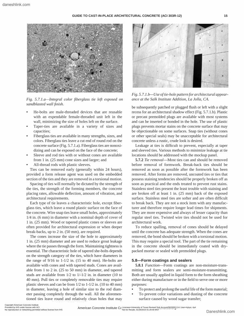
• Fiberglass ties are available in many strengths, sizes, and colors. Fiberglass ties leave a cut end of round rod on the concrete surface (Fig. 5.7.1.a). Fiberglass ties are nonoxi-dizing and can be exposed on the face of the concrete;
• Sleeve and rod ties with or without cones are available from 1 in. (25 mm) cone sizes and larger; and
• All-thread rods with plastic sleeves.Ties can be removed early (generally within 24 hours),
provided a form release agent was used on the embedded section of the ties and they are removed in a torsional motion.
Spacing of ties will normally be dictated by the strength of the ties, the strength of the forming members, the concrete placing rates, allowable deflection, amount of vibration, and architectural requirements.
Each type of tie leaves a characteristic hole, except fiber-glass ties, which leave a round plastic surface on the face of the concrete. Wire snap ties leave small holes, approximately 1/4 in. (6 mm) in diameter with a nominal depth of cover of 1 in. (25 mm). Wood or tapered plastic cones or sleeves are often provided for architectural expression or when deeper break-backs, up to 2 in. (50 mm), are required.
The cones increase the size of the hole to approximately 1 in. (25 mm) diameter and are used to reduce grout leakage where the tie passes through the form. Maintaining tightness is essential. The characteristic hole of tapered she-bolts depends on the strength category of the ties, which have diameters in the range of 9/16 to 1-1/2 in. (15 to 40 mm). He-bolts are available with cones and with tapered studs. Cones are avail-able from 1 to 2 in. (25 to 50 mm) in diameter, and tapered studs are available from 1/2 to 1/-1/2 in. in diameter (10 to 40 mm). Pull ties or completely removable ties may require plastic sleeves and can be from 1/2 to 1-1/2 in. (10 to 40 mm) in diameter, leaving a hole of similar size to the rod diam-eter passing completely through the wall. All the aforemen-tioned ties leave round and relatively clean holes that may
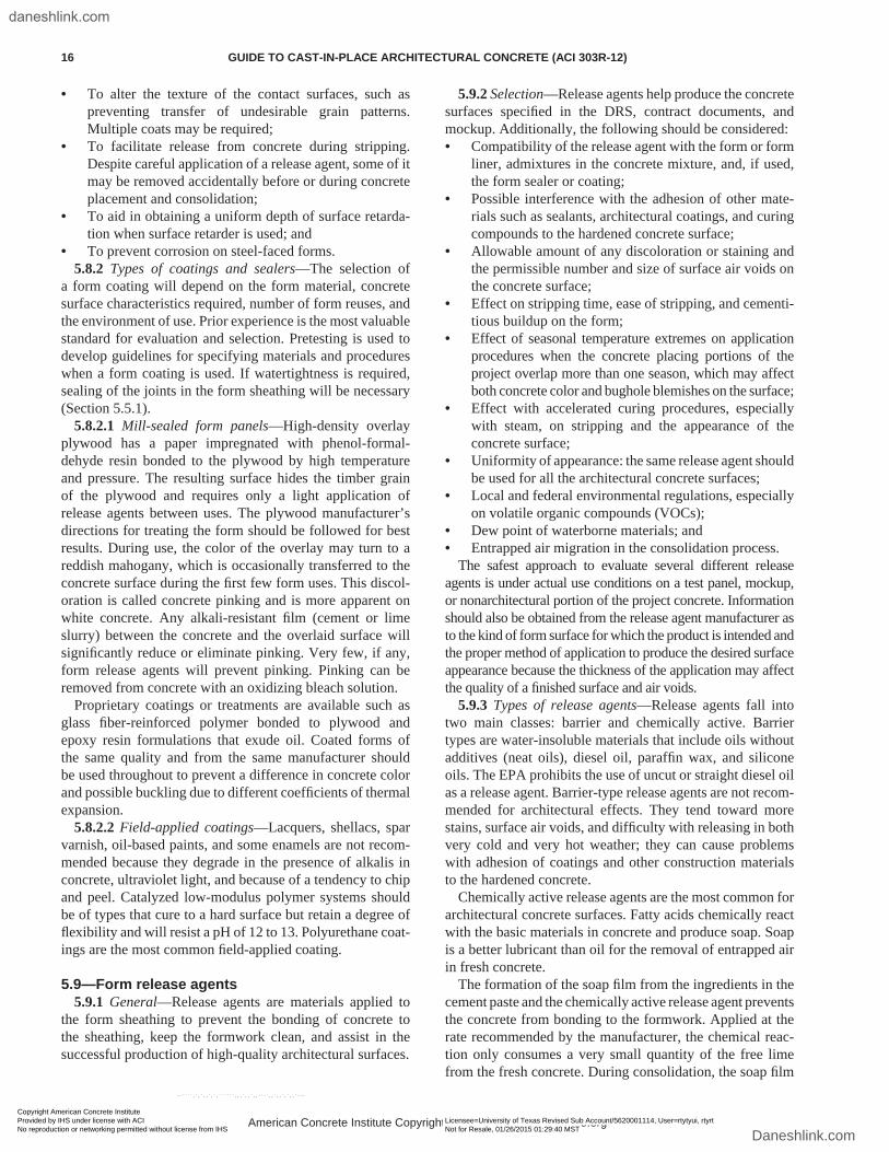
be subsequently patched or plugged flush or left with a slight recess for an architectural shadow effect (Fig. 5.7.1.b). Plastic or precast premolded plugs are available with most systems and can be inserted or bonded in the hole. The use of plastic plugs prevents mortar stains on the concrete surface that may be objectionable on some surfaces. Snap ties (without cones or other special seals) may be unacceptable for architectural concrete unless a rustic, crude look is desired.
Leakage at ties is difficult to prevent, especially at taper and sleeved ties. Various methods to minimize leakage at tie locations should be addressed with the mockup panel.
5.7.2 Tie removal—Most ties can and should be removed before removal of formwork. Break-back ties should be removed as soon as possible after the formwork has been removed. After forms are removed, uncoated ties or ties that possess staining tendencies should be properly broken off as soon as practical and the ends treated to prevent rust stains. Stainless steel ties present the least trouble with staining and are broken off at least 1 in. (25 mm) back of the exposed surface. Stainless steel ties are softer and are often difficult to break back. They are not a stock item with any manufac-turer and therefore require longer lead times for shipments. They are more expensive and always of lesser capacity than regular steel ties. Twisted wire ties should not be used for architectural work.
To reduce spalling, removal of cones should be delayed until the concrete has adequate strength. When the cones are removed, the bond should be broken with a torsional motion. This may require a special tool. The part of the tie remaining in the concrete should be immediately coated with dry-packed mortar or sealed with premolded plugs.
5.8—Form coatings and sealers5.8.1 Function—Form coatings are non-moisture-trans-
mitting and form sealers are semi-moisture-transmitting. Both are usually applied in liquid form to the form sheathing either during manufacture or in the field to serve one or more purposes:• To protect and prolong the useful life of the form material;• To prevent color variations and dusting of the concrete
surface caused by wood sugar transfer;
Fig. 5.7.1.a—Integral color fiberglass tie left exposed on sandblasted wall finish.
Fig. 5.7.1.b—Use of tie-hole pattern for architectural appear-ance at the Salk Institute Addition, La Jolla, CA.
American Concrete Institute Copyrighted Material—www.concrete.org
GUIDE TO CAST-IN-PLACE ARCHITECTURAL CONCRETE (ACI 303R-12) 15
Copyright American Concrete Institute Provided by IHS under license with ACI Licensee=University of Texas Revised Sub Account/5620001114, User=rtytyui, rtyrt
Not for Resale, 01/26/2015 01:29:40 MSTNo reproduction or networking permitted without license from IHS
--````,`,`,,`,`,``````,,,`,,`,,-`-`,,`,,`,`,,`---
daneshlink.com
Daneshlink.com
• To alter the texture of the contact surfaces, such as preventing transfer of undesirable grain patterns. Multiple coats may be required;
• To facilitate release from concrete during stripping. Despite careful application of a release agent, some of it may be removed accidentally before or during concrete placement and consolidation;
• To aid in obtaining a uniform depth of surface retarda-tion when surface retarder is used; and
• To prevent corrosion on steel-faced forms.5.8.2 Types of coatings and sealers—The selection of
a form coating will depend on the form material, concrete surface characteristics required, number of form reuses, and the environment of use. Prior experience is the most valuable standard for evaluation and selection. Pretesting is used to develop guidelines for specifying materials and procedures when a form coating is used. If watertightness is required, sealing of the joints in the form sheathing will be necessary (Section 5.5.1).
5.8.2.1 Mill-sealed form panels—High-density overlay plywood has a paper impregnated with phenol-formal-dehyde resin bonded to the plywood by high temperature and pressure. The resulting surface hides the timber grain of the plywood and requires only a light application of release agents between uses. The plywood manufacturer’s directions for treating the form should be followed for best results. During use, the color of the overlay may turn to a reddish mahogany, which is occasionally transferred to the concrete surface during the first few form uses. This discol-oration is called concrete pinking and is more apparent on white concrete. Any alkali-resistant film (cement or lime slurry) between the concrete and the overlaid surface will significantly reduce or eliminate pinking. Very few, if any, form release agents will prevent pinking. Pinking can be removed from concrete with an oxidizing bleach solution.
Proprietary coatings or treatments are available such as glass fiber-reinforced polymer bonded to plywood and epoxy resin formulations that exude oil. Coated forms of the same quality and from the same manufacturer should be used throughout to prevent a difference in concrete color and possible buckling due to different coefficients of thermal expansion.
5.8.2.2 Field-applied coatings—Lacquers, shellacs, spar varnish, oil-based paints, and some enamels are not recom-mended because they degrade in the presence of alkalis in concrete, ultraviolet light, and because of a tendency to chip and peel. Catalyzed low-modulus polymer systems should be of types that cure to a hard surface but retain a degree of flexibility and will resist a pH of 12 to 13. Polyurethane coat-ings are the most common field-applied coating.
5.9—Form release agents5.9.1 General—Release agents are materials applied to
the form sheathing to prevent the bonding of concrete to the sheathing, keep the formwork clean, and assist in the successful production of high-quality architectural surfaces.
5.9.2 Selection—Release agents help produce the concrete surfaces specified in the DRS, contract documents, and mockup. Additionally, the following should be considered:• Compatibility of the release agent with the form or form
liner, admixtures in the concrete mixture, and, if used, the form sealer or coating;
• Possible interference with the adhesion of other mate-rials such as sealants, architectural coatings, and curing compounds to the hardened concrete surface;
• Allowable amount of any discoloration or staining and the permissible number and size of surface air voids on the concrete surface;
• Effect on stripping time, ease of stripping, and cementi-tious buildup on the form;
• Effect of seasonal temperature extremes on application procedures when the concrete placing portions of the project overlap more than one season, which may affect both concrete color and bughole blemishes on the surface;
• Effect with accelerated curing procedures, especially with steam, on stripping and the appearance of the concrete surface;
• Uniformity of appearance: the same release agent should be used for all the architectural concrete surfaces;
• Local and federal environmental regulations, especially on volatile organic compounds (VOCs);
• Dew point of waterborne materials; and• Entrapped air migration in the consolidation process.
The safest approach to evaluate several different release agents is under actual use conditions on a test panel, mockup, or nonarchitectural portion of the project concrete. Information should also be obtained from the release agent manufacturer as to the kind of form surface for which the product is intended and the proper method of application to produce the desired surface appearance because the thickness of the application may affect the quality of a finished surface and air voids.
5.9.3 Types of release agents—Release agents fall into two main classes: barrier and chemically active. Barrier types are water-insoluble materials that include oils without additives (neat oils), diesel oil, paraffin wax, and silicone oils. The EPA prohibits the use of uncut or straight diesel oil as a release agent. Barrier-type release agents are not recom-mended for architectural effects. They tend toward more stains, surface air voids, and difficulty with releasing in both very cold and very hot weather; they can cause problems with adhesion of coatings and other construction materials to the hardened concrete.
Chemically active release agents are the most common for architectural concrete surfaces. Fatty acids chemically react with the basic materials in concrete and produce soap. Soap is a better lubricant than oil for the removal of entrapped air in fresh concrete.
The formation of the soap film from the ingredients in the cement paste and the chemically active release agent prevents the concrete from bonding to the formwork. Applied at the rate recommended by the manufacturer, the chemical reac-tion only consumes a very small quantity of the free lime from the fresh concrete. During consolidation, the soap film
American Concrete Institute Copyrighted Material—www.concrete.org
16 GUIDE TO CAST-IN-PLACE ARCHITECTURAL CONCRETE (ACI 303R-12)
Copyright American Concrete Institute Provided by IHS under license with ACI Licensee=University of Texas Revised Sub Account/5620001114, User=rtytyui, rtyrt
Not for Resale, 01/26/2015 01:29:40 MSTNo reproduction or networking permitted without license from IHS
--````,`,`,,`,`,``````,,,`,,`,,-`-`,,`,,`,`,,`---
daneshlink.com
Daneshlink.com
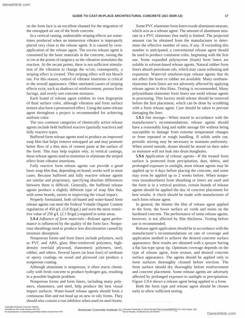
on the form face is an excellent channel for the migration of the entrapped air out of the fresh concrete.
In a vertical casting, undesirable striping effects are some-times produced when an immersion vibrator is improperly placed very close to the release agent. It is caused by over-application of the release agent. The excess release agent is consumed by the basic materials in the concrete, raising the w/cm at the points of tangency as the vibration stimulates the reaction. At the secant points, there is not sufficient stimula-tion of the vibration to change the w/cm; consequently, a striping effect is created. This striping effect will not bleach out. For this reason, control of vibrator insertions is critical to the overall appearance. Other unrelated causes of striping effects exist, such as shadows of reinforcement, porous form facings, and overly wet concrete mixtures.
Each brand of release agent exhibits its own fingerprint of final surface color, although vibration and form surface texture also have a pronounced effect. Using the same release agent throughout a project is recommended for achieving uniform color.
The two common categories of chemically active release agents include both buffered reactive (partially reactive) and fully reactive types.
Buffered form release agents tend to produce an improved soap film that helps remove entrapped air and may promote better flow of a thin skin of cement paste at the surface of the form. This may help explain why, in vertical castings, these release agents tend to minimize or eliminate the striped effect from vibrator insertions.
Fully reactive form release agents can provide a good basic soap film that, depending on brand, works well in most cases. Because buffered and fully reactive release agents are similar and proprietary, specifying absolute differences between them is difficult. Generally, the buffered release agents produce a slightly different type of soap film that, with some brands, assists in improving the visual impact.
Properly formulated, both oil-based and water-based form release agents can meet the Federal Volatile Organic Content regulations of 450 g/L (3.8 lb/gal.) and even the more restric-tive value of 250 g/L (2.1 lb/gal.) required in some areas.
5.9.4 Influence of form materials—Release agent perfor-mance is influenced by the quality of the form face. Nonpo-rous sheathings tend to produce less discoloration caused by moisture absorption.
Nonporous forms and form liners include polymers, such as PVC and ABS, glass fiber-reinforced polymers, high-density overlaid plywood, elastomeric polymers, steel, rubber, and others. Several layers (at least four) of urethane or epoxy coatings on wood and plywood can produce a nonporous coating.
Although aluminum is nonporous, it often reacts chemi-cally with fresh concrete to produce hydrogen gas, resulting in a possible bughole problem.
Nonporous forms and form liners, including many poly-mers, elastomers, and steel, help produce the best visual impact surfaces. Water-based release agents should form a continuous film and not bead up on new or oily forms. They should also contain a rust inhibitor when used on steel forms.
Some PVC elastomer form liners exude aluminum stearate, which acts as a release agent. The amount of aluminum stea-rate in a PVC elastomer (hot melt) is limited. The projected amount can be obtained from the manufacturer to deter-mine the effective number of uses, if any. If exceeding this number is anticipated, a conventional release agent should be used to produce consistent color, beginning with the first use. Some expanded polystyrene (foam) form liners are soluble in solvent-based release agents. Natural rubber form liners absorb petroleum oils, which may cause softening and expansion. Water/oil emulsion-type release agents that do not affect the foam or rubber are available. Many urethane-elastomer form liners are not adversely affected by applying release agents in thin films. Testing is recommended. Many polyurethane elastomer form liners use mold release agents in processing. This factory mold release should be removed before the first placement, which can be done by scrubbing with a form release agent. Care should be taken to prevent damaging the liner.
5.9.5 Site storage—When stored in accordance with the manufacturer’s recommendations, release agents should have a reasonably long and stable storage life without being susceptible to damage from extreme temperature changes or from repeated or rough handling. If solids settle out, periodic stirring may be necessary to maintain uniformity. When stored outside, drums should be stored on their sides so moisture will not leak into drum bungholes.
5.9.6 Application of release agents—If the treated form surface is protected from precipitation, dust, debris, and prolonged exposure to sunlight, most release agents may be applied up to 4 days before placing the concrete, and some may even be applied up to 2 weeks before. When nonpo-rous (nonabsorbent) form sheathing or liners are used and the form is in a vertical position, certain brands of release agents should be applied the day of concrete placement for best results. A check should be made with manufacturer of each form release agent.
In general, the thinner the film of release agent applied to the form, the fewer surface air voids and stains on the hardened concrete. The performance of some release agents, however, is not affected by film thickness. Testing before use is recommended.
Release agent application should be in accordance with the manufacturer’s recommendations on rate of coverage and application method to achieve the desired concrete surface appearance. Best results are obtained with a sprayer having a flat fan-type spray tip. Optimum coverage depends on the type of release agent, form texture, and desired concrete surface appearance. The agents should be applied only to form surfaces thoroughly cleaned before erection. The form surface should dry thoroughly before reinforcement and concrete placement. Some release agents are adversely affected by prolonged exposure to sunlight or precipitation. Figure 5.9.6 shows a release agent being applied to a form.
Both the form type and release agent should be chosen early to allow sufficient testing.
American Concrete Institute Copyrighted Material—www.concrete.org
GUIDE TO CAST-IN-PLACE ARCHITECTURAL CONCRETE (ACI 303R-12) 17
Copyright American Concrete Institute Provided by IHS under license with ACI Licensee=University of Texas Revised Sub Account/5620001114, User=rtytyui, rtyrt
Not for Resale, 01/26/2015 01:29:40 MSTNo reproduction or networking permitted without license from IHS
--````,`,`,,`,`,``````,,,`,,`,,-`-`,,`,,`,`,,`---
daneshlink.com
Daneshlink.com
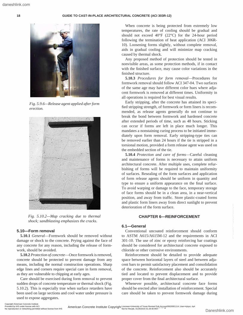
5.10—Form removal5.10.1 General—Formwork should be removed without
damage or shock to the concrete. Prying against the face of any concrete for any reason, including the release of form-work, should be avoided.
5.10.2 Protection of concrete—Once formwork is removed, concrete should be protected to prevent damage from any means, including the normal construction operations. Sharp edge lines and corners require special care in form removal, as they are vulnerable to chipping at early ages.
Care should be exercised during form removal to prevent sudden drops of concrete temperature or thermal shock (Fig. 5.10.2). This is especially true when surface retarders have been used on large sections and cool water under pressure is used to expose aggregates.
When concrete is being protected from extremely low temperatures, the rate of cooling should be gradual and should not exceed 40°F (22°C) for the 24-hour period following the termination of heat application (ACI 306R-10). Loosening forms slightly, without complete removal, aids in gradual cooling and will minimize map cracking caused by thermal shock.
Any proposed method of protection should be tested in nonvisible areas, as some protection methods, if in contact with the finished surface, may cause color variations in the finished structure.
5.10.3 Procedures for form removal—Procedures for formwork removal should follow ACI 347-04. Two surfaces of the same age may have different color hues where adja-cent formwork is removed at different times. Uniformity in all operations is required for best visual results.
Early stripping, after the concrete has attained its speci-fied stripping strength, of formwork or form liners is recom-mended, as release agents generally do not continue to break the bond between formwork and hardened concrete after extended periods of time, such as 48 hours. Sticking can occur if forms are left in place much longer. This mandates a nonstaining curing process to be initiated imme-diately upon form removal. Early stripping-type ties can be removed earlier than 24 hours if the tie is stripped in a torsional motion, provided a form release agent was used on the embedded section of the tie.
5.10.4 Protection and care of forms—Careful cleaning and maintenance of forms is necessary to attain uniform architectural concrete. After multiple uses, complete refur-bishing of forms will be required to maintain uniformity of surfaces. Resealing of the form surfaces and application of form release agents should be uniform in quantity and type to ensure a uniform appearance on the final surface. To avoid warping or damage to the face, temporary storage of face forms should be in a clean area, in a near-vertical position, and away from traffic. Store plastic-coated forms and plastic form liners away from direct sunlight to prevent deterioration of the form surface.
CHAPTER 6—REINFORCEMENT
6.1—GeneralConventional uncoated reinforcement should conform
to ASTM A615/A615M-12 and the requirements in ACI 301-10. The use of zinc or epoxy reinforcing bar coatings should be considered for architectural concrete exposed to chloride or other corrosive environments.
Reinforcement should be detailed to provide adequate space between horizontal layers of steel and between adja-cent bars to permit satisfactory placement and consolidation of the concrete. Reinforcement also should be accurately tied and located to prevent displacement and to provide proper cover from the final architectural surface.
Whenever possible, architectural concrete face forms should be erected after installation of reinforcement. Special care should be taken to prevent formwork damage during
Fig. 5.9.6—Release agent applied after form erection.
Fig. 5.10.2—Map cracking due to thermal shock; sandblasting emphasizes the cracks.
American Concrete Institute Copyrighted Material—www.concrete.org
18 GUIDE TO CAST-IN-PLACE ARCHITECTURAL CONCRETE (ACI 303R-12)
Copyright American Concrete Institute Provided by IHS under license with ACI Licensee=University of Texas Revised Sub Account/5620001114, User=rtytyui, rtyrt
Not for Resale, 01/26/2015 01:29:40 MSTNo reproduction or networking permitted without license from IHS
--````,`,`,,`,`,``````,,,`,,`,,-`-`,,`,,`,`,,`---
daneshlink.com
Daneshlink.com
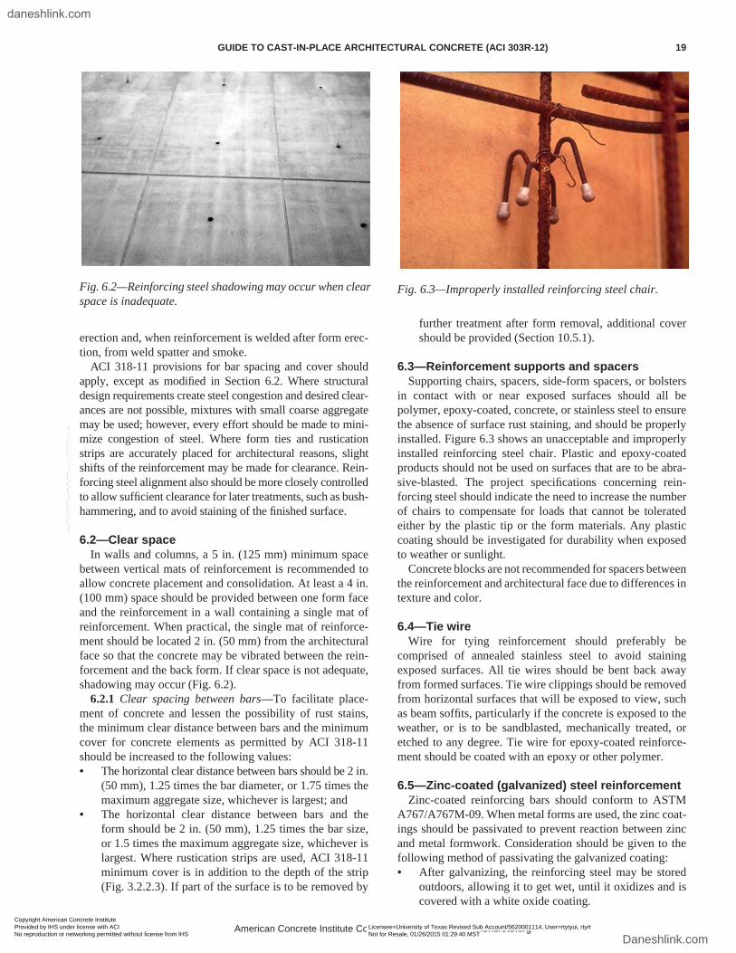
erection and, when reinforcement is welded after form erec-tion, from weld spatter and smoke.
ACI 318-11 provisions for bar spacing and cover should apply, except as modified in Section 6.2. Where structural design requirements create steel congestion and desired clear-ances are not possible, mixtures with small coarse aggregate may be used; however, every effort should be made to mini-mize congestion of steel. Where form ties and rustication strips are accurately placed for architectural reasons, slight shifts of the reinforcement may be made for clearance. Rein-forcing steel alignment also should be more closely controlled to allow sufficient clearance for later treatments, such as bush-hammering, and to avoid staining of the finished surface.
6.2—Clear spaceIn walls and columns, a 5 in. (125 mm) minimum space
between vertical mats of reinforcement is recommended to allow concrete placement and consolidation. At least a 4 in. (100 mm) space should be provided between one form face and the reinforcement in a wall containing a single mat of reinforcement. When practical, the single mat of reinforce-ment should be located 2 in. (50 mm) from the architectural face so that the concrete may be vibrated between the rein-forcement and the back form. If clear space is not adequate, shadowing may occur (Fig. 6.2).
6.2.1 Clear spacing between bars—To facilitate place-ment of concrete and lessen the possibility of rust stains, the minimum clear distance between bars and the minimum cover for concrete elements as permitted by ACI 318-11 should be increased to the following values:• The horizontal clear distance between bars should be 2 in.
(50 mm), 1.25 times the bar diameter, or 1.75 times the maximum aggregate size, whichever is largest; and
• The horizontal clear distance between bars and the form should be 2 in. (50 mm), 1.25 times the bar size, or 1.5 times the maximum aggregate size, whichever is largest. Where rustication strips are used, ACI 318-11 minimum cover is in addition to the depth of the strip (Fig. 3.2.2.3). If part of the surface is to be removed by
further treatment after form removal, additional cover should be provided (Section 10.5.1).
6.3—Reinforcement supports and spacersSupporting chairs, spacers, side-form spacers, or bolsters
in contact with or near exposed surfaces should all be polymer, epoxy-coated, concrete, or stainless steel to ensure the absence of surface rust staining, and should be properly installed. Figure 6.3 shows an unacceptable and improperly installed reinforcing steel chair. Plastic and epoxy-coated products should not be used on surfaces that are to be abra-sive-blasted. The project specifications concerning rein-forcing steel should indicate the need to increase the number of chairs to compensate for loads that cannot be tolerated either by the plastic tip or the form materials. Any plastic coating should be investigated for durability when exposed to weather or sunlight.
Concrete blocks are not recommended for spacers between the reinforcement and architectural face due to differences in texture and color.
6.4—Tie wireWire for tying reinforcement should preferably be
comprised of annealed stainless steel to avoid staining exposed surfaces. All tie wires should be bent back away from formed surfaces. Tie wire clippings should be removed from horizontal surfaces that will be exposed to view, such as beam soffits, particularly if the concrete is exposed to the weather, or is to be sandblasted, mechanically treated, or etched to any degree. Tie wire for epoxy-coated reinforce-ment should be coated with an epoxy or other polymer.
6.5—Zinc-coated (galvanized) steel reinforcementZinc-coated reinforcing bars should conform to ASTM
A767/A767M-09. When metal forms are used, the zinc coat-ings should be passivated to prevent reaction between zinc and metal formwork. Consideration should be given to the following method of passivating the galvanized coating:• After galvanizing, the reinforcing steel may be stored
outdoors, allowing it to get wet, until it oxidizes and is covered with a white oxide coating.
Fig. 6.2—Reinforcing steel shadowing may occur when clear space is inadequate.
Fig. 6.3—Improperly installed reinforcing steel chair.
American Concrete Institute Copyrighted Material—www.concrete.org
GUIDE TO CAST-IN-PLACE ARCHITECTURAL CONCRETE (ACI 303R-12) 19
Copyright American Concrete Institute Provided by IHS under license with ACI Licensee=University of Texas Revised Sub Account/5620001114, User=rtytyui, rtyrt
Not for Resale, 01/26/2015 01:29:40 MSTNo reproduction or networking permitted without license from IHS
--````,`,`,,`,`,``````,,,`,,`,,-`-`,,`,,`,`,,`---
daneshlink.com
Daneshlink.com
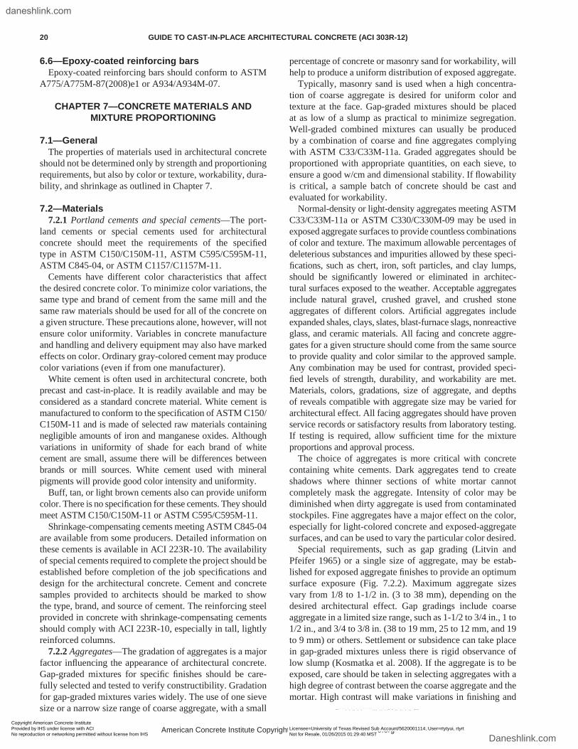
6.6—Epoxy-coated reinforcing barsEpoxy-coated reinforcing bars should conform to ASTM
A775/A775M-87(2008)e1 or A934/A934M-07.
CHAPTER 7—CONCRETE MATERIALS AND MIXTURE PROPORTIONING
7.1—GeneralThe properties of materials used in architectural concrete
should not be determined only by strength and proportioning requirements, but also by color or texture, workability, dura-bility, and shrinkage as outlined in Chapter 7.
7.2—Materials7.2.1 Portland cements and special cements—The port-
land cements or special cements used for architectural concrete should meet the requirements of the specified type in ASTM C150/C150M-11, ASTM C595/C595M-11, ASTM C845-04, or ASTM C1157/C1157M-11.
Cements have different color characteristics that affect the desired concrete color. To minimize color variations, the same type and brand of cement from the same mill and the same raw materials should be used for all of the concrete on a given structure. These precautions alone, however, will not ensure color uniformity. Variables in concrete manufacture and handling and delivery equipment may also have marked effects on color. Ordinary gray-colored cement may produce color variations (even if from one manufacturer).
White cement is often used in architectural concrete, both precast and cast-in-place. It is readily available and may be considered as a standard concrete material. White cement is manufactured to conform to the specification of ASTM C150/C150M-11 and is made of selected raw materials containing negligible amounts of iron and manganese oxides. Although variations in uniformity of shade for each brand of white cement are small, assume there will be differences between brands or mill sources. White cement used with mineral pigments will provide good color intensity and uniformity.
Buff, tan, or light brown cements also can provide uniform color. There is no specification for these cements. They should meet ASTM C150/C150M-11 or ASTM C595/C595M-11.
Shrinkage-compensating cements meeting ASTM C845-04 are available from some producers. Detailed information on these cements is available in ACI 223R-10. The availability of special cements required to complete the project should be established before completion of the job specifications and design for the architectural concrete. Cement and concrete samples provided to architects should be marked to show the type, brand, and source of cement. The reinforcing steel provided in concrete with shrinkage-compensating cements should comply with ACI 223R-10, especially in tall, lightly reinforced columns.
7.2.2 Aggregates—The gradation of aggregates is a major factor influencing the appearance of architectural concrete. Gap-graded mixtures for specific finishes should be care-fully selected and tested to verify constructibility. Gradation for gap-graded mixtures varies widely. The use of one sieve size or a narrow size range of coarse aggregate, with a small
percentage of concrete or masonry sand for workability, will help to produce a uniform distribution of exposed aggregate.
Typically, masonry sand is used when a high concentra-tion of coarse aggregate is desired for uniform color and texture at the face. Gap-graded mixtures should be placed at as low of a slump as practical to minimize segregation. Well-graded combined mixtures can usually be produced by a combination of coarse and fine aggregates complying with ASTM C33/C33M-11a. Graded aggregates should be proportioned with appropriate quantities, on each sieve, to ensure a good w/cm and dimensional stability. If flowability is critical, a sample batch of concrete should be cast and evaluated for workability.
Normal-density or light-density aggregates meeting ASTM C33/C33M-11a or ASTM C330/C330M-09 may be used in exposed aggregate surfaces to provide countless combinations of color and texture. The maximum allowable percentages of deleterious substances and impurities allowed by these speci-fications, such as chert, iron, soft particles, and clay lumps, should be significantly lowered or eliminated in architec-tural surfaces exposed to the weather. Acceptable aggregates include natural gravel, crushed gravel, and crushed stone aggregates of different colors. Artificial aggregates include expanded shales, clays, slates, blast-furnace slags, nonreactive glass, and ceramic materials. All facing and concrete aggre-gates for a given structure should come from the same source to provide quality and color similar to the approved sample. Any combination may be used for contrast, provided speci-fied levels of strength, durability, and workability are met. Materials, colors, gradations, size of aggregate, and depths of reveals compatible with aggregate size may be varied for architectural effect. All facing aggregates should have proven service records or satisfactory results from laboratory testing. If testing is required, allow sufficient time for the mixture proportions and approval process.
The choice of aggregates is more critical with concrete containing white cements. Dark aggregates tend to create shadows where thinner sections of white mortar cannot completely mask the aggregate. Intensity of color may be diminished when dirty aggregate is used from contaminated stockpiles. Fine aggregates have a major effect on the color, especially for light-colored concrete and exposed-aggregate surfaces, and can be used to vary the particular color desired.
Special requirements, such as gap grading (Litvin and Pfeifer 1965) or a single size of aggregate, may be estab-lished for exposed aggregate finishes to provide an optimum surface exposure (Fig. 7.2.2). Maximum aggregate sizes vary from 1/8 to 1-1/2 in. (3 to 38 mm), depending on the desired architectural effect. Gap gradings include coarse aggregate in a limited size range, such as 1-1/2 to 3/4 in., 1 to 1/2 in., and 3/4 to 3/8 in. (38 to 19 mm, 25 to 12 mm, and 19 to 9 mm) or others. Settlement or subsidence can take place in gap-graded mixtures unless there is rigid observance of low slump (Kosmatka et al. 2008). If the aggregate is to be exposed, care should be taken in selecting aggregates with a high degree of contrast between the coarse aggregate and the mortar. High contrast will make variations in finishing and
American Concrete Institute Copyrighted Material—www.concrete.org
20 GUIDE TO CAST-IN-PLACE ARCHITECTURAL CONCRETE (ACI 303R-12)
Copyright American Concrete Institute Provided by IHS under license with ACI Licensee=University of Texas Revised Sub Account/5620001114, User=rtytyui, rtyrt
Not for Resale, 01/26/2015 01:29:40 MSTNo reproduction or networking permitted without license from IHS
--````,`,`,,`,`,``````,,,`,,`,,-`-`,,`,,`,`,,`---
daneshlink.com
Daneshlink.com
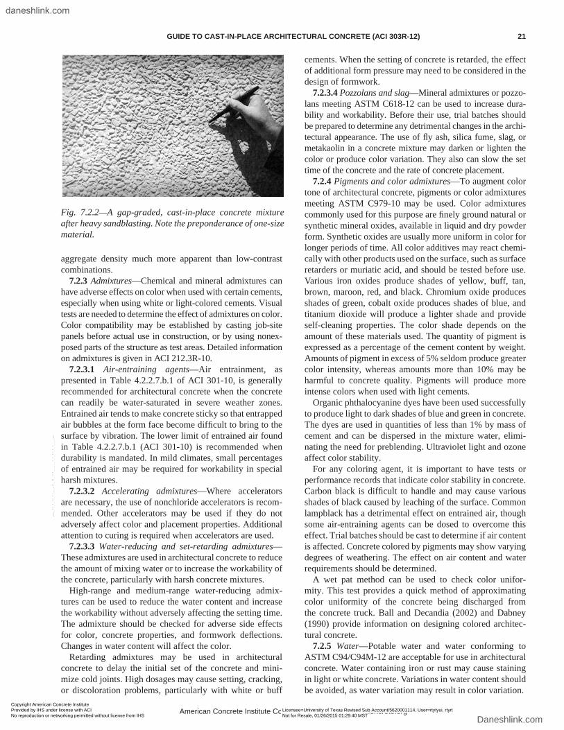
aggregate density much more apparent than low-contrast combinations.
7.2.3 Admixtures—Chemical and mineral admixtures can have adverse effects on color when used with certain cements, especially when using white or light-colored cements. Visual tests are needed to determine the effect of admixtures on color. Color compatibility may be established by casting job-site panels before actual use in construction, or by using nonex-posed parts of the structure as test areas. Detailed information on admixtures is given in ACI 212.3R-10.
7.2.3.1 Air-entraining agents—Air entrainment, as presented in Table 4.2.2.7.b.1 of ACI 301-10, is generally recommended for architectural concrete when the concrete can readily be water-saturated in severe weather zones. Entrained air tends to make concrete sticky so that entrapped air bubbles at the form face become difficult to bring to the surface by vibration. The lower limit of entrained air found in Table 4.2.2.7.b.1 (ACI 301-10) is recommended when durability is mandated. In mild climates, small percentages of entrained air may be required for workability in special harsh mixtures.
7.2.3.2 Accelerating admixtures—Where accelerators are necessary, the use of nonchloride accelerators is recom-mended. Other accelerators may be used if they do not adversely affect color and placement properties. Additional attention to curing is required when accelerators are used.
7.2.3.3 Water-reducing and set-retarding admixtures—These admixtures are used in architectural concrete to reduce the amount of mixing water or to increase the workability of the concrete, particularly with harsh concrete mixtures.
High-range and medium-range water-reducing admix-tures can be used to reduce the water content and increase the workability without adversely affecting the setting time. The admixture should be checked for adverse side effects for color, concrete properties, and formwork deflections. Changes in water content will affect the color.
Retarding admixtures may be used in architectural concrete to delay the initial set of the concrete and mini-mize cold joints. High dosages may cause setting, cracking, or discoloration problems, particularly with white or buff
cements. When the setting of concrete is retarded, the effect of additional form pressure may need to be considered in the design of formwork.
7.2.3.4 Pozzolans and slag—Mineral admixtures or pozzo-lans meeting ASTM C618-12 can be used to increase dura-bility and workability. Before their use, trial batches should be prepared to determine any detrimental changes in the archi-tectural appearance. The use of fly ash, silica fume, slag, or metakaolin in a concrete mixture may darken or lighten the color or produce color variation. They also can slow the set time of the concrete and the rate of concrete placement.
7.2.4 Pigments and color admixtures—To augment color tone of architectural concrete, pigments or color admixtures meeting ASTM C979-10 may be used. Color admixtures commonly used for this purpose are finely ground natural or synthetic mineral oxides, available in liquid and dry powder form. Synthetic oxides are usually more uniform in color for longer periods of time. All color additives may react chemi-cally with other products used on the surface, such as surface retarders or muriatic acid, and should be tested before use. Various iron oxides produce shades of yellow, buff, tan, brown, maroon, red, and black. Chromium oxide produces shades of green, cobalt oxide produces shades of blue, and titanium dioxide will produce a lighter shade and provide self-cleaning properties. The color shade depends on the amount of these materials used. The quantity of pigment is expressed as a percentage of the cement content by weight. Amounts of pigment in excess of 5% seldom produce greater color intensity, whereas amounts more than 10% may be harmful to concrete quality. Pigments will produce more intense colors when used with light cements.
Organic phthalocyanine dyes have been used successfully to produce light to dark shades of blue and green in concrete. The dyes are used in quantities of less than 1% by mass of cement and can be dispersed in the mixture water, elimi-nating the need for preblending. Ultraviolet light and ozone affect color stability.
For any coloring agent, it is important to have tests or performance records that indicate color stability in concrete. Carbon black is difficult to handle and may cause various shades of black caused by leaching of the surface. Common lampblack has a detrimental effect on entrained air, though some air-entraining agents can be dosed to overcome this effect. Trial batches should be cast to determine if air content is affected. Concrete colored by pigments may show varying degrees of weathering. The effect on air content and water requirements should be determined.
A wet pat method can be used to check color unifor-mity. This test provides a quick method of approximating color uniformity of the concrete being discharged from the concrete truck. Ball and Decandia (2002) and Dabney (1990) provide information on designing colored architec-tural concrete.
7.2.5 Water—Potable water and water conforming to ASTM C94/C94M-12 are acceptable for use in architectural concrete. Water containing iron or rust may cause staining in light or white concrete. Variations in water content should be avoided, as water variation may result in color variation.
Fig. 7.2.2—A gap-graded, cast-in-place concrete mixture after heavy sandblasting. Note the preponderance of one-size material.
American Concrete Institute Copyrighted Material—www.concrete.org
GUIDE TO CAST-IN-PLACE ARCHITECTURAL CONCRETE (ACI 303R-12) 21
Copyright American Concrete Institute Provided by IHS under license with ACI Licensee=University of Texas Revised Sub Account/5620001114, User=rtytyui, rtyrt
Not for Resale, 01/26/2015 01:29:40 MSTNo reproduction or networking permitted without license from IHS
--````,`,`,,`,`,``````,,,`,,`,,-`-`,,`,,`,`,,`---
daneshlink.com
Daneshlink.com
7.3—Proportioning, mixing, and temperature control
Mixture proportions for architectural concrete should provide a mixture of proper workability and strength.
The slump at the point of discharge into the form should be consistent with the particular type of concrete and the methods of placing and consolidation. In general, the water content for any placement should be constant from batch to batch to provide uniformity of color in the end product, even during significant seasonal temperature fluctuations. There is a tendency for a lighter color and an increase in surface air voids to occur in the concrete near the top of placement lifts due to decreased form pressures, inadequate vibration, and an increase in the w/cm at these locations. Attention should be given to properly consolidate the concrete in the upper layers of place-ment lifts to improve appearance. Gradually using less water to provide dryer concrete for lifts toward the top could affect a more uniform color; however, this procedure is impractical for most projects. If used, experimentation on nonarchitectural walls with the architectural concrete mixture would determine actual proportions and procedures to be used.
7.3.1 Temperature—The concrete temperature should be kept consistent; concrete temperatures between 65 and 85°F (18 and 29°C) will normally produce concrete uniform in color. Concrete temperatures higher than 80°F (27°C) may result in a faster setting rate, visible flow lines, and cold joints if proper scheduling of the concrete placement is not closely coordinated with the concrete producer.
Holding the temperature constant is especially difficult when the project extends over more than one season. If color uniformity is critical, testing for variations of color at different temperatures should be considered.
CHAPTER 8—PLACING AND CONSOLIDATION
8.1—Conveying and placing8.1.1 General—Methods of conveying and placing archi-
tectural concrete should conform to the requirements of ACI 304R-00, except as modified herein. A description of the methods and sequence of placement to be used for the struc-ture should be submitted in writing to the architect/engineer and inspector for review. These should be the same as used in fabricating the approved preconstruction field mockup.
Concrete trucks should be scheduled and dispatched to arrive at the job site just before the concrete is needed. This will avoid excessive mixing while waiting or during delays in placement, which may cause non-uniform color and, possibly, cause cold joints.
8.1.2 Conveying—Care should be taken with any conveying equipment to prevent contamination of architec-tural concrete by other mixtures. If methods of conveyance are varied during placement of architectural concrete, the uniformity of color may be affected.
8.1.3 Depositing in the form—With proper proportioning, depending on the width of the forms and the amount of rein-forcement, lifts can be up to 36 in. (900 mm) deep. Deeper lifts, accompanied by additional careful vibration, can be used with high-density forming to eliminate excess surface
air voids. The surface of each layer should be sufficiently level so that the vibrator does not move the concrete later-ally, as this might cause segregation. This can be accom-plished by depositing the concrete on the leading edge of the prior placement. Avoid placing the concrete at a new location and then transporting it back to the leading edge of the prior placement by using a vibrator.
Spattering the form face with high-cement-content mortar that stiffens before being covered by the concrete may cause mortar streaks in exposed aggregate finishes. Metal or poly-ethylene sheets placed against the form face and raised with the height of concrete will protect the form face against spatter. Also, insertion of the placing pump hose into the concrete while discharging aids in reducing spatter. The use of elephant trunks (tremies) used to contain spatter is another way to eliminate the problems of dried spatter.
8.2—Consolidation8.2.1 General—Consolidation that eliminates entrapped
air throughout the mass and minimizes surface voids is particularly important to architectural concrete. Today, most concrete is consolidated by immersion vibration, which is especially required by stiffer consistencies (Fig. 8.2.1).
An explanation of consolidation, and detailed recommen-dations on the selection of vibrators and vibration proce-dures, are given in ACI 309R-05. Elimination of surface voids is discussed further in ACI 309.2R-98.
8.2.2 Internal (immersion) vibration—Internal vibration is recommended for all vertical, cast-in-place, architectural concrete. The vibrator should be inserted vertically at 1.5 times the radius of influence (ACI 309R-05), uniformly spaced over the entire area. The distance between insertions should depend on the properties of the mixture, maximum aggregate size, slump, and the amount of power getting to the vibrator. The area visibly affected by the vibrator should overlap the adjacent just-vibrated area. There should be a row of insertions within 6 in. (150 mm) of the form.
The vibrators should operate at frequencies above 9000 vpm. The diameter of the vibrator head should be at least 2 in. (50 mm), except when reinforcing steel congestion or clear space limits vibrator head size. Where space permits, a high-cycle, motor-in-head vibrator should be used. These vibrators require a special generator that produces 180 Hz electrical power (ACI 309R-05).
The vibrator should penetrate rapidly to the bottom of the layer and at least 6 in. (150 mm) into the preceding layer. The vibrator should be manipulated in an up-and-down motion, generally for 5 to 15 seconds, to knit the two layers together, then withdrawn gradually with a series of up-and-down motions. The down motion should be a rapid drop to apply a force to the concrete that will, in turn, increase internal pressure in the freshly placed mixture.
Rapidly extract the vibrator from the concrete when the head becomes only partially immersed in the concrete. The concrete should move back into the space vacated by the vibrator. For dry mixtures where the hole does not close during the withdrawal, reinserting the vibrator a few inches (several centimeters) away will sometimes resolve
American Concrete Institute Copyrighted Material—www.concrete.org
22 GUIDE TO CAST-IN-PLACE ARCHITECTURAL CONCRETE (ACI 303R-12)
Copyright American Concrete Institute Provided by IHS under license with ACI Licensee=University of Texas Revised Sub Account/5620001114, User=rtytyui, rtyrt
Not for Resale, 01/26/2015 01:29:40 MSTNo reproduction or networking permitted without license from IHS
--````,`,`,,`,`,``````,,,`,,`,,-`-`,,`,,`,`,,`---
daneshlink.com
Daneshlink.com
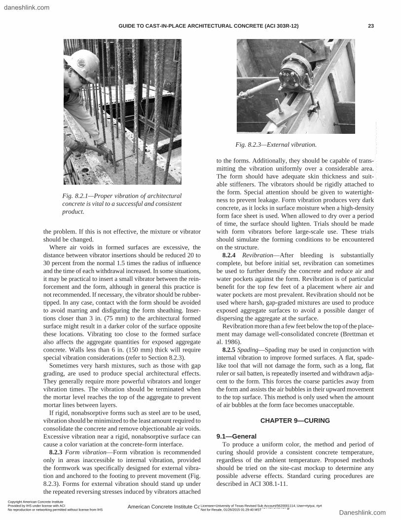
the problem. If this is not effective, the mixture or vibrator should be changed.
Where air voids in formed surfaces are excessive, the distance between vibrator insertions should be reduced 20 to 30 percent from the normal 1.5 times the radius of influence and the time of each withdrawal increased. In some situations, it may be practical to insert a small vibrator between the rein-forcement and the form, although in general this practice is not recommended. If necessary, the vibrator should be rubber-tipped. In any case, contact with the form should be avoided to avoid marring and disfiguring the form sheathing. Inser-tions closer than 3 in. (75 mm) to the architectural formed surface might result in a darker color of the surface opposite these locations. Vibrating too close to the formed surface also affects the aggregate quantities for exposed aggregate concrete. Walls less than 6 in. (150 mm) thick will require special vibration considerations (refer to Section 8.2.3).
Sometimes very harsh mixtures, such as those with gap grading, are used to produce special architectural effects. They generally require more powerful vibrators and longer vibration times. The vibration should be terminated when the mortar level reaches the top of the aggregate to prevent mortar lines between layers.
If rigid, nonabsorptive forms such as steel are to be used, vibration should be minimized to the least amount required to consolidate the concrete and remove objectionable air voids. Excessive vibration near a rigid, nonabsorptive surface can cause a color variation at the concrete-form interface.
8.2.3 Form vibration—Form vibration is recommended only in areas inaccessible to internal vibration, provided the formwork was specifically designed for external vibra-tion and anchored to the footing to prevent movement (Fig. 8.2.3). Forms for external vibration should stand up under the repeated reversing stresses induced by vibrators attached
to the forms. Additionally, they should be capable of trans-mitting the vibration uniformly over a considerable area. The form should have adequate skin thickness and suit-able stiffeners. The vibrators should be rigidly attached to the form. Special attention should be given to watertight-ness to prevent leakage. Form vibration produces very dark concrete, as it locks in surface moisture when a high-density form face sheet is used. When allowed to dry over a period of time, the surface should lighten. Trials should be made with form vibrators before large-scale use. These trials should simulate the forming conditions to be encountered on the structure.
8.2.4 Revibration—After bleeding is substantially complete, but before initial set, revibration can sometimes be used to further densify the concrete and reduce air and water pockets against the form. Revibration is of particular benefit for the top few feet of a placement where air and water pockets are most prevalent. Revibration should not be used where harsh, gap-graded mixtures are used to produce exposed aggregate surfaces to avoid a possible danger of dispersing the aggregate at the surface.
Revibration more than a few feet below the top of the place-ment may damage well-consolidated concrete (Brettman et al. 1986).
8.2.5 Spading—Spading may be used in conjunction with internal vibration to improve formed surfaces. A flat, spade-like tool that will not damage the form, such as a long, flat ruler or sail batten, is repeatedly inserted and withdrawn adja-cent to the form. This forces the coarse particles away from the form and assists the air bubbles in their upward movement to the top surface. This method is only used when the amount of air bubbles at the form face becomes unacceptable.
CHAPTER 9—CURING
9.1—GeneralTo produce a uniform color, the method and period of
curing should provide a consistent concrete temperature, regardless of the ambient temperature. Proposed methods should be tried on the site-cast mockup to determine any possible adverse effects. Standard curing procedures are described in ACI 308.1-11.
Fig. 8.2.1—Proper vibration of architectural concrete is vital to a successful and consistent product.
Fig. 8.2.3—External vibration.
American Concrete Institute Copyrighted Material—www.concrete.org
GUIDE TO CAST-IN-PLACE ARCHITECTURAL CONCRETE (ACI 303R-12) 23
Copyright American Concrete Institute Provided by IHS under license with ACI Licensee=University of Texas Revised Sub Account/5620001114, User=rtytyui, rtyrt
Not for Resale, 01/26/2015 01:29:40 MSTNo reproduction or networking permitted without license from IHS
--````,`,`,,`,`,``````,,,`,,`,,-`-`,,`,,`,`,,`---
daneshlink.com
Daneshlink.com
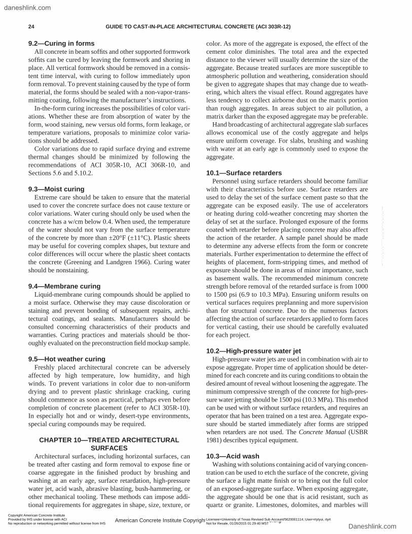
9.2—Curing in formsAll concrete in beam soffits and other supported formwork
soffits can be cured by leaving the formwork and shoring in place. All vertical formwork should be removed in a consis-tent time interval, with curing to follow immediately upon form removal. To prevent staining caused by the type of form material, the forms should be sealed with a non-vapor-trans-mitting coating, following the manufacturer’s instructions.
In-the-form curing increases the possibilities of color vari-ations. Whether these are from absorption of water by the form, wood staining, new versus old forms, form leakage, or temperature variations, proposals to minimize color varia-tions should be addressed.
Color variations due to rapid surface drying and extreme thermal changes should be minimized by following the recommendations of ACI 305R-10, ACI 306R-10, and Sections 5.6 and 5.10.2.
9.3—Moist curingExtreme care should be taken to ensure that the material
used to cover the concrete surface does not cause texture or color variations. Water curing should only be used when the concrete has a w/cm below 0.4. When used, the temperature of the water should not vary from the surface temperature of the concrete by more than ±20°F (±11°C). Plastic sheets may be useful for covering complex shapes, but texture and color differences will occur where the plastic sheet contacts the concrete (Greening and Landgren 1966). Curing water should be nonstaining.
9.4—Membrane curingLiquid-membrane curing compounds should be applied to
a moist surface. Otherwise they may cause discoloration or staining and prevent bonding of subsequent repairs, archi-tectural coatings, and sealants. Manufacturers should be consulted concerning characteristics of their products and warranties. Curing practices and materials should be thor-oughly evaluated on the preconstruction field mockup sample.
9.5—Hot weather curingFreshly placed architectural concrete can be adversely
affected by high temperature, low humidity, and high winds. To prevent variations in color due to non-uniform drying and to prevent plastic shrinkage cracking, curing should commence as soon as practical, perhaps even before completion of concrete placement (refer to ACI 305R-10). In especially hot and or windy, desert-type environments, special curing compounds may be required.
CHAPTER 10—TREATED ARCHITECTURAL SURFACES
Architectural surfaces, including horizontal surfaces, can be treated after casting and form removal to expose fine or coarse aggregate in the finished product by brushing and washing at an early age, surface retardation, high-pressure water jet, acid wash, abrasive blasting, bush-hammering, or other mechanical tooling. These methods can impose addi-tional requirements for aggregates in shape, size, texture, or
color. As more of the aggregate is exposed, the effect of the cement color diminishes. The total area and the expected distance to the viewer will usually determine the size of the aggregate. Because treated surfaces are more susceptible to atmospheric pollution and weathering, consideration should be given to aggregate shapes that may change due to weath-ering, which alters the visual effect. Round aggregates have less tendency to collect airborne dust on the matrix portion than rough aggregates. In areas subject to air pollution, a matrix darker than the exposed aggregate may be preferable.
Hand broadcasting of architectural aggregate slab surfaces allows economical use of the costly aggregate and helps ensure uniform coverage. For slabs, brushing and washing with water at an early age is commonly used to expose the aggregate.
10.1—Surface retardersPersonnel using surface retarders should become familiar
with their characteristics before use. Surface retarders are used to delay the set of the surface cement paste so that the aggregate can be exposed easily. The use of accelerators or heating during cold-weather concreting may shorten the delay of set at the surface. Prolonged exposure of the forms coated with retarder before placing concrete may also affect the action of the retarder. A sample panel should be made to determine any adverse effects from the form or concrete materials. Further experimentation to determine the effect of heights of placement, form-stripping times, and method of exposure should be done in areas of minor importance, such as basement walls. The recommended minimum concrete strength before removal of the retarded surface is from 1000 to 1500 psi (6.9 to 10.3 MPa). Ensuring uniform results on vertical surfaces requires preplanning and more supervision than for structural concrete. Due to the numerous factors affecting the action of surface retarders applied to form faces for vertical casting, their use should be carefully evaluated for each project.
10.2—High-pressure water jetHigh-pressure water jets are used in combination with air to
expose aggregate. Proper time of application should be deter-mined for each concrete and its curing conditions to obtain the desired amount of reveal without loosening the aggregate. The minimum compressive strength of the concrete for high-pres-sure water jetting should be 1500 psi (10.3 MPa). This method can be used with or without surface retarders, and requires an operator that has been trained on a test area. Aggregate expo-sure should be started immediately after forms are stripped when retarders are not used. The Concrete Manual (USBR 1981) describes typical equipment.
10.3—Acid washWashing with solutions containing acid of varying concen-
tration can be used to etch the surface of the concrete, giving the surface a light matte finish or to bring out the full color of an exposed-aggregate surface. When exposing aggregate, the aggregate should be one that is acid resistant, such as quartz or granite. Limestones, dolomites, and marbles will
American Concrete Institute Copyrighted Material—www.concrete.org
24 GUIDE TO CAST-IN-PLACE ARCHITECTURAL CONCRETE (ACI 303R-12)
Copyright American Concrete Institute Provided by IHS under license with ACI Licensee=University of Texas Revised Sub Account/5620001114, User=rtytyui, rtyrt
Not for Resale, 01/26/2015 01:29:40 MSTNo reproduction or networking permitted without license from IHS
--````,`,`,,`,`,``````,,,`,,`,,-`-`,,`,,`,`,,`---
daneshlink.com
Daneshlink.com
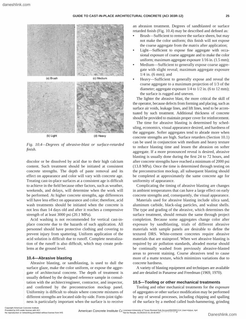
discolor or be dissolved by acid due to their high calcium content. Such treatment should be initiated at consistent concrete strengths. The depth of paste removal and its effect on appearance and color will vary with concrete age. Treating cast-in-place surfaces at a consistent age is difficult to achieve in the field because other factors, such as weather, weekends, and delays, will determine when the work will be performed. At higher concrete strengths, age differences will have less effect on appearance and color; therefore, acid wash treatments should be initiated when the concrete is not less than 14 days old and after it reaches a compressive strength of at least 3000 psi (20.1 MPa).
Acid washing is not recommended for vertical cast-in-place concrete due to the hazards of such application. All personnel should have protective clothing and covering to prevent injury from spattering. Uniform application of the acid solution is difficult due to runoff. Complete neutraliza-tion of the runoff is also difficult, which may create prob-lems at the ground level.
10.4—Abrasive blastingAbrasive blasting, or sandblasting, is used to dull the
surface glaze, make the color uniform, or expose the aggre-gate of architectural concrete. The depth of treatment is usually defined by the designed reference sample in consul-tation with the architect/engineer, contractor, and inspector, and confirmed by the preconstruction mockup panel. Uniformity is difficult to obtain where concrete mixtures of different strengths are located side-by-side. Form-joint tight-ness is particularly important when the surface is to receive
an abrasion treatment. Degrees of sandblasted or surface retarded finish (Fig. 10.4) may be described and defined as:• Brush—Sufficient to remove the surface sheen, but may
not make the color uniform; this finish will not expose the coarse aggregate from the matrix after application;
• Light—Sufficient to expose fine aggregate with occa-sional exposure of coarse aggregate and to make the color uniform; maximum aggregate exposure 1/16 in. (1.5 mm);
• Medium—Sufficient to generally expose coarse aggre-gate with slight reveal; maximum aggregate exposure 1/4 in. (6 mm); and
• Heavy—Sufficient to generally expose and reveal the coarse aggregate to a maximum projection of 1/3 of the diameter; aggregate exposure 1/4 to 1/2 in. (6 to 12 mm); the surface is rugged and uneven.
The lighter the abrasive blast, the more critical the skill of the operator, because defects from forming and placing, such as surface air voids, leakage lines, and lift lines, tend to be accen-tuated by such treatment. Additional thickness of concrete should be provided to maintain proper cover for reinforcement.
The time for abrasive blasting is determined by sched-uling, economics, visual appearance desired, and hardness of the aggregate. Softer aggregates tend to abrade more when concrete strengths are high. Surface retarders (Section 10.1) can be used in conjunction with medium and heavy texture to reduce blasting time and lessen the abrasion on softer aggregate. If a more pronounced reveal is desired, abrasive blasting is usually done during the first 24 to 72 hours, and after concrete strengths have reached a minimum of 2000 psi (13.8 MPa). Once the time is determined through testing on the preconstruction mockup, all subsequent blasting should be completed at approximately the same concrete age for uniformity of appearance.
Complicating the timing of abrasive blasting are changes in ambient temperatures that can have a large effect on early concrete strengths and, consequently, the visual appearance.
Materials used for abrasive blasting include silica sand, aluminum carbide, black-slag particles, and walnut shells. The type and grading of the abrasive, which determines the surface treatment, should remain the same through project completion. Because some aggregates change color after exposure by sandblasting, trials of different abrasive materials with sample panels are desirable to define the textured DRS. White-cement concretes require abrasive materials that are stainproof. When wet abrasive blasting is required by air pollution standards, abraded mortar should be continually washed from previously abrasive-blasted areas to prevent staining. Course abrasives tend to cause more of a matte texture, which minimizes variations due to concrete hardness.
A variety of blasting equipment and techniques are available and are detailed in Panarese and Freedman (1969, 1970).
10.5—Tooling or other mechanical treatmentsTooling and other mechanical treatments for the exposure
of aggregates or other surface modification may be performed by any of several processes, including chipping and spalling of the surface by a method called bush-hammering, grinding
Fig. 10.4—Degrees of abrasive-blast or surface-retarded finish.
American Concrete Institute Copyrighted Material—www.concrete.org
GUIDE TO CAST-IN-PLACE ARCHITECTURAL CONCRETE (ACI 303R-12) 25
Copyright American Concrete Institute Provided by IHS under license with ACI Licensee=University of Texas Revised Sub Account/5620001114, User=rtytyui, rtyrt
Not for Resale, 01/26/2015 01:29:40 MSTNo reproduction or networking permitted without license from IHS
--````,`,`,,`,`,``````,,,`,,`,,-`-`,,`,,`,`,,`---
daneshlink.com
Daneshlink.com
to produce a smooth exposed aggregate surface, or breaking off the projections of fluted surfaces to produce alternate rough and smooth areas. Orientation of equipment for tooling, blasting, or fracturing should be kept uniform throughout the architectural work. To maintain uniformity, the same operator should perform this work throughout the project, or at least on adjacent portions of a structure (PCA 1987).
10.5.1 Bush-hammering—Bush-hammered surfaces are produced by pneumatic tools fitted with a bush-hammer, comb, chisel, or multiple pointed attachments. The type of tool will be determined by the surface effect desired. Because most bush-hammering will remove approximately 3/16 in. (5 mm) of material, additional concrete cover should be provided. To prevent loosening of the aggregate, a concrete strength of 4500 psi (31.3 MPa) in compression and a minimum age of 14 days are required. In many cases, better uniformity is found when the concrete is allowed to age for 21 days and the surface to dry. Bush-hammering at corners tends to cause jagged edges. If sharp corners are desired, bush-hammering is held back from the corner a distance of 1 to 2 in. (25 to 50 mm). Aggregates should be carefully selected and tested in the mockup panel to avoid internal cracks from occurring in the concrete as a result of the bush-hammering operation.
10.5.2 Grinding—Grinding of concrete surfaces is more laborious than the other treatments, especially on vertical and overhead surfaces. Final costs are determined by the hard-ness of the aggregate and the desired exposure. To define the final product, treatment is accomplished on the precon-struction mockup or a trial area of minor importance. Small samples may not be capable of field reproduction. This type of treatment produces a result similar to terrazzo work.
10.5.3 Manual treatment—Vertical surfaces of structures may be formed to produce projections of concrete of trian-gular or rectangular shape. These may be broken off either by removing the form or by hand at a concrete age suffi-cient to also fracture the aggregate. Prior testing should be performed on the preconstruction mockup to determine the optimum procedures.
CHAPTER 11—FINISHING AND FINAL CLEANUP
11.1—GeneralEven with good workmanship and positive effort to
produce excellent architectural concrete, an occasional blemish will need repair or variations in color and texture can occur, or both. Limits to their acceptance should be determined during the review of the field mockup sample.
11.2—Tie holesTie holes should be plugged or the exposed metal portion
of the tie sealed with sealant to prevent corrosion and possible staining of the surface, except where stainless steel form ties or fiberglass ties are used. The holes left in the surface of the concrete as the result of the form tie may be small or large, depending on the type used. In a rough textured surface, small holes can be plugged flush with the surface and concealed. With smooth-surface concrete, the tie holes
will be more apparent, and it is better to only partially fill the holes, leaving the holes as a part of the planned appearance. The color of the tie-hole patches in the mockup panel should be approved by the designer.
Care should be exercised to avoid smearing the fill material on the surface of the concrete. Materials used for plugging tie holes include portland-cement mortar, epoxy mortar, plastic plugs, precast mortar plugs, and lead plugs. They should be carefully selected from among those that have shown no staining or discoloration tendencies in use. Some epoxy mortars change to brilliant orange or yellow after exposure to sunlight. Mortar materials of a dry-pack consistency and densely tamped into the hole will be less likely to smear on to the surface than those of a wet consistency. When portland-cement mortar is used, the tie hole should first be prewetted with clean water, and a neat cement slurry bond coat should be applied to the hole surfaces before filling with mortar. If epoxy mortar is used, it should be applied in accordance with the manufacturer’s instructions, and a caulking gun used to inject it into the tie hole to prevent surface smearing. Cleaning is difficult and will usually leave a stain on the surface. Plastic inserts provided by cone tie manufacturers should be wedged into the tie hole, leaving a standard prede-termined recess. Alternatively, lead plugs can be wedged into the hole by hammering. Sometimes the removable cone becomes embedded in the concrete due to form movement or leakage around the cone. It can be removed to produce a neat appearance by drilling out the cone with a diamond bit tool conforming to the hole size produced by the cone. It may be economical to remove all cones in this manner to ensure neat, uniform holes.
11.3—Blemish repairBlemishes that are beyond the limits of variations as estab-
lished by the quality of the preconstruction mockup should be repaired. Generally, the repair work should proceed as soon as possible after form removal and surface finishing using the materials and methods already accepted on the approved mockup. Then the repair and the surrounding concrete will age together, and the chance of color varia-tion will be minimized. The importance of establishing a repair method before the need arises cannot be overstressed. Once proven acceptable on the mockup, repairs can be made without delay and with confidence of the final outcome. Where adjacent abrasive-blasting or bush-hammering treat-ments have to be matched, prior experimentation should be performed on secondary and less visible areas. Ingenuity may sometimes be used to establish methods and techniques that are as satisfactory as those in standard use. Light abra-sive blasting sometimes greatly emphasizes cracks as well as blemishes or surface air voids caused by forming or placing. When their appearance is unacceptable, it may be decided to accept a heavily blasted surface; additional blasting may diminish the effect of the cracks and other defects after they have been repaired. Filling the cracks with epoxy before blasting can prevent rounding of the crack edges during blasting. After blasting, the resulting epoxy fin is broken off
American Concrete Institute Copyrighted Material—www.concrete.org
26 GUIDE TO CAST-IN-PLACE ARCHITECTURAL CONCRETE (ACI 303R-12)
Copyright American Concrete Institute Provided by IHS under license with ACI Licensee=University of Texas Revised Sub Account/5620001114, User=rtytyui, rtyrt
Not for Resale, 01/26/2015 01:29:40 MSTNo reproduction or networking permitted without license from IHS
--````,`,`,,`,`,``````,,,`,,`,,-`-`,,`,,`,`,,`---
daneshlink.com
Daneshlink.com
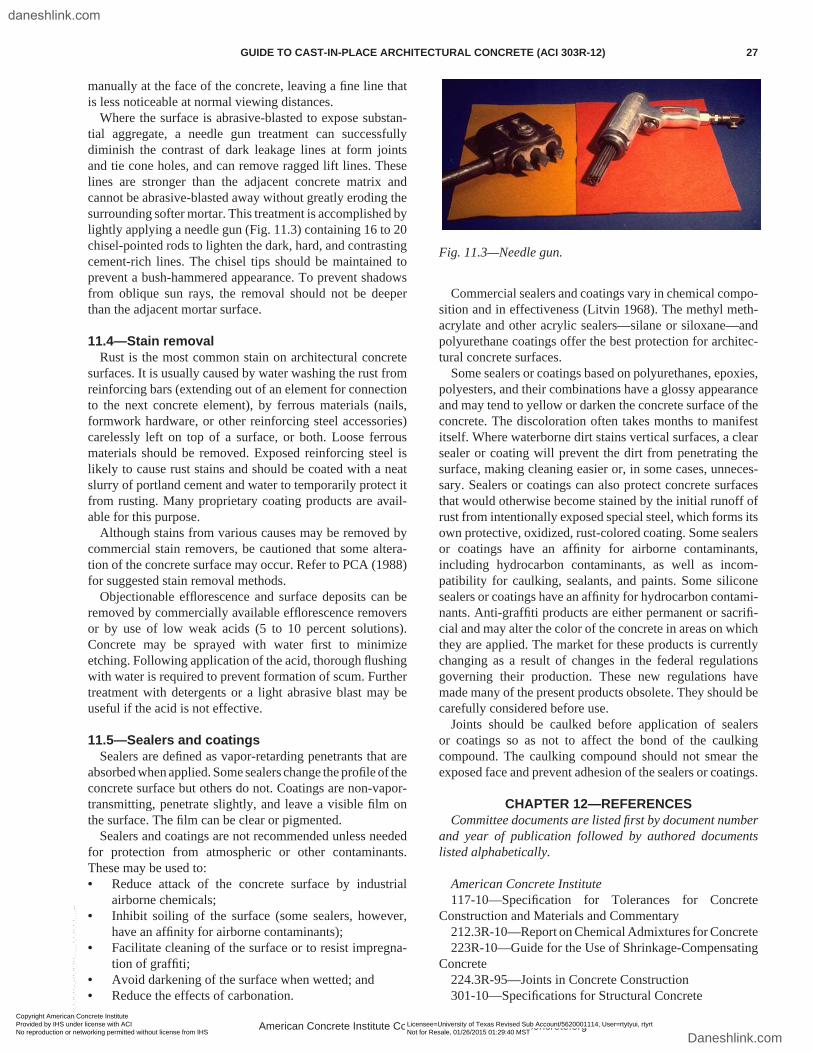
manually at the face of the concrete, leaving a fine line that is less noticeable at normal viewing distances.
Where the surface is abrasive-blasted to expose substan-tial aggregate, a needle gun treatment can successfully diminish the contrast of dark leakage lines at form joints and tie cone holes, and can remove ragged lift lines. These lines are stronger than the adjacent concrete matrix and cannot be abrasive-blasted away without greatly eroding the surrounding softer mortar. This treatment is accomplished by lightly applying a needle gun (Fig. 11.3) containing 16 to 20 chisel-pointed rods to lighten the dark, hard, and contrasting cement-rich lines. The chisel tips should be maintained to prevent a bush-hammered appearance. To prevent shadows from oblique sun rays, the removal should not be deeper than the adjacent mortar surface.
11.4—Stain removalRust is the most common stain on architectural concrete
surfaces. It is usually caused by water washing the rust from reinforcing bars (extending out of an element for connection to the next concrete element), by ferrous materials (nails, formwork hardware, or other reinforcing steel accessories) carelessly left on top of a surface, or both. Loose ferrous materials should be removed. Exposed reinforcing steel is likely to cause rust stains and should be coated with a neat slurry of portland cement and water to temporarily protect it from rusting. Many proprietary coating products are avail-able for this purpose.
Although stains from various causes may be removed by commercial stain removers, be cautioned that some altera-tion of the concrete surface may occur. Refer to PCA (1988) for suggested stain removal methods.
Objectionable efflorescence and surface deposits can be removed by commercially available efflorescence removers or by use of low weak acids (5 to 10 percent solutions). Concrete may be sprayed with water first to minimize etching. Following application of the acid, thorough flushing with water is required to prevent formation of scum. Further treatment with detergents or a light abrasive blast may be useful if the acid is not effective.
11.5—Sealers and coatingsSealers are defined as vapor-retarding penetrants that are
absorbed when applied. Some sealers change the profile of the concrete surface but others do not. Coatings are non-vapor-transmitting, penetrate slightly, and leave a visible film on the surface. The film can be clear or pigmented.
Sealers and coatings are not recommended unless needed for protection from atmospheric or other contaminants. These may be used to:• Reduce attack of the concrete surface by industrial
airborne chemicals;• Inhibit soiling of the surface (some sealers, however,
have an affinity for airborne contaminants);• Facilitate cleaning of the surface or to resist impregna-
tion of graffiti;• Avoid darkening of the surface when wetted; and• Reduce the effects of carbonation.
Commercial sealers and coatings vary in chemical compo-sition and in effectiveness (Litvin 1968). The methyl meth-acrylate and other acrylic sealers—silane or siloxane—and polyurethane coatings offer the best protection for architec-tural concrete surfaces.
Some sealers or coatings based on polyurethanes, epoxies, polyesters, and their combinations have a glossy appearance and may tend to yellow or darken the concrete surface of the concrete. The discoloration often takes months to manifest itself. Where waterborne dirt stains vertical surfaces, a clear sealer or coating will prevent the dirt from penetrating the surface, making cleaning easier or, in some cases, unneces-sary. Sealers or coatings can also protect concrete surfaces that would otherwise become stained by the initial runoff of rust from intentionally exposed special steel, which forms its own protective, oxidized, rust-colored coating. Some sealers or coatings have an affinity for airborne contaminants, including hydrocarbon contaminants, as well as incom-patibility for caulking, sealants, and paints. Some silicone sealers or coatings have an affinity for hydrocarbon contami-nants. Anti-graffiti products are either permanent or sacrifi-cial and may alter the color of the concrete in areas on which they are applied. The market for these products is currently changing as a result of changes in the federal regulations governing their production. These new regulations have made many of the present products obsolete. They should be carefully considered before use.
Joints should be caulked before application of sealers or coatings so as not to affect the bond of the caulking compound. The caulking compound should not smear the exposed face and prevent adhesion of the sealers or coatings.
CHAPTER 12—REFERENCESCommittee documents are listed first by document number
and year of publication followed by authored documents listed alphabetically.
American Concrete Institute117-10—Specification for Tolerances for Concrete
Construction and Materials and Commentary212.3R-10—Report on Chemical Admixtures for Concrete223R-10—Guide for the Use of Shrinkage-Compensating
Concrete224.3R-95—Joints in Concrete Construction301-10—Specifications for Structural Concrete
Fig. 11.3—Needle gun.
American Concrete Institute Copyrighted Material—www.concrete.org
GUIDE TO CAST-IN-PLACE ARCHITECTURAL CONCRETE (ACI 303R-12) 27
Copyright American Concrete Institute Provided by IHS under license with ACI Licensee=University of Texas Revised Sub Account/5620001114, User=rtytyui, rtyrt
Not for Resale, 01/26/2015 01:29:40 MSTNo reproduction or networking permitted without license from IHS
--````,`,`,,`,`,``````,,,`,,`,,-`-`,,`,,`,`,,`---
daneshlink.com
Daneshlink.com
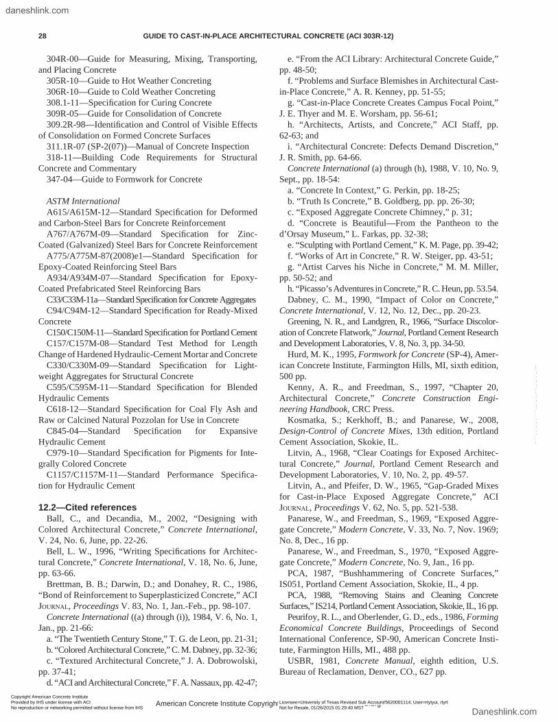
304R-00—Guide for Measuring, Mixing, Transporting, and Placing Concrete
305R-10—Guide to Hot Weather Concreting306R-10—Guide to Cold Weather Concreting308.1-11—Specification for Curing Concrete309R-05—Guide for Consolidation of Concrete309.2R-98—Identification and Control of Visible Effects
of Consolidation on Formed Concrete Surfaces311.1R-07 (SP-2(07))—Manual of Concrete Inspection318-11—Building Code Requirements for Structural
Concrete and Commentary347-04—Guide to Formwork for Concrete
ASTM InternationalA615/A615M-12—Standard Specification for Deformed
and Carbon-Steel Bars for Concrete ReinforcementA767/A767M-09—Standard Specification for Zinc-
Coated (Galvanized) Steel Bars for Concrete ReinforcementA775/A775M-87(2008)e1—Standard Specification for
Epoxy-Coated Reinforcing Steel BarsA934/A934M-07—Standard Specification for Epoxy-
Coated Prefabricated Steel Reinforcing BarsC33/C33M-11a—Standard Specification for Concrete AggregatesC94/C94M-12—Standard Specification for Ready-Mixed
ConcreteC150/C150M-11—Standard Specification for Portland CementC157/C157M-08—Standard Test Method for Length
Change of Hardened Hydraulic-Cement Mortar and ConcreteC330/C330M-09—Standard Specification for Light-
weight Aggregates for Structural ConcreteC595/C595M-11—Standard Specification for Blended
Hydraulic CementsC618-12—Standard Specification for Coal Fly Ash and
Raw or Calcined Natural Pozzolan for Use in ConcreteC845-04—Standard Specification for Expansive
Hydraulic CementC979-10—Standard Specification for Pigments for Inte-
grally Colored ConcreteC1157/C1157M-11—Standard Performance Specifica-
tion for Hydraulic Cement
12.2—Cited referencesBall, C., and Decandia, M., 2002, “Designing with
Colored Architectural Concrete,” Concrete International, V. 24, No. 6, June, pp. 22-26.
Bell, L. W., 1996, “Writing Specifications for Architec-tural Concrete,” Concrete International, V. 18, No. 6, June, pp. 63-66.
Brettman, B. B.; Darwin, D.; and Donahey, R. C., 1986, “Bond of Reinforcement to Superplasticized Concrete,” ACI Journal, Proceedings V. 83, No. 1, Jan.-Feb., pp. 98-107.
Concrete International ((a) through (i)), 1984, V. 6, No. 1, Jan., pp. 21-66:
a. “The Twentieth Century Stone,” T. G. de Leon, pp. 21-31;b. “Colored Architectural Concrete,” C. M. Dabney, pp. 32-36;c. “Textured Architectural Concrete,” J. A. Dobrowolski,
pp. 37-41;d. “ACI and Architectural Concrete,” F. A. Nassaux, pp. 42-47;
e. “From the ACI Library: Architectural Concrete Guide,” pp. 48-50;
f. “Problems and Surface Blemishes in Architectural Cast-in-Place Concrete,” A. R. Kenney, pp. 51-55;
g. “Cast-in-Place Concrete Creates Campus Focal Point,” J. E. Thyer and M. E. Worsham, pp. 56-61;
h. “Architects, Artists, and Concrete,” ACI Staff, pp. 62-63; and
i. “Architectural Concrete: Defects Demand Discretion,” J. R. Smith, pp. 64-66.
Concrete International (a) through (h), 1988, V. 10, No. 9, Sept., pp. 18-54:
a. “Concrete In Context,” G. Perkin, pp. 18-25;b. “Truth Is Concrete,” B. Goldberg, pp. pp. 26-30;c. “Exposed Aggregate Concrete Chimney,” p. 31;d. “Concrete is Beautiful—From the Pantheon to the
d’Orsay Museum,” L. Farkas, pp. 32-38;e. “Sculpting with Portland Cement,” K. M. Page, pp. 39-42;f. “Works of Art in Concrete,” R. W. Steiger, pp. 43-51;g. “Artist Carves his Niche in Concrete,” M. M. Miller,
pp. 50-52; andh. “Picasso’s Adventures in Concrete,” R. C. Heun, pp. 53.54.Dabney, C. M., 1990, “Impact of Color on Concrete,”
Concrete International, V. 12, No. 12, Dec., pp. 20-23.Greening, N. R., and Landgren, R., 1966, “Surface Discolor-
ation of Concrete Flatwork,” Journal, Portland Cement Research and Development Laboratories, V. 8, No. 3, pp. 34-50.
Hurd, M. K., 1995, Formwork for Concrete (SP-4), Amer-ican Concrete Institute, Farmington Hills, MI, sixth edition, 500 pp.
Kenny, A. R., and Freedman, S., 1997, “Chapter 20, Architectural Concrete,” Concrete Construction Engi-neering Handbook, CRC Press.
Kosmatka, S.; Kerkhoff, B.; and Panarese, W., 2008, Design-Control of Concrete Mixes, 13th edition, Portland Cement Association, Skokie, IL.
Litvin, A., 1968, “Clear Coatings for Exposed Architec-tural Concrete,” Journal, Portland Cement Research and Development Laboratories, V. 10, No. 2, pp. 49-57.
Litvin, A., and Pfeifer, D. W., 1965, “Gap-Graded Mixes for Cast-in-Place Exposed Aggregate Concrete,” ACI Journal, Proceedings V. 62, No. 5, pp. 521-538.
Panarese, W., and Freedman, S., 1969, “Exposed Aggre-gate Concrete,” Modern Concrete, V. 33, No. 7, Nov. 1969; No. 8, Dec., 16 pp.
Panarese, W., and Freedman, S., 1970, “Exposed Aggre-gate Concrete,” Modern Concrete, No. 9, Jan., 16 pp.
PCA, 1987, “Bushhammering of Concrete Surfaces,” IS051, Portland Cement Association, Skokie, IL, 4 pp.
PCA, 1988, “Removing Stains and Cleaning Concrete Surfaces,” IS214, Portland Cement Association, Skokie, IL, 16 pp.
Peurifoy, R. L., and Oberlender, G. D., eds., 1986, Forming Economical Concrete Buildings, Proceedings of Second International Conference, SP-90, American Concrete Insti-tute, Farmington Hills, MI., 488 pp.
USBR, 1981, Concrete Manual, eighth edition, U.S. Bureau of Reclamation, Denver, CO., 627 pp.
American Concrete Institute Copyrighted Material—www.concrete.org
28 GUIDE TO CAST-IN-PLACE ARCHITECTURAL CONCRETE (ACI 303R-12)
Copyright American Concrete Institute Provided by IHS under license with ACI Licensee=University of Texas Revised Sub Account/5620001114, User=rtytyui, rtyrt
Not for Resale, 01/26/2015 01:29:40 MSTNo reproduction or networking permitted without license from IHS
--````,`,`,,`,`,``````,,,`,,`,,-`-`,,`,,`,`,,`---
daneshlink.com
Daneshlink.com
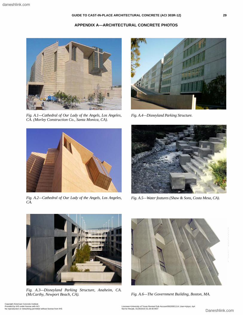
GUIDE TO CAST-IN-PLACE ARCHITECTURAL CONCRETE (ACI 303R-12) 29
APPENDIX A—ARCHITECTURAL CONCRETE PHOTOS
Fig. A.1—Cathedral of Our Lady of the Angels, Los Angeles,CA. (Morley Construction Co., Santa Monica, CA).
Fig. A.2—Cathedral of Our Lady of the Angels, Los Angeles,CA.
Fig. A.3—Disneyland Parking Structure, Anaheim, CA.(McCarthy, Newport Beach, CA).
Fig. A.4—Disneyland Parking Structure.
Fig. A.5—Water features (Shaw & Sons, Costa Mesa, CA).
Fig. A.6—The Government Building, Boston, MA.
Copyright American Concrete Institute Provided by IHS under license with ACI Licensee=University of Texas Revised Sub Account/5620001114, User=rtytyui, rtyrt
Not for Resale, 01/26/2015 01:29:40 MSTNo reproduction or networking permitted without license from IHS
--````,`,`,,`,`,``````,,,`,,`,,-`-`,,`,,`,`,,`---
daneshlink.com
Daneshlink.com
30 GUIDE TO CAST-IN-PLACE ARCHITECTURAL CONCRETE (ACI 303R-12)
Fig. A.7—Christian Science Plaza; Colonnade Buildingfeaturing sun shade columns.
Fig. A.8—Kaiser Permanente Regional Office Building,Oakland, CA.
Fig. A.9—Torre Dataflux, Monterrey, Mexico.
Fig. A.10—Rock & Roll Hall of Fame, Cleveland, OH. I. M.Pei, Architect.
Copyright American Concrete Institute Provided by IHS under license with ACI Licensee=University of Texas Revised Sub Account/5620001114, User=rtytyui, rtyrt
Not for Resale, 01/26/2015 01:29:40 MSTNo reproduction or networking permitted without license from IHS
--````,`,`,,`,`,``````,,,`,,`,,-`-`,,`,,`,`,,`---
daneshlink.com
Daneshlink.com
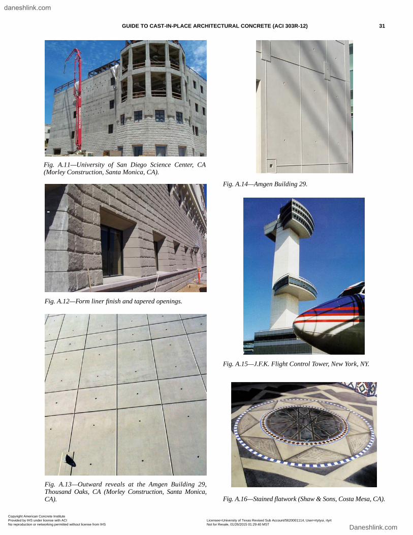
GUIDE TO CAST-IN-PLACE ARCHITECTURAL CONCRETE (ACI 303R-12) 31
Fig. A.11—University of San Diego Science Center, CA(Morley Construction, Santa Monica, CA).
Fig. A.12—Form liner finish and tapered openings.
Fig. A.13—Outward reveals at the Amgen Building 29,Thousand Oaks, CA (Morley Construction, Santa Monica,CA).
Fig. A.14—Amgen Building 29.
Fig. A.15—J.F.K. Flight Control Tower, New York, NY.
Fig. A.16—Stained flatwork (Shaw & Sons, Costa Mesa, CA).
Copyright American Concrete Institute Provided by IHS under license with ACI Licensee=University of Texas Revised Sub Account/5620001114, User=rtytyui, rtyrt
Not for Resale, 01/26/2015 01:29:40 MSTNo reproduction or networking permitted without license from IHS
--````,`,`,,`,`,``````,,,`,,`,,-`-`,,`,,`,`,,`---
daneshlink.com
Daneshlink.com
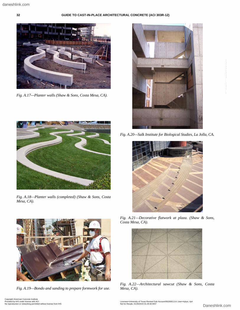
32 GUIDE TO CAST-IN-PLACE ARCHITECTURAL CONCRETE (ACI 303R-12)
Fig. A.17—Planter walls (Shaw & Sons, Costa Mesa, CA).
Fig. A.18—Planter walls (completed) (Shaw & Sons, CostaMesa, CA).
Fig. A.19—Bondo and sanding to prepare formwork for use.
Fig. A.20—Salk Institute for Biological Studies, La Jolla, CA.
Fig. A.21—Decorative flatwork at plaza. (Shaw & Sons,Costa Mesa, CA).
Fig. A.22—Architectural sawcut (Shaw & Sons, CostaMesa, CA).
Copyright American Concrete Institute Provided by IHS under license with ACI Licensee=University of Texas Revised Sub Account/5620001114, User=rtytyui, rtyrt
Not for Resale, 01/26/2015 01:29:40 MSTNo reproduction or networking permitted without license from IHS
--````,`,`,,`,`,``````,,,`,,`,,-`-`,,`,,`,`,,`---
daneshlink.com
Daneshlink.com
As ACI begins its second century of advancing concrete knowledge, its original chartered purpose remains “to provide a comradeship in finding the best ways to do concrete work of all kinds and in spreading knowledge.” In keeping with this purpose, ACI supports the following activities:
· Technical committees that produce consensus reports, guides, specifications, and codes.
· Spring and fall conventions to facilitate the work of its committees.
· Educational seminars that disseminate reliable information on concrete.
· Certification programs for personnel employed within the concrete industry.
· Student programs such as scholarships, internships, and competitions.
· Sponsoring and co-sponsoring international conferences and symposia.
· Formal coordination with several international concrete related societies.
· Periodicals: the ACI Structural Journal and the ACI Materials Journal, and Concrete International.
Benefits of membership include a subscription to Concrete International and to an ACI Journal. ACI members receive discounts of up to 40% on all ACI products and services, including documents, seminars and convention registration fees.
As a member of ACI, you join thousands of practitioners and professionals worldwide who share a commitment to maintain the highest industry standards for concrete technology, construction, and practices. In addition, ACI chapters provide opportunities for interaction of professionals and practitioners at a local level.
American Concrete Institute38800 Country Club DriveFarmington Hills, MI 48331U.S.A.Phone: 248-848-3700Fax: 248-848-3701
www.concrete.org
American Concrete Institute®
Advancing concrete knowledge
Copyright American Concrete Institute Provided by IHS under license with ACI Licensee=University of Texas Revised Sub Account/5620001114, User=rtytyui, rtyrt
Not for Resale, 01/26/2015 01:29:40 MSTNo reproduction or networking permitted without license from IHS
--````,`,`,,`,`,``````,,,`,,`,,-`-`,,`,,`,`,,`---
daneshlink.com
Daneshlink.com
Guide to Cast-in-Place Architectural Concrete Practice
The AMERICAN CONCRETE INSTITUTE
was founded in 1904 as a nonprofit membership organization dedicated to public service and representing the user interest in the field of concrete. ACI gathers and distributes information on the improvement of design, construction and maintenance of concrete products and structures. The work of ACI is conducted by individual ACI members and through volunteer committees composed of both members and non-members.
The committees, as well as ACI as a whole, operate under a consensus format, which assures all participants the right to have their views considered. Committee activities include the development of building codes and specifications; analysis of research and development results; presentation of construction and repair techniques; and education.
Individuals interested in the activities of ACI are encouraged to become a member. There are no educational or employment requirements. ACI’s membership is composed of engineers, architects, scientists, contractors, educators, and representatives from a variety of companies and organizations.
Members are encouraged to participate in committee activities that relate to their specific areas of interest. For more information, contact ACI.
www.concrete.org
American Concrete Institute®
Advancing concrete knowledge
Copyright American Concrete Institute Provided by IHS under license with ACI Licensee=University of Texas Revised Sub Account/5620001114, User=rtytyui, rtyrt
Not for Resale, 01/26/2015 01:29:40 MSTNo reproduction or networking permitted without license from IHS
--````,`,`,,`,`,``````,,,`,,`,,-`-`,,`,,`,`,,`---
daneshlink.com
Daneshlink.com
Copyright © 2022 FDOKUMEN