GUIDE NO. AERB/NRF/SG/RP-1 GOVERNMENT OF INDIA ...
96
GUIDE NO. AERB/NRF/SG/RP-1 GOVERNMENT OF INDIA AERB SAFETY GUIDE Monitoring and Assessment of Occupational Exposure Due to Intake of Radionuclides ATOMIC ENERGY REGULATORY BOARD
-
Upload
khangminh22 -
Category
Documents
-
view
0 -
download
0
Transcript of GUIDE NO. AERB/NRF/SG/RP-1 GOVERNMENT OF INDIA ...

GUIDE NO. AERB/NRF/SG/RP-1
GOVERNMENT OF INDIA
AERB SAFETY GUIDE
Monitoring and Assessment of Occupational Exposure Due to Intake of Radionuclides
ATOMIC ENERGY REGULATORY BOARD

AERB SAFETY GUIDE NO. AERB/NRF/SG/RP-1
Monitoring and Assessment of Occupational Exposure Due to Intake of Radionuclides
Atomic Energy Regulatory Board
Mumbai – 400094
India
December, 2019

Price
Orders for this ‘Guide’ should be addressed to:
The Chief Administrative Officer,
Atomic Energy Regulatory Board
NiyamakBhavan-A
Anushaktinagar
Mumbai - 400 094
India


ii
DEFINITIONS
Absorbed Dose
The fundamental dosimetric quantity D is defined as:
D = dE /dm
where, ‘dE’ is the mean energy imparted by ionising radiation to the matter in a volume element
and ‘dm’ is the mass of matter in the volume element. The energy can be averaged over any
defined volume, the average dose being equal to the total energy imparted in the volume divided
by the mass in the volume. The SI unit of absorbed dose is joule/kg (J.kg-1), termed the gray
(Gy).
Activity
The quantity ‘A’ for an amount of radionuclide in a given energy state at a given time is defined
as:
A(t) = dN/dt
where ‘dN’ is the expectation value of the number of spontaneous nuclear transformations from
the given energy state in a time interval ‘dt’. The SI unit of activity is the reciprocal of second
(s-1), termed the Becquerel (Bq).
Activity Median Aerodynamic Diameter (AMAD)
The value of aerodynamic diameter such that 50% of the airborne activity in a specified aerosol
is associated with particles smaller than the AMAD, and 50% of the activity is associated with
particles larger than the AMAD.
Assessment
Systematic evaluation of the arrangements, processes, activities and related results for their
adequacy and effectiveness in comparison with set criteria.
Atomic Energy Regulatory Board (AERB)
A national authority designated by the Government of India having the legal authority for
issuing regulatory consent for various activities related to the nuclear and radiation facility and
to perform safety and regulatory functions, including their enforcement for the protection of site
personnel, the public and the environment against undue radiation hazards.
Commissioning
The process during which structures, systems, components and equipment of a nuclear or
radiation facility, on being constructed, are made functional and verified in accordance with
design specifications and found to have met the performance criteria.
Committed Effective Dose, E ()
The time integral of the whole body effective dose rate following an intake of a radionuclide.
The quantity ‘E ()’ is defined as
𝐸() = ∑ 𝑤𝑇 . 𝐻𝑇()
𝑇

iii
Where 𝐻𝑇() is the committed equivalent dose to tissue or organ T over the integration time τ
elapsed after an intake of radioactive substances and 𝑤𝑇 is the tissue weighting factor for tissue
or organ T. Where τ is not specified, it will be taken to be 50 years for adults and the time to
the age of 70 years for intakes by children.
Committed Equivalent Dose, HT()
The time integral of the equivalent dose rate in an organ or tissue following an intake of a
radionuclide. The quantity ‘HT()’ is defined as
𝐻𝑇() = ∫ 𝐻𝑡̇ (𝑡)𝑑𝑡
t0+
𝑡0
where ‘t0’ is the time of intake, ‘HT(t) dt’ is the equivalent dose rate at time ‘t’ in an organ or
tissue ‘T’ and ‘’ is the integration time elapsed after an intake of radioactive substances. Where
τ is not specified, it is taken to be 50 years for adults and the time to the age of 70 years for
intakes by children.
Competent Authority
Any official or authority appointed, approved or recognised by the Government of India for the
purpose of the Rules promulgated under the Atomic Energy Act, 1962.
Consentee
A person to whom consent is granted by the competent authority under the relevant rules.
Contamination
The presence of radioactive substances in or on a material/the human body or other places in
excess of quantities specified by the competent authority.
Controlled Area
A delineated area to which access is controlled and in which specific protection measures and
safety provisions are, or could be, required for
(a) controlling normal exposures or preventing the spread of contamination during
normal working conditions; and
(b) preventing potential exposures or limiting their extent should they occur.
Derived Air Concentration
That activity concentration of the radionuclide in air (Bq/m3) which, if breathed by reference
man for a working year of 2000 h under conditions of light physical activity (breathing rate of
1.2 m3/h), would result in one annual limit on intake, or the concentration, which for 2000 h of
air immersion, would lead to irradiation of any organ or tissue to the appropriate annual dose
limit.
Derived Limits
A limit on a measurable quantity set, on the basis of a model, such that compliance with the
derived limit may be assumed to ensure compliance with a primary limit.

iv
Deterministic Effect
A radiation induced health effect for which generally a threshold level of dose exists above
which the severity of the effect is greater for a higher dose. Deterministic effects are also
referred to as (harmful) tissue reactions..
Document
Recorded or pictorial information describing, defining, specifying, reporting or certifying
activities, requirements, procedures or results.
Dose
A measure of the energy deposited by radiation in a target. The quantities termed absorbed dose,
equivalent dose, effective dose, committed equivalent dose, or committed effective dose are
used, depending on the context.
Dose coefficient
Used as a synonym for dose per unit intake of a radioactive substance, but sometimes also used
to describe other coefficients linking quantities or concentrations of activity to doses or dose
rates, such as the external dose rate at a specified distance above a surface with a deposit of a
specified activity per unit area of a specified radionuclide.
Dose Constraint
A prospective and source-related restriction on the individual dose delivered by the source,
which serves as a bound in the optimisation of protection and safety of the source. For
occupational exposures, dose constraint is a source-related value of individual dose used to limit
the range of options considered in the process of optimisation. For public exposure, the dose
constraint is an upper bound on the annual dose that a member of the public should receive from
the planned operation of any controlled source. The exposure to which the dose constraint
applies is the annual dose to any critical group summed over all exposure pathways, arising
from the predicted operation of the controlled source. For medical exposure the dose constraint
level should be interpreted as a guidance level, except when used in optimising the protection
of persons, other than workers, who assist in the care, support or comfort of exposed patients.
Dose Limit
The value of the effective dose or the equivalent dose to individuals from controlled practices
that shall not be exceeded.
Effective Dose
The quantity ‘E’ defined as a summation of the tissue equivalent doses, each multiplied by the
appropriate tissue weighting factor:
𝐸 = ∑ 𝑤𝑇
𝑇
. 𝐻𝑇
where ‘HT’ is the equivalent dose in tissue or organ ‘T’ and ‘𝑤𝑇’ is the tissue weighting factor
for tissue or organ ‘T’.
Employer

v
Any person with recognised responsibility, commitment and duties towards a worker in his or
her employment by virtue of a mutually agreed relationship. (A self-employed person is
regarded as being both a worker and employer).
Equivalent Dose (HT, R)
The quantity ‘HT, R’” is defined as
𝐻𝑇,𝑅 = 𝑤𝑅 . 𝐷𝑇,𝑅
where ‘DT,R’ is the absorbed dose delivered by radiation type ‘R’ averaged over a tissue or organ
‘T’ and ‘𝑤𝑅’ is the radiation weighing factor for radiation type ‘R’. When the radiation field is
composed of different radiation types with different values of ‘𝑤𝑅’ the equivalent dose is
𝐻𝑇 = ∑ 𝑤𝑅 . 𝐷𝑇,𝑅
𝑅
Exposure
The act or condition of being subject to irradiation. Exposure may be either external (irradiation
by sources outside the body) or internal (irradiation by sources inside the body). Exposure can
be classified as either normal exposure or potential exposure; occupational, medical or public
exposure; and in intervention situations, either emergency exposure or chronic exposure. The
term ‘exposure’ is also used in radiation dosimetry to express the amount of ions produced in
air by ionising radiation.
Investigation Level
The value of a quantity such as effective dose, intake, or contamination per unit area or volume,
at or above which an investigation should be conducted.
Intake
The process of taking radionuclide into the body by inhalation or ingestion, or through the skin,
and the amount of given radionuclide taken in during a given period.
Monitoring
The continuous or periodic measurement of parameters for reasons related to the determination,
assessment in respect of structure, system or component in a facility or control of radiation.
Nuclear Fuel Cycle
All operations associated with the production of nuclear energy, including mining, milling,
processing and enrichment of uranium or processing of thorium, manufacture of nuclear fuel,
operation of nuclear reactors, reprocessing of irradiated nuclear fuel, decommissioning, and any
activity for radioactive waste management and research or development activity related to any
of the foregoing.
Occupational Exposure
All exposures of personnel incurred in the course of their work.
Occupational Worker

vi
Any person, working full time or part time in a nuclear or radiation facility, who may be
employed directly by the “consentee” or through a contractor.
Operation
All activities following and prior to commissioning performed to achieve, in a safe manner, the
purpose for which a nuclear/radiation facility is constructed. For nuclear power plants, this
includes maintenance, refuelling, in-service inspection and other associated activities.
Quality Assurance (QA)
Planned and systematic actions necessary to provide the confidence that an item, process or
service will satisfy given requirements for quality.
Radiation Surveillance
Measures that may be specified by the competent authority to provide adequate radiological
protection either generally or in any individual case.
Radiation Worker
Any person who is occupationally exposed to radiation, and who in the opinion of the regulatory
body, should be subjected to radiation surveillance.
Radiological Safety Officer (RSO)
Any person who is so designated by the employer and who, in the opinion of the competent
authority is qualified to discharge the functions outlined in the Radiation Protection Rules, 2004.
Records
Documents which furnish objective evidence of the quality of items and activities affecting
quality. It also includes logging of events and other measurements.
Reference Level
Action level, intervention level, investigation level or recording level established for any of the
quantities determined in the practice of radiation protection.
Regulatory Constraints
Restrictions on radiation protection parameters as specified by the regulatory body.
Source
Anything that causes radiation exposure, either by emitting ionising radiation or releasing
radioactive substances or materials.
Source Region
An anatomical region within the reference phantom body which contains the radionuclide
following its intake. The region may be an organ, a tissue, the contents of the gastrointestinal
tract or urinary bladder, or the surfaces of tissues as in the skeleton, the alimentary tract, and
the respiratory tract.
Stochastic Effects (Radiation)
Radiation effects generally occurring without a threshold level of dose whose probability is
proportional to the dose and whose severity is independent of the dose.

vii
Supervised Area
Any area not designated as a controlled area but for which occupational exposure conditions
are kept under review even though specific protective measures and safety provisions are not
normally needed.
Surveillance
All planned activities, viz. monitoring, verifying, checking including in-service inspection,
functional testing, calibration and performance testing carried out to ensure compliance with
specifications established in a facility.
Target Tissue/Organ
The tissue or organ to which radiation is directed.
Working Level (WL)
A unit of potential alpha energy concentration (i.e. the potential alpha energy per unit volume
of air) resulting from the presence of radon progeny or thoron progeny, equal to 1.3 x 10⁵ MeV
per litre. In SI units, a working level is 2.1 x 10⁻⁵ J/m3.

viii
Special Definitions
Reference Biokinetic Model (ICRP 130, 2015)
A reference biokinetic model describes the intake, uptake, distribution, and retention of a
radionuclide in various organs or tissues of the body, and the subsequent excretion from the
body by various pathways.
Clearance (IAEA Glossary)
The net effect of the biological processes by which radionuclides are removed from a tissue,
organ or area of the body.
Uptake (ICRP 130, 2015)
Activity that enters blood from the respiratory or alimentary tract through the skin or wound.
Bioassay (IAEA Glossary)
Any procedure used to determine the nature, activity, location or retention of radionuclides in
the body by direct (in vivo) measurement or by in vitro analysis of material excreted
or otherwise removed from the body

ix
LIST OF ABBREVIATION
AERB : Atomic Energy Regulatory Board
AMAD : Activity Median Aerodynamic Diameter
ASV : Anodic / Adsorptive Stripping Voltametry
BOMAB : Bottle Mannequin Absorber
Ca-DTPA : Calcium diethylene triamine penta acetic acid
CED : Committed Effective Dose
DAC : Derived Air Concentration
DRL : Derived Reference Level
DNAA : Delayed Neutron Activation Analysis
FTA : Fission Track Analysis
GSR : General Safety Requirements
HEP : High Energy Photon
IAEA : International Atomic Energy Agency
ICP-MS : Inductively Coupled Plasma Mass Spectrometry
ICRP : International Commission on Radiological Protection
JAERI : Japan Atomic Energy Research Institute
IL : Investigation Level
LEP : Low Energy Photon
LLNL : Lawrence Livermore National Laboratory
LLRDS : Low Level Radon Detection System
MDA : Minimum Detectable Activity
MEQ-CWT: Muscle Equivalent Chest Wall Thickness
MRI : Magnetic Resonance Imaging
MRL : Medical Referral Level
NAA : Neutron Activation Analysis
NCRP : National Council on Radiation Protection and Measurements
NODRS : National Occupational Dose Registry System
OBT : Organically Bound Tritium
PAS : Personal Air Sampler
PIPS : Passivated Implanted Silicon
RL : Recording Level
RSO : Radiological Safety Officer
SAS : Static Air Samplers
SEE : Specific Effective Energy
SSNTD : Solid State Nuclear Track Detector
TLD : Thermo Luminescent Dosimeter
WBC : Whole Body Counter
WBM : Whole Body Monitor

x
CONTENTS
FOREWORD ............................................................................................................................................................ i
DEFINITIONS ........................................................................................................................................................ ii
LIST OF ABBREVIATION ................................................................................................................................... ix
1. INTRODUCTION ..................................................................................................................................... 1
1.1 General....................................................................................................................................................... 1 1.2 Objective .................................................................................................................................................... 1 1.3 Scope ......................................................................................................................................................... 1
2. ROLES AND RESPONSIBILITIES ......................................................................................................... 3
2.1 General....................................................................................................................................................... 3 2.2 Consentee / Licensee ................................................................................................................................. 3 2.3 Radiological Safety Officer (RSO) ............................................................................................................ 3 2.4 Radiation Worker ....................................................................................................................................... 4 2.5 In charge of the Internal Dosimetry Laboratory ........................................................................................ 4
3. METHODS FOR INTERNAL DOSIMETRY .......................................................................................... 5
3.1 General....................................................................................................................................................... 5 3.2 Criteria for Individual Internal Monitoring ................................................................................................ 5 3.3 Types of Monitoring .................................................................................................................................. 6
3.3.1 Routine Monitoring ....................................................................................................................... 6
3.3.2 Special / Task Related Monitoring ................................................................................................ 6
3.3.3 Confirmatory Monitoring .............................................................................................................. 7
3.4 Assessment of Internal Contamination ...................................................................................................... 7 3.5 Assessment of Internal Dose ...................................................................................................................... 8 3.6 Biokinetic Models ...................................................................................................................................... 8
3.6.1. Respiratory Tract and Gastro Intestinal Tract Models ................................................................... 8
3.6.2 Wound Model ................................................................................................................................ 9
3.6.3 Systemic Models............................................................................................................................ 9
3.7 Date of Intake ............................................................................................................................................ 9 3.8 Normalizing Bioassay Data ..................................................................................................................... 10 3.9 Assignment of Internal Doses .................................................................................................................. 10 3.10 Reference Levels and Derived Reference Levels .................................................................................... 10
3.10.1 Recording level (RL) ................................................................................................................... 10
3.10.2 Investigation Level (IL) ............................................................................................................... 11
3.10.3 Medical Referral Level ( MRL) ................................................................................................... 11
3.10.4 Derived Reference Levels (DL) ................................................................................................... 11
3.11 Requirements of Internal Dosimetry Laboratories ................................................................................... 12
4. DIRECT MEASUREMENT METHODS ............................................................................................... 14
4.1 General..................................................................................................................................................... 14 4.2 Direct Measurement Systems .................................................................................................................. 14 4.3 Measurement Geometry ........................................................................................................................... 14 4.4 Detection System ..................................................................................................................................... 15 4.5 Calibration Procedures ............................................................................................................................. 15 4.6 Whole Body / Organ Counting Procedure ............................................................................................... 16 4.7 Background Measurement ....................................................................................................................... 17 4.8 Minimum Detectable Activity (MDA): ................................................................................................... 17

xi
5. INDIRECT MEASUREMENT METHODS ........................................................................................... 19
5.1 General..................................................................................................................................................... 19 5.2 Sample Collection Methodology ............................................................................................................. 19 5.3 Radiochemical Separation ....................................................................................................................... 20 5.4 Analytical Techniques ............................................................................................................................. 20 5.5 Minimum Detectable Activity (MDA) .................................................................................................... 21 5.6 Internal Dosimetry for Tritium ................................................................................................................ 22
5.6.1 General ........................................................................................................................................ 22
5.6.2 Method of dose calculation due to chronic exposure ................................................................... 23
5.6.2.1 Dose calculation from urine samples submitted at regular interval ........................................... 23
5.6.2.2 Dose calculation from urine samples submitted at interval more than specified period ......... 24
5.6.3 Method of dose calculations for acute exposure .......................................................................... 24
6. WORK PLACE MONITORING METHODS ........................................................................................ 26
6.1 General..................................................................................................................................................... 26 6.2 Monitoring of Radon and its Daughter products in Mines ...................................................................... 26
6.2.1 Radon monitoring ........................................................................................................................ 26
6.2.2 Radon progeny monitoring .......................................................................................................... 26
6.3 Dose Evaluation for Mine Workers ......................................................................................................... 27 6.4 Personal and Static Air Samplers ............................................................................................................. 27
7. INTERPRETATION OF BIOASSAY MEASUREMENTS ................................................................... 29
7.1 General..................................................................................................................................................... 29 7.2 Intake Estimate from Special Monitoring ................................................................................................ 30 7.3 Intake Estimate from Routine Monitoring ............................................................................................... 30 7.4 Intake Estimate from Multiple Bioassay Data ......................................................................................... 31 7.5 Intake Estimates from Measurements of Related Nuclides (Tracer) ....................................................... 31 7.6 Workplace Information ............................................................................................................................ 31 7.7 Uncertainties in Internal Dose Assessment .............................................................................................. 31
8. QUALITY ASSURANCE ....................................................................................................................... 33
8.1 General..................................................................................................................................................... 33 8.2 Quality Assurance Plan ............................................................................................................................ 33 8.3 Quality Assuranc eProcedures ................................................................................................................. 33 8.4 Performance Checks of Instrumentation for In-vivo and In-vitro Radiobioassay ................................... 34 8.5 Performance Checks on In Vitro Bioassay Procedures ............................................................................ 34 8.6 Use of Reference Radioactive Materials for Equipment Calibrations ..................................................... 34 8.7 Computer Software Quality Assurance ................................................................................................... 34
9. DOCUMENTATION AND RECORDS ................................................................................................. 36
9.1 General..................................................................................................................................................... 36 9.2 Record Keeping of Internal Dosimetry Laboratories ............................................................................... 36 9.3 Record Keeping of Individual Monitoring and Work place Monitoring by RSO .................................... 37 9.4 Record Keeping by Consentee / Licensee................................................................................................ 37 9.5 Retention Periods for Radiological Record ............................................................................................. 38 9.6 Reporting Information ............................................................................................................................. 38
9.6.1 Reporting by Internal Dosimetry Laboratories: ........................................................................... 38
9.6.2 Reporting by RSO ....................................................................................................................... 39
9.6.3 Reporting by the Consentee / Licensee ........................................................................................ 39
9.7 Training of personnel ............................................................................................................................... 39 9.7.1 Training of workers ..................................................................................................................... 39
9.7.2 Training of dosimetry service personnel ..................................................................................... 39

xii
Annexure I ............................................................................................................................................................. 41
IMPORTANT INTERNAL DOSIMETRY INFORMATION FOR SELECTED RADIONUCLIDES ............... 41
1. Hydrogen (Tritium) ................................................................................................................................. 41 2. Cobalt....................................................................................................................................................... 44 3. Strontium ................................................................................................................................................. 47 4. Iodine ....................................................................................................................................................... 49 5. Caesium ................................................................................................................................................... 52 6. Polonium .................................................................................................................................................. 54 7. Radium..................................................................................................................................................... 55 8. Thorium ................................................................................................................................................... 58 9. Uranium ................................................................................................................................................... 62 10. Plutonium ................................................................................................................................................. 65 11. Americium ............................................................................................................................................... 68
Annexure II ............................................................................................................................................................ 71
METHODS FOR MEASUREMENT OF RADON, THORON AND THEIR DAUGHTER PRODUCTS ......... 71
REFERENCES ...................................................................................................................................................... 75
BIBLIOGRAPHY ................................................................................................................................................. 78
EXPERT COMMITTEE FOR DEVELOPMENT OF SAFETY GUIDE ............................................................. 79
PROVISIONAL LIST OF REGULATORY DOCUMENTS ON RADIATION PROTETION ........................... 81
1
1. INTRODUCTION
1.1 General
Radiation exposure, both external and internal, can occur to radiation workers during
the operation of various nuclear fuel cycle facilities and radiation facilities. In view of
the potential health effects of radiation exposures, it is necessary that all activities
involving radiation exposures and the facilities handling radioactive materials are
regulated. Therefore, radiological protection programs are usually planned to prevent,
control / limit and minimize the exposures,so that deterministic effects are prevented
and stochastic effects are reduced to the extent reasonably achievable. The basic
requirements for such radiation protection programme are given in the AERB Safety
Code on “Radiation Protection for Nuclear Fuel Cycle Facilities” [1]and AERB Safety
Code on “Radiation sources, equipment and installations’, AERB/RF/SC”1.
The assessment of radiation doses to workers routinely or potentially exposed to
radiation through intake of radionuclide is an integral part of the radiation protection
programme.Approved procedures are required to be used for assessment of both
external and internal exposures. Unlike external exposure, internal exposure cannot be
measured directly. Its evaluation is based on the calculation of the intake of
radionuclide either from direct measurements (e.g. external monitoring of whole body
or ofspecific organs and tissues) or indirect measurements (e.g. radioactivity in urine,
faeces, breath or samples from the working environment)[2][3].
1.2 Objective
The objective of this Safety Guide is to provide criteria and guidance for evaluating
the radiation dose that may be received following intakes of radioactive materials due
to occupational exposure. This safety guide provides the methodologies and
procedures for assessment of radiation dose due to intake of various radionuclides.
This Safety Guide also provides guidance for monitoring of internal exposures in both
routine and off-normal situations, using direct and indirect methods.
1.3 Scope
This guide is applicable for the internal dosimetry of personnel working in nuclear fuel
cycle and radiation facilities having potential for internal exposure such as:
a) Mining and milling of uranium and thorium ores;
b) Fuel enrichment/fabrication facilities;
c) Nuclear power plants;
d) Research/experimental reactors;
e) Fuel reprocessing plants;
f) Radioactive waste management plants;
1 The Safety Code (AERB/RF/SC) is under preparation.

2
g) Radiation facilities producing or handling large quantities of radionuclides for
medical, industrial, research purpose etc.; and
h) Any other facility as determined by AERB
This Safety Guide does not cover the medical exposure of patients or exposure of
members of the public.

3
2. ROLES AND RESPONSIBILITIES
2.1 General
Consentee / licensee has the overall responsibility for the radiological safety of the
radiation workers. The consentee / licensee shall ensure that the radiation protection
programme put in place has an appropriate internal dosimetry components
commensurate with the radiological hazards associated with the operations of the
facility [4]. Roles and responsibilities of consentee/ licensee, Radiological Safety
Officer (RSO), the radiation worker and the in-charge of internal dosimetry laboratory
are stated in this section.
2.2 Consentee / Licensee
The consentee /licenseeis responsible for the dose assessmentof radiation workers
through an appropriate individual monitoring programmeandshall maintain the dose
record as specified by AERB[1]. The consentee / licenseeshallensure establishment of
an internal dosimetry programme. The consentee / licenseeshould use only laboratories
recognized by AERB for internal dose assessment.The internal dosimetry programme
should include the following features:
a) Defined criteria for identifying workers who need to be covered in the individual
monitoring programme;
b) Appropriate bioassay measurement methods and the measurement frequencies;
c) Methods for collection, control, accountability, and safe handling of samples;
d) Scheme for timely analysis of bioassay samples and measurements;
e) Defined criteria and actions for identifying individuals with suspected intakes, based
on workplace monitoring and bioassay measurements;
f) Establish appropriate reference levels;
g) Formulation of action plan for medical management of internally contaminated
workers; and
h) Defined program to report internal doses to AERB and workers.
The consentee / licensee should investigate case(s) of exposure, if any, in excess of
regulatory constraints / limits received by individual workers in consultation with the
Radiological Safety Officer (RSO) and maintain records of such investigations. The
consentee / licenseeshall informAERB promptly of the occurrence, investigation,
follow-up and corrective actions in cases of exposures in excess of regulatory
constraints / limits. The consentee / licensee should also examine the overall trend of
internal dose contribution over the years.
2.3 Radiological Safety Officer (RSO)
The Radiological Safety Officer (RSO) is responsible for the implementation,
coordination, and day-to-day overseeing of the radiation protection programme. As

4
part of this responsibility, withrespect to internalexposure monitoring programme,
RSO should:
a) Ensure that the radiation workers are covered by an appropriate internal dosimetry
programme;
b) Assist the consentee / licensee in coordinating with the internal dosimetry laboratory
for implementation of the bioassay programme;
c) Instruct the workers on the importance of bioassay programme;
d) In case of off – normal situation, recommend the workers for in vivo as well as in vitro
monitoring;
e) Ensure timely entry of internal dose data into the individual dose record;
f) Assist the consentee / licensee in carrying out investigation in cases exceeding
reference levels;
g) Furnish reports to AERB on cases exceeding investigationlevels;
h) Coordinate with the hospital staff in cases requiring medical attention;
i) Obtain physicochemical parameters, such as isotopic composition, solubility and
particle size data wherever required.
2.4 Radiation Worker
Every radiation worker with respect to internalexposure controlshould;
a) Adhere to the recommendationsof the RSOincluding use ofpersonal protective
equipments (PPEs);
b) Provide samples of urine / faecesetc. for bioassay purposes and / or report for whole
body counting / organ monitoring as instructed by the RSO;
c) Assist the consentee / licensee and the RSO in investigations when the reference levels
are exceeded.
2.5 In charge of the Internal Dosimetry Laboratory
Internal dosimetry laboratory shall have the accreditation from relevant agency
recognised by AERB. The In charge of the internal dosimetry laboratory should;
a) Co-ordinate with the RSO / consentee / licensee for implementation of
bioassayprogramme;
b) Carry out necessary follow-up measurements in case of significant intake, if required;
c) Collect and assess the monitoring results obtained by all the individual monitoring
techniques before computation of internal dose based on information provided by the
consentee / licensee and the RSO;
d) Report the results to the Consentee / Licensee.

5
3. METHODS FOR INTERNAL DOSIMETRY
3.1 General
Internal dose is the radiation exposure that results from the intake of radioactive
materials into the body by inhalation, ingestion, absorption through the skin or via
wounds. Assessment of radiation doses arising from the intake of radioactive material
by the workers is termed as internal exposure assessment. It is primarily needed for
demonstrating compliance with the dose constraint /limits and facilitating safe
operations in nuclear or radiological facilities. In case of off-normal exposures, it can
provide useful information for taking appropriate intervention measures. Evaluation of
internal exposure of an individual is mostly based on bioassay measurements. Another
method of internal dose assessment is based on the measurement of airborne
radionuclides in the working areas of the facility and the worker’s occupancy in those
areas.
3.2 Criteria for Individual Internal Monitoring
Individual monitoring measures are necessary if there is a likelihood of workers
receiving internal dose of 1 mSv or more from all occupational intakes of radionuclides
in a year[5]. The consentee / licensee, in consultation with the RSO should identify
such workers for monitoring purposes.
The probability of workers exceeding an internal dose of 1 mSv per year should be
assessed on the basis of the following considerations;
a) The amount of radioactive material handled by the worker;
b) The type of radionuclides involved;
c) The physical and chemical form of the radionuclides;
d) The type of containment used;
e) The nature of the operations performed;
f) The air activity in the operating area; and
g) Workers to whom TLD / work permit issued and / or in the opinion of RSO
considering exposure potential.
In addition to these, before introducing any new operations or starting a new facility,
individual monitoring is to be implemented for all radiation workers and reviewed over
the years based on the experience accumulated.
Individual monitoring for internal exposures should be carried out for
a) Generation of baseline bioassay data for new workers;
b) Routine bioassay of radiation workers;
c) Investigation of any incident at workplace;
d) Workers with potential for inhalation exposures from radon/thoron daughters; and
e) Demonstration of regulatory compliance of the dose limit.

6
3.3 Types of Monitoring
Following types of internal monitoring programmes are generally needed [2]:
a) Routine monitoring
b) Special or task related monitoring
c) Confirmatory monitoring.
3.3.1 Routine Monitoring
Routine bioassay monitoring is the usual and the most frequent type of bioassay
measurements which indicates internal exposures that might have been incurred by the
workers during the course of their work either during normal operations or due to minor
events. It also includes the baseline bioassay monitoring which is carried out to
establish a pre-employment condition of internal deposition, which may exist in any
individual before undertaking work, involving handling of radioisotopes. These
measurements form the personal baseline and need to be subtracted from results
obtained during subsequent routine monitoring programmes in the facility to identify
potential intakes, if any, before assignment of internal dose.
The clearance rate and/or effective half-life of the internally deposited radioactive
materials and the minimum detectable activity (MDA) of the measurement technique
govern the frequency of routine internal monitoring. It is recommended that monitoring
periods should generally be selected such that assumption of intake occurring at the
midpoint of two successive monitoring intervals, would not lead to an underestimation
of intake by a factor of more than three[2][6].
Annual monitoring frequency is commonly adopted for radionuclides like 90Sr, 137Cs, 60Co,232Th, U(nat), 233U, 239+240Pu, 241Am, etc. which have long effective retention in
the body whereas for radionuclides like 3H and 131I, weekly/fortnightly monitoring is
recommended.
3.3.2 Special / Task Related Monitoring
Special monitoring is performed in response to a particular circumstance, such as a
known or suspected intake of radioactive material due to an abnormal incident in the
workplace and on completion of planned operations. Monitoring of temporary workers
may also fall in this category. The reason for the special monitoring and interpretation
of the results should be clearly identified and recorded. In all such cases, internal
monitoring should begin as early as possible and dose assignment as well as
refinement, if required, should be based on follow-up bioassay measurements.
In case of special monitoring there is fair knowledge on time and type of intake. When
the time of intake is not known (or cannot easily be determined), it should be assumed
that the intake occurred at the mid-point of monitoring interval or of the planned
operation.
Special internal monitoring is recommended in following situations:
a) Nasal smears, nose blows showing activity in excess of the prescribed action levels;

7
b) Injury resulting in wound in controlled areas;
c) Surface contamination and air activity levels in excess of the derived levels (100 DAC-
h = 1 mSv committed effective dose);
d) Contamination of the face or mouth area due to incidents like spillage;
e) Unexpected air activity levels and workers found in the area without adequate
respiratory protection;
f) Detection of contamination inside the respiratory protection equipment worn during
any special work permit operation;
g) High level of activity in urinary / faecal excretion, whole body/ organ.
3.3.3 Confirmatory Monitoring
The supervised area generally has very low potential for internal contamination
because no radioactive material is handled openly in this area and radioactive
contamination is not likely to occur. Hence, there is no need to establish a routine
internal monitoring program for the workers in this area. However, provision should
be made for confirmatory monitoring as per the frequency specified by RSO or once
in five years, whichever is earlier,for few workers working in supervised area to
confirm that working conditions at the facility are satisfactory.
A confirmatory bioassay program is intended to verify that
a) Assumptions about the radiological exposure conditions in the workplace are valid;
b) Protection measures are effective during any off-normal event
c) Routine bioassay is not required.
3.4 Assessment of Internal Contamination
The assessment of intake of radionuclide can be carried out, in most cases by whole
body / organ activity measurements, excreta monitoring, air sampling with
personal/static air samplers or a combination of these techniques.
The choice of measurement technique will be determined by several factors like
a) Characteristics of radiation emitted by the radionuclide
b) Biokinetic behaviour of the contaminant
c) Likely level of dose.
d) Required frequency of measurements and
e) Sensitivity; availability, and convenience of the appropriate measurement techniques
/systems.
Methods of internal contamination monitoring can be classified in two categories:
(i) Direct method or in vivo method which refers to direct measurement of the amount of
radioactive material deposited in organs, tissues, or the whole body. Common methods
are thyroid monitoring, lung/organ monitoring and whole body monitoring.

8
(ii) Indirect method or in vitro method which refers to measuring the amount of radioactive
material in biological samples collected from the workers. The most common method
is urine analysis. Other methods are faecal, nasal swabs, blood analysis and breath
analysis especially for radon / thoron inhalation intakes. It also includes analysis of
filter papers collected from static and / or personal air samplers.
Routine monitoring programme generally involves only one type of monitoring if
adequate sensitivity can be achieved. For some radionuclides only one measurement
technique is feasible for example urine monitoring for pure beta emitters like 3H. For
radionuclides like plutonium isotopes,due to limitations of measurement as well as
interpretation of the measured data, a combination of techniques may have to be used
to assess the dose.
3.5 Assessment of Internal Dose
For intakes of radionuclides in the workplace, a number of routes are possible including
inhalation, ingestion and entry through intact skin and wounds. In inhalation, the
radioactive contaminant enters the body through the nasal passage and gets deposited
in the respiratory tract. A fraction of the material deposited in the respiratory system
will be absorbed in the blood and some part of the deposited material transferred to the
throat and swallowed, resulting in possible absorption of radionuclides from the
gastrointestinal tract. In occupational exposure, the main route of intake is by
inhalation. Intake by direct ingestion may occur by accidental swallowing of
radioactivity, eating with contaminated hands or eating contaminated foods etc. Some
radionuclides like tritium, radioiodines may get absorbed through the intact skin.
Damage to the skin by cuts or other wounds can also result in intakes of radionuclides.
Following the intake of radionuclide, the dose is delivered as the material gets
metabolized and deposit in various organs. For radiation workers the commitment
period over which the effective dose is assessed is taken as 50 years following the
intake [7].
3.6 Biokinetic Models
Biokinetic and dosimetric models published by the ICRP and the National Council on
Radiation Protection & Measurements (NCRP) are recommended for computation of
dose[8][9][10][11][12][13] [14].Annexure I gives the description of the ICRP models
for selected important radionuclides.
3.6.1. Respiratory Tract and Gastro Intestinal Tract Models
The deposition and transport behaviour of inhaled radionuclides in the lungs depends
on the particle size of the aerosols and their solubility characteristics in lung
fluids[10].The knowledge of particle size distribution in the work environment is
necessary for the interpretation of results in terms of intake and Committed Effective
Dose (CED). In the absence of such information, default value of 5m AMADas
recommended by ICRP [10] is used for assessment of the intake. Default parameters
for material deposited in the respiratory system are assigned Types F, M and S for
material cleared with Fast, Moderate and Slow kinetics, respectively. Soluble
radionuclides readily enter the blood stream from the lungs and deposit in body organs

9
and their elimination from the body is mainly through urinary excretion. For insoluble
radionuclides, the lung is usually the target organ because it retains them for a long
time. In the event of incidents involving significant intakes, efforts should be made to
obtain the physicochemical characteristics of the aerosols like their particle size
distribution and solubility of the inhaled particles.
The retention fractions in various regions of the gastrointestinal tract and ingestion
dose coefficients [15] [16] presently being used are based on the gastro intestinal tract
model [8].It has four compartments representing namely the stomach, the small
intestine, the upper large intestine and the lower large intestine with mean residence
times of 1, 4, 13, 24 h respectively. It is assumed that the uptake / absorption of
radionuclides to the blood takes place only from small intestine and is specified by
fractional uptake (f1) values.
3.6.2 Wound Model
The National Council on Radiation Protection and Measurements (NCRP) has
published a biokinetic model for radionuclide-contaminated wounds[14]. The model
comprises seven categories for absorption from wound site to blood. This
categorization depends on the chemical characteristics of the radionuclides which is
injected. These categories are weakly, moderately, strongly and avidly retained in case
of solutions & colloid, and particle and fragments in case of solids. The wound model
consists of following compartments: Fragment (FRG); Particles, Aggregates and
Bound States (PABS); Trapped Particles and Aggregates (TPA); Colloid and
Intermediate State (CIS); Soluble (SOL); Lymph nodes (LN); and Blood (or transfer
compartment). Once injected and absorbed into the blood, the distribution of the
radionuclide is similar to that material entering the blood from lungs or alimentary
tract. This model can be adopted for computation of internal dose using Integrated
Module for Bioassay Assessment (IMBA) software or by using the wound retention,
excretion fractions and the dose coefficients published by Toohey et al [17].
3.6.3 Systemic Models
A systemic model describes the time-dependent distribution and retention of a
radionuclide in the body after it reaches the systemic circulation, and its excretion from
the body. Use of biokinetic models is important for the estimation of organ doses
resulting from internal deposition of radionuclides in humans. The generic systemic
model structures in ICRP’s reports [9] [11] [12] [13] are physiologically more realistic
with regard to the dynamics of organ retention and excretion so that they are applicable
to the interpretation of bioassay data as well as the calculation of dose coefficients.
3.7 Date of Intake
For assessment of intake and dose, the actual intake time or period should be used
when that time is known. When the actual intake time or period is not known, it is
necessary to identify the probable time of intake. This may be done by considering
available data from operational log books and radiological monitoring reports, such as
air monitoring results, contamination surveys, unusual occurrences report, operating
periods, specific tasks performed and previous bioassay measurement results. After the

10
intake time is narrowed to a probable time period, it is assumed that an acute intake
occurred at the midpoint of that period. If the evidence suggests that a chronic intake
is more reasonable, it is assumed that the intake occurred uniformly throughout the
probable exposure period. In addition, follow-up bioassay measurements data could
also be used to correlate the time or period of intake in special circumstances.
3.8 Normalizing Bioassay Data
In-vitro bioassay data should be normalized based on the sampling protocol. Generally,
urine data are automatically normalized to a total 24-hour excretion by use of the
standard “approximate 24-hour” sampling protocol of collecting overnight urine
sample. The information collected from worker should be used to ascertain the
representativeness of 24 hrs sample. However, in case of individual monitoring
programme for tritium, urine samples need not be collected over a whole day. It is
assumed that the activity concentration of tritiated water in urine is equal to the activity
concentration in body water [2]. Thus, analysis of spot urine sample can provide
information regarding the activity concentration of tritium in body water at the time
that sample was collected.
3.9 Assignment of Internal Doses
Internal dose assessments are mostly based on estimated intake. The intake is estimated
using available data, preferably bioassay measurements. The 50-year committed
effective dose, E(50), is calculated based on the intake multiplied by the appropriate
dose coefficient[15]. The 50-year committed doses, assigned to the year of intake,
should be used as the basis for compliance monitoring.
3.10 Reference Levels and Derived Reference Levels
A reference level is a predetermined value of a quantity that triggers a specified course
of action when exceeded or expected to be exceeded. Reference levels may be dose-
based or intake-based.
There can be many reference levels like recording level, investigation level and
medical referral levels for any of the quantities determined in the internal dosimetry
practices. Derived reference levels are the measurement values for particular bioassay
or air sampling results that correspond to a reference level under specifically defined
operational circumstances. The reference levels recommended in this guide are as
follows:
3.10.1 Recording level (RL)
Recording level (RL) is a defined value of committed effective dose of 1mSv or
corresponding intake at annual monitoring frequency above which a result from a
monitoring programme is of sufficient significance to require inclusion in a dose
record.
𝑅𝐿 =0.001
𝑁𝑒(𝑔)
11
Where, N is number of monitoring periods per year and e(g) is the appropriate dose
coefficient in Sv/Bqdepending on the route of intake[15].
3.10.2 Investigation Level (IL)
Investigation level (IL) is a defined value of committed effective dose of 2 mSv or
corresponding intake at annual monitoring frequency above which investigations are
carried out tofind the circumstances and, to the extent reasonable, to determine actual
conditions and parameters for dose evaluation, rather than use default assumptions. An
investigation may involve special measurements, work history review, determination
of material form, and modification of biokinetic parameters, and may culminate in a
dose assessment.
𝐼𝐿 = 0.002
𝑁𝑒(𝑔)
3.10.3 Medical Referral Level ( MRL)
Medical Referral Level(MRL)[18]is a defined value of committed effective dose of
20 mSv or corresponding intake at annual monitoring frequency above which the
medical staff should be notified. The notification should be made as promptly as
possible, but does not necessarily constitute an identified need for
intervention.MRLhas the value of annual dose limit and if the sum of internal and
external exposures exceeds the limit, the worker is to be removed from further
radiation work and to be investigated thoroughly. The actions are similar to that of IL
except in this case the radiation worker is laid off from radioactive jobs till the dose is
assigned / investigation completed. If the assigned dose is more than 20 mSv the case
is referred to MedicalOfficer.
𝑀𝑅𝐿 = 0.020
𝑁 𝑒(𝑔)
3.10.4 Derived Reference Levels (DL)
Derived Reference Levels (DLs)are measured values of radioactivity in the whole body
/ tissue or excreta concentrations or excretion rates that indicate an intake resulting in
a dose exceeding one reference level. e.g. For routine monitoring Derived Reference
Level (DL) is determined from a reference dose D as
𝐷𝐿 = 𝐷
𝑁𝑒(𝑔)× 𝑚(𝑇/2)
Where, m(T/2) = ICRP predicted fraction of the intake retained in the body or having
been excreted from the body at monitoring interval of T days following an intake of 1
Bq
And for special monitoring,
𝐷𝐿 = 𝐷
𝑁𝑒(𝑔)× 𝑚(𝑡)

12
Where, m(t) = ICRP predicted fraction of the intake retained in the body or having
been excreted from the body at time t days following an intake of 1 Bq.
Derived Recording Level (DRL),Derived Investigation Level (DIL) and Derived
Medical Referral Level (DMRL) will correspond to the reference doses of 0.001 Sv
,0.002 Sv and 0.020 Sv respectively.
Table 1 gives the Derived Reference Levels and Recommended Actions appropriate to
these levels.
Table 1: Derived Reference Levels and Recommended Actions
Bioassay Result Recommended Action
< DRL Record the bioassay measurement result as < DRL
DRL ≤ Result <
DIL
Confirm and record the bioassay measurement result. If the
result is confirmed, assess the CED and include in individual
dose record.
DIL ≤ Result
<DMRL
Confirm and record the bioassay measurement result.
If the result is confirmed, assess the CED and include in
individual dose record.
Radiation worker laid off from radioactive job to facilitate
investigation
≥ DMRL
Confirm and record the bioassay measurement result.
If the result is confirmed, assess the CED and include in
individual dose record.
Radiation worker laid off from radioactive job to facilitate
investigation.
Case is referred to Medical Officerfor consideration of
measures to decorporate radionuclides from the body.
3.11 Requirements of Internal Dosimetry Laboratories
Adequate laboratory and office space should be available to accommodate the
necessary equipment and personnel with adequate space for maintaining dose records.
Preferably in vivo and in vitro monitoring facilities should be located away from any
nuclear and radiation facility in order to minimize background radiation levels and the
possibility of contamination. In particular, the in vivo monitoring laboratory should be
located at an appropriate distance from areas where radioactive materials are
processed, stored or transported or where ionizing radiation is generated. These
laboratories shall be designed with sufficient ventilation; filtration and shielding in
order to avoid interfering background fluctuations, such as those due to radon. Access

13
control to all facilities is necessary, both to protect sensitive equipment and to maintain
confidentiality of records. Change rooms and showers should be provided at facilities
used for direct measurements.

14
4. DIRECT MEASUREMENT METHODS
4.1 General
Direct measurement of radioactivity content of body or organ provides a quick and
convenient estimate of activity in the body [19]. Such a measurement is possible for
all those radionuclides which emit radiations that can be detected from outside the
body. The technique can be used for radionuclides that emit: -ray or gamma radiation;
positrons, since they can be detected by measurement of annihilation radiation;
energetic beta particles that can be detected by measurement of bremsstrahlung and
certain alpha emitters that can be detected by measurement of characteristic -rays that
follow the alpha decay. This covers all relevant fission / activation products and other
important radionuclides like Pu/Am, U, Th etc.
4.2 Direct Measurement Systems
Monitoring systems for the measurement of radionuclides in the whole body or in
regions of the body consist of one or more number of high efficiency detectors housed
in well-shielded, low-background environments along with the necessary electronics.
The geometrical configuration of the detectors is arranged to suit the purpose of the
measurement, e.g. the determination of whole-body activity or of activity in a region
of the body such as the thorax or the thyroid or the liver. The skull or knees may be
used as a suitable site for measurement of bone seeking radionuclides.
Commonly encountered fission and activation products, such as 131I, 137Cs and 60Co,
can be detected with comparatively simple equipment at levels that are adequate for
radiation protection purposes. Such simple equipment may consist of a single detector,
viewing the whole body or a portion of the body/ wound, or, for iodine isotopes, a
small detector placed close to the thyroid. In contrast, highly sensitive techniques are
needed for monitoring a few radionuclides at the levels that are required for protection
purposes. Examples are 210Pb, 241Am and plutonium isotopes.Table 2 gives types of
in-vivo methods that should be used for measurement of various radionuclides.
Table 2: In Vivo Methods for Important Radionuclides
In Vivo Method Radionuclide
Whole Body Monitoring 40K, 51Cr, 54Mn, 59Fe, 57Co, 58Co, 60Co, 95Zr/95Nb, 106Ru, 110mAg, 124Sb, 125Sb, 134Cs, 137Cs, 144Ce, 203Hg, 226Ra, 228Ra, etc.
Lung/organ Monitoring 60Co, 210Pb, 232Th, 235U, 238U, 239Pu 240Pu, 241Am, etc.
Thyroid Monitoring 125I, 131I, etc.
4.3 Measurement Geometry
For whole body counting of High Energy Photon (HEP) emitters which are distributed
uniformly throughout the body, the linear scanning geometry provides the best

15
sensitivity. The scanning is accomplished by either moving the detector or the stretcher
at a fixed speed in a linear axis. It can be used to generate a profile curve of
radioactivity in the body that can be further used to assess the radioactive contents in
different organs or regions of the body. For radionuclides that are highly localized in
particular organs or tissues, after incorporation e.g. iodine in thyroid, monitoring of
that specific site is recommended. Localized monitoring is also recommended when
intake is through a wound, using conventional β-γ detectors. However, in case of
wound contamination with α-emitters, detection is more difficult as the low energy -
rays that follow the α-decay are severely attenuated in tissue. For Low Energy Photon
(LEP) emitters, the detectors need to be positioned as close to the organ as possible
e.g. in case of lung counting of actinides anterior chest offers the maximum advantage.
4.4 Detection System
For HEP emitters, mainly fission and activation products, NaI(Tl) and HPGe detectors
are used with partially or totally shielded arrangements. NaI(Tl) are most popular. The
partially shielded systems such as shadow shield, shielded chair or standing type are
most popular and design of their shield is such that no gamma ray from the
environment can reach the detector directly. Standing type Whole Body Counter
(WBC) typically uses minimum two NaI(Tl) detectors positioned in a linear array. The
system is designed to achieve sensitivity comparable with conventional Whole Body
Monitors (WBM) for a 1 - 2 minutes counting time. The chair and quick scan type of
WBM are useful during radiation emergencies when rapid measurements are required.
For thyroid monitoring system, detectors like HPGe and NaI(Tl) can be mounted in
simple chair type of geometry to measure 125I, 131I and 133I.
For LEP emitters, phoswich detector is used. Detection sensitivity is improved by
reduction of background in the primary thin NaI(Tl) crystal in combination with thick
CsI (Tl) crystal working in anti-coincidence with the NaI(Tl) crystal. Arrays of three
to six HPGe detectors are also widely being used for the monitoring of actinide (LEPs)
contamination in specific organs such as lungs and liver. The superior energy resolving
power of HPGe detectors simplifies the interpretation of spectra obtained from
complex mixtures of radionuclides as compared to phoswich detectors. Both these
detectors need to be placed inside a well shielded steel room to reduce the natural
background radiation. Totally shielded steel room is constructed with typically 20 cm
thick mild steel walls all around which are lined inside with [Pb (3cm) +Cd (2 cm) +Cu
(0.5 cm)] to reduce the background radiation.
Miniature cadmium telluride (CdTe) offer high sensitivity for detection of low energy
photons and are ideal for localized wound monitoring. These detectors can be operated
at room temperatures, require no shielded enclosure, thus are more useful in quick
assessment and enable timely surgical excision procedure.
4.5 Calibration Procedures
The purpose of calibration is to derive factors, which will facilitate the conversion of
observed net count-rates from a whole body counter to contents of radionuclides in the
body. Calibration of all in-vivo monitoring systems used for measurement of
16
radionuclides should be carried out at least annually using standard phantoms.
However, the energy resolution and efficiency of detection system should be checked
weekly with test sources and the record of the same should be maintained. The standard
method of calibration is based on the use of anthropomorphic phantoms. These
phantoms are constructed from the tissue equivalent materials (in terms of density and
effective atomic number) to closely approximate the human body and its various
organs in their shapes and sizes.
For HEP emitters, Masonite phantoms or Bottle Mannequin Absorber (BOMAB)
phantom should be used for calibration. Calibration can be done with either point
source or uniformly distributed sources in the entire body or its different organs. In
case of in vivo systems used for radioiodines measurements, phantom representing the
shape and size of the thyroid should be used for the calibration of thyroid monitor.
However, when calibrating in-vivo measurement systems for LEPs, especially isotopes
of plutonium, 241Am and uranium appropriate phantoms should be used. The most
commonly used phantoms are those developed by (a) Lawrence Livermore National
Laboratory (LLNL), or (b) Japan Atomic Energy Research Institute (JAERI) phantom.
The efficiency and MDA for estimating activity in the lung are strongly affected by the
Muscle Equivalent Chest Wall Thickness (MEQ-CWT) of the subject. The CWT can
be determined using ultra sound technique or a correlation should be made between
physical measurements of the subject’s weight, height; chest circumference and chest
wall thickness. This should be used to estimate chest wall thickness of subject being
monitored. The estimated MEQ-CWT is used to derive subject specific calibration
factors of the actinide lung monitoring system [20].
The calibration of in-vivo measurement systems can also be performed using
computational voxel phantoms [21]. The voxel phantom is constructed using data from
Computed Tomography (CT) or Magnetic Resonance Imaging (MRI). Monte Carlo
simulations are used to model photon transport from the phantom and the detection of
photons by a simulated detector [22]. Using this numerical calibration technique,
calibration factors with respect to body size, body shape and radionuclide distribution
can be derived.
4.6 Whole Body / Organ Counting Procedure
All the radiation workers undergoing whole body counting /organ monitoring should
take a shower to remove any external loose deposition of radioactivity and change over
from personal clothing to pre-monitored contamination free clothes provided by the
monitoring laboratory. Accessories such as jewellery, watches and spectacles should
be removed to eliminate any interference in the counting. The monitoring laboratory
should have the following facilities.
a) Personnel decontamination facilities should be provided in proximity to the counting
facility and away from contaminated area. Decontamination measures, such as
showering, followed by recounting may be used as a means for removing the external
contamination.
17
b) The measurement room should be provided with anti-claustrophobial features such as
a fail-safe door opening service that can be operated by the individual being monitored,
a two way communication system, CCTV, musicetc.
c) The measurement area should have adequate ventilation.
Wherever liquid nitrogen is used appropriate personal safety measures should be
provided.
4.7 Background Measurement
Background counts arising in the detector are normally attributed to four sources:
a) Ambient background radiation from natural sources, such as cosmic rays or radon and
its decay products;
b) Background radiation from the shielding, nearby nuclear/radiological facilities and
other equipment;
c) Radiation from natural radioactivity in the subject;
d) Radiation scattered into the detector by interactions of the subject with the nearby
materials.
For counting systems, background counts should be determined using an appropriate
phantom, as similar as possible to the subject to be counted and placed in the defined
counting position. For whole body counting, background counts determined using
uncontaminated subjects matched with respect to gender, height and weight will
improve the results. Measurements of background in the counter should be made as
close as possible in time to the measurement of the subject, just before or just after the
measurement.
4.8 Minimum Detectable Activity (MDA):
The MDA is primarily dependent on the background count rate and the efficiency
factor for the detector system. The standard deviation of background (σB) is obtained
from the average counts of background spectra of non-radiation worker subjects of
varying body builds. The number of background subjects should be at least 20 and the
spectra region (energy band) considered should be equal to 3*FWHM (keV) region.
MDA at 95% confidence level is evaluated from:
𝑀𝐷𝐴(𝐵𝑞) =4.65𝜎𝐵 + 2.7
𝐸 × 𝐼 × 𝑇
Where, σB is square root of background counts (integral counts of the selected region),
T: counting time, E: efficiency factor, I: gamma abundance fraction (can be unity for
nuclide specific efficiency). The typical MDAs of various system used for in vivo
measurement are given in Table 3.The CEDs are evaluated using ICRP 78 [2] default
parameters for inhalation intake.

18
Table 3: Typical MDAs of in-vivo monitoring systems and corresponding
CEDs.
Isotope Measured
organ
MDA
(Bq)
Lung
absorptio
n Type
Monitorin
g
Frequency
Corresponding
CED
(mSv)
60Co Whole Body 100 S Annual 0.05
137Cs Whole Body 200 F Annual 0.01
125I Thyroid 25 F Monthly 0.002
131I Thyroid 100 F Monthly 0.03
241Am** Lungs 6 M Annual 13.5
239Pu Lungs 2000 S Annual 518.0
239Pu(Pu:24
1Am = 3 :
1)
Lungs 18 S Annual 4.8
235U Lungs 3 S Annual 0.6
238U Lungs 40 S Annual 7.1
228Th* Lungs
(208Tl)
10 S Annual 27.8
Lungs
(212Pb)
6 S Annual 6.0
232Th* Lungs
(228Ac)
10 S Annual 3.8
*Assuming in equilibrium with its daughter products.
**241Am, if present, can be used as a tracer for 239Pu provided 239Pu: 241Am ratio is
known. The 239Pu:241Am ratio depends on the burn-up of nuclear fuel and time elapsed
after purification of Pu.
19
5. INDIRECT MEASUREMENT METHODS
5.1 General
Indirect monitoring programmes usually involve analysis of biological sample
collected from the exposed individuals. These include urine, faeces, breath, sputum,
blood or filter papers from static /personal air samples, surface swipes etc. In-vitro
bioassay monitoring is most suitable for radionuclides which have no gamma ray
emissions or which have only low energy photon emissions, particularly the alpha and
beta emitters [23]. For such radionuclides, excreta monitoring may be the only
measurement technique for ascertaining internal contamination and hence intake.
Bioassay monitoring programmes usually involve analysis of urine due to ease of
collection, transportation and analysis. However, faecal analysis is carried out in
addition to urine analysis, if an element preferentially excretes via faeces (Type S) or
during special incidental exposure.
Breath is a significant route of excretion only for those few materials which are gaseous
and are exhaled directly (radon, thoron), or metabolized to gases (CO2). Analysis of
the radon or thoron in breath can provide a sensitive method for estimating the body
content of 226Ra (from 238U series) or 228Ra (from 232Th series) respectively. Breath
analysis requires the worker to breathe into a breath collecting apparatus for a period
up to 30 min depending upon the volume required. Other samples like nose blows or
nasal smears are analyzed in case of suspected high level contamination or to confirm
that inhalation exposure has taken place [24]. They also provide information regarding
the radionuclide content and isotopic composition in the inhaled activity.
Injection of radioactive material into the body or absorption through intact skin is also
an additional route of intake of radionuclides. Tissues samples excised from the
contaminated wound by medical doctors can be subjected to direct monitoring using
HPGe detectors [25] and then radiochemically analyzed to know the injected/ ingested
radionuclides and their relative concentrations. Bioassay measurements also need to be
carried out before and after every wound excision.
5.2 Sample Collection Methodology
Due to the ease of collection and interpretation of the results, urine samples are
preferred. Urine/ faecal samples need to be collected away from workplace or at home
after taking bath, to prevent the external contamination of the sample. As diurnal
variations are observed in the individuals, collection of 24h bioassay samples is
preferable. In case of overnight bioassay samples, the results should be extrapolated to
24 h. It is advisable that the bioassay samples are taken-up immediately for analysis
without delay, or when necessary, stabilized until analysis by refrigeration or freezing
especially for tritium, or by addition of acid (1% by volume hydrochloric acid or nitric
acid) to prevent the growth of pathogens or degradation of the samples. The workers
should be provided with an appropriate protocol and the sample collection kit to take
home.

20
Faecal monitoring is more often used in special investigations, particularly following
a known or suspected intake by inhalation of Type M or S compounds. In case of off-
normal exposure or exposure to insoluble radioactive materials, an additional kit may
be given to the workers to collect the faecal samples. Faecal samples undergo
biodegradation; therefore they should be analyzed promptly, ashed or preserved by
deep freezing.
In case of administration of chelating agents like Ca- DTPA, the monitoring frequency
recommended is repeat urine analysis at an interval of 15 days for 12 weeks. After 12
weeks, 3 days pooled urine sample is analyzed for estimation of intake and CED.
However, changes in the above frequency of monitoring may be needed based on the
observed levels of radionuclides in urine.
5.3 Radiochemical Separation
The radiochemical process adopted depends on the radionuclide that needs to be
analysed. Most of these procedures include wet digestion, preconcentration,
purification, source preparation and activity quantification. For the analysis known
quantities of an appropriate radioactive chemical yield monitor is added to the sample
as early in the process as is feasible e.g. during sample preparation. A determination of
how much of the yield monitor was lost by the end of the analysis indicates how much
analyte loss occurred during the analysis. The analytical results for the analyte are then
corrected accordingly [26]. In addition to the actual samples, blank sample analysis is
also carried out to study the background interferences and estimate the detection limits.
5.4 Analytical Techniques
The techniques involved in the measurement of the contents of the radionuclides
depend on the types of radiation emitted by them. The techniques selected for bioassay
monitoring need to be specific, sensitive, precise, rapid, economical and applicable to
a wide variety of matrices. Some common analytical techniques used are
a) Alpha Spectrometry
b) Spectrophotometry
c) Laser Fluorimetry (LF)
d) Neutron Activation Analysis (NAA)
e) Delayed Neutron Activation Analysis (DNAA)
f) Kinetic Phosphorescence Analysis
g) Solid State Nuclear Track Detector (SSNTD)
h) Anodic / Adsorptive Stripping Voltametry (ASV)
i) Fission Track Analysis (FTA)
j) Inductively Coupled Plasma – Mass Spectrometry (ICP – MS)
Alpha spectrometry technique using Passivated Ion Implanted Silicon (PIPS) detector
is most commonly used for qualification and quantification of alpha emitters in

21
electrodeposited samples. This technique provides information regarding the isotopic
composition of radionuclides in the sample but requires long counting times to achieve
the required sensitivity for routine monitoring of most of the actinides. NAA is
sufficiently sensitive for estimationof 232Th and 238U at few nanogram levels; however
it requires a nuclear reactor for irradiation of the samples and also no information is
provided on the isotopic composition of Th and U in the samples. Kinetic
Phosphorescence and Laser Fluorimetry detect uranium in samples by 2 to 3 orders of
magnitude lower than that compared to alpha spectrometry. High Resolution ICP-MS
and FTA [27] are sufficiently sensitive to measure Pu in urine at level well below the
DIL. The advantage of High Resolution ICP-MS technique over alpha spectrometry
and FTA is its sensitivity and capability to measure 239Pu and 240Pu separately. High
Resolution ICP-MS is superior to most of these techniques in terms of capability to
measure extremely low concentrations of actinides and also provide information on
various isotopic ratios.
For low energy pure beta emitters like 3H, 14C, 35S, 241Pu, liquid scintillation
spectrometry is the only method of detection. Other beta emitters mainly fission
products present in the sample are estimated using gas flow Geiger-Müller counters or
plastic scintillator based detectors.
The gamma ray spectrometric system is required to measure the activity in neutron
activated (232Th and 238U) samples [28] [29] and direct estimation of 241Am in
ashedfaecal samples.
5.5 Minimum Detectable Activity (MDA)
The MDA [30]of alpha spectrometer is calculated by using the following formula
𝑀𝐷𝐴(𝑚𝐵𝑞/𝑑𝑎𝑦) =4.65𝜎𝐵 + 2.7
𝑎𝐷𝐸𝑅𝑇
Where, σB is square root of background counts in the corresponding spectral region in
the recorded alpha spectrum for blank sample for counting time T(mins), a is the
appropriate conversion factor (60), D is the fraction of urine sample collected in 24h,
E is the absolute efficiency of the alpha spectrometer, R is the recovery fraction, T is
the background counting time (mins).Table 4 gives the typical MDAs for in vitro (urine
analysis) monitoring and corresponding CEDs in case of inhalation intake using ICRP
78 default parameters [2].
Table 4: Typical MDAs and corresponding CEDs
Isotope Method MDA
(mBq d-1)
Lung
absorption
Type
Monitoring
Frequency
Correspo
nding
CED
(mSv)

22
90Sr
RCA and gas
flow GM
counter
15 F Annual 0.008
137Cs
RCA and gas
flow GM
counter
15 F Annual 0.0001
232Th RCA and
NAA
0.0008 M Annual 0.003
0.0008 S Annual 0.03
U(nat.)
RCA and LF
0.005 M Annual 0.0001
0.005 S Annual 0.01
U(nat.)
RCA and α-
spectrometry
0.5 M Annual 0.01
0.5 S Annual 1.0
239Pu
RCA and α-
spectrometry
0.5 M Annual 3.0
0.5 S Annual 26.0
239Pu RCA and FTA
0.012 M Annual 0.07
0.012 S Annual 0.6
241Am RCA and α-
spectrometry 0.5 M Annual 1.2
RCA –radiochemical analysis
5.6 Internal Dosimetry for Tritium
5.6.1 General
Tritium is the radionuclide giving rise to internal dose to the radiation workers in a
Heavy Water Reactor (HWR) and tritium handling facilities. The pathway for exposure
of tritium is mostly through inhalation and skin absorption. Radiation dose from tritium
intake cannot be measured directly and is usually estimated by measuring the tritium
in bioassay samples (such as urine).
Tritium can exist in several chemical forms including tritiated water (HTO), tritiated
gas (HT) and organically bound tritium (OBT).
The most common form of tritium is tritiated water (HTO), where a tritium atom
replaces a hydrogen atom in water (H2O) to form HTO. Being equivalent to water,

23
tritiated water (HTO) is absorbed quickly and completely in all soft tissues of the body.
Following an intake of tritium, a fraction of the tritium can become incorporated into
organic molecules such as carbohydrates, fats, or proteins and is termed organically
bound tritium (OBT).
The dose of tritium is dependent upon the initial intake and effective removal from the
body. Within few hours tritium will equilibrate with the fluid compartments of the
body and deliver the dose to the whole body.
5.6.2 Method of dose calculation due to chronic exposure
Tritium rapidly attains equilibrium with body water and since bioassay (urine) sample
is representative of body water, concentration in the samples can be used to estimate
effective dose due to chronic exposure. Biological half-life in human body varies from
4-10 days and depends on various individual and environmental parameters. In order
to control the dose occupational radiation workers are advised to submit urine samples
at regular intervals.
5.6.2.1 Dose calculation from urine samples submitted at regular interval
The effective dose E (mSv) due to an average tritium activity of Q (MBq/l) in urine
for a period of t (days) is given by
E = Q ×106 × 0.0057× 1.6×10-13 ×86400×1.11×(2/3)×t×1000
(mSv) (Bq/l)(MeV/dis) (J/MeV) (sec/day) (Note 1&2) (days) (mSv/Sv)
𝑬 (𝒎𝑺𝒗) = 𝟎. 𝟎𝟓𝟖𝟑 × 𝑸 × 𝒕
Note 1:
ICRP publication 78 [2] states that 97% of tritium activity intake in the form of
Tritiated water equilibrates in a few hours with body water and follows biological half-
life of 10 days for Reference Person. While the 3% activity, which forms the
organically bound tritium (OBT) follows biological half-life of 40 days. Thus the total
dose due to both components is 11% higher than the dose calculated by body water
activity calculations.
Note 2:
The factor for calculating dose from Tritium in equilibrium with body water to soft
tissue is used. 90% of body weight is soft tissue and 60% of body weight is water.
Therefore, to arrive at the soft tissue dose the multiplication factor is 2/3.
Total effective dose due to samples submitted at fairly regular interval less than or
equal to seven days is calculated by summing over a period as follows.
E (mSv) = 0.0583×iQi× ti)
Where Qi and ti are the urine sample average tritium concentrations and corresponding
period of intervals.

24
Committed Effective Dose is calculated by adding contribution from exponential
decay of residual activity at the end of monitoring period as follows.
E(mSv) = 0.0583×( Qi×ti +Qn×Te/0.693)
Where Qn is last urine sample tritium concentration and Te is effective half life.
5.6.2.2 Dose calculation from urine samples submitted at interval more than specified
period
If the interval between two successive samples is > 7 days and Qi and Qi+1 are first and
second urine sample concentrations at start and end of the interval, then the interval is
divided into 2 parts. First part is the duration of seven or multiple of seven days and
the second part is the remaining duration which is less than seven days. For the first
part, the dose is calculated by exponential decay of Tritium activity concentration in
the body. Effective dose, Ei,1 for first part of the interval is calculated as follows.
Ei,1(mSv)= 0.0583×(Qi ∫t e-0.693×t / Tedt)
Where, Te is the effective half-life and integration over t is the duration from 0 to m×7
days where m is an integer.
For calculation of dose in the second part of the interval duration, average
concentration method as described in section 5.6.2.1 is used. Average concentration of
residual activity concentration obtained by exponential decay of first urine sample
concentration at the end of duration of first part and urine sample concentration at the
end of the interval are used to calculate dose. Thus
Qav= 0.5×(Qi×e-0.0693×t / Te +Qi+1)
Thus effective dose, Ei,2, for second part of the interval is calculated as follows.
Ei,2 (mSv) = 0.0583×Qav×(ti –t)
Where ti is the period of the interval for sample Qi and Qi+1.
Total effective dose for the interval is given by
Ei(mSv)= Ei,1+ Ei,2
5.6.3 Method of dose calculations for acute exposure
The method of average is very appropriate for chronic uptake cases, but care should be
taken while calculating doses for cases where initially tritium concentration in urine
was low and later due to involvement in high active jobs, high tritium concentration in
urine is observed. The average method will result in underestimation. Under such
cases, as the time of intake is known, committed effective dose should be calculated
from the date of incident only.
E(mSv) = 0.0583×Q0 ×Te/ 0.693
Where Q0 is extrapolated concentration (uptake) due to acute exposure at the time of
intake. If Q is the sample concentration t days after intake then Q =Q0 e-0.693×t/Te .
Or Q0 =Q×e0.693×t/Te

25
For High uptake cases (> 1 IL) the sampling frequency has to be increased to more
than 2 samples per week or as specified by RSO commensurate with the potential of
intake.

26
6. WORK PLACE MONITORING METHODS
6.1 General
In certain situations and for certain radionuclides the internal dose has to be assessed
based on the monitoring of the working environment as the direct and indirect methods
described in the earlier sections cannot be used. For example the workplace monitoring
is used for assessment of internal exposures in the case of mining workers exposed to
radon and its daughter products. Workplace monitoring data can be used to confirm
the requirement for individual monitoring by in-vivo and in-vitro methods.
6.2 Monitoring of Radon and its Daughter products in Mines
Internal exposure of workers in uranium mines mainly arises from inhalation of radon
with its progeny. A small fraction of internal dose is also from the inhalation of
uranium ore dust. The airborne ore dust is mainly composed of free silica (SiO2)
particles and the alpha activity due to uranium and long-lived daughter products is
often very small. All the components of internal exposures should be identified and
appropriate measurements should be carried out to assess their contribution to the
internal dose. In mill areas and tailings sites, the exposure of the workers is mainly
from the long-lived uranium bearing dust or airborne uranium particles.
Internal exposure of workers is therefore evaluated by monitoring radon at the
workplace (such as mine or mill) and calculated occupancy period for a set of workers,
and using a measured or a default equilibrium factor (F) between radon and its short-
lived decay product. Personal radon dosimeters based on SSNTD are used for internal
dose assessment. As for the exposure from long-lived uranium radionuclides, routine
bioassay techniques can be used.
6.2.1 Radon monitoring
Radon in mines is monitored by drawing a sample of the air through filter in pre-
evacuated scintillation cells (grab sample) [31] which are counted for alpha activity
using an appropriate counting system in the laboratory. In areas with lower
concentration of radon like the mill, tailings site and the environment, a low level radon
detection system (LLRDS) or a solid state nuclear track detector (SSNTD) based radon
dosimeter is used to measure radon. Techniques developed for measurement of radon,
thoron and their progeny are given in the Annexure II.
6.2.2 Radon progeny monitoring
For measurement of radon daughters the air sample is drawn through a filter paper at
a known flow rate for a specified time period and counted for alpha activity after a
delay time varying from 40 to 90 minutes according to the most widely used Kusnetz’s
technique also given in the Annexure II.
Radon and the potential alpha energy concentration of its progeny are measured
simultaneously to evaluate the equilibrium factor, F, (F = WL x 3700 / Rnconc, in Bq.m-
3; i.e. 3700 Bq.m-3 of Rn in equilibrium with its progeny = 1Working Level). When

27
the F is not precisely known, the ICRP recommends a default value of 0.4 in work
areas.
6.3 Dose Evaluation for Mine Workers
For dose evaluation, radon progeny concentration (WL) is computed from the radon
monitoring data and the average equilibrium factor ‘F’ for different locations. From
the progeny concentrations in unit of working level (WL), occupancy period and
gamma dose rate obtained from the TLD, the annual effective dose (E) is given as
Where, E =effective dose, mSv
K =conversion factor
WL =radon daughter conc. at ith location (WL)
Ti =time spent at ith location (h)
N =no. of locations
A =annual attendance (d/y)
Gi =gamma dose rate at ith location
6.4 Personal and Static Air Samplers
A Personal Air Sampler (PAS) is portable device specifically designed for the
estimation of intake by an individual worker from a measurement of time integrated
concentration of activity in air in the breathing zone of the worker. A sampling head
containing a filter is worn on the upper torso close to the breathing zone. Air is drawn
through the filter by a calibrated air pump carried by the worker. Activity on the filter
may be measured at the end of sampling period to give an indication of any abnormally
high exposure. The filters can then be retained, bulked over a longer period, and
activity determined by radiochemical separation and high sensitivity measurement
techniques. An estimate of intake during the sampling period can be made by
multiplying the measured average air concentration by the volume breathed by the
worker during the period of intake.
PAS monitoring is most often used for radionuclides such as plutonium, for which a
very small number of particles may contain activities that would correspond to a
significant intake. The statistics of sampling small numbers of events then becomes
the critical factor in determining sampling accuracy.
Static Air Samplers (SAS) are also commonly used to monitor workplace conditions,
but can underestimate concentration in air in the breathing zone of a worker, typically
a factor of up to about 10. Nevertheless, if SAS device are sited appropriately, a
comparison of PAS and SAS measurements can be used to define a PAS : SAS air
n
i
ii
n
i
ii
TG
TWLAK
mSvE170
..

28
concentration ratio which can be used in the interpretation of SAS measurements for
dose assessment purposes. It should however be recognized that the use of SAS is a
relatively indirect method for assessing doses and use of the results to estimate
individual dose requires a careful assessment of exposure conditions and working
practices. SAS devices are used for collection of aerosols not only for the measurement
of concentration but also for characterisation of the aerosols, in particular their size
distribution and solubility types F, M & S.

29
7. INTERPRETATION OF BIOASSAY MEASUREMENTS
7.1 General
Measurement data obtained by using in vivo and in vitro monitoring techniques are
first interpreted using the biokinetic models given by ICRP in terms of intake of
radionuclide by the worker. Once the intake is estimated, the committed effective dose
is then computed from the product of the intake and the appropriate dose coefficient.
Alternatively, in some cases measurements of activity in the body can be used to
estimate dose rates directly, but the calculation of CED still requires a biokinetic model
in case sufficient numbers of measurements are not available to determine individual
specific retention functions.
In order to compute the estimated intake I, the measured body content, body region
content or excretion rate, M, is divided by the fraction of a unit intake, m(t), which is
the fraction retained in the whole body or in body tissues / organs (for direct in vivo
measurements) or excreted in a time period, usually per day, from the body (for excreta
measurements) at time t (usually in days) after intake (Fig. 1).
When only a single bioassay measurement is available, a point estimate of the intake
is made. If multiple measurements are available, a best estimate of intake may be
obtained by applying a statistical method. When significant intakes may have occurred,
more refined calculations based on material data and wherever possible individual
specific parameters need to be made.
Fig. 1: General scheme for the interpretation of the results of monitoring
measurements (alternative approaches for calculation are indicated as dashed
lines)

30
7.2 Intake Estimate from Special Monitoring
For special monitoring, intake is computed using following equation:
𝐼(𝐵𝑞) = 𝑀
𝑚(𝑡)
Where, m(t) is the predicted value of the measured quantity at time t days after intake
of 1Bq. The m(t) for selected radionuclides in urine, faeces, the whole body and
selected tissues for intakes by inhalation, ingestion and injection are published by the
ICRP[2] [17]. A few softwares like Mondes-Mondal [32] and IMBA [33] which are
based on the standard ICRP biokinetic models can also be used to obtain the m(t)
values.
For whole body or organ retention the m(t) value is the fractional retention in the region
considered at time t (in days). Whole body content is the sum of all systemic material,
the contents of the urinary bladder, the GI tract and all regions of the respiratory tract.
The contents of the lungs are taken to be the sum of the bronchi,bronchioles and
alveolar interstial regions together with the thoracic lymph nodes. The contents of the
skeleton is taken to be the contents of the bone compartment in the simple models and
the sum of all compartments of cortical and trabecular bone and the bone marrow in
the more complex models, for example those for plutonium and uranium.
For excretion, in general m(t) is the fraction of the intake excreted during the sampling
period of 24 h preceding time t, taking into account radioactive decay. The m(t) values
are given for time since intake in days, on an expanding scale (i.e. t = 1, 2, 3,…, 10,
20, 30…, etc.). To obtain a value for a time not listed, a logarithmic interpolation
between adjacent values is needed. If the values are not changing rapidly, a linear
interpolation may be sufficiently accurate.
7.3 Intake Estimate from Routine Monitoring
For routine monitoring, intake is computed using following equation:
𝐼(𝐵𝑞) = 𝑀
𝑚(𝑇
2)
where, m(T/2) is the predicted value of the measured quantity per Bq intake at the mid-
point of monitoring interval. When the time of intake is not known (or cannot easily
be determined), it should be assumed that the intake occurred at the mid-point of two
successive monitoring data. Computed intake when multiplied by the appropriate dose
coefficient (e50 Sv Bq-1)[15], GSR [16] gives the CED receivable by the individual
over a period of 50 y following the intake.
𝐶𝐸𝐷(𝑆𝑣) = 𝐼(𝐵𝑞) × 𝑒(50) (𝑆𝑣
𝐵𝑞)
An intake in a preceding monitoring interval may influence the actual measurement
result obtained. For a series of measurements in a routine monitoring programme, the
following procedure may be followed:

31
a) Determine the magnitude of the intake in the first monitoring interval.
b) Estimate the contribution to each of the subsequent measurements from this intake.
c) Subtract the corresponding contributions from all subsequent data.
d) Repeat above for the next monitoring interval.
If a measured value in a routine monitoring programme exceeds a predetermined
investigation level (or dose level), special monitoring needs to be initiated for dose
refinement.
7.4 Intake Estimate from Multiple Bioassay Data
Usually, the bioassay data for an intake estimate will consist of results for different
samples collected at different times, and even from different monitoring techniques,
for example urine data and faecal data, and perhaps also from direct measurements. If
the initial result from a routine sample indicates a potentially significant intake, special
monitoring is started to characterize the intake more accurately. Numerous statistical
methods for data fitting are available; the two methods that are most widely applicable
are the maximum likelihood method and the Bayesian approach.
7.5 Intake Estimates from Measurements of Related Nuclides (Tracer)
Some radionuclides cannot be measured directly, but their body content can be
assessed by the measurement of a daughter nuclide; examples are the in vivo
measurement of: 228Ac for the assessment of 232Th in the body; 214Bi for 226Ra; and 234Th for 238U. These assessments rely on assumptions about the activity ratios or
equilibrium of the radionuclides or on a well-established degree of non-equilibrium.
Values for m(t) for 228Ac in the body following 232Th intakes are given in ICRP [2].
7.6 Workplace Information
The workplace information is required to understand the exposure situations, e.g.
radionuclides that may have been incorporated (including equilibrium assumptions for
the natural radionuclide series), chemical form, particle size, likely time, pattern and
pathway of any intake.
7.7 Uncertainties in Internal Dose Assessment
The uncertainty in an internal dose assessment based on bioassay data depends on the
uncertainties associated with measurements used to determine the activity of a
radionuclide in vivo or in a biological sample, uncertainties in the exposure scenario
used to interpret the bioassay results, and uncertainties in the biokinetic and dosimetric
models used to interpret the bioassay results. The major sources of uncertainties on the
estimate of intakes and doses are as follows:
a. Individual monitoring measurements
Uncertainties associated with measurements include representativeness of the samples
in terms of volume, time of collection, duration of collection (24h, 78h), counting
statistics in case the observed body content or urinary activity excretion level is close
to the detection limit of the counting system, correction of the current measurement

32
result for residual activity from previous intakes can contribute significantly in
overestimating the internal dose especially in case of radionuclide with long effective
retention in the body.
b. Assessment of intake from the measurements
A principal source of uncertainty in the interpretation of bioassay data is the
determination of the time of intake in case of routine monitoring. If the exposure takes
place before the mid-point of monitoring interval the intake will be underestimated.
The monitoring intervals therefore need to be selected in such a way that any
underestimation introduced by the unknown time of intake is no more than a factor of
three and can be achieved if the monitoring (T) is less than 3.2 times the effective half
– life of the radionuclide in the body (T 3.2 Teff)[6]. Similarly, overestimation in
computed intake occurs if the exposure happens just before the monitoring or after mid
- point of monitoring interval. This results in significantly higher fraction of the
radionuclide in urine. In such situations, the calculated body content is significantly
high and is therefore, investigated before making entry in dose records, in order to
avoid raising of a false alarm from reporting of such an exposure as an over exposure.
Lastly use of default parameters like particle size and chemical nature recommended
by ICRP may be sufficient when exposures are well within the prescribed dose limits.
However, for exposures approaching or exceeding annual dose limits, more specific
information may be needed for realistic dose assessment.
c. Assessment of dose from the intake
Use of standard dosimetric and biokinetic models published by ICRP for Caucasians
also add to the uncertainty while computing dose for Indian population. For intakes
of radionuclides approaching the annual dose limit, ICRP recommends an individual-
specific analysis based on the biokinetic parameter values for that individual. However,
use of individual specific model is not justified for small intakes and doses. Whenever
medical intervention is carried out to enhance the elimination of the radionuclide from
the body the standard models recommended by ICRP cannot be used. In such cases
internal doses should be based on the bioassay data collected as part of the detailed
investigations.

33
8. QUALITY ASSURANCE
8.1 General
It is important to establish a quality assurance (QA) programme for the internal
dosimetry laboratory. The programme should cover the overall management of the
laboratory, equipment, materials, staff, procedures, computer software, documentation
etc. The internal dosimetry laboratory should have an in-house QA manual.
8.2 Quality Assurance Plan
The internal dosimetry laboratory should have a written QA plan to ensure
conformance to policies, procedures, and instructions. The plan should include the
following:
a) Organization structure, management and operational responsibilities;
b) Instructions and procedures, including procedure on software validation;
c) Qualification and training of laboratory personnel;
d) Document control;
e) Documentation and chain of custody of samples;
f) Inspection and testing of material and equipment;
g) Control and maintenance of calibration standards;
h) Preventive and corrective actions;
i) Review of procedures, specifications and operating logs;
j) Observation of operations and evaluation of quality control data;
k) Periodic audit;
l) Quality assurance records;
m) Documentation of detection limit, relative bias, repeatability and methods of
calculating results for periodic quality control determinations;and
n) Non Conformance
8.3 Quality Assuranc eProcedures
Performance checks should be conducted to ensure the conformance of analytical
processes, measurement equipment and the facilities to predetermine operational
requirements. The laboratory should have written quality control procedures to verify
that the quality of measurements or radioactivity determinations complies with the
accuracy requirements specified in the QA manual. The quality control procedures
should include the following:
a) Use of traceable radionuclide reference standards;
b) Performance checks of measurement systems;
c) Instrument calibration;

34
d) Intra-laboratory analyses (e.g., known quantities, replicates and blanks);
e) Participation in available interlaboratory intercomparison programs;
f) Computational checks;
g) Review of procedures, specifications and operating logs;
h) Observation of operations and evaluation of quality control data;
8.4 Performance Checks of Instrumentation for In-vivo and In-vitro Radiobioassay
Performance of the measurement equipment should be checked and evaluated at
regular intervals while the equipment is in use. These checks should be sufficient to
demonstrate that the measurement equipment is properly calibrated and that all
components are functioning properly. Measurements should include instrument
background and response checks. In the case of in-vivo, measurement system response
stability should be established by means of a check source and a “tolerance chart”. The
response should not vary by more than 5% from the established mean.
8.5 Performance Checks on In Vitro Bioassay Procedures
Reagent blank and biological samples of each type known to contain only natural or
baseline levels of radioactivity should be analysed periodically to determine the values
of appropriate blanks. Samples containing known quantities of each radionuclide of
interest should be analysed annually to determine bias and repeatability of the
analytical procedures.
8.6 Use of Reference Radioactive Materials for Equipment Calibrations
Radionuclide standards used for equipment calibrations and to test the accuracy of
analytical procedures and/or measurement equipment should either be those
designated as Certified Reference Material (CRM) or standards traceable to accredited
national / international testing laboratories.
8.7 Computer Software Quality Assurance
Computer software is an important tool in internal dosimetry. The software may
include commercial dosimetry codes, in-house developed dosimetry codes,
calculational algorithms incorporated into commercial application codes (e.g.,
spreadsheets), and database application software for management, analysis and
reporting of data. Quality assurance activities involve configuration management, code
testing, error correction, and security.
Dosimetry codes should be subject to configuration management, including records of
the version of the code, the user’s manual, instructions for running the code, limitations
of the code, hardware requirements, acceptance testing records, and a copy of the code
itself.
Computer codes should undergo a two-step verification and validation process as
acceptance testing before their routine use for dosimetry. Part of the testing should
include running selected “benchmark” cases for comparison against an independent
solution process (e.g., hand calculations, published tabulations of reference man dose,

35
results from other verified code, etc). Results of this testing should be maintained with
the internal dosimetry laboratory records. This testing should be successfully
completed before the code or algorithm is used for dosimetry calculations of workers.

36
9. DOCUMENTATION AND RECORDS
9.1 General
Record keeping is an essential part of the individual and work place monitoring
programme. Dose records should be kept up-to-date and procedures should be
established to ensure that assessments of dose from any monitoring period reach the
individual’s dose record.
The individual occupational exposure record should be uniquely linked to the worker
and should enable the appropriate summation of external and internal doses. For each
year, the record should comprise:
a) Unique identification of the individual (TLD and / or Employee No.);
b) Exposure for the year to date and, where necessary, for the appropriate five year period;
c) Method used for assessment of internal dose;
d) Information about the material and radionuclides involved in suspected intakes;
e) Lifetime dose to date.
9.2 Record Keeping of Internal Dosimetry Laboratories
The results of in-vivo measurements are expressed interms of retained activity in whole
body / organ in Bq with standard uncertainty. Similarly the results of in-vitro samples
are expressed as mBq/day with standard uncertainty. Counting time of sample should
be chosen in such a way that the degree of uncertainty is not more than 30% for
samples near the detection limit and not be more than 10% for samples having activity
concentration of 5 times the detection limit. The records to be kept at the monitoring
laboratory should include the results of bioassay data (whole body counting, organ /
tissue monitoring and excreta analysis) and of PAS sample analyses (if employed). It
is essential that type of sample, time of collection, techniques used, measurement
results, and details of internal dose estimates are recorded systematically and the
records maintained for future reference. These should be maintained in a log book as
well as in a computer. The minimum information maintained in the records should
include:
a) Worker details (age, weight, TLD No., date of joining the institution etc.) and nature
of job;
b) Type of sample submitted and its mass (faeces, tissues etc.) and / or volume (urine,
blood etc.) or in vivo monitoring technique used (organ / whole body counting);
c) Documentation and the custody of the sample from collection to analysis and disposal
of the sample;
d) Dates and times of in vivo monitoring, dates and times of biological sample collection
and analysis, sample mass (faeces, tissues etc.) and / or volume (urine, blood etc.);
e) Analytical procedure(s) employed, analytical instrument / detecting systems used, its
corresponding MDA(s) and radiochemical yield of the procedure;

37
f) Calibration information, gross and background counts in regions of interest;
g) Measured activity of each radionuclide analysed, together with its estimated
uncertainty. The uncertainty should specify whether it is due to counting statistics only
or to a total propagated error, and in terms of standard deviations (or errors) it
represents. All measurement results should be recorded, even if these are below the
detection limits;
h) Calculation of final results such as activity content of the body or daily excretion rates
and their statistical analyses;
i) Information regarding the solubility type and particle size pertaining to the radioactive
contaminant as received from the Consentee / Licensee / RSO;
j) Calculated estimates of intake and the biokinetic models (software model and version)
from which they were derived;
k) Estimated doses and the dose coefficient used;
l) Remark on whether or not the result exceeds a specified derived recording or
investigation level;
m) Name the radiochemical analyst(s) / scientist and / or the person responsible for the
whole body / lung counting;
n) Copies of reports issued to Consentee / Licensee and RSO
The Internal Dosimetry Laboratory should maintain periodic QA audit records.
9.3 Record Keeping of Individual Monitoring and Work place Monitoring by RSO
RSO of the facility should keep the following radiological safety records
a) Radionuclide handled
b) Details of personnel contamination
c) Decontamination procedure followed
d) Levels of air activity concentrations
e) Evaluation of the radiological conditions in all workplaces,
f) Particle size analysis and solubility type
g) Surface contamination level/ nasal swab level etc.
h) Samples submitted for in vivo / in vitro monitoring
9.4 Record Keeping by Consentee / Licensee
The Consentee / Licensee should:
a) Provide any worker information of his own dose records on request;
b) Make the dose data available to
(i) Approved physician whenever a medical investigation/ review is required
(ii) AERB and

38
(iii) National Occupational Dose Registry System (NODRS).
c) If a worker changes employment, his dose record shall be transferred to his new
employer and inform the same to the NODRS.
d) The dose and health records of all the radiation workers shall be maintained by the
Consentee / Licensee and the NODRS; and
e) Give due care and attention to the maintenance of appropriate confidentiality of
records.
9.5 Retention Periods for Radiological Record
Type of record Retention period
Workplace monitoring, calibration of
survey instrument, calibration of
personal monitoring equipment,
Individual monitoring labs
5 years
Occupational exposure of worker
During the worker’s working life and
afterwards at least until the worker attains or
would have attained the age of 75 years, and
for not less than 30 years after cessation of
work involving occupational exposure
9.6 Reporting Information
9.6.1 Reporting by Internal Dosimetry Laboratories:
The required dose reports are sent to concerned authority for the purpose of
implementation of radiation protection programmes and maintaining of dose records.
Copy of the results should be sent to Consentee / Licensee and RSO of the facility.
The report should contain the following information.
a) Identification of the worker and his TLD No.
b) Techniques used for monitoring
c) Radionuclides analyzed
d) Final result and it’s uncertainty
e) If measured activity content in the worker or bioassay sample is less than MDA of the
system then routine and special monitoring result should be reported as below
detection level (BDL) with writing MDA equivalent activity in the footnote
f) Whenever an assessment of internal exposure is made that is found to be below the
recording level, indication to that effect shall be entered in the dose records with the
mark, ‘below recording level’
39
g) Quote appropriate references from the Consentee / Licensee regarding the input
parameters used for dose computation
h) The dose report should specify the methodology, the biokinetic and dosimetric model
or the software used for internal dose computation
i) Internal dose due to individual radionuclides as well as sum of total CED receivable
j) Recommendations on follow-up individual monitoring, if necessary
k) Identification of the individual providing the report
9.6.2 Reporting by RSO
RSO shall furnish reports to AERB on cases exceeding investigation levels with details
of
a) Incident information,
b) Details of personnel contamination
c) Medical intervention
d) Workplace restrictions, if any
9.6.3 Reporting by the Consentee / Licensee
All installations should maintain appropriate documentation on the various aspects
described in this guide. They should be updated and reviewed periodically.
Appropriate information (as mentioned in Section 9.4) should be communicated to the
AERB and the NODRS.Documents should be easily identifiable, retrievable and
should include time periods for which the relevant information is recorded.
9.7 Training of personnel
9.7.1 Training of workers
It is the consentee’s / licensee’s responsibility to ensure that workers occupationally
exposed to radiation and persons with assigned responsibilities in the Radiation
Protection Programme receive general radiation protection information and training.
Such training programme should also include internal exposure control and
assessment procedures.
9.7.2 Training of dosimetry service personnel
Training should include on the following topics:
a) Basic philosophy and strategy of internal dose assessment;
b) Principles and details of the methods and procedures used, and their limitations;
c) Technical details of the processes;
d) Importance of their work;
e) Reporting method; and
f) Quality assurance programme and its objectives,

40
g) Decorporation treatment and follow-up monitoring.

41
Annexure I
IMPORTANT INTERNAL DOSIMETRY INFORMATION FOR SELECTED
RADIONUCLIDES
ICRP Metabolic and Biokinetic Models
The currently recommended systemic models for the radioelements are of two different
types:
1. Non-recycling compartments ("metabolic" models) that were introduced in ICRP
Publication 30 [8].
2. Recycling compartments ("biokinetic" models) that were introduced in ICRP
Publication 56 [9] onwards.
A few of these models for important radionuclides are described in the following
sections. In addition to these, ICRP Publication 78 [2] used the biokinetic model for
the urinary bladder used earlier in Publication 67 [11] and Publication 68 [34] to
evaluate urinary excretion, assuming number of urine voids per day as 6 and the rate
of elimination from the urinary bladder (content) to be 12 d-1.
1. Hydrogen (Tritium)
ICRP currently recommends three metabolic models for tritium (T): (1) for tritiated
water (HTO), (2) for dosimetry of organically bound tritium (OBT), adopted in ICRP
Publication 67[11], and (3) for bioassay of OBT (adopted in ICRP Publication 78, [2].
The models are shown in Figures 1.1 to 1.3, respectively.
Figure 1.1 ICRP Publication 67 [11] metabolic model for tritiated water (HTO).
It is assumed that tritiated water (HTO) equilibrates rapidly with all body water. Thus
its concentration is uniform throughout the body. ICRP Publication 67 [11]
recommended the values of fractional uptake and transfer rates shown in Table 1.1, for
substitution in the tritiated water (HTO) metabolic model (Figure 1.1).
Table 1.1 Retention half-times and fractional uptake for tritiated water (HTO).

42
Retention Compartment Fractional Uptake Half-time (d)
Transfer compartment
(Blood)
- 0.25
Total Body A 97% 10
Total Body B 3% 40
Figure 1.2 ICRP Publication 67 [11]metabolic model for organically bound tritium
(OBT).
For organically bound tritium (OBT), it is assumed that half equilibrates rapidly with
all body water. The other half is assumed to be metabolized as organic carbon. This is
retained longer in the body. ICRP Publication 67 [11] recommended the values of
fractional uptake and transfer rates shown in Table 1.2 for substitution in the
organically bound tritium (OBT) metabolic model (Figure 1.2).
Table 1.2 Retention half-times and fractional uptake for organically bound tritium
(OBT).
Retention Compartment Fractional Uptake Half-time (d)
Transfer compartment
(Blood)
- 0.25
Total Body 1 (Body
water)
50% 10
Total Body 2 (Organic) 50% 40
Assumed metabolism of organically bound tritium (OBT) – for bioassay:
For OBT, the ICRP revised its treatment of urinary excretion . This is now treated
explicitly in the metabolic model, by considering that approximately half (14/30) the
excreted body water is excreted in the urine (and also, therefore, approximately half
the OBT in equilibrium with the body water). The remaining fraction (16/30) is
excreted in the breath.

43
Figure 1.3 ICRP Publication 78 [2] metabolic; model for organically bound tritium
(OBT).
Table 1.3 Compounds, absorption types and f1 values
f1 Intake
Ingestion 1.0 Ingestion of tritiated water or organically bound
tritium
Vapour a Inhalation of tritiated water vapour
Gas a Inhalation of tritium gas aNot applicable since all activity deposited in the respiratory tract is instantaneously
absorbed
Table 1.4 Emissions
Radiation Average energy (MeV) Intensity (%)
β 0.0057 100
Table 1.5 Measurement techniques
Method of measurement Typical detection limit
Liquid scintillation counting Urine 50 Bq L-1
Tritium presents no detection problems.
Table 1.6 Dose coefficients (Sv Bq-1) for intake of tritiated compounds via inhalation /
ingestion [2]
Chemical form t1/2 Type Inhalation Ingestion
f1 e(50)
f1 e(50)
Tritiated water 12.3 y SR-2 a 1.8 x 10⁻¹¹ 1.0 1.8 x 10⁻¹¹
Tritium gas 12.3 y SR-2 a 1.8 x 10⁻¹⁵ ---- ----
OBTb 12.3 y SR-2 a 4.1 x 10⁻¹¹ 1.0 4.2 x 10⁻¹¹ aNot applicable since all activity deposited in the respiratory tract is instantaneously absorbed.

44
bOBT –Organically bound tritium.
Table 1.7 Dose coefficients (Sv Bq-1) for intake of tritiated compounds via a
contaminated wound for all wound modelcategories [14].
Radio-
nuclide
Weak Modera
te
Strong Avid Colloid Particle Fragme
nt 3H
(HTO)1
1.84
×10-11
1.84×10⁻¹¹ 1.78×10⁻¹¹ 1.61×
10-11
1.56×10⁻¹¹ 1.01×10⁻¹¹ 4.07×10⁻¹³
3H
(OBT)2
4.16
×10-11
4.16×10⁻¹¹ 4.01×10⁻¹¹ 3.64×
10-11
3.52×10⁻¹¹ 2.28×10⁻¹¹ 9.19×10⁻¹³
1 tritiated water 2 organically bound tritium
2. Cobalt
The currently recommended biokinetic model for cobalt was adopted in ICRP
Publication 67 [11].This is shown in Figure 2.1. Following entry into the transfer
compartment, 50% of the cobalt is rapidly excreted with a biological half-life of 0.5
day, 5% is taken up by the liver and 45% is uniformly distributed in all other tissues.
Fractions of 0.6, 0.2 and 0.2 are assumed to be lost from the liver and other tissues with
biological half-lives of 6, 60 and 800 days, respectively. For activity lost to excretion
from systemic compartments, 86% is assumed to be lost to urine and 14% to faeces.
ICRP Publication 67 [11] recommended the values of fractional uptake and transfer
rates shown in Table 2.1, for substitution in the cobalt metabolic model (Figure 2.1).
Figure 2.1 ICRP Publication 67 [11]metabolic model for cobalt.

45
The urinary to faecal excretion ratio for cobalt is 6:1 [11]. A large fraction (50%) of
excretion is assumed to occur directly from the transfer compartment.
Table 2.1 Retention half-times and fractional uptake for cobalt metabolic model.
Retention Compartment Fractional Uptake Half-time (d)
Transfer compartment (blood) - 0.5
Liver A 3% 6
Liver B 1% 60
Liver C 1% 800
Soft tissues (other) A 27% 6
Soft tissues (other) B 9% 60
Soft tissues (other) C 9% 800
Direct to Urinary bladder
content
(6/7) × 50% -
Direct to Upper large intestine (1/7) × 50% -
Table 2.2 Compounds, absorption types and f1 values
Intake f1 Compound
Ingestion 0.1 Unspecified compounds
Ingestion 0.05 Oxides, hydroxides and inorganic
compounds
Inhalation, Type M 0.1 Unspecified compounds
Inhalation, Type S 0.05 Oxides, hydroxides, halides and
nitrates
Cobalt-57(half- life =271 d)
Table 2.3 Emissions
Radiation Energy (MeV) Intensity (%)
0.122 85.6
0.137 10.6
Table 2.4 Measurement techniques
Method of measurement Typical detection limit
–ray spectrometry in vivo Whole body 100 Bq
–ray spectrometry on
biological samples
Urine 1 Bq l-1
faeces 1 Bq per sample
Cobalt -57 presents no detection problems.
Cobalt -58 (half-life =70.8 d)
Table 2.5 Emissions
Radiation Energy (MeV) Intensity (%)
0.511 30
0.811 99

46
Table 2.6 Measurement techniques
Method of measurement Typical detection limit
–ray spectrometry in vivo Whole body 100 Bq
–ray spectrometry on
biological samples
Urine 1 Bq l-1
Faeces 1 Bq per sample
Cobalt -58 presents no detection problems.
Cobalt -60(half-life = 5.27 y)
Table 2.7 Emissions
Radiation Energy (MeV) Intensity (%)
1.17 100
1.33 100
Table 2.8 Measurement techniques
Method of measurement Typical detection limit
–ray spectrometry in
vivo
Whole body 100 Bq
–ray spectrometry on
biological samples
Urine 1 Bq l-1
Faeces 1 Bq per sample
Cobalt -60 presents no detection problems.
Table 2.9 Dose coefficients (SvBq-1) for intake of cobalt via inhalation / ingestion [2]
Nuclide t1/2 Type Inhalation Ingestion
f1 e(50) f1 e(50)
57Co 271 d M 0.1 3.9 x 10⁻¹⁰ 0.1 2.1 x 10⁻¹⁰
S 0.05 6.0 x 10⁻¹⁰ 0.05 1.9 x10⁻¹⁰ 58Co 70.8 d M 0.1 1.4 x 10⁻⁹ 0.1 7.4 x10⁻¹⁰
S 0.05 1.7 x 10⁻⁹ 0.05 7.0x 10⁻¹⁰ 60Co 5.27 y M 0.1 7.1 x 10⁻⁹ 0.1 3.4 x 10⁻⁹
S 0.05 1.7 x 10⁻⁸ 0.05 2.5 x 10⁻⁹
Table 2.10 Dose coefficients (SvBq-1) for intake of cobalt via a contaminated wound for all
wound model categories[14].
Radio-
nuclide Weak Moderate Strong Avid Colloid Particle
Fragmen
t
57Co 6.36
×10-10 6.28×10⁻¹⁰ 5.16×10⁻¹⁰
2.59
×10-
10
1.84×10⁻¹⁰ 2.45×10⁻¹¹ 3.00×10⁻¹²
58Co 1.53
×10-9 1.47×10⁻⁹ 1.10×10⁻⁹
4.01
×10-
10
2.03×10⁻¹⁰ 1.46×10⁻¹¹ 3.07×10⁻¹²
60Co 1.94
×10-8 1.94×10⁻⁸ 1.81×10⁻⁸
1.49
×10-8 1.38×10⁻⁸
6.11×10⁻⁹ 2.47×10⁻¹⁰

47
3. Strontium
The currently recommended biokinetic model for the alkaline earth elements
(including strontium) was adopted in ICRP Publication 67 [11]. This is shown in Figure
3.1 [2]. This model describes in detail the kinetics of alkaline earth elements in bone,
which is the main site of deposition and retention, and considers also retention in soft
tissues and routes of excretion. It takes account of initial uptake on to bone surfaces,
transfer from the surface to bone volume and recycling from bone and soft tissues to
blood. It also describes the excretion routes for which no constant ratio is used.
Figure 3.1 ICRP Publication 67 [11] biokinetic model for the alkaline earth elements
(calcium, strontium, barium and radium).
ICRP Publication 67 [11] recommended the values of transfer rates shown in Table 3.1
for substitution in the strontium biokinetic model (Figure 3.1).
Table 3.1 Transfer rates for strontium biokinetic model.
Route of transfer between compartments Transfer rate (d-1)
Plasma to ST0 7.5
Plasma to Urinary bladder content 1.73
Plasma to ULI content 0.525
Plasma to ST1 1.50
Plasma to ST2 0.003

48
Plasma to Trabecular surfaces 2.08
Plasma to Cortical surfaces 1.67
ST0 to Plasma 2.50
ST1 to Plasma 0.116
ST2 to Plasma 0.000380
Bone surfaces to Plasma 0.578
Non-exchangeable trabecular volume to Plasma 0.000493
Non-exchangeable cortical volume to Plasma 0.0000821
Bone surfaces to Exchangeable volume 0.116
Exchangeable bone volume to Bone surfaces 0.00430
Exchangeable bone volume to Non-exchangeable
volume
0.00430
Table 3.2 Compounds, absorption types and f1 values
Intake f1 Compounds
Ingestion 0.3 Unspecified compounds
Ingestion 0.01 Strontium titanate (SrTiO3)
Inhalation, Type F 0.3 Unspecified compounds
Inhalation, Type S 0.01 Strontium titanate (SrTiO3)
Strontium -85 (half-life = 64.8 d)
Table 3.3 Emissions
Radiation Energy (MeV) Intensity (%)
0.51 98
Table 3.4 Measurement techniques
Method of measurement Typical detection limit
γ –ray spectrometry in vivo Whole body 150 Bq
γ –ray spectrometry on biological
samples
Urine 10 Bq d-1
Strontium -89 (half-life = 50.5 d)
Table 3.5 Emissions
Radiation Average energy
(MeV)
Intensity (%)
β- 0.58 100
Table 3.6 Measurement techniques
Method of measurement Typical detection limit
β- counting following chemical
separation
Urine 0.015 Bq d-1
Strontium-89 presents no detection problems.

49
Strontium -90 (half –life = 29.1 y) Yttrium -90 (half –life = 64 h)
Table 3.7 Emissions
Radionuclide Radiation Average energy
(MeV)
Intensity (%)
90Sr β- 0.20 100 90Y β- 0.99 100
Table 3.8 Measurement techniques
Method of measurement Typical detection limit
β- counting following chemical
separation
Urine 0.015 Bq d-1
Table 3.9 Dose coefficients(SvBq-1)for intake of strontium via inhalation / ingestion
[2]
Nuclide t1/2 Type Inhalation Ingestion
f1 e(50) f1 e(50)
85Sr 64.8 d F 0.3 5.6 x 10⁻¹⁰ 0.3 5.6 x 10⁻¹⁰
S 0.01 6.4 x 10⁻¹⁰ 0.01 3.3x 10⁻¹⁰ 89Sr 50.5 d F 0.3 1.4 x 10⁻⁹ 0.3 2.6 x 10⁻⁹
S 0.01 5.6 x 10⁻⁹ 0.01 2.3 x 10⁻⁹ 90Sr 29.1 y F 0.3 3.0 x 10⁻⁸ 0.3 2.8 x 10⁻⁸
S 0.01 7.7 x 10⁻⁸ 0.01 2.7 x 10⁻⁹
Table 3.10 Dose coefficients (SvBq-1) for intake of strontium via a contaminated
wound for all wound model categories[14].
Radio-
nuclide
Weak Moderate Strong Avid Colloid Particle Fragment
85Sr 1.10
×10-9
1.06×10⁻⁹ 7.86×10⁻¹⁰ 2.83×
10-10
1.39×10-
10
9.77×10-
12
2.05×10⁻¹²
89Sr 3.13
×10-9
2.98×10⁻⁹ 2.17×10⁻⁹ 7.61×
10-10
3.43×10-
10
2.24×10-
11
4.59×10⁻¹²
90Sr 8.80
×10-8
8.81×10⁻⁸ 8.66×10⁻⁸ 8.26×
10-8
8.22×10⁻⁸ 6.57×10⁻⁸ 2.87×10⁻⁹
4. Iodine
The currently recommended biokinetic model for iodine was adopted in ICRP
Publication 67 [11]. This is shown in Figure 4.1. ICRP Publication 78 [2]
recommended the values of transfer rates shown in Table 4.1, for substitution in the
iodine biokinetic model (Figure 4.1). It is assumed that, of the iodine reaching the
blood, a fraction of 0.3 is accumulated in the thyroid gland and 0.7 is excreted directly

50
in urine. The biological half-life in blood is taken to be 0.25 day. Iodine incorporated
into thyroid hormones leaves the thyroid gland with a biological half-life of 80 days
and enters other tissues, where it is retained with a biological half-life of 12 days. Most
iodine (80%) is subsequently released to the blood and is available in the circulation
for uptake by the thyroid gland and urinary excretion; the remainder (20%) is excreted
in faeces in organic form.
Pathological states of the thyroid may result in uptake values of 0–0.05 (blocked
thyroid) to more than 0.5. When such cases are suspected, then individual values need
to be introduced in the dose calculation, especially for accidental exposures leading to
significant doses, for which a precise assessment is needed.
Figure 4.1 ICRP Publication 67 [11] biokinetic model for iodine.
Table 4.1 Transfer rates for iodine biokinetic model.
Route of transfer between
compartments
Transfer rate (d-1)
Blood to Thyroid 0.83178
Blood to Urinary bladder content 0.19408
Thyroid to Rest of body 0.0086643
Rest of body to Blood 0.04621
Rest of body to Upper large intestine
content
0.01155
Table 4.2 Compounds, absorption types and f1 values
Intake f1 Compounds
Ingestion 1.0 All compounds
Inhalation, class SR-1 1.0 Iodine vapour
Inhalation, Type F 1.0 All other compounds
Iodine-125 (half life = 60.1 d)

51
Table 4.3 Emissions
Radiation Energy (MeV) Intensity (%)
0.027-0.032 140
γ 0.035 6.7
Table 4.4 Measurement techniques
Method of
measurement
Typical detection
limit
Photon spectrometry in
vivo
Thyroid 25 Bq
Iodine-129 (half life = 1.57E+07 y)
Table 4.5 Emissions
Radiation Energy (MeV) Intensity (%)
β- 0.049a 100
0.030-0.034 70
γ 0.040 7.5 aAverage energy
Table 4.6 Measurement techniques
Method of measurement Typical detection limit
Photon spectrometry in vivo Thyroid 25 Bq
Iodine-131 (half life = 8.04d)
Table 4.7 Emissions
Radiation Energy (MeV) Intensity (%)
β- 0.019 89
γ 0.36 81
Table 4.8 Measurement techniques
Method of measurement Typical detection limit
γ-ray spectrometry in vivo Thyroid 100 Bq
γ-ray spectrometry on biological
sample
Urine 1 Bq d-1
I-131 presents no detection problems.
Table 4.9 Dose coefficients (SvBq-1)for intake of iodine via inhalation / ingestion [2]
Nuclide t1/2 Type Class Inhalation Ingestion
f1 e(50) f1 e(50) 125I 60.1 d F - 1.0 7.3 x 10⁻⁹ 1.0 1.5x 10⁻⁸
F SR-1a 1.0 1.4 x 10⁻⁸ 129I 1.57E07 y F - 1.0 5.1 x 10⁻⁸ 1.0 1.1 x 10⁻⁷
F SR-1 1.0 9.6 x 10⁻⁸
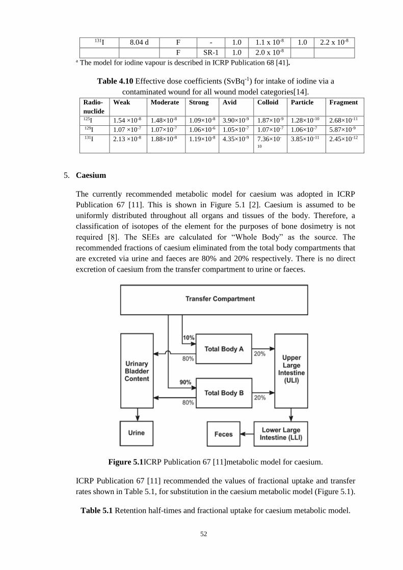
52
131I 8.04 d F - 1.0 1.1 x 10⁻⁸ 1.0 2.2 x 10⁻⁸
F SR-1 1.0 2.0 x 10⁻⁸ a The model for iodine vapour is described in ICRP Publication 68 [41].
Table 4.10 Effective dose coefficients (SvBq-1) for intake of iodine via a
contaminated wound for all wound model categories[14].
Radio-
nuclide
Weak Moderate Strong Avid Colloid Particle Fragment
125I 1.54 ×10⁻⁸ 1.48×10⁻⁸ 1.09×10⁻⁸ 3.90×10⁻⁹ 1.87×10⁻⁹ 1.28×10⁻¹⁰ 2.68×10⁻¹¹
129I 1.07 ×10⁻⁷ 1.07×10⁻⁷ 1.06×10⁻⁶ 1.05×10⁻⁷ 1.07×10⁻⁷ 1.06×10⁻⁷ 5.87×10⁻⁹
131I 2.13 ×10⁻⁸ 1.88×10⁻⁸ 1.19×10⁻⁸ 4.35×10⁻⁹ 7.36×10-
10
3.85×10⁻¹¹ 2.45×10⁻¹²
5. Caesium
The currently recommended metabolic model for caesium was adopted in ICRP
Publication 67 [11]. This is shown in Figure 5.1 [2]. Caesium is assumed to be
uniformly distributed throughout all organs and tissues of the body. Therefore, a
classification of isotopes of the element for the purposes of bone dosimetry is not
required [8]. The SEEs are calculated for “Whole Body” as the source. The
recommended fractions of caesium eliminated from the total body compartments that
are excreted via urine and faeces are 80% and 20% respectively. There is no direct
excretion of caesium from the transfer compartment to urine or faeces.
Figure 5.1ICRP Publication 67 [11]metabolic model for caesium.
ICRP Publication 67 [11] recommended the values of fractional uptake and transfer
rates shown in Table 5.1, for substitution in the caesium metabolic model (Figure 5.1).
Table 5.1 Retention half-times and fractional uptake for caesium metabolic model.

53
Retention Compartment Fractional Uptake Half-time (d)
Transfer compartment (blood) - 0.25
Total Body A 10% 2
Total Body B 90% 110
According to ICRP-78 [2], following entry into the transfer compartment, caesium is
taken to be distributed uniformly throughout all body tissues; 10% of the activity is
assumed to be retained with a biological half-life of two days and 90% with 110 days.
A urinary to faecal ratio of 4:1 is recommended.
Table 5.2 Compounds, absorption types and f1 values
Intake f1 Compounds
Ingestion 1.0 All compounds
Inhalation, Type F 1.0 All compounds
Caesium-134 (half life = 2.06 y)
Table 5.3 Emissions
Radiation Energy (MeV) Intensity (%)
γ 0.60 98
γ 0.80 85
Table 5.4 Measurement techniques
Method of measurement Typical detection
limit
γ-ray spectrometry in vivo Whole body 200 Bq
γ-ray spectrometry on
biological sample
Urine 1 Bq d-1
134Cs presents no detection problems
Caesium-137 (half life = 30.0 y)
Table 5.5 Emissions
Radiation Energy (MeV) Intensity (%)
γ (137mBa) 0.661 85.1
Table 5.6 Measurement techniques
Method of
measurement
Typical detection limit
γ-ray spectrometry in
vivo
Whole body 200 Bq
γ-ray spectrometry on
biological sample
Urine 1 Bq d-1
Cs-137 presents no detection problems.
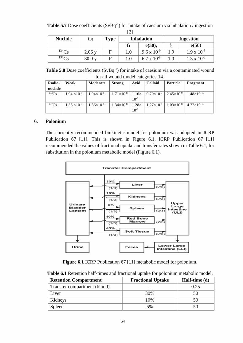
54
Table 5.7 Dose coefficients (SvBq-1) for intake of caesium via inhalation / ingestion
[2]
Nuclide t1/2 Type Inhalation Ingestion
f1 e(50), f1 e(50) 134Cs 2.06 y F 1.0 9.6 x 10⁻⁹ 1.0 1.9 x 10⁻⁸
137Cs 30.0 y F 1.0 6.7 x 10⁻⁹ 1.0 1.3 x 10⁻⁸
Table 5.8 Dose coefficients (SvBq-1) for intake of caesium via a contaminated wound
for all wound model categories[14]
Radio-
nuclide
Weak Moderate Strong Avid Colloid Particle Fragment
134Cs 1.94 ×10⁻⁸ 1.94×10⁻⁸ 1.71×10⁻⁸ 1.16×
10-8
9.70×10⁻⁹ 2.45×10⁻⁹ 1.48×10⁻¹⁰
137Cs 1.36 ×10⁻⁸ 1.36×10⁻⁸ 1.34×10⁻⁸ 1.28×
10-8
1.27×10⁻⁸ 1.03×10⁻⁸ 4.77×10⁻¹⁰
6. Polonium
The currently recommended biokinetic model for polonium was adopted in ICRP
Publication 67 [11]. This is shown in Figure 6.1. ICRP Publication 67 [11]
recommended the values of fractional uptake and transfer rates shown in Table 6.1, for
substitution in the polonium metabolic model (Figure 6.1).
Figure 6.1 ICRP Publication 67 [11] metabolic model for polonium.
Table 6.1 Retention half-times and fractional uptake for polonium metabolic model.
Retention Compartment Fractional Uptake Half-time (d)
Transfer compartment (blood) - 0.25
Liver 30% 50
Kidneys 10% 50
Spleen 5% 50

55
Red bone marrow 10% 50
Soft tissues (other) 45% 50
For bone dosimetry, it is assumed that all polonium in the skeleton is associated with
the bone marrow. The fraction of polonium excretion via urine, fu, is one-third [11].
There is no direct excretion of polonium from the transfer compartment to urine or
faeces.
Table 6.2 Compounds, absorption types and f1 values
Intake f1 Compounds
Ingestion 0.1 All compounds
Inhalation, Type F 0.1 Unspecified
compounds
Inhalation, Type M 0.1 Oxides, hydroxides
and nitrates
Polonium-210 (half life = 138.4 d)
Table 6.3 Emissions
Radiation Energy (MeV) Intensity (%)
α 5.3 100
γ 0.80 1.6 E-3
Table 6.4 Measurement techniques
Method of measurement Typical detection limit
α-ray spectrometry on biological
sample
Urine 0.5 mBq d-1
Table 6.5 Dose coefficients(SvBq-1) for intake of polonium via inhalation / ingestion
[2]
Nuclide t1/2 Type Inhalation Ingestion
f1 e(50) f1 e(50) 210Po
138.4 d
F 0.1 7.1 x 10⁻⁷ 0.1 2.4 x 10⁻⁷
M 0.1 2.2 x 10⁻⁶
Table 6.6 Dose coefficients (SvBq-1) for intake of polonium via a contaminated
wound for all wound model categories [14]
Radio-
nuclide
Weak Moderate Strong Avid Colloid Particle Fragment
210Po 2.36
×10-6 2.31×10⁻⁶ 1.81×10⁻⁶ 7.52×10⁻⁷ 4.60×10⁻⁷
4.31×10⁻⁸ 7.72×10⁻⁹
7. Radium
The currently recommended biokinetic model for the alkaline earth elements
(strontium, barium, and radium) was adopted in ICRP Publication 67 [11]. This is

56
shown in Figure 7.1 [2]. ICRP Publication 67 [11] recommended the values of transfer
rates shown in Table 7.1, for substitution in the radium biokinetic model (Figure 7.1).
The model describes the kinetics of radium in bone, which is the main site of deposition
and retention, and also considers retention in liver and other soft tissues as well as
routes of excretion. It takes account of initial uptake onto bone surfaces, transfer from
surface to bone volume and recycling from bone and other tissues to plasma.
Figure 7.1 ICRP Publication 67[11]biokinetic model for the alkaline earth elements
(calcium, strontium, barium, and radium).
Table 7.1 Transfer rates for radium biokinetic model.(a)
Route of transfer between compartments Transfer rate (d-1)
Plasma to ST0 22.68
Plasma to Urinary bladder content 0.606
Plasma to ULI content 21.79
Plasma to ST1 7.0
Plasma to ST2 0.07
Plasma to Trabecular bone surface 9.72
Plasma to Cortical bone surface 7.78
Plasma to Liver 0.35
Liver to Plasma 0.0139
ST0 to Plasma 7.56
ST1 to Plasma 0.693
ST2 to Plasma 0.00038
Bone surfaces to Plasma 0.578
Non-exchangeable trabecular volume to Plasma 0.000493

57
Non-exchangeable cortical volume to Plasma 0.0000821
Bone surfaces to Exchangeable bone volume 0.116
Exchangeable bone volume to Non-exchangeable bone
volume
0.0046
Exchangeable bone volume to Bone surfaces 0.0185 (a)ICRP Publication 78 [2] notes that the values of rate constants are given to sufficient
precision [3 significant figures] for calculational purposes and that this may be more
precise than the biological data would support.
Table 7.2 Compounds, absorption types and f1 values
Intake f1 Compounds
Ingestion 0.2 All compounds
Inhalation, Type M 0.2 All compounds
Radium-226 (half life = 1.6E03 y)
Table 7.3 Emissions
Radionuclide Radiation Energy (MeV) Intensity (%) 226Ra α 4.6 6
α 4.8 94
γ 0.19 3 214Pb γ 0.30 19
γ 0.35 37 214Bi γ 0.61 46
γ 1.12 15
γ 1.76 16
Table 7.4 Measurement techniques
Method of measurement Typical detection
limit
γ-ray spectrometry in vivo Whole body 1000 Bq
Radiochemical separation and α-
spectrometry on biological sample
Urine 0.5 mBq d-1
Radium-228 (half life = 5.75 y)
Table 7.5 Emissions
Radionuclide Radiation Energy (MeV) Intensity (%) 228Ra - 0.01a 100 228Ac γ 0.34 16
γ 0.91 29
γ 0.96 23 212Pb γ 0.24 45

58
208Tl γ 0.51 22b
γ 0.58 86b
γ 0.86 12b
γ 2.61 100b
aAverage energy bThese intensities refer to one disintegration of 208Tl, the decay of 228Ra to 208Tl
involves a branching fraction of 0.36. This should be taken into account when relating
these intensities to one disintegration of 228Ra.
Table 7.6 Measurement techniques
Method of measurement Typical detection
limit
γ-ray spectrometry in vivo by means
of decay products
Whole body 200 Bq
Radiochemical separation and -
counting
Urine 1 Bq L-1
Table 7.7 Dose coefficients (SvBq-1) for intake of radium via inhalation / ingestion
[2]
Nuclide t1/2 Type Inhalation Ingestion
f1 e(50) f1 e(50) 226Ra 1.6 x 10³ y M 0.2 2.2 x 10-
6
0.2 2.8 x 10⁻⁷
228Ra 5.75 y M 0.2 1.7 x 10-
6
0.2 6.7x 10⁻⁷
Table 7.8 Dose coefficients (SvBq-1) for intake of radium via a contaminated wound for all wound
model categories[14]
Radio-
nuclide
Weak Moderate Strong Avid Colloid Particle Fragment
226Ra 1.36 ×10⁻⁶ 1.31×10⁻⁶ 1.44×10⁻⁶ 1.62×10⁻⁶ 1.77×10⁻⁶ 2.64×10⁻⁶ 1.65×10⁻⁷
228Ra 3.37 ×10⁻⁶ 3.96×10⁻⁶ 1.41×10⁻⁵ 3.81×10⁻⁵ 4.56×10⁻⁵ 4.04×10⁻⁵ 1.13×10⁻⁶
8. Thorium
The currently recommended biokinetic model for the actinide elements (thorium,
neptunium, plutonium, americium, and curium) was adopted in ICRP Publication 67
[11]. This is shown in Figure 8.1 [2]. For thorium absorbed to blood main sites of
deposition are liver and skeleton. ICRP Publication 78 [2] recommended the values of
transfer rates shown in Table 8.1 for substitution in the thorium biokinetic model. The
model takes account of the initial deposition in bone, liver, gonads, and other tissues,
and allows for transfer of activity from bone surfaces to bone volume and marrow,
recycling of activity between tissues, as well as loss by excretion.

59
Figure 8.1 ICRP Publication 67 [11] biokinetic model for thorium.
ICRP Publication 78 [2] recommended the values of transfer rates shown in Table 8.1,
for substitution in the thorium biokinetic model (Figure 8.1).
Table 8.1 Transfer rates for thorium biokinetic model.(a)
Route of transfer between compartments Transfer rate (d-1)
Blood to ST0 0.832
Blood to ST1 0.243
Blood to ST2 0.0388
Blood to Trabecular surface 0.6793
Blood to Cortical surface 0.6793
Blood to Urinary bladder content 0.1067
Blood to Kidneys (urinary path) 0.0679
Blood to Kidneys (other tissue) 0.0194
Blood to ULI content 0.0097
Blood to Liver 1 0.097
Blood to Testes 0.00068
Blood to Ovaries 0.00021
ST0 to Blood 0.462
ST1 to Blood 0.00095
ST2 to Blood 0.000019

60
Liver 2 to Blood 0.000211
Liver 1 to Liver 2 0.00095
Liver 1 to Blood 0.000475
Liver 1 to Small intestine content (SI) 0.000475
Kidneys (other tissue) to Blood 0.00038
Kidneys (urinary path) to Urinary bladder
content
0.0462
Trabecular marrow to Blood 0.0076
Cortical marrow to Blood 0.0076
Trabecular surface to Trabecular volume 0.000247
Cortical surface to Cortical volume 0.0000411
Trabecular surface to Trabecular marrow 0.000493
Trabecular volume to Trabecular marrow 0.000493
Cortical surface to Cortical marrow 0.0000821
Cortical volume to Cortical marrow 0.0000821
Testes to Blood 0.00019
Ovaries to Blood 0.00019 (a)ICRP Publication 78 [2] notes that the values of rate constants are given to sufficient
precision for calculational purposes and that this may be more precise than the
biological data would support.
Table 8.2 Compounds, absorption types and f1 values
Intake f1 Compounds
Ingestion 5.0 x 10⁻⁴ Unspecified compounds
Ingestion 2.0 x 10⁻⁴ Oxides and hydroxides
Inhalation, Type M 5.0 x 10⁻⁴ Unspecified compounds
Inhalation, Type S 2.0 x 10⁻⁴ Oxides and hydroxides
Thorium-228 (half life = 1.91 y)
Table 8.3 Emissions
Radionuclide Radiation Energy (MeV) Intensity (%) 228Th α 5.3 27
α 5.4 73 212Pb γ 0.24 45 212Bi γ 0.73 12 208Tl γ 0.51 22a
γ 0.58 86a
γ 0.86 12a
γ 2.6 100a aThese intensities refer to one disintegration of 208Tl, the decay of 228Th to 208Tl
involves a branching fraction of 0.36. This should be taken into account when relating
these intensities to one disintegration of 228Th.

61
Table 8.4 Measurement techniques
Method of measurement Typical detection limit
γ-ray spectrometry in vivo
(measurement of daughter product 208Tl)
Whole
body
10 Bq
lungs 6 Bq
Radiochemical separation and α-
spectrometry on biological sample
Urine 0.5 mBq d-1
Faeces 0.5 mBq
Thorium-232 (half life = 1.4 x 10¹⁰ y)
Table 8.5 Emissions
Radionuclide Radiation Energy
(MeV)
Intensity (%)
232Th α 3.95 23
α 4.01 77 228Ac - 0.39a 40
- 0.61a 11
- 0.75a 8
γ 0.34 16
γ 0.91 29
γ 0.96 23 228Th α 5.3 27
α 5.4 73 212Pb γ 0.24 45 212Bi γ 0.73 12 208Tl γ 0.51 22b
γ 0.58 86b
γ 0.86 12b
γ 2.6 100b aAverage energy bThese intensities refer to one disintegration of 208Tl, the decay of 232Th to 208Tl
involves a branching fraction of 0.36. This should be taken into account when relating
these intensities to one disintegration of 232Th.
Table 8.6 Measurement techniques
Method of measurement Typical detection
limit
γ-ray spectrometry in vivo
(measurement of daughter product Ac-
228)
Lungs
10 Bq
Radiochemical separation, NAA and -
spectrometry on biological sample
Urine 0.0008 mBqd-1
Faeces 0.0008 mBq per
sample
*NAA = Neutron Activation Analysis

62
Table 8.7 Dose coefficients (SvBq-1) for intake of thorium via inhalation / ingestion
[2]
Nuclide t1/2 Type Inhalation Ingestion
f1 e(50) f1 e(50) 228Th 1.91y M 5.0 x 10⁻⁴ 2.3 x 10⁻⁵ 5.0 x 10⁻⁴ 7.0 x 10⁻⁸
S 2.0 x 10⁻⁴ 3.2 x 10⁻⁵ 2.0 x 10⁻⁴ 3.5 x 10⁻⁸ 232Th 1.40 x 10¹⁰ y M 5.0 x 10⁻⁴ 2.9 x 10⁻⁵ 5.0 x 10⁻⁴ 2.2 x 10⁻⁷
S 2.0 x 10⁻⁴ 1.2 x 10⁻⁵ 2.0 x 10⁻⁴ 9.2 x 10⁻⁸
Table 8.8 Dose coefficients (SvBq-1) for intake of thorium via a contaminated wound
for all wound model categories[14]
Radio-
nuclide
Weak Moderat
e
Strong Avid Colloid Particle Fragme
nt 228Th 1.18×10⁻⁴ 1.17×10⁻⁴ 1.03×10⁻⁴ 6.86×10⁻⁵ 5.68×10⁻⁵
1.37×10⁻⁵ 8.64×10⁻⁷ 232Th 4.52×10⁻⁴ 4.52×10⁻⁴ 4.48×10⁻⁴ 4.4×10⁻⁴ 4.47×10⁻⁴
4.17×10⁻⁴ 1.92×10⁻⁵
9. Uranium
The currently recommended biokinetic model for uranium was adopted in ICRP
Publication 69[12]. This is shown in Figure 9.1 [2]. ICRP Publication 78 [2
]recommended the values of transfer rates shown in Table 9.1, for substitution in the
uraium biokinetic model (Figure 9.1). The model describes the kinetics of uranium in
bone, which is the main site of deposition and retention, and also considers retention
in liver, kidneys, and other soft tissues as well as routes of excretion. It takes account
of initial uptake onto bone surfaces, transfer from surface to bone volume and recycling
from bone and other tissues to plasma.

63
Figure 9.1 ICRP Publication 69 [12]biokinetic model for uranium.
Table 9.1 Transfer rates for uranium biokinetic model. (a)
Route of transfer between compartments Transfer rate (d-1)
Plasma to ST0 10.5
Plasma to RBC 0.245
Plasma to Urinary bladder content 15.43
Plasma to Kidneys (urinary path) 2.94
Plasma to Kidneys (other tissue) 0.0122
Plasma to ULI contents 0.122
Plasma to Liver 1 0.367
Plasma to ST1 1.63
Plasma to ST2 0.0735
Plasma to Trabecular surfaces 2.04
Plasma to Cortical surfaces 1.63
ST0 to Plasma 8.32
RBC to Plasma 0.347
Kidneys (other tissue) to Plasma 0.00038
Liver 1 to Plasma 0.092
Liver 2 to Plasma 0.00019
ST1 to Plasma 0.0347
ST2 to Plasma 0.000019
Bone surfaces to Plasma 0.0693
Non-exchangeable trabecular volume to Plasma 0.000493
Non-exchangeable cortical volume to Plasma 0.0000821
Kidneys (urinary path) to Urinary bladder content 0.099
Liver 1 to Liver 2 0.00693
Bone surfaces to Exchangeable volume 0.0693
Exchangeable bone volume to Bone surfaces 0.0173
Exchangeable bone volume to Non-exchangeable
volume
0.00578
(a) ICRP Publication 69 [12]notes that the values of rate constants are given to sufficient
precision [3 decimal places in exponential notation] for calculational purposes and that
this may be more precise than the biological data would support.
Table 9.2 Compounds, absorption types and f1 values
Intake f1 Compounds
Ingestion 0.02 Unspecified compounds
Ingestion 0.002 Most tetravalent compounds e.g. UO2, U3O8,
UF4
Inhalation, Type F 0.02 Soluble compounds including hexavalent
compounds e.g. UF6, UO2F2, and UO2(NO3)2
Inhalation, Type M 0.02 Less soluble compounds, e.g. UO3, UF4,
UCl4, and most other hexavalent compounds

64
Inhalation, Type S 0.002 Highly insoluble compounds, e.g. UO2 and
U3O8
Table 9.3 Emissions
Radionuclide Radiation Energy (MeV) Intensity (%) 232U α 5.32 68.15
5.26 31.55 233U α 4.82 84.4
4.78 13.2 234U α 4.72 27
α 4.77 72 235U α 4.22 6
α 4.33 5
α 4.37 18
α 4.40 56
α 4.56 4
α 4.60 5
γ 0.14 11
γ 0.19 54
γ 0.21 5 238U α 4.15 23
α 4.20 77
Table 9.4 Measurement techniques
Method of measurement Radionuclide Typical detection
limit
γ-ray spectrometry in vivo
238U Lungs 40 Bq 235U Lungs 3 Bq 232U Lungs
[-ray
spectrometry
of 212Pb]
6 Bq
Radiochemical separation
and α-spectrometry on
biological sample
Urine 0.5 mBqd-1
Faeces 0.5 mBq per sample
Table 9.5 Dose coefficients(SvBq-1) for intake of uranium via inhalation / ingestion
[2]
Nuclide t1/2 Type Inhalation Ingestion
f1 e(50) f1 e(50) 232U 68.9 y F 0.02 4.7 x 10⁻⁶ 0.02 3.3 x 10⁻⁷
M 0.02 4.8 x 10⁻⁶ 0.002 3.7 x 10⁻⁸
S 0.002 2.6 x 10⁻⁵ 233U 1.59 x 10⁵ y F 0.02 6.6 x 10⁻⁷ 0.02 5.0 x 10⁻⁸
M 0.02 2.2 x 10⁻⁶ 0.002 8.5 x 10⁻⁹

65
S 0.002 6.9 x 10⁻⁶ 234U 2.44 x 10⁵ y F 0.02 6.4 x 10⁻⁷ 0.02 4.9 x 10⁻⁸
M 0.02 2.1 x 10⁻⁶ 0.002 8.3 x 10⁻⁹
S 0.002 6.8 x 10⁻⁶ 235U 7.04 x 10⁸ y F 0.02 6.0 x 10⁻⁷ 0.02 4.6 x 10⁻⁸
M 0.02 1.8 x 10⁻⁶ 0.002 8.3 x 10⁻⁹
S 0.002 6.1 x 10⁻⁶ 238U 4.47 x 10⁹ y F 0.02 5.8 x 10⁻⁷ 0.02 4.4 x 10⁻⁸
M 0.02 1.6 x 10⁻⁶ 0.002 7.6 x 10⁻⁹
S 0.002 5.7 x 10⁻⁶
Table 9.6 Dose coefficients (SvBq-1) for intake of uranium via a contaminated wound for all wound
model categories[14]
Radio-
nuclide
Weak Moderate Strong Avid Colloid Particle Fragment
232U 1.25×10⁻⁵ 1.25 x 10⁻⁵ 1.27×10⁻⁵ 1.30×10⁻⁵ 1.33×10⁻⁵ 1.19×10⁻⁵ 5.18×10⁻⁷ 233U 2.33×10⁻⁶ 2.33 ×10⁻⁶ 2.30×10⁻⁶ 2.24×10⁻⁶ 2.25×10⁻⁶ 1.97×10⁻⁶ 9.02×10⁻⁸ 234U 2.27×10⁻⁶ 2.27×10⁻⁶ 2.25×10⁻⁶ 2.18×10⁻⁶ 2.19×10⁻⁶
1.92×10⁻⁶ 8.75×10⁻⁸ 235U 2.11×10⁻⁶ 2.11×10⁻⁶ 2.09×10⁻⁶ 2.03×10⁻⁶ 2.04×10⁻⁶ 1.78×10⁻⁶ 8.13×10⁻⁸ 238U 2.03×10⁻⁶ 2.03×10⁻⁶ 2.01×10⁻⁶ 1.96×10⁻⁶ 1.97×10⁻⁶
1.73×10⁻⁶ 7.89×10⁻⁸
10. Plutonium
The currently recommended biokinetic model for the actinide elements (thorium,
neptunium, plutonium, americium, and curium) was adopted in ICRP Publication
67[11]. This is shown in Figure 10.1 [2]. For plutonium absorbed to blood the main
sites of deposition are the liver and skeleton. The model takes account of the initial
deposition in bone, the liver, gonads and other tissues, and allows for transfer of
activity from bone surfaces to bone volume and marrow, recycling of activity between
tissues, as well as loss by excretion. ICRP recommended the values of transfer rates
shown in Table 10.1 for substitution in the plutonium biokinetic model.

66
Figure 10.1 ICRP Publication 67 [11 ]biokinetic model for plutonium.
Table 10.1. Transfer rates for plutonium biokinetic model.(a)
Route of transfer between compartments Transfer rate (d-1)
Blood to ST0 0.2773
Blood to ST1 0.0806
Blood to ST2 0.0129
Blood to Trabecular surface 0.1941
Blood to Cortical surface 0.1294
Blood to Urinary bladder contents 0.0129
Blood to Kidneys (urinary path) 0.00647
Blood to Kidneys (other tissue) 0.00323
Blood to ULI content 0.0129
Blood to Liver 1 0.1941
Blood to Testes 0.00023
Blood to Ovaries 0.000071
ST0 to Blood 0.693
ST1 To Blood 0.000475
ST1 to Urinary bladder content 0.000475
ST2 to Blood 0.000019
Liver 2 to Blood 0.000211
Liver 1 to Liver 2 0.00177
Liver 1 to Small Intestine (SI) 0.000133
Kidneys (other tissue) to blood 0.00139
Kidneys (urinary path) to Urinary bladder content 0.01386
Trabecular marrow to Blood 0.00760
Cortical marrow to blood 0.00760
Trabecular surface to Trabecular volume 0.000247
Cortical surface to Cortical volume 0.0000411
Trabecular surface to Trabecular marrow 0.000493
Trabecular volume to Trabecular marrow 0.000493
Cortical surface to Cortical marrow 0.0000821
Cortical volume to Cortical marrow 0.0000821
Testes to Blood 0.00019
Ovaries to Blood 0.00019 (a)ICRP Publication 78[2] notes that the values of rate constants are given to sufficient
precision for calculational purposes and that this may be more precise than the
biological data would support.
Table 10.2 Compounds, absorption types and f1 values

67
Intake f1 Compounds
Ingestion 5.0 x 10⁻⁴ Unspecified compounds
Ingestion 1.0 x 10⁻⁴ Nitrates
Ingestion 1.0 x 10⁻⁵ Insoluble oxides
Inhalation, Type M 5.0 x 10⁻⁴ Unspecified compounds
Inhalation, Type S 1.0 x 10⁻⁵ Insoluble oxides
Table 10.3 Emissions
Radionuclide Radiation Energy (MeV) Intensity (%) 238Pu α 5.46 28
α 5.50 72
-rays 0.014-0.020 11 239Pu α 5.11 11
α 5.14 15
α 5.16 74
-rays 0.014-0.022 4.6 240Pu α 5.12 27
α 5.17 73
-rays 0.014-0.020 10
Table 10.4 Measurement techniques
Method of
measurement
Typical detection limit
γ-ray spectrometry in
vivo
Lungs 2000 Bq
Radiochemical
separation and α-
spectrometry on
biological sample
Urine 0.5 mBqd-1
Faeces 0.5 mBq per sample
Table 10.5 Dose coefficients (SvBq-1) for intake of plutonium via inhalation /
ingestion [2]
Nuclide t1/2 Type Inhalation Ingestion
f1 e(50) f1 e(50) 238Pu 87.7y M 5.0 x 10⁻⁴ 3.0 x 10⁻⁵ 5.0 x 10⁻⁴ 2.3 x 10⁻⁷
S 1.0 x 10⁻⁵ 1.1 x 10⁻⁵ 1.0 x 10⁻⁴ 4.9 x 10⁻⁸
1.0 x 10⁻⁵ 8.8 x 10⁻⁹ 239Pu 2.41 x 10⁴
y
M 5.0 x 10⁻⁴ 3.2 x 10⁻⁵ 5.0 x 10⁻⁴ 2.5 x 10⁻⁷
S 1.0 x 10⁻⁵ 8.3 x 10⁻⁶ 1.0 x 10⁻⁴ 5.3 x 10⁻⁸
1.0 x 10⁻⁵ 9.0 x 10⁻⁹ 240Pu
6.54 x 10³
y
M 5.0 x 10⁻⁴ 3.2 x 10⁻⁵ 5.0 x 10⁻⁴ 2.5 x 10⁻⁷
S 1.0 x 10⁻⁵ 8.3 x 10⁻⁶ 1.0 x 10⁻⁴ 5.3 x 10⁻⁸
1.0 x 10⁻⁵ 9.0 x 10⁻⁹

68
Table 10.6 Dose coefficients (SvBq-1) for intake of plutonium via a contaminated wound for all
wound model categories[14]
Radio-
nuclide
Weak Moderate Strong Avid Colloid Particle Fragment
238Pu 4.44x10⁻⁴ 4.43x10⁻⁴ 4.36x10⁻⁴ 4.18x10⁻⁴ 4.17x10⁻⁴ 3.36x10⁻⁴ 1.41x10⁻⁵
239Pu 4.89x10⁻⁴ 4.89x10⁻⁴ 4.83x10⁻⁴ 4.66x10⁻⁴ 4.67x10⁻⁴ 3.9x10⁻⁴ 1.67x10⁻⁵
240Pu 4.89x10⁻⁴ 4.89x10⁻⁴ 4.83x10⁻⁴ 4.66x10⁻⁴ 4.67x10⁻⁴ 3.9x10⁻⁴ 1.67x10⁻⁵
11. Americium
The currently recommended biokinetic model for the actinide elements (thorium,
neptunium, plutonium, americium, and curium) was adopted in ICRP Publication 67
[11]. This is shown in Figure 11.1 [2]. For americium absorbed to blood the main sites
of deposition are the liver and skeleton. The model takes account of the initial
deposition in bone, the liver, gonads and other tissues, and allows for transfer of
activity from bone surfaces to bone volume and marrow, recycling of activity between
tissues, as well as loss by excretion. ICRP recommended the values of transfer rates
shown in Table 11.1 for substitution in the americium biokinetic model
Figure 11.1 ICRP Publication 67 [11]biokinetic model for americium.
Table 11.1 Transfer rates for americium biokinetic model.(a)
Route of transfer between compartments Transfer rate (d-1)
Blood to ST0 10.0
Blood to ST1 1.67
Blood to ST2 0.466
Blood to Trabecular surface 3.49
Blood to Cortical surface 3.49

69
Blood to Urinary bladder content 1.63
Blood to Kidneys (urinary path) 0.466
Blood to Kidneys (other tissue) 0.116
Blood to ULI content 0.303
Blood to Liver 11.6
Blood to Testes 0.0082
Blood to Ovaries 0.0026
ST0 to Blood 1.386
ST1 to Blood 0.0139
ST2 to Blood 0.000019
Liver to Blood 0.00185
Liver to Small intestine (SI) 0.000049
Kidneys (other tissue) to Blood 0.00139
Kidneys (urinary path) to Urinary bladder content 0.099
Trabecular marrow to Blood 0.0076
Cortical marrow to Blood 0.0076
Trabecular surface to Trabecular volume 0.000247
Cortical surface to Cortical volume 0.0000411
Trabecular surface to Trabecular marrow 0.000493
Trabecular volume to Trabecular marrow 0.000493
Cortical surface to Cortical marrow 0.0000821
Cortical volume to Cortical marrow 0.0000821
Testes to Blood 0.00019
Ovaries to Blood 0.00019 (a)ICRP Publication 78 [2] notes that the values of rate constants are given to sufficient
precision for calculational purposes and that this may be more precise than the biological data
would support.
Table 11.2 Compounds, absorption types and f1 values
Intake f1 Compounds
Ingestion 5.0 x 10⁻⁴ All compounds
Inhalation, Type M 5.0 x 10⁻⁴ All compounds
Table 11.3Emissions
Radionuclide Radiation Energy
(MeV)
Intensity (%)
241Am α 5.39 1.4
α 5.44 13
α 5.49 85
α 5.51 0.2
α 5.54 0.3
0.06 36
Table 11.4 Measurement techniques
Method of measurement Typical detection limit
γ-ray spectrometry in vivo Lungs 6 Bq
Urine 0.5 mBqd-1

70
Radiochemical separation
and α-spectrometry on
biological sample
Faeces 0.5 mBq per sample
Table 11.5 Dose coefficients (SvBq-1) for intake of americium via inhalation / ingestion [2]
Nuclide t1/2 Typ
e
Inhalation Ingestion
f1 e(50) f1 e(50) 241Am 4.32 x
102y
M 5.0 x 10⁻⁴ 2.7 x 10⁻⁵ 5.0 x 10⁻⁴ 2.0 x 10⁻⁷
Table 11.6 Dose coefficients (SvBq-1) for intake of americium via a contaminated wound for
all wound model categories[14]
Radio-
nuclide
Weak Moderate Strong Avid Colloid Particle Fragment
241Am 3.97x10⁻⁴ 3.96x10⁻⁴ 3.91x10⁻⁴ 3.79x10⁻⁴ 3.8x10⁻⁴ 3.23x10⁻⁴ 1.41x10⁻⁵

71
Annexure II
METHODS FOR MEASUREMENT OF RADON, THORON AND THEIR
DAUGHTER PRODUCTS
There are several methods for measurement of radon and its progeny in the working
environment. Some of the commonly employed techniques are described in this
annexure.
A.1 Scintillation cell technique for radon measurement
One of the simplest and very convenient method for collection of large number of air
samples from the mine workings for radon measurements is based on the scintillation
cell technique [31]. In this technique a 150 ml metallic cylindrical cell coated inside
with ZnS(Ag) with a transparent window is optically coupled to a photomultiplier tube
and a counting system. Pre-filtered air is introduced into the evacuated cell which is
later counted for alpha activity over a known period, typically for about 600 seconds
after ~ 180 minutes post sampling, when the progeny attain equilibrium with radon in
the cell. Radon concentration is estimated using the relation;
CRn =0.0697 × 𝐶
𝐸 × 𝑉 × exp(−𝜆𝑡) × [1 − exp(−𝜆𝑇)]
Where, CRn = radon concentration, Bq.m-3,
C = net count rate (cps),
E = efficiency of counting system (fraction),
V = volume of the sampler (m3),
= decay constant of radon (s-1),
t = time delay post-sampling (s),
T = counting period (s).
For a 10 min (600 s) counting time after 180 min (10800 s) post sampling, the
minimum detectable concentration of radon is ~ 40 Bq.m-3.
A.2 Low level radon detection system (LLRDS)
Another method for the measurement of radon is based on electro-deposition of freshly
formed positively charged (~90 %) 218Po atoms on a negatively charged plate for a
predetermined collection and alpha counting period [35]. The system typically consists
of a 5 litre cylindrical aluminium chamber with a ~ 5 cm dia Al disc on the top lid.
Filtered air is introduced in the system. A negative voltage of – 800 V is applied to the
metallic disc for a period of 90 min and the alpha activity from radon progeny
deposited on the plate is counted, ideally from 1 to 75 min post collection. The radon
concentration is evaluated from the relation,

72
CRn =𝐶
𝐸 × 𝑉 × 𝑍 × 0.9 × (1 − 𝑒(0.042𝐻−4.31))
Where C = net counts observed
E = efficiency of the counting system (fraction)
V = volume of the chamber (m3)
H = relative humidity in the sample (%)
Z = alpha emission factor
K1 = 277 s, K2 = 982 s, K3 = - 5599 s
i – decay constant of the ith radon daughter (s-1), (i=1, 2,3).
T1 and T2 are start and end time of the measurement and t is total collection period.
This system is also used for measurement of radon in the exhaled breath of workers to
evaluate internally deposited radium inhaled in the form of ore dust [35].
There are many other methods for measurement of radon in the working environment
like continuous radon monitoring system [36][37] [38].
A.3 Measurement of radon daughter concentrations
The short-lived radon progeny are more important from the point of view of hazard
evaluation. Hence there are several techniques and instruments available for evaluation
of radon progeny detection and estimation. One of the most commonly used methods
is the Kusnetz’s method.
Kusnetz’s method
In the Kusnetz’s method [39] radon daughters are collected on a filter paper by drawing
air with a pump for about 10 min and counting the alpha activity on the filter at any
time between 40 and 90 min. This most widely used method in mines gives radon
daughter working level concentrations within an error of ± 13 %, irrespective of the
equilibrium condition, which is acceptable for a mine atmosphere which has many
other variables. The radon daughter concentration in units of working level (WL) is
given by relation,
WL =100 × 𝐶
𝐸 × 𝑉 × 𝐹(𝑇, 𝑡)
Where
WL - radon progeny concentration (Working Level)
C - Count rate at the delay time of ‘t’
E - Efficiency of the alpha counter (%)
V - Sampling rate (lpm)
F(T,t) - is the Kusnetz’s factor which is a function of T and t (given in
the table below)*
3
1
211i
TTt
iiii eeeKZ

73
t - Counting delay after end of sampling (min.)
T - Sampling time (min.).
*Kuznet’s factor for determination of Rn daughter concentration in working level (WL)
Time after sampling (min) Kusznet’s factor, F(T,t)
40 150
50 130
60 110
70 90
80 75
90 60
A.4 Measurement of Thoron daughter concentration
Similar to the measurement of radon daughter concentration, a simple methodology
has been developed for evaluation of thoron daughter working level [40]. An air
sample is collected by passing air through a high efficiency filter paper for 10 min.
The alpha activity on the filter is measured for 10 minutes at any time between 180
minutes to 600 minutes post sampling. The thoron working level concentration is
obtained using the relation,
𝑇(𝑊𝐿) =𝐶
𝐸 × 𝑉 × 𝑇 × 𝑍(𝑊𝐿)
Where C - α count rate (cpm) on the filter paper beyond 180 min,
E - efficiency of counting (fraction),
V - sampling flow rate (lpm),
T - duration of sampling (min),
Z(WL) – theoretical correction factor for thoron daughter at the counting instant
(equivalent of Kusnetz’s factor for thoron daughters).
The thoron concentration of 275 Bq.m-3 in equilibrium with its daughter products gives
a potential alpha energy equivalent to 1 WL (20.8 µJ.m-3). For a given mixture of air
containing 275 Bq.m-3 of Th-B (214Pb), at extreme equilibrium ratios with Th-C (214Bi),
the alpha activity decays with the decay rate of Th-B. But at Th-B to Th-C ratio of 1:0,
the alpha activity is initially zero and gradually grows to a maximum value at 180 min
and thereafter decays with the decay rate of Th-B. The decay curve beyond 180 min
may be approximately given by the relation,
𝑍(𝑊𝐿) = 246 × 𝑒−𝜆𝑏×𝑡
Where λb is the decay constant of Th-B and t is the counting time, for instant beyond 180
min.The maximum error due to different equilibrium conditions is within 10%.
A - 5 SSNTD based radon evaluation

74
For evaluation of very low levels of radon in the environment or in dwellings and for
dosimetry of mine workers a system for integrated measurement of radon using
SSNTD can be used.
The device comprises of a 60 ml cylindrical aluminium chamber covered with a
permeable membrane which allows only radon to diffuse in, due to its relatively longer
half life, and serves as a barrier for Rn-219, Rn-220 and aerosols. A 1.8 cm x 3 cm
SSNTD film is placed between two TLD chips mounted on a disc at the base of the
chamber. The SSNTD film and the TLD in the chamber are replaced every two months.
The TLDs are processed to give cumulative gamma radiation exposure. The SSNTD
film is etched with 10 % sodium hydroxide solution at a temperature of 60ºC for 90
min. The tracks are electronically counted which are correlated to radon exposure using
a calibration system [41]. The cumulative radon exposure is obtained from the track
density as,
E (Bq×h×l-1)= 0.554 T
Where
E – Cumulativeexposure
T – Track density per cm2
h – Exposure period (h)
0.554 is calibration factor between track density T and Rn
concentration Bq.l-1)
When used for personnel dosimetery, the exposure from radon progeny (ERp) is given
as,
ERp = 4.4×10⁻⁴ ×F×T
Where
F – Equilibrium factor (0.4 for mines)
4.4 x 10⁻⁴ is the proportionality constant.

75
REFERENCES
[1] ATOMIC ENERGY REGULATORY BOARD, SAFETY CODE on Radiation Protection for
Nuclear Fuel cycle Facilities (AERB/NF/SC/RP (2012).
[2] INTERNATIONAL COMMISSION ON RADIOLOGICAL PROTECTION, Individual
Monitoring for Internal Exposure of Workers, ICRP Publication 78, Ann. ICRP 27 (3-4) (1997).
[3] NATIONAL RADIOLOGICAL PROTECTION BOARD, Optimisation of Monitoring for Internal
Exposure (OMINEX), NRPB-W60 (2004).
[4] INTERNATIONAL ATOMIC ENERGY AGENCY, Assessment of Occupational Exposure due to
Intakes of Radionuclides, Safety Standard Series No. RS-G-1.2, IAEA, Vienna(1999).
[5] INTERNATIONAL COMMISSION ON RADIOLOGICAL PROTECTION, General Principles
for the Radiation Protection of the Workers, ICRP Publication 75. Ann. ICRP 27 (1) (1997).
[6] Manual on Internal Dose Computation and Reporting. Sawant, P. D; Sawant, J. V; Gurg, R. P; Rudran,
K; Gupta, V. K; Abani, M. C; BARC/1999/E/010, pp.73. Bhabha Atomic Research Centre, Mumbai,
India (1999).
[7] INTERNATIONAL COMMISSION ON RADIOLOGICAL PROTECTION, The 2007
Recommendations of the International Commission on Radiological Protection, ICRP Publication
103, Ann. ICRP 37 (2-4) (2008).
[8] INTERNATIONAL COMMISSION ON RADIOLOGICAL PROTECTION, Limits for the Intakes
of Radionuclides by Workers, ICRP Publication 30, Part 1. Ann. ICRP 2 (3/4) (1979).
[9] INTERNATIONAL COMMISSION ON RADIOLOGICAL PROTECTION, Age–dependent
Doses to Members of the Public from Intake of Radionuclides, ICRP Publication 56, Part 1. Ann.
ICRP 20 (2) (1989).
[10] INTERNATIONAL COMMISSION ON RADIOLOGICAL PROTECTION, Human Respiratory
Tract Model for Radiological Protection, ICRP Publication 66, Ann. ICRP 24 (1-3) (1994).
[11] INTERNATIONAL COMMISSION ON RADIOLOGICAL PROTECTION, Age–dependent
Doses to Members of the Public from Intake of Radionuclides, ICRP Publication 67, Part 2 Ingestion
Dose Coefficients. Ann. ICRP 23 (3/4) (1993).
[12] INTERNATIONAL COMMISSION ON RADIOLOGICAL PROTECTION, Age–dependent
Doses to Members of the Public from Intake of Radionuclides, ICRP Publication 69, Part 3 Ingestion
Dose Coefficients. Ann. ICRP 25 (1) (1995).
[13] INTERNATIONAL COMMISSION ON RADIOLOGICAL PROTECTION, Age–dependent
Doses to Members of the Public from Intake of Radionuclides, ICRP Publication 71, Part 4,
Inhalation Dose Coefficients,, Ann. ICRP 25(3-4) (1995).
[14] NATIONAL COUNCIL ON RADIATION PROTECTION & MEASUREMENTS, Development
of a Biokinetic Model for Radionuclide-Contaminated Wounds and Procedures for Their
Assessment, Dosimetry and Treatment, .NCRP Report No. 156, (2006).
[15] INTERNATIONAL COMMISSION ON RADIOLOGICAL PROTECTION, Compendium of
Dose Coefficients based on ICRP Publication 60, ICRP Publication 119, Ann. ICRP 41 (Suppl.)
(2012).
[16] INTERNATIONAL ATOMIC ENERGY AGENCY, General Safety Requirements Part 3 (GSR
Part 3), Radiation Protection and Safety of Radiation Sources: International Basic Safety Standards,
IAEA, Vienna (2014).
[17] Dose Co-efficients for Intakes of Radionuclides via Contaminated Wounds, Toohey R.E; Bertelli,
L; Sugarman, S. L; Wiley, A. L; Christensen, D. M; Radiation Emergency Assistance
76
Center/Training Site, REAC/TS-2012, Oak Ridge Institute for Science and Education, Oak Ridge
(2012).
[18] United States of America Department of Energy Standard on Internal Dosimetry, DOE-STD 1121
(2008).
[19] INTERNATIONAL ATOMIC ENERGY AGENCY, Direct Methods for Measuring Radionuclides
in the Human Body. Safety Series No. 114, IAEA, Vienna (1996).
[20] Ultrasonic Measurements of Chest Wall Thickness for the Assessment of Internal Contamination
due to Actinides in Indian Radiation Workers, Nadar, M. Y; Singh, I. S; Chaubey, A; Kantharia, S;
Bhati, S; Paper presented at NSRP-18 held at M.L. Sukhadia University Udaipur during 19-21
November, 2009.
[21] INTERNATIONAL COMMISSION ON RADIOLOGICAL PROTECTION, Adult Reference
Computational Phantoms, ICRP Publication 110, Ann. ICRP 39 (2), (2009).
[22] Monte Carlo Simulation of Skull and Knee Voxel Phantoms for the Assessment of Skeletal Burden
of Low-energy Photon Emitters, Nadar, M. Y; Akar, D. K; Patni, H. K; Singh, I. S; Mishra, L; Rao,
D. D; Pradeepkumar, K. S; Rad.. Prot. and Dosim. Vol 162(4), doi:10.1093/rpd/nct367 (2014).
[23] INTERNATIONAL ATOMIC ENERGY AGENCY, Indirect Methods for Assessing Intakes of
Radionuclides causing Occupational Exposure, Safety Reports Series No. 18, IAEA, Vienna (2000).
[24] Technical Basis for using Nose Swab Bioassay Data for Early Internal Dose Assessment, Guilmette,
R; Bertelli, L; Miller, G; Little T; Rad. Prot. Dosim. Prot., 127, 356, (2007).
[25] Applying Low Energy HPGe detector Gamma Ray Spectrometric technique for the evaluation of
Pu/Am ratio in biological samples, Singh, I. S; Mishra, L; Yadav, J. R; Nadar, M. N; Rao, D. D;
Pradeepkumar, K. S; Appl. Rad.Iso. 104, 49-54 (2015).
[26] Feasibility Studies to Assess the use of 236Pu as a Radiochemical Yield Monitor in Bioassay
Samples, Sawant, P. D; Kalsi, P. C; J. Radioanal. Nucl. Chem., 274 (1), 67 – 69,(2007).
[27] Estimation of Trace Levels of Plutonium in Urine Samples by Fission Track. Sawant, P. D; Prabhu,
S. P; Kalsi, P. C; Pendharkar K. A; J. Radioanal. and Nucl. Chem., 279 (1), 179 – 183, (2009).
[28] Thorium in Human Blood Serum, Clot, and Urine - Comparison with ICRP Excretion Model. Sunta,
C. M; Dang, H. S; Jaiswal, D. D; Soman S. D; J. Radioanal. & Nuc. Chem., Articles, 138 (1), 139-
144, (1990).
[29] Determining the Normal Concentration of Uranium in Urine and Application of the Data to its
Biokinetics. Dang, H. S; Pullat, V. R; Pillai, K. C; Health Phys. 62 (6):562–566, (1992).
[30] Current Status of Bioassay Procedures to Detect and Quantify Previous Exposures to Radioactive
Materials, Boecker, B; Hall, R; Inn, K; Lawrence, J; Ziemer, P; Eisele, G; Wachholz, B; Burr, W.,
Jr.; Health Phys. 60, (1), 45 – 100 (1991).
[31] An Inexpensive Radon Scintillation Cell. Raghavayya, M; Health Phys. 40, 894-896, (1981).
[32] Database of Calculated Values of Retention and Excretion for Members of the Public following
Acute Intake of Radionuclides. Ishigure, N; Nakano, T; Matsumoto, M; Enomoto, H; Rad. Prot.
Dosim., 105 (1-4) 311- 316 (2003).
[33] IMBA Professional Plus: A Flexible Approach to Internal Dosimetry. Birchall, A; Puncher, M;
Marsh, J. W; Davis, K; Bailey, M.R; Jarvis, N. S; Peach, A. D; Dorrian, M. D; James, A.C; Radiat.
Prot. Dosim.125 (1-4): 194-197 (2007).
[34] INTERNATIONAL COMMISSION ON RADIOLOGICAL PROTECTION, Dose Coefficients for
Intakes of Radionuclides by Workers, ICRP Publication 68, Ann. ICRP 24 (4) (1994).
[35] A Low Level Radon Detection System. Srivastava, G. K; Raghavayya, M; Khan, A. H; Kotrappa,
P; Health. Physics J., 46 (1), 225–228, (1984).
[36] A Study of the Technologically Modified Sources of 222Rn and its Environmental Impact in an
Indian U Mineralized Belt. Jha, S; Khan, A. H; Mishra, U. C; J. Environ. Radioact. 53, 183–197
(2001).

77
[37] Radon Measurement Studies with Indigenously Developed Continuous Radon Monitor (CRM),
Ashokkumar, P; Raman, A; Srivastava, V. S; Patnaik, R. L; Babu, D. A. R; Sharma, D. N; Sixteenth
National Symposium on Environment, Guru Jambeshwar University of Science and Technology,
Hissar, Haryana, July 16 -18, 2008.
[38] Development of a Continuous Radon Monitor and Instant Working Level Meter. Khan, A. H;
Raghavayya, M; Sharma, D. N; Raman, N; Jethmalani, P; Krishnamachari G; Iyer, M. R; Bull. of
Rad. Prot., 12 (3), 56 - 61 (1989).
[39] Radon Daughters in Mine Atmosphere. Kusnetz, H. L; Amer. Ind. Hyg.Assoc. Qurtly. 17, 1, p. 85
(1956).
[40] Measurement of the Potential Alpha Energy Exposure of Thoron Progeny in Air. Khan, A . H;
Gohel, C. D; Raghavayya, M; Nambiar P.P.V.J; Proceedings of the 15th Annual Conference of the
IARP, CCMB, Hyderabad, March 7-9, 1988.
[41] Dose Estimate for Jaduguda Mine Workers. Raghavayya, M; Khan, A. H; Jha, G; Bulletin of
Radiation Protection, 8, 69-73, (1986).
78
BIBLIOGRAPHY
1. Modification of the Tsivoglou method for radon daughters in air, Thomas, J. W.,Health. Phys. Vol. 19,
p-691 (1970).
2. Radiation protection- Dose assessment for monitoring of workers for internal radiation exposure,
ISO/DIS 27048; International Organization for Standardization, Geneva (2011).
3. Radiation protection - Performance criteria for Radiobioassay, ISO/DIS28218;International
Organization for Standardization, Geneva (2010).
4. Internal Dosimetry Program Guide for Use with Title 10, Code of Federal Regulations, Part 835, DOE
G 441.1-3A, Occupational Radiation Protection, U.S. Department of Energy Washington D.C. 20585
(2005).
5. DOE Standard-1121: Internal Dosimetry, U.S. Department of Energy Washington D.C. 20585 (2008).
6. Pacific Northwest National Laboratory (PNNL). Methods and Models of the Hanford Internal
Dosimetry Program, PNNL-MA-860. Report PNNL-15614, Rev. 1, Richland, Washington (2009).
7. INTERNATIONAL COMMISSION ON RADIOLOGICAL PROTECTION,Occupational Intakes of
radionuclides (Part I), ICRP Publication 130 Ann. ICRP 44(2), (2015).

79
EXPERT COMMITTEE FOR DEVELOPMENT OF SAFETY GUIDE
ON ‘MONITORING AND ASSESSMENT OF OCCUPATIONAL EXPOSURE DUE
TO INTAKE OF RADIONUCLIDES’
Dates of meeting: April 9, 2013
April 10, 2013
May 22, 2014
May 23, 2014
September 23, 2014
December 16, 2014
March 4, 2015
December 14 & 20, 2017
Shri. A.R. Sundararajan Ex. AERB : Chairman
Dr.Pushparaja, Ex. BARC : Member
Shri. A.H. Khan, Ex. BARC : Member
Shri. R.G. Purohit, BARC : Member
Dr.Pramilla D. Sawant, BARC : Member
Shri. K. Venkataramana, NPCIL : Member
Shri R. Mathiyarasu, RSD, IGCAR : Member
Dr. I. S. Singh, BARC : Member
Dr.P.Vijayan, AERB : Member
Shri.Vikas Shukla, AERB : Invitee
Shri.NishikantTyagi, AERB : Invitee
Shri. Haradhan Ghosh, AERB : Invitee
Shri Krishna Reddy, AERB : Invitee
Shri. Ashish Jaiswal, AERB : Secretary

80
ADVISORY COMMITTEE FOR NUCLEAR AND RADIATION SAFETY (ACNRS)
Dates of meeting: July 08, 2017
August 03, 2019
Members and Invitees of the committee:
Shri S. S. Bajaj Chairman Former Chairman, AERB
Shri D. K. Shukla Member Chairman, SARCOP, AERB
Dr. N. Ramamoorthy Member Chairman, SARCAR, AERB
Dr. M. R. Iyer Member Former Head, RSSD, BARC
Shri U. C. Muktibodh Member Director (T), NPCIL
Shri V. Rajan Babu Member Director (T), BHAVINI
Prof. C.V. R. Murthy Member Director, IIT, Jodhpur
Shri H. S. Kushwaha Member Former Director, HS&E Group,
BARC
Shri K. K. Vaze Member Former Director, RD&D Group,
BARC
Shri S. K. Ghosh Member Former Director, CE Group,
BARC
Dr. S. C. Chetal Member Former Director, IGCAR
Shri A. R. Sundararajan Member Former Director, RSD, AERB
Dr. A. N. Nandakumar Member Former Head, RSD, AERB
Shri S. T. Swamy Member- Secretary
Head, RDS, R&DD, AERB,
Mumbai

81
PROVISIONAL LIST OF REGULATORY DOCUMENTS ON RADIATION
PROTETION
Sr.No. AERB Document No. Title
1.
2.
3.
4.
5.
AERB/NF/SC/RP; 2012
AERB/NPP-PHWR/SG/D-12; 2005
AERB/SG/O-5; 1998
AERB/SG/G-8; 2001
AERB/NF/SM/O-2 (Rev. 4); 2005
Radiation Protection for Nuclear Fuel Cycle Facilities
Radiation Protection Aspects in Design for Pressurised
Heavy Water Reactor Based Nuclear Power Plants
Radiation Protection during Operation of Nuclear Power
Plants
Criteria for Regulation of Health and Safety of Nuclear
Power Plant Personnel, the Public and the Environment
Radiation Protection for Nuclear Facilities