GridScan GRS English - REM-Technik s.r.o.
20
CEDES © CEDES Version 1.1 14 th July 2011 Part No. 110 643 en GridScan GRS Safety light curtain for industrial doors English EN 13849-1 Only GRS 7xx: EN 12978 Only GRS 7xx: IEC 61496-2 IMPORTANT NOTE FOLLOW THE INSTRUCTIONS GIVEN IN THIS MANUAL CAREFULLY. FAILURE TO DO SO MAY CAUSE CUSTOMER COMPLAINTS AND SERIOUS CALLBACKS. KEEP INSTRUCTION MANUAL ON SITE. Installation and Operation Manual
-
Upload
khangminh22 -
Category
Documents
-
view
0 -
download
0
Transcript of GridScan GRS English - REM-Technik s.r.o.

CEDES
© CEDES Version 1.1 14th July 2011 Part No. 110 643 en
GridScan GRS
Safety light curtain for industrial doors
English
EN 13849-1 Only GRS 7xx:
EN 12978 Only GRS 7xx:
IEC 61496-2
IMPORTANT NOTE
FOLLOW THE INSTRUCTIONS GIVEN IN THIS MANUAL CAREFULLY. FAILURE TO DO SO MAY CAUSE CUSTOMER COMPLAINTS AND SERIOUS CALLBACKS. KEEP INSTRUCTION MANUAL ON SITE.
Installation and Operation Manual

GridScan Installation and operation manual
2 www.cedes.com © CEDES/July 2011
IMPORTANT INFORMATION
GRIDSCAN SHOULD ONLY BE INSTALLED BY AUTHORIZED AND FULLY TRAINED PERSONNEL! GRIDSCAN IS ONLY A SAFETY PROTECTION DEVICE IF ALL INSTRUCTIONS IN THIS MANUAL AND IN THE RELATED DOCUMENTS ARE CAREFULLY FOLLOWED AND FULLY COMPLIED WITH. IN ADDITION, THE INSTALLER IS REQUIRED TO COMPLY WITH ALL LOCAL LAWS AND STANDARDS. SHOULD ANY OF THESE INSTRUCTIONS NOT BE CAREFULLY FOLLOWED, SERIOUS INJURY OR DEATH MAY OCCUR. THE INSTALLER OR SYSTEM INTEGRATER IS FULLY RESPONSIBLE FOR THE SAFE INTEGRATION OF THE SENSOR. IT IS THE SOLE RESPONSIBILITY OF THE PLANNER AND/OR INSTALLER AND/OR BUYER TO ENSURE THAT THIS PRODUCT IS USED ACCORDING TO ALL APPLICABLE CODES AND STANDARDS IN ORDER TO ENSURE SAFE OPERATION OF THE WHOLE APPLICATION. ANY ALTERATIONS TO THE DEVICE BY THE BUYER, INSTALLER OR USER MAY RESULT IN UNSAFE OPERATING CONDITIONS. CEDES IS NOT RESPONSIBLE FOR ANY LIABILITY OR WARRANTY CLAIM WHICH RESULT FROM SUCH MANIPULATION. DO NOT USE THIS PRODUCT IN EXPLOSIVE ATMOSPHERES, RADIOACTIVE ENVIRONMENTS OR FOR MEDICAL APPLICATIONS! USE ONLY SPECIFIC AND APPROVED DEVICES FOR SUCH APPLICATIONS, OTHERWISE SERIOUS INJURY OR DEATH OR DAMAGE TO PROPERTY MAY OCCUR!
Ex
Original version - Installation and operation manual
CEDES Headquarters:
CEDES AG
Science Park
CH-7302 Landquart
Switzerland

Installation and operation manual GridScan
© CEDES/July 2011 www.cedes.com 3
Content 1. Introduction...........................................3
1.1. Functionality ........................................... 3 1.2. Safety integrity check............................... 3 1.3. Features................................................. 3 1.4. Alignment and Reflection ........................ 4
2. Type Definition ......................................4 3. System setup .........................................5
3.1. General instruction and precaution.......... 6 3.2. Installation ............................................. 7
4. Electrical connection and configuration 9 4.1. Connection diagramm............................ 9 4.2. Configuration....................................... 10 4.3. Configuration by signal lines................. 10 4.4. Output signals...................................... 11 4.5. Test input ............................................. 13
5. Start-Up...............................................13 6. Troubleshooting ..................................14 7. Maintenance and Disposal .................14
7.1. Maintenance ........................................ 14 7.2. Disposal............................................... 14
8. Technical data .....................................15 9. Ordering information..........................16 10. Certificates...........................................17
10.1. CE certificate ........................................ 17
1. Introduction
GridScan consists of highly sophisticated detection elements for modern industrial door applications. Featuring automatic beam blanking and a cross section of just 25.8 x 20.6 mm, the optical emitter and receiver edges can be installed directly into the guide rails of the door. This increases safety and prevents collisions between a closing vertical door and people or objects in the closing area of the door. GridScan offers maximum safety according to the latest standards at an excellent price-performance ratio and is the perfect safety sensor solution for reliable high quality door operation. It is designed for easy installation and electrical integration into existing and new door systems.
1.1. Functionality
Emitter edge and receiver edge build a protection area with straight beams in between. A built-in controller is integrated in the Rx edge. The device provides a signal output that is used to prevent hazardous motion of the closing door. If all infra-red beams are uninterrupted, the output signal is activated, allowing the door to close. In the case where one or more beams are interrupted, the output signal is deactivated in order to immediately stop the door closing procedure.
Increased safety is achieved by the integrated blanking mode during the entire closing process of the door as all beams below the moving door edge maintain active object detection.
Status LEDs for emitter and receiver power, output status and automatic beam blanking mode are provided for ease of use.
1.2. Safety integrity check
Since GridScan is a safety device, appropriate measures have to be implemented by the user in order to maintain the required safety level. A test-signal has to be applied once in a closing/opening cycle of the door, best right before the hazardous motion. This test signal puts GridScan into a test mode whereby the device checks all relevant safety circuits. Only if this internal test is successful, the door is allowed to operate.
Important safety notes: This test sequence must be implemented otherwise a safe operation cannot be guaranteed! Please refer to section 4.5. (Test input) for more application details.
Figure 1: Typical application example - the ideal mounting location of the optical edges is situated in the guide rails of the door.
1.3. Features
GRS 7xx: certified according to EN 12978 and accordding to IEC 61496-2
Safeguards all types of high-speed and sectional doors
Detects all forms of door movement (partial opening and closing)
Direct integration into the door edges (dynamic beam blanking)
Semiconductor output (PNP) Additional frequency safety signal FSS Status and signal transmission for additional
information (e.g. Gate-End position) Configurable via signal lines Variable operating range Data interface for single beam information on
request (RS485) Customer-specific OEM varieties
GridScan Installation and operation manual
4 www.cedes.com © CEDES/July 2011
1.4. Alignment and Reflection
Make sure the receiver elements are located within the aperture angle of the emitter edge and vice versa. For knowing the aperture angle of your system please refer to chapter 2 (Type Definition).
E R5°12°
5°
Figure 2: Aperture angle
When there is a reflective surface parallel or near the safeguarded area reflections can occur. These can be eliminated while having enough space between the optical edges and the reflective surface. The bigger the aperture angle of the light curtain, the more space is needed.
Reflection
E R
Optical axis
Reflective surface
Figure 3: Reflective surface
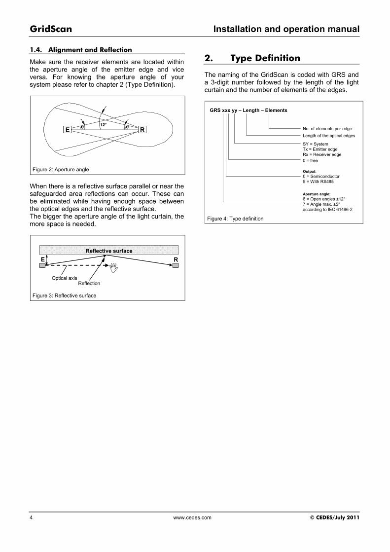
2. Type Definition
The naming of the GridScan is coded with GRS and a 3-digit number followed by the length of the light curtain and the number of elements of the edges.
GRS xxx yy – Length – Elements
No. of elements per edge
Length of the optical edges
0 = free
Output:0 = Semiconductor5 = With RS485
Aperture angle:6 = Open angles ±12°7 = Angle max. ±5°according to IEC 61496-2
SY = SystemTx = Emitter edgeRx = Receiver edge
Figure 4: Type definition
Installation and operation manual GridScan
© CEDES/July 2011 www.cedes.com 5
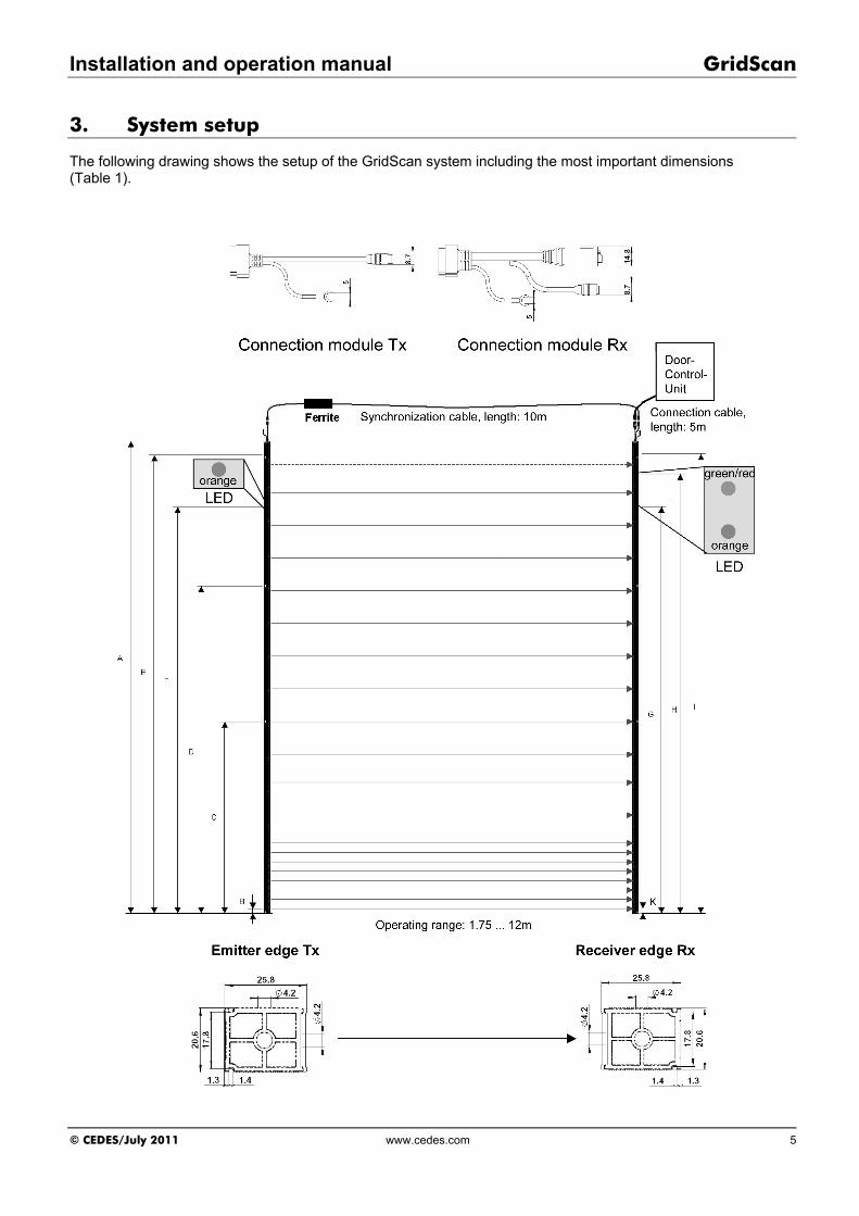
3. System setup
The following drawing shows the setup of the GridScan system including the most important dimensions (Table 1).

GridScan Installation and operation manual
6 www.cedes.com © CEDES/July 2011
Types
GRS xx0-
SY-1976-18 GRS xx0-
SY-2176-18 GRS xx0-
SY-2376-20 GRS xx0-
SY-2576-20 Number of beams* 18 18 20 20
A System length 1,976 2,176 2,376 2,576
B Position mounting hole 1 5.9 5.9 5.9 5.9
C Position mounting hole 2 955 1,035 981 1,047
D Position mounting hole 3 1,928 2,128 1,654 1,786
E Position mounting hole 4 - - 2,329 2,527
F Position LED / emitter edge, color: Orange 1,752 1,952 2,152 2,352
G Position LED / receiver edge, color: Orange 1,652 1,852 2,052 2,252
H Position LED / receiver edge, color: Red, green 1,753 1,953 2,153 2,353
I Protection height (labeled) 1,900 2,100 2,300 2,500
K Lowest beam 21 21 21 21
Table 1: System dimensions (all dimensions in mm)
* Please note: The uppermost beam is not safety-active.
3.1. General instruction and precaution
Never scratch or paint the front window. Do not drill additional holes into the profile. Unpack them just before installation in order to avoid damage.
Do not bend or twist the edges!
Oil and silicon may damage the cable and the profiles. Contamination must therefore be avoided at all times.
Em
itte
r
Re
ce
ive
r
Correct Incorrect
Re
ce
ive
r
Em
itte
r
Make sure to place the connection plugs for both the emitter and receiver at the same end.
Tx Rx
Tx Rx Rx Tx
Other light sources Other light sourcesTx Rx
Even though GridScan is not sensitive to direct sunlight, it is better to avoid direct exposure.
Avoid external interference from flashlights or other infrared light sources, such as photo eyes or light barriers.

Installation and operation manual GridScan
© CEDES/July 2011 www.cedes.com 7
3.2. Installation
It is recommended to carry out the system installation according to the following steps:
1. Check if the scope of delivery is complete: 1x receiver edge (Rx) 1x emitter edge (Tx) 1x synchronization cable, 10 m length 1x receiver connection cable, 5 m length 1x Installation and operation manual
If GPI is required, it must be ordered seperately.
Before mounting the GridScan please make sure that you have ten screws of max. OD of 4 mm and a fiiting screw driver at hand.
2. Switch off mains of the door and the door
control unit for your own safety and mark clearly that this object is out of service
3. Mount receiver edge by using required number
of screws with max. OD (outer diameter) of 4 mm into the guiding rail next to the door control unit. The receiver edge should be mounted on a plane surface.
Orientation: The CEDES logo label marks the front site of the GridScan.
Required number of screws: GRS xx0-SY-2576-20: 10 screws GRS xx0-SY-2376-20: 10 screws GRS xx0-SY-2176-18: 8 screws GRS xx0-SY-1976-18: 8 screws
Do not over-tighten the mounting screws.
Do not drill additional holes into the light curtain.
Do not use countersink screws for fastening.
Receiver edge
Emitter edge
Door controller
Figure 5: Positioning of emitter and receiver edge
4. Mount the grounding wire to adjacent earthed conductive material (e.g. guiding rail) by means of a screw with max. OD of 4 mm.
Grounding wires of both, receiver and emitter edge must be connected to a functional earth. The functional earth can consist of a grounded or ungrounded massive conductive material, adjacent to the edges, e.g. the guiding rail. In case, the conductive material is used as a protective earth, a proper grounding concept for the entire installation is a mandatory prerequisite. The wires must not be extended otherwise EMC interference to the light curtain function cannot be entirely avoided.
5. Mount emitter edge by using required number of screws (see step 3) with max. OD of 4 mm into the guiding rail, being situated opposite to the receiver edge. The emitter edge should be mounted on a plane surface.
Orientation: The CEDES logo label marks the front site of the GridScan.
6. Mount the grounding wire to adjacent conductive material (e.g. guiding rail) by means of a screw with max. OD of 4 mm.
7. Choose appropriate location at the door for GPI mounting.
The GPI needs to be mounted in front of the receiver edge in order to reflect the auxiliary beam, being emitted by the receiver element.
Positioning is dependent on the GPI orientation. The marked arrow on the front surface must point upwards.

GridScan Installation and operation manual
8 www.cedes.com © CEDES/July 2011
(all dimensions in mm)
Figure 6: GPI positioning dimensions for vertically oriented GPI (standard)
(all dimensions in mm)
Figure 7: GPI positioning dimensions for horizontally oriented GPI (option)
The distance between the GPI and the receiver edge should not exceed 100 mm at any point during door closure.
When mounting the GPI, select a location where it will not be damaged during door motion.
Make sure that the door deflection is in the range of ±5 mm at 100 mm distance between GPI and receiver edge (perpendicular to door flat) in order to ensure proper blanking functionality.
-10° +10°
max. +5 mm
max. -5 mm
Figure 8: GPI reflection of auxiliary beam
8. Mount GPI by using countersink screws with maximum OD of 4 mm.
Installation and operation manual GridScan
© CEDES/July 2011 www.cedes.com 9
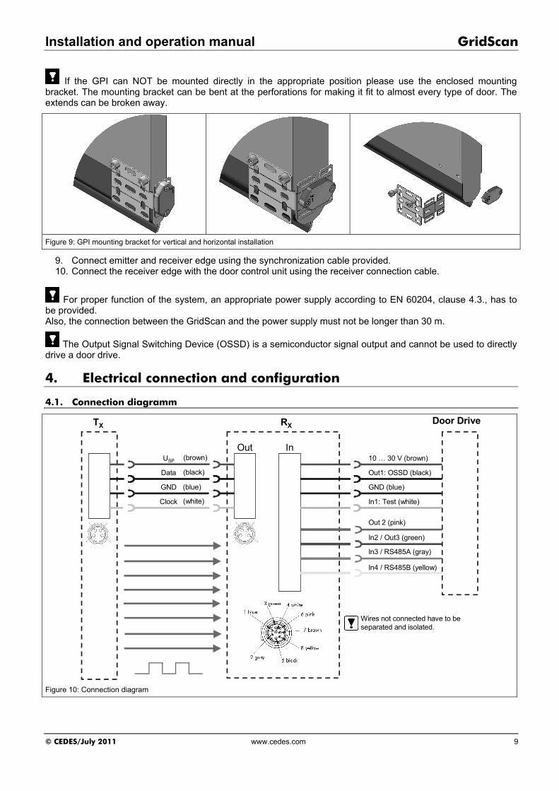
If the GPI can NOT be mounted directly in the appropriate position please use the enclosed mounting bracket. The mounting bracket can be bent at the perforations for making it fit to almost every type of door. The extends can be broken away.
Figure 9: GPI mounting bracket for vertical and horizontal installation
9. Connect emitter and receiver edge using the synchronization cable provided. 10. Connect the receiver edge with the door control unit using the receiver connection cable.
For proper function of the system, an appropriate power supply according to EN 60204, clause 4.3., has to be provided. Also, the connection between the GridScan and the power supply must not be longer than 30 m.
The Output Signal Switching Device (OSSD) is a semiconductor signal output and cannot be used to directly drive a door drive.
4. Electrical connection and configuration
4.1. Connection diagramm
TX
InUSP
GND
Clock
Data
Out
Door Drive
Out1: OSSD (black)
10 … 30 V (brown)
GND (blue)
In1: Test (white)
RX
(brown)
(blue)
(white)
(black)
In2 / Out3 (green)
Out 2 (pink)
In3 / RS485A (gray)
In4 / RS485B (yellow)
Wires not connected have to be separated and isolated.
Figure 10: Connection diagram

GridScan Installation and operation manual
10 www.cedes.com © CEDES/July 2011
4.2. Configuration
Output signals Input signals
Sta
tus
of
pro
tect
ion
fie
ld
Do
or
clo
sed
p
osi
tio
n s
ign
al
Do
or
blo
w-o
ut
sig
nal
FS
S –
Fre
qu
ency
sa
fety
Sig
nal
Tes
t in
pu
t
Op
erat
ing
ran
ge
Op
erat
ion
mo
de
RS
485
Requirements
High speed doors ++ ++ ++ ++ ++ ++ ++ Sectional doors ++ ++ ++ ++ ++ ++
Signal lines
Out 1 x Out 2 x In1 x In2 / Out 3 x x x In3 x x In4 x
Signal behaviour
24 VDC
Free
End
posi
tion
reac
hed
Doo
r out
of
rail
Nor
mal
m
ode
Red
uced
ra
nge
Hig
h sp
eed
door
0 VDC
Inte
rrupt
ed
Not
in e
nd
posi
tion
All O
K
Test
cyc
le
Open / not connected
Test
cy
cle
Stan
dard
ra
nge
Sect
iona
l do
or
4.3. Configuration by signal lines
The GridScan light curtain can be configured by two additional input signal lines.
In2 In3 Operating range
USP: Reduced range Open: Standard range
Operation mode
USP: High speed door Open: Sectional door
(open / not connected is the default behaviour)
4.3.1. In2: Operating range selection
Description Range (m) Open / not connected
Standard range 1.8 … 12
USP Reduced range 0.7 … 6
Important note: If the input 2 is not connected to USP, it is operated as output 3 with “Door closed position” signal or “Door blow-out” signal, depending on In3 signal. The signals at Out 3 will not be available while operating the GridScan in “Reduced range” mode
4.3.2. In3: Operation mode
“High speed door” operation mode The high speed operation mode is meant for
doors without partial opening. The door is either open or closed. When an interruption of the light curtain occurs the door is to open again.
GridScan has implemented a blanking mode including a continuous check of the door position. At the interruption the door position is reset and the light curtain is checking the whole safeguarding area again.
If the door is not detected at the next position within a certain time, the GridScan switches the output to state “interrupted”. In addition, this status is signalled to the door control unit by activating Out 3 (door blow-out detection) (4.4.2. Out 3).

Installation and operation manual GridScan
© CEDES/July 2011 www.cedes.com 11
Figure 11: High speed door – operation mode
Restrictions for this operation mode: Continuous door movement without inter-
mediate stops Door movement to the final end position.
“Sectional door” operation mode This operation mode allows stop&go, partial
opening and reverse movement of the door. The beams covered by the door are blanked. No time-out is calculated; i.e. the next beam is
blanked out as soon as the door edge is detected at a certain position.
If the light curtain is interrupted or the gate is being stopped during the opening or closing cycle, the GridScan remains in the current blanking status; i.e. the beams below the door edge are active and the beams at the door edge and above are blanked out. For a further door movement the signal for opening or closing has to be sent again.
Figure 12: Sectional door – operation mode
4.3.3. Blanking
The GridScan is able to perform a door blanking by using the GPI (Gate Position Indicator). Blanking means that light beams are ignored when the closing gate interrupts them – and therefore the light curtain does not switch the output. The GridScan detects the GPI mounted at the
gate and moving downwards in front of the GridScan receiver edge.
The topmost light beam is only activated for GPI detection; i.e. it is not an active beam for safety protection.
All beam states and the current GPI position are reset at power-up; i.e. theses states are not saved at a power failure.
Figure 13: Blanking
4.4. Output signals
Out 1 (output only)
Out 2 (output only)
Out 3 (out- and input)
OSSD PNP output
High: Free Low: Interrupted
FSS – Frequency Safety Signal
1 kHz: Free Low: Interrupted
Door closed position signal (for sectional doors)
High: End position reached Low: Not in end position
Door blow-out signal (for high speed doors)
High: Door out of rail Low: OK
RS485 With the RS485 interface the status of every single beam is available. Therefore not all the configuration possibilities are necessary. The RS485 interface is customer related. For more information or defining the protocol please contact your local CEDES representative.

GridScan Installation and operation manual
12 www.cedes.com © CEDES/July 2011
4.4.1. Out 1 / Out 2: Output signals
OSSD (Out 1)ON
OFF
FSS (Out 2)ON
OFF
Light beamsFree
Interrupted
t1 t3
t2
Time OSSD output
Response time t1 < 50 ms
Output off time t2 > 80 ms
Rise time t3 < 100 ms
Out 2: FSS signal
Light curtain status
FSS output
Frequency Signal Amplitude
Free 400 Hz … 2 KHz Square-wave signal
50% duty cycle GND* … 5 V
Interrupted 0 - GND*
Test cycle 0 - GND*
* plus saturation voltage
Figure 14: Output signals (values based on a GridScan GRS with 20 elements)
4.4.2. Out 3: Door position signal
End position detection The light curtain GridScan can detect the doors fully closed position. The output signal “Door closed position” is activated when the door obstructs the two under-most beams.
Door closed position(Out 3)
USP
GND
Door positionOpen
Closed
Figure 15: End position detection
Conditions: GPI in one of the lower elements 1 to 4. This
must not necessarily be the lowest position (No. 1); i.e. the door may reach the end position and the GPI is at the third or second last element. This depends on the GPI mounting position at the door edge and the distance between the optical elements.
Lowest light beam permanently interrupted by the door edge
Door blow-out signal The GridScan monitors the continuous move of the door. If the door is not detected at the next beam position, the output switches to Out 3. In addition, the OSSD output switches to “interrupted” before the GridScan is reset.. This status is reset by the next test signal or when the door is being recognized again.
Figure 16: Door blow-out behaviour
Response time t1 30 ms
Output off time t2 40 … 80 ms
Figure 17: Door blow-out behaviour
Installation and operation manual GridScan
© CEDES/July 2011 www.cedes.com 13
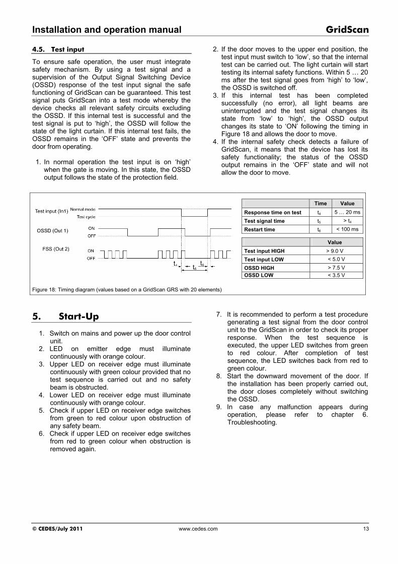
4.5. Test input
To ensure safe operation, the user must integrate safety mechanism. By using a test signal and a supervision of the Output Signal Switching Device (OSSD) response of the test input signal the safe functioning of GridScan can be guaranteed. This test signal puts GridScan into a test mode whereby the device checks all relevant safety circuits excluding the OSSD. If this internal test is successful and the test signal is put to ‘high’, the OSSD will follow the state of the light curtain. If this internal test fails, the OSSD remains in the ‘OFF’ state and prevents the door from operating. 1. In normal operation the test input is on ‘high’
when the gate is moving. In this state, the OSSD output follows the state of the protection field.
2. If the door moves to the upper end position, the test input must switch to ‘low’, so that the internal test can be carried out. The light curtain will start testing its internal safety functions. Within 5 … 20 ms after the test signal goes from ‘high’ to ‘low’, the OSSD is switched off.
3. If this internal test has been completed successfully (no error), all light beams are uninterrupted and the test signal changes its state from ‘low’ to ‘high’, the OSSD output changes its state to ‘ON’ following the timing in Figure 18 and allows the door to move.
4. If the internal safety check detects a failure of GridScan, it means that the device has lost its safety functionality; the status of the OSSD output remains in the ‘OFF’ state and will not allow the door to move.
Time Value
Response time on test t4 5 … 20 ms
Test signal time t5 > t4
Restart time t6 < 100 ms
Value
Test input HIGH > 9.0 V
Test input LOW < 5.0 V
OSSD HIGH > 7.5 V
OSSD LOW < 3.5 V
Figure 18: Timing diagram (values based on a GridScan GRS with 20 elements)
5. Start-Up
1. Switch on mains and power up the door control unit.
2. LED on emitter edge must illuminate continuously with orange colour.
3. Upper LED on receiver edge must illuminate continuously with green colour provided that no test sequence is carried out and no safety beam is obstructed.
4. Lower LED on receiver edge must illuminate continuously with orange colour.
5. Check if upper LED on receiver edge switches from green to red colour upon obstruction of any safety beam.
6. Check if upper LED on receiver edge switches from red to green colour when obstruction is removed again.
7. It is recommended to perform a test procedure generating a test signal from the door control unit to the GridScan in order to check its proper response. When the test sequence is executed, the upper LED switches from green to red colour. After completion of test sequence, the LED switches back from red to green colour.
8. Start the downward movement of the door. If the installation has been properly carried out, the door closes completely without switching the OSSD.
9. In case any malfunction appears during operation, please refer to chapter 6. Troubleshooting.

GridScan Installation and operation manual
14 www.cedes.com © CEDES/July 2011
6. Troubleshooting
When the door is not working properly please refer to the status LEDs if there an error occurred. Receiver output status LED’s:
Green Red Status
Light curtain free; OSSD on
Light curtain interrupted; OSSD off (in safe state)
Fault (overload, wrong connection); OSSD off (in safe state)
Receiver blanking status LED:
Orange Status
Blanking mode active
Blanking mode inactive
Fault Emitter power status LED:
Orange Status
Power OK
No power or power not within the limits = LED on = LED off = LED flashing When according to the status LEDs everything should be alright but still the performance of the GridScan is not as meant, please check the connection and the configuration of the light curtain again (section 4, 5, and 6). Also check the mounting position of the GPI (section 3.2).
Wires not connected have to be separated and isolated.
7. Maintenance and Disposal
7.1. Maintenance
Although GridScan does not need regular maintenance, a periodical functional check is strongly recommended as follows: Clean the front surface with a soft towel and a
little soap water from dust or dirt. Confirm edges are fastened securely in the
guide rails. Confirm cables are routed properly. Clean the front surface of the GPI with a soft
tissue from dust or dirt. Confirm GPI is fastened securely to the door.
Important notes: Never use any solvents, cleaners or mechanically abrasive towels as well as high pressure water to clean the edges. The front window may be damaged! Please also avoid scratching the edges while cleaning.
7.2. Disposal
The light curtain should only be replaced if a similar protection device is installed. Disposal should be done using the most up-to-date recycling technology according to local rules and laws. There are no harmful materials used in the design and manufacture of the light curtain. Traces of such dangerous materials could be used in the electronic components but not in quantities that are harmful to health.

Installation and operation manual GridScan
© CEDES/July 2011 www.cedes.com 15
8. Technical data
Optical Operating range - Standard - Reduced range
1.8 … 12 m 0.7 … 6 m
Protection height Up to 2.5 m Number of elements 2 … 50 Resolution 50 / 200 mm Maximal angle of paraxial detection
according to IEC 61496-2: - GRS 7xx Max. angle of paraxial detection: - GRS 6xx
Rx: ±5° at 3 m, Tx: ±5° at 3 m Rx: ±12° at 3 m, Tx: ±5° at 3 m
Maximal ambient light 100,000 Lux
Mechanical Dimensions ( w x h x l) 20.6 x 25.8 x max 2,576 mm Housing material Polycarbonate, black Enclosure rating IP65 Temperature range -40° … +60°C (operation), -40° … +85°C (storage)
Electrical Supply voltage USP 10 … 30 VDC Ripple at USP Max. 10% Current consumption at 24 VDC < 100 mA (without load) Output type 3 x semiconductor Output load Max. 80 mA, 500 nF Response time OSSD Max. 50 ms at 20 elements Door speed 0.1 … 3 m/s
Material PVC, black Diameter Ø 5.7 mm
Connection cable and electrical connection
Length 5 m Connector 8-Pin Mini-DIN8 Wires AWG26
- blue GND (0 V) - black Out 1 - OSSD - gray In3 / RS485A - pink Out 2 - FSS - green In2 / Out 3 - brown USP (10 … 30 V)
Pin assignment
- white In1-Test input - yellow In4 / RS485A
Sync cable Material PVC, black Diameter Ø 3.5 mm Length 10 m Connector 4-Pin M8 Wires AWG26 Pin assignment - brown USP (10 … 30 V)
- black Data - blue GND (0 V) - white Clock
Safety category EN 12978 (GRS 7xx only) IEC 61496-2 Type 2 AOPD (GRS 7xx only) EN 13849-1 Cat. 2 PL D, EN 61508 SIL CL 2
General
Eye safety EN 62471 EMC emission EN 61000-6-3 EMC immunity EN 61000-6-2 Vibration EN 60068-2-6 Shock EN 60068-2-27 Certificates CE, TÜV RoHS Fulfilled 2002/95/EC
GridScan Installation and operation manual
16 www.cedes.com © CEDES/Mai 2011
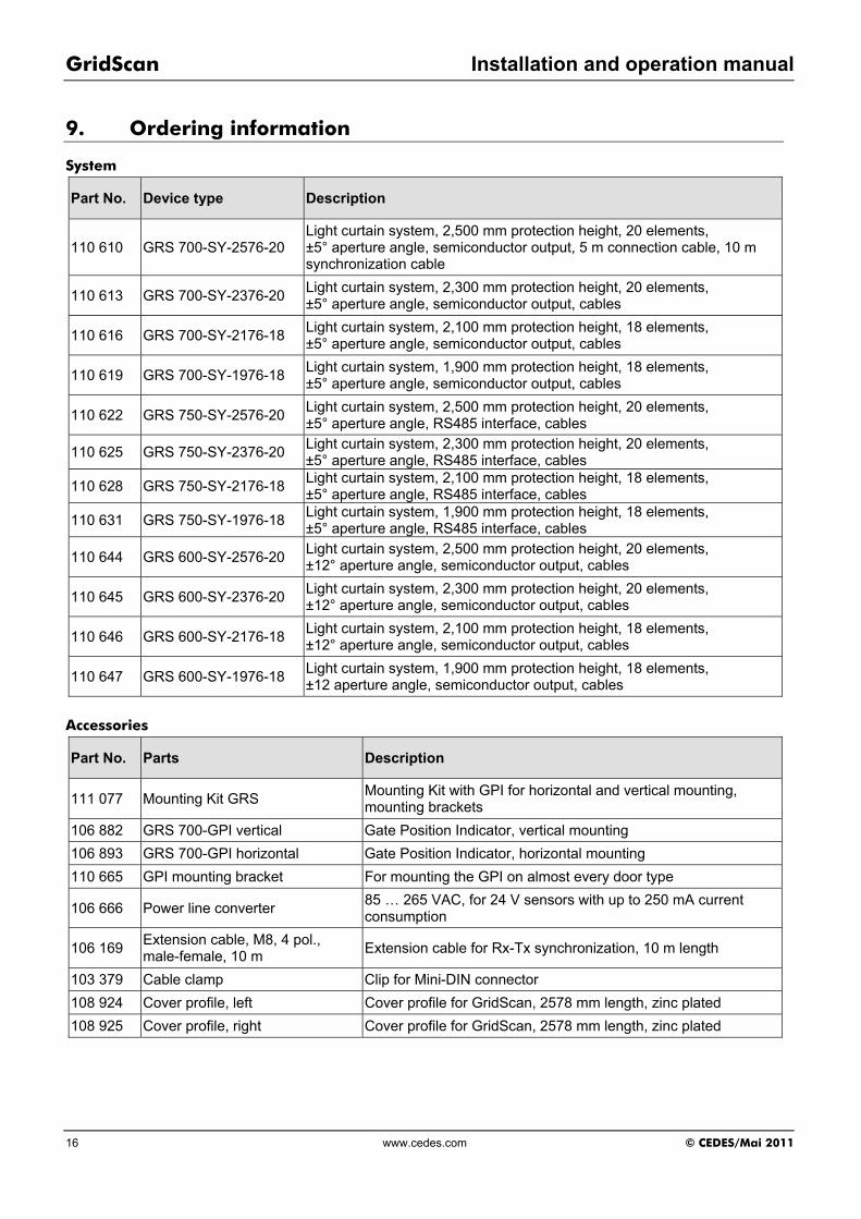
9. Ordering information
System
Part No. Device type Description
110 610 GRS 700-SY-2576-20 Light curtain system, 2,500 mm protection height, 20 elements, ±5° aperture angle, semiconductor output, 5 m connection cable, 10 m synchronization cable
110 613 GRS 700-SY-2376-20 Light curtain system, 2,300 mm protection height, 20 elements, ±5° aperture angle, semiconductor output, cables
110 616 GRS 700-SY-2176-18 Light curtain system, 2,100 mm protection height, 18 elements, ±5° aperture angle, semiconductor output, cables
110 619 GRS 700-SY-1976-18 Light curtain system, 1,900 mm protection height, 18 elements, ±5° aperture angle, semiconductor output, cables
110 622 GRS 750-SY-2576-20 Light curtain system, 2,500 mm protection height, 20 elements, ±5° aperture angle, RS485 interface, cables
110 625 GRS 750-SY-2376-20 Light curtain system, 2,300 mm protection height, 20 elements, ±5° aperture angle, RS485 interface, cables
110 628 GRS 750-SY-2176-18 Light curtain system, 2,100 mm protection height, 18 elements, ±5° aperture angle, RS485 interface, cables
110 631 GRS 750-SY-1976-18 Light curtain system, 1,900 mm protection height, 18 elements, ±5° aperture angle, RS485 interface, cables
110 644 GRS 600-SY-2576-20 Light curtain system, 2,500 mm protection height, 20 elements, ±12° aperture angle, semiconductor output, cables
110 645 GRS 600-SY-2376-20 Light curtain system, 2,300 mm protection height, 20 elements, ±12° aperture angle, semiconductor output, cables
110 646 GRS 600-SY-2176-18 Light curtain system, 2,100 mm protection height, 18 elements, ±12° aperture angle, semiconductor output, cables
110 647 GRS 600-SY-1976-18 Light curtain system, 1,900 mm protection height, 18 elements, ±12 aperture angle, semiconductor output, cables
Accessories
Part No. Parts Description
111 077 Mounting Kit GRS Mounting Kit with GPI for horizontal and vertical mounting, mounting brackets
106 882 GRS 700-GPI vertical Gate Position Indicator, vertical mounting
106 893 GRS 700-GPI horizontal Gate Position Indicator, horizontal mounting
110 665 GPI mounting bracket For mounting the GPI on almost every door type
106 666 Power line converter 85 … 265 VAC, for 24 V sensors with up to 250 mA current consumption
106 169 Extension cable, M8, 4 pol., male-female, 10 m
Extension cable for Rx-Tx synchronization, 10 m length
103 379 Cable clamp Clip for Mini-DIN connector
108 924 Cover profile, left Cover profile for GridScan, 2578 mm length, zinc plated
108 925 Cover profile, right Cover profile for GridScan, 2578 mm length, zinc plated
Installation and operation manual GridScan
© CEDES/July 2011 www.cedes.com 17
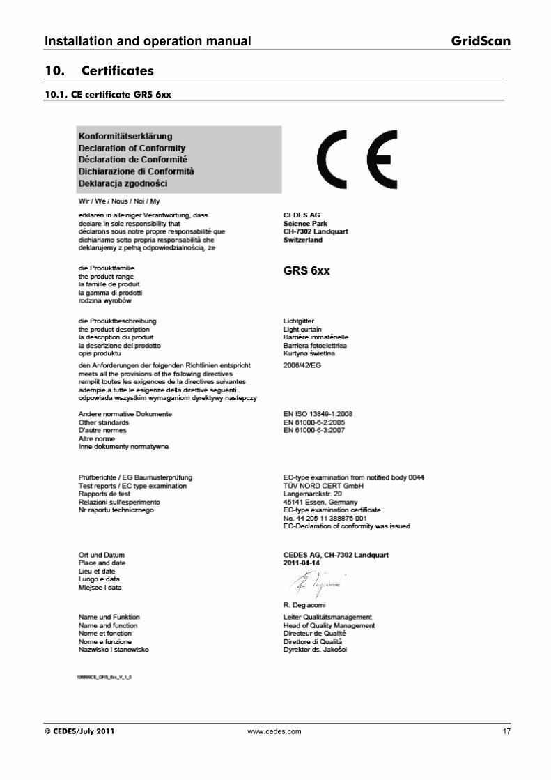
10. Certificates
10.1. CE certificate GRS 6xx

GridScan Installation and operation manual
18 www.cedes.com © CEDES/Mai 2011
10.2. CE certificate GRS 700

Installation and operation manual GridScan
© CEDES/July 2011 www.cedes.com 19
10.3. TÜV certificate

GridScan Installation and operation manual
CEDES AG / Switzerland Tel. +41 81 307 2323 Fax +41 81 307 2325 [email protected] www.cedes.com
CEDES AG is certified according to ISO 9001: 2008. CEDES AG reserves the right to modify or change technical data without prior notice.