
Gorbel Work Station Jib Crane Manual - Ergonomic Partners
20
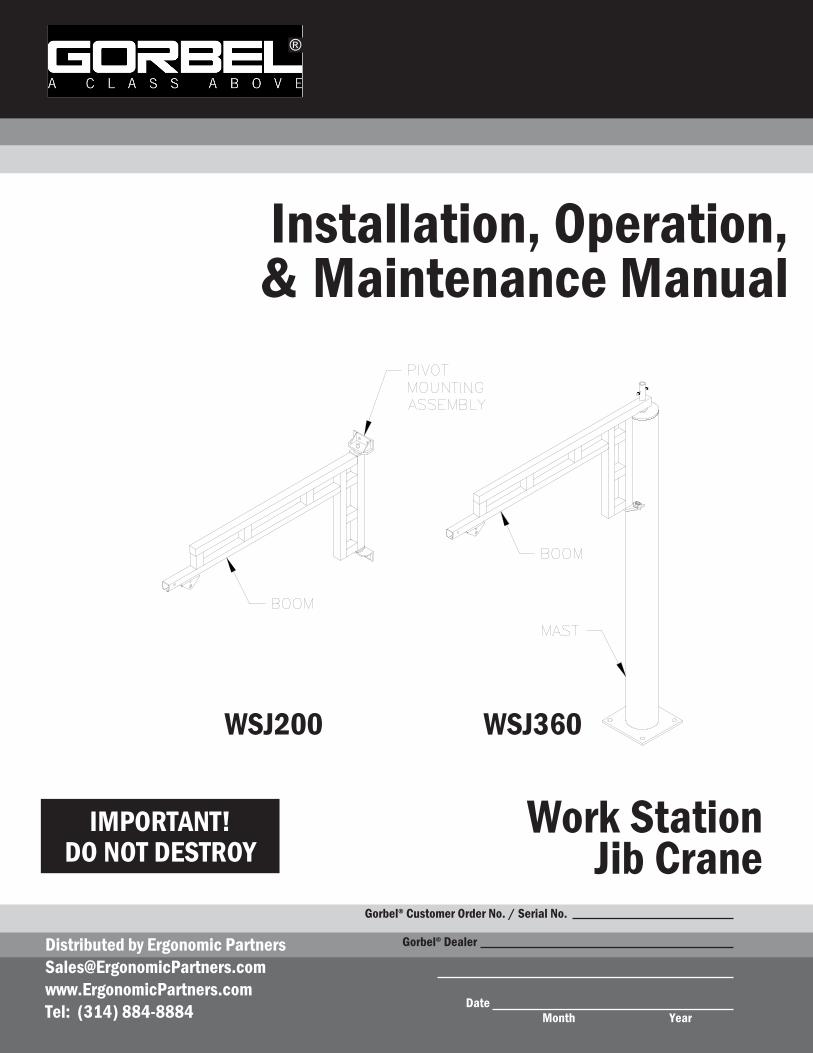
IMPORTANT! DO NOT DESTROY Installation, Operation, & Maintenance Manual Month Year Gorbel ® Dealer Date Work Station Jib Crane Gorbel ® Customer Order No. / Serial No. ® WSJ200 WSJ360 Distributed by Ergonomic Partners [email protected] www.ErgonomicPartners.com Tel: (314) 884-8884
-
Upload
khangminh22 -
Category
Documents
-
view
0 -
download
0
Transcript of Gorbel Work Station Jib Crane Manual - Ergonomic Partners
IMPORTANT!DO NOT DESTROY
Installation, Operation, & Maintenance Manual
Month Year
Gorbel® Dealer
Date
Work StationJib Crane
Gorbel® Customer Order No. / Serial No.
®
WSJ200 WSJ360
Distributed by Ergonomic [email protected]: (314) 884-8884
TABLE OF CONTENTSIntroduction.................................................................................................... 1
Installation....Step.1..-.Pre-assembly.............................................................................................2-3
.....Step.2..-.WSJ200.(Wall/Column.Mounted).Boom.Installation.....................................4
.....Step.3..-.WSJ360.(Free.Standing).Mast.Installation................................................5-8
.....Step.4..-.WSJ360.(Free.Standing).Boom.Installation.................................................9
.....Step.5..-.Hoist.Trolley.Installation..............................................................................10
.....Step.6..-.Festooning.Installation................................................................................11
.....Step.7..-.Tagline.Installation......................................................................................12
.....Step.8..-.Friction.Brake.Installation......................................................................12-13
.....Step.9..-.Accessories............................................................................................14-15
.....Step.10..-.Final.Steps................................................................................................15
Crane.Operator.Instructions........................................................................ 16
General.Safety.Requirements..................................................................... 16
Limited.Warranty......................................................................................... 17
Inspection.and.Maintenance.Schedule....................................................... 18
Questions?..Concerns?..Comments?..Please.call.(800).821-0086.(US.and.Canada).or(585).924-6262.(outside.US).
®

INTRODUCTIONThank.you.for.choosing.Gorbel®.Work.Station.Jib.Cranes.to.solve.your.material.handling.needs..The.innovative.design.and.heavy.duty.construction.of.Gorbel®.Work.Station.Jib.Cranes.will.provide.a.superior.quality.product.that.will.offer.years.of.long.term.value..All.Gorbel®.cranes.are.pre-engineered.for.powered.hoist.operation..The.hoist.weight.allowance.is.15%.of.the.crane.capacity.(for.example,.a.crane.rated.for.1000.pounds.allows.for.a.1000-pound.live.load.plus.150.pounds.for.the.weight.of.the.hoist)..There.is.also.an.allowance.of.25%.of.the.crane.capacity.for.impact.caused.by.hoist.use..Gorbel®.Work.Station.Jib.Cranes.will.provide.many.years.of.dependable.service.byfollowing.the.installation.and.maintenance.procedures.described.herein.
Dimensions contained in this installation manual are for reference only and may differ for your particular application. Please refer to the enclosed General Arrangement Drawing for actual dimensions.
Normal safety precautions: These.include,.but.are.not.limited.to:
•. Checking.for.obstructions.in.crane.rotation•. Checking.that.all.bolts.are.tight.and.have.lockwashers•. Making.sure.that.endstop.is.in.place•. Making.sure.that.festooning.cannot.be.snagged.or.pinched
For.additional.safety.precautions.see.page.16.
WARNINGOnly.competent.erection.personnel.familiar.with.standard.fabrication.practices.should.be.employed.to.assemble.these.cranes.because.of.the.necessity.of.properly.interpreting.these.instructions..Gorbel.is.not.responsible.for.the.quality.of.workmanship.employed.in.the.installation.of.a.crane.according.to.these.instructions..Contact.Gorbel,.Inc.,.at.600.Fishers.Run,.P.O..Box.593,.Fishers,.New.York.14453-0593,.1-800-821-0086,.for.additional.information.ifnecessary.
WARNINGEquipment.described.herein.is.not.designed.for,.and.should.not.be.used.for,.lifting,.supporting.or.transporting.humans..Failure.to.comply.with.any.one.of.the.limitations.noted.herein.can.result.in.serious.bodily.injury.and/or.property.damage..Check.Federal,.State.and.Local.regulations.for.any.additional.requirements.
WARNINGConsult.a.qualified.structural.engineer.to.determine.if.your.support.structure.is.adequate.to.support.the.loadsgenerated.by.thrust.and.pull.(wall/column.mounted),.or.anchor.bolt.force,.overturning.moment,.or.axial.load.(free.standing).of.your.crane.
WARNINGCrane.cannot.be.utilized.as.a.ground:..A.separate.ground.wire.is.required..For.example,.systems.with.3.phase.power.require.3.conductors.plus.one.ground.wire.
WARNINGReference.American.Institute.of.Steel.Construction.(AISC).Manual.of.Steel.Construction.(9th.edition),.Part.5,.Specification.for.Structural.Joints.using.ASTM.A325.or.A490.Bolts.(Section.8.d.2).for.proper.procedures.to.follow.when.using.any.torque.tightening.method.
WARNINGDo.not.field.modify.crane.in.any.way..Any.modifications.without.the.written.consent.of.Gorbel,.Inc.,.will.voidwarranty.
110/12 ®

INSTALLATIONSTEP 1 - PRE-ASSEMBLY
1.1. Read.entire.manual.before.installing.the.crane.
1.2. Check.packing.list.to.ensure.no.parts.have.been.lost.prior.to.initiating.assembly.of.crane.
1.3. Tools.and.materials.typically.needed.to.assemble.crane:. . •.Torque.wrench. . •.Ladders/man.lifts. . •.Hand.tools. . . •.Heavy.duty.drill. . •.Allen.wrench.(1/4”). •.Leveling.tools.(plumb.bob,.plumb.fixture-pg..8). . •.Lifting.device.to.lift.heavy.masts.and.booms. . •.WSJ200.mounting.bolts.(Ø.5/8”.Grade.5.or.better). . •.WSJ360.anchor.bolts.(Grade.5.or.better),.refer.to.pages.5-7.for.specifications. . •.Grout.(Non-Shrink.Precision.Grout.for.WSJ360)
1.4. Identify.crane.type:
Wall/Column Mounted Crane (diagram 1A). Refer.to.Chart 1A to.determine.thrust.and. pull,.and.distance.between.pivot.mounting. assembly.(bracket).centers,.then.proceed. to.Step 2,.page.4.
Free Standing Crane (diagram 1B). Refer.to.Chart 1B,.on.page.3,.to.determine. anchor.bolt.load.and.footer.width.and.depth,. then.proceed.to.Step 3,.page.5.
TIP: .Packing.list.can.be.found.in.plastic.pocket.inside.hardware.box:.General.Arrangement. ...Drawing.can.be.found.inserted.in.this.installation.manual.
WARNINGConsult.a.qualified.structural.engineer.to.determine.that.your.support.structure.is.adequate.to.support.the.loads.generated.by.thrust.and.pull.(wall/column.mounted).or.anchor.bolt.force,.overturning.moment,.or.axial.load.(free.standing).of.your.crane.
Diagram 1A. .Wall/Column Mounted Crane.
Diagram 1B. Free Standing Crane.
2 10/12
Chart 1A. Chart for determining thrust and pull, and pivot mounting (bracket) centers.
®
CAPACITY SPAN (ft)
MODELNUMBER
TRACK SERIES
B*(in)
THRUST & PULL
100#
4’6’8’
10’12’14’16’
WSJ200-100-4WSJ200-100-6WSJ200-100-8WSJ200-100-10WSJ200-100-12WSJ200-100-14WSJ200-100-16
250250250250250250250
36.25”36.25”36.25”36.25”48.25”48.25”48.25”
185.#306.#437.#579.#549.#672.#803.#
150#
4’6’8’
10’12’14’16’
WSJ200-150-4WSJ200-150-6WSJ200-150-8WSJ200-150-10WSJ200-150-12WSJ200-150-14WSJ200-150-16
250250250250250500500
36.25”36.25”36.25”36.25”48.25”60.25”60.25”
267.#434.#612.#801.#750.#782.#932.#
250#
4’6’8’
10’12’14’16’
WSJ200-250-4WSJ200-250-6WSJ200-250-8WSJ200-250-10WSJ200-250-12WSJ200-250-14WSJ200-250-16
250250250250500500500
36.25”36.25”36.25”48.25”60.25”60.25”60.25”
430.#691.#962.#933.#945.#
1,160.#1,366.#
500#
4’6’8’
10’12’14’16’
WSJ200-500-4WSJ200-500-6WSJ200-500-8WSJ200-500-10WSJ200-500-12WSJ200-500-14WSJ200-500-16
50050050050050010001000
36.25”36.25”48.25”48.25”60.25”60.25”60.25”
843.#1,342.#1,390.#1,784.#1.750.#2,152.#2,512.#
1000#
4’6’8’
10’12’14’16’
WSJ200-1000-4WSJ200-1000-6WSJ200-1000-8WSJ200-1000-10WSJ200-1000-12WSJ200-1000-14WSJ200-1000-16
1000100010001000100020002000
36.25”36.25”48.25”60.25”60.25”72.25”72.25”
1,666.#2,639.#2,722.#2,781.#3,394.#3,451.#4,010.#
*This.column.provides.the.distance.between.pivot.mounting.assem-bly.(bracket).centers.

Chart 1B. .Chart for determining footer depth, footer width and anchor bolt load.
310/12
*See.pages.5.and.6.for.additional.information.on.footer.requirements.
®
CA
PAC
ITY
HU
B
SPAN
MODELNUMBER
TRACK SERIES
FOO
TER D
EPTH (L)
FOO
TER W
IDTH
(M)
MA
ST DIA
.
AN
CH
OR
BO
LT LOA
D
HU
B
SPAN
MODELNUMBER
TRACK SERIES
FOO
TER D
EPTH (L)
FOO
TER W
IDTH
(M)
MA
ST DIA
.
AN
CH
OR
BO
LT LOA
D
100#
8’
4’6’8’
10’12’14’16’
WSJ360-100-8-4WSJ360-100-8-6WSJ360-100-8-8WSJ360-100-8-10WSJ360-100-8-12WSJ360-100-8-14WSJ360-100-8-16
250250250250250250250
6”6”6”6”6”6”6”
48”48”48”48”48”48”48”
6-5/8”6-5/8”6-5/8”6-5/8”6-5/8”6-5/8”6-5/8”
240.#420.#615.#822.#1,047.#1,289.#1,547.#
12’
4’6’8’
10’12’14’16’
WSJ360-100-12-4WSJ360-100-12-6WSJ360-100-12-8WSJ360-100-12-10WSJ360-100-12-12WSJ360-100-12-14WSJ360-100-12-16
250250250250250250250
6”6”6”6”6”6”6”
48”48”48”48”48”48”48”
6-5/8”6-5/8”6-5/8”6-5/8”6-5/8”6-5/8”8-5/8”
240.#420.#615.#822.#1,047.#1,289.#1,547.#
10’
4’6’8’
10’12’14’16’
WSJ360-100-10-4WSJ360-100-10-6WSJ360-100-10-8WSJ360-100-10-10WSJ360-100-10-12WSJ360-100-10-14WSJ360-100-10-16
250250250250250250250
6”6”6”6”6”6”6”
48”48”48”48”48”48”48”
6-5/8”6-5/8”6-5/8”6-5/8”6-5/8”6-5/8”6-5/8”
240.#420.#615.#822.#1,047.#1,289.#1,547.#
14’
4’6’8’
10’12’14’16’
WSJ360-100-14-4WSJ360-100-14-6WSJ360-100-14-8WSJ360-100-14-10WSJ360-100-14-12WSJ360-100-14-14WSJ360-100-14-16
250250250250250250250
6”6”6”6”6”6”6”
48”48”48”48”48”48”48”
6-5/8”6-5/8”6-5/8”6-5/8”8-5/8”8-5/8”8-5/8”
240.#420.#615.#822.#1,047.#1,289.#1,547.#
150#
8’
4’6’8’
10’12’14’16’
WSJ360-150-8-4WSJ360-150-8-6WSJ360-150-8-8WSJ360-150-8-10WSJ360-150-8-12WSJ360-150-8-14WSJ360-150-8-16
250250250250250500500
6”6”6”6”6”6”6”
48”48”48”48”48”48”48”
6-5/8”6-5/8”6-5/8”6-5/8”6-5/8”6-5/8”8-5/8”
348.#595.#857.#1,137.#1,432.#1,873.#2,242.#
12’
4’6’8’
10’12’14’16’
WSJ360-150-12-4WSJ360-150-12-6WSJ360-150-12-8WSJ360-150-12-10WSJ360-150-12-12WSJ360-150-12-14WSJ360-150-12-16
250250250250250500500
6”6”6”6”6”6”6”
48”48”48”48”48”48”48”
6-5/8”6-5/8”6-5/8”6-5/8”6-5/8”8-5/8”8-5/8”
348.#595.#857.#1,137.#1,432.#1,873.#2,242.#
10’
4’6’8’
10’12’14’16’
WSJ360-150-10-4WSJ360-150-10-6WSJ360-150-10-8WSJ360-150-10-10WSJ360-150-10-12WSJ360-150-10-14WSJ360-150-10-16
250250250250250500500
6”6”6”6”6”6”6”
48”48”48”48”48”48”48”
6-5/8”6-5/8”6-5/8”6-5/8”6-5/8”6-5/8”8-5/8”
348.#595.#857.#1,137.#1,432.#1,873.#2,242.#
14’
4’6’8’
10’12’14’16’
WSJ360-150-14-4WSJ360-150-14-6WSJ360-150-14-8WSJ360-150-14-10WSJ360-150-14-12WSJ360-150-14-14WSJ360-150-14-16
250250250250250500500
6”6”6”6”6”6”6”
48”48”48”48”48”48”48”
6-5/8”8-5/8”8-5/8”8-5/8”8-5/8”8-5/8”8-5/8”
348.#595.#857.#1,137.#1,432.#1,873.#2,242.#
250#
8’
4’6’8’
10’12’14’16’
WSJ360-250-8-4WSJ360-250-8-6WSJ360-250-8-8WSJ360-250-8-10WSJ360-250-8-12WSJ360-250-8-14WSJ360-250-8-16
250250250250500500500
6”6”6”6”6”6”6”
48”48”48”48”60”66”66”
6-5/8”6-5/8”6-5/8”6-5/8”8-5/8”8-5/8”8-5/8”
558.#945.#1,347.#1,767.#955.#1,186.#1,410.#
12’
4’6’8’
10’12’14’16’
WSJ360-250-12-4WSJ360-250-12-6WSJ360-250-12-8WSJ360-250-12-10WSJ360-250-12-12WSJ360-250-12-14WSJ360-250-12-16
250250250250500500500
6”6”6”6”6”6”6”
48”48”48”48”60”66”66”
6-5/8”6-5/8”8-5/8”8-5/8”8-5/8”8-5/8”12-3/4”
558.#945.#1,347.#1,767.#955.#1,186.#1,410.#
10’
4’6’8’
10’12’14’16’
WSJ360-250-10-4WSJ360-250-10-6WSJ360-250-10-8WSJ360-250-10-10WSJ360-250-10-12WSJ360-250-10-14WSJ360-250-10-16
250250250250500500500
6”6”6”6”6”6”6”
48”48”48”48”60”66”66”
6-5/8”6-5/8”8-5/8”8-5/8”8-5/8”8-5/8”8-5/8”
558.#945.#1,347.#1,767.#955.#1,186.#1,410.#
14’
4’6’8’
10’12’14’16’
WSJ360-250-14-4WSJ360-250-14-6WSJ360-250-14-8WSJ360-250-14-10WSJ360-250-14-12WSJ360-250-14-14WSJ360-250-14-16
250250250250500500500
6”6”6”6”6”6”6”
48”48”48”48”60”66”66”
8-5/8”8-5/8”8-5/8”8-5/8”12-3/4”12-3/4”12-3/4”
558.#945.#1,347.#1,767.#955.#1,186.#1,410.#
500#
8’
4’6’8’
10’12’14’16’
WSJ360-500-8-4WSJ360-500-8-6WSJ360-500-8-8WSJ360-500-8-10WSJ360-500-8-12WSJ360-500-8-14WSJ360-500-8-16
50050050050050010001000
6”6”6”6”6”48”48”
48”48”60”66”69”48”48”
8-5/8”8-5/8”8-5/8”12-3/4”12-3/4”12-3/4”12-3/4”
1,088.#1,831.#1,071.#1,417.#1,771.#2,201.#2,594.#
12’
4’6’8’
10’12’14’16’
WSJ360-500-12-4WSJ360-500-12-6WSJ360-500-12-8WSJ360-500-12-10WSJ360-500-12-12WSJ360-500-12-14WSJ360-500-12-16
50050050050050010001000
6”6”6”6”6”48”48”
48”48”60”66”69”48”48”
8-5/8”8-5/8”12-3/4”12-3/4”12-3/4”12-3/4”14”
1,088.#1,831.#1,071.#1,417.#1,771.#2,201.#2,594.#
10’
4’6’8’
10’12’14’16’
WSJ360-500-10-4WSJ360-500-10-6WSJ360-500-10-8WSJ360-500-10-10WSJ360-500-10-12WSJ360-500-10-14WSJ360-500-10-16
50050050050050010001000
6”6”6”6”6”48”48”
48”48”60”66”69”48”48”
8-5/8”8-5/8”8-5/8”12-3/4”12-3/4”12-3/4”12-3/4”
1,088.#1,831.#1,071.#1,417.#1,771.#2,201.#2,594.#
14’
4’6’8’
10’12’14’16’
WSJ360-500-14-4WSJ360-500-14-6WSJ360-500-14-8WSJ360-500-14-10WSJ360-500-14-12WSJ360-500-14-14WSJ360-500-14-16
50050050050050010001000
6”6”6”6”6”48”48”
48”48”60”66”69”48”48”
12-3/4”12-3/4”12-3/4”12-3/4”12-3/4”12-3/4”14”
407.#735.#1,072.#1,417.#1,772.#2,201.#2,037.#
1000#
8’
4’6’8’
10’12’14’16’
WSJ360-1000-8-4WSJ360-1000-8-6WSJ360-1000-8-8WSJ360-1000-8-10WSJ360-1000-8-12WSJ360-1000-8-14WSJ360-1000-8-16
1000100010001000100020002000
48”48”48”48”48”48”48”
48”48”48”48”48”60”60”
12-3/4”12-3/4”12-3/4”12-3/4”12-3/4”14”14”
797.#1,434.#2,083.#2,739.#3,405.#3,354.#3,953.#
12’
4’6’8’
10’12’14’16’
WSJ360-1000-12-4WSJ360-1000-12-6WSJ360-1000-12-8WSJ360-1000-12-10WSJ360-1000-12-12WSJ360-1000-12-14WSJ360-1000-12-16
1000100010001000100020002000
48”48”48”48”48”48”48”
48”48”48”48”48”60”60”
12-3/4”12-3/4”12-3/4”12-3/4”12-3/4”14”16”
797.#1,441.#1,611.#2,142.#2,681.#3,354.#3,953.#
10’
4’6’8’
10’12’14’16’
WSJ360-1000-10-4WSJ360-1000-10-6WSJ360-1000-10-8WSJ360-1000-10-10WSJ360-1000-10-12WSJ360-1000-10-14WSJ360-1000-10-16
1000100010001000100020002000
48”48”48”48”48”48”48”
48”48”48”48”48”60”60”
12-3/4”12-3/4”12-3/4”12-3/4”12-3/4”14”14”
797.#1,434.#2,083.#2,739.#3,405.#3,354.#3,953.#
14’
4’6’8’
10’12’14’16’
WSJ360-1000-14-4WSJ360-1000-14-6WSJ360-1000-14-8WSJ360-1000-14-10WSJ360-1000-14-12WSJ360-1000-14-14WSJ360-1000-14-16
1000100010001000100020002000
48”48”48”48”48”48”48”
48”48”48”48”48”60”60”
12-3/4”12-3/4”14”14”14”14”16”
797.#1,434.#2,083.#2,739.#3,405.#3,354.#3,953.#
STEP 2 - WSJ200 (WALL/COLUMN MOUNTED) BOOM INSTALLATION
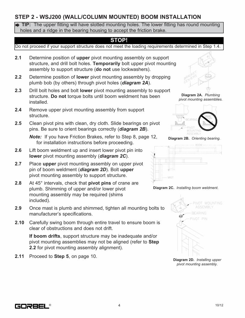
2.1. Determine.position.of.upper.pivot.mounting.assembly.on.support. structure,.and.drill.bolt.holes..Temporarily.bolt.upper.pivot.mounting. assembly.to.support.structure.(do not.use.lockwashers).2.2. Determine.position.of.lower.pivot.mounting.assembly.by.dropping. plumb.bob.(by.others).through.pivot.holes.(diagram 2A).2.3. Drill.bolt.holes.and.bolt.lower.pivot.mounting.assembly.to.support. structure..Do not.torque.bolts.until.boom.weldment.has.been.. installed.2.4. Remove.upper.pivot.mounting.assembly.from.support. structure.2.5. Clean.pivot.pins.with.clean,.dry.cloth..Slide.bearings.on.pivot. pins..Be.sure.to.orient.bearings.correctly.(diagram 2B).. Note:..If.you.have.Friction.Brakes,.refer.to.Step.8,.page.12,. . for.installation.instructions.before.proceeding.2.6. Lift.boom.weldment.up.and.insert.lower.pivot.pin.into. lower.pivot.mounting.assembly.(diagram 2C).2.7. Place.upper.pivot.mounting.assembly.on.upper.pivot. pin.of.boom.weldment.(diagram 2D)..Bolt.upper. pivot.mounting.assembly.to.support.structure.2.8. At.45°.intervals,.check.that.pivot pins.of.crane.are. plumb..Shimming.of.upper.and/or.lower.pivot. mounting.assembly.may.be.required.(shims. included).2.9. Once.mast.is.plumb.and.shimmed,.tighten.all.mounting.bolts.to. manufacturer’s.specifications.
2.10. Carefully.swing.boom.through.entire.travel.to.ensure.boom.is. clear.of.obstructions.and.does.not.drift.. If boom drifts,.support.structure.may.be.inadequate.and/or. pivot.mounting.assemblies.may.not.be.aligned.(refer.to.Step 2.2.for.pivot.mounting.assembly.alignment).
2.11. Proceed.to.Step 5,.on.page.10.
TIP: .The.upper.fitting.will.have.slotted.mounting.holes..The.lower.fitting.has.round.mounting.holes.and.a.ridge.in.the.bearing.housing.to.accept.the.friction.brake.
STOP!Do.not.proceed.if.your.support.structure.does.not.meet.the.loading.requirements.determined.in.Step.1.4.
Diagram 2A.. Plumbing pivot mounting assemblies.
Diagram 2B. Orienting bearing.
Diagram 2C. .Installing boom weldment.
Diagram 2D. Installing upper pivot mounting assembly.
4 10/12®
STEP 3 - WSJ360 (FREE STANDING) MAST INSTALLATION
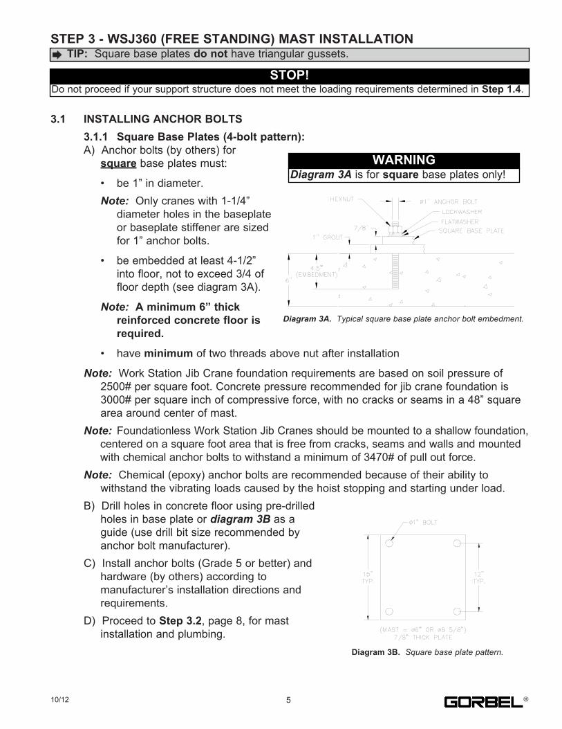
3.1 INSTALLING ANCHOR BOLTS 3.1.1 Square Base Plates (4-bolt pattern):. A)..Anchor.bolts.(by.others).for. .....square.base.plates.must:
. .....•. be.1”.in.diameter.
. .... Note:..Only.cranes.with.1-1/4”
. . diameter.holes.in.the.baseplate
. . or.baseplate.stiffener.are.sized
. . for.1”.anchor.bolts.
. .....•. be.embedded.at.least.4-1/2”
. . into.floor,.not.to.exceed.3/4.of
. . floor.depth.(see.diagram.3A).
. .. Note: .A minimum 6” thick reinforced concrete floor is required.
. .....•. have.minimum.of.two.threads.above.nut.after.installation
. Note: .Work.Station.Jib.Crane.foundation.requirements.are.based.on.soil.pressure.of
. .....2500#.per.square.foot..Concrete.pressure.recommended.for.jib.crane.foundation.is
. .....3000#.per.square.inch.of.compressive.force,.with.no.cracks.or.seams.in.a.48”.square
. .....area.around.center.of.mast.
. Note: Foundationless.Work.Station.Jib.Cranes.should.be.mounted.to.a.shallow.foundation,
. .....centered.on.a.square.foot.area.that.is.free.from.cracks,.seams.and.walls.and.mounted
. .....with.chemical.anchor.bolts.to.withstand.a.minimum.of.3470#.of.pull.out.force.
. Note: .Chemical.(epoxy).anchor.bolts.are.recommended.because.of.their.ability.to
. .....withstand.the.vibrating.loads.caused.by.the.hoist.stopping.and.starting.under.load.
. B)..Drill.holes.in.concrete.floor.using.pre-drilled
. .....holes.in.base.plate.or.diagram 3B.as.a
. .....guide.(use.drill.bit.size.recommended.by
. .....anchor.bolt.manufacturer).
. C)..Install.anchor.bolts.(Grade.5.or.better).and
. .....hardware.(by.others).according.to
. .....manufacturer’s.installation.directions.and
. .....requirements.
. D)..Proceed.to.Step 3.2,.page.8,.for.mast
. .....installation.and.plumbing.
.TIP: .Square.base.plates.do not.have.triangular.gussets.
STOP!Do.not.proceed.if.your.support.structure.does.not.meet.the.loading.requirements.determined.in.Step 1.4.
WARNINGDiagram 3A.is.for.square.base.plates.only!
Diagram 3A. Typical square base plate anchor bolt embedment.
Diagram 3B. Square base plate pattern.
510/12 ®
STEP 3 - WSJ360 (FREE STANDING) MAST INSTALLATION (CONTINUED)
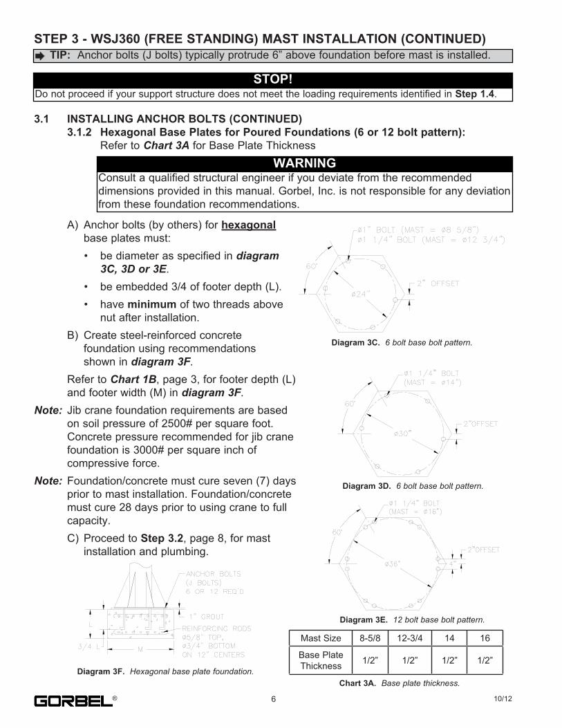
3.1 INSTALLING ANCHOR BOLTS (CONTINUED) 3.1.2 Hexagonal Base Plates for Poured Foundations (6 or 12 bolt pattern):. . Refer.to.Chart 3A.for.Base.Plate.Thickness
. A). Anchor.bolts.(by.others).for.hexagonal
. . base.plates.must:
. .....•. be.diameter.as.specified.in.diagram 3C, 3D or 3E.. .....•. be.embedded.3/4.of.footer.depth.(L).. .....•. have.minimum.of.two.threads.above. . . nut.after.installation.. B). Create.steel-reinforced.concrete. . foundation.using.recommendations. . shown.in.diagram 3F.. Refer.to.Chart 1B,.page.3,.for.footer.depth.(L). and.footer.width.(M).in.diagram 3F.Note:. Jib.crane.foundation.requirements.are.based. on.soil.pressure.of.2500#.per.square.foot... Concrete.pressure.recommended.for.jib.crane. foundation.is.3000#.per.square.inch.of. compressive.force.Note:. Foundation/concrete.must.cure.seven.(7).days. prior.to.mast.installation..Foundation/concrete. must.cure.28.days.prior.to.using.crane.to.full. capacity.. C). Proceed.to.Step 3.2,.page.8,.for.mast. . installation.and.plumbing.
.TIP: .Anchor.bolts.(J.bolts).typically.protrude.6”.above.foundation.before.mast.is.installed.
STOP!Do.not.proceed.if.your.support.structure.does.not.meet.the.loading.requirements.identified.in.Step 1.4.
WARNINGConsult.a.qualified.structural.engineer.if.you.deviate.from.the.recommendeddimensions.provided.in.this.manual..Gorbel,.Inc..is.not.responsible.for.any.deviation.from.these.foundation.recommendations.
Diagram 3C. 6 bolt base bolt pattern.
Diagram 3D. .6 bolt base bolt pattern.
Diagram 3E. 12 bolt base bolt pattern.
Diagram 3F. Hexagonal base plate foundation.Chart 3A.. Base plate thickness.
6 10/12®
Mast.Size 8-5/8 12-3/4 14 16
Base.Plate.Thickness 1/2” 1/2” 1/2” 1/2”
STEP 3 - WSJ 360 (FREE STANDING) MAST INSTALLATION (CONTINUED)
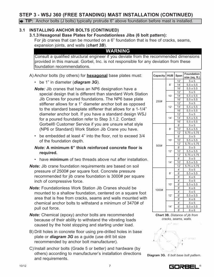
3.1 INSTALLING ANCHOR BOLTS (CONTINUED) 3.1.3 Hexagonal Base Plates for Foundationless Jibs (6 bolt pattern):. . For.jib.cranes.that.can.be.mounted.on.a.6”.foundation.that.is.free.of.cracks,.seams,. . expansion.joints,.and.walls.(chart 3B).
. A).Anchor.bolts.(by.others).for.hexagonal.base.plates.must:
. . •. be.1”.in.diameter.(diagram 3G).
. . Note:.Jib.cranes.that.have.an.NP6.designation.have.a
. . . special.design.that.is.different.than.standard.Work.Station
. . . Jib.Cranes.for.poured.foundations..The.NP6.base.plate
. . . stiffener.allows.for.a.1”.diameter.anchor.bolt.as.opposed
. . . to.the.standard.baseplate.stiffener.that.allows.for.a.1-1/4”
. . . diameter.anchor.bolt..If.you.have.a.standard.design.WSJ
. . . for.a.poured.foundation.refer.to.Step.3.1.2..Contact
. . . Gorbel®.Customer.Service.if.you.are.unsure.what.style
. . . (NP6.or.Standard).Work.Station.Jib.Crane.you.have.
. . •. be.embedded.at.least.4”.into.the.floor,.not.to.exceed.3/4
. . . of.the.foundation.depth.
. . Note:.A minimum 6” thick reinforced concrete floor is required.. . •. have.minimum.of.two.threads.above.nut.after.installation.. Note:.Jib.crane.foundation.requirements.are.based.on.soil. . pressure.of.2500#.per.square.foot..Concrete.pressure. . recommended.for.jib.crane.foundation.is.3000#.per.square. . inch.of.compressive.force.. Note:.Foundationless.Work.Station.Jib.Cranes.should.be. . mounted.to.a.shallow.foundation,.centered.on.a.square.foot. . area.that.is.free.from.cracks,.seams.and.walls.mounted.with. . chemical.anchor.bolts.to.withstand.a.minimum.of.3470#.of. . pull.out.force.. Note:.Chemical.(epoxy).anchor.bolts.are.recommended. . because.of.their.ability.to.withstand.the.vibrating.loads. . caused.by.the.hoist.stopping.and.starting.under.load.. B).Drill.holes.in.concrete.floor.using.pre-drilled.holes.in.base. . plate.or.diagram 3G.as.a.guide.(use.drill.bit.size. . recommended.by.anchor.bolt.manufacturer).. C).Install.anchor.bolts.(Grade.5.or.better).and.hardware.(by. . others).according.to.manufacturer’s.installation.directions. . and.requirements.
TIP:..Anchor.bolts.(J.bolts).typically.protrude.6”.above.foundation.before.mast.is.installed.
WARNINGConsult.a.qualified.structural.engineer.if.you.deviate.from.the.recommended.dimensions.provided.in.this.manual..Gorbel,.Inc..is.not.responsible.for.any.deviation.from.these.foundation.recommendations.
Diagram 3G. 6 bolt base bolt pattern.
Capacity HUB Span Foundation size (sq. ft.)
250#
8’12’ 5.x.514’ 5.5.x.5.516’ 5.5.x.5.5
10’12’ 5.x.514’ 5.5.x.5.516’ 5.5.x.5.5
12’12’ 5.x.514’ 5.5.x.5.516’ 5.5.x.5.5
14’12’ 5.x.514’ 5.5.x.5.516’ 5.5.x.5.5
500#
8’8’ 5.x.510’ 5.5.x.5.512’ 5.75.x.5.75
10’8’ 5.x.510’ 5.5.x.5.512’ 5.75.x.5.75
12’8’ 5.x.510’ 5.5.x.5.512’ 5.75.x.5.75
14’8’ 5.x.510’ 5.5.x.5.512’ 5.75.x.5.75
1000#
8’4’ 5.x.56’ 5.5.x.5.58’ 6.x.6
10’4’ 5.x.56’ 5.5.x.5.58’ 6.x.6
12’4’ 5.x.56’ 5.5.x.5.58’ 6.x.6
14’4’ 5.x.56’ 5.5.x.5.58’ 6.x.6
Chart 3B. Distance of jib from cracks, seams, walls.
710/12 ®
STEP 3 - WSJ360 (FREE STANDING) MAST INSTALLATION (CONTINUED)
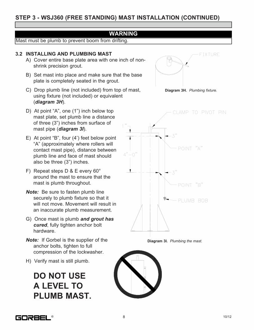
3.2 INSTALLING AND PLUMBING MAST. A)..Cover.entire.base.plate.area.with.one.inch.of.non-. .....shrink.precision.grout.
. B)..Set.mast.into.place.and.make.sure.that.the.base
. .....plate.is.completely.seated.in.the.grout.
. C)..Drop.plumb.line.(not.included).from.top.of.mast,
. .....using.fixture.(not.included).or.equivalent
. .....(diagram 3H).
. D)..At.point.“A”,.one.(1”).inch.below.top
. .....mast.plate,.set.plumb.line.a.distance
. .....of.three.(3”).inches.from.surface.of
. .....mast.pipe.(diagram 3I).
. E)..At.point.“B”,.four.(4’).feet.below.point
. .....“A”.(approximately.where.rollers.will
. .....contact.mast.pipe),.distance.between
. .....plumb.line.and.face.of.mast.should
. .....also.be.three.(3”).inches.
. F)..Repeat.steps.D.&.E.every.60°
. . ..around.the.mast.to.ensure.that.the
. . ..mast.is.plumb.throughout.
. Note: .Be.sure.to.fasten.plumb.line
. .....securely.to.plumb.fixture.so.that.it
. . ..will.not.move..Movement.will.result.in
. . ..an.inaccurate.plumb.measurement.
. G)..Once.mast.is.plumb.and grout has cured,.fully.tighten.anchor.bolt. .....hardware.
. Note:..If.Gorbel.is.the.supplier.of.the
. .....anchor.bolts,.tighten.to.full
. .....compression.of.the.lockwasher.
. H)..Verify.mast.is.still.plumb.
. ...DO NOT USE A LEVEL TO PLUMB MAST.
WARNINGMast.must.be.plumb.to.prevent.boom.from.drifting.
Diagram 3H.. Plumbing fixture.
Diagram 3I. Plumbing the mast.
8 10/12®
STEP 4 - WSJ360 (FREE STANDING) BOOM INSTALLATION
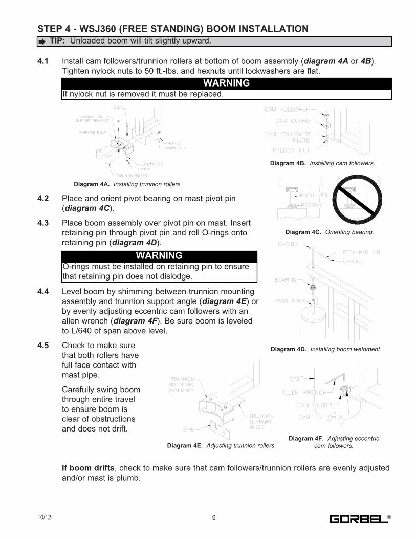
4.1. Install.cam.followers/trunnion.rollers.at.bottom.of.boom.assembly.(diagram 4A.or.4B).. Tighten.nylock.nuts.to.50.ft.-lbs..and.hexnuts.until.lockwashers.are.flat.
4.2. Place.and.orient.pivot.bearing.on.mast.pivot.pin. (diagram 4C).
4.3. Place.boom.assembly.over.pivot.pin.on.mast..Insert. retaining.pin.through.pivot.pin.and.roll.O-rings.onto. retaining.pin.(diagram 4D).
4.4. Level.boom.by.shimming.between.trunnion.mounting. assembly.and.trunnion.support.angle.(diagram 4E).or. by.evenly.adjusting.eccentric.cam.followers.with.an. allen.wrench.(diagram 4F)..Be.sure.boom.is.leveled. to.L/640.of.span.above.level.
4.5. Check.to.make.sure. that.both.rollers.have. full.face.contact.with. mast.pipe.
. Carefully.swing.boom
. through.entire.travel
. to.ensure.boom.is
. clear.of.obstructions
. and.does.not.drift.
. If boom drifts,.check.to.make.sure.that.cam.followers/trunnion.rollers.are.evenly.adjusted
. and/or.mast.is.plumb.
.TIP:..Unloaded.boom.will.tilt.slightly.upward.
WARNINGIf.nylock.nut.is.removed.it.must.be.replaced.
Diagram 4A. Installing trunnion rollers.
Diagram 4B. .Installing cam followers.
Diagram 4C. .Orienting bearing.
WARNINGO-rings.must.be.installed.on.retaining.pin.to.ensure.that.retaining.pin.does.not.dislodge.
Diagram 4D.. Installing boom weldment.
Diagram 4F.. Adjusting eccentric cam followers.Diagram 4E. Adjusting trunnion rollers.
910/12 ®
STEP 5 - HOIST TROLLEY INSTALLATION
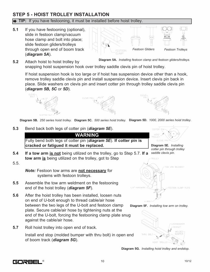
5.1. If.you.have.festooning.(optional),. slide.in.festoon.clamp/vacuum. hose.clamp.and.bolt.into.place;. slide.festoon.gliders/trolleys. through.open.end.of.boom.track. (diagram 5A).
5.2. Attach.hoist.to.hoist.trolley.by. snapping.hoist.suspension.hook.over.trolley.saddle.clevis.pin.of.hoist.trolley.
. If.hoist.suspension.hook.is.too.large.or.if.hoist.has.suspension.device.other.than.a.hook,
. remove.trolley.saddle.clevis.pin.and.install.suspension.device..Insert.clevis.pin.back.in
. place..Slide.washers.on.clevis.pin.and.insert.cotter.pin.through.trolley.saddle.clevis.pin
. (diagram 5B, 5C.or.5D).
5.3. Bend.back.both.legs.of.cotter.pin.(diagram 5E).
5.4. If a tow arm is not.being.utilized.on.the.trolley,.go.to.Step.5.7..If a tow arm is.being.utilized.on.the.trolley,.got.to.Step.5.5.
Note:.Festoon.tow.arms.are.not necessary.for. . systems.with.festoon.trolleys.
5.5. Assemble.the.tow.arm.weldment.on.the.festooning. end.of.the.hoist.trolley.(diagram 5F).
5.6. After.the.hoist.trolley.has.been.installed,.loosen.nuts. on.end.of.U-bolt.enough.to.thread.cable/air.hose. between.the.two.legs.of.the.U-bolt.and.festoon.clamp. plate..Secure.cable/air.hose.by.tightening.nuts.at.the. end.of.the.U-bolt,.forcing.the.festooning.clamp.plate.snug. against.the.cable/air.hose.
5.7. Roll.hoist.trolley.into.open.end.of.track.
. Install.end.stop.(molded.bumper.with.thru.bolt).in.open.end
. of.boom.track.(diagram 5G).
.TIP: .If.you.have.festooning,.it.must.be.installed.before.hoist.trolley.
Festoon Gliders Festoon Trolleys
Diagram 5A.. Installing festoon clamp and festoon gliders/trolleys.
Diagram 5B.. 250 series hoist trolley. Diagram 5C. 500 series hoist trolley. Diagram 5D. .1000, 2000 series hoist trolley.
WARNINGFully.bend.both.legs.of.cotter.pin.(diagram 5E)..If cotter pin is cracked or fatigued it must be replaced.
Diagram 5G. Installing hoist trolley and endstop.
10 10/12®
Diagram 5E. Installingcotter pin through trolley saddle clevis pin.
Diagram 5F. Installing tow arm on trolley.
STEP 6 - FESTOONING INSTALLATION (OPTIONAL)
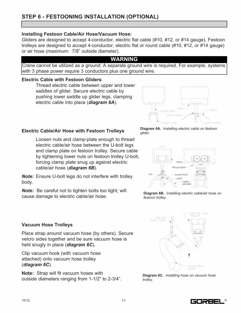
Installing Festoon Cable/Air Hose/Vacuum Hose:Gliders.are.designed.to.accept.4-conductor,.electric.flat.cable.(#10,.#12,.or.#14.gauge)..Festoon.trolleys.are.designed.to.accept.4-conductor,.electric.flat.or.round.cable.(#10,.#12,.or.#14.gauge).or.air.hose.(maximum:..7/8”.outside.diameter).
Electric Cable with Festoon Gliders. Thread.electric.cable.between.upper.and.lower. saddles.of.glider..Secure.electric.cable.by. pushing.lower.saddle.up.glider.legs,.clamping. electric.cable.into.place.(diagram 6A).
Electric Cable/Air Hose with Festoon Trolleys
. Loosen.nuts.and.clamp-plate.enough.to.thread
. electric.cable/air.hose.between.the.U-bolt.legs
. and.clamp.plate.on.festoon.trolley..Secure.cable
. by.tightening.lower.nuts.on.festoon.trolley.U-bolt,
. forcing.clamp.plate.snug.up.against.electric
. cable/air.hose.(diagram 6B).
Note:. Ensure.U-bolt.legs.do.not.interfere.with.trolleybody.
Note:..Be.careful.not.to.tighten.bolts.too.tight;.willcause.damage.to.electric.cable/air.hose.
Vacuum Hose Trolleys
Place.strap.around.vacuum.hose.(by.others)..Securevelcro.sides.together.and.be.sure.vacuum.hose.isheld.snugly.in.place.(diagram 6C).
Clip.vacuum.hook.(with.vacuum.hoseattached).onto.vacuum.hose.trolley(diagram 6C).
Note:..Strap.will.fit.vacuum.hoses.withoutside.diameters.ranging.from.1-1/2”.to.2-3/4”.
WARNINGCrane.cannot.be.utilized.as.a.ground:.A.separate.ground.wire.is.required..For.example,.systems.with.3.phase.power.require.3.conductors.plus.one.ground.wire.
Diagram 6A. Installing electric cable on festoon glider.
U-BOLT
CLAMP PLATE
TROLLEY BODY
NUT
CABLE/AIR HOSE
TRACK
Diagram 6B. Installing electric cable/air hose on festoon trolley.
Diagram 6C. Installing hose on vacuum hosetrolley.
1110/12 ®
STEP 7 - TAGLINE INSTALLATION (OPTIONAL)
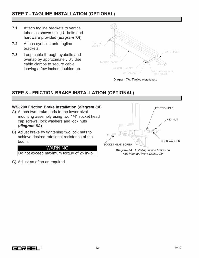
7.1. Attach.tagline.brackets.to.vertical. tubes.as.shown.using.U-bolts.and. hardware.provided.(diagram 7A).7.2. Attach.eyebolts.onto.tagline. brackets.7.3. Loop.cable.through.eyebolts.and. overlap.by.approximately.6”..Use. cable.clamps.to.secure.cable. leaving.a.few.inches.doubled.up.
STEP 8 - FRICTION BRAKE INSTALLATION (OPTIONAL)
WSJ200 Friction Brake Installation (diagram 8A)A). Attach.two.brake.pads.to.the.lower.pivot. mounting.assembly.using.two.1/4”.socket.head. cap.screws,.lock.washers.and.lock.nuts. (diagram 8A).B). Adjust.brake.by.tightening.two.lock.nuts.to. achieve.desired.rotational.resistance.of.the. boom.
C). Adjust.as.often.as.required.
Diagram 7A..Tagline Installation.
12 10/12®
WARNINGDo.not.exceed.maximum.torque.of.25.in-lb.
Diagram 8A.. Installing friction brakes on Wall Mounted Work Station Jib.
HEX.NUT
LOCK.WASHER
FRICTION.PAD
SOCKET.HEAD.SCREW
STEP 8 - FRICTION BRAKE INSTALLATION (CONTINUED)
Retrofitting Friction Brakes on Existing WSJ200Consult.Gorbel®.Customer.Service.at.800-821-0086.for.further.instructions.
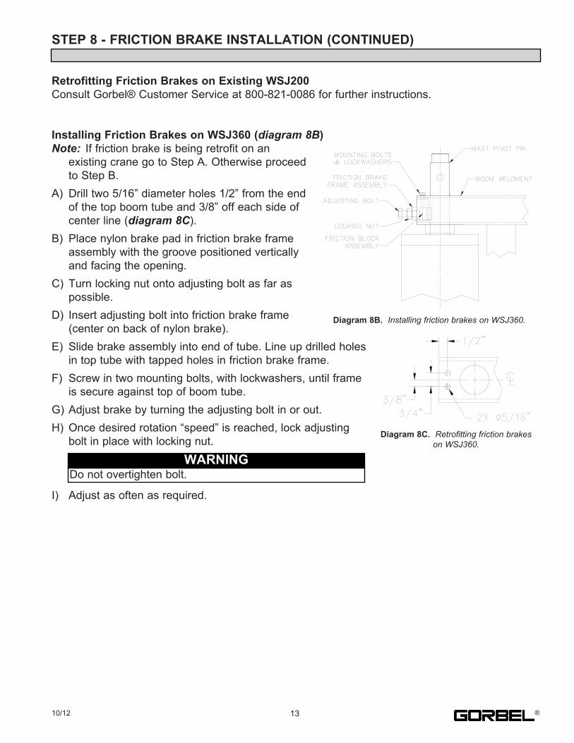
Installing Friction Brakes on WSJ360 (diagram 8B)Note:. If.friction.brake.is.being.retrofit.on.an. existing.crane.go.to.Step.A..Otherwise.proceed. to.Step.B.A). Drill.two.5/16”.diameter.holes.1/2”.from.the.end. of.the.top.boom.tube.and.3/8”.off.each.side.of. center.line.(diagram 8C).B). Place.nylon.brake.pad.in.friction.brake.frame. assembly.with.the.groove.positioned.vertically. and.facing.the.opening.C). Turn.locking.nut.onto.adjusting.bolt.as.far.as. possible.D). Insert.adjusting.bolt.into.friction.brake.frame. (center.on.back.of.nylon.brake).E). Slide.brake.assembly.into.end.of.tube..Line.up.drilled.holes. in.top.tube.with.tapped.holes.in.friction.brake.frame.F). Screw.in.two.mounting.bolts,.with.lockwashers,.until.frame. is.secure.against.top.of.boom.tube.G).Adjust.brake.by.turning.the.adjusting.bolt.in.or.out.H).Once.desired.rotation.“speed”.is.reached,.lock.adjusting. bolt.in.place.with.locking.nut.
.I). Adjust.as.often.as.required.
Diagram 8C...Retrofitting friction brakes on WSJ360.
Diagram 8B. Installing friction brakes on WSJ360.
WARNINGDo.not.overtighten.bolt.
1310/12 ®
STEP 9 - ACCESSORIES (OPTIONAL)
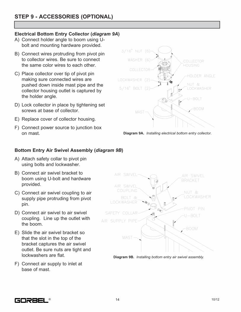
Electrical Bottom Entry Collector (diagram 9A)A). Connect.holder.angle.to.boom.using.U-. bolt.and.mounting.hardware.provided.
B). Connect.wires.protruding.from.pivot.pin. to.collector.wires..Be.sure.to.connect. the.same.color.wires.to.each.other.
C). Place.collector.over.tip.of.pivot.pin. making.sure.connected.wires.are. pushed.down.inside.mast.pipe.and.the. collector.housing.outlet.is.captured.by. the.holder.angle.
D). Lock.collector.in.place.by.tightening.set. screws.at.base.of.collector.
E). Replace.cover.of.collector.housing.
F). Connect.power.source.to.junction.box. on.mast.
Bottom Entry Air Swivel Assembly (diagram 9B)
A). Attach.safety.collar.to.pivot.pin. using.bolts.and.lockwasher.
B). Connect.air.swivel.bracket.to. boom.using.U-bolt.and.hardware. provided.
C). Connect.air.swivel.coupling.to.air. supply.pipe.protruding.from.pivot. pin.
D). Connect.air.swivel.to.air.swivel. coupling...Line.up.the.outlet.with. the.boom.
E). Slide.the.air.swivel.bracket.so. that.the.slot.in.the.top.of.the. bracket.captures.the.air.swivel. outlet..Be.sure.nuts.are.tight.and. lockwashers.are.flat.
F). Connect.air.supply.to.inlet.at. base.of.mast.
Diagram 9A. Installing electrical bottom entry collector.
Diagram 9B. Installing bottom entry air swivel assembly.
14 10/12®
STEP 9 - ACCESSORIES (OPTIONAL) (CONTINUED)
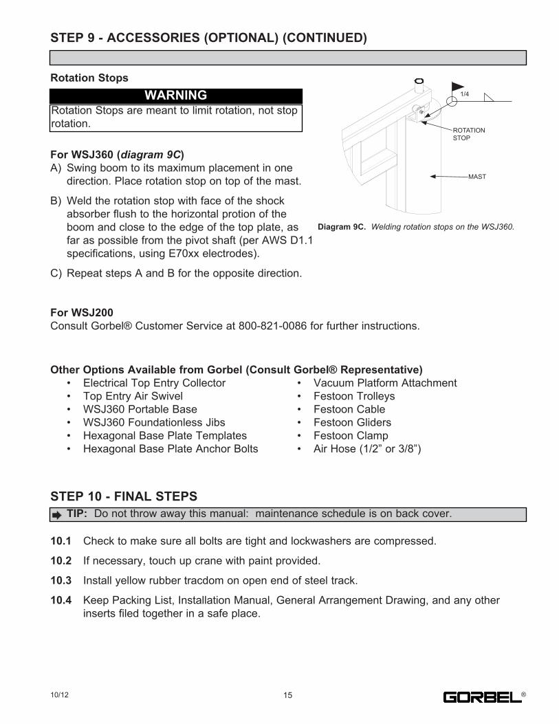
Rotation Stops
For WSJ360 (diagram 9C)A). Swing.boom.to.its.maximum.placement.in.one. direction..Place.rotation.stop.on.top.of.the.mast.
B). Weld.the.rotation.stop.with.face.of.the.shock. absorber.flush.to.the.horizontal.protion.of.the. boom.and.close.to.the.edge.of.the.top.plate,.as. far.as.possible.from.the.pivot.shaft.(per.AWS.D1.1. specifications,.using.E70xx.electrodes).
C). Repeat.steps.A.and.B.for.the.opposite.direction.
For WSJ200Consult.Gorbel®.Customer.Service.at.800-821-0086.for.further.instructions.
Other Options Available from Gorbel (Consult Gorbel® Representative). •. Electrical.Top.Entry.Collector. •. Vacuum.Platform.Attachment. •. Top.Entry.Air.Swivel. •. Festoon.Trolleys. •. WSJ360.Portable.Base. •. Festoon.Cable. •. WSJ360.Foundationless.Jibs. •. Festoon.Gliders. •. Hexagonal.Base.Plate.Templates. •. Festoon.Clamp. •. Hexagonal.Base.Plate.Anchor.Bolts. •. Air.Hose.(1/2”.or.3/8”)
STEP 10 - FINAL STEPS
10.1. Check.to.make.sure.all.bolts.are.tight.and.lockwashers.are.compressed.
10.2. If.necessary,.touch.up.crane.with.paint.provided.
10.3. Install.yellow.rubber.tracdom.on.open.end.of.steel.track.
10.4. Keep.Packing.List,.Installation.Manual,.General.Arrangement.Drawing,.and.any.other. inserts.filed.together.in.a.safe.place.
1510/12
.TIP: .Do.not.throw.away.this.manual:..maintenance.schedule.is.on.back.cover.
Diagram 9C. .Welding rotation stops on the WSJ360.
WARNINGRotation.Stops.are.meant.to.limit.rotation,.not.stop.rotation.
®
1/4
ROTATION.STOP
MAST
CRANE OPERATOR INSTRUCTIONSOverhead.cranes.and.jib.cranes.generally.handle.materials.over.working.areas.where.there.are.personnel...Therefore,.it.is.important.for.the.Crane.Operator.to.be.instructed.in.the.use.of.the.crane.and.to.understand.the.severe.consequences.of.careless.operation...It.is.not.intended.that.these.suggestions.take.precedence.over.existing.plant.safety.rules.and.regulations.or.OSHA.regulations...However,.a.thorough.study.of.the.following.information.should.provide.a.better.understanding.of.safe.operation.and.afford.a.greater.margin.of.safety.for.people.and.machinery.on.the.plant.floor...It.must.be.recognized.that.these.are.suggestions.for.the.Crane.Operator’s.use...It.is.the.responsibility.of.the.owner.to.make.personnel.aware.of.all.federal,.state.and.local.rules.and.codes,.and.to.make.certain.operators.are.properly.trained.QualificationsCrane.operation,.to.be.safe.and.efficient,.requires.skill:..the.exercise.of.extreme.care.and.good.judgment,.alertness.and.concentration,.and.rigid.adherence.to.proven.safety.rules.and.practices.as.outlined.in.applicable.and.current.ANSI.and.OSHA.safety.standards...In.general.practice,.no.person.should.be.permitted.to.operate.a.crane:. •. Who.cannot.speak.the.appropriate.language.or.read.and.understand.the.printed.instructions.. •. Who.is.not.of.legal.age.to.operate.this.type.of.equipment.. •. Whose.hearing.or.eyesight.is.impaired.(unless.suitably.corrected.with.good.depth.perception).. •. Who.may.be.suffering.from.heart.or.other.ailments.which.might.interfere.with.the.operator’s.safe.performance.. •. Unless.the.operator.has.carefully.read.and.studied.this.operation.manual.. •. Unless.the.operator.has.been.properly.instructed.. •. Unless.the.operator.has.demonstrated.his.instructions.through.practical.operation.. •. Unless.the.operator.is.familiar.with.hitching.equipment.and.safe.hitching.equipment.practices.Handling the Jib Boom MotionBefore.using.the.boom.of.the.jib.crane,.the.operator.should.be.sure.the.hook.is.high.enough.to.clear.any.obstruction...Before.a.load.is.handled.by.the.crane,.the.jib.boom.should.be.brought.into.position.so.that.it.is.directly.over.the.load...Start.the.jib.boom.slowly.and.bring.it.up.to.speed.gradually...Approaching.the.place.where.it.is.desired.to.stop.the.jib,.reduce.the.boom.speed.Handling the Trolley MotionBefore.a.load.is.handled,.the.hoist.should.be.positioned.directly.over.the.load.that.is.to.be.handled...When.the.slack.is.taken.out.of.the.slings,.if.the.hoist.is.not.directly.over.the.load,.bring.it.directly.over.the.load.before.hoisting.is.continued...Failure.to.center.the.hoist.over.the.load.may.cause.the.load.to.swing.upon.lifting...Always.start.the.trolley.motion.slowly.and.reduce.the.trolley.speed.gradually.Handling the Hoist MotionRefer.to.the.lifting.(hoist).equipment’s.operating.instructions.
GENERAL SUGGESTIONSKnow Your CraneCrane.operators.should.be.familiar.with.the.principal.parts.of.a.crane.and.have.a.thorough.knowledge.of.crane.control.functions.and.movements...The.crane.operator.should.be.required.to.know.the.location.and.proper.operation.of.the.main.conductor.disconnecting.means.for.all.power.to.the.attachments.on.the.crane.ResponsibilityEach.crane.operator.should.be.held.directly.responsible.for.the.safe.operation.of.the.crane...Whenever.there.is.any.doubt.as.to.SAFETY,.the.crane.operator.should.stop.the.crane.and.refuse.to.handle.loads.until:..(1).safety.has.been.assured.or.(2).the.operator.has.been.ordered.to.proceed.by.the.supervisor,.who.then.assumes.all.responsibility.for.the.SAFETY.of.the.lift.Do.not.permit.ANYONE.to.ride.on.the.hook.or.a.load.InspectionTest.the.crane.movement.and.any.attachments.on.the.crane.at.the.beginning.of.each.shift...Whenever.the.operator.finds.anything.wrong.or.apparently.wrong,.the.problem.should.be.reported.immediately.to.the.proper.supervisor.and.appropriate.corrective.action.taken.Operating SuggestionsOne.measure.of.a.good.crane.operator.is.the.smoothness.of.the.crane.operation...The.good.crane.operator.should.know.and.follow.these.proven.suggestions.forsafe,.efficient.crane.handling.1.. The.crane.should.be.moved.smoothly.and.gradually.to.avoid.abrupt,.jerky.movements.of.the.load...Slack.must.be.removed.from.the.sling.and.hoisting.ropes. before.the.load.is.lifted.2.. Center.the.crane.over.the.load.before.starting.the.hoist.to.avoid.swinging.the.load.as.the.lift.is.started...Loads.should.not.be.swung.by.the.crane.to.reach.areas. not.under.the.crane.3.. Crane-hoisting.ropes.should.be.kept.vertical...Cranes.shall.not.be.used.for.side.pulls.4.. Be.sure.everyone.in.the.immediate.area.is.clear.of.the.load.and.aware.that.a.load.is.being.moved.5.. Do.not.make.lifts.beyond.the.rated.load.capacity.of.the.crane,.sling.chains,.rope.slings,.etc.6.. Make.certain.that.before.moving.the.load,.load.slings,.load.chains,.or.other.lifting.devices.are.fully.seated.in.the.saddle.of.the.hook.with.the.hook.latch.closed.(if. equipped.with.hook.latch).7.. Check.to.be.sure.that.the.load.and/or.bottom.block.is.lifted.high.enough.to.clear.all.obstructions.when.moving.boom.or.trolley.8.. At.no.time.should.a.load.be.left.suspended.from.the.crane.unless.the.operator.has.the.push.button.with.the.power.on,.and.under.this.condition.keep.the.load.as. close.as.possible.to.the.floor.to.minimize.the.possibility.of.an.injury.if.the.load.should.drop...When.the.crane.is.holding.a.load,.the.crane.operator.should.remain. at.the.push.button.9.. Do.not.lift.loads.with.sling.hooks.hanging.loose...If.all.sling.hooks.are.not.needed,.they.should.be.properly.stored,.or.use.a.different.sling.10.. All.slings.or.cables.should.be.removed.from.the.crane.hooks.when.not.in.use.(dangling.cables.or.hooks.hung.in.sling.rings.can.inadvertently.snag.other.objects. when.the.crane.is.moving).11.. Operators.shall.not.carry.loads.and/or.empty.bottom.blocks.over.personnel...Particular.additional.caution.should.be.practiced.when.using.magnet.or.vacuum. devices...Loads,.or.parts.of.loads,.held.magnetically.could.drop...Failure.of.power.to.magnets.or.vacuum.devices.can.result.in.dropping.the.load...Extra. precaution.should.be.exercised.when.handling.molten.metal.in.the.proximity.of.personnel.12.. Whenever.the.operator.leaves.the.crane.the.following.procedure.should.be.followed:. . •. Raise.all.hooks.to.an.intermediate.position.. . •. Spot.the.crane.at.an.approved.designated.location.. . •. Place.all.controls.in.the.“off”.position.. . •. Open.the.main.switch.to.the.“off”.position.. . •. Make.visual.check.before.leaving.the.crane.13.. In.case.of.emergency.or.during.inspection,.repairing,.cleaning.or.lubrication,.a.warning.sign.or.signal.should.be.displayed.and.the.main.switch.should.be.locked. in.the.“off”.position...This.should.be.done.whether.the.work.is.being.done.by.the.crane.operator.or.by.others.14.. Contact.with.rotation.stops.or.trolley.end.stops.shall.be.made.with.extreme.caution...The.operator.should.do.so.with.particular.care.for.the.safety.of.persons. below.the.crane,.and.only.after.making.certain.that.any.persons.on.the.other.cranes.are.aware.of.what.is.being.done.15.. ANY.SAFETY.FEATURES.AND.MECHANISMS.BUILT-IN.OR.OTHERWISE.PROVIDED.WITH.THE.CRANE.BY.GORBEL.ARE.REQUIRED.FOR.THE.SAFE. OPERATION.OF.THE.CRANE...DO.NOT,.UNDER.ANY.CIRCUMSTANCES,.REMOVE.OR.OTHERWISE.IMPAIR.OR.DISABLE.THE.PROPER.FUNCTIONING. OF.ANY.CRANE.SAFETY.MECHANISMS.OR.FEATURES.BUILT-IN.OR.OTHERWISE.PROVIDED.BY.GORBEL.FOR.SAFE.OPERATION.OF.THE.CRANE.. ANY.REMOVAL,.IMPAIRMENT.OR.DISABLING.OF.ANY.SUCH.SAFETY.MECHANISMS.OR.FEATURES.OR.OTHER.USE.OR.OPERATION.OF.THE.CRANE. WITHOUT.THE.COMPLETE.AND.PROPER.FUNCTIONING.OF.ANY.SUCH.SAFETY.MECHANISMS.OR.FEATURES.AUTOMATICALLY.AND.IMMEDIATELY. VOIDS.ANY.AND.ALL.EXPRESS.AND.IMPLIED.WARRANTIES.OF.ANY.KIND.OR.NATURE.
16 10/12®
LIMITED WARRANTYIt.is.agreed.that.the.equipment.purchased.hereunder.is.subject.to.the.following.LIMITED.warranty.and.no.other..Gorbel.Incorporated.(“Gorbel”).warrants.the.manual.push-pull.Work.Station.Cranes,.Jib.Crane,.and.Gantry.Crane.products.to.be.free.from.defects.in.material.or.workmanship.for.a.period.of.ten.years.or.20,000.hours.use.from.date.of.shipment...Gorbel.warrants.the.Motorized.Work.Station.Cranes.and.Jib.Crane.products.to.be.free.from.defects.in.material.or.workmanship.for.a.period.of.two.years.or.4,000.hours.use.from.the.date.of.shipment..Gorbel.warrants.the.G-Force®.and.Easy.Arm™.products.to.be.free.from.defects.in.material.orworkmanship.for.a.period.of.one.year.or.2,000.hours.use.from.the.date.of.shipment..This.warranty.does.not.cover.Gantry.Crane.wheels.This.warranty.shall.not.cover.failure.or.defective.operation.caused.by.operation.in.excess.of.recommended.capacities,.misuses,.negligence.or.accident,.and.alteration.or.repair.not.authorized.by.Gorbel..No.system.shall.be.field.modified.after.manufacture.without.the.written.authorization.of.Gorbel,.Inc..Any.field.modification.made.to.the.system.without.thewritten.authorization.of.Gorbel,.Inc..shall.void.Gorbel’s.warranty.obligation..OTHER.THAN.AS.SET.FORTH.HEREIN,.NO.OTHER.EXPRESS.WARRANTIES,.AND.NO.IMPLIED.WARRANTIES,.ORAL.OR.WRITTEN,.INCLUDING.BUT.NOT.LIMITED.TO.THE.WARRANTIES.OF.MERCHANTABILITY.OR.FITNESS.FOR.PARTICULAR.PURPOSE,.ARE.MADE.BY.GORBEL.WITH.RESPECT.TO.ITS.PRODUCTS.AND.ALL.SUCH.WARRANTIES.ARE.HEREBY.SPECIFICALLY.DISCLAIMED..GORBEL.SHALL.NOT.BE.LIABLE.UNDER.ANY.CIRCUMSTANCES.FOR.ANY.INCIDENTAL,.SPECIAL.AND/OR.CONSEQUENTIAL.DAMAGES.WHATSOEVER,.WHETHER.OR.NOT.FORESEEABLE,.INCLUDING.BUT.NOT.LIMITED.TO.DAMAGES.FOR.LOST.PROFITS.AND.ALL.SUCH.INCIDENTAL,.SPECIAL.AND/OR.CONSEQUENTIAL.DAMAGES.ARE.HEREBY.ALSO.SPECIFICALLY.DISCLAIMED..Gorbel’s.obligation.and.Purchaser’s.or.end.user’s.sole.remedy.under.thiswarranty.is.limited.to.the.replacement.or.repair.of.Gorbel’s.products.at.the.factory,.or.at.the.discretion.of.Gorbel,.at.a.location.designated.by.Gorbel...Purchaser.or.end.user.shall.be.solely.responsible.for.all.freight.and.transportation.costs.incurred.in.connection.with.any.warranty.work.provided.by.Gorbel.hereunder...Gorbel.will.not.be.liable.for.any.loss,.injury.or.damage.to.persons.or.property,.nor.for.damages.of.any.kind.resulting.from.failure.or.defective.operation.of.any.materials.or.equipmentfurnished.hereunder..Components.and.accessories.not.manufactured.by.Gorbel.are.not.included.in.this.warranty...Purchaser’s.or.end.user’s.remedy.for.components.and.accessories.not.manufactured.by.Gorbel.is.limited.to.and.determined.by.the.terms.and.conditions.of.the.warranty.provided.by.the.respective.manufacturers.of.such.components.and.accessories. A) DISCLAIMER OF IMPLIED WARRANTY OF MERCHANTABILITY. . . Gorbel.and.Purchaser.agree.that.any.claim.made.by.Purchaser.which.is.inconsistent.with.Gorbel’s.obligations.and.the.warranty.remedies. . . provided.with.Gorbel’s.products,.and.in.particular,.special,.incidental.and.consequential.damages,.are.expressly.excluded. B) DISCLAIMER OF IMPLIED WARRANTY OF FITNESS FOR PARTICULAR PURPOSE. . . Gorbel.and.Purchaser.agree.that.the.implied.warranty.of.fitness.for.particular.purpose.is.excluded.from.this.transaction.and.shall.not.apply.to. . . the.goods.involved.in.this.transaction. C) DISCLAIMER OF EXPRESS WARRANTY. . . Gorbel’s.agents,.or.dealer’s.agents,.or.distributor’s.agents.may.have.made.oral.statements.about.the.machinery.and.equipment.described.in. . . this.transaction..Such.statements.do.not.constitute.warranties,.and.Purchaser.agrees.not.to.rely.on.such.statements..Purchaser.also.agrees. . . that.such.statements.are.not.part.of.this.transaction. D) DISCLAIMER OF SPECIAL, INCIDENTAL AND CONSEQUENTIAL DAMAGES. . . Gorbel.and.Purchaser.agree.that.any.claim.made.by.Purchaser.which.is.inconsistent.with.Gorbel’s.obligations.and.the.warranty.remedies. . . provided.with.Gorbel’s.products,.and.in.particular,.special,.incidental.and.consequential.damages,.are.expressly.excluded. E) DEALER OR DISTRIBUTOR NOT AN AGENT. . . Gorbel.and.Purchaser.agree.that.Purchaser.has.been.put.on.notice.that.dealer.or.distributor.is.not.Gorbel’s.agent.in.any.respect.for.any. . . reason..Gorbel.and.Purchaser.also.agree.that.Purchaser.has.been.put.on.notice.that.dealer.or.distributor.is.not.authorized.to.incur.any. . . obligations.or.to.make.any.representations.or.warranties.on.Gorbel’s.behalf.other.than.those.specifically.set.forth.in.Gorbel’s.warranty.provided. . . in.connection.with.its.product. F) MERGER. . . This.warranty.agreement.constitutes.a.final.and.complete.written.expression.of.all.the.terms.and.conditions.of.this.warranty.and.is.a.complete. . . and.exclusive.statement.of.those.terms. G) PAINTING. . . Every.crane.(excluding.components).receives.a.quality.paint.job.before.leaving.the.factory..Unfortunately,.no.paint.will.protect.against.the. . . abuses.received.during.the.transportation.process.via.common.carrier..We.have.included.at.least.one.(1).twelve.ounce.spray.can.for.touchup. . . with.each.crane.ordered.(unless.special.paint.was.specified)..If.additional.paint.is.required,.contact.a.Gorbel®.Customer.Service. . . Representative.at.1-800-821-0086.or.1-585-924-6262.
Title and Ownership:. Title.to.the.machinery.and.equipment.described.in.the.foregoing.proposal.shall.remain.with.Gorbel.and.shall.not.pass.to.the.Purchaser.until.the.full.amount. herein.agreed.to.be.paid.has.been.fully.paid.in.cash.
Claims and Damages:. Unless.expressly.stated.in.writing,.goods.and.equipment.shall.be.at.Purchaser’s.risk.on.and.after.Seller’s.delivery.in.good.shipping.order.to.the.Carrier..Gorbel. shall.in.no.event.be.held.responsible.for.materials.furnished.or.work.performed.by.any.person.other.than.it.or.its.authorized.representative.or.agent.
Cancellations:. If.it.becomes.necessary.for.the.purchaser.to.cancel.this.order.wholly.or.in.part,.he.shall.at.once.so.advise.Gorbel.in.writing..Upon.receipt.of.such.written.notice. all.work.will.stop.immediately..If.the.order.entails.only.stock.items,.a.flat.restocking.charge.of.15%.of.the.purchase.price.will.become.due.and.payable.by. Purchaser.to.Gorbel..Items.purchased.specifically.for.the.canceled.order.shall.be.charged.for.in.accordance.with.the.cancellation.charges.of.our.supplier.plus. 15%.for.handling.in.our.factory..The.cost.of.material.and/or.labor.expended.in.general.fabrication.for.the.order.shall.be.charged.for.on.the.basis.of.total.costs.to. Gorbel.up.to.the.time.of.cancellation.plus.15%.
Returns:. No.equipment,.materials.or.parts.may.be.returned.to.Gorbel.without.express.permission.in.writing.to.do.so.
. Extra.Charge.Delay:.If.Purchaser.delays.or.interrupts.progress.of.Seller’s.performance,.or.causes.changes.to.be.made,.Purchaser.agrees.to.reimburse.Gorbel
. for.expense,.if.any,.incident.to.such.delay.
Changes and Alterations:. Gorbel.reserves.the.right.to.make.changes.in.the.details.of.construction.of.the.equipment,.as.in.its.judgment,.will.be.in.the.interest.of.the.Purchaser;.will.make. any.changes.in.or.additions.to.the.equipment.which.may.be.agreed.upon.in.writing.by.the.Purchaser;.and.Gorbel.is.not.obligated.to.make.such.changes.in. products.previously.sold.any.customer.
Third Party Action:. Should.Gorbel.have.to.resort.to.third.party.action.to.collect.any.amount.due.after.thirty.(30).days.from.date.of.invoice,.the.Purchaser.agrees.to.pay.collection. costs,.reasonable.attorney’s.fees,.court.costs.and.legal.interest.
OSHA Responsibilities:. Gorbel.agrees.to.fully.cooperate.with.Purchaser.in.the.design,.manufacture.or.procurement.of.safety.features.or.devices.that.comply.with.OSHA.regulations..In. the.event.additional.equipment.or.labor.shall.be.furnished.by.Gorbel,.it.will.be.at.prices.and.standard.rates.then.in.effect,.or.as.may.be.mutually.agreed.upon.at. the.time.of.the.additional.installation.
Equal Employment Opportunity: . Gorbel.agrees.to.take.affirmative.action.to.ensure.equal.employment.opportunity.for.all.job.applicants.and.employees.without.regard.to.race,.color,.age,. religion,.sex,.national.origin,.handicap,.veteran,.or.marital.status..Gorbel.agrees.to.maintain.non-segregated.work.facilities.and.comply.with.rules.and.regulations. of.the.Secretary.of.Labor.or.as.otherwise.provided.by.law.or.Executive.Order.
1710/12 ®
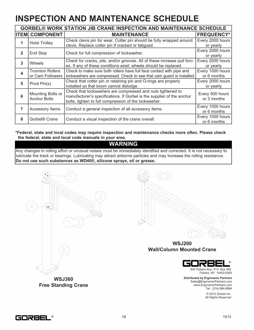
INSPECTION AND MAINTENANCE SCHEDULE
*Federal, state and local codes may require inspection and maintenance checks more often. Please checkthe federal, state and local code manuals in your area.
18 10/12
WARNINGAny.changes.in.rolling.effort.or.unusual.noises.must.be.immediately.identified.and.corrected..It.is.not.necessary.to.lubricate.the.track.or.bearings..Lubricating.may.attract.airborne.particles.and.may.increase.the.rolling.resistance...Do not use such substances as WD40®, silicone sprays, oil or grease.
WSJ360Free Standing Crane
WSJ200Wall/Column Mounted Crane
600.Fishers.Run,.P.O..Box.593 Fishers,.NY..14453-0593
Distributed by Ergonomic [email protected]
www.ErgonomicPartners.comTel: (314) 884-8884
©.2012.Gorbel.Inc.All.Rights.Reserved
®
®
GORBEL® WORK STATION JIB CRANE INSPECTION AND MAINTENANCE SCHEDULEITEM COMPONENT MAINTENANCE FREQUENCY*
1 Hoist.Trolley Check.clevis.pin.for.wear..Cotter.pin.should.be.fully.wrapped.around.clevis..Replace.cotter.pin.if.cracked.or.fatigued.
Every.2000.hours.or.yearly
2 End.Stop Check.for.full.compression.of.lockwasher. Every.2000.hours.or.yearly
3 Wheels Check.for.cracks,.pits,.and/or.grooves..All.of.these.increase.pull.forc-es..If.any.of.these.conditions.exist,.wheels.should.be.replaced.
Every.2000.hours.or.yearly
4 Trunnion.Rollers.or.Cam.Followers
Check.to.make.sure.both.rollers.have.full.face.contact.with.pipe.and.lockwashers.are.compressed..Check.to.see.that.cam.guard.is.installed.
Every.1000.hours.or.6.months
5 Pivot.Pin(s) Check.that.cotter.pin.or.retaining.pin.and.O-rings.are.properly.installed.so.that.boom.cannot.dislodge.
Every.2000.hours.or.yearly
6 Mounting.Bolts.or.Anchor.Bolts
Check.that.lockwashers.are.compressed.and.nuts.tightened.tomanufacturer’s.specifications..If.Gorbel.is.the.supplier.of.the.anchor.bolts,.tighten.to.full.compression.of.the.lockwasher.
Every.500.hours.or.3.months
7 Accessory.Items Conduct.a.general.inspection.of.all.accessory.items. Every.1000.hours.or.6.months
8 Gorbel®.Crane Conduct.a.visual.inspection.of.the.crane.overall. Every.1000.hours.or.6.months