Generating set R135 - User manual - SDMO - Rental Power
260
User and maintenance manual for generating sets R135 33501720101NE_2_1
-
Upload
khangminh22 -
Category
Documents
-
view
7 -
download
0
Transcript of Generating set R135 - User manual - SDMO - Rental Power
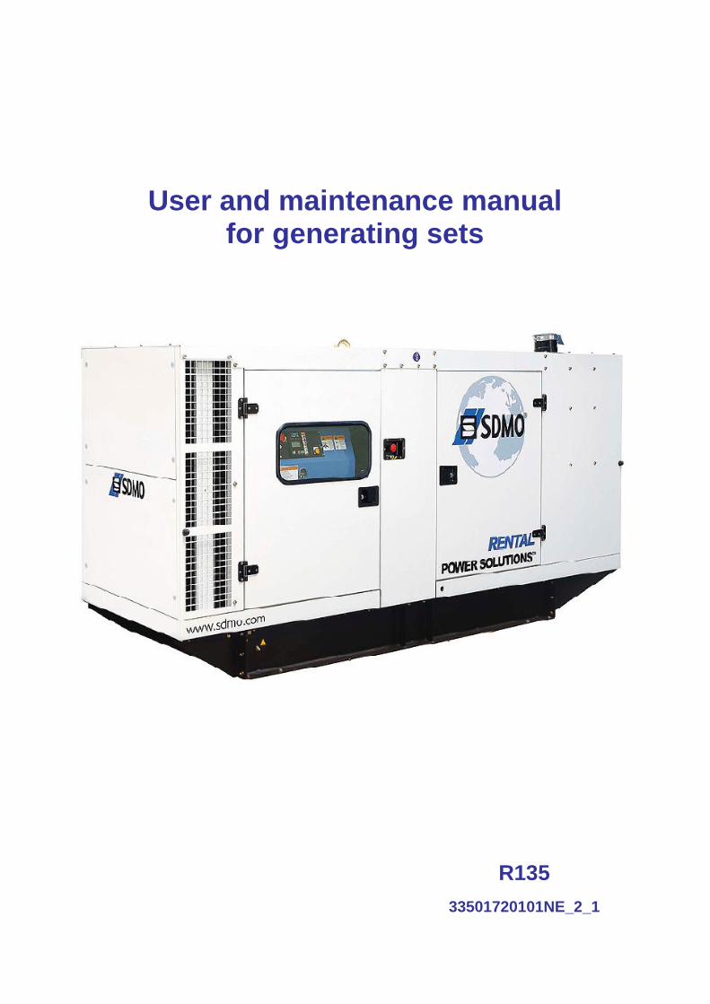
User and maintenance manual for generating sets
R135 3350174
33501720101NE_2_1

1. Preface ..................................................................................................................................................................................................3 1.1. General recommendations .......................................................................................................................................................3 1.2. Pictograms and their meanings ................................................................................................................................................4 1.3. Instructions and safety regulations ...........................................................................................................................................8
1.3.1 General advice .........................................................................................................................................................................8 1.3.2 Risks related to exhaust gases and fuels.................................................................................................................................9 1.3.3 Risks related to toxic products .................................................................................................................................................9 1.3.4 Risk of fire, burns and explosion ............................................................................................................................................10 1.3.5 Risks related to electrical networks ........................................................................................................................................10 1.3.6 Dangers presented by electric currents (first aid)...................................................................................................................11 1.3.7 Risks related to moving the set ..............................................................................................................................................11
1.4. Identifying sets .......................................................................................................................................................................12 2. General description..............................................................................................................................................................................14
2.1. Description .............................................................................................................................................................................14 2.2. Technical specifications .........................................................................................................................................................20 2.3. Fuel and consumables ...........................................................................................................................................................22
2.3.1 Specifications .........................................................................................................................................................................22 2.3.1.1. Oil grades..................................................................................................................................................................22 2.3.1.2. Specifications of coolants..........................................................................................................................................23
3. Installation............................................................................................................................................................................................25 3.1. Unloading ...............................................................................................................................................................................25
3.1.1 Safety during unloading .........................................................................................................................................................25 3.1.2 Instructions for unloading .......................................................................................................................................................25
3.1.2.1. Slings ........................................................................................................................................................................25 3.1.2.2. Fork lift truck..............................................................................................................................................................25
3.2. Fluid retention.........................................................................................................................................................................26 3.3. Choice of location...................................................................................................................................................................27 3.4. Electricity ................................................................................................................................................................................28 3.5. Special arrangements ............................................................................................................................................................29
4. Trailer...................................................................................................................................................................................................30 4.1. Trailer linkage.........................................................................................................................................................................30 4.2. Check before towing...............................................................................................................................................................30 4.3. Operation ...............................................................................................................................................................................31 4.4. Unhitching the trailer ..............................................................................................................................................................31 4.5. Implementation for installation................................................................................................................................................32 4.6. Break transmission adjustment ..............................................................................................................................................32 4.7. Faults and repairs...................................................................................................................................................................34 4.8. Electrical connection diagram.................................................................................................................................................35 4.9. Complete wheels technical information ..................................................................................................................................35
5. Preparation before operating the set ...................................................................................................................................................36 5.1. Installation checks ..................................................................................................................................................................36 5.2. Checks after starting the generating set .................................................................................................................................36
1/258
6. Using the generator set........................................................................................................................................................................36 6.1. Pre-Start Inspection................................................................................................................................................................36 6.2. Generator set with NEXYS control panel................................................................................................................................39
6.2.1 Control panel presentation .....................................................................................................................................................39 6.2.1.1. Introduction to pictograms .........................................................................................................................................40
6.2.2 Manual starting.......................................................................................................................................................................41 6.2.3 Switching off ...........................................................................................................................................................................42 6.2.4 Alarms and faults....................................................................................................................................................................42 6.2.5 Faults and alarms - Details.....................................................................................................................................................42
6.3. Generator set with TELYS control panel ................................................................................................................................45 6.3.1 Control panel presentation .....................................................................................................................................................45
6.3.1.1. View of the front panel...............................................................................................................................................45 6.3.1.2. Description of the screen...........................................................................................................................................47 6.3.1.3. Description of the pictograms in zone 1.....................................................................................................................48 6.3.1.4. Description of the pictograms in zone 2.....................................................................................................................49 6.3.1.5. Description of the pictograms in zone 3.....................................................................................................................50 6.3.1.6. Display of messages in zone 4..................................................................................................................................52
6.3.2 Starting...................................................................................................................................................................................56 6.3.3 Switching off ...........................................................................................................................................................................57 6.3.4 Alarms and faults....................................................................................................................................................................57
6.3.4.1. Viewing alarms and faults..........................................................................................................................................57 6.3.4.2. Activation of an alarm or fault ....................................................................................................................................58 6.3.4.3. Activation of an alarm and a fault ..............................................................................................................................59 6.3.4.4. Engine fault codes display.........................................................................................................................................60 6.3.4.5. Horn reset..................................................................................................................................................................61
7. Maintenance schedule .........................................................................................................................................................................62 7.1. Reminder of use .....................................................................................................................................................................62 7.2. Engine ....................................................................................................................................................................................62 7.3. Alternator ................................................................................................................................................................................62
8. Battery..................................................................................................................................................................................................63 8.1. Storage and transport .............................................................................................................................................................63 8.2. Battery setting into service......................................................................................................................................................64 8.3. Check .....................................................................................................................................................................................64 8.4. Load preconization .................................................................................................................................................................65 8.5. Faults and remedies ...............................................................................................................................................................66
9. Appendix ..............................................................................................................................................................................................67 9.1. Appendix A – Engine user and maintenance manual .............................................................................................................67 9.2. Appendix B - Alternator user and maintenance manual .......................................................................................................191 9.3. Appendix C - Common spare parts ......................................................................................................................................243 9.4. Appendix D - List of John Deere - Volvo and Perkins fault codes.........................................................................................245
2/258
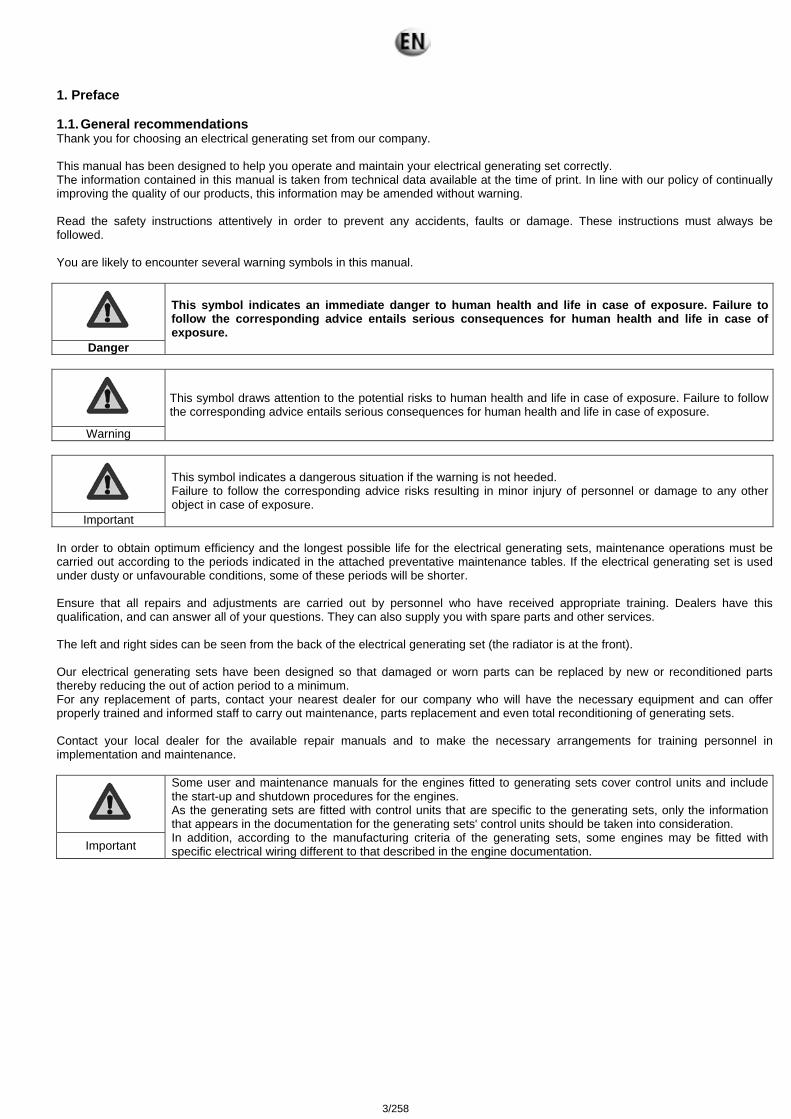
1. Preface 1.1. General recommendations Thank you for choosing an electrical generating set from our company. This manual has been designed to help you operate and maintain your electrical generating set correctly. The information contained in this manual is taken from technical data available at the time of print. In line with our policy of continually improving the quality of our products, this information may be amended without warning. Read the safety instructions attentively in order to prevent any accidents, faults or damage. These instructions must always be followed. You are likely to encounter several warning symbols in this manual.
Danger
This symbol indicates an immediate danger to human health and life in case of exposure. Failure to follow the corresponding advice entails serious consequences for human health and life in case of exposure.
Warning
This symbol draws attention to the potential risks to human health and life in case of exposure. Failure to follow the corresponding advice entails serious consequences for human health and life in case of exposure.
Important
This symbol indicates a dangerous situation if the warning is not heeded. Failure to follow the corresponding advice risks resulting in minor injury of personnel or damage to any other object in case of exposure.
In order to obtain optimum efficiency and the longest possible life for the electrical generating sets, maintenance operations must be carried out according to the periods indicated in the attached preventative maintenance tables. If the electrical generating set is used under dusty or unfavourable conditions, some of these periods will be shorter. Ensure that all repairs and adjustments are carried out by personnel who have received appropriate training. Dealers have this qualification, and can answer all of your questions. They can also supply you with spare parts and other services. The left and right sides can be seen from the back of the electrical generating set (the radiator is at the front). Our electrical generating sets have been designed so that damaged or worn parts can be replaced by new or reconditioned parts thereby reducing the out of action period to a minimum. For any replacement of parts, contact your nearest dealer for our company who will have the necessary equipment and can offer properly trained and informed staff to carry out maintenance, parts replacement and even total reconditioning of generating sets. Contact your local dealer for the available repair manuals and to make the necessary arrangements for training personnel in implementation and maintenance.
Important
Some user and maintenance manuals for the engines fitted to generating sets cover control units and include the start-up and shutdown procedures for the engines. As the generating sets are fitted with control units that are specific to the generating sets, only the information that appears in the documentation for the generating sets' control units should be taken into consideration. In addition, according to the manufacturing criteria of the generating sets, some engines may be fitted with specific electrical wiring different to that described in the engine documentation.
3/258
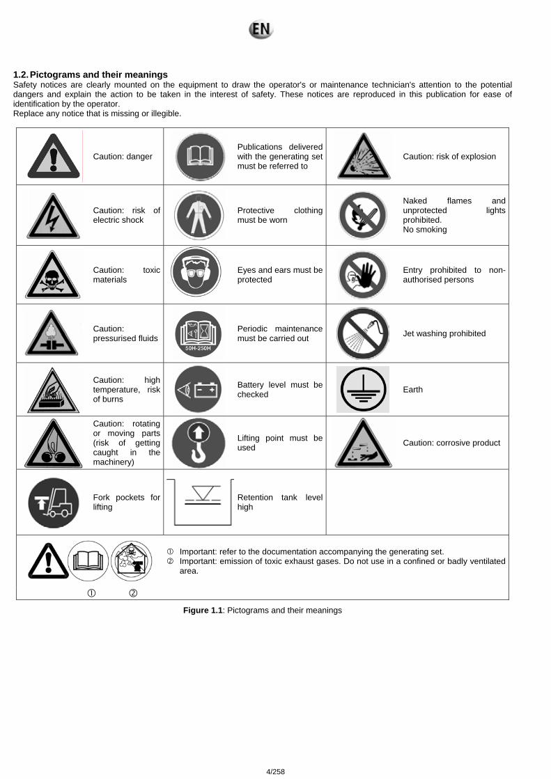
1.2. Pictograms and their meanings Safety notices are clearly mounted on the equipment to draw the operator's or maintenance technician's attention to the potential dangers and explain the action to be taken in the interest of safety. These notices are reproduced in this publication for ease of identification by the operator. Replace any notice that is missing or illegible.
Caution: danger
Publications delivered with the generating set must be referred to
Caution: risk of explosion
Caution: risk of electric shock
Protective clothing must be worn
Naked flames and unprotected lights prohibited. No smoking
Caution: toxic materials
Eyes and ears must be protected
Entry prohibited to non-authorised persons
Caution: pressurised fluids
Periodic maintenance must be carried out
Jet washing prohibited
Caution: high temperature, risk of burns
Battery level must be checked
Earth
Caution: rotating or moving parts (risk of getting caught in the machinery)
Lifting point must be used
Caution: corrosive product
Fork pockets for lifting
Retention tank level high
Important: refer to the documentation accompanying the generating set. Important: emission of toxic exhaust gases. Do not use in a confined or badly ventilated
area.
Figure 1.1: Pictograms and their meanings
4/258
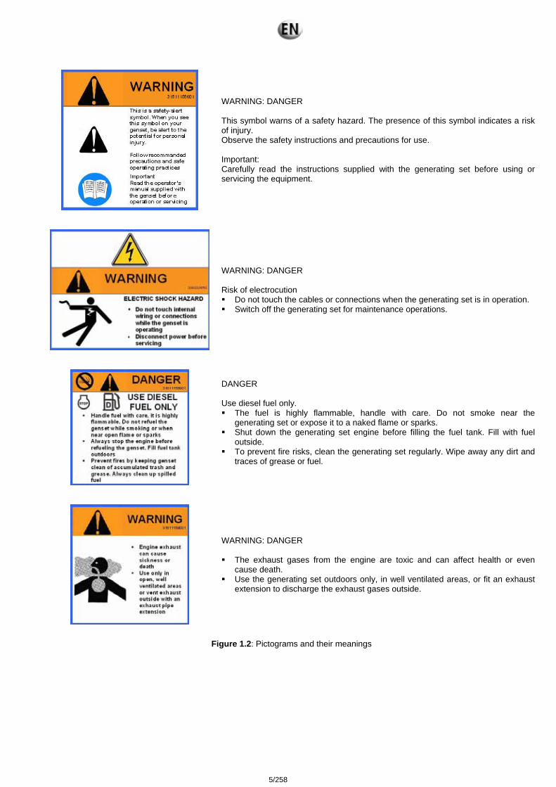
WARNING: DANGER This symbol warns of a safety hazard. The presence of this symbol indicates a risk of injury. Observe the safety instructions and precautions for use. Important: Carefully read the instructions supplied with the generating set before using or servicing the equipment.
WARNING: DANGER Risk of electrocution Do not touch the cables or connections when the generating set is in operation. Switch off the generating set for maintenance operations.
DANGER Use diesel fuel only. The fuel is highly flammable, handle with care. Do not smoke near the
generating set or expose it to a naked flame or sparks. Shut down the generating set engine before filling the fuel tank. Fill with fuel
outside. To prevent fire risks, clean the generating set regularly. Wipe away any dirt and
traces of grease or fuel.
WARNING: DANGER The exhaust gases from the engine are toxic and can affect health or even
cause death. Use the generating set outdoors only, in well ventilated areas, or fit an exhaust
extension to discharge the exhaust gases outside.
Figure 1.2: Pictograms and their meanings
5/258
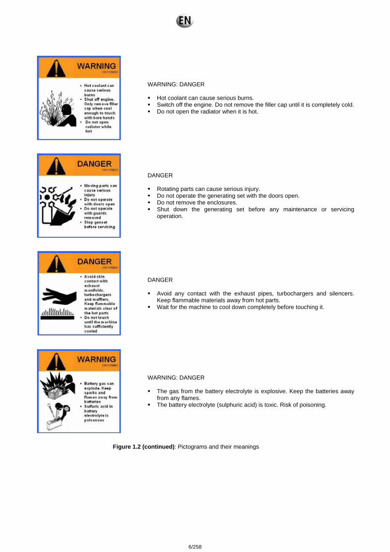
WARNING: DANGER Hot coolant can cause serious burns. Switch off the engine. Do not remove the filler cap until it is completely cold. Do not open the radiator when it is hot.
DANGER Rotating parts can cause serious injury. Do not operate the generating set with the doors open. Do not remove the enclosures. Shut down the generating set before any maintenance or servicing
operation.
DANGER Avoid any contact with the exhaust pipes, turbochargers and silencers.
Keep flammable materials away from hot parts. Wait for the machine to cool down completely before touching it.
WARNING: DANGER The gas from the battery electrolyte is explosive. Keep the batteries away
from any flames. The battery electrolyte (sulphuric acid) is toxic. Risk of poisoning.
Figure 1.2 (continued): Pictograms and their meanings
6/258
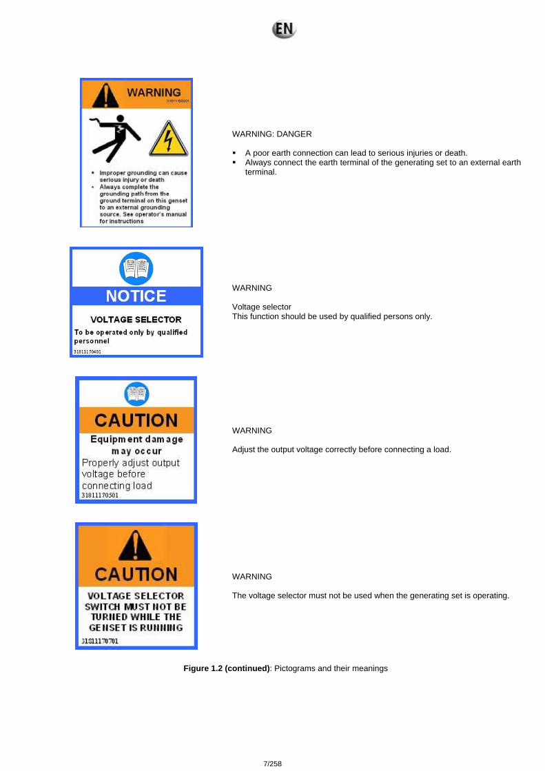
WARNING: DANGER A poor earth connection can lead to serious injuries or death. Always connect the earth terminal of the generating set to an external earth
terminal.
WARNING Voltage selector This function should be used by qualified persons only.
WARNING Adjust the output voltage correctly before connecting a load.
WARNING The voltage selector must not be used when the generating set is operating.
Figure 1.2 (continued): Pictograms and their meanings
7/258

1.3. Instructions and safety regulations
THESE SAFETY GUIDELINES ARE IMPORTANT If you do not understand or have any questions about any point in this manual, contact your dealer who will explain it to you or give you a demonstration. A list of risks and precautionary measures to take follows. You should also refer to any local and national regulations that apply in accordance with your own jurisdiction.
KEEP THIS MANUAL This manual contains important instructions which must be followed when installing or carrying out maintenance on a generating set or batteries. 1.3.1 General advice Use
The operating and safety instructions must be made known to operating personnel. They will be regularly updated. Read and understand the manuals provided with the generating set, pump unit or lighting column properly. The manufacturer's
instructions must remain at the disposal of technicians, if possible in situ. The facility must be operated under the direct or indirect supervision of a person appointed by the operator, who is familiar with the
operation of the facility, and the dangers and drawbacks of the products used or stored in the facility. Do not wear loose clothing, or get close to machines in operation. Note that the fans are not clearly visible when the engine is
running. Warn personnel present to keep their distance during operation. Do not run the generating set, pump unit or lighting column without refitting the protective covers and closing all the access doors. Never let a child touch the generating set, pump unit or lighting column, even when shut down. Avoid operating the generating set, pump unit or lighting tower in the presence of animals (disturbance, scares, etc.). Engage the parking brake when the generating set or lighting tower on its trailer is installed on the operating site. When chocking
the trailer on a slope; ensure that there is nobody in the path of the trailer. Never start the engine without an air filter or exhaust. Engine with turbocharger: never start the engine without fitting the air filter. The compressor wheel rotating inside the turbocharger
may cause serious bodily injury. Foreign objects in the inlet pipe may cause mechanical damage. Engine with air preheating (starting components): never use a starting spray or any other similar starter assistance product. Upon
contact with the starting component, an explosion may occur in the inlet tube, causing bodily injury. Do not touch the lighting column lights when they are switched on.
Maintenance
Follow the maintenance table and its instructions. Always use tools in good condition which are suited to the work to be done. Ensure you have understood the instructions before
beginning any operation. Goggles should be worn when carrying out maintenance operations and watches, bracelets etc. should be removed. Fit only original parts. Disconnect the battery and the pneumatic starter (if fitted) before undertaking any repairs, to prevent the engine from starting
accidentally. Fit a panel over the controls to prevent any attempt to start. Only use the correct crankshaft turning techniques for turning the crankshaft manually. Do not try to turn the crankshaft by pulling it
or levering the fan. This method may cause serious bodily or material damage, or damage the vanes of the fan, reducing the service life of the fan.
Clean off any trace of oil, fuel or coolant using a clean cloth. Do not use a soapy solution containing either chlorine or ammonia, as these two chemicals prevent bubble formation. Never use petrol or other inflammable substances to clean the parts. Use only approved cleaning solvents. Do not use a high pressure cleaner for cleaning the engine and equipment. The radiator, hoses, electrical components, etc. may
be damaged. Avoid accidental contact with parts at high temperatures (exhaust manifold, exhaust). Before any maintenance operation on a lighting column light, cut the electrical power supply and wait for the bulbs to cool down.
Consumables
Observe regulations in force concerning use of fuel before using your generating set, pump unit or lighting tower. Under no circumstances use seawater or any other corrosive or electrolytic product in the cooling circuit.
Environment
The operator must take the necessary measures to comply with the aesthetics of the site of use. The whole site must be maintained in a good state of cleanliness.
The premises must be kept clean, and be regularly cleaned so as to avoid accumulation of dangerous materials or pollutants and dust, which could ignite or cause an explosion. The cleaning equipment must be suited to the risks posed by the products and dust.
The presence of dangerous or combustible materials inside premises housing combustion devices shall be limited to the operating requirements.
8/258
Facilities must be operated under the constant supervision of a qualified person, who must regularly check that the safety devices are operating correctly and ensure that the combustion devices have the correct fuel supply.
Apart from the combustion devices, it is prohibited to use fire in any form. This restriction must be clearly displayed. Spreading of waste water, sludge and waste is prohibited. The fuels to be used must correspond to those featured in the declaration file and the specifications recommended by the
combustion device manufacturer. The fuel is considered to remain in the same physical state as when it is introduced into the combustion chamber. Burning of waste in the open air is prohibited. Always protect your hands when checking for leaks. Pressurised liquids may penetrate body tissue and cause serious damage.
Risk of blood contamination. Drain and dispose of engine oil in a specially provided container (fuel distributors can collect your used oil). Except by special agreement, once closed, the gas supply main unit must only be re-opened by the gas distributor. However, the
user may access it under certain conditions. Check these for each site. 1.3.2 Risks related to exhaust gases and fuels
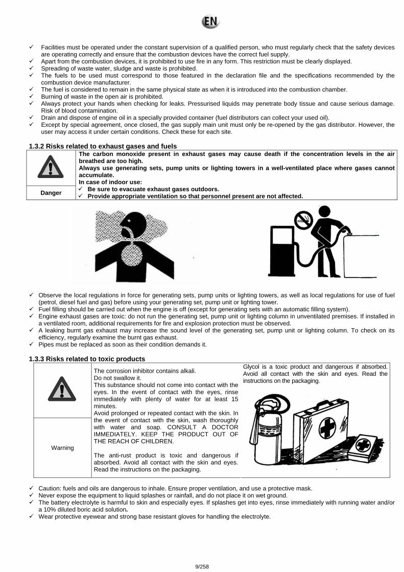
Danger
The carbon monoxide present in exhaust gases may cause death if the concentration levels in the air breathed are too high. Always use generating sets, pump units or lighting towers in a well-ventilated place where gases cannot accumulate. In case of indoor use:
Be sure to evacuate exhaust gases outdoors. Provide appropriate ventilation so that personnel present are not affected.
Observe the local regulations in force for generating sets, pump units or lighting towers, as well as local regulations for use of fuel
(petrol, diesel fuel and gas) before using your generating set, pump unit or lighting tower. Fuel filling should be carried out when the engine is off (except for generating sets with an automatic filling system). Engine exhaust gases are toxic: do not run the generating set, pump unit or lighting column in unventilated premises. If installed in
a ventilated room, additional requirements for fire and explosion protection must be observed. A leaking burnt gas exhaust may increase the sound level of the generating set, pump unit or lighting column. To check on its
efficiency, regularly examine the burnt gas exhaust. Pipes must be replaced as soon as their condition demands it.
1.3.3 Risks related to toxic products
Warning
The corrosion inhibitor contains alkali. Do not swallow it. This substance should not come into contact with the eyes. In the event of contact with the eyes, rinse immediately with plenty of water for at least 15 minutes. Avoid prolonged or repeated contact with the skin. In the event of contact with the skin, wash thoroughly with water and soap. CONSULT A DOCTOR IMMEDIATELY. KEEP THE PRODUCT OUT OF THE REACH OF CHILDREN. The anti-rust product is toxic and dangerous if absorbed. Avoid all contact with the skin and eyes. Read the instructions on the packaging.
Glycol is a toxic product and dangerous if absorbed. Avoid all contact with the skin and eyes. Read the instructions on the packaging.
Caution: fuels and oils are dangerous to inhale. Ensure proper ventilation, and use a protective mask. Never expose the equipment to liquid splashes or rainfall, and do not place it on wet ground. The battery electrolyte is harmful to skin and especially eyes. If splashes get into eyes, rinse immediately with running water and/or
a 10% diluted boric acid solution. Wear protective eyewear and strong base resistant gloves for handling the electrolyte.
9/258
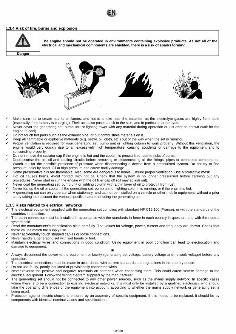
1.3.4 Risk of fire, burns and explosion
Danger
The engine should not be operated in environments containing explosive products. As not all of the electrical and mechanical components are shielded, there is a risk of sparks forming.
Make sure not to create sparks or flames, and not to smoke near the batteries, as the electrolyte gases are highly flammable
(especially if the battery is charging). Their acid also poses a risk to the skin, and in particular to the eyes. Never cover the generating set, pump unit or lighting tower with any material during operation or just after shutdown (wait for the
engine to cool). Do not touch hot parts such as the exhaust pipe, or put combustible materials on it. Keep all flammable or explosive materials (e.g. petrol, oil, cloth, etc.) out of the way when the set is running. Proper ventilation is required for your generating set, pump unit or lighting column to work properly. Without this ventilation, the
engine would very quickly rise to an excessively high temperature, causing accidents or damage to the equipment and to surrounding property.
Do not remove the radiator cap if the engine is hot and the coolant is pressurised, due to risks of burns. Depressurise the air, oil and cooling circuits before removing or disconnecting all the fittings, pipes or connected components.
Watch out for the possible presence of pressure when disconnecting a device from a pressurised system. Do not try to find pressure leaks by hand. Oil at high pressure can cause bodily damage.
Some preservative oils are flammable. Also, some are dangerous to inhale. Ensure proper ventilation. Use a protective mask. Hot oil causes burns. Avoid contact with hot oil. Check that the system is no longer pressurised before carrying out any
procedures. Never start or run the engine with the oil filler cap off (oil may splash out). Never coat the generating set, pump unit or lighting column with a thin layer of oil to protect it from rust. Never top up the oil or coolant if the generating set, pump unit or lighting column is running, or if the engine is hot. A generating set can only operate when stationary, and cannot be installed on a vehicle or other mobile equipment, without a prior
study taking into account the various specific features of using the generating set. 1.3.5 Risks related to electrical networks
The electrical equipment supplied with the generating set complies with standard NF C15.100 (France), or with the standards of the countries in question.
The earth connection must be installed in accordance with the standards in force in each country in question, and with the neutral system sold.
Read the manufacturer's identification plate carefully. The values for voltage, power, current and frequency are shown. Check that these values match the supply use.
Never accidentally touch stripped cables or loose connections. Never handle a generating set with wet hands or feet. Maintain electrical wires and connections in good condition. Using equipment in poor condition can lead to electrocution and
damage to equipment.
Always disconnect the power to the equipment or facility (generating set voltage, battery voltage and network voltage) before any operation.
The electrical connections must be made in accordance with current standards and regulations in the country of use. Do not use faulty, poorly insulated or provisionally connected wires. Never reverse the positive and negative terminals on batteries when connecting them. This could cause severe damage to the
electrical equipment. Follow the wiring diagram supplied by the manufacturer. The generating set should not be connected to any other power sources, such as the mains supply network. In specific cases
where there is to be a connection to existing electrical networks, this must only be installed by a qualified electrician, who should take the operating differences of the equipment into account, according to whether the mains supply network or generating set is being used.
Protection against electric shocks is ensured by an assembly of specific equipment. If this needs to be replaced, it should be by components with identical nominal values and specifications.
10/258
If the protective plates (blanking covers) need to be removed to route cables, the protector (blanking cover) must be refitted when the operations are finished.
Due to high mechanical stresses, use only strong flexible wiring with rubber sheathing, compliant with IEC 245-4, or equivalent wiring.
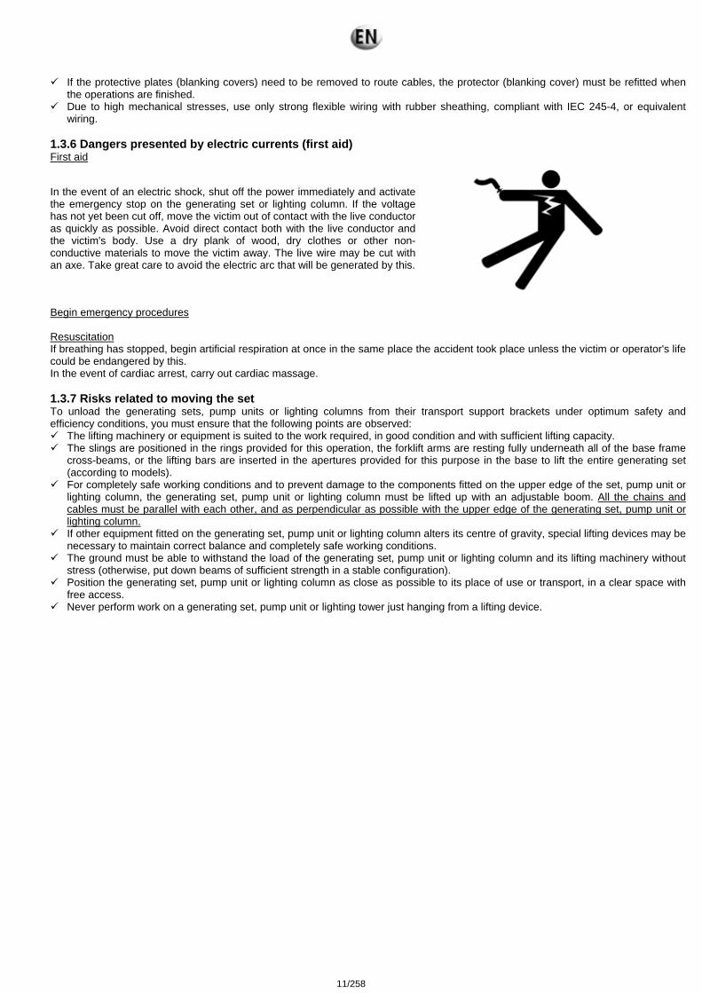
1.3.6 Dangers presented by electric currents (first aid) First aid
In the event of an electric shock, shut off the power immediately and activate the emergency stop on the generating set or lighting column. If the voltage has not yet been cut off, move the victim out of contact with the live conductor as quickly as possible. Avoid direct contact both with the live conductor and the victim's body. Use a dry plank of wood, dry clothes or other non-conductive materials to move the victim away. The live wire may be cut with an axe. Take great care to avoid the electric arc that will be generated by this.
Begin emergency procedures Resuscitation If breathing has stopped, begin artificial respiration at once in the same place the accident took place unless the victim or operator's life could be endangered by this. In the event of cardiac arrest, carry out cardiac massage. 1.3.7 Risks related to moving the set To unload the generating sets, pump units or lighting columns from their transport support brackets under optimum safety and efficiency conditions, you must ensure that the following points are observed:
The lifting machinery or equipment is suited to the work required, in good condition and with sufficient lifting capacity. The slings are positioned in the rings provided for this operation, the forklift arms are resting fully underneath all of the base frame
cross-beams, or the lifting bars are inserted in the apertures provided for this purpose in the base to lift the entire generating set (according to models).
For completely safe working conditions and to prevent damage to the components fitted on the upper edge of the set, pump unit or lighting column, the generating set, pump unit or lighting column must be lifted up with an adjustable boom. All the chains and cables must be parallel with each other, and as perpendicular as possible with the upper edge of the generating set, pump unit or lighting column.
If other equipment fitted on the generating set, pump unit or lighting column alters its centre of gravity, special lifting devices may be necessary to maintain correct balance and completely safe working conditions.
The ground must be able to withstand the load of the generating set, pump unit or lighting column and its lifting machinery without stress (otherwise, put down beams of sufficient strength in a stable configuration).
Position the generating set, pump unit or lighting column as close as possible to its place of use or transport, in a clear space with free access.
Never perform work on a generating set, pump unit or lighting tower just hanging from a lifting device.
11/258
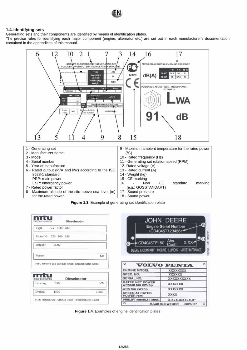
1.4. Identifying sets Generating sets and their components are identified by means of identification plates. The precise rules for identifying each major component (engine, alternator etc.) are set out in each manufacturer's documentation contained in the appendices of this manual.
1 - Generating set 2 - Manufacturer name 3 - Model 4 - Serial number 5 - Year of manufacture 6 - Rated output (kVA and kW) according to the ISO
8528-1 standard PRP: main power ESP: emergency power
7 - Rated power factor 8 - Maximum altitude of the site above sea level (m)
for the rated power
9 - Maximum ambient temperature for the rated power (°C)
10 - Rated frequency (Hz) 11 - Generating set rotation speed (RPM) 12- Rated voltage (V) 13 - Rated current (A) 14 - Weight (kg) 15 - CE marking 16 - Non CE standard marking
(e.g.: GOSSTANDART) 17 - Sound pressure 18 - Sound power
Figure 1.3: Example of generating set identification plate
Figure 1.4: Examples of engine identification plates
12/258
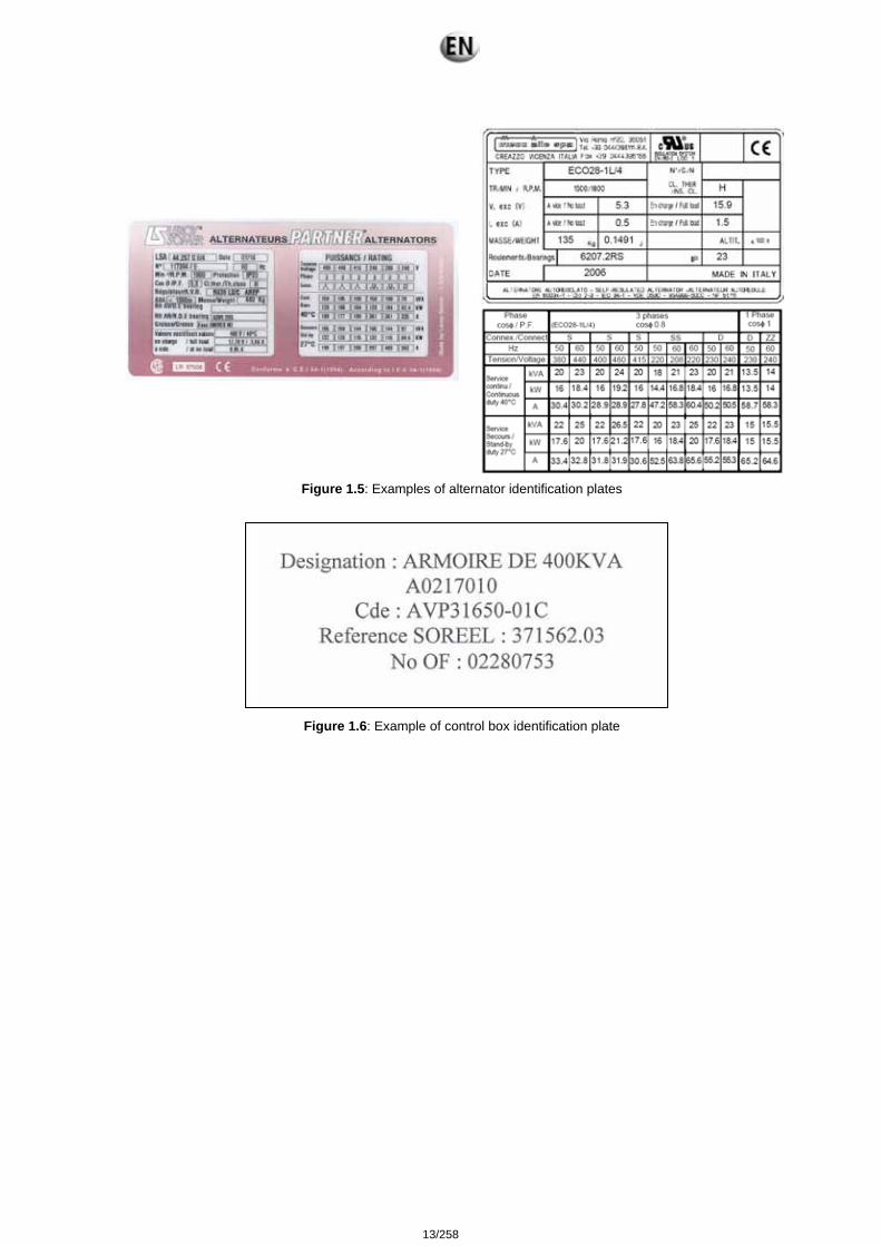
Figure 1.5: Examples of alternator identification plates
Control box
Figure 1.6: Example of control box identification plate
13/258
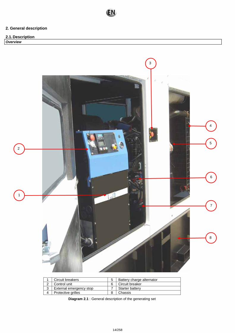
2. General description 2.1. Description Overview
1 Circuit breakers 5 Battery charge alternator 2 Control unit 6 Circuit breaker 3 External emergency stop 7 Starter battery 4 Protective grilles 8 Chassis
Diagram 2.1 : General description of the generating set
2
3
1
4
5
6
7
8
14/258
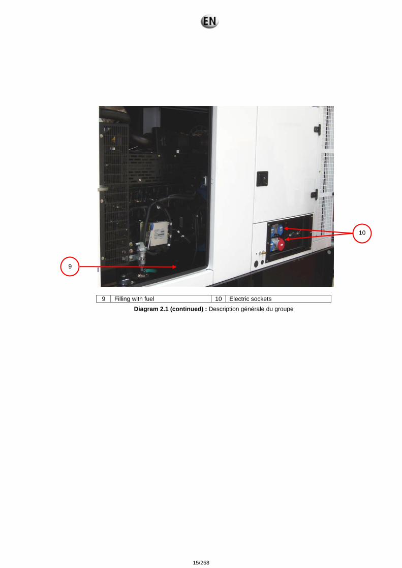
Diagram 2.1 (continued) : Description générale du groupe
9 Filling with fuel 10 Electric sockets
9
10
15/258
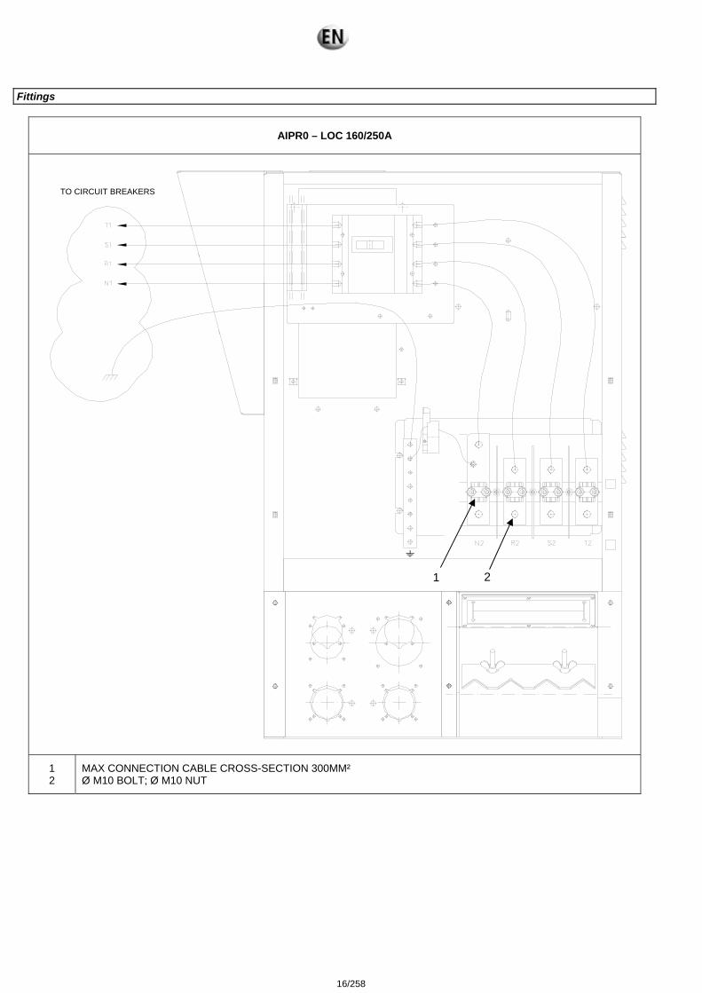
Fittings
AIPR0 – LOC 160/250A
1 2
MAX CONNECTION CABLE CROSS-SECTION 300MM² Ø M10 BOLT; Ø M10 NUT
1 2
TO CIRCUIT BREAKERS
16/258
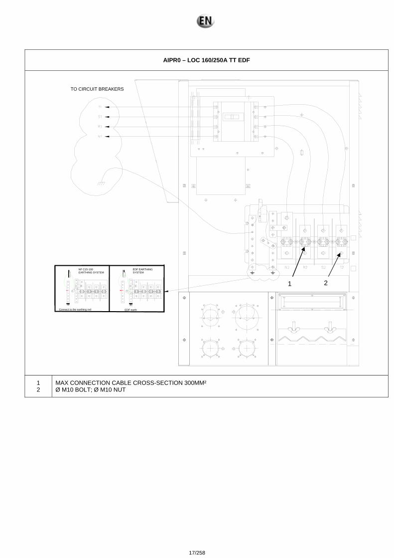
AIPR0 – LOC 160/250A TT EDF
1 2
MAX CONNECTION CABLE CROSS-SECTION 300MM² Ø M10 BOLT; Ø M10 NUT
NF C15-100 EARTHING SYSTEM
EDF EARTHING SYSTEM
Connect to the earthing rod EDF earth
1 2
TO CIRCUIT BREAKERS
17/258
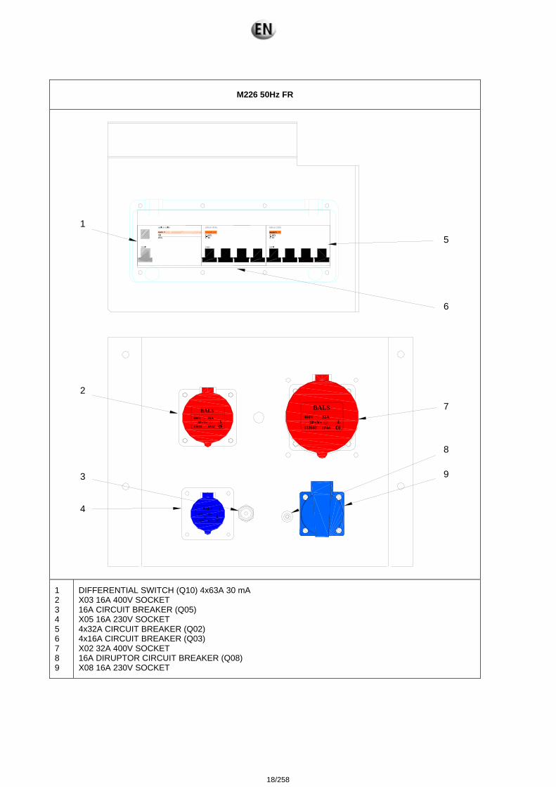
M226 50Hz FR
3
4
7
5
98
2
6
1
400V
1320023P+N+
IP44
BALS32A
230V
136682P+
IP67
BALS16A
400V
136813P+N+
IP44
BALS16A
1 2 3 4 5 6 7 8 9
DIFFERENTIAL SWITCH (Q10) 4x63A 30 mA X03 16A 400V SOCKET 16A CIRCUIT BREAKER (Q05) X05 16A 230V SOCKET 4x32A CIRCUIT BREAKER (Q02) 4x16A CIRCUIT BREAKER (Q03) X02 32A 400V SOCKET 16A DIRUPTOR CIRCUIT BREAKER (Q08) X08 16A 230V SOCKET
1
2
3
4
5
6
7 8
9
18/258
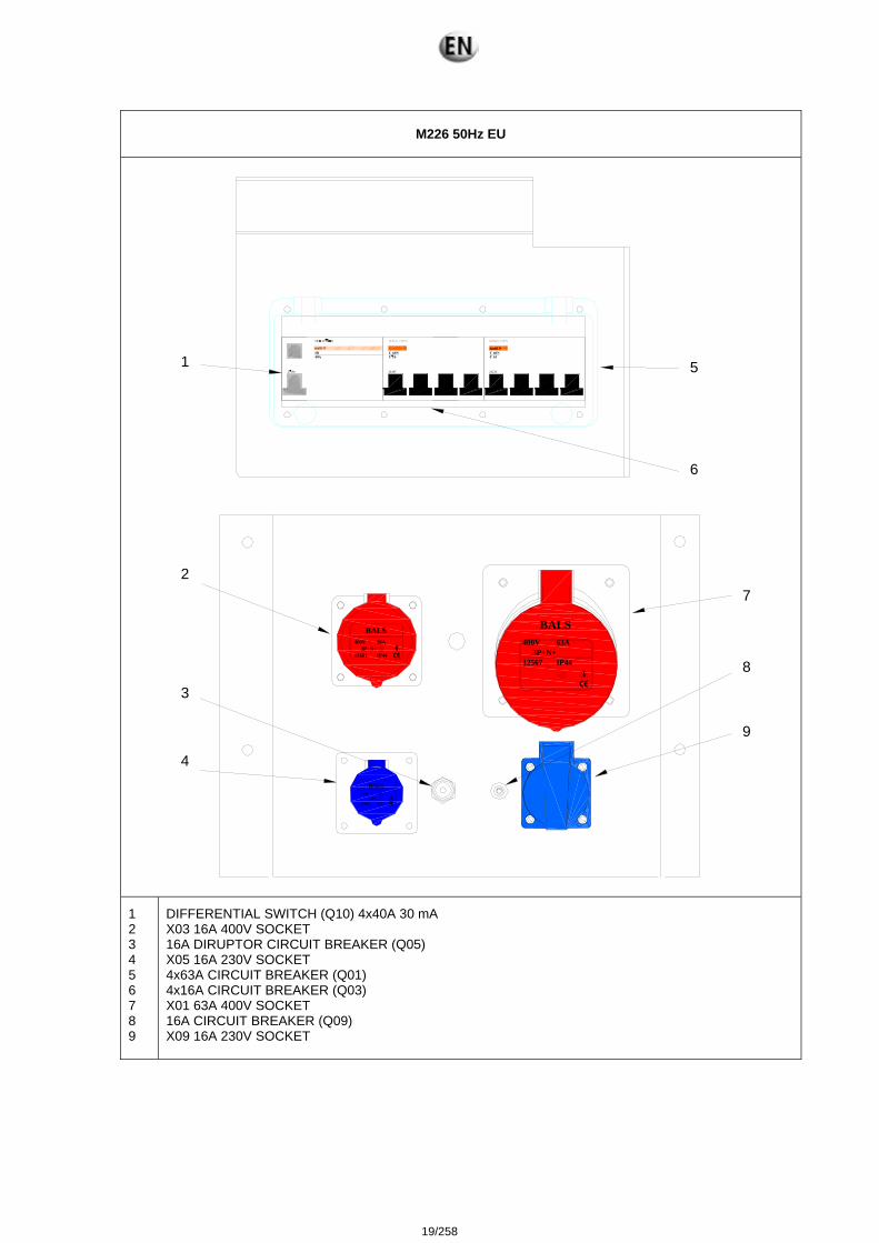
M226 50Hz EU
230V
136682P+
IP67
BALS16A
3
4
7
5
9
8
2
6
1
400V
125673P+N+
IP44
BALS63A400V
136813P+N+
IP44
BALS16A
1 2 3 4 5 6 7 8 9
DIFFERENTIAL SWITCH (Q10) 4x40A 30 mA X03 16A 400V SOCKET 16A DIRUPTOR CIRCUIT BREAKER (Q05) X05 16A 230V SOCKET 4x63A CIRCUIT BREAKER (Q01) 4x16A CIRCUIT BREAKER (Q03) X01 63A 400V SOCKET 16A CIRCUIT BREAKER (Q09) X09 16A 230V SOCKET
1
2
3
4
5 6
7
8 9
19/258
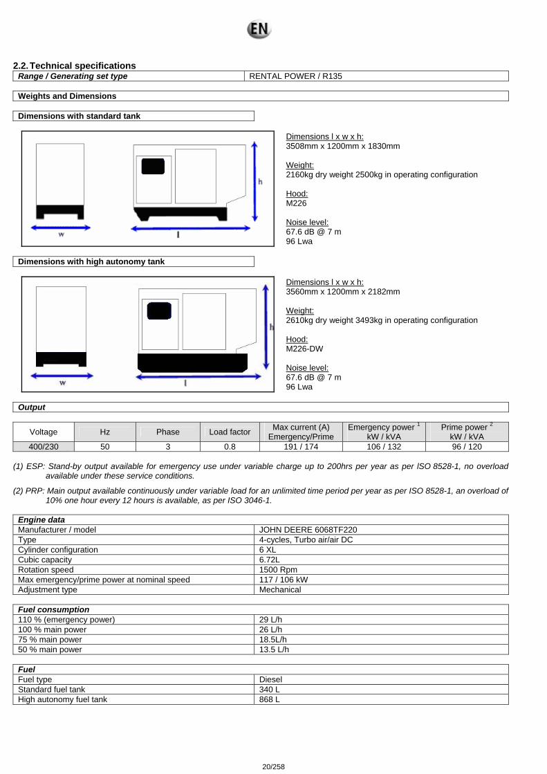
2.2. Technical specifications Range / Generating set type RENTAL POWER / R135
Weights and Dimensions
Dimensions with standard tank
Dimensions l x w x h:
3508mm x 1200mm x 1830mm Weight: 2160kg dry weight 2500kg in operating configuration Hood: M226 Noise level: 67.6 dB @ 7 m 96 Lwa
Dimensions with high autonomy tank
Dimensions l x w x h:
3560mm x 1200mm x 2182mm Weight: 2610kg dry weight 3493kg in operating configuration Hood: M226-DW Noise level: 67.6 dB @ 7 m 96 Lwa
Output
Voltage Hz Phase Load factor Max current (A) Emergency/Prime
Emergency power 1
kW / kVA Prime power 2
kW / kVA 400/230 50 3 0.8 191 / 174 106 / 132 96 / 120
(1) ESP: Stand-by output available for emergency use under variable charge up to 200hrs per year as per lSO 8528-1, no overload
available under these service conditions.
(2) PRP: Main output available continuously under variable load for an unlimited time period per year as per ISO 8528-1, an overload of 10% one hour every 12 hours is available, as per ISO 3046-1.
Engine data Manufacturer / model JOHN DEERE 6068TF220 Type 4-cycles, Turbo air/air DC Cylinder configuration 6 XL Cubic capacity 6.72L Rotation speed 1500 Rpm Max emergency/prime power at nominal speed 117 / 106 kW Adjustment type Mechanical
Fuel consumption 110 % (emergency power) 29 L/h 100 % main power 26 L/h 75 % main power 18.5L/h 50 % main power 13.5 L/h
Fuel Fuel type Diesel Standard fuel tank 340 L High autonomy fuel tank 868 L
20/258
Lubrication Oil capacity with filter 21.5L Min. Oil pressure 1 bar Nominal oil pressure 5 bar Oil consumption (100 % load) 0.029 L/h Oil sump capacity 20.6 L Type of lubricant Genlub
Cooling Engine capacity with radiator 27.3L Max coolant temperature 105 °C Fan power 3 kW Ventilator air flow 4.4 m3/s Refrigerant type Gencool Thermostat 82-94 °C
Emissions HC 42 mg/Nm3 CO 140 mg/Nm3 NoX 3500 mg/Nm3 PM 60 mg/Nm3
Alternator data Compliant with NEMA MG21 standards, UTE NF C51.111,
VDE 0530, BS 4999, IEC 34.1, CSA The alternator is protected against short circuits Vacuum impregnation, epoxy winding, IP23 protection rating
Type LEROY SOMER LSA442S7 Number of phases 3 Power factor (cos Phi) 0.8 Number of poles 4 Excitation type AREP Voltage regulator R438 Short-circuit current 3 IN Number of bearings 1 Coupling Direct
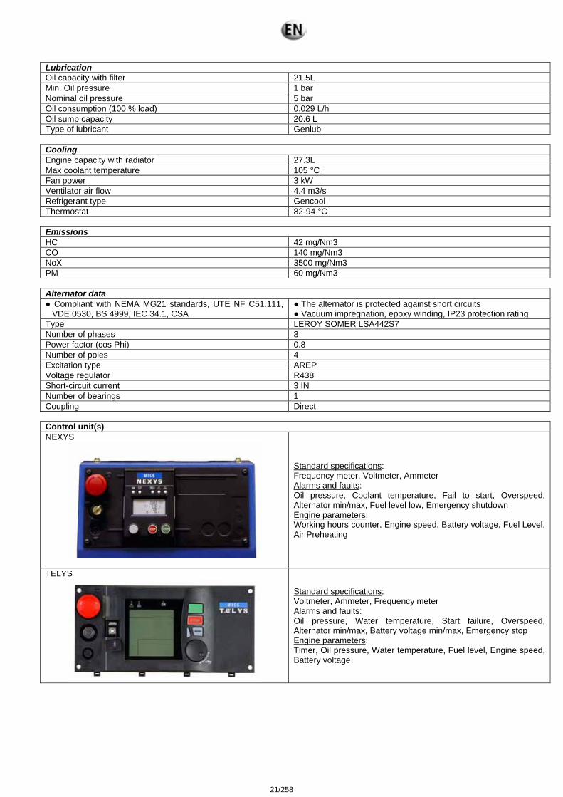
Control unit(s) NEXYS
Standard specifications: Frequency meter, Voltmeter, Ammeter Alarms and faults: Oil pressure, Coolant temperature, Fail to start, Overspeed, Alternator min/max, Fuel level low, Emergency shutdown Engine parameters: Working hours counter, Engine speed, Battery voltage, Fuel Level, Air Preheating
TELYS
Standard specifications: Voltmeter, Ammeter, Frequency meter Alarms and faults: Oil pressure, Water temperature, Start failure, Overspeed, Alternator min/max, Battery voltage min/max, Emergency stop Engine parameters: Timer, Oil pressure, Water temperature, Fuel level, Engine speed, Battery voltage
21/258
2.3. Fuel and consumables All specifications (product features) are given in the motor and alternator maintenance manuals attached to this manual. In addition, we recommend the consumables to be used in the "specifications" section. 2.3.1 Specifications 2.3.1.1. Oil grades
Engine Oil Make Type Make Type
John Deere John Deere PLUS-50 John Deere All GenPARTS GENLUB TDX 15W40 MITSUBISHI All GenPARTS GENLUB TDX 15W40
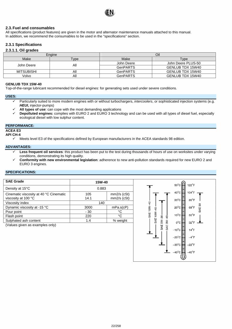
Volvo All GenPARTS GENLUB TDX 15W40 GENLUB TDX 15W-40 Top-of-the-range lubricant recommended for diesel engines: for generating sets used under severe conditions. USES:
Particularly suited to more modern engines with or without turbochargers, intercoolers, or sophisticated injection systems (e.g. HEUI, injector-pumps)
All types of use: can cope with the most demanding applications Depolluted engines: complies with EURO 2 and EURO 3 technology and can be used with all types of diesel fuel, especially
ecological diesel with low sulphur content. PERFORMANCE: ACEA E3 API CH-4
Meets level E3 of the specifications defined by European manufacturers in the ACEA standards 98 edition. ADVANTAGES:
Less frequent oil services: this product has been put to the test during thousands of hours of use on worksites under varying conditions, demonstrating its high quality.
Conformity with new environmental legislation: adherence to new anti-pollution standards required for new EURO 2 and EURO 3 engines.
SPECIFICATIONS: SAE Grade 15W-40
Density at 15°C 0.883 Cinematic viscosity at 40 °C Cinematic viscosity at 100 °C
105 14.1
mm2/s (cSt) mm2/s (cSt)
Viscosity index 140 Dynamic viscosity at -15 °C 3000 mPa.s(cP) Pour point - 30 °C Flash point 220 °C Sulphated ash content 1.4 % weight (Values given as examples only)
22/258
2.3.1.2. Specifications of coolants Engine Coolants
Make Type Make Type John Deere All GenPARTS GENCOOL PC -26°C
Mitsubishi LLC MITSUBISHI All GenPARTS GENCOOL PC -26°C Volvo All GenPARTS GENCOOL PC -26°C
GenCOOL PC -26 High-protection coolant, approved by manufacturers. GenCOOL PC -26 is a ready-to-use, highly protective coolant which is produced from an antifreeze recommended by the majority of European manufacturers. It is made from antifreeze and G 48 inhibitors. It protects up to -26°C. It is free from nitrates, amines and phosphates. It is a clear, fluorescent orange liquid.
REFERENCES/APPROVALS (for the antifreeze):
HEAVY GOODS VEHICLE LIGHTER VEHICLES Approved by MTU, MERCEDES BENZ, MAN, KHD, GENERAL MOTORS Conforms with VOLVO, IVECO, VAN HOOL and STAYR TRUCK specifications
Approved by BMW, VOLKSWAGEN, MERCEDES, PORSCHE Conforms with VOLVO, OPEL, SEAT and SKODA specifications
Conforms with the NF R 15.601 standard REINFORCED ANTI-CORROSION FEATURES:
Protects against high-temperature corrosion by oxidisation of ethylene (cylinder head protection). Protects against high-temperature cavitation (top of cylinder and coolant pump protection) Non-corrosive for seals and hoses. Improves the efficiency and longevity of the cooling system. GenCOOL PC -26 is especially recommended for engines fitted with aluminium or light alloy radiators.
HIGH TEMPERATURE SUITABILITY:
Provides good conditions for thermal exchange. Perfect stability at high temperatures. GenCOOL PC -26 is specially adapted for engines with high power densities.
LONG LASTING PROTECTION:
High alkaline reserve/stability and longevity of corrosion inhibitors Maintains its technical properties during prolonged use at high temperatures (neutralisation of acids). Ensures maximum heat transfer without the build up of deposits in the cooling system GenCOOL PC -26 ensures optimum protection against overheating and corrosion in extreme conditions of vehicle use.
23/258
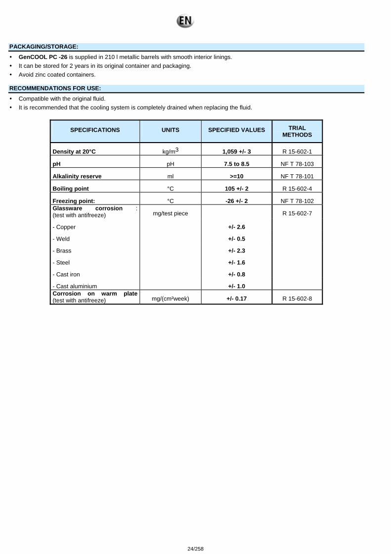
PACKAGING/STORAGE:
GenCOOL PC -26 is supplied in 210 l metallic barrels with smooth interior linings. It can be stored for 2 years in its original container and packaging. Avoid zinc coated containers.
RECOMMENDATIONS FOR USE:
Compatible with the original fluid. It is recommended that the cooling system is completely drained when replacing the fluid.
SPECIFICATIONS UNITS SPECIFIED VALUES TRIAL METHODS
Density at 20°C kg/m3 1,059 +/- 3 R 15-602-1
pH pH 7.5 to 8.5 NF T 78-103
Alkalinity reserve ml >=10 NF T 78-101
Boiling point °C 105 +/- 2 R 15-602-4
Freezing point: °C -26 +/- 2 NF T 78-102 Glassware corrosion : (test with antifreeze) mg/test piece R 15-602-7
- Copper +/- 2.6
- Weld +/- 0.5
- Brass +/- 2.3
- Steel +/- 1.6
- Cast iron +/- 0.8
- Cast aluminium +/- 1.0 Corrosion on warm plate (test with antifreeze) mg/(cm²week) +/- 0.17 R 15-602-8
24/258
3. Installation 3.1. Unloading 3.1.1 Safety during unloading To unload electrical generating sets from their transport supports under optimum safety and efficiency conditions, you need to ensure
that the following points are observed: - Lifting machinery or equipment appropriate to the work required. - Slings positioned in the eyes provided for this operation or lifting arms resting fully underneath the chassis cross members. - Ground able to take the load of the set and the lifting machinery without stress (otherwise lay down beams of sufficient strength and
stability). - Set put down as close as possible to its point of use or transportation, in a clear area with free access. Example of equipment to be used:
crane, slings, cross bar, safety catch, shackles. Fork lift truck.
3.1.2 Instructions for unloading 3.1.2.1. Slings
Attach the lifting vehicle slings to the rings on the generating set designed for this procedure. Hang the slings carefully. Check that the slings are correctly attached and the equipment is solid. Lift the generating set carefully. Direct and stabilise the set towards the chosen position. Carefully set down the equipment while continuing to position it. Release the slings, then detach and remove the lifting rings.
3.1.2.2. Fork lift truck
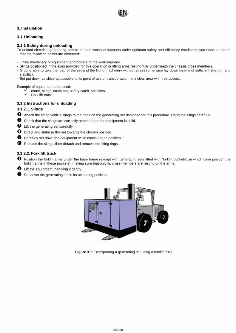
Position the forklift arms under the base frame (except with generating sets fitted with "forklift pockets", in which case position the forklift arms in these pockets), making sure that only its cross-members are resting on the arms.
Lift the equipment, handling it gently. Set down the generating set in its unloading position.
Figure 3.1: Transporting a generating set using a forklift truck
25/258

3.2. Fluid retention Any outflow of the fluids contained in the generating sets (fuel, oil and coolant, or rainwater or condensation) will be collected in a retention container if the generating set is fitted with this option. The containers have a capacity which allows 110% of the fluids contained in the generating set fitted with this option to be collected. Three different fittings are available.
Diagram 3.2: Fluid retention container integrated into the tank chassis.
Diagram 3.3: Offset fluid retention container underneath the generating set chassis.
26/258
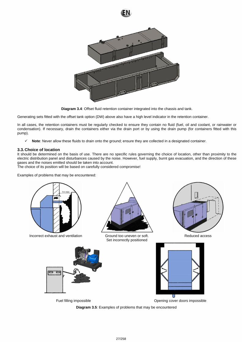
Diagram 3.4: Offset fluid retention container integrated into the chassis and tank.
Generating sets fitted with the offset tank option (DW) above also have a high level indicator in the retention container. In all cases, the retention containers must be regularly checked to ensure they contain no fluid (fuel, oil and coolant, or rainwater or condensation). If necessary, drain the containers either via the drain port or by using the drain pump (for containers fitted with this pump).
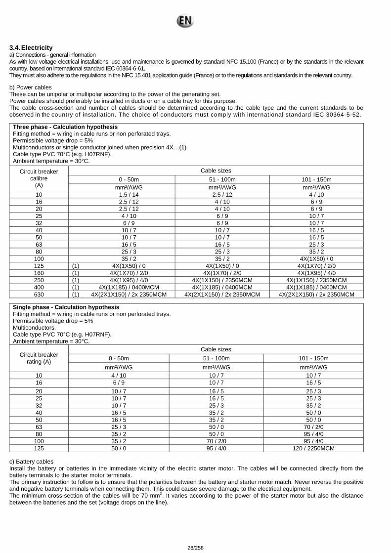
Note: Never allow these fluids to drain onto the ground; ensure they are collected in a designated container. 3.3. Choice of location It should be determined on the basis of use. There are no specific rules governing the choice of location, other than proximity to the electric distribution panel and disturbances caused by the noise. However, fuel supply, burnt gas evacuation, and the direction of these gases and the noises emitted should be taken into account. The choice of its position will be based on carefully considered compromise! Examples of problems that may be encountered:
Incorrect exhaust and ventilation Ground too uneven or soft.
Set incorrectly positioned Reduced access
Fuel filling impossible Opening cover doors impossible
Diagram 3.5: Examples of problems that may be encountered
27/258
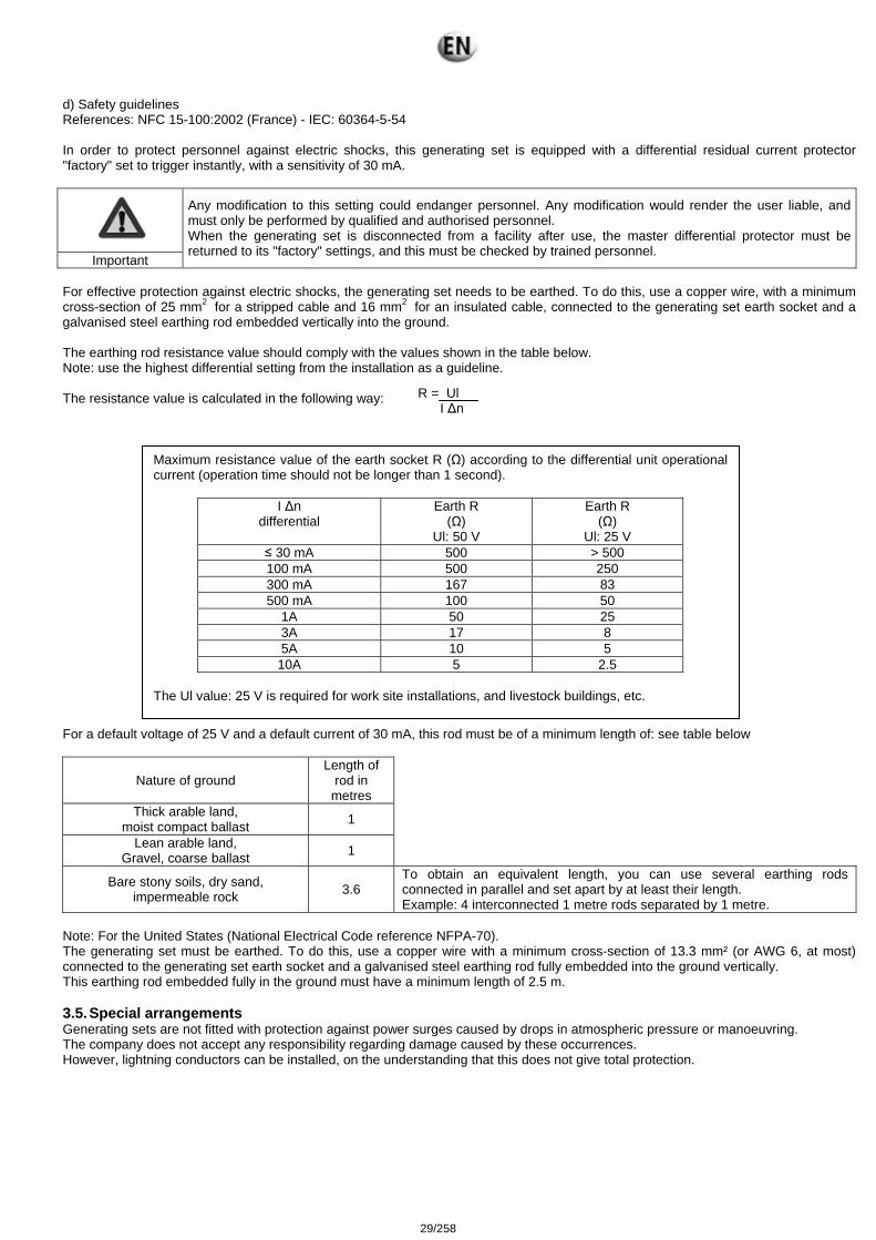
3.4. Electricity a) Connections - general information As with low voltage electrical installations, use and maintenance is governed by standard NFC 15.100 (France) or by the standards in the relevant country, based on international standard IEC 60364-6-61. They must also adhere to the regulations in the NFC 15.401 application guide (France) or to the regulations and standards in the relevant country. b) Power cables These can be unipolar or multipolar according to the power of the generating set. Power cables should preferably be installed in ducts or on a cable tray for this purpose. The cable cross-section and number of cables should be determined according to the cable type and the current standards to be observed in the country of installation. The choice of conductors must comply with international standard IEC 30364-5-52.
Three phase - Calculation hypothesis Fitting method = wiring in cable runs or non perforated trays. Permissible voltage drop = 5% Multiconductors or single conductor joined when precision 4X…(1) Cable type PVC 70°C (e.g. H07RNF). Ambient temperature = 30°C.
Cable sizes 0 - 50m 51 - 100m 101 - 150m
Circuit breaker calibre
(A) mm²/AWG mm²/AWG mm²/AWG 10 1.5 / 14 2.5 / 12 4 / 10 16 2.5 / 12 4 / 10 6 / 9 20 2.5 / 12 4 / 10 6 / 9 25 4 / 10 6 / 9 10 / 7 32 6 / 9 6 / 9 10 / 7 40 10 / 7 10 / 7 16 / 5 50 10 / 7 10 / 7 16 / 5 63 16 / 5 16 / 5 25 / 3 80 25 / 3 25 / 3 35 / 2
100 35 / 2 35 / 2 4X(1X50) / 0 125 (1) 4X(1X50) / 0 4X(1X50) / 0 4X(1X70) / 2/0 160 (1) 4X(1X70) / 2/0 4X(1X70) / 2/0 4X(1X95) / 4/0 250 (1) 4X(1X95) / 4/0 4X(1X150) / 2350MCM 4X(1X150) / 2350MCM 400 (1) 4X(1X185) / 0400MCM 4X(1X185) / 0400MCM 4X(1X185) / 0400MCM 630 (1) 4X(2X1X150) / 2x 2350MCM 4X(2X1X150) / 2x 2350MCM 4X(2X1X150) / 2x 2350MCM
Single phase - Calculation hypothesis Fitting method = wiring in cable runs or non perforated trays. Permissible voltage drop = 5% Multiconductors. Cable type PVC 70°C (e.g. H07RNF). Ambient temperature = 30°C.
Cable sizes 0 - 50m 51 - 100m 101 - 150m Circuit breaker
rating (A) mm²/AWG mm²/AWG mm²/AWG
10 4 / 10 10 / 7 10 / 7 16 6 / 9 10 / 7 16 / 5 20 10 / 7 16 / 5 25 / 3 25 10 / 7 16 / 5 25 / 3 32 10 / 7 25 / 3 35 / 2 40 16 / 5 35 / 2 50 / 0 50 16 / 5 35 / 2 50 / 0 63 25 / 3 50 / 0 70 / 2/0 80 35 / 2 50 / 0 95 / 4/0
100 35 / 2 70 / 2/0 95 / 4/0 125 50 / 0 95 / 4/0 120 / 2250MCM
c) Battery cables Install the battery or batteries in the immediate vicinity of the electric starter motor. The cables will be connected directly from the battery terminals to the starter motor terminals. The primary instruction to follow is to ensure that the polarities between the battery and starter motor match. Never reverse the positive and negative battery terminals when connecting them. This could cause severe damage to the electrical equipment. The minimum cross-section of the cables will be 70 mm2. It varies according to the power of the starter motor but also the distance between the batteries and the set (voltage drops on the line).
28/258
d) Safety guidelines References: NFC 15-100:2002 (France) - IEC: 60364-5-54 In order to protect personnel against electric shocks, this generating set is equipped with a differential residual current protector "factory" set to trigger instantly, with a sensitivity of 30 mA.
Important
Any modification to this setting could endanger personnel. Any modification would render the user liable, and must only be performed by qualified and authorised personnel. When the generating set is disconnected from a facility after use, the master differential protector must be returned to its "factory" settings, and this must be checked by trained personnel.
For effective protection against electric shocks, the generating set needs to be earthed. To do this, use a copper wire, with a minimum cross-section of 25 mm2 for a stripped cable and 16 mm2 for an insulated cable, connected to the generating set earth socket and a galvanised steel earthing rod embedded vertically into the ground. The earthing rod resistance value should comply with the values shown in the table below. Note: use the highest differential setting from the installation as a guideline. The resistance value is calculated in the following way: For a default voltage of 25 V and a default current of 30 mA, this rod must be of a minimum length of: see table below
Nature of ground Length of
rod in metres
Thick arable land, moist compact ballast 1
Lean arable land, Gravel, coarse ballast 1
Bare stony soils, dry sand, impermeable rock 3.6
To obtain an equivalent length, you can use several earthing rods connected in parallel and set apart by at least their length. Example: 4 interconnected 1 metre rods separated by 1 metre.
Note: For the United States (National Electrical Code reference NFPA-70). The generating set must be earthed. To do this, use a copper wire with a minimum cross-section of 13.3 mm² (or AWG 6, at most) connected to the generating set earth socket and a galvanised steel earthing rod fully embedded into the ground vertically. This earthing rod embedded fully in the ground must have a minimum length of 2.5 m. 3.5. Special arrangements Generating sets are not fitted with protection against power surges caused by drops in atmospheric pressure or manoeuvring. The company does not accept any responsibility regarding damage caused by these occurrences. However, lightning conductors can be installed, on the understanding that this does not give total protection.
R = Ul I Δn
Maximum resistance value of the earth socket R (Ω) according to the differential unit operational current (operation time should not be longer than 1 second).
I Δn differential
Earth R (Ω)
Ul: 50 V
Earth R (Ω)
Ul: 25 V ≤ 30 mA 500 > 500 100 mA 500 250 300 mA 167 83 500 mA 100 50
1A 50 25 3A 17 8 5A 10 5 10A 5 2.5
The Ul value: 25 V is required for work site installations, and livestock buildings, etc.
29/258
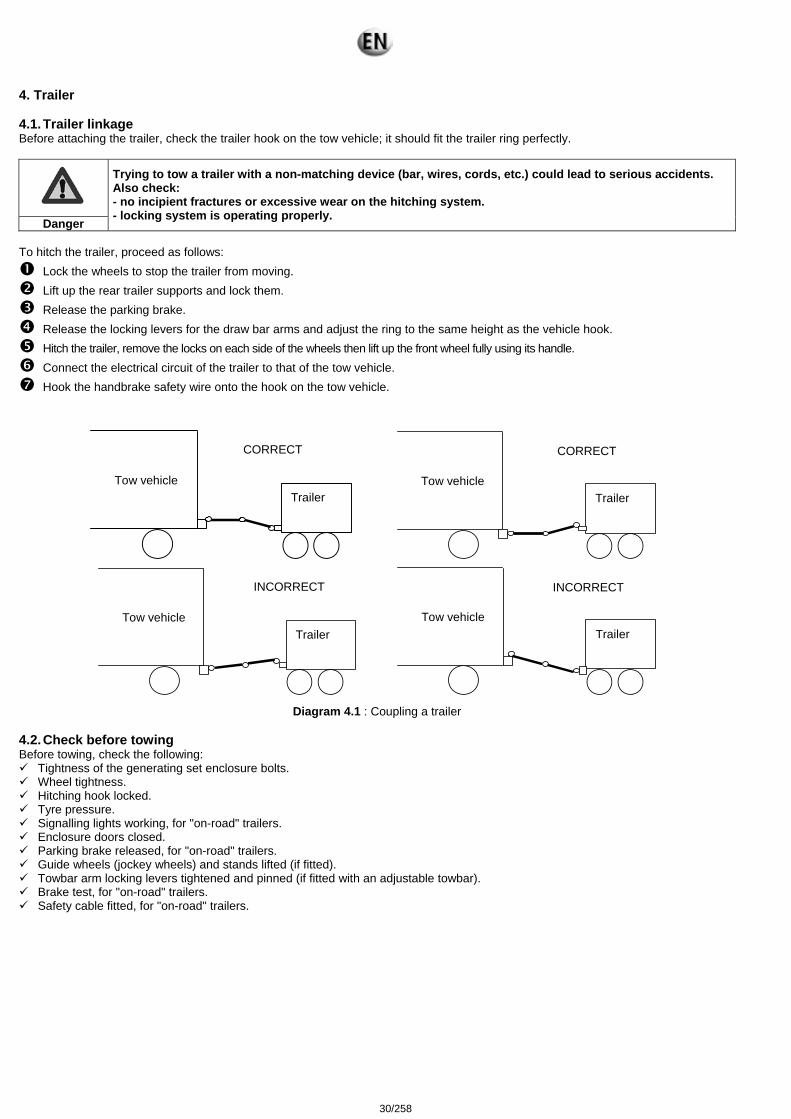
4. Trailer 4.1. Trailer linkage Before attaching the trailer, check the trailer hook on the tow vehicle; it should fit the trailer ring perfectly.
Danger
Trying to tow a trailer with a non-matching device (bar, wires, cords, etc.) could lead to serious accidents. Also check: - no incipient fractures or excessive wear on the hitching system. - locking system is operating properly.
To hitch the trailer, proceed as follows:
Lock the wheels to stop the trailer from moving. Lift up the rear trailer supports and lock them. Release the parking brake. Release the locking levers for the draw bar arms and adjust the ring to the same height as the vehicle hook. Hitch the trailer, remove the locks on each side of the wheels then lift up the front wheel fully using its handle. Connect the electrical circuit of the trailer to that of the tow vehicle. Hook the handbrake safety wire onto the hook on the tow vehicle.
Diagram 4.1 : Coupling a trailer 4.2. Check before towing Before towing, check the following:
Tightness of the generating set enclosure bolts. Wheel tightness. Hitching hook locked. Tyre pressure. Signalling lights working, for "on-road" trailers. Enclosure doors closed. Parking brake released, for "on-road" trailers. Guide wheels (jockey wheels) and stands lifted (if fitted). Towbar arm locking levers tightened and pinned (if fitted with an adjustable towbar). Brake test, for "on-road" trailers. Safety cable fitted, for "on-road" trailers.
Tow vehicle
Trailer
CORRECT
Tow vehicle Trailer
CORRECT
Tow vehicle
Trailer
INCORRECT
Tow vehicle
Trailer
INCORRECT
30/258
4.3. Operation "On-site" trailer These trailers are not fitted with a main brake, and so cannot be braked in motion; the tyres allow for a maximum speed of 27 km/h. So it is absolutely prohibited to exceed this speed. Nor are these trailers fitted with signalling lights. On-road use is prohibited. "On-road" trailer The driving speed must be suited to the condition of the road and the handling of the trailer. Driving at high speed causes heating of the tyres; so it is important to stop from time to time, and check them. Excessive heating may cause a puncture, and therefore a serious accident. For reversing manoeuvres, remember to lock the inertia brake.
Warning
Particular attention must be paid to the tightness of the wheels on new vehicles. In the first few miles' driving, heating of the brake hubs and drums will actually reduce the wheel tightness. It is therefore essential to check the tightness every 6 miles (10 kilometres) until no further loosening is noted. Nonetheless the tightness must be checked whenever you are about to tow the trailer.
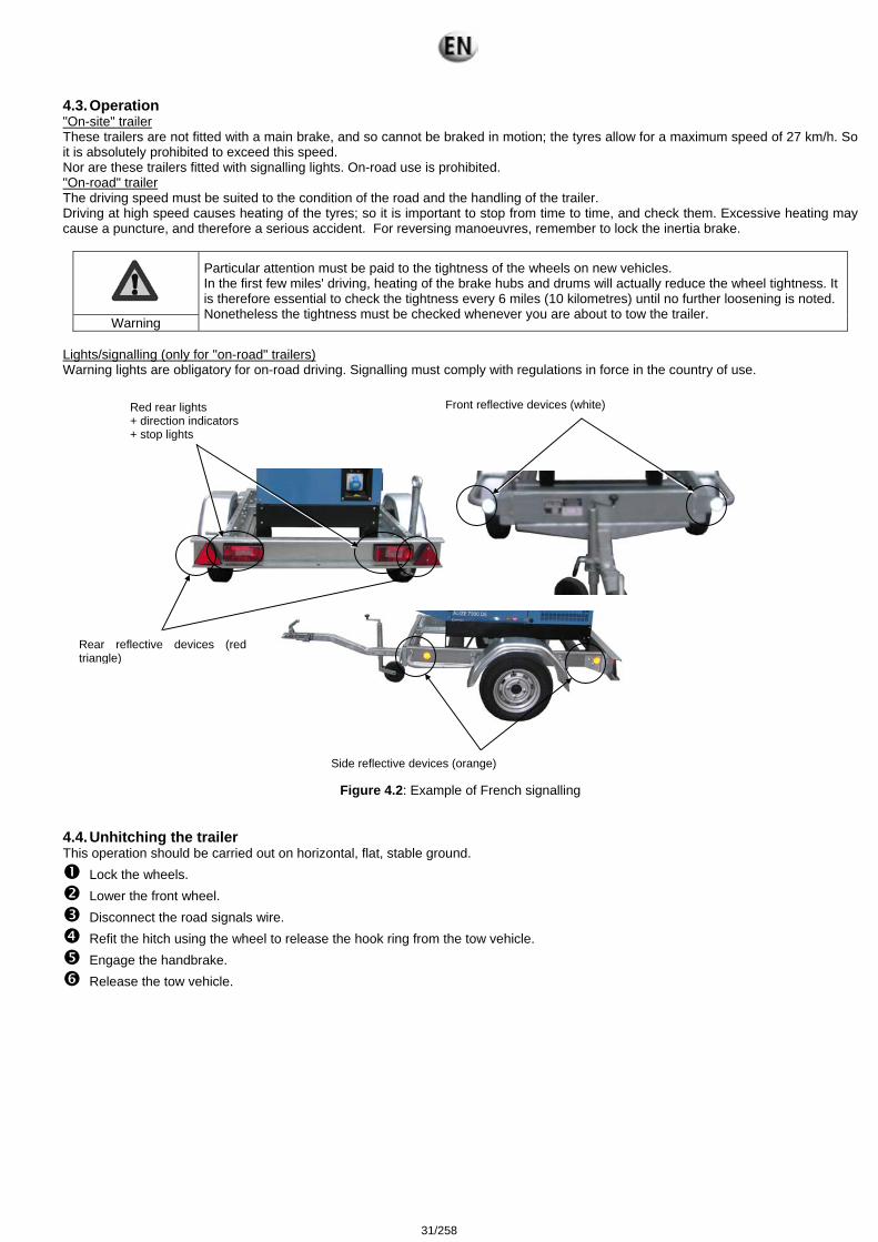
Lights/signalling (only for "on-road" trailers) Warning lights are obligatory for on-road driving. Signalling must comply with regulations in force in the country of use.
Figure 4.2: Example of French signalling
4.4. Unhitching the trailer This operation should be carried out on horizontal, flat, stable ground.
Lock the wheels. Lower the front wheel. Disconnect the road signals wire. Refit the hitch using the wheel to release the hook ring from the tow vehicle. Engage the handbrake. Release the tow vehicle.
Red rear lights + direction indicators + stop lights
Front reflective devices (white)
Side reflective devices (orange)
Rear reflective devices (red triangle)
31/258
4.5. Implementation for installation Operations to be carried out:
Ensure that the ground is strong enough for the assembly not to sink into it. Unhitch the trailer. Immobilise the trailer by placing chocks under the wheels. Fully engage the parking brake (if fitted). Using the front wheel, position the generating set as close to horizontal as possible. Lower the stands (if fitted), and lock them.
4.6. Break transmission adjustment
Important
- The handbrake is used only as a parking brake. - Setting is carried out starting with the brakes moving to the brake control.
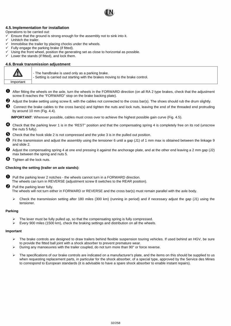
After fitting the wheels on the axle, turn the wheels in the FORWARD direction (on all RA 2 type brakes, check that the adjustment
screw 8 reaches the “FORWARD” stop on the brake backing plate). Adjust the brake setting using screw 8, with the cables not connected to the cross bar(s). The shoes should rub the drum slightly. Connect the brake cables to the cross bars(s) and tighten the nuts and lock nuts, leaving the end of the threaded end protruding
by around 10 mm (Fig. 4.4).
IMPORTANT: Wherever possible, cables must cross over to achieve the highest possible gain curve (Fig. 4.5).
Check that the parking lever 1 is in the ‘REST” position and that the compensating spring 4 is completely free on its rod (unscrew the nuts 5 fully).
Check that the hook slide 2 is not compressed and the yoke 3 is in the pulled out position. Fit the transmission and adjust the assembly using the tensioner 6 until a gap (J1) of 1 mm max is obtained between the linkage 9
and slide 2. Adjust the compensating spring 4 at one end pressing it against the anchorage plate, and at the other end leaving a 2 mm gap (J2)
max between the spring and nuts 5. Tighten all the lock nuts.
Checking the setting (trailer on axle stands):
Pull the parking lever 2 notches - the wheels cannot turn in a FORWARD direction. The wheels can turn in REVERSE (adjustment screw 8 switches to the REAR position). Pull the parking lever fully. The wheels will not turn either in FORWARD or REVERSE and the cross bar(s) must remain parallel with the axle body.
Check the transmission setting after 180 miles (300 km) (running in period) and if necessary adjust the gap (J1) using the
tensioner. Parking
The lever must be fully pulled up, so that the compensating spring is fully compressed. Every 900 miles (1500 km), check the braking settings and distribution on all the wheels.
Important
The brake controls are designed to draw trailers behind flexible suspension touring vehicles. If used behind an HGV, be sure to provide the fitted ball joint with a shock absorber to prevent premature wear.
During any manoeuvres with the trailer coupled, do not turn more than 90° or force reverse.
The specifications of our brake controls are indicated on a manufacturer's plate, and the items on this should be supplied to us when requesting replacement parts, in particular for the shock absorber, of a special type, approved by the Service des Mines to correspond to European standards (it is advisable to have a spare shock absorber to enable instant repairs).
32/258
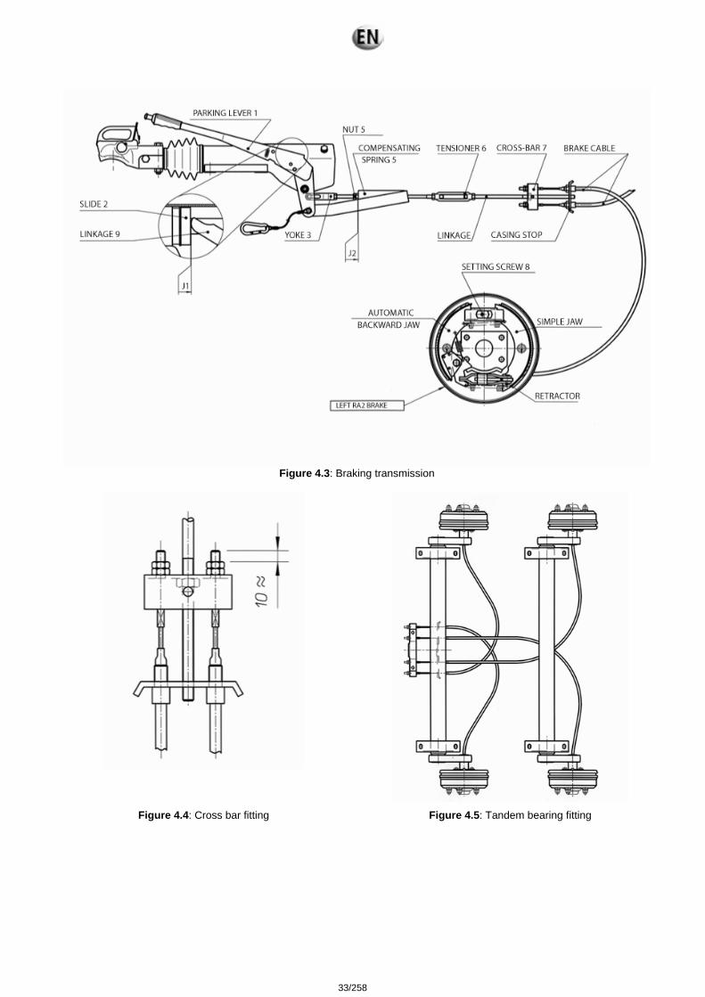
Figure 4.3: Braking transmission
Figure 4.4: Cross bar fitting Figure 4.5: Tandem bearing fitting
33/258
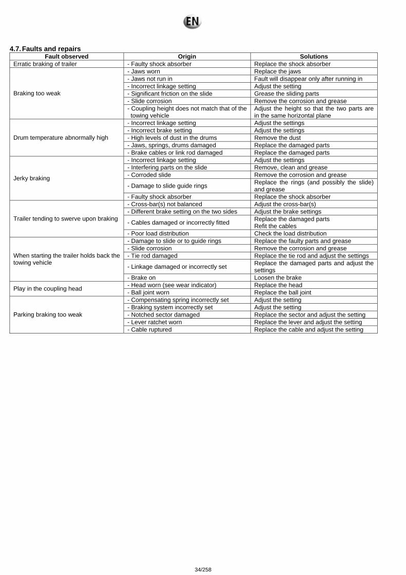
4.7. Faults and repairs Fault observed Origin Solutions
Erratic braking of trailer - Faulty shock absorber Replace the shock absorber - Jaws worn Replace the jaws - Jaws not run in Fault will disappear only after running in - Incorrect linkage setting Adjust the setting - Significant friction on the slide Grease the sliding parts - Slide corrosion Remove the corrosion and grease
Braking too weak
- Coupling height does not match that of the towing vehicle
Adjust the height so that the two parts are in the same horizontal plane
- Incorrect linkage setting Adjust the settings - Incorrect brake setting Adjust the settings - High levels of dust in the drums Remove the dust - Jaws, springs, drums damaged Replace the damaged parts
Drum temperature abnormally high
- Brake cables or link rod damaged Replace the damaged parts - Incorrect linkage setting Adjust the settings - Interfering parts on the slide Remove, clean and grease - Corroded slide Remove the corrosion and grease
- Damage to slide guide rings Replace the rings (and possibly the slide) and grease
Jerky braking
- Faulty shock absorber Replace the shock absorber - Cross-bar(s) not balanced Adjust the cross-bar(s) - Different brake setting on the two sides Adjust the brake settings
- Cables damaged or incorrectly fitted Replace the damaged parts Refit the cables
Trailer tending to swerve upon braking
- Poor load distribution Check the load distribution - Damage to slide or to guide rings Replace the faulty parts and grease - Slide corrosion Remove the corrosion and grease - Tie rod damaged Replace the tie rod and adjust the settings
- Linkage damaged or incorrectly set Replace the damaged parts and adjust the settings
When starting the trailer holds back the towing vehicle
- Brake on Loosen the brake - Head worn (see wear indicator) Replace the head Play in the coupling head - Ball joint worn Replace the ball joint - Compensating spring incorrectly set Adjust the setting - Braking system incorrectly set Adjust the setting - Notched sector damaged Replace the sector and adjust the setting - Lever ratchet worn Replace the lever and adjust the setting
Parking braking too weak
- Cable ruptured Replace the cable and adjust the setting
34/258
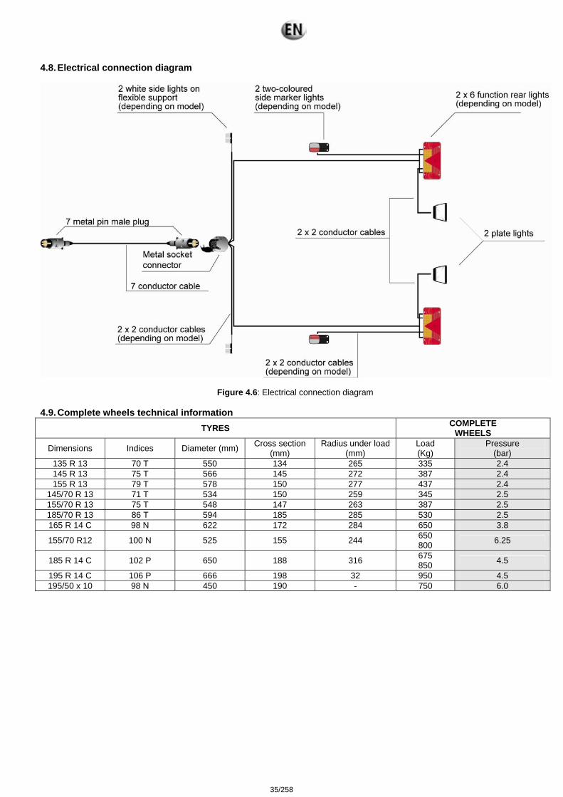
4.8. Electrical connection diagram
Figure 4.6: Electrical connection diagram 4.9. Complete wheels technical information
TYRES COMPLETE WHEELS
Dimensions Indices Diameter (mm) Cross section (mm)
Radius under load(mm)
Load (Kg)
Pressure (bar)
135 R 13 70 T 550 134 265 335 2.4 145 R 13 75 T 566 145 272 387 2.4 155 R 13 79 T 578 150 277 437 2.4
145/70 R 13 71 T 534 150 259 345 2.5 155/70 R 13 75 T 548 147 263 387 2.5 185/70 R 13 86 T 594 185 285 530 2.5 165 R 14 C 98 N 622 172 284 650 3.8
155/70 R12 100 N 525 155 244 650 800 6.25
185 R 14 C 102 P 650 188 316 675 850 4.5
195 R 14 C 106 P 666 198 32 950 4.5 195/50 x 10 98 N 450 190 - 750 6.0
35/258
5. Preparation before operating the set
Danger
The inspections referred to in this section enable the electrical generator set to operate. Specific skills are required to carry out these operations. They must only be entrusted to personnel with the necessary skills. Failure to follow these instructions in any way could result in malfunction or very serious accidents.
5.1. Installation checks
• check that the general recommendations given in the installation section (ventilation, exhaust, fluids, etc.) are observed. • carry out the level checks (oil, water, diesel fuel, battery). • check the generating set earth connection is earthed. • check that the electrical connections are in order.
5.2. Checks after starting the generating set
• carry out the mechanical checks (oil pressure, water temperature, absence of noise etc.) • carry out the electrical checks (voltage and frequency) • carry out the safety checks (emergency stop, oil pressure, water temperature etc.)
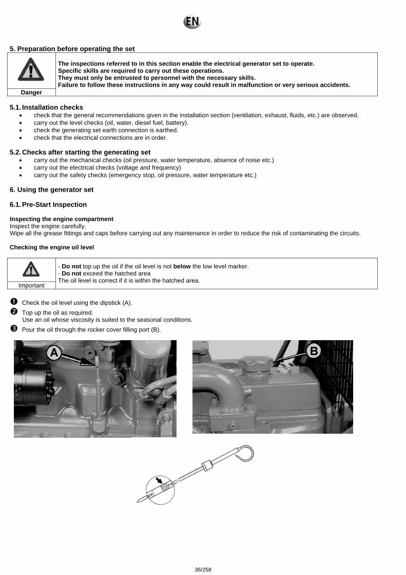
6. Using the generator set 6.1. Pre-Start Inspection Inspecting the engine compartment Inspect the engine carefully. Wipe all the grease fittings and caps before carrying out any maintenance in order to reduce the risk of contaminating the circuits. Checking the engine oil level
Important
- Do not top up the oil if the oil level is not below the low level marker. - Do not exceed the hatched area The oil level is correct if it is within the hatched area.
Check the oil level using the dipstick (A). Top up the oil as required.
Use an oil whose viscosity is suited to the seasonal conditions. Pour the oil through the rocker cover filling port (B).
36/258
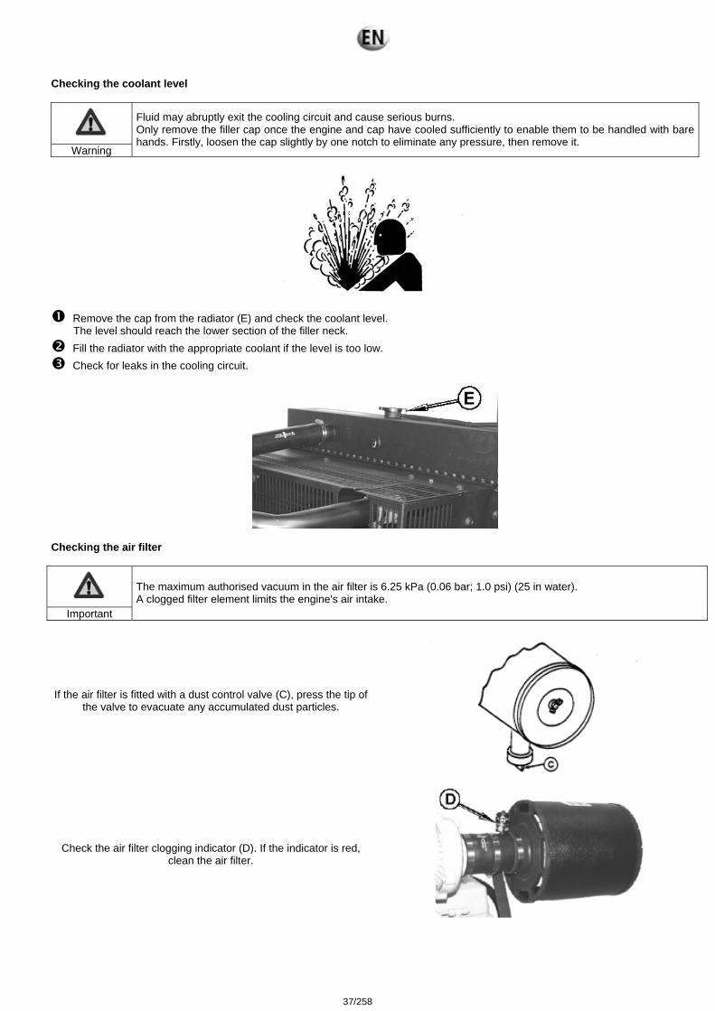
Checking the coolant level
Warning
Fluid may abruptly exit the cooling circuit and cause serious burns. Only remove the filler cap once the engine and cap have cooled sufficiently to enable them to be handled with bare hands. Firstly, loosen the cap slightly by one notch to eliminate any pressure, then remove it.
Remove the cap from the radiator (E) and check the coolant level. The level should reach the lower section of the filler neck.
Fill the radiator with the appropriate coolant if the level is too low. Check for leaks in the cooling circuit.
Checking the air filter
Important
The maximum authorised vacuum in the air filter is 6.25 kPa (0.06 bar; 1.0 psi) (25 in water). A clogged filter element limits the engine's air intake.
If the air filter is fitted with a dust control valve (C), press the tip of the valve to evacuate any accumulated dust particles.
Check the air filter clogging indicator (D). If the indicator is red, clean the air filter.
37/258

Checking the fuel filters
Danger
The fuel is highly flammable and its vapours are combustible. The fuel filter(s) must only be bled when the engine is stopped and cold.
Note: Engines with a mechanical supply circuit have a single fuel filter whilst electronically controlled engines (DE10 and high pressure common rail fuel circuits) have two fuel filters (primary and final). In addition, fuel filters in electronically controlled engines may be fitted with a water presence sensor. An indicator on the instrument panel warns the operator that the water must be drained from the filter cup. Inspect fuel filters (C) and (D) as follows, in order to detect any traces of water or debris:
Undo the drain plug(s) (A) at the bottom of the fuel filter(s) or cup(s) by two or three turns. Loosen the air drain plugs(s) (B) by two full turns and drain the water into a suitable container. When the fuel begins to flow out, tighten the drain plugs. Bleed the supply circuit.
A – Drain plug
B – Air bleed plug C – Main fuel filter D – Final fuel filter
38/258
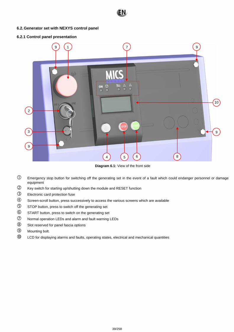
6.2. Generator set with NEXYS control panel 6.2.1 Control panel presentation
Diagram 6.1: View of the front side
Emergency stop button for switching off the generating set in the event of a fault which could endanger personnel or damage
equipment Key switch for starting up/shutting down the module and RESET function
Electronic card protection fuse
Screen-scroll button, press successively to access the various screens which are available
STOP button, press to switch off the generating set START button, press to switch on the generating set
Normal operation LEDs and alarm and fault warning LEDs
Slot reserved for panel fascia options
Mounting bolt.
LCD for displaying alarms and faults, operating states, electrical and mechanical quantities
2
1
3
5
9 9
9
6
7
8 4
9
10
39/258

Diagram 6.2 – Description of the LEDs
A lit LED indicates:
Module being supplied (green, lights up and remains lit)
Emergency stop activated (control panel or external emergency stop) (red, lights up and remains lit)
Visualisation of starting phase and speed/voltage stabilisation (flashing) and generating set operating OK or set ready to generate (green, lights up and remains lit)
General alarm (orange, flashing)
General fault (red, flashing) 6.2.1.1. Introduction to pictograms The pictograms are as follows:
Operating temperature Fuel
Overspeed
Non-starting fault Starting on external command
Preheating
Air intake
Oil pressure
Battery Delay
Diagram 6.3: View of pictograms
The "fuel level" pictogram is used to display the fault, the alarm and the fuel level. The "operating temperature" and "oil pressure" pictograms are used to display the fault and analog value. The "overspeed" and "non-starting fault" pictograms are used to display the fault. The "battery" pictogram is used to display the "alternator charge" fault and to indicate the battery voltage.
Symbols for electric and mechanical sizes
1 2 3 4 5
40/258
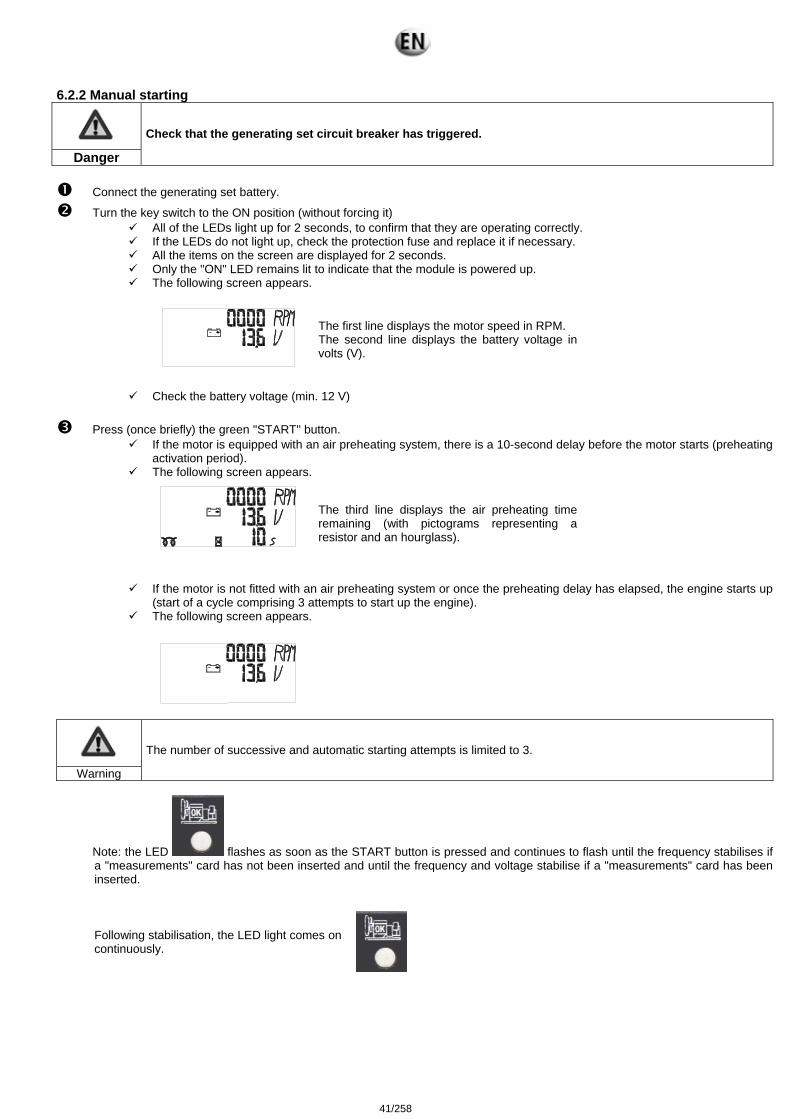
6.2.2 Manual starting
Danger
Check that the generating set circuit breaker has triggered.
Connect the generating set battery.
Turn the key switch to the ON position (without forcing it) All of the LEDs light up for 2 seconds, to confirm that they are operating correctly. If the LEDs do not light up, check the protection fuse and replace it if necessary. All the items on the screen are displayed for 2 seconds. Only the "ON" LED remains lit to indicate that the module is powered up. The following screen appears.
The first line displays the motor speed in RPM. The second line displays the battery voltage in volts (V).
Check the battery voltage (min. 12 V)
Press (once briefly) the green "START" button. If the motor is equipped with an air preheating system, there is a 10-second delay before the motor starts (preheating
activation period). The following screen appears.
The third line displays the air preheating time remaining (with pictograms representing a resistor and an hourglass).
If the motor is not fitted with an air preheating system or once the preheating delay has elapsed, the engine starts up
(start of a cycle comprising 3 attempts to start up the engine). The following screen appears.
Warning
The number of successive and automatic starting attempts is limited to 3.
Note: the LED flashes as soon as the START button is pressed and continues to flash until the frequency stabilises if a "measurements" card has not been inserted and until the frequency and voltage stabilise if a "measurements" card has been inserted.
Following stabilisation, the LED light comes on continuously.
41/258
6.2.3 Switching off Trigger the circuit breaker located at the base of the centre console.
Let the motor run under no load for 1 to 2 minutes to allow it to cool.
Press the "STOP" button to stop the generating set.
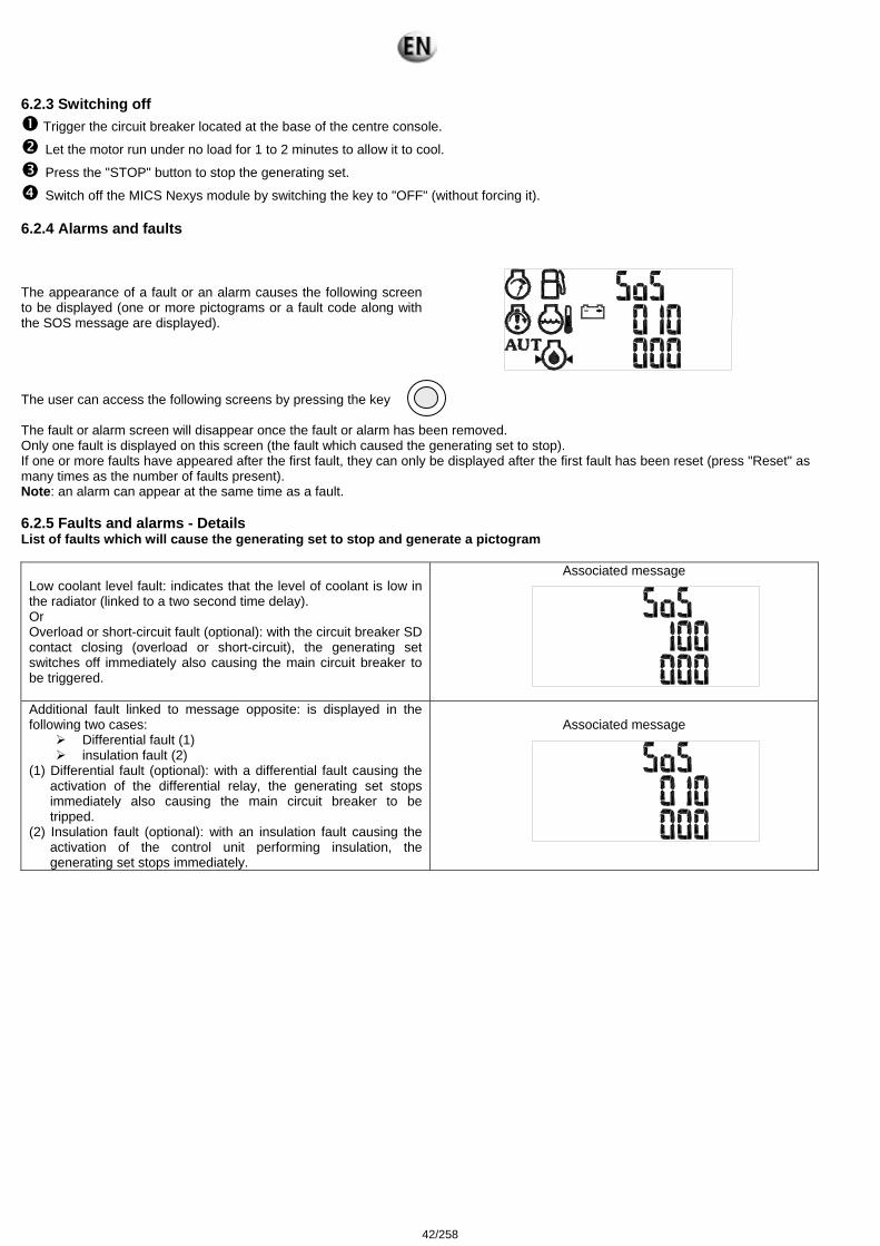
Switch off the MICS Nexys module by switching the key to "OFF" (without forcing it). 6.2.4 Alarms and faults The appearance of a fault or an alarm causes the following screen to be displayed (one or more pictograms or a fault code along with the SOS message are displayed).
The user can access the following screens by pressing the key The fault or alarm screen will disappear once the fault or alarm has been removed. Only one fault is displayed on this screen (the fault which caused the generating set to stop). If one or more faults have appeared after the first fault, they can only be displayed after the first fault has been reset (press "Reset" as many times as the number of faults present). Note: an alarm can appear at the same time as a fault. 6.2.5 Faults and alarms - Details List of faults which will cause the generating set to stop and generate a pictogram
Low coolant level fault: indicates that the level of coolant is low in the radiator (linked to a two second time delay). Or Overload or short-circuit fault (optional): with the circuit breaker SD contact closing (overload or short-circuit), the generating set switches off immediately also causing the main circuit breaker to be triggered.
Associated message
Additional fault linked to message opposite: is displayed in the following two cases:
Differential fault (1) insulation fault (2)
(1) Differential fault (optional): with a differential fault causing the activation of the differential relay, the generating set stops immediately also causing the main circuit breaker to be tripped.
(2) Insulation fault (optional): with an insulation fault causing the activation of the control unit performing insulation, the generating set stops immediately.
Associated message
42/258
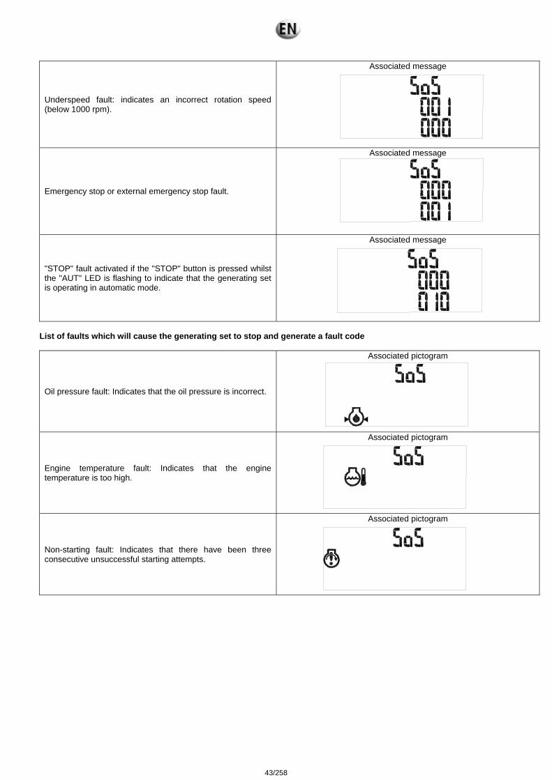
Underspeed fault: indicates an incorrect rotation speed (below 1000 rpm).
Associated message
Emergency stop or external emergency stop fault.
Associated message
"STOP" fault activated if the "STOP" button is pressed whilst the "AUT" LED is flashing to indicate that the generating set is operating in automatic mode.
Associated message
List of faults which will cause the generating set to stop and generate a fault code
Oil pressure fault: Indicates that the oil pressure is incorrect.
Associated pictogram
Engine temperature fault: Indicates that the engine temperature is too high.
Associated pictogram
Non-starting fault: Indicates that there have been three consecutive unsuccessful starting attempts.
Associated pictogram
43/258
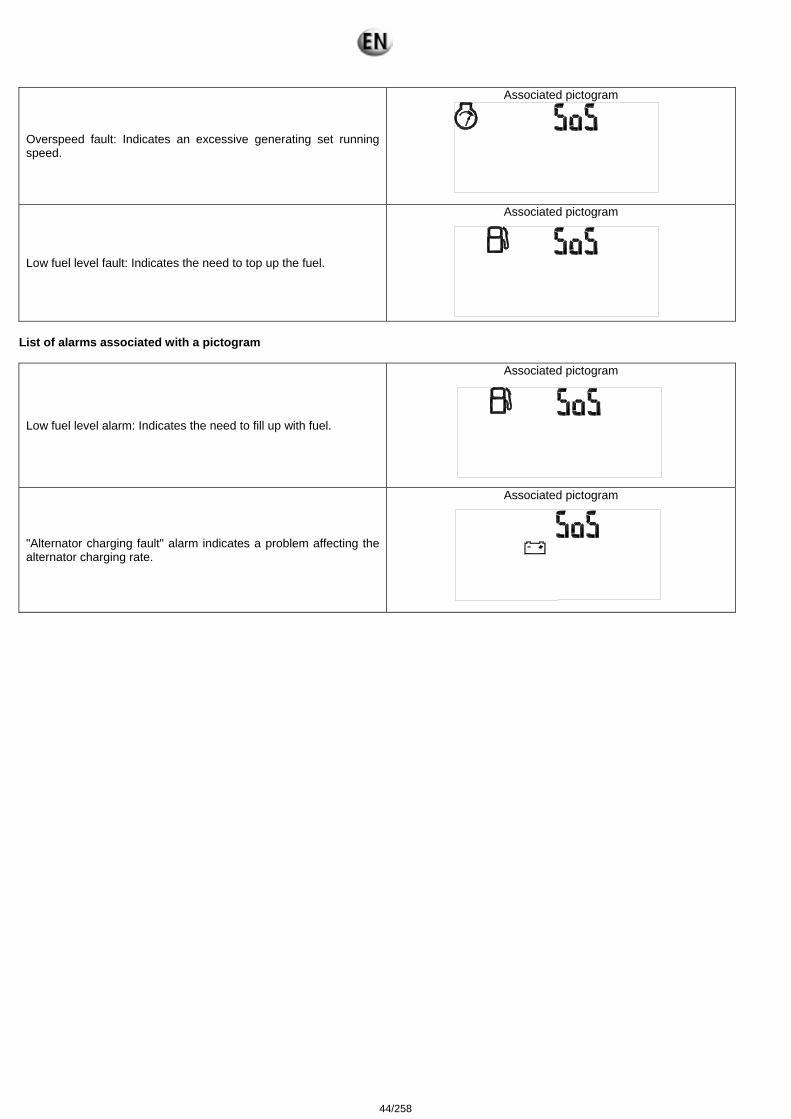
Overspeed fault: Indicates an excessive generating set running speed.
Associated pictogram
Low fuel level fault: Indicates the need to top up the fuel.
Associated pictogram
List of alarms associated with a pictogram
Low fuel level alarm: Indicates the need to fill up with fuel.
Associated pictogram
"Alternator charging fault" alarm indicates a problem affecting the alternator charging rate.
Associated pictogram
44/258
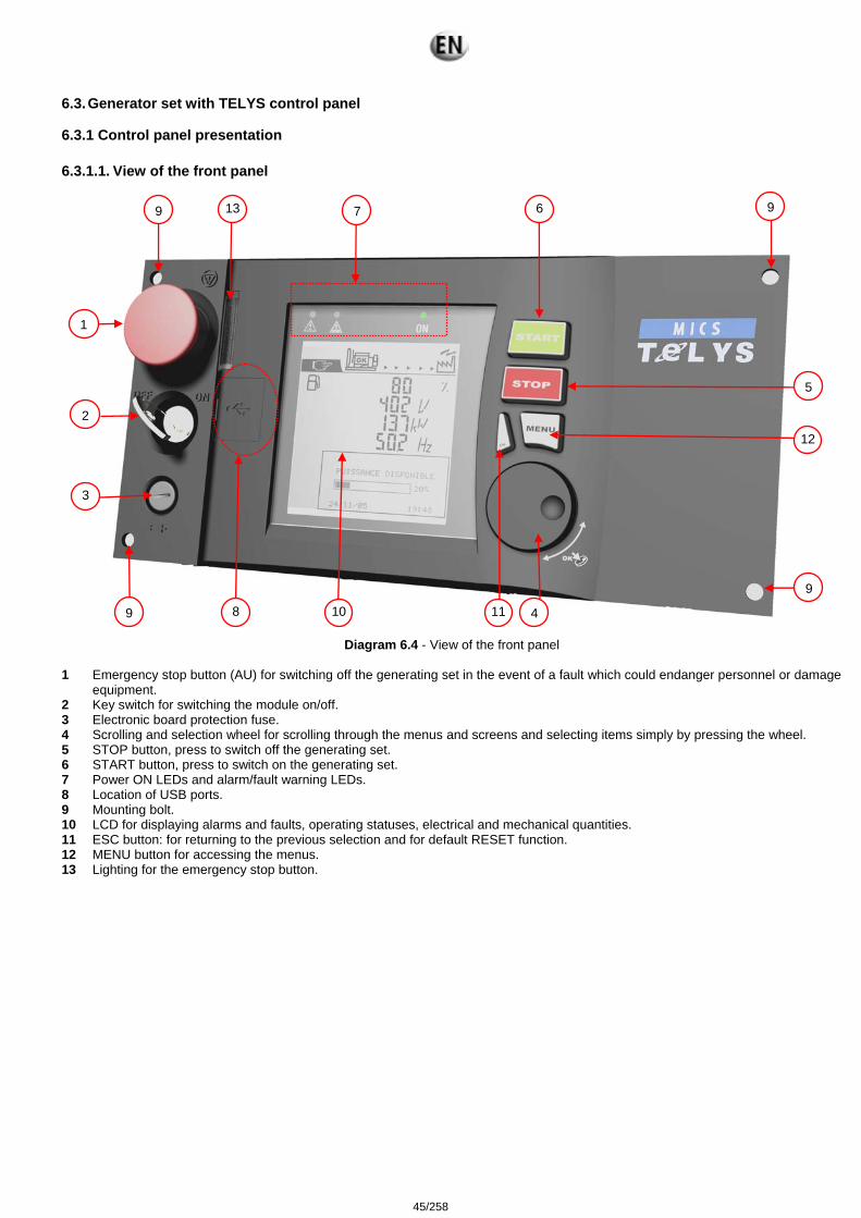
6.3. Generator set with TELYS control panel 6.3.1 Control panel presentation 6.3.1.1. View of the front panel
Diagram 6.4 - View of the front panel 1 Emergency stop button (AU) for switching off the generating set in the event of a fault which could endanger personnel or damage
equipment. 2 Key switch for switching the module on/off. 3 Electronic board protection fuse. 4 Scrolling and selection wheel for scrolling through the menus and screens and selecting items simply by pressing the wheel. 5 STOP button, press to switch off the generating set. 6 START button, press to switch on the generating set. 7 Power ON LEDs and alarm/fault warning LEDs. 8 Location of USB ports. 9 Mounting bolt. 10 LCD for displaying alarms and faults, operating statuses, electrical and mechanical quantities. 11 ESC button: for returning to the previous selection and for default RESET function. 12 MENU button for accessing the menus. 13 Lighting for the emergency stop button.
2
1
3
5
67
8 49 10 9
11
12
13 9 9
45/258
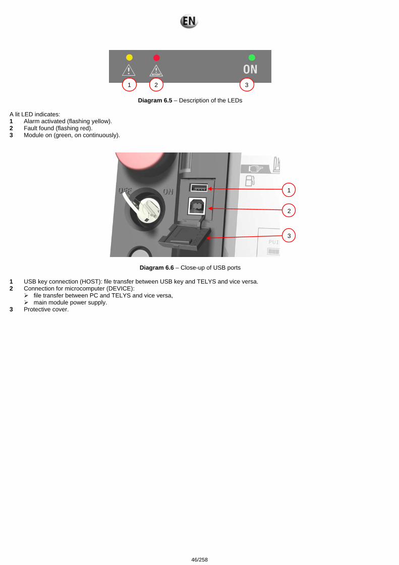
Diagram 6.5 – Description of the LEDs
A lit LED indicates: 1 Alarm activated (flashing yellow). 2 Fault found (flashing red). 3 Module on (green, on continuously).
Diagram 6.6 – Close-up of USB ports 1 USB key connection (HOST): file transfer between USB key and TELYS and vice versa. 2 Connection for microcomputer (DEVICE):
file transfer between PC and TELYS and vice versa, main module power supply.
3 Protective cover.
1 2 3
2
3
1
46/258
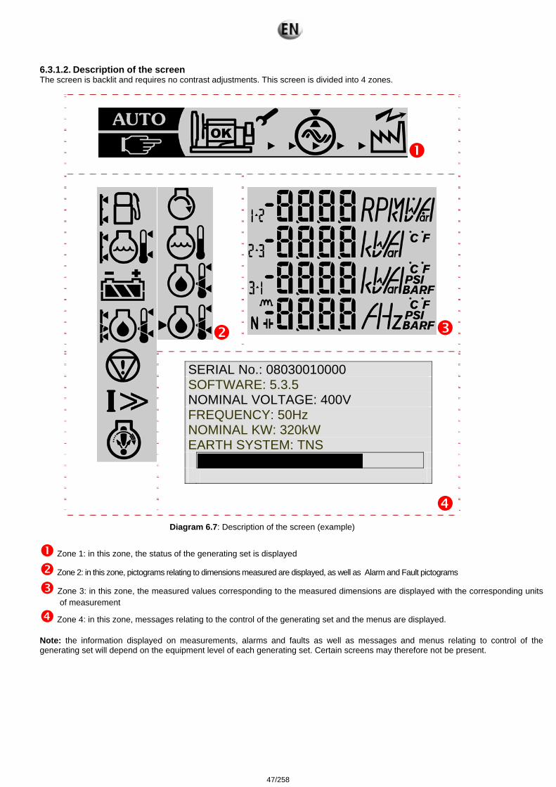
6.3.1.2. Description of the screen The screen is backlit and requires no contrast adjustments. This screen is divided into 4 zones.
SERIAL No.: 08030010000 SOFTWARE: 5.3.5 NOMINAL VOLTAGE: 400V FREQUENCY: 50Hz NOMINAL KW: 320kW EARTH SYSTEM: TNS
Diagram 6.7: Description of the screen (example)
Zone 1: in this zone, the status of the generating set is displayed
Zone 2: in this zone, pictograms relating to dimensions measured are displayed, as well as Alarm and Fault pictograms
Zone 3: in this zone, the measured values corresponding to the measured dimensions are displayed with the corresponding units of measurement
Zone 4: in this zone, messages relating to the control of the generating set and the menus are displayed. Note: the information displayed on measurements, alarms and faults as well as messages and menus relating to control of the generating set will depend on the equipment level of each generating set. Certain screens may therefore not be present.
47/258
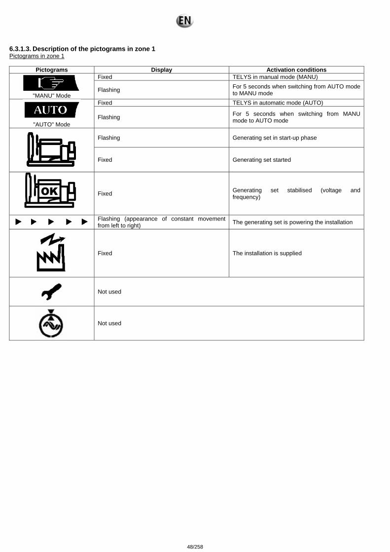
6.3.1.3. Description of the pictograms in zone 1 Pictograms in zone 1
Pictograms Display Activation conditions Fixed TELYS in manual mode (MANU)
"MANU" Mode
Flashing For 5 seconds when switching from AUTO mode to MANU mode
Fixed TELYS in automatic mode (AUTO)
"AUTO" Mode
Flashing For 5 seconds when switching from MANU mode to AUTO mode
Flashing Generating set in start-up phase
Fixed Generating set started
Fixed Generating set stabilised (voltage and frequency)
Flashing (appearance of constant movement from left to right) The generating set is powering the installation
Fixed The installation is supplied
Not used
Not used
48/258
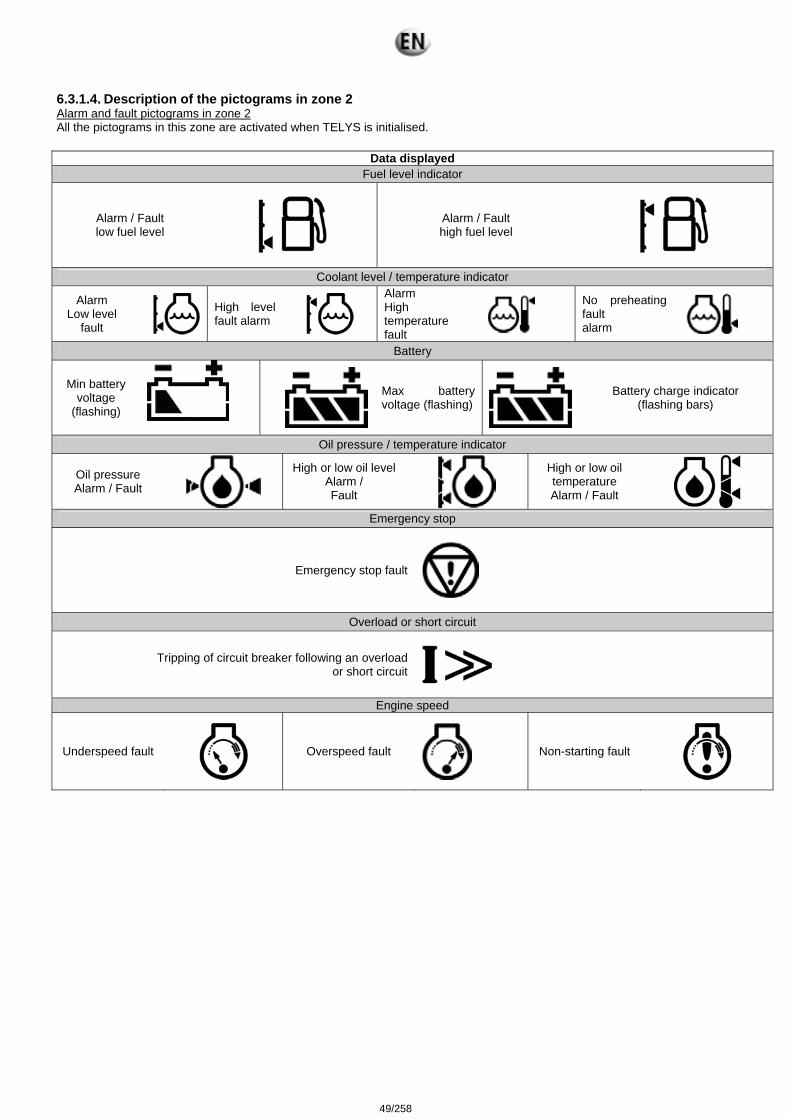
6.3.1.4. Description of the pictograms in zone 2 Alarm and fault pictograms in zone 2 All the pictograms in this zone are activated when TELYS is initialised.
Data displayed Fuel level indicator
Alarm / Fault low fuel level
Alarm / Fault high fuel level
Coolant level / temperature indicator
Alarm Low level
fault
High level fault alarm
Alarm High temperature fault
No preheating fault alarm
Battery
Min battery voltage
(flashing)
Max battery voltage (flashing)
Battery charge indicator (flashing bars)
Oil pressure / temperature indicator
Oil pressure Alarm / Fault
High or low oil level Alarm / Fault
High or low oil temperature Alarm / Fault
Emergency stop
Emergency stop fault
Overload or short circuit
Tripping of circuit breaker following an overload or short circuit
Engine speed
Underspeed fault
Overspeed fault
Non-starting fault
49/258
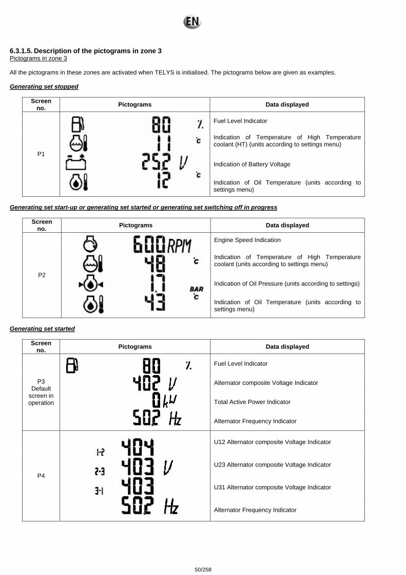
6.3.1.5. Description of the pictograms in zone 3 Pictograms in zone 3 All the pictograms in these zones are activated when TELYS is initialised. The pictograms below are given as examples. Generating set stopped
Screen no. Pictograms Data displayed
Fuel Level Indicator
Indication of Temperature of High Temperature coolant (HT) (units according to settings menu)
Indication of Battery Voltage P1
Indication of Oil Temperature (units according to settings menu)
Generating set start-up or generating set started or generating set switching off in progress
Screen no. Pictograms Data displayed
Engine Speed Indication
Indication of Temperature of High Temperature coolant (units according to settings menu)
Indication of Oil Pressure (units according to settings) P2
Indication of Oil Temperature (units according to settings menu)
Generating set started
Screen no. Pictograms Data displayed
Fuel Level Indicator
Alternator composite Voltage Indicator
Total Active Power Indicator
P3 Default
screen in operation
Alternator Frequency Indicator
U12 Alternator composite Voltage Indicator
U23 Alternator composite Voltage Indicator
U31 Alternator composite Voltage Indicator
P4
Alternator Frequency Indicator
50/258
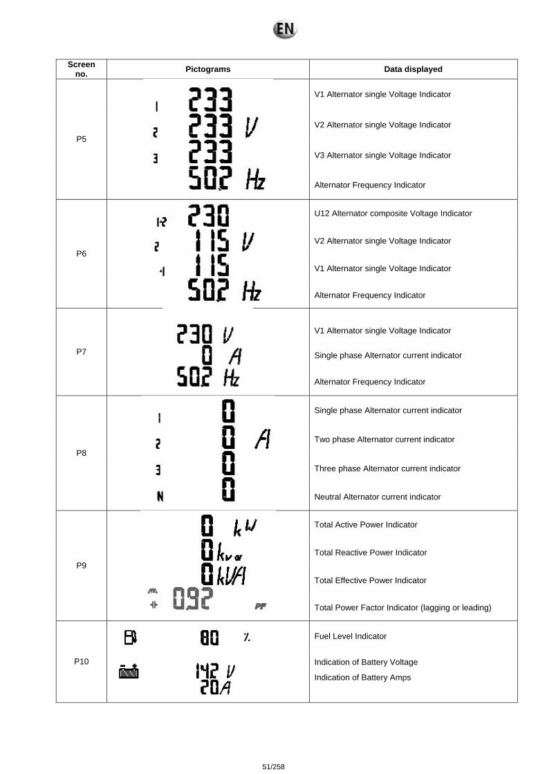
Screen no. Pictograms Data displayed
V1 Alternator single Voltage Indicator
V2 Alternator single Voltage Indicator
V3 Alternator single Voltage Indicator
P5
Alternator Frequency Indicator
U12 Alternator composite Voltage Indicator
V2 Alternator single Voltage Indicator
V1 Alternator single Voltage Indicator
P6
Alternator Frequency Indicator
V1 Alternator single Voltage Indicator
Single phase Alternator current indicator P7
Alternator Frequency Indicator
Single phase Alternator current indicator
Two phase Alternator current indicator
Three phase Alternator current indicator
P8
Neutral Alternator current indicator
Total Active Power Indicator
Total Reactive Power Indicator
Total Effective Power Indicator
P9
Total Power Factor Indicator (lagging or leading)
Fuel Level Indicator
Indication of Battery Voltage P10
Indication of Battery Amps
51/258

Screen order of appearance according to network type with the generating set on.
Type of network Order of appearance 3P+N 3P 2P+N 1P+N
1 P3 P3 P3 P3 2 P4 P4 P6 P7 3 P5 P8 P8 P9 4 P8 P9 P9 P2 5 P9 P2 P2 P10 6 P2 P10 P10 7 P10
Change screens by using the scrolling and selection wheel. When the wheel is rotated clockwise, the screens scroll upwards and vice-versa. The screens scroll in a loop. E.g.: On three-phase + neutral network, then screen 7, then screen 1 and vice-versa. 6.3.1.6. Display of messages in zone 4 The display (zone 4), among other things, displays messages relating to the operation of the generating set. The messages are as follows: Initialisation of TELYS
Screen no. Screen Data displayed
G 1
Initialisation of TELYS when the power is switched on and/or when loading a configuration
G 2
SERIAL No.: 08030010000 SOFTWARE: 6.1.0 NOMINAL VOLTAGE: 400V FREQUENCY: 50Hz NOMINAL KW: 320kW EARTH SYSTEM: TNS
Generating set serial no. Software version of TELYS Alternator Nominal Voltage Alternator Nominal Frequency Nominal Active Output Neutral Point Bar graph indicating the display delay of the screen
Generating set stopped
Screen no. Screen Data displayed
G 3
OPERATION MANUAL
Press START
to start 24/08/2005 13:12
Operating mode - generating set in Manual Mode ready to start Date and time (depending on settings)
52/258
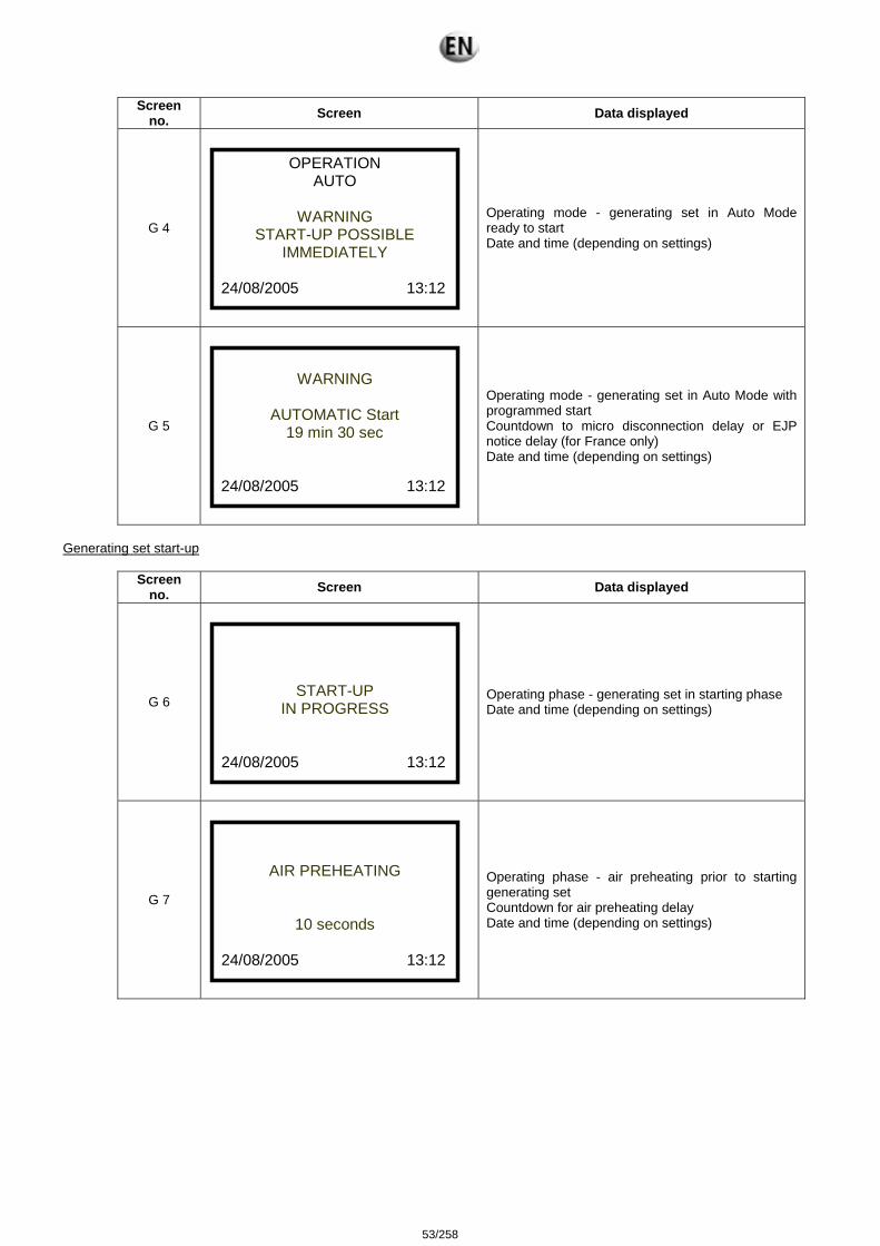
Screen no. Screen Data displayed
G 4
OPERATION AUTO
WARNING
START-UP POSSIBLE IMMEDIATELY
24/08/2005 13:12
Operating mode - generating set in Auto Mode ready to start Date and time (depending on settings)
G 5
WARNING
AUTOMATIC Start
19 min 30 sec 24/08/2005 13:12
Operating mode - generating set in Auto Mode with programmed start Countdown to micro disconnection delay or EJP notice delay (for France only) Date and time (depending on settings)
Generating set start-up
Screen no. Screen Data displayed
G 6
START-UP IN PROGRESS
24/08/2005 13:12
Operating phase - generating set in starting phase Date and time (depending on settings)
G 7
AIR PREHEATING
10 seconds
24/08/2005 13:12
Operating phase - air preheating prior to starting generating set Countdown for air preheating delay Date and time (depending on settings)
53/258

Generating set started
Screen no. Screen Data displayed
G 8 Default screen
AVAILABLE POWER
75%
24/08/2005 13:12
Operating phase – generating set in operation – stable voltage and frequency Available power Date and time (depending on settings)
G 9
AUTOMATIC STOP
IN PROGRESS
LOAD SUPPRESSION 1 min 30 sec
24/08/2005 13:12
Operating mode - operation in Auto Mode Opening of power supply device (motorised circuit breaker or source changeover switch controlled by TELYS) Countdown for the mains return delay OR the load test delay Date and time (depending on settings)
G 10
AUTOMATIC STOP
IN PROGRESS
COOLING DOWN 1 min 30 sec
24/08/2005 13:14
Operating mode - operation in Auto Mode Generation set cooling in progress Countdown for Engine Stop delay (cooling) OR Gradual Stop delay (Coolant temperature) OR Overload Gradual Stop delay OR OFF load test delay Date and time (depending on settings)
Generating setstop
Screen no.
Screen Data displayed
G 11
OFF IN PROGRESS
24/08/2005 13:16
Generating set stop in progress Date and time (depending on settings)
54/258
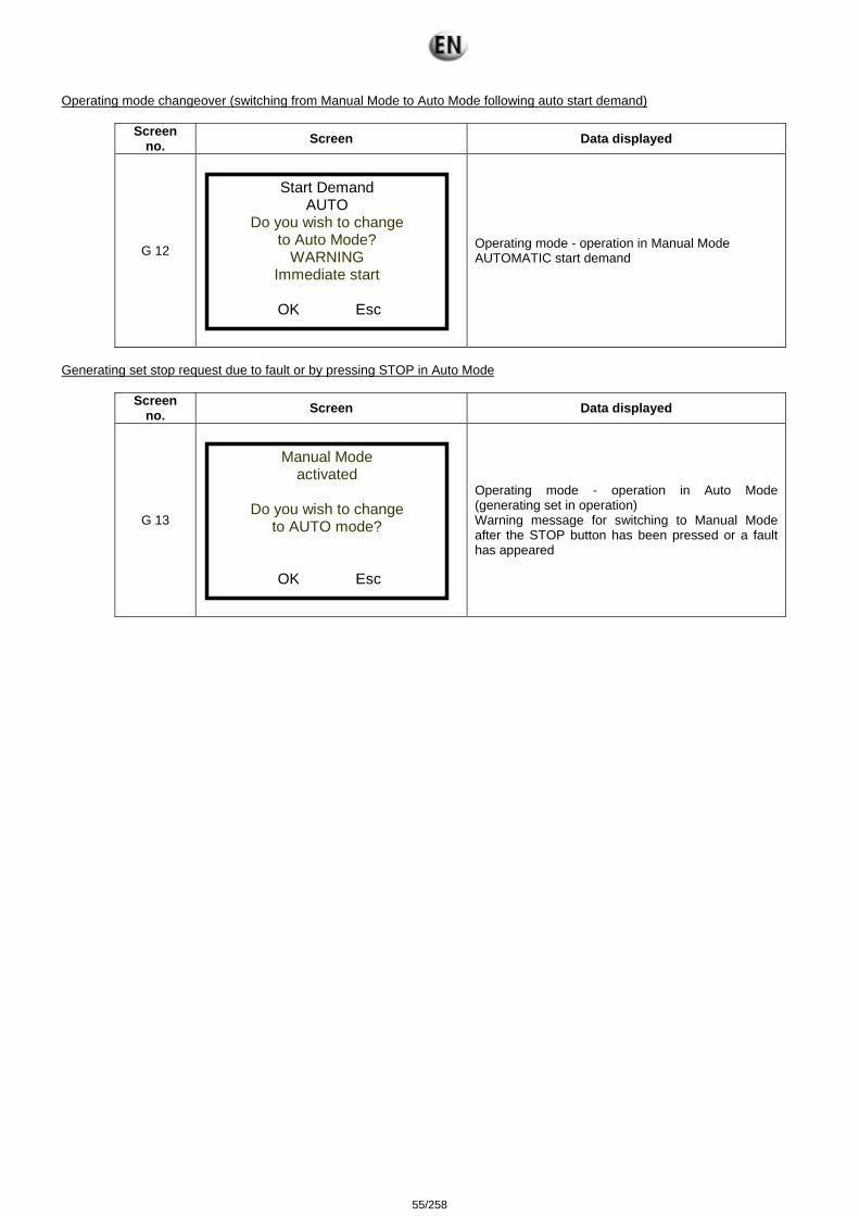
Operating mode changeover (switching from Manual Mode to Auto Mode following auto start demand)
Screen no. Screen Data displayed
G 12
Start Demand AUTO
Do you wish to change to Auto Mode?
WARNING Immediate start
OK Esc
Operating mode - operation in Manual Mode AUTOMATIC start demand
Generating set stop request due to fault or by pressing STOP in Auto Mode
Screen no. Screen Data displayed
G 13
Manual Mode activated
Do you wish to change
to AUTO mode?
OK Esc
Operating mode - operation in Auto Mode (generating set in operation) Warning message for switching to Manual Mode after the STOP button has been pressed or a fault has appeared
55/258
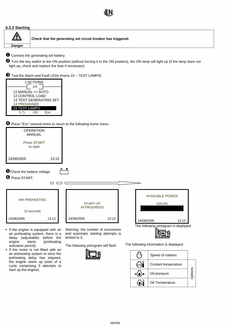
6.3.2 Starting
Danger
Check that the generating set circuit breaker has triggered.
Connect the generating set battery
Turn the key switch to the ON position (without forcing it to the ON position), the ON lamp will light up (if the lamp does not light up, check and replace the fuse if necessary)
Test the Alarm and Fault LEDs (menu 15 – TEST LAMPS)
1 ACTIONS 1/5
11 MANUAL <> AUTO 12 CONTROL LOAD
13 TEST GENERATING SET 14 PROGRAMS 15 TEST LAMPS
OK Esc
Press "Esc" several times to return to the following home menu
OPERATION MANUAL
Press START
to start 24/08/2005 13:12
Check the battery voltage Press START:
AIR PREHEATING
10 seconds
24/08/2005 13:12
If the engine is equipped with an air preheating system, there is a delay (adjustable) before the engine starts (preheating activation period).
If the motor is not fitted with an air preheating system or once the preheating delay has elapsed, the engine starts up (start of a cycle comprising 3 attempts to start up the engine).
START-UP IN PROGRESS
24/08/2005 13:12
Warning: the number of successive and automatic starting attempts is limited to 3. The following pictogram will flash
AVAILABLE POWER
100.0%
24/08/2005 13:12
The following pictogram is displayed
The following information is displayed
Speed of rotation
Coolant temperature
Oil pressure
Oil Temperature
Opt
ions
56/258
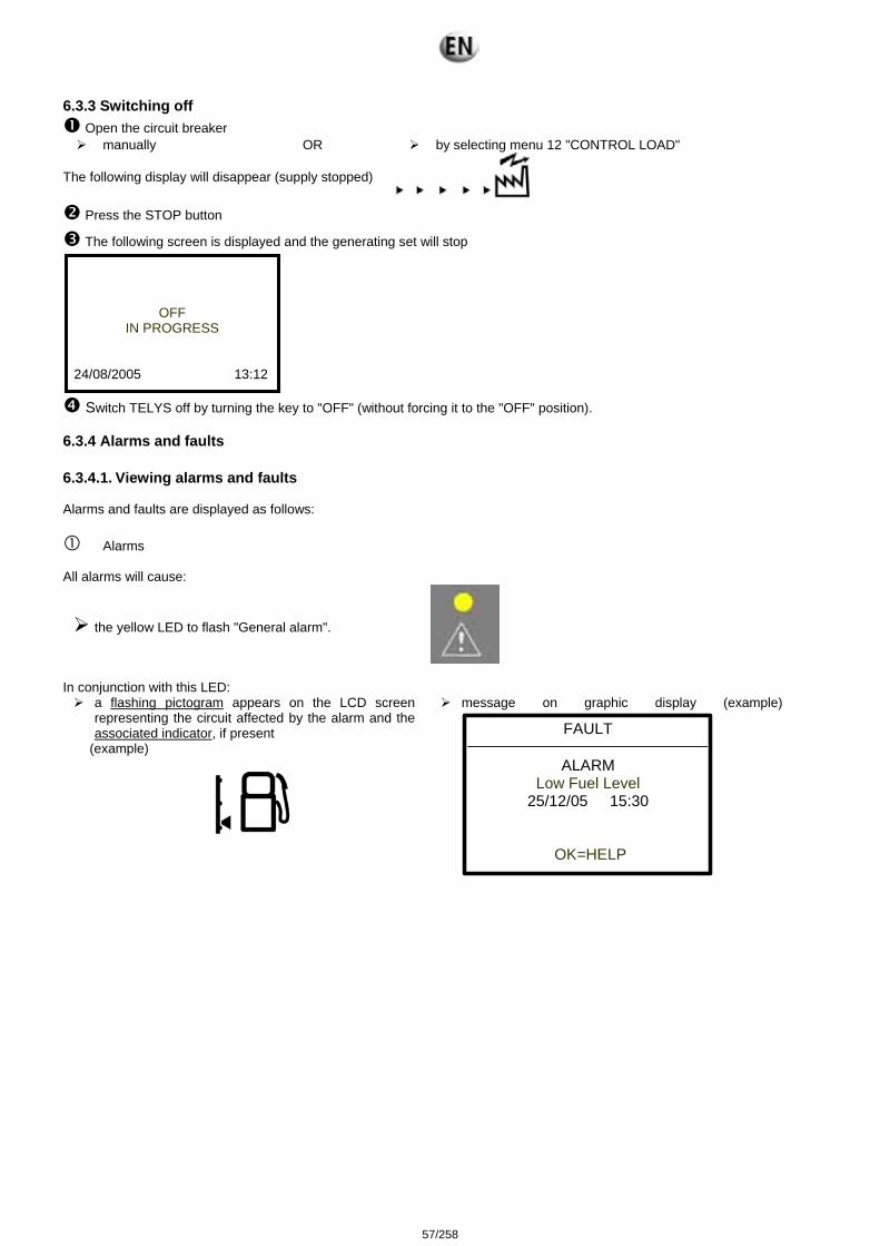
6.3.3 Switching off Open the circuit breaker manually OR by selecting menu 12 "CONTROL LOAD"
The following display will disappear (supply stopped)
Press the STOP button
The following screen is displayed and the generating set will stop
OFF IN PROGRESS
24/08/2005 13:12
Switch TELYS off by turning the key to "OFF" (without forcing it to the "OFF" position).
6.3.4 Alarms and faults 6.3.4.1. Viewing alarms and faults Alarms and faults are displayed as follows:
Alarms All alarms will cause:
the yellow LED to flash "General alarm".
In conjunction with this LED:
a flashing pictogram appears on the LCD screen representing the circuit affected by the alarm and the associated indicator, if present
(example)
message on graphic display (example) FAULT
ALARM Low Fuel Level
25/12/05 15:30
OK=HELP
57/258
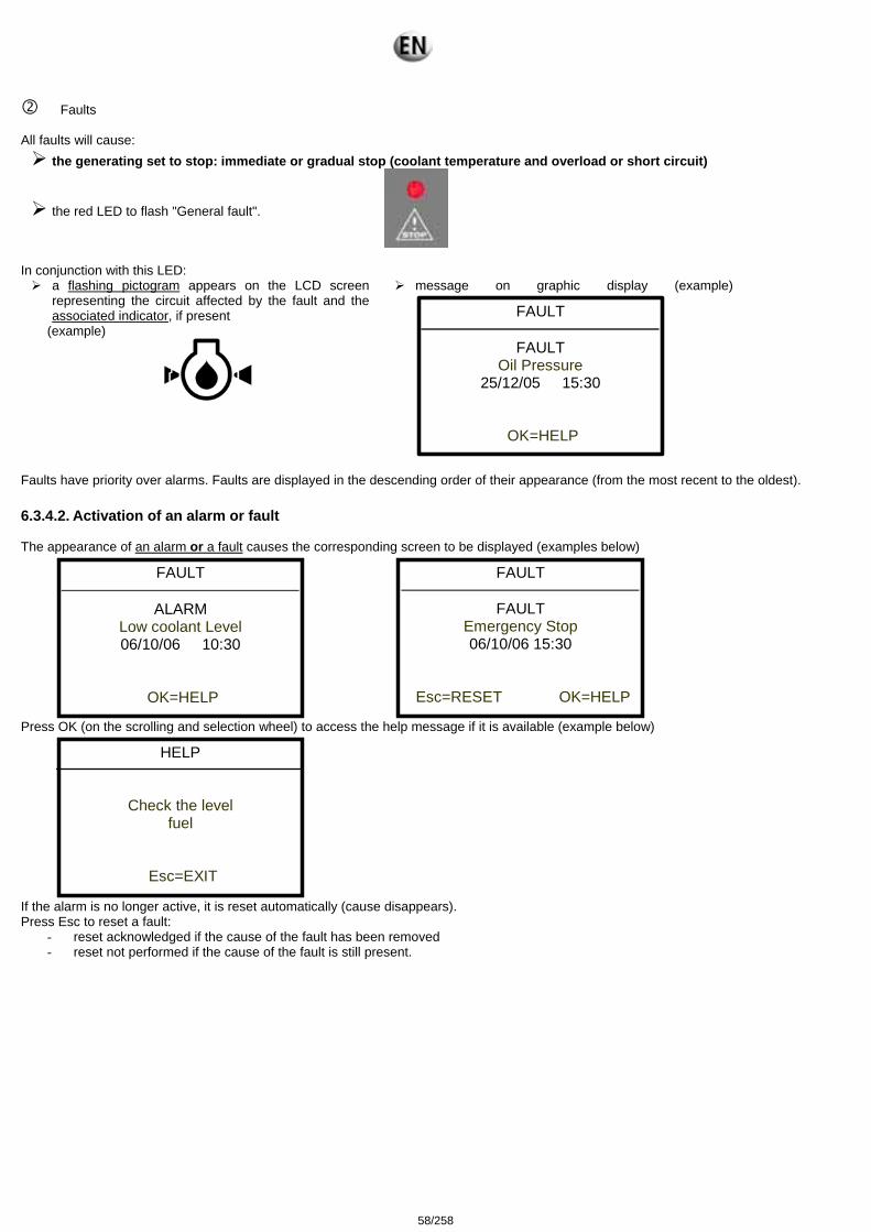
Faults All faults will cause:
the generating set to stop: immediate or gradual stop (coolant temperature and overload or short circuit)
the red LED to flash "General fault".
In conjunction with this LED:
a flashing pictogram appears on the LCD screen representing the circuit affected by the fault and the associated indicator, if present
(example)
message on graphic display (example) FAULT
FAULT Oil Pressure
25/12/05 15:30
OK=HELP
Faults have priority over alarms. Faults are displayed in the descending order of their appearance (from the most recent to the oldest). 6.3.4.2. Activation of an alarm or fault The appearance of an alarm or a fault causes the corresponding screen to be displayed (examples below)
FAULT
ALARM Low coolant Level 06/10/06 10:30
OK=HELP
FAULT
FAULT Emergency Stop 06/10/06 15:30
Esc=RESET OK=HELP
Press OK (on the scrolling and selection wheel) to access the help message if it is available (example below)
HELP
Check the level fuel
Esc=EXIT
If the alarm is no longer active, it is reset automatically (cause disappears). Press Esc to reset a fault:
- reset acknowledged if the cause of the fault has been removed - reset not performed if the cause of the fault is still present.
58/258
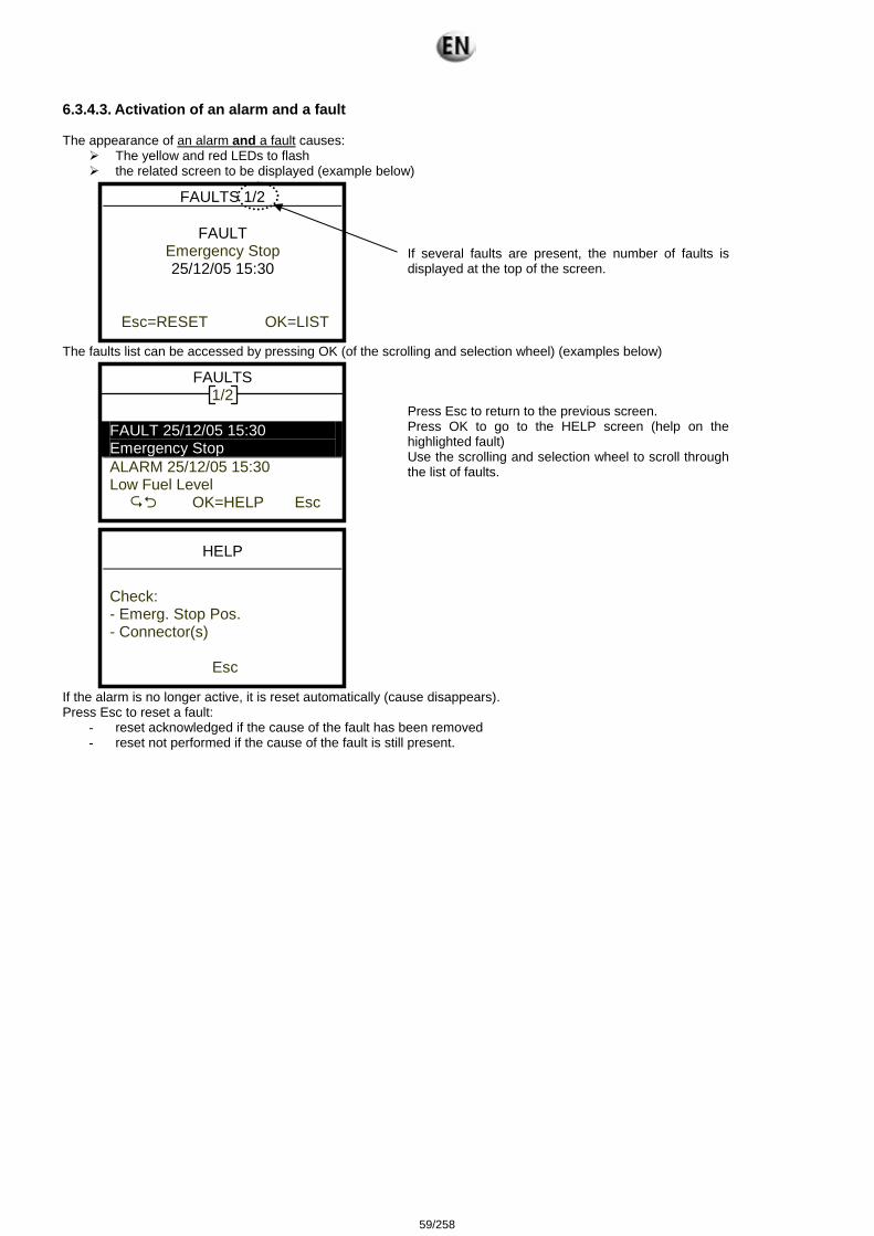
6.3.4.3. Activation of an alarm and a fault The appearance of an alarm and a fault causes:
The yellow and red LEDs to flash the related screen to be displayed (example below)
FAULTS 1/2
FAULT Emergency Stop 25/12/05 15:30
Esc=RESET OK=LIST
If several faults are present, the number of faults is displayed at the top of the screen.
The faults list can be accessed by pressing OK (of the scrolling and selection wheel) (examples below)
FAULTS 1/2
FAULT 25/12/05 15:30 Emergency Stop ALARM 25/12/05 15:30 Low Fuel Level
OK=HELP Esc
Press Esc to return to the previous screen. Press OK to go to the HELP screen (help on the highlighted fault) Use the scrolling and selection wheel to scroll through the list of faults.
HELP
Check: - Emerg. Stop Pos. - Connector(s)
Esc
If the alarm is no longer active, it is reset automatically (cause disappears). Press Esc to reset a fault:
- reset acknowledged if the cause of the fault has been removed - reset not performed if the cause of the fault is still present.
59/258
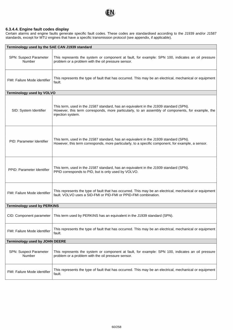
6.3.4.4. Engine fault codes display Certain alarms and engine faults generate specific fault codes. These codes are standardised according to the J1939 and/or J1587 standards, except for MTU engines that have a specific transmission protocol (see appendix, if applicable). Terminology used by the SAE CAN J1939 standard
SPN: Suspect Parameter Number
This represents the system or component at fault, for example: SPN 100, indicates an oil pressure problem or a problem with the oil pressure sensor.
FMI: Failure Mode identifier This represents the type of fault that has occurred. This may be an electrical, mechanical or equipment fault.
Terminology used by VOLVO
SID: System Identifier This term, used in the J1587 standard, has an equivalent in the J1939 standard (SPN). However, this term corresponds, more particularly, to an assembly of components, for example, the injection system.
PID: Parameter Identifier This term, used in the J1587 standard, has an equivalent in the J1939 standard (SPN). However, this term corresponds, more particularly, to a specific component, for example, a sensor.
PPID: Parameter Identifier This term, used in the J1587 standard, has an equivalent in the J1939 standard (SPN). PPID corresponds to PID, but is only used by VOLVO.
FMI: Failure Mode identifier This represents the type of fault that has occurred. This may be an electrical, mechanical or equipment fault. VOLVO uses a SID-FMI or PID-FMI or PPID-FMI combination.
Terminology used by PERKINS
CID: Component parameter This term used by PERKINS has an equivalent in the J1939 standard (SPN).
FMI: Failure Mode identifier This represents the type of fault that has occurred. This may be an electrical, mechanical or equipment fault.
Terminology used by JOHN DEERE
SPN: Suspect Parameter Number
This represents the system or component at fault, for example: SPN 100, indicates an oil pressure problem or a problem with the oil pressure sensor.
FMI: Failure Mode identifier This represents the type of fault that has occurred. This may be an electrical, mechanical or equipment fault.
60/258
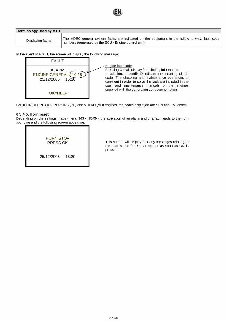
Terminology used by MTU
Displaying faults The MDEC general system faults are indicated on the equipment in the following way: fault code numbers (generated by the ECU - Engine control unit).
In the event of a fault, the screen will display the following message:
FAULT
ALARM ENGINE GENERAL 110 18
25/12/2005 15:30
OK=HELP
Engine fault code. Pressing OK will display fault finding information. In addition, appendix D indicate the meaning of the code. The checking and maintenance operations to carry out in order to solve the fault are included in the user and maintenance manuals of the engines supplied with the generating set documentation.
For JOHN DEERE (JD), PERKINS (PE) and VOLVO (VO) engines, the codes displayed are SPN and FMI codes. 6.3.4.5. Horn reset Depending on the settings made (menu 363 - HORN), the activation of an alarm and/or a fault leads to the horn sounding and the following screen appearing:
HORN STOP PRESS OK
25/12/2005 15:30
This screen will display first any messages relating to the alarms and faults that appear as soon as OK is pressed.
61/258
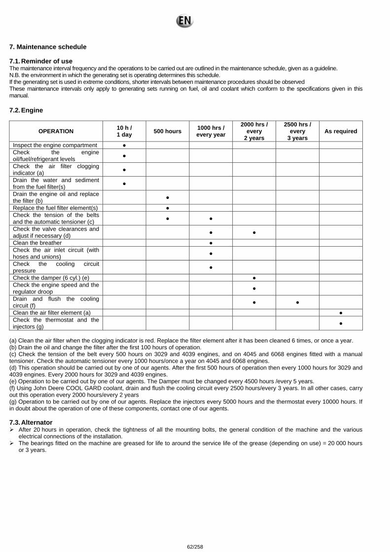
7. Maintenance schedule 7.1. Reminder of use The maintenance interval frequency and the operations to be carried out are outlined in the maintenance schedule, given as a guideline. N.B. the environment in which the generating set is operating determines this schedule. If the generating set is used in extreme conditions, shorter intervals between maintenance procedures should be observed These maintenance intervals only apply to generating sets running on fuel, oil and coolant which conform to the specifications given in this manual.
7.2. Engine
OPERATION 10 h / 1 day 500 hours 1000 hrs /
every year 2000 hrs /
every 2 years
2500 hrs / every
3 years As required
Inspect the engine compartment Check the engine oil/fuel/refrigerant levels
Check the air filter clogging indicator (a)
Drain the water and sediment from the fuel filter(s)
Drain the engine oil and replace the filter (b)
Replace the fuel filter element(s) Check the tension of the belts and the automatic tensioner (c)
Check the valve clearances and adjust if necessary (d)
Clean the breather Check the air inlet circuit (with hoses and unions)
Check the cooling circuit pressure
Check the damper (6 cyl.) (e) Check the engine speed and the regulator droop
Drain and flush the cooling circuit (f)
Clean the air filter element (a) Check the thermostat and the injectors (g)
(a) Clean the air filter when the clogging indicator is red. Replace the filter element after it has been cleaned 6 times, or once a year. (b) Drain the oil and change the filter after the first 100 hours of operation. (c) Check the tension of the belt every 500 hours on 3029 and 4039 engines, and on 4045 and 6068 engines fitted with a manual tensioner. Check the automatic tensioner every 1000 hours/once a year on 4045 and 6068 engines. (d) This operation should be carried out by one of our agents. After the first 500 hours of operation then every 1000 hours for 3029 and 4039 engines. Every 2000 hours for 3029 and 4039 engines. (e) Operation to be carried out by one of our agents. The Damper must be changed every 4500 hours /every 5 years. (f) Using John Deere COOL GARD coolant, drain and flush the cooling circuit every 2500 hours/every 3 years. In all other cases, carry out this operation every 2000 hours/every 2 years (g) Operation to be carried out by one of our agents. Replace the injectors every 5000 hours and the thermostat every 10000 hours. If in doubt about the operation of one of these components, contact one of our agents. 7.3. Alternator
After 20 hours in operation, check the tightness of all the mounting bolts, the general condition of the machine and the various electrical connections of the installation.
The bearings fitted on the machine are greased for life to around the service life of the grease (depending on use) = 20 000 hours or 3 years.
62/258
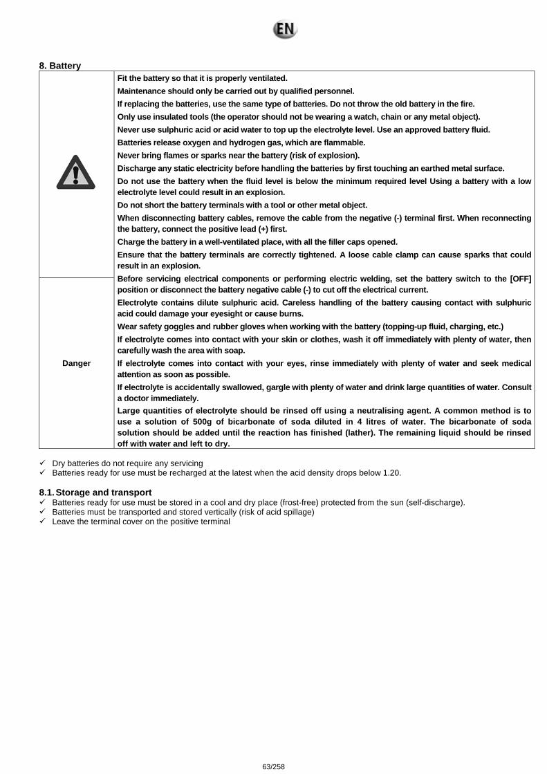
8. Battery
Danger
Fit the battery so that it is properly ventilated. Maintenance should only be carried out by qualified personnel. If replacing the batteries, use the same type of batteries. Do not throw the old battery in the fire. Only use insulated tools (the operator should not be wearing a watch, chain or any metal object). Never use sulphuric acid or acid water to top up the electrolyte level. Use an approved battery fluid. Batteries release oxygen and hydrogen gas, which are flammable. Never bring flames or sparks near the battery (risk of explosion). Discharge any static electricity before handling the batteries by first touching an earthed metal surface. Do not use the battery when the fluid level is below the minimum required level Using a battery with a low electrolyte level could result in an explosion. Do not short the battery terminals with a tool or other metal object. When disconnecting battery cables, remove the cable from the negative (-) terminal first. When reconnecting the battery, connect the positive lead (+) first. Charge the battery in a well-ventilated place, with all the filler caps opened. Ensure that the battery terminals are correctly tightened. A loose cable clamp can cause sparks that could result in an explosion. Before servicing electrical components or performing electric welding, set the battery switch to the [OFF] position or disconnect the battery negative cable (-) to cut off the electrical current. Electrolyte contains dilute sulphuric acid. Careless handling of the battery causing contact with sulphuric acid could damage your eyesight or cause burns. Wear safety goggles and rubber gloves when working with the battery (topping-up fluid, charging, etc.) If electrolyte comes into contact with your skin or clothes, wash it off immediately with plenty of water, then carefully wash the area with soap. If electrolyte comes into contact with your eyes, rinse immediately with plenty of water and seek medical attention as soon as possible. If electrolyte is accidentally swallowed, gargle with plenty of water and drink large quantities of water. Consult a doctor immediately. Large quantities of electrolyte should be rinsed off using a neutralising agent. A common method is to use a solution of 500g of bicarbonate of soda diluted in 4 litres of water. The bicarbonate of soda solution should be added until the reaction has finished (lather). The remaining liquid should be rinsed off with water and left to dry.
Dry batteries do not require any servicing Batteries ready for use must be recharged at the latest when the acid density drops below 1.20.
8.1. Storage and transport
Batteries ready for use must be stored in a cool and dry place (frost-free) protected from the sun (self-discharge). Batteries must be transported and stored vertically (risk of acid spillage) Leave the terminal cover on the positive terminal
63/258
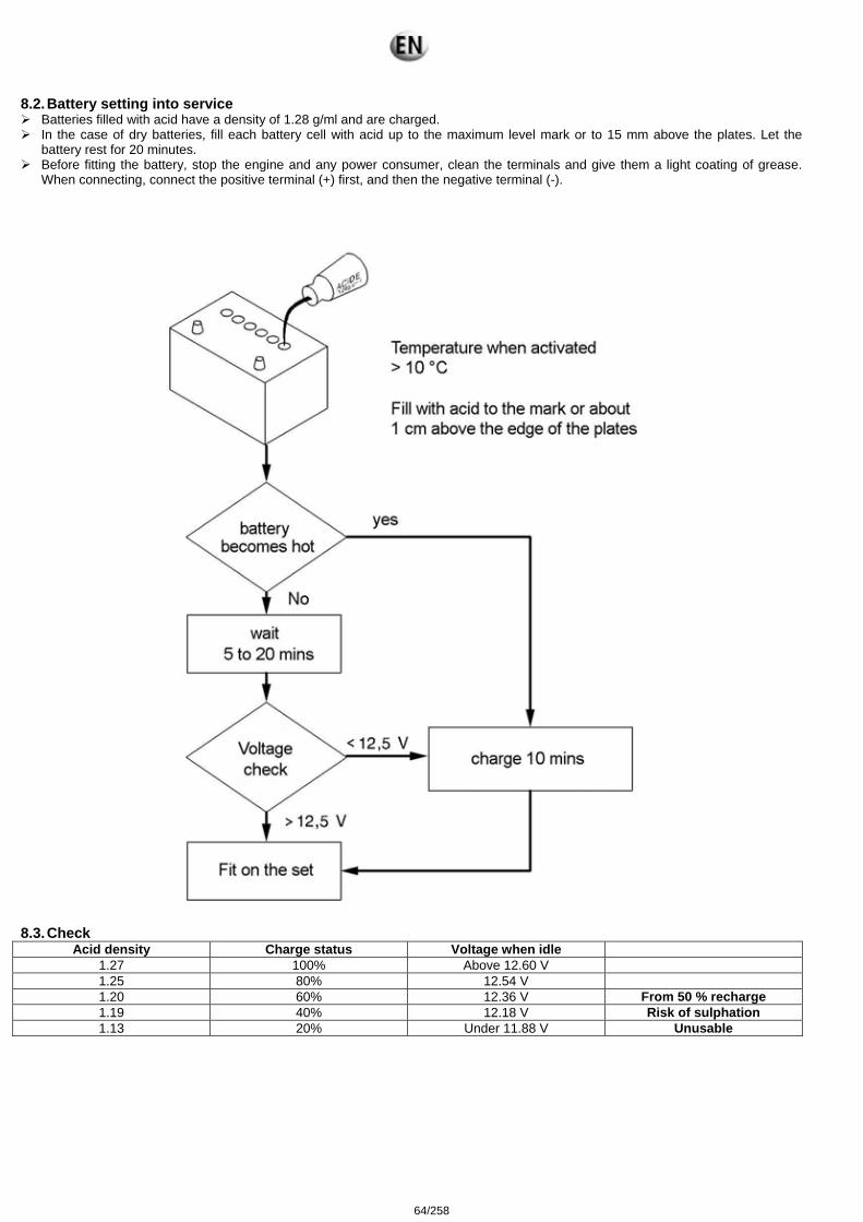
8.2. Battery setting into service Batteries filled with acid have a density of 1.28 g/ml and are charged. In the case of dry batteries, fill each battery cell with acid up to the maximum level mark or to 15 mm above the plates. Let the
battery rest for 20 minutes. Before fitting the battery, stop the engine and any power consumer, clean the terminals and give them a light coating of grease.
When connecting, connect the positive terminal (+) first, and then the negative terminal (-).
8.3. Check
Acid density Charge status Voltage when idle 1.27 100% Above 12.60 V 1.25 80% 12.54 V 1.20 60% 12.36 V From 50 % recharge 1.19 40% 12.18 V Risk of sulphation 1.13 20% Under 11.88 V Unusable
64/258
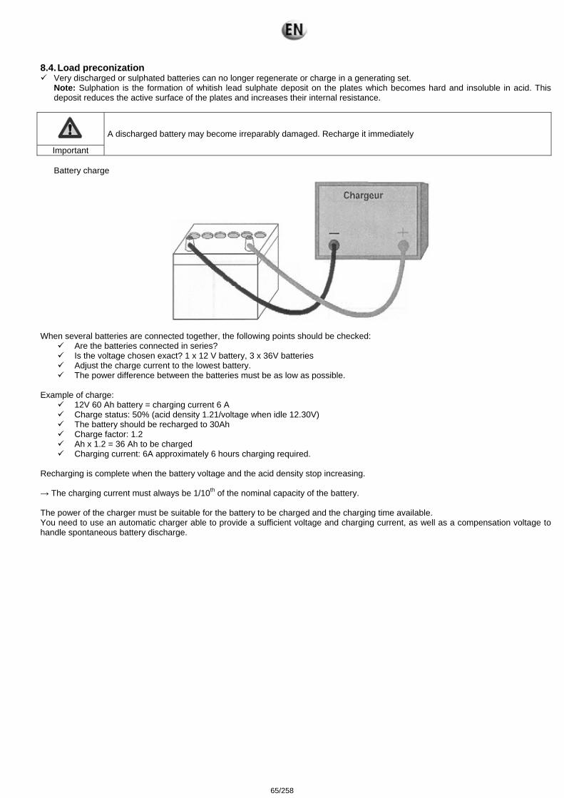
8.4. Load preconization Very discharged or sulphated batteries can no longer regenerate or charge in a generating set.
Note: Sulphation is the formation of whitish lead sulphate deposit on the plates which becomes hard and insoluble in acid. This deposit reduces the active surface of the plates and increases their internal resistance.
Important
A discharged battery may become irreparably damaged. Recharge it immediately
Battery charge
When several batteries are connected together, the following points should be checked:
Are the batteries connected in series? Is the voltage chosen exact? 1 x 12 V battery, 3 x 36V batteries Adjust the charge current to the lowest battery. The power difference between the batteries must be as low as possible.
Example of charge:
12V 60 Ah battery = charging current 6 A Charge status: 50% (acid density 1.21/voltage when idle 12.30V) The battery should be recharged to 30Ah Charge factor: 1.2 Ah x 1.2 = 36 Ah to be charged Charging current: 6A approximately 6 hours charging required.
Recharging is complete when the battery voltage and the acid density stop increasing. → The charging current must always be 1/10th of the nominal capacity of the battery. The power of the charger must be suitable for the battery to be charged and the charging time available. You need to use an automatic charger able to provide a sufficient voltage and charging current, as well as a compensation voltage to handle spontaneous battery discharge.
65/258
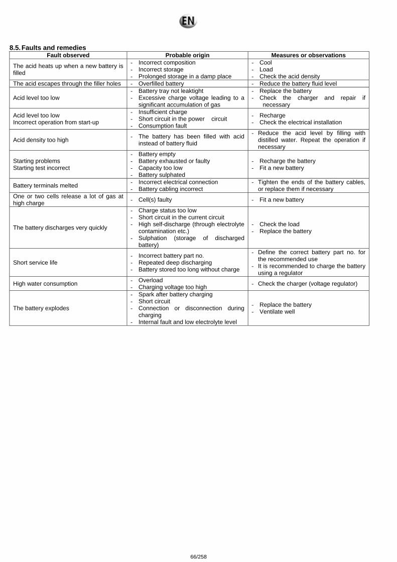
8.5. Faults and remedies Fault observed Probable origin Measures or observations
The acid heats up when a new battery is filled
- Incorrect composition - Incorrect storage - Prolonged storage in a damp place
- Cool - Load - Check the acid density
The acid escapes through the filler holes - Overfilled battery - Reduce the battery fluid level
Acid level too low - Battery tray not leaktight - Excessive charge voltage leading to a
significant accumulation of gas
- Replace the battery - Check the charger and repair if
necessary
Acid level too low Incorrect operation from start-up
- Insufficient charge - Short circuit in the power circuit - Consumption fault
- Recharge - Check the electrical installation
Acid density too high - The battery has been filled with acid instead of battery fluid
- Reduce the acid level by filling with distilled water. Repeat the operation if necessary
Starting problems Starting test incorrect
- Battery empty - Battery exhausted or faulty - Capacity too low - Battery sulphated
- Recharge the battery - Fit a new battery
Battery terminals melted - Incorrect electrical connection - Battery cabling incorrect
- Tighten the ends of the battery cables, or replace them if necessary
One or two cells release a lot of gas at high charge - Cell(s) faulty - Fit a new battery
The battery discharges very quickly
- Charge status too low - Short circuit in the current circuit - High self-discharge (through electrolyte
contamination etc.) - Sulphation (storage of discharged
battery)
- Check the load - Replace the battery
Short service life - Incorrect battery part no. - Repeated deep discharging - Battery stored too long without charge
- Define the correct battery part no. for the recommended use
- It is recommended to charge the battery using a regulator
High water consumption - Overload - Charging voltage too high - Check the charger (voltage regulator)
The battery explodes
- Spark after battery charging - Short circuit - Connection or disconnection during
charging - Internal fault and low electrolyte level
- Replace the battery - Ventilate well
66/258

9. Appendix 9.1. Appendix A – Engine user and maintenance manual
67/258

68/258
User guide and maintenance manual
JJOOHHNN DDEEEERREE
EEnnggiinnee 33002299TTFF112200 33002299DDFF112200 66006688TTFF222200 44004455TTFF222200 44004455HHFF112200 44004455TTFF112200
66006688HHFF112200--115533 33002299TTFFSS7700 ((TTFF227700)) 33002299HHFFSS7700 ((HHFF227700)) 44004455HHFFSS7722 ((HHFF227755)) 44004455HHFFSS7733 ((HHFF227799)) 44004455HHFFSS8800 ((HHFF228800)) 44004455HHFFSS8822 ((HHFF228855)) 44004455HHFFSS8833 ((HHFF228855)) 44004455TTFFSS7700 ((TTFF227700)) 66006688HHFFSS7722 ((HHFF227755)) 66006688HHFFSS7733 ((HHFF227799)) 66006688HHFFSS7766 ((HHFF447755)) 66006688HHFFSS7777 ((HHFF447755)) 66006688HHFFSS8822 ((HHFF228855)) 66006688HHFFSS8833 ((HHFF228855)) 66006688HHFFSS8899 ((HHFF448855))
OMCD16564 06/07/2009
33522039401_4_1
69/258

70/258
Engines & Power Unitsfor Generator Sets
(SaranBuilt)
OPERATOR’S MANUALEngines & Power Units
for Generator Sets (SaranBuilt)OMCD16564 ISSUE G9 (ANGLAIS)
CALIFORNIAProposition 65 Warning
Diesel engine exhaust and some of its constituentsare known to the State of California to cause cancer,
birth defects, and other reproductive harm.
If this product contains a gasoline engine:
WARNING
The engine exhaust from this product containschemicals known to the State of California to causecancer, birth defects or other reproductive harm.
The State of California requires the above two warnings.
John Deere Usine De Saran(This manual replaces OMCD16564 F8)
European VersionPRINTED IN GERMANY
71/258
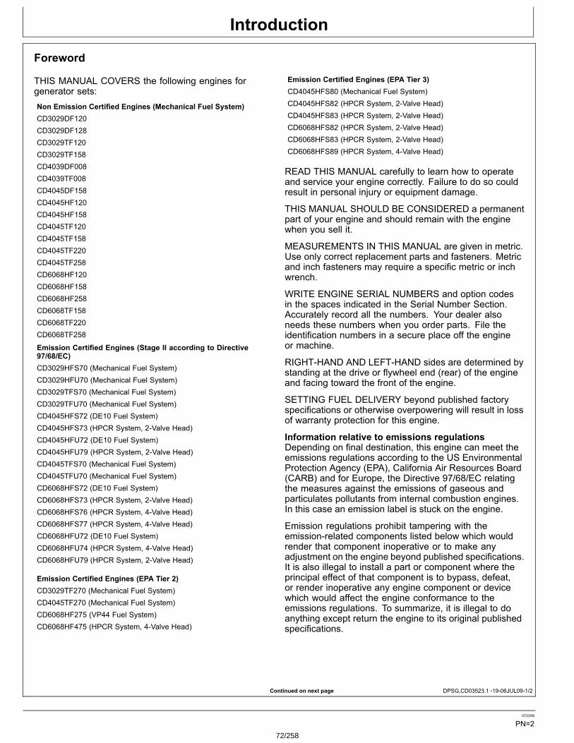
Introduction
Continued on next page DPSG,CD03523,1 1906JUL091/2
Foreword
THIS MANUAL COVERS the following engines forgenerator sets:Non Emission Certified Engines (Mechanical Fuel System)CD3029DF120CD3029DF128CD3029TF120CD3029TF158CD4039DF008CD4039TF008CD4045DF158CD4045HF120CD4045HF158CD4045TF120CD4045TF158CD4045TF220CD4045TF258CD6068HF120CD6068HF158CD6068HF258CD6068TF158CD6068TF220CD6068TF258
Emission Certified Engines (Stage II according to Directive97/68/EC)CD3029HFS70 (Mechanical Fuel System)CD3029HFU70 (Mechanical Fuel System)CD3029TFS70 (Mechanical Fuel System)CD3029TFU70 (Mechanical Fuel System)CD4045HFS72 (DE10 Fuel System)CD4045HFS73 (HPCR System, 2Valve Head)CD4045HFU72 (DE10 Fuel System)CD4045HFU79 (HPCR System, 2Valve Head)CD4045TFS70 (Mechanical Fuel System)CD4045TFU70 (Mechanical Fuel System)CD6068HFS72 (DE10 Fuel System)CD6068HFS73 (HPCR System, 2Valve Head)CD6068HFS76 (HPCR System, 4Valve Head)CD6068HFS77 (HPCR System, 4Valve Head)CD6068HFU72 (DE10 Fuel System)CD6068HFU74 (HPCR System, 4Valve Head)CD6068HFU79 (HPCR System, 2Valve Head)
Emission Certified Engines (EPA Tier 2)CD3029TF270 (Mechanical Fuel System)CD4045TF270 (Mechanical Fuel System)CD6068HF275 (VP44 Fuel System)CD6068HF475 (HPCR System, 4Valve Head)
Emission Certified Engines (EPA Tier 3)CD4045HFS80 (Mechanical Fuel System)CD4045HFS82 (HPCR System, 2Valve Head)CD4045HFS83 (HPCR System, 2Valve Head)CD6068HFS82 (HPCR System, 2Valve Head)CD6068HFS83 (HPCR System, 2Valve Head)CD6068HFS89 (HPCR System, 4Valve Head)
READ THIS MANUAL carefully to learn how to operateand service your engine correctly. Failure to do so couldresult in personal injury or equipment damage.
THIS MANUAL SHOULD BE CONSIDERED a permanentpart of your engine and should remain with the enginewhen you sell it.
MEASUREMENTS IN THIS MANUAL are given in metric.Use only correct replacement parts and fasteners. Metricand inch fasteners may require a specific metric or inchwrench.
WRITE ENGINE SERIAL NUMBERS and option codesin the spaces indicated in the Serial Number Section.Accurately record all the numbers. Your dealer alsoneeds these numbers when you order parts. File theidentification numbers in a secure place off the engineor machine.
RIGHTHAND AND LEFTHAND sides are determined bystanding at the drive or flywheel end (rear) of the engineand facing toward the front of the engine.
SETTING FUEL DELIVERY beyond published factoryspecifications or otherwise overpowering will result in lossof warranty protection for this engine.
Information relative to emissions regulationsDepending on final destination, this engine can meet theemissions regulations according to the US EnvironmentalProtection Agency (EPA), California Air Resources Board(CARB) and for Europe, the Directive 97/68/EC relatingthe measures against the emissions of gaseous andparticulates pollutants from internal combustion engines.In this case an emission label is stuck on the engine.
Emission regulations prohibit tampering with theemissionrelated components listed below which wouldrender that component inoperative or to make anyadjustment on the engine beyond published specifications.It is also illegal to install a part or component where theprincipal effect of that component is to bypass, defeat,or render inoperative any engine component or devicewhich would affect the engine conformance to theemissions regulations. To summarize, it is illegal to doanything except return the engine to its original publishedspecifications.
072209
PN=272/258
Introduction
DPSG,CD03523,1 1906JUL092/2
List of emissionrelated components: Fuel injection pump Intake manifold Turbocharger Charge air cooling system
PistonCALIFORNIA PROPOSITION 65 WARNING
Diesel engine exhaust and some of its constituents are knownto the State of California to cause cancer,birth defects and other reproductive harm.
072209
PN=373/258

Introduction
072209
PN=474/258
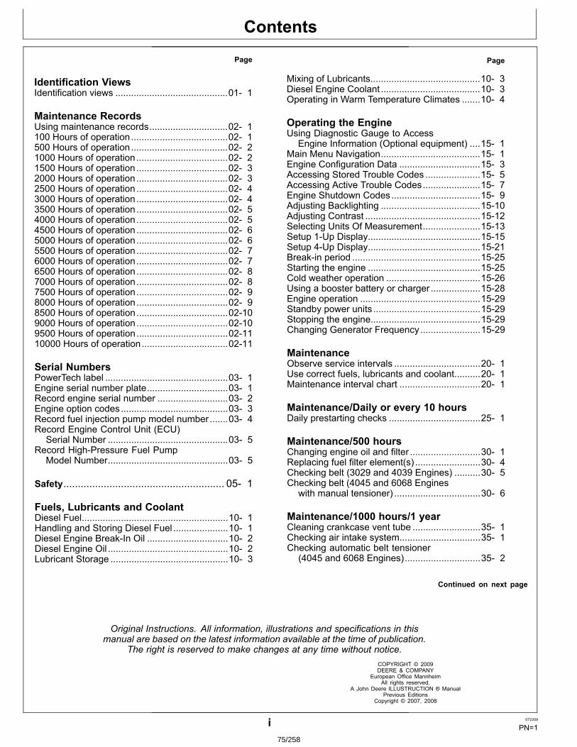
Contents
Page
Identification ViewsIdentification views ...........................................01 1
Maintenance RecordsUsing maintenance records..............................02 1100 Hours of operation.....................................02 1500 Hours of operation.....................................02 21000 Hours of operation...................................02 21500 Hours of operation...................................02 32000 Hours of operation...................................02 32500 Hours of operation...................................02 43000 Hours of operation...................................02 43500 Hours of operation...................................02 54000 Hours of operation...................................02 54500 Hours of operation...................................02 65000 Hours of operation...................................02 65500 Hours of operation...................................02 76000 Hours of operation...................................02 76500 Hours of operation...................................02 87000 Hours of operation...................................02 87500 Hours of operation...................................02 98000 Hours of operation...................................02 98500 Hours of operation...................................02109000 Hours of operation...................................02109500 Hours of operation...................................021110000 Hours of operation.................................0211
Serial NumbersPowerTech label ...............................................03 1Engine serial number plate...............................03 1Record engine serial number ...........................03 2Engine option codes.........................................03 3Record fuel injection pump model number .......03 4Record Engine Control Unit (ECU)
Serial Number ..............................................03 5Record HighPressure Fuel Pump
Model Number..............................................03 5
Safety........................................................ 05 1
Fuels, Lubricants and CoolantDiesel Fuel........................................................10 1Handling and Storing Diesel Fuel .....................10 1Diesel Engine BreakIn Oil ...............................10 2Diesel Engine Oil ..............................................10 2Lubricant Storage .............................................10 3
Page
Mixing of Lubricants..........................................10 3Diesel Engine Coolant ......................................10 3Operating in Warm Temperature Climates .......10 4
Operating the EngineUsing Diagnostic Gauge to Access
Engine Information (Optional equipment) ....15 1Main Menu Navigation......................................15 1Engine Configuration Data ...............................15 3Accessing Stored Trouble Codes .....................15 5Accessing Active Trouble Codes......................15 7Engine Shutdown Codes..................................15 9Adjusting Backlighting ......................................1510Adjusting Contrast ............................................1512Selecting Units Of Measurement......................1513Setup 1Up Display...........................................1515Setup 4Up Display...........................................1521Breakin period .................................................1525Starting the engine ...........................................1525Cold weather operation ....................................1526Using a booster battery or charger ...................1528Engine operation ..............................................1529Standby power units .........................................1529Stopping the engine..........................................1529Changing Generator Frequency.......................1529
MaintenanceObserve service intervals .................................20 1Use correct fuels, lubricants and coolant..........20 1Maintenance interval chart ...............................20 1
Maintenance/Daily or every 10 hoursDaily prestarting checks ...................................25 1
Maintenance/500 hoursChanging engine oil and filter ...........................30 1Replacing fuel filter element(s) .........................30 4Checking belt (3029 and 4039 Engines) ..........30 5Checking belt (4045 and 6068 Engines
with manual tensioner) .................................30 6
Maintenance/1000 hours/1 yearCleaning crankcase vent tube ..........................35 1Checking air intake system...............................35 1Checking automatic belt tensioner
(4045 and 6068 Engines).............................35 2
Continued on next page
Original Instructions. All information, illustrations and specifications in thismanual are based on the latest information available at the time of publication.
The right is reserved to make changes at any time without notice.COPYRIGHT © 2009DEERE & COMPANY
European Office MannheimAll rights reserved.
A John Deere ILLUSTRUCTION ® ManualPrevious Editions
Copyright © 2007, 2008
i 072209
PN=175/258
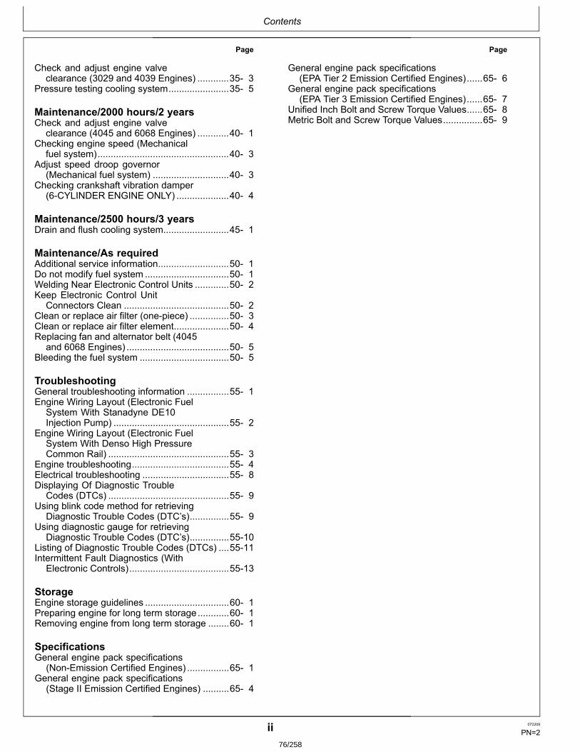
Contents
Page
Check and adjust engine valveclearance (3029 and 4039 Engines) ............35 3
Pressure testing cooling system.......................35 5
Maintenance/2000 hours/2 yearsCheck and adjust engine valve
clearance (4045 and 6068 Engines) ............40 1Checking engine speed (Mechanical
fuel system)..................................................40 3Adjust speed droop governor
(Mechanical fuel system) .............................40 3Checking crankshaft vibration damper
(6CYLINDER ENGINE ONLY) ....................40 4
Maintenance/2500 hours/3 yearsDrain and flush cooling system.........................45 1
Maintenance/As requiredAdditional service information...........................50 1Do not modify fuel system ................................50 1Welding Near Electronic Control Units .............50 2Keep Electronic Control Unit
Connectors Clean ........................................50 2Clean or replace air filter (onepiece) ...............50 3Clean or replace air filter element.....................50 4Replacing fan and alternator belt (4045
and 6068 Engines) .......................................50 5Bleeding the fuel system ..................................50 5
TroubleshootingGeneral troubleshooting information ................55 1Engine Wiring Layout (Electronic Fuel
System With Stanadyne DE10Injection Pump) ............................................55 2
Engine Wiring Layout (Electronic FuelSystem With Denso High PressureCommon Rail) ..............................................55 3
Engine troubleshooting.....................................55 4Electrical troubleshooting .................................55 8Displaying Of Diagnostic Trouble
Codes (DTCs) ..............................................55 9Using blink code method for retrieving
Diagnostic Trouble Codes (DTC’s)...............55 9Using diagnostic gauge for retrieving
Diagnostic Trouble Codes (DTC’s)...............5510Listing of Diagnostic Trouble Codes (DTCs) ....5511Intermittent Fault Diagnostics (With
Electronic Controls)......................................5513
StorageEngine storage guidelines ................................60 1Preparing engine for long term storage............60 1Removing engine from long term storage ........60 1
SpecificationsGeneral engine pack specifications
(NonEmission Certified Engines) ................65 1General engine pack specifications
(Stage II Emission Certified Engines) ..........65 4
Page
General engine pack specifications(EPA Tier 2 Emission Certified Engines)......65 6
General engine pack specifications(EPA Tier 3 Emission Certified Engines)......65 7
Unified Inch Bolt and Screw Torque Values......65 8Metric Bolt and Screw Torque Values...............65 9
ii 072209
PN=276/258
Identification Views
Continued on next page DPSG,CD03523,3 1922JAN071/3
Identification views
CD30840—UN—10JAN03
3029DF128
011 072209
PN=777/258
Identification Views
Continued on next page DPSG,CD03523,3 1922JAN072/3
CD30841—UN—10JAN03
4045HF158
012 072209
PN=878/258
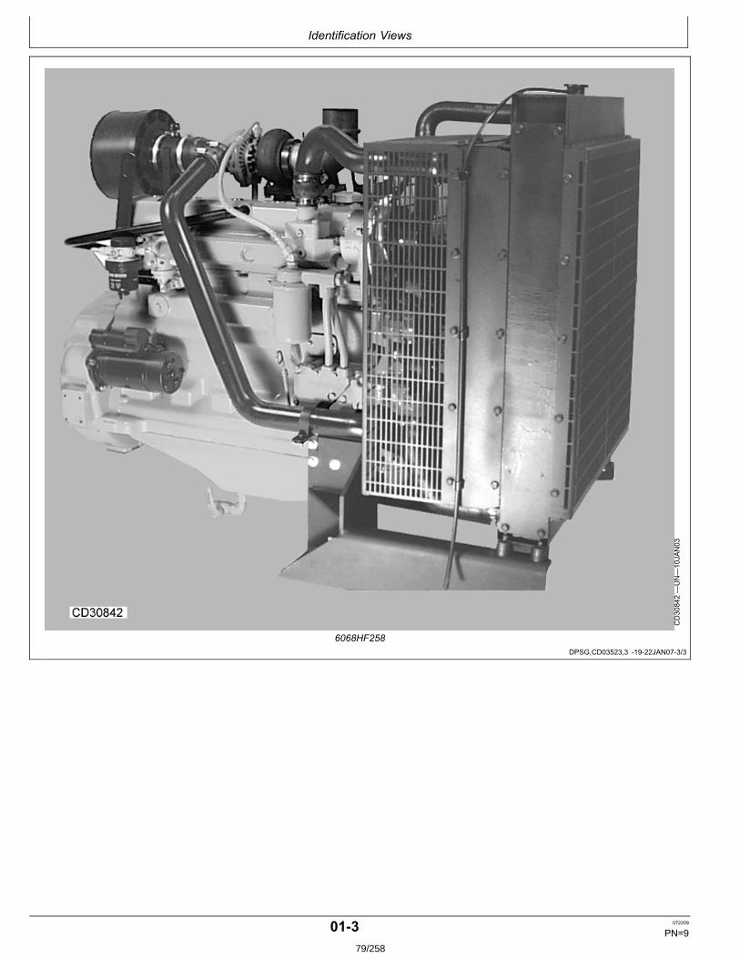
Identification Views
DPSG,CD03523,3 1922JAN073/3
CD30842—UN—10JAN03
6068HF258
013 072209
PN=979/258
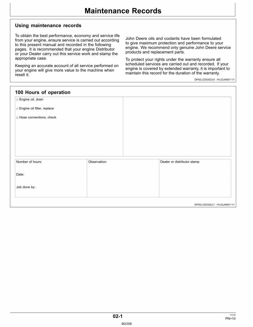
Maintenance Records
DPSG,CD03523,6 1922JAN071/1
DPSG,CD03523,7 1922JAN071/1
Using maintenance records
To obtain the best performance, economy and service lifefrom your engine, ensure service is carried out accordingto this present manual and recorded in the followingpages. It is recommended that your engine Distributoror your Dealer carry out this service work and stamp theappropriate case.
Keeping an accurate account of all service performed onyour engine will give more value to the machine whenresell it.
John Deere oils and coolants have been formulatedto give maximum protection and performance to yourengine. We recommend only genuine John Deere serviceproducts and replacement parts.
To protect your rights under the warranty ensure allscheduled services are carried out and recorded. If yourengine is covered by extended warranty, it is important tomaintain this record for the duration of the warranty.
100 Hours of operation Engine oil, drain
Engine oil filter, replace
Hose connections, check
Number of hours: Observation: Dealer or distributor stamp
Date:
Job done by:
021 072209
PN=1080/258
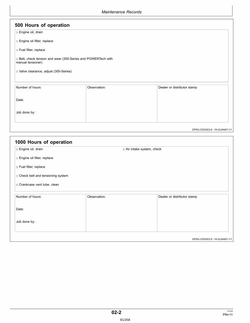
Maintenance Records
DPSG,CD03523,8 1922JAN071/1
DPSG,CD03523,9 1922JAN071/1
500 Hours of operation Engine oil, drain
Engine oil filter, replace
Fuel filter, replace
Belt, check tension and wear (300Series and POWERTech withmanual tensioner)
Valve clearance, adjust (300Series)
Number of hours: Observation: Dealer or distributor stamp
Date:
Job done by:
1000 Hours of operation Engine oil, drain Air intake system, check
Engine oil filter, replace
Fuel filter, replace
Check belt and tensioning system
Crankcase vent tube, clean
Number of hours: Observation: Dealer or distributor stamp
Date:
Job done by:
022 072209
PN=1181/258
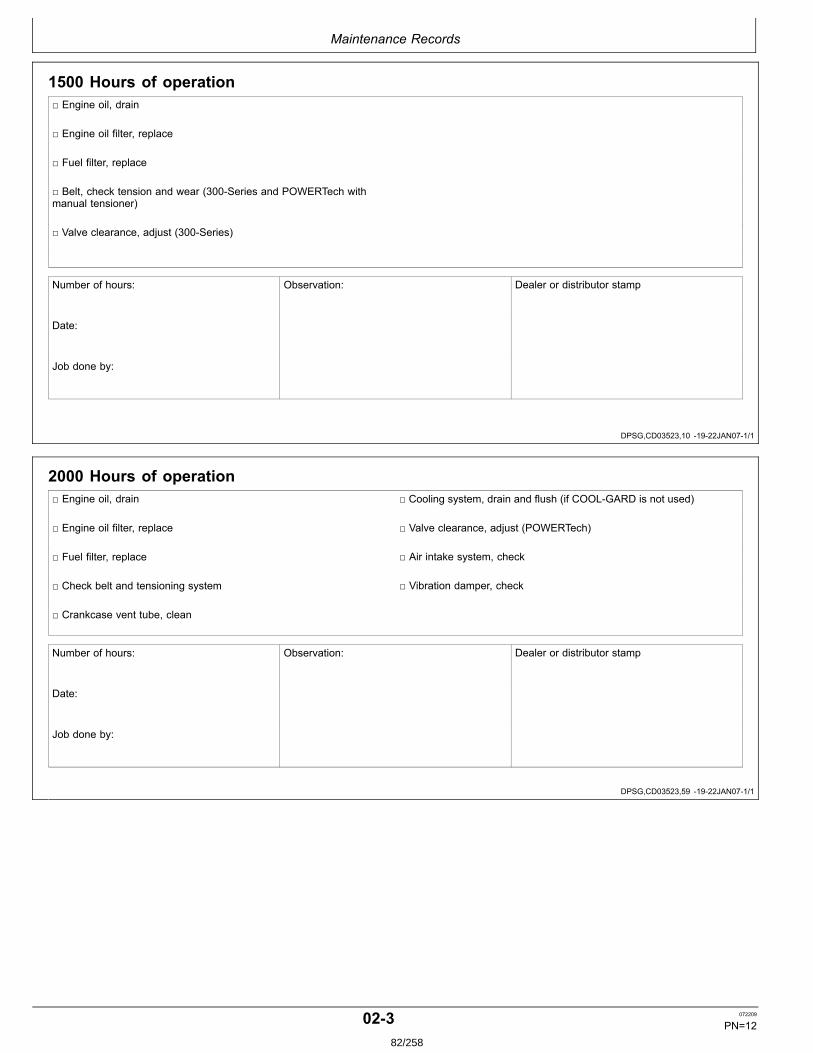
Maintenance Records
DPSG,CD03523,10 1922JAN071/1
DPSG,CD03523,59 1922JAN071/1
1500 Hours of operation Engine oil, drain
Engine oil filter, replace
Fuel filter, replace
Belt, check tension and wear (300Series and POWERTech withmanual tensioner)
Valve clearance, adjust (300Series)
Number of hours: Observation: Dealer or distributor stamp
Date:
Job done by:
2000 Hours of operation Engine oil, drain Cooling system, drain and flush (if COOLGARD is not used)
Engine oil filter, replace Valve clearance, adjust (POWERTech)
Fuel filter, replace Air intake system, check
Check belt and tensioning system Vibration damper, check
Crankcase vent tube, clean
Number of hours: Observation: Dealer or distributor stamp
Date:
Job done by:
023 072209
PN=1282/258
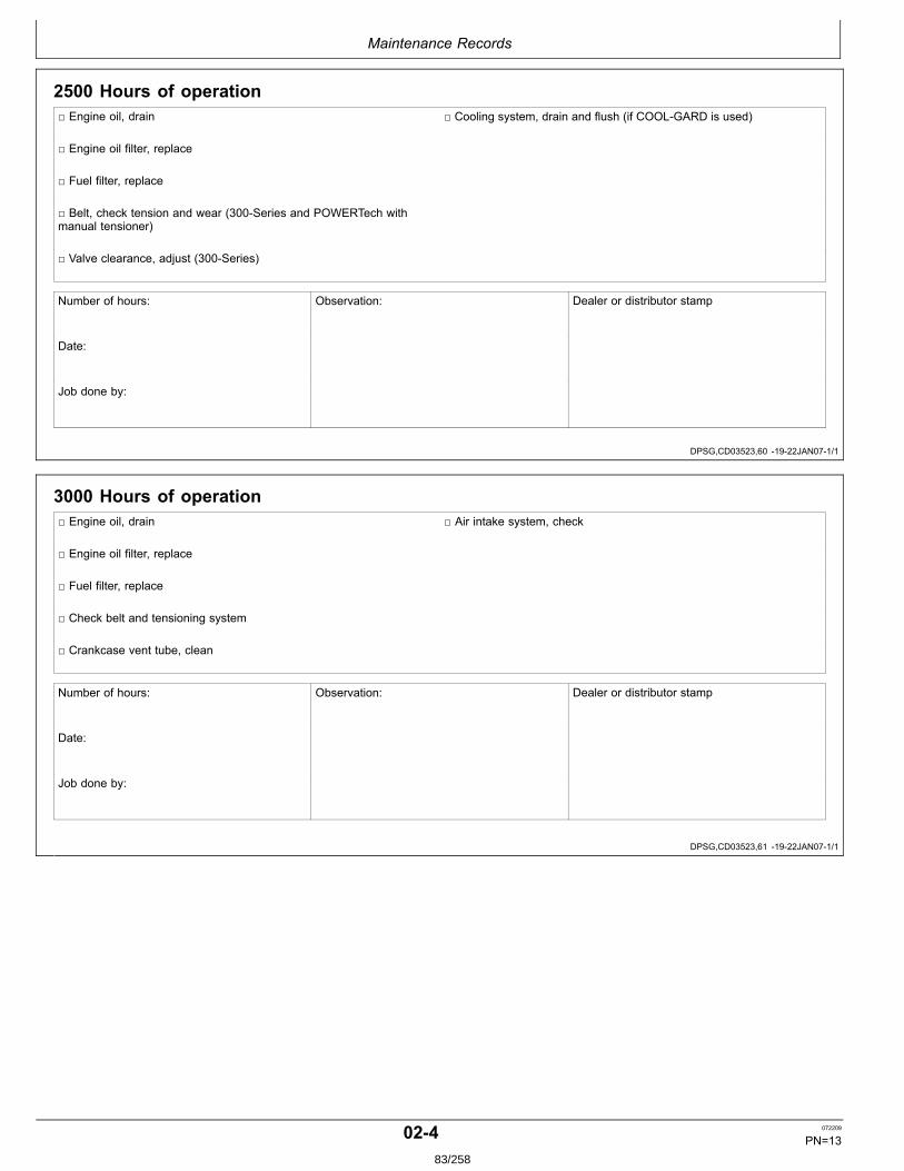
Maintenance Records
DPSG,CD03523,60 1922JAN071/1
DPSG,CD03523,61 1922JAN071/1
2500 Hours of operation Engine oil, drain Cooling system, drain and flush (if COOLGARD is used)
Engine oil filter, replace
Fuel filter, replace
Belt, check tension and wear (300Series and POWERTech withmanual tensioner)
Valve clearance, adjust (300Series)
Number of hours: Observation: Dealer or distributor stamp
Date:
Job done by:
3000 Hours of operation Engine oil, drain Air intake system, check
Engine oil filter, replace
Fuel filter, replace
Check belt and tensioning system
Crankcase vent tube, clean
Number of hours: Observation: Dealer or distributor stamp
Date:
Job done by:
024 072209
PN=1383/258

Maintenance Records
DPSG,CD03523,62 1922JAN071/1
DPSG,CD03523,63 1922JAN071/1
3500 Hours of operation Engine oil, drain
Engine oil filter, replace
Fuel filter, replace
Belt, check tension and wear (300Series and POWERTech withmanual tensioner)
Valve clearance, adjust (300Series)
Number of hours: Observation: Dealer or distributor stamp
Date:
Job done by:
4000 Hours of operation Engine oil, drain Cooling system, drain and flush (if COOLGARD is not used)
Engine oil filter, replace Valve clearance, adjust (POWERTech)
Fuel filter, replace Air intake system, check
Check belt and tensioning system Vibration damper, check
Crankcase vent tube, clean
Number of hours: Observation: Dealer or distributor stamp
Date:
Job done by:
025 072209
PN=1484/258
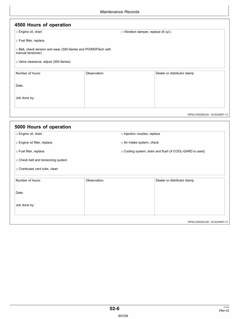
Maintenance Records
DPSG,CD03523,64 1922JAN071/1
DPSG,CD03523,65 1922JAN071/1
4500 Hours of operation Engine oil, drain Vibration damper, replace (6 cyl.)
Fuel filter, replace
Belt, check tension and wear (300Series and POWERTech withmanual tensioner)
Valve clearance, adjust (300Series)
Number of hours: Observation: Dealer or distributor stamp
Date:
Job done by:
5000 Hours of operation Engine oil, drain Injection nozzles, replace
Engine oil filter, replace Air intake system, check
Fuel filter, replace Cooling system, drain and flush (if COOLGARD is used)
Check belt and tensioning system
Crankcase vent tube, clean
Number of hours: Observation: Dealer or distributor stamp
Date:
Job done by:
026 072209
PN=1585/258
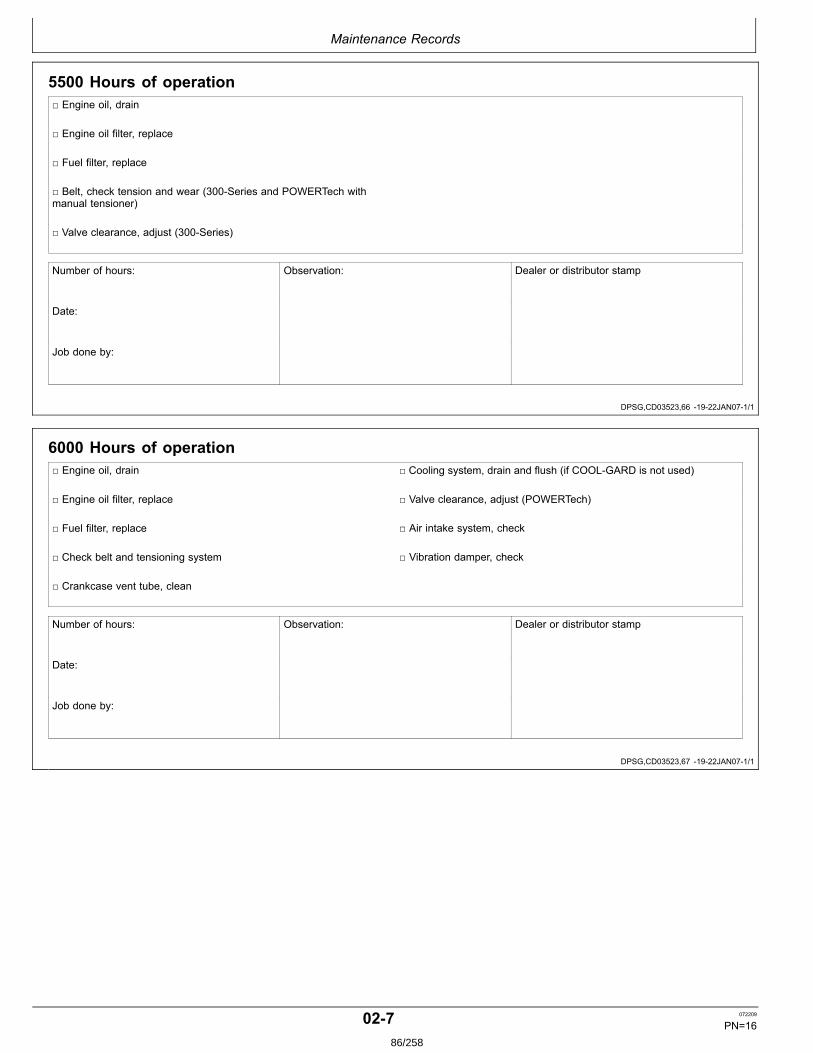
Maintenance Records
DPSG,CD03523,66 1922JAN071/1
DPSG,CD03523,67 1922JAN071/1
5500 Hours of operation Engine oil, drain
Engine oil filter, replace
Fuel filter, replace
Belt, check tension and wear (300Series and POWERTech withmanual tensioner)
Valve clearance, adjust (300Series)
Number of hours: Observation: Dealer or distributor stamp
Date:
Job done by:
6000 Hours of operation Engine oil, drain Cooling system, drain and flush (if COOLGARD is not used)
Engine oil filter, replace Valve clearance, adjust (POWERTech)
Fuel filter, replace Air intake system, check
Check belt and tensioning system Vibration damper, check
Crankcase vent tube, clean
Number of hours: Observation: Dealer or distributor stamp
Date:
Job done by:
027 072209
PN=1686/258
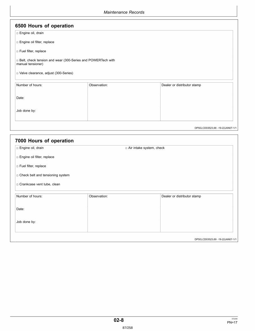
Maintenance Records
DPSG,CD03523,68 1922JAN071/1
DPSG,CD03523,69 1922JAN071/1
6500 Hours of operation Engine oil, drain
Engine oil filter, replace
Fuel filter, replace
Belt, check tension and wear (300Series and POWERTech withmanual tensioner)
Valve clearance, adjust (300Series)
Number of hours: Observation: Dealer or distributor stamp
Date:
Job done by:
7000 Hours of operation Engine oil, drain Air intake system, check
Engine oil filter, replace
Fuel filter, replace
Check belt and tensioning system
Crankcase vent tube, clean
Number of hours: Observation: Dealer or distributor stamp
Date:
Job done by:
028 072209
PN=1787/258
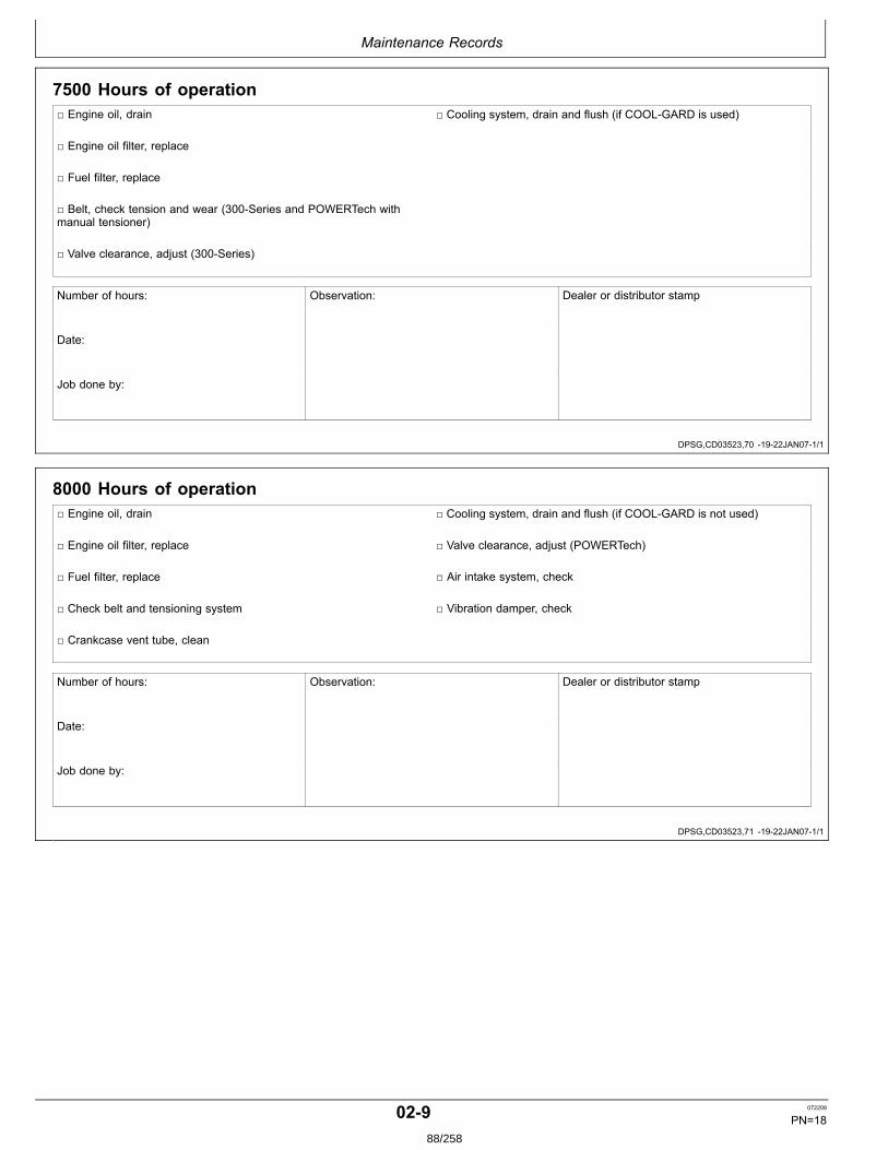
Maintenance Records
DPSG,CD03523,70 1922JAN071/1
DPSG,CD03523,71 1922JAN071/1
7500 Hours of operation Engine oil, drain Cooling system, drain and flush (if COOLGARD is used)
Engine oil filter, replace
Fuel filter, replace
Belt, check tension and wear (300Series and POWERTech withmanual tensioner)
Valve clearance, adjust (300Series)
Number of hours: Observation: Dealer or distributor stamp
Date:
Job done by:
8000 Hours of operation Engine oil, drain Cooling system, drain and flush (if COOLGARD is not used)
Engine oil filter, replace Valve clearance, adjust (POWERTech)
Fuel filter, replace Air intake system, check
Check belt and tensioning system Vibration damper, check
Crankcase vent tube, clean
Number of hours: Observation: Dealer or distributor stamp
Date:
Job done by:
029 072209
PN=1888/258
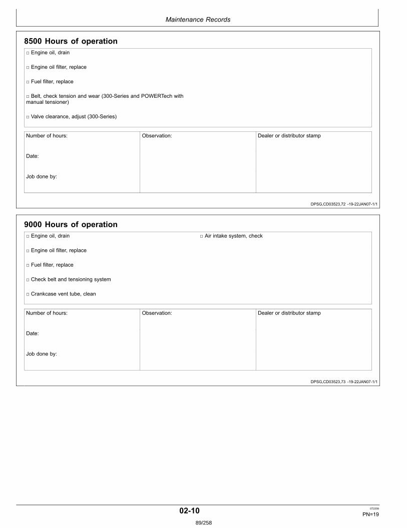
Maintenance Records
DPSG,CD03523,72 1922JAN071/1
DPSG,CD03523,73 1922JAN071/1
8500 Hours of operation Engine oil, drain
Engine oil filter, replace
Fuel filter, replace
Belt, check tension and wear (300Series and POWERTech withmanual tensioner)
Valve clearance, adjust (300Series)
Number of hours: Observation: Dealer or distributor stamp
Date:
Job done by:
9000 Hours of operation Engine oil, drain Air intake system, check
Engine oil filter, replace
Fuel filter, replace
Check belt and tensioning system
Crankcase vent tube, clean
Number of hours: Observation: Dealer or distributor stamp
Date:
Job done by:
0210 072209
PN=1989/258
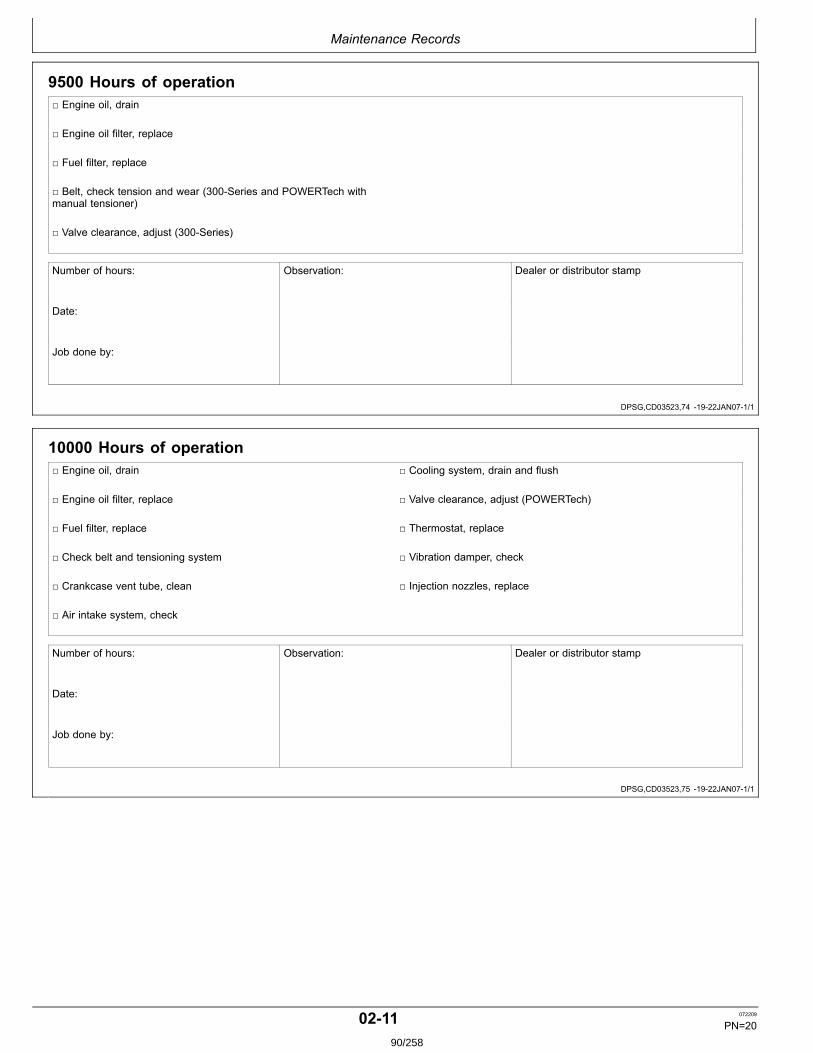
Maintenance Records
DPSG,CD03523,74 1922JAN071/1
DPSG,CD03523,75 1922JAN071/1
9500 Hours of operation Engine oil, drain
Engine oil filter, replace
Fuel filter, replace
Belt, check tension and wear (300Series and POWERTech withmanual tensioner)
Valve clearance, adjust (300Series)
Number of hours: Observation: Dealer or distributor stamp
Date:
Job done by:
10000 Hours of operation Engine oil, drain Cooling system, drain and flush
Engine oil filter, replace Valve clearance, adjust (POWERTech)
Fuel filter, replace Thermostat, replace
Check belt and tensioning system Vibration damper, check
Crankcase vent tube, clean Injection nozzles, replace
Air intake system, check
Number of hours: Observation: Dealer or distributor stamp
Date:
Job done by:
0211 072209
PN=2090/258
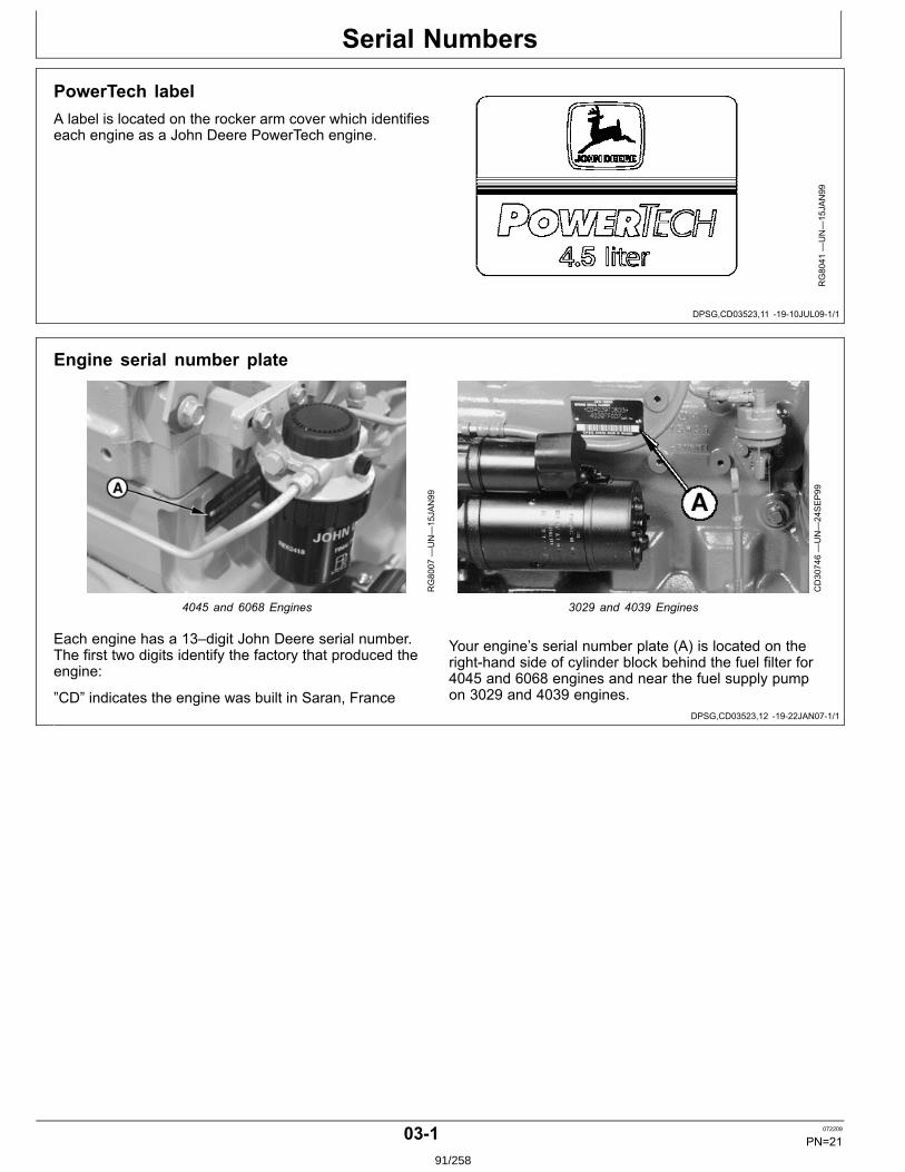
Serial Numbers
DPSG,CD03523,11 1910JUL091/1
DPSG,CD03523,12 1922JAN071/1
PowerTech labelA label is located on the rocker arm cover which identifieseach engine as a John Deere PowerTech engine.
RG8041
—UN—15JAN99
Engine serial number plate
RG8007
—UN—15JAN99
4045 and 6068 Engines
CD30746—UN—24SEP99
3029 and 4039 Engines
Each engine has a 13–digit John Deere serial number.The first two digits identify the factory that produced theengine:
”CD” indicates the engine was built in Saran, France
Your engine’s serial number plate (A) is located on therighthand side of cylinder block behind the fuel filter for4045 and 6068 engines and near the fuel supply pumpon 3029 and 4039 engines.
031 072209
PN=2191/258

Serial Numbers
DPSG,CD03523,13 1922JAN071/1
Record engine serial number
Record all of the numbers and letters found on yourengine serial number plate in the spaces provided below.
This information is very important for repair parts orwarranty information.
Engine Serial Number (B)
___________________
Engine Model Number (C)
___________________
Coefficient of Absorption Value (D)
___________________
CD30705B
—UN—24AUG99
3029 and 4039 engine plate
CD30747A
—UN—22JAN07
4045 and 6068 engine plate
032 072209
PN=2292/258
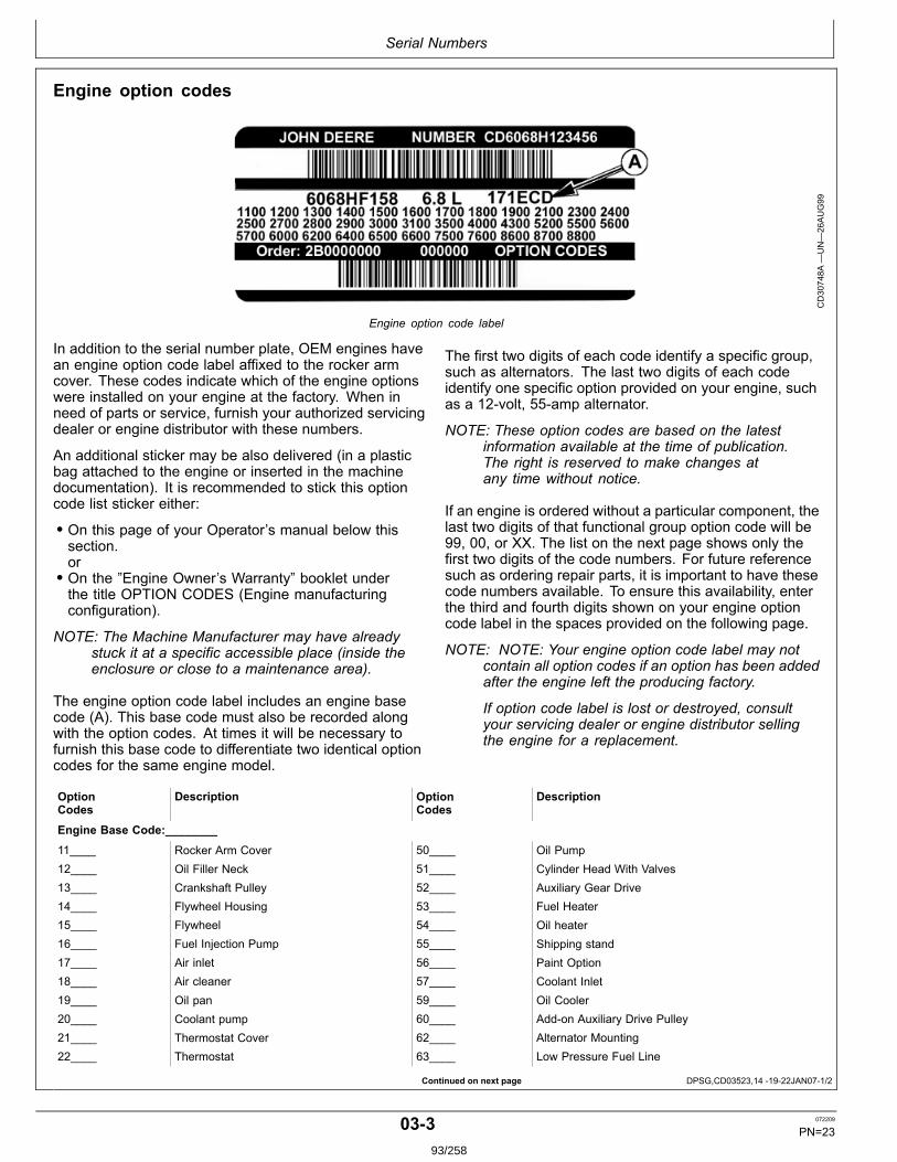
Serial Numbers
Continued on next page DPSG,CD03523,14 1922JAN071/2
Engine option codes
CD30748A
—UN—26AUG99
Engine option code label
In addition to the serial number plate, OEM engines havean engine option code label affixed to the rocker armcover. These codes indicate which of the engine optionswere installed on your engine at the factory. When inneed of parts or service, furnish your authorized servicingdealer or engine distributor with these numbers.
An additional sticker may be also delivered (in a plasticbag attached to the engine or inserted in the machinedocumentation). It is recommended to stick this optioncode list sticker either:
• On this page of your Operator’s manual below thissection.or• On the ”Engine Owner’s Warranty” booklet underthe title OPTION CODES (Engine manufacturingconfiguration).
NOTE: The Machine Manufacturer may have alreadystuck it at a specific accessible place (inside theenclosure or close to a maintenance area).
The engine option code label includes an engine basecode (A). This base code must also be recorded alongwith the option codes. At times it will be necessary tofurnish this base code to differentiate two identical optioncodes for the same engine model.
The first two digits of each code identify a specific group,such as alternators. The last two digits of each codeidentify one specific option provided on your engine, suchas a 12volt, 55amp alternator.
NOTE: These option codes are based on the latestinformation available at the time of publication.The right is reserved to make changes atany time without notice.
If an engine is ordered without a particular component, thelast two digits of that functional group option code will be99, 00, or XX. The list on the next page shows only thefirst two digits of the code numbers. For future referencesuch as ordering repair parts, it is important to have thesecode numbers available. To ensure this availability, enterthe third and fourth digits shown on your engine optioncode label in the spaces provided on the following page.
NOTE: NOTE: Your engine option code label may notcontain all option codes if an option has been addedafter the engine left the producing factory.
If option code label is lost or destroyed, consultyour servicing dealer or engine distributor sellingthe engine for a replacement.
OptionCodes
Description OptionCodes
Description
Engine Base Code:________
11____ Rocker Arm Cover 50____ Oil Pump12____ Oil Filler Neck 51____ Cylinder Head With Valves13____ Crankshaft Pulley 52____ Auxiliary Gear Drive14____ Flywheel Housing 53____ Fuel Heater15____ Flywheel 54____ Oil heater16____ Fuel Injection Pump 55____ Shipping stand17____ Air inlet 56____ Paint Option18____ Air cleaner 57____ Coolant Inlet19____ Oil pan 59____ Oil Cooler20____ Coolant pump 60____ Addon Auxiliary Drive Pulley21____ Thermostat Cover 62____ Alternator Mounting22____ Thermostat 63____ Low Pressure Fuel Line
033 072209
PN=2393/258
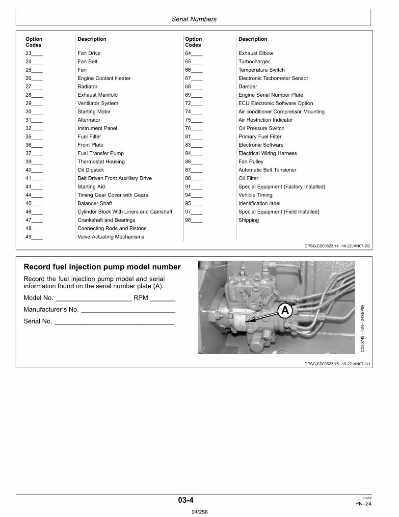
Serial Numbers
DPSG,CD03523,14 1922JAN072/2
DPSG,CD03523,15 1922JAN071/1
OptionCodes
Description OptionCodes
Description
23____ Fan Drive 64____ Exhaust Elbow24____ Fan Belt 65____ Turbocharger25____ Fan 66____ Temperature Switch26____ Engine Coolant Heater 67____ Electronic Tachometer Sensor27____ Radiator 68____ Damper28____ Exhaust Manifold 69____ Engine Serial Number Plate29____ Ventilator System 72____ ECU Electronic Software Option30____ Starting Motor 74____ Air conditioner Compressor Mounting31____ Alternator 75____ Air Restriction Indicator32____ Instrument Panel 76____ Oil Pressure Switch35____ Fuel Filter 81____ Primary Fuel Filter36____ Front Plate 83____ Electronic Software37____ Fuel Transfer Pump 84____ Electrical Wiring Harness39____ Thermostat Housing 86____ Fan Pulley40____ Oil Dipstick 87____ Automatic Belt Tensioner41____ Belt Driven Front Auxiliary Drive 88____ Oil Filter43____ Starting Aid 91____ Special Equipment (Factory Installed)44____ Timing Gear Cover with Gears 94____ Vehicle Timing45____ Balancer Shaft 95____ Identification label46____ Cylinder Block With Liners and Camshaft 97____ Special Equipment (Field Installed)47____ Crankshaft and Bearings 98____ Shipping48____ Connecting Rods and Pistons49____ Valve Actuating Mechanisms
Record fuel injection pump model numberRecord the fuel injection pump model and serialinformation found on the serial number plate (A).
Model No. _____________________ RPM _______
Manufacturer’s No. __________________________
Serial No. _________________________________
CD30749—UN—24SEP99
034 072209
PN=2494/258
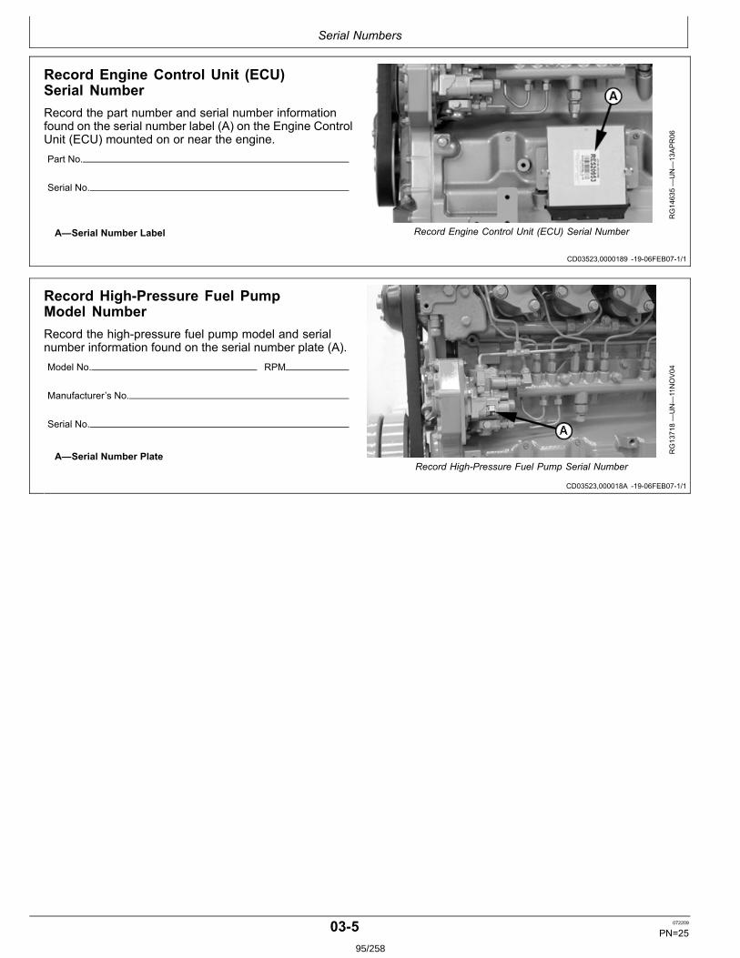
Serial Numbers
CD03523,0000189 1906FEB071/1
CD03523,000018A 1906FEB071/1
Record Engine Control Unit (ECU)Serial NumberRecord the part number and serial number informationfound on the serial number label (A) on the Engine ControlUnit (ECU) mounted on or near the engine.Part No.
Serial No.
A—Serial Number Label
RG14635—UN—13APR06
Record Engine Control Unit (ECU) Serial Number
Record HighPressure Fuel PumpModel NumberRecord the highpressure fuel pump model and serialnumber information found on the serial number plate (A).Model No. RPM
Manufacturer’s No.
Serial No.
A—Serial Number Plate RG13718—UN—11NOV04
Record HighPressure Fuel Pump Serial Number
035 072209
PN=2595/258
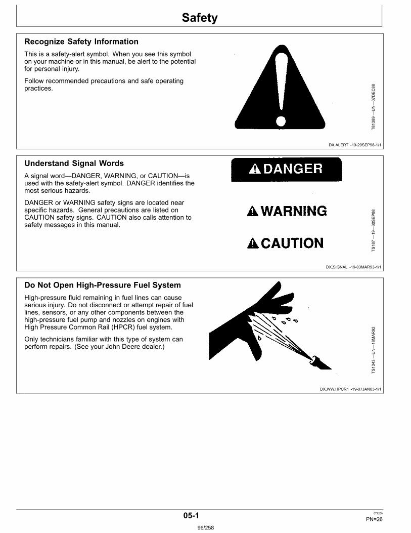
Safety
DX,ALERT 1929SEP981/1
DX,SIGNAL 1903MAR931/1
DX,WW,HPCR1 1907JAN031/1
Recognize Safety InformationThis is a safetyalert symbol. When you see this symbolon your machine or in this manual, be alert to the potentialfor personal injury.
Follow recommended precautions and safe operatingpractices.
T81389
—UN—07DEC88
Understand Signal WordsA signal word—DANGER, WARNING, or CAUTION—isused with the safetyalert symbol. DANGER identifies themost serious hazards.
DANGER or WARNING safety signs are located nearspecific hazards. General precautions are listed onCAUTION safety signs. CAUTION also calls attention tosafety messages in this manual.
TS187—19—30SEP88
Do Not Open HighPressure Fuel SystemHighpressure fluid remaining in fuel lines can causeserious injury. Do not disconnect or attempt repair of fuellines, sensors, or any other components between thehighpressure fuel pump and nozzles on engines withHigh Pressure Common Rail (HPCR) fuel system.
Only technicians familiar with this type of system canperform repairs. (See your John Deere dealer.)
TS1343
—UN—18MAR92
051 072209
PN=2696/258
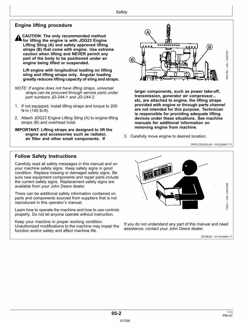
Safety
DPSG,CD03523,95 1922JAN071/1
DX,READ 1916JUN091/1
Engine lifting procedure
CAUTION: The only recommended methodfor lifting the engine is with JDG23 EngineLifting Sling (A) and safety approved liftingstraps (B) that come with engine. Use extremecaution when lifting and NEVER permit anypart of the body to be positioned under anengine being lifted or suspended.
Lift engine with longitudinal loading on liftingsling and lifting straps only. Angular loadinggreatly reduces lifting capacity of sling and straps.
NOTE: If engine does not have lifting straps, universalstraps can be procured through service parts underpart numbers JD2441 and JD2442.
1. If not equipped, install lifting straps and torque to 200N∙m (145 lbft).
2. Attach JDG23 Engine Lifting Sling (A) to engine liftingstraps (B) and overhead hoist.
IMPORTANT: Lifting straps are designed to lift theengine and accessories such as radiator,air filter and other small components. If
RG7784
—UN—11NOV97
larger components, such as power takeoff,transmission, generator air compressor...etc, are attached to engine, the lifting strapsprovided with engine or through parts channelare not intended for this purpose. Technicianis responsible for providing adequate liftingdevices under these situations. See machinemanuals for additional information onremoving engine from machine.
3. Carefully move engine to desired location.
Follow Safety InstructionsCarefully read all safety messages in this manual and onyour machine safety signs. Keep safety signs in goodcondition. Replace missing or damaged safety signs. Besure new equipment components and repair parts includethe current safety signs. Replacement safety signs areavailable from your John Deere dealer.
There can be additional safety information contained onparts and components sourced from suppliers that is notreproduced in this operator’s manual.
Learn how to operate the machine and how to use controlsproperly. Do not let anyone operate without instruction.
Keep your machine in proper working condition.Unauthorized modifications to the machine may impair thefunction and/or safety and affect machine life.
TS201—UN—23AUG88
If you do not understand any part of this manual and needassistance, contact your John Deere dealer.
052 072209
PN=2797/258

Safety
DX,BYPAS1 1929SEP981/1
DX,FIRE1 1903MAR931/1
DX,FIRE2 1903MAR931/1
Prevent Machine RunawayAvoid possible injury or death from machinery runaway.
Do not start engine by shorting across starter terminals.Machine will start in gear if normal circuitry is bypassed.
NEVER start engine while standing on ground. Startengine only from operator’s seat, with transmission inneutral or park.
TS177—UN—11JAN89
Handle Fuel Safely—Avoid FiresHandle fuel with care: it is highly flammable. Do not refuelthe machine while smoking or when near open flame orsparks.
Always stop engine before refueling machine. Fill fueltank outdoors.
Prevent fires by keeping machine clean of accumulatedtrash, grease, and debris. Always clean up spilled fuel.
TS202—UN—23AUG88
Prepare for EmergenciesBe prepared if a fire starts.
Keep a first aid kit and fire extinguisher handy.
Keep emergency numbers for doctors, ambulanceservice, hospital, and fire department near your telephone.
TS291—UN—23AUG88
053 072209
PN=2898/258
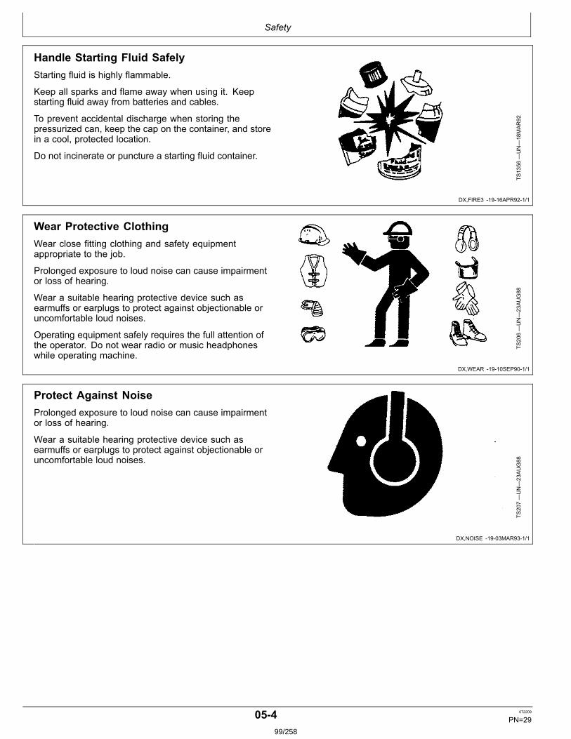
Safety
DX,FIRE3 1916APR921/1
DX,WEAR 1910SEP901/1
DX,NOISE 1903MAR931/1
Handle Starting Fluid SafelyStarting fluid is highly flammable.
Keep all sparks and flame away when using it. Keepstarting fluid away from batteries and cables.
To prevent accidental discharge when storing thepressurized can, keep the cap on the container, and storein a cool, protected location.
Do not incinerate or puncture a starting fluid container.
TS1356
—UN—18MAR92
Wear Protective ClothingWear close fitting clothing and safety equipmentappropriate to the job.
Prolonged exposure to loud noise can cause impairmentor loss of hearing.
Wear a suitable hearing protective device such asearmuffs or earplugs to protect against objectionable oruncomfortable loud noises.
Operating equipment safely requires the full attention ofthe operator. Do not wear radio or music headphoneswhile operating machine.
TS206—UN—23AUG88
Protect Against NoiseProlonged exposure to loud noise can cause impairmentor loss of hearing.
Wear a suitable hearing protective device such asearmuffs or earplugs to protect against objectionable oruncomfortable loud noises.
TS207—UN—23AUG88
054 072209
PN=2999/258
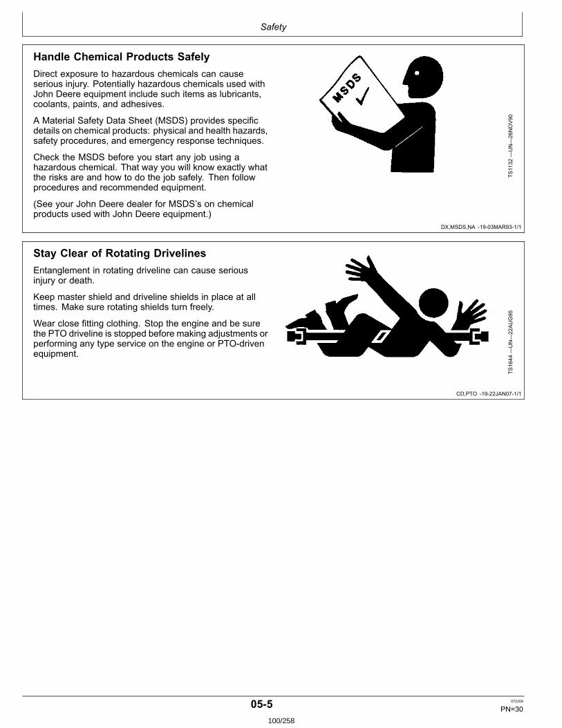
Safety
DX,MSDS,NA 1903MAR931/1
CD,PTO 1922JAN071/1
Handle Chemical Products SafelyDirect exposure to hazardous chemicals can causeserious injury. Potentially hazardous chemicals used withJohn Deere equipment include such items as lubricants,coolants, paints, and adhesives.
A Material Safety Data Sheet (MSDS) provides specificdetails on chemical products: physical and health hazards,safety procedures, and emergency response techniques.
Check the MSDS before you start any job using ahazardous chemical. That way you will know exactly whatthe risks are and how to do the job safely. Then followprocedures and recommended equipment.
(See your John Deere dealer for MSDS’s on chemicalproducts used with John Deere equipment.)
TS1132
—UN—26NOV90
Stay Clear of Rotating DrivelinesEntanglement in rotating driveline can cause seriousinjury or death.
Keep master shield and driveline shields in place at alltimes. Make sure rotating shields turn freely.
Wear close fitting clothing. Stop the engine and be surethe PTO driveline is stopped before making adjustments orperforming any type service on the engine or PTOdrivenequipment.
TS1644
—UN—22AUG95
055 072209
PN=30100/258
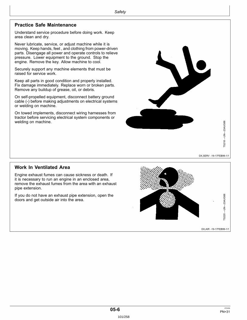
Safety
DX,SERV 1917FEB991/1
DX,AIR 1917FEB991/1
Practice Safe MaintenanceUnderstand service procedure before doing work. Keeparea clean and dry.
Never lubricate, service, or adjust machine while it ismoving. Keep hands, feet , and clothing from powerdrivenparts. Disengage all power and operate controls to relievepressure. Lower equipment to the ground. Stop theengine. Remove the key. Allow machine to cool.
Securely support any machine elements that must beraised for service work.
Keep all parts in good condition and properly installed.Fix damage immediately. Replace worn or broken parts.Remove any buildup of grease, oil, or debris.
On selfpropelled equipment, disconnect battery groundcable () before making adjustments on electrical systemsor welding on machine.
On towed implements, disconnect wiring harnesses fromtractor before servicing electrical system components orwelding on machine.
TS218—UN—23AUG88
Work In Ventilated AreaEngine exhaust fumes can cause sickness or death. Ifit is necessary to run an engine in an enclosed area,remove the exhaust fumes from the area with an exhaustpipe extension.
If you do not have an exhaust pipe extension, open thedoors and get outside air into the area.
TS220—UN—23AUG88
056 072209
PN=31101/258
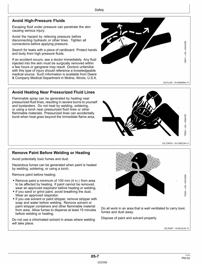
Safety
DX,FLUID 1903MAR931/1
DX,TORCH 1910DEC041/1
DX,PAINT 1924JUL021/1
Avoid HighPressure FluidsEscaping fluid under pressure can penetrate the skincausing serious injury.
Avoid the hazard by relieving pressure beforedisconnecting hydraulic or other lines. Tighten allconnections before applying pressure.
Search for leaks with a piece of cardboard. Protect handsand body from high pressure fluids.
If an accident occurs, see a doctor immediately. Any fluidinjected into the skin must be surgically removed withina few hours or gangrene may result. Doctors unfamiliarwith this type of injury should reference a knowledgeablemedical source. Such information is available from Deere& Company Medical Department in Moline, Illinois, U.S.A.
X9811
—UN—23AUG88
Avoid Heating Near Pressurized Fluid LinesFlammable spray can be generated by heating nearpressurized fluid lines, resulting in severe burns to yourselfand bystanders. Do not heat by welding, soldering,or using a torch near pressurized fluid lines or otherflammable materials. Pressurized lines can accidentallyburst when heat goes beyond the immediate flame area.
TS953—UN—15MAY
90
Remove Paint Before Welding or HeatingAvoid potentially toxic fumes and dust.
Hazardous fumes can be generated when paint is heatedby welding, soldering, or using a torch.
Remove paint before heating:
• Remove paint a minimum of 100 mm (4 in.) from areato be affected by heating. If paint cannot be removed,wear an approved respirator before heating or welding.• If you sand or grind paint, avoid breathing the dust.Wear an approved respirator.• If you use solvent or paint stripper, remove stripper withsoap and water before welding. Remove solvent orpaint stripper containers and other flammable materialfrom area. Allow fumes to disperse at least 15 minutesbefore welding or heating.
Do not use a chlorinated solvent in areas where weldingwill take place.
TS220—UN—23AUG88
Do all work in an area that is well ventilated to carry toxicfumes and dust away.
Dispose of paint and solvent properly.
057 072209
PN=32102/258
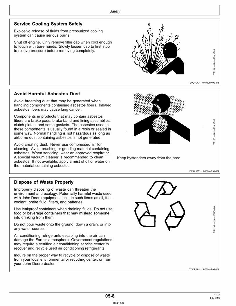
Safety
DX,RCAP 1904JUN901/1
DX,DUST 1915MAR911/1
DX,DRAIN 1903MAR931/1
Service Cooling System SafelyExplosive release of fluids from pressurized coolingsystem can cause serious burns.
Shut off engine. Only remove filler cap when cool enoughto touch with bare hands. Slowly loosen cap to first stopto relieve pressure before removing completely.
TS281—UN—23AUG88
Avoid Harmful Asbestos DustAvoid breathing dust that may be generated whenhandling components containing asbestos fibers. Inhaledasbestos fibers may cause lung cancer.
Components in products that may contain asbestosfibers are brake pads, brake band and lining assemblies,clutch plates, and some gaskets. The asbestos used inthese components is usually found in a resin or sealed insome way. Normal handling is not hazardous as long asairborne dust containing asbestos is not generated.
Avoid creating dust. Never use compressed air forcleaning. Avoid brushing or grinding material containingasbestos. When servicing, wear an approved respirator.A special vacuum cleaner is recommended to cleanasbestos. If not available, apply a mist of oil or water onthe material containing asbestos.
TS220—UN—23AUG88
Keep bystanders away from the area.
Dispose of Waste ProperlyImproperly disposing of waste can threaten theenvironment and ecology. Potentially harmful waste usedwith John Deere equipment include such items as oil, fuel,coolant, brake fluid, filters, and batteries.
Use leakproof containers when draining fluids. Do not usefood or beverage containers that may mislead someoneinto drinking from them.
Do not pour waste onto the ground, down a drain, or intoany water source.
Air conditioning refrigerants escaping into the air candamage the Earth’s atmosphere. Government regulationsmay require a certified air conditioning service center torecover and recycle used air conditioning refrigerants.
Inquire on the proper way to recycle or dispose of wastefrom your local environmental or recycling center, or fromyour John Deere dealer.
TS1133
—UN—26NOV90
058 072209
PN=33103/258
Fuels, Lubricants and Coolant
DX,FUEL1 1928APR091/1
DX,FUEL4 1919DEC031/1
Diesel Fuel
Consult your local fuel distributor for properties of thediesel fuel available in your area.
In general, diesel fuels are blended to satisfy the lowtemperature requirements of the geographical area inwhich they are marketed.
Diesel fuels specified to EN 590 or ASTM D975 arerecommended. Renewable diesel fuel produced byhydrotreating animal fats and vegetable oils is basicallyidentical to petroleum diesel fuel. Renewable diesel thatmeets EN 590 or ASTM D975 is acceptable for use at allpercentage mixture levels.
Required Fuel Properties
In all cases, the fuel shall meet the following properties:
Cetane number of 45 minimum. Cetane number greaterthan 50 is preferred, especially for temperatures below–20°C (–4°F) or elevations above 1500 m (5000 ft).
Cold Filter Plugging Point (CFPP) should be at least 5°C(9°F) below the expected lowest temperature or CloudPoint below the expected lowest ambient temperature.
Fuel lubricity should pass a maximum scar diameter of0.45 mm as measured by ASTM D6079 or ISO 121561.
Sulfur Content for Interim Tier 4 and EUStage IIIB Engines
• Diesel fuel quality and fuel sulfur content must complywith all existing emissions regulations for the area inwhich the engine operates.• Use ONLY ultra low sulfur diesel (ULSD) fuel with amaximum of 0.0015% (15 ppm) sulfur content.
Sulfur Content for Other Engines
• Diesel fuel quality and fuel sulfur content must complywith all existing emissions regulations for the area inwhich the engine operates.• Use of diesel fuel with sulfur content less than 0.10%(1000 ppm) is STRONGLY recommended.• Use of diesel fuel with sulfur content 0.10% (1000 ppm)to 0.50% (5000 ppm) may result in REDUCED oil andfilter change intervals. Refer to table in Diesel EngineOil and Filter Service Intervals.• BEFORE using diesel fuel with sulfur content greaterthan 0.50% (5000 ppm), contact your John Deeredealer.
IMPORTANT: Do not mix used diesel engine oil or anyother type of lubricating oil with diesel fuel.
Improper fuel additive usage may cause damageon fuel injection equipment of diesel engines.
Handling and Storing Diesel Fuel
CAUTION: Handle fuel carefully. Do not fill thefuel tank when engine is running.
DO NOT smoke while you fill the fuel tankor service the fuel system.
Fill the fuel tank at the end of each day’s operation toprevent water condensation and freezing during coldweather.
Keep all storage tanks as full as practicable to minimizecondensation.
Ensure that all fuel tank caps and covers are installedproperly to prevent moisture from entering.
Monitor water content of the fuel regularly.
When using biodiesel fuel, the fuel filter may require morefrequent replacement due to premature plugging.
Check engine oil level daily prior to starting engine. Arising oil level may indicate fuel dilution of the engine oil.
IMPORTANT: The fuel tank is vented through thefiller cap. If a new filler cap is required, alwaysreplace it with an original vented cap.
When fuel is stored for an extended period or if there is aslow turnover of fuel, add a fuel conditioner to stabilize thefuel and prevent water condensation. Contact your fuelsupplier for recommendations.
101 072209
PN=34104/258
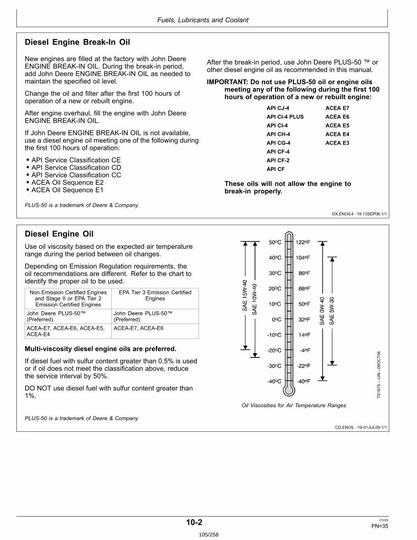
Fuels, Lubricants and Coolant
DX,ENOIL4 1913SEP061/1
CD,ENOIL 1901JUL091/1
Diesel Engine BreakIn Oil
New engines are filled at the factory with John DeereENGINE BREAKIN OIL. During the breakin period,add John Deere ENGINE BREAKIN OIL as needed tomaintain the specified oil level.
Change the oil and filter after the first 100 hours ofoperation of a new or rebuilt engine.
After engine overhaul, fill the engine with John DeereENGINE BREAKIN OIL.
If John Deere ENGINE BREAKIN OIL is not available,use a diesel engine oil meeting one of the following duringthe first 100 hours of operation:
• API Service Classification CE• API Service Classification CD• API Service Classification CC• ACEA Oil Sequence E2• ACEA Oil Sequence E1
After the breakin period, use John Deere PLUS50 ™ orother diesel engine oil as recommended in this manual.
IMPORTANT: Do not use PLUS50 oil or engine oilsmeeting any of the following during the first 100hours of operation of a new or rebuilt engine:
API CJ4 ACEA E7API CI4 PLUS ACEA E6API CI4 ACEA E5API CH4 ACEA E4API CG4 ACEA E3API CF4API CF2API CF
These oils will not allow the engine tobreakin properly.
PLUS50 is a trademark of Deere & Company.
Diesel Engine OilUse oil viscosity based on the expected air temperaturerange during the period between oil changes.
Depending on Emission Regulation requirements, theoil recommendations are different. Refer to the chart toidentify the proper oil to be used.Non Emission Certified Enginesand Stage II or EPA Tier 2Emission Certified Engines
EPA Tier 3 Emission CertifiedEngines
John Deere PLUS50™(Preferred)
John Deere PLUS50™(Preferred)
ACEAE7, ACEAE6, ACEAE5,ACEAE4
ACEAE7, ACEAE6
Multiviscosity diesel engine oils are preferred.
If diesel fuel with sulfur content greater than 0.5% is usedor if oil does not meet the classification above, reducethe service interval by 50%.
DO NOT use diesel fuel with sulfur content greater than1%. TS
1675
—UN—09OCT06
Oil Viscosities for Air Temperature Ranges
PLUS50 is a trademark of Deere & Company
102 072209
PN=35105/258
Fuels, Lubricants and Coolant
DX,LUBST 1918MAR961/1
DX,LUBMIX 1918MAR961/1
DX,COOL8 1916NOV011/1
Lubricant Storage
Your equipment can operate at top efficiency only whenclean lubricants are used.
Use clean containers to handle all lubricants.
Whenever possible, store lubricants and containersin an area protected from dust, moisture, and othercontamination. Store containers on their side to avoidwater and dirt accumulation.
Make certain that all containers are properly marked toidentify their contents.
Properly dispose of all old containers and any residuallubricant they may contain.
Mixing of Lubricants
In general, avoid mixing different brands or types of oil.Oil manufacturers blend additives in their oils to meetcertain specifications and performance requirements.
Mixing different oils can interfere with the properfunctioning of these additives and degrade lubricantperformance.
Consult your John Deere dealer to obtain specificinformation and recommendations.
Diesel Engine Coolant
The engine cooling system is filled to provide yearroundprotection against corrosion and cylinder liner pitting, andwinter freeze protection to 37°C (34°F).
John Deere COOLGARD is preferred for service.
If John Deere COOLGARD is not available, use a lowsilicate ethylene glycol or propylene glycol base coolantconcentrate in a 50% mixture of concentrate with qualitywater.
The coolant concentrate shall be of a quality that providescavitation protection to cast iron and aluminum parts inthe cooling system. John Deere COOLGARD meets thisrequirement.
Freeze protection
A 50% mixture of ethylene glycol engine coolant in waterprovides freeze protection to 37°C (34°F).
A 50% mixture of propylene glycol engine coolant in waterprovides freeze protection to 33°C (27°F).
If protection at lower temperatures is required, consultyour John Deere dealer for recommendations.
Water quality
Water quality is important to the performance of thecooling system. Distilled, deionized, or demineralizedwater is recommended for mixing with ethylene glycol andpropylene glycol base engine coolant concentrate.
IMPORTANT: Do not use cooling system sealingadditives or antifreeze that containssealing additives.
IMPORTANT: Do not mix ethylene glycol andpropylene glycol base coolants.
103 072209
PN=36106/258
Fuels, Lubricants and Coolant
DX,COOL6 1903NOV081/1
Operating in Warm Temperature Climates
John Deere engines are designed to operate using glycolbase engine coolants.
Always use a recommended glycol base engine coolant,even when operating in geographical areas where freezeprotection is not required.
John Deere COOLGARD™ II Premix is available in aconcentration of 50% ethylene glycol. However, thereare situations in warm temperature climates where acoolant with lower glycol concentration (approximately20% ethylene glycol) has been approved. In these cases,the low glycol formulation has been modified to providethe same level of corrosion inhibitor as John DeereCOOLGARD II Premix (50/50).
IMPORTANT: Water may be used as coolant inemergency situations only.
Foaming, hot surface aluminum and ironcorrosion, scaling, and cavitation will occurwhen water is used as the coolant, even whencoolant conditioners are added.
Drain cooling system and refill withrecommended glycol base engine coolantas soon as possible.
COOLGARD is a trademark of Deere & Company
104 072209
PN=37107/258
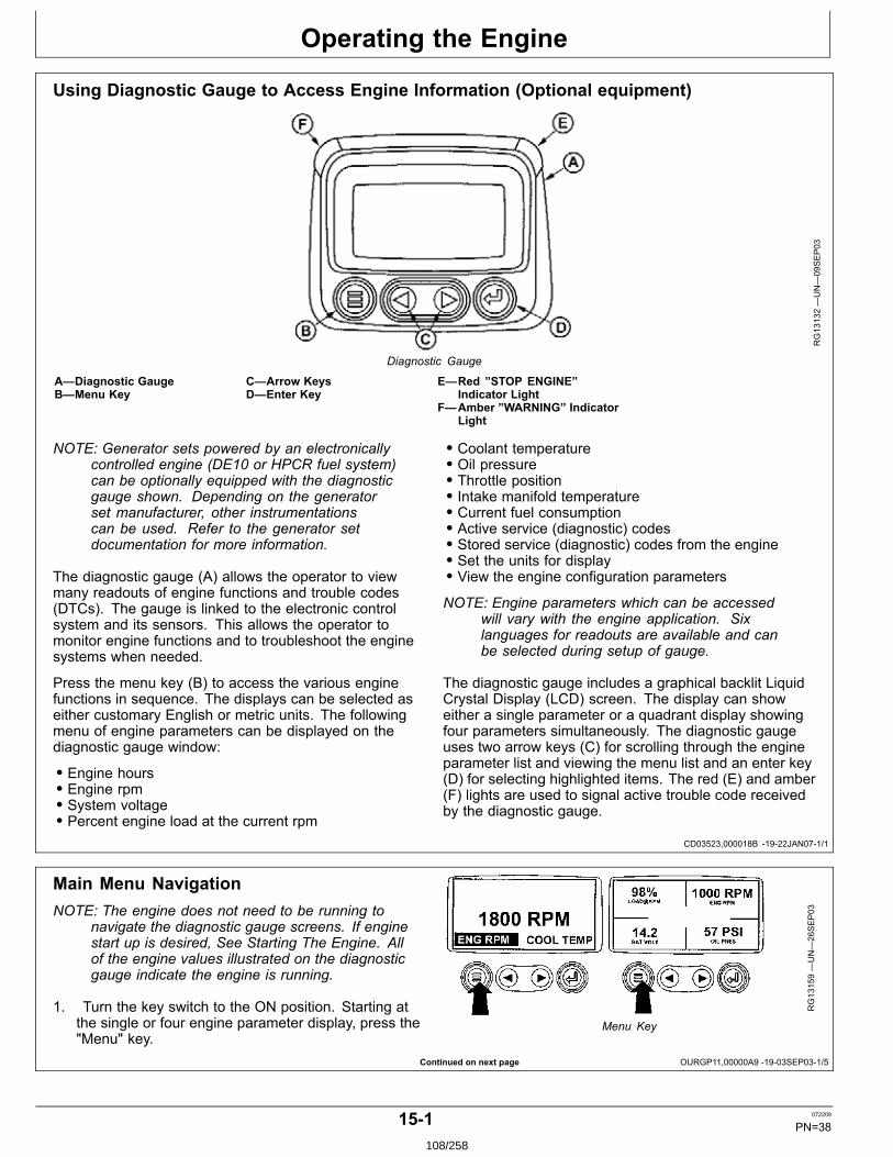
Operating the Engine
CD03523,000018B 1922JAN071/1
Continued on next page OURGP11,00000A9 1903SEP031/5
Using Diagnostic Gauge to Access Engine Information (Optional equipment)
RG13132—UN—09SEP03
Diagnostic Gauge
A—Diagnostic GaugeB—Menu Key
C—Arrow KeysD—Enter Key
E—Red ”STOP ENGINE”Indicator Light
F—Amber ”WARNING” IndicatorLight
NOTE: Generator sets powered by an electronicallycontrolled engine (DE10 or HPCR fuel system)can be optionally equipped with the diagnosticgauge shown. Depending on the generatorset manufacturer, other instrumentationscan be used. Refer to the generator setdocumentation for more information.
The diagnostic gauge (A) allows the operator to viewmany readouts of engine functions and trouble codes(DTCs). The gauge is linked to the electronic controlsystem and its sensors. This allows the operator tomonitor engine functions and to troubleshoot the enginesystems when needed.
Press the menu key (B) to access the various enginefunctions in sequence. The displays can be selected aseither customary English or metric units. The followingmenu of engine parameters can be displayed on thediagnostic gauge window:
• Engine hours• Engine rpm• System voltage• Percent engine load at the current rpm
• Coolant temperature• Oil pressure• Throttle position• Intake manifold temperature• Current fuel consumption• Active service (diagnostic) codes• Stored service (diagnostic) codes from the engine• Set the units for display• View the engine configuration parameters
NOTE: Engine parameters which can be accessedwill vary with the engine application. Sixlanguages for readouts are available and canbe selected during setup of gauge.
The diagnostic gauge includes a graphical backlit LiquidCrystal Display (LCD) screen. The display can showeither a single parameter or a quadrant display showingfour parameters simultaneously. The diagnostic gaugeuses two arrow keys (C) for scrolling through the engineparameter list and viewing the menu list and an enter key(D) for selecting highlighted items. The red (E) and amber(F) lights are used to signal active trouble code receivedby the diagnostic gauge.
Main Menu NavigationNOTE: The engine does not need to be running to
navigate the diagnostic gauge screens. If enginestart up is desired, See Starting The Engine. Allof the engine values illustrated on the diagnosticgauge indicate the engine is running.
1. Turn the key switch to the ON position. Starting atthe single or four engine parameter display, press the"Menu" key.
RG13159—UN—26SEP03
Menu Key
151 072209
PN=38108/258

Operating the Engine
OURGP11,00000A9 1903SEP032/5
OURGP11,00000A9 1903SEP033/5
Continued on next page OURGP11,00000A9 1903SEP034/5
2. The first seven items of the "Main Menu" will bedisplayed.
RG13160—UN—02OCT03
Menu Display
3. Pressing the "Arrow" keys will scroll through the menuselections.
RG13161—UN—02OCT03
Main Menu Items
4. Pressing the right arrow key will scroll down to revealthe last items of "Main Menu" screen, highlighting thenext item down.
RG13162—UN—26SEP03
Last Items On Main Menu
152 072209
PN=39109/258
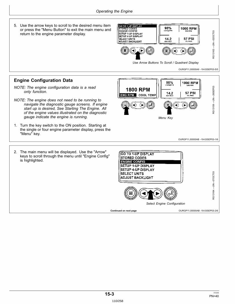
Operating the Engine
OURGP11,00000A9 1903SEP035/5
OURGP11,00000AB 1903SEP031/6
Continued on next page OURGP11,00000AB 1903SEP032/6
5. Use the arrow keys to scroll to the desired menu itemor press the "Menu Button" to exit the main menu andreturn to the engine parameter display.
RG13163—UN—02OCT03
Use Arrow Buttons To Scroll / Quadrant Display
Engine Configuration DataNOTE: The engine configuration data is a read
only function.
NOTE: The engine does not need to be running tonavigate the diagnostic gauge screens. If enginestart up is desired, See Starting The Engine. Allof the engine values illustrated on the diagnosticgauge indicate the engine is running.
1. Turn the key switch to the ON position. Starting atthe single or four engine parameter display, press the"Menu" key.
RG13159—UN—26SEP03
Menu Key
2. The main menu will be displayed. Use the "Arrow"keys to scroll through the menu until "Engine Config"is highlighted.
RG13164—UN—07OCT03
Select Engine Configuration
153 072209
PN=40110/258
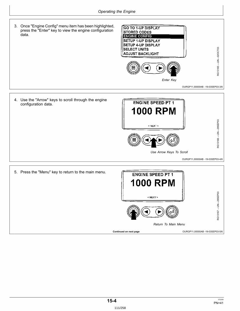
Operating the Engine
OURGP11,00000AB 1903SEP033/6
OURGP11,00000AB 1903SEP034/6
Continued on next page OURGP11,00000AB 1903SEP035/6
3. Once "Engine Config" menu item has been highlighted,press the "Enter" key to view the engine configurationdata.
RG13165—UN—02OCT03
Enter Key
4. Use the "Arrow" keys to scroll through the engineconfiguration data.
RG13166—UN—29SEP03
Use Arrow Keys To Scroll
5. Press the "Menu" key to return to the main menu.
RG13167—UN—29SEP03
Return To Main Menu
154 072209
PN=41111/258
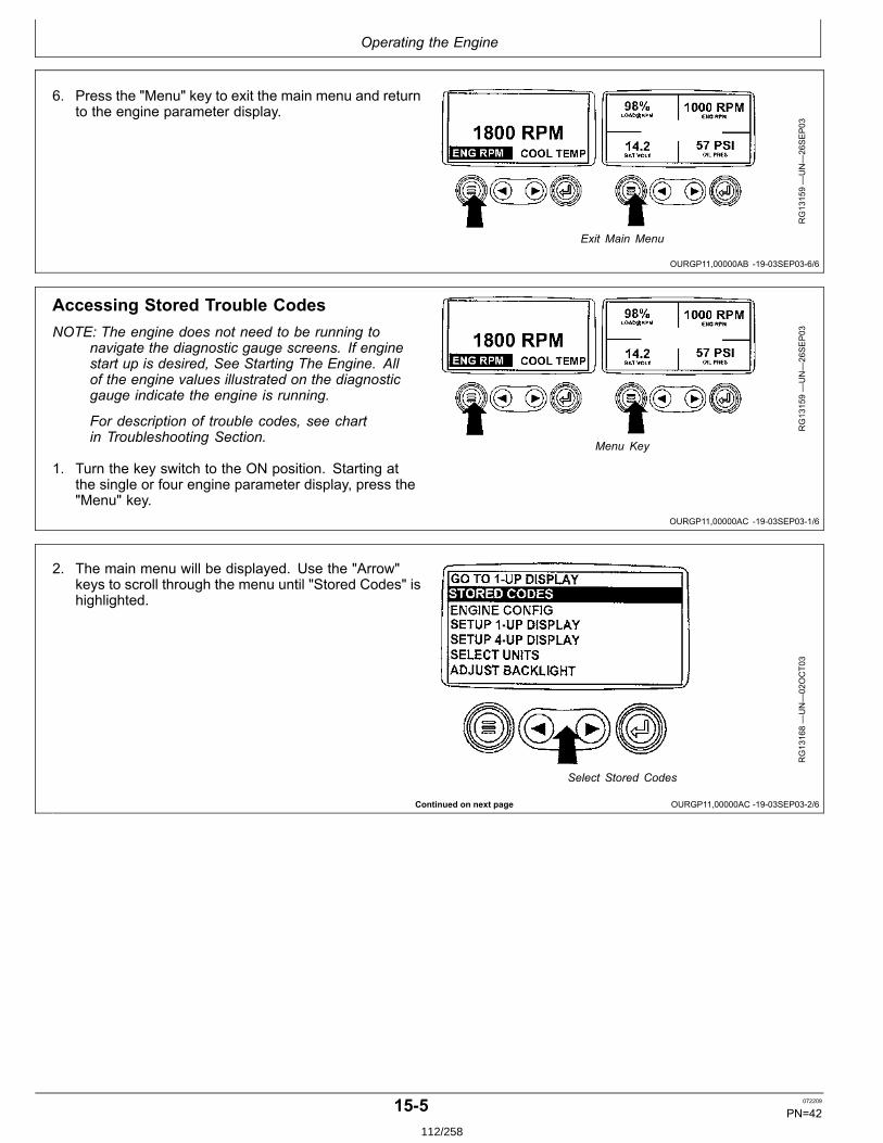
Operating the Engine
OURGP11,00000AB 1903SEP036/6
OURGP11,00000AC 1903SEP031/6
Continued on next page OURGP11,00000AC 1903SEP032/6
6. Press the "Menu" key to exit the main menu and returnto the engine parameter display.
RG13159—UN—26SEP03
Exit Main Menu
Accessing Stored Trouble CodesNOTE: The engine does not need to be running to
navigate the diagnostic gauge screens. If enginestart up is desired, See Starting The Engine. Allof the engine values illustrated on the diagnosticgauge indicate the engine is running.
For description of trouble codes, see chartin Troubleshooting Section.
1. Turn the key switch to the ON position. Starting atthe single or four engine parameter display, press the"Menu" key.
RG13159—UN—26SEP03
Menu Key
2. The main menu will be displayed. Use the "Arrow"keys to scroll through the menu until "Stored Codes" ishighlighted.
RG13168—UN—02OCT03
Select Stored Codes
155 072209
PN=42112/258
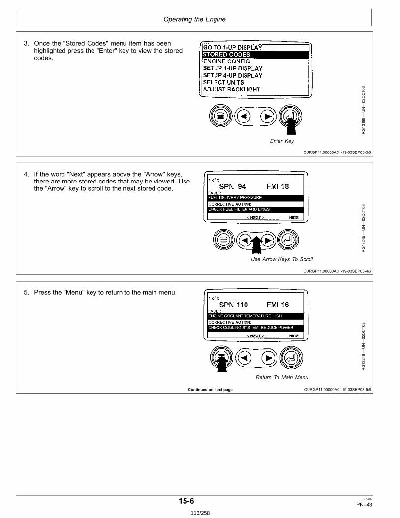
Operating the Engine
OURGP11,00000AC 1903SEP033/6
OURGP11,00000AC 1903SEP034/6
Continued on next page OURGP11,00000AC 1903SEP035/6
3. Once the "Stored Codes" menu item has beenhighlighted press the "Enter" key to view the storedcodes.
RG13169—UN—02OCT03
Enter Key
4. If the word "Next" appears above the "Arrow" keys,there are more stored codes that may be viewed. Usethe "Arrow" key to scroll to the next stored code.
RG13245—UN—02OCT03
Use Arrow Keys To Scroll
5. Press the "Menu" key to return to the main menu.
RG13246—UN—02OCT03
Return To Main Menu
156 072209
PN=43113/258

Operating the Engine
OURGP11,00000AC 1903SEP036/6
OURGP11,00000AD 1903SEP031/7
OURGP11,00000AD 1903SEP032/7
Continued on next page OURGP11,00000AD 1903SEP033/7
6. Press the "Menu" key to exit the main menu and returnto the engine parameter display.
RG13159—UN—26SEP03
Exit Main Menu
Accessing Active Trouble CodesNOTE: The engine does not need to be running to
navigate the diagnostic gauge screens. If enginestart up is desired, See Starting The Engine. Allof the engine values illustrated on the diagnosticgauge indicate the engine is running.
For description of trouble codes, see chartin Troubleshooting Section.
1. During normal operation the single or four parameterscreen will be displayed.
RG13172—UN—26SEP03
Normal Operation
2. When the diagnostic gauge receives a troublecode from an engine control unit, the single or fourparameter screen will be replaced with the "Warning"message. The SPN and FMI number will be displayedalong with a description of the problem and thecorrective action needed.
IMPORTANT: Ignoring active trouble codes canresult in severe engine damage.
RG13240—UN—30SEP03
Active Trouble Codes Displayed
3. If the word "Next" appears above the arrow keys, thereare more trouble codes that can be viewed by usingthe arrow keys to scroll to the next trouble code.
RG13241—UN—30SEP03
Use Arrow Keys To Scroll
157 072209
PN=44114/258

Operating the Engine
OURGP11,00000AD 1903SEP034/7
OURGP11,00000AD 1903SEP035/7
OURGP11,00000AD 1903SEP036/7
OURGP11,00000AD 1903SEP037/7
IMPORTANT: Ignoring active trouble codes canresult in severe engine damage.
4. To acknowledge and hide the code and return to thesingle or four parameter display, press the "Enter" Key.
RG13242—UN—30SEP03
Hide Trouble Codes
5. The display will return to the single or four parameterdisplay, but the display will contain the warning icon.Pressing the "Enter" key will redisplay the hiddentrouble code.
RG13176—UN—26SEP03
Active Trouble Code Icon
IMPORTANT: Ignoring active trouble codes canresult in severe engine damage.
6. Pressing the "Enter" key once again will hide thetrouble code and return the screen to the single or fourparameter display.
RG13242—UN—30SEP03
Enter Key
7. The single or four parameter screen will displaythe warning icon until the trouble code condition iscorrected.
RG13243—UN—01OCT03
Active Trouble Code Condition
158 072209
PN=45115/258

Operating the Engine
OURGP11,00000AE 1903SEP031/6
OURGP11,00000AE 1903SEP032/6
OURGP11,00000AE 1903SEP033/6
Continued on next page OURGP11,00000AE 1903SEP034/6
Engine Shutdown Codes1. During normal operation the single or four parameter
screen will be displayed.
RG13172—UN—26SEP03
Normal Operation
2. When the diagnostic gauge receives a severe troublecode from an engine control unit, the single or fourparameter screen will be replaced with the "Shutdown"message. The SPN and FMI number will be displayedalong with a description of the problem and thecorrective action needed.
If the word "Next" appears above the arrow keys, thereare more trouble codes that can be viewed by usingthe arrow keys to scroll to the next trouble code.
RG13238—UN—29SEP03
Shutdown Message
3. To acknowledge and hide the trouble code and returnto the single or four parameter display, press the"Enter" key".
IMPORTANT: Ignoring the shutdown message canresult in severe engine damage.
RG13239—UN—29SEP03
Hide Trouble Code
4. The display will return to the single or four parameterdisplay, but the display will contain the "Shutdown"icon. Pressing the "Enter" key will redisplay the hiddentrouble code.
IMPORTANT: Ignoring the shutdown message canresult in severe engine damage.
RG13179—UN—26SEP03
Flashing Shutdown Icon
159 072209
PN=46116/258
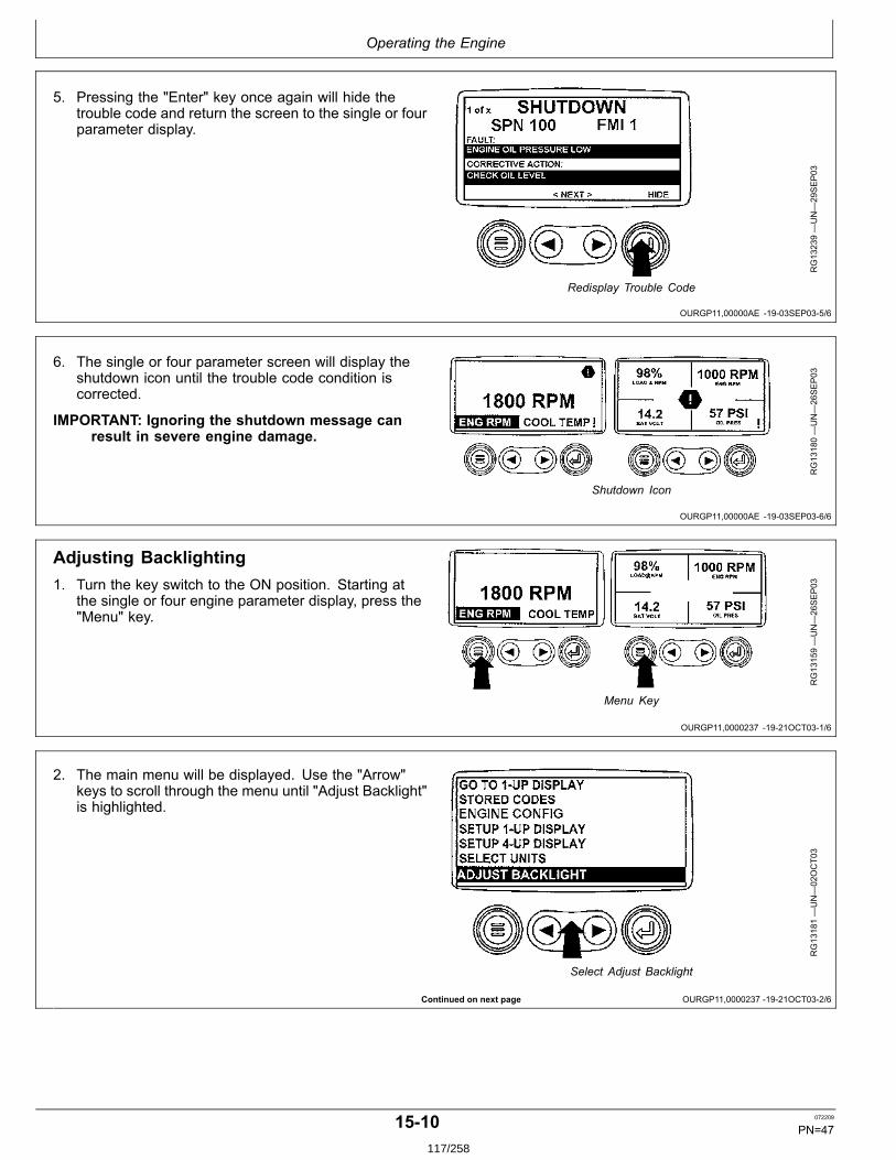
Operating the Engine
OURGP11,00000AE 1903SEP035/6
OURGP11,00000AE 1903SEP036/6
OURGP11,0000237 1921OCT031/6
Continued on next page OURGP11,0000237 1921OCT032/6
5. Pressing the "Enter" key once again will hide thetrouble code and return the screen to the single or fourparameter display.
RG13239—UN—29SEP03
Redisplay Trouble Code
6. The single or four parameter screen will display theshutdown icon until the trouble code condition iscorrected.
IMPORTANT: Ignoring the shutdown message canresult in severe engine damage.
RG13180—UN—26SEP03
Shutdown Icon
Adjusting Backlighting1. Turn the key switch to the ON position. Starting at
the single or four engine parameter display, press the"Menu" key.
RG13159—UN—26SEP03
Menu Key
2. The main menu will be displayed. Use the "Arrow"keys to scroll through the menu until "Adjust Backlight"is highlighted.
RG13181—UN—02OCT03
Select Adjust Backlight
1510 072209
PN=47117/258
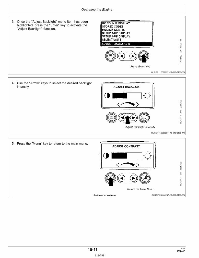
Operating the Engine
OURGP11,0000237 1921OCT033/6
OURGP11,0000237 1921OCT034/6
Continued on next page OURGP11,0000237 1921OCT035/6
3. Once the "Adjust Backlight" menu item has beenhighlighted, press the "Enter" key to activate the"Adjust Backlight" function.
RG13182—UN—02OCT03
Press Enter Key
4. Use the "Arrow" keys to select the desired backlightintensity.
RG13183—UN—29SEP03
Adjust Backlight Intensity
5. Press the "Menu" key to return to the main menu.
RG13184—UN—26SEP03
Return To Main Menu
1511 072209
PN=48118/258
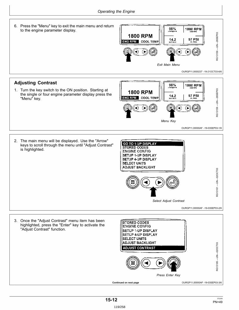
Operating the Engine
OURGP11,0000237 1921OCT036/6
OURGP11,00000AF 1903SEP031/6
OURGP11,00000AF 1903SEP032/6
Continued on next page OURGP11,00000AF 1903SEP033/6
6. Press the "Menu" key to exit the main menu and returnto the engine parameter display.
RG13159—UN—26SEP03
Exit Main Menu
Adjusting Contrast1. Turn the key switch to the ON position. Starting at
the single or four engine parameter display press the"Menu" key.
RG13159—UN—26SEP03
Menu Key
2. The main menu will be displayed. Use the "Arrow"keys to scroll through the menu until "Adjust Contrast"is highlighted.
RG13161—UN—02OCT03
Select Adjust Contrast
3. Once the "Adjust Contrast" menu item has beenhighlighted, press the "Enter" key to activate the"Adjust Contrast" function.
RG13185—UN—02OCT03
Press Enter Key
1512 072209
PN=49119/258
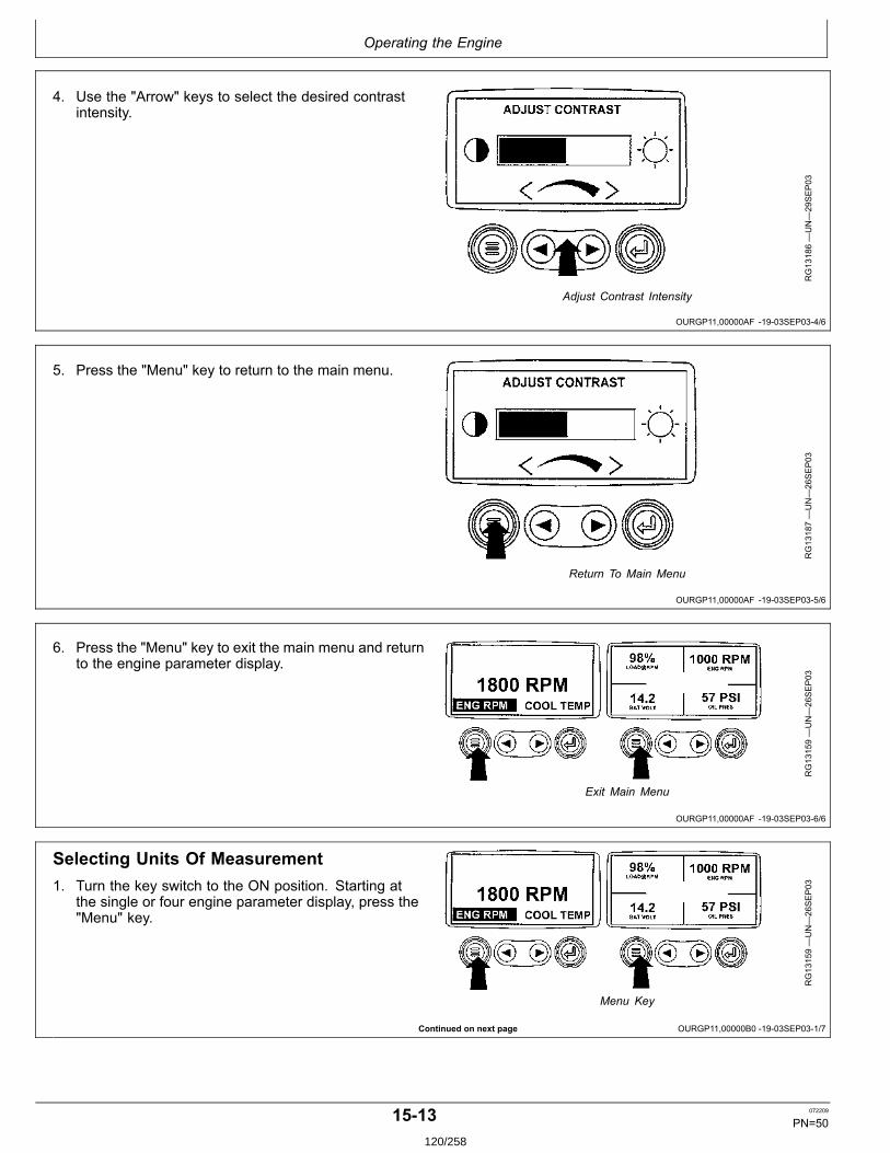
Operating the Engine
OURGP11,00000AF 1903SEP034/6
OURGP11,00000AF 1903SEP035/6
OURGP11,00000AF 1903SEP036/6
Continued on next page OURGP11,00000B0 1903SEP031/7
4. Use the "Arrow" keys to select the desired contrastintensity.
RG13186—UN—29SEP03
Adjust Contrast Intensity
5. Press the "Menu" key to return to the main menu.
RG13187—UN—26SEP03
Return To Main Menu
6. Press the "Menu" key to exit the main menu and returnto the engine parameter display.
RG13159—UN—26SEP03
Exit Main Menu
Selecting Units Of Measurement1. Turn the key switch to the ON position. Starting at
the single or four engine parameter display, press the"Menu" key.
RG13159—UN—26SEP03
Menu Key
1513 072209
PN=50120/258
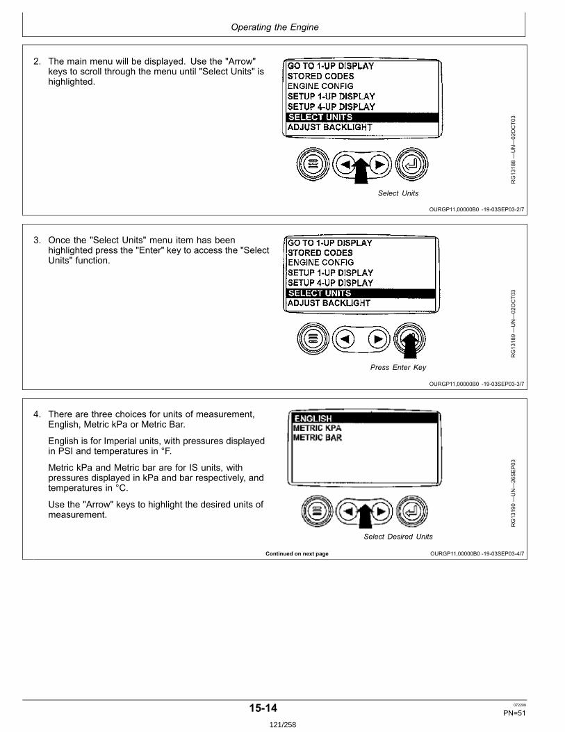
Operating the Engine
OURGP11,00000B0 1903SEP032/7
OURGP11,00000B0 1903SEP033/7
Continued on next page OURGP11,00000B0 1903SEP034/7
2. The main menu will be displayed. Use the "Arrow"keys to scroll through the menu until "Select Units" ishighlighted.
RG13188—UN—02OCT03
Select Units
3. Once the "Select Units" menu item has beenhighlighted press the "Enter" key to access the "SelectUnits" function.
RG13189—UN—02OCT03
Press Enter Key
4. There are three choices for units of measurement,English, Metric kPa or Metric Bar.
English is for Imperial units, with pressures displayedin PSI and temperatures in °F.
Metric kPa and Metric bar are for IS units, withpressures displayed in kPa and bar respectively, andtemperatures in °C.
Use the "Arrow" keys to highlight the desired units ofmeasurement.
RG13190—UN—26SEP03
Select Desired Units
1514 072209
PN=51121/258

Operating the Engine
OURGP11,00000B0 1903SEP035/7
OURGP11,00000B0 1903SEP036/7
OURGP11,00000B0 1903SEP037/7
Continued on next page OURGP11,00000B1 1903SEP031/18
5. Press the "Enter" key to select the highlighted units.
RG13191—UN—30SEP03
Press Enter Key to Select
6. Press the "Menu" key to return to the main menu.
RG13192—UN—26SEP03
Return To Main Menu
7. Press the "Menu" key to return to the engine parameterdisplay.
RG13159—UN—26SEP03
Press Menu Key
Setup 1Up Display1. Turn the key switch to the ON position. Starting at the
single engine parameter display, press the "Menu" key.
RG13159—UN—26SEP03
Menu Key
1515 072209
PN=52122/258
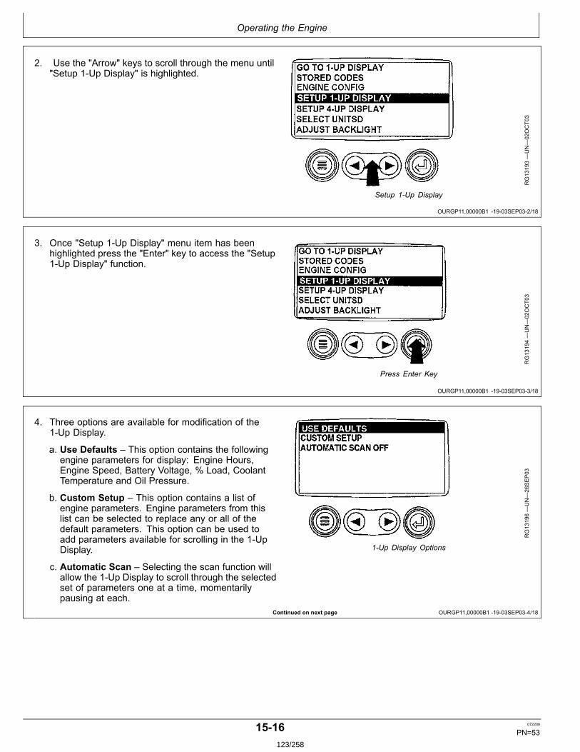
Operating the Engine
OURGP11,00000B1 1903SEP032/18
OURGP11,00000B1 1903SEP033/18
Continued on next page OURGP11,00000B1 1903SEP034/18
2. Use the "Arrow" keys to scroll through the menu until"Setup 1Up Display" is highlighted.
RG13193—UN—02OCT03
Setup 1Up Display
3. Once "Setup 1Up Display" menu item has beenhighlighted press the "Enter" key to access the "Setup1Up Display" function.
RG13194—UN—02OCT03
Press Enter Key
4. Three options are available for modification of the1Up Display.
a. Use Defaults – This option contains the followingengine parameters for display: Engine Hours,Engine Speed, Battery Voltage, % Load, CoolantTemperature and Oil Pressure.
b. Custom Setup – This option contains a list ofengine parameters. Engine parameters from thislist can be selected to replace any or all of thedefault parameters. This option can be used toadd parameters available for scrolling in the 1UpDisplay.
c. Automatic Scan – Selecting the scan function willallow the 1Up Display to scroll through the selectedset of parameters one at a time, momentarilypausing at each.
RG13196—UN—26SEP03
1Up Display Options
1516 072209
PN=53123/258

Operating the Engine
OURGP11,00000B1 1903SEP035/18
OURGP11,00000B1 1903SEP036/18
Continued on next page OURGP11,00000B1 1903SEP037/18
5. Use Defaults To select "Use Defaults" use the Arrowkeys to scroll to and highlight "Use Defaults" in themenu display.
RG13195—UN—26SEP03
Select Defaults
6. Press the "Enter" key to activate the "Use Defaults"function.
RG13197—UN—29SEP03
Defaults Selected
7. The display parameters are reset to the factorydefaults, then the display will return to the "Setup 1UpDisplay" menu.
RG13149—UN—24SEP03
Restored To Defaults
1517 072209
PN=54124/258
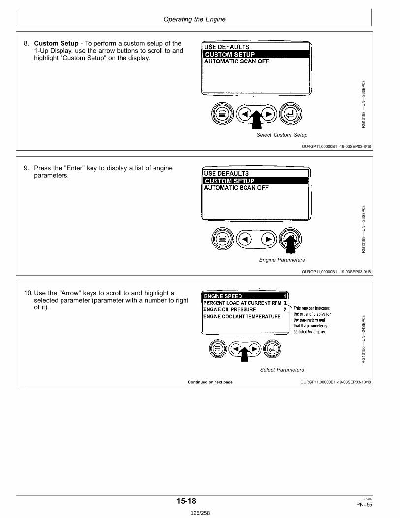
Operating the Engine
OURGP11,00000B1 1903SEP038/18
OURGP11,00000B1 1903SEP039/18
Continued on next page OURGP11,00000B1 1903SEP0310/18
8. Custom Setup To perform a custom setup of the1Up Display, use the arrow buttons to scroll to andhighlight "Custom Setup" on the display.
RG13198—UN—26SEP03
Select Custom Setup
9. Press the "Enter" key to display a list of engineparameters.
RG13199—UN—26SEP03
Engine Parameters
10. Use the "Arrow" keys to scroll to and highlight aselected parameter (parameter with a number to rightof it).
RG13150—UN—24SEP03
Select Parameters
1518 072209
PN=55125/258
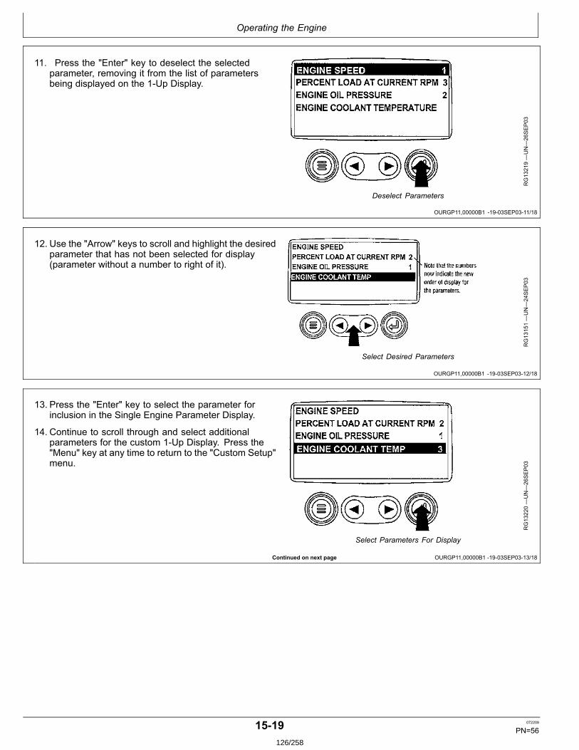
Operating the Engine
OURGP11,00000B1 1903SEP0311/18
OURGP11,00000B1 1903SEP0312/18
Continued on next page OURGP11,00000B1 1903SEP0313/18
11. Press the "Enter" key to deselect the selectedparameter, removing it from the list of parametersbeing displayed on the 1Up Display.
RG13219—UN—26SEP03
Deselect Parameters
12. Use the "Arrow" keys to scroll and highlight the desiredparameter that has not been selected for display(parameter without a number to right of it).
RG13151—UN—24SEP03
Select Desired Parameters
13. Press the "Enter" key to select the parameter forinclusion in the Single Engine Parameter Display.
14. Continue to scroll through and select additionalparameters for the custom 1Up Display. Press the"Menu" key at any time to return to the "Custom Setup"menu.
RG13220—UN—26SEP03
Select Parameters For Display
1519 072209
PN=56126/258
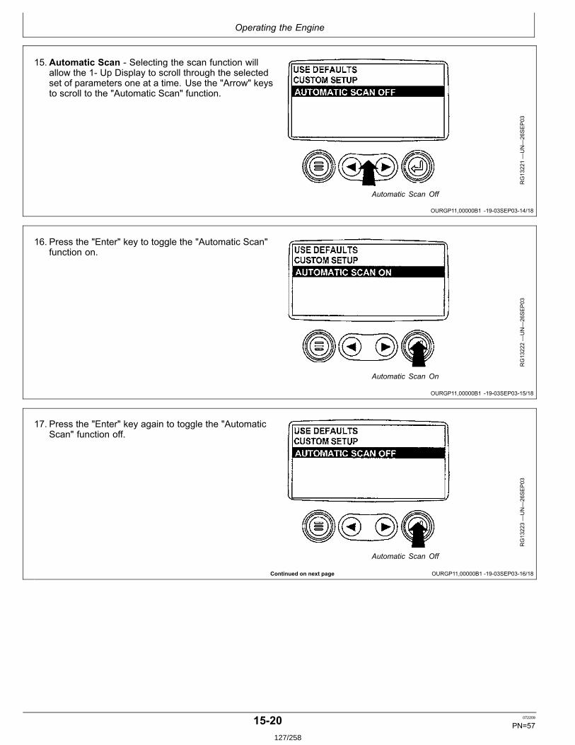
Operating the Engine
OURGP11,00000B1 1903SEP0314/18
OURGP11,00000B1 1903SEP0315/18
Continued on next page OURGP11,00000B1 1903SEP0316/18
15.Automatic Scan Selecting the scan function willallow the 1 Up Display to scroll through the selectedset of parameters one at a time. Use the "Arrow" keysto scroll to the "Automatic Scan" function.
RG13221—UN—26SEP03
Automatic Scan Off
16. Press the "Enter" key to toggle the "Automatic Scan"function on.
RG13222—UN—26SEP03
Automatic Scan On
17. Press the "Enter" key again to toggle the "AutomaticScan" function off.
RG13223—UN—26SEP03
Automatic Scan Off
1520 072209
PN=57127/258
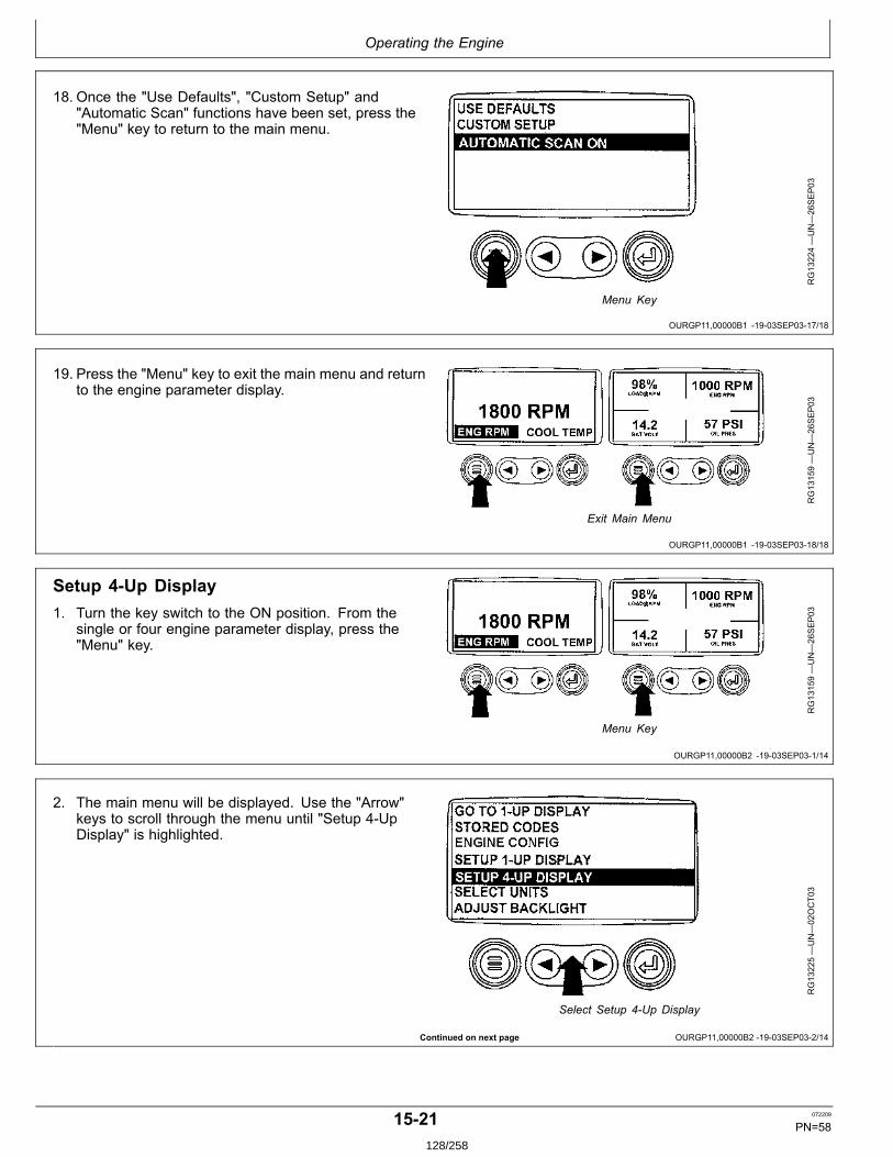
Operating the Engine
OURGP11,00000B1 1903SEP0317/18
OURGP11,00000B1 1903SEP0318/18
OURGP11,00000B2 1903SEP031/14
Continued on next page OURGP11,00000B2 1903SEP032/14
18. Once the "Use Defaults", "Custom Setup" and"Automatic Scan" functions have been set, press the"Menu" key to return to the main menu.
RG13224—UN—26SEP03
Menu Key
19. Press the "Menu" key to exit the main menu and returnto the engine parameter display.
RG13159—UN—26SEP03
Exit Main Menu
Setup 4Up Display1. Turn the key switch to the ON position. From the
single or four engine parameter display, press the"Menu" key.
RG13159—UN—26SEP03
Menu Key
2. The main menu will be displayed. Use the "Arrow"keys to scroll through the menu until "Setup 4UpDisplay" is highlighted.
RG13225—UN—02OCT03
Select Setup 4Up Display
1521 072209
PN=58128/258
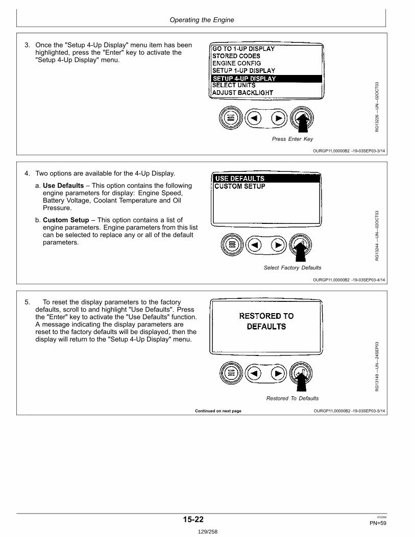
Operating the Engine
OURGP11,00000B2 1903SEP033/14
OURGP11,00000B2 1903SEP034/14
Continued on next page OURGP11,00000B2 1903SEP035/14
3. Once the "Setup 4Up Display" menu item has beenhighlighted, press the "Enter" key to activate the"Setup 4Up Display" menu.
RG13226—UN—02OCT03
Press Enter Key
4. Two options are available for the 4Up Display.
a. Use Defaults – This option contains the followingengine parameters for display: Engine Speed,Battery Voltage, Coolant Temperature and OilPressure.
b. Custom Setup – This option contains a list ofengine parameters. Engine parameters from this listcan be selected to replace any or all of the defaultparameters.
RG13244—UN—02OCT03
Select Factory Defaults
5. To reset the display parameters to the factorydefaults, scroll to and highlight "Use Defaults". Pressthe "Enter" key to activate the "Use Defaults" function.A message indicating the display parameters arereset to the factory defaults will be displayed, then thedisplay will return to the "Setup 4Up Display" menu.
RG13149—UN—24SEP03
Restored To Defaults
1522 072209
PN=59129/258
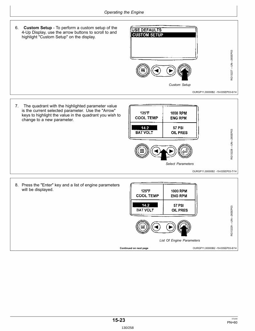
Operating the Engine
OURGP11,00000B2 1903SEP036/14
OURGP11,00000B2 1903SEP037/14
Continued on next page OURGP11,00000B2 1903SEP038/14
6. Custom Setup To perform a custom setup of the4Up Display, use the arrow buttons to scroll to andhighlight "Custom Setup" on the display.
RG13227—UN—26SEP03
Custom Setup
7. The quadrant with the highlighted parameter valueis the current selected parameter. Use the "Arrow"keys to highlight the value in the quadrant you wish tochange to a new parameter.
RG13228—UN—26SEP03
Select Parameters
8. Press the "Enter" key and a list of engine parameterswill be displayed.
RG13229—UN—26SEP03
List Of Engine Parameters
1523 072209
PN=60130/258
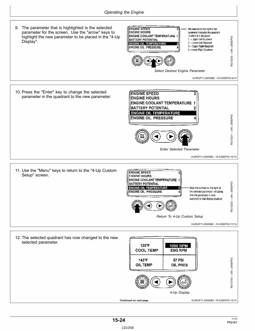
Operating the Engine
OURGP11,00000B2 1903SEP039/14
OURGP11,00000B2 1903SEP0310/14
OURGP11,00000B2 1903SEP0311/14
Continued on next page OURGP11,00000B2 1903SEP0312/14
9. The parameter that is highlighted is the selectedparameter for the screen. Use the "arrow" keys tohighlight the new parameter to be placed in the "4UpDisplay".
RG13230—UN—26SEP03
Select Desired Engine Parameter
10. Press the "Enter" key to change the selectedparameter in the quadrant to the new parameter.
RG13231—UN—26SEP03
Enter Selected Parameter
11. Use the "Menu" keys to return to the "4Up CustomSetup" screen.
RG13232—UN—26SEP03
Return To 4Up Custom Setup
12. The selected quadrant has now changed to the newselected parameter.
RG13153—UN—24SEP03
4Up Display
1524 072209
PN=61131/258
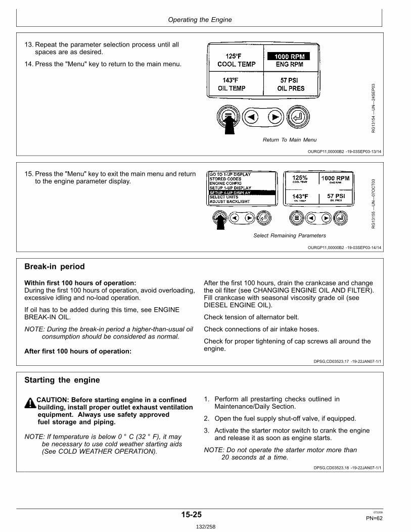
Operating the Engine
OURGP11,00000B2 1903SEP0313/14
OURGP11,00000B2 1903SEP0314/14
DPSG,CD03523,17 1922JAN071/1
DPSG,CD03523,18 1922JAN071/1
13. Repeat the parameter selection process until allspaces are as desired.
14. Press the "Menu" key to return to the main menu.
RG13154—UN—24SEP03
Return To Main Menu
15. Press the "Menu" key to exit the main menu and returnto the engine parameter display.
RG13155—UN—07OCT03
Select Remaining Parameters
Breakin period
Within first 100 hours of operation:During the first 100 hours of operation, avoid overloading,excessive idling and noload operation.
If oil has to be added during this time, see ENGINEBREAKIN OIL.
NOTE: During the breakin period a higherthanusual oilconsumption should be considered as normal.
After first 100 hours of operation:
After the first 100 hours, drain the crankcase and changethe oil filter (see CHANGING ENGINE OIL AND FILTER).Fill crankcase with seasonal viscosity grade oil (seeDIESEL ENGINE OIL).
Check tension of alternator belt.
Check connections of air intake hoses.
Check for proper tightening of cap screws all around theengine.
Starting the engine
CAUTION: Before starting engine in a confinedbuilding, install proper outlet exhaust ventilationequipment. Always use safety approvedfuel storage and piping.
NOTE: If temperature is below 0 ° C (32 ° F), it maybe necessary to use cold weather starting aids(See COLD WEATHER OPERATION).
1. Perform all prestarting checks outlined inMaintenance/Daily Section.
2. Open the fuel supply shutoff valve, if equipped.
3. Activate the starter motor switch to crank the engineand release it as soon as engine starts.
NOTE: Do not operate the starter motor more than20 seconds at a time.
1525 072209
PN=62132/258
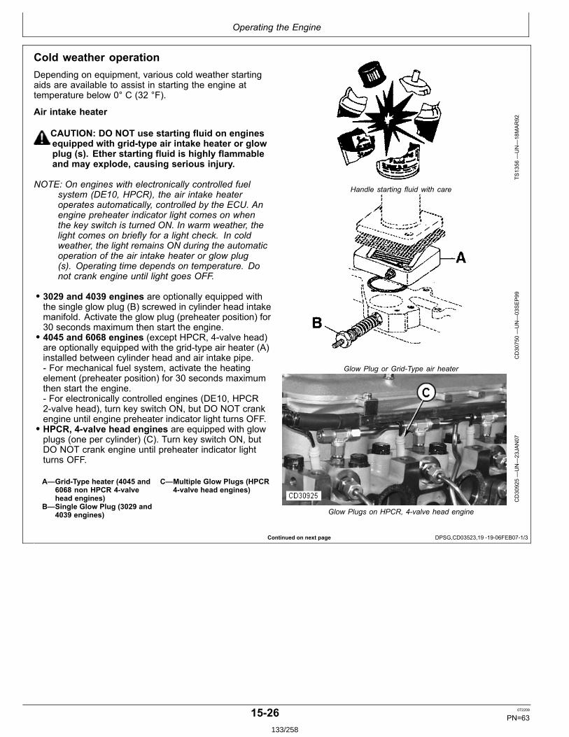
Operating the Engine
Continued on next page DPSG,CD03523,19 1906FEB071/3
Cold weather operationDepending on equipment, various cold weather startingaids are available to assist in starting the engine attemperature below 0° C (32 °F).
Air intake heater
CAUTION: DO NOT use starting fluid on enginesequipped with gridtype air intake heater or glowplug (s). Ether starting fluid is highly flammableand may explode, causing serious injury.
NOTE: On engines with electronically controlled fuelsystem (DE10, HPCR), the air intake heateroperates automatically, controlled by the ECU. Anengine preheater indicator light comes on whenthe key switch is turned ON. In warm weather, thelight comes on briefly for a light check. In coldweather, the light remains ON during the automaticoperation of the air intake heater or glow plug(s). Operating time depends on temperature. Donot crank engine until light goes OFF.
• 3029 and 4039 engines are optionally equipped withthe single glow plug (B) screwed in cylinder head intakemanifold. Activate the glow plug (preheater position) for30 seconds maximum then start the engine.• 4045 and 6068 engines (except HPCR, 4valve head)are optionally equipped with the gridtype air heater (A)installed between cylinder head and air intake pipe. For mechanical fuel system, activate the heatingelement (preheater position) for 30 seconds maximumthen start the engine. For electronically controlled engines (DE10, HPCR2valve head), turn key switch ON, but DO NOT crankengine until engine preheater indicator light turns OFF.• HPCR, 4valve head engines are equipped with glowplugs (one per cylinder) (C). Turn key switch ON, butDO NOT crank engine until preheater indicator lightturns OFF.
A—GridType heater (4045 and6068 non HPCR 4valvehead engines)
B—Single Glow Plug (3029 and4039 engines)
C—Multiple Glow Plugs (HPCR4valve head engines)
TS1356
—UN—18MAR92
Handle starting fluid with care
CD30750—UN—03SEP99
Glow Plug or GridType air heater
CD30925—UN—23JAN07
Glow Plugs on HPCR, 4valve head engine
1526 072209
PN=63133/258
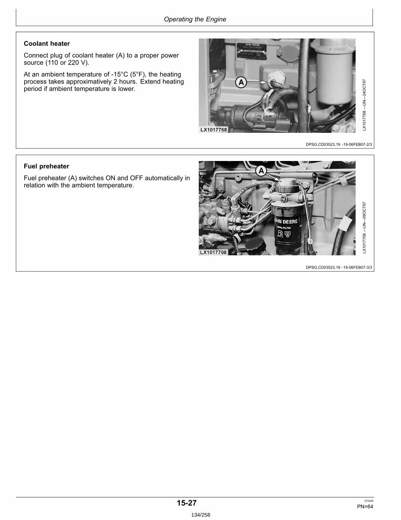
Operating the Engine
DPSG,CD03523,19 1906FEB072/3
DPSG,CD03523,19 1906FEB073/3
Coolant heater
Connect plug of coolant heater (A) to a proper powersource (110 or 220 V).
At an ambient temperature of 15°C (5°F), the heatingprocess takes approximatively 2 hours. Extend heatingperiod if ambient temperature is lower.
LX1017768—UN—24OCT97
Fuel preheater
Fuel preheater (A) switches ON and OFF automatically inrelation with the ambient temperature.
LX1017708—UN—09OCT97
1527 072209
PN=64134/258
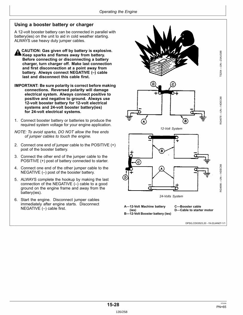
Operating the Engine
DPSG,CD03523,20 1922JAN071/1
Using a booster battery or chargerA 12volt booster battery can be connected in parallel withbattery(ies) on the unit to aid in cold weather starting.ALWAYS use heavy duty jumper cables.
CAUTION: Gas given off by battery is explosive.Keep sparks and flames away from battery.Before connecting or disconnecting a batterycharger, turn charger off. Make last connectionand first disconnection at a point away frombattery. Always connect NEGATIVE (–) cablelast and disconnect this cable first.
IMPORTANT: Be sure polarity is correct before makingconnections. Reversed polarity will damageelectrical system. Always connect positive topositive and negative to ground. Always use12volt booster battery for 12volt electricalsystems and 24volt booster battery(ies)for 24volt electrical systems.
1. Connect booster battery or batteries to produce therequired system voltage for your engine application.
NOTE: To avoid sparks, DO NOT allow the free endsof jumper cables to touch the engine.
2. Connect one end of jumper cable to the POSITIVE (+)post of the booster battery.
3. Connect the other end of the jumper cable to thePOSITIVE (+) post of battery connected to starter.
4. Connect one end of the other jumper cable to theNEGATIVE (–) post of the booster battery.
5. ALWAYS complete the hookup by making the lastconnection of the NEGATIVE (–) cable to a goodground on the engine frame and away from thebattery(ies).
6. Start the engine. Disconnect jumper cablesimmediately after engine starts. DisconnectNEGATIVE (–) cable first.
TS204—UN—23AUG88
RG4678
—UN—14DEC88
12Volt System
RG4698
—UN—14DEC88
24Volts System
A—12Volt Machine battery(ies)
B—12Volt Booster battery (ies)
C—Booster cableD—Cable to starter motor
1528 072209
PN=65135/258
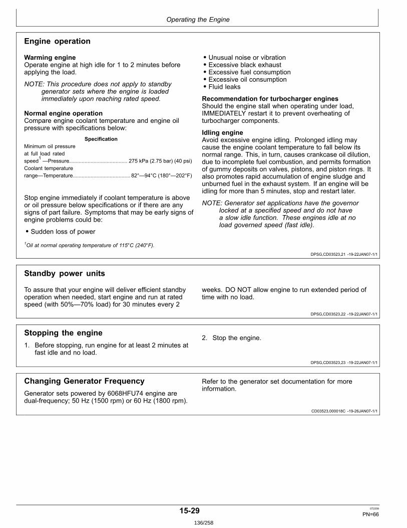
Operating the Engine
DPSG,CD03523,21 1922JAN071/1
DPSG,CD03523,22 1922JAN071/1
DPSG,CD03523,23 1922JAN071/1
CD03523,000018C 1926JAN071/1
Engine operation
Warming engineOperate engine at high idle for 1 to 2 minutes beforeapplying the load.
NOTE: This procedure does not apply to standbygenerator sets where the engine is loadedimmediately upon reaching rated speed.
Normal engine operationCompare engine coolant temperature and engine oilpressure with specifications below:
SpecificationMinimum oil pressureat full load ratedspeed1 —Pressure........................................ 275 kPa (2.75 bar) (40 psi)Coolant temperaturerange—Temperature....................................... 82°—94°C (180°—202°F)
Stop engine immediately if coolant temperature is aboveor oil pressure below specifications or if there are anysigns of part failure. Symptoms that may be early signs ofengine problems could be:
• Sudden loss of power
• Unusual noise or vibration• Excessive black exhaust• Excessive fuel consumption• Excessive oil consumption• Fluid leaks
Recommendation for turbocharger enginesShould the engine stall when operating under load,IMMEDIATELY restart it to prevent overheating ofturbocharger components.
Idling engineAvoid excessive engine idling. Prolonged idling maycause the engine coolant temperature to fall below itsnormal range. This, in turn, causes crankcase oil dilution,due to incomplete fuel combustion, and permits formationof gummy deposits on valves, pistons, and piston rings. Italso promotes rapid accumulation of engine sludge andunburned fuel in the exhaust system. If an engine will beidling for more than 5 minutes, stop and restart later.
NOTE: Generator set applications have the governorlocked at a specified speed and do not havea slow idle function. These engines idle at noload governed speed (fast idle).
1Oil at normal operating temperature of 115°C (240°F).
Standby power units
To assure that your engine will deliver efficient standbyoperation when needed, start engine and run at ratedspeed (with 50%—70% load) for 30 minutes every 2
weeks. DO NOT allow engine to run extended period oftime with no load.
Stopping the engine1. Before stopping, run engine for at least 2 minutes at
fast idle and no load.
2. Stop the engine.
Changing Generator FrequencyGenerator sets powered by 6068HFU74 engine aredualfrequency; 50 Hz (1500 rpm) or 60 Hz (1800 rpm).
Refer to the generator set documentation for moreinformation.
1529 072209
PN=66136/258
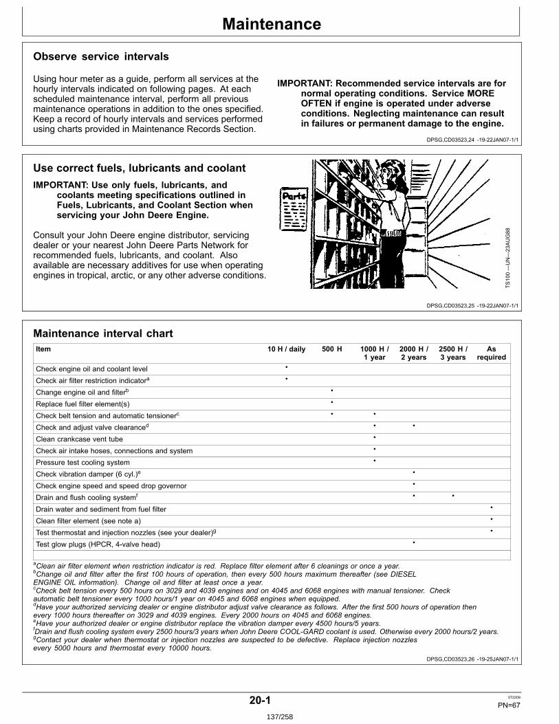
Maintenance
DPSG,CD03523,24 1922JAN071/1
DPSG,CD03523,25 1922JAN071/1
DPSG,CD03523,26 1925JAN071/1
Observe service intervals
Using hour meter as a guide, perform all services at thehourly intervals indicated on following pages. At eachscheduled maintenance interval, perform all previousmaintenance operations in addition to the ones specified.Keep a record of hourly intervals and services performedusing charts provided in Maintenance Records Section.
IMPORTANT: Recommended service intervals are fornormal operating conditions. Service MOREOFTEN if engine is operated under adverseconditions. Neglecting maintenance can resultin failures or permanent damage to the engine.
Use correct fuels, lubricants and coolantIMPORTANT: Use only fuels, lubricants, and
coolants meeting specifications outlined inFuels, Lubricants, and Coolant Section whenservicing your John Deere Engine.
Consult your John Deere engine distributor, servicingdealer or your nearest John Deere Parts Network forrecommended fuels, lubricants, and coolant. Alsoavailable are necessary additives for use when operatingengines in tropical, arctic, or any other adverse conditions.
TS100—UN—23AUG88
Maintenance interval chartItem 10 H / daily 500 H 1000 H /
1 year2000 H /2 years
2500 H /3 years
Asrequired
Check engine oil and coolant level •
Check air filter restriction indicatora •
Change engine oil and filterb •
Replace fuel filter element(s) •
Check belt tension and automatic tensionerc • •
Check and adjust valve clearanced • •
Clean crankcase vent tube •
Check air intake hoses, connections and system •
Pressure test cooling system •
Check vibration damper (6 cyl.)e •
Check engine speed and speed drop governor •
Drain and flush cooling systemf • •
Drain water and sediment from fuel filter •
Clean filter element (see note a) •
Test thermostat and injection nozzles (see your dealer)g •
Test glow plugs (HPCR, 4valve head) •
aClean air filter element when restriction indicator is red. Replace filter element after 6 cleanings or once a year.bChange oil and filter after the first 100 hours of operation, then every 500 hours maximum thereafter (see DIESELENGINE OIL information). Change oil and filter at least once a year.cCheck belt tension every 500 hours on 3029 and 4039 engines and on 4045 and 6068 engines with manual tensioner. Checkautomatic belt tensioner every 1000 hours/1 year on 4045 and 6068 engines when equipped.dHave your authorized servicing dealer or engine distributor adjust valve clearance as follows. After the first 500 hours of operation thenevery 1000 hours thereafter on 3029 and 4039 engines. Every 2000 hours on 4045 and 6068 engines.eHave your authorized dealer or engine distributor replace the vibration damper every 4500 hours/5 years.fDrain and flush cooling system every 2500 hours/3 years when John Deere COOLGARD coolant is used. Otherwise every 2000 hours/2 years.gContact your dealer when thermostat or injection nozzles are suspected to be defective. Replace injection nozzlesevery 5000 hours and thermostat every 10000 hours.
201 072209
PN=67137/258
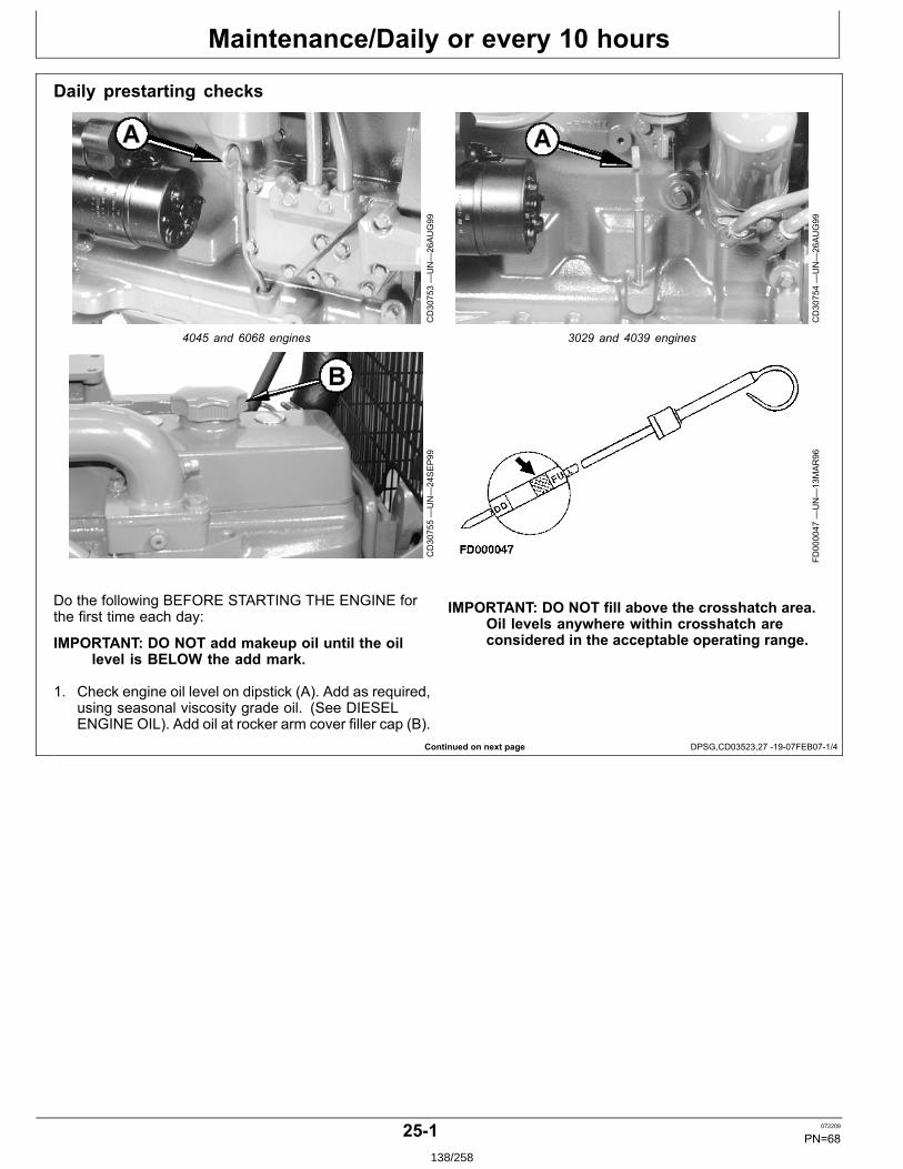
Maintenance/Daily or every 10 hours
Continued on next page DPSG,CD03523,27 1907FEB071/4
Daily prestarting checks
CD30753—UN—26AUG99
4045 and 6068 engines
CD30754—UN—26AUG99
3029 and 4039 engines
CD30755—UN—24SEP99
FD000047
—UN—13MAR96
Do the following BEFORE STARTING THE ENGINE forthe first time each day:
IMPORTANT: DO NOT add makeup oil until the oillevel is BELOW the add mark.
1. Check engine oil level on dipstick (A). Add as required,using seasonal viscosity grade oil. (See DIESELENGINE OIL). Add oil at rocker arm cover filler cap (B).
IMPORTANT: DO NOT fill above the crosshatch area.Oil levels anywhere within crosshatch areconsidered in the acceptable operating range.
251 072209
PN=68138/258
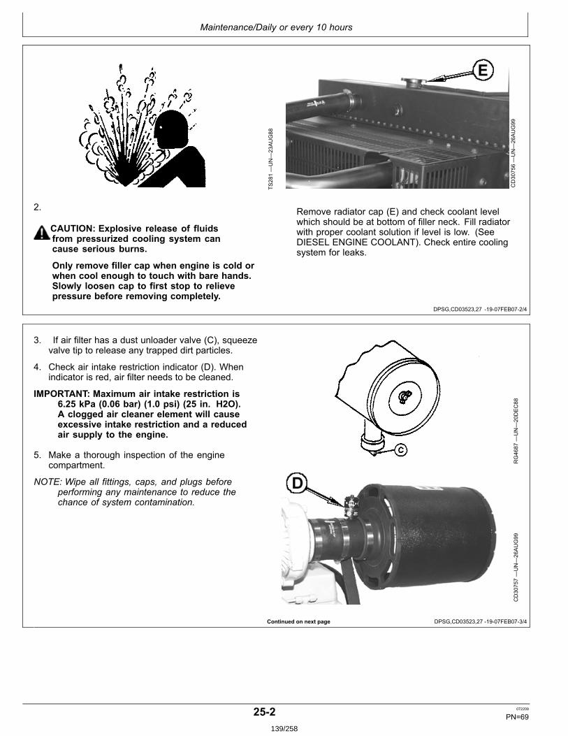
Maintenance/Daily or every 10 hours
DPSG,CD03523,27 1907FEB072/4
Continued on next page DPSG,CD03523,27 1907FEB073/4
TS281—UN—23AUG88
CD30756—UN—26AUG99
2.
CAUTION: Explosive release of fluidsfrom pressurized cooling system cancause serious burns.
Only remove filler cap when engine is cold orwhen cool enough to touch with bare hands.Slowly loosen cap to first stop to relievepressure before removing completely.
Remove radiator cap (E) and check coolant levelwhich should be at bottom of filler neck. Fill radiatorwith proper coolant solution if level is low. (SeeDIESEL ENGINE COOLANT). Check entire coolingsystem for leaks.
3. If air filter has a dust unloader valve (C), squeezevalve tip to release any trapped dirt particles.
4. Check air intake restriction indicator (D). Whenindicator is red, air filter needs to be cleaned.
IMPORTANT: Maximum air intake restriction is6.25 kPa (0.06 bar) (1.0 psi) (25 in. H2O).A clogged air cleaner element will causeexcessive intake restriction and a reducedair supply to the engine.
5. Make a thorough inspection of the enginecompartment.
NOTE: Wipe all fittings, caps, and plugs beforeperforming any maintenance to reduce thechance of system contamination.
RG4687
—UN—20DEC88
CD30757—UN—26AUG99
252 072209
PN=69139/258
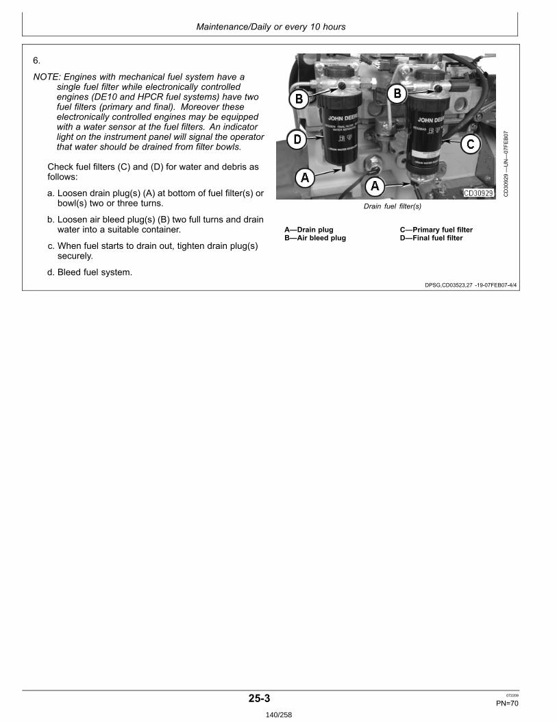
Maintenance/Daily or every 10 hours
DPSG,CD03523,27 1907FEB074/4
6.
NOTE: Engines with mechanical fuel system have asingle fuel filter while electronically controlledengines (DE10 and HPCR fuel systems) have twofuel filters (primary and final). Moreover theseelectronically controlled engines may be equippedwith a water sensor at the fuel filters. An indicatorlight on the instrument panel will signal the operatorthat water should be drained from filter bowls.
Check fuel filters (C) and (D) for water and debris asfollows:
a. Loosen drain plug(s) (A) at bottom of fuel filter(s) orbowl(s) two or three turns.
b. Loosen air bleed plug(s) (B) two full turns and drainwater into a suitable container.
c. When fuel starts to drain out, tighten drain plug(s)securely.
d. Bleed fuel system.
CD30929—UN—07FE
B07
Drain fuel filter(s)
A—Drain plugB—Air bleed plug
C—Primary fuel filterD—Final fuel filter
253 072209
PN=70140/258
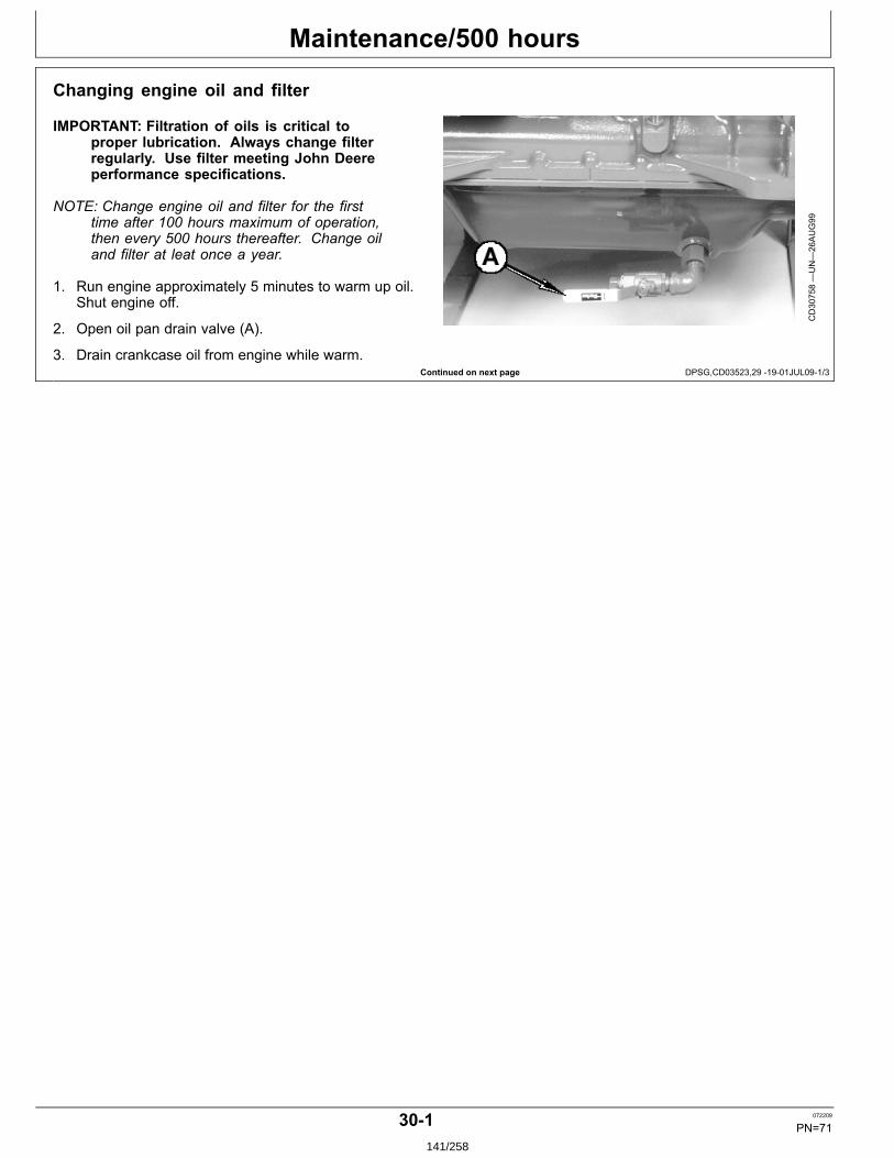
Maintenance/500 hours
Continued on next page DPSG,CD03523,29 1901JUL091/3
Changing engine oil and filter
IMPORTANT: Filtration of oils is critical toproper lubrication. Always change filterregularly. Use filter meeting John Deereperformance specifications.
NOTE: Change engine oil and filter for the firsttime after 100 hours maximum of operation,then every 500 hours thereafter. Change oiland filter at leat once a year.
1. Run engine approximately 5 minutes to warm up oil.Shut engine off.
2. Open oil pan drain valve (A).
3. Drain crankcase oil from engine while warm.
CD30758—UN—26AUG99
301 072209
PN=71141/258

Maintenance/500 hours
Continued on next page DPSG,CD03523,29 1901JUL092/3
CD30760—UN—26AUG99
Oil filter on 3029 and 4039 engines
CD30926—UN—30JAN07
Oil new filter element packing
CD30759A
—UN—29JAN07
Oil filter on 4045 and 6068 engines
RG11617—UN—24OCT01
Oil filter seals
4. Replace oil filter
• 3029 and 4039 enginesa. Remove and discard oil filter element (B) using a
suitable filter wrench.b. Oil new packing (C) and install new filter element.
Hand tighten element according to values printedon filter element. If values are not provided,tighten element approximately 3/4 — 11/4 turnafter packing contacts filter housing. DO NOTovertighten filter element.
• 4045 and 6068 enginesa. Remove and discard oil filter element (A) using a
suitable filter wrench.b. Apply clean engine oil to inner (B) and outer (C)
seals and to filter threads.c. Wipe both sealing surfaces of the header (D, E)
with a clean rag. Ensure notches in dust seal (F)are properly installed in the slots in the housing.Replace dust seal if damaged.
d. Install and tighten oil filter by hand until firmlyagainst dust seal (F). DO NOT overtighten.
RG11618—UN—24OCT01
Filter and mounting header
A—Oil filter elementB—Inner sealC—Outer seal
D—Sealing surfaceE—Sealing surfaceF—Dust seal
5. Close oil pan drain valve.
302 072209
PN=72142/258
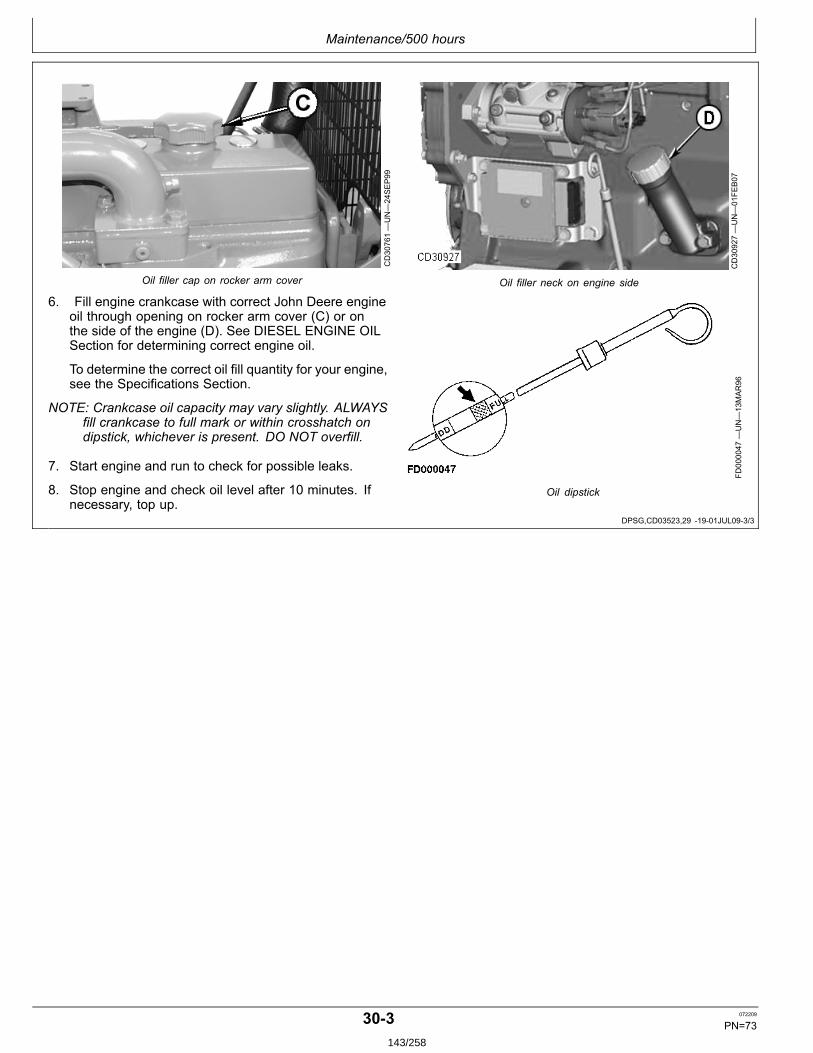
Maintenance/500 hours
DPSG,CD03523,29 1901JUL093/3
CD30761—UN—24SEP99
Oil filler cap on rocker arm cover
CD30927—UN—01FE
B07
Oil filler neck on engine side
6. Fill engine crankcase with correct John Deere engineoil through opening on rocker arm cover (C) or onthe side of the engine (D). See DIESEL ENGINE OILSection for determining correct engine oil.
To determine the correct oil fill quantity for your engine,see the Specifications Section.
NOTE: Crankcase oil capacity may vary slightly. ALWAYSfill crankcase to full mark or within crosshatch ondipstick, whichever is present. DO NOT overfill.
7. Start engine and run to check for possible leaks.
8. Stop engine and check oil level after 10 minutes. Ifnecessary, top up.
FD000047
—UN—13MAR96
Oil dipstick
303 072209
PN=73143/258
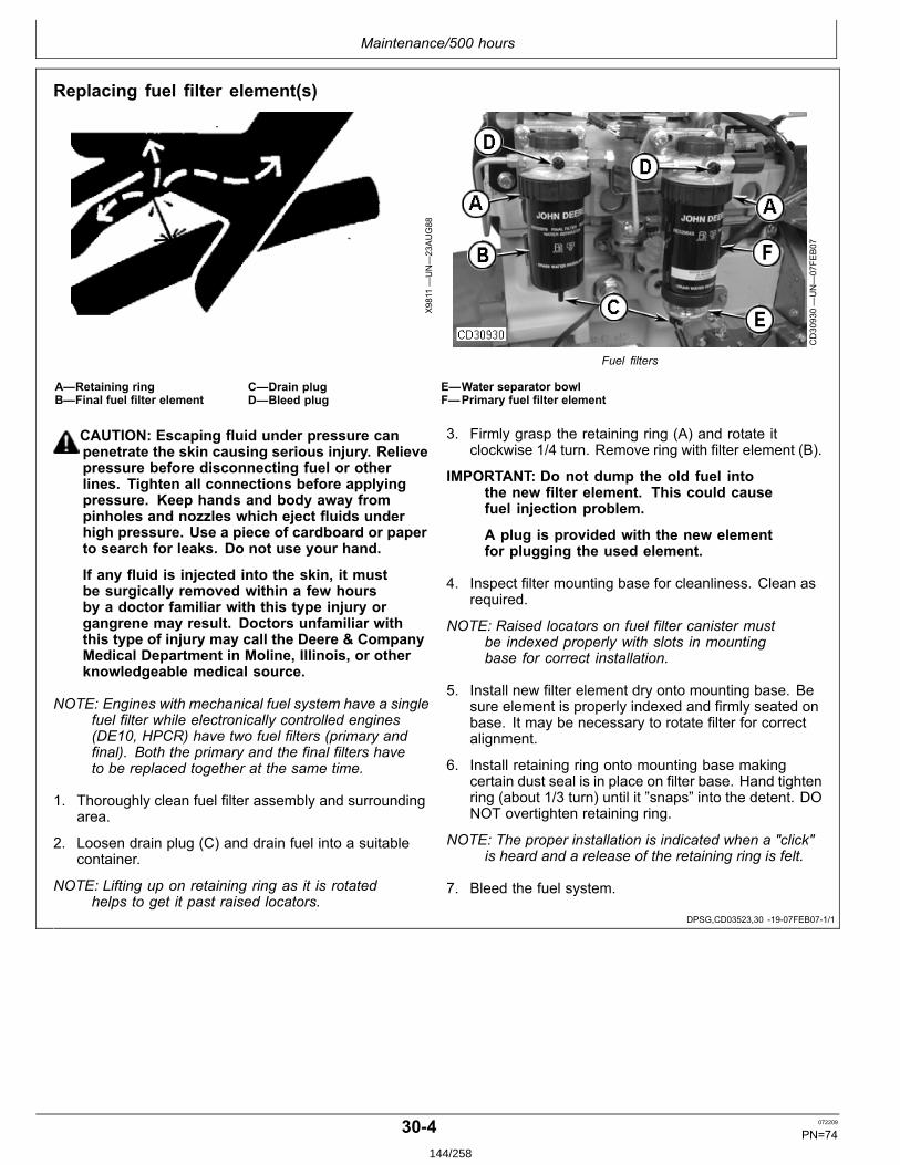
Maintenance/500 hours
DPSG,CD03523,30 1907FEB071/1
Replacing fuel filter element(s)
X9811
—UN—23AUG88
CD30930—UN—07FE
B07
Fuel filters
A—Retaining ringB—Final fuel filter element
C—Drain plugD—Bleed plug
E—Water separator bowlF—Primary fuel filter element
CAUTION: Escaping fluid under pressure canpenetrate the skin causing serious injury. Relievepressure before disconnecting fuel or otherlines. Tighten all connections before applyingpressure. Keep hands and body away frompinholes and nozzles which eject fluids underhigh pressure. Use a piece of cardboard or paperto search for leaks. Do not use your hand.
If any fluid is injected into the skin, it mustbe surgically removed within a few hoursby a doctor familiar with this type injury organgrene may result. Doctors unfamiliar withthis type of injury may call the Deere & CompanyMedical Department in Moline, Illinois, or otherknowledgeable medical source.
NOTE: Engines with mechanical fuel system have a singlefuel filter while electronically controlled engines(DE10, HPCR) have two fuel filters (primary andfinal). Both the primary and the final filters haveto be replaced together at the same time.
1. Thoroughly clean fuel filter assembly and surroundingarea.
2. Loosen drain plug (C) and drain fuel into a suitablecontainer.
NOTE: Lifting up on retaining ring as it is rotatedhelps to get it past raised locators.
3. Firmly grasp the retaining ring (A) and rotate itclockwise 1/4 turn. Remove ring with filter element (B).
IMPORTANT: Do not dump the old fuel intothe new filter element. This could causefuel injection problem.
A plug is provided with the new elementfor plugging the used element.
4. Inspect filter mounting base for cleanliness. Clean asrequired.
NOTE: Raised locators on fuel filter canister mustbe indexed properly with slots in mountingbase for correct installation.
5. Install new filter element dry onto mounting base. Besure element is properly indexed and firmly seated onbase. It may be necessary to rotate filter for correctalignment.
6. Install retaining ring onto mounting base makingcertain dust seal is in place on filter base. Hand tightenring (about 1/3 turn) until it ”snaps” into the detent. DONOT overtighten retaining ring.
NOTE: The proper installation is indicated when a "click"is heard and a release of the retaining ring is felt.
7. Bleed the fuel system.
304 072209
PN=74144/258
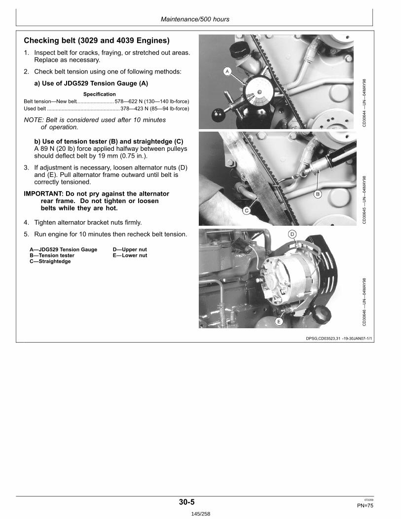
Maintenance/500 hours
DPSG,CD03523,31 1930JAN071/1
Checking belt (3029 and 4039 Engines)1. Inspect belt for cracks, fraying, or stretched out areas.
Replace as necessary.
2. Check belt tension using one of following methods:
a) Use of JDG529 Tension Gauge (A)Specification
Belt tension—New belt.......................... 578—622 N (130—140 lbforce)Used belt .................................................. 378—423 N (85—94 lbforce)
NOTE: Belt is considered used after 10 minutesof operation.
b) Use of tension tester (B) and straightedge (C)A 89 N (20 lb) force applied halfway between pulleysshould deflect belt by 19 mm (0.75 in.).
3. If adjustment is necessary, loosen alternator nuts (D)and (E). Pull alternator frame outward until belt iscorrectly tensioned.
IMPORTANT: Do not pry against the alternatorrear frame. Do not tighten or loosenbelts while they are hot.
4. Tighten alternator bracket nuts firmly.
5. Run engine for 10 minutes then recheck belt tension.
A—JDG529 Tension GaugeB—Tension testerC—Straightedge
D—Upper nutE—Lower nut
CD30644—UN—04MAY
98CD30645—UN—04MAY
98CD30646—UN—04MAY
98
305 072209
PN=75145/258
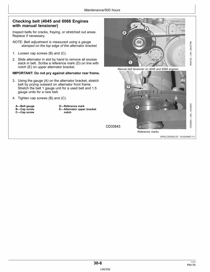
Maintenance/500 hours
DPSG,CD03523,57 1930JAN071/1
Checking belt (4045 and 6068 Engineswith manual tensioner)Inspect belts for cracks, fraying, or stretched out areas.Replace if necessary.
NOTE: Belt adjustment is measured using a gaugestamped on the top edge of the alternator bracket.
1. Loosen cap screws (B) and (C).
2. Slide alternator in slot by hand to remove all excessslack in belt. Scribe a reference mark (D) on line withnotch (E) on upper alternator bracket.
IMPORTANT: Do not pry against alternator rear frame.
3. Using the gauge (A) on the alternator bracket, stretchbelt by prying outward on alternator front frame.Stretch the belt 1 gauge unit for a used belt and 1.5gauge units for a new belt.
4. Tighten cap screws (B) and (C).
A—Belt gaugeB—Cap screwC—Cap screw
D—Reference markE—Alternator upper bracket
notch
RG9132
—UN—04OCT99
Manual belt tensioner on 4045 and 6068 engines
CD30843—UN—10JAN03
Reference marks
306 072209
PN=76146/258
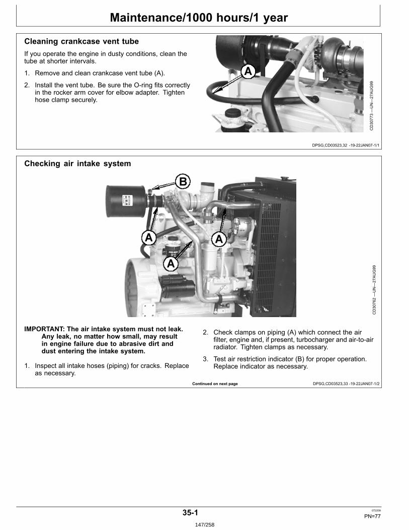
Maintenance/1000 hours/1 year
DPSG,CD03523,32 1922JAN071/1
Continued on next page DPSG,CD03523,33 1922JAN071/2
Cleaning crankcase vent tubeIf you operate the engine in dusty conditions, clean thetube at shorter intervals.
1. Remove and clean crankcase vent tube (A).
2. Install the vent tube. Be sure the Oring fits correctlyin the rocker arm cover for elbow adapter. Tightenhose clamp securely.
CD30773—UN—27AUG99
Checking air intake system
CD30762—UN—27AUG99
IMPORTANT: The air intake system must not leak.Any leak, no matter how small, may resultin engine failure due to abrasive dirt anddust entering the intake system.
1. Inspect all intake hoses (piping) for cracks. Replaceas necessary.
2. Check clamps on piping (A) which connect the airfilter, engine and, if present, turbocharger and airtoairradiator. Tighten clamps as necessary.
3. Test air restriction indicator (B) for proper operation.Replace indicator as necessary.
351 072209
PN=77147/258
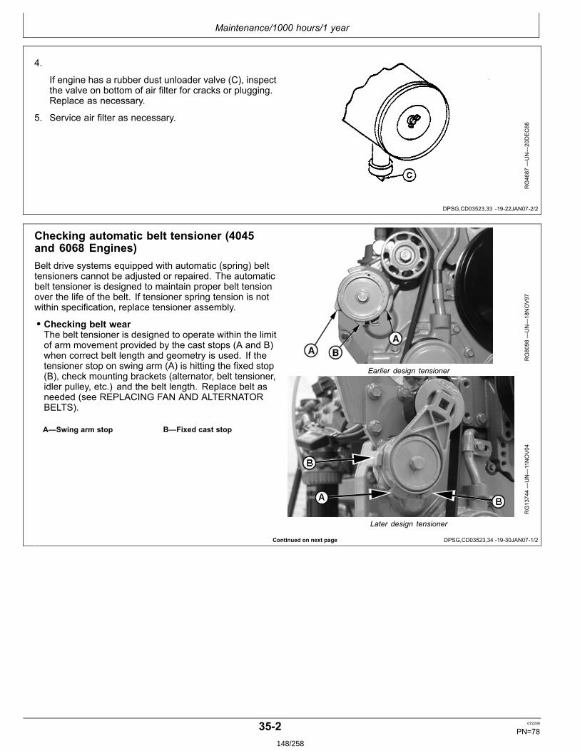
Maintenance/1000 hours/1 year
DPSG,CD03523,33 1922JAN072/2
Continued on next page DPSG,CD03523,34 1930JAN071/2
4.
If engine has a rubber dust unloader valve (C), inspectthe valve on bottom of air filter for cracks or plugging.Replace as necessary.
5. Service air filter as necessary.
RG4687
—UN—20DEC88
Checking automatic belt tensioner (4045and 6068 Engines)Belt drive systems equipped with automatic (spring) belttensioners cannot be adjusted or repaired. The automaticbelt tensioner is designed to maintain proper belt tensionover the life of the belt. If tensioner spring tension is notwithin specification, replace tensioner assembly.
• Checking belt wearThe belt tensioner is designed to operate within the limitof arm movement provided by the cast stops (A and B)when correct belt length and geometry is used. If thetensioner stop on swing arm (A) is hitting the fixed stop(B), check mounting brackets (alternator, belt tensioner,idler pulley, etc.) and the belt length. Replace belt asneeded (see REPLACING FAN AND ALTERNATORBELTS).
A—Swing arm stop B—Fixed cast stop
RG8098
—UN—18NOV97
Earlier design tensioner
RG13744—UN—11NOV04
Later design tensioner
352 072209
PN=78148/258
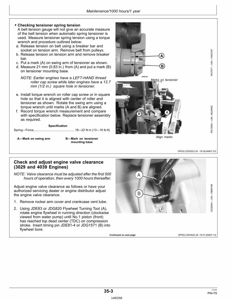
Maintenance/1000 hours/1 year
DPSG,CD03523,34 1930JAN072/2
Continued on next page DPSG,CD03523,35 1931JAN071/2
• Checking tensioner spring tensionA belt tension gauge will not give an accurate measureof the belt tension when automatic spring tensioner isused. Measure tensioner spring tension using a torquewrench and procedure outlined below:a. Release tension on belt using a breaker bar and
socket on tension arm. Remove belt from pulleys.b. Release tension on tension arm and remove breaker
bar.c. Put a mark (A) on swing arm of tensioner as shown.d. Measure 21 mm (0.83 in.) from (A) and put a mark (B)
on tensioner mounting base.
NOTE: Earlier engines have a LEFTHAND threadroller cap screw while later engines have a 12.7mm (1/2 in.) square hole in tensioner.
e. Install torque wrench on roller cap screw or in squarehole so that it is aligned with center of roller andtensioner as shown. Rotate the swing arm using atorque wrench until marks (A and B) are aligned.
f. Record torque wrench measurement and comparewith specification below. Replace tensioner assemblyas required.
SpecificationSpring—Force................................................. 18—22 N∙m (13—16 lbft)
A—Mark on swing arm B—Mark on tensionermounting base
RG7977
—UN—14NOV97
Marks on tensioner
RG12054—UN—08JAN02
Align marks
Check and adjust engine valve clearance(3029 and 4039 Engines)NOTE: Valve clearance must be adjusted after the first 500
hours of operation, then every 1000 hours thereafter.
Adjust engine valve clearance as follows or have yourauthorized servicing dealer or engine distributor adjustthe engine valve clearance.
1. Remove rocker arm cover and crankcase vent tube.
2. Using JDE83 or JDG820 Flywheel Turning Tool (A),rotate engine flywheel in running direction (clockwiseviewed from water pump) until No.1 piston (front)has reached top dead center (TDC) on compressionstroke. Insert timing pin JDE814 or JDG1571 (B) intoflywheel bore.
CD30544—UN—19MAY
98
353 072209
PN=79149/258
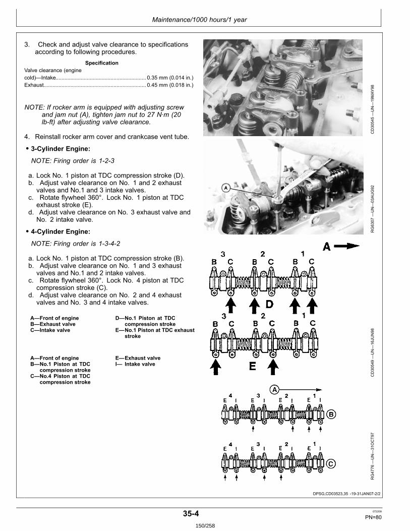
Maintenance/1000 hours/1 year
DPSG,CD03523,35 1931JAN072/2
3. Check and adjust valve clearance to specificationsaccording to following procedures.
SpecificationValve clearance (enginecold)—Intake............................................................. 0.35 mm (0.014 in.)Exhaust..................................................................... 0.45 mm (0.018 in.)
NOTE: If rocker arm is equipped with adjusting screwand jam nut (A), tighten jam nut to 27 N∙m (20lbft) after adjusting valve clearance.
4. Reinstall rocker arm cover and crankcase vent tube.
• 3Cylinder Engine:NOTE: Firing order is 123
a. Lock No. 1 piston at TDC compression stroke (D).b. Adjust valve clearance on No. 1 and 2 exhaust
valves and No.1 and 3 intake valves.c. Rotate flywheel 360°. Lock No. 1 piston at TDC
exhaust stroke (E).d. Adjust valve clearance on No. 3 exhaust valve and
No. 2 intake valve.
• 4Cylinder Engine:NOTE: Firing order is 1342
a. Lock No. 1 piston at TDC compression stroke (B).b. Adjust valve clearance on No. 1 and 3 exhaust
valves and No.1 and 2 intake valves.c. Rotate flywheel 360°. Lock No. 4 piston at TDC
compression stroke (C).d. Adjust valve clearance on No. 2 and 4 exhaust
valves and No. 3 and 4 intake valves.
A—Front of engineB—Exhaust valveC—Intake valve
D—No.1 Piston at TDCcompression stroke
E—No.1 Piston at TDC exhauststroke
A—Front of engineB—No.1 Piston at TDC
compression strokeC—No.4 Piston at TDC
compression stroke
E—Exhaust valveI— Intake valve
CD30545—UN—19MAY
98RG6307
—UN—03AUG92
CD30549—UN—16JU
N98
RG4776
—UN—31OCT97
354 072209
PN=80150/258
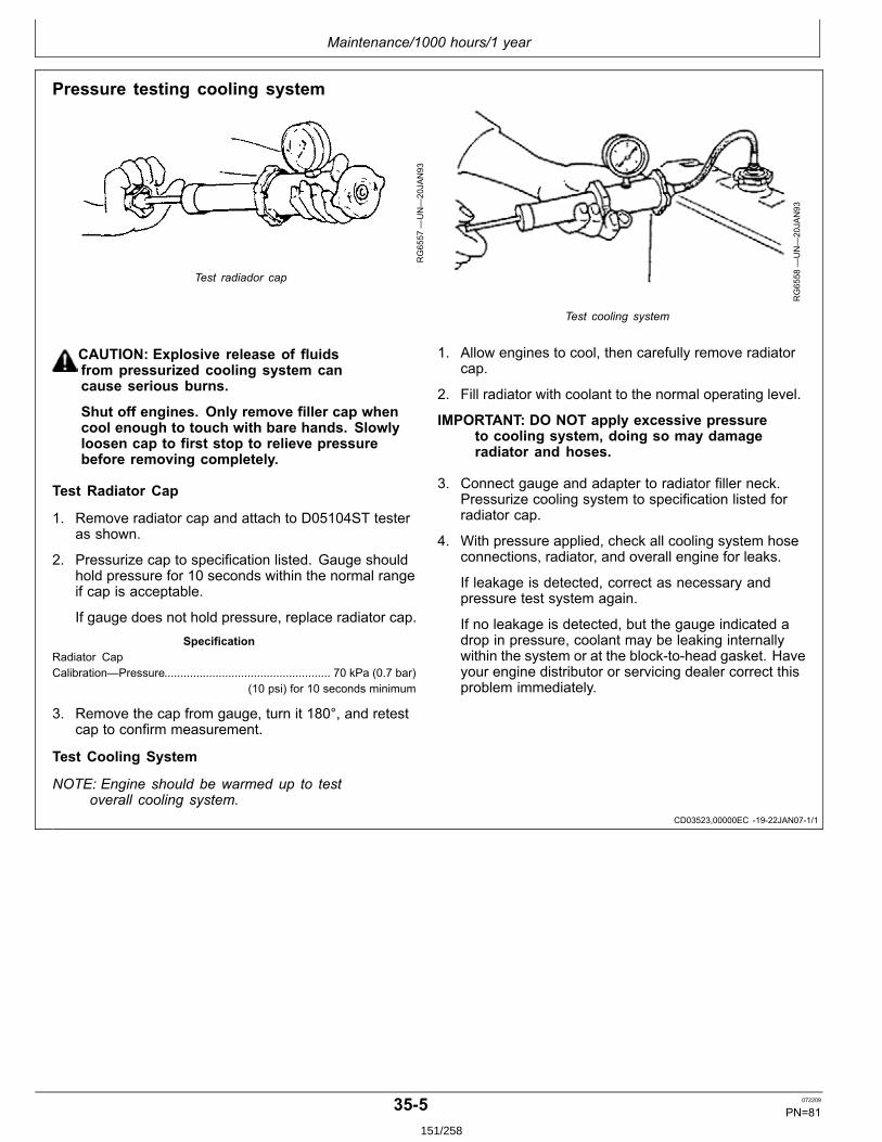
Maintenance/1000 hours/1 year
CD03523,00000EC 1922JAN071/1
Pressure testing cooling system
RG6557
—UN—20JAN93
Test radiador cap
RG6558
—UN—20JAN93
Test cooling system
CAUTION: Explosive release of fluidsfrom pressurized cooling system cancause serious burns.
Shut off engines. Only remove filler cap whencool enough to touch with bare hands. Slowlyloosen cap to first stop to relieve pressurebefore removing completely.
Test Radiator Cap
1. Remove radiator cap and attach to D05104ST testeras shown.
2. Pressurize cap to specification listed. Gauge shouldhold pressure for 10 seconds within the normal rangeif cap is acceptable.
If gauge does not hold pressure, replace radiator cap.Specification
Radiator CapCalibration—Pressure.................................................... 70 kPa (0.7 bar)
(10 psi) for 10 seconds minimum
3. Remove the cap from gauge, turn it 180°, and retestcap to confirm measurement.
Test Cooling System
NOTE: Engine should be warmed up to testoverall cooling system.
1. Allow engines to cool, then carefully remove radiatorcap.
2. Fill radiator with coolant to the normal operating level.
IMPORTANT: DO NOT apply excessive pressureto cooling system, doing so may damageradiator and hoses.
3. Connect gauge and adapter to radiator filler neck.Pressurize cooling system to specification listed forradiator cap.
4. With pressure applied, check all cooling system hoseconnections, radiator, and overall engine for leaks.
If leakage is detected, correct as necessary andpressure test system again.
If no leakage is detected, but the gauge indicated adrop in pressure, coolant may be leaking internallywithin the system or at the blocktohead gasket. Haveyour engine distributor or servicing dealer correct thisproblem immediately.
355 072209
PN=81151/258
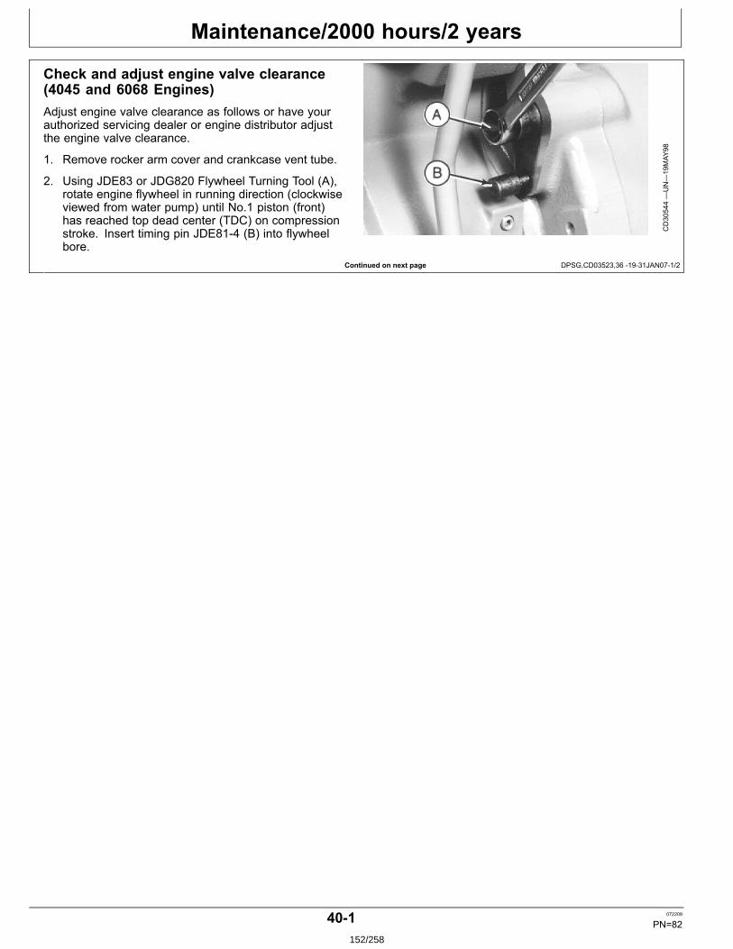
Maintenance/2000 hours/2 years
Continued on next page DPSG,CD03523,36 1931JAN071/2
Check and adjust engine valve clearance(4045 and 6068 Engines)Adjust engine valve clearance as follows or have yourauthorized servicing dealer or engine distributor adjustthe engine valve clearance.
1. Remove rocker arm cover and crankcase vent tube.
2. Using JDE83 or JDG820 Flywheel Turning Tool (A),rotate engine flywheel in running direction (clockwiseviewed from water pump) until No.1 piston (front)has reached top dead center (TDC) on compressionstroke. Insert timing pin JDE814 (B) into flywheelbore.
CD30544—UN—19MAY
98
401 072209
PN=82152/258
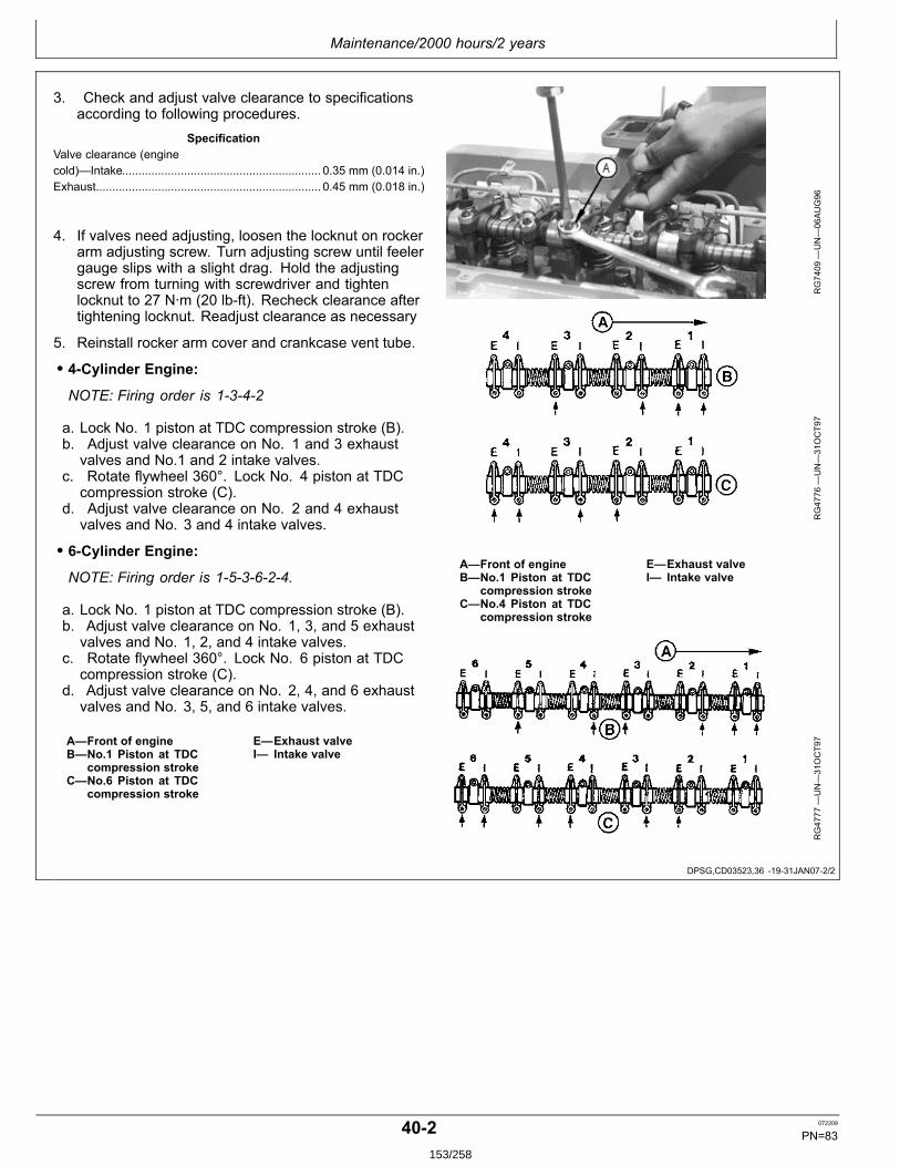
Maintenance/2000 hours/2 years
DPSG,CD03523,36 1931JAN072/2
3. Check and adjust valve clearance to specificationsaccording to following procedures.
SpecificationValve clearance (enginecold)—Intake............................................................. 0.35 mm (0.014 in.)Exhaust..................................................................... 0.45 mm (0.018 in.)
4. If valves need adjusting, loosen the locknut on rockerarm adjusting screw. Turn adjusting screw until feelergauge slips with a slight drag. Hold the adjustingscrew from turning with screwdriver and tightenlocknut to 27 N∙m (20 lbft). Recheck clearance aftertightening locknut. Readjust clearance as necessary
5. Reinstall rocker arm cover and crankcase vent tube.
• 4Cylinder Engine:NOTE: Firing order is 1342
a. Lock No. 1 piston at TDC compression stroke (B).b. Adjust valve clearance on No. 1 and 3 exhaust
valves and No.1 and 2 intake valves.c. Rotate flywheel 360°. Lock No. 4 piston at TDC
compression stroke (C).d. Adjust valve clearance on No. 2 and 4 exhaust
valves and No. 3 and 4 intake valves.
• 6Cylinder Engine:NOTE: Firing order is 153624.
a. Lock No. 1 piston at TDC compression stroke (B).b. Adjust valve clearance on No. 1, 3, and 5 exhaust
valves and No. 1, 2, and 4 intake valves.c. Rotate flywheel 360°. Lock No. 6 piston at TDC
compression stroke (C).d. Adjust valve clearance on No. 2, 4, and 6 exhaust
valves and No. 3, 5, and 6 intake valves.
A—Front of engineB—No.1 Piston at TDC
compression strokeC—No.6 Piston at TDC
compression stroke
E—Exhaust valveI— Intake valve
RG7409
—UN—06AUG96
RG4776
—UN—31OCT97
A—Front of engineB—No.1 Piston at TDC
compression strokeC—No.4 Piston at TDC
compression stroke
E—Exhaust valveI— Intake valve
RG4777
—UN—31OCT97
402 072209
PN=83153/258
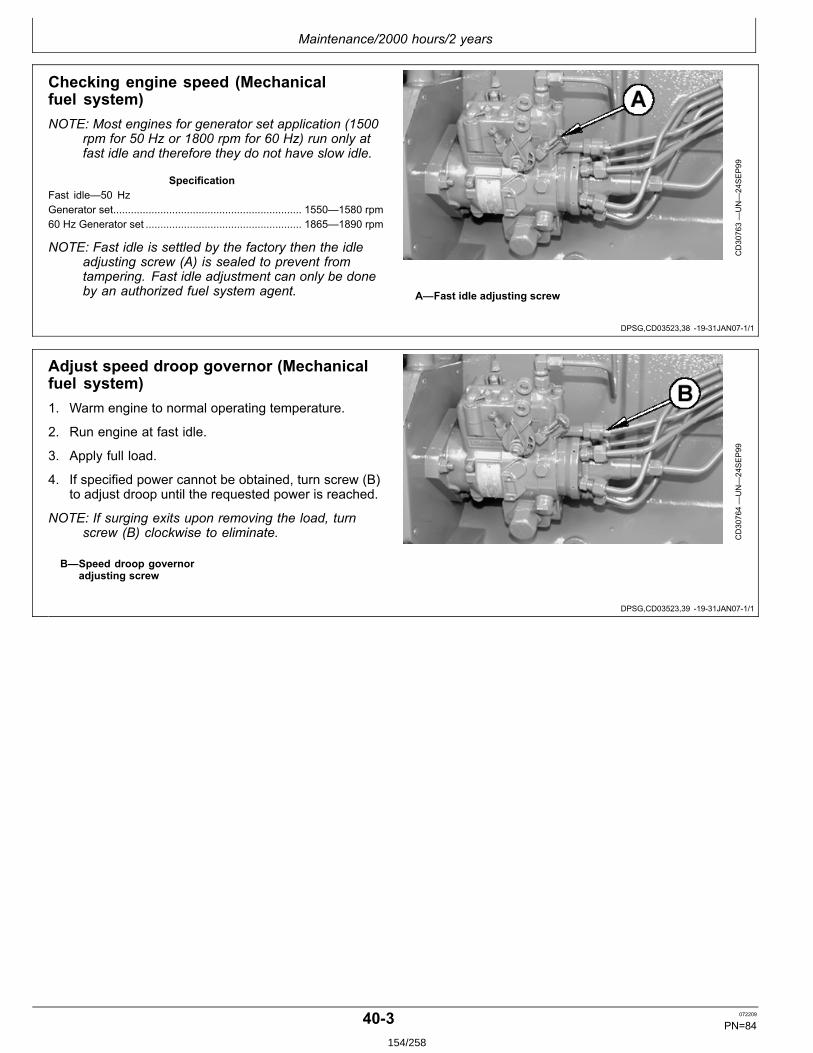
Maintenance/2000 hours/2 years
DPSG,CD03523,38 1931JAN071/1
DPSG,CD03523,39 1931JAN071/1
Checking engine speed (Mechanicalfuel system)NOTE: Most engines for generator set application (1500
rpm for 50 Hz or 1800 rpm for 60 Hz) run only atfast idle and therefore they do not have slow idle.
SpecificationFast idle—50 HzGenerator set................................................................ 1550—1580 rpm60 Hz Generator set ..................................................... 1865—1890 rpm
NOTE: Fast idle is settled by the factory then the idleadjusting screw (A) is sealed to prevent fromtampering. Fast idle adjustment can only be doneby an authorized fuel system agent.
CD30763—UN—24SEP99
A—Fast idle adjusting screw
Adjust speed droop governor (Mechanicalfuel system)1. Warm engine to normal operating temperature.
2. Run engine at fast idle.
3. Apply full load.
4. If specified power cannot be obtained, turn screw (B)to adjust droop until the requested power is reached.
NOTE: If surging exits upon removing the load, turnscrew (B) clockwise to eliminate.
B—Speed droop governoradjusting screw
CD30764—UN—24SEP99
403 072209
PN=84154/258
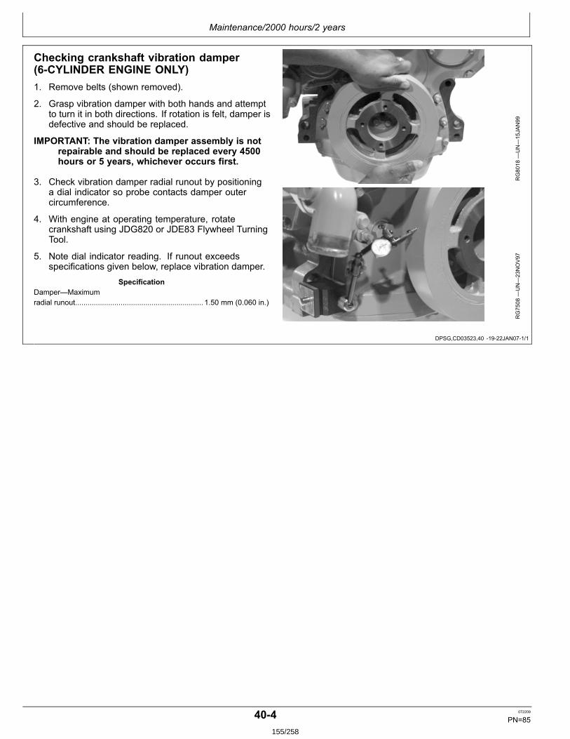
Maintenance/2000 hours/2 years
DPSG,CD03523,40 1922JAN071/1
Checking crankshaft vibration damper(6CYLINDER ENGINE ONLY)1. Remove belts (shown removed).
2. Grasp vibration damper with both hands and attemptto turn it in both directions. If rotation is felt, damper isdefective and should be replaced.
IMPORTANT: The vibration damper assembly is notrepairable and should be replaced every 4500hours or 5 years, whichever occurs first.
3. Check vibration damper radial runout by positioninga dial indicator so probe contacts damper outercircumference.
4. With engine at operating temperature, rotatecrankshaft using JDG820 or JDE83 Flywheel TurningTool.
5. Note dial indicator reading. If runout exceedsspecifications given below, replace vibration damper.
SpecificationDamper—Maximumradial runout.............................................................. 1.50 mm (0.060 in.)
RG8018
—UN—15JAN99
RG7508
—UN—23NOV97
404 072209
PN=85155/258
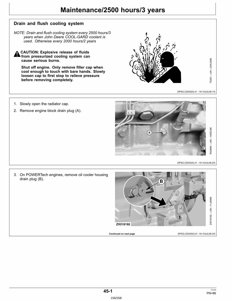
Maintenance/2500 hours/3 years
DPSG,CD03523,41 1915JUL091/5
DPSG,CD03523,41 1915JUL092/5
Continued on next page DPSG,CD03523,41 1915JUL093/5
Drain and flush cooling system
NOTE: Drain and flush cooling system every 2500 hours/3years when John Deere COOLGARD coolant isused. Otherwise every 2000 hours/2 years
CAUTION: Explosive release of fluidsfrom pressurized cooling system cancause serious burns.
Shut off engine. Only remove filler cap whencool enough to touch with bare hands. Slowlyloosen cap to first stop to relieve pressurebefore removing completely.
TS281—UN—23AUG88
1. Slowly open the radiator cap.
2. Remove engine block drain plug (A).
RG4894
—UN—14DEC88
3. On POWERTech engines, remove oil cooler housingdrain plug (B).
ZX016192
—UN—11JAN99
451 072209
PN=86156/258
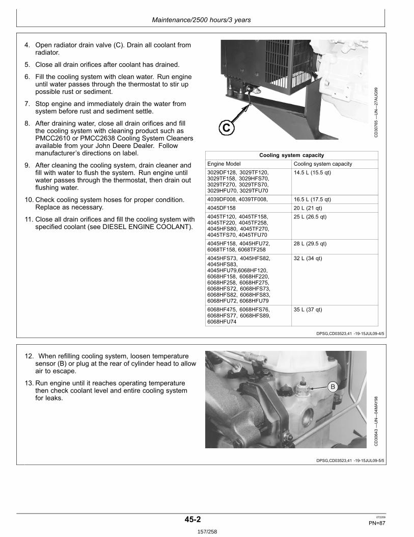
Maintenance/2500 hours/3 years
DPSG,CD03523,41 1915JUL094/5
DPSG,CD03523,41 1915JUL095/5
4. Open radiator drain valve (C). Drain all coolant fromradiator.
5. Close all drain orifices after coolant has drained.
6. Fill the cooling system with clean water. Run engineuntil water passes through the thermostat to stir uppossible rust or sediment.
7. Stop engine and immediately drain the water fromsystem before rust and sediment settle.
8. After draining water, close all drain orifices and fillthe cooling system with cleaning product such asPMCC2610 or PMCC2638 Cooling System Cleanersavailable from your John Deere Dealer. Followmanufacturer’s directions on label.
9. After cleaning the cooling system, drain cleaner andfill with water to flush the system. Run engine untilwater passes through the thermostat, then drain outflushing water.
10. Check cooling system hoses for proper condition.Replace as necessary.
11. Close all drain orifices and fill the cooling system withspecified coolant (see DIESEL ENGINE COOLANT).
CD30765—UN—27AUG99
Cooling system capacityEngine Model Cooling system capacity3029DF128, 3029TF120,3029TF158, 3029HFS70,3029TF270, 3029TFS70,3029HFU70, 3029TFU70
14.5 L (15.5 qt)
4039DF008, 4039TF008, 16.5 L (17.5 qt)4045DF158 20 L (21 qt)4045TF120, 4045TF158,4045TF220, 4045TF258,4045HFS80, 4045TF270,4045TFS70, 4045TFU70
25 L (26.5 qt)
4045HF158, 4045HFU72,6068TF158, 6068TF258
28 L (29.5 qt)
4045HFS73, 4045HFS82,4045HFS83,4045HFU79,6068HF120,6068HF158, 6068HF220,6068HF258, 6068HF275,6068HFS72, 6068HFS73,6068HFS82, 6068HFS83,6068HFU72, 6068HFU79
32 L (34 qt)
6068HF475, 6068HFS76,6068HFS77, 6068HFS89,6068HFU74
35 L (37 qt)
12. When refilling cooling system, loosen temperaturesensor (B) or plug at the rear of cylinder head to allowair to escape.
13. Run engine until it reaches operating temperaturethen check coolant level and entire cooling systemfor leaks.
CD30643—UN—04MAY
98
452 072209
PN=87157/258
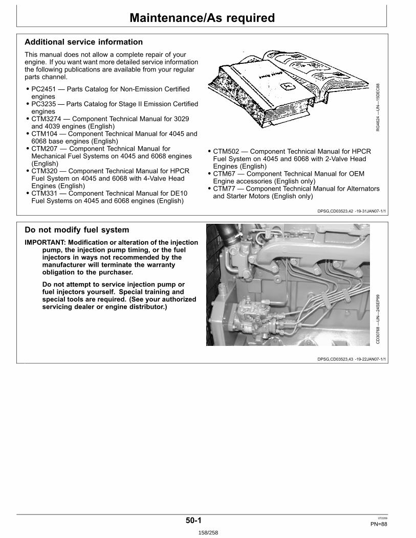
Maintenance/As required
DPSG,CD03523,42 1931JAN071/1
DPSG,CD03523,43 1922JAN071/1
Additional service informationThis manual does not allow a complete repair of yourengine. If you want want more detailed service informationthe following publications are available from your regularparts channel.
• PC2451 — Parts Catalog for NonEmission Certifiedengines• PC3235 — Parts Catalog for Stage II Emission Certifiedengines• CTM3274 — Component Technical Manual for 3029and 4039 engines (English)• CTM104 — Component Technical Manual for 4045 and6068 base engines (English)• CTM207 — Component Technical Manual forMechanical Fuel Systems on 4045 and 6068 engines(English)• CTM320 — Component Technical Manual for HPCRFuel System on 4045 and 6068 with 4Valve HeadEngines (English)• CTM331 — Component Technical Manual for DE10Fuel Systems on 4045 and 6068 engines (English)
RG4624
—UN—15DEC88
• CTM502 — Component Technical Manual for HPCRFuel System on 4045 and 6068 with 2Valve HeadEngines (English)• CTM67 — Component Technical Manual for OEMEngine accessories (English only)• CTM77 — Component Technical Manual for Alternatorsand Starter Motors (English only)
Do not modify fuel systemIMPORTANT: Modification or alteration of the injection
pump, the injection pump timing, or the fuelinjectors in ways not recommended by themanufacturer will terminate the warrantyobligation to the purchaser.
Do not attempt to service injection pump orfuel injectors yourself. Special training andspecial tools are required. (See your authorizedservicing dealer or engine distributor.)
CD30768—UN—24SEP99
501 072209
PN=88158/258
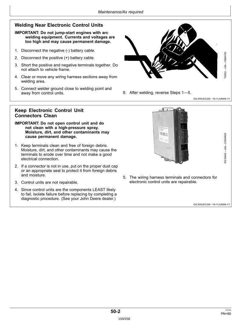
Maintenance/As required
DX,WW,ECU02 1911JUN091/1
DX,WW,ECU04 1911JUN091/1
Welding Near Electronic Control UnitsIMPORTANT: Do not jumpstart engines with arc
welding equipment. Currents and voltages aretoo high and may cause permanent damage.
1. Disconnect the negative () battery cable.
2. Disconnect the positive (+) battery cable.
3. Short the positive and negative terminals together. Donot attach to vehicle frame.
4. Clear or move any wiring harness sections away fromwelding area.
5. Connect welder ground close to welding point andaway from control units.
TS953—UN—15MAY
90
6. After welding, reverse Steps 1—5.
Keep Electronic Control UnitConnectors CleanIMPORTANT: Do not open control unit and do
not clean with a highpressure spray.Moisture, dirt, and other contaminants maycause permanent damage.
1. Keep terminals clean and free of foreign debris.Moisture, dirt, and other contaminants may cause theterminals to erode over time and not make a goodelectrical connection.
2. If a connector is not in use, put on the proper dust capor an appropriate seal to protect it from foreign debrisand moisture.
3. Control units are not repairable.
4. Since control units are the components LEAST likelyto fail, isolate failure before replacing by completing adiagnostic procedure. (See your John Deere dealer.)
RG16946—UN—31MAR09
5. The wiring harness terminals and connectors forelectronic control units are repairable.
502 072209
PN=89159/258
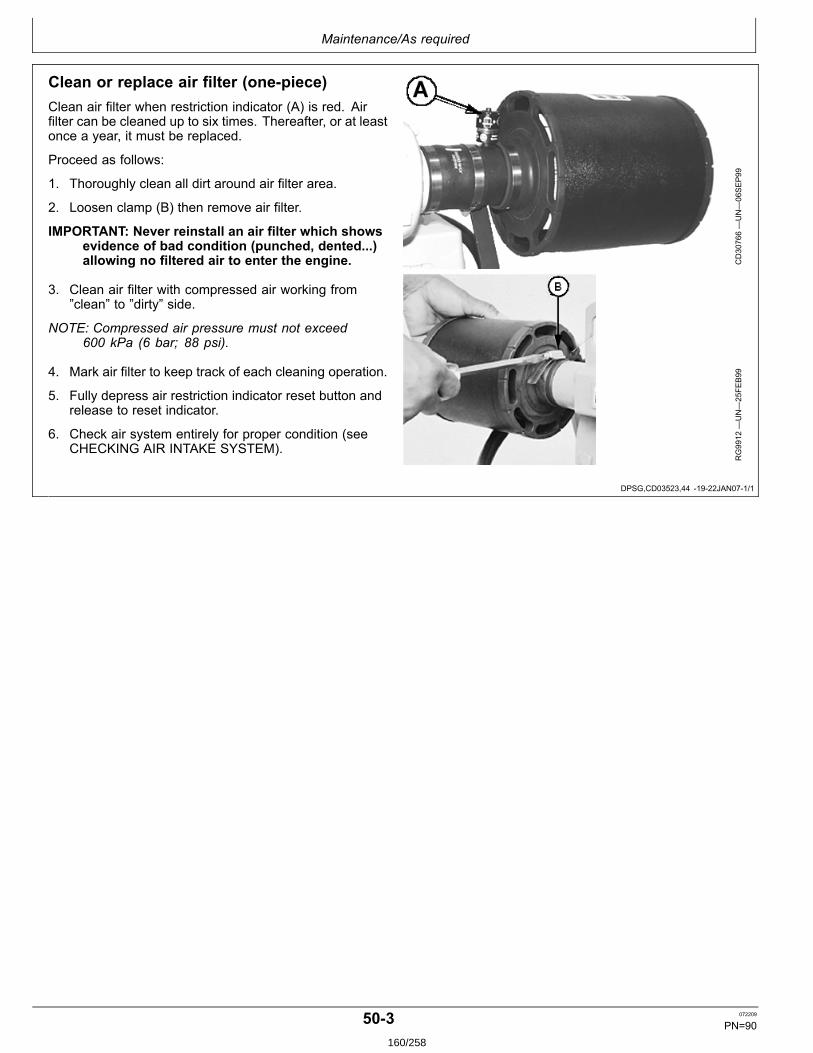
Maintenance/As required
DPSG,CD03523,44 1922JAN071/1
Clean or replace air filter (onepiece)Clean air filter when restriction indicator (A) is red. Airfilter can be cleaned up to six times. Thereafter, or at leastonce a year, it must be replaced.
Proceed as follows:
1. Thoroughly clean all dirt around air filter area.
2. Loosen clamp (B) then remove air filter.
IMPORTANT: Never reinstall an air filter which showsevidence of bad condition (punched, dented...)allowing no filtered air to enter the engine.
3. Clean air filter with compressed air working from”clean” to ”dirty” side.
NOTE: Compressed air pressure must not exceed600 kPa (6 bar; 88 psi).
4. Mark air filter to keep track of each cleaning operation.
5. Fully depress air restriction indicator reset button andrelease to reset indicator.
6. Check air system entirely for proper condition (seeCHECKING AIR INTAKE SYSTEM).
CD30766—UN—06SEP99
RG9912
—UN—25FE
B99
503 072209
PN=90160/258
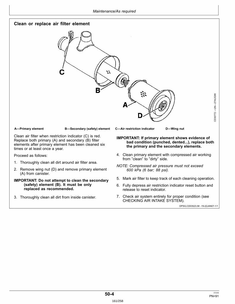
Maintenance/As required
DPSG,CD03523,58 1922JAN071/1
Clean or replace air filter element
CD30772—UN—27AUG99
A—Primary element B—Secondary (safety) element C—Air restriction indicator D—Wing nut
Clean air filter when restriction indicator (C) is red.Replace both primary (A) and secondary (B) filterelements after primary element has been cleaned sixtimes or at least once a year.
Proceed as follows:
1. Thoroughly clean all dirt around air filter area.
2. Remove wing nut (D) and remove primary element(A) from canister.
IMPORTANT: Do not attempt to clean the secondary(safety) element (B). It must be onlyreplaced as recommended.
3. Thoroughly clean all dirt from inside canister.
IMPORTANT: If primary element shows evidence ofbad condition (punched, dented...), replace boththe primary and the secondary elements.
4. Clean primary element with compressed air workingfrom ”clean” to ”dirty” side.
NOTE: Compressed air pressure must not exceed600 kPa (6 bar; 88 psi).
5. Mark air filter to keep track of each cleaning operation.
6. Fully depress air restriction indicator reset button andrelease to reset indicator.
7. Check air system entirely for proper condition (seeCHECKING AIR INTAKE SYSTEM).
504 072209
PN=91161/258
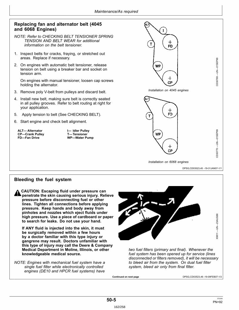
Maintenance/As required
DPSG,CD03523,45 1931JAN071/1
Continued on next page DPSG,CD03523,46 1909FEB071/3
Replacing fan and alternator belt (4045and 6068 Engines)NOTE: Refer to CHECKING BELT TENSIONER SPRING
TENSION AND BELT WEAR for additionalinformation on the belt tensioner.
1. Inspect belts for cracks, fraying, or stretched outareas. Replace if necessary.
2. On engines with automatic belt tensioner, releasetension on belt using a breaker bar and socket ontension arm.
On engines with manual tensioner, loosen cap screwsholding the alternator.
3. Remove poly Vbelt from pulleys and discard belt.
4. Install new belt, making sure belt is correctly seatedin all pulley grooves. Refer to belt routing at right foryour application.
5. Apply tension to belt (See CHECKING BELT).
6. Start engine and check belt alignment.
ALT— AlternatorCP—Crank PulleyFD—Fan Drive
I— Idler PulleyT—TensionerWP—Water Pump
CD30769—UN—01SEP99
Installation on 4045 engines
CD30770—UN—01SEP99
Installation on 6068 engines
Bleeding the fuel system
CAUTION: Escaping fluid under pressure canpenetrate the skin causing serious injury. Relievepressure before disconnecting fuel or otherlines. Tighten all connections before applyingpressure. Keep hands and body away frompinholes and nozzles which eject fluids underhigh pressure. Use a piece of cardboard or paperto search for leaks. Do not use your hand.
If ANY fluid is injected into the skin, it mustbe surgically removed within a few hoursby a doctor familiar with this type injury organgrene may result. Doctors unfamiliar withthis type of injury may call the Deere & CompanyMedical Department in Moline, Illinois, or otherknowledgeable medical source.
NOTE: Engines with mechanical fuel system have asingle fuel filter while electronically controlledengines (DE10 and HPCR fuel systems) have
X9811
—UN—23AUG88
two fuel filters (primary and final). Whenever thefuel system has been opened up for service (linesdisconnected or filters removed), it will be necessaryto bleed air from the system. On dual fuel filtersystem, bleed air only from final filter.
505 072209
PN=92162/258
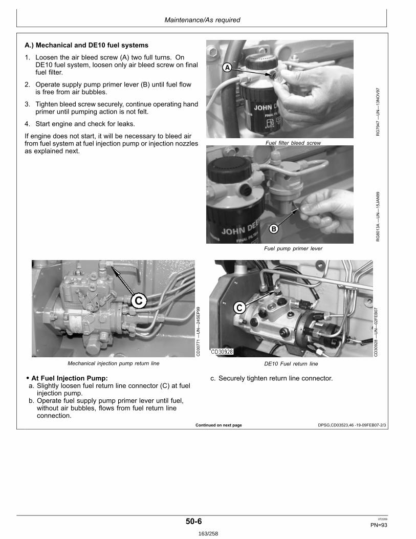
Maintenance/As required
Continued on next page DPSG,CD03523,46 1909FEB072/3
A.) Mechanical and DE10 fuel systems
1. Loosen the air bleed screw (A) two full turns. OnDE10 fuel system, loosen only air bleed screw on finalfuel filter.
2. Operate supply pump primer lever (B) until fuel flowis free from air bubbles.
3. Tighten bleed screw securely, continue operating handprimer until pumping action is not felt.
4. Start engine and check for leaks.
If engine does not start, it will be necessary to bleed airfrom fuel system at fuel injection pump or injection nozzlesas explained next.
RG7947
—UN—13NOV97
Fuel filter bleed screw
RG8013A—UN—15JAN99
Fuel pump primer lever
CD30771—UN—24SEP99
Mechanical injection pump return line
CD30928—UN—02FE
B07
DE10 Fuel return line
• At Fuel Injection Pump:a. Slightly loosen fuel return line connector (C) at fuel
injection pump.b. Operate fuel supply pump primer lever until fuel,
without air bubbles, flows from fuel return lineconnection.
c. Securely tighten return line connector.
506 072209
PN=93163/258

Maintenance/As required
DPSG,CD03523,46 1909FEB073/3
• At Fuel Injection Nozzles:a. Using two openend wrenches, loosen fuel line
connection at injection nozzle.b. Crank engine over with starting motor, (but do not
start engine), until fuel free from bubbles flows outof loosened connection. Retighten connection to 27N∙m (20 lbft).
c. Repeat procedure for remaining injection nozzles (ifnecessary) until all air has been removed from fuelsystem.
If engine still will not start, see your authorized servicingdealer or engine distributor.
RG7725
—UN—08JAN97
Bleed fuel system at fuel injection nozzles
TS1343
—UN—18MAR92
RG12220—UN—24MAY
02
Final fuel filter bleed screw
B.) HPCR fuel system (2 or 4valve head)
CAUTION: Highpressure fluid remaining infuel lines can cause serious injury. Do notdisconnect fuel lines between the high pressurefuel pump and nozzles. Only bleed the fuelsystem at the fuel filter bleed screw (A).
1. Loosen the air bleed screw (A) two full turns on finalfilter base only.
2. Operate fuel supply pump primer lever (B) until fuelflow is free from air bubbles.
3. Tighten bleed screw securely. Continue operatingprimer until pumping action is not felt.
4. Start engine and check for leaks.
If engine will not start, repeat steps 14.
RG12221—UN—24MAY
02
Fuel supply pump primer lever
507 072209
PN=94164/258
Troubleshooting
CD03523,000018D 1908FEB071/1
General troubleshooting information
Troubleshooting electronically controlled engine problemscan be difficult. The first thing to do is to identify the typeof problem which can be mechanical or electrical.
An engine wiring layout is provided in this section toidentify electrical components (engine controller, sensors,connectors... ).
Later in this section is a list of possible engine problemsand diagnostic trouble codes that may be encounteredaccompanied by possible causes and corrections. Thistroubleshooting information is of a general nature.See also the generator documentation for a completeinformation of your application.
A reliable program for troubleshooting engine problemsshould include the following basic diagnostic thoughtprocess:
• Know the engine and all related systems.• Study the problem thoroughly.• Relate the symptoms to your knowledge of engine andsystems.• Diagnose the problem starting with the easiest thingsfirst.• Doublecheck before beginning the disassembly.• Determine cause and make a thorough repair.• After making repairs, operate the engine under normalconditions to verify that the problem and cause wascorrected.
551 072209
PN=95165/258
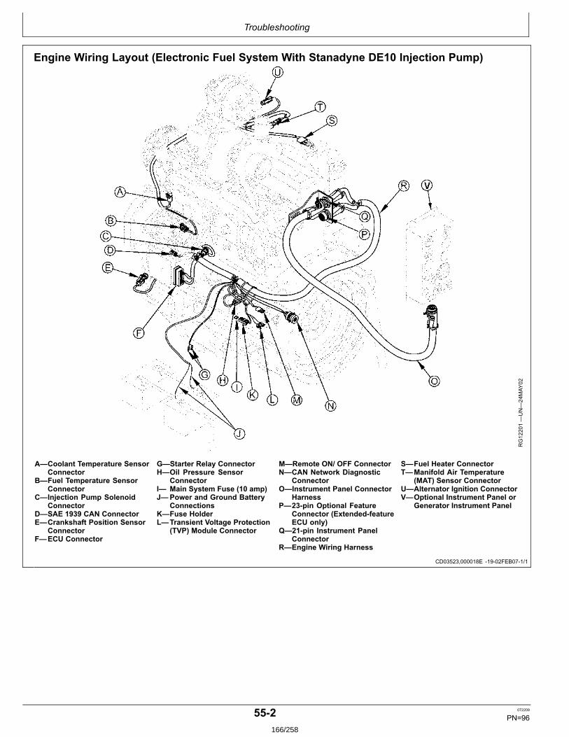
Troubleshooting
CD03523,000018E 1902FEB071/1
Engine Wiring Layout (Electronic Fuel System With Stanadyne DE10 Injection Pump)
RG12201—UN—24MAY
02
A—Coolant Temperature SensorConnector
B—Fuel Temperature SensorConnector
C—Injection Pump SolenoidConnector
D—SAE 1939 CAN ConnectorE—Crankshaft Position Sensor
ConnectorF—ECU Connector
G—Starter Relay ConnectorH—Oil Pressure Sensor
ConnectorI— Main System Fuse (10 amp)J—Power and Ground Battery
ConnectionsK—Fuse HolderL—Transient Voltage Protection
(TVP) Module Connector
M—Remote ON/ OFF ConnectorN—CAN Network Diagnostic
ConnectorO—Instrument Panel Connector
HarnessP—23pin Optional Feature
Connector (ExtendedfeatureECU only)
Q—21pin Instrument PanelConnector
R—Engine Wiring Harness
S—Fuel Heater ConnectorT—Manifold Air Temperature
(MAT) Sensor ConnectorU—Alternator Ignition ConnectorV—Optional Instrument Panel or
Generator Instrument Panel
552 072209
PN=96166/258
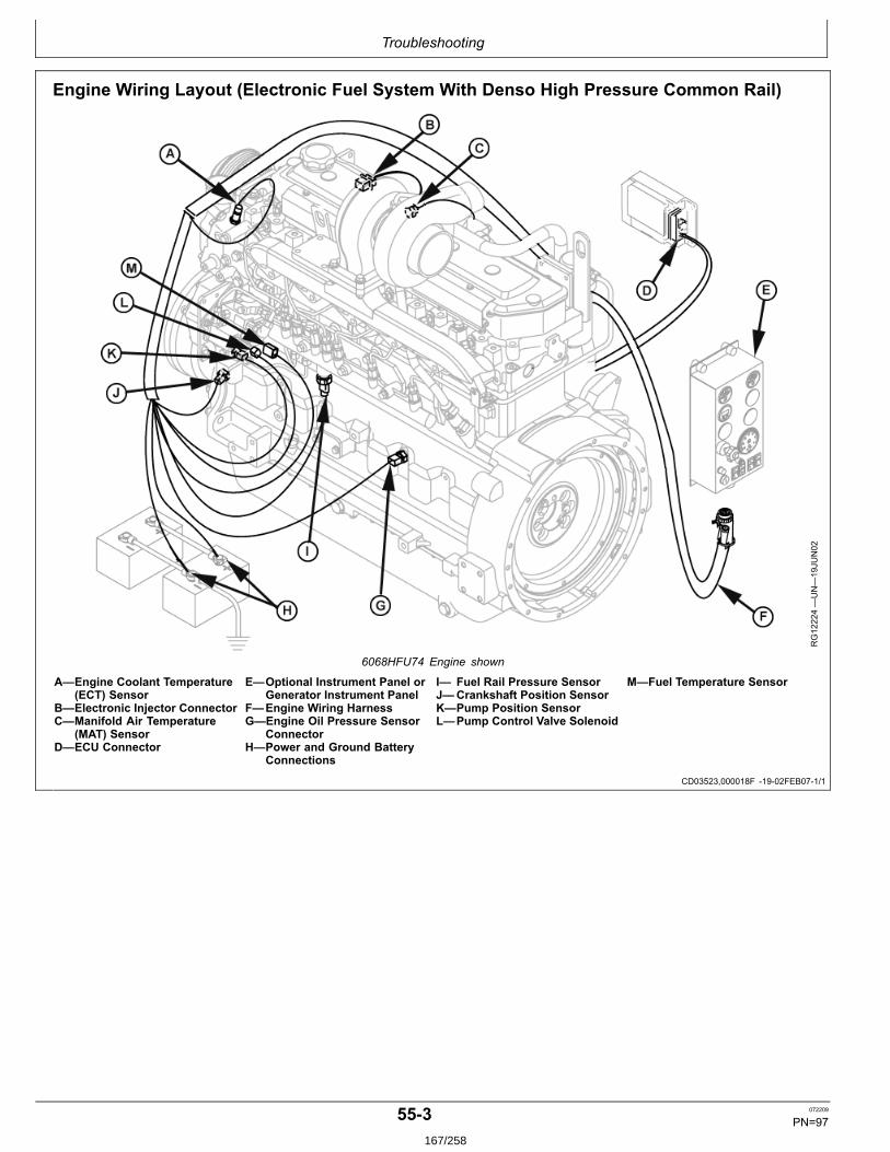
Troubleshooting
CD03523,000018F 1902FEB071/1
Engine Wiring Layout (Electronic Fuel System With Denso High Pressure Common Rail)
RG12224—UN—19JU
N02
6068HFU74 Engine shown
A—Engine Coolant Temperature(ECT) Sensor
B—Electronic Injector ConnectorC—Manifold Air Temperature
(MAT) SensorD—ECU Connector
E—Optional Instrument Panel orGenerator Instrument Panel
F—Engine Wiring HarnessG—Engine Oil Pressure Sensor
ConnectorH—Power and Ground Battery
Connections
I— Fuel Rail Pressure SensorJ—Crankshaft Position SensorK—Pump Position SensorL—Pump Control Valve Solenoid
M—Fuel Temperature Sensor
553 072209
PN=97167/258
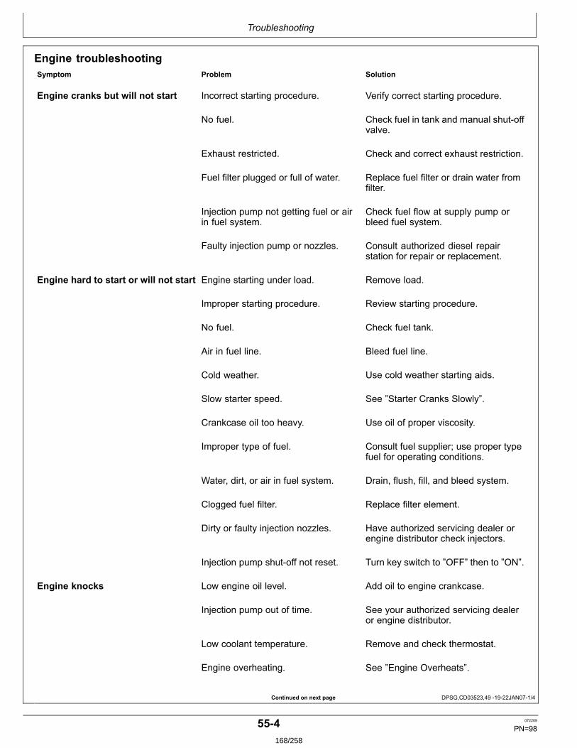
Troubleshooting
Continued on next page DPSG,CD03523,49 1922JAN071/4
Engine troubleshootingSymptom Problem Solution
Engine cranks but will not start Incorrect starting procedure. Verify correct starting procedure.
No fuel. Check fuel in tank and manual shutoffvalve.
Exhaust restricted. Check and correct exhaust restriction.
Fuel filter plugged or full of water. Replace fuel filter or drain water fromfilter.
Injection pump not getting fuel or airin fuel system.
Check fuel flow at supply pump orbleed fuel system.
Faulty injection pump or nozzles. Consult authorized diesel repairstation for repair or replacement.
Engine hard to start or will not start Engine starting under load. Remove load.
Improper starting procedure. Review starting procedure.
No fuel. Check fuel tank.
Air in fuel line. Bleed fuel line.
Cold weather. Use cold weather starting aids.
Slow starter speed. See ”Starter Cranks Slowly”.
Crankcase oil too heavy. Use oil of proper viscosity.
Improper type of fuel. Consult fuel supplier; use proper typefuel for operating conditions.
Water, dirt, or air in fuel system. Drain, flush, fill, and bleed system.
Clogged fuel filter. Replace filter element.
Dirty or faulty injection nozzles. Have authorized servicing dealer orengine distributor check injectors.
Injection pump shutoff not reset. Turn key switch to ”OFF” then to ”ON”.
Engine knocks Low engine oil level. Add oil to engine crankcase.
Injection pump out of time. See your authorized servicing dealeror engine distributor.
Low coolant temperature. Remove and check thermostat.
Engine overheating. See ”Engine Overheats”.
554 072209
PN=98168/258
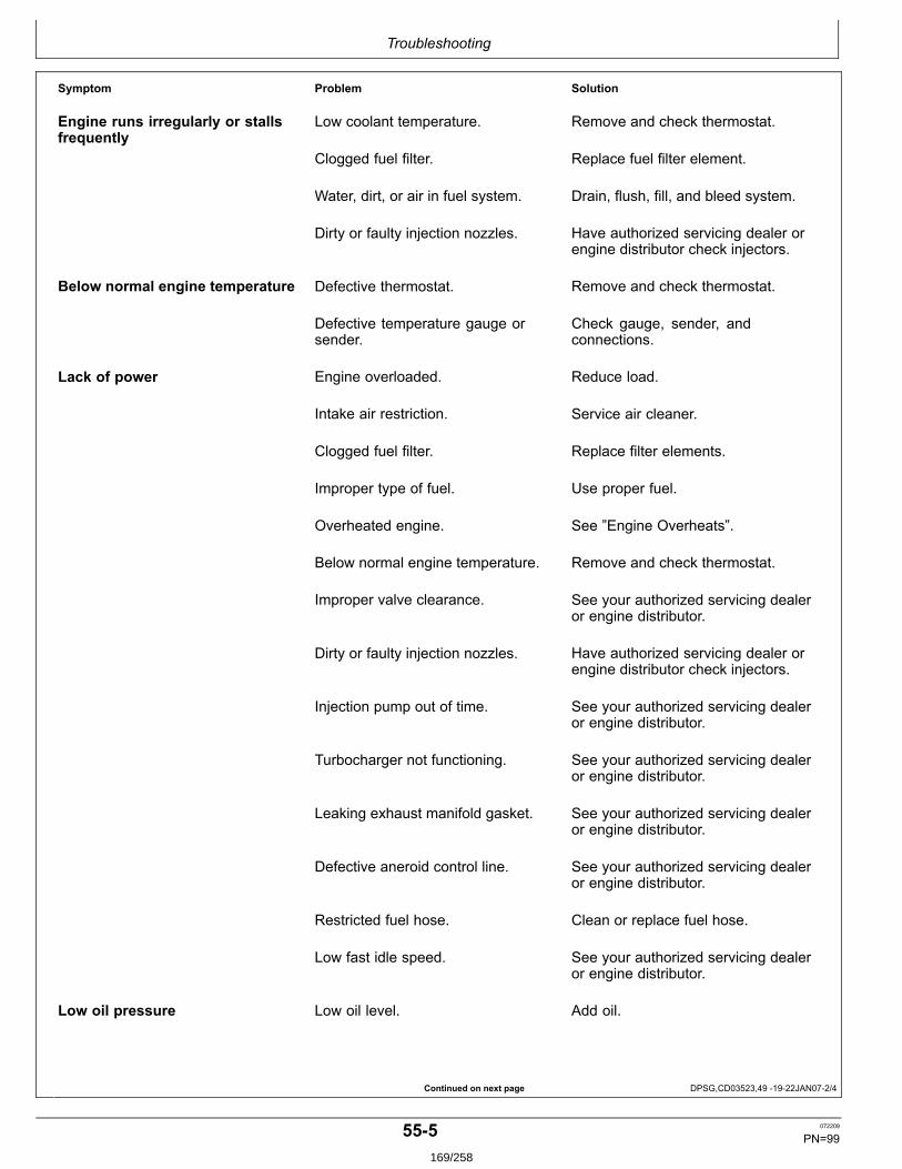
Troubleshooting
Continued on next page DPSG,CD03523,49 1922JAN072/4
Symptom Problem Solution
Engine runs irregularly or stallsfrequently
Low coolant temperature. Remove and check thermostat.
Clogged fuel filter. Replace fuel filter element.
Water, dirt, or air in fuel system. Drain, flush, fill, and bleed system.
Dirty or faulty injection nozzles. Have authorized servicing dealer orengine distributor check injectors.
Below normal engine temperature Defective thermostat. Remove and check thermostat.
Defective temperature gauge orsender.
Check gauge, sender, andconnections.
Lack of power Engine overloaded. Reduce load.
Intake air restriction. Service air cleaner.
Clogged fuel filter. Replace filter elements.
Improper type of fuel. Use proper fuel.
Overheated engine. See ”Engine Overheats”.
Below normal engine temperature. Remove and check thermostat.
Improper valve clearance. See your authorized servicing dealeror engine distributor.
Dirty or faulty injection nozzles. Have authorized servicing dealer orengine distributor check injectors.
Injection pump out of time. See your authorized servicing dealeror engine distributor.
Turbocharger not functioning. See your authorized servicing dealeror engine distributor.
Leaking exhaust manifold gasket. See your authorized servicing dealeror engine distributor.
Defective aneroid control line. See your authorized servicing dealeror engine distributor.
Restricted fuel hose. Clean or replace fuel hose.
Low fast idle speed. See your authorized servicing dealeror engine distributor.
Low oil pressure Low oil level. Add oil.
555 072209
PN=99169/258
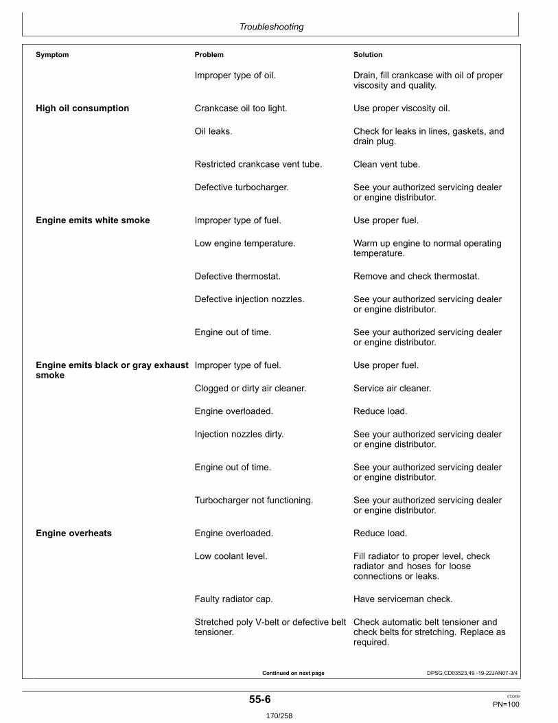
Troubleshooting
Continued on next page DPSG,CD03523,49 1922JAN073/4
Symptom Problem Solution
Improper type of oil. Drain, fill crankcase with oil of properviscosity and quality.
High oil consumption Crankcase oil too light. Use proper viscosity oil.
Oil leaks. Check for leaks in lines, gaskets, anddrain plug.
Restricted crankcase vent tube. Clean vent tube.
Defective turbocharger. See your authorized servicing dealeror engine distributor.
Engine emits white smoke Improper type of fuel. Use proper fuel.
Low engine temperature. Warm up engine to normal operatingtemperature.
Defective thermostat. Remove and check thermostat.
Defective injection nozzles. See your authorized servicing dealeror engine distributor.
Engine out of time. See your authorized servicing dealeror engine distributor.
Engine emits black or gray exhaustsmoke
Improper type of fuel. Use proper fuel.
Clogged or dirty air cleaner. Service air cleaner.
Engine overloaded. Reduce load.
Injection nozzles dirty. See your authorized servicing dealeror engine distributor.
Engine out of time. See your authorized servicing dealeror engine distributor.
Turbocharger not functioning. See your authorized servicing dealeror engine distributor.
Engine overheats Engine overloaded. Reduce load.
Low coolant level. Fill radiator to proper level, checkradiator and hoses for looseconnections or leaks.
Faulty radiator cap. Have serviceman check.
Stretched poly Vbelt or defective belttensioner.
Check automatic belt tensioner andcheck belts for stretching. Replace asrequired.
556 072209
PN=100170/258
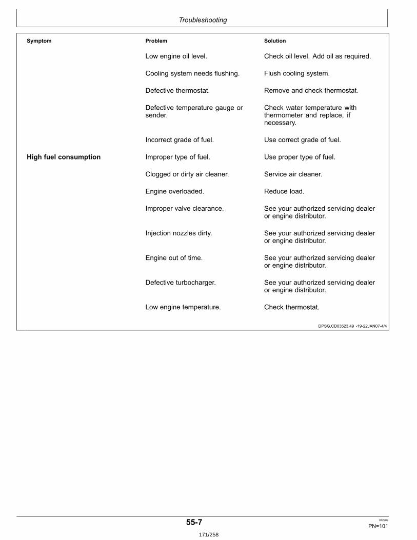
Troubleshooting
DPSG,CD03523,49 1922JAN074/4
Symptom Problem Solution
Low engine oil level. Check oil level. Add oil as required.
Cooling system needs flushing. Flush cooling system.
Defective thermostat. Remove and check thermostat.
Defective temperature gauge orsender.
Check water temperature withthermometer and replace, ifnecessary.
Incorrect grade of fuel. Use correct grade of fuel.
High fuel consumption Improper type of fuel. Use proper type of fuel.
Clogged or dirty air cleaner. Service air cleaner.
Engine overloaded. Reduce load.
Improper valve clearance. See your authorized servicing dealeror engine distributor.
Injection nozzles dirty. See your authorized servicing dealeror engine distributor.
Engine out of time. See your authorized servicing dealeror engine distributor.
Defective turbocharger. See your authorized servicing dealeror engine distributor.
Low engine temperature. Check thermostat.
557 072209
PN=101171/258
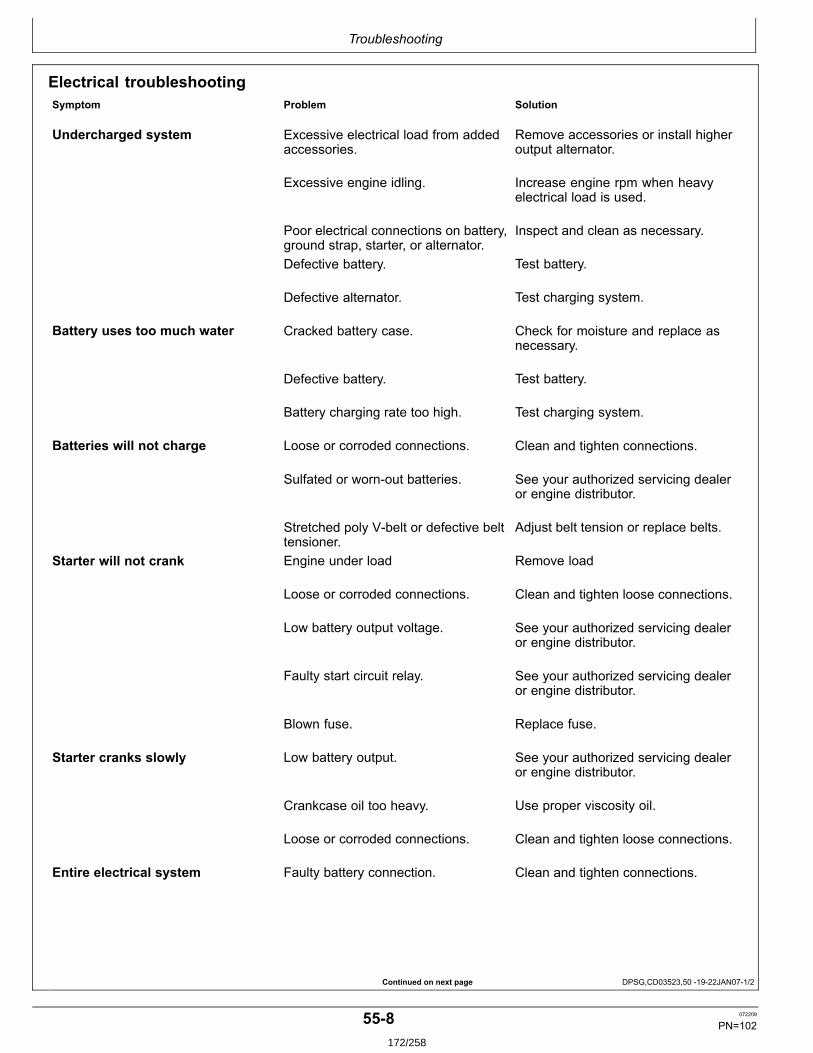
Troubleshooting
Continued on next page DPSG,CD03523,50 1922JAN071/2
Electrical troubleshootingSymptom Problem Solution
Undercharged system Excessive electrical load from addedaccessories.
Remove accessories or install higheroutput alternator.
Excessive engine idling. Increase engine rpm when heavyelectrical load is used.
Poor electrical connections on battery,ground strap, starter, or alternator.
Inspect and clean as necessary.
Defective battery. Test battery.
Defective alternator. Test charging system.
Battery uses too much water Cracked battery case. Check for moisture and replace asnecessary.
Defective battery. Test battery.
Battery charging rate too high. Test charging system.
Batteries will not charge Loose or corroded connections. Clean and tighten connections.
Sulfated or wornout batteries. See your authorized servicing dealeror engine distributor.
Stretched poly Vbelt or defective belttensioner.
Adjust belt tension or replace belts.
Starter will not crank Engine under load Remove load
Loose or corroded connections. Clean and tighten loose connections.
Low battery output voltage. See your authorized servicing dealeror engine distributor.
Faulty start circuit relay. See your authorized servicing dealeror engine distributor.
Blown fuse. Replace fuse.
Starter cranks slowly Low battery output. See your authorized servicing dealeror engine distributor.
Crankcase oil too heavy. Use proper viscosity oil.
Loose or corroded connections. Clean and tighten loose connections.
Entire electrical system Faulty battery connection. Clean and tighten connections.
558 072209
PN=102172/258
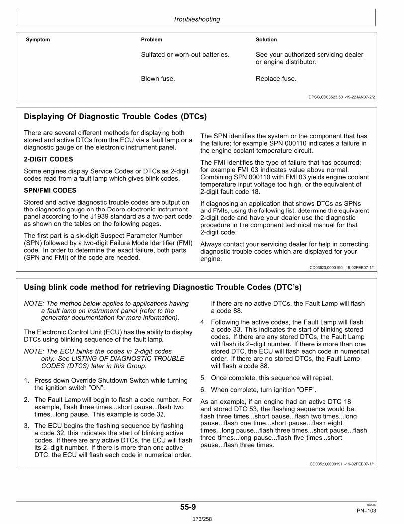
Troubleshooting
DPSG,CD03523,50 1922JAN072/2
CD03523,0000190 1902FEB071/1
CD03523,0000191 1902FEB071/1
Symptom Problem Solution
Sulfated or wornout batteries. See your authorized servicing dealeror engine distributor.
Blown fuse. Replace fuse.
Displaying Of Diagnostic Trouble Codes (DTCs)
There are several different methods for displaying bothstored and active DTCs from the ECU via a fault lamp or adiagnostic gauge on the electronic instrument panel.
2DIGIT CODES
Some engines display Service Codes or DTCs as 2digitcodes read from a fault lamp which gives blink codes.
SPN/FMI CODES
Stored and active diagnostic trouble codes are output onthe diagnostic gauge on the Deere electronic instrumentpanel according to the J1939 standard as a twopart codeas shown on the tables on the following pages.
The first part is a sixdigit Suspect Parameter Number(SPN) followed by a twodigit Failure Mode Identifier (FMI)code. In order to determine the exact failure, both parts(SPN and FMI) of the code are needed.
The SPN identifies the system or the component that hasthe failure; for example SPN 000110 indicates a failure inthe engine coolant temperature circuit.
The FMI identifies the type of failure that has occurred;for example FMI 03 indicates value above normal.Combining SPN 000110 with FMI 03 yields engine coolanttemperature input voltage too high, or the equivalent of2digit fault code 18.
If diagnosing an application that shows DTCs as SPNsand FMIs, using the following list, determine the equivalent2digit code and have your dealer use the diagnosticprocedure in the component technical manual for that2digit code.
Always contact your servicing dealer for help in correctingdiagnostic trouble codes which are displayed for yourengine.
Using blink code method for retrieving Diagnostic Trouble Codes (DTC’s)
NOTE: The method below applies to applications havinga fault lamp on instrument panel (refer to thegenerator documentation for more information).
The Electronic Control Unit (ECU) has the ability to displayDTCs using blinking sequence of the fault lamp.
NOTE: The ECU blinks the codes in 2digit codesonly. See LISTING OF DIAGNOSTIC TROUBLECODES (DTCS) later in this Group.
1. Press down Override Shutdown Switch while turningthe ignition switch ”ON”.
2. The Fault Lamp will begin to flash a code number. Forexample, flash three times...short pause...flash twotimes...long pause. This example is code 32.
3. The ECU begins the flashing sequence by flashinga code 32, this indicates the start of blinking activecodes. If there are any active DTCs, the ECU will flashits 2–digit number. If there is more than one activeDTC, the ECU will flash each code in numerical order.
If there are no active DTCs, the Fault Lamp will flasha code 88.
4. Following the active codes, the Fault Lamp will flasha code 33. This indicates the start of blinking storedcodes. If there are any stored DTCs, the Fault Lampwill flash its 2–digit number. If there is more than onestored DTC, the ECU will flash each code in numericalorder. If there are no stored DTCs, the Fault Lampwill flash a code 88.
5. Once complete, this sequence will repeat.
6. When complete, turn ignition ”OFF”.
As an example, if an engine had an active DTC 18and stored DTC 53, the flashing sequence would be:flash three times...short pause...flash two times...longpause...flash one time...short pause...flash eighttimes...long pause...flash three times...short pause...flashthree times...long pause...flash five times...shortpause...flash three times.
559 072209
PN=103173/258
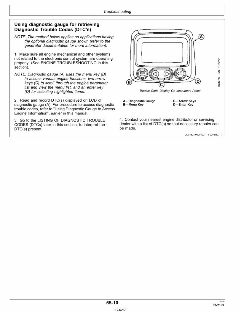
Troubleshooting
CD03523,0000192 1902FEB071/1
Using diagnostic gauge for retrievingDiagnostic Trouble Codes (DTC’s)NOTE: The method below applies on applications having
the optional diagnostic gauge shown (refer to thegenerator documentation for more information).
1. Make sure all engine mechanical and other systemsnot related to the electronic control system are operatingproperly. (See ENGINE TROUBLESHOOTING in thissection).
NOTE: Diagnostic gauge (A) uses the menu key (B)to access various engine functions, two arrowkeys (C) to scroll through the engine parameterlist and view the menu list, and an enter key(D) for selecting highlighted items.
2. Read and record DTC(s) displayed on LCD ofdiagnostic gauge (A). For procedure to access diagnostictrouble codes, refer to ”Using Diagnostic Gauge to AccessEngine Information”, earlier in this manual.
3. Go to the LISTING OF DIAGNOSTIC TROUBLECODES (DTCs) later in this section, to interpret theDTC(s) present.
RG13740—UN—11NOV04
Trouble Code Display On Instrument Panel
A—Diagnostic GaugeB—Menu Key
C—Arrow KeysD—Enter Key
4. Contact your nearest engine distributor or servicingdealer with a list of DTC(s) so that necessary repairs canbe made.
5510 072209
PN=104174/258

Troubleshooting
Continued on next page OURGP12,00001E2 1915MAR061/2
Listing of Diagnostic Trouble Codes (DTCs)NOTE: Not all of these codes are used on all
OEM engine applications
Trouble Codes
SPN FMI Description of Fault Corrective Action000028 03 Throttle #3 Signal Out of Range High Check Sensor and Wiring
04 Throttle #3 Signal Out of Range Low Check Sensor and Wiring000029 03 Throttle #2 Signal Out of Range High Check Sensor and Wiring
04 Throttle #2 Signal Out of Range Low Check Sensor and Wiring000084 31 Vehicle Speed Signal Unreliable Contact Servicing Dealer000091 03 Throttle #1 Signal Out of Range High Check Switch and Wiring
04 Throttle #1 Signal Out of Range Low Check Switch and Wiring09 Throttle #1 Communication Signal Erratic Check Sensor and Wiring
000094 03 Low Pressure Fuel Signal Out of Range High Check Sensor and Wiring04 Low Pressure Fuel Signal Out of Range Low Check Sensor and Wiring10 Low Pressure Fuel Rate of Change Abnormal Contact Servicing Dealer13 Low Pressure Fuel Out of Calibration Contact Servicing Dealer17 High Pressure Fuel System Pressure Slightly Low Contact Servicing Dealer
000097 00 Water in Fuel Continuously Detected Contact Servicing Dealer03 WaterinFuel Signal Out of Range High Check Sensor and Wiring04 WaterinFuel Signal Out of Range Low Check Sensor and Wiring16 Water in Fuel Detected Stop and Drain Water Separator
000100 01 Engine Oil Pressure Signal Extremely Low Check Oil Level03 Engine Oil Pressure Signal Out of Range High Check Sensor and Wiring04 Engine Oil Pressure Signal Out of Range Low Check Sensor and Wiring18 Engine Oil Pressure Signal Moderately Low Check Oil Level
000105 00 Intake Manifold Air Temperature Signal Extremely HighCheck Air Cleaner, Aftercooler, or Room Temperature
03 Intake Manifold Air Temperature Signal Out of Range HighCheck Sensor and Wiring
04 Intake Manifold Air Temperature Signal Out of Range LowCheck Sensor and Wiring
16 Intake Manifold Air Temperature Signal Moderately HighCheck Air Cleaner, Aftercooler, or Room Temperature
000107 00 Air Filter Pressure Differential Extremely High Check for plugged air filter000110 00 Engine Coolant Temperature Signal Extremely High Check Cooling System, Reduce Power
03 Engine Coolant Temperature Signal Out of Range HighCheck Sensor and Wiring
04 Engine Coolant Temperature Signal Out of Range LowCheck Sensor and Wiring
15 Engine Coolant Temperature Signal Slightly High Check Cooling System, Reduce Power16 Engine Coolant Temperature Signal Moderately High Check Cooling System, Reduce Power
000111 01 Engine Coolant Level Low Check Operator’s Manual, “Adding Coolant”000158 17 ECU Power Down Error (Internal ECU Problem) Contact Servicing Dealer000160 02 Axle Speed Signal Unreliable Contact Servicing Dealer000174 00 Fuel Temperature Signal Extremely High Add Fuel or Switch Fuel Tanks000174 03 Fuel Temperature Signal Out of Range High Check Sensor and Wiring
04 Fuel Temperature Signal Out of Range Low Check Sensor and Wiring16 Fuel Temperature Signal Moderately High Add Fuel or Switch Fuel Tanks
000189 00 Engine Speed Derate Condition Exists Check Fault Codes or Contact Servicing Dealer000190 00 Engine Speed Extremely High Reduce Engine Speed
16 Engine Speed Moderately High Reduce Engine Speed000611 03 Injector Shorted to Power Check Wiring
04 Injector Shorted to Ground Check Wiring000620 03 Sensor Supply 2 Voltage High Check Wiring
04 Sensor Supply 2 Voltage Low Check Wiring
5511 072209
PN=105175/258
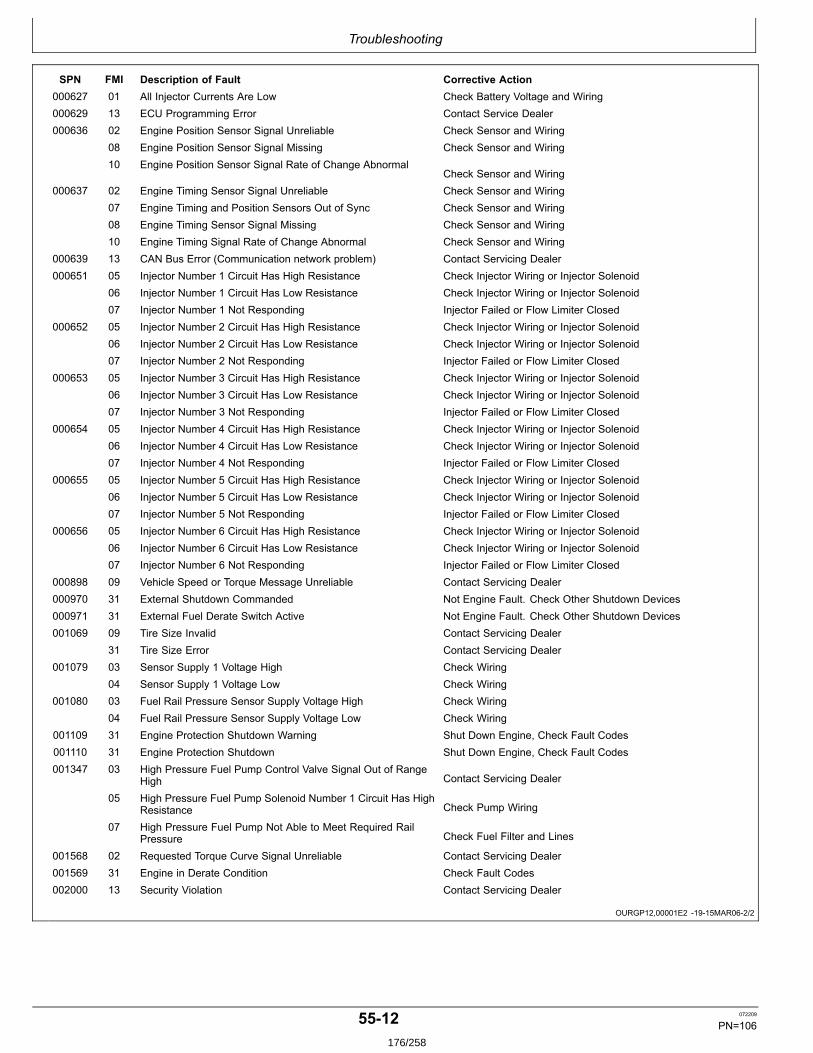
Troubleshooting
OURGP12,00001E2 1915MAR062/2
SPN FMI Description of Fault Corrective Action000627 01 All Injector Currents Are Low Check Battery Voltage and Wiring000629 13 ECU Programming Error Contact Service Dealer000636 02 Engine Position Sensor Signal Unreliable Check Sensor and Wiring
08 Engine Position Sensor Signal Missing Check Sensor and Wiring10 Engine Position Sensor Signal Rate of Change Abnormal
Check Sensor and Wiring000637 02 Engine Timing Sensor Signal Unreliable Check Sensor and Wiring
07 Engine Timing and Position Sensors Out of Sync Check Sensor and Wiring08 Engine Timing Sensor Signal Missing Check Sensor and Wiring10 Engine Timing Signal Rate of Change Abnormal Check Sensor and Wiring
000639 13 CAN Bus Error (Communication network problem) Contact Servicing Dealer000651 05 Injector Number 1 Circuit Has High Resistance Check Injector Wiring or Injector Solenoid
06 Injector Number 1 Circuit Has Low Resistance Check Injector Wiring or Injector Solenoid07 Injector Number 1 Not Responding Injector Failed or Flow Limiter Closed
000652 05 Injector Number 2 Circuit Has High Resistance Check Injector Wiring or Injector Solenoid06 Injector Number 2 Circuit Has Low Resistance Check Injector Wiring or Injector Solenoid07 Injector Number 2 Not Responding Injector Failed or Flow Limiter Closed
000653 05 Injector Number 3 Circuit Has High Resistance Check Injector Wiring or Injector Solenoid06 Injector Number 3 Circuit Has Low Resistance Check Injector Wiring or Injector Solenoid07 Injector Number 3 Not Responding Injector Failed or Flow Limiter Closed
000654 05 Injector Number 4 Circuit Has High Resistance Check Injector Wiring or Injector Solenoid06 Injector Number 4 Circuit Has Low Resistance Check Injector Wiring or Injector Solenoid07 Injector Number 4 Not Responding Injector Failed or Flow Limiter Closed
000655 05 Injector Number 5 Circuit Has High Resistance Check Injector Wiring or Injector Solenoid06 Injector Number 5 Circuit Has Low Resistance Check Injector Wiring or Injector Solenoid07 Injector Number 5 Not Responding Injector Failed or Flow Limiter Closed
000656 05 Injector Number 6 Circuit Has High Resistance Check Injector Wiring or Injector Solenoid06 Injector Number 6 Circuit Has Low Resistance Check Injector Wiring or Injector Solenoid07 Injector Number 6 Not Responding Injector Failed or Flow Limiter Closed
000898 09 Vehicle Speed or Torque Message Unreliable Contact Servicing Dealer000970 31 External Shutdown Commanded Not Engine Fault. Check Other Shutdown Devices000971 31 External Fuel Derate Switch Active Not Engine Fault. Check Other Shutdown Devices001069 09 Tire Size Invalid Contact Servicing Dealer
31 Tire Size Error Contact Servicing Dealer001079 03 Sensor Supply 1 Voltage High Check Wiring
04 Sensor Supply 1 Voltage Low Check Wiring001080 03 Fuel Rail Pressure Sensor Supply Voltage High Check Wiring
04 Fuel Rail Pressure Sensor Supply Voltage Low Check Wiring001109 31 Engine Protection Shutdown Warning Shut Down Engine, Check Fault Codes001110 31 Engine Protection Shutdown Shut Down Engine, Check Fault Codes001347 03 High Pressure Fuel Pump Control Valve Signal Out of Range
High Contact Servicing Dealer
05 High Pressure Fuel Pump Solenoid Number 1 Circuit Has HighResistance Check Pump Wiring
07 High Pressure Fuel Pump Not Able to Meet Required RailPressure Check Fuel Filter and Lines
001568 02 Requested Torque Curve Signal Unreliable Contact Servicing Dealer001569 31 Engine in Derate Condition Check Fault Codes002000 13 Security Violation Contact Servicing Dealer
5512 072209
PN=106176/258
Troubleshooting
CD03523,0000193 1905FEB071/1
Intermittent Fault Diagnostics (With Electronic Controls)
Intermittent faults are problems that periodically ”goaway”. A problem such as a terminal that intermittentlydoesn’t make contact can cause an intermittent fault.Other intermittent faults may be set only under certainoperating conditions such as heavy load, extended idle,etc. When diagnosing intermittent faults, take specialnote of the condition of wiring and connectors, since ahigh percentage of intermittent problems originate here.Check for loose, dirty or disconnected connectors. Inspectthe wiring routing, looking for possible shorts caused bycontact with external parts (for example, rubbing againstsharp sheet metal edges). Inspect the connector vicinity,looking for wires that have pulled out of connectors, poorlypositioned terminals, damaged connectors and corrodedor damaged splices and terminals. Look for broken wires,damaged splices, and wiretowire shorts. Use goodjudgement if component replacement is thought to berequired.
NOTE: The engine control unit (ECU) is the componentLEAST likely to fail.
Suggestions for diagnosing intermittent faults:
• If the problem is intermittent, try to reproduce theoperating conditions that were present when thediagnostic trouble code (DTC) set.• If a faulty connection or wire is suspected to be thecause of the intermittent problem: clear DTCs, thencheck the connection or wire by wiggling it whilewatching the diagnostic gauge to see if the fault resets.
Possible causes of intermittent faults:
• Faulty connection between sensor or actuator harness.• Faulty contact between terminals in connector.• Faulty terminal/wire connection.• Electromagnetic interference (EMI) from an improperlyinstalled 2way radio, etc., can cause faulty signals tobe sent to the ECU.
NOTE: Refer also to generator documents for moreinformation about connections and wirings.
5513 072209
PN=107177/258
Storage
DPSG,CD03523,51 1922JAN071/1
DPSG,CD03523,53 1922JAN071/1
DPSG,CD03523,54 1922JAN071/1
Engine storage guidelines
1. John Deere engines can be stored outside for up tothree (3) months with no long term preparation IFCOVERED BY WATERPROOF COVERING.
2. John Deere engines can be stored in a standardoverseas shipping container for up to three (3) monthswith no long term preparation.
3. John Deere engines can be stored inside, warehoused,for up to six (6) months with no long term preparation.
4. John Deere engines expected to be stored more thansix (6) months, long term storage preparation MUSTBE taken. (See PREPARING ENGINE FOR LONGTERM STORAGE).
Preparing engine for long term storage
The following storage preparations are good for long termengine storage up to one year. After that, the engineshould be started, warmed up, and retreated for anextended storage period.
IMPORTANT: Any time your engine will not beused for over six (6) months, the followingrecommendations for storing it and removingit from storage will help to minimizecorrosion and deterioration.
1. Change engine oil and replace filter. Used oil will notgive adequate protection. (See CHANGING ENGINEOIL AND FILTER).
2. Service air cleaner. (See CLEAN OR REPLACE AIRFILTER).
3. Draining and flushing of cooling system is notnecessary if engine is to be stored only for severalmonths. However, for extended storage periods ofa year or longer, it is recommended that the coolingsystem be drained, flushed, and refilled. Refill
with appropriate coolant. (See DIESEL ENGINECOOLANT).
4. Fill the fuel tank.
5. Remove fan/alternator belt, if desired.
6. Remove and clean batteries. Store them in a cool, dryplace and keep them fully charged.
7. Clean the exterior of the engine with saltfree waterand touchup any scratched or chipped paintedsurfaces with a good quality paint.
8. Coat all exposed (machined) metal surfaces withgrease or corrosion inhibitor if not feasible to paint.
9. Seal all openings on engine with plastic bags and tape.
10. Store the engine in a dry protected place. If enginemust be stored outside, cover it with a waterproofcanvas or other suitable protective material and usea strong waterproof tape.
Removing engine from long term storage
Refer to the appropriate section for detailed serviceslisted below or have your authorized servicing dealer orengine distributor perform services that you may not befamiliar with.
1. Remove all protective coverings from engine. Unsealall openings in engine and remove covering fromelectrical systems.
2. Remove the batteries from storage. Install batteries(fully charged) and connect the terminals.
3. Install fan/alternator belt if removed.
4. Check for filled fuel tank.
5. Perform all appropriate prestarting checks. (SeeDAILY PRESTARTING CHECKS).
IMPORTANT: DO NOT operate starter more than 30seconds at a time. Wait at least 2 minutes forstarter to cool before trying again.
6. Crank engine for 20 seconds with starter (do not allowthe engine to start). Wait 2 minutes and crank enginean additional 20 seconds to assure bearing surfacesare adequately lubricated.
7. Start engine and run at no load for several minutes.Warm up carefully and check all gauges before placingengine under load.
8. On the first day of operation after storage, checkoverall engine for leaks and check all gauges forcorrect operation.
601 072209
PN=108178/258
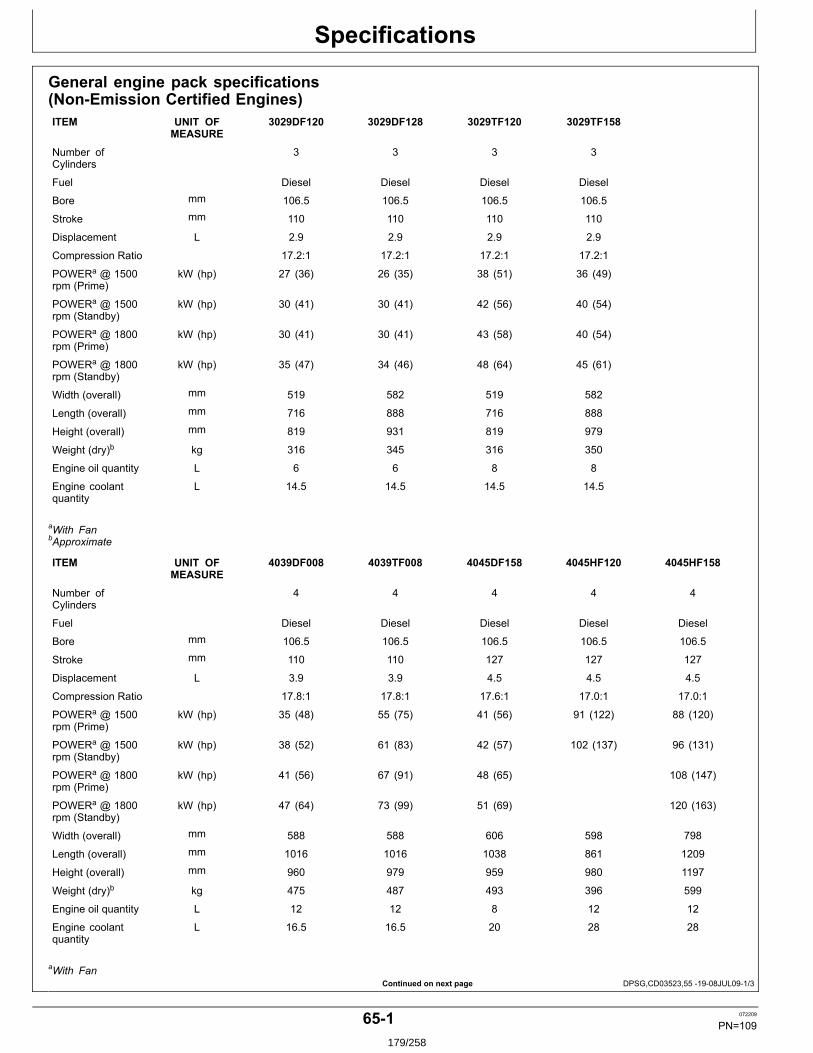
Specifications
Continued on next page DPSG,CD03523,55 1908JUL091/3
General engine pack specifications(NonEmission Certified Engines)ITEM UNIT OF
MEASURE3029DF120 3029DF128 3029TF120 3029TF158
Number ofCylinders
3 3 3 3
Fuel Diesel Diesel Diesel Diesel
Bore mm 106.5 106.5 106.5 106.5
Stroke mm 110 110 110 110
Displacement L 2.9 2.9 2.9 2.9
Compression Ratio 17.2:1 17.2:1 17.2:1 17.2:1
POWERa @ 1500rpm (Prime)
kW (hp) 27 (36) 26 (35) 38 (51) 36 (49)
POWERa @ 1500rpm (Standby)
kW (hp) 30 (41) 30 (41) 42 (56) 40 (54)
POWERa @ 1800rpm (Prime)
kW (hp) 30 (41) 30 (41) 43 (58) 40 (54)
POWERa @ 1800rpm (Standby)
kW (hp) 35 (47) 34 (46) 48 (64) 45 (61)
Width (overall) mm 519 582 519 582
Length (overall) mm 716 888 716 888
Height (overall) mm 819 931 819 979
Weight (dry)b kg 316 345 316 350
Engine oil quantity L 6 6 8 8
Engine coolantquantity
L 14.5 14.5 14.5 14.5
aWith FanbApproximate
ITEM UNIT OFMEASURE
4039DF008 4039TF008 4045DF158 4045HF120 4045HF158
Number ofCylinders
4 4 4 4 4
Fuel Diesel Diesel Diesel Diesel Diesel
Bore mm 106.5 106.5 106.5 106.5 106.5
Stroke mm 110 110 127 127 127
Displacement L 3.9 3.9 4.5 4.5 4.5
Compression Ratio 17.8:1 17.8:1 17.6:1 17.0:1 17.0:1
POWERa @ 1500rpm (Prime)
kW (hp) 35 (48) 55 (75) 41 (56) 91 (122) 88 (120)
POWERa @ 1500rpm (Standby)
kW (hp) 38 (52) 61 (83) 42 (57) 102 (137) 96 (131)
POWERa @ 1800rpm (Prime)
kW (hp) 41 (56) 67 (91) 48 (65) 108 (147)
POWERa @ 1800rpm (Standby)
kW (hp) 47 (64) 73 (99) 51 (69) 120 (163)
Width (overall) mm 588 588 606 598 798
Length (overall) mm 1016 1016 1038 861 1209
Height (overall) mm 960 979 959 980 1197
Weight (dry)b kg 475 487 493 396 599
Engine oil quantity L 12 12 8 12 12
Engine coolantquantity
L 16.5 16.5 20 28 28
aWith Fan
651 072209
PN=109179/258
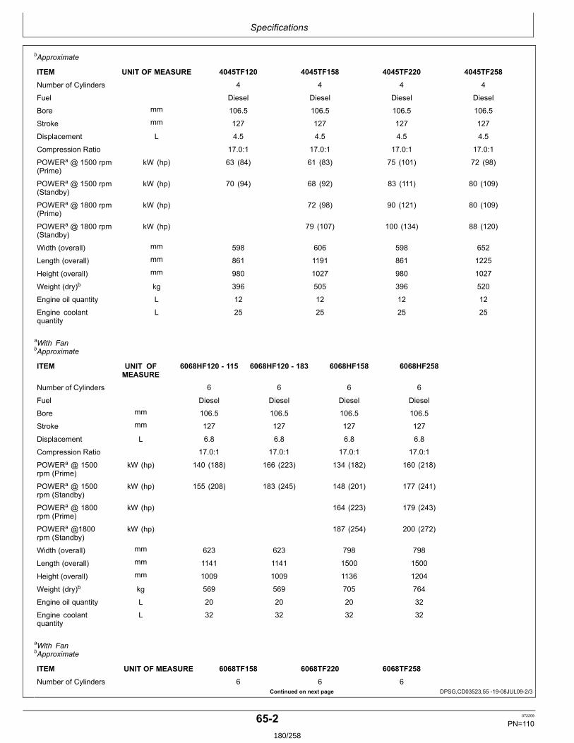
Specifications
Continued on next page DPSG,CD03523,55 1908JUL092/3
bApproximate
ITEM UNIT OF MEASURE 4045TF120 4045TF158 4045TF220 4045TF258
Number of Cylinders 4 4 4 4
Fuel Diesel Diesel Diesel Diesel
Bore mm 106.5 106.5 106.5 106.5
Stroke mm 127 127 127 127
Displacement L 4.5 4.5 4.5 4.5
Compression Ratio 17.0:1 17.0:1 17.0:1 17.0:1
POWERa @ 1500 rpm(Prime)
kW (hp) 63 (84) 61 (83) 75 (101) 72 (98)
POWERa @ 1500 rpm(Standby)
kW (hp) 70 (94) 68 (92) 83 (111) 80 (109)
POWERa @ 1800 rpm(Prime)
kW (hp) 72 (98) 90 (121) 80 (109)
POWERa @ 1800 rpm(Standby)
kW (hp) 79 (107) 100 (134) 88 (120)
Width (overall) mm 598 606 598 652
Length (overall) mm 861 1191 861 1225
Height (overall) mm 980 1027 980 1027
Weight (dry)b kg 396 505 396 520
Engine oil quantity L 12 12 12 12
Engine coolantquantity
L 25 25 25 25
aWith FanbApproximate
ITEM UNIT OFMEASURE
6068HF120 115 6068HF120 183 6068HF158 6068HF258
Number of Cylinders 6 6 6 6
Fuel Diesel Diesel Diesel Diesel
Bore mm 106.5 106.5 106.5 106.5
Stroke mm 127 127 127 127
Displacement L 6.8 6.8 6.8 6.8
Compression Ratio 17.0:1 17.0:1 17.0:1 17.0:1
POWERa @ 1500rpm (Prime)
kW (hp) 140 (188) 166 (223) 134 (182) 160 (218)
POWERa @ 1500rpm (Standby)
kW (hp) 155 (208) 183 (245) 148 (201) 177 (241)
POWERa @ 1800rpm (Prime)
kW (hp) 164 (223) 179 (243)
POWERa @1800rpm (Standby)
kW (hp) 187 (254) 200 (272)
Width (overall) mm 623 623 798 798
Length (overall) mm 1141 1141 1500 1500
Height (overall) mm 1009 1009 1136 1204
Weight (dry)b kg 569 569 705 764
Engine oil quantity L 20 20 20 32
Engine coolantquantity
L 32 32 32 32
aWith FanbApproximate
ITEM UNIT OF MEASURE 6068TF158 6068TF220 6068TF258
Number of Cylinders 6 6 6
652 072209
PN=110180/258
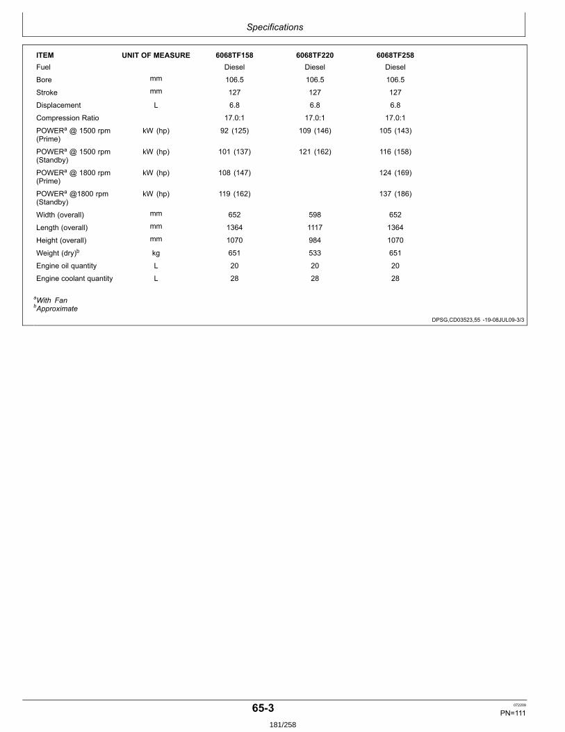
Specifications
DPSG,CD03523,55 1908JUL093/3
ITEM UNIT OF MEASURE 6068TF158 6068TF220 6068TF258Fuel Diesel Diesel Diesel
Bore mm 106.5 106.5 106.5
Stroke mm 127 127 127
Displacement L 6.8 6.8 6.8
Compression Ratio 17.0:1 17.0:1 17.0:1
POWERa @ 1500 rpm(Prime)
kW (hp) 92 (125) 109 (146) 105 (143)
POWERa @ 1500 rpm(Standby)
kW (hp) 101 (137) 121 (162) 116 (158)
POWERa @ 1800 rpm(Prime)
kW (hp) 108 (147) 124 (169)
POWERa @1800 rpm(Standby)
kW (hp) 119 (162) 137 (186)
Width (overall) mm 652 598 652
Length (overall) mm 1364 1117 1364
Height (overall) mm 1070 984 1070
Weight (dry)b kg 651 533 651
Engine oil quantity L 20 20 20
Engine coolant quantity L 28 28 28
aWith FanbApproximate
653 072209
PN=111181/258

Specifications
Continued on next page CD03523,0000194 1908JUL091/3
General engine pack specifications (StageII Emission Certified Engines)ITEM UNIT OF
MEASURE3029HFS70 3029HFU70 3029TFS70 3029TFU70
Number of Cylinders 3 3 3 3
Fuel Diesel Diesel Diesel Diesel
Bore mm 106.5 106.5 106.5 106.5
Stroke mm 110 110 110 110
Displacement L 2.9 2.9 2.9 2.9
Compression Ratio 17.2:1 17.2:1 17.2:1 17.2:1
POWERa @ 1500rpm (Prime)
kW (hp) 37 (50) 37 (50) 28 (37) 28 (37)
POWERa @ 1500rpm (Standby)
kW (hp) 41 (56) 41 (56) 31 (41) 31 (41)
POWERa @ 1800rpm (Prime)
kW (hp)
POWERa @1800rpm (Standby)
kW (hp)
Width (overall) mm 582 582 582 582
Length (overall) mm 888 888 888 888
Height (overall) mm 974 974 974 974
Weight (dry)b kg 350 350 350 350
Engine oil quantity L 8 8 8 8
Engine coolantquantity
L 14.5 14.5 14.5 14.5
aWith FanbApproximate
ITEM UNIT OFMEASURE
4045HFS72 4045HFS73 4045HFU72 4045HFU79
Number of Cylinders 4 4 4 4
Fuel Diesel Diesel Diesel Diesel
Bore mm 106.5 106.5 106.5 106.5
Stroke mm 110 110 127 127
Displacement L 4.5 4.5 4.5 4.5
Compression Ratio 17.0:1 19.0:1 17.0:1 19.0:1
POWERa @ 1500rpm (Prime)
kW (hp) 75 (100) 94 (126) 75 (100) 94 (126)
POWERa @ 1500rpm (Standby)
kW (hp) 83 (111) 103 (138) 83 (111) 103 (138)
POWERa @ 1800rpm (Prime)
kW (hp)
POWERa @1800rpm (Standby)
kW (hp)
Width (overall) mm 751 765 751 765
Length (overall) mm 1362 1365 1362 1365
Height (overall) mm 1137 1162 1137 1162
Weight (dry)b kg 505 505 505 505
Engine oil quantity L 16 16 16 16
Engine coolantquantity
L 28 32 28 32
aWith FanbApproximate
654 072209
PN=112182/258
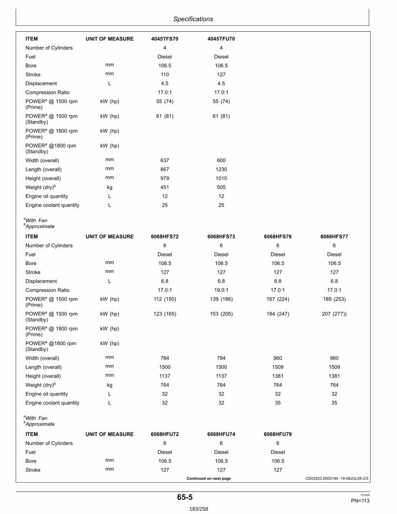
Specifications
Continued on next page CD03523,0000194 1908JUL092/3
ITEM UNIT OF MEASURE 4045TFS70 4045TFU70
Number of Cylinders 4 4
Fuel Diesel Diesel
Bore mm 106.5 106.5
Stroke mm 110 127
Displacement L 4.5 4.5
Compression Ratio 17.0:1 17.0:1
POWERa @ 1500 rpm(Prime)
kW (hp) 55 (74) 55 (74)
POWERa @ 1500 rpm(Standby)
kW (hp) 61 (81) 61 (81)
POWERa @ 1800 rpm(Prime)
kW (hp)
POWERa @1800 rpm(Standby)
kW (hp)
Width (overall) mm 637 600
Length (overall) mm 867 1230
Height (overall) mm 979 1010
Weight (dry)b kg 451 505
Engine oil quantity L 12 12
Engine coolant quantity L 25 25
aWith FanbApproximate
ITEM UNIT OF MEASURE 6068HFS72 6068HFS73 6068HFS76 6068HFS77
Number of Cylinders 6 6 6 6
Fuel Diesel Diesel Diesel Diesel
Bore mm 106.5 106.5 106.5 106.5
Stroke mm 127 127 127 127
Displacement L 6.8 6.8 6.8 6.8
Compression Ratio 17.0:1 19.0:1 17.0:1 17.0:1
POWERa @ 1500 rpm(Prime)
kW (hp) 112 (150) 139 (186) 167 (224) 189 (253)
POWERa @ 1500 rpm(Standby)
kW (hp) 123 (165) 153 (205) 184 (247) 207 (277))
POWERa @ 1800 rpm(Prime)
kW (hp)
POWERa @1800 rpm(Standby)
kW (hp)
Width (overall) mm 784 784 960 960
Length (overall) mm 1500 1500 1509 1509
Height (overall) mm 1137 1137 1381 1381
Weight (dry)b kg 764 764 764 764
Engine oil quantity L 32 32 32 32
Engine coolant quantity L 32 32 35 35
aWith FanbApproximate
ITEM UNIT OF MEASURE 6068HFU72 6068HFU74 6068HFU79
Number of Cylinders 6 6 6
Fuel Diesel Diesel Diesel
Bore mm 106.5 106.5 106.5
Stroke mm 127 127 127
655 072209
PN=113183/258
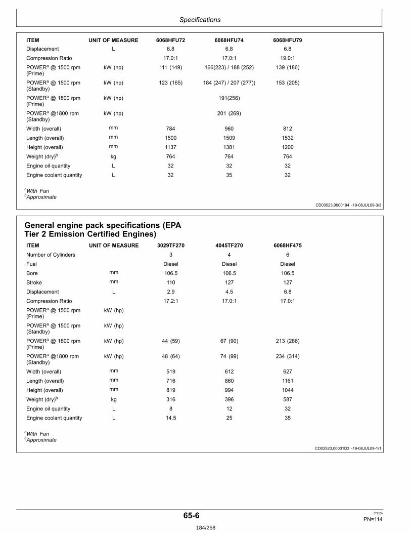
Specifications
CD03523,0000194 1908JUL093/3
CD03523,00001D3 1908JUL091/1
ITEM UNIT OF MEASURE 6068HFU72 6068HFU74 6068HFU79Displacement L 6.8 6.8 6.8
Compression Ratio 17.0:1 17.0:1 19.0:1
POWERa @ 1500 rpm(Prime)
kW (hp) 111 (149) 166(223) / 188 (252) 139 (186)
POWERa @ 1500 rpm(Standby)
kW (hp) 123 (165) 184 (247) / 207 (277)) 153 (205)
POWERa @ 1800 rpm(Prime)
kW (hp) 191(256)
POWERa @1800 rpm(Standby)
kW (hp) 201 (269)
Width (overall) mm 784 960 812
Length (overall) mm 1500 1509 1532
Height (overall) mm 1137 1381 1200
Weight (dry)b kg 764 764 764
Engine oil quantity L 32 32 32
Engine coolant quantity L 32 35 32
aWith FanbApproximate
General engine pack specifications (EPATier 2 Emission Certified Engines)ITEM UNIT OF MEASURE 3029TF270 4045TF270 6068HF475
Number of Cylinders 3 4 6
Fuel Diesel Diesel Diesel
Bore mm 106.5 106.5 106.5
Stroke mm 110 127 127
Displacement L 2.9 4.5 6.8
Compression Ratio 17.2:1 17.0:1 17.0:1
POWERa @ 1500 rpm(Prime)
kW (hp)
POWERa @ 1500 rpm(Standby)
kW (hp)
POWERa @ 1800 rpm(Prime)
kW (hp) 44 (59) 67 (90) 213 (286)
POWERa @1800 rpm(Standby)
kW (hp) 48 (64) 74 (99) 234 (314)
Width (overall) mm 519 612 627
Length (overall) mm 716 860 1161
Height (overall) mm 819 994 1044
Weight (dry)b kg 316 396 587
Engine oil quantity L 8 12 32
Engine coolant quantity L 14.5 25 35
aWith FanbApproximate
656 072209
PN=114184/258

Specifications
CD03523,00001D4 1908JUL091/1
General engine pack specifications (EPATier 3 Emission Certified Engines)ITEM UNIT OF MEASURE 4045HFS80 4045HFS82 4045HFS83
Number of Cylinders 4 4 4
Fuel Diesel Diesel Diesel
Bore mm 106.5 106.5 106.5
Stroke mm 127 127 110
Displacement L 4.5 4.5 4.5
Compression Ratio 19.0:1 19.0:1 19.0:1
POWERa @ 1500 rpm(Prime)
kW (hp)
POWERa @ 1500 rpm(Standby)
kW (hp)
POWERa @ 1800 rpm(Prime)
kW (hp) 67 (90) 85 (114) 107 (143)
POWERa @1800 rpm(Standby)
kW (hp) 74 (99) 94 (126) 118 (158)
Width (overall) mm 600 765 765
Length (overall) mm 1230 1365 1365
Height (overall) mm 1010 1162 1162
Weight (dry)b kg 505 505 505
Engine oil quantity L 12 16 16
Engine coolant quantity L 25 32 32
aWith FanbApproximate
ITEM UNIT OF MEASURE 6068HFS82 6068HFS83 6068HFS89
Number of Cylinders 6 6 6
Fuel Diesel Diesel Diesel
Bore mm 106.5 106.5 106.5
Stroke mm 127 127 127
Displacement L 6.8 6.8 6.8
Compression Ratio 19.0:1 19.0:1 17.0:1
POWERa @ 1500 rpm(Prime)
kW (hp)
POWERa @ 1500 rpm(Standby)
kW (hp)
POWERa @ 1800 rpm(Prime)
kW (hp) 134 (180) 161(216) 214 (287)
POWERa @1800 rpm(Standby)
kW (hp) 147 (197) 177 (237) 235 (315)
Width (overall) mm 784 784 960
Length (overall) mm 1500 1500 1509
Height (overall) mm 1137 1137 1381
Weight (dry)b kg 764 764 764
Engine oil quantity L 32 32 32
Engine coolant quantity L 32 32 35
aWith FanbApproximate
657 072209
PN=115185/258
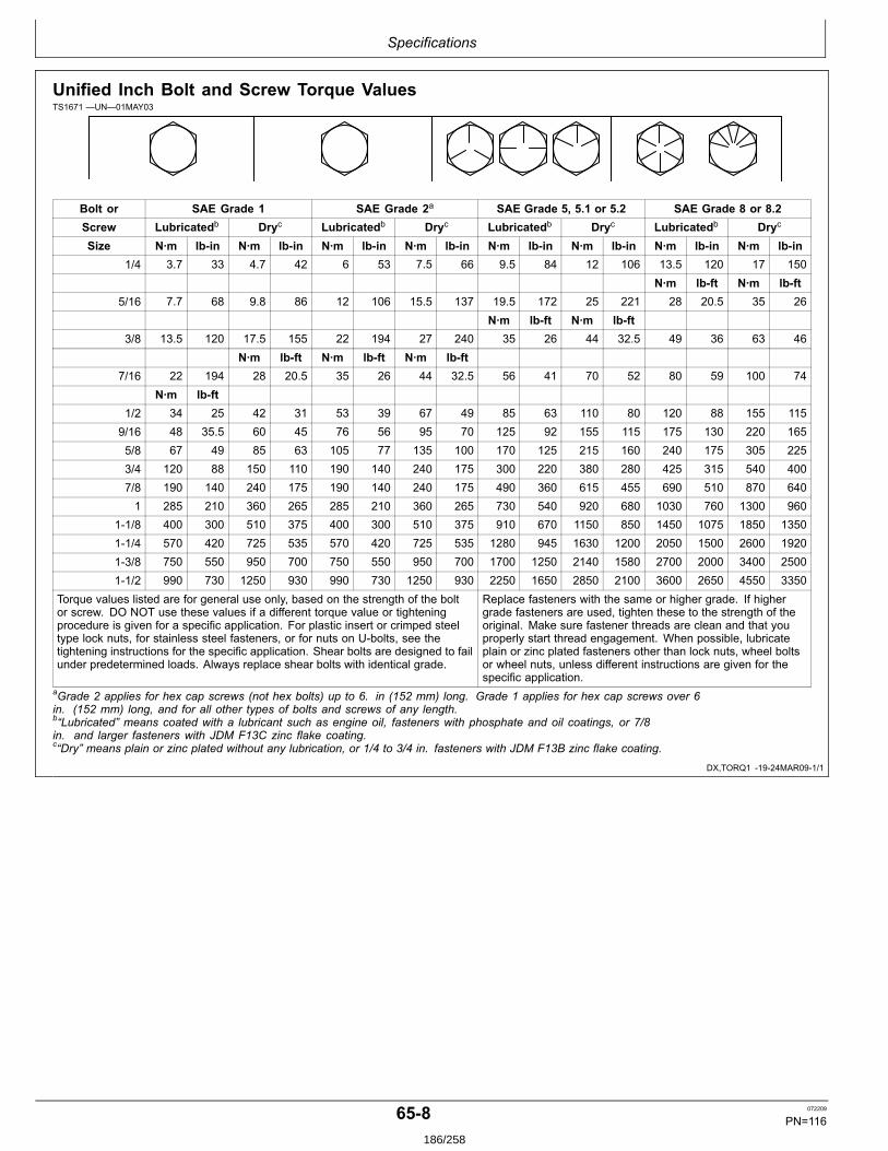
Specifications
DX,TORQ1 1924MAR091/1
Unified Inch Bolt and Screw Torque ValuesTS1671 —UN—01MAY03
Bolt or SAE Grade 1 SAE Grade 2a SAE Grade 5, 5.1 or 5.2 SAE Grade 8 or 8.2Screw Lubricatedb Dryc Lubricatedb Dryc Lubricatedb Dryc Lubricatedb Dryc
Size N∙m lbin N∙m lbin N∙m lbin N∙m lbin N∙m lbin N∙m lbin N∙m lbin N∙m lbin1/4 3.7 33 4.7 42 6 53 7.5 66 9.5 84 12 106 13.5 120 17 150
N∙m lbft N∙m lbft5/16 7.7 68 9.8 86 12 106 15.5 137 19.5 172 25 221 28 20.5 35 26
N∙m lbft N∙m lbft3/8 13.5 120 17.5 155 22 194 27 240 35 26 44 32.5 49 36 63 46
N∙m lbft N∙m lbft N∙m lbft7/16 22 194 28 20.5 35 26 44 32.5 56 41 70 52 80 59 100 74
N∙m lbft1/2 34 25 42 31 53 39 67 49 85 63 110 80 120 88 155 1159/16 48 35.5 60 45 76 56 95 70 125 92 155 115 175 130 220 1655/8 67 49 85 63 105 77 135 100 170 125 215 160 240 175 305 2253/4 120 88 150 110 190 140 240 175 300 220 380 280 425 315 540 4007/8 190 140 240 175 190 140 240 175 490 360 615 455 690 510 870 6401 285 210 360 265 285 210 360 265 730 540 920 680 1030 760 1300 960
11/8 400 300 510 375 400 300 510 375 910 670 1150 850 1450 1075 1850 135011/4 570 420 725 535 570 420 725 535 1280 945 1630 1200 2050 1500 2600 192013/8 750 550 950 700 750 550 950 700 1700 1250 2140 1580 2700 2000 3400 250011/2 990 730 1250 930 990 730 1250 930 2250 1650 2850 2100 3600 2650 4550 3350
Torque values listed are for general use only, based on the strength of the boltor screw. DO NOT use these values if a different torque value or tighteningprocedure is given for a specific application. For plastic insert or crimped steeltype lock nuts, for stainless steel fasteners, or for nuts on Ubolts, see thetightening instructions for the specific application. Shear bolts are designed to failunder predetermined loads. Always replace shear bolts with identical grade.
Replace fasteners with the same or higher grade. If highergrade fasteners are used, tighten these to the strength of theoriginal. Make sure fastener threads are clean and that youproperly start thread engagement. When possible, lubricateplain or zinc plated fasteners other than lock nuts, wheel boltsor wheel nuts, unless different instructions are given for thespecific application.
aGrade 2 applies for hex cap screws (not hex bolts) up to 6. in (152 mm) long. Grade 1 applies for hex cap screws over 6in. (152 mm) long, and for all other types of bolts and screws of any length.b“Lubricated” means coated with a lubricant such as engine oil, fasteners with phosphate and oil coatings, or 7/8in. and larger fasteners with JDM F13C zinc flake coating.c“Dry” means plain or zinc plated without any lubrication, or 1/4 to 3/4 in. fasteners with JDM F13B zinc flake coating.
658 072209
PN=116186/258
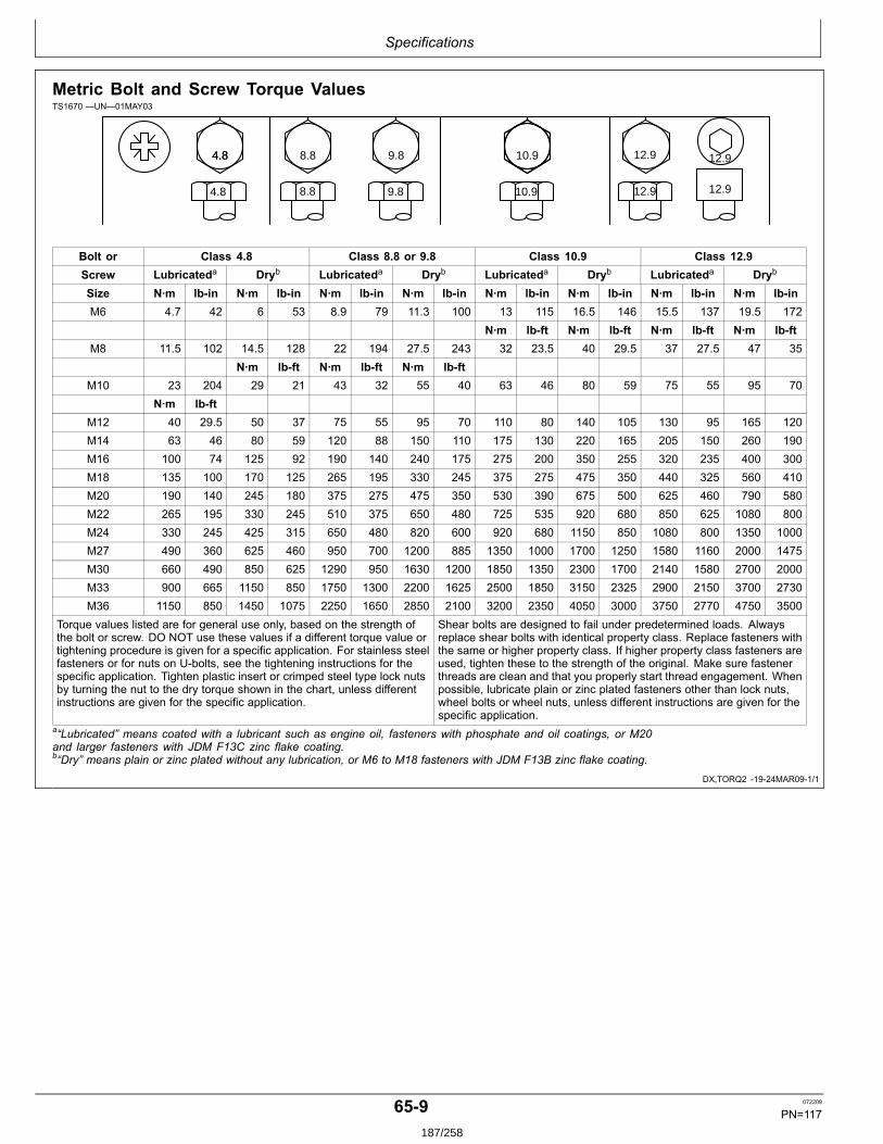
Specifications
DX,TORQ2 1924MAR091/1
Metric Bolt and Screw Torque ValuesTS1670 —UN—01MAY03
4.84.8 8.8 9.8 10.9 12.9 12.9
12.912.910.99.88.84.8
Bolt or Class 4.8 Class 8.8 or 9.8 Class 10.9 Class 12.9Screw Lubricateda Dryb Lubricateda Dryb Lubricateda Dryb Lubricateda Dryb
Size N∙m lbin N∙m lbin N∙m lbin N∙m lbin N∙m lbin N∙m lbin N∙m lbin N∙m lbinM6 4.7 42 6 53 8.9 79 11.3 100 13 115 16.5 146 15.5 137 19.5 172
N∙m lbft N∙m lbft N∙m lbft N∙m lbftM8 11.5 102 14.5 128 22 194 27.5 243 32 23.5 40 29.5 37 27.5 47 35
N∙m lbft N∙m lbft N∙m lbftM10 23 204 29 21 43 32 55 40 63 46 80 59 75 55 95 70
N∙m lbftM12 40 29.5 50 37 75 55 95 70 110 80 140 105 130 95 165 120M14 63 46 80 59 120 88 150 110 175 130 220 165 205 150 260 190M16 100 74 125 92 190 140 240 175 275 200 350 255 320 235 400 300M18 135 100 170 125 265 195 330 245 375 275 475 350 440 325 560 410M20 190 140 245 180 375 275 475 350 530 390 675 500 625 460 790 580M22 265 195 330 245 510 375 650 480 725 535 920 680 850 625 1080 800M24 330 245 425 315 650 480 820 600 920 680 1150 850 1080 800 1350 1000M27 490 360 625 460 950 700 1200 885 1350 1000 1700 1250 1580 1160 2000 1475M30 660 490 850 625 1290 950 1630 1200 1850 1350 2300 1700 2140 1580 2700 2000M33 900 665 1150 850 1750 1300 2200 1625 2500 1850 3150 2325 2900 2150 3700 2730M36 1150 850 1450 1075 2250 1650 2850 2100 3200 2350 4050 3000 3750 2770 4750 3500
Torque values listed are for general use only, based on the strength ofthe bolt or screw. DO NOT use these values if a different torque value ortightening procedure is given for a specific application. For stainless steelfasteners or for nuts on Ubolts, see the tightening instructions for thespecific application. Tighten plastic insert or crimped steel type lock nutsby turning the nut to the dry torque shown in the chart, unless differentinstructions are given for the specific application.
Shear bolts are designed to fail under predetermined loads. Alwaysreplace shear bolts with identical property class. Replace fasteners withthe same or higher property class. If higher property class fasteners areused, tighten these to the strength of the original. Make sure fastenerthreads are clean and that you properly start thread engagement. Whenpossible, lubricate plain or zinc plated fasteners other than lock nuts,wheel bolts or wheel nuts, unless different instructions are given for thespecific application.
a“Lubricated” means coated with a lubricant such as engine oil, fasteners with phosphate and oil coatings, or M20and larger fasteners with JDM F13C zinc flake coating.b“Dry” means plain or zinc plated without any lubrication, or M6 to M18 fasteners with JDM F13B zinc flake coating.
659 072209
PN=117187/258

Specifications
6510 072209
PN=118188/258
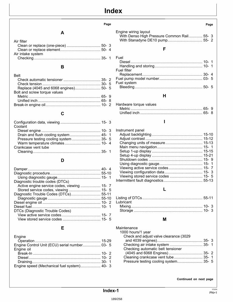
Index
Page
A
Air filterClean or replace (onepiece) ................................ 50 3Clean or replace element...................................... 50 4
Air intake systemChecking............................................................... 35 1
B
BeltCheck automatic tensioner ................................... 35 2Check tension ....................................................... 30 5Replace (4045 and 6068 engines)........................ 50 5
Bolt and screw torque valuesMetric .................................................................... 65 9Unified inch ........................................................... 65 8
Breakin engine oil.................................................... 10 2
C
Configuration data, viewing ...................................... 15 3CoolantDiesel engine ........................................................ 10 3Drain and flush cooling system............................. 45 1Pressure testing cooling system ........................... 35 5Warm temperature climates.................................. 10 4
Crankcase vent tubeCleaning................................................................ 35 1
D
Damper..................................................................... 40 4Diagnostic procedure................................................ 5510Using diagnostic gauge......................................... 15 1
Diagnostic trouble codes (DTCs)Active engine service codes, viewing ................... 15 7Stored service codes, viewing .............................. 15 5
Diagnostic Trouble Codes (DTCs)............................ 5511Diagnostic gauge .................................................. 5510
Diesel engine oil ....................................................... 10 2Diesel fuel................................................................. 10 1DTCs (Diagnostic Trouble Codes)View active service codes..................................... 15 7View stored service codes .................................... 15 5
E
EngineOperation .............................................................. 1529
Engine Control Unit (ECU) serial number................. 03 5Engine oilBreakIn ................................................................ 10 2Diesel .................................................................... 10 2Draining................................................................. 30 1
Engine speed (Mechanical fuel system)................... 40 3
Page
Engine wiring layoutWith Denso High Pressure Common Rail............. 55 3With Stanadyne DE10 pump................................. 55 2
F
FuelDiesel .................................................................... 10 1Handling and storing............................................. 10 1
Fuel filterReplacement......................................................... 30 4
Fuel pump model number......................................... 03 5Fuel systemBleeding................................................................ 50 5
H
Hardware torque valuesMetric .................................................................... 65 9Unified inch ........................................................... 65 8
I
Instrument panelAdjust backlighting................................................ 1510Adjust contrast ...................................................... 1512Changing units of measure................................... 1513Main menu navigation........................................... 15 1Setup 1up display ................................................ 1515Setup 4up display ................................................ 1521Shutdown codes ................................................... 15 9Using diagnostic gauge......................................... 15 1Viewing active service codes ................................ 15 7Viewing configuration data.................................... 15 3Viewing stored service codes ............................... 15 5
Intermittent fault diagnostics..................................... 5513
L
Listing of DTCs......................................................... 5511LubricantMixing.................................................................... 10 3Storage ................................................................. 10 3
M
Maintenance1000 hours/1 yearCheck and adjust valve clearance (3029and 4039 engines)........................................... 35 3Checking air intake system ............................... 35 1Checking automatic belt tensioner(4045 and 6068 Engines) ................................ 35 2Cleaning crankcase vent tube........................... 35 1Pressure testing cooling system........................ 35 5
Continued on next page
Index1 072209
PN=1
189/258
Index
Page
2000 hours/2 yearsAdjust speed droop governor(Mechanical fuel system)................................. 40 3Adjust valve clearance (4045 and 6068engines)........................................................... 40 1Check engine speed (Mechanical fuelsystem) ............................................................ 40 3Damper check ................................................... 40 4
2500 hours/3 yearsDrain and flush cooling system ......................... 45 1
500 hoursChanging engine oil and filter............................ 30 1Checking belt..................................................... 30 5Replace fuel filter............................................... 30 4
As requiredAdditional service information ........................... 50 1Clean or replace air filter (onepiece) ................ 50 3Clean or replace air filter element ..................... 50 4Do not modify fuel system................................. 50 1Replace fan and alternator belts (4045and 6068 engines)........................................... 50 5
Daily or every 10 hours ......................................... 25 1Observe service intervals...................................... 20 1Use correct fuel, lubricant and coolant.................. 20 1
Maintenance records................................................ 02 1Metric bolt and screw torque values ......................... 65 9Mixing lubricants....................................................... 10 3
O
Operating the engineBreakin period...................................................... 1525Changing Generator Frequency ........................... 1529Standby power units ............................................. 1529Starting the engine................................................ 1525Stopping the engine.............................................. 1529Using a booster battery or charger ....................... 1528
S
Serial numberEngine Control Unit (ECU).................................... 03 5Highpressure fuel pump....................................... 03 5
Serial numbersEngine Control Unit (ECU) serial number ............. 03 5
Page
Engine option codes ............................................. 03 3Engine serial number plate ................................... 03 1Fuel pump model number ..................................... 03 5POWERTech label ................................................ 03 1Record engine serial number................................ 03 2Record fuel injection pump model number ........... 03 4
SpecificationsEngine PackEPA Tier 2 Emission Certified Engines ............. 65 6EPA Tier 3 Emission Certified Engines ............. 65 7NonEmission Certified Engines........................ 65 1Stage II Emission Certified Engines .................. 65 4
StorageEngine................................................................... 60 1
Storing fuel ............................................................... 10 1Storing lubricants...................................................... 10 3
T
Torque chartsMetric .................................................................... 65 9Unified inch ........................................................... 65 8
Trouble codes........................................................... 5511TroubleshootingElectrical ............................................................... 55 8Engine................................................................... 55 4General information .............................................. 55 1
U
Unified inch bolt and screw torque values ................ 65 8Units of measure, changing...................................... 1513
V
Valve clearanceAdjust (3029 and 4039 engines) ........................... 35 3Adjust (4045 and 6068 engines) ........................... 40 1
W
Wiring harnessWith Denso High Pressure Common Rail............. 55 3With Stanadyne DE10 pump................................. 55 2
Index2 072209
PN=2
190/258

9.2. Appendix B - Alternator user and maintenance manual
191/258

192/258
User guide and maintenance manual
LLEERROOYY SSOOMMEERR
AAlltteerrnnaattoorr
4433..22 && 4444..22 SSHHUUNNTT,, AARREEPP && PPMMGG
3434 i 01/10/2010
33522059401_6_1
193/258

194/258
2010 .10 / i
343
349
347
7079
90
36
51
48 59
1
124
41
47
198
100107
91
374
1615
1530
33
322324
325
325
320
323
320
49
28
290291
292 293294
295 296297
207120
217
343
349
347
7079
90
36
51
48 59
1
124
41
47
198
100107
91
374
1615
1530
33
322324
325
325
320
323
320
49
28
290291
292 293294
295 296297
207120
217
3434 en -
This manual is to be given
to the end user
LSA 43.2/44.2 - 4 poLeALTeRNAToRS
Installation and maintenance195/258
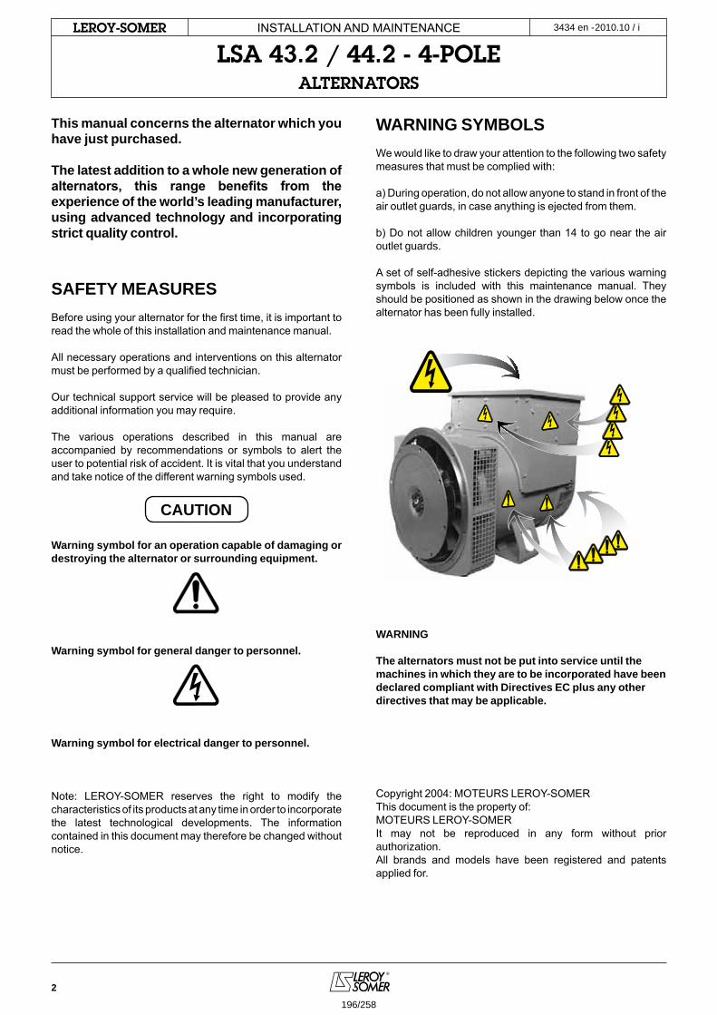
2
2010.10 / iLeRoY-SoMeR
This manual concerns the alternator which you have just purchased.
The latest addition to a whole new generation of alternators, this range benefits from the experience of the world’s leading manufacturer, using advanced technology and incorporating strict quality control.
SAFETY MEASURESBefore using your alternator for the first time, it is important to read the whole of this installation and maintenance manual.
All necessary operations and interventions on this alternator must be performed by a qualified technician.
Our technical support service will be pleased to provide any additional information you may require.
The various operations described in this manual are accompanied by recommendations or symbols to alert the user to potential risk of accident. It is vital that you understand and take notice of the different warning symbols used.
CAUTION
Warning symbol for an operation capable of damaging or destroying the alternator or surrounding equipment.
Warning symbol for general danger to personnel.
Warning symbol for electrical danger to personnel.
Note: LEROY-SOMER reserves the right to modify the characteristics of its products at any time in order to incorporate the latest technological developments. The information contained in this document may therefore be changed without notice.
WARNING SYMBOLSWe would like to draw your attention to the following two safety measures that must be complied with:
a) During operation, do not allow anyone to stand in front of the air outlet guards, in case anything is ejected from them.
b) Do not allow children younger than 14 to go near the air outlet guards.
A set of self-adhesive stickers depicting the various warning symbols is included with this maintenance manual. They should be positioned as shown in the drawing below once the alternator has been fully installed.
WARNING
The alternators must not be put into service until the machines in which they are to be incorporated have been declared compliant with Directives EC plus any other directives that may be applicable.
Copyright 2004: MOTEURS LEROY-SOMERThis document is the property of:MOTEURS LEROY-SOMERIt may not be reproduced in any form without prior authorization. All brands and models have been registered and patents applied for.
INSTALLATION AND MAINTENANCE
LSA 43.2 / 44.2 - 4-poLeALTeRNAToRS
3434 en -
196/258
3
2010.10 / iLeRoY-SoMeR
1 - RECEIPT
1.1 - Standards and safety measures .................... 4
1.2 - Inspection ...................................................... 4
1.3 - Identification .................................................. 4
1.4 - Storage .......................................................... 4
1.5 - Applications ................................................... 4
1.6 - Contra-indications to use .............................. 4
2 - TECHNICAL CHARACTERISTICS
2.1 - Electrical characteristics ................................ 5
2.2 - Mechanical characteristics ............................. 5
3 - INSTALLATION - COMMISSIONING
3.1 - Assembly ....................................................... 6
3.2 - Inspection prior to first use ............................. 6
3.3 - Terminal connection diagrams ....................... 7
3.4 - Commissioning .............................................. 9
3.5 - Settings .......................................................... 9
4 - SERVICING - MAINTENANCE
4.1 - Safety measures .......................................... 10
4.2 - Regular maintenance ................................... 10
4.3 - Fault detection ............................................. 10
4.4 - Mechanical defects .......................................11
4.5 - Electrical faults ..............................................11
4.6 - Dismantling, reassembly .............................. 12
4.7 - Installation and maintenance of the PMG ..... 14
4.8 - Table of characteristics ................................ 14
4.9 - Table of weights ........................................... 15
5 - SPARE PARTS
5.1 - First maintenance parts ............................... 16
5.2 - Bearing designations ................................... 16
5.3 - Technical support service ............................. 16
5.4 - Exploded view, parts list ............................... 17
EC DECLARATION OF INCORPORATION ......19
INSTALLATION AND MAINTENANCE
LSA 43.2 / 44.2 - 4-poLeALTeRNAToRS
3434 en -
197/258
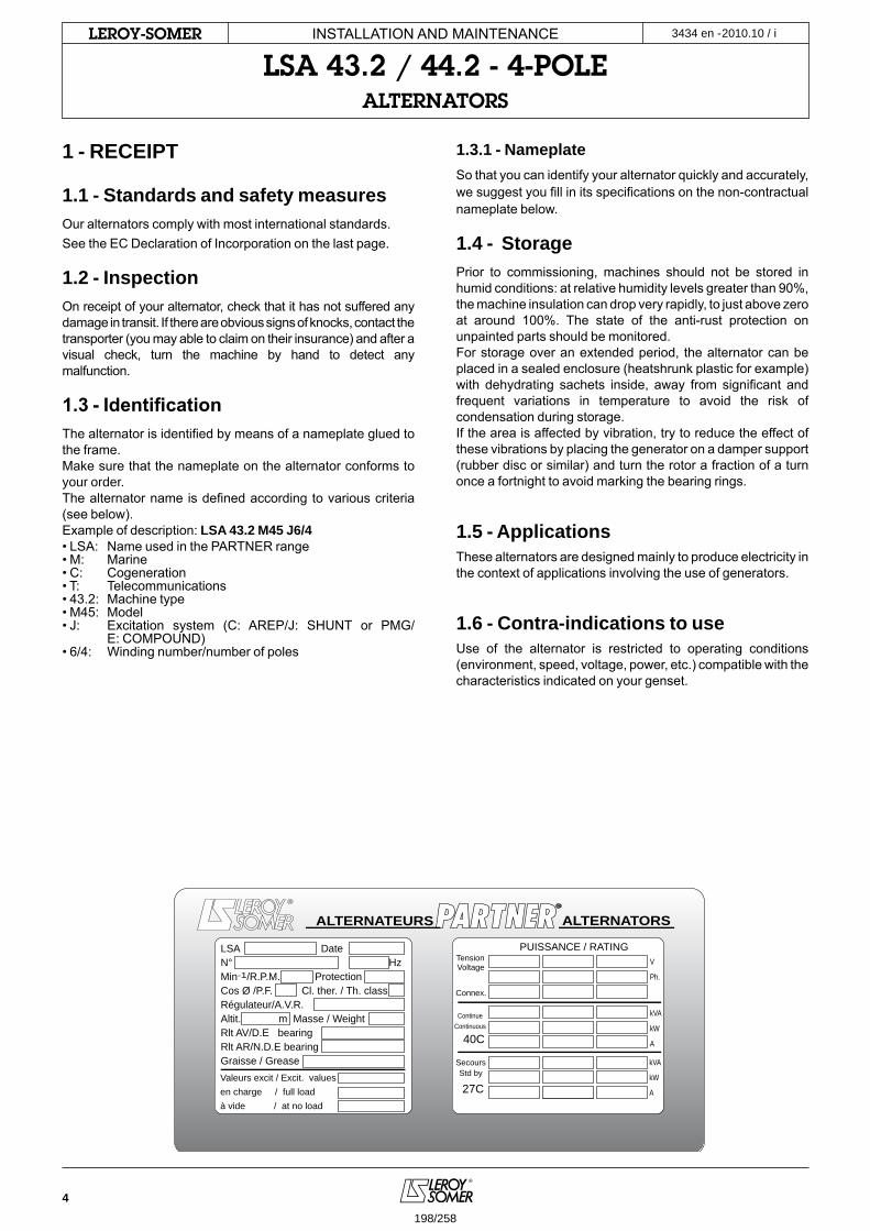
4
2010.10 / iLeRoY-SoMeR
ALTERNATEURS
Valeurs excit / Excit. values en charge / full loadà vide / at no load
Tension Voltage
SecoursStd by
40C
27C
PUISSANCE / RATING
Connex.
kVA
kW
A
kVA
kW
A
V
Ph.
ContinueContinuous
LSA Date N° Hz Min-1/R.P.M. Protection Cos Ø /P.F. Cl. ther. / Th. class Régulateur/A.V.R. Altit. m Masse / Weight Rlt AV/D.E bearing Rlt AR/N.D.E bearing Graisse / Grease
ALTERNATORS
1 - RECEIPT
1.1 - Standards and safety measuresOur alternators comply with most international standards.See the EC Declaration of Incorporation on the last page.
1.2 - InspectionOn receipt of your alternator, check that it has not suffered any damage in transit. If there are obvious signs of knocks, contact the transporter (you may able to claim on their insurance) and after a visual check, turn the machine by hand to detect any malfunction.
1.3 - IdentificationThe alternator is identified by means of a nameplate glued to the frame.Make sure that the nameplate on the alternator conforms to your order.The alternator name is defined according to various criteria (see below).Example of description: LSA 43.2 M45 J6/4 • LSA: Name used in the PARTNER range• M: Marine• C: Cogeneration• T: Telecommunications• 43.2: Machine type• M45: Model• J: Excitation system (C: AREP/J: SHUNT or PMG/ E: COMPOUND)• 6/4: Winding number/number of poles
1.3.1 - NameplateSo that you can identify your alternator quickly and accurately, we suggest you fill in its specifications on the non-contractual nameplate below.
1.4 - StoragePrior to commissioning, machines should not be stored in humid conditions: at relative humidity levels greater than 90%, the machine insulation can drop very rapidly, to just above zero at around 100%. The state of the anti-rust protection on unpainted parts should be monitored.For storage over an extended period, the alternator can be placed in a sealed enclosure (heatshrunk plastic for example) with dehydrating sachets inside, away from significant and frequent variations in temperature to avoid the risk of condensation during storage.If the area is affected by vibration, try to reduce the effect of these vibrations by placing the generator on a damper support (rubber disc or similar) and turn the rotor a fraction of a turn once a fortnight to avoid marking the bearing rings.
1.5 - ApplicationsThese alternators are designed mainly to produce electricity in the context of applications involving the use of generators.
1.6 - Contra-indications to useUse of the alternator is restricted to operating conditions (environment, speed, voltage, power, etc.) compatible with the characteristics indicated on your genset.
INSTALLATION AND MAINTENANCE
LSA 43.2 / 44.2 - 4-poLeALTeRNAToRS
3434 en -
198/258
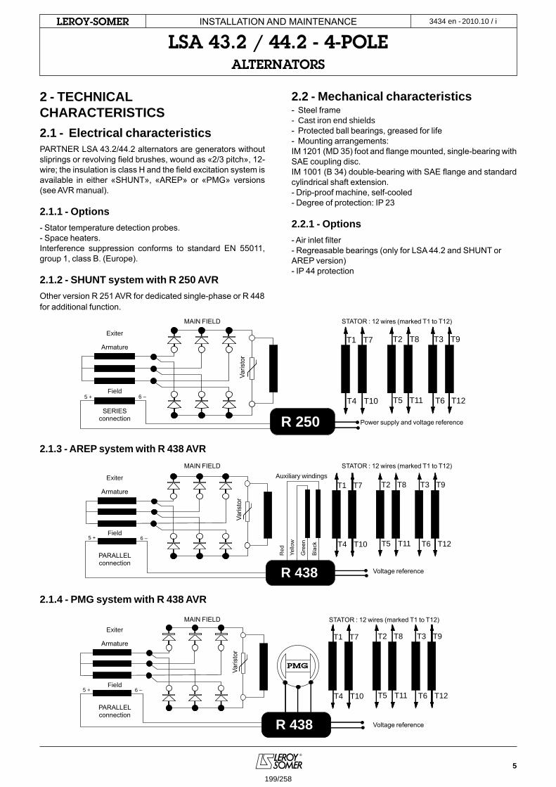
5
2010.10 / iLeRoY-SoMeR
T1 T2 T3
T4 T5 T6
T7 T8 T9
T10 T11 T12
R 250
5 + 6 –
T1 T2 T3
T4 T5 T6
T7 T8 T9
T10 T11 T12
R 250
5 + 6 –
T1 T2 T3
T4 T5 T65 + 6 –
T7 T8 T9
T10 T11 T12
R 438
T1 T2 T3
T4 T5 T65 + 6 –
T7 T8 T9
T10 T11 T12
R 438
PMG
2 - TECHNICAL CHARACTERISTICS2.1 - Electrical characteristicsPARTNER LSA 43.2/44.2 alternators are generators without sliprings or revolving field brushes, wound as «2/3 pitch», 12-wire; the insulation is class H and the field excitation system is available in either «SHUNT», «AREP» or «PMG» versions (see AVR manual).
2.1.1 - Options- Stator temperature detection probes.- Space heaters.Interference suppression conforms to standard EN 55011, group 1, class B. (Europe).
2.1.2 - SHUNT system with R 250 AVROther version R 251 AVR for dedicated single-phase or R 448 for additional function.
2.1.3 - AREP system with R 438 AVR
2.1.4 - PMG system with R 438 AVR
2.2 - Mechanical characteristics- Steel frame- Cast iron end shields- Protected ball bearings, greased for life- Mounting arrangements:IM 1201 (MD 35) foot and flange mounted, single-bearing with SAE coupling disc.IM 1001 (B 34) double-bearing with SAE flange and standard cylindrical shaft extension.- Drip-proof machine, self-cooled- Degree of protection: IP 23
2.2.1 - Options- Air inlet filter- Regreasable bearings (only for LSA 44.2 and SHUNT or AREP version)- IP 44 protection
Exiter
Exiter
Exiter
Armature
Armature
Armature
Field
Field
Field
SERIESconnection
PARALLELconnection
PARALLELconnection
MAIN FIELD
MAIN FIELD
MAIN FIELD
STATOR : 12 wires (marked T1 to T12)
STATOR : 12 wires (marked T1 to T12)
STATOR : 12 wires (marked T1 to T12)
Auxiliary windings
Power supply and voltage reference
Voltage reference
Voltage reference
Varis
tor
Varis
tor
Varis
tor
Red
Yello
w
Gre
en
Bla
ck
INSTALLATION AND MAINTENANCE
LSA 43.2 / 44.2 - 4-poLeALTeRNAToRS
3434 en -
199/258
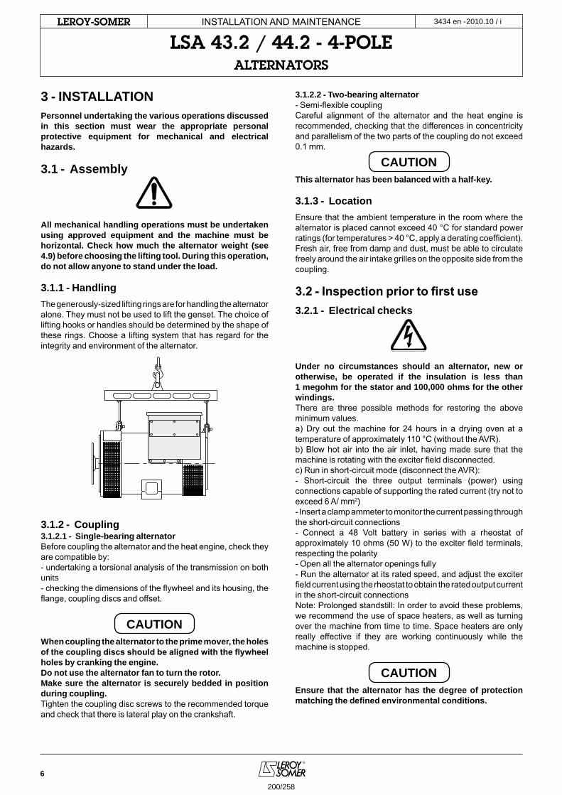
6
2010.10 / iLeRoY-SoMeR
3 - INSTALLATIONPersonnel undertaking the various operations discussed in this section must wear the appropriate personal protective equipment for mechanical and electrical hazards.
3.1 - Assembly
All mechanical handling operations must be undertaken using approved equipment and the machine must be horizontal. Check how much the alternator weight (see 4.9) before choosing the lifting tool. During this operation, do not allow anyone to stand under the load.
3.1.1 - HandlingThe generously-sized lifting rings are for handling the alternator alone. They must not be used to lift the genset. The choice of lifting hooks or handles should be determined by the shape of these rings. Choose a lifting system that has regard for the integrity and environment of the alternator.
3.1.2 - Coupling3.1.2.1 - Single-bearing alternatorBefore coupling the alternator and the heat engine, check they are compatible by:- undertaking a torsional analysis of the transmission on both units- checking the dimensions of the flywheel and its housing, the flange, coupling discs and offset.
CAUTIONWhen coupling the alternator to the prime mover, the holes of the coupling discs should be aligned with the flywheel holes by cranking the engine.Do not use the alternator fan to turn the rotor.Make sure the alternator is securely bedded in position during coupling.Tighten the coupling disc screws to the recommended torque and check that there is lateral play on the crankshaft.
3.1.2.2 - Two-bearing alternator- Semi-flexible couplingCareful alignment of the alternator and the heat engine is recommended, checking that the differences in concentricity and parallelism of the two parts of the coupling do not exceed 0.1 mm.
CAUTIONThis alternator has been balanced with a half-key.
3.1.3 - LocationEnsure that the ambient temperature in the room where the alternator is placed cannot exceed 40 °C for standard power ratings (for temperatures > 40 °C, apply a derating coefficient). Fresh air, free from damp and dust, must be able to circulate freely around the air intake grilles on the opposite side from the coupling.
3.2 - Inspection prior to first use3.2.1 - Electrical checks
Under no circumstances should an alternator, new or otherwise, be operated if the insulation is less than 1 megohm for the stator and 100,000 ohms for the other windings.There are three possible methods for restoring the above minimum values.a) Dry out the machine for 24 hours in a drying oven at a temperature of approximately 110 °C (without the AVR).b) Blow hot air into the air inlet, having made sure that the machine is rotating with the exciter field disconnected.c) Run in short-circuit mode (disconnect the AVR):- Short-circuit the three output terminals (power) using connections capable of supporting the rated current (try not to exceed 6 A/ mm2)- Insert a clamp ammeter to monitor the current passing through the short-circuit connections- Connect a 48 Volt battery in series with a rheostat of approximately 10 ohms (50 W) to the exciter field terminals, respecting the polarity- Open all the alternator openings fully- Run the alternator at its rated speed, and adjust the exciter field current using the rheostat to obtain the rated output current in the short-circuit connectionsNote: Prolonged standstill: In order to avoid these problems, we recommend the use of space heaters, as well as turning over the machine from time to time. Space heaters are only really effective if they are working continuously while the machine is stopped.
CAUTIONEnsure that the alternator has the degree of protection matching the defined environmental conditions.
INSTALLATION AND MAINTENANCE
LSA 43.2 / 44.2 - 4-poLeALTeRNAToRS
3434 en -
200/258
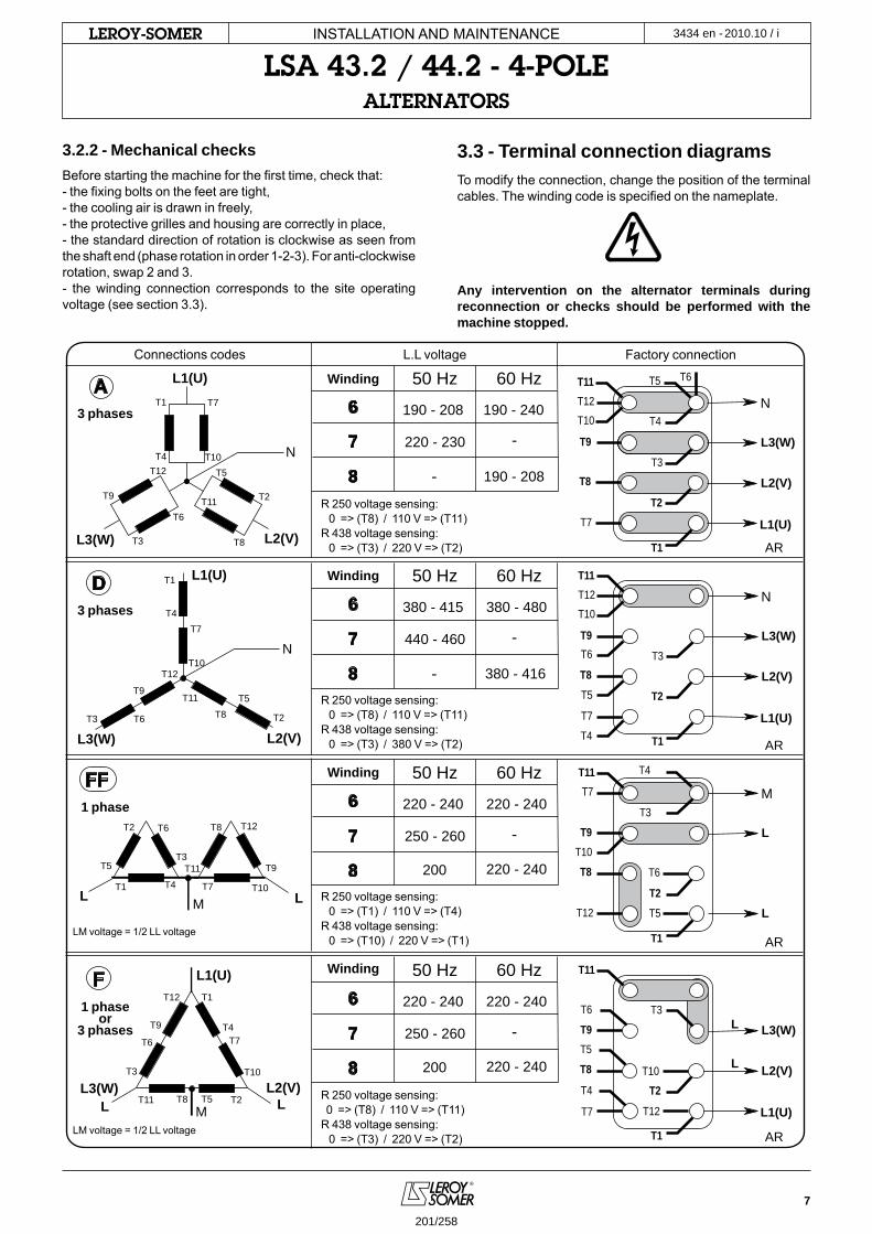
7
2010.10 / iLeRoY-SoMeR
L1(U)
N
L3(W)
T1 T7
T12T10T4
T9
T3
T6T11
T5
T2
T8 L2(V)
A 60 Hz50 Hz
190 - 208 190 - 240
220 - 230 -
- 190 - 208
6
7
8
N
T1
T7
T12T10
T4
T9
T3 T6
T11 T5
T2T8
L1(U)
L3(W) L2(V)
D
F L1(U)
M
L3(W)
T1
T7
T12
T10
T4T9
T3
T6
T11 T5 T2T8L2(V)
N
L1(U)
L2(V)
L3(W)T9
T8
T7
T12T10
T11
T4
T3
T2
T1
T5 T6
60 Hz50 Hz
380 - 415 380 - 480
440 - 460 -
- 380 - 416
6
7
8
N
L1(U)
L2(V)
L3(W)
L1(U)
L2(V)
L3(W)
T9
T8
T7
T12T10
T11
T4
T3
T2
T1
T5
T6
FF 60 Hz50 Hz
220 - 240 220 - 240
220 - 240200
250 - 260 -
6
7
8
M
L
L
L
L
T9
T8
T7
T12
T10
T11 T4
T3
T2
T1
T5
T6
60 Hz50 Hz
220 - 240 220 - 240
220 - 240200
250 - 260 -
6
7
8
T9
T8
T7 T12
T10
T11
T4
T3
T2
T1
T5
T6
L
L L
T1 T7
T12
T10T4
T9T3
T6
T11T5
T2 T8
LM
3.2.2 - Mechanical checksBefore starting the machine for the first time, check that:- the fixing bolts on the feet are tight,- the cooling air is drawn in freely,- the protective grilles and housing are correctly in place,- the standard direction of rotation is clockwise as seen from the shaft end (phase rotation in order 1-2-3). For anti-clockwise rotation, swap 2 and 3.- the winding connection corresponds to the site operating voltage (see section 3.3).
3.3 - Terminal connection diagramsTo modify the connection, change the position of the terminal cables. The winding code is specified on the nameplate.
Any intervention on the alternator terminals during reconnection or checks should be performed with the machine stopped.
R 250 voltage sensing: 0 => (T8) / 110 V => (T11)R 438 voltage sensing: 0 => (T3) / 220 V => (T2)
Connections codes L.L voltage
Winding
Winding
Winding
Winding
3 phases
3 phases
1 phase
1 phaseor
3 phases
Factory connection
R 250 voltage sensing: 0 => (T8) / 110 V => (T11)R 438 voltage sensing: 0 => (T3) / 380 V => (T2)
R 250 voltage sensing: 0 => (T1) / 110 V => (T4)R 438 voltage sensing: 0 => (T10) / 220 V => (T1)
LM voltage = 1/2 LL voltage
LM voltage = 1/2 LL voltage
R 250 voltage sensing: 0 => (T8) / 110 V => (T11)R 438 voltage sensing: 0 => (T3) / 220 V => (T2)
AR
AR
AR
AR
INSTALLATION AND MAINTENANCE
LSA 43.2 / 44.2 - 4-poLeALTeRNAToRS
3434 en -
201/258
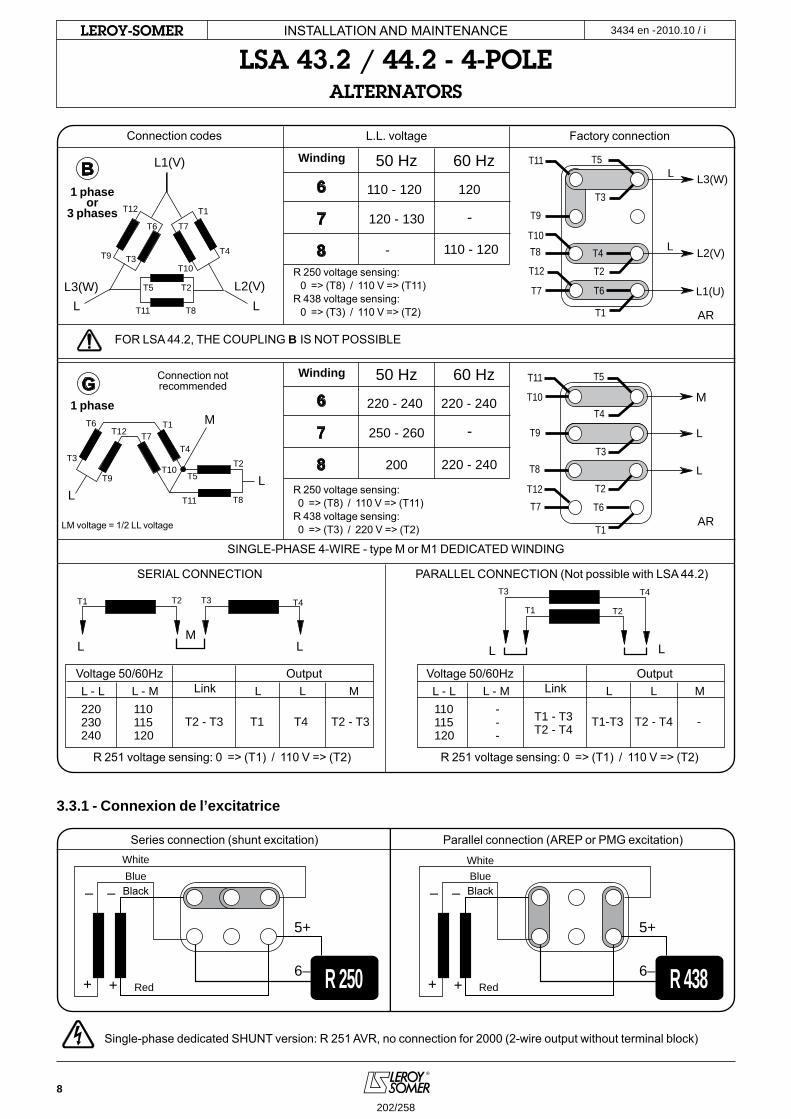
8
2010.10 / iLeRoY-SoMeR
T1 T4T3T2
L LM
L - L220230240
110115120
T2 - T3 T2 - T3T1 T4
L - M L L M
T1
T4T3
T2
L L
L - L---
110115120
T1 - T3T2 - T4 -T1-T3 T2 - T4
L - M L L M
MT1T7T12
T10
T4
T9
T3
T6
T11
T5T2
T8LL
G 60 Hz50 Hz
220 - 240 220 - 240
250 - 260
200
-
220 - 240
6
7
8
M
L
LT9
T8
T7T12
T10
T11
T4
T3
T2
T1
T5
T6
L1(U)
L2(V)
L3(W)L
L
60 Hz50 Hz
110 - 120 120
110 - 120-
120 - 130 -
6
7
8
T9
T8
T7
T12
T10
T11
T4
T3
T2
T1
T5
T6LL
L3(W)
T1
T7
T10T9 T3
T6
T11
T5 T2
T8
L2(V)
B
T12
T4
L1(V)
6-5+
6–+ +
– –
R 250 R 4386-
5+
6–+ +
– –
3.3.1 - Connexion de l’excitatrice
R 250 voltage sensing: 0 => (T8) / 110 V => (T11)R 438 voltage sensing: 0 => (T3) / 110 V => (T2)
R 250 voltage sensing: 0 => (T8) / 110 V => (T11)R 438 voltage sensing: 0 => (T3) / 220 V => (T2)
Connection codes
Series connection (shunt excitation)
WhiteBlue BlueBlack Black
Red Red
Parallel connection (AREP or PMG excitation)
SERIAL CONNECTION
Voltage 50/60Hz
R 251 voltage sensing: 0 => (T1) / 110 V => (T2) R 251 voltage sensing: 0 => (T1) / 110 V => (T2)
Voltage 50/60HzOutput OutputLink Link
PARALLEL CONNECTION (Not possible with LSA 44.2)
Connection notrecommended
LM voltage = 1/2 LL voltage
L.L. voltage
FOR LSA 44.2, THE COUPLING B IS NOT POSSIBLE
SINGLE-PHASE 4-WIRE - type M or M1 DEDICATED WINDING
Winding
Winding
1 phaseor
3 phases
Factory connection
White
AR
AR
INSTALLATION AND MAINTENANCE
LSA 43.2 / 44.2 - 4-poLeALTeRNAToRS
3434 en -
1 phase
Single-phase dedicated SHUNT version: R 251 AVR, no connection for 2000 (2-wire output without terminal block)
202/258
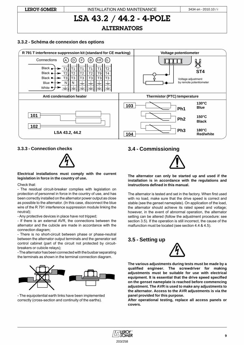
9
2010.10 / iLeRoY-SoMeR
A D F B F/F G
T1 T1 T1 T1 T1 T2 T2 T2 T2 T2 T9 T4 T3 T3 T3 T3 T3 T3 N N
ST4
LSA 43.2, 44.2
Ph1
Ph2
Ph3
101
102
103
104
130°C
150°C
180°C
3.3.3 - Connection checks
Electrical installations must comply with the current legislation in force in the country of use.
Check that:- The residual circuit-breaker complies with legislation on protection of personnel in force in the country of use, and has been correctly installed on the alternator power output as close as possible to the alternator. (In this case, disconnect the blue wire of the R 791 interference suppression module linking the neutral); - Any protective devices in place have not tripped;- If there is an external AVR, the connections between the alternator and the cubicle are made in accordance with the connection diagram;- There is no short-circuit between phase or phase-neutral between the alternator output terminals and the generator set control cabinet (part of the circuit not protected by circuit-breakers or cubicle relays);- The alternator has been connected with the busbar separating the terminals as shown in the terminal connection diagram.
- The equipotential earth links have been implemented correctly (cross-section and continuity of the earths).
3.4 - Commissioning
The alternator can only be started up and used if the installation is in accordance with the regulations and instructions defined in this manual.
The alternator is tested and set in the factory. When first used with no load, make sure that the drive speed is correct and stable (see the genset nameplate). On application of the load, the alternator should achieve its rated speed and voltage; however, in the event of abnormal operation, the alternator setting can be altered (follow the adjustment procedure: see section 3.5). If the operation is still incorrect, the cause of the malfunction must be located (see section 4.4 & 4.5).
3.5 - Setting up
The various adjustments during tests must be made by a qualified engineer. The screwdriver for making adjustments must be suitable for use with electrical equipment. It is essential that the drive speed specified on the genset nameplate is reached before commencing adjustment. The AVR is used to make any adjustments to the alternator. Access to the AVR adjustments is via the panel provided for this purpose.After operational testing, replace all access panels or covers.
R 791 T interference suppression kit (standard for CE marking)
Connections
Voltage adjustment by remote potentiometer
Voltage potentiometer
Anti condensation heater Thermistor (PTC) temperature
Blue
Black
Red/white
Black Black BlackBlue
White
3.3.2 - Schéma de connexion des options
INSTALLATION AND MAINTENANCE
LSA 43.2 / 44.2 - 4-poLeALTeRNAToRS
3434 en -
203/258
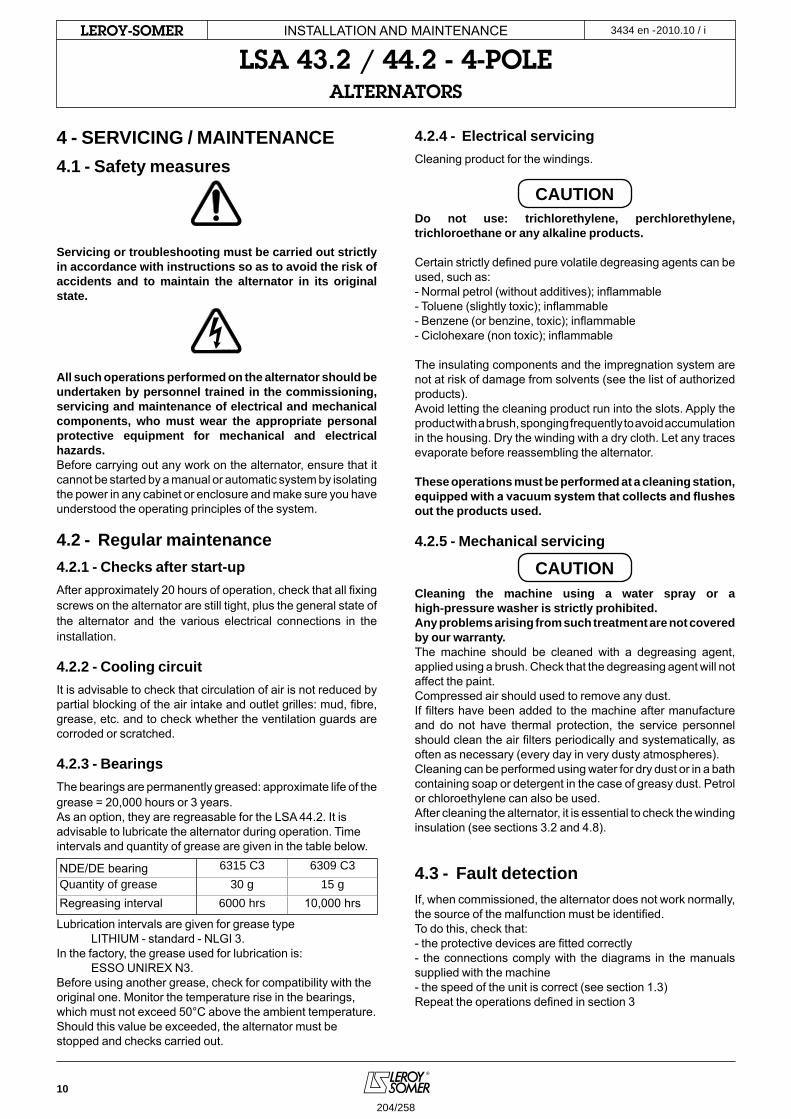
10
2010.10 / iLeRoY-SoMeR
4 - SERVICING / MAINTENANCE4.1 - Safety measures
Servicing or troubleshooting must be carried out strictly in accordance with instructions so as to avoid the risk of accidents and to maintain the alternator in its original state.
All such operations performed on the alternator should be undertaken by personnel trained in the commissioning, servicing and maintenance of electrical and mechanical components, who must wear the appropriate personal protective equipment for mechanical and electrical hazards.Before carrying out any work on the alternator, ensure that it cannot be started by a manual or automatic system by isolating the power in any cabinet or enclosure and make sure you have understood the operating principles of the system.
4.2 - Regular maintenance4.2.1 - Checks after start-upAfter approximately 20 hours of operation, check that all fixing screws on the alternator are still tight, plus the general state of the alternator and the various electrical connections in the installation.
4.2.2 - Cooling circuitIt is advisable to check that circulation of air is not reduced by partial blocking of the air intake and outlet grilles: mud, fibre, grease, etc. and to check whether the ventilation guards are corroded or scratched.
4.2.3 - BearingsThe bearings are permanently greased: approximate life of the grease = 20,000 hours or 3 years.As an option, they are regreasable for the LSA 44.2. It is advisable to lubricate the alternator during operation. Time intervals and quantity of grease are given in the table below.
NDE/DE bearing 6315 C3 6309 C3Quantity of grease 30 g 15 gRegreasing interval 6000 hrs 10,000 hrs
Lubrication intervals are given for grease type LITHIUM - standard - NLGI 3.In the factory, the grease used for lubrication is: ESSO UNIREX N3.Before using another grease, check for compatibility with the original one. Monitor the temperature rise in the bearings, which must not exceed 50°C above the ambient temperature. Should this value be exceeded, the alternator must be stopped and checks carried out.
4.2.4 - Electrical servicingCleaning product for the windings.
CAUTIONDo not use: trichlorethylene, perchlorethylene, trichloroethane or any alkaline products.
Certain strictly defined pure volatile degreasing agents can be used, such as:- Normal petrol (without additives); inflammable- Toluene (slightly toxic); inflammable- Benzene (or benzine, toxic); inflammable- Ciclohexare (non toxic); inflammable
The insulating components and the impregnation system are not at risk of damage from solvents (see the list of authorized products).Avoid letting the cleaning product run into the slots. Apply the product with a brush, sponging frequently to avoid accumulation in the housing. Dry the winding with a dry cloth. Let any traces evaporate before reassembling the alternator.
These operations must be performed at a cleaning station, equipped with a vacuum system that collects and flushes out the products used.
4.2.5 - Mechanical servicing
CAUTIONCleaning the machine using a water spray or a high-pressure washer is strictly prohibited.Any problems arising from such treatment are not covered by our warranty.The machine should be cleaned with a degreasing agent, applied using a brush. Check that the degreasing agent will not affect the paint.Compressed air should used to remove any dust.If filters have been added to the machine after manufacture and do not have thermal protection, the service personnel should clean the air filters periodically and systematically, as often as necessary (every day in very dusty atmospheres).Cleaning can be performed using water for dry dust or in a bath containing soap or detergent in the case of greasy dust. Petrol or chloroethylene can also be used.After cleaning the alternator, it is essential to check the winding insulation (see sections 3.2 and 4.8).
4.3 - Fault detectionIf, when commissioned, the alternator does not work normally, the source of the malfunction must be identified. To do this, check that:- the protective devices are fitted correctly- the connections comply with the diagrams in the manuals supplied with the machine- the speed of the unit is correct (see section 1.3)Repeat the operations defined in section 3
INSTALLATION AND MAINTENANCE
LSA 43.2 / 44.2 - 4-poLeALTeRNAToRS
3434 en -
204/258

11
2010.10 / iLeRoY-SoMeR
4.4 - Mechanical defects Fault Action
BearingExcessive overheating of one or both bearings (temperature > 80 °C on the bearing retainers with or without abnormal noise)
- If the bearing has turned blue or if the grease has turned black, change the bearing.- Bearing not properly seated. - End shields misaligned (flanges not properly fitted).
Temperatureabnormal
Excessive overheating of alternator frame (more than 40 °C above the ambient temperature)
- Air flow (intake-outlet) partially clogged or hot air is being recycled from the alternator or engine- Alternator operating at too high a voltage (> 105% of Un on load)- Alternator overloaded
VibrationExcessive vibration
- Misalignment (coupling)- Defective mounting or play in coupling- Rotor balancing fault
Excessive vibration and humming noise coming from the machine
- Alternator operating in single-phase mode (single-phase load or faulty contactor or installation fault)- Stator short-circuit
Abnormal noiseAlternator damaged by a significant impact, followed by humming and vibration
- System short-circuit- Mis-parallelingPossible consequences- Broken or damaged coupling- Broken or bent shaft end- Shifting and short-circuit of main field- Fan fractured or coming loose on shaft- Irreparable damage to rotating diodes or AVR
4.5 - Electrical faultsFault Action Effect Check/Cause
No voltage at no load on start-up
Connect between E- and E+ a new battery of 4 to 12 volts, respecting the AVR polarities, for 2 to 3 seconds
The alternator builds up and its voltage is still correct when the battery is removed.
- Lack of residual magnetism
The alternator builds up but its voltage does not reach the rated value when the battery is removed.
- Check the connection of the voltage reference to the AVR- Faulty diodes- Armature short-circuit
The alternator builds up but its voltage disappears when the battery is removed
- Faulty AVR- Field windings disconnected- Main field winding open circuit. Check the resistance
Voltage too low Check the drive speedCorrect speed
Check the AVR connections (AVR may be faulty)- Field windings short-circuited- Rotating diodes burnt out- Main field winding short-circuited - Check theresistance
Speed too lowIncrease the drive speed (Do not touch the AVR voltage pot. (P2) before running at the correct speed.)
Voltage too high Adjust AVR voltagepotentiometer
Adjustment ineffective Faulty AVR
Voltageoscillations
Adjust AVR stabilitypotentiometer
If no effect: try normal/rapid recovery modes (ST2)
- Check the speed: possibility of cyclic irregularity- Loose connections- Faulty AVR- Speed too low when on load (or LAM set too high)
Voltage correctat no load and too low when on load (*)
Run at no load and check the voltage between E+ and E- on the AVR
Voltage between E+ and E-SHUNT < 20 V - AREP/PMG < 10 V - Check the speed (or LAM set too high)Voltage between E+ and E-SHUNT > 30 V - AREP/PMG > 15 V
- Faulty rotating diodes- Short-circuit in the main field. Check the resistance - Faulty exciter armature
(*) Caution: For single-phase operation, check that the sensing wires coming from the AVR are correctly connected to the operating terminalsVoltagedisappears during operation (**)
Check the AVR, the surge suppressor, the rotating diodes, and replace any defective components
The voltage does not return to the rated value
- Exciter winding open circuit- Faulty exciter armature- Faulty AVR- Main field open circuit or short-circuited
(**) Caution: Internal protection may be activated (overload, open circuit, short-circuit)
INSTALLATION AND MAINTENANCE
LSA 43.2 / 44.2 - 4-poLeALTeRNAToRS
3434 en -
205/258
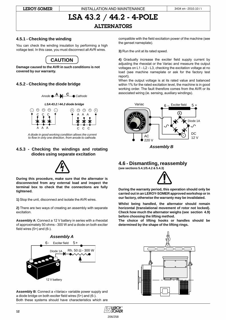
12
2010.10 / iLeRoY-SoMeR
- -C C C
A A A
+
C C C
A A A+~ ~ ~ ~ ~ ~
CA
6- 5+
Rh. 50 Ω - 300 W
- +
-
+
6 – 5 + Variac
AC220 V
DC12 V
50 60
7080
90
100
40
3020
10
0
-
+
6 – 5 + Variac
AC220 V
DC12 V
50 60
7080
90
100
40
3020
10
0
4.5.1 - Checking the windingYou can check the winding insulation by performing a high voltage test. In this case, you must disconnect all AVR wires.
CAUTIONDamage caused to the AVR in such conditions is not covered by our warranty.
4.5.2 - Checking the diode bridge
4.5.3 - Checking the windings and rotating diodes using separate excitation
During this procedure, make sure that the alternator is disconnected from any external load and inspect the terminal box to check that the connections are fully tightened.
1) Stop the unit, disconnect and isolate the AVR wires.
2) There are two ways of creating an assembly with separate excitation.
Assembly A: Connect a 12 V battery in series with a rheostat of approximately 50 ohms - 300 W and a diode on both exciter field wires (5+) and (6-).
Assembly B: Connect a «Variac» variable power supply and a diode bridge on both exciter field wires (5+) and (6-).Both these systems should have characteristics which are
compatible with the field excitation power of the machine (see the genset nameplate).
3) Run the unit at its rated speed.
4) Gradually increase the exciter field supply current by adjusting the rheostat or the Variac and measure the output voltages on L1 - L2 - L3, checking the excitation voltage at no load (see machine nameplate or ask for the factory test report).When the output voltage is at its rated value and balanced within 1% for the rated excitation level, the machine is in good working order. The fault therefore comes from the AVR or its associated wiring (ie. sensing, auxiliary windings).
4.6 - Dismantling, reassembly(see sections 5.4.1/5.4.2 & 5.4.3)
During the warranty period, this operation should only be carried out in an LEROY-SOMER approved workshop or in our factory, otherwise the warranty may be invalidated.
Whilst being handled, the alternator should remain horizontal (translational movement of rotor not locked). Check how much the alternator weighs (see section 4.9) before choosing the lifting method.The choice of lifting hooks or handles should be determined by the shape of the lifting rings.
Assembly A
Diode 1A
Exciter field
12 V battery
Anode
LSA 43.2 / 44.2 diode bridge
A diode in good working condition allows the currentto flow in only one direction, from anode to cathode.
Cathode
Assembly B
Diode 1A
Exciter field
INSTALLATION AND MAINTENANCE
LSA 43.2 / 44.2 - 4-poLeALTeRNAToRS
3434 en -
206/258

13
2010.10 / iLeRoY-SoMeR
4.6.1 - Tools requiredTo fully dismantle the machine, we recommend using the tools listed below:- 1 ratchet spanner + extension- 1 torque wrench- 1 set of flat spanners: 7 mm, 8 mm, 10 mm, 12 mm- 1 socket set: 8 mm, 10 mm, 13 mm, 16 mm, 18 mm, 21 mm, 22 mm, 24 mm- 1 size 5 Allen key (eg. Facom: ET5)- 1 size 6 Allen key (eg. Facom: ET6)- 1 size 10 Allen key (eg. Facom: ET10)- 1 size 14 Allen key (eg. Facom: ET14)- 1 T20 and T30 TORX bit- 1 puller (eg. Facom: U35)- 1 puller (eg. Facom: U32/350).
4.6.2 - Screw tightening torqueIDENTIFICATION screw Ø Torque N.m
Field terminal block screw M4 4 N.mField screw M6 10 N.mDiode bridge/RP M6 5 N.mDiode nut M5 4 N.m43.2 tie rod M12 57 N.m44.2 tie rod M14 90 N.mEarth screw M8 26 N.m43.2 disc/shaft screw M12 110 N.m44.2 disc/shaft screw M16 250 N.m44.2 turbine screw M6 5 N.mGrille screws M6 5 N.mCover screws M6 5 N.mTerminal block nut M10 20 N.m
4.6.3 - Access to connections and the regulation systemThe terminals are accessed directly by removing the terminal box lid [48].To access the AVR adjustment potentiometers, the side plate [367] should be removed.
4.6.4 - Accessing, checking and replacing diodes 4.6.4.1 - Dismantling - Remove the air intake grille [51]- Remove the surge suppressor [347]- Disconnect the 6 diodes using an ohmmeter or a battery lamp (see section 4.5.2)4.6.4.2 - Reassembly- Replace the bridges, respecting the polarity (see section 4.5.1)- Replace the surge suppressor [347]- Refit the air intake grille [51]- Replace the terminal box lid [48]
4.6.5 - Replacing the NDE bearing on single-bearing machines4.6.5.1 - Dismantling - Remove the terminal box lid [48]- Remove the air intake grille [51]- Unscrew the fixing clamps on the power output cables,
remove the connector from the exciter and the R 791 module.- Remove the 4 nuts on the tie rods- Remove the NDE shield [36] using a puller: eg. U.32 - 350 (FACOM)- Remove the ball bearing [70] using a screw puller
4.6.5.2 - Reassembly- Heat the inner slipring of a new bearing by induction or in a drying oven at 80 °C (do not use an oil-bath) and fit it to the machine.- Place the preloading wavy washer [79] in the shield and fit a new O ring seal [349].Refit the NDE shield and pass the bundle of wires between the top bars of the shield.- Refit the fixing clamps on the cables, the R 791 module and the exciter connector.- Refit the air intake grille [51].- Replace the terminal box lid [48].
NDE shieldRotor
Screw rod
4.6.6 - Replacing the bearings on two-bearing machines4.6.6.1 - Dismantling - Uncouple the alternator from the prime mover.- Remove the 8 assembly screws.- Remove the DE shield [30].- Remove the NDE shield (see section 4.6.5.1)- Remove both ball bearings [60] and [70] using a puller with a central screw.
4.6.6.2 - Reassembly- Heat the new bearings by induction or in a drying oven at 80°C (do not use an oil-bath) and fit them to the machine.- Check that both the preloading wavy washer [79] and the new O ring seal [349] have been fitted on the NDE shield [36].Refit the NDE shield and pass the bundle of wires between the top bars of the shield.- Refit the DE shield [30] and tighten the 4 fixing screws.- Check that the machine assembly is correctly mounted and that all screws are tightened.
INSTALLATION AND MAINTENANCE
LSA 43.2 / 44.2 - 4-poLeALTeRNAToRS
3434 en -
207/258
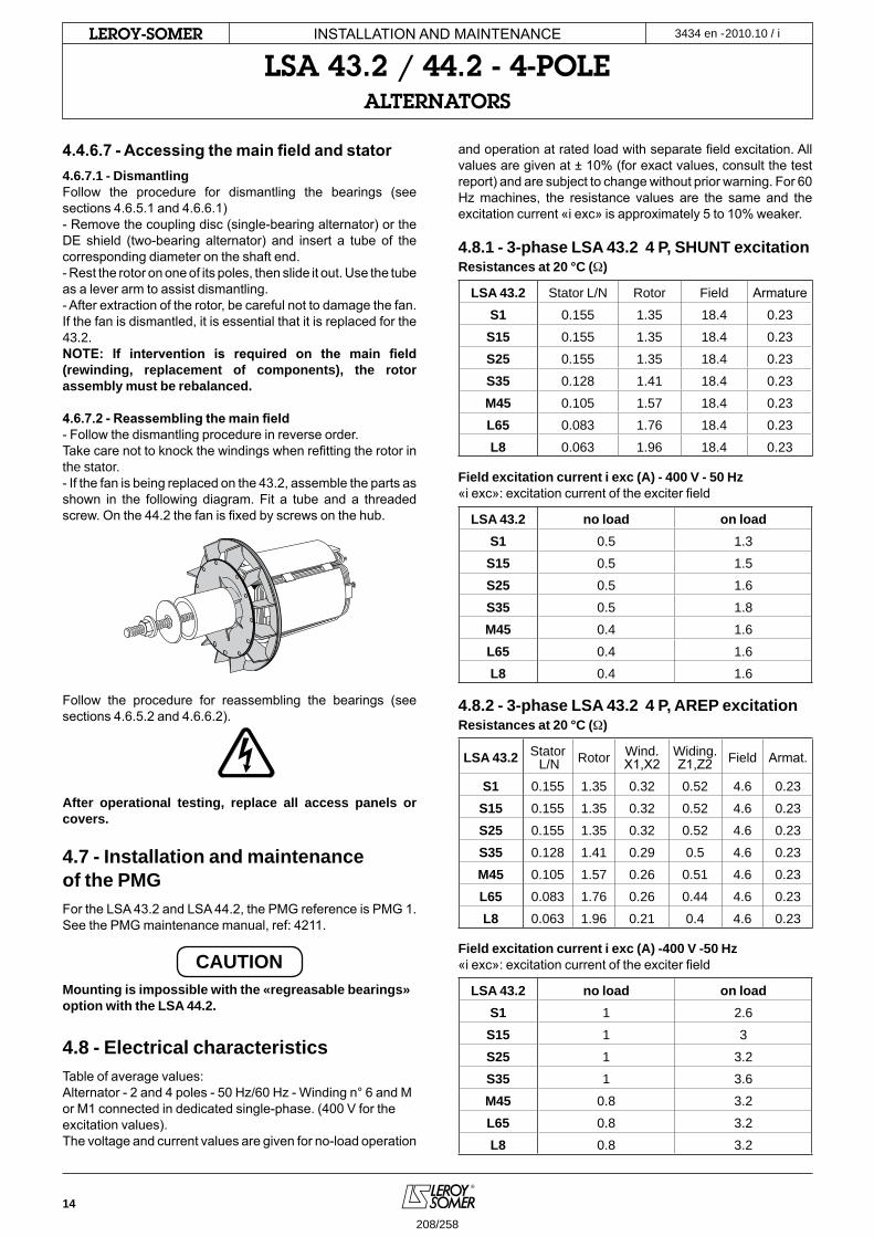
14
2010.10 / iLeRoY-SoMeR
4.4.6.7 - Accessing the main field and stator4.6.7.1 - Dismantling Follow the procedure for dismantling the bearings (see sections 4.6.5.1 and 4.6.6.1)- Remove the coupling disc (single-bearing alternator) or the DE shield (two-bearing alternator) and insert a tube of the corresponding diameter on the shaft end.- Rest the rotor on one of its poles, then slide it out. Use the tube as a lever arm to assist dismantling.- After extraction of the rotor, be careful not to damage the fan. If the fan is dismantled, it is essential that it is replaced for the 43.2.NOTE: If intervention is required on the main field (rewinding, replacement of components), the rotor assembly must be rebalanced.
4.6.7.2 - Reassembling the main field- Follow the dismantling procedure in reverse order.Take care not to knock the windings when refitting the rotor in the stator.- If the fan is being replaced on the 43.2, assemble the parts as shown in the following diagram. Fit a tube and a threaded screw. On the 44.2 the fan is fixed by screws on the hub.
Follow the procedure for reassembling the bearings (see sections 4.6.5.2 and 4.6.6.2).
After operational testing, replace all access panels or covers.
4.7 - Installation and maintenance of the PMG For the LSA 43.2 and LSA 44.2, the PMG reference is PMG 1.See the PMG maintenance manual, ref: 4211.
CAUTIONMounting is impossible with the «regreasable bearings» option with the LSA 44.2.
4.8 - Electrical characteristicsTable of average values: Alternator - 2 and 4 poles - 50 Hz/60 Hz - Winding n° 6 and M or M1 connected in dedicated single-phase. (400 V for the excitation values).The voltage and current values are given for no-load operation
and operation at rated load with separate field excitation. All values are given at ± 10% (for exact values, consult the test report) and are subject to change without prior warning. For 60 Hz machines, the resistance values are the same and the excitation current «i exc» is approximately 5 to 10% weaker.
4.8.1 - 3-phase LSA 43.2 4 P, SHUNT excitationResistances at 20 °C (Ω)
LSA 43.2 Stator L/N Rotor Field Armature
S1 0.155 1.35 18.4 0.23
S15 0.155 1.35 18.4 0.23
S25 0.155 1.35 18.4 0.23
S35 0.128 1.41 18.4 0.23
M45 0.105 1.57 18.4 0.23
L65 0.083 1.76 18.4 0.23
L8 0.063 1.96 18.4 0.23
Field excitation current i exc (A) - 400 V - 50 Hz«i exc»: excitation current of the exciter field
LSA 43.2 no load on loadS1 0.5 1.3
S15 0.5 1.5
S25 0.5 1.6
S35 0.5 1.8
M45 0.4 1.6
L65 0.4 1.6
L8 0.4 1.6
4.8.2 - 3-phase LSA 43.2 4 P, AREP excitationResistances at 20 °C (Ω)
LSA 43.2 Stator L/N Rotor Wind.
X1,X2Widing.Z1,Z2 Field Armat.
S1 0.155 1.35 0.32 0.52 4.6 0.23
S15 0.155 1.35 0.32 0.52 4.6 0.23
S25 0.155 1.35 0.32 0.52 4.6 0.23
S35 0.128 1.41 0.29 0.5 4.6 0.23
M45 0.105 1.57 0.26 0.51 4.6 0.23
L65 0.083 1.76 0.26 0.44 4.6 0.23
L8 0.063 1.96 0.21 0.4 4.6 0.23
Field excitation current i exc (A) -400 V -50 Hz«i exc»: excitation current of the exciter field
LSA 43.2 no load on loadS1 1 2.6
S15 1 3
S25 1 3.2
S35 1 3.6
M45 0.8 3.2
L65 0.8 3.2
L8 0.8 3.2
INSTALLATION AND MAINTENANCE
LSA 43.2 / 44.2 - 4-poLeALTeRNAToRS
3434 en -
208/258
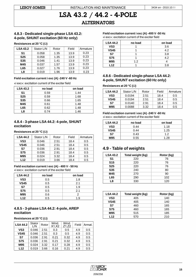
15
2010.10 / iLeRoY-SoMeR
4.8.3 - Dedicated single-phase LSA 43.2: 4-pole, SHUNT excitation (60 Hz only)Resistances at 20 °C (Ω)
LSA 43.2 Stator L/N Rotor Field ArmatureS1 0.058 1.35 13.9 0.23
S25 0.058 1.35 13.9 0.23S35 0.046 1.41 13.9 0.23M45 0.037 1.57 13.9 0.23L65 0.027 1.76 13.9 0.23L8 0.019 1.96 13.9 0.23
Field excitation current i exc (A) -240 V -60 Hz«i exc»: excitation current of the exciter field
LSA 43.2 no load on loadS1 0.59 1.44
S25 0.59 1.68S35 0.66 1.65M45 0.61 1.48L65 0.62 1.48L8 0.74 1.46
4.8.4 - 3-phase LSA 44.2: 4-pole, SHUNT excitationResistances at 20 °C (Ω)
LSA 44.2 Stator L/N Rotor Field ArmatureVS3 0.046 2.51 18.4 0.5VS45 0.046 2.51 18.4 0.5
S7 0.036 2.91 18.4 0.5S75 0.036 2.91 18.4 0.5M95 0.024 3.32 18.4 0.5L12 0.019 3.66 18.4 0.5
Field excitation current i exc (A) - 400 V - 50 Hz«i exc»: excitation current of the exciter field
LSA 44.2 no load on loadVS3 0.5 1.8
VS45 0.5 2.1S7 0.5 1.9
S75 0.5 2.1M95 0.6 2L12 0.5 1.9
4.8.5 - 3-phase LSA 44.2: 4-pole, AREP excitationResistances at 20 °C (Ω)
LSA 44.2 Stator L/N Rotor Wind.
X1,X2Wind.Z1,Z2 Field Armat.
VS3 0.046 2.51 0.3 0.5 4.9 0.5VS45 0.046 2.51 0.3 0.5 4.9 0.5
S7 0.036 2.91 0.21 0.32 4.9 0.5S75 0.036 2.91 0.21 0.32 4.9 0.5M95 0.024 3.32 0.17 0.28 4.9 0.5L12 0.019 3.66 0.16 0.21 4.9 0.5
Field excitation current i exc (A) -400 V -50 Hz«i exc»: excitation current of the exciter field
LSA 44.2 no load on loadVS3 1 3.6VS45 1 4.2
S7 1 3.8S75 1 4.2M95 1.2 4L12 1 3.8
4.8.6 - Dedicated single-phase LSA 44.2: 4-pole, SHUNT excitation (60 Hz only)Resistances at 20 °C (Ω)
LSA 44.2 Stator L/N Rotor Field ArmatureVS3 0.0194 2.51 18.4 0.5VS45 0.0194 2.51 18.4 0.5
S7 0.0140 2.91 18.4 0.5M95 0.0088 3.32 18.4 0.5
Field excitation current i exc (A) -240 V -60 Hz«i exc»: excitation current of the exciter field
LSA 44.2 no load on loadVS3 0.44 1.18
VS45 0.44 1.25S7 0.43 1.2
M95 0.55 1.28
4.9 - Table of weightsLSA 43.2 Total weight (kg) Rotor (kg)
S1 220 76S15 220 76S25 220 76S35 240 80M45 270 90L65 290 102L8 330 120
LSA 44.2 Total weight (kg) Rotor (kg)VS3 405 140
VS45 405 140S7 460 165
S75 460 165M95 515 185L12 570 210
INSTALLATION AND MAINTENANCE
LSA 43.2 / 44.2 - 4-poLeALTeRNAToRS
3434 en -
209/258

16
2010.10 / iLeRoY-SoMeR
5 - SPARE PARTS5.1 - First maintenance partsEmergency repair kits are available as an option.They contain the following items:
Ref. Designation Qty LSA 43.2/44.2 - SHUNT Code
198 AVR 1R 250 AEM 110 RE 019
R 251 AEM 110 RE 021
343 Diode bridge assembly 1 LSA 432 9 100 ALT 432 KD 001
347 Surge suppressor 1 LSA 432 1 13 AEM 000 RE 126
AVR fuse 1 250 V - 8 A/slow-blow
Ref. Designation Qty LSA 43.2/44.2 - AREP 4 P Code198 AVR 1 R 438 AEM 110 RE 017
343 Diode bridge assembly 1 LSA 432 9 100 ALT 432 KD 001
347 Surge suppressor 1 LSA 432 1 13 AEM 000 RE 126
AVR fuse 2 250 V - 8 A/fast-blow
5.2 - Bearing designations
Ref. Designation Qty LSA 43.2 Code LSA 44.2 Code60 Bearing on shaft extension end 1 6312 2RS/C3 RLT060ET007 6315 2RS/C3 RLT075ET004
70 Bearing on exciter end 1 6307 2RS/C3 RLT035ET030 6309 2RS/C3 RLT045ET030
5.3 - Technical support serviceOur technical support service will be pleased to provide any additional information you may require.When ordering spare parts, you should indicate the complete machine type, its serial number and the information given on the genset nameplate.
Address your enquiry to your usual contact.
CAUTION
Part numbers should be identified from the exploded views and their description from the parts list.Our extensive network of service centres can dispatch the necessary parts without delay. To ensure correct operation and the safety of our machines, we recommend the use of original manufacturer spare parts.In the event of failure to comply with this advice, the manufacturer cannot be held responsible for any damage.
INSTALLATION AND MAINTENANCE
LSA 43.2 / 44.2 - 4-poLeALTeRNAToRS
3434 en -
210/258
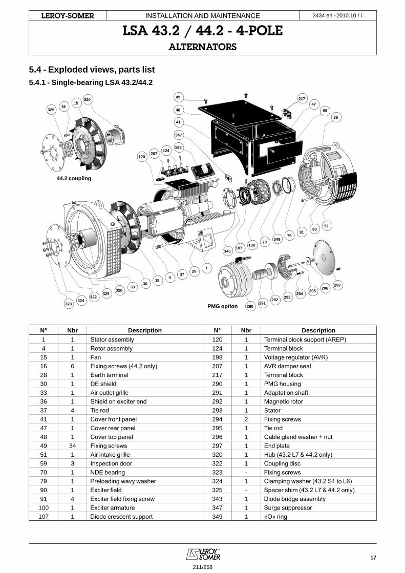
17
2010.10 / iLeRoY-SoMeR
343
349
347
7079
90
36
51
48 59
1
124
41
47
198
100107
91
374
1615
1530
33
322324
325
325
320
323
320
49
28
290291
292 293294
295 296297
207120
217
5.4 - Exploded views, parts list5.4.1 - Single-bearing LSA 43.2/44.2
N° Nbr Description N° Nbr Description1 1 Stator assembly 120 1 Terminal block support (AREP)4 1 Rotor assembly 124 1 Terminal block15 1 Fan 198 1 Voltage regulator (AVR)16 6 Fixing screws (44.2 only) 207 1 AVR damper seal28 1 Earth terminal 217 1 Terminal block30 1 DE shield 290 1 PMG housing33 1 Air outlet grille 291 1 Adaptation shaft36 1 Shield on exciter end 292 1 Magnetic rotor37 4 Tie rod 293 1 Stator41 1 Cover front panel 294 2 Fixing screws47 1 Cover rear panel 295 1 Tie rod48 1 Cover top panel 296 1 Cable gland washer + nut49 34 Fixing screws 297 1 End plate51 1 Air intake grille 320 1 Hub (43.2 L7 & 44.2 only)59 3 Inspection door 322 1 Coupling disc70 1 NDE bearing 323 - Fixing screws79 1 Preloading wavy washer 324 1 Clamping washer (43.2 S1 to L6)90 1 Exciter field 325 - Spacer shim (43.2 L7 & 44.2 only)91 4 Exciter field fixing screw 343 1 Diode bridge assembly
100 1 Exciter armature 347 1 Surge suppressor107 1 Diode crescent support 349 1 «O» ring
44.2 coupling
PMG option
INSTALLATION AND MAINTENANCE
LSA 43.2 / 44.2 - 4-poLeALTeRNAToRS
3434 en -
211/258
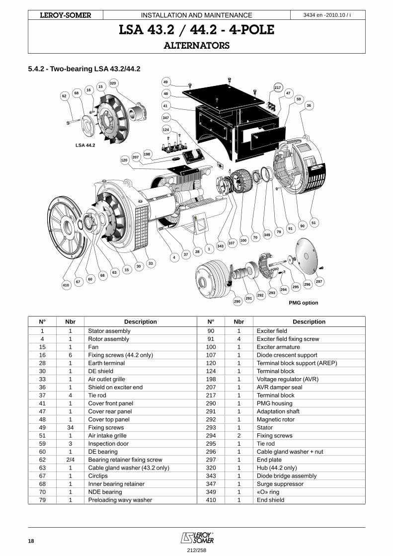
18
2010.10 / iLeRoY-SoMeR
343
349
347
7079
90
36
51
59
1
124
41
48
49
47
100107
91
2837
4
1530
33
290291
292 293294
295 296297
217
410 60
6863
67
198207
120
LSA 44.2
320
1615
6862
5.4.2 - Two-bearing LSA 43.2/44.2
N° Nbr Description N° Nbr Description1 1 Stator assembly 90 1 Exciter field4 1 Rotor assembly 91 4 Exciter field fixing screw
15 1 Fan 100 1 Exciter armature16 6 Fixing screws (44.2 only) 107 1 Diode crescent support28 1 Earth terminal 120 1 Terminal block support (AREP)30 1 DE shield 124 1 Terminal block33 1 Air outlet grille 198 1 Voltage regulator (AVR)36 1 Shield on exciter end 207 1 AVR damper seal37 4 Tie rod 217 1 Terminal block41 1 Cover front panel 290 1 PMG housing47 1 Cover rear panel 291 1 Adaptation shaft48 1 Cover top panel 292 1 Magnetic rotor49 34 Fixing screws 293 1 Stator51 1 Air intake grille 294 2 Fixing screws59 3 Inspection door 295 1 Tie rod60 1 DE bearing 296 1 Cable gland washer + nut62 2/4 Bearing retainer fixing screw 297 1 End plate63 1 Cable gland washer (43.2 only) 320 1 Hub (44.2 only)67 1 Circlips 343 1 Diode bridge assembly68 1 Inner bearing retainer 347 1 Surge suppressor70 1 NDE bearing 349 1 «O» ring79 1 Preloading wavy washer 410 1 End shield
PMG option
INSTALLATION AND MAINTENANCE
LSA 43.2 / 44.2 - 4-poLeALTeRNAToRS
3434 en -
212/258
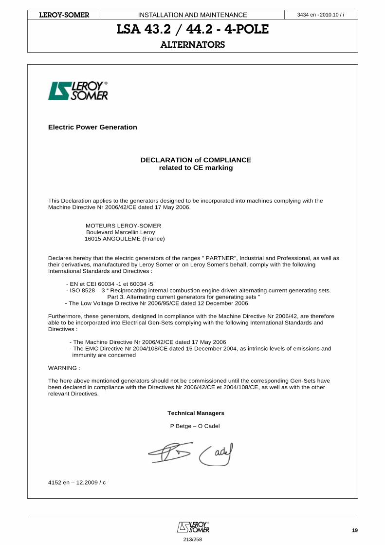
19
2010.10 / iLeRoY-SoMeR INSTALLATION AND MAINTENANCE
LSA 43.2 / 44.2 - 4-poLeALTeRNAToRS
3434 en -
Electric Power Generation
DECLARATION of COMPLIANCE related to CE marking
This Declaration applies to the generators designed to be incorporated into machines complying with the Machine Directive Nr 2006/42/CE dated 17 May 2006.
MOTEURS LEROY-SOMER Boulevard Marcellin Leroy 16015 ANGOULEME (France) Declares hereby that the electric generators of the ranges " PARTNER", Industrial and Professional, as well as their derivatives, manufactured by Leroy Somer or on Leroy Somer's behalf, comply with the following International Standards and Directives :
- EN et CEI 60034 -1 et 60034 -5 - ISO 8528 – 3 “ Reciprocating internal combustion engine driven alternating current generating sets.
Part 3. Alternating current generators for generating sets ” - The Low Voltage Directive Nr 2006/95/CE dated 12 December 2006.
Furthermore, these generators, designed in compliance with the Machine Directive Nr 2006/42, are therefore able to be incorporated into Electrical Gen-Sets complying with the following International Standards and Directives :
- The Machine Directive Nr 2006/42/CE dated 17 May 2006 - The EMC Directive Nr 2004/108/CE dated 15 December 2004, as intrinsic levels of emissions and immunity are concerned
WARNING : The here above mentioned generators should not be commissioned until the corresponding Gen-Sets have been declared in compliance with the Directives Nr 2006/42/CE et 2004/108/CE, as well as with the other relevant Directives.
Technical Managers P Betge – O Cadel
4152 en – 12.2009 / c
213/258
MOTEURS LEROY-SOMER 16015 ANGOULÊME CEDEX - FRANCE
RCS ANGOULÊME N° B 671 820 223S.A. au capital de 62 779 000 €
http://www.leroy-somer.com
214/258
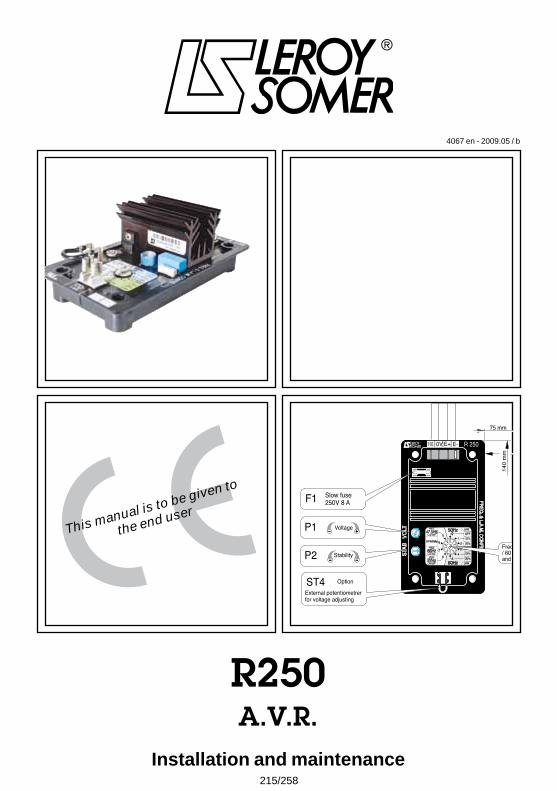
This manual is to be given to
the end user
4067 en - 2009.05 / b
R250A.V.R.
Installation and maintenance
4 x holes Ø 5.8 x 50 x 115 mm
140
mm
75 mm
SHUNT SYSTEM
Field
Induced
T1 T2 T3
T4 T5 T6
Varis
tor
5+ 6-
T7 T8 T9
T10 T11 T12
STATOR : 12 wires (marking T1 to T12)MAIN FIELD
R 250
VO
LT
FREQ. & L.A.M
. CONFIG
.
ST
AB
F1 Slow fuse 250V 8 A
P1 Voltage
P2 Stability
110 E+ E-0V
09
87 6 5 4
321
o1
2
3
56
7
9
8
4
60Hz
65Hz
57Hz
47.5Hz 50HzKNEE
SPECIAL
LAM
OFF
OFF
13%
13%
25%
25%
LAM
KNEE
KNEE
LAM OFF
LAM OFF
LAM OFF
External potentiometrerfor voltage adjusting
ST4 Option
Frequency selector 50 Hz/ 60 Hz for U/F fonctionand LAM adjustement
215/258
Installation and maintenance
R250A.V.R.
2
LEROY-SOMER 4067 en - 2009.05 / b
Before using your machine for the first time, it is important to read the whole of this installation and maintenance manual.
All necessary operations and interventions on this machine must be performed by a qualified technician.
Our technical support service will be pleased to provide any additional information you may require.
The various operations described in this manual are accompanied by recommendations or symbols to alert the user to potential risks of accidents. It is vital that you understand and take notice of the following warning symbols.
Warning symbol for an operation capable of damaging or destroying the machine or surrounding equipment.
Warning symbol for general danger to personnel.
Warning symbol for electrical danger to personnel.
Note : LEROY-SOMER reserves the right to modify the characteristics of its products at any time in order to incorporate the latest technological developments. The information contained in this document may therefore be changed without notice.
WARNING
This manual concerns the alternator A.V.R. which you have just purchased.
We wish to draw your attention to the contents of this maintenance manual. By following certain important points during installation, use and servicing of your A.V.R., you can look forward to many years of trouble-free operation.
SAFETY MEASURES
216/258
Installation and maintenance
R250A.V.R.
4067 en - 2009.05 / bLEROY-SOMER
3
SUMMARY
1 - SUPPLY ..............................................................................................................................41.1 - SHUNT excitation system ............................................................................................4
2 - R250 A.V.R. ........................................................................................................................52.1 - Characteristics .............................................................................................................52.2 - U/F fonction and LAM ...................................................................................................52.3 - R250 A.V.R. option .......................................................................................................52.4 - LAM Characteristics ....................................................................................................62.5 - Typical effects of the LAM .............................................................................................7
3 - INSTALLATION - COMMISIONING ...................................................................................83.1 - Electrical checks on the AVR ........................................................................................83.2 - Settings ........................................................................................................................83.3 - Electrical faults .............................................................................................................9
4 - SPARE PARTS .................................................................................................................10 4.1 - Designation.................................................................................................................10
4.2 - Technical support service. ..........................................................................................10
Any maintenance or breakdown operations on the A.V.R. are to be done by personnel trained on commisioning, servicing and maintenance for the electrical and mechanical elements.
The R250 is an IP00 product. It must be installed inside a unit so that this unit’s cover can provide IP20 minimum total protection (it must only be installed on LS alternators in the appropriate location so that when viewed externally, it has a higher degree of protection than IP20).
Copyright 2005: MOTEURS LEROY-SOMERThis document is the property of:MOTEURS LEROY SOMER.It may not be reproduced in any form without prior authorizationAll brands and models have been registered and patents applied for.
217/258
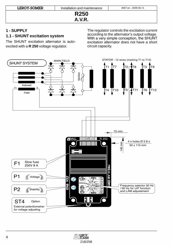
Installation and maintenance
R250A.V.R.
4
LEROY-SOMER 4067 en - 2009.05 / b
1 - SUPPLY1.1 - SHUNT excitation system The SHUNT excitation alternator is auto-excited with a R 250 voltage regulator.
The regulator controls the excitation current according to the alternator’s output voltage. With a very simple conception, the SHUNT excitation alternator does not have a short circuit capacity.
4 x holes Ø 5.8 x 50 x 115 mm
140
mm
75 mm
SHUNT SYSTEM
Field
Induced
T1 T2 T3
T4 T5 T6
Varis
tor
5+ 6-
T7 T8 T9
T10 T11 T12
STATOR : 12 wires (marking T1 to T12)MAIN FIELD
R 250
VOL
T FREQ. & L.A.M. CONFIG.
STA
B
F1 Slow fuse 250V 8 A
P1 Voltage
P2 Stability
110 E+ E-0V
09
87 6 5 4
321
o1
2
3
56
7
9
8
4
60Hz
65Hz
57Hz
47.5Hz 50HzKNEE
SPECIAL
LAM
OFF
OFF
13%
13%
25%
25%
LAM
KNEE
KNEE
LAM OFF
LAM OFF
LAM OFF
External potentiometrerfor voltage adjusting
ST4 Option
Frequency selector 50 Hz/ 60 Hz for U/F fonctionand LAM adjustement
218/258
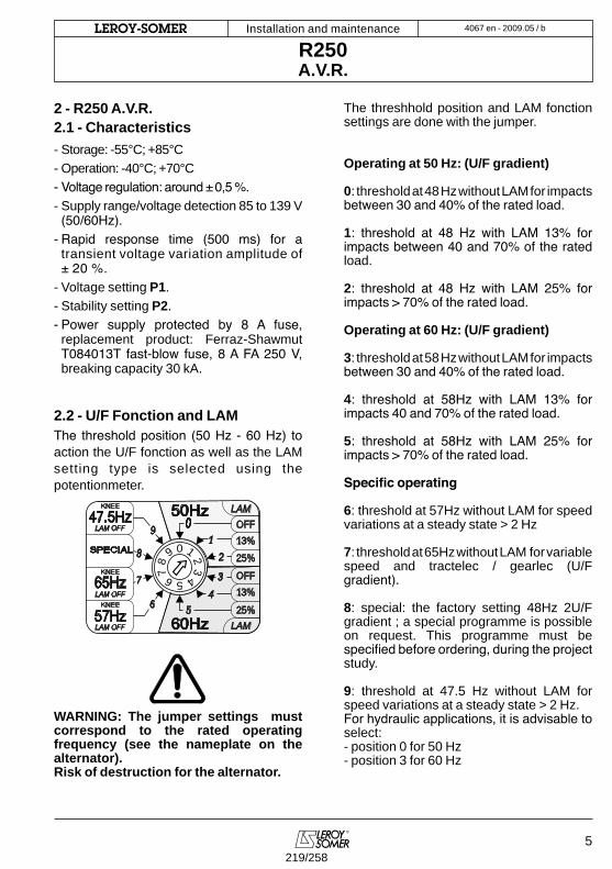
Installation and maintenance
R250A.V.R.
4067 en - 2009.05 / bLEROY-SOMER
5
2 - R250 A.V.R. 2.1 - Characteristics- Storage: -55°C; +85°C- Operation: -40°C; +70°C- Voltage regulation: around ± 0,5 %. - Supply range/voltage detection 85 to 139 V
(50/60Hz).- Rapid response time (500 ms) for a transient voltage variation amplitude of ± 20 %.
- Voltage setting P1.- Stability setting P2.- Power supply protected by 8 A fuse,
replacement product: Ferraz-Shawmut T084013T fast-blow fuse, 8 A FA 250 V, breaking capacity 30 kA.
2.2 - U/F Fonction and LAMThe threshold position (50 Hz - 60 Hz) to action the U/F fonction as well as the LAM setting type is selected using the potentionmeter.
WARNING: The jumper settings must correspond to the rated operating frequency (see the nameplate on the alternator). Risk of destruction for the alternator.
The threshhold position and LAM fonction settings are done with the jumper.
Operating at 50 Hz: (U/F gradient)
0: threshold at 48 Hz without LAM for impacts between 30 and 40% of the rated load. 1: threshold at 48 Hz with LAM 13% for impacts between 40 and 70% of the rated load. 2: threshold at 48 Hz with LAM 25% for impacts > 70% of the rated load. Operating at 60 Hz: (U/F gradient)
3: threshold at 58 Hz without LAM for impacts between 30 and 40% of the rated load.
4: threshold at 58Hz with LAM 13% for impacts 40 and 70% of the rated load.
5: threshold at 58Hz with LAM 25% for impacts > 70% of the rated load.
Specific operating 6: threshold at 57Hz without LAM for speed variations at a steady state > 2 Hz
7: threshold at 65Hz without LAM for variable speed and tractelec / gearlec (U/F gradient).
8: special: the factory setting 48Hz 2U/F gradient ; a special programme is possible on request. This programme must be specified before ordering, during the project study.
9: threshold at 47.5 Hz without LAM for speed variations at a steady state > 2 Hz.For hydraulic applications, it is advisable to select:- position 0 for 50 Hz- position 3 for 60 Hz
09
87 6 5 4
321
o1
2
3
56
7
9
8
4
60Hz
65Hz
57Hz
47.5Hz 50HzKNEE
SPECIAL
LAM
OFF
OFF
13%
13%
25%
25%
LAM
KNEE
KNEE
LAM OFF
LAM OFF
LAM OFF
219/258
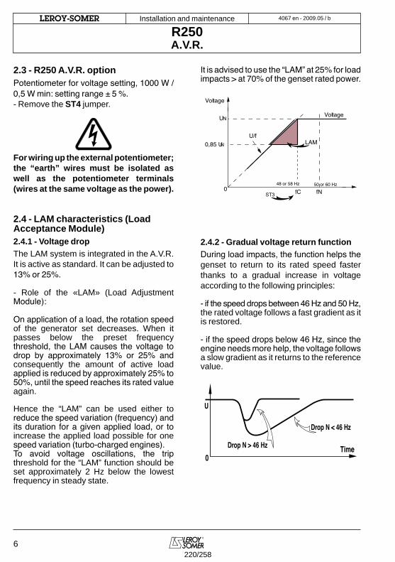
Installation and maintenance
R250A.V.R.
6
LEROY-SOMER 4067 en - 2009.05 / b
2.3 - R250 A.V.R. optionPotentiometer for voltage setting, 1000 W / 0,5 W min: setting range ± 5 %.- Remove the ST4 jumper.
For wiring up the external potentiometer; the “earth” wires must be isolated as well as the potentiometer terminals (wires at the same voltage as the power).
2.4 - LAM characteristics (Load Acceptance Module) 2.4.1 - Voltage dropThe LAM system is integrated in the A.V.R. It is active as standard. It can be adjusted to 13% or 25%.
- Role of the «LAM» (Load Adjustment Module):
On application of a load, the rotation speed of the generator set decreases. When it passes below the preset frequency threshold, the LAM causes the voltage to drop by approximately 13% or 25% and consequently the amount of active load applied is reduced by approximately 25% to 50%, until the speed reaches its rated value again. Hence the “LAM” can be used either to reduce the speed variation (frequency) and its duration for a given applied load, or to increase the applied load possible for one speed variation (turbo-charged engines).To avoid voltage oscillations, the trip threshold for the “LAM” function should be set approximately 2 Hz below the lowest frequency in steady state.
It is advised to use the “LAM” at 25% for load impacts > at 70% of the genset rated power.
2.4.2 - Gradual voltage return functionDuring load impacts, the function helps the genset to return to its rated speed faster thanks to a gradual increase in voltage according to the following principles:
- if the speed drops between 46 Hz and 50 Hz, the rated voltage follows a fast gradient as it is restored.
- if the speed drops below 46 Hz, since the engine needs more help, the voltage follows a slow gradient as it returns to the reference value.
LAM
UN
048 or 58 Hz
0,85 UN
Voltage
U/f
50 or 60 Hz
fC fN
Voltage
ST3
0Time
Drop N < 46 Hz
U
Drop N > 46 Hz
220/258
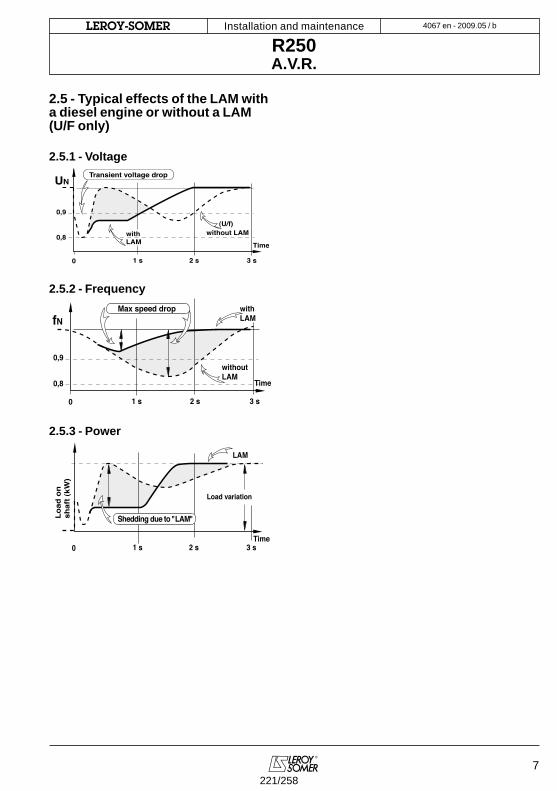
Installation and maintenance
R250A.V.R.
4067 en - 2009.05 / bLEROY-SOMER
7
2.5 - Typical effects of the LAM with a diesel engine or without a LAM (U/F only)
2.5.1 - Voltage
2.5.2 - Frequency
2.5.3 - Power
UN
0
0,9
0,8
(U/f)with LAM Time
without LAM
1 s 2 s 3 s
Transient voltage drop
0,9
0,8
fN Max speed drop
0
with LAM
Time
without LAM
1 s 2 s 3 s
0 1 s 2 s 3 sTime
LAM
Load variation
Load
on
shaf
t (kW
)
Shedding due to "LAM"
221/258

Installation and maintenance
R250A.V.R.
8
LEROY-SOMER 4067 en - 2009.05 / b
3 - INSTALLATION - COMMISSIONING3.1 - Electrical checks on the AVR- Check that all connections have been made properly as shown in the attached wiring diagram.- Check that the position of the jumper corresponds to the operating frequency.- Check whether the ST4 jumper or the remote adjustment potentiometer have been connected.
3.2 - Settings
The different settings made during the trial are to be done by qualified personnel. Respecting the load speed specified on the nameplate is vital in order to start a settings procedure. After operational testing, replace all access panels or covers.The only possible settings on the machine are to be done with the A.V.R.
3.2.1 - R250 settings (SHUNT system)Initial potentiometer positions - voltage setting potentiometer P1 for the A.V.R.: full left- remote voltage setting potentiometer: in the middle.Operate the alternator at its rated speed: if the voltage does not rise it is necessary to re-magnatise the magnetic circuit.- slowly adjust the voltage potentiometer of the A.V.R. P1 until the output voltage reaches its rated value.- Stability setting with P2.
3.2.2 - Special type of use
Excitation circuit E+, E- must not be left open when the machine is running: A.V.R. damage will occur.
3.2.2.1 - R250 field weakening (SHUNT)
The exciter is switched off by disconnecting the A.V.R. power supply (1 wire - 0 or 110V).Contact rating: 16A - 250V AC
Do not reclose the power supply until the voltage has reached a value ≤15% of the rated voltage (approximately 5 seconds after opening)
3.2.2.2 - R250 field forcing
The battery must be isolated from the mass.
Exciter field may be at line potential.
WARNING
E+ E-0V110
Battery (B Volt) +-t
(400V - 10A)
Excitation Inducer
Diode
E+ E-0V110
222/258
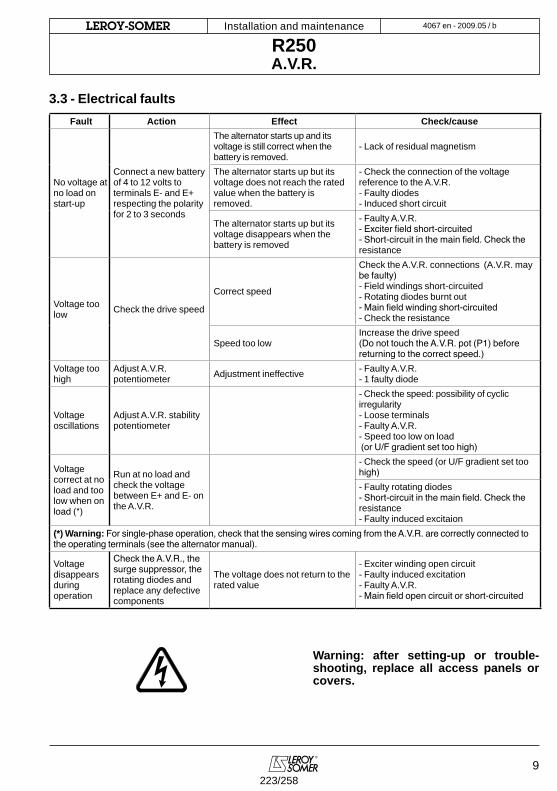
Installation and maintenance
R250A.V.R.
4067 en - 2009.05 / bLEROY-SOMER
9
3.3 - Electrical faults
Warning: after setting-up or trouble-shooting, replace all access panels or covers.
Fault Action Effect Check/cause
No voltage atno load on start-up
Connect a new batteryof 4 to 12 volts to terminals E- and E+ respecting the polarityfor 2 to 3 seconds
The alternator starts up and its voltage is still correct when the battery is removed.
- Lack of residual magnetism
The alternator starts up but its voltage does not reach the rated value when the battery is removed.
- Check the connection of the voltage reference to the A.V.R.- Faulty diodes- Induced short circuit
The alternator starts up but its voltage disappears when the battery is removed
- Faulty A.V.R.- Exciter field short-circuited- Short-circuit in the main field. Check the resistance
Voltage toolow Check the drive speed
Correct speed
Check the A.V.R. connections (A.V.R. may be faulty)- Field windings short-circuited- Rotating diodes burnt out- Main field winding short-circuited- Check the resistance
Speed too lowIncrease the drive speed(Do not touch the A.V.R. pot (P1) before returning to the correct speed.)
Voltage toohigh
Adjust A.V.R. potentiometer Adjustment ineffective - Faulty A.V.R.
- 1 faulty diode
Voltage oscillations
Adjust A.V.R. stability potentiometer
- Check the speed: possibility of cyclic irregularity- Loose terminals- Faulty A.V.R.- Speed too low on load (or U/F gradient set too high)
Voltage correct at no load and too low when on load (*)
Run at no load and check the voltage between E+ and E- on the A.V.R.
- Check the speed (or U/F gradient set too high) - Faulty rotating diodes- Short-circuit in the main field. Check the resistance- Faulty induced excitaion
(*) Warning: For single-phase operation, check that the sensing wires coming from the A.V.R. are correctly connected to the operating terminals (see the alternator manual).
Voltage disappears during operation
Check the A.V.R., the surge suppressor, the rotating diodes and replace any defective components
The voltage does not return to the rated value
- Exciter winding open circuit- Faulty induced excitation - Faulty A.V.R.- Main field open circuit or short-circuited
223/258
Installation and maintenance
R250A.V.R.
10
LEROY-SOMER 4067 en - 2009.05 / b
4 - SPARE PARTS4.1 - DesignationDescription Type CodeA.V.R. R 250 AEM 110 RE 019
4.2 - Technical support serviceOur technical support service will be pleased to help you with any information needed.
For replacement part orders, it is necessary to indicate the type and the code number of the A.V.R.
Please contact your usual correspondant.
An extensive network of service centres is available to rapidly supply any necessary parts. In order to ensure the correct operation and safety of our machines, we strongly recommend that original manufacturer’s spare parts are used.Failure to do so, will discharge the manufacturer from liabilty in the case of damage.
224/258
Installation and maintenance
R250A.V.R.
4067 en - 2009.05 / bLEROY-SOMER
11225/258
MOTEURS LEROY-SOMER 16015 ANGOULÊME CEDEX - FRANCE
338 567 258 RCS ANGOULÊMES.A. au capital de 62 779 000 ¤
www.leroy-somer.com
226/258

200
mm
140 mm
X2 X1 Z2 E+ E- 0V 110 220 380Z1
T1 T2 T3
T4 T5 T65+ 6-
T7 T8 T9
T10 T11 T12
R 438
F1
ST5
P5
ST11
ST2 ST1
P3
P2
ST4
ST9 AREP PMG PMG
T.I.
S1 P1Ph.1
P2S2
R731
50Hz 60Hz
ST1013 % LAM 25 %
P1
2010.11 / f3971 en -
This manual is to be given to
the end user
R438A.V.R.
Installation and maintenance227/258
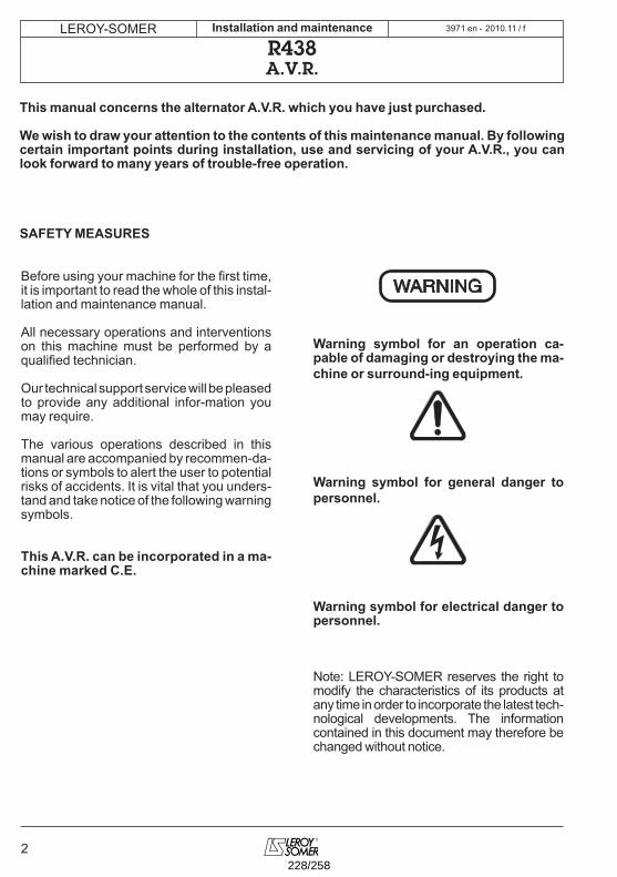
2
LEROY-SOMER 2010.11 / fInstallation and maintenance
R438A.V.R.
3971 en -
Before using your machine for the first time, it is important to read the whole of this instal-lation and maintenance manual.
All necessary operations and interventions on this machine must be performed by a qualified technician.
Our technical support service will be pleased to provide any additional infor-mation you may require.
The various operations described in this manual are accompanied by recommen-da-tions or symbols to alert the user to potential risks of accidents. It is vital that you unders-tand and take notice of the following warning symbols.
This A.V.R. can be incorporated in a ma-chine marked C.E.
Warning symbol for an operation ca-pable of damaging or destroying the ma-chine or surround-ing equipment.
Warning symbol for general danger to personnel.
Warning symbol for electrical danger to personnel.
Note: LEROY-SOMER reserves the right to modify the characteristics of its products at any time in order to incorporate the latest tech-nological developments. The information contained in this document may therefore be changed without notice.
WARNING
This manual concerns the alternator A.V.R. which you have just purchased.
We wish to draw your attention to the contents of this maintenance manual. By following certain important points during installation, use and servicing of your A.V.R., you can look forward to many years of trouble-free operation.
SAFETY MEASURES
228/258
LEROY-SOMER
3
2010.11 / fInstallation and maintenance
R438A.V.R.
3971 en -
CONTENTS
1 - SUPPLY ..............................................................................................................................41.1 - AREP excitation system ...............................................................................................41.2 - PMG excitation system .................................................................................................51.3 - SHUNT or separate excitation system ..........................................................................5
2 - R438 A.V.R. ........................................................................................................................62.1 - Characteristics .............................................................................................................62.2 - Frequency compared with voltage (without LAM) .........................................................62.3 - LAM (Load Acceptance Module) characteristics...........................................................62.4 - Typical effects of the LAM with a diesel engine with or without a LAM (U/F only) ..........72.5 - R438 A.V.R. options .....................................................................................................7
3 - INSTALLATION - COMMISSIONING .................................................................................83.1 - Electrical checks on the AVR ........................................................................................83.2 - Settings ........................................................................................................................83.3 - Electrical faults ........................................................................................................... 11
4 - SPARE PARTS .................................................................................................................124.1 - Designation ................................................................................................................124.2 - Technical support service ...........................................................................................12
All such operations performed on the A.V.R. should be undertaken by personnel trained in the commissioning, servicing and maintenance of electrical and mechanical components.
The R438 is an IP00 product. It must be installed inside a unit so that this unit’s cover can provide IP20 minimum total protection (it must only be installed on LS alternators in the ap-propriate location so that when viewed externally, it has a higher degree of protection than IP20).
Copyright 2005 : MOTEURS LEROY-SOMERThis document is the property of :MOTEURS LEROY-SOMERIt may not be reproduced in any form without prior authorization. All brands and models have been registered and patents applied for.
229/258
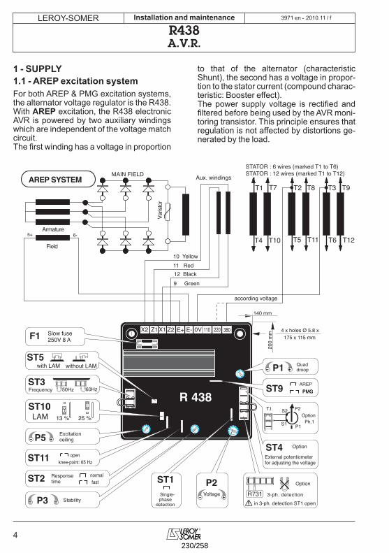
4
LEROY-SOMER 2010.11 / fInstallation and maintenance
R438A.V.R.
1 - SUPPLY1.1 - AREP excitation system For both AREP & PMG excitation systems, the alternator voltage regulator is the R438.With AREP excitation, the R438 electronic AVR is powered by two auxiliary windings which are independent of the voltage match circuit.The first winding has a voltage in proportion
to that of the alternator (characteristic Shunt), the second has a voltage in propor-tion to the stator current (compound charac-teristic: Booster effect).The power supply voltage is rectified and filtered before being used by the AVR moni-toring transistor. This principle ensures that regulation is not affected by distortions ge-nerated by the load.
4 x holes Ø 5.8 x 175 x 115 mm
200
mm
140 mm
X2 X1 Z2 E+ E- 0V 110 220 380Z1
T1 T2 T3
T4 T5 T6
Varis
tor
5+ 6-
T7 T8 T9
T10 T11 T12
R 438
F1
ST5
P5
ST11
ST2 ST1
P3
P2
P1
ST4
ST9
Option
AREP PMG PMG
T.I. Option
S1 P1Ph.1
P2S2
R731Option
AREP SYSTEM
Field
Armature
10 Yellow11 Red
9 Green12 Black
MAIN FIELD Aux. windings
Slow fuse 250V 8 A
with LAM without LAM
Excitationceiling
knee-point: 65 Hz open
Responsetime
normalfast
StabilityVoltage Single-
phasedetection
External potentiometerfor adjusting the voltage
Quaddroop
according voltage
STATOR : 6 wires (marked T1 to T6)STATOR : 12 wires (marked T1 to T12)
in 3-ph. detection ST1 open3-ph. detection
ST350Hz 60Hz
ST1013 % LAM 25 %
Frequency
3971 en -
230/258
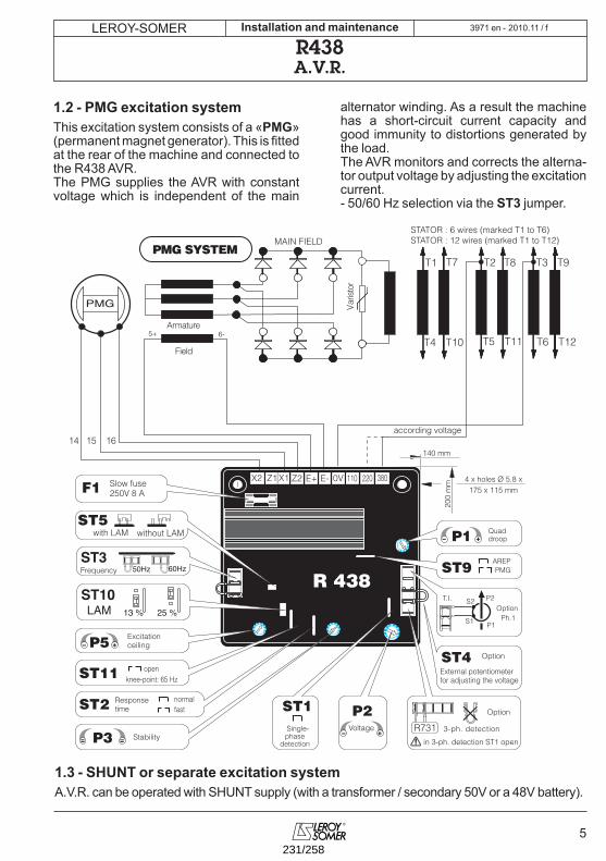
LEROY-SOMER
5
2010.11 / fInstallation and maintenance
R438A.V.R.
1.2 - PMG excitation systemThis excitation system consists of a «PMG» (permanent magnet generator). This is fitted at the rear of the machine and connected to the R438 AVR.The PMG supplies the AVR with constant voltage which is independent of the main
alternator winding. As a result the machine has a short-circuit current capacity and good immunity to distortions generated by the load.The AVR monitors and corrects the alterna-tor output voltage by adjusting the excitation current.- 50/60 Hz selection via the ST3 jumper.
4 x holes Ø 5.8 x 175 x 115 mm
200
mm
140 mm
X2 X1 Z2 E+ E- 0V 110 220 380 Z1
T1 T2 T3
T4 T5 T6 V
a r i s
t o r
5+ 6-
T7 T8 T9
T10 T11 T12
R 438
F1
ST5
P5
ST11
ST2 ST1
P3
P2
P1
ST4
ST9
Option
AREP PMG
14 15 16
PMG
T.I. Option
S1 P1 Ph.1
P2 S2
R731
Option
PMG SYSTEM
Field
Armature
MAIN FIELD
Slow fuse 250V 8 A
with LAM without LAM
Excitation ceiling
knee-point: 65 Hz open
Response time
normal fast
Stability
Voltage
Single- phase
detection
External potentiometer for adjusting the voltage
Quad droop
according voltage
STATOR : 6 wires (marked T1 to T6) STATOR : 12 wires (marked T1 to T12)
in 3-ph. detection ST1 open
3-ph. detection
ST350Hz 60Hz
ST1013 % LAM 25 %
Frequency
1.3 - SHUNT or separate excitation systemA.V.R. can be operated with SHUNT supply (with a transformer / secondary 50V or a 48V battery).
3971 en -
231/258
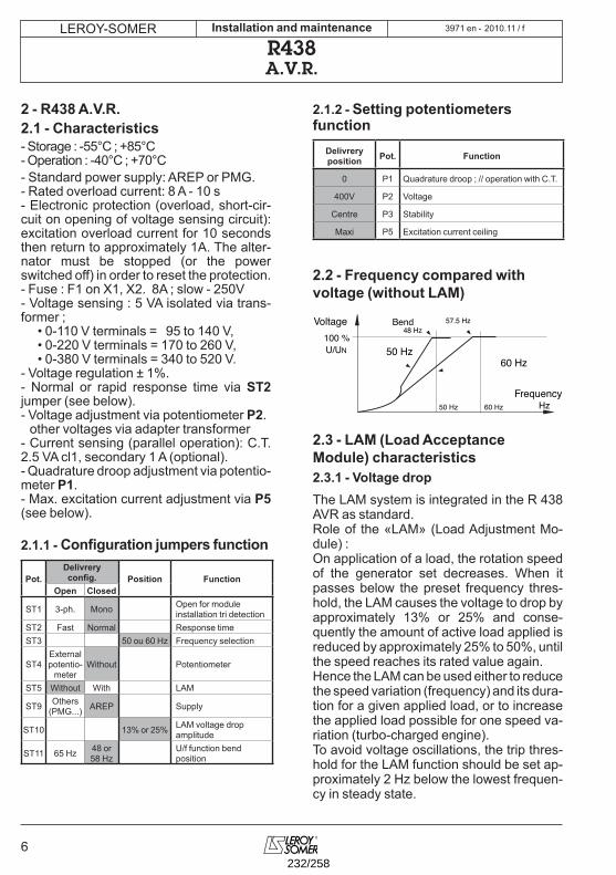
6
LEROY-SOMER 2010.11 / fInstallation and maintenance
R438A.V.R.
2 - R438 A.V.R. 2.1 - Characteristics - Storage : -55°C ; +85°C- Operation : -40°C ; +70°C - Standard power supply: AREP or PMG.- Rated overload current: 8 A - 10 s- Electronic protection (overload, short-cir-cuit on opening of voltage sensing circuit): excitation overload current for 10 seconds then return to approximately 1A. The alter-nator must be stopped (or the power switched off) in order to reset the protection.- Fuse : F1 on X1, X2. 8A ; slow - 250V- Voltage sensing : 5 VA isolated via trans-former ;
• 0-110 V terminals = 95 to 140 V,• 0-220 V terminals = 170 to 260 V,• 0-380 V terminals = 340 to 520 V.
- Voltage regulation ± 1%.- Normal or rapid response time via ST2 jumper (see below).- Voltage adjustment via potentiometer P2. other voltages via adapter transformer- Current sensing (parallel operation): C.T. 2.5 VA cl1, secondary 1 A (optional).- Quadrature droop adjustment via potentio-meter P1.- Max. excitation current adjustment via P5 (see below).
2.1.1 - Configuration jumpers function
Pot.Delivreryconfig. Position Function
Open Closed
ST1 3-ph. Mono Open for moduleinstallation tri detection
ST2 Fast Normal Response timeST3 50 ou 60 Hz Frequency selection
ST4Externalpotentio-
meterWithout Potentiometer
ST5 Without With LAM
ST9 Others (PMG...) AREP Supply
ST10 13% or 25% LAM voltage dropamplitude
ST11 65 Hz 48 or 58 Hz
U/f function bendposition
2.1.2 - Setting potentiometers function
Delivreryposition Pot. Function
0 P1 Quadrature droop ; // operation with C.T.
400V P2 Voltage
Centre P3 Stability
Maxi P5 Excitation current ceiling
2.2 - Frequency compared with voltage (without LAM)
2.3 - LAM (Load Acceptance Module) characteristics 2.3.1 - Voltage dropThe LAM system is integrated in the R 438 AVR as standard.Role of the «LAM» (Load Adjustment Mo-dule) :On application of a load, the rotation speed of the generator set decreases. When it passes below the preset frequency thres-hold, the LAM causes the voltage to drop by approximately 13% or 25% and conse-quently the amount of active load applied is reduced by approximately 25% to 50%, until the speed reaches its rated value again.Hence the LAM can be used either to reduce the speed variation (frequency) and its dura-tion for a given applied load, or to increase the applied load possible for one speed va-riation (turbo-charged engine).To avoid voltage oscillations, the trip thres-hold for the LAM function should be set ap-proximately 2 Hz below the lowest frequen-cy in steady state.
100 %
50 Hz 60 Hz Hz
50 Hz
48 Hz57.5 Hz
60 Hz
Voltage Bend
U/UN
Frequency
3971 en -
232/258
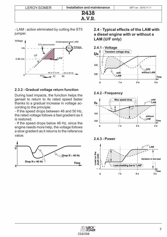
LEROY-SOMER
7
2010.11 / fInstallation and maintenance
R438A.V.R.
- LAM : action eliminated by cutting the ST5 jumper.
2.3.2 - Gradual voltage return functionDuring load impacts, the function helps the genset to return to its rated speed faster thanks to a gradual increase in voltage ac-cording to the principle:- If the speed drops between 46 and 50 Hz, the rated voltage follows a fast gradient as it is restored.- If the speed drops below 46 Hz, since the engine needs more help, the voltage follows a slow gradient as it returns to the reference value.
2.4 - Typical effects of the LAM with a diesel engine with or without a LAM (U/F only)
2.4.1 - Voltage
2.4.2 - Frequency
2.4.3 - Power
LAM
UN
048 or 57.5 Hz
0.85 UN
Voltage
U/f
50 or 60 Hz
fC fN
VoltageST5 disconnected
ST3
P2
Underspeed and LAM
0Time
Drop N ≤ 46 Hz
U
Drop N > 46 Hz
UN
0
0,9
0,8
(U/f)with LAM Time
without LAM
1 s 2 s 3 s
Transient voltage drop
0,9
0,8
fN Max speed drop
0
with LAM
Time
without LAM
1 s 2 s 3 s
0 1 s 2 s 3 sTime
LAM
Variation in the load
Load
on
the
shaf
t (kW
)
Load shedding due to "LAM"
3971 en -
233/258
8
LEROY-SOMER 2010.11 / fInstallation and maintenance
R438A.V.R.
2.5 - R438 A.V.R. options
- Current transformer for parallel operationof ....../1A. 5 VA CL 1.
- Remote voltage adjustment potentiometer: 470 Ω, 0.5 W min: adjustment range ± 5% (range limited by internal voltage potentio-meter P2). Remove ST4 to connect the po-ten-tiometer. (A 1 kΩ potentiometer can also be used to extend the adjustment range).
For wiring up the external potentiometer; the “earth” wires must be isolated as well as the potentiometer terminals (wires at the same voltage as the power).
- R 731 external module: sensing of 3-phase voltage 200 to 500 V, compatible with parallel operation. Disconnect ST1 to connect the module; set the voltage via the module po-tentiometer.
- R 734 module: detection of 3-phase current and voltage for parallel operation on unba-lanced installations (imbalance > 15%).
- R 726 module: 3 functions (mounted exter-nally).P.F. regulation (2F) and voltage sensing cir-cuit before paralleling (3 F).
- Control through DC voltage used monito-ring apply to the terminals for connection of a potentiometer DC voltage :• internal impedance 1,5 kΩ• ± 0,5V enable a voltage setting of 10%.
3971 en -
234/258
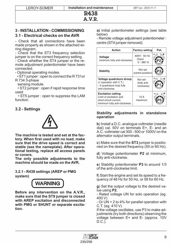
LEROY-SOMER
9
2010.11 / fInstallation and maintenance
R438A.V.R.
3 - INSTALLATION - COMMISSIONING3.1 - Electrical checks on the AVR- Check that all connections have been made properly as shown in the attached wi-ring diagram.- Check that the ST3 frequency selection jumper is on the correct frequency setting.- Check whether the ST4 jumper or the re-mote adjustment potentiometer have been connected.- Optional operating modes. • ST1 jumper : open to connect the R 731or R 734 3-phase sensing module. • ST2 jumper : open if rapid response time used • ST5 jumper : open to suppress the LAM function.
3.2 - Settings
The machine is tested and set at the fac-tory. When first used with no load, make sure that the drive speed is correct and stable (see the nameplate). After opera-tional testing, replace all access panels or covers.The only possible adjustments to the machine should be made on the AVR.
3.2.1 - R438 settings (AREP or PMG system)
Before any intervention on the A.V.R., make sure that the ST9 jumper is closed with AREP excitation and disconnected with PMG or SHUNT or separate excita-tion.
a) Initial potentiometer settings (see table below)- Remote voltage adjustment potentiometer : centre (ST4 jumper removed).
Stability adjustments in standalone operation
b) Install a D.C. analogue voltmeter (needle dial) cal. 50V on terminals E+, E- and an A.C. voltmeter cal 300 - 500 or 1000V on the alternator output terminals.
c) Make sure that the ST3 jumper is positio-ned on the desired frequency (50 or 60 Hz).
d) Voltage potentiometer P2 at minimum, fully anti-clockwise.
e) Stability potentiometer P3 to around 1/3 of the anti-clockwise limit.
f) Start the engine and set its speed to a fre-quency of 48 Hz for 50 Hz, or 58 for 60 Hz.
g) Set the output voltage to the desired va-lue using P2.- Rated voltage UN for solo operation (eg. 400 V)- Or UN + 2 to 4% for parallel operation with C.T. (eg. 410 V)If the voltage oscillates, use P3 to make ad-justments (try both directions) observing the voltage between E+ and E- (approx. 10V D.C.).
WARNING
P2
P3
P1
P5 10 A
maximum
400V - 50 Hz (Input 0 - 380 V)
Not set(centre position)
Not set(fully anti-clockwise)
Excitation ceilingLimit of excitation andshort-circuit current, minimum fully anti-clockwise.
Voltage quadrature droop(// operation with C.T.)- 0 quadrature loop fullyanti-clockwise.
Voltageminimum fully anti-clockwise
Stability
Action Factory setting Pot.
3971 en -
235/258
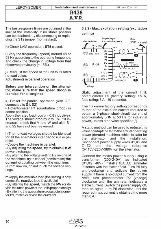
10
LEROY-SOMER 2010.11 / fInstallation and maintenance
R438A.V.R.
The best response times are obtained at the limit of the instability. If no stable position can be obtained, try disconnecting or repla-cing the ST2 jumper (normal/fast).
h) Check LAM operation : ST5 closed.
i) Vary the frequency (speed) around 48 or 58 Hz according to the operating frequency, and check the change in voltage from that observed previously (~ 15%).
j) Readjust the speed of the unit to its rated no-load value.Adjustments in parallel operation
Before any intervention on the alterna-tor, make sure that the speed droop is identical for all engines.
k) Preset for parallel operation (with C.T. connected to S1, S2)- Potentiometer P1 (quadrature droop) in centre position.Apply the rated load (cos ϕ = 0.8 inductive).The voltage should drop by 2 to 3%. If it in-creases, check that V and W and also S1 and S2 have not been reversed.
l) The no-load voltages should be identical for all the alternators intended to run in pa-rallel.- Couple the machines in parallel.- By adjusting the speed, try to obtain 0 KW power exchange.- By altering the voltage setting P2 on one of the machines, try to cancel (or minimise) the current circulating between the machines.- From now on, do not touch the voltage set-tings.
m) Apply the available load (the setting is only correct if a reactive load is available)- By altering the speed, match the kW (or di-vide the rated power of the units proportionally)- By altering the quadrature droop potentiome-ter P1, match or divide the currents.
3.2.2 - Max. excitation setting (excitation ceiling)
Static adjustment of the current limit, potentiometer P5 (factory setting: 7.5 A, fuse rating: 8 A - 10 seconds).
The maximum factory setting corresponds to that of the excitation current required to obtain a 3-phase short-circuit current of approximately 3 IN at 50 Hz for industrial power, unless otherwise specified(*).
A static method can be used to reduce this value or adapt the Isc to the actual operating power (derated machine), which is safer for the alternator and the installation. Disconnect power supply wires X1,X2 and Z1,Z2 and the voltage reference (0-110V-220V-380V) on the alternator.
Connect the mains power supply using a transformer (200-240V) as indicated (X1,X2 : 48V). Install a 10A D.C. ammeter in series with the exciter field. Turn P5 fully anti-clockwise and activate the power supply. If there is no output current from the AVR, turn potentiometer P2 (voltage) clockwise until the ammeter indicates a stable current. Switch the power supply off, then on again, turn P5 clockwise until the required max. current is obtained (no more than 8 A).
Depending onthe mains frequency
Main(50/60 Hz supply)Max. excitation
Voltage
Field~ 5 ohms
X2Z1X1Z2E+E-0V
110 V220 V380 V
50Hz 60Hz
P2
P3
P5
ST3
10 A CC/DC
48 V
110/220/380 V
R 438
ST4
A+–
A
D
3971 en -
236/258
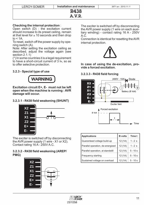
LEROY-SOMER
11
2010.11 / fInstallation and maintenance
R438A.V.R.
Checking the internal protection :Open switch (D) : the excitation current should increase to its preset ceiling, remain at that level for ≥ 10 seconds and then drop to < 1A.To reset, switch off the power supply by ope-ning switch (A).Note: After setting the excitation ceiling as described, adjust the voltage again (see section 2.1.1)(*) In some countries it is a legal requirement to have a short-circuit current of 3 In, so as to offer selective protection.
3.2.3 - Special type of use
Excitation circuit E+, E- must not be left open when the machine is running : AVR damage will occur.
3.2.3.1 - R438 field weakening (SHUNT)
The exciter is switched off by disconnecting the AVR power supply (1 wire - X1 or X2).Contact rating 16 A - 250V A.C.
3.2.3.2 - R438 field weakening (AREP/PMG)
The exciter is switched off by disconnecting the AVR power supply (1 wire on each auxi-liary winding) - contact rating 16 A - 250V A.C.Connection is identical for resetting the AVR internal protection.
In case of using the de-excitation, pro-vide a forced excitation.
3.2.3.3 - R438 field forcing
Applications B volts Time t
Guaranteed voltage build-up 12 (1A) 1 - 2 s
Parallel operation, de-energized 12 (1A) 1 - 2 s
Parallel operation, at standstill 12 (1A) 5 - 10 s
Frequency starting 12 (1A) 5 - 10 s
Sustained voltage on overload 12 (1A) 5 - 10 s
WARNING
X2Z1X1Z2E+E-
X2Z1X1Z2E+E-
X2Z1X1Z2E+E-
Battery (B Volt) +-t
(400V - 10A)
Exciter field
Diode
t
B VoltForced excitation
Time
3971 en -
237/258
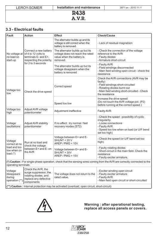
12
LEROY-SOMER 2010.11 / fInstallation and maintenance
R438A.V.R.
3.3 - Electrical faultsFault Action Effect Check/Cause
No voltage at no load on start-up
Connect a new battery of 4 to 12 volts to terminals E- and E+, respecting the polarity, for 2 to 3 seconds
The alternator builds up and its voltage is still correct when the battery is removed.
- Lack of residual magnetism
The alternator builds up but its voltage does not reach the rated value when the battery is removed.
- Check the connection of the voltage reference to the AVR- Faulty diodes- Armature short-circuit
The alternator builds up but its voltage disappears when the battery is removed
- Faulty AVR- Field windings disconnected- Main field winding open circuit - check the resistance
Voltage too low Check the drive speed
Correct speed
Check the AVR connections (AVR may be faulty)- Field windings short-circuited- Rotating diodes burnt out- Main field winding short-circuited - Check the resistance
Speed too low
Increase the drive speed (Do not touch the AVR voltage pot. (P2) before running at the correct speed.)
Voltage too high
Adjust AVR voltage potentiometer Adjustment ineffective Faulty AVR
Voltage oscillations
Adjust AVR stability potentiometer
If no effect : try normal / fast recovery modes (ST2)
- Check the speed : possibility of cyclic irregularity - Loose connections- Faulty AVR- Speed too low when on load (or U/F bend set too high)
Voltage correct at no load and too low when on load (*)
Run at no load and check the voltage between E+ and E- on the AVR
Voltage between E+ and E- SHUNT < 20 VAREP / PMG < 10V
- Check the speed (or U/F bend set too high)
Voltage between E+ and E- SHUNT > 30VAREP / PMG > 15V
- Faulty rotating diodes- Short-circuit in the main field. Check the resistance- Faulty exciter armature.
(*) Caution : For single-phase operation, check that the sensing wires coming from the AVR are correctly connected to the operating terminals
Voltage disappears during operation (**)
Check the AVR, the surge suppressor, the rotating diodes, and replace any defective components
The voltage does not return to the rated value.
- Exciter winding open circuit- Faulty exciter armature- Faulty AVR- Main field open circuit or short-circuited
(**) Caution : Internal protection may be activated (overload, open circuit, short-circuit)
Warning : after operational testing,replace all access panels or covers.
3971 en -
238/258
LEROY-SOMER
13
2010.11 / fInstallation and maintenance
R438A.V.R.
4 - SPARE PARTS4.1 - DesignationDescription Type CodeA.V.R. R 438 AEM 110 RE 017
4.2 - Technical support serviceOur technical support service will be happy to provide any information you require.
When ordering spare parts, you should in-dicate the complete machine type, its serial number and the information indicated on the nameplate.
Part numbers should be identified from the exploded views and their description in the parts list.
Our extensive network of «service stations» can dispatch the necessary parts without delay.To ensure correct operation and the safety of our machines, we recommend the use of original manufacture spare parts.In the event of failure to comply with this ad-vice, the manufacturer cannot be held res-ponsible for any damage.
3971 en -
239/258
14
LEROY-SOMER 2010.11 / fInstallation and maintenance
R438NOTES
3971 en -
240/258
LEROY-SOMER
15
2010.11 / fInstallation and maintenance
R438NOTES
3971 en -
241/258

MOTEURS LEROY-SOMER 16015 ANGOULÊME CEDEX - FRANCE
338 567 258 RCS ANGOULÊMES.A. au capital de 62 779 000 €
www.leroy-somer.com
242/258
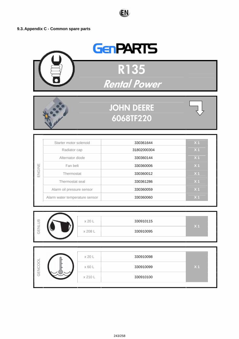
9.3. Appendix C - Common spare parts
R135
Rental Power
JOHN DEERE 6068TF220
Starter motor solenoid 330361644 X 1
Radiator cap 31802000304 X 1
Alternator diode 330360144 X 1
Fan belt 330360006 X 1
Thermostat 330360012 X 1
Thermostat seal 330361286 X 1
Alarm oil pressure sensor 330360059 X 1
Alarm water temperature sensor 330360060 X 1
EN
GIN
E
x 20 L 330910115 x 208 L 330910095
X 1
GE
NLU
B
x 20 L 330910098 x 60 L 330910099 x 210 L 330910100
X 1
GE
NC
OO
L
243/258
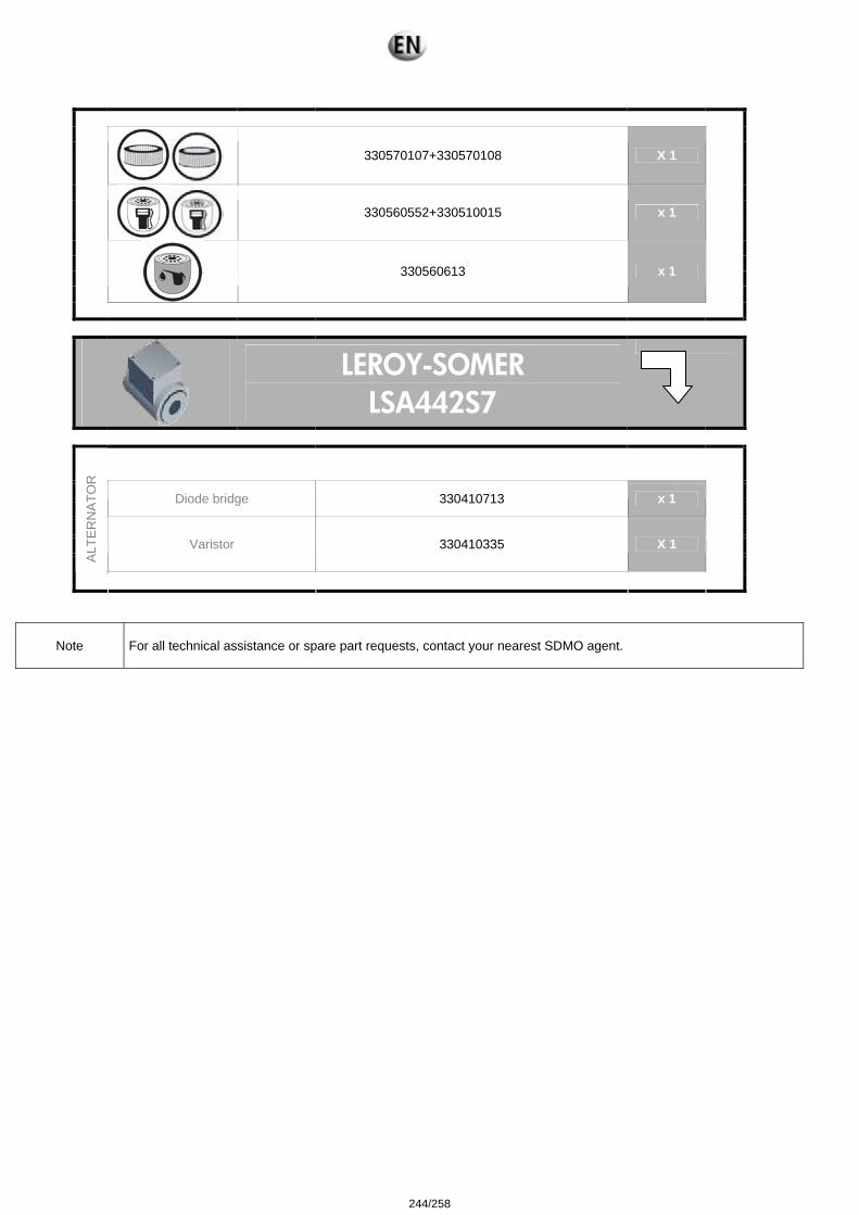
330570107+330570108 X 1
330560552+330510015 x 1
330560613 x 1
LEROY-SOMER LSA442S7
Diode bridge 330410713 x 1 Varistor 330410335 X 1 A
LTE
RN
ATO
R
Note For all technical assistance or spare part requests, contact your nearest SDMO agent.
244/258
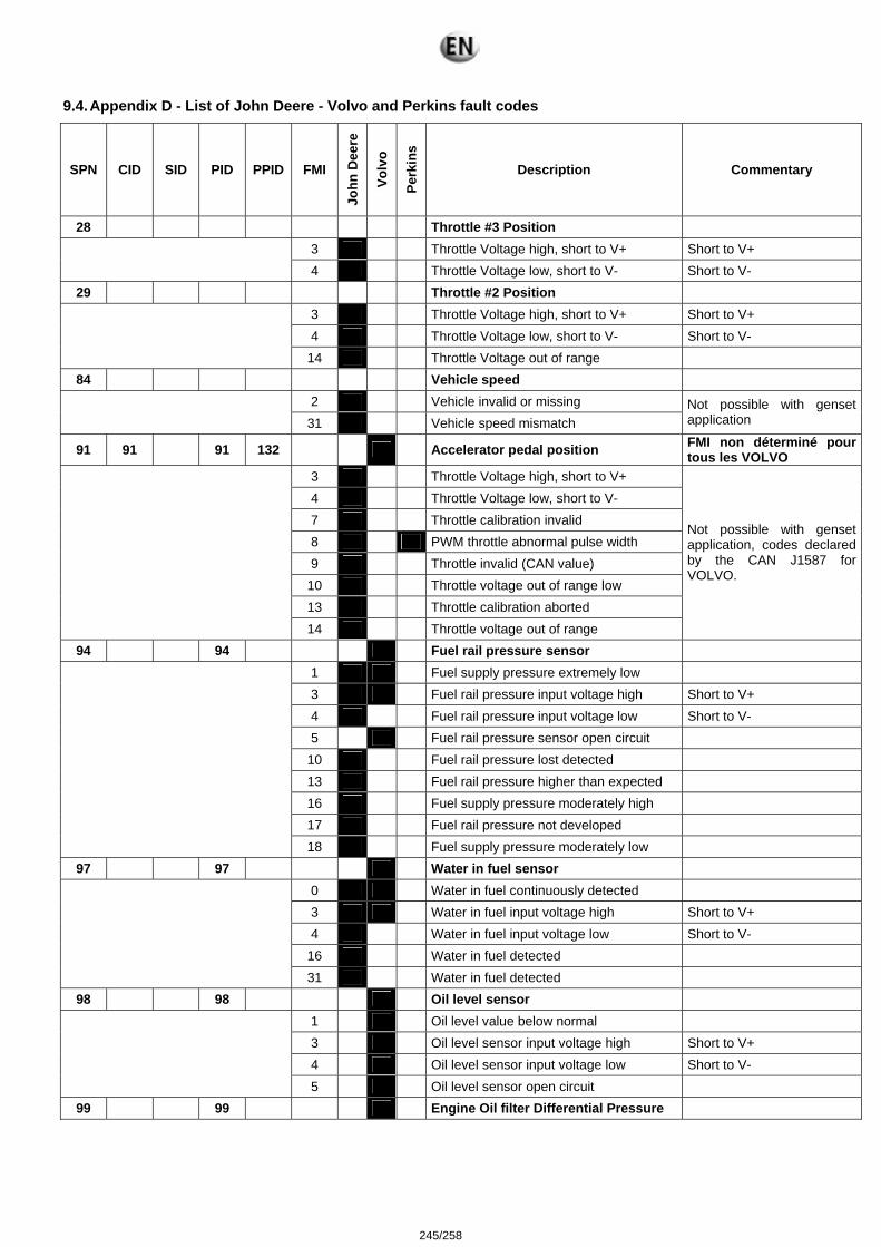
9.4. Appendix D - List of John Deere - Volvo and Perkins fault codes
SPN CID SID PID PPID FMI
John
Dee
re
Volv
o
Perk
ins
Description Commentary
28 Throttle #3 Position 3 Throttle Voltage high, short to V+ Short to V+
4 Throttle Voltage low, short to V- Short to V-
29 Throttle #2 Position 3 Throttle Voltage high, short to V+ Short to V+ 4 Throttle Voltage low, short to V- Short to V-
14 Throttle Voltage out of range 84 Vehicle speed
2 Vehicle invalid or missing
31 Vehicle speed mismatch Not possible with genset application
91 91 91 132 Accelerator pedal position FMI non déterminé pour tous les VOLVO
3 Throttle Voltage high, short to V+ 4 Throttle Voltage low, short to V- 7 Throttle calibration invalid 8 PWM throttle abnormal pulse width 9 Throttle invalid (CAN value)
10 Throttle voltage out of range low 13 Throttle calibration aborted
14 Throttle voltage out of range
Not possible with genset application, codes declared by the CAN J1587 for VOLVO.
94 94 Fuel rail pressure sensor 1 Fuel supply pressure extremely low 3 Fuel rail pressure input voltage high Short to V+ 4 Fuel rail pressure input voltage low Short to V- 5 Fuel rail pressure sensor open circuit
10 Fuel rail pressure lost detected 13 Fuel rail pressure higher than expected 16 Fuel supply pressure moderately high 17 Fuel rail pressure not developed
18 Fuel supply pressure moderately low 97 97 Water in fuel sensor
0 Water in fuel continuously detected 3 Water in fuel input voltage high Short to V+ 4 Water in fuel input voltage low Short to V-
16 Water in fuel detected
31 Water in fuel detected 98 98 Oil level sensor
1 Oil level value below normal 3 Oil level sensor input voltage high Short to V+ 4 Oil level sensor input voltage low Short to V-
5 Oil level sensor open circuit 99 99 Engine Oil filter Differential Pressure
245/258
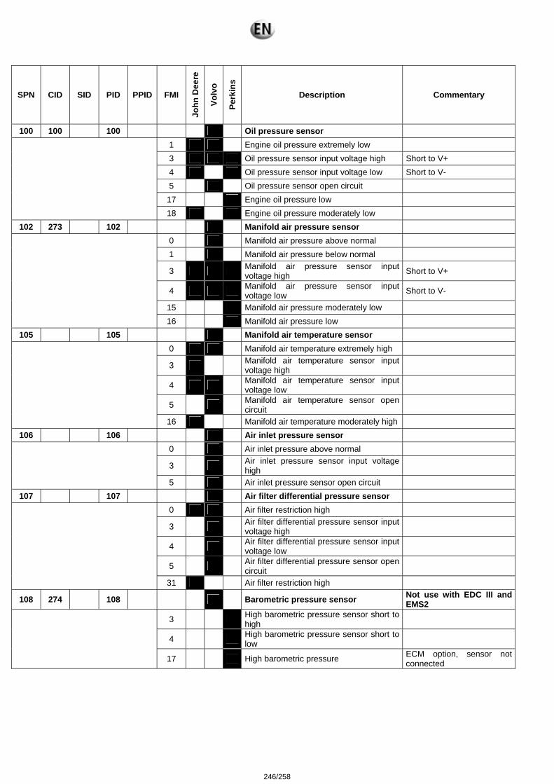
SPN CID SID PID PPID FMI
John
Dee
re
Volv
o
Perk
ins
Description Commentary
100 100 100 Oil pressure sensor 1 Engine oil pressure extremely low 3 Oil pressure sensor input voltage high Short to V+ 4 Oil pressure sensor input voltage low Short to V- 5 Oil pressure sensor open circuit
17 Engine oil pressure low
18 Engine oil pressure moderately low 102 273 102 Manifold air pressure sensor
0 Manifold air pressure above normal 1 Manifold air pressure below normal
3 Manifold air pressure sensor input voltage high Short to V+
4 Manifold air pressure sensor input voltage low Short to V-
15 Manifold air pressure moderately low
16 Manifold air pressure low 105 105 Manifold air temperature sensor
0 Manifold air temperature extremely high
3 Manifold air temperature sensor input voltage high
4 Manifold air temperature sensor input voltage low
5 Manifold air temperature sensor open circuit
16 Manifold air temperature moderately high 106 106 Air inlet pressure sensor
0 Air inlet pressure above normal
3 Air inlet pressure sensor input voltage high
5 Air inlet pressure sensor open circuit 107 107 Air filter differential pressure sensor
0 Air filter restriction high
3 Air filter differential pressure sensor input voltage high
4 Air filter differential pressure sensor input voltage low
5 Air filter differential pressure sensor open circuit
31 Air filter restriction high
108 274 108 Barometric pressure sensor Not use with EDC III and EMS2
3 High barometric pressure sensor short to high
4 High barometric pressure sensor short to low
17 High barometric pressure ECM option, sensor not connected
246/258
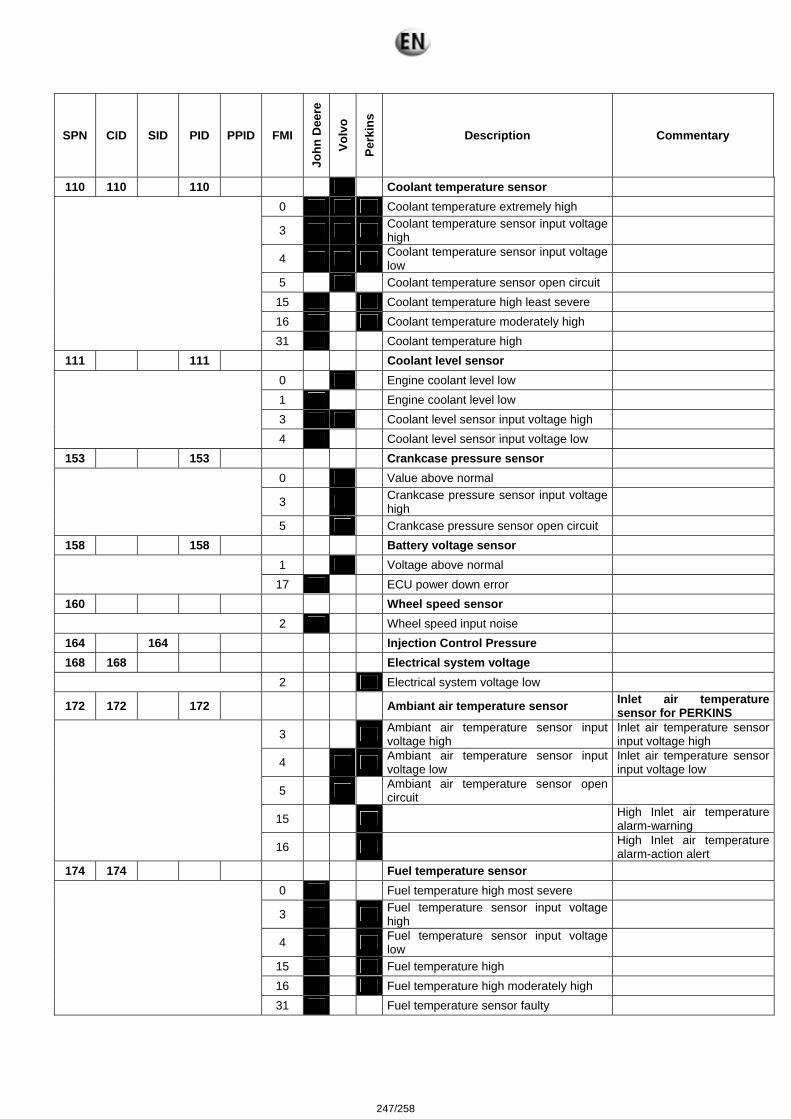
SPN CID SID PID PPID FMI
John
Dee
re
Volv
o
Perk
ins
Description Commentary
110 110 110 Coolant temperature sensor 0 Coolant temperature extremely high
3 Coolant temperature sensor input voltage high
4 Coolant temperature sensor input voltage low
5 Coolant temperature sensor open circuit 15 Coolant temperature high least severe 16 Coolant temperature moderately high
31 Coolant temperature high 111 111 Coolant level sensor
0 Engine coolant level low 1 Engine coolant level low 3 Coolant level sensor input voltage high
4 Coolant level sensor input voltage low 153 153 Crankcase pressure sensor
0 Value above normal
3 Crankcase pressure sensor input voltage high
5 Crankcase pressure sensor open circuit 158 158 Battery voltage sensor
1 Voltage above normal
17 ECU power down error 160 Wheel speed sensor
2 Wheel speed input noise 164 164 Injection Control Pressure 168 168 Electrical system voltage
2 Electrical system voltage low
172 172 172 Ambiant air temperature sensor Inlet air temperature sensor for PERKINS
3 Ambiant air temperature sensor input voltage high
Inlet air temperature sensor input voltage high
4 Ambiant air temperature sensor input voltage low
Inlet air temperature sensor input voltage low
5 Ambiant air temperature sensor open circuit
15 High Inlet air temperature alarm-warning
16 High Inlet air temperature alarm-action alert
174 174 Fuel temperature sensor 0 Fuel temperature high most severe
3 Fuel temperature sensor input voltage high
4 Fuel temperature sensor input voltage low
15 Fuel temperature high 16 Fuel temperature high moderately high
31 Fuel temperature sensor faulty
247/258
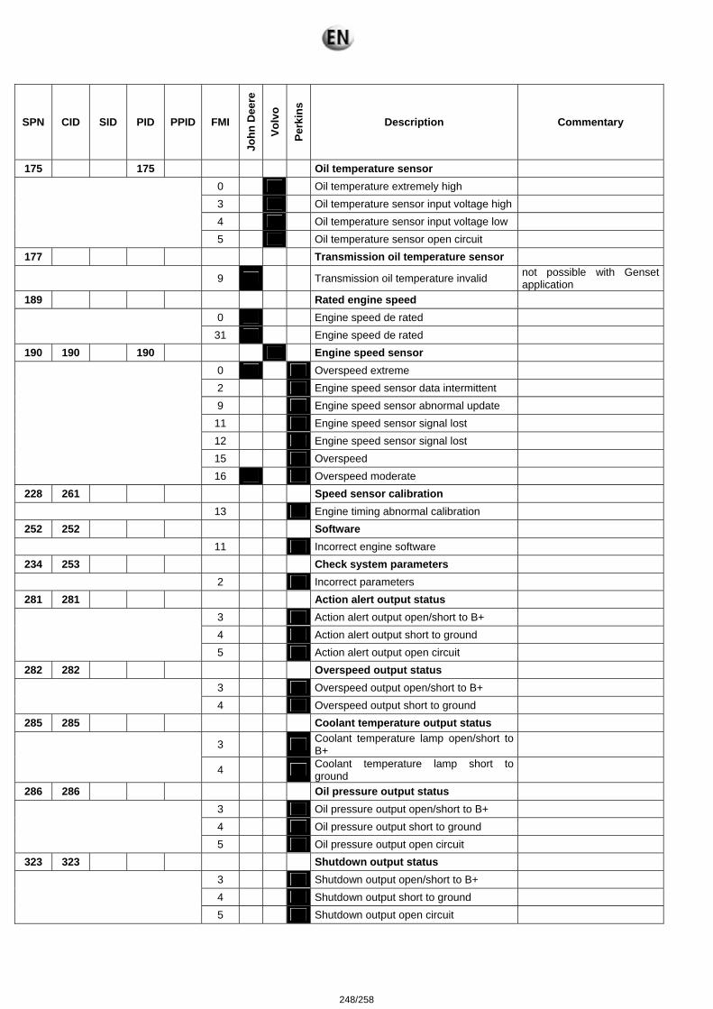
SPN CID SID PID PPID FMI
John
Dee
re
Volv
o
Perk
ins
Description Commentary
175 175 Oil temperature sensor 0 Oil temperature extremely high 3 Oil temperature sensor input voltage high 4 Oil temperature sensor input voltage low
5 Oil temperature sensor open circuit 177 Transmission oil temperature sensor
9 Transmission oil temperature invalid not possible with Genset application
189 Rated engine speed 0 Engine speed de rated
31 Engine speed de rated
190 190 190 Engine speed sensor 0 Overspeed extreme 2 Engine speed sensor data intermittent 9 Engine speed sensor abnormal update
11 Engine speed sensor signal lost 12 Engine speed sensor signal lost 15 Overspeed
16 Overspeed moderate 228 261 Speed sensor calibration
13 Engine timing abnormal calibration 252 252 Software
11 Incorrect engine software 234 253 Check system parameters
2 Incorrect parameters 281 281 Action alert output status
3 Action alert output open/short to B+ 4 Action alert output short to ground 5 Action alert output open circuit
282 282 Overspeed output status 3 Overspeed output open/short to B+
4 Overspeed output short to ground
285 285 Coolant temperature output status
3 Coolant temperature lamp open/short to B+
4 Coolant temperature lamp short to
ground
286 286 Oil pressure output status 3 Oil pressure output open/short to B+ 4 Oil pressure output short to ground 5 Oil pressure output open circuit
323 323 Shutdown output status 3 Shutdown output open/short to B+ 4 Shutdown output short to ground 5 Shutdown output open circuit
248/258
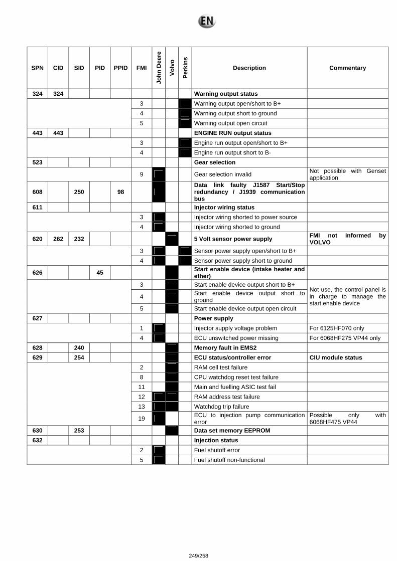
SPN CID SID PID PPID FMI
John
Dee
re
Volv
o
Perk
ins
Description Commentary
324 324 Warning output status 3 Warning output open/short to B+ 4 Warning output short to ground 5 Warning output open circuit
443 443 ENGINE RUN output status 3 Engine run output open/short to B+
4 Engine run output short to B-
523 Gear selection
9 Gear selection invalid Not possible with Genset application
608 250 98 Data link faulty J1587 Start/Stop redundancy / J1939 communication bus
611 Injector wiring status 3 Injector wiring shorted to power source
4 Injector wiring shorted to ground
620 262 232 5 Volt sensor power supply FMI not informed by VOLVO
3 Sensor power supply open/short to B+
4 Sensor power supply short to ground
626 45 Start enable device (intake heater and ether)
3 Start enable device output short to B+
4 Start enable device output short to ground
5 Start enable device output open circuit
Not use, the control panel is in charge to manage the start enable device
627 Power supply 1 Injector supply voltage problem For 6125HF070 only
4 ECU unswitched power missing For 6068HF275 VP44 only
628 240 Memory fault in EMS2 629 254 ECU status/controller error CIU module status
2 RAM cell test failure 8 CPU watchdog reset test failure
11 Main and fuelling ASIC test fail 12 RAM address test failure 13 Watchdog trip failure
19 ECU to injection pump communication error
Possible only with 6068HF475 VP44
630 253 Data set memory EEPROM 632 Injection status
2 Fuel shutoff error
5 Fuel shutoff non-functional
249/258
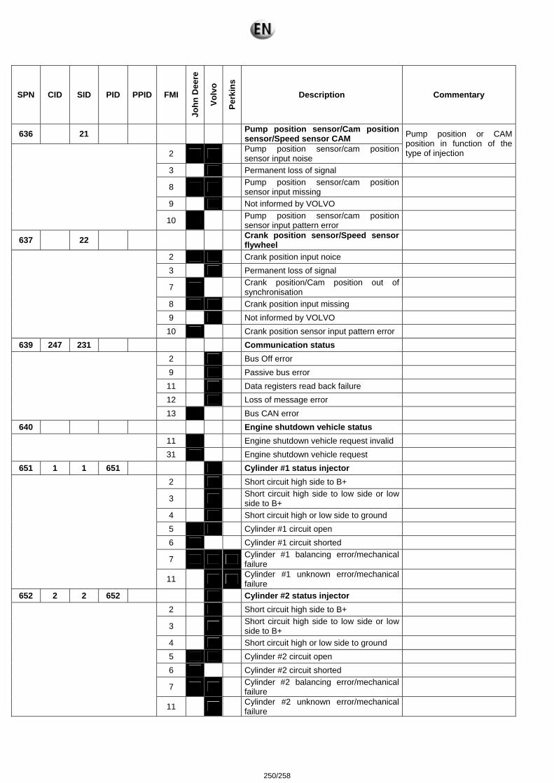
SPN CID SID PID PPID FMI
John
Dee
re
Volv
o
Perk
ins
Description Commentary
636 21 Pump position sensor/Cam position sensor/Speed sensor CAM
2 Pump position sensor/cam position sensor input noise
Pump position or CAM position in function of the type of injection
3 Permanent loss of signal
8 Pump position sensor/cam position sensor input missing
9 Not informed by VOLVO
10 Pump position sensor/cam position sensor input pattern error
637 22 Crank position sensor/Speed sensor flywheel
2 Crank position input noice 3 Permanent loss of signal
7 Crank position/Cam position out of synchronisation
8 Crank position input missing 9 Not informed by VOLVO
10 Crank position sensor input pattern error 639 247 231 Communication status
2 Bus Off error 9 Passive bus error
11 Data registers read back failure 12 Loss of message error
13 Bus CAN error 640 Engine shutdown vehicle status
11 Engine shutdown vehicle request invalid
31 Engine shutdown vehicle request 651 1 1 651 Cylinder #1 status injector
2 Short circuit high side to B+
3 Short circuit high side to low side or low side to B+
4 Short circuit high or low side to ground 5 Cylinder #1 circuit open 6 Cylinder #1 circuit shorted
7 Cylinder #1 balancing error/mechanical failure
11 Cylinder #1 unknown error/mechanical failure
652 2 2 652 Cylinder #2 status injector 2 Short circuit high side to B+
3 Short circuit high side to low side or low side to B+
4 Short circuit high or low side to ground 5 Cylinder #2 circuit open 6 Cylinder #2 circuit shorted
7 Cylinder #2 balancing error/mechanical failure
11 Cylinder #2 unknown error/mechanical failure
250/258

SPN CID SID PID PPID FMI
John
Dee
re
Volv
o
Perk
ins
Description Commentary
653 3 3 653 Cylinder #3 status injector 2 Short circuit high side to B+
3 Short circuit high side to low side or low side to B+
4 Short circuit high or low side to ground 5 Cylinder #3 circuit open 6 Cylinder #3 circuit shorted
7 Cylinder #3 balancing error/mechanical failure
11 Cylinder #3 unknown error/mechanical failure
654 4 4 654 Cylinder #4 status injector 2 Short circuit high side to B+
3 Short circuit high side to low side or low side to B+
4 Short circuit high or low side to ground 5 Cylinder #4 circuit open 6 Cylinder #4 circuit shorted
7 Cylinder #4 balancing error/mechanical failure
11 Cylinder #4 unknown error/mechanical failure
655 5 5 655 Cylinder #5 status injector 2 Short circuit high side to B+
3 Short circuit high side to low side or low side to B+
4 Short circuit high or low side to ground 5 Cylinder #5 circuit open 6 Cylinder #5 circuit shorted
7 Cylinder #5 balancing error/mechanical failure
11 Cylinder #5 unknown error/mechanical failure
656 6 6 656 Cylinder #6 status injector 2 Short circuit high side to B+
3 Short circuit high side to low side or low side to B+
4 Short circuit high or low side to ground 5 Cylinder #6 circuit open 6 Cylinder #6 circuit shorted 7 Cylinder #6 balancing error/mechanical failure
11 Cylinder #6 unknown error/mechanical failure 676 39 Glow plug relay status
3 Glow plug relay voltage high
5 Glow plug relay voltage low 677 3 Start relay status
3 Start relay control short circuit to high 4 Start relay control short circuit low 5 Start relay control open circuit
251/258
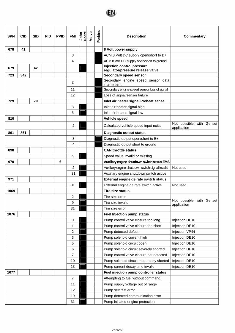
SPN CID SID PID PPID FMI
John
D
eere
Vo
lvo
Perk
ins
Description Commentary
678 41 8 Volt power supply 3 ACM 8 Volt DC supply open/short to B+
4 ACM 8 Volt DC supply open/short to ground
679 42 Injection control pressure regulator/pressure release valve
723 342 Secondary speed sensor
2 Secondary engine speed sensor data intermittent
11 Secondary engine speed sensor loss of signal
12 Loss of signal/sensor failure 729 70 Inlet air heater signal/Preheat sense
3 Inlet air heater signal high
5 Inlet air heater signal low 810 Vehicle speed
2 Calculated vehicle speed input noise Not possible with Genset application
861 861 Diagnostic output status 3 Diagnostic output open/short to B+
4 Diagnostic output short to ground
898 CAN throttle status 9 Speed value invalid or missing
970 6 Auxiliary engine shutdown switch status EMS 2 Auxiliary engine shutdown switch signal invalid Not used
31 Auxiliary engine shutdown switch active
971 External engine de rate switch status 31 External engine de rate switch active Not used
1069 Tire size status 2 Tire size error 9 Tire size invalid
31 Tire size error
Not possible with Genset application
1076 Fuel Injection pump status 0 Pump control valve closure too long Injection DE10 1 Pump control valve closure too short Injection DE10 2 Pump detected defect Injection VP44 3 Pump solenoid current high Injection DE10 5 Pump solenoid circuit open Injection DE10 6 Pump solenoid circuit severely shorted Injection DE10 7 Pump control valve closure not detected Injection DE10
10 Pump solenoid circuit moderately shorted Injection DE10
13 Pump current decay time invalid Injection DE10 1077 Fuel injection pump controller status
7 Attempting to fuel without command
11 Pump supply voltage out of range 12 Pump self test error 19 Pump detected communication error
31 Pump initiated engine protection
252/258
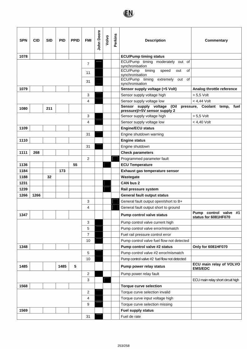
SPN CID SID PID PPID FMI
John
Dee
re
Volv
o
Perk
ins
Description Commentary
1078 ECU/Pump timing status
7 ECU/Pump timing moderately out of synchronisation
11 ECU/Pump timing speed out of synchronisation
31 ECU/Pump timing extremely out of synchronisation
1079 Sensor supply voltage (+5 Volt) Analog throttle reference 3 Sensor supply voltage high > 5,5 Volt
4 Sensor supply voltage low < 4,44 Volt
1080 211 Sensor supply voltage (Oil pressure, Coolant temp, fuel pressure)/+5V sensor supply 2
3 Sensor supply voltage high > 5,5 Volt
4 Sensor supply voltage low < 4,40 Volt 1109 Engine/ECU status
31 Engine shutdown warning 1110 Engine status
31 Engine shutdown 1111 268 Check parameters
2 Programmed parameter fault 1136 55 ECU Temperature 1184 173 Exhaust gas temperature sensor 1188 32 Wastegate 1231 CAN bus 2 1239 Rail pressure system 1266 1266 General fault output status
3 General fault output open/short to B+
4 General fault output short to ground
1347 Pump control valve status Pump control valve #1 status for 6081HF070
3 Pump control valve current high 5 Pump control valve error/mismatch 7 Fuel rail pressure control error
10 Pump control valve fuel flow not detected 1348 Pump control valve #2 status Only for 6081HF070
5 Pump control valve #2 error/mismatch
10 Pump control valve #2 fuel flow not detected
1485 1485 5 Pump power relay status ECU main relay of VOLVO EMS/EDC
2 Pump power relay fault
3 ECU main relay short circuit high 1568 Torque curve selection
2 Torque curve selection invalid 4 Torque curve input voltage high 9 Torque curve selection missing
1569 Fuel supply status 31 Fuel de rate
253/258
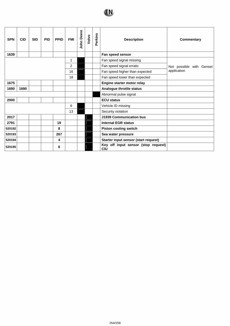
SPN CID SID PID PPID FMI
John
Dee
re
Volv
o
Perk
ins
Description Commentary
1639 Fan speed sensor 1 Fan speed signal missing 2 Fan speed signal erratic
16 Fan speed higher than expected
18 Fan speed lower than expected
Not possible with Genset application
1675 Engine starter motor relay 1690 1690 Analogue throttle status
Abnormal pulse signal 2000 ECU status
6 Vehicle ID missing
13 Security violation 2017 J1939 Communication bus 2791 19 Internal EGR status
520192 8 Piston cooling switch 520193 267 Sea water pressure 520194 4 Starter input sensor (start request)
520195 6 Key off input sensor (stop request) CIU
254/258
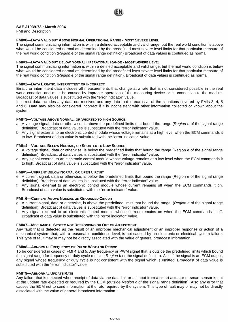
SAE J1939-73 : March 2004 FMI and Description FMI=0—DATA VALID BUT ABOVE NORMAL OPERATIONAL RANGE - MOST SEVERE LEVEL The signal communicating information is within a defined acceptable and valid range, but the real world condition is above what would be considered normal as determined by the predefined most severe level limits for that particular measure of the real world condition (Region e of the signal range definition) Broadcast of data values is continued as normal. FMI=1—DATA VALID BUT BELOW NORMAL OPERATIONAL RANGE - MOST SEVERE LEVEL The signal communicating information is within a defined acceptable and valid range, but the real world condition is below what would be considered normal as determined by the predefined least severe level limits for that particular measure of the real world condition (Region e of the signal range definition). Broadcast of data values is continued as normal. FMI=2—DATA ERRATIC, INTERMITTENT OR INCORRECT Erratic or intermittent data includes all measurements that change at a rate that is not considered possible in the real world condition and must be caused by improper operation of the measuring device or its connection to the module. Broadcast of data values is substituted with the “error indicator” value. Incorrect data includes any data not received and any data that is exclusive of the situations covered by FMIs 3, 4, 5 and 6. Data may also be considered incorrect if it is inconsistent with other information collected or known about the system. FMI=3—VOLTAGE ABOVE NORMAL, OR SHORTED TO HIGH SOURCE a. A voltage signal, data or otherwise, is above the predefined limits that bound the range (Region e of the signal range
definition). Broadcast of data values is substituted with the “error indicator” value. b. Any signal external to an electronic control module whose voltage remains at a high level when the ECM commands it
to low. Broadcast of data value is substituted with the “error indicator” value. FMI=4—VOLTAGE BELOW NORMAL, OR SHORTED TO LOW SOURCE c. A voltage signal, data or otherwise, is below the predefined limits that bound the range (Region e of the signal range
definition). Broadcast of data values is substituted with the “error indicator” value. d. Any signal external to an electronic control module whose voltage remains at a low level when the ECM commands it
to high. Broadcast of data value is substituted with the “error indicator” value. FMI=5—CURRENT BELOW NORMAL OR OPEN CIRCUIT e. A current signal, data or otherwise, is below the predefined limits that bound the range (Region e of the signal range
definition). Broadcast of data values is substituted with the “error indicator” value. f. Any signal external to an electronic control module whose current remains off when the ECM commands it on.
Broadcast of data value is substituted with the “error indicator” value. FMI=6—CURRENT ABOVE NORMAL OR GROUNDED CIRCUIT g. A current signal, data or otherwise, is above the predefined limits that bound the range. (Region e of the signal range
definition). Broadcast of data values is substituted with the “error indicator” value. h. Any signal external to an electronic control module whose current remains on when the ECM commands it off.
Broadcast of data value is substituted with the “error indicator” value. FMI=7—MECHANICAL SYSTEM NOT RESPONDING OR OUT OF ADJUSTMENT Any fault that is detected as the result of an improper mechanical adjustment or an improper response or action of a mechanical system that, with a reasonable confidence level, is not caused by an electronic or electrical system failure. This type of fault may or may not be directly associated with the value of general broadcast information. FMI=8—ABNORMAL FREQUENCY OR PULSE WIDTH OR PERIOD To be considered in cases of FMI 4 and 5. Any frequency or PWM signal that is outside the predefined limits which bound the signal range for frequency or duty cycle (outside Region b or the signal definition). Also if the signal is an ECM output, any signal whose frequency or duty cycle is not consistent with the signal which is emitted. Broadcast of data value is substituted with the “error indicator” value. FMI=9—ABNORMAL UPDATE RATE Any failure that is detected when receipt of data via the data link or as input from a smart actuator or smart sensor is not at the update rate expected or required by the ECM (outside Region c of the signal range definition). Also any error that causes the ECM not to send information at the rate required by the system. This type of fault may or may not be directly associated with the value of general broadcast information.
255/258
FMI=10—ABNORMAL RATE OF CHANGE Any data, exclusive of the abnormalities covered by FMI 2, that is considered valid but whose data is changing at a rate that is outside the predefined limits that bound the rate of change for a properly functioning system (outside Region c of the signal range definition). Broadcast of data values is continued as normal. FMI=11—ROOT CAUSE NOT KNOWN It has been detected that a failure has occurred in a particular subsystem but the exact nature of the fault is not known. Broadcast of data value is substituted with the “error indicator” value. FMI=12—BAD INTELLIGENT DEVICE OR COMPONENT Internal diagnostic procedures have determined that the failure is one which requires the replacement of the ECU, used here to mean the packaged unit that includes some microprocessor and its associated components and circuits. It can be assumed that the communications subsystem is not the part that has failed, and the manufacturer has determined that there is no serviceable component smaller than the ECU involved in the failure. Broadcast of data value is substituted with the “error indicator” value if appropriate, as there may or may not be any broadcast involved. This error is to include all internal controller trouble codes that can not be caused by connections or systems external to the controller. FMI=13—OUT OF CALIBRATION A failure that can be identified to be the result of not being properly calibrated. This may be the case for a subsystem which can identify that the calibration attempting to be used by the controller is out of date. Or it may be the case that the mechanical subsystem is determined to be out of calibration. This failure mode does not relate to the signal range definition as do many of the FMIs. FMI=14—SPECIAL INSTRUCTIONS “Special Instructions” is the FMI to be used when the on-board system can isolate the failure to a small number of choices but not to a single point of failure. When the FMI is used, there is clear necessity for the service technician to take some action to complete the specific diagnosis, and the manufacturer has provided instructions for the completion of that diagnosis. There are two cases where this will be used: 1. for emission-related diagnostics where the particular failure cannot be separated between a sensor out of range and the case where the actual value is at the edge of a diagnostic region, and 2. for the older SPN 611 to 615 where the problem is in determining which of two or more circuits (which may interact) is the one that needs repair. SPNs 611 through 615 are defined as “System Diagnostic Codes” and are used to identify failures that cannot be tied to a specific field replaceable component. Specific subsystem fault isolation is the goal of any diagnostic system, but for various reasons this cannot always be accomplished. These SPNs allow the manufacturer some flexibility to communicate non-“specific component” diagnostic information. Since SPNs 611-615 use the standard SPN/FMI format it allows the use of standard diagnostic tools, electronic dashboards, satellite systems and other advanced devices that scan Parameter Groups containing the SPN/FMI formats. Because manufacturer defined codes are not desirable in terms of standardization, the use of these codes should only occur when diagnostic information cannot be communicated as a specific component and failure mode. Possible reasons for using a System Diagnostic Code include:
1. Cost of specific component fault isolation is not justified, or 2. New concepts in Total Vehicle Diagnostics are being developed, or 3. New diagnostic strategies that are not component specific are being developed.
Due to the fact that SPNs 611-615 are manufacturer defined and are not component specific, FMIs 0-13 and 15-31 have little meaning. Therefore, FMI 14, “Special Instructions”, is usually used. The goal is to refer the service personnel to the manufacturer's troubleshooting manual for more information on the particular diagnostic code. This failure mode does not relate to the signal range definition as do many of the FMIs. This type of fault may or may not be directly associated with the value of general broadcast information. FMI=15—DATA VALID BUT ABOVE NORMAL OPERATING RANGE - LEAST SEVERE LEVEL The signal communicating information is within a defined acceptable and valid range, but the real world condition is above what would be considered normal as determined by the predefined least severe level limits for that particular measure of the real world condition (Region i of the signal range definition). Broadcast of data values is continued as normal. FMI=16—DATA VALID BUT ABOVE NORMAL OPERATING RANGE - MODERATELY SEVERE LEVEL The signal communicating information is within a defined acceptable and valid range, but the real world condition is above what would be considered normal as determined by the predefined moderately severe level limits for that particular measure of the real world condition (Region k of the signal range definition). Broadcast of data values is continued as normal.
256/258
FMI=17—DATA VALID BUT BELOW NORMAL OPERATING RANGE - LEAST SEVERE LEVEL The signal communicating information is within a defined acceptable and valid range, but the real world condition is below what would be considered normal as determined by the predefined least severe level limits for that particular measure of the real world condition (Region h of the signal range definition). Broadcast of data values is continued as normal. FMI=18—DATA VALID BUT BELOW NORMAL OPERATING RANGE - MODERATELY SEVERE LEVEL The signal communicating information is within a defined acceptable and valid range, but the real world condition is below what would be considered normal as determined by the predefined moderately severe level limits for that particular measure of the real world condition (Region j of the signal range definition). Broadcast of data values is continued as normal. FMI=19—RECEIVED NETWORK DATA IN ERROR Any failure that is detected when the data received via the network is found substituted with the “error indicator” value (i.e. FE16, see J1939-71). This type of failure is associated with received network data. The component used to measure the real world signal is wired directly to the module sourcing the data to the network and not to the module receiving the data via the network. The FMI is applicable to Region f and g of the signal range definition. This type of fault may or may not be directly associated with the value of general broadcast information. FMI=20-30—RESERVED FOR SAE ASSIGNMENT FMI=31—CONDITION EXISTS Used to indicate that the condition that is identified by the SPN exists when no more applicable FMI exists or in cases when the reported SPN name spells out the component and a non-standard failure mode. This type of fault may or may be directly associated with the value of general broadcast information. This FMI will mean “not available” when the associated SPN is also “not available” as when the remainder of the packet is filled with binary ones after all data has been transmitted.
257/258

258/258