FY98 Space and Missiles Technology Area Plan
40
FY98 SPACE AND MISSILES TECHNOLOGY AREA PLAN HEADQUARTERS AIR FORCE MATERIEL COMMAND DIRECTORATE OF SCIENCE & TECHNOLOGY WRIGHT PATTERSON AFB, OH DISTRIBUTION A. Approved for Public Release; distribution unlimited.
-
Upload
khangminh22 -
Category
Documents
-
view
0 -
download
0
Transcript of FY98 Space and Missiles Technology Area Plan
FY98 SPACE AND MISSILES
TECHNOLOGY AREA PLAN
HEADQUARTERS AIR FORCE MATERIEL COMMAND DIRECTORATE OF SCIENCE & TECHNOLOGY
WRIGHT PATTERSON AFB, OH DISTRIBUTION A. Approved for Public Release; distribution unlimited.
INTERNET DOCUMENT INFORMATION FORM
A . Report Title: FY98 Space and Missiles Technology Area Plan
B. DATE Report Downloaded From the Internet -25 Feb 98
C. Report's Point of Contact: (Name, Organization, Address, Office Symbol, & Ph #): HQ AF Materiel Cmd, Wright Patterson AFB, OH
D. Currently Applicable Classification Level: Unclassified
E. Distribution Statement A: Approved for Public Release
F. The foregoing information was compiled and provided by: DTIC-OCA, Initials: ,2 /27 Preparation Date:-25 Feb 98
The foregoing information should exactly correspond to the Title, Report Number, and the Date on the accompanying report document. If there are mismatches, or other questions, contact the above OCA Representative for resolution.
"Note: This Technology Area Plan (TAP) is a planning document for the FY98-03 S&T program and is based on the President's FY98 Budget Request. It does not reflect the impact of the FY98 Congressional appropriations and FY98-03 budget actions. You should consult PLIXP, DSN 246- 4962 or Commercial (505) 846-4962 for specific impacts that the FY98 appropriation may have had with regard to the contents of this particular TAP. This document is current as of 1 June 1997."
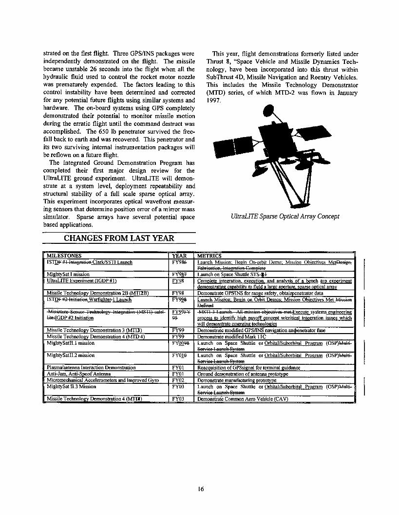
About the cover:
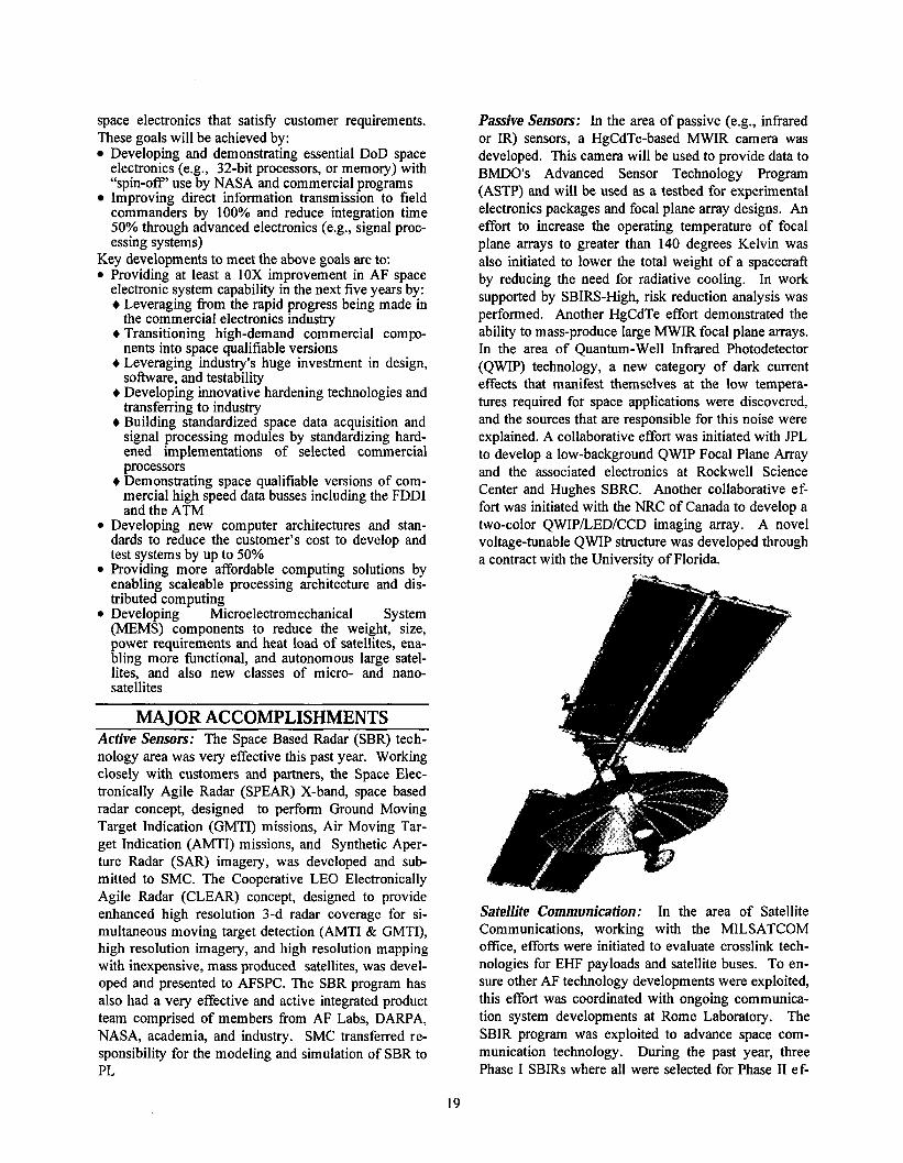
Pictured on the cover is an artist's concept of the MightySat I1 spacecraft. Orderly and routine dan- onstrations provide flight heritage of emerging space and missile technologies prior to their transition to the operational user. MightySat I1 is a three-axis stabilized spacecraft generating 325 watts of power for satellite and payload operations. The first of a series of five spacecraft will fly in FYOO, flying nine experiments developed under the Space and Missiles and Directed Energy TAPS. Among the Space and Missile technologies aboard MightySat I1 are multifunctional structures, the isogrid solar array, composite structures, shape memory alloys and Microsystem and Packaging for Low Power Electronics (MAPLE). MightySat is tailored to fly technologies developed within the Air Force laboratories and supports the test of payloads as well as experimental bus components.
VISIONS & OPPORTUNITIES S ~ a c e & Missiles 1
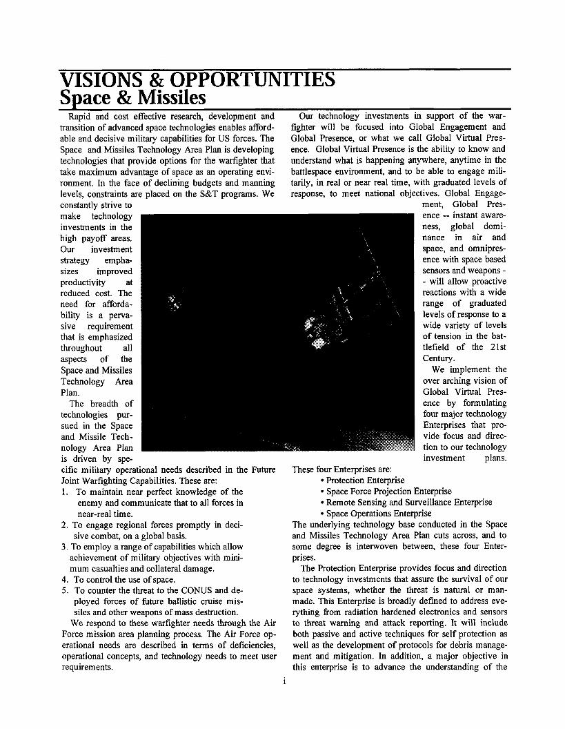
Rapid and cost effective research, development and transition of advanced space technologies enables afford- able and decisive military capabilities for US forces. The Space and Missiles Technology Area Plan is developing technologies that provide options for the warfighter that take maximum advantage of space as an operating envi- ronment. In the face of declining budgets and manning levels, constraints are placed on the S&T programs. We constantly strive to make technology investments in the high payoff areas. Our investment strategy empha- sizes improved productivity at reduced cost. The need for afforda- bility is a perva- sive requirement that is emphasized throughout all aspects of the Space and Missiles Technology Area Plan.
The breadth of technologies pur- sued in the Space and Missile Tech- nology Area Plan is driven by spe-
Our technology investments in support of the war- fighter will be focused into Global Engagement and Global Presence, or what we call Global Virtual Pres- ence. Global Virtual Presence is the ability to know and understand what is happening anywhere, anytime in the battlespace environment, and to be able to engage mili- tarily, in real or near real time, with graduated levels of response, to meet national objectives. Global Engage-
ment, Global Pres-
cific military operational needs described in the Future Joint Warfighting Capabilities. These are: 1. To maintain near perfect knowledge of the
enemy and communicate that to all forces in near-real time.
2. To engage regional forces promptly in deci- sive combat, on a global basis.
3. To employ a range of capabilities which allow achievement of military objectives with mini- mum casualties and collateral damage.
4. To control the use of space. 5. To counter the threat to the C O W S and de-
ployed forces of future ballistic cruise mis- siles and other weapons of mass destruction.
We respond to these warfighter needs through the Air Force mission area planning process. The Air Force op- erational needs are described in terms of deficiencies, operational concepts, and technology needs to meet user requirements.
1
ence -- instant aware- ness, global domi- nance in air and space, and omnipres- ence with space based sensors and weapons - - will allow proactive reactions with a wide range of graduated levels of response to a wide variety of levels of tension in the bat- tlefield of the 21st Century.
We implement the over arching vision of Global Virtual Pres- ence by formulating four major technology Enterprises that pro- vide focus and direc- tion to our technology investment plans.
These four Enterprises are: Protection Enterprise Space Force Projection Enterprise Remote Sensing and Surveillance Enterprise Space Operations Enterprise
The underlying technology base conducted in the Space and Missiles Technology Area Plan cuts across, and to some degree is interwoven between, these four Enter- prises.
The Protection Enterprise provides focus and direction to technology investments that assure the survival of our space systems, whether the threat is natural or man- made. This Enterprise is broadly defined to address eve- rything from radiation hardened electronics and sensors to threat warning and attack reporting. It will include both passive and active techniques for self protection as well as the development of protocols for debris manage- ment and mitigation. In addition, a major objective in this enterprise is to advance the understanding of the
effects of interactions between the environment and military systems and provide guidance to designers of advanced systems to ensure increased survivability and reduced weight and cost. Our space assets and capabili- ties must have assured survivability at any level of adver- sarial hostility.
The Space Force Projection Enterprise provides focus and direction to technology investments that address the application of force fi-om and through space to points in space, in the air and on the ground. The scope of this Enterprise is wide and includes leading technology ini- tiatives in areas such as the Military Space Plane, Space Based Lasers and ballistic missile systems. Though cur- rent treaty implications limit the actual fielding of weap- ons in space, low end capabilities providing entry levels of graduated deterrence are needed now. The technology base required to met future space weapon needs must be developed and matured today if it is to be available for future warfighter needs.
The Remote Sensing and Surveillance Enterprise pro- vides focus and direction to active and passive technology investments that assure innovative and revolutionary techniques for detecting and determining adversarial threats. This investment will form the foundation of the tactical situation awareness for the 2 1 st Century. Class i- cal, wide area surveillance will continue to be a critical Air Force mission area, but this Enterprise will specifi- cally address advanced technologies for tactical theater area interrogation and high value targeting that will be used for cueing other sensor and weapon systems. A critical part of theater information will be the knowledge of the battlespace environment, and this Enterprise will provide the capability to observe, model, and predict en- vironmental conditions encountered by the warfighter at any time, anywhere on the globe. These revolutionary remote sensing tools will allow a level of situational awareness on the ground, in the air and in space that has never before been available to the warfighter.
The Space Operations Enterprise provides focus and direction to technology investments critical to the in-creasingly important operation of the Air Force in space. Satellite autonomous operation will usher in a new era of "information on demand" satellite systems, with inter- connected constellations of satellites precisely providing the information that the warfighter needs, when it's
needed, where it's needed. Mobility in space coupled with less expensive and easier access to space is a key to Air Force dominance of the space arena. Decision aids must be developed for mission planning and operations that specify the expected performance of military systems based on anticipated conditions in the environment. The Air Force of the 21st Century will have to move in and through space with the same ease that it now moves in and through the atmosphere. Orbit transfer propulsion systems will be key to this essential capability. Space systems will cost less, last longer, and perform better through improved capabilities in payload thermal ma& agement; payload stabilization; power generation, storage and management; on-board processing capability, data processing and communication. Deploying these capa- bilities in the space environment will be made more af- fordable through investments in lighter and higher per- formance lift systems, improvements in design, integm tion, and operation processes, component weight reduc- tion, and operation and control technologies.
To meet these aggressive goals for the Air Force's role in Space, we will leverage our efforts with industry and other government agencies to mutually exploit technol- ogy innovation as part of our vision for future technology development and transition. An emphasis is placed on direct commercial exploitation, assessment of commer- cial off-the-shelf technology for military application, and cooperative research and development with industry, academia and other space focused government organiza- tions.
The situational awareness afforded throughout the bat- tlespace -- on the surface of the earth, in the air and in space -- provides the means for aerospace supremacy, enabling the full range of options for other weapons sys- tems employed in the theater. These investments provide the nation not only a precision, global strike capability with minimum casualties and collateral damage, but also the possibility of strategic deterrence, flexible responses, and the ability to influence events in real time, thereby providing the warfighter with a continuous range of re- sponse options, varying from lethal to non-lethal. This is Global Virtual Presence and this is the vision of the Space and Missiles Technology Area Plan. We have the opportunity to lead the Air Force into the Space Force of the 2 1st Century.
"This plan has been reviewed by all Air Force laboratory comrnanders/directors and reflects integrated Air Force technology planning. I request Air Force Acquisition Executive approval of the plan. "
RICHARD R. PAUL MICHAEL L. HEIL, Colonel, USAF Major General, USAF Commander Technology Executive Officer Phillips Laboratory
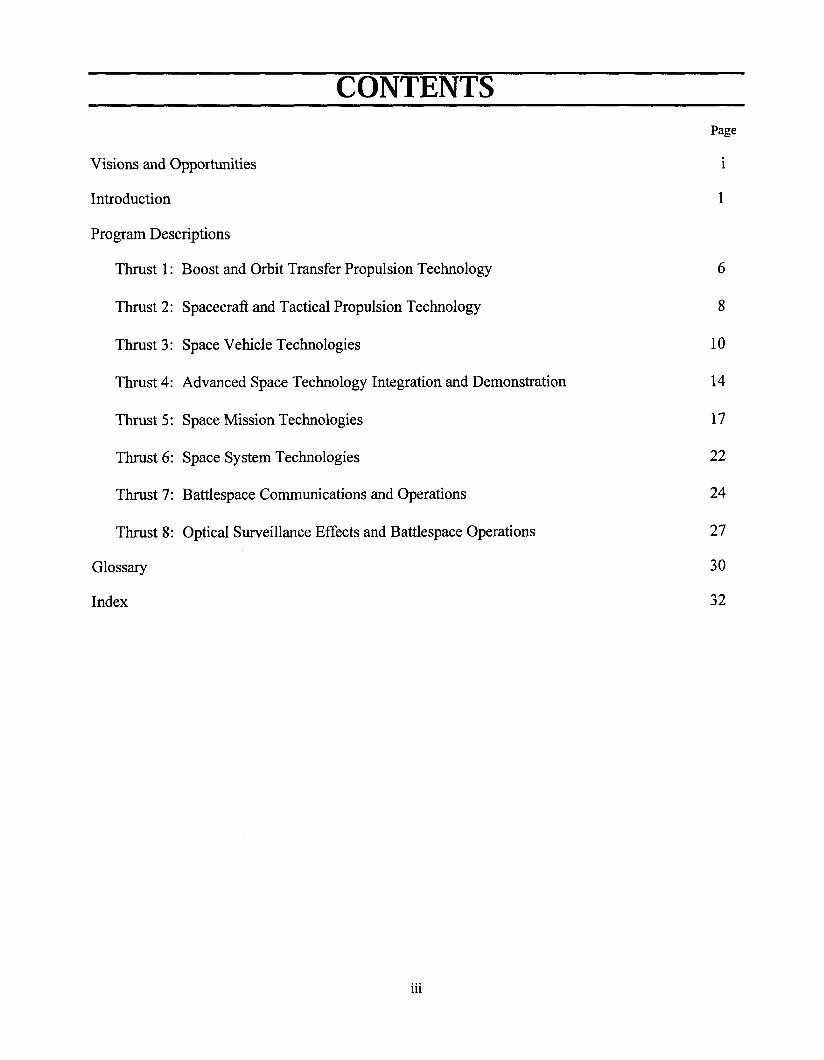
CONTENTS Page
Visions and Opportunities 1
Introduction 1
Program Descriptions
Thrust 1: Boost and Orbit Transfer Propulsion Technology
Thrust 2: Spacecraft and Tactical Propulsion Technology
Thrust 3: Space Vehicle Technologies
Thrust 4: Advanced Space Technology Integration and Demonstration
Thrust 5: Space Mission Technologies
Thrust 6: Space System Technologies
Thrust 7: Battlespace Communications and Operations
Thrust 8: Optical Surveillance Effects and Battlespace Operations
Glossary
Index

This page is intentionally blank.

INTRODUCTION Space & Missiles
BACKGROUND The Space and Missiles Technology Area, highlighted
in Figure 1, is that part of the Air Force Science and Technology (S&T) Program charged with developing evolutionary and revolutionary technology for space and ballistic missile systems. It also includes the former Geophysics Technology Area, which advances Air Force warfighting capabilities by providing technology to de-fine, understand, and control interactions between all Air Force systems and their battlespace environment.
The programming reflected in this Technology Area Plan (TAP) is coordinated and aligned with various Technical Planning Integrated Product Teams (TPIPT) to address user requirements and provide visionary oppor- tunities for technology push. The TPIPTs, in turn, re-ceive far- and near-term requirements of the space and missile community both through the validated MAJCOM requirements in the Mission Need Statements, Opera- tioial Requirements Documents, and Mission ~rea-p lan (MAP) ~eficiencies. Technology requirements to SUP- Port advanced systems are generated by the Product Divi-sions with laboratory support. Both technology push and
AFAE I
I
pull enable substantial payoffs for AF systems. I
Estimated AF S&T Budget for FY98: 1.203 B
AF S&T Balance n
-
Figure 2: S&M S&T $ vs AF S&T $
hi^ document details the implementation of the Space Force Enhancement TPIPTs' technology development plans and includes needs, goals, major accomplishments, and changes from last
1 I I I WRIGHT ROME PHILUPS
& POWER
AIR VEHICLES I
MATERIALS& PROCESSES 1
Figure 1: Air Force Science and Technology Program Structure
The program de-scribed in this TAP is subject to change based on possible congres-sional action.
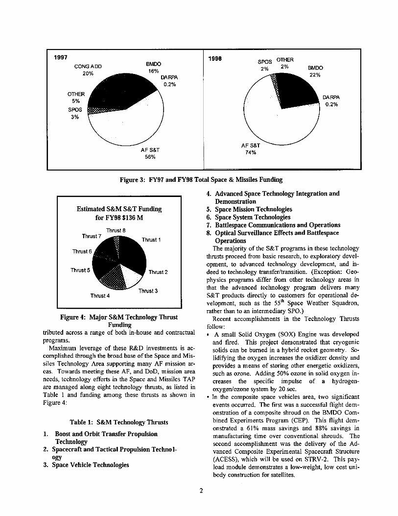
The President's FY98 Budget Request includes an AF S&T funding total to Phillips Laboratory (PL) ap-proaching $136M to perform exploratory and advanced technol- ogy development for the Space and Missiles Technology Area (ref. Figure 2). Additionally, Ballistic Missile De-fense Organization (BMDO), Defense Advanced Research Projects Agency (DARPA), NASA, and others also provide sig- nificant funding to PL for Space and Missile S&T (ref. Figure 3). The total budget is dis-
CONG ADD SPOS OTHER
BMDO
Figure 3: FY97 and FY98 Total Space & Missiles Funding
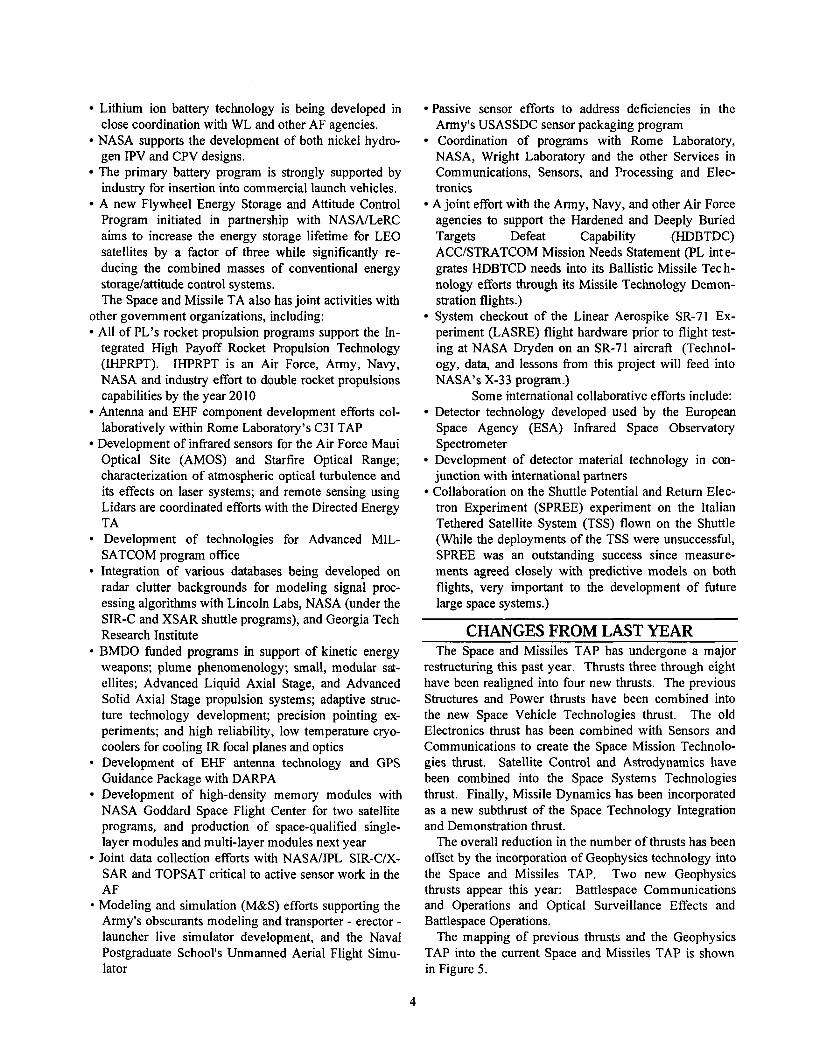
Estimated S&M S&T Funding for FY98 $136 M
Thrust 8
Thrust 4
Figure 4: Major S&M Technology Thrust Funding
tributed across a range of both in-house and contractual programs.
Maximum leverage of these R&D investments is ac- complished through the broad base of the Space and Mis- siles Technology Area supporting many AF mission ar- eas. Towards meeting these AF, and DoD, mission area needs, technology efforts in the Space and Missiles TAP are managed along eight technology thrusts, as listed in Table 1 and funding among these thrusts as shown in Figure 4:
Table 1: S&M Technology Thrusts
1. Boost and Orbit Transfer Propulsion Technology
2. Spacecraft and Tactical Propulsion Techno 1- o m
3. Space Vehicle Technologies
4. Advanced Space Technology Integration and Demonstration
5. Space Mission Technologies 6. Space System Technologies 7. Battlespace Communications and Operations 8. Optical Surveillance Effects and Battlespace
Operations The majority of the S&T programs in these technology
thrusts proceed from basic research, to exploratory devel- opment, to advanced technology development, and m- deed to technology transferltransition. (Exception: Geo- physics programs differ fiom other technology areas in that the advanced technology program delivers many S&T products directly to customers for operational de- velopment, such as the 55" Space Weather Squadron, rather than to an intermediary SPO.)
Recent accomplishments in the Technology Thrusts follow:
A small Solid Oxygen (SOX) Engine was developed and fired. This project demonstrated that cryogenic solids can be burned in a hybrid rocket geometry. So- lidifying the oxygen increases the oxidizer density and provides a means of storing other energetic oxidizers, such as ozone. Adding 50% ozone in solid oxygen in- creases the specific impulse of a hydrogen- oxygenlozone system by 20 sec. In the composite space vehicles area, two significant events occurred. The first was a successful flight dem- onstration of a composite shroud on the BMDO Com- bined Experiments Program (CEP). This flight dem- onstrated a 61% mass savings and 88% savings in manufacturing time over conventional shrouds. The second accomplishment was the delivery of the Ad- vanced Composite Experimental Spacecraft Structure (ACESS), which will be used on STRV-2. This pay- load module demonstrates a low-weight, low cost uni- body construction for satellites.

The multi-junction ManTech Solar Cell program dem- onstrated a photovoltaic array with a lot average con- version efficiency of 24.2% for the first time. This rep- resents a 33% improvement over conventional GaAs solar cells and paves the way for meeting the higher power requirements of future communications satel- lites. The thermal management technology area had a suo cessfbl flight demonstration of the liquid metal heat pipe on STS-77. This demonstrated the highest ever operating temperature for a heat pipe, approximately 900°C. A flight of the Missile Technology Demonstration 2 (MTD 2) was conducted on 29 January 1997. MTD 2 tested range safety, missile electronics, and penetrator technologies for ballistic missiles. MTD 2 utilized an active on-board differential GPStIMU for flight navi- gation in addition to the range safety metrics demon- strated on the flight's predecessor, MTD 1. Three GPS/INS packages were independently demonstrated on the flight. By reconfiguring the design of the Advanced Technol- ogy Insertion Module Single Board Computer and us- ing an advanced Aluminum Nitride substrate, a dou- ble-sided 32-Bit Multichip Module (MCM) was suc- cessfblly designed and prototyped. This design re- duced the weight by lox , size by 15X and provided the same functionality as the larger version. Through innovative design and advanced packaging applications, a credit-card-size, 70V bus, >90% effi- cient distributed payload power converter (EHF Pay- load Power Converter) was developed. The new design eliminates virtually 80 pounds per converter, and re- duces the volume fiom - 3 cu-ft to -0.001 cu-ft.
A GPS Anti-Jam Filter was developed that removes the effects of five jamming frequencies of various nanow- band formats and reconstructs the GPS signal with greater than a 95% accuracy. The design was imple- mented after first pass successes for an adaptive trans- fer filter and a 12-bit analog-to-digital converter. The module can be used in a real sampling-double channel mode of a complex sampling-single channel mode; if two modules are used, complex sampling-double chan- nel mode can be implemented. A prototype Scintillation Network Decision Aid
(SCINDA) was installed at 55SWS to provide the war- fighter with SATCOM outage regions and help plan for such outages andlor degradation of navigation. This aid also helps identify the source of the outage: equipment failure, jamming or ionospheric effect.
Research in energetic materials flows directly into the Applied Research In Energy Storage (ARIES) program investigating High Energy Density Matter (HEDM) Aerospace science research feeds investigations of com- bustion mechanisms, plume phenomena, and plasma diagnostics Space vehicle efforts benefit fiom basic research in
spacecraft dynamics and control phenomena Theoretical chemistry research in reactions of atmos-
pheric species contribute to models of atmospheric ra- diance used by BMDO Atmospheric sciences research improves atmospheric
prediction capabilities to understand atmospheric dy- namics and impacts on communications and surveil- lance systems Space science research is critical to the development of future Air Weather Service space weather prediction models and future Air Force space surveillance systems. Wright Laboratory (WL) provides manufacturing and
materials technology development for several thrusts: Manufacturing Technology (MANTECH) provides
methodologies for scaling research materials into pro- duction quantities. Selected propulsion technology components have been carried fiom exploratory through advanced development and become candidates for MANTECH demonstrations. The Materials Tech- nology Area (WLIML) develops materials and proc- esses for lightweight structural applications, high- efficiency multi-junction solar cells, high temperature rocket engines, thermal protection, sensors and com- munication, and survivability fiom laser threats. In a partnership with PL, WL/ML transitions materials technologies to support PL satellite, launch, and pro- pulsion technologies. Other examples of cooperative programs with WL in- clude obtaining infiared (IR) signatures and predictive models of aircraft for Air Vehicles. Geophysics pro- grams lead in working with the Avionics TA in using Lidar to measure winds aloft as well as aiding in de- fining trajectories of bombs. Avionics leads in using Lidar to correct the trajectories of cargo, pallets, and projectiles originating from aircraft. Rome Laboratory conducts joint ionospheric radio fie-
quency (RF) propagation experiments; and Armstrong Laboratories is provided with space radiation human hazard data.
Rome Laboratory (RL) and WL conduct 6.1 and 6.2 technology programs in the areas of antennas, component reliability, software, photonics, communications, and signal processing, which have been transitioned to PL 6.2 and 6.3 technology efforts.
RELATIONSHIP TO OTHER PL is an active member on joint government and in- TECHNOLOGY PROGRAMS dustry teams working to develop space power technolo-
The Air Force OfFice of Scientific Research (AFOSR) gies for and secondary spacecraft systems: supports numerous PL basic research efforts including:
Lithium ion battery technology is being developed in close coordination with WL and other AF agencies.
NASA supports the development of both nickel hydro- gen IPV and CPV designs. The primary battery program is strongly supported by industry for insertion into commercial launch vehicles. A new Flywheel Energy Storage and Attitude Control Program initiated in partnership with NASAILeRC aims to increase the energy storage lifetime for LEO satellites by a factor of three while significantly re- ducing the combined masses of conventional energy storage/attitude control systems. The Space and Missile TA also has joint activities with
other government organizations, including: All of PL's rocket propulsion programs support the In- tegrated High Payoff Rocket Propulsion Technology (IHPRPT). IHPRPT is an Air Force, Army, Navy, NASA and industry effort to double rocket propulsions capabilities by the year 20 10 Antenna and EHF component development efforts col- laboratively within Rome Laboratory's C31 TAP
Development of infrared sensors for the Air Force Maui Optical Site (AMOS) and Starfue Optical Range; characterization of atmospheric optical turbulence and its effects on laser systems; and remote sensing using Lidars are coordinated efforts with the Directed Energy TA Development of technologies for Advanced MIL- SATCOM program ofice Integration of various databases being developed on radar clutter backgrounds for modeling signal proc- essing algorithms with Lincoln Labs, NASA (under the SIR-C and XSAR shuttle programs), and Georgia Tech Research Institute BMDO funded programs in support of kinetic energy weapons; plume phenomenology; small, modular sat- ellites; Advanced Liquid Axial Stage, and Advanced Solid Axial Stage propulsion systems; adaptive struc- ture technology development; precision pointing ex- periments; and high reliability, low temperature cryo- coolers for cooling IR focal planes and optics Development of EHF antenna technology and GPS Guidance Package with DARPA Development of high-density memory modules with NASA Goddard Space Flight Center for two satellite programs, and production of space-qualified single- layer modules and multi-layer modules next year Joint data collection efforts with NASMJPL SIR-C/X- SAR and TOPSAT critical to active sensor work in the AF Modeling and simulation (M&S) efforts supporting the Army's obscurants modeling and transporter - erector - launcher live simulator development, and the Naval Postgraduate School's Unmanned Aerial Flight Simu- lator
Passive sensor efforts to address deficiencies in the Army's USASSDC sensor packaging program Coordination of programs with Rome Laboratory, NASA, Wright Laboratory and the other Services in Communications, Sensors, and Processing and Elec- tronics A joint effort with the Army, Navy, and other Air Force agencies to support the Hardened and Deeply Buried Targets Defeat Capability (HDBTDC) ACC/STRATCOM Mission Needs Statement (PL int e- grates HDBTCD needs into its Ballistic Missile Tech- nology efforts through its Missile Technology Demon- stration flights.) System checkout of the Linear Aerospike SR-71 Ex- periment (LASRE) flight hardware prior to flight test- ing at NASA Dryden on an SR-71 aircraft (Technol- ogy, data, and lessons from this project will feed into NASA's X-33 program.)
Some international collaborative efforts include: Detector technology developed used by the European Space Agency (ESA) Infrared Space Observatory Spectrometer Development of detector material technology in con- junction with international partners Collaboration on the Shuttle Potential and Return Elec- tron Experiment (SPREE) experiment on the Italian Tethered Satellite System (TSS) flown on the Shuttle (While the deployments of the TSS were unsuccessful, SPREE was an outstanding success since measure- ments agreed closely with predictive models on both flights, very important to the development of future large space systems.)
CHANGES FROM LAST YEAR The Space and Missiles TAP has undergone a major
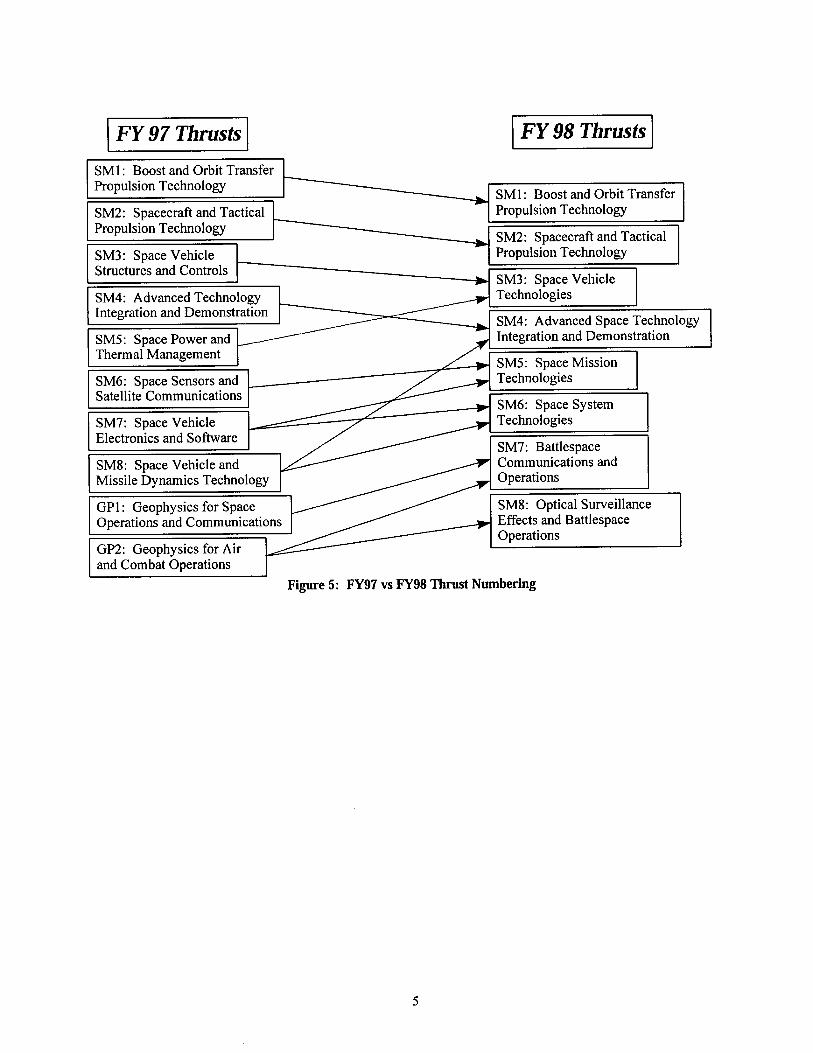
restructuring this past year. Thrusts three through eight have been realigned into four new thrusts. The previous Structures and Power thrusts have been combined into the new Space Vehicle Technologies thrust. The old Electronics thrust has been combined with Sensors and Communications to create the Space Mission Technolo- gies thrust. Satellite Control and Astrodynamics have been combined into the Space Systems Technologies thrust. Finally, Missile Dynamics has been incorporated as a new subthrust of the Space Technology Integration and Demonstration thrust.
The overall reduction in the number of thrusts has been offset by the incorporation of Geophysics technology into the Space and Missiles TAP. Two new Geophysics thrusts appear this year: Battlespace Communications and Operations and Optical Surveillance Effects and Battlespace Operations.
The mapping of previous thrusts and the Geophysics TAP into the current Space and Missiles TAP is shown in Figure 5.
1 FY 97 Thrusts I 1 FY 98 Thrusts I I SMl : Boost and Orbit Transfer I
Propulsion Technology SM1: Boost and Orbit Transfer
SM2: Spacecraft and Tactical Propulsion Technology Propulsion Technology -
SM2: Spacecraft and Tactical SM3: Space Vehicle - Propulsion Technology Structures and Controls
Missile ~ ~ n a m i c s Technology r Operations
GP1: Geophysics for Space SM8: Optical Surveillance Operations and Communications Effects and Battlespace
Operations GP2: Geophysics for Air and Combat Operations
Figure 5: FY97 vs FY98 Thrust Numbering
THRUST 1: BOOST AND ORBIT TRANSFER PROPULSION TECHNOLOGY
USER NEEDS The Air Force Policy of "Global Presence" cites
Situational Awareness and Strategic Agility as ten- ants needing "technological innovations" to "en- hance US ability to exert presence." The following SMC Development Plans and NASA requirements also demand propulsion improvements to fulfill critical deficiencies: Spacelift: High Performance, Advanced, Cryogenic and Liquid Rocket Propellants and Engines, Low Cost Solid and Hybrid Motors, Low Cost Manufac- turing, High Performance Low Cost Expendable Engines, Solar Thermal Propulsion (for Orbit Transfer), Advanced Orbit Transfer Concepts, and Manufacturing Technologies Strategic Sustainment : Motor Aging and Surveil- lance Conventional Deterrence: Missile Propulsion Ma- terial Applications, Global Range and Survivability, Missile Propulsion Technology, Missile Propellant Non-Destructive Test Technology, Solid Rocket Motor Manufacturing, Reliability Reconnaisance/Surveillance: Large Payload Spacelift Systems NASA: Advanced Reusable Spacelift, Low Cost Reliable Access to Space.
GOALS The propulsion needs identified above will be ful-
filled by achieving the goals set forth in the Inte- grated High Payoff Rocket Propulsion Technology (IHPRPT) initiative. IHPRPT's vision is to double spacelift propulsion capability by 20 10 through the development of advanced, innovative rocket propul- sion technology. By 2000, the IHPRPT spacelift goals will:
increase expendable payload to orbit capability by 9% or reusable payload to orbit capability by 71% (over the life of the reusable system) and reduce payload launch costs by 19%.
By 2010, the IHPRPT spacelift goals will: increase expendable payload to orbit capability by 22% or reusable payload to orbit capability by 206% (over the life of the reusable system) and reduce payload launch costs by 42%.
By 2000, the IHPRPT orbit transfer goals will: double repositioning capabilities (double number of repositioning maneuvers) or increase allowable satellite mass by 10%.
By 2010, the IHPRPT orbit transfer goals will: increase repositioning capability by 5 times or
increase allowable satellite mass by 30%. To meet the spacelift and orbit transfer propulsion
goals, chemical (liquid, solid, and hybrid), solar thermal, and electrical propulsion technology devel- opment is crucial. In response to the above needs, PL develops spacelift and orbit transfer pro- pulsion technology for:
high performance, low cost expendable propul- sion advanced liquid and cryogenic reusable and ex- pendable propulsion low cost, rapid prototype thrust cell and compo- nent manufacturing technology high energy materials for potential use as pro- pellants improved ballistic missile motor service life in both existing and new systems dramatically reduced manufacturing and support costs. developing motor manufacturing processes that eliminate harmful chemicals used in motor manufacturing developing long life, high performance, envi- ronmentally acceptable solid propellants while maintaining propertieslintegrity equal to current solid propellants chemical and solar thermal orbit transfer appli- cations.
These technologies will provide the technical so- lutions to develop next generation space systems in addition to upgrades for existing space vehicles. The major challenges to achieving the spacelift goals are addressed by our IHPRPT programs, which coordi- nate our efforts closely with the Air Force, Navy, Army, NASA, and Industry to lower development costs for everyone involved.
MAJOR ACCOMPLISHMENTS A series of U.S. Patents were issued pertaining to
an entirely new polymer technology that was pio- neered and developed at the Phillips Laboratory Pro- pulsion Directorate. The hybrid polymer technology is being evaluated along with conventional (wholly organic) high performance plastics as engine duct- ing, trusses, component substructures, cases, and thermal insulation applications in both rockets and space vehicles.
A small Solid Oxygen (SOX) Engine was devel- oped and fired by the Phillips Laboratory. The ob- jective of this project was to demonstrate that cryo- genic solids can be burned in a hybrid rocket ge- ometry. Solidifying the oxygen increases the oxi-
- -
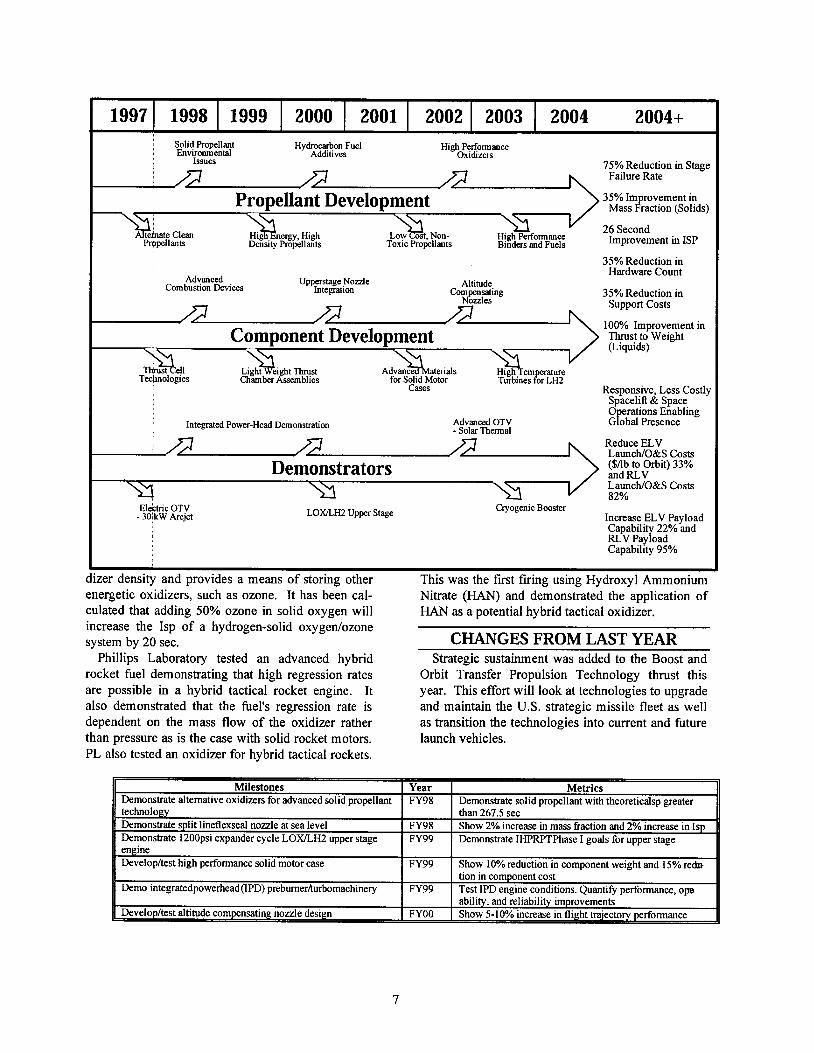
Sohd Propellant Hydrocarbon Fuel H~ghPerformanceEnv~ronmental Additives Oxidizers
Issues 75% Reduction in Stage Failure Rate
Propellant Development ass {action (Solids)35% ~m rovement in
26 SecondH~ghPerformance
Propellants TOXICPropellants Btnders and Fuels Improvement in ISP
35% Reduction in Hardware Count
Advanced Upperstage N o d e Altitude,Combust~onDevices Integrat~on Corn sating 35% Reduction In &%es Support Costs
100% Improvement inComponent Development Thrust to Weight
(Liquids)
H ~ g hTem erature Technologies for Soltd Motor Turbines &r L H ~
Cases Respons~ve, Less Costly Spacelift & Space 0 eratlons Enablmg
Integrated Power-Head Demonstatton Advanced OTV G! obd Presence - Solar Thermal Reduce ELV Launcb/O&S Costs ( S A ~and RLVto Orbit) 33% Demonstrators Launch/O&S Costs 82%
Electric OTV - 30 kW Arcjet LOXILH2 Upper Stage CryogenicBooster Increase ELV Payload Capability 22% and RLV Payload Capability 95%
cer density and provides a means of storing other This was the first firing using Hydroxyl Ammonium energetic oxidizers, such as ozone. It has been cal- Nitrate (HAN) and demonstrated the application of culated that adding 50% ozone in solid oxygen will HAN as a potential hybrid tactical oxidizer. increase the Isp of a hydrogen-solid oxygenlozone system by 20 sec. CHANGES FROM LAST YEAR
Phillips Laboratory tested an advanced hybrid Strategic sustainment was added to the Boost and rocket fuel demonstrating that high regression rates Orbit Transfer Propulsion Technology thrust this are possible in a hybrid tactical rocket engine. It year. This effort will look at technologies to upgrade also demonstrated that the fuel's regression rate is and maintain the U.S. strategic missile fleet as well dependent on the mass flow of the oxidizer rather as transition the technologies into current and future than pressure as is the case with solid rocket motors. launch vehicles. PL also tested an oxidizer for hybrid tactical rockets.
Milestones Metrics Demonstrate alternative oxidizers for advanced solid propellant I FY98 I Demonstrate solid propellant with theoreticalsp greater technology than 267.5 sec Demonstrate split lineflexseal nozzle at sea level FY98 Show 2% increase in mass fraction and 2% increase in Isp Demonstrate 1200psi expander cycle LOXILH;! upper stage FY99 Demonstrate IHPRPTPhase I goals for upper stage pnoinp...-Developltest high performance solid motor case FY99 Show 10%reduction in component weight and 15% re&
tion in component cost Demo integratedpowerheadVD) prebumer/turbomachinery FY99 Test IPD engine conditions. Quantify performance, ope
I I ability, and reliability improvements
THRUST 2: SPACECRAFT AND TACTICAL PROPULSION TECHNOLOGY increase allowable satellite mass by 10% with
USER NEEDS The Air Force Policy of "Global Presence" cites
Situational Awareness, Strategic Agility and Lethal- ity as tenants needing "technological innovations" to "enhance US ability to exert presence." The fol- lowing SMCIAFSPC, ACC and NASA Development Plans require propulsion improvements to fulfill critical deficiencies: Missile Offense, Air to Surface, and Counterair: Motor Service Life Prediction and Extension, High Performance Environmentally Acceptable Propel- lants, Low Cost Environmentally Acceptable Manu- facturing Processes Conventional Deterrence: Missile Propulsion Ma- terial Applications, Global Range and Survivability, Missile Propulsion Technology, Missile Propellant Non-Destructive Test Technology, Solid Rocket Motor Manufacturing, Reliability Reconnaissance/S~r~eillance: Cost and Surviv- ability, Prompt Response without Force Deployment , Long Range Strike Capability Counterspace, Missile Warning: Survivability Missile Defense: Survivability, Propellant Devel- opment Non-Space: Fast Reaction Tactical Missiles, Less Time to Target, Increased Range, Throttle on De- mand, Low Cost, Increased Environmental Compli- ance. Satellite: Advanced Propulsion/Power Conversion for Electric Propulsion (for Stationkeep- inghlaneuvering) Weather: Small Satellite Technology Navigation: Modernization of Current Systems, Upgraded Future Systems to Replace Current Sys- tems with Lower Power Consumption, Improved Power Conversion, Advanced Attitude Control, Ad- vanced Electric Propulsion and Solar Propulsion.
GOALS The propulsion needs identified above will be ful-
filled by achieving the goals set forth in the Inte- grated High Payoff Rocket Propulsion Technology (IHPRPT) initiative. IHPRPT's vision is to double solid rocket propulsion capability by 2010 through the development of advanced, innovative rocket pro- pulsion technology By 2000, satellite propulsion systems will:
extend their life in geosynchronous orbit (GEO) by 25% double repositioning capabilities (number of repositioning maneuvers) or
present life span capabilities. By 2010, satellite propulsion systems will:
extend their life in GEO by 45% increase repositioning capability by 5 times or increase allowable satellite mass by 30% with present life span capabilities.
By 2000, the IHPRPT tactical goals will: increase either warhead payload or range by 10%. The number of theater missile defense systems to cover an area can be reduced by 26% for di- vert (steering control) propulsion systems.
By 2010, the IHPRPT tactical goals will: 0 double tactical warhead payload or range and,
reduce necessary theater missile defense systems for divert propulsion by 60%.
Solar electric and solar thermal spacecraft propul- sion development is critical to achieve the satellite improvements for stationkeeping and maneuvering. PL develops spacecraft propulsion technology for:
pulsed plasma thrusters, anode layer thrusters, and solar thermal (laser thermal) systems.
To accomplish the tactical payoffs, solid propellant and motor component development is crucial. The PL rocket propulsion directorate has the only pro- grams that develop solid rocket propulsion technol- ogy for all Air Force tactical missile systems. PL develops tactical propulsion technology for:
developing low signature, high performance propellants to eliminate tactical missile vulner- ability caused by signature detection.
0 developing lightweight, tactical components to allow for increased warhead carriage capability or increased range.
0 developing longer life, stronger motor compo- nents. decreasing production time and costs by utiliz- ing our carbon densification techniques and lightweight coatings. decreasing nozzle erosion rates (which increases reliability, performance, and range) increasing oxidation resistance (which also in- creases reliability).
MAJOR ACCOMPLISHMENTS PL researchers have discovered and characterized
one of the major sources of the low pulsed plasma thruster (PPT) thrust efficiency - severe propellant loss mechanisms. This new understanding has fueled the design of advanced PPTs, presently being tested
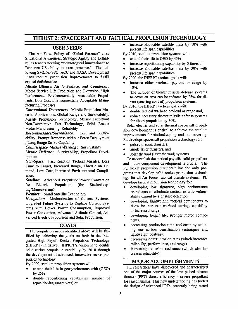
lO% Increase in l s p (Chemica l lSo lar Thermal )
15% Improvement i n Mass
nJ% Improvement In Thruster Ef f i c i ency (Electric)
m/.Increase tn Satellite-~", 30% Increase in Sate l l i t e
Payload
500% Increase in Sate l l i t e Repos i t ion ing
15% I m p r o v e m e n t in Dc l ivcred Energy
lmlrrove Mass Fraction Without
h
With TVCIThrot t l ing 30%
50% Reduct ton in Number o f Interceptors RequircdlThcatcr
at the PL Electric Propulsion Laboratory, which are to the space debris problem. 1t would cure in UV, expected to have thrust efficiencies over three times then the shield and front canopy could be stripped higher than present designs. away leaving the rigid shell that would only dimple
Two experimental PPTs, designed by PL research- around areas of micrometeoroid or space debris ers and fabricated at the Propulsion Directorate, have penetration. passed their initial functional tests. The PPT's in- clude the smallest electric propulsion thruster ever CHANGES FROM LAST YEAR fabricated and tested. The goals for the spacecraft subthrust have been
PL, in cooperation with contractors, developed a refined. This does not impact any of the long term new way to design and fabricate spray foam- payoffs for the subthrust. rigidized solar concentrators. The foam material and solvent are sprayed onto the back of the reflector within a conical shield so they would not contribute
sYear Metrics Design tactical hybrid rocket engine 1 FY98 1 Demonstrate 5% increase in mass fraction and 7% increase in
THRUST 3: SPACE VEHICLE TECHNOLOGIES The Space Vehicles Technology Thrust supports the suc-
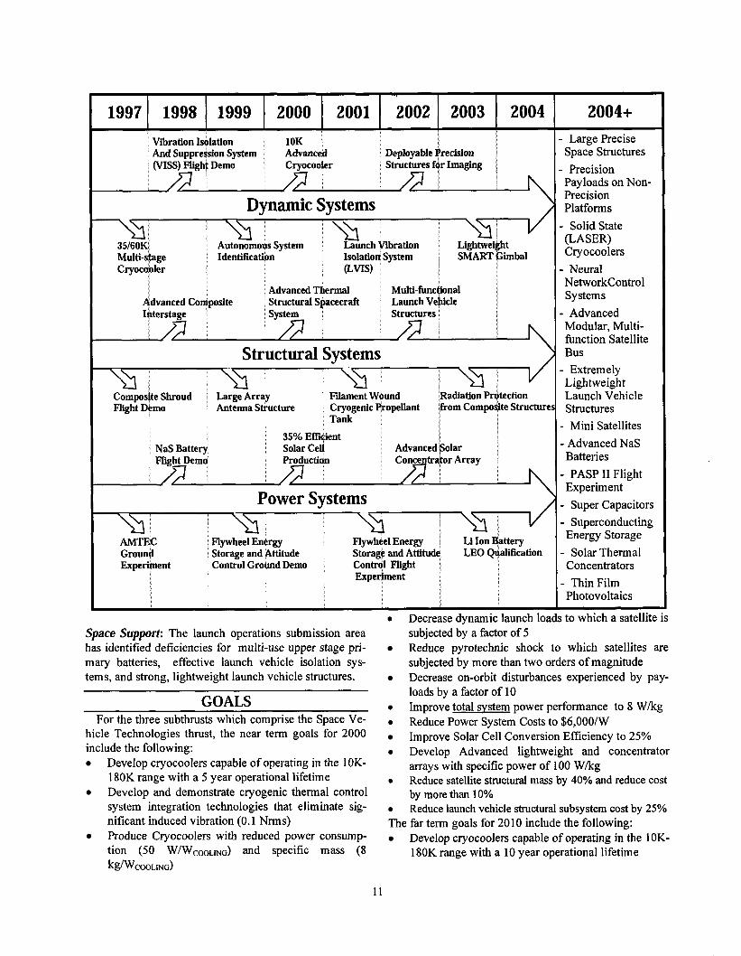
cessful accomplishment of satellite and launch vehicle mi s- sions by conceptualizing, developing, and demonstrating pervasive technologies that enable the use of the most effe c- tive payload packages, operating in the optimum environ- ment. This thrust encompasses a wide range of disciplines including structures and controls, thermal management, and electrical power systems. Whether future systems are large, high power communications or weapons platforms, or small, distributed surveillance packages, technologies are being developed to reduce weight, reduce costs, and increase the capabilities of space systems. The ultimate aim is a mas- sless, rigid spacecraft bus with limitless power generation and energy transmission capabilities that provides the opti- mum structural and thermal environment and that costs next to nothing.
The Space Vehicle Technologies Thrust has three subthrusts: Dynamic Systems, Structural Systems, and Space Power.
The focus of the Dynamic Systems subthrust is pro- viding vibration control, precision mechanisms, and cryocoolers that enhance the performance of payloads. Key programs in this area include launch load vibration and acoustic attenuation, 35160K multistage cryocoolers, and high precision, low-shock deployment devices.
The primary objectives of the Structural Systems sub- thrust are reduced mass and manufacturing costs. Key programs include multifunctional structures, advanced composite structures, inflatable structures, and large ar- ray antennas. Additionally, the thermal bus focused technology area seeks to provide large heat transport ca-pabilities utilizing loop heat pipes and integrated capil- lary pumped loop systems.
The Space Power subthrust is investigating new ways to generate, store, and distribute power efficiently and in quantities required by future spacecraft subsystems. Key programs in this area are Alkali Metal Thermal Electric Conversion (AMTEC), the flywheel energy storage and attitude control cooperative effort with NASAILeRC, and the Multijunction Photovoltaic Array ManTech program.
USER NEEDS The technologies developed in this thrust support many
SMC programs, AFSPC Mission Area Plan deficiencies, and other Air Force space requirements. These include the following Mission and Functional Area Plans. Space Control: The space surveillance submission area seeks to monitor activities in the near earth corridor. To this end, acquisition, tracking and pointing precision structures, very low temperature cryocoolers for broadband IR sensors, and high efficiency power genera- tion are required. The national missile defense submis-
sion area has identified the need for beam generator iso- lation from expansion and pointing optics
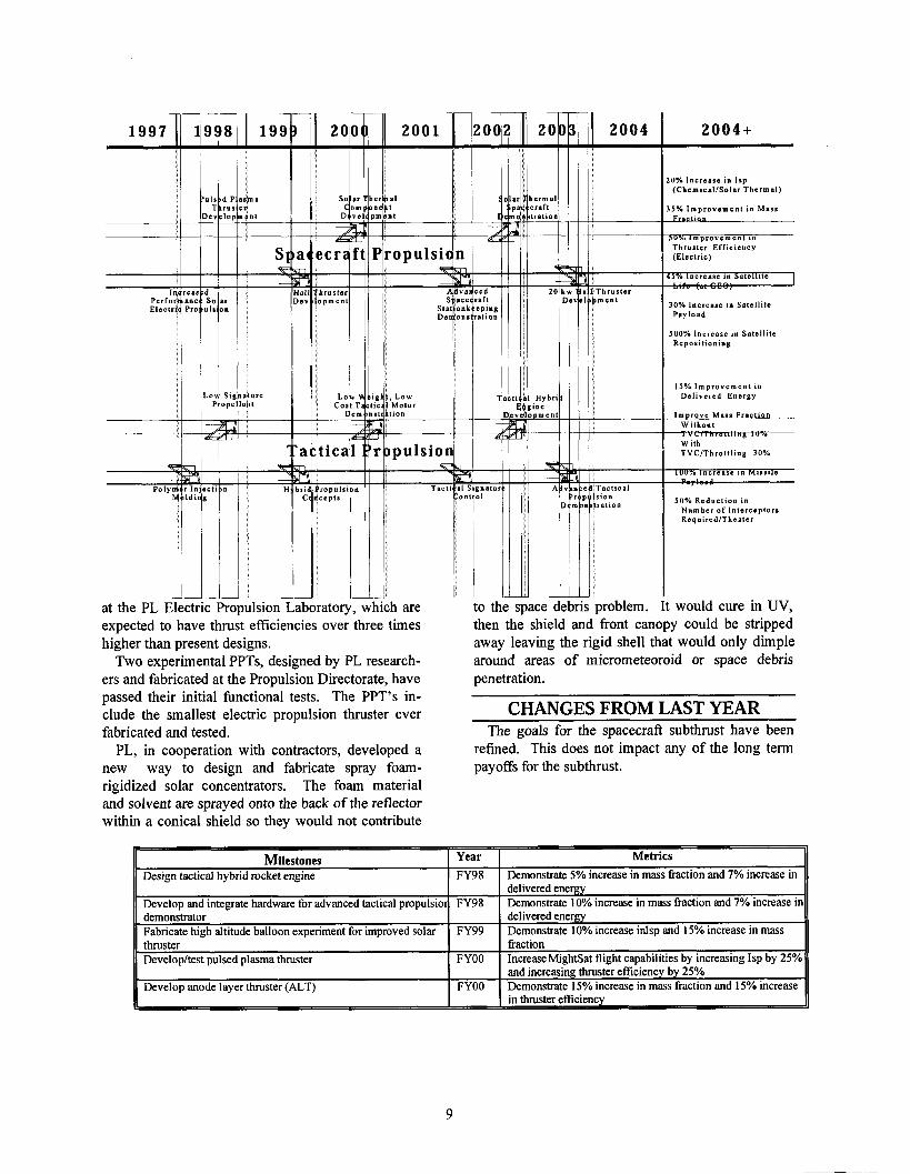
(PASP) Plus Diagnostics Experiment
Space Force Enhancement: The surveillance and threat warning submission requires the ability to loiter in low earth orbit (LEO), monitor hostile activities on the earth surface, and communicate a warning. Cryogenic Cool- ers for 60-150K IR sensors, lightweight structures and antennas, operable smart structures, and high cycle en- ergy storage systems are required to enable this mission. The navigation submission area has identified the need for lightweight, low cost arrays, while the environmental monitoring submission area requires lightweight anten- nas and cryocoolers for the appropriate range of IR sen- sors. For the communications submission area, light- -weight antennas, high efficiency power generation and distribution, and an advanced thermal management bus are being developed.
Precjsion Employment: The global prompt strike sub- mission area will employ weapon systems requiring large capacity cryogenic coolers, high efficiency power gen- eration, and large, lightweight precise structures.
- Mini Satellites
- Advanced NaS
- Super Capacitors
Concentrators
0 Decrease dynamic launch loads to which a satellite is Space Support: The launch operations submission area subjected by a factor of 5 has identified deficiencies for multi-use upper stage pri- Reduce pyrotechnic shock to which satellites are m a y batteries, effective launch vehicle isolation sys- subjected by more than two orders of magnitude tems, and strong, lightweight launch vehicle structures. Decrease on-orbit disturbances experienced by pay-
loads by a factor of 10 GOALS 0 Improve total system power performance to 8 Wkg
For the three subthrusts which comprise the Space Ve- Reduce Power System costs to $6,00O/W hicle ~echno lo~ ie s thrust, the near term goals for 2000 Improve Solar Cell Conversion Efficiency to 25% include the following: 0 Develop Advanced lightweight and concentrator
Develop cryocoolers capable of operating in the 10K- arrays with specific power of 100 Wkg 180K range with a 5 year operational lifetime 0 Reduce satellite structural mass by 40% and reduce cost Develop and demonstrate cryogenic thermal control by more than 10% system integration technologies that eliminate sig- Reduce launch vehicle structural subsystem cost by 25% nificant induced vibration (0.1 Nrms) The far term goals for 2010 include the following: Produce Cryocoolers with mhced Power consump- Develop cryocoolers capable of operating in the 1 OK- tion (50 W/WCOOLwG) and specific mass (8 180K range with a 10 year operational lifetime ~ ~ W C O O L I N G )
Develop and demonstrate cryogenic thermal control system integration technologies that eliminate sig- nificant induced vibration (0.001 Nrms) Produce Cryocoolers with reduced power consump- tion (30 W/WCOOLING) and specific mass (3 ~ ~ J ~ C O O L I N G
Decrease dynamic launch loads to which a is sub- jected by a factor of 20 Decrease on-orbit disturbances experienced by
payloads by a factor of 100 Improve total svstem power performance to 15
W k Reduce Power System Costs to $3,00O/W Improve Solar Cell Conversion Efficiency to 35% Develop Advanced lightweight and concentrator arrays with specific power of 150 Wlkg Reduce satellite structural mass by 75% and reduce cost by more than 25% Reduce launch vehicle structural subsystem cost by a factor of 10
(ASSTREX)
MAJOR ACCOMPLISHMENTS Completed sodium sulfur flight test safety reviews successfully. Provided key data to NASAJDOE that enabled them to select AMTEC as the baseline converter for their advanced radioisotope power system. Successfully tested the first multi-tube AMTEC cells in vacuum. Initiated flywheel energy storage and attitude control program in conjunction with NASA. Accepted delivery of 150 24% efficient multijunction solar cells. Delivered advanced lightweight composite bus structures for BMDO STRV-2 and PL MightySat-I vehicles. Demonstrated 11% structural mass frac- tion and reduced fabrication time by 30%.
Demonstrated applicability of electron-beam proc- essing for fabrication of composite space structures. Commenced characterization of 5 W Reverse Bray- ton Cycle Cryocooler Demonstrated feasibility of Multi-Stage Multi-Load 35160K cryocoolers for MLIRLWIR Sensors. Successful flight Demo of highest ever operating temperature liquid metal heat pipe on STS-77. Accomplished 40% improvement in heat transport with 1.45 micron metal wick capillary pumped loop. Proved feasibility of employing precision payload packages on non-precision satellites with active vi- bration isolation system (VISS). The structures and control technology area received a score of two with special mention from the SAB Review Board.
CHANGES FROM LAST YEAR Thrust 3 Structural Systems and Thrust 5 Power and Thermal ~ a n a ~ e m e i t from the previous TAP have been combined into Thrust 3 Space Vehicle Tech- nologies of the current TAP. This combination of technologies creates a synergy that will accelerate realization of a truly modular, multifunctional satel- lite bus. Flywheel energy storage and attitude control joint program with NASA initiated. Modified AMTEC program to support NASAJDOE advanced radioisotope program. Thermal Management (Bus) focused technology area integrated with spacecraft structures technologies branch. Launch isolation technology has changed from a PL push to an SMCITE sponsored program.
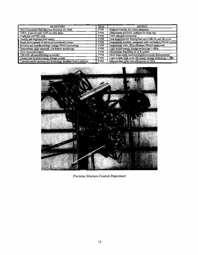
Precision Structure Controls Experiment
THRUST 4: ADVANCED SPACE TECHNOLOGY INTEGRATION AND DEMONSTRATION
Leverage civil and commercial spare capabilities to USER-NEEDS examine new space technologies while reducing bud-
In order to continue to effectively control and exploit space into the next millennium, the Air Force must con- tinue to field affordable, technologically superior systems and effectively use cutting-edge technology to improve operational tactics. Technologies focused on meeting USAF operational needs and deficiencies are identified through the use of the Air Force Technology Planning Integrated Product Teams (TPIPTs); however, timely transition of those technologies has often proven difficult. Orderly and routine demonstrations provide flight heri- tage for emerging technologies and are effective plat- forms for the development and demonstration of im- proved operational tactics. Within this thrust PL con- ducts regularly-scheduled space, near-space, re-entry fiom space, and ground demonstrations to facilitate risk reduction and technology maturation, and hasten tech- nology transition to the operational user. These demon- strations include combining new technologies into mis- sion oriented demonstrations to show advances in opera- tions and tactics. The synergistic effect of operations, tactics, and new technologies will maximize operational system improvements in the areas of life cycle costs as well as performance.
GOALS The broad goals of the Advanced Space Technology
Integration and Demonstration Thrust are to transition technology by:
Providing integrated space technology flight and
getfschedule requirements. Employ simplified command and control concepts; Employ increased autonomous satellite operations; VerifL the maturity of technology, and transition them Emphasize a streamlined concept of operations with maximum use of experienced integrated product teams including contractors, in-house expertise from the AF Laboratories, and other government agencies; Lead the improvement of the laboratory's integration and system engineering capability; Provide actual experience in design, fabrication, inte- gration, systems engineering, and flight of spacecraft payloads to laboratory personnel; Integrate and execute ground, near space, and space demonstrations for other DoD agencies leveraging their technologies to enhance AF capabilities; Demonstrate GPS Range Standardizationlsafety Tech; Demonstrate new miniature GPS systems to lower range costs and enhance safety with greater accuracy and reliability; Demonstrate GPS accuracy enhancements and anti- jam antennas and systems; Increase cost effectiveness, missile navigation, and testing accuracy with improved GPSANS coupling; Fly the Missile Technology Demonstration I11 (MTD 111) during FY98 to gain data on a high speed instru- mented penetrator warhead and GPSIINS navigation -- .-*--
ground demon&ations to address AFSPC identified sysierll.
deficiencies and requirements, as well as DDR&E Defense Technology Objectives Reducing cost of developing, launching, and operating space systems; Minimizing risk associated with inserting advanced technology into operational satellites developed by SMC and operated by AFSPC. Developing technology advances to sustain and in- crease the key ICBM strategic and tactical capabilities, which include range instrumentation and safety, flight and terminal navigation accuracy, as well as lowering the life cycle cost of the existing ICBM fleet.
Methods to Meet Goals: Validate new satellite technologies using state-of-the- art and standard satellite configurations; Plan and execute advanced technology and integrated space flight demonstrations with the user, including
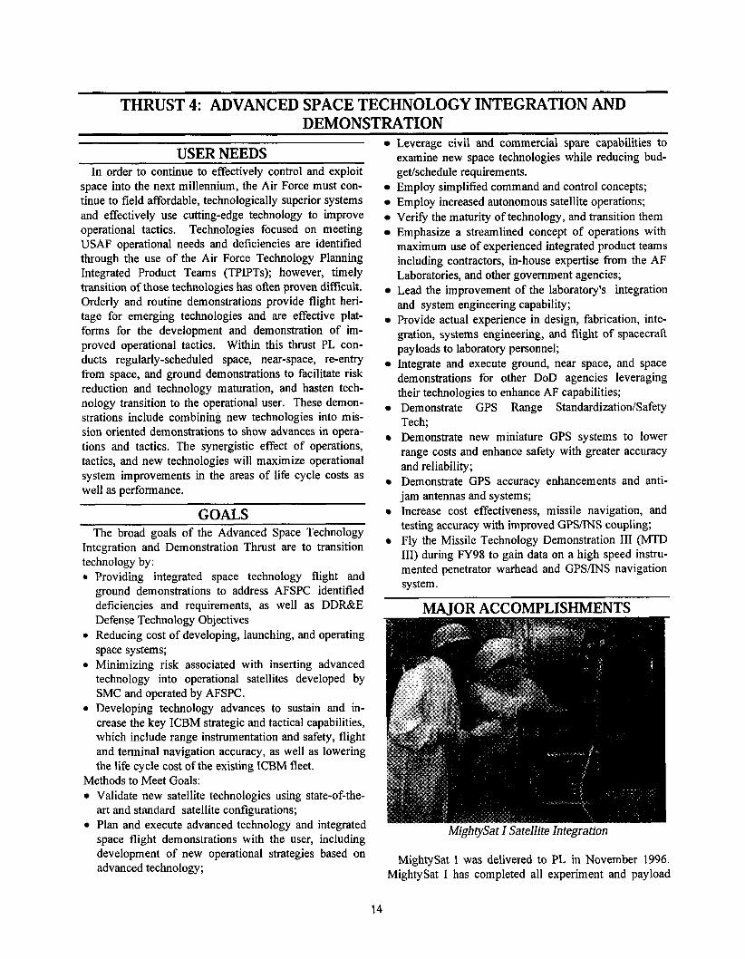
MightySat I Satellite Integration
development of new operational strategies based on I was delivered to PL in November 1996. advanced technology; MightySat I has completed all experiment and payload
14
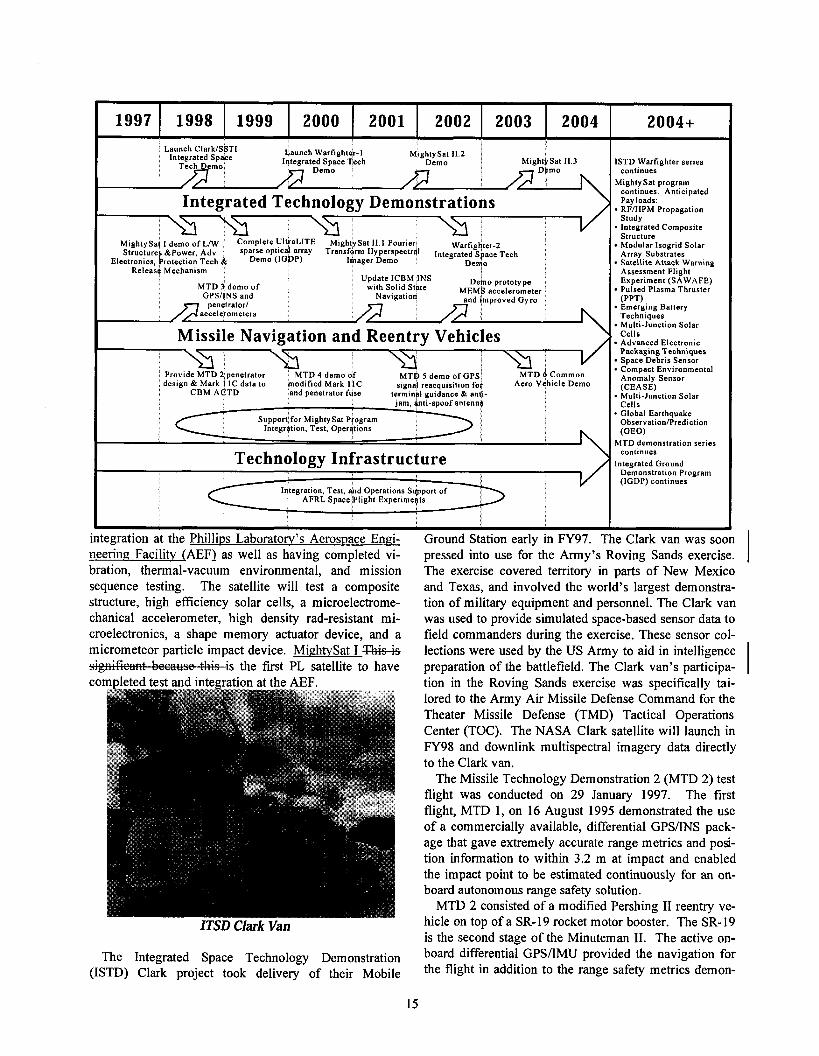
Launch ClarkISSTI Integrated S p w e Launch Warfight&-l Mlghty Sat 11 2 1
Tech Demo Integrated Space Tech Demo I Demo
Integrated Technology Demonstrations
Release Mechanism Update ICBM INS
Missile Navigation and Reentry Vehicles \
I
Provlde MTD 2 penetrator MTD 4 demo of MTD 5 demo of GPS' MTD 8 common deslgn & Mark i l~ data to modified Mark 1 IC slgnal reacquls~tlon foi Aero ~ $ h l c l e Demo
CBM ACTD and penelrator fuse termlnal ruldance & antl- - jam, antl-spoof antennb
Suooort for MlrhtvSat Prorram Integrlltlon, Test, operations
Technology Infrastructure
integration at the Phillips Laboratorv's Aerospace Enci- Ground Station early in FY97. 7
Integration, Test, and Operations Support of AFRL Space F l ~ g h t ~xper rmen t s
neering Facility (AEF) as well as having completed vi- bration, thermal-vacuum environmental, and mission sequence testing. The satellite will test a composite structure, high efficiency solar cells, a microelectrome- chanical accelerometer, high density rad-resistant mi- croelectronics, a shape memory actuator device, and a micrometeor particle impact device. MirrhtySat I Tkisif . . - -is the first PL satellite to have
ITSD Clark Van
The Integrated Space Technology Demonstration (ISTD) Clark project took delivery of their Mobile
ISTD Warfighter series continues
Mighty Sat program continues. Anticipated Pay loads: RFIHPM Propagation Study . Integrated Composite Structure Modular Isogrid Solar Array Substrates Satellite Attack Warning Assessment Flight Experiment (SAWAFE) Pulsed Plasma Thruster (PPT) Emerging Battery Techniques Multi-Junction Sola1 Cells Advanced Electronic Packaging Techniques Space Debris Sensor Compact Environmental Anomaly Sensor (CEASE) Multi-Junction Solar Cells . Global Earthquake ObservationlPrediction (GEO)
MTD demonstration series continues
Integrated Ground Demonstration Program (IGDP) continues
pressed into use for the Army's Roving Sands exercise. I The exercise covered territory in parts of New Mexico and Texas, and involved the world's largest demonstra- tion of military equipment and personnel. The Clark van was used to provide simulated space-based sensor data to field commanders during the exercise. These sensor col- lections were used by the US Army to aid in intelligence preparation of the battlefield. The Clark van's participa- tion in the Roving Sands exercise was specifically tai- lored to the Army Air Missile Defense Command for the Theater Missile Defense (TMD) Tactical Operations Center (TOC). The NASA Clark satellite will launch in FY98 and downlink multispectral imagery data directly to the Clark van.
The Missile Technology Demonstration 2 (MTD 2) test flight was conducted on 29 January 1997. The first flight, MTD 1, on 16 August 1995 demonstrated the use of a commercially available, differential GPS/INS pack- age that gave extremely accurate range metrics and posi- tion information to within 3.2 m at impact and enabled the impact point to be estimated continuously for an on- board autonomous range safety solution.
MTD 2 consisted of a modified Pershing I1 reentry ve- hicle on top of a SR-19 rocket motor booster. The SR-19 is the second stage of the Minuteman 11. The active on- board differential GPSIIMU provided the navigation for the flight in addition to the range safety metrics demon-
strated on the first flight. Three GPSIINS packages were independently demonstrated on the flight. The missile became unstable 26 seconds into the flight when all the hydraulic fluid used to control the rocket motor nozzle was prematurely expended. The factors leading to this control instability have been determined and corrected for any potential future flights using similar systems and hardware. The on-board systems using GPS completely demonstrated their potential to monitor missile motion during the erratic flight until the command destruct was accomplished. The 650 lb penetrator survived the ti-ee- fall back to earth and was recovered. This penetrator and its two surviving internal instrumentation packages will be reflown on a future flight.
The Integrated Ground Demonstration Program has completed their first major design review for the UltraLITE ground experiment. UltraLITE will demon- strate at a system level, deployment repeatability and structural stability of a full scale sparse optical array. This experiment incorporates optical wavefront measur- ing sensors that determine position error of a mirror mass simulator. Sparse arrays have several potential space based applications.
CHANGES FROM LAST YEAR
MightySat I mission FY983 UltraLITE Experiment (IGDP #I) -FY98
kleslGDP #2 Initiation
I MightySatII.2 mission I FYOlQ I
This year, flight demonstrations formerly listed under Thrust 8, "Space Vehicle and Missile Dynamics Tech- nology, have been incorporated into this thrust within SubThrust 4D, Missile Navigation and Reentry Vehicles. This includes the Missile Technology Demonstrator (MTD) series, of which MTD-2 was flown in January 1997.
UltraLITE Sparse Optical Array Concept
Launch on Space Shuttle STS-84 Com~lete internation. execution, and analvsis of a bench to^ experiment
process to identifir high payoff concept w/critical integration issues which
Launch on Space Shuttle or OrbitallSuhorbital Proeram ( 0 S P ) W
THRUST 5: SPACE MISSION TECHNOLOGIES - - - - - - - -
nologies, advanced mid- and long-wavelength focal USER NEEDS
Mission Technologies include those components that perform the primary mission function of AF space systems. In most cases, those technologies are either electronics or sensors. Electronic circuits are as perva- sive in space system payloads (and other parts of the satellite) as they are in everyday life while sensors are the eyes and ears of a spacecraft.
Mission Technologies play a critical role in enabling the US to prevail in space. The AF long-range vision document, "Global Engagement7' states that "Global situational awareness ..." such as that provided by Mis- sion Technologies onboard surveillance and threat warning satellites "... by its very existence, gives na- tional leaders unprecedented leverage, and therefore advantages." The extraordinary importance of Mission Technologies was recognized in a recent letter from the Undersecretary of Defense for Acquisition and Tech- nology where he cited advanced radiation hardened (i.e., space) electronics as crucial to the DoD and, therefore, deserving focused attention. Similarly, re- cent DUSD-level interest in hyperspectral sensors demonstrates how important sensor technology is to DoD warfighting plans.
In recognition of the importance of Mission Tech- nologies, AF SPOs, BMDO, and other space system developers have identified affordable, high perform- ance, radiation hardened, space qualifiable, sensor and signaydata processing subsystems as essential space technologies for the late 1990s and beyond. For exam- ple, improved booster detection sensitivity and cover- age, and worldwide detection and tracking capability for missiles and warheads are requirements identified in several AFSPC Mission Area Plans. To meet the broad range of requirements defined by these users, technologies that extend the performance of today's space sensor and electronic components must be devel- oped and demonstrated. The focus is to support war- fighters and operational users by providing Mission Technologies that are simultaneously more cost effec- tive and higher performance.
The following paragraphs contain specific examples of the numerous technology needs identified in SMC TPIPT development plans: Space Surveillance requires adaptive optics for large mirrors (MEMS), improved radiation-hardened proces- sor, parallel processing, and decreased optical wave- front error for space-based E-0 sensors. National Missile Defense requires survivable high- speed anti-jam electronics, multi-sensor fusion tech-
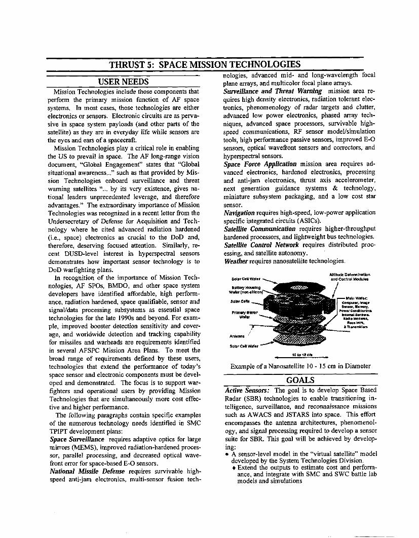
plane arrays, and multicolor focal plane arrays. Surveillance and Threat Warning mission area re- quires high density electronics, radiation tolerant elec- tronics, phenomenology of radar targets and clutter, advanced low power electronics, phased array tech- niques, advanced space processors, survivable high- speed communications, RF sensor modeVsimulation tools, high performance passive sensors, improved E-0 sensors, optical wavefiont sensors and correctors, and hyperspectral sensors. Space Force Application mission area requires ad- vanced electronics, hardened electronics, processing and anti-jam electronics, thrust axis accelerometer, next generation guidance systems & technology, miniature subsystem packaging, and a low cost star sensor. Navigation requires high-speed, low-power application specific integrated circuits (ASICs). Satellite Communication requires higher-throughput hardened processors, and lightweight bus technologies. Satellite Control Network requires distributed proc- essing, and satellite autonomy. Weather requires nanosatellite technologies.
IOIOIY m >
Example of a Nanosatellite 10 - 15 cm in Diameter -- -
GOALS Active Sensors: The goal is to develop Space Based Radar (SBR) technologies to enable transitioning in- telligence, surveillance, and reconnaissance missions such as AWACS and JSTARS into space. This effort encompasses the antenna architectures, phenomenol- ogy, and signal processing required to develop a sensor suite for SBR. This goal will be achieved by develop- ing:
A sensor-level model in the "virtual satellite" model developed by the System Technologies Division. + Extend the outputs to estimate cost and perform-
ance, and integrate with SMC and SWC battle lab models and simulations
demonstrated
1997
I I Sensor characterization modeling and simulation ability, sensitivity, and resolution; and enhance capabilities, including a radar clitter database, for selecting sensor suites and components, and for pro- viding a system perspective for technology develop- ment Antenna deformation compensation and beam steering algorithms and adaptive processing tech- niques based on RL STAP specific-function applica- tions Low cost characterization of SBR components to support antenna and other component development Advanced Onboard Processing & Control technolo- gies for data reduction; advanced signal processing, automatic target recognition, sensor fusion, and cross cueing to ensure timely delivery of reconnais- sance and surveillance products to the tactical war- fighter Large, lightweight, multi-modelband antennas for space based military reconnaissance and surveillance missions and commercial dual-use applications
Passive Sensors: The goal is to reduce development costs, weight, and power consumption; increase reli-
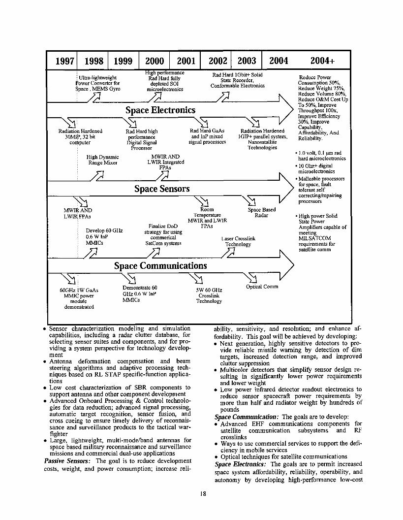
High performance Ultra-lightweight Rad Hard 1Gbit+ Solid
Rad Hard filly State Recorder, Reduce Power Power Converter for depleted SO1 Conformable Electronics Consumption 50%, Space , MEMS Gyro microelectronics Reduce Weight 75%,
Reduce Volume 80%, Reduce O&M Cost Up To SO%, Improve
Space Electronics Throughput loox, Improve Efficiency 30%, Improve
Rad Hard GaAs Capability,
Radiation Hardened Rad Hard high Radiation Hardened ~ f f ~ ~ d ~ b i l i ~ , ~~d ~OMIP, 32 bit performance and InP mixed lGIP+ parallel system, ~ ~ l ~ ~ b ~ l i ~ ,
computer Digltal Signal signal processors Nanosatalhte Processor Technologies
MWIR AND 1.0 volt, 0.1 pm rad
High Dynam~c hard microelectron~cs Range Mixer LWIR Integrated
FPAs 10 Ghz+ digital microelectronics Malleable processors for space, fault tolerant self correctinglrepairing processors
High power Solid State Power Amplifiers capable of meeting MILSATCOM requirements for satellite comm
60GHz 1 W GaAs Demonstrate 60 5W 60 GHz Optical Comm
MMIC power GHz 0.6 W InP Crosslink module MMICs Technology
1998
af- fordability. This goal will be achieved by developing:
Next generation, highly sensitive detectors to pro- vide reliable missile warning by detection of dim targets, increased detection range, and improved clutter suppression
a Multicolor detectors that simplify sensor design re- sulting in significantly lower power requirements and lower weight Low power infrared detector readout electronics to reduce sensor spacecraft power requirements by more than half and radiator weight by hundreds of pounds
Space Communication: The goals are to develop: Advanced EHF communications components for satellite communication subsystems and RF crosslinks Ways to use commercial services to support the defi- ciency in mobile services Optical techniques for satellite communications
Space Electronics: The goals are to permit increased space system affordability, reliability, operability, and
1999
autonomy by developing high-performance low-cost
2000 2001 2002 2003 2004 2004+
space electronics that satisfy customer requirements. These goals will be achieved by:
Developing and demonstrating essential DoD space electronics (e.g., 32-bit processors, or memory) with "spin-off' use by NASA and commercial programs Improving direct information transmission to field commanders by 100% and reduce integration time 50% through advanced electronics (e.g., signal proc- essing systems)
Key developments to meet the above goals are to: Providing at least a 10X improvement in AF space electronic system capability in the next five years by: + Leveraging fiom the rapid progress being made in
the commercial electronics industry + Transitioning high-demand commercial c o m p
nents into svace qualifiable versions + ~ e v e r a ~ i n g indu&y's huge investment in design,
software, and testability + Developing innovative hardening technologies and
transferring to industry + Building standardized space data acquisition and
signal processing modules by standardizing hard- ened implementations of selected commercial processors
+ Demonstrating space qualifiable versions of com- mercial high speed data busses including the FDDI and the ATM
Developing new computer architectures and stan- dards to reduce the customer's cost to develop and test systems by up to 50% Providing more affordable computing solutions by enabling scaleable processing architecture and dis- tributed computing Developing Microelectromechanical System (MEMS) components to reduce the weight, size, power requirements and heat load of satellites, ena- bling more functional, and autonomous large satel- lites, and also new classes of micro- and nano- satellites
MAJOR ACCOMPLISHMENTS Active Sensors: The Space Based Radar (SBR) tech- nology area was very effective this past year. Working closely with customers and partners, the Space Elec- tronically Agile Radar (SPEAR) X-band, space based radar concept, designed to perform Ground Moving Target Indication (GMTI) missions, Air Moving Tar- get Indication (AMTI) missions, and Synthetic Aper- ture Radar (SAR) imagery, was developed and sub- mitted to SMC. The Cooperative LEO Electronically Agile Radar (CLEAR) concept, designed to provide enhanced high resolution 3-d radar coverage for si- multaneous moving target detection (AMTI & GMTI), high resolution imagery, and high resolution mapping with inexpensive, mass produced satellites, was devel- oped and presented to AFSPC. The SBR program has also had a very effective and active integrated product team comprised of members from AF Labs, DARPA, NASA, academia, and industry. SMC transferred re- sponsibility for the modeling and simulation of SBR to PL
Passive Sensors: In the area of passive (e.g., infrared or IR) sensors, a HgCdTe-based MWIR camera was developed. This camera will be used to provide data to BMDO's Advanced Sensor Technology Program (ASTP) and will be used as a testbed for experimental electronics packages and focal plane array designs. An effort to increase the operating temperature of focal plane arrays to greater than 140 degrees Kelvin was also initiated to lower the total weight of a spacecraft by reducing the need for radiative cooling. In work supported by SBIRS-High, risk reduction analysis was performed. Another HgCdTe effort demonstrated the ability to mass-produce large MWIR focal plane arrays. In the area of Quantum-Well Infrared Photodetector (QWIP) technology, a new category of dark current effects that manifest themselves at the low tempera- tures required for space applications were discovered, and the sources that are responsible for this noise were explained. A collaborative effort was initiated with JPL to develop a low-background QWIP Focal Plane Array and the associated electronics at Rockwell Science Center and Hughes SBRC. Another collaborative ef- fort was initiated with the NRC of Canada to develop a two-color QWIPLEDICCD imaging array. A novel voltage-tunable QWIP structure was developed through a contract with the University of Florida.
Satellite Communication: In the area of Satellite Communications, working with the MILSATCOM ofice, efforts were initiated to evaluate crosslink tech- nologies for EHF payloads and satellite buses. To en- sure other AF technology developments were exploited, this effort was coordinated with ongoing communica- tion system developments at Rome Laboratory. The SBIR program was exploited to advance space com- munication technology. During the past year, three Phase I SBIRs where all were selected for Phase I1 ef-
forts. The developments will include engineering and construction of a 5 Watt 60 GHz power combiner, a 28 GHz 1 Gbps wireless link system, and a Code Division Multiple Access fiber optic network that can support up to 1 Terabitlsec. Fabrication and testing of a 1-Watt 60-GHz Solid State Power Amplifier was also initiated. Space Electronics: Many space electronics success were obtained this past year. In collaboration with in- dustry a new analog-to-digital convertor (ADC) was co-developed for the GPS MAGR anti-jam filter. It is both a successful commercial product and a space-qualified component that outperforms any previously space-qualified ADC. A collaborative was initiated with NASA JPL to develop a postage-stamp sized mi- crocontroller-based data acquisition system that offers a flexible solution for a variety of simple spacecraft processing tasks for both NASA and the AF. The con- troller will be used by NASA in two Mars surface probes that are under development for the Mars 98 program, and a hardened version is being evaluated for AF single-node and fault-tolerant applications. In an- other effort, a micro DC-DC power converter was de- veloped--the size was reduced fiom 1000 in3 to 2 in3 and weight from 801b to 0.251b. Finally, development and application of the "hardening by design" approach was continued this year. "Hardening by design" was used for a control application on the STRV- Id mission. In this application, components must withstand harsh radiation in GEO-transfer environments. The ap-proach is now being applied to advanced commercial processes, and being extended to include analog cir- cuitry.
In the flagship, advanced space processor program, a single-board 32-bit ASCM (computer) was demon-strated. This led to an "Outstanding" technical CDR on SBIRS-Low. In addition, ASCM technology was selected for the GPS-IIF and SBIRS-High programs. The first light-weight, double-sided 32-bit datahignal processor was also developed using a reduced version of
ATIM that decreased the weight and size by 10X. A tion hardened foundry was initiated. Considerable savings will result fiom using commercial devices for prototyping and reuse of soha re . Finally, the Im- proved Space Computer Program was iniated to satisfy space system developer needs in the FY01103 time frame with a scaleable, integrated computer architec- ture.
In advanced electronics packaging, advancements were made in the state of the art in space multichip module (MCM) technologies. Twenty high-density interconnect (HDI) modules were developed for the BMDO Midcourse Sensor experiment (MSX) in May 1996. This represents the first fielded demo of this breakthrough packaging technology. Furthermore,
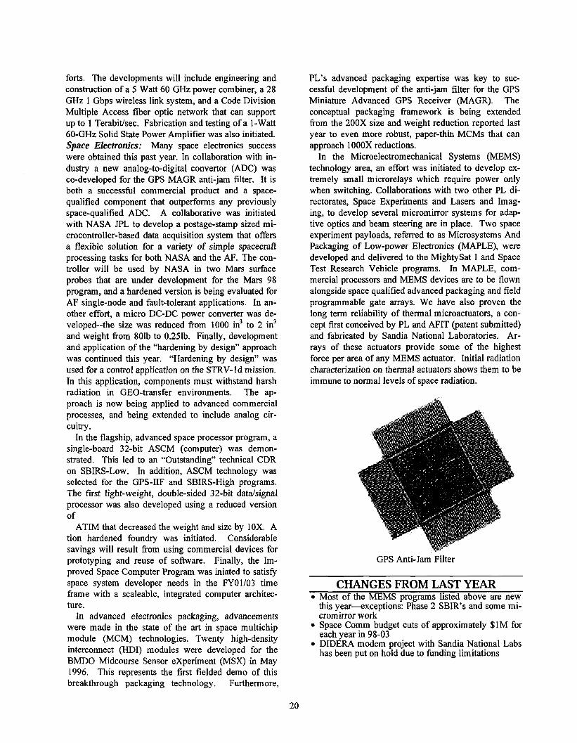
PL's advanced packaging expertise was key to suc-cessful development of the anti-jam filter for the GPS Miniature Advanced GPS Receiver (MAGR). The conceptual packaging framework is being extended fiom the 200X size and weight reduction reported last year to even more robust, paper-thin MCMs that can approach lOOOX reductions.
In the Microelectromechanical Systems (MEMS) technology area, an effort was initiated to develop ex- tremely small microrelays which require power only when switching. Collaborations with two other PL di- rectorates, Space Experiments and Lasers and Imag- ing, to develop several micromirror systems for adap- tive optics and beam steering are in place. Two space experiment payloads, referred to as Microsystems And Packaging of Low-power Electronics (MAPLE), were developed and delivered to the MightySat I and Space Test Research Vehicle programs. In MAPLE, com- mercial processors and MEMS devices are to be flown alongside space qualified advanced packaging and field programmable gate arrays. We have also proven the long term reliability of thermal microactuators, a con- cept first conceived by PL and AFIT (patent submitted) and fabricated by Sandia National Laboratories. Ar-rays of these actuators provide some of the highest force per area of any MEMS actuator. Initial radiation characterization on thermal actuators shows them to be immune to normal levels of space radiation.
GPS Anti-Jam Filter
CHANGES FROM LAST YEAR Most of the MEMS programs listed above are new this year-exceptions: Phase 2 SBIR's and some mi- cromirror work- Space Comm budget cuts of approximately $lM for each year in 98-03 DIDERA modem project with Sandia National Labs has been put on hold due to funding limitations
- -
Milestones I Year I Metrics Complete development of a neural-net controllednicromirror-based I FY98 I Deliver workinmicromirrors for insertion in the SX Smart
adaptive optics demonstration for test in the ache Point telescope, Adaptive Opticitestbed, then into the actual telescove svstem . I part of the VTISXILI collaboration followed b; insertion into multiple BMDQensor sy'stems Deliver spacequalifed Advanced Instrument Controller (AIC) mod- FY98 First space application of plastic form of HDI, which features 2
ules to NASAfor the Mars 98 surface probe weight reduction, 8X costreduction, and can withstand 30,000~I impacts and operate down to -13Qleg C
Demonstrate three-dimensional micro-card cage under the Highly Iat FY98 Demonstrate a generalized approach for packaging digital sy grated Packaging and Processing program
I over competing implementations) Develop beam steering mirror array for future optical sensorincluding I FY98 Demo on space experiment and insert in one future space system
satellite star, earth and sun trackers I Develo~. fabricate and testmicromirror-based s~atial light modulators I FY98 Ground test adaptive optics based omicromirror arrays in AF
for atmospheric and optical system aberration correctioi I telescope, and insert into one future space system, widely publis
Space sensor clutter model database completed I FY98 IModel radar clutter for comprehensive set of terrain types Tropical Rainfall Measuring Mission is launched containing 280 HDII FY98 I First demonstration of thin-filnMCMs built identicallv from
I MCMS I I three different vendors. 20X the capacitv of modules flown on I. . MSX
Develop usable MEMS-based IMU FY99 Insert intonanosatellite design or fly on aNASRJew Millen- nium spacecraft as demo for use in military component replm
THRUST 6: SPACE SYSTEM TECHNOLOGIES
USER NEEDS The Air Force policy of "Global Virtual Presence
requires a broad base of technologies that efficiently service current and future satellite systems. Space System Technology programs are firmly rooted in the Operational Requirements Document AFSPC 00-94, Satellite Control, 4 Aug 95 and the Satellite Operations Mission Area Plan, 20 Nov 95. The focus is on sup- porting warfighters and operational users by providing cost effective, efficient satellite navigation, command and control, onboard mission data prepara-tions/processing, precision orbit prediction, and mod- eling and simulation supporting technology trades and CONOPS evaluations. Space Information Dominance with the attendant Surveillance & Threat Warning and Battle Manage- ment, Command & Control: These areas require high speed decision support systems, data fusion, high-speed on-board signal processing, fast target detection, iden- tification, and targeting. High fidelity simulators and modeling of space environments are essential. Space Forces Support, Satellite Operations, and Sa t- ellite Operator Training: Technical needs relate to the reduction of manpower to monitor remote tracking stations and satellite health and status. Space Lntelligence, Surveillance & Reconnaissance
relevant to Space Control, Space Surveil- lance and Special Operations Forces: Ground control decision aids, automated ground control monitoring and autonomous spacecraft functions, and enhanced satellite navigation are required to accommodate future operations.
GOALS Space System Technologies goals are: Develop reusable, affordable software architectures for on-board and ground station processing, preci- sion navigation, precision orbit prediction, and space debris detection. Rely on others for basic software methods and tool development. Develop and apply software technology concepts to achieve an optimum level of satellite autonomy. Develop a flexible, object-oriented modeling and simulation environment that is capable of including all space assets.
MAJOR ACCOMPLISHMENTS Multimission Advanced Ground Intelligent Control
(MAGIC) system tracks all satellite passes at Falcon AFB Space Operations Complex (SOC) 33. This pro- vides telemehy storage and analysis for the operational life of satellites managed by SOC 33. MAGIC also demonstrated two autonomous anomaly detection sys- tems based on an expert and case based system. A automated pass-plan prototype and hypertext opera- tionltraining manuals were demonstrated. A low cost satellite decommutation system was demonstrated. A software architecture demonstrated the proof-of-concept that satellite software can be reused with con- fidence.
Achievements in FY97 for Modeling and Simulation
include contributing a Spacecraft Simulation Toolkit (SST)-based GPS simulation and a Virtual Cockpit to the ACC's Warrior Flag 97 wargame exercises. These simulations bring realistic modeling of navigational aids to the training and exercise community. Modeling and Simulation has also delivered: the SST baseline architecture; the Ultra-Lightweight Imaging Technol- ogy Experiment (Ultra-LITE) simulation; Space-Based Radar systems simulations; and limited bus health & status simulations used for satellite operator displays, anomaly resolution, and autonomous satellite opera- tion.
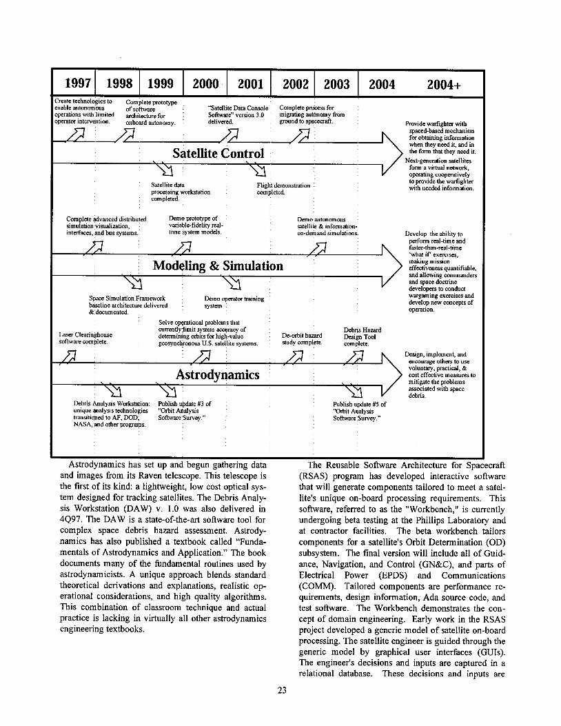
I I I I I I
'reate technolwes to Complete prototype nable autonomous of s o ~ a r e "Satellite Data Console Complete process for peratlons w~th l~m~ted architecture for Software" verslon 3.0 mlgratmg autonomy from Perator lntewentlon onboard autonomy deltvered ground to spacecraft Prov~de warfighter wth
spaced-based mechan~sm for o h n m g dormation when they need ~ t , and in the fom that they need it.
\ . Satellite Control .. Next-generatron satell~tes form a v~rtual network, operating cooperatrvely
Satelhte data Fl~ght demonstrahon to prov~de the warflghter processing workstation completed wth needed ~nformat~on completed
Complete advanced dstnbuted Demo prototype of Demo autonomous simulation v~sualization, vanable-fidehty real- satell~te& ~nformat~on-~nterfaces, and bus systems tlme system models on-demand s~mulat~ons. Develop the abllity to
perform real-tune and faster-than-real-tune 'what ~fexercises.
making mlssloneffectivenessquant~fiable,Modeling & Simulation and allowing commanders and space dochine developers to conduct
Space S~mulation Framework Demo operator baning wargaming exercises and
baselme architecture del~vered system develop new concepts of
& documented. operation.
Solve op@at~onal problems that currently hm~t system accuracy of Debns Hazard
Laser Clearinghouse detemmmng orb~ts for h~gh-value De-orb~t hazard bslgn~~~l software complete geosynchronous U S satelhte systems study complete complete
Des~gn, ~mplement, and encourage others to use
Astrodynamics voluntary, practical, & C O S ~effectwe measures to
< . mit~gate the problems assoc~ated with space debns.
Debns Analys~s Workstat~on Publ~sh update #3 of Publ~sh update #5 of unique analysis technolog~es "Orb~th a l y s ~ s 'Drb~t Analysis trans~honedto AF, DOD, SofhvareSuwey " Software Survey " NASA, and other programs
Astrodynamics has set up and begun gathering data and images from its Raven telescope. This telescope is (RSAS) program has developed interactive software the first of its kind: a lightweight, low cost optical sys- that will generate components tailored to meet a satel- tem designed for tracking satellites. The Debris Analy- lite's unique on-board processing requirements. This sis Workstation (DAW) v. 1.0 was also delivered in software, referred to as the "Workbench," is currently 4497. The DAW is a state-of-the-art software tool for undergoing beta testing at the Phillips Laboratory and complex space debris hazard assessment. Astrody- at contractor facilities. The beta workbench tailors namics has also published a textbook called "Funda- components for a satellite's Orbit Determination (OD) mentals of Astrodynamics and Application." The book subsystem. The final version will include all of Guid- documents many of the fbndamental routines used by ance, Navigation, and Control (GN&C), and parts of astrodynamicists. A unique approach blends standard Electrical Power (EPDS) and Communications theoretical derivations and explanations, realistic op- (COMM). Tailored components are performance re- erational considerations, and high quality algorithms. quirements, design information, Ada source code, and This combination of classroom technique and actual test software. The Workbench demonstrates the con- practice is lacking in virtually all other astrodynamics cept of domain engineering. Early work in the RSAS engineering textbooks. project developed a generic model of satellite on-board
processing. The satellite engineer is guided through the generic model by graphical user interfaces (GUIs). The engineer's decisions and inputs are captured in a relational database. These decisions and inputs are
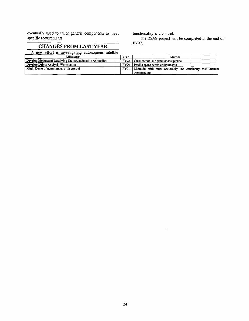
eventually used to tailor generic components to meet hnctionality and control. specific requirements. The RSAS project will be completed at the end of
CHANGES FROM LAST YEAR FY97.
A new effort is investigating autonomous satellite Milestones Year Metrics
Develop Methods of Resolving Unknown Satellite Anomalies FY98 Customer on-site product acceptance Develop Debris Analysis Workstation FY99 Predict space debris collision risk Flight Demo of autonomous orbit control FYOl Maintain orbit more accurately and efficiently than manual
commanding
THRUST 7: BATTLESPACE COMMUICATIONS AND OPERATIONS
USER NEEDS Control and exploitation of space is an Air Force
mission. To achieve this goal, techniques (including sensors and operational models) are developed to spec- ify and forecast the battlespace environment and its effects on Air Force systems and operations. Opera-tional needs, deficiencies, operational concepts, and technology needs are defined in Mission and Func- tional Area Plans in several areas. Space-Based Weather and Environmental Monitoring reflects that weather and environmental monitoring are backbone functions that cut across every command and military activity. All commands include weather and environmental monitoring to some extent in a variety of Mission and Functional Area Development Plans. Relevant extracts include: Navigation: The Navigation Systems Modernization Plan requires increased accuracy through carrier phase ambiguity resolution, system and ionosphere range error correction, and multipath reduction algorithms for user equipment as a near-term need applicable to all GPS users. GPS systems require increased robust- ness against signal fades due to scintillation, especially as solar activity increases.
Improved ionospheric modeling is needed to aug- ment GPS by using geosynchronous satellites such as Advanced MILSATCOM. Like requirements for im- proved GPS are also described in the Satellite Control and Intelligence, Surveillance and Reconnaissance (ISR) plans. Military Satellite Communications: There is a need to extend communications coverage into the polar re-gion, with its intense ionospheric disturbances for which no useful model yet exists. There is a require- ment to combat scintillation effects associated with polar and equatorial ionospheric disturbances. Force Application: There is a demand to characterize, predict, and in some cases mitigate the effects of the intense ionization that surrounds very high speed aero- space platforms. A related need is the ability for sys- tems to receive GPS signals during periods of intense ionization. Satellite Control: Critical RF communication links are susceptible to interruption by environmental distur- bances triggered by anomalous solar or geomagnetic space conditions. These disturbances can increase sat- ellite drag, alter orbits, cause high frequency (HF) blackout at high latitudes, alter the frequencies for HF communication links, and create ionospheric scintilla- tions that disturb ultra-high frequencylextremely-high frequency (UHF-EHF) communications.
Battle Management Command and Control ( B M L ~ ) : Includes improved Over-The-Horizon (OTH) radar for early launch detection and assessment. ACC, North America Air Defense Command and US Southern Command identify OTH radar as a solution for current C ~ Ideficiencies and state that OTH radar will be useful for counter-drug surveillance. Reliable use of OTH radar requires accurate specification and forecasting of the ionosphere, which controls OTH operational per- formance.
GOALS Specify and model the hazardous charged particle
environment throughout near-earth space so designers can maximize performance with minimum life-cycle costs. Measure key solar and interplanetary parameters for specification and forecast models to minimize space system degradation or failure.
Obtain a global, real-time capability to accurately specify and forecast the ionosphere, and provide timely warning of when, and how severely, ionospheric dis- turbances will disrupt C ~ Isystems. Assess the effect of ionospheric scintillations that degrade GPS accuracy or availability. Specify and predict the neutral density of the upper atmosphere within tolerances to meet opera- tional requirements for satellite tracking, reentry pre- dictions, detection of orbital changes, determination of satellite lifetimes plus on-board fuel requirements, and space debris hazard assessments.
Combine the energetic charged particle, ionospheric, and neutral density models into an Integrated Space Environment Model that monitors the environment in which space systems operate, and warns of hazards to space-and ground-based systems, like power transmission grids. Characterize and predict the intense ionization around hypervelocity platforms, quantify their effects on GPS radio signals, and develop techniques to control ioni- zation to alleviate radio blackout and decrease flight drag.
MAJOR ACCOMPLISHMENTS Assessed the over 150 million auroral electron spectra
obtained with DMSP instrumentation. In addition to providing a clearer picture of particle distribution (log normal-Gaussian, population behaviors) for auroral disturbance models, the study will yield a better tool to ascertain auroral boundaries, key indicators of atmos- pheric, ionospheric, and magnetospheric disturbance levels.
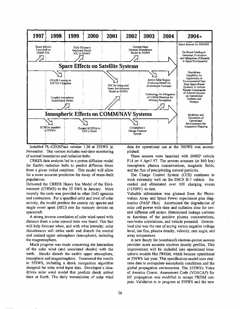
Space Sehsors Fully Dynam~c Coronal Mass ~aunchehon GeoSpace Model Eject~onDisturbance DMSP F14 IOC at 55SWS Model to 55SWS
;pace Sensors for NPOESS
On-Board Intelligent Detection, Evaluation,
and Mitigation of Hazards in Space Environment
Standalone Capability for Application of
Environmental Data from Space-Based Systems To Advise
Theatre Commander of Adverse Impacts
on Operational Systems and
Outages
\ Modeling and
/ Simulation of Operational
Environments for Acquistion Planning
Space Effects on Satellite Systems
i CEASE Launch on STP TX-5 ~4el l l te
i
i Coupled Ionospheric Scmtillahod Model
IOC for Integrated Space ~nviionment Model at 55SWS
\
Active Solar Region Evolution Model for
Disturbance Forecasts
Technology for Mitigation of COMM Blackout forMilitary Spaceplane
Ionospheric Effects on COMM/NAV Systems
SCMDA installed ; Expand SCINDA to at 55SWS GPS L-Band
Installed PL-GEOSPace version 1.30 at 55SWS in November. This version includes real-time monitoring of auroral boundaries and radiation belts.
CRRES data analysis led to a proton diffusion model for Earth's radiation belts to predict diffusion times from a given initial condition. This model will allow for a more accurate prediction for decay of storm-built populations. Delivered the CRRES Heavy Ion Model of the Envi- ronment (CHIME) to the 55 SWS in January. More recently the code was provided to other DoD agencies and contractors. For a specified orbit and level of solar activity, the model predicts the cosmic ray spectra and single event upset (SEU) rate for memory devices on spacecraft.
A strong inverse correlation of solar wind speed with distance from a solar coronal hole was found. This fact will help forecast when, and with what intensity, solar disturbances will strike earth and disturb the neutral and ionized upper atmosphere (ionosphere), including the magnetosphere.
Much progress was made concerning the interaction of the solar wind (and associated shocks) with the earth. Shocks disturb the earth's upper atmosphere, ionosphere and magnetosphere. Transioned the results to 55SWS, including a shock recognition algorithm designed for solar wind input data. Developed a data- driven solar wind model that predicts shock arrival time at Earth. The daily transmission of solar wind
COMM/NAV Outage Forecast
data for operational use at plished.
Three sensors were launched with DMSP vehicle F14 on 4 April 97. The sensors measure (at 840 km) ionospheric plasma concentrations, magnetic fields, and the flux of precipitating auroral particles.
The Charge Control System (CCS) continues to work extremely well on the DSCS B-7 vehicle. Re-corded and eliminated over 100 charging events (>1500V) to date. Valuable information was gleaned from the Photo- voltaic Array and Space Power experiment plus diag- nostics (PASP Plus). Ascertained the degradation of solar cell power with time and radiation dose for sev- eral different cell arrays. Determined leakage currents as functions of the positive plasma concentrations, ramlwake orientations, and vehicle potential. Determ-ined also was the rate of arcing versus negative voltage level, ion flux, plasma density, velocity, ram angle, and array temperature.
A new theory for (combined) electron-proton auroras provides more accurate electron density profiles. This improvement will be included into operational iono- spheric models like PRISM, which became operational at 55SWS last year. This specification model uses real- time data to extrapolate ionospheric conditions and the global propagation environment. The 55SWS's Voice of America Comm. Assessment Code (VOACAP) for HF propagation was modified to accept PRISM out- puts. Validation is in progress at 55SWS and the new
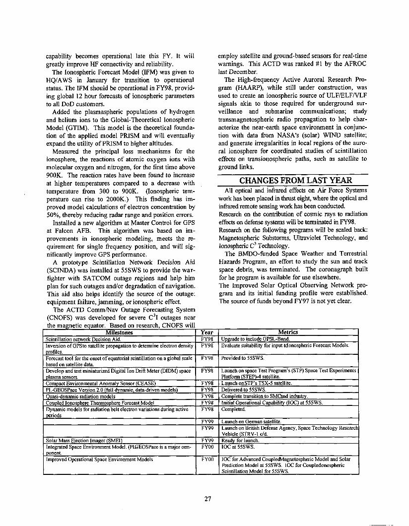
capability becomes operational late this FY. It will greatly improve HF connectivity and reliability.
The Ionospheric Forecast Model (IFM) was given to HQIAWS in January for transition to operational status. The IFM should be operational in FY98, provid- ing global 12 hour forecasts of ionospheric parameters to all DoD customers.
Added the plasmaspheric populations of hydrogen and helium ions to the Global-Theoretical Ionospheric Model (GTIM). This model is the theoretical founda- tion of the applied model PRISM and will eventually expand the utility of PRISM to higher altitudes.
Measured the principal loss mechanisms for the ionosphere, the reactions of atomic oxygen ions with molecular oxygen and nitrogen, for the first time above 900K. The reaction rates have been found to increase at higher temperatures compared to a decrease with temperature fiom 300 to 900K. (Ionospheric tem- perature can rise to 2000K.) This finding has im- proved model calculations of electron concentration by 50%, thereby reducing radar range and position errors.
Installed a new algorithm at Master Control for GPS at Falcon AFB. This algorithm was based on im-provements in ionospheric modeling, meets the re-quirement for single frequency position, and will sig- nificantly improve GPS performance.
A prototype Scintillation Network Decision Aid (SCINDA) was installed at 55SWS to provide the war- fighter with SATCOM outage regions and help him plan for such outages and/or degradation of navigation. This aid also helps identify the source of the outage: equipment failure, jamming, or ionospheric effect.
The ACTD CommhIav Outage Forecasting System (CNOFS) was developed for severe C ~ Ioutages near the magnetic equator.- Based on research, CNOFS will
Milestones Year Scintillation network Decision Aid. FY98 Inversion of GPSto satellite propagation to determine electron density FY98 . . -
profiles. Forecast tool for the onset of equatorial scintillation on a global scale FY98 based on satellite data. Develop and test miniaturized Digital Ion Drift Meter (DIDM) space FY98 plasma sensors Compact Environmental Anomaly Sensor (CEASE) FY98 PLGEOSPace Version 2.0 (full dynamic, data-driven models) FY98 Quasi-dynamic radiation models FY98 Coupled Ionosphere Thermosphere Forecast Model FY98 Dynamic models for radiation belt electron variations during active FY98
I FY99 I FY99
Solar Mass Ejection Imager (SMEI) FY99 Integrated Space Environment Model. (PLGEOSPace is a major can- FYOO ponent. I Improved Operational Space Environment Models I FYOO
27
employ satellite and ground-based sensors for real-time warnings. This ACTD was ranked #1 by the AFROC last December.
The High-frequency Active Auroral Research Pro- gram (HAARP), while still under construction, was used to create an ionospheric source of ULFIELFNLF signals akin to those required for underground sur-veillance and submarine communications; study transmagnetospheric radio propagation to help char- acterize the near-earth space environment in conjunc- tion with data fiom NASA's (solar) WIND satellite; and generate irregularities in local regions of the auro- ral ionosphere for coordinated studies of scintillation effects on transionospheric paths, such as satellite to ground links.
CHANGES FROM LAST YEAR All optical and infi.ared effects on Air Force Systems
work has been placed in thrust eight, where the optical and inkxed remote sensing work has been conducted. Research on the contribution of cosmic rays to radiation effects on defense systems will be terminated in FY98. Research on the following programs will be scaled back: Magnetospheric Substorms, Ultraviolet Technology, and Ionospheric c3Technology.
The BMDO-funded Space Weather and Terrestrial Hazards Program, an effort to study the sun and track space debris, was terminated. The coronagraph built for he program is available for use elsewhere. The Improved Solar Optical Observing Network pro- gram and its initial funding profile were established. The source of funds beyond FY97 is not yet clear.
Metrics Upgrade to include GPSL-Band. Evaluate suitability for input tdonospheric Forecast Models.
Provided to SSSWS.
Launch on space Test Program's (STP) Space Test Experiments Platform (STEP)-4 satellite. Launch onSTP's TSX-S satellite. Delivered to SSSWS. Complete transition to SMCand industry. Initial Operational Capability (IOC) at 55SWS. Completed.
( Launch on German satellite. I Launch on British Defense Agency, Space Technology Researc -.
Vehicle (STRV-I dd. Ready for launch. IOC at SSSWS.
1I IOC for Advanced Couplecblagnetospheric Model and Solar
Prediction Model at SSSWS. IOC for Coupledonospheric Scintillation Model for 55SWS.
THRUST 8: OPTICAL SURVEILLANCE EFFECTS AND BATTLESPACE OPERATIONS
USER NEEDS Exploitation of space and combat environments is key
to Air Force mission success. Important to achieving this goal is the development of techniques to accurately specify, forecast, and mitigate the battlespace environ- ment and its effects on Air Force systems and operations. The pervasive nature of space and combat environment effects is evident in all Commands in deficiencies identi- fied by Mission and Functional Area Plans. It is also rec- ognized by SMC, ESC, and ASC Technology Planning Integrated Product Teams (TPIPTs). Improved specifi- cation and forecasting of the battlespace environment for theater and strategic missile detection and tracking and for air and surface target acquisition in theater engage- ments are needs which impact all military operations: Surveillance and Threat Warning requires improved definition of target and background signatures to design new systems for missile warning, tracking, and intercept for theater and national missile defense. Technology needs for near and far term system concepts include background clutter and target data base measurements and modeling as well as discrimination algorithm devel- opment for SBIRS Geosynchronous/High Earth Orbit (GEOJHEO) and SBIRS Low Earth Orbit (LEO), the SpaceBorne Laser (SBL), and more advanced active sur- veillance systems. Combat Operations require improved target acquisition techniques and tactical decision aids incorporating ad- vanced theater weather forecast models for mission plan- ning and operations support. Technology needs for air- to-surface targeting include data retrieval techniques and cloud cover models for data-denied areas in threat thea- ters. Improved characterization of atmospheric laser propagation for target kill is needed by the AirBorne La- ser (ABL) system.
GOALS Goals for improved target-background discrimination
for surveillance and threat warning include: Measurelcharacterize the infi-ared and optical wavelength signatures of backgrounds and targets (including missile plumes) needed to discriminate target from their backgrounds. Developlvalidate computer codes to simulate ineared and optical atmospheric transmissions and backgrounds and celestial backgrounds to allow designers to optimize the performance of infrared and optical sensors for surveillance, tracking, and interceptor systems at minimum cost.
Goals for improved target acquisition for combat operations include:
Exploit space-based remote sensing technologies for application to theater requirements. Develop Weather Impact Decision Aids to allow operational users to predict electro-optical sensor system performance for all-weather operation. Measure and model small-scale atmospheric effects (including optical turbulence) on high-energy laser propagation for optimizing weapon system power, range, and time-on-target.
MAJOR ACCOMPLISHMENTS The Midcourse Space Experiment (MSX) satellite
performed over 200 data collection events during the ten month cryogenic operations period to provide critically needed data on spatial structure and variability in atmos- pheric, cloud, and terrain infixed backgrounds and key data on celestial backgrounds. A key discovery is high clutter level in the narrow medium-wavelength infrared (MWIR) band due to atmospheric gravity waves. The measured MWIR and LWIR (long-wavelength infrared) atmospheric scenes are needed for background model assessment to support SBIRS system engineering trade studies. An infrared astrometric catalog containing the most extensive survey of IR stars was constructed to pro- vide stellar on-board pointing and calibration for ad- vanced space-based surveillance and tracking systems.
Under the SBIRS Phenomenology Exploitation Pro- gram (PEP), MWIR and LWIR measurements of atmos- pheric, cloud, and terrestrial backgrounds made by the Miniature Sensor Technology Integration-3 (MSTI-3) satellite were used to provide small and large mosaic scenes and global background clutter statistics to assess SBIRS design performance and to determine how often performance may be degraded. MSTI-3 data is also be- ing used to validate background clutter models to provide reliable synthetic background scenes for the fill range of SBIRS operational conditions and system design trade space.
Beta versions of the Synthetic High Altitude Radiance (SHARC) and SHARC Image Generator (SIG) codes to generate two-dimensional images of high altitude IR background clutter were developed to extrapolate meas- ured background data to the full design trade space and all operational conditions for SBIRS and BMDO Theater and National Missile Defense target detection and track- ing concepts. The SBIRS Model Toolkit (SMT) for
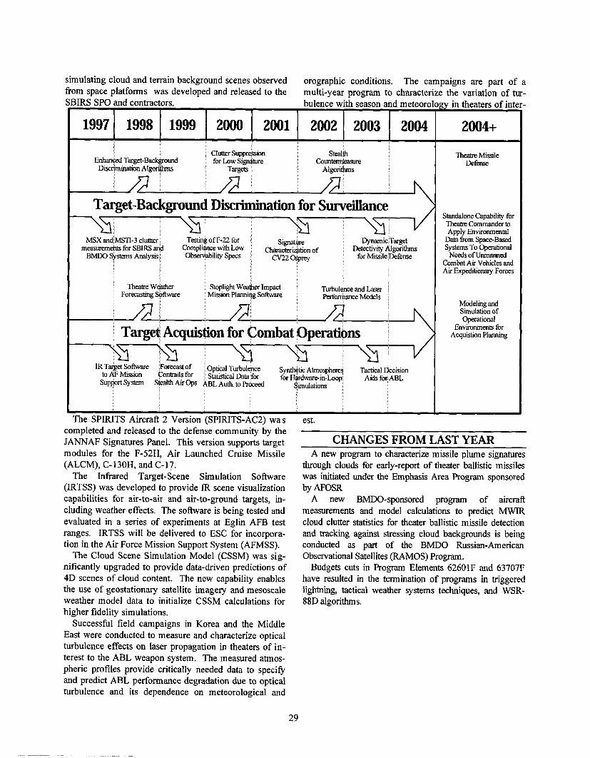
~ ~ ~
- -
simulating cloud and terrain background scenes observed orographic conditions. The campaigns are part of a from space platforms was developed and released to the multi-year program to characterize the variation of tur-
iIRS SPO and contractors. bulence with season and meteor0 gy in theaters of inte
1997 1998 1999 2000 2001 2002 2003 2004 2004+ IClutter Suppress~on 3 Stealth TheatreMissile
Enhanced Target-Back ound for Low Signature Counte- Defense ~iscrimmtion A,go$L Targets Algoritfuns
Target-Background Discrimhation for Surveillance \ /
Standalone Capability for TheatreCommander to Apply Environmental
Data h m Space-BasedMSX andhSTI-3 cluttter Teshng of F-22 for ~ ~measuremen& for SBIRS and Compliance w h Low ~ hof ~Detechv~tyAlgorithms ~ Systems To Operational ~ t
jBMDO Systems Analys~s Observablllty Specs for Mmle Jkfense Needs of Unmanned Combat Air Vehicles and
I1 Air Expeditionaty Forces
Theatre Weather Stopl~ghtWeather Impact TurbulemandLaser ! Forecasbng Sofhvare Mlss~on Plannag Software Performance Models
Modelingand Simulation of Operational
Acquistion Planning I Target Acquistion for Combat Operations \ Environments for
SupprI System StealthAa Ops
est. completed and released to the defense community by the JANNAF Signatures Panel. This version supports target CHANGES FROM LAST YEAR modules for the F-52H, Air Launched Cruise Missile A new program to characterize missile plume signatures (ALCM), C-130H, and C-17. through clouds for early-report of theater ballistic missiles
The Infrared Target-Scene Simulation Software was initiated under the Emphasis Area Program sponsored (IRTSS) was developed to provide IR scene visualization by AFOSR capabilities for air-to-air and air-to-ground targets, in- A new BMDO-sponsored program of aircraft cluding weather effects. The software is being tested and measurements and model calculations to predict MWIR evaluated in a series of experiments at Eglin AFB test cloud clutter statistics for theater ballistic missile detection ranges. IRTSS will be delivered to ESC for incorpora- and tracking against stressing cloud backgrounds is being tion in the Air Force Mission Support System (AFMSS). conducted as part of the BMDO Russian-American
The Cloud Scene Simulation Model (CSSM) was sig- Observational Satellites (RAMOS) Program. nificantly upgraded to provide data-driven predictions of Budgets cuts in Program Elements 62601F and 63707F 4D scenes of cloud content. The new capability enables have resulted in the termination of programs in triggered the use of geostationary satellite imagery and mesoscale lightning, tactical weather systems techniques, and WSR- weather model data to initialize CSSM calculations for 88D algorithms. higher fidelity simulations.
Successful field campaigns in Korea and the Middle East were conducted to measure and characterize optical turbulence effects on laser propagation in theaters of in- terest to the ABL weapon system. The measured atmos- pheric profiles provide critically needed data to specify and predict ABL performance degradation due to optical turbulence and its dependence on meteorological and
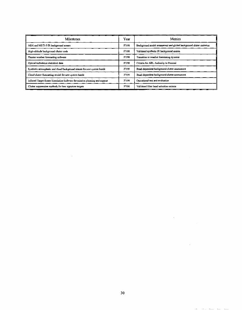
Milestones Year Metrics
MSX and MSTI-3 IR background scenes FY98 Background model assessment and global background clmer statistics
High-altitude background clutter code FY98 Validated synthetic IR background scenes -
([;eater weather forecasting software r~ ~ 9 8 --
to weather forewting systems T~rans i t i on
11 Optical turbulence statistical data r FY98 1 Criteria for ABL Authority to h e d
(1 Synthetic atmospheric and cloud background scenes for new system bands 1 FY99 I Band-dependent background clutter assessment 11 11 Cloud clutter forecasting model for new system bands 1 FY99 I Band-dependent background clutter assessment 1111 I n M Target-Scene Simulation Software for mission planning and suppat FY99 Operational test and evaluation
11 Clutter suppression methods for low signature targets 1 FYOO ( Validated filter band selection criteria 11
ABL - AirBorne Laser ACESS - Advanced Composite Ex-
perimental Spacecraft Structure ACTD - Advanced Concept Tech-
nology Demonstration ADC - Analog-to-Digital Converter AEF - Aerospace Engineering Facil-
ity AFIT - Air Force Institute of Tech-
nology AFMSS - Air Force Mission Support
System AFOSR - Air Force Office of Scien-
tific Research AL - Armstrong Laboratory ALCM - Air Launched Cruise Mis-
sile ALT - Anode Layer Thruster AMTEC - Alkali Metal Thermal
Electric Conversion ARIES - Applied Research In Energy
Storage ASIC - Application-Specific Inte-
grated Circuits ASTP - Advanced Sensor Technol-
ogy Program ATM - Asynchronous Transfer Mode BMDO - Ballistic Missile Defense
Organization C31- Command, Control, Communi-
cations, and Intelligence CAV - Common Aero Vehicle CCD - Charge Coupled Device CCS - Charge Control System CEASE - Compact Environmental
Anomaly Sensor CEP - Circular Error Probable CHIME - CRESS Heavy Ion Model
of the Environment CLEAR - Cooperative LEO Electroni-
cally Agile Radar CNOFS - Communication/ Naviga-
tion Outage Forecasting System CPV CRRES CSSM - Cloud Scene Simulation
Model DARPA - Defense Advanced Re-
search Projects Agency DMSP - Defense Meteriological Sat-
ellite Program
GLOSSARY
EHF - Extremely-High Frequency E-0 - Electro-optical ESA - European Space Agency FDDI - Fiber Optic Digital
Data Interface GaAs - Gallium Arsenide GEO - Geosynchronous Earth Orbit GPS - Global Positioning Satellite GTIM - Global-Theoretical Iono-
spheric Model HAARP - High-frequency Active
Auroral Research Project I-IAN - Hydroxyl Ammonium Nitrate HDBTDC - Hardened and Deeply
Buried Targets Defeat Capability HDI - High-Density Interconnect HEDM - High Energy Density Mate-
rial HE0 - High Earth Orbit HF - High Frequency HgCdTe - Mercury Cadmium Tellu-
ride ICBM - Inter-Continental Ballistic
Missile IFM - Ionospheric Forecast Model IMU - Inertial Measurement Unit INS - Inertial Navigation System IPV - Inertial Penetrator Vehicle IR - Infrared IHPRPT - Integrated High Payoff
Rocket Propulsion Technology IRTSS - Infrared Target-Scene
Simulation S o h a r e ISR - Intelligence, Surveillance, and
Reconnaissance ISTD - Integrated Space Technology
Demonstrations JANNAF - Joint Army, Navy,
NASA, Air Force L A S E - Linear Aerospike SR-71
Experiment LED - Light Emitting Diode LEO - Low-Earth Orbit LWIR - Long-Wave Infrared M&S - Modeling and Simulation MAGIC - Multimission Advanced
Ground Intelligent Control MAGR - Miniature Advanced GPS
Receiver
MANTECH - Manufacturing Tech- nology
MAP - Mission Area Plan MAPLE - Microsystems And Pack-
aging of Low-Power Electronics MCM - Multichip Module MEMS - Microelectromechanical
System MSX - Mid-Course Sensor experi-
ment MTD - Missile Technology Demon-
stration MWIR - Mid-Wave Infrared NOAA - National Oceanic and At-
mospheric Administration OSP - Orbital/Suborbital Program OTH - Over The Horizon PEP - Phenomenology Exploitation
Program PL - Phillips Laboratory PPT - Pulsed Plasma Thruster PRISM - Parameterized Real Time
Ionospheric Specification QWIP - Quantum-Well Infrared
Photodetector RAMOS - Russian-American Obser-
vational Satellites RF - Radio Frequency RL - Rome Laboratory S&T - Science and Technology SBIR - Small Business Innovative
Research SBIRS - Space-Based InfiaRed Sys-
tem SBL - Space-Based Laser SBR - Space-Based Radar SCMDA - Scintillation Network
Decision Aid SEU - Single Event Upset SHARC - Synthetic High Altitude
Radiance SIG - SHARC Image Generator SMC - Space & Missile Systems
Center SMEI - Solar Mass Ejection Imager SMT - SBIRS Model Toolkit SOX - Solid Oxygen SPEAR - Space Electronically Agile
Radar SPIRITS

SPREE - Shuttle Potential and Re- turn Electron Experiment
STIG - Space Technology Inter- agency Group
STRV - Space Technology Research Vehicle
TA - Technology Area
TAP - Technology Area Plan TMD - Theater Missile Defense TOC - Tactical Operations Center TPIPT - Technology Planning Inte-
grated Product Teams TRAM - TransrnittingfReceiving
Antenna Module
TSS - Tethered Satellite System UHF - Ultra-High Frequency VOACAP - Voice of America Com-
munication Assessment Code WL - Wright Laboratory

Air Force Office of Scientific Research (AFOSR), 2, 28, 29
Air Force Space Command (AFSPC), 7, 9, 12, 15, 20
Applied Research In Energy Storage (ARIES), 2
Armstrong Laboratory (AL),3 Autonomous Satellite Operations,
14
ballistic missile, 5 Ballistic Missile Defense
Organization (BMDO), i, 2, 3, 10, 15, 17, 18, 24, 27, 28, 29
Communications, 2,3,10,17,18,24,26
Debris, ii, 9, 22, 23, 24, 25, 27 Defense Advanced Research Projects
Agency (DARPA), 29 deficiencies, 4, 5 Demonstration, 12, 14 Department of Defense (DoD), i, 12,
15, 16, 23,24 DoD, i
Electronics, 2,17,18,19,20 European Space Agency (ESA), 4
Global Positioning Satellite (GPS), 2, 3, 4, 12, 13, 14, 17, 18, 22, 24, 29
INDEX
Global Virtual Presence, 20 GPS, 3
High Energy Density Matter (HEDM), 2
IHPRPT, 5 Integrated High Payoff Rocket
Propulsion Technology (IHPRPT), 4 ,5 ,6 ,7
Integrated Space Technology Demonstrations (ISTD), 13, 14, 29
Jet Propulsion Lab (JPL), 3
Manufacturing Technology (MANTECH), 3,29
materials, 2, 3, 5 MightySat, 10, 13, 14, 18 MILSATCOM, 3,9, 17,22 Missile Technology Demonstration
(MTD), 2, 12, 13, 14,29 Mission Area Plan (MAP), i, 29 Modeling and Simulation,
17,19,22
NASA, i, 3, 4, 5, 7, 9, 10, 13, 16, 17, 19,24
Optical Surveillance Effects, 2,4,27
P power
i,ii,3,10,11,12,17,18,19,20,24,25, 27
powerhead, 6 Propulsion, 3, 4, 5, 7, 8 Pulsed Plasma thruster (PPT), 7, 8,
29
rocket, 7 Rome Laboratory (RL), 3,17
Science and Technology (S&T), i, 29 Sensors, 3, 4, 14, 15, 17, 18, 19, 22,
23, 24,26 SMC,5,7,9, 11, 12, 16,24,26,29 Sodium Sulfur (NaS), 11 Solar, 5, 11 i Space and Missile Systems Center
(SMC), 11, 12, 15, 18,21 Space and Missiles, i, 2, 4 Space Systems, 4, 5,9, 12, 15,22 Space Vehicles, 2, 5 spacelift, 5 structures, i, 10,11,12
Technology Area Plan (TAP), i, 3,4, 30
Technology Planning Integrated Product Teams (TPIPT), i, 15,30
thermal management, ii, 10 transition, 11
Warfighter, 14, 16, 24 Wright Laboratory (WL), 3