Environmentally Degradable Bio-Based Polymeric Blends and Composites
Upload
independentCategory
view
0download
0
www.MaterialsViews.comwww.advenergymat.de
FULL P
APER
© 2014 WILEY-VCH Verlag GmbH & Co. KGaA, Weinheim (1 of 10) 1301437wileyonlinelibrary.com
Fullerene Nucleating Agents: A Route Towards Thermally Stable Photovoltaic Blends
Camilla Lindqvist , Jonas Bergqvist , Ching-Chiao Feng , Stefan Gustafsson , Olof Bäcke , Neil D. Treat , Céline Bounioux , Patrik Henriksson , Renee Kroon , Ergang Wang , Anke Sanz-Velasco , Per Magnus Kristiansen , Natalie Stingelin , Eva Olsson , Olle Inganäs , Mats R. Andersson , and Christian Müller *
C. Lindqvist, C.-C. Feng, Dr. P. Henriksson, Dr. R. Kroon, Dr. E. Wang, Prof. M. R. Andersson, Dr. C. Müller Department of Chemical and Biological Engineering/Polymer Technology Chalmers University of Technology 41296 Göteborg , Sweden E-mail: [email protected] J. Bergqvist, Prof. O. Inganäs Biomolecular and Organic Electronics Department of Physics Chemistry and Biology Linköping University 58183 Linköping , Sweden Dr. S. Gustafsson, O. Bäcke, Prof. E. Olsson Department of Applied Physics Chalmers University of Technology 41296 Göteborg , Sweden
Dr. N. D. Treat, Dr. N. Stingelin Department of Materials and Centre for Plastic Electronics Imperial College London London SW7 2AZ , UK Dr. C. Bounioux Department of Solar Energy and Environmental PhysicsJacob Blaustein Institutes for Desert Research Ben-Gurion University of the Negev, Sede Boqer Campus 84990 Midreshet Ben-Gurion , Israel Dr. A. Sanz-Velasco Department of Microtechnology and Nanoscience – MC2 Chalmers University of Technology 41296 Göteborg , Sweden Dr. P. M. Kristiansen Institute of Polymer Nanotechnology (INKA) University of Applied Sciences and Arts Northwestern Switzerland (FHNW) 5210 Windisch , Switzerland DOI: 10.1002/aenm.201301437
light-harvesting active layer is composed of bulk-heterojunctions, i.e., blends of a polymeric electron-donor (hole-conductor) and an electron-acceptor (electron-con-ductor), with fullerene derivatives yielding particularly promising results. Thanks to recent advances in the synthesis of donor materials, power-conversion effi ciencies of 8–10% can now be achieved with lab-scale devices. [ 1 ]
The precise bulk-heterojunction nano-structure, i.e., the distribution of donor and acceptor molecules, is crucial for maxi-mizing the photovoltaic performance for a given blend composition. This is because a compromise has to be made between two critical aspects: i) a large contact area between donor and acceptor molecules aids charge generation and thus a fi nely inter-mixed blend is favored, and ii) percolation of separated, relatively phase-pure donor and acceptor domains to improve charge trans-port to the electrodes. Therefore, the ideal nanostructure features an intermediate
degree of phase separation, which has to be carefully optimized through processing parameters such as the choice of solvent or solvent mixture, the blend stoichiometry and polymer molecular weight as well as post-deposition thermal or vapor annealing.
The bulk-heterojunction nanostructure of non-crystalline polymer:fullerene blends has the tendency to rapidly coarsen when heated above its glass tran-sition temperature, which represents an important degradation mechanism. We demonstrate that fullerene nucleating agents can be used to thermally arrest the nanostructure of photovoltaic blends that comprise a non-crystal-line thiophene-quinoxaline copolymer and the widely used fullerene derivative [6,6]-phenyl-C 61 -butyric acid methyl ester (PCBM). To this end, C 60 fullerene is employed to effi ciently nucleate PCBM crystallization. Sub-micrometer-sized fullerene crystals are formed when as little as 2 wt% C 60 with respect to PCBM is added to the blend. These reach an average size of only 200 nanometers upon introduction of more than 8 wt% C 60 . Solar cells based on C 60 -nucleated blends indicate signifi cantly improved thermal stability of the bulk-heterojunction nanostructure even after annealing at an elevated temperature of 130 °C, which lies above the glass transition temperature of the blend. Moreover, we fi nd that various other compounds, including C 70 fullerene, single-walled carbon nanotubes, and sodium benzoate, as well as a number of commercial nucleating agents—commonly used to clarify isotactic polypropylene—permit to control crystallization of the fullerene phase.
1. Introduction
Polymer solar cells attract considerable attention because they offer cost-effective processing from solution. Typically, the
Adv. Energy Mater. 2014, 4, 1301437

www.MaterialsViews.comwww.advenergymat.de
FULL
PAPER
© 2014 WILEY-VCH Verlag GmbH & Co. KGaA, Weinheim1301437 (2 of 10) wileyonlinelibrary.com
Today, many research groups are able to prepare small-area polymer solar cells that display high power conversion effi cien-cies under controlled laboratory conditions. During formation of the active layer from solution no heating is necessary to remove the solvent since there are no constraints on the drying time. Similarly, the application of the top electrode does not require a heating step per se. Finally, solar cell performance testing is carried out close to ambient temperature and over a short period of time, which neglects ageing effects.
However, to upscale device fabrication to large-area module production, a high-throughput roll-to-roll process has to be implemented, which requires several heating cycles to ensure solvent removal after deposition of each layer at an economical speed. For this purpose, elevated temperatures of up to 140 °C are needed during the printing process. [ 2 ] Moreover, standard test protocols, which have to be passed in order to certify a solar cell as thermally stable, demand repeated heating to 85 °C. [ 3 ]
From the point of view of equilibrium thermodynamics, bulk-heterojunction blends are metastable materials. There-fore, the blend nanostructure and thereby also their photovol-taic performance tend to evolve with time. Elevated processing and operating temperatures pose a formidable challenge to the long-term stability of these materials, which has to be addressed before practical applications can be considered. One parameter that can only be controlled with great diffi culty is the distribu-tion of the fullerene material in the blend. Fullerenes have the strong tendency to vitrify, i.e., they form a molecular glass. [ 4,5 ] Typically, this resistance of fullerenes towards crystallization is further aggravated in bulk-heterojunction blends, in particular if the donor material is a high molecular weight polymer. [ 6 ] The most widely used fullerene derivative [6,6]-phenyl-C 61 -butyric acid methyl ester (PCBM) has a high glass transition temper-ature Tg
PCBM ≈ 110–140 °C. [ 7–9 ] As a result, polymer:fullerene blends tend to have a Tg
blend above ambient temperature. [ 5,7,9,10 ] Thus, it is possible to freeze in a certain degree of phase separa-tion between PCBM and the donor polymer after evaporation of the processing solvent. However, upon heating above Tg
blend fullerene molecules start to diffuse in the polymer matrix, slowly aggregate and eventually form micrometer-sized crystals. As a result, less optimal nanostructures develop, which leads to a detrimental decrease in power conversion effi ciency. [ 5,11,12 ]
A number of chemistry-based strategies have been explored that permit to arrest the nanostructure of bulk-heterojunction blends. Those include cross-linking reactions of the donor polymer [ 13 ] or fullerene acceptor, [ 14 ] removal of solubilizing side chains by thermocleaving [ 15 ] as well as the use of fullerene-con-taining compatibilizers, [ 16 ] non-crystalline fullerene additives [ 17 ] or high- T g materials. [ 18,19 ] However, all of these approaches require chemical modifi cations that increase the structural complexity of the employed semiconductors and thus are likely to reduce the cost-effectiveness of polymer solar cells.
Instead, straightforward thermodynamic rationales can be used to improve the thermal stability of bulk-heterojunction blends. Some donor polymers are able to crystallize and the formation of ordered domains can slow down phase separa-tion. For instance, Ma et al. have shown that the use of semi-crystalline poly(3-hexylthiophene) (P3HT) imparts some resist-ance to phase separation at temperatures as high as 150 °C. [ 20 ] Nevertheless, fullerene acceptor molecules can diffuse in the
remaining disordered P3HT domains as soon as the blend is heated above its low Tg
P HT PCBM3 : ≈ 40 °C, which eventually leads to aggregation. [ 7,21 ] Many other donor polymers that are investigated today lack the ability to form extended crystalline domains. When these materials are used, control of the blend nanostructure is particularly challenging. When heated to tem-peratures above Tg
blend, phase separation continuously increases and micrometer-sized fullerene crystals rapidly form. [ 9,18 ]
One promising non-crystalline donor is the copolymer poly[2,3-bis-(3-octyloxyphenyl)quinoxaline-5,8-diyl- alt -thio-phene-2,5-diyl] (TQ1) (see Figure 1 a for chemical structure), which is easily synthesized, permits solar cell effi ciencies of up to 6–7%, [ 22,23 ] has a high Tg
TQ 1 ≈ 100 °C [ 24 ] and displays liquid-crystalline order at best. [ 25 ] Nevertheless, its use has so far been limited by the fact that fullerene crystallization in TQ1:PCBM blends is limited by a severe lack of nucleation of PCBM crys-tals. [ 5 ] As a consequence, the fullerene is present in an amor-phous state in as-cast blend fi lms. However, as soon as this system is heated above Tg
TQ PCBM1: ≈ 110 °C, micrometer-sized PCBM crystals are found to form independent of the chosen annealing protocol.
In the present study, we demonstrate that the nucleation of fullerene material in TQ1:PCBM blends can be readily controlled through the addition of C 60 as well as a number of other compounds, including C 70 fullerene, single-walled carbon nanotubes, sodium benzoate and several commercial nucle-ating agents that are commonly used to modify the optical properties of isotactic polypropylene [ 26,27 ] and more recently organic semiconductors including PCBM. [ 28 ] Conveniently, the use of C 60 , which is the starting material for the synthesis of fullerene derivatives such as PCBM, promises to be particularly cost-effective. Recently, Richards et al. have used this approach in combination with semi-crystalline P3HT:PCBM blends but concluded that as much as 50 wt% of PCBM has to be replaced with C 60 in order to reduce the size of fullerene crystals to less than one micrometer. [ 12 ] Encouraged by these results, we here establish that C 60 is an effective nucleating agent for PCBM and show that sub-micrometer-sized fullerene crystals can be obtained by replacing as little as 2 wt% of PCBM with C 60 . As a result, we are able to signifi cantly enhance the thermal stability of the here studied non-crystalline polymer:fullerene bulk-het-erojunction blends.
2. Results and Discussion
We set out with the hypothesis that the addition of C 60 intro-duces heterogeneous nucleation sites that initiate fullerene crystallization. [ 12 ] Thus, in a fi rst set of experiments we used differential scanning calorimetry (DSC) to examine the bulk nucleation kinetics of reference PCBM and of the fullerene material in TQ1:PCBM bulk-heterojunction blends. In order to ensure good distribution of C 60 , materials were fi rst blended in ortho -dichlorobenzene ( o DCB), which can dissolve up to 27 g L −1 of C 60 at ambient temperature, [ 29 ] followed by evapo-ration of the solvent. Then, DSC was performed on the dried powder. We recorded cooling thermograms of neat as well as C 60 -nucleated samples after heating to 295 °C, in order to ensure complete melting by heating far above the peak melting
Adv. Energy Mater. 2014, 4, 1301437

www.MaterialsViews.comwww.advenergymat.de
FULL P
APER
© 2014 WILEY-VCH Verlag GmbH & Co. KGaA, Weinheim (3 of 10) 1301437wileyonlinelibrary.com
temperature T m ≈ 280 °C of reference PCBM and T m ≈ 275 °C of the fullerene material in TQ1:PCBM. Then, peak crystalliza-tion temperatures of neat and C 60 -nucleated samples, Tc
0 and Tc
nuc , were extracted from the corresponding crystallization exotherms. Non-nucleated samples display the lowest crystalli-zation temperatures and we deduce Tc
0 ≈ 240 °C for neat refer-ence PCBM and Tc
0 ≈ 234 °C for neat TQ1:PCBM. In contrast, addition of C 60 to PCBM as well as TQ1:PCBM blends results in a pronounced shift of the crystallization exotherm to higher temperatures, which is a reliable indicator that C 60 -nucleation has indeed occurred (Figure 1 b,c). [ 26,28,30 ] In the following, the C 60 content fC60
is given with respect to the PCBM fraction. For reference PCBM, we observe an increase in crystalliza-tion temperature for fC60 ≥ 0.3 wt%, which reaches a constant value for fC60 ≥ 1 wt% with an average peak Tc
nuc ≈ 268 ± 2 °C (Figure 1 d). Similarly, for TQ1:PCBM an average peak Tc
nuc ≈ 244 ± 1 °C is obtained if fC60 ≥ 2 wt% is added. We note that optimal C 60 nucleation raises the crystallization temperature of reference PCBM to a larger extent as compared to TQ1:PCBM
blends, which indicates that the polymer at least partially hin-ders the formation of C 60 nucleation sites and therefore delays the crystallization process.
It is convenient to express the nucleating effi ciency, NE , of a nucleating agent with respect to optimally self-seeded material according to: [ 30 ]
NE
T
T
T T
T Tcnuc
c
cnuc
c
c cmax
0
max 0= ΔΔ
= −−
(1)
Here, Tcmax is the highest possible crystallization tempera-
ture that can be obtained for optimally nucleated samples, which can be realized through nucleation by a large amount of yet unmolten PCBM seed crystals. Thus, we carried out self-seeding studies by incomplete melting of PCBM. DSC cooling thermograms of samples heated above 282 °C reveal little variation in crystallization temperature, which indicates com-plete melting of PCBM. Instead, samples heated to 282 °C or less display an increase in crystallization temperature during
Adv. Energy Mater. 2014, 4, 1301437
Figure 1. a) Chemical structure of TQ1, PCBM and C 60 . b) DSC cooling thermograms of PCBM with varying C 60 content. c) DSC cooling thermograms of TQ1:PCBM with varying C 60 content. d) Peak crystallization temperatures extracted from DSC cooling thermograms of PCBM (open circles) and TQ1:PCBM (full diamonds) with varying C 60 content. e) DSC heating and cooling thermograms of PCBM after partially melting at different self-seeding temperatures T s = 275, 280, 282 °C and after complete melting at 295 °C. f) DSC heating and cooling thermograms of TQ1:PCBM after self-seeding at different T s = 272, 278, 282 °C and after complete melting at 295 °C.

www.MaterialsViews.comwww.advenergymat.de
FULL
PAPER
© 2014 WILEY-VCH Verlag GmbH & Co. KGaA, Weinheim1301437 (4 of 10) wileyonlinelibrary.com
subsequent cooling due to self-seeding by remaining PCBM crystals. For reference PCBM we fi nd a peak Tc
max ≈ 268 °C (Figure 1 E). Instead, for TQ1:PCBM blends self-seeding only raises the peak crystallization temperature to 242 °C, which indicates that the polymer signifi cantly hinders crystallization (Figure 1 F). Therefore, we used Tc
max ≈ 268 °C to calculate the nucleating effi ciency relative to self-seeding of neat PCBM. We obtain NE ≈ 100% for neat PCBM nucleated with fC60 ≥ 1 wt% and NE ≈ 30% for TQ1:PCBM nucleated with fC60 ≥ 2 wt%. [ 31 ] Evidently, the presence of a suffi cient amount of C 60 nucleates PCBM crystallization to the same extent as PCBM seed crystals. We propose that once the miscibility limit of C 60 in PCBM or TQ1:PCBM is reached, C 60 crystallites form in molten PCBM, which can act as nucleation sites during solidifi cation and thus give rise to the observed increase in crystallization temperature.
In a further set of experiments we investigated the ability of C 60 to nucleate PCBM in ≈50 nm thick TQ1:PCBM fi lms, which were prepared by spin-coating on PEDOT:PSS coated glass in order to closely resemble solar cell active layers. All prepared fi lms appeared featureless independent of fC60
, which indicates that no signifi cant PCBM crystallization had occurred during deposition from solution. Films were subsequently annealed above Tg
blend ≈ 110 °C. [ 5 ] We chose an annealing tem-perature of 130 °C because according to our previous study at these conditions the rate of fullerene crystallization is princi-pally governed by the rate of nucleation. [ 5 ] Optical microscopy was used to screen samples and the absence of microscopic PCBM crystals for fC60 ≥ 5 wt%, which reach a length of 2 ± 1 µm in neat TQ1:PCBM fi lms, was taken as evidence that a high degree of nucleation had indeed occurred ( Figure 2 a). Scanning and transmission electron microscopy (SEM and TEM) was car-ried out to examine nucleated TQ1:PCBM fi lms in more detail, which revealed a large number of ≈200 nm small fullerene clusters for a C 60 content of fC60
≥ 8 wt% (Figure 2 b,c; see Sup-plementary Information Figure S1 for lower magnifi cation TEM images). We used electron diffraction to study the nano-structure of fullerene clusters in more detail (Figure 2 d). For fC60 ≈ 5 wt% and fC60
≈ 10 wt% the diffraction patterns obtained from fullerene clusters are consistent with single crystal orien-tation. In contrast, samples with a higher C 60 content of fC60
≈ 20 wt% reveal ring patterns characteristic of polycrystalline areas, which suggest that most fullerene clusters are composed of smaller crystallites with different orientations. Strikingly, for the investigated range of C 60 composition the amount of fullerene clusters increases by three orders of magnitude from only 0.02 clusters per µm 2 for fC60
≤ 2 wt% to more than 20 clusters per µm 2 for fC60
≥ 8 wt% (Figure 2 e). Accordingly, the separation distance of adjacent fullerene clusters decreases strongly from several micrometers to less than 100 nm for fC60
≥ 10 wt% leading to a continuous network. Careful inspection of TEM images reveals that for reference TQ1:PCBM a deple-tion zone surrounds fullerene crystals, which is composed of a TQ1-rich phase. Additionally, other parts of the same fi lm feature amorphous PCBM-rich domains with a characteristic size of about ≈30–50 nm, which are surrounded by a TQ1-rich phase. We base this interpretation on two previous studies, in which we have characterized the nanostructure of this blend in detail using TEM, electron diffraction and electron tomog-raphy. [ 5,32 ] By contrast, C 60 -nucleated samples are composed of
only two phases, i.e. fullerene crystals and a TQ1-rich phase, which suggests that fullerene crystallization is largely complete.
We performed photoluminescence (PL) spectroscopy to examine the purity of the TQ1-rich phase and calculated the PL quenching ratio Φ according to:
PL ( )d / PL ( )d1: 1TQ PCBM TQ∫∫ λ λ λ λΦ =
(2)
where TQ PCBMPL ( )1: λ and TQPL ( )1 λ are the PL spectrum of TQ1:PCBM and reference TQ1, respectively. Spin-coated fi lms featured a large degree of PL quenching with Φ ≈ 0.5% for fC60
= 0 wt% as well as fC60 ≈ 10 wt% ( Figure 3 ), which indi-
cates fi nely intermixed bulk-heterojunction blends with excel-lent contact between the donor polymer and fullerene acceptor molecules. Upon annealing at 130 °C for 10 min, the PL of all blend fi lms increased signifi cantly, resulting in less quenching with Φ ≈ 2.5% for neat TQ1:PCBM and Φ ≈ 3% for fC60
= 5–20 wt% (Figure 3 ). Moreover, the similar shape of reference TQ1 and all recorded blend spectra indicates that, indeed, polymer emission is observed. We conclude that annealing partially depletes the TQ1-phase of fullerene acceptor, which instead assembles into PCBM crystals. A limited amount of fullerene remains dissolved in the TQ1-rich phase, which is corroborated by the observation that the polymer PL emission continues to be relatively strongly quenched. In addition, we notice that the peak melting temperature of PCBM in the blend is ≈5 °C lower than T m of reference PCBM, which indicates partial miscibility also at elevated temperatures. [ 5 ]
The rate of fullerene crystallization is an important stability parameter. We again employed PL spectroscopy and monitored the increase in Φ of annealed blends with fC60
≈ 10 wt%. The rate of change of Φ is related to the depletion rate of fullerene material from TQ1-rich domains, which instead crystallizes. Initially, we observe a rapid increase from Φ ≈ 0.5% to Φ ≈ 3% after annealing for 10 min at 130 °C, indicating an increase in the purity of TQ1 domains (Figure 3 ). Further annealing results in a more modest increase to Φ ≈ 4% after 30 min. This is in contrast to reference TQ1:PCBM blends, for which we observe a linear increase in Φ. We conclude that for blends with fC60
≈ 10 wt% most PCBM crystallization is complete after only 10 min followed by more gradual evolution of the nanostruc-ture during additional annealing. In agreement with our TEM analysis, the addition of C 60 to TQ1:PCBM blends signifi cantly increases the overall rate of fullerene crystallization.
We tested the stability of C 60 -nucleated TQ1:PCBM blends in complete solar cells. The active layer was spin-coated onto ITO/PEDOT:PSS bottom contacts, followed by annealing at 130 °C (see Experimental for full description of device prepa-ration). Finally, LiF/Al top contacts were evaporated onto the active layer. We argue that this sequence of processing steps most closely resembles high-temperature annealing that needs to be implemented in order to realize high-throughput printing, which requires rapid removal of the processing sol-vent before additional layers can be applied. [ 2 ] Initially, we compared TQ1:PCBM devices that cover the full C 60 composi-tion range, i.e. fC60
= 0–100 wt% (Supplementary Information, Figure S2). For non-annealed devices, we fi nd that for up to fC60
≈ 50 wt% the short-circuit current density J sc and fi ll factor FF are not affected. Strikingly, we only observe a slight decrease
Adv. Energy Mater. 2014, 4, 1301437
www.MaterialsViews.comwww.advenergymat.de
FULL P
APER
© 2014 WILEY-VCH Verlag GmbH & Co. KGaA, Weinheim (5 of 10) 1301437wileyonlinelibrary.com
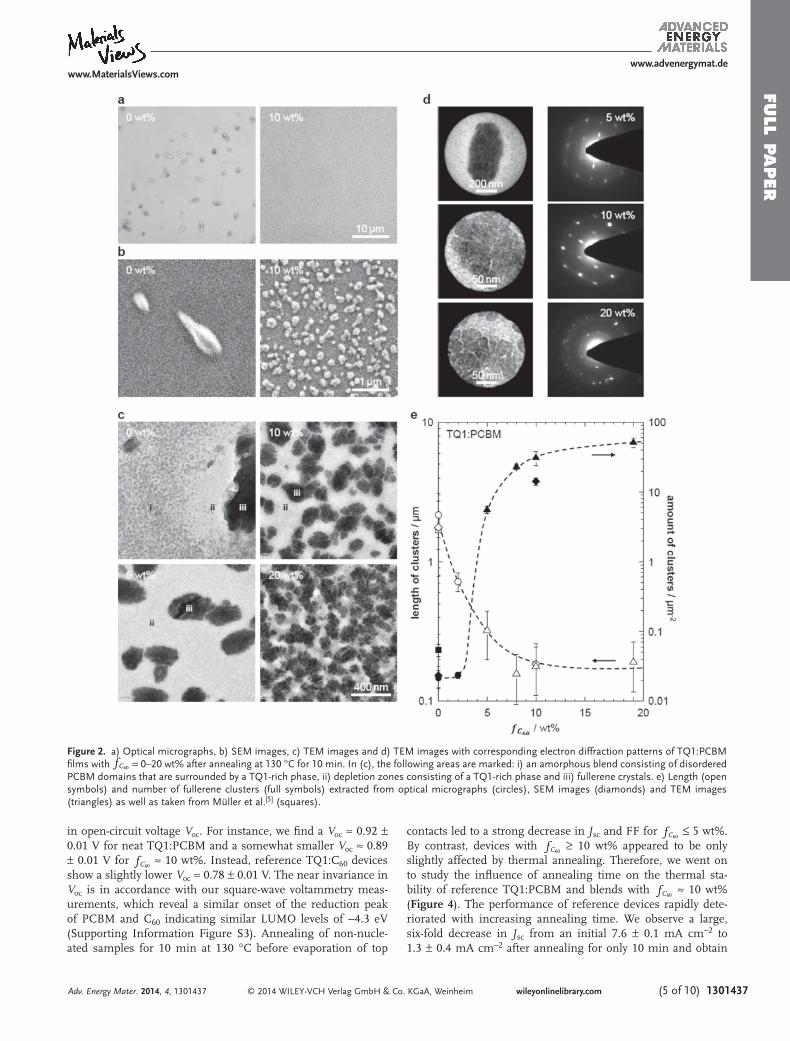
in open-circuit voltage V oc . For instance, we fi nd a V oc ≈ 0.92 ± 0.01 V for neat TQ1:PCBM and a somewhat smaller V oc ≈ 0.89 ± 0.01 V for fC60
≈ 10 wt%. Instead, reference TQ1:C 60 devices show a slightly lower V oc ≈ 0.78 ± 0.01 V. The near invariance in V oc is in accordance with our square-wave voltammetry meas-urements, which reveal a similar onset of the reduction peak of PCBM and C 60 indicating similar LUMO levels of −4.3 eV (Supporting Information Figure S3). Annealing of non-nucle-ated samples for 10 min at 130 °C before evaporation of top
contacts led to a strong decrease in J sc and FF for fC60 ≤ 5 wt%.
By contrast, devices with fC60 ≥ 10 wt% appeared to be only
slightly affected by thermal annealing. Therefore, we went on to study the infl uence of annealing time on the thermal sta-bility of reference TQ1:PCBM and blends with fC60
≈ 10 wt% ( Figure 4 ). The performance of reference devices rapidly dete-riorated with increasing annealing time. We observe a large, six-fold decrease in J sc from an initial 7.6 ± 0.1 mA cm −2 to 1.3 ± 0.4 mA cm −2 after annealing for only 10 min and obtain
Adv. Energy Mater. 2014, 4, 1301437
Figure 2. a) Optical micrographs, b) SEM images, c) TEM images and d) TEM images with corresponding electron diffraction patterns of TQ1:PCBM fi lms with fC60 = 0–20 wt% after annealing at 130 °C for 10 min. In (c), the following areas are marked: i) an amorphous blend consisting of disordered PCBM domains that are surrounded by a TQ1-rich phase, ii) depletion zones consisting of a TQ1-rich phase and iii) fullerene crystals. e) Length (open symbols) and number of fullerene clusters (full symbols) extracted from optical micrographs (circles), SEM images (diamonds) and TEM images (triangles) as well as taken from Müller et al. [ 5 ] (squares).

www.MaterialsViews.comwww.advenergymat.de
FULL
PAPER
© 2014 WILEY-VCH Verlag GmbH & Co. KGaA, Weinheim1301437 (6 of 10) wileyonlinelibrary.com
non-working devices after annealing for 30 min. In stark con-trast, the performance of C 60 -nucleated devices appeared to be signifi cantly more stable. After a small initial drop, all device characteristics are stable even after extended annealing for
60 min (Figure 4 ). For instance, for the inves-tigated annealing times we observe a much smaller decrease in J sc from an initial 7.3 ± 1.1 mA cm −2 to 6.2 ± 0.2 mA cm −2 . To estimate the internal quantum effi ciency of prepared solar cells, transfer matrix simulations [ 33 ] were performed with TQ1:PCBM 1:1 as the active layer to estimate the maximum possible cur-rent output J max from these devices. Our calcu-lations yield a J max ≈ 9.5–10.5 mA cm −2 for an active layer thickness of 110–130 nm, which implies that for devices with fC60 ≥ 10 wt% internal quantum effi ciencies of ≈60% are retained after annealing at 130 °C.
The good photovoltaic performance of C 60 -nucleated blends after annealing is remarkable. It appears that the formation of fi nely distributed fullerene crystals induces a metastable nanostructure that is resistant to further coarsening. Despite the presence of up to ≈100 nm wide TQ1-rich domains in C 60 -nucleated blends (cf. Figure 2 c), gen-erated charges can be effi ciently extracted as evidenced by the high J sc of corresponding
devices. This is in contrast to neat TQ1:PCBM blends, for which only little photocurrent is observed after annealing, although fi nely distributed amorphous PCBM domains remain due to yet incomplete fullerene crystallization.
Adv. Energy Mater. 2014, 4, 1301437
Figure 4. a) J–V curves of TQ1:PCBM solar cells with f C 60 = 0 wt% (top) and f C 60
≈ 10 wt% (bottom) before (black) and after annealing at 130 °C for 30 min (gray). b) Changes in open-circuit voltage V oc (top) and short-circuit current density J sc (bottom) for devices with f C 60
= 0 wt% (open diamonds) and f C 60
≈ 10 wt% (full circles). Error bars indicate the standard deviation of four devices.
Figure 3. a) Photoluminescence (PL) spectra of reference TQ1 (gray) and TQ1:PCBM (black) with fC60 = 0–20 wt% after annealing at 130 °C for 10 min. b) Change in PL quenching Φ of TQ1:PCBM fi lms with fC60 = 0 wt% (open diamonds) and fC60 ≈ 10 wt% (full circles) after annealing at 130 °C for different times.

www.MaterialsViews.comwww.advenergymat.de
FULL P
APER
© 2014 WILEY-VCH Verlag GmbH & Co. KGaA, Weinheim (7 of 10) 1301437wileyonlinelibrary.com
We performed a fi nal set of experiments to investigate if, in principle, other compounds can be employed as PCBM nucleating agents instead of C 60 to control the distribution of fullerene material in bulk-heterojunction blends. In fact, a number of other compounds are known to nucleate organic semiconductors. Those include i) crystallizable solvents such as 1,3,5-trichlorobenzene, which has been shown to nucleate, e.g. , poly(3-alkythiophene)s and polyfl uorenes, [ 34 ] ii) carbon nanotubes, which can act as nucleating agents for P3HT, [ 35 ] and iii) a number of nucleating agents that are commercially used to clarify isotactic polypropylene [ 26,27 ] and recently have been found to also nucleate poly(3-alkylthiophene)s and PCBM. [ 28 ] From the vast library of available compounds we chose to test the PCBM-nucleating ability of C 70 fullerene, single-walled carbon nanotubes (SWNT), sodium benzoate (NaBz), as well as four commercial nucleating agents, namely micronized sodium benzoate (NaBz*; Irgastab NA 04), 1,3:2,4-bis-(3,4-dimethyl benzylidene) sorbitol (DMDBS; Millad 3988), 1,2,3-trideoxy-4,6:5,7-bis-O-[(4-propylphenyl) methylene]-nonitol (TBPMN; Millad NX 8000) and 1,3,5-tris[2,2-dimethyl-propionylamino]benzene (BTA; Irgaclear XT 386). We recorded DSC cooling thermograms of TQ1:PCBM blends that were nucleated with 2–3 wt% of nucleating agent with respect to PCBM ( Figure 5 a and Table 1 ). C 70 -nucleated samples dis-played two crystallization exotherms: one located at Tc
0 ≈ 234 °C and one with a higher peak crystallization temperature Tc
nuc ≈ 240 °C. We propose that two populations of fullerene crys-tals exist, of which the former are non-nucleated whereas the latter grow from C 70 nuclei. Multiple crystallization exotherms were also observed for samples nucleated with SWNTs, NaBz and NaBz*. SWNT and NaBz-nucleated samples feature both,
a population of non-nucleated fullerene crystals ( NE ≈ 0%) as well as a population that is nucleated with high effi ciency, i.e., NE ≈ 71% and NE ≈ 97%, respectively. Interestingly, if instead NaBz* is used, no crystallization exotherm with peak at Tc
0 ≈ 234 °C is observed, which suggests that all fullerene crystalliza-tion is initiated by NaBz* nuclei. We explain this variation with the diffi culty of dispersing SWNTs and NaBz in the processing solvent o DCB. By contrast, a fi ner dispersion can be achieved with NaBz* due to the strongly reduced particle size of micro-nized sodium benzoate. Evidently, the precise distribution of nucleation sites critically infl uences the extent of fullerene crys-tallization. Finally, the commercial nucleating agents DMDBS, TBPMN and BTA were tested. For each compound, we observe a single crystallization exotherm. DMDBS and TBPMN display an increase in the peak crystallization temperature Tc
nuc. Accord-ingly, optical micrographs of drop-cast fi lms reveal a decrease in crystal size (Figure 5 B). Instead, for BTA we observe practically no change in Tc
nuc or reduction in crystal size, which highlights that fullerene nucleation is not a generic process but strongly depends on the chosen nucleating agent.
3. Conclusions
We have demonstrated that the incorporation of C 60 into non-crystalline TQ1:PCBM bulk-heterojunction blends readily per-mits to control the distribution of the fullerene material. Our DSC analysis indicates that C 60 is able to effi ciently nucleate the formation of sub-micrometer-sized fullerene crystals. Annealing of spin-coated TQ1:PCBM fi lms above the glass transition temperature of the blend Tg
TQ PCBM1: ≈ 110 °C results
Adv. Energy Mater. 2014, 4, 1301437
Figure 5. a) DSC cooling thermograms of TQ1:PCBM with 2 wt% nucleating agent (3 wt% in case of SWNT). The dashed lines mark Tc0 and Tc
max. b) Optical micrographs of drop-casted TQ1:PCBM fi lms with 2 wt% nucleating agent.

www.MaterialsViews.comwww.advenergymat.de
FULL
PAPER
© 2014 WILEY-VCH Verlag GmbH & Co. KGaA, Weinheim1301437 (8 of 10) wileyonlinelibrary.com
in the growth of ≈200 nm large fullerene crystal clusters, pro-vided that at least 8 wt% PCBM are replaced with C 60 , i.e., fC60
≥ 8 wt%. Strikingly, solar cells based on C 60 -nucleated active layers display signifi cantly enhanced thermal stability at an annealing temperature of 130 °C for fC60
≥ 10 wt%, which suggests that the use of PCBM nucleating agents is a viable route to improve the thermal stability of non-crystalline polymer:fullerene blends. Moreover, we have demonstrated that besides C 60 other compounds such as C 70 fullerene, single-walled carbon nanotubes, sodium benzoate and a variety of commercial nucleating agents can be employed to nucleate PCBM crystallization, which highlights the generality of our approach. Clearly, the use of nucleating agents may be adopted to also stabilize the electronic performance of a variety of other polymer:fullerene bulk-heterojunctions as well as those based exclusively on small-molecules or polymers, which are of rel-evance for organic solar cells but also other devices such as
bipolar and light-emitting transistors as well as low dark-cur-rent photo-detectors.
4. Experimental Section Materials : PCBM (purity > 99%), C 60 (purity > 99.5%) and C 70
(purity > 99%) were purchased from Solenne BV. TQ1 with a number- and weight-average molecular weight of M n ≈ 34 kg mol −1 and M w ≈ 92 kg mol −1 , respectively, was prepared according to previously published procedures. [ 22 ] DMDBS (Millad 3988) and TBPMN (Millad NX 8000) were obtained from Milliken. BTA (Irgaclear XT 386) and NaBz* (Irgastab NA 04) were obtained from Ciba Specialty Chemicals, now BASF. Sodium benzoate (NaBz) was purchased from Sigma Aldrich. HiPco SWNTs were purchased from Carbon Nanotechnologies Inc., TX, USA.
Dissolution or Dispersion of Nucleating Agents : C 60 and C 70 were dissolved in o DCB (0.5–3 g L −1 ) at 80 °C. DMDBS, TBPMN and BTA were dispersed in o DCB (0.5 g L −1 ) by fi rst heating to 80 °C followed by ultra-sonication for 1–2 hours. NaBz and NaBz* were dissolved in methanol (10 g L −1 ). SWNTs (2 g L −1 ) were dispersed in o DCB by stirring followed by ultra-sonication for 2 hours. Then, appropriate amounts of solutions or dispersions of nucleating agents were added to solutions of 1:1 TQ1:PCBM in o DCB (20 g L −1 ) at 80 °C.
Thin Film Preparation : For spectroscopy, optical microscopy, AFM, SEM and TEM, thin fi lms were spin-coated on poly(3,4-ethylenedioxythiophene):poly(styrenesulfonate) (PEDOT:PSS; Heraeus, Clevios P VP Al 4083) coated glass substrates (cleaned by sonicating in acetone and then isopropanol followed by rinsing with water, acetone, dichloromethane and then isopropanol). The fi lm thickness was ∼50 nm as measured by AFM. Spin-coated fi lms were allowed to dry for at least 15 hours to remove residual solvents. Annealing was carried out at ambient atmosphere but in absence of light. A heating plate was calibrated with K-type self-adhesive thermocouples from Omega (estimated error ±5 °C; time to reach stable temperature ≈30 s).
Differential Scanning Calorimetry (DSC) : Samples were prepared by drop-casting solutions of PCBM or 1:1 TQ1:PCBM in o DCB that contained nucleating agents. Then, dry material was collected into DSC pans. Measurements were performed under nitrogen at a scan rate of 10 °C min −1 with a Perkin Elmer Pyris 1 equipped with a Perkin Elmer Intra cooler 1P.
Photoluminescence (PL) Spectroscopy : PL spectra of thin fi lms were recorded using an Oriel liquid light guide and a Shamrock SR 303i spectrograph coupled to a Newton EMCCD silicon detector.
Optical Microscopy : Optical micrographs were taken in refl ection mode with an Olympus BH-2 microscope equipped with an Olympus DP12 camera system.
Atomic Force Microscopy (AFM) : Measurements were done with a Digital Instrument Nanoscope IIIa equipped with a type G scanner (Digital Instrument Inc., Santa Barbara, CA, USA). The measurements were done in tapping mode and in air using a Micro Masch NSC 15 silicon cantilever.
Scanning Electron Microscopy (SEM) : Measurements were done with a Leo Ultra 55 SEM equipped with a fi eld emission gun (LEO Electron Microscopy Group, Germany) and a secondary electron detector. The acceleration voltage was 1.8 kV. Samples without any conducting layer coating were imaged.
Transmission Electron Microscopy (TEM) : Samples were prepared by fl oating off spin-coated fi lms on PEDOT:PSS coated glass substrates in water, followed by collection with TEM copper mesh grids. TEM images and electron diffraction patterns were recorded with a Tecnai T20 instrument operated at an acceleration voltage of 200 kV.
Transfer Matrix Simulations : Calculations were performed with an in-house Matlab script according to Pettersson et al. [ 33 ] The optical constants for TQ1:PCBM 1:1 was determined by spectroscopic ellipsometry using an RC2 instrument from Woollam.
Photovoltaic Devices : Photovoltaic devices were fabricated on PEDOT:PSS coated (spin-coated from Clevios P VP Al 4083, and treated
Adv. Energy Mater. 2014, 4, 1301437
Table 1. Chemical structure of nucleating agents, increase in peak crys-tallization temperature Tc
nucΔ of TQ1:PCBM containing 2 wt% nucleating agent with respect to PCBM (3 wt% in case of SWNT) and nucleating effi ciency NE .
nucleating agent
chemical structure TcnucΔ
(°C) NE (%)
C 60 9 26
C 70 0, 6 0, 18
SWNT 0, 13, 24 0, 38, 71
NaBz 0, 14, 33 0, 41, 97
NaBz* 8, 17 24, 50
DMDBS 7 21
TBPMN 4 12
BTA 1 3

www.MaterialsViews.comwww.advenergymat.de
FULL P
APER
© 2014 WILEY-VCH Verlag GmbH & Co. KGaA, Weinheim (9 of 10) 1301437wileyonlinelibrary.com
at 120 °C for 20 min, thickness ≈ 40–50 nm) patterned ITO-coated glass substrates. Annealing of the active layer was carried out in darkness under nitrogen atmosphere before deposition of top electrodes. Blend active layers were spin-coated from o DCB (fi lm thickness ≈ 110–130 nm). A LiF layer (thickness ≈ 6 Å) and aluminum (thickness ≈ 90 nm) top electrodes were deposited via thermal evaporation under vacuum (below 10 −5 mbar). The accurate area of every device (3–4 mm 2 ), defi ned by the overlap of the ITO and metal electrode, was determined with an optical microscope. J-V curves were recorded with a Keithley 2400 Source Meter under AM 1.5G illumination with an intensity of 100 mW cm −2 from a solar simulator (Model SS50A, Photo Emission Tech., Inc.). The light source used was a 180 Watt xenon arc lamp (Photo Emission Tech.); the intensity was calibrated using a standard silicon photodiode calibrated at the Energy research Center of the Netherlands (ECN).
Square-Wave Voltammetry : Measurements were carried out with a CH-Instruments 650 D electrochemical workstation using a three electrode setup, consisting of an Ag/Ag + reference electrode and platinum wires as working- and counter electrodes. The electrolyte was a 0.1 M solution of tetrabutylammonium hexafl uorophosphate in anhydrous acetonitrile. PCBM and C 60 were deposited onto the working electrode from toluene. The electrolyte was bubbled with nitrogen gas prior to each experiment to remove oxygen. During the scans the nitrogen inlet was raised above the electrolyte surface to not disturb the measurement. After each experiment a calibration scan using the ferrocene/ferrocenium (Fc/Fc + ) redox reaction was performed. The LUMO energy levels were determined from the fi rst reduction scan, using the peak value and setting the oxidative potential of Fc/Fc + vs. the normal hydrogen electrode (NHE) to 0.630 V [ 36 ] and the difference of NHE and vacuum to 4.5 V. [ 37 ]
Supporting Information Supporting Information is available from the Wiley Online Library or from the author.
Acknowledgements We acknowledge the Swedish Research Council, Swedish Energy Agency, Formas as well as Chalmers’ Areas of Advance Energy, Materials Science and Nanoscience and Nanotechnology for funding. C.L. is supported by the Linnaeus Centre for Bioinspired Supramolecular Function and Design (SUPRA). N.D.T. acknowledges funding through a Marie Curie International Incoming Fellowship.
[1] Z. He , C. Zhong , S. Su , M. Xu , H. Wu , Y. Cao , Nat. Photon. 2012 , 6 , 591 .
[2] M. Jørgensen , K. Norrman , S. A. Gevorgyan , T. Tromholt , B. Andreasen , F. C. Krebs , Adv. Mater. 2012 , 24 , 580 .
[3] International standard ASTM E 1171 requires thermal stability testing of solar cells at a temperature of 85 °C.
[4] C. Müller , T. A. M. Ferenczi , M. Campoy-Quiles , J. M. Frost , D. D. C. Bradley , P. Smith , N. Stingelin-Stutzmann , J. Nelson , Adv. Mater. 2008 , 20 , 3510 .
[5] C. Lindqvist , A. Sanz-Velasco , E. Wang , O. Bäcke , S. Gustafsson , E. Olsson , M. R. Andersson , C. Müller , J. Mater. Chem. A 2013 , 1 , 7174 .
[6] L. Zheng , J. Liu , Y. Sun , Y. Ding , Y. Han , Macromol. Chem. Phys. 2012 , 213 , 2081 .
[7] J. Zhao , A. Swinnen , G. V. Assche , J. Manca , D. Vanderzande , B. V. Mele , J. Phys. Chem. B 2009 , 113 , 1587 .
[8] E. Verploegen , R. Mondal , C. J. Bettinger , S. Sok , M. F. Toney , Z. Bao , Adv. Funct. Mater. 2010 , 20 , 3519 .
[9] C. Müller , J. Bergqvist , K. Vandewal , K. Tvingstedt , A. S. Anselmo , R. Magnusson , M. I. Alonso , E. Moons , H. Arwin , M. Campoy-Quiles , O. Inganäs , J. Mater. Chem. 2011 , 21 , 10676 .
[10] a) J. Zhao , S. Bertho , J. Vandenbergh , G. Van Assche , J. Manca , D. Vanderzande , X. Yin , J. Shi , T. Cleij , L. Lutsen , B. Van Mele , Phys. Chem. Chem. Phys. 2011 , 13 , 12285 ; b) J. Y. Kim , D. Frisbie , J. Phys. Chem. C 2008 , 112 , 17726 ; c) P. E. Hopkinson , P. A. Staniec , A. J. Pearson , A. D. F. Dunbar , T. Wang , A. J. Ryan , R. A. L. Jones , D. G. Lidzey , A. M. Donald , Macromolecules 2011 , 44 , 2908 .
[11] T. A. Bull , L. S. C. Pingree , S. A. Jenekhe , D. S. Ginger , C. K. Luscombe , ACS Nano 2009 , 3 , 627 .
[12] J. J. Richards , A. H. Rice , R. D. Nelson , F. S. Kim , S. A. Jenekhe , C. K. Luscombe , D. C. Pozzo , Adv. Funct. Mater. 2013 , 23 , 514 .
[13] a) G. Griffi ni , J. D. Douglas , C. Piliego , T. W. Holcombe , S. Turri , J. M. J. Frechet , J. L. Mynar , Adv. Mater. 2011 , 23 , 1660 ; b) B. J. Kim , Y. Miyamoto , B. W. Ma , J. M. J. Frechet , Adv. Funct. Mater. 2009 , 19 , 2273 .
[14] a) M. Drees , H. Hoppe , C. Winder , H. Neugebauer , N. S. Sariciftci , W. Schwinger , F. Schaffl er , C. Topf , M. C. Scharber , Z. G. Zhu , R. Gaudiana , J. Mater. Chem. 2005 , 15 , 5158 ; b) Y. J. Cheng , C. H. Hsieh , P. J. Li , C. S. Hsu , Adv. Funct. Mater. 2011 , 21 , 1723 .
[15] a) F. C. Krebs , H. Spanggaard , Chem. Mater. 2005 , 17 , 5235 ; b) M. H. Petersen , S. A. Gevorgyan , F. C. Krebs , Macromolecules 2008 , 41 , 8986 .
[16] a) K. Sivula , Z. T. Ball , N. Watanabe , J. M. J. Frechet , Adv. Mater. 2006 , 18 , 206 ; b) J. U. Lee , J. W. Jung , T. Emrick , T. P. Russell , W. H. Jo , Nanotechnology 2010 , 21 , 105201 ; c) J. U. Lee , J. W. Jung , T. Emrick , T. P. Russell , W. H. Jo , J. Mater. Chem. 2010 , 20 , 3287 .
[17] H. W. Liu , D. Y. Chang , W. Y. Chiu , S. P. Rwei , L. Wang , J. Mater. Chem. 2012 , 22 , 15586 .
[18] S. Bertho , I. Haeldermans , A. Swinnen , W. Moons , T. Martens , L. Lutsen , D. Vanderzande , J. Manca , A. Senes , A. Bonfi glio , Sol. Energy Mater. Sol. Cells 2007 , 91 , 385 .
[19] Y. Zhang , H. L. Yip , O. Acton , S. K. Hau , F. Huang , A. K. Y. Jen , Chem. Mater. 2009 , 21 , 2598 .
[20] W. Ma , C. Yang , X. Gong , K. Lee , A. J. Heeger , Adv. Funct. Mater. 2005 , 15 , 1617 .
[21] N. D. Treat , M. A. Brady , G. Smith , M. F. Toney , E. J. Kramer , C. J. Hawker , M. L. Chabinyc , Adv. Energy Mater. 2011 , 1 , 82 .
[22] E. Wang , L. Hou , Z. Wang , S. Hellström , F. Zhang , O. Inganäs , M. R. Andersson , Adv. Mater. 2010 , 22 , 5240 .
[23] Y. Kim , H. R. Yeom , J. Y. Kim , C. Yang , Energy Environ. Sci. 2013 , 6 , 1909 .
[24] R. Kroon , R. Gehlhaar , T. T. Steckler , P. Henriksson , C. Müller , J. Bergqvist , A. Hadipour , P. Heremans , M. R. Andersson , Sol. Energy Mater. Sol. Cells 2012 , 105 , 280 .
[25] E. Wang , J. Bergqvist , K. Vandewal , Z. Ma , L. Hou , A. Lundin , S. Himmelberger , A. Salleo , C. Müller , O. Inganäs , F. Zhang , M. R. Andersson , Adv. Energy Mater. 2013 , 3 , 806 .
[26] a) M. W. M. Kristiansen , T. Tervoort , P. Smith , M. Blomenhofer , H. W. Schmidt , Macromolecules 2003 , 36 , 5150 ; b) S. G. M. Blomenhofer , D. Hanft , H. W. Schmidt , M. Kristiansen , P. Smith , K. Stoll , D. Mader , K. Hoffmann , Macromolecules 2005 , 38 , 3688 .
[27] K. Bernland , T. Tervoort , P. Smith , Polymer 2009 , 50 , 2460 . [28] N. D. Treat , J. A. N. Malik , O. Reid , L. Yu , C. G. Shuttle , G. Rumbles ,
C. J. Hawker , M. L. Chabinyc , P. Smith , N. Stingelin , Nat. Mater. 2013 , 12 , 628 .
[29] R. S. Ruoff , D. S. Tse , R. Malhotra , D. C. Lorents , J. Phys. Chem. 1993 , 97 , 3379 .
[30] B. Fillon , A. Thierry , B. Lotz , J. C. Wittmann , J. Thermal Anal. 1994 , 42 , 721 .
[31] Note that relative to self-seeding of PCBM:TQ1 with ≈242 °C, we obtain NE 100% for optimally C60-nucleated blends.
Received: September 20, 2013 Revised: January 10, 2014
Published online: March 4, 2014
Adv. Energy Mater. 2014, 4, 1301437

www.MaterialsViews.comwww.advenergymat.de
FULL
PAPER
© 2014 WILEY-VCH Verlag GmbH & Co. KGaA, Weinheim1301437 (10 of 10) wileyonlinelibrary.com Adv. Energy Mater. 2014, 4, 1301437
[32] L. Hou , E. Wang , J. Bergqvist , B. V. Andersson , Z. Wang , C. Müller , M. Campoy-Quiles , M. R. Andersson , F. Zhang , O. Inganäs , Adv. Funct. Mater. 2011 , 21 , 3169 .
[33] L. A. A. Pettersson , L. S. Roman , O. Inganäs , J. Appl. Phys. 1999 , 86 , 487 . [34] a) M. Brinkmann , J. C. Wittmann , Adv. Mater. 2006 , 18 , 860 ;
b) C. Müller , M. Aghamohammadi , S. Himmelberger , P. Sonar , M. Garriga , A. Salleo , M. Campoy-Quiles , Adv. Funct. Mater. 2013 , 23 , 2368 .
[35] a) J. H. Liu , J. H. Zou , L. Zhai , Macromol. Rapid Commun. 2009 , 30 , 1387 ; b) C. Bounioux , P. Díaz-Chao , M. Campoy-Quiles , M. S. Martín-González , A. R. Goñi , R. Yerushalmi-Rozen , C. Müller , Energy Environ. Sci. 2013 , 6 , 918 .
[36] V. V. Pavlishchuk , A. W. Addison , Inorg. Chim. Acta 2000 , 298 , 97 .
[37] A. J. Bard , L. R. Faulkner , Electrochemical Methods: Fundamentals and Applications, Wiley , New York , 2001 .
Copyright © 2022 FDOKUMEN