
Frequently Asked Questions (FAQ) for MIPI I3C® v1.1.1 & MIPI ...
64
Copyright © 2018–2021 MIPI Alliance, Inc. Frequently Asked Questions (FAQ) for MIPI I3C ® v1.1.1 & MIPI I3C Basic SM v1.1.1 FAQ Version 1.0 4 September 2021 MIPI Board Approved 4 September 2021 – Approved for Public Release Public Release Edition
-
Upload
khangminh22 -
Category
Documents
-
view
0 -
download
0
Transcript of Frequently Asked Questions (FAQ) for MIPI I3C® v1.1.1 & MIPI ...
Copyright © 2018–2021 MIPI Alliance, Inc.
Frequently Asked Questions (FAQ) for MIPI I3C® v1.1.1
& MIPI I3C BasicSM v1.1.1
FAQ Version 1.0 4 September 2021
MIPI Board Approved 4 September 2021 – Approved for Public Release
Public Release Edition
FAQ for MIPI I3C v1.1.1 & MIPI I3C Basic v1.1.1 FAQ Version 1.0 04-Sep-2021
ii Copyright © 2018–2021 MIPI Alliance, Inc. Public Release Edition
NOTICE OF DISCLAIMER The material contained herein is provided on an “AS IS” basis. To the maximum extent permitted by applicable law, this material is provided AS IS AND WITH ALL FAULTS, and the authors and developers of this material and MIPI Alliance Inc. (“MIPI”) hereby disclaim all other warranties and conditions, either express, implied or statutory, including, but not limited to, any (if any) implied warranties, duties or conditions of merchantability, of fitness for a particular purpose, of accuracy or completeness of responses, of results, of workmanlike effort, of lack of viruses, and of lack of negligence. ALSO, THERE IS NO WARRANTY OR CONDITION OF TITLE, QUIET ENJOYMENT, QUIET POSSESSION, CORRESPONDENCE TO DESCRIPTION OR NON-INFRINGEMENT WITH REGARD TO THIS MATERIAL. IN NO EVENT WILL ANY AUTHOR OR DEVELOPER OF THIS MATERIAL OR MIPI BE LIABLE TO ANY OTHER PARTY FOR THE COST OF PROCURING SUBSTITUTE GOODS OR SERVICES, LOST PROFITS, LOSS OF USE, LOSS OF DATA, OR ANY INCIDENTAL, CONSEQUENTIAL, DIRECT, INDIRECT, OR SPECIAL DAMAGES WHETHER UNDER CONTRACT, TORT, WARRANTY, OR OTHERWISE, ARISING IN ANY WAY OUT OF THIS OR ANY OTHER AGREEMENT RELATING TO THIS MATERIAL, WHETHER OR NOT SUCH PARTY HAD ADVANCE NOTICE OF THE POSSIBILITY OF SUCH DAMAGES. The material contained herein is not a license, either expressly or impliedly, to any IPR owned or controlled by any of the authors or developers of this material or MIPI. Any license to use this material is granted separately from this document. This material is protected by copyright laws, and may not be reproduced, republished, distributed, transmitted, displayed, broadcast or otherwise exploited in any manner without the express prior written permission of MIPI Alliance. MIPI, MIPI Alliance and the dotted rainbow arch and all related trademarks, service marks, tradenames, and other intellectual property are the exclusive property of MIPI Alliance Inc. and cannot be used without its express prior written permission. The use or implementation of this material may involve or require the use of intellectual property rights (“IPR”) including (but not limited to) patents, patent applications, or copyrights owned by one or more parties, whether or not members of MIPI. MIPI does not make any search or investigation for IPR, nor does MIPI require or request the disclosure of any IPR or claims of IPR as respects the contents of this material or otherwise. Without limiting the generality of the disclaimers stated above, users of this material are further notified that MIPI: (a) does not evaluate, test or verify the accuracy, soundness or credibility of the contents of this material; (b) does not monitor or enforce compliance with the contents of this material; and (c) does not certify, test, or in any manner investigate products or services or any claims of compliance with MIPI specifications or related material. Questions pertaining to this material, or the terms or conditions of its provision, should be addressed to:
MIPI Alliance, Inc. c/o IEEE-ISTO 445 Hoes Lane, Piscataway New Jersey 08854, United States Attn: Managing Director
Special Note Concerning MIPI I3C and MIPI I3C Basic As described in the I3C Basic specification, certain parties have agreed to grant additional rights to I3C Basic implementers, beyond those rights granted under the MIPI Membership Agreement or MIPI Bylaws. Contribution to or other participation in the development of this FAQ document does not create any implication that a party has agreed to grant any additional rights in connection with I3C Basic. Consistent with the statements above, nothing in or about this FAQ document alters any party’s rights or obligations associated with I3C or I3C Basic.

FAQ Version 1.0 FAQ for MIPI I3C v1.1.1 & MIPI I3C Basic v1.1.1 04-Sep-2021
Copyright © 2018–2021 MIPI Alliance, Inc. iii Public Release Edition
Contents 1 Introduction .........................................................................................................1
2 Frequently Asked Questions ..............................................................................3
General Questions ..............................................................................................................4 2.1 Introduction to MIPI I3C .............................................................................................. 4
Q1.1 What is MIPI I3C and I3C Basic? .................................................................................... 4 Q1.2 What does the I3C acronym mean? .................................................................................. 4 Q1.3 Why is MIPI I3C being introduced? ................................................................................. 4 Q1.4 What are the main features of MIPI I3C? ......................................................................... 4 Q1.5 For which applications or use cases is I3C intended to be used? ...................................... 4 Q1.6 How can the MIPI I3C specifications be obtained? .......................................................... 4
2.2 Migration from Legacy I2C or Other Buses ................................................................ 5 Q2.1 Why replace I2C with I3C? ............................................................................................... 5 Q2.2 Does I3C use less power than I²C? ................................................................................... 5 Q2.3 How is I3C different from I²C? ......................................................................................... 5 Q2.4 Why replace SPI (Serial Peripheral Interface) with I3C? ................................................. 5
2.3 I3C Versions and Releases ............................................................................................. 5 Q3.1 What is new in I3C v1.1? .................................................................................................. 5 Q3.2 What are the required features in I3C v1.1 vs. I3C 1.0? ................................................... 6 Q3.3 Are there any I3C v1.0 features that are not supported in I3C v1.1 and beyond? ............ 6 Q3.4 What is new in MIPI I3C v1.1.1? ..................................................................................... 6 Q3.5 Is I3C v1.1.1 compatible/interoperable with I3C v1.1? .................................................... 7 Q3.6 What is new in I3C Basic v1.1.1? ..................................................................................... 7
2.4 Up and Coming .............................................................................................................. 7 Q4.1 What future MIPI specifications will be leveraging I3C? ................................................. 7 Q4.2 Are there any impending fixes or errata for MIPI I3C v1.0 or I3C Basic v1.0 that should
be applied now? ................................................................................................................ 8 Q4.3 Are any revisions to MIPI I3C v1.0 expected? ................................................................. 8 Q4.4 Are there any impending fixes or errata for MIPI I3C v1.1 that should be applied now? 8 Q4.5 Are any revisions to I3C v1.1 expected? .......................................................................... 9 Q4.6 Are any revisions to I3C v1.1.1 expected? ....................................................................... 9 Q4.7 Are there any impending fixes or errata for I3C v1.1.1 and I3C Basic v1.1.1 that should
be applied now? ................................................................................................................ 9 Q4.8 What new features, if any, are coming to MIPI I3C? ........................................................ 9
2.5 Naming and Terminology ............................................................................................ 10 Q5.1 What is an I3C “Controller” Device, and why was the I3C “Master” Device renamed? 10 Q5.2 What is an I3C “Target” Device, and why was the I3C “Slave” Device renamed? ........ 10
FAQ for MIPI I3C v1.1.1 & MIPI I3C Basic v1.1.1 FAQ Version 1.0 04-Sep-2021
iv Copyright © 2018–2021 MIPI Alliance, Inc. Public Release Edition
2.6 Implementation: Ecosystem ........................................................................................ 11 Q6.1 Who is defining the MIPI I3C Specifications? ............................................................... 11 Q6.2 Is anyone currently using I3C? ....................................................................................... 11 Q6.3 What is the availability of development hardware for I3C prototyping, including
FPGAs? ........................................................................................................................... 11 Q6.4 What is the I3C IP core availability in the market? ........................................................ 11
2.7 Implementation: As a System Designer ..................................................................... 12 Q7.1 What is the maximum capacitance load allowed on the I3C Bus? ................................. 12 Q7.2 What is the maximum wire length for I3C communication? .......................................... 12 Q7.3 Can I2C repeaters be used for I3C? ................................................................................. 12 Q7.4 Will the I2C devices respond to I3C commands? ............................................................ 12 Q7.5 How are communication conflicts resolved on the I3C Bus? ......................................... 12 Q7.6 Can I3C Devices cause the communication Bus to hang? .............................................. 12 Q7.7 Will all I3C Devices be compatible with all CCCs? ....................................................... 12
2.8 Implementation: As a Software Developer ................................................................ 13 Q8.1 Are there any companion MIPI I3C Specifications that enable software development? 13 Q8.2 Are there software libraries available for I3C? ............................................................... 13
2.9 Interoperability Workshops ........................................................................................ 14 Q9.1 What is a MIPI I3C Interoperability Workshop? ............................................................ 14 Q9.2 What is the output from a MIPI I3C Interoperability Workshop? ................................... 14 Q9.3 Are MIPI I3C Interoperability Workshops an ongoing activity? .................................... 14 Q9.4 Who can attend or participate in a MIPI I3C Interoperability Workshop? ..................... 14 Q9.5 What HW/SW is typically needed to participate in a MIPI I3C Interoperability
Workshop? ...................................................................................................................... 14 Q9.6 Are there any I3C Interoperability Workshops planned for I3C v1.1.1 or I3C Basic
v1.1.1? ............................................................................................................................. 14 2.10 Conformance Testing ................................................................................................... 15
Q10.1 What is a MIPI Conformance Test Suite (CTS)? ............................................................ 15 Q10.2 Is there a MIPI CTS for I3C? .......................................................................................... 15 Q10.3 What is the scope of tests for the I3C CTS? ................................................................... 15 Q10.4 Does the I3C Interoperability Workshop follow the I3C CTS? ...................................... 15 Q10.5 What details are provided for each I3C CTS test case? .................................................. 15
2.11 Legal and Intellectual Property Related Questions .................................................. 16 Q11.1 Is MIPI I3C Basic royalty free? ...................................................................................... 16 Q11.2 What license terms apply to MIPI I3C v1.x? .................................................................. 16
Detailed Technical Questions ..........................................................................................17 2.12 New Capabilities in I3C ............................................................................................... 17
Q12.1 Can I3C Targets initiate communication (i.e., interrupt the Controller)? ........................ 17 Q12.2 How can Controllers and Targets communicate on the I3C Bus? ................................... 17 Q12.3 What are CCCs (Common Command Codes) and why are they used? .......................... 17 Q12.4 How are the following similar and/or different: In-Band Interrupt, Hot-Join, and
Controller Role Request (IBI / HJ / CRR)? .................................................................... 17
FAQ Version 1.0 FAQ for MIPI I3C v1.1.1 & MIPI I3C Basic v1.1.1 04-Sep-2021
Copyright © 2018–2021 MIPI Alliance, Inc. v Public Release Edition
2.13 Limits and Performance .............................................................................................. 18 Q13.1 What is the maximum number of I3C Devices per Bus? ................................................ 18 Q13.2 Can there be more than one I3C Target inside a chip? .................................................... 18 Q13.3 What is the bit rate for I3C? ............................................................................................ 18 Q13.4 Is it possible to have multiple Controllers on the same I3C Bus? ................................... 19 Q13.5 Can a Target indicate any speed limit that it might have? ............................................... 19 Q13.6 Is there a maximum limit to I3C Bus payload length? .................................................... 19
2.14 Minimum Required Features ...................................................................................... 20 Q14.1 Which features are required for a Device to be a compliant I3C Controller? ................. 20 Q14.2 Which features are required for a Device to be a compliant I3C Target? ....................... 20
2.15 Backwards Compatibility with I2C ............................................................................ 21 Q15.1 Is I3C backward compatible with I²C? ........................................................................... 21 Q15.2 Can I3C Devices operate on a Legacy I2C Bus? ............................................................. 21 Q15.3 Can I3C and I²C co-exist on the same bus? .................................................................... 21 Q15.4 How does an I3C Target behave with an I2C Controller vs. with an I3C Controller? ..... 21
2.16 Address Assignment ..................................................................................................... 22 Q16.1 Are all I3C Targets required to support Dynamic Address Assignment with the
ENTDAA CCC? ............................................................................................................. 22 Q16.2 How can an I3C Target lose its I3C Dynamic Address, and how does it become an I2C
Target again? ................................................................................................................... 22 Q16.3 What is a Provisioned ID, and why is it needed? ............................................................ 22 Q16.4 How do the first 32 bits of the Provisioned ID (PID) work? Are they random or fixed? 23 Q16.5 What if the Controller detects a collision during Dynamic Address Assignment with the
ENTDAA CCC? ............................................................................................................. 23 Q16.6 What CCCs must an I3C Target support before a Dynamic Address is assigned?.......... 23 Q16.7 What implicit state or configuration is required for an I3C Device that supports Group
Addressing? .................................................................................................................... 24 2.17 In-Band Interrupt and Hot-Join ................................................................................ 24
Q17.1 What changed with In-Band Interrupts (IBIs) in I3C v1.1.1? ......................................... 24 Q17.2 How can an I3C Controller support Pending Read Notifications? ................................. 25 Q17.3 What is Hot-Join? ........................................................................................................... 25 Q17.4 Is an I3C Target required to receive and process the Broadcast ENEC, DISEC, and other
Bus-state CCCs before sending a Hot-Join Request, or before being assigned a Dynamic Address?.......................................................................................................................... 25
Q17.5 Is an I3C Target required to wait the full 1 ms before it can send a Hot-Join Request? . 26 Q17.6 Can I3C Hot-Join Target Devices be used on a Legacy I2C bus? ................................... 26 Q17.7 Can an I3C Target support Hot-Join when used on an I3C Bus, and still function
correctly on a Legacy I2C Bus?....................................................................................... 26 Q17.8 Can multiple I3C Targets use the same reserved Hot-Join Address, or can multiple Hot-
Joining I3C Targets raise a Hot-Join Request at the same time? .................................... 27 Q17.9 In a Hot-Join, when should the DISEC CCC be sent? After ACK, or after NACK? ...... 27 Q17.10 What has changed regarding Hot-Join in I3C v1.1.1? .................................................... 28
FAQ for MIPI I3C v1.1.1 & MIPI I3C Basic v1.1.1 FAQ Version 1.0 04-Sep-2021
vi Copyright © 2018–2021 MIPI Alliance, Inc. Public Release Edition
2.18 Common Command Codes (CCCs) ........................................................................... 29 Q18.1 What are the differences between I3C v1.0 and I3C v1.1 in how CCCs are defined? .... 29 Q18.2 Does the mandated "single-retry model" apply to all Directed Read CCCs? ................. 30 Q18.3 What has changed in CCC use or coding in I3C v1.1 or v1.1.1? .................................... 30 Q18.4 What are Vendor / Standard Extension CCCs, who can use them, and how are they
differentiated among different uses? ............................................................................... 32 Q18.5 How should custom CCCs be used as part of a content protocol based on I3C? ............ 32 Q18.6 What is the new Command Code value 0x1F for CCCs, and how should it be used?.... 34 Q18.7 Which Dynamic Address Assignment CCCs is a Device required to support? .............. 34 Q18.8 Why was the RSTDAA Directed CCC deprecated, and why is it being removed? ........ 35 Q18.9 How is the GETMXDS CCC (maximum data speed) updated in I3C v1.1? .................. 35 Q18.10 For Secondary Controller Devices, which format of the GETMXDS Direct CCC is used
with the MSTHDLY Defining Byte? .............................................................................. 35 Q18.11 What is the new GETACCCR CCC, and how is it different from the GETACCMST
CCC? ............................................................................................................................... 35 Q18.12 What is the new DEFTGTS CCC, and how is it different from the DEFSLVS CCC? ... 35 Q18.13 Why has the figure for the GETCAPS CCC changed? ................................................... 35 Q18.14 Why have some of the Defining Byte names changed for the GETCAPS, GETSTATUS,
and GETMXDS CCCs? .................................................................................................. 35 Q18.15 Where is the Defining Byte for the SETXTIME CCC? .................................................. 36 Q18.16 What has changed with the ENDXFER CCC for HDR-TSP and HDR-TSL Modes? .... 36 Q18.17 What has changed with the MLANE CCC and Multi-Lane Device configuration? ....... 36
2.19 High Data Rate (HDR) Modes .................................................................................... 37 Q19.1 Does Figure 44 HDR-DDR Format apply for Command, Data, and CRC? Or only for
Data? ............................................................................................................................... 37 Q19.2 Does the Controller provide an additional CLK after the Terminate Condition and before
the Restart/Exit Pattern, as shown in Figure 52 Controller Terminates Read? ............... 37 Q19.3 During HDR-DDR Mode CRC 5 transmission, how many clocks should the Target
expect to receive? ............................................................................................................ 38 Q19.4 For HDR-DDR Mode transfers, how should the Controller manage the Pull-Ups at the
end of the HDR-DDR Command Word? ........................................................................ 38 Q19.5 What has changed regarding HDR Modes in I3C v1.1.1? .............................................. 38 Q19.6 What has changed regarding HDR Ternary Modes in I3C v1.1.1? ................................. 39 Q19.7 What has changed regarding HDR-BT Mode in I3C v1.1.1? ......................................... 39 Q19.8 Are there any issues with the HDR-BT diagrams? ......................................................... 40 Q19.9 What is the HDR-BT Data Block Delay mechanism? .................................................... 41
FAQ Version 1.0 FAQ for MIPI I3C v1.1.1 & MIPI I3C Basic v1.1.1 04-Sep-2021
Copyright © 2018–2021 MIPI Alliance, Inc. vii Public Release Edition
2.20 I3C Advanced Capabilities .......................................................................................... 42 Q20.1 What is Offline, and what does it mean to be Offline Capable? ..................................... 42 Q20.2 What is a Virtual Target? ................................................................................................. 42 Q20.3 Does the I3C Bus support Bridges? ................................................................................ 42 Q20.4 How does the Set Bridge Targets (SETBRGTGT) CCC differ between I3C v1.0 and I3C
v1.1+? ............................................................................................................................. 43 Q20.5 Does the I3C Bus enable Routing? ................................................................................. 43 Q20.6 Why does I3C allow more than one Controller on the I3C Bus? What can a Secondary
Controller do that the Primary Controller can’t? ............................................................ 43 Q20.7 Is any time-stamping capability defined for the I3C Bus? .............................................. 44 Q20.8 Can Synchronous and Asynchronous Timing Control both be enabled at the same time?
........................................................................................................................................ 44 Q20.9 Is there a way to turn off Timing Control? ...................................................................... 44 Q20.10 What has changed regarding Multi-Lane for SDR Mode? ............................................. 45
2.21 Electricals and Signaling ............................................................................................. 46 Q21.1 How many signal lines does I3C have? .......................................................................... 46 Q21.2 Does I3C require Pull-Up resistors on the bus like I²C? ................................................. 46 Q21.3 When is the Pull-Up resistor enabled? ............................................................................ 46 Q21.4 Is a High-Keeper needed for the I3C Bus? ..................................................................... 46
2.22 Bus Conditions and States ........................................................................................... 47 Q22.1 What are some of the I3C Bus conditions when the Bus is considered inactive? ........... 47 Q22.2 When an I3C Device wishes to send an In-Band Interrupt (IBI) Request, does it need to
see a STOP before a Bus Idle? ........................................................................................ 47 Q22.3 When can an I3C Target issue an In-Band Interrupt (IBI) Request? .............................. 47 Q22.4 What are the I3C Bus Activity States? ............................................................................ 47
2.23 Resets and Error Handling ......................................................................................... 48 Q23.1 Are there any test modes in the I3C Bus? ....................................................................... 48 Q23.2 Are there any error detection and recovery methods in I3C? ......................................... 48 Q23.3 What happens if the Controller crashes during a Read? ................................................. 48 Q23.4 Is there any way to exit from an Error of Type TE0 or TE1, other than waiting for an
Exit Pattern? .................................................................................................................... 48 Q23.5 Can a Controller issue a STOP condition regardless of whether or not a Target has issued
an acknowledgment indicating a completed transaction? ............................................... 48 Q23.6 What errors are reported on the GETSTATUS Protocol Error bit? ................................. 48 Q23.7 What errors does Target Error Type TE5 cover? ............................................................. 49 Q23.8 Are Devices required to wait for a Repeated START or STOP, or both, to recover from
Error Types TE2–TE5? ................................................................................................... 49 Q23.9 What has changed regarding Target Error Types in I3C v1.1.1? .................................... 49 Q23.10 When does the RSTACT CCC state clear in an I3C Target? .......................................... 50 Q23.11 What is the minimal Target Reset support required in I3C v1.1 or v1.1.1? .................... 50 Q23.12 When does a Target escalate Target Reset to Full/Chip Reset? ....................................... 50 Q23.13 How is Target escalation affected when the RSTACT CCC is received? ....................... 50
FAQ for MIPI I3C v1.1.1 & MIPI I3C Basic v1.1.1 FAQ Version 1.0 04-Sep-2021
viii Copyright © 2018–2021 MIPI Alliance, Inc. Public Release Edition
2.24 Timing Parameters ...................................................................................................... 51 Q24.1 Are there any special timing requirements for sending the first START with the
Broadcast Address? ......................................................................................................... 51 Q24.2 What is the I3C Open-Drain tHigh Max? Table 10 shows it as 41 ns, but a Note says it
may be longer .................................................................................................................. 51 Q24.3 How should tSCO timing be interpreted? .......................................................................... 51 Q24.4 If a Device has a tSCO value greater than 12 ns, does that mean it doesn’t qualify as an
I3C Device? .................................................................................................................... 51 Q24.5 How do tCBSr and tCASr timing differ between I3C v1.1 and I3C v1.0? ........................... 52
3 Terminology .......................................................................................................53 3.1 Definitions ..................................................................................................................... 53 3.2 Abbreviations ............................................................................................................... 53 3.3 Acronyms ...................................................................................................................... 54
4 References ..........................................................................................................55
.
FAQ Version 1.0 FAQ for MIPI I3C v1.1.1 & MIPI I3C Basic v1.1.1 04-Sep-2021
Copyright © 2018–2021 MIPI Alliance, Inc. 1 Public Release Edition
1 Introduction This FAQ has been developed to introduce the MIPI I3C [MIPI01][MIPI12][MIPI14] and I3C Basic 1 [MIPI10][MIPI15] specifications to developers and users. The I3C WG has compiled these frequently asked 2 questions (FAQs) to assist Member implementation activity. Some areas also include clarification when an 3 area of the specification was ambiguous, and this FAQ will show the intended resolution of the ambiguity. 4
For I3C v1.1.1 [MIPI14] and I3C Basic v1.1.1 [MIPI15], new FAQs have been added, and the existing FAQs 5 have been updated as needed. Some FAQs show historical information for context, i.e., from older versions 6 of I3C or I3C Basic. 7
Note: 8
For the full MIPI I3C Specification, the most current version is I3C v1.1.1. FAQ entries reflect all 9 updates, both technical and editorial (i.e., the changes from I3C v1.0 or v1.1 to v1.1.1). 10
For the MIPI I3C Basic Specification, the most current version is I3C Basic v1.1.1. FAQ entries 11 reflect all updates, both technical and editorial (i.e., the changes from I3C Basic v1.0 to v1.1.1). Note 12 that there is no I3C Basic v1.0; this version number was skipped. 13
Throughout this FAQ document, unless otherwise noted, the terms ‘MIPI I3C’ and ‘I3C’ refer to both MIPI 14 I3C [MIPI01][MIPI12][MIPI14] and MIPI I3C Basic [MIPI10][MIPI15], unless specified otherwise. 15
Note: 16
None of the answers in this FAQ are intended to overwrite or overrule the information in either the 17 I3C specification [MIPI01][MIPI12][MIPI14] or the I3C Basic specification [MIPI10][MIPI15]. 18
The FAQ questions are organized into Sections by topic, and grouped into two higher-level categories: 19 general questions about MIPI I3C and the ecosystem; and detailed technical questions about material in the 20 I3C specifications. 21
FAQ for MIPI I3C v1.1.1 & MIPI I3C Basic v1.1.1 FAQ Version 1.0 04-Sep-2021
2 Copyright © 2018–2021 MIPI Alliance, Inc. Public Release Edition
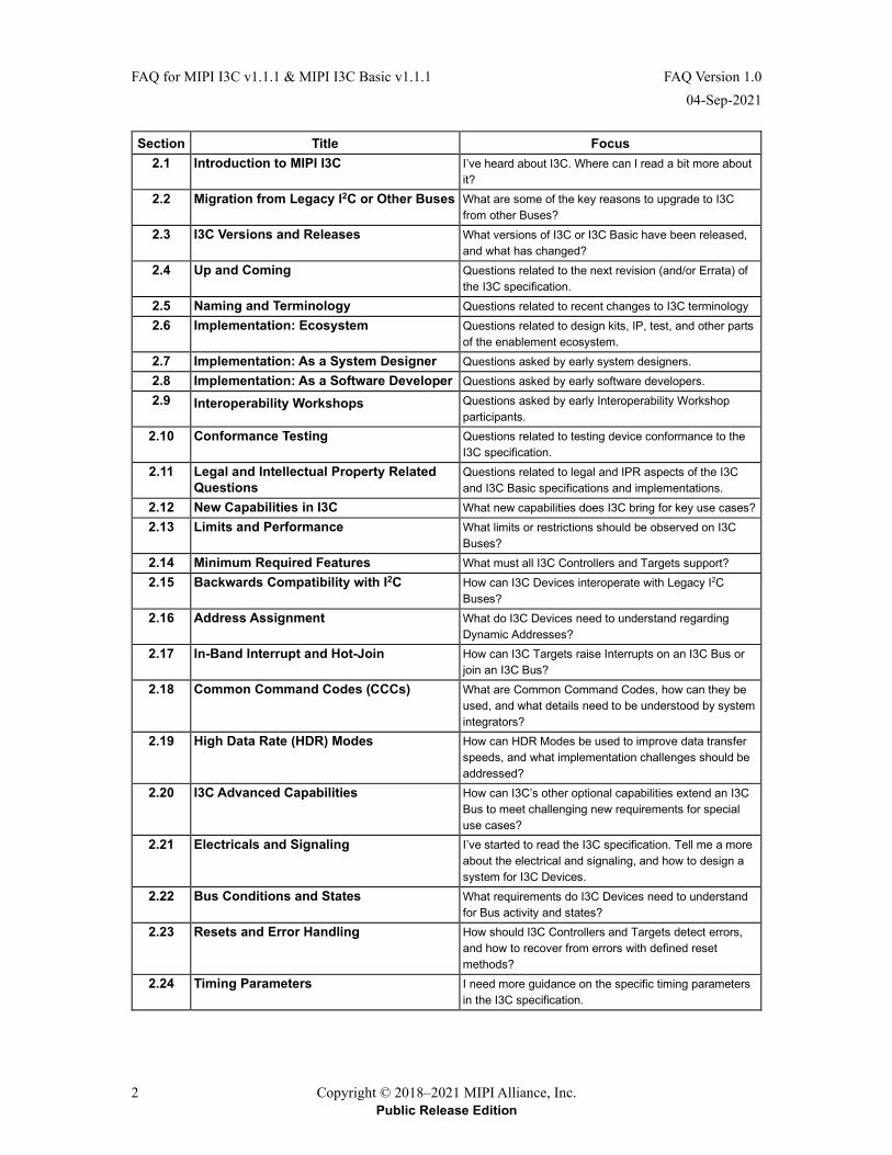
Section Title Focus 2.1 Introduction to MIPI I3C I’ve heard about I3C. Where can I read a bit more about
it? 2.2 Migration from Legacy I2C or Other Buses What are some of the key reasons to upgrade to I3C
from other Buses? 2.3 I3C Versions and Releases What versions of I3C or I3C Basic have been released,
and what has changed? 2.4 Up and Coming Questions related to the next revision (and/or Errata) of
the I3C specification. 2.5 Naming and Terminology Questions related to recent changes to I3C terminology 2.6 Implementation: Ecosystem Questions related to design kits, IP, test, and other parts
of the enablement ecosystem. 2.7 Implementation: As a System Designer Questions asked by early system designers. 2.8 Implementation: As a Software Developer Questions asked by early software developers. 2.9 Interoperability Workshops Questions asked by early Interoperability Workshop
participants. 2.10 Conformance Testing Questions related to testing device conformance to the
I3C specification. 2.11 Legal and Intellectual Property Related
Questions Questions related to legal and IPR aspects of the I3C and I3C Basic specifications and implementations.
2.12 New Capabilities in I3C What new capabilities does I3C bring for key use cases? 2.13 Limits and Performance What limits or restrictions should be observed on I3C
Buses? 2.14 Minimum Required Features What must all I3C Controllers and Targets support? 2.15 Backwards Compatibility with I2C How can I3C Devices interoperate with Legacy I2C
Buses? 2.16 Address Assignment What do I3C Devices need to understand regarding
Dynamic Addresses? 2.17 In-Band Interrupt and Hot-Join How can I3C Targets raise Interrupts on an I3C Bus or
join an I3C Bus? 2.18 Common Command Codes (CCCs) What are Common Command Codes, how can they be
used, and what details need to be understood by system integrators?
2.19 High Data Rate (HDR) Modes How can HDR Modes be used to improve data transfer speeds, and what implementation challenges should be addressed?
2.20 I3C Advanced Capabilities How can I3C’s other optional capabilities extend an I3C Bus to meet challenging new requirements for special use cases?
2.21 Electricals and Signaling I’ve started to read the I3C specification. Tell me a more about the electrical and signaling, and how to design a system for I3C Devices.
2.22 Bus Conditions and States What requirements do I3C Devices need to understand for Bus activity and states?
2.23 Resets and Error Handling How should I3C Controllers and Targets detect errors, and how to recover from errors with defined reset methods?
2.24 Timing Parameters I need more guidance on the specific timing parameters in the I3C specification.
FAQ Version 1.0 FAQ for MIPI I3C v1.1.1 & MIPI I3C Basic v1.1.1 04-Sep-2021
Copyright © 2018–2021 MIPI Alliance, Inc. 3 Public Release Edition
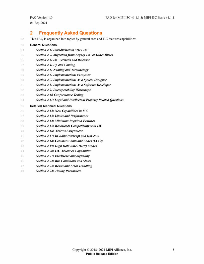
2 Frequently Asked Questions This FAQ is organized into topics by general area and I3C features/capabilities: 22
General Questions 23
Section 2.1: Introduction to MIPI I3C 24
Section 2.2: Migration from Legacy I2C or Other Buses 25
Section 2.3: I3C Versions and Releases 26
Section 2.4: Up and Coming 27
Section 2.5: Naming and Terminology 28
Section 2.6: Implementation: Ecosystem 29
Section 2.7: Implementation: As a System Designer 30
Section 2.8: Implementation: As a Software Developer 31
Section 2.9: Interoperability Workshops 32
Section 2.10 Conformance Testing 33
Section 2.11: Legal and Intellectual Property Related Questions 34
Detailed Technical Questions 35
Section 2.12: New Capabilities in I3C 36
Section 2.13: Limits and Performance 37
Section 2.14: Minimum Required Features 38
Section 2.15: Backwards Compatibility with I2C 39
Section 2.16: Address Assignment 40
Section 2.17: In-Band Interrupt and Hot-Join 41
Section 2.18: Common Command Codes (CCCs) 42
Section 2.19: High Data Rate (HDR) Modes 43
Section 2.20: I3C Advanced Capabilities 44
Section 2.21: Electricals and Signaling 45
Section 2.22: Bus Conditions and States 46
Section 2.23: Resets and Error Handling 47
Section 2.24: Timing Parameters 48
FAQ for MIPI I3C v1.1.1 & MIPI I3C Basic v1.1.1 FAQ Version 1.0 04-Sep-2021
4 Copyright © 2018–2021 MIPI Alliance, Inc. Public Release Edition
General Questions 49
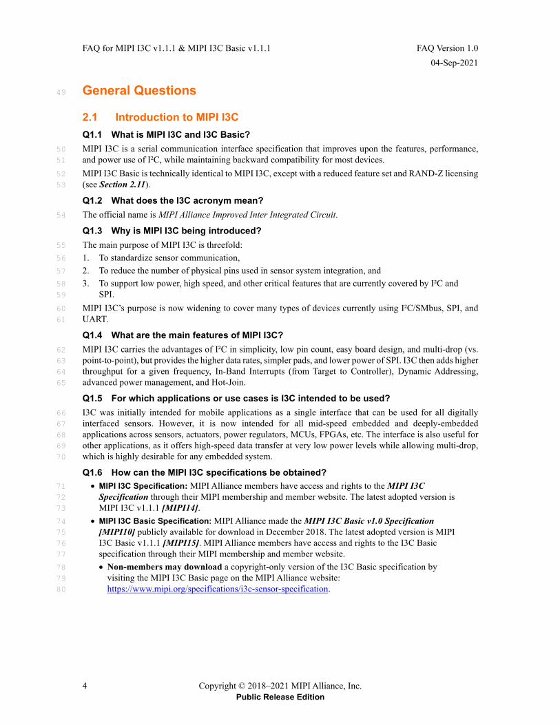
2.1 Introduction to MIPI I3C Q1.1 What is MIPI I3C and I3C Basic? MIPI I3C is a serial communication interface specification that improves upon the features, performance, 50 and power use of I²C, while maintaining backward compatibility for most devices. 51
MIPI I3C Basic is technically identical to MIPI I3C, except with a reduced feature set and RAND-Z licensing 52 (see Section 2.11). 53
Q1.2 What does the I3C acronym mean? The official name is MIPI Alliance Improved Inter Integrated Circuit. 54
Q1.3 Why is MIPI I3C being introduced? The main purpose of MIPI I3C is threefold: 55
1. To standardize sensor communication, 56
2. To reduce the number of physical pins used in sensor system integration, and 57
3. To support low power, high speed, and other critical features that are currently covered by I²C and 58 SPI. 59
MIPI I3C’s purpose is now widening to cover many types of devices currently using I²C/SMbus, SPI, and 60 UART. 61
Q1.4 What are the main features of MIPI I3C? MIPI I3C carries the advantages of I²C in simplicity, low pin count, easy board design, and multi-drop (vs. 62 point-to-point), but provides the higher data rates, simpler pads, and lower power of SPI. I3C then adds higher 63 throughput for a given frequency, In-Band Interrupts (from Target to Controller), Dynamic Addressing, 64 advanced power management, and Hot-Join. 65
Q1.5 For which applications or use cases is I3C intended to be used? I3C was initially intended for mobile applications as a single interface that can be used for all digitally 66 interfaced sensors. However, it is now intended for all mid-speed embedded and deeply-embedded 67 applications across sensors, actuators, power regulators, MCUs, FPGAs, etc. The interface is also useful for 68 other applications, as it offers high-speed data transfer at very low power levels while allowing multi-drop, 69 which is highly desirable for any embedded system. 70
Q1.6 How can the MIPI I3C specifications be obtained? • MIPI I3C Specification: MIPI Alliance members have access and rights to the MIPI I3C 71
Specification through their MIPI membership and member website. The latest adopted version is 72 MIPI I3C v1.1.1 [MIPI14]. 73
• MIPI I3C Basic Specification: MIPI Alliance made the MIPI I3C Basic v1.0 Specification 74 [MIPI10] publicly available for download in December 2018. The latest adopted version is MIPI 75 I3C Basic v1.1.1 [MIPI15]. MIPI Alliance members have access and rights to the I3C Basic 76 specification through their MIPI membership and member website. 77
• Non-members may download a copyright-only version of the I3C Basic specification by 78 visiting the MIPI I3C Basic page on the MIPI Alliance website: 79 https://www.mipi.org/specifications/i3c-sensor-specification. 80
FAQ Version 1.0 FAQ for MIPI I3C v1.1.1 & MIPI I3C Basic v1.1.1 04-Sep-2021
Copyright © 2018–2021 MIPI Alliance, Inc. 5 Public Release Edition
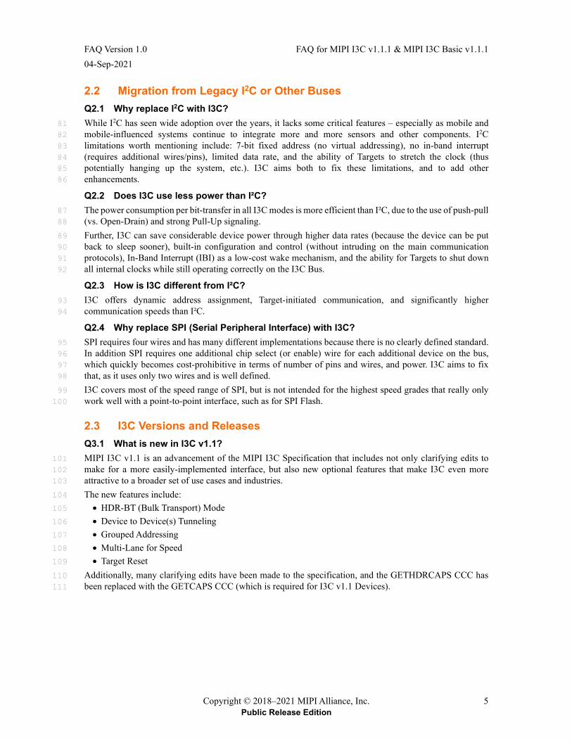
2.2 Migration from Legacy I2C or Other Buses Q2.1 Why replace I2C with I3C? While I2C has seen wide adoption over the years, it lacks some critical features – especially as mobile and 81 mobile-influenced systems continue to integrate more and more sensors and other components. I2C 82 limitations worth mentioning include: 7-bit fixed address (no virtual addressing), no in-band interrupt 83 (requires additional wires/pins), limited data rate, and the ability of Targets to stretch the clock (thus 84 potentially hanging up the system, etc.). I3C aims both to fix these limitations, and to add other 85 enhancements. 86
Q2.2 Does I3C use less power than I²C? The power consumption per bit-transfer in all I3C modes is more efficient than I²C, due to the use of push-pull 87 (vs. Open-Drain) and strong Pull-Up signaling. 88
Further, I3C can save considerable device power through higher data rates (because the device can be put 89 back to sleep sooner), built-in configuration and control (without intruding on the main communication 90 protocols), In-Band Interrupt (IBI) as a low-cost wake mechanism, and the ability for Targets to shut down 91 all internal clocks while still operating correctly on the I3C Bus. 92
Q2.3 How is I3C different from I²C? I3C offers dynamic address assignment, Target-initiated communication, and significantly higher 93 communication speeds than I²C. 94
Q2.4 Why replace SPI (Serial Peripheral Interface) with I3C? SPI requires four wires and has many different implementations because there is no clearly defined standard. 95 In addition SPI requires one additional chip select (or enable) wire for each additional device on the bus, 96 which quickly becomes cost-prohibitive in terms of number of pins and wires, and power. I3C aims to fix 97 that, as it uses only two wires and is well defined. 98
I3C covers most of the speed range of SPI, but is not intended for the highest speed grades that really only 99 work well with a point-to-point interface, such as for SPI Flash. 100
2.3 I3C Versions and Releases Q3.1 What is new in I3C v1.1? MIPI I3C v1.1 is an advancement of the MIPI I3C Specification that includes not only clarifying edits to 101 make for a more easily-implemented interface, but also new optional features that make I3C even more 102 attractive to a broader set of use cases and industries. 103
The new features include: 104
• HDR-BT (Bulk Transport) Mode 105
• Device to Device(s) Tunneling 106
• Grouped Addressing 107
• Multi-Lane for Speed 108
• Target Reset 109
Additionally, many clarifying edits have been made to the specification, and the GETHDRCAPS CCC has 110 been replaced with the GETCAPS CCC (which is required for I3C v1.1 Devices). 111
FAQ for MIPI I3C v1.1.1 & MIPI I3C Basic v1.1.1 FAQ Version 1.0 04-Sep-2021
6 Copyright © 2018–2021 MIPI Alliance, Inc. Public Release Edition
Q3.2 What are the required features in I3C v1.1 vs. I3C 1.0? Almost all new features of I3C v1.1 are optional. 112
However, it should be noted that: 113
• The formerly optional CCC GETHDRCAPS has been changed to GETCAPS, and its support is 114 required for I3C v1.1 Devices, so as to indicate it is a v1.1 (or later) Device. 115
• Additionally, it is necessary to support the new RSTACT CCC; as a result, support for a minimal 116 Target Reset is required. 117
MIPI recommends that Targets consider support of improvement features (such as Flow control for HDR, 118 and Group Addressing), as well as features they likely could use for their application. 119
Q3.3 Are there any I3C v1.0 features that are not supported in I3C v1.1 and beyond? The Directed form of the RSTDAA CCC is not supported in I3C v1.1 and beyond. 120
Q3.4 What is new in MIPI I3C v1.1.1? MIPI I3C v1.1.1 is an editorial update of MIPI I3C v1.1 that contains no new features or capabilities, but 121 resolves issues, clarifies, and improves on the I3C v1.1 specification. 122
MIPI I3C v1.1.1 includes: 123
• Fixes for inconsistencies and other issues that were technical errors in MIPI I3C v1.1 (including 124 all issues resolved by Errata 01) 125
• Clarifications to the requirements and procedures used for Dynamic Address Assignment, Hot-126 Join Requests and In-Band Interrupts 127
• Clarifications to Target Error Types TE0, TE5, and TE6 128
• Improved clarity and fixes for issues in the sections that define CCC flows in HDR Modes 129 (generic as well as HDR Mode–specific) 130
• Additional clarifications and explanations in some sections that did not fully explain new features 131 and capabilities introduced with I3C v1.1 132
• Better explanations of I3C Devices that support advanced features, such as composite I3C Devices 133 that present multiple I3C Target roles (i.e., Virtual Targets) 134
• Additional clarifications concerning the intersection of several of these new features and 135 capabilities when implemented together (i.e., when used in concert in the same I3C Bus with I3C 136 Devices that choose to support several or all such features or capabilities concurrently) 137
• Limited allowances for flexibility in how certain new features and capabilities could be applied, or 138 which of these new features and capabilities might be regarded as required, optional, or 139 conditionally required per use case 140
• Improved descriptions for Multi-Lane Device configuration, including clarified requirements for 141 I3C Devices that present multiple Dynamic Addresses and/or support Group Addressing 142
• Additional diagrams for HDR-BT Mode, including the 1-Lane forms of the structured protocol 143 elements (i.e., Blocks) that are used in HDR-BT transfers, as well as an example of an HDR-BT 144 transfer 145
• Improved descriptions of error detection and recovery methods, such as Error Type TE0 and Error 146 Type DBR (Dead Bus Recovery) 147
• Changes to the Multi-Lane signaling of the Header Byte in SDR Mode 148
FAQ Version 1.0 FAQ for MIPI I3C v1.1.1 & MIPI I3C Basic v1.1.1 04-Sep-2021
Copyright © 2018–2021 MIPI Alliance, Inc. 7 Public Release Edition
Q3.5 Is I3C v1.1.1 compatible/interoperable with I3C v1.1? Yes. I3C v1.1.1 is a purely editorial update that aims to resolve inconsistencies and improve clarity compared 149 to I3C v1.1; no new features or capabilities are added. I3C v1.1.1 addresses all I3C v1.1 issues that Errata 01 150 did. Implementers are strongly advised to confirm that any I3C v1.1–compliant Devices adhere to the fixes 151 published in Errata 01. 152
In particular, see Q4.4 for fixed issues regarding HDR-DDR Mode inconsistencies pertaining to zero-HDR-153 DDR-Data-Word flows, which are no longer allowed. This affects all HDR-DDR transactions, including CCC 154 flows in HDR-DDR Mode. 155
Q3.6 What is new in I3C Basic v1.1.1? I3C Basic v1.1.1 is a fundamental update to I3C Basic v1.0, and adds many of the new optional capabilities 156 from I3C v1.1. I3C Basic v1.1.1 also includes clarifications and fixes for issues that were addressed in I3C 157 v1.1.1 (see Q3.4). Devices that comply with I3C Basic v1.1.1 should be mutually interoperable with I3C 158 v1.1.1, and vice versa. 159
I3C Basic v1.1.1 is a subset of I3C v1.1.1, and adds the following features and capabilities: 160
• HDR-DDR Mode 161
• HDR-BT (Bulk Transport) Mode 162
• Grouped Addressing 163
• Multi-Lane for Speed (for HDR-BT Mode only) 164
• Target Reset with RSTACT CCC (previously defined in a separate addendum for I3C Basic v1.0) 165
• Timing Control (Async Mode 0 only) 166
• CCCs in HDR Modes 167
• GETCAPS CCC 168
• SETBUSCON CCC 169
• SETROUTE CCC 170
• Virtual Target support 171
I3C Basic v1.1.1 also includes numerous clarifications and improved definitions, including Secondary 172 Controllers, Hot-Join, Dynamic Address Assignment, Target Error Types and FSM diagrams. 173
2.4 Up and Coming Q4.1 What future MIPI specifications will be leveraging I3C? Many other MIPI Alliance Working Groups are in the process of leveraging the I3C specification. As of the 174 writing of this FAQ, the list includes: 175
• Camera WG: Camera Control Interface (CCI) chapter of the MIPI Specification for Camera 176 Serial Interface 2 (CSI-2), v4.0 [MIPI06] (In development) 177
• Debug WG: MIPI Specification for Debug for I3C, v1.1 [MIPI16] (In development) 178
• RIO WG (Reduced I/O): MIPI Specification for Virtual GPIO Interface (VGISM), v1.0 [MIPI08], 179 reducing number of GPIOs used via I3C (In development) 180
FAQ for MIPI I3C v1.1.1 & MIPI I3C Basic v1.1.1 FAQ Version 1.0 04-Sep-2021
8 Copyright © 2018–2021 MIPI Alliance, Inc. Public Release Edition
Q4.2 Are there any impending fixes or errata for MIPI I3C v1.0 or I3C Basic v1.0 that should be applied now?
Note: 181
With the release of I3C v1.1 this question has been deprecated; it is retained here for reference. 182 See Q3.1 for what’s new in I3C v1.1. 183
All fixes or Errata for I3C v1.0 have also been applied to I3C v1.1. However, I3C v1.1 has since been 184 superseded by MIPI I3C v1.1.1, which is the newest recommended version of the I3C specification. 185
All fixes for Errata for I3C Basic v1.0 have been incorporated into I3C Basic v1.1.1, which is the newest 186 recommended version of the I3C Basic specification. 187
Based on learning from early implementations, I3C Interoperability Workshops, queries from adopters, and 188 reviews by the I3C WG, this FAQ represents clarifications, improvements that can be implemented by I3C 189 v1.0 Devices or I3C Basic v1.0 Devices, and other guidance for implementers. 190
Q4.3 Are any revisions to MIPI I3C v1.0 expected? No, there are no pending updates at this time. However, MIPI Alliance strongly recommends that all 191 implementers move to MIPI I3C v1.1.1 as the newest recommended version of the I3C specification. 192
Q4.4 Are there any impending fixes or errata for MIPI I3C v1.1 that should be applied now?
Yes, several fixes to MIPI I3C v1.1 have been identified, and MIPI has published these fixes as Errata 01. 193
These fixes fall into four categories: 194
1. Resolving inconsistencies in HDR-DDR Mode 195
I3C v1.0 and v1.1 did not consistently describe whether an HDR-DDR Data Word was always 196 required for HDR-DDR transactions. Additionally, I3C v1.1 introduced CCC flows in HDR-DDR 197 Mode, which assumed that flows with zero HDR-DDR Data Words were both possible and valid, 198 and it did not always provide appropriate acknowledgement for Target Devices. 199
Errata 01 resolves these inconsistencies by always requiring at least one HDR-DDR Data Word for 200 all HDR-DDR transactions. Furthermore, Errata 01 clarifies the requirements for CCC flows in 201 HDR-DDR Mode, and re-defines the special use of the structured protocol elements for these CCC 202 flows to always include at least one HDR-DDR Data Word for appropriate acknowledgement. 203
2. Clarifying Open-Drain timing parameters 204
The timing parameters for I3C v1.1 did not show appropriate definitions for a ‘Pure Bus’ 205 configuration, and also did not provide clarity for sending the first I3C Address Header with the 206 Broadcast Address (i.e., 7’h7E) in order to disable the I2C Spike Filter (for certain I3C Devices). 207
Errata 01 clarifies these timing parameters and fixes other related incorrect timing parameter 208 definitions. 209
3. Updating obsolete FSM Diagrams 210
Several FSM diagrams in Annex C that were initially created during early stages of I3C v1.0 211 specification development were obsolete. For example, the FSM diagram for Dynamic Address 212 Assignment did not reflect the correct Dynamic Address Assignment procedure, and did not 213 include newer CCCs (such as the SETAASA CCC) that were added after I3C v1.0. Several other 214 issues and inconsistencies were also found in other FSM diagrams in Annex C. 215
Errata 01 updates these FSM diagrams to reflect the correct procedures (per the normative text in 216 the I3C v1.1 specification) and to remove other obsolete terminology. 217
4. Typographical fix regarding HDR-TSP and Multi-Lane support 218
Errata 01 corrects a minor typographical error, and resolves an inconsistency regarding which 219 HDR Modes support Multi-Lane transfers in I3C v1.1. 220
FAQ Version 1.0 FAQ for MIPI I3C v1.1.1 & MIPI I3C Basic v1.1.1 04-Sep-2021
Copyright © 2018–2021 MIPI Alliance, Inc. 9 Public Release Edition
Additionally, these issues, plus numerous other inconsistencies, clarifications, and fixes have been addressed 221 in MIPI I3C v1.1.1 [MIPI14]. MIPI Alliance strongly recommends that all implementers move to MIPI I3C 222 v1.1.1 as the newest recommended version of the I3C specification. 223
Q4.5 Are any revisions to I3C v1.1 expected? MIPI I3C v1.1.1 addresses all issues found in I3C v1.1, including those that were published as Errata 01. 224 MIPI Alliance strongly recommends that all implementers move to MIPI I3C v1.1.1 as the newest 225 recommended version of the I3C specification. 226
Q4.6 Are any revisions to I3C v1.1.1 expected? Not at this time. However, the MIPI I3C WG meets regularly and is considering proposals to revise and 227 extend I3C. As part of maintaining the I3C specification, the MIPI I3C WG seeks to improve the I3C 228 specification in areas where it would benefit from clarification or additional explanation. Please direct any 229 comments or suggestions to MIPI Alliance. 230
Q4.7 Are there any impending fixes or errata for I3C v1.1.1 and I3C Basic v1.1.1 that should be applied now?
Yes, several fixes to the MIPI I3C v1.1.1 and I3C Basic v1.1.1 specifications have been identified. MIPI is 231 currently working to publish these as Errata. These fixes all fall into the category of clarifying requirements 232 for Passive Hot-Join. 233
A key technical detail was omitted in I3C v1.1.1 and I3C Basic v1.1.1: a passive Hot-Joining Target needs to 234 see an SDR Frame that is addressed to the Broadcast Address (i.e., 7’h7E / W) in order to determine that it is 235 indeed on an I3C Bus (see Q17.7). Additionally, once it sees this SDR Frame, a passive Hot-Joining Target 236 may either (a) pull SDA Low to raise its own Hot-Join Request, or (b) wait for another I3C Device to pull 237 SDA Low and then arbitrate the Hot-Join Address (i.e., 7’h02) into the Arbitrable Address Header. 238
Note: 239
The I3C v1.1 specification did note the correct requirement for the Broadcast Address. 240
Q4.8 What new features, if any, are coming to MIPI I3C? There are no new approved features, however the MIPI I3C WG is considering the following: 241
• Automotive-focused capabilities 242
• Security over I3C 243
• Improved reliability 244
• Speed increases 245
• New Multi-Lane uses 246
• Long Reach 247
• New HDR Modes 248
• Refining existing features 249
FAQ for MIPI I3C v1.1.1 & MIPI I3C Basic v1.1.1 FAQ Version 1.0 04-Sep-2021
10 Copyright © 2018–2021 MIPI Alliance, Inc. Public Release Edition
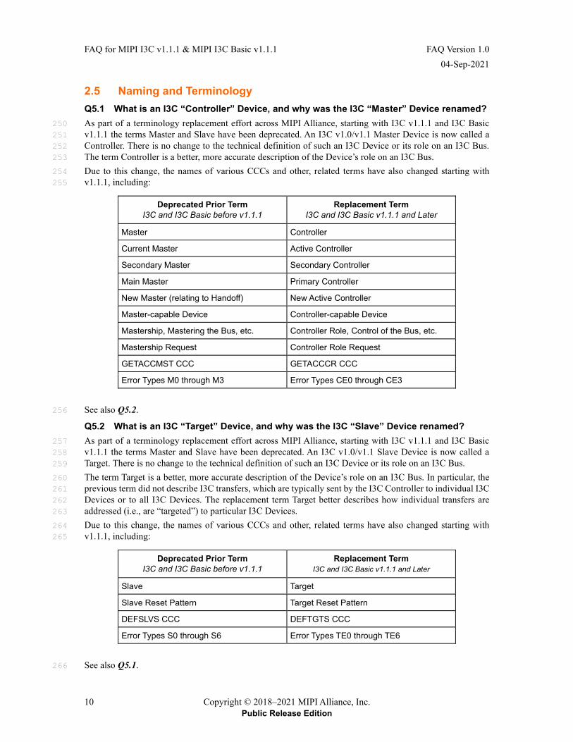
2.5 Naming and Terminology Q5.1 What is an I3C “Controller” Device, and why was the I3C “Master” Device renamed? As part of a terminology replacement effort across MIPI Alliance, starting with I3C v1.1.1 and I3C Basic 250 v1.1.1 the terms Master and Slave have been deprecated. An I3C v1.0/v1.1 Master Device is now called a 251 Controller. There is no change to the technical definition of such an I3C Device or its role on an I3C Bus. 252 The term Controller is a better, more accurate description of the Device’s role on an I3C Bus. 253
Due to this change, the names of various CCCs and other, related terms have also changed starting with 254 v1.1.1, including: 255
Deprecated Prior Term I3C and I3C Basic before v1.1.1
Replacement Term I3C and I3C Basic v1.1.1 and Later
Master Controller
Current Master Active Controller
Secondary Master Secondary Controller
Main Master Primary Controller
New Master (relating to Handoff) New Active Controller
Master-capable Device Controller-capable Device
Mastership, Mastering the Bus, etc. Controller Role, Control of the Bus, etc.
Mastership Request Controller Role Request
GETACCMST CCC GETACCCR CCC
Error Types M0 through M3 Error Types CE0 through CE3
See also Q5.2. 256
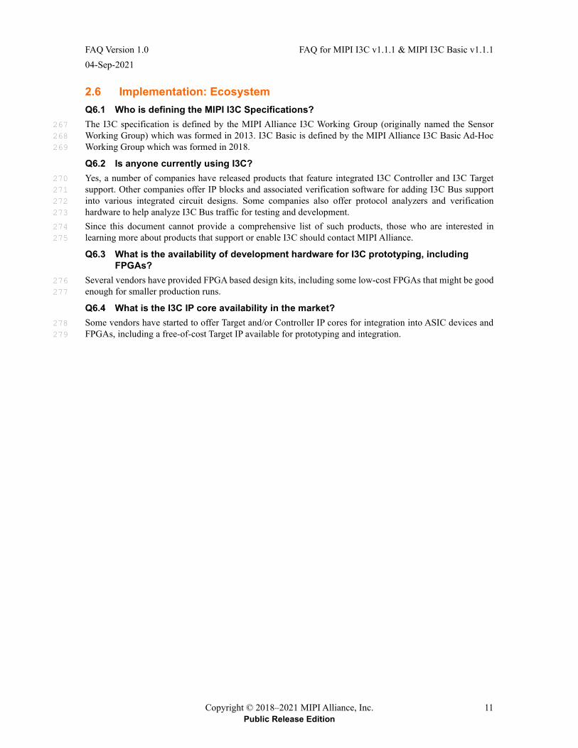
Q5.2 What is an I3C “Target” Device, and why was the I3C “Slave” Device renamed? As part of a terminology replacement effort across MIPI Alliance, starting with I3C v1.1.1 and I3C Basic 257 v1.1.1 the terms Master and Slave have been deprecated. An I3C v1.0/v1.1 Slave Device is now called a 258 Target. There is no change to the technical definition of such an I3C Device or its role on an I3C Bus. 259
The term Target is a better, more accurate description of the Device’s role on an I3C Bus. In particular, the 260 previous term did not describe I3C transfers, which are typically sent by the I3C Controller to individual I3C 261 Devices or to all I3C Devices. The replacement term Target better describes how individual transfers are 262 addressed (i.e., are “targeted”) to particular I3C Devices. 263
Due to this change, the names of various CCCs and other, related terms have also changed starting with 264 v1.1.1, including: 265
Deprecated Prior Term I3C and I3C Basic before v1.1.1
Replacement Term I3C and I3C Basic v1.1.1 and Later
Slave Target
Slave Reset Pattern Target Reset Pattern
DEFSLVS CCC DEFTGTS CCC
Error Types S0 through S6 Error Types TE0 through TE6
See also Q5.1. 266
FAQ Version 1.0 FAQ for MIPI I3C v1.1.1 & MIPI I3C Basic v1.1.1 04-Sep-2021
Copyright © 2018–2021 MIPI Alliance, Inc. 11 Public Release Edition
2.6 Implementation: Ecosystem Q6.1 Who is defining the MIPI I3C Specifications? The I3C specification is defined by the MIPI Alliance I3C Working Group (originally named the Sensor 267 Working Group) which was formed in 2013. I3C Basic is defined by the MIPI Alliance I3C Basic Ad-Hoc 268 Working Group which was formed in 2018. 269
Q6.2 Is anyone currently using I3C? Yes, a number of companies have released products that feature integrated I3C Controller and I3C Target 270 support. Other companies offer IP blocks and associated verification software for adding I3C Bus support 271 into various integrated circuit designs. Some companies also offer protocol analyzers and verification 272 hardware to help analyze I3C Bus traffic for testing and development. 273
Since this document cannot provide a comprehensive list of such products, those who are interested in 274 learning more about products that support or enable I3C should contact MIPI Alliance. 275
Q6.3 What is the availability of development hardware for I3C prototyping, including FPGAs?
Several vendors have provided FPGA based design kits, including some low-cost FPGAs that might be good 276 enough for smaller production runs. 277
Q6.4 What is the I3C IP core availability in the market? Some vendors have started to offer Target and/or Controller IP cores for integration into ASIC devices and 278 FPGAs, including a free-of-cost Target IP available for prototyping and integration. 279
FAQ for MIPI I3C v1.1.1 & MIPI I3C Basic v1.1.1 FAQ Version 1.0 04-Sep-2021
12 Copyright © 2018–2021 MIPI Alliance, Inc. Public Release Edition
2.7 Implementation: As a System Designer Q7.1 What is the maximum capacitance load allowed on the I3C Bus? The I3C specification lists the maximum per-Device capacitance on SCL and SDA, but the goal is that most 280 or all Devices will be well below that. As with any Bus, capacitance alone is not sufficient to determine 281 maximum frequency on the I3C Bus. It is important to consider maximum propagation length, effect of stubs, 282 internal clock-to-data (tSCO) of the Targets, as well as capacitive load. 283
Q7.2 What is the maximum wire length for I3C communication? The maximum wire length would be a function of speed, as all the reflections and Bus turnaround must 284 complete within one cycle. Larger distances can be achieved at the lower speeds than at the higher ones. For 285 example, at 1 meter (between Controller and Target), the maximum effective speed is around 6 MHz for read, 286 to allow for clock propagation time to Target and SDA return time to Controller. 287
Q7.3 Can I2C repeaters be used for I3C? Not directly, for a couple of reasons: 288
1. The I3C Bus works with push-pull modes (in addition to the open drain for some transfers), and 289
2. Much higher speeds. Most such devices are quite limited in speed, because of the lag effect of 290 changing states on SCL and SDA due to both series-resistance and assumptions about Open-Drain. 291
Long wire approaches are being evaluated for a future version of the I3C specification. 292
Q7.4 Will the I2C devices respond to I3C commands? No. The I3C CCCs are always preceded by the I3C Broadcast Address, 7’h7E. Since the I2C specification 293 reserves address 7’h7E, no Legacy I2C Target will match the I3C Broadcast Address, and thus no Legacy I2C 294 Target would respond to the I3C commands. Likewise, the Dynamic Addresses assigned to I3C Devices 295 would not overlap the I2C static addresses, so no I2C device would respond to any I3C address – even if it 296 could see it. 297
Q7.5 How are communication conflicts resolved on the I3C Bus? I3C Targets are only allowed to drive the Bus under certain situations. Besides during a read, and when 298 ACKing their own address, I3C Targets may also drive after a START (but not Repeated START). After a 299 START, the I3C Bus reverts back to Open-Drain Pull-Up resistor mode; thus, the Target that drives a low 300 value (i.e., logic 0) would win. 301
Q7.6 Can I3C Devices cause the communication Bus to hang? Unlike I²C, there is no natural way to hang the I3C Bus. In I²C, clock stretching (where the Target holds the 302 clock low, stopping it from operating) often causes serious problems with no fix: there’s simply no way to 303 get the Target’s attention if it has hung the Bus. By contrast, in I3C only the Controller drives the clock, and 304 so the Target performs all actions on SDA relative to that clock, thereby eliminating the normal causes of 305 such hangs. 306
Further, since I3C is designed to ensure that I3C Targets can operate their back-end I3C peripheral off the 307 SCL clock (vs. oversampling), any problems elsewhere in the Target won’t translate into Bus hangs. 308
If a system implementer is highly concerned about a Target accidently locking itself, then a separate 309 hard-reset line could be used. Alternatively, the I3C v1.1.1 and I3C Basic v1.1.1 specifications add a new 310 feature called Target Reset for resetting non-responsive I3C Targets: if an I3C Controller emits the Target 311 Reset Pattern (a defined unique Bus pattern that does not otherwise occur during regular communication), 312 then the Devices on the Bus will treat it just like a hardwired reset line. 313
This question has been updated for I3C v1.1.1 and I3C Basic v1.1.1. 314
Q7.7 Will all I3C Devices be compatible with all CCCs? No. Some CCCs are mandatory, whereas others are optional or conditionally supported, and a given I3C 315 Device will either support them or not, depending upon the Device’s capabilities. See also Q14.2 and Q18.7. 316
FAQ Version 1.0 FAQ for MIPI I3C v1.1.1 & MIPI I3C Basic v1.1.1 04-Sep-2021
Copyright © 2018–2021 MIPI Alliance, Inc. 13 Public Release Edition
2.8 Implementation: As a Software Developer Q8.1 Are there any companion MIPI I3C Specifications that enable software
development? Yes. The following MIPI specifications are expected to help with software development: 317
• MIPI Specification for I3C Host Controller Interface (I3C HCI), v1.0 [MIPI02] 318 and 319 MIPI Specification for I3C Host Controller Interface (I3C HCI), v1.1 [MIPI13] 320
Creates a standard definition that allows a single OS driver (also known as ‘in-box driver’) to 321 support I3C hardware from several vendors, while also allowing vendor-specific extensions or 322 improvements. The target audience of the HCI specification is application processor host 323 controllers; in particular, developers of host controller (i.e., I3C Primary Controller) hardware, and 324 developers of I3C host controller software. 325
• MIPI Specification for Discovery and Configuration (DisCo), v1.0 [MIPI03] 326
Describes a standardized device discovery and configuration mechanism for interfaces based on 327 MIPI specifications, which can simplify component design and system integration. Also oriented 328 to application processors. 329
• MIPI DisCo Specification for I3C, v1.0 [MIPI04] 330
Allows operating system software to use ACPI (Advanced Configuration and Power Interface) 331 structures to discover and configure the I3C host controller and attached I3C Devices in 332 ACPI-compliant systems. Also oriented to application processors. 333
In addition to these MIPI specifications, a supporting document is also available. The System Integrators 334 Application Note for I3C v1.0 and I3C Basic v1.0, App Note v1.0 [MIPI05] has been developed to help 335 ASIC hardware developers, system designers, and others working in the more deeply embedded I3C Devices. 336 The I3C WG plans to develop additional Application Notes that will cover new features and capabilities 337 included in I3C v1.1.1 and I3C Basic v1.1.1. 338
Q8.2 Are there software libraries available for I3C? Yes. Core I3C infrastructure has been added to the Linux Kernel as part of the I3C subsystem. The I3C 339 subsystem also includes drivers for several I3C Controller devices and IP core implementations, including 340 MIPI I3C HCI–compliant Host Controllers (see [MIPI13]). 341
The current list of Linux Kernel Patches for the I3C subsystem can be accessed via [LINX01]. 342
FAQ for MIPI I3C v1.1.1 & MIPI I3C Basic v1.1.1 FAQ Version 1.0 04-Sep-2021
14 Copyright © 2018–2021 MIPI Alliance, Inc. Public Release Edition
2.9 Interoperability Workshops Q9.1 What is a MIPI I3C Interoperability Workshop? It is a MIPI Alliance sponsored event where different vendors bring their I3C implementations and check 343 interoperation with other vendors. 344
Q9.2 What is the output from a MIPI I3C Interoperability Workshop? There are three major outputs from a MIPI I3C Interoperability Workshop: 345
• Participating vendors can get detailed information about how well their I3C implementations 346 interoperate with other vendors’ implementation. Vendors can also compare their results with one 347 another. 348
• MIPI Alliance can generate an overall picture of the industry state-of-the-I3C-implementaion. For 349 example, how many vendors have implemented I3C, and how many implementations pass or fail 350 against one another. 351
• The MIPI I3C Working Group gets better understanding about any major issues with the I3C 352 specification. The WG can then leverage that learning by adding to this FAQ, other supporting 353 documents (such as Application Notes, per Q8.1), and possible future revision of MIPI I3C 354 Specifications. 355
Q9.3 Are MIPI I3C Interoperability Workshops an ongoing activity? MIPI arranges a particular I3C Interoperability Workshop event in response to requests from its membership. 356 They have typically been co-located with regularly scheduled MIPI Member Meetings. 357
Q9.4 Who can attend or participate in a MIPI I3C Interoperability Workshop? In general, any MIPI Alliance members who have I3C hardware ready to interop can participate. 358
Q9.5 What HW/SW is typically needed to participate in a MIPI I3C Interoperability Workshop?
While this could change in future, the minimal requirements to date have been the availability of a board 359 with an I3C Device that can connect to other Devices via the three wires SDA, SCL, and GND. It’s also 360 useful to have software (e.g., running on a laptop connected to the board and I3C Device) to interactively 361 view transmitted and received Bus communications, but this might not be required for Targets. 362
Currently there are solutions working at 3.3V and 1.8V. 363
Q9.6 Are there any I3C Interoperability Workshops planned for I3C v1.1.1 or I3C Basic v1.1.1?
MIPI Alliance has been hosting I3C Interoperability Workshops in conjunction with MIPI Member Meetings, 364 typically two to three times per year. At this time this FAQ was last updated (August 2021), in-person MIPI 365 Member Meetings have been suspended due to the pandemic. However, MIPI Alliance expects to schedule 366 I3C Interoperability Workshops once in-person MIPI Member Meetings resume. 367
FAQ Version 1.0 FAQ for MIPI I3C v1.1.1 & MIPI I3C Basic v1.1.1 04-Sep-2021
Copyright © 2018–2021 MIPI Alliance, Inc. 15 Public Release Edition
2.10 Conformance Testing Q10.1 What is a MIPI Conformance Test Suite (CTS)? A MIPI WG develops a Conformance Test Suite (CTS) document in order to improve the interoperability of 368 products that implement a given MIPI interface specification. The CTS defines a set of conformance or 369 interoperability tests whereby a product can be tested against other implementations of the same specification. 370
Q10.2 Is there a MIPI CTS for I3C? Yes, MIPI Alliance has released a CTS for I3C v1.1.1 and I3C Basic v1.1.1 [MIPI09]. 371
Q10.3 What is the scope of tests for the I3C CTS? The CTS tests are designed to determine whether a given product conforms to a subset of the common I3C 372 requirements defined in both I3C v1.1.1 and I3C Basic v1.1.1 (i.e., the requirements that are common to both 373 specifications, since I3C Basic is a subset of I3C). The scope of this version of the CTS is intentionally 374 limited, in order to meet time-to-market requirements imposed by the rapid adoption of I3C in the 375 marketplace, focusing on: 376
1. SDR-only Devices without optional I3C capabilities, 377
2. All Controller and Target Error Detection and Recovery methods, and 378
3. Basic HDR Enter/tolerance/Restart/Exit procedures. However, specific HDR Modes are not 379 covered by this version of the CTS. 380
Considering the CTS a living document, the I3C WG plans to continue expanding the scope of the CTS 381 through future revisions or subordinate CTS documents for specific features or capabilities (e.g., HDR 382 Modes). The growing set of CTS documents should eventually encompass a broad array of all required and 383 optional features of both the I3C specification and the I3C Basic specification. 384
The CTS tests are organized as Controller DUT tests (Device Under Test) and Target DUT tests. Tests for 385 each are presented in the order in which they appear in the I3C specification, to simplify identification of 386 pertinent detail between the two documents. 387
Q10.4 Does the I3C Interoperability Workshop follow the I3C CTS? Interoperability Workshops will ultimately follow the tests identified in the I3C CTS, as and when such events 388 can be arranged by MIPI Alliance. 389
Q10.5 What details are provided for each I3C CTS test case? Each test in the I3C CTS contains: 390
• A clear purpose 391
• References 392
• Resource requirements 393
• Tracked last technical modification 394
• Discussion 395
• All test case detail (i.e., Setup, Procedure, Results, and Problems). 396
DC/AC parametric requirements are embedded in each test (not split out into a separate PHY-related CTS or 397 subsection). 398
FAQ for MIPI I3C v1.1.1 & MIPI I3C Basic v1.1.1 FAQ Version 1.0 04-Sep-2021
16 Copyright © 2018–2021 MIPI Alliance, Inc. Public Release Edition
2.11 Legal and Intellectual Property Related Questions Q11.1 Is MIPI I3C Basic royalty free? The parties that directly developed the MIPI I3C Basic specification have agreed to license all implementers 399 on royalty free terms, as further described in the I3C Basic specification document [MIPI10][MIPI15]. 400 Further, all implementers of the I3C Basic specification must commit to grant a reciprocal royalty free license 401 to all other implementers if they wish to benefit from these royalty free license commitments. And, of course, 402 MIPI itself does not charge royalties in connection with its specifications. MIPI’s intent is to create a robust 403 royalty free environment for all implementers of I3C Basic. 404
No set of IPR terms can comprehensively address all potential risks, however. The terms apply only to those 405 parties that agree to them, for example, and the scope of application is limited to what is described in the 406 terms. Implementers must ultimately make their own risk assessment. 407
Q11.2 What license terms apply to MIPI I3C v1.x? MIPI’s regular IPR terms apply to the full MIPI I3C specification. MIPI’s terms require that members make 408 licenses available only to other members, as described in the MIPI Membership Agreement and MIPI Bylaws. 409 To benefit from the license commitments, a party must be a MIPI member. 410
For features that are included in MIPI I3C Basic, a MIPI member can implement under the regular IPR terms, 411 or can opt to implement the feature under the I3C Basic framework. If a member opts in to the I3C Basic 412 framework, then they must grant the reciprocal licenses required under that framework. MIPI Alliance 413 members are not required to participate in the I3C Basic license framework, however. Features of I3C 1.x 414 that are not included in I3C Basic are subject only to MIPI’s regular IPR terms. 415
Prior to the release of I3C Basic, MIPI had made certain versions of the full MIPI I3C specification available 416 for public review, under “copyright only” terms – that is, MIPI published the specification, but noted that no 417 rights to implement the specification were granted under any party’s patent rights. MIPI no longer publishes 418 the full I3C specification publicly. A non-member is not granted any right to implement the full MIPI I3C 1.x 419 specification, either by MIPI or any MIPI member. 420
I3C Basic is available to non-members, as described in Q1.6. 421
FAQ Version 1.0 FAQ for MIPI I3C v1.1.1 & MIPI I3C Basic v1.1.1 04-Sep-2021
Copyright © 2018–2021 MIPI Alliance, Inc. 17 Public Release Edition
Detailed Technical Questions 422
2.12 New Capabilities in I3C Q12.1 Can I3C Targets initiate communication (i.e., interrupt the Controller)? Yes, I3C Targets can initiate communication using In-Band Interrupt requests. Communication conflicts are 423 solved by Target Address Arbitration. 424
Q12.2 How can Controllers and Targets communicate on the I3C Bus? The basic byte-based messaging schemes used in I²C and SPI map easily onto I3C. Additionally, a set of 425 Common Command Codes (CCCs) has been defined for standard operations like enabling and disabling 426 events, managing I3C-specific features (e.g., Dynamic Addressing, Timing Control), and other functions. 427 CCCs are either Broadcasted (i.e., sent to all Devices on the I3C Bus), or else Directed to a particular Device 428 on the I3C Bus (i.e., by Address). 429
CCCs do not interfere with, and do not consume any of the message space of, normal Controller-to-Target 430 communications. That is, I3C provides a separate namespace for CCCs (see the specification at 431 Section 5.1.9.3). 432
Q12.3 What are CCCs (Common Command Codes) and why are they used? CCCs are the commands that an I3C Controller uses to communicate to some or all of the Targets on the I3C 433 Bus. The CCCs are sent to the I3C Broadcast address (which is 7’h7E) so as not to interfere with normal 434 messages sent to a Target. In other words, CCCs are separated from the standard “content protocol” used by 435 normal messages, such as Private Write and Read transfers (in SDR Mode). 436
The CCCs are used for standard operations like enabling/disabling events, managing I3C-specific features, 437 and other Bus operations. CCCs can be either Broadcasted (i.e., sent to all Devices on the I3C Bus), or else 438 Directed to specific Devices on the I3C Bus (i.e., by Address). All CCC command number values are 439 allocated by MIPI Alliance, and some values are reserved for specific purposes including MIPI Alliance 440 enhancements and other extensions (see Q18.4). 441
Q12.4 How are the following similar and/or different: In-Band Interrupt, Hot-Join, and Controller Role Request (IBI / HJ / CRR)?
All three are special, in-band methods that allow the Target to notify the Controller of a new request or state, 442 without having to wait for the Controller to query or poll the Target(s). The term ‘in-band’ refers to doing 443 this via the I3C Bus wires/pins themselves, rather than using methods requiring extra wires/pins. 444
• In-Band Interrupt (IBI): A Target uses an IBI Request to notify the Controller of a new state or 445 event. If the Target so indicates in the BCR, then an IBI may include one or more following data 446 bytes. A Target can only use IBI if it has indicated the intent to do in its BCR. 447
If the Target indicates it will send data with an IBI, then it is required to always send at least 1 448 byte, called the Mandatory Data Byte (MDB). Starting with I3C v1.1, the MDB is coded following 449 certain rules. Any data after the MDB is a contract between Controller and Target. 450
• Hot-Join (HJ): A Hot-Join Request is used only by an I3C Target that hasn’t yet been assigned a 451 Dynamic Address and is attached or awakened on the I3C Bus after the Primary Controller has 452 initialized it. The Hot-Join Request uses a fixed address which is reserved for this purpose only. 453 The Controller will recognize this fixed address and then initiate a new Dynamic Address 454 Assignment procedure. However, a Target cannot use the Hot-Join Request before verifying that 455 the I3C Bus is in SDR Mode. 456
• Controller Role Request (CRR): A Secondary Controller (including the Primary Controller, once 457 it has given up the Controller Role) sends a CRR when it wants to become Controller of the I3C 458 Bus. If the Active Controller accepts the CRR, then it will issue a GETACCCR CCC to pass the 459 Controller Role to the requesting Secondary Controller. It is also possible for the Active Controller 460
FAQ for MIPI I3C v1.1.1 & MIPI I3C Basic v1.1.1 FAQ Version 1.0 04-Sep-2021
18 Copyright © 2018–2021 MIPI Alliance, Inc. Public Release Edition
to initiate handoff on its own without any Target initiating an CRR, for example when a Secondary 461 Controller wants to return control. 462
2.13 Limits and Performance Q13.1 What is the maximum number of I3C Devices per Bus? In I3C v1.1 and I3C Basic v1.0 the maximum number of I3C Target Devices was limited to 11. However, 463 this limit was calculated based on typical electrical parameters, whereas different system designs might 464 present other limitations or challenges. Also, the actual number of Targets presented on the Bus could be 465 higher if some of the I3C Devices enable Bridging (see Q20.3) or present Virtual Targets (see Q20.2) with 466 unique Dynamic Addresses. 467
In I3C v1.1.1 and I3C Basic v1.1.1 the maximum number of I3C Target Devices is no longer stated as a fixed 468 number. Instead, system designers should determine a limit that satisfies all I3C electrical requirements (per 469 Section 6), based on the particular system’s unique layout and the unique selection of I3C Devices to be used 470 on the Bus. 471
Q13.2 Can there be more than one I3C Target inside a chip? Yes, multi-Target I3C chips are possible. I3C v1.1 also defines Virtual Target capabilities; see Q20.2 for 472 examples of Virtual Targets. 473
Q13.3 What is the bit rate for I3C? I3C has several Modes, each with one or more associated bit rates. 474
The base raw bitrate for SDR Mode is 12.5 Mbps, with 11 Mbps real data rate at 12.5 MHz clock frequency. 475 This is the only Mode supported in both I3C v1.0 and I3C Basic v1.0. 476
The maximum raw bitrate is 33.3 Mbps at 12.5 Mhz, with real data rate of 30 Mbps. This is achieved via 477 HDR Modes that are currently only available in I3C v1.x (i.e., not available in I3C Basic v1.0). 478
Most traffic will use the 10–11 Mbps rate, while large messages can use one of the optional higher data rate 479 (HDR) Modes or optional Multi-Lane transfers, which are available in I3C v1.1+ or I3C Basic v1.1.1. 480
Note: 481
This question was updated for I3C v1.1.1. The I3C Controller should use the GETCAPS CCC 482 (formerly named GETHDRCAPS) to determine which optional HDR Modes are supported for a given 483 I3C Target. For details, see the specification at Section 5.1.9.3.19. 484
FAQ Version 1.0 FAQ for MIPI I3C v1.1.1 & MIPI I3C Basic v1.1.1 04-Sep-2021
Copyright © 2018–2021 MIPI Alliance, Inc. 19 Public Release Edition
Q13.4 Is it possible to have multiple Controllers on the same I3C Bus? Yes, I3C allows for multiple Controllers on the same Bus. However, only one Controller can have control of 485 the Bus (i.e., can possess the Controller Role) at any given time. 486
An I3C Bus has one Primary Controller that initially configures the Bus and acts as the initial Active 487 Controller. Optionally, the Bus can also have one or more Secondary Controller Devices; these initially act 488 as Targets, but any one of them can send the Active Controller a Controller Role Request (CRR) to ask to 489 take over the role of Active Controller. Once the Active Controller agrees to a CRR and transfers Bus control 490 (i.e., transfers the Controller Role) to a requesting Secondary Controller Device, the requesting Device then 491 becomes the new Active Controller. 492
Note: 493
The previous Active Controller (including the Primary Controller) can attempt to regain Bus control 494 by performing this same CRR process. Once the previous Active Controller passes the Controller 495 Role to another Controller-capable Device, it typically acts as a Target (i.e., with limited scope) until 496 it receives the Controller Role again. The terms Active Controller and Secondary Controller reflect 497 the current role of the Device at any given time, not the Device’s initial configuration or capabilities. 498 See the specification at Section 5.1.7 for more details. 499
If the Active Controller crashes or becomes unresponsive, then other Controller-capable Devices may use the 500 optional Error Type DBR procedure to test the Bus and regain control if necessary. For details, see the 501 specification at Section 5.1.10.1.8. 502
Note: 503
This question was updated for I3C v1.1.1 and I3C Basic v1.1.1. 504
Q13.5 Can a Target indicate any speed limit that it might have? All I3C Targets must be tolerant of the 12.5 MHz maximum frequency, and all Targets must be able to manage 505 those speeds for CCCs. However, Targets may limit the maximum effective data rate for private messages – 506 either write, read, or both. 507
Q13.6 Is there a maximum limit to I3C Bus payload length? By default, there is no limit to the maximum message length. However, to reduce Bus availability latency 508 across multiple Targets, the I3C Bus allows Controller and Target to negotiate for maximum message lengths. 509 Further, the Controller can terminate a Read, which makes it possible to regain control of the Bus while in a 510 long message. 511
FAQ for MIPI I3C v1.1.1 & MIPI I3C Basic v1.1.1 FAQ Version 1.0 04-Sep-2021
20 Copyright © 2018–2021 MIPI Alliance, Inc. Public Release Edition
2.14 Minimum Required Features Q14.1 Which features are required for a Device to be a compliant I3C Controller? A compliant I3C Device that can fulfill the Controller Role is required to: 512
• Assign a unique Dynamic Address to any I3C Targets on the I3C Bus, using any combination of 513 the ENTDAA, SETDASA, and SETAASA CCCs that is appropriate for such I3C Targets. 514
• Specification Section 5.1.4.2 defines the full requirements of the Dynamic Address Assignment 515 procedure. 516
• The specific CCCs and known Static Addresses (if any) must be a prior configuration, i.e., 517 already known to the system designer. 518
• Note that the SETAASA CCC was not defined in MIPI I3C v1.0, it was added in v1.1. 519
• Manage its Pull-Up structures, including the Open Drain class Pull-Up and High-Keeper Pull-Up 520 for both SDA and SCL. Specification Section 5.1.3.1 defines the full requirements for these Pull-521 Up structures; see also Q21.3 and Q21.4. 522
• Manage START requests and Address Header arbitration in Open Drain mode. 523
• Recover I3C Target Devices using the Error Recovery Escalation Model (per Section 5.1.10). 524
• Support all of the CCC commands that are mandatory for Controllers, including ENEC, DISEC, 525 ENTDAA, SETDASA, RSTDAA, GETCAPS, RSTACT, GETPID, GETBCR, GETDCR, and 526 GETSTATUS. 527
Note: 528
The requirements above apply to the I3C Device that is the Primary Controller of its I3C Bus (i.e., the 529 first Active Controller). An I3C Device that is a Secondary Controller during Bus initialization (or one 530 that subsequently joins after Bus initialization) does not need to meet all of these requirements. See 531 specification Section 5.1.7 for specific requirements for I3C Buses with multiple Controller-capable 532 Devices, including reduced-function Secondary Controllers. 533
Q14.2 Which features are required for a Device to be a compliant I3C Target? A compliant I3C Device that can fulfill the role of Target is required to: 534
• Accept an assigned Dynamic Address from the Active Controller, using any or all of the supported 535 methods (i.e., ENTDAA, SETDASA, and/or SETAASA; see Q18.7 and specification Section 536 5.1.4.2). Note that some of these methods require an I2C Static Address. 537
• If the ENTDAA method is supported, then the Device must have a MIPI Provisional ID and a 538 MIPI-compliant DCR. 539
• Detect when it is addressed by its assigned Dynamic Address in SDR Mode, and respond to any 540 I3C Private Read or Private Write transfers (as appropriate for the I3C content protocol). 541
• Respond to the mandatory CCCs for Targets, including ENEC, DISEC, RSTDAA, GETCAPS, 542 GETSTATUS, and RSTACT 543
• Note that other CCCs might also be conditionally required, such as GETPID, GETBCR, and (if 544 ENTDAA is supported) GETDCR. 545
• Detect when the Active Controller enters any HDR Mode, using the ENTHDR0 – ENTHDR7 546 CCCs, and either: 547
• If the Target supports that HDR Mode: Monitor Bus activity according to the HDR Mode’s 548 signaling and coding, and respond appropriately to any HDR Read or HDR Write transfers that 549 are addressed to the Device’s Dynamic Address. 550
Or: 551
• If the Target does not support that HDR Mode: Ignore all activity on the Bus until the Device 552 sees the HDR Exit Pattern (per specification Section 5.2 and Section 5.2.1). 553
• Implement Error detection and recovery methods for an I3C Target, including Error Types TE0 554 through TE5 per specification Section 5.1.10. 555
FAQ Version 1.0 FAQ for MIPI I3C v1.1.1 & MIPI I3C Basic v1.1.1 04-Sep-2021
Copyright © 2018–2021 MIPI Alliance, Inc. 21 Public Release Edition
2.15 Backwards Compatibility with I2C Q15.1 Is I3C backward compatible with I²C? Yes, most Legacy I²C Target devices can be operated on an I3C Bus, provided they have a 50 ns spike (glitch) 556 filter and do not attempt to stall the clock. Such use will not degrade the speed of communications to I3C 557 Targets; it will require decreased speed only when communicating with the I²C Targets. 558
I3C supports Legacy I2C Target devices using Fast-mode (Fm, 400 KHz) and FastMode+ (Fm+, 1 MHz) with 559 the 50 ns spike filter, but not the other I2C modes, and not I2C devices lacking the spike filter, or I2C devices 560 that stretch the clock. 561
Q15.2 Can I3C Devices operate on a Legacy I2C Bus? I3C Target Devices that have a Static Address can operate as I2C Targets on an I2C bus; optionally, they can 562 also have a 50 ns spike filter. 563
Additional requirements also apply; see also Q15.4 and the specification at Section 5.1.1.1. 564
Q15.3 Can I3C and I²C co-exist on the same bus? Yes, both I3C and I²C can share the same bus, with some limitations: 565
• I3C does not support Legacy I2C Controller Devices, because they cannot share the Bus with I3C 566 Devices. 567
• I3C does support many Legacy I2C Target Devices, on the condition that they meet certain 568 guidelines; see also Q15.1 regarding backward compatibility. 569
Note: 570
This question has been updated for I3C v1.1.1 and I3C Basic v1.1.1. 571
Q15.4 How does an I3C Target behave with an I2C Controller vs. with an I3C Controller? An I3C Target that supports both Legacy I2C and I3C buses typically initializes in I2C mode, as it does not 572 yet possess a Dynamic Address, and also might not know what type of bus is used. However, the Target 573 should be ready to receive a Dynamic Address from an I3C Controller. If the Target also has an I2C Static 574 Address, then it may operate on a Legacy I2C bus using that Static Address. An I3C Target may also support 575 an I2C 50 ns Spike Filter for I2C Fm and Fm+ modes, and it may support other I2C features that are not 576 supported by I3C (such as Device ID). However, per specification Section 5.1.1.1, these features may only 577 be used on a Legacy I2C bus, never on an I3C Bus. 578
For I3C Buses with such I3C Targets, the I3C Controller must emit the first I3C Address Header with the 579 Broadcast Address (7’h7E) at a rate that is slow enough to be seen through an I2C Spike Filter. This allows 580 such an I3C Target to disable its Spike Filter once it sees the first I3C Address Header with the Broadcast 581 Address (see Q24.1 and the specification at Section 5.1.2.1.1). 582
If the I3C Target does not have an I2C Static Address, then it will simply wait for the first I3C Address Header 583 from an I3C Controller (i.e., an I3C Address Header containing the Broadcast Address). Such a Target would 584 be of no value on a Legacy I2C bus, since I2C relies on each Target having a Static Address. 585
Note: 586
If such an I3C Target supports any Legacy I2C features that are not allowed on an I3C Bus (e.g., 587 clock stretching), then the implementer must ensure that these features are never used, unless the 588 Target knows with certainty that it is on a Legacy I2C bus and not on an I3C Bus. 589
An I3C Target must not use clock stretching on an I3C Bus, since clock stretching is not allowed (see 590 the specification at Section 5.1.1.1) and the SCL line is typically managed by the I3C Controller, and 591 is driven in Push-Pull mode. 592
FAQ for MIPI I3C v1.1.1 & MIPI I3C Basic v1.1.1 FAQ Version 1.0 04-Sep-2021
22 Copyright © 2018–2021 MIPI Alliance, Inc. Public Release Edition
2.16 Address Assignment Q16.1 Are all I3C Targets required to support Dynamic Address Assignment with the
ENTDAA CCC? No. If an I3C Target will only be used on I3C Buses that rely on the SETAASA CCC (a Broadcast CCC that 593 auto-sets the Target’s Dynamic Address from its I2C Static Address) and/or the SETDASA CCC (a Direct 594 CCC where the Controller sets the Target’s Dynamic Address using a Direct CCC that references the Target’s 595 I2C Static Address), then that Target will never be asked to use the ENTDAA CCC. In such a case, the I3C 596 Target could participate on the I3C Bus despite not implementing ENTDAA CCC support. Since both of 597 these CCCs rely on the Controller knowing that Target’s I2C Static Address (and perhaps the Static Addresses 598 of all other Targets as well), these methods can save time for certain use cases, although they do impose some 599 implementation requirements on the system designer. 600
Nonetheless, MIPI Alliance strongly recommends supporting the ENTDAA CCC, otherwise the Device will 601 only ever be usable on that narrow subset of I3C Buses. 602
Q16.2 How can an I3C Target lose its I3C Dynamic Address, and how does it become an I2C Target again?
Normally, once an I3C Target is assigned an I3C Dynamic Address, it will be retained until the Target is de-603 powered. However, an I3C Target will lose its I3C Dynamic Address as a result of the RSTDAA Broadcast 604 CCC, since this resets all I3C Targets back to their initial state. After RSTDAA, I3C Targets that can also 605 operate on a Legacy I2C Bus (per Q15.2) would behave as I2C Targets, per the specification at 606 Section 5.1.2.1.1. 607
Note: 608
The RSTDAA Broadcast CCC is not normally used; it would only be used to assign a new Dynamic 609 Address, or to return I3C Targets to their initial state. 610
An I3C Target could also lose its Dynamic Address under other circumstances, for example: 611
• The Device is reset by an out-of-band method, such as a pin-reset 612
• The Device is reset by a full Target Reset (starting with I3C v1.1) which can be invoked two 613 different ways: 614
• RSTACT CCC with Defining Byte 0x02, followed by Target Reset Pattern (per the specification 615 at Section 5.1.11.2) 616
• Two consecutive Target Reset Patterns (per the specification at Section 5.1.11.1) 617
• The Device goes into deepest-sleep (i.e., power down) 618
In the case of an I3C Device losing its Dynamic Address in non-standard ways, the Hot-Join mechanism 619 allows the Target to notify the Controller of the event and receive a new Dynamic Address. In cases where 620 the Controller has deliberately caused the Target to lose its Dynamic Address (e.g., by sending the RSTDAA 621 CCC, or by causing a Target reset), the I3C Controller will start a new Dynamic Address Assignment process 622 using the ENTDAA, SETDASA, or SETAASA CCC. 623
Note: 624
See also Q20.1 for Offline Mode for I3C Targets, where the Devices retain their Dynamic Addresses 625 through a power-down or deepest-sleep cycle. 626
Q16.3 What is a Provisioned ID, and why is it needed? During Bus initialization, the I3C Controller assigns a 7-bit Dynamic Address to each Device on the I3C Bus. 627 For this to happen, each Target device must have a 48-bit Provisioned ID (that is, each Target is provisioned 628 with its ID). The Provisioned ID has multiple fields, including MIPI Manufacturer ID and a vendor-defined 629 part number. The I3C Target may also have a Static Address; if the Controller knows the Static Address, it 630 allows for faster assignment of the Dynamic Address. 631
FAQ Version 1.0 FAQ for MIPI I3C v1.1.1 & MIPI I3C Basic v1.1.1 04-Sep-2021
Copyright © 2018–2021 MIPI Alliance, Inc. 23 Public Release Edition
Q16.4 How do the first 32 bits of the Provisioned ID (PID) work? Are they random or fixed? The first part of the PID contains a unique Manufacturer ID. Companies need not be MIPI Alliance members 632 to be assigned a unique Manufacturer ID. 633
The second part of the PID normally contains a part number (which is normally divided up into general and 634 specific part info for that vendor), as well as possibly an instance number which allows for multiple instances 635 of the same device on the same I3C Bus. The instance ID is usually fed from a pin-strap, fuse(s), or non-636 volatile memory (NVM). 637
A random number may be used for the part number, although normally only for test mode, as set by the 638 Controller using the ENTTM (Enter Test Mode) CCC. When a Device that supports random values enters 639 the test mode, the PID[31:0] bits are randomized. When the Controller exits the test mode, the Devices reset 640 bits PID[31:0] to their default value. 641
Note: 642
The use of a random number in the PID allows for many instances of the same Device to be attached 643 to a gang programmer/tester, relying on the random number to uniquely give each a Dynamic 644 Address. However, the random number should not be used for typical I3C applications where I3C 645 Devices must be uniquely identified, especially by higher-level software that runs on the Application 646 Host that is driving the I3C Controller. 647
Q16.5 What if the Controller detects a collision during Dynamic Address Assignment with the ENTDAA CCC?
With most configurations this is not possible, because each Device will have its own Manufacturer ID and a 648 unique part number; as a result, no collisions are possible. But if more than one instance of the same Device 649 (product) is used on a given I3C Bus, then each such instance must have a separate instance ID; otherwise 650 there would be a collision. Likewise, if any Device is using a random number for its part number (i.e., in the 651 PID), then multiple instances from that manufacturer could collide (i.e., could have the same random value 652 that time). 653
If the Controller knows the number of Devices on the I3C Bus, then it can detect this condition: the number 654 of Dynamic Addresses assigned would be less than the expected number of Devices. If that is detected, then 655 the I3C Controller can take steps to resolve such collisions, for example by resetting all Dynamic Addresses 656 with the RSTDAA CCC and restarting the process, or by declaring a system error after a set maximum 657 number (e.g., 3) of such attempts fail. 658
Q16.6 What CCCs must an I3C Target support before a Dynamic Address is assigned? All I3C Targets must be able to process Broadcast CCCs at any time, whether or not they have been assigned 659 a Dynamic Address. I3C v1.1.1 and I3C Basic v1.1.1 clarify the I3C Target requirements (see the 660 specifications at Section 5.1.2.1) and also clarify which CCCs are required to be supported (see Q18.7 and 661 the specifications at Section 5.1.9.3). 662
Example: An I3C Device may act as an I²C device before it receives its assigned Dynamic Address. However, 663 the Device is still expected to ACK the START with the Broadcast Address (7’h7E). The only exception 664 would be if the Device were to choose to remain an I²C-only device; in this case, the Device would leave any 665 50 ns spike filter enabled (see the specifications at Section 5.1.2.1). 666
Note: 667
Devices that do recognize START with the Broadcast Address could see any CCC (not just ENTDAA, 668 SETDASA, or SETAASA). When determining what effect each CCC will have, these Device may take 669 into account whether or not the Device has received an assigned Dynamic Address. For example, if 670 the Device has not yet received its assigned Dynamic Address, then receipt of the RSTDAA CCC 671 should probably have no effect. 672
FAQ for MIPI I3C v1.1.1 & MIPI I3C Basic v1.1.1 FAQ Version 1.0 04-Sep-2021
24 Copyright © 2018–2021 MIPI Alliance, Inc. Public Release Edition
Q16.7 What implicit state or configuration is required for an I3C Device that supports Group Addressing?
Typically, an I3C Device that supports Group Addressing can be assigned to one or more Group Addresses, 673 but has the same I3C Target configuration and state as any other I3C Target (i.e., its role does not change). In 674 effect, this Device gains the ability to receive I3C transfers that are addressed (i.e., targeted) to the Group 675 Addresses to which it might be currently assigned, but the same configuration or state applies to the entire 676 Target, equally for its assigned Dynamic Address as well as any and all assigned Group Addresses. 677
For some configuration changes, the I3C Controller may use certain Direct CCCs to configure an I3C Target, 678 either individually (i.e., by sending the Direct Write or Direct SET CCC to its Dynamic Address) or in a 679 multicast manner (i.e., by sending the Direct SET CCC to the assigned Group Address). When used as a 680 multicast, the Direct CCC is received by all I3C Targets that are assigned to that Group, and all such I3C 681 Targets apply the same configuration change (if that CCC is supported), exactly as though each I3C Target 682 had received the same Direct CCC addressed to its Dynamic Address. No other internal state is required, and 683 no difference in behavior is expected, when such Direct CCCs are sent to a commonly-assigned Group 684 Address vs. each individual Dynamic Address (see the specification at Section 5.1.9.4). 685
For other configuration changes, specifically for Multi-Lane configuration changes (if the I3C Target 686 supports Multi-Lane transfers and separate Group Address configurations for Multi-Lane transfers, as defined 687 in specification Section 5.3.1.1.1), a Direct CCC sent to a Group Address is a special configuration operation, 688 and the I3C Target must store this configuration differently than it would for the equivalent Direct CCC sent 689 to its Dynamic Address. The MLANE CCC is a special case requiring different handling, where the Group 690 Address must be treated specially (i.e., differently than the MLANE CCC sent to a Dynamic Address). 691
Other Direct CCCs are defined in a different way, and the I3C Target must treat Group Addresses specially. 692 Certain Direct CCCs should never be sent to a Group Address (see the specification at Section 5.1.2.1.3 and 693 Section 5.1.9.4.) 694
Note: 695
Section 5.1.4.4 in v1.1 of the I3C specification has a technical inaccuracy when it states that the 696 SETGRPA CCC “assigns and unassigns a Group Address” to I3C Devices. In fact, the SETGRPA 697 CCC only assigns a Group Address, it does not unassign a Group Address. This misstatement has 698 been corrected in v1.1.1 of the I3C specification. 699
2.17 In-Band Interrupt and Hot-Join Q17.1 What changed with In-Band Interrupts (IBIs) in I3C v1.1.1? While the definition of In-Band Interrupts has not changed in I3C v1.1.1, some of the details of the Pending 700 Read Notification contract (see specification Section 5.1.6.2.2) have been clarified. An I3C Target Device 701 may only queue one active Pending Read Notification (i.e., a single message that will be read with either an 702 SDR Private Read, or an HDR Generic Read) at a time; and it may now send another IBI if the I3C Controller 703 has not followed up to read the enqueued data for the Pending Read Notification: 704
• This IBI may be a reminder, using the same Mandatory Data Byte value that was sent earlier (i.e., 705 it cannot be another MDB value that is also used for Pending Read Notifications). 706
• If so, then it is forbidden to use it to indicate that additional Pending Read Notifications are 707 waiting (i.e., that they are active and are enqueued after this notification), and the Controller is 708 not obligated to keep count of these IBIs. 709
• Alternatively, this IBI may also indicate an error code or some other condition (i.e., due to delayed 710 read). 711
• However, the I3C Target must still keep the data available to read, if it can. 712
FAQ Version 1.0 FAQ for MIPI I3C v1.1.1 & MIPI I3C Basic v1.1.1 04-Sep-2021
Copyright © 2018–2021 MIPI Alliance, Inc. 25 Public Release Edition
Q17.2 How can an I3C Controller support Pending Read Notifications? I3C Controller Devices that comply with the MIPI I3C Host Controller Interface specification (i.e., I3C HCI 713 v1.0 [MIPI02] or v1.1 [MIPI13]) can easily support Pending Read Notifications. MIPI I3C HCI already 714 defines a standard feature known as “Auto-Command” that conforms to the Pending Read Notification 715 contract and enables (in SDR Mode) automatic initiation of Private Reads or (in supported HDR Modes) 716 Generic Reads in hardware, without software intervention, based on matching MDB values in IBIs received 717 from I3C Target Devices. 718
Implementers of other I3C Controller Devices could choose to offer support for Pending Read Notifications 719 as a feature in hardware and/or firmware, with varying degrees of configurability. In situations where 720 hardware or firmware support is not feasible, an I3C Controller Device and its Host could also support this 721 in software, provided that the Host’s software upholds all the expectations in the Pending Read Notification 722 contract (see specification Section 5.1.6.2.2). Note that this may require the ability to pause or cancel any 723 previously enqueued Read transfers if the I3C Controller receives such an IBI with matching MDB value to 724 signal a Pending Read Notification, as this would oblige the I3C Controller or its Host to initiate a Read (i.e., 725 SDR Private Read or HDR Generic Read) that is expected for this particular IBI. 726
Q17.3 What is Hot-Join? The I3C Bus protocol supports a mechanism for Targets to join the I3C Bus after the Bus is already 727 configured. This mechanism is called Hot-Join. The I3C specification defines the conditions under which a 728 Target can do this, e.g., a Target must wait for a Bus Idle condition. 729
Q17.4 Is an I3C Target required to receive and process the Broadcast ENEC, DISEC, and other Bus-state CCCs before sending a Hot-Join Request, or before being assigned a Dynamic Address?
Yes. An I3C Target is expected to monitor Broadcast CCCs; the special exception is for Hot-Join Targets, as 730 explained below. 731
Under most circumstances the Target should process all supported Broadcast CCCs, however the Target is 732 specifically required to process supported Broadcast CCCs that affect Bus state. This includes the ENTHDRn 733 CCCs (which turn the HDR Exit Detector on), as well as the ENEC and DISEC CCCs for whatever events 734 the Target supports (e.g., IBI). 735
Note: 736
As a practical matter, the I3C Primary Controller will not generally use any CCCs other than Dynamic 737 Address assignment while bringing up the I3C Bus. However, it is allowed to use Bus state CCCs as 738 needed. 739
For a Hot-Join Target (i.e., a Target that needs to emit a Hot-Join Request to receive a Dynamic Address), 740 this rule only applies once the Target is safely on the I3C Bus and eligible to emit a Hot-Join Request. Such 741 a Target might also join the Bus without knowing the current state, so in order to know that a Broadcast CCC 742 is being sent it needs to see a a period of inactivity followed by a valid START with the Broadcast Address. 743 I3C v1.1.1 and I3C Basic v1.1.1 clarify these rules for Hot-Join eligibility; see also Q17.10. In such cases,a 744 Target that has not yet seen a START and has also not become eligible to emit the Hot-Join Request might 745 need to wait for a Bus Available Condition (per specification Section 5.1.3.2.2) before it can see a START; 746 or a Bus Idle Condition (Section 5.1.3.2.3) before it would be eligible to pull SDA Low to initiate a START 747 to emit its own Hot-Join Request (i.e., using the standard method). 748
So, as a general rule, the Target will emit the Hot-Join Request before the I3C Controller is able to emit any 749 Broadcast CCCs. However, after that the Target may see one or more Broadcast CCCs prior to being assigned 750 a Dynamic Address. 751
FAQ for MIPI I3C v1.1.1 & MIPI I3C Basic v1.1.1 FAQ Version 1.0 04-Sep-2021
26 Copyright © 2018–2021 MIPI Alliance, Inc. Public Release Edition
Q17.5 Is an I3C Target required to wait the full 1 ms before it can send a Hot-Join Request? Note: 752
This question does not apply to I3C Basic v1.0 and I3C v1.1. 753
In I3C v1.0, an I3C Target was required to wait 1 ms (i.e., the tIDLE minimum value) before it could send a 754 Hot-Join Request. Newer versions of the I3C specification define a new tIDLE minimum value of 200 µs, since 755 that is sufficient for all valid uses. I3C v1.0 devices may choose to support that smaller delay now. I3C Basic 756 v1.0 and I3C v1.0 already support a tIDLE minimum value of 200 µs. 757
Note: 758
The new tIDLE minimum value of 200 µs is safe, as SCL at High in HDR Mode cannot exceed 100 µs 759 (i.e., assuming a typical duty cycle) since the minimum I3C Bus frequency being 10 KHz. 760
Q17.6 Can I3C Hot-Join Target Devices be used on a Legacy I2C bus? Only if they have a way to turn the Hot-Join feature off, or if passive Hot-Join is supported. (See Q17.7) 761
Hot-Join Requests are not compatible with Legacy I2C controllers, so Hot-Join would have to be disabled for 762 the Target to be used on a Legacy I2C bus. The disabling of the Hot-Join feature should be done via some 763 feature that is not part of the I3C protocol (i.e., not via the DISEC CCC), since an I2C controller does not 764 support the I3C protocol. 765
Q17.7 Can an I3C Target support Hot-Join when used on an I3C Bus, and still function correctly on a Legacy I2C Bus?
Yes, but only if it supports the passive Hot-Join method defined in specification Section 5.1.5.3. If the Target 766 does not support passive Hot-Join, then see Q17.6. 767
Before initiating the Hot-Join Request, a Target that supports passive Hot-Join must first ensure that it is 768 actually on an I3C Bus. This can be done by waiting for a recognizable end of an SDR Frame that ends with 769 a STOP. The key difference is that in order to determine that this is actually an I3C Bus, the Target must first 770 see an SDR Frame addressed to the Broadcast Address (7’h7E / W). Following this, the Target could either 771 pull SDA Low to drive a START condition, or wait to see a START that another I3C Device initiates, before 772 emitting the Hot-Join Request (i.e., arbitrating the special Hot-Join Address 7’h02 into the Arbitrable Address 773 Header following the START). 774
Note: 775
A passive Hot-Joining Target needs to see an SDR Frame that is addressed to the Broadcast Address 776 in order to determine that the Bus is in SDR Mode. Without this knowledge, such a Target might see 777 Bus activity in HDR Modes and misinterpret it as STARTs and STOPs. Alternatively, a passive 778 Hot-Joining Target could wait for the HDR Exit Pattern because it clearly indicates a return to SDR 779 Mode. 780
The detection of an SDR Frame that is addressed to the Broadcast Address is critical because a 781 passive Hot-Joining Target might not engage its timer or oscillator (i.e., to check for Bus Idle or Bus 782 Available condition) until it determines that it is on an I3C Bus and that the Bus is in SDR Mode. 783 Without this detection, such a Target will not know whether it is safe to emit the Hot-Join Request. 784
If the Target ensures that it is indeed on an I3C Bus in this manner, then it must observe the standard behaviors 785 of an I3C Target that has not yet received a Dynamic Address, as defined in specification Section 5.1.2.1. 786 The Target must acknowledge the Broadcast Address (7’h7E), which means that it is required to understand 787 and process all required CCCs, including ENEC and DISEC. Such a Target is not eligible to respond to the 788 ENTDAA CCC before it has emitted the Hot-Join Request at least once. 789
A Target that supports both standard and passive Hot-Join methods is free to either A) Initiate a START, wait 790 for the appropriate time (i.e., Bus Idle condition), emit the Hot-Join Request, and then pull SDA Low like a 791 standard Hot-Joining Device; or B) Wait for a START that another I3C Device emits (i.e., after waiting for 792 Bus Idle condition). 793
FAQ Version 1.0 FAQ for MIPI I3C v1.1.1 & MIPI I3C Basic v1.1.1 04-Sep-2021
Copyright © 2018–2021 MIPI Alliance, Inc. 27 Public Release Edition
Q17.8 Can multiple I3C Targets use the same reserved Hot-Join Address, or can multiple Hot-Joining I3C Targets raise a Hot-Join Request at the same time?
Yes, the reserved Hot-Join Address (7’h02) is safe even if multiple I3C Targets all simultaneously attempt to 794 emit a Hot-Join Request. If multiple I3C Targets do join the I3C Bus and all become eligible to emit the Hot-795 Join Request (per specification Section 5.1.5) at the same time, then they would be expected (and allowed) 796 to all emit the Hot-Join Request at the same time. Since a Hot-Join Request is a special form of the In-Band 797 Interrupt Request with no data payload (i.e., no Mandatory Data Byte), multiple I3C Targets may all emit 798 this request at the same time, provided that they are all eligible to do so. 799
Example: As one I3C Target pulls SDA Low to initiate the START Request and drive the 7’h02 Hot-Join 800 Address into the Arbitrable Address Header, and the other eligible I3C Targets see this activity while they are 801 eligible, they would also emit the same Hot-Join Address and behave accordingly. This could be useful if one 802 such I3C Target supported the standard Hot-Join method and waited for the Bus Available condition, while 803 another such I3C Target only supported a passive Hot-Join method but was waiting for another I3C Device 804 to initiate a START Request. 805
Upon receiving the Hot-Join Request and responding with ACK, the Controller sends the ENTDAA CCC 806 (per specification Section 5.1.4.2) to signal its intent to start the Dynamic Address Assignment procedure and 807 assign Dynamic Addresses to all I3C Targets that have not yet received one. Since the Dynamic Address 808 Assignment procedure inherently supports detection of multiple I3C Targets and uses Arbitration to select 809 one I3C Target at a time (i.e., for each iteration of assignment), the Controller should continue the Dynamic 810 Address Assignment procedure so it can catch all eligible I3C Targets that emitted the Hot-Join Request 811 together (as well as any that might have previously emitted the Hot-Join Request). 812
See Q17.10 for more information about Hot-Join Requests and the specification clarifications that are new 813 for I3C v1.1.1. 814
Q17.9 In a Hot-Join, when should the DISEC CCC be sent? After ACK, or after NACK? After the NACK is preferred, but after the ACK is also acceptable. 815
The Hot-Join mechanism allows the Controller to first NACK, and then send the DISEC CCC with the DISHJ 816 bit set to disable subsequent Hot-Join Requests. If the Controller ACKs the Hot-Join Request, then that is 817 interpreted as a promise that the Controller will eventually send the ENTDAA CCC to assign a Dynamic 818 Address to the Target(s) that emitted the Hot-Join Request. 819
If the Controller were to send a subsequent DISEC CCC with the DISHJ bit set, then that would cancel this 820 promise, but it would also leave the Target(s) with no Dynamic Address. 821
Note: 822
If any additional Targets joined the Bus after the DISEC CCC was sent, then they would not have 823 seen the DISEC CCC, and as a result would likely send their own Hot-Join Requests. 824
See Q17.10 for additional clarifications and updates in I3C v1.1.1 and I3C Basic v1.1.1. 825
FAQ for MIPI I3C v1.1.1 & MIPI I3C Basic v1.1.1 FAQ Version 1.0 04-Sep-2021
28 Copyright © 2018–2021 MIPI Alliance, Inc. Public Release Edition
Q17.10 What has changed regarding Hot-Join in I3C v1.1.1? In the I3C v1.0, I3C Basic v1.0, and I3C v1.1 specifications, the requirements for Hot-Join were not clearly 826 defined and the Annex C Hot-Join FSM diagram did not illustrate all of the possible intended flows. 827
The I3C WG received implementer feedback on these points, and in I3C v1.1.1 clarified the normative 828 requirements for a Hot-Joining Device. The WG also added a new definition of the Hot-Join procedure which 829 is now defined separately from the Target requirements. In addition, the Annex C Hot-Join FSM diagram 830 now informatively illustrates a typical flow, rather than being presented as a representation of all possible 831 Hot-Join Request flows. 832
To summarize the Hot-Join changes: 833
• A Hot-Joining Device that has not yet raised the Hot-Join Request (i.e., an In-Band Interrupt to the 834 Reserved I3C Address of 7’h02 with Write) does not follow the standard behaviors of an I3C 835 Target that has not yet received a Dynamic Address (as defined in specification Section 5.1.2.1), 836 with the following exceptions: 837
• If the Target supports a passive Hot-Join method (specification Section 5.1.5.3) and will be 838 using that method instead of the standard Hot-Join Request (which usually requires the I3C Bus 839 to go idle long enough to satisfy the Bus Idle Condition), then it must verify that the bus it is on 840 is on an I3C Bus by watching for an SDR Frame. This means that the Target must already wait 841 for a START with the 7’h7E Address. Q17.7 provides more clarity on Targets that support 842 passive Hot-Join. 843
• The Controller may choose to either ACK or NACK the Hot-Join Request, and may then send the 844 ENTDAA CCC afterwards: 845
• This may happen either immediately (i.e., after the next Repeated START), or later (i.e., after a 846 prolonged period). The ENTDAA CCC might not be in the same SDR Frame, since the 847 Controller may choose to send this after a STOP, followed by a delay (i.e., Bus Free Condition 848 or longer) and then a START. Optionally, the Controller may initiate other transfers and/or 849 CCCs between the ACK/NACK and the ENTDAA CCC. 850
• In short, any valid actions are allowed between the ACK/NACK and ENTDAA CCC, and the 851 Target should still respond to the ENTDAA CCC appropriately. If the Target knows that it needs 852 a Dynamic Address and it has already raised the Hot-Join Request, then it should be ready to 853 respond to the ENTDAA CCC when the Controller starts the Dynamic Address Assignment 854 procedure. 855
• If the Controller provided an ACK to the Hot-Join Request, then any Targets that raised the 856 Hot-Join Request must remember that an ACK was provided, cease raising Hot-Join Requests, 857 and remain ready to participate in a subsequent ENTDAA CCC (which the Controller should 858 send at a later time). The Target should not send a subsequent Hot-Join Request if the Controller 859 is slow to start the ENTDAA procedure. 860
• Although providing an ACK for a Hot-Join Request is a typical flow, providing a NACK is also 861 acceptable. The Target should remain ready to respond to the ENTDAA CCC in either case, 862 even if the Target receives a NACK or is told by the Controller to stop sending Hot-Join 863 Requests (i.e., using the DISEC CCC with the DISHJ bit set). 864
• Note that the Controller may choose to send the DISEC CCC with the DISHJ bit set, after either 865 providing an ACK or a NACK to a Hot-Join Request (see Q17.9). 866
• Any Targets that have already raised a Hot-Join Request are required to also respond to other 867 required CCCs, per specification Section 5.1.2.1 which defines the standard behaviors for an I3C 868 Target that has not yet received a Dynamic Address: 869
• Such Targets must acknowledge the Broadcast Address (7’h7E). This means they are required to 870 understand and process all required CCCs, including ENEC and DISEC. (Targets that support 871 passive Hot-Join methods are already required to do this, once they successfully determine that 872 they are indeed on an I3C Bus; see Q17.7). 873
FAQ Version 1.0 FAQ for MIPI I3C v1.1.1 & MIPI I3C Basic v1.1.1 04-Sep-2021
Copyright © 2018–2021 MIPI Alliance, Inc. 29 Public Release Edition
• After either providing ACK or NACK in response to the Hot-Join Request, the Controller may 874 send (and such Targets are required to properly receive) the DISEC CCC with the DISHJ bit set. 875 The Controller doing so is required to prevent any Targets that raised a Hot-Join Request and 876 received a NACK from subsequently attempting to raise a Hot-Join Request. 877
• Subsequently, the Controller may send (and such Targets are required to properly receive) the 878 ENEC CCC with the ENHJ bit set, to effectively re-enable Hot-Join Requests on the I3C Bus. 879 Any eligible Targets that receive this ENEC CCC and that previously received the DISEC CCC 880 with the DISHJ bit set may choose to re-send the Hot-Join Request if these Targets both (1) are 881 capable of doing so, and (2) had originally emitted a Hot-Join Request, and (3) have not yet 882 received a Dynamic Address. 883
• If the Active Controller is a Secondary Controller Device that is not capable of processing 884 Hot-Join or Dynamic Address Assignment, or one that wishes to defer processing to a more 885 capable Controller (i.e., to the Primary Controller), then it may choose to disable Hot-Join on 886 the I3C Bus by sending the DISEC CCC with the DISHJ bit set. It may then pass the Controller 887 Role to any other Controller-capable Device, including but not limited to the Primary Controller. 888
2.18 Common Command Codes (CCCs) Q18.1 What are the differences between I3C v1.0 and I3C v1.1 in how CCCs are defined? CCCs in I3C v1.1 are defined and marked differently than in I3C v1.0, in two important ways: 889
1. Conditionally Required CCCs: In the I3C v1.1 specification, Table 16 in Section 5.1.9.3 (i.e., the 890 main table that defines the I3C Common Command Codes) now marks every CCC as either 891 Required (‘R’), Conditional (‘C’), or Optional (‘O’). Required and Optional retain the same 892 meanings they had in I3C v1.0, but in I3C v1.1 some CCCs have been changed to Conditional. 893
For Conditional CCCs the Description column includes a note indicating the condition(s) under 894 which the CCC is required (“Required If:”). Typical conditions would be the use of a particular 895 feature, or support for another particular CCC. If the conditions for a given Conditional CCC are 896 not met, then there is no requirement to support that CCC, and support for it can be regarded as 897 Optional. 898
Example: The ENTAS0 CCC is marked as Conditional and only “Required If” any of the other 899 ENTASx CCCs (i.e., ENTAS1, ENTAS2, and/or ENTAS3, all of which are Optional) are 900 supported. Of course, an implementer may choose to support the ENTAS0 CCC even if none of 901 these other Optional ENTASx CCCs are supported. But if at least one of the other ENTASx CCCs 902 are supported, then support for the ENTAS0 CCC is required for that configuration. 903
2. CCCs in HDR Modes: At the discretion of the implementer, CCCs may also be supported in any 904 supported HDR Modes. Specification Section 5.2.1.2 defines the general concepts of CCC 905 framing while in HDR Modes, and specifies key requirements and details regarding their use 906 within an HDR Mode. In general, the use of CCCs within any HDR Mode provides the option to 907 send certain CCCs efficiently while remaining in HDR Mode (i.e., without the extra overhead of 908 exiting HDR Mode and then returning to SDR Mode). The specific CCC framing details for each 909 supported HDR Mode are listed in Table 53 and defined in the sections specifying each HDR 910 Mode. 911
Table 51 defines which CCCs may be supported and permitted for use in any HDR Mode, both for 912 Broadcast CCC and Direct CCC flows. Additionally, Table 52 defines which CCCs are prohibited 913 in any HDR Mode and explains why. Since support for CCCs in HDR Modes is optional, and 914 since an implementer might choose to support a subset of CCCs from Table 16 (i.e., those which 915 are also permitted for use, as per Table 51 and Table 52), it is important for the I3C Controller to 916 know which CCCs are supported in HDR Modes. This might include CCCs set aside for Vendor / 917 Standard Extension use, or ones reserved for another MIPI Alliance WG. It is also required that 918 any CCC that is supported in any HDR Mode is supported in SDR Mode too. 919
FAQ for MIPI I3C v1.1.1 & MIPI I3C Basic v1.1.1 FAQ Version 1.0 04-Sep-2021
30 Copyright © 2018–2021 MIPI Alliance, Inc. Public Release Edition
Note: 920
This last point means that if an I3C Device does not acknowledge a given CCC in a given HDR 921 Mode, then the I3C Controller can determine whether that CCC is only unsupported in that HDR 922 Mode (vs. is not supported at all) by retrying that same CCC in SDR Mode. 923
Q18.2 Does the mandated "single-retry model" apply to all Directed Read CCCs? At Section 5.1.9.2.3 the I3C v1.1 specification states: “I3C mandates a single-retry model for Direct GET 924 CCC Commands.” Based on this statement, adopters have a general notion that the Controller is required to 925 retry once for the Directed GET CCCs if the Target NACKs the first try. This may not be applicable for other 926 “read” Directed CCCs (such as RSTACT, MLANE, vendor read, etc.) that are not defined for dedicated Read 927 CCCs (i.e., CCCs that have names of the form GETxxx). 928
Q18.3 What has changed in CCC use or coding in I3C v1.1 or v1.1.1? The coding and framing details for CCCs have been changed or extended, in three important areas: 929
1. Direct Write/Read Commands: In I3C v1.0, Direct CCCs were either Direct Read Commands 930 (Direct GET CCC) or Direct Write Commands (Direct SET CCC). I3C v1.1 adds an additional 931 Direct Write/Read Command (Direct SET/GET CCC) form: a Direct Write immediately followed 932 by a Direct Read with the same Command Code. This form is used for alternately writing to, and 933 then reading data from, one or more specific I3C Target Devices. The Direct Write/Read 934 Command uses the Direct CCC framing model per specification Section 5.1.9.2.2. 935
Example: An I3C Controller might use the MLANE CCC (Section 5.1.9.3.30) to configure an I3C 936 Target Device to use a specific Multi-Lane configuration using a Direct SET CCC, followed by a 937 Direct GET CCC to read back the active Multi-Lane configuration and confirm that it was selected 938 for operation. Using both forms of Direct SET CCC and Direct GET CCC within the same SDR 939 frame is considered a Direct SET/GET CCC. 940
2. Defining Byte for Directed CCCs: In I3C v1.1, some Directed CCCs add support for a Defining 941 Byte: 942
A. In CCC framing for SDR Mode, the coding of the initial CCC is: 943
S, 7’h7E, CCC_byte, Defining_Byte, Sr, Target_Addr, .... For more framing details for SDR Mode, see Table 15 in Section 5.1.9.1. 944
B. In CCC framing for HDR Modes, the Defining Byte is sent in the HDR-x CCC Header Block 945 of type Indicator. This framing element is defined differently for each HDR Mode; for more 946 framing details, see Table 53 in Section 5.2.1.2.1. 947
Depending on the particular CCC, this Defining Byte can be used in several possible ways: 948
• It might define a register/code to set, either with or without additional per-Target info 949
• It might select a particular register/code to read, from among several available for that CCC 950
• It might indicate one of several completely different sub-commands, each of which might be 951 either required or optional, as needed for the particular CCC definition and use case. 952
Example: When used with the MLANE CCC, a Defining Byte selects a sub-command. One sub-953 command might be used to read the available Multi-Lane capabilities for an I3C Target Device, as 954 a Direct GET CCC; another sub-command might be used to either configure an I3C Target Device 955 to use a specific Multi-Lane configuration, or read back the same active Multi-Lane configuration, 956 as either a Direct GET CCC or a Direct SET CCC. For this use case, each Defining Byte has a 957 different purpose and a different, specific data format. 958
Example: A Defining Byte for the GETCAPS CCC (see Section 5.1.9.3.19) selects among several 959 different capabilities areas, to read from an I3C Target Device as a Direct GET CCC. For this use 960 case, the Defining Byte may also indicate different formats for the data message returned by the 961 I3C Target Device. 962
For some new Direct CCCs defined in I3C v1.1, a Defining Byte is required. 963
FAQ Version 1.0 FAQ for MIPI I3C v1.1.1 & MIPI I3C Basic v1.1.1 04-Sep-2021
Copyright © 2018–2021 MIPI Alliance, Inc. 31 Public Release Edition
3. New Optional Defining Bytes: In I3C v1.1, some CCCs that in I3C v1.0 had no Defining Byte 964 now do have optional Defining Bytes to extend their functionality and support other new 965 behaviors. If the I3C Controller sends the CCC without the Defining Byte then the original 966 functionality or behavior occurs, but if the CCC is sent with the Defining Byte then the optional 967 extended functionality or new behavior is accessed (see Section 5.1.9.2.2). 968
Many Direct GET CCCs that allow optional Defining Bytes also have a method for indicating 969 whether any additional Defining Bytes are supported. This support would be indicated in the data 970 message returned by the Direct version of a particular CCC (which might be the same CCC) when 971 sent without a Defining Byte. This allows an I3C Controller to query an I3C Target Device to 972 determine whether this capability is supported. The particular CCCs that allow optional Defining 973 Bytes are defined in version 1.1 of the I3C specification at Section 5.1.9.3. Additionally, for I3C 974 Target Devices that support such Direct CCCs and also support any optional Defining Bytes, a 975 Defining Byte value of 0x00 generally results in the same behavior as when no Defining Byte is 976 sent. 977
Note: 978
While Defining Byte support for such Direct GET CCCs is generally optional, certain Defining 979 Byte values are required or strongly recommended for certain use cases, or when used in 980 conjunction with other features or capabilities. Such Direct CCCs list these conditions or 981 recommendations, in addition to any changes in the format of the data message that might be 982 returned when a Defining Byte is used. 983
Example: In I3C v1.1, an I3C Controller can use the GETSTATUS CCC (see Section 5.1.9.3.15) 984 to determine the operational status of an I3C Target Device. All I3C Targets support the use of 985 GETSTATUS without a Defining Byte. But if an I3C Target also supports the GETSTATUS CCC 986 with any optional Defining Bytes, then the I3C Controller may also do either of the following 987 things: 988
• Send the Direct GET GETSTATUS CCC with a Defining Byte of 0x00, to return the same data 989 message as if no Defining Byte were used; 990
• Send the Direct GET GETSTATUS CCC with any other Defining Byte value listed in Table 24. 991 Any I3C Target that supports that particular Defining Byte is required to ACK the CCC and 992 return an appropriate data message for that Defining Byte (i.e., not the standard Target Status). 993 For example, if a Defining Byte value of 0x91 (“SECMST”) is supported, then using this 994 Defining Byte would request the Target to return alternate status information related to the 995 Target’s Secondary Controller capabilities. 996
FAQ for MIPI I3C v1.1.1 & MIPI I3C Basic v1.1.1 FAQ Version 1.0 04-Sep-2021
32 Copyright © 2018–2021 MIPI Alliance, Inc. Public Release Edition
Q18.4 What are Vendor / Standard Extension CCCs, who can use them, and how are they differentiated among different uses?
In general, the ranges of command codes byte values that are defined for Vendor or Standards use in 997 specification Table 16 in Section 5.1.9.3 (i.e., the main table that defines the I3C Common Command Codes) 998 can be used by any implementer or any standards developing organization to define custom CCCs that extend 999 I3C to accommodate new use cases. However, the definition of custom CCCs should be considered carefully 1000 because the practical issues of implementation might lead to situations where interoperability could be 1001 affected across multiple I3C Target Devices that interpret the same command code differently. 1002
For example, different implementers or standards groups might define a custom CCC using the same 1003 command code value (i.e., CCC byte value) with (for a Direct GET CCC) different interpretations of the 1004 message format that their custom Target Device should return, or (for a Direct SET CCC) different 1005 expectations about how their custom Target Device should act; or different expectations about which 1006 Defining Bytes might be supported for this CCC, for their custom Target Device. For these conflicting 1007 definitions, interoperability issues would certainly arise if the Controller used this custom CCC on an I3C 1008 Bus that used custom Target Devices from multiple implementers, or custom Target Devices that conformed 1009 to different standards published by several such standards groups. The Controller would not necessarily have 1010 knowledge of this situation until it detected protocol issues or encountered other errors. 1011
To help alleviate this situation, I3C v1.1 and I3C Basic v1.1.1 add a new SETBUSCON CCC (see 1012 specification Section 5.1.9.3.31) that allows the Controller to set the Bus context. This CCC informs Targets 1013 about which version of I3C is used on the Bus, and whether it is a standards-based Bus and/or a vendor-1014 private Bus. This information allows the Target to coordinate its interpretation of extended CCCs, as well as 1015 other uses of the Bus, to match the actual current Bus context. Although the SETBUSCON feature is fully 1016 optional, it provides a powerful way to align standards-group-based uses of I3C with coordinated private 1017 uses. To foster proper coordination, SETBUSCON Context Byte values are published on the MIPI Alliance 1018 public website [MIPI11], and may be assigned by request. 1019
MIPI Alliance strongly recommends that standards groups utilize the SETBUSCON CCC to prevent such 1020 interoperability issues, by requesting an assigned Context Byte for their particular usage, which might include 1021 a specific interpretation of any command codes that are defined for vendor or Standards use. Additionally, 1022 such custom Target Device implementations should not enable this custom interpretation by default, until 1023 they receive the SETBUSCON CCC with an assigned Context Byte from the I3C Controller. 1024
MIPI Alliance offers a similar recommendation to implementers seeking to define custom CCCs for private 1025 use in a custom Target Device, by using similar logic in such a Target implementation to not enable this 1026 custom interpretation by default, until receiving the SETBUSCON CCC with a suitable Context Byte from 1027 the I3C Controller to explicitly enable a private interpretation. 1028
Q18.5 How should custom CCCs be used as part of a content protocol based on I3C? For most use cases, custom CCCs (including the command codes that are defined for vendor or Standards 1029 use, see Q18.4) should generally be used as configuration or control commands, sent from an I3C Controller 1030 to one or more I3C Target Devices. Using custom CCCs for larger data transfers is not recommended. 1031
When considering the practical concerns of implementing support for custom CCCs in an I3C Target, it is 1032 important to note that CCCs in I3C are generally used as shorter messages that are separated from the standard 1033 content protocol (i.e., Write and Read transfers in SDR Mode, or any HDR Modes) and are not intended to 1034 interfere with normal messages sent to a Target (see Q12.3). 1035
Additionally, since the Command Code and Defining Byte for CCCs are sent to the I3C Broadcast Address 1036 7’h7E and rely on a special ‘modality’ that must be observed by all Targets, handling for custom CCCs might 1037 need to be implemented differently within the Target. 1038
With these considerations in mind, implementers should consider using custom CCCs for special purposes, 1039 taking advantage of the CCC flows and their separation from the content protocol, to affect changes to the 1040 flow or meaning of transfers that are used in their content protocol. By contrast, transfers within their content 1041 protocol (such as Write or Read transfers in SDR Mode, or any HDR Modes) should be used for 1042
FAQ Version 1.0 FAQ for MIPI I3C v1.1.1 & MIPI I3C Basic v1.1.1 04-Sep-2021
Copyright © 2018–2021 MIPI Alliance, Inc. 33 Public Release Edition
data-intensive transactions. In most cases, custom CCCs should enable new mechanisms for configuring or 1043 controlling a Target Device, while transfers in their content protocol should be used for data transfers between 1044 a Controller and a Target. 1045
The following examples are provided as guidance for custom CCC definitions: 1046
• Configuration commands that switch between various supported formats of index or selection that 1047 might be used in a Write command, or the first phase of a two-phase Write+Read command. 1048
• Configuration commands that send a directed mode change to particular Targets, or broadcast 1049 mode changes to all Targets that support a particular capability or feature (if applicable). 1050
• Note that custom Broadcast CCCs (i.e., for vendor or Standards use) should be used with 1051 caution, as these are received by all Targets on the I3C Bus and various Targets might handle 1052 such CCCs differently (i.e., by not using a common interpretation; see Q18.4 for guidance). 1053
• Control commands that switch between multiple endpoints within a Target, using a multiplex 1054 model that chooses how and where a standard Write transfer might be directed and processed, or 1055 where a Target might source the data message for a Read transfer. 1056
• In this case, the custom CCC acts as a command to the multiplexor logic. 1057
• However, such a multiplex model means that only one endpoint at a time can be selected for 1058 active use, and this might present a limitation for the use case, and might restrict the modality 1059 for using such a Target. 1060
• Special messages sent only to the Target hardware (i.e., the Peripheral logic) whereas the 1061 data-intensive transfers in the standard content protocol might be implemented via software or 1062 other agents that connect to the Peripheral logic, and would not need to see such special messages. 1063
• In this case, the Peripheral logic would be expected to offer a quick response due to CCC 1064 framing, so a shorter CCC message would offer rapid response due to the expectations based on 1065 capabilities in Peripheral logic, versus waiting for software or other agents to respond, which 1066 might lead to delays. 1067
• By contrast, an implementation that used Peripheral logic with software to respond to Direct 1068 GET CCCs might not be capable of successfully responding to the first such attempt, and would 1069 rely on ideal timing conditions to successfully respond to subsequent attempts. 1070
• Note that this might only apply to implementations that rely on software, versus 1071 implementations that handle custom CCCs natively (i.e., entirely within hardware). 1072
• Commands that change modes to initialize new functions or enable a new modality, which might 1073 change the interpretation of standard transfers for the content protocol (e.g., firmware download, 1074 key exchange). 1075
• For example, a custom CCC might act as a method for entering or exiting the modality in which 1076 the standard transfers are applied to a new purpose (such as transferring new firmware contents 1077 or key data). Upon exiting the modality, the new function of the Target would be applied based 1078 on the data transferred during the modality, and the standard content protocol would be used for 1079 subsequent operations with the new function. 1080
For other use cases that do not generally follow these guidelines, or that rely on larger message lengths for 1081 data-intensive transactions, a content protocol that primarily uses standard transfer commands (i.e., not 1082 CCCs) is strongly recommended. Using custom CCCs for data-intensive transactions on the I3C Bus might 1083 cause implementation issues for various Target Devices that are based on Peripheral logic and use “software” 1084 to handle the response for custom Direct GET CCCs. Additionally, using custom CCCs might introduce 1085 integration issues or other platform power concerns that might only appear on I3C Buses with other Target 1086 Devices which would not have been fully optimized to ignore such custom CCCs, or with other Target 1087 Devices that relied on different interpretations of custom CCCs and might not understand a particular use of 1088 SETBUSCON for the use case (as defined in Q18.4). For such situations, it might not be possible to predict 1089 these issues in advance until full system integration testing is performed. 1090
FAQ for MIPI I3C v1.1.1 & MIPI I3C Basic v1.1.1 FAQ Version 1.0 04-Sep-2021
34 Copyright © 2018–2021 MIPI Alliance, Inc. Public Release Edition
Note: 1091
Higher-level use cases could use a mix of Write/Read transfers for the content protocol, together with 1092 custom CCCs for targeted configuration and control functions. Such a protocol would take advantage 1093 of the strengths of CCCs, as well as the ways in which CCCs are well-suited for effective changes to 1094 control, modes, or operational parameters of an I3C Target Device. For some specific aspects custom 1095 CCCs might be recommended, whereas other use cases involving multiple simultaneous endpoints 1096 might be better served with Virtual Target capabilities (see Q20.2). 1097
Implementers seeking more specific guidance or recommendations should contact the I3C WG within MIPI 1098 Alliance for assistance. 1099
Q18.6 What is the new Command Code value 0x1F for CCCs, and how should it be used? In I3C v1.1.1 and I3C Basic v1.1.1, a new dummy command code value 0x1F is defined for special use only 1100 in CCC flows for HDR Modes that require special structured protocol elements (i.e., Words or Blocks) to 1101 conform to that HDR Mode’s coding. This 0x1F dummy command code has no meaning as a standard CCC. 1102 But in such special flows, it takes the place of a valid CCC and is used in a valid End-of-CCC Procedure to 1103 signal the end of CCC modality and return to that HDR Mode’s standard generic HDR Write and Read 1104 transfers. Dummy command code 0x1F is currently used solely in HDR-DDR Mode, where every HDR-DDR 1105 Write must include at least one HDR-DDR Data Word. 1106
Note: 1107
In I3C v1.1, the equivalent End-of-CCC Procedure was incorrectly defined. Errata 01 for I3C v1.1 1108 addresses this with an updated definition using this dummy command code. Implementers should 1109 use only the updated definition in Errata 01 (or newer), or in I3C v1.1.1 (or newer). See Q4.4. 1110
Dummy command code 0x1F may not be used in SDR Mode, nor in any HDR Modes other than HDR-DDR 1111 Mode. Dummy command code 0x1F has no meaning as a standard CCC. 1112
Q18.7 Which Dynamic Address Assignment CCCs is a Device required to support? In I3C v1.0 and I3C Basic v1.0, support for certain CCCs relating to Dynamic Address Assignment (DAA) 1113 was defined as always required. The SETDASA CCC was originally intended to be a quicker method of 1114 assigning the initial Dynamic Address (i.e., from a fixed Static Address). In I3C Basic v1.0, the SETAASA 1115 CCC was also added in response to a request to more quickly assign all Dynamic Addresses from such fixed 1116 Static Addresses for I3C Target Devices that support these CCCs and that also have fixed Static Addresses. 1117 In both cases, support for the ENTDAA and SETNEWDA CCCs was defined as always required, as the 1118 SETDASA CCC was intended as a time-saving alternative for I3C Target Devices that also supported the 1119 ENTDAA CCC. 1120
In I3C v1.1, the normative text for Dynamic Address Assignment in specification Section 5.1.4.2 was revised 1121 to allow the Controller to end the assignment procedure early without using the ENTDAA CCC, when it 1122 knew that all such I3C Targets already had Dynamic Addresses assigned from Static Addresses (i.e., via the 1123 SETDASA and/or SETAASA CCCs). Additionally, the SETDASA and SETAASA CCCs were defined as 1124 fully-supported options, whereas the ENTDAA CCC was defined as required except under special conditions 1125 (i.e., if a fixed Static Address was used). The SETNEWDA CCC was changed to ‘conditionally required’ 1126 status. Unfortunately, the I3C v1.1 specification text incompletely defined when this CCC should be 1127 supported, and continued to rely on assumptions about the use of this CCC (in particular, assumptions about 1128 the Controller’s ability to change a Target’s Dynamic Address) which conflicted with the CCC’s new 1129 definition as being conditionally required depending upon the use case. 1130
The I3C v1.1.1 specification resolves these conflicts and inconsistencies. The definition of the SETNEWDA 1131 CCC has been revised to clarify how it affects an I3C Target Device’s assigned Dynamic Address, and when 1132 the CCC may be used. 1133
FAQ Version 1.0 FAQ for MIPI I3C v1.1.1 & MIPI I3C Basic v1.1.1 04-Sep-2021
Copyright © 2018–2021 MIPI Alliance, Inc. 35 Public Release Edition
Q18.8 Why was the RSTDAA Directed CCC deprecated, and why is it being removed? The RSTDAA CCC originally (i.e., In I3C v1.0 and I3C Basic v1.0) had a Direct CCC form which could be 1134 used to reset a Dynamic Address for a single I3C Target. The Direct CCC form of RSTDAA was deprecated 1135 In I3C v1.1 and I3C Basic v1.1.1 because it was realized that the RSTDAA CCC should not be directed to 1136 just one Target. 1137
Note: 1138
A Controller that needs to reassign one Target’s address can use the SETNEWDA CCC, if the Target 1139 supports that CCC. 1140
Q18.9 How is the GETMXDS CCC (maximum data speed) updated in I3C v1.1? The standard GETMXDS CCC itself was not changed in I3C v1.1, though the definition of tSCO was clarified. 1141 However, the GETMXDS CCC now supports a Defining Byte value that allows the return of other forms of 1142 information. With no Defining Byte (or with a Defining Byte with value 0), the GETMXDS CCC behaves 1143 exactly the same as the original I3C v1.0 GETMXDS CCC. 1144
Q18.10 For Secondary Controller Devices, which format of the GETMXDS Direct CCC is used with the MSTHDLY Defining Byte?
In I3C v1.1, specification Section 5.1.7.3 erroneously stated that this is the GETMXDS Format 2 CCC. In 1145 fact, it is Format 3, as stated in other sections. I3C v1.1.1 corrects this error and renames the Defining Byte 1146 to CRHDLY (i.e., Controller Role Handoff DeLaY). 1147
Q18.11 What is the new GETACCCR CCC, and how is it different from the GETACCMST CCC?
In I3C v1.1.1 and I3C Basic v1.1.1, the GETACCMST CCC has been renamed to GETACCCR (GET ACCept 1148 Controller Role) because the term ‘Master’ has been deprecated per Q5.1. Note that this is only a naming 1149 change; there is no technical change. In all other respects, GETACCCR is identical to the former 1150 GETACCMST, and is used in exactly the same manner. 1151
Q18.12 What is the new DEFTGTS CCC, and how is it different from the DEFSLVS CCC? In I3C v1.1.1 and I3C Basic v1.1.1, the DEFSLVS CCC has been renamed to DEFTGTS (DEFine list of 1152 TarGeTS) because the term ‘Slave’ has been deprecated per Q5.2. Note that this is only a naming change; 1153 there is no technical change. In all other respects, DEFTGTS is identical to the former DEFSLVS, and is used 1154 in exactly the same manner. 1155
Q18.13 Why has the figure for the GETCAPS CCC changed? The I3C v1.1.1 specification has updated the format of the GETCAP Format 1 (Direct) CCC figure in 1156 Section 5.1.9.3.19 to make it clearer that I3C Devices that comply with I3C version 1.1 or greater are required 1157 to return at least 2 bytes for this CCC. In earlier I3C specification versions, this figure showed four possible 1158 options, one of which allowed a single data byte (i.e., GETCAP1 alone). While this was valid for an I3C 1159 Device that complied with version 1.0 and supported the GETHDRCAP CCC (the precursor to the GETCAPS 1160 CCC), it was not helpful for new I3C Device implementers. The updated figure in v1.1.1 now shows the 1161 supported options for I3C v1.1 and higher Devices. 1162
Q18.14 Why have some of the Defining Byte names changed for the GETCAPS, GETSTATUS, and GETMXDS CCCs?
Starting with I3C and I3C Basic v1.1.1, a number of terms used in earlier versions, including the names of 1163 some Defining Bytes, have been deprecated as detailed in Q5.1 and Q5.2. Note that these are only naming 1164 changes; there are no technical changes. In all other respects, these Defining Bytes are identical to the ones 1165 in earlier I3C specification versions, and are used in exactly the same manner. 1166
FAQ for MIPI I3C v1.1.1 & MIPI I3C Basic v1.1.1 FAQ Version 1.0 04-Sep-2021
36 Copyright © 2018–2021 MIPI Alliance, Inc. Public Release Edition
Q18.15 Where is the Defining Byte for the SETXTIME CCC? In I3C v1.1 and v1.0, the SETXTIME Broadcast and Direct CCC had a Defining Byte. However, the new 1167 Direct CCC framing model introduced in I3C v1.1 used Defining Bytes differently after the Direct CCC. 1168 This was done to allow the I3C Controller to send the Defining Byte after the Command Code and before the 1169 first Repeated START; doing so gives an individual I3C Target the opportunity to ACK or NACK its Dynamic 1170 Address, based on its cached values of the Command Code and Defining Byte (see Q18.3). The SETXTIME 1171 CCC’s definition of a Defining Byte was not aligned with this new standard framing model, which was a 1172 source of confusion. 1173
Since the SETXTIME CCC used this byte as a Sub-Command, the I3C v1.1.1 specification now clarifies this 1174 by renaming the SETXTIME CCC Defining Byte: it is now called the Sub-Command Byte, since in the 1175 Direct CCC format the byte is sent after the Dynamic Address. 1176
Q18.16 What has changed with the ENDXFER CCC for HDR-TSP and HDR-TSL Modes? Note:I 1177
This question does not apply to I3C Basic. 1178
In I3C v1.1.1, Defining Byte values 0x7F and 0x55 now describe the process of configuring and enabling 1179 Data Transfer Early Termination in addition to the previously described HDR Ternary Flow Control. In the 1180 I3C v1.1 specification this was defined as ACK/NACK only for WRITE Commands, whereas it actually 1181 applies to all HDR-Ternary Commands. The new definition of HDR Ternary Flow Control clarifies the full 1182 set of features that these Defining Bytes (as Sub-Commands) configure. 1183
Additionally, specification Section 5.2.3.3 now provides more context for these capabilities, provides a better 1184 explanation of the default state of HDR Ternary Flow Control, and defines which of the procedures defined 1185 in its sub-sections apply when HDR Ternary Flow Control is enabled vs. is disabled. 1186
Q18.17 What has changed with the MLANE CCC and Multi-Lane Device configuration? In I3C v1.1.1 the definition of the MLANE CCC in specification Section 5.1.9.3.30 and details of Multi-1187 Lane Device configuration in Section 5.3.1.1 have been revised and re-written to improve clarity and resolve 1188 inconsistencies: 1189
• The MLANE CCC definition was unclear about how Group Addresses can be used with the 1190 CCC’s Direct SET form. It was also unclear whether all such ML-capable I3C Devices are 1191 required to support separate ML configurations for each assigned Group Address. This has now 1192 been clarified, and the full behavior of the MLANE CCC is now described in detail. 1193
• Multi-Lane configuration of I3C Devices that support multiple Addresses concurrently (i.e., Group 1194 Addresses and/or multiple Dynamic Addresses as Virtual Targets) has been clarified and expanded 1195 to cover possible cases of feature intersection. I3C v1.1.1 now describes how I3C Devices handle 1196 complex configurations, including the default configuration of newly-assigned Group Addresses 1197 based on the I3C Mode and the chosen Data Transfer Coding for Multi-Lane. 1198
• Figures in Section 5.3 showing sample ML Frame formats in HDR Modes included a spurious 1199 Repeated START, after the Enter HDR CCC and before Multi-Lane transfers begin in the HDR 1200 Mode. The v1.1.1 specification corrects these diagrams; they now conform to the Section 5.2.1.3 1201 text. 1202
• In addition, the I3C WG discovered complexities regarding I3C Devices that support HDR-BT 1203 Mode and its Alternate Mode Data Transfer Codings (see specification Section 5.3.2.4.1) with 1204 multiple Addresses. These nuanced issues were discovered after I3C v1.1’s release and 1205 publication, and their full impact was only realized after deep review and investigation by 1206 implementers. 1207
• In the v1.1.1 specification, the definitions of HDR-BT ML Data Transfer Codings address 1208 additional inconsistencies and typographical errors. 1209
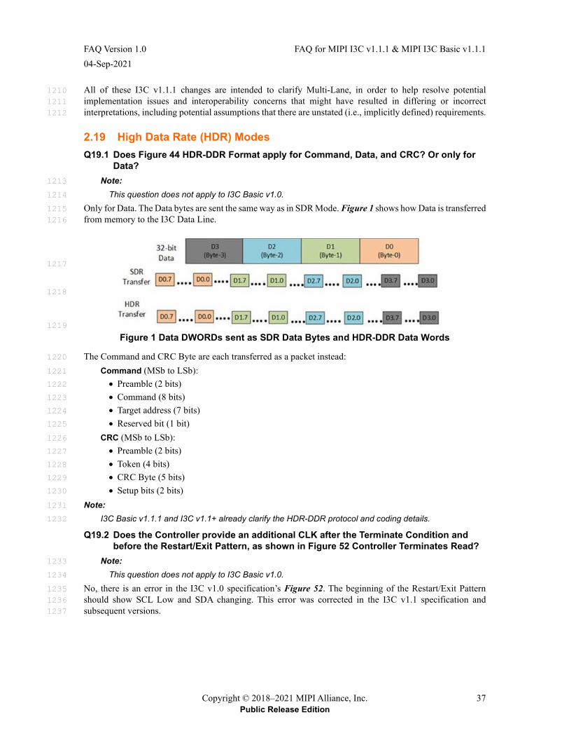
FAQ Version 1.0 FAQ for MIPI I3C v1.1.1 & MIPI I3C Basic v1.1.1 04-Sep-2021
Copyright © 2018–2021 MIPI Alliance, Inc. 37 Public Release Edition
All of these I3C v1.1.1 changes are intended to clarify Multi-Lane, in order to help resolve potential 1210 implementation issues and interoperability concerns that might have resulted in differing or incorrect 1211 interpretations, including potential assumptions that there are unstated (i.e., implicitly defined) requirements. 1212
2.19 High Data Rate (HDR) Modes Q19.1 Does Figure 44 HDR-DDR Format apply for Command, Data, and CRC? Or only for
Data? Note: 1213
This question does not apply to I3C Basic v1.0. 1214
Only for Data. The Data bytes are sent the same way as in SDR Mode. Figure 1 shows how Data is transferred 1215 from memory to the I3C Data Line. 1216
1217
1218
1219
Figure 1 Data DWORDs sent as SDR Data Bytes and HDR-DDR Data Words
The Command and CRC Byte are each transferred as a packet instead: 1220
Command (MSb to LSb): 1221
• Preamble (2 bits) 1222
• Command (8 bits) 1223
• Target address (7 bits) 1224
• Reserved bit (1 bit) 1225
CRC (MSb to LSb): 1226
• Preamble (2 bits) 1227
• Token (4 bits) 1228
• CRC Byte (5 bits) 1229
• Setup bits (2 bits) 1230
Note: 1231
I3C Basic v1.1.1 and I3C v1.1+ already clarify the HDR-DDR protocol and coding details. 1232
Q19.2 Does the Controller provide an additional CLK after the Terminate Condition and before the Restart/Exit Pattern, as shown in Figure 52 Controller Terminates Read?
Note: 1233
This question does not apply to I3C Basic v1.0. 1234
No, there is an error in the I3C v1.0 specification’s Figure 52. The beginning of the Restart/Exit Pattern 1235 should show SCL Low and SDA changing. This error was corrected in the I3C v1.1 specification and 1236 subsequent versions. 1237
FAQ for MIPI I3C v1.1.1 & MIPI I3C Basic v1.1.1 FAQ Version 1.0 04-Sep-2021
38 Copyright © 2018–2021 MIPI Alliance, Inc. Public Release Edition
Q19.3 During HDR-DDR Mode CRC 5 transmission, how many clocks should the Target expect to receive?
Note: 1238
This question does not apply to I3C Basic v1.0. 1239
The CRC transmission ends at bit 6 (counting down from bit 15), but bit 5 allows High-Z. 1240
Q19.4 For HDR-DDR Mode transfers, how should the Controller manage the Pull-Ups at the end of the HDR-DDR Command Word?
Note: 1241
This question does not apply to I3C Basic v1.0. 1242
Per Q21.3 and Q21.4, the Controller manages its Pull-Ups to allow for ACK/NACK as well as Bus 1243 Turnaround. The Controller sends the HDR-DDR Command Word with SDA in Active drive (i.e., Push-Pull 1244 mode) for the Command Word until the last Parity bit (i.e., PA0), which is initially driven High. Before the 1245 falling edge of C10 cycle, the Controller prepares for the Target to respond by disabling Push-Pull mode and 1246 engaging an appropriate Pull-Up to keep SDA at High. After the rising edge of the next C1 cycle, the 1247 addressed Target has the opportunity to either: 1248
• Accept the DDR Write or Read by pulling SDA to Low, or 1249
• Ignore the DDR Write or Read by leaving SDA at High 1250
Note: 1251
This scheme is similar to SDR Mode’s ACK/NACK scheme for the Address Header, where SDA is 1252 “Parked” at High and the Target can pull SDA to Low to acknowledge the transaction. 1253
The Controller should use the appropriate Pull-Up to enable Bus Turnaround or acceptance by the Target. 1254 For most use cases, the Open-Drain class Pull-Up is recommended; however, the High-Keeper could also be 1255 used, based on system design factors per specification Section 5.1.3.1. In either case, the Target must be able 1256 to pull SDA to Low before the falling edge of the C1 cycle. 1257
Note that the next C1 cycle is the start of the first HDR-DDR Data Word (if the Target accepts the transfer) 1258 and the PRE1 bit (i.e., the rising edge of the C1 cycle) is always 1’b1 per Section 5.2.2. Using this scheme, 1259 the Target’s response determines the preamble bits: 1260
• Bits 2’b10 indicate a Target ACK (i.e., accepting the DDR Write or Read) which starts the first 1261 HDR-DDR Data Word; or 1262
• Bits 2’b11 indicate a Target NACK (i.e., ignoring the DDR Write or Read). The Controller then 1263 drives the HDR Restart Pattern or HDR Exit Pattern. 1264
Q19.5 What has changed regarding HDR Modes in I3C v1.1.1? Note: 1265
This question does not apply to I3C Basic. 1266
In I3C v1.1 and earlier, the flow for transitioning from ENTHDRx CCCs into HDR Modes was not fully 1267 defined. I3C v1.1.1 fully defines the flow for transitioning from such CCCs into the first transfer in an HDR 1268 Mode, as well as the corresponding flow transitions from the HDR Restart Pattern to the next HDR transfer 1269 in the same HDR Mode. 1270
christinaslape
Highlight
FAQ Version 1.0 FAQ for MIPI I3C v1.1.1 & MIPI I3C Basic v1.1.1 04-Sep-2021
Copyright © 2018–2021 MIPI Alliance, Inc. 39 Public Release Edition
Q19.6 What has changed regarding HDR Ternary Modes in I3C v1.1.1? Note: 1271
This question does not apply to I3C Basic. 1272
In addition to the changes regarding ENDXFER and HDR Ternary Flow Control (see Q18.16), I3C v1.1.1 1273 now includes: 1274
• Clarifications on the use of Group Addresses for Direct CCC Read/Write segments in HDR 1275 Ternary Modes 1276
• Configuration advisories regarding use of common HDR Ternary Flow Control with CCCs, 1277 especially when sending Direct CCCs to Group Addresses. 1278
• Clarification to the Option 2 End of CCC Procedure, which is now similar to starting a new CCC: 1279 all I3C Targets must acknowledge the Write Command to the Broadcast Address before the 1280 Controller sends an HDR Restart Pattern to end the CCC modality and return to generic HDR 1281 Ternary Read/Write commands. 1282
Q19.7 What has changed regarding HDR-BT Mode in I3C v1.1.1? In addition to the Multi-Lane changes for HDR-BT Mode (see Q18.17), specification Section 5.2.4 now adds: 1283
• Definitions on how to compute the Parity bits in the HDR-BT Header Block 1284
• Definitions and examples for the CRC-16 and CRC-32 polynomials as used for HDR-BT CRC 1285 Block checksums 1286
• Clarifications on how the HDR-BT CRC checksum values are calculated based on the data for 1287 each HDR-BT transfer 1288
• Correction of an error in the figure showing Direct CCC flows in HDR-BT Mode 1289
• Clarifications on the use of Group Addresses for Direct CCC Read/Write segments in HDR-BT 1290 Mode 1291
• Correction of a specification error concerning the use of HDR-BT CRC Blocks in CCC Flows in 1292 HDR-BT Mode 1293
• Clarifications to the Transition_Verify byte in the HDR-BT CRC Block; Bits[4:2] are now 1294 redefined as always zero 1295
• Added new figures in specification Section 5.2.4.6 showing the Single-Lane format for all HDR-1296 BT Mode structured protocol elements 1297
• Corrections to the Dual-Lane and Quad-Lane figures for the HDR-BT Mode structured protocol 1298 elements, to resolve inconsistencies with the normative text and to show proper SDA Lane bit 1299 packing (i.e., the Transition, Transition_Control and Transition_Verify bytes) 1300
• Detailed explanation of the Data Block Delay mechanism (formerly called the Stall [delay] 1301 mechanism), which allows an I3C Target to delay sending the next HDR-BT Data Block until it 1302 has collected enough data bytes (see Q19.9) 1303
• Better explanations of HDR-BT flow control details, including a new Section 5.2.4.7 with 1304 example HDR-BT transfers with different actions at the flow control points (i.e., the various 1305 Transition bytes) 1306
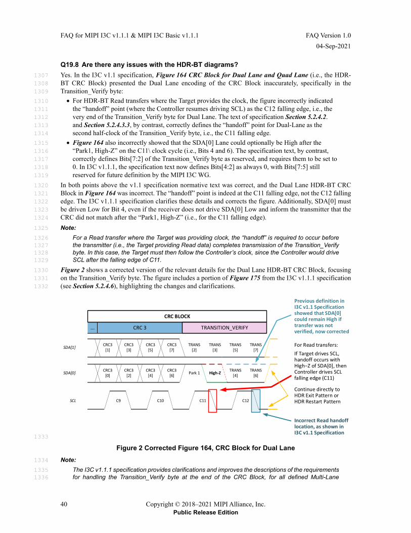
FAQ for MIPI I3C v1.1.1 & MIPI I3C Basic v1.1.1 FAQ Version 1.0 04-Sep-2021
40 Copyright © 2018–2021 MIPI Alliance, Inc. Public Release Edition
Q19.8 Are there any issues with the HDR-BT diagrams? Yes. In the I3C v1.1 specification, Figure 164 CRC Block for Dual Lane and Quad Lane (i.e., the HDR-1307 BT CRC Block) presented the Dual Lane encoding of the CRC Block inaccurately, specifically in the 1308 Transition_Verify byte: 1309
• For HDR-BT Read transfers where the Target provides the clock, the figure incorrectly indicated 1310 the “handoff” point (where the Controller resumes driving SCL) as the C12 falling edge, i.e., the 1311 very end of the Transition_Verify byte for Dual Lane. The text of specification Section 5.2.4.2. 1312 and Section 5.2.4.3.3, by contrast, correctly defines the “handoff” point for Dual-Lane as the 1313 second half-clock of the Transition_Verify byte, i.e., the C11 falling edge. 1314
• Figure 164 also incorrectly showed that the SDA[0] Lane could optionally be High after the 1315 “Park1, High-Z” on the C11\ clock cycle (i.e., Bits 4 and 6). The specification text, by contrast, 1316 correctly defines Bits[7:2] of the Transition_Verify byte as reserved, and requires them to be set to 1317 0. In I3C v1.1.1, the specification text now defines Bits[4:2] as always 0, with Bits[7:5] still 1318 reserved for future definition by the MIPI I3C WG. 1319
In both points above the v1.1 specification normative text was correct, and the Dual Lane HDR-BT CRC 1320 Block in Figure 164 was incorrect. The “handoff” point is indeed at the C11 falling edge, not the C12 falling 1321 edge. The I3C v1.1.1 specification clarifies these details and corrects the figure. Additionally, SDA[0] must 1322 be driven Low for Bit 4, even if the receiver does not drive SDA[0] Low and inform the transmitter that the 1323 CRC did not match after the “Park1, High-Z” (i.e., for the C11 falling edge). 1324
Note: 1325
For a Read transfer where the Target was providing clock, the “handoff” is required to occur before 1326 the transmitter (i.e., the Target providing Read data) completes transmission of the Transition_Verify 1327 byte. In this case, the Target must then follow the Controller’s clock, since the Controller would drive 1328 SCL after the falling edge of C11. 1329
Figure 2 shows a corrected version of the relevant details for the Dual Lane HDR-BT CRC Block, focusing 1330 on the Transition_Verify byte. The figure includes a portion of Figure 175 from the I3C v1.1.1 specification 1331 (see Section 5.2.4.6), highlighting the changes and clarifications. 1332
...
CRC3[0]
CRC3[2]
CRC3[4]
CRC3[6]
CRC3[1]
CRC3[3]
CRC3[5]
CRC3[7]
C11
Park 1 High-Z
TRANS[2]
TRANS[4]
TRANS[3]
TRANS[5]
C9 C10
CRC 3
SCL
SDA[0]
SDA[1]
C12
For Read transfers:If Target drives SCL, handoff occurs with High−Z of SDA[0], then Controller drives SCL falling edge (C11)
TRANS[6]
TRANS[7]
Continue directly to HDR Exit Pattern or HDR Restart Pattern
CRC BLOCK
Incorrect Read handoff location, as shown in I3C v1.1 Specification
TRANSITION_VERIFY
Previous definition in I3C v1.1 Specification showed that SDA[0] could remain High if transfer was not verified, now corrected
1333
Figure 2 Corrected Figure 164, CRC Block for Dual Lane Note: 1334
The I3C v1.1.1 specification provides clarifications and improves the descriptions of the requirements 1335 for handling the Transition_Verify byte at the end of the CRC Block, for all defined Multi-Lane 1336
FAQ Version 1.0 FAQ for MIPI I3C v1.1.1 & MIPI I3C Basic v1.1.1 04-Sep-2021
Copyright © 2018–2021 MIPI Alliance, Inc. 41 Public Release Edition
configurations, including cases where the receiver fails to acknowledge the transfer. In general, the 1337 Controller must control SDA[0] and any other SDA[1:3] data Lanes (per the Lane configuration) due 1338 to the updated definition of the bit fields in the Transition_Verify byte. 1339
Q19.9 What is the HDR-BT Data Block Delay mechanism? This mechanism allows an I3C Target to delay sending a complete HDR-BT Data Block during an HDR-BT 1340 Read transfer, for situations where the I3C Target or its inner system was unable to fully prepare enough data 1341 bytes to fill a Data Block as part of the Read transfer in HDR-BT Mode. 1342
In I3C v1.1, the HDR-BT Data Block Delay mechanism was called the “Stall (delay) mechanism” and was 1343 not fully defined. Additionally, the name “Stall (delay)” was too easily confused with other I3C defined 1344 behaviors in which SCL clock stalling is permitted (i.e., stalling by the I3C Controller is allowed, but never 1345 stalling by an I3C Target). The confusion occurred because this HDR-BT mechanism is fundamentally 1346 different from SDR Mode SCL clock stalling, and I3C forbids SCL clock stalling in HDR-BT Mode 1347
The I3C v1.1.1 specification addresses this confusion by renaming the mechanism to more accurately reflect 1348 its definition, and by adding clearer, more complete normative details. In addition, the name of parameter 1349 “tBT_STALL” was changed to “tBT_DBD”. 1350
During an HDR-BT Read transfer, the Data Block Delay mechanism allows the I3C Target to transmit either: 1351
• A valid Data Block, which is not intended to be the last such Data Block, if the Target has a full 32 1352 bytes of data to transmit; or 1353
• A single Delay byte, indicating that the Target is not yet ready to transmit a Data Block and that 1354 the I3C Controller should therefore continue the Read if it wishes to receive more data. 1355
This Delay byte differs from a valid Transition_Control byte (i.e., the first byte of an HDR-BT Data Block). 1356 The I3C Target may defer sending a Data Block (i.e., by sending a Delay byte up to a maximum of 1024 1357 times) at any point of a Read transfer, before it must terminate the Read transfer. The I3C Controller also has 1358 the opportunity either to continue waiting (i.e., receiving more Delay bytes until the I3C Target has enough 1359 data), or to terminate the Read transfer at its discretion. 1360
This mechanism does not allow an I3C Target to delay sending either the CRC Block or the Last Data Block 1361 (e.g., one that might have “ragged” data). 1362
The I3C Controller determines whether the I3C Target may use the Data Byte Delay mechanism. The 1363 Controller indicates this in the Control byte of the HDR-BT Header Block that starts each HDR-BT Read 1364 transfer. 1365
• If the I3C Target supports this mechanism and chooses to use it for this transfer, then the Target 1366 may use the mechanism if needed. 1367
• If the I3C Target does not support this mechanism, or if the I3C Controller has indicated that the 1368 Data Byte Delay is not permitted, then the I3C Target must not use this mechanism, in case it 1369 encountered a situation where it was unable to fully prepare enough bytes to fill a Data Block. In 1370 such a situation, the I3C Target might be forced to end the HDR-BT Read transfer early (i.e., by 1371 sending incomplete data). 1372
This mechanism is primarily useful when the I3C Controller controls the SCL clock during the HDR-BT 1373 Read transfer, as the I3C Target would otherwise not have a method for indicating that the transfer should be 1374 slowed to match the actual rate of Data Blocks that it can reasonably produce (i.e., from its inner system that 1375 might provide the data bytes). 1376
FAQ for MIPI I3C v1.1.1 & MIPI I3C Basic v1.1.1 FAQ Version 1.0 04-Sep-2021
42 Copyright © 2018–2021 MIPI Alliance, Inc. Public Release Edition
2.20 I3C Advanced Capabilities Q20.1 What is Offline, and what does it mean to be Offline Capable? The Offline capability allows a Target to become inactive on the I3C Bus at some times, but then return to 1377 normal activity later. The Offline capability is now indicated in the Target’s Bus Control Register (BCR). 1378
There are two basic types of Offline-capable Target: 1379
1. A Target that is fully inactive on the I3C Bus (e.g., is powered off) and only becomes active again 1380 as the result of some external event. Such a Target will then Hot-Join to get a new Dynamic 1381 Address. 1382
2. A Target that is inactive on the I3C Bus, but some portion of the Target is monitoring the Bus for 1383 either Target Reset, or the use of the Target’s Dynamic Address. The monitoring portion of the 1384 Target retains the Target’s Dynamic Address, even though the Target might be mostly powered-off 1385 or in deepest sleep. 1386
Such Targets can be awakened (i.e., re-activated) by a Target Reset or by the use of their Dynamic 1387 Address. They will take some time to become active on the Bus again, such as the RSTACT CCC 1388 recovery from Full Reset time. While they are offline, and while awakening, they will not be 1389 responsive to the Controller, nor will they record CCCs, nor will they necessarily retain state (e.g., 1390 the ENEC/DISEC CCCs); as a result, the Controller will have to wait until such Targets become 1391 active, and then might also need to configure them again. This is all by private contract 1392 (agreement). 1393
See specification Section 5.1.10.2.5 for details, both in I3C v1.0 (which does not include Target Reset) and 1394 in I3C v1.1 (which does include Target Reset). 1395
Q20.2 What is a Virtual Target? Generally, a Virtual Target is a function of a single physical Device that represents multiple I3C Targets on 1396 the I3C Bus, such that the I3C Controller can address each of those Targets independently. 1397
In the simplest form, a Virtual Target could be one of a set of several Target Devices, all integrated into the 1398 same physical package and all sharing a common set of pins connecting them to an I3C Bus. 1399
In a more advanced form, a Virtual Target could act as one of several virtualized functions presented by a 1400 highly-integrated Device that stores a different Dynamic Address for each function. Depending on the 1401 implementation, such virtualized functions might share configuration information, and might return the same 1402 values for some CCCs. 1403
Examples could include Bridging or Routing Devices, as well as other types of Devices that expose multiple 1404 functions and use shared Peripheral logic. I3C v1.1 defines several new capabilities and features for such 1405 Virtual Targets. 1406
For details, see the I3C v1.1 specification at Section 5.1.9.3.19, and the System Integrators Application Note 1407 for I3C [MIPI05] at Section 5.7. 1408
Q20.3 Does the I3C Bus support Bridges? Yes. Bridge Devices enable an I3C Bus to be bridged to other protocols, such as SPI, UART, etc. The 1409 SETBRGTGT (SET BRidGe TarGeT) CCC is defined to enable Bridge Devices, where the Controller either 1410 knows in advance that certain Devices are bridges, or can discover a Bridge Device during Bus initialization. 1411
FAQ Version 1.0 FAQ for MIPI I3C v1.1.1 & MIPI I3C Basic v1.1.1 04-Sep-2021
Copyright © 2018–2021 MIPI Alliance, Inc. 43 Public Release Edition
Q20.4 How does the Set Bridge Targets (SETBRGTGT) CCC differ between I3C v1.0 and I3C v1.1+?
In I3C v1.1, use of this CCC is expanded to support Bridging Devices that have Dynamic Addresses, which 1412 makes multiple Bridging Devices on the same I3C Bus possible. The context of the SETBRGTGT CCC is 1413 also redefined: a Bridging Device is now one of several types of Devices that expose or present Virtual 1414 Targets. Bit[4] of the Target’s Bus Configuration Register (BCR) now indicates Virtual Target capabilities. 1415
For bridged Targets that are enabled by a Bridging Device, I3C v1.1 clarifies the use of other CCCs (such as 1416 SETMRL) that address a bridged Target. The I3C v1.1 specification also clarifies that to change the Dynamic 1417 Address of a bridged Target, the SETBRGTGT CCC (not the SETNEWDA CCC) must be used. 1418
For details, see the I3C v1.1 specification at Sections 5.1.1.2.1, 5.1.9.3.17, and 5.1.9.3.19. 1419
Q20.5 Does the I3C Bus enable Routing? Yes. I3C v1.1+ and I3C Basic v1.1.1 define the requirements, expectations, and configuration for Routing 1420 Devices. 1421
Routing Devices enable the creation of multiple Routes across I3C Buses. A Routing Device enables more 1422 advanced Bus topologies, and requires buffers or queues to handle transactions across each Route. 1423
A Routing Device contains a Control Function which is presented on the I3C Bus as a Virtual Target. The 1424 Controller configures the Routing Device by sending the SETROUTE CCC to its Control Function. Routes 1425 to other I3C Buses are treated as downstream targets, each of which generally has a Target Function which 1426 is also presented as a Virtual Target with its own Dynamic Address. Transactions are sent to the Route’s 1427 Target Function via its Dynamic Address, and the Routing Device manages the communications on the 1428 downstream I3C Bus. 1429
For details, see the I3C v1.1 specification at Section 5.1.9.3.20. 1430
Q20.6 Why does I3C allow more than one Controller on the I3C Bus? What can a Secondary Controller do that the Primary Controller can’t?
The system designer decides whether their system needs more than one Controller on the Bus. To provide 1431 that flexibility MIPI I3C allows this, but also does not require it. Controller Role Handoff is a well-defined 1432 and controlled mechanism in I3C; if used, it can be relied on. 1433
For most use cases, a Secondary Controller is not a required component for an I3C Bus. If your Primary 1434 Controller has all the capabilities and features that you need, and if your use of the I3C Bus wouldn’t benefit 1435 from having multiple Controller-capable Devices, then you might not need a Secondary Controller. 1436
Examples where Secondary Controllers are useful: 1437
1. A Debug controller, if present, would be a Secondary Controller 1438
2. A sensor hub or other offload device can be used to continue operating during periods when the 1439 Host processor is in deep sleep (i.e., to save power) 1440
3. The system can switch between standalone use (such as IoT devices) and connected uses. For 1441 example, perhaps a USB-to-I3C cable is attached to take over temporarily. 1442
Note that Devices such as MCUs will usually be able to operate as fully-fledged Targets, as fully-fledged 1443 Primary Controllers, and as Secondary Controllers (i.e., Devices that come up as Targets but can become the 1444 Active Controller later), depending solely on the particular needs of the given system. They can simply be 1445 configured for the Bus they are on by the firmware. 1446
Note: 1447
This FAQ entry has been updated for I3C v1.1.1 and I3C Basic v1.1.1. In this FAQ entry, the terms 1448 “Primary Controller” and “Secondary Controller” refer to an I3C Device’s initial configuration and 1449 capabilities. In other sections of this FAQ and the I3C specification, the term “Secondary Controller” 1450 might instead reflect a Controller-capable Device’s current role, i.e., as and when it is not currently 1451 the “Active Controller” of the Bus. See Q13.4 for additional details. 1452
FAQ for MIPI I3C v1.1.1 & MIPI I3C Basic v1.1.1 FAQ Version 1.0 04-Sep-2021
44 Copyright © 2018–2021 MIPI Alliance, Inc. Public Release Edition
Q20.7 Is any time-stamping capability defined for the I3C Bus? Note: 1453
• This question does not apply to I3C Basic v1.0. 1454
• I3C Basic v1.1.1 only supports Timing Control with Async Mode 0. 1455
Yes. The I3C Bus supports an optional Timing Control mechanism which has multiple timing modes. One 1456 timing mode is synchronous (from the synchronized timing reference) and four modes are asynchronous 1457 (Target provides timestamp data). All I3C Controllers are expected to support at least Async Mode 0. 1458
• Synchronous: The Controller emits a periodic time sync that allows Targets to set their sampling 1459 time relative to this sync. This may be used in conjunction with one of the Asynchronous modes. 1460
• Asynchronous: The Targets apply their own timestamps to the data at the time they acquire 1461 samples, permitting the Controller to time-correlate samples received from multiple different 1462 Targets or sensors. 1463
There are four types (timing modes) of asynchronous time controls: 1464
• Async Mode 0: Basic timing mode that assumes that a Target has access to a reasonably 1465 accurate and stable clock source to drive the time stamping – at least accurate for the duration of 1466 the time it has to measure (i.e., from event to IBI). A set of counters, in conjunction with IBI, are 1467 used to communicate time stamping information to the Controller. 1468
• Async Mode 1: Advanced timing mode extends the Basic mode by using some mutually 1469 identifiable Bus events, like I3C START. 1470
• Async Mode 2: High-precision timing mode that uses SCL falling edges (for SDR and HDR-1471 DDR modes) as a common timing reference for Controller and Target. A burst oscillator is used 1472 to interpolate the time between a detected event and next SCL falling edge. For HDR-TSL and 1473 HDR-TSP modes, this timing mode uses both SDA transitions and SCL transitions as timing 1474 references. 1475
• Async Mode 3: Highest-precision triggerable timing mode that supports precise time triggering 1476 and measurement across multiple transducers applications like beam forming. 1477
Q20.8 Can Synchronous and Asynchronous Timing Control both be enabled at the same time?
Note: 1478
This question does not apply to I3C Basic v1.0. 1479
Yes. This is allowed such that the ODR (Output Data Rate) rate controls the In-Band Interrupt (IBI) rate, and 1480 the Async Mode timestamp on the IBI indicates how long ago the sample was collected. 1481
Q20.9 Is there a way to turn off Timing Control? Note: 1482
This question does not apply to I3C Basic v1.0. 1483
Yes, the Controller can turn off Timing Control by sending the SETXTIME CCC with the value 0xFF in the 1484 Sub-Command byte. 1485
FAQ Version 1.0 FAQ for MIPI I3C v1.1.1 & MIPI I3C Basic v1.1.1 04-Sep-2021
Copyright © 2018–2021 MIPI Alliance, Inc. 45 Public Release Edition
Q20.10 What has changed regarding Multi-Lane for SDR Mode? Note: 1486
This question does not apply to I3C Basic v1.0. 1487
In I3C v1.1, the Data Transfer Codings for Multi-Lane in SDR Mode (SDR-ML) define the Header Byte to 1488 contain supplementary information to be sent on SDA[1] (i.e., the first Additional Data Lane) when 1489 Multi-Lane is enabled for SDR Mode. This supplementary information includes the inverse of the Address, 1490 since the Header Byte was defined to include the I3C Address Header and was intended to be received and 1491 understood by existing I3C Targets that did not necessarily support SDR-ML. 1492
Upon review, the I3C WG realized that this method would cause implementation challenges during an 1493 Arbitrable Address Header (i.e., after a START) if the I3C Controller were required to echo any changes it 1494 saw on SDA[0] (i.e., to track changes that an I3C Target might drive during Address Arbitration) when 1495 emitting the inverse on SDA[1]. The I3C v1.1.1 specification address these issues by changing the definition 1496 of the Header Byte for SDR-ML to only require the I3C Controller to send this supplementary information 1497 on SDA[1] for the Header Byte (i.e., an Address Header) after a Repeated START. When sending the Header 1498 Byte after a START, the I3C Controller is now required to keep SDA[1] and any other Data Lanes in a High-Z 1499 state, rather than driving this supplementary information. 1500
In SDR Mode, CCCs are always sent in 1-Lane mode, allowing all I3C Targets to track the Command Code 1501 and Defining Byte (if any) in the CCC Framing. This rule places limitations on the use of SDR-ML: 1502
1. If SDR-ML is used, then the Targets should not rely on supplementary information on SDA[1] for 1503 the Header Byte (i.e., the Address Header); the supplemental information should be treated as 1504 optional, because 1-Lane Targets (i.e., Targets that might not support SDR-ML) must track CCC 1505 framing and flow elements but can only see SDA[0]. 1506
2. Transfers after a Repeated START that comprise Broadcast CCCs (i.e., transfers addressed to 1507 7’h7E) must also be sent only in SDR 1-Lane mode. As a result, SDR-ML cannot be used for 1508 Broadcast CCCs in SDR Mode. 1509
3. Transfers after a Repeated START that comprise CCC flow elements (e.g., Direct CCC segments 1510 addressed to a specific Target or Group) must only be sent in SDR 1-Lane mode. As a result, 1511 SDR-ML also cannot be used for Direct CCCs in SDR Mode. 1512
Conditions #2 and #3 above are especially relevant because both Broadcast CCCs and Direct CCCs may be 1513 mixed in among Private Write/Read transfers in continuous SDR Mode framing (i.e., without intervening 1514 STOP Conditions). In such cases the Controller should not send the supplementary information during the 1515 Address Header, and Targets supporting SDR-ML are required not to depend on it, because they will know 1516 that the Controller is sending a CCC. Furthermore, the Controller must not use SDR-ML data byte encoding 1517 for CCCs (both Broadcast and Direct) because some Targets on the I3C Bus might not understand the 1518 encoding. 1519
FAQ for MIPI I3C v1.1.1 & MIPI I3C Basic v1.1.1 FAQ Version 1.0 04-Sep-2021
46 Copyright © 2018–2021 MIPI Alliance, Inc. Public Release Edition
2.21 Electricals and Signaling Q21.1 How many signal lines does I3C have? I3C has two mandatory signal lines: Data (SDA) and Clock (SCL). 1520
I3C v1.1+ and I3C Basic v1.1.1 also support optional Multi-Lane transfers, which use additional Data lines 1521 for supported I3C Modes. In Multi-Lane, the SDA line is called SDA[0] and the additional data lines are 1522 called SDA[1], SDA[2], etc. 1523
Q21.2 Does I3C require Pull-Up resistors on the bus like I²C? Not necessarily. I3C Controllers manage an active (i.e., dynamic) Pull-Up resistance on SDA, which they 1524 can enable and disable as the Bus transitions between Open Drain and Push-Pull mode. This might be a 1525 board-level resistor that is switchable (i.e., that can be engaged/disengaged as needed, controlled by an output 1526 pin from the Controller), or internal to the Controller, or any combination of the two. 1527
Note: 1528
If an I3C Bus has multiple Controller-capable Devices (i.e., one Active Controller and one or more 1529 Secondary Controllers), then the Active Controller manages the Pull-Up on SDA. 1530
Q21.3 When is the Pull-Up resistor enabled? In order to achieve higher data rates, much of the activity on the I3C Bus occurs in Push-Pull mode (i.e., with 1531 the Open Drain Pull-Up resistor disabled). 1532
However for some Bus management activities, and for backwards compatibility with I2C, Pull-Up-resistor-1533 based Open Drain mode is enabled. Examples include: 1534
• Arbitration during Dynamic Address Assignment 1535
• Address Header following a START, which is arbitrable and can become an In-Band Interrupt 1536 Request 1537
• ACK/NACK during the 9th bit of an Address Header. 1538
With very few exceptions, the I3C Controller is responsible for providing an Open Drain class Pull-Up 1539 resistor when the Bus is in the Open Drain mode. See specification Section 5.1.3.1. 1540
Note: 1541
The Open Drain class Pull-Up for SDA could either be provided internally by the Controller, or it could 1542 be an external device that is engaged or disengaged as needed, i.e., switchable between these 1543 states and controlled by a Controller output pin. 1544
By contrast, SCL should always be driven by the Active Controller (i.e., Push-Pull) and no Open Drain 1545 class Pull-Up is needed. 1546
Q21.4 Is a High-Keeper needed for the I3C Bus? A High-Keeper is used for Controller-to-Target and Target-to-Controller Bus handoff, as well as optionally 1547 when the Bus is idle (see Q22.1). The High-Keeper may be a passive weak Pull-Up resistor on the Bus, or an 1548 active weak Pull-Up (or equivalent) in the Controller. The High-Keeper is only required to be strong enough 1549 to prevent system-leakage from pulling the Bus Low. At the same time, the High-Keeper for the SDA line 1550 must be weak enough that a Target with the minimum IOL driver can pull the SDA line Low within the trDA 1551 minimum period. The system designer is responsible for balancing these factors. 1552
Note: 1553
A High-Keeper is required for both SDA and SCL. External High-Keepers might be required if the 1554 Active Controller’s High-Keeper is not adequate per specification Section 5.1.3.1. Additionally, if an 1555 I3C Bus has multiple Controller-capable Devices (i.e., one Primary Controller and one or more 1556 Secondary Controllers), then the Active Controller is responsible for managing the High-Keeper, and 1557 Controllers using the Controller Role Handoff Procedure are required to engage or disengage their 1558 High-Keepers at the defined times during this procedure (per Section 5.1.7.2). 1559
FAQ Version 1.0 FAQ for MIPI I3C v1.1.1 & MIPI I3C Basic v1.1.1 04-Sep-2021
Copyright © 2018–2021 MIPI Alliance, Inc. 47 Public Release Edition
2.22 Bus Conditions and States Q22.1 What are some of the I3C Bus conditions when the Bus is considered inactive? In addition to Open-Drain, Pull-Up, and High-Keeper, the I3C Bus has three distinct conditions under which 1560 the Bus is considered inactive: Bus Free, Bus Available, and Bus Idle. 1561
• Bus Free condition is defined as a period occurring after a STOP and before a START and for a 1562 given duration (e.g., tCAS and tBUF timing). 1563
• Bus Available condition is defined as a Bus Free condition with duration of at least tAVAL. A Target 1564 may only issue a START request (e.g., for In-Band Interrupt or Controller Handoff) after a Bus 1565 Available condition. 1566
• Bus Idle condition is defined to help ensure Bus stability during Hot-Join events. This condition is 1567 defined as a period during which the Bus Available condition is sustained continuously for a 1568 duration of at least tIDLE. 1569
Q22.2 When an I3C Device wishes to send an In-Band Interrupt (IBI) Request, does it need to see a STOP before a Bus Idle?
For normal active I3C Targets, yes. They should only send an In-Band Interrupt (IBI) Request when they 1570
have seen a STOP and the tAVAL time has elapsed (about 1 µs), and in response to a START (but not a 1571 Repeated START). 1572
For Hot-Joining Devices using the standard Hot-Join method, they do not necessarily know the Bus condition, 1573 so they wait until the Bus is Idle (i.e., until SCL and SDA are both high for a duration of at least tIDLE). 1574
Q22.3 When can an I3C Target issue an In-Band Interrupt (IBI) Request? An I3C Target can issue the IBI in the following two ways: 1575
• Following a START (but not a Repeated START) 1576
• If no START is forthcoming within the Bus Available condition, then an I3C Target can issue a 1577 START request by pulling the SDA line Low. The I3C Controller would then complete the START 1578 condition by pulling the SCL clock line Low and taking over the SDA line. 1579
Q22.4 What are the I3C Bus Activity States? Bus Activity States provide a mechanism for the Controller to inform the Targets about the expected 1580 upcoming levels of activity or inactivity on the Bus, in order to help Targets better manage their internal 1581 states (e.g., to save power). 1582
There are four Bus Activity States, each with an expected activity interval: 1583
• Activity State 0: Normal activity 1584
• Activity State 1: Expect quiet for at least 100 µs 1585
• Activity State 2: Expect quiet for at least 2 ms 1586
• Activity State 3: Expect quiet for at least 50 ms 1587
FAQ for MIPI I3C v1.1.1 & MIPI I3C Basic v1.1.1 FAQ Version 1.0 04-Sep-2021
48 Copyright © 2018–2021 MIPI Alliance, Inc. Public Release Edition
2.23 Resets and Error Handling Q23.1 Are there any test modes in the I3C Bus? Yes. The Directed and Broadcast ENTTM CCCs (see specification Section 5.1.9.3.8) allow the Controller to 1588 enter and exit the test modes. Support for the ENTTM CCC is optional for I3C Targets. 1589
The I3C v1.1+ and I3C Basic v1.1.1 specifications also define an optional Defining Byte for the GETCAPS 1590 CCC: the Read Fixed Test Pattern command (see specification Section 5.1.9.3.19). This provides simple Bus 1591 testing that can be supported by I3C Controllers and Targets. 1592
Q23.2 Are there any error detection and recovery methods in I3C? Yes, the I3C Bus has elaborate error detection and recovery methods. Seven Target error types (TE0 through 1593 TE6) and four Controller error types (CE0 through CE3) are defined for SDR Mode, along with suggested 1594 recovery methods. In addition, a similar set of errors is defined for each HDR Mode. 1595
Note: 1596
This question has been updated for I3C v1.1+ and I3C Basic v1.1.1. These versions add new Error 1597 Types CE3 and DBR. 1598
Q23.3 What happens if the Controller crashes during a Read? An I3C Target may optionally choose to time out if it detects more than 100 µs without an SCL edge (see 1599 specification Section 5.1.2.3). If that happens, the Target can abandon the Read and release SDA to avoid a 1600 Bus hang when the Controller restarts. 1601
The optional timeout of 100 µs with no SCL activity is a recommended minimum. It does not have to be 1602 precise, but since I3C’s minimum frequency is 10 KHz, anything longer than 100 µs means that the 1603 Controller has failed to complete the Read, so the Target should High-Z the SDA line and abandon the Read. 1604
Note: 1605
If the Target is in Legacy I2C mode, then it would not normally abandon the read, since there is no 1606 minimum frequency, and because 9 clocks by a Controller will be enough to abort the Read (since 1607 the 9th bit of data is ACK/NACK for a Read in Legacy I2C Mode). 1608
Q23.4 Is there any way to exit from an Error of Type TE0 or TE1, other than waiting for an Exit Pattern?
Yes. An I3C Target may optionally watch for 60 µs with no SCL or SDA changes to make sure that the Bus 1609 is not in HDR Mode (and therefore must be in SDR Mode). After that, it is appropriate to wait for START 1610 (assumed to be Repeated START) or STOP. 1611
Q23.5 Can a Controller issue a STOP condition regardless of whether or not a Target has issued an acknowledgment indicating a completed transaction?
The STOP can be issued anywhere the Target is not driving the SDA during SCL High. It may not be 1612 appropriate to do so in terms of completion of a message. But ACK and completed transaction do not belong 1613 together in I3C. 1614
Q23.6 What errors are reported on the GETSTATUS Protocol Error bit? The Protocol Error Report bit on the GETSTATUS CCC is intended to report errors that have no other way 1615 of being detected unless the Device reports them. It is intended to cover parity error, CRC error, and anything 1616 else that means that a message from the Controller was lost and the Controller has no way of knowing it. 1617
The Protocol Error Report on the GETSTATUS CCC would not cover the case of TE5 errors, as they are 1618 more related to an unsupported CCC or Defining Byte (which is not a protocol error per se). It is also not 1619 intended for situations when the Target NACKs, because the Controller will know that an error occurred 1620 when the Target NACKs and recovers it. Errors such as Error Types TE0, TE3, TE4, and TE5 are detected 1621 by the Controller when the Target sends a NACK response, and are recovered by using the appropriate 1622 recovery methods; as a result, they need not be reported via the GETSTATUS CCC. 1623
FAQ Version 1.0 FAQ for MIPI I3C v1.1.1 & MIPI I3C Basic v1.1.1 04-Sep-2021
Copyright © 2018–2021 MIPI Alliance, Inc. 49 Public Release Edition
Q23.7 What errors does Target Error Type TE5 cover? Error Type TE5 covers illegally formatted CCCs that an I3C Target might see on the I3C Bus. 1624
Due to confusion around the use of the words “illegally formatted” in the I3C v1.0 specification, I3C v1.1 1625 more precisely defined what errors are considered to be instances of Error Type TE5. This section covers 1626 only four cases of errors, as follows. 1627
• The first two cases listed in I3C v1.1 are Unsupported Command Codes and Unsupported 1628 Defining Bytes (i.e., for a supported Command Code), both of which are ignored by a Target if not 1629 supported. 1630
Note that these are not strictly “illegally formatted” CCCs per se according to v1.1.1’s clarified 1631 definition of Error Type TE5, since the CCC format itself might be correct (if the Target happened 1632 to support that CCC). Nonetheless, a Target must still NACK any Command Code or Defining 1633 Byte that it does not support, so that the Controller will see the NACK and know that the Target is 1634 unable to respond to the CCC. In cases where these commands have a special exit condition, the 1635 Target should also still wait for the applicable exit condition. 1636
• The two cases addressed by Error Type TE5 are when the Controller sends the wrong RnW Bit for 1637 a Direct CCC command. That is, the Controller sends a Dynamic Address and Read bit for a 1638 Direct Write or Direct SET CCC command, or vice versa. In these cases, the Target must NACK 1639 its Address, thus notifying the Controller that an error has occurred. The Controller will then use 1640 the Retry and Escalation models. 1641
Additional Defining Bytes, or Additional Data on CCC Payloads, are not error conditions. Targets should 1642 ignore any additional unrecognized data bytes, per the specification at Section 5.1.9.2.2. 1643
Note: 1644
In previous versions of I3C and I3C Basic, Error Type TE5 was named Error Type S5; see Q5.2 for 1645 name change details. 1646
Q23.8 Are Devices required to wait for a Repeated START or STOP, or both, to recover from Error Types TE2–TE5?
Error Types TE2 through TE5 should be recovered by STOP. 1647
However: 1648
• Error Types TE2, TE3, and TE5: Vendors may optionally elect to have Devices recover from 1649 these Error Types upon seeing a Repeated START, per the transaction type. For these Error Types 1650 that support optional Repeated START recovery, STOP is the second step of escalation after 1651 Repeated START recovery. 1652
• Error Type TE4: Requires STOP recovery (the Repeated START option does not apply). 1653
Q23.9 What has changed regarding Target Error Types in I3C v1.1.1? Error Type TE0 (formerly named Error Type S0; see specification Section 5.1.10.1.1) now more clearly 1654 defines the I3C Target Address restrictions for an I3C Controller, and explains the single-bit error conditions 1655 that might occur if the restricted Addresses were used. 1656
Error Type TE5 (formerly named Error Type S5; see Section 5.1.10.1.6) now only provides examples of 1657 “illegally formatted” CCCs that include an incorrect RnW bit for a Direct CCC. Error Type TE5 no longer 1658 lists unsupported CCCs as an error case (see Q23.7). 1659
Note that the Target requirements for handling an unsupported Command Code or unsupported 1660 Defining Byte are now defined in specification Section 5.1.9.2.2. Although these cases are not 1661 strictly covered by Error Type TE5, a Controller might interpret a Target’s NACK response 1662 similarly and handle it with the same recovery procedure. 1663
Error Type TE6 (formerly named Error Type S6; see Section 5.1.10.1.7) now clearly defines the difference 1664 between the Target’s response to a CCC that it perceives as a Read (i.e., a Direct GET or a Direct Read) when 1665
FAQ for MIPI I3C v1.1.1 & MIPI I3C Basic v1.1.1 FAQ Version 1.0 04-Sep-2021
50 Copyright © 2018–2021 MIPI Alliance, Inc. Public Release Edition
there is an error in the RnW bit. This better explains the way that the Target should handle the error situation, 1666 i.e., when the Controller actually intended to send a Write (i.e., a Direct SET or a Direct Write). 1667
Q23.10 When does the RSTACT CCC state clear in an I3C Target? The RSTACT state will be cleared back to default upon either: 1668
1. Detection of a Target Reset Pattern. This will enact the RSTACT action, and then clear the state. 1669
2. Detection of a completed START (but not repeated START). The RSTACT may be cleared either 1670 on that falling edge, or on the rising edge that follows. 1671
Q23.11 What is the minimal Target Reset support required in I3C v1.1 or v1.1.1? I3C Targets that comply with I3C v1.1+ or I3C v1.1.1 must support the Target Reset Pattern, and at least the 1672 Peripheral Reset action (i.e., RSTACT CCC with Defining Byte 0x01). 1673
Although MIPI Alliance strongly recommends true support of Target Reset, such that a Controller can fully 1674 reset a Target chip when needed, it is not required. Full/Chip Reset (see specification Section 5.1.11.4) allows 1675 replacement of a dedicated pin that would normally be used to reset a Device. 1676
Note: 1677
If supported, a Full/Chip Reset causes a typical I3C Target to return to its power-on configuration, 1678 which means re-enabling its I2C Spike Filter if it has one. If so, then the I3C Controller must tell the 1679 I3C Target to turn off its Spike Filter again (see Q24.1). 1680
The minimal reset is a reset of the I3C peripheral, at least to a level that will allow a ‘stuck’ I3C peripheral 1681 to start working again. How much of a reset that requires is up to the Target vendor; for example, it could be 1682 handled by an internal interrupt which would allow firmware/software in the Target to handle the reset. 1683
Q23.12 When does a Target escalate Target Reset to Full/Chip Reset? If the Target does not receive a RSTACT CCC before seeing the Target Reset Pattern, then it uses the default 1684 action of Peripheral Reset: it resets just the I3C block. If the Target again receives no RSTACT CCC before 1685 seeing a Target Reset, it then escalates to a Full/Chip Reset. It therefore retains the state after any default 1686 Peripheral Reset, so it can then activate the escalation. This state is cleared if the Target sees either an 1687 RSTACT CCC, or a GETSTATUS CCC addressed to it. 1688
Note: 1689
The purpose of this mechanism is to fix a broken system or setup. Because the Target Reset Pattern 1690 Detector logic is normally separated both from the I3C block and from other parts of the main system, 1691 it will continue to work even if the rest of the chip becomes broken (e.g., clocks stopped, Bus locked 1692 up, etc.). This means that not seeing a RSTACT CCC would be a symptom of a large problem, so 1693 the Target escalates in order to recover from such a broken condition. The Target first performs a 1694 Peripheral Reset, in case the fault condition exists only in the I3C block itself. 1695
Q23.13 How is Target escalation affected when the RSTACT CCC is received? The RSTACT CCC only determines how the Target will interpret the next Target Reset Pattern that it receives, 1696 the RSTACT CCC does not alter the handling of any currently in-progress Target escalation. 1697
For this reason: 1698
• A Device that supports the RSTACT CCC should always prioritize RSTACT configuration over 1699 any currently occurring Target escalation. 1700
• Any Target escalation operation that might be in progress when the RSTACT CCC is received 1701 should be cleared. 1702
FAQ Version 1.0 FAQ for MIPI I3C v1.1.1 & MIPI I3C Basic v1.1.1 04-Sep-2021
Copyright © 2018–2021 MIPI Alliance, Inc. 51 Public Release Edition
2.24 Timing Parameters Q24.1 Are there any special timing requirements for sending the first START with the
Broadcast Address? Yes. The I3C Controller must emit the first START with the Broadcast Address (7’h7E) at Open-Drain speeds 1703 (i.e., usually I2C Fm+ timings) so that I3C Targets with I2C Spike Filters (per Q15.4) will be able to see the 1704 I3C Broadcast Address, and then as a result turn off the Spike Filter (per the specification at 1705 Section 5.1.2.1.1). 1706
Note: 1707
If another I3C Target arbitrates its own Address (or the special reserved address for a Hot-Join 1708 Request) into this Address Header and thereby wins arbitration, then the I3C Controller must repeat 1709 this special Address Header. 1710
If such an I3C Target supports Full/Chip Reset using the Target Reset Pattern (which might be 1711 preceded by the RSTACT CCC; see specification Section 5.1.11.4), then it will most likely re-enable 1712 its I2C Spike Filter after such a Full/Chip Reset. In this case, the I3C Controller must emit the START 1713 condition with the Broadcast Address (7’h7E) at Open-Drain speeds again, so that the I3C Target 1714 can turn off the Spike Filter. 1715
However, if the Controller knows that none of the I3C Targets has a Spike Filter, then it may omit this. 1716 Similarly, if the Controller knows that all of the I3C Targets have accurate Spike Filters, then it may use the 1717 I3C 2.5 MHz Open-Drain speed (i.e., 200 ns Low, 200 ns High). 1718
Q24.2 What is the I3C Open-Drain tHigh Max? Table 10 shows it as 41 ns, but a Note says it may be longer
In the I3C v1.1 specification, Table 110 I3C Open Draining Timing Parameters shows the tHigh symbol 1719 maximum value as 41 ns, and Note 4 states “tHigh may be exceeded when the signals can be safely seen by 1720 I2C Targets”. This means that a 41 ns tHigh will ensure that no Legacy I2C Target will see the SCL changes, 1721 and so no Legacy I2C Target will interpret the START followed by the Address phase nor the ACK/NACK. 1722 If there is no harm with a Legacy I2C Target on the I3C Bus seeing the clocks, then the Controller may use a 1723 much longer tHigh. For example, Legacy I2C Targets will see the STOP and then a START. It is acceptable for 1724 them to see the Address that follows (arbitrated or not), since none of those Addresses will match their own 1725 Address. However, as the tLow may well be 200 ns, this may present problems for any Legacy I2C Targets not 1726 fast enough to correctly handle a 200 ns Low period. 1727
In the I3C v1.1.1 specification, the parameters are defined in the equivalent Table 122. In the I3C Basic 1728 v1.1.1 specification, the parameters are defined in the equivalent Table 86. 1729
Q24.3 How should tSCO timing be interpreted? This is extensively covered in the I3C v1.1+ and I3C Basic v1.1.1 specifications at Section 5.1.9.3.18. 1730
Q24.4 If a Device has a tSCO value greater than 12 ns, does that mean it doesn’t qualify as an I3C Device?
Note: 1731
This question does not apply to I3C Basic v1.0. 1732
No. The tSCO (Clock-to-Data Turnaround delay time) parameter is information provided by Target Devices 1733 so that system designers can properly compute the maximum effective frequency for reads on the Bus. The 1734 tSCO number is meant to be used together with the line capacitance (trace length) and number of Targets and 1735 stubs (if present). 1736
However, I3C Targets with tSCO delay greater than 12 ns must do all of the following: 1737
• Set the Limitation bit in the Bus Characteristics Register (BCR) to 1’b1 1738
• Set the Clock-to-Data Turnaround field of the maxRD Byte to 3’b111 1739
• Communicate the tSCO value to the Controller by private agreement (i.e., product datasheet) 1740
FAQ for MIPI I3C v1.1.1 & MIPI I3C Basic v1.1.1 FAQ Version 1.0 04-Sep-2021
52 Copyright © 2018–2021 MIPI Alliance, Inc. Public Release Edition
Note: 1741
I3C Basic v1.0 and I3C v1.1+ already clarify these aspects of communications in I3C. 1742
Q24.5 How do tCBSr and tCASr timing differ between I3C v1.1 and I3C v1.0? In I3C v1.0, parameter tCASr’s minimum value was tCASmin. In I3C v1.1, this was reduced to tCASmin/2. Since 1743 satisfying this reduced duration might be challenging for some Targets, the Controller is required to provide 1744 suitable timing, i.e., is required to accommodate the slowest Devices on the Bus. 1745
In version 1.1 of the I3C specification, a new Note clarifying this point was added to Table 111 I3C Push-1746 Pull Timing Parameters for SDR, ML, HDR-DDR, and HDR-BT Modes (in Section 6.2): 1747
9) Targets with speed limitations inform the Controller via the Bus Characteristics Register (BCR) 1748 that the minimum may not be acceptable. As a result, if the given SCL HIGH period is 50 ns or greater, 1749 then the Controller needs to accommodate for Legacy I2C Devices that might see it. 1750
In the I3C v1.1.1 specification, this Note appears in the equivalent Table 123. In the I3C Basic v1.1.1 1751 specification, it appears in the equivalent Table 87. 1752
FAQ Version 1.0 FAQ for MIPI I3C v1.1.1 & MIPI I3C Basic v1.1.1 04-Sep-2021
Copyright © 2018–2021 MIPI Alliance, Inc. 53 Public Release Edition
3 Terminology See also Section 2 in the MIPI I3C Specification [MIPI01][MIPI10][MIPI12]. 1753
3.1 Definitions Bus Available: I3C Bus condition in which a Device is able to initiate a transaction on the Bus. 1754
Bus Free: I3C Bus condition after a STOP and before a START with a duration of at least tCAS. 1755
Bus Idle: An extended duration of the Bus Free condition, during which Devices may attempt to Hot-Join 1756 the I3C Bus. 1757
Controller: The I3C Bus Device that is controlling the Bus. (I3C and I3C Basic versions prior to v1.1.1 used 1758 the deprecated term Master.) 1759
High-Keeper: A weak Pull-Up type Device used when SDA, and sometimes SCL, is in High-Z with respect 1760 to all Devices. 1761
Hot-Join: Targets that join the I3C Bus after it is already started, whether because they were not powered 1762 previously or because they were physically inserted into the Bus. The Hot-Join mechanism allows the Target 1763 to notify the Controller that it is ready to get a Dynamic Address. 1764
In-Band Interrupt (IBI): A method whereby a Target Device emits its Address into the arbitrated Address 1765 header on the I3C Bus to notify the Controller of an interrupt. 1766
Master: Deprecated term used in I3C and I3C Basic versions prior to v1.1.1. See Controller. 1767
Primary Controller: Controller-capable Device that has initial control of the I3C Bus. Formerly called 1768 “Main Master”. 1769
Slave: Deprecated term used in I3C and I3C Basic versions prior to v1.1.1. See Target. 1770
Target: An I3C Target Device can only respond to either Common or individual commands from a Controller. 1771 (I3C and I3C Basic versions prior to v1.1.1 used the deprecated term Slave.) 1772
3.2 Abbreviations ACK Short for “acknowledge” (an I3C Bus operation) 1773
DisCo Discovery and Configuration (family of MIPI Alliance interface specifications) 1774
e.g. For example (Latin: exempli gratia) 1775
i.e. That is (Latin: id est) 1776
FAQ for MIPI I3C v1.1.1 & MIPI I3C Basic v1.1.1 FAQ Version 1.0 04-Sep-2021
54 Copyright © 2018–2021 MIPI Alliance, Inc. Public Release Edition
3.3 Acronyms See also the acronyms defined in the MIPI I3C Specification [MIPI01][MIPI10][MIPI12]. 1777
CCC Common Command Code (an I3C common command or its unique code number) 1778
CTS Conformance Test Suite 1779
DAA Dynamic Address Assignment (an I3C Bus operation) 1780
FAQ Frequently Asked Questions 1781
HCI Host Controller Interface (a MIPI Alliance interface specification [MIPI02] [MIPI13]) 1782
HDR High Data Rate (a set of I3C Bus Modes) 1783
HDR-BT HDR Bulk Transfer (an I3C Bus Mode) 1784
HDR-DDR HDR Double Data Rate (an I3C Bus Mode) 1785
HDR-TSL HDR Ternary Symbol Legacy (an I3C Bus Mode) 1786
HDR-TSP HDR Ternary Symbol for Pure Bus (an I3C Bus Mode) 1787
I3C Improved Inter Integrated Circuit (a MIPI Alliance interface specification 1788 [MIPI01][MIPI10][MIPI12]) 1789
IBI In-Band Interrupt (an I3C Bus feature) 1790
ML Multi-Lane (an I3C Bus feature, and set of Data Transfer Codings for I3C Bus Modes) 1791
ODR Output Data Rate 1792
SCL Serial Clock (an I3C Bus line) 1793
SDA Serial Data (an I3C Bus line) 1794
SDR Single Data Rate (an I3C Bus Mode) 1795
SPI Serial Peripheral Interface (an interface specification) 1796
FAQ Version 1.0 FAQ for MIPI I3C v1.1.1 & MIPI I3C Basic v1.1.1 04-Sep-2021
Copyright © 2018–2021 MIPI Alliance, Inc. 55 Public Release Edition
4 References [MIPI01] MIPI Alliance Specification for I3C® (Improved Inter Integrated Circuit), version 1.0, 1797
MIPI Alliance, Inc., 23 December 2016 (Adopted 31 December 2016). 1798
[MIPI02] MIPI Alliance Specification for I3C Host Controller Interface (I3C HCISM), version 1.0, 1799 MIPI Alliance, Inc., 29 September 2017 (Adopted 4 April 2018). 1800
[MIPI03] MIPI Alliance Specification for Discovery and Configuration (DisCoSM), version 1.0, 1801 MIPI Alliance, Inc., 1 July 2016 (Adopted 28 December 2016). 1802
[MIPI04] MIPI Alliance DisCoSM Specification for I3CSM, version 1.0, MIPI Alliance, Inc., 1803 25 January 2019 (Adopted 18 June 2019). 1804
[MIPI05] MIPI Alliance System Integrators Application Note for I3C® v1.0 and I3C Basic SM v1.0, 1805 App Note version 1.0, MIPI Alliance, Inc., 8 December 2018 (approved 1806 8 December 2018). 1807
[MIPI06] MIPI Alliance Specification for Camera Serial Interface 2 (CSI-2SM), version 4.0, 1808 MIPI Alliance, Inc., In press. 1809
[MIPI07] MIPI Alliance Specification for Debug for I3CSM, version 1.0, MIPI Alliance, Inc., 1810 21 April 2020 (Adopted 4 September 2020). 1811
[MIPI08] MIPI Alliance Specification for Virtual GPIO Interface (VGISM), version 1.0, 1812 MIPI Alliance, Inc., In press. 1813
[MIPI09] MIPI Alliance Conformance Test Suite (CTS) for I3CSM v1.1.1 and I3C Basic v1.1.1, 1814 CTS version 1.0, MIPI Alliance, Inc., 4 August 2021 (approved 5 August 2021). 1815
[MIPI10] MIPI Alliance Specification for I3C BasicSM (Improved Inter Integrated Circuit), 1816 version 1.0, MIPI Alliance, Inc., 19 July 2018 (Adopted 8 October 2018). 1817
[MIPI11] MIPI Alliance, Inc., “I3C SETBUSCON Table”, 1818 https://www.mipi.org/MIPI_I3C_bus_context_byte_values_public.html, last accessed 1819 4 September 2021. 1820
[MIPI12] MIPI Alliance Specification for I3C® (Improved Inter Integrated Circuit), version 1.1, 1821 MIPI Alliance, Inc., 27 November 2019 (Adopted 11 December 2019). 1822
[MIPI13] MIPI Alliance Specification for I3C Host Controller Interface (I3C HCISM), version 1.1, 1823 MIPI Alliance, Inc., 20 May 2021 (Adopted 20 May 2021). 1824
[MIPI14] MIPI Alliance Specification for I3C® (Improved Inter Integrated Circuit), version 1.1.1, 1825 MIPI Alliance, Inc., 11 June 2021 (Adopted 8 June 2021). 1826
[MIPI15] MIPI Alliance Specification for I3C BasicSM (Improved Inter Integrated Circuit), 1827 version 1.1.1, MIPI Alliance, Inc., 9 June 2021 (Adopted 21 July2021). 1828
Note: 1829
Version number v1.1 was not used for I3C Basic. 1830
[MIPI16] MIPI Alliance Specification for Debug for I3CSM, version 1.1, MIPI Alliance, Inc., 1831 In press. 1832
[LINX01] Linux Kernel Patches for I3C subsystem, https://patchwork.kernel.org/project/linux-1833 i3c/list/, last accessed 4 September 2021. 1834

FAQ for MIPI I3C v1.1.1 & MIPI I3C Basic v1.1.1 FAQ Version 1.0 04-Sep-2021
56 Copyright © 2018–2021 MIPI Alliance, Inc. Public Release Edition
This page intentionally left blank.


![rec.autos.vw [W] GENERAL, FREQUENTLY ASKED ...](https://static.fdokumen.com/doc/165x107/63233a18117b4414ec0c3ae3/recautosvw-w-general-frequently-asked-.jpg)