
Foundation for Offshore Structures
22
Foundation for Offshore Structures Professor S. Nallayarasu Department of Ocean Engineering Indian Institute of Technology, Madras Lecture-26 Pile Load Test II (Refer Slide Time: 0:32) Let us continue with the pile testing, so by this I think you could understand the 3 concepts; concept 1 foundation by means of simple spread footing for the cantalage itself. And basically pile foundation where the ground condition does not permit Load distribution around the test pile, the primary concern is we should not put undue load to the pile soil interface which is being tested, so that is why we have to space it larger enough so that the pressure from the thus upload pile cantalage support pile does not affect or influence the result of the test pile itself that is one concern. The 2 nd concern you know when you are doing measurement of a displacement of the pile being tested, you need to have a firm ground or a darter line by which you will be able to measure the settlement. For example, in this case the ground condition is good and also you have accessible ground, so you just put the darter line which is not going to change over period of time during the testing. So if there is a uh easy way of putting a dial gauge with respect to the ground and then measure the movement of the pile. Now if you go to the offshore condition what happens if you have no firm condition or firm ground, you have to use only the pile which is supporting the cantalage but at the time of testing it is not loaded
-
Upload
khangminh22 -
Category
Documents
-
view
1 -
download
0
Transcript of Foundation for Offshore Structures

Foundation for Offshore StructuresProfessor S. Nallayarasu
Department of Ocean EngineeringIndian Institute of Technology, Madras
Lecture-26Pile Load Test II
(Refer Slide Time: 0:32)
Let us continue with the pile testing, so by this I think you could understand the 3 concepts;
concept 1 foundation by means of simple spread footing for the cantalage itself. And
basically pile foundation where the ground condition does not permit Load distribution
around the test pile, the primary concern is we should not put undue load to the pile soil
interface which is being tested, so that is why we have to space it larger enough so that the
pressure from the thus upload pile cantalage support pile does not affect or influence the
result of the test pile itself that is one concern.
The 2nd concern you know when you are doing measurement of a displacement of the pile
being tested, you need to have a firm ground or a darter line by which you will be able to
measure the settlement. For example, in this case the ground condition is good and also you
have accessible ground, so you just put the darter line which is not going to change over
period of time during the testing. So if there is a uh easy way of putting a dial gauge with
respect to the ground and then measure the movement of the pile. Now if you go to the
offshore condition what happens if you have no firm condition or firm ground, you have to
use only the pile which is supporting the cantalage but at the time of testing it is not loaded

anymore so you can use that as a reference and use a beam or some welded connection so that
you can use the dial gauge.
So what we need is the firm place it is not moving during the testing so that is one of the 2nd
concern. And then when you are doing the testing in any case it is not influencing the soil-pile
interface or the capacity of the test pile which is being done the now-that is one of the idea so
you need to keep it faraway 3 to 4 diameters so your cantalage anyway will require a larger
space to stack up the waste and things like this. Very rarely in coastal areas we do this
because it is very expensive, one of the tests could take months to set up and do it and bring
back.
(Refer Slide Time: 2:23)
A typical cantalage test which is just on land, so you can see here even in this particular case
it was done in one location in Kakinada where last year before, you can see piles were driven
so this ground condition was so bad that even you cannot spread the load which coming from
so much of sandbags, so we need to have piles going down to a firm ground because the total
top 15 meter of soil is play soft clay and if you try to put some spread footing, it will
definitely think under this kind of support reaction load during stacking and then you cannot
retrieve and every time when you just load and unload, the foundation becomes no use.
So that is the picture that you are seeing, the pile is being tested which is at the middle and
basically the pile will be provided with a pile cap steel plate and these are the jacks which are
just placed between the cantalage and pile head just to stack of you know. And the dial gauge
can see here is placed at this place and this is the reference to the pile head itself and this is
the bottom line which is not moving. So when the pile is moving up, the dial gauge will show
the displacement every time when your how much pressure you are applying.
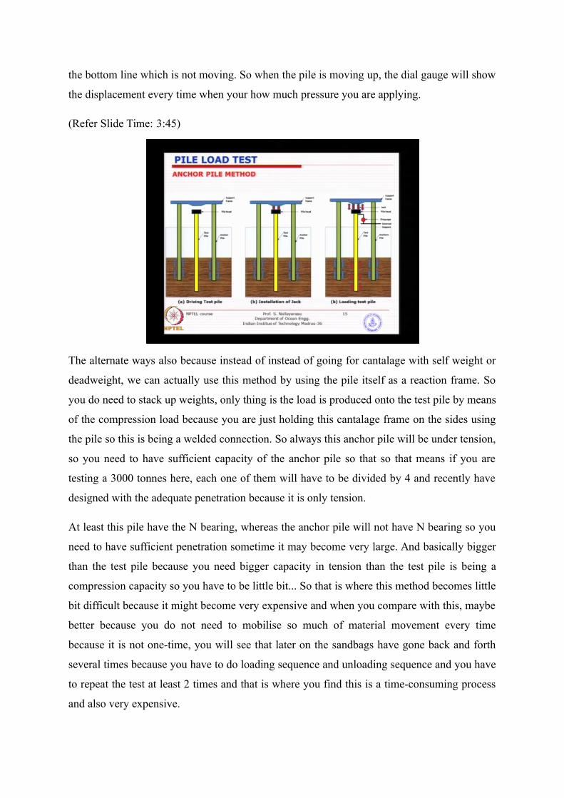
(Refer Slide Time: 3:45)
The alternate ways also because instead of instead of going for cantalage with self weight or
deadweight, we can actually use this method by using the pile itself as a reaction frame. So
you do need to stack up weights, only thing is the load is produced onto the test pile by means
of the compression load because you are just holding this cantalage frame on the sides using
the pile so this is being a welded connection. So always this anchor pile will be under tension,
so you need to have sufficient capacity of the anchor pile so that so that means if you are
testing a 3000 tonnes here, each one of them will have to be divided by 4 and recently have
designed with the adequate penetration because it is only tension.
At least this pile have the N bearing, whereas the anchor pile will not have N bearing so you
need to have sufficient penetration sometime it may become very large. And basically bigger
than the test pile because you need bigger capacity in tension than the test pile is being a
compression capacity so you have to be little bit... So that is where this method becomes little
bit difficult because it might become very expensive and when you compare with this, maybe
better because you do not need to mobilise so much of material movement every time
because it is not one-time, you will see that later on the sandbags have gone back and forth
several times because you have to do loading sequence and unloading sequence and you have
to repeat the test at least 2 times and that is where you find this is a time-consuming process
and also very expensive.

Anchor pile seems to be very good but then caution needs to be taken in terms of design,
make sure that when the pile is being tested, this is the anchor that you have designed, it is
not going to much otherwise you will be measuring actually relative movement of the pile
anchor pile and the pile being tested.
(Refer Slide Time: 5:58)
Typical reaction pile setup, so you can see here this is the pile being tested, pile requires to be
tested otherwise you have the jack being placed at the and these are the pile heads, the left
side and right side you see the pile heads which the piles are being driven with the pile head.
And when you just push this hydraulic jack upwards, the reaction being applied to the test
pile and these the reaction piles on the left side and right side should have sufficient capacity
and basically that should be designed.

(Refer Slide Time: 6:37)
And just a closer view of how the hydraulic jack is placed in the girder so that it reacts
against the test pile as well as the reaction pile.
(Refer Slide Time: 6:50)
Another load test using concrete blocks instead of sandbags, many times people use this
because it is easy to handle and can be used in multiple places, only require storage. But in
any case in construction sites you will find many of these concrete blocks spare capacities
available there but many times people use these sandbags because easy to dispose because
they can be used for construction work, no extra storage space is required and each one of
them will be weight before placing it on the top so that you know the weight what it is, only

the stability of them sometimes bit of a worry because even a small eccentricity caused by
either placement or by you know stability, the whole thing can be turned.
In many places if you notice pile load test failed because of the cantalage tilted or cantalage
failed, which will cause quite a bit of problem. Whereas using concrete blocks is quite useful
because it is very stable, sometimes these concrete blocks will come with a sheer case so you
can have an opening at the bottom and you can when you place it, it will not go anywhere and
horizontal stability is well-established. We can have precast blocks specially for testing not
just for any other purpose.
(Refer Slide Time: 8:08)
So the ultimate load test is basically done to the load, which is taken to the maximum failure
capacity of the pile which will be 2 times or 3 times depending on what the factor of safety
used in the particular project of particular core of design. It is most of the time for IS codes
we design for factor of safety for 3 which is for concrete piles which actually says 2 to 3 but
then mostly we use factor of safety of 3 that means you find out what is the load that is
designed for working conditions, take it to factor of safety of 3 and then find out. So typically
if you look at 300 tonnes is a working load, most of the 1 meter-1 and half meter diameter
piles, then you multiply by 3 you will take to nearly thousand tonnes, so imagine thousand
tonnes, what could be the requirement for dead weights.
Working load test is typically one and a half times safe working load, so we want to go for
slight overloading but not to the ultimate stage. As long as you want to see passing of the
working load and also have little bit of budget, get depends on how much design margin is

available at sometimes be reduced to 25 percent, we normally call it overload test. Even
mechanical devices nowadays everyone of them, the working load test is not acceptable, you
have to go for slightly overload because if the load exceeds the working load even by slight
amount it should not fail so that is why overload test is about 25 to 50 percent.
(Refer Slide Time: 9:48)
So the 2 methods of testing that we were discussing the other day is constant rate of
penetration or maintained load, constant rate of penetration is just you can see here 0.75mm
per minute so it is a quite slow process and that eventually required by the British code, 800
is for design of foundations. And maintained load test typically used in most part of this
construction site in India is very easy to carry out, you do need a sophisticated loop back
system, simply put the weight and get, whereas the constant rate of penetration you need a
good amount of instrumentation to read the penetration backward and adjust the pressure
accordingly and it can only be done by hydraulic system, not by dead weight and cantalage
method, it is just not feasible.
Whereas the maintained load test even in a very simple method which you need a deadweight
and a jack. And the load shall be maintained constant until settlement rate is decreased to
0.25mm per hour, so what we normally do is use you set up your cantalage, put the weights,
safer example 900 tonnes divided into say 5 steps or 6 steps, so the step 1 of the load and this
activates hydraulic jack to transfer the load to the test pile relieving the Anchorage piles or
support system and then monitor the displacement. Initially displacement of the pile may be
larger, slowly reducing reducing indicating that the soil has achieved its failure state at that
load and then it will go constant or may slightly increase in a very low implement.

So once you see that it becomes flat, the displacement graph is flat that means you are not
expecting any more images settlements, you may actually expect long-term settlement which
may be several years which is we are not interested in that. So basically then how do you
decide when to stop the or when to restart the the unloading process because every time you
are going to unload it, bring to 0 then stack up to the next increment. So 1st time say you
arriving 200 tonnes and bring to 0 that means you have to take out the load and load it again
to 400 tonnes so that process when you want to start, as soon as you see the displacement
relationship is going flat that will be better but if the rate is still within this then you can go
that means when the displacement is happening you cannot do unloading process.
(Refer Slide Time: 12:38)
So maintained load test is quite simple, we will see the procedure later on, something like
this, so you see here you put the 200 tonnes and then that the displacement is increasing. So
what you will see is, when you are doing unloading process if there is elastic part it will come
back. There is permanent deformation of the soil that will not come back, that will be residual
so it will keep on stacking up so that is what we are interested in. Similarly we go to the 2 nd
step, so when the 200 ton weight is placed on the cantalage, when you relieved the hydraulic
jack, the load will go back to the support stock then put another 200-300 tonnes on top of it.
It will become 400 ton, take the hydraulic jack and load it on to the pile and just repeat the
procedure until you reach the total test load, it could be ultimate test load or it could be
working test load. And every time you do this, you will see a loading-unloading curve you
can see, so basically you will be taking this as a displacement, 9mm, 8.5mm for 200 tonnes
so you can go and plot here load displacement in a different relationship. And typically we

will take several hours because get this flat curve sometimes you may have to wait longer
time depending on type of soil, if it is a sandy material you will get the displacement quickly,
after that it will just become flat.
(Refer Slide Time: 14:06)
If it is a clay, it might take little bit longer time but then instead of setting this criteria IS
codes actually gives the time to wait, wait for half an hour, wait for one hour depending
depending on you know type of soil you may only vary little bit. So if you look at the
procedure given in IS codes, it will give you the timing, every time step how much time you
need to wait and then start the process of loading-unloading.
(Refer Slide Time: 14:25)

In fact, this particular procedure is taken from pile testing manual which I was talking about
day 1. So the design specifications load all it is basically the test load, if it is ultimate test
design verification load will be your total load multiplied by the fact of safety, 25 percent, 50
percent, 75 percent, so this procedure is just segmented into 4 subdivisions. 30 minutes, so
once you load 25% load, wait for 30 minutes, 30 minutes, 30 minutes and 100% load, wait
for little longer time and then during the unloading process only because relieving of elastic
compression will take just like this, it is not going to take time, so unloading time they are
just allowing you to only little time 10 minutes.
And then again we start the process; 0, 100% and you are going to do a overloading test,
there you are going to wait for little longer time beyond the design verification load if it is a
working load test and then repeat the procedure. So basically this is just typical time versus
increment of load I have just taken from the you know the manual of pile load testing from
the Association of civil engineering contractors, everywhere they used this but if you look at
the IS codes, they may actually gives slightly different numbers and different timings you
know so depending on which jurisdiction you want to use.
(Refer Slide Time: 16:00)
So if you look at this graph, load displacement curve for ultimate load test up to failure. So
you can see, depending on type of foundation material you will see 3 types of so if you look
at the blue one, N bearing and V crock, basically it increases and then suddenly fails. So you
will see a you know certain capacity reaching, the rock is trying to fail, so almost like elastic
and perfectly plastic so something similar like this. And if you look at the black one, friction

pile in soft clay or sand, you will see that highly nonlinear it keeps increasing and then the
failure rate will be slow down achieving certain capacity.
Or else if you have a fiction pile in stiff clay also will be very similar but then there will be a
downgrade effect because the stiff clay broke down when it is achieving the, so typically you
will see something similar when you plot the when you extract the displacement from such
such plots. Nowadays you can automate these kinds of things so automatically we will get a
time bound graph then you can later take the displacement, come up with the displacement
versus the applied load graph is something like this and basically you need to decide now
what capacity is to be taken as ultimate or working load.
(Refer Slide Time: 18:02)
So depending on what the allowable all ultimate reflection that you want to permit, remember
when we were doing the TZ curve for clay and sand, we were talking about 0.1 inch for sand
and then 1% for clay something like this. So that corresponds to the ultimate failure whether
you want to consider here for steel piles has to be decided by what is your you know the
ultimate failure to state you want to define. So once you define that limiting load or limiting
displacement, then you can go onto the graph, you can take this is my ultimate failure load of
the pile beyond which we will not be able to take it.
Saturday is the idea behind construction of this diagram is just to make sure that your TZ
graph you have made is going to be reflected here. And if you get a representative from here
and that will be realistic because this is based on test where as the other one is based on
historical data and empirical methods. So you see here in this particular one, the ultimate

capacity at 25mm settlement is taken as 425 tonnes so though it is highly nonlinear, some
amount of plastic deformation have happened compared to when you go to the blue, if you
look at it this is completely elastic and after that only becomes the plateau so you can see the
difference. So that is the way we want to determine when you do a testing, I want to
determine what is the ultimate capacity.
The thing is you have to sum up what is the displacement at which you would like to take for
example, when you are designing a structure you will always have a limiting deflection in
both horizontal and vertical working load conditions. So then if allowable capacity you want
to find from this then suppose your fix rate 10mm is the allowable displacement during
service life of the structure then 10 you just go to 10mm, the pile has achieved a 350 tonnes.
Now if you take the ultimate capacity, apply a factor of safety of 3 or 2, you will only get
something like 120 tons so that is what will be revealed here.
If you do not know about this graph is going, what you are trying to do is if you take 420 tons
join from here straight away to 0, make a straight line that is what you are doing by means of
factor of safety, 420 divided by factor of safety of 3 on load. Whereas if you have this this
graph, you know very well that you can allow maximum of 10mm during its service life with
the factor or on factor load then you can decide how much margin you have, almost large
margin is available. When you take 10mm and restrict to 10mm is the displacement, 420
decided by factor of safety of 3 you will get around 130 tons that is what you are going to
permit.
But actually the pile has got deserved capacity up to 350 at the same 10mm displacement so
that will be the difference when you have nonlinear load deflection curve, especially after
testing. So this will give you a picture how much extra margin you have because of the soil
behaviour and if you take this one you will not get anything better is not it? Because you are
grabbing almost linear relationship, if you take that will be the capacity of say 550 tonnes
divided by straight away factor of safety of 3 you will get somewhere around 180 tonnes.
Whether it is 10mm or 5mm, you are going to just linearly prorate so does not matter.
So that is the idea of constructing or establishing load displacement characteristics up to
failure, if we have only established up to for example, some lower displacement because you
are not going to do a failure test, you are going to do a working load test just up to the linear
portion then you may not actually reveal how the behaviour after this, this is why at least one

or 2 piles at the site you have to do up to failure to see how much margin you have. It can
behave this way which we do not know unless you do the testing.
(Refer Slide Time: 21:37)
Then we also move onto horizontal load test, basically similarly you can do horizontal load
test. One of the biggest problems is doing reaction, she just now we have learned about
vertical load test with support arrangement somehow we can make it because it is similar
piles can be driven, but when you do horizontal load test you need to have some ground or
firm support condition just to measure the horizontal displacement of the pile and also to
transfer the reaction from the jacks, which is going to be a big challenge. So doing it onshore
itself is a challenge, then when you are doing it in coastal or offshore conditions, it is even a
challenge because you have to design a system stronger than the test pile itself and install it.

(Refer Slide Time: 22:32)
And also you can carry out cycling load test in cases of coastal structures where cyclic
behaviour is required for degradation effects. So typically you see here some working
platform is required, and I would have just straightaway gone to the coastal areas where some
of the berthing structures we still do this lateral load test to establish the capacity in
horizontal direction but most of the structure on land normally we do not do you know
horizontal load test not really required because predominantly it is not so much problem so
far for buildings and bridges predominantly gravity load.
So you see here, we have a test pile which is in yellow colour and we have a reaction pile and
just the jack. Now you see here, the jack is placed in between attached to both the pile heads
and the jack is trying to expand by giving horizontal load through the test pile, the reaction is
transferred to the reaction pile. Noise they reaction pile stable, the reaction pile displacement
is smaller or ignorable then what you are measuring is the pile head displacement otherwise
he will be measuring the, the relative displacement of because this pile is also moving, the
other pile also moving and how much we have to find out. So you need a chilli credit system
to find out what will be the displacement which will be quite tough because you can
theoretically calculate but then it may not be correct.
A reference will be used, another few numbers of piles is required or system is required to
support all this as well as access to these places so you will see that horizontal load test
becomes reasonably expensive because you have reaction frame and you also have a
reference frame, the reference frame the green colour what you see is a reference frame

against which you will do the measurement of displacements. And they are need to be placed
sufficiently you know wider spacing otherwise what happens when you are doing when you
are doing reaction here, when the pile is trying to bend it puts undue pressure on the soil and
that soil gets affected by this particular location and behaviour of the lateral capacity is going
to be affected to some extent and that is why you have to have minimum of 3 diameter or for
diameter or 5 diameter.
Once it become wider spacing, mounting of the jack becomes a problem, you need to design
a frame and that is going to put you onto support system together it has to be mounted onto
the 2 piles which needs to be free to move so that is one of the challenge.
(Refer Slide Time: 25:11)
A typical cyclic load test results or plot how you carry out loading and unloading process,
basically horizontal load versus lateral load displacement. You take it one cycle at particular
load level, bring it to 0, repeat it few times just to get the repeatability and again increase the
higher load, repeat it again, load and unload, since there is no dead weights are involved, it is
only hydraulic jack, doing such load test is very easy then you repeat it again and again for
various loads and stop when you actually reach the expected displacement for example,
ultimate load test you are trying to do for 100mm maximum.
If you are doing a ultimate horizontal failure load test then you can go up to failure of the pile
and stop, otherwise you have a predetermined load by which it will not be a larger capacity,
most of the pile if you look at 50 tonnes or maybe maximum 70-80 tons unlike the vertical
capacity where you have thousands of tons or sometimes very large number. Here it all be

you know restricted by the pile horizontal shear because if the soil does not fail what will
happen, the pile will fail. So if you look at the Shell capacity of the pile that will give you the
maximum magnitude by which you can test, in fact will apply factor of safety on it. What you
do not want, you do not want the system to fail before the soil fails, system means the pile
itself or the anchor pile itself.
(Refer Slide Time: 27:09)
So you will find out what is the bending capacity of the pile or structural capacity and shear
capacity. Make sure that you have got sufficient factor of safety available on the structural
system prior to go to ultimate load test because you do not want the system to fail when there
will be a catastrophe. And in some cases in the coastal structures like berthing structures we
may require pullout test because some of the piles are actually going to have tension capacity
requirement, especially when you build a berthing structure the front pile will be in tension,
the back pile will be in compression when you are having shift or berthing against the
berthing structure.

(Refer Slide Time: 27:46)
So such you may require a pullout test instead of a compression test, it is exactly opposite of
it only the cantalage placement and the hydraulic jack placement is in the reverse condition.
If we just go back to our the this test somewhere here I think something like this, so this this
one is anchor pile method you are doing a compression test, just reverse the process and
placement of the hydraulic jack you will get the... So basically the cantalage arrangement is
attached to the reaction pile and there will be stress blocks and you have hydraulic jacks and
then you attach your brackets welded to the test pile itself.
So what you are trying to do is you are compressing the reaction pile and pulling up the test
pile, so basically you are just reversing the reaction just to get what tension capacity is
available. Many times you will require this for coastal structures but magnitude will be not
very big, few hundred tons.

(Refer Slide Time: 28:37)
So what are the things that we need to note down when you are doing a compression load
test, the support frame needs to be designed appropriately because you you have such a large
weight to be placed. Support piles needs to be placed away by 3 diameter that makes the, so if
you have 2 meter diameter pile you need to go for either side 3 meters, 3 times 2 meters, 6
meters so the frame becomes 12 by 12 or 15 by 15. Structural capacities of test pile as well as
the support piles leads to be made sure that it has good adequate capacity. Special care must
be given to the test pile because it is a cantilever, whereas actually the same pile when it is
working in the actual structural system it may not be a cantilever, it may be combined pile
heads with the other structures.
Whereas when you are doing testing, it is a pure cantilever, you must remember what is the
difference between pile in a temporary condition which is a cantilever to a supported pile in
the permanent condition because of high level buckling. The load capacity will come down
drastically so you cannot think about always you have pile 1 meter diameter in a permanent
system which is connected to a bigger structure which may not behave as a pure cantilever, so
the effective length and the (())(29:51) conditions are different, you are 1 meter diameter pile
may work there, whereas the same 1 meter diameter pile when you bring to the test category,
it becomes a pure cantilever number 1, high-level buckling load will be definitely half or less
than the actual buckling capacity.
When you are doing the same ultimate load test here, you do not want the pile to fail. So what
we really need to do is, keep the diameter same because you need you do not want to change

the pile-soil interface is not it? Because we want to test the 1 meter diameter but what you
can do is you can increase the wall thickness to increase the bending stiffness, buckling
capacity, shear capacity in such a way that structure does not fail but the soil pile interface is
being tested. You understand the idea know, so you need to make sure this otherwise if you
bring the same pile and testing before the soil fails the pile collapses and then it puts the
whole system into problem that is what you have to make sure.
(Refer Slide Time: 30:49)
So what IS codes are suggesting instead of what we saw was 25, 50, 75, they have divided
into 5 sub-segments of loading 20, 40, 60, 80 to 100 so it is just a little difference. And
basically loading-unloading cycles almost similar, I am not very sure whether I have copied
the time cycle. You can look at the code, the time is also given 30 minutes up to 6 hours so
you can refer to the code, but what the criteria I wanted to look at it is basically when do we
decide it has achieved its ultimate capacity and it is applicable only for concrete piles, you
cannot apply this one to steel tubular piles it is not under that particular code.
So if you look at this graph, I have just plotted one of the recent last year test, two thirds of
final load at which the total displacement attains value of 12mm. So you just look at the
graph and just go around, apply the criterion number 1 the safe load on a single pile for initial
test should be least of the following, so the criteria is given. Do the testing, comeback here,
plot the graph and look at these criteria whichever is lower that is your safe working load, so
that is the criteria that you are going to apply.

And of course this is written on the basis of onshore structures, you know 2911 is a code for
both the concrete piles for onshore applications, not even for coastal applications that is why
you cannot blindly apply this principle to a coastal structure on or offshore structure where
displacement get area are different from dawn show structures. You will see that they are very
strict in terms of displacement because these are applicable to buildings and bridges or to
some extent industrial structures on land where they are controlled by deflection.
Whereas if you go to coastal structures and offshore structures, the displacement are
definitely going to be larger, you cannot even think of the criteria here because here they are
talking about 25mm. When you think about coastal or offshore structure, you are going to
have several hundred millimetres of displacement because of the the magnitude of horizontal
load, you have to be a bit cautious and apply the principle differently. 50% of final load at
which the total displacement equal to 10% of the pile diameter, so these are the 2 criteria, so
if you see there the criteria 1 and criteria 2 you can find out whichever is giving you the
capacity.
(Refer Slide Time: 33:34)
I I think even the lateral load also similar crater is given; 50% of the final load at which the
total displacement increases to 12mm, final load at which the total displacement corresponds
to 5mm and then any load corresponds to any specified displacement, this is some at least
some option is given for horizontal load, so according to your project specific requirement so
you specify I can go out to 50mm then I can look at, so that if that is the thing that we need to
have a decision-making process, just doing load test alone will not be good enough, you do

not know what to do with that, what you need is the demarcation what will be the acceptable
displacement for that particular type of structure and applicable code in force.
(Refer Slide Time: 34:54)
What the API says we do not have a procedure to restrict the displacement, unfortunately
there is no requirement because we do not need because offshore structures are subjected to
so much higher loading that if you restrict 25mm displacement for example, your structure
will be so much bigger and may not be practical so that is why the the adapted method by
API is to design by the factor of safety which gives you an adequate safety against pile failure
or premature failure and at the same time you have a ductile material which is steel and you
are not worried about failure by other means of fracture because the worry in concrete
structure is larger displacement either in vertical direction or in horizontal direction can cause
superstructure failure by fracture because the concrete cannot fail by the tail.
So that is one of the reasons why most of these concrete cores they restrict the displacement
to smaller where as the offshore structures we never build using it except the concrete gravity
platforms, all the fixture types of structures are built by steel material has higher tensile
capacity and also have a ductile characteristics. In that reason we go by the method of
engineering-based design based on soil properties with adequate factor of safety and we leave
that, we do not want to apply the restricting displacement. The reason why we developed TZ
all that is to make sure that pile is actually subjected to the actual load displacement
behaviour and the bending stresses are calculated.

So if we have a larger displacement, what happens is the pile is subjected to larger bending
and larger bending means the requirement of section and the diameter and the thicknesses are
going to increase so you design for it rather than trying to limit the displacement of the pile to
lower value and increase the larger diameter, so that is exactly the the design method adapted
by API, so so far I do not think any problem with that idea.
One of the issues with concrete pile supporting concrete structure is the architecture and
finishers and serviceability requirement that is why it restricts the displacement to a very
small value, in fact the reason why we restrict to 1 inch is because of that. You know if you
have the structural system capable of taking the architectural finishes and service functions
will be seriously disturbed that is why buildings are designed for smaller displacement.