Formal Verification of Device State Chart Models
8
Formal Verification of Device State Chart Models Fulvio Corno Dipartimento di Automatica e Informatica Politecnico di Torino Torino, Italy Email: [email protected] Muhammad Sanaullah Dipartimento di Automatica e Informatica Politecnico di Torino Torino, Italy Email: [email protected] Abstract—Design and development of increasingly complex intelligent environments require rich design flows that include strong validation and verification methodologies. Formal verifi- cation techniques are often advocated, and they require formally described models of the smart home devices, their intercon- nections, and their controlling algorithms. Complete verification can only be achieved if all used models are verified, including individual device models. This paper proposes an approach to formally verify the correctness of device models described as UML State Charts, by checking their consistency with respect to the properties, declared in an Ontology, for the categories to which each device belongs. The paper describes the verification methodology and presents some first verification results. Index Terms—Formal Verification, Intelligent Environment, Smart Home, State Charts, Model Checking I. I NTRODUCTION Intelligent Environments (IEs) consist of different integrated heterogeneous devices, ranging from simple sensors to multi- feature devices [1]. The objective of IE designers is to create an environment which can take decisions and, as a result, the devices can perform their ordinary activities in an intelli- gent manner, by facilitating the environment users with ease, comfort, security and safety in their life [2]. The increasing complexity of IEs calls for the adoption of structured and formal design and verification techniques [3], using model- based approaches and formal validation and verification tools. In particular, all devices, their interconnections, and their governing algorithms should be modeled, to allow full system verification. This paper focuses on the correctness of the for- mal models used to describe the individual smart devices, by ensuring the consistency between declarative and operational representation. The paper complements previous work from the same authors [4] where interconnections and governing algorithms were considered and verified. In modeling smart devices, both device interface and behav- ior information are considered. Interface information describes the device as a black box, listing functionalities (a device can perform), commands (that can be sent to the device), notifications (the device can send) and states (in which a device can be at a specific time). The detailed information about the internal workings of the device, such as the action performed when an command is received in a particular state, falls into the behavior category. Interface and behavior descriptions can be expressed as a joint model (like in [5]), or with separate models (like in our previous work [6], [7]). DogOnt [6] is an Ontology based solution for interface modeling and reasoning about such devices, whereas the behavior of each device is modeled in a Device State Chart (DSC) [7]. According to Harel [8], state charts are best suited for representing the complex behavior of communicating devices. In state charts, the internal behavior of devices is represented with states, functionalities, transitions (composed of source state, destination state, triggers, guards and actions) and variables. In our previous work [4], we proposed a design time methodology to formally verify the correct behavior of IEs, by checking the intended system properties. The methodology adopted a model checking approach for verifying the temporal properties over a model of the entire IE, which consists of state charts of devices and control algorithms. Control algorithms are the software components which intelligently control the overall operations of IE. As with any design artifact, the DogOnt ontology and the Device State Charts are prone to errors and inconsistencies. In our previous work [4], we verified the correctness of IEs on the basis of these DSCs, but the correctness of the latter was not checked at that time. This paper addresses and solves the problem by proposing a formal methodology, based on model checking, for the auto- matic identification of inconsistencies between device informa- tion available in DogOnt and the behavior of the corresponding DSC. These inconsistencies must be manually fixed and then the verification process is repeated until consistency is reached. The adopted technologies are presented in section II, and in particular the previous work, on which the proposed approach is based, is detailed in section II-F. The proposed approach for DSC verification is presented in section III, and a case study with the implementation details is presented in section IV. Results and remarks about the case study are given in section V and conclusions are finally drawn in section VI. II. BACKGROUND Our approach uses state machines to represent devices behavior, and is based on a well established smart home framework that adopts semantic web technologies –in the form of an Ontology– known as DogOnt. It uses the UMC model checker [9] for identifying the inconsistencies between DogOnt and DSC. For expressing properties, it uses UCTL temporal properties. The details of the mentioned concepts are
Transcript of Formal Verification of Device State Chart Models

Formal Verification of Device State Chart ModelsFulvio Corno
Dipartimento di Automatica e InformaticaPolitecnico di Torino
Torino, ItalyEmail: [email protected]
Muhammad SanaullahDipartimento di Automatica e Informatica
Politecnico di TorinoTorino, Italy
Email: [email protected]
Abstract—Design and development of increasingly complexintelligent environments require rich design flows that includestrong validation and verification methodologies. Formal verifi-cation techniques are often advocated, and they require formallydescribed models of the smart home devices, their intercon-nections, and their controlling algorithms. Complete verificationcan only be achieved if all used models are verified, includingindividual device models. This paper proposes an approach toformally verify the correctness of device models described asUML State Charts, by checking their consistency with respectto the properties, declared in an Ontology, for the categories towhich each device belongs. The paper describes the verificationmethodology and presents some first verification results.
Index Terms—Formal Verification, Intelligent Environment,Smart Home, State Charts, Model Checking
I. INTRODUCTION
Intelligent Environments (IEs) consist of different integratedheterogeneous devices, ranging from simple sensors to multi-feature devices [1]. The objective of IE designers is to createan environment which can take decisions and, as a result,the devices can perform their ordinary activities in an intelli-gent manner, by facilitating the environment users with ease,comfort, security and safety in their life [2]. The increasingcomplexity of IEs calls for the adoption of structured andformal design and verification techniques [3], using model-based approaches and formal validation and verification tools.In particular, all devices, their interconnections, and theirgoverning algorithms should be modeled, to allow full systemverification. This paper focuses on the correctness of the for-mal models used to describe the individual smart devices, byensuring the consistency between declarative and operationalrepresentation. The paper complements previous work fromthe same authors [4] where interconnections and governingalgorithms were considered and verified.
In modeling smart devices, both device interface and behav-ior information are considered. Interface information describesthe device as a black box, listing functionalities (a devicecan perform), commands (that can be sent to the device),notifications (the device can send) and states (in which a devicecan be at a specific time). The detailed information about theinternal workings of the device, such as the action performedwhen an command is received in a particular state, falls intothe behavior category. Interface and behavior descriptions canbe expressed as a joint model (like in [5]), or with separatemodels (like in our previous work [6], [7]).
DogOnt [6] is an Ontology based solution for interfacemodeling and reasoning about such devices, whereas thebehavior of each device is modeled in a Device State Chart(DSC) [7]. According to Harel [8], state charts are best suitedfor representing the complex behavior of communicatingdevices. In state charts, the internal behavior of devices isrepresented with states, functionalities, transitions (composedof source state, destination state, triggers, guards and actions)and variables.
In our previous work [4], we proposed a design timemethodology to formally verify the correct behavior of IEs,by checking the intended system properties. The methodologyadopted a model checking approach for verifying the temporalproperties over a model of the entire IE, which consists of statecharts of devices and control algorithms. Control algorithmsare the software components which intelligently control theoverall operations of IE.
As with any design artifact, the DogOnt ontology and theDevice State Charts are prone to errors and inconsistencies. Inour previous work [4], we verified the correctness of IEs onthe basis of these DSCs, but the correctness of the latter wasnot checked at that time.
This paper addresses and solves the problem by proposinga formal methodology, based on model checking, for the auto-matic identification of inconsistencies between device informa-tion available in DogOnt and the behavior of the correspondingDSC. These inconsistencies must be manually fixed and thenthe verification process is repeated until consistency is reached.
The adopted technologies are presented in section II, and inparticular the previous work, on which the proposed approachis based, is detailed in section II-F. The proposed approachfor DSC verification is presented in section III, and a casestudy with the implementation details is presented in sectionIV. Results and remarks about the case study are given insection V and conclusions are finally drawn in section VI.
II. BACKGROUND
Our approach uses state machines to represent devicesbehavior, and is based on a well established smart homeframework that adopts semantic web technologies –in theform of an Ontology– known as DogOnt. It uses the UMCmodel checker [9] for identifying the inconsistencies betweenDogOnt and DSC. For expressing properties, it uses UCTLtemporal properties. The details of the mentioned concepts are
given in the following subsections with an example of devicemodeling in DogOnt.
A. DogOnt in a nutshell
In IEs, mostly, hardware (devices) and software (controlalgorithms) components interact with each other in an in-telligent manner. The modeling of these devices (hardwarecomponents) can be performed by adopting different tech-niques. As these devices are of various heterogeneous types,researchers adopted Ontologies for modeling of such systems[10]. Ontologies are one of the semantic web artifacts; theyare based on graph like structure, for representing differentconcepts, their relationships and their associations, and give asuitable reasoning power on these. DogOnt [6] is an Ontologybased solution for the modeling of Smart Homes (IEs).
DogOnt identifies the following basic dimensions for themodeling of IEs (Figure 1):
1) “Building Environment”: information about the environ-ment where the IE is implemented, like building, flat,garage, garden, room (bathroom, bedroom, dining-room,kitchen, living-room, etc);
2) “Building Things”: information about the physical objectsused in the IE, among which some are electrically con-trollable. The electrically controlled devices (like coffeemaker, boiler, cooker, fan, lamp, actuator, sensors andvarious others), used in IE, are categorized under theControllable category. Physical objects (like table, sofa,wall, ceiling and others), which can not be electricallycontrolled, are categorized under the Uncontrollable cat-egory.
3) “Functionality”: Controllable devices used in IEs havedifferent functionalities. DogOnt further classifies them asControl Functionality, Notification Functionality or QueryFunctionality. Control functionalities are the actions thatdevices can perform (like a Lamp has “on” and “off”functionalities). Most controllable devices have the abilityto send a notification back, as an acknowledgment ofthe completion of the assigned task. These notificationcapabilities are modeled under the Notification function-alities classification. For performing the task intelligently,usually, it is required to have a mechanism through whichthe status of devices can be queried at any time, which aremodeled under the Query functionalities classification;
4) “Commands”: Controllable devices in IEs perform theirControl functionalities by receiving some particular com-mands, whose modeling and classification is performedunder this category;
5) “Notification”: Controllable devices send different typesof notifications, e.g., when their state changes;
6) “State” and “State Values”: Controllable devices possessan internal state, which is modeled a set of orthogonalstate spaces (called “States”), with different “State Val-ues” each. A complete description of the state of a deviceis therefore a valid State Value for each of the Statesdefined for that device. State Values can be discrete (e.g.,in Lamp “onState” and “offState”) or continuous within a
Figure 1. DogOnt
specific range of values (e.g, a DimmerLamp device hasa “Light-Intensity-State” whose value ranges from 0% to100%).
7) “Domotic Network Component”: Controllable devicesadopt widely different network protocols. This model-ing dimension describes the protocol characteristic andnetwork addressing scheme.
B. Device Modeling in DogOnt
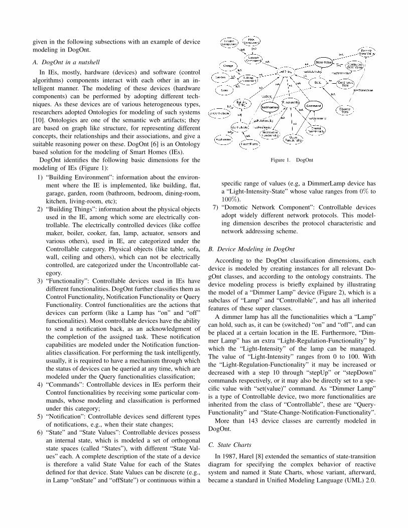
According to the DogOnt classification dimensions, eachdevice is modeled by creating instances for all relevant Do-gOnt classes, and according to the ontology constraints. Thedevice modeling process is briefly explained by illustratingthe model of a “Dimmer Lamp” device (Figure 2), which is asubclass of “Lamp” and “Controllable”, and has all inheritedfeatures of these super classes.
A dimmer lamp has all the functionalities which a “Lamp”can hold, such as, it can be (switched) “on” and “off”, and canbe placed at a certain location in the IE. Furthermore, “Dim-mer Lamp” has an extra “Light-Regulation-Functionality” bywhich the “Light-Intensity” of the lamp can be managed.The value of “Light-Intensity” ranges from 0 to 100. Withthe “Light-Regulation-Functionality” it may be increased ordecreased with a step 10 through “stepUp” or “stepDown”commands respectively, or it may also be directly set to a spe-cific value with “set(value)” command. As “Dimmer Lamp”is a type of Controllable device, two more functionalities areinherited from the class of “Controllable”, these are “Query-Functionality” and “State-Change-Notification-Functionality”.
More than 143 device classes are currently modeled inDogOnt.
C. State Charts
In 1987, Harel [8] extended the semantics of state-transitiondiagram for specifying the complex behavior of reactivesystem and named it State Charts, whose variant, afterward,became a standard in Unified Modeling Language (UML) 2.0.
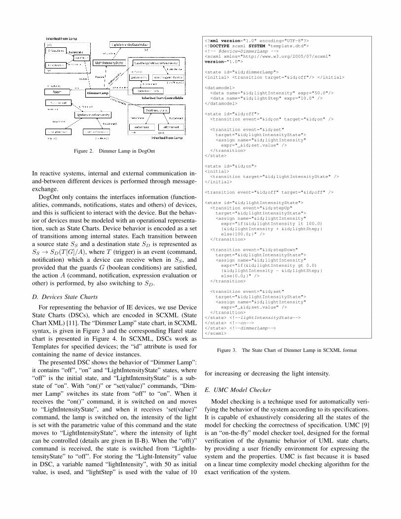
Figure 2. Dimmer Lamp in DogOnt
In reactive systems, internal and external communication in-and-between different devices is performed through message-exchange.
DogOnt only contains the interfaces information (function-alities, commands, notifications, states and others) of devices,and this is sufficient to interact with the device. But the behav-ior of devices must be modeled with an operational representa-tion, such as State Charts. Device behavior is encoded as a setof transitions among internal states. Each transition betweena source state SS and a destination state SD is represented asSS → SD(T [G]/A), where T (trigger) is an event (command,notification) which a device can receive when in SS , andprovided that the guards G (boolean conditions) are satisfied,the action A (command, notification, expression evaluation orother) is performed, by also switching to SD.
D. Devices State Charts
For representing the behavior of IE devices, we use DeviceState Charts (DSCs), which are encoded in SCXML (StateChart XML) [11]. The “Dimmer Lamp” state chart, in SCXMLsyntax, is given in Figure 3 and the corresponding Harel statechart is presented in Figure 4. In SCXML, DSCs work asTemplates for specified devices; the “id” attribute is used forcontaining the name of device instances.
The presented DSC shows the behavior of “Dimmer Lamp”:it contains “off”, “on” and “LightIntensityState” states, where“off” is the initial state, and “LightIntensityState” is a sub-state of “on”. With “on()” or “set(value)” commands, “Dim-mer Lamp” switches its state from “off” to “on”. When itreceives the “on()” command, it is switched on and movesto “LightIntensityState”, and when it receives ‘set(value)”command, the lamp is switched on, the intensity of the lightis set with the parametric value of this command and the statemoves to “LightIntensityState”, where the intensity of lightcan be controlled (details are given in II-B). When the “off()”command is received, the state is switched from “LightIn-tensityState” to “off”. For storing the “Light-Intensity” valuein DSC, a variable named “lightIntensity”, with 50 as initialvalue, is used, and “lightStep” is used with the value of 10
<?xml version="1.0" encoding="UTF-8"?><!DOCTYPE scxml SYSTEM "template.dtd"><!-- @device=DimmerLamp --><scxml xmlns="http://www.w3.org/2005/07/scxml"version="1.0">
<state id="&id;dimmerLamp"><initial> <transition target="&id;off"/> </initial>
<datamodel><data name="&id;lightIntensity" expr="50.0"/><data name="&id;lightStep" expr="10.0" />
</datamodel>
<state id="&id;off"><transition event="&id;on" target="&id;on" />
<transition event="&id;set"target="&id;lightIntensityState"><assign name="&id;lightIntensity"
expr="_&id;set.value" /></transition>
</state>
<state id="&id;on"><initial>
<transition target="&id;lightIntensityState" /></initial>
<transition event="&id;off" target="&id;off" />
<state id="&id;lightIntensityState"><transition event="&id;stepUp"
target="&id;lightIntensityState"><assign name="&id;lightIntensity"
expr="if(&id;lightIntensity lt 100.0){&id;lightIntensity + &id;lightStep;}else{100.0;}" />
</transition>
<transition event="&id;stepDown"target="&id;lightIntensityState"><assign name="&id;lightIntensity"
expr="if(&id;lightIntensity gt 0.0){&id;lightIntensity - &id;lightStep;}else{0.0;}" />
</transition>
<transition event="&id;set"target="&id;lightIntensityState"><assign name="&id;lightIntensity"
expr="_&id;set.value" /></transition>
</state> <!--lightIntensityState--></state> <!--on--></state> <!--dimmerLamp--></scxml>
Figure 3. The State Chart of Dimmer Lamp in SCXML format
for increasing or decreasing the light intensity.
E. UMC Model Checker
Model checking is a technique used for automatically veri-fying the behavior of the system according to its specifications.It is capable of exhaustively considering all the states of themodel for checking the correctness of specification. UMC [9]is an “on-the-fly” model checker tool, designed for the formalverification of the dynamic behavior of UML state charts,by providing a user friendly environment for expressing thesystem and the properties. UMC is fast because it is basedon a linear time complexity model checking algorithm for theexact verification of the system.

Figure 4. Harel State Chart of a Dimmer Lamp
The structure of the model verified by UMC consists ofclasses, instances and abstraction rules. Classes are used torepresent the state machines in textual format. They havestates, operators (used for synchronous communication of mes-sages) or signals (used for asynchronous communication ofmessages), local variables and transitions. Further, transitionsare associated with states (source and destination), triggers,guards and actions. Instances are the objects of the classes.Abstractions are the mechanism for representing the subset ofrelevant information, which users want to observe, from thelarge amount of states and actions (operators and signals) inthe complex graph of the modeled system.
An on-line version of the UMC model checker is alsoavailable1.
The requirements and specifications of the systems must bewritten in some formal way, so that, they can be verified onthe model of the system. Temporal logic is one of these formalways, which is best suited for the verification of reactivesystems, as it is a system of rules for reasoning with differentpropositional quantifiers [12].
For the verification of complex systems, UMC supports theUCTL branching time temporal logic [13], which is a UML-oriented branching-time temporal logic, with the combinedpower of ACTL (Action Based Branching Time Logic) [14]and CTL (State Based Branching time logic) [15]. UCTLuses the box [] (“necessarily”) and diamond <> (“possible”)operators from Hennessy-Milner Logic [16] and temporaloperators (Until, Next, Future, Globally, All, Exists) fromCTL/ACTL.
Due to the rich set of state propositions and action expres-sions, UCTL is best fitted for the verification of state machines.With the help of UCTL, we can verify different propertieslike liveness (something good will eventually happen), safety(nothing bad can happen) and properties with or without thefairness restrictions.
F. Verification methodology for IEs
In our previous work [4], we suggested a design timemethodology for the verification of IEs, by adopting a ModelChecking approach, based on DogOnt, DSCs and Temporalproperties.
1http://fmt.isti.cnr.it/umc/
Temporal properties are designed in order to verify thespecifications of IE by checking the existence, absence andsequence of commands, notifications or states in IE. Thestate charts of IE model (devices and control algorithms)are given to the Model Checker and Temporal properties areverified on them. In case any specification is found incorrect,the required modification is performed and the verificationprocess is repeated until all the specifications satisfy. Theapproach is presented in Figure 5, and shows that the modelunder verification consists of a collection of State Chartsobtained by combining all the individual DSCs, according toIE configuration and topology.
Figure 5. Design Time Methodology
Although the above methodology verifies the correctnessof IE, a missing point, which was not considered in [4],is the correctness of these DSC. These should model theactual device behavior and at the same time be consistent withthe information available in DogOnt: there is a likelihood ofinconsistencies and discrepancies between DSC and DogOnt.In the following proposed approach, we verify these DSCs andensure their consistency with DogOnt.
III. PROPOSED APPROACH
The goal of this paper, as mentioned earlier, is to prove theconsistency between DogOnt (interface information) and thecorresponding DSC (behavioral information) for all devicesclasses, by identifying and fixing discrepancies. In DSCs, eachstate can accept some messages, depending on the outgoingtransitions; anything other than them, will be rejected on thatstate and no action will be performed. The action is in theform of some internal activities or commands/notifications toother DSCs. The following type of discrepancies may occur:
1) the DSC may lack or have some extra notifications withrespect to the ones modeled in DogOnt;
2) the DSC may not receive a command/notification whichis modeled in DogOnt for fulfilling the required function-alities of the device;
3) the DSC may not have a state which is modeled inDogOnt;

4) the DSC may follow some behavior which may notconform with the specifications;
5) the DSC may be designed in such a way that a deadlockmay occur.
The proposed approach, whose general architecture is de-picted in Figure 6, consists of three components, namely“Temporal Properties Generator” (TPG), “Environment De-signer (ED)” and “Model Builder (MB)”. TPG and ED arefully automatic, whereas MB is semi-automatic.
Figure 6. Library Files Verification Methodology
Ontologies (such as DogOnt) and State Charts (such asDSCs) are not directly comparable formalisms. In our verifica-tion approach, we extract some logic and temporal propertiesfrom DogOnt, and we check them against the device DSC.Such properties are derived from the semantic description ofthe device. These temporal properties are of the followingtypes:
1) the acceptance of all the described commands;2) the generation of all the described notifications;3) the reachability of all the described states.If needed, for checking, e.g., the correct behavior, extra
information or deadlock in DSC, our approach also supportsmanual design of further temporal properties.
Verification of a device state chart (DSC) model requiresto embed it into a suitable environment, that may generateand receive the appropriate events. For each DSC, we auto-matically generate an “Environment” in which it is embedded,so that the Environment plus the DSC make a closed system.The environment expects the DSC to implement the interface(commands, notifications, states) prescribed in DogOnt, andis designed to be as hostile as possible (generating commandswith arbitrary orders and speeds), and as general as possible(allowing all possible device behaviors and execution paths): inthis way, the verification results will be valid for any possible“real” environment in which the device may be embedded.
The Environment can send all the commands to DSC andcan receive the notifications from it, where the informationof commands and notifications is obtained from DogOnt.
Its functionality is represented in Figure 7 and is composedof an “Environment Generate Commands” (EGC) and an“Environment Receive Notification” (ERN) parallel modules.EGC generates all the commands obtained from DogOnt,where as ERN receives all the notifications modeled in DogOntagainst this device.
Figure 7. Environment behavior in Verification Process
The Environment is implemented by an “Environment De-signer” component, which queries DogOnt and automaticallygenerates the state charts of EGC and ERN in a formatacceptable by the model checker. After generating these, itsends them to “Model Builder”, which performs the followingactivities;
a. semi-automatically translates DSC from SCXML to thelanguage supported by the model checker. The current“SCXML to UMC” converter tool only deals with thoseSCXML tags used in the modeling of device behavior;
b. automatically combines the Environment state charts (EGCand ERN) with the state chart of the device;
c. automatically adds abstraction rules and generates instancesof these state machines, so that UMC code is ready forfurther processing;
d. automatically saves all these in a file known as “ClosedModel”.
The Temporal Property Generator (TPG) module obtains theinformation about device states, commands and notificationfrom DogOnt, and it automatically generates three types ofproperties in the form of UCTL logic:
1) the first property group checks that all the commandsdeclared for the device are actually sent by the EGCcomponent, and that all the notifications are eventuallysent by the device;
2) the second group checks that such messages are actuallyreceived: commands are correctly received by the deviceDSC and notifications are correctly received by ERN;
3) the third type of properties verifies the reachability of allstates that are explicitly mentioned in DogOnt.
The Closed Model and these Temporal Properties are sent tothe Model checker, which is responsible for the verification ofthese temporal properties on the given model. This verificationprocess is repeated until all found inconsistencies are resolved.Advanced properties may be manually added to verify thecorrect behavior of the modeled device.

Device # External # DogOnt # DogOnt # DogOnt # Explored # Automatically # SatisfiedCommands Commands Notifications States States (max) designed TPs Properties
Button 1 0 3 2 16 8 8Dimmer Lamp 0 5 1 3 417 15 13Door Actuator 4 2 1 4 65 10 8Infrared Sensor 2 0 3 2 16 8 8
Mains Power Outlet 0 6 1 2 30 16 12On Off Switch 1 0 3 2 12 8 8
Shutter Actuator 2 3 1 5 50 13 11Simple Lamp 0 2 1 2 14 8 8Smoke Sensor 2 0 3 2 16 8 8Toggle Relay 0 1 3 2 12 10 10
Window Actuator 4 2 1 4 65 10 8
Table ILIST OF VERIFIED DEVICE STATE CHARTS (DSCS) THROUGH THE PROPOSED APPROACH
IV. CASE STUDY
The proposed approach (section III) relies on tools (shownin Figure 6) implemented in Java. For querying from theOntology, “Temporal Properties Generator” (TPG) and “En-vironment Designer (ED)” use the Jena libraries [17], whilethe “Model Builder (MB)” reads DSCs through an XML DOMparser.
Eleven Device State Charts (DSCs), listed in Table I,were verified by this approach. The table also gives someinformation about the DogOnt modeling of each device, thenumber of automatically generated properties, and the numberof properties found true by the model checker. The lastcolumns show that some devices do not comply with thespecifications, and the DSC (or possibly the DogOnt model)should be modified. Computation times were reasonable, andthey amount to just some seconds per each verified property.
The complete case study of a Dimmer Lamp is presentedhere, for illustrating the details. DogOnt currently modelsthe Dimmer Lamp class through the set of attributes (directand inherited) listed in Table II. According to the modeledinformation, it has two types of states: “OnOffState” and“lightIntensityState”. “OnOffState” is a discrete value statewith “on” and “off” as state values, whereas “lightIntensityS-tate” is a continuous value state, in the range of 0 to 100 andis used for managing the intensity of light. A dimmer lamphas two types of command functionalities: “OnOffFunctional-ity” and “lightRegulationFunctionality”. “OnOffFunctionality”is used for switching the Dimmer Lamp “on” and “off”,and “lightRegulationFunctionality” is used for increasing ordecreasing or even setting the intensity of light in DimmerLamp to a specific value (obtained through “Level-Control-Functionality”, which is in the range of 0 and 100). It has onenotification functionality, “StateChangeNotificationFunctional-ity”; which sends a notification when the state is changed.
With the above information, the properties about the reach-ability of states and the existences of the path (commands) aregenerated automatically by the TPG block. For each commandor notification we generate two properties, one checking thatthe corresponding event is sent, and the other checking that itis accepted by the destination state chart. State properties are
Table IIDIMMER LAMP DETAIL AVAILABLE IN DOGONT
also automatically designed for verifying the existence andreachability of all the states which are modeled in DogOnt.The automatically designed properties for the Dimmer Lampare reported in Figure 8 in UCTL syntax.
With the information presented in Table II, EGC and ERNstate charts are designed automatically and sends them to theModel builder. Model Builder semi-automatically obtains thetranslated state chart of the DSC by using our customized
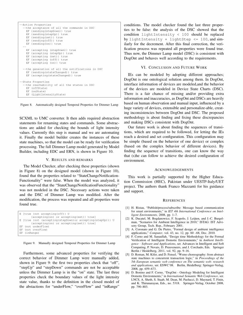
--Action Properties--the acceptance of all the commands in DSC
EF {sending(stepDown)} trueEF {sending(stepUp)} trueEF {sending(set)} trueEF {sending(off)} trueEF {sending(on)} true
--EF {accepting (stepDown)} trueEF {accepting (stepUp)} trueEF {accepting (set)} trueEF {accepting (off)} trueEF {accepting (on)} true
--the generation of all the notifications in DSCEF {sending(stateChanged)} trueEF {accepting(stateChanged)} true
--State Properties--the reachability of all the states in DSC
EF (offState)EF (onState)EF (LightIntensityState)
Figure 8. Automatically designed Temporal Properties for Dimmer Lamp
SCXML to UMC converter. It then adds required abstractionstatements for renaming states and commands. Some abstrac-tions are added for checking the bounds of light intensityvalues. Currently this step is manual and we are automatingit. Finally the model builder creates the instances of thesestate machines, so that the model can be ready for verificationprocessing. The full Dimmer Lamp model generated by ModelBuilder, including EDC and ERN, is shown in Figure 10.
V. RESULTS AND REMARKS
The Model Checker, after checking these properties (shownin Figure 8) on the designed model (shown in Figure 10),found that the properties related to “StateChangeNotification-Functionality” were false. When the model was analyzed, itwas observed that the “StateChangeNotificationFunctionality”was not modeled in the DSC. Necessary actions were takenand the DSC of Dimmer Lamp was modified. After themodification, the process was repeated and all properties werefound true.
E [true {not accepting(off)} U{accepting(on) or accepting(set)} true]
E [true {not (accepting(stepDown)or accepting(stepUp))} U{accepting(on) or accepting(set)} true]
EF (not underFlow)EF (not overFlow)EF (inRange)
Figure 9. Manually designed Temporal Properties for Dimmer Lamp
Furthermore, some advanced properties for verifying thecorrect behavior of Dimmer Lamp were manually added,shown in Figure 9: the first two properties check that “off”,“stepUp” and “stepDown” commands are not be acceptableunless the Dimmer Lamp is in the “on” state. The last threeproperties check the boundary values of the light intensitystate value, thanks to the definition in the closed model ofthe abstactions for “underFlow,” “overFlow” and “inRange”
conditions. The model checker found the last three proper-ties to be false: the analysis of the DSC showed that thecondition lightIntensity < 100 should be replacedby lightIntensity + lightStep <= 100, and sim-ilarly for the decrement. After this final correction, the veri-fication process was repeated all properties were found true.Thus now, the Dimmer Lamp model (DSC) is consistent withDogOnt and behaves well according to the requirements.
VI. CONCLUSION AND FUTURE WORK
IEs can be modeled by adopting different approaches;DogOnt is one ontological solution among them. In DogOnt,interface information of devices are modeled,and the behaviorof the devices are modeled in Device State Charts (DSC).There is a fair chance of missing and/or providing extrainformation and inaccuracies, as DogOnt and DSCs are heavilybased on human observation and manual input, influenced by ahuge variety of devices, extensible and personalize-able, creat-ing inconsistencies between DogOnt and DSC. The proposedmethodology is about finding and fixing these discrepanciesand making DSCs consistent with DogOnt.
Our future work is about finding the sequences of transi-tions, which are required to be followed, for letting the IEsreach a desired and set configuration. This configuration maybe simple (based on the behavior of one device) or complex(based on the complex behavior of different devices). Byfinding the sequence of transitions, one can know the waythat (s)he can follow to achieve the desired configuration ofenvironment.
ACKNOWLEDGEMENTS
This work is partially supported by the Higher Educa-tion Commission (HEC), Pakistan under UESTP-Italy/UETproject. The authors thank Franco Mazzanti for his guidanceand support.
REFERENCES
[1] H. Ristau, “Publish/process/subscribe: Message based communicationfor smart environments,” in IET 4th International Conference on Intel-ligent Environments, 2008, pp. 1–7.
[2] K. Ducatel, M. Bogdanowicz, F. Scapolo, J. Leijten, and J.-C. Burgel-man, “Scenarios for Ambient Intelligence in 2010,” ISTAG: IST Advi-sory Group, Tech. Rep., February 2001.
[3] A. Coronato and G. De Pietro, “Formal design of ambient intelligenceapplications,” Computer, vol. 43, no. 12, pp. 60 –68, Dec. 2010.
[4] F. Corno and M. Sanaullah, “Design time Methodology for the FormalVerification of Intelligent Domotic Environments,” in Ambient Intelli-gence - Software and Applications, ser. Advances in Intelligent and SoftComputing, P. Novais, D. Preuveneers, and J. Corchado, Eds. SpringerBerlin / Heidelberg, 2011, vol. 92, pp. 9–16.
[5] D. Roman, M. Kifer, and D. Fensel, “Wsmo choreography: from abstractstate machines to concurrent transaction logic,” in Proceedings of the5th European semantic web conference on The semantic web: researchand applications, ser. ESWC’08. Berlin, Heidelberg: Springer-Verlag,2008, pp. 659–673.
[6] D. Bonino and F. Corno, “DogOnt - Ontology Modeling for IntelligentDomotic Environments,” in International Semantic Web Conference, ser.LNCS, A. Sheth, S. Staab, M. Dean, M. Paolucci, D. Maynard, T. Finin,and K. Thirunarayan, Eds., no. 5318. Springer-Verlag, October 2008,pp. 790–803.

Class State isend State;
Class EGC isVars: RandomValue:int=35State top = ETransitions:
E -> E {-/DimmerLampInstance.set(RandomValue)}E -> E {-/DimmerLampInstance.stepDown()}E -> E {-/DimmerLampInstance.stepUp()}E -> E {-/DimmerLampInstance.off()}E -> E {-/DimmerLampInstance.on()}
end EGC;
Class ERN isOperations: stateChanged(newState:State)State top = NTransitions:
N -> N {stateChanged(newState)/}end ERN;
Class DimmerLamp isOperations: on(), off(),set(value:int),
stepUp(), stepDown()Vars: lightIntensity:int=50, lightStep:int=10State top = off, onState on = lightIntensityState
Transitions:off-> on{on()/ }off-> lightIntensityState{set(value)/
lightIntensity:=value}
on -> lightIntensityState{-/}on-> off{off()/ }
lightIntensityState -> lightIntensityState{stepUp() /if (lightIntensity < 100 )then{lightIntensity := lightIntensity + lightStep}
else {lightIntensity := 100}; }
lightIntensityState -> lightIntensityState{stepDown() /if (lightIntensity > 0)then{lightIntensity := lightIntensity - lightStep}else {lightIntensity := 0}; }
lightIntensityState -> lightIntensityState{set(value)/lightIntensity:=value}
end DimmerLamp
Objects:ec: EGCen: ERNDimmerLampInstance: DimmerLamp
Abstractions{Action $1($*) -> $1($*)Action $1 -> sending($1)Action accept($1) -> accepting($1)Action lostevent($1) -> discarding($1)
State inState(DimmerLampInstance.lightIntensityState)-> LightIntensityState
State inState(DimmerLampInstance.off) -> offStateState inState(DimmerLampInstance.on) -> onState
State DimmerLampInstance.lightIntensity < 0 -> underFlowState DimmerLampInstance.lightIntensity > 100 -> overFlowState DimmerLampInstance.lightIntensity >= 0 and
DimmerLampInstance.lightIntensity <= 100 -> inRange}
Figure 10. Complete Model File of the Dimmer Lamp
[7] ——, “DogSim: A State Chart Simulator for Domotic Environments,”in Pervasive Computing and Communications Workshops (PERCOMWorkshops), 2010 8th IEEE International Conference on, 29 2010-april2 2010, pp. 208 –213.
[8] D. Harel, “Statecharts: a visual formalism for complex systems,” Scienceof Computer Programming, vol. 8, no. 3, pp. 231 – 274, 1987.
[9] F. Mazzanti, “Designing uml models with umc,” Technical Report 2009-TR-43, ISTI-CNR-Pisa, Italy, Tech. Rep., 2009.
[10] D. Fensel, Ontologies: a silver bullet for knowledge management andelectronic commerce. New York, NY, USA: Springer-Verlag, 2001.
[11] J. Barnett et al., “State chart XML (SCXML): State Machine Notationfor Control Abstraction,” W3C, Tech. Rep., May 2010.
[12] Z. Manna and A. Pnueli, The temporal logic of reactive and concurrentsystems. New York, NY, USA: Springer-Verlag New York, Inc., 1992.
[13] F. Mazzanti, UMC 3.3 User Guide, ISTI Technical Report 2006-TR-33,ISTI-CNR Pisa-Italy, September 2006.
[14] R. De Nicola and F. Vaandrager, “Action Versus State based Logicsfor Transition Systems,” Semantics of Systems of Concurrent Processes,Lecture Notes in Computer Science, vol. 469, pp. 407–419, 1990.
[15] E. M. Clarke, E. A. Emerson, and A. P. Sistla, “Automatic Verification ofFinite-State Concurrent Systems Using Temporal Logic Specifications,”ACM Transactions on Programming Languages and Systems, vol. 8:2,pp. 244–263, April 1986.
[16] M. Hennessy and R. Milner, “On observing nondeterminism and concur-rency,” in Automata, Languages and Programming, ser. Lecture Notesin Computer Science, J. de Bakker and J. van Leeuwen, Eds. SpringerBerlin / Heidelberg, 1980, vol. 85, pp. 299–309.
[17] B. McBride, “Jena: A semantic web toolkit,” IEEE Internet Computing,vol. 6, pp. 55–59, November 2002.