Florian Risch Planning and Production Concepts for ...
216
Florian Risch Planning and Production Concepts for Contactless Power Transfer Systems for Electric Vehicles
-
Upload
khangminh22 -
Category
Documents
-
view
2 -
download
0
Transcript of Florian Risch Planning and Production Concepts for ...

Florian Risch
Planning and Production Concepts for Contactless Power Transfer Systems for Electric Vehicles

Florian Risch
Planning and Production Concepts for Contactless Power Transfer Systems for Electric Vehicles
Bericht aus dem Lehrstuhl fürFertigungsautomatisierung und ProduktionssystematikProf. Dr.-Ing. Jörg Franke
FAPS

Als Dissertation genehmigt von der Technischen Fakultätder Friedrich-Alexander-Universität Erlangen-Nürnberg
Tag der Einreichung: 07. April 2014Tag der Promotion: 30. Juli 2014Dekan: Prof. Dr.-Ing. habil. Marion MerkleinBerichterstatter: Prof. Dr.-Ing. Jörg Franke Prof. Dr.-Ing. Achim Kampker, RWTH Aachen
Bibliografi sche Information Der Deutschen Bibliothek
Die Deutsche Bibliothek verzeichnet diese Publikation in derDeutschen Nationalbibliografi e; detaillierte bibliografi sche Datensind im Internet über http://dnb.ddb.de abrufbar.
ISSN 1431-6226ISBN 978-3-87525-369-6
Dieses Werk ist urheberrechtlich geschützt.Alle Rechte, auch die der Übersetzung, des Nachdrucksund der Vervielfältigung des Buches oder Teilen daraus,vorbehalten.Kein Teil des Werkes darf ohne schriftliche Genehmigung desVerlages in irgendeiner Form (Fotokopie, Mikrofi lm oder einanderes Verfahren), auch nicht für Zwecke der Unterrichts-gestaltung - mit Ausnahme der in den §§ 53, 54 URG ausdrücklichgenannten Sonderfällen -, reproduziert oder unter Verwendungelektronischer Systeme verarbeitet, vervielfältigt oderverbreitet werden.
© Meisenbach Verlag Bamberg 2014Herstellung: inprint GmbH, ErlangenPrinted in Germany
Planning and Production Concepts for Contactless Power Transfer Systems for Electric Vehicles
Planungs- und Produktionskonzepte für kontaktlose Energieübertragungssysteme für Elektrofahrzeuge
Der Technischen Fakultät der Friedrich-Alexander-Universität Erlangen-Nürnberg
zur Erlangung des Doktorgrades Dr.-Ing.
vorgelegt von
Florian Risch aus Nürnberg

Als Dissertation genehmigt von der Technischen Fakultät der
Friedrich-Alexander-Universität Erlangen-Nürnberg
Tag der mündlichen Prüfung: 30.07.2014 Vorsitzende des Promotionsorgans: Prof. Dr.-Ing. habil. M. Merklein Gutachter: Prof. Dr.-Ing. J. Franke Prof. Dr.-Ing. A. Kampker

Vorwort
Die vorliegende Dissertation entstand während meiner Tätigkeit als wissenschaftli-cher Mitarbeiter am Lehrstuhl für Fertigungsautomatisierung und Produktionssyste-matik (FAPS) der Friedrich-Alexander-Universität Erlangen-Nürnberg (FAU).
Herrn Prof. Dr.-Ing. Jörg Franke, dem Leiter dieses Lehrstuhls und Erstgutachter der vorliegenden Dissertation, danke ich für die wohlwollende Förderung bei der Durch-führung dieser Arbeit, die vielfältigen wissenschaftlichen Freiräume und das mir stets entgegengebrachte Vertrauen. Gleiches gilt auch für Herrn Prof. Dr.-Ing. Klaus Feldmann, der mich vor allem in meiner Anfangszeit als wissenschaftlicher Mitarbei-ter am Lehrstuhl begleitete. Auch für die Übernahme des Vorsitzes bei meiner Pro-motionsprüfung möchte ich ihm herzlich danken. Herrn Prof. Dr.-Ing. Achim Kampker, Leiter des Lehrstuhls für Produktionsmanagement der RWTH Aachen, danke ich für die wohlwollende Übernahme des Koreferates. Mein Dank gilt ferner Herrn Prof. Dr. rer. nat. Lothar Frey, Leiter des Lehrstuhls für Elektronische Bauele-mente der Friedrich-Alexander-Universität Erlangen-Nürnberg als weiterem Mitglied des Prüfungsausschusses.
Allen meinen Kollegen, insbesondere des Forschungsbereichs Elektromaschinenbau (E|Drive-Center) sei herzlich für die stets sehr gute und produktive Zusammenarbeit, die konstruktiven fachlichen Diskussionen, die große Hilfsbereitschaft und gegensei-tige Unterstützung in den zahlreichen gemeinsamen Projekten und die schöne ge-meinsame Zeit gedankt. Besonders hervorheben möchte ich in diesem Zusammen-hang Herrn Dipl.-Ing. Alexander Kühl, meinem langjährigen Bürokollegen, sowie Dipl.-Ing. Jan Tremel, Dipl.-Ing. Tobias Klier und Dipl.-Ing. Stefan Günther.
Ferner gilt mein Dank allen Studenten und wissenschaftlichen Hilfskräften für ihr großes Engagement, mit dem sie mir bei der täglichen Arbeit und bei der Realisie-rung von zahlreichen Ideen geholfen haben. Ohne den Beitrag anderer schmälern zu wollen, seien an dieser Stelle Dipl.-Wirtsch.-Ing. Benedikt Weiss, Dipl.-Wirtsch.-Ing. Christian Böhm, Dipl.-Ing. Martin Brunner und Dipl.-Ing. Sebastian Kraner genannt.
Mein herzlichster Dank gilt meiner Familie, insbesondere meiner Schwester Kerstin und meiner Frau Verena. Sie haben durch ihre fortwährende Rücksichtnahme und Unterstützung den erfolgreichen Abschluss dieser Arbeit möglich gemacht.
Nürnberg, im April 2014 Florian Risch

I
Planning and Production Concepts for Contactless Power Transfer Systems for Electric Vehicles
Table of Contents
1 Introduction ....................................................................................................... 1
1.1 Current situation ..................................................................................... 1
1.2 Problem statement and need for action .................................................. 2
1.3 Objectives of the thesis and scientific approach ..................................... 4
2 Derivation of Fields of Application for CPT Systems .................................... 7
2.1 Medical applications and consumer electronics ..................................... 8
2.2 Industrial material handling applications ................................................. 9
2.3 CPT systems for electric vehicles......................................................... 10
2.3.1 Comparison of EV CPT and material handling CPT systems .. 10
2.3.2 General advantages of CPT systems for EVs ......................... 14
2.4 Types of contactlessly powered transportation .................................... 19
2.4.1 Stationary contactlessly powered transportation ..................... 19
2.4.2 Semi-dynamic contactlessly powered transportation ............... 22
2.4.3 Dynamic contactlessly powered transportation ........................ 23
3 Simulation-Based Modeling and Optimizing of CPT Infrastructure (ETEV|SIM) ....................................................................................................... 30
3.1 Planning tools for CPT infrastructure allocation problems .................... 30
3.2 Simulation approach to determine an optimized CPT infrastructure design ................................................................................................... 34
3.3 Simulation of harbor logistics ............................................................... 41
4 Detailed Analysis of CPT Pad Designs for Electric Vehicles ...................... 47
4.1 Physical basics of CPT systems .......................................................... 47
4.1.1 Energy chain of CPT systems ................................................. 53
4.1.2 Main factors impacting the efficiency of CPT systems ............. 55
4.2 Basic charging pad types ..................................................................... 63
4.2.1 Comparison of single-sided circular and double-sided solenoid systems ..................................................................... 63
Table of Contents
II
4.2.1.1 Positioning tolerance and size of the pads .............................. 64
4.2.1.2 Field emissions ........................................................................ 66
4.2.1.3 Future viability – inter-operability ............................................. 67
4.2.2 New coil designs ...................................................................... 69
4.2.2.1 Improved solenoid systems ..................................................... 70
4.2.2.2 Polarized single sided flux pads .............................................. 70
4.2.2.3 Additional design approaches .................................................. 74
4.3 CPT systems for RPEVs ...................................................................... 76
4.3.1 Distributed coil structures for RPEVs ....................................... 77
4.3.2 Lumped coil structures for RPEVs ........................................... 80
5 Development and Implementation of Production Concepts for CPT Systems ........................................................................................................... 82
5.1 Production steps for CPT systems ....................................................... 83
5.1.1 Plastic base parts and housing ................................................ 83
5.1.2 Assembly of ferrites and electronics ........................................ 84
5.1.3 Contacting of HF-Litz wires ...................................................... 86
5.1.4 Encapsulation .......................................................................... 95
5.1.5 Final assembly ......................................................................... 97
5.2 HF-Litz wire winding technologies ...................................................... 102
5.2.1 Analysis of coil types from a process perspective ................. 102
5.2.2 Feeding of HF-Litz wires ........................................................ 107
5.2.3 Inherent coil stability .............................................................. 110
5.2.4 HF-Litz wire winding .............................................................. 115
6 Optimizing CPT Systems from a Process and Material Perspective ........ 136
6.1 Mechanical stress profiles .................................................................. 139
6.2 Thermal stress profiles ....................................................................... 153
7 Summary and Outlook .................................................................................. 160
8 Zusammenfassung ....................................................................................... 164
9 List of Abbreviations .................................................................................... 166
10 Literature ....................................................................................................... 169
1 Introduction
1
1 Introduction
1.1 Current situation
Over the past decade, electrification of vehicles has become an increasingly important topic for sustainable societies. It will continue to play a substantial role in emission-free transportation of the future. In the face of ever-rising fuel prices, general public demand for electrified mobility will continue to soar, and thus increasingly encourage the auto-motive industry to develop alternative vehicle concepts with electrified powertrains. Electrified Vehicles (EV) present several advantages. They can help reduce depend-ence on fossil fuel imports, as they run on electricity which can be generated using al-most any fuel [1]. In combination with renewable energy production (e.g. wind, solar, hydro), it is possible to keep transportation carbon-free or at least carbon-neutral. While these benefits have triggered interest in electric vehicles since the 1990s, market pene-tration has remained low because of a lack of widespread consumer acceptance, mainly due to range anxiety and monetary concerns. The technology has always been expen-sive compared to conventional vehicles [1] due to the fact that electric vehicles require large and expensive batteries. Major improvements are required in order to achieve widespread adoption and raise user acceptance, predominantly in terms of range as well as battery life and cost.
Growing comfort and safety needs will be additional decisive aspects in achieving wide market acceptance of electric vehicles in the future. This will especially be the case for the charging procedure, as even with fast-charging solutions, electric vehicles have to be charged more frequently than vehicles with Internal Combustion Engine (ICE) need to be filled up. Charging solutions have to be found that are suitable for future vehicle and driver requirements. Early adopters, whose motivation has been to support green energy, may accept some discomfort. To win over the future main target group of aver-age car drivers, however, the operating comfort of EVs will be crucial and the need for a simple and robust charging scheme is becoming more important. The currently pre-ferred conductive solutions for charging EVs present problems such as potential vandal-ism of accessible cables, increased maintenance costs due to wear-out, and inconven-ience because of the frequent plugging processes. Contactless Power Transfer (CPT) technology is the focus of research and industry to solve such basic problems of current EV concepts and to increase customer acceptance. Automatic CPT eliminates the con-stant and inconvenient plugging processes. All the driver of an EV has to do is park his/her car correctly over a primary CPT-infrastructure in order to charge. Problems of mechanical wear-out like damaged insulation of charging cables or breaks on the con-nectors can be avoided, improving the reliability of the charging process. There is no more handling and storage of dirty, wet, and heavy cables, enabling all-weather and vandalism-free charging [2], perfectly in line with the general trend towards automated parking and driving. Furthermore, the ease of charging encourages high-frequent grid
1 Introduction
2
connection [3], with high-frequent charging cycles, potentially extending range and life-time of modern batteries [4] [5]. More frequent grid-connection can also accelerate the implementation of a smart-grid approach, as EVs may be used to increase the availabil-ity of vehicles for Vehicle-to-Grid (V2G) operation and thus can be used as dispersed storage devices to stabilize the power grid [6]. Several technology demonstrators have even shown the feasibility of dynamic power transfer in vehicles while they are in mo-tion. Roadway Powered Electric Vehicles (RPEVs) make it possible to extend the EV range with significantly smaller on-board battery capacities [3] [7] [8].
All these considerable advantages and technological progress make CPT technology one of the key market drivers for a widespread market introduction of partial or even fully electrified vehicles in the coming years, especially in terms of higher customer ac-ceptance and the practicality of electro-mobility [7] [9]. Starting with stationary applica-tions placed at home or at work [10], several car manufacturers and suppliers have al-ready announced partnerships for developing CPT systems [7] [11]. Thus, based on current market conditions, the focus of this thesis lies primarily on stationary CPT sys-tems in the range of several kilowatts. In the longer term, however, it is possible that charging systems will be built into public roadways at taxi stands, traffic lights, or even highways [12]. Therefore, this thesis also discusses electrified roadways with power transfer rates of up to several hundred kilowatts, in the appropriate fields of application and their current development context.
1.2 Problem statement and need for action
Modern CPT systems for EVs have already shown their potential of high power transfer efficiency in many prototypes and trials [7] [13]. However, CPT for EVs is a particularly demanding application and still in its early commercialization phase. There are still some barriers to overcome for a successful and large-scale implementation of CPT sys-tems to become a preferred method for recharging EVs.
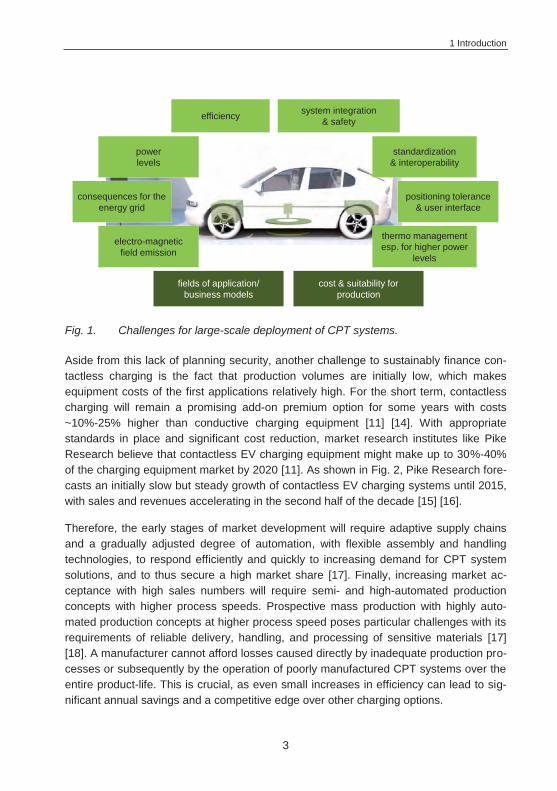
As the technology becomes increasingly sophisticated, important challenges for large-scale deployment remain, such as regulatory (standards, inter-operability, safety re-quirements) and business-related concerns (insecure business models, excessive cost), as shown in Fig. 1. The focus of this thesis is on business-related issues, as regulatory concerns must be solved in multi-company approaches. Several boards of standardiza-tion have already been implemented for this purpose.
Business stakeholders often bring up the concern of insecurity that comes with the very complex combination of parameters that need to be taken into account in order to thor-oughly evaluate the attractiveness of different fields of application. Therefore, potential users in different fields of application, which will at first be predominantly commercial (logistics, public transport, etc.) need substantiated options for a detailed evaluation of the benefits of CPT systems.
1 Introduction
3
Fig. 1. Challenges for large-scale deployment of CPT systems.
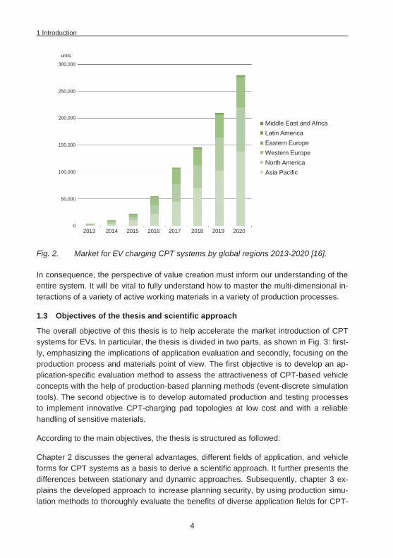
Aside from this lack of planning security, another challenge to sustainably finance con-tactless charging is the fact that production volumes are initially low, which makes equipment costs of the first applications relatively high. For the short term, contactless charging will remain a promising add-on premium option for some years with costs ~10%-25% higher than conductive charging equipment [11] [14]. With appropriate standards in place and significant cost reduction, market research institutes like Pike Research believe that contactless EV charging equipment might make up to 30%-40% of the charging equipment market by 2020 [11]. As shown in Fig. 2, Pike Research fore-casts an initially slow but steady growth of contactless EV charging systems until 2015, with sales and revenues accelerating in the second half of the decade [15] [16].
Therefore, the early stages of market development will require adaptive supply chains and a gradually adjusted degree of automation, with flexible assembly and handling technologies, to respond efficiently and quickly to increasing demand for CPT system solutions, and to thus secure a high market share [17]. Finally, increasing market ac-ceptance with high sales numbers will require semi- and high-automated production concepts with higher process speeds. Prospective mass production with highly auto-mated production concepts at higher process speed poses particular challenges with its requirements of reliable delivery, handling, and processing of sensitive materials [17] [18]. A manufacturer cannot afford losses caused directly by inadequate production pro-cesses or subsequently by the operation of poorly manufactured CPT systems over the entire product-life. This is crucial, as even small increases in efficiency can lead to sig-nificant annual savings and a competitive edge over other charging options.
System integration (weight / size / position)
positioning tolerance & user interface
electro-magnetic field emission
Cost / producibility of the systems
power levels
system integration & safety
standardization & interoperability
thermo management esp. for higher power
levels
consequences for the energy grid
efficiency
fields of application/business models
cost & suitability for production
1 Introduction
4
Fig. 2. Market for EV charging CPT systems by global regions 2013-2020 [16].
In consequence, the perspective of value creation must inform our understanding of the entire system. It will be vital to fully understand how to master the multi-dimensional in-teractions of a variety of active working materials in a variety of production processes.
1.3 Objectives of the thesis and scientific approach
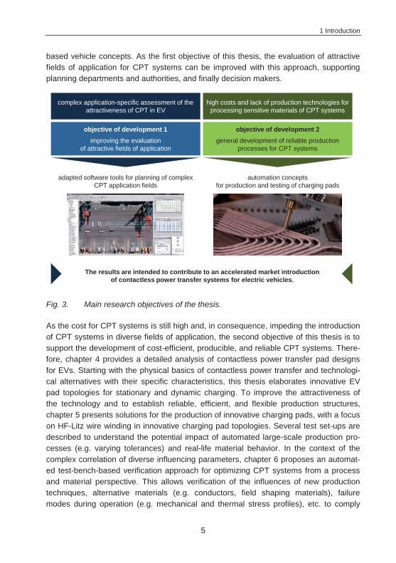
The overall objective of this thesis is to help accelerate the market introduction of CPT systems for EVs. In particular, the thesis is divided in two parts, as shown in Fig. 3: first-ly, emphasizing the implications of application evaluation and secondly, focusing on the production process and materials point of view. The first objective is to develop an ap-plication-specific evaluation method to assess the attractiveness of CPT-based vehicle concepts with the help of production-based planning methods (event-discrete simulation tools). The second objective is to develop automated production and testing processes to implement innovative CPT-charging pad topologies at low cost and with a reliable handling of sensitive materials.
According to the main objectives, the thesis is structured as followed:
Chapter 2 discusses the general advantages, different fields of application, and vehicle forms for CPT systems as a basis to derive a scientific approach. It further presents the differences between stationary and dynamic approaches. Subsequently, chapter 3 ex-plains the developed approach to increase planning security, by using production simu-lation methods to thoroughly evaluate the benefits of diverse application fields for CPT-
300,000
250,000
200,000
150,000
100,000
50,000
0
Middle East and AfricaLatin AmericaEastern EuropeWestern EuropeNorth AmericaAsia Pacific
2013 2014 2015 2016 2017 2018 2019 2020
units
1 Introduction
5
based vehicle concepts. As the first objective of this thesis, the evaluation of attractive fields of application for CPT systems can be improved with this approach, supporting planning departments and authorities, and finally decision makers.
Fig. 3. Main research objectives of the thesis.
As the cost for CPT systems is still high and, in consequence, impeding the introduction of CPT systems in diverse fields of application, the second objective of this thesis is to support the development of cost-efficient, producible, and reliable CPT systems. There-fore, chapter 4 provides a detailed analysis of contactless power transfer pad designs for EVs. Starting with the physical basics of contactless power transfer and technologi-cal alternatives with their specific characteristics, this thesis elaborates innovative EV pad topologies for stationary and dynamic charging. To improve the attractiveness of the technology and to establish reliable, efficient, and flexible production structures, chapter 5 presents solutions for the production of innovative charging pads, with a focus on HF-Litz wire winding in innovative charging pad topologies. Several test set-ups are described to understand the potential impact of automated large-scale production pro-cesses (e.g. varying tolerances) and real-life material behavior. In the context of the complex correlation of diverse influencing parameters, chapter 6 proposes an automat-ed test-bench-based verification approach for optimizing CPT systems from a process and material perspective. This allows verification of the influences of new production techniques, alternative materials (e.g. conductors, field shaping materials), failure modes during operation (e.g. mechanical and thermal stress profiles), etc. to comply
complex application-specific assessment of the attractiveness of CPT in EV
adapted software tools for planning of complex CPT application fields
The results are intended to contribute to an accelerated market introduction of contactless power transfer systems for electric vehicles.
high costs and lack of production technologies for processing sensitive materials of CPT systems
automation concepts for production and testing of charging pads
objective of development 1improving the evaluation
of attractive fields of application
objective of development 2general development of reliable production
processes for CPT systems

1 Introduction
6
with the high demands of quality and power transfer efficiency in automotive applica-tions, and to find further optimization potentials to reduce production costs, weight, and volume of CPT-charging pads.
Chapter 7 sums up the results and gives an outlook on future developments.
2 Derivation of Fields of Application for CPT Systems
7
2 Derivation of Fields of Application for CPT Systems
Contactless power transfer is the transmission of electrical energy from a power source transmitter to a receiver without using any physical conductive connection. This idea of transmitting power through the air without a direct electrical connection has been around since the late 1800s and early 1900s [19], with successful proof-of-concept demonstrations around 1900 [20] [21] [22]. In the past decade, researchers have made several breakthroughs that allow the commercialization of CPT systems [23], and with its key advantages over contact-based approaches (plug-in, bar, and brush), CPT is continually finding new applications. Contactless power transfer systems are reliable and maintenance-free due to their inherent galvanic and physical isolation. Moreover, conductors and electronics are enclosed and protected in sealed watertight and explo-sion-proof casing, which ensures safe operation in wet or dirty environments [24]. In ad-dition, CPT systems appeal to buyers even more because there is no need for battery replacement or a cord, the most failure-prone component [20]. CPT devices are also the more eco-friendly option, with either reduced battery size or even battery-free operation. Using grid power is much less expensive and more environmentally sound than manu-facturing, transporting, and using batteries, especially when they are based on tradition-al electro-chemistries [20].
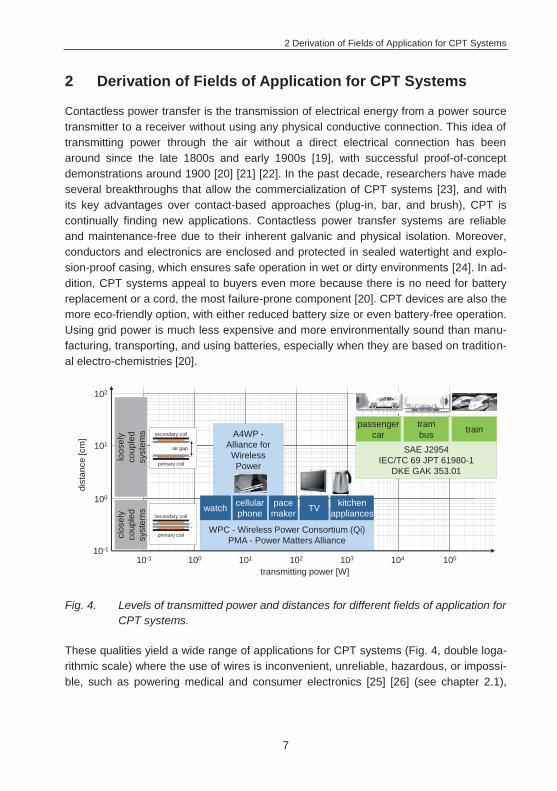
Fig. 4. Levels of transmitted power and distances for different fields of application for CPT systems.
These qualities yield a wide range of applications for CPT systems (Fig. 4, double loga-rithmic scale) where the use of wires is inconvenient, unreliable, hazardous, or impossi-ble, such as powering medical and consumer electronics [25] [26] (see chapter 2.1),
SAE J2954IEC/TC 69 JPT 61980-1
DKE GAK 353.01
dist
ance
[cm
]
transmitting power [W]
10-1
100
101
102
10-1 100 101 102 103 104 105
passenger car
trambus train
WPC - Wireless Power Consortium (Qi) PMA - Power Matters Alliance
A4WP -Alliance for Wireless Power
primary coil
secondary coil
primary coil
secondary coil
air gap
clos
ely
coup
led
syst
ems watch pace
makerkitchen
appliancesTVcellular phone
loos
ely
coup
led
syst
ems
2 Derivation of Fields of Application for CPT Systems
8
factory automation [21] [27] [28] (see chapter 2.2) and - as is the focus of this thesis - electrified vehicle concepts (see chapter 2.3) [24] [29] [30].
The range of different power levels and distances for CPT applications is large. For consumer electronics, power is usually transmitted in the range of a few watts, and the focus is on closely coupled systems with a distance between transmitter and receiver of only a few millimeters. The distance of the coils and power levels for automotive vehicle applications are usually far greater. In loosely coupled systems, the air gaps that have to be covered are in the 100-300 mm range. Depending on the field of application, CPT systems today can generate an output power Pout of up to several hundred kW. For passenger cars, the primary focus is on lumped systems at modest power levels (3.7 kW) for home-based charging, as this is the presumed maximum power rating of a typical household main outlet (230 V, 16 A). However, as fast charging is getting more attention to facilitate the daily operation of EVs, organizations also work on larger power levels. The SAE (Society of Automotive Engineers) J2954 Wireless Charging Task Force, for example, discusses power classes from light duty home (3.7 kW), light duty private/public parking (7.7 kW) up to light duty fast charge (22 kW) [31]. The German National Electric Mobility Platform (Nationale Plattform Elektromobilität - NPE) mentions charging levels for CPT systems for the power levels 3.7 kW, 11 kW, 22 kW, and 60 kW [32]. Beyond that, other projects have already demonstrated power levels of up to 200 kW for buses, trucks, and trains [33] [34].
2.1 Medical applications and consumer electronics
Nowadays, CPT systems represent the state of the art for a wide range of medical and consumer products. Since CPT eliminates the need for cables that penetrate the human body and surgical replacement of primary batteries, commercial exploitation of transcutaneous contactless medical implants began as early as the 1960s with pace-makers [20] [35]. Since then, contactless charging systems are being further developed for other implanted medical devices including Left Ventricular Assist Devices (LVADs), heart assist pumps, and infusion pumps [20] [25] [26].
Towards the end of the 1970s, manufacturers of consumer products also began to offer contactless charging systems, starting with CPT electric toothbrushes, which are con-siderably safer than the contact-based chargers that had been in use before, especially in a high-humidity environment like a bathroom [36]. Due to the positive experience in the field of hygiene and personal care appliances, there has been a clear trend towards contactless power transfer in consumer electronics in recent years. Thus, there are more and more CPT-based devices, particularly in the field of portable consumer elec-tronic equipment with its continuously rising customer demands (larger displays, faster processors, HD graphics, “always online in social media networks”), such as cellular phones and laptop computers [37] [38]. Contactless charging of mobile devices will be
2 Derivation of Fields of Application for CPT Systems
9
even more attractive in the years ahead with manufacturer-independent interfaces of closely coupled systems, like the Qi standard (5 W at 100-205 kHz) of the Wireless Power Consortium (WPC). Higher power levels like 15 W, 200 W, 800 W, and 2.4 kW specifications are currently under development (see Fig. 4). With CPT, consumers will no longer need to carry the correct charging cable for each device. The devices can be charged by simply placing them on top of the charging pad. In the future, these pads might even be embedded in furniture and become standard in public places such as restaurants1, hotels, or train stations. However, aside from the Qi standard, there is also the Power Matters Alliance (PMA, 5 W at 277-357 kHz) and the Alliance for Wireless Power (A4WP), potentially confusing the customers (see also problems of standardiza-tion in chapter 4.2.1.3). The A4WP is expanding to loosely coupled lumped systems, operated by non-radiative, “near-field mid-range” magnetic resonance (see chapter 4.1), with power levels of up to 22 W at 6.78 MHz. The A4WP system thus makes it possible to wirelessly power several devices simultaneously without immediate vicinity (several centimeters) to a charging base station [40].
2.2 Industrial material handling applications
CPT systems have also demonstrated their viability in another crucial and continuously growing market: The field of contactlessly powered material handling applications [30], such as Automated Guided Vehicles (AGVs), skillet systems, monorail overhead con-veyors, sorting systems for flexible manufacturing lines, or logistical systems that can operate inside or outside, in cooling facilities, and wet areas [21] [23] [30]. In the mid-1990s, the automotive industry started requesting contactless power solutions for AGVs in car factories at engine assembly lines, welding bays or paint shops, as CPT systems prove to be more robust (unaffected by chemicals or dirt) and safe with reduced maintenance than power transfer systems that rely on bus bars/brushed contacts [41]. As CPT systems do not generate fine particles that would contaminate sensitive pro-cesses, as brushed electrical contacts tend to do, CPT material handling systems are also used for processes that require a strict control of environmental pollutants, like cleanrooms in chip manufacture, achieving higher yields than any competing technology [30].
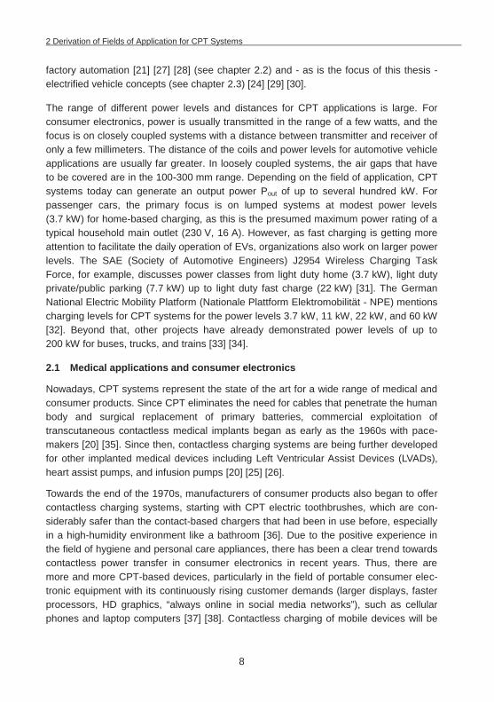
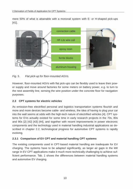
Usually, loosely coupled systems with elongated primary tracks are used here, either in the form of an overhead monorail conveyor or a floor-mounted system. A monorail con-veyor system uses secondary systems with E- or H-shaped ferrite pick-up cores that encircle ~270° of the primary track (two wires at a spacing of 100 mm), operated with relatively small air-gaps, and good coupling factors at high efficiency. Floor-mounted AGVs with flat pick-ups (Fig. 5.) however, do not have such ideal operating conditions for coupling, as they do not even encircle 180° of the two primary track wires (spaced 100 mm apart and buried 10 mm in the shop floor). This results in coupling factors of a
1 Starbucks started to adopt the concept in the U.S. in 2013 [39].
2 Derivation of Fields of Application for CPT Systems
10
mere 50% of what is attainable with a monorail system with E- or H-shaped pick-ups [41].
Fig. 5. Flat pick-up for floor-mounted AGVs.
However, floor-mounted AGVs with flat pick-ups can be flexibly used to leave their pow-er supply and move around factories for some meters on battery power, e.g. to turn to the next assembly line, sensing the wire position under the concrete floor for navigation purposes.
2.3 CPT systems for electric vehicles
As emission-free electrified personal and logistics transportation systems flourish and more and more devices become cable- and wireless, the idea of having to plug your car into the wall seems at odds with the high-tech nature of electrified vehicles [4]. CPT sys-tems for EVs actually existed for some time in early research projects in the 70s, 80s and 90s [2] [42] [43] [44], and together with recent improvements in power electronic components and the technology used in material handling industrial applications as de-scribed in chapter 2.2, technological progress for automotive CPT systems is rapidly evolving.
2.3.1 Comparison of EV CPT and material handling CPT systems
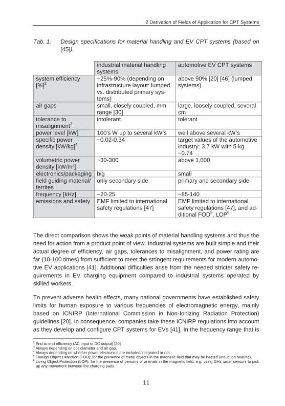
The existing components used in CPT-based material handling are inadequate for EV charging. The systems have to be adapted significantly, as larger air gaps in the kW range in EV CPT applications make it much more technically challenging to achieve suf-ficient performance. Tab. 1 shows the differences between material handling systems and automotive EV charging.
connection cable
HF-Litz wire coil
epoxy resin
ferrite blocks
aluminum-housing
2 Derivation of Fields of Application for CPT Systems
11
Tab. 1. Design specifications for material handling and EV CPT systems (based on [45]).
industrial material handling systems
automotive EV CPT systems
system efficiency [%]2
~25%-90% (depending on infrastructure layout: lumped vs. distributed primary sys-tems)
above 90% [20] [46] (lumped systems)
air gaps small, closely coupled, mm-range [30]
large, loosely coupled, several cm
tolerance to misalignment3
intolerant tolerant
power level [kW] 100's W up to several kW’s well above several kW’s specific power density [kW/kg]4
~0.02-0.34 target values of the automotive industry: 3.7 kW with 5 kg ~0.74
volumetric power density [kW/m³]
~30-300 above 1,000
electronics/packaging big small field guiding material/ ferrites
only secondary side primary and secondary side
frequency [kHz] ~20-25 ~85-140 emissions and safety EMF limited to international
safety regulations [47] EMF limited to international safety regulations [47], and ad-ditional FOD5, LOP6
The direct comparison shows the weak points of material handling systems and thus the need for action from a product point of view. Industrial systems are built simple and their actual degree of efficiency, air gaps, tolerances to misalignment, and power rating are far (10-100 times) from sufficient to meet the stringent requirements for modern automo-tive EV applications [41]. Additional difficulties arise from the needed stricter safety re-quirements in EV charging equipment compared to industrial systems operated by skilled workers.
To prevent adverse health effects, many national governments have established safety limits for human exposure to various frequencies of electromagnetic energy, mainly based on ICNIRP (International Commission in Non-Ionizing Radiation Protection) guidelines [20]. In consequence, companies take these ICNIRP regulations into account as they develop and configure CPT systems for EVs [41]. In the frequency range that is 2 End-to-end efficiency (AC input to DC output) [20]. 3 Always depending on coil diameter and air gap. 4 Always depending on whether power electronics are included/integrated or not. 5 Foreign Object Detection (FOD): for the presence of metal objects in the magnetic field that may be heated (induction heating). 6 Living Object Protection (LOP): for the presence of persons or animals in the magnetic field, e.g. using GHz radar sensors to pick
up any movement between the charging pads.
2 Derivation of Fields of Application for CPT Systems
12
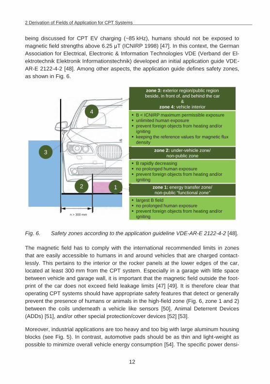
being discussed for CPT EV charging (~85 kHz), humans should not be exposed to magnetic field strengths above 6.25 T (ICNIRP 1998) [47]. In this context, the German Association for Electrical, Electronic & Information Technologies VDE (Verband der El-ektrotechnik Elektronik Informationstechnik) developed an initial application guide VDE-AR-E 2122-4-2 [48]. Among other aspects, the application guide defines safety zones, as shown in Fig. 6.
Fig. 6. Safety zones according to the application guideline VDE-AR-E 2122-4-2 [48].
The magnetic field has to comply with the international recommended limits in zones that are easily accessible to humans in and around vehicles that are charged contact-lessly. This pertains to the interior or the rocker panels at the lower edges of the car, located at least 300 mm from the CPT system. Especially in a garage with little space between vehicle and garage wall, it is important that the magnetic field outside the foot-print of the car does not exceed field leakage limits [47] [49]. It is therefore clear that operating CPT systems should have appropriate safety features that detect or generally prevent the presence of humans or animals in the high-field zone (Fig. 6, zone 1 and 2) between the coils underneath a vehicle like sensors [50], Animal Deterrent Devices (ADDs) [51], and/or other special protection/cover devices [52] [53].
Moreover, industrial applications are too heavy and too big with large aluminum housing blocks (see Fig. 5). In contrast, automotive pads should be as thin and light-weight as possible to minimize overall vehicle energy consumption [54]. The specific power densi-
n > 300 mm
largest B field no prolonged human exposure prevent foreign objects from heating and/or igniting
B rapidly decreasing no prolonged human exposure prevent foreign objects from heating and/or igniting
zone 3: exterior region/public region beside, in front of, and behind the car
&zone 4: vehicle interior
B < ICNIRP maximum permissible exposureunlimited human exposureprevent foreign objects from heating and/or ignitingkeeping the reference values for magnetic flux density
zone 1: energy transfer zone/non-public “functional zone”
zone 2: under-vehicle zone/non-public zone
4
3
2 1
2 Derivation of Fields of Application for CPT Systems
13
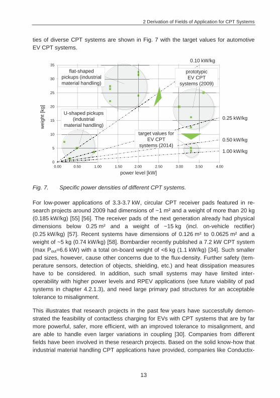
ties of diverse CPT systems are shown in Fig. 7 with the target values for automotive EV CPT systems.
Fig. 7. Specific power densities of different CPT systems.
For low-power applications of 3.3-3.7 kW, circular CPT receiver pads featured in re-search projects around 2009 had dimensions of ~1 m² and a weight of more than 20 kg (0.185 kW/kg) [55] [56]. The receiver pads of the next generation already had physical dimensions below 0.25 m² and a weight of ~15 kg (incl. on-vehicle rectifier) (0.25 kW/kg) [57]. Recent systems have dimensions of 0.126 m² to 0.0625 m² and a weight of ~5 kg (0.74 kW/kg) [58]. Bombardier recently published a 7.2 kW CPT system (max Pout=6.6 kW) with a total on-board weight of <6 kg (1.1 kW/kg) [34]. Such smaller pad sizes, however, cause other concerns due to the flux-density. Further safety (tem-perature sensors, detection of objects, shielding, etc.) and heat dissipation measures have to be considered. In addition, such small systems may have limited inter-operability with higher power levels and RPEV applications (see future viability of pad systems in chapter 4.2.1.3), and need large primary pad structures for an acceptable tolerance to misalignment.
This illustrates that research projects in the past few years have successfully demon-strated the feasibility of contactless charging for EVs with CPT systems that are by far more powerful, safer, more efficient, with an improved tolerance to misalignment, and are able to handle even larger variations in coupling [30]. Companies from different fields have been involved in these research projects. Based on the solid know-how that industrial material handling CPT applications have provided, companies like Conductix-
0.10 kW/kg
1.00 kW/kg
0
5
10
15
20
25
30
35
0,00 0,50 1,00 1,50 2,00 2,50 3,00 3,50 4,00
power level [kW]
wei
ght [
kg]
0.50 kW/kg
0.25 kW/kgU-shaped pickups
(industrial material handling)
flat-shaped pickups (industrial material handling)
prototypic EV CPT
systems (2009)
target values for EV CPT
systems (2014)
0.00 0.50 1.00 1.50 2.00 2.50 3.00 3.50 4.00
2 Derivation of Fields of Application for CPT Systems
14
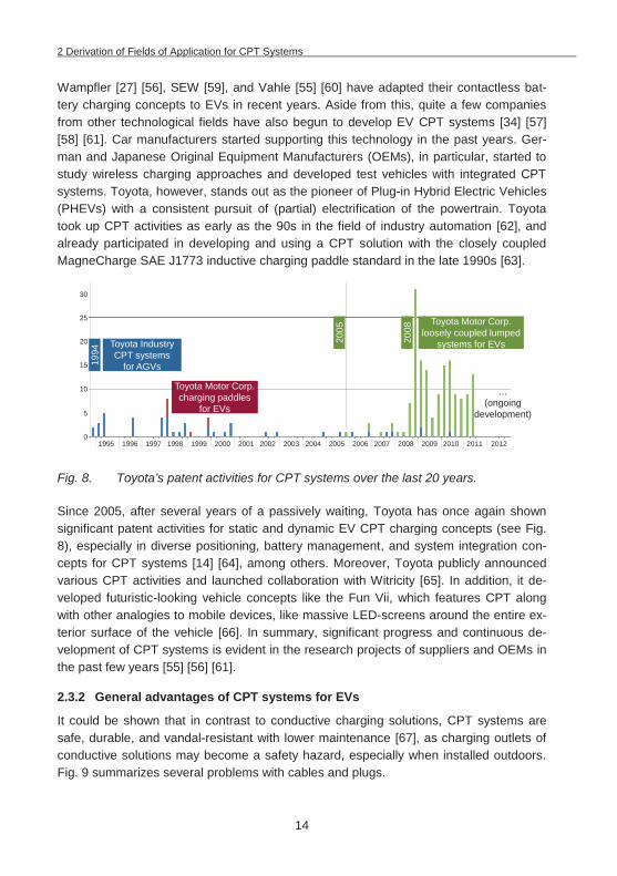
Wampfler [27] [56], SEW [59], and Vahle [55] [60] have adapted their contactless bat-tery charging concepts to EVs in recent years. Aside from this, quite a few companies from other technological fields have also begun to develop EV CPT systems [34] [57] [58] [61]. Car manufacturers started supporting this technology in the past years. Ger-man and Japanese Original Equipment Manufacturers (OEMs), in particular, started to study wireless charging approaches and developed test vehicles with integrated CPT systems. Toyota, however, stands out as the pioneer of Plug-in Hybrid Electric Vehicles (PHEVs) with a consistent pursuit of (partial) electrification of the powertrain. Toyota took up CPT activities as early as the 90s in the field of industry automation [62], and already participated in developing and using a CPT solution with the closely coupled MagneCharge SAE J1773 inductive charging paddle standard in the late 1990s [63].
Fig. 8. Toyota’s patent activities for CPT systems over the last 20 years.
Since 2005, after several years of a passively waiting, Toyota has once again shown significant patent activities for static and dynamic EV CPT charging concepts (see Fig. 8), especially in diverse positioning, battery management, and system integration con-cepts for CPT systems [14] [64], among others. Moreover, Toyota publicly announced various CPT activities and launched collaboration with Witricity [65]. In addition, it de-veloped futuristic-looking vehicle concepts like the Fun Vii, which features CPT along with other analogies to mobile devices, like massive LED-screens around the entire ex-terior surface of the vehicle [66]. In summary, significant progress and continuous de-velopment of CPT systems is evident in the research projects of suppliers and OEMs in the past few years [55] [56] [61].
2.3.2 General advantages of CPT systems for EVs
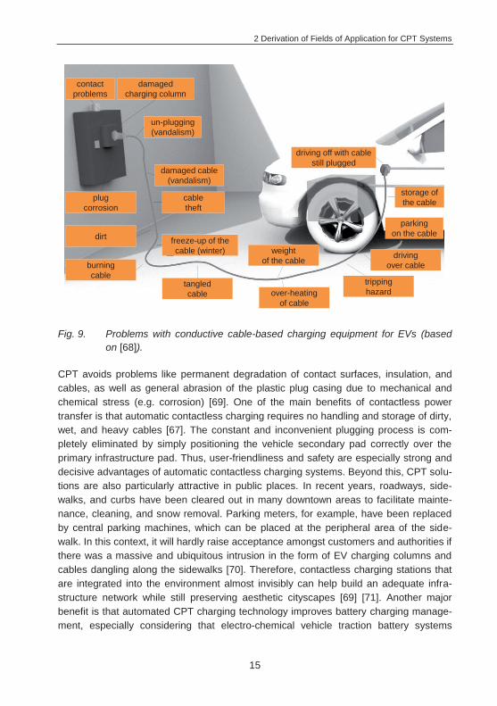
It could be shown that in contrast to conductive charging solutions, CPT systems are safe, durable, and vandal-resistant with lower maintenance [67], as charging outlets of conductive solutions may become a safety hazard, especially when installed outdoors. Fig. 9 summarizes several problems with cables and plugs.
Toyota IndustryCPT systems
for AGVs
Toyota Motor Corp.charging paddles
for EVs
Toyota Motor Corp.loosely coupled lumped
systems for EVs2005
2008
1994
…(ongoing
development)
30
25
20
15
10
5
01995 1996 1997 1998 1999 2000 2001 2002 2003 2004 2005 2006 2007 2008 2009 2010 2011 2012
2 Derivation of Fields of Application for CPT Systems
15
Fig. 9. Problems with conductive cable-based charging equipment for EVs (based on [68]).
CPT avoids problems like permanent degradation of contact surfaces, insulation, and cables, as well as general abrasion of the plastic plug casing due to mechanical and chemical stress (e.g. corrosion) [69]. One of the main benefits of contactless power transfer is that automatic contactless charging requires no handling and storage of dirty, wet, and heavy cables [67]. The constant and inconvenient plugging process is com-pletely eliminated by simply positioning the vehicle secondary pad correctly over the primary infrastructure pad. Thus, user-friendliness and safety are especially strong and decisive advantages of automatic contactless charging systems. Beyond this, CPT solu-tions are also particularly attractive in public places. In recent years, roadways, side-walks, and curbs have been cleared out in many downtown areas to facilitate mainte-nance, cleaning, and snow removal. Parking meters, for example, have been replaced by central parking machines, which can be placed at the peripheral area of the side-walk. In this context, it will hardly raise acceptance amongst customers and authorities if there was a massive and ubiquitous intrusion in the form of EV charging columns and cables dangling along the sidewalks [70]. Therefore, contactless charging stations that are integrated into the environment almost invisibly can help build an adequate infra-structure network while still preserving aesthetic cityscapes [69] [71]. Another major benefit is that automated CPT charging technology improves battery charging manage-ment, especially considering that electro-chemical vehicle traction battery systems
contact problems
dirt
burning cable
plug corrosion
freeze-up of the cable (winter)
tangled cable over-heating
of cable
driving over cable
parking on the cable
weight of the cable
un-plugging (vandalism)
damaged cable (vandalism)
cable theft
damaged charging column
tripping hazard
storage of the cable
driving off with cable still plugged

2 Derivation of Fields of Application for CPT Systems
16
largely determine overall vehicle characteristics. Even modern lithium-ion-batteries re-main the main bottleneck of electric mobility today in terms of cost (up to 2,000 US$/kWh with a long term goal of 100 US$/kWh) [72], range, and weight (specific energy density of 130-200 Wh/kg versus 10,000 Wh/kg for petroleum) [72], charge rate limitations due to the electro-chemical processes in the battery (power density of 350-400 W/kg versus 2,000 W/kg for ultra-capacitors) [72], durability, and environmental costs associated with their production and final disposal. Consequently, most OEMs are also investing in PHEV and Range Extended Electric Vehicles (REEVs). With today’s conventional plug-in hybrid vehicles, however, it is obvious that EV owners will not al-ways use the cable to charge their batteries, as it is a major inconvenience. Instead of physically plugging-in at the end of every short journey, customers prefer to go to the next gas station to get fossil-fuel-based vehicle range, as they have the combustion en-gine on board, anyway. In contrast to contact-based charging, hands-free automatic CPT significantly facilitates charging. Such a process is truly opportunistic and can be repeated many times per day, after each trip, whenever the opportunity arises (“oppor-tunity charging”), rather than irregular and longer charging operations [3] [41]. In conse-quence, charging is more likely and frequent, as customers can no longer forget to plug in [3] [45]. Especially vehicles that are set mainly to electrical driving-mode and there-fore have larger battery systems, like REEVs (electrically driven vehicles with combus-tion engines for an extended range) and BEVs (purely battery-powered vehicles) benefit from automated, more convenient, and thus more frequent wireless charging. It reduces battery wear-out by minimizing the depth of battery discharge, which can extend battery life. Additionally, CPT increases the electrical driving range and driving-mode portion of hybrid vehicles, as batteries are more likely charged up [45] [73]. CPT can thus help reduce the range problem and lower cost with extended battery life or smaller, more frequently charged batteries [1] [69], all crucial aspects that enable OEMs to sell EVs at a larger scale and reduce Total Cost of Ownership (TCO) [4]. However, the monetary benefits of potential extended battery life and increased electrical driving-mode portion are restricted for PHEVs with only very small batteries. For them, the benefits of CPT are ‘limited’ to comfort and safety [45].
Moreover, easy access to regular and more frequent grid connection is also of specific importance to the power grid as such, as there is a clear trend towards “green” power and more renewable energy sources with little or no carbon footprint. It is impossible to accurately forecast the amount of power yielded by a supply mix of solar, wind, wave and tidal power, all of which are fluctuating in nature. Thus, grid frequency cannot be held as precise and stable as is the case with traditional central energy sources like nu-clear power [3]. In this context, reducing peak load effects and stabilizing the grid fre-quency through controlled EV charging is very promising and can become a highly at-tractive business model in the future. In this concept, the car of the future becomes far more than just a transportation medium. With large-scale deployment, battery EVs could
2 Derivation of Fields of Application for CPT Systems
17
form one gigantic electricity storage fleet and act as a controlled, widely dispersed load that automatically improves the stability of any supply network. At times of surging wind, a lot of wind power is added to the power system, increasing mains frequency [3]. How-ever, wind turbines do not need to be shut off, as electric cars can charge up very cheaply with the surplus power in the system. Conversely, in situations with calm wind conditions and acute energy shortages, EV charging can be reduced [3] [6]. In theory, EVs could even feed power back into the grid to meet a temporary demand. In August 2009, Germany’s pumped storage power plant capacity totaled approximately 6.7 GW. Assuming that the accessible power of a vehicle battery can peak at P=20 kW, 340,000 EV batteries together could essentially substitute Germany’s entire pumped storage power plant capacity [69]. However, when considering a power flow back to the mains, the potential additional battery stress and extra electronics costs need to be justified. Moreover, [74] [75] claim that unidirectional power flow and demand control strategies can provide much of the same benefits with little more than a smart control algorithm. These approaches may reduce the amount of spinning reserve that governments need and could increase the wind power penetration without a significant increase in grid de-mand-supply balancing cost [3]. Such “energy services” would improve the quality of power supply from renewable sources if they could be reliably established. To achieve this, it would have to be guaranteed that numerous controllable EV batteries are con-nected to the power grid simultaneously to stabilize daily load curves and thus avoid peak loads in the grid. This endeavor would be greatly compromised if motorists do not keep their batteries well charged at all times. It can be assumed that drivers would not make a constant effort to manually plug and unplug at home, and certainly not in public unless it was absolutely necessary [69]. Automated CPT can mitigate this problem, as CPT leads to better, more regular grid connection and allows the battery to be more fre-quently available for grid services.
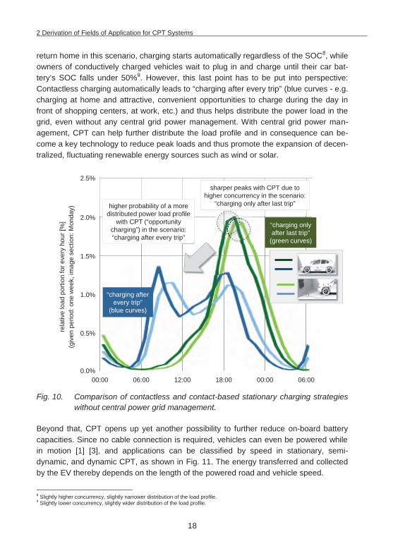
For validation, a load profile scenario has been developed in the scope of this thesis comparing stationary contactless versus contact-based charging with traffic data from the study “Mobility in Germany 2008” [76]7, as shown in Fig. 10. Two charging scenarios were considered, “charging after every trip” (blue curves) and “charging only after last trip” (green curves). One assumption is that the operator of a conductively charged ve-hicle only charges his/her vehicle with a State of Charge (SOC) of below 50% (assum-ing that the operator will handle the charging cable only if necessary). In the “charging after every trip” scenario (blue curves), charging and usage of grid power is widely dis-tributed throughout the day, in contrast to the “green curves” that show a sharp peak in the evening hours. It can also be seen that without central power management, contact-less charging may in theory even have a negative impact on the grid with slightly higher load peaks compared to conductive charging. This is due the fact that as CPT vehicles
7 N=22,043 vehicles, only passenger cars, P=3.7 kW, conductive(AC-mains_to_DC-battery)=95%, contactless(AC-mains_to_DC-battery)=90%, battery-
capacity=25 kWh, weighted average energy consumption=0.174 kWh/km.
2 Derivation of Fields of Application for CPT Systems
18
return home in this scenario, charging starts automatically regardless of the SOC8, while owners of conductively charged vehicles wait to plug in and charge until their car bat-tery’s SOC falls under 50%9. However, this last point has to be put into perspective: Contactless charging automatically leads to “charging after every trip” (blue curves - e.g. charging at home and attractive, convenient opportunities to charge during the day in front of shopping centers, at work, etc.) and thus helps distribute the power load in the grid, even without any central grid power management. With central grid power man-agement, CPT can help further distribute the load profile and in consequence can be-come a key technology to reduce peak loads and thus promote the expansion of decen-tralized, fluctuating renewable energy sources such as wind or solar.
Fig. 10. Comparison of contactless and contact-based stationary charging strategies
without central power grid management.
Beyond that, CPT opens up yet another possibility to further reduce on-board battery capacities. Since no cable connection is required, vehicles can even be powered while in motion [1] [3], and applications can be classified by speed in stationary, semi-dynamic, and dynamic CPT, as shown in Fig. 11. The energy transferred and collected by the EV thereby depends on the length of the powered road and vehicle speed.
8 Slightly higher concurrency, slightly narrower distribution of the load profile. 9 Slightly lower concurrency, slightly wider distribution of the load profile.
00:00 06:00 12:00 18:00 00:00 06:00
sharper peaks with CPT due to higher concurrency in the scenario:
“charging only after last trip”
“charging after every trip”
(blue curves)
“charging only after last trip”
(green curves)
2.5%
2.0%
1.5%
1.0%
0.5%
0.0%
higher probability of a more distributed power load profile
with CPT (“opportunity charging”) in the scenario: “charging after every trip”
rela
tive
load
por
tion
for e
very
hou
r [%
](g
iven
per
iod:
one
wee
k, im
age
sect
ion:
Mon
day)
2 Derivation of Fields of Application for CPT Systems
19
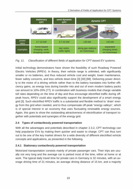
Fig. 11. Classification of different fields of application for CPT-based EV systems.
Initial technology demonstrators have shown the feasibility of such Roadway Powered Electric Vehicles (RPEV). In theory, their vehicle range is unlimited, with significantly smaller or no batteries, and thus reduced vehicle cost and weight, lower maintenance, fewer safety concerns, and less vehicle down-time [3] [30] [68]. Delivering power direct-ly to the motor of a driving vehicle rather than to the battery translates into further effi-ciency gains, as energy loss during transfer into and out of even modern battery packs can amount to 10%-20% [77]. In combination with business models that charge variable toll rates depending on the time of day and thus encourage electrified traffic during off-peak hours, RPEV could also significantly support the development of a smart energy grid [3]. Such electrified RPEV traffic is a substantial and flexible method to ‘drain’ ener-gy from the grid when needed, and to thus compensate off-peak “energy valleys”, which is of special interest in an economy that uses fluctuating renewable energy sources. Again, this goes to show the outstanding attractiveness of electrification of transport to-gether with potentials and synergies of the energy grid.
2.4 Types of contactlessly powered transportation
With all the advantages and potentials described in chapter 2.3.2, CPT technology can help popularize EVs by making them quicker and easier to charge. CPT can thus turn out to be one of the key market drivers for a wide diversity of different electrified vehicle concepts and applications, as presented in the following.
2.4.1 Stationary contactlessly powered transportation
Motorized transportation consists mainly of private passenger cars. Their trips are usu-ally not very long and the average car is parked most of the time, either at home or at work. The typical daily travel time for private cars in Germany is 32 minutes, with an av-erage driving time of 21 minutes, an average driving distance of 15 km, and a majority
stationary CPT
semi-dynamic CPT dynamic CPT
power rates
examples
3.7-22 kW 3.7-22 kW >20 kW >20 kW
home-based charging, work, shopping center
taxi ranks, traffic lights
along gas stations on motorways
separated charging lanes on motorways
2 Derivation of Fields of Application for CPT Systems
20
of private trips shorter than 40 km [76]10. For small cars with energy storage capacities of about 20 kWh that give it a range of about 150 km, power rates of 3.7 kW and charg-ing times of about 5-6 hours overnight11 are sufficient for normal commuter services. It is relatively easy to install stationary CPT infrastructures at parking spaces at home or at work. Therefore, the most promising initial target group for a market introduction would be vehicle owners who own a parking space or garage. This group represents 43% of vehicle owners in urban areas and 71% outside of urban areas [79]. However, as battery systems are still limited today, drivers with a long commute rely on range ex-tender concepts or additional (semi-)public infrastructure. In order to increase the rate of electrical driving, commuters and users that park on the street and do not have a home garage at which to charge (57% inside urban areas, 29% outside urban areas [79]) need publicly accessible charging options. They are thus the main target clientele for public and semi-public charging options. The currently relatively low battery capacities of EVs resulting in limited range mean that charging is more frequent and more time-consuming than conventional refueling of vehicles with Internal Combustion Engine (lCE). Consequently, higher power levels of up to several dozen kWs are on the table to shorten charging times (aside from DC conductive fast charging solutions, 22 kW CPT-systems of, for instance, a fast-chargeable 20 kWh battery within less than an hour)12. The assumption is that these power levels are necessary for consumer acceptance of EVs, and to make them as attractive as vehicles with ICEs, even for longer distances. In addition, to guarantee high utilization of public charging spots and to make such a public infrastructure profitable within a short break-even period, it is vital that charging systems are inter-operable (see chapter 4.2.1.3).
Retro-fitting public spaces is more or less complicated depending on the kind of pave-ment surface (asphalt-paved, concrete, cobblestones), location (parking spaces, bus stations, roadway, etc.), and accessibility of connection lines to the grid peripherals. The main costs arise from the depth of the pit that is necessary in a sub-terrain environment with telephone cables and fibers, and also prescribed by guidelines like the German DIN 1998 that specify how power cables have to be installed in public areas [81]13. This becomes far more complex in dense inner-city areas. All systems also have to meet basic requirements, especially in terms of load profiles of all street-legal vehicles, in-cluding the impact of braking forces on road surfaces, or in terms of thermal profiles, as for example under severe weather conditions. As a solution, primary systems for sta-tionary charging are usually integrated in public parking spaces in standardize-able un-derground systems [34] [59] [82] [83] [84], which makes parking spots easy to equip. The components are integrated in a modular way, safely protected, and installed invisi-
10 In the U.S., the average driving distances are twice as long as they are in Europe [78]. 11 With CPT systems, as has already been successfully demonstrated, an efficiency of more than 90% from grid to battery is possi-
ble within certain operational constraints (see also chapter 4.1.1) [20]. 12 Tesla Motors, Inc., uses conductive 135 kW-fast-charging stations [80]. 13 According to German DIN 1998, power cables in public areas have to be installed between 0.6-1.6 m below street level.
2 Derivation of Fields of Application for CPT Systems
21
bly in the ground. The coil module (pad) usually lies in a metal frame as a cover on top of the cable pit. It is therefore easy to access components in the cable pit at any time by simply lifting the base pad. However, the coils have to be sufficiently protected from mechanical impacts. To make public charging points more durable, the primary-side charging module must be encased, for example with resin-bonded concrete types (pol-ymer concrete) [83]. If needed, concrete or asphalt may also be laid over the pad, mak-ing it even more durable and vandal-resistant. If components are buried and not easily accessible for maintenance and inspection purposes, operational stability is key, espe-cially since mechanical and thermal stresses due to frequent on/off cycles negatively affect the service life and reliability of the components. Moreover, drains need to be put in the shafts to avoid problems with incoming water, e.g. during rain storms, as already reported in [2]. Higher power levels require integrated cooling systems, which further complicates shaft systems [84].
Since such a public charging infrastructure is expensive and difficult to pre-determine, especially due to the variability of private traffic routes [45], it may increase profitability to focus on highly-frequented locations, which, on the other hand, may result in insuffi-cient coverage of CPT charging stations throughout the city. The short range of the EV requires a dense network of charging points, far exceeding the density of today’s con-ventional gas stations, at a variety of suitable (semi-)public areas like car parks, in front of shopping centers, at workplaces, and traffic lights [6]. In order to achieve overall user acceptance, any user who wants to charge his/her car must be able to quickly find a free charging point nearby. This need for widespread availability makes it even harder to establish a profitable business with a public stationary CPT system, as a large num-ber of available charging stations spreads both demand and profit over a larger number of competitors.
The idea of electrifying car sharing makes the problem of a large number of widespread public charging stations even more obvious. Car sharing concepts in general, and par-ticularly with EVs, have come back as an attractive business field in the past few years, as more and more EVs are available on the market [32] [84]. There are two fundamen-tally different concepts for 24-hour car sharing services. The first concept has custom-ers return the shared vehicles to pre-defined locations. The second concept, which is called free-floating, allows customers to park the shared vehicle in any parking space in the city [7]. The current free-floating concept discourages the use of BEVs in car shar-ing, as it would require not only charging capabilities at the car sharing stations, but also a widespread public charging infrastructure. Nevertheless, CPT technology offers major advantages to car sharing companies that still are willing to embark on BEV/PHEV con-cepts: It reduces maintenance costs and simplifies charging for customers and employ-ees who are in charge of keeping the fleet fully charged (see also advantages in chapter 2.3.2) [70]. In 1997, the Praxitele project in Saint-Quentin-en-Yvelines near Paris used
2 Derivation of Fields of Application for CPT Systems
22
EVs with contactless charging for car sharing. The project showed promising results, but was finally terminated due to a lack of public funding and the persisting high cost of EVs [43] [85].
Aside from passenger cars, CPT is also an attractive technology for other vehicle con-cepts, e.g. for catenary-free electric buses. Vehicles make short stops, charge enough power to continue along their route, and can thus stay in circulation all day long [4]. Moreover, CPT is a key lever to make electric buses a commercial alternative to today’s Diesel-fueled buses in public transport, or at least to increase the electric driving por-tions of contactlessly charged hybrid buses. In addition, catenary-free solutions help preserve aesthetic historic cityscapes. The increasing number of CPT bus projects con-firms the attractiveness of this field of CPT application in local public transit [2] [27] [34] [86].
2.4.2 Semi-dynamic contactlessly powered transportation
As a further step to future scenarios with RPEVs, semi-dynamic charging is particularly suited at traffic lights or slow-driving road sections in urban environments [3] [5] [87] [88]. This is of special interest in fields of application where conductive plug-in systems are impracticable because vehicles have to be charged very frequently, due to their dai-ly driving ranges. Such automatic semi-dynamic CPT is particularly attractive for taxis with their long and predictable idle times at taxi stands, moving slowly from one position to the next while waiting for customers [12]. Charging can be activated at each single primary pad underneath the road surface of the taxi stand as soon as the receiving pads of the taxis are roughly aligned with each pad below. In addition, the CPT infrastructure at the taxi stands can also directly supply auxiliaries such as air conditioning. This keeps drivers comfortable as they wait for customers in extreme warm/cold weather conditions, at no cost to range or battery life, because grid power is used rather than discharging the batteries. Moreover, the high turnover of waiting taxis and permanent movement of vehicles at the taxi stand prevents the problem of blocking charging spots with vehicles that are already fully charged. An average taxi driver with a 12-hour shift is driving for 3.5 hours (29.2%), and waiting at the taxi stand for customers 70.8% of the time. The majority of taxi trips are under ten kilometers. However, the travel profile of taxis is very heterogeneous. Special events like international trade shows or weather cancellations in air and/or rail transport cause a peak in demand and thus a need for longer range. Days with more frequent and/or longer taxi rides are economically benefi-cial for taxi drivers, and vital for the one-man taxi businesses that are typical in Germa-ny [7]. Taxis drivers are therefore particularly dependent on long range, available at any time. This still is a problem with BEV, which makes taxis with range extenders more at-tractive, but also more expensive. In summary, CPT systems make sense for taxi com-panies with a larger fleet. They make good pilot projects to test CPT in public, as it is relatively cheap, in absolute terms, to install CPT at the rather few clearly defined taxi
2 Derivation of Fields of Application for CPT Systems
23
stands in a given city. CPT taxis may be particularly promising in larger metropolitan areas that are burdened with heavy traffic and high pollution, as a single taxi covers the transport needs of numerous people per day and runs a much higher mileage than a private car over the course of its product life, making it the optimal and most eco-friendly way to use a car.
Another example for operating a semi-dynamic CPT infrastructure is the vision of charg-ing EVs statically or slow-dynamically at highly frequented traffic sections in urban areas where great numbers of vehicles are stopping or slowly passing an infrastructure, like during idle times at traffic lights [5] [12], main and arterial roads, etc. (city-wide CPT network). Vehicles can be charged on an actively used public roadway and do not need to be driven to specific charging spots. However, such an infrastructure would essential-ly have to be installed instantaneously in order to convince potential user groups like commuters and street parkers to buy BEVs, as they would require a high number of CPT-equipped traffic lights to cover their energy needs in all possible traffic situations. In addition, one must recognize the challenge presented to CPT systems at a semi-dynamic charging infrastructure: as vehicles pass an intersection, the time period they are exposed to the CPT system is short, and the amount of transferred energy small. Even assuming optimistic electricity prices and margins and a large number of CPT-vehicles on the roads, investments do not repay within a reasonable time period by electricity sales alone. This shows the importance of innovative future mobility services that provide sufficient range [km], and do not rely only exclusively on selling energy [kWh]. The necessary higher power levels also have to be seen in the context of battery life. Depending on the battery type, high-charging currents may have a strong detri-mental effect on the number of charging cycles and battery life [5].
Aside from technical and economic problems, CPT presents additional difficulties as it encourages traffic behaviors that are in conflict with transport authorities’ idea of optimal traffic flow. For example, drivers might obstruct traffic by slowing down over charging segments, or even cause accidents by sharply braking for a yellow light to catch some power from the CPT system. It will be necessary to adapt traffic rules to prevent such problems. In summary, city-wide networks with contactless traffic lights do not appear to be economical in an urban environment without massive government subsidies. As high installation and maintenance costs make public CPT energy more expensive than ener-gy from a home- or office-based infrastructure, it may not even be used much by BEV drivers, who most likely already have access to charging at work or at home.
2.4.3 Dynamic contactlessly powered transportation
Purely-battery electric vehicles that are currently available have to sell themselves to users despite the major inconvenience that they carry all of their energy in the form of expensive, low-range, slowly charged and short-lived batteries. Consequently, the next
2 Derivation of Fields of Application for CPT Systems
24
market step up from semi-dynamic could be powering vehicles ‘on the move’, even at higher speeds. While stationary contactless charging eliminates the need for the charg-ing cable, on-demand dynamic charging reduces or even eliminates dependence on the battery. Keeping the energy in the grid, reducing battery size, which leads to cheaper and lighter vehicles with unlimited range is a promising approach.
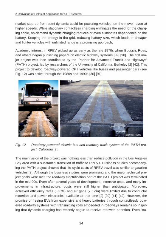
Academic interest in RPEV picked up as early as the late 1970s when BOLGER, ROSS, and others began publishing papers on electric highway systems [89] [90]. The first ma-jor project was then coordinated by the ‘Partner for Advanced Transit and Highways’ (PATH) project, led by researchers of the University of California, Berkeley [2] [42]. This project to develop roadway-powered CPT vehicles like buses and passenger cars (see Fig. 12) was active through the 1980s and 1990s [30] [91].
Fig. 12. Roadway-powered electric bus and roadway track system of the PATH pro-ject, California [2].
The main vision of the project was nothing less than reduce pollution in the Los Angeles Bay area with a substantial transition of traffic to RPEVs. Business studies accompany-ing the PATH project showed that life-cycle costs of RPEV travel was similar to gasoline vehicles [2]. Although the business studies were promising and the major technical pro-ject goals were met, the roadway electrification part of the PATH project was terminated in the mid-90s. Even after several years of development, intensive tests, and many im-provements in infrastructure, costs were still higher than anticipated. Moreover, achieved efficiency rates (~65%) and air gaps (7.5 cm) were limited due to conductor materials and power electronics available at that time [2] [30] [41] [42]. However, the promise of freeing EVs from expensive and heavy batteries through contactlessly pow-ered roadway systems with transmitting coils embedded in roadways remains so inspir-ing that dynamic charging has recently begun to receive renewed attention. Even "na-
source: PATH source: PATH
2 Derivation of Fields of Application for CPT Systems
25
tion-wide electrified roadway networks" as an intense modification of the conventional highway infrastructure are once again subject of extensive discussion. Similar to the PATH business studies [1] [2], BROOKER et al. [92] show that hypothetically, the only type of EV that can hope to compete with a conventional vehicle for cost of ownership from a customer perspective is the (hybrid)-RPEV with smaller batteries, picking up electrical energy from the roadway in-motion. In this context, it is important to note that the final infrastructure for such a dynamic charging system could be relatively small, as highways make up only a small percentage of installed roadway miles, yet carry a sig-nificant percentage of overall vehicle miles. In the U.S., for instance, 1% of roadway miles carry 22% of all vehicle mileage [1] [87] [93]. However, as the PATH project showed, it is quite a complex undertaking to put a public dynamic roadway infrastructure into the ground [2]. High voltage levels, especially, may cause issues. Installation and maintenance costs for such systems have to be reduced by newly developed roadway construction methods like new track laying technologies and machines [94]. Highly au-tomated roadway construction is especially important, as recent research results of the Belgium Flanders' DRIVE project "inductive charging" show performance deviations due to roadwork tolerances of cables that are laid in the ground manually [95].
However, it is hardly possible today to come up with a business model and win stake-holders for a nation-wide electrified roadway network with public dynamic charging for private passenger cars, because everything, infrastructure and vehicles, would have to be built up from scratch. Any consideration of such an infrastructure depends on the utilization rate of CPT EVs, which is simply not high enough in early stages of market development. A massive and costly intervention in and replacement of the existing in-frastructure, with widespread use of contactless charging for passenger cars, requires long-term government initiatives and the cooperation of all stakeholders to ensure in-dustry will be able to implement viable business models. The approach of RPEV could be compared to business models in the mobile phone industry. In the case of RPEVs drivers will pay for the mobility service [range in km] in form of road tolls based on dis-tance or time. These billing methods will also be vital to finance construction and maintenance of a RPEV infrastructure network, as revenues from sales and taxes on fossil fuels decline. However, as such an installation is expensive, smaller step-by-step installation scenarios are also being discussed. For a market introduction, the systems could be implemented on dedicated lanes of major arterial roads e.g. on busy long-haul routes between major cities like Hamburg-Berlin, Shenzhen-Hong Kong, or Los Ange-les-San Francisco. Another example for successive installation is the option of “high-power electrified roadway segments” along highways to charge up vehicles for routes ahead that have no charging infrastructure. Users thus do not have to stop for charging. However, the vehicle must drive as slowly as possible to maximize the amount of trans-ferred energy. To avoid impeding traffic flow, the infrastructure should not be installed directly on the highway lanes, but on a short section parallel to the highway, for example
2 Derivation of Fields of Application for CPT Systems
26
next to a gas station (see Fig. 11) or along a steep uphill section. This way, like the branches of a tree, the technology could spread out to more roads and grow into a tight-ly-knit RPEV infrastructure.
Compared to RPEVs, stationary high-power CPT systems along highways (as Tesla Motors, Inc. is already implementing with conductive 135 kW-fast-charging stations [80]) are also expensive and still require a wait time until the vehicle is charged up. Yet, for the next few decades, they seem more promising than the idealistic vision a of a dy-namic, nation-wide CPT infrastructure for passenger cars.
Different scenarios and strategies have been elaborated to promote the topic of RPEVs for passenger cars nonetheless. One very promising approach is motor sports, espe-cially since power transfer will play a major role in the strategy and tactics of electrified motor sports in the future, similar to today’s tire changes during pit stops. Moreover, CPT could bring a boost to electrified motor sports, as CPT tracks could even be em-bedded in the race tracks, enabling race cars to power up as they pass over designated portions of the course. In September 2013, the company Qualcomm HaloIPT an-nounced a multi-year agreement with Formula E Holdings (FEH) to become an official founding technology partner of the FIA Formula E Championship. CPT charging in the pits was subsequently included in the preliminary status of the FIA Formula E Champi-onship Technical Regulations at the end of 2013 [96]. In 2014/2015, CPT systems will be fitted into the safety cars to familiarize people with it, and from 2015/2016, CPT will be installed in the race cars. CPT systems will then be installed in the pits to simplify charging and to improve safety by removing loose cables and exposed connectors. In a next step, the race cars will also be able to charge while slowly moving along the lane to a pit stop or back onto the race track. Finally, in the battle for ever better times, the long-term goal is to equip the race track itself with CPT segments for dynamic charging. When battery power decreases, drivers could head their vehicles for specially equipped dynamic CPT segments on the route to get additional power. This offers exciting new possibilities for future racing strategies with a reduced or even eliminated need to stop the cars for recharging during a motor race. The main benefit of pioneering CPT in the domain of motor racing will most likely be the experience gained and thereby possible technology transfer from racing cars to series-production vehicles, as was the case for many automotive technologies that are taken for granted today. Motorsport applications will rapidly drive development, pushing mechanical and materials development, result-ing in safer, lighter, more efficient, and more reliable systems. Events like the Formula E are also educating the public about the attractiveness of EVs, planting the notion that EVs can charge continuously and hassle-free around a track in the public mind [4] [97]. As described in a market research study with puls Marktforschung GmbH [7], such
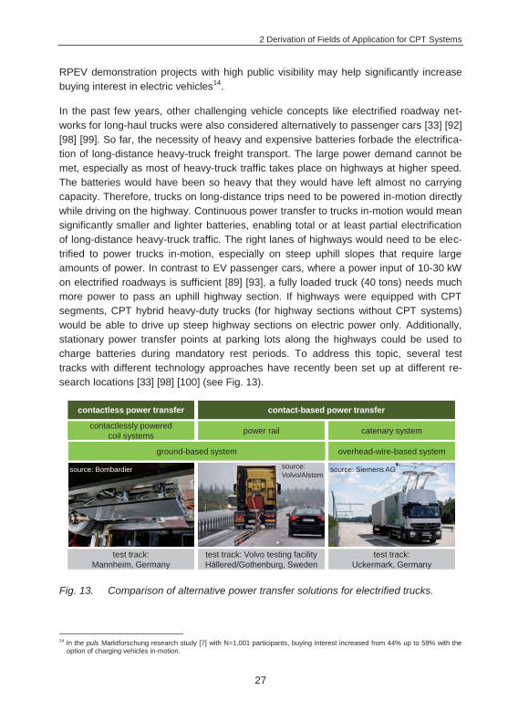
2 Derivation of Fields of Application for CPT Systems
27
RPEV demonstration projects with high public visibility may help significantly increase buying interest in electric vehicles14.
In the past few years, other challenging vehicle concepts like electrified roadway net-works for long-haul trucks were also considered alternatively to passenger cars [33] [92] [98] [99]. So far, the necessity of heavy and expensive batteries forbade the electrifica-tion of long-distance heavy-truck freight transport. The large power demand cannot be met, especially as most of heavy-truck traffic takes place on highways at higher speed. The batteries would have been so heavy that they would have left almost no carrying capacity. Therefore, trucks on long-distance trips need to be powered in-motion directly while driving on the highway. Continuous power transfer to trucks in-motion would mean significantly smaller and lighter batteries, enabling total or at least partial electrification of long-distance heavy-truck traffic. The right lanes of highways would need to be elec-trified to power trucks in-motion, especially on steep uphill slopes that require large amounts of power. In contrast to EV passenger cars, where a power input of 10-30 kW on electrified roadways is sufficient [89] [93], a fully loaded truck (40 tons) needs much more power to pass an uphill highway section. If highways were equipped with CPT segments, CPT hybrid heavy-duty trucks (for highway sections without CPT systems) would be able to drive up steep highway sections on electric power only. Additionally, stationary power transfer points at parking lots along the highways could be used to charge batteries during mandatory rest periods. To address this topic, several test tracks with different technology approaches have recently been set up at different re-search locations [33] [98] [100] (see Fig. 13).
Fig. 13. Comparison of alternative power transfer solutions for electrified trucks.
14 In the puls Marktforschung research study [7] with N=1,001 participants, buying interest increased from 44% up to 59% with the
option of charging vehicles in-motion.
contactless power transfer contact-based power transfer
catenary systempower rail
test track: Uckermark, Germany
test track: Volvo testing facility Hällered/Gothenburg, Sweden
test track: Mannheim, Germany
contactlessly powered coil systems
ground-based system overhead-wire-based system
source: Siemens AGsource: Volvo/Alstom
source: Bombardier
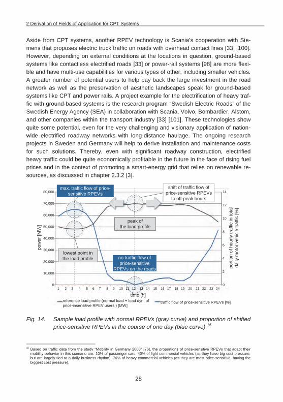
2 Derivation of Fields of Application for CPT Systems
28
Aside from CPT systems, another RPEV technology is Scania’s cooperation with Sie-mens that proposes electric truck traffic on roads with overhead contact lines [33] [100]. However, depending on external conditions at the locations in question, ground-based systems like contactless electrified roads [33] or power-rail systems [98] are more flexi-ble and have multi-use capabilities for various types of other, including smaller vehicles. A greater number of potential users to help pay back the large investment in the road network as well as the preservation of aesthetic landscapes speak for ground-based systems like CPT and power rails. A project example for the electrification of heavy traf-fic with ground-based systems is the research program “Swedish Electric Roads” of the Swedish Energy Agency (SEA) in collaboration with Scania, Volvo, Bombardier, Alstom, and other companies within the transport industry [33] [101]. These technologies show quite some potential, even for the very challenging and visionary application of nation-wide electrified roadway networks with long-distance haulage. The ongoing research projects in Sweden and Germany will help to derive installation and maintenance costs for such solutions. Thereby, even with significant roadway construction, electrified heavy traffic could be quite economically profitable in the future in the face of rising fuel prices and in the context of promoting a smart-energy grid that relies on renewable re-sources, as discussed in chapter 2.3.2 [3].
Fig. 14. Sample load profile with normal RPEVs (gray curve) and proportion of shifted price-sensitive RPEVs in the course of one day (blue curve).15
15 Based on traffic data from the study “Mobility in Germany 2008” [76], the proportions of price-sensitive RPEVs that adapt their
mobility behavior in this scenario are: 10% of passenger cars, 40% of light commercial vehicles (as they have big cost pressure, but are largely tied to a daily business rhythm), 70% of heavy commercial vehicles (as they are most price-sensitive, having the biggest cost pressure).
peak ofthe load profile
lowest point in the load profile
reference load profile (normal load + load dyn. of price-insensitive RPEV users ) [MW]
80,000
70,000
60,000
50,000
40,000
30,000
20,000
10,000
0
pow
er [M
W]
time [h]1 2 3 4 5 6 7 8 9 10 11 12 13 14 15 16 17 18 19 20 21 22 23 24
14
12
0
traffic flow of price-sensitive RPEVs [%]
10
8
6
4
2
max. traffic flow of price-sensitive RPEVs
shift of traffic flow of price-sensitive RPEVs
to off-peak hours
time [h]11 12 131 12 13
no traffic flow of price-sensitive
RPEVs on the roads porti
on o
f hou
rly tr
affic
in to
tal
daily
mot
or v
ehic
le tr
affic
[%]
2 Derivation of Fields of Application for CPT Systems
29
Shifting electric truck traffic to off-peak hours with the help of time-based toll-rates might become a very attractive business model in a context of fluctuating renewable energy sources, especially wind power. The very significant power demand of electric heavy-truck traffic could serve as a substantial and flexible energy sink, filling off-peak “energy valleys”, as shown in Fig. 14. This is of special interest as the majority of Germany’s freight transport, 72% in the year 2006, consists of heavy trucks with a permissible max-imum weight of 40 tons [102]. Making electrified heavy trucks economically viable has enormous potential both for the national economy in terms of job creation and for envi-ronmental protection, as it would lead to a massive reduction of concentrated carbon dioxide emissions [100].
With promising results and higher power rates in the research projects for CPT-powered trucks [33] [98], CPT technology is also being considered for vehicle types like high-speed trains [86] [103]. Today’s catenary systems limit train speed to less than 300 km/h because pantographs are subject significant wear-out (in particular at low temperatures with ice on the overhead wires), cause noise pollution and present sub-stantial aerodynamic resistance at increasing speeds [103]. Contactless transmission can free the train of this encumbrance, allowing it to reach faster speeds and reducing life-cycle costs of the overall system. Another major advantage is that the primary coil segments can be integrated into pre-fabricated ballasted track and slab track systems between the rails in a very compact way. Since this eliminates the need for overhead lines, tunnel diameters can be smaller, which significantly lowers construction costs [103].
The examples for RPEV fields of application and the promising results of the research projects show the potentials for CPT-based transportation in the future. However, it also becomes obvious how difficult it is to derive reliable final statements on the practicability of RPEVs, since scenarios are highly complex with a variety of possible influential pa-rameters, hardly predictable infrastructure costs16, and difficult-to-determine system boundaries. This is especially the case with complex, non-predictable driving behaviors of individual passenger cars, and extreme scenarios that have to be addressed in such traffic-models [2]. Ongoing research projects help gain more and more knowledge and verified parameters from a technical and economic point of view. It is thus reasonable to start with smaller, fleet-operated CPT system applications with clearly defined system boundaries in the first phases of market development. Even these, however, may be-come very complex in verification as many parameters have yet to be factored in. Therefore, the following chapter will present a developed planning approach (called ETEV|SIM – Energy Transfer for Electric Vehicles Simulation) to evaluate CPT-based fields of application, based on event-discrete simulation software to solve complex CPT infrastructure allocation problems.
16 The predicted costs for the infrastructure vary from ~€0.3 M/lane/km [45] to ~€1.25 M/lane/km [92].
3 Simulation-Based Modeling and Optimizing of CPT Infrastructure (ETEV|SIM)
30
3 Simulation-Based Modeling and Optimizing of CPT Infrastructure (ETEV|SIM)
There is a variety of possible attractive fields of application for a step-by-step market introduction of CPT systems. In spite of all the advantages and several successful initial projects [34] [86], the use of CPT systems for EVs still presents a number of uncertain-ties for a variety of potential applications, especially in terms of system stability and achievable vehicle range - factors that are still significantly impeding acceptance and spread of CPT systems [7]. This is even more critical in fast evolving environments (e.g. expansion of logistics and warehouse space in the context of company growth) as the initial system set-up of the expensive charging equipment, number of vehicles, power levels, etc. may have to be upgraded. To avoid planning errors and costly subsequent changes, infrastructure will have to be planned very carefully with continuous adaptation to demand [104]. At this time, there are no clear and user-friendly planning and deci-sion-support tools for evaluating the technical and economic attractiveness of contact-less power transfer to electric vehicles in different fields of application. In this context, this chapter presents a new model-theoretical planning approach (ETEV|SIM) that can solve even complex CPT infrastructure allocation problems by adapting discrete event simulation tools, which are usually known for planning extensive production processes and logistics operations.
3.1 Planning tools for CPT infrastructure allocation problems
CPT tools for infrastructure allocation problems need to map out all interconnections and interactions between different activities in their temporal context so that the com-plexity of the decision-making problems can be handled adequately in the model [104]. In this context, the initial state of the system and input variables have to be transferred into output variables to evaluate the system stability, depending on the events within the simulation (e.g. number of charging operations).
To implement CPT systems and to solve the planning conflict between infrastructure investment and battery costs, a tool as simple as a spreadsheet calculation can deliver a rough estimate of their feasibility. On the one hand, these tools are characterized by a fast learning curve, and can be expanded with visual basic for applications (VBA) for more extensive calculations and data analysis. On the other hand, they are by no means a detailed planning approach for more complex traffic scenarios. They do not offer sufficient simulative capabilities, which are necessary for a detailed evaluation of CPT infrastructure scenarios. In addition, they cannot illustrate complex systems behav-ior and interactions with vehicles. For the present task, these tools are only useful for calculating applications with low complexity and/or a high level of abstraction.
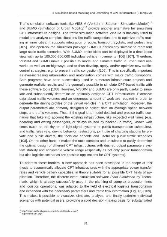
3 Simulation-Based Modeling and Optimizing of CPT Infrastructure (ETEV|SIM)
31
Traffic simulation software tools like VISSIM (Verkehr In Städten - SImulationsModell)17 and SUMO (Simulation of Urban Mobility)18 provide another alternative for simulating CPT infrastructure designs. The traffic simulation software VISSIM is basically used to model and analyze complex situations like traffic congestion, and to optimize traffic rout-ing in inner cities. It supports integration of public transport, cyclists, and pedestrians [105]. The open-source simulation package SUMO is particularly suitable to represent large-scale traffic scenarios. With SUMO, entire cities can be displayed in a time-lapse view with up to 100,000-200,000 individual vehicle movements [106] [107]. Therefore, VISSIM and SUMO make it possible to model and simulate traffic in urban road net-works as well as on highways, and to thus develop, apply, and/or optimize new traffic-control strategies, e.g. to prevent traffic congestion [106]. This is specifically important as ever-increasing urbanization and motorization comes with major traffic disruptions. Both programs have been successfully used in numerous infrastructure projects and generate realistic results and it is generally possible to simulate CPT-based traffic with these software tools [108]. However, VISSIM and SUMO are only partly useful to simu-late and subsequently determine an optimally designed CPT infrastructure. Extensive data about traffic volumes and an enormous amount of work are required in order to generate the driving profiles of the virtual vehicles in a CPT simulation. Moreover, the output parameters are primarily designed to collect data on average speed between stops and traffic volumes. Thus, if the goal is to model detailed and precise traffic sce-narios that take into account the existing infrastructure, like expected wait times (e.g. boarding and exiting passengers, or delays caused by backed-up traffic), known wait times (such as the rhythm of light-signal systems or public transportation schedules), and traffic rules (e.g. driving behavior, restrictions, joint use of charging stations by pri-vate and public drivers) the tools are capable and useful for public traffic scenarios [108]. On the other hand, it makes the tools complex and unsuitable to easily determine the optimal design of different CPT infrastructures with desired output parameters sys-tem stability and achievable vehicle range (especially as not only public transportation but also logistics scenarios are possible applications for CPT systems).
To address these barriers, a new approach has been developed in the scope of this thesis to economically allocate CPT infrastructures with the appropriate power transfer rates and vehicle battery capacities, in theory suitable for all possible CPT fields of ap-plication. Therefore, the discrete-event simulation software Plant Simulation by Tecno-matix, which is already successfully used in the planning of complex production lines and logistics operations, was adapted to the field of electrical logistics transportation and expanded with the necessary parameters and traffic flow information (Fig. 15) [109]. This makes it possible to visualize, simulate, analyze, and finally optimize individual scenarios with potential users, providing a solid decision-making basis for substantiated
17 http://vision-traffic.ptvgroup.com/de/produkte/ptv-vissim/ 18 http://sumo-sim.org/
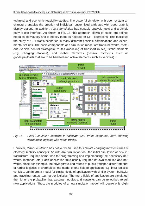
3 Simulation-Based Modeling and Optimizing of CPT Infrastructure (ETEV|SIM)
32
technical and economic feasibility studies. The powerful simulator with open-system ar-chitecture enables the creation of individual, customized attributes with good graphic display options. In addition, Plant Simulation has capable analysis tools and a simple easy-to-use interface. As shown in Fig. 15, this approach allows to select pre-defined modules individually and to modify them as needed for CPT operations. This facilitates the study of CPT traffic scenarios in many different possible combinations and experi-mental set-ups. The basic components of a simulation model are traffic networks, meth-ods (vehicle control strategies), routes (modeling of transport routes), static elements (e.g. charging stations), and mobile elements (passive elements such as goods/payloads that are to be handled and active elements such as vehicles).
Fig. 15. Plant Simulation software to calculate CPT traffic scenarios, here showing warehouse logistics with reach trucks.
However, Plant Simulation has not yet been used to simulate charging infrastructures of electrical mobility concepts. As with any simulation tool, the initial simulation of new in-frastructure requires some time for programming and implementing the necessary net-works, methods, etc. Each application thus usually requires its own modules and net-works, since, for example, the driving/travelling routes of public transport differ from that of harbor logistics. Nevertheless, the model of one field of application, e.g. intra-logistics vehicles, can inform a model for similar fields of application with similar system behavior and traveling routes, e.g. harbor logistics. The more fields of application are simulated, the higher the probability that existing modules and networks can be re-worked to suit new applications. Thus, the modules of a new simulation model will require only slight
traffic network
traffic routes
active mobile elements (vehicles)
passive mobile elements (payload)
output parameters
methods (vehicle control strategies)
input parameters for experiments
static elements (charging stations)
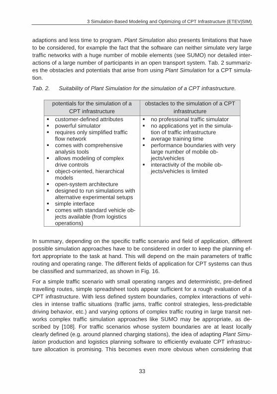
3 Simulation-Based Modeling and Optimizing of CPT Infrastructure (ETEV|SIM)
33
adaptions and less time to program. Plant Simulation also presents limitations that have to be considered, for example the fact that the software can neither simulate very large traffic networks with a huge number of mobile elements (see SUMO) nor detailed inter-actions of a large number of participants in an open transport system. Tab. 2 summariz-es the obstacles and potentials that arise from using Plant Simulation for a CPT simula-tion.
Tab. 2. Suitability of Plant Simulation for the simulation of a CPT infrastructure.
potentials for the simulation of a CPT infrastructure
obstacles to the simulation of a CPT infrastructure
customer-defined attributes powerful simulator requires only simplified traffic
flow network comes with comprehensive
analysis tools allows modeling of complex
drive controls object-oriented, hierarchical
models open-system architecture designed to run simulations with
alternative experimental setups simple interface comes with standard vehicle ob-
jects available (from logistics operations)
no professional traffic simulator no applications yet in the simula-
tion of traffic infrastructure average training time performance boundaries with very
large number of mobile ob-jects/vehicles
interactivity of the mobile ob-jects/vehicles is limited
In summary, depending on the specific traffic scenario and field of application, different possible simulation approaches have to be considered in order to keep the planning ef-fort appropriate to the task at hand. This will depend on the main parameters of traffic routing and operating range. The different fields of application for CPT systems can thus be classified and summarized, as shown in Fig. 16.
For a simple traffic scenario with small operating ranges and deterministic, pre-defined travelling routes, simple spreadsheet tools appear sufficient for a rough evaluation of a CPT infrastructure. With less defined system boundaries, complex interactions of vehi-cles in intense traffic situations (traffic jams, traffic control strategies, less-predictable driving behavior, etc.) and varying options of complex traffic routing in large transit net-works complex traffic simulation approaches like SUMO may be appropriate, as de-scribed by [108]. For traffic scenarios whose system boundaries are at least locally clearly defined (e.g. around planned charging stations), the idea of adapting Plant Simu-lation production and logistics planning software to efficiently evaluate CPT infrastruc-ture allocation is promising. This becomes even more obvious when considering that
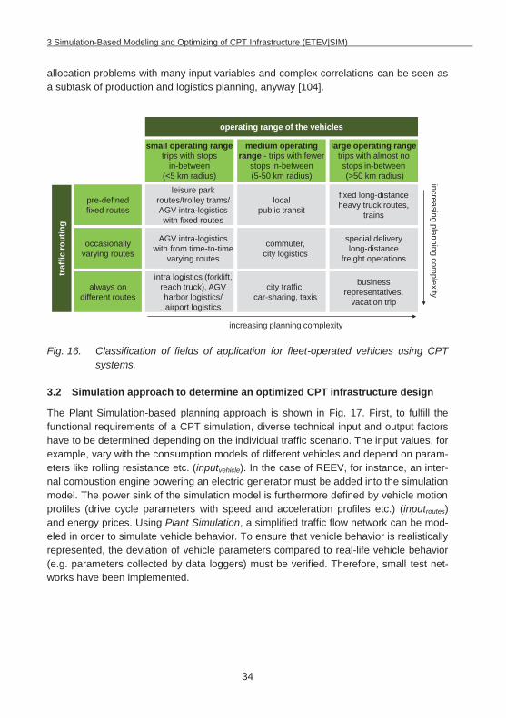
3 Simulation-Based Modeling and Optimizing of CPT Infrastructure (ETEV|SIM)
34
allocation problems with many input variables and complex correlations can be seen as a subtask of production and logistics planning, anyway [104].
Fig. 16. Classification of fields of application for fleet-operated vehicles using CPT systems.
3.2 Simulation approach to determine an optimized CPT infrastructure design
The Plant Simulation-based planning approach is shown in Fig. 17. First, to fulfill the functional requirements of a CPT simulation, diverse technical input and output factors have to be determined depending on the individual traffic scenario. The input values, for example, vary with the consumption models of different vehicles and depend on param-eters like rolling resistance etc. (inputvehicle). In the case of REEV, for instance, an inter-nal combustion engine powering an electric generator must be added into the simulation model. The power sink of the simulation model is furthermore defined by vehicle motion profiles (drive cycle parameters with speed and acceleration profiles etc.) (inputroutes) and energy prices. Using Plant Simulation, a simplified traffic flow network can be mod-eled in order to simulate vehicle behavior. To ensure that vehicle behavior is realistically represented, the deviation of vehicle parameters compared to real-life vehicle behavior (e.g. parameters collected by data loggers) must be verified. Therefore, small test net-works have been implemented.
city traffic, car-sharing, taxis
small operating rangetrips with stops
in-between (<5 km radius)
medium operating range - trips with fewer
stops in-between (5-50 km radius)
large operating range trips with almost no stops in-between(>50 km radius)
pre-defined fixed routes
occasionally varying routes
always on different routes
leisure park routes/trolley trams/ AGV intra-logistics with fixed routes
AGV intra-logistics with from time-to-time
varying routes
intra logistics (forklift, reach truck), AGV harbor logistics/ airport logistics
local public transit
commuter, city logistics
fixed long-distance heavy truck routes,
trains
special delivery long-distance
freight operations
business representatives,
vacation trip
increasing planning complexity
increasing planning complexity
operating range of the vehicles
traf
fic ro
utin
g
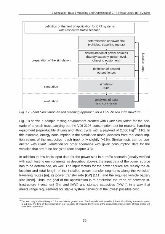
3 Simulation-Based Modeling and Optimizing of CPT Infrastructure (ETEV|SIM)
35
Fig. 17. Plant Simulation-based planning approach for a CPT-based infrastructure.
Fig. 18 shows a sample testing environment created with Plant Simulation for the sce-nario of a reach truck carrying out the VDI 2198 consumption test for material handling equipment (reproducible driving and lifting cycle with a payload of 2,000 kg)19 [110]. In this example, energy consumption in the simulation model deviates from real consump-tion values of the respective reach truck only slightly (~1%). Similar tests can be con-ducted with Plant Simulation for other scenarios with given consumption data for the vehicles that are to be analyzed (see chapter 3.3).
In addition to this basic input data for the power sink in a traffic scenario (ideally verified with such testing environments as described above), the input data of the power source has to be determined, as well. The input factors for the power source are mainly the al-location and total length of the installed power transfer segments along the vehicles’ travelling routes [m], its power transfer rate [kW] [111], and the required vehicle battery size [kWh]. Thus, the goal of the optimization is to determine the trade-off between in-frastructure investment ([m] and [kW]) and storage capacities ([kWh]) in a way that meets range requirements for stable system behavior at the lowest possible cost.
19 The load height while driving is 0.5 meters above ground level. The forward travel speed is 3.3 m/s. For driving in reverse, speed
is 2.1 m/s. The time of the consumption test is exactly 60 minutes. By the end of the consumption test, exactly 60 load cycles will have been performed.
determination of power sources (battery capacity, power level,
charging equipment)
definition of desired output factors
simulation runs
analyzes of data and conclusion
determination of power sink (vehicles, travelling routes)
iteration loops
preparation of the simulation
simulation
evaluation
definition of the field of application for CPT systems with respective traffic scenario
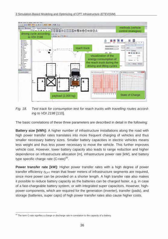
3 Simulation-Based Modeling and Optimizing of CPT Infrastructure (ETEV|SIM)
36
Fig. 18. Test track for consumption test for reach trucks with travelling routes accord-ing to VDI 2198 [110].
The basic correlations of these three parameters are described in detail in the following:
Battery size [kWh]: A higher number of infrastructure installations along the road with high power transfer rates translates into more frequent charging of vehicles and thus smaller necessary battery sizes. Smaller battery capacities in electric vehicles means less weight and thus less power necessary to move the vehicle. This further improves vehicle cost. However, lower battery capacity also leads to range reduction and higher dependence on infrastructure allocation [m], infrastructure power rate [kW], and battery type specific charge rate (C-rate)20.
Power transfer rate [kW]: Higher power transfer rates with a high degree of power transfer efficiency CPT mean that fewer meters of infrastructure segments are required, since more power can be provided on a shorter length. A high transfer rate also makes it possible to reduce battery capacity as the batteries can be charged faster, e.g. in case of a fast-chargeable battery system, or with integrated super capacitors. However, high-power components, which are required for the generation (inverter), transfer (pads), and storage (batteries, super caps) of high power transfer rates also cause higher costs.
20 The term C-rate signifies a charge or discharge rate in correlation to the capacity of a battery.
State of Chargepayload (2,000 kg)
reach truck
driving cycle according to VDI 2198
visualization of the energy consumption of
the reach truck during the driving and lifting cycles
methods (vehiclecontrol strategies)
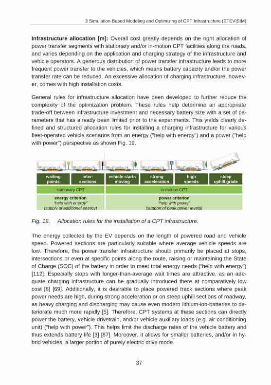
3 Simulation-Based Modeling and Optimizing of CPT Infrastructure (ETEV|SIM)
37
Infrastructure allocation [m]: Overall cost greatly depends on the right allocation of power transfer segments with stationary and/or in-motion CPT facilities along the roads, and varies depending on the application and charging strategy of the infrastructure and vehicle operators. A generous distribution of power transfer infrastructure leads to more frequent power transfer to the vehicles, which means battery capacity and/or the power transfer rate can be reduced. An excessive allocation of charging infrastructure, howev-er, comes with high installation costs.
General rules for infrastructure allocation have been developed to further reduce the complexity of the optimization problem. These rules help determine an appropriate trade-off between infrastructure investment and necessary battery size with a set of pa-rameters that has already been limited prior to the experiments. This yields clearly de-fined and structured allocation rules for installing a charging infrastructure for various fleet-operated vehicle scenarios from an energy ("help with energy") and a power ("help with power") perspective as shown Fig. 19.
Fig. 19. Allocation rules for the installation of a CPT infrastructure.
The energy collected by the EV depends on the length of powered road and vehicle speed. Powered sections are particularly suitable where average vehicle speeds are low. Therefore, the power transfer infrastructure should primarily be placed at stops, intersections or even at specific points along the route, raising or maintaining the State of Charge (SOC) of the battery in order to meet total energy needs (“help with energy”) [112]. Especially stops with longer-than-average wait times are attractive, as an ade-quate charging infrastructure can be gradually introduced there at comparatively low cost [8] [69]. Additionally, it is desirable to place powered track sections where peak power needs are high, during strong acceleration or on steep uphill sections of roadway, as heavy charging and discharging may cause even modern lithium-ion-batteries to de-teriorate much more rapidly [5]. Therefore, CPT systems at these sections can directly power the battery, vehicle drivetrain, and/or vehicle auxiliary loads (e.g. air conditioning unit) (“help with power”). This helps limit the discharge rates of the vehicle battery and thus extends battery life [3] [87]. Moreover, it allows for smaller batteries, and/or in hy-brid vehicles, a larger portion of purely electric drive mode.
waiting points
inter-sections
strong acceleration
vehicle starts moving
high speeds
stationary CPT in-motion CPT
energy criterion“help with energy”
(supply of additional energy)
power criterion“help with power”
(support of peak power levels)
steepuphill grade
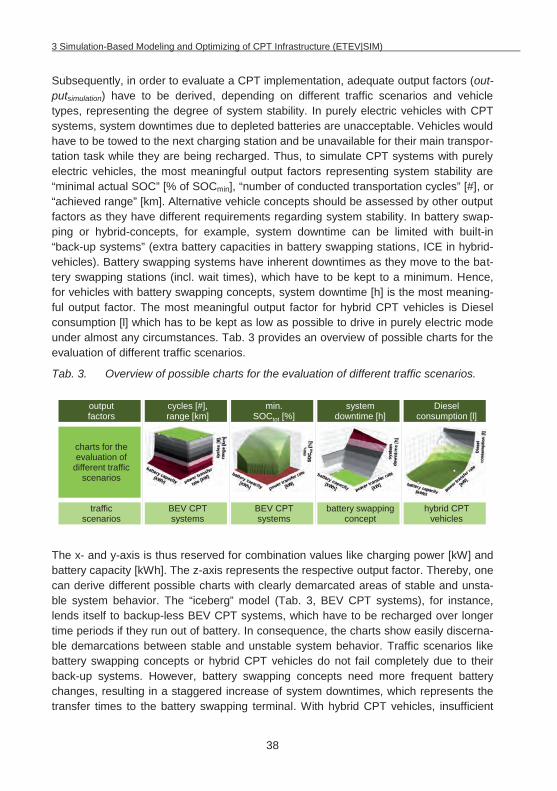
3 Simulation-Based Modeling and Optimizing of CPT Infrastructure (ETEV|SIM)
38
Subsequently, in order to evaluate a CPT implementation, adequate output factors (out-putsimulation) have to be derived, depending on different traffic scenarios and vehicle types, representing the degree of system stability. In purely electric vehicles with CPT systems, system downtimes due to depleted batteries are unacceptable. Vehicles would have to be towed to the next charging station and be unavailable for their main transpor-tation task while they are being recharged. Thus, to simulate CPT systems with purely electric vehicles, the most meaningful output factors representing system stability are “minimal actual SOC” [% of SOCmin], “number of conducted transportation cycles” [#], or “achieved range” [km]. Alternative vehicle concepts should be assessed by other output factors as they have different requirements regarding system stability. In battery swap-ping or hybrid-concepts, for example, system downtime can be limited with built-in “back-up systems” (extra battery capacities in battery swapping stations, ICE in hybrid-vehicles). Battery swapping systems have inherent downtimes as they move to the bat-tery swapping stations (incl. wait times), which have to be kept to a minimum. Hence, for vehicles with battery swapping concepts, system downtime [h] is the most meaning-ful output factor. The most meaningful output factor for hybrid CPT vehicles is Diesel consumption [l] which has to be kept as low as possible to drive in purely electric mode under almost any circumstances. Tab. 3 provides an overview of possible charts for the evaluation of different traffic scenarios.
Tab. 3. Overview of possible charts for the evaluation of different traffic scenarios.
The x- and y-axis is thus reserved for combination values like charging power [kW] and battery capacity [kWh]. The z-axis represents the respective output factor. Thereby, one can derive different possible charts with clearly demarcated areas of stable and unsta-ble system behavior. The “iceberg” model (Tab. 3, BEV CPT systems), for instance, lends itself to backup-less BEV CPT systems, which have to be recharged over longer time periods if they run out of battery. In consequence, the charts show easily discerna-ble demarcations between stable and unstable system behavior. Traffic scenarios like battery swapping concepts or hybrid CPT vehicles do not fail completely due to their back-up systems. However, battery swapping concepts need more frequent battery changes, resulting in a staggered increase of system downtimes, which represents the transfer times to the battery swapping terminal. With hybrid CPT vehicles, insufficient
output factors
traffic scenarios
cycles [#], range [km]
min. SOCtot [%]
system downtime [h]
Diesel consumption [l]
BEV CPT systems
BEV CPT systems
battery swapping concept
hybrid CPT vehicles
charts for the evaluation of
different traffic scenarios
3 Simulation-Based Modeling and Optimizing of CPT Infrastructure (ETEV|SIM)
39
battery capacities or power levels result in a gradual increase of Diesel consumption to compensate the limited range. This favors the use of inverse “valley” models with transi-tions between stable (purely electric) and unstable (back-up systems are needed) sys-tem behavior (Tab. 3, battery swapping concepts and hybrid CPT vehicles). In addition, it keeps values at the z-axis ascending from min to max from the bottom to the top (base values of the z-axis in the diagrams: range = 0 km; number of cycles = 0; min. SOCtot = 0%; Diesel consumption = 0 l; system downtime = 0 h).
Fig. 20 summarizes all input and output factors of the optimization problem and their inter-relations that have to be considered for the evaluation of a CPT traffic simulation in an energy model.
The simulation runs in Plant Simulation can furthermore be structured by the following equation:
nsimulation = ncombinations nexperiments nobservations (3.1)
Thereby, the number of total simulation runs nsimulation to derive the desired output factor (depending on the traffic scenario min. SOCtot [%], cycles [#], range [km], Diesel con-sumption [l], system downtime [h], etc.) is made up of the multiplication of possible combinations of battery [kWh] and charging equipment performance [kW] (ncombinations), with the number of studied experiments (nexperiments), which represent possible CPT traf-fic layouts (transportation network, payloads, number and type of CPT segments, work shifts, etc.), and the number of observations (nobservations). It is vital to perform several observations per experiment to ensure adequate validity and comparability of the con-ducted simulation runs. By performing several observations, certain input values like the detailed traffic routes in a traffic network are set randomly and vary continuously for all vehicles. This ensures that the vehicles generally do not drive in the same order or cy-cles etc. in every simulation run, which helps reduce the influence of possible extreme values of the individually defined experiments and helps reflect real-life system behav-ior. With this repeated random sampling, the planning approach shows the characteris-tics of a Monte Carlo method21.
21 Monte Carlo based methods rely on repeated random sampling for simulating systems with many coupled degrees of freedom
[113].
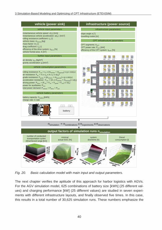
3 Simulation-Based Modeling and Optimizing of CPT Infrastructure (ETEV|SIM)
40
Fig. 20. Basic calculation model with main input and output parameters.
The next chapter verifies the aptitude of this approach for harbor logistics with AGVs. For the AGV simulation model, 625 combinations of battery size [kWh] (25 different val-ues) and charging performance [kW] (25 different values) are studied in seven experi-ments with different infrastructure layouts, and finally observed five times. In this case, this results in a total number of 30,625 simulation runs. These numbers emphasize the
vehicle input parameters
instantaneous vehicle speed: v(tn) [m/s]instantaneous vehicle acceleration: a(tn) [m/s2] rolling resistance coefficient: crl [-]vehicle mass: mvehicle [kg] mass factor: mi [-] drag coefficient: cd [-]efficiency of the drive system: drive [%]vehicle frontal area: A [m2]
CPT segments: #CPT CPT power rate: PCPT [kW]efficiency of the CPT system: CPT [%]
slope angle [°]travelling routes [m]
battery capacity: Cbattery [kWh]charge-rate: C-rate
rolling resistance: Froll = crl x (mvehicle + mpayload) x g x cos( )air resistance: Fair = ½ x cd x A x x v(tn)2
grade resistance: Fgrade = (mvehicle + mpayload) x g x sin( )acceleration resistance : Facc = (mi x mvehicle + mpayload) x a(tn)driving power: Pdrive = (Froll + Fair + Fgrade + Facc) x v(tn)power for auxiliaries: Pauxtotal power demand: Pvehicle = Pdrive + Paux
vehicle consumption parameters
vehicle battery parameters
battery
- +
CPT infrastructure parameters
infrastructure parameters
further input parameters
air density: air [kg/m3]gravity acceleration: g [m/s2]
minimal actual SOC [%]
vehicle (power sink) infrastructure (power source)
nsimulation = ncombinations x nexperiments x nobservations
Diesel consumption [l]
system downtime [h]
number of conducted transportation cycles
[#]/achieved range [km]
output factors of simulation runs nsimulation
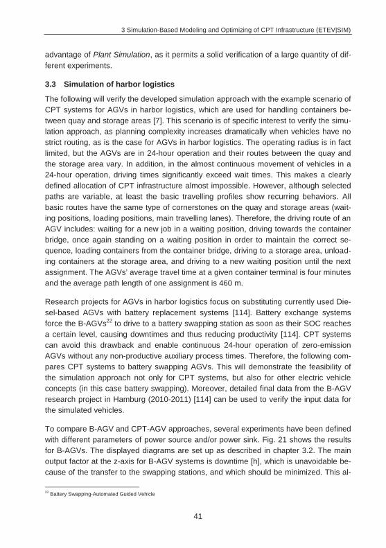
3 Simulation-Based Modeling and Optimizing of CPT Infrastructure (ETEV|SIM)
41
advantage of Plant Simulation, as it permits a solid verification of a large quantity of dif-ferent experiments.
3.3 Simulation of harbor logistics
The following will verify the developed simulation approach with the example scenario of CPT systems for AGVs in harbor logistics, which are used for handling containers be-tween quay and storage areas [7]. This scenario is of specific interest to verify the simu-lation approach, as planning complexity increases dramatically when vehicles have no strict routing, as is the case for AGVs in harbor logistics. The operating radius is in fact limited, but the AGVs are in 24-hour operation and their routes between the quay and the storage area vary. In addition, in the almost continuous movement of vehicles in a 24-hour operation, driving times significantly exceed wait times. This makes a clearly defined allocation of CPT infrastructure almost impossible. However, although selected paths are variable, at least the basic travelling profiles show recurring behaviors. All basic routes have the same type of cornerstones on the quay and storage areas (wait-ing positions, loading positions, main travelling lanes). Therefore, the driving route of an AGV includes: waiting for a new job in a waiting position, driving towards the container bridge, once again standing on a waiting position in order to maintain the correct se-quence, loading containers from the container bridge, driving to a storage area, unload-ing containers at the storage area, and driving to a new waiting position until the next assignment. The AGVs’ average travel time at a given container terminal is four minutes and the average path length of one assignment is 460 m.
Research projects for AGVs in harbor logistics focus on substituting currently used Die-sel-based AGVs with battery replacement systems [114]. Battery exchange systems force the B-AGVs22 to drive to a battery swapping station as soon as their SOC reaches a certain level, causing downtimes and thus reducing productivity [114]. CPT systems can avoid this drawback and enable continuous 24-hour operation of zero-emission AGVs without any non-productive auxiliary process times. Therefore, the following com-pares CPT systems to battery swapping AGVs. This will demonstrate the feasibility of the simulation approach not only for CPT systems, but also for other electric vehicle concepts (in this case battery swapping). Moreover, detailed final data from the B-AGV research project in Hamburg (2010-2011) [114] can be used to verify the input data for the simulated vehicles.
To compare B-AGV and CPT-AGV approaches, several experiments have been defined with different parameters of power source and/or power sink. Fig. 21 shows the results for B-AGVs. The displayed diagrams are set up as described in chapter 3.2. The main output factor at the z-axis for B-AGV systems is downtime [h], which is unavoidable be-cause of the transfer to the swapping stations, and which should be minimized. This al-
22 Battery Swapping-Automated Guided Vehicle
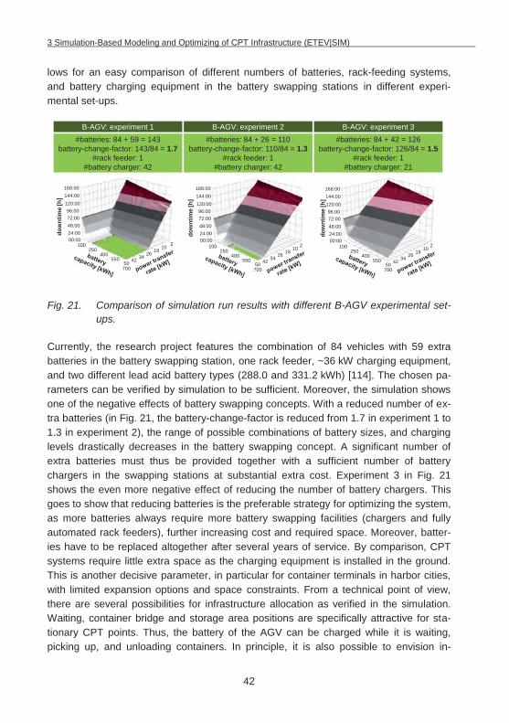
3 Simulation-Based Modeling and Optimizing of CPT Infrastructure (ETEV|SIM)
42
lows for an easy comparison of different numbers of batteries, rack-feeding systems, and battery charging equipment in the battery swapping stations in different experi-mental set-ups.
Fig. 21. Comparison of simulation run results with different B-AGV experimental set-ups.
Currently, the research project features the combination of 84 vehicles with 59 extra batteries in the battery swapping station, one rack feeder, ~36 kW charging equipment, and two different lead acid battery types (288.0 and 331.2 kWh) [114]. The chosen pa-rameters can be verified by simulation to be sufficient. Moreover, the simulation shows one of the negative effects of battery swapping concepts. With a reduced number of ex-tra batteries (in Fig. 21, the battery-change-factor is reduced from 1.7 in experiment 1 to 1.3 in experiment 2), the range of possible combinations of battery sizes, and charging levels drastically decreases in the battery swapping concept. A significant number of extra batteries must thus be provided together with a sufficient number of battery chargers in the swapping stations at substantial extra cost. Experiment 3 in Fig. 21 shows the even more negative effect of reducing the number of battery chargers. This goes to show that reducing batteries is the preferable strategy for optimizing the system, as more batteries always require more battery swapping facilities (chargers and fully automated rack feeders), further increasing cost and required space. Moreover, batter-ies have to be replaced altogether after several years of service. By comparison, CPT systems require little extra space as the charging equipment is installed in the ground. This is another decisive parameter, in particular for container terminals in harbor cities, with limited expansion options and space constraints. From a technical point of view, there are several possibilities for infrastructure allocation as verified in the simulation. Waiting, container bridge and storage area positions are specifically attractive for sta-tionary CPT points. Thus, the battery of the AGV can be charged while it is waiting, picking up, and unloading containers. In principle, it is also possible to envision in-
#batteries: 84 + 59 = 143battery-change-factor: 143/84 = 1.7
#rack feeder: 1#battery charger: 42
B-AGV: experiment 1#batteries: 84 + 26 = 110
battery-change-factor: 110/84 = 1.3#rack feeder: 1
#battery charger: 42
B-AGV: experiment 2#batteries: 84 + 42 = 126
battery-change-factor: 126/84 = 1.5#rack feeder: 1
#battery charger: 21
B-AGV: experiment 3
dow
ntim
e[h
]
168:00144:00120:0096:0072:0048:0024:0000:00
168:00144:00120:0096:0072:0048:0024:0000:00
168:00144:00120:0096:0072:0048:0024:0000:002101826344250
100250
400550
700
dow
ntim
e[h
]
2101826344250
100250
400550
700
dow
ntim
e[h
]
2101826344250
100250
400550
700
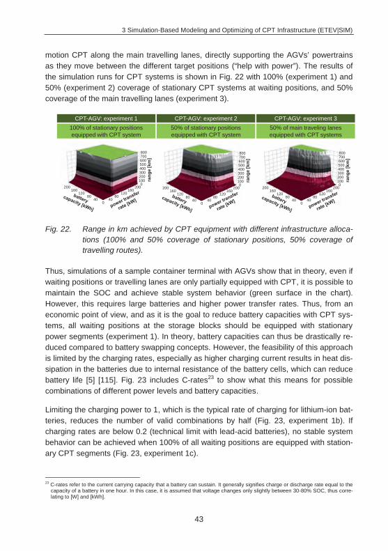
3 Simulation-Based Modeling and Optimizing of CPT Infrastructure (ETEV|SIM)
43
motion CPT along the main travelling lanes, directly supporting the AGVs’ powertrains as they move between the different target positions (“help with power”). The results of the simulation runs for CPT systems is shown in Fig. 22 with 100% (experiment 1) and 50% (experiment 2) coverage of stationary CPT systems at waiting positions, and 50% coverage of the main travelling lanes (experiment 3).
Fig. 22. Range in km achieved by CPT equipment with different infrastructure alloca-tions (100% and 50% coverage of stationary positions, 50% coverage of travelling routes).
Thus, simulations of a sample container terminal with AGVs show that in theory, even if waiting positions or travelling lanes are only partially equipped with CPT, it is possible to maintain the SOC and achieve stable system behavior (green surface in the chart). However, this requires large batteries and higher power transfer rates. Thus, from an economic point of view, and as it is the goal to reduce battery capacities with CPT sys-tems, all waiting positions at the storage blocks should be equipped with stationary power segments (experiment 1). In theory, battery capacities can thus be drastically re-duced compared to battery swapping concepts. However, the feasibility of this approach is limited by the charging rates, especially as higher charging current results in heat dis-sipation in the batteries due to internal resistance of the battery cells, which can reduce battery life [5] [115]. Fig. 23 includes C-rates23 to show what this means for possible combinations of different power levels and battery capacities.
Limiting the charging power to 1, which is the typical rate of charging for lithium-ion bat-teries, reduces the number of valid combinations by half (Fig. 23, experiment 1b). If charging rates are below 0.2 (technical limit with lead-acid batteries), no stable system behavior can be achieved when 100% of all waiting positions are equipped with station-ary CPT segments (Fig. 23, experiment 1c).
23 C-rates refer to the current carrying capacity that a battery can sustain. It generally signifies charge or discharge rate equal to the
capacity of a battery in one hour. In this case, it is assumed that voltage changes only slightly between 30-80% SOC, thus corre-lating to [W] and [kWh].
100% of stationary positions equipped with CPT system
50% of stationary positions equipped with CPT system
50% of main traveling lanesequipped with CPT systems
rang
e[k
m]
800700600500400300200100
200160
12080
400
160120
8040
0200
rang
e[k
m]
800700600500400300200100
200160
12080
400
160120
8040
0200
rang
e[k
m]
800700600500400300200100
200160
12080
400
160120
8040
0200
CPT-AGV: experiment 1 CPT-AGV: experiment 2 CPT-AGV: experiment 3
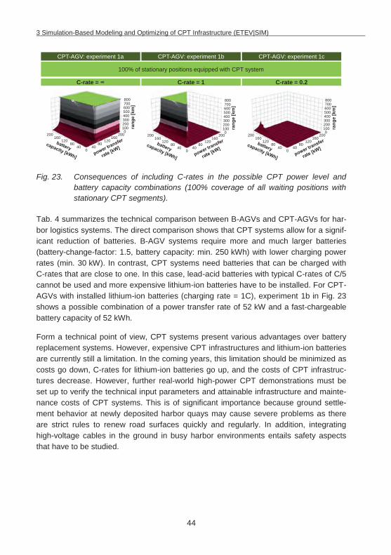
3 Simulation-Based Modeling and Optimizing of CPT Infrastructure (ETEV|SIM)
44
Fig. 23. Consequences of including C-rates in the possible CPT power level and battery capacity combinations (100% coverage of all waiting positions with stationary CPT segments).
Tab. 4 summarizes the technical comparison between B-AGVs and CPT-AGVs for har-bor logistics systems. The direct comparison shows that CPT systems allow for a signif-icant reduction of batteries. B-AGV systems require more and much larger batteries (battery-change-factor: 1.5, battery capacity: min. 250 kWh) with lower charging power rates (min. 30 kW). In contrast, CPT systems need batteries that can be charged with C-rates that are close to one. In this case, lead-acid batteries with typical C-rates of C/5 cannot be used and more expensive lithium-ion batteries have to be installed. For CPT-AGVs with installed lithium-ion batteries (charging rate = 1C), experiment 1b in Fig. 23 shows a possible combination of a power transfer rate of 52 kW and a fast-chargeable battery capacity of 52 kWh.
Form a technical point of view, CPT systems present various advantages over battery replacement systems. However, expensive CPT infrastructures and lithium-ion batteries are currently still a limitation. In the coming years, this limitation should be minimized as costs go down, C-rates for lithium-ion batteries go up, and the costs of CPT infrastruc-tures decrease. However, further real-world high-power CPT demonstrations must be set up to verify the technical input parameters and attainable infrastructure and mainte-nance costs of CPT systems. This is of significant importance because ground settle-ment behavior at newly deposited harbor quays may cause severe problems as there are strict rules to renew road surfaces quickly and regularly. In addition, integrating high-voltage cables in the ground in busy harbor environments entails safety aspects that have to be studied.
100% of stationary positions equipped with CPT system
C-rate = C-rate = 1 C-rate = 0.2
rang
e[k
m]
800700600500400300200100
200160
12080
400
160120
8040
0200
rang
e[k
m]
800700600500400300200100
200160
12080
400
160120
8040
0200
rang
e[k
m]
800700600500400300200100
200160
12080
400
160120
8040
0200
CPT-AGV: experiment 1a CPT-AGV: experiment 1b CPT-AGV: experiment 1c
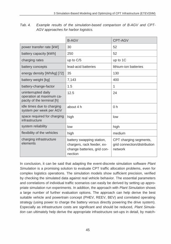
3 Simulation-Based Modeling and Optimizing of CPT Infrastructure (ETEV|SIM)
45
Tab. 4. Example results of the simulation-based comparison of B-AGV and CPT-AGV approaches for harbor logistics.
B-AGV CPT-AGV
power transfer rate [kW] 30 52
battery capacity [kWh] 250 52
charging rates up to C/5 up to 1C
battery concepts lead-acid batteries lithium-ion batteries
energy density [Wh/kg] [72] 35 130
battery weight [kg] 7,143 400
battery-change-factor 1.5 1
uninterrupted daily operation at maximum ca-pacity of the terminal [h]
12.5 24
idle times due to charging system per week per AGV
about 4 h 0 h
space required for charging infrastructure
high low
system reliability low high
flexibility of the vehicles high medium
charging infrastructure elements
battery swapping station, chargers, rack feeder, ex-change batteries, grid con-nection
CPT charging segments, grid connection/distribution network
In conclusion, it can be said that adapting the event-discrete simulation software Plant Simulation is a promising solution to evaluate CPT traffic allocation problems, even for complex logistics operations. The simulation models show sufficient precision, verified by checking the simulated data against real vehicle behavior. The essential parameters and correlations of individual traffic scenarios can easily be derived by setting up appro-priate simulation run experiments. In addition, the approach with Plant Simulation shows a large number of further evaluation options. The approach can help derive the best suitable vehicle and powertrain concept (PHEV, REEV, BEV) and correlated operating strategy (using power to charge the battery versus directly powering the drive system). Especially as infrastructure costs are significant and should be reduced, Plant Simula-tion can ultimately help derive the appropriate infrastructure set-ups in detail, by match-

3 Simulation-Based Modeling and Optimizing of CPT Infrastructure (ETEV|SIM)
46
ing detailed vehicle power consumption profiles with needed CPT charging infrastruc-ture.
To further help accelerate the market introduction of CPT systems for electrified vehi-cles, system cost has to be steadily reduced. Therefore, the following analyzes and pre-sents basic CPT system set-ups (chapter 4) to develop appropriate production technol-ogies (chapter 5).
4 Detailed Analysis of CPT Pad Designs for Electric Vehicles
47
4 Detailed Analysis of CPT Pad Designs for Electric Vehicles
Chapter 4 analyzes various possible basic physical principles of contactless power transfer technologies and alternative system designs with their specific characteristics. It shows the main factors needed to achieve high power transfer efficiencies in order to derive the research needs and scientific approach of this work from a production and material perspective.
4.1 Physical basics of CPT systems
The use of contactless charging technologies in EVs has various implications for the power transmission system and its components. Power must be transferred at the level of several kW and virtually loss-free power transmission needs to be attained with the relatively large air gap (~100-300 mm) that is necessary for underbody ground clear-ance (in the case of underbody system integration) [3]. There are several basic coupling mechanisms to attain contactless transfer of power for EVs, as presented in Tab. 5.
Because of the advantages mentioned in Tab. 5, experiences from the latest research projects, and the necessary distances, inductive coupling is at the main focus of devel-opment in both industry and science. The basic principle of inductive power transfer is thereby based on electro-magnetic interactions between two mutually arranged conduc-tor structures and basically works on the same principle as conventional transformers. Michael Faraday studied the basic principles of electromagnetic induction, which is the basis of electric motor, generator, and transformer technologies, as early as 1831. Far-aday discovered that a copper wire in motion within a magnetic field produces an elec-trical current. In the same way an alternating current in a copper wire creates a time-varying magnetic field. This is used in conventional transformers with a primary and a secondary coil wrapped around a highly magnetic permeable iron core. An AC current generates a magnetic field in the primary coil, which induces an electrical voltage in the secondary coil. The permeable iron core links the wound coils and increases the strength of the time-varying magnetic field, so that the iron channels most of the mag-netic flux through both coils with a tight coupling, thus minimizing power losses with low stray fields. The main difference between contactless power transfer systems and such a conventional transformer is that the magnetic circuit is not closed by a highly magnetic permeable iron core, but by an air gap. In these circumstances, power is transferred by induction from one coil to another without physical contact [41].
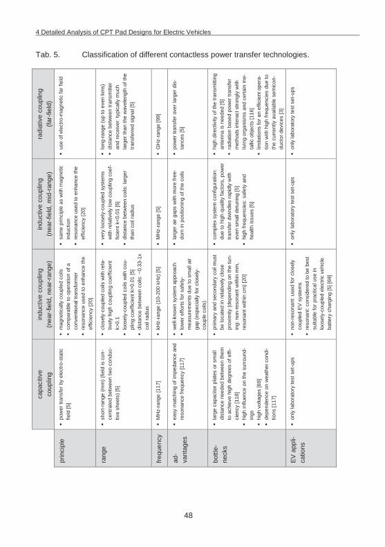
4 Detailed Analysis of CPT Pad Designs for Electric Vehicles
48
Tab. 5. Classification of different contactless power transfer technologies.
radi
ativ
e co
uplin
g
(far-
field
)
use
of e
lect
ro-m
agne
tic fa
r fie
ld
lon
g-ra
nge
(up
to e
ven
kms)
d
ista
nce
betw
een
trans
mitt
er
and
rece
iver
: typ
ical
ly m
uch
larg
er th
an th
e w
avel
engt
h of
the
trans
ferre
d si
gnal
[5]
GH
z-ra
nge
[99]
pow
er tr
ansf
er o
ver l
arge
r dis
-ta
nces
[5]
hig
h di
rect
ivity
of t
he tr
ansm
ittin
g an
tenn
a is
nee
ded
[5]
rad
iatio
n ba
sed
pow
er tr
ansf
er
met
hods
inte
ract
stro
ngly
with
liv
ing
orga
nism
s an
d ce
rtain
me-
tallic
obj
ects
[116
] l
imita
tions
for a
n ef
ficie
nt o
pera
-tio
n w
ith h
igh
frequ
enci
es d
ue to
th
e cu
rrent
ly a
vaila
ble
sem
icon
-du
ctor
dev
ices
[3]
onl
y la
bora
tory
test
set
-ups
indu
ctiv
e co
uplin
g (n
ear-
field
, mid
-ran
ge)
sam
e pr
inci
ple
as w
ith m
agne
tic
indu
ctio
n r
eson
ance
use
d to
enh
ance
the
effic
ienc
y [2
0]
ver
y lo
osel
y-co
uple
d sy
stem
s w
ith re
lativ
ely
low
cou
plin
g co
ef-
ficie
nt k
<0.0
1 [5
] d
ista
nce
betw
een
coils
: lar
ger
than
coi
l rad
ius
MH
z-ra
nge
[5]
lar
ger a
ir ga
ps w
ith m
ore
free-
dom
in p
ositi
onin
g of
the
coils
com
plex
sys
tem
con
figur
atio
n:
due
to h
igh
qual
ity fa
ctor
s, p
ower
tra
nsfe
r dw
indl
es ra
pidl
y w
ith
even
sm
all d
etun
ing
[5]
hig
h fre
quen
cies
: saf
ety
and
heal
th is
sues
[5]
onl
y la
bora
tory
test
set
-ups
indu
ctiv
e co
uplin
g (n
ear-
field
, nea
r-ra
nge)
mag
netic
ally
cou
pled
coi
ls
com
para
ble
to o
pera
tion
of a
co
nven
tiona
l tra
nsfo
rmer
r
eson
ance
use
d to
enh
ance
the
effic
ienc
y [2
0]
clo
sely
-cou
pled
coi
ls w
ith re
la-
tivel
y hi
gh c
oupl
ing
coef
ficie
nt
k>0.
1 l
oose
ly-c
oupl
ed c
oils
with
cou
-pl
ing
coef
ficie
nt k
>0.0
1 [5
] d
ista
nce
betw
een
coils
: ~0.
33-1
x co
il ra
dius
kH
z-ra
nge
(10-
200
kHz)
[5]
wel
l-kno
wn
syst
em a
ppro
ach
low
er e
fforts
for s
afet
y-m
easu
rem
ents
due
to s
mal
l air
gap
(esp
ecia
lly fo
r clo
sely
-co
uple
coi
ls)
prim
ary
and
seco
ndar
y co
il m
ust
be lo
cate
d in
rela
tivel
y cl
ose
prox
imity
(dep
endi
ng o
n th
e tu
n-in
g: n
on-re
sona
nt w
ithin
mm
, re
sona
nt w
ithin
cm
) [20
]
non
- reso
nant
: use
d fo
r clo
sely
co
uple
d EV
sys
tem
s r
eson
ant:
cons
ider
ed to
be
best
su
itabl
e fo
r pra
ctic
al u
se in
lo
osel
y-co
uple
d el
ectri
c ve
hicl
e ba
ttery
cha
rgin
g [5
] [69
]
capa
citiv
e co
uplin
g
pow
er tr
ansf
er b
y el
ectro
-sta
tic
field
[5]
sho
rt-ra
nge
(mm
) (fie
ld is
co n
-ce
ntra
ted
betw
een
two
cond
uc-
tive
shee
ts) [
5]
MH
z-ra
nge
[117
]
eas
y m
atch
ing
of im
peda
nce
and
reso
nanc
e fre
quen
cy [1
17]
lar
ge c
apac
itor p
late
s or
sm
all
dist
ance
nee
ded
betw
een
them
to
ach
ieve
hig
h de
gree
s of
effi
-ci
ency
[118
] h
igh
influ
ence
on
the
surro
und-
ings
h
igh
volta
ges
[69]
d
epen
denc
e on
wea
ther
con
di-
tions
[117
]
onl
y la
bora
tory
test
set
-ups
prin
cipl
e
rang
e
frequ
ency
ad-
vant
ages
bottl
e-ne
cks
EV a
ppli-
catio
ns
4 Detailed Analysis of CPT Pad Designs for Electric Vehicles
49
As air has a high magnetic reluctance, the power transfer is less efficient, especially as the air gap increases. To still operate efficiently, the coupled coils need to operate in what is called a strongly coupled regime with a high magnetic link potential [5] [119]. The magnetic link potential X is thereby represented by the product of the coil’s quality factors Qc1 and Qc2 and coupling coefficient k of the coil system [120] [121] [122]:
(4.1)
The maximal link efficiency is described by
(4.2)
The quality factors
(4.3)
and
(4.4)
can be described by the ratio of its impedance to its AC resistance at the operational frequency [67]. They include the coil’s inductances L1, L2, and their equivalent re-sistances Rc1, Rc2, representing the losses that may be inherent to the induction coils at a specified signal frequency [121]. The higher the operating frequency , the more intense the induction effect and the greater the transmittable power, which makes for a smaller and lighter system set-up [27]. However, the selection of the operating frequen-cy is typically a compromise between efficiency, cost, coil size, and safety concerns due to regulations on flux leakage [5] [41] [123] [124].
Thus, approaches to maximize the magnetic link potential X also inherently depend on the coupling coefficient k. The coupling coefficient k is a dimension-less parameter rep-resenting the fraction of the main magnetic flux m received in the secondary coil to the total flux produced by the transmitting coil total, consisting of the main magnetic flux m and the leakage flux [125].
(4.5)
k has a magnitude between zero (no coupling) and 1 (all flux is coupled) and thus de-pends on the design of and the distance between the coils. In conventional transformers with closed iron cores, k is typically in the order of k>0.95 with a strong magnetic cou-pling compared to CPT systems with k~0.01-0.5 [24].
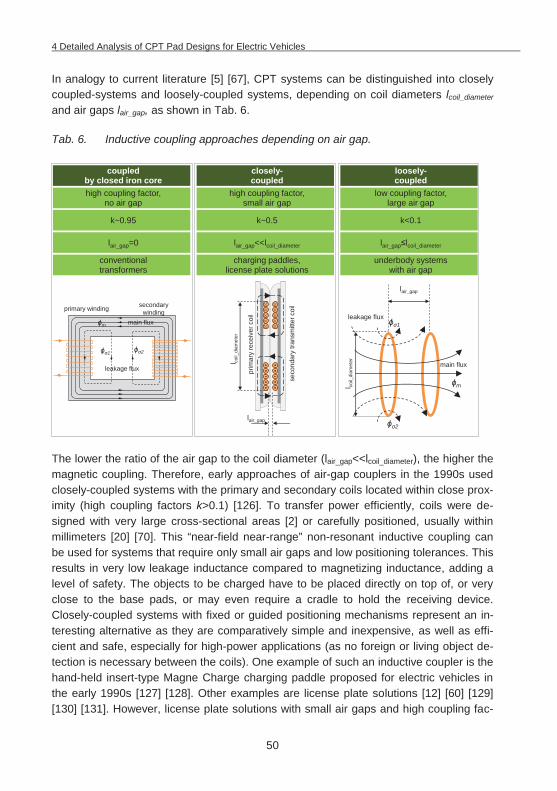
4 Detailed Analysis of CPT Pad Designs for Electric Vehicles
50
In analogy to current literature [5] [67], CPT systems can be distinguished into closely coupled-systems and loosely-coupled systems, depending on coil diameters lcoil_diameter and air gaps lair_gap, as shown in Tab. 6.
Tab. 6. Inductive coupling approaches depending on air gap.
The lower the ratio of the air gap to the coil diameter (lair_gap<<lcoil_diameter), the higher the magnetic coupling. Therefore, early approaches of air-gap couplers in the 1990s used closely-coupled systems with the primary and secondary coils located within close prox-imity (high coupling factors k>0.1) [126]. To transfer power efficiently, coils were de-signed with very large cross-sectional areas [2] or carefully positioned, usually within millimeters [20] [70]. This “near-field near-range” non-resonant inductive coupling can be used for systems that require only small air gaps and low positioning tolerances. This results in very low leakage inductance compared to magnetizing inductance, adding a level of safety. The objects to be charged have to be placed directly on top of, or very close to the base pads, or may even require a cradle to hold the receiving device. Closely-coupled systems with fixed or guided positioning mechanisms represent an in-teresting alternative as they are comparatively simple and inexpensive, as well as effi-cient and safe, especially for high-power applications (as no foreign or living object de-tection is necessary between the coils). One example of such an inductive coupler is the hand-held insert-type Magne Charge charging paddle proposed for electric vehicles in the early 1990s [127] [128]. Other examples are license plate solutions [12] [60] [129] [130] [131]. However, license plate solutions with small air gaps and high coupling fac-
high coupling factor,no air gap
coupled by closed iron core
high coupling factor,small air gap
closely-coupled
low coupling factor,large air gap
loosely-coupled
k~0.95 k~0.5 k<0.1
lair_gap=0 lair_gap<<lcoil_diameter lair_gap lcoil_diameter
conventional transformers
charging paddles, license plate solutions
underbody systems with air gap
seco
ndar
ytra
nsm
itter
coil
prim
ary
rece
iver
coil
lair_gap
l coil_
diam
eter
lair_gap
l coil_
diam
eter
1
2
leakage flux
main flux
m
leakage flux
1 2
m main flux
primary winding secondarywinding
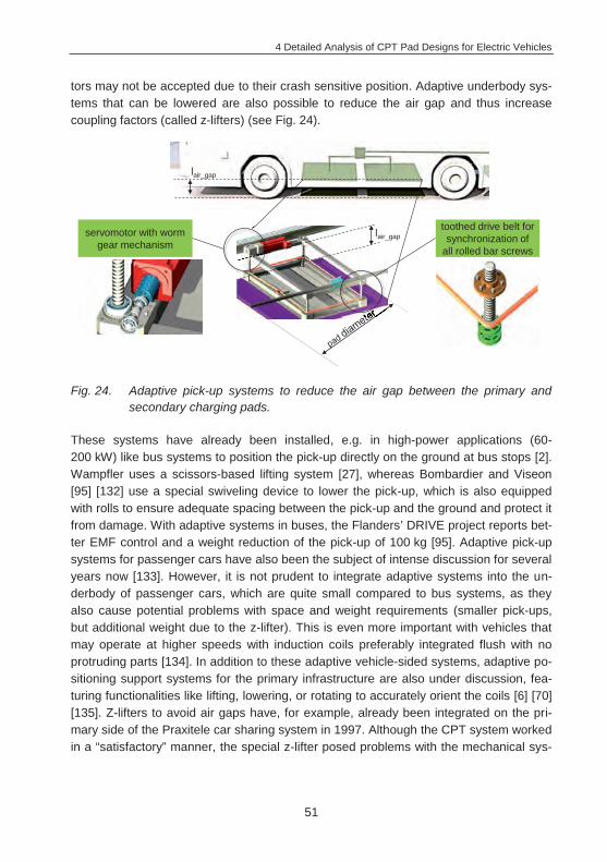
4 Detailed Analysis of CPT Pad Designs for Electric Vehicles
51
tors may not be accepted due to their crash sensitive position. Adaptive underbody sys-tems that can be lowered are also possible to reduce the air gap and thus increase coupling factors (called z-lifters) (see Fig. 24).
Fig. 24. Adaptive pick-up systems to reduce the air gap between the primary and secondary charging pads.
These systems have already been installed, e.g. in high-power applications (60-200 kW) like bus systems to position the pick-up directly on the ground at bus stops [2]. Wampfler uses a scissors-based lifting system [27], whereas Bombardier and Viseon [95] [132] use a special swiveling device to lower the pick-up, which is also equipped with rolls to ensure adequate spacing between the pick-up and the ground and protect it from damage. With adaptive systems in buses, the Flanders’ DRIVE project reports bet-ter EMF control and a weight reduction of the pick-up of 100 kg [95]. Adaptive pick-up systems for passenger cars have also been the subject of intense discussion for several years now [133]. However, it is not prudent to integrate adaptive systems into the un-derbody of passenger cars, which are quite small compared to bus systems, as they also cause potential problems with space and weight requirements (smaller pick-ups, but additional weight due to the z-lifter). This is even more important with vehicles that may operate at higher speeds with induction coils preferably integrated flush with no protruding parts [134]. In addition to these adaptive vehicle-sided systems, adaptive po-sitioning support systems for the primary infrastructure are also under discussion, fea-turing functionalities like lifting, lowering, or rotating to accurately orient the coils [6] [70] [135]. Z-lifters to avoid air gaps have, for example, already been integrated on the pri-mary side of the Praxitele car sharing system in 1997. Although the CPT system worked in a “satisfactory” manner, the special z-lifter posed problems with the mechanical sys-
lair_gap
lair_gap
servomotor with worm gear mechanism
toothed drive belt for synchronization of
all rolled bar screws
4 Detailed Analysis of CPT Pad Designs for Electric Vehicles
52
tem [43]. In consequence, adaptive systems should be avoided in passenger cars as they can malfunction as well as create significant costs and maintenance problems.
In contrast, loosely-coupled systems operate with a significant air gap. One way to make loosely-coupled systems work gained enormous popularity after it was presented and promoted by MIT researchers in 200724 [119] is called the “near-field mid-range” inductive resonant coupling approach. The distance between the coils is usually larger than the coil diameter (lair_gap>>lcoil_diameter). Unlike a tightly-coupled transformer, signifi-cant flux exists in the primary and secondary windings as well as in the space in-between. The bottlenecks of this approach are its relatively low efficiency with very large air gaps (lair_gap/lcoil_diameter>1) [121]. This approach with very loosely-coupled coils (k<0.01) only achieves a strongly-coupled regime with sufficient quality factors Qc1 and Qc2 (1,000 and above). The MIT researchers used for their resonant coupling approach core-less coils with no shielding and an operating frequency in the MHz range [119]. Resonance induction works on the same principles as non-resonance induction, but us-es resonance to enhance the efficiency of the power transfer between two coils [20]. The needed high Q-values, however, make it harder to control the tuning of compensa-tion-circuits to maintain resonance. Therefore, this approach is sometimes referred to as “highly resonant” contactless power transfer [20]. Safety and health issues have to be considered, as well [5]. In terms of efficiency and range, this method is a compromise between the “far-field radiative” approach and the “near-field near-range” approach (see Tab. 5), currently showing promise only for low-power applications that can tolerate lower efficiencies, such as cell phones, medical equipment, and other small IT devices [41].
The alternative that is used far more often for EV-charging is called “near-field near-range” inductive resonant coupling. This approach uses a relatively high coupling coeffi-cient (k>0.01) and a moderate frequency from 10-200 kHz, which requires moderate values for the coil quality factors Qc1 and Qc2. However, practical needs in EV charging dictate a certain economy of space and weight for the pads, which means that a certain Q value (above 100) is still needed to achieve higher overall efficiency at limited pad sizes (see Fig. 25). This approach can transfer a large amount of power while maintain-ing controlled resonance in the compensation-circuits [5]. The described advantages, along with the ability to efficiently transfer power across air gaps that are appropriate for EV charging, make “near-field near-range” inductive resonant coupling using resonant tuned coils the best suitable and practical method for electric vehicle battery charging [5] [20] [41] [69] (see also Tab. 5).
24 Laboratory test set-up: two identical helical copper-coils, rcoil=30 cm, distance=2 m, P=60 W, resonant frequency
f=10.56±0.3 MHz, ~40%, Qmeasured ~950±50.
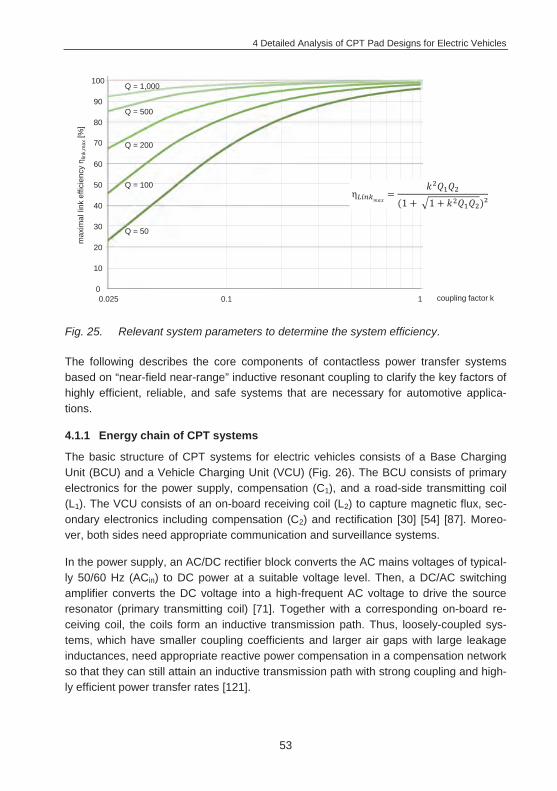
4 Detailed Analysis of CPT Pad Designs for Electric Vehicles
53
Fig. 25. Relevant system parameters to determine the system efficiency.
The following describes the core components of contactless power transfer systems based on “near-field near-range” inductive resonant coupling to clarify the key factors of highly efficient, reliable, and safe systems that are necessary for automotive applica-tions.
4.1.1 Energy chain of CPT systems
The basic structure of CPT systems for electric vehicles consists of a Base Charging Unit (BCU) and a Vehicle Charging Unit (VCU) (Fig. 26). The BCU consists of primary electronics for the power supply, compensation (C1), and a road-side transmitting coil (L1). The VCU consists of an on-board receiving coil (L2) to capture magnetic flux, sec-ondary electronics including compensation (C2) and rectification [30] [54] [87]. Moreo-ver, both sides need appropriate communication and surveillance systems.
In the power supply, an AC/DC rectifier block converts the AC mains voltages of typical-ly 50/60 Hz (ACin) to DC power at a suitable voltage level. Then, a DC/AC switching amplifier converts the DC voltage into a high-frequent AC voltage to drive the source resonator (primary transmitting coil) [71]. Together with a corresponding on-board re-ceiving coil, the coils form an inductive transmission path. Thus, loosely-coupled sys-tems, which have smaller coupling coefficients and larger air gaps with large leakage inductances, need appropriate reactive power compensation in a compensation network so that they can still attain an inductive transmission path with strong coupling and high-ly efficient power transfer rates [121].
max
imal
link
effi
cien
cy
link,
max
[%]
coupling factor k0
20
40
60
0.1 1
80
100
10
30
50
70
90
Q = 50
Q = 100
Q = 200
Q = 500
Q = 1,000
0.025
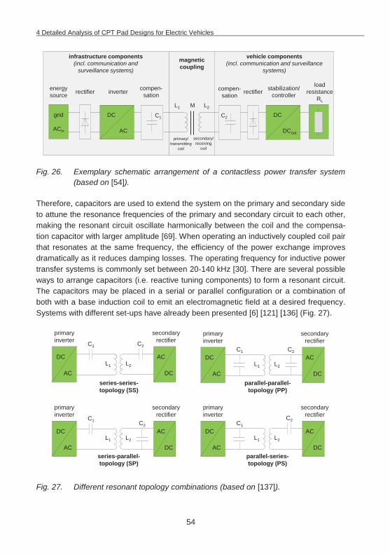
4 Detailed Analysis of CPT Pad Designs for Electric Vehicles
54
Fig. 26. Exemplary schematic arrangement of a contactless power transfer system (based on [54]).
Therefore, capacitors are used to extend the system on the primary and secondary side to attune the resonance frequencies of the primary and secondary circuit to each other, making the resonant circuit oscillate harmonically between the coil and the compensa-tion capacitor with larger amplitude [69]. When operating an inductively coupled coil pair that resonates at the same frequency, the efficiency of the power exchange improves dramatically as it reduces damping losses. The operating frequency for inductive power transfer systems is commonly set between 20-140 kHz [30]. There are several possible ways to arrange capacitors (i.e. reactive tuning components) to form a resonant circuit. The capacitors may be placed in a serial or parallel configuration or a combination of both with a base induction coil to emit an electromagnetic field at a desired frequency. Systems with different set-ups have already been presented [6] [121] [136] (Fig. 27).
Fig. 27. Different resonant topology combinations (based on [137]).
rectifier stabilization/ controller
magnetic coupling
DCout
C2C1
M L2L1
secondary/ receiving
coil
primary/ transmitting
coil
energysource
grid
ACin
inverterload
resistance RL
DC
AC
DC
rectifier
infrastructure components(incl. communication and
surveillance systems)
vehicle components(incl. communication and surveillance
systems)
compen-sation
compen-sation
C2
L2L1
primary inverter
DC
AC
secondary rectifier
AC
DC
C2C1
L2L1
primary inverter
DC
AC
secondary rectifier
AC
DC
C2
L2L1
primary inverter
DC
AC
secondary rectifier
AC
DC
C1
L2L1
primary inverter
DC
AC
secondary rectifier
AC
DC
series-series-topology (SS)
series-parallel-topology (SP)
parallel-parallel-topology (PP)
parallel-series-topology (PS)
C2C1
C1
4 Detailed Analysis of CPT Pad Designs for Electric Vehicles
55
This way, the reactive components in the transmission system are compensated and the classic transformer is functionally replaced by two inductively coupled resonant cir-cuits at a coupling-dependent resonant frequency. It is thus possible to transfer energy efficiently at lower coupling rates, at greater distances, and/or with more positional free-dom than is otherwise possible, eliminating the need for precise positioning between source and device [20].
Aside from the receiver pad inductance L2 (receiving coil) with compensation capacitors (C2), the secondary side of the CPT system in the vehicle also includes circuits for recti-fication from the operating frequency AC voltage back to DC, as well as a switch mode controller for voltage stabilization, at a voltage level matched to that of the vehicle DC link. The stabilized DC voltage is fed to the vehicle DC link and managed by the Battery Management System (BMS) to either charge vehicle storage systems (e.g. high-voltage battery and/or a super capacitor) or to power a load directly.
4.1.2 Main factors impacting the efficiency of CPT systems
One of the decisive factors of contactless charging systems is the degree of efficiency they can attain. High system efficiencies save the scarce resource of energy in the spirit of sustainable green mobility and avoid slow charging, overheating components, and eventually higher energy costs for the customer [10]. Therefore, a high power transfer efficiency rate is key to achieve a competitive advantage over conductive charging solu-tions. It is even possible that industry and policymakers will prescribe a minimum effi-ciency for power transfer to avoid wasting energy [46]. The end-to-end efficiency of CPT systems25 can be defined as the amount of usable electrical energy that is available to the powered device, divided by the amount of energy that is drawn from the power source:
(4.6)
For EV charging in the kW-range, stationary prototypic CPT systems have demonstrat-ed end-to-end efficiencies of >90%, even across larger air gaps of about 20 cm [1] [20]. Such efficiencies require careful design in each stage of the system with an effi-ciency of =~96%-98% or greater [20] [41], as shown in Fig. 28.
It is promising that such high efficiencies (above 90%) are attainable, especially consid-ering that in comparison, conductive charging solutions usually only marginally exceed these efficiency rates (~93-97%), as there are also losses in insulation and control cir-cuitry, components, connectors, and cabling [73] [95].
25 End-to-end efficiencies commonly refer to ACin (energy grid connection) to DC output at the battery connection.
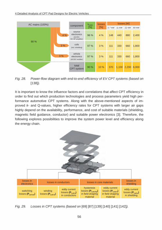
4 Detailed Analysis of CPT Pad Designs for Electric Vehicles
56
Fig. 28. Power-flow diagram with end-to-end efficiency of EV CPT systems (based on [138]).
It is important to know the influence factors and correlations that affect CPT efficiency in order to find out which production technologies and process parameters yield high per-formance automotive CPT systems. Along with the above-mentioned aspects of im-proved k- and Q-values, higher efficiency rates for CPT systems with larger air gaps highly depend on the availability, performance, and cost of suitable materials (shielding, magnetic field guidance, conductor) and suitable power electronics [3]. Therefore, the following explores possibilities to improve the system power level and efficiency along the energy chain.
Fig. 29. Losses in CPT systems (based on [69] [87] [139] [140] [141] [142]).
90 %
3 %
3 %
4 %
component losses[%]
static[%]
sourceelectronics
(AC/DC; DC-HF amplifier)
96 %
3.7 kW
losses [W]11 kW 22 kW 60 kW
148
coils(incl. shielding)
vehicleelectronics
(AC/DC rectifier)
4 % 440 880 2,400
97 % 1113 % 330 660 1,800
97 % 1113 % 330 660 1,800
total CPT system 90 % 37010 % 1,100 2,200 6,000
AC mains (100%)
eddy current losses (Pl,cm-e)in field shaping
material
eddy current losses (Pl,cd-e)in conductors
eddy current losses (Pl,sd-e)
in shielding
hysteresis losses (Pl,cm-hy) in field shaping
material
windinglosses (Pl,cd-w)
losses in conductors losses in core materials losses in shielding
switchinglosses (Pl,el-sw)
losses in electronics
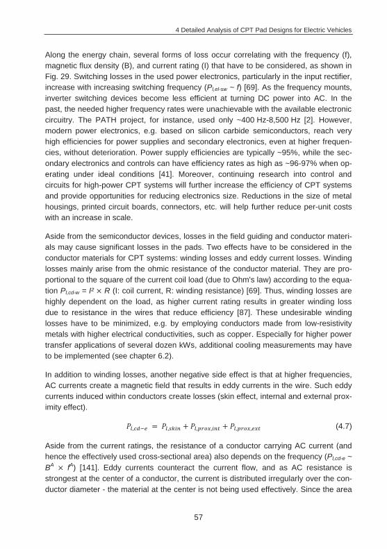
4 Detailed Analysis of CPT Pad Designs for Electric Vehicles
57
Along the energy chain, several forms of loss occur correlating with the frequency (f), magnetic flux density (B), and current rating (I) that have to be considered, as shown in Fig. 29. Switching losses in the used power electronics, particularly in the input rectifier, increase with increasing switching frequency (Pl,el-sw ~ f) [69]. As the frequency mounts, inverter switching devices become less efficient at turning DC power into AC. In the past, the needed higher frequency rates were unachievable with the available electronic circuitry. The PATH project, for instance, used only ~400 Hz-8,500 Hz [2]. However, modern power electronics, e.g. based on silicon carbide semiconductors, reach very high efficiencies for power supplies and secondary electronics, even at higher frequen-cies, without deterioration. Power supply efficiencies are typically ~95%, while the sec-ondary electronics and controls can have efficiency rates as high as ~96-97% when op-erating under ideal conditions [41]. Moreover, continuing research into control and circuits for high-power CPT systems will further increase the efficiency of CPT systems and provide opportunities for reducing electronics size. Reductions in the size of metal housings, printed circuit boards, connectors, etc. will help further reduce per-unit costs with an increase in scale.
Aside from the semiconductor devices, losses in the field guiding and conductor materi-als may cause significant losses in the pads. Two effects have to be considered in the conductor materials for CPT systems: winding losses and eddy current losses. Winding losses mainly arise from the ohmic resistance of the conductor material. They are pro-portional to the square of the current coil load (due to Ohm's law) according to the equa-tion Pl,cd-w = I² R (I: coil current, R: winding resistance) [69]. Thus, winding losses are highly dependent on the load, as higher current rating results in greater winding loss due to resistance in the wires that reduce efficiency [87]. These undesirable winding losses have to be minimized, e.g. by employing conductors made from low-resistivity metals with higher electrical conductivities, such as copper. Especially for higher power transfer applications of several dozen kWs, additional cooling measurements may have to be implemented (see chapter 6.2).
In addition to winding losses, another negative side effect is that at higher frequencies, AC currents create a magnetic field that results in eddy currents in the wire. Such eddy currents induced within conductors create losses (skin effect, internal and external prox-imity effect).
(4.7)
Aside from the current ratings, the resistance of a conductor carrying AC current (and hence the effectively used cross-sectional area) also depends on the frequency (Pl,cd-e ~ BA fA) [141]. Eddy currents counteract the current flow, and as AC resistance is strongest at the center of a conductor, the current is distributed irregularly over the con-ductor diameter - the material at the center is not being used effectively. Since the area
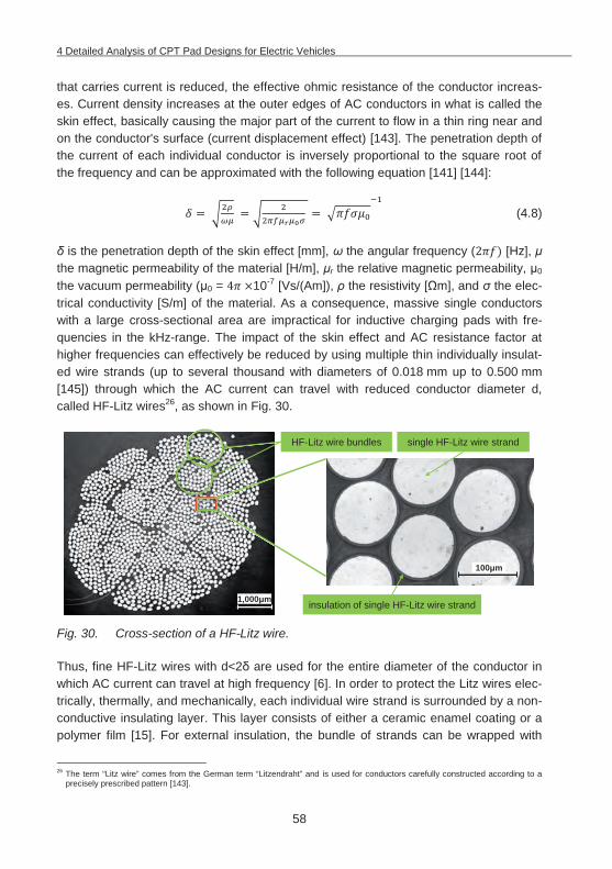
4 Detailed Analysis of CPT Pad Designs for Electric Vehicles
58
that carries current is reduced, the effective ohmic resistance of the conductor increas-es. Current density increases at the outer edges of AC conductors in what is called the skin effect, basically causing the major part of the current to flow in a thin ring near and on the conductor's surface (current displacement effect) [143]. The penetration depth of the current of each individual conductor is inversely proportional to the square root of the frequency and can be approximated with the following equation [141] [144]:
(4.8)
is the penetration depth of the skin effect [mm], the angular frequency ( [Hz], the magnetic permeability of the material [H/m], r the relative magnetic permeability, 0 the vacuum permeability ( 0 = 10-7 [Vs/(Am]), the resistivity [ m], and the elec-trical conductivity [S/m] of the material. As a consequence, massive single conductors with a large cross-sectional area are impractical for inductive charging pads with fre-quencies in the kHz-range. The impact of the skin effect and AC resistance factor at higher frequencies can effectively be reduced by using multiple thin individually insulat-ed wire strands (up to several thousand with diameters of 0.018 mm up to 0.500 mm [145]) through which the AC current can travel with reduced conductor diameter d, called HF-Litz wires26, as shown in Fig. 30.
Fig. 30. Cross-section of a HF-Litz wire.
Thus, fine HF-Litz wires with d<2 are used for the entire diameter of the conductor in which AC current can travel at high frequency [6]. In order to protect the Litz wires elec-trically, thermally, and mechanically, each individual wire strand is surrounded by a non-conductive insulating layer. This layer consists of either a ceramic enamel coating or a polymer film [15]. For external insulation, the bundle of strands can be wrapped with
26 The term “Litz wire” comes from the German term “Litzendraht” and is used for conductors carefully constructed according to a
precisely prescribed pattern [143].
insulation of single HF-Litz wire strand
HF-Litz wire bundles single HF-Litz wire strand
1,000 m
100 m
4 Detailed Analysis of CPT Pad Designs for Electric Vehicles
59
polyester film "Mylar", nylon, or natural silk sheaths to protect the thin insulation of the individual wire strands against mechanical damage, moisture, or the like. External insu-lation materials are needed especially to create HF-Litz wires in special shapes, e.g. rectangular to use available winding space more efficiently. Since HF-Litz wires require high electrical conductivity, they are traditionally based on copper. Another alternative conductor material is aluminum with base material costs of only a quarter of copper and lower price fluctuations compared to Cu (Al03-26-2014=1.27 €/kg vs. Cu03-26-
2014=4.75 €/kg). Innovative bi-metallic HF-Litz wire compounds with copper being clad-ded onto an aluminum core (copper cladded aluminum: CCA) allow the combination of the preferred properties of both metals. With CCA, conductivity increases slightly, prob-lems with the oxide layer of aluminum can be mitigated, and the same contacting tech-niques as for copper conductors can be used [145]. However, there remains a tendency to form aluminum oxides which, without appropriate insulation, will degenerate the en-tire conductor, especially at the terminals [146]. In addition, HF-Litz wires already make up a large proportion of pad costs [24], and CCA makes them even more expensive. Tab. 7 compares the main characteristics of the three relevant conductor materials cop-per, aluminum, and CCA.
Tab. 7. Comparison of different conductor materials for CPT systems [145].
copper aluminum CCA10% CCA15%
volume fraction of copper [%] 100 0 10 15
density [g/cm3] 8.9 2.7 3.3 3.6
conductivity [m/ mm2] 58.5 36 37.7 39.2
breaking strength [N/mm2] 220-270 120-140 130-180 230-280
In addition to the skin effect, the proximity effect is causing losses that have to be con-sidered. The proximity effect is similar to the skin effect, with the difference that the ed-dy current losses are caused by alternating magnetic fields of adjacent wire strands within the Litz wire bundle (internal proximity effect) and by alternating magnetic fields of adjacent Litz wire bundles (external proximity effect). Currents travelling near each other tend to increase the AC resistance as they redistribute current flow in undesirable pat-terns. The smaller the distance between two conductors, the greater the proximity ef-fect. Thus, to mitigate the internal proximity effect, the individual Litz wire strands have to be twisted together in such a way that, viewed over the length of the Litz wire, each conductor weaves evenly towards and away from the core of the Litz wire. On its way along the length of the entire Litz wire, each individual wire strand crosses each possi-ble position in the overall cross-section of the Litz wire, thereby reducing the internal proximity effect. The length of lay thereby describes the length of the path traveled by a
4 Detailed Analysis of CPT Pad Designs for Electric Vehicles
60
single wire strand for one complete revolution (360°) around the center of the Litz wire [141] [143]. According to [144] and [147], a reduced copper filling factor in AC applica-tions in the kHz-range may be preferable to reduce RAC. Therefore, alternative set-ups for loss-minimized HF-Litz wires have been proposed, with Litz wire strands arranged in areas of reduced magnetic field strength (e.g. along the lateral surface) or thicker layers of wire/bundle insulation.
With increasing frequencies, HF-Litz wires clearly show reduced skin effect losses com-pared to solid wires. However, as the frequency rises above the megahertz range (MHz-GHz), current flows in an ever-thinner surface layer. Above a certain frequency (800 kHz in a model consideration of [148] with a 20x0.08 Litz wire), the internal proxim-ity effect leads to increasing losses in the Litz wires. In this situation, solid round wires are once again the better alternative, as they cannot induce internal proximity effects in adjacent internal wire strands. Therefore, to generate the alternating magnetic field, Litz wires are especially effective below 500 kHz and rarely used above 2 MHz [143] [148]. This is absolutely sufficient for the proposed CPT systems frequency of 20-140 kHz. As magnetic design has a significant impact on competitiveness and capability of the sys-tem transmission path, it becomes clear that Litz wires play a crucial role. This, in turn, means that power transfer systems are also limited by the availability and cost of suita-ble Litz wires.
Highly permeable ferromagnetic core material (like ferrites) positioned below the coils are commonly used, as they provide a path of low magnetic reluctance for the flux with minimized field leakages and hence improved coupling [67] [149]. However, increasing frequency also increases losses due to magnetization reversal (hysteresis losses) as well as eddy currents in the applied core materials [69], which together are described as core losses. By changing magnetic fields (AC), induced loops of eddy currents generate resistive losses that can occur in any material with a conductivity of >0 (non-zero resis-tivity). Eddy current losses are proportional to the square of the frequency and to the magnetic flux density predominant in the material (Pl,cm-e ~ BA f²) [69] [139] [142]. Moreover, they are proportional to the area of the loops and inversely proportional to the resistivity of the core material. Thus, eddy currents can be minimized by selecting mag-netic core materials of low electrical conductivity, like ferrites with high-resistance grain boundaries between the ferrite phases, or by using thin sheets of magnetic material with insulating coating in a plane normal to the flux, known as laminations. [150] [151]
In addition to eddy current losses, the core also experiences hysteresis losses (magnet-ization losses) arising from the work that needs to be applied in alternating magnetic fields to re-magnetize the core in the rhythm of the frequency. They only occur in mate-rials with a relative permeability r>1, for example in all ferromagnetic materials. Micro-scopic friction losses that result from the constantly changing orientation of the inner elementary core structure in an external magnetic field cause heating. Each time a
4 Detailed Analysis of CPT Pad Designs for Electric Vehicles
61
magnetic field in the core is reversed, a small amount of energy is lost due to hysteresis within the core. The amount of energy lost in the material in one cycle of the applied field is proportional to the area inside the hysteresis loop, and is dissipated as heat. The coercivity Hc is the degree of magnetic hysteresis and caused losses in the core materi-als. Since the energy lost in each cycle is constant, hysteresis power losses increase exponentially with frequency (Pl,cm-hy ~ BA f) [140] [142]. Therefore, highly permeable core materials are used for field guidance in CPT systems, e.g. with a relatively high magnetic permeability r, high saturation Bs (more than 200 T), and also very small co-ercivity Hc. To minimize core losses in high frequency applications like CPT systems, non-conductive magnetic materials, like ferrite (low conductivity , high permeability of
r>>1) are perfect for field guidance and mainly used as a suitable core material in CPT systems. With small coercivity Hc and a high saturation induction of the ferrite Bs, they have low hysteresis losses. Ferrites are available in a wide variety of material composi-tions with different magnetic and mechanical parameters. For the frequency range of CPT systems (20-145 kHz), manganese-zinc (MnZn) ferrites are commonly used [150] as they have high permeability (typically in the range of 300-18,000, usually 2,400 [123]), small coercivity Hc (5-100 A/m), high saturation flux density (0.2-0.5 T), and good performance at frequencies from a few kHz up to as high as 1 MHz with low losses [142].
Aside from commonly used MnZn materials, there is a significant number of alternative soft magnetic core materials, featuring high saturation induction, high initial permeabil-ity, and low core loss in relation to frequency. Various soft ferrites and a number of non-ferrite materials including Fe-group amorphous alloys, Fe-Al-Si and nano-crystalline al-loys can also in theory be used as core materials in CPT systems [152] [153]. However, alternative materials like powder-/particle-based ferrite cores, iron flakes, and nano-crystalline iron foils all do not attain the characteristics of conventional ferrite at higher frequencies. Even though research results are sobering regarding their magnetic char-acteristics, the opportunities that arise from magnetic conductive compounds made of plastics are still enticing from a production perspective. The use of nano-crystalline iron foils still seems to be promising, as well, as there are more and more system designs that try to adapt their magnetic design to the use of “amorphous” nano-crystalline iron foils. Hybrid core structures have been developed that consist of MnZn ferrites and nano-crystalline iron foils at different areas of the pads in order to combine the optimal characteristics of both materials [154] [155]. However, it is quite challenging to apply such a material with its directional dependence particularly in loosely-coupled CPT sys-tems because of its stray leakage, which will result in higher losses and heating.
Coils without any core material as shown in [119] are generally unsuitable for high pow-er applications. Coreless coils need to be operated at higher frequencies in the MF to VHF band (range of hundreds of kHz to MHz) to compensate for lower coupling and to
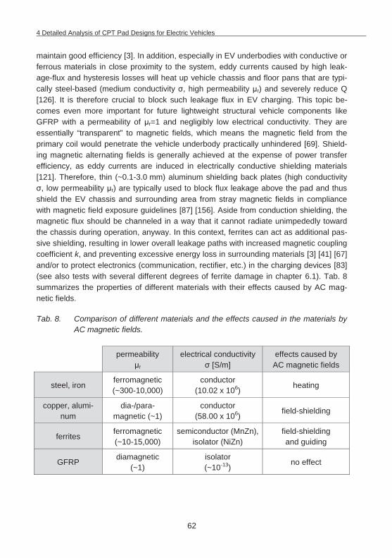
4 Detailed Analysis of CPT Pad Designs for Electric Vehicles
62
maintain good efficiency [3]. In addition, especially in EV underbodies with conductive or ferrous materials in close proximity to the system, eddy currents caused by high leak-age-flux and hysteresis losses will heat up vehicle chassis and floor pans that are typi-cally steel-based (medium conductivity , high permeability r) and severely reduce Q
[126]. It is therefore crucial to block such leakage flux in EV charging. This topic be-comes even more important for future lightweight structural vehicle components like GFRP with a permeability of r=1 and negligibly low electrical conductivity. They are essentially “transparent” to magnetic fields, which means the magnetic field from the primary coil would penetrate the vehicle underbody practically unhindered [69]. Shield-ing magnetic alternating fields is generally achieved at the expense of power transfer efficiency, as eddy currents are induced in electrically conductive shielding materials [121]. Therefore, thin (~0.1-3.0 mm) aluminum shielding back plates (high conductivity
, low permeability r) are typically used to block flux leakage above the pad and thus shield the EV chassis and surrounding area from stray magnetic fields in compliance with magnetic field exposure guidelines [87] [156]. Aside from conduction shielding, the magnetic flux should be channeled in a way that it cannot radiate unimpededly toward the chassis during operation, anyway. In this context, ferrites can act as additional pas-sive shielding, resulting in lower overall leakage paths with increased magnetic coupling coefficient k, and preventing excessive energy loss in surrounding materials [3] [41] [67] and/or to protect electronics (communication, rectifier, etc.) in the charging devices [83] (see also tests with several different degrees of ferrite damage in chapter 6.1). Tab. 8 summarizes the properties of different materials with their effects caused by AC mag-netic fields.
Tab. 8. Comparison of different materials and the effects caused in the materials by AC magnetic fields.
permeability
r electrical conductivity
[S/m] effects caused by
AC magnetic fields
steel, iron ferromagnetic (~300-10,000)
conductor (10.02 x 10⁶) heating
copper, alumi-num
dia-/para-magnetic (~1)
conductor (58.00 x 10⁶) field-shielding
ferrites ferromagnetic (~10-15,000)
semiconductor (MnZn), isolator (NiZn)
field-shielding and guiding
GFRP diamagnetic (~1)
isolator (~10-13)
no effect
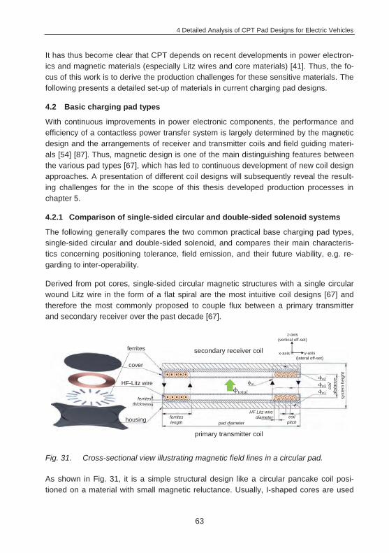
4 Detailed Analysis of CPT Pad Designs for Electric Vehicles
63
It has thus become clear that CPT depends on recent developments in power electron-ics and magnetic materials (especially Litz wires and core materials) [41]. Thus, the fo-cus of this work is to derive the production challenges for these sensitive materials. The following presents a detailed set-up of materials in current charging pad designs.
4.2 Basic charging pad types
With continuous improvements in power electronic components, the performance and efficiency of a contactless power transfer system is largely determined by the magnetic design and the arrangements of receiver and transmitter coils and field guiding materi-als [54] [87]. Thus, magnetic design is one of the main distinguishing features between the various pad types [67], which has led to continuous development of new coil design approaches. A presentation of different coil designs will subsequently reveal the result-ing challenges for the in the scope of this thesis developed production processes in chapter 5.
4.2.1 Comparison of single-sided circular and double-sided solenoid systems
The following generally compares the two common practical base charging pad types, single-sided circular and double-sided solenoid, and compares their main characteris-tics concerning positioning tolerance, field emission, and their future viability, e.g. re-garding to inter-operability.
Derived from pot cores, single-sided circular magnetic structures with a single circular wound Litz wire in the form of a flat spiral are the most intuitive coil designs [67] and therefore the most commonly proposed to couple flux between a primary transmitter and secondary receiver over the past decade [67].
Fig. 31. Cross-sectional view illustrating magnetic field lines in a circular pad.
As shown in Fig. 31, it is a simple structural design like a circular pancake coil posi-tioned on a material with small magnetic reluctance. Usually, I-shaped cores are used
primary transmitter coil
secondary receiver coil
housing
z-axis(vertical off-set)
y-axis(lateral off-set)
x-axis
HF-Litz wire
cover
ferrites
pad diameter
HF Litz wire diameterferrites
length
ferrites thickness
coil pitch
syst
em h
eigh
t
coil
dist
ance
m 3
2
1
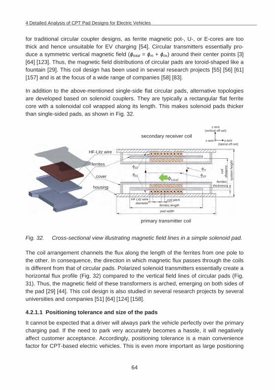
4 Detailed Analysis of CPT Pad Designs for Electric Vehicles
64
for traditional circular coupler designs, as ferrite magnetic pot-, U-, or E-cores are too thick and hence unsuitable for EV charging [54]. Circular transmitters essentially pro-duce a symmetric vertical magnetic field ( total = m + x) around their center points [3] [64] [123]. Thus, the magnetic field distributions of circular pads are toroid-shaped like a fountain [29]. This coil design has been used in several research projects [55] [56] [61] [157] and is at the focus of a wide range of companies [58] [83].
In addition to the above-mentioned single-side flat circular pads, alternative topologies are developed based on solenoid couplers. They are typically a rectangular flat ferrite core with a solenoidal coil wrapped along its length. This makes solenoid pads thicker than single-sided pads, as shown in Fig. 32.
Fig. 32. Cross-sectional view illustrating magnetic field lines in a simple solenoid pad.
The coil arrangement channels the flux along the length of the ferrites from one pole to the other. In consequence, the direction in which magnetic flux passes through the coils is different from that of circular pads. Polarized solenoid transmitters essentially create a horizontal flux profile (Fig. 32) compared to the vertical field lines of circular pads (Fig. 31). Thus, the magnetic field of these transformers is arched, emerging on both sides of the pad [29] [44]. This coil design is also studied in several research projects by several universities and companies [51] [64] [124] [158].
4.2.1.1 Positioning tolerance and size of the pads
It cannot be expected that a driver will always park the vehicle perfectly over the primary charging pad. If the need to park very accurately becomes a hassle, it will negatively affect customer acceptance. Accordingly, positioning tolerance is a main convenience factor for CPT-based electric vehicles. This is even more important as large positioning
primary transmitter coil
secondary receiver coil
housing
z-axis(vertical off-set)
y-axis(lateral off-set)
x-axis
HF-Litz wire
cover
ferrites
pad width
HF Litz wire diameter ferrites length
ferrites thickness
coil pitch
syst
em h
eigh
t
coil
dist
ance
m
3
2
1
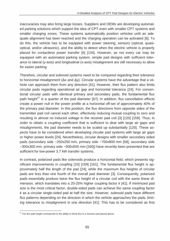
4 Detailed Analysis of CPT Pad Designs for Electric Vehicles
65
inaccuracies may also bring large losses. Suppliers and OEMs are developing automat-ed parking solutions which support the idea of CPT even with smaller CPT systems and smaller charging zones. These systems automatically position vehicles until an ade-quate alignment has been reached and the charging operation can be activated [6]. To do this, the vehicle has to be equipped with power steering, sensors (optical, quasi-optical, and/or ultrasonic), and the ability to detect when the electric vehicle is properly placed for contactless power transfer [6] [134]. However, as not every car may be equipped with an automated parking system, simple pad designs with sufficient toler-ance to lateral (y-axis) and longitudinal (x-axis) misalignment are still necessary to allow for easier parking.
Therefore, circular and solenoid systems need to be compared regarding their tolerance to horizontal misalignment ( x and y). Circular systems have the advantage that a ve-hicle can approach them from any direction [41]. However, their flux pattern also limits circular pads regarding operational air gap and horizontal tolerance [24]. For conven-tional circular pads with identical primary and secondary pads, the fundamental flux path height27 is a quarter of the pad diameter [67]. In addition, flux cancellation effects create a power null in the power profile at a horizontal off-set of approximately 40% of the primary pad diameter. In this position, the flux directions from opposite sides of the transmitter pad coil cancel each other, effectively reducing mutual coupling to zero and resulting in almost no induced voltage in the receiver pad coil [3] [120] [159]. Thus, in order to obtain a coupling coefficient that is sufficient to deal with large air gaps and misalignments, the pad diameter needs to be scaled up substantially [120]. These as-pects have to be considered when developing circular pad systems with large air gaps or higher power levels [24]. Nevertheless, circular designs with smaller secondary sided pads (secondary side ~250x250 mm, primary side ~700x800 mm [58], secondary side ~300x300 mm, primary side ~500x500 mm [160]) have recently been presented that are sufficient for low-power 3.7 kW transfer systems.
In contrast, polarized pads like solenoids produce a horizontal field, which presents sig-nificant improvements in coupling [10] [159] [161]. The fundamental flux height is ap-proximately half the length of the pad [24], while the maximum flux heights of circular pads are less than one fourth of the overall pad diameter [3]. Consequently, polarized pads essentially produce twice the flux height of a circular coil with the same linear di-mension, which translates into a 20-25% higher coupling factor k [41]. If minimized pad size is the most critical factor, double-sided pads can achieve the same coupling factor k as a circular single-sided pad at half the size. However, solenoid pads have different flux patterns depending on the direction in which the vehicle approaches the pads, limit-ing tolerance to misalignment in one direction [41]. This has to be considered as first
27 The flux path height corresponds to the ability to throw flux to a receiver pad placed above.
4 Detailed Analysis of CPT Pad Designs for Electric Vehicles
66
research results on parking behaviors show that drivers have more difficulty handling longitudinal misalignment (x-direction) than lateral misalignment (y-direction) [55]. How-ever, misalignment in longitudinal x-direction can much more easily be corrected by the driver or even avoided than lateral misalignment in y-direction, for example by simple mechanical aids like wheel chocks or other simple guides. It is therefore preferable to orient polarized (solenoid) pads inside the vehicle longitudinally (x-direction along the central vehicle axis) (Fig. 33) [24] [161].
Fig. 33. Direction-dependent integration of different pad designs in the vehicle under-body in the context of tolerable off-sets.
Thus, on the one hand, double-sided solenoid systems allow for smaller pad dimen-sions than single-sided circular pads in compact light-weight designs [161]. On the other hand, solenoids present different performances in lateral and longitudinal misalignment that have to be considered.
4.2.1.2 Field emissions
Aside from positioning tolerance, field emission is of major importance for OEMs, as the systems have to comply with emissions regulations and guidelines such as ICNIRP [47] [67]. CPT systems may cause issues due to their flux pattern when integrated in the ve-hicle underbody (see safety zones in chapter 2.3). CPT must not harm living organisms (humans, animals) and may also not interfere with other devices such as keyless entry systems, electronic control systems, pacemakers, or radio-frequency identification (RFID) systems [124] [162]. The PATH project, for instance, reported problems with magnetic fields that interfered with the electronic engine controls of non-RPEVs passing the CPT segments [2].
The structure of circular pads naturally results in a desirable single-sided flux pattern, ensuring low loss and leakage levels [24]. Moreover, the coils sit above ferrite strips
x-axis (longitudinal
misalignment)
y-axis (lateral misalignment)
circularsolenoid
longitudinallyorientated
solenoidlaterally
orientated
area oftolareable
off-set
y-axis(lateral off-set)
x-axis(longitudinal off-set)
z-axis

4 Detailed Analysis of CPT Pad Designs for Electric Vehicles
67
guiding the majority of the flux out of the front of the pads upwards towards a receiver, thus avoiding unwanted rear flux paths [10]. Especially larger circular pads and ferrite layers that extend beyond the coil area essentially re-capture returning main flux m and help containing leakage flux . Circular pads therefore have comparatively low field emissions [41] [157]. Aluminum shielding added to the back of the pad blocks and thus minimizes stray fields in surrounding metallic materials, like steel chassis under an EV [67]. Shielding has only little effect on pad efficiency, as it only acts to stop leakage rather than main flux m. This is particularly beneficial for electromagnetic compatibility (EMC) on the vehicle-side pick-ups and hence one of the main reasons why circular power pads have been well researched and optimized for EV charging systems.
In contrast, solenoid systems produce strong horizontal flux out of the ends of the pad with equal flux paths on both sides (front and back, see Fig. 32) [161] with field leakage which is particularly difficult to suppress [54] [163]. Additional shielding is therefore needed to avoid low coupling factors and EMC issues [120] [161]. Shielding, however, leads to additional losses, which may significantly reduce the native Q of the coil and hence drop system efficiency below practical levels for an EV charging system. [41] documents expected magnetic losses as high as 10%, compared to target values of no more than 2-4%. Researchers are working on several solutions for this problem and fur-ther adaptions to the magnetic design, as presented in chapter 4.2.2.
Fig. 34. Direction-dependent integration of different pad designs in the vehicle under-body in the context of potential EMC issues.
4.2.1.3 Future viability – inter-operability
Another very decisive aspect of different coil designs is their future technological viabil-ity, which must be considered carefully with regard to global market introduction and a
x-axis (longitudinal
misalignment)
y-axis (lateral misalignment)
area of higher magnetic field
exposure
y-axis(lateral off-set)
x-axis(longitudinal off-set)
z-axis
circularsolenoid
longitudinallyorientated
solenoidlaterally
orientated
4 Detailed Analysis of CPT Pad Designs for Electric Vehicles
68
potential future public charging infrastructure. Different coil designs will not be inter-operable, which means that not every car will be able to use every charging spot. Standardization of CPT systems is thus one of the main challenges, but vital to open up new fields of application [41]. As other fields have shown (diverse conductive plugs28/low-power CPT applications29), different standards that evolve simultaneously can cause problems and potentially slow down market introduction and widespread commercialization, as the future of the products is difficult to predict [165]. Without standards and inter-operability, infrastructure providers will not be willing to invest in a public infrastructure. Most importantly, there is a danger of alienating customers when the existence of several standards impedes sales and thus economies of scale. On the one hand, standardization processes slow down technical development to some extent. On the other hand, however, standards that are set prematurely can also impede devel-opment, especially in a very fast evolving technology field like CPT (see new coil de-signs in chapter 4.2.2).
The issue of circular versus solenoid base pad designs make the problem with inter-operability obvious. The magnetic field patterns of the two pad designs differ greatly (mainly vertical versus horizontal flux pattern). A circular transformer produces magnetic flux from the center pole to the outer pole in all directions, whereas a solenoid core transformer produces magnetix flux in only one direction [166]. As a result, the two types are incompatible without further adaptations. If a vehicle fitted with a circular re-ceiver parks over a polarized transmitter, there will likely be some loss of power and significant leakage flux, which might breach field exposure limits [10] [47]. Moreover, operation between different coil types might not meet tolerable levels of minimum effi-ciency (~90% [46]). Fig. 35 illustrates different possible misalignment situations be-tween circular and solenoid pad designs.
As can be seen, in the case of a longitudinally orientated solenoid secondary and a cir-cular primary, and lateral misalignment (y-axis), there is almost no magnetic coupling between the circular and the solenoid system. This is also the case if a circular and so-lenoid pad is perfectly aligned one over the other. Magnetic fluxes from the base circular pad attempt to pass upward through its coil center. However, the shape of the center portion of the secondary solenoid pad does not allow the magnetic fluxes to pass. As a result, no magnetic circuit can be formed. With longitudinal misalignment (x-axis), mag-netic coupling remains possible between the two pads [64]. This correlation becomes quite more complex with additional pad designs and shows the necessity to study the inter-operability of a receiver pick-up with several types of transmitters. As a result, in-tense research efforts are dedicated to comparing different coil structures in all possible misalignment situations of the x-, y-, and z-axes [46] [167].
28 Several standards for different types of plugs including IEC62196, SAE’s J1772 and CHAdeMO [164]. 29 Competing approaches like the Qi-Standard (Wireless Power Consortium), Power Matters Alliance, A4WP (Alliance for Wireless
Power) or even company-specific approaches.
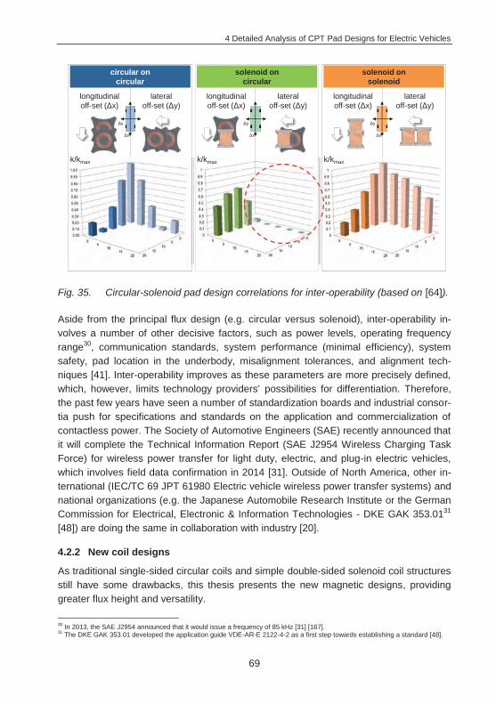
4 Detailed Analysis of CPT Pad Designs for Electric Vehicles
69
Fig. 35. Circular-solenoid pad design correlations for inter-operability (based on [64]).
Aside from the principal flux design (e.g. circular versus solenoid), inter-operability in-volves a number of other decisive factors, such as power levels, operating frequency range30, communication standards, system performance (minimal efficiency), system safety, pad location in the underbody, misalignment tolerances, and alignment tech-niques [41]. Inter-operability improves as these parameters are more precisely defined, which, however, limits technology providers’ possibilities for differentiation. Therefore, the past few years have seen a number of standardization boards and industrial consor-tia push for specifications and standards on the application and commercialization of contactless power. The Society of Automotive Engineers (SAE) recently announced that it will complete the Technical Information Report (SAE J2954 Wireless Charging Task Force) for wireless power transfer for light duty, electric, and plug-in electric vehicles, which involves field data confirmation in 2014 [31]. Outside of North America, other in-ternational (IEC/TC 69 JPT 61980 Electric vehicle wireless power transfer systems) and national organizations (e.g. the Japanese Automobile Research Institute or the German Commission for Electrical, Electronic & Information Technologies - DKE GAK 353.0131 [48]) are doing the same in collaboration with industry [20].
4.2.2 New coil designs
As traditional single-sided circular coils and simple double-sided solenoid coil structures still have some drawbacks, this thesis presents the new magnetic designs, providing greater flux height and versatility.
30 In 2013, the SAE J2954 announced that it would issue a frequency of 85 kHz [31] [167]. 31 The DKE GAK 353.01 developed the application guide VDE-AR-E 2122-4-2 as a first step towards establishing a standard [48].
solenoid on solenoid
solenoid on circular
circular on circular
k/kmax k/kmax k/kmax
longitudinal off-set ( x)
lateraloff-set ( y)
longitudinal off-set ( x)
lateraloff-set ( y)
longitudinal off-set ( x)
lateraloff-set ( y)
x
y
x
y
x
y
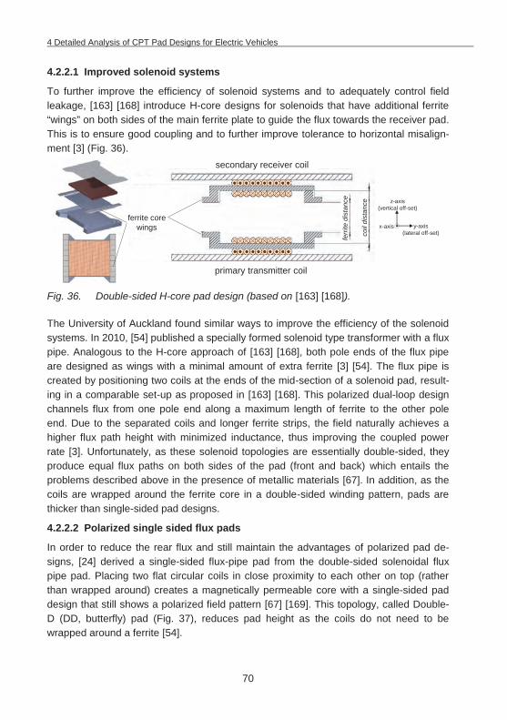
4 Detailed Analysis of CPT Pad Designs for Electric Vehicles
70
4.2.2.1 Improved solenoid systems
To further improve the efficiency of solenoid systems and to adequately control field leakage, [163] [168] introduce H-core designs for solenoids that have additional ferrite “wings” on both sides of the main ferrite plate to guide the flux towards the receiver pad. This is to ensure good coupling and to further improve tolerance to horizontal misalign-ment [3] (Fig. 36).
Fig. 36. Double-sided H-core pad design (based on [163] [168]).
The University of Auckland found similar ways to improve the efficiency of the solenoid systems. In 2010, [54] published a specially formed solenoid type transformer with a flux pipe. Analogous to the H-core approach of [163] [168], both pole ends of the flux pipe are designed as wings with a minimal amount of extra ferrite [3] [54]. The flux pipe is created by positioning two coils at the ends of the mid-section of a solenoid pad, result-ing in a comparable set-up as proposed in [163] [168]. This polarized dual-loop design channels flux from one pole end along a maximum length of ferrite to the other pole end. Due to the separated coils and longer ferrite strips, the field naturally achieves a higher flux path height with minimized inductance, thus improving the coupled power rate [3]. Unfortunately, as these solenoid topologies are essentially double-sided, they produce equal flux paths on both sides of the pad (front and back) which entails the problems described above in the presence of metallic materials [67]. In addition, as the coils are wrapped around the ferrite core in a double-sided winding pattern, pads are thicker than single-sided pad designs.
4.2.2.2 Polarized single sided flux pads
In order to reduce the rear flux and still maintain the advantages of polarized pad de-signs, [24] derived a single-sided flux-pipe pad from the double-sided solenoidal flux pipe pad. Placing two flat circular coils in close proximity to each other on top (rather than wrapped around) creates a magnetically permeable core with a single-sided pad design that still shows a polarized field pattern [67] [169]. This topology, called Double-D (DD, butterfly) pad (Fig. 37), reduces pad height as the coils do not need to be wrapped around a ferrite [54].
secondary receiver coil
z-axis(vertical off-set)
y-axis(lateral off-set)
x-axis
ferri
tedi
stan
ce
coil
dist
ance
primary transmitter coil
ferrite corewings
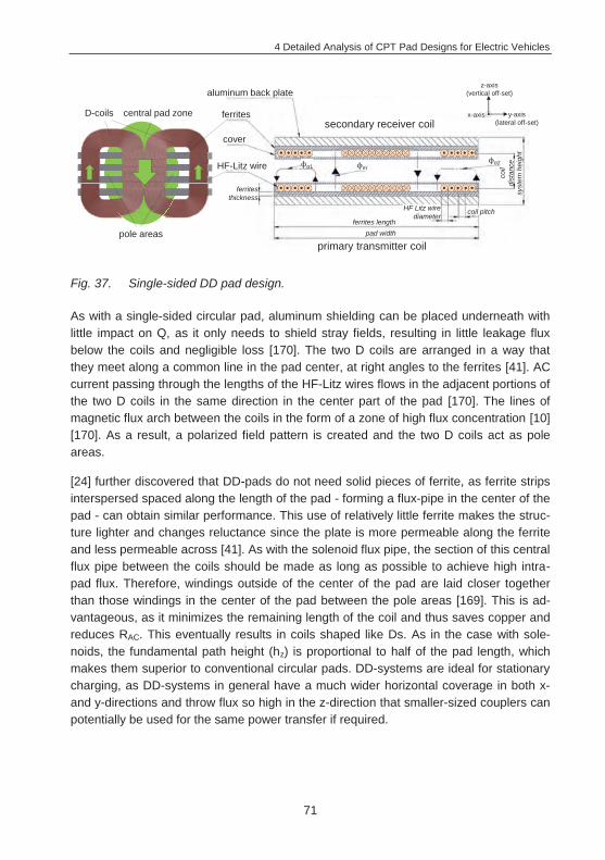
4 Detailed Analysis of CPT Pad Designs for Electric Vehicles
71
Fig. 37. Single-sided DD pad design.
As with a single-sided circular pad, aluminum shielding can be placed underneath with little impact on Q, as it only needs to shield stray fields, resulting in little leakage flux below the coils and negligible loss [170]. The two D coils are arranged in a way that they meet along a common line in the pad center, at right angles to the ferrites [41]. AC current passing through the lengths of the HF-Litz wires flows in the adjacent portions of the two D coils in the same direction in the center part of the pad [170]. The lines of magnetic flux arch between the coils in the form of a zone of high flux concentration [10] [170]. As a result, a polarized field pattern is created and the two D coils act as pole areas.
[24] further discovered that DD-pads do not need solid pieces of ferrite, as ferrite strips interspersed spaced along the length of the pad - forming a flux-pipe in the center of the pad - can obtain similar performance. This use of relatively little ferrite makes the struc-ture lighter and changes reluctance since the plate is more permeable along the ferrite and less permeable across [41]. As with the solenoid flux pipe, the section of this central flux pipe between the coils should be made as long as possible to achieve high intra-pad flux. Therefore, windings outside of the center of the pad are laid closer together than those windings in the center of the pad between the pole areas [169]. This is ad-vantageous, as it minimizes the remaining length of the coil and thus saves copper and reduces RAC. This eventually results in coils shaped like Ds. As in the case with sole-noids, the fundamental path height (hz) is proportional to half of the pad length, which makes them superior to conventional circular pads. DD-systems are ideal for stationary charging, as DD-systems in general have a much wider horizontal coverage in both x- and y-directions and throw flux so high in the z-direction that smaller-sized couplers can potentially be used for the same power transfer if required.
coil
dist
ance
aluminum back plate
D-coils central pad zone
pole areasprimary transmitter coil
secondary receiver coil
z-axis(vertical off-set)
y-axis(lateral off-set)
x-axis
HF-Litz wire
cover
ferrites
pad width
HF Litz wire diameter
ferrites length
ferrites thickness
coil pitch
syst
em h
eigh
t
m2
1
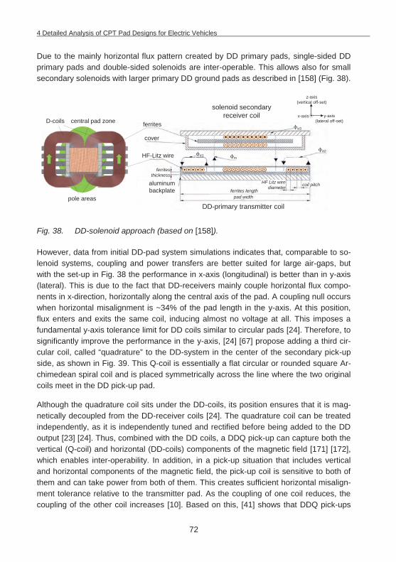
4 Detailed Analysis of CPT Pad Designs for Electric Vehicles
72
Due to the mainly horizontal flux pattern created by DD primary pads, single-sided DD primary pads and double-sided solenoids are inter-operable. This allows also for small secondary solenoids with larger primary DD ground pads as described in [158] (Fig. 38).
Fig. 38. DD-solenoid approach (based on [158]).
However, data from initial DD-pad system simulations indicates that, comparable to so-lenoid systems, coupling and power transfers are better suited for large air-gaps, but with the set-up in Fig. 38 the performance in x-axis (longitudinal) is better than in y-axis (lateral). This is due to the fact that DD-receivers mainly couple horizontal flux compo-nents in x-direction, horizontally along the central axis of the pad. A coupling null occurs when horizontal misalignment is ~34% of the pad length in the y-axis. At this position, flux enters and exits the same coil, inducing almost no voltage at all. This imposes a fundamental y-axis tolerance limit for DD coils similar to circular pads [24]. Therefore, to significantly improve the performance in the y-axis, [24] [67] propose adding a third cir-cular coil, called “quadrature” to the DD-system in the center of the secondary pick-up side, as shown in Fig. 39. This Q-coil is essentially a flat circular or rounded square Ar-chimedean spiral coil and is placed symmetrically across the line where the two original coils meet in the DD pick-up pad.
Although the quadrature coil sits under the DD-coils, its position ensures that it is mag-netically decoupled from the DD-receiver coils [24]. The quadrature coil can be treated independently, as it is independently tuned and rectified before being added to the DD output [23] [24]. Thus, combined with the DD coils, a DDQ pick-up can capture both the vertical (Q-coil) and horizontal (DD-coils) components of the magnetic field [171] [172], which enables inter-operability. In addition, in a pick-up situation that includes vertical and horizontal components of the magnetic field, the pick-up coil is sensitive to both of them and can take power from both of them. This creates sufficient horizontal misalign-ment tolerance relative to the transmitter pad. As the coupling of one coil reduces, the coupling of the other coil increases [10]. Based on this, [41] shows that DDQ pick-ups
D-coils central pad zone
pole areas
solenoid secondaryreceiver coil
DD-primary transmitter coil
aluminum backplate
z-axis(vertical off-set)
y-axis(lateral off-set)
x-axis
HF-Litz wire
cover
ferrites
pad width
HF Litz wire diameter
ferrites length
ferrites thickness
coil pitch
m
21
3
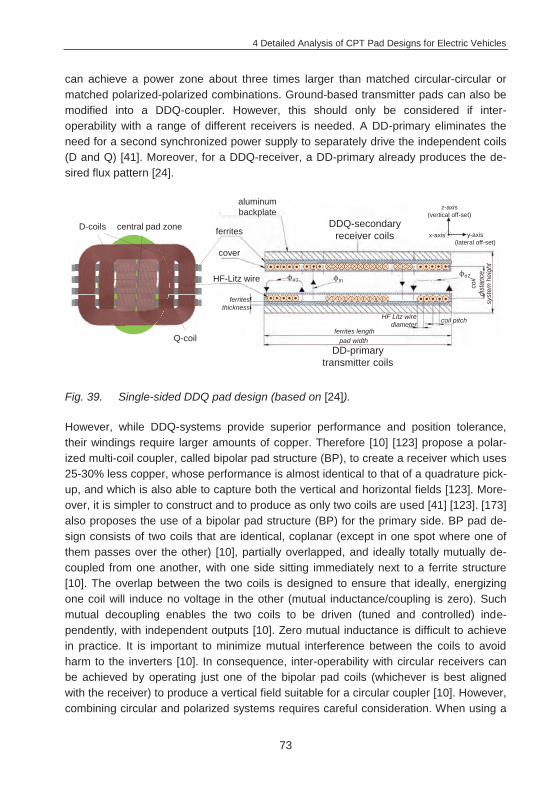
4 Detailed Analysis of CPT Pad Designs for Electric Vehicles
73
can achieve a power zone about three times larger than matched circular-circular or matched polarized-polarized combinations. Ground-based transmitter pads can also be modified into a DDQ-coupler. However, this should only be considered if inter-operability with a range of different receivers is needed. A DD-primary eliminates the need for a second synchronized power supply to separately drive the independent coils (D and Q) [41]. Moreover, for a DDQ-receiver, a DD-primary already produces the de-sired flux pattern [24].
Fig. 39. Single-sided DDQ pad design (based on [24]).
However, while DDQ-systems provide superior performance and position tolerance, their windings require larger amounts of copper. Therefore [10] [123] propose a polar-ized multi-coil coupler, called bipolar pad structure (BP), to create a receiver which uses 25-30% less copper, whose performance is almost identical to that of a quadrature pick-up, and which is also able to capture both the vertical and horizontal fields [123]. More-over, it is simpler to construct and to produce as only two coils are used [41] [123]. [173] also proposes the use of a bipolar pad structure (BP) for the primary side. BP pad de-sign consists of two coils that are identical, coplanar (except in one spot where one of them passes over the other) [10], partially overlapped, and ideally totally mutually de-coupled from one another, with one side sitting immediately next to a ferrite structure [10]. The overlap between the two coils is designed to ensure that ideally, energizing one coil will induce no voltage in the other (mutual inductance/coupling is zero). Such mutual decoupling enables the two coils to be driven (tuned and controlled) inde-pendently, with independent outputs [10]. Zero mutual inductance is difficult to achieve in practice. It is important to minimize mutual interference between the coils to avoid harm to the inverters [10]. In consequence, inter-operability with circular receivers can be achieved by operating just one of the bipolar pad coils (whichever is best aligned with the receiver) to produce a vertical field suitable for a circular coupler [10]. However, combining circular and polarized systems requires careful consideration. When using a
DD-primarytransmitter coils
DDQ-secondaryreceiver coils
D-coils central pad zone
Q-coil
aluminum backplate z-axis
(vertical off-set)
y-axis(lateral off-set)
x-axis
HF-Litz wire
cover
ferrites
pad width
HF Litz wire diameter
ferrites length
ferrites thickness
coil pitch
m1
coil
dist
ance
syst
em h
eigh
t
2
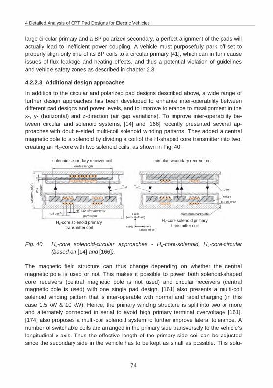
4 Detailed Analysis of CPT Pad Designs for Electric Vehicles
74
large circular primary and a BP polarized secondary, a perfect alignment of the pads will actually lead to inefficient power coupling. A vehicle must purposefully park off-set to properly align only one of its BP coils to a circular primary [41], which can in turn cause issues of flux leakage and heating effects, and thus a potential violation of guidelines and vehicle safety zones as described in chapter 2.3.
4.2.2.3 Additional design approaches
In addition to the circular and polarized pad designs described above, a wide range of further design approaches has been developed to enhance inter-operability between different pad designs and power levels, and to improve tolerance to misalignment in the x-, y- (horizontal) and z-direction (air gap variations). To improve inter-operability be-tween circular and solenoid systems, [14] and [166] recently presented several ap-proaches with double-sided multi-coil solenoid winding patterns. They added a central magnetic pole to a solenoid by dividing a coil of the H-shaped core transmitter into two, creating an Hc-core with two solenoid coils, as shown in Fig. 40.
Fig. 40. Hc-core solenoid-circular approaches - Hc-core-solenoid, Hc-core-circular (based on [14] and [166]).
The magnetic field structure can thus change depending on whether the central magnetic pole is used or not. This makes it possible to power both solenoid-shaped core receivers (central magnetic pole is not used) and circular receivers (central magnetic pole is used) with one single pad design. [161] also presents a multi-coil solenoid winding pattern that is inter-operable with normal and rapid charging (in this case 1.5 kW & 10 kW). Hence, the primary winding structure is split into two or more and alternately connected in serial to avoid high primary terminal overvoltage [161]. [174] also proposes a multi-coil solenoid system to further improve lateral tolerance. A number of switchable coils are arranged in the primary side transversely to the vehicle’s longitudinal x-axis. Thus the effective length of the primary side coil can be adjusted since the secondary side in the vehicle has to be kept as small as possible. This solu-
Hc-core solenoid primarytransmitter coil
solenoid secondary receiver coil circular secondary receiver coil
Hc-core solenoid primarytransmitter coil
z-axis(vertical off-set)
y-axis(lateral off-set)
x-axis
aluminum backplate
HF-Litz wire
cover
ferrites
pad widthHF Litz wire diameter
coil pitch
syst
em h
eigh
t
coil
dist
ance m2m1
ferrites length
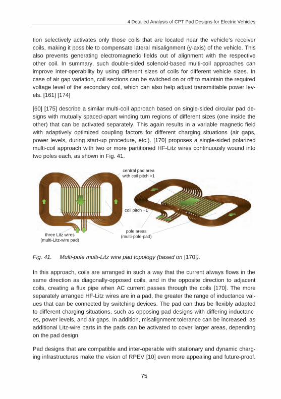
4 Detailed Analysis of CPT Pad Designs for Electric Vehicles
75
tion selectively activates only those coils that are located near the vehicle’s receiver coils, making it possible to compensate lateral misalignment (y-axis) of the vehicle. This also prevents generating electromagnetic fields out of alignment with the respective other coil. In summary, such double-sided solenoid-based multi-coil approaches can improve inter-operability by using different sizes of coils for different vehicle sizes. In case of air gap variation, coil sections can be switched on or off to maintain the required voltage level of the secondary coil, which can also help adjust transmittable power lev-els. [161] [174]
[60] [175] describe a similar multi-coil approach based on single-sided circular pad de-signs with mutually spaced-apart winding turn regions of different sizes (one inside the other) that can be activated separately. This again results in a variable magnetic field with adaptively optimized coupling factors for different charging situations (air gaps, power levels, during start-up procedure, etc.). [170] proposes a single-sided polarized multi-coil approach with two or more partitioned HF-Litz wires continuously wound into two poles each, as shown in Fig. 41.
Fig. 41. Multi-pole multi-Litz wire pad topology (based on [170]).
In this approach, coils are arranged in such a way that the current always flows in the same direction as diagonally-opposed coils, and in the opposite direction to adjacent coils, creating a flux pipe when AC current passes through the coils [170]. The more separately arranged HF-Litz wires are in a pad, the greater the range of inductance val-ues that can be connected by switching devices. The pad can thus be flexibly adapted to different charging situations, such as opposing pad designs with differing inductanc-es, power levels, and air gaps. In addition, misalignment tolerance can be increased, as additional Litz-wire parts in the pads can be activated to cover larger areas, depending on the pad design.
Pad designs that are compatible and inter-operable with stationary and dynamic charg-ing infrastructures make the vision of RPEV [10] even more appealing and future-proof.
central pad areawith coil pitch >1
coil pitch ~1
pole areas(multi-pole-pad)three Litz wires
(multi-Litz-wire pad)
4 Detailed Analysis of CPT Pad Designs for Electric Vehicles
76
Therefore, the following presents RPEV system topology and coil design options that are currently being considered.
4.3 CPT systems for RPEVs
Literature has been discussing electrified roadways that power moving RPEVs [171] for four decades. Early US patents [176] [177], amongst others, show first proposals of track and coil designs that allow vehicles to pick up power contactlessly while driving. More and more projects have been developed and hardware test tracks with several different coil design approaches have been built [2] [33] [95]. These research projects focused on testing diverse challenges of a RPEV infrastructure, e.g. how to transfer suf-ficient power levels to RPEVs over relatively large and varying air gaps. For an EV with an air gap of 175 mm to the road and a track system in the road covered by 75 mm of asphalt/concrete, the de facto air gap is 250 mm. Ideally, the tolerance to vertical ( z) and horizontal ( x and y) misalignment should be even greater at higher power levels for RPEVs [24]. Vertical and horizontal misalignment causes significant changes in the magnetic circuits that couple the power from the roadway to the vehicle and make it dif-ficult to tune the system [30]. For unguided vehicles at higher speeds, the required misalignment tolerance could easily be as high as +/-300-600 mm to enable a vehicle to receive full power across the width of the lane [87]. This makes (semi-)automated driv-ing assistance attractive for RPEV-systems, as well (as already discussed for stationary systems), with automatic tracking that keeps the vehicle in an optimal lateral position over the infrastructure [3] [67]. In the PATH project [2] [42] and recently in the “Partner-ship for Roadway Electrification and Automation” [178] the advantages of connecting roadway electrification and automated driving (roadway automation) have already ex-tensively been discussed. To comply with safety requirements, the energized roadway coils should only be activated to produce a magnetic field when a sensor detects the presence of a passing vehicle [179]. Other road users will not be exposed to the mag-netic field, as only those parts of the roadway directly underneath a passing EV are en-ergized. In the absence of a receiving device, or if the receiving device no longer needs to capture power, the power source should automatically revert to a power-saving “idle” state. This ensures that conventional vehicles can travel on the roadway unaffected by magnetic fields. Under special circumstances, for example in case of debris, animals, or humans on the roadway (traffic jam, accidents, etc.), the systems must shut off or at least drop to safe flux levels within ICNIRP limits [47]. Systems must also ensure that objects in the gap do not overheat in an unsafe manner [41].
The magnetic design of the power track is critical to minimize costs and maximize effi-ciency in a large-scale implementation. The sequence of coils in a continuous strip along the road tends to be different from stationary systems and can basically be divid-ed into distributed (elongated conductor structures in the two-digit meter range) [180]
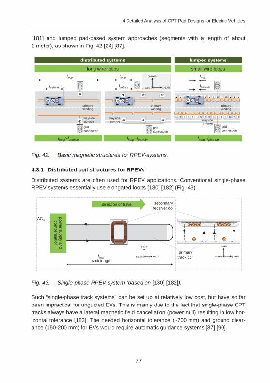
4 Detailed Analysis of CPT Pad Designs for Electric Vehicles
77
[181] and lumped pad-based system approaches (segments with a length of about 1 meter), as shown in Fig. 42 [24] [87].
Fig. 42. Basic magnetic structures for RPEV-systems.
4.3.1 Distributed coil structures for RPEVs
Distributed systems are often used for RPEV applications. Conventional single-phase RPEV systems essentially use elongated loops [180] [182] (Fig. 43).
Fig. 43. Single-phase RPEV system (based on [180] [182]).
Such “single-phase track systems” can be set up at relatively low cost, but have so far been impractical for unguided EVs. This is mainly due to the fact that single-phase CPT tracks always have a lateral magnetic field cancellation (power null) resulting in low hor-izontal tolerance [183]. The needed horizontal tolerance (~700 mm) and ground clear-ance (150-200 mm) for EVs would require automatic guidance systems [87] [90].
lloop
lvehicle
distributed systems lumped systems
small wire loopslong wire loops
lloop>lvehicle lloop~lvehcile lloop~lpick-up
lloop
gridconnection
lvehicle
y-axis
x-axisz-axis
gridconnection
gridconnection
waysideinverter
primarywinding
waysideinverter
primarywinding
waysideinverter
primarywinding
MM M
lloop
lpick-up
llooptrack length
ACin
power supply
andcom
pensation
primarytrack coil
secondaryreceiver coil
direction of travel
y-axis
x-axisz-axis
z-axis
y-axisx-axis
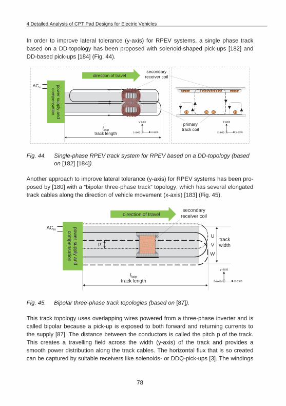
4 Detailed Analysis of CPT Pad Designs for Electric Vehicles
78
In order to improve lateral tolerance (y-axis) for RPEV systems, a single phase track based on a DD-topology has been proposed with solenoid-shaped pick-ups [182] and DD-based pick-ups [184] (Fig. 44).
Fig. 44. Single-phase RPEV track system for RPEV based on a DD-topology (based on [182] [184]).
Another approach to improve lateral tolerance (y-axis) for RPEV systems has been pro-posed by [180] with a “bipolar three-phase track” topology, which has several elongated track cables along the direction of vehicle movement (x-axis) [183] (Fig. 45).
Fig. 45. Bipolar three-phase track topologies (based on [87]).
This track topology uses overlapping wires powered from a three-phase inverter and is called bipolar because a pick-up is exposed to both forward and returning currents to the supply [87]. The distance between the conductors is called the pitch p of the track. This creates a travelling field across the width (y-axis) of the track and provides a smooth power distribution along the track cables. The horizontal flux that is so created can be captured by suitable receivers like solenoids- or DDQ-pick-ups [3]. The windings
ACin
llooptrack length
power supply
andcom
pensation
direction of travel
primarytrack coil
secondaryreceiver coil
y-axis
x-axisz-axis
z-axis
y-axisx-axis
ACin
llooptrack length
power supply
andcom
pensationdirection of travel
secondaryreceiver coil
trackwidth
y-axis
x-axisz-axis
pU
V
W
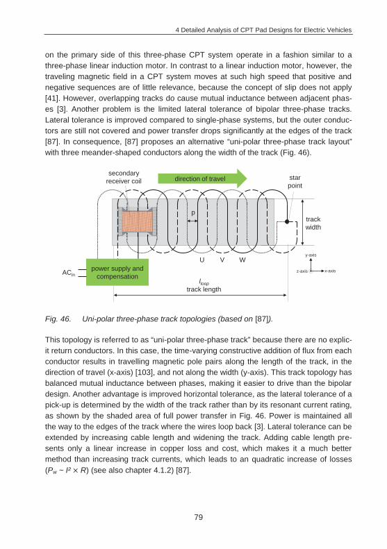
4 Detailed Analysis of CPT Pad Designs for Electric Vehicles
79
on the primary side of this three-phase CPT system operate in a fashion similar to a three-phase linear induction motor. In contrast to a linear induction motor, however, the traveling magnetic field in a CPT system moves at such high speed that positive and negative sequences are of little relevance, because the concept of slip does not apply [41]. However, overlapping tracks do cause mutual inductance between adjacent phas-es [3]. Another problem is the limited lateral tolerance of bipolar three-phase tracks. Lateral tolerance is improved compared to single-phase systems, but the outer conduc-tors are still not covered and power transfer drops significantly at the edges of the track [87]. In consequence, [87] proposes an alternative “uni-polar three-phase track layout” with three meander-shaped conductors along the width of the track (Fig. 46).
Fig. 46. Uni-polar three-phase track topologies (based on [87]).
This topology is referred to as “uni-polar three-phase track” because there are no explic-it return conductors. In this case, the time-varying constructive addition of flux from each conductor results in travelling magnetic pole pairs along the length of the track, in the direction of travel (x-axis) [103], and not along the width (y-axis). This track topology has balanced mutual inductance between phases, making it easier to drive than the bipolar design. Another advantage is improved horizontal tolerance, as the lateral tolerance of a pick-up is determined by the width of the track rather than by its resonant current rating, as shown by the shaded area of full power transfer in Fig. 46. Power is maintained all the way to the edges of the track where the wires loop back [3]. Lateral tolerance can be extended by increasing cable length and widening the track. Adding cable length pre-sents only a linear increase in copper loss and cost, which makes it a much better method than increasing track currents, which leads to an quadratic increase of losses (Pw ~ I² R) (see also chapter 4.1.2) [87].
power supply andcompensationACin
direction of travel
llooptrack length
secondaryreceiver coil
trackwidth
y-axis
x-axisz-axis
p
starpoint
U V W
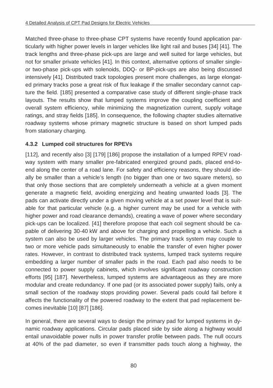
4 Detailed Analysis of CPT Pad Designs for Electric Vehicles
80
Matched three-phase to three-phase CPT systems have recently found application par-ticularly with higher power levels in larger vehicles like light rail and buses [34] [41]. The track lengths and three-phase pick-ups are large and well suited for large vehicles, but not for smaller private vehicles [41]. In this context, alternative options of smaller single- or two-phase pick-ups with solenoids, DDQ- or BP-pick-ups are also being discussed intensively [41]. Distributed track topologies present more challenges, as large elongat-ed primary tracks pose a great risk of flux leakage if the smaller secondary cannot cap-ture the field. [185] presented a comparative case study of different single-phase track layouts. The results show that lumped systems improve the coupling coefficient and overall system efficiency, while minimizing the magnetization current, supply voltage ratings, and stray fields [185]. In consequence, the following chapter studies alternative roadway systems whose primary magnetic structure is based on short lumped pads from stationary charging.
4.3.2 Lumped coil structures for RPEVs
[112], and recently also [3] [179] [186] propose the installation of a lumped RPEV road-way system with many smaller pre-fabricated energized ground pads, placed end-to-end along the center of a road lane. For safety and efficiency reasons, they should ide-ally be smaller than a vehicle’s length (no bigger than one or two square meters), so that only those sections that are completely underneath a vehicle at a given moment generate a magnetic field, avoiding energizing and heating unwanted loads [3]. The pads can activate directly under a given moving vehicle at a set power level that is suit-able for that particular vehicle (e.g. a higher current may be used for a vehicle with higher power and road clearance demands), creating a wave of power where secondary pick-ups can be localized. [41] therefore propose that each coil segment should be ca-pable of delivering 30-40 kW and above for charging and propelling a vehicle. Such a system can also be used by larger vehicles. The primary track system may couple to two or more vehicle pads simultaneously to enable the transfer of even higher power rates. However, in contrast to distributed track systems, lumped track systems require embedding a larger number of smaller pads in the road. Each pad also needs to be connected to power supply cabinets, which involves significant roadway construction efforts [95] [187]. Nevertheless, lumped systems are advantageous as they are more modular and create redundancy. If one pad (or its associated power supply) fails, only a small section of the roadway stops providing power. Several pads could fail before it affects the functionality of the powered roadway to the extent that pad replacement be-comes inevitable [10] [87] [186].
In general, there are several ways to design the primary pad for lumped systems in dy-namic roadway applications. Circular pads placed side by side along a highway would entail unavoidable power nulls in power transfer profile between pads. The null occurs at 40% of the pad diameter, so even if transmitter pads touch along a highway, the
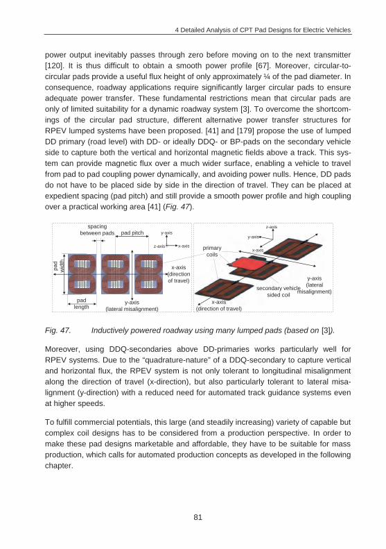
4 Detailed Analysis of CPT Pad Designs for Electric Vehicles
81
power output inevitably passes through zero before moving on to the next transmitter [120]. It is thus difficult to obtain a smooth power profile [67]. Moreover, circular-to-circular pads provide a useful flux height of only approximately ¼ of the pad diameter. In consequence, roadway applications require significantly larger circular pads to ensure adequate power transfer. These fundamental restrictions mean that circular pads are only of limited suitability for a dynamic roadway system [3]. To overcome the shortcom-ings of the circular pad structure, different alternative power transfer structures for RPEV lumped systems have been proposed. [41] and [179] propose the use of lumped DD primary (road level) with DD- or ideally DDQ- or BP-pads on the secondary vehicle side to capture both the vertical and horizontal magnetic fields above a track. This sys-tem can provide magnetic flux over a much wider surface, enabling a vehicle to travel from pad to pad coupling power dynamically, and avoiding power nulls. Hence, DD pads do not have to be placed side by side in the direction of travel. They can be placed at expedient spacing (pad pitch) and still provide a smooth power profile and high coupling over a practical working area [41] (Fig. 47).
Fig. 47. Inductively powered roadway using many lumped pads (based on [3]).
Moreover, using DDQ-secondaries above DD-primaries works particularly well for RPEV systems. Due to the “quadrature-nature” of a DDQ-secondary to capture vertical and horizontal flux, the RPEV system is not only tolerant to longitudinal misalignment along the direction of travel (x-direction), but also particularly tolerant to lateral misa-lignment (y-direction) with a reduced need for automated track guidance systems even at higher speeds.
To fulfill commercial potentials, this large (and steadily increasing) variety of capable but complex coil designs has to be considered from a production perspective. In order to make these pad designs marketable and affordable, they have to be suitable for mass production, which calls for automated production concepts as developed in the following chapter.
x-axis (direction of travel)
y-axis (lateral
misalignment)
primary coils
secondary vehicle sided coil
x-axis (direction of travel)
y-axis (lateral misalignment)
pad pitch
pad length
pad
wid
th
spacingbetween pads y-axis
x-axisz-axis
y-axis
x-axis
z-axis
5 Development and Implementation of Production Concepts for CPT Systems
82
5 Development and Implementation of Production Concepts for CPT Systems
In view of increasing global interest in EV CPT system launches [11] [12], considerable new potentials for value creation opened up for car manufacturers and their suppliers, in combination with a general increase in demand for EVs. The next few years will be of great opportunity to increase demand for CPT systems, as it is not only purely electrical-ly powered vehicles, but especially plug-in hybrid EVs that will favor CPT systems. Therefore, aside from the factors efficiency, safety, etc., the prospect of mass-producing contactless power transfer components puts manufacturers before further challenges of sophisticated system integration approaches (weight, space, temperature, and EMF re-quirements), cost reduction, and cycle times. CPT systems will make EVs in a first step more expensive as all EVs will continue to also have a standard plug in the next years. Further down the road, CPT will make its way into mass market vehicles in cheaper price segments, and thus cost will eventually become the most decisive factor for sys-tem competitiveness [7]. So far, contactless power transfer systems, e.g. for AGVs or prototypic EV systems, have been produced manually with rigid coil structures due to small unit numbers. This often results in quality variations in the pads [18]. However, as quality is paramount in the automotive industry, it is important to ensure product quality with well-established and reliable production processes with material-specific analyses to control production tolerances and to avoid imperfections. A lack of quality can result in lower efficiency (e.g. because of winding tolerances of HF-Litz wires, cracks in fer-rites, etc.) or even be dangerous for the driver and other road users (e.g. HF-Litz wires jutting out of a damaged pad, losing parts of a damaged pad during driving), and may result in expensive recalls accompanied with a loss of reputation. Additionally, the high volatility of the forecast and uncertain sales potentials call for flexible, modular and standardized assembly and handling technologies [16] [17]. Moreover, it is yet unclear to what extend charging pads will have to be adapted to individual vehicle architectures, even with standardized charging pads.
In this context, capable supply chains need to be set up step-by-step as demand evolves - from sub-suppliers all the way to integrating components into the vehicle at the manufacturing plants. It will generally help market development if CPT system de-signs are optimized for manufacturing and process complexity with ultimately reduced costs [7] [71]. Suitable materials and their specific shapes have to be carefully selected as they determine system function and also have a great impact on associated produc-tion processes. Thus, various production technologies and disciplines need to be con-sidered. This chapter covers the entire value chain (5.1) with a focus on the process of winding HF-Litz wire coils (5.2). This process step is especially relevant for product properties and quality, harbors several failure risks, and shows potential for further ra-
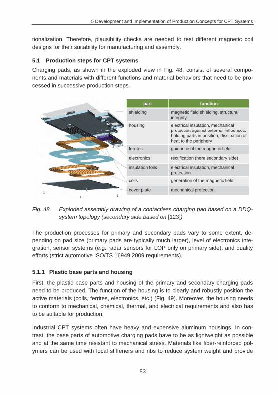
5 Development and Implementation of Production Concepts for CPT Systems
83
tionalization. Therefore, plausibility checks are needed to test different magnetic coil designs for their suitability for manufacturing and assembly.
5.1 Production steps for CPT systems Charging pads, as shown in the exploded view in Fig. 48, consist of several compo-nents and materials with different functions and material behaviors that need to be pro-cessed in successive production steps.
Fig. 48. Exploded assembly drawing of a contactless charging pad based on a DDQ- system topology (secondary side based on [123]).
The production processes for primary and secondary pads vary to some extent, de-pending on pad size (primary pads are typically much larger), level of electronics inte-gration, sensor systems (e.g. radar sensors for LOP only on primary side), and quality efforts (strict automotive ISO/TS 16949:2009 requirements).
5.1.1 Plastic base parts and housing
First, the plastic base parts and housing of the primary and secondary charging pads need to be produced. The function of the housing is to clearly and robustly position the active materials (coils, ferrites, electronics, etc.) (Fig. 49). Moreover, the housing needs to conform to mechanical, chemical, thermal, and electrical requirements and also has to be suitable for production.
Industrial CPT systems often have heavy and expensive aluminum housings. In con-trast, the base parts of automotive charging pads have to be as lightweight as possible and at the same time resistant to mechanical stress. Materials like fiber-reinforced pol-ymers can be used with local stiffeners and ribs to reduce system weight and provide
part function
shielding magnetic field shielding, structural integrity
housing electrical insulation, mechanical protection against external influences, holding parts in position, dissipation of heat to the periphery
ferrites guidance of the magnetic field
electronics rectification (here secondary side)
insulation foils electrical insulation, mechanical protection
coils generation of the magnetic field
cover plate mechanical protection
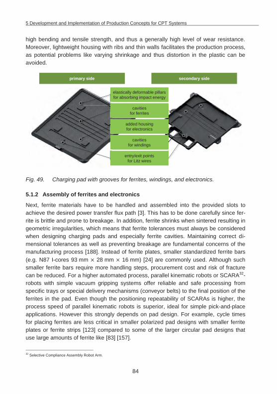
5 Development and Implementation of Production Concepts for CPT Systems
84
high bending and tensile strength, and thus a generally high level of wear resistance. Moreover, lightweight housing with ribs and thin walls facilitates the production process, as potential problems like varying shrinkage and thus distortion in the plastic can be avoided.
Fig. 49. Charging pad with grooves for ferrites, windings, and electronics.
5.1.2 Assembly of ferrites and electronics
Next, ferrite materials have to be handled and assembled into the provided slots to achieve the desired power transfer flux path [3]. This has to be done carefully since fer-rite is brittle and prone to breakage. In addition, ferrite shrinks when sintered resulting in geometric irregularities, which means that ferrite tolerances must always be considered when designing charging pads and especially ferrite cavities. Maintaining correct di-mensional tolerances as well as preventing breakage are fundamental concerns of the manufacturing process [188]. Instead of ferrite plates, smaller standardized ferrite bars (e.g. N87 I-cores 93 mm 28 mm 16 mm) [24] are commonly used. Although such smaller ferrite bars require more handling steps, procurement cost and risk of fracture can be reduced. For a higher automated process, parallel kinematic robots or SCARA32-robots with simple vacuum gripping systems offer reliable and safe processing from specific trays or special delivery mechanisms (conveyor belts) to the final position of the ferrites in the pad. Even though the positioning repeatability of SCARAs is higher, the process speed of parallel kinematic robots is superior, ideal for simple pick-and-place applications. However this strongly depends on pad design. For example, cycle times for placing ferrites are less critical in smaller polarized pad designs with smaller ferrite plates or ferrite strips [123] compared to some of the larger circular pad designs that use large amounts of ferrite like [83] [157].
32 Selective Compliance Assembly Robot Arm.
elastically deformable pillars for absorbing impact energy
primary side secondary side
cavities for ferrites
added housing for electronics
cavities for windings
entry/exit points for Litz wires
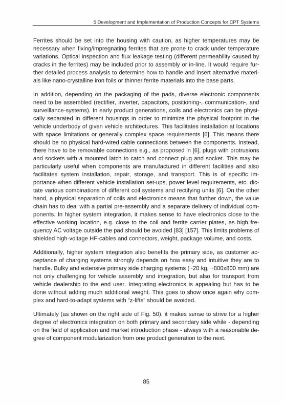
5 Development and Implementation of Production Concepts for CPT Systems
85
Ferrites should be set into the housing with caution, as higher temperatures may be necessary when fixing/impregnating ferrites that are prone to crack under temperature variations. Optical inspection and flux leakage testing (different permeability caused by cracks in the ferrites) may be included prior to assembly or in-line. It would require fur-ther detailed process analysis to determine how to handle and insert alternative materi-als like nano-crystalline iron foils or thinner ferrite materials into the base parts.
In addition, depending on the packaging of the pads, diverse electronic components need to be assembled (rectifier, inverter, capacitors, positioning-, communication-, and surveillance-systems). In early product generations, coils and electronics can be physi-cally separated in different housings in order to minimize the physical footprint in the vehicle underbody of given vehicle architectures. This facilitates installation at locations with space limitations or generally complex space requirements [6]. This means there should be no physical hard-wired cable connections between the components. Instead, there have to be removable connections e.g., as proposed in [6], plugs with protrusions and sockets with a mounted latch to catch and connect plug and socket. This may be particularly useful when components are manufactured in different facilities and also facilitates system installation, repair, storage, and transport. This is of specific im-portance when different vehicle installation set-ups, power level requirements, etc. dic-tate various combinations of different coil systems and rectifying units [6]. On the other hand, a physical separation of coils and electronics means that further down, the value chain has to deal with a partial pre-assembly and a separate delivery of individual com-ponents. In higher system integration, it makes sense to have electronics close to the effective working location, e.g. close to the coil and ferrite carrier plates, as high fre-quency AC voltage outside the pad should be avoided [83] [157]. This limits problems of shielded high-voltage HF-cables and connectors, weight, package volume, and costs.
Additionally, higher system integration also benefits the primary side, as customer ac-ceptance of charging systems strongly depends on how easy and intuitive they are to handle. Bulky and extensive primary side charging systems (~20 kg, ~800x800 mm) are not only challenging for vehicle assembly and integration, but also for transport from vehicle dealership to the end user. Integrating electronics is appealing but has to be done without adding much additional weight. This goes to show once again why com-plex and hard-to-adapt systems with “z-lifts” should be avoided.
Ultimately (as shown on the right side of Fig. 50), it makes sense to strive for a higher degree of electronics integration on both primary and secondary side while - depending on the field of application and market introduction phase - always with a reasonable de-gree of component modularization from one product generation to the next.
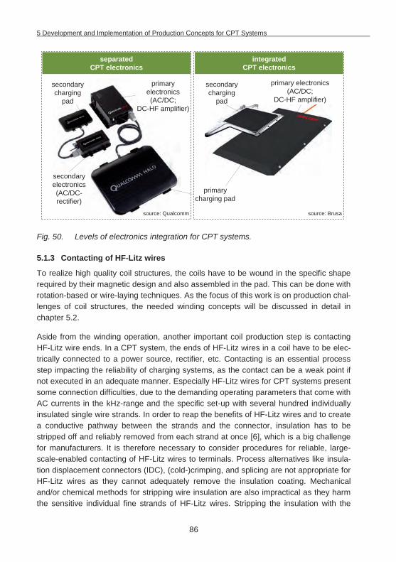
5 Development and Implementation of Production Concepts for CPT Systems
86
Fig. 50. Levels of electronics integration for CPT systems.
5.1.3 Contacting of HF-Litz wires
To realize high quality coil structures, the coils have to be wound in the specific shape required by their magnetic design and also assembled in the pad. This can be done with rotation-based or wire-laying techniques. As the focus of this work is on production chal-lenges of coil structures, the needed winding concepts will be discussed in detail in chapter 5.2.
Aside from the winding operation, another important coil production step is contacting HF-Litz wire ends. In a CPT system, the ends of HF-Litz wires in a coil have to be elec-trically connected to a power source, rectifier, etc. Contacting is an essential process step impacting the reliability of charging systems, as the contact can be a weak point if not executed in an adequate manner. Especially HF-Litz wires for CPT systems present some connection difficulties, due to the demanding operating parameters that come with AC currents in the kHz-range and the specific set-up with several hundred individually insulated single wire strands. In order to reap the benefits of HF-Litz wires and to create a conductive pathway between the strands and the connector, insulation has to be stripped off and reliably removed from each strand at once [6], which is a big challenge for manufacturers. It is therefore necessary to consider procedures for reliable, large-scale-enabled contacting of HF-Litz wires to terminals. Process alternatives like insula-tion displacement connectors (IDC), (cold-)crimping, and splicing are not appropriate for HF-Litz wires as they cannot adequately remove the insulation coating. Mechanical and/or chemical methods for stripping wire insulation are also impractical as they harm the sensitive individual fine strands of HF-Litz wires. Stripping the insulation with the
separated CPT electronics
integrated CPT electronics
primary charging pad
secondary charging
pad
secondary charging
pad
secondary electronics (AC/DC-rectifier)
primary electronics (AC/DC;
DC-HF amplifier)
primary electronics (AC/DC;
DC-HF amplifier)
source: Qualcomm source: Brusa
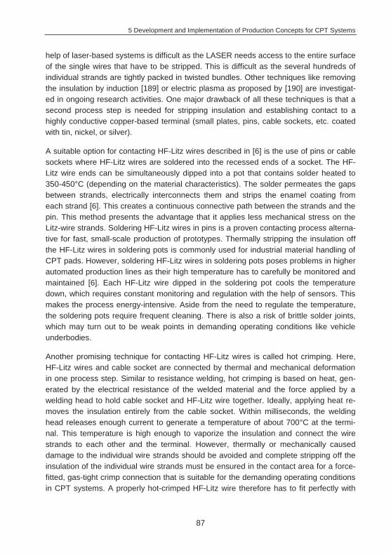
5 Development and Implementation of Production Concepts for CPT Systems
87
help of laser-based systems is difficult as the LASER needs access to the entire surface of the single wires that have to be stripped. This is difficult as the several hundreds of individual strands are tightly packed in twisted bundles. Other techniques like removing the insulation by induction [189] or electric plasma as proposed by [190] are investigat-ed in ongoing research activities. One major drawback of all these techniques is that a second process step is needed for stripping insulation and establishing contact to a highly conductive copper-based terminal (small plates, pins, cable sockets, etc. coated with tin, nickel, or silver).
A suitable option for contacting HF-Litz wires described in [6] is the use of pins or cable sockets where HF-Litz wires are soldered into the recessed ends of a socket. The HF-Litz wire ends can be simultaneously dipped into a pot that contains solder heated to 350-450°C (depending on the material characteristics). The solder permeates the gaps between strands, electrically interconnects them and strips the enamel coating from each strand [6]. This creates a continuous connective path between the strands and the pin. This method presents the advantage that it applies less mechanical stress on the Litz-wire strands. Soldering HF-Litz wires in pins is a proven contacting process alterna-tive for fast, small-scale production of prototypes. Thermally stripping the insulation off the HF-Litz wires in soldering pots is commonly used for industrial material handling of CPT pads. However, soldering HF-Litz wires in soldering pots poses problems in higher automated production lines as their high temperature has to carefully be monitored and maintained [6]. Each HF-Litz wire dipped in the soldering pot cools the temperature down, which requires constant monitoring and regulation with the help of sensors. This makes the process energy-intensive. Aside from the need to regulate the temperature, the soldering pots require frequent cleaning. There is also a risk of brittle solder joints, which may turn out to be weak points in demanding operating conditions like vehicle underbodies.
Another promising technique for contacting HF-Litz wires is called hot crimping. Here, HF-Litz wires and cable socket are connected by thermal and mechanical deformation in one process step. Similar to resistance welding, hot crimping is based on heat, gen-erated by the electrical resistance of the welded material and the force applied by a welding head to hold cable socket and HF-Litz wire together. Ideally, applying heat re-moves the insulation entirely from the cable socket. Within milliseconds, the welding head releases enough current to generate a temperature of about 700°C at the termi-nal. This temperature is high enough to vaporize the insulation and connect the wire strands to each other and the terminal. However, thermally or mechanically caused damage to the individual wire strands should be avoided and complete stripping off the insulation of the individual wire strands must be ensured in the contact area for a force-fitted, gas-tight crimp connection that is suitable for the demanding operating conditions in CPT systems. A properly hot-crimped HF-Litz wire therefore has to fit perfectly with
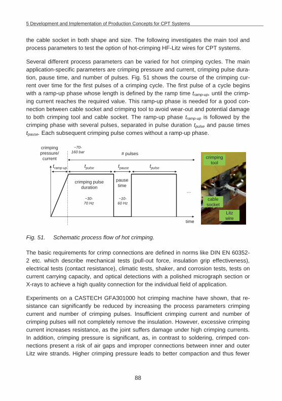
5 Development and Implementation of Production Concepts for CPT Systems
88
the cable socket in both shape and size. The following investigates the main tool and process parameters to test the option of hot-crimping HF-Litz wires for CPT systems.
Several different process parameters can be varied for hot crimping cycles. The main application-specific parameters are crimping pressure and current, crimping pulse dura-tion, pause time, and number of pulses. Fig. 51 shows the course of the crimping cur-rent over time for the first pulses of a crimping cycle. The first pulse of a cycle begins with a ramp-up phase whose length is defined by the ramp time tramp-up, until the crimp-ing current reaches the required value. This ramp-up phase is needed for a good con-nection between cable socket and crimping tool to avoid wear-out and potential damage to both crimping tool and cable socket. The ramp-up phase tramp-up is followed by the crimping phase with several pulses, separated in pulse duration tpulse and pause times tpause. Each subsequent crimping pulse comes without a ramp-up phase.
Fig. 51. Schematic process flow of hot crimping.
The basic requirements for crimp connections are defined in norms like DIN EN 60352-2 etc. which describe mechanical tests (pull-out force, insulation grip effectiveness), electrical tests (contact resistance), climatic tests, shaker, and corrosion tests, tests on current carrying capacity, and optical detections with a polished micrograph section or X-rays to achieve a high quality connection for the individual field of application.
Experiments on a CASTECH GFA301000 hot crimping machine have shown, that re-sistance can significantly be reduced by increasing the process parameters crimping current and number of crimping pulses. Insufficient crimping current and number of crimping pulses will not completely remove the insulation. However, excessive crimping current increases resistance, as the joint suffers damage under high crimping currents. In addition, crimping pressure is significant, as, in contrast to soldering, crimped con-nections present a risk of air gaps and improper connections between inner and outer Litz wire strands. Higher crimping pressure leads to better compaction and thus fewer
time
tramp-up tpausetpulse tpulse
# pulses
pausetime
crimping pulse duration
crimpingpressure/current
…
Litz wire
crimping tool
cable socket
ble
it
~30-70 Hz
~10-60 Hz
~70-160 bar
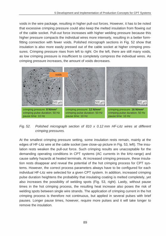
5 Development and Implementation of Production Concepts for CPT Systems
89
voids in the wire package, resulting in higher pull-out forces. However, it has to be noted that excessive crimping pressure could also keep the melted insulation from flowing out of the cable socket. Pull-out force increases with higher welding pressure because this higher pressure compacts the individual wires more intensely, resulting in a better form-fitting connection with fewer voids. Polished micrograph sections in Fig. 52 show that insulation is also more easily pressed out of the cable socket at higher crimping pres-sures. Crimping pressure rises from left to right. On the left, there are still many voids, as low crimping pressure is insufficient to completely compress the individual wires. As crimping pressure increases, the amount of voids decreases.
Fig. 52. Polished micrograph section of 810 x 0.12 mm HF-Litz wires at different crimping pressures.
At the smallest crimping pressure setting, some insulation rests remain, mainly at the edges of HF-Litz wire at the cable socket (see close-up picture in Fig. 53, left). The insu-lation rests weaken the pull-out force. Such crimping results are unacceptable for the demanding operating conditions in CPT systems (AC currents in the kHz-range) and cause safety hazards at heated terminals. At increased crimping pressure, these insula-tion rests disappear and reveal the potential of the hot crimping process for CPT sys-tems. However, the correct process parameters always have to be configured for each individual HF-Litz wire selected for a given CPT system. In addition, increased crimping pulse duration heightens the probability that insulating coating is melted completely, yet also increases the possibility of welding spots (Fig. 53, right). Lastly, without pause times in the hot crimping process, the resulting heat increase also poses the risk of welding spots between single wire strands. The application of crimping current in the hot crimping process is therefore not continuous, but applied in several pulses with brief pauses. Longer pause times, however, require more pulses and it will take longer to remove the insulation.
500 m500 m500 m
voids
crimping pressure: 8 N/mm²crimping pulse duration: 50 Hzpause time: 10 Hz
crimping pressure: 12 N/mm²crimping pulse duration: 50 Hzpause time: 10 Hz
crimping pressure: 16 N/mm²crimping pulse duration: 50 Hzpause time: 10 Hz
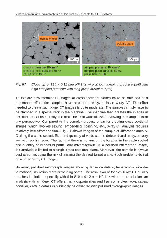
5 Development and Implementation of Production Concepts for CPT Systems
90
Fig. 53. Close up of 810 x 0.12 mm HF-Litz wire at low crimping pressure (left) and high crimping pressure with long pulse duration (right).
To explore how meaningful images of cross-sectional planes could be obtained at a reasonable effort, the samples have also been analyzed in an X-ray CT. The effort needed to create such X-ray CT images is quite moderate. The samples simply have to be clamped in a special rack in the machine. The machine then creates the images in ~30 minutes. Subsequently, the machine's software allows for viewing the samples from any perspective. Compared to the complex process chain for creating cross-sectional images, which involves sawing, embedding, polishing, etc., X-ray CT analysis requires relatively little effort and time. Fig. 54 shows images of the sample at different planes A-C along the cable socket. Size and quantity of voids can be detected and analyzed very well with such images. The fact that there is no limit on the location in the cable socket and quantity of images is particularly advantageous. In a polished micrograph image, the analysis is limited to a single cross-sectional plane. Moreover, the sample is always destroyed, including the risk of missing the desired target plane. Such problems do not arise in an X-ray CT image.
However, polished micrograph images show by far more details, for example wire de-formations, insulation rests or welding spots. The resolution of today’s X-ray CT quickly reaches its limits, especially with thin 810 x 0.12 mm HF Litz wires. In conclusion, an analysis with an X-ray CT offers many opportunities and has some clear advantages; however, certain details can still only be observed with polished micrographic images.
100 m
insulation rest
100 m
welding spots
crimping pressure: 8 N/mm²crimping pulse duration: 50 Hzpause time: 10 Hz
crimping pressure: 16 N/mm²crimping pulse duration: 50 Hzpause time: 10 Hz
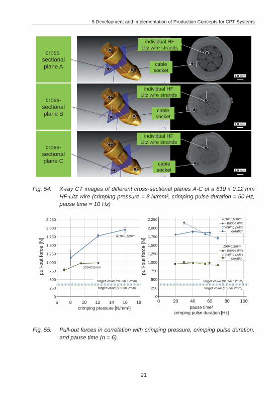
5 Development and Implementation of Production Concepts for CPT Systems
91
Fig. 54. X-ray CT images of different cross-sectional planes A-C of a 810 x 0.12 mm HF-Litz wire (crimping pressure = 8 N/mm², crimping pulse duration = 50 Hz, pause time = 10 Hz)
Fig. 55. Pull-out forces in correlation with crimping pressure, crimping pulse duration, and pause time (n = 6).
individual HF Litz wire strands
cable socket
cross-sectional plane A
cross-sectional plane B
cross-sectional plane C
cable socket
cable socket
individual HF Litz wire strands
individual HF Litz wire strands
1.0 mm
1.0 mm
1.0 mm
crimping pressure [N/mm²]
500
750
1,000
250
6 10 12 14 16 18
1,250
1,500
pause time/ crimping pulse duration [Hz]
8
1,750
2,000
2,250
0
pull-
out f
orce
[N]
500
750
1,000
250
1,250
1,500
1,750
2,000
2,250
0
pull-
out f
orce
[N]
0 40 60 80 10020
target value (810x0.12mm)
target value (150x0.2mm)
target value (810x0.12mm)
target value (150x0.2mm)
810x0.12mm
150x0.2mm
810x0.12mmpause time
crimping pulse duration
150x0.2mmpause time
crimping pulse duration
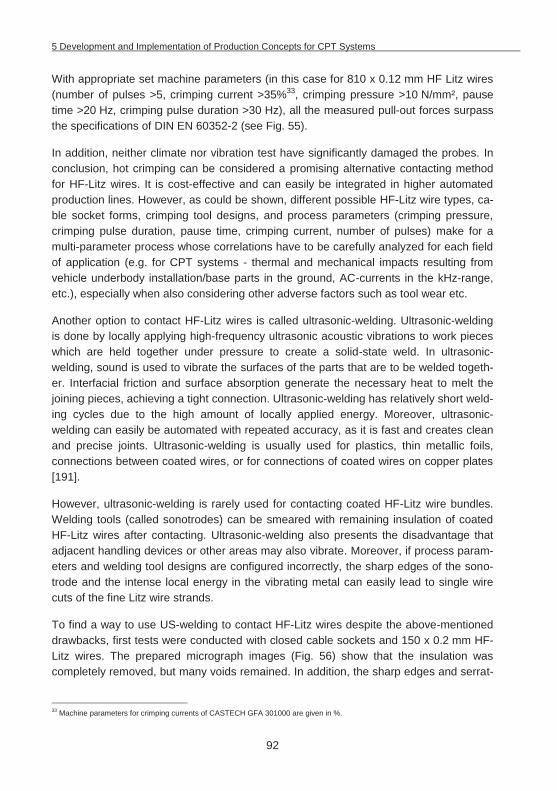
5 Development and Implementation of Production Concepts for CPT Systems
92
With appropriate set machine parameters (in this case for 810 x 0.12 mm HF Litz wires (number of pulses >5, crimping current >35%33, crimping pressure >10 N/mm², pause time >20 Hz, crimping pulse duration >30 Hz), all the measured pull-out forces surpass the specifications of DIN EN 60352-2 (see Fig. 55).
In addition, neither climate nor vibration test have significantly damaged the probes. In conclusion, hot crimping can be considered a promising alternative contacting method for HF-Litz wires. It is cost-effective and can easily be integrated in higher automated production lines. However, as could be shown, different possible HF-Litz wire types, ca-ble socket forms, crimping tool designs, and process parameters (crimping pressure, crimping pulse duration, pause time, crimping current, number of pulses) make for a multi-parameter process whose correlations have to be carefully analyzed for each field of application (e.g. for CPT systems - thermal and mechanical impacts resulting from vehicle underbody installation/base parts in the ground, AC-currents in the kHz-range, etc.), especially when also considering other adverse factors such as tool wear etc.
Another option to contact HF-Litz wires is called ultrasonic-welding. Ultrasonic-welding is done by locally applying high-frequency ultrasonic acoustic vibrations to work pieces which are held together under pressure to create a solid-state weld. In ultrasonic-welding, sound is used to vibrate the surfaces of the parts that are to be welded togeth-er. Interfacial friction and surface absorption generate the necessary heat to melt the joining pieces, achieving a tight connection. Ultrasonic-welding has relatively short weld-ing cycles due to the high amount of locally applied energy. Moreover, ultrasonic-welding can easily be automated with repeated accuracy, as it is fast and creates clean and precise joints. Ultrasonic-welding is usually used for plastics, thin metallic foils, connections between coated wires, or for connections of coated wires on copper plates [191].
However, ultrasonic-welding is rarely used for contacting coated HF-Litz wire bundles. Welding tools (called sonotrodes) can be smeared with remaining insulation of coated HF-Litz wires after contacting. Ultrasonic-welding also presents the disadvantage that adjacent handling devices or other areas may also vibrate. Moreover, if process param-eters and welding tool designs are configured incorrectly, the sharp edges of the sono-trode and the intense local energy in the vibrating metal can easily lead to single wire cuts of the fine Litz wire strands.
To find a way to use US-welding to contact HF-Litz wires despite the above-mentioned drawbacks, first tests were conducted with closed cable sockets and 150 x 0.2 mm HF-Litz wires. The prepared micrograph images (Fig. 56) show that the insulation was completely removed, but many voids remained. In addition, the sharp edges and serrat-
33 Machine parameters for crimping currents of CASTECH GFA 301000 are given in %.
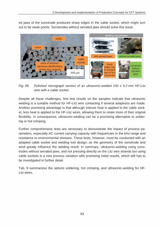
5 Development and Implementation of Production Concepts for CPT Systems
93
ed jaws of the sonotrode produced sharp edges in the cable socket, which might turn out to be weak points. Sonotrodes without serrated jaws should solve this issue.
Fig. 56. Polished micrograph section of an ultrasonic-welded 150 x 0.2 mm HF-Litz wire with a cable socket.
Despite all these challenges, first test results on the samples indicate that ultrasonic welding is a suitable method for HF-Litz wire contacting if several adaptions are made. Another promising advantage is that although intense heat is applied to the cable sock-et, less heat is applied to the HF-Litz wires, allowing them to retain more of their original flexibility. In consequence, ultrasonic-welding can be a promising alternative to solder-ing or hot crimping.
Further comprehensive tests are necessary to demonstrate the impact of process pa-rameters, especially AC current carrying capacity with frequencies in the kHz-range and resistance to environmental stresses. These tests, however, must be conducted with an adapted cable socket and welding tool design, as the geometry of the sonotrode and anvil greatly influence the welding result. In summary, ultrasonic-welding using sono-trodes without serrated jaws, and not pressing directly on the Litz wire strands but using cable sockets is a new process variation with promising initial results, which still has to be investigated in further detail.
Tab. 9 summarizes the options soldering, hot crimping, and ultrasonic-welding for HF-Litz wires.
crack
voids
500 m
area of inhomo-geneous distributions
of the wire strands
sharp edges due to serrated jaws of the sonotrode
cable socket
without serrated jaws
welding sonotrodes
with serrated jawssource: sonotronic
connection without serrated
jaws
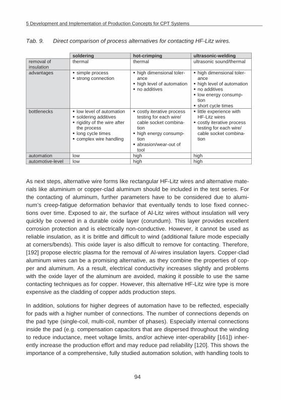
5 Development and Implementation of Production Concepts for CPT Systems
94
Tab. 9. Direct comparison of process alternatives for contacting HF-Litz wires.
soldering hot-crimping ultrasonic-welding removal of insulation
thermal thermal ultrasonic sound/thermal
advantages simple process strong connection
high dimensional toler-ance
high level of automation no additives
high dimensional toler-ance
high level of automation no additives low energy consump-tion
short cycle times bottlenecks low level of automation
soldering additives rigidity of the wire after the process
long cycle times complex wire handling
costly iterative process testing for each wire/ cable socket combina-tion
high energy consump-tion
abrasion/wear-out of tool
little experience with HF-Litz wires
costly iterative process testing for each wire/ cable socket combina-tion
automation low high high automotive-level low high high
As next steps, alternative wire forms like rectangular HF-Litz wires and alternative mate-rials like aluminium or copper-clad aluminum should be included in the test series. For the contacting of aluminum, further parameters have to be considered due to alumi-num’s creep-fatigue deformation behavior that eventually tends to lose fixed connec-tions over time. Exposed to air, the surface of Al-Litz wires without insulation will very quickly be covered in a durable oxide layer (corundum). This layer provides excellent corrosion protection and is electrically non-conductive. However, it cannot be used as reliable insulation, as it is brittle and difficult to wind (additional failure mode especially at corners/bends). This oxide layer is also difficult to remove for contacting. Therefore, [192] propose electric plasma for the removal of Al-wires insulation layers. Copper-clad aluminum wires can be a promising alternative, as they combine the properties of cop-per and aluminum. As a result, electrical conductivity increases slightly and problems with the oxide layer of the aluminum are avoided, making it possible to use the same contacting techniques as for copper. However, this alternative HF-Litz wire type is more expensive as the cladding of copper adds production steps.
In addition, solutions for higher degrees of automation have to be reflected, especially for pads with a higher number of connections. The number of connections depends on the pad type (single-coil, multi-coil, number of phases). Especially internal connections inside the pad (e.g. compensation capacitors that are dispersed throughout the winding to reduce inductance, meet voltage limits, and/or achieve inter-operability [161]) inher-ently increase the production effort and may reduce pad reliability [120]. This shows the importance of a comprehensive, fully studied automation solution, with handling tools to
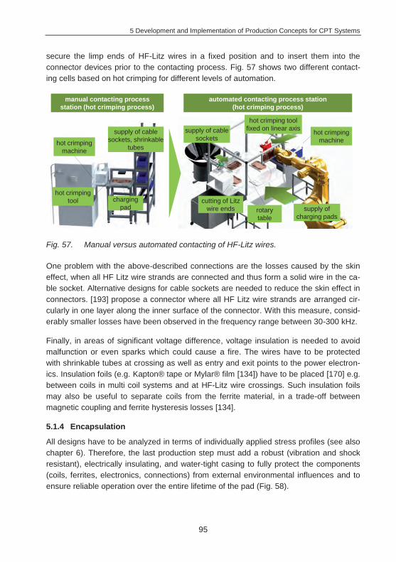
5 Development and Implementation of Production Concepts for CPT Systems
95
secure the limp ends of HF-Litz wires in a fixed position and to insert them into the connector devices prior to the contacting process. Fig. 57 shows two different contact-ing cells based on hot crimping for different levels of automation.
Fig. 57. Manual versus automated contacting of HF-Litz wires.
One problem with the above-described connections are the losses caused by the skin effect, when all HF Litz wire strands are connected and thus form a solid wire in the ca-ble socket. Alternative designs for cable sockets are needed to reduce the skin effect in connectors. [193] propose a connector where all HF Litz wire strands are arranged cir-cularly in one layer along the inner surface of the connector. With this measure, consid-erably smaller losses have been observed in the frequency range between 30-300 kHz.
Finally, in areas of significant voltage difference, voltage insulation is needed to avoid malfunction or even sparks which could cause a fire. The wires have to be protected with shrinkable tubes at crossing as well as entry and exit points to the power electron-ics. Insulation foils (e.g. Kapton® tape or Mylar® film [134]) have to be placed [170] e.g. between coils in multi coil systems and at HF-Litz wire crossings. Such insulation foils may also be useful to separate coils from the ferrite material, in a trade-off between magnetic coupling and ferrite hysteresis losses [134].
5.1.4 Encapsulation
All designs have to be analyzed in terms of individually applied stress profiles (see also chapter 6). Therefore, the last production step must add a robust (vibration and shock resistant), electrically insulating, and water-tight casing to fully protect the components (coils, ferrites, electronics, connections) from external environmental influences and to ensure reliable operation over the entire lifetime of the pad (Fig. 58).
automated contacting process station(hot crimping process)
manual contacting process station (hot crimping process)
hot crimping machine
charging pad supply of
charging padss
cutting of Litz wire ends
supply of cable sockets
supply of cable sockets, shrinkable
tubes
hot crimping machine
hot crimping tool fixed on linear axis
hot crimping tool
rotary table
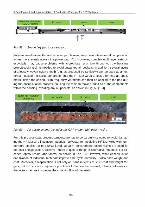
5 Development and Implementation of Production Concepts for CPT Systems
96
Fig. 58. Secondary pad cross section.
Fully encased transmitter and receiver pad housing may distribute external compression forces more evenly across the power pad [71]. However, complex multi-layer set-ups, especially, may cause problems with appropriate resin flow throughout the housing. Low-viscosity resin is needed to avoid unwanted air pockets. In addition, several layers of a loosely woven nylon sheath (e.g. as produced by Sofilec™) can be used as an ex-ternal insulation to assist penetration into the HF-Litz wires to lock them into an epoxy matrix inside the casing. High frequency vibrations can then be applied to the pad dur-ing the encapsulation process, causing the resin to move around all of the components within the housing, avoiding any air pockets, as shown in Fig. 59 [134].
Fig. 59. Air pocket in an AGV industrial CPT system with epoxy resin.
For this process step, process temperature has to be carefully selected to avoid damag-ing the HF-Litz wire insulation materials (polyester for insulating HF-Litz wires with tem-perature stability up to 150°C) [145]. Usually, polyurethane-based resins are used for the final encapsulation. However, there is quite a range of alternative materials like sili-cones, epoxy resins, and foams, as shown in Tab. 10. However, while encapsulation and fixation of individual materials improves life-cycle durability, it also adds weight and cost. Moreover, encapsulation is not only an issue in terms of strict cost and weight tar-gets, but also involves required cycle times to harden the material, a likely bottleneck in the value chain as it impedes the constant flow of materials.
secondary electronics (AC/DC-rectifier)
F
Litz wires ferrites resin
paper (for fixation of Litz wires) air pocket Litz wires resin
10 mm
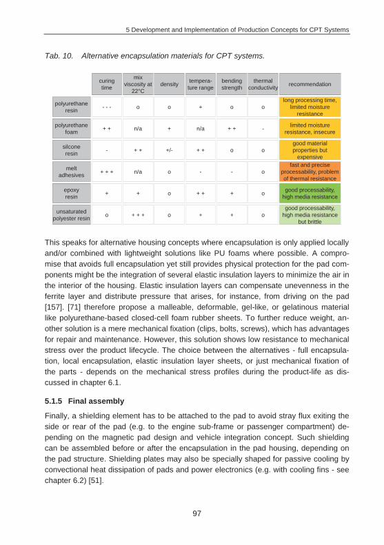
5 Development and Implementation of Production Concepts for CPT Systems
97
Tab. 10. Alternative encapsulation materials for CPT systems.
This speaks for alternative housing concepts where encapsulation is only applied locally and/or combined with lightweight solutions like PU foams where possible. A compro-mise that avoids full encapsulation yet still provides physical protection for the pad com-ponents might be the integration of several elastic insulation layers to minimize the air in the interior of the housing. Elastic insulation layers can compensate unevenness in the ferrite layer and distribute pressure that arises, for instance, from driving on the pad [157]. [71] therefore propose a malleable, deformable, gel-like, or gelatinous material like polyurethane-based closed-cell foam rubber sheets. To further reduce weight, an-other solution is a mere mechanical fixation (clips, bolts, screws), which has advantages for repair and maintenance. However, this solution shows low resistance to mechanical stress over the product lifecycle. The choice between the alternatives - full encapsula-tion, local encapsulation, elastic insulation layer sheets, or just mechanical fixation of the parts - depends on the mechanical stress profiles during the product-life as dis-cussed in chapter 6.1.
5.1.5 Final assembly
Finally, a shielding element has to be attached to the pad to avoid stray flux exiting the side or rear of the pad (e.g. to the engine sub-frame or passenger compartment) de-pending on the magnetic pad design and vehicle integration concept. Such shielding can be assembled before or after the encapsulation in the pad housing, depending on the pad structure. Shielding plates may also be specially shaped for passive cooling by convectional heat dissipation of pads and power electronics (e.g. with cooling fins - see chapter 6.2) [51].
silconeresin
epoxy resin
unsaturatedpolyester resin
melt adhesives
polyurethane foam
polyurethane resin
curingtime
mix viscosity at
22°Cdensity tempera-
ture rangebending strength
thermal conductivity recommendation
- - - o o + o olong processing time,
limited moisture resistance
+ + n/a + n/a + + - limited moisture resistance, insecure
- + + +/- + + o ogood material properties but
expensive
+ + + n/a o - - ofast and precise
processability, problem of thermal resistance
+ + o + + + o good processability, high media resistance
o + + + o + + ogood processability,
high media resistance but brittle
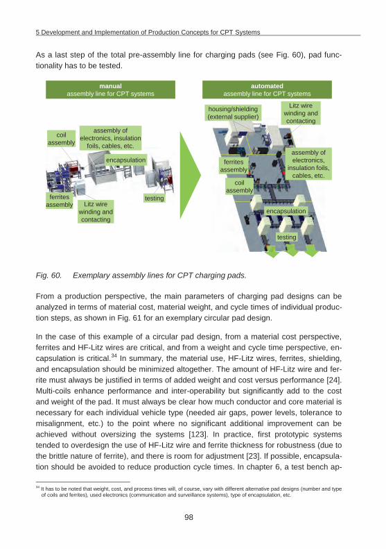
5 Development and Implementation of Production Concepts for CPT Systems
98
As a last step of the total pre-assembly line for charging pads (see Fig. 60), pad func-tionality has to be tested.
Fig. 60. Exemplary assembly lines for CPT charging pads.
From a production perspective, the main parameters of charging pad designs can be analyzed in terms of material cost, material weight, and cycle times of individual produc-tion steps, as shown in Fig. 61 for an exemplary circular pad design.
In the case of this example of a circular pad design, from a material cost perspective, ferrites and HF-Litz wires are critical, and from a weight and cycle time perspective, en-capsulation is critical.34 In summary, the material use, HF-Litz wires, ferrites, shielding, and encapsulation should be minimized altogether. The amount of HF-Litz wire and fer-rite must always be justified in terms of added weight and cost versus performance [24]. Multi-coils enhance performance and inter-operability but significantly add to the cost and weight of the pad. It must always be clear how much conductor and core material is necessary for each individual vehicle type (needed air gaps, power levels, tolerance to misalignment, etc.) to the point where no significant additional improvement can be achieved without oversizing the systems [123]. In practice, first prototypic systems tended to overdesign the use of HF-Litz wire and ferrite thickness for robustness (due to the brittle nature of ferrite), and there is room for adjustment [23]. If possible, encapsula-tion should be avoided to reduce production cycle times. In chapter 6, a test bench ap-
34 It has to be noted that weight, cost, and process times will, of course, vary with different alternative pad designs (number and type
of coils and ferrites), used electronics (communication and surveillance systems), type of encapsulation, etc.
automated assembly line for CPT systems
manual assembly line for CPT systems
encapsulation
assembly of electronics,
insulation foils, cables, etc.
ferrites assembly
Litz wire winding and contacting
housing/shielding (external supplier)
coil assembly
testing
encapsulation
ferrites assembly Litz wire
winding and contacting
coil assembly
testing
assembly of electronics, insulation
foils, cables, etc.
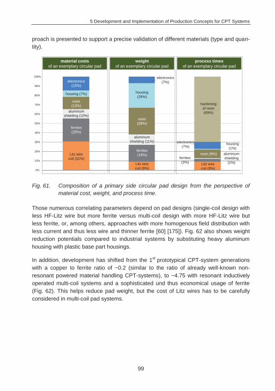
5 Development and Implementation of Production Concepts for CPT Systems
99
proach is presented to support a precise validation of different materials (type and quan-tity).
Fig. 61. Composition of a primary side circular pad design from the perspective of material cost, weight, and process time.
Those numerous correlating parameters depend on pad designs (single-coil design with less HF-Litz wire but more ferrite versus multi-coil design with more HF-Litz wire but less ferrite, or, among others, approaches with more homogenous field distribution with less current and thus less wire and thinner ferrite [60] [175]). Fig. 62 also shows weight reduction potentials compared to industrial systems by substituting heavy aluminum housing with plastic base part housings.
In addition, development has shifted from the 1st prototypical CPT-system generations with a copper to ferrite ratio of ~0.2 (similar to the ratio of already well-known non-resonant powered material handling CPT-systems), to ~4.75 with resonant inductively operated multi-coil systems and a sophisticated und thus economical usage of ferrite (Fig. 62). This helps reduce pad weight, but the cost of Litz wires has to be carefully considered in multi-coil pad systems.
Litz wire coil (31%)
ferrites (25%)
material costs of an exemplary circular pad
weightof an exemplary circular pad
process times of an exemplary circular pad
Litz wire coil (9%)
Litz wire coil (9%)
ferrites (3%)
aluminum shielding
(1%)
resin (9%)
housing (1%)
electronics (7%)
hardening of resin (69%)
ferrites (18%)
aluminum shielding (11%)
resin (28%)
housing (26%)
electronics(7%)
aluminum shielding (10%)
resin (13%)
housing (7%)
electronics (15%)
100%
90%
80%
70%
60%
50%
40%
30%
20%
10%
0%
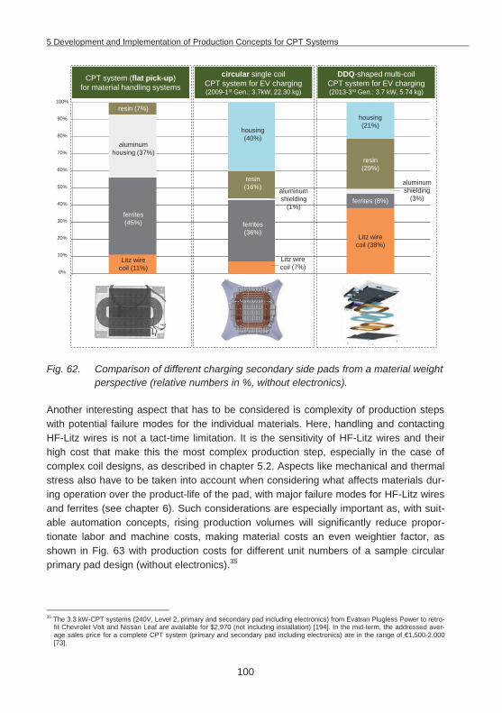
5 Development and Implementation of Production Concepts for CPT Systems
100
Fig. 62. Comparison of different charging secondary side pads from a material weight perspective (relative numbers in %, without electronics).
Another interesting aspect that has to be considered is complexity of production steps with potential failure modes for the individual materials. Here, handling and contacting HF-Litz wires is not a tact-time limitation. It is the sensitivity of HF-Litz wires and their high cost that make this the most complex production step, especially in the case of complex coil designs, as described in chapter 5.2. Aspects like mechanical and thermal stress also have to be taken into account when considering what affects materials dur-ing operation over the product-life of the pad, with major failure modes for HF-Litz wires and ferrites (see chapter 6). Such considerations are especially important as, with suit-able automation concepts, rising production volumes will significantly reduce propor-tionate labor and machine costs, making material costs an even weightier factor, as shown in Fig. 63 with production costs for different unit numbers of a sample circular primary pad design (without electronics).35
35 The 3.3 kW-CPT systems (240V, Level 2, primary and secondary pad including electronics) from Evatran Plugless Power to retro-
fit Chevrolet Volt and Nissan Leaf are available for $2,970 (not including installation) [194]. In the mid-term, the addressed aver-age sales price for a complete CPT system (primary and secondary pad including electronics) are in the range of €1,500-2,000 [73].
Litz wire coil (11%)
ferrites (45%)
CPT system (flat pick-up) for material handling systems
circular single coil CPT system for EV charging(2009-1st Gen.: 3.7kW, 22.30 kg)
DDQ-shaped multi-coil CPT system for EV charging(2013-3rd Gen.: 3.7 kW, 5.74 kg)
Litz wire coil (7%)
Litz wire coil (38%)
ferrites (8%)
aluminum shielding
(3%)
resin (29%)
housing (21%)
ferrites (36%)
aluminum shielding
(1%)
resin (16%)
housing (40%)
aluminum housing (37%)
resin (7%)100%
90%
80%
70%
60%
50%
40%
30%
20%
10%
0%
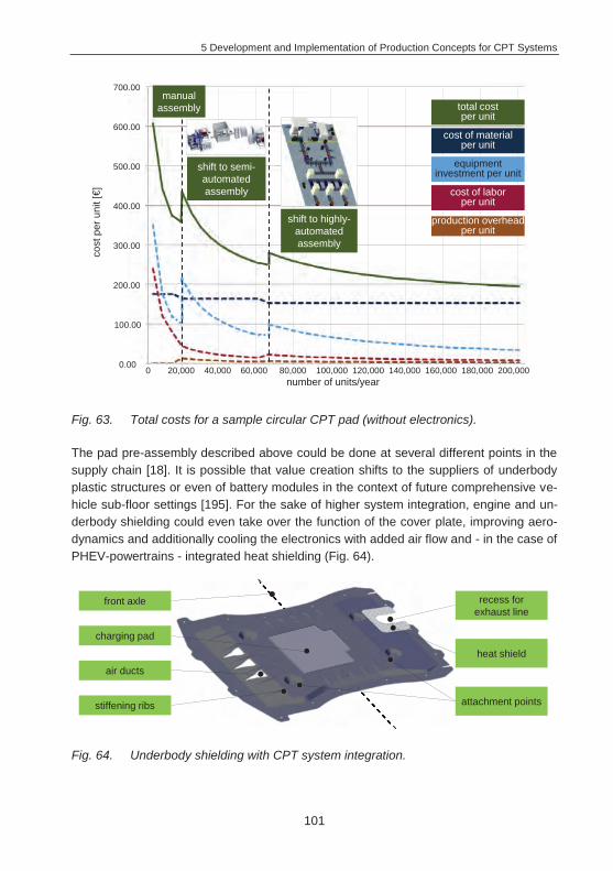
5 Development and Implementation of Production Concepts for CPT Systems
101
Fig. 63. Total costs for a sample circular CPT pad (without electronics).
The pad pre-assembly described above could be done at several different points in the supply chain [18]. It is possible that value creation shifts to the suppliers of underbody plastic structures or even of battery modules in the context of future comprehensive ve-hicle sub-floor settings [195]. For the sake of higher system integration, engine and un-derbody shielding could even take over the function of the cover plate, improving aero-dynamics and additionally cooling the electronics with added air flow and - in the case of PHEV-powertrains - integrated heat shielding (Fig. 64).
Fig. 64. Underbody shielding with CPT system integration.
700.00
600.00
500.00
400.00
300.00
200.00
100.00
0.00
total cost per unit
cost of material per unit
equipment investment per unit
cost of labor per unit
production overheadper unit
shift to semi-automated assembly
shift to highly-automated assembly
cost
per
uni
t [€]
number of units/year
manual assembly
0 20,000 40,000 60,000 80,000 100,000 120,000 140,000 160,000 180,000 200,000
charging pad
front axle
heat shield
stiffening ribs
air ducts
attachment points
recess for exhaust line
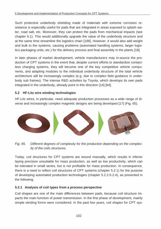
5 Development and Implementation of Production Concepts for CPT Systems
102
Such protective underbody shielding made of materials with extreme corrosion re-sistance is especially useful for pads that are integrated in areas exposed to splash wa-ter, road salt, etc. Moreover, they can protect the pads from mechanical impacts (see chapter 6.1). This would additionally upgrade the value of the underbody structure and at the same time streamline the logistics chain [196]. However, it would also add weight and bulk to the systems, causing problems (automated handling systems, larger logis-tics packaging units, etc.) for the delivery process and final assembly in the plants [18].
In later phases of market development, vehicle manufacturers may in-source the pro-duction of CPT systems in the event that, despite current efforts to standardize contact-less charging systems, they will become one of the key competitive vehicle compo-nents, and adapting modules to the individual underbody structure of the total vehicle architecture will be increasingly complex (e.g. due to complex field guidance in under-body sub frames). The intense R&D activities by Toyota, which develops its own pads integrated in the underbody, already point in this direction [14] [64].
5.2 HF-Litz wire winding technologies
HF-Litz wires, in particular, need adequate production processes as a wide range of di-verse and increasingly complex magnetic designs are being developed [17] (Fig. 65).
Fig. 65. Different degrees of complexity for the production depending on the complex-ity of the coils structures.
Today, coil structures for CPT systems are wound manually, which results in inferior laying precision unsuitable for mass production, as well as low productivity, which can be tolerated in small series, but is not profitable for mass production. In consequence, there is a need to reflect coil structures of CPT systems (chapter 5.2.1) for the purpose of developing automated production technologies (chapter 5.2.2-5.2.4), as presented in the following.
5.2.1 Analysis of coil types from a process perspective
Coil shapes are one of the main differences between pads, because coil structure im-pacts the main function of power transmission. In the first phase of development, mainly simple winding forms were considered. In the past few years, coil shapes for CPT sys-
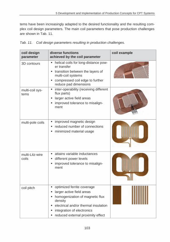
5 Development and Implementation of Production Concepts for CPT Systems
103
tems have been increasingly adapted to the desired functionality and the resulting com-plex coil design parameters. The main coil parameters that pose production challenges are shown in Tab. 11.
Tab. 11. Coil design parameters resulting in production challenges.
coil design parameter
diverse functions achieved by the coil parameter
coil example
3D contours helical coils for long-distance pow-er transfer
transition between the layers of multi-coil systems
compressed coil edge to further reduce pad dimensions
multi-coil sys-tems
inter-operability (receiving different flux parts)
larger active field areas improved tolerance to misalign-
ment
multi-pole coils improved magnetic design reduced number of connections minimized material usage
multi-Litz-wire coils
attains variable inductances different power levels improved tolerance to misalign-
ment
coil pitch optimized ferrite coverage larger active field areas homogenization of magnetic flux
density electrical and/or thermal insulation integration of electronics reduced external proximity effect
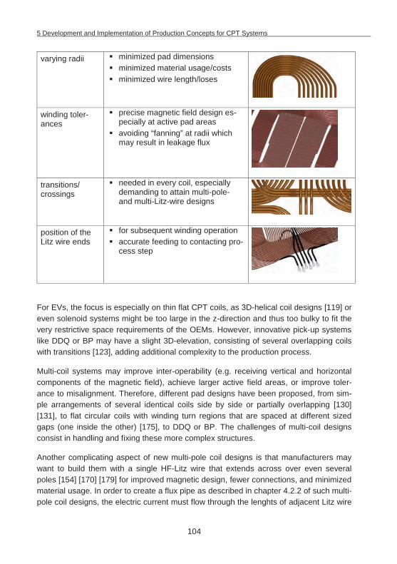
5 Development and Implementation of Production Concepts for CPT Systems
104
varying radii minimized pad dimensions minimized material usage/costs minimized wire length/loses
winding toler-ances
precise magnetic field design es-pecially at active pad areas
avoiding “fanning” at radii which may result in leakage flux
transitions/ crossings
needed in every coil, especially demanding to attain multi-pole- and multi-Litz-wire designs
position of the Litz wire ends
for subsequent winding operation accurate feeding to contacting pro-
cess step
For EVs, the focus is especially on thin flat CPT coils, as 3D-helical coil designs [119] or even solenoid systems might be too large in the z-direction and thus too bulky to fit the very restrictive space requirements of the OEMs. However, innovative pick-up systems like DDQ or BP may have a slight 3D-elevation, consisting of several overlapping coils with transitions [123], adding additional complexity to the production process.
Multi-coil systems may improve inter-operability (e.g. receiving vertical and horizontal components of the magnetic field), achieve larger active field areas, or improve toler-ance to misalignment. Therefore, different pad designs have been proposed, from sim-ple arrangements of several identical coils side by side or partially overlapping [130] [131], to flat circular coils with winding turn regions that are spaced at different sized gaps (one inside the other) [175], to DDQ or BP. The challenges of multi-coil designs consist in handling and fixing these more complex structures.
Another complicating aspect of new multi-pole coil designs is that manufacturers may want to build them with a single HF-Litz wire that extends across over even several poles [154] [170] [179] for improved magnetic design, fewer connections, and minimized material usage. In order to create a flux pipe as described in chapter 4.2.2 of such multi-pole coil designs, the electric current must flow through the lenghts of adjacent Litz wire
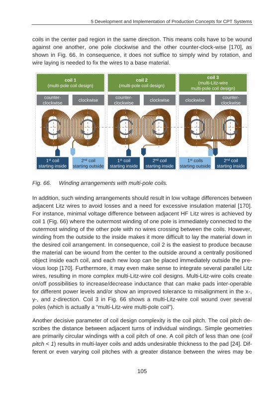
5 Development and Implementation of Production Concepts for CPT Systems
105
coils in the center pad region in the same direction. This means coils have to be wound against one another, one pole clockwise and the other counter-clock-wise [170], as shown in Fig. 66. In consequence, it does not suffice to simply wind by rotation, and wire laying is needed to fix the wires to a base material.
Fig. 66. Winding arrangements with multi-pole coils.
In addition, such winding arrangements should result in low voltage differences between adjacent Litz wires to avoid losses and a need for excessive insulation material [170]. For instance, minimal voltage difference between adjacent HF Litz wires is achieved by coil 1 (Fig. 66) where the outermost winding of one pole is immediately connected to the outermost winding of the other pole with no wires crossing between the coils. However, winding from the outside to the inside makes it more difficult to lay the material down in the desired coil arrangement. In consequence, coil 2 is the easiest to produce because the material can be wound from the center to the outside around a centrally positioned object inside each coil, and each new loop can be placed immediately outside the pre-vious loop [170]. Furthermore, it may even make sense to integrate several parallel Litz wires, resulting in more complex multi-Litz-wire coil designs. Multi-Litz-wire coils create on/off possibilities to increase/decrease inductance that can make pads inter-operable for different power levels and/or show an improved tolerance to misalignment in the x-, y-, and z-direction. Coil 3 in Fig. 66 shows a multi-Litz-wire coil wound over several poles (which is actually a “multi-Litz-wire multi-pole coil”).
Another decisive parameter of coil design complexity is the coil pitch. The coil pitch de-scribes the distance between adjacent turns of individual windings. Simple geometries are primarily circular windings with a coil pitch of one. A coil pitch of less than one (coil pitch < 1) results in multi-layer coils and adds undesirable thickness to the pad [24]. Dif-ferent or even varying coil pitches with a greater distance between the wires may be
coil 1(multi-pole coil design)
coil 2(multi-pole coil design)
coil 3(multi-Litz-wire
multi-pole coil design)
counter-clockwise clockwise counter-
clockwise clockwise counter-clockwiseclockwise
1st coil starting inside
2nd coil starting outside
1st coil starting inside
2nd coil starting inside
1st coils starting outside
2nd coil starting inside
5 Development and Implementation of Production Concepts for CPT Systems
106
necessary for field shaping (e.g. homogeneous low magnetic flux density avoiding local field maxima [60] [175]), ferrite coverage, insulation, heat dissipation, reduced outer proximity effects [143], and material savings. In addition, larger coil pitches make it pos-sible to integrate further electronic components (ICT, LOP, FOD) in the empty spaces between the windings [197]. One example of a coil design that uses coil pitches larger than one is the DD-pad. DD-pads, especially, rely on their specific design in the pad midsection to create a flux pipe. The height and hence effectiveness of the intra-pad flux pipe is created by adjusting coil width in the midsection of the pad and depends on the number of turns as well as on coil pitch [24] [67]. [24] found that the coupling coefficient could be improved by separating the wires slightly (coil pitch > 1). Experiments have shown that coils wound with a larger pitch (coil pitch >> 1) have a shorter effective flux pipe length. If the pitch is greater than a few wire diameters, flux will leak out of the gaps between the turns, causing the air gap flux to collapse effectively, resulting in a short flux pipe. This is because the resulting small flux loops around the separated conduc-tors do not increase coupling and add significantly to pad inductance, eventually reduc-ing the coupling factor [24]. Winding coils with an adequate coil pitch moreover can achieve an optimal percentage of covered ferrite strip, utilizing ferrites more effectively. A coil pitch of about twice the wire diameter in the central pad midsection was used for further tests. This helps improve material usage as it optimizes the correlation between used ferrite and Litz wires [24] [120]. Outside the flux pipe, the remaining coil length of a DD-pad should be minimized with gapless winding (coil pitch = 1) to save copper, weight, cost, and to lower its AC resistance RAC [24]. This results in an even more com-plex pad design, as varying coil pitch and thus different curve radii have to be consid-ered in the coil production process. In addition, the pad designs are very sensitive in terms of stray fluxes. Therefore, precision in winding is a major factor to attain the de-sired magnetic field design. Especially in areas like the above-described flux pipe, pre-cise winding is important to avoid problems like leakage flux that is due to “fanning” at radii. These sophisticated coil designs, particularly multi-Litz-wire and multi-pole de-signs, result in an increased number of transitions/crossings that complicate winding operations. Finally, HF-Litz wire ends have to be accurately positioned for the subse-quent winding operation and for the contacting process.
All these aspects show the wide range of potential challenges for HF-Litz wire winding of CPT-coil designs. Since researchers who invent coil designs are focused on coil per-formance and not particularly preoccupied with easy coil winding [198], winding tech-niques have to meet high demands, as described in the following. To create a finished coil structure that can easily be integrated in the housing of the pad, several process steps need to be carried out. The following presents possibilities that have been devel-oped for HF-Litz wire feeding (chapter 5.2.2), to establish inherent coil stability (chapter 5.2.3), and different winding techniques to attain the coil designs described above (chapter 5.2.4).
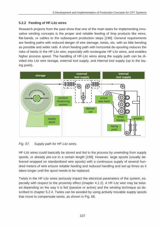
5 Development and Implementation of Production Concepts for CPT Systems
107
5.2.2 Feeding of HF-Litz wires
Research projects from the past show that one of the main tasks for implementing inno-vative winding concepts is the proper and reliable feeding of limp products like wires, flat-bands, or cables to the subsequent production steps [199]. General requirements are feeding paths with reduced danger of wire damage, twists, etc. with as little bending as possible and wider radii. A short feeding path with horizontal de-spooling reduces the risks of twists in the HF-Litz wire, especially with rectangular HF-Litz wires, and enables higher process speed. The handling of HF-Litz wires along the supply path can be di-vided into Litz wire storage, external tool supply, and internal tool supply (up to the lay-ing point).
Fig. 67. Supply path for HF-Litz wires.
HF-Litz wires could basically be stored and fed to the process by unwinding from supply spools, or already pre-cut to a certain length [199]. However, large spools (usually de-livered wrapped on standardized wire spools) with a continuous supply of several hun-dred meters of wire ensure reliable feeding and reduced handling and set-up times as it takes longer until the spool needs to be replaced.
Twists in the HF-Litz wires seriously impact the electrical parameters of the system, es-pecially with respect to the proximity effect (chapter 4.1.2). A HF-Litz wire may be twist-ed depending on the way it is fed (passive or active) and the winding technique as de-scribed in chapter 5.2.4. Twists can be avoided by using actively movable supply spools that move to compensate twists, as shown in Fig. 68.
storage externaltool supply
internaltool supply
dancerroll
position measuring
system
laying point
gripper
active wire feed
shearbladessupply
spool
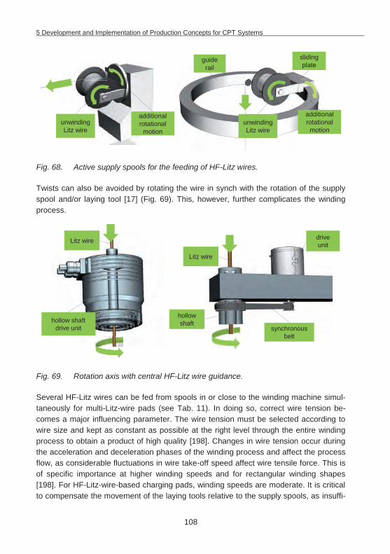
5 Development and Implementation of Production Concepts for CPT Systems
108
Fig. 68. Active supply spools for the feeding of HF-Litz wires.
Twists can also be avoided by rotating the wire in synch with the rotation of the supply spool and/or laying tool [17] (Fig. 69). This, however, further complicates the winding process.
Fig. 69. Rotation axis with central HF-Litz wire guidance.
Several HF-Litz wires can be fed from spools in or close to the winding machine simul-taneously for multi-Litz-wire pads (see Tab. 11). In doing so, correct wire tension be-comes a major influencing parameter. The wire tension must be selected according to wire size and kept as constant as possible at the right level through the entire winding process to obtain a product of high quality [198]. Changes in wire tension occur during the acceleration and deceleration phases of the winding process and affect the process flow, as considerable fluctuations in wire take-off speed affect wire tensile force. This is of specific importance at higher winding speeds and for rectangular winding shapes [198]. For HF-Litz-wire-based charging pads, winding speeds are moderate. It is critical to compensate the movement of the laying tools relative to the supply spools, as insuffi-
unwinding Litz wire
additional rotational motion
guide rail
sliding plate
additional rotational motion
unwinding Litz wire
hollow shaft drive unit synchronous
belt
hollow shaft
drive unit
Litz wire
Litz wire
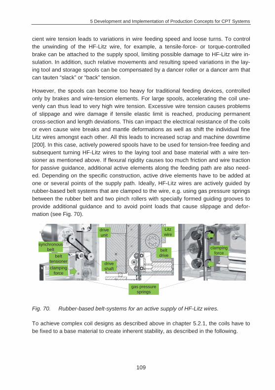
5 Development and Implementation of Production Concepts for CPT Systems
109
cient wire tension leads to variations in wire feeding speed and loose turns. To control the unwinding of the HF-Litz wire, for example, a tensile-force- or torque-controlled brake can be attached to the supply spool, limiting possible damage to HF-Litz wire in-sulation. In addition, such relative movements and resulting speed variations in the lay-ing tool and storage spools can be compensated by a dancer roller or a dancer arm that can tauten “slack” or “back” tension.
However, the spools can become too heavy for traditional feeding devices, controlled only by brakes and wire-tension elements. For large spools, accelerating the coil une-venly can thus lead to very high wire tension. Excessive wire tension causes problems of slippage and wire damage if tensile elastic limit is reached, producing permanent cross-section and length deviations. This can impact the electrical resistance of the coils or even cause wire breaks and mantle deformations as well as shift the individual fine Litz wires amongst each other. All this leads to increased scrap and machine downtime [200]. In this case, actively powered spools have to be used for tension-free feeding and subsequent turning HF-Litz wires to the laying tool and base material with a wire ten-sioner as mentioned above. If flexural rigidity causes too much friction and wire traction for passive guidance, additional active elements along the feeding path are also need-ed. Depending on the specific construction, active drive elements have to be added at one or several points of the supply path. Ideally, HF-Litz wires are actively guided by rubber-based belt systems that are clamped to the wire, e.g. using gas pressure springs between the rubber belt and two pinch rollers with specially formed guiding grooves to provide additional guidance and to avoid point loads that cause slippage and defor-mation (see Fig. 70).
Fig. 70. Rubber-based belt-systems for an active supply of HF-Litz wires.
To achieve complex coil designs as described above in chapter 5.2.1, the coils have to be fixed to a base material to create inherent stability, as described in the following.
belt tensioner
drive unit
synchronous belt
gas pressure springs
belt drive
drive shaft
clamping force
clamping force
Litz wire
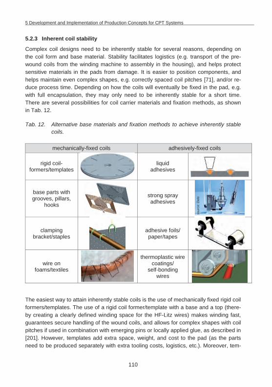
5 Development and Implementation of Production Concepts for CPT Systems
110
5.2.3 Inherent coil stability
Complex coil designs need to be inherently stable for several reasons, depending on the coil form and base material. Stability facilitates logistics (e.g. transport of the pre-wound coils from the winding machine to assembly in the housing), and helps protect sensitive materials in the pads from damage. It is easier to position components, and helps maintain even complex shapes, e.g. correctly spaced coil pitches [71], and/or re-duce process time. Depending on how the coils will eventually be fixed in the pad, e.g. with full encapsulation, they may only need to be inherently stable for a short time. There are several possibilities for coil carrier materials and fixation methods, as shown in Tab. 12.
Tab. 12. Alternative base materials and fixation methods to achieve inherently stable coils.
mechanically-fixed coils adhesively-fixed coils
rigid coil-formers/templates
liquid adhesives
base parts with grooves, pillars,
hooks
strong spray adhesives
clamping bracket/staples
adhesive foils/ paper/tapes
wire on foams/textiles
thermoplastic wire coatings/
self-bonding wires
The easiest way to attain inherently stable coils is the use of mechanically fixed rigid coil formers/templates. The use of a rigid coil former/template with a base and a top (there-by creating a clearly defined winding space for the HF-Litz wires) makes winding fast, guarantees secure handling of the wound coils, and allows for complex shapes with coil pitches if used in combination with emerging pins or locally applied glue, as described in [201]. However, templates add extra space, weight, and cost to the pad (as the parts need to be produced separately with extra tooling costs, logistics, etc.). Moreover, tem-
sour
ce: D
elo
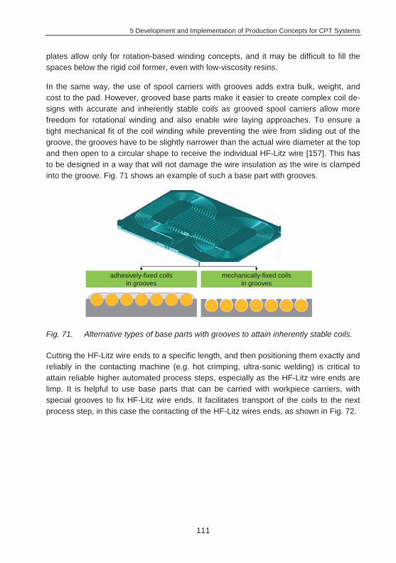
5 Development and Implementation of Production Concepts for CPT Systems
111
plates allow only for rotation-based winding concepts, and it may be difficult to fill the spaces below the rigid coil former, even with low-viscosity resins.
In the same way, the use of spool carriers with grooves adds extra bulk, weight, and cost to the pad. However, grooved base parts make it easier to create complex coil de-signs with accurate and inherently stable coils as grooved spool carriers allow more freedom for rotational winding and also enable wire laying approaches. To ensure a tight mechanical fit of the coil winding while preventing the wire from sliding out of the groove, the grooves have to be slightly narrower than the actual wire diameter at the top and then open to a circular shape to receive the individual HF-Litz wire [157]. This has to be designed in a way that will not damage the wire insulation as the wire is clamped into the groove. Fig. 71 shows an example of such a base part with grooves.
Fig. 71. Alternative types of base parts with grooves to attain inherently stable coils.
Cutting the HF-Litz wire ends to a specific length, and then positioning them exactly and reliably in the contacting machine (e.g. hot crimping, ultra-sonic welding) is critical to attain reliable higher automated process steps, especially as the HF-Litz wire ends are limp. It is helpful to use base parts that can be carried with workpiece carriers, with special grooves to fix HF-Litz wire ends. It facilitates transport of the coils to the next process step, in this case the contacting of the HF-Litz wires ends, as shown in Fig. 72.
adhesively-fixed coils in grooves
mechanically-fixed coils in grooves
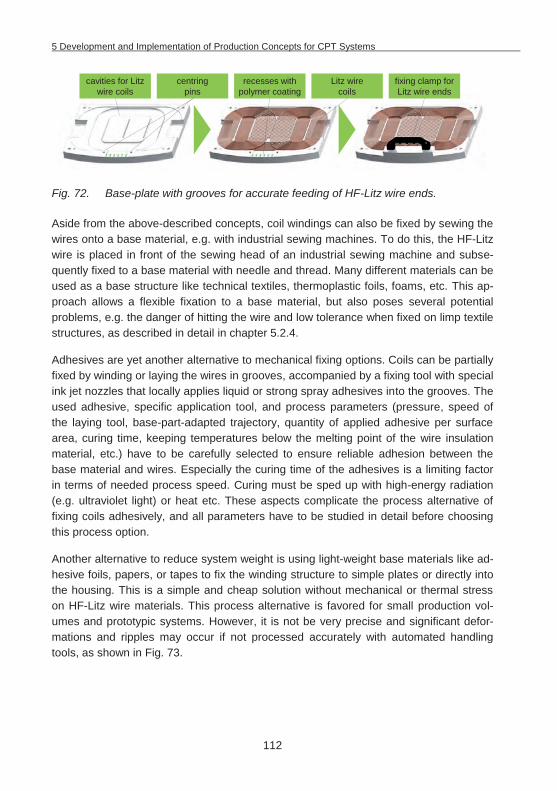
5 Development and Implementation of Production Concepts for CPT Systems
112
Fig. 72. Base-plate with grooves for accurate feeding of HF-Litz wire ends.
Aside from the above-described concepts, coil windings can also be fixed by sewing the wires onto a base material, e.g. with industrial sewing machines. To do this, the HF-Litz wire is placed in front of the sewing head of an industrial sewing machine and subse-quently fixed to a base material with needle and thread. Many different materials can be used as a base structure like technical textiles, thermoplastic foils, foams, etc. This ap-proach allows a flexible fixation to a base material, but also poses several potential problems, e.g. the danger of hitting the wire and low tolerance when fixed on limp textile structures, as described in detail in chapter 5.2.4.
Adhesives are yet another alternative to mechanical fixing options. Coils can be partially fixed by winding or laying the wires in grooves, accompanied by a fixing tool with special ink jet nozzles that locally applies liquid or strong spray adhesives into the grooves. The used adhesive, specific application tool, and process parameters (pressure, speed of the laying tool, base-part-adapted trajectory, quantity of applied adhesive per surface area, curing time, keeping temperatures below the melting point of the wire insulation material, etc.) have to be carefully selected to ensure reliable adhesion between the base material and wires. Especially the curing time of the adhesives is a limiting factor in terms of needed process speed. Curing must be sped up with high-energy radiation (e.g. ultraviolet light) or heat etc. These aspects complicate the process alternative of fixing coils adhesively, and all parameters have to be studied in detail before choosing this process option.
Another alternative to reduce system weight is using light-weight base materials like ad-hesive foils, papers, or tapes to fix the winding structure to simple plates or directly into the housing. This is a simple and cheap solution without mechanical or thermal stress on HF-Litz wire materials. This process alternative is favored for small production vol-umes and prototypic systems. However, it is not be very precise and significant defor-mations and ripples may occur if not processed accurately with automated handling tools, as shown in Fig. 73.
fixing clamp for Litz wire ends
recesses with polymer coating
centringpins
cavities for Litz wire coils
Litz wire coils
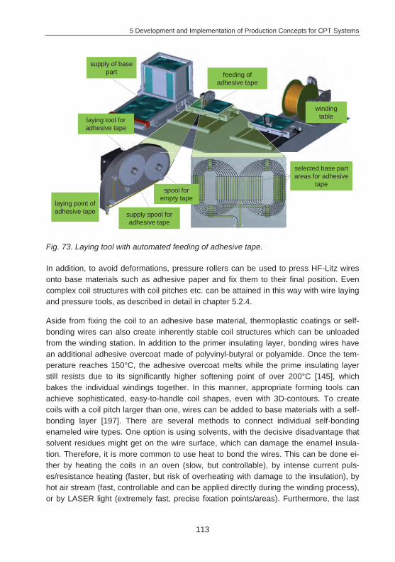
5 Development and Implementation of Production Concepts for CPT Systems
113
Fig. 73. Laying tool with automated feeding of adhesive tape.
In addition, to avoid deformations, pressure rollers can be used to press HF-Litz wires onto base materials such as adhesive paper and fix them to their final position. Even complex coil structures with coil pitches etc. can be attained in this way with wire laying and pressure tools, as described in detail in chapter 5.2.4.
Aside from fixing the coil to an adhesive base material, thermoplastic coatings or self-bonding wires can also create inherently stable coil structures which can be unloaded from the winding station. In addition to the primer insulating layer, bonding wires have an additional adhesive overcoat made of polyvinyl-butyral or polyamide. Once the tem-perature reaches 150°C, the adhesive overcoat melts while the prime insulating layer still resists due to its significantly higher softening point of over 200°C [145], which bakes the individual windings together. In this manner, appropriate forming tools can achieve sophisticated, easy-to-handle coil shapes, even with 3D-contours. To create coils with a coil pitch larger than one, wires can be added to base materials with a self-bonding layer [197]. There are several methods to connect individual self-bonding enameled wire types. One option is using solvents, with the decisive disadvantage that solvent residues might get on the wire surface, which can damage the enamel insula-tion. Therefore, it is more common to use heat to bond the wires. This can be done ei-ther by heating the coils in an oven (slow, but controllable), by intense current puls-es/resistance heating (faster, but risk of overheating with damage to the insulation), by hot air stream (fast, controllable and can be applied directly during the winding process), or by LASER light (extremely fast, precise fixation points/areas). Furthermore, the last
supply of base part feeding of
adhesive tape
winding table
selected base part areas for adhesive
tape
laying tool for adhesive tape
supply spool for adhesive tape
laying point of adhesive tape
spool for empty tape
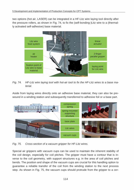
5 Development and Implementation of Production Concepts for CPT Systems
114
two options (hot air, LASER) can be integrated in a HF-Litz wire laying tool directly after the pressure rollers, as shown in Fig. 74, to fix the (self-bonding-)Litz wire to a (thermal-ly activated self-adhesive) base material.
Fig. 74. HF-Litz wire laying tool with hot-air tool to fix the HF-Litz wires to a base ma-terial.
Aside from laying wires directly onto an adhesive base material, they can also be pre-wound in a winding station and subsequently transferred to adhesive foil or a base part.
Fig. 75. Cross-section of a vacuum gripper for HF-Litz wires.
Special air grippers with vacuum cups can be used to maintain the inherent stability of the coil design, especially for coil pitches. The gripper must have a contour that is in-verse to the coil geometry, with support structures e.g. in the area of coil pitches and bends. The position and shape of the vacuum cups are crucial for this handling option to guarantee a reliable transfer of the coil from the winding station to the next process step. As shown in Fig. 75, the vacuum cups should protrude from the gripper to a cer-
air heater
laying point for Litz wire
2-finger parallel gripper
linear actuator
fixation point of Litz wire to base
material
Litz wire feed system
compression spring
base plate
Litz wires
vacuum cups
spring-mounted supporting structure
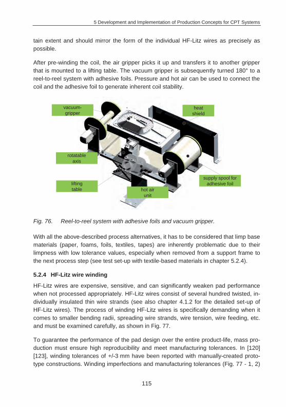
5 Development and Implementation of Production Concepts for CPT Systems
115
tain extent and should mirror the form of the individual HF-Litz wires as precisely as possible.
After pre-winding the coil, the air gripper picks it up and transfers it to another gripper that is mounted to a lifting table. The vacuum gripper is subsequently turned 180° to a reel-to-reel system with adhesive foils. Pressure and hot air can be used to connect the coil and the adhesive foil to generate inherent coil stability.
Fig. 76. Reel-to-reel system with adhesive foils and vacuum gripper.
With all the above-described process alternatives, it has to be considered that limp base materials (paper, foams, foils, textiles, tapes) are inherently problematic due to their limpness with low tolerance values, especially when removed from a support frame to the next process step (see test set-up with textile-based materials in chapter 5.2.4).
5.2.4 HF-Litz wire winding
HF-Litz wires are expensive, sensitive, and can significantly weaken pad performance when not processed appropriately. HF-Litz wires consist of several hundred twisted, in-dividually insulated thin wire strands (see also chapter 4.1.2 for the detailed set-up of HF-Litz wires). The process of winding HF-Litz wires is specifically demanding when it comes to smaller bending radii, spreading wire strands, wire tension, wire feeding, etc. and must be examined carefully, as shown in Fig. 77.
To guarantee the performance of the pad design over the entire product-life, mass pro-duction must ensure high reproducibility and meet manufacturing tolerances. In [120] [123], winding tolerances of +/-3 mm have been reported with manually-created proto-type constructions. Winding imperfections and manufacturing tolerances (Fig. 77 - 1, 2)
vacuum-gripper
heat shield
hot air unit
supply spool for adhesive foillifting
table
rotatable axis
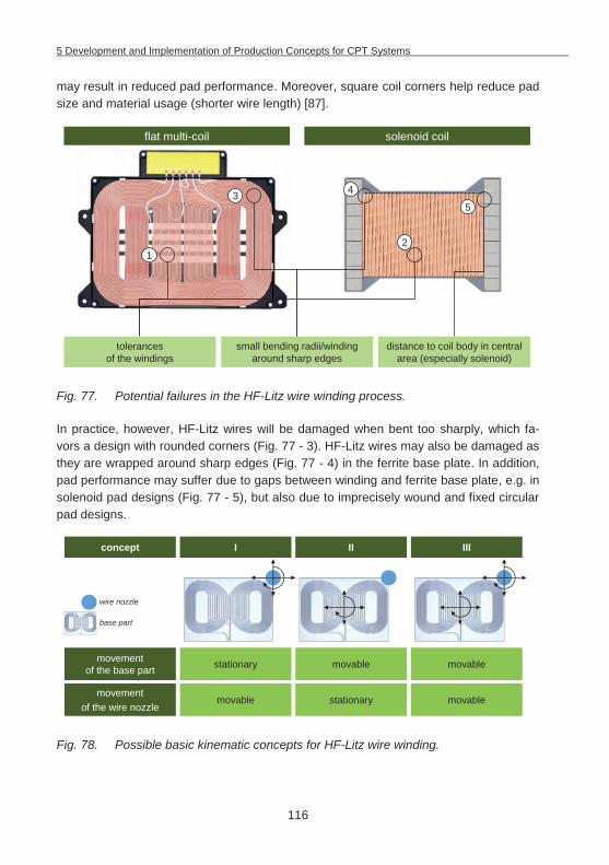
5 Development and Implementation of Production Concepts for CPT Systems
116
may result in reduced pad performance. Moreover, square coil corners help reduce pad size and material usage (shorter wire length) [87].
Fig. 77. Potential failures in the HF-Litz wire winding process.
In practice, however, HF-Litz wires will be damaged when bent too sharply, which fa-vors a design with rounded corners (Fig. 77 - 3). HF-Litz wires may also be damaged as they are wrapped around sharp edges (Fig. 77 - 4) in the ferrite base plate. In addition, pad performance may suffer due to gaps between winding and ferrite base plate, e.g. in solenoid pad designs (Fig. 77 - 5), but also due to imprecisely wound and fixed circular pad designs.
Fig. 78. Possible basic kinematic concepts for HF-Litz wire winding.
distance to coil body in central area (especially solenoid)
small bending radii/winding around sharp edges
tolerances of the windings
12
3 4
5
solenoid coil flat multi-coil
concept I II III
movement of the base part
movement of the wire nozzle
stationary
movable
movable
stationary
movable
movable
base part
wire nozzle
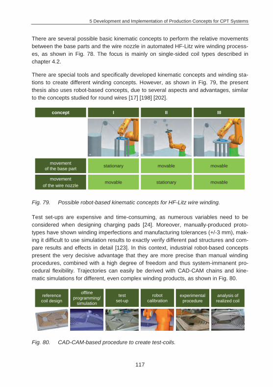
5 Development and Implementation of Production Concepts for CPT Systems
117
There are several possible basic kinematic concepts to perform the relative movements between the base parts and the wire nozzle in automated HF-Litz wire winding process-es, as shown in Fig. 78. The focus is mainly on single-sided coil types described in chapter 4.2.
There are special tools and specifically developed kinematic concepts and winding sta-tions to create different winding concepts. However, as shown in Fig. 79, the present thesis also uses robot-based concepts, due to several aspects and advantages, similar to the concepts studied for round wires [17] [198] [202].
Fig. 79. Possible robot-based kinematic concepts for HF-Litz wire winding.
Test set-ups are expensive and time-consuming, as numerous variables need to be considered when designing charging pads [24]. Moreover, manually-produced proto-types have shown winding imperfections and manufacturing tolerances (+/-3 mm), mak-ing it difficult to use simulation results to exactly verify different pad structures and com-pare results and effects in detail [123]. In this context, industrial robot-based concepts present the very decisive advantage that they are more precise than manual winding procedures, combined with a high degree of freedom and thus system-immanent pro-cedural flexibility. Trajectories can easily be derived with CAD-CAM chains and kine-matic simulations for different, even complex winding products, as shown in Fig. 80.
Fig. 80. CAD-CAM-based procedure to create test-coils.
concept I II III
movement of the base part
movement of the wire nozzle
stationary
movable
movable
stationary
movable
movable
reference coil design
offline programming/
simulation
test set-up
robot calibration
experimental procedure
analysis of realized coil
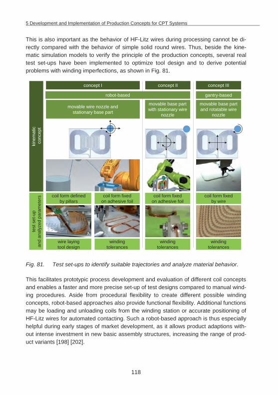
5 Development and Implementation of Production Concepts for CPT Systems
118
This is also important as the behavior of HF-Litz wires during processing cannot be di-rectly compared with the behavior of simple solid round wires. Thus, beside the kine-matic simulation models to verify the principle of the production concepts, several real test set-ups have been implemented to optimize tool design and to derive potential problems with winding imperfections, as shown in Fig. 81.
Fig. 81. Test set-ups to identify suitable trajectories and analyze material behavior.
This facilitates prototypic process development and evaluation of different coil concepts and enables a faster and more precise set-up of test designs compared to manual wind-ing procedures. Aside from procedural flexibility to create different possible winding concepts, robot-based approaches also provide functional flexibility. Additional functions may be loading and unloading coils from the winding station or accurate positioning of HF-Litz wires for automated contacting. Such a robot-based approach is thus especially helpful during early stages of market development, as it allows product adaptions with-out intense investment in new basic assembly structures, increasing the range of prod-uct variants [198] [202].
movable wire nozzle and stationary base part
movable base part with stationary wire
nozzle
movable base part and rotatable wire
nozzle
coil form defined by pillars
coil form fixed on adhesive foil
coil form fixed on adhesive foil
kine
mat
icco
ncep
tte
st s
et-u
p an
d an
alyz
ed p
aram
eter
s
robot-based
coil form fixed by wire
winding tolerances
winding tolerances
winding tolerances
wire layingtool design
gantry-based
concept I concept II concept III
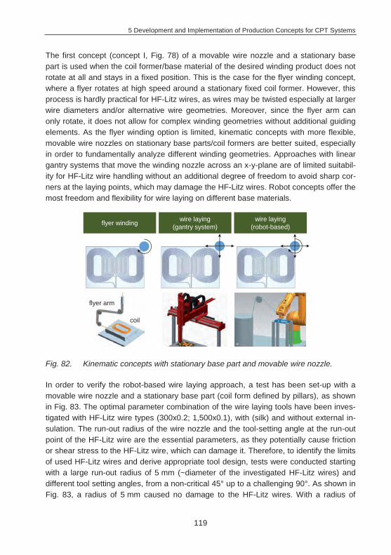
5 Development and Implementation of Production Concepts for CPT Systems
119
The first concept (concept I, Fig. 78) of a movable wire nozzle and a stationary base part is used when the coil former/base material of the desired winding product does not rotate at all and stays in a fixed position. This is the case for the flyer winding concept, where a flyer rotates at high speed around a stationary fixed coil former. However, this process is hardly practical for HF-Litz wires, as wires may be twisted especially at larger wire diameters and/or alternative wire geometries. Moreover, since the flyer arm can only rotate, it does not allow for complex winding geometries without additional guiding elements. As the flyer winding option is limited, kinematic concepts with more flexible, movable wire nozzles on stationary base parts/coil formers are better suited, especially in order to fundamentally analyze different winding geometries. Approaches with linear gantry systems that move the winding nozzle across an x-y-plane are of limited suitabil-ity for HF-Litz wire handling without an additional degree of freedom to avoid sharp cor-ners at the laying points, which may damage the HF-Litz wires. Robot concepts offer the most freedom and flexibility for wire laying on different base materials.
Fig. 82. Kinematic concepts with stationary base part and movable wire nozzle.
In order to verify the robot-based wire laying approach, a test has been set-up with a movable wire nozzle and a stationary base part (coil form defined by pillars), as shown in Fig. 83. The optimal parameter combination of the wire laying tools have been inves-tigated with HF-Litz wire types (300x0.2; 1,500x0.1), with (silk) and without external in-sulation. The run-out radius of the wire nozzle and the tool-setting angle at the run-out point of the HF-Litz wire are the essential parameters, as they potentially cause friction or shear stress to the HF-Litz wire, which can damage it. Therefore, to identify the limits of used HF-Litz wires and derive appropriate tool design, tests were conducted starting with a large run-out radius of 5 mm (~diameter of the investigated HF-Litz wires) and different tool setting angles, from a non-critical 45° up to a challenging 90°. As shown in Fig. 83, a radius of 5 mm caused no damage to the HF-Litz wires. With a radius of
flyer winding wire laying (gantry system)
wire laying (robot-based)
flyer arm
coil
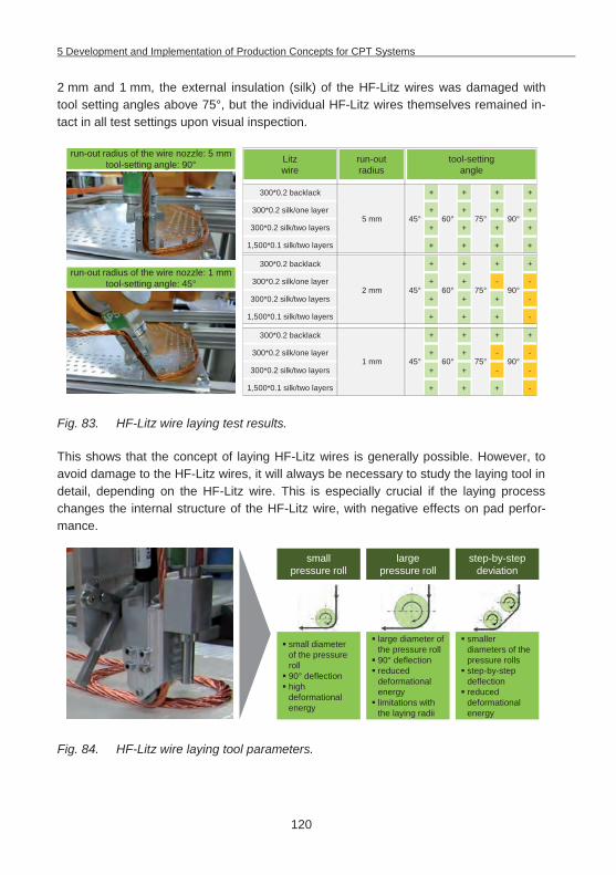
5 Development and Implementation of Production Concepts for CPT Systems
120
2 mm and 1 mm, the external insulation (silk) of the HF-Litz wires was damaged with tool setting angles above 75°, but the individual HF-Litz wires themselves remained in-tact in all test settings upon visual inspection.
Fig. 83. HF-Litz wire laying test results.
This shows that the concept of laying HF-Litz wires is generally possible. However, to avoid damage to the HF-Litz wires, it will always be necessary to study the laying tool in detail, depending on the HF-Litz wire. This is especially crucial if the laying process changes the internal structure of the HF-Litz wire, with negative effects on pad perfor-mance.
Fig. 84. HF-Litz wire laying tool parameters.
run-out radius of the wire nozzle: 5 mm tool-setting angle: 90°
run-out radius of the wire nozzle: 1 mmtool-setting angle: 45°
run-out radius
Litz wire
tool-settingangle
5 mm
2 mm
1 mm
300*0.2 backlack
300*0.2 silk/one layer
300*0.2 silk/two layers
1,500*0.1 silk/two layers
300*0.2 backlack
300*0.2 silk/one layer
300*0.2 silk/two layers
1,500*0.1 silk/two layers
300*0.2 backlack
300*0.2 silk/one layer
300*0.2 silk/two layers
1,500*0.1 silk/two layers
+
45° 75° 90°60°
+++
++++
++++
++++
+
45° 75° 90°60°
+++
--++
-+++
-+++
+
45° 75° 90°60°
+++
--++
--++
-+++
small pressure roll
large pressure roll
step-by-stepdeviation
small diameter of the pressure roll90° deflectionhigh deformational energy
large diameter of the pressure roll90° deflectionreduced deformational energylimitations with the laying radii
smaller diameters of the pressure rollsstep-by-step deflectionreduced deformational energy
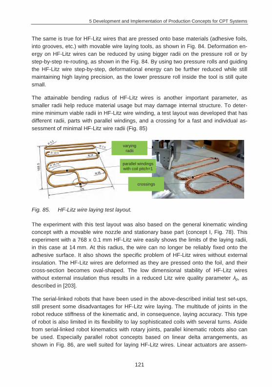
5 Development and Implementation of Production Concepts for CPT Systems
121
The same is true for HF-Litz wires that are pressed onto base materials (adhesive foils, into grooves, etc.) with movable wire laying tools, as shown in Fig. 84. Deformation en-ergy on HF-Litz wires can be reduced by using bigger radii on the pressure roll or by step-by-step re-routing, as shown in the Fig. 84. By using two pressure rolls and guiding the HF-Litz wire step-by-step, deformational energy can be further reduced while still maintaining high laying precision, as the lower pressure roll inside the tool is still quite small.
The attainable bending radius of HF-Litz wires is another important parameter, as smaller radii help reduce material usage but may damage internal structure. To deter-mine minimum viable radii in HF-Litz wire winding, a test layout was developed that has different radii, parts with parallel windings, and a crossing for a fast and individual as-sessment of minimal HF-Litz wire radii (Fig. 85)
Fig. 85. HF-Litz wire laying test layout.
The experiment with this test layout was also based on the general kinematic winding concept with a movable wire nozzle and stationary base part (concept I, Fig. 78). This experiment with a 768 x 0.1 mm HF-Litz wire easily shows the limits of the laying radii, in this case at 14 mm. At this radius, the wire can no longer be reliably fixed onto the adhesive surface. It also shows the specific problem of HF-Litz wires without external insulation. The HF-Litz wires are deformed as they are pressed onto the foil, and their cross-section becomes oval-shaped. The low dimensional stability of HF-Litz wires without external insulation thus results in a reduced Litz wire quality parameter p, as described in [203].
The serial-linked robots that have been used in the above-described initial test set-ups, still present some disadvantages for HF-Litz wire laying. The multitude of joints in the robot reduce stiffness of the kinematic and, in consequence, laying accuracy. This type of robot is also limited in its flexibility to lay sophisticated coils with several turns. Aside from serial-linked robot kinematics with rotary joints, parallel kinematic robots also can be used. Especially parallel robot concepts based on linear delta arrangements, as shown in Fig. 86, are well suited for laying HF-Litz wires. Linear actuators are assem-
parallel windings with coil pitch=1
crossings
varyingradiiR 10.5
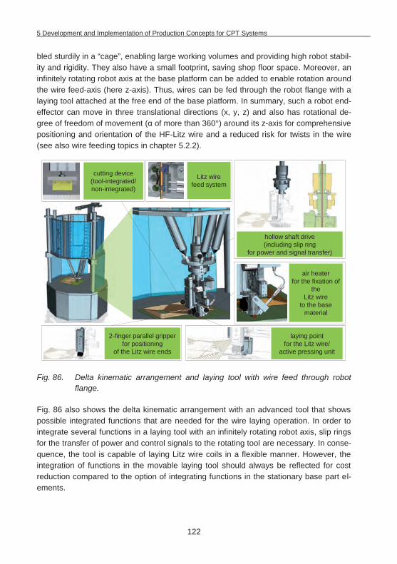
5 Development and Implementation of Production Concepts for CPT Systems
122
bled sturdily in a “cage”, enabling large working volumes and providing high robot stabil-ity and rigidity. They also have a small footprint, saving shop floor space. Moreover, an infinitely rotating robot axis at the base platform can be added to enable rotation around the wire feed-axis (here z-axis). Thus, wires can be fed through the robot flange with a laying tool attached at the free end of the base platform. In summary, such a robot end-effector can move in three translational directions (x, y, z) and also has rotational de-gree of freedom of movement ( of more than 360°) around its z-axis for comprehensive positioning and orientation of the HF-Litz wire and a reduced risk for twists in the wire (see also wire feeding topics in chapter 5.2.2).
Fig. 86. Delta kinematic arrangement and laying tool with wire feed through robot flange.
Fig. 86 also shows the delta kinematic arrangement with an advanced tool that shows possible integrated functions that are needed for the wire laying operation. In order to integrate several functions in a laying tool with an infinitely rotating robot axis, slip rings for the transfer of power and control signals to the rotating tool are necessary. In conse-quence, the tool is capable of laying Litz wire coils in a flexible manner. However, the integration of functions in the movable laying tool should always be reflected for cost reduction compared to the option of integrating functions in the stationary base part el-ements.
air heater for the fixation of
the Litz wire
to the base material
2-finger parallel gripper for positioning
of the Litz wire ends
cutting device (tool-integrated/non-integrated)
Litz wire feed system
laying point for the Litz wire/
active pressing unit
hollow shaft drive (including slip ring
for power and signal transfer)
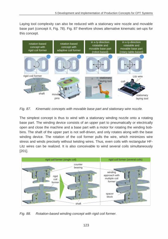
5 Development and Implementation of Production Concepts for CPT Systems
123
Laying tool complexity can also be reduced with a stationary wire nozzle and movable base part (concept II, Fig. 78). Fig. 87 therefore shows alternative kinematic set-ups for this concept.
Fig. 87. Kinematic concepts with movable base part and stationary wire nozzle.
The simplest concept is thus to wind with a stationary winding nozzle onto a rotating base part. The winding device consists of an upper part to pneumatically or electrically open and close the machine and a base part with a motor for rotating the winding bob-bins. The shaft of the upper part is not self-driven, and only rotates along with the base winding device. The rotation of the coil former pulls the wire, which minimizes wire stress and winds precisely without twisting wires. Thus, even coils with rectangular HF-Litz wires can be realized. It is also conceivable to wind several coils simultaneously [201].
Fig. 88. Rotation-based winding concept with rigid coil former.
rotation-based concept with
rigid coil former
rotation-based concept with
adaptive coil former
in x-/y-direction rotatable and
movable base part (robot-based)
in x-/y-direction rotatable and
movable base part (rotary-table-based)
rigid coil former
shaft
coil
movable pins
coil
coil
stationary laying tool
stationary laying tool
Litz wire
rigid coil
former
shaft
winding approach with multiple coil
former
counter bearing
spacerblock
rigid coil former (single coil) rigid coil former (several coils)
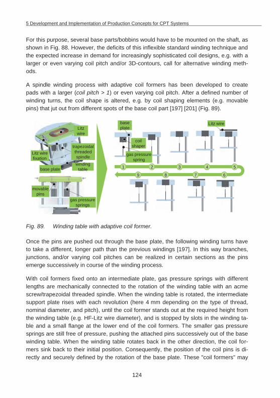
5 Development and Implementation of Production Concepts for CPT Systems
124
For this purpose, several base parts/bobbins would have to be mounted on the shaft, as shown in Fig. 88. However, the deficits of this inflexible standard winding technique and the expected increase in demand for increasingly sophisticated coil designs, e.g. with a larger or even varying coil pitch and/or 3D-contours, call for alternative winding meth-ods.
A spindle winding process with adaptive coil formers has been developed to create pads with a larger (coil pitch > 1) or even varying coil pitch. After a defined number of winding turns, the coil shape is altered, e.g. by coil shaping elements (e.g. movable pins) that jut out from different spots of the base coil part [197] [201] (Fig. 89).
Fig. 89. Winding table with adaptive coil former.
Once the pins are pushed out through the base plate, the following winding turns have to take a different, longer path than the previous windings [197]. In this way branches, junctions, and/or varying coil pitches can be realized in certain sections as the pins emerge successively in course of the winding process.
With coil formers fixed onto an intermediate plate, gas pressure springs with different lengths are mechanically connected to the rotation of the winding table with an acme screw/trapezoidal threaded spindle. When the winding table is rotated, the intermediate support plate rises with each revolution (here 4 mm depending on the type of thread, nominal diameter, and pitch), until the coil former stands out at the required height from the winding table (e.g. HF-Litz wire diameter), and is stopped by slots in the winding ta-ble and a small flange at the lower end of the coil formers. The smaller gas pressure springs are still free of pressure, pushing the attached pins successively out of the base winding table. When the winding table rotates back in the other direction, the coil for-mers sink back to their initial position. Consequently, the position of the coil pins is di-rectly and securely defined by the rotation of the base plate. These "coil formers" may
1 2 3 4 5
6789
Litz wire fixation
windingtable
Litz wire
gas pressure springs
base plate
movablepins
trapezoidal threaded spindle
base plate
coil shaper
gas pressure spring
Litz wire
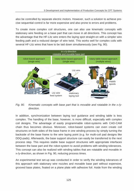
5 Development and Implementation of Production Concepts for CPT Systems
125
also be controlled by separate electric motors. However, such a solution to achieve pre-cise sequential control is far more expensive and also prone to errors and problems.
To create more complex coil structures, one can also use kinematic concepts with stationary wire feeding on a base part that can move in all directions. This concept has the advantage that the HF-Litz wire enters the laying spot straight-on with a simpler wire feeding path and a reduced danger of wire twist. This works well for complex coils with several HF-Litz wires that have to be laid down simultaneously (see Fig. 90).
Fig. 90. Kinematic concepts with base part that is movable and rotatable in the x-/y-direction.
In addition, synchronization between laying tool guidance and winding table is less complex. The handling of the base, however, is more difficult, especially with complex coil designs. The advantage of easily programmable robot-systems with CAD-CAM chain thus becomes obvious. Moreover, robot-based systems can even create coil structures on both sides of the base frame in one winding process by simply turning the backside of the base frame to the wire laying point (e.g. for multi-coil pad designs like DDQ-pads). Afterwards, the base support structure can easily be transferred to the next process step. This requires stable base support structures with appropriate interfaces between the base part and the robot-system to avoid problems with winding tolerances. This concept can also be realized with winding tables that are rotatable and movable in x-/y-direction, as shown in Fig. 90, reducing process times.
An experimental test set-up was conducted in order to verify the winding tolerances of this approach with stationary wire nozzles and movable base part without expensive, grooved base plates, fixated on a plane plate with adhesive foil. Aside from the winding
Litz wire feed system
in x-/y-direction rotatable and movable base part
coils
stationary laying tool
Litz wire
robot-based approach(single wire)
rotary-table-based approach (single wire)
rotary-table-based approach (multiple wires)
supply spools
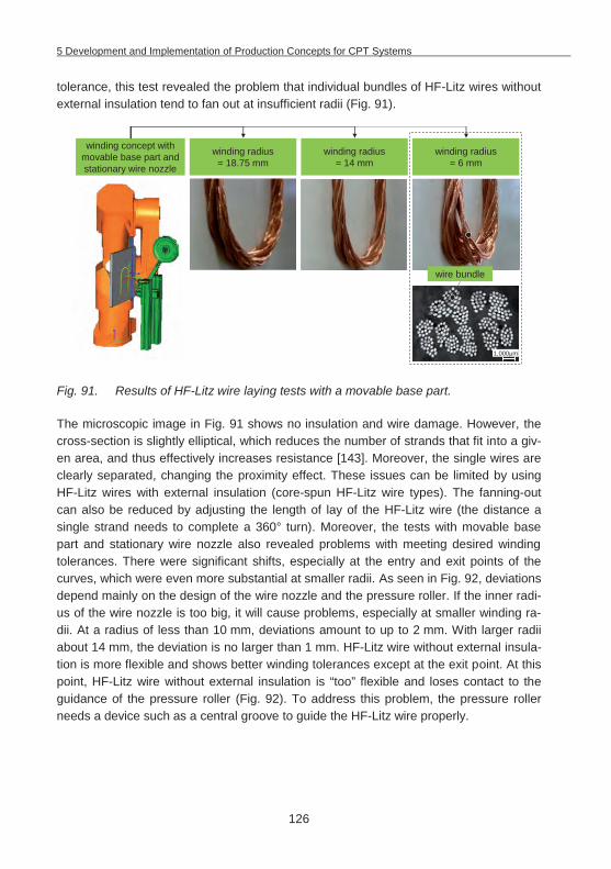
5 Development and Implementation of Production Concepts for CPT Systems
126
tolerance, this test revealed the problem that individual bundles of HF-Litz wires without external insulation tend to fan out at insufficient radii (Fig. 91).
Fig. 91. Results of HF-Litz wire laying tests with a movable base part.
The microscopic image in Fig. 91 shows no insulation and wire damage. However, the cross-section is slightly elliptical, which reduces the number of strands that fit into a giv-en area, and thus effectively increases resistance [143]. Moreover, the single wires are clearly separated, changing the proximity effect. These issues can be limited by using HF-Litz wires with external insulation (core-spun HF-Litz wire types). The fanning-out can also be reduced by adjusting the length of lay of the HF-Litz wire (the distance a single strand needs to complete a 360° turn). Moreover, the tests with movable base part and stationary wire nozzle also revealed problems with meeting desired winding tolerances. There were significant shifts, especially at the entry and exit points of the curves, which were even more substantial at smaller radii. As seen in Fig. 92, deviations depend mainly on the design of the wire nozzle and the pressure roller. If the inner radi-us of the wire nozzle is too big, it will cause problems, especially at smaller winding ra-dii. At a radius of less than 10 mm, deviations amount to up to 2 mm. With larger radii about 14 mm, the deviation is no larger than 1 mm. HF-Litz wire without external insula-tion is more flexible and shows better winding tolerances except at the exit point. At this point, HF-Litz wire without external insulation is “too” flexible and loses contact to the guidance of the pressure roller (Fig. 92). To address this problem, the pressure roller needs a device such as a central groove to guide the HF-Litz wire properly.
winding radius = 18.75 mm
winding concept with movable base part and stationary wire nozzle
winding radius = 14 mm
winding radius = 6 mm
wire bundle
1,000 m
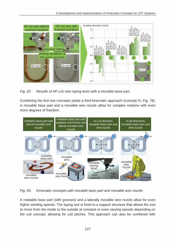
5 Development and Implementation of Production Concepts for CPT Systems
127
Fig. 92. Results of HF-Litz wire laying tests with a movable base part.
Combining the first two concepts yields a third kinematic approach (concept III, Fig. 78). A movable base part and a movable wire nozzle allow for complex motions with even more degrees of freedom.
Fig. 93. Kinematic concepts with movable base part and movable wire nozzle.
A rotatable base part (with grooves) and a laterally movable wire nozzle allow for even higher winding speeds. The laying tool is fixed to a support structure that allows the tool to move from the inside to the outside at constant or even varying speeds depending on the coil concept, allowing for coil pitches. This approach can also be combined with
HF-Litz wire withoutexternal insulation
HF-Litz wire with external insulation
winding deviations at the curve exit point
pressure roller
winding deviation [mm]1.5
1.0
0.5
0.0
-0.0
-1.0
-1.5
R25
mm
R18
.75
mm
R14
mm
R10
.5 m
mR
7.5
mm
R6
mm R
25 m
mR
18.7
5 m
mR
14 m
mR
10.5
mm
R7.
5 m
mR
6 m
mR
25 m
mR
18.7
5 m
mR
14 m
mR
10.5
mm
R7.
5 m
mR
6 m
m
R25
mm
R18
.75
mm
R14
mm
R10
.5 m
mR
7.5
mm
R6
mm
R25
mm
R18
.75
mm
R14
mm
R10
.5 m
mR
7.5
mm
R6
mm
1
2
3
4
550 mm 50 mm
1 2 3 4 5
50 mm
rotatable base part with lateral movable wire
nozzle
rotatable base part with adaptive coil former and
lateral movable wire nozzle
in x-/y-direction movable base part and
wire nozzle
in all directionsmovable base part and
wire nozzle
rotatable base part movable
pins
base material movable
base part
Litz wire
movable wire
nozzle
movable wire nozzle
movable wire feed
rotatable sewing head
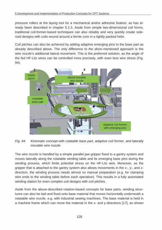
5 Development and Implementation of Production Concepts for CPT Systems
128
pressure rollers at the laying tool for a mechanical and/or adhesive fixation, as has al-ready been described in chapter 5.2.3. Aside from simple two-dimensional coil forms, traditional coil-former-based techniques can also reliably and very quickly create sole-noid designs with coils wound around a ferrite core in a tightly packed helix.
Coil pitches can also be achieved by adding adaptive emerging pins to the base part as already described above. The only difference to the afore-mentioned approach is the wire nozzle’s additional lateral movement. This is the preferred solution, as the angle of the fed HF-Litz wires can be controlled more precisely, with even less wire stress (Fig. 94).
Fig. 94. Kinematic concept with rotatable base part, adaptive coil former, and laterally movable wire nozzle.
The wire nozzle is handled by a simple parallel jaw gripper fixed to a gantry system and moves laterally along the rotatable winding table and its emerging base pins during the winding process, which limits potential stress on the HF-Litz wire. Moreover, as the gripper that is attached to the gantry system also allows movements in the x-, y-, and z-direction, the winding process needs almost no manual preparation (e.g. for clamping wire ends to the winding table before each operation). This results in a fully automated winding station for even complex coil designs with coil pitches.
Aside from the above-described rotation-based concepts for base parts, winding struc-tures can also be laid and fixed onto base material that moves horizontally underneath a rotatable wire nozzle, e.g. with industrial sewing machines. The base material is held in a machine frame which can move the material in the x- and y-directions [17], as shown
rotatable base part
lateral movable wire nozzle
adaptive coil former with emerging pins
supplyspool
ble art
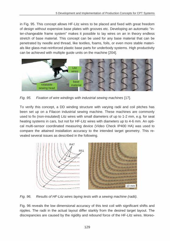
5 Development and Implementation of Production Concepts for CPT Systems
129
in Fig. 95. This concept allows HF-Litz wires to be placed and fixed with great freedom of design without expensive base plates with grooves etc. Developing an automatic "in-ter-changeable frame system" makes it possible to lay wires on an in theory endless stretch of base material. This concept can be used for any base material that can be penetrated by needle and thread, like textiles, foams, foils, or even more stable materi-als like glass-mat-reinforced plastic base parts for underbody systems. High productivity can be achieved with multiple guide units on the machine [204].
Fig. 95. Fixation of wire windings with industrial sewing machines [17].
To verify this concept, a DD winding structure with varying radii and coil pitches has been set up on a Filacon industrial sewing machine. These machines are commonly used to fix (non-insulated) Litz wires with small diameters of up to 1-2 mm, e.g. for seat heating systems in cars, but not for HF-Litz wires with diameters up to 4-6 mm. An opti-cal multi-sensor coordinated measuring device (Video Check IP400 HA) was used to compare the attained installation accuracy to the intended target geometry. This re-vealed several issues as described in the following.
Fig. 96. Results of HF-Litz wires laying tests with a sewing machine (radii).
Fig. 96 reveals the low dimensional accuracy of this test coil with significant shifts and ripples. The radii in the actual layout differ starkly from the desired target layout. The discrepancies are caused by the rigidity and rebound force of the HF-Litz wires. Moreo-
rotatable sewing head
Litz wires
base material
R47
R51
10 mm
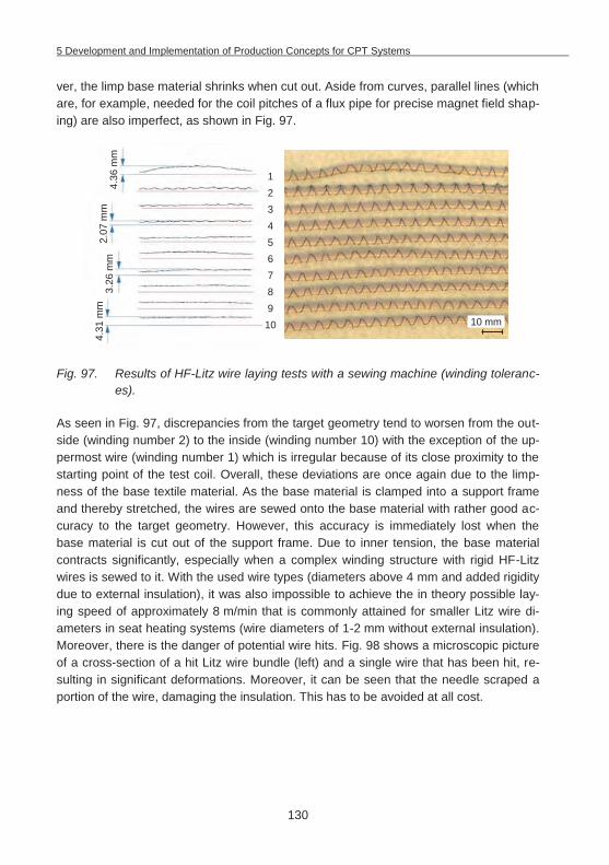
5 Development and Implementation of Production Concepts for CPT Systems
130
ver, the limp base material shrinks when cut out. Aside from curves, parallel lines (which are, for example, needed for the coil pitches of a flux pipe for precise magnet field shap-ing) are also imperfect, as shown in Fig. 97.
Fig. 97. Results of HF-Litz wire laying tests with a sewing machine (winding toleranc-es).
As seen in Fig. 97, discrepancies from the target geometry tend to worsen from the out-side (winding number 2) to the inside (winding number 10) with the exception of the up-permost wire (winding number 1) which is irregular because of its close proximity to the starting point of the test coil. Overall, these deviations are once again due to the limp-ness of the base textile material. As the base material is clamped into a support frame and thereby stretched, the wires are sewed onto the base material with rather good ac-curacy to the target geometry. However, this accuracy is immediately lost when the base material is cut out of the support frame. Due to inner tension, the base material contracts significantly, especially when a complex winding structure with rigid HF-Litz wires is sewed to it. With the used wire types (diameters above 4 mm and added rigidity due to external insulation), it was also impossible to achieve the in theory possible lay-ing speed of approximately 8 m/min that is commonly attained for smaller Litz wire di-ameters in seat heating systems (wire diameters of 1-2 mm without external insulation). Moreover, there is the danger of potential wire hits. Fig. 98 shows a microscopic picture of a cross-section of a hit Litz wire bundle (left) and a single wire that has been hit, re-sulting in significant deformations. Moreover, it can be seen that the needle scraped a portion of the wire, damaging the insulation. This has to be avoided at all cost.
4.36
mm
2.07
mm
3.26
mm
4.31
mm
12345678910 10 mm
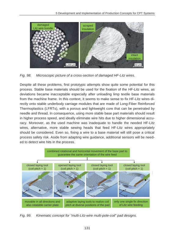
5 Development and Implementation of Production Concepts for CPT Systems
131
Fig. 98. Microscopic picture of a cross-section of damaged HF-Litz wires.
Despite all these problems, first prototypic attempts show quite some potential for this process. Stable base materials should be used for the fixation of the HF-Litz wires, as deviations became inacceptable especially after unloading limp textile base materials from the machine frame. In this context, it seems to make sense to fix HF-Litz wires di-rectly onto stable underbody carriage modules that are made of Long-Fiber Reinforced Thermoplastics (LFRTs), with a porous and lightweight core that can be penetrated by needle and thread. In consequence, using more stable base part materials should result in higher process speed, and ideally eliminate wire hits due to higher dimensional accu-racy. Moreover, as the used machine was inadequate to handle the needed HF-Litz wires, alternative, more stable sewing heads that feed HF-Litz wires appropriately should be considered. Even so, fixing a wire to a base material will still pose a critical process safety risk. Aside from adapting wire guidance, additional sensors will be need-ed to detect wire hits in the process.
Fig. 99. Kinematic concept for “multi-Litz-wire multi-pole-coil” pad designs.
intact insulation
scraped insulation
damaged Litz wire bundle
1,000 m 50 m
combined rotational and horizontal movement of the base part to guarantee the same orientation of the wire feed
adaptive laying tools to realize coil pitch at diverse positions of the pad
x
y
x
y
x
y
x
y
movable in all directions and also rotatable carrier plate
only one single fix direction of Litz wire feeding
closed laying tool (coil pitch = 1)
opened laying tool (coil pitch > 1)
closed laying tool (coil pitch = 1)
closed laying tool (coil pitch = 1)
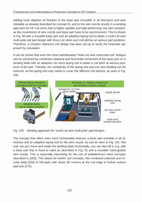
5 Development and Implementation of Production Concepts for CPT Systems
132
Adding more degrees of freedom to the base part (movable in all directions and also rotatable as already described by concept II), and to the wire nozzle results in a winding approach for HF-Litz wires that is highly capable and high-performing, but also complex, as the movements of wire nozzle and base part have to be synchronized. This is shown in Fig. 99 with a movable base part and an adaptive laying tool to attain a multi-Litz-wire multi-pole-coil pad design with three Litz wires and coil pitches at various pad positions. Therefore, a complex reference coil design has been set-up to verify the kinematic ap-proach by simulation.
It can be shown that even the most sophisticated “multi-Litz-wire multi-pole-coil” designs can be achieved by combined rotational and horizontal movement of the base part on a winding table with an adaptive Litz wires laying tool to attain a coil pitch at various posi-tions of the pad. Thereby, the complexity of the laying tool and Litz wire feeding can be reduced, as the laying tool only needs to cover the different coil pitches, as seen in Fig. 100.
Fig. 100. Winding approach for “multi-Litz wire multi-pole” pad designs.
The concept that offers even more functionality features a base part movable in all di-rections and an adaptive laying tool for the wire nozzle, as can be seen in Fig. 101. Not only can you move and rotate the winding table horizontally, you can also tilt it, e.g. with a base part that is fixed to robot as described in Fig. 91 and a movable robot-guided wire nozzle. This is especially interesting for the use of ambidextrous robot concepts described in [205]. This allows for further coil concepts, like combined solenoid and cir-cular pads [206] or DD-pads with sharp 3D corners at the coil edge to further reduce pad size [173].
derivation of adaptive laying tool and winding machine concept
supply spools
multi-axes positioning table
adaptive laying tool
Litz wire carrier plate
adaptive laying tool to realize coil pitch
different laying situations correlating with the coil pitch
storage for Litz wire carrier plates
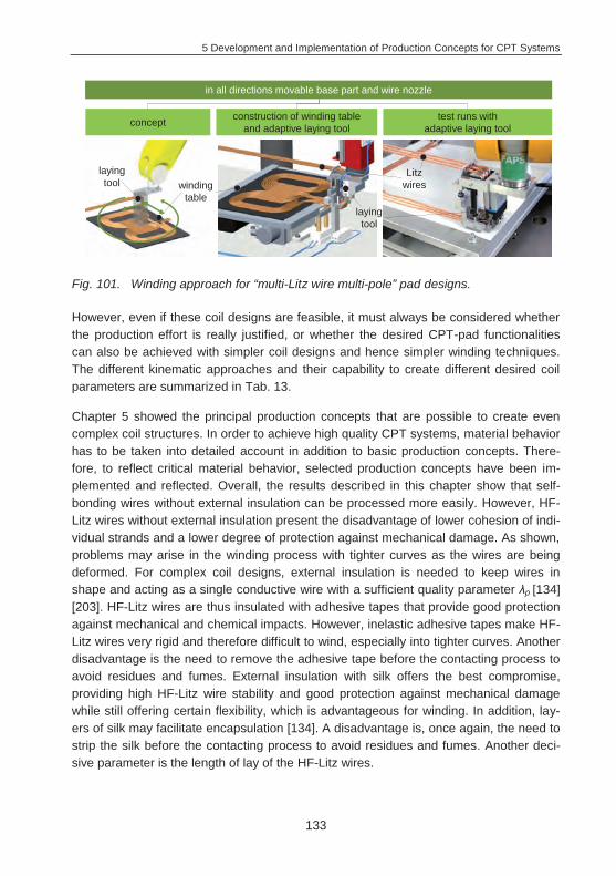
5 Development and Implementation of Production Concepts for CPT Systems
133
Fig. 101. Winding approach for “multi-Litz wire multi-pole” pad designs.
However, even if these coil designs are feasible, it must always be considered whether the production effort is really justified, or whether the desired CPT-pad functionalities can also be achieved with simpler coil designs and hence simpler winding techniques. The different kinematic approaches and their capability to create different desired coil parameters are summarized in Tab. 13.
Chapter 5 showed the principal production concepts that are possible to create even complex coil structures. In order to achieve high quality CPT systems, material behavior has to be taken into detailed account in addition to basic production concepts. There-fore, to reflect critical material behavior, selected production concepts have been im-plemented and reflected. Overall, the results described in this chapter show that self-bonding wires without external insulation can be processed more easily. However, HF-Litz wires without external insulation present the disadvantage of lower cohesion of indi-vidual strands and a lower degree of protection against mechanical damage. As shown, problems may arise in the winding process with tighter curves as the wires are being deformed. For complex coil designs, external insulation is needed to keep wires in shape and acting as a single conductive wire with a sufficient quality parameter p [134] [203]. HF-Litz wires are thus insulated with adhesive tapes that provide good protection against mechanical and chemical impacts. However, inelastic adhesive tapes make HF-Litz wires very rigid and therefore difficult to wind, especially into tighter curves. Another disadvantage is the need to remove the adhesive tape before the contacting process to avoid residues and fumes. External insulation with silk offers the best compromise, providing high HF-Litz wire stability and good protection against mechanical damage while still offering certain flexibility, which is advantageous for winding. In addition, lay-ers of silk may facilitate encapsulation [134]. A disadvantage is, once again, the need to strip the silk before the contacting process to avoid residues and fumes. Another deci-sive parameter is the length of lay of the HF-Litz wires.
in all directions movable base part and wire nozzle
concept construction of winding table and adaptive laying tool
test runs with adaptive laying tool
laying tool
winding table
Litz wires
laying tool
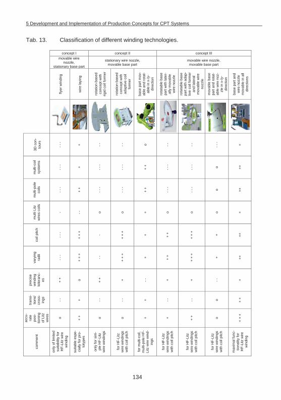
5 Development and Implementation of Production Concepts for CPT Systems
134
Tab. 13. Classification of different winding technologies.
concept I concept II concept III
movable wire nozzle,
stationary base part
stationary wire nozzle, movable base part
movable wire nozzle, movable base part
flyer
win
ding
wire
layi
ng
rota
tion-
base
d co
ncep
t with
rig
id c
oil f
orm
er
rota
tion-
base
d co
ncep
t with
ad
aptiv
e co
il fo
rmer
base
par
t mov
-ab
le a
nd ro
tat-
able
in x
-/y-
dire
ctio
n
rota
tabl
e ba
se
part
with
late
r-al
ly m
ovab
le
wire
noz
zle
rota
tabl
e ba
se
part
with
ada
p-tiv
e co
il fo
rmer
an
d la
tera
l m
ovab
le w
ire
nozz
le
mov
able
bas
e pa
rt an
d ro
tat-
able
wire
noz
-zl
e in
x-/y
-di
rect
ion
base
par
t and
w
ire n
ozzl
e m
ovab
le in
all
dire
ctio
ns
3D c
on-
tour
s
- - - + - -
- -
o - -
- -
- - - +
mul
ti-co
il sy
stem
s
- - - + - - -
- - -
+ +
- - -
- - - o ++
mul
ti-po
le
coils
- - -
+ +
- - -
- - -
+ +
- - -
- - - o ++
mul
ti Li
tz
wire
s co
ils
- - -
o o + o o o +
coil
pitc
h
- - -
+ +
+
-
+ +
+
+ + +
+ +
+
+ ++
vary
ing
radi
i
- - -
+ +
+
- -
+ +
+
+ + +
+ +
+
+ ++
prec
ise
win
ding
to
lera
nc-
es
+ + o + + + - -
+
+ - -
+
trans
i-tio
ns/
cros
s-in
gs
- -
+ - -
- -
+ - -
- -
o + +
accu
-ra
te
posi
-tio
ning
of
Litz
w
ires
o + + o o + + + + o
+ +
+
com
men
t
only
of l
imite
d su
itabi
lity
for
HF-
Litz
wire
w
indi
ng
suita
ble
espe
-ci
ally
for p
ro-
toty
pes
only
for s
im-
ple
HF-
Litz
w
ire w
indi
ngs
for H
F-Li
tz
wire
win
ding
s w
ith c
oil p
itch
for m
ulti-
coil,
m
ulti-
pole
HF-
Litz
wire
win
d-in
gs
for H
F-Li
tz
wire
win
ding
s w
ith c
oil p
itch
for H
F-Li
tz
wire
win
ding
s w
ith c
oil p
itch
for H
F-Li
tz
wire
win
ding
s w
ith c
oil p
itch
max
imal
func
-tio
nalit
y fo
r H
F-Li
tz w
ire
win
ding

5 Development and Implementation of Production Concepts for CPT Systems
135
Longer length of lay is desirable from a production point of view, as it provides a better filling factor and high flexibility due to the lower rigidity of the individual wires. However, with a longer length of lay, dimensional stability and roundness decreases. In setting these parameters, it is important to consider the individual winding pattern, the generat-ed (external/internal) proximity effect, and resulting varying resistances, as an individual strand in a twisted bundle travels a greater distance than a simple straight wire bundle [143]. The test results also highlight the challenges of using simple flat base materials to carry the coils compared to more expensive base parts with mechanical fixation ele-ments such as grooves. Coil forms with grooves guarantee reliable wire positioning even for complex coil shapes. When fixing wires on simple flat base materials, limited positioning accuracy must be carefully considered as the main impeding factor.
In summary, the implemented tests shown above can identify production-relevant char-acteristics to assess the suitability of HF-Litz wires for winding and the winding/wire lay-ing tools needed for this purpose.
6 Optimizing CPT Systems from a Process and Material Perspective
136
6 Optimizing CPT Systems from a Process and Material Perspective
Optimized design results in considerable long-term cost and energy savings. The main objective of pad optimization is thus to identify the limitations of different pad designs and system behaviors, and to propose solutions to overcome them. So far, numerous pad models with various configurations dependent on many variables have been inves-tigated to find improved charging pad designs [24]. This approach addressed system optimization mainly from a geometric (size, form and position of ferrites and coils) and functional perspective (power level, transmission frequency, control strategy, charging currents, protection measures) [120] [121].
But there is also a variety of other aspects from a material and production point of view. For practical application in an EV, power pads must meet strict automotive requirements (certification to ISO/TS 16949:2009). CPT systems have to function reliably from the first to the last day of the vehicle’s product life. The power transfer rate or efficiency may not drop, total system failure is not acceptable. Failure modes and effects need to be identified ahead of time and assessed with a thorough material and process analysis. This has to be done for all production processes in the entire supply chain as early as possible, from early stages of product development (product- and process-FMEA36). Winding resistances and ferrite core losses, for instance, are often ignored in system designs as they are considered to be significantly lower than mutual and leakage reac-tances at the resonant frequency [161]. This may be true for prototypical systems in the lab, where materials are chosen appropriately and the set-up is careful. However, this assumption also has to hold true for pads manufactured with less than perfect off-tool quality, less than premium (i.e. cost-sensitive) materials, processed at higher speeds on industrialized equipment designed for large-scale production, able to handle the stress profiles that arise over the entire product life.
Fig. 102 shows the cause-and-effect diagram of possible issues with CPT systems. Very significant potential failure modes, e.g. due to radiated emissions (EMC issues with keyless entry systems, control systems, LOP, FOD, exceeding permissible expo-sure limits, etc.) have to be carefully considered with suitable design approaches and substantial analyzes in special anechoic RF chambers. Aside from EMC compliance profiles, further problems induced by production, material and operational influences may also significantly impact CPT system performance. The fact that CPT devices op-erate inside vehicles (underbody, front, rear bumpers) and in the ground poses addi-tional challenges. The introduction of contactless charging technology and the integra-tion of secondary charging pads in the underbody means that underbody trim parts must serve an even broader range of functionality and requirements [27]. 36 Failure Mode and Effects Analysis
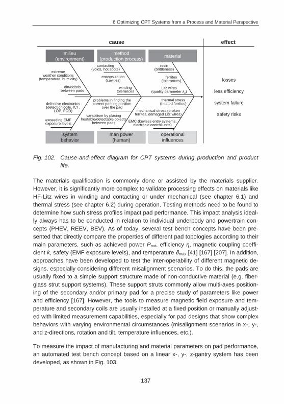
6 Optimizing CPT Systems from a Process and Material Perspective
137
Fig. 102. Cause-and-effect diagram for CPT systems during production and product life.
The materials qualification is commonly done or assisted by the materials supplier. However, it is significantly more complex to validate processing effects on materials like HF-Litz wires in winding and contacting or under mechanical (see chapter 6.1) and thermal stress (see chapter 6.2) during operation. Testing methods need to be found to determine how such stress profiles impact pad performance. This impact analysis ideal-ly always has to be conducted in relation to individual underbody and powertrain con-cepts (PHEV, REEV, BEV). As of today, several test bench concepts have been pre-sented that directly compare the properties of different pad topologies according to their main parameters, such as achieved power Pout, efficiency , magnetic coupling coeffi-cient k, safety (EMF exposure levels), and temperature max [41] [167] [207]. In addition, approaches have been developed to test the inter-operability of different magnetic de-signs, especially considering different misalignment scenarios. To do this, the pads are usually fixed to a simple support structure made of non-conductive material (e.g. fiber-glass strut support systems). These support struts commonly allow multi-axes position-ing of the secondary and/or primary pad for a precise study of parameters like power and efficiency [167]. However, the tools to measure magnetic field exposure and tem-perature and secondary coils are usually installed at a fixed position or manually adjust-ed with limited measurement capabilities, especially for pad designs that show complex behaviors with varying environmental circumstances (misalignment scenarios in x-, y-, and z-directions, rotation and tilt, temperature influences, etc.).
To measure the impact of manufacturing and material parameters on pad performance, an automated test bench concept based on a linear x-, y-, z-gantry system has been developed, as shown in Fig. 103.
losses
less efficiency
system failure
safety risks
effectcause
method (production process) material
operational influences
man power (human)
system behavior
milieu(environment)
extreme weather conditions
(temperature, humidity)
defective electronics (detection coils, ICT,
LOP, FOD)
problems in finding the correct parking position
over the pad
dirt/debris between pads
winding tolerances
encapsulation (cavities)
contacting (voids, hot spots)
Litz wires (quality parameter p)
ferrites (tolerances)
resin (brittleness)
EMC (keyless entry systems, electronic control units)
mechanical stress (broken ferrites, damaged Litz wires)
thermal stress (heated ferrites)
exceeding EMF exposure levels
vandalism by placing heatable/detectable objects
between pads
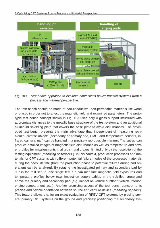
6 Optimizing CPT Systems from a Process and Material Perspective
138
Fig. 103. Test-bench approach to evaluate contactless power transfer systems from a process and material perspective.
The test bench should be made of non-conductive, non-permeable materials like wood or plastic in order not to affect the magnetic field and examined parameters. The proto-typic test bench concept shown in Fig. 103 uses acrylic glass support structures with appropriate distances to the metallic base structure of the test system and an additional aluminum shielding plate that covers the base plate to avoid disturbances. The devel-oped test bench presents the main advantage that, independent of measuring tech-niques, diverse objects (secondary or primary pad, EMF- and temperature sensors, in-frared camera, etc.) can be handled in a precisely reproducible manner. The set-up can produce detailed images of magnetic field disturbance as well as temperature and pow-er profiles for misalignments in all x-, y-, and z-axes, limited only by the resolution of the testing equipment (“handling of sensors”). In this context, production processes and ma-terials for CPT systems with different potential failure modes of the processed materials during the pads’ lifetime (from the production phase to potential failures during pad op-eration) can be analyzed. By rotating the investigated primary and secondary pad by 90° in the test set-up, one single test run can measure magnetic field exposures and temperature profiles below (e.g. impact on supply cables in the sub-floor area) and above the primary and secondary pad (e.g. impact on vehicle subfloor, vehicle interior, engine-compartment, etc.). Another promising aspect of the test bench concept is its precise and flexible orientation between source and capture device (“handling of pads”). This feature allows e.g. for an exact evaluation of RPEV CPT systems by placing sev-eral primary CPT systems on the ground and precisely positioning the secondary sys-
CPTreference pad
multi-axis positioning system
electronics (HF-generator)
Narda EM Field meter (ELT-400)
custom LabViewhost and data
acquisition
temperature sensors
base plate covered with aluminum plate
acrylic glass primary coil stand-off
EMF probe (100 or 3 cm²) pick-up
handling of sensors
handling of charging pads
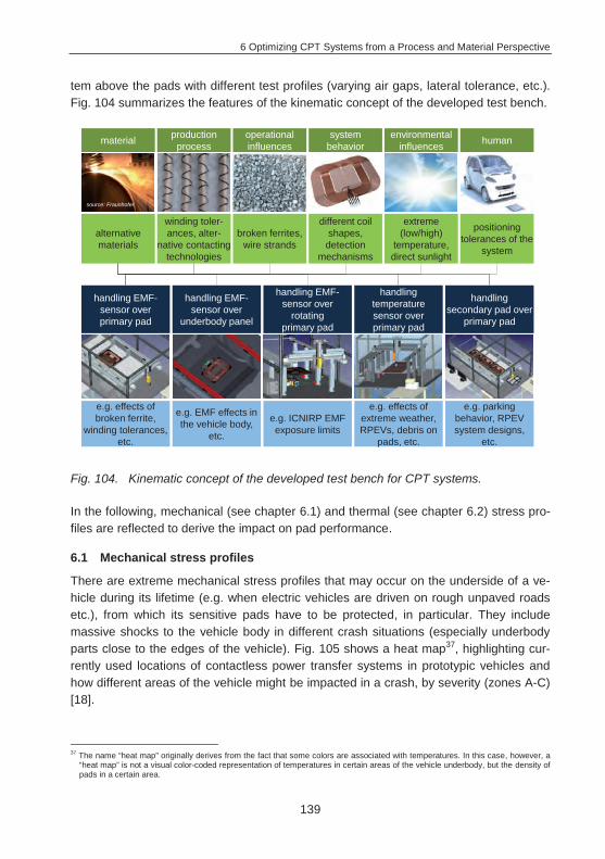
6 Optimizing CPT Systems from a Process and Material Perspective
139
tem above the pads with different test profiles (varying air gaps, lateral tolerance, etc.). Fig. 104 summarizes the features of the kinematic concept of the developed test bench.
Fig. 104. Kinematic concept of the developed test bench for CPT systems.
In the following, mechanical (see chapter 6.1) and thermal (see chapter 6.2) stress pro-files are reflected to derive the impact on pad performance.
6.1 Mechanical stress profiles
There are extreme mechanical stress profiles that may occur on the underside of a ve-hicle during its lifetime (e.g. when electric vehicles are driven on rough unpaved roads etc.), from which its sensitive pads have to be protected, in particular. They include massive shocks to the vehicle body in different crash situations (especially underbody parts close to the edges of the vehicle). Fig. 105 shows a heat map37, highlighting cur-rently used locations of contactless power transfer systems in prototypic vehicles and how different areas of the vehicle might be impacted in a crash, by severity (zones A-C) [18].
37 The name “heat map” originally derives from the fact that some colors are associated with temperatures. In this case, however, a
“heat map” is not a visual color-coded representation of temperatures in certain areas of the vehicle underbody, but the density of pads in a certain area.
production processmaterial operational
influences humansystem behavior
environmental influences
winding toler-ances, alter-
native contacting technologies
alternative materials
broken ferrites, wire strands
positioning tolerances of the
system
different coil shapes,
detection mechanisms
extreme (low/high)
temperature, direct sunlight
source: Fraunhofer
handling EMF-sensor over
rotating primary pad
handling temperature sensor over primary pad
e.g. ICNIRP EMF exposure limits
e.g. effects of extreme weather, RPEVs, debris on
pads, etc.
handling secondary pad over
primary pad
handling EMF-sensor over
underbody panel
handling EMF-sensor overprimary pad
e.g. parking behavior, RPEV system designs,
etc.
e.g. EMF effects in the vehicle body,
etc.
e.g. effects of broken ferrite,
winding tolerances, etc.
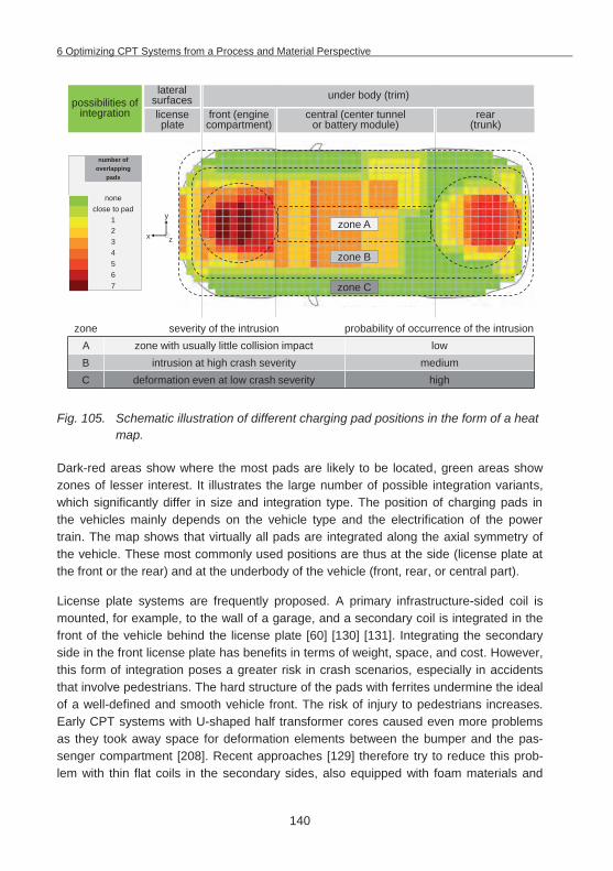
6 Optimizing CPT Systems from a Process and Material Perspective
140
Fig. 105. Schematic illustration of different charging pad positions in the form of a heat map.
Dark-red areas show where the most pads are likely to be located, green areas show zones of lesser interest. It illustrates the large number of possible integration variants, which significantly differ in size and integration type. The position of charging pads in the vehicles mainly depends on the vehicle type and the electrification of the power train. The map shows that virtually all pads are integrated along the axial symmetry of the vehicle. These most commonly used positions are thus at the side (license plate at the front or the rear) and at the underbody of the vehicle (front, rear, or central part).
License plate systems are frequently proposed. A primary infrastructure-sided coil is mounted, for example, to the wall of a garage, and a secondary coil is integrated in the front of the vehicle behind the license plate [60] [130] [131]. Integrating the secondary side in the front license plate has benefits in terms of weight, space, and cost. However, this form of integration poses a greater risk in crash scenarios, especially in accidents that involve pedestrians. The hard structure of the pads with ferrites undermine the ideal of a well-defined and smooth vehicle front. The risk of injury to pedestrians increases. Early CPT systems with U-shaped half transformer cores caused even more problems as they took away space for deformation elements between the bumper and the pas-senger compartment [208]. Recent approaches [129] therefore try to reduce this prob-lem with thin flat coils in the secondary sides, also equipped with foam materials and
license plate
central (center tunnel or battery module)
front (engine compartment)
possibilities of integration
lateral surfaces
rear(trunk)
number of overlapping
pads
noneclose to pad
1234567
under body (trim)
zone severity of the intrusion probability of occurrence of the intrusionA zone with usually little collision impact lowB intrusion at high crash severity mediumC deformation even at low crash severity high
zone A
zone B
zone C
zx
y
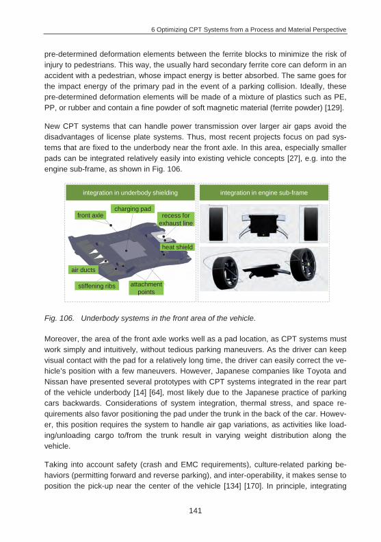
6 Optimizing CPT Systems from a Process and Material Perspective
141
pre-determined deformation elements between the ferrite blocks to minimize the risk of injury to pedestrians. This way, the usually hard secondary ferrite core can deform in an accident with a pedestrian, whose impact energy is better absorbed. The same goes for the impact energy of the primary pad in the event of a parking collision. Ideally, these pre-determined deformation elements will be made of a mixture of plastics such as PE, PP, or rubber and contain a fine powder of soft magnetic material (ferrite powder) [129].
New CPT systems that can handle power transmission over larger air gaps avoid the disadvantages of license plate systems. Thus, most recent projects focus on pad sys-tems that are fixed to the underbody near the front axle. In this area, especially smaller pads can be integrated relatively easily into existing vehicle concepts [27], e.g. into the engine sub-frame, as shown in Fig. 106.
Fig. 106. Underbody systems in the front area of the vehicle.
Moreover, the area of the front axle works well as a pad location, as CPT systems must work simply and intuitively, without tedious parking maneuvers. As the driver can keep visual contact with the pad for a relatively long time, the driver can easily correct the ve-hicle’s position with a few maneuvers. However, Japanese companies like Toyota and Nissan have presented several prototypes with CPT systems integrated in the rear part of the vehicle underbody [14] [64], most likely due to the Japanese practice of parking cars backwards. Considerations of system integration, thermal stress, and space re-quirements also favor positioning the pad under the trunk in the back of the car. Howev-er, this position requires the system to handle air gap variations, as activities like load-ing/unloading cargo to/from the trunk result in varying weight distribution along the vehicle.
Taking into account safety (crash and EMC requirements), culture-related parking be-haviors (permitting forward and reverse parking), and inter-operability, it makes sense to position the pick-up near the center of the vehicle [134] [170]. In principle, integrating
integration in underbody shielding integration in engine sub-frame
charging padfront axle
heat shield
stiffening ribs
air ducts
attachment points
recess for exhaust line
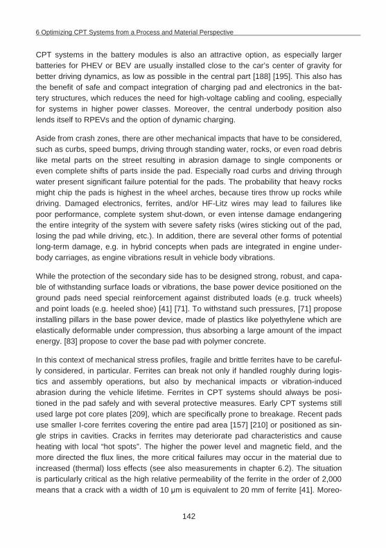
6 Optimizing CPT Systems from a Process and Material Perspective
142
CPT systems in the battery modules is also an attractive option, as especially larger batteries for PHEV or BEV are usually installed close to the car’s center of gravity for better driving dynamics, as low as possible in the central part [188] [195]. This also has the benefit of safe and compact integration of charging pad and electronics in the bat-tery structures, which reduces the need for high-voltage cabling and cooling, especially for systems in higher power classes. Moreover, the central underbody position also lends itself to RPEVs and the option of dynamic charging.
Aside from crash zones, there are other mechanical impacts that have to be considered, such as curbs, speed bumps, driving through standing water, rocks, or even road debris like metal parts on the street resulting in abrasion damage to single components or even complete shifts of parts inside the pad. Especially road curbs and driving through water present significant failure potential for the pads. The probability that heavy rocks might chip the pads is highest in the wheel arches, because tires throw up rocks while driving. Damaged electronics, ferrites, and/or HF-Litz wires may lead to failures like poor performance, complete system shut-down, or even intense damage endangering the entire integrity of the system with severe safety risks (wires sticking out of the pad, losing the pad while driving, etc.). In addition, there are several other forms of potential long-term damage, e.g. in hybrid concepts when pads are integrated in engine under-body carriages, as engine vibrations result in vehicle body vibrations.
While the protection of the secondary side has to be designed strong, robust, and capa-ble of withstanding surface loads or vibrations, the base power device positioned on the ground pads need special reinforcement against distributed loads (e.g. truck wheels) and point loads (e.g. heeled shoe) [41] [71]. To withstand such pressures, [71] propose installing pillars in the base power device, made of plastics like polyethylene which are elastically deformable under compression, thus absorbing a large amount of the impact energy. [83] propose to cover the base pad with polymer concrete.
In this context of mechanical stress profiles, fragile and brittle ferrites have to be careful-ly considered, in particular. Ferrites can break not only if handled roughly during logis-tics and assembly operations, but also by mechanical impacts or vibration-induced abrasion during the vehicle lifetime. Ferrites in CPT systems should always be posi-tioned in the pad safely and with several protective measures. Early CPT systems still used large pot core plates [209], which are specifically prone to breakage. Recent pads use smaller I-core ferrites covering the entire pad area [157] [210] or positioned as sin-gle strips in cavities. Cracks in ferrites may deteriorate pad characteristics and cause heating with local “hot spots”. The higher the power level and magnetic field, and the more directed the flux lines, the more critical failures may occur in the material due to increased (thermal) loss effects (see also measurements in chapter 6.2). The situation is particularly critical as the high relative permeability of the ferrite in the order of 2,000 means that a crack with a width of 10 m is equivalent to 20 mm of ferrite [41]. Moreo-

6 Optimizing CPT Systems from a Process and Material Perspective
143
ver, mechanical impact can dislodge the ferrites in the pad, changing the distances be-tween adjacent ferrite blocks, shielding material, or coils, resulting in leakage flux with additional gap losses. This creates localized areas of increased flux density, resulting in higher losses at those points that can drastically increase overall losses. However, these aspects always strongly depend on the individual magnetic design. Preliminary experiments in research projects with larger circular pads showed that small cracks in and minor damage to the ferrite have hardly any negative effects on the quality of power transmission [56].
To verify mechanical impacts and compressive forces, sample FEM-based mechanical simulations have been conducted to determine stress profiles caused by hitting curbs and driving through water on the secondary pad and the underbody panel. Under such stress profiles, a large proportion of the vehicle weight impacts with a narrow portion of the bottom surface of the UBV. Several assumptions were made to simplify the model for FEM simulation in ANSYS Workbench, limit system boundaries and thus reduce complexity. The CAD models of the pad and underbody shielding were simplified by suppressing small details such as radii, chamfers, and ribs. In addition, all components in the housing except ferrites were replaced by a volume representing the encapsulation that fills the entire housing. This approach is applicable when the electrical components are completely impregnated by resin and, as a consequence, impact forces are more evenly distributed throughout the pad [134].
To determine the effect of a mechanical impact, a proportionate vehicle-weight-caused force is applied to a contact surface. Total load surfaces Pload can be distributed to quite a low level, avoiding point loads. Depending on the impact surface (Aimpact_surface = widthimpact lengthimpact) and the portion of vehicle weightload, the following equation ap-plies:
(6.1)
Due to the significantly higher ductility of copper alloys in comparison to soft magnetic materials, coil windings are not considered in the simulation model. The calculation model thus includes only the gross geometry of the underbody panel, the pad housing with the cover, and the encapsulated ferrites. With this simplified CAD model, a fast cal-culation with fewer elements and nodes as well as a lower number of possible failure causes provides a first rough assessment of stress profiles (Fig. 107).
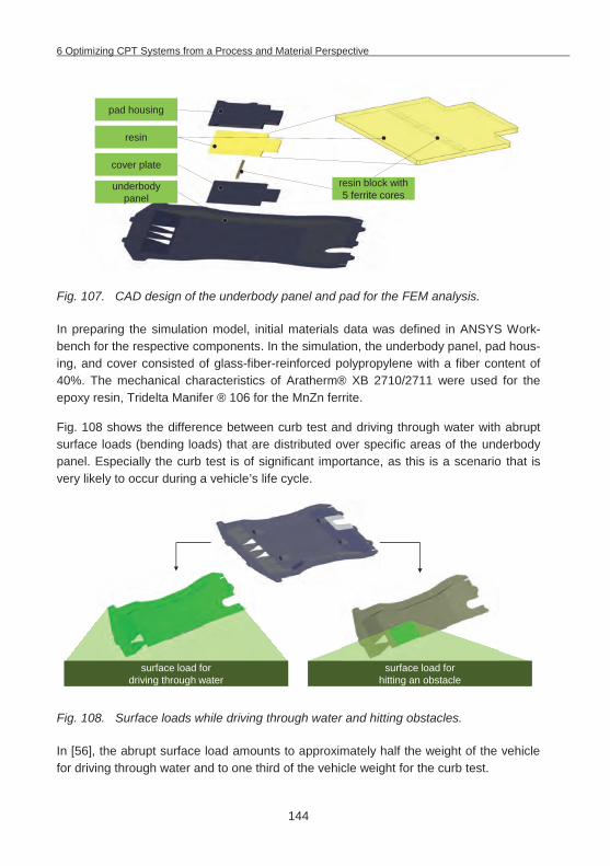
6 Optimizing CPT Systems from a Process and Material Perspective
144
Fig. 107. CAD design of the underbody panel and pad for the FEM analysis.
In preparing the simulation model, initial materials data was defined in ANSYS Work-bench for the respective components. In the simulation, the underbody panel, pad hous-ing, and cover consisted of glass-fiber-reinforced polypropylene with a fiber content of 40%. The mechanical characteristics of Aratherm® XB 2710/2711 were used for the epoxy resin, Tridelta Manifer ® 106 for the MnZn ferrite.
Fig. 108 shows the difference between curb test and driving through water with abrupt surface loads (bending loads) that are distributed over specific areas of the underbody panel. Especially the curb test is of significant importance, as this is a scenario that is very likely to occur during a vehicle’s life cycle.
Fig. 108. Surface loads while driving through water and hitting obstacles.
In [56], the abrupt surface load amounts to approximately half the weight of the vehicle for driving through water and to one third of the vehicle weight for the curb test.
resin block with 5 ferrite cores
resin
pad housing
underbody panel
cover plate
surface load for driving through water
surface load for hitting an obstacle
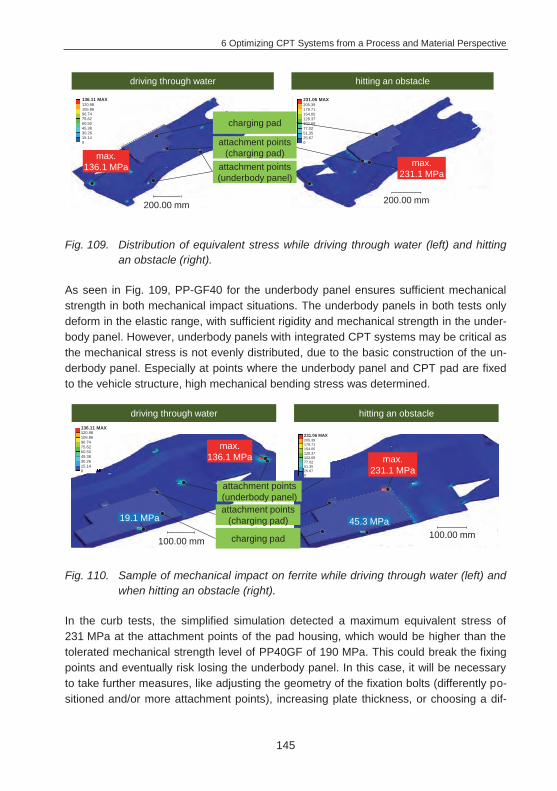
6 Optimizing CPT Systems from a Process and Material Perspective
145
Fig. 109. Distribution of equivalent stress while driving through water (left) and hitting an obstacle (right).
As seen in Fig. 109, PP-GF40 for the underbody panel ensures sufficient mechanical strength in both mechanical impact situations. The underbody panels in both tests only deform in the elastic range, with sufficient rigidity and mechanical strength in the under-body panel. However, underbody panels with integrated CPT systems may be critical as the mechanical stress is not evenly distributed, due to the basic construction of the un-derbody panel. Especially at points where the underbody panel and CPT pad are fixed to the vehicle structure, high mechanical bending stress was determined.
Fig. 110. Sample of mechanical impact on ferrite while driving through water (left) and when hitting an obstacle (right).
In the curb tests, the simplified simulation detected a maximum equivalent stress of 231 MPa at the attachment points of the pad housing, which would be higher than the tolerated mechanical strength level of PP40GF of 190 MPa. This could break the fixing points and eventually risk losing the underbody panel. In this case, it will be necessary to take further measures, like adjusting the geometry of the fixation bolts (differently po-sitioned and/or more attachment points), increasing plate thickness, or choosing a dif-
max.136.1 MPa
driving through water hitting an obstacle
max.231.1 MPa
charging pad
200.00 mm
attachment points (charging pad)
attachment points (underbody panel)
200.00 mm
231.06 MAX205.39179.71154.05128.37102.6977.0251.3525.670
136.11 MAX120.98105.8690.7475.6260.5045.3830.2615.140
19.1 MPa
max.136.1 MPa
driving through water hitting an obstacle
45.3 MPa
max.231.1 MPa
charging pad100.00 mm
attachment points (charging pad)
attachment points (underbody panel)
100.00 mm
231.06 MAX205.39179.71154.05128.37102.6977.0251.3525.670
136.11 MAX120.98105.8690.7475.6260.5045.3830.2615.140
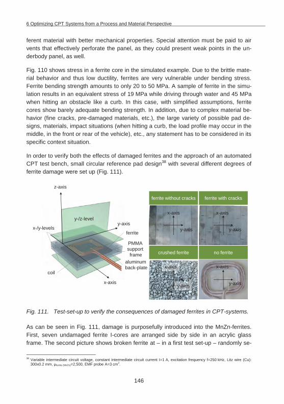
6 Optimizing CPT Systems from a Process and Material Perspective
146
ferent material with better mechanical properties. Special attention must be paid to air vents that effectively perforate the panel, as they could present weak points in the un-derbody panel, as well.
Fig. 110 shows stress in a ferrite core in the simulated example. Due to the brittle mate-rial behavior and thus low ductility, ferrites are very vulnerable under bending stress. Ferrite bending strength amounts to only 20 to 50 MPa. A sample of ferrite in the simu-lation results in an equivalent stress of 19 MPa while driving through water and 45 MPa when hitting an obstacle like a curb. In this case, with simplified assumptions, ferrite cores show barely adequate bending strength. In addition, due to complex material be-havior (fine cracks, pre-damaged materials, etc.), the large variety of possible pad de-signs, materials, impact situations (when hitting a curb, the load profile may occur in the middle, in the front or rear of the vehicle), etc., any statement has to be considered in its specific context situation.
In order to verify both the effects of damaged ferrites and the approach of an automated CPT test bench, small circular reference pad design38 with several different degrees of ferrite damage were set up (Fig. 111).
Fig. 111. Test-set-up to verify the consequences of damaged ferrites in CPT-systems.
As can be seen in Fig. 111, damage is purposefully introduced into the MnZn-ferrites. First, seven undamaged ferrite I-cores are arranged side by side in an acrylic glass frame. The second picture shows broken ferrite at – in a first test set-up – randomly se-
38 Variable intermediate circuit voltage, constant intermediate circuit current I=1 A, excitation frequency f=250 kHz, Litz wire (Cu):
300x0.2 mm, ferrite (MnZn)=2,500, EMF probe A=3 cm2.
ferrite without cracks
crushed ferrite
ferrite with cracks
no ferrite
y-/z-level
x-/y-levels
coil
ferrite
aluminum back-plate
PMMA support frame
z-axis
x-axis
y-axisy-axis
x-axis
y-axis
x-axis
y-axis
x-axis
y-axis
x-axis
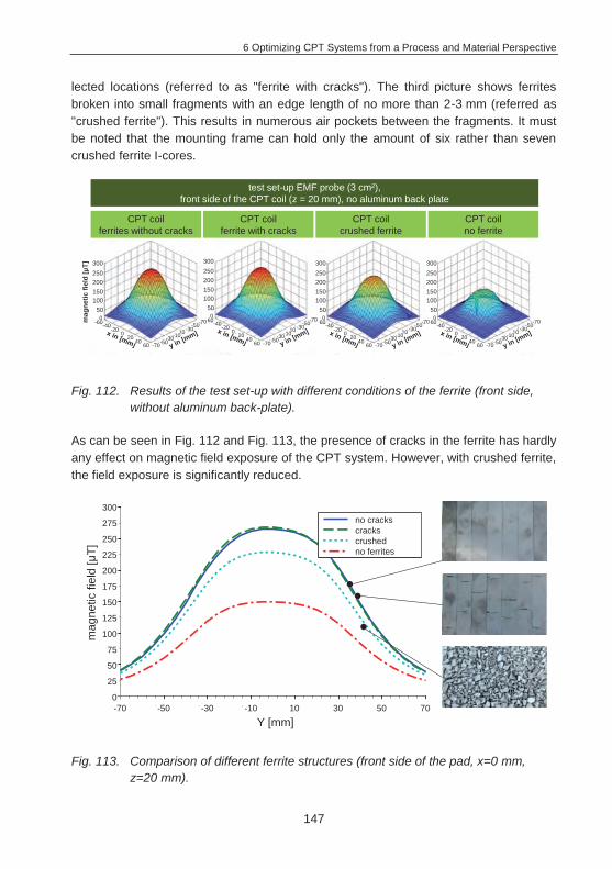
6 Optimizing CPT Systems from a Process and Material Perspective
147
lected locations (referred to as "ferrite with cracks"). The third picture shows ferrites broken into small fragments with an edge length of no more than 2-3 mm (referred as "crushed ferrite"). This results in numerous air pockets between the fragments. It must be noted that the mounting frame can hold only the amount of six rather than seven crushed ferrite I-cores.
Fig. 112. Results of the test set-up with different conditions of the ferrite (front side, without aluminum back-plate).
As can be seen in Fig. 112 and Fig. 113, the presence of cracks in the ferrite has hardly any effect on magnetic field exposure of the CPT system. However, with crushed ferrite, the field exposure is significantly reduced.
Fig. 113. Comparison of different ferrite structures (front side of the pad, x=0 mm, z=20 mm).
300250200150100
50
10-10-30-50-70
020
4060
0
-20-40-60
-30-50-70
300250200150100
50
10-10-30-50-70
020
4060
0
-20-40-60
-30-50-70
300250200150100
50
10-10-30-50-70
020
4060
0
-20-40-60
-30-50-70
CPT coilferrites without cracks
CPT coilferrite with cracks
CPT coilcrushed ferrite
CPT coilno ferrite
test set-up EMF probe (3 cm²), front side of the CPT coil (z = 20 mm), no aluminum back plate
300250200150100
50
10-10-30-50-70
020
4060
0
-20
mag
netic
fiel
d [
T]
-40-60-30-50
-70
70 50 30 10 10 30 50 700
50
100
150
200
250
300
Y in mm
Flux
den
sity
in
T
ferritesferrites with crackscrushed ferritesno ferrites
mag
netic
fiel
d [
T]
Y [mm]
300
175
200
225
250
275
0
25
50
75
100
125
150
-70 -50 -30 -10 10 30 50 70
no crackscrackscrushedno ferrites
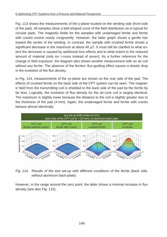
6 Optimizing CPT Systems from a Process and Material Perspective
148
Fig. 113 shows the measurements of the y-plane located on the winding side (front side of the pad). All samples show a bell-shaped curve of the field distribution as is typical for circular pads. The magnetic fields for the samples with undamaged ferrite and ferrite with cracks evolve nearly congruently. However, the latter graph shows a gentle rise toward the center of the winding. In contrast, the sample with crushed ferrite shows a significant decrease in the maximum at about 40 T. It must still be clarified to what ex-tent the decrease is caused by additional loss effects and to what extent to the reduced amount of material (only six I-cores instead of seven). As a further reference for the change in field exposure, the diagram also shows another measurement with an air coil without any ferrite. The absence of the ferrites’ flux-guiding effect causes a drastic drop in the evolution of the flux density.
In Fig. 114, measurements of the xy-plane are shown on the rear side of the pad. The effects of crushed ferrite on the back side of the CPT system can be seen. The magnet-ic field from the transmitting coil is shielded to the back side of the pad by the ferrite by far less. Logically, the evolution of flux density for the air-core coil is largely identical. The maximum is slightly lower because the distance to the coil is slightly greater due to the thickness of the pad (4 mm). Again, the undamaged ferrite and ferrite with cracks behave almost identically.
Fig. 114. Results of the test set-up with different conditions of the ferrite (back side, without aluminum back-plate).
However, in the range around the zero point, the latter shows a minimal increase in flux density (see also Fig. 115).
150
100
50
10-10-30-50-70
020
4060
0
-20-40-60
-30-50-70
150
100
50
10-10-30-50-70
020
4060
0
-20-40-60
-30-50-70
150
100
50
10-10-30-50-70
020
4060
0
-20-40-60
-30-50-70
CPT coilferrites without cracks
CPT coilferrite with cracks
CPT coilcrushed ferrite
CPT coilno ferrite
test set-up EMF probe (3 cm²), back side of the CPT coil (z = 20 mm), no aluminum back plate
150
100
50
10-10-30-50-70
020
4060
0
-20
mag
netic
fiel
d [
T]
-40-60-30-50
-70
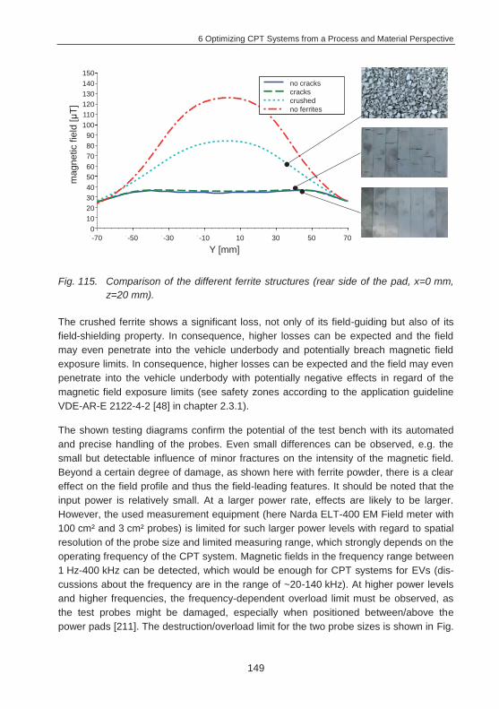
6 Optimizing CPT Systems from a Process and Material Perspective
149
Fig. 115. Comparison of the different ferrite structures (rear side of the pad, x=0 mm, z=20 mm).
The crushed ferrite shows a significant loss, not only of its field-guiding but also of its field-shielding property. In consequence, higher losses can be expected and the field may even penetrate into the vehicle underbody and potentially breach magnetic field exposure limits. In consequence, higher losses can be expected and the field may even penetrate into the vehicle underbody with potentially negative effects in regard of the magnetic field exposure limits (see safety zones according to the application guideline VDE-AR-E 2122-4-2 [48] in chapter 2.3.1).
The shown testing diagrams confirm the potential of the test bench with its automated and precise handling of the probes. Even small differences can be observed, e.g. the small but detectable influence of minor fractures on the intensity of the magnetic field. Beyond a certain degree of damage, as shown here with ferrite powder, there is a clear effect on the field profile and thus the field-leading features. It should be noted that the input power is relatively small. At a larger power rate, effects are likely to be larger. However, the used measurement equipment (here Narda ELT-400 EM Field meter with 100 cm² and 3 cm² probes) is limited for such larger power levels with regard to spatial resolution of the probe size and limited measuring range, which strongly depends on the operating frequency of the CPT system. Magnetic fields in the frequency range between 1 Hz-400 kHz can be detected, which would be enough for CPT systems for EVs (dis-cussions about the frequency are in the range of ~20-140 kHz). At higher power levels and higher frequencies, the frequency-dependent overload limit must be observed, as the test probes might be damaged, especially when positioned between/above the power pads [211]. The destruction/overload limit for the two probe sizes is shown in Fig.
70 50 30 10 10 30 50 700
50
100
150
Y in mm
Flux
den
sity
in
Tferritesferrites with crackscrushed ferritesno ferrites
mag
netic
fiel
d [
T]
Y [mm]
150
100110120130140
0102030405060708090
-70 -50 -30 -10 10 30 50 70
no crackscrackscrushedno ferrites
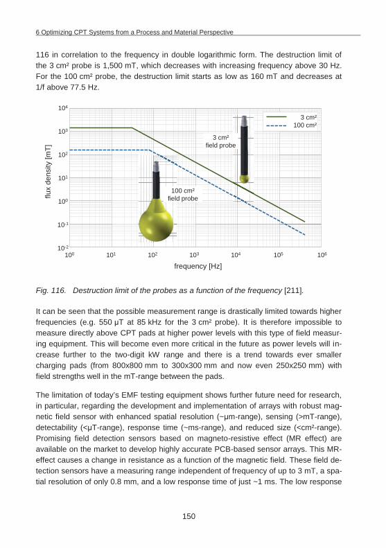
6 Optimizing CPT Systems from a Process and Material Perspective
150
116 in correlation to the frequency in double logarithmic form. The destruction limit of the 3 cm² probe is 1,500 mT, which decreases with increasing frequency above 30 Hz. For the 100 cm² probe, the destruction limit starts as low as 160 mT and decreases at 1/f above 77.5 Hz.
Fig. 116. Destruction limit of the probes as a function of the frequency [211].
It can be seen that the possible measurement range is drastically limited towards higher frequencies (e.g. 550 T at 85 kHz for the 3 cm² probe). It is therefore impossible to measure directly above CPT pads at higher power levels with this type of field measur-ing equipment. This will become even more critical in the future as power levels will in-crease further to the two-digit kW range and there is a trend towards ever smaller charging pads (from 800x800 mm to 300x300 mm and now even 250x250 mm) with field strengths well in the mT-range between the pads.
The limitation of today’s EMF testing equipment shows further future need for research, in particular, regarding the development and implementation of arrays with robust mag-netic field sensor with enhanced spatial resolution (~ m-range), sensing (>mT-range), detectability (< T-range), response time (~ms-range), and reduced size (<cm²-range). Promising field detection sensors based on magneto-resistive effect (MR effect) are available on the market to develop highly accurate PCB-based sensor arrays. This MR-effect causes a change in resistance as a function of the magnetic field. These field de-tection sensors have a measuring range independent of frequency of up to 3 mT, a spa-tial resolution of only 0.8 mm, and a low response time of just ~1 ms. The low response
flux
dens
ity [m
T]
frequency [Hz]
100
101
102
10-1
100 101 102 103 104 105 10610-2
103
104
3 cm²100 cm²
100 cm²field probe
3 cm²field probe
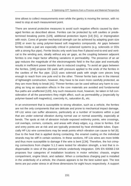
6 Optimizing CPT Systems from a Process and Material Perspective
151
time allows to collect measurements even while the gantry is moving the sensor, with no need to stop at each measurement point.
There are several protective measures to avoid such negative effects caused by dam-aged ferrites as described above. Ferrites can be protected by soft cavities or prede-termined breaking points [129], additional protection layers [14] [51], or impregnation with resin. Cores of greater mechanical strength can be achieved by adapting grain size [209] or even by using polymer-based soft magnetics compounds. Air gaps between ferrites inside a pad are especially critical in polarized systems (e.g. solenoids or DDs with a strong flux pipe). Ferrite blocks only work loss-free if placed end-to-end and verti-cal to the winding axis, ideally without any air gaps, as the coupling between adjacent ferrites is one major factor affecting variations in permeability. The presence of an air gap reduces the magnitude of the electromagnetic field in the flux pipe and eventually results in inefficient power transfer due to reduced coupling. To avoid air gaps between the ferrites, [188] propose DD pads with pressure applied to the ends of the ferrites in the cavities of the flux pipe. [212] uses solenoid pads with single core pieces long enough to reach from one pole end to the other. Thinner ferrite bars are in the interest of lightweight construction, however, they have to be even more carefully protected, as they are more likely to break [41]. Thinner ferrites can be used without any harm to cou-pling as long as saturation effects in the core materials are avoided and fundamental flux paths are unaffected [120]. Any such measures must, however, be taken in full con-sideration of all the parameters they might affect, such as permeability (especially by polymer-based soft magnetics), coercivity Hc, saturation Bs, etc.
In an environment that is susceptible to strong vibration, such as a vehicle, the ferrites are not the only components that are delicate and prone to mechanical impact damage. HF-Litz wires can suffer abrasions, particularly at a number of locations within a pad that are under external vibration during normal use or normal assembly, especially at bends. The spots at risk of abrasion include exposed exit/entry points, wire crossings, coil overlaps, corners, contacts, and areas with sharp edges, e.g. close to ferrites. Exit and entry points are at risk and are typically protected by heat shrinkable tubes. Espe-cially HF-Litz wire connections may be weak points which vibration can cause to fail [6]. Due to the heat that is applied during contacting, the enamel coating on the individual strands may be stiff in certain sections. In these sections, HF-Litz wires are more brittle and thus more susceptible to damage if the wire is bent [134]. Therefore, the hot crimp-ing connections from chapter 5.1.3 were tested for vibration strength, a test that is in-dispensable in view of the planned vehicle underbody integration. DIN EN 60068-2-64 proposes four categories of installation locations in motor vehicles: chassis, engine compartment, engine block, and radiator. When a contactless charging pad is installed in the underbody of a vehicle, the chassis appears to be the best suited spot. The test items are put under stress in all three dimensions for eight hours respectively. A support
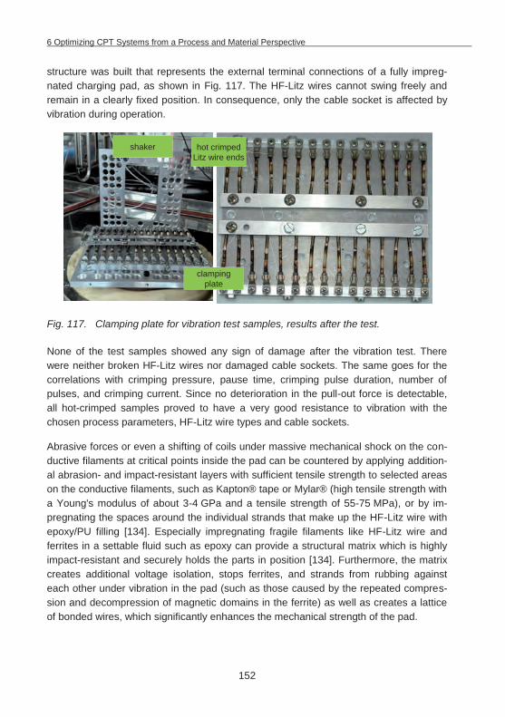
6 Optimizing CPT Systems from a Process and Material Perspective
152
structure was built that represents the external terminal connections of a fully impreg-nated charging pad, as shown in Fig. 117. The HF-Litz wires cannot swing freely and remain in a clearly fixed position. In consequence, only the cable socket is affected by vibration during operation.
Fig. 117. Clamping plate for vibration test samples, results after the test.
None of the test samples showed any sign of damage after the vibration test. There were neither broken HF-Litz wires nor damaged cable sockets. The same goes for the correlations with crimping pressure, pause time, crimping pulse duration, number of pulses, and crimping current. Since no deterioration in the pull-out force is detectable, all hot-crimped samples proved to have a very good resistance to vibration with the chosen process parameters, HF-Litz wire types and cable sockets.
Abrasive forces or even a shifting of coils under massive mechanical shock on the con-ductive filaments at critical points inside the pad can be countered by applying addition-al abrasion- and impact-resistant layers with sufficient tensile strength to selected areas on the conductive filaments, such as Kapton® tape or Mylar® (high tensile strength with a Young's modulus of about 3-4 GPa and a tensile strength of 55-75 MPa), or by im-pregnating the spaces around the individual strands that make up the HF-Litz wire with epoxy/PU filling [134]. Especially impregnating fragile filaments like HF-Litz wire and ferrites in a settable fluid such as epoxy can provide a structural matrix which is highly impact-resistant and securely holds the parts in position [134]. Furthermore, the matrix creates additional voltage isolation, stops ferrites, and strands from rubbing against each other under vibration in the pad (such as those caused by the repeated compres-sion and decompression of magnetic domains in the ferrite) as well as creates a lattice of bonded wires, which significantly enhances the mechanical strength of the pad.
hot crimped Litz wire ends
clamping plate
shaker
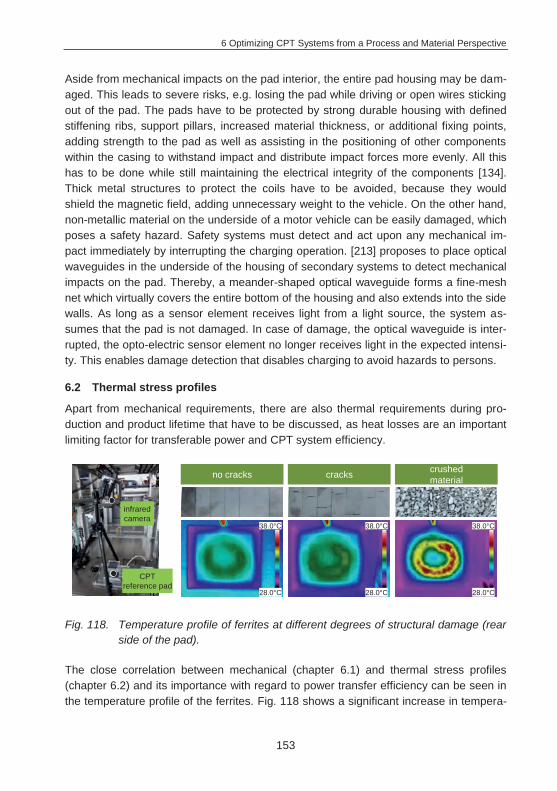
6 Optimizing CPT Systems from a Process and Material Perspective
153
Aside from mechanical impacts on the pad interior, the entire pad housing may be dam-aged. This leads to severe risks, e.g. losing the pad while driving or open wires sticking out of the pad. The pads have to be protected by strong durable housing with defined stiffening ribs, support pillars, increased material thickness, or additional fixing points, adding strength to the pad as well as assisting in the positioning of other components within the casing to withstand impact and distribute impact forces more evenly. All this has to be done while still maintaining the electrical integrity of the components [134]. Thick metal structures to protect the coils have to be avoided, because they would shield the magnetic field, adding unnecessary weight to the vehicle. On the other hand, non-metallic material on the underside of a motor vehicle can be easily damaged, which poses a safety hazard. Safety systems must detect and act upon any mechanical im-pact immediately by interrupting the charging operation. [213] proposes to place optical waveguides in the underside of the housing of secondary systems to detect mechanical impacts on the pad. Thereby, a meander-shaped optical waveguide forms a fine-mesh net which virtually covers the entire bottom of the housing and also extends into the side walls. As long as a sensor element receives light from a light source, the system as-sumes that the pad is not damaged. In case of damage, the optical waveguide is inter-rupted, the opto-electric sensor element no longer receives light in the expected intensi-ty. This enables damage detection that disables charging to avoid hazards to persons.
6.2 Thermal stress profiles
Apart from mechanical requirements, there are also thermal requirements during pro-duction and product lifetime that have to be discussed, as heat losses are an important limiting factor for transferable power and CPT system efficiency.
Fig. 118. Temperature profile of ferrites at different degrees of structural damage (rear side of the pad).
The close correlation between mechanical (chapter 6.1) and thermal stress profiles (chapter 6.2) and its importance with regard to power transfer efficiency can be seen in the temperature profile of the ferrites. Fig. 118 shows a significant increase in tempera-
no cracks cracks crushedmaterial
38.0°C
28.0°C
38.0°C
28.0°C
38.0°C
28.0°C
CPTreference pad
infrared camera
6 Optimizing CPT Systems from a Process and Material Perspective
154
ture for the crushed ferrite material. Heating by thermal conduction between the winding and the ferrites can be ruled out, since they are separated by a 2 mm PMMA plate with poor heat conduction. The difference in temperature can therefore be attributed to hys-teresis losses in the material. Even though this test set-up was conducted with a low-power CPT reference pad with moderate max. temperature levels, the rise in tempera-ture emphasizes the importance of safely integrating the ferrites into the pads to avoid additional heat problems due to damaged pad structures.
In first prototypical EV charging CPT systems in the kW-range (3.7 kW, large pad di-mensions ~800x800 mm on both primary and secondary side and without damaged fer-rites), the stationary measured operating temperatures did not exceed 100°C in the CPT systems, as documented in the final reports, with no further need for thermal heat dissipation [56] [69] [214]. However, thermal issues occur in CPT systems, especially when pad size is further reduced and/or with high power pad systems of several dozen kWs. A fast chargeable CPT system of 22 kW inevitably presents thermal problems as generated losses (e.g. Plosses = of 2,200 W with static = 90%) have to be quickly and ef-fectively transferred away from the charging equipment to ensure optimal operation of the CPT system (transmitter pad, electronics, etc. - see loss model of CPT systems in chapter 4.1) [84]. The smaller the pad area, the lower the heat capacity, especially of secondary charging pads. Thus, small systems dissipate substantially smaller amounts of heat via convection and radiation and generate considerably higher temperatures during the charging process (comparison of surface areas: 1,000 mm x 1,000 mm = 1 m² versus 300 mm x 300 mm = 0.09 m²). Thermal issues arise especially with smaller secondary high-power double-sided solenoid systems, due to poor heat dissipation per unit of space that is related to their magnetic design [161].
Moreover, intelligent heat dissipation concepts are needed especially for pads that are mounted to the undercarriage of plug-in and range-extender vehicles with internal com-bustion engine and exhaust systems. The exhaust line and catalytic converter are the largest sources of heat in a conventional or hybrid-powered vehicle, whose temperature can exceed 500°C (Tmax ~900°C). To integrate pads in the front, they may have to be installed close to components such as the gearbox that may also reach temperatures of over 100°C after driving. Together with seasonal differences between winter and sum-mer, the heat of surrounding components may negatively affect charging, e.g. heat in the underbody engine compartment immediately after a highway trip at a rest area (Fig. 119).
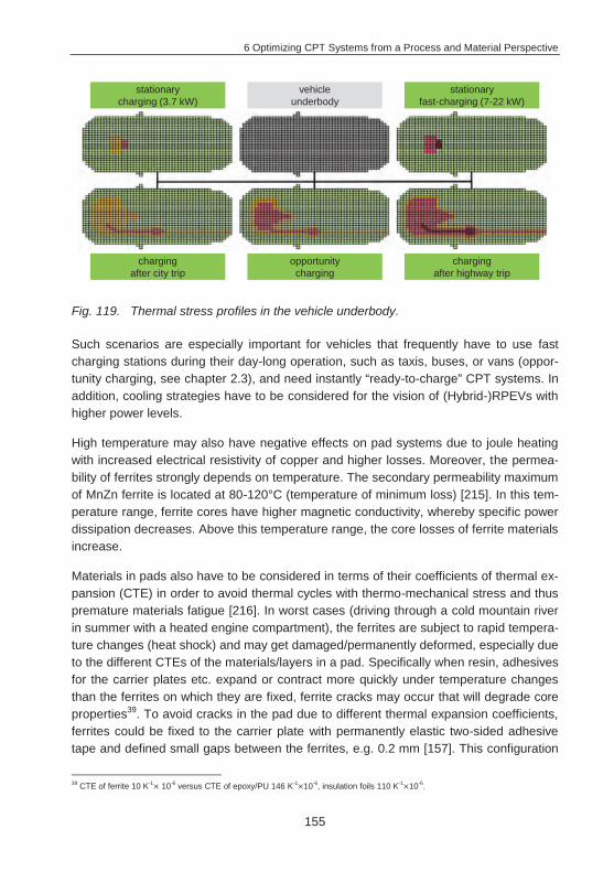
6 Optimizing CPT Systems from a Process and Material Perspective
155
Fig. 119. Thermal stress profiles in the vehicle underbody.
Such scenarios are especially important for vehicles that frequently have to use fast charging stations during their day-long operation, such as taxis, buses, or vans (oppor-tunity charging, see chapter 2.3), and need instantly “ready-to-charge” CPT systems. In addition, cooling strategies have to be considered for the vision of (Hybrid-)RPEVs with higher power levels.
High temperature may also have negative effects on pad systems due to joule heating with increased electrical resistivity of copper and higher losses. Moreover, the permea-bility of ferrites strongly depends on temperature. The secondary permeability maximum of MnZn ferrite is located at 80-120°C (temperature of minimum loss) [215]. In this tem-perature range, ferrite cores have higher magnetic conductivity, whereby specific power dissipation decreases. Above this temperature range, the core losses of ferrite materials increase.
Materials in pads also have to be considered in terms of their coefficients of thermal ex-pansion (CTE) in order to avoid thermal cycles with thermo-mechanical stress and thus premature materials fatigue [216]. In worst cases (driving through a cold mountain river in summer with a heated engine compartment), the ferrites are subject to rapid tempera-ture changes (heat shock) and may get damaged/permanently deformed, especially due to the different CTEs of the materials/layers in a pad. Specifically when resin, adhesives for the carrier plates etc. expand or contract more quickly under temperature changes than the ferrites on which they are fixed, ferrite cracks may occur that will degrade core properties39. To avoid cracks in the pad due to different thermal expansion coefficients, ferrites could be fixed to the carrier plate with permanently elastic two-sided adhesive tape and defined small gaps between the ferrites, e.g. 0.2 mm [157]. This configuration
39 CTE of ferrite 10 K-1 10-6 versus CTE of epoxy/PU 146 K-1 10-6, insulation foils 110 K-1 10-6.
stationary charging (3.7 kW)
vehicle underbody
stationary fast-charging (7-22 kW)
charging after city trip
opportunity charging
charging after highway trip
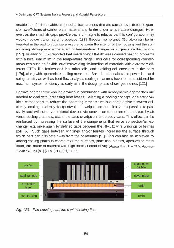
6 Optimizing CPT Systems from a Process and Material Perspective
156
enables the ferrite to withstand mechanical stresses that are caused by different expan-sion coefficients of carrier plate material and ferrite under temperature changes. How-ever, as the small air gaps provide paths of magnetic reluctance, this configuration may weaken power transmission properties [188]. Special membranes (Goretex) can be in-tegrated in the pad to equalize pressure between the interior of the housing and the sur-rounding atmosphere in the event of temperature changes or air pressure fluctuations [157]. In addition, [69] reported that overlapping HF-Litz wires caused heating problems with a local maximum in the temperature range. This calls for corresponding counter-measures such as flexible cavities/avoiding fix-bonding of materials with extremely dif-ferent CTEs, like ferrites and insulation foils, and avoiding coil crossings in the pads [170], along with appropriate cooling measures. Based on the calculated power loss and coil geometry as well as heat-flow analysis, cooling measures have to be considered for maximum system efficiency as early as in the design phase of coil geometries [121].
Passive and/or active cooling devices in combination with aerodynamic approaches are needed to deal with increasing heat losses. Selecting a cooling concept for electric ve-hicle components to reduce the operating temperature is a compromise between effi-ciency, cooling efficiency, footprint/volume, weight, and complexity. It is possible to pas-sively cool without any additional devices via convection to the ambient air, e.g. by air vents, cooling channels, etc. in the pads or adjacent underbody parts. This effect can be reinforced by increasing the surface of the components that serve convection/air ex-change, e.g. once again by defined gaps between the HF-Litz wire windings or ferrites [24] [60]. Such gaps between windings and/or ferrites increases the surface through which heat can dissipate away from the coil/ferrites [51]. This can also be achieved by adding cooling plates to coarse-textured surfaces, plate fins, pin fins, open-celled metal foam, etc. made of material with high thermal conductivity ( copper = 401 W/mK, aluminum = 236 W/mK) [51] [216] [217] (Fig. 120).
Fig. 120. Pad housing structured with cooling fins.
sealing rings
pin fins
pad housing
coils
resin
cover plate
channel for air flow
protection layer
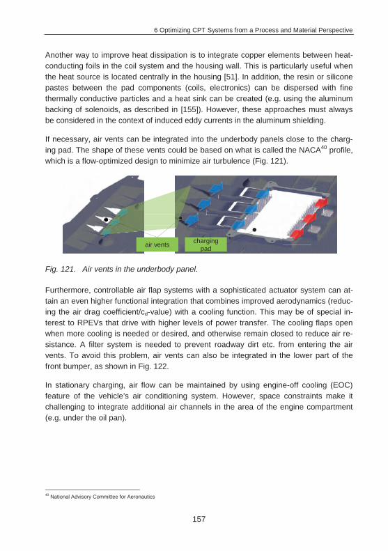
6 Optimizing CPT Systems from a Process and Material Perspective
157
Another way to improve heat dissipation is to integrate copper elements between heat-conducting foils in the coil system and the housing wall. This is particularly useful when the heat source is located centrally in the housing [51]. In addition, the resin or silicone pastes between the pad components (coils, electronics) can be dispersed with fine thermally conductive particles and a heat sink can be created (e.g. using the aluminum backing of solenoids, as described in [155]). However, these approaches must always be considered in the context of induced eddy currents in the aluminum shielding.
If necessary, air vents can be integrated into the underbody panels close to the charg-ing pad. The shape of these vents could be based on what is called the NACA40 profile, which is a flow-optimized design to minimize air turbulence (Fig. 121).
Fig. 121. Air vents in the underbody panel.
Furthermore, controllable air flap systems with a sophisticated actuator system can at-tain an even higher functional integration that combines improved aerodynamics (reduc-ing the air drag coefficient/cd-value) with a cooling function. This may be of special in-terest to RPEVs that drive with higher levels of power transfer. The cooling flaps open when more cooling is needed or desired, and otherwise remain closed to reduce air re-sistance. A filter system is needed to prevent roadway dirt etc. from entering the air vents. To avoid this problem, air vents can also be integrated in the lower part of the front bumper, as shown in Fig. 122.
In stationary charging, air flow can be maintained by using engine-off cooling (EOC) feature of the vehicle’s air conditioning system. However, space constraints make it challenging to integrate additional air channels in the area of the engine compartment (e.g. under the oil pan).
40 National Advisory Committee for Aeronautics
air vents charging pad
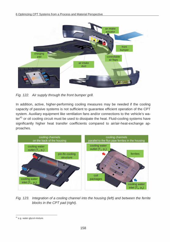
6 Optimizing CPT Systems from a Process and Material Perspective
158
Fig. 122. Air supply through the front bumper grill.
In addition, active, higher-performing cooling measures may be needed if the cooling capacity of passive systems is not sufficient to guarantee efficient operation of the CPT system. Auxiliary equipment like ventilation fans and/or connections to the vehicle’s wa-ter41 or oil cooling circuit must be used to dissipate the heat. Fluid-cooling systems have significantly higher heat transfer coefficients compared to air/air-heat-exchange ap-proaches.
Fig. 123. Integration of a cooling channel into the housing (left) and between the ferrite blocks in the CPT pad (right).
41 e.g. water-glycol-mixture.
front bumper
air intake duct
charging pad
air intake actuator
controllable air flaps
cooling water outlet (T1, p1)
cooling water inlet (T0, p0)
cooling water outlet (T1, p1)
cooling water inlet (T0, p0)
coil packages
pin-fin cooling structure
ferrites
cooling channels on the back of the housing
cooling channels parallel to the flux pipe ferrites in the housing
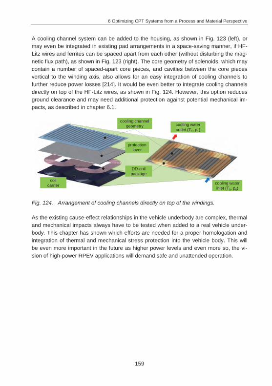
6 Optimizing CPT Systems from a Process and Material Perspective
159
A cooling channel system can be added to the housing, as shown in Fig. 123 (left), or may even be integrated in existing pad arrangements in a space-saving manner, if HF-Litz wires and ferrites can be spaced apart from each other (without disturbing the mag-netic flux path), as shown in Fig. 123 (right). The core geometry of solenoids, which may contain a number of spaced-apart core pieces, and cavities between the core pieces vertical to the winding axis, also allows for an easy integration of cooling channels to further reduce power losses [214]. It would be even better to integrate cooling channels directly on top of the HF-Litz wires, as shown in Fig. 124. However, this option reduces ground clearance and may need additional protection against potential mechanical im-pacts, as described in chapter 6.1.
Fig. 124. Arrangement of cooling channels directly on top of the windings.
As the existing cause-effect relationships in the vehicle underbody are complex, thermal and mechanical impacts always have to be tested when added to a real vehicle under-body. This chapter has shown which efforts are needed for a proper homologation and integration of thermal and mechanical stress protection into the vehicle body. This will be even more important in the future as higher power levels and even more so, the vi-sion of high-power RPEV applications will demand safe and unattended operation.
cooling water outlet (T1, p1)
cooling channel geometry
coil carrier
DD-coil package
protection layer
cooling water inlet (T0, p0)
7 Summary and Outlook
160
7 Summary and Outlook
Contactless power transfer in electric vehicles is technically feasible for both stationary vehicles and in-motion [3] and can help popularize EVs by enhancing their capability and convenience. Renowned OEMs are developing CPT charging pads in cooperation with suppliers and presenting more and more concepts and prototypes [16]. However, the market introduction of contactless power transfer systems still faces some uncer-tainties.
Therefore, this thesis presents and discusses different fields of application for static and dynamic CPT approaches with their advantages and possibilities in chapter 2. For a de-tailed evaluation of the benefits of different fields of application and to improve planning security, a simulation-based approach (ETEV|SIM) has been developed and successful-ly verified by adapting a production and logistics event-discrete simulation tool in chap-ter 3. This allowed for a thorough verification of the scenarios approach with a signifi-cant number of simulation runs, and has shown promising results. Thus, this approach enables potential customers of CPT systems to reliably simulate and calculate even complex scenarios with the help of Digital Factory planning tools in an early planning phase. However, the output of these models is only as accurate as the input variables. This is specifically true for system cost and battery systems behavior, as they have complex correlations especially at different charging levels. A critical review of results and assumptions is therefore always necessary. As deterministic assumptions and giv-en settings may not perfectly reflect actual vehicle operation under all possible circum-stances (e.g. cold weather, mass event in a city, traffic jam), more detailed technical performance parameters and cost data need to be collected and confirmed in future demonstration projects for all CPT scenarios, so that ultimately, reliable operation can be guaranteed in almost any conceivable operation scenario. Particularly for RPEV ap-proaches, further tests are pending to show the systems’ technical and economic per-formance. In order to convince governments and other authorities, there has to be inde-pendent verification of safety levels, efficiency rates, and construction cost for systems that may be on the road for decades as technology continues to change [41], in harsh environmental conditions, and at higher speeds with different vehicle types. Therefore, the developed simulation tool can easily be adapted and expanded as soon as more detailed data becomes available in the ongoing technological development of CPT and battery systems. Thus reducing uncertainty in the planning of CPT systems for fleet-operated electric vehicle scenarios will further promote future acceptance and spread of this technology.
To further support this development with reduced costs, production approaches for CPT systems have been developed and implemented in the scope of this thesis. In chapter 4 it could be shown that the developed pads, and especially the coil systems become in-
7 Summary and Outlook
161
creasingly complex, as does a detailed understanding of their correlations. These corre-lations have yet to be reflected in detail from a process and material perspective. Based on these considerations, chapter 5 showed production technologies with a focus on producing a finished coil package, as most complex part of a charging pad. Winding processes for HF-Litz wires have been developed to attain complex pad designs. Flexi-ble robot-based assembly and handling technologies work best in the early stages of market development when different coil designs are being considered. This robot-based approach allows for the creation of prototype systems, an analysis of their suitability for manufacturing, and setting design rules. These approaches (kinematic models, material reflection, and design rules) lay another cornerstone that will make it easier to analyze newly developed coil designs for their viability in high-quality and high-performance sys-tems with steady cost reduction potentials.
Chapter 6 revealed the importance of a detailed study of materials- and process-related aspects over the entire product-life, showing potential failure modes but also further op-portunities for improvement from a material and production perspective. The study of production and material parameters during the entire product-life, with appropriate measures against mechanical and thermal stress, shows the variety of challenges that come with CPT systems that are integrated in the underbody of a vehicle. Although there are retro-fitted CPT systems on the market already42, the integration of a contact-less power transfer system is by far more complex than just adding a socket and plug system. It will take well designed, well produced, vehicle-integrated, and tested contact-less power transfer systems with high efficiency rates to meet safety and environmental standards. Therefore, in the interest of greater market penetration, the industry will move from retro-fitting vehicles to a properly integrated and homologated OEM option with comprehensively adapted and safety-tested body structures. OEMs that gain a thorough understanding of CPT systems, which can, for instance, predict in detail where stray fields go in the underbody of a given vehicle, which can determine safety levels all around the car, which are ready for yet higher power levels, or even for RPEV vehicle concepts with all their mechanical, thermal, and EMC challenges - those OEMs will have a distinct competitive advantage. In order to support this approach from a produc-tion and material perspective, an automated test concept has been developed to exam-ine the impact of different materials, varying tolerances, and alternative production pro-cesses on the efficiency of the power transfer system. This allows for a thorough analysis of the relevant automated production processes with a suitable material char-acterization to reduce production cost, weight, and volume of the charging pads. Thor-ough and expensive material test set-ups are therefore inevitable to understand material behavior and potential failures in the different processes in detail, especially for the de-velopment of large-scale automated production processes.
42 3.3 kW-CPT systems (240V, Level 2) from Evatran Plugless Power and Bosch SPX Service Solutions to retro-fit Chevrolet Volt
and Nissan Leaf [167].
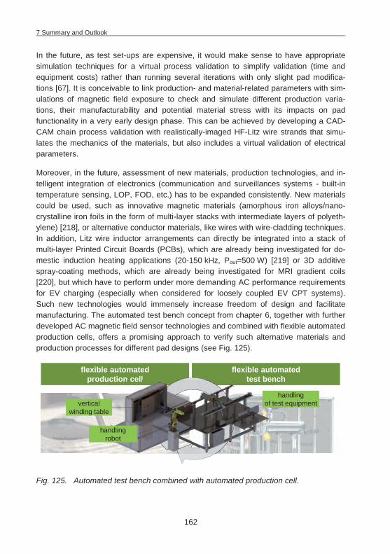
7 Summary and Outlook
162
In the future, as test set-ups are expensive, it would make sense to have appropriate simulation techniques for a virtual process validation to simplify validation (time and equipment costs) rather than running several iterations with only slight pad modifica-tions [67]. It is conceivable to link production- and material-related parameters with sim-ulations of magnetic field exposure to check and simulate different production varia-tions, their manufacturability and potential material stress with its impacts on pad functionality in a very early design phase. This can be achieved by developing a CAD-CAM chain process validation with realistically-imaged HF-Litz wire strands that simu-lates the mechanics of the materials, but also includes a virtual validation of electrical parameters.
Moreover, in the future, assessment of new materials, production technologies, and in-telligent integration of electronics (communication and surveillances systems - built-in temperature sensing, LOP, FOD, etc.) has to be expanded consistently. New materials could be used, such as innovative magnetic materials (amorphous iron alloys/nano-crystalline iron foils in the form of multi-layer stacks with intermediate layers of polyeth-ylene) [218], or alternative conductor materials, like wires with wire-cladding techniques. In addition, Litz wire inductor arrangements can directly be integrated into a stack of multi-layer Printed Circuit Boards (PCBs), which are already being investigated for do-mestic induction heating applications (20-150 kHz, Pout=500 W) [219] or 3D additive spray-coating methods, which are already being investigated for MRI gradient coils [220], but which have to perform under more demanding AC performance requirements for EV charging (especially when considered for loosely coupled EV CPT systems). Such new technologies would immensely increase freedom of design and facilitate manufacturing. The automated test bench concept from chapter 6, together with further developed AC magnetic field sensor technologies and combined with flexible automated production cells, offers a promising approach to verify such alternative materials and production processes for different pad designs (see Fig. 125).
Fig. 125. Automated test bench combined with automated production cell.
flexible automatedproduction cell
flexible automatedtest benchtest benction cell
vertical winding table
handling robot
handling of test equipment

7 Summary and Outlook
163
Detailed process knowledge and experience yields positive effects on functionality, quality, and cost structure. It is this sort of process mastery that will eventually differen-tiate global competition. The approaches presented in this thesis thus deliver a basis to achieve future high-performance CPT systems for challenging automotive applications.
8 Zusammenfassung
164
8 Zusammenfassung
Die Technologie der kontaktlosen Energieübertragung bietet eine attraktive Alternative zu kabelgebundenen Ladesystemen. Die kontaktlose Energieübertragung wird dabei in der Konsumelektronik, der Medizintechnik und auch bei Industrielösungen bereits viel-fach eingesetzt. Durch die stetige Weiterentwicklung dieser Technologie werden Über-tragungsleistungen in einer Höhe erreicht, die auch für den Einsatz in Fahrzeugen mit elektrifiziertem Antriebsstrang wegweisend sein werden. Die meisten OEMs haben die potentielle Schlüsselrolle der kontaktlosen Ladetechnik erkannt und entwickeln zusam-men mit ihren Lieferanten erste Lösungsansätze mit dem Ziel in den nächsten Jahren serienreife Produkte auf den Markt zu bringen. Bis 2020 werden dabei von Marktfor-schungsinstituten bereits signifikante Stückzahlen für CPT Systeme vorausgesagt. Für eine umfassende Markteinführung von kontaktlosen Energieübertragungssystemen existieren allerdings noch Barrieren, die es zu überwinden gilt. Diese betreffen neben den Herausforderungen in der Standardisierung und Interoperabilität insbesondere die hohe Unsicherheit hinsichtlich der Auswahl geeigneter Anwendungsfelder sowie die zu-nächst noch hohen Kosten der CPT Systeme. Ziel der vorliegenden Arbeit ist es daher zum einen die Planungsunsicherheit durch die Entwicklung geeigneter simulations-basierter Planungsmethoden zu reduzieren und zum anderen die Realisierung kosten-effizienter und zuverlässiger CPT Systeme durch die Entwicklung geeigneter Produkti-ons- und Prüfverfahren zu fördern.
Dazu werden zunächst die verschiedenen Anwendungsbereiche für statische und dy-namische CPT Systeme mit ihren Vorteilen und Möglichkeiten präsentiert und diskutiert. Für eine detaillierte Bewertung verschiedener Anwendungsbereiche wurde ein simulati-ons-basierter Ansatz (ETEV|SIM) auf Basis von Methoden der Digitalen Fabrik entwi-ckelt und erfolgreich verifiziert. Dieser Ansatz ermöglicht vorab eine fundierte Analyse unterschiedlicher Einsatzfelder für die kontaktlose Energieübertragung. Der entwickelte Lösungsansatz basiert auf der automatisierten Durchführung zahlreicher Simulations-läufe und liefert potentiellen Anwendern von CPT Systemen die Grundlage in einer frü-hen Planungsphase auch komplexe Szenarien zuverlässig simulieren und berechnen zu können. Die Unsicherheit bei der Planung von CPT Systemen kann dadurch insbe-sondere für flottenbetriebene Elektrofahrzeug-Szenarien reduziert werden, was die Ak-zeptanz und zukünftige Verbreitung dieser Technologie fördert.
Inwiefern sich die kontaktlose Ladetechnologie am Markt durchsetzen kann, hängt zu-dem von den realisierbaren Kosten für die Systeme ab. Im Wettbewerb zwischen poten-tiellen Lieferanten der CPT Systeme sind insofern neben produktseitigen Entwicklungs-kompetenzen vor allem detaillierte Prozesskenntnisse zur Erreichung der angestrebten Funktionalität, Qualität und Kostenstruktur erforderlich. Dazu wurden im Rahmen der vorliegenden Arbeit Produktionsansätze für CPT Systeme basierend auf flexiblen robo-

8 Zusammenfassung
165
tergestützten Montage- und Handhabungs-Technologien entwickelt und implementiert. Die Ansätze erlauben die umfassende Reflektion derzeit diskutierter komplexer Spulen-Geometrien aus Prozess- und Material-Perspektive. Zudem werden die speziellen Her-ausforderungen adressiert, die bei der Integration von CPT Systemen im Fahrzeugun-terboden entstehen (insbesondere thermische und mechanische). Ein automatisierter Prüfstand zur detaillierten Untersuchung material- und prozessbezogener Aspekte über den gesamten Produktlebenszyklus wurde entwickelt und realisiert. Dieser ermöglicht die fundierte Analyse der vielfältigen Wechselwirkungen in komplexen Pad-Systemen (Mehrspulen-Systeme, integrierte Elektronik, etc.) und Unterbodenkonfigurationen. Zu-dem ermöglicht der Ansatz die systematische Analyse alternativer Fertigungsverfahren bzw. alternativer Materialien, sowie möglicher Fehlerzustände im Fahrzeuglebenszyk-lus, um Verbesserungsmöglichkeiten für eine kontinuierliche Reduktion von Produkti-onskosten, Gewicht und Volumen ableiten zu können. Die in dieser Arbeit vorgestellten Ansätze liefern somit eine Basis zur Entwicklung leistungsgesteigerter CPT Systeme für anspruchsvolle Automotive-Anwendungen.
9 List of Abbreviations
166
9 List of Abbreviations
A4WP .......... Alliance for Wireless Power AC ............... Alternating Current ADD ............. Animal Deterrent Device AGV ............. Automated Guided Vehicle B-AGV ......... Battery Swapping-Automated Guided Vehicle BCU ............. Base Charging Unit BEV ............. Battery Electric Vehicle BMS ............. Battery Management System CAD ............. Computer-Aided Design CAM ............ Computer-Aided Manufacturing CCA ............. Copper Cladded Aluminum CPT ............. Contactless Power Transfer CT ................ Computed Tomography CTE ............. Coefficient of Thermal Expansion DC ............... Direct Current DIN .............. Deutsches Institut für Normung EOC ............. Engine-Off Cooling EMC ............ Electromagnetic compatibility EMF ............. Electromagnetic Field ETEV|SIM .... Energy Transfer for Electric Vehicles Simulation Tool EV ................ Electric Vehicle FIA ............... Fédération Internationale de l’Automobile FEH ............. Formula E Holdings FEM ............. Finite Element Method FMEA .......... Failure Mode and Effects Analysis FOD ............. Foreign Object Detection GFRP .......... Glas-Fiber Reinforced Plastic HD ............... High-Definition HF ................ High Frequency ICE .............. Internal Combustion Engine ICNIRP ........ International Commission in Non-Ionizing Radiation Protection ICT ............... Information and Communications Technology IDC .............. Insulation Displacement Connectors

9 List of Abbreviations
167
IEC .............. International Electrotechnical Commission ISO .............. International Organization for Standardization LASER ......... Light Amplification by Stimulated Emission of Radiation LED ............. Light-Emitting Diode LFRT ........... Long-Fiber Reinforced Thermoplastics LOP ............. Living Object Protection LVAD ........... Left Ventricular Assist Device MF ............... Medium Frequency MIT .............. Massachusetts Institute of Technology MnZn ........... Manganese-Zinc MRI .............. Magnetic Resonance Imaging NACA .......... National Advisory Committee for Aeronautics NPE ............. Nationale Plattform Elektromobilität OEM ............ Original Equipment Manufacturer PATH ........... Partner for Advanced Transit and Highways PCB ............. Printed Circuit Board PE ................ Polyethylene PHEV ........... Plug-In Hybrid Electric Vehicle PMA ............. Power Matters Alliance PMMA .......... Poly-Methyl-Methacrylate PP ................ Polypropylene PU ............... Polyurethane R&D ............. Research and Development REEV ........... Range Extended Electric Vehicle RF ................ Radio Frequency RFID ............ Radio Frequency Identification RPEV ........... Roadway Powered Electric Vehicle SAE ............. Society of Automotive Engineers SCARA ........ Selective Compliance Assembly Robot Arm SEA ............. Swedish Energy Agency SOC ............. State of Charge SUMO .......... Simulation of Urban Mobility TCO ............. Total Cost of Ownership TS ................ Technical Specification U.S. ............. United States

9 List of Abbreviations
168
US ............... Ultra-Sonic V2G ............. Vehicle-to-Grid VBA ............. Visual Basic for Applications VCU ............. Vehicle Charging Unit VDE ............. Verband der Elektrotechnik Elektronik Informationstechnik VDI .............. Verein Deutscher Ingenieure VHF ............. Very High Frequency VISSIM ........ Verkehr In Städten - SImulationsModell WPC ............ Wireless Power Consortium
10 Literature
169
10 Literature
[1] BROOKER, A.; THORNTON, M.; RUGH, J.: Technology Improvement Pathways to Cost-Effective Vehicle Electrification. SAE 2010 World Congress, Detroit, Michigan, USA (2010), p. 1–15
[2] N. N.: Roadway Powered Electric Vehicle Project Track Construction And Testing Program Phase 3D. Palo Alto, California, USA, 1994
[3] COVIC, G. A.; BOYS, J. T.; BUDHIA, M.; HUANG, C.-Y.: Electric Vehicles – Personal transportation for the future. In: EVS25 World Battery, Hybrid and Fuel Cell Electric Vehicle Symposium, Shenzhen, China (2010), p. 693–704
[4] KAHL, M.: Wireless charging: the Holy Grail of the EV. In: Automotive World mega-trends magazine, Q1 2013, p. 27–31
[5] PANTIC, Z.: Inductive Power Transfer Systems for Charging of Electric Vehicles. Ra-leigh, North Carolina, North Carolina State University, Electrical Engineering. PhD thesis. 2013
[6] COVIC, G. A.; BOYS, J. T.; VAN BOHEEMEN, E.; KISSIN, M.; KEELING, N. A.; BEAVER, J.: A Wiring Harness and Wireless Power Transfer System. 26.09.2013. Publication nr. WO2013/141717A1
[7] WESSNER, K.; RISCH, F.; MEINDL, P.; FITZEK, M.: Marktpotenziale von induktivem Laden als Aufladetechnologie von Elektrofahrzeugen. 1. Aufl. Schwaig bei Nürn-berg, 2011
[8] LORICO, A.; TAIBER, J.; YANNI, T.: Inductive Power Transfer System Integration for Battery-Electric Vehicles. In: 3rd International Conference of Sustainable Automo-tive Technologies (2011), p. 75–83
[9] FRANKE, J.; RISCH, F.: Unternehmensübergreifende Planung komplexer Technolo-gieszenarien am Beispiel des kontaktlosen Ladens von Elektrofahrzeugen über ei-ne elektrifizierte Straße (E|ROAD). In: 6. Symposium für Vorausschau und Tech-nologieplanung (2010), p. 255–271
[10] COVIC, G. A.; KISSIN, M.; KACPRZAK, D.; CLAUSEN, N.; HAO HAO: A bipolar primary pad topology for EV stationary charging and highway power by inductive coupling. In: Energy Conversion Congress and Exposition (ECCE), IEEE (2011), p. 1832–1838
[11] MARTIN, R.: Wireless Charging for EVs: Forecasts, Market Issues and Technologi-cal Issues (International Forum on Electric Vehicle). Daejeon, Korea, 18.11.2011
[12] NIETSCHKE, W.; FICKEL, F.; KÜMMELL, S.: Induktive Energieübertragung für Elektro-fahrzeuge. In: ATZ 113 (2011), no. 04, p. 280–285
[13] PERRIN, J.: Inductive Charging of Electric Vehicles: a European Perspective (Con-ference on Electric Roads & Vehicles (CERV)). Park City, Utah, USA, 04.02.2013
10 Literature
170
[14] TANAKA, J.; YOSHI, S.: Vehicle capable of contact-free power reception. Toyota Jidosha Kabushiki Kaisha. 14.11.2013. Publication nr. WO2013168239 A1
[15] WEBB, A.: Coming Soon: Standards for Wireless Electric Car Charging. URL http:// www.plugincars.com/coming-soon-standards-wireless-electric-car-charging-128975.html – last checked on 2014-03-02
[16] N. N.: Wireless EV Charging System Sales to Surpass 280,000 by 2020. URL http://electriccarsreport.com/2012/12/wireless-ev-charging-system-sales-to-surpass-280000-by-2020/ – last checked on 2014-01-20
[17] RISCH, F.; GÜNTHER, S.; BICKEL, B.; FRANKE, J.: Flexible Automation for the Produc-tion of Contactless Power Transfer Systems for Electric Vehicles. In: 3rd Interna-tional Electric Drives Production Conference (EDPC), Nuremberg, Germany (2013)
[18] RISCH, F.; GÜNTHER, S.; FRANKE, J.: Production Concepts for Inductive Power Transfer Systems for Electric Vehicles. In: 2nd International Electric Drives Produc-tion Conference (EDPC), Nuremberg, Germany (2012)
[19] HUTIN, M.; LEBLANC, M.: Transformer system for electric railways. 23.10.1894. Pub-lication nr. US527857
[20] KESLER, M.: Highly Resonant Wireless Power Transfer: Safe, Efficient, and over Distance. Watertown, Mass., USA, 2013
[21] RAABE, S.: Inductive Power Transfer Pickups for High Demand Applications. Uni-versity of Auckland. PhD thesis. 2011
[22] TESLA, N.: Apparatus for Transmission of Electrical Energy. Publication nr. US649621A
[23] RAABE, S.; COVIC, G. A.: Practical Design Considerations for Contactless Power Transfer Quadrature Pick-Ups. In: IEEE Transactions on Industrial Electronics (2013), p. 400–409
[24] BUDHIA, M.; BOYS, J. T.; COVIC, G. A.; HUANG, C.-Y.: Development of a Single-Sided Flux Magnetic Coupler for Electric Vehicle IPT Charging Systems. In: IEEE Trans-actions on Industrial Electronics (2011), p. 318–328
[25] AHN, D.; HONG, S.: Wireless Power Transmission With Self-Regulated Output Volt-age for Biomedical Implant. In: IEEE Transactions on Industrial Electronics, vol. 61, issue 5 (2014), p. 2225–2235
[26] JOUNG, G. B.; CHO, B. H.: An Energy Transmission System for an Artificial Heart Using Leakage Inductance Compensation of Transcutaneous Transformer. In: IEEE Transactions on Power Electronics, vol. 13, no. 6 (1998), p. 1013–1022
[27] HERNANDEZ, G.; HIRSCH, O.: Inductive Power Transfer: From the laboratory to the real world (Conference on Electric Roads & Vehicles (CERV)). Park City, Utah, USA, 17.02.2012
10 Literature
171
[28] ZAHEER, A.; COVIC, G. A.; KACPRZAK, D.: A Bipolar Pad in a 10-kHz 300-W Distribut-ed IPT System for AGV Applications. In: IEEE Transactions on Industrial Electron-ics, vol. 61, issue 7 (2014), p. 3288–3301
[29] KANEKO, Y.; ABE, S.: Technology trends of wireless power transfer systems for elec-tric vehicle and plug-in hybrid electric vehicle. In: IEEE 10th International Confer-ence on Power Electronics and Drive Systems (PEDS) (2013), p. 1009–1014
[30] COVIC, G. A.; BOYS, J. T.: Inductive Power Transfer. In: Proceedings of the IEEE, Invited Paper, vol. 101, no. 6 (2013), p. 1276–1289
[31] N. N.: SAE International Task Force Announces Agreement on Frequency of Oper-ation and Power Classes for Wireless Power Transfer for its Electric and Plug-In Electric Vehicle Guideline. URL http://www.sae.org/servlets/pressRoom?OBJECT _TYPE=PressReleases&PAGE=showRelease&RELEASE_ID=2296 – last checked on 2014-02-22
[32] N. N.: Zwischenbericht der Nationalen Plattform Elektromobilität (NPE). Berlin, No-vember 2010
[33] GUSTAVSSON, H.: Slide-in Electric Road System, Inductive project report. Gothen-burg, Sweden, 18.10.2013
[34] KÖBEL, C.: Primove - inductive charging for electric mobility (3rd International Elec-tric Drives Production Conference (EDPC)). Nuremberg, Germany, 29.10.2013
[35] SCHUDER, J. C.: Powering an Artificial Heart: Birth of the Inductively Coupled-Radio Frequency System in 1960. In: Artificial Organs, vol. 26, issue 11 (2002), p. 909–915
[36] ROSZYK, L.; BARNAS, L.: Hand held battery operated device and charging means therefor. Sunbeam Corp. 08.10.1974. Publication nr. US3840795 A
[37] KIM, C.-G.; SEO, D.-H.; YOU, J.-S.; PARK, J.-H.; CHO, B.-H.: Design of a Contactless Battery Charger for Cellular Phone. In: Applied Power Electronics Conference and Exposition (APEC), vol. 2 (2000), p. 769–773
[38] HUI, S. Y. R.; HO, W. C.: A New Generation of Universal Contactless Battery Charg-ing Platform for Portable Consumer Electronic Equipment. In: 35th Annual IEEE Power Electronics Specialists Conference (PESC) (2004), p. 638–644
[39] FRIEDMAN, J.: Companies, public connect with wireless smartphone chargers. In: USA TODAY (2013-08-02)
[40] TSENG, R.; VON NOVAK, B.; SHEVDE, S.; GRAJSKI, K. A.: Introduction to the Alliance for Wireless Power Loosely-Coupled Wireless Power Transfer System Specifica-tion Version 1.0. In: IEEE Wireless Power Transfer (WPT) (2013), p. 79–83
10 Literature
172
[41] COVIC, G. A.; BOYS, J. T.: Modern Trends in Inductive Power Transfer for Transpor-tation Applications. In: IEEE Journal of Emerging and Selected Topics in Power Electronics (2013), p. 28–41
[42] SHLADOVER, S. E.: PATH at 20-History and Major Milestones. In: IEEE Transactions in Intelligent Transportation Systems, vol. 8, no. 4, December 2007 (2007), p. 584–592
[43] MASSOT, M.-H.; LAPIERRE, E.: Praxitele: The Missing Link. In: Association for Euro-pean Transport Conference, Cambridge (1999), p. 91–100
[44] COVIC, G. A.; ELLIOTT, G.; STIELAU, O. H.; GREEN, R. M.; BOYS, J. T.: The design of a contact-less energy transfer system for a people mover system. In: International Conference on Power System Technology (PowerCon) (2000), p. 79–84
[45] WU, H.; BOYS, J. T.; COVIC, G. A.; RIM, C.-T.; RISCH, F.: Pre-Conference-Tutorial (Conference on Electric Roadway and Vehicles (CERV)). Park City, Utah, USA, 16.02.2012
[46] KIEFER, S.: Verbundvorhaben InterOp - Inductive Norm Test by Exchange in Real Operation: Auslegungskriterien Interoperabilität: Kostenstrukutr und -ziele, Ge-schäftsmodelle (8. Fachveranstaltung Kontaktlose Energieübertragung Stand der Technik (Haus der Technik)). Stuttgart, 11.06.2013
[47] N. N.: ICNIRP: Guidelines for limiting exposure to time-varying electric, magnetic, and electromagnetic fields (up to 300 GHz). In: Health Physics, vol. 74, no. 4 (1998), p. 494–522
[48] N. N.: Elektrische Ausrüstung von Elektro-Straßenfahrzeugen - Induktive Ladung von Elektrofahrzeugen - Teil 4-2: Niedriger Leistungsbereich (Electric equipment of electric road vehicles - Electric vehicle inductie charging systems - Part 4-2: Low power range). 01.03.2011 (VDE-AR-E 2122-4-2)
[49] N. N.: ICNIRP: Guidelines for limiting exposure to time-varying electric and magnet-ic fields (1 Hz to 100 kHz). In: Health Physics, vol. 99, no. 6 (2010), p. 818–836
[50] ELIAS, B.; SCHMIDT, F.: Measuring a Temperature During Contactless Transmission of Energy. AUDI AG. 12.01.2012. Publication nr. WO2012003957A2
[51] HICKOX, J. M.: Coil apparatus having coil arrangement that includes a ferrite layer and a thermally-conductive silicone layer. Delphi Technologies, Inc. 24.07.2013. Publication nr. EP2618344A1
[52] MAHLEIN, J.; EGGER, B.: Anordnung zur berührungslosen Energieübertragung. SEW-EURODRIVE GmbH & Co. KG. 10.11.2011. Publication nr. DE102010020122A1
[53] KRONEWITTER, M.; BAIER, K.; WEBER, T.: Motor Vehicle Charging and/or Motor Vehi-cle Discharging Device. Daimler AG. 21.06.2012. Publication nr. DE102010055369A1
10 Literature
173
[54] BUDHIA, M.; COVIC, G. A.; BOYS, J. T.: A New IPT Magnetic Coupler for Electric Ve-hicle Charging Systems. In: 36th Annual Conference on IEEE Industrial Electronics Society (IECON) (2010), p. 2487–2492
[55] BARTH, H.; BRAUN, M.; JUNG, M.; ELIAS, B.; PEER, R.; REKER, U.; SCHMÜLLING, B.; TURKI, F.; SCHULZE, E.: Abschlussbericht zum Verbundvorhaben Kontaktloses La-den von Elektrofahrzeugen (W-Charge). Kassel, October 2011
[56] N. N.: Abschlussbericht zum Verbundvorhaben Kabelloses Laden von Elektrofahr-zeugen (Conductix). Weil am Rhein, Oktober 2011
[57] N. N.: WiTricity: WiT-3300 Deployment Kit Data Sheet. Watertown, Mass., USA, 2011
[58] N. N.: Data Sheet ICS - Inductive Charging System (Brusa Elektronik AG). Senn-wald, Switzerland, 2013
[59] GÖTZMANN, T.: Urban Infrastructure: Inductive Charging Technology (2nd Interna-tional Electric Drives Production Conference (EDPC)). Nuremberg, Germany, 17.10.2012
[60] TURKI, F.; SCHMÜLLING, B.; PAVLIDIS, M.: Coil Design of Electric Vehicle Inductive Chargers with Homogeneous Low Magnetic Flux De (3rd International Electric Drives Production Conference (EDPC)). Nuremberg, Germany, 29.10.2013
[61] PRESTL, W.; HÄSE, K.; NIEDERBERGER, D.: Abschlussbericht zum Verbundvorhaben Kontaktloses Laden von batterieelektrischen Fahrzeugen (IndiOn). München, Ok-tober 2011
[62] ODACHI, Y.; TAKASAN, M.; MINOSHIMA, N.: Non-Contact Electric Power Supplying System For Vehicle. Toyoda Automatic Loom Works. 05.01.1999. Publication nr. US5855261A
[63] OGURI, K.: Charging paddle. Toyota Motor Co. Ltd. 16.01.2001. Publication nr. US6175212B1
[64] ICHIKAWA, S.; TAKURA, T.; MATSUKI, H.; SATO, F.: Contactless power transmitting de-vice, contactless power receiving device, and contactless power transfer system. Toyota Jidosha Kabushiki Kaisha. 19.12.2013. Publication nr. US20130335015 A1
[65] GARDNER, M.; SCHATZ, D.: Toyota Licenses WiTricity Patent Portfolio for Wireless Power. URL http://www.businesswire.com/news/home/20131205005161/en/ Toyo-ta-Licenses-WiTricity-Patent-Portfolio-Wireless-Power#.Uv91IIX6QnU – last checked on 2014-02-15
[66] N. N.: Fun Vii Concept Car. URL http://www.toyota.com/letsgoplaces/fun-vii-concept-car/ – last checked on 2014-02-04
10 Literature
174
[67] BUDHIA, M.; COVIC, G. A.; BOYS, J. T.; HUANG, C.-Y.: Development and evaluation of single sided flux couplers for contactless electric vehicle charging. In: IEEE Energy Conversion Congress and Exposition (ECCE) (2011), p. 614–621
[68] FRANKE, J.; RISCH, F.: Forschungsbericht - Geschäftspotenziale durch kontaktlose Energieübertragung in Elektromobile. October 2011
[69] MATHAR, S.: Konzeption und Entwicklung eines Systems zur kontaktlosen Energie-übertragung für Elektrofahrzeuge. Aachen, RWTH Aachen, Fakultät für Maschi-nenwesen. PhD thesis. 20.08.2012
[70] MAGGETTO, G.; VAN DEN BOSSCHE, P.: Inductive Automatic Charging: The Way to Safe, Efficient and User-Friendly Electric Vehicle Infrastructure. In: Electric Vehicle Symposium EVS-18 (2001)
[71] KEELING, N. A.; VAN BOHEEMEN, E.; KISSIN, M.; BEAVER, J.: Wireless power transfer apparatus and method of manufacture. Qualcomm Inc. 26.09.2013. Publication nr. WO2013142064A1
[72] DIXON, J.: Energy Storage for Electric Vehicles. In: IEEE International Conference on Industrial Technology (ICIT) (2010), p. 20–26
[73] N. N.: Abschlussbericht zum Verbundvorhaben Begleitforschung zum kabellosen Laden von Elektrofahrzeugen: Chancen und Risiken beim kabellosen Laden von Elektrofahrzeugen, Technologiefolgenabschätzung für eine Schlüsseltechnologie in der Durchbruchphase der Elektromobilität (JustPark). October 2011
[74] FASUGBA, M. A.; KREIN, P. T.: Gaining Vehicle-to-Grid Benefits with Unidirectional Electric and Plug-In Hybrid Vehicle Chargers. In: IEEE Vehicle Power and Propul-sion Conference (VPPC) (2011), p. 1–6
[75] FASUGBA, M. A.; KREIN, P. T.: Cost Benefits and Vehicle-to-Grid Regulation Services of Unidirectional Charging of Electric Vehicles. In: IEEE Energy Conversion Con-gress and Exposition (ECCE) (2011), p. 827–834
[76] N. N.: Mobilität in Deutschland 2008 (MiD): Ergebnisbericht: Struktur – Aufkommen – Emissionen – Trends. Bonn und Berlin, February 2010
[77] VALØENA, L. O.; SHOESMITH, M. I.: The Effect of PHEV and HEV Duty Cycles on Bat-tery and Battery Pack Performance. In: Plugin Highway Conference (2007), p. 1–9
[78] SAMMER, G.; BERGER, W. J.; MATIASEK, F.: Travel Behaviour Patterns in the USA and Austria in Comparison: An Instructive Lesson for Transport Policy. In: Euro-pean Transport Conference, Homerton College, Cambridge (2002)
[79] BIERE, D.; DALLINGER, D.; WIETSCHEL, M.: Ökonomische Analyse der Erstnutzer von Elektrofahrzeugen. In: ZfE Zeitschrift für Energiewirtschaft 02 | 173 (2009), no. 02, p. 173–181
10 Literature
175
[80] EVANSON, J.: Tesla Motors Investor Presentation. January 2014. URL http://files. shareholder.com/downloads/ABEA-4CW8X0/2921970389x0x720221/5647bed2-1c27-4b40-abd3-dd11f8bc474e/ Investor%20Presentation%20-%20Jan%202014. pdf – last checked on 2014-02-16
[81] N. N.: DIN 1998: Placing of service conduits in public areas; directives for planning. 1978-05
[82] WECHLIN, M.: Device for Inductive Power Transfer of Electrical Energy. Conductix-Wampfler GmbH. 28.11.2013. Publication nr. WO2013174527A1
[83] SLISKOVIC, M.; HUA, Z.; EGGER, B.: System zum berührungslosen Übertragen von Energie an ein Fahrzeug. SEW-EURODRIVE GmbH & Co. KG. 13.09.2012. Publi-cation nr. WO2012119688 A2
[84] BORRMANN, D.; ROTHFUSS, F.; DANGELMAIER, M.: Charging infrastructure for shared use of electric vehicles in an urban area. In: 3rd International Electric Drives Pro-duction Conference (EDPC), Nuremberg, Germany (2013)
[85] GANDULFO, M.; BYRNS, J.: Branché -Self-Service Electric Car and Bicycle Project in the Metropolitan Region of Montréal. Montréal, Québec, Canada, 2003
[86] SUH, I.-S.: Innovative EV Charging with OLEV Technology and its Practical Ap-plicability (2nd International Electric Drives Production Conference (EDPC)). Nu-remberg, Germany, 16.10.2012
[87] BUDHIA, M.; COVIC, G. A.; BOYS, J. T.: Magnetic Design of a Three-Phase Inductive Power Transfer System for Roadway Powered Electric Vehicles. In: IEEE Vehicle Power and Propulsion Conference (VPPC) (2010)
[88] KISZKA, J.: System zur kurzfristigen Ladung von elektrisch betriebenen Fahrzeugen. Siemens AG. 27.09.2012. Publication nr. DE102011005915A1
[89] BOLGER, J. G.; KIRSTEN, F. A.; NG, L. S.: Inductive Power Coupling for an Electric Highway System. In: IEEE Vehicular Technology Conference, vol. 28 (1978), p. 137–144
[90] BOLGER, J. G.; NG, L. S.; TURNER, D. B.; WALLACE, R. I.: Testing a Prototype Induc-tive Power Coupling for an Electric Highway System. In: IEEE Vehicular Technolo-gy Conference, vol. 29 (1979), p. 48–56
[91] BOLGER, J. G.: Urban Electric Transportation Systems: The Role of Magnetic Power Transfer. In: WESCON/94. Idea/Microelectronics. Conference Record (1994), p. 41–45
[92] BROOKER, A.; WU, H.; EARLEYWINE, M.; GONDER, J.: Evaluation of the Costs, Bene-fits, and Feasibility of Electric Roadway Technologies and Travel Scenarios (Con-ference on Electric Roads & Vehicles (CERV)). Park City, Utah, USA, 17.02.2012
10 Literature
176
[93] PANTIC, Z.; BAI, S.; LUKIC, S. M.: Inductively Coupled Power Transfer for Continu-ously Powered Electric Vehicles. In: IEEE Vehicle Power and Propulsion Confer-ence (VPPC) (2009), p. 1271–1278
[94] GARCIA, F.; PÉREZ, S.; CURRAN, É.: Cable Support for Supporting a Conductor Ar-rangement Producing an Electromagnetic Field, Conductor Arrangement, and Route for Vehicles Comprising the Conductor Arrangement. Bombardier Transpor-tation GmbH. 30.01.2014. Publication nr. WO2014/016365A2
[95] PERIK, H.: Practical EV Integration Cases for Static and Dynamic Wireless Power Transfer (3rd International Electric Drives Production Conference (EDPC)). Nu-remberg, Germany, 30.10.2013
[96] N. N.: FIA Formula E Championship Technical Regulations. Paris, France, 05.12.2013
[97] HARRIS, S.: Your questions answered: inductive charging for road vehicles. URL http://www.theengineer.co.uk/automotive/in-depth/your-questions-answered-inductive-charging-for-road-vehicles/1015724.article#ixzz2ZzfI84z8 – last checked on 2013-02-16
[98] SEBESTYÉN, R.: Slide-in Electric Road System, Conductive project report. Gothen-burg, 18.10.2013
[99] SHINOHARA, N.; KUBO, Y.; TONOMURA, H.: Mid-Distance Wireless Power Transmis-sion for Electric Truck via Microwaves. In: Proceedings of URSI International Sym-posium on Electromagnetic Theory (EMTS) (2013), p. 841–843
[100] GERSTENBERG, F.; LEHMANN, M.; ZAUNER, F.: Elektromobilität bei schweren Nutz-fahrzeugen. In: eb - Elektrische Bahnen 110 (2012), 8-9, p. 452–460
[101] ALAKÜLA, M.: Electric Road Systems (Conference on Electric Roads & Vehicles (CERV)). Park City, Utah, USA, 17.02.2012
[102] N. N.: DIW Tabellenblatt - Gütertransportleistung in Deutschland in Mrd. tkm 1991 - 2006. URL http://www.bmub.bund.de/fileadmin/bmu-import/files/pdfs/ allge-mein/application/pdf/verk_guetertransport.pdf – last checked on 2014-02-16
[103] WINTER, J.; MAYER, S.; KAIMER, S.; SEITZ, P.; PAGENKOPF, J.; STREIT, S.: Inductive Power Supply for Heavy Rail Vehicles. In: 3rd International Electric Drives Produc-tion Conference (EDPC), Nuremberg, Germany (2013)
[104] SCHENK, M.; SEIDEL, H.; EBERT, R.: Konfiguration einer Ladeinfrastruktur für Elekt-rofahrzeuge. In: Industrie-Management 26 (2010), no. 6, p. 53–56
[105] WAHLSTEDT, J.: Evaluation of the two self-optimising traffic signal systems Uto-pia/Spot and ImFlow, and comparison with existing signal control in Stockholm, Sweden. In: 16th International IEEE Conference on Intelligent Transportation Sys-tems (ITSC) (2013), p. 1541–1546
10 Literature
177
[106] KRAJZEWICZ, D.; BONERT, M.; WAGNER, P.: The Open Source Traffic Simulation Package SUMO. In: RoboCup 2006 Infrastructure Simulation Competition (2006)
[107] MASALKINA, E.; ECKHOFF, D.; BERNDT, R.; GERMAN, R.: Towards the City-scale Sim-ulation and Performance Assessment of Electric Vehicles. In: Proceedings of 2nd GI/ITG KuVS Fachgespräch Inter-Vehicle Communication (FG-IVC 2014).
[108] KURCZVEIL, T.; SCHNIEDER, E.: Extending a Traffic Simulation Tool for the Evalua-tion of novel Charging Infrastructures. In: 3rd International Electric Drives Produc-tion Conference (EDPC), Nuremberg, Germany (2013)
[109] KÜHN, W.: Digitale Fabrik - Fabriksimulation für Produktionsplaner : Carl Hanser Verlag GmbH & Co. KG, 2006
[110] N. N.: Type sheets for industrial trucks, VDI 2198, Düsseldorf, Germany. 2012-12
[111] JAE JANG, Y.; DAE KO, Y.; JEONG, S.: Optimal Design of the Wireless Charging Electric Vehicle. In: IEEE International Electric Vehicle Conference (IEVC) (2012)
[112] ROSS, H. R.: Roadway-Powered Electric Vehicle System. H. R. Industries, Inc. 23.09.1997. Publication nr. US5669470
[113] ANDERSON, H. L.: Metropolis, Monte Carlo, and the MANIAC. In: Los Alamos Sci-ence (1986), no. 14, p. 96–108
[114] N. N.: B-AGV: Forschung und Entwicklung batteriebetriebener Schwerlastfahrzeu-ge (AGV) und deren Erprobung in einem Feldversuch im Container-Terminal Al-tenwerder in Hamburg. Düsseldorf, 10/2011
[115] LUKIC, S. M.; SAUNDERS, M.; PANTIC, Z.; HUNG, S.; TAIBER, J.: Use of Inductive Power Transfer for Electric Vehicles. In: IEEE Power and Energy Society General Meeting (2010), p. 1–6
[116] STUCHLY, M. A.: Health Effects of Exposure to Electromagnetic Fields. In: IEEE Aerospace Applications Conference, vol. 1 (1995), p. 351–368
[117] KIM, J.; HOANG, H.; BIEN, F.: Feasibility of Electric-Field Coupling Scheme for Wire-less Power Transfer of Electric Vehicles (International Forum on Electric Vehicle). Daejeon, Korea, 18.11.2011
[118] KLINE, M.; IZYUMIN, I.; BOSER, B.; SANDERS, S.: Capacitive Power Transfer for Con-tactless Charging. In: 26th IEEE Applied Power Electronics Conference and Expo-sition (APEC) (2011), p. 1398–1404
[119] KURS, A.; KARALIS, A.; MOFFATT, R.; JOANNOPOULOS, J. D.; FISHER, P.; SOLJACIC, M.: Wireless Power Transfer via Strongly Coupled Magnetic Resonances. In: Science (2007), no. 317, p. 83–86
[120] BUDHIA, M.; COVIC, G. A.; BOYS, J. T.: Design and Optimization of Circular Magnet-ic Structures for Lumped Inductive Power Transfer Systems. In: IEEE Transactions on Power Electronics, vol. 26, issue 11 (2011), p. 3096–3108
10 Literature
178
[121] KÜRSCHNER, D.; RATHGE, C.; JUMAR, U.: Design Methodology for High Efficient In-ductive Power Transfer Systems With High Coil Positioning Flexibility. In: IEEE Transactions on Industrial Electronics, vol. 60, issue 1 (2013), p. 372–381
[122] VAN SCHUYLENBERGH, K.; PUERS, R.: Inductive Powering: Basic Theory and Appli-cation to Biomedical Systems : Springer, 2009
[123] ZAHEER, A.; KACPRZAK, D.; COVIC, G. A.: A Bipolar Receiver Pad in a Lumped IPT System for Electric Vehicle Charging Applications. In: IEEE Energy Conversion Congress and Exposition (ECCE) (2012), p. 283–290
[124] MCLEAN, J.; MEDINA, A.; SUTTON, R.: Magnetostimulation by Inductive Power Transfer Systems. In: IEEE Topical Conference on Power Amplifiers for Wireless and Radio Applications (PAWR) (2013), p. 127–129
[125] PETERSEN, M.; FUCHS, F. W.: Comparative Study on Optimal Core Design for Max-imizing the Coupling Coefficient in Electric Vehicle Inductive Power Transfer Sys-tem. In: PCIM Europe , 14-16 May 2013, Nuremberg, Germany (2013), p. 1525–1530
[126] SAKAMOTO, H.; HARADA, K.; WASHIMIYA, S.; TAKEHARA, K.: Large air-gap coupler for inductive charger. In: IEEE Transactions on Magnetics, Vol. 35, Issue 5 (1999), p. 3526–3528
[127] N. N.: WM7200 Inductive Charger, Owner’s Manual: WM7200 Inductive Charger, Owner’s Manual. 1998
[128] SEVERNS, R.; YEOW, E.; WOODY, G.; HALL, J.; HAYES, J.: An ultra-compact trans-former for a 100 W to 120 kW inductive coupler for electric vehicle battery charg-ing. In: 11th Applied Power Electronics Conference and Exposition (APEC), vol. 1 (1996), p. 32–38
[129] ELIAS, B.; EBNER, A.; OHLEN, C.: Sekundärtransformatoreinheit zur Anbringung an einem Fahrzeug mit Elektroantrieb und Fahrzeug mit Elektroantrieb. AUDI AG. 25.04.2013. Publication nr. WO2013056799
[130] JOFFE, C.; DITZE, S.; ROßKOPF, A.: A novel positioning tolerant inductive power transfer system. In: 3rd International Electric Drives Production Conference (EDPC), Nuremberg, Germany (2013)
[131] SCHERBAUER, B.; SCHNEIDER, U.: Energieübertragungsvorrichtung für ein Kraftfahr-zeug, mit zumindest einem induktiven Energieübertragungsmodul. Daimler AG, DE. 23.01.2014. Publication nr. DE102012014185A1
[132] KELLERMANN, M.; RITZINGER, R.; VANA, C.: Verfahren zur induktiven Energieerzeu-gung für ein Fahrzeug sowie Vorrichtung zur induktiven Energieerzeugung für ein Fahrzeug. Viseon Bus GmbH. 02.01.2014. Publication nr. DE102012105687A1
[133] SEELIG, A.: Verfahren und Anordnung zum automatischen berührungslosen Laden. Daimler AG. 05.05.1994. Publication nr. DE4236286A1
10 Literature
179
[134] KEELING, N. A.; VAN BOHEEMEN, E.; KISSIN, M.; BEAVER, J.: Wireless power charging pad and method of construction. Qualcomm Inc. 26.09.2013. Publication nr. WO2013142056A1
[135] ELIAS, B.; PEER, R.: Verfahren zum Aufladen einer Traktionsbatterie, Vorrichtung zum Übertragen von Energie an ein Elektrofahrzeug und Kraftwagen. AUDI AG. 24.01.2013. Publication nr. DE102011108386A1
[136] HEINRICH, J.: Positionierungstolerante, bidirektionale Ladestation für Elektrofahr-zeuge (8. Fachveranstaltung Kontaktlose Energieübertragung Stand der Technik (Haus der Technik)). Stuttgart, 10.06.2013
[137] TURKI, F.; REKER, U.: Further Design Approaches of the Standardization: Inductive Charging of Electric Vehicles. In: 2nd International Electric Drives Production Con-ference (EDPC), Nuremberg, Germany (2012)
[138] PARSPOUR, N.: Einführung in die kontaktlose Energieübertragung (8. Fachveran-staltung Kontaktlose Energieübertragung Stand der Technik (Haus der Technik)). Stuttgart, 10.06.2013
[139] MAYER, A.; BÖLLING, F.: Some Physical and Metallurgical Fundamentals of the Electrical Sheet Production. In: Journal of Magnetism and Magnetic Materials 2 2 (1976), p. 151–161
[140] DE LEÓN, F.; SEMLYEN, A.: A Simple Representation of Dynamic Hysteresis Losses in Power Transformers. In: IEEE Transactions on Power Delivery 10 (1995), no. 1, p. 315–321
[141] BIELA, J.: Wirbelstromverluste in Wicklungen induktiver Bauelemente: Skriptum Professur für Hochleistungselektronik, ETH Zürich. 2012
[142] DREIKORN, J.: Gefügebildung und Verdichtungsvorgänge bei weichmagnetischen Ferriten. Göttingen, Georg-August-Universität. PhD thesis. 2005
[143] SULLIVAN, C. R.: Optimal Choice for Number of Strands in a Litz-Wire Transformer Winding. In: IEEE Transactions on Power Electronics, vol. 14, no. 2 1999, p. 283–291
[144] BÜHLER, G.: Wirbelstromverluste in Litzenleitern. Braunschweig, 2008 (Jahresbe-richt)
[145] N. N.: ELEKTRISOLA: Hochfrequenz-Litzen. URL http://www.elektrisola.com/de/hochfrequenz-litzen.html – last checked on 2014-02-23
[146] REINOLD, S.: Aluminium Verbindungstechnologie bei kleinen und mittleren Quer-schnitten (Fachkongress Bordnetze im Automobil). Ludwigsburg, Germany, 12.04.2013
10 Literature
180
[147] BÜHLER, G.; CZAINSKI, R.: CPS für die Magnetschnellbahn Transrapid. TU Braun-schweig, 2005 (Jahresbericht)
[148] BARTOLI, M.; NOFERI, N.; REATTI, A.; KAZIMIERCZUK, M. K.: Modeling Litz-wire win-ding losses in high-frequency power inductors. In: 27th Annual IEEE Power Elec-tronics Specialists Conference (PESC), vol. 2 (1996), p. 1690–1696
[149] WAMBSGANSS, P.; PARSPOUR, N.: Kontaktlose Energieübertragung. URL http:// www.rrc-wireless-power.de/fileadmin/website_wireless_power/Dokumente/White papers/RRC_WirelessPower_Kontaktlose_Energieuebertragung.pdf – last checked on 2014-02-19
[150] MATSUO, Y.; OTOBE, S.; NAKAO, F.; SAKAMOTO, H.: Development of a Ferrite Mate-rial for Inductive Chargers. In: International Electric Vehicle Symposium (EVS), vol. 16, Beijing, China (1999)
[151] MATSUO, Y.; MOCHIZUKI, T.; ISHIKURA, M.; SASAKI, I.: Decreasing core loss of Mn-Zn ferrite. In: Magn. Soc. Jpn., vol. 20, no. 2, 429 (1996)
[152] YOSHIZAWA, K.: Nano-structure Control and Soft Magnetic Properties of Rapidly Quenched Metal Ribbons. In: Magn. Soc. Jpn., vol. 91st, 15 (1995)
[153] MAKINO, A.; HATANAI, T.; AKIHISA, I.; MASUMOTO, T.: Development of Nanocrystalline Soft Magnetic Alloys "Nanoperm" with High Saturation Magnetization. In: Materia Japan, vol. 34, no. 5 (1995)
[154] ASSELIN, P.; GREEN, A.; WECHLIN, M.: Apparatus for Inductively Transmitting Elec-trical Energy. Conductix-Wampfler GmbH. 25.04.2013. Publication nr. WO2013056879A1
[155] YASUDA, T.; KISHI, H.; ABE, S.; SUZUKI, A.: Contactless Power Transfer System. Technova Inc. 27.11.2013. Publication nr. EP2667390A1
[156] GIMM, Y.-M.; JU, Y.-J.; LEE, D.-Y.; LEE, Y.-R.: Magnetic Field Shielding Materials of 20 kHz for Roadbed Recharging Vehicle (International Forum on Electric Vehicle (IFEV)). Daejeon, Korea, 18.11.2011
[157] ELLINGER, G.; KOMMA, T.; PÖBL, M.; WÜNSCHE, H.: Vorrichtung zur kontaktlosen Übertragung von Energie auf eine korrespondierende Vorrichtung. Siemens AG. 22.08.2013. Publication nr. DE102012202472 A1
[158] KOMMA, T.: Arrangement for the inductive wireless delivery of energy. Siemens AG. 19.12.2013. Publication nr. US20130334891 A1
[159] NAGATSUKA, Y.; EHARA, N.; KANEKO, Y.; ABE, S.; YASUDA, T.: Compact contactless power transfer system for electric vehicles. In: International Power Electronics Con-ference (IPEC) (2010), p. 807–813
[160] MEINS, J.: Berührungslose Energieübertragung für mobile Anwendungen: Grund-lagen der Induktiven Energieübertragung - Grundlagen, Designoptimierung und
10 Literature
181
Anwendung (8. Fachveranstaltung Kontaktlose Energieübertragung Stand der Technik (Haus der Technik)). Stuttgart, 10.06.2013
[161] YAMANAKA, T.; KANEKO, Y.; ABE, S.; YASUDA, T.: 10 kW Contactless Power Transfer System for Rapid Charger of Electric Vehicle. In: EVS26 International Battery, Hy-brid and Fuel Cell Electric Vehicle Symposium, Los Angeles, CA, USA (2012)
[162] OMBACH, G.: Wireless EV Charging, optimum operating frequency selection for power range 3.3 and 6.6kW (IEEE Energy Conversion Congress & Expo). Denver, Colorado, USA, September 2013
[163] CHIGIRA, M.; NAGATSUKA, Y.; KANEKO, Y.; ABE, S.; YASUDA, T.; SUZUKI, A.: Small-size light-weight transformer with new core structure for contactless electric vehicle power transfer system. In: IEEE Energy Conversion Congress and Exposition (ECCE) (2011), p. 260–266
[164] CHEN, Y.; YU, R. R.; DE LA PARRA, H. Z.: Standardization Progress Investigation on Electric Vehicle Charging Infrastructure in China. In: IET Hybrid and Electric Vehi-cles Conference (HEVC) (2013), p. 1–6
[165] ERDLE, F.: Smartphones ohne Ladehemmung. In: VDI Nachrichten, Düsseldorf, Germany 2012 (2012-12-14), Nr. 50
[166] SHIMIZU, R.; KANEKO, Y.; ABE, S.: A New Hc-Core Transmitter of a Contactless Power Transfer System that is Compatible with Circular Core Receivers and H-Shaped Core Receivers. In: 3rd International Electric Drives Production Confer-ence (EDPC), Nuremberg, Germany (2013), p. 1–7
[167] FRANCFORT, J.: Testing Results: PLUGLESS TM Wireless Charging System by Evatran Group Inc. (IWC meeting). Franklin, TN, December 2013
[168] TAKANASHI, H.; SATO, Y.; KANEKO, Y.; ABE, S.; YASUDA, T.: A large air gap 3 kW wireless power transfer system for electric vehicles. In: IEEE Energy Conversion Congress and Exposition (ECCE) (2012), p. 269–274
[169] BOYS, J. T.; COVIC, G. A.; BUDDHIA, M.: Inductive Power Transfer Apparatus. Auck-land Uniservices Ltd. 17.10.2013. Publication nr. US2013270921A1
[170] COVIC, G. A.; BOYS, J. T.; KEELING, N. A.; VAN BOHEEMEN, E.; KISSIN, M.; BEAVER, J.; BUDHIA, M. B.; HUANG, C.-Y.: Winding Arrangements in Wireless Power Transfer Systems. Auckland Uniservices Limited. 26.09.2013. Publication nr. WO2013141718A1
[171] ELLIOTT, G.; RAABE, S.; COVIC, G. A.; BOYS, J. T.: Multiphase Pickups for Large Lateral Tolerance Contactless Power-Transfer Systems. In: IEEE Transactions on Industrial Electronics, vol. 57, issue 5 (2010), p. 1590–1598
[172] RAABE, S.; ELLIOTT, G.; COVIC, G. A.; BOYS, J. T.: A Quadrature Pickup for Induc-tive Power Transfer Systems. In: 2nd IEEE Conference on Industrial Electronics and Applications (ICIEA) (2007), p. 68–73
10 Literature
182
[173] NINDL, T.: Qualcomm Halo™ WEVC Interoperability: Multi-coil resonant magnetic induction (eMonday). Munich, 21.07.2014
[174] ELIAS, B.; PEER, R.: Vorrichtung zur induktiven Übertragung elektrischer Energie an ein Fahrzeug. AUDI AG. 17.01.2013. Publication nr. DE102012013498 B3
[175] MEINS, J.; SCHMÜLLING, B.; TURKI, F.; VOSSHAGEN, T.: Flat Coil for a Contactless Inductive Energy Transmission. Paul Vahle GmbH & Co. KG. 22.08.2013. Publica-tion nr. US20130328412A1
[176] BOLGER, J. G.: Power control system for electrically driven vehicle. 25.05.1982. Publication nr. US4331225
[177] BOLGER, J. G.: Roadway power and control system for inductively coupled trans-portation system. Inductran Corp. 06.06.1989. Publication nr. US4836344
[178] MUHS, J. D.: An Analysis of the Potential of Roadway Electrification and Vehicle Automation in the United States and Preliminary Results on Energy and Transpor-tation Impacts (2nd International Electric Drives Production Conference (EDPC)). Nuremberg, Germany, 16.10.2012
[179] KRAUSE, A.: Vorrichtung zum induktiven Laden zumindest eines elektrischen Ener-giespeichers eines Elektrofahrzeuges. Brusa Elektronik AG. 21.11.2012. Publica-tion nr. EP2524834 A1
[180] COVIC, G. A.; BOYS, J. T.; KISSIN, M.; LU, H. G.: A Three-Phase Inductive Power Transfer System for Roadway-Powered Vehicles. In: IEEE Transactions on Indus-trial Electronics, vol. 54, issue 6 2007, p. 3370–3378
[181] HUH, J.; LEE, S.; PARK, C.; CHO, G.-H.; RIM, C.-T.: High performance inductive power transfer system with narrow rail width for On-Line Electric Vehicles. In: IEEE Energy Conversion Congress and Exposition (ECCE) (2010), p. 647–651
[182] LEE, S.; HUH, J.; PARK, C.; CHOI, N.-S.; CHO, G.-H.; RIM, C.-T.: On-Line Electric Ve-hicle using Inductive Power Transfer System. In: IEEE Energy Conversion Con-gress and Exposition (ECCE) (2010), p. 1598–1601
[183] WU, H.; GILCHRIST, A.; SEALY, K.; ISRAELSEN, P.; MUHS, J.: A Review on Inductive Charging for Electric Vehicles. In: IEEE International Electric Machines & Drives Conference (IEMDC) (2011), p. 143–147
[184] SCHULTE, J.; SNIEDERS, G.: Primärleitersystem und Energieübertragungsvorrich-tung. IABG mbh. 13.02.2014. Publication nr. DE102012107358A1
[185] YILMAZ, M.; BUYUKDEGIRMENCI, V. T.; KREIN, P. T.: General design requirements and analysis of roadbed inductive power transfer system for dynamic electric vehi-cle charging. In: IEEE Transportation Electrification Conference and Expo (ITEC) (2012), p. 1–6
10 Literature
183
[186] FRANKE, J.; RISCH, F.; KÜHL, A.: Produktionsprozesse für kontaktlose Ladeinfra-strukturen: Kosteneffiziente Produktion und Integration von Systemen zur kontakt-losen Übertragung von Energie in stationäre und bewegte Elektrofahrzeuge. In: ZWF 106 (2011), no. 5, p. 361–365
[187] BOYS, J. T.; COVIC, G. A.: Roadway Powered Electric Vehicle. Auckland Uniservices Lim. 10.02.2011. Publication nr. WO2011016736A2
[188] KEELING, N. A.; VAN BOHEEMEN, E.; KISSIN, M.; BEAVER, J.: Magnetically Permeable Structures. Qualcomm Inc. 26.09.2013. Publication nr. US2013249303A1
[189] MARYNIAK, B.; SAATHOFF, T.; FLEISCHER, M.; CLAßEN, T.; WAGENAAR, C.: Device for Inductively Removing the Insulation from Wires and/or Profiles. Wobben Properties GmbH. 23.08.2012. Publication nr. WO2012110475 A2
[190] BUCHHALLA, H.; MEYER, C.: Process for Electric Bonding of an Aluminum Wire. Hanning Elektro Werke GmbH & Co. KG. 12.12.2013. Publication nr. US2013327814 A1
[191] TSUJINO, J.; IHARA, S.; HARADA, Y.; KASAHARA, K.; SAKAMAKI, N.: Characteristics of coated copper wire specimens using high frequency ultrasonic complex vibration welding equipments. In: Ultrasonics, vol. 42, issue 1-9 (2004), p. 121–124
[192] BUCHALLA, H.; MEYER, C.: Process for Electric Bonding of an Aluminum Wire. Han-ning Elektro Werke GmbH & Co. KG. 12.12.2013. Publication nr. US2013327814A1
[193] ROßKOPF, A.; BÄR, E.; JOFFE, C.: Influence of Inner Skin- and Proximity Effects on Conduction in Litz Wires. In: IEEE Transactions on Power Electronics, Vol. 29, Is-sue 10 (2014), p. 5454–5461
[194] N. N.: Plugless L2 EV Charging System (Evatran Group, Inc.). URL http://www.pluglesspower.com/order/ – last checked on 2014-04-02
[195] WECHLIN, M.; GREEN, A.: Energieversorgungseinheit, Landfahrzeug, Austauschsta-tion und Verfahren zum Austausch einer in einem Landfahrzeug enthaltenen Ener-gieversorgungseinheit. Conductix-Wampfler. 20.01.2011. Publication nr. DE102009033235A1
[196] RISCH, F.; GÜNTHER, S.; FRANKE, J.: Wertschöpfungsketten für kontaktlose Lade-systeme: Konsequenzen der kontaktlosen Energieübertragung in Elektrofahrzeuge für automobile Wertschöpfungsketten. In: Industrie Management 28 (2012), no. 5, p. 45–48
[197] MICHALK, M.: Spulenanordnung und Verfahren zu ihrer Herstellung. Cubit Electro-nics GmbH. 18.06.2003. Publication nr. DE10160390A1
[198] WENGER, U.: Prozessoptimierung in der Wickeltechnik durch innovative maschi-nenbauliche und regelungstechnische Ansätze. Erlangen-Nürnberg, Friedrich-
10 Literature
184
Alexander-Universität, Lehrstuhl für Fertigungsautomatisierung und Produktions-systematik. PhD thesis. 2004
[199] KUNZE, A.: Automatisierte Montage von makromechatronischen Modulen zur fle-xiblen Integration in hybride Pkw-Bordnetzsysteme. Erlangen-Nürnberg, Friedrich-Alexander-Universität, Lehrstuhl für Fertigungsautomatisierung und Produktions-systematik. PhD thesis. 2008
[200] WOLF, K.-U.: Verbesserte Prozessführung und Prozessplanung zur Leistungs- und Qualitätssteigerung beim Spulenwickeln. Erlangen-Nürnberg, Friedrich-Alexander-Universität, Fertigungsautomatisierung und Produktionssystematik. PhD thesis. 1997
[201] TREMEL, J.; RISCH, F.: Method and device for producing flat coils. Friedrich-Alexander-Universität Erlangen-Nürnberg. 28.02.2013. Publication nr. WO2013/026531A2
[202] DOBROSCHKE, A.: Flexible Automatisierungslösungen für die Fertigung wickeltech-nischer Produkte. Erlangen-Nürnberg, Friedrich-Alexander-Universität, Lehrstuhl für Fertigungsautomatisierung und Produktionssystematik. PhD thesis. 2011
[203] ALBACH, M.; PATZ, J.; ROßMANITH, H.; EXNER, D.; STADLER, A.: Optimale Wicklung = optimaler Wirkungsgrad: Vergleich der Verluste in Litzen und Runddrähten. In: Elektronik power (2010), p. 38–47
[204] N. N.: Draht und Kabel auf dünnem Stoff fixiert. In: Draht (2014), no. 1, p. 28
[205] KÜHL, A.; HÖFT, A.; FRANKE, J.: Robotergestützte Montage von Elektromotorstato-ren: Methoden und Werkzeuge zur Montage von Wicklungen und Deckschiebern. In: ZWF (2014), no. 05, p. 310–313
[206] ICHIKAWA, S.; KOMATSU, M.; MATSUKI, H.; SATO, F.; TAKURA, T.; YAMAGUCHI, H.: Parking Assist System for Vehicle, Contactless Power Transmitting Device, and Contactless Power Receiving Device. Toyota Jidosha Kabushiki Kaisha. Publica-tion nr. WO2014/68384A2
[207] SUH, N. P.; CHANG, S. H.; CHO, D.; YIM, J.; KANG, S.: Energy consumption efficien-cy measuring apparatus and method for on-line electric vehicle. Korea Advanced Institute Of Science And Technology (KAIST). 09.09.2011. Publication nr. WO2011046408 A3
[208] KÖPPL, J.; NIRSCHL, J.: System zur elektischen Energieübertragung. Rohde & Schwarz GmbH & Co. KG. 09.12.2010. Publication nr. DE102009023409 A1
[209] MATSUO, Y.; ONO, K.; HASHIMOTO, T.; NAKAO, F.: Magnetic Properties and Mechan-ical Strength of MnZn Ferrite. In: IEEE Transactions on Magnetics, Vol. 37, Issue 4 (2001), p. 2369–2372
10 Literature
185
[210] DEGEN, D.; MAHLEIN, J.; PODBIELSKI, L.; SCHWESINGER, K.: Vorrichtung zur berüh-rungslosen Energieübertragung. SEW-EURODRIVE GmbH & Co. KG. 29.09.2011. Publication nr. DE102010050935A1
[211] N. N.: ELT-400 - Exposure Level Tester (Narda Safety Test Solutions GmbH): Op-erating Manual. Pfullingen, Germany, 2004 (BN 2300/98.11)
[212] ICHIKAWA, S.: Vehicle. 14.11.2013. Publication nr. WO2013168241 A1
[213] ELIAS, B.; PEER, R.: Motor Vehicle having a Store for Electrical Energy. AUDI AG. 13.12.2012. Publication nr. WO2012167851 A2
[214] FUJITA, I.; YAMANAKA, T.; KANEKO, Y.; ABE, S.; YASUDA, T.: A 10kW Transformer with A Novel Cooling Structure of A Contactless Power Transfer System for Electric Vehicles. In: IEEE Energy Conversion Congress and Exposition (ECCE), Denver, CO, USA (2013), p. 3643–3650
[215] WINKLER, J.: Materialen für ein effizientes Magnetic Design zur kontaktlosen Ener-gieübertragung (bayme vbm F+E Tagung Elektrofahrzeuge kontaktlos laden). Augsburg, Germany, 25.10.2011
[216] MÄRZ, M.; SCHLETZ, A.; ECKARDT, B.; EGELKRAUT, S.; RAUH, H.: Power electronics system integration for electric and hybrid vehicles. In: Conference on Integrated Power Electronics Systems (CIPS), vol. 6, Nuremberg, Germany (2010)
[217] YASUDA, T.; KISHI, H.; ABE, S.; SUZUKI, A.: Contactless Power Transfer System. Technova Inc. 26.07.2012. Publication nr. WO2012099170A1
[218] VANAUD, S.: Coil Arrangement for a System for Inductive Energy Transmission. SEW-EURODRIVE GmbH & Co. KG. 25.07.2013. Publication nr. WO2013107620 A1
[219] LOPE, I.; ACERO, J.; BURDIO, J. M.; ALONSO, R.: Printed Circuit Board Implementa-tion of Small Inductors for Domestic Induction Heating Applications Using a Planar Litz Wire Structure. In: IEEE Applied Power Electronics Conference and Exposition (APEC), vol. 28, Long Beach, CA, USA (2013), p. 2402–2407
[220] URDANETA, M. G.; PROBST, R.; STEPANOV, P. Y.; WEINBERG, I. N.; FRICKE, S. T.: Goodbye Wires and Formers: 3-D Additive Manufacturing and Fractal Cooling Ap-plied to Construction of MRI Gradient Coils. In: IEEE Nuclear Science Symposium and Medical Imaging Conference (NSS/MIC), Valencia, Spain (2011), p. 2479–2482


������������ ������������������������������������������ ���������������������� ��� ����!�"#����������������$�"�� ������� ����!��������%�!������&����������������� �������'��&(��&� )&�������������������������������*�&����&����������� �� �� �����+, ��������������������������������������������������������������-���+��������������.�����/���&��� ������"&��� , �����������+�� &�������&���������������+������ �&�-�)������������������������������������ ��!����"#$%��#����&'������*�&0��������(&��"&��� , ������������������������������(�����������������������)�������"#�*���1�-�� ��� �������(&��"&��� , ������������������� �-�����+������&� ������������������������������������������+���#�$),���-����2�3����(&��"&�������-���4���������(&��'��� ����&�&�����.�����������.��������������������.��/,�'���&,���5��� ��������-������������ 6����/����������� , ���4� �� ���� �����������.�����������+��������.�(�������������������������%'��������"#'�0�"&�����-������������ #-���*���������&��� ������"&����������������������������������������������� ���$1*����%�2�����������-��������������� ������(������� ��(&����������7����8)��8����-���������������������������(�������������������������/�����3������9&�-�)�&������:�� ���3���������(&��*����� , ������������*�&����&���� ����������.�������������������������/'���4�������;����&�&� ���&���������"&���)������������� )��������+���������������.���������������������.�(������������������������� �����!��"#�� �������*����� , ����-������.�����/ �����������������������������;����3����������������������������������������

���������� �������������������������� ����������� ����� ��� � ������������������������������������������������������������������������������������ ���� ������� ���! ��������"��� �#������� �!��������������"�����������#�$�%��������������������#����& ������������$ ������� � ������ ��� %�� !�����"!��� ���� ������!���#�� �! ������&'%(�������� ������ �� �!�������������������������#�$�%���������������������'�()����*�����������%��� !���� ���"��� �� ����)��� �*���������� ��������#���������#������������$�%���������������������"�������+�)����,����+ �,�� �� ��� ����� �������� ����� ���-������������������������� ������ �� ��!���""������������������������������������,��%����-��. ���&������� ��!��.� ������������ ���!�������� ������������������� ������� ����/����������������������$�%���������������������/�0���1��. ��������!����� ��� !�+� ������� �#���,���-��� ��������� ���������� ������ ���/���������"'������������������������2������3���4����$ ������� � �����*�������� �����������������������""���������''������������$�%�����������������������0��. ����. ����*���������������������� �*����� ���� �/���� ��"�����0 !����������� �� ��!����"���������������������"�$�%�����������������������45���������������������������� ������ ������ !��0 !������������� ��� ������ ��//����������������������������������������5��6���+ �,�� �� ������������������������� � �� �� �!���� ��������������������������������������������-��������� ��*����������������� ����� !� ����� � ��� �!��&����1�� �� ����2#�34��/"����������������������������������#�2�1����-��1�$ ������� � ����������� ������5������������ �! ��� !�%���,�" �� �!���� ������������� ��� �!���#'���������'/���������'�$�%��������������������'�7 �����& �$ ����� �� ���������&������� ���� �����������"���� ��� �� �!��+� ��� � �� ����!�����#�������� ��//����������#�����������������������"�-������89������&'�65������������ �! ���� � �����������1� � ����� !,� ����� ��#����������������������#�$�%�����������������������9�� ����. :1���0 �������0 �������� ��������� �����!���� ������ � ����'����������"��������������������

������/�8������,�11�����+ �,�� �� ��� ���������%����" ��������!��(������ ���� �*��������� ��#����������/�������������������������;�����,�11����������� ������5������������ �! �� !�%���,�" �������"����� ��� !�#-������ � �� �!��7�%5���������������� ����� �*���������� ��/"�����������������������$�%�����������������������+��1��. �<����8�)����.� ���������� ��������9 ���� ���� �#���,������ ��� ��/����������/#�������������������������,!%����-�����. ���� � ��%�� !�#���� ��,� ����������������� �:�1������������ ��� ��������� �� �!���������������������������������������������5������:����!� ���+� �*����������*,��� ��!��/���� � ���� ������� ����� ������������� ����1� �� ���)��� ����!� ��� ���� �� �!�����������������������������������������0��. ���,!�1�����5������������� ��� !�&��� !��� ���� ��� �!��#���������� ��� ���&'6(�������� ������� ������'�����������������������$�%���������������������#�()��9�=���+ �,�� �� ��� !�+� ������ ��#�������� ������� ���������������� !�������������������!�����!� ��� ���� � ��� !�%����� ��� ��!��������������""���������'�$�%���������������������'���������4 �����&��������8����� ���� ������ ��!�����&������� ��������������� ��*������ �����1���� �!��+� ��� � ������ �����!���"������������#�����������������������"�,����������>���+ �,�� �� ��� ��� ������� ���� �.� ����������������-���������!���5������������ �! �������������""�����������$�%�������������������������& �����2%������!����� ��� !�&������� ���� ��� ���� ��� �� �� ��� ������ �#�������� ��-�����//���������//�����������������������/�-�%�����. ����?,�%%���5������������� �!�������"������ !��������� ���;�����#'���������"�������������$�%�����������������������@��%����A!�=�&����1�� �� ������� �� ���������.� �����������<��%+)��������������� ���/�����������/������������$�%����������#���������#������������&&��� �� �������� �����3���� !�#����� ���� �#���� ������,����� �#��%*���� �� � ���/���������//������������'���������#��8��������. �.��� ��������$ �������� ��!��� ������������ ��� �!��0 ������� ������ !�������"����������"/������������'���������#��2�������&&�� ��� %�� !�����"!��� ���� ������#�� �! ������ �������� �=!�>�:%5�����"����������//�����������$�%����������'�����������

�����#��B������,�.����&�������7�%/� ��������� ��� !�� %�� �*��,� ����� ������!��5������� ��������� ��#����������#�������������$�%����������'��������##�2�����-�� �!&����!��������� � ���-���������&������� ��!��+� ��� � ������ ���/�������������������������'��������#'�������C<�������!���������� ���� �!��+� ��� � ���!� ��� ���'����������#�����������$�%����������'���������#"��������������*���������������������� �(� !���� ����� � �� ����)��*������������"���������/������������$�%����������'���������#��;������. ��&1�?�� ��� ��� ������� ������ � ���##����������'������������'��������#/�-����������=%9. ���/� ����������� �� ������ ��������������� ��� ���)��� �8����� ���-��� ��'"���������"�������������'���������#��B��15��5�������.��� ��������� ��-��� !�/����������� ���� �*������ ��##����������"������������'���������'��0<�5��������0 �������+ �,�� �� �� ������!� �%�� !����!� ��� ���� ����� ������1������������������ �#������ ����1���276���0�4���"���������/"���������#�$�%����������'��������'������=?0���1�C������# ������ � ��� !���� ���# ������� ������0 !��������������������������������������$�%����������'���������'��8�. �������3���?����� !�� ��� !�������!��%$ �������� ���� �8�! ���� � ���� ��-��� �������������/�����������'�$�%����������"��������'��-�%����,�&&������=��� �� �� ��� �!��+� ���6�� !�+� ��� � � !�������/������������������������$�%���������"��� ��@��D/�'�'D���D��������'#�$ �����-�% ���*������������ ���������������� ������+)�������� �%�#-��� ���� � �� !������� ��������� � ��#/���������"�������������$�%����������"���� ��@��D/�'�'D��'D��������''�,�����5�,���%!� �5��������������;� �����?,���������� � ��'����������'/������������$�%����������"���� ��@��D/�'�'D��#D'�������'"�()���. <� ����#���� ��� !�# ���!�� � ������� �������)����8����� ����� ������ ������ ! ������ ��//�����������"�����������$�%����������"��� ��@��D/�'�'D��"D��������'�����1���,��=���*����� ������8������ ������5���������� ���"����������"�������������$�%����������"���� ��@��D/�'�'D���D"����������

�����'/�8���!���. !��=�8����� ��@�����1������7�%5������������,�" ���� �*���������� ��"'���������//�����������$�%�������������� ��@��D/�'�'D�/�D��������'��$ ��������%��0 ������� �� ������� ��������%� , !� � ������� ��#3+�%���!� ���!�����/���������'/���������/�$�%�������������� ��@��D/�'�'D�/�D/�� ������"��09�5�����!�������"� �������A�����1�������� ���� �!��+� ��� � ���!� ��� ��"����������������������'�$�%��������������� ��@��D/�'�'D�/�D"�������"��2��������������������� !�#-��������*���� � ����1��������� ��� ������*������� �27�6�0�4��/������������������������������ ��@��D/�'�'D�/�D��������"��8�. ������!1���� ��!��5�������������� ��� !�!��8� ������������ ���&'6(�������� ������� �����#���������������������'�$�%��������������� ��@��D/�'�'D�/�D#�������"��;����������)��������!������0 �������� ��� ��� ���� �!��� ������ ����!� �%�� !�����"��� � ��������������/������������������ ��@��D/�'�'D�/#D��������"#����5�A�����0 �������������������� �� � ���������! ���)��� �����������"�� �!��+� ��� � ���!� ��� ���"����������"�����������$�%��������������� ��@��D/�'�'D�/"D��������"'�2�������+����3�� �� �������������5������������,�" �������������"������������$�%�������������� ��@��D/�'�'D�/�D��������""�B��15��5���<. ��+�,�����0 �������� ���������� ��� ���� ��=�%#���� � ���������"%�� !����������������� ���"/����������"����������������� ��@��D/�'�'D���D'�������"�����!�?()��B��1�������������"����� ��� !�����"��� � �������5���� ��%�� !�A�����1�������� ������#��� ,�� � ��/"�����������'����������������� ��@��D/�'�'D���D��������"/���������.����3�� �������� �����*�� ��� � ������!��7�%5���������������� ����/����������������������$�%��������������� ��@��D/�'�'D���D��������"��09�5������!��5��������������� ��� ������� ������������������������/�$�%��������������� ��@��D/�'�'D��#D�����������@��%����@�!%�!����!������#���������� � ������&'65���� ��� �������������'������������$�%��������������� ��@��D/�'�'D��'D/���������

��������8�. �������%�������"����������*�������)�����#������������ ��� �!�������������� ��� �����"/����������/�����������$�%��������������� ��@��D/�'�'D��"D"����������8���!��;1�����1�8� ��� ���7�%&����1�� ��;" �� �!��$�������� � ��"����������/#����������'�$�%�������������� ��@��D/�'�'D���D#������������������������0 ���������� � ��� !�/� ���� ��� ���� �.� ��� �����!��*��������� ���#����������/�������������/���� ��@��D/�'�'D��/D���������#�,��%�����. ���������������������� ����-����� !���-��� ����������!� �������� ��� ��� ������*������� ��/#�����������#������������$�%����������/��� ��@��D/�'�'D���D����������'�2�� !��8�*����/���������������� �������������/�� ������%��.� ����������� B�.�� ��1�� ���� �B�����"������ ����"#���������������������#�$�%����������/���� ��@��D/�'�'D���D/��������"�8�� ���������. �������"%�� !�#-������ � �����5���������%�� �����,�" ��/#�����������#������������$�%����������/���� ��@��D/�'�'D���D"�����������8�. �����. )����?���;�� ������+������� ������ ������+�� ������ ���� �8� ���� �����!��.��������������� ���#���������"/���������/�$�%����������/���� ��@��D/�'�'D���D#���������/�8��1������ ����A�����1�������� ��� �!��+� ��� � ���!� ��� �!�����&������� ��!������"����� ������5;� � ����)��*������� ���������������������������$�%����������/���� ��@��D/�'�'D���D������������4����-�! �����!�����+� �� !� ��!��#�������� ��� �!����������� ���� � ��%�� !�+ �����!� �����1�����������������#���������#�$�%����������/���� ��@��D/�'�'D��#D���������/��������@�����������"� ������ ������$ ������� ��!��.�� ��1�� ���� ��������������� ���� ������� ������������#"���������"�$�%����������/���� ��@��D/�'�'D��'D��������/�����1����. !%��� ���� ��!��8� ����������#��,�" ������&'%(�������� ������ �� ���+� ������� ��!����� �&��� ��#����������"#�����������$�%����������/���� ��@��D/�'�'D��"D���������/��2�������B������7����%�������� ��� !�0���� ����� ����(������������� �����#������������8�)�������!����� �#-�����$�� ��(����5��������=�����"���������/"������������/���� ��@��D/�'�'D���D���������/��+����8�����+����� ������� �������� ����� !��-��� ���!�������)������� ������ ����� �� !�������������!� �������� ���/"������������������������/���� ��@��D/�'�'D��/D���������

�����/#���!� �<�=���!���� !������ ����!�����!� �������A�����1�������� ��� �!��+� ��� � ���!� ��� ��������������������������#�$�%����������/���� ��@��D/�'�'D���D���������/'�-��1�A!. ��+� �����;����� �� ���� !��/������������������1���� �/� �� ���� ��� ��� ������*���� ��� �!��#�3���"�����������"������������$�%����������/���� ��@��D/�'�'D���D���������/"�������;< ��!�+ �����!� ����� !��� �����+� ����� ����1������������������� ��#������ ����1���27%���0�4��##���������������������������� ��@��D/�'�'D��#D/��������/��-������$��2�������8� !�� ������ ������ ����������� �������������,�� � ������������/���������'/������������$�%��������������� ��@��D/�'�'D��'D"�������//��� ����A! ��0���������.��� �� !���� ������(� !� �����*������!��+� ��� � ���!� ��� ��'����������"������������$�%�������������� ��@��D/�'�'D��"D#��������/��2E����&���5����!�������#��� ��� ��� ������ ���%#��� ���"������ ���#���������"����������#�$�%�������������� ��@��D/�'�'D���D������������,���?0<�5�;!. ���$ ������� � ���������"�����$����� B�*���� ��� !�5����������;� ��� ��� �� � �� � ��'/���������"������������$�%��������������� ��@��D/�'�'D���D������������,�����2�������������� ����� � ���������:���������� ����/���������"������������$�%��������������� ��@��D/�'�'D���D�����������F������. !%��������"��!����� ��� !�3�� ����� �,�� �� ������������ ������&'65���������� ��������������'�������������$�%��������������� ��@��D/�'�'D���D�����������2�����!��A��;��7��������5����������� �� ��� ������������%������"��!����� �B�#-������ � B�+�� ������ �������������� ���������� ;�����/#�����������/������������$�%��������������� ��@��D/�'�'D��#D'��������#�,���D8��������� ����&������� �� � ��������A�����1��!�� �������� ��� !�0 �������� ���������� ��� �!��+� ��� � ������ ����#�����������'����������������� ��@��D/�'�'D��"D���������'�B��15��5���.����&����1�� ������!� ��� !��������������+�� ������ �)�����������������������(�������� �� ���� ���'����������������������$�%��������������� ��@��D/�'�'D���D���������"�; ���&&�,����0 ����!��� 6$����� ��� �*������� ����!����� �B�����"������ ��� !�����"����� ��������������'������������$�%�������������� ��@��D/�'�'D��/D/��������

��������!�����������5���(������ ��6�� !����������� ���������������������#������ ����1����"������������������������$�%��������������� ��@��D/�'�'D���D"��������/�09�5������%��. �*������������� �� �������� ���������� ������� �� ����� �� ������ ��� �*������ �����(����,��� �������������! ��''���������'�����������"�$�%��������������� ��@��D/�'�'D���D������������������������%�. �*��!�������� ���-��������+������ ��!��� �����"�������� ��� ������#�36*���� ���#������������������������$�%��������������� ��@��D/�'�'D���D/����������������������#�������� ��������5� �!�����������������.� ����!��/���������������� ����#���������##����������'�$�%��������������� ��@��D/�'�'D��"D������������B��15��5��. �<5��0 ��������#�������� �!�� 6�� ��� ������������� �,�� �� ��� !�� ��� ��� � ���"�������������������������$�%��������������� ��@��D/�'�'D���D������������7 ��������,������+���!� ������������ ���������������������.� �����1���� �!��/���������������� ��������������/�����������#�$�%��������������� ��@��D/�'�'D��/D'��������������1�����%%����#�������� ��������������������� �������!���0 ����!��� 6$����� ��� �*������� ������������������������������� ��@��D/�'�'D�#'D/���������#�,������-���%�!�����!��������� � ��,� ������������!� ��� ��� ��� ��� �!��+� ��� � ���!� ��� ��""�����������"����������������� ��@��D/�'�'D���D����������'�$ �����,����5��8�)����8������ ���� �*��� �!�����5��������������� �������������'����������������� ��@��D/�'�'D�#�D����������"�$ �����8��=���.��� ������������! �����!����� �������������� ������� ���� !�*,��� ��� ��������8����� ����������'����������������������������� ��@��D/�'�'D�#�D������������$ �������<.����/���� � ���� ���� �����0 ������� �!������"� ��� ����!� ��� ��-����!�������!!�,��68���,�� ���#����������"'���������'�$�%��������������� ��@��D/�'�'D�#�D����������/�������;�������������� ��������� ���� �.� ��������� ��!�����+� ������������ ������# ����;�� � ��'/���������������������/�$�%��������������� ��@��D/�'�'D�##D������������8���!����������0 ������� ��� �������6#-������ �� ������� �8����� ��!�� ���� !�������������'�������������$�%��������������� ��@��D/�'�'D�#"D"������

����������!�� ����89�����5���������9����� �����+)����65��� �%�����"��������� !���!�������� ��� � ���� ��� ���/����������"�����������$�%������������� ��@��D/�'�'D�'�D/�����������09�5���< ���5���0 �������3�!��� �������0 �� ����������� � �#������� ����!� ��� ��-��� ���/�����������/���������'�$�%�������������� ��@��D/�'�'D�#�D#�����������-�%������!��������A�����1��6�� !� ��� ����� ��0 ������� � ���*���� ���� ����� �� �!��8������������ ������ ���"������������������������$�%�������������� ��@��D/�'�'D�'�D������������8��.!��-��. ��%��5���+�� ������ �� !�+� �����;����� �� ����� ������+� ��� � ����� �!��&����1�� �� ����2#�34��"'���������������������/�$�%�������������� ��@��D/�'�'D�'�D����������#�2��E������,!%���C����� ������ ������#-��������!��=!�>�:65����� ���+� ������� �� ��� �������������'/���������'�$�%�������������� ��@��D/�'�'D�'�D����������'������������� ��-��� !�&������� ���� ��� ����-��� �� �!��+� ��� � ���!� ��� ��''���������//�����������$�%�������������� ��@��D/�'�'D�'�D����������"�8������8��������5��������������� ��� ������ ���,� ����� �6�*� ������ ��!���� ������ ����� !�!������ ���� �+�� ������ �������������"'����������'�$�%�������������� ��@��D/�'�'D�'"D������������$ �����7�������+� �� �������� ������������������� ��� � ��������� @������� ���������� ����� ������ ��/������������'�����������$�%�������������� ��@��D/�'�'D�"#D#���������/�8���!����. ����� ������� ��� !���� �������&������� �����0 ��������!�����! �+� �������!� �������������� ����� � ���"����������/�����������$�%�������������� ��@��D/�'�'D�"'D������������8�. �����. ���������"���� ������!���5���������6�� ����,�" �� �!��+� ��� � ���!� ��� ��'�����������������������$�%�������������� ��@��D/�'�'D�""D������������@�.�����$�������:�� !�� !�$ ������� � �����8��"���� ������������/�� ��������"����������/������������$�%�������������� ��@��D/�'�'D��'D������������A����;!��. ������! �������� �������� ���� ������������ ������!��7�65����� ��������� ���������������������������$�%�������������� ��@��D/�'�'D�/�D������������0��D+��3���������������" � ����������5���������6�� �����,�" ��#/�����������������������$�%�������������� ��@��D/�'�'D�/�D#��

���������8��������������" � ������� !�%����� ������5������������,�" ������! �����! �!�� ������ �� ��- ��� ���'���������#"�����������$�%�������������� ��@��D/�'�'D�/�D"���������#�����4*���5���������� ���������+����� �������������5������� ��� �����3����������������� �����!���0�63�� � ��#/���������"����������"�$�%�������������� ��@��D/�'�'D���D����������'�8��.����.���������A�����1������������6��������� ������ !� � �� ��� ������/� �� ���'�����������������������$�%�������������� ��@��D/�'�'D���D����������"����1�����!1�����:�� !�� !�$ ������� � �����=!�>�:6�5������������ ��� �#������������/���� � �!��&���� ��� � ��'����������������������"�$�%�������������� ��@��D/�'�'D���D'�����������$ �������< ��. �#������ ��5;� ��� �� �����" � �� � �� ��� ������*���� ���������! ����������� ���#�����������'���������"�$�%�������������� ��@��D/�'�'D�/"D'���������/�2. ���,�1�����+�,���� ��!��8������ ���� � �����$����� ��� ������ ���,� ����� �!�����! �+� ������������ ������������� �������������'/���������#�$�%������� ��@��D/�'�'D�/�D������������ �5������%��=�. �7�6����0��3�� ������� �!������������ ��� � ����������������������������$�%�������������� ��@��D/�'�'D�"�D'�����������$ �����;� ��8����� ��@�����1��� !�$�������� �����������������,�"���8�������� ���������� �������� � ���������������������������$�%������������� ��@��D/�'�'D���D������������8��� ����B����+ �,�� �� ��� �� � ���������� �#���� ���-���������!����)����# �������� ���� �0 !����������� ��"����������/'�����������$�%������������� ��@��D/�'�'D��#D������������8��� ����@�5�����.��=��# ���� �� !�� ���� �����*������ �� ;�������5������������,�" ���"���������"�����������#�$�%������� ��@��D/�'�'D�/#D������������+��3���������0 �������8����� ��%�������� �� ������� �!�����0 ����!��� 6$����� B�3� �� !�5������������,�" �� �� ��.� ������,��������6�� !�������!������1� ����� ��"���������������������#��$�%������� ��@��D/�'�'D��"D/���������#����1���$��!�����3�� �����$����� �����!� ����� ��0 ����� ��!��$�,�������� ����+� ���6�� !�+� ��� � ��1� ���������������������������$�%�������������� ��@��D/�'�'D���D"������

�������'�-������8�����#������ ������ ����!� ���� ���� �+� ������1������������������� ��#������ ����1���276���0�4��''���������//����������#�$�%������������� ��@��D/�'�'D��/D#���������"�09�5���B!������. �/��� ��������� �%�#�������� ��������.������������� ������� �� ����)�����!� ��� ��-�������������������������������$�%�������������� ��@��D/�'�'D���D���������������1���@�3���6�0 ����!��� 6$����� ��� �*��� ���������� ���6�� !����� ��������� � ������;����3��������������������/����������"�$�%�������������� ��@��D/�'�'D�/'D����������/�2�������A�. ��8�)������ ��������������� ������/�������� ������1�� ���������!� ����� ��� �!����� ������ !�0 !�������������'/���������/����������/�$�%�������������� ��@��D/�'�'D�/�D������������8�. ����4����%��� �*����������&������� ��!��������6�� !����� !� ����� � ������������ �����*������� ��������������#������������$�%�������������� ��@��D/�'�'D���D���������#��������7 �����& �������1 ������������� ������������ � ���� �8����� ��� ������ � �!��+� ��� � ���!� ��� ��/������������������������$�%�������������� ��@��D/�'�'D���D���������#��,�������,�5��� �#�������� ��������*������ ��!������,��� ! ����"������ �������!���*������ ��������������"����������"�$�%�������������� ��@��D/�'�'D���D���������#��-��1�4.�������#������ �! �� !�*�� ������������/�� ������%���������� ������� !�������������� ��#/�����������������������$�%�������������� ��@��D/�'�'D���D/��������#��������,��8�6��D;�����11�+)����������������� �!� �������������8��� ����������� ��5������ ����/���������"�����������"�$�%�������������� ��@��D/�'�'D��"D���������##�2���������. ��� ���������� ����� ���� �5������������ �!��� �� �*�������,���� � �������������"�������������$�%����������#��� ��@��D/�'�'D���D���������#'����1���,�����#-���6�� !�����"��� � �����!���������� �5;� ��������! ����������� ���� �� ��� ���� �*���� � ���#���������""���������#�$�%����������#��� ��@��D/�'�'D��/D���������#"�$ �����@�!��.����3������������+�� ������ � ���������*���������,� ���6�+� ������� ��&����1�� !������� ���������+)��������������� ���""����������'����������"�$�%����������#��� ��@��D/�'�'D���D#��������

������#��(���. �B��5����������������� ��� �!��.�� ���� � �!������ ������������� ��������� !����� ����� ������ �1���������������//�����������$�%����������#��� ��@��D/�'�'D���D���������#/����1���������+����� ������� ��� �!���� ����!�������� ���� ������� ������� ��� �� !��,�������������� ���� ���//�����������'�����������$�%����������#��� ��@��D/�'�'D��#D���������#��$ �����B!���5���������9����� ��������� ��� �%��+ �,�� �� ���� �/� ��� �� !�����! �����!����� �� �����������!����� ��� !�&������� ���� �� ����) �� ����-��� �� �!���� ����� � �������������'������������$�%����������#��� ��@��D/�'�'D��"D���������'��8�������7���5 ����.�� �!� �������*���������� ����:�� !��� � ������� � ������+� �������� �.� ������� !�*�������������#"��������������������"�$�%����������#��� ��@��D/�'�'D���D���������'��-��& �,� ��������+ �,��������!- ��������# ���6�� !����-���������!���!������5���������� ���/����������"�����������"�$�%����������#��� ��@��D/�'�'D���D���������'��2�5������,!�������+ �,�� �� �����������,��� !���� ����������)����8������ ����������#����������'������������$�%����������'��� ��@��D/�'�'D���D/��������'��4����45����������������� ������������/�� �����������;��������������������'/���������/�������������$�%����������'��� ��@��D/�'�'D���D"��������'#�-9��5���,��=�����#������ ����� ��������� �&������� ���� �A�����1��� !�?����1���� ���� �!��8����� ������� ��������8������������ ��/"�����������������������$�%����������'��� ��@��D/�'�'D���D���������''�8��.��@�.��*�������� �����+�������,� ��� �8��������!�5��;��=����!���5!�5�!���2%5���=!�5���������1� ������������&��������-� �%��5�����"#���������/'������������$�%����������'��� ��@��D/�'�'D��/D���������'"�������@��%���5�A���������� ��� �������� ��������5����������� �� ������������*�������#/���������/������������$�%����������'��� ��@��D/�'�'D���D'��������'��8���!��8������:��"��� �������� �������� ���������������������������� ���������������,� ��!����5�����(�����!. !�5���=!��$��%���5����=!��(�1���3�� ������!�����!����3���!. ����#���������'�������������$�%����������'��� ��@��D/�'�'D���D���������

������'/�25!���!������#������ ������������������ � �����������-�#-������ �3��6��� ��� �����������+ ���� � ����"�����������/�����������$�%����������'��� ��@��D/�'�'D���D���������'��8��� �������5���(�������� ���-��������!��8����� ��� ��� ������*������� �����!��*�������)�����#������ ����1�����'���������������������/�$�%����������'��� ��@��D/�'�'D���D'��������"��8��� ����;��=�5���� ����������*�� ��;���������������� ��1�����������������������������$�%����������'��� ��@��D/�'�'D���D���������"��8������ ��*��������������� �*� ������ ��!��.� ����������������0 ����!��� 6$����� ��� �*��� ��"'����������#����������'�$�%����������'��� ��@��D/�'�'D��#D���������"��;�����������!������������������ �%�������� ��� ������� �6�� !� ��� �������� �.�����;��� ���/�����������'�����������$�%����������'��� ��@��D/�'�'D��"D/��������"��2�������7����5����������������������%�������� ��-��� !�6��!����� ���#"����������������������$�%����������'��� ��@��D/�'�'D���D"��������"#�8���!��7��,� ��:�� !�� !�$ ������� � �����(������ ���� �5����������� !���� ��� ���������� ��������� � ��#����������"�����������"�$�%����������'��� ��@��D/�'�'D��/D#��������"'��������8�. ���������� ������ �1�������&������� ���� ������������� ��#"���������/�������������$�%����������'��� ��@��D/�'�'D���D"��������""�8���!�������������� ��� !�8����� ��������1�����8���6/���������6����-���'/�����������'������������$�%����������'��� ��@��D/�'�'D���D#��������"��G!���5�C �!�/�������������+ �� �� ���� ��� ��� �!��� ������ �������� ��+ �,�� �� ��!��� ��� �����!��+� ��� � ���!� ��� ��'"���������/#���������"�$�%����������'��� ��@��D/�'�'D���D���������"/�B������4�����=��8��� ����� ���� !��;������� ���������/� �� ���� � ������������ �����*������� �������������������������'�$�%����������'��� ��@��D/�'�'D���D���������"���������8��=���0 ����������!� ������� ����� ������ �� !�� ��� ���� �:�1� �����&������� ��!�����!���65��6�-����''�����������������������$�%����������'��� ��@��D/�'�'D��#D������������2��E������;!�=�:�� !�� !�$ ������� � �����+������ ��!����� ������� � ���� ������� �/������"����,� ��� ��������$�����������������������������������'�$�%����������"��� ��@��D/�'�'D���D�������

���������8������;��. �����������������#������������ ���������������8��� �%��#-���6�� !���������� � ��'#���������#'�����������$�%����������"��� ��@��D/�'�'D��/D������������8���!��8�������*����������!���� ������� �5� �!��������1��� ���� �.� ��� �!��/���������������� ���������������/�����������$�%����������"��� ��@��D/�'�'D���D������������������89����������B���������������� ����-����!������!����������������� ���� !��� ���������� !�8�����1� ��� ����*��������1������5������������#�����������������������$�%����������"��� ��@��D/�'�'D�#�D����������#�2��E������,�1�����(-���!��5���!�������������,�" ��� �/� ������� ���"��������������������#�$�%����������"��� ��@���/D�D/�'�'D�#�D��� ��@��D/�'�'D�#�D/���������'�;�����B<�1��.��0 �������#��������� !�������������� �� �#��� ��� ������������������� � 6� , !� � ��������������#/����������#�$�%����������"��� ��@���/D�D/�'�'D�#"D��� ��@��D/�'�'D�#"D����������"�2����������H��������� �� !���� ��� ����(������� ��!��� ��5����.�!� ���������� ��������-��$�� ���!�� �!�#�������� �����!���''���������/�����������#�$�%����������"��� ��@���/D�D/�'�'D�#/D#�� ��@��D/�'�'D�#/D������������()��;�&&�:�� !�� !�$ ������� � �����5������������� ����� ��� �/���������������,� ��� ��#����������"�����������"�$�%����������"��� ��@���/D�D/�'�'D�#�D��� ��@��D/�'�'D�#�D����������/������-9.������ ������������������ � ��� !�*�� � ���� ��8��� ������ !�0 !�������������#/����������'�����������$�%����������"��� ��@���/D�D/�'�'D�'�D��� ��@��D/�'�'D�'�D������������8��1����F���. ����=����6����������� ��9�������� � ������������� �����5���������'#���������"�������������$�%�������������� ��@���/D�D/�'�'D�'�D#�� ��@��D/�'�'D�'�D���������/��G��5�C !��+ �,����� ����� �������� �� ������ �#-���������/� ���� ��� �� !�8����� ����� � ���1������������������� ��#������ ����1���27�6�0�4��/�����������'���������'�$�%�������������� ��@���/D�D/�'�'D�'�D/��������/�����1���A��5�������1 �������������� �������� �����#����� ���� �+����� ��� !����������������� �!�����!� ��� ������������������������������� ��@���/D�D/�'�'D�'�D"��������/��,���D0��. ������!*�5���������� !�������-���-����1 ������������-���������������������������������� ��@���/D�D/�'�'D�'/D�������

������/������1���0!�����3�� ����� �� !�#-����;�� � �����!����)�����������������*���� � ������ ��������51�������������1�� �� ���� �������� � ��������������'���������������� ��@���/D�D/�'�'D�'�D���������/#��-�������� �%�!���.��� ������������! �����!����������� ��������������� ��,�� �!� ��������*������������������'���������'����������������� ��@���/D�D/�'�'D�"�D"��������/'�����!��A��&��. ��.�� �!� �������$������ ��������� ��������� �� ������ !���*��� �������� ����"���� �!����(�������������������/����������������� ��@���/D�D/�'�'D�"'D���������/"��������C�����*�&���������������� !�#-��������!��*���� � ��������� ������*������� ��/����������������������������� ��@���/D�D/�'�'D�""D/��������/���8�. ��������!�. �#�������� ��������������������� ������!���$����� ��� ���,1����� !��������� �������� ��#"����������"�����������$�%������������� ��@���/D�D/�'�'D�"�D'��������//��8��� ����B�%���$ �������� ��!��.� !�� ���1��� ����� ����!� ��� �� ��� �!������ �������#���,���-�����/������������������������$�%������������� ��@���/D�D/�'�'D�"�D���������/���$ ��������.��$ ������� ��!�������������� ! �#�����6#����6.����,�� � � �����5������������,�" ��� �/� ������� ����#���������"����������/�$�%������������� ��@���/D�D/�'�'D�"/D�������������0��. ���,�. ��.� ���������� ������� ��� !������������� ������!��,�� �!� ����������������6$������ ���� ���� ��������� � ���������������������������$�%������������� ��@���/D�D/�'�'D���D'������������-��1��<����#������������#�������� �����.� ����� �!����������� ��� !���1����� ������� ��� �!��/���������������� �����/����������'������������$�%���������/��� ��@���/D�D/�'�'D���D�������������8�������$���==��0 ����!��� 6$����� �����1� ���*���6��� ���� ��� ���"#���������/'�����������$�%���������/��� ��@���/D�D/�'�'D���D"������������7��������,�11�$ ������� ��!��������� �������;" �����������1�� �!���;������� ������� ������������ *D�������������������������'�$�%���������/��� ��@���/D�D/�'�'D��'D����������#��7 ��������2�3���=�#�������� �������������! ���������� � �:������ ���� �5;������� �� �!��+� ��� � ���!� ��� ���#����������/"���������/�$�%���������/��� ��@���/D�D/�'�'D���D#���������'��2��������!�=����������������� ������ ��� ��������� ���� ���!�� �������)��� �0 ������� �� ��-���!�� ,6*��! ���-������"����������������������#�$�%���������/��� ��@���/D�D/�'�'D��/D����

�������"��B��15��5�,!*�:�����:�� !�� !�$ ������� � �����)���� ��� �+������� ��� !�������!����� ���� �8��"��� ��� ������;�� �3������� ��'������������������������$�%���������/��� ��@���/D�D/�'�'D���D/������������$ �������5��+ �,�� �� �B�� �������(������ �������� �� !��,�����A�����1�������� ���� �� ��������� �� ��� ���� �*������� ���'����������������������#�$�%���������/��� ��@���/D�D/�'�'D�/�D#���������/�����& ���-�� �:�� !�� !�$ ������� � �����+)��������������6������ ��� ���8������ ������� �������������#�����������#�$�%���������/��� ��@���/D�D/�'�'D�/�D�������������2��!���������������� �����$ ������� � ��������������,�" ������������.� ��������������������#����������"�$�%���������/��� ��@���/D�D/�'�'D�/�D/������������09�5���A�. ����*������� ��� !���!����� ��!��.� ����������� ���� �������1����� �*��6�� �� ��1�� ��'#����������'������������$�%����������������������������������� ��@���/D�D/�'�'D�/"D"������������2��������������$ ������� � �����+��;�� ��!���������������������!���0 ����!��� 6$������ ���� ���1���� �(������ ���������6���,E� ����������� �5������������������� �������������"/�����������$�%��������������������������������� ��@���/D�D/�'�'D�/�D�������������2��������. ��������!����� ��� �� ���������� ���� ����!� ��� � � ���������������3� ���� � ���� ���1���������������������������$�%��������������������������������� ��@���/D�D/�'�'D�/�D�������������7��!��!���. ��&1�&������� ���� �?����1���� ���� ������� � B��������1�� �� !�=��������������� �� �!��+� ��� � ���!� ��� ��"����������������������#�$�%��������������������������������� ��@���/D�D/�'�'D���D�����������#��������F�����. �# ���� �����#��,��� ������������ ��!��������� ������������� ������5���������������,�" ���/��������������������'�$�%��������������������������������� ��@���/D�D/�'�'D���D�����������'��B��15��5�B��1�+ �,�� �� ��� ���� � ������ ��#���� ���-������������������������� ������ ����,� !���� ����!� ��� �����!��"�����������/������������������������������������ ��@���/D�D/�'�'D���D#����������"�����11���;�������5���!�������������,�" ���� ���� ������-����������"������������������������$�%��������������������������������� ��@���/D�D/�'�'D��#D������

Band 207: Stephan Manuel Dörfl erRührreibschweißen von walzplattiertem Halbzeug und Aluminiumblechzur Herstellung fl ächiger Aluminiumschaum-Sandwich-Verbundstrukturen190 Seiten, 98 Bilder, 5 Tabellen 2009. ISBN 978-3-87525-295-8
Band 208: Uwe VogtSeriennahe Auslegung von Aluminium Tailored Heat Treated Blanks151 Seiten, 68 Bilder, 26 Tabellen 2009. ISBN 978-3-87525-296-5
Band 209: Till LaumannQualitative und quantitative Bewertung der Crashtauglichkeit vonhöchstfesten Stählen117 Seiten, 69 Bilder, 7 Tabellen 2009. ISBN 978-3-87525-299-6
Band 210: Alexander DiehlGrößeneffekte bei Biegeprozessen- Entwicklungeiner Methodik zur Identifi kation und Quantifi zierung180 Seiten, 92 Bilder, 12 Tabellen 2010. ISBN 978-3-87525-302-3
Band 211: Detlev StaudEffi ziente Prozesskettenauslegung für das Umformenlokal wärmebehandelter und geschweißter Aluminiumbleche164 Seiten, 72 Bilder, 12 Tabellen 2010. ISBN 978-3-87525-303-0
Band 212: Jens AckermannProzesssicherung beim Laserdurchstrahlschweißenthermoplastischer Kunststoffe129 Seiten, 74 Bilder, 13 Tabellen 2010. ISBN 978-3-87525-305-4
Band 213: Stephan WeidelGrundlegende Untersuchungen zum Kontaktzustand zwischen Werkstück und Werkzeug bei umformtechnischen Prozessen unter tribologischen Gesichtspunkten144 Seiten, 67 Bilder, 11 Tabellen 2010. ISBN 978-3-87525-307-8
Band 214: Stefan GeißdörferEntwicklung eines mesoskopischen Modells zur Abbildung von Größeneffekten in derKaltmassivumformung mit Methoden der FE-Simulation133 Seiten, 83 Bilder, 11 Tabellen 2010. ISBN 978-3-87525-308-5
Band 215: Christian MatznerKonzeption produktspezifi scher Lösungen zur Robustheitssteigerung elektronischer Systeme gegen die Einwirkung von Betauung im Automobil165 Seiten, 93 Bilder, 14 Tabellen 2010. ISBN 978-3-87525-309-2
Band 216: Florian SchüßlerVerbindungs- und Systemtechnik für thermisch hochbeanspruchte und miniaturisierte elektronische Baugruppen184 Seiten, 93 Bilder, 18 Tabellen 2010. ISBN 978-3-87525-310-8
Band 217: Massimo CojuttiStrategien zur Erweiterung der Prozessgrenzen bei der Innhochdruck-Umformungvon Rohren und Blechpaaren125 Seiten, 56 Bilder, 9 Tabellen 2010. ISBN 978-3-87525-312-2
Band 218: Raoul PlettkeMehrkriterielle Optimierung komplexer Aktorsysteme für das Laserstrahljustieren152 Seiten, 25 Bilder, 3 Tabellen 2010. ISBN 978-3-87525-315-3

Band 219: Andreas DobroschkeFlexible Automatisierungslösungen für die Fertigungwickeltechnischer Produkte184 Seiten, 109 Bilder, 18 Tabellen 2011. ISBN 978-3-87525-317-7
Band 220: Azhar ZamOptical Tissue Differentiation for Sensor-ControlledTissue-Specifi c Laser Surgery99 Seiten, 45 Bilder, 8 Tabellen 2011. ISBN 978-3-87525-318-4
Band 221: Michael RöschPotenziale und Strategien zur Optimierung des Schablonendruckprozesses in der Elektronikproduktion192 Seiten, 127 Bilder, 19 Tabellen 2011. ISBN 978-3-87525-319-1
Band 222: Thomas RechtenwaldQuasi-isothermes Laserstrahlsintern von Hochtemperatur-Thermoplasten - Eine Betrachtung werkstoff- prozessspezifi scher Aspekte am Beispiel PEEK150 Seiten, 62 Bilder, 8 Tabellen 2011. ISBN 978-3-87525-320-7
Band 223: Daniel CraiovanProzesse und Systemlösungen für die SMT-Montage optischer Bauelementeauf Substrate mit integrierten Lichtwellenleitern165 Seiten, 85 Bilder, 8 Tabellen 2011. ISBN 978-3-87525-324-5
Band 224: Kay WagnerBeanspruchungsangepasste Kaltmassivumformwerkzeuge durch lokal optimierteWerkzeugoberfl ächen147 Seiten, 103 Bilder, 17 Tabellen 2011. ISBN 978-3-87525-325-2
Band 225: Martin BrandhuberVerbesserung der Prognosegüte des Versagens von Punktschweißverbindungen beihöchstfesten Stahlgüten155 Seiten, 91 Bilder, 19 Tabellen 2011. ISBN 978-3-87525-327-6
Band 226: Peter Sebastian FeuserEin Ansatz zur Herstellung von pressgehärteten Karosseriekomponenten mit maßgeschneidertenmechanischen Eigenschaften: Temperierte Umformwerkzeuge. Prozessfenster, Prozesssimulationund funktionale Untersuchung195 Seiten, 97 Bilder, 60 Tabellen 2012. ISBN 978-3-87525-328-3
Band 227: Murat ArbakMaterial Adapted Design of Cold Forging Tools Exemplifi edby Powder Metallurgical Tool Steels and Ceramics109 Seiten, 56 Bilder, 8 Tabellen 2012.
ISBN 978-3-87525-330-6
Band 228: Indra PitzBeschleunigte Simulation des Laserstrahlumformens von Aluminiumblechen137 Seiten, 45 Bilder, 27 Tabellen 2012. ISBN 978-3-87525-333-7
Band 229: Alexander GrimmProzessanalyse und -überwachung des Laserstrahlhartlötens mittels optischer Sensorik125 Seiten, 61 Bilder, 5 Tabellen 2012. ISBN 978-3-87525-334-4
Band 230: Markus KaupperBiegen von höhenfesten Stahlblechwerkstoffen - Umformverhalten und Grenzen der Biegbarkeit160 Seiten, 57 Bilder, 10 Tabellen 2012. ISBN 978-3-87525-339-9

Band 231: Thomas KroißModellbasierte Prozessauslegung für die Kaltmassivumformung unter Brücksichtigung der Werkzeug- und Pressenauffederung169 Seiten, 50 Bilder, 19 Tabellen 2012. ISBN 978-3-87525-341-2
Band 232: Christian GothAnalyse und Optimierung der Entwicklung und Zuverlässigkeit räumlicher Schaltungsträger (3D-MID)176 Seiten, 102 Bilder, 22 Tabellen 2012. ISBN 978-3-87525-340-5
Band 233: Christian ZieglerGanzheitliche Automatisierung mechatronischer Systeme in der Medizin am Beispiel Strahlentherapie170 Seiten, 71 Bilder, 19 Tabellen 2012. ISBN 978-3-87525-342-9
Band 234: Florian AlbertAutomatisiertes Laserstrahllöten und -reparaturlöten elektronischer Baugruppen127 Seiten, 78 Bilder, 11 Tabellen 2012. ISBN 978-3-87525-344-3
Band 235: Thomas StöhrAnalyse und Beschreibung des mechanischen Werkstoffverhaltens von presshärtbaren Bor-Manganstählen118 Seiten, 74 Bilder, 18 Tabellen 2013 ISBN 978-3-87525-346-7
Band 236: Christian KägelerProzessdynamik beim Laserstrahlschweißen verzinkter Stahlbleche im Überlappstoß145 Seiten, 80 Bilder, 3 Tabellen 2013 ISBN 978-3-87525-347-4
Band 237: Andreas SulzbergerSeriennahe Auslegung der Prozesskette zur wärmeunterstützten Umformung von Aluminiumblechwerkstoffen153 Seiten, 87 Bilder, 17 Tabellen 2013 ISBN 978-3-87525-349-8
Band 238: Simon OpelHerstellung prozessangepasster Halbzeuge mit variabler Blechdicke durch die Anwendung von Verfahren der Blech-massivumformung163 Seiten, 108 Bilder, 207 Tabellen 2013 ISBN 978-3-87525-350-4
Band 239: Rajesh KanawadeIn-vivo Monitoring of Epithelium Vessel and Capillary Density for the Application of Detection of Clinical Shock and Early Signs of Cancer Development124 Seiten, 58 Bilder, 15 Tabellen 2013 ISBN 978-3-87525-351-1
Band 240: Stephan BusseEntwicklung und Qualifi zierung eines Schneidclinchverfahrens119 Seiten, 86 Bilder, 20 Tabellen 2013 ISBN 978-3-87525-352-8
Band 241: Karl-Heinz LeitzMikro- und Nanostrukturierung mit kurz und ultrakurz gepulster Laserstrahlung154 Seiten, 71 Bilder, 9 Tabellen 2013 ISBN 978-3-87525-355-9
Band 242: Markus MichlWebbasierte Ansätze zur ganzheitlichen technischen Diagnose182 Seiten, 62 Bilder, 20 Tabellen 2013 ISBN 978-3-87525-356-6
Band 243: Vera SturmEinfl uss von Chargenschwankungen auf die Verarbeitungsgrenzen von Stahlwerkstoffen113 Seiten, 58 Bilder, 9 Tabellen ISBN 978-3-87525-357-3
Band 244: Christian NeudelMikrostrukturelle und mechanisch-technologische Eigenschaften widerstandspunktgeschweißter Aluminium-Stahl-Verbindungen für den Fahrzeugbau178 Seiten, 171 Bilder, 31 Tabellen ISBN 978-3-87525-358-0

Band 245: Anja NeumannKonzept zur Beherrschung der Prozessschwankungen im Presswerk162 Seiten, 68 Bilder, 15 Tabellen ISBN 978-3-87525-360-3
Band 246: Ulf-Hermann QuentinLaserbasierte Nanostrukturierung mit optisch positionierten Mikrolinsen137 Seiten, 89 Bilder, 6 Tabellen ISBN 978-3-87525-361-0
Band 247: Erik LamprechtDer Einfl uss der Fertigungsverfahren auf die Wirbelstromverluste von Stator-Einzelzahnblechpaketen für den Einsatz in Hybrid- und Elektrofahrzeugen148 Seiten, 138 Bilder, 4 Tabellen ISBN 978-3-87525-362-7
Band 248: Sebastian RöselWirkmedienbasierte Umformung von Blechhalbzeugen unter Anwendung magnetorheologischer Flüssigkeiten als kombiniertes Wirk- und Dichtmedium148 Seiten, 61 Bilder, 12 Tabellen ISBN 978-3-87525-363-4
Band 249: Paul HippchenSimulative Prognose der Geometrie indirekt pressgehärteter Karosseriebauteile für die industrielle Anwendung163 Seiten, 89 Bilder, 12 Tabellen ISBN 978-3-87525-364-1
Band 250: Martin ZubeilVersagensprognose bei der Prozesssimulation von Biegeumform- und Falzverfahren171 Seiten, 90 Bilder, 5 Tabellen ISBN 978-3-87525-365-8
Band 251: Alexander KühlFlexible Automatisierung der Statorenmontage mit Hilfe einer universellen ambidexteren Kinematik142 Seiten, 60 Bilder, 26 Tabellen 2014 ISBN 978-3-87525-367-2
Band 252: Thomas AlbrechtOptimierte Fertigungstechnologien für Rotoren getriebeintegrierter PM-Synchronmotoren von Hybridfahrzeugen198 Seiten, 130 Bilder, 38 Tabellen 2014 ISBN 978-3-87525-368-9
Band 253: Florian RischPlanning and Production Concepts for Contactless Power Transfer Systems for Electric Vehicles185 Seiten, 125 Bilder, 13 Tabellen 2014 ISBN 978-3-87525-369-6